ASF4 API Reference Manual
User Manual:
Open the PDF directly: View PDF ![]() .
.
Page Count: 497 [warning: Documents this large are best viewed by clicking the View PDF Link!]
- Table of Contents
- 1. Advanced Software Framework Version 4 (ASF4) Introduction and Context
- 2. Software Architecture
- 2.1. Peripheral Driver - Architecture Overview
- 2.2. Driver Use-cases, Types, and Variants
- 2.3. ASF4 Project Folder Structure
- 2.4. Hardware Abstraction Layer (HAL)
- 2.5. I/O System
- 2.6. Hardware Proxy Layer (HPL)
- 2.7. Hardware Register Interface (HRI)
- 2.8. RTOS Support
- 2.9. ASF4 Project Folder Structure - Full
- 3. Driver Implementation and Design Conventions
- 3.1. Introduction
- 3.2. ASF4 and Atmel START Configuration
- 3.3. Driver Implementation
- 3.4. Design Conventions
- 3.5. Toolchain and Device-specific Support
- 3.6. Embedded Software Coding Style
- 3.6.1. MISRA 2004 Compliance
- 3.6.2. Function and Variable Names
- 3.6.3. Constants
- 3.6.4. Inline Constants
- 3.6.5. Variables
- 3.6.6. Type Definitions
- 3.6.7. Structures and Unions
- 3.6.8. Functions
- 3.6.9. Return Statement
- 3.6.10. Function like Macro
- 3.6.11. Indentation
- 3.6.12. Text Formatting
- 3.6.13. Space
- 3.6.14. Continuation
- 3.6.15. Comments
- 3.6.16. Braces
- 3.6.17. Pointer Declaration
- 3.6.18. Compound Statements
- 3.6.19. Switch-case Statement
- 3.6.20. "Fall-through" Switch-cases
- 3.6.21. Goto Statments
- 3.6.22. Operators
- 3.6.23. Preprocessor Directives
- 3.6.24. Header Files
- 3.6.25. Doxygen Comments
- 3.6.26. End of File
- 4. AC Drivers
- 4.1. AC Basics and Best Practice
- 4.2. AC Asynchronous Driver
- 4.3. AC Synchronous Driver
- 5. ADC Drivers
- 5.1. ADC Basics and Best Practice
- 5.2. ADC Asynchronous Driver
- 5.2.1. Summary of the API's Functional Features
- 5.2.2. Summary of Configuration Options
- 5.2.3. Driver Implementation Description
- 5.2.4. Example of Usage
- 5.2.5. Dependencies
- 5.2.6. Structs
- 5.2.7. Enums
- 5.2.8. Typedefs
- 5.2.9. Functions
- 5.2.9.1. adc_async_init
- 5.2.9.2. adc_async_deinit
- 5.2.9.3. adc_async_register_channel_buffer
- 5.2.9.4. adc_async_enable_channel
- 5.2.9.5. adc_async_disable_channel
- 5.2.9.6. adc_async_register_callback
- 5.2.9.7. adc_async_read_channel
- 5.2.9.8. adc_async_start_conversion
- 5.2.9.9. adc_async_set_reference
- 5.2.9.10. adc_async_set_resolution
- 5.2.9.11. adc_async_set_inputs
- 5.2.9.12. adc_async_set_conversion_mode
- 5.2.9.13. adc_async_set_channel_differential_mode
- 5.2.9.14. adc_async_set_channel_gain
- 5.2.9.15. adc_async_set_window_mode
- 5.2.9.16. adc_async_set_thresholds
- 5.2.9.17. adc_async_get_threshold_state
- 5.2.9.18. adc_async_is_channel_conversion_complete
- 5.2.9.19. adc_async_flush_rx_buffer
- 5.2.9.20. adc_async_get_version
- 5.3. ADC DMA Driver
- 5.3.1. Summary of the API's Functional Features
- 5.3.2. Summary of Configuration Options
- 5.3.3. Driver Implementation Description
- 5.3.4. Example of Usage
- 5.3.5. Dependencies
- 5.3.6. Structs
- 5.3.7. Enums
- 5.3.8. Typedefs
- 5.3.9. Functions
- 5.3.9.1. adc_dma_init
- 5.3.9.2. adc_dma_deinit
- 5.3.9.3. adc_dma_enable_channel
- 5.3.9.4. adc_dma_disable_channel
- 5.3.9.5. adc_dma_register_callback
- 5.3.9.6. adc_dma_read
- 5.3.9.7. adc_dma_start_conversion
- 5.3.9.8. adc_dma_set_reference
- 5.3.9.9. adc_dma_set_resolution
- 5.3.9.10. adc_dma_set_inputs
- 5.3.9.11. adc_dma_set_conversion_mode
- 5.3.9.12. adc_dma_set_channel_differential_mode
- 5.3.9.13. adc_dma_set_channel_gain
- 5.3.9.14. adc_dma_set_window_mode
- 5.3.9.15. adc_dma_set_thresholds
- 5.3.9.16. adc_dma_get_threshold_state
- 5.3.9.17. adc_dma_is_conversion_complete
- 5.3.9.18. adc_dma_get_version
- 5.4. ADC RTOS Driver
- 5.4.1. Summary of the API's Functional Features
- 5.4.2. Summary of Configuration Options
- 5.4.3. Driver Implementation Description
- 5.4.4. Example of Usage
- 5.4.5. Dependencies
- 5.4.6. Structs
- 5.4.7. Functions
- 5.4.7.1. adc_os_init
- 5.4.7.2. adc_os_deinit
- 5.4.7.3. adc_os_register_channel_buffer
- 5.4.7.4. adc_os_enable_channel
- 5.4.7.5. adc_os_disable_channel
- 5.4.7.6. adc_os_read_channel
- 5.4.7.7. adc_os_start_conversion
- 5.4.7.8. adc_os_set_reference
- 5.4.7.9. adc_os_set_resolution
- 5.4.7.10. adc_os_set_inputs
- 5.4.7.11. adc_os_set_conversion_mode
- 5.4.7.12. adc_os_set_channel_differential_mode
- 5.4.7.13. adc_os_set_channel_gain
- 5.4.7.14. adc_os_set_window_mode
- 5.4.7.15. adc_os_set_thresholds
- 5.4.7.16. adc_os_get_threshold_state
- 5.4.7.17. adc_os_wait_channel_threshhold_reach
- 5.4.7.18. adc_os_flush_rx_buffer
- 5.4.7.19. adc_os_get_version
- 5.5. ADC Synchronous Driver
- 5.5.1. Summary of the API's Functional Features
- 5.5.2. Summary of Configuration Options
- 5.5.3. Driver Implementation Description
- 5.5.4. Example of Usage
- 5.5.5. Dependencies
- 5.5.6. Structs
- 5.5.7. Functions
- 5.5.7.1. adc_sync_init
- 5.5.7.2. adc_sync_deinit
- 5.5.7.3. adc_sync_enable_channel
- 5.5.7.4. adc_sync_disable_channel
- 5.5.7.5. adc_sync_read_channel
- 5.5.7.6. adc_sync_set_reference
- 5.5.7.7. adc_sync_set_resolution
- 5.5.7.8. adc_sync_set_inputs
- 5.5.7.9. adc_sync_set_conversion_mode
- 5.5.7.10. adc_sync_set_channel_differential_mode
- 5.5.7.11. adc_sync_set_channel_gain
- 5.5.7.12. adc_sync_set_window_mode
- 5.5.7.13. adc_sync_set_thresholds
- 5.5.7.14. adc_sync_get_threshold_state
- 5.5.7.15. adc_sync_is_channel_conversion_complete
- 5.5.7.16. adc_sync_get_version
- 6. Analog Glue Function
- 7. Audio Driver
- 8. CAN Driver
- 8.1. CAN Basics and Best Practice
- 8.2. CAN Asynchronous Driver
- 8.2.1. Summary of the API's Functional Features
- 8.2.2. Summary of Configuration Options
- 8.2.3. Driver Implementation Description
- 8.2.4. Example of Usage
- 8.2.5. Dependencies
- 8.2.6. Structs
- 8.2.7. Typedefs
- 8.2.8. Functions
- 8.2.8.1. can_async_init
- 8.2.8.2. can_async_deinit
- 8.2.8.3. can_async_enable
- 8.2.8.4. can_async_disable
- 8.2.8.5. can_async_read
- 8.2.8.6. can_async_write
- 8.2.8.7. can_async_register_callback
- 8.2.8.8. can_async_get_rxerr
- 8.2.8.9. can_async_get_txerr
- 8.2.8.10. can_async_set_mode
- 8.2.8.11. can_async_set_filter
- 8.2.8.12. can_async_get_version
- 9. CRC Driver
- 10. Calendar Drivers
- 10.1. Calendar Basics and Best Practice
- 10.2. Calendar Bare-bone Driver
- 10.3. Calendar RTOS Driver
- 11. Camera Driver
- 11.1. Camera Basics and Best Practice
- 11.2. Camera Asynchronous Driver
- 12. Cryptography (AES) Driver
- 12.1. AES Basics and Best Practice
- 12.2. AES Synchronous Driver
- 12.2.1. Summary of the API's Functional Features
- 12.2.2. Summary of Configuration Options
- 12.2.3. Driver Implementation Description
- 12.2.4. Example of Usage
- 12.2.5. Dependencies
- 12.2.6. Structs
- 12.2.7. Functions
- 12.2.7.1. aes_sync_init
- 12.2.7.2. aes_sync_deinit
- 12.2.7.3. aes_sync_enable
- 12.2.7.4. aes_sync_disable
- 12.2.7.5. aes_sync_set_encrypt_key
- 12.2.7.6. aes_sync_set_decrypt_key
- 12.2.7.7. aes_sync_ecb_crypt
- 12.2.7.8. aes_sync_cbc_crypt
- 12.2.7.9. aes_sync_cfb128_crypt
- 12.2.7.10. aes_sync_cfb64_crypt
- 12.2.7.11. aes_sync_cfb32_crypt
- 12.2.7.12. aes_sync_cfb16_crypt
- 12.2.7.13. aes_sync_cfb8_crypt
- 12.2.7.14. aes_sync_ofb_crypt
- 12.2.7.15. aes_sync_ctr_crypt
- 12.2.7.16. aes_sync_gcm_crypt_and_tag
- 12.2.7.17. aes_sync_gcm_auth_decrypt
- 12.2.7.18. aes_sync_gcm_start
- 12.2.7.19. aes_sync_gcm_update
- 12.2.7.20. aes_sync_gcm_finish
- 12.2.7.21. aes_sync_ccm_crypt_and_tag
- 12.2.7.22. aes_sync_ccm_auth_decrypt
- 12.2.7.23. aes_sync_get_version
- 13. DAC Drivers
- 13.1. DAC Basics and Best Practice
- 13.2. DAC Asynchronous Driver
- 13.3. DAC RTOS Driver
- 13.4. DAC Synchronous Driver
- 14. Delay Driver
- 15. Digital Glue Logic
- 16. Ethernet MAC Driver
- 16.1. Ethernet Asynchronous Driver
- 16.1.1. Summary of the API's Functional Features
- 16.1.2. Dependencies
- 16.1.3. Structs
- 16.1.4. Typedefs
- 16.1.5. Functions
- 16.1.5.1. mac_async_init
- 16.1.5.2. mac_async_deinit
- 16.1.5.3. mac_async_enable
- 16.1.5.4. mac_async_disable
- 16.1.5.5. mac_async_write
- 16.1.5.6. mac_async_read
- 16.1.5.7. mac_async_read_len
- 16.1.5.8. mac_async_enable_irq
- 16.1.5.9. mac_async_disable_irq
- 16.1.5.10. mac_async_register_callback
- 16.1.5.11. mac_async_set_filter
- 16.1.5.12. mac_async_set_filter_ex
- 16.1.5.13. mac_async_write_phy_reg
- 16.1.5.14. mac_async_read_phy_reg
- 16.1.5.15. mac_async_get_version
- 16.1. Ethernet Asynchronous Driver
- 17. Event System Driver
- 18. External Bus Driver
- 19. External IRQ Driver
- 20. Flash Driver
- 21. Frequency Meter Drivers
- 21.1. Frequency Meter Basics and Best Practice
- 21.2. Frequency Meter Asynchronous Driver
- 21.2.1. Summary of the API's Functional Features
- 21.2.2. Summary of Configuration Options
- 21.2.3. Driver Implementation Description
- 21.2.4. Example of Usage
- 21.2.5. Dependencies
- 21.2.6. Structs
- 21.2.7. Enums
- 21.2.8. Typedefs
- 21.2.9. Functions
- 21.2.9.1. freqmeter_async_init
- 21.2.9.2. freqmeter_async_deinit
- 21.2.9.3. freqmeter_async_enable
- 21.2.9.4. freqmeter_async_disable
- 21.2.9.5. freqmeter_async_start
- 21.2.9.6. freqmeter_async_register_callback
- 21.2.9.7. freqmeter_async_set_measurement_period
- 21.2.9.8. freqmeter_async_set_measurement_parameter
- 21.2.9.9. freqmeter_async_read
- 21.2.9.10. freqmeter_async_flush_rx_buffer
- 21.2.9.11. freqmeter_async_get_version
- 21.3. Frequency Meter Synchronous Driver
- 22. Graphic LCD Driver
- 23. Graphics Processing Unit Driver(2D)
- 24. Hash Algorithm Driver
- 24.1. SHA Synchronous Driver
- 24.1.1. Summary of the API's Functional Features
- 24.1.2. Driver Implementation Description
- 24.1.3. Dependencies
- 24.1.4. Structs
- 24.1.5. Functions
- 24.1.5.1. sha_sync_init
- 24.1.5.2. sha_sync_deinit
- 24.1.5.3. sha_sync_enable
- 24.1.5.4. sha_sync_disable
- 24.1.5.5. sha_sync_sha1_start
- 24.1.5.6. sha_sync_sha256_start
- 24.1.5.7. sha_sync_sha1_update
- 24.1.5.8. sha_sync_sha256_update
- 24.1.5.9. sha_sync_sha1_finish
- 24.1.5.10. sha_sync_sha256_finish
- 24.1.5.11. sha_sync_sha1_compute
- 24.1.5.12. sha_sync_sha256_compute
- 24.1.5.13. sha_sync_get_version
- 24.1. SHA Synchronous Driver
- 25. Helper Drivers
- 26. I2C Drivers
- 26.1. I2C Basics and Best Practice
- 26.2. I2C Master Asynchronous Driver
- 26.2.1. Summary of the API's Functional Features
- 26.2.2. Summary of Configuration Options
- 26.2.3. Driver Implementation Description
- 26.2.4. Example of Usage
- 26.2.5. Dependencies
- 26.2.6. Structs
- 26.2.7. Defines
- 26.2.8. Enums
- 26.2.9. Typedefs
- 26.2.10. Functions
- 26.2.10.1. i2c_m_async_init
- 26.2.10.2. i2c_m_async_deinit
- 26.2.10.3. i2c_m_async_set_slaveaddr
- 26.2.10.4. i2c_m_async_register_callback
- 26.2.10.5. i2c_m_async_set_baudrate
- 26.2.10.6. i2c_m_async_enable
- 26.2.10.7. i2c_m_async_disable
- 26.2.10.8. i2c_m_async_cmd_write
- 26.2.10.9. i2c_m_async_cmd_read
- 26.2.10.10. i2c_m_async_transfer
- 26.2.10.11. i2c_m_async_send_stop
- 26.2.10.12. i2c_m_async_get_status
- 26.2.10.13. i2c_m_async_get_io_descriptor
- 26.2.10.14. i2c_m_get_version
- 26.3. I2C Master RTOS Driver
- 26.4. I2C Master Synchronous Driver
- 26.4.1. Summary of the API's Functional Features
- 26.4.2. Summary of Configuration Options
- 26.4.3. Driver Implementation Description
- 26.4.4. Example of Usage
- 26.4.5. Dependencies
- 26.4.6. Structs
- 26.4.7. Defines
- 26.4.8. Functions
- 26.4.8.1. i2c_m_sync_init
- 26.4.8.2. i2c_m_sync_deinit
- 26.4.8.3. i2c_m_sync_set_slaveaddr
- 26.4.8.4. i2c_m_sync_set_baudrate
- 26.4.8.5. i2c_m_sync_enable
- 26.4.8.6. i2c_m_sync_disable
- 26.4.8.7. i2c_m_sync_cmd_write
- 26.4.8.8. i2c_m_sync_cmd_read
- 26.4.8.9. i2c_m_sync_transfer
- 26.4.8.10. i2c_m_sync_send_stop
- 26.4.8.11. i2c_m_sync_get_io_descriptor
- 26.4.8.12. i2c_m_sync_get_version
- 26.5. I2C Slave Asynchronous Driver
- 26.5.1. Summary of the API's Functional Features
- 26.5.2. Summary of Configuration Options
- 26.5.3. Driver Implementation Description
- 26.5.4. Example of Usage
- 26.5.5. Dependencies
- 26.5.6. Structs
- 26.5.7. Enums
- 26.5.8. Typedefs
- 26.5.9. Functions
- 26.5.9.1. i2c_s_async_init
- 26.5.9.2. i2c_s_async_deinit
- 26.5.9.3. i2c_s_async_set_addr
- 26.5.9.4. i2c_s_async_register_callback
- 26.5.9.5. i2c_s_async_enable
- 26.5.9.6. i2c_s_async_disable
- 26.5.9.7. i2c_s_async_get_io_descriptor
- 26.5.9.8. i2c_s_async_get_bytes_received
- 26.5.9.9. i2c_s_async_get_bytes_sent
- 26.5.9.10. i2c_s_async_flush_rx_buffer
- 26.5.9.11. i2c_s_async_abort_tx
- 26.5.9.12. i2c_s_async_get_status
- 26.5.9.13. i2c_s_async_get_version
- 26.6. I2C Slave Synchronous Driver
- 27. I2S Controller Driver
- 28. MCI Drivers
- 28.1. MCI RTOS Driver
- 28.1.1. Summary of the API's Functional Features
- 28.1.2. Dependencies
- 28.1.3. Structs
- 28.1.4. Functions
- 28.1.4.1. mci_os_init
- 28.1.4.2. mci_os_deinit
- 28.1.4.3. mci_os_select_device
- 28.1.4.4. mci_os_deselect_device
- 28.1.4.5. mci_os_get_bus_width
- 28.1.4.6. mci_os_is_high_speed_capable
- 28.1.4.7. mci_os_send_init_sequence
- 28.1.4.8. mci_os_send_cmd
- 28.1.4.9. mci_os_get_response
- 28.1.4.10. mci_os_get_response_128
- 28.1.4.11. mci_os_adtc_start
- 28.1.4.12. mci_os_adtc_stop
- 28.1.4.13. mci_os_read_bytes
- 28.1.4.14. mci_os_write_bytes
- 28.1.4.15. mci_os_start_read_blocks
- 28.1.4.16. mci_os_start_write_blocks
- 28.1.4.17. mci_os_wait_end_of_read_blocks
- 28.1.4.18. mci_os_wait_end_of_write_blocks
- 28.1.4.19. mci_os_get_version
- 28.2. MCI Synchronous Driver
- 28.2.1. Summary of the API's Functional Features
- 28.2.2. Dependencies
- 28.2.3. Structs
- 28.2.4. Functions
- 28.2.4.1. mci_sync_init
- 28.2.4.2. mci_sync_deinit
- 28.2.4.3. mci_sync_select_device
- 28.2.4.4. mci_sync_deselect_device
- 28.2.4.5. mci_sync_get_bus_width
- 28.2.4.6. mci_sync_is_high_speed_capable
- 28.2.4.7. mci_sync_send_clock
- 28.2.4.8. mci_sync_send_cmd
- 28.2.4.9. mci_sync_get_response
- 28.2.4.10. mci_sync_get_response_128
- 28.2.4.11. mci_sync_adtc_start
- 28.2.4.12. mci_sync_adtc_stop
- 28.2.4.13. mci_sync_read_word
- 28.2.4.14. mci_sync_write_word
- 28.2.4.15. mci_sync_start_read_blocks
- 28.2.4.16. mci_sync_start_write_blocks
- 28.2.4.17. mci_sync_wait_end_of_read_blocks
- 28.2.4.18. mci_sync_wait_end_of_write_blocks
- 28.2.4.19. mci_sync_get_version
- 28.1. MCI RTOS Driver
- 29. PAC Driver
- 30. PWM Driver
- 31. Position Decoder Driver
- 31.1. PDEC Basics and Best Practice
- 31.2. PDEC Asynchronous Driver
- 31.2.1. Summary of the API's Functional Features
- 31.2.2. Summary of Configuration Options
- 31.2.3. Driver Implementation Description
- 31.2.4. Example of Usage
- 31.2.5. Dependencies
- 31.2.6. Structs
- 31.2.7. Typedefs
- 31.2.8. Functions
- 31.2.8.1. pdec_async_init
- 31.2.8.2. pdec_async_deinit
- 31.2.8.3. pdec_async_enable
- 31.2.8.4. pdec_async_disable
- 31.2.8.5. pdec_async_write_position
- 31.2.8.6. pdec_async_read_position
- 31.2.8.7. pdec_async_set_up_threshold
- 31.2.8.8. pdec_async_set_low_threshold
- 31.2.8.9. pdec_async_register_callback
- 31.2.8.10. pdec_async_get_version
- 32. Quad SPI Drivers
- 32.1. Quad SPI Basics and Best Practice
- 32.2. Quad SPI DMA Driver
- 32.3. Quad SPI Synchronous Driver
- 33. RAND Driver
- 34. SPI Drivers
- 34.1. SPI Basics and Best Practice
- 34.2. SPI Master Asynchronous Driver
- 34.2.1. Summary of the API's Functional Features
- 34.2.2. Summary of Configuration Options
- 34.2.3. Driver Implementation Description
- 34.2.4. Example of Usage
- 34.2.5. Dependencies
- 34.2.6. Structs
- 34.2.7. Defines
- 34.2.7.1. SPI_M_ASYNC_STATUS_BUSY
- 34.2.7.2. SPI_M_ASYNC_STATUS_TX_DONE
- 34.2.7.3. SPI_M_ASYNC_STATUS_RX_DONE
- 34.2.7.4. SPI_M_ASYNC_STATUS_COMPLETE
- 34.2.7.5. SPI_M_ASYNC_STATUS_ERR_MASK
- 34.2.7.6. SPI_M_ASYNC_STATUS_ERR_POS
- 34.2.7.7. SPI_M_ASYNC_STATUS_ERR_OVRF
- 34.2.7.8. SPI_M_ASYNC_STATUS_ERR_ABORT
- 34.2.7.9. SPI_M_ASYNC_STATUS_ERR_EXTRACT
- 34.2.8. Enums
- 34.2.9. Typedefs
- 34.2.10. Functions
- 34.2.10.1. spi_m_async_init
- 34.2.10.2. spi_m_async_deinit
- 34.2.10.3. spi_m_async_enable
- 34.2.10.4. spi_m_async_disable
- 34.2.10.5. spi_m_async_set_baudrate
- 34.2.10.6. spi_m_async_set_mode
- 34.2.10.7. spi_m_async_set_char_size
- 34.2.10.8. spi_m_async_set_data_order
- 34.2.10.9. spi_m_async_transfer
- 34.2.10.10. spi_m_async_get_status
- 34.2.10.11. spi_m_async_register_callback
- 34.2.10.12. spi_m_async_get_io_descriptor
- 34.2.10.13. spi_m_async_get_version
- 34.3. SPI Master DMA Driver
- 34.3.1. Summary of the API's Functional Features
- 34.3.2. Summary of Configuration Options
- 34.3.3. Driver Implementation Description
- 34.3.4. Example of Usage
- 34.3.5. Dependencies
- 34.3.6. Structs
- 34.3.7. Enums
- 34.3.8. Typedefs
- 34.3.9. Functions
- 34.3.9.1. spi_m_dma_init
- 34.3.9.2. spi_m_dma_deinit
- 34.3.9.3. spi_m_dma_enable
- 34.3.9.4. spi_m_dma_disable
- 34.3.9.5. spi_m_dma_set_baudrate
- 34.3.9.6. spi_m_dma_set_mode
- 34.3.9.7. spi_m_dma_set_char_size
- 34.3.9.8. spi_m_dma_set_data_order
- 34.3.9.9. spi_m_dma_transfer
- 34.3.9.10. spi_m_dma_register_callback
- 34.3.9.11. spi_m_dma_get_io_descriptor
- 34.3.9.12. spi_m_dma_get_version
- 34.4. SPI Master RTOS Driver
- 34.4.1. Summary of the API's Functional Features
- 34.4.2. Summary of Configuration Options
- 34.4.3. Driver Implementation Description
- 34.4.4. Example of Usage
- 34.4.5. Dependencies
- 34.4.6. Structs
- 34.4.7. Functions
- 34.4.7.1. spi_m_os_init
- 34.4.7.2. spi_m_os_deinit
- 34.4.7.3. spi_m_os_enable
- 34.4.7.4. spi_m_os_disable
- 34.4.7.5. spi_m_os_set_baudrate
- 34.4.7.6. spi_m_os_set_mode
- 34.4.7.7. spi_m_os_set_char_size
- 34.4.7.8. spi_m_os_set_data_order
- 34.4.7.9. spi_m_os_transfer
- 34.4.7.10. spi_m_os_get_io_descriptor
- 34.4.7.11. spi_m_os_get_version
- 34.5. SPI Master Synchronous Driver
- 34.5.1. Summary of the API's Functional Features
- 34.5.2. Summary of Configuration Options
- 34.5.3. Driver Implementation Description
- 34.5.4. Example of Usage
- 34.5.5. Dependencies
- 34.5.6. Structs
- 34.5.7. Functions
- 34.5.7.1. spi_m_sync_init
- 34.5.7.2. spi_m_sync_deinit
- 34.5.7.3. spi_m_sync_enable
- 34.5.7.4. spi_m_sync_disable
- 34.5.7.5. spi_m_sync_set_baudrate
- 34.5.7.6. spi_m_sync_set_mode
- 34.5.7.7. spi_m_sync_set_char_size
- 34.5.7.8. spi_m_sync_set_data_order
- 34.5.7.9. spi_m_sync_transfer
- 34.5.7.10. spi_m_sync_get_io_descriptor
- 34.5.7.11. spi_m_sync_get_version
- 34.6. SPI Slave Asynchronous Driver
- 34.6.1. Summary of the API's Functional Features
- 34.6.2. Summary of Configuration Options
- 34.6.3. Driver Implementation Description
- 34.6.4. Example of Usage
- 34.6.5. Dependencies
- 34.6.6. Structs
- 34.6.7. Enums
- 34.6.8. Typedefs
- 34.6.9. Functions
- 34.6.9.1. spi_s_async_init
- 34.6.9.2. spi_s_async_deinit
- 34.6.9.3. spi_s_async_enable
- 34.6.9.4. spi_s_async_disable
- 34.6.9.5. spi_s_async_set_mode
- 34.6.9.6. spi_s_async_set_char_size
- 34.6.9.7. spi_s_async_set_data_order
- 34.6.9.8. spi_s_async_get_status
- 34.6.9.9. spi_s_async_register_callback
- 34.6.9.10. spi_s_async_flush_rx_buffer
- 34.6.9.11. spi_s_async_abort_tx
- 34.6.9.12. spi_s_async_get_io_descriptor
- 34.6.9.13. spi_s_async_get_version
- 34.7. SPI Slave Synchronous Driver
- 34.7.1. Summary of the API's Functional Features
- 34.7.2. Summary of Configuration Options
- 34.7.3. Driver Implementation Description
- 34.7.4. Example of Usage
- 34.7.5. Dependencies
- 34.7.6. Structs
- 34.7.7. Functions
- 34.7.7.1. spi_s_sync_init
- 34.7.7.2. spi_s_sync_deinit
- 34.7.7.3. spi_s_sync_enable
- 34.7.7.4. spi_s_sync_disable
- 34.7.7.5. spi_s_sync_set_mode
- 34.7.7.6. spi_s_sync_set_char_size
- 34.7.7.7. spi_s_sync_set_data_order
- 34.7.7.8. spi_s_sync_break_on_ss_detect
- 34.7.7.9. spi_s_sync_transfer
- 34.7.7.10. spi_s_sync_get_io_descriptor
- 34.7.7.11. spi_s_sync_get_version
- 35. Segment LCD Drivers
- 35.1. Segment LCD Synchronous Driver
- 35.1.1. Summary of the API's Functional Features
- 35.1.2. Dependencies
- 35.1.3. Structs
- 35.1.4. Functions
- 35.1.4.1. slcd_sync_init
- 35.1.4.2. slcd_sync_deinit
- 35.1.4.3. slcd_sync_enable
- 35.1.4.4. slcd_sync_disable
- 35.1.4.5. slcd_sync_seg_on
- 35.1.4.6. slcd_sync_seg_off
- 35.1.4.7. slcd_sync_seg_blink
- 35.1.4.8. slcd_sync_write_char
- 35.1.4.9. slcd_sync_write_string
- 35.1.4.10. slcd_sync_start_animation
- 35.1.4.11. slcd_sync_stop_animation
- 35.1.4.12. slcd_sync_set_animation_period
- 35.1. Segment LCD Synchronous Driver
- 36. Temperature Sensor Drivers
- 36.1. Temperature Sensor Asynchronous Driver
- 36.1.1. Summary of the API's Functional Features
- 36.1.2. Summary of Configuration Options
- 36.1.3. Driver Implementation Description
- 36.1.4. Example of Usage
- 36.1.5. Dependencies
- 36.1.6. Structs
- 36.1.7. Enums
- 36.1.8. Typedefs
- 36.1.9. Functions
- 36.1.9.1. temp_async_init
- 36.1.9.2. temp_async_deinit
- 36.1.9.3. temp_async_enable
- 36.1.9.4. temp_async_disable
- 36.1.9.5. temp_async_read
- 36.1.9.6. temp_async_set_window_monitor
- 36.1.9.7. temp_async_start_window_monitor
- 36.1.9.8. temp_async_stop_window_monitor
- 36.1.9.9. temp_async_register_callback
- 36.1.9.10. temp_async_get_version
- 36.2. Temperature Sensor Synchronous Driver
- 36.1. Temperature Sensor Asynchronous Driver
- 37. Timer Driver
- 38. USART Drivers
- 38.1. USART Basics and Best Practice
- 38.2. USART Asynchronous Driver
- 38.2.1. Summary of the API's Functional Features
- 38.2.2. Summary of Configuration Options
- 38.2.3. Driver Implementation Description
- 38.2.4. Example of Usage
- 38.2.5. Dependencies
- 38.2.6. Structs
- 38.2.7. Defines
- 38.2.8. Enums
- 38.2.9. Typedefs
- 38.2.10. Functions
- 38.2.10.1. usart_async_init
- 38.2.10.2. usart_async_deinit
- 38.2.10.3. usart_async_enable
- 38.2.10.4. usart_async_disable
- 38.2.10.5. usart_async_get_io_descriptor
- 38.2.10.6. usart_async_register_callback
- 38.2.10.7. usart_async_set_flow_control
- 38.2.10.8. usart_async_set_baud_rate
- 38.2.10.9. usart_async_set_data_order
- 38.2.10.10. usart_async_set_mode
- 38.2.10.11. usart_async_set_parity
- 38.2.10.12. usart_async_set_stopbits
- 38.2.10.13. usart_async_set_character_size
- 38.2.10.14. usart_async_flow_control_status
- 38.2.10.15. usart_async_is_tx_empty
- 38.2.10.16. usart_async_is_rx_not_empty
- 38.2.10.17. usart_async_get_status
- 38.2.10.18. usart_async_flush_rx_buffer
- 38.2.10.19. usart_async_get_version
- 38.3. USART DMA Driver
- 38.3.1. Summary of the API's Functional Features
- 38.3.2. Summary of configuration options
- 38.3.3. Driver Implementation Description
- 38.3.4. Example of Usage
- 38.3.5. Dependencies
- 38.3.6. Structs
- 38.3.7. Functions
- 38.3.7.1. usart_dma_init
- 38.3.7.2. usart_dma_deinit
- 38.3.7.3. usart_dma_enable
- 38.3.7.4. usart_dma_disable
- 38.3.7.5. usart_dma_get_io_descriptor
- 38.3.7.6. usart_dma_register_callback
- 38.3.7.7. usart_dma_set_baud_rate
- 38.3.7.8. usart_dma_set_data_order
- 38.3.7.9. usart_dma_set_mode
- 38.3.7.10. usart_dma_set_parity
- 38.3.7.11. usart_dma_set_stopbits
- 38.3.7.12. usart_dma_set_character_size
- 38.3.7.13. _usart_dma_set_flow_control_state
- 38.3.7.14. usart_dma_get_version
- 38.4. USART RTOS Driver
- 38.4.1. Summary of the API's Functional Features
- 38.4.2. Summary of Configuration Options
- 38.4.3. Driver Implementation Description
- 38.4.4. Example of Usage
- 38.4.5. Dependencies
- 38.4.6. Structs
- 38.4.7. Functions
- 38.4.7.1. usart_os_init
- 38.4.7.2. usart_os_deinit
- 38.4.7.3. usart_os_enable
- 38.4.7.4. usart_os_disable
- 38.4.7.5. usart_os_get_io
- 38.4.7.6. usart_os_set_flow_control
- 38.4.7.7. usart_os_set_baud_rate
- 38.4.7.8. usart_os_set_data_order
- 38.4.7.9. usart_os_set_mode
- 38.4.7.10. usart_os_set_parity
- 38.4.7.11. usart_os_set_stopbits
- 38.4.7.12. usart_os_set_character_size
- 38.4.7.13. usart_os_flow_control_status
- 38.4.7.14. usart_os_flush_rx_buffer
- 38.4.7.15. usart_os_get_version
- 38.5. USART Synchronous Driver
- 38.5.1. Summary of the API's Functional Features
- 38.5.2. Summary of Configuration Options
- 38.5.3. Driver Implementation Description
- 38.5.4. Example of Usage
- 38.5.5. Dependencies
- 38.5.6. Structs
- 38.5.7. Functions
- 38.5.7.1. usart_sync_init
- 38.5.7.2. usart_sync_deinit
- 38.5.7.3. usart_sync_enable
- 38.5.7.4. usart_sync_disable
- 38.5.7.5. usart_sync_get_io_descriptor
- 38.5.7.6. usart_sync_set_flow_control
- 38.5.7.7. usart_sync_set_baud_rate
- 38.5.7.8. usart_sync_set_data_order
- 38.5.7.9. usart_sync_set_mode
- 38.5.7.10. usart_sync_set_parity
- 38.5.7.11. usart_sync_set_stopbits
- 38.5.7.12. usart_sync_set_character_size
- 38.5.7.13. usart_sync_flow_control_status
- 38.5.7.14. usart_sync_is_tx_empty
- 38.5.7.15. usart_sync_is_rx_not_empty
- 38.5.7.16. usart_sync_get_version
- 39. USB Drivers
- 39.1. USB Driver Basics and Best Practice
- 39.2. USB Device Driver
- 39.2.1. Summary of the API's Functional Features
- 39.2.2. Driver Implementation Description
- 39.2.3. Dependencies
- 39.2.4. Considerations for SAM D21 USB
- 39.2.5. Structs
- 39.2.6. Typedefs
- 39.2.7. Functions
- 39.2.7.1. usb_d_init
- 39.2.7.2. usb_d_deinit
- 39.2.7.3. usb_d_register_callback
- 39.2.7.4. usb_d_enable
- 39.2.7.5. usb_d_disable
- 39.2.7.6. usb_d_attach
- 39.2.7.7. usb_d_detach
- 39.2.7.8. usb_d_get_speed
- 39.2.7.9. usb_d_get_frame_num
- 39.2.7.10. usb_d_get_uframe_num
- 39.2.7.11. usb_d_set_address
- 39.2.7.12. usb_d_send_remotewakeup
- 39.2.7.13. usb_d_ep0_init
- 39.2.7.14. usb_d_ep_init
- 39.2.7.15. usb_d_ep_deinit
- 39.2.7.16. usb_d_ep_register_callback
- 39.2.7.17. usb_d_ep_enable
- 39.2.7.18. usb_d_ep_disable
- 39.2.7.19. usb_d_ep_get_req
- 39.2.7.20. usb_d_ep_transfer
- 39.2.7.21. usb_d_ep_abort
- 39.2.7.22. usb_d_ep_get_status
- 39.2.7.23. usb_d_ep_halt
- 39.2.7.24. usb_d_get_version
- 39.3. USB Host Driver
- 39.3.1. Summary of the API's Functional Features
- 39.3.2. Dependencies
- 39.3.3. Functions
- 39.3.3.1. usb_h_init
- 39.3.3.2. usb_h_deinit
- 39.3.3.3. usb_h_enable
- 39.3.3.4. usb_h_disable
- 39.3.3.5. usb_h_register_callback
- 39.3.3.6. usb_h_get_frame_n
- 39.3.3.7. usb_h_get_microframe_n
- 39.3.3.8. usb_h_suspend
- 39.3.3.9. usb_h_resume
- 39.3.3.10. usb_h_rh_reset
- 39.3.3.11. usb_h_rh_suspend
- 39.3.3.12. usb_h_rh_resume
- 39.3.3.13. usb_h_rh_check_status
- 39.3.3.14. usb_h_pipe_allocate
- 39.3.3.15. usb_h_pipe_free
- 39.3.3.16. usb_h_pipe_set_control_param
- 39.3.3.17. usb_h_pipe_register_callback
- 39.3.3.18. usb_h_control_xfer
- 39.3.3.19. usb_h_bulk_int_iso_xfer
- 39.3.3.20. usb_h_high_bw_out
- 39.3.3.21. usb_h_pipe_is_busy
- 39.3.3.22. usb_h_pipe_abort
- 39.3.3.23. usb_h_get_version
- 40. Utility Drivers
- 40.1. List
- 40.2. Ring Buffer
- 40.3. Utility Macros
- 40.3.1. Defines
- 40.3.1.1. CONTAINER_OF
- 40.3.1.2. ARRAY_SIZE
- 40.3.1.3. COMPILER_PRAGMA
- 40.3.1.4. COMPILER_PACK_SET
- 40.3.1.5. COMPILER_PACK_RESET
- 40.3.1.6. LE_BYTE0
- 40.3.1.7. LE_BYTE1
- 40.3.1.8. LE_BYTE2
- 40.3.1.9. LE_BYTE3
- 40.3.1.10. LE_2_U16
- 40.3.1.11. LE_2_U32
- 40.3.1.12. size_of_mask
- 40.3.1.13. pos_of_mask
- 40.3.1.14. round_up
- 40.3.1.15. min
- 40.3.1.16. max
- 40.3.2. Typedefs
- 40.3.3. Zero-Bit Counting
- 40.3.1. Defines
- 41. WDT Driver
- 42. Revision History
- The Microchip Web Site
- Customer Change Notification Service
- Customer Support
- Microchip Devices Code Protection Feature
- Legal Notice
- Trademarks
- Quality Management System Certified by DNV
- Worldwide Sales and Service

ASF4 API Reference Manual
ASF4 API Reference Manual
© 2018 Microchip Technology Inc. User Guide DS50002633B-page 1

Table of Contents
1. Advanced Software Framework Version 4 (ASF4) Introduction and Context ...........8
1.1. Introduction to ASF4.....................................................................................................................8
1.2. ASF4: Atmel START, Software Content and IDEs........................................................................9
1.3. Quick Start and Workflow Overview .......................................................................................... 11
1.4. Documentation Resources......................................................................................................... 12
1.5. ASFv4 vs ASFv3 Benchmark..................................................................................................... 14
2. Software Architecture.............................................................................................. 16
2.1. Peripheral Driver - Architecture Overview.................................................................................. 16
2.2. Driver Use-cases, Types, and Variants...................................................................................... 18
2.3. ASF4 Project Folder Structure................................................................................................... 21
2.4. Hardware Abstraction Layer (HAL)............................................................................................ 28
2.5. I/O System..................................................................................................................................30
2.6. Hardware Proxy Layer (HPL)..................................................................................................... 32
2.7. Hardware Register Interface (HRI).............................................................................................34
2.8. RTOS Support............................................................................................................................37
2.9. ASF4 Project Folder Structure - Full.......................................................................................... 39
3. Driver Implementation and Design Conventions..................................................... 42
3.1. Introduction.................................................................................................................................42
3.2. ASF4 and Atmel START Configuration...................................................................................... 42
3.3. Driver Implementation................................................................................................................ 43
3.4. Design Conventions................................................................................................................... 45
3.5. Toolchain and Device-specific Support...................................................................................... 49
3.6. Embedded Software Coding Style............................................................................................. 50
4. AC Drivers............................................................................................................... 62
4.1. AC Basics and Best Practice......................................................................................................62
4.2. AC Asynchronous Driver............................................................................................................ 62
4.3. AC Synchronous Driver..............................................................................................................67
5. ADC Drivers.............................................................................................................72
5.1. ADC Basics and Best Practice................................................................................................... 72
5.2. ADC Asynchronous Driver......................................................................................................... 73
5.3. ADC DMA Driver........................................................................................................................ 86
5.4. ADC RTOS Driver...................................................................................................................... 96
5.5. ADC Synchronous Driver......................................................................................................... 108
6. Analog Glue Function............................................................................................ 117
6.1. Summary of the API's Functional Features.............................................................................. 117
6.2. Summary of Configuration Options.......................................................................................... 117
6.3. Driver Implementation Description........................................................................................... 117
6.4. Example of Usage.................................................................................................................... 117
6.5. Dependencies...........................................................................................................................117
ASF4 API Reference Manual
© 2018 Microchip Technology Inc. User Guide DS50002633B-page 2

6.6. Functions.................................................................................................................................. 118
7. Audio Driver........................................................................................................... 119
7.1. Audio Basics and Best Practice................................................................................................119
7.2. Audio DMA Driver.....................................................................................................................119
8. CAN Driver............................................................................................................ 127
8.1. CAN Basics and Best Practice................................................................................................. 127
8.2. CAN Asynchronous Driver....................................................................................................... 127
9. CRC Driver............................................................................................................ 135
9.1. CRC Basics and Best Practice.................................................................................................135
9.2. CRC Synchronous Driver......................................................................................................... 135
10. Calendar Drivers....................................................................................................140
10.1. Calendar Basics and Best Practice.......................................................................................... 140
10.2. Calendar Bare-bone Driver...................................................................................................... 140
10.3. Calendar RTOS Driver............................................................................................................. 147
11. Camera Driver....................................................................................................... 154
11.1. Camera Basics and Best Practice............................................................................................154
11.2. Camera Asynchronous Driver.................................................................................................. 154
12. Cryptography (AES) Driver....................................................................................159
12.1. AES Basics and Best Practice................................................................................................. 159
12.2. AES Synchronous Driver..........................................................................................................159
13. DAC Drivers...........................................................................................................177
13.1. DAC Basics and Best Practice................................................................................................. 177
13.2. DAC Asynchronous Driver....................................................................................................... 177
13.3. DAC RTOS Driver.................................................................................................................... 183
13.4. DAC Synchronous Driver......................................................................................................... 188
14. Delay Driver...........................................................................................................192
14.1. Summary of the API's Functional Features..............................................................................192
14.2. Summary of Configuration Options.......................................................................................... 192
14.3. Driver Implementation Description........................................................................................... 192
14.4. Example of Usage.................................................................................................................... 192
14.5. Dependencies.......................................................................................................................... 192
14.6. Functions..................................................................................................................................192
15. Digital Glue Logic.................................................................................................. 195
15.1. Summary of the API's Functional Features..............................................................................195
15.2. Summary of Configuration Options.......................................................................................... 195
15.3. Driver Implementation Description........................................................................................... 195
15.4. Example of Usage.................................................................................................................... 195
15.5. Dependencies.......................................................................................................................... 195
15.6. Functions..................................................................................................................................196
ASF4 API Reference Manual
© 2018 Microchip Technology Inc. User Guide DS50002633B-page 3

16. Ethernet MAC Driver............................................................................................. 197
16.1. Ethernet Asynchronous Driver................................................................................................. 197
17. Event System Driver..............................................................................................205
17.1. Event System Basics and Best Practice.................................................................................. 205
17.2. Summary of the API's Functional Features..............................................................................205
17.3. Summary of Configuration Options.......................................................................................... 205
17.4. Driver Implementation Description........................................................................................... 206
17.5. Example of Usage.................................................................................................................... 206
17.6. Dependencies.......................................................................................................................... 206
17.7. Functions..................................................................................................................................206
18. External Bus Driver................................................................................................209
18.1. Summary of the API's Functional Features..............................................................................209
18.2. Summary of Configuration Options.......................................................................................... 209
18.3. Example of Usage.................................................................................................................... 209
18.4. Dependencies.......................................................................................................................... 210
19. External IRQ Driver................................................................................................211
19.1. External IRQ Basics and Best Practice.................................................................................... 211
19.2. Summary of the API's Functional Features.............................................................................. 211
19.3. Summary of Configuration Options.......................................................................................... 211
19.4. Example of Usage.................................................................................................................... 211
19.5. Dependencies.......................................................................................................................... 212
19.6. Typedefs...................................................................................................................................212
19.7. Functions..................................................................................................................................212
20. Flash Driver........................................................................................................... 215
20.1. Summary of the API's Functional Features..............................................................................215
20.2. Summary of Configuration Options.......................................................................................... 215
20.3. Driver Implementation Description........................................................................................... 215
20.4. Example of Usage.................................................................................................................... 215
20.5. Dependencies.......................................................................................................................... 216
20.6. Structs...................................................................................................................................... 216
20.7. Enums...................................................................................................................................... 216
20.8. Typedefs...................................................................................................................................216
20.9. Functions..................................................................................................................................217
21. Frequency Meter Drivers.......................................................................................223
21.1. Frequency Meter Basics and Best Practice............................................................................. 223
21.2. Frequency Meter Asynchronous Driver....................................................................................223
21.3. Frequency Meter Synchronous Driver......................................................................................229
22. Graphic LCD Driver............................................................................................... 234
22.1. Summary of the API's Functional Features..............................................................................234
22.2. Summary of Configuration Options.......................................................................................... 234
22.3. Driver Implementation Description........................................................................................... 234
ASF4 API Reference Manual
© 2018 Microchip Technology Inc. User Guide DS50002633B-page 4

22.4. Example of Usage.................................................................................................................... 234
22.5. Dependencies.......................................................................................................................... 235
22.6. Defines..................................................................................................................................... 235
22.7. Functions..................................................................................................................................235
23. Graphics Processing Unit Driver(2D).................................................................... 240
23.1. Summary of the API's Functional Features..............................................................................240
23.2. Summary of Configuration Options.......................................................................................... 240
23.3. Driver Implementation Description........................................................................................... 240
23.4. Example of Usage.................................................................................................................... 240
23.5. Dependencies.......................................................................................................................... 241
23.6. Defines..................................................................................................................................... 241
23.7. Functions..................................................................................................................................241
24. Hash Algorithm Driver........................................................................................... 246
24.1. SHA Synchronous Driver......................................................................................................... 246
25. Helper Drivers........................................................................................................253
25.1. Atomic Driver............................................................................................................................253
25.2. I/O Driver.................................................................................................................................. 254
25.3. Init Driver.................................................................................................................................. 256
25.4. Reset Driver............................................................................................................................. 256
25.5. Sleep Driver..............................................................................................................................257
26. I2C Drivers.............................................................................................................259
26.1. I2C Basics and Best Practice................................................................................................... 259
26.2. I2C Master Asynchronous Driver............................................................................................. 259
26.3. I2C Master RTOS Driver.......................................................................................................... 269
26.4. I2C Master Synchronous Driver............................................................................................... 277
26.5. I2C Slave Asynchronous Driver............................................................................................... 284
26.6. I2C Slave Synchronous Driver................................................................................................. 292
27. I2S Controller Driver..............................................................................................297
27.1. I2S Controller Synchronous Driver...........................................................................................297
28. MCI Drivers............................................................................................................301
28.1. MCI RTOS Driver..................................................................................................................... 301
28.2. MCI Synchronous Driver.......................................................................................................... 310
29. PAC Driver.............................................................................................................318
29.1. Summary of the API's Functional Features..............................................................................318
29.2. Summary of Configuration Options.......................................................................................... 318
29.3. Driver Implementation Description........................................................................................... 318
29.4. Example of Usage.................................................................................................................... 318
29.5. Dependencies.......................................................................................................................... 318
29.6. Functions..................................................................................................................................319
30. PWM Driver........................................................................................................... 321
ASF4 API Reference Manual
© 2018 Microchip Technology Inc. User Guide DS50002633B-page 5

30.1. PWM Basics and Best Practice................................................................................................321
30.2. PWM Asynchronous Driver...................................................................................................... 321
31. Position Decoder Driver.........................................................................................326
31.1. PDEC Basics and Best Practice...............................................................................................326
31.2. PDEC Asynchronous Driver..................................................................................................... 326
32. Quad SPI Drivers...................................................................................................333
32.1. Quad SPI Basics and Best Practice......................................................................................... 333
32.2. Quad SPI DMA Driver.............................................................................................................. 333
32.3. Quad SPI Synchronous Driver................................................................................................. 337
33. RAND Driver..........................................................................................................342
33.1. RAND Synchronous Driver.......................................................................................................342
34. SPI Drivers............................................................................................................ 347
34.1. SPI Basics and Best Practice...................................................................................................347
34.2. SPI Master Asynchronous Driver............................................................................................. 347
34.3. SPI Master DMA Driver............................................................................................................ 357
34.4. SPI Master RTOS Driver.......................................................................................................... 365
34.5. SPI Master Synchronous Driver............................................................................................... 372
34.6. SPI Slave Asynchronous Driver............................................................................................... 379
34.7. SPI Slave Synchronous Driver................................................................................................. 388
35. Segment LCD Drivers............................................................................................395
35.1. Segment LCD Synchronous Driver.......................................................................................... 395
36. Temperature Sensor Drivers..................................................................................402
36.1. Temperature Sensor Asynchronous Driver.............................................................................. 402
36.2. Temperature Sensor Synchronous Driver................................................................................ 407
37. Timer Driver........................................................................................................... 411
37.1. Timer Basics and Best Practice................................................................................................411
37.2. Summary of the API's Functional Features.............................................................................. 411
37.3. Summary of Configuration Options.......................................................................................... 411
37.4. Driver Implementation Description........................................................................................... 411
37.5. Example of Usage.................................................................................................................... 412
37.6. Dependencies.......................................................................................................................... 412
37.7. Structs...................................................................................................................................... 412
37.8. Enums...................................................................................................................................... 413
37.9. Typedefs...................................................................................................................................413
37.10. Functions..................................................................................................................................413
38. USART Drivers...................................................................................................... 418
38.1. USART Basics and Best Practice............................................................................................ 418
38.2. USART Asynchronous Driver...................................................................................................418
38.3. USART DMA Driver..................................................................................................................429
38.4. USART RTOS Driver................................................................................................................437
ASF4 API Reference Manual
© 2018 Microchip Technology Inc. User Guide DS50002633B-page 6

38.5. USART Synchronous Driver.....................................................................................................446
39. USB Drivers...........................................................................................................455
39.1. USB Driver Basics and Best Practice.......................................................................................455
39.2. USB Device Driver................................................................................................................... 455
39.3. USB Host Driver....................................................................................................................... 466
40. Utility Drivers......................................................................................................... 479
40.1. List............................................................................................................................................479
40.2. Ring Buffer............................................................................................................................... 483
40.3. Utility Macros............................................................................................................................485
41. WDT Driver............................................................................................................488
41.1. Summary of the API's Functional Features..............................................................................488
41.2. Summary of Configuration Options.......................................................................................... 488
41.3. Driver Implementation Description........................................................................................... 488
41.4. Example of Usage.................................................................................................................... 488
41.5. Dependencies.......................................................................................................................... 489
41.6. Structs...................................................................................................................................... 489
41.7. Functions..................................................................................................................................489
42. Revision History.....................................................................................................493
The Microchip Web Site.............................................................................................. 494
Customer Change Notification Service........................................................................494
Customer Support....................................................................................................... 494
Microchip Devices Code Protection Feature............................................................... 494
Legal Notice.................................................................................................................495
Trademarks................................................................................................................. 495
Quality Management System Certified by DNV...........................................................496
Worldwide Sales and Service......................................................................................497
ASF4 API Reference Manual
© 2018 Microchip Technology Inc. User Guide DS50002633B-page 7

1. Advanced Software Framework Version 4 (ASF4) Introduction and
Context
This chapter starts with an overview of the features and objectives of ASF4. The context in the larger SW/
Tools ecosystem is defined, giving a relation between the ASF4, START, and the IDE. A high-level work-
flow overview is presented and documentation resources are described, to give insight into which
references to use for what.
1.1 Introduction to ASF4
ASF4 is a collection of software components such as peripheral drivers, middleware, and software
applications provided by Microchip. The framework supports the Microchip's SAM family of
microcontrollers.
Unlike older versions of the software framework, version 4 is designed to work together with Atmel
START. Atmel START is a web-based user interface, which allows the users to configure code according
to their needs. The configuration is input to START’s code generator, resulting in an optimal code
implementing exactly the functionality configured by the user. The generated C-code is exported from
START and into the user’s development environment of choice for modification and compilation.
The tight integration with Atmel START means that the ASF4 code is more tailored to the users'
specification than before. For instance, instead of using C preprocessor conditional expressions to
enable/disable code blocks, disabled code blocks can be entirely removed from the project source, which
results in cleaner and easier to read code. The integration into Atmel START means that software
configuration is done in a much more user-friendly environment and the only configuration information
loaded on the device is the raw peripheral register content, which makes the firmware image much more
compact. Code generation results in smaller and faster code compared to previous versions of ASF.
ASF4 has many improvements compared to previous ASF versions:
• Common set of software interfaces across different devices
• Smaller code size
• Easier to use
Common set of software interfaces across different devices
ASF4 has a set of fully hardware-abstracted interfaces as a part of the core architecture. These interfaces
are use-case driven and supports only a subset of the functionality offered by the hardware. One
hardware module is typically supported by multiple interfaces, and START is used to select which
interfaces to be included in his project.
Providing common interfaces that are completely abstracted from the hardware makes them easier to use
in middleware and software stacks since it is not necessary to add architecture specific code.
Smaller code size
Having START generate the code exactly matching the required configuration reduces the code size
according to drivers in previous versions of ASF. Full featured and generic drivers make it hard for the
driver developer to make optimal decisions for often mutually exclusive design parameters, such as like
high speed, low power, low code size, ease of use, and advanced feature support. Such drivers often
miss the target in many applications because some of the parameters are wrongly tuned for the
application in mind. However, limiting the scope of the driver to a specific use-case, ASF4 drivers are able
to get the balance between these parameters right.
ASF4 API Reference Manual
Advanced Software Framework Version 4 (ASF4) ...
© 2018 Microchip Technology Inc. User Guide DS50002633B-page 8
Use-case drivers limit the driver functionality to the functionality required by the user, which usually is a
subset of the full functionality provided by the peripheral. The use-cases can also tailor the driver to work
in a specific environment such as:
• Barebone synchronous, optimized to be used on the "bare metal" (OS less application)
• RTOS asynchronous, optimized to be used with an RTOS
See 1.5 ASFv4 vs ASFv3 Benchmark for more details on improved code efficiency.
Easier to use
ASF4 is easy to use due to:
• Graphical configuration of the system through Atmel START
• Use-case drivers offering only the functionality required by the user's application, reducing the
configuration complexity compared to full-featured generic drivers. ASF4 provides multiple use-
case drivers for each peripheral, each with a specific application target.
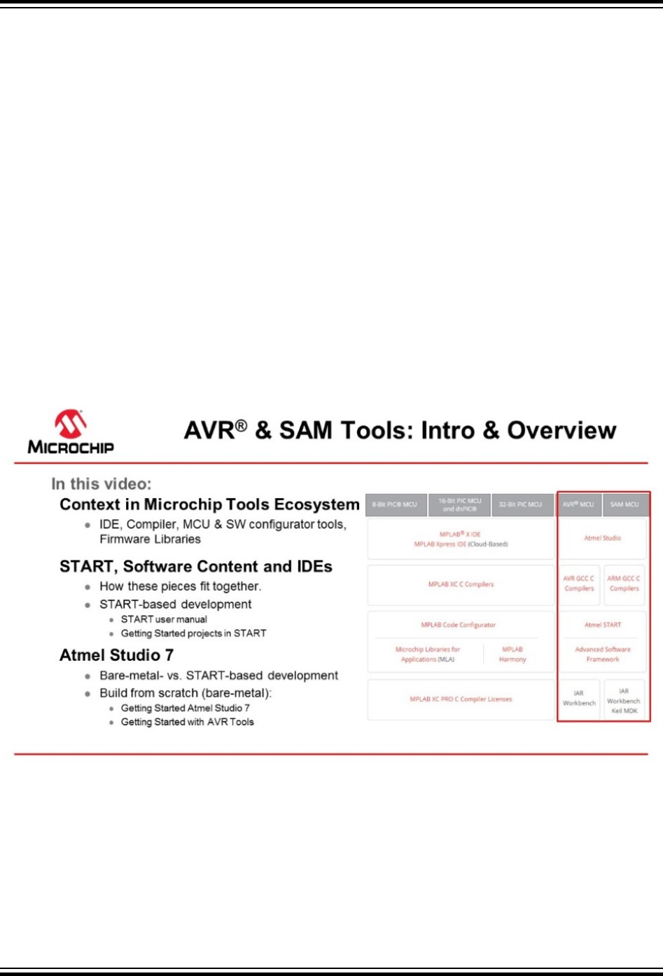
1.2 ASF4: Atmel START, Software Content and IDEs
This section gives an overview of ASF4 within the larger context of the SAM Tools ecosystem.
Getting Started Topics
Video: AVR and SAM Tools ecosystem overview
1.2.1 Atmel START
Atmel START is a web-based software configuration tool, for various software frameworks, which helps
you get started with MCU development. Starting from either a new project or an example project, Atmel
START allows you to select and configure software components (from ASF4 and AVR Code), such as
drivers and middleware to tailor your embedded application in a usable and optimized manner. Once an
optimized software configuration is done, you can download the generated code project and open it in the
ASF4 API Reference Manual
Advanced Software Framework Version 4 (ASF4) ...
© 2018 Microchip Technology Inc. User Guide DS50002633B-page 9
IDE of your choice, including Studio 7, IAR Embedded Workbench®, Keil® μVision®, or simply generate a
makefile.
Atmel START enables you to:
• Get help with selecting an MCU, based on both software and hardware requirements
• Find and develop examples for your board
• Configure drivers, middleware, and example projects
• Get help with setting up a valid PINMUX layout
• Configure system clock settings
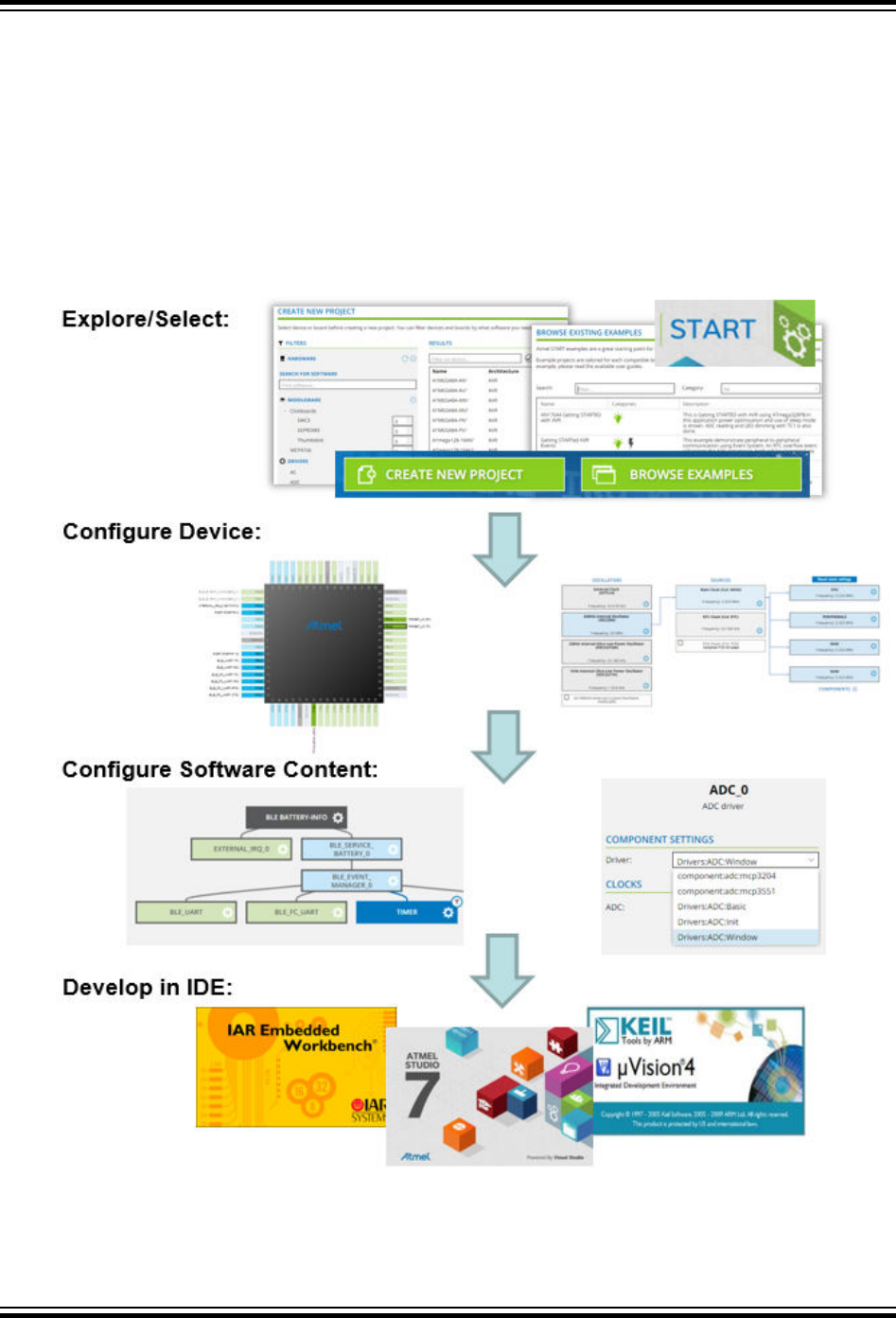
Figure 1-1. Relation between START, Software Content, and IDEs
ASF4 API Reference Manual
Advanced Software Framework Version 4 (ASF4) ...
© 2018 Microchip Technology Inc. User Guide DS50002633B-page 10

1.2.2 Software Content (Drivers and Middlewares)
Advanced Software Framework(ASF)
ASF, the Advanced Software Framework, provides a rich set of proven drivers and code modules
developed by experts to reduce customer design-time. It simplifies the usage of microcontrollers by
providing an abstraction to the hardware through drivers and high-value middlewares. ASF is a free and
open-source code library designed to be used for evaluation, prototyping, design, and production phases.
ASF4, supporting the SAM product line, is the fourth major generation of ASF. c represents a complete
re-design and -implementation of the whole framework, to improve the memory footprint, code
performance, as well as to better integrate with the Atmel START web user interface. ASF4 must be used
in conjunction with Atmel START, which replaces the ASF Wizard of ASF2 and 3.
Microchip.com: ASF Product Page
AVR Code
AVR Code, supporting the AVR product line, is a simple firmware framework for AVR 8-bit MCUs,
equivalent to Foundation Services, which supports 8- and 16-bit PIC MCUs. AVR Code is optimized for
code-size and -speed, as well as simplicity and readability of code. AVR Code is configured by Atmel
START.
1.2.3 Integrated Development Environment (IDE)
An IDE (Integrated Development Environment) is used to develop an application (or further develop an
example application) based on the software components, such as drivers and middlewares, configured in
and exported from Atmel START. Atmel START supports a range of IDEs, including Studio 7, IAR
Embedded Workbench®, Keil® μVision®.
Atmel Studio 7 is the integrated development platform (IDP) for developing and debugging all AVR and
SAM microcontroller applications. The Atmel Studio 7 IDP gives you a seamless and easy-to-use
environment to write, build, and debug your applications written in C/C++ or assembly code. It also
connects seamlessly to the debuggers, programmers, and development kits that support AVR and SAM
devices. The development experience between Atmel START and Studio 7 has been optimized. Iterative
development of START-based projects in Studio 7 is supported through re-configure and merge
functionality.
This Getting Started training for Atmel Studio 7 will guide you through all the major features of the IDE. It
is designed as a video series with accompanying hands-on. Each section starts with a video, which
covers that section.
1.3 Quick Start and Workflow Overview
ASF4 is a software library consisting of peripheral drivers and example applications. The Atmel START
web page (http://start.atmel.com) is used to select which software modules are needed in the user's
application, and to configure these modules according to the user's needs. When using the Export
Project screen, the corresponding generated C-code project can be downloaded to the user's computer
and imported into an IDE of the user’s choice, such as Atmel Studio 7, IAR™ Embedded Workbench, or
Keil μVision. The IDE is used to modify, compile, program, and debug the project.
Installation
ASF4 is configured using the Atmel START web page (http://start.atmel.com), and the configured
application is thereafter downloaded to the user’s computer as a zip-file. ASF4 does not need to install
ASF4 API Reference Manual
Advanced Software Framework Version 4 (ASF4) ...
© 2018 Microchip Technology Inc. User Guide DS50002633B-page 11

any components locally. The user will normally want to have an IDE or stand-alone toolchain installed on
their computer, so the user can compile, program, and debug the downloaded code.
Workflow
The workflow is quite straightforward, starting with either the Create New Project screen or the Browse
Existing Examples.
Starting with the Browse Existing Examples screen:
The Atmel START examples were designed to be used as a starting point for development. Efficient
filtering mechanisms are therefore available to help developers find the projects closest to their
requirements, giving them high quality, production ready code that will work "out of the box". However,
these example projects are also easy to modify as the software configuration can be extended by
changing the pinout (PINMUX screen) or adding additional drivers or middlewares (project
DASHBOARD). For example, adding support for an extra timer or even adding a BLE interface. See the
Configuration Screens section of the Atmel START user manual to understand project configuration
options using Atmel START. It is also possible to create or re-configure Atmel START projects, directly
from Atmel Studio 7 (File > New > Atmel Start project).
Starting with the Create New Project screen:
This screen was designed to help select an MCU for your project, based on both software and hardware
requirements.
1. Filter MCUs by requirements before starting a project.
2. Add components to your project, i.e. peripheral drivers and middlewares.
3. Configure each component.
4. Export the project and add it into one of the supported IDEs for further development.
The role of the IDE and Running the Code
Once the user is happy with the software configuration, the project is exported as a zip-file to the
developer’s IDE of choice. See Using Atmel Start Output in External Tools in the Atmel START user
manual for instructions about how to do this, as well as present a list of supported IDEs. ASF4/Atmel
START does not need to install any components on your local computer.
An IDE is used to develop the code required to extend the functionality of the example project into the
final product, as well as compile, program, and debug the downloaded code. A downloaded application is
ready to compile. Refer to your IDE documentation for instructions on compiling the code. The behavior
of the downloaded code is application-dependent:
• Configuring a "New project" generates a main()-function initializing all drivers, but no other
operations
• Configuring an "Example project" generates a main()-function performing more complex operations
1.4 Documentation Resources
The major sources of documentation are Getting Started projects, the Atmel START User Manual, as
well as reference manuals for ASF4 and Foundation Services framework content.
Getting Started projects
How to use the different pieces of the system to get them work together, for example, how to use Atmel
START efficiently with an IDE, such as Atmel Studio 7, in order to build your embedded application.
ASF4 API Reference Manual
Advanced Software Framework Version 4 (ASF4) ...
© 2018 Microchip Technology Inc. User Guide DS50002633B-page 12

Getting Started projects have training materials like video series and/or hands-on training manuals, linked
to the project user guides. The example project itself often represents the goal or end-point of the related
hands-on or video training material. Training materials will give you a workflow overview of how the Atmel
START and your IDE work together.
• Open Browse Examples, click the "Category" drop-down menu, and select the “Getting started”
category
• Links to training materials are found in the example project user-guides, which can be accessed
without opening the project
• See the Atmel START User Manual
START User Manual
• What is Atmel START?
• Quick Start and Workflow Overview
– Using Getting Started projects, finding/reconfiguring relevant example projects
– Create New Project, selecting an MCU based on both software and hardware project
requirements
• How to use the various Atmel START configuration screens:
– Dashboard
– PINMUX
– Event System Configurator
– QTouch® Configurator
• How to export projects to various IDEs as:
– Atmel Studio 7
– IAR Embedded Workbench
– Keil µVision
– Makefile
• Content overview, software that Atmel START can configure and generate:
– ASF4
– Foundation Services
ASF4 API Reference Manual
• ASF4 Software Architecture
• Driver implementation and Design conventions
• API reference
AVR Code API Reference Manual
• Foundation Services Software Architecture
• Driver implementation and Design conventions
• API reference
ASF4 API Reference Manual
Advanced Software Framework Version 4 (ASF4) ...
© 2018 Microchip Technology Inc. User Guide DS50002633B-page 13

1.5 ASFv4 vs ASFv3 Benchmark
ASFv4 vs ASFv3 benchmark comparison.
One of the best ways to show how the changes in ASFv4 have improved the drivers is to show some
benchmark numbers. These benchmarks compare applications are written in ASFv4 code with the same
application written in ASFv3 code. The behavior of these example applications is exactly the same. In all
these examples the default linker script has been used which set aside 8192 bytes of SRAM for a stack.
The stack usage has been removed from the SRAM numbers.
Table 1-1. ASFv4 vs. ASFv3 SPI Master Driver Memory Size Benchmark
FLASH SRAM
Full code Driver code Full code Driver code
ASFv3 4328 2916 184 + STACK 120
ASFv4 2908 1916 208 + STACK 64
Table 1-2. ASFv4 vs. ASFv3 SPI Master Driver Throughput
Bytes/s
ASFv3 54078
ASFv4 82987
Compiled in Atmel Studio 7 (7.0.582) with GCC 4.9.3, with default settings except for optimization level -
O3 and using the C lib specification nano-lib.
Hardware used is a SAMD21J18A. Both the CPU, buses, and SERCOM module are running at 8 MHz.
The example used for this benchmark initializes the device (clock setup, pin multiplexing, interrupts), set
up a SERCOM instance for SPI Master mode with 1000,000 baud rate, enables it, and writes "Hello
World!" on the SPI bus. "Full code" is the memory usage for the whole application loaded on the device
while "driver code" is the memory usage of the SPI driver-specific code components. Because many
different drivers support the same hardware in ASFv4, a lookup table is used to figure out which interrupt
handler to execute for a given peripheral instance. On Cortex M0+ based devices this table is 112 bytes,
and will not grow with the size of the project, this is the reason for ASFv4 slightly higher total (full code)
SRAM usage in this small example code.
Table 1-3. ASFv4 vs. ASFv3 USART Driver Memory Size Benchmark
FLASH SRAM
Full code Driver code Full code Driver code
ASFv3 4940 3376 168 + STACK 80
ASFv4 2684 1756 232 + STACK 88
Compiled in Atmel Studio 7 (7.0.582) with GCC 4.9.3, and with default settings except for optimization
level -Os, and using the C lib specification nano-lib.
The code was compiled for SAM D21.
ASF4 API Reference Manual
Advanced Software Framework Version 4 (ASF4) ...
© 2018 Microchip Technology Inc. User Guide DS50002633B-page 14

The example used for this benchmark initializes the device (clock setup, pin multiplexing, interrupts), set
up a SERCOM instance for USART mode with 9600 baud rate, enables it, and writes "Hello World!" on
the USART bus. "Full code" is the memory usage for the whole application loaded on the device while
"driver code" is the memory usage of the USART driver-specific code components. It's worth noting that
the same 112 bytes interrupt handler lookup table is used in this example, and the USART driver includes
a 16 bytes ring buffer for data reception to make it much less likely to lose data.
ASF4 API Reference Manual
Advanced Software Framework Version 4 (ASF4) ...
© 2018 Microchip Technology Inc. User Guide DS50002633B-page 15

2. Software Architecture
This chapter documents the architecture and high-level design of ASF4. The ASF4 driver architecture
(describes the ASF4 drivers) is built of three layers; HAL, HPL, and HRI. ASF4 has drivers which are
designed to support Use-Cases, e.g. Timer and PWM drivers are use-cases of a Timer-Counter (TC)
peripheral. Driver Variants are different driver implementation architectures, such the Synchronous-,
Asynchronous-, DMA-, and RTOS-Drivers. Driver Types are; Peripheral-, Utility-, and Middleware-drivers.
The ASF4 project folder structure is described, followed by a walk-through of the system initialization
sequence, which relies largely on Root Level Files in the project. The following sections describe in more
detail elements within the project, namely Examples Folder, Pin Configuration, and a description of
START configuration and the Config Folder.
More details are then given about the implementation of the three driver layers, respectively the
Hardware Abstraction Layer (HAL), the Hardware Proxy Layer (HPL), and the Hardware Register
Interface (HRI). For some of the drivers, there is an I/O system on top of the HAL interface, which
disconnects middleware from any driver dependency because the middleware only needs to rely on the
interface that the I/O system provides. Mechanisms for RTOS support are described. The
implementations of various driver variants, such as Synchronous-, Asynchronous-, DMA-, and RTOS-
Drivers, are described in the following chapter in Section Driver Implementation.
2.1 Peripheral Driver - Architecture Overview
Peripheral driver structure
A driver is designed to support a use-case (of a peripheral). For example, instead of one timer-counter
driver, the ASF4 has drivers for PWM, timer, and input-capture.
Use-case drivers can sometimes support various peripherals, for example, a timer could run on the TC,
TCC, or RTC. These are all peripherals that provide the functionality of the use-case, in this case, a
counter and a compare IRQ. For example: On Microchip's M0+ family, the USART, SPI, and I2C are use-
cases of the SERCOM peripheral.
The ASF4 driver architecture is built up of three layers:
• Hardware Abstraction Layer – HAL
• Hardware Proxy Layer – HPL
• Hardware Register Interface – HRI
Users are intended to interact with the HAL layer, which is hardware agnostic and can be used on a wide
range of devices and platforms. The three layers are largely transparent to the user, though all are
available. Each layer is organized into folders in the project structure, each containing files with API
associated with the respective layer.
HAL folder (Hardware Abstraction Layer)
This folder contains hardware independent/agnostic API, for hardware with the same kind of functionality.
The interface, which most users will use, is in the HAL layer.
Naming convention: HAL functions start with usecase_, for example, adc_dma_driver.
In the hal folder, there are four sub-folders. The include and the src folders contain the definition of
the HAL interfaces and implementation of the hardware agnostic part of the driver. The documentation
ASF4 API Reference Manual
Software Architecture
© 2018 Microchip Technology Inc. User Guide DS50002633B-page 16

folder contains the documentation of each driver as displayed in the Atmel START help text. The utils
folder contains API definitions and implementations of the utility function drivers.
HPL folder (Hardware Proxy Layer)
Hardware-aware functionality is needed by the HAL, is implemented in the hardware-aware HPL level,
keeping the HAL level hardware agnostic. There will be a peripheral configuration file associated with the
HPL layer.
Naming convention: HPL functions start with _usecase_, for example: _usart_async_init()
The hpl folder has multiple subfolders - one folder per hardware module supported by ASF4. These
folders contain .h and .c files implementing the HPL layer.
HRI folder (Hardware Register Interface)
HRI level functions are used to configure register bits or bitfields, for example bit_set(), bit_clr().
The hri folder has multiple .h-files - one file per hardware module supported by ASF4. These files define
the register interface of hardware modules.
Layers
The drivers are implemented in layers in order to:
1. Provide software interfaces abstracted from the underlying implementation.
2. Make it easier to document the drivers and architecture making it easier for users and developers
to create, use, modify, and debug the code.
3. Multiple layers make it possible to have both stable and unstable APIs. For instance, the top layer
HAL API should be as stable as possible, and only modified when necessary, and these
modifications must be documented. The HPL layer, however, is not meant to be used as
standalone and cannot, in that context, be called a "public" API, which means that the threshold for
modifying this interface shall be much lower. For example, support for a new feature in hardware
can be performed in the HPL and the HAL is kept untouched.
4. Multiple layers make it easier to separate code making up the hardware support from reusable
common code. In ASF4, all hardware support code is in the HPL. The HRI interface describes only
the hardware register interface. The HAL usually needs to be written only once and then reused
with different HPL layers.
ASF4 API Reference Manual
Software Architecture
© 2018 Microchip Technology Inc. User Guide DS50002633B-page 17
Figure 2-1. The ASF4 Driver Architecture
Middleware
HAL
HPL
HRI
Simple IO
Abstract device
2.2 Driver Use-cases, Types, and Variants
Driver use-cases The application functionality, which a peripheral can be used for, such as PWM and
Timer for a Timer-Counter (TC) peripheral.
Driver variants Different driver implementation architectures, such the Synchronous-,
Asynchronous-, DMA-, and RTOS-Drivers.
Driver Types Relates to whether a driver supports a peripheral, utility function, or middleware.
2.2.1 Driver Use-cases
Instead of having one generic driver per peripheral, the ASF4 drivers provide interfaces to ways of using
the peripheral. These ways are named "use-cases". A use-case typically implements a subset of the total
functionality provided by the peripheral. This is useful as many of the peripherals on SAM devices, such
as the SERCOM, provide a very broad functionality. This would cause a generic driver providing access
to all the functionality of the module to be very large. Because the use-case limits the scope of
functionality provided to the user, the driver is easier to implement and test and is more optimal than a
generic driver would be. The figure below shows that a SERCOM hardware module can be used to
implement various communication protocols, each protocol (or use-case) being implemented by a specific
ASF4 API Reference Manual
Software Architecture
© 2018 Microchip Technology Inc. User Guide DS50002633B-page 18
ASF4 driver. There is no generic "SERCOM" driver in the ASF4 HAL layer, but instead a specific
"USART" driver, "I2C" driver, "LIN" driver, and so on.
The use-case approach together with the HAL and HPL layers allow the driver to be implemented in
different ways, depending on the available hardware. As an example, a driver that issues a periodic
interrupt can be implemented using for example:
• TC Timer
• TCC Timer
• RTC
• Systick in CPU
Atmel START is used to select the hardware instance to be used to implement the driver. This is done
during ASF4 configuration.
Figure 2-2. Example of Use-cases for a SERCOM Module
SERCOM
RS485
ISO7016
I2C
SPI
USART
LIN
ASF4 has different types of drivers; Peripheral-, Utility-, and Middleware-drivers.
2.2.2 Driver Variants
A use-case such as "ADC" can be implemented using drivers with different architectures, such as:
• ADC with blocking receive/transmit functions
• ADC with non-blocking receive/transmit functions
• ADC implemented using DMA transfer of data between peripheral registers to memory
• ADC intended for use with a Real-Time operating system
ADC Synchronous Driver
The driver will block (i.e. not return) until the requested data has been read. Functionality is therefore
synchronous to the calling thread, i.e. the thread waits for the result to be ready. The
adc_sync_read_channel( ) function will perform a conversion of the voltage on the specified channel and
return the result when it is ready.
ASF4 API Reference Manual
Software Architecture
© 2018 Microchip Technology Inc. User Guide DS50002633B-page 19
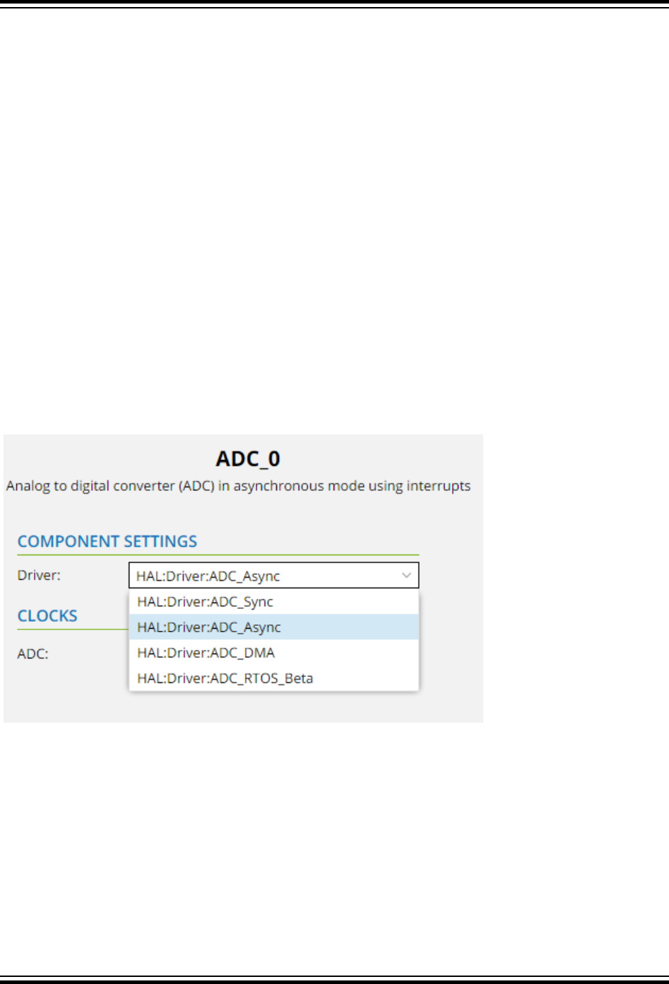
ADC Asynchronous Driver
The driver adc_async_read_channel function will attempt to read the required number of conversion
results from a ring buffer. It will return immediately (i.e. not block), even if the requested number of data is
not available immediately. If data was not available, or fewer data than requested was available, this will
be indicated in the function's return value. The asynchronous driver uses interrupts to communicate that
ADC data is available, and the driver's IRQ handler reads data from hardware and into ringbuffers in
memory. These ringbuffers decouple the generation of data in the ADC with the timing of the application
request for this data. In a way, the producer and consumer events are asynchronous to each other. The
user can register a callback function to piggyback on the IRQ handler routine for communicating with the
main application.
ADC DMA Driver
Uses DMA system to transfer data from ADC to a memory buffer in RAM. The user must configure the
DMAC system driver accordingly. To set the memory buffer and its size the adc_dma_read function is
used. This function programs DMA to transfer the results of input signal conversion to the given buffer. A
callback is called when all data is transferred if it is registered via the adc_dma_register_callback
function.
ADC RTOS Driver
The driver is intended for using ADC functions in a real-time operating system, i.e. a thread-safe system.
For drivers providing multiple variants, the variant to be used is selected during the ASF4 configuration in
START.
2.2.3 Driver Types
Driver Types relate to whether a driver supports a peripheral, utility function, or middleware.
Peripheral Driver
A peripheral driver is a driver that is directly related to some functionality in some hardware peripherals.
This is usually not the full functionality set available in the hardware peripheral, but a subset to make it
portable between hardware platforms with different hardware peripheral implementations. A peripheral
driver in the ASF4 consists of the HRI, HPL, and HAL layers. The user will normally interface only with the
topmost HAL layer.
ASF4 API Reference Manual
Software Architecture
© 2018 Microchip Technology Inc. User Guide DS50002633B-page 20
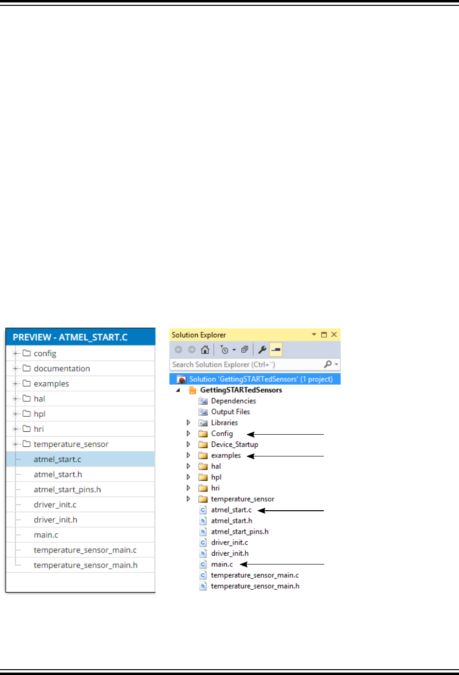
Utility Driver
Utility drivers are hardware agnostic drivers that implement commonly used software concepts. The utility
drivers are available for both the ASF4 drivers and the user application. Examples of utility drivers are a
generic linked list or a ring buffer. Utility drivers can also be in form of C macro definitions.
Moving commonly used code into utility drivers makes it easier to maintain code and help the compiler to
optimize the code because the same code is used by different drivers, but only one copy is needed. The
utility drivers are fully abstracted and not bound to any particular hardware platform or type.
Middleware Driver
Middleware drivers are built on top of peripheral drivers and do not have any direct link to the underlying
hardware. A middleware driver can depend on multiple peripheral drivers at the same time or support a
range of different peripheral drivers. These drivers usually implement highly abstracted code that
implements some kind of software concepts like graphics libraries, USB classes, or file systems.
2.3 ASF4 Project Folder Structure
In this section, the project folder structure and file descriptions of an example Atmel START/ASF4 project
are described. By clicking the VIEW CODE tab, at the top of the project, the folder structure, as well as
the generated code based on the current configuration, can easily be previewed. This will be the same as
the one generated in the Export Project screen, once the imported into an IDE. For example, the figure
below shows the project structure from both the VIEW CODE preview, as well as the Atmel Studio 7
solution explorer.
Figure 2-3. Folder Structure of an ASF4 Project Generated from Atmel START
Configuration files
Application level example
functions to quickly get going
System_init( ) as well as
middleware init functions.
Application
The config folder contains one *_config.h for each hpl-device configured by Atmel START. The files
in the config folder are used by the HPL layer to configure the functionality the user entered in Atmel
START. The files use the CMSIS wizard annotation format.
ASF4 API Reference Manual
Software Architecture
© 2018 Microchip Technology Inc. User Guide DS50002633B-page 21

The examples folder contains examples of using the drivers and is useful to see how to use the ASF4
drivers.
The root folder contains the following files:
•atmel_start.c – Code for initializing MCU, drivers, and middleware in the project
•atmel_start.h – API for initializing MCU, drivers, and middleware in the project
•atmel_start_pins.h – Pin MUX mappings as made by the user inside START
•driver_init.c – Code for initializing drivers
•driver_init.h – API for initializing drivers
•main.c – Main application, initializing the selected peripherals
A full expanded project directory for a simple generated project for the SAM D21 with a single USART is
available in 2.9 ASF4 Project Folder Structure - Full.
In the following sections, more details are given about Root Level Files, Pin Configuration, Examples
Folder, and Config Folder. Then System Initialization walks through the start-up sequence of an ASF4
project.
2.3.1 System Initialization
This section walks you through the startup sequence of an ASF4 project. This system initialization
sequence relies mainly on root level files, which are described in more detail in 2.3.2 Root Level Files.
An empty ASF4 project, generated from Atmel START will contain only the atmel_start_init()
function in main().
int main(void)
{
atmel_start_init();
/* Replace with your application code */
while(1) {
}
}
The atmel_start_init() function is implemented in atmel_start.c and:
• initializes any middleware libraries, which have been added to the project
• calls system_init()
void system_init(void)
{
system_init();
temperature_sensors_init();
}
The system_init() function is implemented in driver_init.c and:
• initializes the MCU (oscillators, clocks, flash wait states, etc.) using the init_mcu() function
• initializes the peripherals, which have been selected (in our case the USART), using the
USART_0_init() function
void system_init(void)
{
init_mcu();
USART_0_init();
}
ASF4 API Reference Manual
Software Architecture
© 2018 Microchip Technology Inc. User Guide DS50002633B-page 22
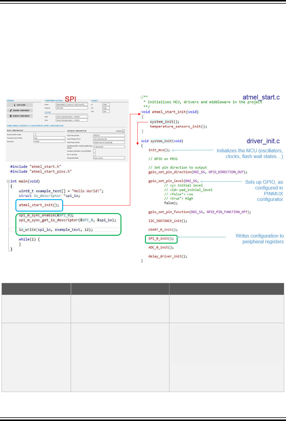
The different initialization functions which are called in system_init(), use the configuration’s
parameters that the user has selected during the Atmel START configuration process.
An example initialization of an SPI peripheral is considered in the picture below.
1. In main.c: main() calls atmel_start_init().
2. In atmel_start.c: atmel_start_init() calls temperature_sensors_init(), a middleware
initialization function, as well as system_init().
3. In driver_init.c: system_init() calls init_mcu(), pin configuration functions and driver
initialization functions, such as SPI_0_init().
4. SPI_0_init() writes START configuration to the SPI (SERCOM) peripheral registers.
2.3.2 Root Level Files
File name What is in the file Example
main.c Main application, initializing the
selected peripherals by calling
atmel_start_init( ).
See project initialization sequence
atmel_start.c Code for initializing the MCU,
drivers, and middleware in the
project.
The system_init( ) function
initializes the MCU (oscillators,
clocks, flash wait states, etc.) and
peripherals, which have been
selected.
#include <atmel_start.h>
void atmel_start_init(void)
{
system_init();
temperature_sensors_init();
}
ASF4 API Reference Manual
Software Architecture
© 2018 Microchip Technology Inc. User Guide DS50002633B-page 23
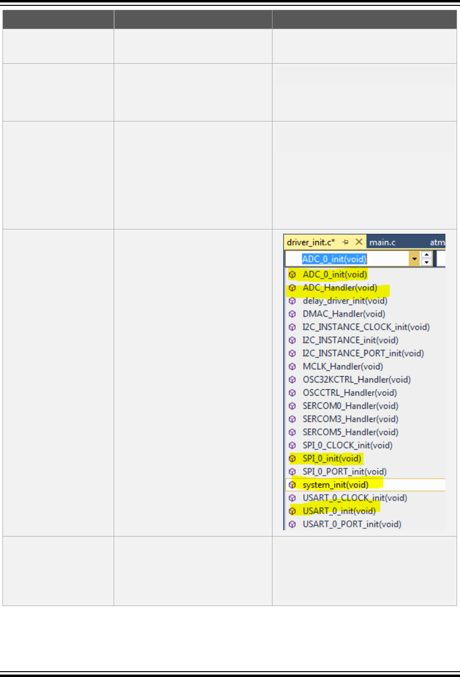
File name What is in the file Example
Middleware initialization functions
are called.
atmel_start.h API for initializing the MCU,
drivers, and middleware in the
project. Function definitions of
atmel_start_init( ).
void atmel_start_init(void);
atmel_start_pins.h Pin MUX mappings as made by
the user inside Atmel START.
Defines of pin user labels are
found in the file
atmel_start_pins.h. These
user labels match what is
configured in the PINMUX
CONFIGURATOR.
#define PB23 GPIO(GPIO_PORTB, 23)
#define DGI_SS GPIO(GPIO_PORTB, 31)
driver_init.c Code for initializing drivers.
Contains system_init() and all
peripheral initialization functions.
For peripherals using
asynchronous drivers (IRQ
enabled), there are IRQ handler
functions.
For example: ADC_Handler( ) is
the IRQ handler. If the HAL layer
has callbacks this handler will call
these callbacks.
driver_init.h API for initializing drivers. Function
definitions of peripheral
initialization functions, related
variables, and header files.
#include <hal_usart_sync.h>
extern struct
usart_sync_descriptor USART_0;
void USART_0_PORT_init(void);
void USART_0_CLOCK_init(void);
void USART_0_init(void);
ASF4 API Reference Manual
Software Architecture
© 2018 Microchip Technology Inc. User Guide DS50002633B-page 24

File name What is in the file Example
middleware_main.c Initialization of middleware
libraries.
void temperature_sensors_init(void)
{
}
middleware_main.h Function definition of middleware
initialization functions, related
variables, and header files.
#include <at30tse75x.h>
#include <at30tse75x_config.h>
extern struct temperature_sensor
*TEMPERATURE_SENSOR_0;
void
temperature_sensors_init(void);
2.3.3 Examples Folder
Application level example functions are provided in examples\driver_examples.c. When we
develop an application in the main.c file, these functions may be useful to call and adapt (if required), in
order to very quickly build and test peripheral functionality. For example, a function to call “Hello World!” is
provided for the USART.
/**
* Example of using USART_0 to write "Hello World" using the IO abstraction.
*/void USART_0_example(void)
{
struct io_descriptor *io;
usart_sync_get_io_descriptor(&USART_0, &io);
usart_sync_enable(&USART_0);
io_write(io, (uint8_t *)"Hello World!", 12);
}
If you have added the USART driver only, you will find USART related functions only as this is the only
peripheral that has been added to the project and configured in Atmel START.
Example functions are grouped into separate folders, which can easily be deleted if not needed so that
the final project contains the production code only.
2.3.4 Pin Configuration
Defines of pin user labels are found in the file atmel_start_pins.h. These user labels match what is
configured in the PINMUX CONFIGURATOR.
ASF4 API Reference Manual
Software Architecture
© 2018 Microchip Technology Inc. User Guide DS50002633B-page 25
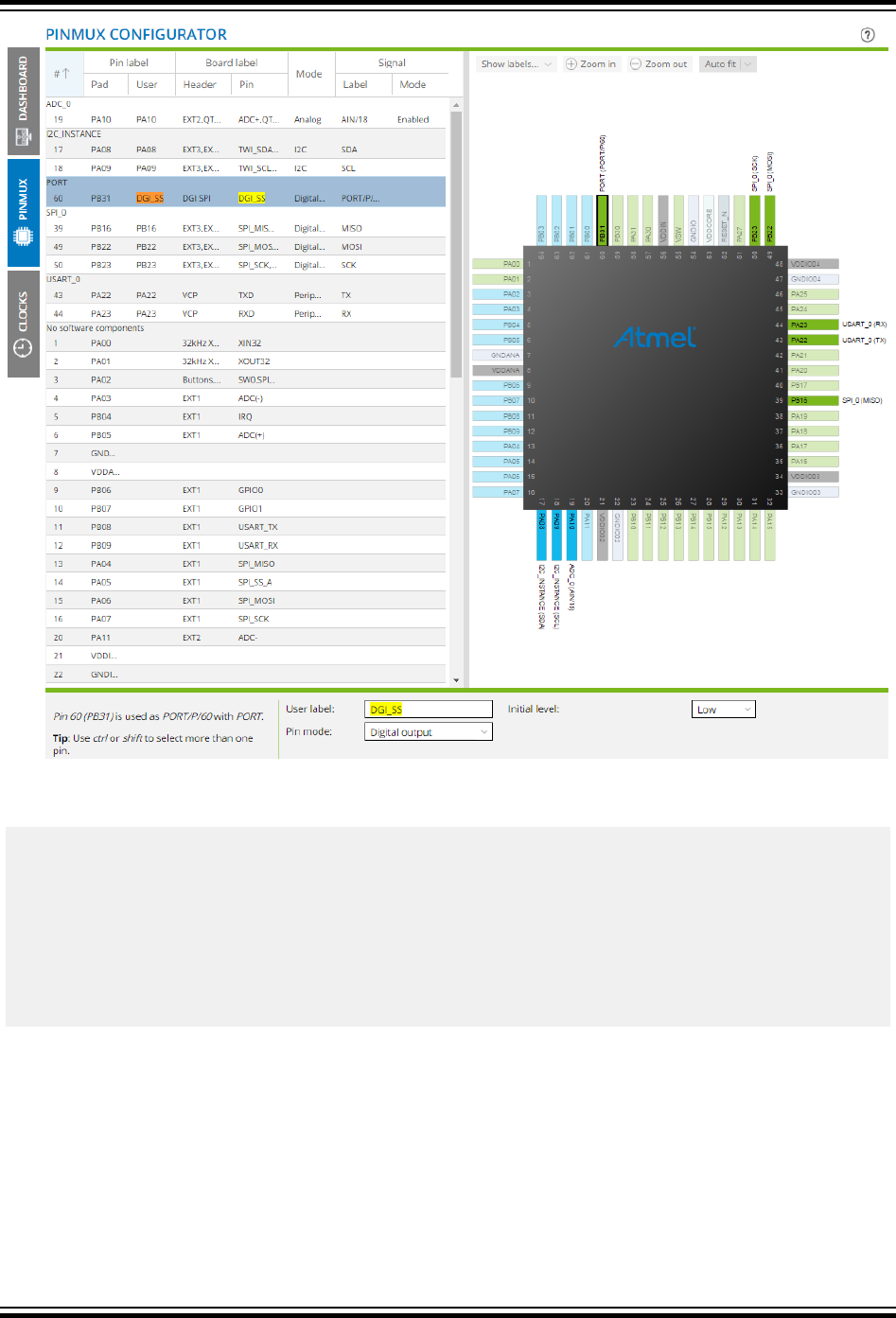
For example, PB31 is given a user label DGI_SS, which can be seen as the define associated with this
pin in the atmel_start_pins.h file:
#include <hal_gpio.h>
#define PA08 GPIO(GPIO_PORTA, 8)
#define PA09 GPIO(GPIO_PORTA, 9)
#define PA10 GPIO(GPIO_PORTA, 10)
#define PA22 GPIO(GPIO_PORTA, 22)
#define PA23 GPIO(GPIO_PORTA, 23)
#define PB16 GPIO(GPIO_PORTB, 16)
#define PB22 GPIO(GPIO_PORTB, 22)
#define PB23 GPIO(GPIO_PORTB, 23)
#define DGI_SS GPIO(GPIO_PORTB, 31)
2.3.5 Config Folder
The config folder contains header files, which hold the configuration data associated with each driver.
These configuration files are associated with the Hardware Proxy Layer (HPL) of the driver. By
connecting the configuration file to the HPL it is possible to expose hardware-specific configuration
options to the user, that is, the configuration includes settings which are hardware-aware.
The START-based configuration is based on the ARM-CMSIS wizard annotation format.
ASF4 API Reference Manual
Software Architecture
© 2018 Microchip Technology Inc. User Guide DS50002633B-page 26
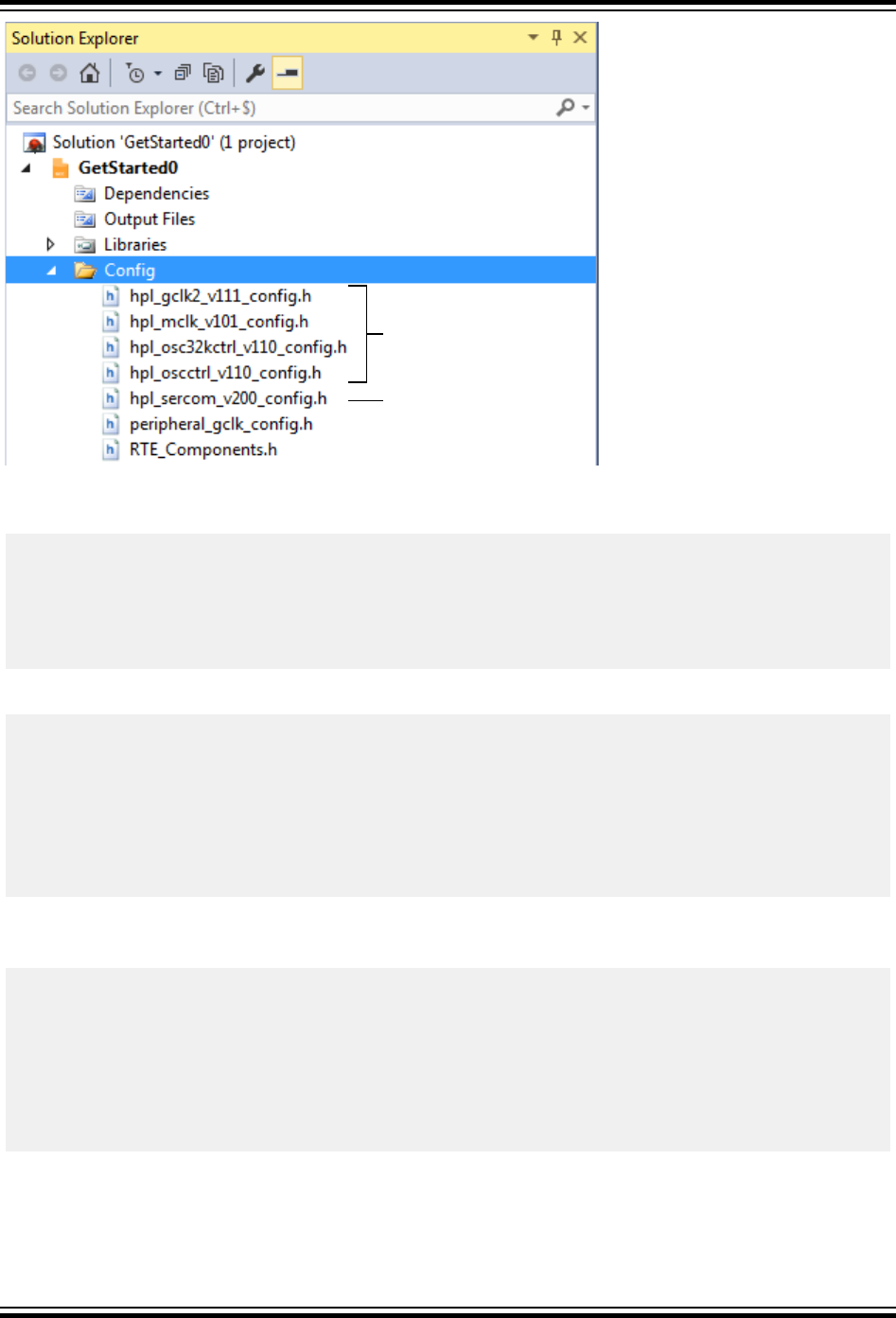
USART (SERCOM)
Oscillators
and clocks
As an example, if you open the hpl_oscctrl_vxxx_config.h file, you can check that the only
oscillator enabled is the OSC16M:
// <h> 16MHz Internal Oscillator Control
// <q> Enable
// <i> Indicates whether 16MHz Internal Oscillator is enabled or not
// <id> osc16m_arch_enable
#ifndef CONF_OSC16M_ENABLE
# define CONF_OSC16M_ENABLE 1
#endif
And that the selected frequency for the OSC16M oscillator is 4 MHz:
// <y> Oscillator Frequency Selection(Mhz)
// <OSCCTRL_OSC16MCTRL_FSEL_4_Val"> 4
// <OSCCTRL_OSC16MCTRL_FSEL_8_Val"> 8
// <OSCCTRL_OSC16MCTRL_FSEL_12_Val"> 12
// <OSCCTRL_OSC16MCTRL_FSEL_16_Val"> 16
// <i> This defines the oscillator frequency (Mhz)
// <id> osc16m_freq
#ifndef CONF_OSC16M_FSEL
# define CONF_OSC16M_FSEL OSCCTRL_OSC16MCTRL_FSEL_4_Val
#endif
An extract of the ADC config file (hpl_adc1_v120_config.h) is shown below, representing the ADC
conversion resolution configuration output.
// <o> Conversion Result Resolution
// <0x0=>12-bit
// <0x1=>16-bit (averaging must be enabled)
// <0x2=>10-bit
// <0x3=>8-bit
// <i> Defines the bit resolution for the ADC sample values (RESSEL)
// <id> adc_resolution
#ifndef CONF_ADC_0_RESSEL
# define CONF_ADC_0_RESSEL 0x3
#endif
In the #define, the RESSEL is the register bit field name. The value of the define represents what will be
written to the associated register. The commented out values function as an enumerator of other potential
valid values. Enumerators used in ASF3 have been replaced by this syntax.
ASF4 API Reference Manual
Software Architecture
© 2018 Microchip Technology Inc. User Guide DS50002633B-page 27

Note: To find the register this relates to, open the data sheet register summary for the given peripheral,
then search for this bit field value.
Another example is given below, which shows a baud rate calculation of the SERCOM in USART mode,
that is the USART use-case of the SERCOM peripheral. Here one can also see the formula in the
generated macro in order to calculate the correct value to be programmed into the BAUD register. These
calculations will tend to be found near the bottom of the configuration file.
// <o> Baud rate <1-3000000>
// <i> USART baud rate setting
// <id> usart_baud_rate
#ifndef CONF_SERCOM_3_USART_BAUD
# define CONF_SERCOM_3_USART_BAUD 9600
#endif
// gclk_freq - (i2c_scl_freq * 10) - (gclk_freq * i2c_scl_freq * Trise)
// BAUD + BAUDLOW = --------------------------------------------------------------------
// i2c_scl_freq
// BAUD: register value low [7:0]
// BAUDLOW: register value high [15:8], only used for odd BAUD + BAUDLOW
#define CONF_SERCOM_0_I2CM_BAUD_BAUDLOW (((CONF_GCLK_SERCOM0_CORE_FREQUENCY - \
(CONF_SERCOM_0_I2CM_BAUD * 10) -\
(CONF_SERCOM_0_I2CM_TRISE * (CONF_SERCOM_0_I2CM_BAUD / 100) * \
(CONF_GCLK_SERCOM0_CORE_FREQUENCY / 1000) / 10000 )) * 10 + 5) / \
(CONF_SERCOM_0_I2CM_BAUD * 10))
#ifndef CONF_SERCOM_0_I2CM_BAUD_RATE
What configuration files will I see?
The configuration files appearing depends on the configuration selected. For example, consider adding
Timer and PWM drivers to a SAM D21 project. Both drivers can run on either the TC or TCC peripherals.
If both the Timer and the PWM are configured to run on the TC, then a single conf_tc.h will be placed
in the Config folder. However, if the Timer driver runs on the TC while the PWM runs on the TCC, then
both the conf_tc.h and the conf_tcc.h will be generated for the Timer and PWM respectively.
Naming convention
What is in the hpl_adc1_v120_config.h file name?
hpl this is the hardware-aware software layer
adc1_v120(a) adc1 is an ADC project in IC design v120, a silicon version of the ADC integrated
peripheral (FYI) (a) variant of the silicon version to support a subset of MCUs.
2.4 Hardware Abstraction Layer (HAL)
The HAL is the topmost driver layer and the only one that most users should interact with. This layer is a
common, reusable interface supporting a range of devices and architectures. This layer abstracts away
the peculiarities of hardware and provides the same services to the programmer irrespectively of the
hardware implementing the HAL. The HAL layer contains functions allowing the user access to the
driver's functionality. Therefore, many of the functions are driver specific and may perform things such as:
• Transfer data between the driver and the application
• Start a specific operation provided by the driver, such as start a data transmission
ASF4 API Reference Manual
Software Architecture
© 2018 Microchip Technology Inc. User Guide DS50002633B-page 28

Driver handle
As part of the abstraction between a specific hardware implementation and the HAL interface, the HAL
driver specifies its own handle to store necessary data like hardware register interface pointers, buffer
pointers, etc. The handle is used as a parameter to HAL functions in order to identify which resource to
address.
The handles have the following definition:
struct [namespace]_descriptor
Example: struct usart_sync_descriptor USART0;
2.4.1 Mandatory Driver Functionality
The following functions are found in all drivers and complement the driver-specific functions.
Driver initialization
All HAL interfaces have an initialization function named init(). This function is responsible for loading
the module configuration, pin MUX setup, and clock source setup found in the configuration file. This
function is also responsible for initializing the HAL device handle, with references to the hardware
interface and buffers if needed. The parameter list of this function shall start with the HAL device handle,
followed by a pointer to the hardware register interface of the module instance to be associated with this
HAL device. Any parameters after the first two parameters are interface specific. After this call, the
module is enabled and ready for use, if not an error code should be returned to the application.
Name convention
[namespace]_init(struct [namespace]_descriptor *desc, adc *hw, ...);
Example
adc_sync_init(struct adc_sync_descriptor *adc, adc *hw, ...);
Driver deinitialization
All high-level HAL interfaces have a deinitialization function named deinit(). This function is
responsible for releasing the hardware module and any resource allocated by this module. This includes
disabling any clock source for the module, resetting any pin MUX setting and resetting the module itself.
Name convention
[namespace]_deinit(struct [namespace)_descriptor *desc);
Example
adc_sync_deinit(struct adc_sync_descriptor *adc);
Register interrupt handler callback
APIs supporting interrupts have a function to register different interrupt handlers. When this function
returns, the interrupt is enabled in the module and is ready for use. This function does not change the
state of the global interrupt flag. Registering a NULL pointer as handler disables the interrupt used by the
driver.
ASF4 API Reference Manual
Software Architecture
© 2018 Microchip Technology Inc. User Guide DS50002633B-page 29

Name convention
[namespace]_register_callback(struct [namespace]_descriptor *desc, [namespace]_callback_type
type);
Example
adc_async_register_callback(struct adc_async_descriptor *adc, adc_async_callback_type type);
Get driver version
All HAL drivers are tagged with a version number. The version number has the format 0x00xxyyzz and
can be retrieved using the [namespace]_get_version() function, e.g. adc_sync_get_version().
• xx: Major version number
– Additions/changes to the driver and/or driver API
– Driver does not need to stay backward compatible
• yy: Minor version number
– Additions to the API
– Bug-fixes and/or optimization to the implementation
– The driver shall stay backward compatible
• zz: Revision number
– Bug-fixes and/or optimizations of the driver
– The API shall not be changed
– The driver shall stay backward compatible
Get I/O descriptor
For APIs with I/O system support, there is a function to extract the I/O descriptor from the device
descriptor. This function returns a pointer to the generic I/O descriptor type.
Name convention
[namespace]_get_io_descriptor(struct [namespace]_descriptor *descriptor, struct io_descriptor
**io);
Example
usart_sync_get_io_descriptor(struct usart_sync_descriptor *descriptor, struct io_descriptor
**io);
2.5 I/O System
For some of the drivers, there is an I/O system on top of the HAL interface. The I/O system disconnects
middleware from any driver dependency because the middleware only needs to rely on the interface that
the I/O system provides. The I/O system has a write and a read method that are used to move data in/out
of the underlying interface. An example is a file system stack that can be used with any of the external
interfaces on the device to communicate with an external storage unit. The application will have to set up
the interface, and then supply a pointer to the I/O object to the file system stack.
ASF4 API Reference Manual
Software Architecture
© 2018 Microchip Technology Inc. User Guide DS50002633B-page 30

Figure 2-4. Overview of the I/O System
Module A
Module B
Module C
HAL A
HAL B
HAL C
Middleware
Common
IO System
int32_t write(...)
int32_t read(...)
Example of I/O system code
/* This is conceptual code, and not copied from ASF4 framwork code */
#define BUF_SIZE 4
uint8_t buf[BUF_SIZE];
int8_t data_received;
io_handle_t spi_io;
fs_handle_t fs;
file_handle_t file;
hal_spi_init(&spi_io, hw);
do {
data_received = io.read(buf, BUF_SIZE);
} while (data_recieved == 0);
if(data_received < 0) {
/* Something wrong was detected */
while(1) {
};
}
/* Write something on the SPI bus */
spi_io.write(buf, data_received);
/* Using a storage device over the SPI interface */
fat_fs_init(fs, spi_io);
fat_fs_write_file(fs, file);
ASF4 API Reference Manual
Software Architecture
© 2018 Microchip Technology Inc. User Guide DS50002633B-page 31
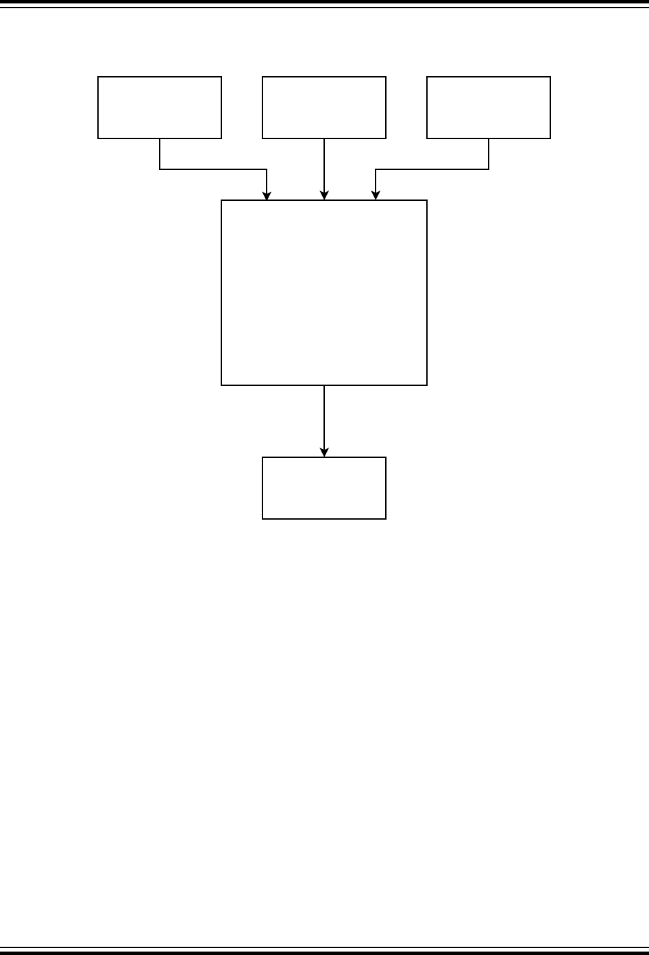
2.6 Hardware Proxy Layer (HPL)
Figure 2-5. Example HPL for TC Supporting Three Different HAL APIs
TASKS PWM TIMER
TC HRI
TC HPL
_tc_generic_init();
_tasks_init();
_pwm_init();
_timer_init();
Most drivers consist of a mix of code that do not require direct hardware peripheral access and code that
require hardware access. In ASF4 this code is split into two different layers called the Hardware
Abstraction Layer (HAL) and the Hardware Proxy Layer (HPL). The HAL is the layer where all hardware
agnostic code is implemented and the interface that the user access, to use the framework, is defined.
The HPL is where the hardware-aware code is implemented.
A typical example of this split is a function that reads a buffer of some length from a hardware module
asynchronously. The application does not know when data will arrive at the peripheral so a ring-buffer is
used to store the data until the application is ready to read it. As none of the actual hardware
implementations of the module supported through this interface has a hardware-based ring-buffer, a
software implementation of the buffer is used. Since the data going into the buffer is hardware
independent, the ring-buffer is implemented in the HAL driver. Reading the data from the hardware
module will, on the other hand, be hardware dependent as the register location, name, and access
sequence might differ. This code will, therefore, be implemented in the HPL driver.
The split between HAL and HPL makes it clear which code has to be updated when adding support for
new hardware, and which code can be reused without any modification. The expected interface between
the HAL and HPL is defined by an abstract device.
The HPL/HAL driver split allows the different hardware modules with overlapping functionality, to use the
same HAL interface. As an example, a device contains different timer/counter module designs: One
simple timer/counter design and one more advanced targeted for advanced PWM. Both types can be
ASF4 API Reference Manual
Software Architecture
© 2018 Microchip Technology Inc. User Guide DS50002633B-page 32

used to periodically increment a counter and to trigger an interrupt event when the counter reaches some
pre-defined value. The same HAL interface and implementation can be used for both module types but
mapped to the two different HPL layers.
The abstracted device and interface
The abstracted device is a definition of a non-physical virtual device with a defined feature set. This
feature set can be implemented using compatible features in physical hardware modules. This means
that an abstract device has a feature set which is a subset of what the physical hardware modules
support.
Figure 2-6. An Abstract USART Device is Defined with a Subset of the Feature Sets in USART A,
B, and C
USART A
feature set
USART B
feature set
USART C
feature set
Virtual
USART
feature set
The abstract USART device in the figure above is defined as a subset of what USART A, B, and C can
offer. USART implementations often support features like IrDA, SPI-master, Lin, RS485, etc., on top of
the USART/UART support, but it is not given which of these features are supported by which
implementation. To make sure that the virtual USART device is compatible with the feature set of each
physical implementation, the feature scope will be limited to UART/USART. Support for other features can
be provided through other abstract device definitions.
The HAL interface gives the user one common interface across multiple hardware implementations. This
makes the code easier to port between devices/platforms. Since the HAL implements use cases, the
code is more focused, and therefore more optimized for the limited scope than a more general driver
would be. Since the HAL driver interfaces hardware through the abstracted device, the HAL driver is
completely decoupled from the hardware. The abstract interface is implemented by the hardware’s HPL
driver.
Example of abstract device
struct _usart_device {
struct _usart_callbacks usart_cb;
void *hw;
};
_usart_init(void *const hw);
ASF4 API Reference Manual
Software Architecture
© 2018 Microchip Technology Inc. User Guide DS50002633B-page 33
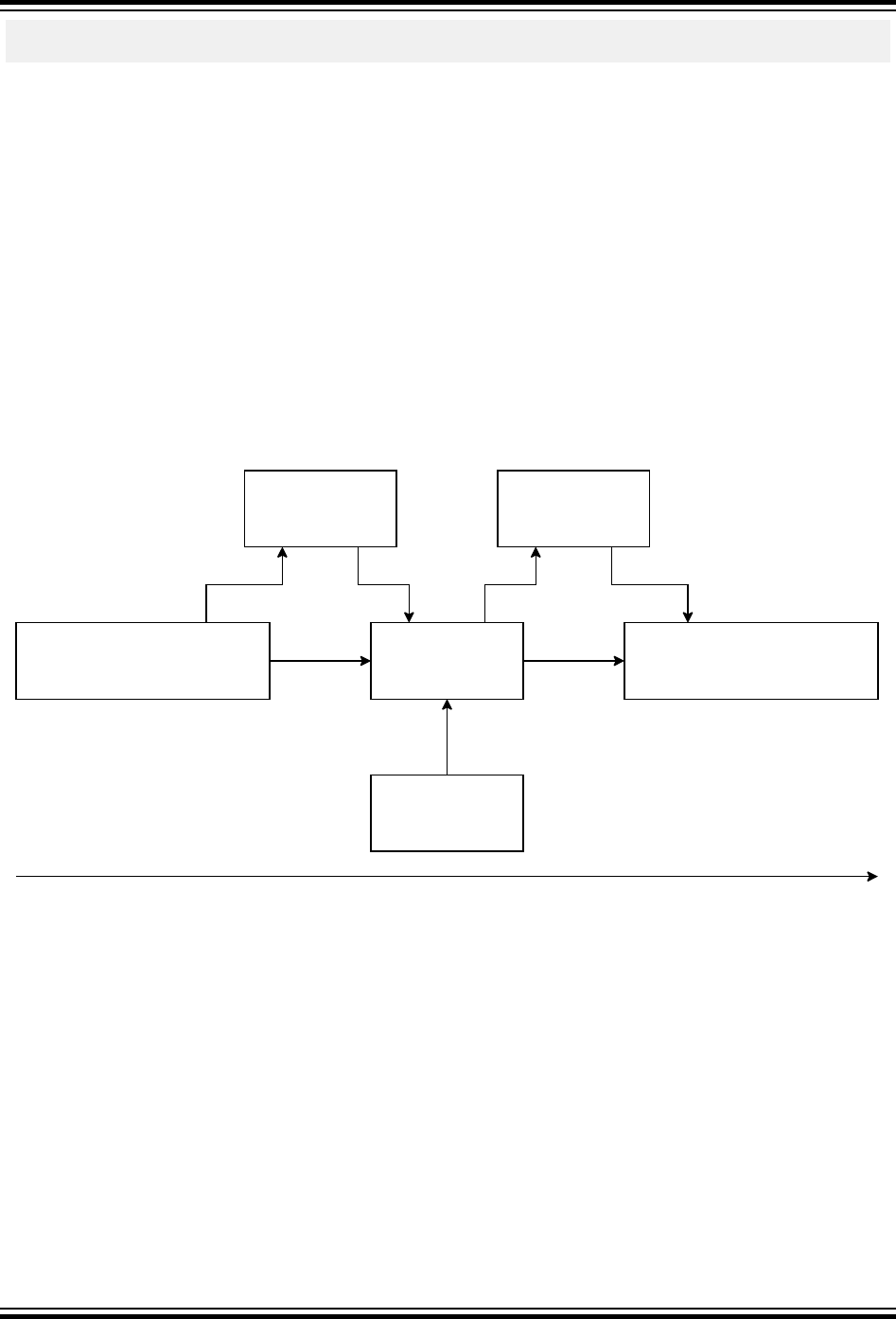
_usart_deinit(void *comst hw);
_usart_transmit(void *const hw, uint8_t *const buf, uint32_t length);
This is a simple abstract USART device, with a small interface for init, deinit, and transmit data. If we
implement this abstract device for SAM D21 an obvious choice would be to use the SERCOM module to
implement this abstract device. To accomplish that, a function to set up the SERCOM and put it into
USART mode (init), put data into the data register (transmit), and disable the SERCOM (deinit), must be
implemented in the HPL driver for the SERCOM.
In ASF4, the abstract device is defined as a data container for any data that is shared between the HAL
and the HPL implementation. Examples are pointers to hardware registers, buffers, state information, and
callback functions for events (interrupts, error detected, etc.). As an example one can use interrupt
events. Parts of an interrupt event are processed in the HPL and parts are processed in the HAL like
custom callback functions. As earlier noted, the HAL must stay hardware agnostic, so, to be notified that
something happens in the underlying hardware, it must register callback functions in the abstract device.
This data is shared with the HPL driver, and the HPL driver can use these callbacks to notify the HAL that
something has happened in the hardware. This keeps the HAL and the HPL decoupled and there are no
dependencies between those two layers, only to the abstract device.
Figure 2-7. Example of Hardware Event Propagation from the HPL to the HAL
HPL
Hardware
device device
HAL A
HAL A
register callback get callback pointer
trigger callback
process event
some event
device->event_callback =
process_event();
process_event;
Timeline
2.7 Hardware Register Interface (HRI)
The layer closest to the hardware is named HRI. This layer is a simple interface with very little logic that
do register data content manipulation with a set of defined functions calls. The data manipulation
operations can be performed on a bit, bit field, and complete register level.
ASF4 API Reference Manual
Software Architecture
© 2018 Microchip Technology Inc. User Guide DS50002633B-page 34

Figure 2-8. HRI Example Data Manipulation of Bit and Bit Field Contents
1
11
1
toggle()
0
01
1
set(0b0011)
1
1
0
0
1
11
1
1
1
0
0
0
01
1
clear(0b0011)
1
1
0
0
1
10
0
0
0
0
0
This layer also abstracts special register access properties like data synchronization between clock
domains. It also ensures that data integrity is kept within an interruptible system by inserting critical
sections when it is not possible to do data manipulation atomically.
Using the HRI interfaces as access interface to the peripheral registers helps the compiler optimize the
code towards targets like low code size or faster code. When targeting fast code, the compiler can
choose to inline the function to be able to optimize the code in context and avoid call conventions. For low
code size, the compiler can avoid in-lining the function and reuse the same copy of the function multiple
times.
All functions in the HRI are defined as static inline. This gives the compiler the possibility to optimize the
code within the context of where it is used. Using functions instead of pre-processor macros keeps the
possibility to use the compiler for type checking and makes the code a bit safer compared to pre-
processor macros.
There are three main categories of access functions; single-bit access functions (accesses one bit at the
time), bit field access functions (accesses multiple bits with a common purpose), and register access
functions (access the content of a full register).
Different operation types available for the access functions
• get - Returns the value of the bit, bit field, or register (bit fields and registers are anded with a mask)
• set - Sets the value to a high state (bit fields and registers are anded with a mask value)
• clear - Sets the value to a low state (bit fields and registers are anded with a mask value)
• toggle - Value is changed to the opposite (bit fields and registers are anded with a mask value)
• write - Copy all bit states from the input data to the bit field or register
• read - Copy all bit states from the register and return it to the application
Note: If shadow registers are detected for set, toggle, and clear they will be used instead of normal
access.
These operations are available for single bit access
• get - read state of bit
• set - set bit state to high
• clear - set bit state to low
ASF4 API Reference Manual
Software Architecture
© 2018 Microchip Technology Inc. User Guide DS50002633B-page 35

• toggle - change bit state to the opposite
• write - change the state of the bit based on input, independent of the previous state
Note: Access to some registers, such as status and INTFLAG registers, only have get and clear access
functions.
These operations are available for bit field access
• get (read the state of bits defined by a mask)
• set (set bit states to high for bits defined by a mask)
• clear (set bit states to low for bits defined by a mask)
• toggle (change bit states to opposite for bits defined by a mask)
• write (set states of all bits to the state defined in the input data)
• read (read the state of all bits)
These operations are available for register access
• get (read the state of bits defined by a mask)
• set (set bit states to high for bits defined by a mask)
• clear (set bit states to low for bits defined by a mask)
• toggle (change bit states to opposite for bits defined by a mask)
• read (read the state of all bits in the register)
• write (set the state of all bits in the register based on input data)
These operations are available for write-only register access
• write register
Note: The bit and bitfield operations are not available for write-only register since they are based on the
latest value in the register.
These operations are available for read-only register access
• read/get register
• read/get bit field
• get bit
Shadow register access
The shadow registers are grouped registers that share data of named or virtual register value. They offer
some atomic way to change this shared data value. As an example, in SAM D20 there is a register group
of OUT, OUTCLR, OUTSET, and OUTTGL in PORT peripheral for port outputs. Writing to OUTCLR,
OUTSET, and OUTTGL actually modifies the value in OUT register. In SAM V71, there is a similar
register group of ODSR, CODR, and SODR in PIO peripheral for I/O outputs, where writing to CODR and
SODR causes changes in ODSR and applies to the actual output pin levels.
Shadow registers have all possible operations for register, bit, and bit field access. The operations target
the actual named or virtual register: There is register, bit, and bit field operations to access OUT register,
but no operation to access OUTCLR, OUTSET, and OUTTGL.
Naming scheme
• module name - The acronym used in the data sheet in lower case letters (e.g. adc) function
ASF4 API Reference Manual
Software Architecture
© 2018 Microchip Technology Inc. User Guide DS50002633B-page 36

• get, set, clear, toggle, write, read bit name - The register position name as written in the data sheet
in upper case letters
• bit field name – The register position name (multiple bits) as written in the data sheet in upper case
letters register name - The register name as written in the data sheet in upper case letters
Single bit access
hri_[module name]_[function]_[REGISTER NAME]_[BIT NAME]
eg. adc_set_CTRLA_ENABLE(hw);
Bit field access
hri_[module name]_[function]_[REGISTER NAME]__[BIT FIELD NAME]
eg. adc_set_AVGCTRL_SAMPLENUM(hw, mask);
Register access
hri_[module name]_[function]_[REGISTER NAME]
eg. adc_set_CTRLA(hw, mask);
Note: Special naming rule for single bit access to an interrupt flag register. This applies only to interrupt
status registers, not interrupt related registers for enabling, disabling, clearing, etc.
[module name]_[function]_interrupt_[BIT NAME]
2.8 RTOS Support
Some of the drivers in ASF4 have RTOS support. RTOS support is selected as a use case in Atmel
START.
Drivers designed for use in RTOSes are designed differently to take advantage of RTOS features. For
example, drivers do not need to poll a signal or status, the RTOS provides synchronization mechanisms
to notify the driver, releasing CPU resources for other tasks.
Semaphore
Semaphores are used as synchronization mechanism in the drivers since all RTOSes have them. Their
behavior and interface are similar, making it easy to support various RTOSes. A typical process of using
an RTOS driver looks like this:
ASF4 API Reference Manual
Software Architecture
© 2018 Microchip Technology Inc. User Guide DS50002633B-page 37
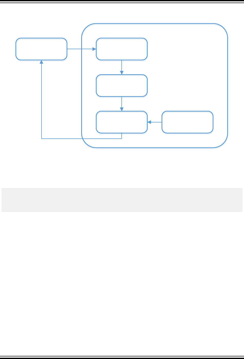
Figure 2-9. RTOS and Semaphores
User thread
User thread User thread
User thread
Start HW
operation
Start HW
operation
Wait on
semaphore
Wait on
semaphore
ISR release
semaphore
ISR release
semaphore
Driver
The driver has an internal semaphore object for synchronizing between the ISR and the thread. The user
thread may be suspended in the driver, and be woken up once the ISR finishes.
To be compatible with various RTOSes, an abstraction interface for semaphores is designed:
int32_t sem_init(sem_t *sem, uint32_t count);
int32_t sem_up(sem_t *sem);
int32_t sem_down(sem_t *sem, uint32_t timeout);
int32_t sem_deinit(sem_t *sem);
To support an RTOS, these functions and the sem_t typedef must be implemented.
OS lock and OS sleep
These two features are useful and are added to the RTOS abstraction. The OS locks/unlocks and
disables/enables the OS scheduler and is an easy way to protect shared code and data among threads.
OS sleep suspends the current thread for a specified tick period.
Thread creation
ASF4 does not provide an abstract interface for thread creation. For pre-defined threads in middleware,
the thread body function and thread stack usage size are provided to the user, allowing the user to easily
create such threads in his application.
HAL and HPL
Since HPL is designed for hardware abstraction, while HAL contains software and algorithms, RTOS
support is located in the HAL layer. RTOS-enabled drivers do not change the HPL layer. The figure below
shows how these two layers work together in an RTOS.
ASF4 API Reference Manual
Software Architecture
© 2018 Microchip Technology Inc. User Guide DS50002633B-page 38
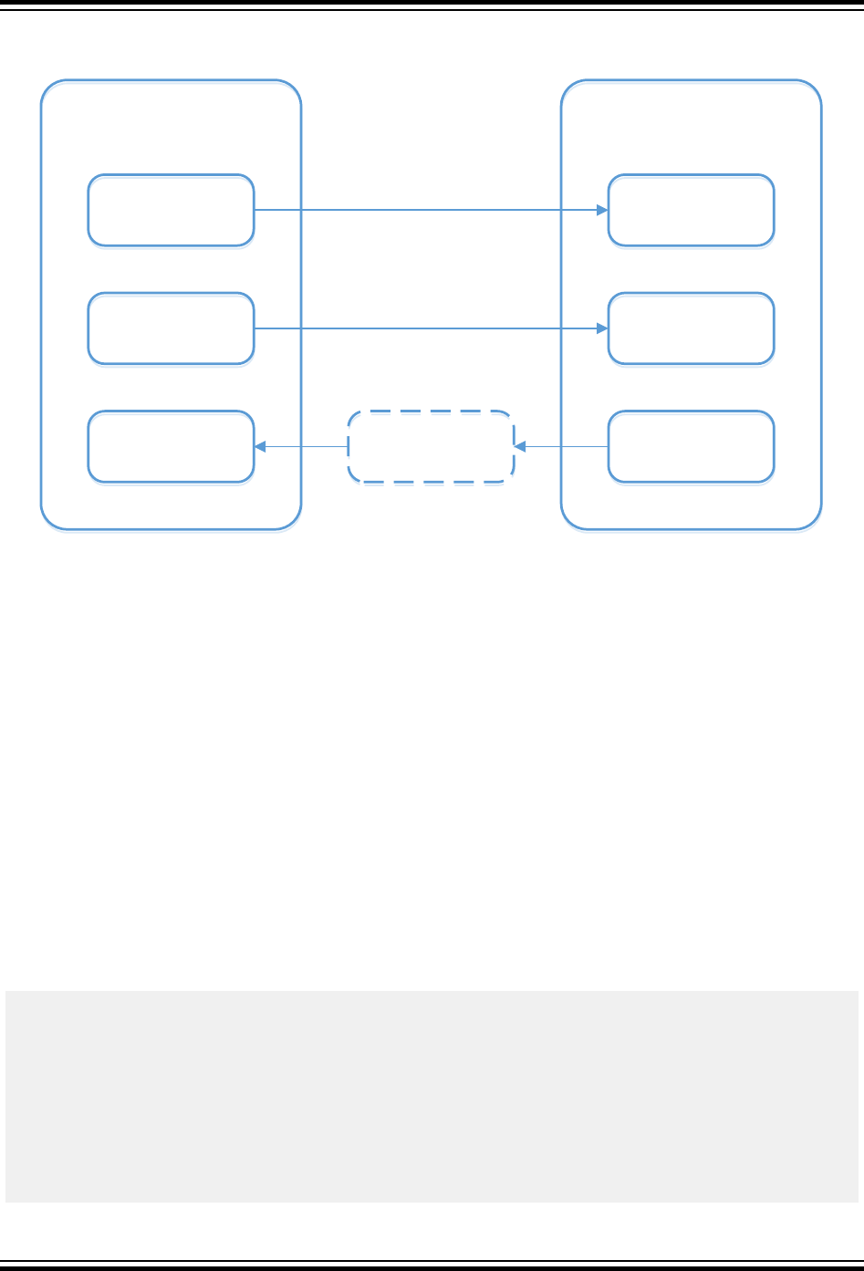
Figure 2-10. HAL and HPL in RTOS
HAL init, register
callback
HAL init, register
callback
HAL interface
HAL interface
Wait on
semaphore
Wait on
semaphore
HAL
HPL init (interrupt
mode)
HPL init (interrupt
mode)
HPL HW operation
(interrupt mode)
HPL HW operation
(interrupt mode)
ISR callback
ISR callback
HPL
Release
semaphore
Release
semaphore
2.9 ASF4 Project Folder Structure - Full
The following is the folder structure generated for a simple project containing a SAM D21 with a single
USART.
The root folder contains the following files:
•atmel_start.c – Code for initializing MCU, drivers, and middleware in the project
•atmel_start.h – API for initializing MCU, drivers, and middleware in the project
•atmel_start_pins.h – Pin MUX mappings as made by the user inside Atmel START
•driver_init.c – Code for initializing drivers
•driver_init.h – API for initializing drivers
•main.c – Main application, initializing the selected peripherals
•atmel_start_config.atstart – Atmel START-internal description of the project
•atmelStart.gpdsc – Atmel START-internal description of the project
.
├── atmel_start.c
├── atmel_start_config.atstart
├── AtmelStart.gpdsc
├── atmel_start.h
├── atmel_start_pins.h
├── config
│ ├── hpl_dmac_v100_config.h
│ ├── hpl_gclk1_v210_config.h
│ ├── hpl_pm1_v201_config.h
│ ├── hpl_sercom_v200_config.h
│ ├── hpl_sysctrl_v201a_config.h
│ └── peripheral_clk_config.h
ASF4 API Reference Manual
Software Architecture
© 2018 Microchip Technology Inc. User Guide DS50002633B-page 39

├── driver_init.c
├── driver_init.h
├── examples
│ ├── driver_examples.c
│ └── driver_examples.h
├── hal
│ ├── documentation
│ │ └── usart_async.rst
│ ├── include
│ │ ├── hal_atomic.h
│ │ ├── hal_delay.h
│ │ ├── hal_gpio.h
│ │ ├── hal_init.h
│ │ ├── hal_io.h
│ │ ├── hal_sleep.h
│ │ ├── hal_usart_async.h
│ │ ├── hpl_core.h
│ │ ├── hpl_delay.h
│ │ ├── hpl_dma.h
│ │ ├── hpl_gpio.h
│ │ ├── hpl_i2c_m_async.h
│ │ ├── hpl_i2c_m_sync.h
│ │ ├── hpl_i2c_s_async.h
│ │ ├── hpl_i2c_s_sync.h
│ │ ├── hpl_init.h
│ │ ├── hpl_irq.h
│ │ ├── hpl_missing_features.h
│ │ ├── hpl_reset.h
│ │ ├── hpl_sleep.h
│ │ ├── hpl_spi_async.h
│ │ ├── hpl_spi.h
│ │ ├── hpl_spi_m_async.h
│ │ ├── hpl_spi_m_sync.h
│ │ ├── hpl_spi_s_async.h
│ │ ├── hpl_spi_s_sync.h
│ │ ├── hpl_spi_sync.h
│ │ ├── hpl_usart_async.h
│ │ ├── hpl_usart.h
│ │ └── hpl_usart_sync.h
│ ├── src
│ │ ├── hal_atomic.c
│ │ ├── hal_delay.c
│ │ ├── hal_gpio.c
│ │ ├── hal_init.c
│ │ ├── hal_io.c
│ │ ├── hal_sleep.c
│ │ └── hal_usart_async.c
│ └── utils
│ ├── include
│ │ ├── compiler.h
│ │ ├── err_codes.h
│ │ ├── events.h
│ │ ├── parts.h
│ │ ├── utils_assert.h
│ │ ├── utils_event.h
│ │ ├── utils.h
│ │ ├── utils_increment_macro.h
│ │ ├── utils_list.h
│ │ ├── utils_repeat_macro.h
│ │ └── utils_ringbuffer.h
│ └── src
│ ├── utils_assert.c
│ ├── utils_event.c
│ ├── utils_list.c
│ ├── utils_ringbuffer.c
│ └── utils_syscalls.c
├── hpl
│ ├── core
│ │ ├── hpl_core_m0plus_base.c
│ │ ├── hpl_core_port.h
│ │ └── hpl_init.c
│ ├── dmac
│ │ └── hpl_dmac_v100.c
│ ├── gclk
│ │ ├── hpl_gclk1_v210_base.c
│ │ └── hpl_gclk1_v210_base.h
ASF4 API Reference Manual
Software Architecture
© 2018 Microchip Technology Inc. User Guide DS50002633B-page 40

│ ├── pm
│ │ ├── hpl_pm1_v201a.c
│ │ └── hpl_pm1_v201_base.h
│ ├── port
│ │ └── hpl_port_v100.c
│ ├── sercom
│ │ └── hpl_sercom_v200.c
│ └── sysctrl
│ └── hpl_sysctrl_v201a.c
├── hri
│ ├── hri_dmac_v100.h
│ ├── hri_gclk1_v210.h
│ ├── hri_nvmctrl_v106.h
│ ├── hri_pm_v201a.h
│ ├── hri_port_v100.h
│ ├── hri_sercom_v200.h
│ └── hri_sysctrl_v201a.h
└── main.c
ASF4 API Reference Manual
Software Architecture
© 2018 Microchip Technology Inc. User Guide DS50002633B-page 41

3. Driver Implementation and Design Conventions
3.1 Introduction
This chapter covers driver implementation and design conventions, in the following major sections:
•3.2 ASF4 and Atmel START Configuration
•3.3 Driver Implementation
•3.4 Design Conventions
•3.5 Toolchain and Device-specific Support
•3.6 Embedded Software Coding Style
3.2 ASF4 and Atmel START Configuration
The ASF4 framework cannot be used as a stand-alone framework, it must be used together with Atmel
START. Atmel START contains a code generator that generates ASF4 C-code based on the user's
configuration. Atmel START uses two mechanisms to generate the final C-code:
• Code generation - Atmel START has an internal representation of the C-code. This internal
representation is processed by a code generator resulting in C-code.
• Parameter generation - The generated C-code accepts parameters in the form of C #define
statements. These statements are generated by Atmel START, based on the user's input. The
CMSIS wizard annotation format is used for the parameters.
3.2.1 Hardware Configuration
For microcontroller projects, configuration data is normally available before or at the point of compilation.
Calculation of register data and resolving of configuration can therefore be calculated at compile time.
This will free up flash space and lower the processing power needed to initialize the module. An added
benefit of less code in the initialization function is that time spent to get into the main loop will be shorter.
A combination of constants set by Atmel START, pre-processor macros, and static functions are used to
avoid doing such calculations in the runtime code.
The configuration for each module and each instance of the module is stored statically in configuration
files in the config/ folder as #define macros. All configuration parameters have names in uppercase and
belong to the "CONF_" namespace, followed by the name of the hardware module, instance, and then
the bit or bit field name as spelled in the data sheet. All parameters that are visible in configuration
dialogs in Atmel START are annotated with the CMSIS configuration wizard annotation language.
3.2.2 Output from Atmel START
When exporting a project from Atmel START, the output is a single file with an *.atzip extension. This is
basically an ordinary zip-file. Renaming it from *.atzip to *.zip allows it to be unzipped with standard zip-
tools. This would result in a file tree as shown in the folder structure section shown elsewhere in this
manual.
3.2.3 Reconfiguring Output from Atmel START
There may be a need to reconfigure code generated by ASF4 at a later time, for example changing
baudrate of a USART, or moving an I/O pin to a new location. If using Atmel Studio as IDE, the ASF4
code can be imported back into Atmel START again and reconfigured by right-clicking on the project
ASF4 API Reference Manual
Driver Implementation and Design Conventions
© 2018 Microchip Technology Inc. User Guide DS50002633B-page 42

name in Project Explorer, and selecting "Re-Configure Atmel Start Project". This will open Atmel START
inside a window in Studio, allowing the user to perform the required changes and export the result back
into the Studio project. Studio will detect any changed ASF4 files, and attempt to merge them into the
original project.
If using other IDEs than Studio, or no IDE at all, an already generated project can be reconfigured by
opening the Atmel START webpage, and selecting "Load existing project" from the front page. Use the
originally generated *.atzip-file as input file. The project can thereafter be reconfigured and exported
anew. Any changes and conflicts between the original and the reconfigured project must be merged
manually by the user.
3.2.4 Versioning of ASF4 Code
Atmel START and ASF4 are tightly connected. A specific version of ASF4 code will only run on a
compatible version of Atmel START. This may pose problems as an ASF4 code generated with a
particular version of Atmel START may not be possible to read back into and reconfigure with newer
versions of Atmel START. Since Atmel START is a web-based tool, it may be updated without the user
being able to affect the update process.
Future versions of Atmel START will add the concept of versioning, where the web-based Atmel START
configurator will support different versions of ASF4.
3.3 Driver Implementation
Drivers consist of two parts; a static part and a dynamic or configurable part. The static part is hardwired
code not intended to be changed or reconfigured by the application after being exported from Atmel
START. The dynamic part allows the application to configure the behavior of the driver through e.g.
callbacks, or provide resources such as ring buffers to drivers.
The dynamic part is normally configured during driver initialization by calling the driver's init-function. This
is typically done during the device initialization and startup phase.
The functionality provided by the static and dynamic parts of the driver is unique to each driver, and
documented separately for each driver.
3.3.1 Driver Initialization
All drivers configured in Atmel START are automatically initialized. Atmel START generates calls to the
init()-functions of all drivers inside driver_init.c. The driver_init.c file is called by the main.c-file generated
by Atmel START.
Each driver has an init()- and a deinit()-function. The init() function:
• hooks up IRQ handler and enables the module's IRQs if necessary
• configures the module as desired by writing the module descriptor contents to the correct control
registers
• enables the module
• does NOT enable any clocks required by the module, this must be done separately
• does NOT enable any I/O pins required by the module, this must be done separately
The deinit()-function:
• disables and clears the module's interrupts, if enabled
• disbles the module, typically by clearing the module's enable-bit in the module's control register
ASF4 API Reference Manual
Driver Implementation and Design Conventions
© 2018 Microchip Technology Inc. User Guide DS50002633B-page 43

• does NOT disable any clocks used by the module, this must be done separately
• does NOT disable any I/O pins used by the module, this must be done separately
3.3.2 Descriptors
Descriptors are driver-specific data structures that are used to fine-tune the behavior of the driver. The
application populates the descriptors with the desired configuration information, and passes the
descriptors into the driver. Typical information contained in descriptors can be:
• pointer to and size of ring buffer to be used by the driver
• desired behavior or configuration of the driver hardware
• description of interrupt routines
• pointers to callback functions
3.3.3 Configuring the Dynamic Part of Drivers
The dynamic part of drivers is normally configured during system initialization. The most commonly
configured resources are interrupt routine callback functions and memory buffers. How this is done is best
illustrated with an example, using the ADC in synchronous mode as an example. All the following code is
found in driver_init.c.
The following code declares and defines various resources that will be made available to the ADC:
/* The channel amount for ADC */
#define ADC_0_CH_AMOUNT 1
/* The buffer size for ADC */
#define ADC_0_BUFFER_SIZE 16
/* The maximal channel number of enabled channels */
#define ADC_0_CH_MAX 0
extern struct _irq_descriptor *_irq_table[PERIPH_COUNT_IRQn];
extern void Default_Handler(void);
struct adc_async_descriptor ADC_0;
struct adc_async_channel_descriptor ADC_0_ch[ADC_0_CH_AMOUNT];
static uint8_t ADC_0_buffer[ADC_0_BUFFER_SIZE];
static uint8_t ADC_0_map[ADC_0_CH_MAX+1];
The system_init()-function is called by main and initializes the peripheral driver(s), in this case the ADC:
void system_init(void)
{
ADC_0_init();
}
The ADC_0_init() function initializes ADC0. The two first lines enable the clock to the ADC.
static void ADC_0_init(void)
{ _pm_enable_bus_clock(PM_BUS_APBC, ADC); _gclk_enable_channel(ADC_GC
LK_ID, CONF_GCLK_ADC_SRC); adc_async_init(&ADC_0, ADC, ADC_0_map, ADC_0_
CH_MAX, ADC_0_CH_AMOUNT, &ADC_0_ch[0]); adc_async_register_channel_buffe
r(&ADC_0, 0, ADC_0_buffer, ADC_0_BUFFER_SIZE);}
The 5.2.9.1 adc_async_init-function updates the ADC_0 descriptor with information found in the other
parameters of the function, and writes this configuration to the ADC hardware. The configured data
includes:
ASF4 API Reference Manual
Driver Implementation and Design Conventions
© 2018 Microchip Technology Inc. User Guide DS50002633B-page 44

• hooking up any callback functions
• configuring the number of channels to use, in this case one channel (channel 0)
• configuring the behavior of each channel used
The 5.2.9.3 adc_async_register_channel_buffer-function hooks the ring buffer ADC_0_buffer with size
ADC_0_BUFFER_SIZE up to the ADC descriptor ADC_0, to be used for channel 0.
The ADC_Handler()-function hooks the driver's ISR up to the IRQ vector table. _irq_table[] is a table of
interrupt handler descriptors handled by the HPL layer of the IRQ driver.
void ADC_Handler(void)
{
if (_irq_table[ ADC_IRQn + 0 ]) {
_irq_table[ ADC_IRQn + 0 ]-
>handler(_irq_table[ ADC_IRQn + 0 ]->parameter);
} else {
Default_Handler();
}
}
3.3.4 Compile-time Configuration and Parameterization from Atmel START
The user is normally able to configure driver parameters in Atmel START. A typical example is setting of
baudrate and parity for a USART. The files in the config-folder are generated by Atmel START in order to
transfer the configurations the user made in Atmel START into the HPL layer. The files use the CMSIS
wizard annotation format. Example of contents in hpl_sercom_v200_config.h:
// <o> Frame parity
// <0x0=>No parity
// <0x1=>Even parity
// <0x2=>Odd parity
// <i> Parity bit mode for USART frame
// <id> usart_parity
#ifndef CONF_SERCOM_0_USART_PARITY
# define CONF_SERCOM_0_USART_PARITY 0x0
#endif
3.3.5 Utility Drivers
The utility drivers support other drivers with commonly used software concepts and macros such as ring
buffers, linked lists, state machines, etc. Moving this commonly used code into utility drivers makes it
easier to maintain the code and help the compiler to optimize the code because the same code is used
by different drivers, but only one copy is needed. The utility drivers are fully abstracted and not bound to
any particular hardware platform or type. Utility drivers are located in the hal/utils folder with public
declaration files in a include folder and function declaration in a src folder. All filenames starts with the
prefix utils_. See the API reference in the file "utils.h" for more information on the utility functions.
3.4 Design Conventions
3.4.1 Memory Buffers
As a rule of thumb, no memory buffer is allocated by the driver. Allocation is done by the application and
provided to the driver as pointer variables. This allows the author of the application freedom to choose
ASF4 API Reference Manual
Driver Implementation and Design Conventions
© 2018 Microchip Technology Inc. User Guide DS50002633B-page 45

how memory is allocated in the application. In many cases, memory management can be done at compile
time by allocating memory statically. Allocation outside the driver also gives the user the possibility of
using a memory manager of his choosing.
3.4.2 Parameter List
The parameter list for a given public ASF4 function shall have a hard limit of up to four parameters. If this
limit is surpassed the function's purpose shall be redesigned or split into multiple function calls. Another
approach would be to use a container for the parameters like a struct.
3.4.3 Naming Convention
3.4.3.1 Reserved Words/Acronyms
Some words/acronyms are given a special meaning in the framework to give the user a better
understanding about the purpose of function/symbol/etc. These words are:
3.4.3.1.1 Callback
Short: cb
Typically used for functions or pointers. Refers to functions/code that is triggered by events in hardware
or other parts of the software.
struct spi_dev_callbacks {
/* TX callback, see \ref spi_dev_cb_xfer_t. */
spi_dev_cb_xfer_t tx;
/* RX callback, see \ref spi_dev_cb_xfer_t. */
spi_dev_cb_xfer_t rx;
/* Complete callback, see \ref spi_dev_cb_complete. */
spi_dev_cb_complete_t complete;
3.4.3.1.2 Configuration
Short: conf
Typically used to symbols, macros defining a configuration parameter or a set of configuration
parameters.
#define CONF_SERCOM_0_USART_DORD CONF_SERCOM_USART_DATA_ORDER
_LSB
#define CONF_SERCOM_0_USART_CPOL CONF_SERCOM_USART_CLOCK_POLA
RITY_TX_RISING_EDGE
#define CONF_SERCOM_0_USART_CMODE CONF_SERCOM_USART_COMMUNICAT
ION_MODE_ASYNCHRONOUS
3.4.3.1.3 Deinitialize
Short: deinit
Typically used for a function that resets something to the initial state, for instance deinit of a peripheral
should disable it, remove any clock connections and preferably set it back to device power up state.
int32_t adc_deinit(struct adc_descriptor *const descr);
3.4.3.1.4 Device
Short: dev
ASF4 API Reference Manual
Driver Implementation and Design Conventions
© 2018 Microchip Technology Inc. User Guide DS50002633B-page 46

Typically used when referring to something that can be described as a "device" like the abstracted device
definition.
struct _adc_device {
struct _adc_callbacks adc_cb;
void *hw;
};
3.4.3.1.5 Initialize
Short: init
Typically used for functions that initializes something, like a peripheral for instance.
int32_t usart_sync_init(struct usart_sync_descriptor *const descr, void *co
nst hw);
3.4.3.1.6 Interface
Short: iface
Typically used when referring to driver interfaces (APIs) like the abstracted interface used between the
HPL and HAL.
struct i2c_interface {
int32_t (*init)(struct i2c_device *i2c_dev);
int32_t (*deinit)(struct i2c_device *i2c_dev);
int32_t (*enable)(struct i2c_device *i2c_dev);
int32_t (*disable)(struct i2c_device *i2c_dev);
int32_t (*transfer)
(struct i2c_device *i2c_dev, struct i2c_msg *msg);
int32_t (*set_baudrate)
(struct i2c_device *i2c_dev, uint32_t clkrate, uint32_t baudrate);
3.4.3.1.7 Message
Short: msg
Typically used when data sent over an interface has to be compiled from different data sources before it
is sent. For instance, an I2C message has to consist of an address and data.
struct i2c_msg {
uint16_t addr;
volatile uint16_t flags;
int32_t len;
uint8_t *buffer;
3.4.3.1.8 Private
Acronym: prvt
Typically used for private data members or symbols, which contain data that should not be accessed by
external code (for instance user code, or it can even be localised to just parts of the owner code).
ASF4 API Reference Manual
Driver Implementation and Design Conventions
© 2018 Microchip Technology Inc. User Guide DS50002633B-page 47

Typically used for the hardware pointer member in the device descriptor struct as it should only be
accessed by the HPL after it has be assigned.
struct spi_sync_dev {
/
* Pointer to the hardware base or private data for special device. */
void *prvt;
/* CS information,
* Pointer to information list to configure and use I/
O pins as SPI CSes
* (master), or CS pin information when \c cs_num is 0 (slave).
*/
union spi_dev_cs cs;
/
* Number of Chip Select (CS), set to 0 for SPI slave, 0xFF to ignore CS beh
aviour */
int8_t cs_num;
/* Data size, number of bytes for each character */
uint8_t char_size;
/
* Flags for the driver for implementation use (could change in implementati
on) */
uint16_t flags;
};
3.4.3.1.9 Status
Short: stat
Typically used when referring to functions/symbols related to returning or storing status information.
3.4.3.1.10 Error
Short: err
Typically used for containers/variables holding information about error state information in hardware or
software, can also refer to callbacks or functions referring to error handling code.
static void dac_tx_error(struct _dac_device *device, const uint8_t ch);
3.4.3.1.11 Transfer
Short: xfer
Typically used when referring to functions/symbols related to moving data in one or both direction.
enum spi_transfer_mode {
/
* Leading edge is rising edge, data sample on leading edge. */
SPI_MODE_0,
/
* Leading edge is rising edge, data sample on trailing edge. */
SPI_MODE_1,
/
* Leading edge is falling edge, data sample on leading edge. */
SPI_MODE_2,
/
ASF4 API Reference Manual
Driver Implementation and Design Conventions
© 2018 Microchip Technology Inc. User Guide DS50002633B-page 48

* Leading edge is falling edge, data sample on trailing edge. */
SPI_MODE_3
};
3.5 Toolchain and Device-specific Support
3.5.1 System Startup Sequence
An ASF4 project executes the following startup sequence:
1. The initial value of the stack pointer is read from the linker script, and written to the first 32-bit
address in the exception vector. The startup sequencing hardware will write this value to the stack
pointer (SP) in the register file, before releasing the CPU from reset.
2. The address of the Reset_Handler() is placed as the second 32-bit word in the exception vector.
The ARM hardware will execute the code in this function immediately after releasing the CPU from
reset.
The Reset_Handler() function can be found in the /Device_Startup/startup_{device}.c file, where {device}
is the name of the device chosen. The reset handler:
1. Initializes various memory segments
2. Configures the bus matrix if applicable
3. Initializes data structures in the C library
4. Jumps to the main() function
3.5.2 Portability of Generated ASF4 Code Between Devices
An ASF4 project generated for one device should in general not be compiled for other devices. There
may be differences between devices so that the code may not compile, or may compile but not behave as
intended.
3.5.3 CMSIS-CORE Library
The CMSIS-CORE library is provided as part of the Device Family Packages (DFPs) for all Microchip
SAM devices. Functions in CMSIS-CORE, for example __set_BASEPRI() can be called from the ASF4
code. ASF4 also provides an HPL library abstracting the CPU core. This core-specific library is part of the
*.atzip file exported from Atmel START. The library can be found in the /hpl/core/ directory. The device
header file, named {device}.h, present in the device DFP directory, configures the CMSIS-CORE
parameters and includes the CMSIS-CORE header file, named core_{core_name}.h. An example of a
{device-file, CMSIS-CORE file}-pair is {samd21e15a.h, core_cm0plus.h}.
3.5.4 Interrupt Vectors
The interrupt vector table can be found in the /Device_Startup/startup_{device}.c file, where {device} is
the name of the device chosen, e.g. samd21. The vector table is populated with jumps to a
Dummy_Handler(), performing an eternal while-loop. The Dummy_Handler() has the GCC attribute
"weak", and is intended to be overridden by the appropriate handler provided by ASF4, or defined by the
user.
ASF4 does not assign a specific priority to the IRQs, but instead uses the default priority as assigned by
the NVIC. Different ARM cores have NVIC interrupt controllers with individual specifications and features.
Refer to the device data sheet and NVIC documentation for the ARM core being used in the selected
target device for more information on manipulating interrupt priorities and masking interrupts.
ASF4 API Reference Manual
Driver Implementation and Design Conventions
© 2018 Microchip Technology Inc. User Guide DS50002633B-page 49

The ARM CMSIS-CORE specification has functions for manipulating the NVIC in order to prioritize IRQs
and mask interrupts. Refer to the CMSIS specification and CMSIS-CORE
library(doc_driver_hal_intro_toolchain_1s_ds_cmsis) for more information.
3.5.5 C Library
Atmel START generates code to be used together with the GCC tool suite for ARM. This includes system
call implementations for the GCC newlib C library, such as _exit() and _close(). The system call
implementations can be found in /hal/utils/src/utils_syscalls.c. Other compilers, such as IAR or Keil, may
use proprietary C-libraries, and not use these syscall implementations.
3.5.6 Linker Scripts
A set of default linker scripts for the GCC compiler are provided by Atmel START. The scripts are tailored
to the device selected in Atmel START. They can be found in the /Device_Startup/*.ld files. Multiple
scripts may be provided, e.g. one script for placing code in flash, another for placing code in RAM. Other
compilers, such as IAR or Keil, may use proprietary linker scripts and formats, and not use these linker
scripts implementations. Atmel START does not generate linker scripts for other compilers than GCC.
3.5.7 Support for Various Toolchains
ASF4 consists of generic C-code and can in be compiled using any ARM C-compiler. However, Atmel
START includes support for exporting projects into the following toolchains:
• Atmel Studio/GCC
• IAR Embedded Workbench
• Keil uVision
• Standalone makefile system
3.5.7.1 GCC and Atmel Studio
When generating output for Atmel Studio, an *.atzip file is generated. This file can be opened directly in
Studio.
3.5.7.1.1 Compiler options
The various compiler and toolchain options set by default by Atmel START can be examined by right-
clicking on the project name in Studio. The default build configuration is Debug, with debug symbol
generation enabled (-g) and minimum optimization (-O1).
3.5.7.1.2 Build system
The project in the *.atzip file can be built directly using Studio's build system. Refer to the Studio
documentation for more information.
3.5.7.2 IAR Embedded Workbench (EW)
The ASF4 code can be imported into IAR EW. Refer to the Atmel START documentation for more
information.
3.5.7.3 Keil uVision
The ASF4 code can be imported into Keil uVision. Refer to the Atmel START documentation for more
information.
3.6 Embedded Software Coding Style
3.6.1 MISRA 2004 Compliance
ASF4 follows the MISRA 2004 rules with the CMSIS-CORE exceptions.
ASF4 API Reference Manual
Driver Implementation and Design Conventions
© 2018 Microchip Technology Inc. User Guide DS50002633B-page 50

3.6.2 Function and Variable Names
• Functions and variables are named using all lower case letters: [a-z] and [0-9]
• Underscore '_' is used to split function and variable names into more logical groups
3.6.2.1 Example
void this_is_a_function_prototype(void);
3.6.2.2 Rationale
All-lowercase names are easy on the eyes, and it is a very common style to find in C code.
3.6.3 Constants
• Constants are named using all upper case letters: [A-Z] and [0-9]
• Underscore '_' is used to split constant names into more logical groups
• Enumeration constants shall follow this rule
• Constants made from an expression must have braces around the entire expression; single value
constants may skip this
• Constants must always be defined and used instead of "magic numbers" in the code
• Definitions for unsigned integer constants (including hexadecimal values) must use a "u" suffix
• For hexadecimal values, use upper case A-F
• Samme rules apply to enumerations as they are constants too
3.6.3.1 Example
#define BUFFER_SIZE 512
#define WTK_FRAME_RESIZE_WIDTH (WTK_FRAME_RESIZE_RADIUS + 1)
enum buffer_size = {
BUFFER_SIZE_A = 128,
BUFFER_SIZE_B = 512,
};
3.6.3.2 Rationale
Constants shall stand out from the rest of the code, and all-uppercase names ensure that. Also, all-
uppercase constants are very common in specification documents and data sheets, from which many
such constants originate. MISRA rule 10.6. MISRA specifies "U", but this is less readable than "u" and
both are accepted. The braces around an expression are vital to avoid an unexpected evaluation. For
example, a constant consisting of two variables added together, which are later multiplied with a variable
in the source code.
#define NUM_X_PINS (24u)
#define XEDGEGRADIENT_MASK (0x3Fu)
#define NUM_MATRIX_PINS (NUM_X_PINS + NUM_Y_PINS)
Do not include cast operations types in constant definitions:
#define THIS_CONSTANT (uint8_t)(0x0Fu)
ASF4 API Reference Manual
Driver Implementation and Design Conventions
© 2018 Microchip Technology Inc. User Guide DS50002633B-page 51

3.6.4 Inline Constants
Where a constant value is only to be used once within a particular function, and is not derived from or
related to functionality from another module, it should be defined as an appropriately typed const (using
variable naming conventions) within that function, e.g.:
void this_function(void)
{
uint8_t const num_x_pins = 24u; /* max number of X pins */
...
3.6.4.1 Rationale
Keeps constant definition close to where it is used and in appropriate scope; avoids a large block of often
unrelated macro definitions.
3.6.5 Variables
Variables should be defined individually on separate lines. Examples:
/* Do like this */
uint8_t x_edge_dist;
uint8_t y_edge_dist;
/* Don't do like this */
uint8_t x_edge_dist, y_edge_dist;
Constant or volatile variables should be defined with the qualifier following the type. Examples:
/* Do like this */
uint8_t const x_edge_dist;
uint8_t volatile register_status;
/* Don't do like this */
const uint8_t x_edge_dist;
Variables must only be defined at the start of a source code block (denoted by {} braces). Examples:
void this_function(void)
{ uint8_t x_edge_dist;for (line_idx = LINE_IDX_MIN; line_idx <= LINE_IDX
_MAX; line_idx++){ bool_t this_flag = FALSE;
3.6.6 Type Definitions
• stdint.h and stdbool.h types must be used when available
• Type definitions are named using all lower case letters: [a-z] and [0-9]
• Underscore '_' is used to split names into more logical groups
• Every type definition must have a trailing '_t'
3.6.6.1 Example
typedef uint8_t buffer_item_t;
ASF4 API Reference Manual
Driver Implementation and Design Conventions
© 2018 Microchip Technology Inc. User Guide DS50002633B-page 52

3.6.6.2 Rationale
stdint and stdbool ensures that all drivers on all platforms uses the same set of types with clearly defined
size. Trailing _t follows the same convention used in stdint and stdbool, which clearly differentiate the
type from a variable.
3.6.7 Structures and Unions
• Structures and unions follow the same naming rule as functions and variables
• When the content of the struct shall be kept hidden for the user, typedef shall be used
3.6.7.1 Example
struct cmd {
uint8_t length;
uint8_t *payload;
};
union cmd_parser {
cmd_t cmd_a;
cmd_t cmd_b;
};
typedef struct {
void *hw;
} device_handle_t;
3.6.8 Functions
Lay out functions as follows, explicitly defining function return type and naming any parameters, and
where possible writing them all on the same line:
return_type_t function_name(param1_t param1, param2_t param2)
{
statements;
}
For a function with a long definition, split it over several lines, with arguments on following lines aligned
with the first argument. Example:
uint16_t this_function(uint8_t uint8_value,
char_t *char_value_ptr,
uint16_t *uint16_t_value_ptr);
If a function has more than three parameters, consider passing them via a pointer to a structure that
contains related values, to save compiled code and/or stack space. Using a structure in this way also
avoids having to update a function prototype, and therefore having to update calling software, should
additional parameter values be needed. Use "const correctness" to protect parameters passed via pointer
from being changed by a function. Example:
void this_function(uint8_t *value_ptr, /
* pointer to value */
uint8_t const *const_ptr, /
* pointer to const value */
uint8_t *const const_value_ptr, /
ASF4 API Reference Manual
Driver Implementation and Design Conventions
© 2018 Microchip Technology Inc. User Guide DS50002633B-page 53

* const pointer to value */
uint8_t const *const_const_ptr); /
* const pointer to const value */
3.6.9 Return Statement
Every function should have only one return statement, unless there are specific and commented reasons
for multiple return statements e.g. saving compiled code, clarifying functionality.
3.6.9.1 Rationale
MISRA rule 14.7 Easier debugging.
Do not embed conditional compilation inside a return statement. Examples:
/* Don't do like this */
return (
#ifdef PRXXX_ADDR
(uint32_t*)PRXXX _ADDR
#else
(uint32_t*)NULL_PTR
#endif
);
/* Do like this */
uint32_t* addr_ptr;
...
#ifdef PRXXX_ADDR
addr_ptr = (uint32_t*)PRXXX_ADDR;
#else
addr_ptr = (uint32_t*)NULL_PTR;
#endif
return (addr_ptr);
3.6.10 Function like Macro
• Function like macros follow the same naming rules as the functions and variables. This way it is
easier to exchange them for inline functions at a later stage.
• Where possible, function like macros shall be blocked into a do {} while (0)
• Function like macros must never access their arguments more than once
• All macro arguments as well as the macro definition itself must be parenthesized
• Function like macros shall be avoided if possible, static inline function shall be used instead.
• Functional macros must not refer to local variables from their "host" calling function, but can make
use of global variables or parameters passed into them.
3.6.10.1 Example
#define set_io(id) do { \
PORTA |= (1 << (id)); \
} while (0)
3.6.10.2 Rationale
We want function like macros to behave as close to regular functions as possible. This means that they
must be evaluated as a single statement; the do { } while (0) wrapper for "void" macros and surrounding
parentheses for macros returning a value ensure this. The macro arguments must be parenthesized to
ASF4 API Reference Manual
Driver Implementation and Design Conventions
© 2018 Microchip Technology Inc. User Guide DS50002633B-page 54

avoid any surprises related to operator precedence; we want the argument to be fully evaluated before it's
being used in an expression inside the macro. Also, evaluation of some macro arguments may have side
effects, so the macro must ensure it is only evaluated once (sizeof and typeof expressions don't count).
3.6.11 Indentation
• Indentation is done by using the TAB character. This way one ensures that different editor
configurations do not clutter the source code and alignment.
• The TAB characters must be used before expressions/text, for the indentation.
• TAB must not be used after an expression/text, use spaces instead. This will ensure good
readability of the source code independent of the TAB size.
• The TAB size shall be fixed to four characters.
3.6.11.1 Example
enum scsi_asc_ascq {
[TAB] [spaces]
SCSI_ASC_NO_ADDITIONAL_SENSE_INFO = 0x0000,
SCSI_ASC_LU_NOT_READY_REBUILD_IN_PROGRESS = 0x0405,
SCSI_ASC_WRITE_ERROR = 0x0c00,
SCSI_ASC_UNRECOVERED_READ_ERROR = 0x1100,
SCSI_ASC_INVALID_COMMAND_OPERATION_CODE = 0x2000,
SCSI_ASC_INVALID_FIELD_IN_CDB = 0x2400,
SCSI_ASC_MEDIUM_NOT_PRESENT = 0x3a00,
SCSI_ASC_INTERNAL_TARGET_FAILURE = 0x4400,
};
3.6.11.2 Rationale
The size of the TAB character can be different for each developer. We cannot impose a fixed size. In
order to have the best readability, the TAB character can only be used, on a line, before expressions and
text. After expressions and text, the TAB character must not be used, use spaces instead. The entire
point about indentation is to show clearly where a control block starts and ends. With large indentations, it
is much easier to distinguish the various indentation levels from each others than with small indentations
(with two-character indentations it is almost impossible to comprehend a non-trivial function). Another
advantage of large indentations is that it becomes increasingly difficult to write code with increased levels
of nesting, thus providing a good motivation for splitting the function into multiple, more simple units and
thus improve the readability further. This obviously requires the 80-character rule to be observed as well.
If you're concerned that using TABs will cause the code to not line up properly, see the section about
continuation.
3.6.12 Text Formatting
• One line of code, documentation, etc. should not exceed 80 characters, given TAB indentation of
four spaces
• Text lines longer than 80 characters should be wrapped and double indented
3.6.12.1 Example
/
* This is a comment which is exactly 80 characters wide for example showing
. */
dma_pool_init_coherent(&usbb_desc_pool, addr, size,
sizeof(struct usbb_sw_dma_desc), USBB_DMA_DESC_ALIGN);
ASF4 API Reference Manual
Driver Implementation and Design Conventions
© 2018 Microchip Technology Inc. User Guide DS50002633B-page 55

#define unhandled_case(value)
\
do {
\
if (ASSERT_ENABLED) {
\
dbg_printf_level(DEBUG_ASSERT,
\
"%s:%d: Unhandled case value %d
\n", \
__FILE__, __LINE__, (value));
\
abort();
\
}
\
} while (0)
3.6.12.2 Rationale
Keeping line width below 80 characters will help identify excessive levels of nesting or if code should be
refactored into separate functions.
3.6.13 Space
• After an expression/text, use spaces instead of the TAB character
• Do not put spaces between parentheses and the expression inside them
• Do not put space between function name and parameters in function calls and function definitions
3.6.13.1 Example
fat_dir_current_sect
= ((uint32_t)
(dclusters[fat_dchain_index].cluster + fat_dchain_nb_clust - 1)
fat_cluster_size) + fat_ptr_data + (nb_sect % fat_cluster
_size);
3.6.14 Continuation
• Continuation is used to break a long expression that does not fit on a single line
• Continuation shall be done by adding an extra TAB to the indentation level
3.6.14.1 Example
static void xmega_usb_udc_submit_out_queue(struct xmega_usb_udc *xudc,
usb_ep_id_t ep_id, struct xmega_usb_udc_ep *ep)
{
(...)
}
#define xmega_usb_read(reg) \
mmio_read8((void *)(XMEGA_USB_BASE + XMEGA_USB_
ASF4 API Reference Manual
Driver Implementation and Design Conventions
© 2018 Microchip Technology Inc. User Guide DS50002633B-page 56

\sectionreg))
3.6.14.2 Rationale
By indenting continuations using an extra TAB, we ensure that the continuation will always be easy to
distinguish from code at both the same and the next indentation level. The latter is particularly important
in if, while, and for statements. Also, by not requiring anything to be lined up (which will often cause
things to end up at the same indentation level as the block, which is being started), things will line up
equally well regardless of the TAB size.
3.6.15 Comments
3.6.15.1 Short Comments
Short comments may use the
/* Comment */(...)
3.6.15.2 Long Comments, Comment Blocks
Long (multiline) comments shall use the
/* * Long comment that might wrap multiple lines ... */(...)
3.6.15.3 ss_cs_comment_ind Comment Indentation
Indent comments with the corresponding source code. Example:
for (;;) {
/
* get next token, checking for comments, pausing, and printing */
process_token(token, token_size);
}
3.6.15.4 Comment Placement
Put comments on lines by themselves, not mixed with the source code. Example:
/* get next token */process_token(token, token_size);
3.6.15.5 Rationale
Ease of readability, ease of maintenance, makes using file comparison tools easier.
3.6.15.6 Commenting long code
Where a source code block is typically more than 25 lines (so that matching opening/closing braces
cannot be seen together onscreen), add a comment to the end brace of the block to clarify which
conditional block it belongs to. Example:
if (MAX_LINE_LENGTH <= line_length) {
/* ...long block of source code... */
} else { /* MAX_LINE_LENGTH > line_length */
/* ...long block of source code... */
} /* end if (MAX_LINE_LENGTH <= line_length) ...else... */
3.6.16 Braces
• The opening brace shall be put at the end of the line in all cases, except for function definition. The
closing brace is put at the same indent level than the expression
ASF4 API Reference Manual
Driver Implementation and Design Conventions
© 2018 Microchip Technology Inc. User Guide DS50002633B-page 57

• The code inside the braces is indented
• Single line code blocks should also be wrapped in braces
3.6.16.1 Examples
if (byte_cnt == MAX_CNT) {
do_something();
} else {
do_something_else();
}
3.6.17 Pointer Declaration
When declaring a pointer, link the star (*) to the variable.
3.6.17.1 Example
uint8_t *p1;
3.6.17.2 Rationale
If multiple variable types are declared on the same line, this rule will make it easier to identify the pointers
variables.
3.6.18 Compound Statements
• The opening brace is placed at the end of the line, directly following the parenthesized expression
• The closing brace is placed at the beginning of the line following the body
• Any continuation of the same statement (for example, an 'else' or 'else if' statement, or the 'while' in
a do/while statement) is placed on the same line as the closing brace
• The body is indented one level more than the surrounding code
• The 'if', 'else', 'do', 'while', and 'switch' keywords are followed by a space
• Where an else if() clause is used, there must be a closing else clause, even if it is empty. MISRA
rule 14.10.
3.6.18.1 Example
if (byte_cnt == MAX1_CNT) {
do_something();
} else if (byte_cnt > MAX1_CNT) {
do_something_else();
} else {
now_for_something_completely_different();
}
while (i <= 0xFF) {
++i;
}
do {
++i;
} while (i <= 0xFF);
for (i = 0; i < 0xFF; ++i) {
do_something();
}
/* Following example shows how to break a long expression. */
for (uint8_t i = 0, uint8_t ii = 0, uint8_t iii = 0;
(i < LIMIT_I) && (ii < LIMIT_II) && (iii == LIMIT_III);
ASF4 API Reference Manual
Driver Implementation and Design Conventions
© 2018 Microchip Technology Inc. User Guide DS50002633B-page 58

++i, ++ii, ++iii) {
do_something();
}
3.6.19 Switch-case Statement
• The switch block follows the same rules as other compound statements
• The case labels are on the same indentation level as the switch keyword
• The break keyword is on the same indentation level as the code inside each label
• The code inside each label is indented
• The switch-case shall always end with a default label
• Labels may be shared where the same statements are required for each
• Should primarly be used for flow control; with any complex processing inside each case being
moved to (inline if appropriate) functions
3.6.19.1 Example
switch (byte_cnt) {
case 0:
...
break;
case 1:
case 2:
...
break;
default:
...
}
3.6.20 "Fall-through" Switch-cases
Avoid using "fall-through" from one case to a following case where it saves compiled code and/or reduces
functional complexity, it may be used but must be clearly commented and explained:
case VALUE_1:
statements;
/* no break; - DELIBERATE FALL-
THROUGH TO VALUE_2 CASE TO REDUCE COMPILED CODE SIZE */
case VALUE_2:
statements;
break;
3.6.21 Goto Statments
The goto statement must never be used. The only acceptable label is the default: label in a switch()
statement.
3.6.22 Operators
Do not add spaces between an unary operator (-, !, ~, &, *, ++, etc.) and its operand. Example:
/* Do like this */
x = ++y;
ASF4 API Reference Manual
Driver Implementation and Design Conventions
© 2018 Microchip Technology Inc. User Guide DS50002633B-page 59

/* Don't do like this */
x = ++ y;
Add a space on either side of a binary operator. Examples:
a = b + c;
a *= b;
Restrict use of the ternary operator to simple assignments e.g.:
range_setting = (5u <= parm_value) ? RANGE_IS_HIGH : RANGE_IS_LOW;
Use braces to clarify operator precedence, even if not strictly required. Example:
a = b + (c * d);
3.6.23 Preprocessor Directives
• The # operator must always at the beginning of the line
• The directives are indented (if needed) after the #
3.6.23.1 Example
#if (UART_CONF == UART_SYNC)
# define INIT_CON (UART_EN | UART_SYNC | UART_PAUSE)
#elif (UART_CONF == UART_ASYNC)
# define INIT_CON (UART_EN | UART_ASYNC)
#elif (UART_CONF==UART_PCM)
# define INIT_CON (UART_EN | UART_PCM | UART_NO_HOLE)
#else
# error Unknown UART configuration
#endif
Comment #endif statements to clarify which conditional block they belong to, regardless of how many
lines of source code the block comprises of. This is especially important for nested conditional blocks.
Example:
statements;
#ifdef DEBUG
statements;
#endif /* DEBUG */
3.6.24 Header Files
3.6.24.1 Include of Header Files
When including header files, one shall use "" for files that are included relative to the current file’s path
and <> for files that are included relative to an include path. Essentially, this means that "" is for files that
ASF4 API Reference Manual
Driver Implementation and Design Conventions
© 2018 Microchip Technology Inc. User Guide DS50002633B-page 60

are included from the ASF module itself, while <> is for files that are included from other ASF modules.
For example, in adc.c, one could include accordingly:
#include <compiler.h>
#include "adc.h"
3.6.24.2 Header File Guard
Include guards are used to avoid the problem of double inclusion. A module header file include guard
must be in the form MODULE_H_INCLUDED. For example, in adc.h:
#ifndef ADC_H_INCLUDED
#define ADC_H_INCLUDED
#endif /* ADC_H_INCLUDED */
3.6.25 Doxygen Comments
Comments that are to appear in Doxygen output shall start with /** characters and end with * / where the
comments refer to the following statement. For example:
/** node index; */
uint8_t node_idx;
End-of-line Doxygen comments shall start with /**< characters and end with * /. The < tells Doxygen that
the comment refer to the preceding statement. For example:
uint8_t node_idx; /**< node index */
3.6.26 End of File
Each file must end with a new line character i.e. have a final blank line.
3.6.26.1 Rationale
ISO C99 requirement.
ASF4 API Reference Manual
Driver Implementation and Design Conventions
© 2018 Microchip Technology Inc. User Guide DS50002633B-page 61

4. AC Drivers
This Analog Comparator (AC) driver provides an interface for voltage comparison of two input channels.
The following driver variants are available:
•4.3 AC Synchronous Driver: The driver supports polling for hardware changes, functionality is
synchronous to the main clock of the MCU.
•4.2 AC Asynchronous Driver: The driver supports a callback handler for the IRQ caused by
hardware state changes. Functionality is asynchronous to the main clock of the MCU.
4.1 AC Basics and Best Practice
An analog comparator compares two analog voltage levels, and outputs a digital value indicating which is
the larger. The comparator has normally two analog inputs, V+ and V-, but internal sources in the MCU
can also be used as source for one of the inputs. The digital output value is outputted on Vout.
4.2 AC Asynchronous Driver
In the Analog Comparator (AC) asynchronous driver, a callback function can be registered in the driver by
the application and triggered when comparison is done to let the application know the comparison result.
4.2.1 Summary of the API's Functional Features
The API provides functions to:
• Initialize and deinitialize the driver and associated hardware
• Hookup callback handlers on comparison done
• Enable or disable AC comparator
• Start single-short comparison if signal-shot mode is enabled (no need to start for continuous mode)
4.2.2 Summary of Configuration Options
Below is a list of the main AC parameters that can be configured in START. Many of these parameters
are used by the 4.2.9.1 ac_async_init function when initializing the driver and underlying hardware.
• Select positive and negative input for AC comparator
• Select single shot or continuous measurement mode
• Filter length and hysteresis setting, etc.
• Run in Standby or Debug mode
• Various aspects of Event control
4.2.3 Driver Implementation Description
After the AC hardware initialization, the application can register the callback function for comparison done
by 4.2.9.5 ac_async_register_callback.
4.2.4 Example of Usage
The following shows a simple example of using the AC. The AC must have been initialized by 4.2.9.1
ac_async_init. This initialization will configure the operation of the AC, such as input pins, single-shot, or
continuous measurement mode, etc.
ASF4 API Reference Manual
AC Drivers
© 2018 Microchip Technology Inc. User Guide DS50002633B-page 62

The example registers a callback function for comparison ready and enables comparator 0 of AC, and
then finally starts a voltage comparison on this comparator.
static void ready_cb_AC_0(struct ac_async_descriptor *const descr, const ui
nt8_t comp, const uint8_t result)
{
/* Handle date here */
}
/**
* Example of using AC_0 to compare the voltage level.
*/
void AC_0_example(void)
{
ac_async_register_callback(&AC_0, AC_COMPARISON_READY_CB, (ac_cb_t)read
y_cb_AC_0);
ac_async_enable(&AC_0);
ac_async_start_comparison(&AC_0, 0);
}
4.2.5 Dependencies
• The AC peripheral and its related I/O lines and clocks
• The NVIC must be configured so that AC interrupt requests are periodically serviced
4.2.6 Structs
4.2.6.1 ac_callbacks Struct
AC callbacks.
Members
comparison_ready
4.2.6.2 ac_async_descriptor Struct
AC descriptor.
Members
device AC HPL device descriptor
cb AC Callback handlers
4.2.7 Enums
4.2.7.1 ac_callback_type Enum
AC_COMPARISON_READY_CB Comparison ready handler
4.2.8 Typedefs
4.2.8.1 ac_cb_t typedef
typedef void(* ac_cb_t) (const struct ac_async_descriptor *const descr, const uint8_t comp, const uint8_t
result)
ASF4 API Reference Manual
AC Drivers
© 2018 Microchip Technology Inc. User Guide DS50002633B-page 63

AC callback type.
Parameters
descr Direction: in
An AC descriptor
comp Direction: in
Comparator number
result Direction: in
Comparison result, 0 positive input less than negative input, 1 positive input high than negative
input
4.2.9 Functions
4.2.9.1 ac_async_init
Initialize AC.
int32_t ac_async_init(
struct ac_async_descriptor *const descr,
void *const hw
)
This function initializes the given AC descriptor. It checks if the given hardware is not initialized and if the
given hardware is permitted to be initialized.
Parameters
descr Type: struct 4.2.6.2 ac_async_descriptor Struct *const
An AC descriptor to initialize
hw Type: void *const
The pointer to hardware instance
Returns
Type: int32_t
Initialization status.
4.2.9.2 ac_async_deinit
Deinitialize AC.
int32_t ac_async_deinit(
struct ac_async_descriptor *const descr
)
This function deinitializes the given AC descriptor. It checks if the given hardware is initialized and if the
given hardware is permitted to be deinitialized.
ASF4 API Reference Manual
AC Drivers
© 2018 Microchip Technology Inc. User Guide DS50002633B-page 64

Parameters
descr Type: struct 4.2.6.2 ac_async_descriptor Struct *const
An AC descriptor to deinitialize
Returns
Type: int32_t
De-initialization status.
4.2.9.3 ac_async_enable
Enable AC.
int32_t ac_async_enable(
struct ac_async_descriptor *const descr
)
This function enables the AC by the given AC descriptor.
Parameters
descr Type: struct 4.2.6.2 ac_async_descriptor Struct *const
An AC descriptor to enable
Returns
Type: int32_t
Enabling status.
4.2.9.4 ac_async_disable
Disable AC.
int32_t ac_async_disable(
struct ac_async_descriptor *const descr
)
This function disables the AC by the given AC descriptor.
Parameters
descr Type: struct 4.2.6.2 ac_async_descriptor Struct *const
An AC descriptor to disable
Returns
Type: int32_t
Disabling status.
4.2.9.5 ac_async_register_callback
Register AC callback.
int32_t ac_async_register_callback(
struct ac_async_descriptor *const descr,
const enum ac_callback_type type,
ASF4 API Reference Manual
AC Drivers
© 2018 Microchip Technology Inc. User Guide DS50002633B-page 65

ac_cb_t cb
)
Parameters
descr Type: struct 4.2.6.2 ac_async_descriptor Struct *const
An AC descriptor
type Type: const enum 4.2.7.1 ac_callback_type Enum
Callback type
cb Type: 4.2.8.1 ac_cb_t typedef
A callback function, passing NULL will de-register any registered callback
Returns
Type: int32_t
The status of callback assignment.
-1 Passed parameters were invalid or the AC is not initialized
0A callback is registered successfully
4.2.9.6 ac_async_start_comparison
Start comparison.
int32_t ac_async_start_comparison(
struct ac_async_descriptor *const descr,
uint8_t comp
)
This function starts the AC comparator comparison.
Parameters
descr Type: struct 4.2.6.2 ac_async_descriptor Struct *const
The pointer to AC descriptor
comp Type: uint8_t
Comparator number
Returns
Type: int32_t
The result of comparator n start operation.
4.2.9.7 ac_async_stop_comparison
Stop comparison.
int32_t ac_async_stop_comparison(
struct ac_async_descriptor *const descr,
uint8_t comp
)
ASF4 API Reference Manual
AC Drivers
© 2018 Microchip Technology Inc. User Guide DS50002633B-page 66

This function stops the AC comparator comparison.
Parameters
descr Type: struct 4.2.6.2 ac_async_descriptor Struct *const
The pointer to AC descriptor
comp Type: uint8_t
Comparator number
Returns
Type: int32_t
The result of comparator n stop the operation.
4.2.9.8 ac_async_get_version
Retrieve the current driver version.
uint32_t ac_async_get_version(
void
)
Returns
Type: uint32_t
Current driver version.
4.3 AC Synchronous Driver
The functions in the Analog Comparator (AC) synchronous driver will block (i.e. not return) until the
operation is done.
The comparison result can be get by 4.3.7.5 ac_sync_get_result, if the return is not ERR_NOT_READY
then it's the result of voltage comparison for two input channels.
4.3.1 Summary of the API's Functional Features
The API provides functions to:
• Initialize and deinitialize the driver and associated hardware
• Enable or disable the AC comparator
• Start single-short comparison if signal-shot mode is enabled (no need to start for continuous
sampling mode)
• Read back the comparison result
4.3.2 Summary of Configuration Options
Below is a list of the main AC parameters that can be configured in START. Many of these parameters
are used by the 4.3.7.1 ac_sync_init function when initializing the driver and underlying hardware.
• Select positive and negative input for the AC comparator
• Select single shot or continuous measurement mode
• Filter length and hysteresis setting, etc.
ASF4 API Reference Manual
AC Drivers
© 2018 Microchip Technology Inc. User Guide DS50002633B-page 67

• Run in Standby or Debug mode
• Various aspects of Event control
4.3.3 Driver Implementation Description
After AC hardware initialization, the comparison result can be get by 4.3.7.5 ac_sync_get_result. If the
AC hardware is configured to single-shot mode, then 4.3.7.6 ac_sync_start_comparison is needed to
start conversion, otherwise the comparator is continuously enabled and performing comparisons.
4.3.4 Example of Usage
The following shows a simple example of using the AC. The AC must have been initialized by 4.3.7.1
ac_sync_init. This initialization will configure the operation of the AC, such as input pins, single-shot, or
continuous measurement mode, etc.
The example enables comparator 0 of AC, and finally starts a voltage comparison on this comparator.
/**
* Example of using AC_0 to compare the voltage level.
*/
void AC_0_example(void)
{
int32_t cmp_result;
ac_sync_enable(&AC_0);
ac_sync_start_comparison(&AC_0, 0);
while (true) {
cmp_result = ac_sync_get_result(&AC_0, 0);
}
}
4.3.5 Dependencies
• The AC peripheral and its related I/O lines and clocks
4.3.6 Structs
4.3.6.1 ac_sync_descriptor Struct
AC descriptor.
Members
device AC HPL device descriptor
4.3.7 Functions
4.3.7.1 ac_sync_init
Initialize AC.
int32_t ac_sync_init(
struct ac_sync_descriptor *const descr,
void *const hw
)
This function initializes the given AC descriptor. It checks if the given hardware is not initialized and if the
given hardware is permitted to be initialized.
ASF4 API Reference Manual
AC Drivers
© 2018 Microchip Technology Inc. User Guide DS50002633B-page 68

Parameters
descr Type: struct 4.3.6.1 ac_sync_descriptor Struct *const
An AC descriptor to initialize
hw Type: void *const
The pointer to hardware instance
Returns
Type: int32_t
Initialization status.
4.3.7.2 ac_sync_deinit
Deinitialize AC.
int32_t ac_sync_deinit(
struct ac_sync_descriptor *const descr
)
This function deinitializes the given AC descriptor. It checks if the given hardware is initialized and if the
given hardware is permitted to be deinitialized.
Parameters
descr Type: struct 4.3.6.1 ac_sync_descriptor Struct *const
An AC descriptor to deinitialize
Returns
Type: int32_t
De-initialization status.
4.3.7.3 ac_sync_enable
Enable AC.
int32_t ac_sync_enable(
struct ac_sync_descriptor *const descr
)
This function enables the AC by the given AC descriptor.
Parameters
descr Type: struct 4.3.6.1 ac_sync_descriptor Struct *const
An AC descriptor to enable
Returns
Type: int32_t
Enabling status.
ASF4 API Reference Manual
AC Drivers
© 2018 Microchip Technology Inc. User Guide DS50002633B-page 69

4.3.7.4 ac_sync_disable
Disable AC.
int32_t ac_sync_disable(
struct ac_sync_descriptor *const descr
)
This function disables the AC by the given AC descriptor.
Parameters
descr Type: struct 4.3.6.1 ac_sync_descriptor Struct *const
An AC descriptor to disable
Returns
Type: int32_t
Disabling status.
4.3.7.5 ac_sync_get_result
Read Comparison result.
int32_t ac_sync_get_result(
struct ac_sync_descriptor *const descr,
const uint8_t comp
)
Parameters
descr Type: struct 4.3.6.1 ac_sync_descriptor Struct *const
The pointer to AC descriptor
comp Type: const uint8_t
Comparator number
Returns
Type: int32_t
The comparison result.
0The comparison result is 0
1The comparison result is 1
ERR_NOT_READY The comparison result is not ready or input parameters are not correct.
4.3.7.6 ac_sync_start_comparison
Start conversion.
int32_t ac_sync_start_comparison(
struct ac_sync_descriptor *const descr,
uint8_t comp
)
ASF4 API Reference Manual
AC Drivers
© 2018 Microchip Technology Inc. User Guide DS50002633B-page 70

This function starts single-short comparison if signal-shot mode is enabled.
Parameters
descr Type: struct 4.3.6.1 ac_sync_descriptor Struct *const
The pointer to AC descriptor
comp Type: uint8_t
Comparator number
Returns
Type: int32_t
Start Comparator n start Comparison.
4.3.7.7 ac_sync_stop_comparison
Stop conversion.
int32_t ac_sync_stop_comparison(
struct ac_sync_descriptor *const descr,
uint8_t comp
)
This function stops single-short comparison if signal-shot mode is enabled.
Parameters
descr Type: struct 4.3.6.1 ac_sync_descriptor Struct *const
The pointer to AC descriptor
comp Type: uint8_t
Comparator number
Returns
Type: int32_t
Start Comparator n start Comparison.
4.3.7.8 ac_sync_get_version
Retrieve the current driver version.
uint32_t ac_sync_get_version(
void
)
Returns
Type: uint32_t
Current driver version.
ASF4 API Reference Manual
AC Drivers
© 2018 Microchip Technology Inc. User Guide DS50002633B-page 71

5. ADC Drivers
This Analog to Digital Converter (ADC) driver provides an interface for the conversion of analog voltage
to digital value.
The following driver variants are available:
•5.5 ADC Synchronous Driver: The driver will block there (i.e. not return) until the requested data
has been read. Functionality is therefore synchronous to the calling thread, i.e. the thread will wait
for the result to be ready. The 5.5.7.5 adc_sync_read_channel function will perform a conversion of
the voltage on the specified channel and return the result when it is ready.
•5.2 ADC Asynchronous Driver: The driver 5.2.9.7 adc_async_read_channel function will attempt
to read the required number of conversion results from a ring buffer. It will return immediately (i.e.
not block), even if the requested number of data is not available. If data was not available, or less
data than requested was available, this will be indicated in the function's return value. The
asynchronous driver uses interrupts to communicate that ADC data is available, and the driver's
IRQ handler reads data from hardware and into ring buffers in memory. These ring buffers decouple
the generation of data in the ADC with the timing of the application request for this data. In a way,
the producer and consumer events are asynchronous to each other. The user can register a
callback function to piggyback on the IRQ handler routine for communicating with the main
application.
•5.4 ADC RTOS Driver: The driver is intended to use ADC functions in a Real-Time operating
system, i.e. is thread safe.
•5.3 ADC DMA Driver: The driver uses a DMA system to transfer data from ADC to a memory buffer
in RAM.
5.1 ADC Basics and Best Practice
An Analog-to-Digital Converter (ADC) converts analog signals to digital values. A reference signal with a
known voltage level is quantified into equally sized chunks, each representing a digital value from 0 to the
highest number possible with the bit resolution supported by the ADC. The input voltage measured by the
ADC is compared against these chunks and the chunk with the closest voltage level defines the digital
value that can be used to represent the analog input voltage level.
Normally an ADC can operate in either differential or single-ended mode. In differential mode two signals
(V+ and V-) are compared against each other and the resulting digital value represents the relative
voltage level between V+ and V-. This means that if the input voltage level on V+ is lower than on V- the
digital value is negative, which also means that in differential mode one bit is lost to the sign. In single-
ended mode only V+ is compared against the reference voltage, and the resulting digital value can only
be positive, but the full bit-range of the ADC can be used.
Normally multiple resolutions are supported by the ADC. Lower resolution can reduce the conversion
time, but lose accuracy.
Some ADCs have a gain stage on the input lines, which can be used to increase the dynamic range. The
default gain value is normally x1, which means that the conversion range is from 0V to the reference
voltage. Applications can change the gain stage to increase or reduce the conversion range.
The window mode allows the conversion result to be compared to a set of predefined threshold values.
Applications can use the callback function to monitor if the conversion result exceeds the predefined
threshold value.
ASF4 API Reference Manual
ADC Drivers
© 2018 Microchip Technology Inc. User Guide DS50002633B-page 72

Normally multiple reference voltages are supported by the ADC, both internal and external, with different
voltage levels. The reference voltage have an impact on the accuracy, and should be selected to cover
the full range of the analog input signal and never less than the expected maximum input voltage.
There are two conversion modes supported by ADC: single shot and free running. In single shot mode
the ADC make only one conversion when triggered by the application. In free running mode it continues
to make conversion from it is triggered until it is stopped by the application. When window monitoring, the
ADC should be set to free running mode.
5.2 ADC Asynchronous Driver
The Analog to Digital Converter (ADC) asynchronous driver 5.2.9.7 adc_async_read_channel function
will attempt to read the required number of conversion results from a ring buffer. It will return immediately
after call (i.e. not block) if the requested number of data is not available. If data was not available, or less
data than requested was available, this will be indicated in the function's return value.
The asynchronous driver uses interrupts to communicate that the ADC data is available, and the IRQ
handler reads data from hardware and into ring buffers in memory. These ring buffers decouple the
generation of data in the ADC with the timing of the application request for this data. In a way, the
producer and consumer events are asynchronous to each other. The user can register a callback
function to piggyback on the IRQ handler routine for communicating with the main application.
5.2.1 Summary of the API's Functional Features
The API provides functions to:
• Initialize and deinitialize the driver and associated hardware
• Select single shot or free running conversion modes
• Configure major ADC properties such as resolution and reference source
• Hookup callback handlers on conversion done, error, and monitor events
• Start ADC conversion
• Read back conversion results
5.2.2 Summary of Configuration Options
Below is a list of the main ADC parameters that can be configured in START. Many of these parameters
are used by the 5.2.9.1 adc_async_init function when initializing the driver and underlying hardware.
Most of the initial values can be overridden and changed runtime by calling the appropriate API functions,
such as 5.2.9.10 adc_async_set_resolution.
• Selecting which ADC input channels to enable for positive and negative input
• Which clock source and prescaler the ADC uses
• Various aspects of Event control
• Single shot or free running conversion modes
• Sampling properties such as resolution, window mode, and reference source
• Run in Standby or Debug mode
5.2.3 Driver Implementation Description
5.2.3.1 Channel Map
The ADC asynchronous driver uses a channel map buffer to map the channel number of each enabled
channel and the index of the descriptor for the channel.
ASF4 API Reference Manual
ADC Drivers
© 2018 Microchip Technology Inc. User Guide DS50002633B-page 73

The channel map is an array defined as follows:
static uint8_t ADC_0_map[ADC_0_CH_MAX+1];
The index of the channel map buffer is the channel number, and the value of the channel map buffer is
the index of the channel descriptor. For example, when registering (using 5.2.9.3
adc_async_register_channel_buffer) channel_1, channel_5, and channel_9 in sequence, the value of
channel_map[1] is 0, the value of channel_map[5] is 1, and the value of channel_map[9] is 2.
5.2.3.2 Ring Buffer
The ADC asynchronous driver uses a ring buffer to store ADC sample data. When the ADC raise the
sample complete the interrupt, and a copy of the ADC sample register is stored in the ring buffer at the
next free location. This will happen regardless of the ADC being in one shot mode or in free running
mode. When the ring buffer is full, the next sample will overwrite the oldest sample in the ring buffer.
The 5.2.9.7 adc_async_read_channel function reads bytes from the ring buffer. For ADC sample size
larger than 8-bit the read length has to be a power-of-two number greater than or equal to the sample
size.
5.2.4 Example of Usage
The following shows a simple example of using the ADC. The ADC must have been initialized by 5.2.9.1
adc_async_init. This initialization will configure the operation of the ADC, such as single-shot or
continuous mode, etc.
The example hooks up a callback handler to be called every time conversion is complete, thereafter
enables channel 0 of ADC0, and finally starts a conversion on this channel.
uint32_t number_of_conversions = 0;
uint8_t buffer[32];
/*
* Example of callback function called by the ADC IRQ handler when conversi
on is complete.
* The printf-
string is printed every time a conversion is complete.
*/
static void convert_cb_ADC_0(const struct adc_async_descriptor *const descr
, const uint8_t channel)
{
number_of_conversions++;
printf("Number of conversions is now: %d
\n", number_of_conversions);
}
/**
* Example of using ADC_0 to generate waveform.
*/
void ADC_0_example(void)
{
adc_async_register_callback(&ADC_0, 0, ADC_ASYNC_CONVERT_CB, convert_cb
_ADC_0);
adc_async_enable_channel(&ADC_0, 0);
adc_async_start_conversion(&ADC_0);
/* Attempt to read 4 conversion results into buffer */
ASF4 API Reference Manual
ADC Drivers
© 2018 Microchip Technology Inc. User Guide DS50002633B-page 74

int32_t conversions_read = adc_async_read_channel(&ADC_0, 0, buffer, 4)
;
}
5.2.5 Dependencies
• The ADC peripheral and its related I/O lines and clocks
• The NVIC must be configured so that ADC interrupt requests are periodically serviced
5.2.6 Structs
5.2.6.1 adc_async_callbacks Struct
ADC callbacks.
Members
monitor Monitor callback
error Error callback
5.2.6.2 adc_async_ch_callbacks Struct
ADC channel callbacks.
Members
convert_done Convert done callback
5.2.6.3 adc_async_channel_descriptor Struct
ADC channel buffer descriptor.
Members
adc_async_ch_cb ADC channel callbacks type
convert Convert buffer
bytes_in_buffer Bytes in buffer
5.2.6.4 adc_async_descriptor Struct
ADC descriptor.
Members
device ADC device
adc_async_cb ADC callbacks type
channel_map Enabled channel map
channel_max Enabled maximum channel number
channel_amount Enabled channel amount
ASF4 API Reference Manual
ADC Drivers
© 2018 Microchip Technology Inc. User Guide DS50002633B-page 75

descr_ch ADC channel descriptor
5.2.7 Enums
5.2.7.1 adc_async_callback_type Enum
ADC_ASYNC_CONVERT_CB ADC convert done callback
ADC_ASYNC_MONITOR_CB ADC monitor callback
ADC_ASYNC_ERROR_CB ADC error callback
5.2.8 Typedefs
5.2.8.1 adc_async_cb_t typedef
typedef void(* adc_async_cb_t) (const struct adc_async_descriptor *const descr, const uint8_t channel)
ADC callback type.
5.2.9 Functions
5.2.9.1 adc_async_init
Initialize ADC.
int32_t adc_async_init(
struct adc_async_descriptor *const descr,
void *const hw,
uint8_t * channel_map,
uint8_t channel_max,
uint8_t channel_amount,
struct adc_async_channel_descriptor *const descr_ch,
void *const func
)
This function initializes the given ADC descriptor. It checks if the given hardware is not initialized and if
the given hardware is permitted to be initialized.
Parameters
descr Type: struct 5.2.6.4 adc_async_descriptor Struct *const
An ADC descriptor to initialize
hw Type: void *const
The pointer to hardware instance
channel_map Type: uint8_t *
The pointer to ADC channel mapping
channel_max Type: uint8_t
ADC enabled maximum channel number
channel_amount Type: uint8_t
ADC enabled channel amount
ASF4 API Reference Manual
ADC Drivers
© 2018 Microchip Technology Inc. User Guide DS50002633B-page 76

descr_ch Type: struct 5.2.6.3 adc_async_channel_descriptor Struct *const
A buffer to keep all channel descriptor
func Type: void *const
The pointer to as set of functions pointers
Returns
Type: int32_t
Initialization status.
-1 Passed parameters were invalid or an ADC is already initialized
0The initialization is completed successfully
5.2.9.2 adc_async_deinit
Deinitialize ADC.
int32_t adc_async_deinit(
struct adc_async_descriptor *const descr
)
This function deinitializes the given ADC descriptor. It checks if the given hardware is initialized and if the
given hardware is permitted to be deinitialized.
Parameters
descr Type: struct 5.2.6.4 adc_async_descriptor Struct *const
An ADC descriptor to deinitialize
Returns
Type: int32_t
De-initialization status.
5.2.9.3 adc_async_register_channel_buffer
Register ADC channel buffer.
int32_t adc_async_register_channel_buffer(
struct adc_async_descriptor *const descr,
const uint8_t channel,
uint8_t *const convert_buffer,
const uint16_t convert_buffer_length
)
This function initializes the given ADC channel buffer descriptor.
Parameters
descr Type: struct 5.2.6.4 adc_async_descriptor Struct *const
An ADC descriptor to initialize
channel Type: const uint8_t
ASF4 API Reference Manual
ADC Drivers
© 2018 Microchip Technology Inc. User Guide DS50002633B-page 77

Channel number
convert_buffer Type: uint8_t *const
A buffer to keep converted values
convert_buffer_length Type: const uint16_t
The length of the buffer above
Returns
Type: int32_t
Initialization status.
-1 Passed parameters were invalid or an ADC is already initialized
0The initialization is completed successfully
5.2.9.4 adc_async_enable_channel
Enable channel of ADC.
int32_t adc_async_enable_channel(
struct adc_async_descriptor *const descr,
const uint8_t channel
)
Use this function to set the ADC peripheral to enabled state.
Parameters
descr Type: struct 5.2.6.4 adc_async_descriptor Struct *const
Pointer to the ADC descriptor
channel Type: const uint8_t
Channel number
Returns
Type: int32_t
Operation status.
5.2.9.5 adc_async_disable_channel
Disable channel of ADC.
int32_t adc_async_disable_channel(
struct adc_async_descriptor *const descr,
const uint8_t channel
)
Use this function to set the ADC peripheral to disabled state.
Parameters
descr Type: struct 5.2.6.4 adc_async_descriptor Struct *const
ASF4 API Reference Manual
ADC Drivers
© 2018 Microchip Technology Inc. User Guide DS50002633B-page 78

Pointer to the ADC descriptor
channel Type: const uint8_t
Channel number
Returns
Type: int32_t
Operation status.
5.2.9.6 adc_async_register_callback
Register ADC callback.
int32_t adc_async_register_callback(
struct adc_async_descriptor *const descr,
const uint8_t channel,
const enum adc_async_callback_type type,
adc_async_cb_t cb
)
Parameters
io_descr An adc descriptor
channel Type: const uint8_t
Channel number
type Type: const enum 5.2.7.1 adc_async_callback_type Enum
Callback type
cb Type: 5.2.8.1 adc_async_cb_t typedef
A callback function, passing NULL de-registers callback
Returns
Type: int32_t
The status of callback assignment.
-1 Passed parameters were invalid or the ADC is not initialized
0A callback is registered successfully
5.2.9.7 adc_async_read_channel
Read data from the ADC.
int32_t adc_async_read_channel(
struct adc_async_descriptor *const descr,
const uint8_t channel,
uint8_t *const buffer,
const uint16_t length
)
ASF4 API Reference Manual
ADC Drivers
© 2018 Microchip Technology Inc. User Guide DS50002633B-page 79

Parameters
descr Type: struct 5.2.6.4 adc_async_descriptor Struct *const
The pointer to the ADC descriptor
channel Type: const uint8_t
Channel number
buf A buffer to read data to
length Type: const uint16_t
The size of a buffer
Returns
Type: int32_t
The number of bytes read.
5.2.9.8 adc_async_start_conversion
Start conversion.
int32_t adc_async_start_conversion(
struct adc_async_descriptor *const descr
)
This function starts single conversion if no automatic (free-run) mode is enabled.
Parameters
descr Type: struct 5.2.6.4 adc_async_descriptor Struct *const
The pointer to the ADC descriptor
Returns
Type: int32_t
Start conversion status.
5.2.9.9 adc_async_set_reference
Set ADC reference source.
int32_t adc_async_set_reference(
struct adc_async_descriptor *const descr,
const adc_reference_t reference
)
This function sets ADC reference source.
Parameters
descr Type: struct 5.2.6.4 adc_async_descriptor Struct *const
The pointer to the ADC descriptor
reference Type: const adc_reference_t
ASF4 API Reference Manual
ADC Drivers
© 2018 Microchip Technology Inc. User Guide DS50002633B-page 80

A reference source to set
Returns
Type: int32_t
Status of the ADC reference source setting.
5.2.9.10 adc_async_set_resolution
Set ADC resolution.
int32_t adc_async_set_resolution(
struct adc_async_descriptor *const descr,
const adc_resolution_t resolution
)
This function sets ADC resolution.
Parameters
descr Type: struct 5.2.6.4 adc_async_descriptor Struct *const
The pointer to the ADC descriptor
resolution Type: const adc_resolution_t
A resolution to set
Returns
Type: int32_t
Status of the ADC resolution setting.
5.2.9.11 adc_async_set_inputs
Set ADC input source of a channel.
int32_t adc_async_set_inputs(
struct adc_async_descriptor *const descr,
const adc_pos_input_t pos_input,
const adc_neg_input_t neg_input,
const uint8_t channel
)
This function sets the ADC positive and negative input sources.
Parameters
descr Type: struct 5.2.6.4 adc_async_descriptor Struct *const
The pointer to the ADC descriptor
pos_input Type: const adc_pos_input_t
A positive input source to set
neg_input Type: const adc_neg_input_t
A negative input source to set
ASF4 API Reference Manual
ADC Drivers
© 2018 Microchip Technology Inc. User Guide DS50002633B-page 81

channel Type: const uint8_t
Channel number
Returns
Type: int32_t
Status of the ADC channels setting.
5.2.9.12 adc_async_set_conversion_mode
Set ADC conversion mode.
int32_t adc_async_set_conversion_mode(
struct adc_async_descriptor *const descr,
const enum adc_conversion_mode mode
)
This function sets ADC conversion mode.
Parameters
descr Type: struct 5.2.6.4 adc_async_descriptor Struct *const
The pointer to the ADC descriptor
mode Type: const enum adc_conversion_mode
A conversion mode to set
Returns
Type: int32_t
Status of the ADC conversion mode setting.
5.2.9.13 adc_async_set_channel_differential_mode
Set ADC differential mode.
int32_t adc_async_set_channel_differential_mode(
struct adc_async_descriptor *const descr,
const uint8_t channel,
const enum adc_differential_mode mode
)
This function sets ADC differential mode.
Parameters
descr Type: struct 5.2.6.4 adc_async_descriptor Struct *const
The pointer to the ADC descriptor
channel Type: const uint8_t
Channel number
mode Type: const enum adc_differential_mode
A differential mode to set
ASF4 API Reference Manual
ADC Drivers
© 2018 Microchip Technology Inc. User Guide DS50002633B-page 82

Returns
Type: int32_t
Status of the ADC differential mode setting.
5.2.9.14 adc_async_set_channel_gain
Set ADC channel gain.
int32_t adc_async_set_channel_gain(
struct adc_async_descriptor *const descr,
const uint8_t channel,
const adc_gain_t gain
)
This function sets ADC channel gain.
Parameters
descr Type: struct 5.2.6.4 adc_async_descriptor Struct *const
The pointer to the ADC descriptor
channel Type: const uint8_t
Channel number
gain Type: const adc_gain_t
A gain to set
Returns
Type: int32_t
Status of the ADC gain setting.
5.2.9.15 adc_async_set_window_mode
Set ADC window mode.
int32_t adc_async_set_window_mode(
struct adc_async_descriptor *const descr,
const adc_window_mode_t mode
)
This function sets ADC window mode.
Parameters
descr Type: struct 5.2.6.4 adc_async_descriptor Struct *const
The pointer to the ADC descriptor
mode Type: const adc_window_mode_t
A window mode to set
Returns
Type: int32_t
Status of the ADC window mode setting.
ASF4 API Reference Manual
ADC Drivers
© 2018 Microchip Technology Inc. User Guide DS50002633B-page 83

5.2.9.16 adc_async_set_thresholds
Set ADC thresholds.
int32_t adc_async_set_thresholds(
struct adc_async_descriptor *const descr,
const adc_threshold_t low_threshold,
const adc_threshold_t up_threshold
)
This function sets the ADC positive and negative thresholds.
Parameters
descr Type: struct 5.2.6.4 adc_async_descriptor Struct *const
The pointer to the ADC descriptor
low_threshold Type: const adc_threshold_t
A lower thresholds to set
up_threshold Type: const adc_threshold_t
An upper thresholds to set
Returns
Type: int32_t
Status of the ADC thresholds setting.
5.2.9.17 adc_async_get_threshold_state
Retrieve threshold state.
int32_t adc_async_get_threshold_state(
const struct adc_async_descriptor *const descr,
adc_threshold_status_t *const state
)
This function retrieves ADC threshold state.
Parameters
descr Type: const struct 5.2.6.4 adc_async_descriptor Struct *const
The pointer to the ADC descriptor
state Type: adc_threshold_status_t *const
The threshold state
Returns
Type: int32_t
The state of ADC thresholds state retrieving.
ASF4 API Reference Manual
ADC Drivers
© 2018 Microchip Technology Inc. User Guide DS50002633B-page 84

5.2.9.18 adc_async_is_channel_conversion_complete
Check if conversion is complete.
int32_t adc_async_is_channel_conversion_complete(
const struct adc_async_descriptor *const descr,
const uint8_t channel
)
This function checks if the ADC has finished the conversion.
Parameters
descr Type: const struct 5.2.6.4 adc_async_descriptor Struct *const
The pointer to the ADC descriptor
channel Type: const uint8_t
Channel number
Returns
Type: int32_t
The status of the ADC conversion completion checking.
1The conversion is complete
0The conversion is not complete
5.2.9.19 adc_async_flush_rx_buffer
Flush ADC ringbuf.
int32_t adc_async_flush_rx_buffer(
struct adc_async_descriptor *const descr,
const uint8_t channel
)
This function flush ADC RX ringbuf.
Parameters
descr Type: struct 5.2.6.4 adc_async_descriptor Struct *const
The pointer to the ADC descriptor
channel Type: const uint8_t
Channel number
Returns
Type: int32_t
ERR_NONE
ASF4 API Reference Manual
ADC Drivers
© 2018 Microchip Technology Inc. User Guide DS50002633B-page 85

5.2.9.20 adc_async_get_version
Retrieve the current driver version.
uint32_t adc_async_get_version(
void
)
Returns
Type: uint32_t
Current driver version.
5.3 ADC DMA Driver
The Analog to Digital Converter (ADC) DMA driver uses DMA system to transfer data from ADC to a
memory buffer in RAM. User must configure DMAC system driver accordingly. To set memory buffer and
its size 5.3.9.6 adc_dma_read function is used. This function programs DMA to transfer the results of
input signal conversion to the given buffer. A callback is called when all the data is transfered, if it is
registered via 5.3.9.5 adc_dma_register_callback function.
5.3.1 Summary of the API's Functional Features
The API provides functions to:
• Initialize and deinitialize the driver and associated hardware
• Select single shot or free running conversion modes
• Configure major ADC properties such as resolution and reference source
• Notification via callback about errors and transfer completion
5.3.2 Summary of Configuration Options
Below is a list of the main ADC parameters that can be configured in START. Many of these parameters
are used by the 5.3.9.1 adc_dma_init function when initializing the driver and underlying hardware. Most
of the initial values can be overridden and changed runtime by calling the appropriate API functions, such
as 5.3.9.9 adc_dma_set_resolution.
• Selecting which ADC input channels to enable for positive and negative input
• Which clock source and prescaler the ADC uses
• Various aspects of Event control
• Single shot or free running conversion modes
• Sampling properties such as resolution, window mode, and reference source
• Run in Standby or Debug mode
DMA is a system driver in START and can be enabled and configured there.
5.3.3 Driver Implementation Description
5.3.3.1 Dependencies
• ADC hardware with result ready/conversion done and error interrupts
5.3.4 Example of Usage
The following shows a simple example of using the DMA to transfer ADC results into RAM buffer. User
must configure DMAC system driver accordingly in START.
ASF4 API Reference Manual
ADC Drivers
© 2018 Microchip Technology Inc. User Guide DS50002633B-page 86

The ADC must have been initialized by 5.3.9.1 adc_dma_init. This initialization will configure the
operation of the ADC, such as resolution and reference source, etc.
/* The buffer size for ADC */
#define ADC_0_BUFFER_SIZE 16
static uint8_t ADC_0_buffer[ADC_0_BUFFER_SIZE];
static void convert_cb_ADC_0(const struct adc_dma_descriptor *const descr)
{
}
/**
* Example of using ADC_0 to generate waveform.
*/
void ADC_0_example(void)
{
adc_dma_register_callback(&ADC_0, ADC_DMA_COMPLETE_CB, convert_cb_ADC_0
);
adc_dma_enable_channel(&ADC_0, 0);
adc_dma_read(&ADC_0, ADC_0_buffer, ADC_0_BUFFER_SIZE);
}
5.3.5 Dependencies
• The ADC peripheral and its related I/O lines and clocks
• The NVIC must be configured so that ADC interrupt requests are periodically serviced
• DMA
5.3.6 Structs
5.3.6.1 adc_dma_callbacks Struct
ADC callbacks.
Members
convert_done DMA convert done callback
error DMA Error callback
5.3.6.2 adc_dma_descriptor Struct
ADC descriptor.
Members
device ADC device
adc_dma_cb ADC callbacks
resource ADC DMA resource
ASF4 API Reference Manual
ADC Drivers
© 2018 Microchip Technology Inc. User Guide DS50002633B-page 87

5.3.7 Enums
5.3.7.1 adc_dma_callback_type Enum
ADC_DMA_COMPLETE_CB ADC DMA complete callback
ADC_DMA_ERROR_CB ADC DMA error callback
5.3.8 Typedefs
5.3.8.1 adc_dma_cb_t typedef
typedef void(* adc_dma_cb_t) (const struct adc_dma_descriptor *const descr)
ADC callback type.
5.3.9 Functions
5.3.9.1 adc_dma_init
Initialize ADC.
int32_t adc_dma_init(
struct adc_dma_descriptor *const descr,
void *const hw
)
This function initializes the given ADC descriptor. It checks if the given hardware is not initialized and if
the given hardware is permitted to be initialized.
Parameters
descr Type: struct 5.3.6.2 adc_dma_descriptor Struct *const
An ADC descriptor to initialize
hw Type: void *const
The pointer to hardware instance
Returns
Type: int32_t
Initialization status.
-1 Passed parameters were invalid or an ADC is already initialized
0The initialization is completed successfully
5.3.9.2 adc_dma_deinit
Deinitialize ADC.
int32_t adc_dma_deinit(
struct adc_dma_descriptor *const descr
)
This function deinitializes the given ADC descriptor. It checks if the given hardware is initialized and if the
given hardware is permitted to be deinitialized.
ASF4 API Reference Manual
ADC Drivers
© 2018 Microchip Technology Inc. User Guide DS50002633B-page 88

Parameters
descr Type: struct 5.3.6.2 adc_dma_descriptor Struct *const
An ADC descriptor to deinitialize
Returns
Type: int32_t
De-initialization status.
5.3.9.3 adc_dma_enable_channel
Enable ADC.
int32_t adc_dma_enable_channel(
struct adc_dma_descriptor *const descr,
const uint8_t channel
)
Use this function to set the ADC peripheral to enabled state.
Parameters
descr Type: struct 5.3.6.2 adc_dma_descriptor Struct *const
Pointer to the ADC descriptor
channel Type: const uint8_t
Channel number
Returns
Type: int32_t
Operation status
5.3.9.4 adc_dma_disable_channel
Disable ADC.
int32_t adc_dma_disable_channel(
struct adc_dma_descriptor *const descr,
const uint8_t channel
)
Use this function to set the ADC peripheral to disabled state.
Parameters
descr Type: struct 5.3.6.2 adc_dma_descriptor Struct *const
An ADC descriptor
channel Type: const uint8_t
Channel number
ASF4 API Reference Manual
ADC Drivers
© 2018 Microchip Technology Inc. User Guide DS50002633B-page 89

Returns
Type: int32_t
Operation status
5.3.9.5 adc_dma_register_callback
Register ADC callback.
int32_t adc_dma_register_callback(
struct adc_dma_descriptor *const descr,
const enum adc_dma_callback_type type,
adc_dma_cb_t cb
)
Parameters
io_descr An ADC descriptor
type Type: const enum 5.3.7.1 adc_dma_callback_type Enum
Callback type
cb Type: 5.3.8.1 adc_dma_cb_t typedef
A callback function, passing NULL de-registers callback
Returns
Type: int32_t
The status of the callback assignment.
-1 Passed parameters were invalid or the ADC is not initialized
0A callback is registered successfully
5.3.9.6 adc_dma_read
Read data from ADC.
int32_t adc_dma_read(
struct adc_dma_descriptor *const descr,
uint8_t *const buffer,
const uint16_t length
)
Parameters
descr Type: struct 5.3.6.2 adc_dma_descriptor Struct *const
The pointer to the ADC descriptor
buf A buffer to read data to
length Type: const uint16_t
The size of a buffer
ASF4 API Reference Manual
ADC Drivers
© 2018 Microchip Technology Inc. User Guide DS50002633B-page 90

Returns
Type: int32_t
The number of bytes read.
5.3.9.7 adc_dma_start_conversion
Start conversion.
int32_t adc_dma_start_conversion(
struct adc_dma_descriptor *const descr
)
This function starts the single conversion if no automatic (free-run) mode is enabled.
Parameters
descr Type: struct 5.3.6.2 adc_dma_descriptor Struct *const
The pointer to the ADC descriptor
Returns
Type: int32_t
Start conversion status.
5.3.9.8 adc_dma_set_reference
Set ADC reference source.
int32_t adc_dma_set_reference(
struct adc_dma_descriptor *const descr,
const adc_reference_t reference
)
This function sets ADC reference source.
Parameters
descr Type: struct 5.3.6.2 adc_dma_descriptor Struct *const
The pointer to the ADC descriptor
reference Type: const adc_reference_t
A reference source to set
Returns
Type: int32_t
Status of the ADC reference source setting.
5.3.9.9 adc_dma_set_resolution
Set ADC resolution.
int32_t adc_dma_set_resolution(
struct adc_dma_descriptor *const descr,
const adc_resolution_t resolution
)
ASF4 API Reference Manual
ADC Drivers
© 2018 Microchip Technology Inc. User Guide DS50002633B-page 91

This function sets ADC resolution.
Parameters
descr Type: struct 5.3.6.2 adc_dma_descriptor Struct *const
The pointer to the ADC descriptor
resolution Type: const adc_resolution_t
A resolution to set
Returns
Type: int32_t
Status of the ADC resolution setting.
5.3.9.10 adc_dma_set_inputs
Set ADC input source of a channel.
int32_t adc_dma_set_inputs(
struct adc_dma_descriptor *const descr,
const adc_pos_input_t pos_input,
const adc_neg_input_t neg_input,
const uint8_t channel
)
This function sets ADC positive and negative input sources.
Parameters
descr Type: struct 5.3.6.2 adc_dma_descriptor Struct *const
The pointer to the ADC descriptor
pos_input Type: const adc_pos_input_t
A positive input source to set
neg_input Type: const adc_neg_input_t
A negative input source to set
channel Type: const uint8_t
Channel number
Returns
Type: int32_t
Status of the ADC channels setting.
5.3.9.11 adc_dma_set_conversion_mode
Set ADC conversion mode.
int32_t adc_dma_set_conversion_mode(
struct adc_dma_descriptor *const descr,
const enum adc_conversion_mode mode
)
ASF4 API Reference Manual
ADC Drivers
© 2018 Microchip Technology Inc. User Guide DS50002633B-page 92

This function sets ADC conversion mode.
Parameters
descr Type: struct 5.3.6.2 adc_dma_descriptor Struct *const
The pointer to the ADC descriptor
mode Type: const enum adc_conversion_mode
A conversion mode to set
Returns
Type: int32_t
Status of the ADC conversion mode setting.
5.3.9.12 adc_dma_set_channel_differential_mode
Set ADC differential mode.
int32_t adc_dma_set_channel_differential_mode(
struct adc_dma_descriptor *const descr,
const uint8_t channel,
const enum adc_differential_mode mode
)
This function sets the ADC differential mode.
Parameters
descr Type: struct 5.3.6.2 adc_dma_descriptor Struct *const
The pointer to the ADC descriptor
channel Type: const uint8_t
Channel number
mode Type: const enum adc_differential_mode
A differential mode to set
Returns
Type: int32_t
Status of the ADC differential mode setting.
5.3.9.13 adc_dma_set_channel_gain
Set ADC channel gain.
int32_t adc_dma_set_channel_gain(
struct adc_dma_descriptor *const descr,
const uint8_t channel,
const adc_gain_t gain
)
This function sets ADC channel gain.
ASF4 API Reference Manual
ADC Drivers
© 2018 Microchip Technology Inc. User Guide DS50002633B-page 93

Parameters
descr Type: struct 5.3.6.2 adc_dma_descriptor Struct *const
The pointer to the ADC descriptor
channel Type: const uint8_t
Channel number
gain Type: const adc_gain_t
A gain to set
Returns
Type: int32_t
Status of the ADC gain setting.
5.3.9.14 adc_dma_set_window_mode
Set ADC window mode.
int32_t adc_dma_set_window_mode(
struct adc_dma_descriptor *const descr,
const adc_window_mode_t mode
)
This function sets ADC window mode.
Parameters
descr Type: struct 5.3.6.2 adc_dma_descriptor Struct *const
The pointer to the ADC descriptor
mode Type: const adc_window_mode_t
A window mode to set
Returns
Type: int32_t
Status of the ADC window mode setting.
5.3.9.15 adc_dma_set_thresholds
Set ADC thresholds.
int32_t adc_dma_set_thresholds(
struct adc_dma_descriptor *const descr,
const adc_threshold_t low_threshold,
const adc_threshold_t up_threshold
)
This function sets ADC positive and negative thresholds.
Parameters
descr Type: struct 5.3.6.2 adc_dma_descriptor Struct *const
ASF4 API Reference Manual
ADC Drivers
© 2018 Microchip Technology Inc. User Guide DS50002633B-page 94

The pointer to the ADC descriptor
low_threshold Type: const adc_threshold_t
A lower thresholds to set
up_threshold Type: const adc_threshold_t
An upper thresholds to set
Returns
Type: int32_t
Status of the ADC thresholds setting.
5.3.9.16 adc_dma_get_threshold_state
Retrieve threshold state.
int32_t adc_dma_get_threshold_state(
const struct adc_dma_descriptor *const descr,
adc_threshold_status_t *const state
)
This function retrieves ADC threshold state.
Parameters
descr Type: const struct 5.3.6.2 adc_dma_descriptor Struct *const
The pointer to the ADC descriptor
state Type: adc_threshold_status_t *const
The threshold state
Returns
Type: int32_t
The state of ADC thresholds state retrieving.
5.3.9.17 adc_dma_is_conversion_complete
Check if conversion is complete.
int32_t adc_dma_is_conversion_complete(
const struct adc_dma_descriptor *const descr
)
This function checks if ADC has finished the conversion.
Parameters
descr Type: const struct 5.3.6.2 adc_dma_descriptor Struct *const
The pointer to the ADC descriptor
Returns
Type: int32_t
ASF4 API Reference Manual
ADC Drivers
© 2018 Microchip Technology Inc. User Guide DS50002633B-page 95

The status of ADC conversion completion checking.
1The conversion is complete
0The conversion is not complete
5.3.9.18 adc_dma_get_version
Retrieve the current driver version.
uint32_t adc_dma_get_version(
void
)
Returns
Type: uint32_t
Current driver version.
5.4 ADC RTOS Driver
The Analog to Digital Converter (ADC) RTOS driver is intended to use ADC functions in a Real-Time
operating system, i.e. is thread safe.
5.4.1 Summary of the API's Functional Features
The API provides functions to:
• Initialize and deinitialize the driver and associated hardware
• Select single shot or free running conversion modes
• Configure major ADC properties such as resolution and reference source
• Start ADC conversion
• Read back conversion results
5.4.2 Summary of Configuration Options
Below is a list of the main ADC parameters that can be configured in START. Many of these parameters
are used by the 5.4.7.1 adc_os_init function when initializing the driver and underlying hardware. Most of
the initial values can be overridden and changed runtime by calling the appropriate API functions, such as
5.4.7.9 adc_os_set_resolution.
• Selecting which ADC input channels to enable for positive and negative input
• Which clock source and prescaler the ADC uses
• Various aspects of Event control
• Single shot or free running conversion modes
• Sampling properties such as resolution, window mode, and reference source
• Run in Standby or Debug mode
5.4.3 Driver Implementation Description
The convert functions of the ADC RTOS driver are optimized for RTOS support. That is, the convert
functions will not work without RTOS. The convert functions should only be called in an RTOS task or
thread.
The ADC OS driver use a ring buffer to store ADC sample data. When the ADC raise the sample
complete interrupt, a copy of the ADC sample register is stored in the ring buffer at the next free location.
ASF4 API Reference Manual
ADC Drivers
© 2018 Microchip Technology Inc. User Guide DS50002633B-page 96

This will happen regardless of if the ADC is in one shot mode or in free running mode. When the ring
buffer is full, the next sample will overwrite the oldest sample in the ring buffer.
To read the samples from the ring buffer, the function 5.4.7.6 adc_os_read_channel is used. This
function reads the number of bytes asked for from the ring buffer, starting from the oldest byte. If the
number of bytes asked for are more than currently available in the ring buffer, or more than ringbuf size,
the task/thread will be blocked until read done. If the number of bytes asked for is less than the available
bytes in the ring buffer, the remaining bytes will be kept until a new call. The 5.4.7.6
adc_os_read_channel function will return the number of bytes that want to read from the buffer back to
the caller.
During data conversion, the ADC convert process is not protected, so that a more flexible way can be
chosen in the application if multi-task/thread access.
5.4.4 Example of Usage
The following shows a simple example of using the ADC. The ADC must have been initialized by 5.4.7.1
adc_os_init. This initialization will configure the operation of the ADC, such as single-shot or continuous
mode, etc.
The example creates two tasks for channel 0 of ADC0: convert task and read task, and finally starts the
RTOS task scheduler.
/**
* Example convert task of using ADC_0.
*/
void ADC_0_example_convert_task(void *p)
{
(void)p;
adc_os_enable_channel(&ADC_0, 0);
while (1) {
adc_os_start_conversion(&ADC_0);
os_sleep(10);
}
}
/**
* Example read task of using ADC_0.
*/
void ADC_0_example_read_task(void *p)
{
uint8_t adc_values[8];
uint8_t num = 0;
(void)p;
while (1) {
num = adc_os_read_channel(&ADC_0, 0, adc_values, 8);
if (num == 8) {
/* read OK, handle data. */;
} else {
/* error. */;
}
}
}
#define TASK_ADC_CONVERT_STACK_SIZE ( 256/
sizeof( portSTACK_TYPE ))
#define TASK_ADC_CONVERT_PRIORITY ( tskIDLE_PRIORITY + 1 )
#define TASK_ADC_READ_STACK_SIZE ( 256/
sizeof( portSTACK_TYPE ))
#define TASK_ADC_READ_STACK_PRIORITY ( tskIDLE_PRIORITY + 1 )
static TaskHandle_t xAdcConvertTask;
ASF4 API Reference Manual
ADC Drivers
© 2018 Microchip Technology Inc. User Guide DS50002633B-page 97

static TaskHandle_t xAdcReadTask;
int main(void)
{
/* Initializes MCU, drivers and middleware */
atmel_start_init();
/* Create ADC convert task */
if (xTaskCreate(ADC_0_example_convert_task, "ADC convert", TASK_ADC_CON
VERT_STACK_SIZE,
NULL,
TASK_ADC_CONVERT_PRIORITY, &xAdcConvertTask) !
= pdPASS) {
while (1) {
;
}
}
/* Create ADC read task */
if (xTaskCreate(ADC_0_example_read_task, "ADC read", TASK_ADC_READ_STAC
K_SIZE,
NULL,
TASK_ADC_READ_STACK_PRIORITY, &xAdcReadTask) !
= pdPASS) {
while (1) {
;
}
}
/* Start RTOS scheduler */
vTaskStartScheduler();
/* Replace with your application code */
while (1) {
}
}
5.4.5 Dependencies
• The ADC peripheral and its related I/O lines and clocks
• The NVIC must be configured so that ADC interrupt requests are periodically serviced
• RTOS
5.4.6 Structs
5.4.6.1 adc_os_channel_descriptor Struct
ADC os channel buffer descriptor.
Members
convert Storage the ADC convert data
rx_sem ADC read data semaphore
rxbuf Pointer to data buffer to RX
size Size of data characters in RX
num The user wants to read data number
ASF4 API Reference Manual
ADC Drivers
© 2018 Microchip Technology Inc. User Guide DS50002633B-page 98

5.4.6.2 adc_os_descriptor Struct
ADC descriptor.
Members
device Pointer to ADC device instance
descr_ch Pointer to ADC os channel instance
monitor_sem ADC window_threshold_reached semaphore
channel_map Enabled channel map
channel_max Enabled maximum channel number
channel_amount Enabled channel amount
5.4.7 Functions
5.4.7.1 adc_os_init
Initialize ADC.
int32_t adc_os_init(
struct adc_os_descriptor *const descr,
void *const hw,
uint8_t * channel_map,
uint8_t channel_max,
uint8_t channel_amount,
struct adc_os_channel_descriptor *const descr_ch
)
This function initializes the given ADC descriptor. It checks if the given hardware is not initialized and if
the given hardware is permitted to be initialized.
Parameters
descr Type: struct 5.4.6.2 adc_os_descriptor Struct *const
An ADC descriptor to initialize
hw Type: void *const
The pointer to hardware instance
channel_map Type: uint8_t *
The pointer to adc channel mapping
channel_max Type: uint8_t
ADC enabled maximum channel number
channel_amount Type: uint8_t
ADC enabled channel amount
descr_ch Type: struct 5.4.6.1 adc_os_channel_descriptor Struct *const
A buffer to keep all channel descriptor
ASF4 API Reference Manual
ADC Drivers
© 2018 Microchip Technology Inc. User Guide DS50002633B-page 99

Returns
Type: int32_t
Initialization status.
<0 Passed parameters were invalid or an ADC is already initialized
ERR_NONE The initialization is completed successfully
5.4.7.2 adc_os_deinit
Deinitialize ADC.
int32_t adc_os_deinit(
struct adc_os_descriptor *const descr
)
This function deinitializes the given ADC descriptor. It checks if the given hardware is initialized and if the
given hardware is permitted to be deinitialized.
Parameters
descr Type: struct 5.4.6.2 adc_os_descriptor Struct *const
An ADC descriptor to deinitialize
Returns
Type: int32_t
ERR_NONE
5.4.7.3 adc_os_register_channel_buffer
Register ADC channel buffer.
int32_t adc_os_register_channel_buffer(
struct adc_os_descriptor *const descr,
const uint8_t channel,
uint8_t *const convert_buffer,
const uint16_t convert_buffer_length
)
This function initializes the given ADC channel buffer descriptor.
Parameters
descr Type: struct 5.4.6.2 adc_os_descriptor Struct *const
An ADC descriptor to initialize
channel Type: const uint8_t
Channel number
convert_buffer Type: uint8_t *const
A buffer to keep converted values
convert_buffer_length Type: const uint16_t
ASF4 API Reference Manual
ADC Drivers
© 2018 Microchip Technology Inc. User Guide DS50002633B-page 100

The length of the buffer above
Returns
Type: int32_t
Initialization status.
-1 Passed parameters were invalid or an ADC is already initialized
0The initialization is completed successfully
5.4.7.4 adc_os_enable_channel
Enable channel of ADC.
int32_t adc_os_enable_channel(
struct adc_os_descriptor *const descr,
const uint8_t channel
)
Use this function to set the ADC peripheral to enabled state.
Parameters
descr Type: struct 5.4.6.2 adc_os_descriptor Struct *const
Pointer to the ADC descriptor
channel Type: const uint8_t
Channel number
Returns
Type: int32_t
ERR_NONE
5.4.7.5 adc_os_disable_channel
Disable channel of ADC.
int32_t adc_os_disable_channel(
struct adc_os_descriptor *const descr,
const uint8_t channel
)
Use this function to set the ADC peripheral to disabled state.
Parameters
descr Type: struct 5.4.6.2 adc_os_descriptor Struct *const
Pointer to the ADC descriptor
channel Type: const uint8_t
Channel number
ASF4 API Reference Manual
ADC Drivers
© 2018 Microchip Technology Inc. User Guide DS50002633B-page 101

Returns
Type: int32_t
ERR_NONE
5.4.7.6 adc_os_read_channel
Read data asked for from the ring buffer.
int32_t adc_os_read_channel(
struct adc_os_descriptor *const descr,
const uint8_t channel,
uint8_t *const buffer,
const uint16_t length
)
If the number of data in ring buffer less than want to read, the task/thread will be blocked until read is
done.
Parameters
descr Type: struct 5.4.6.2 adc_os_descriptor Struct *const
The pointer to ADC descriptor
channel Type: const uint8_t
Channel number
buf A buffer to read data
length Type: const uint16_t
The size of the buffer
Returns
Type: int32_t
The number of bytes the user wants to read.
5.4.7.7 adc_os_start_conversion
Start conversion.
int32_t adc_os_start_conversion(
struct adc_os_descriptor *const descr
)
This function starts single conversion if no automatic (free-run) mode is enabled.
Parameters
descr Type: struct 5.4.6.2 adc_os_descriptor Struct *const
The pointer to ADC descriptor
Returns
Type: int32_t
ERR_NONE
ASF4 API Reference Manual
ADC Drivers
© 2018 Microchip Technology Inc. User Guide DS50002633B-page 102

5.4.7.8 adc_os_set_reference
Set ADC reference source.
int32_t adc_os_set_reference(
struct adc_os_descriptor *const descr,
const adc_reference_t reference
)
This function sets ADC reference source.
Parameters
descr Type: struct 5.4.6.2 adc_os_descriptor Struct *const
The pointer to ADC descriptor
reference Type: const adc_reference_t
A reference source to set
Returns
Type: int32_t
ERR_NONE
5.4.7.9 adc_os_set_resolution
Set ADC resolution.
int32_t adc_os_set_resolution(
struct adc_os_descriptor *const descr,
const adc_resolution_t resolution
)
This function sets ADC resolution.
Parameters
descr Type: struct 5.4.6.2 adc_os_descriptor Struct *const
The pointer to ADC descriptor
resolution Type: const adc_resolution_t
A resolution to set
Returns
Type: int32_t
ERR_NONE
5.4.7.10 adc_os_set_inputs
Set ADC input source of a channel.
int32_t adc_os_set_inputs(
struct adc_os_descriptor *const descr,
const adc_pos_input_t pos_input,
const adc_neg_input_t neg_input,
const uint8_t channel
)
ASF4 API Reference Manual
ADC Drivers
© 2018 Microchip Technology Inc. User Guide DS50002633B-page 103

This function sets ADC positive and negative input sources.
Parameters
descr Type: struct 5.4.6.2 adc_os_descriptor Struct *const
The pointer to ADC descriptor
pos_input Type: const adc_pos_input_t
A positive input source to set
neg_input Type: const adc_neg_input_t
A negative input source to set
channel Type: const uint8_t
Channel number
Returns
Type: int32_t
ERR_NONE
5.4.7.11 adc_os_set_conversion_mode
Set ADC conversion mode.
int32_t adc_os_set_conversion_mode(
struct adc_os_descriptor *const descr,
const enum adc_conversion_mode mode
)
This function sets ADC conversion mode.
Parameters
descr Type: struct 5.4.6.2 adc_os_descriptor Struct *const
The pointer to ADC descriptor
mode Type: const enum adc_conversion_mode
A conversion mode to set
Returns
Type: int32_t
ERR_NONE
5.4.7.12 adc_os_set_channel_differential_mode
Set ADC differential mode.
int32_t adc_os_set_channel_differential_mode(
struct adc_os_descriptor *const descr,
const uint8_t channel,
const enum adc_differential_mode mode
)
ASF4 API Reference Manual
ADC Drivers
© 2018 Microchip Technology Inc. User Guide DS50002633B-page 104

This function sets ADC differential mode.
Parameters
descr Type: struct 5.4.6.2 adc_os_descriptor Struct *const
The pointer to ADC descriptor
channel Type: const uint8_t
Channel number
mode Type: const enum adc_differential_mode
A differential mode to set
Returns
Type: int32_t
ERR_NONE
5.4.7.13 adc_os_set_channel_gain
Set ADC gain.
int32_t adc_os_set_channel_gain(
struct adc_os_descriptor *const descr,
const uint8_t channel,
const adc_gain_t gain
)
This function sets ADC gain.
Parameters
descr Type: struct 5.4.6.2 adc_os_descriptor Struct *const
The pointer to ADC descriptor
channel Type: const uint8_t
Channel number
gain Type: const adc_gain_t
A gain to set
Returns
Type: int32_t
ERR_NONE
5.4.7.14 adc_os_set_window_mode
Set ADC window mode.
int32_t adc_os_set_window_mode(
struct adc_os_descriptor *const descr,
const adc_window_mode_t mode
)
ASF4 API Reference Manual
ADC Drivers
© 2018 Microchip Technology Inc. User Guide DS50002633B-page 105

This function sets ADC window mode.
Parameters
descr Type: struct 5.4.6.2 adc_os_descriptor Struct *const
The pointer to ADC descriptor
mode Type: const adc_window_mode_t
A window mode to set
Returns
Type: int32_t
ERR_NONE
5.4.7.15 adc_os_set_thresholds
Set ADC thresholds.
int32_t adc_os_set_thresholds(
struct adc_os_descriptor *const descr,
const adc_threshold_t low_threshold,
const adc_threshold_t up_threshold
)
This function sets ADC positive and negative thresholds.
Parameters
descr Type: struct 5.4.6.2 adc_os_descriptor Struct *const
The pointer to ADC descriptor
low_threshold Type: const adc_threshold_t
A lower threshold to set
up_threshold Type: const adc_threshold_t
An upper threshold to set
Returns
Type: int32_t
ERR_NONE
5.4.7.16 adc_os_get_threshold_state
Retrieve threshold state.
int32_t adc_os_get_threshold_state(
const struct adc_os_descriptor *const descr,
adc_threshold_status_t *const state
)
This function retrieves ADC threshold state.
ASF4 API Reference Manual
ADC Drivers
© 2018 Microchip Technology Inc. User Guide DS50002633B-page 106

Parameters
descr Type: const struct 5.4.6.2 adc_os_descriptor Struct *const
The pointer to ADC descriptor
state Type: adc_threshold_status_t *const
The threshold state
Returns
Type: int32_t
ERR_NONE
5.4.7.17 adc_os_wait_channel_threshhold_reach
Wait reach the ADC window threshhold.
int32_t adc_os_wait_channel_threshhold_reach(
struct adc_os_descriptor *const descr,
const uint8_t channel
)
This function waits for the reach of ADC window threshhold. The task/thread will block until reach window
threshhold.
Parameters
descr Type: struct 5.4.6.2 adc_os_descriptor Struct *const
The pointer to ADC descriptor
channel Type: const uint8_t
Channel number
Returns
Type: int32_t
ERR_TIMEOUT The semaphore down timeout
ERR_NONE The window threshhold has reached
5.4.7.18 adc_os_flush_rx_buffer
Flush ADC ringbuf.
int32_t adc_os_flush_rx_buffer(
struct adc_os_descriptor *const descr,
const uint8_t channel
)
This function flushes ADC RX ringbuf.
Parameters
descr Type: struct 5.4.6.2 adc_os_descriptor Struct *const
ASF4 API Reference Manual
ADC Drivers
© 2018 Microchip Technology Inc. User Guide DS50002633B-page 107

The pointer to ADC descriptor
channel Type: const uint8_t
Channel number
Returns
Type: int32_t
ERR_NONE
5.4.7.19 adc_os_get_version
Retrieve the current ADC RTOS driver version.
uint32_t adc_os_get_version(
void
)
Returns
Type: uint32_t
Current driver version.
5.5 ADC Synchronous Driver
The Analog to Digital Converter (ADC) synchronous driver will block (i.e. not return) there until the
requested data has been read. Functionality is therefore synchronous to the calling thread, i.e. the thread
will wait for the result to be ready. The 5.5.7.5 adc_sync_read_channel function will perform a conversion
of the voltage on the specified channel and return the result when it is ready.
5.5.1 Summary of the API's Functional Features
The API provides functions to:
• Initialize and deinitialize the driver and associated hardware
• Select single shot or free running conversion modes
• Configure major ADC properties such as resolution and reference source
• Read back conversion results
5.5.2 Summary of Configuration Options
Below is a list of the main ADC parameters that can be configured in START. Many of these parameters
are used by the 5.5.7.1 adc_sync_init function when initializing the driver and underlying hardware. Most
of the initial values can be overridden and changed runtime by calling the appropriate API functions, such
as 5.5.7.7 adc_sync_set_resolution.
• Selecting which ADC input channels to enable for positive and negative input
• Which clock source and prescaler the ADC uses
• Various aspects of Event control
• Single shot or free running conversion modes
• Sampling properties such as resolution, window mode, and reference source
• Run in Standby or Debug mode
ASF4 API Reference Manual
ADC Drivers
© 2018 Microchip Technology Inc. User Guide DS50002633B-page 108

5.5.3 Driver Implementation Description
The functions in the ADC synchronous driver will block (i.e. not return) until the operation is done.
5.5.4 Example of Usage
The following shows a simple example of using the ADC. The ADC must have been initialized by 5.5.7.1
adc_sync_init. This initialization will configure the operation of the ADC, such as single-shot or continuous
mode, etc.
The example enables channel 0 of ADC0, and finally starts a conversion on this channel.
/**
* Example of using ADC_0 to generate waveform.
*/
void ADC_0_example(void)
{
uint8_t buffer[2];
adc_sync_enable_channel(&ADC_0, 0);
while (1) {
adc_sync_read_channel(&ADC_0, 0, buffer, 2);
}
}
5.5.5 Dependencies
• ADC peripheral and its related I/O lines and clocks
5.5.6 Structs
5.5.6.1 adc_sync_descriptor Struct
ADC descriptor.
Members
device ADC device
5.5.7 Functions
5.5.7.1 adc_sync_init
Initialize ADC.
int32_t adc_sync_init(
struct adc_sync_descriptor *const descr,
void *const hw,
void *const func
)
This function initializes the given ADC descriptor. It checks if the given hardware is not initialized and if
the given hardware is permitted to be initialized.
Parameters
descr Type: struct 5.5.6.1 adc_sync_descriptor Struct *const
An ADC descriptor to initialize
ASF4 API Reference Manual
ADC Drivers
© 2018 Microchip Technology Inc. User Guide DS50002633B-page 109

hw Type: void *const
The pointer to hardware instance
func Type: void *const
The pointer to a set of functions pointers
Returns
Type: int32_t
Initialization status.
5.5.7.2 adc_sync_deinit
Deinitialize ADC.
int32_t adc_sync_deinit(
struct adc_sync_descriptor *const descr
)
This function deinitializes the given ADC descriptor. It checks if the given hardware is initialized and if the
given hardware is permitted to be deinitialized.
Parameters
descr Type: struct 5.5.6.1 adc_sync_descriptor Struct *const
An ADC descriptor to deinitialize
Returns
Type: int32_t
De-initialization status.
5.5.7.3 adc_sync_enable_channel
Enable ADC.
int32_t adc_sync_enable_channel(
struct adc_sync_descriptor *const descr,
const uint8_t channel
)
Use this function to set the ADC peripheral to enabled state.
Parameters
descr Type: struct 5.5.6.1 adc_sync_descriptor Struct *const
Pointer to the ADC descriptor
channel Type: const uint8_t
Channel number
Returns
Type: int32_t
ASF4 API Reference Manual
ADC Drivers
© 2018 Microchip Technology Inc. User Guide DS50002633B-page 110

Operation status
5.5.7.4 adc_sync_disable_channel
Disable ADC.
int32_t adc_sync_disable_channel(
struct adc_sync_descriptor *const descr,
const uint8_t channel
)
Use this function to set the ADC peripheral to disabled state.
Parameters
descr Type: struct 5.5.6.1 adc_sync_descriptor Struct *const
Pointer to the ADC descriptor
channel Type: const uint8_t
Channel number
Returns
Type: int32_t
Operation status
5.5.7.5 adc_sync_read_channel
Read data from ADC.
int32_t adc_sync_read_channel(
struct adc_sync_descriptor *const descr,
const uint8_t channel,
uint8_t *const buffer,
const uint16_t length
)
Parameters
descr Type: struct 5.5.6.1 adc_sync_descriptor Struct *const
The pointer to the ADC descriptor
channel Type: const uint8_t
Channel number
buf A buffer to read data to
length Type: const uint16_t
The size of a buffer
Returns
Type: int32_t
The number of bytes read.
ASF4 API Reference Manual
ADC Drivers
© 2018 Microchip Technology Inc. User Guide DS50002633B-page 111

5.5.7.6 adc_sync_set_reference
Set ADC reference source.
int32_t adc_sync_set_reference(
struct adc_sync_descriptor *const descr,
const adc_reference_t reference
)
This function sets ADC reference source.
Parameters
descr Type: struct 5.5.6.1 adc_sync_descriptor Struct *const
The pointer to the ADC descriptor
reference Type: const adc_reference_t
A reference source to set
Returns
Type: int32_t
Status of the ADC reference source setting.
5.5.7.7 adc_sync_set_resolution
Set ADC resolution.
int32_t adc_sync_set_resolution(
struct adc_sync_descriptor *const descr,
const adc_resolution_t resolution
)
This function sets ADC resolution.
Parameters
descr Type: struct 5.5.6.1 adc_sync_descriptor Struct *const
The pointer to the ADC descriptor
resolution Type: const adc_resolution_t
A resolution to set
Returns
Type: int32_t
Status of the ADC resolution setting.
5.5.7.8 adc_sync_set_inputs
Set ADC input source of a channel.
int32_t adc_sync_set_inputs(
struct adc_sync_descriptor *const descr,
const adc_pos_input_t pos_input,
const adc_neg_input_t neg_input,
const uint8_t channel
)
ASF4 API Reference Manual
ADC Drivers
© 2018 Microchip Technology Inc. User Guide DS50002633B-page 112

This function sets ADC positive and negative input sources.
Parameters
descr Type: struct 5.5.6.1 adc_sync_descriptor Struct *const
The pointer to the ADC descriptor
pos_input Type: const adc_pos_input_t
A positive input source to set
neg_input Type: const adc_neg_input_t
A negative input source to set
channel Type: const uint8_t
Channel number
Returns
Type: int32_t
Status of the ADC channels setting.
5.5.7.9 adc_sync_set_conversion_mode
Set ADC conversion mode.
int32_t adc_sync_set_conversion_mode(
struct adc_sync_descriptor *const descr,
const enum adc_conversion_mode mode
)
This function sets ADC conversion mode.
Parameters
descr Type: struct 5.5.6.1 adc_sync_descriptor Struct *const
The pointer to the ADC descriptor
mode Type: const enum adc_conversion_mode
A conversion mode to set
Returns
Type: int32_t
Status of the ADC conversion mode setting.
5.5.7.10 adc_sync_set_channel_differential_mode
Set ADC differential mode.
int32_t adc_sync_set_channel_differential_mode(
struct adc_sync_descriptor *const descr,
const uint8_t channel,
const enum adc_differential_mode mode
)
ASF4 API Reference Manual
ADC Drivers
© 2018 Microchip Technology Inc. User Guide DS50002633B-page 113

This function sets ADC differential mode.
Parameters
descr Type: struct 5.5.6.1 adc_sync_descriptor Struct *const
The pointer to the ADC descriptor
channel Type: const uint8_t
Channel number
mode Type: const enum adc_differential_mode
A differential mode to set
Returns
Type: int32_t
Status of the ADC differential mode setting.
5.5.7.11 adc_sync_set_channel_gain
Set ADC channel gain.
int32_t adc_sync_set_channel_gain(
struct adc_sync_descriptor *const descr,
const uint8_t channel,
const adc_gain_t gain
)
This function sets ADC channel gain.
Parameters
descr Type: struct 5.5.6.1 adc_sync_descriptor Struct *const
The pointer to the ADC descriptor
channel Type: const uint8_t
Channel number
gain Type: const adc_gain_t
A gain to set
Returns
Type: int32_t
Status of the ADC gain setting.
5.5.7.12 adc_sync_set_window_mode
Set ADC window mode.
int32_t adc_sync_set_window_mode(
struct adc_sync_descriptor *const descr,
const adc_window_mode_t mode
)
ASF4 API Reference Manual
ADC Drivers
© 2018 Microchip Technology Inc. User Guide DS50002633B-page 114

This function sets ADC window mode.
Parameters
descr Type: struct 5.5.6.1 adc_sync_descriptor Struct *const
The pointer to the ADC descriptor
mode Type: const adc_window_mode_t
A window mode to set
Returns
Type: int32_t
Status of the ADC window mode setting.
5.5.7.13 adc_sync_set_thresholds
Set ADC thresholds.
int32_t adc_sync_set_thresholds(
struct adc_sync_descriptor *const descr,
const adc_threshold_t low_threshold,
const adc_threshold_t up_threshold
)
This function sets ADC positive and negative thresholds.
Parameters
descr Type: struct 5.5.6.1 adc_sync_descriptor Struct *const
The pointer to the ADC descriptor
low_threshold Type: const adc_threshold_t
A lower thresholds to set
up_threshold Type: const adc_threshold_t
An upper thresholds to set
Returns
Type: int32_t
Status of the ADC thresholds setting.
5.5.7.14 adc_sync_get_threshold_state
Retrieve threshold state.
int32_t adc_sync_get_threshold_state(
const struct adc_sync_descriptor *const descr,
adc_threshold_status_t *const state
)
This function retrieves ADC threshold state.
ASF4 API Reference Manual
ADC Drivers
© 2018 Microchip Technology Inc. User Guide DS50002633B-page 115

Parameters
descr Type: const struct 5.5.6.1 adc_sync_descriptor Struct *const
The pointer to the ADC descriptor
state Type: adc_threshold_status_t *const
The threshold state
Returns
Type: int32_t
The state of ADC thresholds state retrieving.
5.5.7.15 adc_sync_is_channel_conversion_complete
Check if conversion is complete.
int32_t adc_sync_is_channel_conversion_complete(
const struct adc_sync_descriptor *const descr,
const uint8_t channel
)
This function checks if the ADC has finished the conversion.
Parameters
descr Type: const struct 5.5.6.1 adc_sync_descriptor Struct *const
The pointer to the ADC descriptor
channel Type: const uint8_t
Channel number
Returns
Type: int32_t
The status of ADC conversion completion checking.
1The conversion is complete
0The conversion is not complete
5.5.7.16 adc_sync_get_version
Retrieve the current driver version.
uint32_t adc_sync_get_version(
void
)
Returns
Type: uint32_t
Current driver version.
ASF4 API Reference Manual
ADC Drivers
© 2018 Microchip Technology Inc. User Guide DS50002633B-page 116

6. Analog Glue Function
This custom analog driver offers a way to initialize on-chip programmable analog units, such as
Operational Amplifiers (OPAMP), so that a specific analog circuit is built. Then this analog "circuit" can be
connected to internal or external analog circuit to perform analog signal processing.
6.1 Summary of the API's Functional Features
The API provides functions to:
• Initialize and deinitialize the driver and associated hardware
• Enabling and disabling
6.2 Summary of Configuration Options
Most custom analog driver parameters are configured in START. Many of these parameters are used by
the 6.6.1 custom_analog_init function when initializing the driver and underlying hardware (for example,
OPAMP).
6.3 Driver Implementation Description
The implementation is simple in this driver and most custom analog parameters are static configuration.
6.4 Example of Usage
The following shows a simple example of using the custom analog driver. The custom analog driver must
have been initialized by 6.6.1 custom_analog_init. This initialization will configure the operation of the
hardware programmable analog instance.
/**
* Example of using ANALOG_GLUE_FUNCTION_0 to generate waveform.
*/
void ANALOG_GLUE_FUNCTION_0_example(void)
{
custom_analog_enable();
/
* Now custom analog (operational amplifiers) works as configured */
}
6.5 Dependencies
• On-chip programmable analog units, such as Operational Amplifiers (OPAMP)
ASF4 API Reference Manual
Analog Glue Function
© 2018 Microchip Technology Inc. User Guide DS50002633B-page 117

6.6 Functions
6.6.1 custom_analog_init
Initialize the custom logic hardware.
static int32_t custom_analog_init(
void
)
Returns
Type: int32_t
Initialization operation status
6.6.2 custom_analog_deinit
Disable and reset the custom logic hardware.
static void custom_analog_deinit(
void
)
Returns
Type: void
6.6.3 custom_analog_enable
Enable the custom logic hardware.
static int32_t custom_analog_enable(
void
)
Returns
Type: int32_t
Initialization operation status
6.6.4 custom_analog_disable
Disable the custom logic hardware.
static void custom_analog_disable(
void
)
Returns
Type: void
ASF4 API Reference Manual
Analog Glue Function
© 2018 Microchip Technology Inc. User Guide DS50002633B-page 118

7. Audio Driver
An audio peripheral can be interfaced to most available codec devices to provide microcontroller-based
audio solution. The audio driver is designed to provide raw data read and write function through different
audio peripherals.
The following driver variants are available:
•7.2 Audio DMA Driver: The driver uses a DMA system to transfer data from audio peripheral to
memory buffer in RAM.
7.1 Audio Basics and Best Practice
Audio peripheral is a serial bus standard for connecting to most available codec devices to provide
microcontroller-based audio solution. The driver only focus on raw data transfer, so it supports most audio
protocols like I2S, TDM, PCM, even though a PDM microphone.
In most use case, the audio driver should work with some of decoder libraries. Like AAC/FLAC/MP3/
Opus/Speex/WMA Decoder Library. And a thirdpart codec driver maybe included if the audio peripheral
connected to a configable codec device, Like AK4662 codec have a I2C Control Interface.
7.2 Audio DMA Driver
The Audio DMA driver provides a set of data buffer based transfer functions, both of writing or reads data
to/from the audio peripheral. Each buffer should be assigned with a handler. In the Audio DMA driver, a
callback function can be registered in the driver by the application and triggered when buffer transfer is
done to let the application know the transfer result. The callback function has a handler parameter to let
the application know which buffer was processed. The driver has an internal buffer queue mechanism,
the queue size can be configurable in drivers configurations. The driver also needs to know the DMA
channel number for each write and read.
7.2.1 Summary of the API's Functional Features
The API provides functions to:
• Initialize and deinitialize the driver and associated hardware
• Hookup callback handlers on data buffer transfer done
• Enable or disable Audio hardware
• Add buffer to write/read data from hardware
• Flush(discard) data buffer for write/read which not transferred yet
• Return the number of bytes has been processed in the buffer queue
7.2.2 Summary of Configuration Options
Below is a list of the main audio parameters that can be configured in START. Many of these parameters
are used by the 7.2.9.1 audio_dma_init function when initializing the driver and underlying hardware.
• Select Clock for audio hardware to generate peripheral clock and audio clock.
• Select Pin for audio hardware.
• Configure Audio peripherals, such like data format, baud rate, etc.
• Select DMA channel for data to write/read operation.
ASF4 API Reference Manual
Audio Driver
© 2018 Microchip Technology Inc. User Guide DS50002633B-page 119

• Select queue size for internal buffer queue mechanism.
7.2.3 Driver Implementation Description
After the Audio hardware initialization, the application can register the callback function for transfer done
by 7.2.9.5 audio_dma_register_callback, and invoke 7.2.9.6 audio_dma_add_buffer to write/read data
from audio hardware.
7.2.4 Example of Usage
The following shows a simple example of using the Audio DMA driver. The Audio must have been
initialized by 7.2.9.1 audio_dma_init. This initialization will configure the operation of the Audio
Peripheral, such as the clock, input pins, baud rate, format, etc.
The example registers a callback function for data transfer done and enables Audio hardware, and then
finally starts a buffer transfer to the hardware.
audio_buffer_handler_t tx_buffer_handler = 0;
uint8_t data[1024];
uint8_t tx_result = 0;
void audio_buffer_event_handler(enum audio_buffer_event event, audio_buffer
_handler_t handler)
{
if (tx_buffer_handler == 0) {
if (event == AUDIO_BUFFER_EVENT_COMPLETE) {
tx_result = 1;
} else {
tx_result = 2;
}
}
}
/**
* Example of using AUDIO_0 to write data
*/
void audio_example(void)
{
uint32_t len;
audio_dma_register_callback(&AUDIO_0, audio_buffer_event_handler);
audio_dma_enable(&AUDIO_0);
audio_dma_add_buffer(&AUDIO_0, AUDIO_WRITE, data, 1024);
/* Wait for buffer send out */
while (tx_result == 0) {
}
/**
* Error handling here.
* We can find out how many bytes were processed in this buffer
* before the error occurred.
*/
if (tx_result == 2) {
len = audio_dma_get_buffer_size(&AUDIO_0, AUDIO_WRITE);
}
}
ASF4 API Reference Manual
Audio Driver
© 2018 Microchip Technology Inc. User Guide DS50002633B-page 120

7.2.5 Dependencies
• The AUDIO peripheral and it's related I/O lines and clocks
• The DMA peripheral and its configuration must be aligned with AUDIO peripheral
7.2.6 Structs
7.2.6.1 audio_dma_descriptor Struct
Audio Driver descriptor.
Members
dev Audio HPL device descriptor
cb Audio Buffer Callback function
txq Internal TX Queue
rxq Internal RX Queue
7.2.7 Enums
7.2.7.1 audio_dir Enum
AUDIO_READ Read data from codec or microphone
AUDIO_WRITE Write data to codec or speaker
7.2.7.2 audio_buffer_event Enum
AUDIO_BUFFER_EVENT_COMPLETE Data was transferred successfully
AUDIO_BUFFER_EVENT_ERROR Data while processing the request
AUDIO_BUFFER_EVENT_ABORT Data transfer aborted
7.2.8 Typedefs
7.2.8.1 audio_buffer_handler_t typedef
typedef uint32_t audio_buffer_handler_t
7.2.8.2 audio_buffer_cb typedef
typedef void(* audio_buffer_cb) (enum audio_buffer_event event, audio_buffer_handler_t handler)
Audio Buffer Event Handler Function.
Parameters
event Direction: in
Identifies the type of event
handler Direction: in
Handle identifying the buffer which the event relates
ASF4 API Reference Manual
Audio Driver
© 2018 Microchip Technology Inc. User Guide DS50002633B-page 121

context Direction: in
Value identifying the context of the application that registered the event handling function
7.2.9 Functions
7.2.9.1 audio_dma_init
Initialize Audio Device Driver.
int32_t audio_dma_init(
struct audio_dma_descriptor *const desc,
void *const hw
)
This function initializes the Audio Driver Descriptor for the given hardware instance. Making it ready for
application enable and use it.
Parameters
desc Type: struct 7.2.6.1 audio_dma_descriptor Struct *const
Pointer to the driver descriptor
hw Type: void *const
Pointer to the hardware instance
Returns
Type: int32_t
Initialization status.
7.2.9.2 audio_dma_deinit
Deinitialize Audio Device Driver.
int32_t audio_dma_deinit(
struct audio_dma_descriptor *const desc
)
This function deinitializes the given Audio Driver descriptor. Disabling its operation (and any hardware).
Invalidates all the internal data.
Parameters
desc Type: struct 7.2.6.1 audio_dma_descriptor Struct *const
Pointer to the audio driver descriptor
Returns
Type: int32_t
De-initialization status.
ASF4 API Reference Manual
Audio Driver
© 2018 Microchip Technology Inc. User Guide DS50002633B-page 122

7.2.9.3 audio_dma_enable
Enable Audio Device.
int32_t audio_dma_enable(
struct audio_dma_descriptor *const desc
)
This function enables the Audio Driver by the given Audio Driver descriptor.
Parameters
desc Type: struct 7.2.6.1 audio_dma_descriptor Struct *const
Pointer to the audio driver descriptor
Returns
Type: int32_t
Enabling status.
7.2.9.4 audio_dma_disable
Disable Audio Device.
int32_t audio_dma_disable(
struct audio_dma_descriptor *const desc
)
This function disables the Audio Driver by the given Driver descriptor.
Parameters
desc Type: struct 7.2.6.1 audio_dma_descriptor Struct *const
Pointer to the Audio Driver descriptor
Returns
Type: int32_t
Disabling status.
7.2.9.5 audio_dma_register_callback
Register Audio callback function.
int32_t audio_dma_register_callback(
struct audio_dma_descriptor *const desc,
audio_buffer_cb cb
)
This function allows the application to register a function for the driver to call back when queued buffer
transfer has finished, or error happens.
Parameters
desc Type: struct 7.2.6.1 audio_dma_descriptor Struct *const
Pointer to the audio driver descriptor
ASF4 API Reference Manual
Audio Driver
© 2018 Microchip Technology Inc. User Guide DS50002633B-page 123

cb Type: 7.2.8.2 audio_buffer_cb typedef
Callback function, passing NULL will de-register any registered callback function
Returns
Type: int32_t
The status of callback assignment.
7.2.9.6 audio_dma_add_buffer
Schedule a non-blocking read or write operation.
int32_t audio_dma_add_buffer(
struct audio_dma_descriptor *const desc,
enum audio_dir dir,
audio_buffer_handler_t handler,
void * buf,
uint32_t size
)
This function schedules a non-blocking read or write operation. The function adds the requests to the
hardware instance queue and returns immediately.
Parameters
desc Type: struct 7.2.6.1 audio_dma_descriptor Struct *const
Pointer to the audio driver descriptor
dir Type: enum 7.2.7.1 audio_dir Enum
Identifies add the buffer to read or write queue
handler Type: 7.2.8.1 audio_buffer_handler_t typedef
Pointer the return buffer handle
buf Type: void *
Buffer where the read or write data will be stored
size Type: uint32_t
Buffer size in bytes
Returns
Type: int32_t
The state of the buffer operation.
ERR_NONE Schedule buffer operation success
ERR_NO_RESOURCE Buffer queue was full
ASF4 API Reference Manual
Audio Driver
© 2018 Microchip Technology Inc. User Guide DS50002633B-page 124

7.2.9.7 audio_dma_flush_buffer
Flush off the buffers.
int32_t audio_dma_flush_buffer(
struct audio_dma_descriptor *const desc,
enum audio_dir dir
)
This function flushes off the write or read buffers and disable the DMA channel.
Parameters
desc Type: struct 7.2.6.1 audio_dma_descriptor Struct *const
Pointer to audio driver descriptor
dir Type: enum 7.2.7.1 audio_dir Enum
Identifies flush the read or write queue
Returns
Type: int32_t
The result of comparator n stop the operation.
7.2.9.8 audio_dma_get_buffer_size
Get the number of bytes has been processed for the queued buffer.
int32_t audio_dma_get_buffer_size(
struct audio_dma_descriptor *const desc,
enum audio_dir dir
)
This function returns the number of bytes has been processed in the buffer queue of the driver instance.
The application can use this function to know how many bytes has been processed.
Parameters
desc Type: struct 7.2.6.1 audio_dma_descriptor Struct *const
Pointer to audio driver descriptor
dir Type: enum 7.2.7.1 audio_dir Enum
Identifies flush the read or write queue
Returns
Type: int32_t
The number of bytes that have been processed for this buffer
7.2.9.9 audio_dma_get_version
Retrieve the current driver version.
uint32_t audio_dma_get_version(
void
)
ASF4 API Reference Manual
Audio Driver
© 2018 Microchip Technology Inc. User Guide DS50002633B-page 125

Returns
Type: uint32_t
Current driver version.
ASF4 API Reference Manual
Audio Driver
© 2018 Microchip Technology Inc. User Guide DS50002633B-page 126

8. CAN Driver
This Control Area Network (CAN) driver provides an interface for CAN message transfer.
The following driver variant is available:
•8.2 CAN Asynchronous Driver: The driver supports a callback handler for the IRQ caused by
hardware state changes. Functionality is asynchronous to the main clock of the MCU.
8.1 CAN Basics and Best Practice
CAN is a multi-master serial bus standard for connecting Electronic Control Units (ECUs) also known as
nodes. Two or more nodes are required on the CAN network to communicate. The complexity of the node
can range from a simple I/O device up to an embedded computer with a CAN interface and sophisticated
software.
CAN bus is a message based protocol designed specifically for automotive applications, but is also used
in areas such as aerospace, maritime, railway vehicles, industrial automation, and medical equipment.
The CAN message ID not only provides identification for the type of message being sent or received, it
also determines the priority of the message. Message IDs must be unique on a single CAN bus,
otherwise two nodes would continue transmission beyond the end of the arbitration field (ID) causing an
error.
8.2 CAN Asynchronous Driver
In Control Area Network (CAN) asynchronous driver, a callback function can be registered in the driver by
the application and triggered when CAN message transfer done or error happen.
8.2.1 Summary of the API's Functional Features
The API provides functions to:
• Initialize and deinitialize the driver and associated hardware
• Enable or disable CAN instance
• CAN message transfer: transmission, reception
• Callback on message transmitted, recepted, error
• Callback on error warning, error active, error passive, bus off, data overrun
• Set CAN mode: normal, monitoring
8.2.2 Summary of Configuration Options
Below is a list of the main CAN parameters that can be configured in START. Many of these parameters
are used by the 8.2.8.1 can_async_init function when initializing the driver and underlying hardware.
• CAN TX and RX signal pin
• Data bit timing and prescaler configuration
• Normal bit timing and prescaler configuration
• TX FIFO configuration
• RX FIFO configuration
• Filter configuration
ASF4 API Reference Manual
CAN Driver
© 2018 Microchip Technology Inc. User Guide DS50002633B-page 127

8.2.3 Driver Implementation Description
The driver is focus on the MAC layer and try to offer the APIs which can be used by upper application
layer.
8.2.4 Example of Usage
The following shows a simple example of using the CAN. The CAN must have been initialized by 8.2.8.1
can_async_init. This initialization will configure the operation of the CAN, such as input pins, single-shot,
or continuous measurement mode, etc.
The example registers callback functions for CAN message send and receive.
void CAN_0_tx_callback(struct can_async_descriptor *const descr)
{
(void)descr;
}
void CAN_0_rx_callback(struct can_async_descriptor *const descr)
{
struct can_message msg;
uint8_t data[64];
msg.data = data;
can_async_read(descr, &msg);
return;
}
/**
* Example of using CAN_0 to Encrypt/Decrypt data.
*/
void CAN_0_example(void)
{
struct can_message msg;
struct can_filter filter;
uint8_t send_data[4];
send_data[0] = 0x00;
send_data[1] = 0x01;
send_data[2] = 0x02;
send_data[3] = 0x03;
msg.id = 0x45A;
msg.type = CAN_TYPE_DATA;
msg.data = send_data;
msg.len = 4;
msg.fmt = CAN_FMT_STDID;
can_async_register_callback(&CAN_0, CAN_ASYNC_TX_CB, (FUNC_PTR)CAN_0_tx
_callback);
can_async_enable(&CAN_0);
/**
* CAN_0_tx_callback callback should be invoked after call
* can_async_write, and remote device should receive message with ID=0
x45A
*/
can_async_write(&CAN_0, &msg);
msg.id = 0x100000A5;
msg.fmt = CAN_FMT_EXTID;
/**
* remote device should receive message with ID=0x100000A5
*/
can_async_write(&CAN_0, &msg);
/**
* CAN_0_rx_callback callback should be invoked after call
ASF4 API Reference Manual
CAN Driver
© 2018 Microchip Technology Inc. User Guide DS50002633B-page 128

* can_async_set_filter and remote device send CAN Message with the sa
me
* content as the filter.
*/
can_async_register_callback(&CAN_0, CAN_ASYNC_RX_CB, (FUNC_PTR)CAN_0_rx
_callback);
filter.id = 0x469;
filter.mask = 0;
can_async_set_filter(&CAN_0, 0, CAN_FMT_STDID, &filter);
filter.id = 0x10000096;
filter.mask = 0;
can_async_set_filter(&CAN_0, 1, CAN_FMT_EXTID, &filter);
}
8.2.5 Dependencies
• The CAN peripheral and its related I/O lines and clocks
• The NVIC must be configured so that CAN interrupt requests are periodically serviced
8.2.6 Structs
8.2.6.1 can_callbacks Struct
CAN callbacks.
Members
tx_done
rx_done
irq_handler
8.2.6.2 can_async_descriptor Struct
CAN descriptor.
Members
dev CAN HPL device descriptor
cb CAN Interrupt Callbacks handler
8.2.7 Typedefs
8.2.7.1 can_cb_t typedef
typedef void(* can_cb_t) (struct can_async_descriptor *const descr)
8.2.8 Functions
8.2.8.1 can_async_init
Initialize CAN.
int32_t can_async_init(
struct can_async_descriptor *const descr,
void *const hw
)
ASF4 API Reference Manual
CAN Driver
© 2018 Microchip Technology Inc. User Guide DS50002633B-page 129

This function initializes the given CAN descriptor.
Parameters
descr Type: struct 8.2.6.2 can_async_descriptor Struct *const
A CAN descriptor to initialize.
hw Type: void *const
The pointer to hardware instance.
Returns
Type: int32_t
Initialization status.
8.2.8.2 can_async_deinit
Deinitialize CAN.
int32_t can_async_deinit(
struct can_async_descriptor *const descr
)
This function deinitializes the given CAN descriptor.
Parameters
descr Type: struct 8.2.6.2 can_async_descriptor Struct *const
The CAN descriptor to deinitialize.
Returns
Type: int32_t
De-initialization status.
8.2.8.3 can_async_enable
Enable CAN.
int32_t can_async_enable(
struct can_async_descriptor *const descr
)
This function enables CAN by the given can descriptor.
Parameters
descr Type: struct 8.2.6.2 can_async_descriptor Struct *const
The CAN descriptor to enable.
Returns
Type: int32_t
Enabling status.
ASF4 API Reference Manual
CAN Driver
© 2018 Microchip Technology Inc. User Guide DS50002633B-page 130

8.2.8.4 can_async_disable
Disable CAN.
int32_t can_async_disable(
struct can_async_descriptor *const descr
)
This function disables CAN by the given can descriptor.
Parameters
descr Type: struct 8.2.6.2 can_async_descriptor Struct *const
The CAN descriptor to disable.
Returns
Type: int32_t
Disabling status.
8.2.8.5 can_async_read
Read a CAN message.
int32_t can_async_read(
struct can_async_descriptor *const descr,
struct can_message * msg
)
Parameters
descr Type: struct 8.2.6.2 can_async_descriptor Struct *const
The CAN descriptor to read message.
msg Type: struct can_message *
The CAN message to read to.
Returns
Type: int32_t
The status of read message.
8.2.8.6 can_async_write
Write a CAN message.
int32_t can_async_write(
struct can_async_descriptor *const descr,
struct can_message * msg
)
Parameters
descr Type: struct 8.2.6.2 can_async_descriptor Struct *const
The CAN descriptor to write message.
ASF4 API Reference Manual
CAN Driver
© 2018 Microchip Technology Inc. User Guide DS50002633B-page 131

msg Type: struct can_message *
The CAN message to write.
Returns
Type: int32_t
The status of write message.
8.2.8.7 can_async_register_callback
Register CAN callback function to interrupt.
int32_t can_async_register_callback(
struct can_async_descriptor *const descr,
enum can_async_callback_type type,
FUNC_PTR cb
)
Parameters
descr Type: struct 8.2.6.2 can_async_descriptor Struct *const
The CAN descriptor
type Type: enum can_async_callback_type
Callback type
cb Type: 40.3.2.1 FUNC_PTR typedef
A callback function, passing NULL will de-register any registered callback
Returns
Type: int32_t
The status of callback assignment.
8.2.8.8 can_async_get_rxerr
Return number of read errors.
uint8_t can_async_get_rxerr(
struct can_async_descriptor *const descr
)
This function returns the number of read errors.
Parameters
descr Type: struct 8.2.6.2 can_async_descriptor Struct *const
The CAN descriptor pointer
Returns
Type: uint8_t
The number of read errors.
ASF4 API Reference Manual
CAN Driver
© 2018 Microchip Technology Inc. User Guide DS50002633B-page 132

8.2.8.9 can_async_get_txerr
Return number of write errors.
uint8_t can_async_get_txerr(
struct can_async_descriptor *const descr
)
This function returns the number of write errors.
Parameters
descr Type: struct 8.2.6.2 can_async_descriptor Struct *const
The CAN descriptor pointer
Returns
Type: uint8_t
The number of write errors.
8.2.8.10 can_async_set_mode
Set CAN to the specified mode.
int32_t can_async_set_mode(
struct can_async_descriptor *const descr,
enum can_mode mode
)
This function sets CAN to a specified mode.
Parameters
descr Type: struct 8.2.6.2 can_async_descriptor Struct *const
The CAN descriptor pointer
mode Type: enum can_mode
The CAN operation mode
Returns
Type: int32_t
Status of the operation.
8.2.8.11 can_async_set_filter
Set CAN Filter.
int32_t can_async_set_filter(
struct can_async_descriptor *const descr,
uint8_t index,
enum can_format fmt,
struct can_filter * filter
)
This function sets CAN to a specified mode.
ASF4 API Reference Manual
CAN Driver
© 2018 Microchip Technology Inc. User Guide DS50002633B-page 133

Parameters
descr Type: struct 8.2.6.2 can_async_descriptor Struct *const
The CAN descriptor pointer
index Type: uint8_t
Index of Filter list
fmt Type: enum can_format
CAN Indentify Type
filter Type: struct can_filter *
CAN Filter struct, NULL for clear filter
Returns
Type: int32_t
Status of the operation.
8.2.8.12 can_async_get_version
Retrieve the current driver version.
uint32_t can_async_get_version(
void
)
Returns
Type: uint32_t
The current driver version.
ASF4 API Reference Manual
CAN Driver
© 2018 Microchip Technology Inc. User Guide DS50002633B-page 134

9. CRC Driver
This Cyclic Redundancy Check (CRC) driver provides an interface for the CRC calculation of given length
data.
The following driver variant is available:
•9.2 CRC Synchronous Driver: The driver supports polling for hardware changes, functionality is
synchronous to the main clock of the MCU.
9.1 CRC Basics and Best Practice
A Cyclic Redundancy Check (CRC) is an error-detecting code for detecting errors of raw data. It takes a
data block of any length, and gives out a fixed length check value. The CRC cannot make corrections
when errors are detected.
In the CRC method, a fixed length check value (often called Checksum) is appended to the transmit data
block. The receiver can use the same CRC function to check whether the checksum matches the
received data. If the received checksum does not match the computation checksum, it means something
is wrong when the transfered data. The receiver can request the data to be send.
Below is an application example for how to use this driver:
• Calculate a checksum for a data block to be sent and append it to the data. When the data block
with checksum has been received by the receiver, the receive checksum can be compared with the
new and calculated checksum from the data block.
9.2 CRC Synchronous Driver
The functions in the Cyclic Redundancy Check (CRC) synchronous driver will block (i.e. not return) until
the operation is done.
9.2.1 Summary of the API's Functional Features
The API provides functions to:
• Initialization and de-initialization
• Enabling and Disabling
• CRC32 (IEEE-802.3)
• CRC16 (CCITT)
9.2.2 Summary of Configuration Options
Normally there is no parameter to be configured in START.
9.2.3 Driver Implementation Description
The driver supports IEEE CRC32 polynomial and CCITT CRC16 polynomial. The initial value used for the
CRC calculation must be assigned. This value is normally 0xFFFFFFFF(CRC32) or 0xFFFF(CRC16), but
can be, for example, the result of a previously computed CRC separate memory blocks.
ASF4 API Reference Manual
CRC Driver
© 2018 Microchip Technology Inc. User Guide DS50002633B-page 135

9.2.4 Example of Usage
The following shows a simple example of using the CRC32 functions.
/* CRC Data in flash */
COMPILER_ALIGNED(4)
static const uint32_t crc_datas[] = {0x00000000,
0x11111111,
0x22222222,
0x33333333,
0x44444444,
0x55555555,
0x66666666,
0x77777777,
0x88888888,
0x99999999};
/**
* Example of using CRC_0 to Calculate CRC32 for a buffer.
*/
void CRC_0_example(void)
{
/
* The initial value used for the CRC32 calculation usually be 0xFFFFFFFF,
* but can be, for example, the result of a previous CRC32 calculation
if
* generating a common CRC32 of separate memory blocks.
*/
uint32_t crc = 0xFFFFFFFF;
uint32_t crc2;
uint32_t ind;
crc_sync_enable(&CRC_0);
crc_sync_crc32(&CRC_0, (uint32_t *)crc_datas, 10, &crc);
/* The read value must be complemented to match standard CRC32
* implementations or kept non-
inverted if used as starting point for
* subsequent CRC32 calculations.
*/
crc ^= 0xFFFFFFFF;
/
* Calculate the same data with subsequent CRC32 calculations, the result
* should be same as previous way.
*/
crc2 = 0xFFFFFFFF;
for (ind = 0; ind < 10; ind++) {
crc_sync_crc32(&CRC_0, (uint32_t *)&crc_datas[ind], 1, &crc2);
}
crc2 ^= 0xFFFFFFFF;
/* The calculate result should be same. */
while (crc != crc2)
;
}
9.2.5 Dependencies
• CRC capable hardware. For Cortex-M0+ based SAM devices, the CRC uses hardware DSU engine
which only supports CRC32 (IEEE-802.3) reversed polynomial representation.
ASF4 API Reference Manual
CRC Driver
© 2018 Microchip Technology Inc. User Guide DS50002633B-page 136

9.2.6 Structs
9.2.6.1 crc_sync_descriptor Struct
CRC descriptor.
Members
dev CRC HPL device descriptor
9.2.7 Functions
9.2.7.1 crc_sync_init
Initialize CRC.
int32_t crc_sync_init(
struct crc_sync_descriptor *const descr,
void *const hw
)
This function initializes the given CRC descriptor. It checks if the given hardware is not initialized and if
the given hardware is permitted to be initialized.
Parameters
descr Type: struct 9.2.6.1 crc_sync_descriptor Struct *const
A CRC descriptor to initialize
hw Type: void *const
The pointer to hardware instance
Returns
Type: int32_t
Initialization status.
9.2.7.2 crc_sync_deinit
Deinitialize CRC.
int32_t crc_sync_deinit(
struct crc_sync_descriptor *const descr
)
This function deinitializes the given CRC descriptor. It checks if the given hardware is initialized and if the
given hardware is permitted to be deinitialized.
Parameters
descr Type: struct 9.2.6.1 crc_sync_descriptor Struct *const
A CRC descriptor to deinitialize
Returns
Type: int32_t
ASF4 API Reference Manual
CRC Driver
© 2018 Microchip Technology Inc. User Guide DS50002633B-page 137

De-initialization status.
9.2.7.3 crc_sync_enable
Enable CRC.
int32_t crc_sync_enable(
struct crc_sync_descriptor *const descr
)
This function enables CRC by the given CRC descriptor.
Parameters
descr Type: struct 9.2.6.1 crc_sync_descriptor Struct *const
A CRC descriptor to enable
Returns
Type: int32_t
Enabling status.
9.2.7.4 crc_sync_disable
Disable CRC.
int32_t crc_sync_disable(
struct crc_sync_descriptor *const descr
)
This function disables CRC by the given CRC descriptor.
Parameters
descr Type: struct 9.2.6.1 crc_sync_descriptor Struct *const
A CRC descriptor to disable
Returns
Type: int32_t
Disabling status.
9.2.7.5 crc_sync_crc32
Calculate CRC32 value of the buffer.
int32_t crc_sync_crc32(
struct crc_sync_descriptor *const descr,
uint32_t *const data,
const uint32_t len,
uint32_t * pcrc
)
This function calculates the standard CRC-32 (IEEE 802.3).
Parameters
data Type: uint32_t *const
ASF4 API Reference Manual
CRC Driver
© 2018 Microchip Technology Inc. User Guide DS50002633B-page 138

Pointer to the input data buffer
len Type: const uint32_t
Length of the input data buffer
pcrc Type: uint32_t *
Pointer to the CRC value
Returns
Type: int32_t
Calculated result.
9.2.7.6 crc_sync_crc16
Calculate the CRC16 value of the buffer.
int32_t crc_sync_crc16(
struct crc_sync_descriptor *const descr,
uint16_t *const data,
const uint32_t len,
uint16_t * pcrc
)
This function calculates CRC-16 (CCITT).
Parameters
data Type: uint16_t *const
Pointer to the input data buffer
len Type: const uint32_t
Length of the input data buffer
pcrc Type: uint16_t *
Pointer to the CRC value
Returns
Type: int32_t
Calculated result.
9.2.7.7 crc_sync_get_version
Retrieve the current driver version.
uint32_t crc_sync_get_version(
void
)
Returns
Type: uint32_t
Current driver version.
ASF4 API Reference Manual
CRC Driver
© 2018 Microchip Technology Inc. User Guide DS50002633B-page 139

10. Calendar Drivers
This Calendar driver provides an interface to set and get the current date and time, and also the alarm
functionality.
The following driver variants are available:
•10.2 Calendar Bare-bone Driver: The driver supports setting and getting the current date and time,
and alarm functionality with callback handler.
•10.3 Calendar RTOS Driver: The driver is intended for using calendar functions in a Real-Time
operating system, i.e. is thread safe.
10.1 Calendar Basics and Best Practice
The Calendar driver provides functions to set and get the current date and time. After enabling, an
instance of the driver starts counting time from the base date with a resolution of one second. The default
base date is 00:00:00 1st of January 1970.
The current date and time is kept internally in a relative form as the difference between the current date
and the time, and the base date and time. This means that changing the base year changes current date.
The base date and time defines time "zero" or the earliest possible point in time that the calender driver
can describe, this means that current time and alarms cannot be set to anything earlier than this time.
The Calendar driver provides an alarm functionality. An alarm is a software trigger, which fires on a given
date and time with given periodicity. Upon firing, the given callback function is called.
An alarm can be in single-shot mode, firing only once at matching time; or in repeating mode, meaning
that it will reschedule a new alarm automatically based on the repeating mode configuration. In single-
shot mode an alarm is removed from the alarm queue before its callback is called. It allows an application
to reuse the memory of an expired alarm in the callback.
An alarm can be triggered on the following events: match on second, minute, hour, day, month, or year.
Matching on second means that the alarm is triggered when the value of seconds of the current time is
equal to the alarm's value of seconds. This means repeating alarm with match on seconds is triggered
with the period of a minute. Matching on minute means that the calendar's minute and seconds values
have to match the alarms, the rest of the date-time values are ignored. In repeating mode this means a
new alarm every hour. The same logic is applied to match on hour, day, month, and year.
Each instance of the Calendar driver supports an infinite amount of software alarms, only limited by the
amount of RAM available.
Below are some application examples for how to use this driver:
• A source of current date and time for an embedded system
• Periodical functionality in low-power applications since the driver is designed to use 1Hz clock
• Periodical function calls in case if it is more convenient to operate with absolute time
10.2 Calendar Bare-bone Driver
This Calendar bare-bone driver provides an interface to set and get current date and time, and also alarm
functionality.
Refer 10. Calendar Drivers for more detailed calendar basics.
ASF4 API Reference Manual
Calendar Drivers
© 2018 Microchip Technology Inc. User Guide DS50002633B-page 140

10.2.1 Summary of the API's Functional Features
The API provides functions to:
• Initialize and deinitialize the driver and associated hardware
• Enable and disable calendar instance
• Set time, date, and base year
• Get current date and time
• Set the software alarm timer with callback handler on the alarm event happen
10.2.2 Summary of Configuration Options
Below is the main Calendar parameters that can be configured in START. These parameters are used by
the 10.2.8.1 calendar_init function when initializing the driver and underlying hardware.
• The clock source and the prescaler of counter hardware used by the calendar
10.2.3 Driver Implementation Description
The calendar driver implementation is based on a hardware counter which is configured to increase with
one every second. The hardware may be RTC (Real-Time Counter) or RTT (Real-time Timer) depend on
the device.
10.2.3.1 Concurrency
The Calendar driver is an interrupt driven driver. This means that the interrupt that triggers an alarm may
occur during the process of adding or removing an alarm via the driver's API. In such case the interrupt
processing is postponed until the alarm adding or removing is complete.
The alarm queue is not protected from the access by interrupts not used by the driver. Due to this it is not
recommended to add or remove an alarm from such interrupts: in case if a higher priority interrupt
supersedes the driver's interrupt. Adding or removing an alarm may cause unpredictable behavior of the
driver.
10.2.3.2 Limitations
• Only years divisible by 4 are leap year. This gives a correct result between the years 1901 to 2099
• The driver is designed to work outside of an operating system environment. The software alarm
queue is therefore processed in interrupt context, which may delay execution of other interrupts
• If there are a lot of frequently called interrupts with a priority higher than the driver's one, it may
cause a delay in the alarm's triggering
• Changing the base year or setting current date or time does not shift the alarms' date and time
accordingly or expires alarms
10.2.4 Example of Usage
The following shows a simple example of using the Calendar. The calendar must have been initialized by
10.2.8.1 calendar_init. This initialization will configure the operation of the underlying hardware counter.
The example first sets the given date and time, then sets a repeat alarm timer on specific second match
with a callback function.
ASF4 API Reference Manual
Calendar Drivers
© 2018 Microchip Technology Inc. User Guide DS50002633B-page 141

Tip:
Take for example SAM D21. The RTC peripheral is used in counter mode and to be increased
by one every second. Correct RTC clock settings can be configured in START:
• Clock
• Select OSCULP32K source as generic clock generator 1 input
• Enable generic clock generator 1 with division 32 to get 1kHz output
• Calendar driver (RTC)
• Select generic clock generator 1 as RTC clock input
• Set prescaler to 1024, then RTC get a 1Hz clock input
static void alarm_cb(struct calendar_descriptor *const descr)
{
/* alarm expired */
}
void CALENDAR_0_example(void)
{
struct calendar_date date;
struct calendar_time time;
calendar_enable(&CALENDAR_0);
date.year = 2000;
date.month = 12;
date.day = 31;
time.hour = 12;
time.min = 59;
time.sec = 59;
calendar_set_date(&CALENDAR_0, &date);
calendar_set_time(&CALENDAR_0, &time);
alarm.cal_alarm.datetime.time.sec = 4;
alarm.cal_alarm.option = CALENDAR_ALARM_MATCH_SEC;
alarm.cal_alarm.mode = REPEAT;
calendar_set_alarm(&CALENDAR_0, &alarm, alarm_cb);
}
10.2.5 Dependencies
• This driver expects a counter to be increased by one every second to count date and time correctly
• Each instance of the driver requires separate hardware timer
10.2.6 Structs
10.2.6.1 calendar_alarm Struct
Struct for alarm time.
Members
elem
cal_alarm
callback
ASF4 API Reference Manual
Calendar Drivers
© 2018 Microchip Technology Inc. User Guide DS50002633B-page 142

10.2.7 Typedefs
10.2.7.1 calendar_cb_alarm_t typedef
typedef void(* calendar_cb_alarm_t) (struct calendar_descriptor *const calendar)
Prototype of callback on alarm match.
Parameters
calendar Direction:
Pointer to the HAL Calendar instance.
10.2.8 Functions
10.2.8.1 calendar_init
Initialize the Calendar HAL instance and hardware.
int32_t calendar_init(
struct calendar_descriptor *const calendar,
const void * hw
)
Parameters
calendar Type: struct calendar_descriptor *const
Pointer to the HAL Calendar instance.
hw Type: const void *
Pointer to the hardware instance.
Returns
Type: int32_t
Operation status of init
0Completed successfully.
10.2.8.2 calendar_deinit
Reset the Calendar HAL instance and hardware.
int32_t calendar_deinit(
struct calendar_descriptor *const calendar
)
Reset Calendar instance to hardware defaults.
Parameters
calendar Type: struct calendar_descriptor *const
Pointer to the HAL Calendar instance.
ASF4 API Reference Manual
Calendar Drivers
© 2018 Microchip Technology Inc. User Guide DS50002633B-page 143

Returns
Type: int32_t
Operation status of reset.
0Completed successfully.
10.2.8.3 calendar_enable
Enable the Calendar HAL instance and hardware.
int32_t calendar_enable(
struct calendar_descriptor *const calendar
)
Parameters
calendar Type: struct calendar_descriptor *const
Pointer to the HAL Calendar instance.
Returns
Type: int32_t
Operation status of init
0Completed successfully.
10.2.8.4 calendar_disable
Disable the Calendar HAL instance and hardware.
int32_t calendar_disable(
struct calendar_descriptor *const calendar
)
Disable Calendar instance to hardware defaults.
Parameters
calendar Type: struct calendar_descriptor *const
Pointer to the HAL Calendar instance.
Returns
Type: int32_t
Operation status of reset.
0Completed successfully.
10.2.8.5 calendar_set_baseyear
Configure the base year for calendar HAL instance and hardware.
int32_t calendar_set_baseyear(
struct calendar_descriptor *const calendar,
const uint32_t p_base_year
)
ASF4 API Reference Manual
Calendar Drivers
© 2018 Microchip Technology Inc. User Guide DS50002633B-page 144

Parameters
calendar Type: struct calendar_descriptor *const
Pointer to the HAL Calendar instance.
p_base_year Type: const uint32_t
The desired base year.
Returns
Type: int32_t
0Completed successfully.
10.2.8.6 calendar_set_time
Configure the time for calendar HAL instance and hardware.
int32_t calendar_set_time(
struct calendar_descriptor *const calendar,
struct calendar_time *const p_calendar_time
)
Parameters
calendar Type: struct calendar_descriptor *const
Pointer to the HAL Calendar instance.
p_calendar_time Type: struct calendar_time *const
Pointer to the time configuration.
Returns
Type: int32_t
0Completed successfully.
10.2.8.7 calendar_set_date
Configure the date for calendar HAL instance and hardware.
int32_t calendar_set_date(
struct calendar_descriptor *const calendar,
struct calendar_date *const p_calendar_date
)
Parameters
calendar Type: struct calendar_descriptor *const
Pointer to the HAL Calendar instance.
p_calendar_date Type: struct calendar_date *const
Pointer to the date configuration.
ASF4 API Reference Manual
Calendar Drivers
© 2018 Microchip Technology Inc. User Guide DS50002633B-page 145

Returns
Type: int32_t
Operation status of time set.
0Completed successfully.
10.2.8.8 calendar_get_date_time
Get the time for calendar HAL instance and hardware.
int32_t calendar_get_date_time(
struct calendar_descriptor *const calendar,
struct calendar_date_time *const date_time
)
Parameters
calendar Type: struct calendar_descriptor *const
Pointer to the HAL Calendar instance.
date_time Type: struct calendar_date_time *const
Pointer to the value that will be filled with the current time.
Returns
Type: int32_t
Operation status of time retrieve.
0Completed successfully.
10.2.8.9 calendar_set_alarm
Config the alarm time for calendar HAL instance and hardware.
int32_t calendar_set_alarm(
struct calendar_descriptor *const calendar,
struct calendar_alarm *const alarm,
calendar_cb_alarm_t callback
)
Set the alarm time to calendar instance. If the callback is NULL, remove the alarm if the alarm is already
added, otherwise, ignore the alarm.
Parameters
calendar Type: struct calendar_descriptor *const
Pointer to the HAL Calendar instance.
alarm Type: struct 10.2.6.1 calendar_alarm Struct *const
Pointer to the configuration.
callback Type: 10.2.7.1 calendar_cb_alarm_t typedef
Pointer to the callback function.
ASF4 API Reference Manual
Calendar Drivers
© 2018 Microchip Technology Inc. User Guide DS50002633B-page 146

Returns
Type: int32_t
Operation status of alarm time set.
0Completed successfully.
10.2.8.10 calendar_get_version
Retrieve the current driver version.
uint32_t calendar_get_version(
void
)
Returns
Type: uint32_t
Current driver version.
10.3 Calendar RTOS Driver
This Calendar RTOS driver provides an interface to set and get current date and time, and also alarm
functionality used in a Real-Time operating system.
Refer 10. Calendar Drivers for more detailed calendar basics.
10.3.1 Summary of the API's Functional Features
The API provides functions to:
• Initialize and deinitialize the driver and associated hardware
• Set time, date and base year
• Get current date, and time
• Set the software alarm timer with callback handler on the alarm event happen
10.3.2 Summary of Configuration Options
Below is the main Calendar parameters that can be configured in START. These parameters are used by
the 10.3.9.1 calendar_os_init function when initializing the driver and underlying hardware.
• The clock source and the prescaler of counter hardware used by the calendar
10.3.3 Driver Implementation Description
The calendar driver implementation is based on a hardware counter which is configured to increase with
one every second. The hardware may be RTC (Real-Time Counter) or RTT (Real-time Timer) depend on
the device.
To use the software alarm, the alarm task API (calendar_os_task) should be called as an RTOS task or in
the user while-loop thread.
The alarm task functions use semaphore to block the current task or thread until an alarm occurs. So the
alarm task functions do not work without RTOS, and must be called in an RTOS task or thread.
10.3.3.1 Limitations
• Only years divisible by 4 are leap year. This gives a correct result between the years 1901 to 2099
• The task API (calendar_os_task) should be called in a user while-loop thread
ASF4 API Reference Manual
Calendar Drivers
© 2018 Microchip Technology Inc. User Guide DS50002633B-page 147

10.3.4 Example of Usage
The following shows a simple example of using the Calendar. The calendar must have been initialized by
10.3.9.1 calendar_os_init. This initialization will configure the operation of the underlying hardware
counter.
The example creates the calendar example task. In the task, it first sets the given date and time, then it
sets two alarm timers on specific second match with a callback function. Finally, the 10.3.9.6
calendar_os_task is called in the while-loop thread.
Tip:
Take for example SAM D21. The RTC peripheral is used in counter mode and is to be increased
by one every second. Correct RTC clock settings can be configured in START:
• Clock
• Select OSCULP32K source as generic clock generator 1 input
• Enable generic clock generator 1 with division 32 to get 1kHz output
• Calendar driver (RTC)
• Select generic clock generator 1 as RTC clock input
• Set prescaler to 1024, then RTC get a 1Hz clock input
static struct calendar_os_alarm alarm1, alarm2;
/**
* Example of using CALENDAR_0.
*/
static void alarm_cb(struct calendar_os_descriptor *const descr)
{
/* Handle alarm event */
}
/**
* The alarm task function(calendar_os_task) should be called
* in user while-
loop thread, so that the soft alarm could be processed and
* the alarm_cb function could be called.
*/
void CALENDAR_0_example_task(void)
{
struct calendar_date_time dt;
dt.date.year = 2000;
dt.date.month = 12;
dt.date.day = 31;
dt.time.hour = 12;
dt.time.min = 59;
dt.time.sec = 59;
calendar_os_set_date_time(&CALENDAR_0, &dt);
alarm1.cal_alarm.datetime.time.sec = 20;
alarm1.cal_alarm.option = CALENDAR_ALARM_MATCH_SEC;
alarm1.cal_alarm.mode = ONESHOT;
calendar_os_set_alarm(&CALENDAR_0, &alarm1, alarm_cb);
alarm2.cal_alarm.datetime.time.sec = 40;
alarm2.cal_alarm.option = CALENDAR_ALARM_MATCH_SEC;
alarm2.cal_alarm.mode = REPEAT;
calendar_os_set_alarm(&CALENDAR_0, &alarm2, alarm_cb);
while(1) {
calendar_os_task(&CALENDAR_0);
ASF4 API Reference Manual
Calendar Drivers
© 2018 Microchip Technology Inc. User Guide DS50002633B-page 148

}
}
#define TASK_EXAMPLE_STACK_SIZE (256 / sizeof(portSTACK_TYPE))
#define TASK_EXAMPLE_STACK_PRIORITY (tskIDLE_PRIORITY + 1)
static TaskHandle_t xCreatedExampleTask;
int main(void)
{
/* Initializes MCU, drivers and middleware */
atmel_start_init();
if (xTaskCreate(
CALENDAR_0_example_task, "Example", TASK_EXAMPLE_STACK_SIZE, NU
LL,
TASK_EXAMPLE_STACK_PRIORITY, xCreatedExampleTask) !
= pdPASS) {
while (1) {
;
}
}
vTaskStartScheduler();
/* Replace with your application code */
while (1) {
}
}
10.3.5 Dependencies
• This driver expects a counter to be increased by one every second to count date and time correctly
• Each instance of the driver requires a separate hardware timer
• RTOS
10.3.6 Structs
10.3.6.1 calendar_os_descriptor Struct
Calendar HAL driver struct.
Members
device
alarms
alarm_sem
10.3.6.2 calendar_os_alarm Struct
Struct for alarm time.
Members
elem
cal_alarm
callback
ASF4 API Reference Manual
Calendar Drivers
© 2018 Microchip Technology Inc. User Guide DS50002633B-page 149

10.3.7 Defines
10.3.7.1 DEFAULT_BASE_YEAR
#define DEFAULT_BASE_YEAR( ) 1970
Default base year.
10.3.8 Typedefs
10.3.8.1 calendar_os_cb_alarm_t typedef
typedef void(* calendar_os_cb_alarm_t) (struct calendar_os_descriptor *const calendar)
Prototype of callback on alarm match.
Parameters
calendar Direction:
Pointer to the HAL Calendar instance.
10.3.9 Functions
10.3.9.1 calendar_os_init
Initialize the Calendar HAL instance and hardware.
int32_t calendar_os_init(
struct calendar_os_descriptor *const calendar,
const void * hw
)
Parameters
calendar Type: struct 10.3.6.1 calendar_os_descriptor Struct *const
Pointer to the HAL Calendar instance.
hw Type: const void *
Pointer to the hardware instance.
Returns
Type: int32_t
Operation status of init
0Completed successfully.
10.3.9.2 calendar_os_deinit
Reset the Calendar HAL instance and hardware.
int32_t calendar_os_deinit(
struct calendar_os_descriptor *const calendar
)
Reset Calendar instance to hardware defaults.
ASF4 API Reference Manual
Calendar Drivers
© 2018 Microchip Technology Inc. User Guide DS50002633B-page 150

Parameters
calendar Type: struct 10.3.6.1 calendar_os_descriptor Struct *const
Pointer to the HAL Calendar instance.
Returns
Type: int32_t
Operation status of reset.
0Completed successfully.
10.3.9.3 calendar_os_set_date_time
Configure the time for calendar HAL instance and hardware.
int32_t calendar_os_set_date_time(
struct calendar_os_descriptor *const calendar,
struct calendar_date_time *const time
)
Parameters
calendar Type: struct 10.3.6.1 calendar_os_descriptor Struct *const
Pointer to the HAL Calendar instance.
time Type: struct calendar_date_time *const
Pointer to the time configuration.
Returns
Type: int32_t
0Completed successfully.
10.3.9.4 calendar_os_get_date_time
Get the time for calendar HAL instance and hardware.
int32_t calendar_os_get_date_time(
struct calendar_os_descriptor *const calendar,
struct calendar_date_time *const time
)
Retrieve the time from calendar instance.
Parameters
calendar Type: struct 10.3.6.1 calendar_os_descriptor Struct *const
Pointer to the HAL Calendar instance.
time Type: struct calendar_date_time *const
Pointer to the value that will be filled with the current time.
ASF4 API Reference Manual
Calendar Drivers
© 2018 Microchip Technology Inc. User Guide DS50002633B-page 151

Returns
Type: int32_t
Operation status of time retrieve.
0Completed successfully.
10.3.9.5 calendar_os_set_alarm
Config the alarm time for calendar HAL instance and hardware.
int32_t calendar_os_set_alarm(
struct calendar_os_descriptor *const calendar,
struct calendar_os_alarm *const alarm,
calendar_os_cb_alarm_t callback
)
Set the alarm time to the calendar instance. If callback is NULL, remove the alarm if the alarm is already
added, otherwise, ignore the alarm.
Parameters
calendar Type: struct 10.3.6.1 calendar_os_descriptor Struct *const
Pointer to the HAL Calendar instance.
alarm Type: struct 10.3.6.2 calendar_os_alarm Struct *const
Pointer to the configuration.
callback Type: 10.3.8.1 calendar_os_cb_alarm_t typedef
Pointer to the callback function.
Returns
Type: int32_t
Operation status of alarm time set.
0Completed successfully.
10.3.9.6 calendar_os_task
Alarm process task.
int32_t calendar_os_task(
struct calendar_os_descriptor *const calendar
)
It should be called in the user thread or while loop.
Parameters
calendar Type: struct 10.3.6.1 calendar_os_descriptor Struct *const
Pointer to the HAL calendar instance.
Returns
Type: int32_t
ASF4 API Reference Manual
Calendar Drivers
© 2018 Microchip Technology Inc. User Guide DS50002633B-page 152

Operation status of alarm task.
0Completed successfully.
10.3.9.7 calendar_os_get_version
Retrieve the current driver version.
uint32_t calendar_os_get_version(
void
)
Returns
Type: uint32_t
Current driver version.
ASF4 API Reference Manual
Calendar Drivers
© 2018 Microchip Technology Inc. User Guide DS50002633B-page 153

11. Camera Driver
This Camera driver provides an interface for a CMOS digital image sensor.
The following driver variant is available:
•11.2 Camera Asynchronous Driver: The driver supports a callback handler for the IRQ caused by
hardware state changes. The functionality is asynchronous to the main clock of the MCU.
11.1 Camera Basics and Best Practice
A Camera can be used to interface a CMOS digital image sensor to the processor and provide image
capture.
The Camera interface driver supports the CMOS sensor data format configuration and data stream
capture.
11.2 Camera Asynchronous Driver
In the Camera asynchronous driver, a callback function can be registered in the driver by the application
and triggered when the capture is done.
The Camera interface driver supports the CMOS sensor data format configuration and data stream
capture. The "Image Sensor" middleware is used to select which image sensor is to be used.
11.2.1 Summary of the API's Functional Features
The API provides functions to:
• Initialize and deinitialize the driver and associated hardware
• Enabling and disabling
• Hookup callback handlers on capture done
• Data stream capture
11.2.2 Summary of Configuration Options
Below is a list of the main Camera parameters that can be configured in START. Many of these
parameters are used by the 11.2.9.1 camera_async_init function when initializing the driver and
underlying hardware. Most of the initial values can be overridden and changed runtime by calling the
appropriate API functions.
• Select input data stream format
• Select input data stream path
• Set vertical and horizontal size of the image sensor
• Set vertical and horizontal size of the preview path
• Which clock source is used
11.2.3 Driver Implementation Description
After the Camera hardware initialization, the application can register a callback function for capture done
by 11.2.9.5 camera_async_register_callback.
ASF4 API Reference Manual
Camera Driver
© 2018 Microchip Technology Inc. User Guide DS50002633B-page 154

11.2.4 Example of Usage
The following shows a simple example of using the Camera. The Camera must have been initialized by
11.2.9.1 camera_async_init. This initialization will configure the operation of the Camera, such as input
pins, Camera configuration, and interrupt configuration, etc.
The example registers a callback function for capture done and enables the Camera to start recording.
/**
* Example of using CAMERA_0.
*/
static void capture_cb(struct camera_async_descriptor *const descr, uint32_
t ch)
{
if (ch == 0) {
// Application can process data in frame_buf.
camera_async_capture_start(&CAMERA_0, 0, frame_buf);
}
}
/**
* Application example.
*/
void CAMERA_0_example(void)
{
camera_async_register_callback(&CAMERA_0, capture_cb);
camera_async_enable(&CAMERA_0);
camera_async_capture_start(&CAMERA_0, 0, frame_buf);
}
11.2.5 Dependencies
• The Camera peripheral and its related I/O lines and clocks
• The NVIC must be configured so that Camera interrupt requests are periodically serviced
11.2.6 Structs
11.2.6.1 camera_async_descriptor Struct
Camera sensor descriptor.
Members
device Camera sensor HPL device descriptor
capture_done Capture done callback handlers on camera channels
11.2.7 Defines
11.2.7.1 CAMERA_ASYNC_DRIVER_VERSION
#define CAMERA_ASYNC_DRIVER_VERSION( ) 0x00000001u
Camera driver version.
11.2.8 Typedefs
11.2.8.1 camera_async_cb_t typedef
typedef void(* camera_async_cb_t) (struct camera_async_descriptor *const descr, uint32_t ch)
ASF4 API Reference Manual
Camera Driver
© 2018 Microchip Technology Inc. User Guide DS50002633B-page 155

Camera sensor callback type.
Parameters
descr Direction: in
Camera sensor descriptor
ch Direction: in
Camera channel number
11.2.9 Functions
11.2.9.1 camera_async_init
Initialize Camera sensor.
int32_t camera_async_init(
struct camera_async_descriptor *const descr,
void *const hw
)
This function initializes the given Camera sensor descriptor. It checks if the given hardware is initialized or
not and if the given hardware is permitted to be initialized.
Parameters
descr Type: struct 11.2.6.1 camera_async_descriptor Struct *const
The camera sensor descriptor to initialize
hw Type: void *const
The pointer to hardware instance
Returns
Type: int32_t
Initialization status.
11.2.9.2 camera_async_deinit
Deinitialize camera sensor.
static int32_t camera_async_deinit(
struct camera_async_descriptor *const descr
)
This function deinitializes the given camera sensor descriptor. It checks if the given hardware is initialized
and if the given hardware is permitted to be deinitialized.
Parameters
descr Type: struct 11.2.6.1 camera_async_descriptor Struct *const
Camera sensor descriptor to deinitialize
ASF4 API Reference Manual
Camera Driver
© 2018 Microchip Technology Inc. User Guide DS50002633B-page 156

Returns
Type: int32_t
De-initialization status.
11.2.9.3 camera_async_enable
Enable camera sensor.
static int32_t camera_async_enable(
struct camera_async_descriptor *const descr
)
This function enables the camera sensor by the given camera sensor descriptor.
Parameters
descr Type: struct 11.2.6.1 camera_async_descriptor Struct *const
Camera sensor descriptor to enable
Returns
Type: int32_t
Enabling status.
11.2.9.4 camera_async_disable
Disable camera sensor.
static int32_t camera_async_disable(
struct camera_async_descriptor *const descr
)
This function disables the camera sensor by the given camera sensor descriptor.
Parameters
descr Type: struct 11.2.6.1 camera_async_descriptor Struct *const
The camera sensor descriptor to disable
Returns
Type: int32_t
Disabling status.
11.2.9.5 camera_async_register_callback
Register camera sensor callback.
static int32_t camera_async_register_callback(
struct camera_async_descriptor *const descr,
camera_async_cb_t cb
)
Parameters
descr Type: struct 11.2.6.1 camera_async_descriptor Struct *const
ASF4 API Reference Manual
Camera Driver
© 2018 Microchip Technology Inc. User Guide DS50002633B-page 157

Pointer to the HAL descriptor
cb Type: 11.2.8.1 camera_async_cb_t typedef
A callback function, passing NULL de-registers callback
Returns
Type: int32_t
The status of callback assignment.
ERR_NONE A callback is registered successfully
-1 Passed parameters were invalid
11.2.9.6 camera_async_capture_start
Start camera data capture.
static int32_t camera_async_capture_start(
struct camera_async_descriptor *const descr,
uint32_t ch,
uint32_t * buf
)
This function starts capturing camera data.
Parameters
descr Type: struct 11.2.6.1 camera_async_descriptor Struct *const
Camera sensor descriptor
ch Type: uint32_t
Capture channel
buf Type: uint32_t *
Pointer to frame buffer
Returns
Type: int32_t
Capture start status.
11.2.9.7 camera_async_get_version
Retrieve the current driver version.
static uint32_t camera_async_get_version(
void
)
Returns
Type: uint32_t
Current driver version.
ASF4 API Reference Manual
Camera Driver
© 2018 Microchip Technology Inc. User Guide DS50002633B-page 158

12. Cryptography (AES) Driver
This Cryptography driver provides an interface for encryption or decryption.
The following driver variant is available:
•12.2 AES Synchronous Driver: The driver will block (i.e. not return) until the requested data has
been read. Functionality is therefore synchronous to the calling thread, i.e. the thread wait for the
result to be ready.
12.1 AES Basics and Best Practice
The Advanced Encryption Standard (AES) is a specification for the encryption of electronic data
established by the U.S. National Institute of Standards and Technology (NIST) in 2001. AES operates on
a 128-bit block of input data. The key size used for an AES cipher specifies the number of repetitions of
transformation rounds that converts the input, called the plaintext, into the final output, called the
ciphertext. The AES works on a symmetric-key algorithm, meaning the same key is used for both
encrypting and decrypting the data.
The driver supports ECB/CBC/CFB/OFB/CTR mode for data encryption, and GCM/CCM for authenticated
encryption. Before using any encrypted mode of AES, the key must be first be set. For privacy situation,
after encrypting/decrypting data, the key should be cleared by the application. Common practice is to set
the key to zero.
12.2 AES Synchronous Driver
The Advanced Encryption Standard (AES) driver provides an interface for encryption or decryption.
The driver will block (i.e. not return) until the requested data has been read. Functionality is therefore
synchronous to the calling thread, i.e. the thread waits for the result to be ready.
Refer 12. Cryptography (AES) Driver for more detailed calendar basics.
12.2.1 Summary of the API's Functional Features
The API provides functions to:
• Initialize and deinitialize the driver and associated hardware
• Enable or disable the driver
• Configure 128/192/256 bit cryptographic keys
• Support of the Modes of Operation Specified in the NIST Special Publication 800-38A and NIST
Special Publication 800-38D:
• ECB: Electronic Code Book
• CBC: Cipher Block Chaining
• CFB: Cipher Feedback in 8,16,32,64,128 bits size
• OFB: Output Feedback
• CTR: Counter
• CCM: Counter with CBC-MAC mode for authenticated encryption
• GCM: Galois Counter mode encryption and authentication
ASF4 API Reference Manual
Cryptography (AES) Driver
© 2018 Microchip Technology Inc. User Guide DS50002633B-page 159

12.2.2 Summary of Configuration Options
The user selects which clock source the AES uses in START. No more parameters are configured when
initializing the driver and underlying hardware.
12.2.3 Driver Implementation Description
The functions in the AES synchronous driver will block (i.e. not return) until operation is done.
12.2.3.1 Limitations
• The GCM supports data processes with known lengths only. This mean the 12.2.7.19
aes_sync_gcm_update cannot be invoked multiple times. The application should assembly all data
into a data buffer and then call the 12.2.7.19 aes_sync_gcm_update to encrypt/decrypt data.
12.2.4 Example of Usage
The following shows a simple example of using the AES. The AES must have been initialized by 12.2.7.1
aes_sync_init.
The example enables AES driver and sets ac encrypt key, and then invokes the function for Electronic
Code Book (ECB) mode. Finally, we can get the ciphered data. If the ciphered data isn't similar to the
plain data, the project will go into an infinite loop.
static uint8_t aes_plain_text[16]
= {0x6b, 0xc1, 0xbe, 0xe2, 0x2e, 0x40, 0x9f, 0x96, 0xe9, 0x3d, 0x7e, 0x
11, 0x73, 0x93, 0x17, 0x2a};
static uint8_t aes_key[16]
= {0x2b, 0x7e, 0x15, 0x16, 0x28, 0xae, 0xd2, 0xa6, 0xab, 0xf7, 0x15, 0x
88, 0x09, 0xcf, 0x4f, 0x3c};
static uint8_t aes_cipher_text[16]
= {0x3a, 0xd7, 0x7b, 0xb4, 0x0d, 0x7a, 0x36, 0x60, 0xa8, 0x9e, 0xca, 0x
f3, 0x24, 0x66, 0xef, 0x97};
uint8_t aes_output[16] = {0x00};
/**
* Example of using CRYPTOGRAPHY_0 to Encrypt/Decrypt datas.
*/
void CRYPTOGRAPHY_0_example(void)
{
int32_t i;
aes_sync_enable(&CRYPTOGRAPHY_0);
aes_sync_set_encrypt_key(&CRYPTOGRAPHY_0, aes_key, AES_KEY_128);
aes_sync_ecb_crypt(&CRYPTOGRAPHY_0, AES_ENCRYPT, aes_plain_text, aes_ou
tput);
for (i = 0; i < 16; i++) {
while (aes_output[i] != aes_cipher_text[i])
;
}
}
12.2.5 Dependencies
• AES peripheral and its related clocks
ASF4 API Reference Manual
Cryptography (AES) Driver
© 2018 Microchip Technology Inc. User Guide DS50002633B-page 160

12.2.6 Structs
12.2.6.1 aes_sync_descriptor Struct
Members
dev AES HPL device descriptor
12.2.7 Functions
12.2.7.1 aes_sync_init
Initialize AES Descriptor.
int32_t aes_sync_init(
struct aes_sync_descriptor * descr,
void *const hw
)
Parameters
desc The AES descriptor to be initialized
hw Type: void *const
The pointer to hardware instance
Returns
Type: int32_t
12.2.7.2 aes_sync_deinit
Deinitialize AES Descriptor.
int32_t aes_sync_deinit(
struct aes_sync_descriptor * desc
)
Parameters
desc Type: struct 12.2.6.1 aes_sync_descriptor Struct *
The AES descriptor to be deinitialized
Returns
Type: int32_t
12.2.7.3 aes_sync_enable
Enable AES.
int32_t aes_sync_enable(
struct aes_sync_descriptor * desc
)
ASF4 API Reference Manual
Cryptography (AES) Driver
© 2018 Microchip Technology Inc. User Guide DS50002633B-page 161

Parameters
desc Type: struct 12.2.6.1 aes_sync_descriptor Struct *
The AES descriptor
Returns
Type: int32_t
12.2.7.4 aes_sync_disable
Disable AES.
int32_t aes_sync_disable(
struct aes_sync_descriptor * desc
)
Parameters
desc Type: struct 12.2.6.1 aes_sync_descriptor Struct *
The AES descriptor
Returns
Type: int32_t
12.2.7.5 aes_sync_set_encrypt_key
Set AES Key (encryption).
int32_t aes_sync_set_encrypt_key(
struct aes_sync_descriptor * descr,
const uint8_t * key,
const enum aes_keysize size
)
Parameters
desc The AES descriptor
key Type: const uint8_t *
Encryption key
size Type: const enum aes_keysize
Bit length of key
Returns
Type: int32_t
12.2.7.6 aes_sync_set_decrypt_key
Set AES Key (decryption).
int32_t aes_sync_set_decrypt_key(
struct aes_sync_descriptor * descr,
const uint8_t * key,
ASF4 API Reference Manual
Cryptography (AES) Driver
© 2018 Microchip Technology Inc. User Guide DS50002633B-page 162

const enum aes_keysize size
)
Parameters
desc The AES descriptor
key Type: const uint8_t *
Decryption key
size Type: const enum aes_keysize
Bit length of key
Returns
Type: int32_t
12.2.7.7 aes_sync_ecb_crypt
AES-ECB block encryption/decryption.
int32_t aes_sync_ecb_crypt(
struct aes_sync_descriptor * descr,
const enum aes_action enc,
const uint8_t * input,
uint8_t * output
)
Parameters
descr Type: struct 12.2.6.1 aes_sync_descriptor Struct *
The AES descriptor
enc Type: const enum aes_action
AES_SYNC_ENCRYPT or AES_SYNC_DECRYPT
input Type: const uint8_t *
16-byte input data
output Type: uint8_t *
16-byte output data
Returns
Type: int32_t
ERR_NONE if successful
12.2.7.8 aes_sync_cbc_crypt
The AES-CBC block encryption/decryption length should be a multiple of 16 bytes.
int32_t aes_sync_cbc_crypt(
struct aes_sync_descriptor * descr,
const enum aes_action enc,
const uint8_t * input,
uint8_t * output,
ASF4 API Reference Manual
Cryptography (AES) Driver
© 2018 Microchip Technology Inc. User Guide DS50002633B-page 163

uint32_t length,
uint8_t iv
)
Parameters
descr Type: struct 12.2.6.1 aes_sync_descriptor Struct *
The AES descriptor
enc Type: const enum aes_action
AES_SYNC_ENCRYPT or AES_SYNC_DECRYPT
input Type: const uint8_t *
16-byte input data
output Type: uint8_t *
16-byte output data
length Type: uint32_t
Byte length of the input data
iv Type: uint8_t
Initialization vector (updated after use)
Returns
Type: int32_t
ERR_NONE if successful
12.2.7.9 aes_sync_cfb128_crypt
AES-CFB128 block encryption/decryption.
int32_t aes_sync_cfb128_crypt(
struct aes_sync_descriptor * descr,
const enum aes_action enc,
const uint8_t * input,
uint8_t * output,
uint32_t length,
uint8_t * iv,
uint32_t * iv_ofst
)
Parameters
descr Type: struct 12.2.6.1 aes_sync_descriptor Struct *
The AES descriptor
enc Type: const enum aes_action
AES_SYNC_ENCRYPT or AES_SYNC_DECRYPT
input Type: const uint8_t *
ASF4 API Reference Manual
Cryptography (AES) Driver
© 2018 Microchip Technology Inc. User Guide DS50002633B-page 164

Buffer holding the input data
output Type: uint8_t *
Buffer holding the output data
length Type: uint32_t
Byte length of the input data
iv Type: uint8_t *
Initialization Vector (updated after use)
iv_ofst Type: uint32_t *
Offset in IV (updated after use)
Returns
Type: int32_t
ERR_NONE if successful
12.2.7.10 aes_sync_cfb64_crypt
AES-CFB64 block encryption/decryption.
int32_t aes_sync_cfb64_crypt(
struct aes_sync_descriptor * descr,
const enum aes_action enc,
const uint8_t * input,
uint8_t * output,
uint32_t length,
uint8_t * iv,
uint32_t * iv_ofst
)
Parameters
descr Type: struct 12.2.6.1 aes_sync_descriptor Struct *
The AES descriptor
enc Type: const enum aes_action
AES_SYNC_ENCRYPT or AES_SYNC_DECRYPT
input Type: const uint8_t *
Buffer holding the input data
output Type: uint8_t *
Buffer holding the output data
length Type: uint32_t
Byte length of the input data
iv Type: uint8_t *
ASF4 API Reference Manual
Cryptography (AES) Driver
© 2018 Microchip Technology Inc. User Guide DS50002633B-page 165

Initialization Vector (updated after use)
iv_ofst Type: uint32_t *
Offset in IV (updated after use)
Returns
Type: int32_t
ERR_NONE if successful
12.2.7.11 aes_sync_cfb32_crypt
AES-CFB32 block encryption/decryption.
int32_t aes_sync_cfb32_crypt(
struct aes_sync_descriptor * descr,
const enum aes_action enc,
const uint8_t * input,
uint8_t * output,
uint32_t length,
uint8_t * iv,
uint32_t * iv_ofst
)
Parameters
descr Type: struct 12.2.6.1 aes_sync_descriptor Struct *
The AES descriptor
enc Type: const enum aes_action
AES_SYNC_ENCRYPT or AES_SYNC_DECRYPT
input Type: const uint8_t *
Buffer holding the input data
output Type: uint8_t *
Buffer holding the output data
length Type: uint32_t
Byte length of the input data
iv Type: uint8_t *
Initialization Vector (updated after use)
iv_ofst Type: uint32_t *
Offset in IV (updated after use)
Returns
Type: int32_t
ERR_NONE if successful
ASF4 API Reference Manual
Cryptography (AES) Driver
© 2018 Microchip Technology Inc. User Guide DS50002633B-page 166

12.2.7.12 aes_sync_cfb16_crypt
AES-CFB16 block encryption/decryption.
int32_t aes_sync_cfb16_crypt(
struct aes_sync_descriptor * descr,
const enum aes_action enc,
const uint8_t * input,
uint8_t * output,
uint32_t length,
uint8_t * iv,
uint32_t * iv_ofst
)
Parameters
descr Type: struct 12.2.6.1 aes_sync_descriptor Struct *
The AES descriptor
enc Type: const enum aes_action
AES_SYNC_ENCRYPT or AES_SYNC_DECRYPT
input Type: const uint8_t *
Buffer holding the input data
output Type: uint8_t *
Buffer holding the output data
length Type: uint32_t
Byte length of the input data
iv Type: uint8_t *
Initialization Vector (updated after use)
iv_ofst Type: uint32_t *
Offset in IV (updated after use)
Returns
Type: int32_t
ERR_NONE if successful
12.2.7.13 aes_sync_cfb8_crypt
AES-CFB8 block encryption/decryption.
int32_t aes_sync_cfb8_crypt(
struct aes_sync_descriptor * descr,
const enum aes_action enc,
const uint8_t * input,
uint8_t * output,
uint32_t length,
uint8_t * iv
)
ASF4 API Reference Manual
Cryptography (AES) Driver
© 2018 Microchip Technology Inc. User Guide DS50002633B-page 167

Parameters
descr Type: struct 12.2.6.1 aes_sync_descriptor Struct *
The AES descriptor
enc Type: const enum aes_action
AES_SYNC_ENCRYPT or AES_SYNC_DECRYPT
input Type: const uint8_t *
Buffer holding the input data
output Type: uint8_t *
Buffer holding the output data
iv Type: uint8_t *
Initialization Vector (updated after use)
Returns
Type: int32_t
ERR_NONE if successful
12.2.7.14 aes_sync_ofb_crypt
AES-OFB block encryption/decryption.
int32_t aes_sync_ofb_crypt(
struct aes_sync_descriptor * descr,
const uint8_t * input,
uint8_t * output,
uint32_t length,
uint8_t * iv,
uint32_t * iv_ofst
)
Parameters
descr Type: struct 12.2.6.1 aes_sync_descriptor Struct *
The AES descriptor
input Type: const uint8_t *
Buffer holding the input data
output Type: uint8_t *
Buffer holding the output data
length Type: uint32_t
Byte length of the input data
iv Type: uint8_t *
Initialization Vector (updated after use)
ASF4 API Reference Manual
Cryptography (AES) Driver
© 2018 Microchip Technology Inc. User Guide DS50002633B-page 168

iv_ofst Type: uint32_t *
Offset in IV (updated after use)
Returns
Type: int32_t
ERR_NONE if successful
12.2.7.15 aes_sync_ctr_crypt
AES-CTR block encryption/decryption.
int32_t aes_sync_ctr_crypt(
struct aes_sync_descriptor * descr,
const uint8_t * input,
uint8_t * output,
uint32_t length,
uint8_t buffer,
uint8_t nc,
uint32_t * nc_ofst
)
Parameters
descr Type: struct 12.2.6.1 aes_sync_descriptor Struct *
The AES descriptor
input Type: const uint8_t *
Buffer holding the input data
output Type: uint8_t *
Buffer holding the output data
length Type: uint32_t
Byte length of the input data
buffer Type: uint8_t
Stream block for resuming
nc Type: uint8_t
The 128-bit nonce and counter
nc_ofst Type: uint32_t *
The offset in the current stream_block (for resuming within current cipher stream). The offset
pointer should be 0 at the start of a stream.
Returns
Type: int32_t
ERR_NONE if successful
ASF4 API Reference Manual
Cryptography (AES) Driver
© 2018 Microchip Technology Inc. User Guide DS50002633B-page 169

12.2.7.16 aes_sync_gcm_crypt_and_tag
AES-GCM block encryption/decryption.
int32_t aes_sync_gcm_crypt_and_tag(
struct aes_sync_descriptor *const descr,
const enum aes_action enc,
const uint8_t * input,
uint8_t * output,
uint32_t length,
const uint8_t * iv,
uint32_t iv_len,
const uint8_t * aad,
uint32_t aad_len,
uint8_t * tag,
uint32_t tag_len
)
Parameters
descr Type: struct 12.2.6.1 aes_sync_descriptor Struct *const
The AES descriptor
enc Type: const enum aes_action
AES_SYNC_ENCRYPT or AES_SYNC_DECRYPT
input Type: const uint8_t *
Buffer holding the input data
output Type: uint8_t *
Buffer holding the output data
length Type: uint32_t
Byte length of the input data
iv Type: const uint8_t *
Initialization Vector
iv_len Type: uint32_t
Length of IV
aad Type: const uint8_t *
Additional data
aad_len Type: uint32_t
Length of additional data
tag Type: uint8_t *
Buffer holding the input data
tag_len Type: uint32_t
Length of tag
ASF4 API Reference Manual
Cryptography (AES) Driver
© 2018 Microchip Technology Inc. User Guide DS50002633B-page 170

Returns
Type: int32_t
ERR_NONE if successful
12.2.7.17 aes_sync_gcm_auth_decrypt
AES-GCM block encryption.
int32_t aes_sync_gcm_auth_decrypt(
struct aes_sync_descriptor *const descr,
const uint8_t * input,
uint8_t * output,
uint32_t length,
const uint8_t * iv,
uint32_t iv_len,
const uint8_t * aad,
uint32_t aad_len,
const uint8_t * tag,
uint32_t tag_len
)
Parameters
desc The AES descriptor
input Type: const uint8_t *
Buffer holding the input data
output Type: uint8_t *
Buffer holding the output data
length Type: uint32_t
Byte length of the input data
iv Type: const uint8_t *
Initialization Vector
iv_len Type: uint32_t
Length of IV
aad Type: const uint8_t *
Additional data
aad_len Type: uint32_t
Length of additional data
tag Type: const uint8_t *
Buffer holding the input data
tag_len Type: uint32_t
Length of tag
ASF4 API Reference Manual
Cryptography (AES) Driver
© 2018 Microchip Technology Inc. User Guide DS50002633B-page 171

Returns
Type: int32_t
ERR_NONE if successful
12.2.7.18 aes_sync_gcm_start
AES-GCM block start.
int32_t aes_sync_gcm_start(
struct aes_sync_descriptor *const descr,
const enum aes_action enc,
const uint8_t * iv,
uint32_t iv_len,
const uint8_t * aad,
uint32_t aad_len
)
Parameters
descr Type: struct 12.2.6.1 aes_sync_descriptor Struct *const
The AES descriptor
enc Type: const enum aes_action
AES_SYNC_ENCRYPT or AES_SYNC_DECRYPT
iv Type: const uint8_t *
Initialization Vector
iv_len Type: uint32_t
Length of the IV
aad Type: const uint8_t *
Additional data
aad_len Type: uint32_t
Length of additional data
Returns
Type: int32_t
ERR_NONE if successful
12.2.7.19 aes_sync_gcm_update
AES-GCM block update.
int32_t aes_sync_gcm_update(
struct aes_sync_descriptor *const descr,
const uint8_t * input,
uint8_t * output,
uint32_t length
)
ASF4 API Reference Manual
Cryptography (AES) Driver
© 2018 Microchip Technology Inc. User Guide DS50002633B-page 172

Parameters
descr Type: struct 12.2.6.1 aes_sync_descriptor Struct *const
The AES descriptor
input Type: const uint8_t *
Buffer holding the input data
output Type: uint8_t *
Buffer holding the output data
length Type: uint32_t
Byte length of the input data
Returns
Type: int32_t
ERR_NONE if successful
12.2.7.20 aes_sync_gcm_finish
AES-GCM block finish.
int32_t aes_sync_gcm_finish(
struct aes_sync_descriptor *const descr,
uint8_t * tag,
uint32_t tag_len
)
Parameters
descr Type: struct 12.2.6.1 aes_sync_descriptor Struct *const
The AES descriptor
tag Type: uint8_t *
Buffer holding the input data
tag_len Type: uint32_t
Length of tag
Returns
Type: int32_t
ERR_NONE if successful
12.2.7.21 aes_sync_ccm_crypt_and_tag
AES-CCM block encryption/decryption.
int32_t aes_sync_ccm_crypt_and_tag(
struct aes_sync_descriptor *const descr,
const enum aes_action enc,
const uint8_t * input,
uint8_t * output,
uint32_t length,
ASF4 API Reference Manual
Cryptography (AES) Driver
© 2018 Microchip Technology Inc. User Guide DS50002633B-page 173

const uint8_t * iv,
uint32_t iv_len,
const uint8_t * aad,
uint32_t aad_len,
uint8_t * tag,
uint32_t tag_len
)
Parameters
descr Type: struct 12.2.6.1 aes_sync_descriptor Struct *const
The AES descriptor
enc Type: const enum aes_action
AES_SYNC_ENCRYPT or AES_SYNC_DECRYPT
input Type: const uint8_t *
Buffer holding the input data
output Type: uint8_t *
Buffer holding the output data
length Type: uint32_t
Byte length of the input data
iv Type: const uint8_t *
Initialization Vector
iv_len Type: uint32_t
Length of IV
aad Type: const uint8_t *
Additional data
aad_len Type: uint32_t
Length of additional data
tag Type: uint8_t *
Buffer holding the input data
tag_len Type: uint32_t
Length of tag
Returns
Type: int32_t
ERR_NONE if successful
ASF4 API Reference Manual
Cryptography (AES) Driver
© 2018 Microchip Technology Inc. User Guide DS50002633B-page 174

12.2.7.22 aes_sync_ccm_auth_decrypt
AES-CCM block authenticated decryption.
int32_t aes_sync_ccm_auth_decrypt(
struct aes_sync_descriptor *const descr,
const uint8_t * input,
uint8_t * output,
uint32_t length,
const uint8_t * iv,
uint32_t iv_len,
const uint8_t * aad,
uint32_t aad_len,
const uint8_t * tag,
uint32_t tag_len
)
Parameters
descr Type: struct 12.2.6.1 aes_sync_descriptor Struct *const
The AES descriptor
input Type: const uint8_t *
Buffer holding the input data
output Type: uint8_t *
Buffer holding the output data
length Type: uint32_t
Byte length of the input data
iv Type: const uint8_t *
Initialization Vector
iv_len Type: uint32_t
Length of IV
aad Type: const uint8_t *
Additional data
aad_len Type: uint32_t
Length of additional data
tag Type: const uint8_t *
Buffer holding the input data
tag_len Type: uint32_t
Length of tag
Returns
Type: int32_t
ERR_NONE if successful
ASF4 API Reference Manual
Cryptography (AES) Driver
© 2018 Microchip Technology Inc. User Guide DS50002633B-page 175

12.2.7.23 aes_sync_get_version
Retrieve the current driver version.
uint32_t aes_sync_get_version(
void
)
Returns
Type: uint32_t
Current driver version.
ASF4 API Reference Manual
Cryptography (AES) Driver
© 2018 Microchip Technology Inc. User Guide DS50002633B-page 176

13. DAC Drivers
This Digital-to-Analog Converter (DAC) driver provides an interface for the conversion of digital values to
analog voltage.
The following driver variants are available:
•13.4 DAC Synchronous Driver: The driver supports polling for hardware changes. The functionality
is synchronous to the main clock of the MCU.
•13.2 DAC Asynchronous Driver: The driver supports a callback handler for the IRQ caused by
hardware state changes. The functionality is asynchronous to the main clock of the MCU.
•13.3 DAC RTOS Driver: The driver is intended for using functions in a Real-Time operating
system, i.e. is thread safe.
13.1 DAC Basics and Best Practice
A Digital-to-Analog Converter (DAC) converts a digital value to an analog voltage. The digital from 0 to
the highest value represents the output voltage value. The highest digital value is possible with the bit
resolution supported by the DAC. For example, for a 10-bit resolution DAC hardware, the highest value is
1024. The highest output voltage is possible with the reference voltage.
A common use of DAC is to generate audio signals by connecting the DAC output to a speaker, or to
generate a reference voltage; either for an external circuit or an internal peripheral, such as the Analog
Comparator.
13.2 DAC Asynchronous Driver
In the Digital-to-Analog Converter (DAC) asynchronous driver, the callback functions can be registered in
the driver by the application and triggered when the DAC convention is done or an error happens.
13.2.1 Summary of the API's Functional Features
The API provides functions to:
• Initialize and deinitialize the driver and associated hardware
• Hookup callback handlers on DAC conversion done or error
• Enable and disable DAC channel
• Write buffers with multiple digital data to DAC
13.2.2 Summary of Configuration Options
Below is a list of the main DAC parameters that can be configured in START. Many of these parameters
are used by the 13.2.9.1 dac_async_init function when initializing the driver and underlying hardware.
• Select which DAC output signals are to be enabled
• Which clock source and prescaler the DAC uses
• Reference voltage selection
• Various aspects of Event control, such as "Start Conversion on Event Input"
• Run in Standby or Debug mode
ASF4 API Reference Manual
DAC Drivers
© 2018 Microchip Technology Inc. User Guide DS50002633B-page 177

13.2.3 Driver Implementation Description
The driver can convert a serial digital value. The pre-defined data should be put in a data array.
Application can invoke 13.2.9.6 dac_async_write to start the conversion, and get a notice by the
registered callback function.
Implementation of 13.2.9.6 dac_async_write is based on the underlying DAC peripheral. Normally, there
is a FIFO buffer for writing conversion data. Take SAM D21 for example, the Data Buffer register
(DATABUF) and the Data register (DATA) are linked together to form a two-stage FIFO. The DAC uses
the Start Conversion event to load data from DATABUF into DATA and start a new conversion. In the
SAM D21 case, 13.2.9.6 dac_async_write will write data to the DATABUF register, so the Start
Conversion event should be configured properly to use this asynchronous driver.
13.2.4 Example of Usage
The following shows a simple example of using the DAC. The DAC must have been initialized by
13.2.9.1 dac_async_init. This initialization will configure the operation of the DAC, such as reference
voltage and Start Conversion Event Input, etc.
The example registers a callback function for conversion done and enables channel 0 of DAC0, and
finally starts a D/A conversion to output a waveform.
Tip:
Normally it is also necessary to configure the Event system to trigger the DAC conversion. Take
SAM D21 for example, the RTC period 0 event can be used to trigger loading data from
DATABUF into DATA and start a new conversion in the DAC peripheral. These drivers are
needed for this example, with some configurations in START:
• Calendar driver (RTC)
• Select 32.768kHz as RTC clock input
• Enable "Periodic Interval 0 Event Output"
• Event driver
• Enable one event channel for DAC and configure it
• Select "RTC period 0" as Event generator and choose Event channel for DAC
• Select Event path "Asynchronous path"
• DAC
• Enable "Start Conversion on Event Input"
static uint16_t example_DAC_0[10] = {
0, 100, 200, 300, 400,
500, 600, 700, 800, 900
};
static void tx_cb_DAC_0(struct dac_async_descriptor *const descr, const uin
t8_t ch)
{
dac_async_write(descr, 0, example_DAC_0, 10);
}
/**
* Example of using DAC_0 to generate waveform.
*/
void DAC_0_example(void)
{
ASF4 API Reference Manual
DAC Drivers
© 2018 Microchip Technology Inc. User Guide DS50002633B-page 178

dac_async_enable_channel(&DAC_0, 0);
dac_async_register_callback(&DAC_0, DAC_ASYNC_CONVERSION_DONE_CB, tx_cb
_DAC_0);
dac_async_write(&DAC_0, 0, example_DAC_0, 10);
}
13.2.5 Dependencies
• The DAC peripheral and its related I/O lines and clocks
• The NVIC must be configured so that DAC interrupt requests are periodically serviced
• The Event Driver
• The driver (e.g RTC) of Event generator, which is used to trigger DAC convention
13.2.6 Structs
13.2.6.1 dac_async_callbacks Struct
DAC callback handlers.
Members
conversion_done Conversion done event handler
error Error event handler
13.2.6.2 dac_async_channel Struct
DAC asynchronous channel descriptor.
Members
buffer Pointer to buffer what to be converted
length The length of the buffer
13.2.6.3 dac_async_descriptor Struct
DAC asynchronous descriptor.
Members
dac_cb DAC callback handlers
device DAC device
sel_ch DAC channel handlers
13.2.7 Enums
13.2.7.1 dac_async_callback_type Enum
DAC_ASYNC_CONVERSION_DONE_CB DAC conversion done
DAC_ASYNC_ERROR_CB DAC conversion error
ASF4 API Reference Manual
DAC Drivers
© 2018 Microchip Technology Inc. User Guide DS50002633B-page 179

13.2.8 Typedefs
13.2.8.1 dac_async_cb_t typedef
typedef void(* dac_async_cb_t) (struct dac_async_descriptor *const descr, const uint8_t ch)
DAC callback type
Parameters
descr Direction: in
A DAC descriptor
ch Direction: in
DAC channel number
13.2.9 Functions
13.2.9.1 dac_async_init
Initialize the DAC HAL instance and hardware.
int32_t dac_async_init(
struct dac_async_descriptor *const descr,
void *const hw
)
Parameters
descr Type: struct 13.2.6.3 dac_async_descriptor Struct *const
A DAC descriptor to initialize
hw Type: void *const
The pointer to hardware instance
Returns
Type: int32_t
Operation status.
13.2.9.2 dac_async_deinit
Deinitialize the DAC HAL instance and hardware.
int32_t dac_async_deinit(
struct dac_async_descriptor *const descr
)
Parameters
descr Type: struct 13.2.6.3 dac_async_descriptor Struct *const
Pointer to the HAL DAC descriptor
ASF4 API Reference Manual
DAC Drivers
© 2018 Microchip Technology Inc. User Guide DS50002633B-page 180

Returns
Type: int32_t
Operation status.
13.2.9.3 dac_async_enable_channel
Enable DAC channel.
int32_t dac_async_enable_channel(
struct dac_async_descriptor *const descr,
const uint8_t ch
)
Parameters
descr Type: struct 13.2.6.3 dac_async_descriptor Struct *const
Pointer to the HAL DAC descriptor
ch Type: const uint8_t
channel number
Returns
Type: int32_t
Operation status.
13.2.9.4 dac_async_disable_channel
Disable DAC channel.
int32_t dac_async_disable_channel(
struct dac_async_descriptor *const descr,
const uint8_t ch
)
Parameters
descr Type: struct 13.2.6.3 dac_async_descriptor Struct *const
Pointer to the HAL DAC descriptor
ch Type: const uint8_t
Channel number
Returns
Type: int32_t
Operation status.
13.2.9.5 dac_async_register_callback
Register DAC callback.
int32_t dac_async_register_callback(
struct dac_async_descriptor *const descr,
const enum dac_async_callback_type type,
ASF4 API Reference Manual
DAC Drivers
© 2018 Microchip Technology Inc. User Guide DS50002633B-page 181

dac_async_cb_t cb
)
Parameters
descr Type: struct 13.2.6.3 dac_async_descriptor Struct *const
Pointer to the HAL DAC descriptor
type Type: const enum 13.2.7.1 dac_async_callback_type Enum
Interrupt source type
cb Type: 13.2.8.1 dac_async_cb_t typedef
A callback function, passing NULL de-registers callback
Returns
Type: int32_t
Operation status
0Success
-1 Error
13.2.9.6 dac_async_write
DAC converts digital data to analog output.
int32_t dac_async_write(
struct dac_async_descriptor *const descr,
const uint8_t ch,
uint16_t * buffer,
uint32_t length
)
Parameters
descr Type: struct 13.2.6.3 dac_async_descriptor Struct *const
Pointer to the HAL DAC descriptor
ch Type: const uint8_t
The channel selected to output
buffer Type: uint16_t *
Pointer to digital data or buffer
length Type: uint32_t
The number of elements in buffer
Returns
Type: int32_t
Operation status.
ASF4 API Reference Manual
DAC Drivers
© 2018 Microchip Technology Inc. User Guide DS50002633B-page 182

13.2.9.7 dac_async_get_version
Get DAC driver version.
uint32_t dac_async_get_version(
void
)
Returns
Type: uint32_t
Current driver version.
13.3 DAC RTOS Driver
The convert functions of the Digital-to-Analog Converter (DAC) RTOS driver are optimized for RTOS
support. That is, the convert functions will not work without RTOS, the convert functions should only be
called in an RTOS task or thread.
13.3.1 Summary of the API's Functional Features
The API provides functions to:
• Initialize and deinitialize the driver and associated hardware
• Enable and disable the DAC channel
• Write buffers with multiple digital data to DAC
13.3.2 Summary of Configuration Options
Below is a list of the main DAC parameters that can be configured in START. Many of these parameters
are used by the 13.3.7.1 dac_os_init function when initializing the driver and underlying hardware.
• Select which DAC output signals to be enabled
• Which clock source and prescaler the DAC uses
• Reference voltage selection
• Various aspects of Event control, such as "Start conversion on Event Input"
• Run in Standby or Debug mode
13.3.3 Driver Implementation Description
The driver can convert a serial digital value. The pre-defined data should be put in a data array. The
Application can invoke 13.3.7.5 dac_os_write to start the conversion (asyn mode). The task/thread will
be blocked until the conversion is done.
During data conversion, the DAC convert process is not protected, so that a more flexible way can be
chosen in the application.
13.3.4 Example of Usage
The following shows a simple example of using the DAC. The DAC must have been initialized by the
13.3.7.1 dac_os_init. This initialization will configure the operation of the DAC, such as reference voltage
and Start Conversion Event Input, etc.
The example creates one convert task for channel 0 of DAC0 and finally starts the RTOS task scheduler.
ASF4 API Reference Manual
DAC Drivers
© 2018 Microchip Technology Inc. User Guide DS50002633B-page 183

Tip:
Normally it is also necessary to configure the Event system to trigger the DAC conversion. See
the example in 13.2 DAC Asynchronous Driver for reference.
static uint16_t example_DAC_0[10] = {
0, 100, 200, 300, 400,
500, 600, 700, 800, 900
};
/**
* Example task of using DAC_0 to generate waveform.
*/
void DAC_0_example_task(void *p)
{
(void)p;
dac_os_enable_channel(&DAC_0, 0);
for(;;) {
if (dac_os_write(&DAC_0, 0, example_DAC_0, 10) == 10) {
/* convert OK */;
} else {
/* error. */;
}
}
}
#define TASK_DAC_CONVERT_STACK_SIZE ( 256/
sizeof( portSTACK_TYPE ))
#define TASK_DAC_CONVERT_PRIORITY ( tskIDLE_PRIORITY + 1 )
static TaskHandle_t xDacConvertTask;
int main(void)
{
/* Initializes MCU, drivers and middleware */
atmel_start_init();
/* Create DAC convert task */
if (xTaskCreate(DAC_0_example_task, "DAC convert", TASK_DAC_CONVERT_STA
CK_SIZE,
NULL,
TASK_DAC_CONVERT_PRIORITY, &xDacConvertTask) !
= pdPASS) {
while (1) {
;
}
}
/* Start RTOS scheduler */
vTaskStartScheduler();
/* Replace with your application code */
while (1) {
}
}
13.3.5 Dependencies
• The DAC peripheral and its related I/O lines and clocks
• The NVIC must be configured so that DAC interrupt requests are periodically serviced
• RTOS
ASF4 API Reference Manual
DAC Drivers
© 2018 Microchip Technology Inc. User Guide DS50002633B-page 184

13.3.6 Structs
13.3.6.1 dac_os_channel Struct
DAC RTOS channel descriptor.
Members
buffer
length Pointer to buffer what to be converted
13.3.6.2 dac_os_descriptor Struct
DAC RTOS descriptor.
Members
device
sel_ch DAC device
tx_sem DAC channel handlers
error DAC channel write data semaphore
13.3.7 Functions
13.3.7.1 dac_os_init
Initialize the DAC HAL instance and hardware.
int32_t dac_os_init(
struct dac_os_descriptor *const descr,
void *const hw
)
Parameters
descr Type: struct 13.3.6.2 dac_os_descriptor Struct *const
A DAC descriptor to initialize
hw Type: void *const
The pointer to hardware instance
Returns
Type: int32_t
Operation status.
<0 The passed parameters were invalid or a DAC is already initialized
ERR_NONE The initialization has completed successfully
ASF4 API Reference Manual
DAC Drivers
© 2018 Microchip Technology Inc. User Guide DS50002633B-page 185

13.3.7.2 dac_os_deinit
Deinitialize the DAC HAL instance and hardware.
int32_t dac_os_deinit(
struct dac_os_descriptor *const descr
)
Parameters
descr Type: struct 13.3.6.2 dac_os_descriptor Struct *const
Pointer to the HAL DAC descriptor
Returns
Type: int32_t
ERR_NONE
13.3.7.3 dac_os_enable_channel
Enable DAC channel.
int32_t dac_os_enable_channel(
struct dac_os_descriptor *const descr,
const uint8_t ch
)
Parameters
descr Type: struct 13.3.6.2 dac_os_descriptor Struct *const
Pointer to the HAL DAC descriptor
ch Type: const uint8_t
Channel number
Returns
Type: int32_t
ERR_NONE
13.3.7.4 dac_os_disable_channel
Disable DAC channel.
int32_t dac_os_disable_channel(
struct dac_os_descriptor *const descr,
const uint8_t ch
)
Parameters
descr Type: struct 13.3.6.2 dac_os_descriptor Struct *const
Pointer to the HAL DAC descriptor
ch Type: const uint8_t
ASF4 API Reference Manual
DAC Drivers
© 2018 Microchip Technology Inc. User Guide DS50002633B-page 186

Channel number
Returns
Type: int32_t
ERR_NONE
13.3.7.5 dac_os_write
The DAC convert digital data to analog output.
int32_t dac_os_write(
struct dac_os_descriptor *const descr,
const uint8_t ch,
uint16_t * buffer,
uint32_t length
)
It blocks the task/thread until the conversation is done. The buffer sample should be 16-bit wide. 8-bit
data will not be supported. You must convert to 16-bit if there are 8-bit samples.
Parameters
descr Type: struct 13.3.6.2 dac_os_descriptor Struct *const
Pointer to the HAL DAC descriptor
ch Type: const uint8_t
The channel selected to output
buffer Type: uint16_t *
Pointer to digital data or buffer
length Type: uint32_t
The number of elements in buffer
Returns
Type: int32_t
Operation status.
<0 Error code
length Convert success
13.3.7.6 dac_os_get_version
Get DAC driver version.
uint32_t dac_os_get_version(
void
)
Returns
Type: uint32_t
ASF4 API Reference Manual
DAC Drivers
© 2018 Microchip Technology Inc. User Guide DS50002633B-page 187

Current driver version.
13.4 DAC Synchronous Driver
The functions in Digital-to-Analog Converter (DAC) synchronous driver will block (i.e. not return) until the
operation is done.
The 13.4.7.5 dac_sync_write function will perform a conversion of digital value to analog voltage and
return the result when it is ready.
13.4.1 Summary of the API's Functional Features
The API provides functions to:
• Initialize and deinitialize the driver and associated hardware
• Enable and disable the DAC channel
• Write buffers with multiple digital data to DAC
13.4.2 Summary of Configuration Options
Below is a list of the main DAC parameters that can be configured in START. Many of these parameters
are used by the 13.4.7.1 dac_sync_init function when initializing the driver and underlying hardware.
• Select which DAC output signals to be enabled
• Which clock source and prescaler the DAC uses
• Reference voltage selection
• Run in Standby or Debug mode
13.4.3 Driver Implementation Description
In DAC synchronous driver, new digital values will be written directly to the DAC hardware and returned
when all digital data has been converted.
13.4.4 Example of Usage
The following shows a simple example of using the DAC. The DAC must have been initialized by
13.4.7.1 dac_sync_init. This initialization will configure the operation of the DAC, such as reference
voltage, etc.
The example enables channel 0 of DAC0, and finally starts a D/A conversion to output a waveform.
/**
* Example of using DAC_0 to generate waveform.
*/
void DAC_0_example(void)
{
uint16_t i = 0;
dac_sync_enable_channel(&DAC_0, 0);
for(;;) {
dac_sync_write(&DAC_0, 0, &i, 1);
i = (i+1) % 1024;
}
}
ASF4 API Reference Manual
DAC Drivers
© 2018 Microchip Technology Inc. User Guide DS50002633B-page 188

13.4.5 Dependencies
• The DAC peripheral and its related I/O lines and clocks
13.4.6 Structs
13.4.6.1 dac_sync_channel Struct
DAC synchronous channel descriptor.
Members
buffer Pointer to buffer what to be converted
length The length of buffer
13.4.6.2 dac_sync_descriptor Struct
DAC synchronous descriptor.
Members
device DAC device
sel_ch DAC selected channel
13.4.7 Functions
13.4.7.1 dac_sync_init
Initialize the DAC HAL instance and hardware.
int32_t dac_sync_init(
struct dac_sync_descriptor *const descr,
void *const hw
)
Parameters
descr Type: struct 13.4.6.2 dac_sync_descriptor Struct *const
A DAC descriptor to initialize
hw Type: void *const
The pointer to hardware instance
Returns
Type: int32_t
Operation status.
13.4.7.2 dac_sync_deinit
Deinitialize the DAC HAL instance and hardware.
int32_t dac_sync_deinit(
struct dac_sync_descriptor *const descr
)
ASF4 API Reference Manual
DAC Drivers
© 2018 Microchip Technology Inc. User Guide DS50002633B-page 189

Parameters
descr Type: struct 13.4.6.2 dac_sync_descriptor Struct *const
Pointer to the HAL DAC descriptor
Returns
Type: int32_t
Operation status.
13.4.7.3 dac_sync_enable_channel
Enable DAC channel.
int32_t dac_sync_enable_channel(
struct dac_sync_descriptor *const descr,
const uint8_t ch
)
Parameters
descr Type: struct 13.4.6.2 dac_sync_descriptor Struct *const
Pointer to the HAL DAC descriptor
ch Type: const uint8_t
Channel number
Returns
Type: int32_t
Operation status.
13.4.7.4 dac_sync_disable_channel
Disable DAC channel.
int32_t dac_sync_disable_channel(
struct dac_sync_descriptor *const descr,
const uint8_t ch
)
Parameters
descr Type: struct 13.4.6.2 dac_sync_descriptor Struct *const
Pointer to the HAL DAC descriptor
ch Type: const uint8_t
Channel number
Returns
Type: int32_t
Operation status.
ASF4 API Reference Manual
DAC Drivers
© 2018 Microchip Technology Inc. User Guide DS50002633B-page 190

13.4.7.5 dac_sync_write
DAC converts digital data to analog output.
int32_t dac_sync_write(
struct dac_sync_descriptor *const descr,
const uint8_t ch,
uint16_t * buffer,
uint32_t length
)
Parameters
descr Type: struct 13.4.6.2 dac_sync_descriptor Struct *const
Pointer to the HAL DAC descriptor
ch Type: const uint8_t
the Channel selected to output
buffer Type: uint16_t *
Pointer to digital data or buffer
length Type: uint32_t
The number of elements in the buffer
Returns
Type: int32_t
Operation status.
13.4.7.6 dac_sync_get_version
Get DAC driver version.
uint32_t dac_sync_get_version(
void
)
Returns
Type: uint32_t
Current driver version.
ASF4 API Reference Manual
DAC Drivers
© 2018 Microchip Technology Inc. User Guide DS50002633B-page 191

14. Delay Driver
This Delay driver provides an interface for basic delay functions for applications requiring a brief wait
during execution.
14.1 Summary of the API's Functional Features
The API provides functions to:
• Initialize the Delay driver and associated hardware
• Delay for the given amount of microseconds
• Delay for the given amount of milliseconds
14.2 Summary of Configuration Options
No configuration is needed in START.
14.3 Driver Implementation Description
The driver will first calculate the amount of cycles to delay for the given time according to the system
clock, then use Systick to delay these cycles.
14.4 Example of Usage
The following shows a simple example of using the delay function. The delay driver must have been
initialized by 14.6.1 delay_init. This initialization will configure the operation of the SysTick.
void delay_example(void)
{
delay_ms(5000);
}
14.5 Dependencies
• SysTick
14.6 Functions
14.6.1 delay_init
Initialize Delay driver.
void delay_init(
void *const hw
)
ASF4 API Reference Manual
Delay Driver
© 2018 Microchip Technology Inc. User Guide DS50002633B-page 192

Parameters
hw Type: void *const
The pointer to hardware instance
Returns
Type: void
14.6.2 delay_us
Perform delay in us.
void delay_us(
const uint16_t us
)
This function performs delay for the given amount of microseconds.
Parameters
us Type: const uint16_t
The amount delay in us
Returns
Type: void
14.6.3 delay_ms
Perform delay in ms.
void delay_ms(
const uint16_t ms
)
This function performs delay for the given amount of milliseconds.
Parameters
ms Type: const uint16_t
The amount delay in ms
Returns
Type: void
14.6.4 delay_get_version
Retrieve the current driver version.
uint32_t delay_get_version(
void
)
Returns
Type: uint32_t
ASF4 API Reference Manual
Delay Driver
© 2018 Microchip Technology Inc. User Guide DS50002633B-page 193

Current driver version.
ASF4 API Reference Manual
Delay Driver
© 2018 Microchip Technology Inc. User Guide DS50002633B-page 194

15. Digital Glue Logic
This custom logic driver offers a way to initialize on-chip programmable logic units, so that a specific logic
box is built. Then this "box" can be connected to an internal or external circuit to perform the logic
operations.
15.1 Summary of the API's Functional Features
The API provides functions to:
• Initialize and deinitialize the driver and associated hardware
• Enabling and disabling digital glue logic
15.2 Summary of Configuration Options
Most custom logic parameters are configured in START. Many of these parameters are used by the
15.6.1 custom_logic_init function when initializing the driver and underlying hardware (for example,
CCL).
15.3 Driver Implementation Description
The implementation is simple in this driver and most custom logic parameters are static configuration.
15.4 Example of Usage
The following shows a simple example of using the custom logic driver. The custom logic driver must
have been initialized by 15.6.1 custom_logic_init. This initialization will configure the operation of the
hardware programmable logic instance.
/**
* Example of using DIGITAL_GLUE_LOGIC_0.
*/
void DIGITAL_GLUE_LOGIC_0_example(void)
{
custom_logic_enable();
/* Customer logic now works. */
}
15.5 Dependencies
• Programmable logic control units, such as Configurable Custom Logic (CCL)
ASF4 API Reference Manual
Digital Glue Logic
© 2018 Microchip Technology Inc. User Guide DS50002633B-page 195

15.6 Functions
15.6.1 custom_logic_init
Initialize the custom logic hardware.
static int32_t custom_logic_init(
void
)
Returns
Type: int32_t
Initialization operation status
15.6.2 custom_logic_deinit
Disable and reset the custom logic hardware.
static void custom_logic_deinit(
void
)
Returns
Type: void
15.6.3 custom_logic_enable
Enable the custom logic hardware.
static int32_t custom_logic_enable(
void
)
Returns
Type: int32_t
Initialization operation status
15.6.4 custom_logic_disable
Disable the custom logic hardware.
static void custom_logic_disable(
void
)
Returns
Type: void
ASF4 API Reference Manual
Digital Glue Logic
© 2018 Microchip Technology Inc. User Guide DS50002633B-page 196

16. Ethernet MAC Driver
The Ethernet MAC driver implements a 10/100 Mbps Ethernet MAC compatible with the IEEE 802.3
standard.
16.1 Ethernet Asynchronous Driver
The Ethernet MAC driver implements a 10/100 Mbps Ethernet MAC compatible with the IEEE 802.3
standard. It co-works with the thirdparty TCP/IP stacks. E.g., Lwip, Cyclone IP stack.
16.1.1 Summary of the API's Functional Features
The API provides functions to:
• Initialize and deinitialize the driver and associated hardware
• Enabling/disabling
• Data transfer: transmission, reception
• Enabling/disabling Interrupt
• Notifications about transfer completion and frame received via callbacks
• Address Filter for Specific 48-bit Addresses and Type ID
• Address Filter for unicast and multicast Addresses
• Reading/writing PHY registers
16.1.2 Dependencies
• MAC capable hardware compatible with the IEEE 802.3 standard
16.1.3 Structs
16.1.3.1 mac_async_callbacks Struct
MAC callbacks.
Members
receive
transmit
16.1.3.2 mac_async_descriptor Struct
MAC descriptor.
Members
dev MAC HPL device descriptor
cb MAC Callback handlers
16.1.4 Typedefs
16.1.4.1 mac_async_cb_t typedef
typedef void(* mac_async_cb_t) (struct mac_async_descriptor *const descr)
ASF4 API Reference Manual
Ethernet MAC Driver
© 2018 Microchip Technology Inc. User Guide DS50002633B-page 197

MAC callback type.
Parameters
descr Direction: in
A MAC descriptor
16.1.4.2 mac_cb typedef
typedef void(* mac_cb) (struct mac_async_descriptor *const descr)
16.1.5 Functions
16.1.5.1 mac_async_init
Initialize the MAC driver.
int32_t mac_async_init(
struct mac_async_descriptor *const descr,
void *const dev
)
Parameters
descr Type: struct 16.1.3.2 mac_async_descriptor Struct *const
A MAC descriptor to init.
hw Hardware instance pointer.
Returns
Type: int32_t
Operation status.
ERR_NONE Success.
16.1.5.2 mac_async_deinit
Deinitialize the MAC driver.
int32_t mac_async_deinit(
struct mac_async_descriptor *const descr
)
Parameters
descr Type: struct 16.1.3.2 mac_async_descriptor Struct *const
A MAC descriptor to deinitialize.
Returns
Type: int32_t
Operation status.
ASF4 API Reference Manual
Ethernet MAC Driver
© 2018 Microchip Technology Inc. User Guide DS50002633B-page 198

ERR_NONE Success.
16.1.5.3 mac_async_enable
Enable the MAC.
int32_t mac_async_enable(
struct mac_async_descriptor *const descr
)
Parameters
descr Type: struct 16.1.3.2 mac_async_descriptor Struct *const
Pointer to the HAL MAC descriptor.
Returns
Type: int32_t
Operation status.
ERR_NONE Success.
16.1.5.4 mac_async_disable
Disable the MAC.
int32_t mac_async_disable(
struct mac_async_descriptor *const descr
)
Parameters
descr Type: struct 16.1.3.2 mac_async_descriptor Struct *const
Pointer to the HAL MAC descriptor
Returns
Type: int32_t
Operation status.
ERR_NONE Success.
16.1.5.5 mac_async_write
Write raw data to MAC.
int32_t mac_async_write(
struct mac_async_descriptor *const descr,
uint8_t * buf,
uint32_t len
)
Write the raw data to the MAC that will be transmitted
ASF4 API Reference Manual
Ethernet MAC Driver
© 2018 Microchip Technology Inc. User Guide DS50002633B-page 199

Parameters
descr Type: struct 16.1.3.2 mac_async_descriptor Struct *const
Pointer to the HAL MAC descriptor.
buf Type: uint8_t *
Pointer to the data buffer.
len Type: uint32_t
Length of the data buffer.
Returns
Type: int32_t
Operation status.
ERR_NONE Success.
16.1.5.6 mac_async_read
Read raw data from MAC.
uint32_t mac_async_read(
struct mac_async_descriptor *const descr,
uint8_t * buf,
uint32_t len
)
Read received raw data from MAC
Parameters
descr Type: struct 16.1.3.2 mac_async_descriptor Struct *const
Pointer to the HAL MAC descriptor.
buffer Pointer to the data buffer. If the pointer is NULL, then the frame will be discarded.
length The max. length of the data buffer to be read. If the length is zero, then the frame will be discard
Returns
Type: uint32_t
Number of bytes that received
16.1.5.7 mac_async_read_len
Get next valid package length.
uint32_t mac_async_read_len(
struct mac_async_descriptor *const descr
)
Get next valid package length from the MAC. The application can use this function to fetch the length of
the next package, malloc a buffer with this length, and then invoke mac_async_read to read out the
package data.
ASF4 API Reference Manual
Ethernet MAC Driver
© 2018 Microchip Technology Inc. User Guide DS50002633B-page 200

Parameters
descr Type: struct 16.1.3.2 mac_async_descriptor Struct *const
Pointer to the HAL MAC descriptor.
Returns
Type: uint32_t
The number of bytes in the next package that can be read.
16.1.5.8 mac_async_enable_irq
Enable the MAC IRQ.
void mac_async_enable_irq(
struct mac_async_descriptor *const descr
)
Parameters
descr Type: struct 16.1.3.2 mac_async_descriptor Struct *const
Pointer to the HAL MAC descriptor
Returns
Type: void
16.1.5.9 mac_async_disable_irq
Disable the MAC IRQ.
void mac_async_disable_irq(
struct mac_async_descriptor *const descr
)
Parameters
descr Type: struct 16.1.3.2 mac_async_descriptor Struct *const
Pointer to the HAL MAC descriptor
Returns
Type: void
16.1.5.10 mac_async_register_callback
Register the MAC callback function.
int32_t mac_async_register_callback(
struct mac_async_descriptor *const descr,
const enum mac_async_cb_type type,
const FUNC_PTR func
)
Parameters
descr Type: struct 16.1.3.2 mac_async_descriptor Struct *const
ASF4 API Reference Manual
Ethernet MAC Driver
© 2018 Microchip Technology Inc. User Guide DS50002633B-page 201

Pointer to the HAL MAC descriptor.
type Type: const enum mac_async_cb_type
Callback function type.
func Type: const 40.3.2.1 FUNC_PTR typedef
A callback function. Passing NULL will de-register any registered callback.
Returns
Type: int32_t
Operation status.
ERR_NONE Success.
16.1.5.11 mac_async_set_filter
Set MAC filter.
int32_t mac_async_set_filter(
struct mac_async_descriptor *const descr,
uint8_t index,
struct mac_async_filter * filter
)
Set MAC filter. Ethernet frames matching the filter, will be received.
Parameters
descr Type: struct 16.1.3.2 mac_async_descriptor Struct *const
Pointer to the HAL MAC descriptor.
index Type: uint8_t
MAC filter index. Start from 0. The maximum value depends on the hardware specifications.
filter Type: struct mac_async_filter *
Pointer to the filter descriptor.
Returns
Type: int32_t
Operation status.
ERR_NONE Success.
16.1.5.12 mac_async_set_filter_ex
Set MAC filter (expanded).
int32_t mac_async_set_filter_ex(
struct mac_async_descriptor *const descr,
uint8_t mac
)
Set MAC filter. The Ethernet frames matching the filter, will be received.
ASF4 API Reference Manual
Ethernet MAC Driver
© 2018 Microchip Technology Inc. User Guide DS50002633B-page 202

Parameters
descr Type: struct 16.1.3.2 mac_async_descriptor Struct *const
Pointer to the HAL MAC descriptor
mac Type: uint8_t
MAC address
Returns
Type: int32_t
Operation status.
ERR_NONE Success.
16.1.5.13 mac_async_write_phy_reg
Write PHY register.
int32_t mac_async_write_phy_reg(
struct mac_async_descriptor *const descr,
uint16_t addr,
uint16_t reg,
uint16_t val
)
Parameters
descr Type: struct 16.1.3.2 mac_async_descriptor Struct *const
Pointer to the HAL MAC descriptor.
addr Type: uint16_t
PHY address.
reg Type: uint16_t
Register address.
val Type: uint16_t
Register value.
Returns
Type: int32_t
Operation status.
ERR_NONE Success.
16.1.5.14 mac_async_read_phy_reg
Read PHY register.
int32_t mac_async_read_phy_reg(
struct mac_async_descriptor *const descr,
uint16_t addr,
ASF4 API Reference Manual
Ethernet MAC Driver
© 2018 Microchip Technology Inc. User Guide DS50002633B-page 203

uint16_t reg,
uint16_t * val
)
Parameters
descr Type: struct 16.1.3.2 mac_async_descriptor Struct *const
Pointer to the HAL MAC descriptor.
addr Type: uint16_t
PHY address.
reg Type: uint16_t
Register address.
val Type: uint16_t *
Register value.
Returns
Type: int32_t
Operation status.
ERR_NONE Success.
16.1.5.15 mac_async_get_version
Get the MAC driver version.
uint32_t mac_async_get_version(
void
)
Returns
Type: uint32_t
ASF4 API Reference Manual
Ethernet MAC Driver
© 2018 Microchip Technology Inc. User Guide DS50002633B-page 204

17. Event System Driver
The Event system driver allows to configure the event system of an MCU.
17.1 Event System Basics and Best Practice
The Event system allows autonomous, low-latency, and configurable communication between
peripherals.
Communication is made without CPU intervention and without consuming system resources such as bus
or RAM bandwidth. This reduces the load on the CPU and system resources, compared to a traditional
interrupt-based system.
The Event system consists of several channels, which route the internal events from generators to users.
Each event generator can be selected as source for multiple channels, but a channel cannot be set to
use multiple event generators at the same time.
Several peripherals can be configured to generate and/or respond to signals known as events. The exact
condition to generate an event, or the action taken upon receiving an event, is specific to each peripheral.
Peripherals that respond to events are event users, peripherals that generate events are called event
generators. A peripheral can have one or more event generators and can have one or more event users.
17.1.1 Event Channels
The Event module in each device consists of several channels, which can be freely linked to an event
generator (i.e. a peripheral within the device that is capable of generating events). Each channel can be
individually configured to select the generator peripheral, signal path, and edge detection applied to the
input event signal, before being passed to any event user(s).
Event channels can support multiple users within the device in a standardized manner. When an Event
User is linked to an Event Channel, the channel will automatically handshake with all attached users to
ensure that all modules correctly receive and acknowledge the event.
17.1.2 Event Users
Event Users are able to subscribe to an Event Channel, once it has been configured. Each Event User
consists of a fixed connection to one of the peripherals within the device (for example, an ADC module, or
Timer module) and is capable of being connected to a single Event Channel.
17.2 Summary of the API's Functional Features
The API provides functions to:
• Initialize and deinitialize the driver and associated hardware
• Enable and disable the generator and user for a given channel
17.3 Summary of Configuration Options
Below is a list of the main Event parameters that can be configured in START. All of these are used by the
17.7.1 event_system_init function when initializing the driver and underlying hardware.
• Select clock source for each Event channel
• Select Event parameters for each channel
ASF4 API Reference Manual
Event System Driver
© 2018 Microchip Technology Inc. User Guide DS50002633B-page 205

• Edge detection
• Path selection
• Event generator
• Interrupt setting for Event, etc.
• Event channel selection for peripheral users
17.4 Driver Implementation Description
All Event configuration is static and configured in START. Event API functions can be used to enable or
disable a specific generator or user for a given channel.
17.5 Example of Usage
Refer example in 13.2 DAC Asynchronous Driver of using the RTC period 0 event to trigger DAC
convention.
17.6 Dependencies
• Event peripheral and its related clocks
• Related peripheral generator and user, such as RTC, ADC, DAC, etc.
17.7 Functions
17.7.1 event_system_init
Initialize event system.
int32_t event_system_init(
void
)
Returns
Type: int32_t
Initialization status.
17.7.2 event_system_deinit
Deinitialize event system.
int32_t event_system_deinit(
void
)
Returns
Type: int32_t
De-initialization status.
ASF4 API Reference Manual
Event System Driver
© 2018 Microchip Technology Inc. User Guide DS50002633B-page 206

17.7.3 event_system_enable_user
Enable event reception by the given user from the given channel.
int32_t event_system_enable_user(
const uint16_t user,
const uint16_t channel
)
Parameters
user Type: const uint16_t
A user to enable
channel Type: const uint16_t
A channel the user is assigned to
Returns
Type: int32_t
Status of operation.
17.7.4 event_system_disable_user
Disable event reception by the given user from the given channel.
int32_t event_system_disable_user(
const uint16_t user,
const uint16_t channel
)
Parameters
user Type: const uint16_t
A user to disable
channel Type: const uint16_t
A channel the user is assigned to
Returns
Type: int32_t
Status of operation.
17.7.5 event_system_enable_generator
Enable event generation by the given generator for the given channel.
int32_t event_system_enable_generator(
const uint16_t generator,
const uint16_t channel
)
ASF4 API Reference Manual
Event System Driver
© 2018 Microchip Technology Inc. User Guide DS50002633B-page 207

Parameters
generator Type: const uint16_t
A generator to disable
channel Type: const uint16_t
A channel the generator is assigned to
Returns
Type: int32_t
Status of operation.
17.7.6 event_system_disable_generator
Disable event generation by the given generator for the given channel.
int32_t event_system_disable_generator(
const uint16_t generator,
const uint16_t channel
)
Parameters
generator Type: const uint16_t
A generator to disable
channel Type: const uint16_t
A channel the generator is assigned to
Returns
Type: int32_t
Status of operation.
17.7.7 event_system_get_version
Retrieve the current driver version.
uint32_t event_system_get_version(
void
)
Returns
Type: uint32_t
Current driver version.
ASF4 API Reference Manual
Event System Driver
© 2018 Microchip Technology Inc. User Guide DS50002633B-page 208

18. External Bus Driver
The External Bus Interface (EBI) connects external memory and peripheral devices such as static
memory and SDRAM, so that they can be accessed via reading or writing to their address spaces.
18.1 Summary of the API's Functional Features
No special API is provided for this driver, just accessing the external memory via their address space.
The configured EBI parameters in Atmel START are automatically initialized via atmel_start_init() in
main.c.
18.2 Summary of Configuration Options
Depend on device, all EBI parameters can be configured in START, such as pin signals, chip select, and
bus timing etc.
18.3 Example of Usage
The following shows a simple example of access external memory. The EBI parameters must be
configured correctly according to hardware in START. The EBI driver must have been initialized by
atmel_start_init(). This initialization will configure the operation of the hardware EBI instance.
/** Memory base address for EBI access example */
#warning no external memory enabled, please check!
static uint32_t MEM_BASE[1];
/*
* Example of accessing external bus memory
*/
void EXTERNAL_BUS_0_example(void)
{
volatile uint32_t *pu32 = (uint32_t *)MEM_BASE;
volatile uint16_t *pu16 = (uint16_t *)MEM_BASE;
volatile uint8_t * pu8 = (uint8_t *)MEM_BASE;
/* Backup one WORD */
uint32_t bak = _ext_bus_read_u32((void *)pu32);
/* Write and verify BYTE */
*pu8 = 0xAA;
if (*pu8 != 0xAA) {
/* Error ! */
while (1)
;
}
*pu8 = 0x55;
if (*pu8 != 0x55) {
/* Error ! */
while (1)
;
}
/* Write and verify HALF WORD */
*pu16 = 0xAAAA;
if (*pu16 != 0xAAAA) {
/* Error ! */
while (1)
ASF4 API Reference Manual
External Bus Driver
© 2018 Microchip Technology Inc. User Guide DS50002633B-page 209

;
}
*pu16 = 0x5555;
if (*pu16 != 0x5555) {
/* Error ! */
while (1)
;
}
/* Write and verify WORD */
*pu32 = 0xAAAA5555;
if (*pu32 != 0xAAAA5555) {
/* Error ! */
while (1)
;
}
*pu32 = 0x5A5A55AA;
if (*pu32 != 0x5A5A55AA) {
/* Error ! */
while (1)
;
}
/* Restore one WORD */
_ext_bus_write_u32((void *)pu32, bak);
}
18.4 Dependencies
• External bus interface
ASF4 API Reference Manual
External Bus Driver
© 2018 Microchip Technology Inc. User Guide DS50002633B-page 210

19. External IRQ Driver
The External Interrupt driver allows external pins to be configured as interrupt lines. Each interrupt line
can be individually masked and generate an interrupt on rising, falling, or both edges, or on high or low
levels. Some of the external pins can also be configured to wake up the device from sleep modes where
all clocks have been disabled.
19.1 External IRQ Basics and Best Practice
The driver can be used for such application:
• Generate an interrupt on rising, falling or both edges, or on high or low levels
19.2 Summary of the API's Functional Features
• Initialize and deinitialize the driver and associated hardware
• Hookup callback handler on external pin interrupt
• Enable or disable interrupt on external pin
19.3 Summary of Configuration Options
Below is a list of the main External Interrupt parameters that can be configured in START. Many of these
parameters are used by the 19.7.1 ext_irq_init function when initializing the driver and underlying
hardware.
• Select external pin signal for each interrupt line
• Select interrupt detection type for a pin (rising, falling, or both edges etc.)
• Select if pin interrupt will wake up the device
19.4 Example of Usage
The following shows a simple example of registering a callback on an external pin interrupt.
The External Interrupt driver must have been initialized by 19.7.1 ext_irq_init. This initialization will
configure the operation of the hardware External Interrupt instance.
static void button_on_PA16_pressed(void)
{
}
/**
* Example of using EXTERNAL_IRQ_0
*/
void EXTERNAL_IRQ_0_example(void)
{
ext_irq_register(PIN_PA16, button_on_PA16_pressed);
}
ASF4 API Reference Manual
External IRQ Driver
© 2018 Microchip Technology Inc. User Guide DS50002633B-page 211

19.5 Dependencies
• External Interrupt Controller and its related I/O lines and clocks
19.6 Typedefs
19.6.1 ext_irq_cb_t typedef
typedef void(* ext_irq_cb_t) (void)
External IRQ callback type.
19.7 Functions
19.7.1 ext_irq_init
Initialize external IRQ component, if any.
int32_t ext_irq_init(
void
)
Returns
Type: int32_t
Initialization status.
-1 External IRQ module is already initialized
0The initialization is completed successfully
19.7.2 ext_irq_deinit
Deinitialize external IRQ, if any.
int32_t ext_irq_deinit(
void
)
Returns
Type: int32_t
De-initialization status.
-1 External IRQ module is already deinitialized
0The de-initialization is completed successfully
19.7.3 ext_irq_register
Register callback for the given external interrupt.
int32_t ext_irq_register(
const uint32_t pin,
ext_irq_cb_t cb
)
ASF4 API Reference Manual
External IRQ Driver
© 2018 Microchip Technology Inc. User Guide DS50002633B-page 212

Parameters
pin Type: const uint32_t
Pin to enable external IRQ on
cb Type: 19.6.1 ext_irq_cb_t typedef
Callback function
Returns
Type: int32_t
Registration status.
-1 Passed parameters were invalid
0The callback registration is completed successfully
19.7.4 ext_irq_enable
Enable external IRQ.
int32_t ext_irq_enable(
const uint32_t pin
)
Parameters
pin Type: const uint32_t
Pin to enable external IRQ on
Returns
Type: int32_t
Enabling status.
-1 Passed parameters were invalid
0The enabling is completed successfully
19.7.5 ext_irq_disable
Disable external IRQ.
int32_t ext_irq_disable(
const uint32_t pin
)
Parameters
pin Type: const uint32_t
Pin to enable external IRQ on
ASF4 API Reference Manual
External IRQ Driver
© 2018 Microchip Technology Inc. User Guide DS50002633B-page 213

Returns
Type: int32_t
Disabling status.
-1 Passed parameters were invalid
0The disabling is completed successfully
19.7.6 ext_irq_get_version
Retrieve the current driver version.
uint32_t ext_irq_get_version(
void
)
Returns
Type: uint32_t
Current driver version.
ASF4 API Reference Manual
External IRQ Driver
© 2018 Microchip Technology Inc. User Guide DS50002633B-page 214

20. Flash Driver
Flash is a re-programmable memory that retains program and data storage even with the power off.
The user can write or read several bytes from any valid address in a flash.
20.1 Summary of the API's Functional Features
The API provides functions to:
• Initialize and deinitialize the driver and associated hardware
• Writing/Reading bytes
• Locking/Unlocking/Erasing pages
• Get page size and total pages information
• Notifications about errors or being ready for a new command
20.2 Summary of Configuration Options
Depend on device, few flash parameters can be configured in START.
20.3 Driver Implementation Description
As to the erase/lock/unlock command, the input parameter of an address should be a byte address
aligned with the page start, otherwise, the command will fail to be executed. At the meantime, the number
of pages that can be locked or unlocked at once depends on the region size of the flash. The user can
get the real number from the function return value, which can be different for the different devices.
20.4 Example of Usage
The following shows a simple example of using the Flash. The Flash driver must have been initialized by
20.9.1 flash_init. This initialization will configure the operation of the hardware Flash instance.
The example writes one page size of data into flash and read it back.
static uint8_t src_data[128];
static uint8_t chk_data[128];
/**
* Example of using FLASH_0 to read and write buffer.
*/
void FLASH_0_example(void)
{
uint32_t page_size;
uint16_t i;
/* Init source data */
page_size = flash_get_page_size(&FLASH_0);
for (i = 0; i < page_size; i++) {
src_data[i] = i;
}
/* Write data to flash */
flash_write(&FLASH_0, 0x3200, src_data, page_size);
/* Read data from flash */
flash_read(&FLASH_0, 0x3200, chk_data, page_size);
ASF4 API Reference Manual
Flash Driver
© 2018 Microchip Technology Inc. User Guide DS50002633B-page 215

}
20.5 Dependencies
• Non-Volatile Memory (NVM) peripheral and clocks
20.6 Structs
20.6.1 flash_callbacks Struct
FLASH HAL callbacks.
Members
cb_ready Callback invoked when ready to accept a new command
cb_error Callback invoked when error occurs
20.6.2 flash_descriptor Struct
FLASH HAL driver struct for asynchronous access.
Members
dev Pointer to FLASH device instance
callbacks Callbacks for asynchronous transfer
20.7 Enums
20.7.1 flash_cb_type Enum
FLASH_CB_READY Callback type for ready to accept a new command
FLASH_CB_ERROR Callback type for error
FLASH_CB_N
20.8 Typedefs
20.8.1 flash_cb_t typedef
typedef void(* flash_cb_t) (struct flash_descriptor *const descr)
Prototype of callback on FLASH.
ASF4 API Reference Manual
Flash Driver
© 2018 Microchip Technology Inc. User Guide DS50002633B-page 216

20.9 Functions
20.9.1 flash_init
Initialize the FLASH HAL instance and hardware for callback mode.
int32_t flash_init(
struct flash_descriptor * flash,
void *const hw
)
Initialize FLASH HAL with interrupt mode (uses callbacks).
Parameters
flash Type: struct 20.6.2 flash_descriptor Struct *
Pointer to the HAL FLASH instance.
hw Type: void *const
Pointer to the hardware base.
Returns
Type: int32_t
Initialize status.
20.9.2 flash_deinit
Deinitialize the FLASH HAL instance.
int32_t flash_deinit(
struct flash_descriptor * flash
)
Abort transfer, disable and reset FLASH, and deinitialize software.
Parameters
flash Type: struct 20.6.2 flash_descriptor Struct *
Pointer to the HAL FLASH instance.
Returns
Type: int32_t
Deinitialze status.
20.9.3 flash_write
Writes a number of bytes to a page in the internal Flash.
int32_t flash_write(
struct flash_descriptor * flash,
uint32_t dst_addr,
uint8_t * buffer,
uint32_t length
)
ASF4 API Reference Manual
Flash Driver
© 2018 Microchip Technology Inc. User Guide DS50002633B-page 217

Parameters
flash Type: struct 20.6.2 flash_descriptor Struct *
Pointer to the HAL FLASH instance.
dst_addr Type: uint32_t
Destination bytes address to write into flash
buffer Type: uint8_t *
Pointer to a buffer where the content will be written to the flash
length Type: uint32_t
Number of bytes to write
Returns
Type: int32_t
Write status.
20.9.4 flash_append
Appends a number of bytes to a page in the internal Flash.
int32_t flash_append(
struct flash_descriptor * flash,
uint32_t dst_addr,
uint8_t * buffer,
uint32_t length
)
This functions never erases the flash before writing.
Parameters
flash Type: struct 20.6.2 flash_descriptor Struct *
Pointer to the HAL FLASH instance.
dst_addr Type: uint32_t
Destination bytes address to write to flash
buffer Type: uint8_t *
Pointer to a buffer with data to write to flash
length Type: uint32_t
Number of bytes to append
Returns
Type: int32_t
Append status.
ASF4 API Reference Manual
Flash Driver
© 2018 Microchip Technology Inc. User Guide DS50002633B-page 218

20.9.5 flash_read
Reads a number of bytes to a page in the internal Flash.
int32_t flash_read(
struct flash_descriptor * flash,
uint32_t src_addr,
uint8_t * buffer,
uint32_t length
)
Parameters
flash Type: struct 20.6.2 flash_descriptor Struct *
Pointer to the HAL FLASH instance.
src_addr Type: uint32_t
Source bytes address to read from flash
buffer Type: uint8_t *
Pointer to a buffer where the content of the read pages will be stored
length Type: uint32_t
Number of bytes to read
Returns
Type: int32_t
Read status.
20.9.6 flash_register_callback
Register a function as FLASH transfer completion callback.
int32_t flash_register_callback(
struct flash_descriptor * flash,
const enum flash_cb_type type,
flash_cb_t func
)
Parameters
flash Type: struct 20.6.2 flash_descriptor Struct *
Pointer to the HAL FLASH instance.
type Type: const enum 20.7.1 flash_cb_type Enum
Callback type (20.7.1 flash_cb_type Enum).
func Type: 20.8.1 flash_cb_t typedef
Pointer to callback function.
Returns
Type: int32_t
ASF4 API Reference Manual
Flash Driver
© 2018 Microchip Technology Inc. User Guide DS50002633B-page 219

0Success
-1 Error
20.9.7 flash_lock
Execute lock in the internal flash.
int32_t flash_lock(
struct flash_descriptor * flash,
const uint32_t dst_addr,
const uint32_t page_nums
)
Parameters
flash Type: struct 20.6.2 flash_descriptor Struct *
Pointer to the HAL FLASH instance.
dst_addr Type: const uint32_t
Destination bytes address aligned with page start to be locked
page_nums Type: const uint32_t
Number of pages to be locked
Returns
Type: int32_t
Real locked numbers of pages.
20.9.8 flash_unlock
Execute unlock in the internal flash.
int32_t flash_unlock(
struct flash_descriptor * flash,
const uint32_t dst_addr,
const uint32_t page_nums
)
Parameters
flash Type: struct 20.6.2 flash_descriptor Struct *
Pointer to the HAL FLASH instance.
dst_addr Type: const uint32_t
Destination bytes address aligned with page start to be unlocked
page_nums Type: const uint32_t
Number of pages to be unlocked
ASF4 API Reference Manual
Flash Driver
© 2018 Microchip Technology Inc. User Guide DS50002633B-page 220

Returns
Type: int32_t
Real unlocked numbers of pages.
20.9.9 flash_erase
Execute erase in the internal flash.
int32_t flash_erase(
struct flash_descriptor * flash,
const uint32_t dst_addr,
const uint32_t page_nums
)
Parameters
flash Type: struct 20.6.2 flash_descriptor Struct *
Pointer to the HAL FLASH instance.
dst_addr Type: const uint32_t
Destination bytes address aligned with page start to be erased
page_nums Type: const uint32_t
Number of pages to be erased
Returns
Type: int32_t
0Success
-1 Error
20.9.10 flash_get_page_size
Get the flash page size.
uint32_t flash_get_page_size(
struct flash_descriptor * flash
)
Parameters
flash Type: struct 20.6.2 flash_descriptor Struct *
Pointer to the HAL FLASH instance
Returns
Type: uint32_t
The flash page size
ASF4 API Reference Manual
Flash Driver
© 2018 Microchip Technology Inc. User Guide DS50002633B-page 221

20.9.11 flash_get_total_pages
Get the number of flash page.
uint32_t flash_get_total_pages(
struct flash_descriptor * flash
)
Parameters
flash Type: struct 20.6.2 flash_descriptor Struct *
Pointer to the HAL FLASH instance.
Returns
Type: uint32_t
The flash total page numbers
20.9.12 flash_get_version
Retrieve the current driver version.
uint32_t flash_get_version(
void
)
Returns
Type: uint32_t
Current driver version.
ASF4 API Reference Manual
Flash Driver
© 2018 Microchip Technology Inc. User Guide DS50002633B-page 222

21. Frequency Meter Drivers
This Frequency Meter (FREQM) driver provides an interface for measure the frequency of a clock by
comparing it to a known reference clock.
The following driver variants are available:
•21.3 Frequency Meter Synchronous Driver: The driver supports polling for hardware changes,
functionality is synchronous to the main clock of the MCU.
•21.2 Frequency Meter Asynchronous Driver: The driver supports a callback handler for the IRQ
caused by hardware state changes. Functionality is asynchronous to the main clock of the MCU.
21.1 Frequency Meter Basics and Best Practice
The Frequency Meter driver provides means to measure the frequency or the period of the input clock
signal.
The driver uses a direct method of frequency measurement, that means it counts the amount of low-to-
high transitions in the input signal during a period of time. The lower the measured frequency, the longer
the measurement period should be for higher accuracy.
21.2 Frequency Meter Asynchronous Driver
In Frequency Meter (FREQM) asynchronous driver, a callback function can be registered in the driver by
the application and triggered when measurement is done to let the application know the result.
21.2.1 Summary of the API's Functional Features
The API provides functions to:
• Initialize and deinitialize the driver and associated hardware
• Enable or disable Frequency Meter
• Set measurement parameter (measure period, frequency or period measurement)
• Hookup callback handlers on frequency measurement done
• Start frequency measurement
21.2.2 Summary of Configuration Options
Below is a list of the main FREQM parameters that can be configured in START. Many of these
parameters are used by the 21.2.9.1 freqmeter_async_init function when initializing the driver and
underlying hardware.
• Clock to be measured
• Reference clock
• Number of reference clock cycles (measure period)
21.2.3 Driver Implementation Description
The driver uses a ring buffer to store the results of measurements. When the done interrupt is raised, the
result is stored in the ring buffer at the next free location. When the ring buffer is full, the next sample will
overwrite the oldest sample in the ring buffer.
To read the results from the ring buffer, the function 21.2.9.9 freqmeter_async_read is used. This function
reads the number of measurement results asked for from the ring buffer, starting from the oldest byte. If
ASF4 API Reference Manual
Frequency Meter Drivers
© 2018 Microchip Technology Inc. User Guide DS50002633B-page 223

the number of bytes asked for are more than currently available in the ring buffer, the number of available
bytes is read. The 21.2.9.9 freqmeter_async_read function returns the actual number of bytes read from
the buffer back to the caller. If the number of bytes asked for is less than the available bytes in the ring
buffer, the remaining bytes will be kept until a new call to 21.2.9.9 freqmeter_async_read or it's
overwritten because the ring buffer is full.
21.2.4 Example of Usage
The following shows a simple example of using the FREQM. The FREQM must have been initialized by
4.2.9.1 ac_async_init. This initialization will configure the operation of the FREQM, such as clock to be
measured, reference clock, etc.
The example registers a callback function for measurement ready and enables FREQM, finally starts a
frequency measurement.
static void freqmeter_cb(const struct freqmeter_async_descriptor *const des
cr)
{
uint32_t value;
freqmeter_async_read(&FREQUENCY_METER_0, &value, 1);
freqmeter_async_start(&FREQUENCY_METER_0);
}
void FREQUENCY_METER_0_example(void)
{
freqmeter_async_register_callback(&FREQUENCY_METER_0, FREQMETER_ASYNC_M
EASUREMENT_DONE, freqmeter_cb);
freqmeter_async_enable(&FREQUENCY_METER_0);
freqmeter_async_start(&FREQUENCY_METER_0);
}
21.2.5 Dependencies
• FREQM peripheral and its related I/O lines and clocks
• NVIC must be configured so that FREQM interrupt requests are periodically serviced.
21.2.6 Structs
21.2.6.1 freqmeter_async_callbacks Struct
Frequency meter callbacks.
Members
done
21.2.6.2 freqmeter_async_descriptor Struct
Asynchronous frequency meter descriptor.
Members
period
param
ASF4 API Reference Manual
Frequency Meter Drivers
© 2018 Microchip Technology Inc. User Guide DS50002633B-page 224

device
cbs
measures
21.2.7 Enums
21.2.7.1 freqmeter_async_callback_type Enum
FREQMETER_ASYNC_MEASUREMENT_DONE
21.2.8 Typedefs
21.2.8.1 freqmeter_cb_t typedef
typedef void(* freqmeter_cb_t) (const struct freqmeter_async_descriptor *const descr)
Frequency meter callback type.
21.2.9 Functions
21.2.9.1 freqmeter_async_init
Initialize frequency meter.
int32_t freqmeter_async_init(
struct freqmeter_async_descriptor *const descr,
void *const hw,
uint8_t *const buffer,
const uint16_t buffer_length
)
Parameters
descr Type: struct 21.2.6.2 freqmeter_async_descriptor Struct *const
The pointer to the frequency meter descriptor
hw Type: void *const
The pointer to the hardware instance
buffer Type: uint8_t *const
A buffer to keep the measured values
buffer_length Type: const uint16_t
The length of the buffer above
Returns
Type: int32_t
Initialization status.
ASF4 API Reference Manual
Frequency Meter Drivers
© 2018 Microchip Technology Inc. User Guide DS50002633B-page 225

21.2.9.2 freqmeter_async_deinit
Deinitialize frequency meter.
int32_t freqmeter_async_deinit(
struct freqmeter_async_descriptor *const descr
)
Parameters
descr Type: struct 21.2.6.2 freqmeter_async_descriptor Struct *const
The pointer to the frequency meter descriptor
Returns
Type: int32_t
De-initialization status.
21.2.9.3 freqmeter_async_enable
Enable frequency meter.
int32_t freqmeter_async_enable(
struct freqmeter_async_descriptor *const descr
)
Parameters
descr Type: struct 21.2.6.2 freqmeter_async_descriptor Struct *const
The pointer to the frequency meter descriptor
Returns
Type: int32_t
Enabling status.
21.2.9.4 freqmeter_async_disable
Disable frequency meter.
int32_t freqmeter_async_disable(
struct freqmeter_async_descriptor *const descr
)
Parameters
descr Type: struct 21.2.6.2 freqmeter_async_descriptor Struct *const
The pointer to the frequency meter descriptor
Returns
Type: int32_t
Disabling status.
ASF4 API Reference Manual
Frequency Meter Drivers
© 2018 Microchip Technology Inc. User Guide DS50002633B-page 226

21.2.9.5 freqmeter_async_start
Start frequency meter.
int32_t freqmeter_async_start(
struct freqmeter_async_descriptor *const descr
)
Parameters
descr Type: struct 21.2.6.2 freqmeter_async_descriptor Struct *const
The pointer to the frequency meter descriptor
Returns
Type: int32_t
Starting status.
21.2.9.6 freqmeter_async_register_callback
Register frequency meter callback.
int32_t freqmeter_async_register_callback(
struct freqmeter_async_descriptor *const descr,
const enum freqmeter_async_callback_type type,
freqmeter_cb_t cb
)
Parameters
descr Type: struct 21.2.6.2 freqmeter_async_descriptor Struct *const
A frequency meter descriptor
type Type: const enum 21.2.7.1 freqmeter_async_callback_type Enum
Callback type
cb Type: 21.2.8.1 freqmeter_cb_t typedef
A callback function
Returns
Type: int32_t
The status of callback assignment.
-1 Passed parameters were invalid or the interface is not initialized
0A callback is registered successfully
21.2.9.7 freqmeter_async_set_measurement_period
Set period of measurement.
int32_t freqmeter_async_set_measurement_period(
struct freqmeter_async_descriptor *const descr,
const uint32_t period
)
ASF4 API Reference Manual
Frequency Meter Drivers
© 2018 Microchip Technology Inc. User Guide DS50002633B-page 227

Parameters
descr Type: struct 21.2.6.2 freqmeter_async_descriptor Struct *const
The pointer to the frequency meter descriptor
period Type: const uint32_t
Period in microseconds
Returns
Type: int32_t
Status for the period setting
21.2.9.8 freqmeter_async_set_measurement_parameter
Set the parameter to measure.
int32_t freqmeter_async_set_measurement_parameter(
struct freqmeter_async_descriptor *const descr,
const enum freqmeter_parameter parameter
)
Parameters
descr Type: struct 21.2.6.2 freqmeter_async_descriptor Struct *const
The pointer to the frequency meter descriptor
parameter Type: const enum freqmeter_parameter
The signal parameter to measure
Returns
Type: int32_t
Status for parameter setting
21.2.9.9 freqmeter_async_read
Read values from the frequency meter.
int32_t freqmeter_async_read(
struct freqmeter_async_descriptor *const descr,
uint32_t *const data,
const uint16_t length
)
Parameters
descr Type: struct 21.2.6.2 freqmeter_async_descriptor Struct *const
The pointer to the frequency meter descriptor
data Type: uint32_t *const
The point to the data buffer to write data to
length Type: const uint16_t
ASF4 API Reference Manual
Frequency Meter Drivers
© 2018 Microchip Technology Inc. User Guide DS50002633B-page 228

The amount of measurements to read
Returns
Type: int32_t
Amount of bytes read
21.2.9.10 freqmeter_async_flush_rx_buffer
Flush frequency meter ring buffer.
int32_t freqmeter_async_flush_rx_buffer(
struct freqmeter_async_descriptor *const descr
)
Parameters
descr Type: struct 21.2.6.2 freqmeter_async_descriptor Struct *const
The pointer to the frequency meter descriptor
Returns
Type: int32_t
ERR_NONE
21.2.9.11 freqmeter_async_get_version
Retrieve the current driver version.
uint32_t freqmeter_async_get_version(
void
)
Returns
Type: uint32_t
Current driver version.
21.3 Frequency Meter Synchronous Driver
The functions in Frequency Meter (FREQM) synchronous driver will block (i.e. not return) until the
operation is done.
21.3.1 Summary of the API's Functional Features
The API provides functions to:
• Initialize and deinitialize the driver and associated hardware
• Enable or disable Frequency Meter
• Set measurement parameter (measure period, frequency or period measurement)
• Read measurement results
ASF4 API Reference Manual
Frequency Meter Drivers
© 2018 Microchip Technology Inc. User Guide DS50002633B-page 229

21.3.2 Summary of Configuration Options
Below is a list of the main FREQM parameters that can be configured in START. Many of these
parameters are used by the 21.3.7.1 freqmeter_sync_init function when initializing the driver and
underlying hardware.
• Clock to be measured
• Reference clock
• Number of reference clock cycles (measure period)
21.3.3 Driver Implementation Description
After FREQM hardware initialization, the measure result can get by 21.3.7.7 freqmeter_sync_read.
21.3.4 Example of Usage
The following shows a simple example of using the FREQM. The FREQM must have been initialized by
21.3.7.1 freqmeter_sync_init. This initialization will configure the operation of the FREQM, such as clock
to be measured, reference clock, etc.
The example enables FREQM, and finally starts to read measurement results.
void FREQUENCY_METER_0_example(void)
{
uint32_t value;
freqmeter_sync_enable(&FREQUENCY_METER_0);
freqmeter_sync_read(&FREQUENCY_METER_0, &value, 1);
}
21.3.5 Dependencies
• FREQM peripheral and its related I/O lines and clocks
21.3.6 Structs
21.3.6.1 freqmeter_sync_descriptor Struct
Synchronous frequency meter descriptor.
Members
period
param
device
21.3.7 Functions
21.3.7.1 freqmeter_sync_init
Initialize the frequency meter.
int32_t freqmeter_sync_init(
struct freqmeter_sync_descriptor *const descr,
void *const hw
)
ASF4 API Reference Manual
Frequency Meter Drivers
© 2018 Microchip Technology Inc. User Guide DS50002633B-page 230

Parameters
descr Type: struct 21.3.6.1 freqmeter_sync_descriptor Struct *const
The pointer to the frequency meter descriptor
hw Type: void *const
The pointer to the hardware instance
Returns
Type: int32_t
Initialization status.
21.3.7.2 freqmeter_sync_deinit
Deinitialize the frequency meter.
int32_t freqmeter_sync_deinit(
struct freqmeter_sync_descriptor *const descr
)
Parameters
descr Type: struct 21.3.6.1 freqmeter_sync_descriptor Struct *const
The pointer to the frequency meter descriptor
Returns
Type: int32_t
De-initialization status.
21.3.7.3 freqmeter_sync_enable
Enable the frequency meter.
int32_t freqmeter_sync_enable(
struct freqmeter_sync_descriptor *const descr
)
Parameters
descr Type: struct 21.3.6.1 freqmeter_sync_descriptor Struct *const
The pointer to the frequency meter descriptor
Returns
Type: int32_t
Enabling status.
ASF4 API Reference Manual
Frequency Meter Drivers
© 2018 Microchip Technology Inc. User Guide DS50002633B-page 231

21.3.7.4 freqmeter_sync_disable
Disable the frequency meter.
int32_t freqmeter_sync_disable(
struct freqmeter_sync_descriptor *const descr
)
Parameters
descr Type: struct 21.3.6.1 freqmeter_sync_descriptor Struct *const
The pointer to the frequency meter descriptor
Returns
Type: int32_t
Disabling status.
21.3.7.5 freqmeter_sync_set_measurement_period
Set period of measurement.
int32_t freqmeter_sync_set_measurement_period(
struct freqmeter_sync_descriptor *const descr,
const uint32_t period
)
Parameters
descr Type: struct 21.3.6.1 freqmeter_sync_descriptor Struct *const
The pointer to the frequency meter descriptor
period Type: const uint32_t
Period in microseconds
Returns
Type: int32_t
Status for period setting
21.3.7.6 freqmeter_sync_set_measurement_parameter
Set the parameter to measure.
int32_t freqmeter_sync_set_measurement_parameter(
struct freqmeter_sync_descriptor *const descr,
const enum freqmeter_parameter parameter
)
Parameters
descr Type: struct 21.3.6.1 freqmeter_sync_descriptor Struct *const
The pointer to the frequency meter descriptor
parameter Type: const enum freqmeter_parameter
ASF4 API Reference Manual
Frequency Meter Drivers
© 2018 Microchip Technology Inc. User Guide DS50002633B-page 232

Signal parameter to measure
Returns
Type: int32_t
Status for the parameter setting
21.3.7.7 freqmeter_sync_read
Read values from the frequency meter.
int32_t freqmeter_sync_read(
struct freqmeter_sync_descriptor *const descr,
uint32_t *const data,
const uint16_t length
)
Parameters
descr Type: struct 21.3.6.1 freqmeter_sync_descriptor Struct *const
The pointer to the frequency meter descriptor
data Type: uint32_t *const
The point to the data buffer to write data to
length Type: const uint16_t
The amount of measurements to read
Returns
Type: int32_t
Amount of bytes to read
21.3.7.8 freqmeter_sync_get_version
Retrieve the current driver version.
uint32_t freqmeter_sync_get_version(
void
)
Returns
Type: uint32_t
Current driver version.
ASF4 API Reference Manual
Frequency Meter Drivers
© 2018 Microchip Technology Inc. User Guide DS50002633B-page 233

22. Graphic LCD Driver
A LCD Controller typically consists of logic for transferring LCD image data from an external display buffer
to an LCD module. The Graphic LCD driver is designed to provide basic interface for LCD Controller, like
initialization and de-initialization, enabling and disabling. And some common interface used to work with
thirdpart graphic library like SEGGER emWin and Microchip Graphic library. So for most use cases, the
Graphic LCD driver should works with a graphic library.
22.1 Summary of the API's Functional Features
The API provides functions to:
• Initializing and deinitializing the driver and associated hardware
• Enabling and Disabling
• Interface for thirdpart graphic library.
22.2 Summary of Configuration Options
Depend on device, LCD controller parameters can be configured in START.
22.3 Driver Implementation Description
The driver supply some API for working with thirdpart graphic library. And the range of layer parameter for
the API depends on device. The driver supports to operate display layer by given layer index.
22.4 Example of Usage
The following shows a simple example of using the Graphic LCD. The Graphic driver must have been
initialized fristly. This initialization configures the hardware LCD controller instance.
The example sets the base layer to visible on LCD Display. The framebuffer(fb) was allocated by
application, normally in SDRAM memory area. And the size of the framebuffer is depend on LCD size and
bpp size (Bits per pixel) which defined in LCD's configurations. For example if LCD size is 480 * 320, and
bpp is 32bits. Then the framebuffer size is 480 * 320 * 4bytes.
/**
* Example of using Graphic LCD to set backgroup layer visible.
* \param[in] fb Pointer to framebuffer
*/
void LCD_0_example(void *fb)
{
/* Enable LCD Controller */
lcd_enable();
/* Set Layer 0(backgroup layer) framebuffer */
lcd_show(0, fb);
/* Set layer 0(backgroup layer) to visible */
lcd_set_visible(0, 1);
}
ASF4 API Reference Manual
Graphic LCD Driver
© 2018 Microchip Technology Inc. User Guide DS50002633B-page 234

22.5 Dependencies
• LCD Controller peripheral, clock and singals.
22.6 Defines
22.6.1 HAL_LCD_DRIVER_VERSION
#define HAL_LCD_DRIVER_VERSION( ) 0x00000001u
Driver version.
22.7 Functions
22.7.1 lcd_init
Initialize LCD.
static int32_t lcd_init(
void
)
This function initializes the LCD.
Returns
Type: int32_t
Initialization status.
22.7.2 lcd_deinit
De-initialize LCD.
static int32_t lcd_deinit(
void
)
This function de-initializes the LCD.
Returns
Type: int32_t
De-initialization status.
22.7.3 lcd_enable
Enable LCD.
static int32_t lcd_enable(
void
)
This function enable LCD.
Returns
Type: int32_t
ASF4 API Reference Manual
Graphic LCD Driver
© 2018 Microchip Technology Inc. User Guide DS50002633B-page 235

Enabling status.
22.7.4 lcd_disable
Disable LCD.
static int32_t lcd_disable(
void
)
This function disable LCD.
Returns
Type: int32_t
Disabling status.
22.7.5 lcd_set_lut_entry
Setup color lookup table entry.
static int32_t lcd_set_lut_entry(
uint8_t layer,
uint8_t index,
uint32_t val
)
This function set color lookup table entry by given layer.
Parameters
layer Type: uint8_t
Index of layer, 0 for base layer.
index Type: uint8_t
Lookup table index.
val Type: uint32_t
7:0 Blue, 15:8 Green, 23:16 Red, 31:24 Alpha.
Returns
Type: int32_t
Set status.
22.7.6 lcd_set_alpha
Set the required layer alpha value.
static int32_t lcd_set_alpha(
uint8_t layer,
uint8_t val
)
This function set the required layer alpha value.
ASF4 API Reference Manual
Graphic LCD Driver
© 2018 Microchip Technology Inc. User Guide DS50002633B-page 236

Parameters
layer Type: uint8_t
Index of layer, 0 for base layer.
val Type: uint8_t
Alpha value to be used. 255 for transparent and 0 for opaque.
Returns
Type: int32_t
Set status.
22.7.7 lcd_set_position
Set the required layer position.
static int32_t lcd_set_position(
uint8_t layer,
int32_t x,
int32_t y
)
This function set the required layer position.
Parameters
layer Type: uint8_t
Index of layer, 0 for base layer.
xType: int32_t
Physical X-position to be used to set up the layer position.
yType: int32_t
Physical Y-position to be used to set up the layer position.
Returns
Type: int32_t
Set status.
22.7.8 lcd_set_size
Set the required layer size.
static int32_t lcd_set_size(
uint8_t layer,
int32_t x,
int32_t y
)
This function set the required layer size.
ASF4 API Reference Manual
Graphic LCD Driver
© 2018 Microchip Technology Inc. User Guide DS50002633B-page 237

Parameters
layer Type: uint8_t
Index of layer, 0 for base layer.
xType: int32_t
Physical X-position to be used to set up the layer size.
yType: int32_t
Physical Y-position to be used to set up the layer size.
Returns
Type: int32_t
Set status.
22.7.9 lcd_set_visible
Set the required layer visible or invisible.
static int32_t lcd_set_visible(
uint8_t layer,
int8_t on
)
This function set the required layer visible or invisible.
Parameters
layer Type: uint8_t
Index of layer, 0 for base layer.
on Type: int8_t
1 if layer should be visible, 0 for invisible.
Returns
Type: int32_t
Set status.
22.7.10 lcd_show
Set framebuffer for the required layer.
static int32_t lcd_show(
uint8_t layer,
void * fb
)
This function set the framebuffer pointer for the required layer.
Parameters
layer Type: uint8_t
ASF4 API Reference Manual
Graphic LCD Driver
© 2018 Microchip Technology Inc. User Guide DS50002633B-page 238

Index of layer.
fb Type: void *
Pointer to framebuffer.
Returns
Type: int32_t
Set status.
22.7.11 lcd_show_streams
Set YUV framebuffer for the required layer.
static int32_t lcd_show_streams(
uint8_t layer,
void * fb1,
void * fb2,
void * fb3
)
This function set the YUV framebuffer pointer for the required layer.
Parameters
layer Type: uint8_t
Index of layer.
fb1 Type: void *
Pointer to framebuffer of Y.
fb2 Type: void *
Pointer to framebuffer of U or UV, NULL if no used.
fb3 Type: void *
Pointer to framebuffer of V, NULL if no used.
Returns
Type: int32_t
Set status.
22.7.12 lcd_get_version
Retrieve the current driver version.
static uint32_t lcd_get_version(
void
)
Returns
Type: uint32_t
Current driver version.
ASF4 API Reference Manual
Graphic LCD Driver
© 2018 Microchip Technology Inc. User Guide DS50002633B-page 239

23. Graphics Processing Unit Driver(2D)
Graphics Processing Unit(GPU) manipulates and alters the contents of the frame buffer in system RAM
or DRAM memory to accelerate the generation of images for eventual pixel display. Hardware
acceleration is brought to numerous 2-D applications, such as graphic user interfaces (menus, objects,
etc.), touch screen user interfaces, Flash animation and gaming among others.
23.1 Summary of the API's Functional Features
The API provides functions to:
• Initializing and de-initializing the driver and associated hardware
• Enabling and Disabling
• Register Interrupt Callback function
• Invoke GPU instruction(FILL, COPY, BLEND) to manipulate and alters the contents of the frame
buffer.
23.2 Summary of Configuration Options
Depend on the device, GPU parameters can be configured in START.
23.3 Driver Implementation Description
The driver support FILL, COPY, BLEND GPU instruction to manipulates and alters the contents of the
frame buffer. Those functions are asynchronous, an application can call the gpu_register_callback
function to register a callback function. The callback function will be invoked when one GPU operation
finished or an error occurs.
23.4 Example of Usage
The following shows an example of using the Graphic Processing Unit. The GPU driver must have been
initialized firstly. This initialization configures the hardware Graphic Processing Unit instance.
This example will invoke a FILL instruction to fill an area (10x10 pixel) with BLUE color(ARGB format
0x000000FF).
# include <utils.h>
/* Frame buffer for 10x10 pixel, ARGB 32bit format */
COMPILER_ALIGNED(4) uint32_t framebuffer[100];
/* Indicate end of execute instruction */
volatile uint8_t gpu_end = 0;
void gpu_cb(uint8_t state)
{
gpu_end = state;
}
/**
* Example of using GPU to fill a frame buffer with color.
*/
void GPU_example(void)
{
struct gpu_buffer dst;
ASF4 API Reference Manual
Graphics Processing Unit Driver(2D)
© 2018 Microchip Technology Inc. User Guide DS50002633B-page 240

struct gpu_rectangle rect;
uint32_t i;
gpu_enable(ringbuffer, 0x40);
gpu_register_callback(gpu_callback);
dst.width = 10;
dst.height = 10;
dst.fmt = GPU_ARGB8888;
dst.addr = framebuffer;
rect.x = 0;
rect.y = 0;
rect.width = 10;
rect.height = 10;
gpu_fill(&dst, &rect, GPU_COLOR(0,0,0,0xFF));
/* Wait for instruction process finished */
while (gpu_end == 0) {
};
/* Check if all data in framebuffer was set to 0x000000FF */
for (i = 0; i < 100; i ++) {
if (((uint32_t *)framebuffer)[i] != 0x000000FF) {
/* Error happened */
while (1) {};
}
}
/* Success */
return;
}
23.5 Dependencies
• 2D Graphic Engine peripheral.
23.6 Defines
23.6.1 HAL_GPU_ASYNC_DRIVER_VERSION
#define HAL_GPU_ASYNC_DRIVER_VERSION( ) 0x00000001u
Driver version.
23.7 Functions
23.7.1 gpu_async_init
Initialize GPU.
static int32_t gpu_async_init(
void
)
This function initializes the GPU.
Returns
Type: int32_t
Initialization status.
ASF4 API Reference Manual
Graphics Processing Unit Driver(2D)
© 2018 Microchip Technology Inc. User Guide DS50002633B-page 241

23.7.2 gpu_async_deinit
De-initialize GPU.
static int32_t gpu_async_deinit(
void
)
This function de-initializes the gpu.
Returns
Type: int32_t
De-initialization status.
23.7.3 gpu_async_enable
Enable GPU.
static int32_t gpu_async_enable(
void
)
This function enable GPU.
Returns
Type: int32_t
Enabling status.
23.7.4 gpu_async_disable
Disable GPU.
static int32_t gpu_async_disable(
void
)
This function disable GPU.
Returns
Type: int32_t
Disabling status.
23.7.5 gpu_async_fill
FILL a frame-buffer with color.
static int32_t gpu_async_fill(
struct gpu_buffer * dst,
struct gpu_rectangle * rect,
gpu_color_t color
)
This function FILL a destination-filled area with color. This function is asynchronous, application can call
23.7.8 gpu_async_register_callback function to register a callback function. The callback function will be
invoked when GPU operation finished.
ASF4 API Reference Manual
Graphics Processing Unit Driver(2D)
© 2018 Microchip Technology Inc. User Guide DS50002633B-page 242

Parameters
dst Type: struct gpu_buffer *
Pointer to the destination-filled area buffer.
rect Type: struct gpu_rectangle *
Pointer to the destination-filled area rectangle.
color Type: gpu_color_t
A 32-bit ARGB color resized to the area pixel format.
Returns
Type: int32_t
Operation status.
ERR_BUSY A GPU Operation still in processing.
23.7.6 gpu_async_copy
COPY from a frame-buffer to another.
static int32_t gpu_async_copy(
struct gpu_buffer * dst,
struct gpu_rectangle * dst_rect,
struct gpu_buffer * src,
struct gpu_rectangle * src_rect
)
This function COPY a frame-buffer to a destination frame-buffer. This function is asynchronous,
application can call 23.7.8 gpu_async_register_callback function to register a callback function. The
callback function will be invoked when GPU operation finished.
Parameters
dst Type: struct gpu_buffer *
Pointer to the destination area buffer.
dst_rect Type: struct gpu_rectangle *
Pointer to the destination area rectangle.
src Type: struct gpu_buffer *
Pointer to the source area buffer.
src_rect Type: struct gpu_rectangle *
Pointer to the source area rectangle.
Returns
Type: int32_t
Operation status.
ASF4 API Reference Manual
Graphics Processing Unit Driver(2D)
© 2018 Microchip Technology Inc. User Guide DS50002633B-page 243

ERR_BUSY A GPU Operation still in processing.
23.7.7 gpu_async_blend
Blend foreground and background to a destination frame-buffer.
static int32_t gpu_async_blend(
struct gpu_buffer * dst,
struct gpu_rectangle * dst_rect,
struct gpu_buffer * fg,
struct gpu_rectangle * fg_rect,
struct gpu_buffer * bg,
struct gpu_rectangle * bg_rect,
enum gpu_blend blend
)
This function BLEND a foreground frame-buffer and a background frame-buffer to a destination frame-
buffer. This function is asynchronous, application can call 23.7.8 gpu_async_register_callback function to
register a callback function. The callback function will be invoked when GPU operation finished.
Parameters
dst Type: struct gpu_buffer *
Pointer to the destination area buffer.
dst_rect Type: struct gpu_rectangle *
Pointer to the destination area rectangle.
fg Type: struct gpu_buffer *
Pointer to the foreground area buffer.
fg_rect Type: struct gpu_rectangle *
Pointer to the foreground area rectangle.
bg Type: struct gpu_buffer *
Pointer to the background area buffer.
bg_rect Type: struct gpu_rectangle *
Pointer to the background area rectangle.
blend Type: enum gpu_blend
Blend function.
Returns
Type: int32_t
Operation status.
ERR_BUSY A GPU Operation still in processing.
ASF4 API Reference Manual
Graphics Processing Unit Driver(2D)
© 2018 Microchip Technology Inc. User Guide DS50002633B-page 244

23.7.8 gpu_async_register_callback
Register GPU callback.
static int32_t gpu_async_register_callback(
gpu_cb_t cb
)
Parameters
cb Type: gpu_cb_t
A callback function, passing NULL will de-register.
Returns
Type: int32_t
The status of callback assignment.
23.7.9 gpu_async_get_version
Retrieve the current driver version.
static uint32_t gpu_async_get_version(
void
)
Returns
Type: uint32_t
Current driver version.
ASF4 API Reference Manual
Graphics Processing Unit Driver(2D)
© 2018 Microchip Technology Inc. User Guide DS50002633B-page 245

24. Hash Algorithm Driver
The Secure Hash Algorithm (SHA) is a family of cryptographic hash functions published by the National
Institute of Standards and Technology (NIST) as a U.S. Federal Information Processing Standard (FIPS).
SHA is useful in the generation and verification of digital signatures and message authentication codes,
and in the generation of random numbers (bits).
The driver supports the SHA-1/224/256 mode for data hash.
24.1 SHA Synchronous Driver
The driver supports the SHA-1/224/256 mode for data hash.
24.1.1 Summary of the API's Functional Features
The API provides functions to:
• Initialize and deinitialize the driver and associated hardware
• Enabling and Disabling
• Compute SHA-1/224/256 message digest
24.1.2 Driver Implementation Description
24.1.2.1 Limitations
The sha_context struct must align for some devices, it depends if the array that holding message digest
required to align, for example, SAMV71 must align 128 bytes.
24.1.3 Dependencies
• The SHA capable hardware
24.1.4 Structs
24.1.4.1 sha_sync_descriptor Struct
Members
dev SHA HPL device descriptor
24.1.5 Functions
24.1.5.1 sha_sync_init
Initialize the SHA Descriptor.
int32_t sha_sync_init(
struct sha_sync_descriptor * descr,
void *const hw
)
Parameters
desc The SHA descriptor to be initialized
ASF4 API Reference Manual
Hash Algorithm Driver
© 2018 Microchip Technology Inc. User Guide DS50002633B-page 246

hw Type: void *const
The pointer to hardware instance
Returns
Type: int32_t
Initialization status.
24.1.5.2 sha_sync_deinit
Deinitialize SHA Descriptor.
int32_t sha_sync_deinit(
struct sha_sync_descriptor * desc
)
Parameters
desc Type: struct 24.1.4.1 sha_sync_descriptor Struct *
The SHA descriptor to be deinitialized
Returns
Type: int32_t
De-initialization status.
24.1.5.3 sha_sync_enable
Enable SHA.
int32_t sha_sync_enable(
struct sha_sync_descriptor * desc
)
Parameters
desc Type: struct 24.1.4.1 sha_sync_descriptor Struct *
SHA descriptor
Returns
Type: int32_t
Enabling status.
24.1.5.4 sha_sync_disable
Disable SHA.
int32_t sha_sync_disable(
struct sha_sync_descriptor * desc
)
ASF4 API Reference Manual
Hash Algorithm Driver
© 2018 Microchip Technology Inc. User Guide DS50002633B-page 247

Parameters
desc Type: struct 24.1.4.1 sha_sync_descriptor Struct *
SHA descriptor
Returns
Type: int32_t
Disabling status.
24.1.5.5 sha_sync_sha1_start
SHA-1 start.
int32_t sha_sync_sha1_start(
struct sha_sync_descriptor * descr,
struct sha_context * ctx
)
Parameters
descr Type: struct 24.1.4.1 sha_sync_descriptor Struct *
SHA descriptor
ctx Type: struct sha_context *
SHA context structure
Returns
Type: int32_t
Start status.
24.1.5.6 sha_sync_sha256_start
SHA-256/224 start.
int32_t sha_sync_sha256_start(
struct sha_sync_descriptor * descr,
struct sha_context * ctx,
bool is224
)
Parameters
descr Type: struct 24.1.4.1 sha_sync_descriptor Struct *
SHA descriptor
ctx Type: struct sha_context *
SHA context structure
is224 Type: bool
If true, use SHA-224
ASF4 API Reference Manual
Hash Algorithm Driver
© 2018 Microchip Technology Inc. User Guide DS50002633B-page 248

Returns
Type: int32_t
Start status.
24.1.5.7 sha_sync_sha1_update
SHA-1 input update.
int32_t sha_sync_sha1_update(
struct sha_sync_descriptor * descr,
const uint8_t * input,
uint32_t length
)
Parameters
descr Type: struct 24.1.4.1 sha_sync_descriptor Struct *
SHA descriptor
input Type: const uint8_t *
Buffer holding the input data
length Type: uint32_t
Byte length of the input data
Returns
Type: int32_t
Update status.
24.1.5.8 sha_sync_sha256_update
SHA-256/224 input update.
int32_t sha_sync_sha256_update(
struct sha_sync_descriptor * descr,
const uint8_t * input,
uint32_t length
)
Parameters
descr Type: struct 24.1.4.1 sha_sync_descriptor Struct *
SHA descriptor
input Type: const uint8_t *
Buffer holding the input data
length Type: uint32_t
Byte length of the input data
Returns
Type: int32_t
ASF4 API Reference Manual
Hash Algorithm Driver
© 2018 Microchip Technology Inc. User Guide DS50002633B-page 249

Update status.
24.1.5.9 sha_sync_sha1_finish
SHA-1 finish.
int32_t sha_sync_sha1_finish(
struct sha_sync_descriptor * descr,
uint8_t output
)
Parameters
descr Type: struct 24.1.4.1 sha_sync_descriptor Struct *
SHA descriptor
output Type: uint8_t
SHA digest data
Returns
Type: int32_t
Finish status.
24.1.5.10 sha_sync_sha256_finish
SHA-256/224 finish.
int32_t sha_sync_sha256_finish(
struct sha_sync_descriptor * descr,
uint8_t output
)
Parameters
descr Type: struct 24.1.4.1 sha_sync_descriptor Struct *
SHA descriptor
output Type: uint8_t
SHA digest data
Returns
Type: int32_t
Finish status.
24.1.5.11 sha_sync_sha1_compute
SHA-1 compute digest.
int32_t sha_sync_sha1_compute(
struct sha_sync_descriptor * descr,
struct sha_context * ctx,
const uint8_t * input,
uint32_t length,
uint8_t output
)
ASF4 API Reference Manual
Hash Algorithm Driver
© 2018 Microchip Technology Inc. User Guide DS50002633B-page 250

Parameters
descr Type: struct 24.1.4.1 sha_sync_descriptor Struct *
SHA descriptor
ctx Type: struct sha_context *
SHA context structure
input Type: const uint8_t *
Buffer holding the input data
length Type: uint32_t
Byte length of the input data
output Type: uint8_t
SHA digest data
Returns
Type: int32_t
Compute status.
24.1.5.12 sha_sync_sha256_compute
SHA-256/224 compute digest.
int32_t sha_sync_sha256_compute(
struct sha_sync_descriptor * descr,
struct sha_context * ctx,
bool is224,
const uint8_t * input,
uint32_t length,
uint8_t output
)
Parameters
descr Type: struct 24.1.4.1 sha_sync_descriptor Struct *
SHA descriptor
ctx Type: struct sha_context *
SHA context structure
is224 Type: bool
If true, use SHA-224
input Type: const uint8_t *
Buffer holding the input data
length Type: uint32_t
Byte length of the input data
ASF4 API Reference Manual
Hash Algorithm Driver
© 2018 Microchip Technology Inc. User Guide DS50002633B-page 251

output Type: uint8_t
SHA digest data
Returns
Type: int32_t
Compute status.
24.1.5.13 sha_sync_get_version
Retrieve the current driver version.
uint32_t sha_sync_get_version(
void
)
Returns
Type: uint32_t
Current driver version.
ASF4 API Reference Manual
Hash Algorithm Driver
© 2018 Microchip Technology Inc. User Guide DS50002633B-page 252

25. Helper Drivers
The following helper functions are available:
•25.1 Atomic Driver
•25.3 Init Driver
•25.2 I/O Driver
•25.4 Reset Driver
•25.5 Sleep Driver
25.1 Atomic Driver
25.1.1 Defines
25.1.1.1 CRITICAL_SECTION_ENTER
#define CRITICAL_SECTION_ENTER( ) {volatile hal_atomic_t __atomic;
atomic_enter_critical(&__atomic);
Helper macro for entering critical sections.
This macro is recommended to be used instead of a direct call hal_enterCritical() function to enter critical
sections. No semicolon is required after the macro.
25.1.1.2 CRITICAL_SECTION_LEAVE
#define CRITICAL_SECTION_LEAVE( ) atomic_leave_critical(&__atomic);}
Helper macro for leaving critical sections.
This macro is recommended to be used instead of a direct call hal_leaveCritical() function to leave critical
sections. No semicolon is required after the macro.
25.1.2 Typedefs
25.1.2.1 hal_atomic_t typedef
typedef uint32_t hal_atomic_t
Type for the register holding global interrupt enable flag.
25.1.3 Functions
25.1.3.1 atomic_enter_critical
Disable interrupts, enter critical section.
void atomic_enter_critical(
hal_atomic_t volatile * atomic
)
Disables global interrupts. Supports nested critical sections, so that global interrupts are only re-enabled
upon leaving the outermost nested critical section.
Parameters
atomic Type: 25.1.2.1 hal_atomic_t typedef volatile *
ASF4 API Reference Manual
Helper Drivers
© 2018 Microchip Technology Inc. User Guide DS50002633B-page 253

The pointer to a variable to store the value of global interrupt enable flag
Returns
Type: void
25.1.3.2 atomic_leave_critical
Exit atomic section.
void atomic_leave_critical(
hal_atomic_t volatile * atomic
)
Enables global interrupts. Supports nested critical sections, so that global interrupts are only re-enabled
upon leaving the outermost nested critical section.
Parameters
atomic Type: 25.1.2.1 hal_atomic_t typedef volatile *
The pointer to a variable, which stores the latest stored value of the global interrupt enable flag
Returns
Type: void
25.1.3.3 atomic_get_version
Retrieve the current driver version.
uint32_t atomic_get_version(
void
)
Returns
Type: uint32_t
Current driver version.
25.2 I/O Driver
25.2.1 Structs
25.2.1.1 io_descriptor Struct
I/O descriptor.
Members
write
read The write function pointer.
ASF4 API Reference Manual
Helper Drivers
© 2018 Microchip Technology Inc. User Guide DS50002633B-page 254

25.2.2 Typedefs
25.2.2.1 io_write_t typedef
typedef int32_t(* io_write_t) (struct io_descriptor *const io_descr, const uint8_t *const buf, const uint16_t
length)
I/O write function pointer type.
25.2.2.2 io_read_t typedef
typedef int32_t(* io_read_t) (struct io_descriptor *const io_descr, uint8_t *const buf, const uint16_t length)
I/O read function pointer type.
25.2.3 Functions
25.2.3.1 io_write
I/O write interface.
int32_t io_write(
struct io_descriptor *const io_descr,
const uint8_t *const buf,
const uint16_t length
)
This function writes up to length of bytes to a given I/O descriptor. It returns the number of bytes
actually write.
Parameters
descr An I/O descriptor to write
buf Type: const uint8_t *const
The buffer pointer to story the write data
length Type: const uint16_t
The number of bytes to write
Returns
Type: int32_t
The number of bytes written
25.2.3.2 io_read
I/O read interface.
int32_t io_read(
struct io_descriptor *const io_descr,
uint8_t *const buf,
const uint16_t length
)
This function reads up to length bytes from a given I/O descriptor, and stores it in the buffer pointed to
by buf. It returns the number of bytes actually read.
ASF4 API Reference Manual
Helper Drivers
© 2018 Microchip Technology Inc. User Guide DS50002633B-page 255

Parameters
descr An I/O descriptor to read
buf Type: uint8_t *const
The buffer pointer to story the read data
length Type: const uint16_t
The number of bytes to read
Returns
Type: int32_t
The number of bytes actually read. This number can be less than the requested length. E.g., in a driver
that uses ring buffer for reception, it may depend on the availability of data in the ring buffer.
25.3 Init Driver
25.3.1 Functions
25.3.1.1 init_mcu
Initialize the hardware abstraction layer.
static void init_mcu(
void
)
This function calls the various initialization functions. Currently the following initialization functions are
supported:
• System clock initialization
Returns
Type: void
25.3.1.2 init_get_version
Retrieve the current driver version.
uint32_t init_get_version(
void
)
Returns
Type: uint32_t
Current driver version.
25.4 Reset Driver
ASF4 API Reference Manual
Helper Drivers
© 2018 Microchip Technology Inc. User Guide DS50002633B-page 256

25.4.1 Functions
25.4.1.1 reset_mcu
Reset the MCU.
void reset_mcu(
void
)
Returns
Type: void
25.4.1.2 get_reset_reason
Retrieve the reset reason.
enum reset_reason get_reset_reason(
void
)
Retrieves the reset reason of the last MCU reset.
Returns
Type: enum reset_reason
An enum value indicating the reason of the last reset.
25.4.1.3 reset_get_version
Retrieve the current driver version.
uint32_t reset_get_version(
void
)
Returns
Type: uint32_t
Current driver version.
25.5 Sleep Driver
25.5.1 Functions
25.5.1.1 sleep
Set the sleep mode of the device and put the MCU to sleep.
int sleep(
const uint8_t mode
)
For an overview of which systems are disabled in sleep for the different sleep modes, see the data sheet.
Parameters
mode Type: const uint8_t
ASF4 API Reference Manual
Helper Drivers
© 2018 Microchip Technology Inc. User Guide DS50002633B-page 257

Sleep mode to use
Returns
Type: int
The status of a sleep request
-1 The requested sleep mode was invalid or not available
0The operation completed successfully, returned after leaving the sleep
25.5.1.2 sleep_get_version
Retrieve the current driver version.
uint32_t sleep_get_version(
void
)
Returns
Type: uint32_t
Current driver version.
ASF4 API Reference Manual
Helper Drivers
© 2018 Microchip Technology Inc. User Guide DS50002633B-page 258

26. I2C Drivers
Three driver variants are available for the I2C Master: Synchronous, Asynchronous, and RTOS.
•26.4 I2C Master Synchronous Driver: The driver supports polling for hardware changes. The
functionality is synchronous to the main clock of the MCU.
•26.2 I2C Master Asynchronous Driver: The driver supports a callback handler for the IRQ caused
by hardware state changes. The functionality is asynchronous to the main clock of the MCU.
•26.3 I2C Master RTOS Driver: The driver supports a Real-Time operating system, i.e. is thread
safe.
Two driver variants are available for the I2C Slave: Synchronous and Asynchronous.
•26.6 I2C Slave Synchronous Driver: The driver supports polling for hardware changes. The
functionality is synchronous to the main clock of the MCU.
•26.5 I2C Slave Asynchronous Driver: The driver supports a callback handler for the IRQ caused by
hardware state changes. The functionality is asynchronous to the main clock of the MCU.
26.1 I2C Basics and Best Practice
I2C (Inter-Integrated Circuit) is a two-wire serial interface normally used for on-board low-speed
bidirectional communication between controllers and peripherals. The master device is responsible for
initiating and controlling all transfers on the I2C bus. Only one master device can be active on the I2C bus
at the time, but the master role can be transferred between devices on the same I2C bus. I2C uses only
two bidirectional open-drain lines, normally designated SDA (Serial Data Line) and SCL (Serial Clock
Line), with pull up resistors.
26.2 I2C Master Asynchronous Driver
In Inter-Integrated Circuit (I2C) master asynchronous driver, a callback function can be registered in the
driver by the application and triggered when the transfer done. It provides an interface to read/write the
data from/to the slave device.
The stop condition is automatically controlled by the driver if the I/O write and read functions are used,
but can be manually controlled by using the 26.2.10.10 i2c_m_async_transfer function.
Often a master accesses different information in the slave by accessing different registers in the slave.
This is done by first sending a message to the target slave containing the register address, followed by a
repeated start condition (no stop condition in between) ending with transferring register data. This
scheme is supported by the 26.2.10.8 i2c_m_async_cmd_write and 26.2.10.9 i2c_m_async_cmd_read
function, but limited to 8-bit register addresses.
Transfer callbacks are executed at the end of a full transfer, that is, when a complete message with
address is either sent or read from the slave. When the 26.2.10.10 i2c_m_async_transfer function is
used the TX and RX callbacks are triggered regardless if a stop condition is generated at the end of the
message.
The TX and RX callbacks are reused for the cmd functions and are triggered at the end of a full register
write or read, that is, after the register address has been written to the slave and data has been
transferred to or from the master.
ASF4 API Reference Manual
I2C Drivers
© 2018 Microchip Technology Inc. User Guide DS50002633B-page 259

The error callback is executed as soon as an error is detected, the error situation can both be detected
while processing an interrupt or detected by the hardware which may trigger a special error interrupt. In
situations where errors are detected by the software, there will be a slight delay from the error occurs until
the error callback is triggered due to software processing.
I2C Modes (standard mode/fastmode+/highspeed mode) can only be selected in START. If the SCL
frequency (baudrate) has changed run-time, make sure to stick within the SCL clock frequency range
supported by the selected mode. The requested SCL clock frequency is not validated by the 26.2.10.5
i2c_m_async_set_baudrate function against the selected I2C mode.
26.2.1 Summary of the API's Functional Features
The API provides functions to:
• Initialize and deinitialize the driver and associated hardware
• Register I/O descriptor
• Enable or disable I2C master
• Hookup callback handlers on TX complete, RX complete, or error events
• Set the address of slave device
• Read/Write message to/from the slave
26.2.2 Summary of Configuration Options
Below is a list of the main I2C master parameters that can be configured in START. Many of these
parameters are used by the 26.2.10.1 i2c_m_async_init function when initializing the driver and
underlying hardware. Most of the initial values can be overridden and changed runtime by calling the
appropriate API functions, such as 26.2.10.5 i2c_m_async_set_baudrate.
• Set I2C bus clock speed
• Which clock source is used
26.2.3 Driver Implementation Description
After I2C hardware initialization, the 26.2.10.13 i2c_m_async_get_io_descriptor function is needed to
register an I/O descriptor. Then enable the I2C hardware, and use the 26.2.10.4
i2c_m_async_register_callback to register callback function for RX/TX complete. After that, the
application needs to set the slave address by the 26.2.10.3 i2c_m_async_set_slaveaddr function. At the
end, start the read/write operation.
26.2.3.1 Limitations
• System Management Bus (SMBus) not supported
• Power Management Bus (PMBus) not supported
• The register value for the requested I2C speed is calculated and placed in the correct register, but
not validated if it works correctly with the clock/prescaler settings used for the module. To validate
the I2C speed setting use the formula found in the configuration file for the module. Selectable
speed is automatically limited within the speed range defined by the I2C mode selected
26.2.4 Example of Usage
The following shows a simple example of using the I2C master. The I2C master must have been
initialized by 26.2.10.1 i2c_m_async_init. This initialization will configure the operation of the I2C master.
The example registers an I/O descriptor and enables the hardware. Then it registers a callback for TX
complete, sets the slave address, finally starts a writing operation.
static uint8_t I2C_0_example_str[12] = "Hello World!";
ASF4 API Reference Manual
I2C Drivers
© 2018 Microchip Technology Inc. User Guide DS50002633B-page 260

void I2C_0_tx_complete(struct i2c_m_async_desc *const i2c)
{
}
void I2C_0_example(void)
{
struct io_descriptor *I2C_0_io;
i2c_m_async_get_io_descriptor(&I2C_0, &I2C_0_io);
i2c_m_async_enable(&I2C_0);
i2c_m_async_register_callback(&I2C_0, I2C_M_ASYNC_TX_COMPLETE, (FUNC_PT
R)I2C_0_tx_complete);
i2c_m_async_set_slaveaddr(&I2C_0, 0x12, I2C_M_SEVEN);
io_write(I2C_0_io, I2C_0_example_str, 12);
}
26.2.5 Dependencies
• The I2C master peripheral and its related I/O lines and clocks
• The NVIC must be configured so that I2C interrupt requests are periodically serviced
26.2.6 Structs
26.2.6.1 i2c_m_async_status Struct
I2C status.
Members
flags Status flags
left The number of characters left in the message buffer
26.2.6.2 i2c_m_async_callback Struct
I2C master callback pointers structure.
Members
error
tx_complete
rx_complete
26.2.6.3 i2c_m_async_desc Struct
I2C descriptor structure, embed i2c_device & i2c_interface.
Members
device
io
i2c_cb
slave_addr
ASF4 API Reference Manual
I2C Drivers
© 2018 Microchip Technology Inc. User Guide DS50002633B-page 261

26.2.7 Defines
26.2.7.1 I2C_M_MAX_RETRY
#define I2C_M_MAX_RETRY( ) 1
26.2.8 Enums
26.2.8.1 i2c_m_async_callback_type Enum
I2C_M_ASYNC_ERROR
I2C_M_ASYNC_TX_COMPLETE
I2C_M_ASYNC_RX_COMPLETE
26.2.9 Typedefs
26.2.9.1 i2c_complete_cb_t typedef
typedef void(* i2c_complete_cb_t) (struct i2c_m_async_desc *const i2c)
The I2C master callback function type for completion of RX or TX.
26.2.9.2 i2c_error_cb_t typedef
typedef void(* i2c_error_cb_t) (struct i2c_m_async_desc *const i2c, int32_t error)
The I2C master callback function type for error.
26.2.10 Functions
26.2.10.1 i2c_m_async_init
Initialize the asynchronous I2C master interface.
int32_t i2c_m_async_init(
struct i2c_m_async_desc *const i2c,
void *const hw
)
This function initializes the given I2C descriptor to be used as asynchronous I2C master interface
descriptor. It checks if the given hardware is not initialized and if the given hardware is permitted to be
initialized.
Parameters
i2c Type: struct 26.2.6.3 i2c_m_async_desc Struct *const
An I2C master descriptor, which is used to communicate through I2C
hw Type: void *const
The pointer to hardware instance
Returns
Type: int32_t
Initialization status.
ASF4 API Reference Manual
I2C Drivers
© 2018 Microchip Technology Inc. User Guide DS50002633B-page 262

26.2.10.2 i2c_m_async_deinit
Deinitialize asynchronous I2C master interface.
int32_t i2c_m_async_deinit(
struct i2c_m_async_desc *const i2c
)
This function deinitializes the given asynchronous I2C master descriptor. It checks if the given hardware
is initialized and if the given hardware is permitted to be deinitialized.
Parameters
i2c Type: struct 26.2.6.3 i2c_m_async_desc Struct *const
An I2C master descriptor, which is used to communicate through I2C
Returns
Type: int32_t
De-initialization status.
-1 The passed parameters were invalid or the interface is already deinitialized
0The de-initialization is completed successfully
26.2.10.3 i2c_m_async_set_slaveaddr
Set the slave device address.
int32_t i2c_m_async_set_slaveaddr(
struct i2c_m_async_desc *const i2c,
int16_t addr,
int32_t addr_len
)
This function sets the next transfer target slave I2C device address. It takes no effect to an already
started access.
Parameters
i2c Type: struct 26.2.6.3 i2c_m_async_desc Struct *const
An I2C master descriptor, which is used to communicate through I2C
addr Type: int16_t
The slave address to access
addr_len Type: int32_t
The slave address length, can be I2C_M_TEN or I2C_M_SEVEN
Returns
Type: int32_t
Masked slave address. The mask is maximum a 10-bit address, and the 10th bit set if 10-bit address is
used
ASF4 API Reference Manual
I2C Drivers
© 2018 Microchip Technology Inc. User Guide DS50002633B-page 263

26.2.10.4 i2c_m_async_register_callback
Register callback function.
int32_t i2c_m_async_register_callback(
struct i2c_m_async_desc *const i2c,
enum i2c_m_async_callback_type type,
FUNC_PTR func
)
This function registers one callback function to the I2C master device specified by the given descriptor
Parameters
i2c Type: struct 26.2.6.3 i2c_m_async_desc Struct *const
An I2C master descriptor, which is used to communicate through I2C
type Type: enum 26.2.8.1 i2c_m_async_callback_type Enum
Type of a callback to set
func Type: 40.3.2.1 FUNC_PTR typedef
Callback function pointer
Returns
Type: int32_t
Callback setting status
-1 The passed parameters were invalid
0The callback set is completed successfully
26.2.10.5 i2c_m_async_set_baudrate
Set baudrate.
int32_t i2c_m_async_set_baudrate(
struct i2c_m_async_desc *const i2c,
uint32_t clkrate,
uint32_t baudrate
)
This function sets the I2C master device to a specified baudrate. It only takes effect when the hardware is
disabled.
Parameters
i2c Type: struct 26.2.6.3 i2c_m_async_desc Struct *const
An I2C master descriptor, which is used to communicate through I2C
clkrate Type: uint32_t
Unused parameter, should always be 0
baudrate Type: uint32_t
ASF4 API Reference Manual
I2C Drivers
© 2018 Microchip Technology Inc. User Guide DS50002633B-page 264

The baudrate value set to master
Returns
Type: int32_t
The status whether successfully set the baudrate
-1 The passed parameters were invalid or the device is already enabled
0The baudrate set is completed successfully
26.2.10.6 i2c_m_async_enable
Async version of enable hardware.
int32_t i2c_m_async_enable(
struct i2c_m_async_desc *const i2c
)
This function enables the I2C master device and then waits for this enabling operation to be done.
Parameters
i2c Type: struct 26.2.6.3 i2c_m_async_desc Struct *const
An I2C master descriptor, which is used to communicate through I2C
Returns
Type: int32_t
The status whether successfully enabled
-1 The passed parameters were invalid or the device enable failed
0The hardware enabling is completed successfully
26.2.10.7 i2c_m_async_disable
Async version of disable hardware.
int32_t i2c_m_async_disable(
struct i2c_m_async_desc *const i2c
)
This function disables the I2C master device and then waits for this disabling operation to be done.
Parameters
i2c Type: struct 26.2.6.3 i2c_m_async_desc Struct *const
An I2C master descriptor, which is used to communicate through I2C
Returns
Type: int32_t
The status whether successfully disabled
ASF4 API Reference Manual
I2C Drivers
© 2018 Microchip Technology Inc. User Guide DS50002633B-page 265

-1 The passed parameters were invalid or the device disable failed
0The hardware disabling is completed successfully
26.2.10.8 i2c_m_async_cmd_write
Async version of the write command to I2C slave.
int32_t i2c_m_async_cmd_write(
struct i2c_m_async_desc *const i2c,
uint8_t reg,
uint8_t value
)
This function will write the value to a specified register in the I2C slave device, and then return before the
last sub-operation is done.
The sequence of this routine is sta->address(write)->ack->reg address->ack->resta->address(write)-
>ack->reg value->nack->stt
Parameters
i2c Type: struct 26.2.6.3 i2c_m_async_desc Struct *const
An I2C master descriptor, which is used to communicate through I2C
reg Type: uint8_t
The internal address/register of the I2C slave device
value Type: uint8_t
The value write to the I2C slave device
Returns
Type: int32_t
The status whether successfully write to the device
<0 The passed parameters were invalid or write fail
0Writing to register is completed successfully
26.2.10.9 i2c_m_async_cmd_read
Async version of read register value from the I2C slave.
int32_t i2c_m_async_cmd_read(
struct i2c_m_async_desc *const i2c,
uint8_t reg,
uint8_t * value
)
This function will read a byte value from a specified reg in the I2C slave device and then return before the
last sub-operation is done.
The sequence of this routine is sta->address(write)->ack->reg address->ack->resta->address(read)->ack-
>reg value->nack->stt
ASF4 API Reference Manual
I2C Drivers
© 2018 Microchip Technology Inc. User Guide DS50002633B-page 266

Parameters
i2c Type: struct 26.2.6.3 i2c_m_async_desc Struct *const
An I2C master descriptor, which is used to communicate through I2C
reg Type: uint8_t
The internal address/register of the I2C slave device
value Type: uint8_t *
The value read from the I2C slave device
Returns
Type: int32_t
The status whether successfully read from the device
<0 The passed parameters were invalid or read fail
0Reading from register is completed successfully
26.2.10.10 i2c_m_async_transfer
Async version of transfer message to/from I2C slave.
int32_t i2c_m_async_transfer(
struct i2c_m_async_desc *const i2c,
struct _i2c_m_msg * msg
)
This function will transfer a message between the I2C slave and the master. This function will not wait for
the transfer to complete.
Parameters
i2c Type: struct 26.2.6.3 i2c_m_async_desc Struct *const
An I2C master descriptor, which is used to communicate through I2C
msg Type: struct _i2c_m_msg *
An i2c_m_msg struct
Returns
Type: int32_t
The status of the operation
0Operation completed successfully
<0 Operation failed
ASF4 API Reference Manual
I2C Drivers
© 2018 Microchip Technology Inc. User Guide DS50002633B-page 267

26.2.10.11 i2c_m_async_send_stop
Generate stop condition on the I2C bus.
int32_t i2c_m_async_send_stop(
struct i2c_m_async_desc *const i2c
)
This function will generate a stop condition on the I2C bus
Parameters
i2c Type: struct 26.2.6.3 i2c_m_async_desc Struct *const
An I2C master descriptor, which is used to communicate through I2C
Returns
Type: int32_t
Operation status
0Operation executed successfully
<0 Operation failed
26.2.10.12 i2c_m_async_get_status
Returns the status during the transfer.
int32_t i2c_m_async_get_status(
struct i2c_m_async_desc *const i2c,
struct i2c_m_async_status * stat
)
Parameters
i2c Type: struct 26.2.6.3 i2c_m_async_desc Struct *const
An i2c descriptor which is used to communicate through I2C
stat Type: struct 26.2.6.1 i2c_m_async_status Struct *
Pointer to the detailed status descriptor, set to NULL
Returns
Type: int32_t
Status of transfer
0No error detected
<0 Error code
26.2.10.13 i2c_m_async_get_io_descriptor
Return I/O descriptor for this I2C instance.
int32_t i2c_m_async_get_io_descriptor(
struct i2c_m_async_desc *const i2c,
ASF4 API Reference Manual
I2C Drivers
© 2018 Microchip Technology Inc. User Guide DS50002633B-page 268

struct io_descriptor ** io
)
This function will return an I/O instance for this I2C driver instance
Parameters
i2c Type: struct 26.2.6.3 i2c_m_async_desc Struct *const
An I2C master descriptor, which is used to communicate through I2C
io Type: struct 25.2.1.1 io_descriptor Struct **
A pointer to an I/O descriptor pointer type
Returns
Type: int32_t
Error code
0No error detected
<0 Error code
26.2.10.14 i2c_m_get_version
Retrieve the current driver version.
uint32_t i2c_m_get_version(
void
)
Returns
Type: uint32_t
Current driver version.
26.3 I2C Master RTOS Driver
The driver is intended to use I2C master functions in a Real-Time operating system, i.e. is thread safe.
The stop condition is automatically controlled by the driver if the I/O write and read functions are used,
but can be manually controlled by using the 26.3.7.7 i2c_m_os_transfer function.
The transfer functions of the I2C Master RTOS driver are optimized for RTOS support. When data
transfer is in progress, the transfer functions use semaphore to block the current task or thread until the
transfer end. So the transfer functions do not work without RTOS, the transfer functions must be called in
an RTOS task or thread.
During data transfer, the I2C transfer process is not protected, so that a more flexible way can be chosen
in the application.
I2C Modes (standard mode/fastmode+/highspeed mode) can only be selected in START. If the SCL
frequency (baudrate) has changed run-time, make sure to stick within the SCL clock frequency range
supported by the selected mode. The requested SCL clock frequency is not validated by the 26.3.7.4
i2c_m_os_set_baudrate function against the selected I2C mode.
ASF4 API Reference Manual
I2C Drivers
© 2018 Microchip Technology Inc. User Guide DS50002633B-page 269

26.3.1 Summary of the API's Functional Features
The API provides functions to:
• Initialize and deinitialize the driver and associated hardware
• Register I/O descriptor
• Enable or disable I2C master
• Hookup callback handlers on TX complete, RX complete, and error events
• Set the address of the slave device
• Read/Write message to/from the slave
26.3.2 Summary of Configuration Options
Below is a list of the main I2C master parameters that can be configured in START. Many of these
parameters are used by the 26.3.7.1 i2c_m_os_init function when initializing the driver and underlying
hardware. Most of the initial values can be overridden and changed runtime by calling the appropriate API
functions, such as 26.3.7.4 i2c_m_os_set_baudrate.
• Set I2C bus clock speed
• Which clock source is used
26.3.3 Driver Implementation Description
After I2C hardware initialization, the 26.3.7.9 i2c_m_os_get_io function is needed to register an I/O
descriptor. Then the application needs to set the slave address by the 26.3.7.3 i2c_m_os_set_slaveaddr
function. At the end, start the read/write operation.
26.3.3.1 Limitations
• System Management Bus (SMBus) is not supported
• Power Management Bus (PMBus) is not supported
• The register value for the requested I2C speed is calculated and placed in the correct register, but
not validated if it works correctly with the clock/prescaler settings used for the module. To validate
the I2C speed setting use the formula found in the configuration file for the module. Selectable
speed is automatically limited within the speed range defined by the I2C mode selected
26.3.4 Example of Usage
The following shows a simple example of using the I2C master. The I2C master must have been
initialized by 26.3.7.1 i2c_m_os_init. This initialization will configure the operation of the I2C master.
The example registers an I/O descriptor and sets the slave address, and finally starts a writing operation.
The example creates an I2C master example task. In the task, it registers an I/O descriptor for an I2C
instance, then sets the slave address. Here we assume that the I2C device is a 0AT30TSE temperature
sensor on an I/O1 Xplained Pro connected to an Xplained board. Write the data to the slave device, and
the RTOS task scheduler starts to read the data from the slave device.
/**
* Example task of using I2C_0 to echo using the I/O abstraction.
* Assume the I2C device is AT30TSE temp sensor on IO1 Xplained Pro connect
ed to
* XPlained board.
*/
void I2C_example_task(void *p)
{
struct io_descriptor *io;
ASF4 API Reference Manual
I2C Drivers
© 2018 Microchip Technology Inc. User Guide DS50002633B-page 270

uint16_t data;
uint8_t buf[2];
(void)p;
i2c_m_os_get_io(&I2C_0, &io);
/* Address of the temp sensor. */
i2c_m_os_set_slaveaddr(&I2C_0, 0x4f, 0);
/* Set configuration to use 12-bit temperature */
buf[0] = 1;
buf[1] = 3 << 5;
io_write(&I2C_0.io, buf, 2);
/* Set to temperature register. */
buf[0] = 0;
io_write(&I2C_0.io, buf, 1);
for (;;) {
if (io->read(io, (uint8_t *)&data, 2) == 2) {
/* read OK, handle data. */;
} else {
/* error. */;
}
}
}
#define TASK_TRANSFER_STACK_SIZE ( 256/
sizeof( portSTACK_TYPE ))
#define TASK_TRANSFER_STACK_PRIORITY ( tskIDLE_PRIORITY + 0 )
static TaskHandle_t xCreatedTransferTask;
static void task_transfer_create(void)
{
/* Create the task that handles the CLI. */
if (xTaskCreate(I2C_example_task, "transfer", TASK_TRANSFER_STACK_SIZE,
NULL,
TASK_TRANSFER_STACK_PRIORITY, &xCreatedTransferTask) !
= pdPASS) {
while(1) {;
}
}
}
static void tasks_run(void)
{
vTaskStartScheduler();
}
int main(void)
{
/* Initializes MCU, drivers and middleware */
atmel_start_init();
task_transfer_create();
tasks_run();
/* Replace with your application code */
while (1) {
}
}
26.3.5 Dependencies
• The I2C master peripheral and its related I/O lines and clocks
• The NVIC must be configured so that I2C interrupt requests are periodically serviced
• RTOS
ASF4 API Reference Manual
I2C Drivers
© 2018 Microchip Technology Inc. User Guide DS50002633B-page 271

26.3.6 Structs
26.3.6.1 i2c_m_os_desc Struct
I2C descriptor structure, embed i2c_device & i2c_interface.
Members
device
io
xfer_sem
slave_addr
error
26.3.7 Functions
26.3.7.1 i2c_m_os_init
Initialize I2C master interface.
int32_t i2c_m_os_init(
struct i2c_m_os_desc *const i2c,
void *const hw
)
This function initializes the given I2C descriptor to be used as an RTOS I2C master interface descriptor. It
checks if the given hardware is not initialized and if the given hardware is permitted to be initialized.
Parameters
i2c Type: struct 26.3.6.1 i2c_m_os_desc Struct *const
An I2C master descriptor, which is used to communicate
hw Type: void *const
The pointer to hardware instance
Returns
Type: int32_t
Initialization status.
-1 The passed parameters were invalid or already initialized
0The initialization is completed successfully
26.3.7.2 i2c_m_os_deinit
Deinitialize I2C master interface.
int32_t i2c_m_os_deinit(
struct i2c_m_os_desc *const i2c
)
This function deinitializes the given RTOS I2C master descriptor. It checks if the given hardware is
initialized and if the given hardware is permitted to be deinitialized.
ASF4 API Reference Manual
I2C Drivers
© 2018 Microchip Technology Inc. User Guide DS50002633B-page 272

Parameters
i2c Type: struct 26.3.6.1 i2c_m_os_desc Struct *const
An I2C master descriptor, which is used to communicate through I2C
Returns
Type: int32_t
De-initialization status.
-1 The passed parameters were invalid or the interface is already deinitialized
0The de-initialization is completed successfully
26.3.7.3 i2c_m_os_set_slaveaddr
Set the slave device address.
int32_t i2c_m_os_set_slaveaddr(
struct i2c_m_os_desc *const i2c,
int16_t addr,
int32_t addr_len
)
This function sets the next transfer target slave I2C device address. It takes no effect to any already
started access.
Parameters
i2c Type: struct 26.3.6.1 i2c_m_os_desc Struct *const
An I2C master descriptor, which is used to communicate through I2C
addr Type: int16_t
The slave address to access
addr_len Type: int32_t
The slave address length, can be I2C_M_TEN or I2C_M_SEVEN
Returns
Type: int32_t
Masked slave address, the mask is a maximum 10-bit address, and the 10th bit is set if a 10-bit address
is used
26.3.7.4 i2c_m_os_set_baudrate
Set baudrate.
int32_t i2c_m_os_set_baudrate(
struct i2c_m_os_desc *const i2c,
uint32_t clkrate,
uint32_t baudrate
)
This function sets the I2C master device to a specified baudrate, and it only takes effect when the
hardware is disabled
ASF4 API Reference Manual
I2C Drivers
© 2018 Microchip Technology Inc. User Guide DS50002633B-page 273

Parameters
i2c Type: struct 26.3.6.1 i2c_m_os_desc Struct *const
An I2C master descriptor, which is used to communicate through I2C
clkrate Type: uint32_t
Unused parameter, should always be 0
baudrate Type: uint32_t
The baudrate value set to master
Returns
Type: int32_t
The status whether successfully set the baudrate
-1 The passed parameters were invalid or the device is already enabled
0The baudrate set is completed successfully
26.3.7.5 i2c_m_os_enable
Enable hardware.
int32_t i2c_m_os_enable(
struct i2c_m_os_desc *const i2c
)
This function enables the I2C master device and then waits for this enabling operation to be done
Parameters
i2c Type: struct 26.3.6.1 i2c_m_os_desc Struct *const
An I2C master descriptor, which is used to communicate through I2C
Returns
Type: int32_t
The status whether successfully enable the device
-1 The passed parameters were invalid or the device enable failed
0The hardware enabling is completed successfully
26.3.7.6 i2c_m_os_disable
Disable hardware.
int32_t i2c_m_os_disable(
struct i2c_m_os_desc *const i2c
)
This function disables the I2C master device and then waits for this disabling operation to be done
ASF4 API Reference Manual
I2C Drivers
© 2018 Microchip Technology Inc. User Guide DS50002633B-page 274

Parameters
i2c Type: struct 26.3.6.1 i2c_m_os_desc Struct *const
An I2C master descriptor, which is used to communicate through I2C
Returns
Type: int32_t
The status whether successfully disable the device
-1 The passed parameters were invalid or the device disable failed
0The hardware disabling is completed successfully
26.3.7.7 i2c_m_os_transfer
Async version of transfer message to/from I2C slave.
int32_t i2c_m_os_transfer(
struct i2c_m_os_desc *const i2c,
struct _i2c_m_msg * msg,
int n
)
This function will transfer messages between the I2C slave and the master. The function will wait for the
transfer to complete.
Parameters
i2c Type: struct 26.3.6.1 i2c_m_os_desc Struct *const
An I2C master descriptor, which is used to communicate through I2C
msg Type: struct _i2c_m_msg *
An _i2c_m_msg struct array
nType: int
The number of msgs in the array
Returns
Type: int32_t
The status of the operation
0Operation completed successfully
<0 Operation failed
26.3.7.8 i2c_m_os_send_stop
Generate stop condition on the I2C bus.
int32_t i2c_m_os_send_stop(
struct i2c_m_os_desc *const i2c
)
ASF4 API Reference Manual
I2C Drivers
© 2018 Microchip Technology Inc. User Guide DS50002633B-page 275

This function will generate a stop condition on the I2C bus
Parameters
i2c Type: struct 26.3.6.1 i2c_m_os_desc Struct *const
An I2C master descriptor, which is used to communicate through I2C
Returns
Type: int32_t
Operation status
0Operation executed successfully
<0 Operation failed
26.3.7.9 i2c_m_os_get_io
Return I/O descriptor for this I2C instance.
static int32_t i2c_m_os_get_io(
struct i2c_m_os_desc *const i2c,
struct io_descriptor ** io
)
This function will return a I/O instance for this I2C driver instance
Parameters
i2c Type: struct 26.3.6.1 i2c_m_os_desc Struct *const
An I2C master descriptor, which is used to communicate through I2C
io Type: struct 25.2.1.1 io_descriptor Struct **
A pointer to an I/O descriptor pointer type
Returns
Type: int32_t
Error code
0No error detected
<0 Error code
26.3.7.10 i2c_m_get_version
Retrieve the current driver version.
uint32_t i2c_m_get_version(
void
)
Returns
Type: uint32_t
ASF4 API Reference Manual
I2C Drivers
© 2018 Microchip Technology Inc. User Guide DS50002633B-page 276

Current driver version.
26.4 I2C Master Synchronous Driver
The functions in the Inter-Integrated Circuit (I2C) Master synchronous driver provide an interface to read/
write the data from/to the slave device.
The stop condition is automatically controlled by the driver if the I/O write and read functions are used,
but can be manually controlled by using the 26.4.8.9 i2c_m_sync_transfer function.
Often a master accesses different information in the slave by accessing different registers in the slave.
This is done by first sending a message to the target slave containing the register address, followed by a
repeated start condition (no stop condition in between) ending with transferring the register data. This
scheme is supported by the 26.4.8.7 i2c_m_sync_cmd_write and 26.4.8.8 i2c_m_sync_cmd_read
function, but limited to 8-bit register addresses.
I2C Modes (standard mode/fastmode+/highspeed mode) can only be selected in START. If the SCL
frequency (baudrate) has changed run-time, make sure to stick within the SCL clock frequency range
supported by the selected mode. The requested SCL clock frequency is not validated by the 26.4.8.4
i2c_m_sync_set_baudrate function against the selected I2C mode.
26.4.1 Summary of the API's Functional Features
The API provides functions to:
• Initialize and deinitialize the driver and associated hardware
• Register I/O descriptor
• Enable or disable the I2C master
• Set the address of the slave device
• Read/Write message to/from the slave
26.4.2 Summary of Configuration Options
Below is a list of the main I2C master parameters that can be configured in START. Many of these
parameters are used by the 26.4.8.1 i2c_m_sync_init function when initializing the driver and underlying
hardware. Most of the initial values can be overridden and changed runtime by calling the appropriate API
functions, such as 26.4.8.4 i2c_m_sync_set_baudrate.
• Set I2C bus clock speed
• Which clock source is used
26.4.3 Driver Implementation Description
After the I2C hardware initialization, the 26.4.8.11 i2c_m_sync_get_io_descriptor function is needed to
register an I/O descriptor. Then enable the I2C hardware, and use the 26.4.8.3
i2c_m_sync_set_slaveaddr function to set the slave address. At the end, start the read/write operation.
26.4.4 Example of Usage
The following shows a simple example of using the I2C master. The I2C master must have been
initialized by 26.4.8.1 i2c_m_sync_init. This initialization will configure the operation of the I2C master.
26.4.4.1 Limitations
• System Management Bus (SMBus) is not supported
• Power Management Bus (PMBus) is not supported
ASF4 API Reference Manual
I2C Drivers
© 2018 Microchip Technology Inc. User Guide DS50002633B-page 277

• The register value for the requested I2C speed is calculated and placed in the correct register, but
not validated if it works correctly with the clock/prescaler settings used for the module. To validate
the I2C speed setting use the formula found in the configuration file for the module. Selectable
speed is automatically limited within the speed range defined by the I2C mode selected
The example enables the I2C master, and finally starts a writing operation to the slave.
void I2C_0_example(void)
{ struct io_descriptor *I2C_0_io; i2c_m_sync_get_io_descriptor(&I2C_0
, &I2C_0_io); i2c_m_sync_enable(&I2C_0); i2c_m_sync_set_slaveaddr(&I2
C_0, 0x12, I2C_M_SEVEN); io_write(I2C_0_io, (uint8_t *)"Hello World!", 1
2);}
26.4.5 Dependencies
• The I2C master peripheral and its related I/O lines and clocks
26.4.6 Structs
26.4.6.1 i2c_m_sync_desc Struct
I2C descriptor structure, embed i2c_device & i2c_interface.
Members
device
io
slave_addr
26.4.7 Defines
26.4.7.1 I2C_M_MAX_RETRY
#define I2C_M_MAX_RETRY( ) 1
26.4.8 Functions
26.4.8.1 i2c_m_sync_init
Initialize synchronous I2C interface.
int32_t i2c_m_sync_init(
struct i2c_m_sync_desc * i2c,
void * hw
)
This function initializes the given I/O descriptor to be used as a synchronous I2C interface descriptor. It
checks if the given hardware is not initialized and if the given hardware is permitted to be initialized.
Parameters
i2c Type: struct 26.4.6.1 i2c_m_sync_desc Struct *
An I2C descriptor, which is used to communicate through I2C
hw Type: void *
The pointer to hardware instance
ASF4 API Reference Manual
I2C Drivers
© 2018 Microchip Technology Inc. User Guide DS50002633B-page 278

Returns
Type: int32_t
Initialization status.
-1 The passed parameters were invalid or the interface is already initialized
0The initialization is completed successfully
26.4.8.2 i2c_m_sync_deinit
Deinitialize I2C interface.
int32_t i2c_m_sync_deinit(
struct i2c_m_sync_desc * i2c
)
This function deinitializes the given I/O descriptor. It checks if the given hardware is initialized and if the
given hardware is permitted to be deinitialized.
Parameters
i2c Type: struct 26.4.6.1 i2c_m_sync_desc Struct *
An I2C descriptor, which is used to communicate through I2C
Returns
Type: int32_t
Uninitialization status.
-1 The passed parameters were invalid or the interface is already deinitialized
0The de-initialization is completed successfully
26.4.8.3 i2c_m_sync_set_slaveaddr
Set the slave device address.
int32_t i2c_m_sync_set_slaveaddr(
struct i2c_m_sync_desc * i2c,
int16_t addr,
int32_t addr_len
)
This function sets the next transfer target slave I2C device address. It takes no effect to any already
started access.
Parameters
i2c Type: struct 26.4.6.1 i2c_m_sync_desc Struct *
An I2C descriptor, which is used to communicate through I2C
addr Type: int16_t
The slave address to access
addr_len Type: int32_t
ASF4 API Reference Manual
I2C Drivers
© 2018 Microchip Technology Inc. User Guide DS50002633B-page 279

The slave address length, can be I2C_M_TEN or I2C_M_SEVEN
Returns
Type: int32_t
Masked slave address. The mask is a maximum 10-bit address, and 10th bit is set if a 10-bit address is
used
26.4.8.4 i2c_m_sync_set_baudrate
Set baudrate.
int32_t i2c_m_sync_set_baudrate(
struct i2c_m_sync_desc * i2c,
uint32_t clkrate,
uint32_t baudrate
)
This function sets the I2C device to the specified baudrate. It only takes effect when the hardware is
disabled.
Parameters
i2c Type: struct 26.4.6.1 i2c_m_sync_desc Struct *
An I2C descriptor, which is used to communicate through I2C
clkrate Type: uint32_t
Unused parameter. Should always be 0
baudrate Type: uint32_t
The baudrate value set to master
Returns
Type: int32_t
Whether successfully set the baudrate
-1 The passed parameters were invalid or the device is already enabled
0The baudrate set is completed successfully
26.4.8.5 i2c_m_sync_enable
Sync version of enable hardware.
int32_t i2c_m_sync_enable(
struct i2c_m_sync_desc * i2c
)
This function enables the I2C device, and then waits for this enabling operation to be done
Parameters
i2c Type: struct 26.4.6.1 i2c_m_sync_desc Struct *
ASF4 API Reference Manual
I2C Drivers
© 2018 Microchip Technology Inc. User Guide DS50002633B-page 280

An I2C descriptor, which is used to communicate through I2C
Returns
Type: int32_t
Whether successfully enable the device
-1 The passed parameters were invalid or the device enable failed
0The hardware enabling is completed successfully
26.4.8.6 i2c_m_sync_disable
Sync version of disable hardware.
int32_t i2c_m_sync_disable(
struct i2c_m_sync_desc * i2c
)
This function disables the I2C device and then waits for this disabling operation to be done
Parameters
i2c Type: struct 26.4.6.1 i2c_m_sync_desc Struct *
An I2C descriptor, which is used to communicate through I2C
Returns
Type: int32_t
Whether successfully disable the device
-1 The passed parameters were invalid or the device disable failed
0The hardware disabling is completed successfully
26.4.8.7 i2c_m_sync_cmd_write
Sync version of write command to I2C slave.
int32_t i2c_m_sync_cmd_write(
struct i2c_m_sync_desc * i2c,
uint8_t reg,
uint8_t * buffer,
uint8_t length
)
This function will write the value to a specified register in the I2C slave device and then wait for this
operation to be done.
The sequence of this routine is sta->address(write)->ack->reg address->ack->resta->address(write)-
>ack->reg value->nack->stt
Parameters
i2c Type: struct 26.4.6.1 i2c_m_sync_desc Struct *
ASF4 API Reference Manual
I2C Drivers
© 2018 Microchip Technology Inc. User Guide DS50002633B-page 281

An I2C descriptor, which is used to communicate through I2C
reg Type: uint8_t
The internal address/register of the I2C slave device
buffer Type: uint8_t *
The buffer holding data to write to the I2C slave device
length Type: uint8_t
The length (in bytes) to write to the I2C slave device
Returns
Type: int32_t
Whether successfully write to the device
<0 The passed parameters were invalid or write fail
0Writing to register is completed successfully
26.4.8.8 i2c_m_sync_cmd_read
Sync version of read register value from I2C slave.
int32_t i2c_m_sync_cmd_read(
struct i2c_m_sync_desc * i2c,
uint8_t reg,
uint8_t * buffer,
uint8_t length
)
This function will read a byte value from a specified register in the I2C slave device and then wait for this
operation to be done.
The sequence of this routine is sta->address(write)->ack->reg address->ack->resta->address(read)->ack-
>reg value->nack->stt
Parameters
i2c Type: struct 26.4.6.1 i2c_m_sync_desc Struct *
An I2C descriptor, which is used to communicate through I2C
reg Type: uint8_t
The internal address/register of the I2C slave device
buffer Type: uint8_t *
The buffer to hold the read data from the I2C slave device
length Type: uint8_t
The length (in bytes) to read from the I2C slave device
ASF4 API Reference Manual
I2C Drivers
© 2018 Microchip Technology Inc. User Guide DS50002633B-page 282

Returns
Type: int32_t
Whether successfully read from the device
<0 The passed parameters were invalid or read fail
0Reading from register is completed successfully
26.4.8.9 i2c_m_sync_transfer
Sync version of transfer message to/from the I2C slave.
int32_t i2c_m_sync_transfer(
struct i2c_m_sync_desc *const i2c,
struct _i2c_m_msg * msg
)
This function will transfer a message between the I2C slave and the master. This function will wait for the
operation to be done.
Parameters
i2c Type: struct 26.4.6.1 i2c_m_sync_desc Struct *const
An I2C descriptor, which is used to communicate through I2C
msg Type: struct _i2c_m_msg *
An i2c_m_msg struct
Returns
Type: int32_t
The status of the operation
0Operation completed successfully
<0 Operation failed
26.4.8.10 i2c_m_sync_send_stop
Sync version of send stop condition on the i2c bus.
int32_t i2c_m_sync_send_stop(
struct i2c_m_sync_desc *const i2c
)
This function will create a stop condition on the i2c bus to release the bus
Parameters
i2c Type: struct 26.4.6.1 i2c_m_sync_desc Struct *const
An I2C descriptor, which is used to communicate through I2C
Returns
Type: int32_t
ASF4 API Reference Manual
I2C Drivers
© 2018 Microchip Technology Inc. User Guide DS50002633B-page 283

The status of the operation
0Operation completed successfully
<0 Operation failed
26.4.8.11 i2c_m_sync_get_io_descriptor
Return I/O descriptor for this I2C instance.
int32_t i2c_m_sync_get_io_descriptor(
struct i2c_m_sync_desc *const i2c,
struct io_descriptor ** io
)
This function will return a I/O instance for this I2C driver instance
Parameters
i2c_m_sync_desc An I2C descriptor, which is used to communicate through I2C
io_descriptor A pointer to an I/O descriptor pointer type
Returns
Type: int32_t
Error code
0No error detected
<0 Error code
26.4.8.12 i2c_m_sync_get_version
Retrieve the current driver version.
uint32_t i2c_m_sync_get_version(
void
)
Returns
Type: uint32_t
Current driver version.
26.5 I2C Slave Asynchronous Driver
In Inter-Integrated Circuit (I2C) slave asynchronous driver, a callback function can be registered in the
driver by the application and triggered when the transfer is done. The driver 25.2.3.2 io_read/io_write()
function will attempt to read/write the data from/to the master device.
I2C Modes (standard mode/fastmode+/highspeed mode) can only be selected in START. Make sure that
the selected speed mode is within the expected SCL clock frequency range of the i2c bus.
The error callback is executed as soon as an error is detected by the hardware.
ASF4 API Reference Manual
I2C Drivers
© 2018 Microchip Technology Inc. User Guide DS50002633B-page 284

The RX callback is invoked each time a byte is received by an I2C slave device, the byte is put into the
ring buffer prior to the callback calling. Received data can be read out in the callback via the I/O read
function.
The TX pending callback is invoked when a master device requests data from a slave device via sending
slave device address with R/W bit set to one. A slave device can send data to a master device via the I/O
write function.
The TX callback is invoked at the end of buffer transfer caused by a call to the I/O write function.
26.5.1 Summary of the API's Functional Features
The API provides functions to:
• Initialize and deinitialize the driver and associated hardware
• Register the I/O descriptor
• Enable or disable the I2C slave
• Hookup callback handlers on TX complete, RX complete, or error events
• Set the address of the slave device
• Read/Write message to/from the master
26.5.2 Summary of Configuration Options
Below is a list of the main I2C slave parameters that can be configured in START. Many of these
parameters are used by the 26.5.9.1 i2c_s_async_init function when initializing the driver and underlying
hardware. Most of the initial values can be overridden.
• Set I2C slave device address
• Which clock source is used
26.5.3 Driver Implementation Description
After the I2C hardware initialization, the 26.5.9.7 i2c_s_async_get_io_descriptor function is needed to
register an I/O descriptor. Then use 26.5.9.4 i2c_s_async_register_callback to register the callback
function for RX/TX complete, and enable the I2C hardware. At the end, start the read/write operation.
26.5.3.1 Limitations
• System Management Bus (SMBus) is not supported
• Power Management Bus (PMBus) is not supported
• During the write operation the buffer content should not be changed before the transfer is complete
26.5.4 Example of Usage
The following shows a simple example of using the I2C slave. The I2C slave must have been initialized
by 26.5.9.1 i2c_s_async_init. This initialization will configure the operation of the I2C slave.
The example registers an I/O descriptor and enables the hardware. Then it registers a callback for RX
complete, and finally starts a reading operation.
static struct io_descriptor *io;
static void I2C_0_rx_complete(const struct i2c_s_async_descriptor *const de
scr)
{
uint8_t c;
io_read(io, &c, 1);
}
ASF4 API Reference Manual
I2C Drivers
© 2018 Microchip Technology Inc. User Guide DS50002633B-page 285

void I2C_0_example(void)
{
i2c_s_async_get_io_descriptor(&I2C_0, &io);
i2c_s_async_register_callback(&I2C_0, I2C_S_RX_COMPLETE, I2C_0_rx_compl
ete);
i2c_s_async_enable(&I2C_0);
}
26.5.5 Dependencies
• The I2C slave peripheral and its related I/O lines and clocks
• The NVIC must be configured so that I2C interrupt requests are periodically serviced
26.5.6 Structs
26.5.6.1 i2c_s_async_callbacks Struct
i2c callback pointers structure
Members
error
tx_pending
tx
rx
26.5.6.2 i2c_s_async_descriptor Struct
I2C slave descriptor structure.
Members
device
io
cbs
rx
tx_buffer
tx_buffer_length
tx_por
26.5.7 Enums
26.5.7.1 i2c_s_async_callback_type Enum
I2C_S_ERROR
I2C_S_TX_PENDING
I2C_S_TX_COMPLETE
I2C_S_RX_COMPLETE
ASF4 API Reference Manual
I2C Drivers
© 2018 Microchip Technology Inc. User Guide DS50002633B-page 286

26.5.8 Typedefs
26.5.8.1 i2c_s_async_cb_t typedef
typedef void(* i2c_s_async_cb_t) (const struct i2c_s_async_descriptor *const descr)
I2C slave callback function type.
26.5.9 Functions
26.5.9.1 i2c_s_async_init
Initialize asynchronous I2C slave interface.
int32_t i2c_s_async_init(
struct i2c_s_async_descriptor *const descr,
void *const hw,
uint8_t *const rx_buffer,
const uint16_t rx_buffer_length
)
This function initializes the given I2C descriptor to be used as asynchronous I2C slave interface
descriptor. It checks if the given hardware is not initialized and if it is permitted to be initialized.
Parameters
descr Type: struct 26.5.6.2 i2c_s_async_descriptor Struct *const
An I2C slave descriptor which is used to communicate through I2C
hw Type: void *const
The pointer to hardware instance
rx_buffer Type: uint8_t *const
An RX buffer
rx_buffer_length Type: const uint16_t
The length of the buffer above
Returns
Type: int32_t
Initialization status.
26.5.9.2 i2c_s_async_deinit
Deinitialize asynchronous I2C slave interface.
int32_t i2c_s_async_deinit(
struct i2c_s_async_descriptor *const descr
)
This function deinitializes the given asynchronous I2C slave descriptor. It checks if the given hardware is
initialized and if it is permitted to be deinitialized.
Parameters
descr Type: struct 26.5.6.2 i2c_s_async_descriptor Struct *const
ASF4 API Reference Manual
I2C Drivers
© 2018 Microchip Technology Inc. User Guide DS50002633B-page 287

An I2C slave descriptor which is used to communicate through I2C
Returns
Type: int32_t
De-initialization status.
26.5.9.3 i2c_s_async_set_addr
Set the device address.
int32_t i2c_s_async_set_addr(
struct i2c_s_async_descriptor *const descr,
const uint16_t addr
)
This function sets the I2C slave device address.
Parameters
descr Type: struct 26.5.6.2 i2c_s_async_descriptor Struct *const
An I2C slave descriptor which is used to communicate through I2C
address An address
Returns
Type: int32_t
Status of address setting.
26.5.9.4 i2c_s_async_register_callback
Register callback function.
int32_t i2c_s_async_register_callback(
struct i2c_s_async_descriptor *const descr,
const enum i2c_s_async_callback_type type,
i2c_s_async_cb_t func
)
This function registers callback functions to the I2C slave device specified by the given descriptor
Parameters
descr Type: struct 26.5.6.2 i2c_s_async_descriptor Struct *const
An I2C slave descriptor which is used to communicate through I2C
type Type: const enum 26.5.7.1 i2c_s_async_callback_type Enum
Type of a callback to set
func Type: 26.5.8.1 i2c_s_async_cb_t typedef
Callback function pointer
Returns
Type: int32_t
ASF4 API Reference Manual
I2C Drivers
© 2018 Microchip Technology Inc. User Guide DS50002633B-page 288

Callback setting status.
-1 Passed parameters were invalid
0The callback set is completed successfully
26.5.9.5 i2c_s_async_enable
Enable I2C slave communication.
int32_t i2c_s_async_enable(
struct i2c_s_async_descriptor *const descr
)
This function enables the I2C slave device
Parameters
descr Type: struct 26.5.6.2 i2c_s_async_descriptor Struct *const
An I2C slave descriptor which is used to communicate through I2C
Returns
Type: int32_t
Enabling status.
26.5.9.6 i2c_s_async_disable
Disable I2C slave communication.
int32_t i2c_s_async_disable(
struct i2c_s_async_descriptor *const descr
)
This function disables the I2C slave device
Parameters
descr Type: struct 26.5.6.2 i2c_s_async_descriptor Struct *const
An I2C slave descriptor which is used to communicate through I2C
Returns
Type: int32_t
Disabling status
26.5.9.7 i2c_s_async_get_io_descriptor
Retrieve I/O descriptor.
int32_t i2c_s_async_get_io_descriptor(
struct i2c_s_async_descriptor *const descr,
struct io_descriptor ** io
)
This function returns a I/O instance for the given I2C slave driver instance
ASF4 API Reference Manual
I2C Drivers
© 2018 Microchip Technology Inc. User Guide DS50002633B-page 289

Parameters
descr Type: struct 26.5.6.2 i2c_s_async_descriptor Struct *const
An I2C slave descriptor which is used to communicate through I2C
io Type: struct 25.2.1.1 io_descriptor Struct **
A pointer to an I/O descriptor pointer type
Returns
Type: int32_t
I/O retrieving status.
26.5.9.8 i2c_s_async_get_bytes_received
Retrieve the number of received bytes in the buffer.
int32_t i2c_s_async_get_bytes_received(
const struct i2c_s_async_descriptor *const descr
)
This function retrieves the number of received bytes which were not read out
Parameters
descr Type: const struct 26.5.6.2 i2c_s_async_descriptor Struct *const
An I2C slave descriptor which is used to communicate through
Returns
Type: int32_t
The amount of bytes received
26.5.9.9 i2c_s_async_get_bytes_sent
Retrieve the number of bytes sent.
int32_t i2c_s_async_get_bytes_sent(
const struct i2c_s_async_descriptor *const descr
)
This function retrieves the number of sent bytes for the last write operation
Parameters
descr Type: const struct 26.5.6.2 i2c_s_async_descriptor Struct *const
An I2C slave descriptor which is used to communicate through
Returns
Type: int32_t
The amount of bytes sent
ASF4 API Reference Manual
I2C Drivers
© 2018 Microchip Technology Inc. User Guide DS50002633B-page 290

26.5.9.10 i2c_s_async_flush_rx_buffer
Flush received data.
int32_t i2c_s_async_flush_rx_buffer(
struct i2c_s_async_descriptor *const descr
)
This function flushes all received data
Parameters
descr Type: struct 26.5.6.2 i2c_s_async_descriptor Struct *const
An I2C slave descriptor which is used to communicate through
Returns
Type: int32_t
The status of data flushing
26.5.9.11 i2c_s_async_abort_tx
Abort sending.
int32_t i2c_s_async_abort_tx(
struct i2c_s_async_descriptor *const descr
)
This function aborts data sending
Parameters
descr Type: struct 26.5.6.2 i2c_s_async_descriptor Struct *const
An I2C slave descriptor which is used to communicate through
Returns
Type: int32_t
The amount of bytes received
26.5.9.12 i2c_s_async_get_status
Retrieve the current interface status.
int32_t i2c_s_async_get_status(
const struct i2c_s_async_descriptor *const descr,
i2c_s_status_t *const status
)
Parameters
descr Type: const struct 26.5.6.2 i2c_s_async_descriptor Struct *const
An I2C descriptor which is used to communicate via USART
status Type: i2c_s_status_t *const
ASF4 API Reference Manual
I2C Drivers
© 2018 Microchip Technology Inc. User Guide DS50002633B-page 291

The state of I2C slave
Returns
Type: int32_t
The status of the I2C status retrieving.
26.5.9.13 i2c_s_async_get_version
Retrieve the current driver version.
uint32_t i2c_s_async_get_version(
void
)
Returns
Type: uint32_t
Current driver version.
26.6 I2C Slave Synchronous Driver
The functions in the Inter-Integrated Circuit (I2C) Slave synchronous driver provides an interface to read/
write the data from/to the master device. The functions will be blocked until the operation is done.
I2C Modes (standard mode/fastmode+/highspeed mode) can only be selected in START.
26.6.1 Summary of the API's Functional Features
The API provides functions to:
• Initialize and deinitialize the driver and associated hardware
• Register the I/O descriptor
• Set the address of the slave device
• Enable or disable the I2C slave
• Read/Write message to/from the master
26.6.2 Summary of Configuration Options
Below is a list of the main I2C slave parameters that can be configured in START. Many of these
parameters are used by the 26.6.7.1 i2c_s_sync_init function when initializing the driver and underlying
hardware. Most of the initial values can be overridden.
• Set the I2C slave device address
• Which clock source is used
26.6.3 Driver Implementation Description
After the I2C hardware initialization, the 26.6.7.6 i2c_s_sync_get_io_descriptor function is needed to
register an I/O descriptor. Then use the 26.6.7.3 i2c_s_sync_set_addr function to set the slave address
and enable the I2C hardware. At the end, start the read/write operation.
26.6.3.1 Limitations
• System Management Bus (SMBus) is not supported
• Power Management Bus (PMBus) is not supported
ASF4 API Reference Manual
I2C Drivers
© 2018 Microchip Technology Inc. User Guide DS50002633B-page 292

26.6.4 Example of Usage
The following shows a simple example of using the I2C slave. The I2C slave must have been initialized
by 26.6.7.1 i2c_s_sync_init. This initialization will configure the operation of the I2C slave.
The example enables the I2C slave, and finally starts a reading operation to the master.
void I2C_0_example(void)
{ struct io_descriptor *io; uint8_t c; i2c_s_sync_ge
t_io_descriptor(&I2C_0, &io); i2c_s_sync_set_addr(&I2C_0, 1); i2c_s_s
ync_enable(&I2C_0); io_read(io, &c, 1);}
26.6.5 Dependencies
• The I2C slave peripheral and its related I/O lines and clocks
26.6.6 Structs
26.6.6.1 i2c_s_sync_descriptor Struct
I2C slave descriptor structure.
Members
device
io
26.6.7 Functions
26.6.7.1 i2c_s_sync_init
Initialize synchronous I2C slave interface.
int32_t i2c_s_sync_init(
struct i2c_s_sync_descriptor *const descr,
void * hw
)
This function initializes the given I2C descriptor to be used as synchronous I2C slave interface descriptor.
It checks if the given hardware is not initialized and if it is permitted to be initialized.
Parameters
descr Type: struct 26.6.6.1 i2c_s_sync_descriptor Struct *const
An I2C slave descriptor which is used to communicate through I2C
hw Type: void *
The pointer to hardware instance
Returns
Type: int32_t
Initialization status.
ASF4 API Reference Manual
I2C Drivers
© 2018 Microchip Technology Inc. User Guide DS50002633B-page 293

26.6.7.2 i2c_s_sync_deinit
Deinitialize synchronous I2C slave interface.
int32_t i2c_s_sync_deinit(
struct i2c_s_sync_descriptor *const descr
)
This function deinitializes the given synchronous I2C slave descriptor. It checks if the given hardware is
initialized and if it is permitted to be deinitialized.
Parameters
descr Type: struct 26.6.6.1 i2c_s_sync_descriptor Struct *const
An I2C slave descriptor which is used to communicate through I2C
Returns
Type: int32_t
De-initialization status.
26.6.7.3 i2c_s_sync_set_addr
Set the device address.
int32_t i2c_s_sync_set_addr(
struct i2c_s_sync_descriptor *const descr,
const uint16_t address
)
This function sets the I2C slave device address.
Parameters
descr Type: struct 26.6.6.1 i2c_s_sync_descriptor Struct *const
An I2C slave descriptor which is used to communicate through I2C
address Type: const uint16_t
An address
Returns
Type: int32_t
Status of the address setting.
26.6.7.4 i2c_s_sync_enable
Enable I2C slave communication.
int32_t i2c_s_sync_enable(
struct i2c_s_sync_descriptor *const descr
)
This function enables the I2C slave device
ASF4 API Reference Manual
I2C Drivers
© 2018 Microchip Technology Inc. User Guide DS50002633B-page 294

Parameters
descr Type: struct 26.6.6.1 i2c_s_sync_descriptor Struct *const
An I2C slave descriptor which is used to communicate through I2C
Returns
Type: int32_t
Enabling status.
26.6.7.5 i2c_s_sync_disable
Disable I2C slave communication.
int32_t i2c_s_sync_disable(
struct i2c_s_sync_descriptor *const descr
)
This function disables the I2C slave device
Parameters
descr Type: struct 26.6.6.1 i2c_s_sync_descriptor Struct *const
An I2C slave descriptor which is used to communicate through I2C
Returns
Type: int32_t
Disabling status.
26.6.7.6 i2c_s_sync_get_io_descriptor
Retrieve I/O descriptor.
int32_t i2c_s_sync_get_io_descriptor(
struct i2c_s_sync_descriptor *const descr,
struct io_descriptor ** io
)
This function returns a I/O instance for the given I2C slave driver instance
Parameters
descr Type: struct 26.6.6.1 i2c_s_sync_descriptor Struct *const
An I2C slave descriptor which is used to communicate through I2C
io Type: struct 25.2.1.1 io_descriptor Struct **
A pointer to an I/O descriptor pointer type
Returns
Type: int32_t
I/O retrieving status.
ASF4 API Reference Manual
I2C Drivers
© 2018 Microchip Technology Inc. User Guide DS50002633B-page 295

26.6.7.7 i2c_s_sync_get_status
Retrieve the current interface status.
int32_t i2c_s_sync_get_status(
const struct i2c_s_sync_descriptor *const descr,
i2c_s_status_t *const status
)
Parameters
descr Type: const struct 26.6.6.1 i2c_s_sync_descriptor Struct *const
An i2c descriptor which is used to communicate via USART
status Type: i2c_s_status_t *const
The state of I2C slave
Returns
Type: int32_t
The status of I2C status retrieving.
26.6.7.8 i2c_s_sync_get_version
Retrieve the current driver version.
uint32_t i2c_s_sync_get_version(
void
)
Returns
Type: uint32_t
Current driver version.
ASF4 API Reference Manual
I2C Drivers
© 2018 Microchip Technology Inc. User Guide DS50002633B-page 296

27. I2S Controller Driver
The following driver variant is available:
•27.1 I2S Controller Synchronous Driver: The driver supports polling for hardware changes,
functionality is synchronous to the main clock of the MCU.
27.1 I2S Controller Synchronous Driver
The Inter-IC Sound (I2S) module provides a bidirectional, synchronous, and digital audio link for
transferring the PCM audio data. The I2S bus has separate clock signals for lower jitter than typical serial
buses. When the I2S module is in controller mode it will only provide control signals (MCK, SCK, and FS)
on the I2S bus, the data transfer will happen between the separate I2S Transmitter and I2S Receiver
slave modules on the same bus.
It's used to generate continuous I2S compatible clock and control signals for I2S slaves such like audio
codecs to use.
27.1.1 Summary of the API's Functional Features
The API provides functions to:
• Initialize and deinitialize the driver and associated hardware
• Enable or disable the I2S controller hardware
• Change clock and control signals settings, including:
• Serial Clock (SCK) generation
• Word Select (WS)/Frame Select (FS) generation
27.1.2 Dependencies
• The I2S master/controller capable hardware
27.1.3 Structs
27.1.3.1 i2s_c_sync_desc Struct
Members
dev HPL device instance for I2S Controller.
27.1.4 Enums
27.1.4.1 i2s_c_iface Enum
I2S_C_IFACE_0 I2S controller interface 0.
I2S_C_IFACE_1 I2S controller interface 1.
ASF4 API Reference Manual
I2S Controller Driver
© 2018 Microchip Technology Inc. User Guide DS50002633B-page 297

27.1.5 Functions
27.1.5.1 i2s_c_sync_init
Initialize the I2S Controller.
int32_t i2s_c_sync_init(
struct i2s_c_sync_desc * i2s,
const void * hw,
const enum i2s_c_iface iface
)
Parameters
i2s Type: struct 27.1.3.1 i2s_c_sync_desc Struct *
Pointer to the I2S Controller instance.
hw Type: const void *
Pointer to the hardware base.
iface Type: const enum 27.1.4.1 i2s_c_iface Enum
The I2S interface used.
Returns
Type: int32_t
Operation status.
0Success.
<0 Error.
27.1.5.2 i2s_c_sync_deinit
Deinitialize the I2S Controller.
void i2s_c_sync_deinit(
struct i2s_c_sync_desc * i2s
)
Parameters
i2s Type: struct 27.1.3.1 i2s_c_sync_desc Struct *
Pointer to the I2S Controller instance.
Returns
Type: void
27.1.5.3 i2s_c_sync_enable
Enable the I2S Controller.
int32_t i2s_c_sync_enable(
struct i2s_c_sync_desc * i2s
)
ASF4 API Reference Manual
I2S Controller Driver
© 2018 Microchip Technology Inc. User Guide DS50002633B-page 298

Parameters
i2s Type: struct 27.1.3.1 i2s_c_sync_desc Struct *
Pointer to the I2S Controller instance.
Returns
Type: int32_t
Operation status.
0Success.
<0 Error.
27.1.5.4 i2s_c_sync_disable
Disable the I2S Controller.
void i2s_c_sync_disable(
struct i2s_c_sync_desc * i2s
)
Parameters
i2s Type: struct 27.1.3.1 i2s_c_sync_desc Struct *
Pointer to the I2S Controller instance.
Returns
Type: void
27.1.5.5 i2s_c_sync_set_ws_length
Set the Word Select pulse Length of the I2S Controller.
int32_t i2s_c_sync_set_ws_length(
struct i2s_c_sync_desc * i2s,
const uint16_t n_sck
)
Note that it works only when the I2S Controller is disabled.
Parameters
i2s Type: struct 27.1.3.1 i2s_c_sync_desc Struct *
Pointer to the I2S Controller instance.
n_sck Type: const uint16_t
Describes how many SCK bits generates a Word Select pulse.
Returns
Type: int32_t
Operation status.
ASF4 API Reference Manual
I2S Controller Driver
© 2018 Microchip Technology Inc. User Guide DS50002633B-page 299

0Success.
<0 Error.
27.1.5.6 i2s_c_sync_set_sck_div
Set the SCK division from MCK.
int32_t i2s_c_sync_set_sck_div(
struct i2s_c_sync_desc * i2s,
const uint32_t n_mck
)
Note that it works only when the I2S Controller is disabled.
Parameters
i2s Type: struct 27.1.3.1 i2s_c_sync_desc Struct *
Pointer to the I2S Controller instance.
n_mck Type: const uint32_t
Describes how many MCK bits generates a SCK clock.
Returns
Type: int32_t
Operation status.
0Success.
<0 Error.
27.1.5.7 i2s_c_sync_get_version
Retrieve the current driver version.
uint32_t i2s_c_sync_get_version(
void
)
Returns
Type: uint32_t
Current driver version.
ASF4 API Reference Manual
I2S Controller Driver
© 2018 Microchip Technology Inc. User Guide DS50002633B-page 300

28. MCI Drivers
The MCI (Multimedia Card / Memory Card Interface) driver are commonly used in an application for
reading and writing SD/MMC/SDIO type card.
The following driver variants are available:
•28.2 MCI Synchronous Driver: The driver supports polling for hardware changes, functionality is
synchronous to the main clock of the MCU.
•28.1 MCI RTOS Driver: The driver supports a Real-Time operating system, i.e. is thread safe.
28.1 MCI RTOS Driver
The MCI (Multimedia Card / Memory Card Interface) RTOS driver is used for a high level stack
implementation, which supports the MultiMedia Card (MMC) Specification V4.3, the SD Memory Card
Specification V2.0, and the SDIO V2.0 specification.
The read/write functions of MCI RTOS driver are optimized for RTOS support. When data transfer is in
progress, the read/write functions use semaphore to block the current task or thread until transfer end.
That is, the read/write functions will not work without RTOS support, the read/write functions should only
be called in a RTOS task or thread.
During data read/write, the MCI read/write process is not protected, so that a more flexible way can be
chosen in application.
28.1.1 Summary of the API's Functional Features
The API provides functions to:
• Initialize and deinitialize the driver and associated hardware
• Device selection/de-selection
• Send command on the selected slot
• Data transfer: reading, writing
28.1.2 Dependencies
• Multimedia Card / Memory Card Interface capable hardware
• RTOS
28.1.3 Structs
28.1.3.1 mci_os_desc Struct
mci descriptor structure
Members
dev
xfer_sem MCI transfer semphore
error MCI transfer status, 0:no error
ASF4 API Reference Manual
MCI Drivers
© 2018 Microchip Technology Inc. User Guide DS50002633B-page 301

28.1.4 Functions
28.1.4.1 mci_os_init
Initialize MCI low level driver.
int32_t mci_os_init(
struct mci_os_desc *const desc,
void *const hw
)
Parameters
desc Type: struct 28.1.3.1 mci_os_desc Struct *const
Mci os descriptor
hw Type: void *const
Mci hardware instance
Returns
Type: int32_t
Operation status.
0Success.
<0 Error code.
28.1.4.2 mci_os_deinit
Deinitialize MCI low level driver.
int32_t mci_os_deinit(
struct mci_os_desc *const desc
)
Parameters
desc Type: struct 28.1.3.1 mci_os_desc Struct *const
Mci os descriptor
Returns
Type: int32_t
Operation status.
0Success.
<0 Error code.
28.1.4.3 mci_os_select_device
Select a device and initialize it.
int32_t mci_os_select_device(
struct mci_os_desc *const desc,
ASF4 API Reference Manual
MCI Drivers
© 2018 Microchip Technology Inc. User Guide DS50002633B-page 302

uint8_t slot,
uint32_t clock,
uint8_t bus_width,
bool high_speed
)
Parameters
desc Type: struct 28.1.3.1 mci_os_desc Struct *const
Mci os descriptor
slot Type: uint8_t
Selected slot
clock Type: uint32_t
Maximum clock to use (Hz)
bus_width Type: uint8_t
Bus width to use (1, 4 or 8)
high_speed Type: bool
true, to enable high speed mode
Returns
Type: int32_t
Operation status.
0Success.
<0 Error code.
28.1.4.4 mci_os_deselect_device
Deselect a device by an assigned slot.
int32_t mci_os_deselect_device(
struct mci_os_desc *const desc,
uint8_t slot
)
Parameters
desc Type: struct 28.1.3.1 mci_os_desc Struct *const
Mci os descriptor
slot Type: uint8_t
Selected slot
Returns
Type: int32_t
ASF4 API Reference Manual
MCI Drivers
© 2018 Microchip Technology Inc. User Guide DS50002633B-page 303

Operation status.
0Success.
<0 Error code.
28.1.4.5 mci_os_get_bus_width
Get the maximum bus width of a device by a selected slot.
uint8_t mci_os_get_bus_width(
struct mci_os_desc *const desc,
uint8_t slot
)
Parameters
desc Type: struct 28.1.3.1 mci_os_desc Struct *const
Mci os descriptor
slot Type: uint8_t
Selected slot
Returns
Type: uint8_t
bus width.
28.1.4.6 mci_os_is_high_speed_capable
Get the high speed capability of the device.
bool mci_os_is_high_speed_capable(
struct mci_os_desc *const desc
)
Parameters
desc Type: struct 28.1.3.1 mci_os_desc Struct *const
Mci os descriptor
Returns
Type: bool
true, if the high speed is supported.
28.1.4.7 mci_os_send_init_sequence
Send 74 clock cycles on the line.
void mci_os_send_init_sequence(
struct mci_os_desc *const desc
)
ASF4 API Reference Manual
MCI Drivers
© 2018 Microchip Technology Inc. User Guide DS50002633B-page 304

Parameters
desc Type: struct 28.1.3.1 mci_os_desc Struct *const
Mci os descriptor
Returns
Type: void
28.1.4.8 mci_os_send_cmd
Send a command on the selected slot.
bool mci_os_send_cmd(
struct mci_os_desc *const desc,
uint32_t cmd,
uint32_t arg
)
Parameters
desc Type: struct 28.1.3.1 mci_os_desc Struct *const
Mci os descriptor
cmd Type: uint32_t
Command definition
arg Type: uint32_t
Argument of the command
Returns
Type: bool
true if success, otherwise false
28.1.4.9 mci_os_get_response
Get 32 bits response of the last command.
uint32_t mci_os_get_response(
struct mci_os_desc *const desc
)
Parameters
desc Type: struct 28.1.3.1 mci_os_desc Struct *const
Mci os descriptor
Returns
Type: uint32_t
32 bits response.
ASF4 API Reference Manual
MCI Drivers
© 2018 Microchip Technology Inc. User Guide DS50002633B-page 305

28.1.4.10 mci_os_get_response_128
Get 128 bits response of the last command.
void mci_os_get_response_128(
struct mci_os_desc *const desc,
uint8_t * response
)
Parameters
desc Type: struct 28.1.3.1 mci_os_desc Struct *const
Mci os descriptor
response Type: uint8_t *
Pointer on the array to fill with the 128 bits response.
Returns
Type: void
28.1.4.11 mci_os_adtc_start
Send an ADTC command on the selected slot An ADTC (Addressed Data Transfer Commands)
command is used for read/write access..
bool mci_os_adtc_start(
struct mci_os_desc *const desc,
uint32_t cmd,
uint32_t arg,
uint16_t block_size,
uint16_t nb_block,
bool access_block
)
Parameters
desc Type: struct 28.1.3.1 mci_os_desc Struct *const
Mci os descriptor
cmd Type: uint32_t
Command definition.
arg Type: uint32_t
Argument of the command.
block_size Type: uint16_t
Block size used for the transfer.
nb_block Type: uint16_t
Total number of block for this transfer
access_block Type: bool
ASF4 API Reference Manual
MCI Drivers
© 2018 Microchip Technology Inc. User Guide DS50002633B-page 306

if true, the x_read_blocks() and x_write_blocks() functions must be used after this
function. If false, the mci_read_word() and mci_write_word() functions must be used
after this function.
Returns
Type: bool
true if success, otherwise false
28.1.4.12 mci_os_adtc_stop
Send a command to stop an ADTC command on the selected slot.
bool mci_os_adtc_stop(
struct mci_os_desc *const desc,
uint32_t cmd,
uint32_t arg
)
Parameters
desc Type: struct 28.1.3.1 mci_os_desc Struct *const
Mci os descriptor
cmd Type: uint32_t
Command definition
arg Type: uint32_t
Argument of the command
Returns
Type: bool
true if success, otherwise false
28.1.4.13 mci_os_read_bytes
Read a word on the line.
bool mci_os_read_bytes(
struct mci_os_desc *const desc,
uint32_t * value
)
Parameters
desc Type: struct 28.1.3.1 mci_os_desc Struct *const
Mci os descriptor
value Type: uint32_t *
Pointer on a word to fill.
ASF4 API Reference Manual
MCI Drivers
© 2018 Microchip Technology Inc. User Guide DS50002633B-page 307

Returns
Type: bool
true if success, otherwise false
28.1.4.14 mci_os_write_bytes
Write a word on the line.
bool mci_os_write_bytes(
struct mci_os_desc *const desc,
uint32_t value
)
Parameters
desc Type: struct 28.1.3.1 mci_os_desc Struct *const
Mci os descriptor
value Type: uint32_t
Word to send
Returns
Type: bool
true if success, otherwise false
28.1.4.15 mci_os_start_read_blocks
Start a read blocks transfer on the line Note: The driver will use the DMA available to speed up the
transfer.
bool mci_os_start_read_blocks(
struct mci_os_desc *const desc,
void * dst,
uint16_t nb_block
)
Parameters
desc Type: struct 28.1.3.1 mci_os_desc Struct *const
Mci os descriptor
dst Type: void *
Pointer on the buffer to fill
nb_block Type: uint16_t
Number of block to transfer
Returns
Type: bool
true if started, otherwise false
ASF4 API Reference Manual
MCI Drivers
© 2018 Microchip Technology Inc. User Guide DS50002633B-page 308

28.1.4.16 mci_os_start_write_blocks
Start a write blocks transfer on the line Note: The driver will use the DMA available to speed up the
transfer.
bool mci_os_start_write_blocks(
struct mci_os_desc *const desc,
const void * src,
uint16_t nb_block
)
Parameters
desc Type: struct 28.1.3.1 mci_os_desc Struct *const
Mci os descriptor
src Type: const void *
Pointer on the buffer to send
nb_block Type: uint16_t
Number of block to transfer
Returns
Type: bool
true if started, otherwise false
28.1.4.17 mci_os_wait_end_of_read_blocks
Wait the end of transfer initiated by mci_start_read_blocks()
bool mci_os_wait_end_of_read_blocks(
struct mci_os_desc *const desc
)
Parameters
desc Type: struct 28.1.3.1 mci_os_desc Struct *const
Mci os descriptor
Returns
Type: bool
true if success, otherwise false
28.1.4.18 mci_os_wait_end_of_write_blocks
Wait the end of transfer initiated by mci_start_write_blocks()
bool mci_os_wait_end_of_write_blocks(
struct mci_os_desc *const desc
)
ASF4 API Reference Manual
MCI Drivers
© 2018 Microchip Technology Inc. User Guide DS50002633B-page 309

Parameters
desc Type: struct 28.1.3.1 mci_os_desc Struct *const
Mci os descriptor
Returns
Type: bool
true if success, otherwise false
28.1.4.19 mci_os_get_version
Retrieve the current driver version.
uint32_t mci_os_get_version(
void
)
Returns
Type: uint32_t
Current driver version.
28.2 MCI Synchronous Driver
The MCI (Multimedia Card / Memory Card Interface) synchronous driver is used for a high level stack
implementation, which supports the MultiMedia Card (MMC) Specification V4.3, the SD Memory Card
Specification V2.0, and the SDIO V2.0 specification.
28.2.1 Summary of the API's Functional Features
The API provides functions to:
• Initialize and deinitialize the driver and associated hardware
• Device selection/de-selection
• Send command on the selected slot
• Data transfer: reading, writing
28.2.2 Dependencies
• Multimedia Card / Memory Card Interface capable hardware
28.2.3 Structs
28.2.3.1 mci_sync_desc Struct
MCI descriptor structure.
Members
device
ASF4 API Reference Manual
MCI Drivers
© 2018 Microchip Technology Inc. User Guide DS50002633B-page 310

28.2.4 Functions
28.2.4.1 mci_sync_init
Initialize MCI low level driver.
int32_t mci_sync_init(
struct mci_sync_desc * mci,
void * hw
)
Returns
Type: int32_t
Operation status.
0Success.
<0 Error code.
28.2.4.2 mci_sync_deinit
Deinitialize MCI low level driver.
int32_t mci_sync_deinit(
struct mci_sync_desc * mci
)
Returns
Type: int32_t
Operation status.
0Success.
<0 Error code.
28.2.4.3 mci_sync_select_device
Select a device and initialize it.
int32_t mci_sync_select_device(
struct mci_sync_desc * mci,
uint8_t slot,
uint32_t clock,
uint8_t bus_width,
bool high_speed
)
Parameters
slot Type: uint8_t
Selected slot
clock Type: uint32_t
Maximum clock to use (Hz)
bus_width Type: uint8_t
ASF4 API Reference Manual
MCI Drivers
© 2018 Microchip Technology Inc. User Guide DS50002633B-page 311

Bus width to use (1, 4, or 8)
high_speed Type: bool
True, to enable high speed mode
Returns
Type: int32_t
Operation status.
0Success.
<0 Error code.
28.2.4.4 mci_sync_deselect_device
Deselect a device by an assigned slot.
int32_t mci_sync_deselect_device(
struct mci_sync_desc * mci,
uint8_t slot
)
Parameters
slot Type: uint8_t
Selected slot
Returns
Type: int32_t
Operation status.
0Success.
<0 Error code.
28.2.4.5 mci_sync_get_bus_width
Get the maximum bus width of a device by a selected slot.
uint8_t mci_sync_get_bus_width(
struct mci_sync_desc * mci,
uint8_t slot
)
Parameters
slot Type: uint8_t
Selected slot
Returns
Type: uint8_t
ASF4 API Reference Manual
MCI Drivers
© 2018 Microchip Technology Inc. User Guide DS50002633B-page 312

Bus width.
28.2.4.6 mci_sync_is_high_speed_capable
Get the high-speed capability of the device.
bool mci_sync_is_high_speed_capable(
struct mci_sync_desc * mci
)
Returns
Type: bool
True, if the high-speed is supported.
28.2.4.7 mci_sync_send_clock
Send 74 clock cycles on the line. Note: It is required after card plug and before card install.
void mci_sync_send_clock(
struct mci_sync_desc * mci
)
Returns
Type: void
28.2.4.8 mci_sync_send_cmd
Send a command on the selected slot.
bool mci_sync_send_cmd(
struct mci_sync_desc * mci,
uint32_t cmd,
uint32_t arg
)
Parameters
cmd Type: uint32_t
Command definition
arg Type: uint32_t
Argument of the command
Returns
Type: bool
True if success, otherwise false
28.2.4.9 mci_sync_get_response
Get 32-bits response of the last command.
uint32_t mci_sync_get_response(
struct mci_sync_desc * mci
)
Returns
Type: uint32_t
ASF4 API Reference Manual
MCI Drivers
© 2018 Microchip Technology Inc. User Guide DS50002633B-page 313

32-bits response.
28.2.4.10 mci_sync_get_response_128
Get 128-bits response of the last command.
void mci_sync_get_response_128(
struct mci_sync_desc * mci,
uint8_t * response
)
Parameters
response Type: uint8_t *
Pointer on the array to fill with the 128-bits response.
Returns
Type: void
28.2.4.11 mci_sync_adtc_start
Send an ADTC command on the selected slot. An ADTC (Addressed Data Transfer Commands)
command is used for read/write access.
bool mci_sync_adtc_start(
struct mci_sync_desc * mci,
uint32_t cmd,
uint32_t arg,
uint16_t block_size,
uint16_t nb_block,
bool access_block
)
Parameters
cmd Type: uint32_t
Command definition.
arg Type: uint32_t
Argument of the command.
block_size Type: uint16_t
Block size used for the transfer.
nb_block Type: uint16_t
Total number of blocks for this transfer
access_block Type: bool
If true, the x_read_blocks() and x_write_blocks() functions must be used after this
function. If false, the mci_read_word() and mci_write_word() functions must be used
after this function.
Returns
Type: bool
ASF4 API Reference Manual
MCI Drivers
© 2018 Microchip Technology Inc. User Guide DS50002633B-page 314

True if success, otherwise false
28.2.4.12 mci_sync_adtc_stop
Send a command to stop an ADTC command on the selected slot.
bool mci_sync_adtc_stop(
struct mci_sync_desc * mci,
uint32_t cmd,
uint32_t arg
)
Parameters
cmd Type: uint32_t
Command definition
arg Type: uint32_t
Argument of the command
Returns
Type: bool
True if success, otherwise false
28.2.4.13 mci_sync_read_word
Read a word on the line.
bool mci_sync_read_word(
struct mci_sync_desc * mci,
uint32_t * value
)
Parameters
value Type: uint32_t *
Pointer on a word to fill.
Returns
Type: bool
True if success, otherwise false
28.2.4.14 mci_sync_write_word
Write a word on the line.
bool mci_sync_write_word(
struct mci_sync_desc * mci,
uint32_t value
)
Parameters
value Type: uint32_t
ASF4 API Reference Manual
MCI Drivers
© 2018 Microchip Technology Inc. User Guide DS50002633B-page 315

Word to send
Returns
Type: bool
True if success, otherwise false
28.2.4.15 mci_sync_start_read_blocks
Start a read blocks transfer on the line.
bool mci_sync_start_read_blocks(
struct mci_sync_desc * mci,
void * dst,
uint16_t nb_block
)
Note: The driver will use the DMA available to speed up the transfer.
Parameters
dst Type: void *
Pointer on the buffer to fill
nb_block Type: uint16_t
Number of block to transfer
Returns
Type: bool
True if started, otherwise false
28.2.4.16 mci_sync_start_write_blocks
Start a write blocks transfer on the line.
bool mci_sync_start_write_blocks(
struct mci_sync_desc * mci,
const void * src,
uint16_t nb_block
)
Note: The driver will use the DMA available to speed up the transfer.
Parameters
src Type: const void *
Pointer on the buffer to send
nb_block Type: uint16_t
Number of block to transfer
Returns
Type: bool
ASF4 API Reference Manual
MCI Drivers
© 2018 Microchip Technology Inc. User Guide DS50002633B-page 316

True if started, otherwise false
28.2.4.17 mci_sync_wait_end_of_read_blocks
Wait for the end of transfer to be initiated by the mci_start_read_blocks()
bool mci_sync_wait_end_of_read_blocks(
struct mci_sync_desc * mci
)
Returns
Type: bool
True if success, otherwise false
28.2.4.18 mci_sync_wait_end_of_write_blocks
Wait for the end of transfer to be initiated by the mci_start_write_blocks()
bool mci_sync_wait_end_of_write_blocks(
struct mci_sync_desc * mci
)
Returns
Type: bool
True if success, otherwise false
28.2.4.19 mci_sync_get_version
Retrieve the current driver version.
uint32_t mci_sync_get_version(
void
)
Returns
Type: uint32_t
Current driver version.
ASF4 API Reference Manual
MCI Drivers
© 2018 Microchip Technology Inc. User Guide DS50002633B-page 317

29. PAC Driver
The Peripheral Access Controller (PAC) provides write protection for registers of the peripherals.
The user can use periph_lock to enable a selected peripheral's write-protection, and periph_unlock to
disable the selected peripheral's write-protection.
If a peripheral is write-protected, and if a write access is performed, data will not be written.
29.1 Summary of the API's Functional Features
The API provides functions to:
• Lock(enable write-protection)
• Unlock(disable write-protection)
• Get the write-protection state
29.2 Summary of Configuration Options
No PAC parameter needed to be configured in START.
29.3 Driver Implementation Description
29.3.1 Limitations
• Double write-protection or double unprotection may lead to an access error
29.4 Example of Usage
The following shows a simple example of using the PAC to lock GCLK peripheral.
/**
* Lock GCLK.
*/
void pac_example(void)
{
bool stat;
periph_get_lock_state(GCLK, &stat);
if (!stat) {
periph_lock(GCLK);
}
}
29.5 Dependencies
• PAC peripheral and clocks
ASF4 API Reference Manual
PAC Driver
© 2018 Microchip Technology Inc. User Guide DS50002633B-page 318

29.6 Functions
29.6.1 periph_lock
Enable write protect for the given hardware module.
static int32_t periph_lock(
void *const module
)
Parameters
module Type: void *const
Pointer to the hardware module
Returns
Type: int32_t
29.6.2 periph_unlock
Disable write protect for the given hardware module.
static int32_t periph_unlock(
void *const module
)
Parameters
module Type: void *const
Pointer to the hardware module
Returns
Type: int32_t
29.6.3 periph_get_lock_state
Get write protect state for the given hardware module.
static int32_t periph_get_lock_state(
void *const module,
bool *const state
)
Parameters
module Type: void *const
Pointer to the hardware module
state Type: bool *const
Pointer to write protect state for specified module
ASF4 API Reference Manual
PAC Driver
© 2018 Microchip Technology Inc. User Guide DS50002633B-page 319

Returns
Type: int32_t
29.6.4 pac_get_version
Get PAC driver version.
uint32_t pac_get_version(
void
)
Returns
Type: uint32_t
ASF4 API Reference Manual
PAC Driver
© 2018 Microchip Technology Inc. User Guide DS50002633B-page 320

30. PWM Driver
This Pulse Width Modulation (PWM) driver provides an interface for generating PWM waveforms.
The following driver variant is available:
•30.2 PWM Asynchronous Driver: The driver supports a callback handler for the IRQ caused by
hardware state changes. Functionality is asynchronous to the main clock of the MCU.
30.1 PWM Basics and Best Practice
The Pulse-width modulation (PWM) is used to create an analog behavior digitally by controlling the
amount of power transferred to the connected peripheral. This is achieved by controlling the high period
(duty-cycle) of a periodic signal.
The PWM can be used in motor control, ballast, LED, H-bridge, power converters, and other types of
power control applications.
30.2 PWM Asynchronous Driver
In the Pulse Width Modulation (PWM) asynchronous driver, a callback function can be registered in the
driver by the application and triggered when errors and one PWM period is done.
The user can change the period or duty cycle whenever PWM is running. The function 30.2.9.6
pwm_set_parameters is used to configure these two parameters. Note that these are raw register values
and the parameter duty_cycle means the period of first half during one cycle, which should be not beyond
the total period value.
In addition, the user can also get multiple PWM channels output from different peripherals at the same
time, which is implemented more flexible by the function pointers.
30.2.1 Summary of the API's Functional Features
The API provides functions to:
• Initialize and deinitialize the driver and associated hardware
• Hookup callback handlers on errors and one PWM period
• Enable or disable the PWM related hardware
• Run-time control of PWM duty-cycle and period
30.2.2 Summary of Configuration Options
Below is a list of the main PWM parameters that can be configured in START. Many of these parameters
are used by the 30.2.9.1 pwm_init function when initializing the driver and underlying hardware.
• The PWM waveform duty value
• The PWM waveform period value
30.2.3 Driver Implementation Description
30.2.3.1 Limitations
The current driver doesn't support the features like recoverable, non-recoverable faults, dithering, and
dead-time insertion.
ASF4 API Reference Manual
PWM Driver
© 2018 Microchip Technology Inc. User Guide DS50002633B-page 321

30.2.4 Example of Usage
The following shows a simple example of using the PWM. The PWM must have been initialized by
30.2.9.1 pwm_init. This initialization will configure the operation of the related PWM hardware, such as
input pins, period, and duty cycle.
/**
* Example of using PWM_0.
*/
void PWM_0_example(void)
{
pwm_set_parameters(&PWM_0, 10000, 5000);
pwm_enable(&PWM_0);
}
30.2.5 Dependencies
• The peripheral which can perform waveform generation like frequency generation and pulse-width
modulation, such as Timer/Counter.
• The NVIC must be configured so that the peripheral interrupt requests are periodically serviced
30.2.6 Structs
30.2.6.1 pwm_callbacks Struct
PWM callbacks.
Members
period
error
30.2.6.2 pwm_descriptor Struct
PWM descriptor.
Members
device PWM device
pwm_cb PWM callback structure
30.2.7 Enums
30.2.7.1 pwm_callback_type Enum
PWM_PERIOD_CB
PWM_ERROR_CB
30.2.8 Typedefs
30.2.8.1 pwm_cb_t typedef
typedef void(* pwm_cb_t) (const struct pwm_descriptor *const descr)
PWM callback type.
ASF4 API Reference Manual
PWM Driver
© 2018 Microchip Technology Inc. User Guide DS50002633B-page 322

30.2.9 Functions
30.2.9.1 pwm_init
Initialize the PWM HAL instance and hardware.
int32_t pwm_init(
struct pwm_descriptor *const descr,
void *const hw,
struct _pwm_hpl_interface *const func
)
Parameters
descr Type: struct 30.2.6.2 pwm_descriptor Struct *const
Pointer to the HAL PWM descriptor
hw Type: void *const
The pointer to hardware instance
func Type: struct _pwm_hpl_interface *const
The pointer to a set of functions pointers
Returns
Type: int32_t
Operation status.
30.2.9.2 pwm_deinit
Deinitialize the PWM HAL instance and hardware.
int32_t pwm_deinit(
struct pwm_descriptor *const descr
)
Parameters
descr Type: struct 30.2.6.2 pwm_descriptor Struct *const
Pointer to the HAL PWM descriptor
Returns
Type: int32_t
Operation status.
30.2.9.3 pwm_enable
PWM output start.
int32_t pwm_enable(
struct pwm_descriptor *const descr
)
ASF4 API Reference Manual
PWM Driver
© 2018 Microchip Technology Inc. User Guide DS50002633B-page 323

Parameters
descr Type: struct 30.2.6.2 pwm_descriptor Struct *const
Pointer to the HAL PWM descriptor
Returns
Type: int32_t
Operation status.
30.2.9.4 pwm_disable
PWM output stop.
int32_t pwm_disable(
struct pwm_descriptor *const descr
)
Parameters
descr Type: struct 30.2.6.2 pwm_descriptor Struct *const
Pointer to the HAL PWM descriptor
Returns
Type: int32_t
Operation status.
30.2.9.5 pwm_register_callback
Register PWM callback.
int32_t pwm_register_callback(
struct pwm_descriptor *const descr,
enum pwm_callback_type type,
pwm_cb_t cb
)
Parameters
descr Type: struct 30.2.6.2 pwm_descriptor Struct *const
Pointer to the HAL PWM descriptor
type Type: enum 30.2.7.1 pwm_callback_type Enum
Callback type
cb Type: 30.2.8.1 pwm_cb_t typedef
A callback function, passing NULL de-registers callback
Returns
Type: int32_t
Operation status.
ASF4 API Reference Manual
PWM Driver
© 2018 Microchip Technology Inc. User Guide DS50002633B-page 324

0Success
-1 Error
30.2.9.6 pwm_set_parameters
Change PWM parameter.
int32_t pwm_set_parameters(
struct pwm_descriptor *const descr,
const pwm_period_t period,
const pwm_period_t duty_cycle
)
Parameters
descr Type: struct 30.2.6.2 pwm_descriptor Struct *const
Pointer to the HAL PWM descriptor
period Type: const pwm_period_t
Total period of one PWM cycle
duty_cycle Type: const pwm_period_t
Period of PWM first half during one cycle
Returns
Type: int32_t
Operation status.
30.2.9.7 pwm_get_version
Get PWM driver version.
uint32_t pwm_get_version(
void
)
Returns
Type: uint32_t
Current driver version.
ASF4 API Reference Manual
PWM Driver
© 2018 Microchip Technology Inc. User Guide DS50002633B-page 325

31. Position Decoder Driver
The Position Decoder (PDEC) driver provides an interface for detection the movement of a motor axis.
The following driver variant is available:
•31.2 PDEC Asynchronous Driver: The driver supports a callback handler for the IRQ caused by
hardware state changes. Functionality is asynchronous to the main clock of the MCU.
31.1 PDEC Basics and Best Practice
Position decoder can be used for a wide range of applications. The driver supports both motor axis
position and window monitor position. The window monitor can be used to monitor the axis position and
compare it to a predefined threshold. The callback function can be registered as overflow interrupt,
direction interrupt, position changed interrupt, and error interrupt. Once the condition happens, the
callback function is invoked to notify the application.
Normally a PDEC operates in QDEC mode. This mode can be used to measure the position, rotation,
and speed of motor, to detect the missing pulse and auto-correction. There are three signal inputs in this
mode. Signal 0 and Signal 1 control logic inputs refer to Phase A and Phase B in the quadrature decoder
direction mode, and to count/direction in the decoder direction mode. The Signal 3 control logic input
refers to the Index, in both quadrature decoder direction and decoder direction mode of the operation.
31.2 PDEC Asynchronous Driver
In the Position Decoder (PDEC) asynchronous driver, a callback function can be registered in the driver
by the application, and the callback function will be triggered when axis position changed.
The driver 31.2.8.6 pdec_async_read_position function will attempt to read the required position results
of the axis.
31.2.1 Summary of the API's Functional Features
The API provides functions to:
• Initialize and deinitialize the driver and associated hardware
• Hookup callback handlers on position changed done and IRQ events
• Enable or disable PDEC module
• Read back axis position result
31.2.2 Summary of Configuration Options
Below is a list of the main PDEC parameters that can be configured in START. Many of these parameters
are used by the 5.2.9.1 adc_async_init function when initializing the driver and underlying hardware.
• Select whether phase A, B, or index invert is to be used
• Select whether phase A or B should be swapped
• Which clock source and prescaler the PDEC uses
• Which configuration the PDEC uses
• Which events the PDEC interrupt uses
• Run in Standby or Debug mode
ASF4 API Reference Manual
Position Decoder Driver
© 2018 Microchip Technology Inc. User Guide DS50002633B-page 326

31.2.3 Driver Implementation Description
After PDEC hardware initialization, thee application can register the callback function for axis position
changed and IRQ events by 31.2.8.9 pdec_async_register_callback.
31.2.4 Example of Usage
The following shows a simple example of using the PDEC. The PDEC must have been initialized by
31.2.8.1 pdec_async_init. This initialization will configure the operation of the PDEC, such as input pins,
prescaler value, PDEC configuration, and interrupt configuration, etc.
The example registers a callback function for comparison ready and enables the PDEC, and read back
the result of the axis position changed.
static void position_cb_POSITION_DECODER_0(struct pdec_async_descriptor *co
nst descr, uint8_t ch)
{
uint16_t count;
count = pdec_async_read_position(descr, ch);
}
static void irq_handler_cb_POSITION_DECODER_0(struct pdec_async_descriptor
*const descr,
enum pdec_async_callback_type
type, uint8_t ch)
{
}
/**
* Example of using POSITION_DECODER_0.
*/
void POSITION_DECODER_0_example(void)
{
pdec_async_register_callback(
&POSITION_DECODER_0, PDEC_ASYNC_POS_CHANGED_CB, (FUNC_PTR)position_
cb_POSITION_DECODER_0);
pdec_async_register_callback(&POSITION_DECODER_0, PDEC_ASYNC_IRQ_CB, (F
UNC_PTR)irq_handler_cb_POSITION_DECODER_0);
pdec_async_enable(&POSITION_DECODER_0);
}
31.2.5 Dependencies
• The PDEC peripheral and its related I/O lines and clocks
• The NVIC must be configured so that PDEC interrupt requests are periodically serviced
31.2.6 Structs
31.2.6.1 pdec_async_callbacks Struct
Position Decoder callbacks.
Members
pos_changed
ASF4 API Reference Manual
Position Decoder Driver
© 2018 Microchip Technology Inc. User Guide DS50002633B-page 327

irq_handler
31.2.6.2 pdec_async_descriptor Struct
Position Decoder descriptor.
Members
device
pdec_async_cb
31.2.7 Typedefs
31.2.7.1 pdec_async_position_cb_t typedef
typedef void(* pdec_async_position_cb_t) (const struct pdec_async_descriptor *const descr, uint8_t ch)
31.2.7.2 pdec_async_irq_cb_t typedef
typedef void(* pdec_async_irq_cb_t) (const struct pdec_async_descriptor *const descr, enum
pdec_async_interrupt_type type, uint8_t ch)
31.2.8 Functions
31.2.8.1 pdec_async_init
Initialize Position Decoder.
int32_t pdec_async_init(
struct pdec_async_descriptor *const descr,
void *const hw
)
This function initializes the given Position Decoder descriptor. It checks if the given hardware is not
initialized and if the given hardware is permitted to be initialized.
Parameters
descr Type: struct 31.2.6.2 pdec_async_descriptor Struct *const
A Position Decoder descriptor to be initialized
hw Type: void *const
The pointer to hardware instance
Returns
Type: int32_t
Initialization status.
-1 Passed parameters were invalid
0The initialization is completed successfully
ASF4 API Reference Manual
Position Decoder Driver
© 2018 Microchip Technology Inc. User Guide DS50002633B-page 328

31.2.8.2 pdec_async_deinit
Deinitialize Position Decoder.
int32_t pdec_async_deinit(
struct pdec_async_descriptor *const descr
)
This function deinitializes the given Position Decoder descriptor. It checks if the given hardware is
initialized and if the given hardware is permitted to be deinitialized.
Parameters
descr Type: struct 31.2.6.2 pdec_async_descriptor Struct *const
A Position Decoder descriptor to deinitialize
Returns
Type: int32_t
De-initialization status.
31.2.8.3 pdec_async_enable
Eanble Position Decoder.
int32_t pdec_async_enable(
struct pdec_async_descriptor *const descr
)
This function starts the Position Decoder
Parameters
descr Type: struct 31.2.6.2 pdec_async_descriptor Struct *const
The pointer to the Position Decoder descriptor
Returns
Type: int32_t
Enabling status.
31.2.8.4 pdec_async_disable
Disable Position Decoder.
int32_t pdec_async_disable(
struct pdec_async_descriptor *const descr
)
This function stops of Position Decoder
Parameters
descr Type: struct 31.2.6.2 pdec_async_descriptor Struct *const
The pointer to the Position Decoder descriptor
ASF4 API Reference Manual
Position Decoder Driver
© 2018 Microchip Technology Inc. User Guide DS50002633B-page 329

Returns
Type: int32_t
Disabling status.
31.2.8.5 pdec_async_write_position
Write motor axis position.
int32_t pdec_async_write_position(
struct pdec_async_descriptor *const descr,
uint32_t value,
uint8_t axis
)
Parameters
descr Type: struct 31.2.6.2 pdec_async_descriptor Struct *const
The pointer to the Position Decoder descriptor
value Type: uint32_t
The position count to write
axis Type: uint8_t
The axis number to read
Returns
Type: int32_t
Write operation status
31.2.8.6 pdec_async_read_position
Read motor axis position.
uint32_t pdec_async_read_position(
struct pdec_async_descriptor *const descr,
uint8_t axis
)
This function reads the position count of the motor axis. With this count, the user will know if the motor
axis movement is clockwise (increase) or re-clockwise (decrease), and the position of the movement.
Parameters
descr Type: struct 31.2.6.2 pdec_async_descriptor Struct *const
The pointer to the Position Decoder descriptor
axis Type: uint8_t
The axis number to read
Returns
Type: uint32_t
The position count of the motor axis.
ASF4 API Reference Manual
Position Decoder Driver
© 2018 Microchip Technology Inc. User Guide DS50002633B-page 330

31.2.8.7 pdec_async_set_up_threshold
Set Position Decoder upper threshold.
int32_t pdec_async_set_up_threshold(
struct pdec_async_descriptor *const descr,
const uint32_t up_threshold,
uint8_t axis
)
This function sets Position Decoder upper threshold.
Parameters
descr Type: struct 31.2.6.2 pdec_async_descriptor Struct *const
The pointer to the Position Decoder descriptor
up_threshold Type: const uint32_t
An upper threshold to set
Returns
Type: int32_t
Status of the Position Decoder upper threshold setting.
31.2.8.8 pdec_async_set_low_threshold
Set Position Decoder lower threshold.
int32_t pdec_async_set_low_threshold(
struct pdec_async_descriptor *const descr,
const uint32_t low_threshold,
uint8_t axis
)
This function sets Position Decoder lower threshold.
Parameters
descr Type: struct 31.2.6.2 pdec_async_descriptor Struct *const
The pointer to the Position Decoder descriptor
low_threshold Type: const uint32_t
A lower threshold to set
axis Type: uint8_t
The axis number to set
Returns
Type: int32_t
Status of the Position Decoder lower threshold setting.
ASF4 API Reference Manual
Position Decoder Driver
© 2018 Microchip Technology Inc. User Guide DS50002633B-page 331

31.2.8.9 pdec_async_register_callback
Register Position Decoder callback.
int32_t pdec_async_register_callback(
struct pdec_async_descriptor *const descr,
const enum pdec_async_callback_type type,
FUNC_PTR cb
)
Parameters
io_descr A Position Decoder descriptor
type Type: const enum pdec_async_callback_type
Callback type
cb Type: 40.3.2.1 FUNC_PTR typedef
A callback function, passing NULL de-registers callback
Returns
Type: int32_t
The status of callback assignment.
-1 Passed parameters were invalid
0A callback is registered successfully
31.2.8.10 pdec_async_get_version
Retrieve the current driver version.
uint32_t pdec_async_get_version(
void
)
Returns
Type: uint32_t
Current driver version.
ASF4 API Reference Manual
Position Decoder Driver
© 2018 Microchip Technology Inc. User Guide DS50002633B-page 332

32. Quad SPI Drivers
This Quad SPI Interface (QSPI) driver provides a synchronous serial communication interface to operate
a serial flash memory.
The following driver variants are available:
• Quad SPI Synchronous Driver: The driver supports polling for hardware changes, functionality is
synchronous to the main clock of the MCU.
• Quad SPI DMA Driver: The driver uses a DMA system to transfer and receive data between the
QSPI and a memory buffer. It supports a callback handler for the IRQ caused by hardware state
changes. The functionality is asynchronous to the main clock of the MCU.
32.1 Quad SPI Basics and Best Practice
The QSPI is a synchronous serial data link that provides communication with external devices in master
mode. The QSPI is a high-speed synchronous data transfer interface and operates as a master. It
initiates and controls all data transactions.
The QSPI is commonly used in an application for using serial flash memory operating in single-bit SPI,
Dual SPI and Quad SPI.
32.2 Quad SPI DMA Driver
The Quad SPI Interface (QSPI) DMA driver provides a communication interface to operate a serial flash
memory with DMA support.
User must configure DMAC system driver accordingly. The callback function is called when all the data is
transferred or transfer error occurred, if it is registered via 32.2.7.6 qspi_dma_register_callback function.
32.2.1 Summary of the API's Functional Features
The API provides functions to:
• Initialize and deinitialize the driver and associated hardware
• Enable or disable QSPI master
• Hookup callback handlers on the data is transferred or transfer error occurred
• Execute command in Serial Memory Mode
32.2.2 Summary of Configuration Options
Below is a list of the main QSPI parameters that can be configured in START. Many of these parameters
are used by the 32.2.7.1 qspi_dma_init function when initializing the driver and underlying hardware.
• Select QSPI pins signals
• Set QSPI baudrate
• Select QSPI clock polarity and phase
• Select QSPI DMA TX channel
• Select QSPI DMA RX channel
32.2.3 Driver Implementation Description
The driver can be used for SPI serial memory middleware which support flash earse, program and read.
ASF4 API Reference Manual
Quad SPI Drivers
© 2018 Microchip Technology Inc. User Guide DS50002633B-page 333

32.2.4 Example of Usage
The following shows a simple example of using the QSPI to send command to a serial memory flash. The
callback function is called when the data is transferred.
The QSPI driver must have been initialized by 32.2.7.1 qspi_dma_init. This initialization will configure the
operation of the QSPI master.
static uint8_t buf[16] = {0x0};
static void xfer_complete_cb_QUAD_SPI_0(struct _dma_resource *resource)
{
/* Transfer completed */
}
/**
* Example of using QUAD_SPI_0 to get N25Q256A status value,
* and check bit 0 which indicate embedded operation is busy or not.
*/
void QUAD_SPI_0_example(void)
{
struct _qspi_command cmd = {
.inst_frame.bits.inst_en = 1,
.inst_frame.bits.data_en = 1,
.inst_frame.bits.addr_en = 1,
.inst_frame.bits.dummy_cycles = 8,
.inst_frame.bits.tfr_type = QSPI_READMEM_ACCESS,
.instruction = 0x0B,
.address = 0,
.buf_len = 14,
.rx_buf = buf,
};
qspi_dma_register_callback(&QUAD_SPI_0, QSPI_DMA_CB_XFER_DONE,
xfer_complete_cb_QUAD_SPI_0);
qspi_dma_enable(&QUAD_SPI_0);
qspi_dma_serial_run_command(&QUAD_SPI_0, &cmd);
}
32.2.5 Dependencies
• QSPI peripheral and its related I/O lines and clocks
• The NVIC must be configured so that QSPI interrupt requests are periodically serviced
• DMA
32.2.6 Structs
32.2.6.1 qspi_dma_descriptor Struct
QSPI descriptor structure.
Members
dev Pointer to QSPI device instance
ASF4 API Reference Manual
Quad SPI Drivers
© 2018 Microchip Technology Inc. User Guide DS50002633B-page 334

32.2.7 Functions
32.2.7.1 qspi_dma_init
Initialize QSPI low level driver.
int32_t qspi_dma_init(
struct qspi_dma_descriptor * qspi,
void * hw
)
Parameters
qspi Type: struct 32.2.6.1 qspi_dma_descriptor Struct *
Pointer to the QSPI device instance
hw Type: void *
Pointer to the hardware base
Returns
Type: int32_t
Operation status.
ERR_NONE Success
32.2.7.2 qspi_dma_deinit
Deinitialize QSPI low level driver.
int32_t qspi_dma_deinit(
struct qspi_dma_descriptor * qspi
)
Parameters
qspi Type: struct 32.2.6.1 qspi_dma_descriptor Struct *
Pointer to the QSPI device instance
Returns
Type: int32_t
Operation status.
ERR_NONE Success
32.2.7.3 qspi_dma_enable
Enable QSPI for access without interrupts.
int32_t qspi_dma_enable(
struct qspi_dma_descriptor * qspi
)
ASF4 API Reference Manual
Quad SPI Drivers
© 2018 Microchip Technology Inc. User Guide DS50002633B-page 335

Parameters
qspi Type: struct 32.2.6.1 qspi_dma_descriptor Struct *
Pointer to the QSPI device instance.
Returns
Type: int32_t
Operation status.
ERR_NONE Success
32.2.7.4 qspi_dma_disable
Disable QSPI for access without interrupts.
int32_t qspi_dma_disable(
struct qspi_dma_descriptor * qspi
)
Disable QSPI. Deactivate all CS pins if it works as master.
Parameters
qspi Type: struct 32.2.6.1 qspi_dma_descriptor Struct *
Pointer to the QSPI device instance.
Returns
Type: int32_t
Operation status.
ERR_NONE Success
32.2.7.5 qspi_dma_serial_run_command
Execute command in Serial Memory Mode.
int32_t qspi_dma_serial_run_command(
struct qspi_dma_descriptor * qspi,
const struct _qspi_command * cmd
)
Parameters
qspi Type: struct 32.2.6.1 qspi_dma_descriptor Struct *
Pointer to the HAL QSPI instance
cmd Type: const struct _qspi_command *
Pointer to the command structure
Returns
Type: int32_t
ASF4 API Reference Manual
Quad SPI Drivers
© 2018 Microchip Technology Inc. User Guide DS50002633B-page 336

Operation status.
ERR_NONE Success
32.2.7.6 qspi_dma_register_callback
Register a function as QSPI transfer completion callback.
void qspi_dma_register_callback(
struct qspi_dma_descriptor * qspi,
const enum _qspi_dma_cb_type type,
_qspi_dma_cb_t cb
)
Register callback function specified by its type.
• QSPI_DMA_CB_XFER_DONE: set the function that will be called on QSPI transfer completion
including deactivate the CS.
• QSPI_DMA_CB_ERROR: set the function that will be called on QSPI transfer error. Register NULL
function to not use the callback.
Parameters
qspi Type: struct 32.2.6.1 qspi_dma_descriptor Struct *
Pointer to the HAL QSPI instance
type Type: const enum _qspi_dma_cb_type
Callback type (_qspi_dma_cb_type)
cb Type: _qspi_dma_cb_t
Pointer to callback function
Returns
Type: void
32.2.7.7 qspi_dma_get_version
Retrieve the current driver version.
uint32_t qspi_dma_get_version(
void
)
Returns
Type: uint32_t
Current driver version.
32.3 Quad SPI Synchronous Driver
The Quad SPI Interface (QSPI) synchronous driver provides a communication interface to operate a
serial flash memory.
The function 32.3.7.5 qspi_sync_serial_run_command can be used to send command (ex: READ,
PROGRAM, ERASE, LOCK, etc.) to a serial flash memory.
ASF4 API Reference Manual
Quad SPI Drivers
© 2018 Microchip Technology Inc. User Guide DS50002633B-page 337

32.3.1 Summary of the API's Functional Features
The API provides functions to:
• Initialize and deinitialize the driver and associated hardware
• Enable or disable QSPI master
• Execute command in Serial Memory Mode
32.3.2 Summary of Configuration Options
Below is a list of the main QSPI parameters that can be configured in START. Many of these parameters
are used by the 32.3.7.1 qspi_sync_init function when initializing the driver and underlying hardware.
• Select QSPI pins signals
• Set QSPI baudrate
• Select QSPI clock polarity and phase
32.3.3 Driver Implementation Description
The driver can be used for SPI serial memory middleware which support flash earse, program and read.
32.3.4 Example of Usage
The following shows a simple example of using the QSPI to send command to a serial memory flash.
The QSPI driver must have been initialized by 32.3.7.1 qspi_sync_init. This initialization will configure the
operation of the QSPI master.
/**
* Example of using QUAD_SPI_0 to get N25Q256A status value,
* and check bit 0 which indicate embedded operation is busy or not.
*/
void QUAD_SPI_0_example(void)
{
uint8_t status = 0xFF;
struct _qspi_command cmd = {
.inst_frame.bits.inst_en = 1,
.inst_frame.bits.data_en = 1,
.inst_frame.bits.tfr_type = QSPI_READ_ACCESS,
.instruction = 0x05,
.buf_len = 1,
.rx_buf = &status,
};
qspi_sync_enable(&QUAD_SPI_0);
while(status & (1 << 0)) {
qspi_sync_serial_run_command(&QUAD_SPI_0, &cmd);
}
qspi_sync_deinit(&QUAD_SPI_0);
}
32.3.5 Dependencies
• QSPI peripheral and its related I/O lines and clocks
ASF4 API Reference Manual
Quad SPI Drivers
© 2018 Microchip Technology Inc. User Guide DS50002633B-page 338

32.3.6 Structs
32.3.6.1 qspi_sync_descriptor Struct
QSPI descriptor structure.
Members
dev
32.3.7 Functions
32.3.7.1 qspi_sync_init
Initialize QSPI low level driver.
int32_t qspi_sync_init(
struct qspi_sync_descriptor * qspi,
void * hw
)
Parameters
qspi Type: struct 32.3.6.1 qspi_sync_descriptor Struct *
Pointer to the QSPI device instance
hw Type: void *
Pointer to the hardware base
Returns
Type: int32_t
Operation status.
ERR_NONE Success
32.3.7.2 qspi_sync_deinit
Deinitialize QSPI low level driver.
int32_t qspi_sync_deinit(
struct qspi_sync_descriptor * qspi
)
Parameters
qspi Type: struct 32.3.6.1 qspi_sync_descriptor Struct *
Pointer to the QSPI device instance
Returns
Type: int32_t
Operation status.
ASF4 API Reference Manual
Quad SPI Drivers
© 2018 Microchip Technology Inc. User Guide DS50002633B-page 339

ERR_NONE Success
32.3.7.3 qspi_sync_enable
Enable QSPI for access without interrupts.
int32_t qspi_sync_enable(
struct qspi_sync_descriptor * qspi
)
Parameters
qspi Type: struct 32.3.6.1 qspi_sync_descriptor Struct *
Pointer to the QSPI device instance
Returns
Type: int32_t
Operation status.
ERR_NONE Success
32.3.7.4 qspi_sync_disable
Disable QSPI for access without interrupts.
int32_t qspi_sync_disable(
struct qspi_sync_descriptor * qspi
)
Disable QSPI. Deactivate all CS pins if it works as master.
Parameters
qspi Type: struct 32.3.6.1 qspi_sync_descriptor Struct *
Pointer to the QSPI device instance
Returns
Type: int32_t
Operation status.
ERR_NONE Success
32.3.7.5 qspi_sync_serial_run_command
Execute command in Serial Memory Mode.
int32_t qspi_sync_serial_run_command(
struct qspi_sync_descriptor * qspi,
const struct _qspi_command * cmd
)
ASF4 API Reference Manual
Quad SPI Drivers
© 2018 Microchip Technology Inc. User Guide DS50002633B-page 340

Parameters
qspi Type: struct 32.3.6.1 qspi_sync_descriptor Struct *
Pointer to the HAL QSPI instance
cmd Type: const struct _qspi_command *
Pointer to the command structure
Returns
Type: int32_t
Operation status.
ERR_NONE Success
32.3.7.6 qspi_sync_get_version
Retrieve the current driver version.
uint32_t qspi_sync_get_version(
void
)
Returns
Type: uint32_t
Current driver version.
ASF4 API Reference Manual
Quad SPI Drivers
© 2018 Microchip Technology Inc. User Guide DS50002633B-page 341

33. RAND Driver
The Random Number Generator (RAND) generates a sequence of numbers that can not be reasonably
predicted better than by a random chance.
33.1 RAND Synchronous Driver
The Random Number Generator (RAND) generates a sequence of numbers that can not be reasonably
predicted better than by a random chance.
In some implementation cases, seed is required for the Random Number Generator to generate random
numbers. The 33.1.4.5 rand_sync_set_seed function is used to update the seed. If it's actually not
required by the generator implementation, the function returns ERR_UNSUPPORTED_OP.
33.1.1 Summary of the API's Functional Features
The API provides functions to:
• Initialize and deinitialize the driver and associated hardware
• Enabling and Disabling
• Setting seed
• 8-bit and 32-bit random data/data array generation
33.1.2 Dependencies
• The Random number generation hardware/software
33.1.3 Structs
33.1.3.1 rand_sync_desc Struct
Members
dev
33.1.4 Functions
33.1.4.1 rand_sync_init
Initialize the Random Number Generator Driver.
int32_t rand_sync_init(
struct rand_sync_desc *const desc,
void *const hw
)
Parameters
desc Type: struct 33.1.3.1 rand_sync_desc Struct *const
Pointer to the device descriptor instance struct
hw Type: void *const
Pointer to the hardware for device instance
ASF4 API Reference Manual
RAND Driver
© 2018 Microchip Technology Inc. User Guide DS50002633B-page 342

Returns
Type: int32_t
Initialization operation result status, ERR_NONE (0) for OK.
33.1.4.2 rand_sync_deinit
Deinitialize the Random Number Generator Driver.
void rand_sync_deinit(
struct rand_sync_desc *const desc
)
Parameters
desc Type: struct 33.1.3.1 rand_sync_desc Struct *const
Pointer to the device descriptor instance struct
Returns
Type: void
33.1.4.3 rand_sync_enable
Enable the Random Number Generator Driver.
int32_t rand_sync_enable(
struct rand_sync_desc *const desc
)
Parameters
desc Type: struct 33.1.3.1 rand_sync_desc Struct *const
Pointer to the device descriptor instance struct
Returns
Type: int32_t
Enable operation result status, ERR_NONE (0) for OK.
33.1.4.4 rand_sync_disable
Disable the Random Number Generator Driver.
void rand_sync_disable(
struct rand_sync_desc *const desc
)
Parameters
desc Type: struct 33.1.3.1 rand_sync_desc Struct *const
Pointer to the device descriptor instance struct
Returns
Type: void
ASF4 API Reference Manual
RAND Driver
© 2018 Microchip Technology Inc. User Guide DS50002633B-page 343

33.1.4.5 rand_sync_set_seed
Set seed for the Random Number Generator Driver.
int32_t rand_sync_set_seed(
struct rand_sync_desc *const desc,
const uint32_t seed
)
Parameters
desc Type: struct 33.1.3.1 rand_sync_desc Struct *const
Pointer to the device descriptor instance struct
Returns
Type: int32_t
33.1.4.6 rand_sync_read8
Read the 8-bit Random Number.
uint8_t rand_sync_read8(
const struct rand_sync_desc *const desc
)
Parameters
desc Type: const struct 33.1.3.1 rand_sync_desc Struct *const
Pointer to the device descriptor instance struct
Returns
Type: uint8_t
The random number generated
33.1.4.7 rand_sync_read32
Read the 32-bit Random Number.
uint32_t rand_sync_read32(
const struct rand_sync_desc *const desc
)
Parameters
desc Type: const struct 33.1.3.1 rand_sync_desc Struct *const
Pointer to the device descriptor instance struct
Returns
Type: uint32_t
The random number generated
ASF4 API Reference Manual
RAND Driver
© 2018 Microchip Technology Inc. User Guide DS50002633B-page 344

33.1.4.8 rand_sync_read_buf8
Read the 8-bit Random Number Sequence into a buffer.
void rand_sync_read_buf8(
const struct rand_sync_desc *const desc,
uint8_t * buf,
uint32_t len
)
Parameters
desc Type: const struct 33.1.3.1 rand_sync_desc Struct *const
Pointer to the device descriptor instance struct
buf Type: uint8_t *
Pointer to the buffer to fill an array of generated numbers
len Type: uint32_t
Number of random numbers to read
Returns
Type: void
33.1.4.9 rand_sync_read_buf32
Read the 32-bit Random Number Sequence into a buffer.
void rand_sync_read_buf32(
const struct rand_sync_desc *const desc,
uint32_t * buf,
uint32_t len
)
Parameters
desc Type: const struct 33.1.3.1 rand_sync_desc Struct *const
Pointer to the device descriptor instance struct
buf Type: uint32_t *
Pointer to the buffer to fill an array of generated numbers
len Type: uint32_t
Number of random numbers to read
Returns
Type: void
33.1.4.10 rand_sync_get_version
Retrieve the current driver version.
uint32_t rand_sync_get_version(
void
)
ASF4 API Reference Manual
RAND Driver
© 2018 Microchip Technology Inc. User Guide DS50002633B-page 345

Returns
Type: uint32_t
Current driver version.
ASF4 API Reference Manual
RAND Driver
© 2018 Microchip Technology Inc. User Guide DS50002633B-page 346

34. SPI Drivers
Four driver variants are available for the SPI Master: Synchronous, Asynchronous, RTOS, and DMA.
•34.5 SPI Master Synchronous Driver: The driver supports polling for hardware changes. The
functionality is synchronous to the main clock of the MCU.
•34.2 SPI Master Asynchronous Driver: The driver supports a callback handler for the IRQ caused
by hardware state changes. The functionality is asynchronous to the main clock of the MCU.
•34.4 SPI Master RTOS Driver: The driver supports a Real-Time operating system, i.e. is thread
safe.
•34.3 SPI Master DMA Driver: The driver uses a DMA system to transfer and receive data between
the SPI and a memory buffer. It supports a callback handler for the IRQ caused by hardware state
changes. The functionality is asynchronous to the main clock of the MCU.
Two driver variants are available for the SPI Slave: Synchronous and Asynchronous.
•34.7 SPI Slave Synchronous Driver: The driver supports polling for hardware changes. The
functionality is synchronous to the main clock of the MCU.
•34.6 SPI Slave Asynchronous Driver: The driver supports a callback handler for the IRQ caused by
hardware state changes. The functionality is asynchronous to the main clock of the MCU.
34.1 SPI Basics and Best Practice
The Serial Peripheral Interface (SPI) is a synchronous serial communication interface.
SPI devices communicate in full duplex mode using a master-slave architecture with a single master. The
master device originates the frame for reading and writing. Multiple slave devices are supported through
selection by individual slave select (SS) lines.
34.2 SPI Master Asynchronous Driver
In the serial peripheral interface (SPI) driver, a callback function can be registered in the driver by the
application and triggered when the transfer done. It provides an interface to read/write the data from/to
the slave device.
Refer 34. SPI Drivers for more detailed SPI basics.
34.2.1 Summary of the API's Functional Features
The API provides functions to:
• Initialize and deinitialize the driver and associated hardware
• Register I/O descriptor
• Enable or disable SPI master
• Hookup callback handlers on read/write/transfer complete, or error events
• Read/Write message to/from the slave
34.2.2 Summary of Configuration Options
Below is a list of the main SPI master parameters that can be configured in START. Many of these
parameters are used by the 34.2.10.1 spi_m_async_init function when initializing the driver and
ASF4 API Reference Manual
SPI Drivers
© 2018 Microchip Technology Inc. User Guide DS50002633B-page 347

underlying hardware. Most of the initial values can be overridden and changed runtime by calling the
appropriate API functions.
• Select character size
• Set SPI baudrate
• Which clock source is used
34.2.3 Driver Implementation Description
After the SPI hardware initialization, the 34.2.10.12 spi_m_async_get_io_descriptor function is needed to
register an I/O descriptor. Then use 34.2.10.11 spi_m_async_register_callback to register a callback
function for the RX/TX/transfer, and enable the SPI hardware. After that, control the slave select (SS) pin
and start the read/write operation.
34.2.3.1 Limitations
The slave select (SS) is not automatically inserted during read/write/transfer, user must use I/O to control
the devices' SS.
While read/write/transfer is in progress, the data buffer used must be kept unchanged.
34.2.4 Example of Usage
The following shows a simple example of using the SPI master. The SPI master must have been
initialized by 34.2.10.1 spi_m_async_init. This initialization will configure the operation of the SPI master.
The example registers an I/O descriptor and enables the hardware. Then it registers a callback, and
finally starts a writing operation.
/**
* Example of using SPI_0 to write "Hello World" using the I/
O abstraction.
* Since the driver is asynchronous we need to use statically allocated mem
ory for string
* because driver initiates transfer and then returns before the transmissi
on is completed.
* Once transfer has been completed the tx_cb function will be called.
*/
static uint8_t example_SPI_0[12] = "Hello World!";
static uint8_t flag = false;
static void complete_cb_SPI_0(const struct spi_m_async_descriptor *const io
_descr)
{
/* Transfer completed */
flag = true;
}
void SPI_0_example(void)
{
struct io_descriptor *io;
spi_m_async_get_io_descriptor(&SPI_0, &io);
spi_m_async_register_callback(&SPI_0, SPI_M_ASYNC_CB_XFER, (FUNC_PTR)co
mplete_cb_SPI_0);
spi_m_async_enable(&SPI_0);
/* Control the slave select (SS) pin */
ASF4 API Reference Manual
SPI Drivers
© 2018 Microchip Technology Inc. User Guide DS50002633B-page 348

//gpio_set_pin_level(SPI_0_SS, false);
io_write(io, example_SPI_0, 12);
while (!flag) {
}
flag = false;
/* Control the slave select (SS) pin */
//gpio_set_pin_level(SPI_0_SS, true);
}
34.2.5 Dependencies
• The SPI master peripheral and its related I/O lines and clocks
• The NVIC must be configured so that SPI interrupt requests are periodically serviced
34.2.6 Structs
34.2.6.1 spi_m_async_status Struct
SPI status.
Members
flags Status flags
xfercnt Number of characters transmitted
34.2.6.2 spi_m_callbacks Struct
SPI HAL callbacks.
Members
cb_xfer Callback invoked when the buffer read/write/transfer done.
cb_error Callback invoked when the CS deactivates, goes wrong, or aborts.
34.2.6.3 spi_m_async_descriptor Struct
SPI HAL driver struct for asynchronous access.
Members
dev Pointer to the SPI device instance
io I/O read/write
stat SPI transfer status
callbacks Callbacks for asynchronous transfer
xfer Transfer information copy, for R/W/Transfer
xfercnt Character count in current transfer
34.2.7 Defines
34.2.7.1 SPI_M_ASYNC_STATUS_BUSY
#define SPI_M_ASYNC_STATUS_BUSY( ) 0x0010
ASF4 API Reference Manual
SPI Drivers
© 2018 Microchip Technology Inc. User Guide DS50002633B-page 349

SPI is busy (read/write/transfer, with CS activated)
34.2.7.2 SPI_M_ASYNC_STATUS_TX_DONE
#define SPI_M_ASYNC_STATUS_TX_DONE( ) 0x0020
SPI finished transmit buffer
34.2.7.3 SPI_M_ASYNC_STATUS_RX_DONE
#define SPI_M_ASYNC_STATUS_RX_DONE( ) 0x0040
SPI finished receive buffer
34.2.7.4 SPI_M_ASYNC_STATUS_COMPLETE
#define SPI_M_ASYNC_STATUS_COMPLETE( ) 0x0080
SPI finished everything including CS deactivate
34.2.7.5 SPI_M_ASYNC_STATUS_ERR_MASK
#define SPI_M_ASYNC_STATUS_ERR_MASK( ) 0x000F
34.2.7.6 SPI_M_ASYNC_STATUS_ERR_POS
#define SPI_M_ASYNC_STATUS_ERR_POS( ) 0
34.2.7.7 SPI_M_ASYNC_STATUS_ERR_OVRF
#define SPI_M_ASYNC_STATUS_ERR_OVRF( ) ((-ERR_OVERFLOW) <<
SPI_M_ASYNC_STATUS_ERR_POS)
34.2.7.8 SPI_M_ASYNC_STATUS_ERR_ABORT
#define SPI_M_ASYNC_STATUS_ERR_ABORT( ) ((-ERR_ABORTED) <<
SPI_M_ASYNC_STATUS_ERR_POS)
34.2.7.9 SPI_M_ASYNC_STATUS_ERR_EXTRACT
#define SPI_M_ASYNC_STATUS_ERR_EXTRACT( ) (((st) >> SPI_M_ASYNC_STATUS_ERR_POS) &
SPI_M_ASYNC_STATUS_ERR_MASK)
34.2.8 Enums
34.2.8.1 spi_m_async_cb_type Enum
SPI_M_ASYNC_CB_XFER Callback type for read/write/transfer buffer done, see 34.2.9.2
spi_m_async_cb_xfer_t typedef.
SPI_M_ASYNC_CB_ERROR Callback type for CS deactivate, error, or abort, see 34.2.9.1
spi_m_async_cb_error_t typedef.
SPI_M_ASYNC_CB_N
34.2.9 Typedefs
34.2.9.1 spi_m_async_cb_error_t typedef
typedef void(* spi_m_async_cb_error_t) (struct spi_m_async_descriptor *, const int32_t status)
Prototype of callback on SPI transfer errors.
34.2.9.2 spi_m_async_cb_xfer_t typedef
typedef void(* spi_m_async_cb_xfer_t) (struct spi_m_async_descriptor *)
ASF4 API Reference Manual
SPI Drivers
© 2018 Microchip Technology Inc. User Guide DS50002633B-page 350

Prototype of callback on SPI read/write/transfer buffer completion.
34.2.10 Functions
34.2.10.1 spi_m_async_init
Initialize the SPI HAL instance and hardware for callback mode.
int32_t spi_m_async_init(
struct spi_m_async_descriptor * spi,
void *const hw
)
Initialize SPI HAL with interrupt mode (uses callbacks).
Parameters
spi Type: struct 34.2.6.3 spi_m_async_descriptor Struct *
Pointer to the HAL SPI instance.
hw Type: void *const
Pointer to the hardware base.
Returns
Type: int32_t
Operation status.
ERR_NONE Success.
ERR_INVALID_DATA Error, initialized.
34.2.10.2 spi_m_async_deinit
Deinitialize the SPI HAL instance.
void spi_m_async_deinit(
struct spi_m_async_descriptor * spi
)
Abort transfer, disable and reset SPI, de-init software.
Parameters
spi Type: struct 34.2.6.3 spi_m_async_descriptor Struct *
Pointer to the HAL SPI instance.
Returns
Type: void
Operation status.
ERR_NONE Success.
<0 Error code.
ASF4 API Reference Manual
SPI Drivers
© 2018 Microchip Technology Inc. User Guide DS50002633B-page 351

34.2.10.3 spi_m_async_enable
Enable SPI.
void spi_m_async_enable(
struct spi_m_async_descriptor * spi
)
Parameters
spi Type: struct 34.2.6.3 spi_m_async_descriptor Struct *
Pointer to the HAL SPI instance.
Returns
Type: void
Operation status.
ERR_NONE Success.
<0 Error code.
34.2.10.4 spi_m_async_disable
Disable the SPI and abort any pending transfer in progress.
void spi_m_async_disable(
struct spi_m_async_descriptor * spi
)
If there is any pending transfer, the complete callback is invoked with the ERR_ABORTED status.
Parameters
spi Type: struct 34.2.6.3 spi_m_async_descriptor Struct *
Pointer to the HAL SPI instance.
Returns
Type: void
Operation status.
ERR_NONE Success.
<0 Error code.
34.2.10.5 spi_m_async_set_baudrate
Set SPI baudrate.
int32_t spi_m_async_set_baudrate(
struct spi_m_async_descriptor * spi,
const uint32_t baud_val
)
Works if the SPI is initialized as master. In the function a sanity check is used to confirm it's called in the
correct mode.
ASF4 API Reference Manual
SPI Drivers
© 2018 Microchip Technology Inc. User Guide DS50002633B-page 352

Parameters
spi Type: struct 34.2.6.3 spi_m_async_descriptor Struct *
Pointer to the HAL SPI instance.
baud_val Type: const uint32_t
The target baudrate value (see "baudrate calculation" for calculating the value).
Returns
Type: int32_t
Operation status.
ERR_NONE Success.
ERR_BUSY Busy.
34.2.10.6 spi_m_async_set_mode
Set SPI mode.
int32_t spi_m_async_set_mode(
struct spi_m_async_descriptor * spi,
const enum spi_transfer_mode mode
)
Set the SPI transfer mode (spi_transfer_mode), which controls the clock polarity and clock phase:
• Mode 0: leading edge is rising edge, data sample on leading edge.
• Mode 1: leading edge is rising edge, data sample on trailing edge.
• Mode 2: leading edge is falling edge, data sample on leading edge.
• Mode 3: leading edge is falling edge, data sample on trailing edge.
Parameters
spi Type: struct 34.2.6.3 spi_m_async_descriptor Struct *
Pointer to the HAL SPI instance.
mode Type: const enum spi_transfer_mode
The mode (spi_transfer_mode).
Returns
Type: int32_t
Operation status.
ERR_NONE Success.
ERR_BUSY Busy, CS activated.
ASF4 API Reference Manual
SPI Drivers
© 2018 Microchip Technology Inc. User Guide DS50002633B-page 353

34.2.10.7 spi_m_async_set_char_size
Set SPI transfer character size in number of bits.
int32_t spi_m_async_set_char_size(
struct spi_m_async_descriptor * spi,
const enum spi_char_size char_size
)
The character size (spi_char_size) influence the way the data is sent/received. For char size <= 8-bit,
data is stored byte by byte. For char size between 9-bit ~ 16-bit, data is stored in 2-byte length. Note that
the default and recommended char size is 8-bit since it's supported by all system.
Parameters
spi Type: struct 34.2.6.3 spi_m_async_descriptor Struct *
Pointer to the HAL SPI instance.
char_size Type: const enum spi_char_size
The char size (spi_char_size).
Returns
Type: int32_t
Operation status.
ERR_NONE Success.
ERR_BUSY Busy, CS activated.
ERR_INVALID_ARG The char size is not supported.
34.2.10.8 spi_m_async_set_data_order
Set SPI transfer data order.
int32_t spi_m_async_set_data_order(
struct spi_m_async_descriptor * spi,
const enum spi_data_order dord
)
Parameters
spi Type: struct 34.2.6.3 spi_m_async_descriptor Struct *
Pointer to the HAL SPI instance.
dord Type: const enum spi_data_order
The data order: send LSB/MSB first.
Returns
Type: int32_t
Operation status.
ASF4 API Reference Manual
SPI Drivers
© 2018 Microchip Technology Inc. User Guide DS50002633B-page 354

ERR_NONE Success.
ERR_BUSY Busy, CS activated.
ERR_INVALID The data order is not supported.
34.2.10.9 spi_m_async_transfer
Perform the SPI data transfer (TX and RX) asynchronously.
int32_t spi_m_async_transfer(
struct spi_m_async_descriptor * spi,
uint8_t const * txbuf,
uint8_t *const rxbuf,
const uint16_t length
)
Log the TX and RX buffers and transfer them in the background. It never blocks.
Parameters
spi Type: struct 34.2.6.3 spi_m_async_descriptor Struct *
Pointer to the HAL SPI instance.
txbuf Type: uint8_t const *
Pointer to the transfer information (spi_transfer).
rxbuf Type: uint8_t *const
Pointer to the receiver information (spi_receive).
length Type: const uint16_t
SPI transfer data length.
Returns
Type: int32_t
Operation status.
ERR_NONE Success.
ERR_BUSY Busy.
34.2.10.10 spi_m_async_get_status
Get the SPI transfer status.
int32_t spi_m_async_get_status(
struct spi_m_async_descriptor * spi,
struct spi_m_async_status * stat
)
Get transfer status, transfer counts in a structured way.
Parameters
spi Type: struct 34.2.6.3 spi_m_async_descriptor Struct *
ASF4 API Reference Manual
SPI Drivers
© 2018 Microchip Technology Inc. User Guide DS50002633B-page 355

Pointer to the HAL SPI instance.
stat Type: struct 34.2.6.1 spi_m_async_status Struct *
Pointer to the detailed status descriptor, set to NULL to not return details.
Returns
Type: int32_t
Status.
ERR_NONE Not busy.
ERR_BUSY Busy.
34.2.10.11 spi_m_async_register_callback
Register a function as SPI transfer completion callback.
void spi_m_async_register_callback(
struct spi_m_async_descriptor * spi,
const enum spi_m_async_cb_type type,
FUNC_PTR func
)
Register callback function specified by its type.
• SPI_CB_COMPLETE: set the function that will be called on the SPI transfer completion including
deactivating the CS.
• SPI_CB_XFER: set the function that will be called on the SPI buffer transfer completion. Register
NULL function to not use the callback.
Parameters
spi Type: struct 34.2.6.3 spi_m_async_descriptor Struct *
Pointer to the HAL SPI instance.
type Type: const enum 34.2.8.1 spi_m_async_cb_type Enum
Callback type (34.2.8.1 spi_m_async_cb_type Enum).
func Type: 40.3.2.1 FUNC_PTR typedef
Pointer to callback function.
Returns
Type: void
34.2.10.12 spi_m_async_get_io_descriptor
Return I/O descriptor for this SPI instance.
int32_t spi_m_async_get_io_descriptor(
struct spi_m_async_descriptor *const spi,
struct io_descriptor ** io
)
This function will return an I/O instance for this SPI driver instance
ASF4 API Reference Manual
SPI Drivers
© 2018 Microchip Technology Inc. User Guide DS50002633B-page 356

Parameters
spi Type: struct 34.2.6.3 spi_m_async_descriptor Struct *const
An SPI master descriptor, which is used to communicate through SPI
io Type: struct 25.2.1.1 io_descriptor Struct **
A pointer to an I/O descriptor pointer type
Returns
Type: int32_t
ERR_NONE
34.2.10.13 spi_m_async_get_version
Retrieve the current driver version.
uint32_t spi_m_async_get_version(
void
)
Returns
Type: uint32_t
Current driver version.
34.3 SPI Master DMA Driver
The serial peripheral interface (SPI) is a DMA serial communication interface.
The SPI Master DMA driver uses the DMA system to transfer data from a memory buffer to the SPI
(Memory to Peripheral), and receive data from the SPI to a memory buffer (Peripheral to Memory). User
must configure the DMA system driver accordingly. A callback is called when all the data is transfered or
received, if it is registered via the 34.3.9.10 spi_m_dma_register_callback function.
Refer 34. SPI Drivers for more detailed SPI basics.
34.3.1 Summary of the API's Functional Features
The API provides functions to:
• Initialize and deinitialize the driver and associated hardware
• Register I/O descriptor
• Enable or disable SPI master
• Hookup callback handlers on read/write/transfer complete, or error events
• Read/Write message to/from the slave
34.3.2 Summary of Configuration Options
Below is a list of the main SPI master DMA parameters that can be configured in START. Many of these
parameters are used by the 34.3.9.1 spi_m_dma_init function when initializing the driver and underlying
hardware. Most of the initial values can be overridden and changed runtime by calling the appropriate API
functions.
ASF4 API Reference Manual
SPI Drivers
© 2018 Microchip Technology Inc. User Guide DS50002633B-page 357

• Select SPI DMA TX channel
• Select SPI DMA RX channel
• Select character size
• Set SPI baudrate
• Which clock source is used
34.3.3 Driver Implementation Description
After the SPI hardware initialization, the 34.3.9.11 spi_m_dma_get_io_descriptor function is needed to
register an I/O descriptor. Then use 34.3.9.10 spi_m_dma_register_callback to register a callback
function for the RX/TX/transfer, and enable SPI hardware complete. Then, control the slave select (SS)
pin and start the read/write operation.
34.3.3.1 Limitations
The slave select (SS) is not automatically inserted during read/write/transfer. The user must use an I/O to
control the devices'SS.
When the DMA channel is only used for receiving data, the transfer channel must be enabled to send
dummy data to the slave.
While read/write/transfer is in progress, the data buffer used must be kept unchanged.
34.3.4 Example of Usage
The following shows a simple example of using the SPI master DMA. The SPI master must have been
initialized by 34.3.9.1 spi_m_dma_init. This initialization will configure the operation of the SPI master.
The example registers an I/O descriptor and enables the hardware. Then it registers a callback, and
finally starts a writing operation.
/**
* Example of using SPI_0 to write "Hello World" using the I/
O abstraction.
* Since the driver is asynchronous we need to use statically allocated mem
ory for string
* because driver initiates transfer and then returns before the transmissi
on is completed.
* Once transfer has been completed the tx_cb function will be called.
*/
static uint8_t example_SPI_0[12] = "Hello World!";
static void tx_complete_cb_SPI_0(struct _dma_resource *resource)
{
/* Transfer completed */
}
void SPI_0_example(void)
{
struct io_descriptor *io;
spi_m_dma_get_io_descriptor(&SPI_0, &io);
spi_m_dma_register_callback(&SPI_0, SPI_M_DMA_CB_TX_DONE, (FUNC_PTR)tx_
complete_cb_SPI_0);
spi_m_dma_enable(&SPI_0);
/* Control the slave select (SS) pin */
//gpio_set_pin_level(SPI_0_SS, false);
ASF4 API Reference Manual
SPI Drivers
© 2018 Microchip Technology Inc. User Guide DS50002633B-page 358

io_write(io, example_SPI_0, 12);
}
34.3.5 Dependencies
• The SPI master peripheral and its related I/O lines and clocks
• The NVIC must be configured so that SPI interrupt requests are periodically serviced
• DMA
34.3.6 Structs
34.3.6.1 spi_m_dma_descriptor Struct
SPI HAL driver struct for DMA access.
Members
dev Pointer to SPI device instance
io I/O read/write
resource DMA resource
34.3.7 Enums
34.3.7.1 spi_m_dma_cb_type Enum
SPI_M_DMA_CB_TX_DONE Callback type for DMA transfer buffer done
SPI_M_DMA_CB_RX_DONE Callback type for DMA receive buffer done
SPI_M_DMA_CB_ERROR Callback type for DMA errors
SPI_M_DMA_CB_N
34.3.8 Typedefs
34.3.8.1 spi_m_dma_cb_t typedef
typedef void(* spi_m_dma_cb_t) (struct _dma_resource *resource)
SPI Master DMA callback type.
34.3.9 Functions
34.3.9.1 spi_m_dma_init
Initialize the SPI HAL instance and hardware for DMA mode.
int32_t spi_m_dma_init(
struct spi_m_dma_descriptor * spi,
void *const hw
)
Initialize SPI HAL with dma mode.
ASF4 API Reference Manual
SPI Drivers
© 2018 Microchip Technology Inc. User Guide DS50002633B-page 359

Parameters
spi Type: struct 34.3.6.1 spi_m_dma_descriptor Struct *
Pointer to the HAL SPI instance.
hw Type: void *const
Pointer to the hardware base.
Returns
Type: int32_t
Operation status.
ERR_NONE Success.
ERR_INVALID_DATA Error, initialized.
34.3.9.2 spi_m_dma_deinit
Deinitialize the SPI HAL instance.
void spi_m_dma_deinit(
struct spi_m_dma_descriptor * spi
)
Abort transfer, disable and reset SPI, de-init software.
Parameters
spi Type: struct 34.3.6.1 spi_m_dma_descriptor Struct *
Pointer to the HAL SPI instance.
Returns
Type: void
Operation status.
ERR_NONE Success.
<0 Error code.
34.3.9.3 spi_m_dma_enable
Enable SPI.
void spi_m_dma_enable(
struct spi_m_dma_descriptor * spi
)
Parameters
spi Type: struct 34.3.6.1 spi_m_dma_descriptor Struct *
Pointer to the HAL SPI instance.
ASF4 API Reference Manual
SPI Drivers
© 2018 Microchip Technology Inc. User Guide DS50002633B-page 360

Returns
Type: void
Operation status.
ERR_NONE Success.
<0 Error code.
34.3.9.4 spi_m_dma_disable
Disable SPI.
void spi_m_dma_disable(
struct spi_m_dma_descriptor * spi
)
Parameters
spi Type: struct 34.3.6.1 spi_m_dma_descriptor Struct *
Pointer to the HAL SPI instance.
Returns
Type: void
Operation status.
ERR_NONE Success.
<0 Error code.
34.3.9.5 spi_m_dma_set_baudrate
Set SPI baudrate.
int32_t spi_m_dma_set_baudrate(
struct spi_m_dma_descriptor * spi,
const uint32_t baud_val
)
Works if SPI is initialized as master. In the function a sanity check is used to confirm it's called in the
correct mode.
Parameters
spi Type: struct 34.3.6.1 spi_m_dma_descriptor Struct *
Pointer to the HAL SPI instance.
baud_val Type: const uint32_t
The target baudrate value (See "baudrate calculation" for calculating the value).
Returns
Type: int32_t
Operation status.
ASF4 API Reference Manual
SPI Drivers
© 2018 Microchip Technology Inc. User Guide DS50002633B-page 361

ERR_NONE Success.
ERR_BUSY Busy.
34.3.9.6 spi_m_dma_set_mode
Set SPI mode.
int32_t spi_m_dma_set_mode(
struct spi_m_dma_descriptor * spi,
const enum spi_transfer_mode mode
)
Set SPI transfer mode (spi_transfer_mode), which controls clock polarity and clock phase:
• Mode 0: leading edge is rising edge, data sample on leading edge.
• Mode 1: leading edge is rising edge, data sample on trailing edge.
• Mode 2: leading edge is falling edge, data sample on leading edge.
• Mode 3: leading edge is falling edge, data sample on trailing edge.
Parameters
spi Type: struct 34.3.6.1 spi_m_dma_descriptor Struct *
Pointer to the HAL SPI instance.
mode Type: const enum spi_transfer_mode
The mode (spi_transfer_mode).
Returns
Type: int32_t
Operation status.
ERR_NONE Success.
ERR_BUSY Busy, CS activated.
34.3.9.7 spi_m_dma_set_char_size
Set the SPI transfer character size in number of bits.
int32_t spi_m_dma_set_char_size(
struct spi_m_dma_descriptor * spi,
const enum spi_char_size char_size
)
The character size (spi_char_size) influence the way the data is sent/received. For char size <= 8-bit,
data is stored byte by byte. For char size between 9-bit ~ 16-bit, data is stored in 2-byte length. Note that
the default and recommended char size is 8-bit since it's supported by all system.
Parameters
spi Type: struct 34.3.6.1 spi_m_dma_descriptor Struct *
Pointer to the HAL SPI instance.
ASF4 API Reference Manual
SPI Drivers
© 2018 Microchip Technology Inc. User Guide DS50002633B-page 362

char_size Type: const enum spi_char_size
The char size (spi_char_size).
Returns
Type: int32_t
Operation status.
ERR_NONE Success.
ERR_BUSY Busy, CS activated.
ERR_INVALID_ARG The char size is not supported.
34.3.9.8 spi_m_dma_set_data_order
Set SPI transfer data order.
int32_t spi_m_dma_set_data_order(
struct spi_m_dma_descriptor * spi,
const enum spi_data_order dord
)
Parameters
spi Type: struct 34.3.6.1 spi_m_dma_descriptor Struct *
Pointer to the HAL SPI instance.
dord Type: const enum spi_data_order
The data order: send LSB/MSB first.
Returns
Type: int32_t
Operation status.
ERR_NONE Success.
ERR_BUSY Busy, CS activated.
ERR_INVALID The data order is not supported.
34.3.9.9 spi_m_dma_transfer
Perform the SPI data transfer (TX and RX) with the DMA.
int32_t spi_m_dma_transfer(
struct spi_m_dma_descriptor * spi,
uint8_t const * txbuf,
uint8_t *const rxbuf,
const uint16_t length
)
ASF4 API Reference Manual
SPI Drivers
© 2018 Microchip Technology Inc. User Guide DS50002633B-page 363

Parameters
spi Type: struct 34.3.6.1 spi_m_dma_descriptor Struct *
Pointer to the HAL SPI instance.
txbuf Type: uint8_t const *
Pointer to the transfer information.
rxbuf Type: uint8_t *const
Pointer to the receiver information.
length Type: const uint16_t
SPI transfer data length.
Returns
Type: int32_t
Operation status.
ERR_NONE Success.
ERR_BUSY Busy.
34.3.9.10 spi_m_dma_register_callback
Register a function as an SPI transfer completion callback.
void spi_m_dma_register_callback(
struct spi_m_dma_descriptor * spi,
const enum spi_m_dma_cb_type type,
spi_m_dma_cb_t func
)
Register a callback function specified by its type.
• SPI_CB_COMPLETE: set the function that will be called on the SPI transfer completion including
deactivating the CS.
• SPI_CB_XFER: set the function that will be called on the SPI buffer transfer completion. Register a
NULL function to not use the callback.
Parameters
spi Type: struct 34.3.6.1 spi_m_dma_descriptor Struct *
Pointer to the HAL SPI instance.
type Type: const enum 34.3.7.1 spi_m_dma_cb_type Enum
Callback type (34.3.7.1 spi_m_dma_cb_type Enum).
func Type: 34.3.8.1 spi_m_dma_cb_t typedef
Pointer to callback function.
ASF4 API Reference Manual
SPI Drivers
© 2018 Microchip Technology Inc. User Guide DS50002633B-page 364

Returns
Type: void
34.3.9.11 spi_m_dma_get_io_descriptor
Return I/O descriptor for this SPI instance.
int32_t spi_m_dma_get_io_descriptor(
struct spi_m_dma_descriptor *const spi,
struct io_descriptor ** io
)
This function will return an I/O instance for this SPI driver instance
Parameters
spi Type: struct 34.3.6.1 spi_m_dma_descriptor Struct *const
An SPI master descriptor, which is used to communicate through SPI
io Type: struct 25.2.1.1 io_descriptor Struct **
A pointer to an I/O descriptor pointer type
Returns
Type: int32_t
ERR_NONE
34.3.9.12 spi_m_dma_get_version
Retrieve the current driver version.
uint32_t spi_m_dma_get_version(
void
)
Returns
Type: uint32_t
Current driver version.
34.4 SPI Master RTOS Driver
The driver is intended for using the SPI master functions in a Real-Time operating system, i.e. is thread
safe.
The transfer functions of the SPI Master RTOS driver are optimized for RTOS support. When data
transfer is in progress, the transfer functions use semaphore to block the current task or thread until the
transfer ends. So the transfer functions do not work without RTOS as the transfer functions must be
called in an RTOS task or thread.
During data transfer, the SPI transfer process is not protected, so that a more flexible way can be chosen
in application.
34.4.1 Summary of the API's Functional Features
The API provides functions to:
ASF4 API Reference Manual
SPI Drivers
© 2018 Microchip Technology Inc. User Guide DS50002633B-page 365

• Initialize and deinitialize the driver and associated hardware
• Register I/O descriptor
• Enable or disable SPI master
• Hookup callback handlers on read/write/transfer complete, or error events
• Read/Write message to/from the slave
34.4.2 Summary of Configuration Options
Below is a list of the main SPI master parameters that can be configured in START. Many of these
parameters are used by the 34.4.7.1 spi_m_os_init function when initializing the driver and underlying
hardware. Most of the initial values can be overridden and changed runtime by calling the appropriate API
functions.
• Select character size
• Set SPI baudrate
• Which clock source is used
34.4.3 Driver Implementation Description
After the SPI hardware initialization, the 34.4.7.10 spi_m_os_get_io_descriptor function is needed to
register an I/O descriptor. Then control the slave select (SS) pin, and start the read/write operation.
34.4.3.1 Limitations
The slave select (SS) is not automatically inserted during read/write/transfer, user must use I/O to control
the devices' SS.
While read/write/transfer is in progress, the data buffer used must be kept unchanged.
34.4.4 Example of Usage
The following shows a simple example of using the SPI master. The SPI master must have been
initialized by 34.4.7.1 spi_m_os_init. This initialization will configure the operation of the SPI master.
The example registers an I/O descriptor and then starts a reading operation.
/** * Example task of using SPI_0 to echo using the I/O abstraction. */
void SPI_0_example_task(void *p)
{ struct io_descriptor *io; uint16_t data; (void)p;
spi_m_os_get_io_descriptor(&SPI_0, &io); /
* Control the slave select (SS) pin */ //
gpio_set_pin_level(SPI_0_SS, false); for (;;) { if (io_read(io, (
uint8_t *)&data, 2) == 2) { /
* read OK, handle data. */; } else { /
* error. */; } }}#define TASK_TRANSFER_STACK_SIZE ( 25
6/
sizeof( portSTACK_TYPE ))#define TASK_TRANSFER_STACK_PRIORITY ( tskI
DLE_PRIORITY + 0 )static TaskHandle_t xCreatedTransferTask;static void task
_transfer_create(void){ /
* Create the task that handles the CLI. */ if (xTaskCreate(SPI_0_example
_task, "transfer", TASK_TRANSFER_STACK_SIZE, NULL, TASK_TRANSFER_STACK_P
RIORITY, &xCreatedTransferTask) !
= pdPASS) { while(1) {; } }}static void tasks_run(void)
{ vTaskStartScheduler();}int main(void){ /
* Initializes MCU, drivers and middleware */ atmel_start_init(); task
_transfer_create(); tasks_run(); /
* Replace with your application code */ while (1) { }}
ASF4 API Reference Manual
SPI Drivers
© 2018 Microchip Technology Inc. User Guide DS50002633B-page 366

34.4.5 Dependencies
• The SPI master peripheral and its related I/O lines and clocks
• The NVIC must be configured so that SPI interrupt requests are periodically serviced
• RTOS
34.4.6 Structs
34.4.6.1 spi_m_os_descriptor Struct
SPI HAL driver struct for asynchronous access.
Members
dev
io Pointer to SPI device instance
xfer_sem I/O read/write
xfer SPI semphore
xfercnt Transfer information copy, for R/W/Transfer
error Character count in current transfer
34.4.7 Functions
34.4.7.1 spi_m_os_init
Initialize the SPI HAL instance and hardware for RTOS mode.
int32_t spi_m_os_init(
struct spi_m_os_descriptor *const spi,
void *const hw
)
Initialize SPI HAL with interrupt mode (uses RTOS).
Parameters
spi Type: struct 34.4.6.1 spi_m_os_descriptor Struct *const
Pointer to the HAL SPI instance.
hw Type: void *const
Pointer to the hardware base.
Returns
Type: int32_t
Operation status.
ERR_NONE Success.
ERR_INVALID_DATA Error, initialized.
ASF4 API Reference Manual
SPI Drivers
© 2018 Microchip Technology Inc. User Guide DS50002633B-page 367

34.4.7.2 spi_m_os_deinit
Deinitialize the SPI HAL instance.
int32_t spi_m_os_deinit(
struct spi_m_os_descriptor *const spi
)
Abort transfer, disable and reset SPI, de-init software.
Parameters
spi Type: struct 34.4.6.1 spi_m_os_descriptor Struct *const
Pointer to the HAL SPI instance.
Returns
Type: int32_t
Operation status.
ERR_NONE Success.
<0 Error code.
34.4.7.3 spi_m_os_enable
Enable SPI.
int32_t spi_m_os_enable(
struct spi_m_os_descriptor *const spi
)
Parameters
spi Type: struct 34.4.6.1 spi_m_os_descriptor Struct *const
Pointer to the HAL SPI instance.
Returns
Type: int32_t
Operation status.
ERR_NONE Success.
<0 Error code.
34.4.7.4 spi_m_os_disable
Disable the SPI and abort any pending transfer in progress.
int32_t spi_m_os_disable(
struct spi_m_os_descriptor *const spi
)
If there is any pending transfer, the complete callback is invoked with the ERR_ABORTED status.
ASF4 API Reference Manual
SPI Drivers
© 2018 Microchip Technology Inc. User Guide DS50002633B-page 368

Parameters
spi Type: struct 34.4.6.1 spi_m_os_descriptor Struct *const
Pointer to the HAL SPI instance.
Returns
Type: int32_t
Operation status.
ERR_NONE Success.
<0 Error code.
34.4.7.5 spi_m_os_set_baudrate
Set SPI baudrate.
int32_t spi_m_os_set_baudrate(
struct spi_m_os_descriptor *const spi,
const uint32_t baud_val
)
Works if the SPI is initialized as master. In the function a sanity check is used to confirm it's called in the
correct mode.
Parameters
spi Type: struct 34.4.6.1 spi_m_os_descriptor Struct *const
Pointer to the HAL SPI instance.
baud_val Type: const uint32_t
The target baudrate value (see "baudrate calculation" for calculating the value).
Returns
Type: int32_t
Operation status.
ERR_NONE Success.
ERR_BUSY Busy.
34.4.7.6 spi_m_os_set_mode
Set SPI mode.
int32_t spi_m_os_set_mode(
struct spi_m_os_descriptor *const spi,
const enum spi_transfer_mode mode
)
Set the SPI transfer mode (spi_transfer_mode), which controls the clock polarity and clock phase:
• Mode 0: leading edge is rising edge, data sample on leading edge.
• Mode 1: leading edge is rising edge, data sample on trailing edge.
ASF4 API Reference Manual
SPI Drivers
© 2018 Microchip Technology Inc. User Guide DS50002633B-page 369

• Mode 2: leading edge is falling edge, data sample on leading edge.
• Mode 3: leading edge is falling edge, data sample on trailing edge.
Parameters
spi Type: struct 34.4.6.1 spi_m_os_descriptor Struct *const
Pointer to the HAL SPI instance.
mode Type: const enum spi_transfer_mode
The mode (spi_transfer_mode).
Returns
Type: int32_t
Operation status.
ERR_NONE Success.
ERR_BUSY Busy, CS activated.
34.4.7.7 spi_m_os_set_char_size
Set SPI transfer character size in number of bits.
int32_t spi_m_os_set_char_size(
struct spi_m_os_descriptor *const spi,
const enum spi_char_size char_size
)
The character size (spi_char_size) influence the way the data is sent/received. For char size <= 8-bit,
data is stored byte by byte. For char size between 9-bit ~ 16-bit, data is stored in 2-byte length. Note that
the default and recommended char size is 8-bit since it's supported by all system.
Parameters
spi Type: struct 34.4.6.1 spi_m_os_descriptor Struct *const
Pointer to the HAL SPI instance.
char_size Type: const enum spi_char_size
The char size (spi_char_size).
Returns
Type: int32_t
Operation status.
ERR_NONE Success.
ERR_BUSY Busy, CS activated.
ERR_INVALID_ARG The char size is not supported.
ASF4 API Reference Manual
SPI Drivers
© 2018 Microchip Technology Inc. User Guide DS50002633B-page 370

34.4.7.8 spi_m_os_set_data_order
Set SPI transfer data order.
int32_t spi_m_os_set_data_order(
struct spi_m_os_descriptor *const spi,
const enum spi_data_order order
)
Parameters
spi Type: struct 34.4.6.1 spi_m_os_descriptor Struct *const
Pointer to the HAL SPI instance.
order Type: const enum spi_data_order
The data order: send LSB/MSB first.
Returns
Type: int32_t
Operation status.
ERR_NONE Success.
ERR_BUSY Busy, CS activated.
ERR_INVALID The data order is not supported.
34.4.7.9 spi_m_os_transfer
Perform the SPI data transfer (TX and RX) using RTOS.
int32_t spi_m_os_transfer(
struct spi_m_os_descriptor *const spi,
uint8_t const * txbuf,
uint8_t *const rxbuf,
const uint16_t length
)
Log the TX and RX buffers and transfer them in background. It blocks task/thread until the transfer done.
Parameters
spi Type: struct 34.4.6.1 spi_m_os_descriptor Struct *const
Pointer to the HAL SPI instance.
txbuf Type: uint8_t const *
Pointer to the transfer information (spi_transfer).
rxbuf Type: uint8_t *const
Pointer to the receiver information (spi_receive).
length Type: const uint16_t
SPI transfer data length.
ASF4 API Reference Manual
SPI Drivers
© 2018 Microchip Technology Inc. User Guide DS50002633B-page 371

Returns
Type: int32_t
Operation status.
ERR_NONE Success.
ERR_BUSY Busy.
34.4.7.10 spi_m_os_get_io_descriptor
Return the I/O descriptor for this SPI instance.
static int32_t spi_m_os_get_io_descriptor(
struct spi_m_os_descriptor *const spi,
struct io_descriptor ** io
)
This function will return an I/O instance for this SPI driver instance.
Parameters
spi Type: struct 34.4.6.1 spi_m_os_descriptor Struct *const
An SPI master descriptor, which is used to communicate through SPI
io Type: struct 25.2.1.1 io_descriptor Struct **
A pointer to an I/O descriptor pointer type
Returns
Type: int32_t
ERR_NONE
34.4.7.11 spi_m_os_get_version
Retrieve the current driver version.
uint32_t spi_m_os_get_version(
void
)
Returns
Type: uint32_t
Current driver version.
34.5 SPI Master Synchronous Driver
The Serial Peripheral Interface (SPI) Master synchronous driver provides a communication interface to
read/write the data from/to the slave device.
Refer 34. SPI Drivers for more detailed calendar basics.
34.5.1 Summary of the API's Functional Features
The API provides functions to:
ASF4 API Reference Manual
SPI Drivers
© 2018 Microchip Technology Inc. User Guide DS50002633B-page 372

• Initialize and deinitialize the driver and associated hardware
• Register I/O descriptor
• Enable or disable SPI master
• Data transfer: transmission, reception, and full-duplex
34.5.2 Summary of Configuration Options
Below is a list of the main SPI master parameters that can be configured in START. Many of these
parameters are used by the 34.5.7.1 spi_m_sync_init function when initializing the driver and underlying
hardware. Most of the initial values can be overridden and changed runtime by calling the appropriate API
functions.
• Select character size
• Set SPI baudrate
• Which clock source is used
34.5.3 Driver Implementation Description
After SPI hardware initialization, the 34.5.7.10 spi_m_sync_get_io_descriptor function is needed to
register an I/O descriptor. Then enable the SPI hardware. At the end, control the slave select (SS) pin,
and start the read/write operation.
34.5.3.1 Limitations
The slave select (SS) is not automatically inserted during read/write/transfer, user must use I/O to control
the devices' SS.
34.5.4 Example of Usage
The following shows a simple example of using the SPI master. The SPI master must have been
initialized by 34.5.7.1 spi_m_sync_init. This initialization will configure the operation of the SPI master.
The example enables the SPI master, and finally starts a writing operation to the slave.
/** * Example of using SPI_0 to write "Hello World" using the I/
O abstraction. */
static uint8_t example_SPI_0[12] = "Hello World!";void SPI_0_example(void)
{ struct io_descriptor *io; spi_m_sync_get_io_descriptor(&SPI_0, &io)
; spi_m_sync_enable(&SPI_0); /
* Control the slave select (SS) pin */ //
gpio_set_pin_level(SPI_0_SS, false); io_write(io, example_SPI_0, 12);
/* Control the slave select (SS) pin */ //
gpio_set_pin_level(SPI_0_SS, true);}
34.5.5 Dependencies
• SPI master peripheral and its related I/O lines and clocks
34.5.6 Structs
34.5.6.1 spi_m_sync_descriptor Struct
SPI HAL driver struct for polling mode.
Members
dev SPI device instance
io I/O read/write
ASF4 API Reference Manual
SPI Drivers
© 2018 Microchip Technology Inc. User Guide DS50002633B-page 373

flags Flags for HAL driver
34.5.7 Functions
34.5.7.1 spi_m_sync_init
Initialize SPI HAL instance and hardware for polling mode.
int32_t spi_m_sync_init(
struct spi_m_sync_descriptor * spi,
void *const hw
)
Initialize SPI HAL with polling mode.
Parameters
spi Type: struct 34.5.6.1 spi_m_sync_descriptor Struct *
Pointer to the HAL SPI instance.
hw Type: void *const
Pointer to the hardware base.
Returns
Type: int32_t
Operation status.
ERR_NONE Success.
ERR_INVALID_DATA Error, initialized.
34.5.7.2 spi_m_sync_deinit
Deinitialize the SPI HAL instance and hardware.
void spi_m_sync_deinit(
struct spi_m_sync_descriptor * spi
)
Abort transfer, disable and reset SPI, deinit software.
Parameters
spi Type: struct 34.5.6.1 spi_m_sync_descriptor Struct *
Pointer to the HAL SPI instance.
Returns
Type: void
Operation status.
ERR_NONE Success.
ASF4 API Reference Manual
SPI Drivers
© 2018 Microchip Technology Inc. User Guide DS50002633B-page 374

<0 Error code.
34.5.7.3 spi_m_sync_enable
Enable SPI.
void spi_m_sync_enable(
struct spi_m_sync_descriptor * spi
)
Parameters
spi Type: struct 34.5.6.1 spi_m_sync_descriptor Struct *
Pointer to the HAL SPI instance.
Returns
Type: void
Operation status.
ERR_NONE Success.
<0 Error code.
34.5.7.4 spi_m_sync_disable
Disable SPI.
void spi_m_sync_disable(
struct spi_m_sync_descriptor * spi
)
Parameters
spi Type: struct 34.5.6.1 spi_m_sync_descriptor Struct *
Pointer to the HAL SPI instance.
Returns
Type: void
Operation status.
ERR_NONE Success.
<0 Error code.
34.5.7.5 spi_m_sync_set_baudrate
Set SPI baudrate.
int32_t spi_m_sync_set_baudrate(
struct spi_m_sync_descriptor * spi,
const uint32_t baud_val
)
Works if SPI is initialized as master, it sets the baudrate.
ASF4 API Reference Manual
SPI Drivers
© 2018 Microchip Technology Inc. User Guide DS50002633B-page 375

Parameters
spi Type: struct 34.5.6.1 spi_m_sync_descriptor Struct *
Pointer to the HAL SPI instance.
baud_val Type: const uint32_t
The target baudrate value (see "baudrate calculation" for calculating the value).
Returns
Type: int32_t
Operation status.
ERR_NONE Success.
ERR_BUSY Busy
ERR_INVALID_ARG The baudrate is not supported.
34.5.7.6 spi_m_sync_set_mode
Set SPI mode.
int32_t spi_m_sync_set_mode(
struct spi_m_sync_descriptor * spi,
const enum spi_transfer_mode mode
)
Set the SPI transfer mode (spi_transfer_mode), which controls the clock polarity and clock phase:
• Mode 0: leading edge is rising edge, data sample on leading edge.
• Mode 1: leading edge is rising edge, data sample on trailing edge.
• Mode 2: leading edge is falling edge, data sample on leading edge.
• Mode 3: leading edge is falling edge, data sample on trailing edge.
Parameters
spi Type: struct 34.5.6.1 spi_m_sync_descriptor Struct *
Pointer to the HAL SPI instance.
mode Type: const enum spi_transfer_mode
The mode (0~3).
Returns
Type: int32_t
Operation status.
ERR_NONE Success.
ERR_BUSY Busy
ERR_INVALID_ARG The mode is not supported.
ASF4 API Reference Manual
SPI Drivers
© 2018 Microchip Technology Inc. User Guide DS50002633B-page 376

34.5.7.7 spi_m_sync_set_char_size
Set SPI transfer character size in number of bits.
int32_t spi_m_sync_set_char_size(
struct spi_m_sync_descriptor * spi,
const enum spi_char_size char_size
)
The character size (spi_char_size) influence the way the data is sent/received. For char size <= 8-bit,
data is stored byte by byte. For char size between 9-bit ~ 16-bit, data is stored in 2-byte length. Note that
the default and recommended char size is 8-bit since it's supported by all system.
Parameters
spi Type: struct 34.5.6.1 spi_m_sync_descriptor Struct *
Pointer to the HAL SPI instance.
char_size Type: const enum spi_char_size
The char size (~16, recommended 8).
Returns
Type: int32_t
Operation status.
ERR_NONE Success.
ERR_BUSY Busy
ERR_INVALID_ARG The char size is not supported.
34.5.7.8 spi_m_sync_set_data_order
Set SPI transfer data order.
int32_t spi_m_sync_set_data_order(
struct spi_m_sync_descriptor * spi,
const enum spi_data_order dord
)
Parameters
spi Type: struct 34.5.6.1 spi_m_sync_descriptor Struct *
Pointer to the HAL SPI instance.
dord Type: const enum spi_data_order
The data order: send LSB/MSB first.
Returns
Type: int32_t
Operation status.
ASF4 API Reference Manual
SPI Drivers
© 2018 Microchip Technology Inc. User Guide DS50002633B-page 377

ERR_NONE Success.
ERR_BUSY Busy
ERR_INVALID_ARG The data order is not supported.
34.5.7.9 spi_m_sync_transfer
Perform the SPI data transfer (TX and RX) in polling way.
int32_t spi_m_sync_transfer(
struct spi_m_sync_descriptor * spi,
const struct spi_xfer * xfer
)
Activate CS, do TX and RX and deactivate CS. It blocks.
Parameters
spi Type: struct 34.5.6.1 spi_m_sync_descriptor Struct *
Pointer to the HAL SPI instance.
xfer Type: const struct spi_xfer *
Pointer to the transfer information (spi_xfer).
Returns
Type: int32_t
size Success.
>=0 Timeout, with number of characters transferred.
ERR_BUSY SPI is busy
34.5.7.10 spi_m_sync_get_io_descriptor
Return the I/O descriptor for this SPI instance.
int32_t spi_m_sync_get_io_descriptor(
struct spi_m_sync_descriptor *const spi,
struct io_descriptor ** io
)
This function will return an I/O instance for this SPI driver instance.
Parameters
spi Type: struct 34.5.6.1 spi_m_sync_descriptor Struct *const
An SPI master descriptor, which is used to communicate through SPI
io Type: struct 25.2.1.1 io_descriptor Struct **
A pointer to an I/O descriptor pointer type
ASF4 API Reference Manual
SPI Drivers
© 2018 Microchip Technology Inc. User Guide DS50002633B-page 378

Returns
Type: int32_t
ERR_NONE
34.5.7.11 spi_m_sync_get_version
Retrieve the current driver version.
uint32_t spi_m_sync_get_version(
void
)
Returns
Type: uint32_t
Current driver version.
34.6 SPI Slave Asynchronous Driver
In the serial peripheral interface (SPI) slave asynchronous driver, a callback function can be registered in
the driver by the application and triggered when the transfer is done. The driver 25.2.3.2 io_read/
io_write() function will attempt to read/write the data from/to the master device.
When data is written through the I/O writing function, the data buffer pointer and its size is logged
internally by the driver. The data is sent character by character in background interrupts. When all data in
the buffer is sent, a callback is invoked to notify that it's done.
When the driver is enabled, the characters shifted in will be filled to a receiving ring buffer, then the
available data can be read out through the I/O reading function. On each character's reception a callback
is invoked.
In some cases, the SS deactivation is considered. It's notified through a completion callback with status
code zero. When status code is lower than zero, an error is indicated.
Refer 34. SPI Drivers for more detailed SPI basics.
34.6.1 Summary of the API's Functional Features
The API provides functions to:
• Initialize and deinitialize the driver and associated hardware
• Register I/O descriptor
• Enable or disable SPI slave
• Hookup callback handlers on TX complete, RX complete, or error events
• Read/Write message to/from the master
34.6.2 Summary of Configuration Options
Below is a list of the main SPI slave parameters that can be configured in START. Many of these
parameters are used by the 34.6.9.1 spi_s_async_init function when initializing the driver and underlying
hardware. Most of the initialized values can be overridden.
• Select character size
• Which clock source is used
ASF4 API Reference Manual
SPI Drivers
© 2018 Microchip Technology Inc. User Guide DS50002633B-page 379

34.6.3 Driver Implementation Description
After the SPI hardware initialization, the 34.6.9.12 spi_s_async_get_io_descriptor function is needed to
register an I/O descriptor. Then use 34.6.9.9 spi_s_async_register_callback to register a callback
function for the RX/TX complete, and enable the SPI hardware. At the end, start the read/write operation.
34.6.3.1 Limitations
When received data is not read promptly, the ring buffer is used. In this case the oldest characters will be
overwritten by the newest ones.
34.6.3.2 Known Issues and Workarounds
When writing data through the SPI slave, the time that the data appears on the data line depends on the
SPI hardware, and previous writing state, since there can be data in output fifo filled by previous broken
transmitting. The number of such dummy/broken characters is limited by the hardware. Whether these
dummy/broken characters can be flushed is also limited by the hardware.
34.6.4 Example of Usage
The following shows a simple example of using the SPI slave. The SPI slave must have been initialized
by 34.6.9.1 spi_s_async_init. This initialization will configure the operation of the SPI slave.
The example registers an I/O descriptor and enables the hardware. Then it registers a callback for RX
complete and finally starts a reading operation.
/**
* Example of using SPI_0 to write "Hello World" using the I/
O abstraction.
* Since the driver is asynchronous we need to use statically allocated mem
ory for string
* because driver initiates transfer and then returns before the transmissi
on is completed.
* Once transfer has been completed the tx_cb function will be called.
*/
static uint8_t example_SPI_0[12] = "Hello World!";
static void complete_cb_SPI_0(const struct spi_s_async_descriptor *const de
sc)
{
/* Transfer completed */
}
void SPI_0_example(void)
{
struct io_descriptor *io;
spi_s_async_get_io_descriptor(&SPI_0, &io);
spi_s_async_register_callback(&SPI_0, SPI_S_CB_TX, (FUNC_PTR)complete_c
b_SPI_0);
spi_s_async_enable(&SPI_0);
io_write(io, example_SPI_0, 12);
}
34.6.5 Dependencies
• The SPI slave peripheral and its related I/O lines and clocks
ASF4 API Reference Manual
SPI Drivers
© 2018 Microchip Technology Inc. User Guide DS50002633B-page 380

• The NVIC must be configured so that SPI interrupt requests are periodically serviced
34.6.6 Structs
34.6.6.1 spi_s_async_status Struct
SPI slave status.
Members
txcnt Number of characters to send
rxrdy_cnt Number of characters ready in buffer
error Last error code.
tx_busy TX busy.
34.6.6.2 spi_s_async_callbacks Struct
SPI Slave HAL callbacks.
Members
complete Callback invoked when the CS deactivates, goes wrong, or aborts.
tx Callback invoked when transmitting has been down.
rx Callback invoked when each character received.
34.6.6.3 spi_s_async_descriptor Struct
SPI Slave HAL driver struct for asynchronous access with ring buffer.
Members
dev SPI device instance
io I/O read/write
callbacks Callbacks for asynchronous transfer
txbuf Transmit buffer.
txsize Transmit size in number of characters.
txcnt Transmit count in number of characters.
rx_rb ring buffer for RX.
error Last error code.
busy TX busy.
enabled Enabled.
ASF4 API Reference Manual
SPI Drivers
© 2018 Microchip Technology Inc. User Guide DS50002633B-page 381

34.6.7 Enums
34.6.7.1 spi_s_async_cb_type Enum
SPI_S_CB_TX Callback type for TX finish, see spi_s_cb_xfer_t.
SPI_S_CB_RX Callback type for RX notification, see spi_s_cb_xfer_t.
SPI_S_CB_COMPLETE Callback type for CS deactivate, error or abort, see spi_s_cb_complete_t.
34.6.8 Typedefs
34.6.8.1 spi_s_async_cb_complete_t typedef
typedef void(* spi_s_async_cb_complete_t) (struct spi_s_async_descriptor *, const int32_t status)
Prototype of callback on SPI transfer completion.
34.6.8.2 spi_s_async_cb_xfer_t typedef
typedef void(* spi_s_async_cb_xfer_t) (struct spi_s_async_descriptor *)
Prototype of callback on SPI transfer notification.
34.6.9 Functions
34.6.9.1 spi_s_async_init
Initialize the SPI Slave HAL instance and hardware for callback mode.
int32_t spi_s_async_init(
struct spi_s_async_descriptor * spi,
void *const hw,
uint8_t *const rxbuf,
int16_t bufsize
)
Initialize SPI Slave HAL with interrupt mode (uses callbacks).
Parameters
spi Type: struct 34.6.6.3 spi_s_async_descriptor Struct *
Pointer to the SPI Slave HAL instance.
hw Type: void *const
Pointer to the hardware base.
rxbuf Type: uint8_t *const
Pointer to the buffer for receiving ring buffer.
bufsize Type: int16_t
The receiving ring buffer size.
Returns
Type: int32_t
Operation status.
ASF4 API Reference Manual
SPI Drivers
© 2018 Microchip Technology Inc. User Guide DS50002633B-page 382

0Success.
-1 Error.
34.6.9.2 spi_s_async_deinit
Deinitialize the SPI HAL instance.
void spi_s_async_deinit(
struct spi_s_async_descriptor * spi
)
Abort transfer, flush buffers, disable and reset SPI, de-init software.
Parameters
spi Type: struct 34.6.6.3 spi_s_async_descriptor Struct *
Pointer to the SPI Slave HAL instance.
Returns
Type: void
34.6.9.3 spi_s_async_enable
Enable SPI and start background RX.
void spi_s_async_enable(
struct spi_s_async_descriptor * spi
)
Enable the hardware and start RX with buffer in background.
Parameters
spi Type: struct 34.6.6.3 spi_s_async_descriptor Struct *
Pointer to the SPI Slave HAL instance.
Returns
Type: void
34.6.9.4 spi_s_async_disable
Disable SPI and abort any pending transfer in progress and flush buffers.
void spi_s_async_disable(
struct spi_s_async_descriptor * spi
)
Disable SPI and flush buffers. If there is pending transfer, the complete callback is invoked with
SPI_ERR_ABORT status.
Parameters
spi Type: struct 34.6.6.3 spi_s_async_descriptor Struct *
Pointer to the SPI Slave HAL instance.
ASF4 API Reference Manual
SPI Drivers
© 2018 Microchip Technology Inc. User Guide DS50002633B-page 383

Returns
Type: void
34.6.9.5 spi_s_async_set_mode
Set SPI mode.
int32_t spi_s_async_set_mode(
struct spi_s_async_descriptor * spi,
const enum spi_transfer_mode mode
)
Set the SPI transfer mode (spi_transfer_mode_t), which controls the clock polarity and clock phase:
• Mode 0: leading edge is rising edge, data sample on leading edge.
• Mode 1: leading edge is rising edge, data sample on trailing edge.
• Mode 2: leading edge is falling edge, data sample on leading edge.
• Mode 3: leading edge is falling edge, data sample on trailing edge. Note that SPI must be disabled
to change mode.
Parameters
spi Type: struct 34.6.6.3 spi_s_async_descriptor Struct *
Pointer to the HAL SPI instance.
mode Type: const enum spi_transfer_mode
The mode (spi_transfer_mode_t).
Returns
Type: int32_t
Operation status.
ERR_NONE Success.
ERR_DENIED Not Ready
ERR_BUSY Busy, CS activated.
34.6.9.6 spi_s_async_set_char_size
Set SPI transfer character size in number of bits.
int32_t spi_s_async_set_char_size(
struct spi_s_async_descriptor * spi,
const enum spi_char_size char_size
)
The character size (spi_char_size_t) influence the way the data is sent/received. For char size <= 8-bit,
data is stored byte by byte. For char size between 9-bit ~ 16-bit, data is stored in 2-byte length. Note that
the default and recommended char size is 8-bit since it's supported by all system. Note that the SPI must
be disabled to change character size. Also it affects buffer accessing, the ring buffer should be flushed
before changing it to avoid conflicts.
ASF4 API Reference Manual
SPI Drivers
© 2018 Microchip Technology Inc. User Guide DS50002633B-page 384

Parameters
spi Type: struct 34.6.6.3 spi_s_async_descriptor Struct *
Pointer to the HAL SPI instance.
char_size Type: const enum spi_char_size
The char size (~32, recommended 8).
Returns
Type: int32_t
Operation status.
ERR_NONE Success.
ERR_DENIED Not Ready
ERR_BUSY Busy, CS activated.
34.6.9.7 spi_s_async_set_data_order
Set SPI transfer data order.
int32_t spi_s_async_set_data_order(
struct spi_s_async_descriptor * spi,
const enum spi_data_order dord
)
Note that the SPI must be disabled to change data order.
Parameters
spi Type: struct 34.6.6.3 spi_s_async_descriptor Struct *
Pointer to the HAL SPI instance.
dord Type: const enum spi_data_order
The data order: send LSB/MSB first.
Returns
Type: int32_t
Operation status.
ERR_NONE Success.
ERR_DENIED Not Ready
ERR_BUSY Busy, CS activated.
34.6.9.8 spi_s_async_get_status
Get SPI transfer status.
int32_t spi_s_async_get_status(
struct spi_s_async_descriptor * spi,
ASF4 API Reference Manual
SPI Drivers
© 2018 Microchip Technology Inc. User Guide DS50002633B-page 385

struct spi_s_async_status * stat
)
Get transfer status, buffers statuses in a structured way.
Parameters
spi Type: struct 34.6.6.3 spi_s_async_descriptor Struct *
Pointer to the HAL SPI instance.
stat Type: struct 34.6.6.1 spi_s_async_status Struct *
Pointer to the detailed status descriptor, set to NULL to not return details.
Returns
Type: int32_t
Status.
0Not busy.
ERR_BUSY Busy.
-1 Error.
34.6.9.9 spi_s_async_register_callback
Register a function as SPI transfer completion callback.
void spi_s_async_register_callback(
struct spi_s_async_descriptor * spi,
const enum spi_s_async_cb_type type,
const FUNC_PTR func
)
Register callback function specified by its type.
• SPI_S_CB_COMPLETE: set the function that will be called on SPI transfer completion including
deactivating the CS.
• SPI_S_CB_TX: set the function that will be called on the TX threshold notification.
• SPI_S_CB_RX: set the function that will be called on the RX threshold notification. Register a
NULL function to not use the callback.
Parameters
spi Type: struct 34.6.6.3 spi_s_async_descriptor Struct *
Pointer to the HAL SPI instance.
type Type: const enum 34.6.7.1 spi_s_async_cb_type Enum
Callback type (spi_s_cb_type).
func Type: const 40.3.2.1 FUNC_PTR typedef
Pointer to callback function.
ASF4 API Reference Manual
SPI Drivers
© 2018 Microchip Technology Inc. User Guide DS50002633B-page 386

Returns
Type: void
34.6.9.10 spi_s_async_flush_rx_buffer
Flush the RX ring buffer.
void spi_s_async_flush_rx_buffer(
struct spi_s_async_descriptor * spi
)
Parameters
spi Type: struct 34.6.6.3 spi_s_async_descriptor Struct *
Pointer to the HAL SPI instance.
Returns
Type: void
34.6.9.11 spi_s_async_abort_tx
Abort pending transmission.
void spi_s_async_abort_tx(
struct spi_s_async_descriptor * spi
)
Parameters
spi Type: struct 34.6.6.3 spi_s_async_descriptor Struct *
Pointer to the HAL SPI instance.
Returns
Type: void
34.6.9.12 spi_s_async_get_io_descriptor
Return I/O descriptor for this SPI instance.
int32_t spi_s_async_get_io_descriptor(
struct spi_s_async_descriptor * spi,
struct io_descriptor ** io
)
This function will return an I/O instance for this SPI driver instance
Parameters
spi Type: struct 34.6.6.3 spi_s_async_descriptor Struct *
An spi slave descriptor which is used to communicate through SPI
io Type: struct 25.2.1.1 io_descriptor Struct **
A pointer to an I/O descriptor pointer type
ASF4 API Reference Manual
SPI Drivers
© 2018 Microchip Technology Inc. User Guide DS50002633B-page 387

Returns
Type: int32_t
Error code
0No error detected
<0 Error code
34.6.9.13 spi_s_async_get_version
Retrieve the current driver version.
uint32_t spi_s_async_get_version(
void
)
Returns
Type: uint32_t
Current driver version.
34.7 SPI Slave Synchronous Driver
The functions in the serial peripheral interface (SPI) Slave synchronous driver provides an interface to
read/write the data from/to the master device.
When data is read or written through the I/O writing function, the driver keeps polling until the correct
amount of data is achieved. Also, it's possible to perform a full-duplex read and write through transfer
function, which process both read and write at the same time.
When SS detection is considered, a "break on SS detection" option can be enabled to make it possible to
terminate the read/write/transfer on SS desertion.
Refer 34. SPI Drivers for more detailed SPI basics.
34.7.1 Summary of the API's Functional Features
The API provides functions to:
• Initialize and deinitialize the driver and associated hardware
• Register I/O descriptor
• Enable or disable SPI slave
• Read/Write message to/from the master
• Data transfer: transmission, reception, and full-duplex
34.7.2 Summary of Configuration Options
Below is a list of the main SPI slave parameters that can be configured in START. Many of these
parameters are used by the 34.7.7.1 spi_s_sync_init function when initializing the driver and underlying
hardware. Most of the initial values can be overridden.
• Select character size
• Which clock source is used
ASF4 API Reference Manual
SPI Drivers
© 2018 Microchip Technology Inc. User Guide DS50002633B-page 388

34.7.3 Driver Implementation Description
After the SPI hardware initialization, the 34.7.7.10 spi_s_sync_get_io_descriptor function is needed to
register an I/O descriptor. Then enable SPI hardware and start the read/write operation.
34.7.3.1 Known Issues and Workarounds
When writing data through SPI slave, the time that the data appears on the data line depends on the SPI
hardware and previous writing state, since there can be data in output FIFO filled by previous broken
transmitting. The number of such dummy/broken characters is limited by the hardware. Whether these
dummy/broken characters can be flushed is also limited by the hardware.
34.7.4 Example of Usage
The following shows a simple example of using the SPI slave. The SPI slave must have been initialized
by 34.7.7.1 spi_s_sync_init. This initialization will configure the operation of the SPI slave.
The example enables SPI slave, and finally starts a reading operation to the master.
/** * Example of using SPI_0 to write "Hello World" using the I/
O abstraction. */
static uint8_t example_SPI_0[12] = "Hello World!";void SPI_0_example(void)
{ struct io_descriptor *io; spi_s_sync_get_io_descriptor(&SPI_0, &io)
; spi_s_sync_enable(&SPI_0); io_write(io, example_SPI_0, 12);}
34.7.5 Dependencies
• SPI slave peripheral and its related I/O lines and clocks
34.7.6 Structs
34.7.6.1 spi_s_sync_descriptor Struct
SPI Slave HAL driver struct for synchronous access.
Members
dev SPI device instance
io I/O read/write
break_on_ss_det Break on SS desert detection.
34.7.7 Functions
34.7.7.1 spi_s_sync_init
Initialize the SPI Slave HAL instance and hardware.
int32_t spi_s_sync_init(
struct spi_s_sync_descriptor * spi,
void *const hw
)
Initialize SPI Slave HAL with polling mode.
Parameters
spi Type: struct 34.7.6.1 spi_s_sync_descriptor Struct *
Pointer to the SPI Slave HAL instance.
ASF4 API Reference Manual
SPI Drivers
© 2018 Microchip Technology Inc. User Guide DS50002633B-page 389

hw Type: void *const
Pointer to the hardware base.
Returns
Type: int32_t
Operation status.
0Success.
<0 Error.
34.7.7.2 spi_s_sync_deinit
Deinitialize the SPI HAL instance.
void spi_s_sync_deinit(
struct spi_s_sync_descriptor * spi
)
Disable and reset SPI, de-init software.
Parameters
spi Type: struct 34.7.6.1 spi_s_sync_descriptor Struct *
Pointer to the SPI Slave HAL instance.
Returns
Type: void
34.7.7.3 spi_s_sync_enable
Enable SPI.
void spi_s_sync_enable(
struct spi_s_sync_descriptor * spi
)
Parameters
spi Type: struct 34.7.6.1 spi_s_sync_descriptor Struct *
Pointer to the SPI Slave HAL instance.
Returns
Type: void
34.7.7.4 spi_s_sync_disable
Disable SPI.
void spi_s_sync_disable(
struct spi_s_sync_descriptor * spi
)
ASF4 API Reference Manual
SPI Drivers
© 2018 Microchip Technology Inc. User Guide DS50002633B-page 390

Parameters
spi Type: struct 34.7.6.1 spi_s_sync_descriptor Struct *
Pointer to the SPI Slave HAL instance.
Returns
Type: void
34.7.7.5 spi_s_sync_set_mode
Set SPI mode.
int32_t spi_s_sync_set_mode(
struct spi_s_sync_descriptor * spi,
const enum spi_transfer_mode mode
)
Set the SPI transfer mode (spi_transfer_mode_t), which controls the clock polarity and clock phase:
• Mode 0: leading edge is rising edge, data sample on leading edge.
• Mode 1: leading edge is rising edge, data sample on trailing edge.
• Mode 2: leading edge is falling edge, data sample on leading edge.
• Mode 3: leading edge is falling edge, data sample on trailing edge. Note that SPI must be disabled
to change mode.
Parameters
spi Type: struct 34.7.6.1 spi_s_sync_descriptor Struct *
Pointer to the HAL SPI instance.
mode Type: const enum spi_transfer_mode
The mode (spi_transfer_mode_t).
Returns
Type: int32_t
Operation status.
0Success.
<0 Error.
34.7.7.6 spi_s_sync_set_char_size
Set SPI transfer character size in number of bits.
int32_t spi_s_sync_set_char_size(
struct spi_s_sync_descriptor * spi,
const enum spi_char_size char_size
)
The character size (spi_char_size_t) influence the way the data is sent/received. For char size <= 8-bit,
data is stored byte by byte. For char size between 9-bit ~ 16-bit, data is stored in 2-byte length. Note that
the default and recommended char size is 8-bit since it's supported by all system. Note that the SPI must
ASF4 API Reference Manual
SPI Drivers
© 2018 Microchip Technology Inc. User Guide DS50002633B-page 391

be disabled to change character size. Also it affects buffer accessing, the ring buffer should be flushed
before changing it to avoid conflicts.
Parameters
spi Type: struct 34.7.6.1 spi_s_sync_descriptor Struct *
Pointer to the HAL SPI instance.
char_size Type: const enum spi_char_size
The char size (~32, recommended 8).
Returns
Type: int32_t
Operation status.
0Success.
<0 Error.
34.7.7.7 spi_s_sync_set_data_order
Set SPI transfer data order.
int32_t spi_s_sync_set_data_order(
struct spi_s_sync_descriptor * spi,
const enum spi_data_order dord
)
Note that the SPI must be disabled to change data order.
Parameters
spi Type: struct 34.7.6.1 spi_s_sync_descriptor Struct *
Pointer to the HAL SPI instance.
dord Type: const enum spi_data_order
The data order: send LSB/MSB first.
Returns
Type: int32_t
Operation status.
0Success.
<0 Error.
34.7.7.8 spi_s_sync_break_on_ss_detect
Enable/disable break on SS desert detection.
void spi_s_sync_break_on_ss_detect(
struct spi_s_sync_descriptor * spi,
ASF4 API Reference Manual
SPI Drivers
© 2018 Microchip Technology Inc. User Guide DS50002633B-page 392

const bool enable
)
Parameters
spi Type: struct 34.7.6.1 spi_s_sync_descriptor Struct *
Pointer to the HAL SPI instance.
enable Type: const bool
Set to true to break R/W loop on SS desert.
Returns
Type: void
34.7.7.9 spi_s_sync_transfer
Write/read at the same time.
int32_t spi_s_sync_transfer(
struct spi_s_sync_descriptor * spi,
const struct spi_xfer * xfer
)
Parameters
spi Type: struct 34.7.6.1 spi_s_sync_descriptor Struct *
Pointer to the HAL SPI instance.
xfer Type: const struct spi_xfer *
Pointer to the transfer information (spi_xfer).
Returns
Type: int32_t
Operation result.
<0 Error.
>=0 Number of characters transferred.
34.7.7.10 spi_s_sync_get_io_descriptor
Return I/O descriptor for this SPI instance.
int32_t spi_s_sync_get_io_descriptor(
struct spi_s_sync_descriptor * spi,
struct io_descriptor ** io
)
This function will return an I/O instance for this SPI driver instance
Parameters
spi Type: struct 34.7.6.1 spi_s_sync_descriptor Struct *
ASF4 API Reference Manual
SPI Drivers
© 2018 Microchip Technology Inc. User Guide DS50002633B-page 393

An SPI slave descriptor, which is used to communicate through SPI
io Type: struct 25.2.1.1 io_descriptor Struct **
A pointer to an I/O descriptor pointer type
Returns
Type: int32_t
Error code.
0No error detected
<0 Error code
34.7.7.11 spi_s_sync_get_version
Retrieve the current driver version.
uint32_t spi_s_sync_get_version(
void
)
Returns
Type: uint32_t
Current driver version.
ASF4 API Reference Manual
SPI Drivers
© 2018 Microchip Technology Inc. User Guide DS50002633B-page 394

35. Segment LCD Drivers
This Segment LCD driver provides an interface for segment on/off/blink, animation, and character display.
The following driver variants are available:
•35.1 Segment LCD Synchronous Driver: The driver supports polling for hardware changes,
functionality is synchronous to the main clock of the MCU.
35.1 Segment LCD Synchronous Driver
An LCD display is made of several segments (pixels or complete symbols) which can block the light or let
it through. In each segment one electrode is connected to the common terminal (COM pin) and one is
connected to the segment terminal (SEG pin). When a voltage above a certain threshold level is applied
across the liquid crystal, the crystal orientation will change and either let the light through or block it.
The driver supports segment on/off/blink, animation, and character display.
Each segment has a unique int32 segment ID which is used by the driver. The ID is combined by a
common number(COM) and a segment number(SEG). The COM and SEG start from 0. The unique
segment ID is calculated by this formula: (COM << 16) | SEG. For example an
8(coms)*8(segments)SLCD, the unique segment ID for a segment should be:
+-----+-----+---------+
| COM | SEG | ID |
+-----+-----+---------+
| 0 | 0 | 0x00000 |
+-----+-----+---------+
| 1 | 0 | 0x10000 |
+-----+-----+---------+
| 7 | 7 | 0x70007 |
+-----+-----+---------+
The segment ID can be calculated using the pre-defined macro SLCD_SEGID(com, seg).
For character display, the "segment character mapping table" and "character mapping table" should be
set up during the configuration. The driver has no API to set up/change those mapping settings.
There are two pre-defined "segment character mapping tables" in this driver, the 7-segments and the 14-
segments. The 7-segments character mapping can display 0-9 and a-f, the 14-segments character
mapping can display 0-9, A-Z and some special ASCII. For more details refer to
hpl_slcd_cm_7_seg_mapping.h and hpl_slcd_cm_14_seg_mapping.h. The application can also adjust
this mapping table in the configuration header file to add more character mappings or remove some
unused characters.
The "character mapping" is used to set up each character in SLCD display screen. The driver supports
multiple character mapping, the max. number varies according to which MCU/MPU is used. For example,
if an LCD display screen has five 7-segments character and eight 14-segments character, and the MCU
supports max. 44 characters setting, then the 13 characters should have been set up during the
configuration. Application can select any position from those 44 characters setting to save those 13
characters. The index of the character setting will be used in the driver API. For example, five 7-segments
character settings to 0 to 4 and eight 14-segments character settings to 10 to 17. Then the application
can use the index from 0 to 4 to display the 7-segments character and use the index from 10 to 14 to
display the 14-segments character.
The driver can be used in following applications:
ASF4 API Reference Manual
Segment LCD Drivers
© 2018 Microchip Technology Inc. User Guide DS50002633B-page 395

• SLCD display control, segment on/off/blink
• Play battery animation, running wheel, WIFI signal, etc.
• Display Time Clock by 7 segments character mapping
• Display ASCII character by 14 segments character mapping
35.1.1 Summary of the API's Functional Features
The API provides functions to:
• Initialize and deinitialize the driver and associated hardware
• Enable or disable the SLCD hardware
• Switch segment on/off
• Set segment blink
• Autonomous animation
• Character display
35.1.2 Dependencies
• The SLCD capable hardware
35.1.3 Structs
35.1.3.1 slcd_sync_descriptor Struct
Members
dev SLCD HPL device descriptor
35.1.4 Functions
35.1.4.1 slcd_sync_init
Initialize SLCD Descriptor.
int32_t slcd_sync_init(
struct slcd_sync_descriptor *const descr,
void *const hw
)
Parameters
descr Type: struct 35.1.3.1 slcd_sync_descriptor Struct *const
SLCD descriptor to be initialized
hw Type: void *const
The pointer to hardware instance
Returns
Type: int32_t
ASF4 API Reference Manual
Segment LCD Drivers
© 2018 Microchip Technology Inc. User Guide DS50002633B-page 396

35.1.4.2 slcd_sync_deinit
Deinitialize SLCD Descriptor.
int32_t slcd_sync_deinit(
struct slcd_sync_descriptor *const descr
)
Parameters
descr Type: struct 35.1.3.1 slcd_sync_descriptor Struct *const
SLCD descriptor to be deinitialized
Returns
Type: int32_t
35.1.4.3 slcd_sync_enable
Enable SLCD driver.
int32_t slcd_sync_enable(
struct slcd_sync_descriptor *const descr
)
Parameters
descr Type: struct 35.1.3.1 slcd_sync_descriptor Struct *const
SLCD descriptor to be initialized
Returns
Type: int32_t
35.1.4.4 slcd_sync_disable
Disable SLCD driver.
int32_t slcd_sync_disable(
struct slcd_sync_descriptor *const descr
)
Parameters
descr Type: struct 35.1.3.1 slcd_sync_descriptor Struct *const
SLCD descriptor to be disabled
Returns
Type: int32_t
35.1.4.5 slcd_sync_seg_on
Turn on a Segment.
int32_t slcd_sync_seg_on(
struct slcd_sync_descriptor *const descr,
uint32_t seg
)
ASF4 API Reference Manual
Segment LCD Drivers
© 2018 Microchip Technology Inc. User Guide DS50002633B-page 397

Parameters
descr Type: struct 35.1.3.1 slcd_sync_descriptor Struct *const
SLCD descriptor to be enabled
seg Type: uint32_t
Segment index. The segment index is by the combination of common and segment terminal
index. The SLCD_SEGID(com, seg) macro can generate the index.
Returns
Type: int32_t
35.1.4.6 slcd_sync_seg_off
Turn off a Segment.
int32_t slcd_sync_seg_off(
struct slcd_sync_descriptor *const descr,
uint32_t seg
)
Parameters
descr Type: struct 35.1.3.1 slcd_sync_descriptor Struct *const
SLCD descriptor
seg Type: uint32_t
Segment index value is "(common terminals << 16 | segment terminal)"
Returns
Type: int32_t
35.1.4.7 slcd_sync_seg_blink
Blink a Segment.
int32_t slcd_sync_seg_blink(
struct slcd_sync_descriptor *const descr,
uint32_t seg,
const uint32_t period
)
Parameters
descr Type: struct 35.1.3.1 slcd_sync_descriptor Struct *const
SLCD descriptor
seg Type: uint32_t
Segment index value is "(common terminals << 16 | segment terminal)"
period Type: const uint32_t
Blink period, unit is millisecond
ASF4 API Reference Manual
Segment LCD Drivers
© 2018 Microchip Technology Inc. User Guide DS50002633B-page 398

Returns
Type: int32_t
35.1.4.8 slcd_sync_write_char
Displays a character.
int32_t slcd_sync_write_char(
struct slcd_sync_descriptor *const descr,
const uint8_t character,
uint32_t index
)
Parameters
descr Type: struct 35.1.3.1 slcd_sync_descriptor Struct *const
SLCD descriptor
character Type: const uint8_t
Character to be displayed
index Type: uint32_t
Index of the character Mapping Group
Returns
Type: int32_t
35.1.4.9 slcd_sync_write_string
Displays character string string.
int32_t slcd_sync_write_string(
struct slcd_sync_descriptor *const descr,
uint8_t *const str,
uint32_t len,
uint32_t index
)
Parameters
descr Type: struct 35.1.3.1 slcd_sync_descriptor Struct *const
SLCD descriptor
str Type: uint8_t *const
String to be displayed, 0 will turn off the corresponding char to display
len Type: uint32_t
Length of the string array
index Type: uint32_t
Index of the character Mapping Group
ASF4 API Reference Manual
Segment LCD Drivers
© 2018 Microchip Technology Inc. User Guide DS50002633B-page 399

Returns
Type: int32_t
35.1.4.10 slcd_sync_start_animation
Start animation play by a segment array.
int32_t slcd_sync_start_animation(
struct slcd_sync_descriptor *const descr,
const uint32_t segs,
uint32_t len,
const uint32_t period
)
Parameters
descr Type: struct 35.1.3.1 slcd_sync_descriptor Struct *const
SLCD descriptor
segs Type: const uint32_t
Segment array
len Type: uint32_t
Length of the segment array
period Type: const uint32_t
Period (milliseconds) of each segment to animation
Returns
Type: int32_t
35.1.4.11 slcd_sync_stop_animation
Stop animation play by a segment array.
int32_t slcd_sync_stop_animation(
struct slcd_sync_descriptor *const descr,
const uint32_t segs,
uint32_t len
)
Parameters
descr Type: struct 35.1.3.1 slcd_sync_descriptor Struct *const
SLCD descriptor
segs Type: const uint32_t
Segment array
len Type: uint32_t
Length of the segment array
ASF4 API Reference Manual
Segment LCD Drivers
© 2018 Microchip Technology Inc. User Guide DS50002633B-page 400

Returns
Type: int32_t
35.1.4.12 slcd_sync_set_animation_period
Set animation Frequency.
int32_t slcd_sync_set_animation_period(
struct slcd_sync_descriptor *const descr,
const uint32_t period
)
Parameters
descr Type: struct 35.1.3.1 slcd_sync_descriptor Struct *const
SLCD descriptor
period Type: const uint32_t
Period (million second) of each segment to animation
Returns
Type: int32_t
ASF4 API Reference Manual
Segment LCD Drivers
© 2018 Microchip Technology Inc. User Guide DS50002633B-page 401

36. Temperature Sensor Drivers
This Temperature Sensor (TSENS) driver provides an interface for getting the operating temperature of
the device.
The following driver variants are available:
•36.2 Temperature Sensor Synchronous Driver: The driver supports polling for hardware changes,
functionality is synchronous to the main clock of the MCU.
•36.1 Temperature Sensor Asynchronous Driver: The driver supports a callback handler for the IRQ
caused by hardware state changes. Functionality is asynchronous to the main clock of the MCU.
36.1 Temperature Sensor Asynchronous Driver
In the Temperature Sensor (TSENS) asynchronous driver, a callback function can be registered in the
driver by the application and triggered when temperature measurement complete or window monitor
condition happens to let the application know the result.
36.1.1 Summary of the API's Functional Features
The API provides functions to:
• Initialize and deinitialize the driver and associated hardware
• Enable or disable the TSENS hardware
• Temperature Measurement (Celsius)
• Hook callback functions on temperature measurement complete or window monitor condition
36.1.2 Summary of Configuration Options
The main TSENS parameters can be configured in START. Many of these parameters are used by the
36.1.9.1 temp_async_init function when initializing the driver and underlying hardware.
36.1.3 Driver Implementation Description
The driver supports temperature measurement, and window monitor. The window monitor can be used to
monitor temperature and compare to predefined threshold. The threshold include two values, lower and
upper temperature value. The threshold value should be setup by application before starting window
monitor. There are several monitor modes that can be selected in the driver configuration. Typical one
includes inside, outside, beyond upper threshold or below the lower threshold. For different MCU/MPU
device, the supported monitor modes maybe different, please refer to driver's configuration. A callback
function can be registered to window monitor, once the monitor condition happens, the callback function
is invoked to notify the application.
The temperature unit used in this driver is Celsius.
36.1.4 Example of Usage
The following shows a simple example of using the TSENS driver to get device temperature. The TSENS
must have been initialized by 36.1.9.1 temp_async_init.
The example registers a callback function for temperature data complete and will be invoked when
temperature measurement is done.
static int32_t temp;
ASF4 API Reference Manual
Temperature Sensor Drivers
© 2018 Microchip Technology Inc. User Guide DS50002633B-page 402

static int32_t result;
static void read_cb_TEMPERATURE_SENSOR_0(const struct temp_async_descriptor
*const descr, int32_t state)
{
result = state;
}
/**
* Example of using TEMPERATURE_SENSOR_0 to generate waveform.
*/
void TEMPERATURE_SENSOR_0_example(void)
{
result = -1;
temp_async_enable(&TEMPERATURE_SENSOR_0);
temp_async_register_callback(&TEMPERATURE_SENSOR_0, TEMP_ASYNC_READY_CB
, read_cb_TEMPERATURE_SENSOR_0);
temp_async_read(&TEMPERATURE_SENSOR_0, &temp);
while (result != ERR_NONE)
;
}
36.1.5 Dependencies
• The Temperature Sensor peripheral and its related I/O lines and clocks
• The NVIC must be configured so that AC interrupt requests are periodically serviced
36.1.6 Structs
36.1.6.1 temp_async_callbacks Struct
Temperature Sensor callbacks.
Members
ready ready
window window condition
36.1.6.2 temp_async_descriptor Struct
Asynchronous Temperature Sensor descriptor structure.
Members
dev Temperature HPL descriptor
cb Temperature Callback handlers
36.1.7 Enums
36.1.7.1 temp_async_callback_type Enum
TEMP_ASYNC_READY_CB Temperature measure complete
TEMP_ASYNC_WINDOW_CB Temperature value reaches the window condition
ASF4 API Reference Manual
Temperature Sensor Drivers
© 2018 Microchip Technology Inc. User Guide DS50002633B-page 403

36.1.8 Typedefs
36.1.8.1 temp_ready_cb_t typedef
typedef void(* temp_ready_cb_t) (const struct temp_async_descriptor *const descr, int32_t state)
Temperature read ready callback type.
Parameters
descr Direction: in
The pointer to the Temperature Sensor Descriptor
state Direction: in
Read state, ERR_NONE for read success
36.1.8.2 temp_window_cb_t typedef
typedef void(* temp_window_cb_t) (const struct temp_async_descriptor *const descr)
Temperature window callback type.
Parameters
descr Direction: in
The pointer to the Temperature Sensor Descriptor
36.1.9 Functions
36.1.9.1 temp_async_init
Initialize Temperature Sensor.
int32_t temp_async_init(
struct temp_async_descriptor *const descr,
void *const hw
)
Parameters
descr Type: struct 36.1.6.2 temp_async_descriptor Struct *const
Temperature Sensor Descriptor to be initialized
hw Type: void *const
The pointer to the hardware instance
Returns
Type: int32_t
36.1.9.2 temp_async_deinit
Deinitialize Temperature Sensor.
int32_t temp_async_deinit(
struct temp_async_descriptor *const descr
)
ASF4 API Reference Manual
Temperature Sensor Drivers
© 2018 Microchip Technology Inc. User Guide DS50002633B-page 404

Parameters
descr Type: struct 36.1.6.2 temp_async_descriptor Struct *const
Temperature Sensor Descriptor to be deinitialized
Returns
Type: int32_t
36.1.9.3 temp_async_enable
Enable Temperature Sensor.
int32_t temp_async_enable(
struct temp_async_descriptor *const desc
)
Parameters
descr Temperature Sensor Descriptor
Returns
Type: int32_t
36.1.9.4 temp_async_disable
Disable Temperature Sensor.
int32_t temp_async_disable(
struct temp_async_descriptor *const desc
)
Parameters
descr Temperature Sensor Descriptor
Returns
Type: int32_t
36.1.9.5 temp_async_read
Read Temperature Value.
int32_t temp_async_read(
struct temp_async_descriptor *const descr,
int32_t *const temp
)
Parameters
descr Type: struct 36.1.6.2 temp_async_descriptor Struct *const
Temperature Sensor Descriptor
temp Type: int32_t *const
Temperature Value (Celsius)
ASF4 API Reference Manual
Temperature Sensor Drivers
© 2018 Microchip Technology Inc. User Guide DS50002633B-page 405

Returns
Type: int32_t
36.1.9.6 temp_async_set_window_monitor
Set temperature window monitor threshold.
int32_t temp_async_set_window_monitor(
struct temp_async_descriptor *const descr,
const int32_t lower,
const int32_t upper
)
Parameters
descr Type: struct 36.1.6.2 temp_async_descriptor Struct *const
Temperature Sensor Descriptor
lower Type: const int32_t
Lower temperature value threshold (Celsius)
upper Type: const int32_t
Upper temperature value threshold (Celsius)
Returns
Type: int32_t
36.1.9.7 temp_async_start_window_monitor
Start temperature window monitor.
int32_t temp_async_start_window_monitor(
struct temp_async_descriptor *const descr
)
Parameters
descr Type: struct 36.1.6.2 temp_async_descriptor Struct *const
Temperature Sensor Descriptor
Returns
Type: int32_t
36.1.9.8 temp_async_stop_window_monitor
Stop temperature window monitor.
int32_t temp_async_stop_window_monitor(
struct temp_async_descriptor *const descr
)
Parameters
descr Type: struct 36.1.6.2 temp_async_descriptor Struct *const
ASF4 API Reference Manual
Temperature Sensor Drivers
© 2018 Microchip Technology Inc. User Guide DS50002633B-page 406

Temperature Sensor Descriptor
Returns
Type: int32_t
36.1.9.9 temp_async_register_callback
Register callback function.
int32_t temp_async_register_callback(
struct temp_async_descriptor *const descr,
const enum temp_async_callback_type type,
const FUNC_PTR cb
)
Parameters
descr Type: struct 36.1.6.2 temp_async_descriptor Struct *const
Temperature Sensor Descriptor
type Type: const enum 36.1.7.1 temp_async_callback_type Enum
Callback type
cb Type: const 40.3.2.1 FUNC_PTR typedef
A callback function, passing NULL will de-register any registered callback
Returns
Type: int32_t
36.1.9.10 temp_async_get_version
Retrieve the current driver version.
uint32_t temp_async_get_version(
void
)
Returns
Type: uint32_t
Current driver version.
36.2 Temperature Sensor Synchronous Driver
The functions in the Temperature Sensor (TSENS) synchronous driver will block (i.e. not return) until the
operation is done.
The temperature result can be get by 36.2.7.5 temp_sync_read, if the return is ERR_NONE then it's the
result of the operating temperature of the device.
36.2.1 Summary of the API's Functional Features
The API provides functions to:
ASF4 API Reference Manual
Temperature Sensor Drivers
© 2018 Microchip Technology Inc. User Guide DS50002633B-page 407

• Initialize and deinitialize the driver and associated hardware
• Enable or disable the TSENS hardware
• Temperature Measurement (Celsius)
36.2.2 Summary of Configuration Options
The main TSENS parameters can be configured in START. Many of these parameters are used by the
36.2.7.1 temp_sync_init function when initializing the driver and underlying hardware.
36.2.3 Driver Implementation Description
After the TSENS hardware initialization, the operating temperature of the device can be get by 36.2.7.5
temp_sync_read.
The temperature unit used in this driver is Celsius.
36.2.4 Example of Usage
The following shows a simple example of using the TSENS driver to get device temperature. The TSENS
must have been initialized by tsens_sync_init().
/**
* Example of using TEMPERATURE_SENSOR_0 to generate waveform.
*/
void TEMPERATURE_SENSOR_0_example(void)
{
int32_t temp;
temp_sync_enable(&TEMPERATURE_SENSOR_0);
temp_sync_read(&TEMPERATURE_SENSOR_0, &temp);
}
36.2.5 Dependencies
• The Temperature Sensor peripheral and its related I/O lines and clocks
36.2.6 Structs
36.2.6.1 temp_sync_descriptor Struct
Members
dev Temperature Sensor HPL device descriptor
36.2.7 Functions
36.2.7.1 temp_sync_init
Initialize Temperature Sensor Descriptor.
int32_t temp_sync_init(
struct temp_sync_descriptor *const descr,
void *const hw
)
ASF4 API Reference Manual
Temperature Sensor Drivers
© 2018 Microchip Technology Inc. User Guide DS50002633B-page 408

Parameters
desc Temperature Sensor Descriptor to be initialized
hw Type: void *const
The pointer to the hardware instance
Returns
Type: int32_t
36.2.7.2 temp_sync_deinit
Deinitialize Temperature Sensor Descriptor.
int32_t temp_sync_deinit(
struct temp_sync_descriptor *const descr
)
Parameters
desc Temperature Sensor Descriptor to be deinitialized
Returns
Type: int32_t
36.2.7.3 temp_sync_enable
Enable Temperature Sensor.
int32_t temp_sync_enable(
struct temp_sync_descriptor *const descr
)
Parameters
desc Temperature Sensor Descriptor
Returns
Type: int32_t
36.2.7.4 temp_sync_disable
Disable Temperature Sensor.
int32_t temp_sync_disable(
struct temp_sync_descriptor *const descr
)
Parameters
desc Temperature Sensor Descriptor
Returns
Type: int32_t
ASF4 API Reference Manual
Temperature Sensor Drivers
© 2018 Microchip Technology Inc. User Guide DS50002633B-page 409

36.2.7.5 temp_sync_read
Read Temperature Value.
int32_t temp_sync_read(
struct temp_sync_descriptor *const descr,
int32_t *const temp
)
Parameters
desc Temperature Sensor Descriptor
temp Type: int32_t *const
Temperature Value (Celsius)
Returns
Type: int32_t
36.2.7.6 temp_sync_get_version
Retrieve the current driver version.
uint32_t temp_sync_get_version(
void
)
Returns
Type: uint32_t
Current driver version.
ASF4 API Reference Manual
Temperature Sensor Drivers
© 2018 Microchip Technology Inc. User Guide DS50002633B-page 410

37. Timer Driver
The Timer driver provides means for delayed and periodical function invocation.
37.1 Timer Basics and Best Practice
A timer task is a piece of code (function) executed at a specific time or periodically by the timer after the
task has been added to the timers task queue. The execution delay or period is set in ticks, where one
tick is defined as a configurable number of clock cycles in the hardware timer. Changing the number of
clock cycles in a tick automatically changes execution delays and periods for all tasks in the timers task
queue.
A task has two operation modes, single-shot or repeating mode. In single-shot mode the task is removed
from the task queue and then executed once. In repeating mode the task reschedules itself automatically
after it has executed based on the period set in the task configuration. In single-shot mode a task is
removed from the task queue before its callback is invoked. It allows an application to reuse the memory
of expired tasks in the callback.
Each instance of the Timer driver supports an infinite number of timer tasks, only limited by the amount of
RAM available.
37.2 Summary of the API's Functional Features
The API provides functions to:
• Initialization and deinitialization
• Starting and stopping
• Timer tasks - periodical invocation of functions
• Changing and obtaining of the period of a timer
37.3 Summary of Configuration Options
A hardware timer is needed for this timer driver, and can be configured in START. Take SAM D21 for
example, one of TC, TCC, RTC can be selected as hardware timer instance, and can configure timer tick
in START.
37.4 Driver Implementation Description
37.4.1 Concurrency
The Timer driver is an interrupt driven driver.This means that the interrupt that triggers a task may occur
during the process of adding or removing a task via the driver's API. In such case the interrupt processing
is postponed until the task adding or removing is complete.
The task queue is not protected from the access by interrupts not used by the driver. Due to this it is not
recommended to add or remove a task from such interrupts: in case if a higher priority interrupt
supersedes the driver's interrupt, adding or removing a task may cause an unpredictable behavior of the
driver.
ASF4 API Reference Manual
Timer Driver
© 2018 Microchip Technology Inc. User Guide DS50002633B-page 411

37.4.2 Limitations
• The driver is designed to work outside of an operating system environment. The task queue is
therefore processed in interrupt context which may delay execution of other interrupts
• If there are a lot of frequently called interrupts with a priority higher than the driver's one, it may
cause delay for triggering of a task
37.5 Example of Usage
The following shows a simple example of using the Timer. The Timer driver must have been initialized by
37.10.1 timer_init. This initialization will configure the operation of the hardware timer instance, such as
ticks for this timer.
The example enables two repeat timer tasks at different time intervals.
/**
* Example of using TIMER_0.
*/
static void TIMER_0_task1_cb(const struct timer_task *const timer_task)
{
}
static void TIMER_0_task2_cb(const struct timer_task *const timer_task)
{
}
void TIMER_0_example(void)
{
TIMER_0_task1.interval = 100;
TIMER_0_task1.cb = TIMER_0_task1_cb;
TIMER_0_task1.mode = TIMER_TASK_REPEAT;
TIMER_0_task2.interval = 200;
TIMER_0_task2.cb = TIMER_0_task2_cb;
TIMER_0_task2.mode = TIMER_TASK_REPEAT;
timer_add_task(&TIMER_0, &TIMER_0_task1);
timer_add_task(&TIMER_0, &TIMER_0_task2);
timer_start(&TIMER_0);
}
37.6 Dependencies
• Each instance of the driver requires separate hardware timer capable of generating periodic
interrupt
37.7 Structs
37.7.1 timer_task Struct
Timer task structure.
Members
elem
ASF4 API Reference Manual
Timer Driver
© 2018 Microchip Technology Inc. User Guide DS50002633B-page 412

time_label List element.
interval Absolute timer start time.
cb Number of timer ticks before calling the task.
mode Function pointer to the task.
37.7.2 timer_descriptor Struct
Timer structure.
Members
func
device
time
tasks
flags Timer tasks list.
37.8 Enums
37.8.1 timer_task_mode Enum
TIMER_TASK_ONE_SHOT
TIMER_TASK_REPEAT
37.9 Typedefs
37.9.1 timer_cb_t typedef
typedef void(* timer_cb_t) (const struct timer_task *const timer_task)
Timer task callback function type.
37.10 Functions
37.10.1 timer_init
Initialize timer.
int32_t timer_init(
struct timer_descriptor *const descr,
void *const hw,
struct _timer_hpl_interface *const func
)
This function initializes the given timer. It checks if the given hardware is not initialized and if the given
hardware is permitted to be initialized.
ASF4 API Reference Manual
Timer Driver
© 2018 Microchip Technology Inc. User Guide DS50002633B-page 413

Parameters
descr Type: struct 37.7.2 timer_descriptor Struct *const
A timer descriptor to initialize
hw Type: void *const
The pointer to the hardware instance
func Type: struct _timer_hpl_interface *const
The pointer to a set of function pointers
Returns
Type: int32_t
Initialization status.
37.10.2 timer_deinit
Deinitialize timer.
int32_t timer_deinit(
struct timer_descriptor *const descr
)
This function deinitializes the given timer. It checks if the given hardware is initialized and if the given
hardware is permitted to be deinitialized.
Parameters
descr Type: struct 37.7.2 timer_descriptor Struct *const
A timer descriptor to deinitialize
Returns
Type: int32_t
De-initialization status.
37.10.3 timer_start
Start timer.
int32_t timer_start(
struct timer_descriptor *const descr
)
This function starts the given timer. It checks if the given hardware is initialized.
Parameters
descr Type: struct 37.7.2 timer_descriptor Struct *const
The timer descriptor of a timer to start
ASF4 API Reference Manual
Timer Driver
© 2018 Microchip Technology Inc. User Guide DS50002633B-page 414

Returns
Type: int32_t
Timer starting status.
37.10.4 timer_stop
Stop timer.
int32_t timer_stop(
struct timer_descriptor *const descr
)
This function stops the given timer. It checks if the given hardware is initialized.
Parameters
descr Type: struct 37.7.2 timer_descriptor Struct *const
The timer descriptor of a timer to stop
Returns
Type: int32_t
Timer stopping status.
37.10.5 timer_set_clock_cycles_per_tick
Set amount of clock cycles per timer tick.
int32_t timer_set_clock_cycles_per_tick(
struct timer_descriptor *const descr,
const uint32_t clock_cycles
)
This function sets the amount of clock cycles per timer tick for the given timer. It checks if the given
hardware is initialized.
Parameters
descr Type: struct 37.7.2 timer_descriptor Struct *const
The timer descriptor of a timer to stop
clock_cycles Type: const uint32_t
The amount of clock cycles per tick to set
Returns
Type: int32_t
Setting clock cycles amount status.
37.10.6 timer_get_clock_cycles_in_tick
Retrieve the amount of clock cycles in a tick.
int32_t timer_get_clock_cycles_in_tick(
const struct timer_descriptor *const descr,
ASF4 API Reference Manual
Timer Driver
© 2018 Microchip Technology Inc. User Guide DS50002633B-page 415

uint32_t *const cycles
)
This function retrieves how many clock cycles there are in a single timer tick. It checks if the given
hardware is initialized.
Parameters
descr Type: const struct 37.7.2 timer_descriptor Struct *const
The timer descriptor of a timer to convert ticks to clock cycles
cycles Type: uint32_t *const
The amount of clock cycles
Returns
Type: int32_t
The status of clock cycles retrieving.
37.10.7 timer_add_task
Add timer task.
int32_t timer_add_task(
struct timer_descriptor *const descr,
struct timer_task *const task
)
This function adds the given timer task to the given timer. It checks if the given hardware is initialized.
Parameters
descr Type: struct 37.7.2 timer_descriptor Struct *const
The timer descriptor of a timer to add task to
task Type: struct 37.7.1 timer_task Struct *const
A task to add
Returns
Type: int32_t
Timer's task adding status.
37.10.8 timer_remove_task
Remove timer task.
int32_t timer_remove_task(
struct timer_descriptor *const descr,
const struct timer_task *const task
)
This function removes the given timer task from the given timer. It checks if the given hardware is
initialized.
ASF4 API Reference Manual
Timer Driver
© 2018 Microchip Technology Inc. User Guide DS50002633B-page 416

Parameters
descr Type: struct 37.7.2 timer_descriptor Struct *const
The timer descriptor of a timer to remove task from
task Type: const struct 37.7.1 timer_task Struct *const
A task to remove
Returns
Type: int32_t
Timer's task removing status.
37.10.9 timer_get_version
Retrieve the current driver version.
uint32_t timer_get_version(
void
)
Returns
Type: uint32_t
Current driver version.
ASF4 API Reference Manual
Timer Driver
© 2018 Microchip Technology Inc. User Guide DS50002633B-page 417

38. USART Drivers
Four driver variants are available for the USART: Synchronous, Asynchronous, RTOS, and DMA.
•38.5 USART Synchronous Driver: The driver supports polling for hardware changes, the
functionality is synchronous to the main clock of the MCU.
•38.2 USART Asynchronous Driver: The driver supports a callback handler for the IRQ caused by
hardware state changes. The functionality is asynchronous to the main clock of the MCU.
•38.4 USART RTOS Driver: The driver supports a Real-Time operating system, i.e. is thread safe.
•38.3 USART DMA Driver: The driver uses a DMA system to transfer and receive data between the
USART and a memory buffer. It supports a callback handler for the IRQ caused by hardware state
changes. The functionality is asynchronous to the main clock of the MCU.
38.1 USART Basics and Best Practice
The universal synchronous and asynchronous receiver and transmitter (USART) is normally used to
transfer data from one device to the other.
The USART provides one full duplex universal synchronous asynchronous serial link. Data frame format
is widely programmable (data length, parity, number of stop bits) to support a maximum of standards. The
receiver implements parity error, framing error, and overrun error detection. The receiver timeout enables
handling variable-length frames and the transmitter timeguard facilitates communications with slow
remote devices. Multidrop communications are also supported through address bit handling in reception
and transmission.
38.2 USART Asynchronous Driver
The universal synchronous and asynchronous receiver and transmitter (USART) is normally used to
transfer data from one device to the other.
The USART driver uses a ring buffer to store received data. When the USART raise the data received
interrupt, this data will be stored in the ring buffer at the next free location. When the ring buffer is full, the
next reception will overwrite the oldest data stored in the ring buffer. There is one USART_BUFFER_SIZE
macro per used hardware instance, e.g. for SERCOM0 the macro is called
SERCOM0_USART_BUFFER_SIZE.
On the other hand, when sending data over USART, the data is not copied to an internal buffer, but the
data buffer supplied by the user is used. The callback will only be generated at the end of the buffer and
not for each byte.
The user can set an action for flow control pins by 38.2.10.7 usart_async_set_flow_control function, if the
flow control is enabled. All the available states are defined in 38.2.10.14
usart_async_flow_control_status union.
Note that user can set state of flow control pins only if automatic support of the flow control is not
supported by the hardware.
38.2.1 Summary of the API's Functional Features
The API provides functions to:
• Initialize and deinitialize the driver and associated hardware
ASF4 API Reference Manual
USART Drivers
© 2018 Microchip Technology Inc. User Guide DS50002633B-page 418

• Register I/O descriptor
• Enable or disable USART
• Hookup callback handlers on transfer complete, or error events
• Data transfer: transmission and reception
38.2.2 Summary of Configuration Options
Below is a list of the main USART parameters that can be configured in START. Many of these are used
by the 38.2.10.1 usart_async_init function when initializing the driver and underlying hardware. Most of
the initial values can be overridden and changed runtime by calling the appropriate API functions.
• Set USART baudrate
• Select UART or USART communication mode
• Select character size
• Set Data order
• Flow control
• Which clock source is used
38.2.3 Driver Implementation Description
After USART hardware initialization, the 38.2.10.5 usart_async_get_io_descriptor function is needed to
register an I/O descriptor. Then use 38.2.10.6 usart_async_register_callback to register the callback
function for transfer, and enable the USART hardware. After that, start the read/write operation.
38.2.3.1 Concurrency
• The write buffer should not be changed while data is being sent
38.2.3.2 Limitations
• The driver does not support 9-bit character size
• The "USART with ISO7816" mode can be used only in ISO7816 capable devices, and the SCK pin
can't be set directly. The application can use a GCLK output pin to generate SCK. For example, to
communicate with a SMARTCARD with ISO7816 (F = 372; D = 1), and baudrate=9600, the SCK
pin output frequency should be configured as 372*9600=3571200Hz. For more information, refer to
the ISO7816 Specification.
38.2.4 Example of Usage
The following shows a simple example of using the USART. The USART master must have been
initialized by 38.2.10.1 usart_async_init. This initialization will configure the operation of the USART.
The example registers an I/O descriptor and enables the hardware. Then it registers a callback, and
finally starts a writing operation.
/**
* Example of using USART_0 to write "Hello World" using the I/
O abstraction.
* Since the driver is asynchronous we need to use statically allocated mem
ory for string
* because driver initiates transfer and then returns before the transmissi
on is completed.
* Once transfer has been completed the tx_cb function will be called.
ASF4 API Reference Manual
USART Drivers
© 2018 Microchip Technology Inc. User Guide DS50002633B-page 419

*/
static uint8_t example_USART_0[12] = "Hello World!";
static void tx_cb_USART_0(const struct usart_async_descriptor *const io_des
cr)
{
/* Transfer completed */
}
void USART_0_example(void)
{
struct io_descriptor *io;
usart_async_register_callback(&USART_0, USART_ASYNC_TXC_CB, tx_cb_USART
_0);
/
*usart_async_register_callback(&USART_0, USART_ASYNC_RXC_CB, rx_cb);
usart_async_register_callback(&USART_0, USART_ASYNC_ERROR_CB, err_cb);*
/
usart_async_get_io_descriptor(&USART_0, &io);
usart_async_enable(&USART_0);
io_write(io, example_USART_0, 12);
}
38.2.5 Dependencies
• The USART peripheral and its related I/O lines and clocks
• The NVIC must be configured so that USART interrupt requests are periodically serviced
38.2.6 Structs
38.2.6.1 usart_async_callbacks Struct
USART callbacks.
Members
tx_done
rx_done
error
38.2.6.2 usart_async_status Struct
USART status Status descriptor holds the current status of transfer.
Members
flags Status flags
txcnt Number of characters transmitted
rxcnt Number of characters receviced
ASF4 API Reference Manual
USART Drivers
© 2018 Microchip Technology Inc. User Guide DS50002633B-page 420

38.2.6.3 usart_async_descriptor Struct
Asynchronous USART descriptor structure.
Members
io
device
usart_cb
stat
rx
tx_por
tx_buffer
tx_buffer_length
38.2.7 Defines
38.2.7.1 USART_ASYNC_STATUS_BUSY
#define USART_ASYNC_STATUS_BUSY( ) 0x0001
USART write busy
38.2.8 Enums
38.2.8.1 usart_async_callback_type Enum
USART_ASYNC_RXC_CB
USART_ASYNC_TXC_CB
USART_ASYNC_ERROR_CB
38.2.9 Typedefs
38.2.9.1 usart_cb_t typedef
typedef void(* usart_cb_t) (const struct usart_async_descriptor *const descr)
USART callback type.
38.2.10 Functions
38.2.10.1 usart_async_init
Initialize USART interface.
int32_t usart_async_init(
struct usart_async_descriptor *const descr,
void *const hw,
uint8_t *const rx_buffer,
const uint16_t rx_buffer_length,
void *const func
)
This function initializes the given I/O descriptor to be used as USART interface descriptor. It checks if the
given hardware is not initialized and if the given hardware is permitted to be initialized.
ASF4 API Reference Manual
USART Drivers
© 2018 Microchip Technology Inc. User Guide DS50002633B-page 421

Parameters
descr Type: struct 38.2.6.3 usart_async_descriptor Struct *const
A USART descriptor which is used to communicate via the USART
hw Type: void *const
The pointer to the hardware instance
rx_buffer Type: uint8_t *const
An RX buffer
rx_buffer_length Type: const uint16_t
The length of the buffer above
func Type: void *const
The pointer to a set of function pointers
Returns
Type: int32_t
Initialization status.
-1 Passed parameters were invalid or the interface is already initialized
0The initialization is completed successfully
38.2.10.2 usart_async_deinit
Deinitialize USART interface.
int32_t usart_async_deinit(
struct usart_async_descriptor *const descr
)
This function deinitializes the given I/O descriptor. It checks if the given hardware is initialized and if the
given hardware is permitted to be deinitialized.
Parameters
descr Type: struct 38.2.6.3 usart_async_descriptor Struct *const
A USART descriptor which is used to communicate via USART
Returns
Type: int32_t
De-initialization status.
38.2.10.3 usart_async_enable
Enable USART interface.
int32_t usart_async_enable(
struct usart_async_descriptor *const descr
)
ASF4 API Reference Manual
USART Drivers
© 2018 Microchip Technology Inc. User Guide DS50002633B-page 422

Enables the USART interface
Parameters
descr Type: struct 38.2.6.3 usart_async_descriptor Struct *const
A USART descriptor which is used to communicate via USART
Returns
Type: int32_t
Enabling status.
38.2.10.4 usart_async_disable
Disable USART interface.
int32_t usart_async_disable(
struct usart_async_descriptor *const descr
)
Disables the USART interface
Parameters
descr Type: struct 38.2.6.3 usart_async_descriptor Struct *const
A USART descriptor which is used to communicate via USART
Returns
Type: int32_t
Disabling status.
38.2.10.5 usart_async_get_io_descriptor
Retrieve I/O descriptor.
int32_t usart_async_get_io_descriptor(
struct usart_async_descriptor *const descr,
struct io_descriptor ** io
)
This function retrieves the I/O descriptor of the given USART descriptor.
Parameters
descr Type: struct 38.2.6.3 usart_async_descriptor Struct *const
A USART descriptor which is used to communicate via USART
io Type: struct 25.2.1.1 io_descriptor Struct **
An I/O descriptor to retrieve
Returns
Type: int32_t
ASF4 API Reference Manual
USART Drivers
© 2018 Microchip Technology Inc. User Guide DS50002633B-page 423

The status of I/O descriptor retrieving.
38.2.10.6 usart_async_register_callback
Register USART callback.
int32_t usart_async_register_callback(
struct usart_async_descriptor *const descr,
const enum usart_async_callback_type type,
usart_cb_t cb
)
Parameters
descr Type: struct 38.2.6.3 usart_async_descriptor Struct *const
A USART descriptor which is used to communicate via USART
type Type: const enum 38.2.8.1 usart_async_callback_type Enum
Callback type
cb Type: 38.2.9.1 usart_cb_t typedef
A callback function
Returns
Type: int32_t
The status of callback assignment.
-1 Passed parameters were invalid or the interface is not initialized
0A callback is registered successfully
38.2.10.7 usart_async_set_flow_control
Specify action for flow control pins.
int32_t usart_async_set_flow_control(
struct usart_async_descriptor *const descr,
const union usart_flow_control_state state
)
This function sets action (or state) for flow control pins if the flow control is enabled. It sets state of flow
control pins only if automatic support of the flow control is not supported by the hardware.
Parameters
descr Type: struct 38.2.6.3 usart_async_descriptor Struct *const
A USART descriptor which is used to communicate via USART
state Type: const union usart_flow_control_state
A state to set the flow control pins
Returns
Type: int32_t
ASF4 API Reference Manual
USART Drivers
© 2018 Microchip Technology Inc. User Guide DS50002633B-page 424

The status of flow control action setup.
38.2.10.8 usart_async_set_baud_rate
Set USART baud rate.
int32_t usart_async_set_baud_rate(
struct usart_async_descriptor *const descr,
const uint32_t baud_rate
)
Parameters
descr Type: struct 38.2.6.3 usart_async_descriptor Struct *const
A USART descriptor which is used to communicate via USART
baud_rate Type: const uint32_t
A baud rate to set
Returns
Type: int32_t
The status of baud rate setting.
38.2.10.9 usart_async_set_data_order
Set USART data order.
int32_t usart_async_set_data_order(
struct usart_async_descriptor *const descr,
const enum usart_data_order data_order
)
Parameters
descr Type: struct 38.2.6.3 usart_async_descriptor Struct *const
A USART descriptor which is used to communicate via USART
data_order Type: const enum usart_data_order
A data order to set
Returns
Type: int32_t
The status of data order setting.
38.2.10.10 usart_async_set_mode
Set USART mode.
int32_t usart_async_set_mode(
struct usart_async_descriptor *const descr,
const enum usart_mode mode
)
ASF4 API Reference Manual
USART Drivers
© 2018 Microchip Technology Inc. User Guide DS50002633B-page 425

Parameters
descr Type: struct 38.2.6.3 usart_async_descriptor Struct *const
A USART descriptor which is used to communicate via USART
mode Type: const enum usart_mode
A mode to set
Returns
Type: int32_t
The status of mode setting.
38.2.10.11 usart_async_set_parity
Set USART parity.
int32_t usart_async_set_parity(
struct usart_async_descriptor *const descr,
const enum usart_parity parity
)
Parameters
descr Type: struct 38.2.6.3 usart_async_descriptor Struct *const
A USART descriptor which is used to communicate via USART
parity Type: const enum usart_parity
A parity to set
Returns
Type: int32_t
The status of parity setting.
38.2.10.12 usart_async_set_stopbits
Set USART stop bits.
int32_t usart_async_set_stopbits(
struct usart_async_descriptor *const descr,
const enum usart_stop_bits stop_bits
)
Parameters
descr Type: struct 38.2.6.3 usart_async_descriptor Struct *const
A USART descriptor which is used to communicate via USART
stop_bits Type: const enum usart_stop_bits
Stop bits to set
ASF4 API Reference Manual
USART Drivers
© 2018 Microchip Technology Inc. User Guide DS50002633B-page 426

Returns
Type: int32_t
The status of stop bits setting.
38.2.10.13 usart_async_set_character_size
Set USART character size.
int32_t usart_async_set_character_size(
struct usart_async_descriptor *const descr,
const enum usart_character_size size
)
Parameters
descr Type: struct 38.2.6.3 usart_async_descriptor Struct *const
A USART descriptor which is used to communicate via USART
size Type: const enum usart_character_size
A character size to set
Returns
Type: int32_t
The status of character size setting.
38.2.10.14 usart_async_flow_control_status
Retrieve the state of flow control pins.
int32_t usart_async_flow_control_status(
const struct usart_async_descriptor *const descr,
union usart_flow_control_state *const state
)
This function retrieves the flow control pins if the flow control is enabled.
The function can return USART_FLOW_CONTROL_STATE_UNAVAILABLE in case if the flow control is
done by the hardware and the pins state cannot be read out.
Parameters
descr Type: const struct 38.2.6.3 usart_async_descriptor Struct *const
A USART descriptor which is used to communicate via USART
state Type: union usart_flow_control_state *const
The state of flow control pins
Returns
Type: int32_t
The status of flow control state reading.
ASF4 API Reference Manual
USART Drivers
© 2018 Microchip Technology Inc. User Guide DS50002633B-page 427

38.2.10.15 usart_async_is_tx_empty
Check if the USART transmitter is empty.
int32_t usart_async_is_tx_empty(
const struct usart_async_descriptor *const descr
)
Parameters
descr Type: const struct 38.2.6.3 usart_async_descriptor Struct *const
A USART descriptor which is used to communicate via USART
Returns
Type: int32_t
The status of USART TX empty checking.
0The USART transmitter is not empty
1The USART transmitter is empty
38.2.10.16 usart_async_is_rx_not_empty
Check if the USART receiver is not empty.
int32_t usart_async_is_rx_not_empty(
const struct usart_async_descriptor *const descr
)
Parameters
descr Type: const struct 38.2.6.3 usart_async_descriptor Struct *const
A USART descriptor which is used to communicate via USART
Returns
Type: int32_t
The status of the USART RX empty checking.
1The USART receiver is not empty
0The USART receiver is empty
38.2.10.17 usart_async_get_status
Retrieve the current interface status.
int32_t usart_async_get_status(
struct usart_async_descriptor *const descr,
struct usart_async_status *const status
)
ASF4 API Reference Manual
USART Drivers
© 2018 Microchip Technology Inc. User Guide DS50002633B-page 428

Parameters
descr Type: struct 38.2.6.3 usart_async_descriptor Struct *const
A USART descriptor which is used to communicate via USART
status Type: struct 38.2.6.2 usart_async_status Struct *const
The state of USART
Returns
Type: int32_t
The status of USART status retrieving.
38.2.10.18 usart_async_flush_rx_buffer
flush USART ringbuf
int32_t usart_async_flush_rx_buffer(
struct usart_async_descriptor *const descr
)
This function flush USART RX ringbuf.
Parameters
descr Type: struct 38.2.6.3 usart_async_descriptor Struct *const
The pointer to USART descriptor
Returns
Type: int32_t
ERR_NONE
38.2.10.19 usart_async_get_version
Retrieve the current driver version.
uint32_t usart_async_get_version(
void
)
Returns
Type: uint32_t
Current driver version.
38.3 USART DMA Driver
The universal synchronous and asynchronous receiver and transmitter (USART) is normally used to
transfer data from one device to the other.
When receiving data over USART DMA, the data buffer supplied by the user is used. The RX done
callback will only be generated at the end of the buffer and not for each byte.
ASF4 API Reference Manual
USART Drivers
© 2018 Microchip Technology Inc. User Guide DS50002633B-page 429

On the other hand, when sending data over USART DMA, the data is stored in a buffer defined by the
user, the TX done callback will be generated only at the end of the buffer and not for each byte.
38.3.1 Summary of the API's Functional Features
The API provides functions to:
• Initialize and deinitialize the driver and associated hardware
• Register I/O descriptor
• Enable or disable USART
• Hookup callback handlers on transfer complete, or error events
• Data transfer: transmission, reception
38.3.2 Summary of configuration options
Below is a list of the main USART parameters that can be configured in START. Many of these are used
by the 38.3.7.1 usart_dma_init function when initializing the driver and underlying hardware. Most of the
initial values can be overridden and changed runtime by calling the appropriate API functions.
• Select USART DMA TX channel
• Select USART DMA RX channel
• Set USART baudrate
• Select UART or USART communication mode
• Select character size
• Set Data order
• Flow control
• Which clock source is used
38.3.3 Driver Implementation Description
After USART hardware initialization, the 38.3.7.5 usart_dma_get_io_descriptor function is needed to
register an I/O descriptor. Then use 38.3.7.6 usart_dma_register_callback to register the callback
function for transfer, and enable USART hardware complete. After that, start the read/write operation.
38.3.3.1 Concurrency
• The write buffer should not be changed while data is being sent
38.3.3.2 Limitations
• The driver does not support 9-bit character size
38.3.4 Example of Usage
The following shows a simple example of using the USART DMA. The USART must have been initialized
by 38.3.7.1 usart_dma_init. This initialization will configure the operation of the USART.
The example registers an I/O descriptor and enables the hardware. Then it registers a callback, and
finally starts a writing operation.
/**
* Example of using USART_0 to write "Hello World" using the I/
O abstraction.
* Once transfer has been completed the tx_cb function will be called.
*/
static uint8_t example_USART_0[12] = "Hello World!";
ASF4 API Reference Manual
USART Drivers
© 2018 Microchip Technology Inc. User Guide DS50002633B-page 430

static void tx_cb_USART_0(struct _dma_resource *resource)
{
/* Transfer completed */
}
void USART_0_example(void)
{
struct io_descriptor *io;
usart_dma_register_callback(&USART_0, USART_DMA_TX_DONE, tx_cb_USART_0)
;
usart_dma_get_io_descriptor(&USART_0, &io);
usart_dma_enable(&USART_0);
io_write(io, example_USART_0, 12);
}
38.3.5 Dependencies
• The USART peripheral and its related I/O lines and clocks
• The NVIC must be configured so that USART interrupt requests are periodically serviced
• DMA
38.3.6 Structs
38.3.6.1 usart_dma_descriptor Struct
DMA USART descriptor structure.
Members
device
io
resource
38.3.7 Functions
38.3.7.1 usart_dma_init
Initialize USART interface.
int32_t usart_dma_init(
struct usart_dma_descriptor *const descr,
void *const hw,
void *const func
)
This function initializes the given I/O descriptor to be used as USART interface descriptor. It checks if the
given hardware is not initialized and if the given hardware is permitted to be initialized.
Parameters
descr Type: struct 38.3.6.1 usart_dma_descriptor Struct *const
A USART descriptor which is used to communicate via the USART
hw Type: void *const
The pointer to the hardware instance
ASF4 API Reference Manual
USART Drivers
© 2018 Microchip Technology Inc. User Guide DS50002633B-page 431

func Type: void *const
The pointer to as set of functions pointers
Returns
Type: int32_t
Initialization status.
-1 Passed parameters were invalid or the interface is already initialized
0The initialization is completed successfully
38.3.7.2 usart_dma_deinit
Deinitialize USART interface.
int32_t usart_dma_deinit(
struct usart_dma_descriptor *const descr
)
This function deinitializes the given I/O descriptor. It checks if the given hardware is initialized and if the
given hardware is permitted to be deinitialized.
Parameters
descr Type: struct 38.3.6.1 usart_dma_descriptor Struct *const
A USART descriptor which is used to communicate via USART
Returns
Type: int32_t
De-initialization status.
38.3.7.3 usart_dma_enable
Enable USART interface.
int32_t usart_dma_enable(
struct usart_dma_descriptor *const descr
)
Enables the USART interface
Parameters
descr Type: struct 38.3.6.1 usart_dma_descriptor Struct *const
A USART descriptor which is used to communicate via USART
Returns
Type: int32_t
Enabling status.
ASF4 API Reference Manual
USART Drivers
© 2018 Microchip Technology Inc. User Guide DS50002633B-page 432

38.3.7.4 usart_dma_disable
Disable USART interface.
int32_t usart_dma_disable(
struct usart_dma_descriptor *const descr
)
Disables the USART interface
Parameters
descr Type: struct 38.3.6.1 usart_dma_descriptor Struct *const
A USART descriptor which is used to communicate via USART
Returns
Type: int32_t
Disabling status.
38.3.7.5 usart_dma_get_io_descriptor
Retrieve I/O descriptor.
int32_t usart_dma_get_io_descriptor(
struct usart_dma_descriptor *const descr,
struct io_descriptor ** io
)
This function retrieves the I/O descriptor of the given USART descriptor.
Parameters
descr Type: struct 38.3.6.1 usart_dma_descriptor Struct *const
A USART descriptor which is used to communicate via USART
io Type: struct 25.2.1.1 io_descriptor Struct **
An I/O descriptor to retrieve
Returns
Type: int32_t
The status of I/O descriptor retrieving.
38.3.7.6 usart_dma_register_callback
Register USART callback.
int32_t usart_dma_register_callback(
struct usart_dma_descriptor *const descr,
const enum usart_dma_callback_type type,
usart_dma_cb_t cb
)
Parameters
descr Type: struct 38.3.6.1 usart_dma_descriptor Struct *const
ASF4 API Reference Manual
USART Drivers
© 2018 Microchip Technology Inc. User Guide DS50002633B-page 433

A USART descriptor which is used to communicate via USART
type Type: const enum usart_dma_callback_type
Callback type
cb Type: usart_dma_cb_t
A callback function
Returns
Type: int32_t
The status of callback assignment.
-1 Passed parameters were invalid or the interface is not initialized
0A callback is registered successfully
38.3.7.7 usart_dma_set_baud_rate
Set USART baud rate.
int32_t usart_dma_set_baud_rate(
struct usart_dma_descriptor *const descr,
const uint32_t baud_rate
)
Parameters
descr Type: struct 38.3.6.1 usart_dma_descriptor Struct *const
A USART descriptor which is used to communicate via USART
baud_rate Type: const uint32_t
A baud rate to set
Returns
Type: int32_t
The status of baud rate setting.
38.3.7.8 usart_dma_set_data_order
Set USART data order.
int32_t usart_dma_set_data_order(
struct usart_dma_descriptor *const descr,
const enum usart_data_order data_order
)
Parameters
descr Type: struct 38.3.6.1 usart_dma_descriptor Struct *const
A USART descriptor which is used to communicate via USART
ASF4 API Reference Manual
USART Drivers
© 2018 Microchip Technology Inc. User Guide DS50002633B-page 434

data_order Type: const enum usart_data_order
A data order to set
Returns
Type: int32_t
The status of data order setting.
38.3.7.9 usart_dma_set_mode
Set USART mode.
int32_t usart_dma_set_mode(
struct usart_dma_descriptor *const descr,
const enum usart_mode mode
)
Parameters
descr Type: struct 38.3.6.1 usart_dma_descriptor Struct *const
A USART descriptor which is used to communicate via USART
mode Type: const enum usart_mode
A mode to set
Returns
Type: int32_t
The status of mode setting.
38.3.7.10 usart_dma_set_parity
Set USART parity.
int32_t usart_dma_set_parity(
struct usart_dma_descriptor *const descr,
const enum usart_parity parity
)
Parameters
descr Type: struct 38.3.6.1 usart_dma_descriptor Struct *const
A USART descriptor which is used to communicate via USART
parity Type: const enum usart_parity
A parity to set
Returns
Type: int32_t
The status of parity setting.
ASF4 API Reference Manual
USART Drivers
© 2018 Microchip Technology Inc. User Guide DS50002633B-page 435

38.3.7.11 usart_dma_set_stopbits
Set USART stop bits.
int32_t usart_dma_set_stopbits(
struct usart_dma_descriptor *const descr,
const enum usart_stop_bits stop_bits
)
Parameters
descr Type: struct 38.3.6.1 usart_dma_descriptor Struct *const
A USART descriptor which is used to communicate via USART
stop_bits Type: const enum usart_stop_bits
Stop bits to set
Returns
Type: int32_t
The status of stop bits setting.
38.3.7.12 usart_dma_set_character_size
Set USART character size.
int32_t usart_dma_set_character_size(
struct usart_dma_descriptor *const descr,
const enum usart_character_size size
)
Parameters
descr Type: struct 38.3.6.1 usart_dma_descriptor Struct *const
A USART descriptor which is used to communicate via USART
size Type: const enum usart_character_size
A character size to set
Returns
Type: int32_t
The status of character size setting.
38.3.7.13 _usart_dma_set_flow_control_state
Set the state of flow control pins.
void _usart_dma_set_flow_control_state(
struct _usart_dma_device *const device,
const union usart_flow_control_state state
)
ASF4 API Reference Manual
USART Drivers
© 2018 Microchip Technology Inc. User Guide DS50002633B-page 436

Parameters
device Type: struct _usart_dma_device *const
The pointer to USART device instance
state Type: const union usart_flow_control_state
A state of flow control pins to set
Returns
Type: void
38.3.7.14 usart_dma_get_version
Retrieve the current driver version.
uint32_t usart_dma_get_version(
void
)
Returns
Type: uint32_t
Current driver version.
38.4 USART RTOS Driver
The universal synchronous and asynchronous receiver and transmitter (USART) is normally used to
transfer data from one device to the other.
The transfer functions of the USART RTOS driver are optimized for RTOS support. That is, the transfer
functions will not work without RTOS, the transfer functions should be called only in an RTOS task or
thread.
The USART RTOS driver use a ring buffer to store received data. When the USART raise the data
received interrupt, the data will be stored in the ring buffer at the next free location. When the ring buffer
is full, the next reception will overwrite the oldest data stored in the ring buffer. When initialize the driver,
the ring buffer must be allocated and passed to driver for use. The size of the buffer must be the power of
two, e.g., 32 or 64. When reading data through the USART RTOS API, and if the number of bytes asked
for are more than currently available in the ring buffer or more than the ringbuf size, the task/thread will be
blocked until read is done. If the number of bytes asked for is less than the available bytes in the ring
buffer, the remaining bytes will be kept until a new call.
On the other hand, when sending data over USART, the data is not copied to an internal buffer. The data
buffer supplied by the user is used. Then the task/thread will be blocked to wait until all data is sent.
During data transfer, the USART TX/RX process is not protected, so that a more flexible way can be
chosen in the application.
The user can set an action for the flow control pins by the driver API if the flow control is enabled. All the
available states are defined in the 38.4.7.13 usart_os_flow_control_status union.
Note that the user can set the state of the flow control pins only if the automatic support of the flow control
is not supported by the hardware.
ASF4 API Reference Manual
USART Drivers
© 2018 Microchip Technology Inc. User Guide DS50002633B-page 437

38.4.1 Summary of the API's Functional Features
The API provides functions to:
• Initialize and deinitialize the driver and associated hardware
• Register I/O descriptor
• Enable or disable USART
• Hookup callback handlers on transfer complete, or error events
• Data transfer: transmission, reception
38.4.2 Summary of Configuration Options
Below is a list of the main USART parameters that can be configured in START. Many of these
parameters are used by the 38.4.7.1 usart_os_init function when initializing the driver and underlying
hardware. Most of the initial values can be overridden and changed runtime by calling the appropriate API
functions.
• Set USART baudrate
• Select UART or USART communication mode
• Select character size
• Set Data order
• Flow control
• Which clock source is used
38.4.3 Driver Implementation Description
After USART hardware initialization, the usart_os_get_io_descriptor() function is needed to register an I/O
descriptor. Then start the read/write operation.
38.4.3.1 Concurrency
• The write buffer should not be changed while data is being sent
38.4.3.2 Limitations
• The driver does not support 9-bit character size
38.4.4 Example of Usage
The following shows a simple example of using the USART. The USART must have been initialized by
38.4.7.1 usart_os_init. This initialization will configure the operation of the USART.
The example registers an I/O descriptor and then starts a reading operation.
/** * Example task of using USART_0 to echo using the I/O abstraction. */
static void USART_0_example_task(void *p)
{ struct io_descriptor *io; uint16_t data; (void)p;
usart_os_get_io(&USART_0, &io); for (;;) { if (io_read(io, (uin
t8_t *)&data, 2) == 2) { io_write(io, (uint8_t *)&data, 2);
} }}#define TASK_TRANSFER_STACK_SIZE ( 256/
sizeof( portSTACK_TYPE ))#define TASK_TRANSFER_STACK_PRIORITY ( tskI
DLE_PRIORITY + 0 )static TaskHandle_t xCreatedTransferTask;static void task
_transfer_create(void){ /
* Create the task that handles the CLI. */ if (xTaskCreate(USART_0_examp
le_task, "transfer", TASK_TRANSFER_STACK_SIZE, NULL, TASK_TRANSFER_STACK
_PRIORITY, &xCreatedTransferTask) !
= pdPASS) { while(1) {; } }}static void tasks_run(void)
{ vTaskStartScheduler();}int main(void){ /
* Initializes MCU, drivers and middleware */ atmel_start_init(); task
_transfer_create(); tasks_run(); /
* Replace with your application code */ while (1) { }}
ASF4 API Reference Manual
USART Drivers
© 2018 Microchip Technology Inc. User Guide DS50002633B-page 438

38.4.5 Dependencies
• The USART peripheral and its related I/O lines and clocks
• The NVIC must be configured so that USART interrupt requests are periodically serviced
• RTOS
38.4.6 Structs
38.4.6.1 usart_os_descriptor Struct
Asynchronous USART descriptor structure.
Members
io
device
rx
rx_buffer
rx_size
rx_length
tx_buffer
tx_por
tx_buffer_length
rx_sem
tx_sem
38.4.7 Functions
38.4.7.1 usart_os_init
Initialize USART interface.
int32_t usart_os_init(
struct usart_os_descriptor *const descr,
void *const hw,
uint8_t *const rx_buffer,
const uint16_t rx_buffer_length,
void *const func
)
This function initializes the given I/O descriptor to be used as USART interface descriptor. It checks if the
given hardware is not initialized and if the given hardware is permitted to be initialized.
Parameters
descr Type: struct 38.4.6.1 usart_os_descriptor Struct *const
A USART descriptor which is used to communicate via the USART
hw Type: void *const
The pointer to the hardware instance
ASF4 API Reference Manual
USART Drivers
© 2018 Microchip Technology Inc. User Guide DS50002633B-page 439

rx_buffer Type: uint8_t *const
An RX buffer
rx_buffer_length Type: const uint16_t
The length of the buffer above
Returns
Type: int32_t
Initialization status.
-1 Passed parameters were invalid or the interface is already initialized
0The initialization is completed successfully
38.4.7.2 usart_os_deinit
Deinitialize USART interface.
int32_t usart_os_deinit(
struct usart_os_descriptor *const descr
)
This function deinitializes the given I/O descriptor. It checks if the given hardware is initialized and if the
given hardware is permitted to be deinitialized.
Parameters
descr Type: struct 38.4.6.1 usart_os_descriptor Struct *const
A USART descriptor which is used to communicate via USART
Returns
Type: int32_t
De-initialization status.
-1 Passed parameters were invalid or the interface is already deinitialized
0The de-initialization is completed successfully
38.4.7.3 usart_os_enable
Enable USART interface.
int32_t usart_os_enable(
struct usart_os_descriptor *const descr
)
Enables the USART interface
Parameters
descr Type: struct 38.4.6.1 usart_os_descriptor Struct *const
ASF4 API Reference Manual
USART Drivers
© 2018 Microchip Technology Inc. User Guide DS50002633B-page 440

A USART descriptor which is used to communicate via USART
Returns
Type: int32_t
Enabling status.
38.4.7.4 usart_os_disable
Disable USART interface.
int32_t usart_os_disable(
struct usart_os_descriptor *const descr
)
Disables the USART interface
Parameters
descr Type: struct 38.4.6.1 usart_os_descriptor Struct *const
A USART descriptor which is used to communicate via USART
Returns
Type: int32_t
Disabling status.
38.4.7.5 usart_os_get_io
Retrieve I/O descriptor.
int32_t usart_os_get_io(
struct usart_os_descriptor *const descr,
struct io_descriptor ** io
)
This function retrieves the I/O descriptor of the given USART descriptor.
Parameters
descr Type: struct 38.4.6.1 usart_os_descriptor Struct *const
A USART descriptor which is used to communicate via USART
io Type: struct 25.2.1.1 io_descriptor Struct **
An I/O descriptor to retrieve
Returns
Type: int32_t
The status of I/O descriptor retrieving.
-1 Passed parameters were invalid or the interface is already deinitialized
0The retrieving is completed successfully
ASF4 API Reference Manual
USART Drivers
© 2018 Microchip Technology Inc. User Guide DS50002633B-page 441

38.4.7.6 usart_os_set_flow_control
Specify action for flow control pins.
int32_t usart_os_set_flow_control(
struct usart_os_descriptor *const descr,
const union usart_flow_control_state state
)
This function sets the action (or state) for flow control pins if the flow control is enabled. It sets the state of
flow control pins only if the automatic support of the flow control is not supported by the hardware.
Parameters
descr Type: struct 38.4.6.1 usart_os_descriptor Struct *const
A USART descriptor which is used to communicate via USART
state Type: const union usart_flow_control_state
A state to set the flow control pins
Returns
Type: int32_t
The status of the flow control action setup.
-1 Passed parameters were invalid or the interface is not initialized
0The flow control action is set successfully
38.4.7.7 usart_os_set_baud_rate
Set USART baud rate.
int32_t usart_os_set_baud_rate(
struct usart_os_descriptor *const descr,
const uint32_t baud_rate
)
Parameters
descr Type: struct 38.4.6.1 usart_os_descriptor Struct *const
A USART descriptor which is used to communicate via USART
baud_rate Type: const uint32_t
A baud rate to set
Returns
Type: int32_t
The status of the baudrate setting.
-1 Passed parameters were invalid or the interface is not initialized
0The flow control action is set successfully
ASF4 API Reference Manual
USART Drivers
© 2018 Microchip Technology Inc. User Guide DS50002633B-page 442

38.4.7.8 usart_os_set_data_order
Set USART data order.
int32_t usart_os_set_data_order(
struct usart_os_descriptor *const descr,
const enum usart_data_order data_order
)
Parameters
descr Type: struct 38.4.6.1 usart_os_descriptor Struct *const
A USART descriptor which is used to communicate via USART
data_order Type: const enum usart_data_order
A data order to set
Returns
Type: int32_t
The status of data order setting.
-1 Passed parameters were invalid or the interface is not initialized
0The flow control action is set successfully
38.4.7.9 usart_os_set_mode
Set USART mode.
int32_t usart_os_set_mode(
struct usart_os_descriptor *const descr,
const enum usart_mode mode
)
Parameters
descr Type: struct 38.4.6.1 usart_os_descriptor Struct *const
A USART descriptor which is used to communicate via USART
mode Type: const enum usart_mode
A mode to set
Returns
Type: int32_t
The status of mode setting.
-1 Passed parameters were invalid or the interface is not initialized
0The flow control action is set successfully
ASF4 API Reference Manual
USART Drivers
© 2018 Microchip Technology Inc. User Guide DS50002633B-page 443

38.4.7.10 usart_os_set_parity
Set USART parity.
int32_t usart_os_set_parity(
struct usart_os_descriptor *const descr,
const enum usart_parity parity
)
Parameters
descr Type: struct 38.4.6.1 usart_os_descriptor Struct *const
A USART descriptor which is used to communicate via USART
parity Type: const enum usart_parity
A parity to set
Returns
Type: int32_t
The status of parity setting.
-1 Passed parameters were invalid or the interface is not initialized
0The flow control action is set successfully
38.4.7.11 usart_os_set_stopbits
Set USART stop bits.
int32_t usart_os_set_stopbits(
struct usart_os_descriptor *const descr,
const enum usart_stop_bits stop_bits
)
Parameters
descr Type: struct 38.4.6.1 usart_os_descriptor Struct *const
A USART descriptor which is used to communicate via USART
stop_bits Type: const enum usart_stop_bits
Stop bits to set
Returns
Type: int32_t
The status of stop bits setting.
-1 Passed parameters were invalid or the interface is not initialized
0The flow control action is set successfully
ASF4 API Reference Manual
USART Drivers
© 2018 Microchip Technology Inc. User Guide DS50002633B-page 444

38.4.7.12 usart_os_set_character_size
Set USART character size.
int32_t usart_os_set_character_size(
struct usart_os_descriptor *const descr,
const enum usart_character_size size
)
Parameters
descr Type: struct 38.4.6.1 usart_os_descriptor Struct *const
A USART descriptor which is used to communicate via USART
size Type: const enum usart_character_size
A character size to set
Returns
Type: int32_t
The status of character size setting.
-1 Passed parameters were invalid or the interface is not initialized
0The flow control action is set successfully
38.4.7.13 usart_os_flow_control_status
Retrieve the state of flow control pins.
int32_t usart_os_flow_control_status(
const struct usart_os_descriptor *const descr,
union usart_flow_control_state *const state
)
This function retrieves the flow control pins if the flow control is enabled. The function can return
UASRT_OS_FLOW_CONTROL_STATE_UNAVAILABLE in case if the flow control is done by the
hardware and pins state cannot be read out.
Parameters
descr Type: const struct 38.4.6.1 usart_os_descriptor Struct *const
A USART descriptor which is used to communicate via USART
state Type: union usart_flow_control_state *const
The state of flow control pins
Returns
Type: int32_t
The status of flow control state reading.
-1 Passed parameters were invalid or the interface is not initialized
ASF4 API Reference Manual
USART Drivers
© 2018 Microchip Technology Inc. User Guide DS50002633B-page 445

0The flow control state is retrieved successfully
38.4.7.14 usart_os_flush_rx_buffer
flush USART ringbuf
int32_t usart_os_flush_rx_buffer(
struct usart_os_descriptor *const descr
)
This function flush USART RX ringbuf.
Parameters
descr Type: struct 38.4.6.1 usart_os_descriptor Struct *const
The pointer to USART descriptor
Returns
Type: int32_t
ERR_NONE
38.4.7.15 usart_os_get_version
Retrieve the current driver version.
uint32_t usart_os_get_version(
void
)
Returns
Type: uint32_t
Current driver version.
38.5 USART Synchronous Driver
The universal synchronous and asynchronous receiver and transmitter (USART) is normally used to
transfer data from one device to the other.
The user can set the action for flow control pins by the 38.5.7.6 usart_sync_set_flow_control function, if
the flow control is enabled. All the available states are defined in the 38.5.7.13
usart_sync_flow_control_status union.
Note that the user can set the state of the flow control pins only if automatic support of the flow control is
not supported by the hardware.
38.5.1 Summary of the API's Functional Features
The API provides functions to:
• Initialize and deinitialize the driver and associated hardware
• Register I/O descriptor
• Enable or disable USART
• Data transfer: transmission, reception
ASF4 API Reference Manual
USART Drivers
© 2018 Microchip Technology Inc. User Guide DS50002633B-page 446

38.5.2 Summary of Configuration Options
Below is a list of the main USART parameters that can be configured in START. Many of these
parameters are used by the 38.5.7.1 usart_sync_init function when initializing the driver and underlying
hardware. Most of the initial values can be overridden and changed runtime by calling the appropriate API
functions.
• Set USART baudrate
• Select UART or USART communication mode
• Select character size
• Set Data order
• Flow control
• Which clock source is used
38.5.3 Driver Implementation Description
After the USART hardware initialization, the 38.5.7.5 usart_sync_get_io_descriptor function is needed to
register an I/O descriptor. Then enable USART hardware, and start the read/write operation.
38.5.3.1 Concurrency
• Write buffer should not be changed while data is being sent
38.5.3.2 Limitations
• The driver does not support 9-bit character size
• The "USART with ISO7816" mode can be only used in ISO7816 capable devices. And the SCK pin
can't be set directly. Application can use a GCLK output PIN to generate SCK. For example to
communicate with a SMARTCARD with ISO7816 (F = 372; D = 1), and baudrate=9600, the SCK
pin output frequency should be config as 372*9600=3571200Hz. More information can be refer to
ISO7816 Specification.
38.5.4 Example of Usage
The following shows a simple example of using the USART. The USART must have been initialized by
38.5.7.1 usart_sync_init. This initialization will configure the operation of the USART.
The example enables USART, and finally starts a writing operation.
/** * Example of using USART_0 to write "Hello World" using the I/
O abstraction. */void USART_0_example(void)
{ struct io_descriptor *io; usart_sync_get_io_descriptor(&USART_0, &i
o); usart_sync_enable(&USART_0); io_write(io, (uint8_t *)"Hello World
!", 12);}
38.5.5 Dependencies
• USART peripheral and its related I/O lines and clocks
38.5.6 Structs
38.5.6.1 usart_sync_descriptor Struct
Synchronous USART descriptor.
Members
io
ASF4 API Reference Manual
USART Drivers
© 2018 Microchip Technology Inc. User Guide DS50002633B-page 447

device
38.5.7 Functions
38.5.7.1 usart_sync_init
Initialize USART interface.
int32_t usart_sync_init(
struct usart_sync_descriptor *const descr,
void *const hw,
void *const func
)
This function initializes the given I/O descriptor to be used as USART interface descriptor. It checks if the
given hardware is not initialized and if the given hardware is permitted to be initialized.
Parameters
descr Type: struct 38.5.6.1 usart_sync_descriptor Struct *const
A USART descriptor which is used to communicate via USART
hw Type: void *const
The pointer to hardware instance
func Type: void *const
The pointer to as set of functions pointers
Returns
Type: int32_t
Initialization status.
38.5.7.2 usart_sync_deinit
Deinitialize USART interface.
int32_t usart_sync_deinit(
struct usart_sync_descriptor *const descr
)
This function deinitializes the given I/O descriptor. It checks if the given hardware is initialized and if the
given hardware is permitted to be deinitialized.
Parameters
descr Type: struct 38.5.6.1 usart_sync_descriptor Struct *const
A USART descriptor which is used to communicate via USART
Returns
Type: int32_t
De-initialization status.
ASF4 API Reference Manual
USART Drivers
© 2018 Microchip Technology Inc. User Guide DS50002633B-page 448

38.5.7.3 usart_sync_enable
Enable USART interface.
int32_t usart_sync_enable(
struct usart_sync_descriptor *const descr
)
Enables the USART interface
Parameters
descr Type: struct 38.5.6.1 usart_sync_descriptor Struct *const
A USART descriptor which is used to communicate via USART
Returns
Type: int32_t
Enabling status.
38.5.7.4 usart_sync_disable
Disable USART interface.
int32_t usart_sync_disable(
struct usart_sync_descriptor *const descr
)
Disables the USART interface
Parameters
descr Type: struct 38.5.6.1 usart_sync_descriptor Struct *const
A USART descriptor which is used to communicate via USART
Returns
Type: int32_t
Disabling status.
38.5.7.5 usart_sync_get_io_descriptor
Retrieve I/O descriptor.
int32_t usart_sync_get_io_descriptor(
struct usart_sync_descriptor *const descr,
struct io_descriptor ** io
)
This function retrieves the I/O descriptor of the given USART descriptor.
Parameters
descr Type: struct 38.5.6.1 usart_sync_descriptor Struct *const
A USART descriptor which is used to communicate via USART
io Type: struct 25.2.1.1 io_descriptor Struct **
ASF4 API Reference Manual
USART Drivers
© 2018 Microchip Technology Inc. User Guide DS50002633B-page 449

An I/O descriptor to retrieve
Returns
Type: int32_t
The status of the I/O descriptor retrieving.
38.5.7.6 usart_sync_set_flow_control
Specify action for flow control pins.
int32_t usart_sync_set_flow_control(
struct usart_sync_descriptor *const descr,
const union usart_flow_control_state state
)
This function sets the action (or state) for the flow control pins if the flow control is enabled. It sets the
state of flow control pins only if the automatic support of the flow control is not supported by the
hardware.
Parameters
descr Type: struct 38.5.6.1 usart_sync_descriptor Struct *const
A USART descriptor which is used to communicate via USART
state Type: const union usart_flow_control_state
A state to set the flow control pins
Returns
Type: int32_t
The status of flow control action setup.
38.5.7.7 usart_sync_set_baud_rate
Set USART baud rate.
int32_t usart_sync_set_baud_rate(
struct usart_sync_descriptor *const descr,
const uint32_t baud_rate
)
Parameters
descr Type: struct 38.5.6.1 usart_sync_descriptor Struct *const
A USART descriptor which is used to communicate via USART
baud_rate Type: const uint32_t
A baud rate to set
Returns
Type: int32_t
The status of baud rate setting.
ASF4 API Reference Manual
USART Drivers
© 2018 Microchip Technology Inc. User Guide DS50002633B-page 450

38.5.7.8 usart_sync_set_data_order
Set USART data order.
int32_t usart_sync_set_data_order(
struct usart_sync_descriptor *const descr,
const enum usart_data_order data_order
)
Parameters
descr Type: struct 38.5.6.1 usart_sync_descriptor Struct *const
A USART descriptor which is used to communicate via USART
data_order Type: const enum usart_data_order
A data order to set
Returns
Type: int32_t
The status of data order setting.
38.5.7.9 usart_sync_set_mode
Set USART mode.
int32_t usart_sync_set_mode(
struct usart_sync_descriptor *const descr,
const enum usart_mode mode
)
Parameters
descr Type: struct 38.5.6.1 usart_sync_descriptor Struct *const
A USART descriptor which is used to communicate via USART
mode Type: const enum usart_mode
A mode to set
Returns
Type: int32_t
The status of mode setting.
38.5.7.10 usart_sync_set_parity
Set USART parity.
int32_t usart_sync_set_parity(
struct usart_sync_descriptor *const descr,
const enum usart_parity parity
)
ASF4 API Reference Manual
USART Drivers
© 2018 Microchip Technology Inc. User Guide DS50002633B-page 451

Parameters
descr Type: struct 38.5.6.1 usart_sync_descriptor Struct *const
A USART descriptor which is used to communicate via USART
parity Type: const enum usart_parity
A parity to set
Returns
Type: int32_t
The status of parity setting.
38.5.7.11 usart_sync_set_stopbits
Set USART stop bits.
int32_t usart_sync_set_stopbits(
struct usart_sync_descriptor *const descr,
const enum usart_stop_bits stop_bits
)
Parameters
descr Type: struct 38.5.6.1 usart_sync_descriptor Struct *const
A USART descriptor which is used to communicate via USART
stop_bits Type: const enum usart_stop_bits
Stop bits to set
Returns
Type: int32_t
The status of stop bits setting.
38.5.7.12 usart_sync_set_character_size
Set USART character size.
int32_t usart_sync_set_character_size(
struct usart_sync_descriptor *const descr,
const enum usart_character_size size
)
Parameters
descr Type: struct 38.5.6.1 usart_sync_descriptor Struct *const
A USART descriptor which is used to communicate via USART
size Type: const enum usart_character_size
A character size to set
ASF4 API Reference Manual
USART Drivers
© 2018 Microchip Technology Inc. User Guide DS50002633B-page 452

Returns
Type: int32_t
The status of character size setting.
38.5.7.13 usart_sync_flow_control_status
Retrieve the state of flow control pins.
int32_t usart_sync_flow_control_status(
const struct usart_sync_descriptor *const descr,
union usart_flow_control_state *const state
)
This function retrieves the of flow control pins if the flow control is enabled. Function can return
USART_FLOW_CONTROL_STATE_UNAVAILABLE in case if the flow control is done by the hardware
and the pins state cannot be read out.
Parameters
descr Type: const struct 38.5.6.1 usart_sync_descriptor Struct *const
A USART descriptor which is used to communicate via USART
state Type: union usart_flow_control_state *const
The state of flow control pins
Returns
Type: int32_t
The status of flow control state reading.
38.5.7.14 usart_sync_is_tx_empty
Check if the USART transmitter is empty.
int32_t usart_sync_is_tx_empty(
const struct usart_sync_descriptor *const descr
)
Parameters
descr Type: const struct 38.5.6.1 usart_sync_descriptor Struct *const
A USART descriptor which is used to communicate via USART
Returns
Type: int32_t
The status of USART TX empty checking.
0The USART transmitter is not empty
1The USART transmitter is empty
ASF4 API Reference Manual
USART Drivers
© 2018 Microchip Technology Inc. User Guide DS50002633B-page 453

38.5.7.15 usart_sync_is_rx_not_empty
Check if the USART receiver is not empty.
int32_t usart_sync_is_rx_not_empty(
const struct usart_sync_descriptor *const descr
)
Parameters
descr Type: const struct 38.5.6.1 usart_sync_descriptor Struct *const
A USART descriptor which is used to communicate via USART
Returns
Type: int32_t
The status of USART RX empty checking.
1The USART receiver is not empty
0The USART receiver is empty
38.5.7.16 usart_sync_get_version
Retrieve the current driver version.
uint32_t usart_sync_get_version(
void
)
Returns
Type: uint32_t
Current driver version.
ASF4 API Reference Manual
USART Drivers
© 2018 Microchip Technology Inc. User Guide DS50002633B-page 454

39. USB Drivers
39.1 USB Driver Basics and Best Practice
The Universal Serial Bus (USB) is an industry standard that defines the cables, connectors, and
communication protocols used in a bus for connection, communication, and power supply between
computers and electronic devices.
The following driver variants are available:
•39.2 USB Device Driver
•39.3 USB Host Driver
39.2 USB Device Driver
The Universal Serial Bus (USB) is an industry standard that defines the cables, connectors, and
communication protocols used in a bus for connection, communication, and power supply between
computers and electronic devices.
The USB device driver provides necessary APIs to support USB Device states and USB data flow, so that
the USB Device enumeration, class, and vendor support can be implemented based on it. The driver is
asynchronous, which means that all USB data processing is done in callbacks.
To be recognized by a host, a USB device must handle a subset of the USB events. The USB device
should build up control communication to report its descriptors to the host and accept host's requests. An
application or upper stack that uses the USB device driver should have its descriptors prepared, catch the
callbacks, monitor the control requests and handle them correctly. Usually, a USB device application that
can be enumerated may use the following sequence:
• Initialize
• Register callback and handle Reset event, where:
• Initialize endpoint 0
• Register callbacks for endpoint 0, where some of the standard requests defined in Chapter 9,
USB specification (see USB 2.0 Documents http://www.usb.org/developers/docs/
usb20_docs_) are handled
• Setup request handling callback
• On GetDeviceDescriptor request, sends device descriptor
• On GetConfigurationDescriptor request, sends configuration descriptors
• On SetAddress request sends no data, just goes to status phase
• On SetConfigure request initialize and enable other endpoints, sends no data,
just goes to status phase
• Transfer done handling callback
• On SetAddress request apply the new address
• On SetConfigure request a global variable can be set to indicates that the host
driver is loaded and device is ready to work
• Enable endpoint 0
• Enable
ASF4 API Reference Manual
USB Drivers
© 2018 Microchip Technology Inc. User Guide DS50002633B-page 455

• Attach device
To support USB transfer on endpoints, endpoints information is stored by the driver internally, including
control request data, endpoint status, callbacks and transfer data pointers. The number of endpoints that
the driver can support is defined through configuration. To optimize RAM usage, the number of endpoints
the driver needs to support should be minimized.
39.2.1 Summary of the API's Functional Features
The API provides functions to:
• Initialization/de-initialization
• Enabling/disabling
• USB device attachment/detachment
• USB device address control
• USB working speed status
• USB device frame number and micro frame number status
• Sending remote wakeup to host
• Callback management for following USB events:
• Start of Frame (SOF)
• Other USB events:
• VBus change
• Reset
• Wakeup
• Linked Power Management (LPM) Suspend
• Suspend
• Error
• Endpoints management:
• Endpoint initialization/de-initialization
• Endpoint enabling/disabling
• Control endpoint setup request packet
• Data transfer and abort
• Endpoint halt state control
• Endpoint status, including:
• Endpoint address
• Last transfer result status code
• Last error status code
• Current transfer state
• Transfer size and done count
• Endpoint callback management for endpoint and its transfer events:
• In case a setup request received on control endpoint
• In case transfer finished with/without error
39.2.2 Driver Implementation Description
39.2.2.1 Limitations
• When a buffer is used by a USB endpoint to transfer data, it must be kept unchanged while the
transfer is in progress.
ASF4 API Reference Manual
USB Drivers
© 2018 Microchip Technology Inc. User Guide DS50002633B-page 456

• After receiving a request that has no data expected, the transfer function must be called with data
length zero to complete control status phase.
39.2.3 Dependencies
• The USB device capable hardware
• 48MHz clock for low-speed and full-speed and 480MHz clock for high-speed
39.2.4 Considerations for SAM D21 USB
39.2.4.1 Clocks
DFLL must be used to generate 48MHz clock for USB device with either of the following mode:
• USB Clock Recovery Mode
• Set "DFLL Enable", "Bypass Coarse Lock", "Chill Cycle Disable", "USB Clock Recovery
Mode", "Stable DFLL Frequency"
• Clear "Wait Lock"
• Leave "Operating Mode Selection" to "Closed Loop Mode"
• Closed Loop Mode
• Set "DFLL Enable"
• Clear "USB Clock Recovery Mode", "Stable DFLL Frequency"
• Select "Closed Loop Mode" of "Operating Mode Selection"
• Set "DFLL Multiply Factor" to 1464 or 1465 (48000000/32768)
• Select "Reference Clock Source" to use 32768Hz source, e.g., use GCLK1 and for GCLK1
settings:
• Set "Generic Clock Generator Enable"
• Select "XOSC32K" of "Generic clock generator 1 source", and for XOSC32K settings:
• Set "External 32K Oscillator Enable", "Enable 32KHz Output", "Enable XTAL"
• Set a right value for "Startup time for the 32K Oscillator", e.g., 1125092 us
39.2.4.2 Endpoints
Each USB device endpoint number supports two endpoint addresses, corresponding to IN and OUT
endpoint. E.g., for endpoint 1, the endpoint IN has address 0x81 and endpoint OUT has address 0x01.
Thus, the possible supported endpoint addresses are almost two times of max endpoint number
(endpoint 0 must be used as control endpoint instead of dedicated IN and OUT endpoints).
39.2.4.3 Buffering and RAM usage optimization
When transferring data through USB device endpoints, buffer pointers can be used to let endpoint get
access to the buffer, but there are some limits:
• For control endpoint there must always be a buffer available to put received setup packet.
• For IN endpoint (transmit to host) the data must in RAM.
• For OUT endpoint (receive from host) the data pointer must be aligned, and the data size must be
aligned by max endpoint size and not zero.
The driver has option for each endpoint to allocate internal static buffer as cache to buffer input/output
data, to remove upper limits. The configuration affects the parameter check of transfer functions, and the
RAM usage.
• For control endpoints, cache buffer must be enabled to fill setup packet. In addition, to support
unaligned OUT packet and IN packet inside flash, the buffer size must be equal to or larger than
max endpoint size.
ASF4 API Reference Manual
USB Drivers
© 2018 Microchip Technology Inc. User Guide DS50002633B-page 457

• For OUT endpoints, if the cache is allocated, it's possible to pass unaligned buffer address and
buffer size to transfer function. Else the transfer function only accepts aligned buffer with it's size
multiple of endpoint packet size.
• For IN endpoints, if the cache is allocated, it's possible to pass buffer pointer to internal flash or
other memory part other than RAM to the transfer function.
To optimize the RAM usage, the configuration of max endpoint number, max number of endpoints
supported and the buffer usage of used input and/or output endpoints can be adjusted.
39.2.5 Structs
39.2.5.1 usb_d_ep_status Struct
Members
ep Endpoint address, including direction.
code Endpoint transfer status code that triggers the callback. usb_xfer_code.
error Endpoint error, if code is USB_TRANS_ERROR.
state Transfer state, usb_ep_state.
count Transfer count.
size Transfer size.
39.2.5.2 usb_d_callbacks Struct
Members
sof Callback that is invoked on SOF.
event Callback that is invoked on USB RESET/WAKEUP/RESUME/SUSPEND.
39.2.6 Typedefs
39.2.6.1 usb_d_sof_cb_t typedef
typedef void(* usb_d_sof_cb_t) (void)
39.2.6.2 usb_d_event_cb_t typedef
typedef void(* usb_d_event_cb_t) (const enum usb_event event, const uint32_t param)
39.2.6.3 usb_d_ep_cb_setup_t typedef
typedef bool(* usb_d_ep_cb_setup_t) (const uint8_t ep, const uint8_t *req)
39.2.6.4 usb_d_ep_cb_more_t typedef
typedef bool(* usb_d_ep_cb_more_t) (const uint8_t ep, const uint32_t count)
39.2.6.5 usb_d_ep_cb_xfer_t typedef
typedef bool(* usb_d_ep_cb_xfer_t) (const uint8_t ep, const enum usb_xfer_code code, void *param)
ASF4 API Reference Manual
USB Drivers
© 2018 Microchip Technology Inc. User Guide DS50002633B-page 458

39.2.7 Functions
39.2.7.1 usb_d_init
Initialize the USB device driver.
int32_t usb_d_init(
void
)
Returns
Type: int32_t
Operation status.
0Success.
<0 Error code.
39.2.7.2 usb_d_deinit
Deinitialize the USB device driver.
void usb_d_deinit(
void
)
Returns
Type: void
39.2.7.3 usb_d_register_callback
Register the USB device callback.
void usb_d_register_callback(
const enum usb_d_cb_type type,
const FUNC_PTR func
)
Parameters
type Type: const enum usb_d_cb_type
The callback type to register.
func Type: const 40.3.2.1 FUNC_PTR typedef
The callback function, NULL to disable callback.
Returns
Type: void
39.2.7.4 usb_d_enable
Enable the USB device driver.
int32_t usb_d_enable(
void
)
ASF4 API Reference Manual
USB Drivers
© 2018 Microchip Technology Inc. User Guide DS50002633B-page 459

Returns
Type: int32_t
Operation status.
0Success.
<0 Error code.
39.2.7.5 usb_d_disable
Disable the USB device driver.
void usb_d_disable(
void
)
Returns
Type: void
39.2.7.6 usb_d_attach
Attach the USB device.
void usb_d_attach(
void
)
Returns
Type: void
39.2.7.7 usb_d_detach
Detach the USB device.
void usb_d_detach(
void
)
Returns
Type: void
39.2.7.8 usb_d_get_speed
Retrieve current USB working speed.
enum usb_speed usb_d_get_speed(
void
)
Returns
Type: enum usb_speed
USB Speed. See usb_speed.
ASF4 API Reference Manual
USB Drivers
© 2018 Microchip Technology Inc. User Guide DS50002633B-page 460

39.2.7.9 usb_d_get_frame_num
Retrieve current USB frame number.
uint16_t usb_d_get_frame_num(
void
)
Returns
Type: uint16_t
Frame number.
39.2.7.10 usb_d_get_uframe_num
Retrieve current USB micro frame number.
uint8_t usb_d_get_uframe_num(
void
)
Returns
Type: uint8_t
Micro frame number inside a frame (0~7). 0 if not available (not HS).
39.2.7.11 usb_d_set_address
Set the USB address that is used.
void usb_d_set_address(
const uint8_t addr
)
Parameters
addr Type: const uint8_t
The address to set.
Returns
Type: void
39.2.7.12 usb_d_send_remotewakeup
Send remote wakeup to host.
void usb_d_send_remotewakeup(
void
)
Returns
Type: void
Operation status.
ASF4 API Reference Manual
USB Drivers
© 2018 Microchip Technology Inc. User Guide DS50002633B-page 461

39.2.7.13 usb_d_ep0_init
Initialize the endpoint 0.
int32_t usb_d_ep0_init(
const uint8_t max_pkt_size
)
Note that endpoint 0 must be initialized as control endpoint.
Parameters
max_pkt_size Type: const uint8_t
Max. packet size of EP0.
Returns
Type: int32_t
Operation status.
0Success.
<0 Error code.
39.2.7.14 usb_d_ep_init
Initialize the endpoint.
int32_t usb_d_ep_init(
const uint8_t ep,
const uint8_t attr,
const uint16_t max_pkt_size
)
Parameters
ep Type: const uint8_t
The endpoint address.
attr Type: const uint8_t
The endpoint attributes.
max_pkt_size Type: const uint16_t
Max. packet size of EP0.
Returns
Type: int32_t
Operation status.
0Success.
<0 Error code.
ASF4 API Reference Manual
USB Drivers
© 2018 Microchip Technology Inc. User Guide DS50002633B-page 462

39.2.7.15 usb_d_ep_deinit
Disable and deinitialize the endpoint.
void usb_d_ep_deinit(
const uint8_t ep
)
Parameters
ep Type: const uint8_t
The endpoint address to deinitialize.
Returns
Type: void
39.2.7.16 usb_d_ep_register_callback
Register the USB device endpoint callback on initialized endpoint.
void usb_d_ep_register_callback(
const uint8_t ep,
const enum usb_d_ep_cb_type type,
const FUNC_PTR func
)
Parameters
ep Type: const uint8_t
The endpoint address.
type Type: const enum usb_d_ep_cb_type
The callback type to register.
func Type: const 40.3.2.1 FUNC_PTR typedef
The callback function, NULL to disable callback.
Returns
Type: void
39.2.7.17 usb_d_ep_enable
Enabled the initialized endpoint.
int32_t usb_d_ep_enable(
const uint8_t ep
)
Setup request will be monitored after enabling a control endpoint.
Parameters
ep Type: const uint8_t
The endpoint address.
ASF4 API Reference Manual
USB Drivers
© 2018 Microchip Technology Inc. User Guide DS50002633B-page 463

Returns
Type: int32_t
Operation status.
0Success.
<0 Error code.
39.2.7.18 usb_d_ep_disable
Disable the initialized endpoint.
void usb_d_ep_disable(
const uint8_t ep
)
Parameters
ep Type: const uint8_t
The endpoint address.
Returns
Type: void
39.2.7.19 usb_d_ep_get_req
Get request data pointer to access received setup request packet.
uint8_t* usb_d_ep_get_req(
const uint8_t ep
)
Parameters
ep Type: const uint8_t
The endpoint address.
Returns
Type: uint8_t *
Pointer to the request data.
NULL The endpoint is not a control endpoint.
39.2.7.20 usb_d_ep_transfer
Endpoint transfer.
int32_t usb_d_ep_transfer(
const struct usb_d_transfer * xfer
)
For control endpoints, start the transfer according to the direction in the bmRequest type, and finish with
STATUS stage. For non-control endpoints, the transfer will be unique direction. Defined by bit 8 of the
endpoint address.
ASF4 API Reference Manual
USB Drivers
© 2018 Microchip Technology Inc. User Guide DS50002633B-page 464

Parameters
xfer Type: const struct usb_d_transfer *
Pointer to the transfer description.
Returns
Type: int32_t
Operation status.
0Success.
<0 Error code.
39.2.7.21 usb_d_ep_abort
Abort an on-going transfer on a specific endpoint.
void usb_d_ep_abort(
const uint8_t ep
)
Parameters
ep Type: const uint8_t
The endpoint address.
Returns
Type: void
39.2.7.22 usb_d_ep_get_status
Retrieve the endpoint status.
int32_t usb_d_ep_get_status(
const uint8_t ep,
struct usb_d_ep_status * stat
)
Parameters
ep Type: const uint8_t
The endpoint address.
stat Type: struct 39.2.5.1 usb_d_ep_status Struct *
Pointer to the buffer to fill the status description.
Returns
Type: int32_t
Endpoint status.
ASF4 API Reference Manual
USB Drivers
© 2018 Microchip Technology Inc. User Guide DS50002633B-page 465

1Busy.
0Idle.
<0 Error code.
39.2.7.23 usb_d_ep_halt
Endpoint halt control.
int32_t usb_d_ep_halt(
const uint8_t ep,
const enum usb_ep_halt_ctrl ctrl
)
Parameters
ep Type: const uint8_t
The endpoint address.
ctrl Type: const enum usb_ep_halt_ctrl
Control code (SET/CLEAR/GET).
Returns
Type: int32_t
Operation status or HALT state (if ctrl is USB_EP_HALT_GET).
39.2.7.24 usb_d_get_version
Retrieve the current driver version.
uint32_t usb_d_get_version(
void
)
Returns
Type: uint32_t
Current driver version.
39.3 USB Host Driver
The Universal Serial Bus (USB) is an industry standard that defines the cables, connectors, and
communication protocols used in a bus for connection, communication, and power supply between
computers and electronic devices.
The USB host driver provides necessary APIs to support USB states and USB data flow. So that the USB
Device enumeration, class and vendor support can be implemented base on it. The driver is
asynchronous, which means that all USB data processing is done in callbacks.
To recognized a device, a USB host must handle a subset of the USB events. The USB host should turn
on VBus supply, monitor root hub events, build up control communication to request descriptors of
attached device. An application or upper stack that uses the USB host driver should have its descriptors
buffer prepared, issue the control requests, analyze the returned descriptors and handle them correctly.
ASF4 API Reference Manual
USB Drivers
© 2018 Microchip Technology Inc. User Guide DS50002633B-page 466

Usually, a USB host application that can enumerates USB device may use the following sequence:
• Initialize
• Register callback and handle root hub events, where:
• On connection, issue USB Reset
• On USB Reset end, initialize pipe 0, register request end callback and issue
*GetDeviceDescriptor- request
• On disconnection, free all allocated pipes
• In pipe 0 request done handling callback:
• On *GetDeviceDescriptor- OK, modify pipe 0 endpoint size according to the descriptor
returned, issue *SetAddress- request
• On *SetAddress- request OK, issue *GetConfigurationDescriptor- request
• On *GetConfigurationDescriptor- request OK, create pipes based on returned configuration
descriptor; issue *SetConfigure- request
• Enable
• After the *SetConfigure- request is done correctly, the created pipes should be OK to communicate
with the USB device
39.3.1 Summary of the API's Functional Features
The API provides functions to:
• Initialization/de-initialization
• Enabling/disabling
• USB root hub control
• Attach/detach detection
• Reset
• Suspend/resume
• Connection speed detection
• USB host frame number and micro frame number status
• Callback management for:
• Start of Frame (SOF)
• Root hub events
• Pipes management:
• Pipe allocation/free
• Control pipe request
• Bulk, interrupt and ISO pipe transfer
• Pipe callback management for transfer done
39.3.2 Dependencies
• The USB host capable hardware
• 48MHz clock for low-speed and full-speed and 480MHz clock for high-speed
ASF4 API Reference Manual
USB Drivers
© 2018 Microchip Technology Inc. User Guide DS50002633B-page 467

39.3.3 Functions
39.3.3.1 usb_h_init
USB HCD Initialization.
static int32_t usb_h_init(
struct usb_h_desc * drv,
void * hw,
void * prvt
)
Parameters
drv Type: struct usb_h_desc *
Pointer to the HCD driver instance
hw Type: void *
Pointer to hardware base
prvt Type: void *
The private driver data (implement specific)
Returns
Type: int32_t
Operation result status
ERR_DENIED Hardware has been enabled
ERR_NONE Operation done successfully
39.3.3.2 usb_h_deinit
USB HCD de-initialization.
static void usb_h_deinit(
struct usb_h_desc * drv
)
Parameters
drv Type: struct usb_h_desc *
The driver
Returns
Type: void
39.3.3.3 usb_h_enable
USB HCD enable.
static void usb_h_enable(
struct usb_h_desc * drv
)
ASF4 API Reference Manual
USB Drivers
© 2018 Microchip Technology Inc. User Guide DS50002633B-page 468

Parameters
drv Type: struct usb_h_desc *
The driver
Returns
Type: void
39.3.3.4 usb_h_disable
USB HCD disable.
static void usb_h_disable(
struct usb_h_desc * drv
)
Parameters
drv Type: struct usb_h_desc *
The driver
Returns
Type: void
39.3.3.5 usb_h_register_callback
Register callbacks for USB HCD.
static int32_t usb_h_register_callback(
struct usb_h_desc * drv,
enum usb_h_cb_type type,
FUNC_PTR cb
)
Parameters
drv Type: struct usb_h_desc *
The driver
type Type: enum usb_h_cb_type
The callback type
cb Type: 40.3.2.1 FUNC_PTR typedef
The callback function entry
Returns
Type: int32_t
Operation result status
ERR_INVALID_ARG Argument error
ASF4 API Reference Manual
USB Drivers
© 2018 Microchip Technology Inc. User Guide DS50002633B-page 469

ERR_NONE Operation done successfully
39.3.3.6 usb_h_get_frame_n
Return current frame number.
static uint16_t usb_h_get_frame_n(
struct usb_h_desc * drv
)
Parameters
drv Type: struct usb_h_desc *
The driver
Returns
Type: uint16_t
Current frame number
39.3.3.7 usb_h_get_microframe_n
Return current micro frame number.
static uint8_t usb_h_get_microframe_n(
struct usb_h_desc * drv
)
Parameters
drv Type: struct usb_h_desc *
The driver
Returns
Type: uint8_t
Current micro frame number
39.3.3.8 usb_h_suspend
Suspend the USB bus.
static void usb_h_suspend(
struct usb_h_desc * drv
)
Parameters
drv Type: struct usb_h_desc *
The driver
Returns
Type: void
ASF4 API Reference Manual
USB Drivers
© 2018 Microchip Technology Inc. User Guide DS50002633B-page 470

39.3.3.9 usb_h_resume
Resume the USB bus.
static void usb_h_resume(
struct usb_h_desc * drv
)
Parameters
drv Type: struct usb_h_desc *
The driver
Returns
Type: void
39.3.3.10 usb_h_rh_reset
Reset the root hub port.
static void usb_h_rh_reset(
struct usb_h_desc * drv,
uint8_t port
)
Parameters
drv Type: struct usb_h_desc *
Pointer to the USB HCD driver
port Type: uint8_t
Root hub port, ignored if there is only one port
Returns
Type: void
39.3.3.11 usb_h_rh_suspend
Suspend the root hub port.
static void usb_h_rh_suspend(
struct usb_h_desc * drv,
uint8_t port
)
Parameters
drv Type: struct usb_h_desc *
Pointer to the USB HCD driver
port Type: uint8_t
Root hub port, ignored if there is only one port
ASF4 API Reference Manual
USB Drivers
© 2018 Microchip Technology Inc. User Guide DS50002633B-page 471

Returns
Type: void
39.3.3.12 usb_h_rh_resume
Resume the root hub port.
static void usb_h_rh_resume(
struct usb_h_desc * drv,
uint8_t port
)
Parameters
drv Type: struct usb_h_desc *
Pointer to the USB HCD driver
port Type: uint8_t
Root hub port, ignored if there is only one port
Returns
Type: void
39.3.3.13 usb_h_rh_check_status
Root hub or port feature status check.
static bool usb_h_rh_check_status(
struct usb_h_desc * drv,
uint8_t port,
uint8_t ftr
)
Check USB Spec. for hub status and feature selectors.
Parameters
drv Type: struct usb_h_desc *
Pointer to the USB HCD driver
port Type: uint8_t
Set to 0 to get hub status, otherwise to get port status
ftr Type: uint8_t
Feature selector (0: connection, 2: suspend, 4: reset, 9: LS, 10: HS)
Returns
Type: bool
true if the status bit is 1
ASF4 API Reference Manual
USB Drivers
© 2018 Microchip Technology Inc. User Guide DS50002633B-page 472

39.3.3.14 usb_h_pipe_allocate
Allocate a pipe for the USB host communication.
static struct usb_h_pipe* usb_h_pipe_allocate(
struct usb_h_desc * drv,
uint8_t dev,
uint8_t ep,
uint16_t max_pkt_size,
uint8_t attr,
uint8_t interval,
uint8_t speed,
bool minimum_rsc
)
Parameters
drv Type: struct usb_h_desc *
The USB HCD driver
dev Type: uint8_t
The device address
ep Type: uint8_t
The endpoint address
max_pkt_size Type: uint16_t
The endpoint maximum packet size
attr Type: uint8_t
The endpoint attribute
interval Type: uint8_t
The endpoint interval (bInterval of USB Endpoint Descriptor)
speed Type: uint8_t
The transfer speed of the endpoint
minimum_rsc Type: bool
Minimum resource usage,
Returns
Type: struct usb_h_pipe *
Pointer to the allocated pipe structure instance
NULL allocation fail
ASF4 API Reference Manual
USB Drivers
© 2018 Microchip Technology Inc. User Guide DS50002633B-page 473

39.3.3.15 usb_h_pipe_free
Free an allocated pipe.
static int32_t usb_h_pipe_free(
struct usb_h_pipe * pipe
)
Parameters
pipe Type: struct usb_h_pipe *
The pipe
Returns
Type: int32_t
Operation result status
ERR_BUSY Pipe is busy, use _usb_h_pipe_abort to abort
ERR_NONE Operation done successfully
39.3.3.16 usb_h_pipe_set_control_param
Modify parameters of an allocated control pipe.
static int32_t usb_h_pipe_set_control_param(
struct usb_h_pipe * pipe,
uint8_t dev,
uint8_t ep,
uint16_t max_pkt_size,
uint8_t speed
)
Parameters
pipe Type: struct usb_h_pipe *
The pipe
dev Type: uint8_t
The device address
ep Type: uint8_t
The endpoint address
max_pkt_size Type: uint16_t
The maximum packet size, must be equal or less than the allocated size
speed Type: uint8_t
The working speed
Returns
Type: int32_t
ASF4 API Reference Manual
USB Drivers
© 2018 Microchip Technology Inc. User Guide DS50002633B-page 474

Operation result status
ERR_NOT_INITIALIZED The pipe is not allocated
ERR_BUSY The pipe is busy transferring
ERR_INVALID_ARG Argument error
ERR_UNSUPPORTED_OP The pipe is not control pipe
ERR_NONE The operation is done successfully
39.3.3.17 usb_h_pipe_register_callback
Register transfer callback on a pipe.
static int32_t usb_h_pipe_register_callback(
struct usb_h_pipe * pipe,
usb_h_pipe_cb_xfer_t cb
)
Parameters
pipe Type: struct usb_h_pipe *
The pipe
cb Type: usb_h_pipe_cb_xfer_t
Transfer callback function
Returns
Type: int32_t
Operation result status
ERR_INVALID_ARG Argument error
ERR_NONE Operation done successfully
39.3.3.18 usb_h_control_xfer
Issue a control transfer (request) on a pipe.
static int32_t usb_h_control_xfer(
struct usb_h_pipe * pipe,
uint8_t * setup,
uint8_t * data,
uint16_t length,
int16_t timeout
)
Parameters
pipe Type: struct usb_h_pipe *
The pipe
setup Type: uint8_t *
ASF4 API Reference Manual
USB Drivers
© 2018 Microchip Technology Inc. User Guide DS50002633B-page 475

Pointer to the setup packet
data Type: uint8_t *
Pointer to the data buffer
length Type: uint16_t
The data length
timeout Type: int16_t
Timeout for whole request in ms
Returns
Type: int32_t
Operation result status
ERR_NOT_INITIALIZED Pipe is not allocated
ERR_BUSY Pipe is busy transferring
ERR_INVALID_ARG Argument error
ERR_UNSUPPORTED_OP Pipe is not control pipe
ERR_NONE Operation done successfully
39.3.3.19 usb_h_bulk_int_iso_xfer
Issue a bulk/interrupt/iso transfer on a pipe.
static int32_t usb_h_bulk_int_iso_xfer(
struct usb_h_pipe * pipe,
uint8_t * data,
uint32_t length,
bool auto_zlp
)
Parameters
pipe Type: struct usb_h_pipe *
The pipe
data Type: uint8_t *
Pointer to the data buffer
length Type: uint32_t
The data length
auto_zlp Type: bool
Auto append ZLP for OUT
ASF4 API Reference Manual
USB Drivers
© 2018 Microchip Technology Inc. User Guide DS50002633B-page 476

Returns
Type: int32_t
Operation result status
ERR_NOT_INITIALIZED The pipe is not allocated
ERR_BUSY The pipe is busy transferring
ERR_INVALID_ARG Argument error
ERR_UNSUPPORTED_OP The pipe is control pipe
ERR_NONE The operation is done successfully
39.3.3.20 usb_h_high_bw_out
Issue a periodic high bandwidth output on a pipe.
static int32_t usb_h_high_bw_out(
struct usb_h_pipe * pipe,
uint8_t * data,
uint32_t length,
uint16_t trans_pkt_size
)
Parameters
pipe Type: struct usb_h_pipe *
The pipe
data Type: uint8_t *
Pointer to the data buffer
length Type: uint32_t
The data length
trans_pkt_size Type: uint16_t
The transaction packet sizes in a micro frame, 0 to use endpoint max packet size
Returns
Type: int32_t
Operation result status
ERR_NOT_INITIALIZED The pipe is not allocated
ERR_BUSY The pipe is busy transferring
ERR_INVALID_ARG Argument error
ERR_UNSUPPORTED_OP The pipe is not a high bandwidth periodic pipe, or the DMA feature is not
enabled, or high bandwidth not enabled
ASF4 API Reference Manual
USB Drivers
© 2018 Microchip Technology Inc. User Guide DS50002633B-page 477

ERR_NONE The operation is done successfully
39.3.3.21 usb_h_pipe_is_busy
Check if the pipe is busy transferring.
static bool usb_h_pipe_is_busy(
struct usb_h_pipe * pipe
)
Parameters
pipe Type: struct usb_h_pipe *
The pipe
Returns
Type: bool
true if pipe is busy
39.3.3.22 usb_h_pipe_abort
Abort pending transfer on a pipe.
static void usb_h_pipe_abort(
struct usb_h_pipe * pipe
)
Parameters
pipe Type: struct usb_h_pipe *
The pipe
Returns
Type: void
Operation result status
39.3.3.23 usb_h_get_version
Return version of the driver.
static uint32_t usb_h_get_version(
void
)
Returns
Type: uint32_t
ASF4 API Reference Manual
USB Drivers
© 2018 Microchip Technology Inc. User Guide DS50002633B-page 478

40. Utility Drivers
The following utility drivers are available:
•40.1 List
•40.2 Ring Buffer
•40.3 Utility Macros
40.1 List
The List driver provides a basic operation (insert, remove, find) on a linked list.
A linked list is a linear collection of data elements, called nodes, each pointing to the next node by means
of a pointer. It is a data structure consisting of a group of nodes which together represent a sequence.
The principal benefit of a linked list over a conventional array is that the list elements can easily be
inserted or removed without reallocation or reorganization of the entire structure because the data items
need not be stored contiguously in memory or on disk, while an array has to be declared in the source
code, before compiling and running the program.
40.1.1 Structs
40.1.1.1 list_element Struct
List element type.
Members
next
40.1.1.2 list_descriptor Struct
List head type.
Members
head
40.1.2 Functions
40.1.2.1 list_reset
Reset list.
static void list_reset(
struct list_descriptor *const list
)
Parameters
list Type: struct 40.1.1.2 list_descriptor Struct *const
The pointer to a list descriptor
ASF4 API Reference Manual
Utility Drivers
© 2018 Microchip Technology Inc. User Guide DS50002633B-page 479

Returns
Type: void
40.1.2.2 list_get_head
Retrieve list head.
static void* list_get_head(
const struct list_descriptor *const list
)
Parameters
list Type: const struct 40.1.1.2 list_descriptor Struct *const
The pointer to a list descriptor
Returns
Type: void *
A pointer to the head of the given list or NULL if the list is empty
40.1.2.3 list_get_next_element
Retrieve next list head.
static void* list_get_next_element(
const void *const element
)
Parameters
list The pointer to a list element
Returns
Type: void *
A pointer to the next list element or NULL if there is not next element
40.1.2.4 list_insert_as_head
Insert an element as list head.
void list_insert_as_head(
struct list_descriptor *const list,
void *const element
)
Parameters
list Type: struct 40.1.1.2 list_descriptor Struct *const
The pointer to a list element
element Type: void *const
An element to insert to the given list
ASF4 API Reference Manual
Utility Drivers
© 2018 Microchip Technology Inc. User Guide DS50002633B-page 480

Returns
Type: void
40.1.2.5 list_insert_after
Insert an element after the given list element.
void list_insert_after(
void *const after,
void *const element
)
Parameters
after Type: void *const
An element to insert after
element Type: void *const
Element to insert to the given list
Returns
Type: void
40.1.2.6 list_insert_at_end
Insert an element at list end.
void list_insert_at_end(
struct list_descriptor *const list,
void *const element
)
Parameters
after An element to insert after
element Type: void *const
Element to insert to the given list
Returns
Type: void
40.1.2.7 is_list_element
Check whether an element belongs to a list.
bool is_list_element(
const struct list_descriptor *const list,
const void *const element
)
Parameters
list Type: const struct 40.1.1.2 list_descriptor Struct *const
ASF4 API Reference Manual
Utility Drivers
© 2018 Microchip Technology Inc. User Guide DS50002633B-page 481

The pointer to a list
element Type: const void *const
An element to check
Returns
Type: bool
The result of checking
true If the given element is an element of the given list
false Otherwise
40.1.2.8 list_remove_head
Removes list head.
void* list_remove_head(
struct list_descriptor *const list
)
This function removes the list head and sets the next element after the list head as a new list head.
Parameters
list Type: struct 40.1.1.2 list_descriptor Struct *const
The pointer to a list
Returns
Type: void *
The pointer to the new list head of NULL if the list head is NULL
40.1.2.9 list_delete_element
Removes the list element.
bool list_delete_element(
struct list_descriptor *const list,
const void *const element
)
Parameters
list Type: struct 40.1.1.2 list_descriptor Struct *const
The pointer to a list
element Type: const void *const
An element to remove
Returns
Type: bool
ASF4 API Reference Manual
Utility Drivers
© 2018 Microchip Technology Inc. User Guide DS50002633B-page 482

The result of element removing
true The given element is removed from the given list
false The given element is not an element of the given list
40.2 Ring Buffer
The ring buffer driver provides basic operation (get, put, etc.) on a uint8_t type ring buffer.
The ring buffer is a circular software queue with two indexes to the elements within the buffer. This queue
has a first-in-first-out (FIFO) data characteristic. The ring buffer's first-in first-out data structure is useful
tool for transmitting data between asynchronous processes.
40.2.1 Structs
40.2.1.1 ringbuffer Struct
Ring buffer element type.
Members
buf
size Buffer base address
read_index Buffer size
write_index Buffer read index
40.2.2 Functions
40.2.2.1 ringbuffer_init
Ring buffer init.
int32_t ringbuffer_init(
struct ringbuffer *const rb,
void * buf,
uint32_t size
)
Parameters
rb Type: struct 40.2.1.1 ringbuffer Struct *const
The pointer to a ring buffer structure instance
buf Type: void *
Space to store the data
size Type: uint32_t
The buffer length, must be aligned with power of 2
ASF4 API Reference Manual
Utility Drivers
© 2018 Microchip Technology Inc. User Guide DS50002633B-page 483

Returns
Type: int32_t
ERR_NONE on success, or an error code on failure.
40.2.2.2 ringbuffer_get
Get one byte from ring buffer, the user needs to handle the concurrent access on buffer via put/get/flush.
int32_t ringbuffer_get(
struct ringbuffer *const rb,
uint8_t * data
)
Parameters
rb Type: struct 40.2.1.1 ringbuffer Struct *const
The pointer to a ring buffer structure instance
data Type: uint8_t *
One byte space to store the read data
Returns
Type: int32_t
ERR_NONE on success, or an error code on failure.
40.2.2.3 ringbuffer_put
Put one byte to ring buffer, the user needs to handle the concurrent access on buffer via put/get/flush.
int32_t ringbuffer_put(
struct ringbuffer *const rb,
uint8_t data
)
Parameters
rb Type: struct 40.2.1.1 ringbuffer Struct *const
The pointer to a ring buffer structure instance
data Type: uint8_t
One byte data to be put into ring buffer
Returns
Type: int32_t
ERR_NONE on success, or an error code on failure.
40.2.2.4 ringbuffer_num
Return the element number of ring buffer.
uint32_t ringbuffer_num(
const struct ringbuffer *const rb
)
ASF4 API Reference Manual
Utility Drivers
© 2018 Microchip Technology Inc. User Guide DS50002633B-page 484

Parameters
rb Type: const struct 40.2.1.1 ringbuffer Struct *const
The pointer to a ring buffer structure instance
Returns
Type: uint32_t
The number of elements in ring buffer [0, rb->size]
40.2.2.5 ringbuffer_flush
Flush ring buffer, the user needs to handle the concurrent access on buffer via put/get/flush.
uint32_t ringbuffer_flush(
struct ringbuffer *const rb
)
Parameters
rb Type: struct 40.2.1.1 ringbuffer Struct *const
The pointer to a ring buffer structure instance
Returns
Type: uint32_t
ERR_NONE on success, or an error code on failure.
40.3 Utility Macros
Different macros used in ASF4.
40.3.1 Defines
40.3.1.1 CONTAINER_OF
#define CONTAINER_OF( ) ((type *) (((uint8_t *)ptr) - offsetof(type, field_name)))
Retrieve pointer to parent structure.
40.3.1.2 ARRAY_SIZE
#define ARRAY_SIZE( ) (sizeof(a) / sizeof((a)[0]))
Retrieve array size.
40.3.1.3 COMPILER_PRAGMA
#define COMPILER_PRAGMA( ) _Pragma(#arg)
Emit the compiler pragma arg.
Parameters
arg The pragma directive as it would appear after #pragma (i.e. not stringified).
ASF4 API Reference Manual
Utility Drivers
© 2018 Microchip Technology Inc. User Guide DS50002633B-page 485

40.3.1.4 COMPILER_PACK_SET
#define COMPILER_PACK_SET( ) COMPILER_PRAGMA(pack(alignment))
Set maximum alignment for subsequent struct and union definitions to alignment.
40.3.1.5 COMPILER_PACK_RESET
#define COMPILER_PACK_RESET( ) COMPILER_PRAGMA(pack())
Set default alignment for subsequent struct and union definitions.
40.3.1.6 LE_BYTE0
#define LE_BYTE0( ) ((uint8_t)(a))
40.3.1.7 LE_BYTE1
#define LE_BYTE1( ) ((uint8_t)((a) >> 8))
40.3.1.8 LE_BYTE2
#define LE_BYTE2( ) ((uint8_t)((a) >> 16))
40.3.1.9 LE_BYTE3
#define LE_BYTE3( ) ((uint8_t)((a) >> 24))
40.3.1.10 LE_2_U16
#define LE_2_U16( ) ((p)[0] + ((p)[1] << 8))
40.3.1.11 LE_2_U32
#define LE_2_U32( ) ((p)[0] + ((p)[1] << 8) + ((p)[2] << 16) + ((p)[3] << 24))
40.3.1.12 size_of_mask
#define size_of_mask( ) (32 - clz(mask) - ctz(mask))
Counts the number of bits in a mask (no more than 32 bits)
Parameters
mask Mask of which to count the bits.
40.3.1.13 pos_of_mask
#define pos_of_mask( ) ctz(mask)
Retrieve the start position of bits mask (no more than 32 bits)
Parameters
mask Mask of which to retrieve the start position.
40.3.1.14 round_up
#define round_up( ) (((a) - 1) / (b) + 1)
Return division result of a/b and round up the result to the closest number divisible by "b".
ASF4 API Reference Manual
Utility Drivers
© 2018 Microchip Technology Inc. User Guide DS50002633B-page 486

40.3.1.15 min
#define min( ) ((x)>(y)?(y):(x))
Get the minimum of x and y.
40.3.1.16 max
#define max( ) ((x)>(y)?(x):(y))
Get the maximum of x and y.
40.3.2 Typedefs
40.3.2.1 FUNC_PTR typedef
typedef void(* FUNC_PTR) (void)
Set aligned boundary.
40.3.3 Zero-Bit Counting
40.3.3.1 clz
#define clz( )
Counts the leading zero bits of the given value considered as a 32-bit integer.
Parameters
uValue of which to count the leading zero bits.
40.3.3.2 ctz
#define ctz( )
Counts the trailing zero bits of the given value considered as a 32-bit integer.
Parameters
uValue of which to count the trailing zero bits.
ASF4 API Reference Manual
Utility Drivers
© 2018 Microchip Technology Inc. User Guide DS50002633B-page 487

41. WDT Driver
This Watchdog Timer (WDT) driver provides an interface to prevent system lock-up if the software
becomes trapped in a deadlock. It is a system function for monitoring correct operation.
WDT makes it possible to recover from error situations such as runway or deadlocked code. The WDT is
configured to a predefined timeout period, and is constantly running when enabled. If the WDT is not
reset within the timeout period, it will issue a system reset.
41.1 Summary of the API's Functional Features
The API provides functions to:
• Initialize and deinitialize the driver and associated hardware
• Enable or disable WDT
• Reset the watchdog (wdt_feed)
• Timeout period set/get
41.2 Summary of Configuration Options
The main WDT parameters can be configured in START. Many of these parameters are used by the
41.7.1 wdt_init function when initializing the driver and underlying hardware. Most of the initial values can
be overridden and changed runtime by calling the appropriate API functions.
41.3 Driver Implementation Description
41.3.1 Limitations
Available timeout period is device specific, the user must refer the corresponding device to set the
timeout period.
Timeout period can not be changed when WDT is enabled.
41.4 Example of Usage
The following shows a simple example of using the WDT. The WDT driver must have been initialized by
41.7.1 wdt_init. This initialization will configure the operation of the hardware WDT instance.
The example sets the timeout period, and then enables the WDT. When running the project on the board,
the system restarts at regular intervals.
/**
* Example of using WDT_0.
*/
void WDT_0_example(void)
{
uint32_t clk_rate;
uint16_t timeout_period;
clk_rate = 1000;
timeout_period = 4096;
wdt_set_timeout_period(&WDT_0, clk_rate, timeout_period);
ASF4 API Reference Manual
WDT Driver
© 2018 Microchip Technology Inc. User Guide DS50002633B-page 488

wdt_enable(&WDT_0);
}
41.5 Dependencies
• WDT peripheral and clocks
41.6 Structs
41.6.1 wdt_descriptor Struct
WDT HAL driver struct.
Members
dev
41.7 Functions
41.7.1 wdt_init
Initialize the WDT HAL instance and hardware.
static int32_t wdt_init(
struct wdt_descriptor *const wdt,
const void * hw
)
Initialize WDT HAL.
Parameters
wdt Type: struct 41.6.1 wdt_descriptor Struct *const
The pointer to the HAL WDT instance.
hw Type: const void *
The pointer to the hardware instance.
Returns
Type: int32_t
Operation status of init
0Completed sucessfully.
-1 Always on or enabled, don't need init again.
ASF4 API Reference Manual
WDT Driver
© 2018 Microchip Technology Inc. User Guide DS50002633B-page 489

41.7.2 wdt_deinit
Deinitialize the WDT HAL instance and hardware.
static int32_t wdt_deinit(
struct wdt_descriptor *const wdt
)
Deinitialize WDT HAL.
Parameters
wdt Type: struct 41.6.1 wdt_descriptor Struct *const
The pointer to the HAL WDT instance.
Returns
Type: int32_t
Operation status of init
0Completed sucessfully.
-1 Always on, can't deinitialize.
41.7.3 wdt_set_timeout_period
Config the timeout period for WDT HAL instance and hardware.
static int32_t wdt_set_timeout_period(
struct wdt_descriptor *const wdt,
const uint32_t clk_rate,
const uint16_t timeout_period
)
Set the timeout period to WDT instance.
Parameters
wdt Type: struct 41.6.1 wdt_descriptor Struct *const
The pointer to the HAL WDT instance.
clk_rate Type: const uint32_t
The current clock rate of generic clock(GCLK_WDT) in HZ
timeout_period Type: const uint16_t
The desired timeout period(ms).
Returns
Type: int32_t
Operation status of init
0Completed sucessfully.
ASF4 API Reference Manual
WDT Driver
© 2018 Microchip Technology Inc. User Guide DS50002633B-page 490

-1 Always on or enabled, can't set again.
-2 Invalid timeout period.
41.7.4 wdt_get_timeout_period
Get the timeout period for WDT HAL instance and hardware.
static uint32_t wdt_get_timeout_period(
struct wdt_descriptor *const wdt,
const uint32_t clk_rate
)
Parameters
wdt Type: struct 41.6.1 wdt_descriptor Struct *const
The pointer to the HAL WDT instance.
clk_rate Type: const uint32_t
The current clock rate of generic clock (GCLK_WDT) in Hz
Returns
Type: uint32_t
Current timeout period(ms)
-1 Invalid timeout period
41.7.5 wdt_enable
Enbale watchdog timer.
static int32_t wdt_enable(
struct wdt_descriptor *const wdt
)
Parameters
wdt Type: struct 41.6.1 wdt_descriptor Struct *const
The pointer to the HAL WDT instance.
Returns
Type: int32_t
Operation status of init
0Completed sucessfully.
ASF4 API Reference Manual
WDT Driver
© 2018 Microchip Technology Inc. User Guide DS50002633B-page 491

41.7.6 wdt_disable
Disable watchdog timer.
static int32_t wdt_disable(
struct wdt_descriptor *const wdt
)
Parameters
wdt Type: struct 41.6.1 wdt_descriptor Struct *const
The pointer to the HAL WDT instance.
Returns
Type: int32_t
Operation status of init
0Completed sucessfully.
-1 Always on, can't disable.
41.7.7 wdt_feed
Feed watchdog timer to make WDT kick from start.
static int32_t wdt_feed(
struct wdt_descriptor *const wdt
)
Parameters
wdt Type: struct 41.6.1 wdt_descriptor Struct *const
The pointer to the HAL WDT instance.
Returns
Type: int32_t
Operation status of init
0Completed sucessfully.
41.7.8 wdt_get_version
Retrieve the current driver version.
uint32_t wdt_get_version(
void
)
Returns
Type: uint32_t
Current driver version.
ASF4 API Reference Manual
WDT Driver
© 2018 Microchip Technology Inc. User Guide DS50002633B-page 492

42. Revision History
Doc. Rev. Date Comments
B 04/2018 Updated AVR and SAM Development tools overview section.
A 09/2017 Initial document release.
ASF4 API Reference Manual
Revision History
© 2018 Microchip Technology Inc. User Guide DS50002633B-page 493

The Microchip Web Site
Microchip provides online support via our web site at http://www.microchip.com/. This web site is used as
a means to make files and information easily available to customers. Accessible by using your favorite
Internet browser, the web site contains the following information:
•Product Support – Data sheets and errata, application notes and sample programs, design
resources, user’s guides and hardware support documents, latest software releases and archived
software
•General Technical Support – Frequently Asked Questions (FAQ), technical support requests,
online discussion groups, Microchip consultant program member listing
•Business of Microchip – Product selector and ordering guides, latest Microchip press releases,
listing of seminars and events, listings of Microchip sales offices, distributors and factory
representatives
Customer Change Notification Service
Microchip’s customer notification service helps keep customers current on Microchip products.
Subscribers will receive e-mail notification whenever there are changes, updates, revisions or errata
related to a specified product family or development tool of interest.
To register, access the Microchip web site at http://www.microchip.com/. Under “Support”, click on
“Customer Change Notification” and follow the registration instructions.
Customer Support
Users of Microchip products can receive assistance through several channels:
• Distributor or Representative
• Local Sales Office
• Field Application Engineer (FAE)
• Technical Support
Customers should contact their distributor, representative or Field Application Engineer (FAE) for support.
Local sales offices are also available to help customers. A listing of sales offices and locations is included
in the back of this document.
Technical support is available through the web site at: http://www.microchip.com/support
Microchip Devices Code Protection Feature
Note the following details of the code protection feature on Microchip devices:
• Microchip products meet the specification contained in their particular Microchip Data Sheet.
• Microchip believes that its family of products is one of the most secure families of its kind on the
market today, when used in the intended manner and under normal conditions.
• There are dishonest and possibly illegal methods used to breach the code protection feature. All of
these methods, to our knowledge, require using the Microchip products in a manner outside the
operating specifications contained in Microchip’s Data Sheets. Most likely, the person doing so is
engaged in theft of intellectual property.
• Microchip is willing to work with the customer who is concerned about the integrity of their code.
ASF4 API Reference Manual
© 2018 Microchip Technology Inc. User Guide DS50002633B-page 494

• Neither Microchip nor any other semiconductor manufacturer can guarantee the security of their
code. Code protection does not mean that we are guaranteeing the product as “unbreakable.”
Code protection is constantly evolving. We at Microchip are committed to continuously improving the
code protection features of our products. Attempts to break Microchip’s code protection feature may be a
violation of the Digital Millennium Copyright Act. If such acts allow unauthorized access to your software
or other copyrighted work, you may have a right to sue for relief under that Act.
Legal Notice
Information contained in this publication regarding device applications and the like is provided only for
your convenience and may be superseded by updates. It is your responsibility to ensure that your
application meets with your specifications. MICROCHIP MAKES NO REPRESENTATIONS OR
WARRANTIES OF ANY KIND WHETHER EXPRESS OR IMPLIED, WRITTEN OR ORAL, STATUTORY
OR OTHERWISE, RELATED TO THE INFORMATION, INCLUDING BUT NOT LIMITED TO ITS
CONDITION, QUALITY, PERFORMANCE, MERCHANTABILITY OR FITNESS FOR PURPOSE.
Microchip disclaims all liability arising from this information and its use. Use of Microchip devices in life
support and/or safety applications is entirely at the buyer’s risk, and the buyer agrees to defend,
indemnify and hold harmless Microchip from any and all damages, claims, suits, or expenses resulting
from such use. No licenses are conveyed, implicitly or otherwise, under any Microchip intellectual
property rights unless otherwise stated.
Trademarks
The Microchip name and logo, the Microchip logo, AnyRate, AVR, AVR logo, AVR Freaks, BeaconThings,
BitCloud, CryptoMemory, CryptoRF, dsPIC, FlashFlex, flexPWR, Heldo, JukeBlox, KeeLoq, KeeLoq logo,
Kleer, LANCheck, LINK MD, maXStylus, maXTouch, MediaLB, megaAVR, MOST, MOST logo, MPLAB,
OptoLyzer, PIC, picoPower, PICSTART, PIC32 logo, Prochip Designer, QTouch, RightTouch, SAM-BA,
SpyNIC, SST, SST Logo, SuperFlash, tinyAVR, UNI/O, and XMEGA are registered trademarks of
Microchip Technology Incorporated in the U.S.A. and other countries.
ClockWorks, The Embedded Control Solutions Company, EtherSynch, Hyper Speed Control, HyperLight
Load, IntelliMOS, mTouch, Precision Edge, and Quiet-Wire are registered trademarks of Microchip
Technology Incorporated in the U.S.A.
Adjacent Key Suppression, AKS, Analog-for-the-Digital Age, Any Capacitor, AnyIn, AnyOut, BodyCom,
chipKIT, chipKIT logo, CodeGuard, CryptoAuthentication, CryptoCompanion, CryptoController,
dsPICDEM, dsPICDEM.net, Dynamic Average Matching, DAM, ECAN, EtherGREEN, In-Circuit Serial
Programming, ICSP, Inter-Chip Connectivity, JitterBlocker, KleerNet, KleerNet logo, Mindi, MiWi,
motorBench, MPASM, MPF, MPLAB Certified logo, MPLIB, MPLINK, MultiTRAK, NetDetach, Omniscient
Code Generation, PICDEM, PICDEM.net, PICkit, PICtail, PureSilicon, QMatrix, RightTouch logo, REAL
ICE, Ripple Blocker, SAM-ICE, Serial Quad I/O, SMART-I.S., SQI, SuperSwitcher, SuperSwitcher II, Total
Endurance, TSHARC, USBCheck, VariSense, ViewSpan, WiperLock, Wireless DNA, and ZENA are
trademarks of Microchip Technology Incorporated in the U.S.A. and other countries.
SQTP is a service mark of Microchip Technology Incorporated in the U.S.A.
Silicon Storage Technology is a registered trademark of Microchip Technology Inc. in other countries.
GestIC is a registered trademark of Microchip Technology Germany II GmbH & Co. KG, a subsidiary of
Microchip Technology Inc., in other countries.
All other trademarks mentioned herein are property of their respective companies.
ASF4 API Reference Manual
© 2018 Microchip Technology Inc. User Guide DS50002633B-page 495

© 2018, Microchip Technology Incorporated, Printed in the U.S.A., All Rights Reserved.
ISBN: 978-1-5224-2792-6
Quality Management System Certified by DNV
ISO/TS 16949
Microchip received ISO/TS-16949:2009 certification for its worldwide headquarters, design and wafer
fabrication facilities in Chandler and Tempe, Arizona; Gresham, Oregon and design centers in California
and India. The Company’s quality system processes and procedures are for its PIC® MCUs and dsPIC®
DSCs, KEELOQ® code hopping devices, Serial EEPROMs, microperipherals, nonvolatile memory and
analog products. In addition, Microchip’s quality system for the design and manufacture of development
systems is ISO 9001:2000 certified.
ASF4 API Reference Manual
© 2018 Microchip Technology Inc. User Guide DS50002633B-page 496

AMERICAS ASIA/PACIFIC ASIA/PACIFIC EUROPE
Corporate Office
2355 West Chandler Blvd.
Chandler, AZ 85224-6199
Tel: 480-792-7200
Fax: 480-792-7277
Technical Support:
http://www.microchip.com/
support
Web Address:
www.microchip.com
Atlanta
Duluth, GA
Tel: 678-957-9614
Fax: 678-957-1455
Austin, TX
Tel: 512-257-3370
Boston
Westborough, MA
Tel: 774-760-0087
Fax: 774-760-0088
Chicago
Itasca, IL
Tel: 630-285-0071
Fax: 630-285-0075
Dallas
Addison, TX
Tel: 972-818-7423
Fax: 972-818-2924
Detroit
Novi, MI
Tel: 248-848-4000
Houston, TX
Tel: 281-894-5983
Indianapolis
Noblesville, IN
Tel: 317-773-8323
Fax: 317-773-5453
Tel: 317-536-2380
Los Angeles
Mission Viejo, CA
Tel: 949-462-9523
Fax: 949-462-9608
Tel: 951-273-7800
Raleigh, NC
Tel: 919-844-7510
New York, NY
Tel: 631-435-6000
San Jose, CA
Tel: 408-735-9110
Tel: 408-436-4270
Canada - Toronto
Tel: 905-695-1980
Fax: 905-695-2078
Australia - Sydney
Tel: 61-2-9868-6733
China - Beijing
Tel: 86-10-8569-7000
China - Chengdu
Tel: 86-28-8665-5511
China - Chongqing
Tel: 86-23-8980-9588
China - Dongguan
Tel: 86-769-8702-9880
China - Guangzhou
Tel: 86-20-8755-8029
China - Hangzhou
Tel: 86-571-8792-8115
China - Hong Kong SAR
Tel: 852-2943-5100
China - Nanjing
Tel: 86-25-8473-2460
China - Qingdao
Tel: 86-532-8502-7355
China - Shanghai
Tel: 86-21-3326-8000
China - Shenyang
Tel: 86-24-2334-2829
China - Shenzhen
Tel: 86-755-8864-2200
China - Suzhou
Tel: 86-186-6233-1526
China - Wuhan
Tel: 86-27-5980-5300
China - Xian
Tel: 86-29-8833-7252
China - Xiamen
Tel: 86-592-2388138
China - Zhuhai
Tel: 86-756-3210040
India - Bangalore
Tel: 91-80-3090-4444
India - New Delhi
Tel: 91-11-4160-8631
India - Pune
Tel: 91-20-4121-0141
Japan - Osaka
Tel: 81-6-6152-7160
Japan - Tokyo
Tel: 81-3-6880- 3770
Korea - Daegu
Tel: 82-53-744-4301
Korea - Seoul
Tel: 82-2-554-7200
Malaysia - Kuala Lumpur
Tel: 60-3-7651-7906
Malaysia - Penang
Tel: 60-4-227-8870
Philippines - Manila
Tel: 63-2-634-9065
Singapore
Tel: 65-6334-8870
Taiwan - Hsin Chu
Tel: 886-3-577-8366
Taiwan - Kaohsiung
Tel: 886-7-213-7830
Taiwan - Taipei
Tel: 886-2-2508-8600
Thailand - Bangkok
Tel: 66-2-694-1351
Vietnam - Ho Chi Minh
Tel: 84-28-5448-2100
Austria - Wels
Tel: 43-7242-2244-39
Fax: 43-7242-2244-393
Denmark - Copenhagen
Tel: 45-4450-2828
Fax: 45-4485-2829
Finland - Espoo
Tel: 358-9-4520-820
France - Paris
Tel: 33-1-69-53-63-20
Fax: 33-1-69-30-90-79
Germany - Garching
Tel: 49-8931-9700
Germany - Haan
Tel: 49-2129-3766400
Germany - Heilbronn
Tel: 49-7131-67-3636
Germany - Karlsruhe
Tel: 49-721-625370
Germany - Munich
Tel: 49-89-627-144-0
Fax: 49-89-627-144-44
Germany - Rosenheim
Tel: 49-8031-354-560
Israel - Ra’anana
Tel: 972-9-744-7705
Italy - Milan
Tel: 39-0331-742611
Fax: 39-0331-466781
Italy - Padova
Tel: 39-049-7625286
Netherlands - Drunen
Tel: 31-416-690399
Fax: 31-416-690340
Norway - Trondheim
Tel: 47-7289-7561
Poland - Warsaw
Tel: 48-22-3325737
Romania - Bucharest
Tel: 40-21-407-87-50
Spain - Madrid
Tel: 34-91-708-08-90
Fax: 34-91-708-08-91
Sweden - Gothenberg
Tel: 46-31-704-60-40
Sweden - Stockholm
Tel: 46-8-5090-4654
UK - Wokingham
Tel: 44-118-921-5800
Fax: 44-118-921-5820
Worldwide Sales and Service
© 2018 Microchip Technology Inc. User Guide DS50002633B-page 497
