ASK 21 Instructions For Continued Airworthness
User Manual: ASK-21 Instructions for Continued Airworthness
Open the PDF directly: View PDF ![]() .
.
Page Count: 87
nsH 2t
Flight Manual
lnstructions For Continued
Airworth iness
Repair Manual

ALEXANDER SCHLEICHER SEGELF'LUGZEUGBAU
D-36163 Poppenhausen (L.lasserkuppe) Germany
--- Phone 06658 - 890
AIRWORTHINESS
SCHLEICHER ASK2I
fhis Manual is FAA approved for U.S. registered
gliders and is required by FAA Type Certiflcate
Data Sheet No. c 4? EU 1.10,83
Resistrationt I. A.Z.I.G. B
Factory Serial Number: 2.1..9. .3. .7 .
Owner:
l-. German edltion of Instructions for Continued Air-
,,/orthlness are-approved under S12(1)2 Luft Gerpo
Publ ished: l{arch 9, 1.983
Approval of translation has been done by best know-
ledge and Judgement. In any case the original text
ln Gerhan language ls authoritative.

ASK 21 Maintenance Manual (us-version)
Record of Revisions
lssue: March 9, 1983
Revision:
Rev
No.
Page (s)
Affected Date of
Revision Date of
lnsertion Ref. /
Signature
TN
10
45 20.12.83 03.01.84 Juw
TN
11 09.03.84 18.03.84 Juw
TN
14
2.49 16.05.84 08.06.84 Juw
TN
'15
2, 58, 59 08.06.84 23.06.84 Juw
TN
20
2,3, 43, 45, 45a,45b, 60 03.11.87 23.11.87 Juw
TN
24 04.05.92 19.10.92 Juw
corre
ction
2,41 26.04.99 Juw
TN
29
45d, 45e, 45f 25.07.O3 19.09.03 mm
TN
33
Ml (alternative rim for main
wheel) 01.06.10 23.08.10 mg
Pase 1
Instructlons For Contlnucd Alnrorthlness SCHLEICHER ASK 21 5
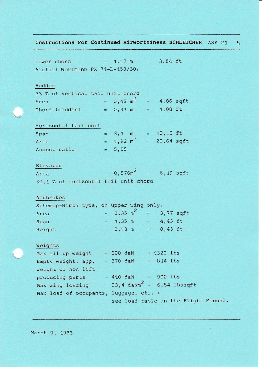
Lower chord = ar17 m = 3rB4 ft
Airfoi1 Wortmann FX 71-L-L50,/30.
Rudder
33 % of vertical tail unit chord
)
Alcd = 0,45 m- - 4186 sqft
Chord (middle) = 0,33 m = 1'08 ft
Horizontal tail unit
Span
Area
Aspect ratio
Area
Span
Heigh t
= 3,1 m = 10116 ft
= a,92 m2 - 2o,64 sqft
= 5'05
2^
= 0,35 m- - 3177 sqft
= 1,35 m = 4.43 tl
= 0113 m = 0,43 ft
Elevator
Area = 0,576m2 = 6t 19 sqft
30r1 % of horizontal tail unit chord
Airbra\es
Schempp-Hirth type, on upper wing on1y.
W eiqhts
Max all up weight = 600 daN = 1320 1bs
Empty weight, app. = 370 daN = 814 lbs
Weight of non lift
producing parts = 410 daN = 902 lbs
Max wj-ng loading = 33t4 daNm2 = 6184 lbssqft
Max load of occupants, luggage, etc. :
see load table in the Flight Manual.
March 9, 1983

Instructlons For Contlnucd Alraorthlncss SCHLEICHER ASK 21 6
II. DESCRIPTION OF AIRCRAFT AND COMPONENTS
Ai rcra ft
The A,SK 21 is a two-seater midwing with T-tail, airbrakes,
fi-xed shock absorbing main wheel and a nose whee1.
The structure is made in a highly developped fiberglass
technology. On certain crilical areas carbon fibers are
us ed.
Winq
Double T spar made of fiberglass roving flanges and fi-
berglass cloth webs. The skin consists of a 9mm Conticell
core with fiberglass on both sides.
Easy wing assembly by longue and fork connection, fixed
by two 356 bo1ts. Two shear bolts at the fuselage which
fi-t the bushings in the wing center rib, absorb the shear
loads to the fuselage. The rear shear bolts are secured
by an automatic safety device.
Fuse I aqe
The fuselage is designed as a honeycomb (tubus core) con-
struction throughout which means considerable increase of
strength compared to non sandwich she1Is.
2-piece canopy, forward hinged in front and rearward hinged
in back; adjustable back rests.
Tai I pL ane
T-tail consisting of the same construction as the wing.
Control Surfaces
Sandwich construction wi-th Rohacell foam core.
IfI. DESCR]P?ION OF A/C ASSEMBLY & EQUIPMENT
III.1 CONTROL SYSTEMS
Genera_L
Except for the rudder which is operated by cables r
March 9, 1983

InEtructlns For [ontinud Airyorthinrrs Schhicher ASK 21
E
(l,
vtc
>o
t, :;
idg
-E ..-
Ed
tg-
L:= o,
gtsE
#+ E
oz<t=
E-
EE
*B
Ec
5E
b.
EE
ag
lrl ,<
Ifi
Controt Systems \l//
'\ \\r',
\I&\
\" -\t-\
\\\\j\
lij r--r 1 {'}!:-l
lnstructions For Gontinued Airworthiness SCHLEICHER ASK 21
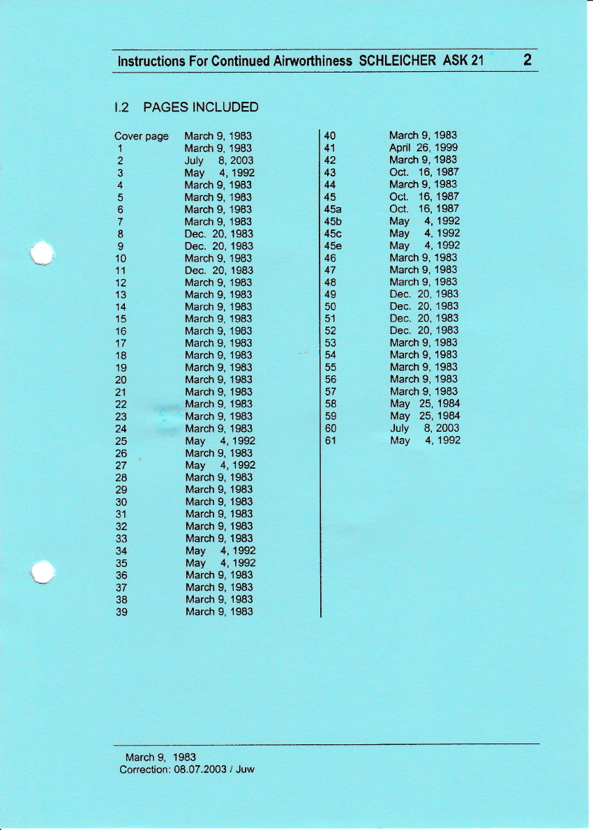
1.2 PAGES INCLUDED
Cover page March 9, 1983
1 March 9, 1983
2 July 8,2003
3 May 4,1992
4 March 9, 1983
5 March 9, 1983
6 March 9, 1983
7 March 9, 1983
8 Dec. 20,1983
I Dec. 20,1983
10 March 9,1983
11 Dec. 20,1983
12 March 9, 1983
13 March 9, 1983
14 March 9, 1983
15 March 9, 1983
16 March 9, 1983
17 March 9, 1983
18 March 9, 1983
19 March 9,1983
20 March g, 1983
21 Marcfi 9, 1983
22 March 9, 1983
23 March 9, 1983
24 March 9, 1983
25 May 4,1992
26 Marcn 9, 1983
27 May 4,1992
28 March 9, 1983
29 March 9, 1983
30 March 9,1983
31 March 9,1983
32 March 9,1983
33 March 9,1983
34 May 4,1992
35 May 4,1932
36 Marct 9, 1983
37 March 9,1983
38 March 9,1983
39 March 9,1983
40
41
42
43
44
45
45a
45b
45c
45e
46
47
48
49
50
51
52
53
54
55
56
57
58
EO
60
61
March 9, 1983
April 26, 1999
March 9, 1983
Oct. 16,1987
March 9, 1983
Oct. 16,1987
Oct. 16,1987
May 4,1992
May 4,1992
May 4,1992
March 9, '1983
March 9, 1983
March 9, 1983
Dec. 20,1983
Dec. 20,1983
Dec. 20,1983
Dec. 20,1983
March 9, 1983
March 9, 1983
March 9, 1983
March 9, 1983
March 9, 1983
May 25,1984
May 25,1984
July 8, 2003
May 4,1992
March 9, 1983
Correction: 08.07.2003 / Juw
Inslructions For Continued Airworthiness Schteicher ASK 21
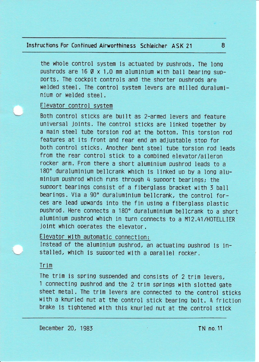
the whole control system ls actuated by pushrods. The lons
pushrods are 16 0 x 1,A lll|Il alufllinlulll wlth ball bearlng sup-
ports, The cockplt controls and the shorter oushrods are
welded steel. The control system levers are rllllled duraluml-
nlum or welded steel,
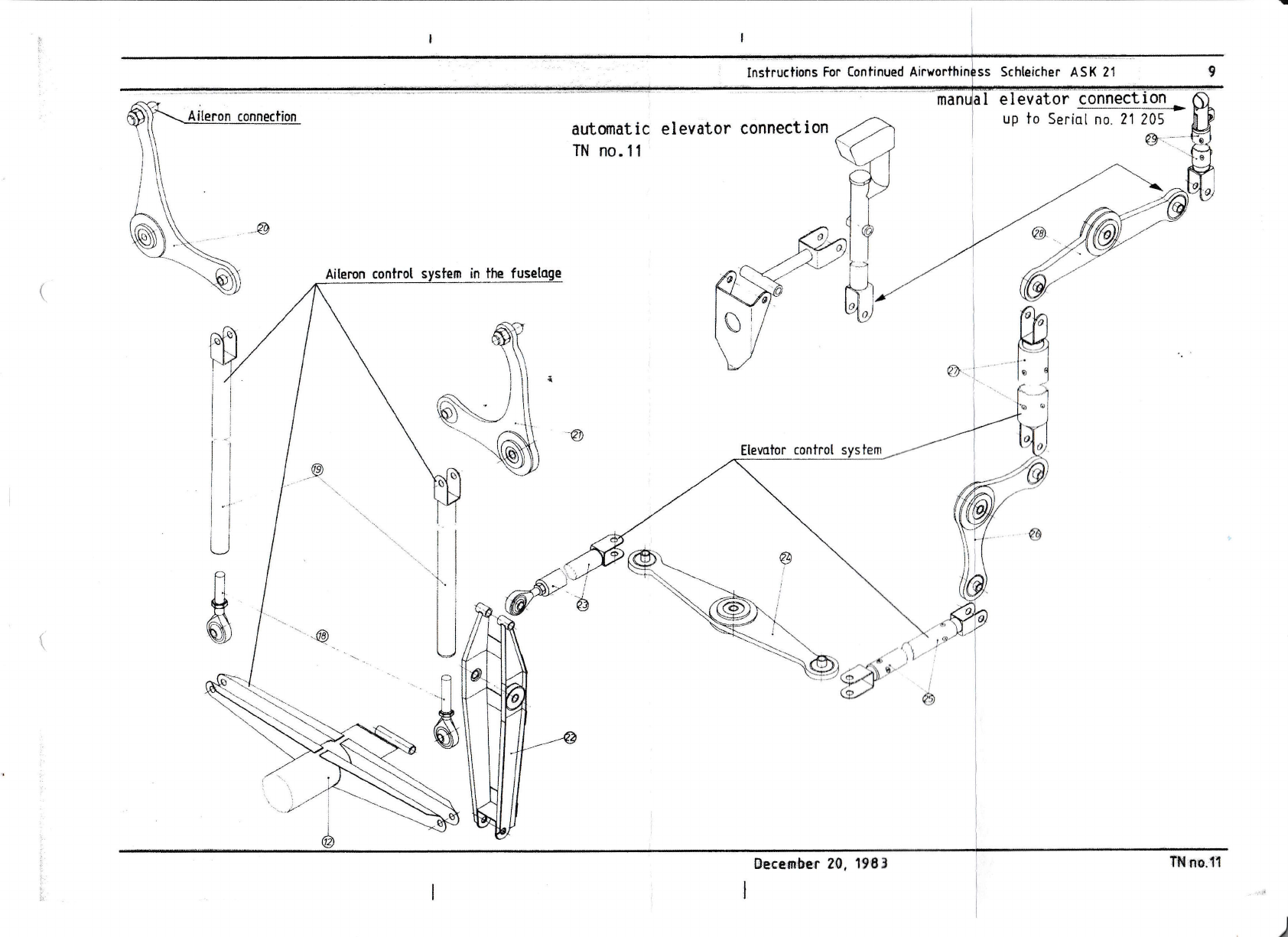
Elevator control system
Both control stlcks are bullt as 2-armed levers and feature
universal Jolnts, The control sttcks are linked together by
a maln steel tube torslon rod at the bottom, Thts torston rod
features at its front and rear end an adJustable stop for
both control stlcks, Another bent steel tube torslon rod leads
from the rear control silck to a combtned elevator/aileron
rocker arm. From there a short alumlnium pushrod leads to a
180" duralumlnium bellcrank whlch ts llnked uo by a lons alu-
lnlnlum pushrod whlch runs throush 4 suoport bearings; the
support bearlngs consist of a flberglass bracket with 3 ball
bearlngs. Vla a 90" duralumlnlum bellcrank, the contr0l for-
ces are lead upwards 1nt0 the fin uslng a ftberglass plastic
pushrod, Here connects a 180' duraluminium bellcrank to a short
alumlnium pushrod which In turn connects to a t412,41IH0TELLIER
jolnt l,,hich ooerates the elevator,
Elevator l.ll th automailc connecilon I
Instead of the alullllniulll pushrod, an actuating pushrod 1s ln-
stalled, rlhlch ts suiported wlth a paraltel rocker,
Tr 1lI}
The trltll ls sprlng susoended and conslsts of 2 trlrrl levers,
I connectlng pushrotl and the 2 trlrll sprlngs with slotted gate
sheet metal, The trlm levers are connected to the control silcks
liith a knurled nut at the control stick bearlng bolt, A frictlon
brake ls tlghtened wtth thls knurled nut at the control silck
December 20, 1 983 TN n0.11

Insfructions For Continued Airyorthiness Schleicher ASK 21
bearing bolt, The braklns force should be dlstributed evenly
between the front and rear brake, The brake should be tighten-
ed so strons that even wlth extremely opposed posltions of
stlck and trim lever, the trltn l{l1l not move, The trim con-
nectlng pushrod features a stop at lts front and rear end.
The sprlngs lllth the adjustlng plate between them, are sus-
oended lnto the 2 rings of the front control shaft. The ad-
Justlng plate ltself 15 mounted to the bolt of the trlrn con-
necting pushrod; here the trim ntay be adjusted.
The trlm should be adjusted such that illth 1 pllot and the trtm
set full forward, a trln,ll1led speed of 150-160 km/h (81*86,3 kts.;
93,2-99,4 mph) is reached; then the trlm lever ls ln a sliSht-
ly forward Dosltlon when the stlck ls free and ln tts center
DoSitlon (elevator connected),
To adjust the trim roughly to a trtmmed speed of max, 160 km/h
(86,3 kts; 99,4 mph)r
1 , Connect elevator,
(Thls 1s inappllcable when your gllder features the auto-
matlc elevator connectlon) .
2. Adjust the trlm spring such that the silck ls set to the
above-mentloned relatlve posltion to the trlril lever. Frlc-
tlon must be balanced by "feellng for" the center posiilon.
Trirll lndlcator
In addltton to the vislble posltlon of the trirn lever itself,
the trirll features a triIIl indtcator, The trlm tndlcatton should
be in the center Dosltlon when the trlm lever ls vertical to
the Sllder's longltudlnal axls. It can be adjusted by openlng
the clamp at the trlm connecting oushrod and by disolacing the
Bowden cable, Then rettghten the clamp.
11
December 20, 1 983 IN n0.11
Instructlons For Contlnucd Alrsorthlneas SCHLEICHER ASK 21 13
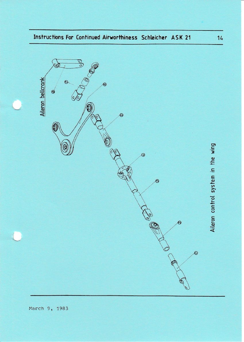
Aileron control svstem
A short aluminum pushrod leads from the horizontal
aileron control system lever at Lhe rear elevator,/
aileron control system torslon rod upwards to a 90o
duraluminum bellcrank in the fuselage. By a HOTELLIER
joint (M12.41) follows from here the long aluminum
pushrod in the wing. This pushrod is supported alto*
gether seven times in each three ball bearings. For
the compensation of the bellcrank travels short steel-
tube pushrods are articulated by balI bearings {14c6}
at both ends of the long pushrod. The inner short
pushrod features the HOTELLfER connection with the ad-
justing screw. At the 90o duraluminum bellcrank the
aileron pushrod acluates the aileron through a HIRSCH-
MANN-UNIBAL adjustable head (SMx CP6).
The stops for the aileron are positioned ln the push-
rod box in front of the rear stick. These are two p1y-
wood blocks glued into the pushrod box and cut out such
that they stop laterally the travel of the front tor-
sion shaft.
March 9, 1983
Instructions For Continued Airyorthiness Schhicher ASK 21 lt.
cn
L
'=
(u
!
+
;
(U
U'
v,
o
L
C
o
U
L
o
L
(l,
a
J"larch 9, 1983

InBtructlons For Contlnucd Alnrorthine8s SCHLEICHER AsK 21 15
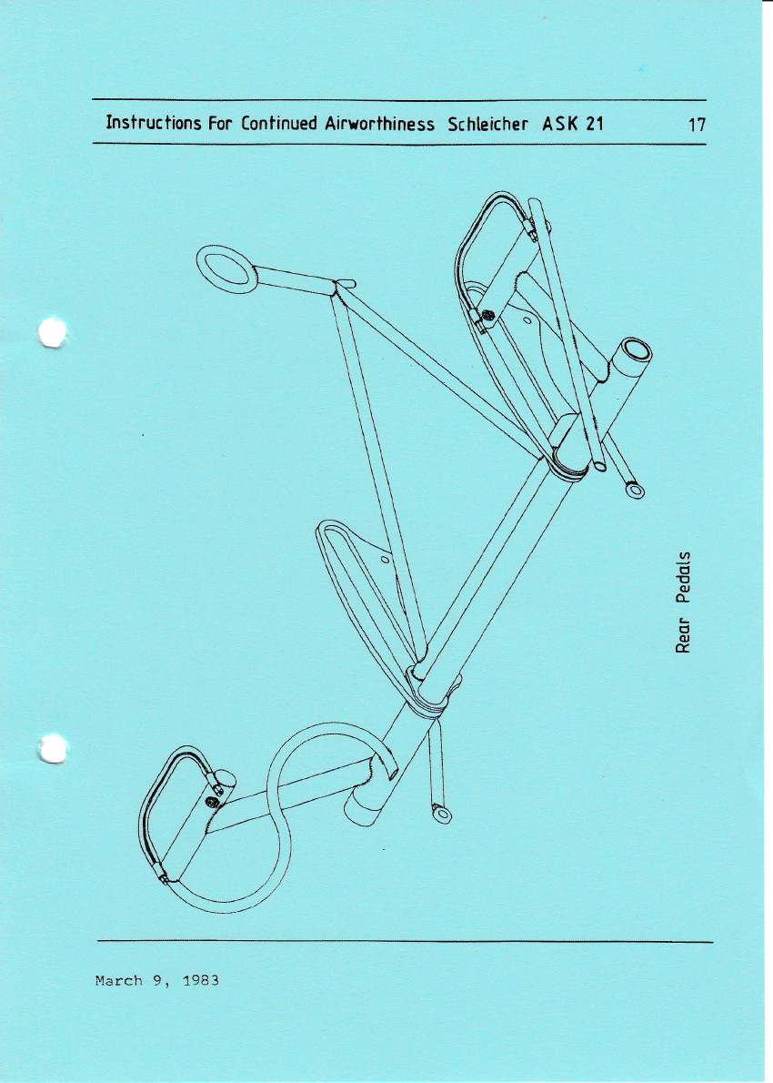
R}dder control svstem
The rudder is actuated by cable (3129 LN 9374).
Both fronL and rear pedals are adjustable. The rudder
cables are running from a fixed point through S-type
pedal loops to an adjusling plate in the rear cockpit.
Here are joined togelher the cables from the front
and rear pedals. From the adjusting plate the cables
run through nylon tubes to the rudder-actuating lever.
At the adjusting plate slight inaccuracies in
the cable length may be adjusted and also the pedal in-
clination. The cables are held taut by springs at the
pedals; at the rear pedals this spring serves simul-
taneously for holding down the adjusting stop.
For the adjustment of the cables at the adjustment plate
the rear seat must be removed.
The stop forthe rudder is located in the back of the
rudder.
The rudder lever strikes a stop at the bearing bracket.
llarch 9, 1983
lnstructions For Continued Airworthiness Schleicher ASK 21
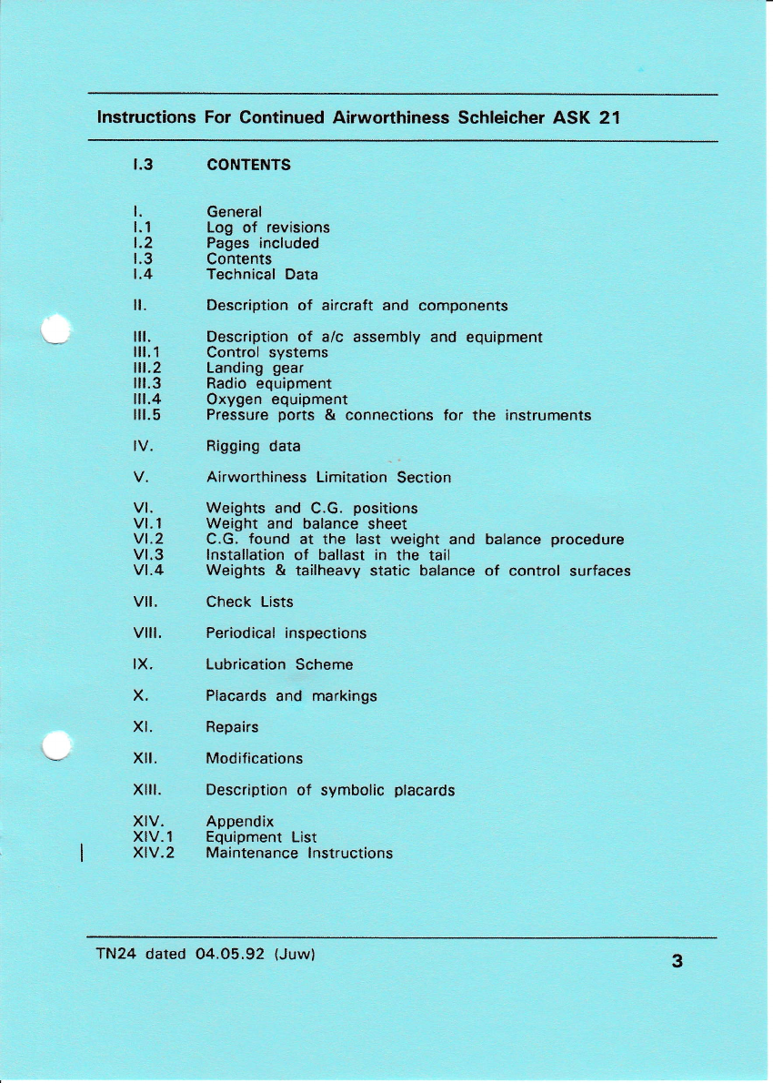
1.3 CONTENTS
l. General
1.1 Log of revisions
1.2 Pages included
1.3 Contents
1.4 Technical Data
ll. Description of aircraft and components
lll. Description of a/c assembly and equipment
lll.1 Control systems
lll.2 Landing gear
lll.3 Radio equipment
lll.4 Oxygen equipment
lll.5 Pressure ports & connections for the instruments
lV. Rigging data
V. Airworthiness Limitation Section
Vl. Weights and C.G. positions
Vl.l Weight and balance sheet
Vl.2 C.G. found at the last weight and balance procedure
Vl.3 lnstallation of ballast in the tail
Vl.4 Weights & tailheavy static balance of control surfaces
Vll. Check Lists
Vlll, Periodical inspections
lX. Lubrication Scheme
X. Placards and markings
Xl. Repairs
Xll. Modifications
Xlll. Description of symbolic placards
XlV. Appendix
XlV.1 Equipment List
XlV.2 Maintenance lnstructions
TN24 dated O4.O5.92 (Juw) 3
Insfructions For Continued
elevator connection
Schleicher ASK 21
I elevator
automat ic
TN no.11
up to Seriol no. 21 205
Aileron control
Becember 20, 1963
)
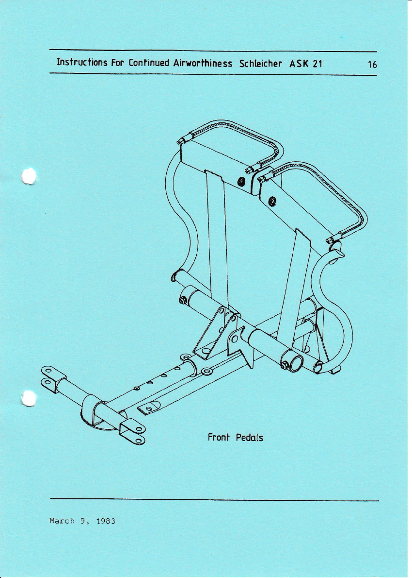
Instructions For Continued Airrorthiness Schteicher ASK Z1 1b
Front Pedqts
l'iarch 9, 1983
Instructions Por Contlnucd Alraorthlna6r SCHLEICHER ASK 21 tt
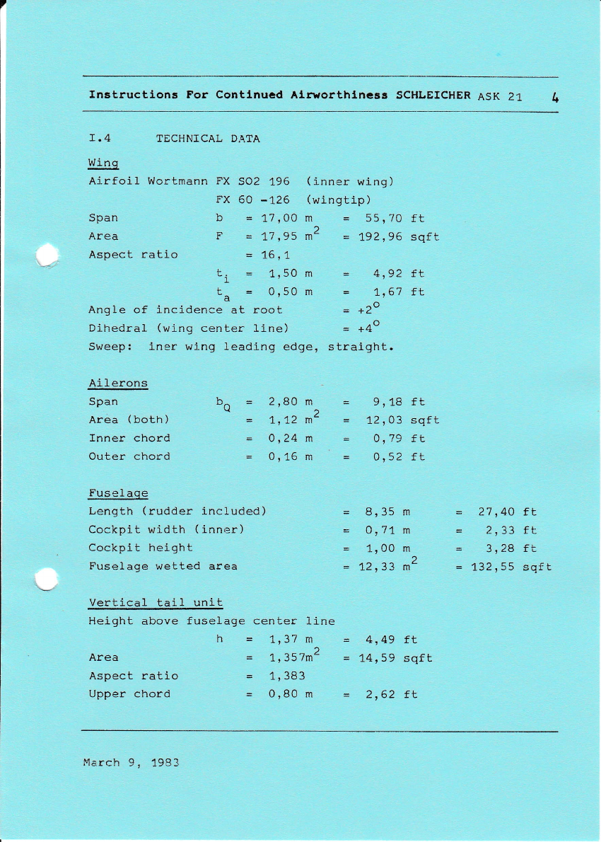
T.4 TECHNICAL D,{TA
Wing
Airfoil Wortmann FX SO2 196
FX 60 -126
Span b = 17,00
Area F = 1,7,95
Aspect ratio = 1617
Li = 1'50
tt = or5o
Angle of incidence at root
Dihedral (wing center line)
sweep! iner wlng leading edge,
( i-nner wing )
(wingtip )
m = 55,70 ft
*2 = 192,96 sqft
- 4,92 tL
- L167 fL
- . ro
= +4o
s traight.
- 9,18 ft
= L2s03 sqft
= 0,79 ft
n Ea cr
- wrJL tL
= 8'35 m
= 0:71 m
= 1100 m)
= 1"2,33 m-
Iil
m
Ai 1 erons
Span
Area (both)
Inner chord
Outer chord
bn = 2'80 m
1, L2 mZ
= 4,24 m
= 0116 m
Fusel aqe
Length (rudder included)
Cockpit width (inner)
Cockpit height
Fuse).age wetted area
vertical tail unit
Hei.ght above fuselage
h
Area
Aspect ratio
Upper chord
= 27 r4O tt
- 2,33 ft
= 3116 lL
= 132,55 sqft
center line
= 1,37 m
,^-_2
= 1'J)/m
= 1,383
= 0,80 m
4149 fL
14,59 sqft
2162 tt
March 9, 1983

Instructions For Continued Airworthiness Schteicher ASK Z1
Trim lever
Stick reqr
(/c
,h
b
Md
SticNr ossembty ond
Trimlsystem
Morch 9,1983
Instructions For Continued Airyorthiness Schleicher ASK 21 17
Q
o
1l
o
o-
L
c,
o
d_
March 9, 1983
Instructlons Por Contlnucd Alryorthlncss SCHLEICHER AsK 21 18
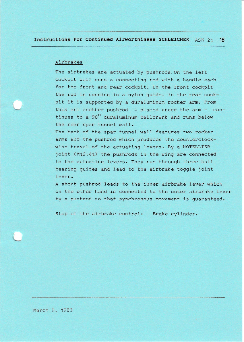
Airbrakes
The airbrakes are actuated by pushrods. On the left
cockpit wall runs a connecting rod with a handle each
for the front and rear cockpit. In the front cockpit
the rod is running in a nylon guide, in the rear cock-
pit it is supported by a duraluminum rocker arm. From
this arm another pushrod - placed under the arm - con-
, ^^o
tinues to a 90" duraluminum bellcrank and runs below
the rear spar tunnel wa1l.
The back of the spar tunnel wa11 features two rocker
arms and the pushrod which produces the counterclock-
wise travel of the actuating levers. By a HOTELLIER
joint (M12.41) the pushrods 1n the wing are connected
to the actuating levers. They run through three ball
bearing guides and lead to the ai-rbrake toggle joint
A short pushrod leads to the inner airbrake lever which
on the other hand is connected to the outer airbrake lever
by a pushrod so that synchronous movement is guaranteed.
Stop of the airbrake control: Brake cylinder.
Plarch 9, 19t3

Instructions For Continued Airuorthiness Schteicher ASK 21 19
c
.e
U
o
c
c
ct
L'
(U
l<
t
L
..It
L
a
(U
c7r
o
(U
tn
3
q
o
E
+
.g
E
(U
+
tt,
th
(U
o
L
.o
.!
e,
6)
March 9, 1983

Instructions For Continued Airvorthiness Schteicher ASK 21 2A
en
c
't
(U
c
.g
o
+
v,
t,
o,
L
E
.tt
,=
-ts1
LJI
el
-ol
,a EI
// l, I
)$l
(Y
Y/
Plarch 9, 1983

Instructlons For Contlnucd Alruorthlnaas SCHLEICHER ASK 21 21
I11.2 LAND]NG GEAR
The landing gear consists of the shock absorbing main
wheel 5.00-5 and the non shock absorbing nose wheel
4.00-4. The trailing boom main wheel uses two hollow-
type rubber shock absorbers (type KE 1ZO/95 core A
with mounting member, quality R"K 55).
The rim is a Cleveland wheel 4078 (B), 5.00-5 Type fIIl
Brake: Cleveland brake assy 30-9.
Main brake cylinder: Master cylinder aO-ZO.
Tank for brake fluid: Below rear seat pan on LH sj-de.
Main wheel: Tire with tube 5,00-5,
6p1y rating.
Nose wheel: fire with tube 4.00-4,
4p1y rating.
?ire pressure
Mai.n wheel
Nose wheel 2,7 bar = 38 psi.
2,0 bar = 28 psi.
To fill up the brake
Brake fluid: ESSO UNIVIS J-13 or
AEROSHELL FLUID 4 I
You absolutely have to observe that only brake fluid
on a mineral oil basis is used.
Car brake fluid on ester basis will destroy gaskets
and tubes in a very short time.
March 9, 1983
Instructlons For Contlnucd Alr1orthlnc8s SCHLEICHER ASK 21 22
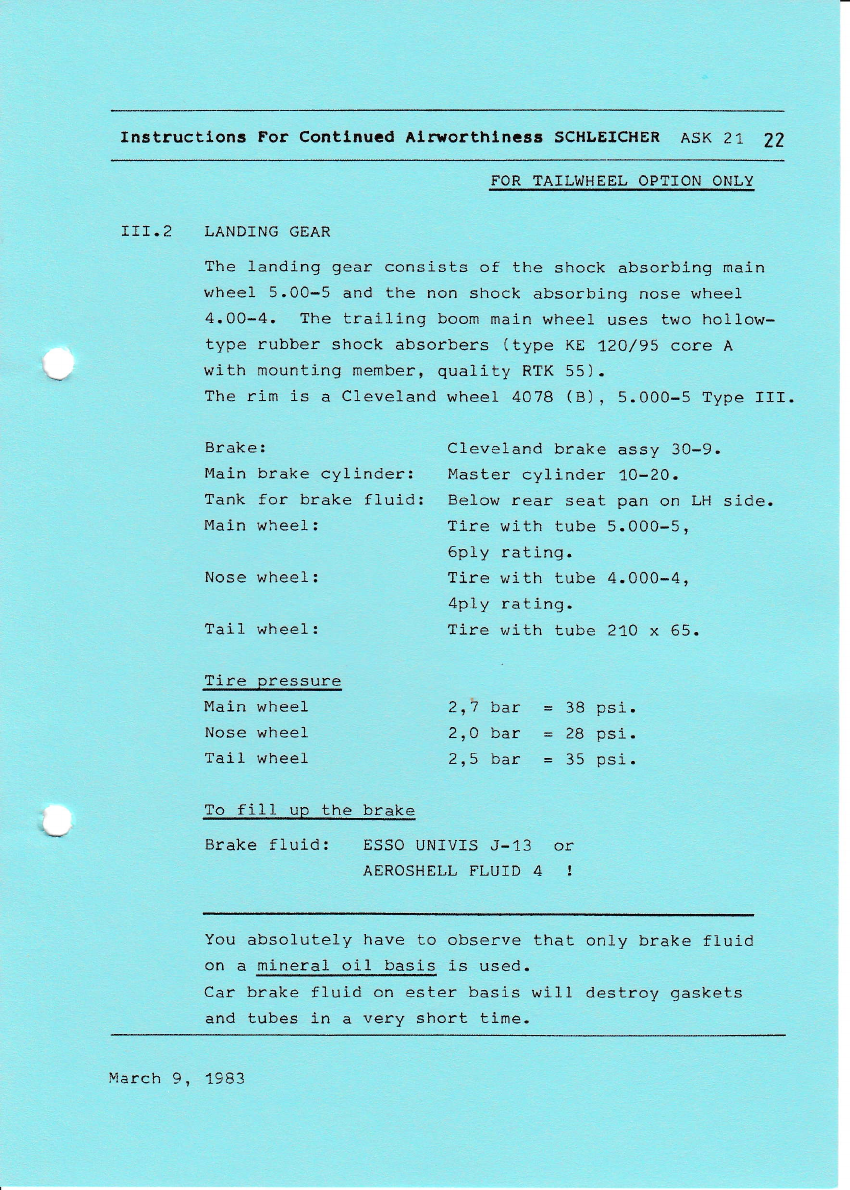
FOR TAILWHEEL OPTION ONLY
III.2 LANDING GEAR
?he landing gear consists of the shock absorbing main
wheel 5.00-5 and the non shock absorbing nose wheel
4.00-4. The traili-ng boom main wheel uses two hol1ow-
type rubber shock absorbers (type KE 1,20/95 core A
with mounting member, quality RTK 55).
?he rim ls a Cleveland wheel 4O7B (B), 5.000-5 Type III.
Brake: Cleveland brake assy 30-9.
Main brake cylinder: Master cylinder 1A-2A.
Tank for brake fluid: Below rear seat pan on LH side.
Main wheel: Tire with tube 5.000-5,
6ply rating.
Nose wheel: Tire with tube 4.000-4,
4p1y rating.
Tail wheel: Tire with tube 210 x 65.
Tire pressure
Main wheel
Nose wheel
Tail wheel
2r7 bar = 38 psi.
2,0 bar = 28 psi.
2r5 bar = 35 psi.
To fill up the brake
Brake fluid: ESSO UNIVIS J-13 or
AEROSHELL FLUID 4 !
You absolutely have to observe that only brake fluid
on a mineral oi1 basis is used.
Car brake fluid on ester basis will destroy gaskets
and tubes in a very short time.
Iqarch 9, 1983
Instructlons Por Contlnucd Alrrrorthlncs8 SCHLEICHER ASK 21 ?3
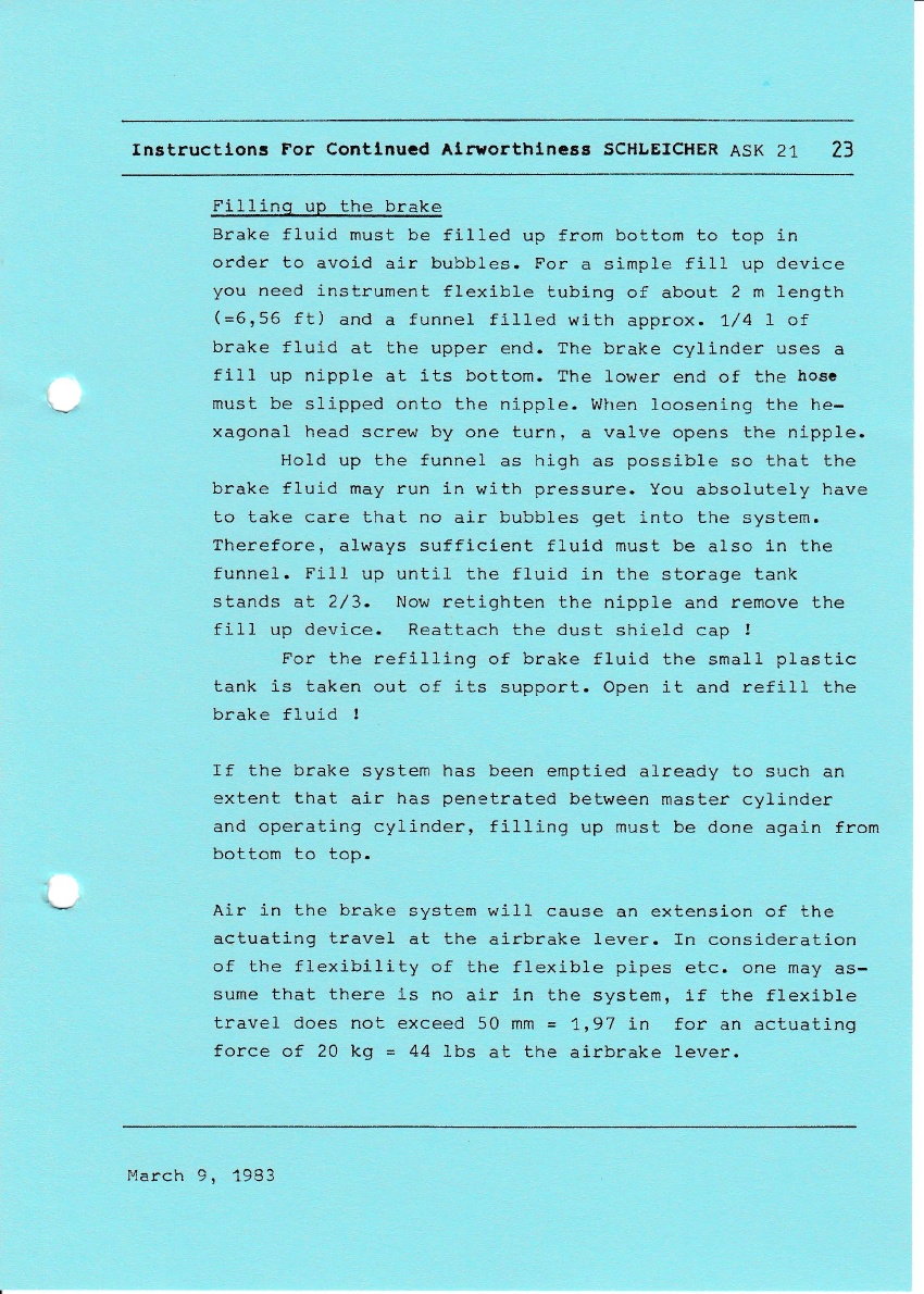
Fillinq up the brake
Brake fluid must be fil1ed up from bottom to top in
order to avoid air bubbles. For a simple fill up device
you need i,nstrument flexible tubing of about 2 m length
(=6,56 ft) and a funnel filled with approx. 1/4 I of
brake fluid at the upper end. The brake cylinder uses a
fill up nipple at its bottom. The lower end of the hosc
must be slipped onto the nipple. Wiren loosening the he-
xagonal head screw by one turn, a valve opens the nipple.
Hold up the funnel as high as possible so that the
brake fluid may run in with pressure. You absolutely have
to take care that no air bubbles get into Lhe system.
Therefore, always sufficient fluid must be also in the
funnel. Fill up untif the fluid in the storage tank
stands at 2/3- Now retighten the nipple and remove the
fill up device. Reattach the dust shield cap !
For the refilling of brake fluid the sma1l plastic
tank is taken out of its support. Open it and refilI the
brake fluid !
If the brake system has been emptled already to such an
extent that air has penetrated between master cylinder
and operating cylinder, fill,ing up must be done again from
bottom to top.
Air in the brake system will cause an extension of the
actuating travel at the airbrake 1ever. In consideration
of the flexibility of the flexi,ble pipes etc. one may as-
sume that there is no air in the system, if the flexible
travel does not exceed 50 mm = 1197 in for an actuating
force of 20 kg = 44 lbs at the ai-rbrake Lever.
I,'larch 9, i9S3
Instrutions For Continued Airvorthiness Schlcicher ASK 21 2l+
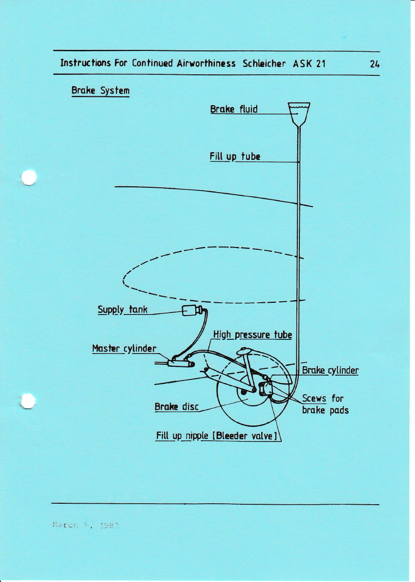
Bmke System
Supp_ty_lsd
Fitt up :lqbe
-------
-
t
h_pg$urelube
-ti!!-trp-rtpple Bteeder vatvp
Scews
brske
ryllr
for
pads
Instructions For Continued Airworthiness Schleicher ASK 21
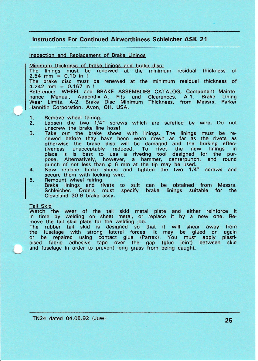
lnspection and Feplacement of Brake Lininos
The linings must be renewed at the minimum residual thickness of
2.54 mm = O. 10 in !
The brake disc must be renewed at the minimum residual thickness of
4.242 mm = 0.167 in !
Reference: WHEEL and BRAKE ASSEMBLIES CATALOG, Component Mainte-
nance Manual, Appendix A, Fits and Clearances, A-1. Brake Lining
Wear Limits, A-2, Brake Disc Minimum Thickness, from Messrs. Parker
Hannifin Corporation, Avon, OH. USA.
1. Bemove wheel fairing.
2. Loosen the two 114" screws which are safetied by wire. Do not
unscrew the brake line hose!
3. Take out the brake shoes with linings, The linings must be re-
newed before they have been worn down as far as the rivets as
otherwise the brake disc will be damaged and the braking effec-
tiveness unacceptably reduced. To rivet the new linings in
place it is best to use a riveting tool designed for the pur-
pose. Alternatively, however, a hammer, centerpunch, and round
punch of not less than O 6 mm at the tip may be used.
4. Now replace brake shoes and tighten the two 114" screws and
secure them with locking wire,
5. Remount wheel fairing.
Brake linings and rivets to suit can be obtained from Messrs.
Schleicher. Orders must specify brake linings suitable for the
Cleveland 30-9 brake assy.
Tail Skid
Watch the wear of the tail skid metal plate and either reinforce it
in time by welding on sheet metal, or replace it by a new one. Re-
move the tail skid plate for the welding job.
The rubber tail skid is designed so that it will shear away from
the fuselage with strong lateral forces. lt may be glued on again
or be repaired using contact glue (Pattex). You must apply plasti-
cised fabric adhesive tape over the gap (glue joint) between skid
and fuselage in order to prevent long grass from being caught.
TN24 dated 04.05.92 (Juw) 25
fnstructions For Contlnued Alrsorthlness SCHLEICHER ASK 21 26
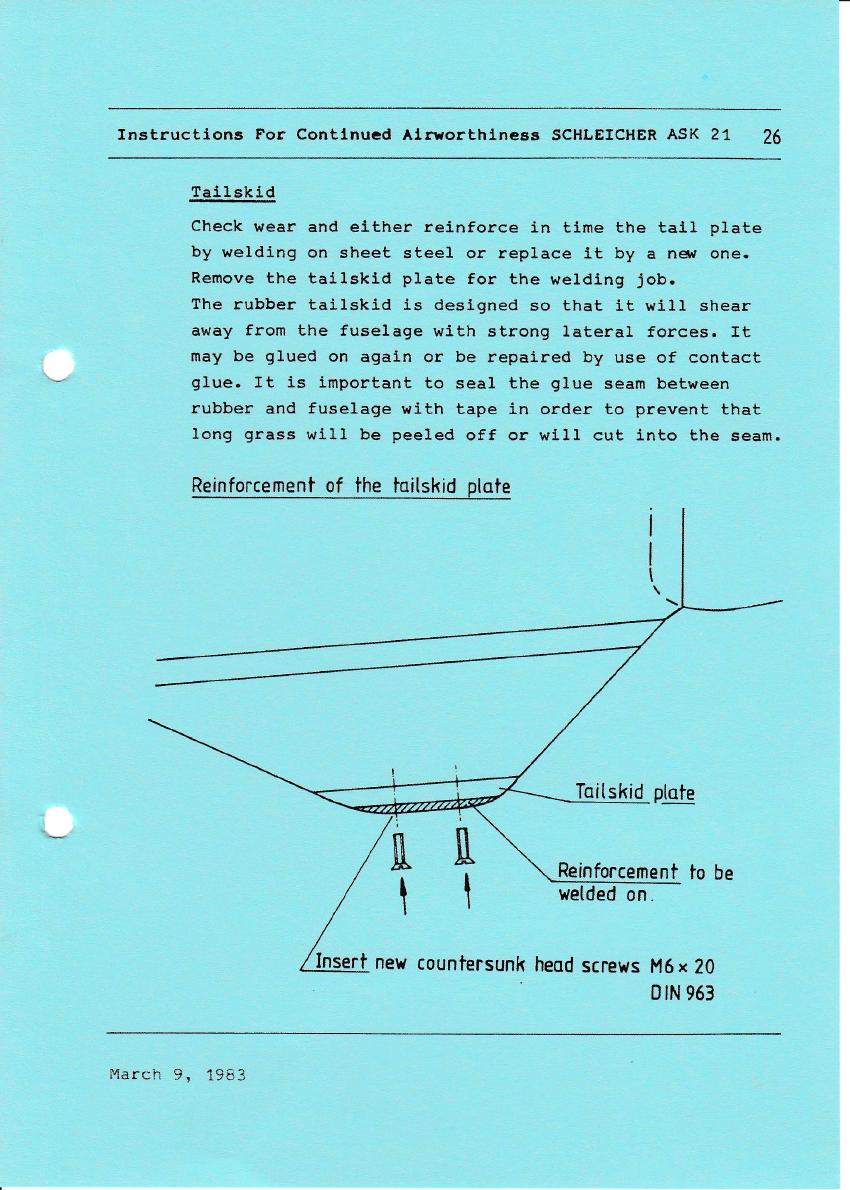
Tailskld
Check wear and elther reinforce in time the tall plate
by welding on sheet steel. or replace it by a ne$ one.
Remove the tallskid plate for the weldlng job.
The rubber tailskid is designed so that tt will shear
away from the fuselage with strong lateral forces. It
may be glued on again or be repaired by use of contact
glue. It is important to seal the glue seam between
rubber and fuselage vJith tape in order to prevent that
long grass will be peeled off or will cut into the seam.
Reinforcement of the taitskid ptote
Iaitskid ptote
Rein ment to be
sert nerd countersunk heod screws M6x 20
[[
tt
B tN 963
March 9, 1963

lnstructions For Continued Airworthiness Schleicher ASK 21
l[.3. Radio Equiment
The front instrument panel is provided for the installation of the
radio. For installing the radio the mounting accessories and cable
harness supplied by the radio manufacturer should be used. Regard-
ing the layout of the instrument panel you have to consider that
the radio must be clearly visible and easily accessible to the
pilot in the flying position.
As to the clear visibility, however, priority must be given to the
flight control instruments. A suggestion for instruments layout is
given on the drawing for the instrument panels.
The Becker radio may be installed both horizontally or vertically.
The loudspeaker may be fitted below the rear instrument panel cover
on the LH side.
The swan neck (boom) microphone is mounted on the RH cockpit wall.
A support for a dryfit battery i.12V, 6.4Ah) is provided in the bag-
gage compartment of the left wingroot,
lll.4 Oxygen Equipment
Suitable bottle fixing brackets for two 4 liter oxygen bottles of
dia, 1OO mm are available as an optional accessory from Messrs.
SCHLEICHER,
When fitting the oxygen bottle(s), ensure that it is properly in-
stalled and securely anchored.
NOTE: Fitting of oxygen equipment causes only a minimal
change in the empty-mass C.G. position ! However,
it is necessary to re-weigh the glider and rede-
termine the empty mass C.G.
When flying at greater heights while using the oxygen system, it
should be borne in mind that any particular system may only be suit-
able for a limited altitude range. The makers' instructions should
be complied with.
TN24 dated 04.O5.92 (Juw) 27

Instructkms For Contintpd Airuorttriness Schhicher ASK 2l Zg
mirophorns on the RH cockpit uall
\t
\l
\ \V
\\)^
Inslallation of boom
I
I
o,
.tf
v|
3
L
5
o
c
o
U
E,
!
4
-ts
o
L'
(u
.c
EI
<I
lrt I
al
Microphone
neor to thc Ventitotion
Instructlons For Contlnucd Alrsorthlncss SCHLEICHER ASK 21 29
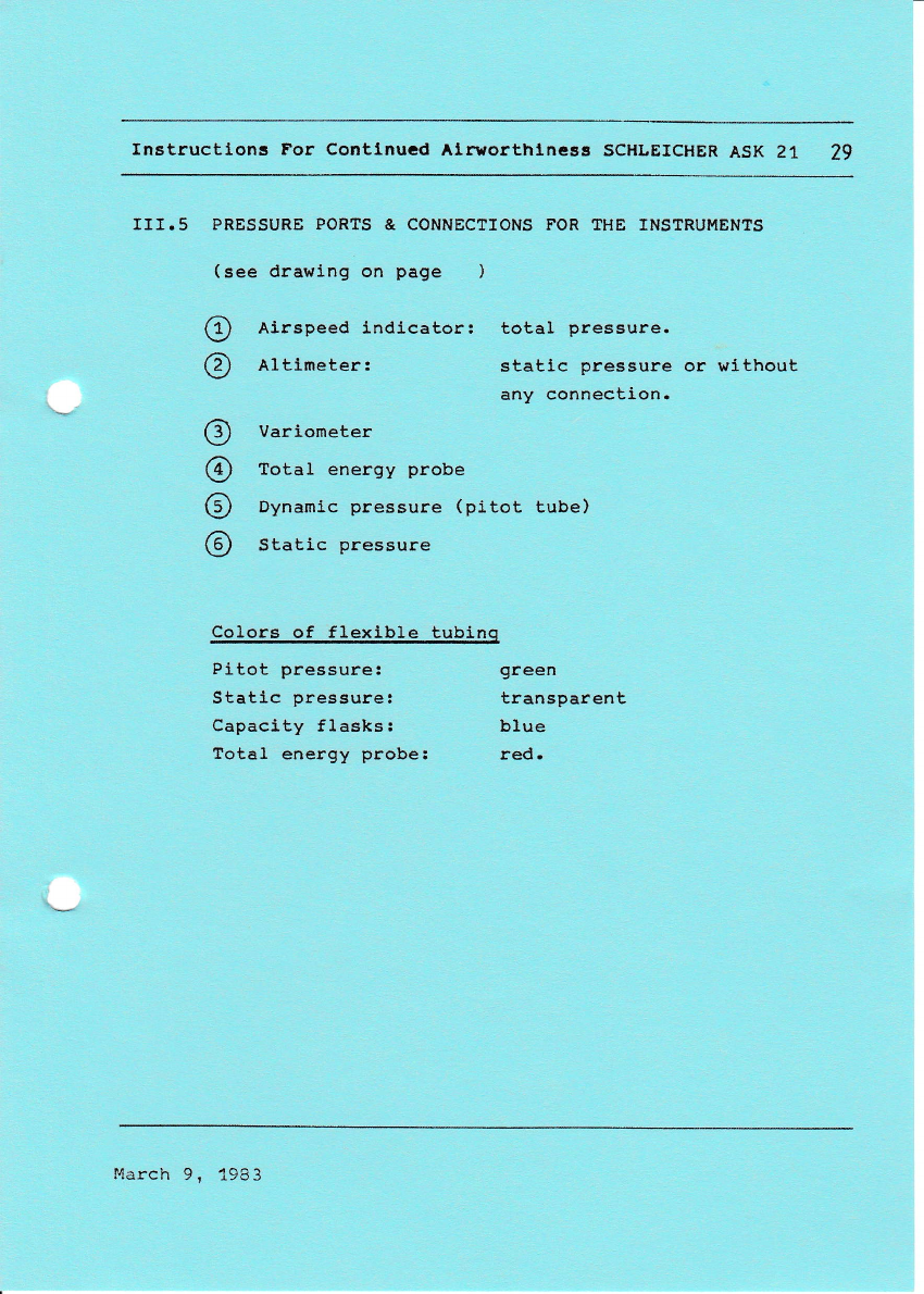
II1.5 PRESSURE PORTS & CONNEC?TONS FOR ?HE INSTRUMENTS
(see drawing on page )
Airspeed indicator: total pressure.
Altimeter: static pressure or without
any connection.
Variometer
fotal energy probe
Dynamlc pressure (pitot tube)
Static pressure
Colors of flexible tubinq
Pitot pressure: green
Statlc pressure! transparent
Capaclty fLasks: blue
fotal energy probe: red.
@
@
o
@
o
@
March 9, 1983
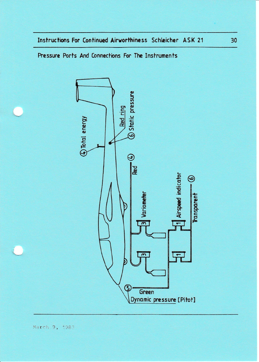
Instructions For tontinued Airworthiness Schhicher ASK 21 30
hessure Ports And Connections For TtE Instruments
o,
C.
3
6
tn
E
tI-
tJ
tc,
vt
EN
L
(U
e
G,
o
P
6reen
mic pressure tPitoil
' r-: ?, '-ta

lnstructions For Continued Airworthiness Schleicher ASK 21
c
o
a
#
tl
o
t
tf,
Instructlons For Contlnucd Alrrorthlnegs SCHLEICHER ASK 21 32
V. A I R W O R T H T N E S S L T M I T A I O N S E C T I O N
The Airworthiness Limltation section is FAA approved for
U.S. registered gliders in accardance with the provisions
of 14 CFR section 21t 29.
In addj.tion, this section es required by FAA Type
Certificate Data sheet
No. G 17EU and it specities maintenance requred under
14 CFR sections 43.16 and 91.163. unless an alternative
programm has been FAA approved.
LBA-approved on:
March 9, 1983

Instructtons For Contlnucd Alrvorthlneas SCHLEICHER AsK 21 33
Log of revisions
Revi s ions
No.
Pages
affected Description LBA approval,
s i gnature Date
March 9, 1983
lnstructions For Continued Airworthiness Schleicher ASK 21
NOTE: Damage to wing, fuselage, tail unit, and controls surfaces
must be repaired prior to the next flight.
Repairs beyond the scope of the REPAIR MANUAL issued by
Messrs. Schleicher must be carried out only by FAA-certifi-
cated aircraft repairers rated for composite aircraft struc-
ture work and only in accordance with Schleicher repair
methods approved by FAA.
V.1 lnsoection Procedures to extend Service Life
Proceed in accordance with Chapter Vlll.1.
V.2. Comoonents With Limited Service Life
Tow Belease Couolings
The Tost tow release couplings, factory fitted,
i.e. the C.G. Safety Tow Release "Europa G 72", or "G 73", or
"G 88" respectively, and
the front Nose Tow Release "E 72", or "E 75", or "E 85" respective-
ly,
have a limited service life (TBO) and must be returned to TOST for
re-inspection in regular intervals. The service life is stated in
the appertaining Manufacturer's Authorized Release Certificate.
The instructions given in the TOST "Operating Manual" or in the "Op-
erating and Maintenance lnstructions" for the tow release couplings
must be observed!
lnstruments
The flight monitoring instruments are
ice life limitations. As a general
should be complied with.
not normally subiect to serv-
rule, the makers' instructions
TN24 dated 04.05,92 (Juw) 34
lnstructions For Continued Airworthiness Schleicher ASK 21
Oxvoen Eouioment
For oxygen systems fitted, the relevant section of the appertaining
Manufacturer's lnspection Release Cenificate states the overhaul
time limit. Over and beyond this, the oxygen bottles must be re-in-
spected by a technical inspection institute every five years in ac-
cordance with pressure vessel regulations,
Soecial Servicino Procedures
At regular intervals of 6 years the brake line hose of the hydrau-
lic wheel brake must be replaced. Should this hose be found to be
in good condition, it need not be replaced, on condition that its
condition is checked at least every 10O flying hours.
TN24 dated O4.05,92 (Juw) 35
Instructlons For Continucd Ainorthlneas SCHLEICHER ASK 21 36
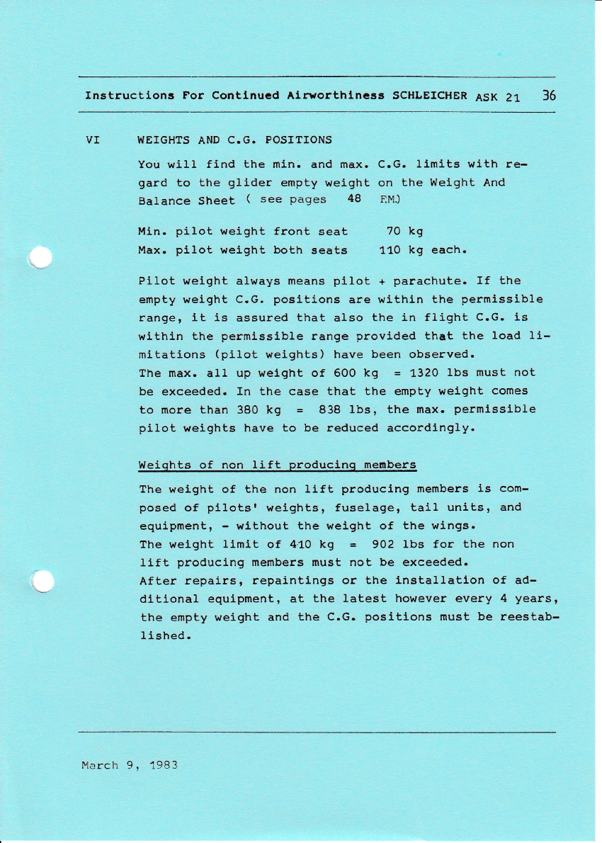
VI WEIGHTS AND C.G. POSITIONS
You will find the min. and max. C.G. Limits with re-
gard to the gllder empty weight on the Weight And
Balance Sheet ( see pages 48 EM)
Min. pilol weight front seat
Max. pilot k,eight both seats
70 kg
110 kg each.
Pilot welght always means plIot + parachute. If the
empty weight C.G. posltions are within the permisslble
range, Lt is assured that also the in flight C.G. is
within the permissible range provided that the load li-
mitations (pilot weights) have been observed.
The max. all up weight of 600 kg = 1"32O lbs must not
be exceeded. In the case that the empty weight comes
to more than 380 kg = 838 lbs, the max. permisslble
piloL weights have to be reduced accordlngly.
Weiqhts of non lift produclnq menbers
The weight of the non lift producing members Is com-
posed of pllotsr weights, fuselage, tail units, and
equipmenL, - wlthout the weight of the wings.
The weight 11mit of 4.10 kq = 902 Ibs for the non
llft produclng members must not be exceeded.
After repairs, repaintlngts or the lnstallation of ad-
dltlonal equlpmenL, at the latest however every 4 yearst
the empty weight and the C.G. positlons must be reestab-
I 1shed.
lvlarch 9. 1983
lnstructions For [ontinued Airuorthiness Schtticher ASK 21 37
VI.1
-
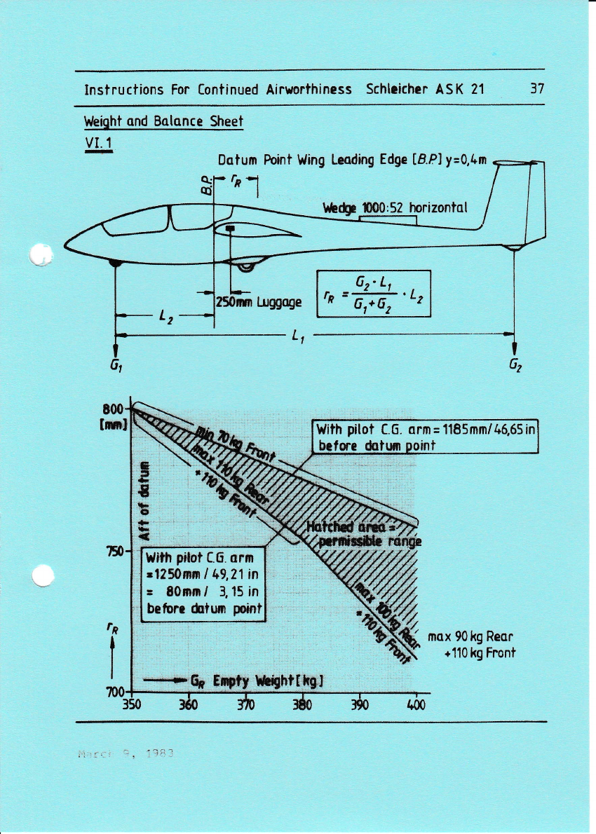
lrleiqht ond Balonce Sheet
Lnggoge
L,
Dotum Poini Wing Leading Edge t8.Pl y=0,1'm
fr-l
hh(p t00:52 lnrizontal
6z'L,
rn =@'Lt
E
=
.E
tF
{l
t
mox 90 kg Reor
+110 kg Froni
With pitot C.6. srm= 1185mm/46,65in
before dotun ooi
t{ith pilot C.6. arm
rt?50mrn I t+9,21in
= 80nm / 3, 15 in
befum &twr poini
-----r'S Eil$fr lBhf t,hSI

Instructlons For Contlnuad Alrworthlnc8s SCHLEICHER ASK 21 38
VT.z C.G. POSI?IONS AT ?HE LAST WEIGHT & BALANCE
lo.
CE
tr{ -i ({
o, ll/|l
O!
t{OC
,"lJ O
JJ UfI
(6 Orr
c ou
gro (u
.rlco
nr{ O
see also EM. page 48
+)
t5
>.c x
(du (6
OE
$d
.dO
tutr
ulFl O
"a
q!d .
ru r{\ c
ooor..{
&AllE
I .lJ
>5 X
(6.c (!
o.U E
JJr
r0d
C'U
utc
r{ ut
+J9
C'lc-{ .
O(6\c
r{ o or*{
[qdJl E
..tJ ?
.c Ic 'r{
(rrc\
-{.-r g
{D.C E
3 tu-
.q
$.a
O.U +r
E.d
tlUg
d
+rO
OJJ U
-cc
(l,} orto
.,u q{ d
.6Cr(0
o 3.q
March 9, 1983
Instructions For Contlnucd Alrrorthlnegs SCIILEICHER ASK 21 39
Weight, empty weight C.G. and payload have to be certi-
fied by an inspector on page 48 of the Fllght Manual and
on page 38 of the InstructiorFFor Continued Airworthlness.
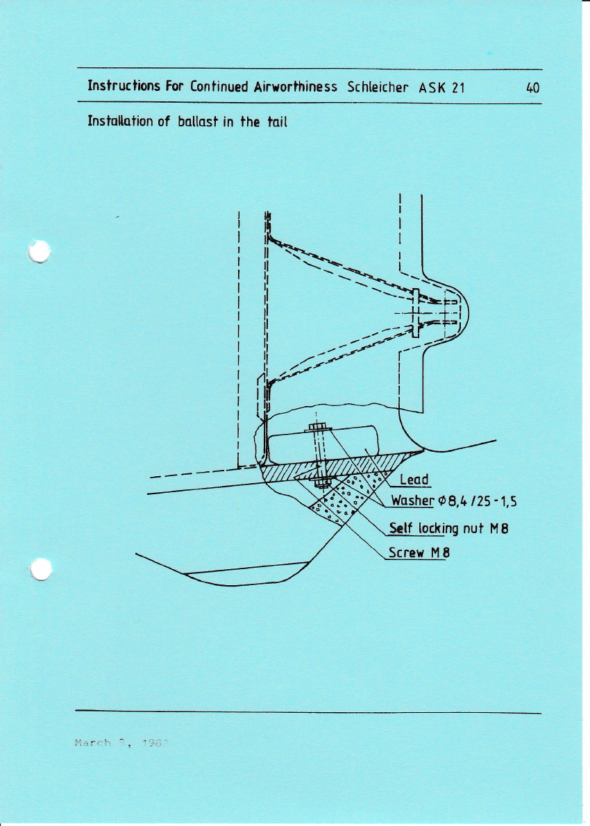
VI.3 INSTALLATION OF BALLAST IN THE TAIL
1.
It may be necessary to
order to get the empty
range.
2.
3.
4.
install ballast in the tail in
welght C.G. within the permlsslble
The amount of the lead ballast which is required ls
establlshed eit,her by calculation or by a weight and
balance procedure.
Sultable cast lead plates are aval.Iable with the
company Schlelcher.
Remove the rudder.
By use of a knife remove the tailskid very carefully.
Grind off glue residues and other impurities.
From below drill a hole of 8 mm (0r3 in) in diameter:
centrically to the lead plate. The long slde of the
lead plate must be placed next to the vertical tail
unlt spar so that the plate will not turn.
Shorten the M8 screws, screw them on and safety with
a selflocking nut. Awasher must be added on each
side.
7. Reglue the rubber skid with contact cement.
8. After the hardenlng smooth the tail.skid/fuselage gap
and tape it in order to prevent the peeling off or
catching of long grass.
9. Refit the rudder and safety duly with castellated nut
and cotter pi.n.
6.
March 9, 1983
Instructio*s For Continued Airuorihiness Schleicher ASK 2't &0
Instafiotion of baltast in the toit
Wosher O9,t+ 125-1,5
locking nut I'18
Screv M
lnstructions For Continued Ainvorthiness ASK 21 41
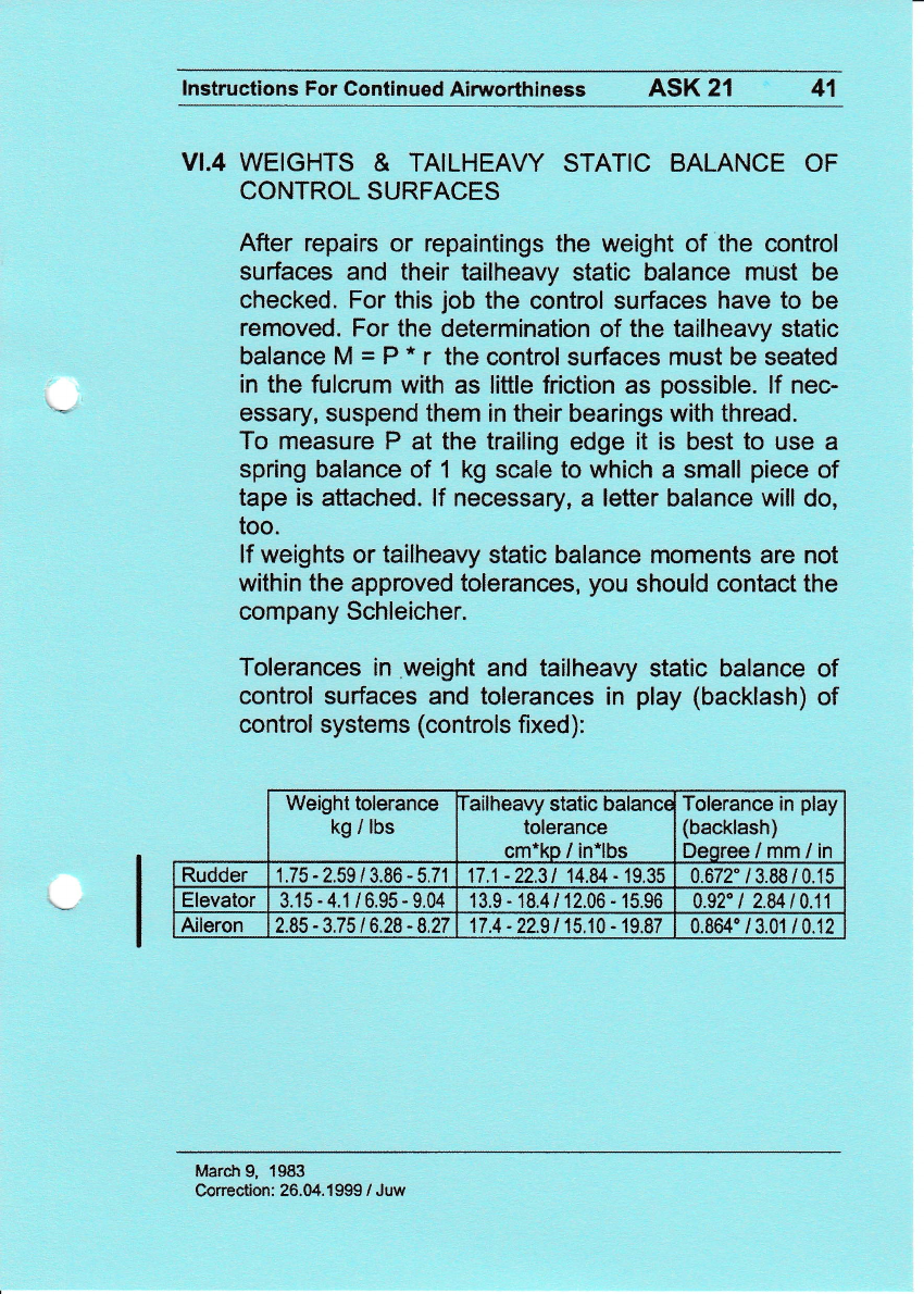
VI.4 WEIGHTS & TAILHEAVY STATIC BALANCE OF
CONTROL SURFACES
After repairs or repaintings the weight of the control
surfaces and their tailheavy static balance must be
checked. For this job the control surfaces have to be
removed. For the determination of the tailheavy static
balance M = P " r the control surfaces must be seated
in the fulcrum with as little friction as possible. lf nec-
essary, suspend them in their bearings with thread.
To measure P at the trailing edge it is best to use a
spring balance of 1 kg scale to which a small piece of
tape is attached. lf necessary, a letter balance will do,
too.
lf weights or tailheavy static balance moments are not
within the approved tolerances, you should contact the
company Schleicher.
Tolerances in weight and tailheavy static balance of
control surfaces and tolerances in play (backlash) of
control systems (controls fixed):
Weight tolerance
kg / lbs ailheavy static balanct
tolerance
cm*ko / in*lbs
Tolerance in play
(backlash)
Deoree/mm/in
Rudder 1.75-2.59/3.86-5.71 17 ,1 - 22.3 t 14.84 - 19.35 0.672"/3.88/0.15
Elevator 3.15-4.1/6,95-9,04 1 3.9 - 18.4 / 12.06 - 15.96 a.g2 l 2.84 t0.11
Aileron 2.85 -3,75 t6.28 - 8.27 17.4 - 22.91 15,10 - 19.87 0.8M'/3.01/0.12
March 9, 1983
Correction: 26.04.1999 / Juw

Instructions fur Continued Airuorthiness Schteicher ASK Z1 Q
Taitheavy stotic batonce meosurement of controts.
M = P- r (&N.cm )
Oeterminotion of P by use of o spring klonce or a lefier bo[once .

Instructions For Continued Airworthiness Schteicher ASK 21 43
V:1. CHECK I,ISTS
Ple ltieht Ckt
1. lhi.rr pbs safetr.ed ?
2. Rear }firg attachmnt ptns: is the safety ioclr nisibie alove
the piD ?
3. lkizsrtal tail udt pins safetied ? I3 the slEjng retamer
eD$€ed ?
4. Elevator $shrod ccffrected ? Safetied T:itb a smw dip ?
this is not aplicable fc Eliders fitdch us€ tbe autcoatic
el€vatc cwectien !
5. Ailerm pslrcds conn€cted ? Saretied ritb a slrim clip ?
Do mt forget tle sight csrtrol throt8h the ac!€ss hole
ccn€r I
6. .lirba]re trlsirrds cqmected ? Saietied rith a sgj-w clip ?
Do rpt iorget the sidrt ourtroi tlrrcrrgh tb aacess hole
ccroer !
7. drcck for foreign objects !
lt!€oql$ I
Ilitl alf. UIII&IEn qtd*rel€ase jairts G ulst be ahle to
t.rd tb brr !d!d by feeury ttu(r[h th slot jr tb hll
sntet. .lxt tb gQer f,lq[ffit d tb satetv l"* bf lllsh.
r.u it cn to dce !
Prc lble trf fuI
1, Paractlute ccnmtei to harrless ?
2. Sale* harness fasteued ?
3. Ai*rales locked ?
4- nria neutral ?
5. llti"Eter curr€ct1y set ?
6. C&cpies closed ard l6}ed ? Rear Cancpy I I
7. Eor flidlts vith mly file occlsant rmve the rear badr
rest I I
8. I€are yos tes l& tle pedal toe-straps I flelEri flatterr
tbe stres ! Htg€r of jamiry the p€dals :
1lHrlo.20 tlated october 15, i987

Instructions Por Contlnucd Alrrorthlncss SCHLEICHER ASK 21 LL
VIIl. PER]ODICAL INSPECTJONS
fhe following maintenance checks have to be caried
out periodically, however, imperatively at the latest
annually :
1. Check the whole glider - outside and inside where
accessible - for cracks, holes, dents and brhite
spots in the fiberglass.
The attachment hinges and pins must be checked for
corrosion, tool marks and play. If the front shear
pins of the wing,/fuselage junctlon show too much
Iateral play due to ground loopings, thin metal
washers must be added on these pins. The spar plns
must show some play, otherwise the wings possibly
cannot be rlgged at a1l with different temperatures.
Besides here the bearing pressure is so low that
there is no danger of wearout.
On the other hand the rear pins of the wing/fuselage
junction require more attentlon. In the case of
play (backlash) at these pins they have to be re-
placed in time agalnst oversize pins. The play at
these pins always should be within the tolerances
H7 / s6.
Good preventive nalntenance will increase eonslderably
the service life of all plns and fittings. Always
clean and relubricate the plns prior to every rigg-
ing. Do not misalign the pins t
Check aI1 metal parts for corroslon and, if necessa-
ry, repaint them. As primlng a zlnc-chromate prime
has to be used.
Make sure that there i.s no
attachment and in the tail
(see also above polnt 2).
2.
3.
4. play in the wing/fuselage
unitlfuselage attachments
ljarch 9, 1983

Instructions For Continued Airuorthiness Schleicher ASK 21 I+5
4.
5.
Check tbat there is no play in the fuselage/ring aDd fuse-
lage/tailplane connections (see also above Point 2.!.
The corditioD of all accessible beari.ngs. fittings, joints,
stops in the control linlages, and especi.ally the control
cables anA tosing hook cables, nust be checkecl.
The plastic tubes inside the S-shaped rudder pedal tubes
nust be checled for proper and tight fit !
The controls. iucluding the airbrakes, ilust be subjected to
aa op€rational test. and their control deflections nea-
sured.
7. If any coDtrol is not free-novinq over its entire range of
novenent, then the cause is to be established and e1i-
ninated.
8. Tbe condition of the nain landing Eear and tailskid (foam
skitl rith vear plate or pneunatic tailrheel respectivel.y)
incLudiDg tire, brake liniags, and rubber shock absorber
Bust be checked. See also that there is sufficient brate
fluid i-n the tark.
9. The toving hooks nust be inspected according to the nanufac-
turer's "operati.ons and maintenance instructions".
10. The pressure openingis (pitot antl statie pressure ports) on
the tusel.age, including their flexible lines, are to be
checked for b}octages and leaks.
Condition and function - if app1i.cable. naxj.[um permissible
operational tine - of all instrunents, VBF-Iransceiver
unit, and other equipnent are to b€ checked :
Tbe ritrg bendiag frequency is to be neasured and conpared
trith the stated value in the latest inspection report. For
this test the fuselage $ust be ri.gidly supported oB tro sup-
ports, in oriler to obtaiD conparable values; for the posi-
tion of the supDorts see the Survey Draring on page 29.
13. Check that the equipnent aDd iDstrunentation are in accord-
ance rith the Equiphent Inventory (Section XIV, AP?ENDIX of
this nanual).
14. lfter repairs or alterations to the equipnent the ner enpty
reight and tbe C.G. positloD are to be found by calculation
or yeighing, and are to be recoraleal in a sunnary of
lleights.
6.
11.
L2.
Til-ilo.20 dated October 16, 1987

lnstructions fur Continued Airuorthiness Schleicher ASK 21 ,+5 a
1. SecuriBg
Past experj.ence shoreii that the quick-release connectors in
the airbrale, aileron anal particularly in the el"evator coa-
trol 1i[kages were incorrectly asseu]Led or that their as-
senbly ras even cospletely forgotten (as of serial no.
21205 the arrcraft was then supplied rith an autonatic ele-
vator connection). A sticler (fig.1) fixed to the fin and
the access hole cover, serve to renind the pilot of the cor-
rect assenbly. All quich-release connectors nust be secured
in addj.tiou by raeans of a spring clip (Fig.2), flitb the o1d-
er type of connectors the check hole nust be drilled to ap-
prox. 1,2 nn g for this purpose.
Fig. I
Fig. ?
* Spri.ng clip no.50030?71 can be ordered fron Alexander
Schleicher or fron the coepany A.$trth, P,o.Box L26L, D-713,8
Kflnzelsau.
(?hi.s part is also identical rith the foRD bralre securing
spring clip).
Tl{-!{o.20 dated October 16. 198?

lnstructions For Continued Airworthiness Schleicher ASK 21
2. Inspection
As experience accumulated in Australia has shown, the condition
of the L'HoTELLIER quick-release connectors must be checked on
every annual inspection of the aircraft, especially when it has
been operated freguently and from sandy airfields.
must not
inl; check this exceed O.15 mm
by using a wire
(o
of
The tight seat ol
ed as loose ball
the thread area.
the
ends
the above diameter!
causrng of the
smallest diameters B to
not differ by more than
ball ends inside the fittings must be check-
are likely to break under bending loads in
Gap generated by an unscrewed and incor-
or owing to over-
lever part.
rectly refitted ball end
loading / wear out of the
NOTE: The Technical Note "Technical Data No. 1M.10.01A, lssue B
01i89", by the manufacturer L'HOTELLIER must be observedt
greatest and
found must
mm (0.O04 inl.
TN24 dated 04.O5.92 (Juw) 45b
lnstructions For Continued Airworthiness Schleicher ASK 21
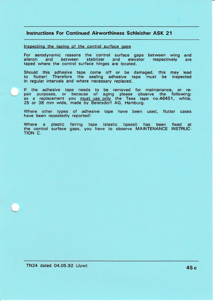
lnspecting the taoino of the conilol surrace gaps
For aerodynamic reasons the control surface gaps between wing and
aileron and between stabilizer and elevator respectively are
taped where the control surface hinges are located.
Should this adhesive tape come off or be damaged, this may lead
to flutter! Therefore the sealing adhesive tape must be inspected
in regular intervals and where necessary replaced.
lf the adhesive tape needs to be removed for maintenance, or re-
pair purposes, or because of aging please observe the following:
as a replacement you must use onlv the Tesa tape no.46451, white,
25 or 38 mm wide, made by Beiersdorf AG, Hamburg.
Where other types of adhesive tape have been used, flutter cases
have been repeatedly reported!
Where a plastic fairing tape (elastic lipseal) has been fixed at
the control surface gaps, you have to observe MAINTENANCE INSTRUC-
TION C,
TN24 dated 04.05.92 (Juw) 45c
lnstructions For Continued Airworthiness Schleicher ASK 21 45d
vilr.1 INSPECTION PROGRAM TO EXTEND SERVICE LIFE
lntroduction
Fatigue tests on GRP/CFRP wings and GRP/CFRP wing
spars have shown that a service life expectancy of at
least 18000 hours may be achieved for these compo-
nents. However, as this test program did not examine an
entire aircraft made of CFRP and GRP, this service life of
18000 hours can be achieved only if the long-term air-
worthiness of each individual glider is demonstrated in a
special multi-stage inspection program (over and above
the mandatory annual C of A inspections).
Time Limits
1st Stage:
When the sailplane has reached a service life of 3000
and 6000 hours respectively, tests must be carried out in
accordance with the lnspection Program for the ASK 21,
lssue 2 dated 28.04.92, as laid down by Messrs. Schlei-
cher.
lf the results of these tests are positive, or if any defects
discovered have been correctly repaired, the service life
of the sailplane will be increased after the 6000 hours-
inspection by 3000 hours, i.e. to a total of 9000 hours.
2nd Stage:
When a service life of 9000 flight hours has been
reached the above lnspection Program must be re-
peated. lf the results are again positive, or any defects
found have been correctly repaired, the service life may
be increased to a totalof 12000 flying hours.
Rev.Nr. / Date SiS.
TN 29 25.07.03 Juw
Author
Kaiser
Date
March 83
lnstructions For Continued Ainrrrorthiness Schleicher ASK 21 45e
3rd Stage:
Before reaching a service life of 12000 flight hours an
inspection in accordance with TN no.29 must be accom-
plished. Depending on the results of this inspection, as
well as on the history of the aircraft and the evidence of
the percentage of aerobatics being below 12.5 o/o as
compared to the totalflight time, Messrs. Schleicher will
decide on a release to service for up to 15000 hours.
The lnspection Program must then again be repeated
and on the condition that the results are again positive, or
any defects found have been correctly repaired, the air-
craft may be approved for increase of service life up to
18000 hours.
It will be decided at a later date whether an extension of
service life beyond 18000 hours may become possible. A
research program which is intended to clear the precon-
ditions of this aim, has already been started with the
BMVBW (Federal Ministry of Transport).
lnspection Proqram
Please contact SCHLEICHER in order to obtain the ln-
spection Program for the ASK 21, lssue 2
dated 28.04.92, or any later issue effective.
The inspections must be carried out only by the manu-
facturer, or by an appropriately licensed aircraft repairer.
The results of the inspections must be entered into the
lnspection Program which is at the same time the report
of findings, where each item must be annotated with a
comprehensive comment, as laid down.
lf the inspections were carried out by a licensed aircraft
repairer, a copy of the filled in lnspection Program (report
of findings) which must be signed by the inspector, must
be returned to SCHLEICHER for the purpose of evalua-
tion.
Rev.Nr. / Date Sig.
TN 29 25.07.03 Juw
Author Date
Kaiser March 83

lnstructions For Continued Airworthiness Schleicher ASK 21 45f
On receipt and examination of such lnspection Program
Report SCHLEICHER will issue an "Acknowledgement of
Receipt" and send this back to the operator of the sail-
plane. Only on receipt of this "Acknowledgement" the in-
spector may certify the extension of the service life as
laid down in the lnspection Program, into the logbook and
the relevant sailplane's inspections papers.
The need for annual Certificate of Ainarorthiness inspec-
tions and overhauls (for German registered gliders $ 27
(1) LuftGerPO applies*' is not affected by this rule.
*) LuftGerPO = Aeronautical Products Examination Order
Rev.Nr. / Date Sig.
TN 29 25.07.03 Juw
Author Date
Kaiser March 83
fnstructlons For Contlnucd Alrvorthlness SCHLEICHER ASK 21 l+6
Special Checks
After rouoh landinos :
Check the landing gear suspension mount at the front
maln bulkhead I
Check the wheel fork for deformation; gear box ll
Check the control shaft above the wheel for deformation!
Make sure that the rubber buffers have not come over
the support discs !
Check spar tongue and fork for whlte areas I
Check the wing connections at the fuseJ.age t
Check the cross tube at the front main bulkhead for com-
presslon deformations I
Determlne wing bending oscillation frequency and compare
the value with that of the last inspection report. In
case of dlfferences by more than 5 % contact the SchLeicher
factory. (See survey drawing on page of the Instruc-
tions For Continued Airworthiness for jack up points).
After oround looos :
Inspect the fuselage tall cone at the transltlon to the
fin and also the attachment of the horizontal tai.l unlt
to the fin !
Check wlng connections at the fuselage t
lnspect horizontal shear web in the fuselage (between
front and rear main bulkhead) t
March 9, i983
Instructlons For Contlnued Airyorthlne8s SCHLEICHER ASK 21 L7
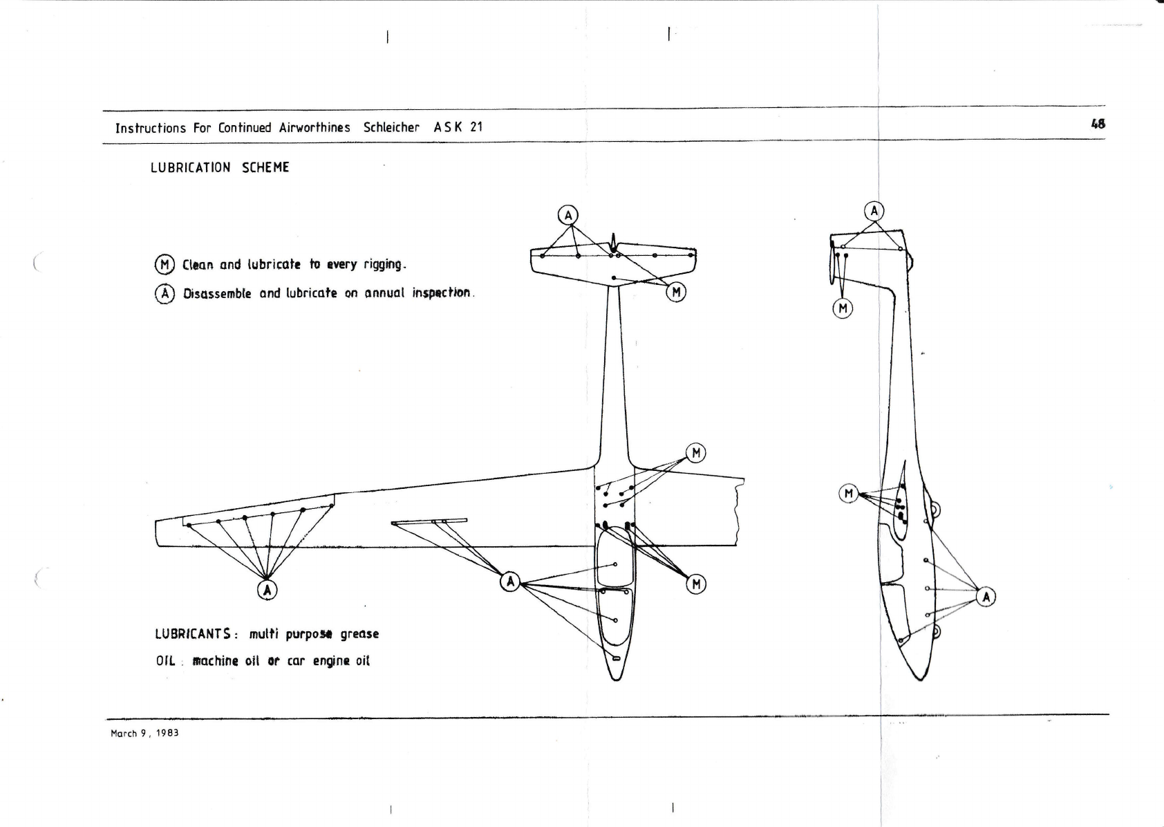
rx. LUBRICA?]ON SCHEME
Bearings : the slotted-sealed ball bearings are fi1led
with a longlasting grease and are capped off. So 1t ls
unnecessary to regrease thls bearing. The 14C6 self-
-aligning bearings in the pushrods and in the duralumi-
num rocker arms are also greased and covered with felt
seals so that they likewise do not need any regreasing
for a long period of time. The same applies to the ball
bearings of the pushrod guides.
The grease nipples at the controlstick and at the land-
ing gear rocker arm should be lubricated at least an-
nua11y.
The grease nipples of the control systems are accesslble
from the top when the seat cushions are removed. The
rear seat has to be removed in order to reach the grease
nipples of the landing gear rocker arm.
?he canopy locks and especially the emergency Jettison-
ing device in the front cockpit have to be kept well lu-
bricated.
Dirty tow releases are cleaned best wlth compressed air,
brush and through movement of the kinematics. ?hen re-
grease them with a spray oll or some slmilar agent.
March 9 . 198:1
Inshuctions For Continued Airrrorthines Schleicher A S K 21
LUBRICATION SCHEME
@ Cnoo and lubrirch lu rrery rigr4"
@ 0irort.mble ond tubricotr on onnuol inpclton.
Instructions For [ontinued Ainrorthiness Schleicher ASK 21 Ug
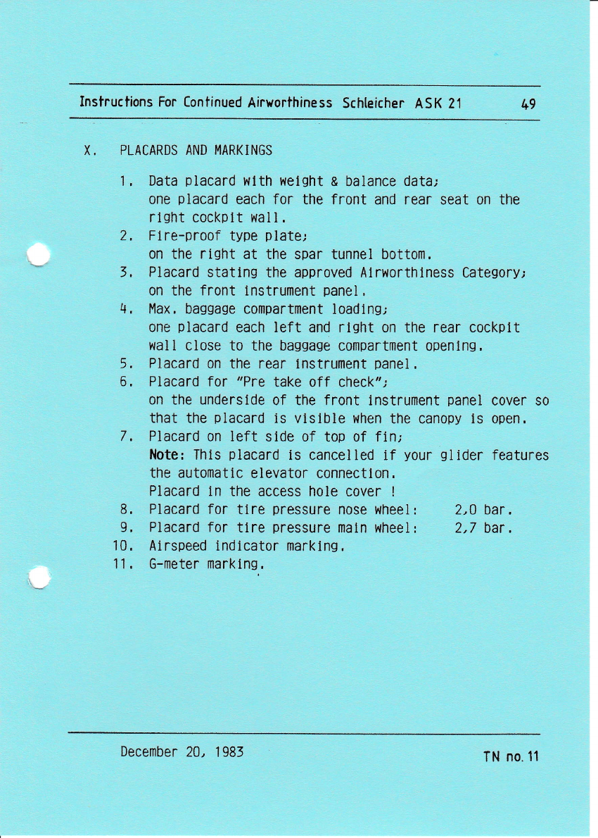
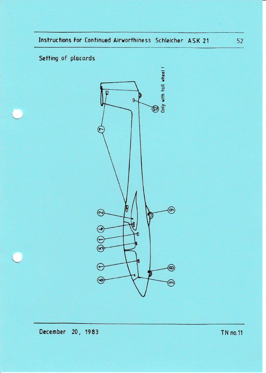
X. PLACARDS AND MARKINGS
1, Data placard wlth welght & balance dataJ
one placard each for the front and rear seat on the
rlght cockplt wall.
2. Flre-proof type plate;
0n the risht at the spar tunnel bottom.
3, Piacard statlng the approved Alrworthlness Categoryr
on the front lnstrument panel ,
4, Max. baggage compartment loadlng;
one placard each left and rlsht on the rear cockplt
wail close t0 the baggage compartment openlng,
5, Placard on the rear lnstrument panel .
6, Placard for "Pre take off check";
0n the underslde of the front lnstrument panel cover so
that the placard is vistble when the canopy ls open.
7. Placard on left side of top of fln;
Note: Thls piacard is cancelled if your giider features
the automatic elevator c0nnectl0n.
Placard ln the access hole cover I
B, Placard for tlre pressure nose wheel: 2,0 bar.
g, Placard for tlre pressure maln wheel; 2,7 bar.
10. Ai rspeed indlcator marklng .
11. G-meter marklng.
December 24, 1983 f N no.1'l
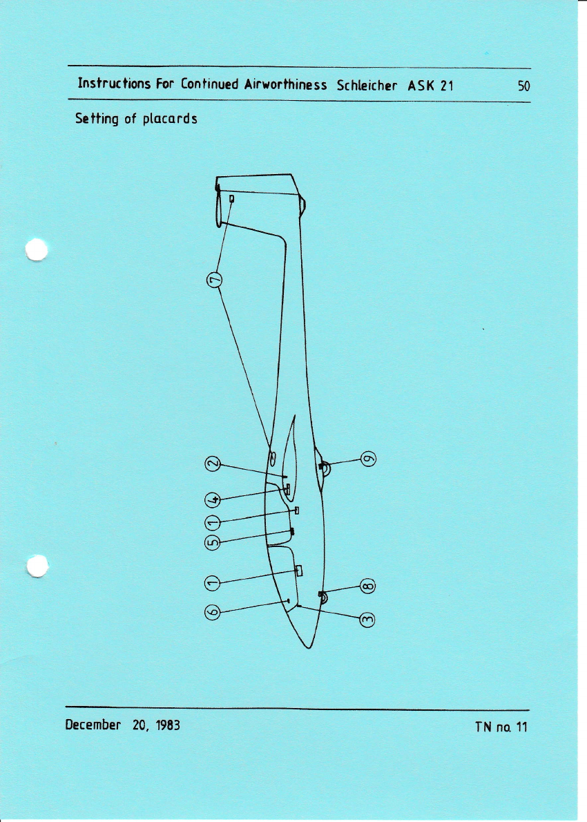
Instructions For [ontinued Airxorthiness Schleicher ASK 21 50
Setting of plocords
0ecember ?0. 1983 TN no 11
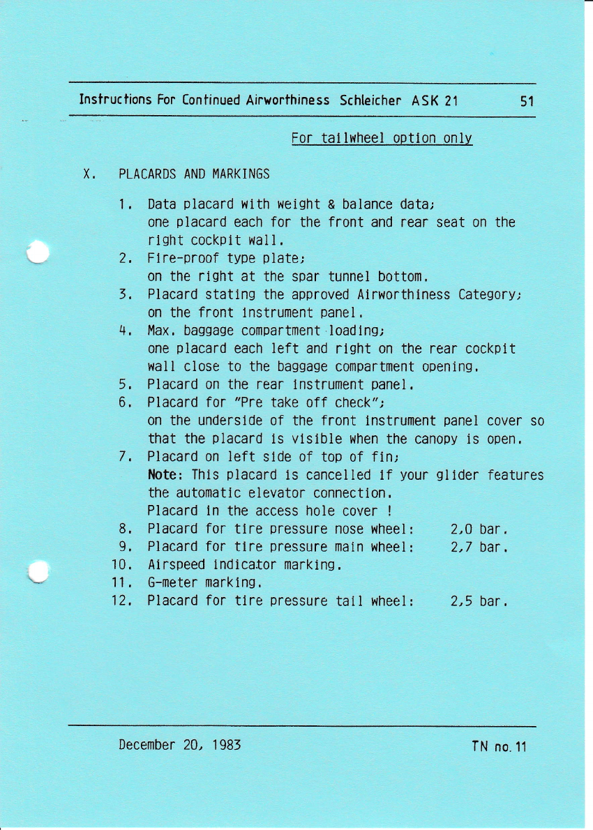
Instructions For Continued Airnorthiness Schleicher ASK Z1 51
For talll.{heel option only
X. PLACARDS AND MARKINGS
1. Data piacard with weight & balance datar
one placard each for the front and rear seat on the
rlght cockplt |,lall.
2, FIre-proof type plate;
0n the right at the spar tunnel bottom,
3, Placard stating the approved Alrworthlness Category;
on the front lnstrument panel.
4, l'lax, baggage compartment loadlngJ
one placard each left and rlsht on the rear cockplt
wall close to the baggage compartment 0pening.
5, Placard on the rear lnstrument panel.
6, Placard for "Pre take off check";
on the underslde of the front lnstrument panel cover so
that the placard ls vlslble when the canopy is open.
7, Placard on left slde of top of fin;
Note: Thls placard 1s cancelled lf your gllder features
the automatlc elevator connectlon,
Placard ln the access hole cover !
8. Placard for tlre pressure nose wheel t 2,0 bar,
9, Placard for tlre pressure main wheel: 2,7 bar,
10. Airspeed lndicator marking.
11 . G-meter marking,
12, Placard for ttre pressure tall wheel: 2,5 bar,
December 20, 1983 TN n0.11
Instructions For [ontinued Airworihiness Schteicher ASK 21 52
Setiing of plocords
December 20, 1983 TN n0.11
Instructkns For Continued Airvorthiness Schteicher ASK 21 53
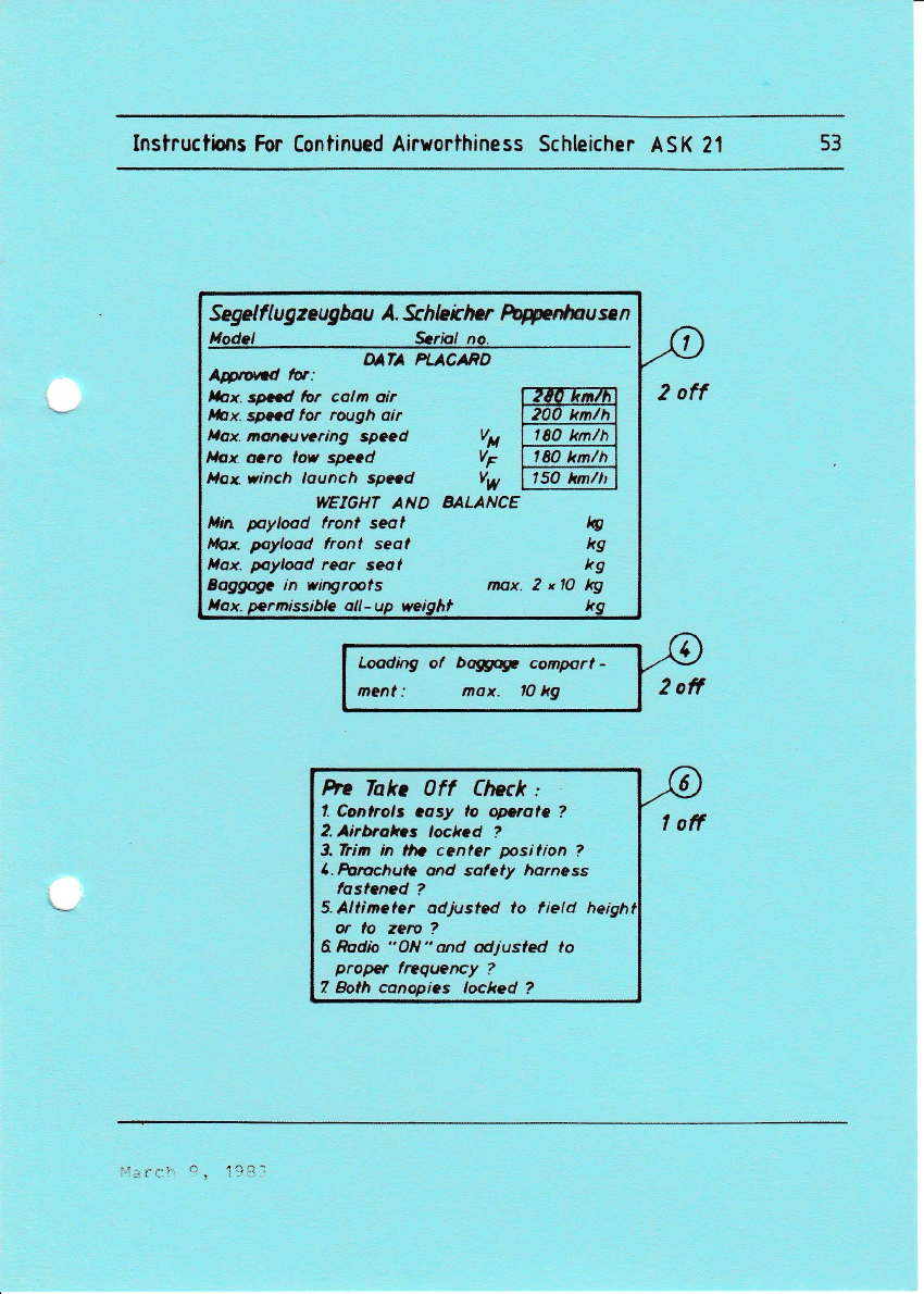
Segelftugzeugbau A. &,hlekhcr @nlr,u so n
Modcl *rp,l no.
DATA PI-ACARA
Aprond fu:
thx. slrtd br colm oir fZttEril-Ft
lihx. spocd lor rough oir | 200 kn/hl
Itax. m@ruvcring spccd Vp Lte0 tl4la)
tlox ocro lou specd i; f lso ir/i1
l,loxvinch lounch sp*d iw 17fi kz7A
WEIaHT AND BALANCE
l,lin pyload lronl seat LC
Mox. poyload front seal kg
llax. pylood reor seot kg
Boggoge in vitryrots mox. 2 xlo kg
he Takc ?ff (lteck '
1. Cootrals cosy to qarotc ?
2. Airbokcs tocked ?
3.him h llto cenler psilion ?
l.furochutc orrd sdfety harness
fostaned ?
5.Altimeter odjusted to field heigh
or to zero ?
6Rodio "ON"ond odjusted to
proper lrequency ?
7 Eoth canopics locked ?
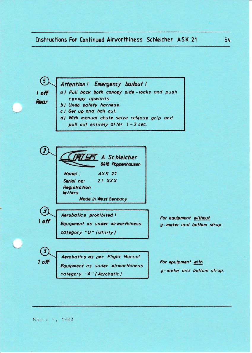
Instructions For Continued Airuorthiness Schleicher ASK 21 54
Attentian ! Energency fuitout !
o] Pull back both canopy sidr-/oclts and push
canopy upwords.
bl Undo sofety horncss.
c ) 6ot up and bail oul.
d) Wilh manuol chulc seize releose grip and
pull out enlirely al ter | -3 sec.
A. Sc hleicher
6af Mnhqrsrn
Hodel : ASK 2,
Srnal no.' 21 XXX
nagisttotion
,lode in llrbst Gcrnany
For equipmcnt witlwut
g-mctcr ond bottom strap.
For quipment with
g-ileler ond battom strop.
Instructbns For Continued Airuorthiness Schleicher ASK 21 55
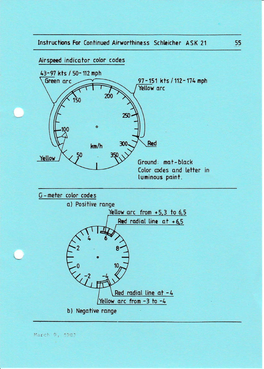
Airspeed indicqtor cotor codes
43-9? kts / 50- 112 nph
6reen orc 97 - 151 kts / 112- 174 mph
Yellow arc
6round, mat-btack
Color odes and tetter in
tuminous point.
0 -meter cotor codes
o) Positive range
Yelton orc frcm +
2
o
0
b) Negative range

Instructions For Continued Airuorthiness Schteicher ASK 21 56
!, i!*i
Instructions For Contlnucd Allorthlness SCHLEICHER ASK 21 57
XT. REPATRS
On principle repairs must only be
turer or by a certified (licensed)
facility.
For exceptions see repair manual.
tact the manufacturer !
xIr.
made by the manufac-
technical aviation
In case of doubt con-
z- 1\
MODIFICATTONS
Minor modification
A modification to the aircraft which has no influence
on its airworthiness and is feasable by using standard
working methods, may be done without prior notification
to the Civil Aviation Authority,if it is done in accor-
' ri $tu,e'tivil Aviation
dance with a technical note !ssued.rp
Authority. -L...1,.' I
: --",
r
Ma i or modi f ication :f'
A modification to the aircra{t--whi'ch-has .l-, inflr.n..
on 1ts airworthiness or requires a change of the opera-
tion instructions or of the operation limitations or is
not feasable by using standard working methods, must on-
1y be done by a certified (licensed) technical aviation
facility. The major modification must only be done in
accordance with technical documentations which were sub-
ject of a supplementary type-approval under the test re-
gulations for aircraft.
A supplementary type-approval is not necessary, if the
major modification is restricted to only some single
units. Prior to the carrying out of the major modification
the proof of the airworthiness must be furnished in ac-
cordance with the test regulations for aircraft.
March 9, L983

InstructLons For Contlnued Alrlrorthlnegs SCHLEICHER ASK 21 58
XIII. DESCRIPTION OF SYMBOLIC PLACARDS
c 0 \* Rudder pedals adjustment: grey
knob on RH slde of the console.
To adJust pedals backwards:
Take your feet off the pedals and pull pedals backwards;
then let go the grey knob and load the pedals in order
to lock them.
To adjust pedals forwards:
Pu1l grey knob and push pedals forwards with your heels;
then let go the grey knob and load the pedals in order
to lock them. Airbrakes! blue lever in the LH
arm rest; pu1l to extend airbrakes.
Trim: noseheavy.
Trim: tailheavy.
Tow release: ye1Iow knob LH below
canopy frame.
OPEN froat canopy;
Hove rbite levers LH and R[ on
canopy frane backxards.
EMERGENCY JETTISONING of front cedopy!
Pusb lever rith red fLat knob to the left
G
:
L:a\
t{ay 29,1984 ?N no. 15

Inatructions For Contlnucd Alrworthiness SCHLEICHER ASK 21 59
OPEN rear catropy
JATTISONING:
Hove rcd lcvsrs
fraoe backrards.
Ventllatlon
anVor EMERGENCY
tH and RE oa caaopy
Prior lo loke off check the
proper engogemenl of the
locks! torvord:{ocked
this placard must be fitteC in
the front and rear cockpit in
fulL view of the pil-ot.
May 25''t984 EN no.15

Instructions For [ontinued Airworthiness Schteicher ASK 21 60
XIV IPPEI]DTX
XIV.1 Equipnent Liat
llinlouq couioacut
1. Alrapcod indicetor
r. Ylatcr cv 6005 50 - ,5o kl^
b. tuL Ps oE p - )Ja k;a/h
2. Altirtrr
r. Iltrt* 4 EX 6
b. Yiatcr { FGE 10
cr WL U-12 S
,. Sefoty hunctr
Gadrtagcr Bagu v-Br/1
Schusu IJ-C/V
Bonr I-B./V front
Bogu I-A./V rear
Additional ainiaun cqulpuaat for aerobatlca :
G-actcr BA ??A L
Addltional EiriEu! rquipocnt for cloud flyiE8 :
tura & bank lndicator Apparatebau Sauting YZ*4O2/
,1.
Colpaaa : LudolPh 9K 5
- Luitol3b Pf 15
w, Bs-1
?7,L *1r/KJ
VIIP- t rauac circ r
r. Dlttrl $e 1r/25
b. Dittrl ?so 16/2,
c. Dtttcl fSG 40 S
d. Brcl,cr ^R 2@8/25
.. Bcel,qr AR eOO9./e5
f. lviosic Dittrl AIR 72O
Tt{-No.20 dated october 16, 198?
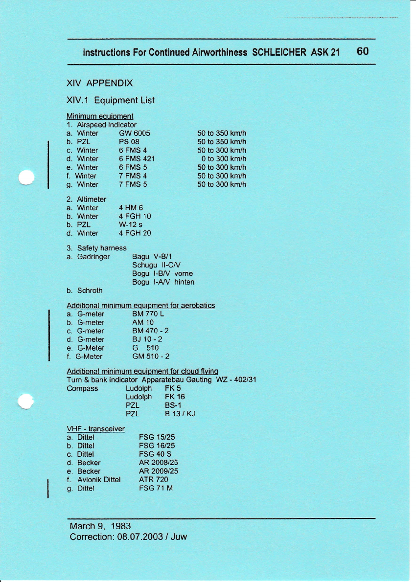
lnstructions For Gontinued Airworthiness SCHLEICHER ASK 21 60
XIV APPENDIX
XlV.l Equipment List
Minimum eouipment
1. Airspeed indicator
a. Winter GW 6005 50 to 350 km/h
50 to 350 km/tr
50 to 300 km/h
0 to 300 kmlh
50 to 300 kmlh
50 to 300 km/h
50 to 300 km/h
b. PZL PS 08
c. winter 6 FMS 4
d. Winter 6 FMS 421
e. Winter 6 FMS 5
f. Winter 7 FMS 4
g. Winter 7 FMS 5
2. Altimeter
a. Winter 4 HM 6
b. Winter 4 FGH 10
b. PZL W-12 s
d. Winter 4 FGH 20
3. Safety harness
a. Gadringer Bagu V-B/1
Schugu ll-CA/
Bogu l-Blr' vome
Bogu l-Aly' hinten
b. Schroth
b. G-meter
c. G-meter
d. G-meter
e. G-Meter
f, G-Meter
BM 770 L
AM 1O
BM470-2
BJ 10 - 2
G 510
GM510-2
Additional minimum equioment tor cloud flvinq
Turn & bank indicator Apparatebau Gauting WZ - 44431
Compass Ludolph FK 5
Ludolph FK 16
PZL BS.1
PZL B131KJ
VHF - transceiver
a. Dittel FSG 15/25
b. Dittel FSG 16/25
c. Dittel FSG 40 S
d. Becker AR 2008/25
e. Becker AR 2009/25
f. Avionik Dittel ATR 720
g. Dittel FSG 71 M
March 9, 1983
Correction: 08.07.2003 / Juw
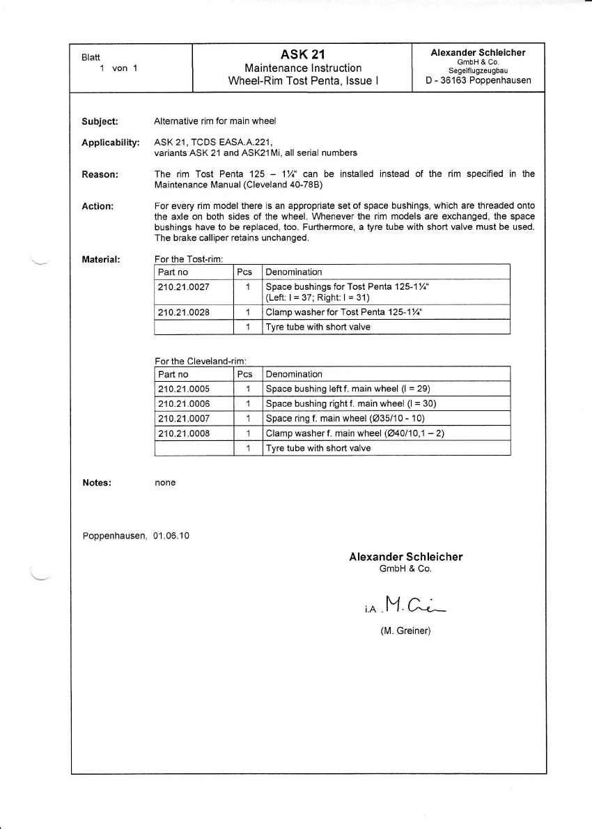
Blatt1 vonl ASK 21
Maintenance lnstruction
Wheel-Rim Tost Penta, lssue I
Alexander Schleicher
GmbH & Co.
Segelflugzeugbau
D - 36163 Poppenhausen
Subject Alternative rim for main wheel
Applicability: ASK 21, TCDS EASA.A.221,
variants ASK 21 and ASK21Mi, all serial numbers
Reason: The rim Tost Penta 125 - 1/i' can be installed instead of the rim specified in the
Maintenance Manual (Cleveland 40-788)
Action: For every rim model there is an appropriate set ot space bushings, which are threaded onto
the axle on both sides of the wheel. Vvhenever the rim models are exchanged, the space
bushings have to be replaced, too. Furthermore, a tyre tube with short valve must be used.
The brake calliper retains unchanged.
Material: For the Tost-rim:
Part no Pcs Denomination
210.21.0027 Space bushings for Tost Penta 12S1%'
(Left: I = 37; Right: I = 31)
210.21.0028 Clamp washerfor Tost Penta 125-17;'
Tyre tube with short valve
Part no Pcs Denomination
210.21.OOO5 Space bushing leftf. main wheel (l = 29)
210.21.0006 Space bushing right f. main wheel (l = 30)
210.21.0007 1Space ring f. main wheel (u35110 - 10)
210.21.0008 Clamp washer f. main wheel (O40110,1 - 2)
ITyre tube with short valve
Notes: none
Poppenhausen, 01.06.10
Alexander Schleicher
GmbH & Co.
i.A M-e;
(M. Greiner)
DOEIil{Srf IEA
No l 10.01
Rev:B EO8.A
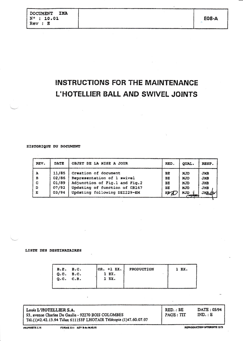
.NSTRUGTIONS FOR THE MAINTENAI\ICE
L'HOTSLLIEH BALL AND ST,\TIVEL JOINTS
EI5:BORISI'S DU DOAN@|!!
LtsEE DES D8stltrt8f,rtts
IruisL'HOTEI,LEBS.A.
93, acorre Chirles De Csullc.- 94170 BOIS COLOMBES
Tdl.(1X2.42. 13.94 T6hx. 61 r l53F IJIOTAIR TeEcopic (t)47.60'0?.0?
nEv. oI"E OE.}E? DB $e $ISE A JOUR. EED. aElx.. 8EAP.
B
B
c
D
E
11/85
02le6
01189
o? 192
0.3194
cteatl-otr of dorunerrt
Bspreacntatl.oa of 1 .rrivsl
Adruactioa of Rtg.l illd E.lE.2
IrpdattGg of functlon of c8147
UldrtitrE follor.irg DEI229-EH
BE
BE
BE
8E
8w
lLrD
l{.tD
t{Jb
llrD
XJD d
JI{B
JI'B
ru8
Jr,t8 r
ne#.
B.E. B.C
0.a. r.c
Q.C. C.B
0R. +1 EX.
1 BX.
1 Ef,.
TRODUGIlOt{ 1 EI(.
mtfGftL'B fouaElh tElrl*r.iltr

DOCU}{EHT THA
lils : 1O. 01 nrsrBggtrrgr{s ron r8E uellmB|escE
LrBOlggttJIEB BilLrr eI[D Sf$IEIJ ifo$fllt EO8-A
cs{PoExlror uo EoemaEuE
PACE rND. Ptct IIID. FA@ INB,. PICE I}ID. ?tcr r$D,
tIa Esox E1E2E
sUHirrI!
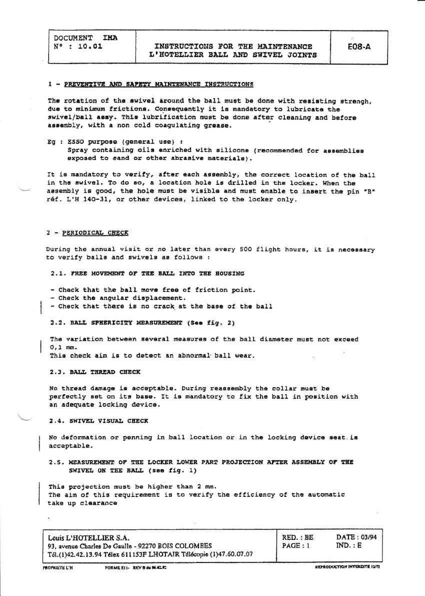
1 - FrEIEtf,!fiE xf,D 6A!ig!r r{A$*IEEAI|CE frSAf,lrellONs
2 - BE*IODICET CTa1EX
:.T. FREE I'OIIEilEN:8 OT EEE EAiiL U*AO lrBE AOUBIilC
2,3. Elr.& SPIEBICXTf r'lEaSUBElsN:t {S.G fig. 2}
2.3. BII.&'IEERETD gEECf,
2.{. afitVllt q[SIritr CEEqf,
2.5" r{Eif,s[ilrl.ErlI Or 18! tacrES IollEB ?eEt Pro.rEq[rEf, lf,uEE
IFsEtI8ar oF Exr'S{IVEL oll El8 EHtiL (si. fig. l}
2.5. 6 T TE I,Iffi BEII{EEI DEJTVE RO' IITD 8TTl'EE.
2.?. $|r!rg, a58I .OPEneEIOtt CEECX
RED. ;8E DAJE I (BlS4
PAGETSOM MD.:E
IrubUEOTELLIERE A.
93, evaruc ehedes Ds Grullc ' 92!7O BOIS COLOMBES
T6t.f lN2.4l. 13.94 Tdler 6Il l53F IJIOTAIE: fd&opic{l}4''69'07'$?
ffigL lffl*.*Gl,
DOCTI!{E}I!' IUil
l{e ! 10. 01 rlr8rBuclroHs roB lEE uBIUTErrnNcE I E08-A
LtEOTEIif,fER BA!Ir BHD AWMII ifOfNEA. I
t-
tha rotrtio[ 6f thr trr'lvel iaoEad the ba!,l firat tre iiaap r*lth rs!i..tl,ng sticngh,
. dqc to 6l,Br-6u!n !ric!ton8, Co,rrcqucnlly lt l. ltrartdetory t6 lubricits the
'reLv.l/brll rE y. Thls lulttficatloa ioust bE alon€ rftBr cleaaing a,ad bef,or€
.r..Ebly, wLth a non col.d catgulating Ercrsa.
8E ! ESSO purto.e {general u6e} t
Spfly containing ollt ctraiched ]rlth Elllcon. (recomEndsd for Bs6€mb1l.si
exlto*ed to.smd ar 6gher abreslv. Eaterlals,.
ft lE mandrtory to eellfy, .ftBr eg6h ert€nblyr th€ correct locrEion of, thc.bal.l,
in the errlvel. lo do Eo, a locetlon hole l,r drilled Ln the lockca. t{hTn tbB
'-' a€Eeilbtry l,s good, th6 hole fturt bG visible e,ld rnuBt a[eble to lnsaat tha pi.r -Er
r€f, &'E 140-31, or othEr d.vl-ceE, llnhed to the. locher only.
2 - PERIODICTL CEECE
Durlng the anDual visit oJ' $g later than every 50O Slight hauss. it ir $e€6.rsery
to verJ,fy balla aad gl,iqrls as followa. !
2.1, reEr Mo r.E&! or GEs BlI.Ii r*to rEE roustlte
- Clreck that th€ bal}, ursvr f,6€ 6! frletlon lFlnt.
- Check th€ alr€uler d:lr]1.c@n!.
- Check that tlrare lg no crack" at tlre bage €f, tbc b81l
2.2. BBIIL s?EEfi,lstlt HET!IaBEI{3!U! (s.. fig. ,}
Th€ varlrt-i.on betw6a)l eeveral nr.e€u?e. of the ball dl,an€etr rrtlEt not €xeeed
0,1 m.
tblE check aLE iB to detaet en alrnordsl'ball rycer.
2.3. BM.I, EBABD CEECX
Eo th!6td darurE6 l"e acceptablc. Dt ritrg rer66embl,y ehE EEllar lruat b€
.FGrfEctly !6t on itc baEe. It la eand.toly to trtx thc ball ln p6siti('n wltb
an rdeqlratE loclLng devl,c€.
2.4. SWrEEr. Vlflrl,r eEECS
N6 defornatlon or pennlag fn ball location or l,a the loc,riag doyico scat,ir
acceptable.
2.5. lrEtstR8$Em or rE rocxEe. Lol{EB ERtu[ t8otEcrlots er:ssf, agsElilBLt or lEl
A$MI. Ol( tE Eer& (sE! .tiE. 1)
thi. proj€ctlon Eust be hiqher tban 2 fttr.
the aj.tt ot thlE requirrment is to v€rlfy tbe efflciercy of the eutonrstic
takB uI, claara$ce
Louis L'IIOTELLIER. S.A,
93, avenueClrartesDo Gaulh -92?70 BOIS COLOMBES
Tgl-(1112-"12. 13.94 T€le* 6l I 153F LIIOf,AIR Tdldeopic (Ila?.60.07.e7
RED. : BE
.FAGE r IDAIE r 0X/9,4
IHD. r E
fiorurErr muEEr! tflrf5g *tnoblE $r{,{fii:BnE rrB
BOCIIHET{tr TIIJI
No:10.01 IIIST'RUCTTO}Tq I,OB TNE UAISAE}IANCE
[reor8r,LrER Bn!I, ]fiD SUXVEI) irort{ts8 EO8.A
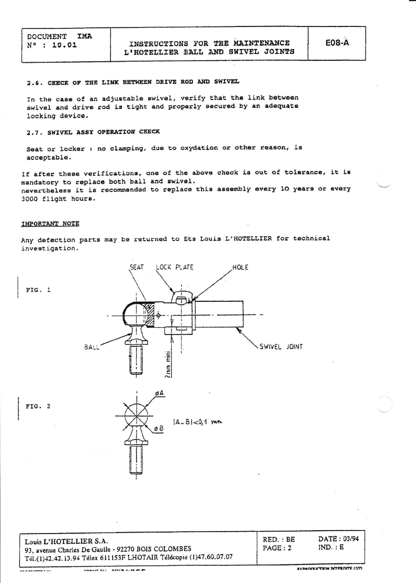
2..6. eEcE oF EEE lIilE aEElEEr DBIVE aoD aND SrvIgEEr
In the ca6. o! aI} .dlr3tabls. swlval, r€rLfy th.t tlte }ink betweatr
B(ivsf and drlve, rod is ttght and Droperly Eecurid by 8a r'lequ4te
lecking dalIj.ee"
2.?, SffiVEr. ASav OFBEffrrOr CEE(X
seat or IsskBr : no clan?log, diro to oxlidatiot sr otier reaton, i.E
aeerptsble.
If aft6f the6e ve?ifis6tion3. ,one of the sboYs ahtsek i.{ oue of tolstanEG? it Ir
nrrldatory to r€plac6 both ball and suj:vsl'
ne+erlhelsss it ig. r6saosl6'nded Co t€9lace thlg 8ss€dlbllr every 10 yeara or av6ry
3OO0 fligbt hoqrs.
IMPORTf,ItrI X TE
Any dsfection paru5 may be returned to Ets I.eult l'tfOIELLfER for letdmical
inve€tigat.ion.
rrc.1
FTG. 2
H-Bl<q{ ttr'
Louis L'HOTETLIER S'4.
93, avenue Ctadss Do Gaslle ' 9A?O BOIS COLOMBES
Tdl.( I )42.42. I 3. 94 T'ilex 6 I I l53F LHOTAIR Tdl€coPie ( l)47.60.07'07
RED.: BE
PAGE: 2
DATE:05/94
IND.: E
rffiffiltmffi14

Sheet:
lofl All FRP glider models
Maintenance Instruction
dated 19.06.86
Alexonder Schleicher
Segelflugzeugbau
6116 Poppenhousen
?.
Removing play betvjeen the sockets and bolts of the wing-fuselage
transl!ron
Longitudinal play between the four sockets in the wings and
the bolts on the fuselage (Note: for the ASK 21, only the
socket/bolt connection front in the wing nose/fuselage tran-
sition) leads to disturbing cl ick-c1 ick noises when the rud-
der is operated, and can result in unpleasant tail oscilla-
tions at high speeds.
The play is eliminated by fitting metal washers of 422,5/32-
thickness according to the extent of the play. By testing,
the play must be reduced such that the wings can be assembled
still properly - this applies to a normal temperature of 20 oC.
Depending on ihe extent of the ptay, the metal t{ashers can be
fitted under one or more bolts.
The bolts are slid out of the fuselage cross tubes by fitting
a steel rod through the hole in the opposite bolt, and driving
the bolt out from the inside t'lith a hammer (see sketch below).
After fitting the metal washer(s), it should be possible to
drive the bolt back in place, using only a 500 s ( - 1 lb) ham-
mer and a few blows. If it returns too easily, then knurl the
seating area slightly untii a tight fit is obtained again.
Poppenhausen, June 1 9, 1 986
3.
4.
ALEXANDER SCHLEICHER
GmbH & Co.
Ax;(,.
€ St.ihflil.. Ftud Sofriwdruck" 09 6rAt ,3

Sheet 1 of4 Maintenance lnstruction
PAINT CRACKS
Alexander Schleicher
GmbH & Co.
Segeflugzeugbau
D-36163 Poppenhausen
Subiect:
Tvpes affected:
Comoliance: 1.
Reason:
2.
Paint cracks on fiber composite gliders.
ASW 12, ASW 15, ASW 17, ASW .I9, ASW 20, ASK 21, ASW 22
ASK 23, ASW 24, ASH 25: ALL variants and all serial no.s.
lf deep cracks which go down to the fiber composite structure, are
found on the glider, the glider must be presented each year to the
manufacturer or any other licensed aviation station, who upon ex-
amination of the glider decides whether the glider can be contin-
ued in service fol| year more or whether the repair must be done
at once (see point'Ac'tion A.").
lf hairline cracks which run only in the paint surface, are found on
the glider, the glider shall be presented at the latest after three
years annually to the manufacturer or any other licensed aviation
station, who upon examination of the glider decides whether the
glider can be continued in service for 1 year more or whether the
repair must be done at once (see point'Ac{ion B."). The 3 years
extension applies only on the condition that the maintenance and
care of the aircraft is no longer neglected during this period of
time and that the gliders are no longer stored outside;
The Flight and Maintenance Manuals for SCHLEICHER-gliders con-
tain insistent notes concerning the detrimental influence of moisture
and sun radiation on the aerodynamic paint surface quality standard.
Herewith we point out emphaticallv once aqain that every owner is
obliged to observe the flight and maintenance or operations manuals
of his glider in all points, and this refers also to the relevant notes on
the care and maintenance of the glider.
lf these notes are contravened, the result will be sooner or later - de-
pending on the climate - damage to the paint surface quality.
lnfluence of the two factors
p!g!6 and UV-radiation:
To begin with, generally an enlargement of the waviness of the finish
develops - mainly on the wing and tail unit skins - caused by penetra-
tion of moisture. On the occasion of performance measurements (ac-
complished by P.Bickle, R.Johnson and the German DFVLR/ldaflieg)
it has been demonstrated repeatedly that the larger waviness leads
already to considerable performance loss which is all distinctly no-
ticed in competitions.
Sheet: 2 of4 Maintenance lnstruction
PAINT CRACKS
Alexander Schleicher
GmbH & Co.
Segelflugzeugbau
D-36163 Popoenhausen
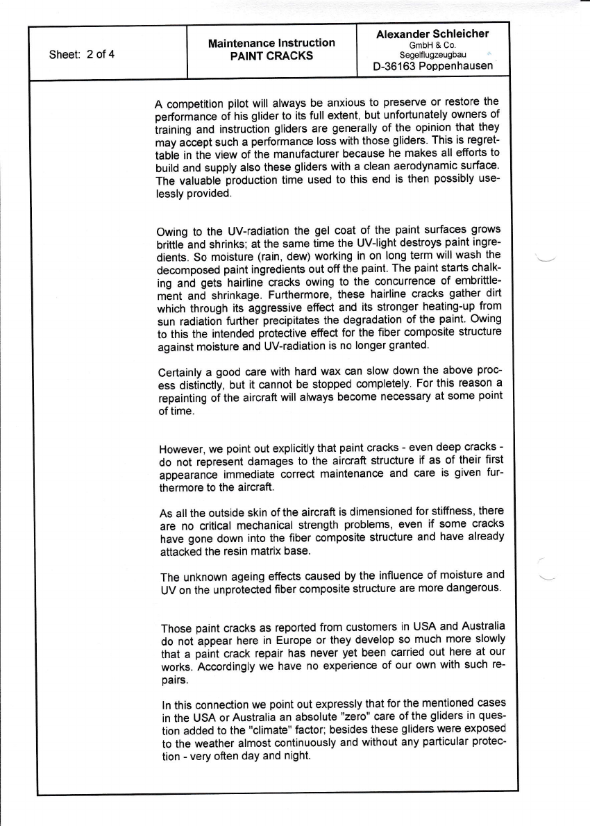
A competition pilot will always be anxious to preserve or restore the
performance of his glider to its full extent, but unfortunately owners of
iraining and instruction gliders are generally of the opinion that they
may accept such a performance loss with those gliders. This is regret-
tabie in the view of the manufacturer because he makes all efforts to
build and supply also these gliders with a clean aerodynamic surface.
The valuable production time used to this end is then possibly use-
lessly provided.
Owing to the UV-radiation the gel coat of the paint surfac,es grows
brittle and shrinks; at the same time the UV-light destroys paint ingre-
dients. So moisture (rain, dew) working in on long term wlll wash the
decomposed paint ingredients out off the paint. The paint starts chalk-
ing and gets hairline cracks owing to the concurrence of embrittle-
m6nt and shrinkage. Furthermore, these hairline cracks gather dirt
which through its aggressive effect and its stronger heating-up from
sun radiation further precipitates the degradation of the paint. Owing
to this the intended protective effect for the fiber composite structure
against moisture and UV-radiation is no longer granted.
Certainly a good care with hard wax can slow down the above proc-
ess distinclly, but it cannot be stopped completely. For this reason a
repainting of the aircraft will always become necessary at some point
of time.
However, we point out explicitly that paint cracks - even deep cracks -
do not represent damages to the aircraft structure if as of their first
appearance immediate correcl maintenance and care is given fur-
thermore to the aircraft.
As all the outside skin of the aircraft is dimensioned for stiffness, there
are no critical mechanical strength problems, even if some cracks
have gone down into the fiber composite structure and have already
attacked the resin matrix base.
The unknown ageing effects caused by the influence of moisture and
UV on the unprotected fiber composite structure are more dangerous.
Those paint cracks as reported from customers in USA and Australia
do not appear here in Europe or they develop so much more slowly
that a paint crack repair has never yet been carried out here at our
works. Accordingly we have no experience of our own with such re-
pairs.
ln this connection we point out expressly that for the mentioned cases
in the USA or Australia an absolute "zero" care of the gliders in ques-
tion added to the "climate" factor; besides these gliders were exposed
to the weather almost continuously and without any particular protec-
tion - very often day and night.
Sheet:3of4 Maintenance I nstruction
PAINT CRACKS
Alexander Schleieher
GmbH & Co.
Segalflugzeugbau
D-36163 Poppenhausen
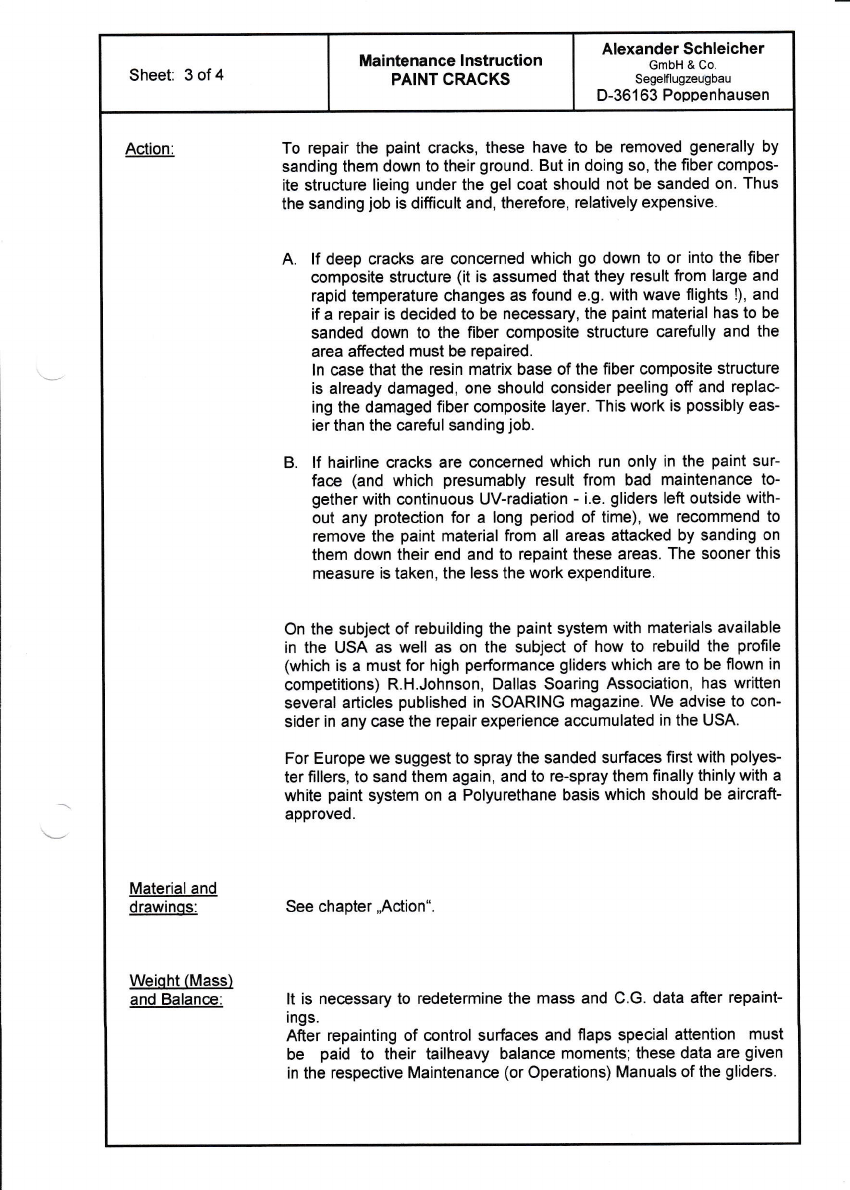
Action:
Material and
drawinqs:
Weiqht (Mass)
and Balance:
A.
To repair the paint cracks, these have to be removed generally by
sanding them down to their ground. But in doing so, the fiber compos-
ite struciure lieing under the gel coat should not be sanded on. Thus
the sanding job is difficult and, therefore, relatively expensive.
lf deep cracks are concerned which go down to or into the fiber
composite structure (it is assumed that they result from large and
rapid temperature changes as found e.g. with wave flights !), and
if a repair is decided to be necessary, the paint material has to be
sanded down to the fiber composite struclure carefully and the
area affecled must be repaired.
ln case that the resin matrix base of the fiber composite structure
is already damaged, one should consider peeling off and replac-
ing the damaged fiber composite layer. This work is possibly eas-
ier than the careful sanding job.
lf hairline cracks are con@rned which run only in the paint sur-
face (and which presumably result from bad maintenance to-
gether with continuous UV-radiation - i.e. gliders left outside with-
out any protection for a long period of time), we recommend to
remove the paint material from all areas aftacked by sanding on
them down their end and to repaint these areas. The sooner this
measure is taken, the less the work expenditure.
On the subject of rebuilding the paint system with materials available
in the USA as well as on the subject of how to rebuild the profile
(which is a must for high performance gliders which are to be flown in
competitions) R.H.Johnson, Dallas Soaring Association, has written
several articles published in SOARING magazine. We advise to con-
sider in any case the repair experience accumulated in the USA.
For Europewe suggestto spraythe sanded surfaces firstwith polyes-
ter fillers, to sand them again, and to re-spray them finally thinly with a
white paint system on a Polyurethane basis which should be aircraft-
approved.
See chapter,Action".
It is necessary to redetermine the mass and C.G. data after repaint-
ings,
After repainting of control surfaces and flaps special aftention must
be paid to their tailheavy balance moments; these data are given
in the respective Maintenance (or Operations) Manuals of the gliders.
Sheet: 4 of4 Maintenance lnstruction
PAINT CRACKS
Alexander Schleicher
GmbH & Co.
Segelflugzeugbau
D-36163 Poppenhausen
lf in the case of older glider models such data are not contained in the
manuals, then the mass of the control surfaces and their tailheavy
static balance moment must be determined gi@.lh@t_i9b, and
must be readjusted after the repainting by *,5 o/o.
Notes: 1. The action as per this Maintenance lnstruc'tion must only by ac-
complished by the manufacturer or by a technical aviation ser-
vice station holding an appropriate license.
The present Maintenance Instruction PAINT CRACKS dated
June26, 1989, supersedes the previous Maintenance Instruction
dated 15.07.87.
2.
Poppenhausen, June 26, 1989
Alexander Schleicher
GmbH & Co.
Gerhard Waibel
The translation into English has been done by best knowledge and judgement; in any case
of doubt the German original is controlling.
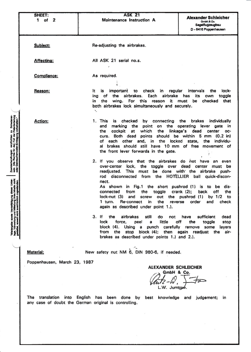
Malrltananca ln3tflrcllDn AAlcrtandcrSchlolchcr
oh$a.&e.
s{ffi{Ed{bru
D -elt6Pq.nharlen
3ubfuct:
Alledro:
Comoliaaca:
Faasonl
R.-adiusting the Eirbrakos.
All ASK 21 serial no,s.
As required.
tt is impo*ani to chsck in regular intervals the look-
ing of dre alrbrakas. Each alrbrake has its own toggte
in th6 wing. For thir rBEon lt must b€ ch6c*sd that
both airbrak:s lock simultansously and secrurely.
1, This is chdcksd by connocthrg ths brakes individually
and rmr&ing tte point on th6 operdhg lever gae in
*re cockpit 6t which the linkage's daad e€nter oe,
curs. Bofi dead Boints should be within 5 rm {O.2 in}
of each other ard, in the loeked stgts, the individu-
al braks sholltl still heve 10 mm .ot frea movernent of
*re lront lever loralards h the gate. ;
2. lf you obsgrve &st the alrbrakes do irot havs an oven
trver-66nter .loclg tha toggle ovcr dead center must b6
reddiusted, This must !e done wth' the alrbake push-
rod disconneGed from t'le HOTtLllER ball qulckdiscon-
rECL
As shown in Fig.t ths shon pushrod (ll lr o ba dis-
connactsd fmm fte toggle crank (2h back off the
lock-nst (3l and scr€w out tha pushrod lll by 1/2 to
1 tum. Re-connect in the revBrse order and check
eguin as desqibsd ufidrr pdint 1,1.
g. lf tlre air&rrkos edll do not h*re srtficient dead
lock force, peel a little srt rtro toggl€ stop
block {4}. u$ng I purrfi carefully rsrnow sdne laysrs
,rorn tfie s$f hlock {4r; then sgain rssdiust the air-
bnkes as descdbed under polnts 1.1 and 2.),
,'-
N€rr, safily nut NM E, DIN 980€, if n€€ded.
Ac{ion:
Matcrial:
Poppenhausen, Marctr 23. 1987 ALEXANDER SCHIEICHEH
,., Gmbll & 9o,
w-#,\#
LW. Jurqg#.
Ths tranrlation into English has been done by best knowledge and judgernent; in
any case of doubt the German orighal is conrolling.
Makrtenance lnstltrction A AlelrnderSchbichsr
Gillt.lrOc
S.gde{EaEE6t
O - 8416 Popp6$atEsr
Fig.1
!
I
I
I
I
r-;+
-.1- .l
il
.€ EXrENst0N
\ HI6HT
t4i
1
-!E
9i:
gE€
-E t
iEt
irE
c'5 I
!iE
{!€
3..
t:3
!9!
i€i
r; i
EE 9
EEi
lii
c5P
eEr
.3i3
FE=
sg-c
SEEET:
1of1 tsf, 21
ilaiDteDance lD6tructiotr B
Issue I
Abrrndrr Schhichcr
GmbH E Co.
S€g.lflugz.ugbu
D-6itl6 Poppenhausen
Subisct:
lf,fectirc-:
lctio:
InstallatioE of oversize elrag Dins
All serial no.s ASK 21.
1- Derig the gliiler,
2. To be abLe to safely reaD the nen holes the safety
clips bave to be renoved at the root ribs
3. Then rig the glider ae usual atd supDort the flings by
use of ring stanils or equivalent (sar horses, trailer
dollies) such that the drag pins can be easily re-
noeed ard inserteil.
4. Tale one ilrag pin out, reaD the oversize bole antl
insert oer ilrag Din.
5. Do the sare on the otber siile.
5. D€rig the glider.
7. Eix the safety clips again at the ner drag pins.
fote: ?he folloriBg piD ilianeters are available:
11.95 ru, 12.0 En. 12.1 Dn, !2.2 nD aud 12,3
Poppenhausen, .ruly 4, 1990
}I,ET.ETIDER SCHLBICEER
GDbH E Co.
A-a-*dA;/,e
doerharil lfaibel-
The traDslation into EngliEh bas been done by best hDoflledge and judgenent; in
atry case of doubt the Gersan original i3 controlling.

lnrl:
l of 6Aa[ul
fitah$nilcr lnstructlon C
lsruc I
ALrrnd.r8chhicfi.r
ffixaod
s.edfFughr
D.G.i6FolD.nh$rt
&rbhEt:
Affect&ro:
Rexonl
Acdon:
Fig.l
Fixlng tur th6 first tim6 or r.plecir|g th€ daedc teirlng
top6 {elagtlc lips6al} at the control gurface geps of aiLur,
.nd horizontal and vortcrl tail.
All ASK 21, Datr Sheet no. L-339, as of scrial no"2I0O1,
optional.
Perlormanca measurements with various gtid€r8 havo Ehown thtt
dtrg cen bs crnsidorably r6&!cod by a continuous fansidon
bstwesi wing ard ell€rofi and b€tweon st blllzor and elevator
respeaively,
This continuous tromition ie achieved by m6ans ot an alasdc
[pseal whic*r i! appliad to tho winE. the stsblllzsr and the
fin rEspadively in otrder to bridge tho actual gap batwaon
wing & aileron, eEblllzer & ol€vator, and fin & rudder, due
to its curvaturs inb whlch it b pre,furmsd to ensura tight
Eoadng on fle coilrol surfaces.
h is import nt to ansrr.€ ftat t'r€ soal undern€efi thie brid*
ing lipssal is 1@ 9( aiftisht, ?ha conuol surfuce gapi ene
sealgd io addition by m6ans of a Tsf,on .soalin0/Blip tap6,
which at tre same tims Bervos to rGduce the trlction of tfie
elastic lipsel on tte ailercn and slev*tc surfaces,
Should the olastic lSpsaal corna off or bs damagad, thls may
l6ad to f,uttBrl
The addhional ailsron, elsvator & ruddof conrol fricdofl g€*-
erated is minlrnal 3nd sccegtebh,
1. lf $s €lastic llpsaal wEs nol fftted bafura to your
glkler, a step muat fkst bs rsbated in tho upp€r winq sur-
face as illua8atad in FIg.l,
IIIOTE:
Ooly tha fhlsh layer is carsfully roilrovad down ae far as
fl. outer FRP lamination without damaging tha glass layor,
Uoocr Wng Surface

StttEt I
2ofE el'lt Zr
MaiirtrBlnsc ln$rucfkt C
lasuc I
Ahrrnd.rGchhichcr
(ffillloq
S.edtpa$(l
O-BftCFoFFrrlrs
Fig.2
2, It tfu Ghsdc lipseal needs to bE r3movad only {or main-
tenanca or topair purposts, Ptoase obs€rYs the following:
For dba$sembly of d*vdor or alsron:
Th6 elaEtiq lipssal and ths ssaling/8lip tgpa m6d to ba
remowd olrlv on thg upo6r surfaca {wlr3 s $e control sur-
facs hlng68 aro locrted).
For disassembly of the ruddcr:
Hero it ls ogt necessary to rornove the elastic lipsoal at
the fin,
2.1 Tha ehstic lipseal must bo rsnovsd very caraldly so as
to svoid any d€lilninadons of fie layers . in thls area. 8*
rnov€ any adhseive regidue bY means of synthadc rssin drin'
oal8.
2.2 Accomplish any r€quired inapsEtion. maint3natlco or repair
work at the conrtd surfsces l}iemselvss and I or their
hing€s.
3. SlYin^ lar ,$a Srd ff rdlacim
iaod lolEstic liosesll
Ilstorr
All surfacas mrst be complately clean, dry snd ft€s from
dust and greassl
This ean best b€ test€d by .ticking a sslf adhssive Hp€
to ths cleaned surfaco and dren pulling lt off again to
crEck t'rat no furthsr du$t particlBs adhsrs to it.
gg.t.-dte-... nejr nlB tis pl.sstc- . Hri.ng upe- qnC.--tg $€dincl
slip tspe ioto agpropriate bngths {refer to the labb ut}'
der poiot "Materiafl.
3.t lr!0!r Wing Surface
Apply 8 12 mm wids t3mporBry pobitioning upe (11 [o.g:
12 mm Tesafilm 1041 abutting the front ed8l3 of the approx,
17 mm wid. rec€Esd s'tep IFis. 21.
.Uooer Wtng Surface

slttsts t:
3af0 A:[( ZI
Main&rffrc. lnrtrucdon C
bsuc I
Ahmnd.rschlolcher
ffi!a
Srg.&Aar&rr
D-eq6hp.rdr*rdt
Flg,3 llnngC WnS Surf.aqp
Now apply rfie sealing/dlp tape {2} l3U Scotch Tsflon Tape
30 mm wldsl sbutting the rear edgp of tha tsmporary gosidon-
ing tepe lll . 86 eareful tirat ths $alirE/sllp taps lkrs
slack ovsr Sro gap,
Set tfte ailgron to meximum iosiriw dgf,sction, so th.t latet
the Teflon s€aling/slip tapo i3 not atrstchod during narmd
full control dsaBcdonsl
Apply full ailgron asvaral timac so thst th3 aea$ng/sllp tap€
fits \llrell into th6 gep.
Then tho Tsflon seelinglslip tape (2! must bo firoly rubbad
down on to the surface.
Then remow the tsmporary positlodng tap6 11, first applied.
P6el the protecdvo backing from tho pl*ric f.irino EBip t3)
lltiylar foil, 30.15mm wide] sod firmly sttuk h on abuttiog dra
frorfi €dge ot th€ raBss6d stBp in rhe wing by ms.ffi ot hs
adhesive lilm layer [FiO.3l.
Press th6 dhesive zonsi of &e plastic fairlng sfrlp firmly
dolvn on ths swfaca using a sofr wooder bloc* l6,E: B8lssl or
i h6rd rubb€r rollar.
Findly, a prut8stive adhe3iv6 t8p€ {4, B applted ovsr dl.
sbutmeot of tlla fronr edgs af tho plestic fei ing $rip {3}
and the $ep in the wing tFn.3l, This tapa ahouH bB as $ln
and moistura.proof as possibla; an oxsmde of a suttabl€ 6p6
would be whhe Tesa lilm No.1O4, 25 mm wide.
This protociivs tepe s€rv6s to prevant th6 d€tachm3fit of frs
frort edg6 of $e p]asth fairing strip {dastic lipseat}
which mlgtrt r€suh in dangeroui f,loht chrrsclarlsdcs,
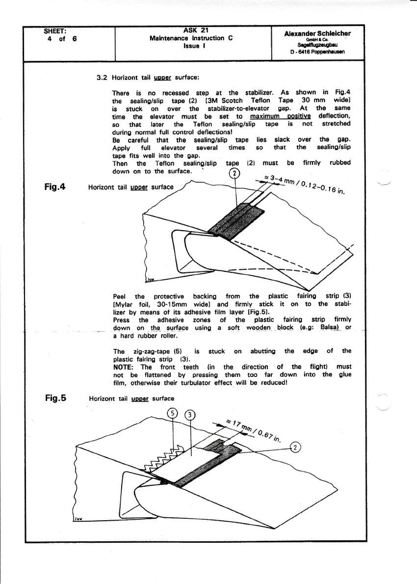
SHEEt:
4ot6 ,lD al
Mslrt nsnca lnrtrustlon C
lrsur I
Ahrrnds Scfiloaclrsr
dt6
S.g.krnrlat
o-oflgPopp.nh$f,i
3.2 Horizont tail us€r s,urfac€l
There is no racssssd 6tep 3t the gtabilieer' As shown ln Fig.4
tlE sealiog/slip t8p€ l2l I3M Scorch Teflon Tape 3O mm widsl
is stuck o$ ov€r the St bilizet-to'shvstot g8p. At *16 ramo
time fia devstor mu8t bs sBt to maximum ooshive deflecrion,
so $at latsr ths Tsflon sealinglslip tap€ is not strsdled
during nonnal,ull control defl€ctionsl
Be careful thar $€ s€aling/slip tapo ligs slack ovot tl8 gap.
Applv full elsvator sevoral times so *lst th€ saaling/elh
tap€ ffts Yv6ll into tha gap.
Thsa ths Teflon s8aling/slip
down on to $e surfaco. {21 must be firmly rubb3d
Fis.4 Horizont tail uooer surface
Pe6l the prot3stive backing from th€ plasfic strip (3)
lMylar foil, 30.15mm wHel and ffrmly stick h o'l to fi3 stabi'
lizer by rneans of its adhesive film layer [fi9.61.
Prass $€ adha3lv6 zonss of tho plsstic tairisg strip firmlY
_.-.. .{o-wn on t$r- _9!rfgce ueing. a sg.t wsgdlEt-.Qlqc.! le'gr .Balggl- or
a hard rubb€r rollsr,
The zig-zag-tape (5) ls stuck on abutdng the dge of fig
plsstlc fairin! strb l3l.
I*OTE: Tlre ftont tssth lin the directidt of ttu flightl must
not b€ flattencd by pre$ing theflr too far down into ths gke
film, otherwise fnlt artbulator sff€cl wiil bB raducadl
Ho.izoflt tall IpElg surfacc
**'o',r-o.,u,n.

TTTIEE I :eol5A:'t( Zr
irrhton$c. lnrtructlon C
llrur I
Akrnhr8chhlchcr
Oil,lrc6i
${*@r*rt
D-Gl|tPs.,rhfl.st
Fig.6
Fis.7
3.3 Wing and horiuont tail lorvor surfac6:
Removs protec.tive backing from plastk fafuing strip {6,
IMylar foll 22-15 mm widel end stick it oo to th€ wing sod
horhontel .tail lower surfacss, by mGans of hi adhssiw
fflm layor IFig.6:.
Pi€ss tho adhasive zones ol the plssdc lalrlng stlp firrF
ly down oo tho sur[8ce using a soft wooden Hock la.g:
Balsrl, or a hard rubber rullerl
Thsn th€ zio-zag-tape (51 k stuck on ahrtting tho sdge
of tfi6 phstic taidng ctrip (61, [Sse the NOTE urdor
poirlt 3,21.
Wing and horlzont tail b!&I curfece
Thera arc no recs$sd fieps at the lia. As shown ln Hg.7
rhs dastic falrtng $rip (61 lMylar foil, 22-lE mm $,601
is Eluck on over tfie rudder-fin transition at ths l€ft and
rlght sids {with its adhocive film layer on th6 fin}, thsn
pressed firmv down on the Eulfece,
Than .the zig-zao-trp€ {51 iB sfirck on abudng the edge
ot the plastic fairing strip,
3.4 Vertical tdl:

s}IEET:
SofB A5[ e't
M.*ttsn$c. lnstruc{on C
lssuo I
AbEnd.rAchhkllrtr
OrilarOq
SdfEErnbG,
D-Ofi6Popp3*n.o
!&,eI!4
( l laeq,orary BoEltloniag t.tr €
(2)saaUng/slip t.p€
31 6o6tch lfeflon l!!8. 30
tling sur- | colizontll I v€rtlcal
facas I Tail Sfca.a ltall sf,c..3
(3)P1a6tla f.lrkrE t.pe
(4rProtactLve edh€Blve tape
(5)Elg-339 g.P€
(6)Plaatlc faillng tape
Optlond in the dace of {5} aod {61:
( 7)cmbl-8tg-aag/pl.aBttc fatrlng tape I
Iu1.' f^l!- 1B-?n ffi ulda Ilzxl
1r... -l lzxlzt
lr-so -l 1-28 d
' = left 8nd tioht
The materiab r€quirsd c8n bE obained {rom Messrs. Schlehher.
Notes: This action can be 8ccomdiihsd by a compet8nt person.
ln fis ptacs of ths plastic fairing tEp,B 16l and the zig-
-zag-t p3 {5} stomlly a
ins trp€ {71 mry be glued ofl. cornbi-AE-la9/plasdc fair-
3. Ell$rtq that ths elastic_ lig.s€al is in tigftt contact with
$e SurfacEs of thg controls awn when ttsy ars fulV
dsfl*t€d.
The sscure and firm adhesion of the alastic lip must b€
ch€ekd.
Poppenhausen, May 7, 1992 ALEXAI{DEB SCHT"EICHEB
/-cmbH & Go._
W;,5-0 tr6
{Lutz-w, Jumog/
Th6 translation into English has be€n dons by best knowl€dgs end iudgsm€mi in
any casa of doubt the Gennan original is eofltmlling.
1,
2.
