ATS SDK Guide 7.2
User Manual:
Open the PDF directly: View PDF ![]() .
.
Page Count: 155 [warning: Documents this large are best viewed by clicking the View PDF Link!]
- Getting Started
- Programmer’s Guide
- AlazarDSP API Documentation
- Advanced Topics
- API Reference
- Board-Specific Information
- Supported impedances and input ranges
- Samples per record alignment requirements
- Samples per timestamp and trigger delay alignment
- Possible input channel configurations
- Supported sample rates
- Miscellaneous features support
- External trigger level support
- Supported clock types
- Frequency limits for external clock types
- Valid frequencies in PLL mode
- Index

ATS-SDK User Guide
Version 7.2.0
April 30, 2018

CONTENTS
1 Getting Started 1
1.1 Introduction ........................................ 1
1.2 Programming Environments ............................... 1
1.3 Sample code ........................................ 4
1.4 Contacting us ........................................ 5
2 Programmer’s Guide 7
2.1 Addressing a board .................................... 7
2.2 Resetting a board ..................................... 9
2.3 Configuring a board .................................... 10
2.4 Acquiring data ....................................... 25
2.5 Processing data ....................................... 48
3 AlazarDSP API Documentation 59
3.1 Introduction ........................................ 59
3.2 Detailed Description .................................... 61
3.3 API Reference ....................................... 63
4 Advanced Topics 73
4.1 External clock issues for OCT applications ........................ 73
4.2 AlazarSetTriggerOperationForScanning ......................... 73
5 API Reference 77
5.1 Functions .......................................... 77
5.2 Constant Definitions ....................................113
5.3 Structures .........................................127
5.4 Return Codes ........................................129
6 Board-Specific Information 135
6.1 Supported impedances and input ranges .........................135
6.2 Samples per record alignment requirements .......................136
6.3 Samples per timestamp and trigger delay alignment ..................136
6.4 Possible input channel configurations ..........................138
6.5 Supported sample rates ..................................138
6.6 Miscellaneous features support ..............................139
6.7 External trigger level support ...............................139
i


CHAPTER
ONE
GETTING STARTED
1.1 Introduction
AlazarTech supplies device drivers for Windows and Linux that allow software to configure
AlazarTech digitizers, and transfer sample data from the digitizer to application buffers.
The AlazarTech software developer’s kit (ATS-SDK) includes header and library files required to call
functions exported by these device drivers in user written applications, as well as documentation
and sample code describing how to use these functions.
This document is a part of the ATS-SDK. It describes how to call functions exported by AlazarTech
device drivers to control one or more digitizer boards. It is divided into the following sections:
• A programming guide that describes how to configure, and acquire data from, digitizer
boards.
• A reference guide that describes the functions exported by the device drivers.
To get the most from your AlazarTech digitizer:
• Read the user manual supplied their digitizer board. It provides an overview of the digitizer
hardware, as well as detailed specifications.
• Read the “Programmer’s guide” section of this document. It describes how to program the dig-
itizer hardware to make an acquisition, and to transfer sample data into application buffers.
• Browse the SDK sample programs. They include sample code that demonstrates how to make
many types of acquisitions supported by the digitizer.
Note that this document includes descriptions of board specific features and options that may not
be available on your digitizer board. Please refer your board’s user manual for its specifications.
1.2 Programming Environments
1.2.1 C/C++ Linux
C/C++ developers under Linux should include the following header files in source files that use
functions exported by the ATS-SDK library:
1

ATS-SDK Documentation, Release 7.2.0
#include "AlazarError.h"
#include "AlazarApi.h"
#include "AlazarCmd.h"
These modules should also link against libATSApi.so.
The development package for Linux defaults to installing the header files in
/usr/local/AlazarTech/include, and the library files in the standard library directory for the
target distribution.
1.2.2 C/C++ Windows
C/C++ developers should include the following header files in source files that use functions ex-
ported by the API library:
#include "AlazarError.h"
#include "AlazarApi.h"
#include "AlazarCmd.h"
These applications should also link against the 32- or 64-bit version of ATSApi.lib, as required.
The SDK setup program installs the header files in “Samples_C\Include”, and the library files in
“Samples_C\Library”.
1.2.3 C#
C# developers should either:
• Add the file AlazarApi.cs to their project; or
• Add a reference to AlazarApiNet.dll to their project.
The ATS-SDK includes a wrapper class that declares many of the constants and unmanaged func-
tions exported by AlazarTech device drivers. This class is provided both as a C# source file
(AlazarApi.cs), and as a compiled assembly (AlazarApiNet.dll).
The SDK setup program copies AlazarApi.cs to the “Samples_CSharp\AlazarApiNet\AlazarApiNet”
directory and AlazarApiNet.dll to the “Samples_CSharp” directory.
Note that you can use the solution “Samples_CSharp\AlazarApiNet” to build AlazarApiNet.dll from
AlazarApi.cs.
1.2.4 LabVIEW
LabVIEW developers can either:
• Use the sub-VIs provided with the ATS-SDK (recommended)
• Call functions from ATSApi.dll directly using the LabVIEW interface for shared libraries.
2©2015 Alazar Technologies Inc.

ATS-SDK Documentation, Release 7.2.0
The ATS-SDK sub-VIs consists of a very thin wrapper on top of the functions exported by the
ATS-SDK. The VIs are named after the functions that they wrap. They are located in “Sam-
ples_LabVIEW\Library”, and are used by all the code samples available in “Samples_LabVIEW”.
The only difference between the connector panes of the VIs and the C function signatures is that
an error cluster is propagated through the VIs. If the input error cluster contains an error, the VI
simply returns without doing anything.
The error cluster output depends on the function:
• If the function does not generate errors, the input error cluster is simply propagated to the
output.
• If the function returns an error code, it is converted to a cluster and send to the output
• If the function can return errors using special return values, then these errors are detected by
the VI, an appropriate error code is generated, converted to a cluster and sent to the output
1.2.5 Python
Python developers can use the atsapi.py module provided in the “Samples_Python\Library” direc-
tory. It provides a very thin wrapper around the AlazarTech C/C++ API, with only minor differ-
ences:
• The ‘Alazar’ prefixes have been removed from the function names, and the first letter is not
capitalized. For example, ‘AlazarAbortAsyncRead’ becomes ‘abortAsyncRead’.
• Board handles have been removed. Instead, a Board class has been added. All the functions
that take a board handle as a parameter are moved to being member functions of the Board
class.
• A DMABuffer convenience class has been added, that takes care of memory allocation of DMA
transfers.
• Some functions of the API use return parameters to give back to the caller primitive types. In
Python, the signature of these functions is changed so that the return parameters are replaced
with return types.
1.2.6 MATLAB
MATLAB developers can:
• Call functions exported by AlazarTech drivers DLL directly from MATLAB scripts and functions
using the MATLAB ‘calllib’ function.
• Create a MEX-file dynamic link library to configure and acquire data from the digitizer, and
call the mexFunction entry point of the DLL from MATLAB.
ATS-SDK samples demonstrate how to use the MATLAB “calllib” interface. They use prototype files
to load the AlazarTech driver library into memory, and call AlazarDefs.m to define constants used
by the AlazarTech library.
©2015 Alazar Technologies Inc. 3

ATS-SDK Documentation, Release 7.2.0
The ATS-SDK setup program installs AlazarDefs.m, alazarLoadLibrary.m, and other helper functions
in the “Samples_MATLAB\Include” folder.
1.2.7 C++/CLI
C++/CLI programmers should include a reference to “Samples_CSharp\AlazarApiNet.dll” in their
solutions. This assembly provides a .NET interface to the functions and constants defined in the
ATS-SDK.
The ATS-SDK does not currently include C++/CLI sample code. See the C# samples for .NET
sample code.
1.3 Sample code
ATS-SDK includes sample programs that demonstrate how to configure and acquire data from
AlazarTech digitizers.
The SDK setup program installs the sample programs to “C:\AlazarTech\ATS-
SDK\%API_VERSION%” under Microsoft Windows, and “/usr/local/AlazarTech” under Linux. See
the “ReadMe.htm” file in the ATS-SDK base directory for a description of the samples included.
Sample programs are available for the following programming environments in the following sub-
directories:
Language Sub-directory
C/C++ Samples_C
C# Samples_CSharp
MATLAB Samples_MATLAB
LabVIEW Samples_LabVIEW
Python Samples_Python
Note: Note that the sample programs contain many parameters that should be modified. These
lines of code are preceded by “TODO” comments. Please search for these lines and modify them as
required for your application.
Warning: Many sample programs require a trigger input. These sample programs configure
a board to trigger when a signal connected to its CH A rises through 0V. Before running these
samples, connect a 1 kHz sine waveform of amplitude about 90% of the board’s input range
from a function generator to the CH A connector, or modify trigger parameters as required. For
example, the ATS9360 has an input range of +/- 400 mV. For this board, a sine wave of 700
mVpp is appropriate. If an appropriate trigger signal is not supplied, these samples will fail with
an acquisition timeout error.
4©2015 Alazar Technologies Inc.

ATS-SDK Documentation, Release 7.2.0
1.4 Contacting us
Contact us if you have any questions or comments about this document, or the sample code.
Web http://www.alazartech.com
Email support@alazartech.com
Phone +1-514-426-4899
Fax +1-514-426-2723
Mail
Alazar Technologies Inc.
6600 Trans-Canada Highway, Suite 310
Pointe-Claire, QC
Canada H9R 4S2
Note that you can download the latest drivers and documentation from our web site.
http://www.alazartech.com/support/downloads.htm
©2015 Alazar Technologies Inc. 5

ATS-SDK Documentation, Release 7.2.0
6©2015 Alazar Technologies Inc.

CHAPTER
TWO
PROGRAMMER’S GUIDE
2.1 Addressing a board
2.1.1 Getting a board identifier
AlazarTech organizes its digitizer boards into “board systems”. A board system is a group of one or
more digitizer boards that share trigger and clock signals. To create a “board system” comprised of
two or more boards, the boards need to be connected together using an AlazarTech SyncBoard. All
of the channels in a board system trigger and are sampled simultaneuously.
ATS-SDK assigns a “system identifier” number to each board system. The first system detected is
assigned system ID number of 1. In addition a “board identifier” number is assigned to each board
in a board system. This number uniquely identifies a board within its board system.
• If a digitizer board is not connected to any other boards using a SyncBoard, then the SDK
assigns it a board ID of 1.
• If two or more boards are connected together using a SyncBoard, then the SDK assigns each
board an ID number that depends on how the board is connected to the SycnBoard. The board
connected to the “master” slot on the SyncBoard is the master board in the board system, and
is assigned a board ID number of 1.
Call the AlazarNumOfSystems() function to determine the number of board systems detected by the
SDK, and call the AlazarBoardsInSystemBySystemID() function to determine the number of boards
in the board system specified by its system identifier. The following code fragment lists the system
and board identifiers of each board detected by the device drivers:
U32 systemCount =AlazarNumOfSystems();
for (U32 systemId =1; systemId <= systemCount; systemId++) {
U32 boardCount =AlazarBoardsInSystemBySystemID(systemId);
for (U32 boardId =1; boardId <= boardCount; boardId++) {
printf("Found SystemID %u Board ID = %u\\n", systemId, boardId);
}
}
7

ATS-SDK Documentation, Release 7.2.0
2.1.2 Getting a board handle
ATS-SDK associates a handle with each digitizer board. Most functions require a board handle as a
parameter. For example, the AlazarSetLED() function allows an application to control the LED on
the PCI/PCIe mounting bracket of a board specified by its handle.
Use the AlazarGetBoardBySystemID() API function to get a handle to a board specified by its system
identifier and board identifier numbers.
Single board installations
If only one board is installed in a computer, ATS-SDK assigns it system ID 1 and board ID 1. The
following code fragment gets a handle to such a board, and uses this handle to toggle the LED on
the board’s PCI/PCIe mounting bracket:
// Select a board
U32 systemId =1;
U32 boardId =1;
// Get a handle to the board
HANDLE boardHandle =AlazarGetBoardBySystemID(systemId, boardId);
// Toggle the LED on the board’s PCI/PCIe mounting bracket
AlazarSetLED(boardHandle, LED_ON);
Sleep(500);
AlazarSetLED(boardHandle, LED_OFF);
Multiple board installations
If more than one board is installed in a PC, the boards are organized into board systems, and are
assigned system and board identifier numbers. The following code fragment demonstrates how to
obtain a handle to each board in such an installation, and use the handle to toggle the LED on the
board’s PCI/PCIe mounting bracket:
U32 systemCount =AlazarNumOfSystems();
for (U32 systemId =1; systemId <= systemCount; systemId++) {
U32 boardCount =AlazarBoardsInSystemBySystemID(systemId);
for (U32 boardId =1; boardId <= boardCount; boardId++) {
printf("SystemID %u Board ID = %u\\n", systemId, boardId);
// Get a handle to the board
HANDLE handle =AlazarGetBoardBySystemID(systemId, boardId);
// Toggle the LED on the board’s PCI/PCIe mounting bracket
AlazarSetLED(handle, LED_ON);
Sleep(500);
AlazarSetLED(handle, LED_OFF);
}
}
8©2015 Alazar Technologies Inc.

ATS-SDK Documentation, Release 7.2.0
System handles
Several ATS-SDK functions require a “system handle”. A system handle is the handle of the master
board in a board system.
• If a board is not connected to other boards using a SyncBoard, then its board handle is the
system handle.
• If a board is connected to other boards using a SyncBoard, then the board that is connected
to the master connector on the SyncBoard is the master board, and its board handle is the
system handle.
2.1.3 Closing a board handle
ATS-SDK maintains a list of board handles in order to support master-slave board systems. The
SDK creates board handles when it is loaded into memory, and destroys these handles when it is
unloaded from memory. An application should not need to close a board handle.
2.1.4 Using a board handle
ATS-SDK includes a number of functions that return information about a board specified by its
handle. These functions include:
AlazarGetBoardKind() Get a board’s model from its handle.
AlazarGetChannelInfo() Get the number of bits per sample, and on-board memory size in samples
per channel.
AlazarGetCPLDVersion() Get the CPLD version of a board.
AlazarGetDriverVersion() Get the driver version of a board.
AlazarGetParameter() Get a board parameter as a signed 32-bit value.
AlazarGetParameterUL() Get a board parameter as an unsigned 32-bit value.
AlazarQueryCapability() Get a board capability as an unsigned 32-bit value.
The sample program “%ATS_SDK_DIR%\Samples\AlazarSysInfo” demonstrates how get a board
handle, and use it to obtain board properties. The API also exports functions that use a board
handle to configure a board, arm it to make an acquisition, and transfer sample data from the
board to application buffers. These topics are discussed in the following sections.
2.2 Resetting a board
The ATS-SDK resets all digitizer boards during its initialization procedure. This initialization pro-
cedure automatically runs when the API library is loaded into memory.
• If an application statically links against the API library, the API resets all boards when the
application is launched.
©2015 Alazar Technologies Inc. 9

ATS-SDK Documentation, Release 7.2.0
• If an application dynamically loads the API library, the API resets all boards when the appli-
cation loads the API into memory.
Warning: Note that when an application using the API is launched, all digitizer boards are
reset. If one application using the API is running when a second application using the API is
launched, configuration settings written by the first application to a board may be lost. If a data
transfer between the first application and a board was in progress, data corruption may occur.
2.3 Configuring a board
Before acquiring data from a board system, an application must configure the timebase, analog
inputs, and trigger system settings of each board in the board system.
2.3.1 Timebase
The timebase of the ADC converters on AlazarTech digitizer boards may be supplied by:
• Its on-board oscillators.
• A user supplied external clock signal.
• An on-board PLL clocked by a user supplied 10 MHz reference signal.
Internal clock
To use on-board oscillators as a timebase, call AlazarSetCaptureClock() specifying
INTERNAL_CLOCK as the clock source identifier, and select the desired sample rate with a sample
rate identifier appropriate for the board. The following code fragment shows how to select a 10
MS/s internal sample rate:
AlazarSetCaptureClock(handle, // HANDLE -- board handle
INTERNAL_CLOCK, // U32 -- clock source Id
SAMPLE_RATE_10MSPS, // U32 -- sample rate Id or value
CLOCK_EDGE_RISING, // U32 -- clock edge Id
0// U32 -- decimation
);
See AlazarSetCaptureClock() or the board reference manual for a list of sample rate identifiers
appropriate for a board.
External clock
AlazarTech boards optionally support using a user-supplied external clock signal input to the ECLK
connector on its PCI/PCIe mounting bracket to clock its ADC converters.
10 ©2015 Alazar Technologies Inc.
ATS-SDK Documentation, Release 7.2.0
To use an external clock signal as a timebase, call AlazarSetCaptureClock() specifying
SAMPLE_RATE_USER_DEF as the sample rate identifier, and select a clock source identifier appro-
priate for the board model and the external clock properties. The following code fragment shows
how to configure an ATS460 to acquire at 100 MS/s with a 100 MHz external clock:
AlazarSetCaptureClock(handle, // HANDLE -- board handle
FAST_EXTERNAL_CLOCK, // U32 -- clock source Id
SAMPLE_RATE_USER_DEF, // U32 -- sample rate Id or value
CLOCK_EDGE_RISING, // U32 -- clock edge Id
0// U32 -- decimation
);
See the board reference manual for the properties of an external clock signal that are appropriate
for a board, and AlazarSetCaptureClock() for a list of external clock source identifiers.
External clock level
Some boards allow adjusting the comparator level of the external clock input receiver to
match the receiver to the clock signal supplied to the ECLK connector. If necessary, call
AlazarSetExternalClockLevel() to set the relative external clock input receiver comparator level,
in percent.
AlazarSetExternalClockLevel( handle, // HANDLE –- board handle level_pecent, //
float –- exernal clock level in percent );
10 MHz PLL
Some boards can generate a timebase from an on-board PLL clocked by user supplied external 10
MHz reference signal input to its ECLK connector.
ATS660
In 10 MHz PLL external clock mode, the ATS660 can generate a sample clock between 110 and 130
MHz, in 1 MHz, steps from an external 10 MHz reference input. Call AlazarSetCaptureClock()
specifying EXTERNAL_CLOCK_10MHz_REF as the clock source identifier, the desired sample rate be-
tween 110 and 130 MHz in 1 MHz steps, and a decimation factor of 1 to 100000. Note that the
decimation value should be one less than the desired decimation factor. The following code frag-
ment shows how to generate a 32.5 MS/s sample rate (130 MHz / 3) from a 10 MHz PLL external
clock input:
AlazarSetCaptureClock(
handle, // HANDLE - board handle
EXTERNAL_CLOCK_10MHz_REF, // U32 - clock source Id
130000000,// U32 - sample rate Id or value
CLOCK_EDGE_RISING, // U32 - clock edge Id
2// U32 - decimation value
);
©2015 Alazar Technologies Inc. 11

ATS-SDK Documentation, Release 7.2.0
ATS9325
In 10 MHz PLL external clock mode, the ATS9325 generates a 500 MHz sample clock from an
external 10 MHz reference input. The 500 MS/s sample data can be decimated by a factor of 2, 4,
or any multiple of 5.
Call AlazarSetCaptureClock() specifying EXTERNAL_CLOCK_10MHz_REF as the clock source and 500
MHz as the sample rate, and select a decimation factor of 2, 4, or any multiple of 5 up to 100000.
For example, the following code fragment shows how to generate a 100 MS/s sample rate (500
MHz / 5) from a 10 MHz external clock input:
AlazarSetCaptureClock(
handle, // HANDLE -- board handle
EXTERNAL_CLOCK_10MHz_REF, // U32 -- clock source Id
500000000,// U32 -- sample rate Id
CLOCK_EDGE_RISING, // U32 -- clock edge Id
5// U32 -- decimation
);
ATS9350/ATS9351
In 10 MHz PLL external clock mode, the ATS9350 and ATS9351 generate a 500 MHz sam-
ple clock from an external 10 MHz reference input. The 500 MS/s sample data can be dec-
imated by a factor of 1, 2, 4, or any multiple of 5. Call AlazarSetCaptureClock() specifying
EXTERNAL_CLOCK_10MHz_REF as the clock source and 500 MHz as the sample rate, and select a dec-
imation factor of 1, 2, 4, or any multiple of 5 up to 100000. For example, the following code
fragment shows how to generate a 100 MS/s sample rate (500 MHz / 5) from a 10 MHz external
clock input:
AlazarSetCaptureClock(
handle, // HANDLE - board handle
EXTERNAL_CLOCK_10MHz_REF, // U32 - clock source Id
500000000,// U32 - sample rate Id
CLOCK_EDGE_RISING, // U32 - clock edge Id
5// U32 - decimation
);
ATS9360
In 10 MHz PLL external clock mode, the ATS9360 can generate any sample clock frequency between
300 MHz and 1800 MHz that is a multiple of 1 MHz. Call AlazarSetCaptureClock() specifying
EXTERNAL_CLOCK_10MHz_REF as the clock source identifier, the desired sample rate between 300
MS/s and 1800 MS/s, and 1 as the decimation ratio. The sample rate must be a multiple of 1 MHz.
For example, the following code fragment shows how to generate a 1.382 GS/s sample clock from
a 10 MHz reference:
12 ©2015 Alazar Technologies Inc.

ATS-SDK Documentation, Release 7.2.0
AlazarSetCaptureClock(
handle, // HANDLE - board handle
EXTERNAL_CLOCK_10MHz_REF, // U32 - clock source Id
1382000000,// U32 - sample rate
CLOCK_EDGE_RISING, // U32 - clock edge Id
1// U32 - decimation
);
ATS9371
In 10 MHz PLL external clock mode, the ATS9371 can generate any sample clock frequency between
300 MHz and 1000 MHz that is a multiple of 1 MHz. Call AlazarSetCaptureClock() specifying
EXTERNAL_CLOCK_10MHz_REF as the clock source identifier, the desired sample rate between 300
MS/s and 1000 MS/s, and 1 as the decimation ratio. The sample rate must be a multiple of 1 MHz.
For example, the following code fragment shows how to generate a 882 MS/s sample clock from a
10 MHz reference:
AlazarSetCaptureClock(
handle, // HANDLE - board handle
EXTERNAL_CLOCK_10MHz_REF, // U32 - clock source Id
882000000,// U32 - sample rate
CLOCK_EDGE_RISING, // U32 - clock edge Id
1// U32 - decimation
);
ATS9373
In 10 MHz PLL external clock mode, the ATS9373 can generate any sample clock frequency between
500 MHz and 2000 MHz that is a multiple of 1 MHz in either single or dual channel mode. In
addition, it can generate any sample clock frequency between 2000 MHz and 4000 MHz that is a
multiple of 2 MHz in single channel mode.
Call AlazarSetCaptureClock() specifying EXTERNAL_CLOCK_10MHz_REF as the clock source identifier,
the desired sample rate between 300 MS/s and 4000 MS/s, and 1 as the decimation ratio. The
sample rate must be a multiple of 1 MHz in dual channel if the frequency is less than or equal to
2000 MHz, and a multiple of 2 MHz if the frequency is above 2000 MHz. For example, the following
code fragment shows how to generate a 1.382 GS/s sample clock from a 10 MHz reference:
AlazarSetCaptureClock(
handle, // HANDLE - board handle
EXTERNAL_CLOCK_10MHz_REF, // U32 - clock source Id
1382000000,// U32 - sample rate
CLOCK_EDGE_RISING, // U32 - clock edge Id
1// U32 - decimation
);
©2015 Alazar Technologies Inc. 13

ATS-SDK Documentation, Release 7.2.0
ATS9440
In 10 MHz PLL external clock mode, the ATS9440 can generate either a 125 MHz or 100 MHz
sample clock from an external 10 MHz reference input. The 125 MS/s or 100 MS/s sample data
can be decimated by a factor of 2, 4, or any multiple of 5.
Call AlazarSetCaptureClock() specifying EXTERNAL_CLOCK_10MHz_REF as the clock source ei-
ther 125 MHz or 100 MHz as the sample rate, and select a decimation radio between 1 and 100000.
For example, the following code fragment shows how to generate a 25 MS/s sample rate (125 MHz
/ 5) from a 10 MHz external clock input:
AlazarSetCaptureClock(
handle, // HANDLE - board handle
EXTERNAL_CLOCK_10MHz_REF, // U32 - clock source Id
125000000,// U32 - sample rate Id
CLOCK_EDGE_RISING, // U32 - clock edge Id
5// U32 - decimation
);
ATS9462
In 10 MHz PLL external clock mode, the ATS9462 can generate a sample clock between 150 and
180 MHz in 1 MHz steps from an external 10 MHz reference input. Sample data can be decimated
by a factor of 1 to 100000.
Call AlazarSetCaptureClock() specifying EXTERNAL_CLOCK_10MHz_REF as the clock source, the de-
sired sample rate between 150 and 180 MHz in 1 MHz steps, and the decimation factor of 1 to
100000. Note that the decimation value should be one less than the desired decimation factor. For
example, the following code fragment shows how to generate a 15 MS/s sample rate (150 MHz /
10) from a 10 MHz external clock input:
AlazarSetCaptureClock(
handle, // HANDLE - board handle
EXTERNAL_CLOCK_10MHz_REF, // U32 - clock source Id
150000000,// U32 - sample rate Id or value
CLOCK_EDGE_RISING, // U32 - clock edge Id
9// U32 - decimation value
);
ATS9625/ATS9626
In 10 MHz PLL external clock mode, the ATS9625/ATS9626 can generate a 250 MHz sample clock
from an external 10 MHz reference input. Sample data can be decimated by a factor of 1 to 100000.
Call AlazarSetCaptureClock() specifying EXTERNAL_CLOCK_10MHz_REF as the clock source, 250 MHz
has the sample rate value, and a decimation ratio of 1 to 100000. For example, the following code
fragment shows how to generate a 25 MS/s sample rate (250 MHz / 10) from a 10 MHz external
clock input:
14 ©2015 Alazar Technologies Inc.

ATS-SDK Documentation, Release 7.2.0
AlazarSetCaptureClock(
handle, // HANDLE - board handle
EXTERNAL_CLOCK_10MHz_REF, // U32 - clock source Id
250000000,// U32 - sample rate Id or value
CLOCK_EDGE_RISING, // U32 - clock edge Id
10 // U32 - decimation value
);
ATS9850
In 10 MHz PLL external clock mode, the ATS9850 generates a 500 MHz sample clock from an
external 10 MHz reference input. The 500 MS/s sample data can be decimated by a factor of 1, 2,
4, or any multiple of 10.
Call AlazarSetCaptureClock() specifying EXTERNAL_CLOCK_10MHz_REF as the clock source and
500 MHz as the sample rate value, and a decimation of 1, 2, 4, or any multiple of 10 up to 100000.
For example, the following code fragment shows how to generate a 125 MS/s sample rate (500
MHz / 4) from a 10 MHz external clock input:
AlazarSetCaptureClock(
handle, // HANDLE - board handle
EXTERNAL_CLOCK_10MHz_REF, // U32 - clock source Id
500000000,// U32 - sample rate Id or value
CLOCK_EDGE_RISING, // U32 - clock edge Id
4// U32 - decimation value
);
ATS9870
In 10 MHz PLL external clock mode, the ATS9870 generates a 1 GHz sample clock from an external
10 MHz reference input. The 1 GS/s sample data can be decimated by a factor of 1, 2, 4, or any
multiple of 10.
Call AlazarSetCaptureClock() specifying EXTERNAL_CLOCK_10MHz_REF as the clock source and
1 GHz as the sample rate value, and a decimation of 1, 2, 4, or any multiple of 10 up to 100000.
For example, the following code fragment shows how to generate a 250 MS/s sample rate (1 GHz
/ 4) from a 10 MHz external clock input:
AlazarSetCaptureClock(
handle, // HANDLE - board handle
EXTERNAL_CLOCK_10MHz_REF, // U32 - clock source Id
1000000000,// U32 - sample rate Id or value
CLOCK_EDGE_RISING, // U32 - clock edge Id
4// U32 - decimation value
);
©2015 Alazar Technologies Inc. 15

ATS-SDK Documentation, Release 7.2.0
2.3.2 Input control
AlazarTech digitizers have analog amplifier sections that process the signals input to its analog input
connectors before they are sampled by its ADC converters. The gain, coupling, and termination of
the amplifier sections should be configured to match the properties of the input signals.
Input range, coupling, and impedance
Call AlazarInputControl() to specify the desired input range, termination, and coupling of an
input channel. The following code fragment configures input CH A for a range of ±800 mV, DC
coupling, and 50Ωtermination:
AlazarInputControl(
boardHandle, // HANDLE -- board handle
CHANNEL_A, // U8 -- input channel
DC_COUPLING, // U32 -- input coupling id
INPUT_RANGE_PM_800_MV, // U32 -- input range id
IMPEDANCE_50_OHM // U32 -- input impedance id
);
See AlazarInputControl() and the board reference manual for a list of input range, coupling, and
impedance identifiers appropriate for the board.
Bandwidth filter
Some digitizers have a low pass filters that attenuate signals above about 20 MHz. By default, these
filters are disabled. Call AlazarSetBWLimit() to enable or disable the bandwidth limit filter. The
following code fragment enables the CH A bandwidth limit filter:
AlazarSetBWLimit (
boardHandle, // HANDLE -- board handle
CHANNEL_A, // U32 -- channel identifier
1// U32 -- 0 = disable, 1 = enable
);
Amplifier bypass
Some digitizer models support “amplifier bypass” mode. In this mode, the analog signal supplied
to an input connector is connected directly the ADC driver of that channel, bypassing its amplifier
section. Amplifier bypass mode must be enabled in hardware either through DIP switches on the
board, or as a factory option. Once enabled in hardware, the following code fragment shows how
to configure this option in software:
AlazarInputControl(
handle, // HANDLE -- board handle
CHANNEL_A, // U8 -- input channel
DC_COUPLING, // U32 - not used
(continues on next page)
16 ©2015 Alazar Technologies Inc.
ATS-SDK Documentation, Release 7.2.0
(continued from previous page)
INPUT_RANGE_HI_FI, // U32 -- input range id
IMPEDANCE_50_OHM // U32 - not used
);
Note that when amplifier bypass mode option is enabled for an input channel, the channel’s full-
scale input range is fixed. The following table lists the nominal full-scale input range values that
may be used to convert sample code values to volts.
Model Full scale input range
ATS460 ±525 mV
ATS660 ±550 mV
ATS9325/ATS9350 ±200 mV
ATS9351 ±400 mV
ATS9462 ±550 mV
ATS9850/ATS9870 ±256 mV
See your board’s hardware reference manual for more information about using amplifier bypass.
2.3.3 Trigger control
AlazarTech digitizer boards have a flexible triggering system with two separate trigger engines that
can be used independently, or combined together to generate trigger events.
Warning: As opposed to what earlier documentation mentionned, the only way to combine
trigger events is with the OR operator.
AlazarSetTriggerOperation
Use the AlazarSetTriggerOperation() API function to configure each of the two trigger engines,
and to specify how they should be used to make the board trigger:
RETURN_CODE
AlazarSetTriggerOperation (
HANDLE handle,
U32 TriggerOperation,
U32 TriggerEngineId1,
U32 SourceId1,
U32 SlopeId1,
U32 Level1,
U32 TriggerEngineId2,
U32 SourceId2,
U32 SlopeId2,
U32 Level2
);
©2015 Alazar Technologies Inc. 17

ATS-SDK Documentation, Release 7.2.0
The following paragraphs describe each of the function’s parameters, and provide examples show-
ing how to use the function.
Trigger engine
The trigger engine identifier parameter specifies which of the two trigger engines you wish to
configure. The parameter may have one of the following values:
TRIG_ENGINE_J Configure trigger engine J
TRIG_ENGINE_K Configure trigger engine K
Data source
The data source identifier parameter selects the where the specified trigger engine should get its
data. Refer to the documentation of the AlazarSetTriggerOperation() function for a list of all
possible values.
Trigger slope
The trigger slope identifier parameter selects whether rising or falling edges of the trigger source
are detected as trigger events.
TRIGGER_SLOPE_POSITIVE The trigger engine detects a trigger event when sample values from the
trigger source rise above a specified level.
TRIGGER_SLOPE_NEGATIVE The trigger engine detects a trigger event when sample values from the
trigger source fall below a specified level.
Trigger level
The trigger level parameter sets the level that the trigger source must rise above, or fall below, for
the selected trigger engine to become active. The trigger level is specified as an unsigned 8-bit
code that represents a fraction of the full scale input range of the trigger source; 0 represents the
negative full-scale input, 128 represents a 0 volt input, and 255 represents the positive full-scale
input. For example, if the trigger source is CH A, and the CH A input range is ±800 mV, then 0
represents a –800 mV trigger level, 128 represents a 0 V trigger level, and 255 represents +800
mV trigger level.
In general, the trigger level value is given by:
TriggerLevelCode =128 +127 *TriggerLevelVolts /InputRangeVolts.
The following table gives examples of how trigger level codes map to trigger levels in volts accord-
ing to the full-scale input range of the trigger source.
18 ©2015 Alazar Technologies Inc.

ATS-SDK Documentation, Release 7.2.0
Code Fraction of input range Level with ±1 V range Level with ±5 V range
0 -100% -1V -5V
64 -50% -500 mV -2.5 V
96 -25% -250 mV -1.25 V
128 0% 0 V 0 V
160 +25 % 250 mV 1.25 V
192 +50% +500 mV +2.5 V
255 +100% +1V +5V
Trigger operation
Finally, the trigger operation identifier specifies how the trigger events detected by the trigger
engines are combined to make the board trigger. Possible values are:
TRIG_ENGINE_OP_J The board triggers when trigger engine J detects a trigger event. Events de-
tected by engine K are ignored.
TRIG_ENGINE_OP_K The board triggers when trigger engine K detects a trigger event. Events de-
tected by engine J are ignored.
TRIG_ENGINE_OP_J_OR_K The board triggers when a trigger event is detected by any of trigger en-
gines J and K.
AlazarSetTriggerOperation examples
The following code fragment configures a board to trigger when the signal connected to CH A rises
above 0V. This example only uses trigger engine J:
AlazarSetTriggerOperation(
handle, // HANDLE -- board handle
TRIG_ENGINE_OP_J, // U32 -- trigger operation
TRIG_ENGINE_J, // U32 -- trigger engine id
TRIG_CHAN_A, // U32 -- trigger source id
TRIGGER_SLOPE_POSITIVE, // U32 -- trigger slope id
128,// U32 -- trigger level (128 = 0V)
TRIG_ENGINE_K, // U32 -- trigger engine id
TRIG_DISABLE, // U32 -- trigger source id for engine K
TRIGGER_SLOPE_POSITIVE, // U32 -- trigger slope id
128 // U32 -- trigger level (0 255)
);
The following code fragment configures a board to trigger when the signal connected to CH B rises
above 500 mV, or falls below -200 mV, if CH B’s input range is ±1V. This example uses both trigger
engine J and K:
double inputRange_volts =1.;// ±1V range
double TriggerLevelJ_volts =.5;// +500 mV trigger level
U32 triggerLevelJ =(U32)(128 +127 *triggerLevelJ_volts /inputRange_volts);
(continues on next page)
©2015 Alazar Technologies Inc. 19

ATS-SDK Documentation, Release 7.2.0
(continued from previous page)
double triggerLevelK_volts = -.2;// -200 mV trigger level
U32 triggerLevelK =(U32)(128 +127 *triggerLevelK_volts /inputRange_volts);
AlazarSetTriggerOperation(
handle, // HANDLE -- board handle
TRIG_ENGINE_OP_J_OR_K, // U32 -- trigger operation
TRIG_ENGINE_J, // U32 -- trigger engine id
TRIG_CHAN_B, // U32 -- trigger source id
TRIGGER_SLOPE_POSITIVE, // U32 -- trigger slope id
triggerLevelJ, // U32 -- trigger level from 0 to 255
TRIG_ENGINE_K, // U32 -- trigger engine id
TRIG_DISABLE, // U32 -- trigger source id for engine K
TRIGGER_SLOPE_POSITIVE, // U32 -- trigger slope id
triggerLevelK, // U32 -- trigger level from 0 to 255
);
External trigger
AlazarTech digitizer boards can trigger on a signal connected to its TRIG IN connector. To use an
external trigger input:
• Call AlazarSetTriggerOperation() with TRIG_EXTERNAL as the trigger source identifier of at
least one of the trigger engines; and
• Call AlazarSetExternalTrigger() to select the range and coupling of the external trigger
input.
The following code fragment configures a board to trigger when the signal connected to the TRIG
IN falls below +2 V, assuming the signal’s range is less than ±5V with DC coupling:
// Calculate the trigger level code from the level and range
double triggerLevel_volts =2.;// trigger level
double triggerRange_volts =5.;// input range
U32 triggerLevel_code =
(U32)(128 +127 *triggerLevel_volts /triggerRange_volts);
// Configure trigger engine J to generate a trigger event
// on the falling edge of an external trigger signal.
AlazarSetTriggerOperation(
handle, // HANDLE -- board handle
TRIG_ENGINE_OP_J, // U32 -- trigger operation
TRIG_ENGINE_J, // U32 -- trigger engine id
TRIG_EXTERNAL, // U32 -- trigger source id
TRIGGER_SLOPE_NEGATIVE, // U32 -- trigger slope id
triggerLevel, // U32 -- trigger level (0 255)
TRIG_ENGINE_K, // U32 -- trigger engine id
TRIG_DISABLE, // U32 -- trigger source id for engine K
TRIGGER_SLOPE_POSITIVE, // U32 -- trigger slope id
128 // U32 -- trigger level (0 255)
);
(continues on next page)
20 ©2015 Alazar Technologies Inc.

ATS-SDK Documentation, Release 7.2.0
(continued from previous page)
// Configure the external trigger input to +/-5V range,
// with DC coupling
AlazarSetExternalTrigger(
handle, // HANDLE -- board handle
DC_COUPLING, // U32 -- coupling id
ETR_5V // U32 -- external range id
);
Trigger timeout
AlazarTech digitizer boards can be configured to automatically trigger when the board is waiting for
a trigger event, but no trigger events arrive after a specified time interval. This behavior is similar
to the “automatic” trigger mode of oscilloscopes, and may be useful to capture waveforms when
trigger conditions are unknown. Call AlazarSetTriggerTimeOut() to specify the amount of time
that a board should wait for a hardware trigger event before automatically generating a software
trigger event and, as a result, acquiring one record. The timeout value is expressed in 10 𝜇s units,
where 0 means disable the timeout counter and wait forever for a trigger event.
Note: The trigger timeout value should be set to zero once stable trigger parameters have been
found. Otherwise, a board may generate unexpected trigger events if the trigger timeout interval
expires before a hardware trigger event occurs.
The following code fragment configures a board to automatically trigger and acquire one record if
it does not receive a trigger event after 1 ms:
double timeout_sec =1.e-3;// 1 ms
U32 timeout_ticks =(U32)(timeout_sec /10.e-6 +0.5);
AlazarSetTriggerTimeOut(
boardHandle, // HANDLE -- board handle
timeout_ticks // U32 timeout_sec / 10.e-6 (0 = infinite)
);
The following code fragment configures a board to wait forever for trigger events:
AlazarSetTriggerTimeOut(
boardHandle, // HANDLE -- board handle
0// U32 -- timeout\_sec / 10.e-6 (0 = infinite)
);
Trigger delay
An AlazarTech digitizer board can be configured to wait for a specified amount of time after it
receives a trigger event before capturing a record for the trigger. Call AlazarSetTriggerDelay() to
specify a time, in sample clock periods, to wait after receiving a trigger event for a record before
capturing samples for that record. The following code fragment shows how to set a trigger delay
of 1 ms, given a sample rate of 100 MS/s:
©2015 Alazar Technologies Inc. 21

ATS-SDK Documentation, Release 7.2.0
double triggerDelay_sec =1.e-3;// 1 ms
double samplesPerSec =100.e6;// 100 MS/s
U32 triggerDelay_samples =
(U32)(triggerDelay_sec *samplesPerSec +0.5);
AlazarSetTriggerDelay(
boardHandle, // HANDLE -- board handle
triggerDelay_samples // U32 -- trigger delay in samples
);
2.3.4 AUX I/O
AlazarTech digitizer boards with an AUX I/O connector can be configured to supply a 5V TTL-level
output signal, or to receive a TTL-level input signal on this connector. Use AlazarConfigureAuxIO()
to configure the function of the AUX I/O connector.
The ATS9440 has two AUX I/O connectors: AUX I/O 1 and AUX I/O 2. AUX I/O 1 is config-
ured by firmware as a trigger output signal, while AUX I/O 2 is configured by software using
AlazarConfigureAuxIO(). A custom FPGA is required to change the operation of AUX I/O 1.
The ATS9625 and ATS9626 have two AUX I/O connectors: AUX1 and AUX2. AUX1 is configured
by by software using AlazarConfigureAuxIO(), while AUX2 is configured by the main FPGA as a
trigger output signal by default. AUX2 can be controlled by its user-programmable FPGA as desired
by the FPGA designer.
Trigger output
The AUX I/O connector can be configured to supply a trigger output signal, where the edge of the
trigger output signal is synchronized with the edge of the sample clock. Note that this is the default
power-on mode for the AUX I/O connector. The following code fragment configures the AUX I/O
connector as a trigger output signal:
AlazarConfigureAuxIO(
handle, // HANDLE -- board handle
AUX_OUT_TRIGGER, // U32 -- mode
0// U32 -- parameter
);
Pacer output
The AUX I/O connector can be configured to output the sample clock divided by a programmable
value. This option may be used to generate a clock signal synchronized with the sample clock of the
digitizer board. The following code fragment generates a 10 MHz signal on an AUX I/O connector,
given a sample rate of 180 MS/s:
AlazarConfigureAuxIO(
handle, // HANDLE -- board handle
AUX_OUT_PACER, // U32 -- mode
(continues on next page)
22 ©2015 Alazar Technologies Inc.

ATS-SDK Documentation, Release 7.2.0
(continued from previous page)
18 // U32 - sample clock divider
);
Note that the sample rate divider value must be greater than 2, and that the signal output may be
limited by the bandwidth of the output’s TTL drivers.
Digital output
The AUX I/O connector can be configured to output a TTL high or low signal. This mode allows a
programmer to use the AUX I/O connector as a general purpose digital output. The following code
fragment configures the AUX I/O connector as a digital output:
AlazarConfigureAuxIO(
handle, // HANDLE -- board handle
AUX_OUT_SERIAL_DATA, // U32 -- mode
0// U32 - 0 = low, 1 = high
);
Trigger enable input
The AUX I/O connector can be configured as an AutoDMA trigger enable input signal. When
enabled, a board will:
• Wait for a rising or falling edge on the AUX I/O.
• Wait for the number of trigger events necessary to capture the number of “records per buffer”
in one AutoDMA segment specified at the start of the acquisition.
• Repeat.
The following code fragment configures the AUX I/O connector to acquire “records per buffer”
records after it receives the rising edge of a TTL pulse connected on the AUX I/O connector:
AlazarConfigureAuxIO(
handle, // HANDLE -- board handle
AUX_IN_TRIGGER_ENABLE, // U32 -- mode
TRIGGER_SLOPE_POSITIVE // U32 -- parameter
);
See Scanning Applications for more information.
Digital input
The AUX I/O connector can be configured to read the TTL level of a signal input to the AUX
connector. This mode allows a programmer to use the AUX I/O connector as a general purpose
digital input. The following code fragment configures the AUX I/O connector as a digital input:
©2015 Alazar Technologies Inc. 23

ATS-SDK Documentation, Release 7.2.0
AlazarConfigureAuxIO(
handle, // HANDLE -- board handle
AUX_IN_AUXILIARY, // U32 -- mode
0// U32 - not used
);
Once configured as a serial input, the following code fragment reads the AUX input level:
long level;
AlazarGetParameter(
handle, // HANDLE -- board handle
0,// U8 -- channel
GET_AUX_INPUT_LEVEL, // U32 -- parameter
&level // long* - 0 = low, 1 = high
);
2.3.5 Data packing
By default, all the boards that have more than 8-bit per sample sampling transfer data to the
host computer with 2 bytes (16 bit) per sample. This behavior can be changed on some boards
by packing the data, either to 8- or 12-bits per sample. This is done by calling the AlazarSet-
Parameter function with the PACK_MODE parameter and a packing option (either PACK_DEFAULT,
PACK_8_BITS_PER_SAMPLE or PACK_12_BITS_PER_SAMPLE). The parameter must be set before calling
AlazarBeforeAsyncRead.
For a list of boards that implement 8-bit packing, 12-bit packing and both; please refer to Table 9 –
Miscellaneous Features Support.
2.3.6 Dual edge sampling
Some AlazarTech digitizers are capable of dual edge sampling (DES), meaning that sample data is
acquired both at the rising and falling edge of the clock signal. This mode can apply both to internal
and external clocks. For example, ATS9373 is capable of 2 GS/s sampling in non-DES mode, and 4
GS/s in DES mode. When using the internal clock, DES sampling is activated automatically. Data
must be acquired from channel A only. To use DES sampling in external clock mode, one must call
AlazarSetParameter as follows before configuring the board:
AlazarSetParameterUL(
handle, // HANDLE -- board handle
channelMask, // U8 -- channel to acquire
SET_ADC_MODE,
ADC_MODE_DES
);
Programs that wish to use DES-capable digitizers in non-DES mode (i.e. ATS9373 at sampling
frequencies at or below 2GS/s) do not need to be modified.
24 ©2015 Alazar Technologies Inc.

ATS-SDK Documentation, Release 7.2.0
2.3.7 NPT footers
Footers can be included to the data and contain additional information about the acquisition of
each record. The footers include a timestamp, the record number in the current acquisition, a
frame count and the state of the AUX I/O signal at the time of the acquisition. As the name implies,
this option is only available in NPT acquisition mode.
Depending if on-FPGA FFT is used or not, the function to retrive the NPT footers and their position
in memory is different. If FFT is not enabled, NPT footers will replace the last 16 bytes of a record,
leading to a loss of a few data points. These NPT footers are labeled Time-Domain to highlighting
the fact that FFT is not used. When one channel is enabled, the last 8 samples of the data will be
removed. When two channels are enabled, only one footer will be appended per record and will
take the place of the last 4 samples from each channel.
When using on-FPGA FFT, a 128-byte word will be appended to each record. The last 16 bytes of
this 128-byte word contain the footer.
For convenience, a structure named :cpp:struct:‘NPTFooter‘ should be used. Here is how to enable
and obtain the NPT footers:
• Connect the start of frame signal to the AUX I/O connector.
• Append the flag ADMA_ENABLE_RECORD_FOOTERS to the options passed to
AlazarBeforeAsyncRead() by using a binary OR (|). Make sure the acquisition mode
is set to ADMA_NPT and FFT processing is enabled if applicable.
• Call AlazarConfigureAuxIO() specifying AUX_IN_AUXILIARY as the mode with 0as parameter.
• Create an array that will contain the NPT footers. This array needs to be contiguous in
memory and can thus be a standard C array or a std::vector with preallocated size.
• Call AlazarExtractTimeDomainNPTFooters() or AlazarExtractFFTNPTFooters() to retrieve
the NPT footers for each buffer and store them in the array. The recordSize_bytes parameter
needs to take into account the number of active channels.
• Browse the array to see the frame associated with each record and count the number of
records in each frame if needed.
See the API reference documentation for details about the specific parameters to use with each
function.
2.4 Acquiring data
AlazarTech digitizers may be configured to acquire in one of the following modes:
•Single port acquisition mode acquires data to on-board memory and then, after the acquisition
is complete, transfers data from on-board memory to application buffers.
•Dual port AutoDMA acquisition mode acquires to on-board memory while, at the same time,
transferring data from on-board memory to application buffers.
©2015 Alazar Technologies Inc. 25

ATS-SDK Documentation, Release 7.2.0
2.4.1 Single port acquisition
The single-port acquisition API allows an application to capture records to on-board memory – one
per trigger event – and transfer records from on-board to host memory. Data acquisition and data
transfer are made serially, so trigger events may be missed if they occur during data transfers. The
single port acquisition API may be used if:
• A board has single-port or dual-port on-board memory.
• An application can miss trigger events that occur while it is transferring data from on-board
to host memory.
The singe port acquisition API must be used if:
• A board does not have dual-port or FIFO on-board memory.
• An application acquires data at an average rate that is greater than maximum transfer rate of
the board’s PCI or PCIe host bus interface.
Ultrasonic testing, OCT, radar, imaging and similar applications should not use the single-port
acquisition API; rather, they should use the dual-port acquisition API described in section 2.4.2
below.
Acquiring to on-board memory
All channels mode
By default, AlazarTech digitizer boards share on-board memory equally between both of a board’s
input channels. A single-port acquisition in dual-channel mode captures samples from both input
channels simultaneously to on-board memory and, after the acquisition is complete, allows samples
from either input channel to be transferred from on-board memory to an application buffer. To
program a board acquire to on-board memory in dual-channel mode:
1. Call AlazarSetRecordSize() to set the number of samples per record, where a record may
contain samples before and after its trigger event.
2. Call AlazarSetRecordCount() to set the number records per acquisition – the board captures
one record per trigger event.
3. Call AlazarStartCapture() to arm the board to wait for trigger events.
4. Call AlazarBusy() in a loop to poll until the board has received all trigger events in the
acquisition, and has captured all records to on-board memory.
5. Call AlazarRead(),AlazarReadEx(), or AlazarHyperDisp() to transfer records from on-board
memory to host memory.
6. Repeat from step 3, if necessary.
The following code fragment acquires to on board memory with on-board memory shared between
both input channels:
26 ©2015 Alazar Technologies Inc.

ATS-SDK Documentation, Release 7.2.0
// 1. Set record size
AlazarSetRecordSize (
boardHandle, // HANDLE -- board handle
preTriggerSamples, // U32 -- pre-trigger samples
postTriggerSamples // U32 -- post-trigger samples
);
// 2. Set record count
AlazarSetRecordCount(
boardHandle, // HANDLE -- board handle
recordsPerCapture // U32 -- records per acquisition
);
// 3. Arm the board to wait for trigger events
AlazarStartCapture(boardHandle);
// 4. Wait for the board to receive all trigger events and capture all
// records to on-board memory
while (AlazarBusy (boardHandle))
{
// The acquisition is in progress
}
// 5. The acquisition is complete. Call AlazarRead or AlazarHyperDisp to
// transfer records from on-board memory to your buffer.
Single channel mode
ATS9325, ATS9350, ATS9351, ATS9440, ATS9625, ATS9626, ATS9850, and ATS9870 and digitizer
boards can be configured to dedicate all on-board memory to one of a board’s input channels. A
single-port acquisition in single-channel mode only captures samples from the specified channel to
on-board memory and, after the acquisition is complete, only allows samples from the specified
channel to be transferred from on-board memory to an application buffer.
To program a board acquire to on-board memory in single-channel mode:
1. Call AlazarSetRecordSize() to set the number of samples per record, where a record may
contain samples before and after its trigger event.
2. Call AlazarSetRecordCount() to set the number records per acquisition – the board captures
one record per trigger event.
3. Call AlazarSetParameter() with the parameter SET_SINGLE_CHANNEL_MODE, and specify the
channel to use all memory.
4. Call AlazarStartCapture() to arm the board to wait for trigger events.
5. Call AlazarBusy() in a loop to poll until the board has received all trigger events in the
acquisition, and has captured all records to on-board memory.
©2015 Alazar Technologies Inc. 27

ATS-SDK Documentation, Release 7.2.0
6. Call AlazarRead(),AlazarReadEx(), or AlazarHyperDisp() to transfer records from on-board
memory to host memory.
7. Repeat from step 3, if necessary.
The following code fragment acquires to on-board memory from CH A in single channel mode:
// 1. Set record size
AlazarSetRecordSize (
boardHandle, // HANDLE -- board handle
preTriggerSamples, // U32 -- pre-trigger samples
postTriggerSamples // U32 -- post-trigger samples
);
// 2. Set record count
AlazarSetRecordCount(
boardHandle, // HANDLE -- board handle
recordsPerCapture // U32 -- records per acquisition
);
// 3. Enable single channel mode
AlazarSetParameter(
boardHandle, // HANDLE -- board handle
0,// U8 -- channel Id (not used)
SET_SINGLE_CHANNEL_MODE, // U32 -- parameter
CHANNEL_A // long CHANNEL_A or CHANNEL_B
);
// 4. Arm the board to wait for trigger events
AlazarStartCapture(boardHandle);
// 5. Wait for the board to receive all trigger events
// and capture all records to on-board memory
while (AlazarBusy (boardHandle))
{
// The acquisition is in progress
}
// 6. The acquisition is complete. Call AlazarRead or
// AlazarHyperDisp to transfer records from on-board memory
// to your buffer.
Note: A call to AlazarSetParameter() must be made before each call to AlazarStartCapture().
If the of number of samples per record specified in AlazarSetRecordSize() is greater than the
maximum number of samples per channel in dual-channel mode, but is less than the max-
imum number of samples per record in single-channel mode, and AlazarSetParameter() is
not called before calling AlazarStartCapture(), then AlazarStartCapture() will fail with error
ApiNotSupportedInDualChannelMode.
28 ©2015 Alazar Technologies Inc.

ATS-SDK Documentation, Release 7.2.0
Using AlazarRead
Use AlazarRead() to transfer samples from records acquired to on-board memory to a buffer in
host memory.
Transferring full records
The following code fragment transfers a full CH A record from on-board memory to a buffer in host
memory:
// Allocate a buffer to hold one record.
// Note that the buffer must be at least 16 samples
// larger than the number of samples per record.
U32 allocBytes =bytesPerSample *(samplesPerRecord +16);
void*buffer =malloc(allocBytes);
// Transfer a CHA record into our buffer
AlazarRead (
boardHandle, // HANDLE -- board handle
CHANNEL_A, // U32 -- channel Id
buffer, // void* -- buffer
bytesPerSample, // int -- bytes per sample
(long) record, // long -- record (1 indexed)
-((long)preTriggerSamples), // long -- trigger offset
samplesPerRecord // U32 -- samples to transfer
);
See “%ATS_SDK_DIR%\Samples\SinglePort\AR” for a complete sample program that demonstrates
how to use AlazarRead() to read full records.
Transferring partial records
AlazarRead() can transfer a segment of a record from on-board memory to a buffer in host memory.
This may be useful if:
• The number of bytes in a full record in on-board memory exceeds the buffer size in bytes that
an application can allocate in host memory.
• An application wishes to reduce the time required for data transfer when it acquires relatively
long records to on-board memory, but is only interested in a relatively small part of the record.
Use the transferOffset parameter in the call to AlazarRead() to specify the offset, in samples
from the trigger position in the record, of the first sample to transfer from on-board memory to
the application buffer. And use the transferLength parameter to specify the number of samples
to transfer from on-board memory to the application buffer, where this number of samples may be
less than the number of samples per record. The following code fragment divides a record into
segments, and transfers the segments from on-board to host memory:
©2015 Alazar Technologies Inc. 29

ATS-SDK Documentation, Release 7.2.0
// Allocate a buffer to hold one record segment.
// Note that the buffer must be at least 16 samples
// larger than the number of samples per buffer.
U32 allocBytes =bytesPerSample *(samplesPerBuffer +16);
void*buffer =malloc(allocBytes);
// Transfer a record in segments from on-board memory
U32 samplesToRead =samplesPerRecord;
long triggerOffset_samples = -(long)preTriggerSamples;
while (samplesToRead >0) {
// Transfer a record segment from on-board memory
U32 samplesThisRead;
if (samplesToRead >samplesPerBuffer)
samplesThisRead =samplesPerBuffer;
else
samplesThisRead =samplesToRead;
AlazarRead (
boardHandle, // HANDLE -- board handle
CHANNEL_A, // U32 -- channel Id
buffer, // void* -- buffer
bytesPerSample, // int -- bytes per sample
(long) record, // long -- record (1 indexed)
triggerOffset_samples, // long -- trigger offset
samplesThisRead // U32 -- samples to transfer
);
// Process the record segment here
WriteSamplesToFile(buffer, samplesThisRead);
// Point to next record segment in on-board memory
triggerOffset_samples += samplesThisRead;
// Decrement number of samples left to read
samplesToRead -= samplesThisRead;
}
See “%ATS_SDK_DIR%\Samples\SinglePort\AR_Segments” for a complete sample program that
demonstrates how to read records in segments.
Using AlazarReadEx
AlazarRead() can transfer samples from records acquired to on-board memory that contain up to
2,147,483,647 samples. If a record contains 2,147,483,648 or more samples, use AlazarReadEx()
rather than AlazarRead().AlazarReadEx() uses signed 64-bit transfer offsets, while AlazarRead()
uses signed 32-bit transfer offsets. Otherwise, AlazarReadEx() and AlazarRead() are identical.
Using AlazarHyperDisp
HyperDisp technology enables the FPGA on an AlazarTech digitizer board to process sample data.
The FPGA divides a record in on-board memory into intervals, finds the minimum and maximum
30 ©2015 Alazar Technologies Inc.

ATS-SDK Documentation, Release 7.2.0
sample values during each interval, and transfers an array of minimum and maximum value pairs
to host memory. This allows the acquisition of relatively long records to on-board memory, but the
transfer of relatively short processed records across the PCI/PCIe bus to host memory.
For example, an ATS860-256M would require over 2 seconds per channel to transfer 256,000,000
samples across the PCI bus. However, with HyperDisp enabled the ATS860 would require a fraction
of a second to calculate HyperDisp data, and transfer a few kilobytes of processed data across the
PCI bus. If an application was searching these records for glitches, it may save a considerable
amount of time by searching HyperDisp data for the glitches and, if a glitch were found, transfer
the raw sample data from the interval from on-board memory to host memory.
Use AlazarHyperDisp() to enable a board to process records in on-board memory, and transfer
processed records to host memory. The following code fragment enables an ATS860-256M to pro-
cess a record in on-board memory containing 250,000,000 samples into an array of 100 HyperDisp
points, where each point contains the minimum and maximum sample values over an interval of
2,500,000 samples in the record:
// Specify number of samples per record
U32 preTriggerSamples =125000000;
U32 postTriggerSamples =125000000;
U32 samplesPerRecord =preTriggerSamples +postTriggerSamples;
U32 recordsPerCapture =1;
// Acquire to on-board memory (omitted)
// Specify the number of HyperDisp points
U32 pointsPerRecord =100;
// Allocate a buffer to store the HyperDisp data
U32 bytesPerSample =1;// ATS860 constant
U32 samplesPerPoint =2;// HyperDisp constant
U32 bytesPerBuffer =bytesPerSample *samplesPerPoint *pointsPerRecord;
U8 *buffer =(U8*) malloc(bytesPerBuffer);
// Enable ATS860 FPGA to process the 250M sample record
// in on-board memory into an array of 100 HyperDisp points,
// and transfer the HyperDisp points into our buffer
U32 error;
AlazarHyperDisp (
boardHandle, // HANDLE -- board handle
NULL,// void* -- reserved
samplesPerRecord, // U32 -- BufferSize
(U8*) buffer, // U8* -- ViewBuffer
bytesPerBuffer, // U32 -- ViewBufferSize
pointsPerRecord, // U32 -- NumOfPixels
1,// U32 -- Option (1 = HyperDisp)
CHANNEL_A, // U32 -- ChannelSelect
1,// U32 -- record (1 indexed)
-(long)preTriggerSamples, // long -- TransferOffset
&error // U32* -- error
);
See “%ATS_SDK_DIR%\Samples\SinglePort\HD” for a complete sample program that demon-
©2015 Alazar Technologies Inc. 31

ATS-SDK Documentation, Release 7.2.0
strates how to use AlazarHyperDisp().
Record timestamps
AlazarTech digitizer boards include a 40-bit counter clocked by the sample clock source scaled by
a board specific divider. When a board receives a trigger event to capture a record to on-board
memory, it latches and saves the value of this counter. The counter value gives the time, relative to
when the counter was reset, when the trigger event for the record occurred.
By default, this counter is reset to zero at the start of each acquisition. Use AlazarResetTimeStamp()
to control when the record timestamp counter is reset.
Use AlazarGetTriggerAddress() to retrieve the timestamp, in timestamp clock ticks, of a record
acquired to on-board memory. This function does not convert the timestamp value to seconds. The
following code fragment gets the record timestamp of a record acquired to on-board memory, and
converts the timestamp value from clocks ticks to seconds:
// Read the record timestamp
U32 triggerAddress;
U32 timestampHigh;
U32 timestampLow;
AlazarGetTriggerAddress (
boardHandle, // HANDLE -- board handle
record, // U32 -- record number (1-indexed)
&triggerAddress, // U32* -- trigger address
×tampHigh, // U32* -- timestamp high part
×tampLow // U32* -- timestamp low part
);
// Convert the record timestamp from counts to seconds
__int64 timeStamp_cnt;
timeStamp_cnt =((__int64) timestampHigh) << 8;
timeStamp_cnt |= timestampLow &0x0ff;
double samplesPerTimestampCount =2;// board specific constant
double samplesPerSec =50.e6;// sample rate
double timeStamp_sec =(double) samplesPerTimestampCount *
timeStamp_cnt /samplesPerSec;
Call AlazarGetParameter() with the GET_SAMPLES_PER_TIMESTAMP_CLOCK parameter to obtain the
board specific “samples per timestamp count” value. See Samples per record alignment requirements
for a list of these values. See “%ATS_SDK_DIR%\Samples\SinglePort\AR_Timestamps” for a com-
plete sample program that demonstrates how to retrieve record timestamps and convert them to
seconds.
Master-slave applications
If the single-port API is used to acquire from master-slave board system, only the master board
in the board system should receive calls to the following API functions: AlazarStartCapture(),
AlazarAbortCapture(),AlazarBusy(),AlazarTriggered() and AlazarForceTrigger(). See
32 ©2015 Alazar Technologies Inc.

ATS-SDK Documentation, Release 7.2.0
“%ATS_SDK_DIR%\Samples\SinglePort\AR_MasterSlave” for a sample program that demonstrates
how to acquire from a master-slave system.
2.4.2 Dual port AutoDMA acquisition
AutoDMA allows a board to capture sample data to on-board dual-port memory while – at the same
time – transferring sample data from on-board dual-port memory to a buffer in host memory. Data
acquisition and data transfer are done in parallel, so any trigger events that occur while the board
is transferring data will not be missed.
AutoDMA may be used if:
• A board has dual-port or FIFO on-board memory.
• An application acquires at an average rate, in MB/s, that is less than maximum transfer rate
of your board’s PCI or PCIe host bus interface.
AutoDMA must be used if:
• A board has FIFO on-board memory.
• An application cannot miss trigger events that occur while it transfers data to host memory,
or re-arms for another acquisition.
• An application acquires more sample points or records than can be stored in on-board mem-
ory.
Applications such as ultrasonic testing, OCT, radar, and imaging should use AutoDMA. An AutoDMA
acquisition is divided into segments. AutoDMA hardware on a board transfers sample data, one
segment at a time, from on-board memory to a buffer in host memory. There may be an unlimited
number of segments in an AutoDMA acquisition, so a board can be armed to make an acquisition
of infinite duration. There are four AutoDMA operating modes:
Traditional AutoDMA This mode acquires multiple records, one per trigger event. Each record
may contain samples before and after its trigger event. Each buffer contains one or more
records. A record header may optionally precede each record. Supports low trigger repeat
rates.
NPT AutoDMA Acquires multiple records, one per trigger event. Some boards support a very lim-
ited number of pre-trigger samples. Otherwise, only post-trigger samples are possible. Each
buffer contains one or more record. Supports high trigger repetition rates.
Triggered streaming AutoDMA Acquires a single, gapless record spanning one or more DMA
buffers. Each DMA buffer then contains only a segment of the record. This mode waits
for a trigger event before acquiring the record.
Continuous streaming AutoDMA Acquires a single, gapless record spanning one or more DMA
buffers. Each DMA buffer then contains only a segment of the record. This mode does not
wait for a trigger event before acquiring the record.
To make an AutoDMA acquisition, an application must:
• Specify the AutoDMA mode, samples per record, records per buffer, and records per acquisi-
tion.
©2015 Alazar Technologies Inc. 33

ATS-SDK Documentation, Release 7.2.0
• Arm the board to start the acquisition.
• Wait for an AutoDMA buffer to be filled, process the buffer, and repeat until the acquisition is
complete.
Traditional AutoDMA
Use traditional mode to acquire multiple records – one per trigger event – with sample points
after, and optionally before, the trigger event in each record. A record header may optionally
precede each record in the AutoDMA buffer. The programmer specifies the number of samples per
record, records per buffer, and buffers in the acquisition. Traditional AutoDMA supports low trigger
repeat rates. For high trigger repeat rates, use NPT AutoDMA mode. Digitizers with four analog
input channels do not support 3-channel operation, and require sample interleave to allow for high
transfer rates from on-board memory.
Each buffer is organized in memory as follows if a board has on-board memory. Rxy represents a
contiguous array of samples from record x of channel y.
Enabled channels Buffer organization
CH A R1A, R2A, R3A, . . . RnA
CH B R1B, R2B, R3B . . . RnB
CH A and CH B R1A, R1B, R2A, R2B, R3A, R3B . . . RnA, RnB
CH C R1C, R2C, R3C . . . RnC
CH A and CH C R1A, R1C, R2A, R2C, R3A, R3C . . . RnA, RnC
CH B and CH C R1B, R1C, R2B, R2C, R3B, R3C . . . RnB, RnC
CH D R1D, R2D, R3D . . . RnD
CH A and CH D R1A, R1D, R2A, R2D, R3A, R3D . . . RnA, RnD
CH B and CH D R1B, R1D, R2B, R2D, R3B, R3D . . . RnB, RnD
CH C and CH D R1C, R1D, R2C, R2D, R3C, R3D . . . RnC, RnD
CH A, CH B, CH C and
CH D
R1A, R1B, R1C, R1D, R2A, R2B, R2C, R2D, R3A, R3B, R3C, R3D . . .
RnA, RnB, RnC, RnD
Each buffer is organized in memory as follows if a board does not have on-board memory, or
if sample interleave is enabled. Rxy represents a contiguous array of samples from record x of
channel y, Rx[uv] represents interleaved samples from record x of channels u and v, and Rx[uvyz]
represents interleaved samples from channels u, v, y, and z.
34 ©2015 Alazar Technologies Inc.

ATS-SDK Documentation, Release 7.2.0
Enabled channels Buffer organization
CH A R1A, R2A, R3A, . . . RnA
CH B R1B, R2B, R3B . . . RnB
CH A and CH B R1[ABAB. . . ], R2[ABAB. . . ], . . . Rn[ABAB. . . ]
CH C R1C, R2C, R3C . . . RnC
CH A and CH C R1[ACAC. . . ], R2[ACAC. . . ], . . . Rn[ACAC. . . ]
CH B and CH C R1[BCBC. . . ], R2[BCBC. . . ], . . . Rn[BCBC. . . ]
CH D R1D R2D, R3D . . . RnD
CH A and CH D R1[ADAD. . . ], R2[ADAD. . . ], . . . Rn[ADAD. . . ]
CH B and CH D R1[BDBD. . . ], R2[BDBD. . . ], . . . Rn[BDBD. . . ]
CH C and CH D R1[CDCD. . . ], R2[CDCD. . . ], . . . Rn[CDCD. . . ]
CH A, CH B, CH C and CH C R1[ABCDABDC . . . ], R2[ABDCABDC . . . ], . . .
Rn[ABDCABDC. . . ]
See “%ATS_SDK_DIR%\Samples\DualPort\TR” for a sample program that demonstrates how to
make an AutoDMA acquisition in Traditional mode.
If record headers are enabled, then a 16-byte record header will precede each record in an Au-
toDMA buffer. The record header contains a record timestamp, as well as acquisition metadata.
See Record headers and timestamps below for a discussion of AutoDMA record headers.
NPT AutoDMA
Use NPT mode to acquire multiple records – one per trigger event – with no sample points before the
trigger event in each record, and with no record headers. The programmer specifies the number of
samples per record, records per buffer, and buffers in the acquisition. Note that NPT mode is highly
optimized, and supports higher trigger repeats rate than possible in Traditional mode. Digitizers
with four analog input channels do not support 3-channel operation, and require sample interleave
to allow for high transfer rates from on-board memory.
Each buffer is organized in memory as follows if a board has on-board memory. Rxy represents a
contiguous array of samples from record x of channel y.
Enabled channels Buffer organization
CH A R1A, R2A, R3A, . . . RnA
CH B R1B, R2B, R3B . . . RnB
CH A and CH B R1A, R2A, R3A . . . RnA, R1B, R2B, R3B . . . RnB
CH C R1C, R2C, R3C, . . . RnC
CH A and CH B R1A, R2A, R3A . . . RnA, R1B, R2B, R3B . . . RnB
CH B and CH C R1B, R2B, R3B . . . RnB, R1C, R2C, R3C . . . RnC
CH D R1D, R2D, R3D, . . . RnD
CH A and CH D R1A, R2A, R3A . . . RnA, R1D, R2D, R3D . . . RnD
CH B and CH D R1B, R2B, R3B . . . RnB, R1D, R2D, R3D . . . RnD
CH C and CH D R1C, R2C, R3C . . . RnC, R1D, R2D, R3D . . . RnD
CH A, CH B, CH C,
and CH D
R1A, R2A, R3A . . . RnA, R1B, R2B, R3B . . . RnB, R1C, R2C, R3C . . .
RnC, R1D, R2D, R3D . . . RnD
©2015 Alazar Technologies Inc. 35

ATS-SDK Documentation, Release 7.2.0
Each buffer is organized in memory as follows if a board does not have on-board memory, or
if sample interleave is enabled. Rxy represents a contiguous array of samples from record x of
channel y, Rx[uv] represents interleaved samples from record x of channels u and v, and Rx[uvyz]
represents interleaved samples from record x of channels u, v, y, and z.
Enabled channels Buffer organization
CH A R1A, R2A, R3A, . . . RnA
CH B R1B, R2B, R3B . . . RnB
CH A and CH B R1[ABAB. . . ], R2[ABAB. . . ], . . . Rn[ABAB. . . ]
CH C R1C, R2C, R3C . . . RnC
CH A and CH C R1[ACAC. . . ], R2[ACAC. . . ], . . . Rn[ACAC. . . ]
CH B and CH C R1[BCBC. . . ], R2[BCBC. . . ], . . . Rn[BCBC. . . ]
CH D R1D R2D, R3D . . . RnD
CH A and CH D R1[ADAD. . . ], R2[ADAD. . . ], . . . Rn[ADAD. . . ]
CH B and CH D R1[BDBD. . . ], R2[BDBD. . . ], . . . Rn[BDBD. . . ]
CH C and CH D R1[CDCD. . . ], R2[CDCD. . . ], . . . Rn[CDCD. . . ]
CH A, CH B, CH C and CH D R1[ABCDABCD . . . ], R2[ABCDABCD . . . ], . . .
Rn[ABCDABCD. . . ]
See “%ATS_SDK_DIR%\Samples\DualPort\NPT” for a sample program that demonstrates how to
make an AutoDMA acquisition in NPT mode.
Continuous streaming AutoDMA
Use continuous streaming mode to acquire a single, gapless record that spans multiple buffers
without waiting for a trigger event to start the acquisition. The programmer specifies the number
of samples per buffer, and buffers per acquisition. Each buffer is organized as follows if a board has
on-board memory. R1x represents a contiguous array of samples from channel x.
Enabled channels Buffer organization
CH A R1A
CH B R1B
CH A and CH B R1A, R1B
CH C R1C
CH A and CH C R1A, R1C
CH B and CH C R1B, R1C
CH D R1D
CH A and CH D R1A, R1D
CH B and CH D R1B, R1D
CH C and CH D R1C, R1D
CH A, CH B, CH C and CH D R1A, R1B, R1C, R1D
Each buffer is organized as follows if a board does not have on-board memory, or if sample inter-
leave is enabled. R1x represents a contiguous array of samples from channel x, R1[uv] represents
samples interleaved from channels u and v, and R1[uvyz] represents samples interleaved from
channels u, v, y, and z.
36 ©2015 Alazar Technologies Inc.

ATS-SDK Documentation, Release 7.2.0
Enabled channels Buffer organization
CH A R1A
CH B R1B
Both CH A and CH B R1[ABAB. . . ]
CH C R1C
CH A and CH C R1[ACAC. . . ]
CH B and CH C R1[BCBC. . . ]
CH D R1D
CH A and CH D R1[ADAD. . . ]
CH B and CH D R1[BDBD. . . ]
CH C and CH D R1[CDCD. . . ]
CH A, CH B, CH C and CH D R1[ABCDABCD . . . ]
See “%ATS_SDK_DIR%\Samples\DualPort\CS” for a sample program that demonstrates how to
make an AutoDMA acquisition in continuous streaming mode.
Triggered streaming AutoDMA
Use triggered streaming mode to acquire a single, gapless record that spans two or more buffers
after waiting for a trigger event to start the acquisition. The programmer specifies the number of
samples in each buffer, and buffers in the acquisition. Each buffer is organized as follows if a board
has on-board memory. R1x represents a contiguous array of samples from channel x.
Enabled channels Buffer organization
CH A R1A
CH B R1B
CH A and CH B R1A, R1B
CH C R1C
CH A and CH C R1A, R1C
CH B and CH C R1B, R1C
CH D R1D
CH A and CH D R1A, R1D
CH B and CH D R1B, R1D
CH C and CH D R1C, R1D
CH A, CH B, CH C and CH D R1A, R2B, R1C, R1D
Each buffer is organized as follows if a board does not have on-board memory, or if sample inter-
leave is enabled. R1x represents a contiguous array of samples from channel x, R1[uv] represents
samples interleaved from channels u and v, and R1[uvyz] represents samples interleaved from
channels u, v, y, and z.
©2015 Alazar Technologies Inc. 37

ATS-SDK Documentation, Release 7.2.0
Enabled channels Buffer organization
CH A R1A
CH B R1B
Both CH A and CH B R1[ABAB. . . ]
CH C R1C
CH A and CH C R1[ACAC. . . ]
CH B and CH C R1[BCBC. . . ]
CH D R1D
CH A and CH D R1[ADAD. . . ]
CH B and CH D R1[BDBD. . . ]
CH C and CH D R1[CDCD. . . ]
CH A, CH B, CH C and CH D R1[ABCDABCD . . . ]
See “%ATS_SDK_DIR%\Samples\DualPort\TS” for a sample program that demonstrates how to
make a triggered streaming AutoDMA acquisition.
Record headers and timestamps
In traditional AutoDMA mode, a 16-byte record header may optionally precede each record in a
buffer. When record headers are enabled, the following table shows the buffer layout if a board has
on-board memory. Record headers are not supported if a board does not have on-board memory.
Rxy represents a contiguous array of samples from record x of channel y, and Hxy is a 16-byte
record header from record x of channel y.
Enabled chan-
nels
Buffer organization
CH A H1A, R1A, H2A, R2A . . . HnA, RnA
CH B H1B, R1B, H2B, R2B . . . HnB, RnB
CH A and CH B H1A, R1A, H1B, R1B, H2A, R2A, H2B, R2B. . . HnA, RnA, HnB, RnB
CH C H1C, R1C, H2C, R2C . . . HnC, RnC
CH A and CH C H1A, R1A, H1C, R1C, H2A, R2A, H2C, R2C. . . HnA, RnA, HnC, RnC
CH B and CH C H1B, R1B, H1C, R1C, H2B, R2B, H2C, R2C. . . HnB, RnB, HnC, RnC
CH D H1D, R1D, H2D, R2D . . . HnD, RnD
CH A and CH D H1A, R1A, H1D, R1D, H2A, R2A, H2D, R2D. . . HnA, RnA, HnD, RnD
CH B and CH D H1B, R1B, H1D, R1D, H2B, R2B, H2D, R2D. . . HnB, RnB, HnD, RnD
CH C and CH D H1C, R1C, H1D, R1D, H2C, R2C, H2D, R2D. . . HnC, RnC, HnD, RnD
CH A, CH B, CH
C and CH D
H1A, R1A, H1B, R1B, H1C, R1C, H1D, R1D, H2A, R2A, H2B, R2B H2C, R2C,
H2D, R2D. . . HnA, RnA, HnB, RnB, HnC, RnC, HnD, RnD
Record headers
A record header is a 16-byte structure defined in AlazarApi.h as follows:
38 ©2015 Alazar Technologies Inc.

ATS-SDK Documentation, Release 7.2.0
struct _HEADER0 {
unsigned int SerialNumber:18;// bits 17..0
unsigned int SystemNumber:4;// bits 21..18
unsigned int WhichChannel:1;// bit 22
unsigned int BoardNumber:4;// bits 26..23
unsigned int SampleResolution:3;// bits 29..27
unsigned int DataFormat:2;// bits 31..30
};
struct _HEADER1 {
unsigned int RecordNumber:24;// bits 23..0
unsigned int BoardType:8;// bits 31..24
};
struct _HEADER2 {
U32 TimeStampLowPart; //bits 31..0
};
struct _HEADER3 {
unsigned int TimeStampHighPart:8;// bits 7..0
unsigned int ClockSource:2;// bits 9..8
unsigned int ClockEdge:1;// bit 10
unsigned int SampleRate:7;// bits 17..11
unsigned int InputRange:5;// bits 22..18
unsigned int InputCoupling:2;// bits 24..23
unsigned int InputImpedence:2;// bits 26..25
unsigned int ExternalTriggered:1;// bit 27
unsigned int ChannelBTriggered:1;// bit 28
unsigned int ChannelATriggered:1;// bit 29
unsigned int TimeOutOccurred:1;// bit 30
unsigned int ThisChannelTriggered:1;// bit 31
};
typedef struct _ALAZAR_HEADER {
struct _HEADER0 hdr0;
struct _HEADER1 hdr1;
struct _HEADER2 hdr2;
struct _HEADER3 hdr3;
}*PALAZAR_HEADER;
typedef struct _ALAZAR_HEADER ALZAR_HEADER;
See ALAZAR_HEADER for more information about each of the fiels of this structure. See
“%ATS_SDK_DIR%\Samples\DualPort\TR_Header” for a full sample program that demonstrates
how to make an AutoDMA acquisition in Traditional mode with record headers.
Record timestamps
AlazarTech digitizer boards include a high-speed 40-bit counter that is clocked by the sample clock
source scaled by a board specific divider. When a board receives a trigger event to capture a record
to on-board memory, it latches the value of this counter. This timestamp value gives the time,
©2015 Alazar Technologies Inc. 39

ATS-SDK Documentation, Release 7.2.0
relative to when the counter was reset, when the trigger event for this record occurred. By default,
this counter is reset to zero at the start of each acquisition. Use AlazarResetTimeStamp() to control
when the record timestamp counter is reset. The following code fragment demonstrates how to
extract the timestamp from a record header, and covert the value from counts to seconds:
double samplesPerTimestampCount =2;// board specific constant
double samplesPerSec =100.e6;// sample rate
void*pRecord; // points to record header in buffer
ALAZAR_HEADER *pHeader =(ALAZAR_HEADER*) pRecord;
__int64 timestamp_counts;
timestamp_counts =(INT64) pHeader->hdr2.TimeStampLowPart;
timestamp_counts =timestamp_counts |
(((__int64) (pHeader->hdr3.TimeStampHighPart &0x0ff)) << 32);
double timestamp_sec =samplesPerTimestampCount *
timestamp_counts /samplesPerSec;
Call AlazarGetParameter() with the GET_SAMPLES_PER_TIMESTAMP_CLOCK parameter to de-
termine the board specific “samples per timestamp count” value. Samples per record alignment
requirements lists these values. See “%ATS_SDK_DIR%\Samples\DualPort\TR_Header” for a full
sample program that demonstrates how to make an AutoDMA acquisition in Traditional mode with
record headers, and convert the timestamp to seconds.
AutoDMA acquisition flow
The AutoDMA functions allow an application to add user-defined number of buffers to a list of
buffers available to be filled by a board, and to wait for the board to receive sufficient trigger
events to fill the buffers with sample data. The board uses AutoDMA to transfer data directly into
a buffer without making any intermediate copies in memory. As soon as one buffer is filled, the
driver automatically starts an AutoDMA transfer into the next available buffer.
AlazarPostBuffer
C/C++ applications should call AlazarPostAsyncBuffer() to make buffers available to be filled
by the board, and AlazarWaitAsyncBufferComplete() to wait for the board to receive sufficient
trigger events to fill the buffers. The following code fragment outlines the steps required to make
an AutoDMA acquisition using AlazarPostAsyncBuffer() and AlazarWaitAsyncBufferComplete():
// Configure the board to make an AutoDMA acquisition
AlazarBeforeAsyncRead(
handle, // HANDLE -- board handle
channelMask, // U32 -- enabled channel mask
-(long)preTriggerSamples, // long -- trigger offset
samplesPerRecord, // U32 -- samples per record
recordsPerBuffer, // U32 -- records per buffer
recordsPerAcquisition, // U32 -- records per acquisition
flags // U32 -- AutoDMA mode and options
);
(continues on next page)
40 ©2015 Alazar Technologies Inc.

ATS-SDK Documentation, Release 7.2.0
(continued from previous page)
// Add two or more buffers to a list of buffers
// available to be filled by the board
for (i =0;i<BUFFER_COUNT; i++) {
AlazarPostAsyncBuffer(
handle, // HANDLE -- board handle
BufferArray[i], // void* -- buffer pointer
BytesPerBuffer // U32 -- buffer length in bytes
);
}
// Arm the board to begin the acquisition
AlazarStartCapture(handle);
// Wait for each buffer in the acquisition to be filled
U32 buffersCompleted =0;
while (buffersCompleted <buffersPerAcquisition) {
// Wait for the board to receives sufficient trigger events
// to fill the buffer at the head of its list of
// available buffers.
U32 bufferIndex =buffersCompleted %BUFFER_COUNT;
U16*pBuffer =BufferArray[bufferIndex];
AlazarWaitAsyncBufferComplete(handle, pBuffer, timeout_ms);
buffersCompleted++;
// The buffer is full, process it.
// Note that while the application processes this buffer,
// the board is filling the next available buffer
// as trigger events arrive.
ProcessBuffer(pBuffer, bytesPerBuffer);
// Add the buffer to the end of the list of buffers
// available to be filled by this board. The board will
// fill it with another segment of the acquisition after
// all of the buffers preceding it have been filled.
AlazarPostAsyncBuffer(handle, pBuffer, bytesPerBuffer);
}
// Abort the acquisition and release resources.
// This function must be called after an acquisition.
AlazarAbortAsyncRead(boardHandle);
See “%ATS_SDK_DIR%\Samples\DualPort\NPT” for a full sample program that demonstrates make
an AutoDMA acquisition using AlazarPostAsyncBuffer.
ADMA_ALLOC_BUFERS
C#, and LabVIEW applications may find it more convenient to allow the API to allocate and
manage a list of buffers available to be filled by the board. These applications should call
AlazarBeforeAsyncRead() with the AMDA_ALLOC_BUFFERS option selected in the “Flags” param-
eter. This option will cause the API to allocate and manage a list of buffers available to be
©2015 Alazar Technologies Inc. 41

ATS-SDK Documentation, Release 7.2.0
filled by the board. The application must call AlazarWaitNextAsyncBufferComplete() to wait
for a buffer to be filled. When the board receives sufficient trigger events to fill a buffer, the
API will copy the data from the internal buffer to the user-supplied buffer. The following code
fragment outlines how make an AutoDMA acquisition using the ADMA_ALLOC_BUFFERS flag and
AlazarWaitNextAsyncBufferComplete():
// Allow the API to allocate and manage AutoDMA buffers
flags |= ADMA_ALLOC_BUFFERS;
// Configure a board to make an AutoDMA acquisition
AlazarBeforeAsyncRead(
handle, // HANDLE -- board handle
channelMask, // U32 -- enabled channel mask
-(long)preTriggerSamples, // long -- trigger offset
samplesPerRecord, // U32 -- samples per record
recordsPerBuffer, // U32 -- records per buffer
recordsPerAcquisition, // U32 -- records per acquisition
flags // U32 -- AutoDMA mode and options
);
// Arm the board to begin the acquisition
AlazarStartCapture(handle);
// Wait for each buffer in the acquisition to be filled
RETURN_CODE retCode =ApiSuccess;
while (retCode == ApiSuccess) {
// Wait for the board to receive sufficient
// trigger events to fill an internal AutoDMA buffer.
// The API will copy data from the internal buffer
// to the user-supplied buffer.
retCode =
AlazarWaitNextAsyncBufferComplete(
handle, // HANDLE -- board handle
pBuffer, // void* -- buffer to receive data
bytesToCopy, // U32 -- bytes to copy into buffer
timeout_ms // U32 -- time to wait for buffer
);
// The buffer is full, process it
// Note that while the application processes this buffer,
// the board is filling the next available internal buffer
// as trigger events arrive.
ProcessBuffer(pBuffer, bytesPerBuffer);
}
// Abort the acquisition and release resources.
// This function must be called after an acquisition.
AlazarAbortAsyncRead(boardHandle);
See “%ATS_SDK_DIR%\Samples\DualPort\CS_WaitNextBuffer” for a full sample program that
demonstrates make an AutoDMA acquisition using ADMA_ALLOC_BUFFERS. An application can get
or set the number of DMA buffers allocated by the API by calling AlazarGetParameter() or
AlazarSetParameter() with the parameter SETGET_ASYNC_BUFFCOUNT.
42 ©2015 Alazar Technologies Inc.

ATS-SDK Documentation, Release 7.2.0
Note that applications may combine ADMA_ALLOC_BUFFERS with options to perform operations that
would be difficult in high-level programming languages like LabVIEW. They include:
• Data normalization – This option enables the API to process sample data so that the data
always has the same arrangement in the application buffer, independent of AutoDMA mode.
See ADMA_GET_PROCESSED_DATA for more information.
• Disk streaming – This option allows the API to use high-performance disk I/O functions to
stream buffer data to files. See AlazarCreateStreamFile() below for more information.
AlazarAsyncRead
Some C/C++ applications under Windows may require waiting for an event to be set to the
signaled state to indicate when an AutoDMA buffer is full. These applications should use the
AlazarAsyncRead() API. The following code fragment outlines how use AlazarAsyncRead() to
make an asynchronous AutoDMA acquisition:
// Configure the board to make an AutoDMA acquisition
AlazarBeforeAsyncRead(
handle, // HANDLE -- board handle
channelMask, // U32 -- enabled channel mask
-(long)preTriggerSamples, // long -- trigger ofset
samplesPerBuffer, // U32 -- samples per buffer
recordsPerBuffer, // U32 -- records per buffer
recordsPerAcquisition, // U32 -- records per acquisition
admaFlags // U32 -- AutoDMA flags
);
// Add two or more buffers to a list of buffers
// available to be filled by the board
for (i =0;i<BUFFER_COUNT; i++) {
AlazarAsyncRead (
handle, // HANDLE -- board handle
IoBufferArray[i].buffer, // void* -- buffer
IoBufferArray[i].bytesPerBuffer, // U32 -- buffer length
&IoBufferArray[i].overlapped // OVERLAPPED*
);
}
// Arm the board to begin the acquisition
AlazarStartCapture(handle);
// Wait for each buffer in the acquisition to be filled.
U32 buffersCompleted =0;
while (buffersCompleted <buffersPerAcquisition)
{
// Wait for the board to receives sufficient
// trigger events to fill the buffer at the head of its
// list of available buffers.
// The event handle will be set to the signaled state when
// the buffer is full.
(continues on next page)
©2015 Alazar Technologies Inc. 43

ATS-SDK Documentation, Release 7.2.0
(continued from previous page)
U32 bufferIndex =buffersCompleted %BUFFER_COUNT;
IO_BUFFER *pIoBuffer =IoBufferArray[bufferIndex];
WaitForSingleObject(pIoBuffer->hEvent, INFINTE);
buffersCompleted++;
// The buffer is full, process it
// Note that while the application processes this buffer,
// the board is filling the next available buffer
// as trigger events arrive.
ProcessBuffer(pIoBuffer->buffer, pIoBuffer->bytesPerBuffer);
// Add the buffer to the end of the list of buffers.
// The board will fill it with another segment from the
// acquisition after the buffers preceding it have been filled.
AlazarAsyncRead (
handle, // HANDLE -- board handle
pIoBuffer->buffer, // void* -- buffer
pIoBuffer->bytesPerBuffer, // U32 -- buffer length
&pIoBuffer->overlapped // OVERLAPPED*
);
}
// Stop the acquisition. This function must be called if unfilled buffers are
// pending.
AlazarAbortAsyncRead(handle);
See “%ATS_SDK_DIR%\Samples\DualPort\CS_AsyncRead” for a full sample program that demon-
strates make an AutoDMA acquisition using AlazarAsyncRead().
AlazarAbortAsyncRead
The asynchronous API driver locks application buffers into memory so that boards may DMA di-
rectly into them. When a buffer is completed, the driver unlocks it from memory. An application
must call AlazarAbortAsyncRead() if, at the end of an acquisition, any of the buffers that it supplies
to a board have not been completed. AlazarAbortAsyncRead() completes any pending buffers, and
unlocks them from memory.
Warning: If an application exits without calling AlazarAbortAsyncRead(), the API driver may
generate a DRIVER_LEFT_LOCKED_PAGES_IN_PROCESS (0x000000CB) bug check error under Win-
dows, or leak the locked memory under Linux. This may happen, for example, if a programmer
runs an application that uses the API under a debugger, stops at a breakpoint, and then stops
the debugging session without letting the application or API exit normally.
44 ©2015 Alazar Technologies Inc.

ATS-SDK Documentation, Release 7.2.0
Buffer count
An application should supply at least two buffers to a board. This allows the board to fill one buffer
while the application consumes the other. As long as the application can consume buffers faster
than the board can fill them, the acquisition can continue indefinitely. However, Microsoft Windows
and general-purpose Linux distributions are not real time operating systems. An application thread
may be suspended for an indeterminate amount of time to allow other threads with higher priority
to run. As a result, buffer processing may take longer than expected. The board is filling AutoDMA
buffers with sample data in real time. If an application is unable to supply buffers as fast a board
fills them, the board will run out of buffers into which it can transfer sample data. The board can
continue to acquire data until it fills is on-board memory, but then it will abort the acquisition and
report a buffer overflow error.
It is recommended that an application supply three or more buffers to a board. This allows some
tolerance for operating system latencies. The programmer may need to increase the number of
buffers according to the application.
Note: The number of buffers required by a board is not the same as the number of buffers
required by an application. There may be little benefit in supplying a board with more than a few
tens of buffers, each of a few million samples. If an application requires much more sample data
for data analysis or other purposes, the programmer should consider managing application buffers
separately from AutoDMA buffers.
Scanning applications
Scanning applications divide an acquisition into frames, where each frame is composed of a number
of scan lines, and each scan line is composed of a number of sample points. These applications
typically:
• Wait for a “start of frame” event.
• Wait for a number of “start of line” events, capturing a specified number of sample points
after each “start of line” event.
• Wait for the next “start of frame” event and repeat.
To implement a scanning application using a hardware “start of frame” signal:
• Connect a TTL signal that will serve as the “start of frame” event to the AUX I/O connector.
• Call AlazarConfigureAuxIO() specifying AUX_IN_TRIGGER_ENABLE as the mode, and the
active edge of the trigger enable signal as the parameter.
• Configure the board to make an NPT() or Traditional() mode AutoDMA acquisition where
the number of “records per buffer” is equal to the number of scan lines per frame.
• Call AlazarStartCapture() to being the acquisition.
• Supply a TTL pulse to the AUX I/O connector (or call AlazarForceTriggerEnable()) to arm
the board to capture one frame. The board will wait for sufficient trigger events to capture
©2015 Alazar Technologies Inc. 45

ATS-SDK Documentation, Release 7.2.0
the number of records in an AutoDMA buffer, and then wait for the next trigger enable event.
To implement a scanning application using a software “start of frame” command:
• Call AlazarConfigureAuxIO() specifying AUX_OUT_TRIGGER_ENABLE as the mode, along
with the signal to output on the AUX I/O connector.
• Configure the board to make an NPT() or Traditional() mode AutoDMA acquisition where
the number of “records per buffer” is equal to the number of scan lines per frame.
• Call AlazarStartCapture() to being the acquisition.
• Call AlazarForceTriggerEnable() to arm the board to capture one frame. The board will
wait for sufficient trigger events to capture the number of records in an AutoDMA buffer, and
then wait for the next trigger enable event.
Note that if the number of records per acquisition is set to infinite, software arms
the digitizer once to make an AutoDMA acquisition with an infinite number of frames.
The hardware will continue acquiring frame data until the acquisition is aborted. See
“%ATS_SDK_DIR%\Samples\DualPort\NPT_Scan” for sample programs that demonstrate how to
make a scanning application using hardware trigger enable signals.
Other scanning applications (NPT Footers)
In some other applications, an acquisition is divided several frames, but the number of records
per frame is not constant. This happens in imaging applications such as intravascular OCT. The
rotation speed of the imaging probe is not constant and the number of records (A-lines) may vary
from one frame to the other.
For this situation, the AUX I/O connector should not be used as a trigger enable input as in con-
ventional scanning application. Instead, it can be used a frame counter. The frame number can be
appended to each data record so the used can recover the frame number for each record and then
reconstruct each frame correctly. These are called footers and can only be used in NPT acquisition
mode. See the NPT footers section for more details about using NPT footers.
Master-slave applications
If a dual-port acquisition API is used to acquire from master-slave board system:
• Call AlazarBeforeAsyncRead() on all slave boards before the master board.
• Call AlazarStartCapture() only on the master board.
• Call AlazarAbortAsyncRead() on the master board before the slave boards.
• The board system acquires the boards in the board system in parallel. As a result, an appli-
cation must consume a buffer from each board in the board system during each cycle of the
acquisition loop.
• Do not use synchronous API functions with master-slave systems – use the asynchronous API
functions instead.
46 ©2015 Alazar Technologies Inc.

ATS-SDK Documentation, Release 7.2.0
The following sample programs demonstrate how to acquire from
a master-slave system: “%ATS_SDK_DIR%\Samples\DualPort\TR_MS”,
“%ATS_SDK_DIR%\Samples\DualPort\NPT_MS”, “%ATS_SDK_DIR%\Samples\DualPort\CS_MS”,
and “%ATS_SDK_DIR%\Samples\DualPort\TS_MS”.
2.4.3 Buffer size and alignment
AlazarTech digitizer boards must be configured to acquire a minimum number of samples per
record, and each record must be a multiple of a specified number of samples. Records may shift
within a buffer if aligment requirements are not met. Please refer to Samples per record alignment
requirements for a list of requirements.
The number of pre-trigger samples in single-port and dual-port “traditional” AutoDMA mode
must be a multiple of the pre-trigger aligment value above. See AlazarSetRecordCount() and
AlazarSetRecordSize() for more information.
The address of application buffers passed to the following data transfer functions
must meet the buffer aligment requirement in Samples per record alignment require-
ments:AlazarRead(),AlazarReadEx(),AlazarAsyncRead(),AlazarPostAsyncBuffer(), and
AlazarWaitAsyncBufferComplete(). For example, the address of a buffer passed to AlazarPostA-
syncBuffer to receive data from an ATS9350 must be aligned to a 32-sample, or 64-byte, address.
Note that AlazarWaitNextAsyncBufferComplete() has no aligment requirements. As a result, an
application can use this function to transfer data if it is impossible to allocate correctly aligned
buffers.
2.4.4 Data format
By default, AlazarTech digitizers generate unsigned sample data. For example, 8-bit digitizers such
as the ATS9870 generate sample codes between 0 and 255 (0xFF) where: 0 represents a negative
full-scale input voltage, 128 (0x80) represents ~0V input voltage, 255 (0xFF) represents a positive
full-scale input voltage. Some AlazarTech digitizer can be configured to generate signed sample
data in two’s complement format. For example, the ATS9870 can be configured to generate sample
codes where: 0 represents ~0V input voltage, 127 (0x7F) represents a positive full-scale input
voltage, and –128 (0x80) represents a negative full-scale input voltage.
Call AlazarSetParameter() with parameter SET_DATA_FORMAT before the start of an acquisition
to set the sample data format, and call AlazarGetParameter() with GET_DATA_FORMAT to get the
current data format. The following code fragment demonstrates how to select signed sample data
output:
AlazarSetParameter(
handle, // HANDLE -- board handle
0,// U8 -- channel Id (not used)
SET_DATA_FORMAT, // U32 -- parameter to set
DATA_FORMAT_SIGNED // long -- value (0 = unsigned, 1 = signed)
);
©2015 Alazar Technologies Inc. 47

ATS-SDK Documentation, Release 7.2.0
2.5 Processing data
2.5.1 Converting sample values to volts
The data acquisition API’s transfer an array of sample values into an application buffer. Each sample
value occupies 1 or 2 bytes in the buffer, where a sample code is stored in the most significant bits
of the sample values. Sample values that occupy two bytes are stored with their least significant
bytes at the lower byte addresses (little-endian byte order) in the buffer. To convert sample values
in the buffer to volts:
• Get a sample value from the buffer.
• Get the sample code from the most-significant bits of the sample value.
• Convert the sample code to volts.
Note that the arrangement of samples values in the buffer into records and channels depends on
the API used to acquire the data.
• Single-port acquisitions return a contiguous array of samples for a specified channel. (See
Single Port Acquisition above.)
• Dual-port AutoDMA acquisitions return sample data whose arrangement depends on the Au-
toDMA mode and options chosen. (See section Dual port AutoDMA Acquisition above.)
Also note that AlazarTech digitizer boards generate unsigned sample codes by default. (See Data
format above.)
8-bits per sample
Getting 1-byte sample values from the buffer
The hexadecimal editor view below shows the first 128-bytes of data in a buffer from an 8-bit
digitizer such as the ATS850, ATS860, ATS9850, and ATS9870.
00000 7F 7F 7F 7F 7F 7F 7F 7F 7F 7F 7F 7F 7F 7F 7F 7F
00010 7F 7F 7F 7F 7F 7F 7F 7F 7F 7F 7F 7F 7F 7F 7F 7F
00020 7F 7F 7F 7F 7F 7F 7F 7F 7F 7F 7F 7F 7F 7F 7F 7F
00030 7F 7F 7F 7F 7F 7F 7F 7F 7F 7F 7F 7F 7F 7F 7F 7F
00040 7F 7F 7F 7F 7F 7F 7F 7F 7F 7F 7F 7F 7F 7F 7F 7F
00050 7F 7F 7F 7F 7F 7F 7F 7F 7F 7F 7F 7F 7F 7F 7F 7F
00060 7F 7F 7F 7F 7F 7F 7F 7F 7F 7F 7F 7F 7F 7F 7F 7F
00070 7F 7F 7F 7F 7F 7F 7F 7F 7F 7F 7F 7F 7F 7F 7F 7F
Each 8-bit sample occupies 1-byte in the buffer, so the block above displays 128 samples (128 bytes
/ 1 byte per sample). The following code fragment demonstrates how to access each 8-bit sample
value in a buffer:
U8 *pSamples =(U8*) buffer;
for (U32 sample =0; sample <samplesPerBuffer; sample++) {
(continues on next page)
48 ©2015 Alazar Technologies Inc.

ATS-SDK Documentation, Release 7.2.0
(continued from previous page)
U8 sampleValue = *pSamples++;
printf("sample value = %02Xn", sampleValue);
}
Getting 8-bit sample codes from 1-byte sample values
Each 8-bit sample value stores an 8-bit sample code. For example, the first byte in buffer above
stores the sample code 0x7F, or 127 decimal.
Converting unsigned 8-bit sample codes to volts
A sample code of 128 (0x80) represents ~0V input voltage, 255 (0xFF) represents a positive full-
scale input voltage, and 0 represents a negative full-scale input voltage. The following table il-
lustrates how unsigned 8-bit sample codes map to values in volts according to the full-scale input
range of the input channel.
Hex value Fraction of input range Volts for ±100 mV range Volts for ±1 V range
0x00 -100% -100 mV -1 V
0x40 -50% -50 mV -.5 V
0x80 0% 0 V 0V
0xC0 +50% 50 mV +.5 V
0xFF +100% +100 mV +1 V
The following code fragment shows how to convert a 1-byte sample value containing an unsigned
8-bit code to in volts:
double SampleToVoltsU8(U8 sampleValue, double inputRange_volts)
{
// AlazarTech digitizers are calibrated as follows
int bitsPerSample =8;
double codeZero =(1<< (bitsPerSample -1)) -0.5;
double codeRange =(1<< (bitsPerSample -1)) -0.5;
// Convert sample code to volts
double sampleVolts =inputRange_volts *
((double) (sampleValue -codeZero) /codeRange);
return sampleVolts;
}
Converting signed 8-bit sample codes to volts
A signed code of 0 represents ~0V input voltage, 127 (0x7F) represents a positive full-scale input
voltage, and –128 (0x80) represents a negative full-scale input voltage. The following table illus-
trates how signed 8-bit sample codes map to values in volts according to the full-scale input range
of the input channel.
©2015 Alazar Technologies Inc. 49

ATS-SDK Documentation, Release 7.2.0
Hex value Fraction of input range Volts for ±100 mV range Volts for ±1 V range
0x81 -100% -100 mV -1 V
0xC0 -50% -50 mV -.5 V
0x00 0% 0 V 0V
0x40 +50% 50 mV +.5 V
0x7F +100% +100 mV +1 V
The following code fragment shows how to convert a 1-byte sample value containing a signed 8-bit
sample code to in volts:
double SampleToVoltsS8(U8 sampleValue, double inputRange_volts)
{
// AlazarTech digitizers are calibrated as follows
int bitsPerSample =8;
double codeZero =(1<< (bitsPerSample -1)) -0.5;
double codeRange =(1<< (bitsPerSample -1)) -0.5;
// Convert signed code to unsigned
U8 sampleCode =sampleValue +0x80;
// Convert sample code to volts
double sampleVolts =inputRange_volts *
((double) (sampleCode -codeZero) /codeRange);
return sampleVolts;
}
12-bits per sample
Getting 2-byte sample values from the buffer
The hexadecimal editor view below displays the first 128-bytes of data in a buffer from a 12-
bit digitizer such as the ATS310, ATS330, ATS9325, ATS9350, ATS9351, ATS9360, ATS9371, and
ATS9373.
00000 E0 7F F0 7F 00 80 F0 7F F0 7F 10 80 E0 7F 00 80
00010 F0 7F 00 80 E0 7F E0 7F 00 80 E0 7F F0 7F F0 7F
00020 E0 7F F0 7F 00 80 F0 7F F0 7F 10 80 E0 7F 00 80
00030 F0 7F 00 80 E0 7F E0 7F 00 80 E0 7F F0 7F F0 7F
00040 E0 7F F0 7F 00 80 F0 7F F0 7F 10 80 E0 7F 00 80
00050 F0 7F 00 80 E0 7F E0 7F 00 80 E0 7F F0 7F F0 7F
00060 E0 7F F0 7F 00 80 F0 7F F0 7F 10 80 E0 7F 00 80
00070 F0 7F 00 80 E0 7F E0 7F 00 80 E0 7F F0 7F F0 7F
Each 12-bit sample value occupies a 2-bytes in the buffer, so the view above displays 64 sample
values (128 bytes / 2 bytes per sample). The first 2 bytes in the buffer are 0xE0 and 0x7F. Two-
byte sample values are stored in little-endian byte order in the buffer, so the first sample value in
the buffer is 0x7FE0. The following code fragment demonstrates how to access each 16-bit sample
value in a buffer:
50 ©2015 Alazar Technologies Inc.
ATS-SDK Documentation, Release 7.2.0
U16 *pSamples =(U16*)buffer;
for (U32 sample =0; sample <samplesPerBuffer; sample++) {
U16 sampleValue = *pSamples++;
printf("sample value = %04X\n", sampleValue);
}
Getting 12-bit sample codes from 16-bit sample values
A 12-bit sample code is stored in the most significant bits (MSB) of each 16-bit sample value, so
right-shift each 16-bit value by 4 (or divide by 16) to obtain the 12-bit sample code. In the example
above, the 16-bit sample value 0x7FE0 right-shifted by four results in the 12-bit sample code 0x7FE,
or 2046 decimal.
16-bit sample value in decimal 32736
16-bit sample value in hex 7FE0
16-bit sample value in binary 0111 1111 1110 0000
12-bit sample code from MSBs of 16-bit value 0111 1101 1110
12-bit sample code in hex 7FE
12-bit sample code in decimal 2046
Converting unsigned 12-bit sample codes to volts
An unsigned code of 2048 (0x800) represents ~0V input voltage, 4095 (0xFFF) represents a pos-
itive full-scale input voltage, and 0 represents a negative full-scale input voltage. The following
table illustrates how unsigned 12-bit sample codes map to values in volts according to the full-scale
input range of the input channel.
Hex value Fraction of input range Volts for ±100 mV range Volts for ±1 V range
0x000 -100% -100 mV -1 V
0x400 -50% -50 mV -.5 V
0x800 0% 0 V 0V
0xC00 +50% 50 mV +.5 V
0xFFF +100% +100 mV +1 V
The following code fragment demonstrates how to convert a 2-byte word containing an unsigned
12-bit sample code to in volts:
double SampleToVoltsU12(U16 sampleValue, double inputRange_volts)
{
// Right-shift 16-bit sample word by 4 to get 12-bit sample code
int bitShift =4;
U16 sampleCode =sampeValue >> bitShift;
// AlazarTech digitizers are calibrated as follows
int bitsPerSample =12;
(continues on next page)
©2015 Alazar Technologies Inc. 51

ATS-SDK Documentation, Release 7.2.0
(continued from previous page)
double codeZero =(1<< (bitsPerSample -1)) -0.5;
double codeRange =(1<< (bitsPerSample -1)) -0.5;
// Convert sample code to volts
double sampleVolts =inputRange_volts *
((double) (sampleCode -codeZero) /codeRange);
return sampleVolts;
}
Converting signed 12-bit sample codes to volts
A signed code of 0 represents ~0V input voltage, 2047 (0x7FF) represents a positive full-scale
input voltage, and -2048 (0x800) represents a negative full-scale input voltage. The following
table illustrates how signed 12-bit sample codes map to values in volts according to the full-scale
input range of the input channel.
Hex value Fraction of input range Volts for ±100 mV range Volts for ±1 V range
0x801 -100% -100 mV -1 V
0xC00 -50% -50 mV -.5 V
0x000 0% 0 V 0V
0x400 +50% 50 mV +.5 V
0x7FF +100% +100 mV +1 V
The following code fragment shows how to convert a 2-byte sample word containing a signed 12-bit
sample code to in volts:
double SampleToVoltsS12(U16 sampleValue, double inputRange_volts)
{
// Right-shift 16-bit sample value by 4 to get 12-bit sample code
int bitShift =4;
U16 sampleCode =sampleValue >> bitShift;
// Convert signed code to unsigned
sampleCode =(sampleCode +0x800)&0x7FF;
// AlazarTech digitizers are calibrated as follows
int bitsPerSample =12;
double codeZero =(1<< (bitsPerSample -1)) -0.5;
double codeRange =(1<< (bitsPerSample -1)) -0.5;
// Convert sample code to volts
double sampleVolts =inputRange_volts *
((double) (sampleCode -codeZero) /codeRange);
return sampleVolts;
}
14-bits per sample
52 ©2015 Alazar Technologies Inc.

ATS-SDK Documentation, Release 7.2.0
Getting 2-byte sample values from the buffer
The hexadecimal editor view below displays the first 128-bytes of data in a buffer from a 14-bit
digitizer such as the ATS460 and ATS9440.
00000 4C 7F EC 7f 3c 80 98 80 D0 80 24 81 7C 81 B4 81
00010 3C 82 B4 82 A8 82 60 83 9C 83 14 84 40 84 88 84
00020 E0 84 50 85 D0 85 FC 85 2C 86 B0 86 10 87 56 87
00030 4C 7F EC 7f 3c 80 98 80 D0 80 24 81 7C 81 B4 81
00040 3C 82 B4 82 A8 82 60 83 9C 83 14 84 40 84 88 84
00050 E0 84 50 85 D0 85 FC 85 2C 86 B0 86 10 87 56 87
00060 4C 7F EC 7f 3c 80 98 80 D0 80 24 81 7C 81 B4 81
00070 E0 84 50 85 D0 85 FC 85 2C 86 B0 86 10 87 56 87
Each sample value occupies a 2-bytes in the buffer, so the figure displays 64 sample values (128
bytes / 2 bytes per sample). The first 2 bytes in the buffer, shown highlighted, are 0x4C and
0x7F. Two-byte sample values are stored in little-endian byte order in the buffer, so the first sample
value in the buffer is 0x7F4C. The following code fragment demonstrates how to access each 16-bit
sample value in a buffer:
U16 *pSamples =(U16*) buffer;
for (U32 sample =0; sample <samplesPerBuffer; sample++) {
U16 sampleValue = *pSamples++;
printf("sample value = %04X\n", sampleValue);
}
Getting 14-bit sample codes from 16-bit sample values
A 14-bit sample code is stored in the most significant bits of each 16-bit sample value in the buffer,
so right-shift each 16-bit value by 2 (or divide by 4) to obtain the 14-bit sample code. In the
example above, the 16-bit value 0x7F4C right-shifted by two results in the 14-bit sample code
0x1FD3, or 8147 decimal.
16-bit sample value in decimal 32588
16-bit sample value in hex 7F4C
16-bit sample value in binary 0111 1111 0100 1100
14-bit sample code from MSBs of 16-bit sample value 01 1111 1101 0011
14-bit sample code in hex 1FD3
14-bit sample code in decimal 8147
Converting unsigned 14-bit sample codes to volts
An unsigned code of 8192 (0x2000) represents ~0V input voltage, 16383 (0x3FFF) represents a
positive full-scale input voltage, and 0 represents a negative full-scale input voltage. The following
table illustrates how unsigned 14-bit sample codes map to values in volts according to the full-scale
input range of an input channel.
©2015 Alazar Technologies Inc. 53

ATS-SDK Documentation, Release 7.2.0
Hex value Fraction of input range Volts for ±100 mV range Volts for ±1 V range
0x0000 -100% -100 mV -1 V
0x1000 -50% -50 mV -.5 V
0x2000 0% 0 V 0V
0x3000 +50% 50 mV +.5 V
0x3FFF +100% +100 mV +1 V
The following code fragment demonstrates how to convert a 2-byte sample value containing an
unsigned 14-bit sample code to in volts:
double SampleToVoltsU14(U16 sampleValue, double inputRange_volts)
{
// Right-shift 16-bit sample word by 2 to get 14-bit sample code
int bitShift =2;
U16 sampleCode =sampleValue >> bitShift;
// AlazarTech digitizers are calibrated as follows
int bitsPerSample =14;
double codeZero =(1<< (bitsPerSample -1)) -0.5;
double codeRange =(1<< (bitsPerSample -1)) -0.5;
// Convert sample code to volts
double sampleVolts =inputRange_volts *
((double) (sampleCode -codeZero) /codeRange);
return sampleVolts;
}
Converting signed 14-bit sample codes to volts
A signed code of 0 represents ~0V input voltage, 8191 (0x1FFF) represents a positive full-scale
input voltage, and –8192 (0x2000) represents a negative full-scale input voltage. The following
table illustrates how signed 14-bit sample codes map to values in volts depending on the full-scale
input range of the input channel.
Hex value Fraction of input range Volts for ±100 mV range Volts for ±1 V range
0x2001 -100% -100 mV -1 V
0x3000 -50% -50 mV -.5 V
0x0000 0% 0 V 0V
0x1000 +50% 50 mV +.5 V
0x1FFF +100% +100 mV +1 V
The following code fragment demonstrates how to convert a 2-byte sample value containing a
signed 14-bit sample code to in volts:
double SampleToVoltsU14(U16 sampleValue, double inputRange_volts)
{
// Right-shift 16-bit sample word by 2 to get 14-bit sample code
int bitShift =2;
(continues on next page)
54 ©2015 Alazar Technologies Inc.

ATS-SDK Documentation, Release 7.2.0
(continued from previous page)
U16 sampleCode =sampeWord >> bitShift;
// AlazarTech digitizers are calibrated as follows
int bitsPerSample =14;
double codeZero =(1<< (bitsPerSample -1)) -0.5;
double codeRange =(1<< (bitsPerSample -1)) -0.5;
// Convert the signed code to unsigned
sampleCode =(sampleCode +0x2000)&0x1FFF;
// Convert sample code to volts
double sampleVolts =inputRange_volts *
((double) (sampleCode -codeZero) /codeRange);
return sampleVolts;
}
16-bit per sample
Getting 2-byte sample values from the buffer
The hexadecimal editor view below displays the first 128-bytes of data in a buffer from a 16-bit
digitizer such as the ATS660, ATS9462, ATS9625, or ATS9626.
00000 14 80 FB 7F FB 7F 08 80 FB 7F 00 80 02 80 ED 7F 00010 0B 80 FF 7F F8 7F 0B
80 09 80 0E 80 F3 7F FE 7F 00020 14 80 FB 7F FB 7F 08 80 FB 7F 00 80 02 80 ED 7F
00030 0B 80 FF 7F F8 7F 0B 80 09 80 0E 80 F3 7F FE 7F 00040 14 80 FB 7F FB 7F 08
80 FB 7F 00 80 02 80 ED 7F 00050 0B 80 FF 7F F8 7F 0B 80 09 80 0E 80 F3 7F FE 7F
00060 14 80 FB 7F FB 7F 08 80 FB 7F 00 80 02 80 ED 7F 00070 14 80 FB 7F FB 7F 08
80 FB 7F 00 80 02 80 ED 7F
Each 16-bit sample value occupies 2 bytes in the buffer, so the figure displays 64 sample values (128
bytes / 2 bytes per sample). The first 2 bytes in the buffer are 0x14 and 0x80. Two-byte samples
values are stored in little-endian byte order in the buffer, so the first sample value is 0x8014. The
following code fragment demonstrates how to access each 16-bit sample value in a buffer:
U16 *pSamples =(U16*)buffer;
for (U32 sample =0; sample <samplesPerBuffer; sample++)
{
U16 sampleValue =*pSamples++;
printf("sample value = %04X\n", sampleValue);
}
Getting 16-bit sample codes from 16-bit sample values
A 16-bit sample code is stored in each 16-bit sample value in the buffer. In the example above, the
first sample code is 0x8014, or 32788 decimal.
©2015 Alazar Technologies Inc. 55

ATS-SDK Documentation, Release 7.2.0
Converting unsigned 16-bit sample codes to volts
An unsigned code of 32768 (0x8000) represents ~0V input voltage, 65535 (0xFFFF) represents a
positive full-scale input voltage, and 0 represents a negative full-scale input voltage. The following
table illustrates how unsigned 16-bit sample codes map to values in volts according to the full-scale
input range of an input channel.
Hex value Fraction of input range Volts for ±100 mV range Volts for ±1 V range
0x0000 -100% -100 mV -1 V
0x4000 -50% -50 mV -.5 V
0x8000 0% 0 V 0V
0xC000 +50% 50 mV +.5 V
0xFFFF +100% +100 mV +1 V
The following code fragment demonstrates how to convert a 2-byte sample value containing an
unsigned 16-bit sample code to in volts:
double SampleToVoltsU16(U16 sampleValue, double inputRange_volts)
{
// AlazarTech digitizers are calibrated as follows
int bitsPerSample =16;
double codeZero =(1<< (bitsPerSample -1)) -0.5;
double codeRange =(1<< (bitsPerSample -1)) -0.5;
// Convert sample code to volts
double sampleVolts =inputRange_volts *
((double) (sampleValue -codeZero) /codeRange);
return sampleVolts;
}
Converting signed 16-bit sample codes to volts
A signed code of 32767 (0x7FFF) represents a positive full-scale input voltage, 0 represents ~0V
input voltage, and –32768 (0x8000) represents a negative full-scale input voltage. The following
table illustrates how signed 16-bit sample codes map to values in volts according to the full-scale
input range of the input channel:
Hex value Fraction of input range Volts for ±100 mV range Volts for ±1 V range
0x8001 -100% -100 mV -1 V
0xC000 -50% -50 mV -.5 V
0x0000 0% 0 V 0V
0x4000 +50% 50 mV +.5 V
0x7FFF +100% +100 mV +1 V
The following code fragment demonstrates how to convert a 2-byte sample word containing a
signed 16-bit sample code to in volts:
56 ©2015 Alazar Technologies Inc.

ATS-SDK Documentation, Release 7.2.0
double SampleToVoltsS16(U16 sampleValue, double inputRange_volts)
{
// AlazarTech digitizers are calibrated as follows
int bitsPerSample =16;
double codeZero =(1<< (bitsPerSample -1)) -0.5;
double codeRange =(1<< (bitsPerSample -1)) -0.5;
// Convert signed sample value to unsigned code
U16 sampleCode =(sampleValue +0x8000);
// Convert sample code to volts
double sampleVolts =inputRange_volts *
((double) (sampleCode -codeZero) /codeRange);
return sampleVolts;
}
2.5.2 Saving binary files
If an application saves sample data to a binary data file for later processing, it may be possible to
improve disk write speeds by considering the following recommendations.
C/C++ applications
If the application is written in C/C++ and is running under Windows, use the Win-
dows CreateFile API with the FILE_FLAG_NO_BUFFERING flag for file I/O, if possible. Se-
quential disk write speeds are often substantially higher when this option is selected. See
“%ATS_SDK_DIR%\Samples\DualPort\TS_DisableFileCache” for a sample program that demon-
strates how to use this API to stream data to disk.
LabVIEW applications
If the application is written in LabVIEW, or another high-level programming environment, then
consider using the AlazarCreateStreamFile() API function. This function creates a binary data
file, and enables the API to save each buffer received during an AutoDMA acquisition to this file.
The API uses high-performance disk I/O functions that would be difficult to implement in high-
level environments like LabVIEW. As a result, it allows an application in such an environment to
perform high-performance disk streaming with a single additional function call. The following code
fragment outlines how to write a disk streaming application using AlazarCreateStreamFile():
// Allow the API to allocate and manage AutoDMA buffers
flags |= ADMA_ALLOC_BUFFERS;
// Configure the board to make an AutoDMA acquisition
AlazarBeforeAsyncRead(
handle, // HANDLE -- board handle
channelMask, // U32 -- enabled channel mask
-(long)preTriggerSamples, // long -- trigger offset
samplesPerRecord, // U32 -- samples per record
recordsPerBuffer, // U32 -- records per buffer
(continues on next page)
©2015 Alazar Technologies Inc. 57

ATS-SDK Documentation, Release 7.2.0
(continued from previous page)
recordsPerAcquisition, // U32 -- records per acquisition
flags // U32 -- AutoDMA mode and options
);
// Create a binary data file, and enable the API save each
// AutoDMA buffer to this file.
AlazarCreateStreamFile(handle, "data.bin");
// Arm the board to begin the acquisition
AlazarStartCapture(handle);
// Wait for each buffer in the acquisition to be filled
RETURN_CODE retCode =ApiSuccess;
while (retCode == ApiSuccess) {
// Wait for the board to receive sufficient trigger
// events to fill an internal buffer.
// The API will save the buffer to a binary data file,
// but will not copy any data into our buffer.
retCode =
AlazarWaitNextAsyncBufferComplete(
handle, // HANDLE -- board handle
NULL,// void* -- buffer to receive data
0,// U32 -- bytes to copy into buffer
timeout_ms // U32 -- time to wait for buffer
);
}
// Abort the acquisition and release resources.
// This function must be called after an acquisition.
AlazarAbortAsyncRead(boardHandle);
See “%ATS_SDK_DIR%\Samples\DualPort\CS_CreateStreamFile” for a full sample program that
demonstrates how to stream sample data to disk using AlazarCreateStreamFile().
58 ©2015 Alazar Technologies Inc.

CHAPTER
THREE
ALAZARDSP API DOCUMENTATION
This document presents the AlazarDSP API that allows accessing the on-board digital signal pro-
cessing (DSP) features provided with some AlazarTech digitizers. Knowledge of the ATS-SDK API
is required to take full advantage of the information presented here.
3.1 Introduction
3.1.1 On-FPGA FFT Overview
The first DSP module to make it into AlazarDSP is a Fast Fourier Transform (FFT) block imple-
mented in ATS9350,ATS9360,ATS9370,ATS9371 and ATS9373. This is a very versatile module that
allows its users to compute the Fourier Transform of the input signal acquired on channel A, and
to retrieve the processed data in a variety of output formats. The acquired records can be padded
then mutiplied with a complex window function before going in the FFT processing block. The
resulting data can optionaly be scaled to get its logarithm. The nature of the output data can be
chosen (amplitude, real, imaginary), and it is then possible to set the output format from a variety
of combinations (floating point, 32-bit unsigned integer, etc.). Lastly, it is possible to get at the
output either FFT data, raw (time domain) data or both. The following diagram is a high-level
overview of the FFT processing module.
59
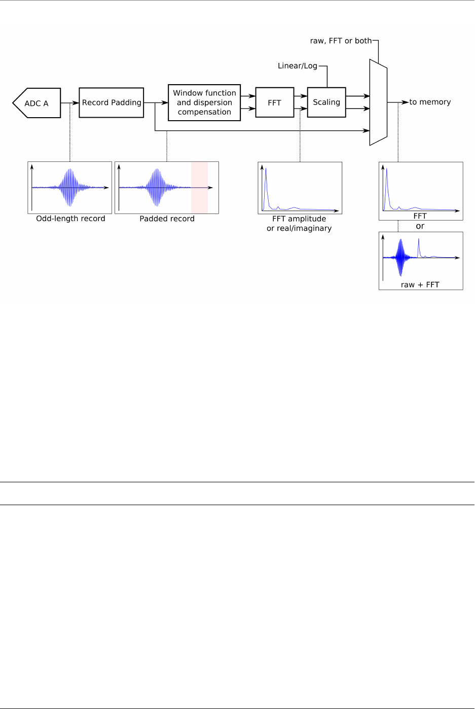
ATS-SDK Documentation, Release 7.2.0
3.1.2 General Programming Concepts
All the functions from the AlazarDSP module are defined in AlazarDSP.h, and are implemented in
the usual ATSApi library (ATSApi.dll under Windows, and libATSApi.so under Linux).
Function are prefixed either with AlazarDSP if they apply to any DSP block, or by AlazarFFT if they
are specific to fast Fourier transform modules.
The AlazarDSP API introduces a new type called dsp_module_handle, which represents a DSP mod-
ule within a digitizer. Depending on their scope, function calls either require a board or a DSP
module handle to be passed.
Note: The AlazarDSP functions must be used in the context of AutoDMA NPT applications.
3.1.3 Transition From Time-Domain Acquisitions
This section details all the steps that are required to take a working AutoDMA NPT program and
turn it into a FFT program. These code samples can be found in AlazarTech’s ATS-SDK
Function calls to the AlazarTech API are usually split into two categories: board configuration
and data acquisition. This is best seen in the code samples provided with the ATS-SDK, where
this separation is shown by sub-routines. Most of the AlazarDSP function calls fall into the second
category. This means that the board configuration routine of the existing code samples is left mostly
untouched.
60 ©2015 Alazar Technologies Inc.

ATS-SDK Documentation, Release 7.2.0
Programs that use the AlazarDSP API need to get the handle of the DSP module they want to
use. This is done by calling AlazarDSPGetModules(). Information about the DSP module can be
retrieved at any time using AlazarDSPGetInfo().
The board configuration section is left untouched when compared to a standard AutoDMA NPT
acquisition.
In the data acquisition section, the following changes must be made:
1. AlazarSetRecordSize() is not called. This function is called internally by AlazarFFTSetup().
2. AlazarFFTSetup() is called before AlazarBeforeAsyncRead() and before allocating the DMA
buffers. This is due to the fact that the number of bytes of data returned by the FFT engine
may vary from one mode to the next, e.g. U16 log of amplitude output, U32 real part, etc.
AlazarFFTSetup() returns the effective number of bytes per record that need to be allocated
and passed to AlazarBeforeAsyncRead()
3. AlazarBeforeAsyncRead() is called by passing:
(a) The number of bytes per record to the fourth parameter (SamplesPerRecord)
(b) 0x7FFFFFFF to RecordsPerAcquisition
4. AlazarWaitAsyncBufferComplete() is replaced with AlazarDSPGetBuffer().
5. AlazarAbortAsyncRead() is replaced with AlazarDSPAbortCapture().
3.2 Detailed Description
3.2.1 DSP Module Variations
Features offered by DSP processing modules can vary from one board to another. An exam-
ple of such variation is the maximum record size, which is generally lower on ATS9350 than
on other board models. In order to query these information at runtime, AlazarDSP offers the
AlazarDSPGetInfo() function. A generic interface to retrieve parameters has also been added with
AlazarDSPGetParameterU32(). Each call to this function allows to retrieve one attribute of a DSP
module. Available attributes to query are listed in DSP_PARAMETERS.
In addition, FFT module have specific parameters that are not indicated by AlazarDSPGetInfo().
For these modules, another introspection method is AlazarFFTGetMaxTriggerRepeatRate().
The maximum FFT input length can be read from the maxLength output parameter of
AlazarDSPGetInfo().
3.2.2 FFT Module Output Data
The output data format of the FFT module is determined by the outputFormat parameter to
AlazarFFTSetup(). This parameter can be any element of the FFT_OUTPUT_FORMAT enumeration ex-
cept FFT_OUTPUT_FORMAT_RAW_PLUS_FFT, optionnaly OR’ed with FFT_OUTPUT_FORMAT_RAW_PLUS_FFT.
The meaning of each element is described in FFT_OUTPUT_FORMAT.
©2015 Alazar Technologies Inc. 61
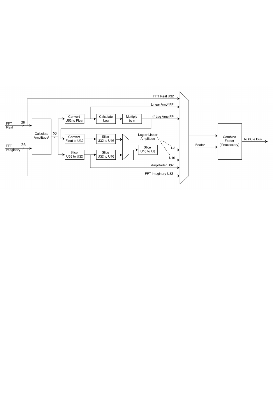
ATS-SDK Documentation, Release 7.2.0
If the RAW + FFT mode is selected, a number of samples that correspond to the FFT length is
prepended to each record during the output. These samples contain the acquired time-domain
data in U16 format, followed with padding to bring the number of samples to the FFT input length.
On the board, the Fourier Transform output is a 53-bit unsigned integer that gets converted in
various blocks to match the requested output format. Along the conversion, it is possible to set a
scaling a slicing parameter. These values are set to sane default in AlazarFFTSetup(). It is possible
however for users to change these values manually, using the AlazarFFTSetScalingAndSlicing()
function. The block diagram below shows where the conversions happen.
3.2.3 Background Subtraction
Starting with version 4.6, the on-FPGA FFT module offers a background sub-
traction feature. A record to subtract is downloaded on the board with
AlazarFFTBackgroundSubtractionSetRecordS16(), and the feature is activated by
AlazarFFTBackgroundSubtractionSetEnabled().
Once background subtraction is enabled, the background is subtracted to all acquired time-domain
records before they are sent in the FFT processing module.
It is not necessary to re-download the background record in between multiple acquisitions in the
same program. The dowloaded record remains on the board. On the other hand, the default
background record should not be assumed to be made of zeros. As the values can remain in the
board, even after a reboot of the computer.
For 12-bit digitizers, the record is downloaded at 16 bits per sample, but only the 12 most significant
bits are actually used. The 4 least significant bits are discarded. This behaviour is consistent with
the way the boards acquire and send data back to user applications.
62 ©2015 Alazar Technologies Inc.
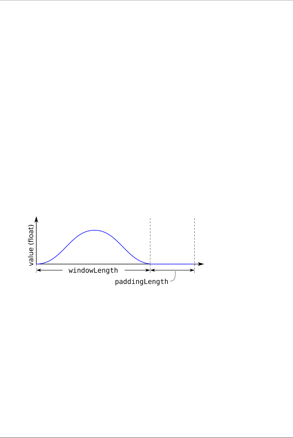
ATS-SDK Documentation, Release 7.2.0
3.3 API Reference
3.3.1 DSP-Specific Functions
RETURN_CODE AlazarDSPAbortCapture(HANDLE boardHandle)
Aborts any in-progress DMA transfer, cancels any pending transfers and does DSP-related
cleanup.
This function should be called instead of AlazarAbortAsyncRead() in a standard acquisition
configuration. In addition to handling pending and in-flight DMA transfers, it takes care of
some cleanup related to the DSP post-processing.
Warning Whereas it is not necessary to call AlazarAbortAsyncRead() to clean after a standard
acquisition, calling AlazarDSPAbortCapture() is strictly required.
Parameters
•boardHandle: The board to stop the acquisition for.
RETURN_CODE AlazarDSPGenerateWindowFunction(U32 windowType, float *window, U32
windowLength_samples, U32 paddin-
gLength_samples)
Fills an array with a generated window function and pads it with zeros.
Please note that the windows length can take any integer value. It does not need to meet the
alignment requirements that apply to the record length (see ATS-SDK guide), nor the power-
of-two requirement of the FFT length. This can allow users a very high level of control over
the effective acquired record length.
For example, if a laser source guarantees 1396 good data points at a particular frequency, the
number of samples per record on ATS9360 should be set to 1408 (the next multiple of 128)
and the FFT length should be 2048 points. The window function will be generated with a
windowLength_samples of 1396, and a paddingLength_samples of 652 (2048 - 1396).
Return ApiSuccess upon sucess.
Parameters
©2015 Alazar Technologies Inc. 63

ATS-SDK Documentation, Release 7.2.0
•windowType: Type of window to generate. Pass an item from DSP_WINDOW_ITEMS
enum.
•window: Array to be filled with the window function. It must be at least
windowLength_samples +paddingLength_samples long.
•windowLength_samples: The size of the window to generate.
•paddingLength_samples: The number of samples after the window function to pad
with zeros.
RETURN_CODE AlazarDSPGetBuffer(HANDLE boardHandle, void *buffer, U32 timeout_ms)
Waits until a buffer becomes available or an error occurs.
This function should be called instead of AlazarWaitAsyncBufferComplete() in a standard ac-
quisition configuration.
Parameters
•boardHandle: Board that filled the buffer we want to retrieve
•buffer: Pointer to the DMA buffer we want to retrieve. This must correspond to the
first DMA buffer posted to the board that has not yet been retrieved.
•timeout_ms: Time to wait for the buffer to be ready before returning with an Api-
WaitTimeout error.
RETURN_CODE AlazarDSPGetInfo(dsp_module_handle dspHandle, U32 *dspModuleId, U16
*versionMajor, U16 *versionMinor, U32 *maxLength, U32
*reserved0, U32 *reserved1)
Get information about a specific On-FPGA DSP implementation.
Use this function to query the type of a DSP module, as well as other information.
Return ApiSuccess upon success.
Parameters
•dspHandle: The handle to the DSP module to query.
•dspModuleId: The identifier of the DSP module. This describes what the type of this
module is, and can be compared against the DSP_MODULE_TYPE enum.
•versionMajor: The major version number of the DSP implementation.
•versionMinor: The minor version number of the DSP implementation.
•maxLength: The maximum length of the records that can be processed.
•reserved0: Reserved parameter. Ignored
•reserved1: Reserved parameter. Ignored
RETURN_CODE AlazarDSPGetModules(HANDLE boardHandle, U32 numEntries,
dsp_module_handle *modules, U32 *numModules)
Queries the list of DSP modules in a given board.
64 ©2015 Alazar Technologies Inc.

ATS-SDK Documentation, Release 7.2.0
This function allows to query the list of DSP modules for a digitizer board. modules is a
pointer to an array of DSP modules to be filled by this function. The numEntries parameter
specifies how many modules can be added by the function to the modules array. Lastly, the
numModules array specifies how many modules are avaiable on the specified board.
modules can be NULL. In this case, the only interest of this function is to return the number of
modules available. Please note that numEntries must be zero if modules is NULL.
numModules can be NULL. In this case, it is ignored.
This function is typically called twice. First without a modules array to query the number of
available modules, and a second time after allocating an appropriate array.
U32 numModules;
U32 retCode =AlazarDSPGetModules(handle, 0,NULL,&numModules);
// Error handling
dsp_module_handle modules[numModules];
retCode =AlazarDSPGetModules(handle, numModules, modules, NULL);
// Error handling
Return ApiSuccess upon success.
Parameters
•boardHandle: The handle of the board to query DSP modules for.
•numEntries: The maximum number of entries that the function can fill in the
modules array. Must be zero if modules is NULL.
•modules: The array where this function fills the dsp_module_handle elements. Can
be NULL.
•numModules: Returns the number of DSP modules available on this board. Ignored
if NULL.
RETURN_CODE AlazarDSPGetNextBuffer(HANDLE boardHandle, void *buffer, U32 bytesTo-
Copy, U32 timeout_ms)
Equivalent of AlazarDSPGetBuffer() to call with ADMA_ALLOC_BUFFERS.
This function should be called instead of AlazarWaitNextAsyncBufferComplete() in a standard
acquisition configuration. See the documentation of this function for more information.
Parameters
•boardHandle: Board that filled the buffer we want to retrieve
•buffer: Pointer to a buffer to receive sample data from the digitizer board.
•bytesToCopy: The number of bytes to copy into the buffer.
©2015 Alazar Technologies Inc. 65

ATS-SDK Documentation, Release 7.2.0
•timeout_ms: Time to wait for the buffer to be ready before returning with an Api-
WaitTimeout error.
RETURN_CODE AlazarDSPGetParameterU32(dsp_module_handle dspHandle, U32 parameter,
U32 *result)
Generic interface to retrieve U32-typed parameters.
This function is called with an element of DSP_PARAMETERS_U32 as parameter. Depending
on which value is selected, the function will query a different parameter internally and pass
the return value to result.
This function returns ApiSuccess upon success, and standard errors otherwise.
3.3.2 DSP-Specific Types and Enumerations
typedef struct dsp_module_descriptor *dsp_module_handle
Handle to a on-FPGA DSP module.
enum DSP_MODULE_TYPE
DSP module type.
Used by AlazarDSPGetInfo().
Values:
DSP_MODULE_NONE = 0xFFFF
DSP_MODULE_FFT
DSP_MODULE_PCD
DSP_MODULE_SSK
DSP_MODULE_DIS
enum DSP_PARAMETERS_U32
Parameters that can be queried with AlazarDSPGetParameter*()
See AlazarDSPGetParameterU32() for information about the way to use these parameters.
Values:
DSP_RAW_PLUS_FFT_SUPPORTED = 0
Tells if an FFT module supports RAW+FFT mode. This parameter returns 0if RAW+FFT
mode is not supported, and 1if it is.
DSP_FFT_SUBTRACTOR_SUPPORTED
Tells if an FFT module supports the background subtraction feature. This parameter
returns 0if the feature is not supported, and 1if it is.
enum DSP_PARAMETERS_S32
Parameters that can be queried with AlazarDSPGetParameter*() or set with AlazarDSPSetPa-
rameter*()
See AlazarDSPGetParameterS32() and AlazarDSPGetParameterS32() for information about
the way to use these parameters.
66 ©2015 Alazar Technologies Inc.

ATS-SDK Documentation, Release 7.2.0
Values:
DSP_FFT_POSTPROC_REAL_A = 0
25-bit signed integer value of “a” for real FFT output value calculation “(Re + a) * b +
c”. To set this parameter in your program, it is necessary to set it after AlazarFFTSetup()
call, because this is where its default value is set.
DSP_FFT_POSTPROC_IMAG_A
25-bit signed integer value of “a” for imaginary FFT output value calculation “(Im + a)
* b + c”. To set this parameter in your program, it is necessary to set it after AlazarFFT-
Setup() call, because this is where its default value is set.
enum DSP_PARAMETERS_FLOAT
Parameters that can be queried with AlazarDSPGetParameter*() or set with AlazarDSPSetPa-
rameter*()
See AlazarDSPGetParameterFloat() and AlazarDSPGetParameterFloat() for information
about the way to use these parameters.
Values:
DSP_FFT_POSTPROC_REAL_B = 0
IEEE754 single precision value of “b” for real FFT output value calculation “(Re + a) *
b + c”. To set this parameter in your program, it is necessary to set it after AlazarFFT-
Setup() call, because this is where its default value is set.
DSP_FFT_POSTPROC_REAL_C
IEEE754 single precision value of “c” for real FFT output value calculation “(Re + a) *
b + c”. To set this parameter in your program, it is necessary to set it after AlazarFFT-
Setup() call, because this is where its default value is set.
DSP_FFT_POSTPROC_IMAG_B
IEEE754 single precision value of “b” for imaginary FFT output value calculation “(Im
+ a) * b + c”. To set this parameter in your program, it is necessary to set it after
AlazarFFTSetup() call, because this is where its default value is set.
DSP_FFT_POSTPROC_IMAG_C
IEEE754 single precision value of “c” for imaginary FFT output value calculation “(Im
+ a) * b + c”. To set this parameter in your program, it is necessary to set it after
AlazarFFTSetup() call, because this is where its default value is set.
DSP_FFT_POSTPROC_SCALE_OUT_MAIN
IEEE754 single precision value of the scaler multiplier for the main output. To set this
parameter in your program, it is necessary to set it after AlazarFFTSetup() call, because
this is where its default value is set.
DSP_FFT_POSTPROC_SCALE_OUT_SEC
IEEE754 single precision value of the scaler multiplier for the secondary output. To
set this parameter in your program, it is necessary to set it after AlazarFFTSetup() call,
because this is where its default value is set.
enum DSP_WINDOW_ITEMS
Various types of window functions.
©2015 Alazar Technologies Inc. 67

ATS-SDK Documentation, Release 7.2.0
Used by AlazarDSPGenerateWindowFunction().
Values:
DSP_WINDOW_NONE = 0
DSP_WINDOW_HANNING
DSP_WINDOW_HAMMING
DSP_WINDOW_BLACKMAN
DSP_WINDOW_BLACKMAN_HARRIS
DSP_WINDOW_BARTLETT
NUM_DSP_WINDOW_ITEMS
3.3.3 FFT-Specific Functions
RETURN_CODE AlazarFFTBackgroundSubtractionGetRecordS16(dsp_module_handle
dspHandle, S16 *back-
groundRecord, U32
size_samples)
Reads the background subtraction record from a board.
This function can be called to read which record the board uses for the background sub-
traction feature. It is used by allocating an array of the right size, then passing it to
backgroundRecord along with it’s size in samples to size_samples.
This function should be called before or between acquisitions, not during one.
RETURN_CODE AlazarFFTBackgroundSubtractionSetEnabled(dsp_module_handle dspHan-
dle, BOOL enabled)
Controls the activation of the background subtraction feature.
Passing true to enabled activates background subtraction. Passing false deactivates it.
This function should be called before or between acquisitions, not during one.
RETURN_CODE AlazarFFTBackgroundSubtractionSetRecordS16(dsp_module_handle
dspHandle,const S16
*record, U32 size_samples)
Download the record for the background subration feature to a board.
Pass this function a pointer to an 16-bit integer array containing the record you want to
download, and the size of this record in samples.
This function should be called before or between acquisitions, not during one.
RETURN_CODE AlazarFFTGetMaxTriggerRepeatRate(dsp_module_handle dspHandle, U32 fft-
Size, double *maxTriggerRepeatRate)
Queries the maximum trigger repeat rate that the FFT engine can support without overflow.
This utility function is useful to calculate the theoretical maximum speed at which FFTs can
be computed on a specific digitizer. The value returned only takes into account the FFT
68 ©2015 Alazar Technologies Inc.

ATS-SDK Documentation, Release 7.2.0
processing speed of the on-board module. Other parameters such as bus transfer speed must
still be taken into account to ensure that an acquisition is possible on a given board.
Warning This function is available for FFT modules versions 4.5 and up.
Return ApiSucces upon success
Return ApiInvalidDspModule if the FFT module is invalid (wrong type or version)
Parameters
•dspHandle: The board for which to calculate the maximum trigger rate.
•fftSize: The number of points acquired by the board per FFT operation.
•maxTriggerRepeatRate: Output parameter that gets assigned the maximum trigger
rate supported by this board’s FFT processing module in Hertz.
RETURN_CODE AlazarFFTSetup(dsp_module_handle dspHandle, U16 inputChannelMask, U32
recordLength_samples, U32 fftLength_samples, U32 output-
Format, U32 footer, U32 reserved, U32 *bytesPerOutpu-
tRecord)
Configure the board for an FFT acquisition.
This function needs to be called in the board configuration procedure, therefore before
AlazarBeforeAsyncRead().
The output format of the fft is controlled by the outputFormat parameter, with
the FFT_OUTPUT_FORMAT enumeration. All elements of FFT_OUTPUT_FORMAT except
FFT_OUTPUT_FORMAT_RAW_PLUS_FFT describe a data type (unsigned 8-bit integer, floating point
number, etc.) as well as a scale (logarithmic or amplitude squared). It is mandatory to select
one (and only one) of these.
On the other hand, when FFT_OUTPUT_FORMAT_RAW_PLUG_FFT is OR’ed (using the C | operator)
to another symbol, it has the meaning of asking the board to output both the time-domain
(raw) and FFT data.
Parameters
•dspHandle: The FFT module to configure.
•inputChannelMask: The channels to acquire data from. This must be CHANNEL_A.
•recordLength_samples: The number of points per record to acquire. This needs to
meet the usual requirements for the number of samples per record. Please see the
documentation of AlazarBeforeAsyncRead() for more information.
•fftLength_samples: The number of points per FFT. This value must be:
–A power of two;
–Greater than or equal to recordLength_samples;
–Less than or equal to the maximum FFT size, as returned by the AlazarDSPGet-
Info() function.
©2015 Alazar Technologies Inc. 69

ATS-SDK Documentation, Release 7.2.0
•outputFormat: Describes what data is output from the FFT post-
processing module. This can be any element of the FFT_OUTPUT_FORMAT
enum except FFT_OUTPUT_FORMAT_RAW_PLUS_FFT, optionnaly OR’ed with
FFT_OUTPUT_FORMAT_RAW_PLUS_FFT.
•footer: Describes if a footer is attached to the returned records. Must be an element
of the FFT_FOOTER enum.
•reserved: Reserved for future use. Pass 0.
•bytesPerOutputRecord: Returns the number of bytes in each record coming out
of the FFT module. This value can be used to know how long the allocated DMA
buffers must be.
RETURN_CODE AlazarFFTSetWindowFunction(dsp_module_handle dspHandle, U32 sam-
plesPerRecord, float *realWindowArray, float
*imagWindowArray)
Sets the window function to use with an on-FPGA FFT module.
Downloads a window function to an AlazarTech digitizer’s memory. This window function
will be used during all subsequent acquisitions that use the on-FPGA DSP module.
This function should be called before AlazarFFTSetup(). It does not have to be called every
time an acquisition is done. It can be located in the board configuration section.
Parameters
•dspHandle: The handle of the FFT DSP module to set the window function for.
•samplesPerRecord: The number of samples in the window function array.
•realWindowArray: The real window function array. Passing NULL is equivalent to
passing an array filled with ones.
•imagWindowArray: The imaginary window function array. Passing NULL is equivalent
to passing an array filled with zeros.
RETURN_CODE AlazarFFTSetScalingAndSlicing(dsp_module_handle dspHandle, U8
slice_pos, float loge_ampl_mult)
Sets internal scaling and slicing parameters in the FFT module.
This function modifies internal parameters used by the on-FPGA FFT module to convert the
output of the FFT engine to the desired format. Please refer to the figure below for details as
to where conversions happen.
Remark This function is only valid for on-FPGA FFT modules with version less than 5.
Warning This function is intended for advanced users only. Calling it with the wrong param-
eters can prevent any meaningful data from being output by the FFT module.
To use this function in your program, it is necessary to call it after AlazarFFTSetup(), because
this is where default scaling and slicing values are set.
70 ©2015 Alazar Technologies Inc.
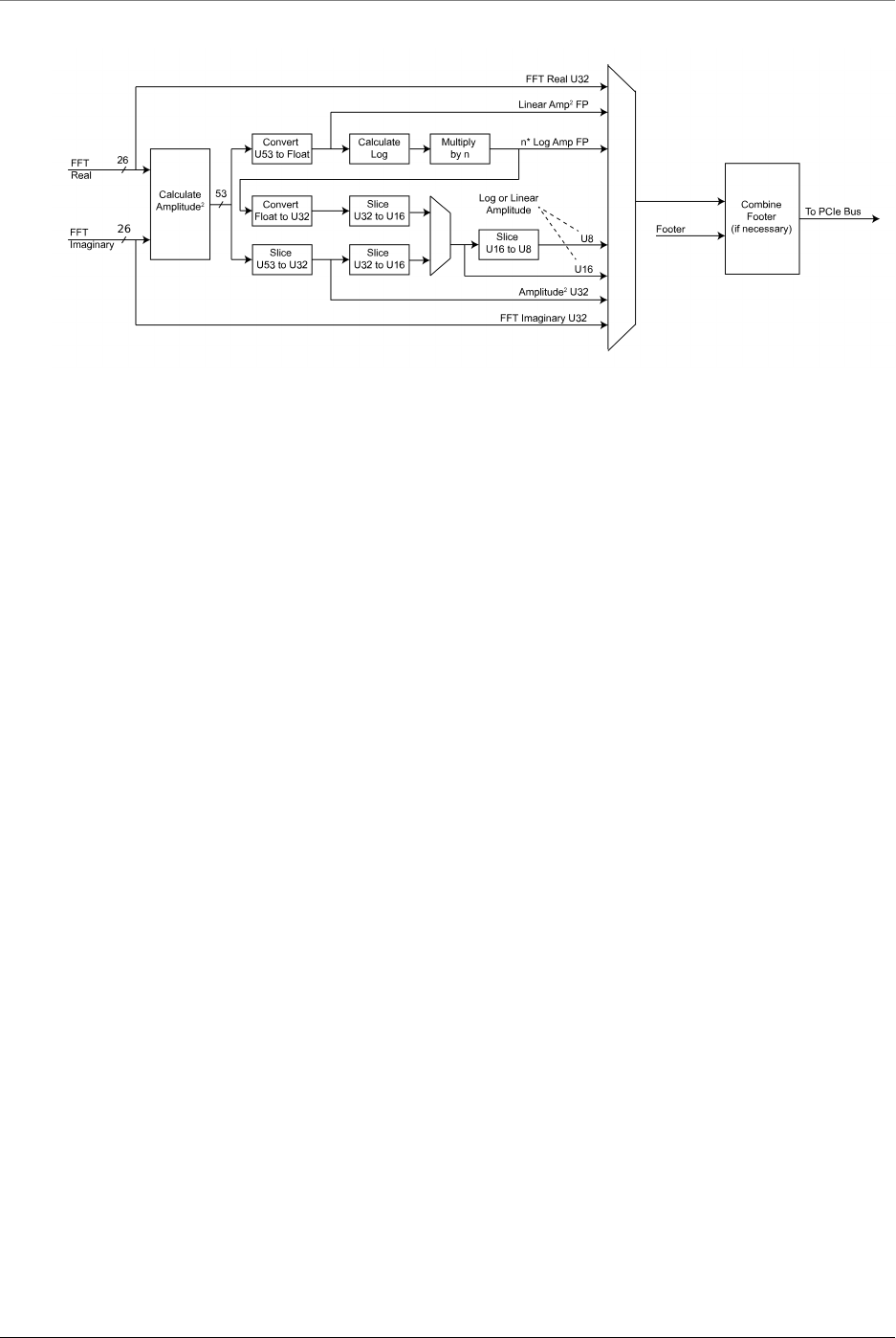
ATS-SDK Documentation, Release 7.2.0
Parameters
•dspHandle: Handle to DSP module
•slice_pos: This parameter indicates the position of the most significant bit of the
output of slicing operations with respect to the input. Lowering this value by one
has the effect of multiplying the output of the FFT module by 2. Default value is 7
for log outputs and 38 otherwise. On the block diagram, this parameter applies to
all blocks marked ‘Slice’.
•loge_ampl_mult: This controls a multiplicative factor used after the log conversion
in the FFT module. Hence, it does not apply to ‘amplitude squared’ outputs. Default
value is 4.3429446 for U8 log and float log outputs, and 1111.7938176 for U16 log
output.
3.3.4 FFT-Specific Enumerations
enum FFT_OUTPUT_FORMAT
FFT output format enumeration.
Values:
FFT_OUTPUT_FORMAT_U32_AMP2 = 0x0
32-bit unsigned integer amplitude squared output.
FFT_OUTPUT_FORMAT_U16_LOG = 0x1
16-bit unsigned integer logarithmic amplitude output.
FFT_OUTPUT_FORMAT_U16_AMP2 = 0x101
16-bit unsigned integer amplitude squared output.
FFT_OUTPUT_FORMAT_U8_LOG = 0x2
8-bit unsigned integer logarithmic amplitude output.
FFT_OUTPUT_FORMAT_U8_AMP2 = 0x102
8-bit unsigned integer amplitude squared output.
©2015 Alazar Technologies Inc. 71

ATS-SDK Documentation, Release 7.2.0
FFT_OUTPUT_FORMAT_S32_REAL = 0x3
32-bit signed integer real part of FFT output.
FFT_OUTPUT_FORMAT_S32_IMAG = 0x4
32-bit signed integer imaginary part of FFT output.
FFT_OUTPUT_FORMAT_FLOAT_AMP2 = 0xA
32-bit floating point amplitude squared output.
FFT_OUTPUT_FORMAT_FLOAT_LOG = 0xB
32-bit floating point logarithmic output.
FFT_OUTPUT_FORMAT_RAW_PLUS_FFT = 0x1000
Prepend each FFT output record with a signed 16-bit version of the time-domain data.
72 ©2015 Alazar Technologies Inc.

CHAPTER
FOUR
ADVANCED TOPICS
4.1 External clock issues for OCT applications
The external clocking feature of AlazarTech boards is commonly used in OCT applications, where
swept laser sources generate a signal to be used for clocking the acquisition. However, in some
cases the external clock signal does not meet the requirements of the digitizers, which can lead to
various issues. This section discusses the steps that need to be taken to diagnose and troubleshoot
external clock problems.
4.1.1 Diagnose external clock issues
External clock issues can be of two natures; trigger jumps, or unexpected (glitchy) acquired data.
These issues can also arise as the result of a board misconfiguration (bad record length, bad trigger
configuration. . . ). Before proceeding with the external clock troubleshooting, you must ensure
that the external clock is indeed the cause of your problems. One way to do that is to make sure
that your acquisition works fine when using the internal clock. Another way is to reproduce your
acquisition configuration in AlazarDSO, and make sure that the problem also shows up there. Once
having made sure that the external clock is the issue, the next step is to identify the problematic
regions of the signal. To do this, please acquire a few record acquisition cycles (laser sweeps) with
a high speed oscilloscope (ideally 20GS/s, 4GHz), and to send the results to us.
Here is an example of an external clock analysis plot, annotated to show the problem:
4.1.2 K-clock deglitching firmware
The k-clock deglitching firmware available for ATS9350 and ATS9351 is specifically designed to
overcome k-clock related issues. If you are using one of these boards, trying this firmware is the
next logical step. In our experience, it solves all k-clock related issues. ATS9360, ATS9370, ATS9371
and ATS9373’s firmwares include the deglitching feature by default.
4.2 AlazarSetTriggerOperationForScanning
AlazarTech digitizers require that the ADC clock be valid when an application calls
AlazarStartCapture() to arm a board to begin an acquisition. The digitizer may not be able
73
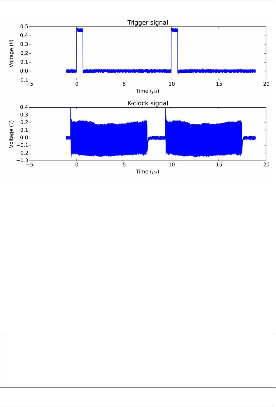
ATS-SDK Documentation, Release 7.2.0
Fig. 1: External Clock Measurement
to start an acquisition if the the application calls AlazarStartCapture() while the ADC clock is in-
valid. If an application uses both external clock and external trigger signals, and the external clock
is not suitable to drive the ADC’s during part of the interval between trigger events, the application
can call AlazarSetTriggerOperationForScanning() (rather than AlazarSetTriggerOperation())
to configure the trigger engines. This function configures the trigger engines to use an external
trigger source connected to the TRIG IN connector, and also allows the board to begin an acquisi-
tion on the next external trigger event after the call to AlazarStartCapture(), when the external
clock signal is valid.
For example, some OCT applications use a laser source that supplies an external clock sig-
nal that is valid on the rising edge of the trigger pulse, but falls to 0 Hz on the falling
edge of the trigger pulse. The digitizer may not work correctly if the application calls
AlazarStartCapture() to arm the board while the clock output is at 0 Hz. These applications
can call AlazarSetTriggerOperationForScanning() to configure the trigger engines to use an ex-
ternal trigger input, and to wait until the first rising edge of the external trigger pulse arrives after
the call the AlazarStartCapture() to start the acquisition, when the external clock is valid:
RETURN_CODE
AlazarSetTriggerOperationForScanning (
HANDLE handle,
U32 SlopeId, // trigger slope identifier
U32 Level, // trigger level code
U32 Options // scanning options
);
74 ©2015 Alazar Technologies Inc.
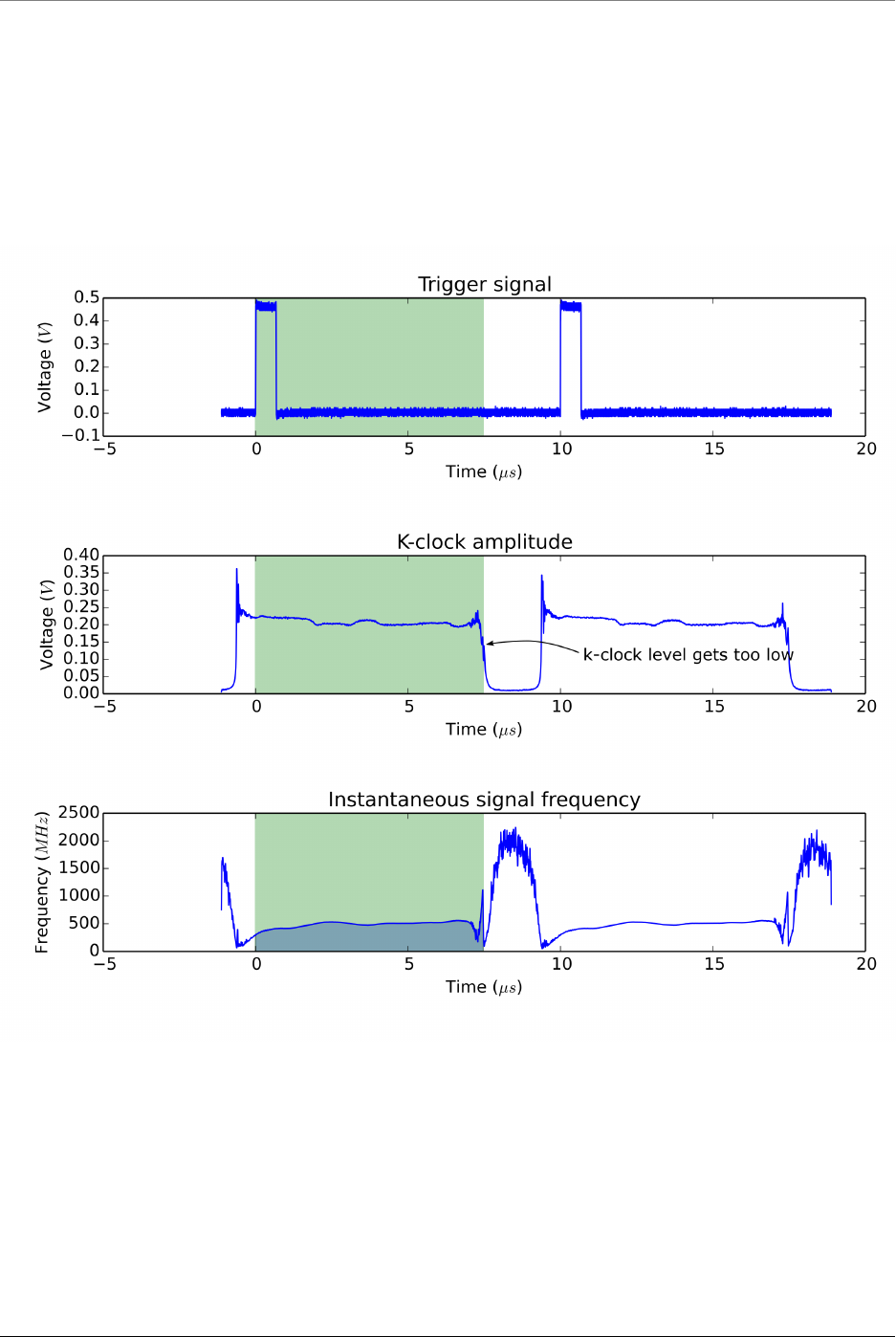
ATS-SDK Documentation, Release 7.2.0
Fig. 2: Example of external clock analysis
©2015 Alazar Technologies Inc. 75
ATS-SDK Documentation, Release 7.2.0
AlazarSetTriggerOperationForScanning() configures a board to use trigger operation
TRIG_ENGINE_OP_J, and configures the source of TRIG_ENGINE_J to be TRIG_EXTERNAL. The applica-
tion must call AlazarSetExternalTrigger() to set the full-scale external input range and coupling
of the external trigger signal connected to the TRIG IN connector. The slope identifier parameter
selects if a trigger event should be generated when the external trigger level rise above, or falls
below, a specified level. The parameter may have one of the following values.
TRIGGER_SLOPE_POSITIVE The external trigger level rises above a specified level.
TRIGGER_SLOPE_NEGATIVE The external trigger level falls below a specified level.
The trigger level parameter sets the external trigger level as an unsigned 8-bit code that represents
a fraction of the external trigger full scale input range: 0 represents the negative full-scale input,
128 represents a 0 volt input, and 255 represents the positive full-scale input. In general, the
trigger level value is given by:
TriggerLevelCode =128 +127 *TriggerLevelVolts /InputRangeVolts
The following table gives examples of how trigger level codes map to trigger levels in volts accord-
ing to the external trigger full-scale input range.
Trigger level code Input fraction Level with ±1V trigger range Level with ±5V trigger range
0 -100% -1V -5V
64 -50% -500 mV -2.5 V
96 -25% -250 mV -1.25 V
128 0% 0 V 0 V
160 +25 % 250 mV 1.25 V
192 +50% +500 mV +2.5 V
255 +100% +1V +5V
The options parameter may be one of the following flags:
STOS_OPTION_DEFER_START_CAPTURE Wait until the next external trigger event after the application
calls AlazarStartCapture() before arming the board to start the acquisition. The external
clock input should be valid when the trigger event arrives.
76 ©2015 Alazar Technologies Inc.

CHAPTER
FIVE
API REFERENCE
5.1 Functions
RETURN_CODE AlazarAbortAsyncRead(HANDLE handle)
Aborts a dual-port acquisition, and any in-process DMA transfers.
This function is part of the dual-port API. It should be used only in this context. To abort
single-port acquisitions using, see AlazarAbortCapture().
Remark If you have started an acquisition and/or posted DMA buffers to a board, you must
call AlazarAbortAsyncRead() before your application exits. If you do not, when your pro-
gram exists, Microsoft Windows may stop with a blue screen error number 0x000000CB
(DRIVER_LEFT_LOCKED_PAGES_IN_PROCESS). Linux may leak the memory used by the
DMA buffers.
Parameters
•handle: Handle to board
Return ApiSuccess upon success
Return An error code upon error. See the error code list for more detailed information.
RETURN_CODE AlazarAbortCapture(HANDLE handle)
Abort an acquisition to on-board memory.
This function is part of the single-port API. It should be used only in this context. To abort
dual-port acquisitions, see AlazarAbortAsyncRead().
Return ApiSuccess upon success
Return An error code upon error. See the error code list for more detailed information.
Parameters
•handle: Board handle
U16 *AlazarAllocBufferU16(HANDLE handle, U32 sampleCount)
Allocates a buffer for DMA transfer for an 16-bit digitizer.
77

ATS-SDK Documentation, Release 7.2.0
Return If the function is successful, it returns the base address of a page-aligned buffer in
the virtual address space of the calling process. If it fails, it returns NULL.
Remark The buffer must be freed using AlazarFreeBufferU16()
Parameters
•handle: Handle to board
•sampleCount: Buffer size in samples
U8 *AlazarAllocBufferU8(HANDLE handle, U32 sampleCount)
Allocates a buffer for DMA transfer for an 8-bit digitizer.
Return If the function is successful, it returns the base address of a page-aligned buffer in
the virtual address space of the calling process. If it fails, it returns NULL.
Remark The buffer must be freed using AlazarFreeBufferU8()
Parameters
•handle: Handle to board
•sampleCount: Buffer size in samples
U16 *AlazarAllocBufferU16Ex(HANDLE handle, U64 sampleCount)
This function acts like AlazarAllocBufferU16() and additionally allows allocation of a buffer
over 4GS for DMA transfer for an 16-bit digitizer.
Return If the function is successful, it returns the base address of a page-aligned buffer in
the virtual address space of the calling process. If it fails, it returns NULL.
Remark The buffer must be freed using AlazarFreeBufferU16Ex()
Parameters
•handle: Handle to board
•sampleCount: Buffer size in samples
U8 *AlazarAllocBufferU8Ex(HANDLE handle, U64 sampleCount)
This function acts like AlazarAllocBufferU8() and additionally allows allocation of a buffer
over 4GS for DMA transfer for an 8-bit digitizer.
Return If the function is successful, it returns the base address of a page-aligned buffer in
the virtual address space of the calling process. If it fails, it returns NULL.
Remark The buffer must be freed using AlazarFreeBufferU8Ex()
Parameters
•handle: Handle to board
•sampleCount: Buffer size in samples
78 ©2015 Alazar Technologies Inc.

ATS-SDK Documentation, Release 7.2.0
RETURN_CODE AlazarBeforeAsyncRead(HANDLE handle, U32 channelSelect, long transfer-
Offset, U32 transferLength, U32 recordsPerBuffer,
U32 recordsPerAcquisition, U32 flags)
Configure a board to make an asynchronous AutoDMA acquisition.
In non-DSP mode, when record headers are not enabled, the total number of bytes per Au-
toDMA buffer is given by
bytesPerBuffer =bytesPerSample *samplesPerRecord *recordsPerBuffer;
Return ApiSuccess upon success
Return An error code upon error. See the error code list for more detailed information.
Remark transferLength must meet certain alignment criteria which depend on the board
model and the acquisition type. Please refer to board-specific documentation for more
information.
Remark recordsPerBuffer must be set to 1 in continuous streaming and triggered streaming
AutoDMA modes.
Remark recordsPerAcquisition is ignored in Continuous Streaming and Triggered Stream-
ing modes. Instead, the acquisition runs continuously until AlazarAbortAsyncRead() is
called. In other modes, it must be either:
• A multiple of recordsPerBuffer
•0x7FFFFFFF to indicate that the acquisition should continue indefinitely.
Parameters
•handle: Handle to board
•channelSelect: Select the channel(s) to control. This can be one or more of the
channels of ALAZAR_CHANNELS, assembled with the OR bitwise operator.
•transferOffset: Specify the first sample from each on-board record to transfer from
on-board to host memory. This value is a sample relative to the trigger position in
an on-board record.
•transferLength: Specify the number of samples from each record to transfer from
on-board to host memory. In DSP-mode, it takes the number of bytes instead of
samples. See remarks.
•recordsPerBuffer: The number of records in each buffer. See remarks.
•recordsPerAcquisition: The number of records to acquire during one acquisition.
Set this value to 0x7FFFFFFF to acquire indefinitely until the acquisition is aborted.
This parameter is ignored in Triggered Streaming and Continuous Streaming modes.
See remarks.
•flags: Specifies AutoDMA mode and option. Must be one element
of ALAZAR_ADMA_MODES combined with zero or more element(s) of
ALAZAR_ADMA_FLAGS using the bitwise OR operator.
©2015 Alazar Technologies Inc. 79

ATS-SDK Documentation, Release 7.2.0
When record headers are enabled, the formula changes to:
bytesPerBuffer =(16 +bytesPerSample *samplesPerRecord) *
recordsPerBuffer;
For best performance, AutoDMA parameters should be selected so that the total number of
bytes per buffer is greater than about 1 MB. This allows for relatively long DMA transfer
times compared to the time required to prepare a buffer for DMA transfer and re-arm the
DMA engines.
ATS460, ATS660 and ATS860 digitizer boards require that AutoDMA parameters be selected
so that the total number of bytes per buffer is less than 4 MB. Other boards require that the
total number of bytes per buffer be less than 64 MB.
U32 AlazarBoardsFound()
Determine the number of digitizer boards that were detected in all board systems.
Return The total number of digitizer boards detected.
See AlazarNumOfSystems()
U32 AlazarBoardsInSystemByHandle(HANDLE systemHandle)
Return the number of digitizer boards in a board system specified by the handle of its master
board.
If this function is called with the handle of to the master board in a master-slave system, it
returns the total number of boards in the system.
If this function is called with the handle of an independent board, it returns 1.
If it is called with the handle to a slave in a master-slave system or with an invalid handle, it
returns 0.
Return ApiSuccess upon success
Return An error code upon error. See the error code list for more detailed information.
U32 AlazarBoardsInSystemBySystemID(U32 systemId)
Returns the number of digitizer boards in a board system specified by its system identifier.
If this function is called with the identifier of a master-slave system, it returns the total number
of boards in the system, including the master.
If this function is called with the identifier of an independent board system, it returns one.
If this fucntion is called with the identifier of an invalid board system, it returns zero.
Return ApiSuccess upon success
Return An error code upon error. See the error code list for more detailed information.
Parameters
•systemId: The system identification number
80 ©2015 Alazar Technologies Inc.

ATS-SDK Documentation, Release 7.2.0
U32 AlazarBusy(HANDLE handle)
Determines if an acquisition is in progress.
Return If the board is busy acquiring data to on-board memory, this function returns 1.
Otherwise, it returns 0.
Parameters
•handle: Board handle
void AlazarClose(HANDLE handle)
This routine will close the AUTODMA capabilities of the device.
Only call this upon exit or error.
Return ApiSuccess upon success
Return An error code upon error. See the error code list for more detailed information.
Parameters
•handle: Board handle
RETURN_CODE AlazarConfigureAuxIO(HANDLE handle, U32 mode, U32 parameter)
Configures the AUX I/O connector as an input or output signal.
The AUX I/O connector generates TTL level signals when configured as an output, and expects
TLL level signals when configured as an input.
Parameters
•handle: Handle to board
•mode: The AUX I/O mode. Can be selected from ALAZAR_AUX_IO_MODES.
If an output mode is selected, the parameter may be OR’ed with
AUX_OUT_TRIGGER_ENABLE to enable the board to use software trigger enable.
When this flag is set, the board will wait for software to call AlazarForceTriggerEn-
able() to generate a trigger enable event; then wait for sufficient trigger events to
capture the records in an AutoDMA buffer; then wait for the next trigger enable
event and repeat.
•parameter: The meaning of this value varies depending on mode. See
ALAZAR_AUX_IO_MODES for more details.
AUX I/O output signals may be limited by the bandwidth of the AUX output drivers.
The ATS9440 has two AUX I/O connectors: AUX 1 and AUX 2. AUX 1 is configured by
firmware as a trigger output signal, while AUX 2 is configured by software using AlazarCon-
figureAuxIO(). A firmware update is required to change the operation of AUX 1.
ATS9625 and ATS9626 have two AUX I/O connectors; AUX 1 and AUX 2. AUX 1 is configured
by software using AlazarConfigureAuxIO(), while AUX 2 is configured by default as a trigger
output signal. A custom user-programmable FGPA can control the operation of AUX 2 as
required by the FPGA designer.
©2015 Alazar Technologies Inc. 81

ATS-SDK Documentation, Release 7.2.0
To enable data skipping, first create a bitmap in memory that specifies which sample clock
edges should generate a sample point, and which sample clock edges should be ignored.
• 1’s in the bitmap specify the clock edges that should generate a sample point. The total
number of 1’s in the bitmap must be equal to the number of post-trigger samples per
record specified in the call to AlazarSetRecordSize.
• 0’s in the bitmap specify the clock edges that should not be used to generate a sample
point.
• The total total number of bits in the bitmap is equal to the number of sample clocks in
one record.
For example, to receive 16 samples from 32 sample clocks where every other sample clock is
ignored, create a bitmap of 32 bits with values { 1 0 1 0 1 0 . . . 1 0 }, or { 0x5555, 0x5555
}. Note that 16 of the 32 bits are 1’s.
And to receive 24 samples from 96 sample clocks where data from every 3 of 4 samples clocks
is ignored, create a bitmap of 96 bits with values { 1 0 0 0 1 0 0 0 1 0 0 0 . . . 1 0 0 0 }, or in
{ 0x1111, 0x1111, 0x1111, 0x1111, 0x1111, 0x1111 }. Note that 24 of the 96 bits are 1’s.
After creating a bitmap, call AlazarConfigureSampleSkipping with:
• Mode equal to SSM_ENABLE (1)
• SampleClocksPerRecord equal to the total number of sample clocks per record.
• pSampleSkipBitmap with the address of the U16 array.
To disable data skipping, call AlazarConfigureSampleSkipping with Mode equal to
SSM_DISABLE (0). The SampleClocksPerRecord and pSampleSkipBitmap parameters are ig-
nored.
Note that data skipping currently is supported by the ATS9371, ATS9373, ATS9360, ATS9350,
ATS9351 and ATS9440. For ATS9440, data skipping only works with post-trigger data ac-
quired at 125 MSPS or 100 MSPS.
Return ApiSuccess upon success
Return An error code upon error. See the error code list for more detailed information.
RETURN_CODE AlazarConfigureLSB(HANDLE handle, U32 valueLsb0, U32 valueLsb1)
Repurposes unused least significant bits in 12- and 14-bit boards.
12- and 14-bit digitizers return 16-bit sample values per sample by default, with the actual
sample codes stored in the most significant bits. By default, the least significant bits of each
sample value are zero-filled. Use this option to use these otherwise unused bits as digital
outputs.
This feature is not available on all boards. See board-specific documentation for more infor-
mation.
Return ApiSuccess upon success
Return An error code upon error. See the error code list for more detailed information.
82 ©2015 Alazar Technologies Inc.

ATS-SDK Documentation, Release 7.2.0
Parameters
•handle: Handle to board
•valueLsb0: Specifies the signal to output to the least significant bit of each sample
value. Must be one of ALAZAR_LSB.
•valueLsb1: Specifies the signal to output to the least significant bit of each sample
value. Must be one of ALAZAR_LSB.
RETURN_CODE AlazarConfigureRecordAverage(HANDLE handle, U32 mode, U32 samples-
PerRecord, U32 recordsPerAverage, U32 op-
tions)
Configures a digitizer to co-add ADC samples from a specified number of records in an accu-
mulator record, and transfer accumulator records rather than the ADC sample values.
When FPGA record averaging is enabled, the digitizer transfers one accumulator record to
host memory after recordsPerAverage trigger events have been captured.
Return ApiSuccess upon success
Return An error code upon error. See the error code list for more detailed information.
Remark FPGA record averaging is currently supported on the following digitizers:
• ATS9870 with FPGA version 180.0 and above, and driver version 5.9.8 and above
• AXI9870 with FPGA version 180.0 and above, and driver version 5.9.23 and above
Parameters
•handle: Handle to board
•mode: Averaging mode. Should be one element of ALAZAR_CRA_MODES.
•samplesPerRecord: The number of ADC samples per accumulator record.
•recordsPerAverage: The number of records to accumulate per average.
•options: The averaging options. Can be one of ALAZAR_CRA_OPTIONS.
Each accumulator record has interleaved samples from CH A and CH B. FPGA accumulators
are 32-bit wide, so each accumulator value occupies 4 bytes in a buffer. The digitizer transfers
multi-byte values in little-endian byte order.
CH A and CH B accumulator records are always transferred to host memory. As a result, the
number of bytes per accumulator record is given by:
samplesPerRecord *2(channels) *4(bytes per accumulator sample)
The maximum value of recordsPerAverage for 8-bit digitizers is 16777215
Note that recordsPerAverage does not have to be equal to the number of records per buffer
in AutoDMA mode.
RETURN_CODE AlazarConfigureSampleSkipping(HANDLE handle, U32 mode, U32 sample-
ClocksPerRecord, U16 *sampleSkipBitmap)
Makes the digitizer sub-sample post trigger data in arbitrary, non-uniform intervals.
©2015 Alazar Technologies Inc. 83

ATS-SDK Documentation, Release 7.2.0
The application specifies which sample clock edges after a trigger event the digitizer should
use to generate sample points, and which sample clock edges the digitizer should ignore.
Return ApiSuccess upon success
Return An error code upon error. See the error code list for more detailed information.
Parameters
•handle: Handle to board
•mode: The data skipping mode. 0 means disable sample skipping and 1 means enable
sample skipping.
•sampleClocksPerRecord: The number of sample clocks per record. This value can-
not exceed 65536.
•sampleSkipBitmap: An array of bits that specify which sample clock edges should be
used to capture a sample point (value = 1) and which should be ignored (value =
0).
RETURN_CODE AlazarCoprocessorDownloadA(HANDLE handle, char *fileName, U32 options)
Downloads a FPGA image in RBF (raw binary file) format to the coprocessor FPGA.
Return ApiSuccess upon success
Return An error code upon error. See the error code list for more detailed information.
Parameters
•handle: Handle to board
•fileName: Path to RBF file
•options: Download options chosen from ALAZAR_COPROCESSOR_DOWNLOAD_OPTIONS
RETURN_CODE AlazarCoprocessorRegisterRead(HANDLE handle, U32 offset, U32 *value)
Reads the content of a user-programmable FPGA register.
Return ApiSuccess upon success
Return An error code upon error. See the error code list for more detailed information.
Parameters
•handle: Handle to board
•offset: Register offset
•value: Address of a variable to receive the register’s value
RETURN_CODE AlazarCoprocessorRegisterWrite(HANDLE handle, U32 offset, U32 value)
Writes a value to a user-programmable coprocessor FPGA register.
Return ApiSuccess upon success
84 ©2015 Alazar Technologies Inc.

ATS-SDK Documentation, Release 7.2.0
Return An error code upon error. See the error code list for more detailed information.
Parameters
•handle: Handle to board
•offset: Register offset
•value: Value to write
RETURN_CODE AlazarCreateStreamFile(HANDLE handle,const char *filePath)
Creates a binary data file for this board, and enables saving AutoDMA data from thie board
to disk.
If possible, select AlazarBeforeAsyncRead() parameters that result in DMA buffers whose
length in bytes is evenly divisible into sectors of the volume selected by filePath. If the DMA
buffer length is evenly divisible into records, AlazarCreateStreamFile() disables file caching to
obtain the highest possible sequential write performance.
Return ApiSuccess upon success
Return An error code upon error. See the error code list for more detailed information.
Parameters
•handle: Handle to board
•filePath: Pointer to a NULL-terminated string that specifies the name of the file.
An AutoDMA buffer is saved to disk when an application calls AlazarWaitNextAsyncBufer-
Complete(). For best performance, set the bytesToCopy parameter in AlazarWaitNextA-
syncBuferComplete() to zero so that data is written to disk without copying it to the user-
supplied buffer.
This function must be called after AlazarBeforeAsyncRead() and before AlazarStartCapture().
File streaming is only active for the acquisition that is about to start when this function is
called. You should call this function again for each acquisition with which you want file
streaming.
RETURN_CODE AlazarDSPAbortCapture(HANDLE boardHandle)
Aborts any in-progress DMA transfer, cancels any pending transfers and does DSP-related
cleanup.
This function should be called instead of AlazarAbortAsyncRead() in a standard acquisition
configuration. In addition to handling pending and in-flight DMA transfers, it takes care of
some cleanup related to the DSP post-processing.
Warning Whereas it is not necessary to call AlazarAbortAsyncRead() to clean after a standard
acquisition, calling AlazarDSPAbortCapture() is strictly required.
Parameters
•boardHandle: The board to stop the acquisition for.
©2015 Alazar Technologies Inc. 85

ATS-SDK Documentation, Release 7.2.0
RETURN_CODE AlazarDSPGetBuffer(HANDLE boardHandle, void *buffer, U32 timeout_ms)
Waits until a buffer becomes available or an error occurs.
This function should be called instead of AlazarWaitAsyncBufferComplete() in a standard ac-
quisition configuration.
Parameters
•boardHandle: Board that filled the buffer we want to retrieve
•buffer: Pointer to the DMA buffer we want to retrieve. This must correspond to the
first DMA buffer posted to the board that has not yet been retrieved.
•timeout_ms: Time to wait for the buffer to be ready before returning with an Api-
WaitTimeout error.
RETURN_CODE AlazarDSPGetModules(HANDLE boardHandle, U32 numEntries,
dsp_module_handle *modules, U32 *numModules)
Queries the list of DSP modules in a given board.
This function allows to query the list of DSP modules for a digitizer board. modules is a
pointer to an array of DSP modules to be filled by this function. The numEntries parameter
specifies how many modules can be added by the function to the modules array. Lastly, the
numModules array specifies how many modules are avaiable on the specified board.
modules can be NULL. In this case, the only interest of this function is to return the number of
modules available. Please note that numEntries must be zero if modules is NULL.
numModules can be NULL. In this case, it is ignored.
This function is typically called twice. First without a modules array to query the number of
available modules, and a second time after allocating an appropriate array.
U32 numModules;
U32 retCode =AlazarDSPGetModules(handle, 0, NULL, &numModules);
// Error handling
dsp_module_handle modules[numModules];
retCode =AlazarDSPGetModules(handle, numModules, modules, NULL);
// Error handling
Return ApiSuccess upon success.
Parameters
•boardHandle: The handle of the board to query DSP modules for.
•numEntries: The maximum number of entries that the function can fill in the
modules array. Must be zero if modules is NULL.
86 ©2015 Alazar Technologies Inc.

ATS-SDK Documentation, Release 7.2.0
•modules: The array where this function fills the dsp_module_handle elements. Can
be NULL.
•numModules: Returns the number of DSP modules available on this board. Ignored
if NULL.
RETURN_CODE AlazarDSPGetNextBuffer(HANDLE boardHandle, void *buffer, U32 bytesTo-
Copy, U32 timeout_ms)
Equivalent of AlazarDSPGetBuffer() to call with ADMA_ALLOC_BUFFERS.
This function should be called instead of AlazarWaitNextAsyncBufferComplete() in a standard
acquisition configuration. See the documentation of this function for more information.
Parameters
•boardHandle: Board that filled the buffer we want to retrieve
•buffer: Pointer to a buffer to receive sample data from the digitizer board.
•bytesToCopy: The number of bytes to copy into the buffer.
•timeout_ms: Time to wait for the buffer to be ready before returning with an Api-
WaitTimeout error.
RETURN_CODE AlazarDSPGetInfo(dsp_module_handle dspHandle, U32 *dspModuleId, U16
*versionMajor, U16 *versionMinor, U32 *maxLength, U32
*reserved0, U32 *reserved1)
Get information about a specific On-FPGA DSP implementation.
Use this function to query the type of a DSP module, as well as other information.
Return ApiSuccess upon success.
Parameters
•dspHandle: The handle to the DSP module to query.
•dspModuleId: The identifier of the DSP module. This describes what the type of this
module is, and can be compared against the DSP_MODULE_TYPE enum.
•versionMajor: The major version number of the DSP implementation.
•versionMinor: The minor version number of the DSP implementation.
•maxLength: The maximum length of the records that can be processed.
•reserved0: Reserved parameter. Ignored
•reserved1: Reserved parameter. Ignored
RETURN_CODE AlazarDSPGenerateWindowFunction(U32 windowType, float *window, U32
windowLength_samples, U32 paddin-
gLength_samples)
Fills an array with a generated window function and pads it with zeros.
©2015 Alazar Technologies Inc. 87

ATS-SDK Documentation, Release 7.2.0
Please note that the windows length can take any integer value. It does not need to meet the
alignment requirements that apply to the record length (see ATS-SDK guide), nor the power-
of-two requirement of the FFT length. This can allow users a very high level of control over
the effective acquired record length.
For example, if a laser source guarantees 1396 good data points at a particular frequency, the
number of samples per record on ATS9360 should be set to 1408 (the next multiple of 128)
and the FFT length should be 2048 points. The window function will be generated with a
windowLength_samples of 1396, and a paddingLength_samples of 652 (2048 - 1396).
Return ApiSuccess upon sucess.
Parameters
•windowType: Type of window to generate. Pass an item from DSP_WINDOW_ITEMS
enum.
•window: Array to be filled with the window function. It must be at least
windowLength_samples +paddingLength_samples long.
•windowLength_samples: The size of the window to generate.
•paddingLength_samples: The number of samples after the window function to pad
with zeros.
const char *AlazarErrorToText(RETURN_CODE retCode)
Converts a numerical return code to a NULL terminated string.
Return A string containing the identifier name of the error code
Remark It is often easier to work with a descriptive error name than an error number.
Parameters
•retCode: Return code from an AlazarTech API function
RETURN_CODE AlazarExtractFFTNPTFooters(void *buffer, U32 recordSize_bytes, U32 buffer-
Size_bytes, NPTFooter *footersArray, U32
numFootersToExtract)
Extracts NPT footers from a buffer acquired during an FFT acquisition.
88 ©2015 Alazar Technologies Inc.

ATS-SDK Documentation, Release 7.2.0
Before calling this function, it is important to make sure that the buffers have been acquired in
NPT mode with the NPT footers active. In addition, the acquisition must have used on-FPGA
FFT computation.
Warning footersArray must contain at least numFootersToExtract elements.
Parameters
•buffer: Base address of the DMA buffer to process
•recordSize_bytes: Bytes per record in the DMA buffer passed as argument as re-
turned by AlazarFFTSetup().
•bufferSize_bytes: Bytes per buffer in the DMA buffer passed as argument
•footersArray: Base address of an array of NPTFooter structures which will be filled
by this function
•numFootersToExtract: Maximum numbers of footers to extract. This can be a num-
ber from zero to the number of records in the DMA buffer passed as argument.
RETURN_CODE AlazarExtractTimeDomainNPTFooters(void *buffer, U32 recordSize_bytes,
U32 bufferSize_bytes, NPTFooter
*footersArray, U32 numFootersToEx-
tract)
Extracts NPT footers from a buffer acquired during a time-domain acquisition.
Before calling this function, it is important to make sure that the buffers have been acquired
in NPT mode with the NPT footers active. In addition, the acquisition must not have used
on-FPGA FFT computation.
Warning footersArray must contain at least numFootersToExtract elements.
Parameters
•buffer: Base address of the DMA buffer to process
•recordSize_bytes: Bytes per record in the DMA buffer passed as argument
•bufferSize_bytes: Bytes per buffer in the DMA buffer passed as argument
•footersArray: Base address of an array of NPTFooter structures which will be filled
by this function
•numFootersToExtract: Maximum numbers of footers to extract. This can be a num-
ber from zero to the number of records in the DMA buffer passed as argument.
RETURN_CODE AlazarExtractNPTFooters(void *buffer, U32 recordSize_bytes, U32 buffer-
Size_bytes, NPTFooter *footersArray, U32 num-
FootersToExtract)
Extracts NPT footers from a buffer that contains them.
Before calling this function, it is important to make sure that the buffers have been acquired
in NPT mode with the NPT footers active.
©2015 Alazar Technologies Inc. 89

ATS-SDK Documentation, Release 7.2.0
Warning This function has been deprecated in favor of AlazarExtractTimeDomainNPTFoot-
ers() and AlazarExtractFFTNPTFooters(). It is still usable, but only works on NPT footers
acquired as part of an FFT acquisition.
Warning footersArray must contain at least numFootersToExtract elements.
Parameters
•buffer: Base address of the DMA buffer to process
•recordSize_bytes: Bytes per record in the DMA buffer passed as argument
•bufferSize_bytes: Bytes per buffer in the DMA buffer passed as argument
•footersArray: Base address of an array of NPTFooter structures which will be filled
by this function
•numFootersToExtract: Maximum numbers of footers to extract. This can be a num-
ber from zero to the number of records in the DMA buffer passed as argument.
RETURN_CODE AlazarFFTSetup(dsp_module_handle dspHandle, U16 inputChannelMask, U32
recordLength_samples, U32 fftLength_samples, U32 output-
Format, U32 footer, U32 reserved, U32 *bytesPerOutpu-
tRecord)
Configure the board for an FFT acquisition.
This function needs to be called in the board configuration procedure, therefore before
AlazarBeforeAsyncRead().
The output format of the fft is controlled by the outputFormat parameter, with
the FFT_OUTPUT_FORMAT enumeration. All elements of FFT_OUTPUT_FORMAT except
FFT_OUTPUT_FORMAT_RAW_PLUS_FFT describe a data type (unsigned 8-bit integer, floating point
number, etc.) as well as a scale (logarithmic or amplitude squared). It is mandatory to select
one (and only one) of these.
On the other hand, when FFT_OUTPUT_FORMAT_RAW_PLUG_FFT is OR’ed (using the C | operator)
to another symbol, it has the meaning of asking the board to output both the time-domain
(raw) and FFT data.
Parameters
•dspHandle: The FFT module to configure.
•inputChannelMask: The channels to acquire data from. This must be CHANNEL_A.
•recordLength_samples: The number of points per record to acquire. This needs to
meet the usual requirements for the number of samples per record. Please see the
documentation of AlazarBeforeAsyncRead() for more information.
•fftLength_samples: The number of points per FFT. This value must be:
–A power of two;
–Greater than or equal to recordLength_samples;
90 ©2015 Alazar Technologies Inc.

ATS-SDK Documentation, Release 7.2.0
–Less than or equal to the maximum FFT size, as returned by the AlazarDSPGet-
Info() function.
•outputFormat: Describes what data is output from the FFT post-
processing module. This can be any element of the FFT_OUTPUT_FORMAT
enum except FFT_OUTPUT_FORMAT_RAW_PLUS_FFT, optionnaly OR’ed with
FFT_OUTPUT_FORMAT_RAW_PLUS_FFT.
•footer: Describes if a footer is attached to the returned records. Must be an element
of the FFT_FOOTER enum.
•reserved: Reserved for future use. Pass 0.
•bytesPerOutputRecord: Returns the number of bytes in each record coming out
of the FFT module. This value can be used to know how long the allocated DMA
buffers must be.
RETURN_CODE AlazarFFTSetWindowFunction(dsp_module_handle dspHandle, U32 sam-
plesPerRecord, float *realWindowArray, float
*imagWindowArray)
Sets the window function to use with an on-FPGA FFT module.
Downloads a window function to an AlazarTech digitizer’s memory. This window function
will be used during all subsequent acquisitions that use the on-FPGA DSP module.
This function should be called before AlazarFFTSetup(). It does not have to be called every
time an acquisition is done. It can be located in the board configuration section.
Parameters
•dspHandle: The handle of the FFT DSP module to set the window function for.
•samplesPerRecord: The number of samples in the window function array.
•realWindowArray: The real window function array. Passing NULL is equivalent to
passing an array filled with ones.
•imagWindowArray: The imaginary window function array. Passing NULL is equivalent
to passing an array filled with zeros.
RETURN_CODE AlazarFreeBufferU16(HANDLE handle, U16 *buffer)
Frees a buffer allocated with AlazarAllocBufferU16()
Return ApiSuccess upon success
Return An error code upon error. See the error code list for more detailed information.
Parameters
•handle: Handle to board
•buffer: Base address of the buffer to free
RETURN_CODE AlazarFreeBufferU8(HANDLE handle, U8 *buffer)
Frees a buffer allocated with AlazarAllocBufferU8()
©2015 Alazar Technologies Inc. 91

ATS-SDK Documentation, Release 7.2.0
Return ApiSuccess upon success
Return An error code upon error. See the error code list for more detailed information.
Parameters
•handle: Handle to board
•buffer: Base address of the buffer to free
RETURN_CODE AlazarFreeBufferU16Ex(HANDLE handle, U16 *buffer)
Frees a buffer allocated with AlazarAllocBufferU16Ex()
Return ApiSuccess upon success
Return An error code upon error. See the error code list for more detailed information.
Parameters
•handle: Handle to board
•buffer: Base address of the buffer to free
RETURN_CODE AlazarFreeBufferU8Ex(HANDLE handle, U8 *buffer)
Frees a buffer allocated with AlazarAllocBufferU8Ex()
Return ApiSuccess upon success
Return An error code upon error. See the error code list for more detailed information.
Parameters
•handle: Handle to board
•buffer: Base address of the buffer to free
RETURN_CODE AlazarForceTrigger(HANDLE handle)
Generate a software trigger event.
Return ApiSuccess upon success
Return An error code upon error. See the error code list for more detailed information.
Parameters
•handle: Board handle
RETURN_CODE AlazarForceTriggerEnable(HANDLE handle)
Generate a software trigger enable event.
Return ApiSuccess upon success
Return An error code upon error. See the error code list for more detailed information.
Parameters
•handle: Board handle
92 ©2015 Alazar Technologies Inc.

ATS-SDK Documentation, Release 7.2.0
HANDLE AlazarGetBoardBySystemHandle(HANDLE systemHandle, U32 boardId)
Get a handle to a board in a board system where the board system is specified by a handle to
its master board and the board by its identifier within the system.
Return A handle to the specified board if it was found
Return NULL if the master board handle is invalid, or a board with the specified board iden-
tifier was not found in the specified board system.
Parameters
•systemHandle: Handle to master board
•boardId: Board identifier in the board system
HANDLE AlazarGetBoardBySystemID(U32 systemId, U32 boardId)
Get a handle to a board in a board system where the board and system are identified by their
ID.
Detailed description
Return A handle to the specified board if it was found.
Return NULL if the board with the specified systemId and boardId was not found.
Parameters
•systemId: The system identifier
•boardId: The board identifier
U32 AlazarGetBoardKind(HANDLE handle)
Get a board model identifier of the board associated with a board handle.
Return A non-zero board model identifier upon success. See BoardTypes for converting the
identifier into a board model.
Return Zero upon error.
Parameters
•handle: Board handle
RETURN_CODE AlazarGetBoardRevision(HANDLE handle, U8 *major, U8 *minor)
Get the PCB hadware revision level of a digitizer board.
AlazarTech periodically updates the PCB hadware of its digitizers to improve functionality.
Many PCIE digitizers can report the PCB hadware revision to software. Note that this function
is not supported on PCI digitizer boards.
Return ApiSuccess upon success
Return An error code upon error. See the error code list for more detailed information.
Parameters
©2015 Alazar Technologies Inc. 93

ATS-SDK Documentation, Release 7.2.0
•handle: The board handle
•major: PCB major version number
•minor: PCB minor version number
RETURN_CODE AlazarGetChannelInfo(HANDLE handle, U32 *memorySize, U8 *bitsPerSam-
ple)
Get the total on-board memory in samples, and sample size in bits per sample.
Return ApiSuccess upon success
Return An error code upon error. See the error code list for more detailed information.
Remark The memory size information is independant of how many channels the board
can acquire on simultaneously. When multiple channels acquire data, they share this
amount.
Remark The memory size indication is given for the default packing mode. See documenta-
tion about data packing for more information.
Parameters
•handle: Board handle.
•memorySize: Total size of the on-board memory in samples.
•bitsPerSample: Bits per sample.
RETURN_CODE AlazarGetChannelInfoEx(HANDLE handle, S64 *memorySize, U8 *bitsPer-
Sample)
Get the total on-board memory in samples, and sample size in bits per sample.
Return ApiSuccess upon success
Return An error code upon error. See the error code list for more detailed information.
Remark The memory size information is independant of how many channels the board
can acquire on simultaneously. When multiple channels acquire data, they share this
amount.
Remark The memory size indication is given for the default packing mode. See documenta-
tion about data packing for more information.
Parameters
•handle: Board handle.
•memorySize: Total size of the on-board memory in samples.
•bitsPerSample: Bits per sample.
RETURN_CODE AlazarGetCPLDVersion(HANDLE handle, U8 *major, U8 *minor)
Get the CPLD version number of the specified board.
Parameters
94 ©2015 Alazar Technologies Inc.

ATS-SDK Documentation, Release 7.2.0
•handle: Board handle
•major: CPLD version number
•minor: CPLD version number
RETURN_CODE AlazarGetDriverVersion(U8 *major, U8 *minor, U8 *revision)
Get the device driver version of the most recently opened device.
Driver releases are given a version number with the format X.Y.Z where: X is the major release
number, Y is the minor release number, and Z is the minor revision number.
Return ApiSuccess upon success
Return An error code upon error. See the error code list for more detailed information.
See AlazarGetSDKVersion()
See AlazarGetCPLDVersion()
Parameters
•major: The driver major version number
•minor: The driver minor version number
•revision: The driver revision number
RETURN_CODE AlazarGetMaxRecordsCapable(HANDLE handle, U32 samplesPerRecord, U32
*maxRecordsPerCapture)
Calculate the maximum number of records that can be captured to on-board memory given
the requested number of samples per record.
Remark This function is part of the single-port API. It should not be used with AutoDMA API
functions.
Return ApiSuccess upon success
Return An error code upon error. See the error code list for more detailed information.
Parameters
•handle: Board handle
•samplesPerRecord: The desired number of samples per record
•maxRecordsPerCapture: The maximum number of records per capture possible with
the requested value of samples per record.
RETURN_CODE AlazarGetParameter(HANDLE handle, U8 channel, U32 parameter, long *ret-
Value)
Get a device parameter as a signed long value.
Return ApiSuccess upon success
Return An error code upon error. See the error code list for more detailed information.
©2015 Alazar Technologies Inc. 95

ATS-SDK Documentation, Release 7.2.0
Parameters
•handle: Board handle
•channel: The channel to control. See ALAZAR_CHANNELS for a list of possible
values. This parameter only takes unsigned 8-bit values.
•parameter: The Parameter to modify. This can be one of ALAZAR_PARAMETERS.
•retValue: Parameter’s value
RETURN_CODE AlazarGetParameterUL(HANDLE handle, U8 channel, U32 parameter, U32
*retValue)
Get a device parameter as an unsigned long value.
Return ApiSuccess upon success
Return An error code upon error. See the error code list for more detailed information.
Parameters
•handle: Board handle
•channel: The channel to control. See ALAZAR_CHANNELS for a list of possible
values. This parameter only takes unsigned 8-bit values.
•parameter: The Parameter to modify. This can be one of ALAZAR_PARAMETERS.
•retValue: Parameter’s value
RETURN_CODE AlazarGetParameterLL(HANDLE handle, U8 channel, U32 parameter, S64
*retValue)
Get a device parameter as a long long value.
Return ApiSuccess upon success
Return An error code upon error. See the error code list for more detailed information.
Parameters
•handle: Board handle
•channel: The channel to control. See ALAZAR_CHANNELS for a list of possible
values. This parameter only takes unsigned 8-bit values.
•parameter: The Parameter to modify. This can be one of ALAZAR_PARAMETERS.
•retValue: Parameter’s value
RETURN_CODE AlazarGetSDKVersion(U8 *major, U8 *minor, U8 *revision)
Get the driver library version. This is the version of ATSApi.dll under Windows, or ATSApi.so
under Linux.
Return ApiSuccess upon success
Return An error code upon error. See the error code list for more detailed information.
96 ©2015 Alazar Technologies Inc.

ATS-SDK Documentation, Release 7.2.0
Remark Note that the version number returned is that of the driver library file, not the ATS-
SDK version number. SDK releases are given a version number with the format X.Y.Z
where: X is the major release number, Y is the minor release number, and Z is the minor
revision number.
See AlazarGetCPLDVersion()
See AlazarGetDriverVersion()
Parameters
•major: The SDK major version number
•minor: The SDK minor version number
•revision: The SDK revision number
U32 AlazarGetStatus(HANDLE handle)
Return a bitmask with board status information.
Return If the function fails, the return value is 0xFFFFFFFF. Upon success, the return value
is a bit mask of the following values:
• 1 : At least one trigger timeout occured.
• 2 : At least one channel A sample was out of range during the last acquisition.
• 4 : At least one channel B sample was out of range during the last acquisition.
• 8 : PLL is locked (ATS660 only)
Parameters
•handle: Board handle
HANDLE AlazarGetSystemHandle(U32 systemId)
Return the handle of the master board in the specified board system.
Return ApiSuccess upon success
Return An error code upon error. See the error code list for more detailed information.
Parameters
•systemId: System identification number
RETURN_CODE AlazarGetTriggerAddress(HANDLE handle, U32 Record, U32 *TriggerAd-
dress, U32 *TimeStampHighPart, U32 *TimeStam-
pLowPart)
Get the timestamp and trigger address of the trigger event in a record acquired to on-board
memory.
The following code fragment demonstrates how to convert the trigger timestamp returned by
AlazarGetTriggerAddress() from counts to seconds.
©2015 Alazar Technologies Inc. 97

ATS-SDK Documentation, Release 7.2.0
__int64 timeStamp_cnt;
timeStamp_cnt =((__int64) timestampHighPart) << 8;
timeStamp_cnt |= timestampLowPart &0x0ff;
double samplesPerTimestampCount =2;// board specific constant
double samplesPerSec =50.e6;// sample rate
double timeStamp_sec =(double) samplesPerTimestampCount *
timeStamp_cnt /samplesPerSec;
The sample per timestamp count value depends on the board model. See board-specific
information to know which value applies to which board.
Return ApiError2 (604) if it is called after a dual-port acquisition. This function should be
called after a single-port acquisition only.
Return ApiSuccess upon success
Return An error code upon error. See the error code list for more detailed information.
Remark This function can be used in single-port acquisitions only.
Parameters
•handle: Board handle
•Record: Record in acquisition (1-indexed)
•TriggerAddress: The trigger address
•TimeStampHighPart: The most significant 32-bits of a record timestamp
•TimeStampLowPart: The least significant 8-bits of a record timestamp
RETURN_CODE AlazarGetTriggerTimestamp(HANDLE handle, U32 Record, U64 *Times-
tamp_samples)
Retrieve the timestamp, in sample clock periods, of a record acquired to on-board memory.
Return ApiSuccess upon success
Return An error code upon error. See the error code list for more detailed information.
Remark This function is part of the single-port data acquisition API. It cannot be used to
retrieve the timestamp of records acquired using dual-port AutoDMA APIs.
Parameters
•handle: Board handle
•Record: 1-indexed record in acquisition
•Timestamp_samples: Record timestamp, in sample clock periods
U32 AlazarGetWhoTriggeredBySystemHandle(HANDLE systemHandle, U32 boardId, U32
recordNumber)
Return which event caused a board system to trigger and capture a record to on-board mem-
ory.
98 ©2015 Alazar Technologies Inc.

ATS-SDK Documentation, Release 7.2.0
Remark This function is part of the single-port API. It cannot be used with the dual-port
AutoDMA APIs.
Return One of the following values:
• 0 : This board did not cause the system to trigger
• 1 : CH A on this board caused the system to trigger
• 2 : CH B on this board caused the system to trigger
• 3 : EXT TRIG IN on this board caused the system to trigger
• 4 : Both CH A and CH B on this board caused the system to trigger
• 5 : Both CH A and EXT TRIG IN on this board caused the system to trigger
• 6 : Both CH B and EXT TRIG IN on this board caused the system to trigger
• 7 : A trigger timeout on this board caused the system to trigger
Parameters
•systemHandle: Handle to a master board in a board system.
•boardId: Board identifier of a board in the specified system.
•recordNumber: Record in acquisition (1-indexed)
U32 AlazarGetWhoTriggeredBySystemID(U32 systemId, U32 boardId, U32 recordNumber)
Return which event caused a board system to trigger and capture a record to on-board mem-
ory.
Remark This function is part of the single-port API. It cannot be used with the dual-port
AutoDMA APIs.
Return One of the following values:
• 0 : This board did not cause the system to trigger
• 1 : CH A on this board caused the system to trigger
• 2 : CH B on this board caused the system to trigger
• 3 : EXT TRIG IN on this board caused the system to trigger
• 4 : Both CH A and CH B on this board caused the system to trigger
• 5 : Both CH A and EXT TRIG IN on this board caused the system to trigger
• 6 : Both CH B and EXT TRIG IN on this board caused the system to trigger
• 7 : A trigger timeout on this board caused the system to trigger
Parameters
•systemId: System indentifier
•boardId: Board identifier of a board in the specified system.
•recordNumber: Record in acquisition (1-indexed)
©2015 Alazar Technologies Inc. 99

ATS-SDK Documentation, Release 7.2.0
RETURN_CODE AlazarHyperDisp(HANDLE handle, void *buffer, U32 bufferSize, U8 *view-
Buffer, U32 viewBufferSize, U32 numOfPixels, U32 option,
U32 channelSelect, U32 record, long transferOffset, U32 *er-
ror)
Enable the on-board FPGA to process records acquired to on-board memory, and transfer the
processed data to host memory.
HyperDisp processing enables the on-board FPGA to divide a record acquired to on-board
memory into intervals, find the minimum and maximum sample values during each interval,
and transfer an array of minimum and maximum sample values to a buffer in host memory.
This allows the acquisition of relatively long records to on-board memory, but the transfer of
relatively short, processed records to a buffer in host memory.
For example, it would take an ATS860-256M about ~2.5 seconds to transfer a 250,000,000
sample record from on-board memory, across the PCI bus, to a buffer in host memory. With
HyperDisp enabled, it would take the on-board FPGA a fraction of a second to process the
record and transfer a few hundred samples from on-board memory, across the PCI bus, to a
buffer in host memory.
Return ApiSuccess upon success
Return An error code upon error. See the error code list for more detailed information.
Remark AlazarHyperDisp() is part of the single-port data acquisition API. It cannot be used
with the dual-port AutoDMA APIs.
Parameters
•handle: Board handle
•buffer: Reseved (Set to NULL)
•bufferSize: Number of samples to process
•viewBuffer: Buffer to receive processed data
•viewBufferSize: Size of processed data buffer in bytes
•numOfPixels: Number of HyperDisp points
•option: Processing mode. Pass 1 to enable HyperDisp processing.
•channelSelect: Channel to process
•record: Record to process (1-indexed)
•transferOffset: The offset, in samples, of first sample to process relative to the
trigger position in record.
•error: Pointer to value to receive a result code.
RETURN_CODE AlazarInputControl(HANDLE handle, U8 channel, U32 coupling, U32 inpu-
tRange, U32 impedance)
Select the input coupling, range, and impedance of a digitizer channel.
Return ApiSuccess upon success
100 ©2015 Alazar Technologies Inc.

ATS-SDK Documentation, Release 7.2.0
Return An error code upon error. See the error code list for more detailed information.
Parameters
•handle: Board handle.
•channel: The channel to control. See ALAZAR_CHANNELS for a list of possible
values. This parameter only takes unsigned 8-bit values. To configure channel I and
above, see AlazarInputControlEx.
•inputRange: Specify the input range of the selected channel. See
ALAZAR_INPUT_RANGES for a list of all existing input ranges. Consult board-specific
information to see which input ranges are supported by each board.
•coupling: Specifies the coupling of the selected chanel. Must be an element of
ALAZAR_COUPLINGS
•impedance: Specify the input impedance to set for the selected channel. See
ALAZAR_IMPEDANCES for a list of all existing values. See the board-specific doc-
umentation to see impedances supported by various boards.
RETURN_CODE AlazarInputControlEx(HANDLE handle, U32 channel, U32 couplingId, U32
rangeId, U32 impedenceId)
Select the input coupling, range and impedance of a digitizer channel.
This function is the equivalent of AlazarInputControl() with a U32-typed parameter to pass
the channel. This allows for boards with more than 8 channels to be configured.
U32 AlazarNumOfSystems()
Get the total number of board systems detected.
Aboard system is a group of one or more digitizer oards that share clock and trigger signals.
A board system may be composed of a single independent board, or a group of two or more
digitizer boards connected together with a SyncBoard.
Return return type
RETURN_CODE AlazarOCTIgnoreBadClock(HANDLE handle, U32 enable, double good-
ClockDuration_seconds, double badClockDura-
tion_seconds, double *triggerCycleTime_seconds,
double *triggerPulseWidth_seconds)
Enables or disables the ‘OCT ignore bad clock’ mechanism.
Parameters
•handle: Handle to board
•enable: Enables (1) or disables (0) the feature
•goodClockDuration_seconds: Good clock duration in seconds
•badClockDuration_seconds: Bad clock duration in seconds
•triggerCycleTime_seconds: Trigger cycle time measured by the board
©2015 Alazar Technologies Inc. 101

ATS-SDK Documentation, Release 7.2.0
•triggerPulseWidth_seconds: Trigger pulse width measured by the board
HANDLE AlazarOpen(char *boardName)
Open and initialize a board.
The ATS library manages board handles internally. This function should only be used in
applications that are written for single board digitizer systems.
Parameters
•boardName: Name of board created by driver. For example “ATS850-0”.
RETURN_CODE AlazarPostAsyncBuffer(HANDLE handle, void *buffer, U32 buffer-
Length_bytes)
Posts a DMA buffer to a board.
This function adds a DMA buffer to the end of a list of buffers available to be filled by the
board. Use AlazarWaitAsyncBufferComplete() to determine if the board has received sufficient
trigger events to fill this buffer.
Return ApiSuccess upon success
Return An error code upon error. See the error code list for more detailed information.
Remark You must call AlazarBeforeAsyncRead() before calling AlazarPostAsyncBuffer().
Warning You must call AlazarAbortAsyncRead() before your application exits if you have
called AlazarPostAsyncBuffer() and buffers are pending when your application exits.
Remark The bufferLength_bytes parameter must be equal to the product of the number of
bytes per record, the number of records per buffer and the number of enabled channels.
If record headers are enabled, the number of bytes per record must include the size of
the record header (16 bytes).
Parameters
•handle: Handle to board
•buffer: Pointer to buffer that will eventually receive data from the digitizer board.
•bufferLength_bytes: The length of the buffer in bytes.
RETURN_CODE AlazarQueryCapability(HANDLE handle, U32 capability, U32 reserved, U32
*retValue)
Get a device attribute as a unsigned 32-bit integer.
Return ApiSuccess upon success
Return An error code upon error. See the error code list for more detailed information.
Parameters
•handle: Board handle
102 ©2015 Alazar Technologies Inc.

ATS-SDK Documentation, Release 7.2.0
•capability: The board capability to query. Must be a member of
ALAZAR_CAPABILITIES.
•reserved: Pass 0
•retValue: Capability value
RETURN_CODE AlazarQueryCapabilityLL(HANDLE handle, U32 capability, U32 reserved,
S64 *retValue)
Get a device attribute as a 64-bit integer.
Return ApiSuccess upon success
Return An error code upon error. See the error code list for more detailed information.
Parameters
•handle: Board handle
•capability: The board capability to query. Must be a member of
ALAZAR_CAPABILITIES.
•reserved: Pass 0
•retValue: Capability value
U32 AlazarRead(HANDLE handle, U32 channelId, void *buffer, int elementSize, long record,
long transferOffset, U32 transferLength)
Read all of part of a record from on-board memory to host memory (RAM).
The record must be less than 2,147,483,648 samples long.
Return ApiSuccess upon success
Return An error code upon error. See the error code list for more detailed information.
Remark AlazarRead() is part of the single-port API, it cannot be used in a dual-port context.
Remark AlazarRead() can transfer segments of a record. This may be useful if a full record
is too large to transfer as a single clock, or if only part of a record is of interest.
Remark Use AlazarReadEx() To transfer records with more than 2 billion samples.
Parameters
•handle: Board handle
•channelId: The channel identifier of the record to read.
•buffer: Buffer to receive sample data
•elementSize: Number of bytes per sample
•record: Index of the record to transfer (1-indexed)
•transferOffset: The offset, in samples, from the trigger position in the record, of
the first sample to transfer.
©2015 Alazar Technologies Inc. 103

ATS-SDK Documentation, Release 7.2.0
•transferLength: The number of samples to transfer.
U32 AlazarReadEx(HANDLE handle, U32 channelId, void *buffer, int elementSize, long record,
INT64 transferOffset, U32 transferLength)
Read all or part of a record from an acquisition to on-board memory from on-board memory
to a buffer in hsot memory. The record may be longer than 2 billion samples.
Use AlazarRead() or AlazarReadEx() to transfer records with less than 2 billion samples. Use
AlazarReadEx() to transfer records with more than 2 billion samples.
Return ApiSuccess upon success
Return An error code upon error. See the error code list for more detailed information.
Remark AlazarReadEx() is part of the single-port data acquisition API. It cannot be used with
the dual-port AutoDMA APIs.
Remark AlazarReadEx() can transfer segments of a record to on-board memory. This may be
useful if a full record is too large to transfer as a single block, or if only part of a record
is of interest.
Parameters
•handle: Handle to board
•channelId: channel identifier of record to read
•buffer: Buffer to receive sample data
•elementSize: number of bytes per sample
•record: record in on-board memory to transfer to buffer (1-indexed).
•transferOffset: The offset in samples from the trigger position in the record of the
first sample in the record in on-board memory to transfer to the buffer
•transferLength: The number of samples to transfer from the record in on-board
memory to the buffer.
RETURN_CODE AlazarResetTimeStamp(HANDLE handle, U32 option)
Resets the record timestamp counter.
Return ApiSuccess upon success
Return An error code upon error. See the error code list for more detailed information.
Remark This function is not supported by ATS310, ATS330 and ATS850
Parameters
•handle: Handle to board
•option: Record timestamp reset option. Can be one of
ALAZAR_TIMESTAMP_RESET_OPTIONS.
RETURN_CODE AlazarSetADCBackgroundCompensation(HANDLE handle, BOOL active)
Activates or deactivates the ADC background compensation.
104 ©2015 Alazar Technologies Inc.

ATS-SDK Documentation, Release 7.2.0
Remark This feature does not exist on all boards. Please check board-specific information
for more details.
Return ApiSuccess upon success
Return An error code upon error. See the error code list for more detailed information.
Parameters
•handle: Handle to board
•active: Determines whether this function activates or deactivates the ADC back-
ground compensation.
RETURN_CODE AlazarSetBWLimit(HANDLE handle, U32 channel, U32 enable)
Activates the bandwith limiter of an input channel. Not all boards support a bandwidth
limiter. See board-specific documentation for more information.
Remark The bandwidth limiter is disabled by default. When enabled, the bandwith is limited
to approximatively 20 MHz.
Return ApiSuccess upon success
Return An error code upon error. See the error code list for more detailed information.
Parameters
•handle: Board handle
•channel: The channel identifier. Must be a channel from ALAZAR_CHANNELS.
•enable: Pass 1 to enable the bandwith limit, or zero otherwise.
RETURN_CODE AlazarSetCaptureClock(HANDLE handle, U32 source, U32 sampleRateIdOr-
Value, U32 edgeId, U32 decimation)
Configure the sample clock source, edge and decimation.
Return ApiSuccess upon success
Return An error code upon error. See the error code list for more detailed information.
Parameters
•handle: Board handle
•source: Clock source identifiers. Must be a member of ALAZAR_CLOCK_SOURCES. See
board-specific information for a list of valid values for each board. For external clock
types, the identifier to choose may depend on the clock’s frequency. See board-
specific information for a list of frequency ranges for all clock types.
•sampleRateIdOrValue: If the clock source chosen is INTERNAL_CLOCK, this value
is a member of ALAZAR_CLOCK_RATES that defines the internal sample rate to
choose. Valid values for each board vary. If the clock source chosen is
EXTERNAL_CLOCK_10_MHZ_REF, pass the value of the sample clock to generate from
the reference in herts. The values that can be generated depend on the board model.
©2015 Alazar Technologies Inc. 105

ATS-SDK Documentation, Release 7.2.0
Otherwise, the clock source is external, pass SAMPLE_RATE_USER_DEF to this parame-
ter.
•edgeId: The external clock edge on which to latch sample rate. Must be a member
of ALAZAR_CLOCK_EDGES.
•decimation: Decimation value. May be an integer between 0 and 100000 with the
following exceptions. Note that a decimation value of 0 means disable decimation.
- If an ATS460/ATS660/ATS860 is configured to use a SLOW_EXTERNAL_CLOCK clock
source, the maximum decimation value is 1. - If an ATS9350 is configured to use
an EXTERNAL_CLOCK_10MHz_REF clock source, the decimation value must be 1, 2, 4
or any multiple of 5. Note that the sample rate identifier value must be 500000000,
and the sample rate will be 500 MHz divided by the decimation value. - If an
ATS9360 / ATS9371 / ATS9373 is configured to use an EXTERNAL_CLOCK_10MHz_REF
clock source, the maximum decimation value is 1. - If an ATS9850 is configured
to use an EXTERNAL_CLOCK_10MHz_REF clock source, the decimation value must be
1, 2, 4 or any multiple of 10. Note that the sample rate identifier value must be
500000000, and the sample rate will be 500 MHz divided by the decimation value.
- If an ATS9870 is configured to use an EXTERNAL_CLOCK_10MHz_REF clock source, the
decimation value must be 1, 2, 4 or any multiple of 10. Note that the sample rate
identifier value must be 1000000000, and the sample rate will be 1 GHz divided by
the decimation value.
RETURN_CODE AlazarSetExternalClockLevel(HANDLE handle, float level_percent)
Set the external clock comparator level.
Remark Only the following boards support this feature: ATS460, ATS660, ATS860, ATS9350,
ATS9351, ATS9440, ATS9462, ATS9625, ATS9626, ATS9870.
Return ApiSuccess upon success
Return An error code upon error. See the error code list for more detailed information.
Parameters
•handle: Board handle
•level_percent: The external clock comparator level, in percent.
RETURN_CODE AlazarSetExternalTrigger(HANDLE handle, U32 couplingId, U32 rangeId)
Set the external trigger range and coupling.
Parameters
•handle: Board handle
•couplingId: Specifies the external trigger coupling. See ALAZAR_COUPLINGS for
existing values. Consult board-specific information to see which values are sup-
ported by each board.
•rangeId: Specifies the external trigger range. See
ALAZAR_EXTERNAL_TRIGGER_RANGES for a list of all existing values. Con-
sult board-specific information to see which values are supported by each board.
106 ©2015 Alazar Technologies Inc.

ATS-SDK Documentation, Release 7.2.0
RETURN_CODE AlazarSetLED(HANDLE handle, U32 state)
Control the LED on a board’s mounting bracket.
Return ApiSuccess upon success
Return An error code upon error. See the error code list for more detailed information.
Parameters
•handle: Board handle
•state: to put the LED in. Must be a member of ALAZAR_LED
RETURN_CODE AlazarSetParameter(HANDLE handle, U8 channel, U32 parameter, long
value)
Set a device parameter as a signed long value.
Return ApiSuccess upon success
Return An error code upon error. See the error code list for more detailed information.
Parameters
•handle: Board handle
•channel: The channel to control. See ALAZAR_CHANNELS for a list of possible
values. This parameter only takes unsigned 8-bit values.
•parameter: The Parameter to modify. This can be one of ALAZAR_PARAMETERS.
•value: Parameter value
RETURN_CODE AlazarSetParameterUL(HANDLE handle, U8 channel, U32 parameter, U32
value)
Set a device parameter as an unsigned long value.
Return ApiSuccess upon success
Return An error code upon error. See the error code list for more detailed information.
Parameters
•handle: Board handle
•channel: The channel to control. See ALAZAR_CHANNELS for a list of possible
values. This parameter only takes unsigned 8-bit values.
•parameter: The Parameter to modify. This can be one of ALAZAR_PARAMETERS.
•value: Parameter value
RETURN_CODE AlazarSetParameterLL(HANDLE handle, U8 channel, U32 parameter, S64
value)
Set a device parameter as a long long value.
Return ApiSuccess upon success
©2015 Alazar Technologies Inc. 107

ATS-SDK Documentation, Release 7.2.0
Return An error code upon error. See the error code list for more detailed information.
Parameters
•handle: Board handle
•channel: The channel to control. See ALAZAR_CHANNELS for a list of possible
values. This parameter only takes unsigned 8-bit values.
•parameter: The Parameter to modify. This can be one of ALAZAR_PARAMETERS.
•value: Parameter value
RETURN_CODE AlazarSetRecordCount(HANDLE handle, U32 Count)
Select the number of records to capture to on-board memory.
Return ApiSuccess upon success
Return An error code upon error. See the error code list for more detailed information.
Remark This function is part of the single-port API, and cannot be used in a dual-port con-
text.
Parameters
•handle: Board handle
•Count: The number of records to acquire to on-board memory during the acquisi-
tion.
RETURN_CODE AlazarSetRecordSize(HANDLE handle, U32 preTriggerSamples, U32 post-
TriggerSamples)
Set the number of pre-trigger and post-trigger samples per record.
Remark The number of pre-trigger samples must not exceed the number of samples per
record minus 64.
Remark The number of samples per record is the sum of the pre- and post-trigger samples.
It must follow requirements specific to each board listed in the board-specific documen-
tation.
Remark The maximum number of records per capture is a function of the board type, the
maximum number of samples per channel (SPC), and the current number of samples
per record (SPR) :
• ATS850, ATS310, ATS330 : min(SPC / (SPR + 16), 10000)
• ATS460, ATS660, ATS9462 : min(SPC / (SPR + 16), 256000)
• ATS860, ATS9325, ATS935X : min(SPC / (SPR + 32), 256000)
• ATS9850, ATS9870 : min(SPC / (SPR + 64), 256000)
Return ApiSuccess upon success
Return An error code upon error. See the error code list for more detailed information.
108 ©2015 Alazar Technologies Inc.

ATS-SDK Documentation, Release 7.2.0
Parameters
•handle: Board handle
•preTriggerSamples: Number of samples before the trigger position in each record.
•postTriggerSamples: Number of samples after the trigger position in each record.
RETURN_CODE AlazarSetTriggerDelay(HANDLE handle, U32 Delay)
Set the time, in sample clocks, to wait after receiving a trigger event before capturing a record
for the trigger.
Return ApiSuccess upon success
Return An error code upon error. See the error code list for more detailed information.
Parameters
•handle: Board handle
•Delay: Trigger delay in sample clocks. Must be a value between 0 and 9 999 999.
It must also be a multiple of a certain value that varies from one board to another.
See board-specific information to know which multiplier must be respected.
RETURN_CODE AlazarSetTriggerOperation(HANDLE handle, U32 TriggerOperation, U32
TriggerEngine1, U32 Source1, U32 Slope1, U32
Level1, U32 TriggerEngine2, U32 Source2, U32
Slope2, U32 Level2)
Configures the trigger system.
Remark The trigger level is specified as an unsigned 8-bit code that represents a fraction of
the full scale input voltage of the trigger source: 0 represents the negative limit, 128
represents the 0 level, and 255 represents the positive limit. For example, if the trigger
source is CH A, and the CH A input range is ±800 mV, then 0 represents a –800 mV
trigger level, 128 represents a 0 V trigger level, and 255 represents +800 mV trigger
level.
Remark If the trigger source is external, the full scale input voltage for the external trigger
connector is dictated by the AlazarSetExternalTrigger() function.
Remark All PCI Express boards except ATS9462 support only one external trigger level. If
both Source1 and Source2 are set to TRIG_EXTERNAL of ALAZAR_TRIGGER_SOURCES,
Level1 is ignored and only Level2 is used. All other boards support using different
values for the two levels.
Return ApiSuccess upon success
Return An error code upon error. See the error code list for more detailed information.
Parameters
•handle: Board handle
•TriggerOperation: Specify how the two independant trigger engines generate a
trigger. This can be one of ALAZAR_TRIGGER_OPERATIONS
©2015 Alazar Technologies Inc. 109

ATS-SDK Documentation, Release 7.2.0
•TriggerEngine1: First trigger engine to configure. Can be one of
ALAZAR_TRIGGER_ENGINES.
•Source1: Signal source for the first trigger engine. Can be one of
ALAZAR_TRIGGER_SOURCES.
•Slope1: Sign Direction of the trigger voltage slope that will generate a trigger event
for the first engine. Can be one of ALAZAR_TRIGGER_SLOPES.
•Level1: Select the voltage level that the trigger signal must cross to generate a
trigger event.
•TriggerEngine2: Second trigger engine to configure. Can be one of
ALAZAR_TRIGGER_ENGINES.
•Source2: Signal source for the second trigger engine. Can be one of
ALAZAR_TRIGGER_SOURCES.
•Slope2: Sign Direction of the trigger voltage slope that will generate a trigger event
for the second engine. Can be one of ALAZAR_TRIGGER_SLOPES.
•Level2: Select the voltage level that the trigger signal must cross to generate a
trigger event.
RETURN_CODE AlazarSetTriggerOperationForScanning(HANDLE handle, U32 slopeId, U32
level, U32 options)
Configure the trigger engines of a board to use an external trigger input and, optionally,
synchronize the start of an acquisition with the next external trigger event after AlazarStart-
Capture() is called.
Return ApiSuccess upon success
Return An error code upon error. See the error code list for more detailed information.
Remark AlazarSetTriggerOperationForScanning() is intended for scanning applications that
supply both external clock and external trigger signals to the digitizer, where the external
clock is not suitable to drive the digitizer in between trigger events.
Remark This function configures a board to use trigger operation TRIG_ENGINE_OP_J,
and the source of TRIG_ENGINE_J to be TRIG_EXTERNAL. The application must call
AlazarSetExternalTrigger() to set the full-scale external input range and coupling of the
external trigger signal connected to the TRIG IN connector. An application should call
AlazarSetTriggerOperationForScanning() or AlazarSetTriggerOperation(), but not both.
Remark The trigger level is specified as an unsigned 8-bit code that represents a fraction of
the full scale input voltage of the external trigger range: 0 represents the negative limit,
128 represents the 0 level, and 255 represents the positive limit.
Remark AlazarSetTriggerOperationForScanning() in currently only supported on ATS9462
with FPGA 35.0 or later.
Parameters
•handle: Board handle
110 ©2015 Alazar Technologies Inc.

ATS-SDK Documentation, Release 7.2.0
•slopeId: Select the direction of the rate of change of the external trigger signal
when it crosses the trigger voltage level that is required to generate a trigger event.
Must be an element of ALAZAR_TRIGGER_SLOPES.
•level: Specify a trigger level code representing the trigger level in volts that an
external trigger signal connected must pass through to generate a trigger event. See
the Remarks section below.
•options: The options parameter may be one of ALAZAR_STOS_OPTIONS
RETURN_CODE AlazarSetTriggerTimeOut(HANDLE handle, U32 timeout_ticks)
Set the time to wait for a trigger event before automatically generating a trigger event.
Return ApiSuccess upon success
Return An error code upon error. See the error code list for more detailed information.
Parameters
•handle: Board handle
•timeout_ticks: The trigger timeout value in ticks. A tick is 10𝜇s.
RETURN_CODE AlazarSleepDevice(HANDLE handle, U32 sleepState)
Control power to ADC devices.
Parameters
•handle: Handle to board
•sleepState: Specifies the power state of the ADC converters. This paramter can be
one of ALAZAR_POWER_STATES.
RETURN_CODE AlazarStartCapture(HANDLE handle)
Arm a board to start an acquisition.
Return ApiSuccess upon success
Return An error code upon error. See the error code list for more detailed information.
Remark Only call on the master board in a master-slave system.
U32 AlazarTriggered(HANDLE handle)
Determine if a board has triggered during the current acquisition.
Return If the board has received at least one trigger event since the last call to AlazarStart-
Capture(), this function returns 1. Otherwise, it returns 0.
Parameters
•handle: Board handle
©2015 Alazar Technologies Inc. 111

ATS-SDK Documentation, Release 7.2.0
RETURN_CODE AlazarWaitAsyncBufferComplete(HANDLE handle, void *buffer, U32 time-
out_ms)
This function returns when a board has received sufficient triggers to fill the specified buffer,
or when the timeout internal elapses.
Each call to AlazarPostAsyncBuffer() adds a buffer to the end of a list fo buffers to be filled by
the board. AlazarWaitAsyncBufferComplete() expects to wait on the buffer at the head of this
list. As a result, you must wait for buffers in the same order than they were posted.
Return If the board receives sufficien ttrigger events to fill this buffer before the timeout
interval elapses, the function returns ApiSuccess.
Return If the timeout interval elapses before the board receives sufficient trigger events to
fill the buffer, the function returns ApiWaitTimeout.
Return If the board overflows its on-board memory, the function returns ApiBufferOverflow.
This happens if the rate at which data is acquired is fater than the rate at which data is
being transferred from on-board memory to host memory across the host bus interface.
Return If this buffer was not found in the list of buffers available to be filled by the board,
the function returns ApiBufferNotReady.
Return If this buffer is not the buffer at the head of the list of buffers to be filled by the board,
this returns ApiDmaInProgress.
Return If the function fails for some other reason, it returns an error code that indicates the
reason that it failed. See RETURN_CODE for more information.
Remark You must call AlazarBeforeAsyncRead() and AlazarPostAsyncBuffer() before calling
AlazarWaitAsyncBufferComplete().
Warning You must call AlazarAbortAsyncRead() before your application exits if your have
called AlazarPostAsyncBuffer() and buffers are pending.
Parameters
•handle: Handle to board
•buffer: Pointer to a buffer to receive sample data form the digitizer board
•timeout_ms: The time to wait for the buffer to be filled, in milliseconds.
When AlazarWaitAsyncBufferComplete() returns ApiSuccess, the buffer is removed from the
list of buffers to be filled by the board.
The arrangement of sample data in each buffer depends on the AutoDMA mode specified in
the call to AlazarBeforeAsyncRead().
RETURN_CODE AlazarWaitNextAsyncBufferComplete(HANDLE handle, void *buffer, U32
bytesToCopy, U32 timeout_ms)
This function returns when the board has received sufficient trigger events to fill the buffer,
or the timeout interval has elapsed.
To use this function, AlazarBeforeAsyncRead() must be called with ADMA_ALLOC_BUFFERS.
You must call AlazarBeforeAsyncRead() with the ADMA_GET_PROCESSED_DATA flag before
calling AlazarWaitNextAsyncBufferComplete().
112 ©2015 Alazar Technologies Inc.

ATS-SDK Documentation, Release 7.2.0
Return If the board receives sufficient trigger events to fill the next available buffer before
the timeout interval elapses, and the buffer is not the last buffer in the acquisition, the
function returns ApiSuccess.
Return If the board receives sufficient trigger events to fill the next available buffer before the
timeout interval elapses, and the buffer is the last buffer in the acquisition, the function
returns ApiTransferComplete.
Return If the timeout interval elapses before the board receives sufficient trigger events to
fill the next available buffer, the function returns ApiWaitTimeout.
Return If the board overflows its on-board memory, the function returns ApiBufferOverflow.
The board may overflow its on-board memory because the rate at which it is acquiring
data is faster than the rate at which the data is being transferred from on-board memory
to host memory across the host bus interface (PCI or PCIe). If this is the case, try reduc-
ing the sample rate, number of enabled channels, or amount of time spent processing
each buffer.
Return If the function fails for some other reason, it returns an error code that indicates the
reason that it failed.
Parameters
•handle: Handle to board
•buffer: Pointer to a buffer to receive sample data from the digitizer board.
•bytesToCopy: The number of bytes to copy into the buffer
•timeout_ms: The time to wait for the buffer to buffer to be filled, in milliseconds.
To discard buffers, set the bytesToCopy parameter to zero. This will cause AlazarWaitNextA-
syncBufferComplete() to wait for a buffer to complete, but not copy any data into the applica-
tion buffer.
To enable disk streaming using high-performance disk I/O functions, call AlazarCreateStream-
File() before calling AlazarWaitNextAsyncBufferComplete(). For best performance, set the
bytesToCopy parameter to zero so that data is streamed to disk without making any inter-
mediate copies in memory.
If AlazarBeforeAsyncRead() is called with the ADMA_GET_PROCESSED_DATA flag,
AlazarWaitNextAsyncBuferComplete() will process buffers so that the data always appears
in NPT format: R1A, R2A, . . . RnA, R1B, R2B, . . . RnB. This may simply you application,
but it comes at the expense of added processing time for each buffer. If AlazarBeforeAsyn-
cRead() is not called with the called with the ADMA_GET_PROCESSED_DATA flag set, then
arrangement of sample data in a buffer depends on the AutoDMA mode.
5.2 Constant Definitions
enum ALAZAR_CAPABILITIES
Capabilities that can be queried through AlazarQueryCapability()
Values:
©2015 Alazar Technologies Inc. 113

ATS-SDK Documentation, Release 7.2.0
GET_SERIAL_NUMBER = 0x10000024UL
Board’s serial number.
GET_FIRST_CAL_DATE = 0x10000025UL
First calibration date.
GET_LATEST_CAL_DATE = 0x10000026UL
Latest calibration date.
GET_LATEST_TEST_DATE = 0x10000027UL
Latest test date.
GET_LATEST_CAL_DATE_MONTH = 0x1000002DUL
Month of latest calibration.
GET_LATEST_CAL_DATE_DAY = 0x1000002EUL
Day of latest calibration.
GET_LATEST_CAL_DATE_YEAR = 0x1000002FUL
Year of latest calibration.
GET_BOARD_OPTIONS_LOW = 0x10000037UL
Low part of the board options.
GET_BOARD_OPTIONS_HIGH = 0x10000038UL
High part of the board options.
MEMORY_SIZE = 0x1000002AUL
The memory size in samples.
ASOPC_TYPE = 0x1000002CUL
The FPGA signature.
BOARD_TYPE = 0x1000002BUL
The board type as a member of ALAZAR_BOARDTYPES.
GET_PCIE_LINK_SPEED = 0x10000030UL
PCIe link speed in Gb/s.
GET_PCIE_LINK_WIDTH = 0x10000031UL
PCIe link width in lanes.
GET_MAX_PRETRIGGER_SAMPLES = 0x10000046UL
Maximum number of pre-trigger samples.
GET_CPF_DEVICE = 0x10000071UL
User-programmable FPGA device. 1 = SL50, 2 = SE260.
HAS_RECORD_FOOTERS_SUPPORT = 0x10000073UL
Queries if the board supports NPT record footers. Returns 1 if the feature is supported
and 0 otherwise
enum ALAZAR_ECC_MODES
ECC Modes.
Values:
114 ©2015 Alazar Technologies Inc.

ATS-SDK Documentation, Release 7.2.0
ECC_DISABLE = 0
ECC_ENABLE = 1
enum ALAZAR_AUX_INPUT_LEVELS
Auxiliary input levels.
Values:
AUX_INPUT_LOW = 0
AUX_INPUT_HIGH = 1
enum ALAZAR_PACK_MODES
Data pack modes.
Values:
PACK_DEFAULT = 0
Default pack mode of the board.
PACK_8_BITS_PER_SAMPLE = 1
8 bits per sample
PACK_12_BITS_PER_SAMPLE = 2
12 bits per sample
enum ALAZAR_API_TRACE_STATES
API trace states.
Values:
API_ENABLE_TRACE = 1
API_DISABLE_TRACE = 0
enum ALAZAR_PARAMETERS
Parameters suitable to be used with AlazarSetParameter() and/or AlazarGetParameter()
Values:
SETGET_ASYNC_BUFFSIZE_BYTES = 0x10000039UL
The size of API-allocated DMA buffers in bytes.
SETGET_ASYNC_BUFFCOUNT = 0x10000040UL
The number of API-allocated DMA buffers.
GET_ASYNC_BUFFERS_PENDING = 0x10000050UL
DMA buffers currently posted to the board.
GET_ASYNC_BUFFERS_PENDING_FULL = 0x10000051UL
DMA buffers waiting to be processed by the application
GET_ASYNC_BUFFERS_PENDING_EMPTY = 0x10000052UL
DMA buffers waiting to be filled by the board.
SET_DATA_FORMAT = 0x10000041UL
0 if the data format is unsigned, and 1 otherwise
©2015 Alazar Technologies Inc. 115

ATS-SDK Documentation, Release 7.2.0
GET_DATA_FORMAT = 0x10000042UL
0 if the data format is unsigned, and 1 otherwise
GET_SAMPLES_PER_TIMESTAMP_CLOCK = 0x10000044UL
Number of samples per timestamp clock.
GET_RECORDS_CAPTURED = 0x10000045UL
Records captured since the start of the acquisition (single-port) or buffer (dual-port)
ECC_MODE = 0x10000048UL
ECC mode. Member of ALAZAR_ECC_MODES.
GET_AUX_INPUT_LEVEL = 0x10000049UL
Read the TTL level of the AUX connector. Member of ALAZAR_AUX_INPUT_LEVELS
GET_CHANNELS_PER_BOARD = 0x10000070UL
Number of analog channels supported by this digitizer.
GET_FPGA_TEMPERATURE = 0x10000080UL
Current FPGA temperature in degrees Celcius. Only supported by PCIe digitizers.
PACK_MODE = 0x10000072UL
Get/Set the pack mode as a member of ALAZAR_PACK_MODES
SET_SINGLE_CHANNEL_MODE = 0x10000043UL
Reserve all the on-board memory to the channel passed as argument. Single-port only.
API_FLAGS = 0x10000090UL
State of the API logging as a member of ALAZAR_API_TRACE_STATES
enum ALAZAR_ADC_MODES
Analog to digital converter modes.
Values:
ADC_MODE_DEFAULT = 0
Default ADC mode.
ADC_MODE_DES = 1
Dual-edge sampling mode.
enum ALAZAR_PARAMETERS_UL
Parameters suitable to be used with AlazarSetParameterUL() and/or AlazarGetParameterUL()
Values:
SET_ADC_MODE = 0x10000047UL
Set the ADC mode as a member of ALAZAR_ADC_MODES.
SET_BUFFERS_PER_TRIGGER_ENABLE = 0x10000097UL
Configures the number of DMA buffers acquired after each trigger enable event. The
default value is 1.
Remark To set the number of buffers per trigger enable, this must be called af-
ter AlazarBeforeAsyncRead() but before AlazarStartCapture(), which means that
AlazarBeforeAsyncRead() must be called with ADMA_EXTERNAL_STARTCAPTURE
116 ©2015 Alazar Technologies Inc.

ATS-SDK Documentation, Release 7.2.0
Remark This parameter is reset in between acquisitions.
GET_POWER_MONITOR_STATUS = 0x10000098UL
Queries the status of the power monitor on the board.
The value returned is zero if there is no problem.If it is not zero,
please send the value returned to AlazarTech's technical support.
enum ALAZAR_BOARD_OPTIONS_LOW
AlazarTech board options. Lower 32-bits.
Values:
OPTION_STREAMING_DMA = (1UL << 0)
OPTION_EXTERNAL_CLOCK = (1UL << 1)
OPTION_DUAL_PORT_MEMORY = (1UL << 2)
OPTION_180MHZ_OSCILLATOR = (1UL << 3)
OPTION_LVTTL_EXT_CLOCK = (1UL << 4)
OPTION_SW_SPI = (1UL << 5)
OPTION_ALT_INPUT_RANGES = (1UL << 6)
OPTION_VARIABLE_RATE_10MHZ_PLL = (1UL << 7)
OPTION_MULTI_FREQ_VCO = (1UL << 7)
OPTION_2GHZ_ADC = (1UL << 8)
OPTION_DUAL_EDGE_SAMPLING = (1UL << 9)
OPTION_DCLK_PHASE = (1UL << 10)
OPTION_WIDEBAND = (1UL << 11)
enum ALAZAR_BOARD_OPTIONS_HIGH
AlazarTech board options. Higher 32-bits.
Values:
OPTION_OEM_FPGA = (1ULL << 15)
enum ALAZAR_SAMPLE_RATES
Sample rate identifiers.
Values:
SAMPLE_RATE_1KSPS = 0X00000001UL
SAMPLE_RATE_2KSPS = 0X00000002UL
SAMPLE_RATE_5KSPS = 0X00000004UL
SAMPLE_RATE_10KSPS = 0X00000008UL
SAMPLE_RATE_20KSPS = 0X0000000AUL
©2015 Alazar Technologies Inc. 117

ATS-SDK Documentation, Release 7.2.0
SAMPLE_RATE_50KSPS = 0X0000000CUL
SAMPLE_RATE_100KSPS = 0X0000000EUL
SAMPLE_RATE_200KSPS = 0X00000010UL
SAMPLE_RATE_500KSPS = 0X00000012UL
SAMPLE_RATE_1MSPS = 0X00000014UL
SAMPLE_RATE_2MSPS = 0X00000018UL
SAMPLE_RATE_5MSPS = 0X0000001AUL
SAMPLE_RATE_10MSPS = 0X0000001CUL
SAMPLE_RATE_20MSPS = 0X0000001EUL
SAMPLE_RATE_25MSPS = 0X00000021UL
SAMPLE_RATE_50MSPS = 0X00000022UL
SAMPLE_RATE_100MSPS = 0X00000024UL
SAMPLE_RATE_125MSPS = 0x00000025UL
SAMPLE_RATE_160MSPS = 0x00000026UL
SAMPLE_RATE_180MSPS = 0x00000027UL
SAMPLE_RATE_200MSPS = 0X00000028UL
SAMPLE_RATE_250MSPS = 0X0000002BUL
SAMPLE_RATE_400MSPS = 0X0000002DUL
SAMPLE_RATE_500MSPS = 0X00000030UL
SAMPLE_RATE_800MSPS = 0X00000032UL
SAMPLE_RATE_1000MSPS = 0x00000035UL
SAMPLE_RATE_1GSPS = SAMPLE_RATE_1000MSPS
SAMPLE_RATE_1200MSPS = 0x00000037UL
SAMPLE_RATE_1500MSPS = 0x0000003AUL
SAMPLE_RATE_1600MSPS = 0x0000003BUL
SAMPLE_RATE_1800MSPS = 0x0000003DUL
SAMPLE_RATE_2000MSPS = 0x0000003FUL
SAMPLE_RATE_2GSPS = SAMPLE_RATE_2000MSPS
SAMPLE_RATE_2400MSPS = 0x0000006AUL
SAMPLE_RATE_3000MSPS = 0x00000075UL
SAMPLE_RATE_3GSPS = SAMPLE_RATE_3000MSPS
SAMPLE_RATE_3600MSPS = 0x0000007BUL
118 ©2015 Alazar Technologies Inc.

ATS-SDK Documentation, Release 7.2.0
SAMPLE_RATE_4000MSPS = 0x00000080UL
SAMPLE_RATE_4GSPS = SAMPLE_RATE_4000MSPS
SAMPLE_RATE_300MSPS = 0x00000090UL
SAMPLE_RATE_350MSPS = 0x00000094UL
SAMPLE_RATE_370MSPS = 0x00000096UL
SAMPLE_RATE_USER_DEF = 0x00000040UL
User-defined sample rate. Used with external clock.
enum ALAZAR_IMPEDANCES
Impedance indentifiers.
Values:
IMPEDANCE_1M_OHM = 0x00000001UL
IMPEDANCE_50_OHM = 0x00000002UL
IMPEDANCE_75_OHM = 0x00000004UL
IMPEDANCE_300_OHM = 0x00000008UL
enum ALAZAR_CLOCK_SOURCES
Clock source identifiers.
Values:
INTERNAL_CLOCK = 0x00000001UL
EXTERNAL_CLOCK = 0x00000002UL
FAST_EXTERNAL_CLOCK = 0x00000002UL
MEDIUM_EXTERNAL_CLOCK = 0x00000003UL
SLOW_EXTERNAL_CLOCK = 0x00000004UL
EXTERNAL_CLOCK_AC = 0x00000005UL
EXTERNAL_CLOCK_DC = 0x00000006UL
EXTERNAL_CLOCK_10MHZ_REF = 0x00000007UL
INTERNAL_CLOCK_10MHZ_REF = 0x00000008
EXTERNAL_CLOCK_10MHZ_PXI = 0x0000000A
INTERNAL_CLOCK_DIV_4 = 0x0000000F
INTERNAL_CLOCK_DIV_5 = 0x00000010
MASTER_CLOCK = 0x00000011
INTERNAL_CLOCK_SET_VCO = 0x00000012
enum ALAZAR_CLOCK_EDGES
Clock edge identifiers.
©2015 Alazar Technologies Inc. 119

ATS-SDK Documentation, Release 7.2.0
Values:
CLOCK_EDGE_RISING = 0x00000000UL
CLOCK_EDGE_FALLING = 0x00000001UL
enum ALAZAR_INPUT_RANGES
Input range identifiers.
Values:
INPUT_RANGE_PM_20_MV = 0x00000001UL
INPUT_RANGE_PM_40_MV = 0x00000002UL
INPUT_RANGE_PM_50_MV = 0x00000003UL
INPUT_RANGE_PM_80_MV = 0x00000004UL
INPUT_RANGE_PM_100_MV = 0x00000005UL
INPUT_RANGE_PM_200_MV = 0x00000006UL
INPUT_RANGE_PM_400_MV = 0x00000007UL
INPUT_RANGE_PM_500_MV = 0x00000008UL
INPUT_RANGE_PM_800_MV = 0x00000009UL
INPUT_RANGE_PM_1_V = 0x0000000AUL
INPUT_RANGE_PM_2_V = 0x0000000BUL
INPUT_RANGE_PM_4_V = 0x0000000CUL
INPUT_RANGE_PM_5_V = 0x0000000DUL
INPUT_RANGE_PM_8_V = 0x0000000EUL
INPUT_RANGE_PM_10_V = 0x0000000FUL
INPUT_RANGE_PM_20_V = 0x00000010UL
INPUT_RANGE_PM_40_V = 0x00000011UL
INPUT_RANGE_PM_16_V = 0x00000012UL
INPUT_RANGE_HIFI = 0x00000020UL
INPUT_RANGE_PM_1_V_25 = 0x00000021UL
INPUT_RANGE_PM_2_V_5 = 0x00000025UL
INPUT_RANGE_PM_125_MV = 0x00000028UL
INPUT_RANGE_PM_250_MV = 0x00000030UL
INPUT_RANGE_0_TO_40_MV = 0x00000031UL
INPUT_RANGE_0_TO_80_MV = 0x00000032UL
INPUT_RANGE_0_TO_100_MV = 0x00000033UL
120 ©2015 Alazar Technologies Inc.

ATS-SDK Documentation, Release 7.2.0
INPUT_RANGE_0_TO_160_MV = 0x00000034UL
INPUT_RANGE_0_TO_200_MV = 0x00000035UL
INPUT_RANGE_0_TO_250_MV = 0x00000036UL
INPUT_RANGE_0_TO_400_MV = 0x00000037UL
INPUT_RANGE_0_TO_500_MV = 0x00000038UL
INPUT_RANGE_0_TO_800_MV = 0x00000039UL
INPUT_RANGE_0_TO_1_V = 0x0000003AUL
INPUT_RANGE_0_TO_1600_MV = 0x0000003BUL
INPUT_RANGE_0_TO_2_V = 0x0000003CUL
INPUT_RANGE_0_TO_2_V_5 = 0x0000003DUL
INPUT_RANGE_0_TO_4_V = 0x0000003EUL
INPUT_RANGE_0_TO_5_V = 0x0000003FUL
INPUT_RANGE_0_TO_8_V = 0x00000040UL
INPUT_RANGE_0_TO_10_V = 0x00000041UL
INPUT_RANGE_0_TO_16_V = 0x00000042UL
INPUT_RANGE_0_TO_20_V = 0x00000043UL
INPUT_RANGE_0_TO_80_V = 0x00000044UL
INPUT_RANGE_0_TO_32_V = 0x00000045UL
INPUT_RANGE_0_TO_MINUS_40_MV = 0x00000046UL
INPUT_RANGE_0_TO_MINUS_80_MV = 0x00000047UL
INPUT_RANGE_0_TO_MINUS_100_MV = 0x00000048UL
INPUT_RANGE_0_TO_MINUS_160_MV = 0x00000049UL
INPUT_RANGE_0_TO_MINUS_200_MV = 0x0000004AUL
INPUT_RANGE_0_TO_MINUS_250_MV = 0x0000004BUL
INPUT_RANGE_0_TO_MINUS_400_MV = 0x0000004CUL
INPUT_RANGE_0_TO_MINUS_500_MV = 0x0000004DUL
INPUT_RANGE_0_TO_MINUS_800_MV = 0x0000004EUL
INPUT_RANGE_0_TO_MINUS_1_V = 0x0000004FUL
INPUT_RANGE_0_TO_MINUS_1600_MV = 0x00000050UL
INPUT_RANGE_0_TO_MINUS_2_V = 0x00000051UL
INPUT_RANGE_0_TO_MINUS_2_V_5 = 0x00000052UL
INPUT_RANGE_0_TO_MINUS_4_V = 0x00000053UL
©2015 Alazar Technologies Inc. 121

ATS-SDK Documentation, Release 7.2.0
INPUT_RANGE_0_TO_MINUS_5_V = 0x00000054UL
INPUT_RANGE_0_TO_MINUS_8_V = 0x00000055UL
INPUT_RANGE_0_TO_MINUS_10_V = 0x00000056UL
INPUT_RANGE_0_TO_MINUS_16_V = 0x00000057UL
INPUT_RANGE_0_TO_MINUS_20_V = 0x00000058UL
INPUT_RANGE_0_TO_MINUS_80_V = 0x00000059UL
INPUT_RANGE_0_TO_MINUS_32_V = 0x00000060UL
enum ALAZAR_COUPLINGS
Coupling identifiers.
Values:
AC_COUPLING = 0x00000001UL
AC coupling.
DC_COUPLING = 0x00000002UL
DC coupling.
enum ALAZAR_TRIGGER_ENGINES
Trigger engine identifiers.
Values:
TRIG_ENGINE_J = 0x00000000UL
The J trigger engine.
TRIG_ENGINE_K = 0x00000001UL
The K trigger engine.
enum ALAZAR_TRIGGER_OPERATIONS
Trigger operation identifiers.
Values:
TRIG_ENGINE_OP_J = 0x00000000UL
The board triggers when a trigger event is detected by trigger engine J. Events detected
by engine K are ignored.
TRIG_ENGINE_OP_K = 0x00000001UL
The board triggers when a trigger event is detected by trigger engine K. Events detected
by engine J are ignored.
TRIG_ENGINE_OP_J_OR_K = 0x00000002UL
The board triggers when a trigger event is detected by any of the J and K trigger engines.
TRIG_ENGINE_OP_J_AND_K = 0x00000003UL
This value is deprecated. It cannot be used.
TRIG_ENGINE_OP_J_XOR_K = 0x00000004UL
This value is deprecated. It cannot be used.
122 ©2015 Alazar Technologies Inc.

ATS-SDK Documentation, Release 7.2.0
TRIG_ENGINE_OP_J_AND_NOT_K = 0x00000005UL
This value is deprecated. It cannot be used.
TRIG_ENGINE_OP_NOT_J_AND_K = 0x00000006UL
This value is deprecated. It cannot be used.
enum ALAZAR_TRIGGER_SOURCES
Trigger sources.
Values:
TRIG_CHAN_A = 0x00000000UL
TRIG_CHAN_B = 0x00000001UL
TRIG_EXTERNAL = 0x00000002UL
TRIG_DISABLE = 0x00000003UL
TRIG_CHAN_C = 0x00000004UL
TRIG_CHAN_D = 0x00000005UL
TRIG_CHAN_E = 0x00000006UL
TRIG_CHAN_F = 0x00000007UL
TRIG_CHAN_G = 0x00000008UL
TRIG_CHAN_H = 0x00000009UL
TRIG_CHAN_I = 0x0000000AUL
TRIG_CHAN_J = 0x0000000BUL
TRIG_CHAN_K = 0x0000000CUL
TRIG_CHAN_L = 0x0000000DUL
TRIG_CHAN_M = 0x0000000EUL
TRIG_CHAN_N = 0x0000000FUL
TRIG_CHAN_O = 0x00000010UL
TRIG_CHAN_P = 0x00000011UL
TRIG_PXI_STAR = 0x00000100UL
enum ALAZAR_TRIGGER_SLOPES
Trigger slope identifiers.
These identifiers selects whether rising or falling edges of the trigger source signal are de-
tected as trigger events.
Values:
TRIGGER_SLOPE_POSITIVE = 0x00000001UL
The trigger engine detects a trigger event when sample values from the trigger source
rise above a specified level.
©2015 Alazar Technologies Inc. 123

ATS-SDK Documentation, Release 7.2.0
TRIGGER_SLOPE_NEGATIVE = 0x00000002UL
The trigger engine detects a trigger event when sample values from the trigger source
fall below a specified level.
enum ALAZAR_CHANNELS
Channel identifiers.
Values:
CHANNEL_ALL = 0x00000000
CHANNEL_A = 0x00000001
CHANNEL_B = 0x00000002
CHANNEL_C = 0x00000004
CHANNEL_D = 0x00000008
CHANNEL_E = 0x00000010
CHANNEL_F = 0x00000020
CHANNEL_G = 0x00000040
CHANNEL_H = 0x00000080
CHANNEL_I = 0x00000100
CHANNEL_J = 0x00000200
CHANNEL_K = 0x00000400
CHANNEL_L = 0x00000800
CHANNEL_M = 0x00001000
CHANNEL_N = 0x00002000
CHANNEL_O = 0x00004000
CHANNEL_P = 0x00008000
enum ALAZAR_MASTER_SLAVE_CONFIGURATION
Master/Slave configuration.
Values:
BOARD_IS_INDEPENDENT = 0x00000000UL
BOARD_IS_MASTER = 0x00000001UL
BOARD_IS_SLAVE = 0x00000002UL
BOARD_IS_LAST_SLAVE = 0x00000003UL
enum ALAZAR_LED
LED state identifiers.
Values:
LED_OFF = 0x00000000UL
124 ©2015 Alazar Technologies Inc.

ATS-SDK Documentation, Release 7.2.0
LED_ON = 0x00000001UL
enum ALAZAR_EXTERNAL_TRIGGER_RANGES
External trigger range identifiers.
Values:
ETR_5V = 0x00000000UL
ETR_1V = 0x00000001UL
ETR_TTL = 0x00000002UL
ETR_2V5 = 0x00000003UL
enum ALAZAR_POWER_STATES
Power states.
Values:
POWER_OFF = 0x00000000UL
POWER_ON = 0x00000001UL
enum ALAZAR_SOFTWARE_EVENTS_CONTROL
Software events control. See AlazarEvents()
Values:
SW_EVENTS_OFF = 0x00000000UL
SW_EVENTS_ON = 0x00000001UL
enum ALAZAR_TIMESTAMP_RESET_OPTIONS
Timestamp reset options. See AlazarResetTimeStamp()
Values:
TIMESTAMP_RESET_FIRSTTIME_ONLY = 0x00000000UL
TIMESTAMP_RESET_ALWAYS = 0x00000001UL
enum ALAZAR_AUX_IO_MODES
Alazar AUX I/O identifiers.
Values:
AUX_OUT_TRIGGER = 0U
Outputs a signal that is high whenever data is being acquired to on-board memory, and
low otherwise. The parameter argument of AlazarConfigureAuxIO() is ignored in this
mode.
AUX_IN_TRIGGER_ENABLE = 1U
Uses the edge of a pulse to the AUX I/O connector as an AutoDMA trigger enable
signal. Please note that this is different from a standard trigger signal. In this
mode, the parameter argument of AlazarConfigureAuxIO() can takes an element of
ALAZAR_TRIGGER_SLOPES, which defines on which edge of the input signal a trigger
enable event is generated.
©2015 Alazar Technologies Inc. 125

ATS-SDK Documentation, Release 7.2.0
AUX_OUT_PACER = 2U
Output the sample clock divided by the value passed to the parameter argument of
AlazarConfigureAuxIO(). Please note that the divided must be greater than 2.
AUX_OUT_SERIAL_DATA = 14U
Use the AUX I/O connector as a general purpose digital output. The paramter argu-
ment of AlazarConfigureAuxIO() specifies the TTL output level. 0 means TTL low level,
whereas 1 means TTL high level.
AUX_IN_AUXILIARY = 13U
Configure the AUX connector as a digital input. Call AlazarGetParameter() with
GET_AUX_INPUT_LEVEL to read the digital input level.
enum ALAZAR_STOS_OPTIONS
Options for AlazarSetExternalTriggerOperationForScanning()
Values:
STOS_OPTION_DEFER_START_CAPTURE = 1
enum ALAZAR_SAMPLE_SKIPPING_MODES
Data skipping modes. See AlazarConfigureSampleSkipping()
Values:
SSM_DISABLE = 0
SSM_ENABLE = 1
enum ALAZAR_COPROCESSOR_DOWNLOAD_OPTIONS
Coprocessor download options.
Values:
CPF_OPTION_DMA_DOWNLOAD = 1
enum ALAZAR_LSB
Least significant bit identifiers.
Values:
LSB_DEFAULT = 0
LSB_EXT_TRIG = 1
LSB_AUX_IN_1 = 3
LSB_AUX_IN_2 = 2
enum ALAZAR_BOARD_PERSONALITIES
AlazarTech board personalities.
Values:
BOARD_PERSONALITY_DEFAULT = 0
BOARD_PERSONALITY_8KFFT = 1
126 ©2015 Alazar Technologies Inc.

ATS-SDK Documentation, Release 7.2.0
5.3 Structures
typedef struct _ALAZAR_HEADER ALAZAR_HEADER
Traditional Record Header Typedef.
struct _ALAZAR_HEADER
Traditional Record Header.
Public Members
struct _HEADER0 _ALAZAR_HEADERhdr0
Substructure 0.
struct _HEADER1 _ALAZAR_HEADERhdr1
Substructure 1.
struct _HEADER2 _ALAZAR_HEADERhdr2
Substructure 2.
struct _HEADER3 _ALAZAR_HEADERhdr3
Substructure 3.
struct _HEADER0
Traditional Record Header Substructure 1.
Public Members
unsigned int _HEADER0SerialNumber
18-bit serial number of this board as a signed integer
unsigned int _HEADER0SystemNumber
4-bit system identifier number for this board
unsigned int _HEADER0WhichChannel
1-bit input channel of this header. 0 is channel A, 1 is channel B
unsigned int _HEADER0BoardNumber
4-bit board identifier number of this board
unsigned int _HEADER0SampleResolution
3-bit reserved field
unsigned int _HEADER0DataFormat
2-bit reserved field
struct _HEADER1
Traditional Record Header Substructure 1.
©2015 Alazar Technologies Inc. 127

ATS-SDK Documentation, Release 7.2.0
Public Members
unsigned int _HEADER1RecordNumber
24-bit index of record in the acquisition
unsigned int _HEADER1BoardType
8-bit board type identifier. See BoardTypes for a list of existing board
struct _HEADER2
Traditional Record Header Substructure 2.
Public Members
unsigned int _HEADER2TimeStampLowPart
Lower 32 bits of 40-bit record timestamp.
struct _HEADER3
Traditional Record Header Substructure 3.
Public Members
unsigned int _HEADER3TimeStampHighPart
8-bit field containing the upper part of the 40-bit record timestamp
unsigned int _HEADER3ClockSource
2-bit clock source identifier. See ALAZAR_CLOCK_SOURCES
unsigned int _HEADER3ClockEdge
1-bit clock edge identifier. See ALAZAR_CLOCK_EDGES
unsigned int _HEADER3SampleRate
7-bit sample rate identifier. See ALAZAR_SAMPLE_RATES
unsigned int _HEADER3InputRange
5-bit input range identifier. See ALAZAR_INPUT_RANGES
unsigned int _HEADER3InputCoupling
2-bit input coupling identifier. See ALAZAR_COUPLINGS
unsigned int _HEADER3InputImpedence
2-bit input impedance identifier. See ALAZAR_IMPEDANCES
unsigned int _HEADER3ExternalTriggered
1-bit field set if and only if TRIG IN on this board caused the board to
unsigned int _HEADER3ChannelBTriggered
capture this record.
1-bit field set if and only if CH B on this board caused the board to
unsigned int _HEADER3ChannelATriggered
capture this record.
128 ©2015 Alazar Technologies Inc.

ATS-SDK Documentation, Release 7.2.0
1-bit field set if and only if CH A on this board caused the board to
unsigned int _HEADER3TimeOutOccurred
capture this record.
1-bit field set if and only if a timeout on a trigger engine on this
unsigned int _HEADER3ThisChannelTriggered
board caused it to capture this record.
1-bit field set if and only if the channel specified by _HEADER0::WhichChannel caused
the
5.4 Return Codes
enum RETURN_CODE
API functions return codes. Failure is ApiSuccess.
Values:
ApiSuccess = API_RETURN_CODE_STARTS
512 - The operation completed without error
ApiFailed
513 - The operation failed
ApiAccessDenied
514
ApiDmaChannelUnavailable
515
ApiDmaChannelInvalid
516
ApiDmaChannelTypeError
517
ApiDmaInProgress
518
ApiDmaDone
519
ApiDmaPaused
520
ApiDmaNotPaused
521
ApiDmaCommandInvalid
522
ApiDmaManReady
523
©2015 Alazar Technologies Inc. 129

ATS-SDK Documentation, Release 7.2.0
ApiDmaManNotReady
524
ApiDmaInvalidChannelPriority
525
ApiDmaManCorrupted
526
ApiDmaInvalidElementIndex
527
ApiDmaNoMoreElements
528
ApiDmaSglInvalid
529
ApiDmaSglQueueFull
530
ApiNullParam
531
ApiInvalidBusIndex
532
ApiUnsupportedFunction
533
ApiInvalidPciSpace
534
ApiInvalidIopSpace
535
ApiInvalidSize
536
ApiInvalidAddress
537
ApiInvalidAccessType
538
ApiInvalidIndex
539
ApiMuNotReady
540
ApiMuFifoEmpty
541
ApiMuFifoFull
542
130 ©2015 Alazar Technologies Inc.

ATS-SDK Documentation, Release 7.2.0
ApiInvalidRegister
543
ApiDoorbellClearFailed
544
ApiInvalidUserPin
545
ApiInvalidUserState
546
ApiEepromNotPresent
547
ApiEepromTypeNotSupported
548
ApiEepromBlank
549
ApiConfigAccessFailed
550
ApiInvalidDeviceInfo
551
ApiNoActiveDriver
552
ApiInsufficientResources
553
ApiObjectAlreadyAllocated
554
ApiAlreadyInitialized
555
ApiNotInitialized
556
ApiBadConfigRegEndianMode
557
ApiInvalidPowerState
558
ApiPowerDown
559
ApiFlybyNotSupported
560
ApiNotSupportThisChannel
561
©2015 Alazar Technologies Inc. 131

ATS-SDK Documentation, Release 7.2.0
ApiNoAction
562
ApiHSNotSupported
563
ApiVPDNotSupported
564
ApiVpdNotEnabled
565
ApiNoMoreCap
566
ApiInvalidOffset
567
ApiBadPinDirection
568
ApiPciTimeout
569
ApiDmaChannelClosed
570
ApiDmaChannelError
571
ApiInvalidHandle
572
ApiBufferNotReady
573
ApiInvalidData
574
ApiDoNothing
575
ApiDmaSglBuildFailed
576
ApiPMNotSupported
577
ApiInvalidDriverVersion
578
ApiWaitTimeout
579 - The operation did not finish during the timeout interval. try the operation again,
or abort the acquisition.
ApiWaitCanceled
580
132 ©2015 Alazar Technologies Inc.

ATS-SDK Documentation, Release 7.2.0
ApiBufferTooSmall
581
ApiBufferOverflow
582 - The board overflowed its internal (on-board) memory.
ApiInvalidBuffer
583
ApiInvalidRecordsPerBuffer
584
ApiDmaPending
585 - An asynchronous I/O operation was successfully started on the board. It will be
completed when sufficient trigger events are supplied to the board to fill the buffer.
ApiLockAndProbePagesFailed
586
ApiWaitAbandoned
587
ApiWaitFailed
588
ApiTransferComplete
589 - This buffer is the last in the current acquisition
ApiPllNotLocked
590 - The on-board PLL circuit could not lock. If the acquisition used an internal sample
clock, this might be a symptom of a hardware problem; contact AlazarTech. If the
acquisition used an external 10 MHz PLL signal, please make sure that the signal is fed
in properly.
ApiNotSupportedInDualChannelMode
591 - The requested acquisition is not possible with two channels. This can be due to
the sample rate being too fast for DES boards, or to the number of samples per record
being too large.
ApiNotSupportedInQuadChannelMode
591 - The requested acquisition is not possible with four channels. This can be due to
the sample rate being too fast for DES boards, or to the number of samples per record
being too large.
ApiFileIoError
593 - A file read or write error occured.
ApiInvalidClockFrequency
594 - The requested ADC clock frequency is not supported.
ApiInvalidSkipTable
595
ApiInvalidDspModule
596
©2015 Alazar Technologies Inc. 133

ATS-SDK Documentation, Release 7.2.0
ApiDESOnlySupportedInSingleChannelMode
597
ApiInconsistentChannel
598
ApiDspFiniteRecordsPerAcquisition
599
ApiNotEnoughNptFooters
600
ApiInvalidNptFooter
601
ApiOCTIgnoreBadClockNotSupported
602 - OCT ignore bad clock is not supported
ApiError1
603 - The requested number of records in a single-port acquisition exceeds the maxi-
mum supported by the digitizer. Use dual-ported AutoDMA to acquire more records per
acquisition.
ApiError2
604 - The requested number of records in a single-port acquisition exceeds the maximum
supported by the digitizer.
ApiOCTNoTriggerDetected
605 - No trigger is detected as part of the OCT ignore bad clock feature.
ApiOCTTriggerTooFast
606 - Trigger detected is too fast for the OCT ignore bad clock feature.
ApiNetworkError
607 - There was an isse related to network. Make sure that the network connection and
settings are correct.
ApiFftSizeTooLarge
608 - On-FPGA FFT cannot support FFT that large. Try reducing the FFT size, or querying
the maximum FFT size with AlazarDSPGetInfo()
ApiGPUError
609 - CUDA returned an error. See log for more information
134 ©2015 Alazar Technologies Inc.

CHAPTER
SIX
BOARD-SPECIFIC INFORMATION
6.1 Supported impedances and input ranges
ATS310/50Ω, ATS330/50Ω, ATS9120/50Ω, ATS9130/50Ω±40mV, ±50mV, ±80mV, ±100mV,
±200mV, ±400mV, ±500mV, ±800mV, ±1V, ±2V, ±4V
ATS310/1MΩ, ATS330/1MΩ±40mV, ±50mV, ±80mV, ±100mV, ±200mV, ±400mV, ±500mV,
±800mV, ±1V, ±2V, ±4V, ±5V, ±8V, ±10V
ATS460/50Ω±20mV, ±40mV, ±50mV, ±80mV, ±100mV, ±200mV, ±400mV, ±500mV, ±800mV,
±1V, ±2V, ±4V
ATS460/1MΩ±20mV, ±40mV, ±50mV, ±80mV, ±100mV, ±200mV, ±400mV, ±500mV,
±800mV, ±1V, ±2V, ±4V, ±5V, ±8V, ±10V
ATS660/50Ω, ATS9462/50Ω±200mV, ±400mV, ±800mV, ±2V, ±4V
ATS660/1MΩ, ATS9462/1MΩ±200mV, ±400mV, ±800mV, ±2V, ±4V, ±8V, ±16V
ATS850/50Ω±40mV, ±50mV, ±80mV, ±100mV, ±200mV, ±400mV, ±500mV, ±800mV, ±1V,
±2V, ±4V
ATS850/1MΩ±20mV, ±40mV, ±50mV, ±80mV, ±100mV, ±200mV, ±400mV, ±500mV,
±800mV, ±1V, ±2V, ±4V, ±5V, ±8V, ±10V
ATS860/50Ω±20mV, ±40mV, ±50mV, ±80mV, ±100mV, ±200mV, ±400mV, ±500mV, ±800mV,
±1V, ±2V, ±4V
ATS860/1MΩ±20mV, ±40mV, ±50mV, ±80mV, ±100mV, ±200mV, ±400mV, ±500mV,
±800mV, ±1V, ±2V, ±4V, ±5V, ±8V, ±10V
ATS9325/50Ω, ATS9350/50Ω, ATS9850/50Ω, ATS9870/50Ω, AXI9870/50Ω±40mV, ±100mV,
±200mV, ±400mV, ±1V, ±2V, ±4V
ATS9351/50Ω, ATS9360/50Ω, ATS9370/50Ω, ATS9371/50Ω, ATS9373/50Ω±400mV
ATS9625/50Ω, ATS9626/50Ω±1.25V
ATS9440/50Ω±100mV, ±200mV, ±400mV, ±1V, ±2V, ±4V
ATS9416/50Ω±1V
135

ATS-SDK Documentation, Release 7.2.0
6.2 Samples per record alignment requirements
Board type Min. record
size
Pretrig. align-
ment
Buffer align-
ment
NPT Buffer
align.
ATS310, ATS330 256 4 16 N/S
ATS460, ATS660 128 16 16 32
ATS850 256 4 16 N/S
ATS860 256 32 32 64
ATS9350,
ATS9351
256 32 32 32
ATS9120,
ATS9130
256 32 32 32
ATS9360,
ATS9370
256 128 128 128
ATS9371,
ATS9373
256 128 128 128
ATS9416 256 128 128 128
ATS9440,
ATS9462
256 32 32 32
ATS9625,
ATS9626
256 32 32 32
ATS9870,
AXI9870
256 64 64 64
6.3 Samples per timestamp and trigger delay alignment
Numbers in this table correspond to:
• The ratio between timestamp units and sample clocks in traditional record headers.
• The trigger delay value alignment requirement
136 ©2015 Alazar Technologies Inc.

ATS-SDK Documentation, Release 7.2.0
Active Channels
Board 1 ch. 2 ch. 4 ch. 8 ch. 16 ch.
ATS310 2 1
ATS330 2 1
ATS460 2 1
ATS660 2 1
ATS850 2 1
ATS860 4 2 1
ATS9120 8 4
ATS9130 8 4
ATS9350 8 4
ATS9351 8 4
ATS9360 16 8 4 2 1
ATS9370 16 8 4 2 1
ATS9371 16 8 4 2 1
ATS9373 16 8 4 2 1
ATS9416 16 8 4 2 1
ATS9440 4 2 1
ATS9462 2 1
ATS9625 2 1
ATS9626 2 1
ATS9870 16 8
AXI9870 16 8
©2015 Alazar Technologies Inc. 137

ATS-SDK Documentation, Release 7.2.0
6.4 Possible input channel configurations
Channels per board
Channels 2 4
AX X X
BX X X
A+B X X X
CX X
A+C X
B+C X
DX X
A+D X
B+D X
C+D X
A +..+ D X X
EX
FX
GX
HX
A +..+ H X
IX
JX
KX
LX
MX
NX
OX
PX
A +..+ P X
6.5 Supported sample rates
ATS310 ATS9120 10kS/s, 20kS/s, 50kS/s, 100kS/s, 200kS/s, 500kS/s, 1MS/s, 2MS/s, 5MS/s,
10MS/s, 20MS/s
ATS330 ATS9130 10kS/s, 20kS/s, 50kS/s, 100kS/s, 200kS/s, 500kS/s, 1MS/s, 2MS/s, 5MS/s,
10MS/s, 25MS/s, 50MS/s
ATS460, ATS660 1kS/s, 2kS/s, 5kS/s, 10kS/s, 20kS/s, 50kS/s, 100kS/s, 200kS/s, 500kS/s,
1MS/s, 2MS/s, 5MS/s, 10MS/s, 20MS/s, 50MS/s, 100MS/s, 125MS/s
ATS850 10kS/s, 20kS/s, 50kS/s, 100kS/s, 200kS/s, 500kS/s, 1MS/s, 2MS/s, 5MS/s, 10MS/s,
25MS/s, 50MS/s
ATS860 1kS/s, 2kS/s, 5kS/s, 10kS/s, 20kS/s, 50kS/s, 100kS/s, 200kS/s, 500kS/s, 1MS/s, 2MS/s,
5MS/s, 10MS/s, 25MS/s, 50MS/s, 100MS/s, 125MS/s, 250MS/s
138 ©2015 Alazar Technologies Inc.

ATS-SDK Documentation, Release 7.2.0
ATS9350, ATS9351 1kS/s, 2kS/s, 5kS/s, 10kS/s, 20kS/s, 50kS/s, 100kS/s, 200kS/s, 500kS/s,
1MS/s, 2MS/s, 5MS/s, 10MS/s, 20MS/s, 50MS/s, 100MS/s, 125MS/s, 250MS/s, 500MS/s
ATS9360 1kS/s, 2kS/s, 5kS/s, 10kS/s, 20kS/s, 50kS/s, 100kS/s, 200kS/s, 500kS/s, 1MS/s,
2MS/s, 5MS/s, 10MS/s, 20MS/s, 50MS/s, 100MS/s, 200MS/s, 500MS/s, 800MS/s,
1000MS/s, 1200MS/s, 1500MS/s, 1800MS/s
ATS9373 1kS/s, 2kS/s, 5kS/s, 10kS/s, 20kS/s, 50kS/s, 100kS/s, 200kS/s, 500kS/s, 1MS/s,
2MS/s, 5MS/s, 10MS/s, 20MS/s, 50MS/s, 100MS/s, 200MS/s, 500MS/s, 800MS/s,
1000MS/s
ATS9373 1kS/s, 2kS/s, 5kS/s, 10kS/s, 20kS/s, 50kS/s, 100kS/s, 200kS/s, 500kS/s, 1MS/s,
2MS/s, 5MS/s, 10MS/s, 20MS/s, 50MS/s, 100MS/s, 200MS/s, 500MS/s, 800MS/s,
1000MS/s, 1200MS/s, 1500MS/s, 2000MS/s, 2400MS/s, 3000MS/s, 3600MS/s, 4000MS/s
ATS9416 1MS/s, 2MS/s, 5MS/s, 10MS/s, 20MS/s, 50MS/s, 100MS/s
ATS9440 1kS/s, 2kS/s, 5kS/s, 10kS/s, 20kS/s, 50kS/s, 100kS/s, 200kS/s, 500kS/s, 1MS/s,
2MS/s, 5MS/s, 10MS/s, 20MS/s, 50MS/s, 100MS/s, 125MS/s
ATS9462 1kS/s, 2kS/s, 5kS/s, 10kS/s, 20kS/s, 50kS/s, 100kS/s, 200kS/s, 500kS/s, 1MS/s,
2MS/s, 5MS/s, 10MS/s, 20MS/s, 50MS/s, 100MS/s, 125MS/s, 160MS/s, 180MS/s
ATS9625, ATS9626 1kS/s, 2kS/s, 5kS/s, 10kS/s, 20kS/s, 50kS/s, 100kS/s, 200kS/s, 500kS/s,
1MS/s, 2MS/s, 5MS/s, 10MS/s, 20MS/s, 50MS/s, 100MS/s, 125MS/s, 250MS/s
ATS9870, AXI9870 1kS/s, 2kS/s, 5kS/s, 10kS/s, 20kS/s, 50kS/s, 100kS/s, 200kS/s, 500kS/s,
1MS/s, 2MS/s, 5MS/s, 10MS/s, 20MS/s, 50MS/s, 100MS/s, 250MS/s, 500MS/s, 1000MS/s
6.6 Miscellaneous features support
Bandwidth limit ATS460, ATS660, ATS9462, ATS9870
AC input coupling
ATS310, ATS330, ATS460, ATS660, ATS850, ATS860, ATS9350, ATs9440, ATS9462,
ATS9870, AXI9870, ATS9120, ATS9130
DC input coupling All boards except ATS9625
8-bit data packing ATS9360, ATS9371, ATS9373, ATS9440
12-bit data packing ATS9360, ATS9371, ATS9373
Configure LSB ATS9440
6.7 External trigger level support
6.8 Supported clock types
#INTERNAL_CLOCK
©2015 Alazar Technologies Inc. 139

ATS-SDK Documentation, Release 7.2.0
ATS310, ATS330, ATS460, ATS660, ATS850, ATS860, ATS9350, ATS9351, ATS9360,
ATS9371, ATS9373, ATS9416, ATS9440, ATS9462, ATS9625, ATS9626, ATS9870,
AXI9870, ATS9120, ATS9130
#FAST_EXTERNAL_CLOCK ATS310, ATS330, ATS460, ATS850, ATS860, ATS9360, ATS9371,
ATS9373, ATS9416, ATS9440
#MEDIUM_EXTERNAL_CLOCK ATS460
#SLOW_EXTERNAL_CLOCK ATS460, ATS660, ATS860, ATS9350, ATS9351, ATS9440, ATS9462,
ATS9870, AXI9870
#EXTERNAL_CLOCK_AC ATS660, ATS9350, ATS9351, ATS9462, ATS9625, ATS9626, ATS9870,
AXI9870
#EXTERNAL_CLOCK_DC ATS660, ATS9462
#EXTERNAL_CLOCK_10_MHZ_REF
ATS660, ATS9350, ATS9351, ATS9360, ATS9371, ATS9373, ATS9416, ATS9440,
ATS9462, ATS9625, ATS9626, ATS9870, AXI9870
6.9 Frequency limits for external clock types
Values are in MHz unles noted otherwise
Fast Medium Slow AC DC
low high low high low high low high low high
ATS310 0 20
ATS330 0 50
ATS460 80 125 10 80 0 10
ATS660 0 10 1k 125 1k 125
ATS850
ATS860 20 250 0 250
ATS9350 0 20 1 500
ATS9351 0 20 1 500
ATS9360 300 1800
ATS9371 300 1000
ATS9373 300 2000
ATS9416 5 100
ATS9440 1 125 0 20
ATS9462 0 10 1 180 1 180
ATS9625 50 250
ATS9626 50 250
ATS9870 0 60 200 1000
AXI9870 0 60 200 1000
ATS9120 0 20
ATS9130 0 50
140 ©2015 Alazar Technologies Inc.

ATS-SDK Documentation, Release 7.2.0
6.10 Valid frequencies in PLL mode
ATS660 100-130 MHz in 1 MHZ steps
ATS9350 / ATS9351 500 MHz
ATS9360 300-1800 MHz in 1 MHz steps
ATS9371 300-1000 MHz in 1 MHz steps
ATS9373 in non-DES mode 300-2000 MHz in 1 MHz steps
ATS9373 in DES mode 500-2000 MHz in 1 MHz steps
ATS9416 5-100 MHz in 1 MHz steps
ATS9440 125 MHz or 100 MHz
ATS9462 150-180 MHz in 1 MHz steps
ATS9625 / ATS9626 250 MHz
ATS9870 / AXI9870 1 GHz
©2015 Alazar Technologies Inc. 141

ATS-SDK Documentation, Release 7.2.0
142 ©2015 Alazar Technologies Inc.

INDEX
Symbols
_ALAZAR_HEADER (C++ class), 127
_ALAZAR_HEADER::hdr0 (C++ member), 127
_ALAZAR_HEADER::hdr1 (C++ member), 127
_ALAZAR_HEADER::hdr2 (C++ member), 127
_ALAZAR_HEADER::hdr3 (C++ member), 127
_HEADER0 (C++ class), 127
_HEADER0::BoardNumber (C++ member),
127
_HEADER0::DataFormat (C++ member), 127
_HEADER0::SampleResolution (C++ member),
127
_HEADER0::SerialNumber (C++ member), 127
_HEADER0::SystemNumber (C++ member),
127
_HEADER0::WhichChannel (C++ member),
127
_HEADER1 (C++ class), 127
_HEADER1::BoardType (C++ member), 128
_HEADER1::RecordNumber (C++ member),
128
_HEADER2 (C++ class), 128
_HEADER2::TimeStampLowPart (C++ mem-
ber), 128
_HEADER3 (C++ class), 128
_HEADER3::ChannelATriggered (C++ mem-
ber), 128
_HEADER3::ChannelBTriggered (C++ mem-
ber), 128
_HEADER3::ClockEdge (C++ member), 128
_HEADER3::ClockSource (C++ member), 128
_HEADER3::ExternalTriggered (C++ member),
128
_HEADER3::InputCoupling (C++ member),
128
_HEADER3::InputImpedence (C++ member),
128
_HEADER3::InputRange (C++ member), 128
_HEADER3::SampleRate (C++ member), 128
_HEADER3::ThisChannelTriggered (C++ mem-
ber), 129
_HEADER3::TimeOutOccurred (C++ member),
129
_HEADER3::TimeStampHighPart (C++ mem-
ber), 128
A
AC_COUPLING (C++ enumerator), 122
ADC_MODE_DEFAULT (C++ enumerator), 116
ADC_MODE_DES (C++ enumerator), 116
ALAZAR_ADC_MODES (C++ type), 116
ALAZAR_API_TRACE_STATES (C++ type), 115
ALAZAR_AUX_INPUT_LEVELS (C++ type), 115
ALAZAR_AUX_IO_MODES (C++ type), 125
ALAZAR_BOARD_OPTIONS_HIGH (C++ type),
117
ALAZAR_BOARD_OPTIONS_LOW (C++ type),
117
ALAZAR_BOARD_PERSONALITIES (C++
type), 126
ALAZAR_CAPABILITIES (C++ type), 113
ALAZAR_CHANNELS (C++ type), 124
ALAZAR_CLOCK_EDGES (C++ type), 119
ALAZAR_CLOCK_SOURCES (C++ type), 119
ALAZAR_COPROCESSOR_DOWNLOAD_OPTIONS
(C++ type), 126
ALAZAR_COUPLINGS (C++ type), 122
ALAZAR_ECC_MODES (C++ type), 114
ALAZAR_EXTERNAL_TRIGGER_RANGES (C++
type), 125
ALAZAR_HEADER (C++ type), 127
ALAZAR_IMPEDANCES (C++ type), 119
ALAZAR_INPUT_RANGES (C++ type), 120
ALAZAR_LED (C++ type), 124
143

ATS-SDK Documentation, Release 7.2.0
ALAZAR_LSB (C++ type), 126
ALAZAR_MASTER_SLAVE_CONFIGURATION
(C++ type), 124
ALAZAR_PACK_MODES (C++ type), 115
ALAZAR_PARAMETERS (C++ type), 115
ALAZAR_PARAMETERS_UL (C++ type), 116
ALAZAR_POWER_STATES (C++ type), 125
ALAZAR_SAMPLE_RATES (C++ type), 117
ALAZAR_SAMPLE_SKIPPING_MODES (C++
type), 126
ALAZAR_SOFTWARE_EVENTS_CONTROL
(C++ type), 125
ALAZAR_STOS_OPTIONS (C++ type), 126
ALAZAR_TIMESTAMP_RESET_OPTIONS (C++
type), 125
ALAZAR_TRIGGER_ENGINES (C++ type), 122
ALAZAR_TRIGGER_OPERATIONS (C++ type),
122
ALAZAR_TRIGGER_SLOPES (C++ type), 123
ALAZAR_TRIGGER_SOURCES (C++ type), 123
AlazarAbortAsyncRead (C++ function), 77
AlazarAbortCapture (C++ function), 77
AlazarAllocBufferU16 (C++ function), 77
AlazarAllocBufferU16Ex (C++ function), 78
AlazarAllocBufferU8 (C++ function), 78
AlazarAllocBufferU8Ex (C++ function), 78
AlazarBeforeAsyncRead (C++ function), 78
AlazarBoardsFound (C++ function), 80
AlazarBoardsInSystemByHandle (C++ func-
tion), 80
AlazarBoardsInSystemBySystemID (C++ func-
tion), 80
AlazarBusy (C++ function), 80
AlazarClose (C++ function), 81
AlazarConfigureAuxIO (C++ function), 81
AlazarConfigureLSB (C++ function), 82
AlazarConfigureRecordAverage (C++ func-
tion), 83
AlazarConfigureSampleSkipping (C++ func-
tion), 83
AlazarCoprocessorDownloadA (C++ function),
84
AlazarCoprocessorRegisterRead (C++ func-
tion), 84
AlazarCoprocessorRegisterWrite (C++ func-
tion), 84
AlazarCreateStreamFile (C++ function), 85
AlazarDSPAbortCapture (C++ function), 63,85
AlazarDSPGenerateWindowFunction (C++
function), 63,87
AlazarDSPGetBuffer (C++ function), 64,85
AlazarDSPGetInfo (C++ function), 64,87
AlazarDSPGetModules (C++ function), 64,86
AlazarDSPGetNextBuffer (C++ function), 65,
87
AlazarDSPGetParameterU32 (C++ function),
66
AlazarErrorToText (C++ function), 88
AlazarExtractFFTNPTFooters (C++ function),
88
AlazarExtractNPTFooters (C++ function), 89
AlazarExtractTimeDomainNPTFooters (C++
function), 89
AlazarFFTBackgroundSubtractionGetRecordS16
(C++ function), 68
AlazarFFTBackgroundSubtractionSetEnabled
(C++ function), 68
AlazarFFTBackgroundSubtractionSetRecordS16
(C++ function), 68
AlazarFFTGetMaxTriggerRepeatRate (C++
function), 68
AlazarFFTSetScalingAndSlicing (C++ func-
tion), 70
AlazarFFTSetup (C++ function), 69,90
AlazarFFTSetWindowFunction (C++ function),
70,91
AlazarForceTrigger (C++ function), 92
AlazarForceTriggerEnable (C++ function), 92
AlazarFreeBufferU16 (C++ function), 91
AlazarFreeBufferU16Ex (C++ function), 92
AlazarFreeBufferU8 (C++ function), 91
AlazarFreeBufferU8Ex (C++ function), 92
AlazarGetBoardBySystemHandle (C++ func-
tion), 93
AlazarGetBoardBySystemID (C++ function), 93
AlazarGetBoardKind (C++ function), 93
AlazarGetBoardRevision (C++ function), 93
AlazarGetChannelInfo (C++ function), 94
AlazarGetChannelInfoEx (C++ function), 94
AlazarGetCPLDVersion (C++ function), 94
AlazarGetDriverVersion (C++ function), 95
AlazarGetMaxRecordsCapable (C++ function),
95
AlazarGetParameter (C++ function), 95
AlazarGetParameterLL (C++ function), 96
AlazarGetParameterUL (C++ function), 96
144 ©2015 Alazar Technologies Inc.

ATS-SDK Documentation, Release 7.2.0
AlazarGetSDKVersion (C++ function), 96
AlazarGetStatus (C++ function), 97
AlazarGetSystemHandle (C++ function), 97
AlazarGetTriggerAddress (C++ function), 97
AlazarGetTriggerTimestamp (C++ function),
98
AlazarGetWhoTriggeredBySystemHandle (C++
function), 98
AlazarGetWhoTriggeredBySystemID (C++
function), 99
AlazarHyperDisp (C++ function), 100
AlazarInputControl (C++ function), 100
AlazarInputControlEx (C++ function), 101
AlazarNumOfSystems (C++ function), 101
AlazarOCTIgnoreBadClock (C++ function),
101
AlazarOpen (C++ function), 102
AlazarPostAsyncBuffer (C++ function), 102
AlazarQueryCapability (C++ function), 102
AlazarQueryCapabilityLL (C++ function), 103
AlazarRead (C++ function), 103
AlazarReadEx (C++ function), 104
AlazarResetTimeStamp (C++ function), 104
AlazarSetADCBackgroundCompensation (C++
function), 104
AlazarSetBWLimit (C++ function), 105
AlazarSetCaptureClock (C++ function), 105
AlazarSetExternalClockLevel (C++ function),
106
AlazarSetExternalTrigger (C++ function), 106
AlazarSetLED (C++ function), 107
AlazarSetParameter (C++ function), 107
AlazarSetParameterLL (C++ function), 107
AlazarSetParameterUL (C++ function), 107
AlazarSetRecordCount (C++ function), 108
AlazarSetRecordSize (C++ function), 108
AlazarSetTriggerDelay (C++ function), 109
AlazarSetTriggerOperation (C++ function),
109
AlazarSetTriggerOperationForScanning (C++
function), 110
AlazarSetTriggerTimeOut (C++ function), 111
AlazarSleepDevice (C++ function), 111
AlazarStartCapture (C++ function), 111
AlazarTriggered (C++ function), 111
AlazarWaitAsyncBufferComplete (C++ func-
tion), 111
AlazarWaitNextAsyncBufferComplete (C++
function), 112
API_DISABLE_TRACE (C++ enumerator), 115
API_ENABLE_TRACE (C++ enumerator), 115
API_FLAGS (C++ enumerator), 116
ApiAccessDenied (C++ enumerator), 129
ApiAlreadyInitialized (C++ enumerator), 131
ApiBadConfigRegEndianMode (C++ enumera-
tor), 131
ApiBadPinDirection (C++ enumerator), 132
ApiBufferNotReady (C++ enumerator), 132
ApiBufferOverflow (C++ enumerator), 133
ApiBufferTooSmall (C++ enumerator), 132
ApiConfigAccessFailed (C++ enumerator), 131
ApiDESOnlySupportedInSingleChannelMode
(C++ enumerator), 133
ApiDmaChannelClosed (C++ enumerator), 132
ApiDmaChannelError (C++ enumerator), 132
ApiDmaChannelInvalid (C++ enumerator), 129
ApiDmaChannelTypeError (C++ enumerator),
129
ApiDmaChannelUnavailable (C++ enumera-
tor), 129
ApiDmaCommandInvalid (C++ enumerator),
129
ApiDmaDone (C++ enumerator), 129
ApiDmaInProgress (C++ enumerator), 129
ApiDmaInvalidChannelPriority (C++ enumera-
tor), 130
ApiDmaInvalidElementIndex (C++ enumera-
tor), 130
ApiDmaManCorrupted (C++ enumerator), 130
ApiDmaManNotReady (C++ enumerator), 129
ApiDmaManReady (C++ enumerator), 129
ApiDmaNoMoreElements (C++ enumerator),
130
ApiDmaNotPaused (C++ enumerator), 129
ApiDmaPaused (C++ enumerator), 129
ApiDmaPending (C++ enumerator), 133
ApiDmaSglBuildFailed (C++ enumerator), 132
ApiDmaSglInvalid (C++ enumerator), 130
ApiDmaSglQueueFull (C++ enumerator), 130
ApiDoNothing (C++ enumerator), 132
ApiDoorbellClearFailed (C++ enumerator), 131
ApiDspFiniteRecordsPerAcquisition (C++ enu-
merator), 134
ApiEepromBlank (C++ enumerator), 131
ApiEepromNotPresent (C++ enumerator), 131
©2015 Alazar Technologies Inc. 145

ATS-SDK Documentation, Release 7.2.0
ApiEepromTypeNotSupported (C++ enumera-
tor), 131
ApiError1 (C++ enumerator), 134
ApiError2 (C++ enumerator), 134
ApiFailed (C++ enumerator), 129
ApiFftSizeTooLarge (C++ enumerator), 134
ApiFileIoError (C++ enumerator), 133
ApiFlybyNotSupported (C++ enumerator), 131
ApiGPUError (C++ enumerator), 134
ApiHSNotSupported (C++ enumerator), 132
ApiInconsistentChannel (C++ enumerator),
134
ApiInsufficientResources (C++ enumerator),
131
ApiInvalidAccessType (C++ enumerator), 130
ApiInvalidAddress (C++ enumerator), 130
ApiInvalidBuffer (C++ enumerator), 133
ApiInvalidBusIndex (C++ enumerator), 130
ApiInvalidClockFrequency (C++ enumerator),
133
ApiInvalidData (C++ enumerator), 132
ApiInvalidDeviceInfo (C++ enumerator), 131
ApiInvalidDriverVersion (C++ enumerator),
132
ApiInvalidDspModule (C++ enumerator), 133
ApiInvalidHandle (C++ enumerator), 132
ApiInvalidIndex (C++ enumerator), 130
ApiInvalidIopSpace (C++ enumerator), 130
ApiInvalidNptFooter (C++ enumerator), 134
ApiInvalidOffset (C++ enumerator), 132
ApiInvalidPciSpace (C++ enumerator), 130
ApiInvalidPowerState (C++ enumerator), 131
ApiInvalidRecordsPerBuffer (C++ enumerator),
133
ApiInvalidRegister (C++ enumerator), 130
ApiInvalidSize (C++ enumerator), 130
ApiInvalidSkipTable (C++ enumerator), 133
ApiInvalidUserPin (C++ enumerator), 131
ApiInvalidUserState (C++ enumerator), 131
ApiLockAndProbePagesFailed (C++ enumera-
tor), 133
ApiMuFifoEmpty (C++ enumerator), 130
ApiMuFifoFull (C++ enumerator), 130
ApiMuNotReady (C++ enumerator), 130
ApiNetworkError (C++ enumerator), 134
ApiNoAction (C++ enumerator), 131
ApiNoActiveDriver (C++ enumerator), 131
ApiNoMoreCap (C++ enumerator), 132
ApiNotEnoughNptFooters (C++ enumerator),
134
ApiNotInitialized (C++ enumerator), 131
ApiNotSupportedInDualChannelMode (C++
enumerator), 133
ApiNotSupportedInQuadChannelMode (C++
enumerator), 133
ApiNotSupportThisChannel (C++ enumerator),
131
ApiNullParam (C++ enumerator), 130
ApiObjectAlreadyAllocated (C++ enumerator),
131
ApiOCTIgnoreBadClockNotSupported (C++
enumerator), 134
ApiOCTNoTriggerDetected (C++ enumerator),
134
ApiOCTTriggerTooFast (C++ enumerator), 134
ApiPciTimeout (C++ enumerator), 132
ApiPllNotLocked (C++ enumerator), 133
ApiPMNotSupported (C++ enumerator), 132
ApiPowerDown (C++ enumerator), 131
ApiSuccess (C++ enumerator), 129
ApiTransferComplete (C++ enumerator), 133
ApiUnsupportedFunction (C++ enumerator),
130
ApiVpdNotEnabled (C++ enumerator), 132
ApiVPDNotSupported (C++ enumerator), 132
ApiWaitAbandoned (C++ enumerator), 133
ApiWaitCanceled (C++ enumerator), 132
ApiWaitFailed (C++ enumerator), 133
ApiWaitTimeout (C++ enumerator), 132
ASOPC_TYPE (C++ enumerator), 114
AUX_IN_AUXILIARY (C++ enumerator), 126
AUX_IN_TRIGGER_ENABLE (C++ enumera-
tor), 125
AUX_INPUT_HIGH (C++ enumerator), 115
AUX_INPUT_LOW (C++ enumerator), 115
AUX_OUT_PACER (C++ enumerator), 125
AUX_OUT_SERIAL_DATA (C++ enumerator),
126
AUX_OUT_TRIGGER (C++ enumerator), 125
B
BOARD_IS_INDEPENDENT (C++ enumerator),
124
BOARD_IS_LAST_SLAVE (C++ enumerator),
124
BOARD_IS_MASTER (C++ enumerator), 124
146 ©2015 Alazar Technologies Inc.

ATS-SDK Documentation, Release 7.2.0
BOARD_IS_SLAVE (C++ enumerator), 124
BOARD_PERSONALITY_8KFFT (C++ enumera-
tor), 126
BOARD_PERSONALITY_DEFAULT (C++ enu-
merator), 126
BOARD_TYPE (C++ enumerator), 114
C
CHANNEL_A (C++ enumerator), 124
CHANNEL_ALL (C++ enumerator), 124
CHANNEL_B (C++ enumerator), 124
CHANNEL_C (C++ enumerator), 124
CHANNEL_D (C++ enumerator), 124
CHANNEL_E (C++ enumerator), 124
CHANNEL_F (C++ enumerator), 124
CHANNEL_G (C++ enumerator), 124
CHANNEL_H (C++ enumerator), 124
CHANNEL_I (C++ enumerator), 124
CHANNEL_J (C++ enumerator), 124
CHANNEL_K (C++ enumerator), 124
CHANNEL_L (C++ enumerator), 124
CHANNEL_M (C++ enumerator), 124
CHANNEL_N (C++ enumerator), 124
CHANNEL_O (C++ enumerator), 124
CHANNEL_P (C++ enumerator), 124
CLOCK_EDGE_FALLING (C++ enumerator),
120
CLOCK_EDGE_RISING (C++ enumerator), 120
CPF_OPTION_DMA_DOWNLOAD (C++ enu-
merator), 126
D
DC_COUPLING (C++ enumerator), 122
DSP_FFT_POSTPROC_IMAG_A (C++ enumera-
tor), 67
DSP_FFT_POSTPROC_IMAG_B (C++ enumera-
tor), 67
DSP_FFT_POSTPROC_IMAG_C (C++ enumera-
tor), 67
DSP_FFT_POSTPROC_REAL_A (C++ enumera-
tor), 67
DSP_FFT_POSTPROC_REAL_B (C++ enumera-
tor), 67
DSP_FFT_POSTPROC_REAL_C (C++ enumera-
tor), 67
DSP_FFT_POSTPROC_SCALE_OUT_MAIN
(C++ enumerator), 67
DSP_FFT_POSTPROC_SCALE_OUT_SEC (C++
enumerator), 67
DSP_FFT_SUBTRACTOR_SUPPORTED (C++
enumerator), 66
DSP_MODULE_DIS (C++ enumerator), 66
DSP_MODULE_FFT (C++ enumerator), 66
dsp_module_handle (C++ type), 66
DSP_MODULE_NONE (C++ enumerator), 66
DSP_MODULE_PCD (C++ enumerator), 66
DSP_MODULE_SSK (C++ enumerator), 66
DSP_MODULE_TYPE (C++ type), 66
DSP_PARAMETERS_FLOAT (C++ type), 67
DSP_PARAMETERS_S32 (C++ type), 66
DSP_PARAMETERS_U32 (C++ type), 66
DSP_RAW_PLUS_FFT_SUPPORTED (C++ enu-
merator), 66
DSP_WINDOW_BARTLETT (C++ enumerator),
68
DSP_WINDOW_BLACKMAN (C++ enumera-
tor), 68
DSP_WINDOW_BLACKMAN_HARRIS (C++
enumerator), 68
DSP_WINDOW_HAMMING (C++ enumerator),
68
DSP_WINDOW_HANNING (C++ enumerator),
68
DSP_WINDOW_ITEMS (C++ type), 67
DSP_WINDOW_NONE (C++ enumerator), 68
E
ECC_DISABLE (C++ enumerator), 114
ECC_ENABLE (C++ enumerator), 115
ECC_MODE (C++ enumerator), 116
ETR_1V (C++ enumerator), 125
ETR_2V5 (C++ enumerator), 125
ETR_5V (C++ enumerator), 125
ETR_TTL (C++ enumerator), 125
EXTERNAL_CLOCK (C++ enumerator), 119
EXTERNAL_CLOCK_10MHZ_PXI (C++ enu-
merator), 119
EXTERNAL_CLOCK_10MHZ_REF (C++ enu-
merator), 119
EXTERNAL_CLOCK_AC (C++ enumerator),
119
EXTERNAL_CLOCK_DC (C++ enumerator),
119
©2015 Alazar Technologies Inc. 147

ATS-SDK Documentation, Release 7.2.0
F
FAST_EXTERNAL_CLOCK (C++ enumerator),
119
FFT_OUTPUT_FORMAT (C++ type), 71
FFT_OUTPUT_FORMAT_FLOAT_AMP2 (C++
enumerator), 72
FFT_OUTPUT_FORMAT_FLOAT_LOG (C++
enumerator), 72
FFT_OUTPUT_FORMAT_RAW_PLUS_FFT
(C++ enumerator), 72
FFT_OUTPUT_FORMAT_S32_IMAG (C++ enu-
merator), 72
FFT_OUTPUT_FORMAT_S32_REAL (C++ enu-
merator), 71
FFT_OUTPUT_FORMAT_U16_AMP2 (C++ enu-
merator), 71
FFT_OUTPUT_FORMAT_U16_LOG (C++ enu-
merator), 71
FFT_OUTPUT_FORMAT_U32_AMP2 (C++ enu-
merator), 71
FFT_OUTPUT_FORMAT_U8_AMP2 (C++ enu-
merator), 71
FFT_OUTPUT_FORMAT_U8_LOG (C++ enu-
merator), 71
G
GET_ASYNC_BUFFERS_PENDING (C++ enu-
merator), 115
GET_ASYNC_BUFFERS_PENDING_EMPTY
(C++ enumerator), 115
GET_ASYNC_BUFFERS_PENDING_FULL (C++
enumerator), 115
GET_AUX_INPUT_LEVEL (C++ enumerator),
116
GET_BOARD_OPTIONS_HIGH (C++ enumera-
tor), 114
GET_BOARD_OPTIONS_LOW (C++ enumera-
tor), 114
GET_CHANNELS_PER_BOARD (C++ enumera-
tor), 116
GET_CPF_DEVICE (C++ enumerator), 114
GET_DATA_FORMAT (C++ enumerator), 115
GET_FIRST_CAL_DATE (C++ enumerator),
114
GET_FPGA_TEMPERATURE (C++ enumera-
tor), 116
GET_LATEST_CAL_DATE (C++ enumerator),
114
GET_LATEST_CAL_DATE_DAY (C++ enumera-
tor), 114
GET_LATEST_CAL_DATE_MONTH (C++ enu-
merator), 114
GET_LATEST_CAL_DATE_YEAR (C++ enumer-
ator), 114
GET_LATEST_TEST_DATE (C++ enumerator),
114
GET_MAX_PRETRIGGER_SAMPLES (C++ enu-
merator), 114
GET_PCIE_LINK_SPEED (C++ enumerator),
114
GET_PCIE_LINK_WIDTH (C++ enumerator),
114
GET_POWER_MONITOR_STATUS (C++ enu-
merator), 117
GET_RECORDS_CAPTURED (C++ enumera-
tor), 116
GET_SAMPLES_PER_TIMESTAMP_CLOCK
(C++ enumerator), 116
GET_SERIAL_NUMBER (C++ enumerator),
113
H
HAS_RECORD_FOOTERS_SUPPORT (C++
enumerator), 114
I
IMPEDANCE_1M_OHM (C++ enumerator),
119
IMPEDANCE_300_OHM (C++ enumerator),
119
IMPEDANCE_50_OHM (C++ enumerator), 119
IMPEDANCE_75_OHM (C++ enumerator), 119
INPUT_RANGE_0_TO_100_MV (C++ enumera-
tor), 120
INPUT_RANGE_0_TO_10_V (C++ enumera-
tor), 121
INPUT_RANGE_0_TO_1600_MV (C++ enu-
merator), 121
INPUT_RANGE_0_TO_160_MV (C++ enumera-
tor), 120
INPUT_RANGE_0_TO_16_V (C++ enumera-
tor), 121
INPUT_RANGE_0_TO_1_V (C++ enumerator),
121
INPUT_RANGE_0_TO_200_MV (C++ enumera-
tor), 121
148 ©2015 Alazar Technologies Inc.

ATS-SDK Documentation, Release 7.2.0
INPUT_RANGE_0_TO_20_V (C++ enumera-
tor), 121
INPUT_RANGE_0_TO_250_MV (C++ enumera-
tor), 121
INPUT_RANGE_0_TO_2_V (C++ enumerator),
121
INPUT_RANGE_0_TO_2_V_5 (C++ enumera-
tor), 121
INPUT_RANGE_0_TO_32_V (C++ enumera-
tor), 121
INPUT_RANGE_0_TO_400_MV (C++ enumera-
tor), 121
INPUT_RANGE_0_TO_40_MV (C++ enumera-
tor), 120
INPUT_RANGE_0_TO_4_V (C++ enumerator),
121
INPUT_RANGE_0_TO_500_MV (C++ enumera-
tor), 121
INPUT_RANGE_0_TO_5_V (C++ enumerator),
121
INPUT_RANGE_0_TO_800_MV (C++ enumera-
tor), 121
INPUT_RANGE_0_TO_80_MV (C++ enumera-
tor), 120
INPUT_RANGE_0_TO_80_V (C++ enumera-
tor), 121
INPUT_RANGE_0_TO_8_V (C++ enumerator),
121
INPUT_RANGE_0_TO_MINUS_100_MV (C++
enumerator), 121
INPUT_RANGE_0_TO_MINUS_10_V (C++ enu-
merator), 122
INPUT_RANGE_0_TO_MINUS_1600_MV (C++
enumerator), 121
INPUT_RANGE_0_TO_MINUS_160_MV (C++
enumerator), 121
INPUT_RANGE_0_TO_MINUS_16_V (C++ enu-
merator), 122
INPUT_RANGE_0_TO_MINUS_1_V (C++ enu-
merator), 121
INPUT_RANGE_0_TO_MINUS_200_MV (C++
enumerator), 121
INPUT_RANGE_0_TO_MINUS_20_V (C++ enu-
merator), 122
INPUT_RANGE_0_TO_MINUS_250_MV (C++
enumerator), 121
INPUT_RANGE_0_TO_MINUS_2_V (C++ enu-
merator), 121
INPUT_RANGE_0_TO_MINUS_2_V_5 (C++
enumerator), 121
INPUT_RANGE_0_TO_MINUS_32_V (C++ enu-
merator), 122
INPUT_RANGE_0_TO_MINUS_400_MV (C++
enumerator), 121
INPUT_RANGE_0_TO_MINUS_40_MV (C++
enumerator), 121
INPUT_RANGE_0_TO_MINUS_4_V (C++ enu-
merator), 121
INPUT_RANGE_0_TO_MINUS_500_MV (C++
enumerator), 121
INPUT_RANGE_0_TO_MINUS_5_V (C++ enu-
merator), 121
INPUT_RANGE_0_TO_MINUS_800_MV (C++
enumerator), 121
INPUT_RANGE_0_TO_MINUS_80_MV (C++
enumerator), 121
INPUT_RANGE_0_TO_MINUS_80_V (C++ enu-
merator), 122
INPUT_RANGE_0_TO_MINUS_8_V (C++ enu-
merator), 122
INPUT_RANGE_HIFI (C++ enumerator), 120
INPUT_RANGE_PM_100_MV (C++ enumera-
tor), 120
INPUT_RANGE_PM_10_V (C++ enumerator),
120
INPUT_RANGE_PM_125_MV (C++ enumera-
tor), 120
INPUT_RANGE_PM_16_V (C++ enumerator),
120
INPUT_RANGE_PM_1_V (C++ enumerator),
120
INPUT_RANGE_PM_1_V_25 (C++ enumera-
tor), 120
INPUT_RANGE_PM_200_MV (C++ enumera-
tor), 120
INPUT_RANGE_PM_20_MV (C++ enumera-
tor), 120
INPUT_RANGE_PM_20_V (C++ enumerator),
120
INPUT_RANGE_PM_250_MV (C++ enumera-
tor), 120
INPUT_RANGE_PM_2_V (C++ enumerator),
120
INPUT_RANGE_PM_2_V_5 (C++ enumerator),
120
INPUT_RANGE_PM_400_MV (C++ enumera-
©2015 Alazar Technologies Inc. 149

ATS-SDK Documentation, Release 7.2.0
tor), 120
INPUT_RANGE_PM_40_MV (C++ enumera-
tor), 120
INPUT_RANGE_PM_40_V (C++ enumerator),
120
INPUT_RANGE_PM_4_V (C++ enumerator),
120
INPUT_RANGE_PM_500_MV (C++ enumera-
tor), 120
INPUT_RANGE_PM_50_MV (C++ enumera-
tor), 120
INPUT_RANGE_PM_5_V (C++ enumerator),
120
INPUT_RANGE_PM_800_MV (C++ enumera-
tor), 120
INPUT_RANGE_PM_80_MV (C++ enumera-
tor), 120
INPUT_RANGE_PM_8_V (C++ enumerator),
120
INTERNAL_CLOCK (C++ enumerator), 119
INTERNAL_CLOCK_10MHZ_REF (C++ enu-
merator), 119
INTERNAL_CLOCK_DIV_4 (C++ enumerator),
119
INTERNAL_CLOCK_DIV_5 (C++ enumerator),
119
INTERNAL_CLOCK_SET_VCO (C++ enumera-
tor), 119
L
LED_OFF (C++ enumerator), 124
LED_ON (C++ enumerator), 125
LSB_AUX_IN_1 (C++ enumerator), 126
LSB_AUX_IN_2 (C++ enumerator), 126
LSB_DEFAULT (C++ enumerator), 126
LSB_EXT_TRIG (C++ enumerator), 126
M
MASTER_CLOCK (C++ enumerator), 119
MEDIUM_EXTERNAL_CLOCK (C++ enumera-
tor), 119
MEMORY_SIZE (C++ enumerator), 114
N
NUM_DSP_WINDOW_ITEMS (C++ enumera-
tor), 68
O
OPTION_180MHZ_OSCILLATOR (C++ enu-
merator), 117
OPTION_2GHZ_ADC (C++ enumerator), 117
OPTION_ALT_INPUT_RANGES (C++ enumera-
tor), 117
OPTION_DCLK_PHASE (C++ enumerator),
117
OPTION_DUAL_EDGE_SAMPLING (C++ enu-
merator), 117
OPTION_DUAL_PORT_MEMORY (C++ enu-
merator), 117
OPTION_EXTERNAL_CLOCK (C++ enumera-
tor), 117
OPTION_LVTTL_EXT_CLOCK (C++ enumera-
tor), 117
OPTION_MULTI_FREQ_VCO (C++ enumera-
tor), 117
OPTION_OEM_FPGA (C++ enumerator), 117
OPTION_STREAMING_DMA (C++ enumera-
tor), 117
OPTION_SW_SPI (C++ enumerator), 117
OPTION_VARIABLE_RATE_10MHZ_PLL (C++
enumerator), 117
OPTION_WIDEBAND (C++ enumerator), 117
P
PACK_12_BITS_PER_SAMPLE (C++ enumera-
tor), 115
PACK_8_BITS_PER_SAMPLE (C++ enumera-
tor), 115
PACK_DEFAULT (C++ enumerator), 115
PACK_MODE (C++ enumerator), 116
POWER_OFF (C++ enumerator), 125
POWER_ON (C++ enumerator), 125
R
RETURN_CODE (C++ type), 129
S
SAMPLE_RATE_1000MSPS (C++ enumerator),
118
SAMPLE_RATE_100KSPS (C++ enumerator),
118
SAMPLE_RATE_100MSPS (C++ enumerator),
118
SAMPLE_RATE_10KSPS (C++ enumerator),
117
150 ©2015 Alazar Technologies Inc.

ATS-SDK Documentation, Release 7.2.0
SAMPLE_RATE_10MSPS (C++ enumerator),
118
SAMPLE_RATE_1200MSPS (C++ enumerator),
118
SAMPLE_RATE_125MSPS (C++ enumerator),
118
SAMPLE_RATE_1500MSPS (C++ enumerator),
118
SAMPLE_RATE_1600MSPS (C++ enumerator),
118
SAMPLE_RATE_160MSPS (C++ enumerator),
118
SAMPLE_RATE_1800MSPS (C++ enumerator),
118
SAMPLE_RATE_180MSPS (C++ enumerator),
118
SAMPLE_RATE_1GSPS (C++ enumerator), 118
SAMPLE_RATE_1KSPS (C++ enumerator), 117
SAMPLE_RATE_1MSPS (C++ enumerator), 118
SAMPLE_RATE_2000MSPS (C++ enumerator),
118
SAMPLE_RATE_200KSPS (C++ enumerator),
118
SAMPLE_RATE_200MSPS (C++ enumerator),
118
SAMPLE_RATE_20KSPS (C++ enumerator),
117
SAMPLE_RATE_20MSPS (C++ enumerator),
118
SAMPLE_RATE_2400MSPS (C++ enumerator),
118
SAMPLE_RATE_250MSPS (C++ enumerator),
118
SAMPLE_RATE_25MSPS (C++ enumerator),
118
SAMPLE_RATE_2GSPS (C++ enumerator), 118
SAMPLE_RATE_2KSPS (C++ enumerator), 117
SAMPLE_RATE_2MSPS (C++ enumerator), 118
SAMPLE_RATE_3000MSPS (C++ enumerator),
118
SAMPLE_RATE_300MSPS (C++ enumerator),
119
SAMPLE_RATE_350MSPS (C++ enumerator),
119
SAMPLE_RATE_3600MSPS (C++ enumerator),
118
SAMPLE_RATE_370MSPS (C++ enumerator),
119
SAMPLE_RATE_3GSPS (C++ enumerator), 118
SAMPLE_RATE_4000MSPS (C++ enumerator),
118
SAMPLE_RATE_400MSPS (C++ enumerator),
118
SAMPLE_RATE_4GSPS (C++ enumerator), 119
SAMPLE_RATE_500KSPS (C++ enumerator),
118
SAMPLE_RATE_500MSPS (C++ enumerator),
118
SAMPLE_RATE_50KSPS (C++ enumerator),
117
SAMPLE_RATE_50MSPS (C++ enumerator),
118
SAMPLE_RATE_5KSPS (C++ enumerator), 117
SAMPLE_RATE_5MSPS (C++ enumerator), 118
SAMPLE_RATE_800MSPS (C++ enumerator),
118
SAMPLE_RATE_USER_DEF (C++ enumerator),
119
SET_ADC_MODE (C++ enumerator), 116
SET_BUFFERS_PER_TRIGGER_ENABLE (C++
enumerator), 116
SET_DATA_FORMAT (C++ enumerator), 115
SET_SINGLE_CHANNEL_MODE (C++ enumer-
ator), 116
SETGET_ASYNC_BUFFCOUNT (C++ enumera-
tor), 115
SETGET_ASYNC_BUFFSIZE_BYTES (C++ enu-
merator), 115
SLOW_EXTERNAL_CLOCK (C++ enumerator),
119
SSM_DISABLE (C++ enumerator), 126
SSM_ENABLE (C++ enumerator), 126
STOS_OPTION_DEFER_START_CAPTURE
(C++ enumerator), 126
SW_EVENTS_OFF (C++ enumerator), 125
SW_EVENTS_ON (C++ enumerator), 125
T
TIMESTAMP_RESET_ALWAYS (C++ enumera-
tor), 125
TIMESTAMP_RESET_FIRSTTIME_ONLY (C++
enumerator), 125
TRIG_CHAN_A (C++ enumerator), 123
TRIG_CHAN_B (C++ enumerator), 123
TRIG_CHAN_C (C++ enumerator), 123
TRIG_CHAN_D (C++ enumerator), 123
©2015 Alazar Technologies Inc. 151

ATS-SDK Documentation, Release 7.2.0
TRIG_CHAN_E (C++ enumerator), 123
TRIG_CHAN_F (C++ enumerator), 123
TRIG_CHAN_G (C++ enumerator), 123
TRIG_CHAN_H (C++ enumerator), 123
TRIG_CHAN_I (C++ enumerator), 123
TRIG_CHAN_J (C++ enumerator), 123
TRIG_CHAN_K (C++ enumerator), 123
TRIG_CHAN_L (C++ enumerator), 123
TRIG_CHAN_M (C++ enumerator), 123
TRIG_CHAN_N (C++ enumerator), 123
TRIG_CHAN_O (C++ enumerator), 123
TRIG_CHAN_P (C++ enumerator), 123
TRIG_DISABLE (C++ enumerator), 123
TRIG_ENGINE_J (C++ enumerator), 122
TRIG_ENGINE_K (C++ enumerator), 122
TRIG_ENGINE_OP_J (C++ enumerator), 122
TRIG_ENGINE_OP_J_AND_K (C++ enumera-
tor), 122
TRIG_ENGINE_OP_J_AND_NOT_K (C++ enu-
merator), 122
TRIG_ENGINE_OP_J_OR_K (C++ enumera-
tor), 122
TRIG_ENGINE_OP_J_XOR_K (C++ enumera-
tor), 122
TRIG_ENGINE_OP_K (C++ enumerator), 122
TRIG_ENGINE_OP_NOT_J_AND_K (C++ enu-
merator), 123
TRIG_EXTERNAL (C++ enumerator), 123
TRIG_PXI_STAR (C++ enumerator), 123
TRIGGER_SLOPE_NEGATIVE (C++ enumera-
tor), 123
TRIGGER_SLOPE_POSITIVE (C++ enumera-
tor), 123
152 ©2015 Alazar Technologies Inc.
