Preface ATT Io T Starter Kit (SK2) Users Guide
User Manual:
Open the PDF directly: View PDF ![]() .
.
Page Count: 84
- AT&T IoT Starter Kit (2nd Generation) User’s Guide
- 1. Getting Started
- 2. Embedded Linux
- Appendix
September 2016
Getting Started Guide
AT&T IoT Starter Kit
Getting Started Guide


Table of Contents
AT&T IoT Starter Kit (2nd Generation) User's Guide - Preface Page 3
Table of Contents
AT&T IoT Starter Kit (2nd Generation) User’s Guide ............................................................................... 2
Table of Contents ........................................................................................................................................ 3
Table of Code Listings.................................................................................................................................. 5
License for Code Examples .......................................................................................................................... 6
Preface ........................................................................................................................................................ 7
Work in Progress .................................................................................................................................... 7
What this Book Covers ........................................................................................................................... 7
Downloads, Support and Tools ................................................................................................................... 9
Related Documentation ............................................................................................................................ 10
Document Locations ............................................................................................................................. 11
1. Getting Started ............................................................................................................................ 11
1.1. What is IoT? ................................................................................................................................. 12
1.1.1. How Does IoT Work? ........................................................................................................... 13
1.1.2. Connectivity Problem .......................................................................................................... 14
1.1.3. Why LTE and this Kit? .......................................................................................................... 14
1.2. IoT Starter Kit (SK2) ...................................................................................................................... 15
1.2.1. What Comes In the Box ....................................................................................................... 16
1.2.2. Hardware Overview ............................................................................................................ 17
1.2.3. Software Overview .............................................................................................................. 20
1.2.4. Cloud Connectivity .............................................................................................................. 20
1.2.5. Description of QuickStart Demo ......................................................................................... 21
1.3. Running the QuickStart Demo ...................................................................................................... 22
1.4. Resources ..................................................................................................................................... 30
1.4.1. AT&T Resources .................................................................................................................. 30
1.4.2. Register with cloudconnectkits.org ..................................................................................... 30
1.4.3. What’s Next? ....................................................................................................................... 30
2. Embedded Linux .......................................................................................................................... 31
2.1. Introduction to Linux .................................................................................................................... 32
2.1.1. Kernel Space vs User Space ................................................................................................. 33
2.2. Linux Distribution ......................................................................................................................... 34
2.2.1. Linux Kernel ......................................................................................................................... 34
2.2.2. Filesystem ........................................................................................................................... 35
2.2.3. Boot Loader ......................................................................................................................... 37
2.2.4. Toolchain ............................................................................................................................. 37
2.3. Linux Shell .................................................................................................................................... 38
2.3.1. Basic Linux Commands ........................................................................................................ 38
2.3.2. Shell Scripting ...................................................................................................................... 41
2.4. ADB – Connecting to the SK2 ....................................................................................................... 43
2.4.1. Installing ADB ...................................................................................................................... 44
2.4.2. Sidebar - What happens during “adb devices” ................................................................... 47
2.4.3. Troubleshooting “adb devices” ........................................................................................... 47

Table of Contents
AT&T IoT Starter Kit (2nd Generation) User's Guide - Preface Page 4
2.4.4. ADB Commands .................................................................................................................. 51
2.5. Controlling Hardware Using the Linux Shell ................................................................................. 58
2.6. Linux Boot Sequence .................................................................................................................... 60
2.6.1. How Does the QuickStart Demo Run Automatically? ......................................................... 60
2.6.2. Stop the QuickStart Demo from Running Automatically .................................................... 61
Appendix ............................................................................................................................................. 65
Topics ........................................................................................................................................................ 65
Glossary ..................................................................................................................................................... 66
What is, and how do you configure, the APN? .......................................................................................... 68
What is “APN”? ..................................................................................................................................... 68
Starter Kit APN value ............................................................................................................................ 68
Prerequisites ......................................................................................................................................... 68
View APN .............................................................................................................................................. 68
Modify APN ........................................................................................................................................... 69
General Purpose Bit I/O (GPIO) ................................................................................................................. 72
What is GPIO? ....................................................................................................................................... 72
SK2 GPIO Pins for LEDs and Pushbuttons ............................................................................................. 73
GPIO Pin Numbers – WNC vs Qualcomm ............................................................................................. 74
Linux GPIO Drivers ................................................................................................................................ 75
More Details about the Linux Boot Sequence ........................................................................................... 79
Getting to custapp-postinit.sh .............................................................................................................. 79

Table of Code Listings
AT&T IoT Starter Kit (2nd Generation) User's Guide - Preface Page 5
Table of Code Listings
Listing 1 list.sh ............................................................................................................................................... 41
Listing 2 list_dev.sh ....................................................................................................................................... 42
Listing 3 list_pipe_cat.sh ............................................................................................................................... 42
Listing 4 Turn Off the LED .............................................................................................................................. 58
Listing 5 Turn On the LED .............................................................................................................................. 58
Listing 6 blink.sh ............................................................................................................................................ 58
Listing 7 - Turning on the Red LED ................................................................................................................. 59
Listing 8 - custapp-postinit.sh ........................................................................................................................ 60
Listing 9 - run_demo.sh ................................................................................................................................. 60
Listing 1 - # TurnOnRedLed.sh ....................................................................................................................... 76
Listing 2 - Turn off Red LED ........................................................................................................................... 76
Listing 3 - Blink the Blue LED five times ......................................................................................................... 76
Listing 4 - Reading USER Button .................................................................................................................... 77
Listing 5 - USER Button Lights Green or Red LED .......................................................................................... 78
Listing 6 - /etc/rc5.d/S25host-mode-preinit.sh ............................................................................................. 80
Listing 7 - /etc/rc5.d/S100host-mode-postinit.sh ......................................................................................... 81
Listing 8 - /CUSTAPP/custapp-postinit.sh ...................................................................................................... 81
Listing 9 - run_demo.sh ................................................................................................................................. 81

License for Code Examples
AT&T IoT Starter Kit (2nd Generation) User's Guide - Preface Page 6
License for Code Examples
Copyright © 2018 AT&T
Licensed under the Apache License, Version 2.0 (the "License");
you may not use this file except in compliance with the License.
You may obtain a copy of the License at:
http://www.apache.org/licenses/LICENSE-2.0
Unless required by applicable law or agreed to in writing, software
distributed under the License is distributed on an "AS IS" BASIS,
WITHOUT WARRANTIES OR CONDITIONS OF ANY KIND, either express or implied.
See the License for the specific language governing permissions and
limitations under the License.

Preface
AT&T IoT Starter Kit (2nd Generation) User's Guide - Preface Page 7
Preface
Work in Progress
As of September 2018, this User’s Guide is a work in progress. It currently includes the first two chapters.
The goal being to add a new chapter, or two, each month throughout 2018.
The next section highlights the first two chapters that are available, as well as the additional chapters
planned for development
What this Book Covers
The 2nd generation IoT Starter Kit (SK2) development module runs a version of Linux and can be
programmed with either the C language or with Python. It has quite a few peripherals that allow users to
connect to various sensors and systems. What makes it an Internet of Things (IoT) module is its ability to
connect to the world via an on-board LTE radio. These various capabilities and services are discussed in
the following chapters.
Chapter 1 - Getting Started
The first chapter is all about getting started with the SK2. After a brief introduction to the kit itself, you’ll
begin by registering your kit’s SIM card and then working through the QuickStart application that comes
programmed into the SK2.
The second part of the QuickStart lets you view the sensor data sent by your SK2 on a pre-built Asset
Tracking dashboard that located in the AT&T IoT Marketplace.
Chapter 2 - Using Embedded Linux
The SK2 runs a tiny distribution of Linux. If you’ve used Linux before then you already know most of
what’s in this chapter. Along with showing you how to connect your personal computer to the kit, this
chapter provide a quick primer for running Linux on the SK2.
Note: Note - As described earlier, the following chapters are currently in development
Chapter 3 - Programming with C
The SK2 can be programmed using the C programming language. In essence, you can write C Linux
application to control the SK2 module. The SK2 is supported by two C callable libraries which let you
access the on-board peripherals as well as the LTE communications.
This chapter takes you through installing the C programming environment and writing your first C
program. Once complete, you should be able to control the on-board LED and read the User Switch by
programming the pins attached to those controls via the GPIO (general purpose bit I/O) API (applications
programming interface).

Preface
AT&T IoT Starter Kit (2nd Generation) User's Guide - Preface Page 8
Chapter 4 - Programming with Python
The fourth chapter accomplishes the same goals as Chapter 3, but using Python. Therefore, in this chapter
we will learn how to install a new Python-based image to the SK2 as well as use it to read the User Switch
and toggle the LED.
Chapter 5 - Connecting to the Cloud with LTE
One of the unique capabilities of the SK2 is its ability to communicate over the AT&T LTE wireless
connection. This allows untethered, mobile access to the Internet. In this chapter you will learn how to
connect to the Cloud to send and receive data. This chapter leverages the connectivity libraries to support
both programming languages (Python and C).
Chapter 6 - Using I2C with the Accelerometer
I²C (pronounced I-squared-C) is a common serial communications port widely used on microcontrollers
and processors. Alternatively, it’s also called an I2C port, as this is easier to write in simple text files.
This serial port is widely used for communicating with lower-speed peripherals across short-distances
within a board. One of the main differences between other types of serial ports (SPI or UART) is that I2C
ports support a simple addressing mechanism which allows them to connect multiple devices together
across a single port.
Conveniently, the SK2 contains an on-board sensor (the accelerometer) which is connected to our Linux
processor by way of the I2C port. This makes it makes it easy to experiment with the I2C port as we learn
about how it works.
Chapter 7 - Using the ADC with the Light Sensor
The ADC (analogue to digital converter) is another useful peripheral interface found on the SK2’s Linux
processor. This port converts real-world analogue signals (i.e. voltages) into digital values (i.e. numbers)
that we can use to observe our environment. In this case, the on-board light sensor is connected to our
Linux processor through the ADC peripheral interface.
As the light landing on the sensor gets brighter or dimmer, the light sensor outputs a greater or lesser
voltage. Our Linux programs (either using C or Python) can read a numerical representation of the voltage
via the ADC port.
Chapter 8 - Getting the Location Using GPS
GPS (global positioning system) is another popular sensor built into the SK2. In fact, this one is notable in
that the GPS antenna is one of the three wires that need to be connected when first assembling the kit.
If you have a phone, or a GPS unit in your car, then you already know that GPS systems provide location
data by reading signals sent by orbiting satellites. We won’t get too deep into how GPS works but we’ll
examine how your programs can retrieve location data from the GPS sensor to use locally or pass along to
the Cloud for further processing or tracking.

Downloads, Support and Tools
AT&T IoT Starter Kit (2nd Generation) User's Guide - Preface Page 9
Downloads, Support and Tools
Downloads
Visit the following sites to download the code for this User Guide:
• https://github.com/att-iotstarterkits
Support
Please visit the the AT&T IoT Starter Kit Knowledge Base for support related to this book and/or your kit.
https://att-iotservices.groovehq.com/help_center
Tools Needed for Code Examples
If you’re just planning to read this document, all you’ll need is your eyes and an inquisitive mind. But if
reading turns to doing, and you want to run the examples or write your own code, you’ll need a few tools.
Hardware
• Computer with an available USB 2.0/3.0 port.
A Linux computer is required if you want to compile C code to run on the SK2.
Windows or Mac computer will work fine if you only planning on to connect to the SK2 to view files or
execute pre-built examples. These operating systems will also be fine if you’re only planning to write
Python code.
Software
• Android Debug Bridge (ADB) is required to talk to the SK2 from your computer. Installation
instructions are included in Chapter 2.
• Command line (i.e. shell) is needed to execute ADB commands and run scripts. Linux (BASH shell) and
Mac (Terminal) command-line tools should work fine. Windows users may want to install an
improved command-line tool, such as one of these tools:
• WSL (Windows Subsystem for Linux)
https://en.wikipedia.org/wiki/Windows_Subsystem_for_Linux
• CMDR (http://cmder.net/)

Related Documentation
AT&T IoT Starter Kit (2nd Generation) User's Guide - Preface Page 10
Related Documentation
Product Brief
• AT&T IoT Starter Kit 2nd Generation Product Brief (PDF)
• SK2 AT&T IoT Starter Kit Overview Slides (PDF)
Hardware Documentation
• SK2 Hardware User Guide (PDF)
• SK2 SOM Schematic (PDF)
• AES-M18QX LTE SOM Schematic Symbol (Orcad) (ZIP)
• SK2 LTE SOM Bill of Materials (PDF)
Software Guides
• SK2 Quick Start Card (PDF)
• IoT Starter Kit (2nd Generation) Quick Start Guide (PDF)
• Avnet M18Qx LTE IoT API Guide (DOCX)
• Avnet M18Qx Perpherial IoT Guide (DOCX)
Software / Repositories
• Avnet WNC SDK: This repository contains the software development kit (SDK) libraries and
documentation for use with the the IoT Starter Kit2.
https://github.com/Avnet/AvnetWNCSDK
• Avnet IoT Monitor Example: The monitor source code for the IoT Starter Kit 2 (SK2). This is the source
code for the Out-of-Box program that is loaded on the SK2 board when delivered from the factory.
https://github.com/Avnet/M18QxIotMonitor
• AT&T GitHub Repository
https://github.com/att-iotstarterkits
AT&T IoT Starter Kit (2nd Generation) Videos
• Device Fundamental Tutorial 1: Install the SDK, ADB plus other Tools (MP4)
• Device Fundamental Tutorial 2: Install and Build the IoT_Monitor Reference Design (MP4)
• Device Fundamental Tutorial 3: Running IoT_Monitor and Other Applications (MP4)
• Device Fundamental Tutorial 4: Exploring the IoT_Monitor Application Source Code (MP4)

AT&T IoT Starter Kit (2nd Generation) User's Guide - Preface Page 11
Certifications
The SK2 module has gained several certifications. Please refer to Avnet’s Cloud Connect Kits page and
scroll to the “Certifications” heading (toward the bottom of the page) to review and download the
certification documents.
http://cloudconnectkits.org/product/lte-starter-kit-2
Document Locations
Most of the SK2 documents can be found at the following locations. Please check these sites for new
and/or updated documentation.
AT&T Marketplace
• https://marketplace.att.com/products/att-iot-starter-kit-2nd-gen
• https://marketplace.att.com/quickstart#starterkit-2nd-gen
Avnet Cloud Connect Kits
• http://cloudconnectkits.org/product/lte-starter-kit-2
• http://cloudconnectkits.org/product/global-lte-starter-kit

AT&T IoT Starter Kit (2nd Generation) User's Guide - Preface Page 12
Page left blank

AT&T IoT Starter Kit (2nd Generation) User's Guide - Getting Started pg. 13
1. Getting Started
The first chapter introduces you to IoT (Internet of Things) and the AT&T Iot Starter Kit (2nd
generation) - nicknamed the “SK2” - and quickly gets you playing with the demonstration program
that comes programmed into the kit.
After a brief review of IoT and the kit’s hardware, we will take you through registering the SIM
(Subscriber Identity Module) card that comes with the SK2 so that your kit can be recognized by
AT&T’s LTE cellular network.
Once registered, we’ll take you through assembling your kit and kicking off the QuickStart demo,
by pushing the board’s User Button, where upon the on-board LEDs indicate the various stages
of the demo’s execution.
Once you have successfully run the QuickStart demo, we’ll log into the AT&T Marketplace
dashboard to view the data sent by your kit every time you click the button while this demo.
Finally, we’ll introduce some of the many support and development resources available to you
while working with your SK2.
Topics
1. Getting Started ..................................................................................................................... 13
1.1. What is IoT? ................................................................................................................... 14
1.1.1. How Does IoT Work? ............................................................................................. 15
1.1.2. Connectivity Problem ............................................................................................. 16
1.1.3. Why LTE and this Kit? ............................................................................................ 16
1.2. IoT Starter Kit (SK2) ....................................................................................................... 17
1.2.1. What Comes In the Box ......................................................................................... 18
1.2.2. Hardware Overview ................................................................................................ 19
1.2.3. Software Overview ................................................................................................. 22
1.2.4. Cloud Connectivity ................................................................................................. 22
1.2.5. Description of QuickStart Demo ............................................................................. 23
1.3. Running the QuickStart Demo ....................................................................................... 24
1.4. Resources ...................................................................................................................... 32
1.4.1. AT&T Resources .................................................................................................... 32
1.4.2. Register with cloudconnectkits.org ........................................................................ 32
1.4.3. What’s Next? .......................................................................................................... 32
What is IoT?
AT&T IoT Starter Kit (2nd Generation) User's Guide - Getting Started pg. 14
1.1. What is IoT?
Who hasn’t heard of IoT (Internet of Things) these days? Well, maybe my mother doesn’t realize
that her thermostat, which can be controlled by her iPhone, is an IoT device. But engineers,
programmers and makers are all trying to figure out how to leverage the Internet to make their
projects more exciting and useful.
There are just too many applications where IoT might useful to cover them all, but here’s three
examples where you might see it in your daily life:
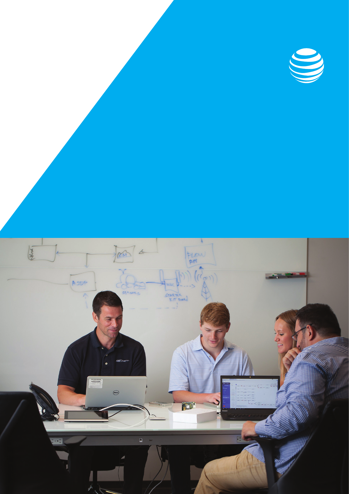
1. Tracking buses, trains and other transportation - while it’s handy to inform riders when to
expect the next bus, it also provides useful data for managing operations and expenses.
Figure 1-1
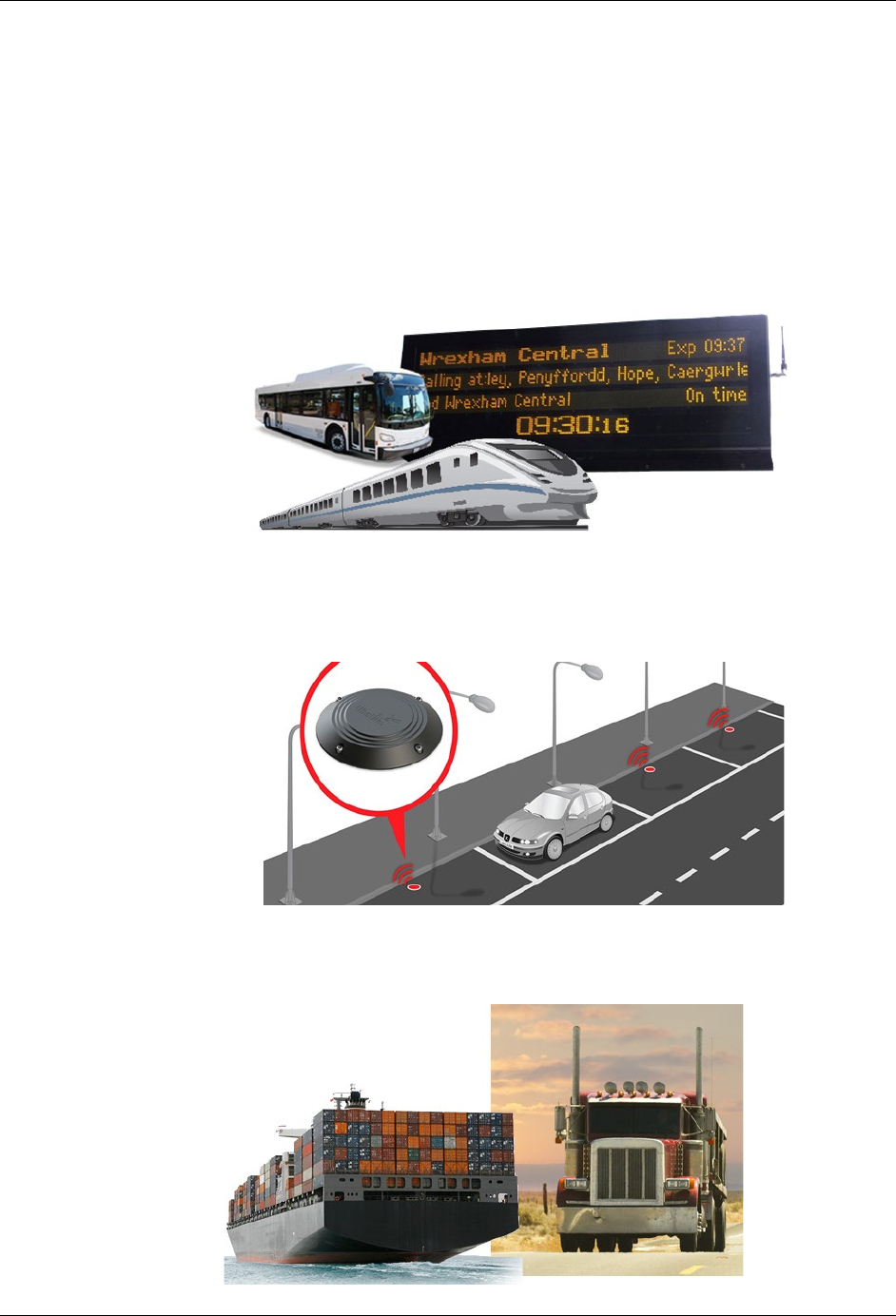
2. Parking - becoming more popular at airports and cities, tracking empty parking spaces allows
cloud and mobile apps to direct citizens and clients to available spaces. Once again, though,
the aggregate data from these operations also help communities and business better plan
for, and utilize, their infrastructure.
Figure 1-2
3. Asset Tracking - is likely the most widely used application for IoT today. Keeping track of
trucks, containers, pallets - or just about anything - is an essential requirement for our just-in-
time world.
Figure 1-3
What is IoT?
AT&T IoT Starter Kit (2nd Generation) User's Guide - Getting Started pg. 15
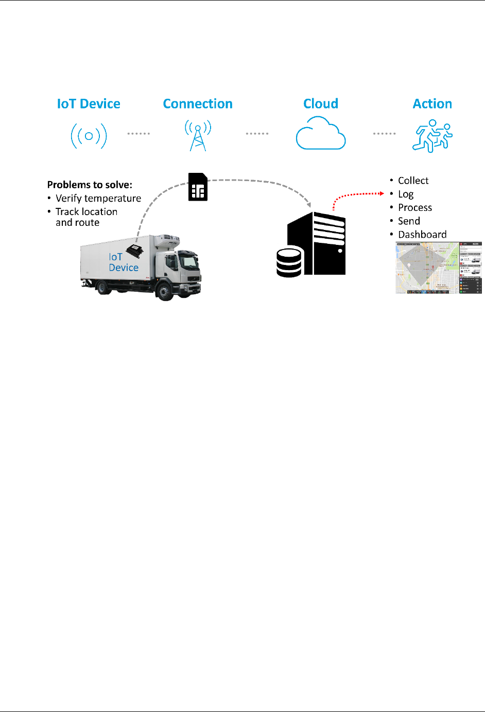
1.1.1. How Does IoT Work?
In each of above use-cases, the device (ie “thing”) is capturing data (location, temperature, etc.)
and sending it to the cloud (ie “Internet”).
Figure 1-4
Breaking it down, we can describe IoT in four parts:
1. IoT Device - the device captures sensor data and sends it to the Internet. For decades we
have built devices that can read sensors, but only in the past few years have we begun to
add the hardware which allows them to talk to networks and the cloud.
2. Connection - there are several methods for sending data to the Cloud. For example, until
recently, WiFi has been one of the most popular methods for many home or business
applications. Although, a growing number of applications require connectivity with greater
range and less difficult configuration headaches.
3. Cloud - that is, the “Internet”, receives and processes the data sent from the device.
4. Action - to be fair, the “Action” is generally handled by the Cloud, but we like to spike it out
because this represents the reason for using IoT in the first place. Why capture and send
data to the Cloud if you don’t need to trigger alarms, notifications, or analyze the data in the
first place?
What is IoT?
AT&T IoT Starter Kit (2nd Generation) User's Guide - Getting Started pg. 16
1.1.2. Connectivity Problem
As stated in the previous section, WiFi has been a popular ingredient for early IoT projects, but it
runs into several roadblocks for a growing list of applications. In our earlier examples, WiFi might
only be able to send data from truck or container residing in a terminal, but not while in transit.
Similarly, trying to provide WiFi across an entire city, or even just a parking garage, is difficult and
expensive.
Finally, WiFi configuration is tedious and difficult. Many early IoT adopters have struggled with the
cost of setting up and maintaining WiFi configuration. It’s not hard to imagine the value of
outfitting every vending machine with an IoT device. Just think of how useful that data might be in
managing a vending operation. Then consider how much time you would need to pay your
technicians to configure the WiFi settings for each vending machine. Even worse, how about
paying them to do this again each time the building or business hosting the machines updates
their WiFi passwords?
1.1.3. Why LTE and this Kit?
Cellular LTE communications have revolutionized personal communications. We see this in the
phones we carry with us everyday. The nearly ubiquitous coverage and ease of connection make
LTE networks ideal.
Even better, their simple, one-time configuration makes LTE easy for users and customers. Our
LTE-based devices contain a SIM (subscriber identity module) card which uniquly identifies each
device on the cellular network. Configured only once - often right at the factory itself - the cellular
device is now enabled throughout the entire LTE network.
Why have IoT devices not used LTE in the past? Because of design, development, certification
and monthly costs, application developers have largely ignored the advantages their numerous
advantages. But these difficulties are being addressed so that a new wave of applications can be
enabled by LTE networks.
Figure 1-5
This is where the AT&T IoT Starter Kits fit into the picture. They give developers access to low-
cost, fully certified, small footprint modules that can be used to build LTE connected IoT devices.
Use them to host your embedded applications, or to just provide the LTE connectivity to an
embedded system you have already developed. Either way, these kits make LTE a reality for IoT
applications.
IoT Starter Kit (SK2)
AT&T IoT Starter Kit (2nd Generation) User's Guide - Getting Started pg. 17
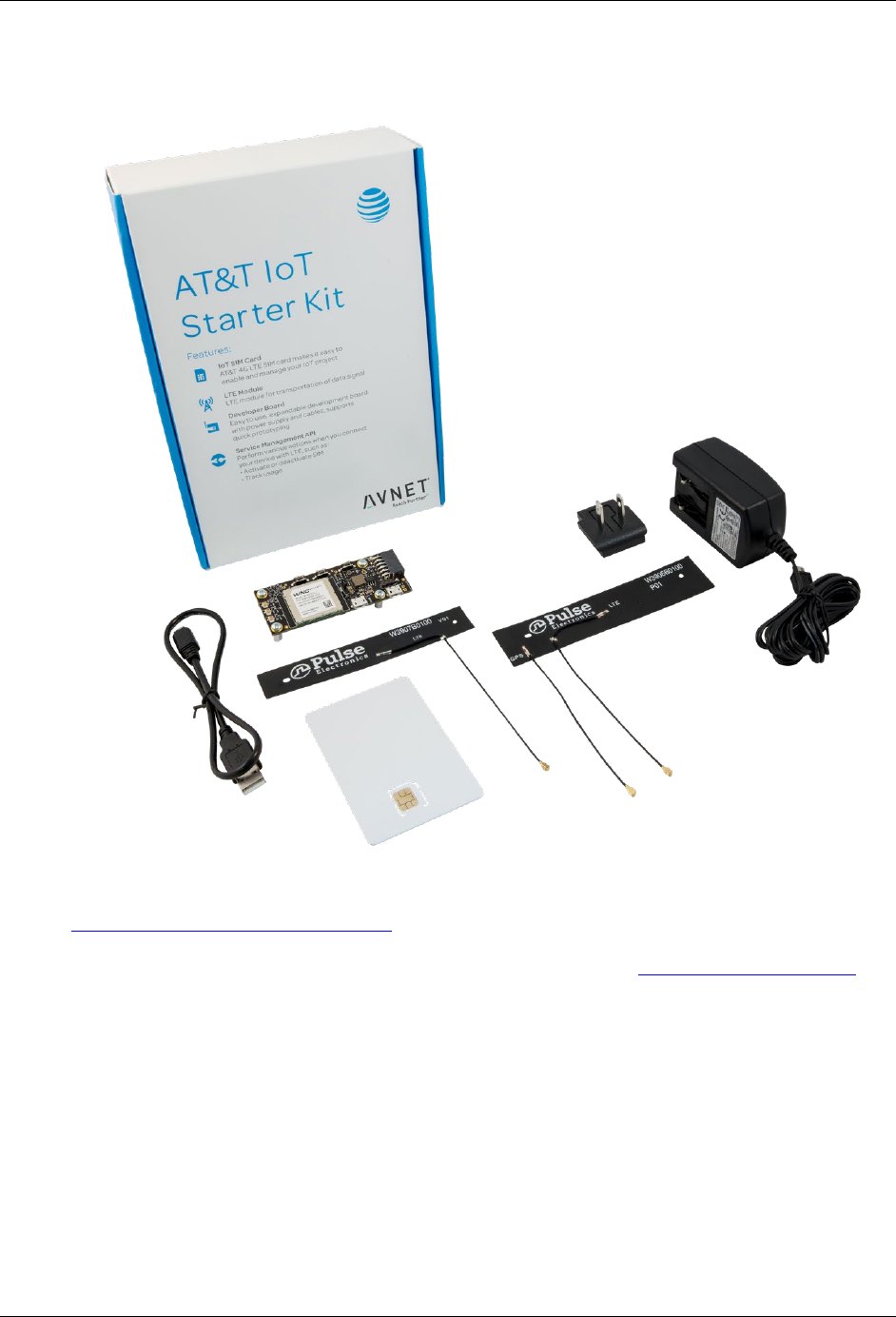
1.2. IoT Starter Kit (SK2)
Figure 1-6
AT&T IoT Starter Kit (2nd Generation) - also known as “SK2” - provides an innovative new
System-on-Module IoT solution, enabling the design of cellular connected edge devices, certified
for operation in the United States. (An alternative version of the kit “Global LTE IoT Starter Kit” is
also available from Avnet to support markets outside of the United States.)
Designed to be used for both prototyping and production, the slim form-factor LTE SK2 board is
fully compliant with FCC, PTCRB, and AT&T network certifications, thereby reducing
development risk and speeding IoT deployments.
IoT Starter Kit (SK2)
AT&T IoT Starter Kit (2nd Generation) User's Guide - Getting Started pg. 18
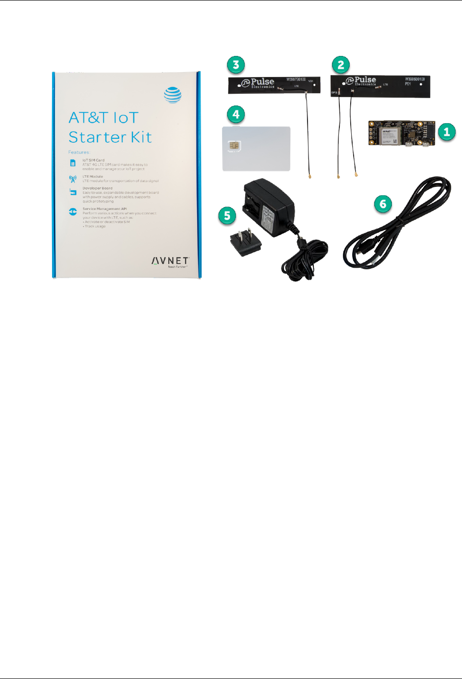
1.2.1. What Comes In the Box
Figure 1-7
1. LTE IoT SOM - LTE System Board (p/n: AES-ATT-M18Q2FG-M1-G).
2. LTE Primary + GPS Antennas - Pulse FPC LTE combo antenna.
3. LTE Secondary Antenna - Pulse FPC LTE antenna.
4. AT&T IoT Starter SIM Card - 3FF Micro-SIM card.
5. AC/DC Power Supply - AC/DC power supply (5V @ 2.5A) plus country/region outlet adapter.
6. USB Cable - for programming and debug.
IoT Starter Kit (SK2)
AT&T IoT Starter Kit (2nd Generation) User's Guide - Getting Started pg. 19
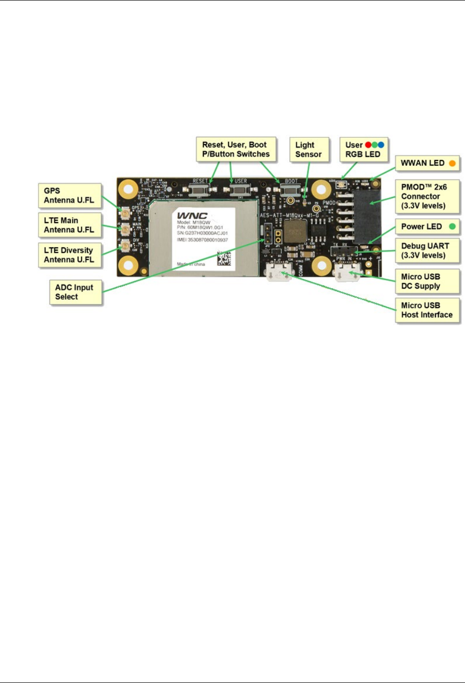
1.2.2. Hardware Overview
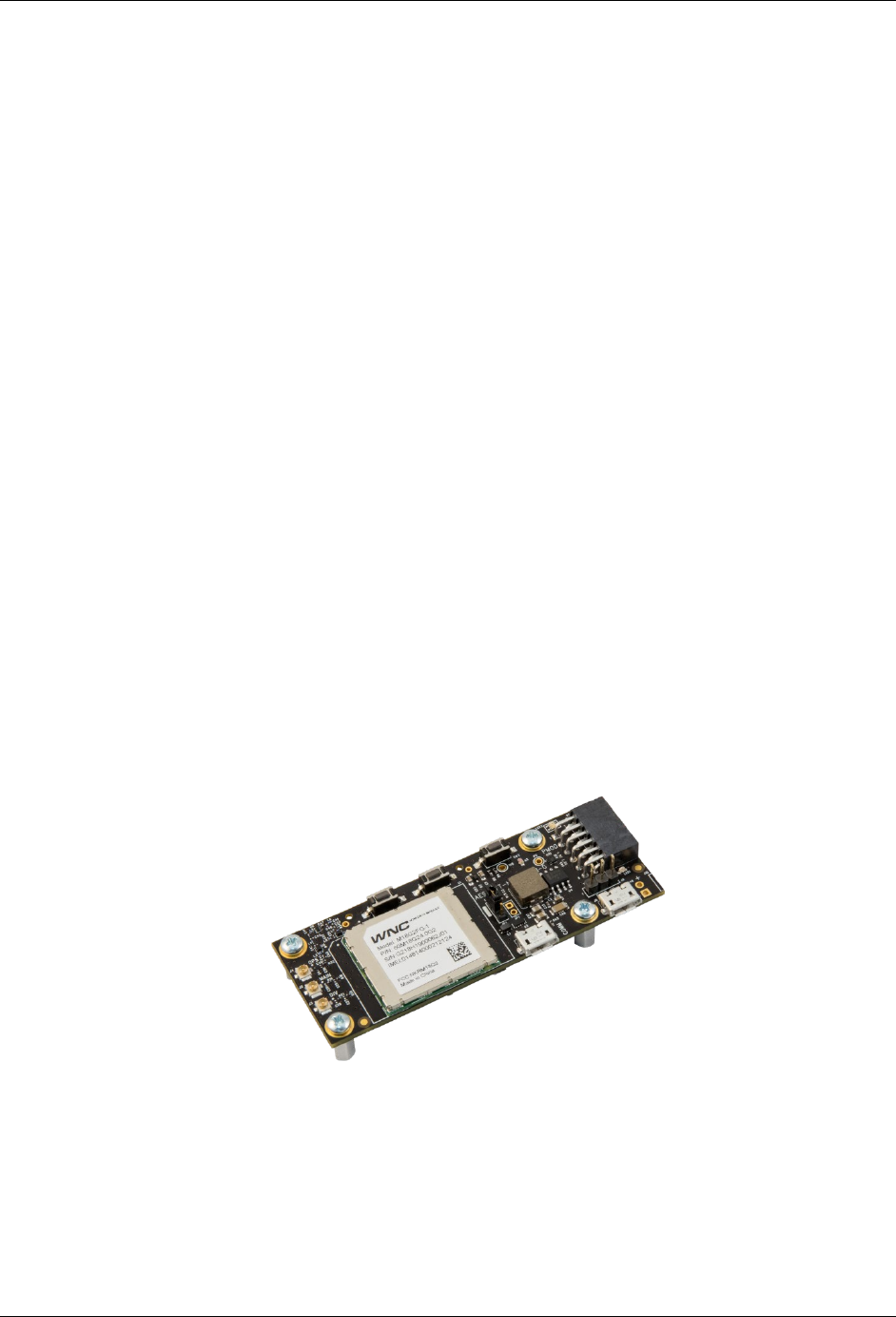
The Starter Kit features a small (79.5 mm x 30 mm) development board built around Wistron
NeWeb Corporation (WNC) M18Q2FG-1 LTE Cat-4 modem module. The M18Q2FG-1 module
provides cellular modem functionality plus user application code support via a dedicated Arm®
Cortex™-A7 processor, thus eliminating the need for an external host processor.
1.2.2.1. Top
Figure 1-8
Along with the WNC modem/processor module, the top-side of the module contains many
components. Starting at the left side of Figure 1-8:
• The ADC (analog to digital convertor) jumper lets you select how the ADC pins from the WNC
module are connected within the SK2 board: either to the light sensor or the 60-pin jumper.
• Three antenna connections are found on the left side of the module. This support both the
LTE radio (which requires two antennas) as well as the GPS sensor.
• There are three push-button switches on the board - the middle one can be accessed by user
programs while the other two are for Rest and Boot. Programming the User Switch via GPIO
(general purpose input/output) will be discussed in Chapters 3 and 4.
• The User RGB (red, green, blue) LED can also be controlled via user software (also
discussed in Chapters 3 and 4).
• The WWAN (wireless wide-area network) LED is controlled by the LTE modem and provides
status regarding the cellular connection.
• The PMOD connector allows you to attach PMOD peripheral boards, making it easy attach
sensors or other resources to your kit. There are a wide number of PMOD capable modules
that can be purchased separately.
• The Power LED lets you know if power is available (from the Micro USB DC power supply
connector).
• The “Debug UART” dedicated for system debug output (ie Linux kernel debug log output).
IoT Starter Kit (SK2)
AT&T IoT Starter Kit (2nd Generation) User's Guide - Getting Started pg. 20
• There are two Micro USB connectors on the SK2 module:
− The “DC Supply” USB connector provides DC power to the module. You should use the
supply provided in the kit to assure the proper amount of power is available to run the
SK2 module.
− The “Host Interface” USB connector can be connected to your computer, allowing you to
modify and control the module via the ADB (Android Debug Bus) protocol. (This will be
discussed in the next chapter.)
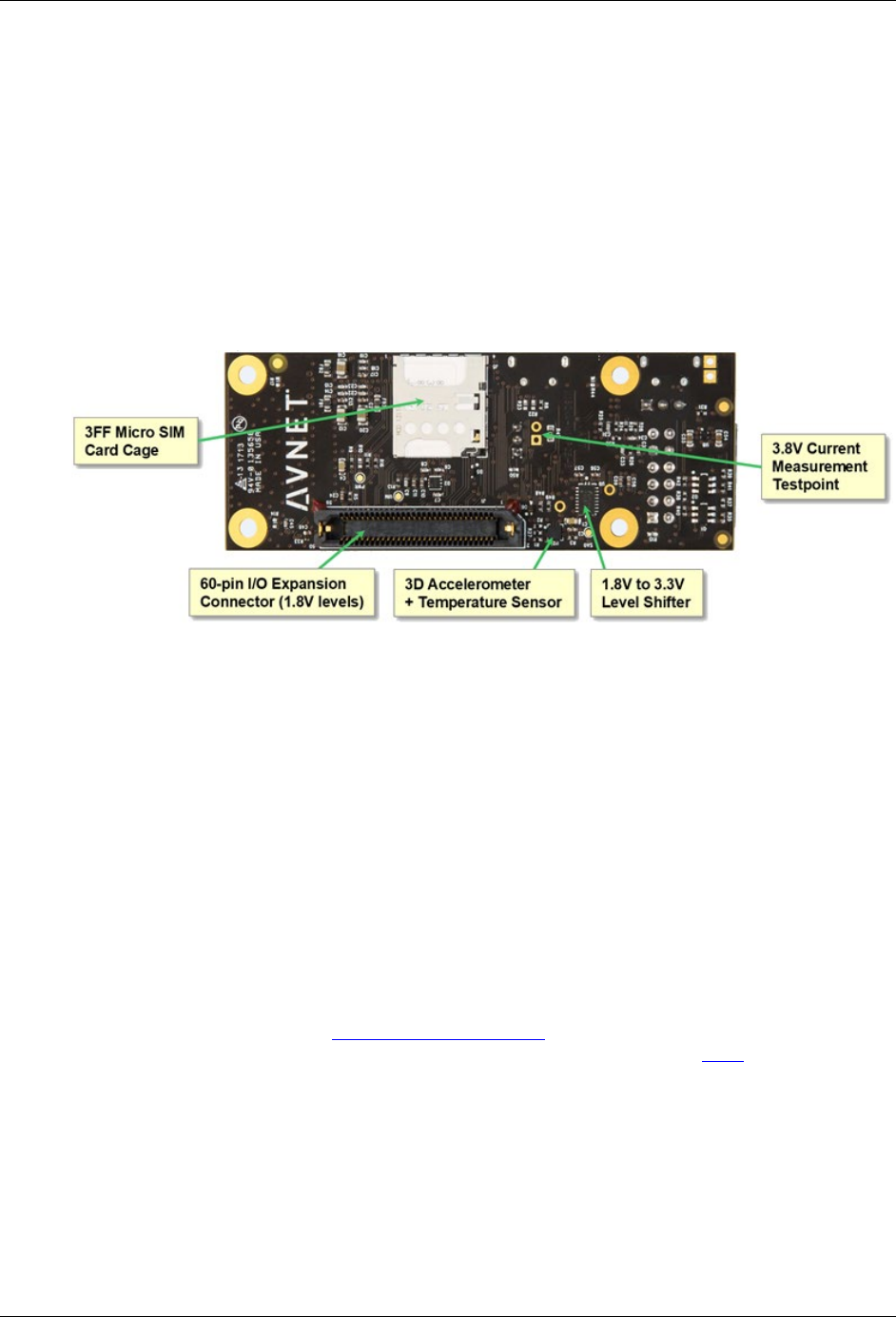
1.2.2.2. Bottom
The bottom of the SK2 contains a few more items of interest.
Figure 1-9
Starting from the left and working around the board:
• 3FF Micro SIM Card Cage - is where you will insert the micro SIM (Subscriber
Identification Module) card that comes with the kit, once you have registered it with
AT&T. (See the SIM registration steps later in this chapter.)
• 3.8V Current Measurement Testpoint - can be used to test the output of the on-board
voltage converter. After applying an unregulated 5V supply thru, say, the micro-USB
power connector, the on-board converter adapts and regulates the power supply to the
board. With a small hardware adaptation, this unpopulated header can be used to
measure the current from by this regulated supply.
• 1.8V to 3.3V Level Shifter - handles the voltage differences between the modem
processor module pins and the sensor and expansion devices.
• 3D Accelerometer & Temperature Sensor - provides movement and temperature data to
the system. (These will be discussed later during the I2c chapter.)
• 60-pin I/O Expansion connector - provides access to many of the processor module’s
pins and ports. Use this to add your own hardware to the SK2 system. Alternatively, you
can attach the Avnet’s LTE IoT Breakout Carrier as shown below. The breakout makes it
easier to access the expansion pins - or allows easy connection of Click modules (as
shown below).

IoT Starter Kit (SK2)
AT&T IoT Starter Kit (2nd Generation) User's Guide - Getting Started pg. 21
Figure 1-10
1.2.2.3. Block Diagram
The block diagram provides an alternative view of the SK2. From this view, it’s easy to see how
the kit’s components are interconnected. In fact, this view of the system highlights what signals
are routed to the PMOD and Expansion connectors.
Figure 1-11
Please refer to the SK2 Hardware User’s Guide for further details and explanation regarding this
board.

IoT Starter Kit (SK2)
AT&T IoT Starter Kit (2nd Generation) User's Guide - Getting Started pg. 22
1.2.3. Software Overview
From the diagram in the previous section, we can see the WNC M18Q2FG-1 module is the
central component of the SK2. It is the ‘brains’ behind this kit. As mentioned earlier, this module
contains an ARM Cortex-A7 processor which runs an OpenEmbedded version of Linux. User
application code (scripts, C language, and Python) can run within this Linux environment.
A Software Development Kit (SDK), specific to the M18Q2FG-1 module, provides the necessary
API calls allowing your code to access hardware peripherals and system resources. Application
code built with the SDK is loaded into the M18Q2FG-1 module through the host USB interface
(see the Top of board description), eliminating the need for proprietary debug/emulation
hardware.
The SDK consists of two main APIs (Application Programming Interfaces):
• LTE IoT: provides access to the communications services over the LTE cellular radio.
• Peripheral: provides access to the peripheral ports and pins on the M18Q2FG-1 processor
module. In other words, using this API you can access the ports, as well as the sensors that
are connected to these ports (e.g. temperature, accelerometer).
You can control these API from one of three different languages:
1. Linux shell scripts - useful for simple demos and examples.
2. Python - the AT&T Python environment lets you access the hardware using the popular
scripting language. The Python environment will be covered in greater detail in a future
chapter.
3. C - the ever-popular C language is supported; letting you build C applications that run within
the Linux environment. In fact, the IoT Monitor demo program - which comes pre-loaded on
the SK2 - was written using the C language and accessing the WNC API. A future chapter
will describe how to setup and build user applications using the C language.
1.2.4. Cloud Connectivity
AT&T services facilitate Cloud based application development and deployment:
• M2X - a cloud-based, fully managed IoT device management and time-series data storage
service for network connected devices.
• Flow Designer - a visual IoT application development and data orchestration environment,
with run-time support for complex nonstandard protocol translation, data processing and
integrations, to help developers create IoT applications fast.
The SK2’s QuickStart demo (i.e. IoT Monitor program) utilizes these services and provides an
example for how to get started with them.

IoT Starter Kit (SK2)
AT&T IoT Starter Kit (2nd Generation) User's Guide - Getting Started pg. 23
1.2.5. Description of QuickStart Demo
When the IoT Starter Kit (2nd Generation) is initially powered-on, a basic user interface will allow
you to perform complete Transmit/Receive operations. This initial program will post readings from
the sensors located on the IoT Starter Kit module to a pre-configured AT&T Dashboard each time
you push the “User” button. You can see this operation progress by following the LED sequence
on the board. After registering your kit with the AT&T Dashboard, you will be able to view the data
online.
Sensor data from the module includes:
• Motion sensor data provides 3-axis accelerometer data indicating board position
• Temperature sensor
• Ambient light sensor
Note that GPS location data is not enabled in the startup application.
The demonstration runs the “IoT Monitor” application. The code for this can be found on Avnet’s
GitHub site:
https://github.com/Avnet/M18QxIotMonitor
As this software is pre-loaded onto the module at production, there is no need for you to
download or modify it before running the QuickStart out-of-box demo. You can find further
explanation, and directions, for this demo in the next section. (Instructions for running the demo
can be found in the next section.)
1.2.5.1. IoT Monitor program
To clarify, the initial program that runs automatically upon powering up the SK2 may be called by
either of these names:
• QuickStart demo
• IoT Monitor program – The C source-code program used to implement the QuickStart demo
We just point this out so that you won’t get confused thinking that there might be more than one
startup demo in the SK2. The IoT Monitor source code will be examined later on in this user
guide.
Running the QuickStart Demo
AT&T IoT Starter Kit (2nd Generation) User's Guide - Getting Started pg. 24
1.3. Running the QuickStart Demo
1.3.1.1. Register the AT&T SIM Card
Before we get started with the QuickStart demo, we need to register your kit and its SIM card with
the AT&T Marketplace. This provisioning will allow AT&T’s network to recognize your kit.
1. Log onto AT&T’s IoT Marketplace:
https://marketplace.att.com
You have choice of login methods - either using an account that you have previously setup,
an AT&T Developer account, or a GitHub account. If you would like to create a new account,
click the “Create an account” link near the bottom of the screen.
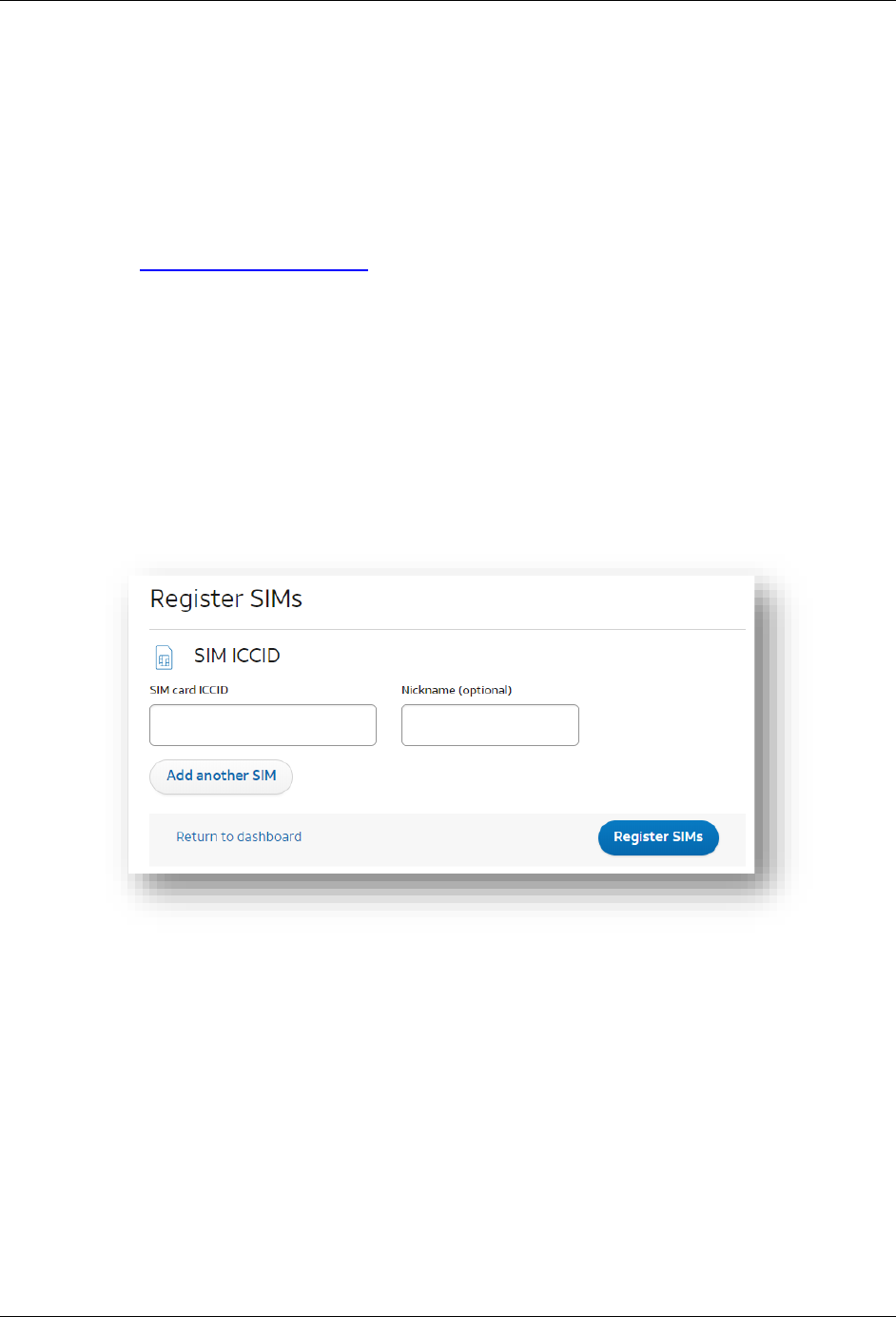
2. After you are logged in, navigate to the Register SIMs screen by clicking:
Management > Register SIMs
3. Enter the SIM ICCID number located on the SIM card carrier (and the SIM card itself).
Then click the “Register SIMs” button.
We recommend giving it a nickname, just in case you end up with more than one kit or SIM
card and want to tell them apart.
4. View data about your SIM in the “Dashboard”.
If you are not taken to the Dashboard, click the “Dashboard” button and you should see your
SIM card listed. Click the + button next to your SIM card to view more data about your SIM
card.
Running the QuickStart Demo
AT&T IoT Starter Kit (2nd Generation) User's Guide - Getting Started pg. 25
1.3.1.2. AssemblingtheSK2
To assemble IoT Starter Kit (2nd Generation) components, there are just a few connection steps
required to connect the three main items needed for basic operation.
Antenna
SIM card
Power adapter cable
Directions to assemble the kit include:
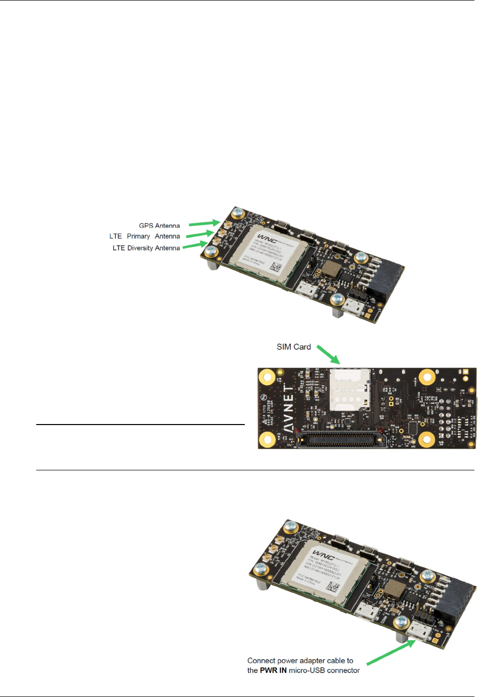
1. Connect the antennas.
The flexible antenna arrays should be gently connected to the module antenna terminals as
shown by matching each of the labeled antenna cables to the corresponding connector:
2. Install the SIM into the SK2 holder.
Carefully pop the AT&T micro-SIM card
out from its carrier and install it into SIM
card holder:
Note: Note that you must register the SIM
card before it will be recognized by
the AT&T network. (These instructions were provided in Section 1.3.1.1.)
3. Connect the micro-USB power cable.
The included power adapter cable
should be connected to the micro-USB
connector labeled “PWR IN” and the
wall adapter plugged into an AC power
outlet. This will power on the module:
Figure
1-14
Figure 1-15
Running the QuickStart Demo
AT&T IoT Starter Kit (2nd Generation) User's Guide - Getting Started pg. 26
1.3.1.3. RunningtheQuickStartDemo
As stated earlier, the QuickStart demo comes pre-programmed into your kit and should run
automatically after power-up.
Note: The next chapter (Chapter 2 – Embedded Linux) will show how to stop this program from
running automatically – or how to set your own program or script to run at power-on.
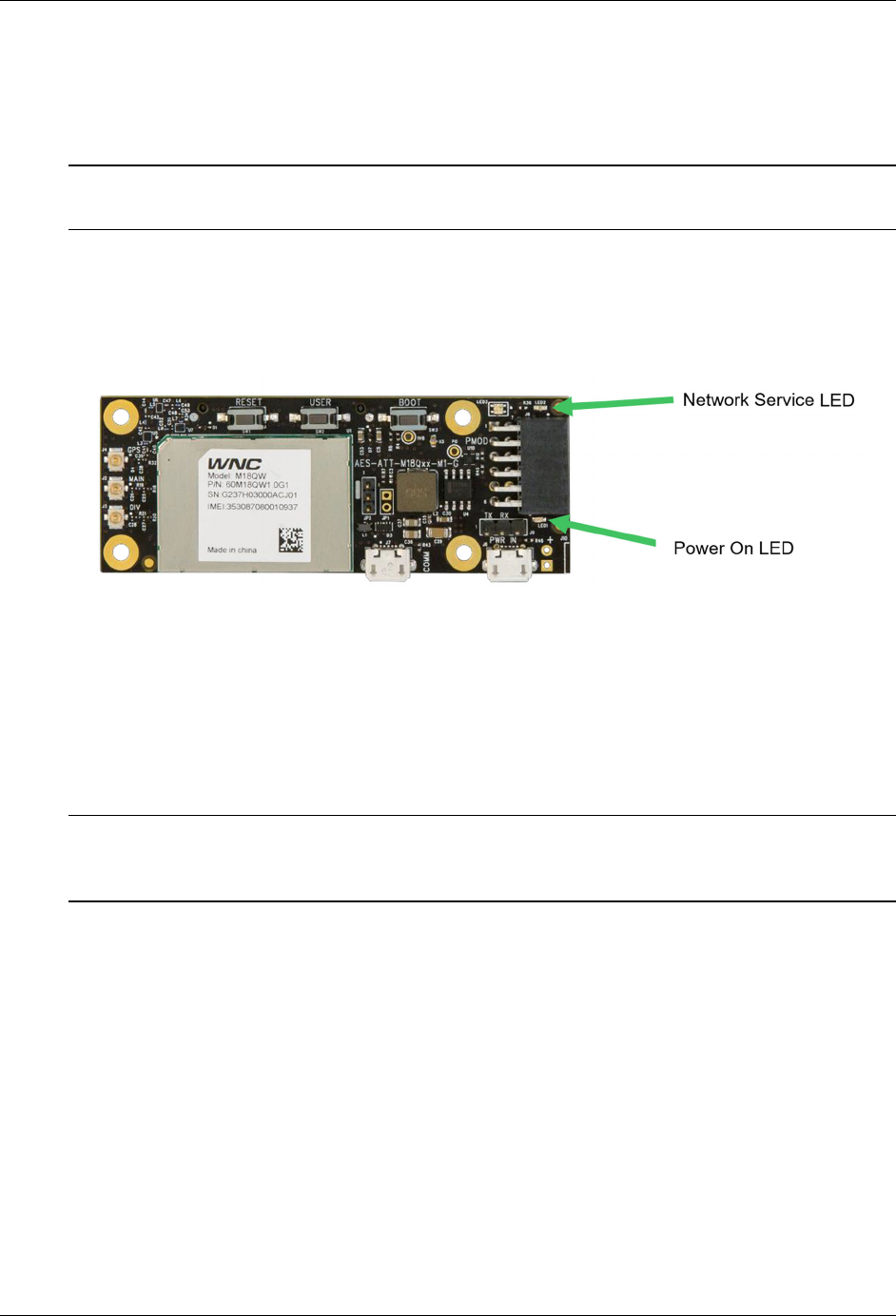
4. Power-on the board. If already on, power-cycle it by disconnecting and then
reconnecting power.
When power is provided to the IoT module it automatically begins basic operations. The
presence of power is indicated by the Power-On LED (LED1) illumination:
Figure 1-16
5. Watch for the module to connect to LTE cellular network service.
After the module is powered on, the Network Service LED (LED2) will begin flashing. This
indicates that the module is attempting to register with the AT&T network and establish a
connection.
Once connected to the AT&T network, the Network Service LED will quit flashing and
become steady.
Note: If the Network Service LED does not become steady (i.e. it keeps flashing), then it’s
possible that the APN has been incorrectly configured for your kit. Please refer to the
Appendix for more information about the APN setting and how to configure it.
Running the QuickStart Demo
AT&T IoT Starter Kit (2nd Generation) User's Guide - Getting Started pg. 27
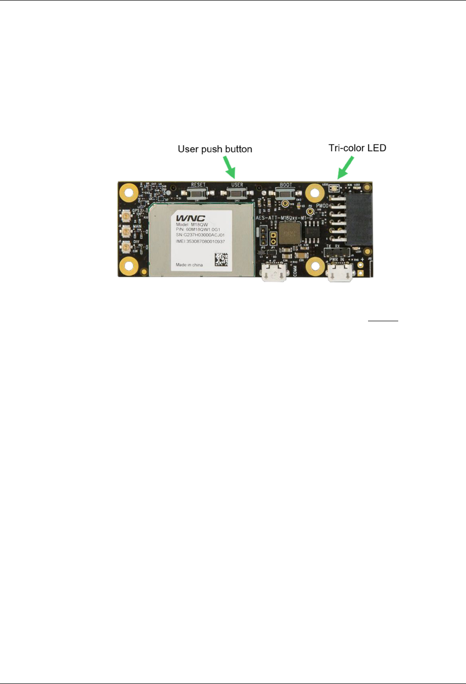
6. When the Tri-color LED turns Green, push the user button once.
After network service is obtained, the module’s demo will connect to the AT&T M2X service.
Once established, the tri-color LED becomes GREEN.
After network service is established and the module is ready to receive user input, you can
press the USER Push Button (SW2) to initiate collecting sensor data from the SK2 and
sending it to the M2X service.
Each step in the sequence of events kicked off by pressing the USER button can been seen
in the Tri-color LED (LED3).
Figure 1-17
The QuickStart program’s sequence of events are described in Section 1.3.1.4, on the next
page.
Running the QuickStart Demo
AT&T IoT Starter Kit (2nd Generation) User's Guide - Getting Started pg. 28
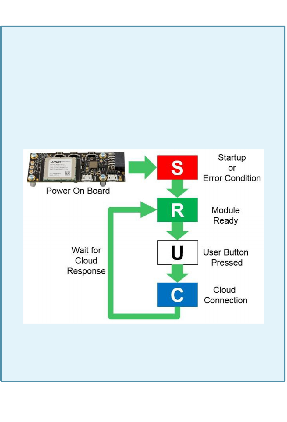
1.3.1.4. QuickStartDemoSequenceofEvents
While the tri-color LED is GREEN, the user may press the USER button to initiate an
M2X data transmission. While the push button is being pressed, the tri-color LED will
illuminate white, while the tri-color LED is WHITE no transmission takes place. The
WHITE LED only indicates that the module detects that the USER button is being
depressed.
Once the USER push button is released, the tri-color LED will illuminate BLUE and the
sensor data will be collected and sent to the M2X Dashboard associated with your IoT
Marketplace account. It will stay BLUE until all the data has been sent and acknowledged
by M2X.
After the data transmission is completed, the tri-color LED will go back to GREEN. This
process can be repeated, and the Quick Start demonstration application will continue to
follow this execution logic as indicated in the following diagram:
Figure 1-18
If the USER push button is depressed for greater than 3 seconds, it signals that the
demonstration program should be terminated, and no further operations performed. At
this point to restart the Quick Start demonstration application, you will need to depress
the RESET button for longer than 3 seconds (or power-cycle the board) to reset the
module.
Running the QuickStart Demo
AT&T IoT Starter Kit (2nd Generation) User's Guide - Getting Started pg. 29
1.3.1.5. AT&TMarketplaceDashboard
After running the SK2 out-of-box QuickStart demo your data is available in the AT&T Marketplace
dashboard. Your kit’s serial number needs to be added to your Marketplace account, though, so
that your data can be displayed.
7. Log onto AT&T’s IoT Marketplace (unless you are still logged in):
https://marketplace.att.com
You have choice of login methods - either using an account that you have previously setup,
an AT&T Developer account, or a GitHub account. If you would like to create a new account,
click the “Create an account” link near the bottom of the screen.
8. After you are logged in, navigate to the Marketplace Dashboard registration screen:
marketplace.att.com/amoc/devices/gsk/register
Note: If the registration form does not look like that shown in Step #3, make sure you are
logged into the Marketplace and try clicking on the registration link again.
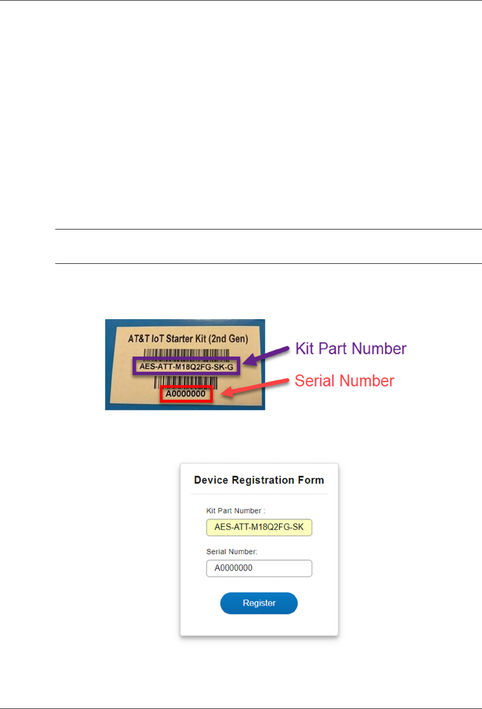
9. Enter the kit’s Serial Number located on your SK2’s box.
You can find your kit’s serial number on the box as shown:
Figure 1-19
Then enter it into the registration dialog:
Figure 1-20
Running the QuickStart Demo
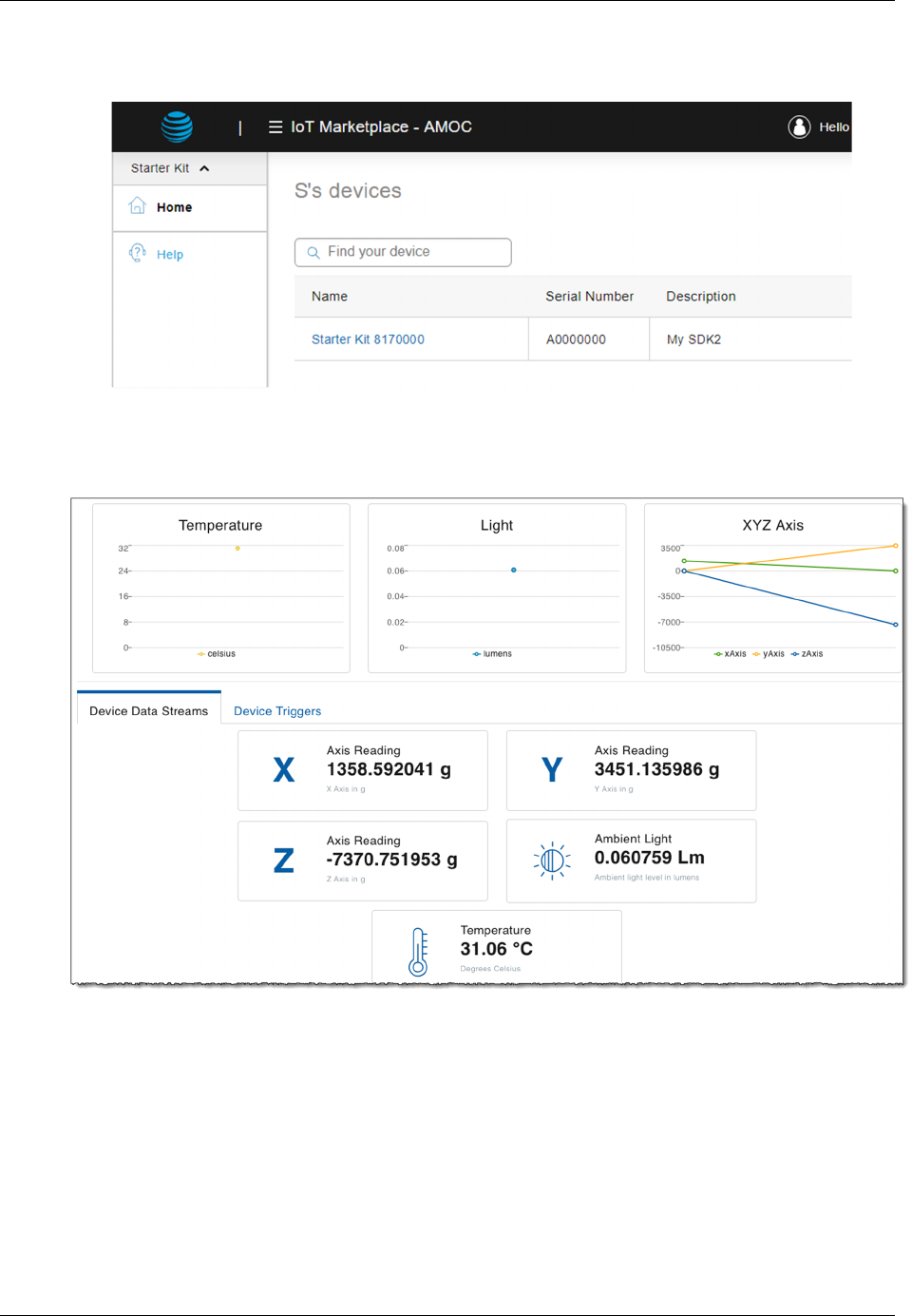
AT&T IoT Starter Kit (2nd Generation) User's Guide - Getting Started pg. 30
10. After clicking “Register”, which closes the dialog, you will find your kit listed on the
Data dashboard:
Figure 1-21
11. Click on the Starter Kit’s link (i.e. ‘Name’) and you will find the dashboard’s data
displayed for your kit.
Figure 1-22

Running the QuickStart Demo
AT&T IoT Starter Kit (2nd Generation) User's Guide - Getting Started pg. 31
1.3.1.5.1. Sidebar – Data Sent to AT&T Dashboard
The following sensor data is sent to your AT&T Marketplace Dashboard each time the
user presses the USER key:
3-Axis Acceleration Sensor Data:
• XVALUE = X data point from the onboard LIS2DW12 sensor chip
• YVALUE = Y data point from the onboard LIS2DW12 sensor chip
• ZVALUE = Z data point from the onboard LIS2DW12 sensor chip
Temperature Sensor Data:
• TEMP = Temperature data from the onboard LIS2DW12 sensor
Ambient Light Sensor Data:
• ADC = Light intensity measurement from the integrated ADC and onboard light
sensor
The data is stored within your AT&T Marketplace Dashboard so that you can access this
data from your IoT applications later.
Resources
AT&T IoT Starter Kit (2nd Generation) User's Guide - Getting Started pg. 32
1.4. Resources
1.4.1. AT&T Resources
AT&T provides several resources, many of them are listed in the preface of this book. Here are
four sites to find support from AT&T for the SK2:
• https://marketplace.att.com/products/att-iot-starter-kit-2nd-gen
• https://marketplace.att.com/quickstart#starterkit-2nd-gen
• https://github.com/att-iotstarterkits
• https://att-iotservices.groovehq.com/help_center
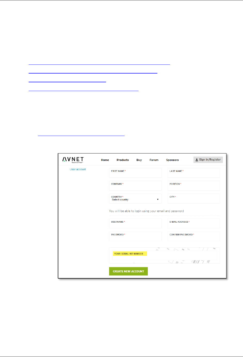
1.4.2. Register with cloudconnectkits.org
Along with AT&T’s information website, you can also find resources at Avnet’s
Cloudconnectkits.org. We recommend creating an account at:
http://cloudconnectkits.org/
During account creating, you will be able to register your kit.
Figure 1-23
1.4.3. What’s Next?
In the next chapter, we shall see that Embedded Linux is used as the baseline operating system
for the SK2. Due to Linux’s ease of use, this makes it easy for us to add, view and manage
programs and files on the kit.
Additionally, the Linux command-line interface, accessed via one of the USB ports, makes it easy
to control the user LED on the board.

AT&T IoT Starter Kit (2nd Generation) User's Guide - Embedded Linux pg. 33
2. Embedded Linux
Most of today’s embedded systems run some form of operating system (OS). The OS provides a
broad set of services that simplifies programming the device, making it easier – and faster – to
deploy new products.
Linux is fast becoming a favorite operating system for embedded devices. Not only does it
provide a rich set of services, but it has wide community support and is a favorite among
developers.
The AT&T IoT Starter Kit (SK2) is based on an OpenEmbedded distribution of Linux. This
environment provides the foundational basis for all interaction and development with this kit. If
you are already a Linux master, then you’ll have a big headstart with your development. If not, we
think you will find this OS, and the kit itself, convenient and fun to program.
Using the SK2 is somewhat akin to using a Raspberry Pi in that they are both small, Linux-based,
software-programmable kits. While the IoT Starter Kit doesn’t provide quite the wide-range of
functionality found in the Raspberry Pi, it has a built-in LTE cellular modem which gives it wide
ranging IoT connectivity.
Topics
2. Embedded Linux .................................................................................................................. 33
2.1. Introduction to Linux ....................................................................................................... 34
2.1.1. Kernel Space vs User Space ................................................................................. 35
2.2. Linux Distribution ............................................................................................................ 36
2.2.1. Linux Kernel ........................................................................................................... 36
2.2.2. Filesystem .............................................................................................................. 37
2.2.3. Boot Loader ............................................................................................................ 39
2.2.4. Toolchain ................................................................................................................ 39
2.3. Linux Shell ...................................................................................................................... 40
2.3.1. Basic Linux Commands ......................................................................................... 40
2.3.2. Shell Scripting ........................................................................................................ 43
2.4. ADB – Connecting to the SK2 ........................................................................................ 45
2.4.1. Installing ADB ......................................................................................................... 46
2.4.2. Sidebar - What happens during “adb devices” ....................................................... 49
2.4.3. Troubleshooting “adb devices” ............................................................................... 49
2.4.4. ADB Commands .................................................................................................... 53
2.5. Controlling Hardware Using the Linux Shell .................................................................. 60
2.6. Linux Boot Sequence ..................................................................................................... 62
2.6.1. How Does the QuickStart Demo Run Automatically? ............................................ 62
2.6.2. Stop the QuickStart Demo from Running Automatically ........................................ 63
Introduction to Linux
AT&T IoT Starter Kit (2nd Generation) User's Guide - Embedded Linux pg. 34
2.1. Introduction to Linux
Linux, like all operating systems, provides a set of services to the user.
If you have ever used a Linux computer – or another other computer (e.g. Windows, Mac) – you
are familiar with many of these user-oriented services. For example, you may have used word
processor program to create and edit files, which are stored in the OS’s filesystem. Or, you may
have used a web browser, which relies on the networking services provided by the operating
system.
While many Linux-based “embedded systems” do not generally run big word processor programs,
they still rely on the Linux filesystem to manage files – allowing programs to create, edit and
delete files as needed.
And like most other operating systems, Linux provides a command-line interface that can be used
to view files, execute programs or otherwise interrogate the system. While a command-line is
rarely used during the execution of an embedded system’s target application (i.e. we don’t use a
command-line to run our microwave), it is quite handy when developing and debugging software
running user software.
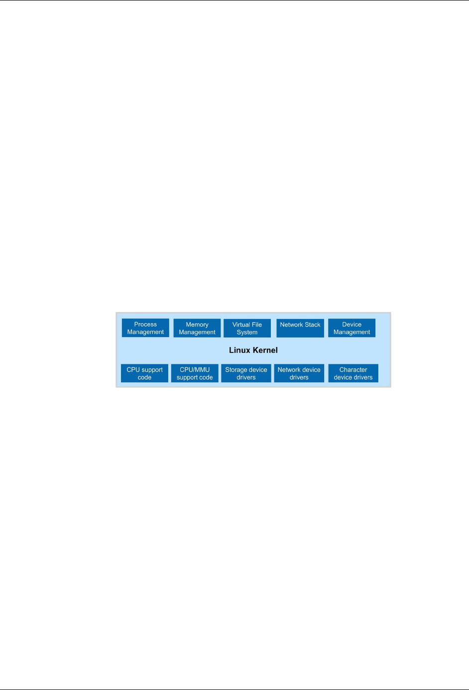
While the following diagram is only a generic description, it gives us a summary of the types of
services we can expect to find in Linux, such as: memory management, file systems, networking,
and device drivers (e.g. serial ports, analog to digital converters). Together, this core group of
services is often called the ‘kernel’ of an operating system, hence the name Linux Kernel.
Figure 2-1 Linux Kernel
During this chapter we hope to provide a brief introduction to embedded Linux, some details
about the Linux distribution provided with the SK2, and how to interact with it. In subsequent
chapters, we’ll dig even further, learning how to write programs that run within the SK2’s Linux
environment.

Introduction to Linux
AT&T IoT Starter Kit (2nd Generation) User's Guide - Embedded Linux pg. 35
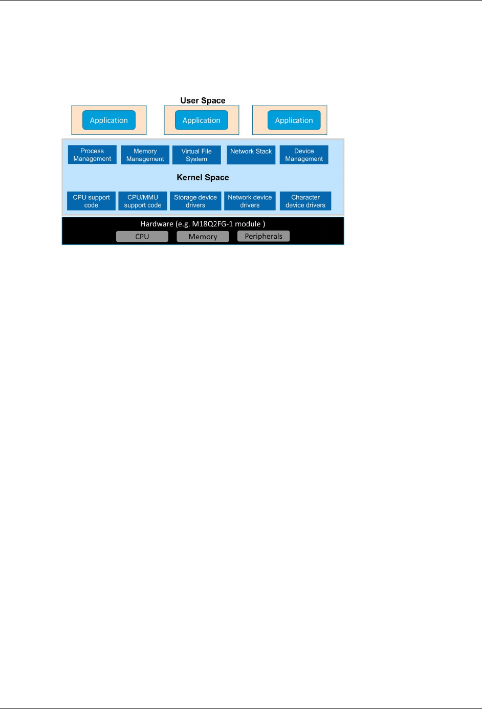
2.1.1. Kernel Space vs User Space
Digging a little deeper into Linux, we need to delineate between “kernel” space and “user” space.
Figure 2-2 User Space vs Kernel Space
2.1.1.1. Kernel Space
In the previous section we described the Linux kernel as all the drivers and networking services
provided by the OS. This code typically runs with permissions that allow it to directly interact with
the hardware. With the SK2, the hardware manufacturer created the Linux kernel for us to work
with their hardware. In other words, WNC adapted generic Linux code to work with the CPU,
memory and peripherals found on their M18Q2FG-1 modem module.
2.1.1.2. User Space
In a similar way, we might describe ‘user’ space as all the programs and code that are isolated
from the hardware. These programs access standard driver and socket interfaces that are
portable across devices.
In fact, if you’ve used an Ubuntu Linux computer before, you might only recognize user space, as
this is the area where we interact with Linux to run programs and configure our preferences. In an
embedded system, we might think of user space as the area where we create and run software
applications.
2.1.1.3. Protecting the Environment
Notice how Kernel space comes between User space and the hardware? Linux systems are
layered in this fashion to create a secure and stable system. User applications are not allowed to
talk directly to hardware, rather, they must call upon the services of the Linux kernel to interact
with memory and peripherals. Therefore, when writing programs for Linux, we will need to learn
how to interact with the Linux kernel – that is, we will need to learn how to call the functions
provided by Linux and WNC that will let us access OS resources, such as the peripherals which
talk to the sensors on the SK2, as well as the cellular LTE modem.
Linux Distribution
AT&T IoT Starter Kit (2nd Generation) User's Guide - Embedded Linux pg. 36
2.1.1.4. Protecting Users From Each Other
One last note, while we are talking about protection and User space. Another advantage to
enforcing that all resources are accessed via the kernel is that it helps to protect one user from
another. We might redraw our previous diagram to look like this:
Figure 2-3 Separation of User Space
Linux allows programmers to create application programs which run independently of each other,
as shown above. Alternatively, applications can be programmed to run in the same ‘space’ as
each other (like on the previous page). While the choice is yours, as a programmer, how to
implement your application(s) code, but we can thank the separation of Kernel space for helping
to provide us with these options.
2.2. Linux Distribution
Linux is delivered as a ‘distribution’. Generally, a distribution includes:
• Linux kernel – set of core services (as we discussed earlier)
• Filesystem – collection of user space libraries and utilities/applications
• Boot loader – an orderly, sequential means for low level hardware configuration and loading
the kernel
• Toolchain – common collection of compiler, linker, libraries, etc.
For personal computers, there are many different examples of Linux distributions; for example,
you may have seen: Ubuntu, Red Hat, and Suse. In fact, some of you may have created your
own distributions by downloading the Linux source code and putting everything together yourself.
Thankfully, we won’t have to build Linux from scratch for the SK2. In this case, our board comes
pre-loaded with the Linux distribution. When writing code for the SK2, though, you will need to
download the appropriate toolset – choosing whether you want to write your programs in Python
or the C language. (Chapters 3 & 4 will describe each of these toolsets – how to download,
install, and build programs with them.)
2.2.1. Linux Kernel
We access resources using a combination of common Linux commands (e.g. reading and writing
a file or memory) or using a set of device driver libraries provided by WNC (the module vendor).
These will be covered in greater detail throughout the rest of this user’s guide.
Linux Distribution
AT&T IoT Starter Kit (2nd Generation) User's Guide - Embedded Linux pg. 37
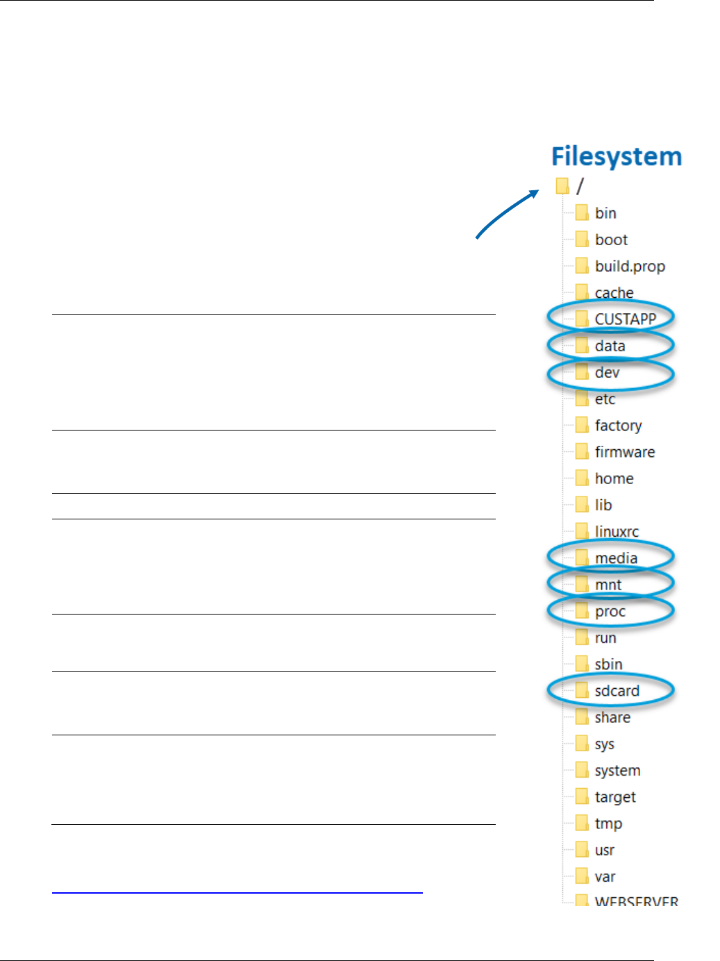
2.2.2. Filesystem
The Linux filesystem provides a hierarchical organization for storing and retrieving files. Like most
operating systems, the Linux community has defined a common set of directories for storage. As
an example, the description below highlights a few key directories found on the SK2 filesystem
(found on the right side of the page):
Filesystem - Unlike Microsoft Windows, Linux only has a single
filesystem. In other words, Linux doesn’t have a filesystems for each
drive or entity. Where Windows users might be used to “C” and “D”
drives, Linux only has a single filesystem.
In Linux, the topmost location – that is, the root of the filesystem – is
denoted by “/”.
We won’t describe each folder in the SK2 filesystem, but here’s a
description for a few of them:
Here’s a good reference, if you are looking to learn more about the
standard Linux Filesystem Heirarchy:
https://en.wikipedia.org/wiki/Filesystem_Hierarchy_Standard
CUSTAPP • For ‘your’ application (i.e. customer applications)
• It’s the only folder in the filesystem that can be
written to; all other folders are read only
• Contains the QuickStart demo that runs on
powerup; this will be discussed further later in this
guide
data • This ‘directory’ is just a link to ‘/CUSTAPP’.
• Like a shortcut in Windows or Mac
/data -> /CUSTAPP
dev • Common location for listing Linux device drivers
mnt • Common location to mount other file systems
• Additional drives, memory cards, or network
locations become part of the one filesystem
whenever they are added (i.e. “mounted”) to the
Linux device. “mnt” is a generic place to place them.
media • Rather than using mnt for USB drives and CDROM
media, some Linux distributions create a “media”
where these items are mounted
sdcard • This ‘directory’ is just a link to ‘/media/card’.
• Like a shortcut in Windows or Mac
/sdcard -> /media/card
proc • “/proc” is not a real directory, but rather, it’s a virtual
directory and does not hold physical files. Contained
within proc are information about processes and
other system information. This information is
mapped to /proc and mounted at boot time.
Figure 2-4 Filesystem
Linux Distribution
AT&T IoT Starter Kit (2nd Generation) User's Guide - Embedded Linux pg. 38
2.2.2.1. Virtual Files, Status Info, and Configuration
But, wait, there’s more. The filesystem is a fundamental component of Linux. That is, it uses the
filesystem for more than just text or binary files.
For one, Linux uses the file reading/writing paradigm to write to peripheral device-drivers. For
example, you can write to the user-LED on the SK2 by writing to a virtual file, as we will see later
in the chapter.
In a similar fashion, Linux lets users read status information and/or write configuration
preferences through its filesystem. (As discussed earlier in the description of the /proc filesystem
directory.)
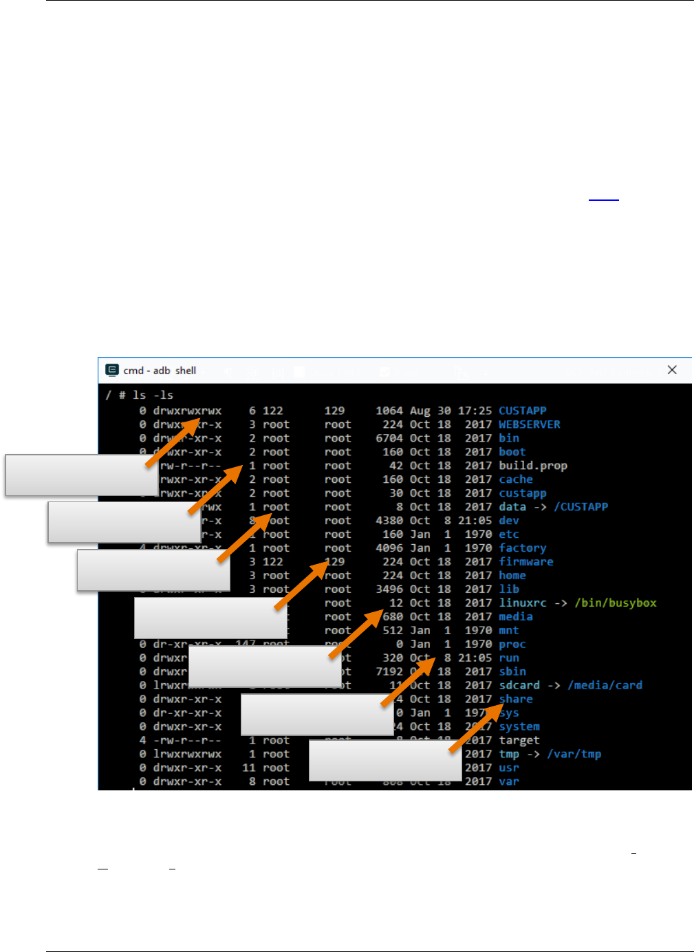
2.2.2.2. Permissions and Owners
The Linux filesystem provides a robust set of file permissions and owners. To access a file, you
must have the required permission to read, write, and/or execute it.
Here is another view of the SK2 filesystem. This one was generated using the “ls” Linux listing
command.
Figure 2-5 Filesystem Listing ("ls -ls")
Note that if the “File Permissions” begins with a “d” then that line represents a directory. The
remaining characters indicate if the “owner”, “group”, and “all users” have permission to read,
write, and execute.
File permissions
Links to file
File Owner
File Group
Size (bytes)
Modification Date
File/Directory name

Linux Distribution
AT&T IoT Starter Kit (2nd Generation) User's Guide - Embedded Linux pg. 39
The “Linux Commands” section lists several commands useful for listing (e.g. “ls”), reading and
modifying the ownership of files, (“chown”) as well as viewing and changing the permissions on
files (“chmod”).
2.2.3. Boot Loader
The SK2 Linux kernel has a pre-defined sequence for getting the module up-and-running. As part
of this sequence, you can hook your programs to “auto-execute”. That is, you make your own
programs begin running at power-up, just like the Out-of-Box example that ships with the SK2.
This will be discussed in further detail during a later part of this Users Guide.
2.2.4. Toolchain
The set of tools used to write software programs to run in a specific version of Linux. In later
chapters, we will introduce two toolchains for the SK2. One will focus on writing C programs,
while the other will utilize Python.

Linux Shell
AT&T IoT Starter Kit (2nd Generation) User's Guide - Embedded Linux pg. 40
2.3. Linux Shell
The Linux shell – also known as the Linux command-line – provides a textual interface for issuing
commands to Linux and then viewing the results. While most operating systems provide this
capability, Linux (and Unix) users, seem to rely on it more than users of other operating systems.
With Embedded Linux – where limited memory may not be able to support graphical interfaces –
the command-line shell becomes even more important.
The next section highlights several key commands that can be invoked from the Linux shell.
Experienced Linux users will likely know these already. For those new to Linux, we provide a
short explanation of each. With a little practice – and some Googling – all users should become
comfortable with them.
Note: If you are familiar with using the Windows command line, then you should be familiar with
the Linux shell. In some cases, both use the same command – for example both use the
command “cd” for “changing the active directory”. In other cases, they use different
commands (e.g. Windows uses “dir” to list a directory, while Linux uses “ls”).
Check out the ComputerHope site, which provides a brief comparison of both DOS and
Linux command-line shells.
2.3.1. Basic Linux Commands
Linux distributions a common set of programs that can invoke from the Linux shell. For example,
if you have ever used Linux – whether Ubuntu or embedded Linux – you will likely have made use
of these various command-line programs. From listing the files in a directory (“ls”), to editing files
(“vi”), or pinging a network (“ping”).
Note: It’s OK if you’re not familiar with the tools we just mentioned. Those, and many more, will
be discussed as needed throughout the rest of this user’s guide.
In other words, the commands we run from the Linux shell command are just executable
applications that reside within the Linux filesystem.
To minimize the size of the Linux on the SK2, its distribution packs all of these little command-line
utility programs into a single executable called BusyBox. This is a common way for embedded
Linux systems to include a large set of tools with a very small memory footprint, albeit with some
minor tradeoffs in functionality.
Linux Shell
AT&T IoT Starter Kit (2nd Generation) User's Guide - Embedded Linux pg. 41
2.3.1.1. BusyBox Commands
We mentioned earlier that the SK2, as do many Embedded Linux distributions, relies on BusyBox
to provide many of the command line utilities that we use every day. For that reason, BusyBox is
often called “The Swiss Army Knife of Embedded Linux”.
Here are a couple useful commands that can be used to interrogate BusyBox itself.
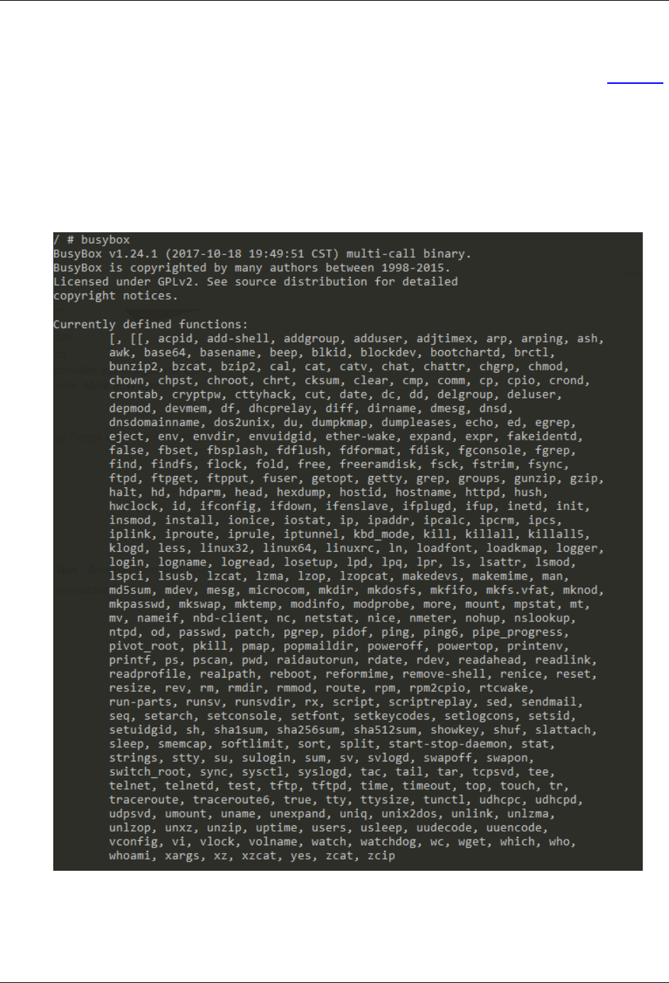
busybox
Entering the ‘busybox’ at the command line will return the version of BusyBox along with the
command-line functions supported with this distribution.
Figure 2-6 BusyBox

Linux Shell
AT&T IoT Starter Kit (2nd Generation) User's Guide - Embedded Linux pg. 42
2.3.1.2. File Management
• pwd: print working directory – simply returns the directory where your command line is
currently located; good for answering “where am I” in the filesystem?
• ls (small LS): listing – creates a simple listing of the files and subdirectories in the current
working directory
Make this more useful by adding an option, such as, “ls -ls” or “ls -la”. This will list the
files vertically and provide the additional information shown in the graphic in Section 2.2.2.2
• alias: tells the shell to replace one string with another
This lets you create a new command from one (or more) other commands; for example:
alias ll=’ls -la’
After entering this command, entering ll (small LL) will execture the “ls -la” command for you.
• cd: change directory – changes the current working directory to a new location
Examples:
• “cd /” sets your command-line session to the root of the filesystem
• “cd /CUSTAPP” makes CUSTAPP your current working directory
• cp: copy – copies a file (or files) from one location to another
• mv: move – moves a file (or files) from one location to another
Note that this is how you rename a file in Linux
• rm: remove – is how you delete a file or files
• ln (small LN): link – link files which is like shortcuts in Windows
Also popular to create symbolic links, which adds an s option: “ln –s”.
• chmod: change mode – allows you to change the permissions of files and directories
• chown: change ownership of files and directories
• mkdir: make a new directory
• rmdir: remove directory – note that the directory must be empty before it can be deleted
• mount: mount a filesystem to your root (for example, attaching a USB or network drive)
• Generally, you must create a new empty directory – for example, in the /mnt folder – and
then mount the new filesystem into the root filesystem
• umount: unmount – unmounting a filesystem from the root
• find: find a file or group of files
• grep: global regular expression print – search one or more files for lines that match a regular
expression pattern
• tar: tape archive - combine a group of files into the tar archive format with - or without -
compression; the tar command can also be used to modify, extract and manage tar files

Linux Shell
AT&T IoT Starter Kit (2nd Generation) User's Guide - Embedded Linux pg. 43
2.3.1.3. Viewing, Creating and Editing Text Files
• touch – Either creates a new empty file with the specified name or updates the files
modification timestamp if the file already exists
• cat: catenate – reads data from the specified file(s) and outputs the contents to the
command-line
• vi: visual editor – a small, simple text editor included with most Linux distributions
It’s not visual (or anything) like Microsoft Word, but it lets us view and modify text files while
taking up very little of our valuable memory
2.3.1.4. Program Control
ps: process listing – produces a list of processes running on the Linux system
top: produces a listing of processes sorted by % CPU usage
kill: tell Linux to kill a process using it PID (process ID) number; a PID can be viewed
using the ps or top command
<ctrl>-c: stops a process by sending it the SIGINT interrupt signal
clear: clears the Linux shell
2.3.2. Shell Scripting
As discussed earlier, the command-line shell provides a handy and powerful way to work with
Linux, such as managing files or executing programs.
Behind the scenes, this shell itself is a Linux program that provides the command-line interface
and command interpreter. There are a variety of shell programs found in Linux (and Unix)
distributions – the most common being one called Bash. Alternatively, the SK2 comes with a
similar, smaller shell program called Ash, which is part of the BusyBox toolset. (In fact, you can
see this listed in Figure 2-6 BusyBox.)
Shell scripting is nothing more than a sequence of command-line (i.e. shell) calls. These
sequences can be a simple grouping of one or two commands or complicated sequences that
contain logical control statements.
We use the term “scripting”, rather than “programming”, as these sequences do not need to be
explicitly compiled before they are executed.
When grouped together into a single text file, the “.sh” file extension is used to signify a shell
script. Linux doesn’t require that we use the .sh extension, but this is common practice in Linux
since this makes it easier for us to identify which files are shell scripts.
Listing 1 is an example of a very simple shell script that was used to create Figure 2-5 Filesystem
Listing ("ls -ls"):
# list.sh
# list the files in the current directory to the command-line
# note that the -ls option creates a vertical listing with more info
ls -ls
Listing 1 list.sh

Linux Shell
AT&T IoT Starter Kit (2nd Generation) User's Guide - Embedded Linux pg. 44
A second example lists the files in the dev directory:
# list_dev.sh
# change to the /dev directory
# and then print a listing the command line
cd /dev
ls -ls
Listing 2 list_dev.sh
Let’s look at one final example:
# list_pipe_cat.sh
#
# - This script writes a listing of /dev directory
# into the file mylisting.txt in /CUSTAPP
# - The ‘>’ pipes tells the shell to pipe the output
# into the txt file rather than to the standard output
# - It then prints out the contents of mylisting.txt
# using the ‘cat’ command
ls -ls /dev > /CUSTAPP/mylisting.txt
cat /CUSTAPP/mylisting.txt
Listing 3 list_pipe_cat.sh
Later, in Section 2.4.4.3 on page 56, we walk you through using shell scripts on your SK2.
Note: Linux Line Endings
Be careful when creating shell scripts in Windows for use in Linux on your SK2. Windows
uses different characters to signify line-endings than Linux. In some cases, the different
characters can return unexpected results.
A couple of guidelines to help you get better results:
- Do not use Windows Notepad to create shell scripts. It does not handle Linux line
endings.
- Find and use a good Windows text editor. There are many good ones available. A
popular,
free editor is Notepad++ (https://notepad-plus-plus.org).

ADB – Connecting to the SK2
AT&T IoT Starter Kit (2nd Generation) User's Guide - Embedded Linux pg. 45
2.4. ADB – Connecting to the SK2
Now that we are familiar with several Linux commands, how do we connect to the SK2 to view
the filesystem and utilize these commands?
The SK2 was developed using ADB (Android Debug Bridge) to communicate between your
computer and the kit. ADB is a versatile command-line tool that facilitates a variety of device
actions, such as pushing and pulling files, as well as providing access to a Unix shell that you can
use to run a variety of commands on your device.
It is a client-server program that includes three components:
1. (SK2) An ADB daemon is resident on your SK2, running in the background, providing
development and debug access to authorized users through the COMmunications USB port.
2. (Computer) A client, which sends commands. The client runs on your development machine.
You can invoke a client from a command-line terminal by issuing ADB commands.
3. (Computer) A server, which manages communication between the client and the daemon.
The server runs as a background process on your development machine. Once the server
has set up connections to all devices, you can use adb commands to access those devices.
Since the ADB daemon is already installed on your SDK, we only need to install ADB onto our
development computers. This is addressed in the next section.

ADB – Connecting to the SK2
AT&T IoT Starter Kit (2nd Generation) User's Guide - Embedded Linux pg. 46
2.4.1. Installing ADB
Since ADB is already installed on your SK2, we only need to install the remaining two
components on your development computer; these are both installed with a single installation
program.
Installing ADB on your Windows, Mac or Linux computer follows a similar set of steps. After
downloading and extracting the ADB executables, you will also need to set up an access key file
which will grant you authorization to connect to your SK2.
2.4.1.1. Install ADB Executables
1. Download the ADB ZIP file for your computer from the Android developers’ site.
There are separate download links for each OS (Windows, Mac, Linux). Pick the one that
matches your development computer.
https://developer.android.com/studio/releases/platform-tools
Note: Debian-based Linux users, such as those using Ubuntu Linux, can type the following
command to install ADB:
sudo apt-get install adb
2. Extract the contents of this ZIP file into an easily accessible folder.
Some suggestions include:
Windows: C:\adb
Mac: /Users/MY_USER_NAME/Desktop/adb (replacing MY_USER_NAME with your own)
Linux: /Users/MY_USER_NAME/Desktop/adb (replacing MY_USER_NAME with your own)
Note: You can skip this step if, as a Linux user, you installed ADB with apt-get.

ADB – Connecting to the SK2
AT&T IoT Starter Kit (2nd Generation) User's Guide - Embedded Linux pg. 47
2.4.1.2. Set up Credentials (i.e. access key)
3. Create a new folder called “.android” in your user directory.
Using your computer’s file browser (or command-line), create the new folder as shown:
Windows: C:\Users\MY_USER_NAME\.android
Mac: /Users/MY_USER_NAME/.android
Linux: /Users/MY_USER_NAME/.android
replacing MY_USER_NAME with your own user account folder.
4. Add “adbkey.pub to your new “.android” folder.
For the SK2, this is simply a text file named “adbkey.pub” which contains a single word:
wnc000000
Hint: This file should contain only this word. It should not contain a carriage return or line-
feed.
You can create this file on yourself or download it from github.com:
https://github.com/Avnet/AvnetWNCSDK/blob/master/adbkey.pub
For example, in Windows with a user name of “doug”, when this step is complete you should
have the following in your .android directory:
C:\Users\doug\.android\adbkey.pub
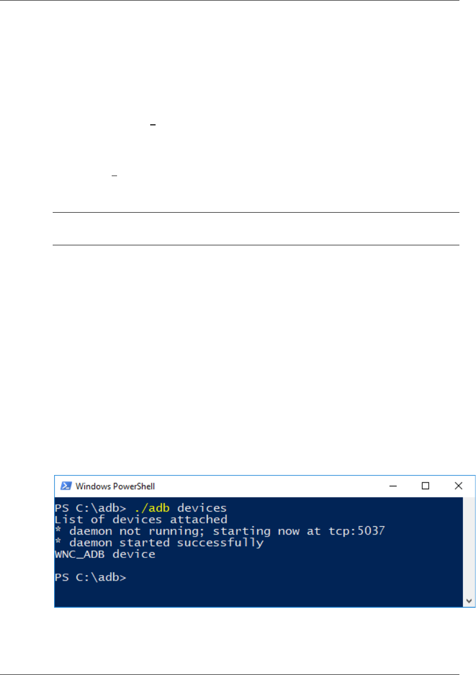
ADB – Connecting to the SK2
AT&T IoT Starter Kit (2nd Generation) User's Guide - Embedded Linux pg. 48
2.4.1.3. Connect to Your SK2
5. Open a command window in the same directory where you installed the ADB binary.
In Windows, this can be done by holding Shift and Right-clicking within the ADB folder then
choosing the “open command prompt here” option. (Some Windows 10 users may see
“PowerShell” instead of “command prompt”.)
Mac users can open “Terminal” from their Applications folder and navigate to where you
installed ADB (in step 2). For example:
cd /Users/MY_USER_NAME/Desktop/adb
Linux users should open their command-line shell and and navigate to where you installed
ADB (in step 2). For example:
cd /Users/MY_USER_NAME/Desktop/adb
Note: Linux users who installed ADB with apt-get may run adb commands from any
location. You do not need to navigate to the adb folder in order to run it.
6. Connect your SK2 to your computer with a USB cable.
Make sure the USB power cable is also connected. It won’t work without both USB cables
being connected.
7. In the Command Prompt window, enter the following command to launch the ADB
daemon:
Windows command-line:
adb devices
For Mac, Linux, and PowerShell users, commands are preceded with “./”:
./adb devices
In response, you should see:
WNC_ADB device
As shown below:
Figure 2-7 adb devices
You can now run ADB commands on your device – which we’ll look at in Section2.4.4 on
page 53.
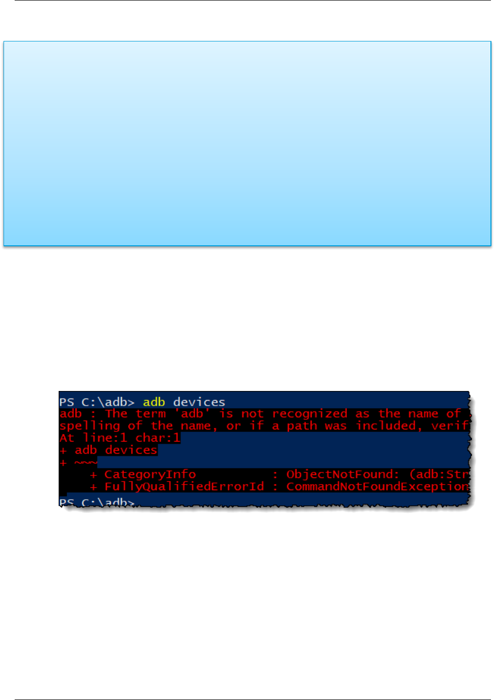
ADB – Connecting to the SK2
AT&T IoT Starter Kit (2nd Generation) User's Guide - Embedded Linux pg. 49
2.4.2. Sidebar - What happens during “adb devices”
When you run “adb devices” a few things happen:
1. ADB Server is started. (This was briefly described in Section 2.4 on page 45.)
2. The ADB Server scans you computer for connected ADB devices.
3. It then verifies if you have the credentials to access the connected ADB devices.
a) Looks for the required ‘key’ in your .android folder.
b) Creates the .android folder, if it doesn’t exist.
c) If it finds the key, is uses that to create the actual authorization key “adbkey”.
4. Finally, it prints the list of devices to the command line (as we saw in the diagram for Step 7
of Section 2.4.1.3).
2.4.3. Troubleshooting “adb devices”
Please refer to this section if you failed to connect to your device in Step 7 of Installing ADB
(Section 2.4.1). In other words you can skip this section if executing “adb devices” returns:
WNC_ADB device
Otherwise, examine some of the problems and solutions listed here.
2.4.3.1. Precede Command with ./
Figure 2-8 Mac/Linux/Powershell needs ./
When using Windows Powershell, Mac or Linux, you should precede the “adb” command with “./”.
(Powershell also accepts “.\”.)
./adb devices

ADB – Connecting to the SK2
AT&T IoT Starter Kit (2nd Generation) User's Guide - Embedded Linux pg. 50
2.4.3.2. Execute From ADB Directory
Figure 2-9 Use ADB Folder
The ADB executable wasn’t found. Since “./adb” was used correctly for PowerShell, we know that
wasn’t the issue. But, it appears we were trying to run ADB from the “C:/” drive location. Unless
you modify your Windows configuration (i.e. PATH variable), you either need to specify the full
path to ADB… or simply run ADB from the folder you installed it to.
Change to the ADB folder by using the “cd” command as shown above. Since we installed ADB
to the “C:\adb” directory, and our cursor resides at “C:\”, we only need to use:
cd adb
to get to the proper location.
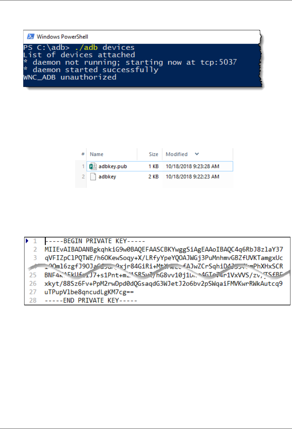
ADB – Connecting to the SK2
AT&T IoT Starter Kit (2nd Generation) User's Guide - Embedded Linux pg. 51
2.4.3.3. WNC_ADB unauthorized
Figure 2-10 WNC_ADB Unauthorized
In this case, it appears that the ADB server started and found our WNC_ADB device but did not
find the proper credentials to access the device.
Go and examine your .android directory (created in Step 3 on page 47.). It should now contain
two files:
Figure 2-11 adb keys
“adbkey” is a private key generated by the ADB Server based upon the “adbkey.pub” file we
placed in our .android directory.
If you examine “adbkey” with a text editor, you will notice it looks like:
Figure 2-12 Private key
If our device is unauthorized, then something is likely wrong with this file. Since it is generated by
“adbkey.pub”, it is likely that it has been corrupted. For some reason, it gets overwritten with
some incorrect hash string.

ADB – Connecting to the SK2
AT&T IoT Starter Kit (2nd Generation) User's Guide - Embedded Linux pg. 52
Procedure to Correct Unauthorized
1. Double-check that “adbkey.pub” still contains the single word “wnc000000” (without the
quotes). if it doesn’t, delete the contents of this file and replace it with this word.
Figure 2-13 adbkey.pub
Hint: This file should contain only this word.
It should not contain a carriage return or line-feed.
2. Run the following ADB command to stop the server from running.
adb kill-server
or
./adb kill-server
3. Run the “adb devices” command again.
You can see the sequence we followed below.
Figure 2-14 kill-server and re-running adb devices
If these three steps do not result in “WNC_ADB device”, try working through them again. We
have occasionally seen it require these 2 or 3 times for it to work correctly.
Replace corrupt
contents of
“adbkey.pub” with the
single word:
wnc000000
Then run kill-server
command

ADB – Connecting to the SK2
AT&T IoT Starter Kit (2nd Generation) User's Guide - Embedded Linux pg. 53
2.4.4. ADB Commands
Once ADB is installed on your development computer, there are several ADB commands
available for use. On this page we will describe a subset of ADB commands that will be used
throughout this user guide.
2.4.4.1. ADB Commands found in this User Guide
ADB Debugging
• adb devices – lists available adb targets
• adb kill-server – stop the adb server
• adb reboot – reboots the SK2
File Management
• adb pull – pull a file from the SK2
• adb push – push a file to the SK2
Execute on Device
• adb shell - Starts a remote shell on the SK2
• exit – exits the remote shell and returns to your computers command-line
Of course, you can find a listing of all the commands from many places on the Internet, such as:
adbshell.com, https://developer.android.com/studio/command-line/adb, droidviews.
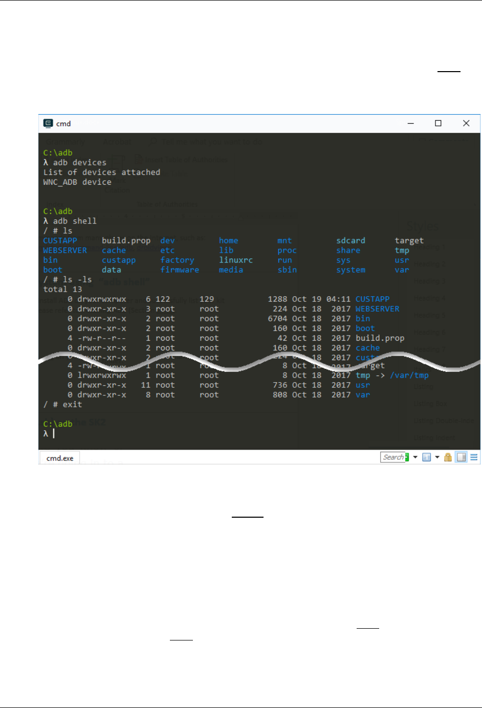
ADB – Connecting to the SK2
AT&T IoT Starter Kit (2nd Generation) User's Guide - Embedded Linux pg. 54
2.4.4.2. Exploring the SK2 Filesystem using “adb shell”
This section assumes that you were able to install ADB on your computer and successfully list
your kit using the “adb devices” command. If not, please refer to Installing ADB (Section 2.4.1).
Here is a screen capture from our computer when executed the following instructions. (Note that
this example uses the CMDR shell running on Windows.)
Figure 2-15 Using "adb shell"
1. Open a command-line shell on your computer in the ADB folder.
This was discussed in Step 5 (Section 2.4.1.3) on page 48.
2. Verify you can connect to your board using ADB.
Running this command from the shell you just opened:
adb devices or ./adb devices
Should return:
WNC_ADB device
If it doesn’t, then you need to verify your ADB installation (Section 2.4.1) and/or view ADB
troubleshooting (Section 2.4.3).

ADB – Connecting to the SK2
AT&T IoT Starter Kit (2nd Generation) User's Guide - Embedded Linux pg. 55
3. Start a remote session on your SK2 using “adb shell”.
You can start a remote shell session running on your SK2 using the adb shell command.
adb shell or ./adb shell
Notice, in Using "adb shell (Figure 2-15 Using "adb shell"), that the command prompt
changes to “#” after running the “adb shell” command. The commands executed from the #
shell are running on the SK2 (and not on your computer).
4. List the SK2 filesystem “ls”.
5. List the SK2 filesystem again using “ls -ls”.
6. Exit the SK2 remote shell.
Exit the remote shell using the exit command.
exit
Notice how the command prompt returns to its original value. This indicates that our
command-line is running on our computer again.

ADB – Connecting to the SK2
AT&T IoT Starter Kit (2nd Generation) User's Guide - Embedded Linux pg. 56
2.4.4.3. Running Shell Scripts (.sh) on the SK2
To demonstrat running shell scripts on your SK2, we will use the script (Listing 2 list_dev.sh) we
examined earlier that lists the contents of the /dev directory. We will create (or download) the
shell script on our computer and then push it to the SK2 and execute it.
Note: See a screen capture of this procedure at the end of the instructions.
1. Create (or download) the list_dev.sh file to your adb folder.
Since this is such a small file, you may prefer to create it using you’re a text editor. If so,
create a file called “list_dev.sh” and add the following two lines of code.
cd /dev
ls -ls
Note: If using Windows, save the file using Linux (or Unix) line endings.
(See note on page 44).
Alternatively, you may want to download this file from the AT&T Starter Kit GitHub site:
GitHub site coming soon
Hint You can place your shell file in any folder, we only chose the adb folder for
convenience.
2. Open a command-line shell on your computer, if it isn’t already open.
This was discussed in Step 5 (Section 2.4.1.3) on page 48.
3. Verify your SK2 connection using “adb devices”.
It should return:
WNC_ADB device
Otherwise you need to verify your ADB installation (Section 2.4.1) and/or view ADB
troubleshooting (Section 2.4.3).
4. Push the shell script to the /CUSTAPP folder.
The ADB push command takes two arguments, the from and to location.
adb push “C:/adb/list_dev.sh” /CUSTAPP
or ./adb push “C:/adb/list_dev.sh” /CUSTAPP
Modify the path to your list_dev.sh file as necessary.
5. Open a shell session on your SK2.
adb shell
or ./adb shell

ADB – Connecting to the SK2
AT&T IoT Starter Kit (2nd Generation) User's Guide - Embedded Linux pg. 57
6. Change directories, opening /CUSTAPP.
cd /CUSTAPP
7. List the /CUSTAPP directory and look at the permissions for your list_dev.sh file.
ls -ls
You will see the shell file has the following permissions.
4 -rw-rw-rw- 1 root root 104 Oct 19 04:15 list_dev.sh
Unfortunately, since the permissions do not include an ‘x’, you won’t be able to execute the
script. In fact, you can try to run it, if you’d like.
8. Modify permissions so that you can execute your shell script.
There are several permutations for setting file permissions. By using the “+x” argument with
the CHMOD command we simply enable execute permission for our script file. (We
recommend that you explore file permission options further on your own.)
chmod +x list_dev.sh
Hint Handily, Linux will autofill filenames when possible. For example, in this step, typing
“chmod +x lis” and hitting the tab key should autofill the full filename.
9. Check the permissions on the file after chmod.
ls -ls list_dev.sh
Notice that the executable flags are set: -rwxrwxrwx
10. Run the list_dev.sh.
Since we are using the SK2 Linux shell, we must append “./” when running executables.
./list_dev.sh
The contents of the /dev directory (the SK2 Linux drivers) should be printed to your terminal.
11. Notice that you remained in the /CUSTAPP directory.
Even though the shell script changed to the working directory to /dev, the script returned to
the /CUSTAPP directory when it finished running.
This happens because shell scripts are run in their own sub-shell. This is often handy,
especially when running multiple sequential scripts.
Using the “source” command (in the next step) if you want to affect the working directory.
12. Run your script with the “source” command to have the script affect the working
directory.
source ./list_dev.sh
This time, your working directory should be /dev when the script completes.
13. Exit the ADB shell.
exit
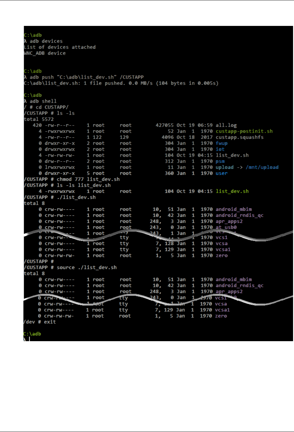
ADB – Connecting to the SK2
AT&T IoT Starter Kit (2nd Generation) User's Guide - Embedded Linux pg. 58
Here is a recording of our running the list_dev.sh shell script.
Figure 2-16 Running the list_dev.sh script

ADB – Connecting to the SK2
AT&T IoT Starter Kit (2nd Generation) User's Guide - Embedded Linux pg. 59
2.4.4.4. Modifying shell script with vi
You can use the “vi” text editor to create and modify text files with your SK2. This can be handy if
you need to make a change to a file already resident on the board.
This section assumes you have created the shell script (list_dev.sh) used in the previous section.
Additionally, please refer back to previous sections if you need with the early instructions in this
sequence.
1. Open a command-line shell on your computer, if it isn’t already open.
2. Verify your SK2 connection using “adb devices”.
3. Open a shell session on your SK2.
4. Change directories, opening /CUSTAPP.
cd /CUSTAPP
5. Copy “list_dev.sh” to “list_lib.sh”.
cp list_dev.sh list_lib.sh
6. Open the list_dev.sh file for editing.
vi list_lib.sh
7. Enter insert mode in the vi editor.
i
8. Change the cd command.
From: cd /dev
To: cd /lib
9. Exit the editing mode.
<esc>
:
10. Write the changes and quit the file.
wq
<Return>
11. Run the newly edited script.
./list_lib.sh
If you are used to editing with Microsoft Word, the “vi” editor may take some time to get used to.
But, it’s a convenient – and very powerful – text editor that resides inside your SK2.
Please search the web for numerous pages describing how to use vi’s many options. Here are
two to get you started:
• https://www.howtogeek.com/102468/a-beginners-guide-to-editing-text-files-with-vi/
• https://www.cs.colostate.edu/helpdocs/vi.html
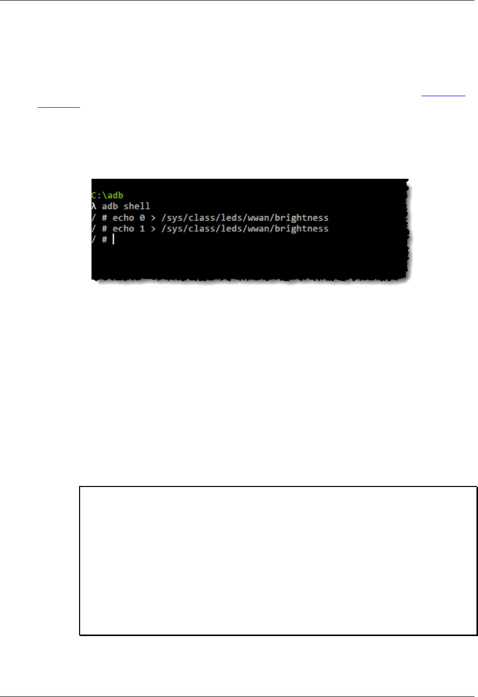
Controlling Hardware Using the Linux Shell
AT&T IoT Starter Kit (2nd Generation) User's Guide - Embedded Linux pg. 60
2.5. Controlling Hardware Using the Linux Shell
The SK2 hardware can be controlled from the Linux shell. While it isn’t very effective to try and
control an I2C serial port from the command-line, the LED makes a convenient example.
The following examples demonstrate how to turn the WWAN LED on/off. (Refer to the Hardware
Overview in Chapter 1 if you cannot find the WWAN LED.)
2.5.1.1. Writing the WWAN LED
In the filesystem, the WWAN LED is found under the /sys directory. This is another directory,
along with /dev, that maps hardware to the Linux filesystem.
Figure 2-17 Turning the WWAN LED off/on
To turn off the LED, we simply write a “0” to its associated (virtual) file.
echo 0 > /sys/class/leds/wwan/brightness
Listing 4 Turn Off the LED
Similarly, we can turn the LED on by writing a “1” to the same location.
echo 1 > /sys/class/leds/wwan/brightness
Listing 5 Turn On the LED
2.5.1.2. Simple Blink LED Script
Here’s a very simple script which blinks the WWAN LED.
# blink.sh
#
# This is a simple example for blinking the WWAN LED five times
# - The For loop executes once per character (a thru e)
# - 'sleep 1' causes the cpu to wait 1 second
# - At the end of the script, the LED is turned off
#
for var in a b c d e; do
echo 0 > /sys/class/leds/wwan/brightness
sleep 1
echo 1 > /sys/class/leds/wwan/brightness
sleep 1
done
echo 0 > /sys/class/leds/wwan/brightness
Listing 6 blink.sh

Controlling Hardware Using the Linux Shell
AT&T IoT Starter Kit (2nd Generation) User's Guide - Embedded Linux pg. 61
2.5.1.3. Using the RGB LED or USER Button
While the WWAN LED is controlled directly by the WWAN pin on the WNC module, the RGB LED
and USER button are controlled by GPIO pins.
Here’s a simple example for lighting the Red LED (in the RGB LED).
# TurnOnRedLed.sh
#
# This simple example turns on the Red RGB LED
#
cd /sys/class/gpio
echo 38 > export
echo out > gpio38/direction
echo 1 > gpio38/value
Listing 7 - Turning on the Red LED
Refer to the Appendix on GPIO for more details concerning:
• What is GPIO?
• How do I use the Linux GPIO driver to access the RGB LED and Button?
• Addtional GPIO shell examples

Linux Boot Sequence
AT&T IoT Starter Kit (2nd Generation) User's Guide - Embedded Linux pg. 62
2.6. Linux Boot Sequence
Linux follows an orderly boot sequence from power-up to user shell access. This sequence of
scripts, functions, and tasks prepares the operating system to host users or run programs. While
most of these details are not generally of interest – especially on the SK2 since we cannot affect
them – the final steps may be useful for us to understand.
In our case, the questions of interest may include:
• How does the SK2 QuickStart demo start running automatically?
• Can I stop the demo from running automatically?
• Once I have written a program of my own, can I start it running automatically?
These are the questions we’ll address in this section.
2.6.1. How Does the QuickStart Demo Run Automatically?
The QuickStart demo consists of a C program called iot_monitor, since it monitors several
sensors and communicates that information over the Internet. (Note that throughout the various
chapters in this book we’ll explore the various facets of the iot_monitor program.)
So how exactly is “iot_monitor” getting started? Let’s look at the sequence of events starting at
the end of the Linux boot sequence.
1. The simple answer is that Linux always calls the following script file after its done booting up:
/CUSTAPP/custapp-postinit.sh
2. Examining the script file, we find it calls another script called run_demo.sh:
Listing 8 - custapp-postinit.sh
start-stop-daemon -S -b -x /CUSTAPP/iot/run_demo.sh
The start-stop-daemon is used to start system level processes as described by:
http://www.man.he.net/man8/start-stop-daemon
3. Finally, when examining the /CUSTAPP/iot/run_demo.sh, script we see that it calls the
actual iot_monitor program (along with a few arguments).
Listing 9 - run_demo.sh
iot_monitor -q5 -a a2e26b03f4e77aab23dbc5294b277d69
Bottom line, you can control what programs autostart on your SK2 by editing (or deleting) the
custapp-postinit.sh script.
Note: There’s the simple, short answer (described here)… and the longer, more involved
answer that is in the Appendix Linux Boot Sequence discussion.

Linux Boot Sequence
AT&T IoT Starter Kit (2nd Generation) User's Guide - Embedded Linux pg. 63
2.6.2. Stop the QuickStart Demo from Running Automatically
The QuickStart demo can be turned off by holding the USER Button down for longer than 3
seconds. After doing so, you will see the RGB LED turn off.
Since the iot_monitor program autostarts after power-cycling the SK2, turning off the program
using the USER Button is only temporary. To stop the program altogether we need to edit, delete,
or rename the custapp-postinit.sh script. In this case, let’s rename the script and then
verify that the QuickStart program doesn’t run.
2.6.2.1. Stop the QuickStart Demo
1. Power-cycle your SK2 and verify the QuickStart demo runs.
Unplug, then plug back in the USB power to your SK2. The QuickStart demo should begin
running within a minute. You can refer back to Chapter 1 (Running the QuickStart Demo) for
more information about the demo.
2. Open a command-line shell on your computer in the ADB folder.
This was discussed in Step 5 (Section 2.4.1.3) on page 48.
3. Verify you can connect to your board using ADB.
Running this command from the shell you just opened:
adb devices or ./adb devices
Should return:
WNC_ADB device
If it doesn’t, then you need to verify your ADB installation (Section 2.4.1) and/or view ADB
troubleshooting (Section 2.4.3).
4. Start a remote session on your SK2 using “adb shell”.
You can start a remote shell session running on your SK2 using the adb shell command.
adb shell or ./adb shell
Notice, in Using "adb shell (Figure 2-15 Using "adb shell"), that the command prompt
changes to “#” after running the “adb shell” command. The commands executed from the #
shell are running on the SK2 (and not on your computer).
5. Navigate to the /CUSTAPP folder.
cd /CUSTAPP
6. Rename the custapp-postinit.sh script to something else.
In Linux we can use the the “move” command to rename a file. In this case, let’s just append
“.txt” to the end of the filename.
mv custapp-postinit.sh custapp-postinit.sh.txt
7. List the directory to verify the name was changed.
ls -l

Linux Boot Sequence
AT&T IoT Starter Kit (2nd Generation) User's Guide - Embedded Linux pg. 64
8. Exit the ADB remote shell.
exit
9. Power-cycle your SK2 and watch the LEDs to verify the QuickStart demo doesn’t start.
If the WWAN and RGB LEDs do not light up within a minute or two, it’s a safe bet that the
QuickStart demo is not running.

Linux Boot Sequence
AT&T IoT Starter Kit (2nd Generation) User's Guide - Embedded Linux pg. 65
Autostart the Blink Script
If you created and ran the /CUSTAPP/blink.sh script in Section 2.5.1.2, let’s try running that
script automatically. If not, we suggest that you return to that section and create the script and put
it into the /CUSTAPP directory before doing the following steps in this section.
10. Reconnect to the ADB shell.
adb shell
11. Change to the /CUSTAPP directory.
cd /CUSTAPP
12. Verify that blink.sh exists and is working.
./blink.sh
The WWAN LED should blink 5 times.
13. Create a new copy the custapp-postinit.sh file.
cp custapp-postinit.sh.txt custapp-postinit.sh
14. Edit the custapp-postinit.sh file.
vi custapp-postinit.sh
a) Enter Insert/Edit mode.
i
b) Modify the script to be executed:
The original script runs /CUSTAPP/iot/rundemo.sh. Change this to run our
blink.sh script. Afterward editing it should read:
start-stop-daemon -S -b -x /CUSTAPP/blink.sh
c) Exit Insert/Edit mode.
<esc>
d) Quit and save the file.
:wq
15. Verify the file is correct.
cat custapp-postinit.sh
Which should print out the contents:
start-stop-daemon -S -b -x /CUSTAPP/blink.sh
16. Exit the ADB remote shell.
exit
17. Power-cycle the board to view blink running.
After 10-15 seconds, the blink.sh script runs and blinks the WWAN LED five times.

AT&T IoT Starter Kit (2nd Generation) User's Guide - Embedded Linux pg. 66
2.6.2.2. Autostart the QuickStart Demo
Assuming that you have completed the previous two sections (2.6.2.1 and 0) we can return the
SK2 to its original state of running the QuickStart demo by renaming (or deleting) our new
custapp-postinit.sh file and restoring the original file.
18. Enter the ADB shell and change to the /CUSTAPP directory.
adb shell
19. Rename your new custapp-postinit.sh file by adding appending blink to the name.
mv custapp-postinit.sh custapp-postinit.sh.blink
20. Restore the original custapp-postinit.sh file.
mv custapp-postinit.sh.txt custapp-postinit.sh
21. Verify the original file was restored by listing the directory and cat’ing the file.
ls -l
cat custapp-postinit.sh
22. Exit the shell.
exit
23. Power-cycle your SK2 to verify the original QuickStart demo runs again.
As an alternative, rather than power-cycling the board, you could execute:
adb restart
to restart the SK2. However you restart the board, you should see the QuickStart demo begin
running within 45-60 seconds, as it did in Chapter 1 (and at the beginning of this Section
2.6.2).

AT&T IoT Starter Kit (2nd Generation) User's Guide - Appendix pg. 67
Appendix
Topics
Appendix ............................................................................................................................................. 67
Topics ........................................................................................................................................................ 67
Glossary ..................................................................................................................................................... 68
What is, and how do you configure, the APN? .......................................................................................... 70
What is “APN”? ..................................................................................................................................... 70
Starter Kit APN value ............................................................................................................................ 70
Prerequisites ......................................................................................................................................... 70
View APN .............................................................................................................................................. 70
Modify APN ........................................................................................................................................... 71
General Purpose Bit I/O (GPIO) ................................................................................................................. 74
What is GPIO? ....................................................................................................................................... 74
SK2 GPIO Pins for LEDs and Pushbuttons ............................................................................................. 75
GPIO Pin Numbers – WNC vs Qualcomm ............................................................................................. 76
Linux GPIO Drivers ................................................................................................................................ 77
More Details about the Linux Boot Sequence ........................................................................................... 81
Getting to custapp-postinit.sh .............................................................................................................. 81

Glossary
AT&T IoT Starter Kit (2nd Generation) User's Guide - Appendix pg. 68
Glossary
APN (Access Point Name)
The APN is the endpoint where cellular communications enter a cellular carrier’s mobile network.
Or, as Wikipedia says, an Access Point Name (APN) is the name of a gateway between a GSM, GPRS,
3G or 4G mobile network and another computer network, frequently the public Internet.
The APN’s network must be provisioned to recognize each SIM card that wants communicate with it.
Based on this, most cellular phone SIM cards will not be able to communicate with IoT APN’s and vice
versa.
Embedded System
Embedded Systems are small systems that generally provide a static set of functionalities aimed at
addressing a problem. Think, for example, that your microwave oven cooks food, but that’s about it.
Similarly, your thermostat controls your heating and air conditioning, but is limited to that functionality,
too.
EOL (End of Line)
The end-of-line character(s) – also known as “newline” – tell software reading a document that a line of
text has ended. While this is a relatively straightforward concept, Mac/Linux/Unix and Windows use
different characters (or sets of characters) to signify EOL.
− Mac / Linux / Unix use a line-feed (LF) to signify the end of a line.
− Windows uses line-feed (LF) and a carriage-return (CR) to end a line.
GPIO (General Purpose Input/Output)
Processors (e.g. microprocessors, microcontrollers) have various ways to communicate with external
devices, the most basic of which is GPIO. GPIO generally refers to talking across a single pin of the device.
With a single pin the device can receive or send (i.e. the input and output in GPIO) an “On” or “Off” value
using a higher or lower voltage, respectively. Programmers describe this On/Off communication using a
“bit” (binary digit) which can have the value “1” or “0”. In light of this, it’s easy to understand why many
users commonly define GPIO as “General Purpose Bit I/O”.
LED (Light Emitting Diode)
A light-emitting diode is a semiconductor light source. It’s a diode that emits light a suitable current is
applied to it. LEDs can be created in a variety of colors.
Microcontroller (MCU) / Microprocessor (MPU)
The terms processor, microprocessor, and microcontroller are used fairly interchangeably nowadays. They
generally refer to an integrated circuit (i.e. semiconductor) that can be programmed with software to
implement a variety of tasks.
The microprocessor originally consisted of a block called the central processing unit (CPU) which handled
the execution of software mainly consisting of logical, arithmetic, and control instructions. The term
“micro” processor referred to their small size as compared to the original computers (which were often

Glossary
AT&T IoT Starter Kit (2nd Generation) User's Guide - Appendix pg. 69
room-size). While processor is a general term for “processing” things, it has also become an abbreviated
way to reference microprocessors. Likewise, the acronym “MPU” is used for a long list of terms, one of
which is “microprocessor”.
The term microcontroller (MCU) was created in 1971 when engineers from Texas Instruments put all the
building blocks of a computer onto a single integrated semiconductor. You can think of MCU’s as a
superset of the microprocessor. Along with the CPU (found in the microprocessor), they added memory
and input/output peripherals.
Over the years both types of processors have become more and more integrated with the addition of
different types of memory and peripherals. In fact, it can difficult to tell them apart in todays processor
market. Vendors still use the term microcontroller, though, to refer to their processor chips which include
Read Only Memory (ROM) – such as Flash EEPROM (electrically eraseable programmable read only
memory). Devices use ROM memory to store software instructions, thus making them stand alone
computer devices. Microprocessors, on the other hand, require an external ROM-like memory chip to
store their instructions, which are usually loaded into fast RAM (read-write memory) at boot time (i.e.
startup). In these days of highly integrated circuits, microprocessors still use an external memory chip
because inexpensive read-only memory circuits are not fast enough to keep up with the high clock rates
of MPU’s.
Operating System (OS or O/S)
An operating system is system software that manages computer – or embedded system – hardware and
software resources and provides common services for computer programs.
The OS is often thought of the support infrastructure for the program that users what to run. For
example, a user may want to run a want to run a word processor. The OS does not include a program such
as this, but it provides underlaying software support for such programs.
Similarly, looking at an embedded system example – say, an Internet connected thermostat. The
operating system would not provide the logic to control the heating and ventilation (HVAC) unit, but it
would provide services to the embedded software that runs the HVAC unit.
SIM (Subscriber Identity Module)
A subscriber identity module or subscriber identification module, widely known as a SIM card, is an
integrated circuit that is intended to securely store the international mobile subscriber identity number
and its related key. These are used to identify and authenticate subscribers on mobile telephony devices

What is, and how do you configure, the APN?
AT&T IoT Starter Kit (2nd Generation) User's Guide - Appendix pg. 70
What is, and how do you configure, the APN?
What is “APN”?
According to Wikipedia:
An Access Point Name (APN) is the name of a gateway between
a GSM, GPRS, 3G or 4G mobile network and another computer network, frequently
the public Internet.
In other words, the APN is the endpoint for the cellular network that your IoT Starter Kit connects to. This
value is not embedded into the SIM card; therefore, you may need to configure this if it’s not connecting
to the network properly.
Note, AT&T cellular phones (as well as other vendors) use different APN addresses. As such, you cannot
generally use a SIM card provisioned for a cellular phone in your AT&T IoT Starter Kit. You must use the
SIM card that comes with the Starter Kit or purchase a new IoT SIM from the AT&T Marketplace. (Note
that SIM cards are defined in Chapter 1.)
Starter Kit APN value
The APN for our Starter Kit:
m2m.com.attz
Your board should be pre-configured with this value. If not, you will need to modify your board’s
configuration before it can connect with the network.
Prerequisites
The following procedure requires:
• ADB connection to your starter kit. (Chapter 2 - ADB)
• Rudimetary knowledge of Linux filesystem. (Chapter 2 - Filesystems)
View APN
The APN for your SK2 is stored on your kit in the malmanager.cfg file. If you are comfortable with editing
using the “vi” editor, you could connect to your SK2 (using “ADB shell”) and directly view this file.
Alternatively, you can pull this file over to your computer and view it with any text editor.
The following command will “pull” a copy of the malmanage configuration file from your SK2 filesystem to
the “adb” folder on your computer.
adb pull /data/user/mm_conf/malmanager.cfg C:\adb\
You don’t have to use the “adb” folder, but that is where we copied it to on our Windows computer.
Once the file is on your computer, you can search for “name” to see if it’s set to the correct value (i.e.
m2m.com.attz). You can see a picture of the “name” in the diagram below.

What is, and how do you configure, the APN?
AT&T IoT Starter Kit (2nd Generation) User's Guide - Appendix pg. 71
ForthecomparisoninFigureA‐1,wecopiedthemalmanger.cfgfrombothaworkingSK2(left)anda
non‐workingSK2(right).NoticehowtheAPNintheworkingsystemincludes“m2m.com.attz”,while
thenon‐workingsystemdoesnot.
FigureA‐1–Malmanager.cfgcomparison
ModifyAPN
TomodifytheAPNforyourSK2,youneedtoeditmalmanager.cfgtoincludetheproperAPNvalue
specifiedbyyourcellularcarrier.FortheSK2,thatmeansusing“m2m.com.attz”.

What is, and how do you configure, the APN?
AT&T IoT Starter Kit (2nd Generation) User's Guide - Appendix pg. 72
Edit in Place
You can edit your APN “in place” by connecting to the SK2 and changing the APN.
1. Verify that your computer is connected to the SK2.
ADB devices
2. Open a remote session on your SK2.
ADB shell
3. Change to the mm_conf directory.
cd /data/user/mm_conf
4. Edit malmanager.cfg with vi.
vi malmanager.cfg
5. Change the APN, as required using “vi”.
See Chapter 2 - vi for more info.
6. Power-cycle your SK2.
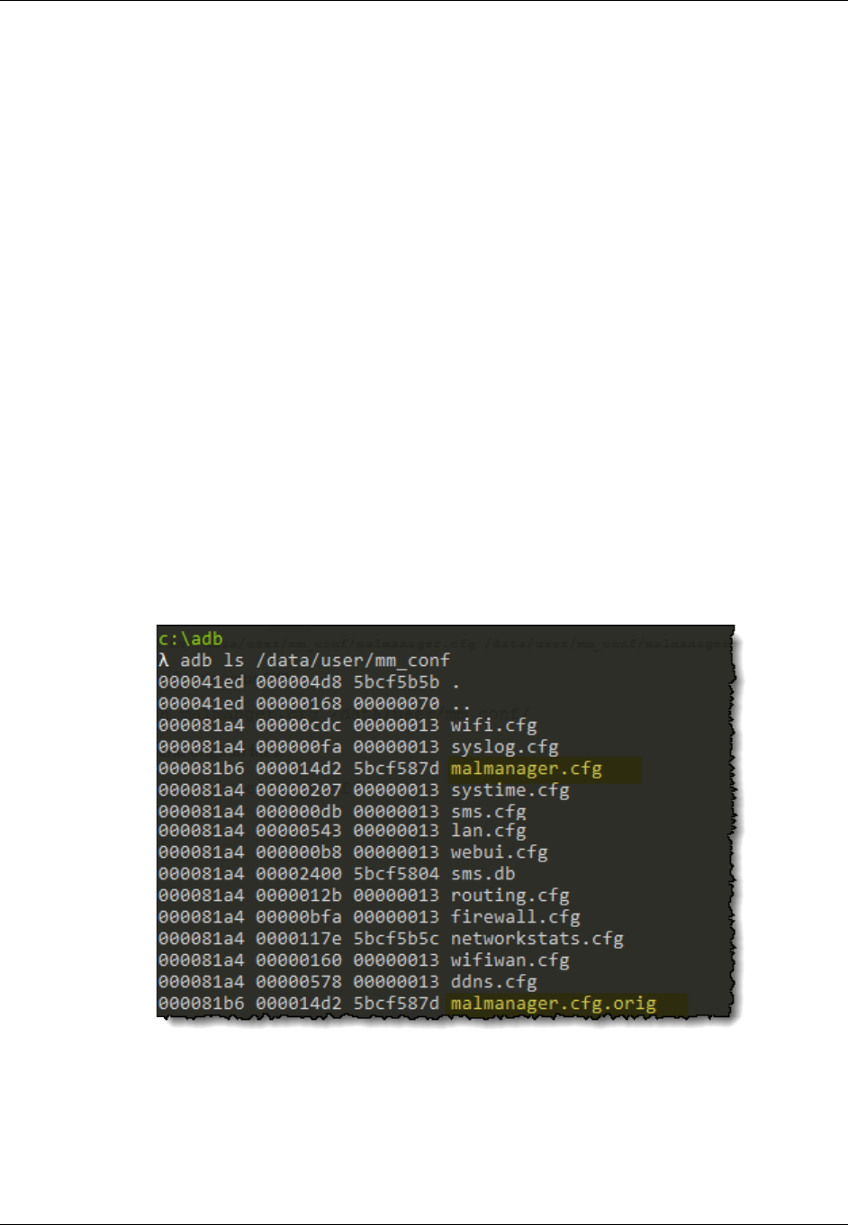
What is, and how do you configure, the APN?
AT&T IoT Starter Kit (2nd Generation) User's Guide - Appendix pg. 73
Edit on your Computer
Alternatively, you can pull the malmanager.cfg file over to your computer. Edit it and then push it back
onto the SK2.
1. Verify that your computer is connected to the SK2.
adb devices
2. Pull the malmanager.cfg file onto your computer. (We chose to place it into our “adb” folder.)
adb pull /data/user/mm_conf/malmanager.cfg C:\adb\
Replace C:\adb\ as needed for your OS and preference.
3. Change the APN, as required using your favorite text editor.
Windows users, make sure you save the file using Unix/Linux/Mac line-endings.
4. Rename the original file.
adb shell mv /data/user/mm_conf/malmanager.cfg /data/user/mm_conf/malmanager.cfg.orig
5. Push the file back onto your SK2.
adb push malmanger.cfg /data/user/mm_conf/
6. View the new and original files.
adb ls /data/user/mm_conf
7. Power-cycle your SK2 to utilize the new APN.
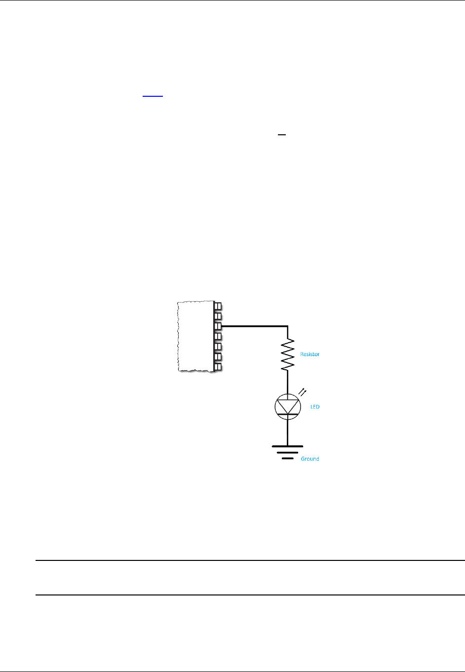
General Purpose Bit I/O (GPIO)
AT&T IoT Starter Kit (2nd Generation) User's Guide - Appendix pg. 74
General Purpose Bit I/O (GPIO)
What is GPIO?
From the glossary we find GPIO defined as:
Processors (e.g. microprocessors, microcontrollers) have various ways to communicate with external devices, the
most basic of which is GPIO. GPIO generally refers to talking across a single pin of the device. With a single pin
the device can receive or send (i.e. the input and output in GPIO) an “On” or “Off” value using a higher or lower
voltage, respectively. Programmers describe this On/Off communication using a “bit” (binary digit) which can
have the value “1” or “0”. In light of this, it’s easy to understand why many users commonly define GPIO as
“General Purpose Bit I/O”.
In other words, GPIO allows us to send or receive a single bit of information at a time through one of the
GPIO pins on a processor. While multiple GPIO pins on a device could be grouped together to send larger
numerical values than 1 or 0, a single bit of information is actually quite useful in embedded systems.
With a single bit we can control lights (e.g. LED) or read the value of a switch. Similarly, we could use it to
control whether a motor – or just about anything – is on or off. Of course, there is a limited amount of
power that can be supplied by a microcontroller’s pin, but the GPIO pin can be used to control a relay or
driver that can supply a much greater amount of power to a circuit.
Looking at at a simple circuit connecting an LED to a GPIO pin we see:
Figure 2 - Generic LED Circuit
In this example, the GPIO pin is supplying the voltage and current which travels through a resistor, the
LED, and then into ground. When the pin is set to low (i.e. “0”), there is little to no voltage difference
between the pin and ground and therefore the LED is off. Conversely, when the pin is set high (i.e. “1”),
the voltage drop between the pin and ground is large enough to allow the LED to turn on.
Note: If you were building this circuit, you would choose a resistor value that allows the full (or desired)
brightness of the LED without burning it out.
The LED circuits on the SK2 board are a bit fancier than what we have shown here, but the premise still
holds. By setting the GPIO pin on the processor module to “1” or “0” we can turn the associated LED on or
off.

General Purpose Bit I/O (GPIO)
AT&T IoT Starter Kit (2nd Generation) User's Guide - Appendix pg. 75
SK2 GPIO Pins for LEDs and Pushbuttons
As shown in Chapter 1 (Hardware Overview), the SK2 provides a few user-controllable items connected to
GPIO lines on the WNC module. They include:
• WWAN LED – which uses 1 GPIO pin.
• RGB LED – which uses 3 GPIO pins to control the Red, Green, and Blue individual colors.
• User push-button switch – which uses a GPIO pin to input the physical state of the switch.
The SK2 schematic shows how the GPIO lines are connected to each user
component. For example, here’s a clip of the schematic showing the RGB LED.
From this diagram, we can see that the following GPIO pins are connected to
the RGB LED colors:
GPIO92 Red LED
GPIO101 Green LED
GPIO102 Blue LED
Therefore, we need to set the values on these three pins to turn the
associated LEDs on/off, which is discussed in Chapter 2 where we
demonstrate controlling LEDs from the Linux Shell. In fact, one of the
examples takes this a step further by showing how to blink an LED, turning it
off/on once per second.
By speeding up the blinking to a rate fast enough that the human eye doesn’t
perceive blinking anymore, you could effectively control the brightness of each
LED. And with the RGB LED, by similarly controlling all three LEDs and their brighnesses, it’s possible to
create the effect of generating a wide array of colors.
Figure 3 - RGB LED Schematic
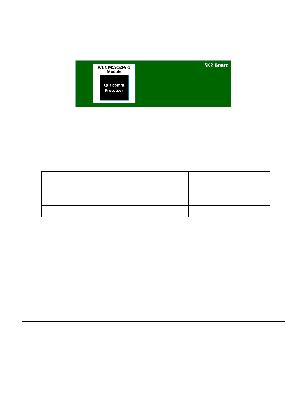
General Purpose Bit I/O (GPIO)
AT&T IoT Starter Kit (2nd Generation) User's Guide - Appendix pg. 76
GPIO Pin Numbers – WNC vs Qualcomm
As discussed earlier in this document, the IoT Starter Kit (2nd generation) board includes the WNC
M18Q2FG-1 LTE module. If we could look inside the WNC module, we would find it contains a Qualcomm
processor, which is at the heart of the SK2.
Figure 4 - SK2 Nested Processor Modules
The GPIO pins from the Qualcomm processor are routed to pins on the WNC module… which are then
routed to the various components on the SK2, such as the LEDs. As often happens when building systems
up from various components, WNC pin numbers don’t exactly match with those coming from the
Qualcomm processor. Here’s a table that describes the GPIO pin numbers we are concerned with:
SK2 Component WNC Pin Number Qualcomm Pin Number
USER Button GPIO98 GPIO_MDM_GPIO23
RGB – Red LED GPIO92 GPIO_MDM_GPIO38
RGB – Green LED GPIO101 GPIO_MDM_GPIO21
RGB – Blue LED GPIO102 GPIO_MDM_GPIO22
Using this table as a key, we can figure out how to design the hardware or software. Since the SK2
hardware designers were building the board using the WNC module, their design schematics show the
WNC GPIO pin numbers (e.g. Red LED connected to GPIO92).
On the other hand, since software actually runs on the Qualcomm processor inside the WNC module,
software should be written using the Qualcomm pin number. For example, from the Linux shell we can
use the Linux “echo” command to write a “1” to Pin 38 to turn on the Red LED. (We explain what “/value”
means in the next section.)
echo 1 > gpio38/value
Note that code examples for controlling LED’s using Python and C will be described in Chapters 3 and 4.
Note: The WWAN LED is driven by the WWAN pin on the WNC module. As such, it does not connect to
a general purpose GPIO pin which is why it was not listed in the WNC vs Qualcomm table.

General Purpose Bit I/O (GPIO)
AT&T IoT Starter Kit (2nd Generation) User's Guide - Appendix pg. 77
Linux GPIO Drivers
By choosing Linux for the SK2, its developers were granted access to the various services in the O/S. In this
case, it means they were able to utilize the Linux GPIO driver architecture. But it’s not only the developers
who benefit by using standard Linux drivers, SK2 users also get to use a common, standard driver API for
GPIO. If you’re experienced with Linux, the following should be familiar to you; if you’re new to Linux,
you’ll not only learn how to use the GPIO driver for the SK2, but this knowledge will likely by useful if you
ever use another Linux based system.
GPIO Driver Architecture
As discussed in Chapter 2 (Kernel Space vs User Space), the Linux Kernel owns all the hardware resources.
Users must request access – or call Kernel functions – to gain access to these resources. Such is the case
with GPIO. The Linux GPIO driver architecture provides a standard methodology for accessing and
reading/writing the available GPIO pins in the system.
When a User request is granted by the Linux Kernel, it will become available under the Sysfs (“system file
system”) directory in the Linux filesystem. Specifically, it will be found in:
/sys/class/gpio
Also mentioned back in Chapter 2 (Virtual Files), that while its obvious that a GPIO pin is not a real file,
upon request, Linux will create a virtual file interface for each available GPIO pin that you can read or
write. For example, writing a “1” to this virtual file will set the associated GPIO pin “on” (i.e. high voltage).
GPIO Control Interface
The Linux GPIO driver provides two functions for controlling User access to a GPIO pin:
export Request kernel to export control of GPIO pin to userspace
unexport “Return” control of GPIO pin back to kernel
Note that once you “export” a pin, unless you export it, it will be available until you power-down or reset
the device. In other words, it’s common to “export” the pins you need during your programs system
initialization code.
GPIO Signal Interface
Once exported, access to GPIO pins are found along the /sys/class/gpio path. For example, gpio38
would be found in the filesystem at:
/sys/class/gpio/gpio38
Even further, working with each GPIO is structured around a standard set of read/write attributes.
direction Defines which direction (“in” or “out”) should be assigned to a given pin.
Note that the the SK2 hardware is fixed for the GPIO pins being discussed;
in other words, you cannot change how the hardware works by using this
signal, rather, you must apply the value as assigned by the hardware
(i.e. “out” for LED, “in” for button).
value Represents the “value” of the pin. For input direction, reads as either a
0 (low) or 1 (high). When used as an output, writing a 0 sets the pin “low”,
while any non-zero value sets it “high”.

General Purpose Bit I/O (GPIO)
AT&T IoT Starter Kit (2nd Generation) User's Guide - Appendix pg. 78
LED Examples
Considering the previous discussions for the SK2 GPIO assignments and the Linux GPIO driver architecture,
the following shell code example turns “on” the RED.
Listing 1 - # TurnOnRedLed.sh
# TurnOnRedLed.sh
#
# This simple example turns on the Red RGB LED
#
cd /sys/class/gpio
echo 38 > export
echo out > gpio38/direction
echo 1 > gpio38/value
Listing 2 - Turn off Red LED
# TurnOffRedLed.sh
#
# This simple example turns off the Red RGB LED
#
cd /sys/class/gpio
echo 38 > export
echo out > gpio38/direction
echo 0 > gpio38/value
Like the export command, the direction persists until the system is reset or powered off. Thus it can also
be set once in your program’s initialization code.
The following blink example simply blinks the Blue LED five times.
Listing 3 - Blink the Blue LED five times
# blinkBlue.sh
#
# This is a simple example for blinking the Blue RGB LED five times
# - The For loop executes once per character (a thru e)
# - 'sleep 1' causes the cpu to wait 1 second
# - At the end of the script, the LED is turned off
#
cd /sys/class/gpio
echo 22 > export
echo out > gpio22/direction
for var in a b c d e; do
echo 0 > gpio22/value
sleep 1
echo 1 > gpio22/value
sleep 1
done
echo 0 > gpio22/value

General Purpose Bit I/O (GPIO)
AT&T IoT Starter Kit (2nd Generation) User's Guide - Appendix pg. 79
USER Button Examples
The USER button on the SK2 is like the LED example except that we set it up as an input and read the
value from the virtual file.
Hint: The SK2 button hardware was designed so that the button is “up” by default and therefore reads
as “1”. When pressed down, the button will read as “0”.
The first button example makes use of the Linux “cat” command. You may remember that this will read
the contents of a file and write it to the standard output (i.e. your ADB shell terminal – refer to Chapter 2
for a listing of common Linux shell commands as well as how to use the ADB shell.)
The example also sleeps for 3 seconds after reading the switch, letting you change the state of the button
– that is, pressing it down – before reading the button again.
Listing 4 - Reading USER Button
# userButtonCat.sh
#
# This is a simple example reads the value of the user button
# and outputs the value (using 'cat') to the command line.
# It then waits 3 seconds and does it again#
cd /sys/class/gpio
echo 23 > export
echo in > gpio23/direction
cat gpio23/value
sleep 3
# now hold-down the USER button and press up-arrow to repeat previous command
cat gpio23/value

General Purpose Bit I/O (GPIO)
AT&T IoT Starter Kit (2nd Generation) User's Guide - Appendix pg. 80
The second button example reads the value of the button and turns on either the Red or Green LED.
Listing 5 - USER Button Lights Green or Red LED
# userButtonLed.sh
#
# This example reads the value of the user button and turns
# on either the Green or Red RGB LED depending upon the value
# of the user button
#
# Go to the GPIO directory
cd /sys/class/gpio
# Grant user-space access to all 3 LEDs and the USER button
# USER button
echo 23 > export
echo in > gpio23/direction
# Green LED
echo 21 > export
echo out > gpio21/direction
# Blue LED
echo 22 > export
echo out > gpio22/direction
# Red LED
echo 38 > export
echo out > gpio38/direction
# Turn off all three LEDs
echo 0 > gpio38/value
echo 0 > gpio22/value
echo 0 > gpio21/value
# Read the value of the USER push button into "val"
val=$(cat gpio23/value)
echo $val
# Turn on LED
if [ $val -gt 0 ]
then
# If "up" turn on Green LED
echo 1 > gpio21/value
else
# If "down" turn on Red LED
echo 1 > gpio38/value
fi
Further Reading
For further details, you may want to refer to: https://www.kernel.org/doc/Documentation/gpio/sysfs.txt
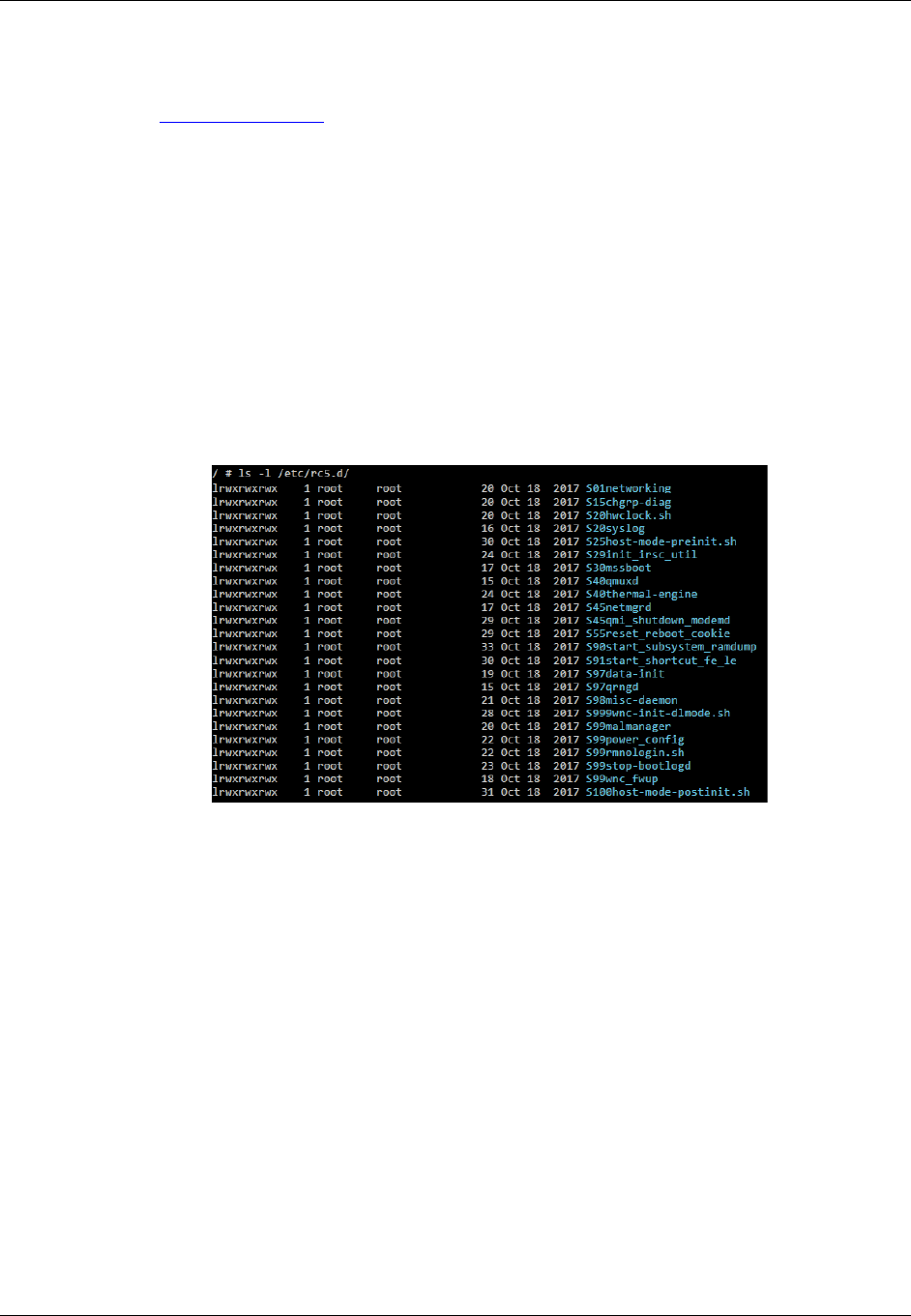
More Details about the Linux Boot Sequence
AT&T IoT Starter Kit (2nd Generation) User's Guide - Appendix pg. 81
More Details about the Linux Boot Sequence
Chapter 2 (Linux Boot Sequence) provided the simple answer to “How does the QuickStart boot
automatically run at startup?” The QuickStart program (called iot_monitor) is started by the script
/CUSTAPP/custapp-postinit.sh
which is always run by Linux once the boot process has completed. This chapter provides further details
for how this script gets run.
The following discussion is only background information, though, since the scripts leading up to
custapp-postinit.sh reside in read-only memory on the SK2.
Getting to custapp-postinit.sh
We won’t start at the beginning of the Linux boot sequence, but rather at the at the point where it runs a
set of scripts found in the “/etc/rc5.d” directory.
Figure 5 - Listing /etc/rc5.d
Ideally a very skilled system administrator can modify these scripts files to change the system options and
programs that get started at boot time. (But as we said above, on the SK2 these files reside in read-only
memory and cannot be changed.)
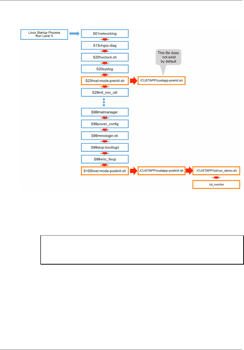
More Details about the Linux Boot Sequence
AT&T IoT Starter Kit (2nd Generation) User's Guide - Appendix pg. 82
During the boot process, Linux executes these files in numerical order. “S01” is executed first, followed by
“S15”, then “S20”, and so on. The following diagram highlights this sequence.
Figure 6 - Linux Boot Sequence - running files from /etc/rc5.d
Note that S25host-mode-preinit.sh executes 4th – or better put, very early in the boot process –
while S100host-mode-postinit.sh executes last or very late in the process.
Viewing the contents of /etc/rc5.d/S25host-mode-preinit.sh we see:
Listing 6 - /etc/rc5.d/S25host-mode-preinit.sh
#!/bin/sh
if [ -e /data/custapp-preinit.sh ]; then
chmod +x /data/custapp-preinit.sh
. /data/custapp-preinit.sh
fi
Looking at this file, we see that the S25host-mode-preinit.sh file calls /data/custapp-
preinit.sh, and this is started early in the process.

More Details about the Linux Boot Sequence
AT&T IoT Starter Kit (2nd Generation) User's Guide - Appendix pg. 83
From Chapter 2, remember /data is a link to /CUSTAPP. Examining that directory:
/CUSTAPP # ls -la
total 1144
drwxrwxrwx 6 122 129 1128 Feb 8 20:09 .
drwxr-xr-x 24 root root 2048 Feb 7 20:34 ..
-rw-r--r-- 1 root root 170378 Feb 8 20:38 all.log
-rwxrwxrwx 1 root root 0 Feb 7 19:51 custapp-postinit.sh
drwxr-xr-x 2 root root 304 Jan 1 1970 fwup
drwxrwxrwx 2 root root 304 Feb 6 22:39 iot
drw-r--r-- 2 root root 312 Jan 3 1970 psm
lrwxrwxrwx 1 root root 11 Jan 1 1970 upload -> /mnt/upload
drwxr-xr-x 5 root root 592 Jan 2 1970 user
we find there is not a file called custapp-preinit.sh. That is okay, though, since the script tests for
the existence of the file before executing it (using the “-e” option).
Further down the list of /etc/rc5.d files is a second script S100host-mode-postinit.sh that
executes after all the board “services” are set up and running. This script:
Listing 7 - /etc/rc5.d/S100host-mode-postinit.sh
#!/bin/sh
if [ -e /data/custapp-postinit.sh ]; then
chmod +x /data/custapp-postinit.sh
. /data/custapp-postinit.sh
fi
also tests for and executes a program in the /data (i.e. /CUSTAPP) directory called custapp-
postinit.sh. This is the same file we discussed in Chapter 2 (How Does the QuickStart Run).
Examining it we find:
Listing 8 - /CUSTAPP/custapp-postinit.sh
start-stop-daemon -S -b -x /CUSTAPP/iot/run_demo.sh
Following the chain to /CUSTAPP/iot/run_demo.sh file, we find that it finally points to the
QuickStart demo executable, called iot_monitor.
Listing 9 - run_demo.sh
iot_monitor -q5 -a a2e26b03f4e77aab23dbc5294b277d69
That’s quite a long process to start the “iot_monitor” QuickStart demo, but this chain of
events provides a great deal of flexibility for the Linux operating system. In our case, we
can create/edit the two init scripts in the /CUSTAPP directory to kick off programs early
or late in the boot process, as needed:
custapp-preinit.sh
custapp-postinit.sh
This process was explored, for custapp-postinit.sh, in Chapter 2.

More Details about the Linux Boot Sequence
AT&T IoT Starter Kit (2nd Generation) User's Guide - Appendix pg. 84
Page left blank.
