Application Interfaces User Guide AUTOSAR EXP AIUser
User Manual:
Open the PDF directly: View PDF ![]() .
.
Page Count: 102 [warning: Documents this large are best viewed by clicking the View PDF Link!]
- 1 Purpose of this document
- 2 Introduction to Application Interfaces Table
- 3 AUTOSAR Methodology
- 3.1 Overview on available documents
- 3.1.1 Software Component Template [1]
- 3.1.2 Standardization Template [2]
- 3.1.3 Generic Structure Template [4]
- 3.1.4 AI Specification [6]
- 3.1.5 Modeling Guide for Application Interfaces [9]
- 3.1.6 AUTOSAR Methodology [10]
- 3.1.7 Explanation of Application Interfaces for Domain Body Comfort [11]
- 3.1.8 Explanation of Application Interfaces for Domain Powertrain [12]
- 3.1.9 Explanation of Application Interfaces for Domain Chassis [13]
- 3.1.10 Explanation of Application Interfaces for Domain Occupant and Pedestrian Safety [14]
- 3.1.11 Explanation of Application Interfaces for Domain Multimedia, Telematics, Human Machine Interface [15]
- 3.1 Overview on available documents
- 4 Metamodel representation of AI Table
- 5 Backward Compatibility
- 6 Life Cycle States
- 7 View Concept in Application Interfaces (Variant Handling)
- 8 Structure of Application Interfaces (AI) Table
- 8.1 Main sheets of the AI Table
- 8.1.1 Sheet 04_Keywords
- 8.1.2 Sheet 05_TopLevel
- 8.1.3 Sheets 050xxxxx
- 8.1.4 Sheet 06_Interfaces_DataElements (SenderReceiverInterface)
- 8.1.5 Sheet 06_Interface_ClientServer
- 8.1.6 Sheet 07_DataTypes_ContinuousValue
- 8.1.7 Sheet 08_DataTypes_Enumeration
- 8.1.8 Sheet 09_DataTypes_Array
- 8.1.9 Sheet 11_DataTypes_Record
- 8.1.10 Sheet 13_Units
- 8.1.11 Sheet 15_Redirected_Ports
- 8.2 Complete List of all Sheets of the AI Table
- 8.1 Main sheets of the AI Table
- 9 Relationship between AI Table data and XML Output
- 10 References

Application Interfaces User Guide
AUTOSAR CP Release 4.4.0
1 of 102 Document ID 442: AUTOSAR_EXP_AIUserGuide
- AUTOSAR confidential -
Document Title
Application Interfaces User
Guide
Document Owner
AUTOSAR
Document Responsibility
AUTOSAR
Document Identification No
442
Document Status
Final
Part of AUTOSAR Standard
Classic Platform
Part of Standard Release
4.4.0
Document Change History
Date
Release
Changed by
Change Description
2018-10-31
4.4.0
AUTOSAR
Release
Management
Editorial changes
2017-12-08
4.3.1
AUTOSAR
Release
Management
Editorial changes
2016-11-30
4.3.0
AUTOSAR
Release
Management
Add chapter about implementation
of data types as integer or floating
point data types – Chapter ID
4.2.3.3. Bugzilla # 72021
2015-07-31
4.2.2
AUTOSAR
Release
Management
Updated explanation of the
COMPU_METHOD reusage
Updated the Linear Conversion
Example
2014-10-31
4.2.1
AUTOSAR
Release
Management
Sensors and Actuators Pattern
adopted in the AI Domain
Obsolete AI Table substituted by
new official AI Tool for content
development phase and arxml
generation
Enhanced collections arxml
deliverables structure
2013-10-31
4.1.2
AUTOSAR
Release
Management
New ARXML file distribution feature
Application Interfaces User Guide
AUTOSAR CP Release 4.4.0
2 of 102 Document ID 442: AUTOSAR_EXP_AIUserGuide
- AUTOSAR confidential -
Document Change History
Date
Release
Changed by
Change Description
2013-03-15
4.1.1
AUTOSAR
Administration
Updated categories of model
elements (Data Constraints and
Keywords to Blueprints)
Introduced description of Backward
Compatibility, Lifecyle State and
Variant Handling (Views) concepts
Deliverables from Application
Interfaces updated
2011-12-22
4.0.3
AUTOSAR
Administration
Description of Categories of model
elements created
Synchronization of Update of XML
package structure especially
regarding Port Blueprints
Synchronization to updates of
AUTOSAR meta model
Description of Naming conventions
for connectors
2011-04-15
4.0.2
AUTOSAR
Administration
Initial Release

Application Interfaces User Guide
AUTOSAR CP Release 4.4.0
3 of 102 Document ID 442: AUTOSAR_EXP_AIUserGuide
- AUTOSAR confidential -
Disclaimer
This work (specification and/or software implementation) and the material contained
in it, as released by AUTOSAR, is for the purpose of information only. AUTOSAR
and the companies that have contributed to it shall not be liable for any use of the
work.
The material contained in this work is protected by copyright and other types of
intellectual property rights. The commercial exploitation of the material contained in
this work requires a license to such intellectual property rights.
This work may be utilized or reproduced without any modification, in any form or by
any means, for informational purposes only. For any other purpose, no part of the
work may be utilized or reproduced, in any form or by any means, without permission
in writing from the publisher.
The work has been developed for automotive applications only. It has neither been
developed, nor tested for non-automotive applications.
The word AUTOSAR and the AUTOSAR logo are registered trademarks.

Application Interfaces User Guide
AUTOSAR CP Release 4.4.0
4 of 102 Document ID 442: AUTOSAR_EXP_AIUserGuide
- AUTOSAR confidential -
Table of Contents
1 Purpose of this document .................................................................................. 7
1.1 Document Overview ..................................................................................... 7
2 Introduction to Application Interfaces Table ....................................................... 8
2.1 Structural overview of Domains in AI Table ................................................ 10
3 AUTOSAR Methodology .................................................................................. 11
3.1 Overview on available documents .............................................................. 12
3.1.1 Software Component Template [1] ........................................................ 12
3.1.2 Standardization Template [2] ................................................................. 12
3.1.3 Generic Structure Template [4] .............................................................. 12
3.1.4 AI Specification [6] ................................................................................. 12
3.1.5 Modeling Guide for Application Interfaces [9] ......................................... 12
3.1.6 AUTOSAR Methodology [10] ................................................................. 12
3.1.7 Explanation of Application Interfaces for Domain Body Comfort [11] ..... 13
3.1.8 Explanation of Application Interfaces for Domain Powertrain [12] .......... 13
3.1.9 Explanation of Application Interfaces for Domain Chassis [13] .............. 13
3.1.10 Explanation of Application Interfaces for Domain Occupant and
Pedestrian Safety [14] ............................................................................ 13
3.1.11 Explanation of Application Interfaces for Domain Multimedia,
Telematics, Human Machine Interface [15] ............................................ 13
4 Metamodel representation of AI Table ............................................................. 14
4.1 Category of Model Elements ...................................................................... 14
4.1.1 STANDARD ........................................................................................... 14
4.1.2 BLUEPRINT ........................................................................................... 14
4.1.3 EXAMPLE .............................................................................................. 15
4.2 Meta model diagrams and the AI Table ...................................................... 15
4.2.1 Composition ........................................................................................... 15
4.2.2 Blueprint Mapping & BlueprintMappingSet............................................. 21
4.2.3 PortPrototypes ....................................................................................... 21
4.2.4 PortInterfaces ......................................................................................... 24
4.2.5 DataTypes .............................................................................................. 27
4.2.6 Physical Units ........................................................................................ 33
4.2.7 Computation Methods ............................................................................ 34
4.2.8 Keyword and KeywordSet ...................................................................... 34
5 Backward Compatibility .................................................................................... 37

Application Interfaces User Guide
AUTOSAR CP Release 4.4.0
5 of 102 Document ID 442: AUTOSAR_EXP_AIUserGuide
- AUTOSAR confidential -
5.1 Introduction ................................................................................................. 37
5.2 Backward Compatibility Definition .............................................................. 37
5.3 Summary .................................................................................................... 40
6 Life Cycle States .............................................................................................. 41
6.1 Introduction ................................................................................................. 41
6.2 Representation in AI Table ......................................................................... 41
6.3 Representation in meta model and arxml ................................................... 42
7 View Concept in Application Interfaces (Variant Handling) .............................. 44
7.1 Introduction ................................................................................................. 44
7.2 Implementation in Application Interfaces and Meta Model Representation 44
8 Structure of Application Interfaces (AI) Table ................................................... 48
8.1 Main sheets of the AI Table ........................................................................ 48
8.1.1 Sheet 04_Keywords ............................................................................... 48
8.1.2 Sheet 05_TopLevel ................................................................................ 49
8.1.3 Sheets 050xxxxx .................................................................................... 52
8.1.4 Sheet 06_Interfaces_DataElements (SenderReceiverInterface) ............ 53
8.1.5 Sheet 06_Interface_ClientServer ........................................................... 55
8.1.6 Sheet 07_DataTypes_ContinuousValue ................................................ 57
8.1.7 Sheet 08_DataTypes_Enumeration ....................................................... 57
8.1.8 Sheet 09_DataTypes_Array ................................................................... 59
8.1.9 Sheet 11_DataTypes_Record ................................................................ 60
8.1.10 Sheet 13_Units ...................................................................................... 62
8.1.11 Sheet 15_Redirected_Ports ................................................................... 63
8.2 Complete List of all Sheets of the AI Table ................................................. 64
9 Relationship between AI Table data and XML Output ...................................... 67
9.1 Overview .................................................................................................... 67
9.1.1 Dependencies of XML Generation ......................................................... 67
9.1.2 Contents of Generated XML .................................................................. 67
9.1.3 Schema Structure .................................................................................. 69
9.2 Common Elements ..................................................................................... 71
9.2.1 Package Structure ................................................................................. 71
9.2.2 References ............................................................................................. 76
9.2.3 Instance References .............................................................................. 76
9.2.4 Type References .................................................................................... 77
9.2.5 Descriptions ........................................................................................... 77
9.3 Component Types ...................................................................................... 78
9.3.1 Composition Types ................................................................................ 79
9.3.2 Ports....................................................................................................... 80

Application Interfaces User Guide
AUTOSAR CP Release 4.4.0
6 of 102 Document ID 442: AUTOSAR_EXP_AIUserGuide
- AUTOSAR confidential -
9.3.3 Components ........................................................................................... 80
9.3.4 Connectors ............................................................................................. 81
9.4 PortPrototypeBlueprints .............................................................................. 83
9.5 PortInterfaces ............................................................................................. 84
9.5.1 Sender-Receiver-Interface ..................................................................... 84
9.5.2 Client-Server-Interface ........................................................................... 85
9.6 Blueprint Mapping Sets .............................................................................. 87
9.7 Data Types ................................................................................................. 88
9.7.1 Continuous Value Types ........................................................................ 88
9.7.2 Enumeration Types ................................................................................ 92
9.7.3 Array Types ............................................................................................ 94
9.7.4 Record Types ......................................................................................... 95
9.7.5 Float Types ............................................................................................ 96
9.8 Units ........................................................................................................... 96
9.9 Life Cycle State .......................................................................................... 97
9.10 Views ........................................................................................................ 100
10 References ..................................................................................................... 102
10.1 Standard documents ................................................................................ 102
10.2 Auxiliary documents ................................................................................. 102

Application Interfaces User Guide
AUTOSAR CP Release 4.4.0
7 of 102 Document ID 442: AUTOSAR_EXP_AIUserGuide
- AUTOSAR confidential -
1 Purpose of this document
AUTOSAR aims at the delivery of functionality through communicating Software-
Components, which can be placed nearly arbitrarily on a network of ECUs. To ensure
the interoperability of Software-Components from different sources (i.e. vendors), the
interfaces of these should be unified.
The content of the AI Table [8] is the specification of interfaces of several automotive
domains. The composition of these domains will establish the Top-level domain
inside the table. The goal is to define and publish stable and widely accepted
application interfaces.
This document aims at explaining all relevant details about the AI Table especially for
users, who have to maintain the standardized application interfaces. Experienced
users can skip the chapter AUTOSAR Methodology. Some sections contain extract
from other AUTOSAR documents. In case of differences in the contents then the
original AUTOSAR documents are valid.
1.1 Document Overview
This document gives an overview of the methodological background of the
application interfaces. This document also gives an overview of the content of the
‘Application Interface Table’, the top level (inter-domain level) and included domains
(Body, Powertrain, Chassis, Occupant and Pedestrian Safety, Multimedia,
Telematics, Human Machine Interface). It also describes the structure of the AI Table
(realized in an Excel table) and explains how to handle it.
Abbreviations List
Abbreviation
Meaning
.arxml
Autosar Extensible Markup Language File
AI Table
Application Interface Table
Bugzilla
Tool for change request management
CPU
Central Processing Unit
ECU
Electronic Control Unit
Excel
Microsoft spreadsheet-application
MS
Milestone
RTE
Run-Time Environment
SPEM
Software Process Engineering meta-model
SVN
Subversion (version control system)
SW-C
SoftwareComponent
SWC
SoftwareComponent
SW
Software
VB
Visual Basic
VFB
Virtual Function Bus
WP
Work package
XML
Extensible Markup Language
XSD
XML Schema Definition
HMI
Human Machine Interface
Application Interfaces User Guide
AUTOSAR CP Release 4.4.0
8 of 102 Document ID 442: AUTOSAR_EXP_AIUserGuide
- AUTOSAR confidential -
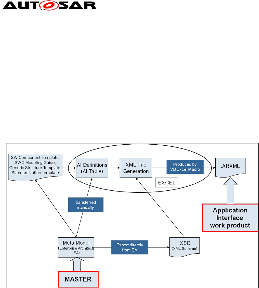
2 Introduction to Application Interfaces Table
The application interface table (AI Table) is the user interface dedicated to manage
all the data, which define the application interfaces (see Figure 1). This is
implemented in a tool (Excel) with validation and work product output generation
macros (e.g. VB scripts). Input to the tool is based on AUTOSAR defined
methodology meta-model data. The output of the tool is a XML model, which is
conform to the XSD and follows the semantics defined in the template. The
AUTOSAR XML file (called .ARXML file) contains detailed information in a structured
format of all the standardized application interfaces data. The xml file contains the
definitions of the application interfaces transferred to a commonly readable format,
which can be the input for e.g. authoring tools at the development units of SW
developing companies.
Figure 1: The AI Table Process
The AI Table enables the manipulation of AI definitions in order to produce the
outcome: the xml file for data exchange.
The SWC template [1] tells us what can be modeled. The Standardization Template
[2] explains and supports the blueprint approach.
The AI Table description (i.e. XML) tells us what is being modeled. The AI Table
definitions follow the modeling guide defined by SWC modeling guide [9]. The
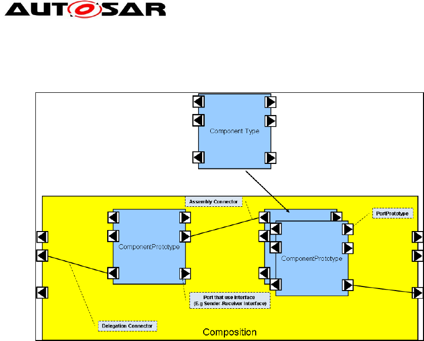
following Figure 2 shows the main structure of SW composition and their
decomposition into components.
In order to standardize application interfaces a number of SW components are
described within the AI Table decomposed to the domains and their main functions.
Nevertheless, these components must be seen as examples only (at present for
Release 4.0 only). They are not part of the standard; but they are necessary in order
to specify the port / port prototypes in a consistent way. Each port / port prototype
needs a connection to a component to be specified in a proper way.
Application Interfaces User Guide
AUTOSAR CP Release 4.4.0
9 of 102 Document ID 442: AUTOSAR_EXP_AIUserGuide
- AUTOSAR confidential -
The structure within Figure 2 illustrates the decomposition of Software-Compositions
using the AUTOSAR Software Component Template [1].
Figure 2: Decomposition of a component using the concepts defined in the software
component template
Note: The yellow blocks in the figure represent the AI Table columns with yellow
color, which are the composition that is decomposed into other compositions /
components. These component types and prototypes are described within the same
AI Table sheet in blue colored columns (see blue blocks in the figure). A
SwComponentPrototype implements the usage of a SwComponentType in a specific
role.
SwComponentPrototypes are only used for implementing SwComponentTypes in a
specific role, i.e. they are used to instantiate the SwComponentType.
Example: a SwComponentPrototype ”LeftDoorControl” fulfills the role of implementing the
SwComponentType ”DoorControl” for the left door of a vehicle while the
SwComponentPrototype ”RightDoorControl” fulfills the role of the SwComponentType
”DoorControl” for the right door.
The AI Table is an Excel table containing a number of work sheets. Within the sheets
the following main information that are application interface relevant are handled:
Compositions; main compositions are from domains (1) Body, (2) Powertrain, (3)
Chassis, (4) Occupant and Pedestrian Safety, (5) multimedia and telematics and
human machine interface
Components
Ports
PortInterfaces and its VariableDataPrototypes
Data types for VariableDataPrototypes
Units
Instances of component types

Application Interfaces User Guide
AUTOSAR CP Release 4.4.0
10 of 102 Document ID 442: AUTOSAR_EXP_AIUserGuide
- AUTOSAR confidential -
Keywords
For a detailed list of sheets provided by the table, refer to Chapter 8.
2.1 Structural overview of Domains in AI Table
Currently the AI Table contains the specification of a number of different automotive
domains. The outcome of each domain including inter-domain connections can be
identified within the sheets of the AI Table:
Interdomain level (Top level) Sheet: 0500
Body Sheet: 0501*
Powertrain Sheet: 0502*
Chassis Sheet: 0503*
Occupant and pedestrian safety Sheet: 0504*
Multimedia, Telematics, Human Machine Interface (HMI) Sheet: 0505*
Although the table is structured following the domains, the resulting decomposition
into components/compositions is not a mandatory architecture for AUTOSAR
compliant vehicle architectures. The AI Table shows components/compositions as
examples for explanation of standardized ports and PortInterfaces. The top level
composition is a dummy composition required to represent the inter domain ports in
the VFB view.
Further explanations on domain details can be found in chapter 3.1.7 to 3.1.11 and
further referenced documents.
Application Interfaces User Guide
AUTOSAR CP Release 4.4.0
11 of 102 Document ID 442: AUTOSAR_EXP_AIUserGuide
- AUTOSAR confidential -
3 AUTOSAR Methodology
AUTOSAR requires a formal technical approach for some steps of system
development. This approach is called the “AUTOSAR Methodology”. The AUTOSAR
Methodology is neither a complete process description nor a business model and
“roles” and “responsibilities” are not defined in this methodology. Furthermore, it does
not prescribe a precise order in which activities should be carried out. The
methodology is a mere work-product flow: it defines the dependencies of activities on
work-products.
During system design, the software components and the hardware have to be
selected, and overall system constraints have to be identified. AUTOSAR intends to
ease the formal description of these initial system design decisions via the
information exchange format and the use of templates. So defining the System
Configuration Input means to fill out or edit the appropriate templates. AUTOSAR
methodology allows for a high degree of reuse in this context. In any case, this
editing is assumed to be supported by editing tools. Here is a brief description of
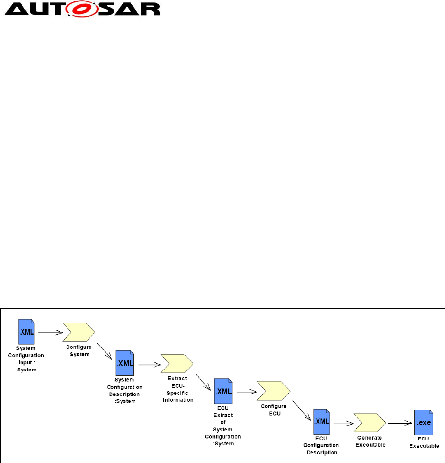
activities:
Figure 3: Overview AUTOSAR Methodology
- Configure System: mainly maps the software components to the ECUs with regard
to resources and timing requirements.
The SW-component description, system constraints description and ECU resources
description are required to configure the system.
The AI Table output along the internal behavior defines the SW-component
description.
The output of this activity is the System Configuration Description. This description
includes all system information (e.g. bus mapping, topology) and the mapping of
which software component is located on which ECU.
- Extract ECU-Specific Information: extracts the information from the System
Configuration Description needed for a specific ECU. This is then placed in the ECU
Extract of System Configuration.
- Configure ECU: adds all necessary information for implementation like task
scheduling, necessary Basic Software modules, configuration of the Basic Software,
assignment of runnable entities to tasks, etc. The result of the activity Configure ECU

Application Interfaces User Guide
AUTOSAR CP Release 4.4.0
12 of 102 Document ID 442: AUTOSAR_EXP_AIUserGuide
- AUTOSAR confidential -
is included in the ECU Configuration Description, which collects all information that is
local to a specific ECU. The runnable software to this specific ECU can be built from
this information.
- Generate Executable: an executable is generated based on the configuration of
the ECU described in the ECU Configuration Description. This step typically involves
generating code (e.g. for the RTE and the Basic Software), compiling code
(compiling generated code or compiling software-components available as source-
code) and linking everything together into an executable.
Nevertheless, the implementation of a software component is more or less
independent from ECU configuration.
The general concepts of this chapter are an extract of the detailed AUTOSAR
Methodology [10].
3.1 Overview on available documents
For detailed information, following documents are available.
3.1.1 Software Component Template [1]
This document provides introductory description and rationale for the part of the
AUTOSAR meta-model relevant for the definition of Software Components.
3.1.2 Standardization Template [2]
This document is intended to support the delivery of standardized model elements by
AUTOSAR. This document also refines the blueprint approach for standardization.
3.1.3 Generic Structure Template [4]
This document acts as a supplement for the formal definition provided by the
AUTOSAR meta model. This document provides the introductory description and
rationale for the parts of the AUTOSAR meta model relevant for all AUTOSAR
templates.
3.1.4 AI Specification [6]
This is the output of the standardization of Application Interfaces. The output is
delivered as a set of .arxml files.
3.1.5 Modeling Guide for Application Interfaces [9]
This document gives guidelines and conventions on using the AUTOSAR model
elements in order to build AUTOSAR systems. It does not contain guidelines for the
AUTOSAR meta-model.
3.1.6 AUTOSAR Methodology [10]
See above.

Application Interfaces User Guide
AUTOSAR CP Release 4.4.0
13 of 102 Document ID 442: AUTOSAR_EXP_AIUserGuide
- AUTOSAR confidential -
3.1.7 Explanation of Application Interfaces for Domain Body Comfort [11]
The document explains design decisions and boundary conditions that lead to the
Application Interfaces of the domain Body and Comfort.
3.1.8 Explanation of Application Interfaces for Domain Powertrain [12]
The document explains design decisions and boundary conditions that lead to the
Application Interfaces of the domain Powertrain.
3.1.9 Explanation of Application Interfaces for Domain Chassis [13]
The document explains design decisions and boundary conditions that lead to the
Application Interfaces of the domain Chassis.
3.1.10 Explanation of Application Interfaces for Domain Occupant and
Pedestrian Safety [14]
The document explains design decisions and boundary conditions that lead to the
Application Interfaces of the domain Occupant and pedestrian safety.
3.1.11 Explanation of Application Interfaces for Domain Multimedia, Telematics,
Human Machine Interface [15]
The document explains design decisions and boundary conditions that lead to the
Application Interfaces of the domain Multimedia, Telematics, Human Machine
Interface.
To find these documents refer to the table at the end of this document (See Chapter
10).

Application Interfaces User Guide
AUTOSAR CP Release 4.4.0
14 of 102 Document ID 442: AUTOSAR_EXP_AIUserGuide
- AUTOSAR confidential -
4 Metamodel representation of AI Table
This section describes the relation between meta-model implementation (AUTOSAR
Meta Model [7]) and representation within the AI Table [8]).
The AUTOSAR meta-model conceptually is defined as ‘M2’ level, which describes
the entities called software components and ports. The relations between those
entities as well as their semantics are part of this model.
4.1 Category of Model Elements
All Application Interface model elements are classified into three different categories.
They are;
STANDARD
BLUEPRINT
EXAMPLE
4.1.1 STANDARD
All elements, which can be used as they are defined by just including them in the
project, belong to the category STANDARD. These elements need no modifications
before their use in the projects.
Elements of category STANDARD are;
PhysicalDimensions
Units
LifeCycleInfoSets
4.1.2 BLUEPRINT
Blueprints are the pre-definition of model elements, which form the basis for further
modeling. Blueprints are model elements from which other model elements can be derived
by copying. These elements are not complete in all aspects. They act as a template
for projects to create the real elements.
Elements of category BLUEPRINT are;
ApplicationDataTypes
CompuMethods
DataConstraints
KeywordSets
PortInterfaces
PortPrototypeBlueprints
Collections
Rules for naming Prototypes derived from BLUEPRINTs
AUTOSAR Standardization will use rules for creating ShortNames for prototypes
derived from blueprints, i.e. the recommendation below is mandatory for AUTOSAR
standardization work.
Recommendation in case of single usage: <ShortName>
Recommendation in case of multiple usage: <ShortName>{<Keyword>}0..n"
Application Interfaces User Guide
AUTOSAR CP Release 4.4.0
15 of 102 Document ID 442: AUTOSAR_EXP_AIUserGuide
- AUTOSAR confidential -
The ShortName pattern for the derived model elements may follow a
{anyName} pattern from the associated Blueprints
4.1.3 EXAMPLE
Elements that shall not be standardized, but are helpful for understanding are
created as category EXAMPLE. These act as help for the users to actually create
their project specific implementations. The elements of category EXAMPLE represent
one out of many possible ways of implementation.
Elements of category EXAMPLE are;
SwComponentTypes
ApplicationDataTypes
BlueprintMappingSets
CompuMethods
DataConstrs
PortInterfaces
ApplicationDataTypes, CompuMethods, DataConstrs and PortInterfaces categorized
as examples are the derived elements from their blueprints and are not additional
elements.
4.2 Meta model diagrams and the AI Table
This section describes the AUTOSAR meta-model (M2) diagrams and their
relationship with the AI Table contents to implement the application software-
component.
The following diagrams correspond to R4.0 of the AUTOSAR meta-model.
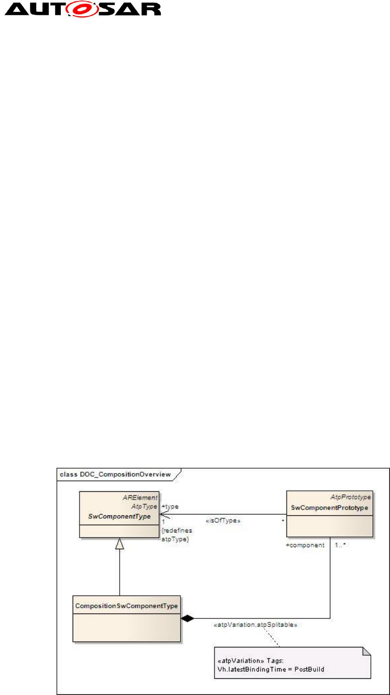
4.2.1 Composition
Figure 4: Composition
Application Interfaces User Guide
AUTOSAR CP Release 4.4.0
16 of 102 Document ID 442: AUTOSAR_EXP_AIUserGuide
- AUTOSAR confidential -
The purpose of an AUTOSAR CompositionSwComponentType is to allow the
encapsulation of specific functionality by aggregating existing software-components.
Since a CompositionSwComponentType is also a SwComponentType, it may be
aggregated again in further CompositionSwComponentTypes. This recursive relation
is formally expressed in Figure 4.
It is important to understand that while compositions allow for (sub-) system
abstraction, they are solely an architectural element for the implementation of model
scalability. They simply group existing software-components and thereby take away
complexity when viewing or designing logical system architecture.
Meta Model Reference:
M2::AUTOSARTemplates::SWComponentTemplate::Composition [1]
AI Table Reference:
AUTOSAR_ApplicationInterfaces.xls [8]
Work Sheet Name: Compositions
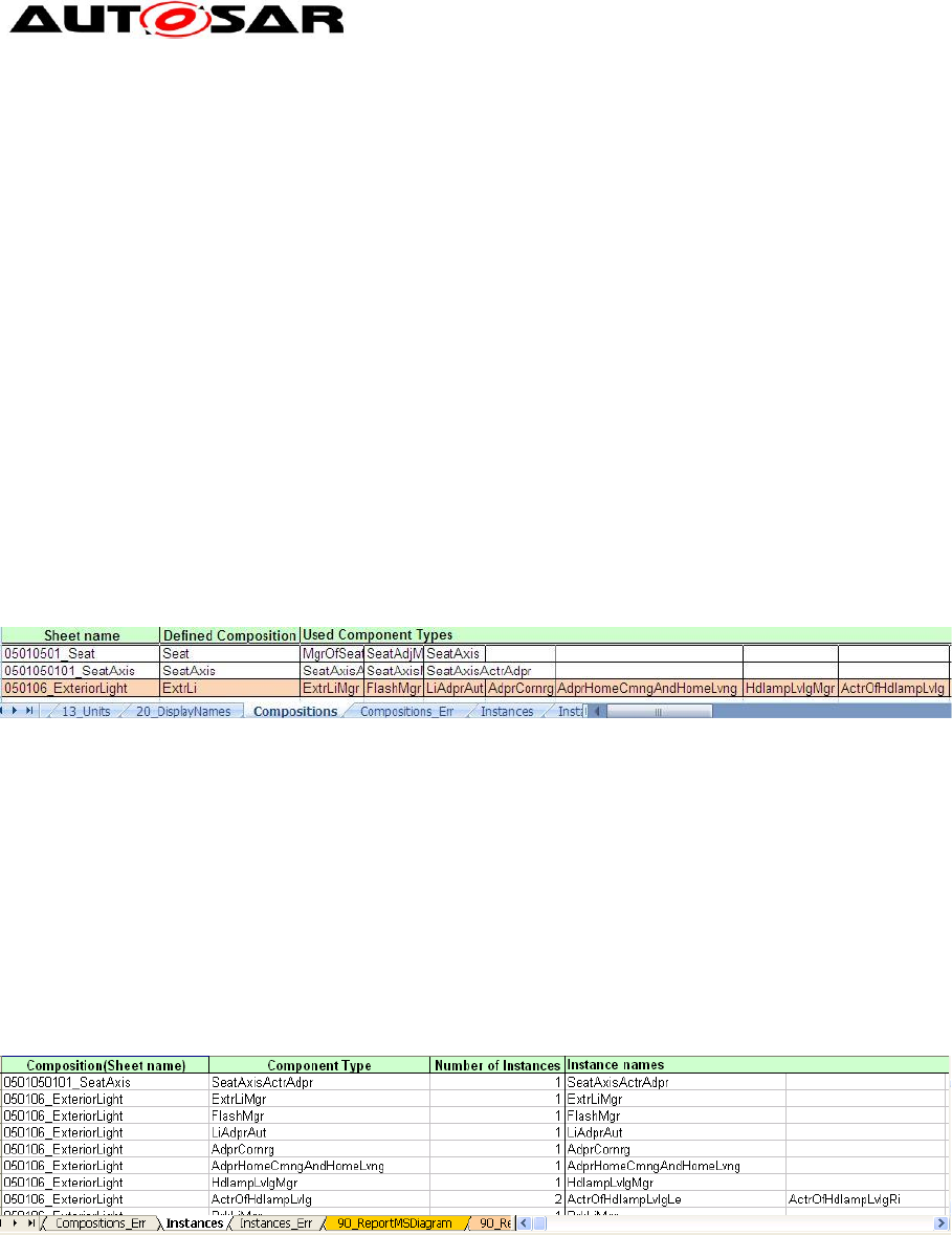
Figure 5: part of sheet ‘Compositions’
Example:
In the case of Exterior light Composition found in sheet 050106_ExteriorLight: the
“ExtrLi” which is a CompositionSwComponent type, composed of different
component types like ExtrLiMgr, FlashMgr, LiAdprAut, AdprCornrg,
AdprHomeCmngAndHomeLvng, HdlampLvlMgr, ActrOfHdlampLvlg etc…
AI Table Reference:
AUTOSAR_ApplicationInterfaces.xls [8]
Work Sheet Name: Instances
Figure 6: part of sheet ‘Instances’
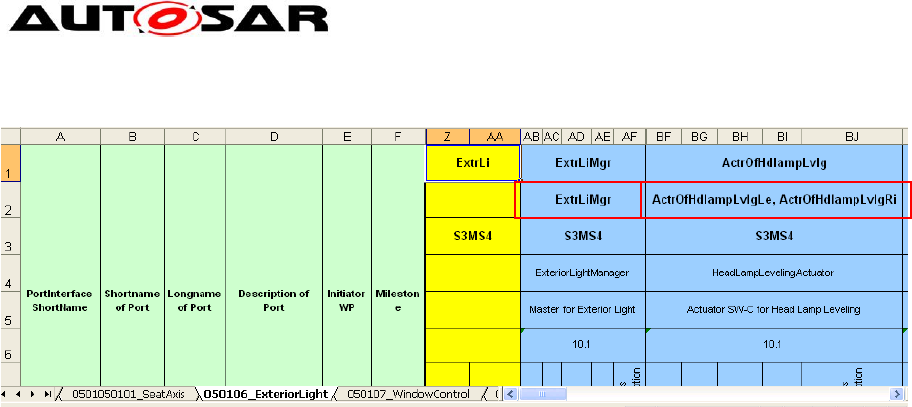
Example: The component type ExtrLiMgr is not decomposed further into component
types therefore; it is just a component type. The component prototype ExtrLiMgr
found in 050106_ExteriorLight (cell AB2 shown in Figure 7) is of the type ExtrLiMgr
(component type). Here the type and prototype have the same ShortName.
The component prototypes ActrOfHdlampLvlgLe and ActrOfHdlampLvlgRi found in
050106_ExteriorLight (cell BF2 shown in Figure 7) is of the type ActrOfHdlampLvlg
(component type). Here the type and prototype have different ShortName and the
type is instantiated twice.
Application Interfaces User Guide
AUTOSAR CP Release 4.4.0
17 of 102 Document ID 442: AUTOSAR_EXP_AIUserGuide
- AUTOSAR confidential -
Figure 7: Sheet 050106_ExteriorLight - Decomposition Components
There can be arbitrary numbers of SwComponentPrototypes that refer to specific
SwComponentTypes created. Note that CompositionSwComponentType also
aggregates the abstract meta-class SwConnector for connection of the
SwComponentPrototypes belonging to each other.
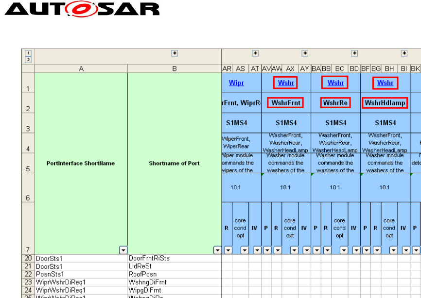
4.2.1.1 Multiple Instantiation
When designing a system it is often the case that elements in the runtime space share the
same structure. A well-known example domain is object-oriented programming, where
objects instantiated from the same class all have the same structure specified by that class.
The ability to specify a structure once and then use it in multiple places in the design is called
as multiple instantiation.
The same concept is used in the AI Table for definition of SwComponentType for the
components which exists multiple times in a domain.
In the example shown below, the SoftwareComponents WshrFrnt, WshrRe and WshrHdlamp
are created from the SwComponentType Wshr.
Application Interfaces User Guide
AUTOSAR CP Release 4.4.0
18 of 102 Document ID 442: AUTOSAR_EXP_AIUserGuide
- AUTOSAR confidential -
Figure 8: Sheet 050108_WiperWasher – Example of Multiple Instantiation
All the SwComponentPrototypes instantiated from the SwComponentType will have
the same properties of the SwComponentType, in other words for example if
SwComponentType is defined with 2 Provider PortPrototypes and 3 Receiver
PortPrototypes then all the instances of the SwComponentType will have same
number of Provider and Receiver PortPrototypes.
If two SwComponentTypes are connected to each other and both the
SwComponentTypes are multiply instantiated then it is possible that the connections
between these SwComponentTypes are ambiguous. However due to limitations in
the AI Table macros it is currently not feasible to cover all possible model scenarios.
Application Interfaces User Guide
AUTOSAR CP Release 4.4.0
19 of 102 Document ID 442: AUTOSAR_EXP_AIUserGuide
- AUTOSAR confidential -
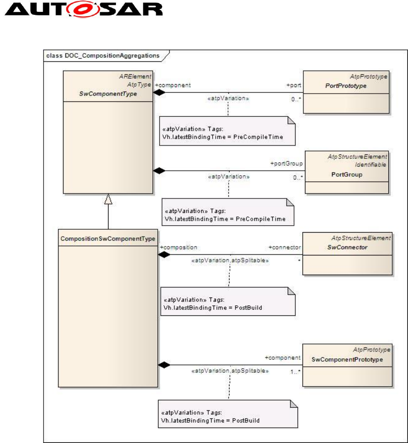
Figure 9: Composition – Aggregations
Meta Model Reference:
M2::AUTOSARTemplates::SWComponentTemplate:: Components [1]
AI Table Reference:
AUTOSAR_ApplicationInterfaces.xls [8]
Work Sheet Name: 050XXXXX Sheets
Note that being a SwComponentType, a CompositionSwComponentType also
exposes PortPrototypes to the outside world. However, the PortPrototypes are only
delegated and do not play the same role as PortPrototypes attached to
AtomicSwComponentTypes (AtomicSwComponentTypes encapsulate the
implementation of their functionality and behavior and merely expose well defined
connection points, called PortPrototypes, to the outside world.). For more details, refer to
the SW Component Template [1]
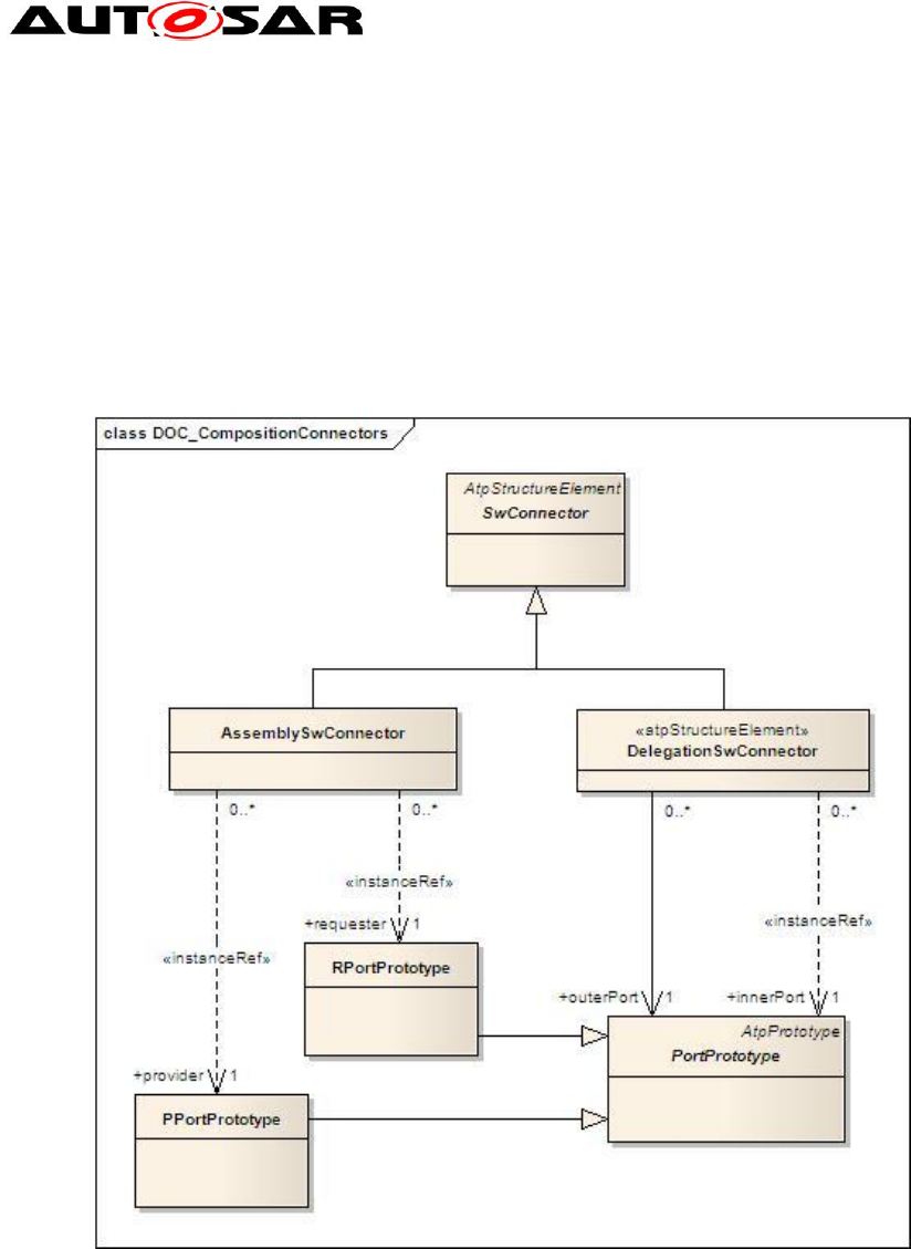
CompositionSwComponentTypes contain two types of SwConnectors.
Application Interfaces User Guide
AUTOSAR CP Release 4.4.0
20 of 102 Document ID 442: AUTOSAR_EXP_AIUserGuide
- AUTOSAR confidential -
1. AssemblySwConnectors to interconnect PortPrototypes of
SwComponentPrototypes that are part of the CompositionSwComponentType
2. DelegationSwConnectors to connect from "inner" PortPrototypes to delegated
"outer" PortPrototypes.
In the case that the outer PortPrototype is referenced by multiple
DelegationSwConnectors, the semantic is the multiplication of the
AssemblySwConnectors referencing the outer PortPrototypes.
Figure 10: Composition - Connectors
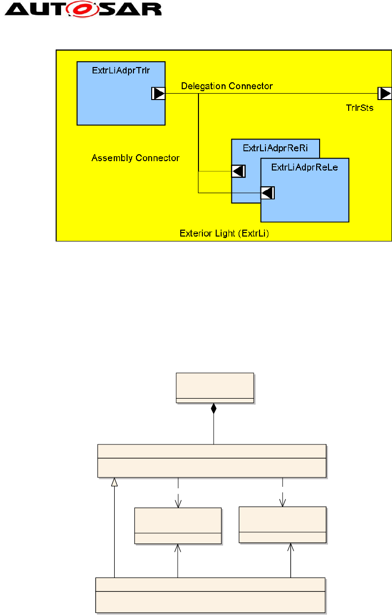
Example: In the case of Exterior light decomposition, “ExtrLi” software component
prototype is the composite type which provides an “outer” PPortPrototype “TrlrSts”,
which is delegated from “inner” PPortPrototype of software component prototype
“ExtrLiAdprTrlr”. The same PPortPrototype is connected to RPortPrototype of
“ExtrLiAdprReLe” and “ExtrLiAdprReRi” through an assembly connector prototype.
Application Interfaces User Guide
AUTOSAR CP Release 4.4.0
21 of 102 Document ID 442: AUTOSAR_EXP_AIUserGuide
- AUTOSAR confidential -
Figure 11 : Exterior Light Decomposition example
4.2.2 Blueprint Mapping & BlueprintMappingSet
Blueprint mapping acts as reference between the blueprint and the derived element.
Blueprint mapping identifies the relationship between the blueprinted element and the
actual blueprint. It also validates the derived element against the blueprint.
Aggregation of these BlueprintMappings is a BlueprintMappingSet. The Figure below
shows the BlueprintMapping and BlueprintMappingSet.
Identifiable
AbstractBlueprintStructure::
AtpBlueprint
Identifiable
AbstractBlueprintStructure::
AtpBlueprintable
AbstractBlueprintStructure::AtpBlueprintMapping
BlueprintMapping
ARElement
BlueprintMapping::
BlueprintMappingSet
+blueprint 1
{redefines
atpBlueprint}
«atpAbstract,atpUriDef»
+/atpBlueprint 1
+derivedObject 1
{redefines
atpBlueprintedElement}
«atpAbstract»
+/atpBlueprintedElement 1
+blueprintMap 0..*
Figure 12: BlueprintMapping & BlueprintMappingSet
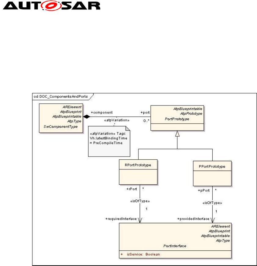
4.2.3 PortPrototypes
PortPrototypes also referred as Ports in some places are the well-defined connection
points for communication between different software-components. A PortPrototype is
either required type or provided type. A require-port (in technical terms: RPortPrototype)
Application Interfaces User Guide
AUTOSAR CP Release 4.4.0
22 of 102 Document ID 442: AUTOSAR_EXP_AIUserGuide
- AUTOSAR confidential -
requires certain services or data, while a provider-port (or PPortPrototype) on the other
hand provides those services or data.
Two SwComponentPrototypes are eventually connected by hooking up a PPortPrototype of
one SwComponentPrototype to a compatible RPortPrototype of the other
SwComponentPrototype.
Figure 13: PortPrototypes
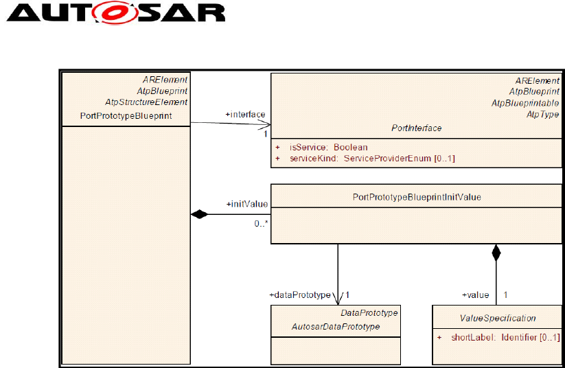
4.2.3.1 PortPrototypeBlueprints
PortPrototypeBlueprint is an ARElement and acts as a blueprint for the creation of
PortPrototypes. A user can pick a specific PortPrototypeBlueprint and create PortPrototype
out of it.
PortPrototypeBlueprint is not related to the SwComponentType. The
PortPrototypeBlueprints are not explicitly represented in the AI Table, they can be
found as a separate package in the XML.
PortPrototypeBlueprints can be seen as a library, from which the user can choose a
PortPrototyepBlueprint as a template to create PortProtoype. Consequently, the
PortPrototypeBlueprints are just a collection of PortPrototypes without any
architectural relation. As soon as a PortPrototypeBlueprint is attached to a
SwComponentPrototpye, it becomes a PortPrototype.
Application Interfaces User Guide
AUTOSAR CP Release 4.4.0
23 of 102 Document ID 442: AUTOSAR_EXP_AIUserGuide
- AUTOSAR confidential -
Figure 14: PortPrototypeBlueprints
4.2.3.2 BlueprintMapping of PortPrototypeBlueprints
The process of creating a PortPrototype from the available PortPrototypeBlueprints is
called BlueprintMapping. BlueprintMapping is demonstrated in Figure 12. The
mapping between PortPrototypes and PortPrototypeBlueprints can be found in the
BlueprintMappingSet "PortPrototypeBlueprintMappings" within the package
"BlueprintMappingSets_Example”.
4.2.3.3 Rules and Recommendations for the usage of Float data
Here are few rule and recommendatios how float data can be used for Port
Prototypes
Always use 1:1 Scaling: e.g. Internal representation = 10.1, use Physical
Value 10.1Pa
Only single precision calculations shall be done (f64 is not recommended)
In case target ECU is known: Do not use float if the RAM/Stack resources are
more critical than CPU load
Float should always be used together with SI Unit as physical representation.
Float is strictly recommended if for one and the same signal either large range
and low precision or small range and high precision is required. Examples:
a. Float is strictly recommended for Pressure ([Pa])
b. Float is strictly recommended for Injection Quantity ([kg])
Float should not be used whenever integer precision is sufficient (e.g.
Temperature ([K]))
While using float in Flat Instance Descriptors (SW Signals) , few
Rules/Recommendations are
The compatibility rules of AUTOSAR meta model have to be fulfilled
Any physical display representation can be used.
Application Interfaces User Guide
AUTOSAR CP Release 4.4.0
24 of 102 Document ID 442: AUTOSAR_EXP_AIUserGuide
- AUTOSAR confidential -
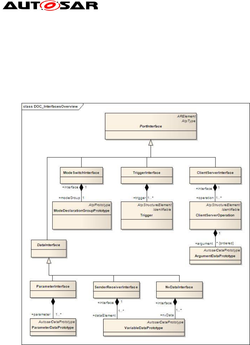
4.2.4 PortInterfaces
The PortInterface defines the kind of information transported between two
PortPrototypes.
PortInterfaces are used to support a design-by-contract workflow, i.e. they provide a
means to formally verify structural and dynamic compatibility between software-
components. In other words, PortInterfaces represent a pivotal point in the
AUTOSAR concept.
Figure 15: Interfaces Overview
Meta Model Reference:
M2::AUTOSARTemplates::SWComponentTemplate::PortInterface [1]
BlueprintMapping is the process of creating PortInterfaces from the
PortInterfaceBlueprints. This is demonstrated in Figure 12. The mappings between
PortInterfaces and PortInterfaceBlueprints can be found in the BlueprintMappingSet "
PortInterfaceBlueprintMappings" within the package
"BlueprintMappingSets_Example”.
Application Interfaces User Guide
AUTOSAR CP Release 4.4.0
25 of 102 Document ID 442: AUTOSAR_EXP_AIUserGuide
- AUTOSAR confidential -
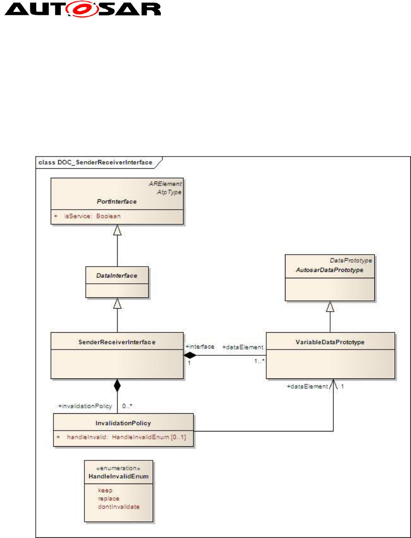
4.2.4.1 Sender Receiver Communication
SenderReceiverInterfaces allow for the specification of the typically asynchronous
communication pattern where a sender provides data that is required by one or more
receivers. While the actual communication takes place via the respective
PortPrototypes, a SenderReceiverInterface allows for formally describing what kind
of information is sent and received.
Figure 16: SenderReceiverInterface
A SenderReceiverInterface declares a number of data elements
(VariableDataPrototype) to be sent and received. A SenderReceiverInterface focuses
on the description of information items represented by VariableDataPrototypes. A
VariableDataPrototype aggregated in the role of dataElement represents an atomic
piece of information transmitted among PortPrototypes typed by a
SenderReceiverInterface.
AI Table Reference:
AUTOSAR_ApplicationInterfaces.xls [8]
Work Sheet Name: 06_Interface_DataElements
Application Interfaces User Guide
AUTOSAR CP Release 4.4.0
26 of 102 Document ID 442: AUTOSAR_EXP_AIUserGuide
- AUTOSAR confidential -
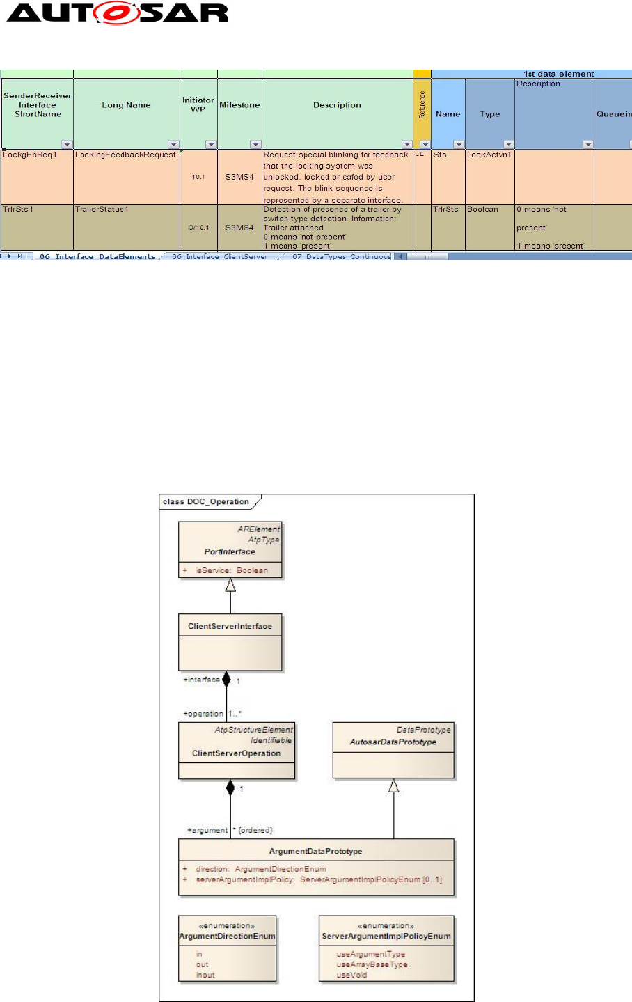
Figure 17: Sheet 06_Interface_DataElements – Example of SenderReceiver Interface
Example: “TrlrSts1” is a SenderReceiver interface that has one data element “TrlrSts”
of Type “Boolean”.
4.2.4.2 ClientServer Communication
The underlying semantics of a client/server communication is that a client may initiate
the execution of an operation by a server that supports the operation. The server
executes the operation and immediately provides the client with the result
(synchronous operation call) or else the client checks for the completion of the
operation by itself (asynchronous operation call).
Figure 18: ClientServerInterface
Application Interfaces User Guide
AUTOSAR CP Release 4.4.0
27 of 102 Document ID 442: AUTOSAR_EXP_AIUserGuide
- AUTOSAR confidential -
ClientServerInterface, therefore to some extent is a counterpart to the
SenderReceiverInterface. Instead of defining pieces of information to be transferred
among software-components, a ClientServerInterface defines a collection of
ClientServerOperations.
As depicted in Figure 18, a ClientServerInterface is composed of
ClientServerOperations, i.e. a ClientServerOperation cannot be reused in the context
of a different ClientServerInterface. A ClientServerOperation consists of 0 to many
ArgumentDataPrototypes. The latter may be
passed to the operation
passed to and returned from the operation
Returned from the operation.
AI Table Reference: AUTOSAR_ApplicationInterfaces.xls [8]
Work Sheet Name: 06_Interface_ClientServer
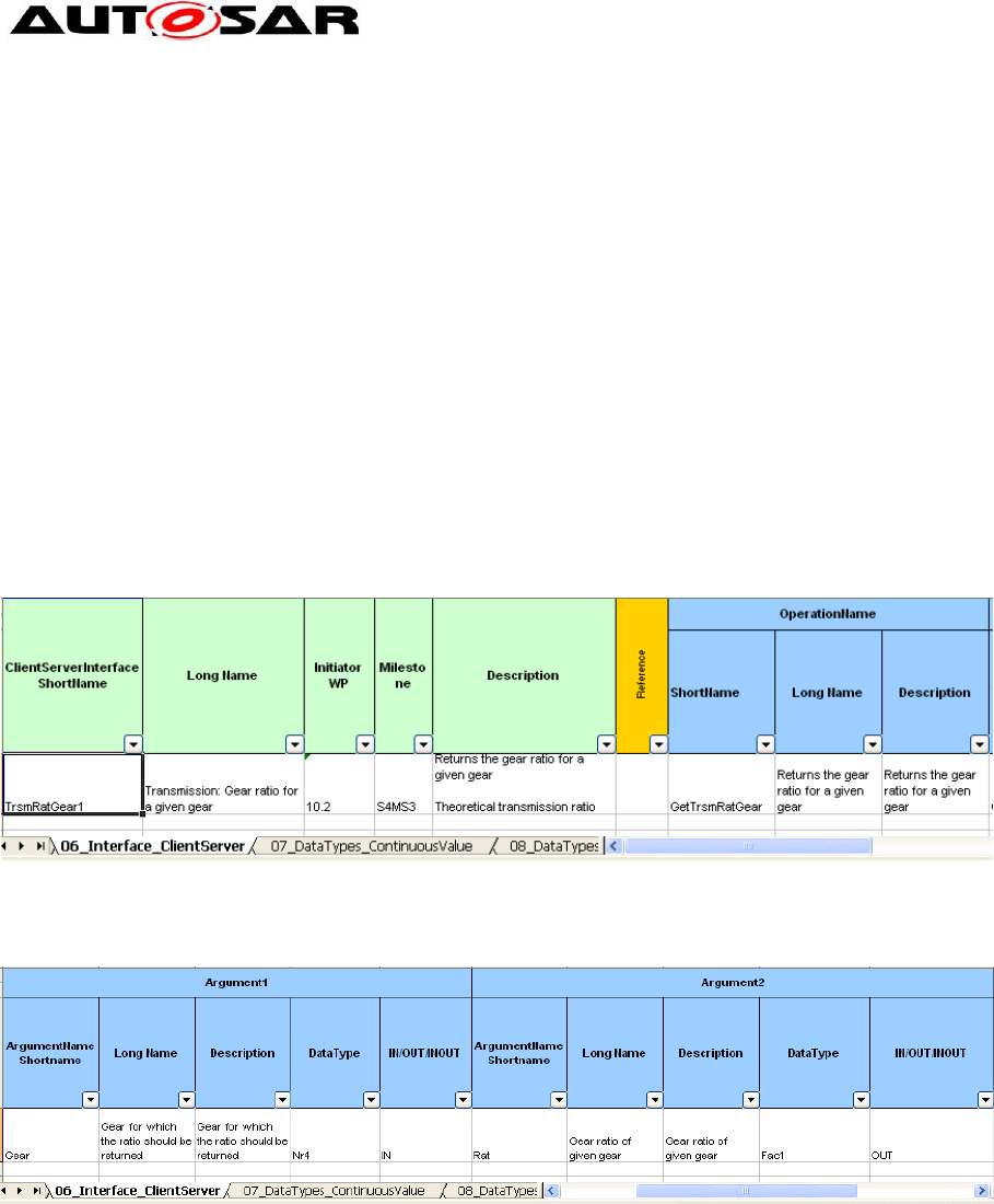
Figure 19: Sheet 06_InterfaceClientServer – Example of ClientServer Interface, showing
operation
Figure 20: Sheet 06_InterfaceClientServer – Example of ClientServer Interface, showing
arguments
Example: In the above screen shots, a client/server interface “TrsmRatGear1” is
defined to return the gear ratio for a given gear, the client requests the operation
‘GetTrsmRatGear’ with input argument ‘Gear’. The function call returns the output
argument ‘Rat’.
4.2.5 DataTypes
It is possible to describe data provided by a software component from the application as well
as implementation point of view. The common concept behind this is expressed by the
abstract meta-class AutosarDataType, from which an ApplicationDataType and an
ImplementationDataType are derived.
Application Interfaces User Guide
AUTOSAR CP Release 4.4.0
28 of 102 Document ID 442: AUTOSAR_EXP_AIUserGuide
- AUTOSAR confidential -
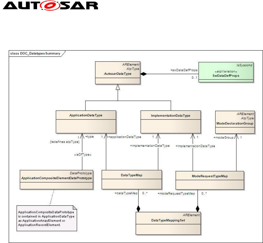
Figure 21 shows a summary of the basic meta-classes used for the definition of
AutosarDataTypes.
Figure 21: DataTypes Overview
An ApplicationDataType can be composed (in form of a record or an array) of elements, which
themselves are typed by another ApplicationDataType. This is expressed by the meta-class
ApplicationCompositeElementDataPrototype, which is shown in
Figure 21 for completeness. An ImplementationDataType can be composed too, but
in this case, no type/prototype concept has been applied.
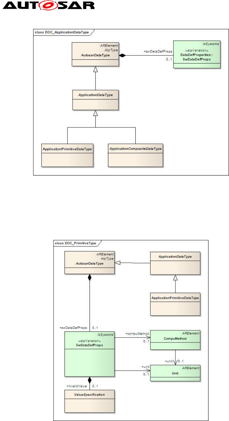
4.2.5.1 ApplicationDataTypes
The abstract meta-class ApplicationDataType is further derived into an
ApplicationPrimitiveDataType and an ApplicationCompositeDataType. Like any
AutosarDataType, the primitive and composite types on application level are
characterized by its category and its SwDataDefProps. For a given category, only a
limited set of attributes of the SwDataDefProps make sense.
Application Interfaces User Guide
AUTOSAR CP Release 4.4.0
29 of 102 Document ID 442: AUTOSAR_EXP_AIUserGuide
- AUTOSAR confidential -
Figure 22: Application Data Type
4.2.5.1.1 Application Primitive Data Types
This chapter defines the primitive application data types that may be used for the
data prototypes of PortInterfaces or composite application data types.
Figure 23: Data Types Primitive
Application Interfaces User Guide
AUTOSAR CP Release 4.4.0
30 of 102 Document ID 442: AUTOSAR_EXP_AIUserGuide
- AUTOSAR confidential -
Meta Model Reference:
M2::AUTOSARTemplates::SWComponentTemplate::DataType::DataTypes [1]
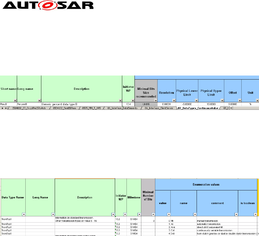
AI Table Reference: AUTOSAR_ApplicationInterfaces.xls [8]
Work Sheet Name: 07_DataTypes_ContinuousValue
Figure 24: Sheet 07_DataTypes_ContinuousValue – Example of a Continuous Value DataType
Example: In the above screen shot, a ContinuousValue DataType Perc8 is defined.
The resolution, physical lower and upper limits as well as the offset and unit of this
DataType are also shown in the screen shot.
AI Table Reference: AUTOSAR_ApplicationInterfaces.xls [8]
Work Sheet Name: 08_DataTypes_Enumeration
Figure 25: Sheet 08_DataTypes_Enumeration – Example of Enumeration DataType
Example: In the above screen shot, an Enumeration DataType TrsmTyp1 is defined.
All permissible values of the Enumeration DataType are also included in the AI
Table.
4.2.5.1.2 Application Composite Data Types
The meta-classes ApplicationArrayDataType and ApplicationRecordDataType
provide the means to define composite DataTypes. Such a composite DataType is
required, if the application software wants to have access to the individual elements
of the composite as well as to do operations with the whole composite, e.g. wants to
communicate the complete record or array in a single transaction.

Application Interfaces User Guide
AUTOSAR CP Release 4.4.0
31 of 102 Document ID 442: AUTOSAR_EXP_AIUserGuide
- AUTOSAR confidential -
Figure 26: Data Types Composite
It is possible to use a combination of ApplicationArrayDataType and
ApplicationRecordDataType, so that an ApplicationArrayDataType could be defined
as ApplicationRecordElement of an ApplicationRecordDataType and in the same
manner, an ApplicationRecordDataType could be used as the base type of an
ApplicationArrayDataType. The creation of nested ApplicationComposite DataTypes
is also possible.
4.2.5.1.3 ApplicationArrayDataType
An ApplicationArrayDataType may contain maxNumberOfElements of
ApplicationArrayElements. Each of these ApplicationArrayElements must have the
same type. When referring to an element of an array within the software-component
descriptions, the element index runs from 0 to (maxNumberOfElements-1).
AI Table Reference: AUTOSAR_ApplicationInterfaces.xls [8]
Work Sheet Name: 09_DataTypes_Array

Application Interfaces User Guide
AUTOSAR CP Release 4.4.0
32 of 102 Document ID 442: AUTOSAR_EXP_AIUserGuide
- AUTOSAR confidential -
Figure 27: Sheet 09_DataTypes_Array – Examples of Array DataType
Example: The standard variables of DataType array used in application component
development are listed here for reference. Array DataType “TirePPerWhl1” contains
5 elements, each of DataType ‘P1’.
4.2.5.1.4 ApplicationRecordDataType
A declaration of ApplicationRecordDataType describes a nonempty set of objects,
each of which has a unique identifier with respect to the ApplicationRecordDataType
and each has its own ApplicationDataType. The ShortName of each
ApplicationRecordElement within the scope of an ApplicationRecordDataType must
be unique.
AI Table Reference: AUTOSAR_ApplicationInterfaces.xls [8]
Work Sheet Name: 11_DataTypes_Record
Figure 28: Sheet 11_DataTypes_Record – Example of Record DataType
Example: The “IndcrTurnSeq1” is a record type variable to represent the turn
indicator sequence. The record DataType ‘IndcrTurnSeq1’ contains 5 elements’,
each element represented in a unique row defined with a corresponding DataType.
Application Interfaces User Guide
AUTOSAR CP Release 4.4.0
33 of 102 Document ID 442: AUTOSAR_EXP_AIUserGuide
- AUTOSAR confidential -
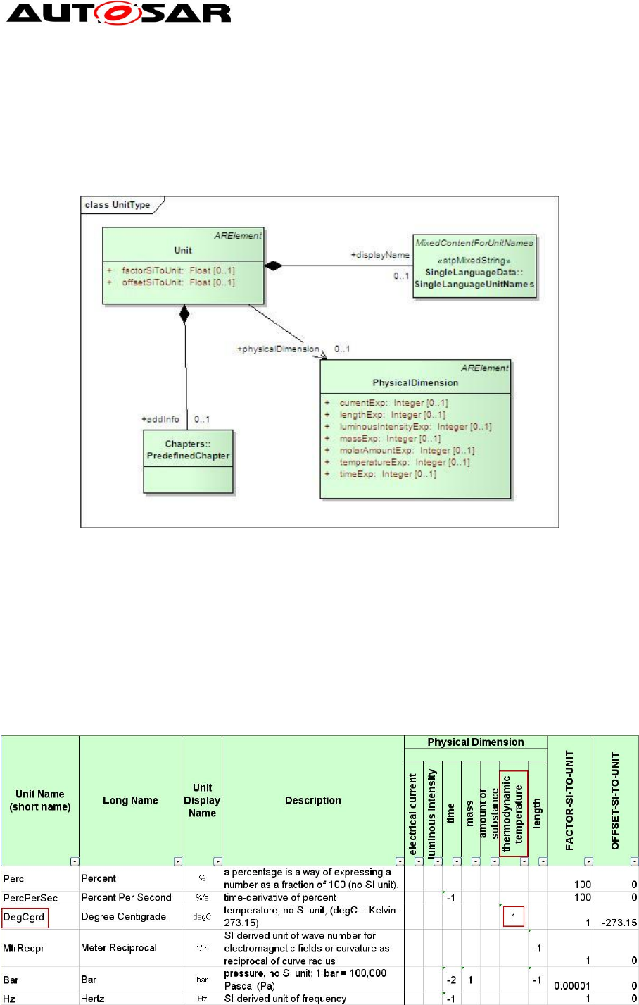
4.2.6 Physical Units
An important part of the semantics associated with a DataType is its physical
dimension. Units are used to augment the value with additional information like m/s
or liter. This is necessary for a correct interpretation of the physical value for input
and output processes. The unit involves information about its physical dimensions.
Figure 29: Units
The unit references one physical dimension. If the physical dimensions of two units
are identical, a conversion between them is possible.
Meta Model Reference:
M2::AUTOSARTemplates::SWComponentTemplate::DataType::Units [1]
AI Table Reference: AUTOSAR_ApplicationInterfaces.xls [8]
Work Sheet Name: 13_Units
Figure 30: Sheet 13_Units – Example of Unit

Application Interfaces User Guide
AUTOSAR CP Release 4.4.0
34 of 102 Document ID 442: AUTOSAR_EXP_AIUserGuide
- AUTOSAR confidential -
Example: The unit represented as ‘DegCgrd’, belonging to the physical dimension of
‘thermodynamic temperature’.
4.2.7 Computation Methods
This meta-class represents the ability to express the relationship between a physical
value and the mathematical representation.
Note that this is still independent of the technical implementation in data types. It only
specifies the formula how the internal value corresponds to its physical pendant.
CompuMethods in general shall be reuseable and not fixed to a specific data type.
CompuMethods can be referenced by any kind of datatype which need such
described computational features; the reuse is strongly recommended and
mandatory for float datatypes definition. Application Interface Tooling (AIT) tool
support such cross referencing of parameters. For more information, Refer SW-C
and System Modeling Guide [9].
4.2.7.1 Example of Linear Conversion
The following examples illustrates how a linear conversion is specified using CompuMethod.
<COMPU-METHOD>
<SHORT-NAME>LinearExample</SHORT-NAME>
<CATEGORY>LINEAR</CATEGORY>
<UNIT-REF DEST="UNIT">kmh</UNIT-REF>
<COMPU-INTERNAL-TO-PHYS>
<COMPU-SCALES>
<COMPU-SCALE>
<COMPU-RATIONAL-COEFFS>
<COMPU-NUMERATOR>
<V>30</V>
<V>2</V>
</COMPU-NUMERATOR>
<COMPU-DENOMINATOR>
<V>1</V>
</COMPU-DENOMINATOR>
</COMPU-RATIONAL-COEFFS>
</COMPU-SCALE>
</COMPU-SCALES>
</COMPU-INTERNAL-TO-PHYS>
</COMPU-METHOD>
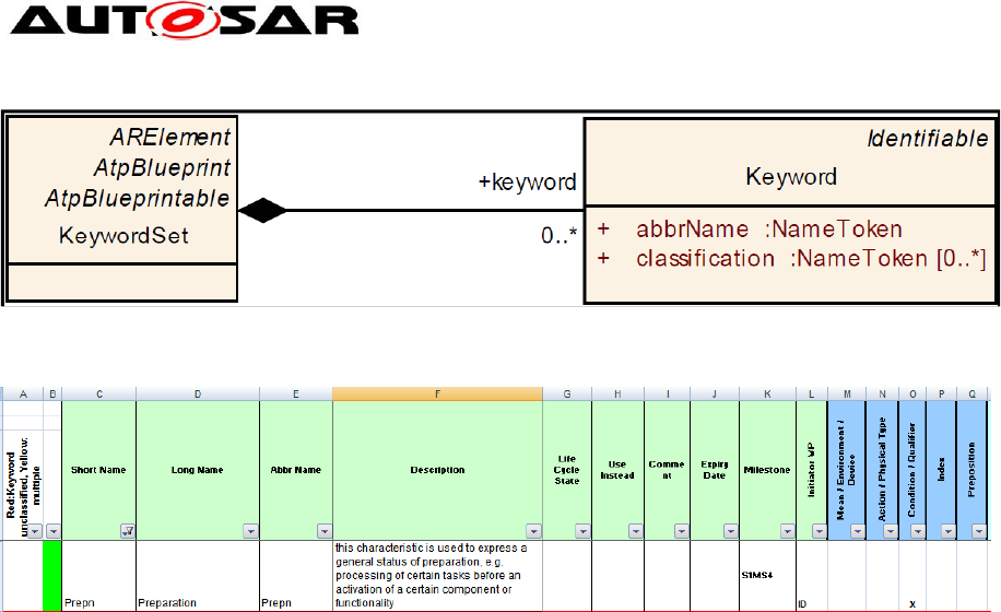
4.2.8 Keyword and KeywordSet
An important part of defining short names for component types, ports, PortInterfaces
or data elements is to make use of the predefined keywords in AUTOSAR and their
abbreviations. The advantage is, that this results in relatively short names with
established meaning. The Keywords are aggregated under the category
KeywordSets_Blueprint.
Application Interfaces User Guide
AUTOSAR CP Release 4.4.0
35 of 102 Document ID 442: AUTOSAR_EXP_AIUserGuide
- AUTOSAR confidential -
Figure 31: Class diagram for Keyword and KeywordSet
Figure 32: Sheet 04_Keywords
From Figure above, each keyword is described by the following attributes:
ShortName: represent the unique name of the keyword, it’s not involved in
name construction (Prepn in above e.g)
longName: represent the long form of the keyword (Preparation)
desc: represent the definition of the keyword
abbrName: specifies the abbreviated name of the keyword and it’s used to
build ShortNames
classification: describe the semantic field of the keyword (Mean-
Environment-Device, Action-PhysicalType, Condition-Qualifier, Index,
Preposition)
If not differently specified in the rest of the document the term keyword will refer to
the longName of the keyword, while the abbreviated name could be referred as
“abbrName attribute” or “keyword abbreviation” as well.
The resulting xml outputs is as under:
<SHORT-NAME>AISpecification</SHORT-NAME>
<AR-PACKAGES>
<AR-PACKAGE>
<SHORT-NAME>KeywordSets_Blueprint</SHORT-NAME>
<CATEGORY>BLUEPRINT</CATEGORY>
<ELEMENTS>
<KEYWORD-SET>
<SHORT-NAME>KeywordList</SHORT-NAME>
<LONG-NAME><L-4 L="EN">AUTOSAR Keywords and
Keywords Abbreviations</L-4></LONG-NAME>
<KEYWORDS>
<KEYWORD>
<SHORT-NAME>Prepn</SHORT-NAME>
<LONG-NAME><L-4 L="EN">Preparation</L-4></LONG-NAME>
<DESC><L-2 L="EN">this characteristic is used to express a general status of
preparation, e.g. processing of certain tasks before an activation of a certain
component or functionality</L-2></DESC>
<ABBR-NAME>Prepn</ABBR-NAME>
<CLASSIFICATIONS>
<CLASSIFICATION>Condition-Qualifier</CLASSIFICATION>

Application Interfaces User Guide
AUTOSAR CP Release 4.4.0
36 of 102 Document ID 442: AUTOSAR_EXP_AIUserGuide
- AUTOSAR confidential -
</CLASSIFICATIONS>
</KEYWORD>
……
In order to build readable and understandable names, keywords shall be arranged
according to semantic rules. Such rules define Semantic Fields that must be used in
a defined sequence. These are described further in [9]
Application Interfaces User Guide
AUTOSAR CP Release 4.4.0
37 of 102 Document ID 442: AUTOSAR_EXP_AIUserGuide
- AUTOSAR confidential -
5 Backward Compatibility
5.1 Introduction
In course of the AUTOSAR standard development, it was recognised with newer
releases that the standard was not compatible with its predecessor version. This in
turn resulted in severe integration issues especially for configurations that intended to
use certain modules from the updated version of the specification.
Therefore, AUTOSAR introduced the Backward Compatibility requirement for new
concepts to ensure smooth and error free operation of software with mixed versions
of implementations.
Three use-cases induce three kinds of compatibility statements that will be provided
by AUTOSAR- the respective document owners provide list of changes with analysis
of impact on the three kinds of Backward Compatibility.
Specification-wise backwards compatibility
Bus backwards compatibility
Application backwards compatibility
For the Application wise backward compatibility, it considers that set of modules of
an AUTOSAR release that has an effect on the interaction of application software
components.
Hence, the use case definition for Application Interfaces is derived to be:
Horizontal “application-compatibility” (only standardized Application Interfaces are
regarded)
Old scenario: Application development based on standardized Application
Interfaces defined in e.g. release R4.0.3
New scenario: The Applications shall be updated with respect to the standardized
Application Interfaces of e.g. release R4.1.1
Question: Do the new standardized Application interfaces work with the older
(unchanged) standardized Application interfaces without adaptations?
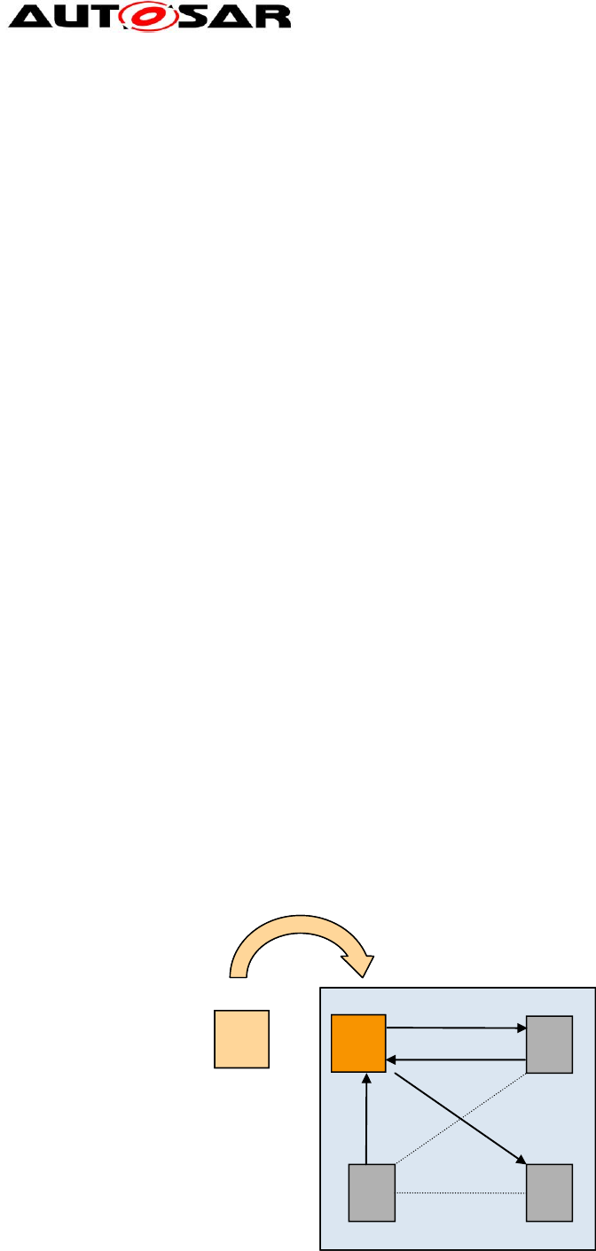
5.2 Backward Compatibility Definition
Figure 33: Illustrative representation of Backward Compatibility
Qi+1 Qi
Qi+1
Qi+1 Qi
Qi

Application Interfaces User Guide
AUTOSAR CP Release 4.4.0
38 of 102 Document ID 442: AUTOSAR_EXP_AIUserGuide
- AUTOSAR confidential -
According to AUTOSAR;
A product Qi+1 is said to be compatible to product Qi if Qi+1 is able to take the
place of Qi that again is interacting with other products (which were left
untouched) designed for product Qi.
A product Qi+1 is said to be backwards compatible to product Qi if Qi+1 is
compatible to Qi and Qi+1 is a successor of Qi.
Therefore the definition in the context of Application Interfaces is:
A blueprint Qi+1 is said to be compatible to blueprint Qi if blueprint Qi+1 is
able to take the place of blueprint Qi that again is referenced by ports (which
were left untouched).
Application Interface Qi+1 is said to be compatible to application interface Qi if
application interface Qi+1 is able to take the place of application interface Qi
that again is referenced by a system (which were left untouched) and which
was designed according to application interface Qi.
Example:
PortCompliance is:
* ShortNames are equal
* InterfaceBlueprint of Portblueprint complies to interface of port
* …
InterfaceCompliance is:
* has the same number of dataElementPrototypes
* names of dataElementPrototypes are the same
* Datatypes of the dataElementProtopes are compatible
* …
Explanations
The Backward Compatibility requirement is a necessary precondition in order to
enable exchange of SWC with new standardized Application Interfaces.
In an ECU developed based upon e.g. release R4.0.3 - the standardized Applications
Interfaces shall be updated to the new standardized Application Interfaces of e.g.
release R4.1.1
Figure 34: Example representation of BWC w.r.t. Application Interfaces
Microcontroller
CDD
Microcontroller Abstraction Layer
Services Layer
Runtime Environment
ECU Abstraction Layer
SWC1SWC2SWCn
SWCn-
1
SWC3
Microcontroller
CDD
Microcontroller Abstraction Layer
Services Layer
Runtime Environment
ECU Abstraction Layer
SWC1SWC2SWCn
SWCn-
1
SWC3
SWCiSWCiusing std app interfaces of R4.0.3
:= SWCiSWCiusing std app interfaces of R4.0.4
:=
BWC
wrt
std app if
Microcontroller
CDD
Microcontroller Abstraction Layer
Services Layer
Runtime Environment
ECU Abstraction Layer
SWC1SWC2SWCn
SWCn-
1
SWC3
MicrocontrollerMicrocontroller
CDD
Microcontroller Abstraction Layer
Services Layer
Runtime Environment
ECU Abstraction Layer
SWC1SWC2SWCn
SWCn-
1
SWC3
CDDCDD
Microcontroller Abstraction Layer
Services LayerServices Layer
Runtime EnvironmentRuntime Environment
ECU Abstraction LayerECU Abstraction Layer
SWC1
SWC1SWC2
SWC2SWCn
SWCn
SWCn-
1
SWCn-
1
SWC3
SWC3
MicrocontrollerMicrocontroller
CDDCDD
Microcontroller Abstraction Layer
Services LayerServices Layer
Runtime EnvironmentRuntime Environment
ECU Abstraction LayerECU Abstraction Layer
SWC1
SWC1SWC2
SWC2SWCn
SWCn
SWCn-
1
SWCn-
1
SWC3
SWC3
SWCiSWCiusing std app interfaces of R4.0.3
:=
SWCi
SWCiSWCiusing std app interfaces of R4.0.3
:= SWCiSWCiusing std app interfaces of R4.0.4
:=
SWCi
SWCiSWCiusing std app interfaces of R4.0.4
:=
BWC
wrt
std app if
Application Interfaces User Guide
AUTOSAR CP Release 4.4.0
39 of 102 Document ID 442: AUTOSAR_EXP_AIUserGuide
- AUTOSAR confidential -
Preconditions:
The standardized Application Interfaces are updated to latest releases;
everything else stays the same
Configurations are semantically equivalent
The SWC is recompiled
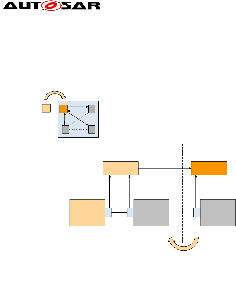
Figure 35: BWC with reference to Blueprints
Elements affecting Backward Compatibility; if these elements are changed, backward
compatibility is affected
(Refer SW-C and System Modeling Guide [9], Future extensions (ch. 5.4))
Short name
Enumeration data type
o Enumeration value, enumeration value name
Continuous data type
o Resolution, physical limits, offset, unit
Array data type
o Number of elements, type of elements
Record data type
o Number of elements, elements name, elements type
Sender-receiver interface
o Number of data elements, name of data elements, type of data
elements
Client-server interface
o Operation name, number of arguments, argument names, argument
data types, argument in/out property
Comp X
PBP A successor
Comp Y is
untouched
Backward Compatibiltiy regarding
Port Blueprints
PBP A
Comp YComp Y
maps tomaps to maps to
Release N+1 Release N
Component Y
is untouched
A A A
Comp X
PBP A successor
Comp Y is
untouched
Backward Compatibiltiy regarding
Port Blueprints
PBP A
Comp YComp Y
maps tomaps to maps to
Release N+1 Release N
Component Y
is untouched
A A A

Application Interfaces User Guide
AUTOSAR CP Release 4.4.0
40 of 102 Document ID 442: AUTOSAR_EXP_AIUserGuide
- AUTOSAR confidential -
5.3 Summary
For any change in a port blueprint and it’s referenced elements
(PortInterfaces, application data types and units) a new version of all affected
elements shall be created. Exception: changes to descriptive elements (unless
the meaning of original element is not modified)
New elements use same defined sequence numbering as currently used for
interfaces (see SW-C and System Modeling Guide [9], chapter 5.4).
Descriptive elements doesn’t obligatory* lead to a new version. This is applied
to the following elements:
Description
LongName
Introduction
*Note: In case a descriptive element of a blueprint changes in a way that it’s meaning
with regard to the original blueprint is also changed, a new version of all affected
elements shall be created.
For AI, R4.0.3 is the basis for BWC.
Application Interfaces User Guide
AUTOSAR CP Release 4.4.0
41 of 102 Document ID 442: AUTOSAR_EXP_AIUserGuide
- AUTOSAR confidential -
6 Life Cycle States
6.1 Introduction
In order to support evolution and backward compatibility of the standardized model
elements like port prototype blueprints, PortInterfaces, keyword abbreviations and
other STANDARD or BLUEPRINT elements, AUTOSAR needed to support life
cycles states.
Definition of “Life Cycle” [17]
The course of development/evolutionary stages of a model element during its
life time.
A life cycle consists of a set of life cycle states. A life cycle state can be
attached to an element in parallel to its version information.
A typical life cycle is {valid, obsolete} and means that a valid element is up to date
when first introduced but is substituted later by a new one and therefore gets the life
cycle state “obsolete”.
An element’s “Life Cycle state” is different from its “Version” in that:
Version: refers to the information traced within the journey of its development to bring
to existence (example: proposal, in work, released...) where as
Life Cycle traces the journey of an element from its point of mainstream introduction
until its obsolescence.
Life Cycle states is further described in Ch 11 of the GenericStructureTemplate [4].
6.2 Representation in AI Table
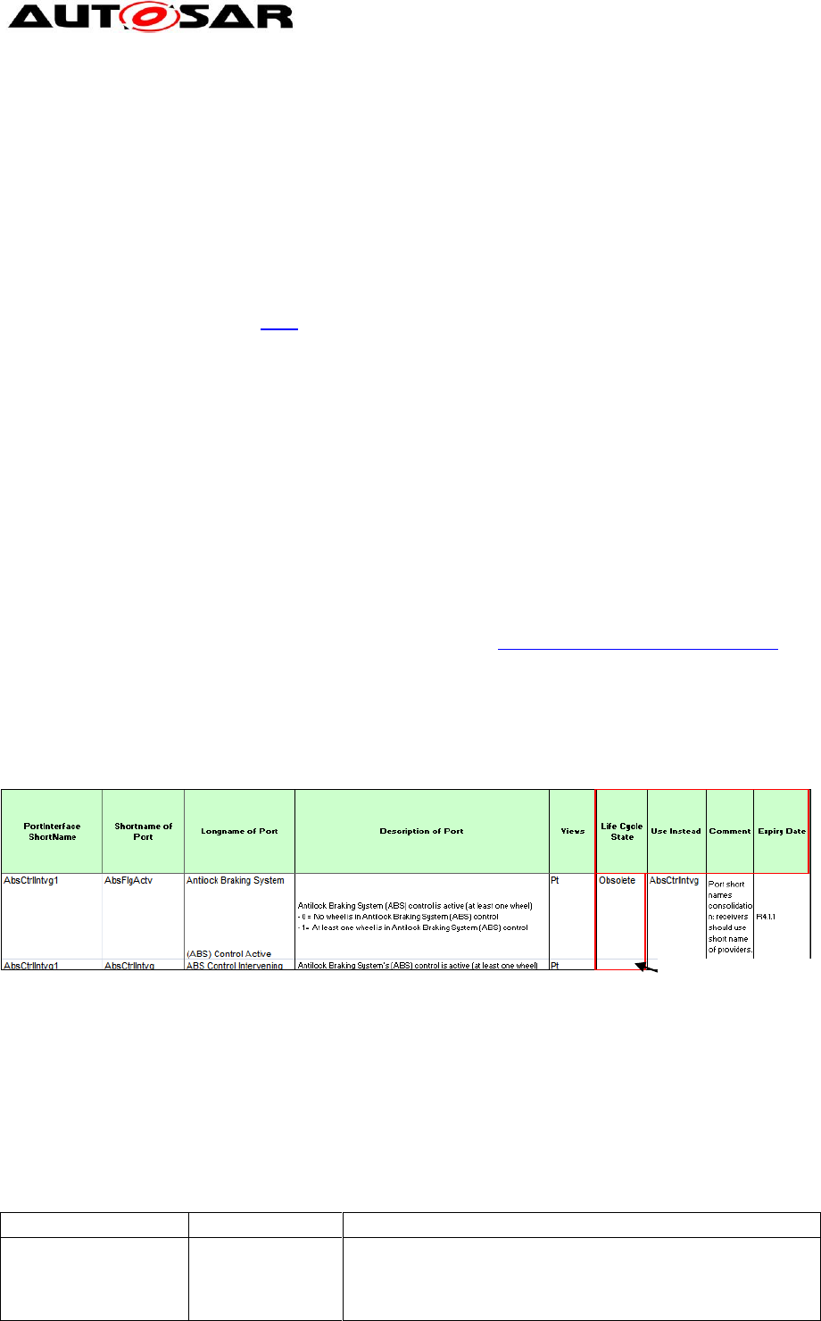
In order to support the introduction of Life Cycle states in the AI Table, new columns
have been added to the affected sheets as depicted in the Figure below.
Figure 36: Representation of Life Cycle States in AI Table
The description of the columns is indicated below. Currently there are two Life Cycle
states defined for AI usage:
Obsolete (with a reasoning for its obsolescence and an alternative provided)
Valid (default state which is left blank in column “Life Cycle State”)
It is also possible there are two entries available for the attribute “Use Instead”. In
such a case, the entries are separated by a comma (,).
Worksheets
Column Desc.
Explanation
04*,05*,06*,07*,08*,
09*,11*,13*,15*
Life Cycle State
Extension for Life Cycle concept:
- Life Cycle State valid in case of an empty field
- Life Cycle State obsolete in case of “obsolete” in the
field
Default State=Valid (Blank)
Application Interfaces User Guide
AUTOSAR CP Release 4.4.0
42 of 102 Document ID 442: AUTOSAR_EXP_AIUserGuide
- AUTOSAR confidential -
04*,05*,06*,07*,08*,
09*,11*,13*,15*
Use Instead
- reference to the model element short name that will
replace the obsolete model element
- in case of two entries in this column, these are
separated by a comma (,)
04*,05*,06*,07*,08*,
09*,11*,13*,15*
Comment
- comment field, e.g. reason not to use the model element
any more
04*,05*,06*,07*,08*,
09*,11*,13*,15*
Expiry Date
- AUTOSAR revision for expiry date in the form of R4.1.1,
i.e. the version, when this element became obsolete
Please note, that the respective changes to the layout of the AI Table are not
reflected in the other figures throughout this document.
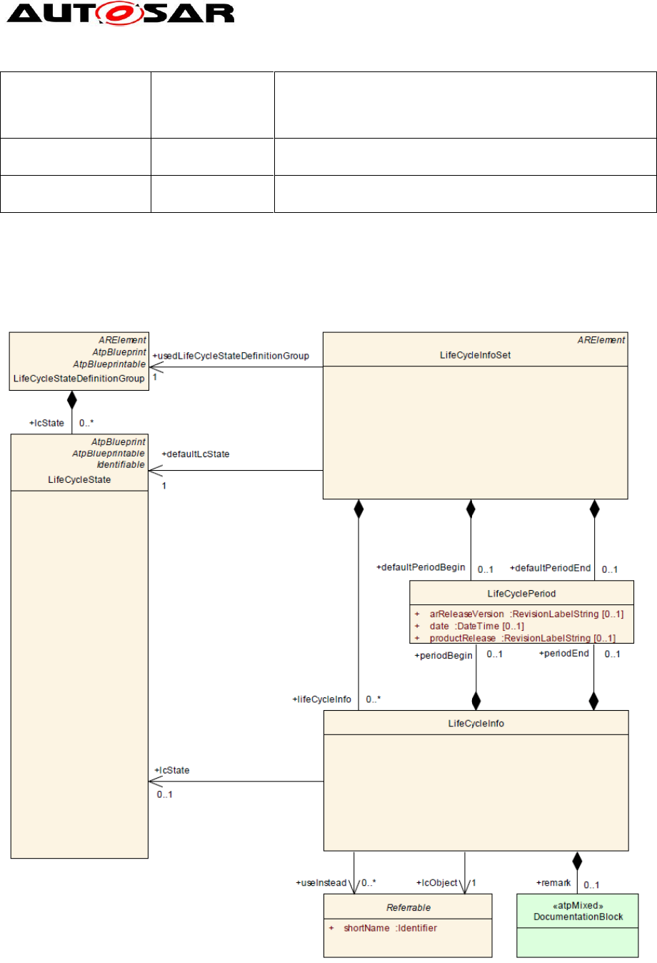
6.3 Representation in meta model and arxml
Figure 37: Definition of Life Cycle – meta model representation
The Life Cycle information of elements is available in the xml files generated under

Application Interfaces User Guide
AUTOSAR CP Release 4.4.0
43 of 102 Document ID 442: AUTOSAR_EXP_AIUserGuide
- AUTOSAR confidential -
AUTOSAR_MOD_GeneralDefinition_LifeCycle.arxml: Definition of a life cycle state that is
applicable globally in the AUTOSAR project and also used in the Basic SW area
(LifeCycleStateDefinitionGroup). This file is not part of the AI deliverables and is only
referenced from inside AUTOSAR_MOD_GeneralDefinitions.zip folder.
AUTOSAR_MOD_AISpecification_<Element>_LifeCycle_Standard.arxml:Application of a life
cycle – refers to elements defined within the Application Interfaces and their
associated LifeCycleState (LifeCycleInfoSet). There is one file per model element and
is part of the AI deliverables inside the AUTOSAR_MOD_AISpecification.zip folder.
For instance, from the above table, it is seen that the Port AbsFlgActv is set to Obsolete and
referred to Use Instead AbsCtrlIntvg.
The same is reflected in the arxml extract in file
AUTOSAR_MOD_AISpecification_PortPrototypeBlueprint_LifeCycle_Standard.arxml as
shown below.
<LIFE-CYCLE-INFO>
<LC-OBJECT-REF DEST="PORT-PROTOTYPE-BLUEPRINT"
BASE="PortPrototypeBlueprints_Blueprint">AbsFlgActv</LC-OBJECT-REF>
<PERIOD-BEGIN>
<AR-RELEASE-VERSION>4.1.1</AR-RELEASE-VERSION>
</PERIOD-BEGIN>
<REMARK>
<P><L-1 L="EN">Port short names consolidation: receivers
should use short name of providers.</L-1></P>
</REMARK>
<USE-INSTEAD-REFS>
<USE-INSTEAD-REF DEST="PORT-PROTOTYPE-BLUEPRINT"
BASE="PortPrototypeBlueprints_Blueprint">AbsCtrlIntvg</USE-
INSTEAD-REF>
</USE-INSTEAD-REFS>
</LIFE-CYCLE-INFO>
The AUTOSAR_MOD_AISpecification_<Element>_LifeCycle_Standard.arxml contains only
those elements that are marked as Obsolete (since default value is Valid) and the
corresponding element to be used instead, i.e. the substitute of the obsolete element. The
expiry version defines the begin of the period of the element being obsolete, i.e. the first
AUTOSAR release where this element was set from valid to obsolete, in this case “R.4.1.1”.

Application Interfaces User Guide
AUTOSAR CP Release 4.4.0
44 of 102 Document ID 442: AUTOSAR_EXP_AIUserGuide
- AUTOSAR confidential -
7 View Concept in Application Interfaces (Variant
Handling)
7.1 Introduction
A Variant Handling Concept will help to implement different architectures in the
vehicle using application interfaces. With the port prototype blueprint concept the
final end-to-end communication of an interface will be performed by the configuration
of a system. This will also allow different configurations of physical vehicles such as
compact car, premium car, to truck applications to be included in the standardization
of application interfaces.
As AUTOSAR only standardizes blueprints, there is no necessity to implement
variant handling in the AI specification. It is easily possible to add new blueprint
elements for every variant needed. To differentiate between different variants,
different views are introduced. A view allows filtering for blueprint elements for a
specific variant or use case. For example, if a view for “trucks” is introduced, it would
be possible to filter for the “truck” view, i.e. to filter for all blueprint elements that are
relevant for the use case “trucks”.
7.2 Implementation in Application Interfaces and Meta Model
Representation
The views defined by 10.x are in a package of Category BLUEPRINT. The reason for
this is, that in a company environment, additional elements may be added.
For the first introduction of views, only views for each domain are introduced, i.e. the
views “Body” (Body), “Powertrain” (Pt), “Chassis” (Chassis), “Occupant and
Pedestrian Safety” (OccptPedSfty) and “Multimedia, Telematics and HMI”
(MmedTelmHmi). More views might be added for future releases. Currently, these
views can be specified for PortPrototypeBlueprints and ApplicationDataTypes in the
AI Table. The elements belonging to a specific view are marked with the terms in
brackets, e.g. as “Pt”, “Body” or “Chassis” under the “Views” column in the AI Table
sheets as shown below. Upon setting the filter, the respective collection of elements
can be seen.
Figure 38: Representation of Views in AI Table
Application Interfaces User Guide
AUTOSAR CP Release 4.4.0
45 of 102 Document ID 442: AUTOSAR_EXP_AIUserGuide
- AUTOSAR confidential -
Additionally, it is also possible that ‘multiple views’ can be assigned to a single model
element. For instance, in above Figure we see that a single model element
(BodyPitchAgAbsltEstimd) has two views assigned to it (Chassis and Pt) respectively
separated by a ‘comma’.
Please note, that the respective changes to the layout of the AI Table are not
reflected in the other figures throughout this document.
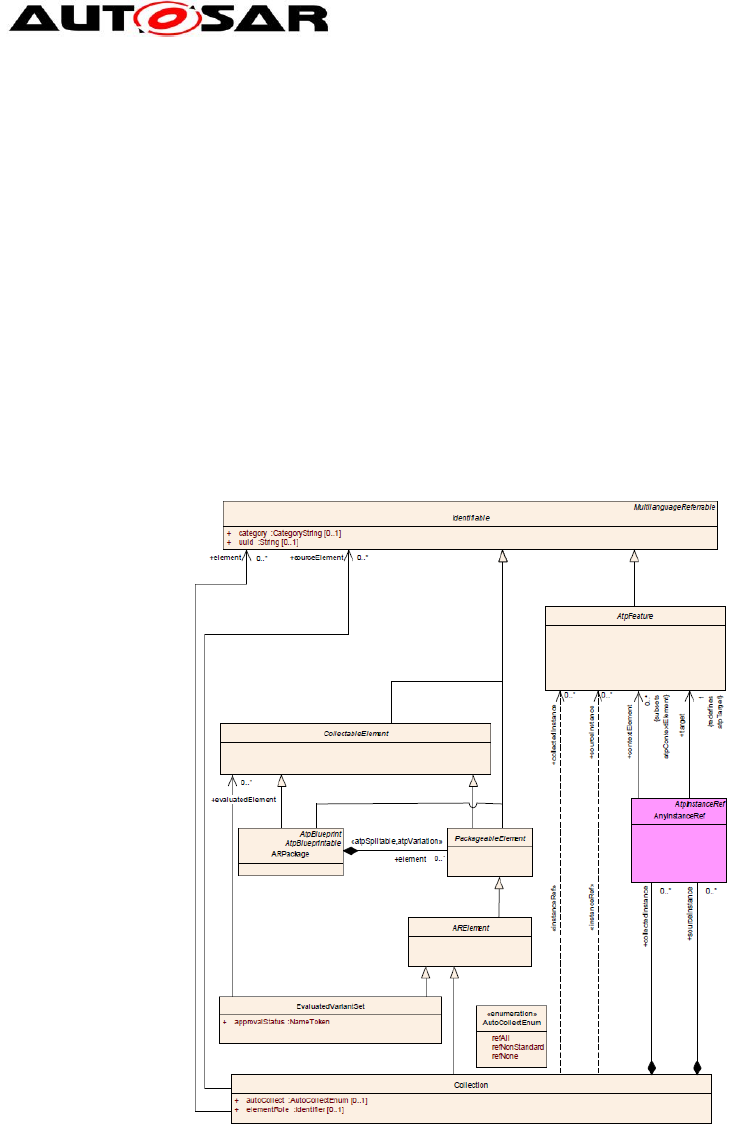
For some use cases it is necessary to establish a collection of elements. Such collections are
orthogonal to packages. Therefore a collection resides in a package but is established by
associations to the collected elements as seen in the Figure below. For the Application
Interfaces however, only a subset of this methodology will be used and further details
can be seen in [4].
The different views will be specified in form of collections with the category SET and
the element role PART_OF_SUBSET
Figure 39: Representation of Collections in Meta Model
Two collections will be specified to define the views, one with autoCollect=REF-ALL
and the other one with autoCollect=REF-NONE.
REF-ALL means that this collection automatically will include all referenced model
elements. These elements are not listed within the collection.
REF-NONE means that this collection does not include any referenced model
elements. That means that only the listed elements of the collection will belong to it.
For the generated XML the two generated collections will define the respective
content.
With reference to xml extract below:

Application Interfaces User Guide
AUTOSAR CP Release 4.4.0
46 of 102 Document ID 442: AUTOSAR_EXP_AIUserGuide
- AUTOSAR confidential -
The collection with autoCollect=REF-ALL contains a PortPrototypeBlueprint
(AbsCtrlIntvg). That means that the referenced model elements like PortInterface,
ApplicationDataType, CompuMethod and Unit also belong to this collection.
The collection with autoCollect=REF-NONE contains a PortPrototypeBlueprint
(AbsCtrlIntvg) and the referenced model elements like PortInterface,
ApplicationDataType, CompuMethod and Unit within the collection.
For the specification of the views within the AI table it is sufficient to mark a
PortPrototypeBlueprint on one sheet, e.g. the provider. That means it will belong to
the view even if it is not marked on the receiver side. Also, it is possible to have two
different views specified on different sheets. The XML generation will consider all the
specified views.
<?xml version="1.0" encoding="UTF-8"?>
<AUTOSAR xmlns="http://autosar.org/schema/r4.0"
xmlns:xsi="http://www.w3.org/2001/XMLSchema-instance"
xsi:schemaLocation="http://autosar.org/schema/r4.0 AUTOSAR_4-1-1.xsd">
<ADMIN-DATA>
<LANGUAGE>EN</LANGUAGE>
<USED-LANGUAGES>
<L-10 L="EN" xml:space="default">English</L-10>
</USED-LANGUAGES>
</ADMIN-DATA>
<AR-PACKAGES>
<AR-PACKAGE>
<SHORT-NAME>AUTOSAR</SHORT-NAME>
<LONG-NAME>
<L-4 L="EN">AUTOSAR</L-4>
</LONG-NAME>
<AR-PACKAGES>
<AR-PACKAGE>
<SHORT-NAME>AISpecification</SHORT-NAME>
<AR-PACKAGES>
<AR-PACKAGE>
<SHORT-NAME>Collections_Blueprint</SHORT-NAME>
<CATEGORY>BLUEPRINT</CATEGORY>
<REFERENCE-BASES>
<ELEMENTS>
<COLLECTION>
<SHORT-NAME>ChassisRefAll</SHORT-NAME>
<CATEGORY>SET</CATEGORY>
<AUTO-COLLECT>REF-ALL</AUTO-COLLECT>
<ELEMENT-ROLE>PART_OF_SUBSET</ELEMENT-ROLE>
<ELEMENT-REFS>
<ELEMENT-REF DEST="PORT-PROTOTYPE-BLUEPRINT"
BASE="PortPrototypeBlueprints">AbsCtrlIntvg</ELEMEN
T-REF>
</COLLECTION>
……
<COLLECTION>
<SHORT-NAME>Chassis</SHORT-NAME>
<CATEGORY>SET</CATEGORY>
<AUTO-COLLECT>REF-NONE</AUTO-COLLECT>
<ELEMENT-ROLE>PART_OF_SUBSET</ELEMENT-ROLE>
<ELEMENT-REFS>
<ELEMENT-REF DEST="PORT-PROTOTYPE-
BLUEPRINT" BASE="PortPrototypeBlueprints">AbsCtrlIntvg</ELEMENT-REF>
<ELEMENT-REF DEST="SENDER-RECEIVER-
INTERFACE" BASE="PortInterfaces">AbsCtrlIntvg1</ELEMENT-REF>

Application Interfaces User Guide
AUTOSAR CP Release 4.4.0
47 of 102 Document ID 442: AUTOSAR_EXP_AIUserGuide
- AUTOSAR confidential -
<ELEMENT-REF DEST="APPLICATION-
PRIMITIVE-DATA-TYPE" BASE="ApplicationDataTypes">CtrlSts1</ELEMENT-REF>
<ELEMENT-REF DEST="COMPU-METHOD"
BASE="CompuMethods">CtrlSts1</ELEMENT-REF>
<ELEMENT-REF DEST="UNIT"
BASE="Units">NoUnit</ELEMENT-REF>
<ELEMENT-REF DEST="PHYSICAL-
DIMENSION" BASE="PhysicalDimensions">NoDimension</ELEMENT-REF>
<ELEMENT-REF DEST="DATA-CONSTR"
BASE="DataConstrs">CtrlSts1</ELEMENT-REF>
</COLLECTION>
……
</ELEMENTS>
</AR-PACKAGE>
</AR-PACKAGES>
</AR-PACKAGE>
</AR-PACKAGES>
</AR-PACKAGE>
</AR-PACKAGES>
</AUTOSAR>
Application Interfaces User Guide
AUTOSAR CP Release 4.4.0
48 of 102 Document ID 442: AUTOSAR_EXP_AIUserGuide
- AUTOSAR confidential -
8 Structure of Application Interfaces (AI) Table
The AI Table is referenced as [8].
8.1 Main sheets of the AI Table
A brief overview of the sheets can be found in 02_General_Purposes of the AI Table.
The following section gives a detailed explanation of the structure with graphical
representations. The essential sheets of the AI Table are listed below; a complete list
can be referenced in sub-section 8.2.
These are the sheets relevant for modifying contents of the AI Table for standardized
application interfaces without taking into account administrative sheets.
Administrative sheets contain the results of consistency checks and they are filled in
automatically by the macros. The sheets might have to be checked by the user after
consistency check macros are executed.
Sheet number
Content
04_Keywords
Definition of keywords
05… compositions, components
Definition of compositions and components
along with its ports
06_Interface_DataElements
06_Interface_ClientServer
Definition of sender/receiver interface
ClientServerInterface
07_DataTypes_ContinuousValue
Definition of DataTypes for continuous values
08_DataTypes_Enumeration
Definition of DataTypes for enumerations
09_DataTypes_Array
Definition of DataTypes for arrays
11_DataTypes_Record
Definition of DataTypes for records
13_Units
Definition of units
15_Redirected_Ports
Definition of redirected ports
In the following sections, all the main categories of the sheets are explained in detail.
Note: All the figures and screenshots shown in the following sections are only
examples and they may not match exactly to the AI Table content.
8.1.1 Sheet 04_Keywords
The “04_Keywords” work sheet of the AI Table contains the Keywords and
abbreviations for them. The columns “Short Name”,“Long Name”, “Abbr Name” and
“Description” are used to define Keywords (e.g. Accept), keywords abbreviation (e.g.
Acpt) which are commonly agreed in AUTOSAR. These defined keyword
abbreviations are used to define short names of standardized Meta model elements
(e.g. Port, PortInterface) in the AI Table. The Keywords sheet is shown in Figure 40.
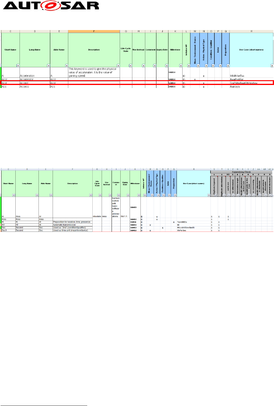
Application Interfaces User Guide
AUTOSAR CP Release 4.4.0
49 of 102 Document ID 442: AUTOSAR_EXP_AIUserGuide
- AUTOSAR confidential -
Figure 40: Sheet 04_Keywords – Example of Keywords
In certain cases it is observed that the Keywords could have multiple meanings
depending on the context of usage. For instance the cases where the Abbr Name of
the Keyword is the same, eg “At” may be used as a “Preposition” or also as
“Automatic Transmission” as seen in Figure below. Such keyword entries are
repeated wherein two separate entries are made with same Abbr Name and
corresponding short names and classification is updated based on usage. The
Description and Classification of the Keyword differentiates its usage and meaning.
Figure 41: Sheet 04_Keywords – Multiple meaning of Keywords
8.1.2 Sheet 05_TopLevel
The TopLevel worksheet contains inter-domain PortPrototypes and PortInterface
connection matrix. PortInterface short name, port short name, port long name, port
description of each of the entries are present in columns with headings “PortInterface
ShortName” “ShortName of Port”, “Long name of Port” and “Description of port”
respectively. After these columns administrative columns (Initiator WP and
Milestone
1
) and consistency check results matrix columns are present (For
consistency check understanding refer sheet 102_User_Documentation in AI Table).
After the administrative columns, communication related information is provided in
'transmissionAcknowledgement Timeout' and 'canInvalidate' columns.
'TransmissionAcknowledgement Timeout' column specifies the number of seconds
before an error is reported or in case of allowed redundancy, the value is sent again.
'canInvalidate' column provides the status whether the component can actively
invalidate data. The information 'TransmissionAcknowledgement Timeout' and
'canInvalidate' are not created in the generated XML file.
1
The quality of data visible within the AI Table is always with a quality indicator based on a
combination taken from step numbers and milestones like SxMSy (where x could be 0, 1, 2, 3 … and y
could be 1, 2, 3, 4). Milestones field needs to be changed manually always after a review or after any
modification to the model elements. Milestone of the PortInterface cannot be higher than the milestone
of the DataType. Similarly, the milestone of the port cannot be higher than the milestone of the
PortInterface.

Application Interfaces User Guide
AUTOSAR CP Release 4.4.0
50 of 102 Document ID 442: AUTOSAR_EXP_AIUserGuide
- AUTOSAR confidential -
After the grey marked ‘consistency check’ columns, yellow marked ‘TopLvl’ column is
present. This yellow marked column has no functional meaning in this sheet. Each
domain is represented in the following columns. The short name of composite
composition type (e.g. Body) and short name of composite composition prototype
(e.g. Body) are mentioned in separate rows for each domain column.
Each domain column contains 5 sub columns
Provider port (with headline ‘P”)
Receiver port (with headline ‘R”)
Existence of port (with headline” core cond opt”)
Initial value (with headline IV) and
Description (with headline components specific description)
For each entry of PortInterface and its corresponding port, a inter domain link (data
exchange connection) is established with an ‘X’ in column ‘P’ or ‘R’ as required.
The column “core cond opt” was defined to represent whether the respective Port
belongs to the Core functionality of the SWC (Core) or it is just present Conditionally
(Cond). This information is however ignored in ARXML generation.
The ‘IV’ column is used to specify the initial value in case the sending component is
not yet initialized. If the sender also specifies an init value the receiver’s value will be
used. This information is not created in the XML file generated by the macro.
The ‘components specific description’ is used to specify any additional remarks for
the ports that will be considered for the description/introduction [Refer [1]] attribute for
the PortPrototype in the XML file.
As per AUTOSAR definition there should be a unique provider, resulting in only one
column “P” marked with “X” per entry. As data can be received by more than one
port, several “R” columns can be marked with “X” per entry.
In some use cases, the P or R columns in the sheet could have the short name of a
port written directly in the cell instead of an 'X'. This could happen if the short names
of the ports are not identical in different domains or due to modeling of the
component due to multiple instantiation.
For every port, its corresponding PortInterface is defined with the data elements (for
SenderReceiver interface) or arguments for operations (for Client-Server interface).
Details of their definition and specification are available in sheets
06_Interface_DataElements and 06_Interface_ClientServer as part of the interface
definition.
The below diagram shows inter domain interface definitions, for simplicity only two
domains “Body “and “Pt” are shown.
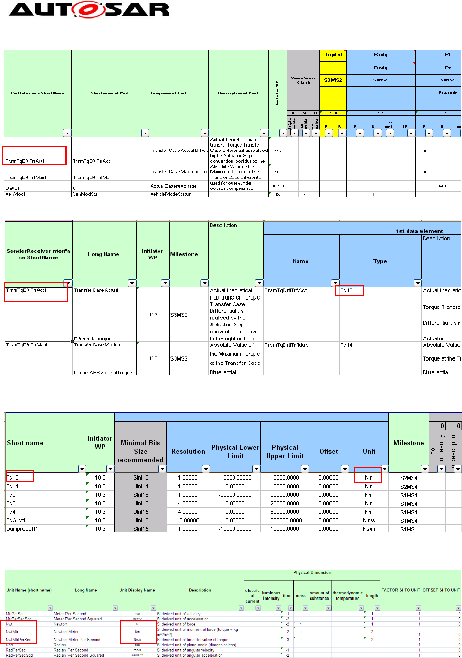
Application Interfaces User Guide
AUTOSAR CP Release 4.4.0
51 of 102 Document ID 442: AUTOSAR_EXP_AIUserGuide
- AUTOSAR confidential -
Figure 42: Sheet 0500_TopLevel – AI Table inter domain interface definitions
Figure 43: Sheet 06_Interface_DataElements – Interface Specification
Figure 44: Sheet 07_DataTypes_ContinuousValue - ContinuousValue DataType definition
Figure 45: Sheet 13_Units - Unit Definition
In above diagrams the Interface assignment information flow in AI Table is shown by
Red rectangle boxes.
In ideal case of standardization, there should not be any open ports, but in current
release of the AI Table some connections are left open. So in “TopLevel” open ports
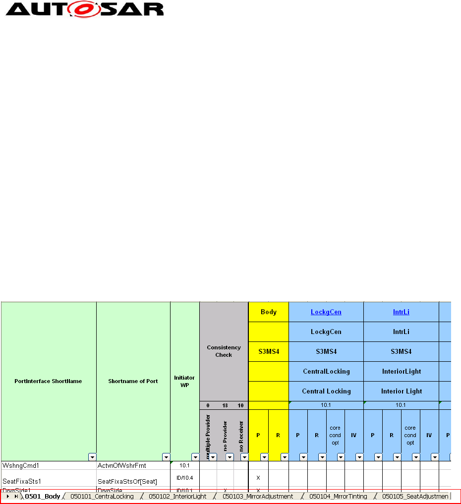
Application Interfaces User Guide
AUTOSAR CP Release 4.4.0
52 of 102 Document ID 442: AUTOSAR_EXP_AIUserGuide
- AUTOSAR confidential -
are allowed although it is not a desired situation. Open ports are those ports which
could be defined as provider “P” only or receiver "R" only and there is no closed
connection established between SWCs across domains.
8.1.3 Sheets 050xxxxx
These worksheet contents are very similar to the contents explained in the
“TopLevel” worksheet. For each of the domains a worksheet exists with the format
“050x_<Domain Name / Composite composition>” (e.g. 0501_Body) which contains
the intra domain SoftwareComposition data exchange matrix. Following this first
worksheet the domain can have several worksheets “050xy_<Domain composition
type name (Decomposed composition)>” (e.g. 050101_CentralLocking) will have the
intra sub compositions / SW components data exchange matrix. For all the domains
worksheet naming and organization is arranged in the manner as explained above
with example.
Below diagram is example for the for “Body” Domain worksheet, in this diagram for
simplicity limited information is shown
Below diagram shows the “Body” domain composition work sheets
Figure 46: Sheet 0501_Body – Body Domain Composition Worksheet
The first worksheet of each domain represents the Toplevel interface matrix for that
domain. Corresponding worksheets of the domain are containing information about
port and PortInterface connection matrix for each of the SW composition /
component.
Each of the worksheets contains the following information
PortInterface short name, port short name, port long name, port description are
present in columns with headings “PortInterface ShortName” “ShortName of Port”,
“Long name of Port” and “Description of port” respectively. After these columns
administrative columns and consistency check results matrix columns are present
(For consistency check understanding refer sheet 102_User_Documentation in AI
Table). In headline row each domain ShortName of component / composition type
and ShortName of component / composition prototype are mentioned in different
columns depending upon the number of component / composition.
For each entry of PortInterface and its corresponding port, a inter domain link (data
exchange connection) is established with an ‘X’ in column ‘P’ or ‘R’ as required. As
per AUTOSAR definition there should be a unique provider, resulting in only one

Application Interfaces User Guide
AUTOSAR CP Release 4.4.0
53 of 102 Document ID 442: AUTOSAR_EXP_AIUserGuide
- AUTOSAR confidential -
column “P” marked with “X” per entry. As data can be received by more than one
port, several “R” columns can be marked with “X” per entry.
The column “core cond opt” was defined to represent whether the respective Port
belongs to the Core functionality of the SWC (Core) or it is just present Conditionally
(Cond). This information is however ignored in ARXML generation.
The ‘IV’ column is used to specify the initial value in case the sending component is
not yet initialized. If the sender also specifies an init value the receiver’s value will be
used. This information is not created in the XML file generated by the macro.
The ‘components specific description’ is used to specify any additional remarks for
the ports which will be considered for the description/introduction [Refer [1]] attribute
for the PortPrototype in the XML model.
In some use cases, the P or R columns in the sheet could have the short name of a
port written directly in the cell instead of an 'X'. This could happen if the short names
of the ports are not identical in different domains or due to modeling of the
component due to multiple instantiation.
For every port, its corresponding PortInterface is defined with the data elements (for
SenderReceiver interface) or arguments for operations (for Client-Server interface).
Details of their definition and specification are available in the sheets
06_Interface_DataElements and 06_Interface_ClientServer as part of the interface
definition.
Example diagrams for data information flow across other worksheets are available in
Chapter 8.1.2.
8.1.4 Sheet 06_Interfaces_DataElements (SenderReceiverInterface)
This work book sheet contains all the SenderReceiverinterfaces referenced in any of
worksheets 05xx domain / composition. Each of the Sender-Receiver interfaces can
be used in all the 05xx domain / composition worksheets more than once. One
interface can also be used for different ports.
In this sheet, PortInterface ShortName and PortInterface longname of each of the
interfaces are present in columns with headings “SenderReceiverInterface
ShortName” and “Long Name” respectively. After these columns administrative data
columns and the “Description” column are present. The “Description” column
contains the description of the PortInterface. For each of the interfaces at least one
data element (Variable Data Prototype) has to be specified. It is also allowed to
specify more than one data elements. At the moment in current AI Table a maximum
of 6 data elements is used, but if required more data elements can be added. Every
data element has data element name, DataType, description of the data element,
queuing information and signal quality information in separate columns with headings
“Name”, “Type”, “Description”, “Queuing” and “Signal Qualifier” respectively. The
‘Queuing’ column indicates the way the DataElement must be processed at the
receiver’s side. TRUE: elements added to a queue in FIFO data structure; FALSE:
last is best semantics applies. This information is not exported yet in the XML model
and currently not used. The column ‘Signal Qualifier’ provides additional information
on the quality of the signal and its representation. This information is not exported yet
in the XML model, and its usage is still under discussion. Data type for each data

Application Interfaces User Guide
AUTOSAR CP Release 4.4.0
54 of 102 Document ID 442: AUTOSAR_EXP_AIUserGuide
- AUTOSAR confidential -
element can be of continuous value or enumeration or array or record DataTypes,
these are defined in the worksheets
“07_DataTypes_ContinuousValue”,“08_DataTypes_Enumeration”,”09_DataTypes_Ar
ray”, “11_DataTypes_Record” respectively.
In addition, this worksheet has columns marked with grey color headings which are
used for consistency check results.
The diagram below shows the data information flow between the interfaces
worksheet 06_Interfaces_DataElements and the DataType worksheets (e.g.
07_DataTypes_ContinuousValue) marked with red rectangular boxes.
Figure 47: Sheet 06_Interface_DataElements – AI Table Sender-Receiver-interfaces
specification
Figure 48: Sheet 07_DataTypes_ContinuousValue – AI Table ContinuousValue DataType
definition
Figure 49: Sheet 13_Units - Unit definition
Since PortInterfaces are designed to support reusability, it is recommended to reuse
already defined SenderReceiver PortInterfaces for PortPrototypes with same kind of
information to be transported.
Figure 50 demonstrates the reusability of PortInterfaces. In the example shown
below the PortInterface BodyRollAg1 is used by the PortPrototypes
BodyRollAgAbsltEstimd, BodyRollAgRelEstimd and BodyRollAgRelMeasd. These
PortPrototypes are received by the SW-Component Esc. The PortPrototypes
BodyRollAgAbsltEstimd and BodyRollAgRelEstimd are provided by the SW-
Component Susp and the PortPrototype BodyRollAgRelEstimd is provided by the
SW-Component ChassisSnsr.
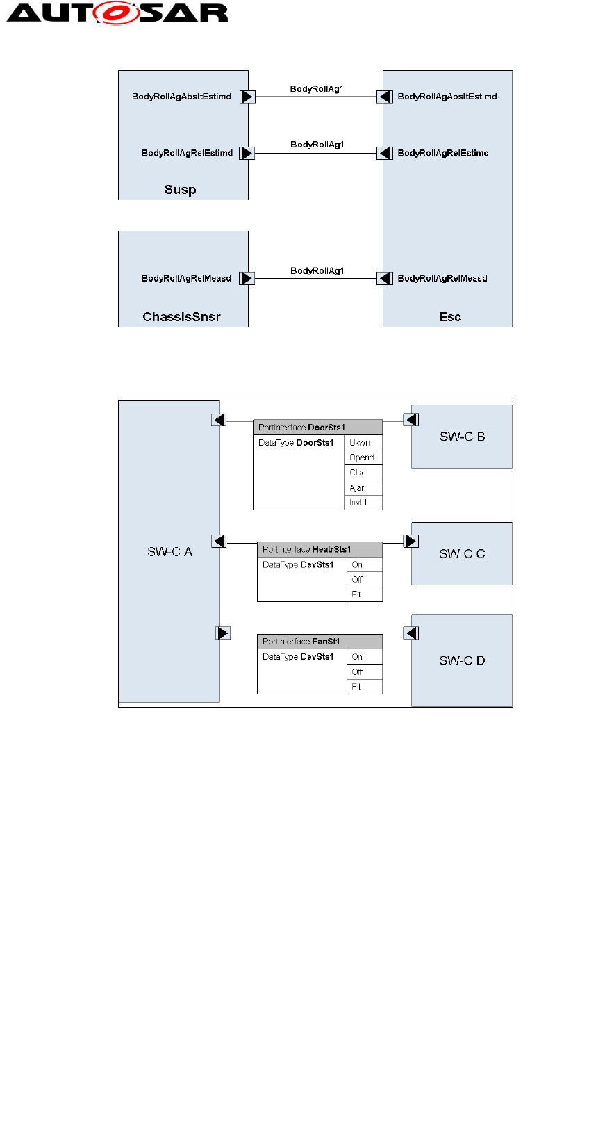
Application Interfaces User Guide
AUTOSAR CP Release 4.4.0
55 of 102 Document ID 442: AUTOSAR_EXP_AIUserGuide
- AUTOSAR confidential -
Figure 50: PortInterface reusability example
Similar to PortInterfaces, it is recommended to reuse already defined DataType
Figure 51: Reusability of DataTypes
Note that some rules in the SW-C and System Modeling Guide [9], such as NR044
and NR048, are defined in order to enable the reusability of the DataType.
8.1.5 Sheet 06_Interface_ClientServer
This worksheet contains all the ClientServer interfaces referenced in any of
worksheets 05xx composite compositions / decomposed composition. Each of the
defined ClientServer interfaces can be used in all the 05xx domain / composition
worksheets more than once. One interface can also be used for different ports.
In this sheet, PortInterface short name and PortInterface long name of each of the
interfaces are present in columns with headings “ClientServerInterface ShortName”
and “Long Name” respectively. After these columns administrative data columns and
the “Description” column are present. The “Description” column contains the
description of the PortInterface. After these columns the operation names of the
ClientServer interface are defined. This contains information, operation short name,

Application Interfaces User Guide
AUTOSAR CP Release 4.4.0
56 of 102 Document ID 442: AUTOSAR_EXP_AIUserGuide
- AUTOSAR confidential -
operation long name and operation description as defined in separate columns with
headings “ShortName”,” Long Name” and “Description” respectively. One interface
consists of multiple operations that will be specified in different rows. For each
operation it is allowed to specify any number of arguments. For simplifying AI Table
in current state any defined interface can specify maximum three arguments. Every
argument has an argument short name, argument long name, argument description,
argument DataType, type of the argument (input, output and input as well as output)
in separate columns with headings “ArgumentName ShortName”, “Long Name”,
“Description”, “DataType” and “IN/OUT/INOUT” respectively. The Data type for each
element can be of continuous value or enumeration or array or record types, these
are defined in the worksheets “07_DataTypes_ContinuousValue”,
“08_DataTypes_Enumeration”, ”09_DataTypes_Array”, “11_DataTypes_Record”
respectively.
In addition, this work sheet contains columns marked with grey color headings, which
are used for consistency check results
The diagram below shows the data information flow between the interfaces
worksheet 06_Interface_ClientServer and the DataType worksheets marked with red
rectangular boxes.
Figure 52 : Sheet 06_Interface_ClientServer – AI Table ClientServer interfaces specification
Figure 53 : Sheet 07_DataTypes_ContinuousValue – AI Table ContinuousValue DataType
definition
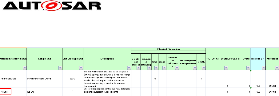
Application Interfaces User Guide
AUTOSAR CP Release 4.4.0
57 of 102 Document ID 442: AUTOSAR_EXP_AIUserGuide
- AUTOSAR confidential -
The unit for the DataType Nr4 is ‘NoUnit’ and is represented as ‘-‘. The DataType Nr4
is only a number and does not represent any physical quantity hence there is no unit.
Figure 54: Sheet 13_Units - AI Table Units Definition
Since PortInterfaces are designed to support reusability, it is recommended to reuse
already defined ClientServer PortInterfaces for PortPrototypes with the same kind of
information to be transported.
8.1.6 Sheet 07_DataTypes_ContinuousValue
This worksheet will have DataTypes with different resolution defined to be utilized in
any of the PortInterfaces defined in any of worksheets 06xx or in complex
DataTypes.
In this sheet, Data type short name, Data type long name and DataType description
of each of the DataType definition entry are present in columns with headings “Short
Name”, “Long Name” and “Description” respectively. Following the administrative
data columns resolution and range details of the DataTypes are defined. These
columns will have information on minimum number of bits requirement, resolution,
physical lower and higher limits, offset value and physical unit are defined, with
headings “Minimal Bits Size recommended”,” Resolution” , “Physical Lower Limit”,
“Physical Upper Limit”, “Offset” and “Unit” respectively. The Minimal Bits Size
recommended is calculated from the macro with inputs provided in the resolution,
physical lower limit, higher limit and offset value columns. Units column utilizes the
physical units defined in the work sheet “13_Units” referenced by “Unit Display
Name”.
Also, there is a column “Is float” used to mark if a DataType is recommended for
usage as float datatype. In such a case this DataType is marked “x” in this column.
In addition this worksheet contains columns marked with grey color headings and
these are used for consistency check results.
Figure 52 and Figure 53 present above show the data information flow between
interfaces to DataTypes_ContinuousValue.
8.1.7 Sheet 08_DataTypes_Enumeration
This worksheet contains enumeration DataTypes with value to be utilized in any of
the PortInterfaces defined in any of worksheets 06xx and complex DataTypes.
In this sheet, Enumeration (enum) Data type short name, Enum Data type long name
and enum DataType description of each of the enum DataType definition entry are
present in columns with headings “Data Type Name”, “Long Name” and “Description”
respectively. Following the administrative data columns information on minimum bits
required for enum DataType, value and name of enum elements and comments for
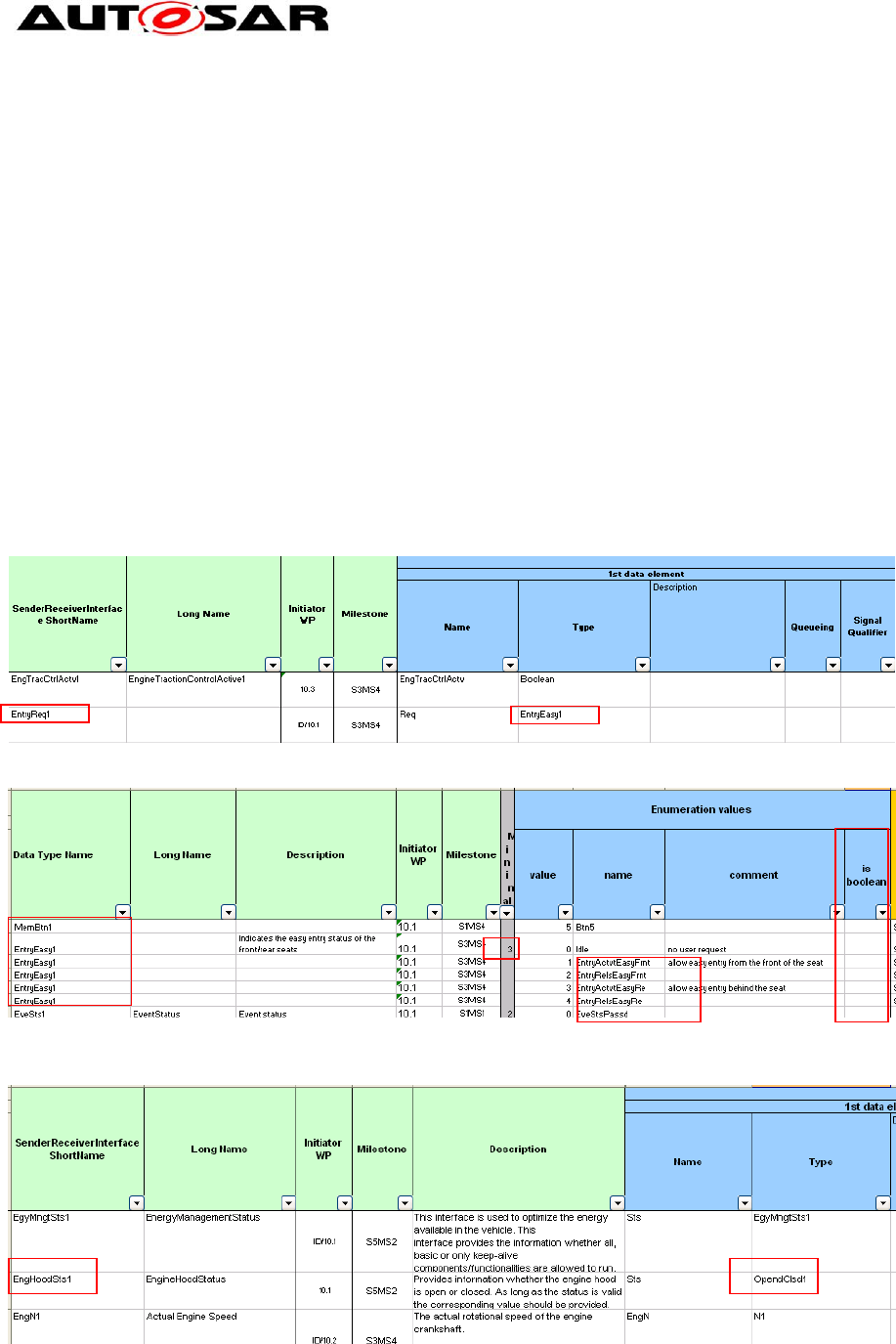
Application Interfaces User Guide
AUTOSAR CP Release 4.4.0
58 of 102 Document ID 442: AUTOSAR_EXP_AIUserGuide
- AUTOSAR confidential -
each enum are defined in separate columns with headings “Minimal Number of Bits”,
” value”, “name” and “comment” respectively. The Minimal Bits Size required for each
enum DataType are calculated from the macro and this value is placed in the first
enum element row. Every enum data element value is defined in a separate row,
hence more than one row belong to each enum DataType definition.
If the first line of an Enumeration data type definition contains an “X” in column “is
boolean”, the generator will assign category “BOOLEAN” to the data type. Otherwise,
category “VALUE” will be used. Any data type marked “is boolean” must consist of
exactly two lines of definition, containing literal definitions for values 0 and 1.
In addition this worksheet contains columns marked with grey color headings and
these are used for consistency check results.
The diagrams below show the data information flow between interfaces worksheet to
the enum DataType sheets marked with red rectangular boxes.
Figure 55: Sheet 06_Interface_DataElements – AI Table SenderReceiver Interfaces specification
Figure 56: Sheet 08_DataTypes_Enumeration – AI Table non-Boolean enumeration DataType
definitions
Figure 57: 06_Interface_DataElements – AI Table SenderReceiver Interface with Boolean type
Enumeration DataType
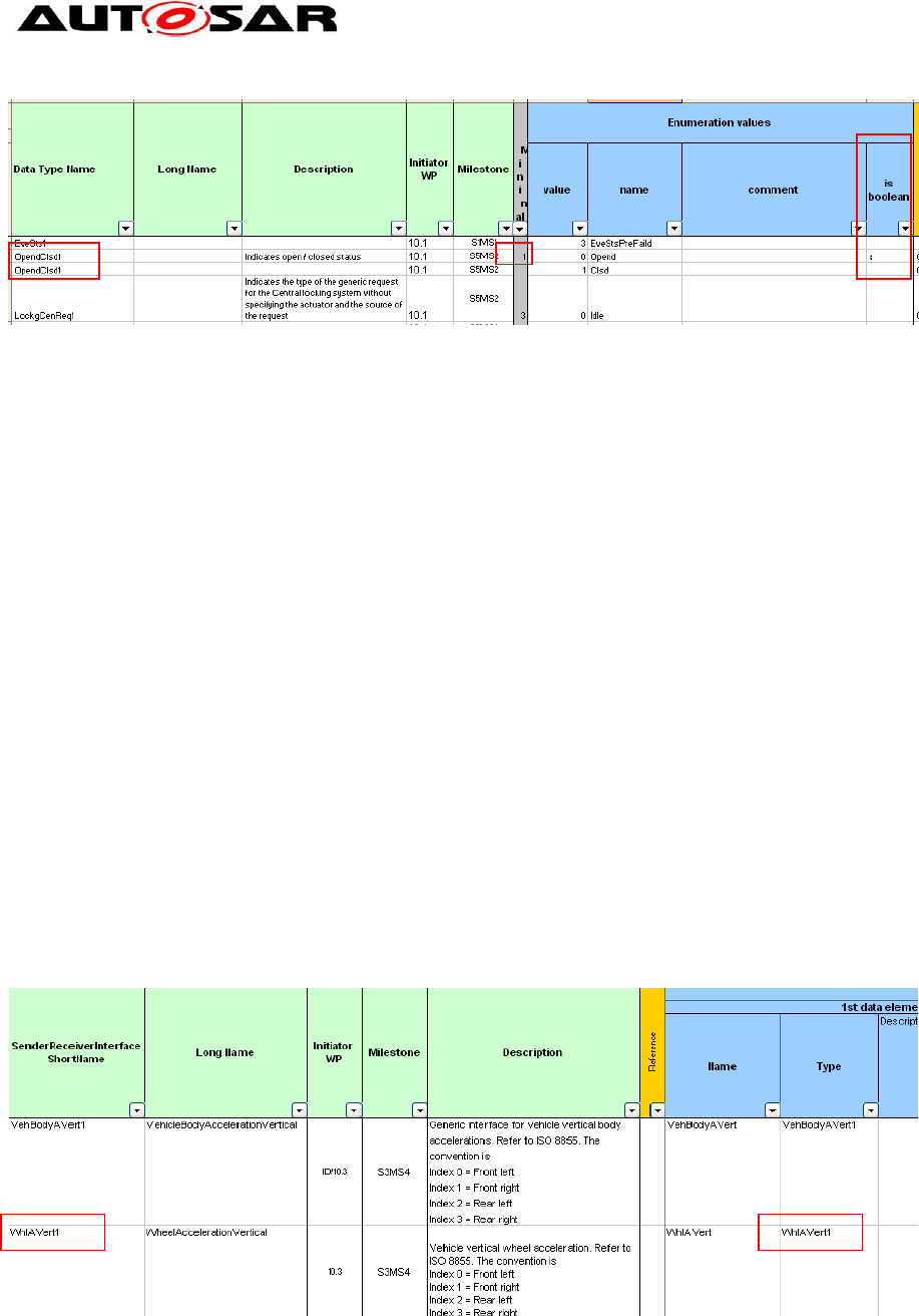
Application Interfaces User Guide
AUTOSAR CP Release 4.4.0
59 of 102 Document ID 442: AUTOSAR_EXP_AIUserGuide
- AUTOSAR confidential -
Figure 58: Sheet 08_DataTypes_Enumeration – AI Table Boolean enumeration DataType
definitions
8.1.8 Sheet 09_DataTypes_Array
This worksheet contains array DataTypes defined to be utilized in any of the
PortInterfaces defined in any of work book sheets 06xx and complex DataTypes.
In this sheet, Array DataType short name, Array DataType long name and Array
DataType description of each of the Array DataType definition entry are present in
columns with headings “Data Type Name”, “Long Name” and “Description”
respectively. Following the administrative data columns information on array
elements DataType short name and size of the array are defined in separate
columns with headings “Type Name” and ” Number of Elements” respectively. Type
name of an array can be found in one of the work sheets
07_DataTypes_ContinuousValue, 08_DataTypes_Enumeration,
09_DataTypes_Array and 11_DataTypes_Record.
In addition this worksheet contains columns marked with grey color headings and
these are used for consistency check results.
The diagrams below show the data information flow between interfaces worksheet
06_Interfaces_DataElements to the array DataType sheets marked with red
rectangular boxes.
Figure 59: Sheet 06_Interface_DataElements – AI Table Sender-Receiver-interfaces
specification
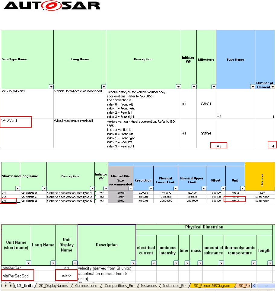
Application Interfaces User Guide
AUTOSAR CP Release 4.4.0
60 of 102 Document ID 442: AUTOSAR_EXP_AIUserGuide
- AUTOSAR confidential -
Figure 60: Sheet 09_DataTypes_Array – AI Table array DataType definitions
Figure 61: Sheet 07_DataTypes_ContinuousValue – AI Table ContinuousValue DataType
definitions
Figure 62: Sheet 13_Units - Unit Definition
8.1.9 Sheet 11_DataTypes_Record
This worksheet contains record DataTypes in which each of the record elements /
entries may have different (sub) DataTypes. These are similar DataType definitions
like the “C” language structure types. These record DataTypes are defined to be
utilized in any of the PortInterfaces defined in any of work book sheets 06xx and
complex DataTypes.
In this sheet, record DataType short name, record DataType long name and record
DataType description of each of the record DataType definition entry are present in
columns with headings “Record Type Name”, “Long Name” and “Description”
respectively. Following the administrative data columns information on number of
record data elements in a defined DataType, name of the record element, (sub)
DataType of the record element and comments for each element are defined with
headings “Number of element”, “Name”, “Type Name” and ” Comment” respectively.
Record DataTypes are utilized to store the multiple values of different DataTypes.
The record DataTypes can have one or more record elements, each record element
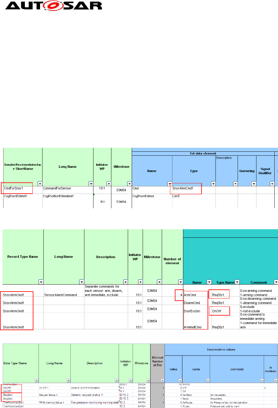
Application Interfaces User Guide
AUTOSAR CP Release 4.4.0
61 of 102 Document ID 442: AUTOSAR_EXP_AIUserGuide
- AUTOSAR confidential -
will have a different ShortName and may have different (sub) DataTypes. For every
record DataType first row will have the number of the elements defined in the column
with heading “Number of element”. Each of the record elements is defined in
separate rows. Record elements (sub) DataType definition short name can be found
in one of the following work sheets 07_DataTypes_ContinuousValue,
08_DataTypes_Enumeration, 09_DataTypes_Array and 11_DataTypes_Record.
In addition this worksheet contains columns marked with grey color headings and
these are used for consistency check results.
The diagram below shows the data information flow between interfaces worksheet
06_Interfaces_DataElements to the record DataType worksheet marked with red
rectangular boxes.
Figure 63: Sheet 06_Interface_DataElements – AI Table Sender-Receiver-interfaces
specification
Figure 64: Sheet 11_DataTypes_Record – AI Table Record DataType definition
Figure 65: Sheet 08_DataTypes_Enumeration – AI Table enumeration DataType definition

Application Interfaces User Guide
AUTOSAR CP Release 4.4.0
62 of 102 Document ID 442: AUTOSAR_EXP_AIUserGuide
- AUTOSAR confidential -
8.1.10 Sheet 13_Units
In this sheet, the units used for specification of the continuous DataTypes are
defined. Units are referenced by the unit display names.
In this sheet, physical unit short name, physical unit long name, physical unit
description and physical unit display name of each of the physical unit entry are
present in columns with headings “Unit Name (short name)”, “Long Name”, “Unit
Display Name” and “Description” respectively. After these columns, Physical
Dimension list columns are present. The seven base quantities of International
System of Units are represented between columns E and K. The factor and offset
used for the units are mentioned in columns L & M. Following this, administrative
data columns and columns marked with grey color headings used for consistency
check results are present.
Figure 66: Sheet 06_Interface_DataElements – AI Table SenderReceiverInterfaces specification
Figure 67: Sheet 07_DataTypes_ContinuousValue – ContinuousValue DataType with a unit
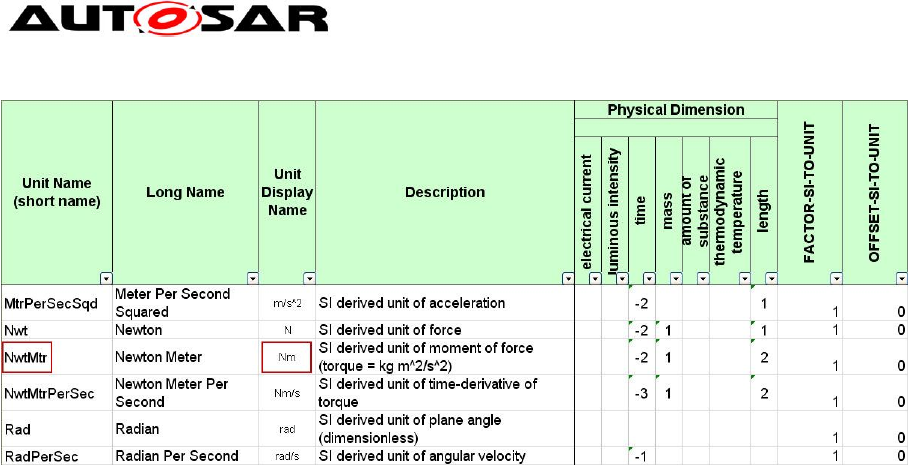
Application Interfaces User Guide
AUTOSAR CP Release 4.4.0
63 of 102 Document ID 442: AUTOSAR_EXP_AIUserGuide
- AUTOSAR confidential -
Figure 68: Sheet 13_Units – Unit definition
8.1.11 Sheet 15_Redirected_Ports
This sheet is used for providing PortPrototypeBlueprint definitions for ports that have
been renamed/redirected in the connection matrix specified in one of the 05 sheets.
As described above, it is possible for any given component prototype to locally
rename or redirect the port name given at the beginning of a line by specifying a new
port short name in the connection matrix instead of using an “X” in the “P” or “R”
fields. In such cases, often the long name and description specified within the first
columns in the row will not be correct for the PortPrototypeBlueprint generated for the
renamed port.
In order to come to a full definition for these ports, they can either be defined in more
detail within the context of another 05 composition sheet; or they can be defined in a
generic (i.e. composition type independent way) by adding an entry in worksheet
15_Redirected_Ports.
When the macro "Update and Check" detects that one such redirected/renamed port
does not have a proper definition, it will create a new entry in Sheet 15. However, it
will leave the entries for “long name” and “description” blank; these need to be filled
in by a human user. Until the entries are completed, the generator will signal error
messages in consecutive runs.
If a port is defined more than once, i.e. either one of the 05 sheets contains a usable
port definition or the same port is defined more than once in sheet 15, the generator
will flag the error message “redundant port def. for redirected port” or "unused def. of
redirected port". The user should then remove the duplicate entry from Sheet 15 in
order to remove the error.
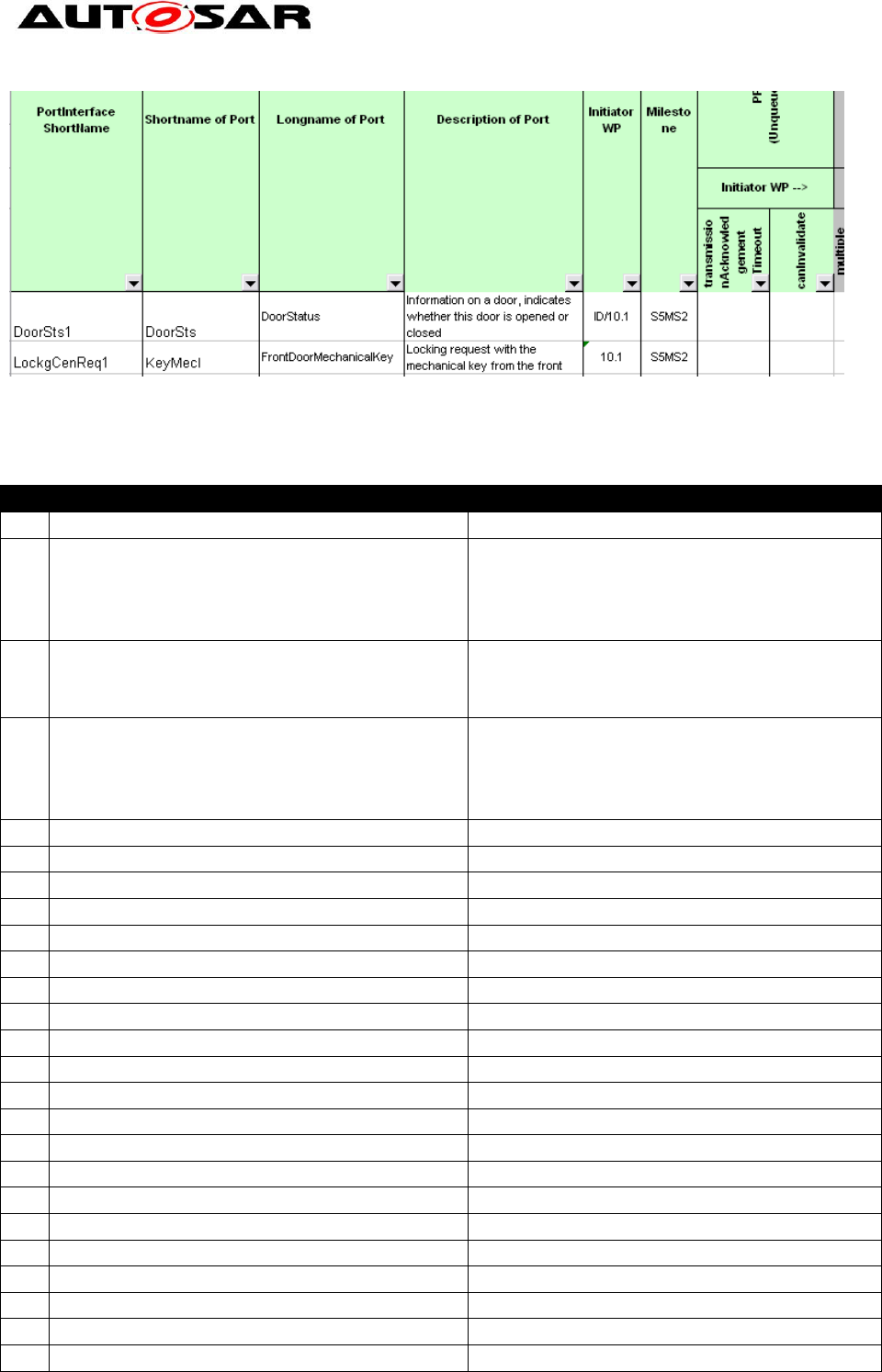
Application Interfaces User Guide
AUTOSAR CP Release 4.4.0
64 of 102 Document ID 442: AUTOSAR_EXP_AIUserGuide
- AUTOSAR confidential -
Figure 69: Sheet 15_Redirected_Ports
8.2 Complete List of all Sheets of the AI Table
Title
Content
1.
01_History
History of changes to the table
2.
02_General Purposes
Contains a list of column titles in relation
to the sheets; explanations are given in
order to add or change data sets within
the table
3.
04_Keywords
List of agreed keywords and their
abbreviations along with their usage
context description
4.
0500_TopLevel
Toplevel composition contains the
information related to inter-domain port
prototypes of major domain
compositions (e.g. Body, Powertrain)
5.
0501_Body
(1) Body domain composition
6.
050101_CentralLocking
Central locking component
7.
050102_InteriorLight
Interior light component
8.
050103_MirrorAdjustment
Mirror adjustment component
9.
050104_MirrorTinting
Mirror tinting component
10.
050105_SeatAdjustment
Seat adjustment component
11.
05010501_Seat
Seat component
12.
0501050101_SeatAxis
SeatAxis component
13.
050106_ExteriorLight
Exterior light component
14.
050107_WindowControl
Window control component
15.
050108_WiperWasher
Wiper washer component
16.
05010801_NozzleHeater
Nozzle heater component
17.
05010802_Wiper
Wiper component
18.
05010803_Washer
Washer component
19.
05010804_WasherFluidTank
Washer fluid tank component
20.
05010805_RainSensing
Rain sensing component
21.
050109_AntiTheftSystem
Anti theft system component
22.
050110_HornControl
Horn control component
23.
050111_ConvertibleControl
Convertible control component
24.
050112_DefrostControl
Defrost control component
25.
050113_ParkDistanceControl
Park distance control component

Application Interfaces User Guide
AUTOSAR CP Release 4.4.0
65 of 102 Document ID 442: AUTOSAR_EXP_AIUserGuide
- AUTOSAR confidential -
Title
Content
26.
050114_Immobilizer
Immobilizer component
27.
050115_BodySensors
Body sensors component
28.
050117_RemoteKeylessEntry
Keyless access component
29.
050118_KeyPad
Key pad component
30.
050119_PassiveEntry
Passive entry component
31.
050120_TerminalClampControl
Terminal clamp control component
32.
050121_SeatClimatization
Seat climatization component
33.
0502_Powertrain
(2) Powertrain composition
34.
050201_CombustionEngine
Combustion engine component
35.
050299_VehicleMotionforPt
Vehicle motion for Powertrain
component
36.
0503_Chassis
(3) Chassis composition
37.
050301_CrsCtrlAndAcc
Cruise control and adaptive cruise
control component
38.
0504_OPSafety
(4) Occupant safety composition
39.
0504001_OcctPedSftySnrsPool
Occupant and pedestrian safety sensor
pool component
40.
0504002_I_OcctPedSftyActrPool
Occupant and pedestrian safety
actuator pool component I
41.
0504002_II_OcctPedSftyActrPool
Occupant and pedestrian safety
actuator pool component II
42.
0504002_III_OcctPedSftyActrPool
Occupant and pedestrian safety
actuator pool component III
43.
0504102_SeatBltRmn
Seat belt reminder component
44.
0505_MM_T_HMI
(5) Multimedia, telematics, human
machine interface component
45.
06_Interface_DataElements
List of sender-receiver interface
definitions
46.
06_Interface_ClientServer
List of ClientReceiverInterface
definitions
47.
07_DataTypes_ContinuousValue
List of continuous value DataTypes
48.
08_DataTypes_Enumeration
List of enumeration DataTypes
49.
09_DataTypes_Array
List of array DataTypes
50.
11_DataTypes_Record
List of record DataTypes
51.
13_Units
List of units
52.
15_Redirected_Ports
List of definition of redirected ports
53.
101_Description
Explanation of results of consistency
checks presented in summary dialogue
box
54.
102_User_Documentation
Contains a list of available Visual Basic
macros and their functionality.
The sheets below are administrative sheets and are filled automatically by the macros.
55.
Compositions
Overview of compositions / components
available in the AI Table
56.
Compositions_Err
Failed consistency check results of
compositions and their decomposition.

Application Interfaces User Guide
AUTOSAR CP Release 4.4.0
66 of 102 Document ID 442: AUTOSAR_EXP_AIUserGuide
- AUTOSAR confidential -
Title
Content
57.
Instances
Overview of composition prototype
(instances) available in the AI Table
58.
Instances_Err
Failed consistency check results of
composition prototypes (instances)
59.
90_ReportMSDiagram
Diagram representing history of the
distribution of table entries with model
elements in relation to milestones. This
data is generated by macros.
60.
90_ReportMSTable
Pivot table history of the distribution of
table entries in relation to milestones
and steps. This data is generated by
macros.
61.
90_ReportMSTableNoSteps
Pivot table history of the distribution of
table entries in relation to milestones.
The step information will be excluded.
This data is generated by macros.
62.
91_ReportErrDiagram
Diagram representing an overview on
detected errors. This data is generated
by macros.
63.
91_ReportErrTable
Pivot table of detected errors. This data
is generated by macros.
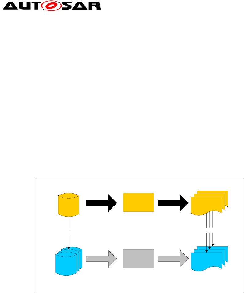
Application Interfaces User Guide
AUTOSAR CP Release 4.4.0
67 of 102 Document ID 442: AUTOSAR_EXP_AIUserGuide
- AUTOSAR confidential -
9 Relationship between AI Table data and XML Output
The data from the AI Table, which reflects the structure defined in the AUTOSAR
Meta-Model, is used to generate XML descriptions of the AUTOSAR Application
Interfaces. The XML descriptions shall adhere to the AUTOSAR Schema [3] which is
generated from the AUTOSAR Meta-Model [7].
9.1 Overview
9.1.1 Dependencies of XML Generation
Figure 70 illustrates the dependencies in the XML generation process. Currently, the
AI Table reflects the structure for multiple releases in one database, i.e. for R3.0 and
R4.0. This common database is then used by the AI XML Generation, to generate
XML descriptions for each supported release. This approach implies that not all data
from the AI Table will be reflected in all generated XML files as only the data for R4.0
is taken into account.
XML
Generation
Schema
Generation
Application
Interfaces
AI XML Files
(one for each release)
AUTOSAR Schemas
(one for each release)
AUTOSAR Meta Models
(one for each release)
adhere to
match
Figure 70: Dependencies in the XML generation process for application interfaces
9.1.2 Contents of Generated XML
The XML files contain descriptions of the following elements:
Common elements
o Package Structure and Categories
o References
o Instance References
o Type References
o Descriptions
Composition Types with
o Ports
o Component Prototypes and
o Connectors
PortPrototypeBlueprints
o BlueprintMappings for PortPrototypeBlueprints

Application Interfaces User Guide
AUTOSAR CP Release 4.4.0
68 of 102 Document ID 442: AUTOSAR_EXP_AIUserGuide
- AUTOSAR confidential -
Interfaces
o Sender-Receiver-Interfaces
o Client-Server-Interfaces
o BlueprintMappings for PortInterfaces
Application Data Types, being
o Primitive Types with constraints
o Array Types
o Record Types
o BlueprintMappings for ApplicationDataTypes
o Data Constraints
o Computation Methods
o BlueprintMappings for CompuMethods
Units
o Physical Dimension
Keywords
Data Constraints
o BlueprintMappings for DataConstrs
9.1.2.1 File Distribution
From R4.1.1 onwards, the XML generated from the AI Table is divided into the
following .arxml files as shown below. This is due to the AUTOSAR Methodology
implications that require strict separation of categories STANDARD and
BLUEPRINT.
Delivery Structure of Application Interfaces Domain:
the Standard section of the official Release’s SVN repository provides:
AUTOSAR_MOD_AISpecification.zip archive , which contains:
o AUTOSAR_MOD_AISpecification_PhysicalDimension_Standard.arxml
o AUTOSAR_MOD_AISpecification_Unit_Standard.arxml
o AUTOSAR_MOD_AISpecification_DataConstr_Blueprint.arxml
o AUTOSAR_MOD_AISpecification_CompuMethod_Blueprint.arxml
o AUTOSAR_MOD_AISpecification_ApplicationDataType_Blueprint.arxml
o AUTOSAR_MOD_AISpecification_PortInterface_Blueprint.arxml
o AUTOSAR_MOD_AISpecification_PortPrototypeBlueprint_Blueprint.arxml
o AUTOSAR_MOD_AISpecification_KeywordSet_Blueprint.arxml
o
o AUTOSAR_MOD_AISpecification_Collection_Body_Blueprint.arxml
o AUTOSAR_MOD_AISpecification_Collection_Pt_Blueprint.arxml
o AUTOSAR_MOD_AISpecification_Collection_Chassis_Blueprint.arxml
o AUTOSAR_MOD_AISpecification_Collection_OccptPedSfty_Blueprint.arxml
o AUTOSAR_MOD_AISpecification_Collection_MmedTelmHmi_Blueprint.arxml
o
o AUTOSAR_MOD_AISpecification_PortPrototypeBlueprint_LifeCycle_Standard.arxml
o AUTOSAR_MOD_AISpecification_PortInterface_LifeCycle_Standard.arxml
o AUTOSAR_MOD_AISpecification_ApplicationDataType_LifeCycle_Standard.arxml
o AUTOSAR_MOD_AISpecification_CompuMethod_LifeCycle_Standard.arxml
o AUTOSAR_MOD_AISpecification_DataConstr_LifeCycle_Standard.arxml
o AUTOSAR_MOD_AISpecification_Unit_LifeCycle_Standard.arxml
o AUTOSAR_MOD_AISpecification_PhysicalDimension_LifeCycle_Standard.arxml
o AUTOSAR_MOD_AISpecification_Keyword_LifeCycle_Standard.arxml
o AUTOSAR_MOD_AISpecification_Collection_AIMC_Keyword_Blueprint.arxml

Application Interfaces User Guide
AUTOSAR CP Release 4.4.0
69 of 102 Document ID 442: AUTOSAR_EXP_AIUserGuide
- AUTOSAR confidential -
o AUTOSAR_CC_AISpecification.xml
Please note that the file “AUTOSAR_MOD_GeneralDefinition_Lifecycle.arxml” will be
released under the AUTOSAR General Definitions and is not part of Application
Interfaces deliverables. For more details please refer the readme.txt file under the
Application Interfaces deliverables. The AUTOSAR_CC_AISpecification.xml catalog
file is used to help resolve references incase needed by specific tools.
The Auxiliary section of the official Release’s SVN repository provides:
AUTOSAR_MOD_AISpecification_Examples.zip archive, which contains
o AUTOSAR_MOD_AISpecification_Example.arxml
o AUTOSAR_CC_AISpecificationExample.xml (*)
AUTOSAR_TR_AIMeasurementCalibrationDiagnostics (pdf)
AUTOSAR_TR_SWCModelingGuide (pdf)
AUTOSAR_RS_SWCModeling (pdf)
AUTOSAR_EXP_AIUserGuide (pdf)
AUTOSAR_TR_AIDesignPatternCatalogue (pdf)
(*)The AUTOSAR_CC_AISpecificationExample.xml catalog file is used to help
resolve references incase needed by specific tools.
9.1.3 Schema Structure
In order to understand the XML generation, it is necessary to understand the relation
between meta-model and schema. Generally, the schema contains an xsd:group for
each class of the meta-model. The group contains all attributes of the class, including
aggregations and references as sequence of xsd:element. Concrete classes (in
contrast to abstract classes) also have a corresponding xsd:complexType. These are
sequences of all inherited groups from parent elements.
The general concept behind the structure of the schema will be described according
to the example depicted in the following diagram, which shows the structure of the
Unit element in the meta-model, including its inheritance hierarchy.
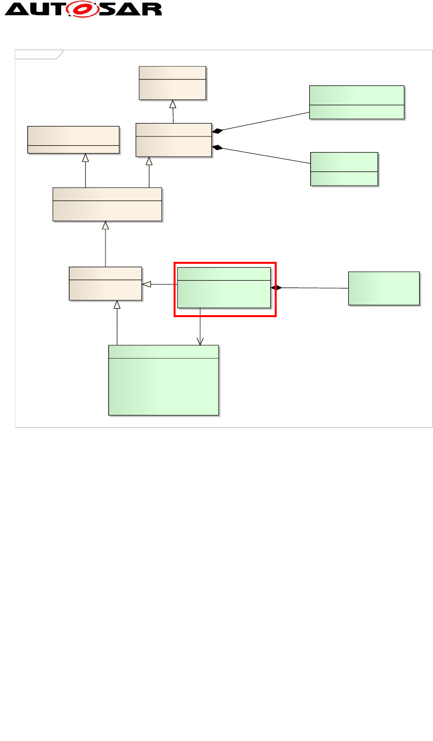
Application Interfaces User Guide
AUTOSAR CP Release 4.4.0
70 of 102 Document ID 442: AUTOSAR_EXP_AIUserGuide
- AUTOSAR confidential -
class UnitType
PhysicalDimension
+ currentExp: Numerical [0..1]
+ lengthExp: Numerical [0..1]
+ luminousIntensityExp: Numerical [0..1]
+ massExp: Numerical [0..1]
+ molarAmountExp: Numerical [0..1]
+ temperatureExp: Numerical [0..1]
+ timeExp: Numerical [0..1]
Unit
+ factorSiToUnit: Float [0..1]
+ offsetSiToUnit: Float [0..1]
MixedContentForUnitNames
«atpMixedString»
SingleLanguageData::
SingleLanguageUnitNames
ARPackage::ARElement
ARPackage::PackageableElement
ElementCollection::
CollectableElement
Identifiable::Identifiable
+ category: Identifier [0..1]
+ uuid: String [0..1]
Identifiable::Referrable
+ shortName: Identifier
MultilanguageData::
MultilanguageLongName
MultilanguageData::
MultiLanguageOverviewParagraph
+desc
0..1
+longName
0..1
+physicalDimension 0..1
+displayName
0..1
Figure 71: Cut-out from the meta-model defining the structure of the element Unit
This structure can be found in the following elements in the AUTOSAR schema:
<xsd:group name="UNIT">
<xsd:annotation>...</xsd:annotation>
<xsd:sequence>
<xsd:element
name="DISPLAY-NAME"
type="AR:SINGLE-LANGUAGE-UNIT-NAMES"
minOccurs="0"/>
<xsd:element
name="FACTOR-SI-TO-UNIT"
type="xsd:double" minOccurs="0"/>
<xsd:element
name="OFFSET-SI-TO-UNIT"
type="xsd:double" minOccurs="0"/>
<xsd:element
name="PHYSICAL-DIMENSION-REF"
minOccurs="0">
...
</xsd:element>
</xsd:sequence>
</xsd:group>
<!-- complex type for class Units::Unit -->
<xsd:complexType name="UNIT" abstract="false" mixed="false">
<xsd:sequence>
<xsd:group ref="AR:AR-OBJECT"/>

Application Interfaces User Guide
AUTOSAR CP Release 4.4.0
71 of 102 Document ID 442: AUTOSAR_EXP_AIUserGuide
- AUTOSAR confidential -
<xsd:group ref="AR:REFERRABLE"/>
<xsd:group ref="AR:IDENTIFIABLE"/>
<xsd:group ref="AR:COLLECTABLE-ELEMENT"/>
<xsd:group ref="AR:PACKAGEABLE-ELEMENT"/>
<xsd:group ref="AR:AR-ELEMENT"/>
<xsd:group ref="AR:UNIT"/>
</xsd:sequence>
...
</xsd:complexType>
This structuring into groups (for all classes including abstract ones) and complex
types (for concrete classes only) leads to the particularity, that only concrete classes
can be used on XML instance level, and that the inheritance hierarchy is not visible
on instance level. The following example shows a unit from table “13_Units” on
instance level, this table only contains attributes from Identifiable:
<UNIT>
<SHORT-NAME>DegCgrd</SHORT-NAME>
<LONG-NAME><L-4 L="EN">Degree Centigrade</L-4></LONG-NAME>
<DESC><L-2 L="EN">temperature, no SI unit, (degC = Kelvin - 273.15)</L-
2></DESC>
<DISPLAY-NAME>degC</DISPLAY-NAME>
<FACTOR-SI-TO-UNIT>1</FACTOR-SI-TO-UNIT>
<OFFSET-SI-TO-UNIT>-273.15</OFFSET-SI-TO-UNIT>
<PHYSICAL-DIMENSION-REF DEST="PHYSICAL-DIMENSION"
BASE="PhysicalDimensions">T1</PHYSICAL-DIMENSION-REF>
</UNIT>
Details on the relation of meta-model and AUTOSAR Schema can be found in the
Model Persistence Rules for XML [5]. See also Figure 70.
The following sections describe in detail, how the AI Table is related to the elements
on XML instance level. Details about the relation of AI Table and meta-model are
described in Chapter 4.
All following descriptions refer to the AUTOSAR R4.0 schema.
9.2 Common Elements
9.2.1 Package Structure
The XML content is structured into hierarchical packages. The top-level package is
named AUTOSAR and contains one package named AISpecification. Beneath this
package the output is structured into 20 different packages as listed below.
The different packages under AISpecification are
PhysicalDimensions: Package of the category STANDARD, contains all the
physical dimensions
Units: Package of the category STANDARD, contains all the standardized
units
Standard_LifeCycle: Package of the category STANDARD, contains the Life
Cycle information of the model elements
ApplicationDataTypes_Blueprint: Package of the category BLUEPRINT,
contains all ApplicationDataTypes
CompuMethods_Blueprint: Package of the category BLUEPRINT, contains all
computation methods

Application Interfaces User Guide
AUTOSAR CP Release 4.4.0
72 of 102 Document ID 442: AUTOSAR_EXP_AIUserGuide
- AUTOSAR confidential -
DataConstrs_Blueprint: Package of the category BLUEPRINT, contains all the
data constraints
KeywordSets_Blueprint: Package of the category BLUEPRINT, contains all
the keywords
PortInterfaces_Blueprint: Package of the category BLUEPRINT, contains all
PortInterface Blueprints
PortPrototypeBlueprints_Blueprint: Package of the category BLUEPRINT,
contains all PortPrototypeBlueprints
Collection_Body_Blueprint: Package of the category BLUEPRINT, contains all
the elements under the “Body” view
Collection_Pt_Blueprint: Package of the category BLUEPRINT, contains all
the elements under the “Powertrain” view
Collection_Chassis_Blueprint: Package of the category BLUEPRINT, contains
all the elements under the “Chassis” view
Collection_OccptPedSfty_Blueprint: Package of the category BLUEPRINT,
contains all the elements under the “Occupant and Pedestrian Safety” view
Collection_MmedTelmHmi_Blueprint: Package of the category BLUEPRINT,
contains all the elements under the “Mutimedia Telematics and HMI” view
PL_List: Contains selected keywords that cover physical and logical types of
signals; used for documentation, measurement and calibration purposes
(AUTOSAR_MOD_AISpecification_Collection_AIMC_Keyword_Blueprint.arxm
l
SwComponentTypes_Example: Package of the category EXAMPLE, contains
all SwComponentTypes
BlueprintMappingSets_Example: Package of the category EXAMPLE,
contains BlueprintMappingSets for all Blueprint elements
ApplicationDataTypes_Example: Package of the category EXAMPLE, exists in
this package only as a copy of ApplicationDataTypes_Blueprint elements
PortInterfaces_Example: Package of the category EXAMPLE, exists in this
package only as a copy of PortInterfaces_Blueprint
CompuMethods_Example: Package of the category EXAMPLE, exists in this
package only as a copy of CompuMethods_Blueprint elements
DataConstrs_Example: Package of the category EXAMPLE, exists in this
package only as a copy of DataConstrs _Blueprint elements
The XML extract below shows the package structure of each of these categories.
AUTOSAR_MOD_AISpecification_ApplicationDataType_Blueprint
<?xml version="1.0" encoding="UTF-8"?>
<AUTOSAR
xmlns="http://autosar.org/schema/r4.0"
xmlns:xsi="http://www.w3.org/2001/XMLSchema-instance"
xsi:schemaLocation=”http://autosar.org/schema/r4.0%20AUTOSAR_4-1-1.xsd”
>
<ADMIN-DATA>
<LANGUAGE>EN</LANGUAGE>
<USED-LANGUAGES>
<L-10 L="EN" xml:space="default">English</L-10>
</USED-LANGUAGES>
</ADMIN-DATA>
<AR-PACKAGES>
<AR-PACKAGE>

Application Interfaces User Guide
AUTOSAR CP Release 4.4.0
73 of 102 Document ID 442: AUTOSAR_EXP_AIUserGuide
- AUTOSAR confidential -
<SHORT-NAME>AUTOSAR</SHORT-NAME>
<LONG-NAME><L-4 L="EN">AUTOSAR</L-4></LONG-NAME>
<AR-PACKAGES>
<AR-PACKAGE>
<SHORT-NAME>AISpecification</SHORT-NAME>
<AR-PACKAGES>
<AR-PACKAGE>
<SHORT-NAME>
ApplicationDataTypes_Blueprint
</SHORT-NAME>
<CATEGORY>BLUEPRINT</CATEGORY>
<REFERENCE-BASES> ... </REFERENCE-BASES>
<ELEMENTS> ... </ELEMENTS>
</AR-PACKAGE>
<AR-PACKAGE>
<SHORT-NAME>
CompuMethods_Blueprint
</SHORT-NAME>
<CATEGORY>BLUEPRINT</CATEGORY>
<REFERENCE-BASES> ... </REFERENCE-BASES>
<ELEMENTS> ... </ELEMENTS>
</AR-PACKAGE>
<AR-PACKAGE>
<SHORT-NAME>
DataConstrs_Blueprint
</SHORT-NAME>
<CATEGORY>BLUEPRINT</CATEGORY>
<REFERENCE-BASES> ... </REFERENCE-BASES>
<ELEMENTS> ... </ELEMENTS>
</AR-PACKAGE>
<AR-PACKAGE>
<SHORT-NAME>
PortInterfaces_Blueprint
</SHORT-NAME>
<CATEGORY>BLUEPRINT</CATEGORY>
<REFERENCE-BASES> ... </REFERENCE-BASES>
<ELEMENTS> ... </ELEMENTS>
</AR-PACKAGE>
<AR-PACKAGE>
<SHORT-NAME>
PortPrototypeBlueprints_Blueprint
</SHORT-NAME>
<CATEGORY>BLUEPRINT</CATEGORY>
<REFERENCE-BASES> ... </REFERENCE-BASES>
<ELEMENTS> ... </ELEMENTS>
</AR-PACKAGE>
</AR-PACKAGES>
</AR-PACKAGE>
</AR-PACKAGES>
</AR-PACKAGE>
</AR-PACKAGES>
</AUTOSAR>
AUTOSAR_MOD_AISpecification_Example.arxml
<?xml version="1.0" encoding="UTF-8"?>
<AUTOSAR
xmlns="http://autosar.org/schema/r4.0"
xmlns:xsi="http://www.w3.org/2001/XMLSchema-instance"
xsi:schemaLocation="http://autosar.org/schema/r4.0%20AUTOSAR_4-1-1.xsd"
>
<ADMIN-DATA>
<LANGUAGE>EN</LANGUAGE>
<USED-LANGUAGES>
<L-10 L="EN" xml:space="default">English</L-10>
</USED-LANGUAGES>

Application Interfaces User Guide
AUTOSAR CP Release 4.4.0
74 of 102 Document ID 442: AUTOSAR_EXP_AIUserGuide
- AUTOSAR confidential -
</ADMIN-DATA>
<AR-PACKAGES>
<AR-PACKAGE>
<SHORT-NAME>AUTOSAR</SHORT-NAME>
<LONG-NAME><L-4 L="EN">AUTOSAR</L-4></LONG-NAME>
<AR-PACKAGES>
<AR-PACKAGE>
<SHORT-NAME>AISpecification</SHORT-NAME>
<AR-PACKAGES>
<AR-PACKAGE>
<SHORT-NAME>
ApplicationDataTypes_Example
</SHORT-NAME>
<CATEGORY>EXAMPLE</CATEGORY>
<REFERENCE-BASES> ... </REFERENCE-BASES>
<ELEMENTS> ... </ELEMENTS>
</AR-PACKAGE>
<AR-PACKAGE>
<SHORT-NAME>
BlueprintMappingSets_Example
</SHORT-NAME>
<CATEGORY>EXAMPLE</CATEGORY>
<REFERENCE-BASES> ... </REFERENCE-BASES>
<ELEMENTS> ... </ELEMENTS>
</AR-PACKAGE>
<AR-PACKAGE>
<SHORT-NAME>CompuMethods_Example</SHORT-NAME>
<CATEGORY>EXAMPLE</CATEGORY>
<REFERENCE-BASES> ... </REFERENCE-BASES>
<ELEMENTS> ... </ELEMENTS>
</AR-PACKAGE>
<AR-PACKAGE>
<SHORT-NAME>DataConstrs_Example</SHORT-NAME>
<CATEGORY>EXAMPLE</CATEGORY>
<REFERENCE-BASES> ... </REFERENCE-BASES>
<ELEMENTS> ... </ELEMENTS>
</AR-PACKAGE>
<AR-PACKAGE>
<SHORT-NAME>PortInterfaces_Example</SHORT-NAME>
<CATEGORY>EXAMPLE</CATEGORY>
<REFERENCE-BASES> ... </REFERENCE-BASES>
<ELEMENTS> ... </ELEMENTS>
</AR-PACKAGE>
<AR-PACKAGE>
<SHORT-NAME>SwComponentTypes_Example</SHORT-NAME>
<CATEGORY>EXAMPLE</CATEGORY>
<REFERENCE-BASES> ... </REFERENCE-BASES>
<ELEMENTS> ... </ELEMENTS>
</AR-PACKAGE>
</AR-PACKAGES>
</AR-PACKAGE>
</AR-PACKAGES>
</AR-PACKAGE>
</AR-PACKAGES>
</AUTOSAR>
AUTOSAR_MOD_AISpecification_KeywordSet_Blueprint.arxml
<?xml version="1.0" encoding="UTF-8"?>
<AUTOSAR
xmlns="http://autosar.org/schema/r4.0"
xmlns:xsi="http://www.w3.org/2001/XMLSchema-instance"
xsi:schemaLocation="http://autosar.org/schema/r4.0 AUTOSAR_4-1-1.xsd"
>
<ADMIN-DATA>
<LANGUAGE>EN</LANGUAGE>

Application Interfaces User Guide
AUTOSAR CP Release 4.4.0
75 of 102 Document ID 442: AUTOSAR_EXP_AIUserGuide
- AUTOSAR confidential -
<USED-LANGUAGES><L-10 L="EN" xml:space="default">English</L-10></USED-
LANGUAGES>
</ADMIN-DATA>
<AR-PACKAGES>
<AR-PACKAGE>
<SHORT-NAME>AUTOSAR</SHORT-NAME>
<LONG-NAME><L-4 L="EN">AUTOSAR</L-4></LONG-NAME>
<AR-PACKAGES>
<AR-PACKAGE>
<SHORT-NAME>AISpecification</SHORT-NAME>
<AR-PACKAGES>
<AR-PACKAGE>
<SHORT-NAME>KeywordSets_Blueprint</SHORT-NAME>
<CATEGORY>BLUEPRINT</CATEGORY>
<ELEMENTS>…… </ELEMENTS>
</AR-PACKAGE>
</AR-PACKAGES>
</AR-PACKAGE>
</AR-PACKAGES>
</AR-PACKAGE>
</AR-PACKAGES>
</AUTOSAR>
AUTOSAR_MOD_AISpecification_Standard.arxml
<?xml version="1.0" encoding="UTF-8"?>
<AUTOSAR
xmlns="http://autosar.org/schema/r4.0"
xmlns:xsi="http://www.w3.org/2001/XMLSchema-instance"
xsi:schemaLocation="http://autosar.org/schema/r4.0%20AUTOSAR_4-1-1.xsd"
>
<ADMIN-DATA>
<LANGUAGE>EN</LANGUAGE>
<USED-LANGUAGES>
<L-10 L="EN" xml:space="default">English</L-10>
</USED-LANGUAGES>
</ADMIN-DATA>
<AR-PACKAGES>
<AR-PACKAGE>
<SHORT-NAME>AUTOSAR</SHORT-NAME>
<LONG-NAME><L-4 L="EN">AUTOSAR</L-4></LONG-NAME>
<AR-PACKAGES>
<AR-PACKAGE>
<SHORT-NAME>AISpecification</SHORT-NAME>
<AR-PACKAGES>
<AR-PACKAGE>
<SHORT-NAME>PhysicalDimensions</SHORT-NAME>
<CATEGORY>STANDARD</CATEGORY>
<ELEMENTS> ... </ELEMENTS>
</AR-PACKAGE>
<AR-PACKAGE>
<SHORT-NAME>Units</SHORT-NAME>
<CATEGORY>STANDARD</CATEGORY>
<REFERENCE-BASES> ... </REFERENCE-BASES>
<ELEMENTS> ... </ELEMENTS>
</AR-PACKAGE>
</AR-PACKAGES>
</AR-PACKAGE>
</AR-PACKAGES>
</AR-PACKAGE>
</AR-PACKAGES>
</AUTOSAR>

Application Interfaces User Guide
AUTOSAR CP Release 4.4.0
76 of 102 Document ID 442: AUTOSAR_EXP_AIUserGuide
- AUTOSAR confidential -
9.2.2 References
The generated XML for the Application Interfaces consistently makes use of
reference-bases and relative paths for all referencing. A relative path is identified by
not starting with a slash (“/”). The following XML snippet shows the reference to a
port of a composition type. The DEST-attribute defines the type of the reference XML
element, the BASE-Attribute references the nearest reference-base defined in any
parent package, and the content defines the reference target, in this case the port
WipgSpdIntlFromHmi in the composition type WiprWshr from the package
/AUTOSAR/AISpecification/SwComponentTypes_Example.
Example for the definition of reference base:
<REFERENCE-BASE>
<SHORT-LABEL>SwComponentTypes</SHORT-LABEL>
<IS-DEFAULT>false</IS-DEFAULT>
<IS-GLOBAL>false</IS-GLOBAL>
<BASE-IS-THIS-PACKAGE>false</BASE-IS-THIS-PACKAGE>
<PACKAGE-REF DEST="AR-PACKAGE">
/AUTOSAR/AISpecification/SwComponentTypes_Example
</PACKAGE-REF>
</REFERENCE-BASE>
Example for the usage of the reference base:
<DELEGATION-SW-CONNECTOR>
<SHORT-NAME>WipgSpdIntlFromHmiToWipgSpdIntlFromHmiOfWiprWshrMgr</SHORT-
NAME>
<INNER-PORT-IREF>
<R-PORT-IN-COMPOSITION-INSTANCE-REF>
<CONTEXT-COMPONENT-REF DEST="SW-COMPONENT-PROTOTYPE"
BASE="SwComponentTypes">WiprWshr/WiprWshrMgr</CONTEXT-COMPONENT-REF>
<TARGET-R-PORT-REF DEST="R-PORT-PROTOTYPE"
BASE="SwComponentTypes">WiprWshrMgr/WipgSpdIntlFromHmi</TARGET-R-PORT-REF>
</R-PORT-IN-COMPOSITION-INSTANCE-REF>
</INNER-PORT-IREF>
<OUTER-PORT-REF DEST="R-PORT-PROTOTYPE"
BASE="SwComponentTypes">WiprWshr/WipgSpdIntlFromHmi</OUTER-PORT-REF>
</DELEGATION-SW-CONNECTOR>
9.2.3 Instance References
AUTOSAR XML allows to reference elements from the type definition for a particular
instance of the type using instance references. E.g. component prototypes do not
define ports, but only reference their composition type, which defines ports. If it is
required to reference this port, a reference to the context element is needed. The
reference contains the instance and the target element. For a port, the instance is the
component prototype, and the target element is the port definition in the composition
type. The following example defines a reference to the port WipgSpdIntlFromHmi at
the component prototype
/AUTOSAR/AISpecification/SwComponentTypes_Example/WiprWshr/WiprWshrMgr, which is
defined in the composition type
/AUTOSAR/AISpecification/SwComponentTypes_Example/WiprWshrMgr.
<DELEGATION-SW-CONNECTOR>
<SHORT-NAME>WipgSpdIntlFromHmiToWipgSpdIntlFromHmiOfWiprWshrMgr</SHORT-
NAME>
<INNER-PORT-IREF>
<R-PORT-IN-COMPOSITION-INSTANCE-REF>

Application Interfaces User Guide
AUTOSAR CP Release 4.4.0
77 of 102 Document ID 442: AUTOSAR_EXP_AIUserGuide
- AUTOSAR confidential -
<CONTEXT-COMPONENT-REF DEST="SW-COMPONENT-PROTOTYPE"
BASE="SwComponentTypes">WiprWshr/WiprWshrMgr</CONTEXT-COMPONENT-REF>
<TARGET-R-PORT-REF DEST="R-PORT-PROTOTYPE"
BASE="SwComponentTypes">WiprWshrMgr/WipgSpdIntlFromHmi</TARGET-R-PORT-REF>
</R-PORT-IN-COMPOSITION-INSTANCE-REF>
</INNER-PORT-IREF>
<OUTER-PORT-REF DEST="R-PORT-PROTOTYPE"
BASE="SwComponentTypes">WiprWshr/WipgSpdIntlFromHmi</OUTER-PORT-REF>
</DELEGATION-SW-CONNECTOR>
9.2.4 Type References
In case the target element is referenced as type of the source element, AUTOSAR
XML uses type references, i.e. a *-TREF-element, e.g. the following snippet
references the element
/AUTOSAR/AISpecification/ApplicationDataTypes_Blueprint/WipgSpdIntl1 as the type of the
data prototype Req.
<VARIABLE-DATA-PROTOTYPE>
<SHORT-NAME>Req</SHORT-NAME>
<TYPE-TREF
DEST="APPLICATION-PRIMITIVE-DATA-TYPE"
BASE="ApplicationDataTypes">
WipgSpdIntl1
</TYPE-TREF>
</VARIABLE-DATA-PROTOTYPE>
9.2.5 Descriptions
Descriptions are not simply put into one description element, but parsed and split into
multiple different elements, where indicated. The following rules apply to the parsing
of description fields:
Blank lines separate sections of documentation/description (Hint: line-breaks
shall be introduced by Alt+Enter = Chr(10))
In XML, these description fields are mapped into the following two different elements:
The first section goes to the DESC element, which is supposed to contain a
brief description.
The subsequent sections go to the INTRODUCTION element as separate
sub-elements
o Sections starting with a line that ends with a colon (:) and that is
completely capitalized (e.g. REMARK:) will become NOTE elements
with the first line being the LABEL, the rest a P element
o Sections without label will become simple P elements within the
INTRODUCTION. Additional information for the specific PortPrototype
can be added here.
o Sections starting with a star (“*”) or a hyphen (“-“) become list items. If
the previous section is not a list item, a list element will be started
o Sections starting with a blank will become part of a verbatim
environment. If the previous section is not part of a verbatim
environment, the verbatim environment will be started
These verbatim environments from a cell would be translated to the following
structure in XML.
Text from Cell:

Application Interfaces User Guide
AUTOSAR CP Release 4.4.0
78 of 102 Document ID 442: AUTOSAR_EXP_AIUserGuide
- AUTOSAR confidential -
Returns the gear ratio for a given gear
Theoretical transmission ratio
i = ntransmission_in / ntransmission_out
transmission_in = after converter
transmission_out = gearbox out
The gear ratio means the theoretical/physical ratio belonging to each gear and
not any actual measured value (proposal for Continuously Variable
Transmission(CVT): if there is a wide range for gear states, this value could
deliver a theoretical value).
Negative values: Reverse driving direction.
Without considering the:
* axle ratio
* converter ratio
* High/Low-Range ratio
REMARK:
Default value after reset is 1.0
XML Structure:
<DESC><L-2 L="EN">Returns the gear ratio for a given gear</L-2></DESC>
<INTRODUCTION>
<P><L-1 L="EN">
Theoretical transmission ratio i = ntransmission_in /
ntransmission_out
</L-1></P>
<P><L-1 L="EN">
transmission_in = after converter transmission_out = gearbox out
</L-1></P>
<P><L-1 L="EN">
The gear ratio means the theoretical/physical ratio belonging to
each gear and not any actual measured value (proposal for
Continuously Variable Transmission(CVT): if there is a wide range
for gear states, this value could deliver a theoretical value).
</L-1></P>
<P><L-1 L="EN">
Negative values: Reverse driving direction.
</L-1></P> <P><L-1 L="EN">
Without considering the:
</L-1></P>
<LIST TYPE="UNNUMBER">
<ITEM><P><L-1 L="EN"> axle ratio </L-1></P></ITEM>
<ITEM><P><L-1 L="EN"> converter ratio </L-1></P></ITEM>
<ITEM><P><L-1 L="EN"> High/Low-Range ratio </L-1></P></ITEM>
</LIST>
<NOTE>
<LABEL><L-4 L="EN">REMARK</L-4></LABEL>
<P><L-1 L="EN">Default value after reset is 1.0 </L-1></P>
</NOTE>
</INTRODUCTION>
9.3 Component Types
Data for composition types are collected in the “05”-sheets. The rows at the top
define composition types, while the rows below define the ports and connectors of
composition types.
Each “05”-sheet defines one outer composition type (yellow columns) and multiple
inner components, called component prototypes (blue columns). Each component
prototype must reference a component (composition) type. If this type is not declared
on another “05”-sheet as outer composition type (referenced by the hyperlink) it is
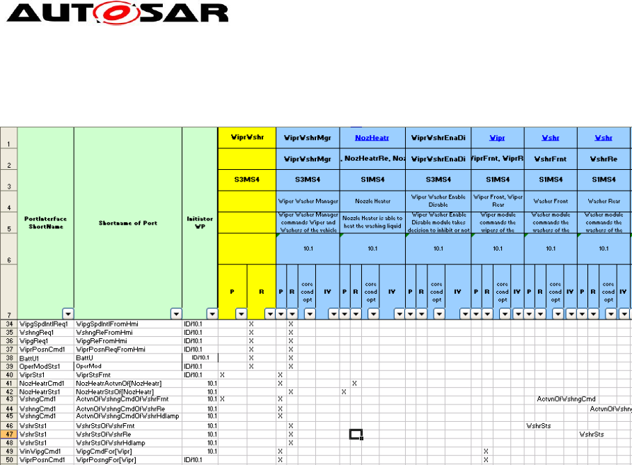
Application Interfaces User Guide
AUTOSAR CP Release 4.4.0
79 of 102 Document ID 442: AUTOSAR_EXP_AIUserGuide
- AUTOSAR confidential -
defined locally. In the latter case the composition type is defined the same as the
component prototype and shall not be reused in other sheets.
Figure 72: Sheet 050108_WiperWasher – Example specification from the AI Table for the
composition type WiprWshr
9.3.1 Composition Types
The XML generator creates per sheet one composition type for the yellow column
and a composition type for each blue column without hyperlink (the composition
types for the blue columns with hyperlink are created later, when iterating over the
linked “05”-sheets). The definition is written to the package
/AUTOSAR/AISpecification/SwComponentTypes_Example. The composition type is defined
by its ports (green columns), components (blue columns) and connectors (connector
matrix with X’s). The composition short-name is taken from the first row in the yellow
columns as shown in Figure 72 (Cell Z1).

Application Interfaces User Guide
AUTOSAR CP Release 4.4.0
80 of 102 Document ID 442: AUTOSAR_EXP_AIUserGuide
- AUTOSAR confidential -
The following XML snippet shows the XML generated for the WiprWshr component:
<COMPOSITION-SW-COMPONENT-TYPE>
<SHORT-NAME>WiprWshr</SHORT-NAME>
<PORTS>
... (See Section 9.3.2)
</PORTS>
<COMPONENTS>
... (See Section 9.3.3)
</COMPONENTS>
<CONNECTORS>
... (See Section 9.3.4)
</CONNECTORS>
</COMPOSITION-SW-COMPONENT-TYPE>
The following sections describe the elements from the three collections Ports,
Components and Connectors.
9.3.2 Ports
The lower part of the “05”-sheets defines ports and connectors. The green columns
define the ports, the right part (below the components) define existence and
connections of ports. E.g. row 35 in the screenshot from Figure 72 defines a required
port WipgSpdIntlFromHmi for composite component WiprWshr (marked by an X in
Cell AA35). The mark in column AA from Figure 72 results in an R-Port-Prototype item
in the ports collection of the composite component type WiprWshr as follows:
<R-PORT-PROTOTYPE>
<SHORT-NAME>WipgSpdIntlFromHmi</SHORT-NAME>
<LONG-NAME><L-4 L="EN">Wiping Speed Interval From Hmi</L-4></LONG-NAME>
<REQUIRED-INTERFACE-TREF
DEST="SENDER-RECEIVER-INTERFACE"
BASE="PortInterfaces">
WipgSpdIntlReq1
</REQUIRED-INTERFACE-TREF>
</R-PORT-PROTOTYPE>
The referenced interface must be a valid interface from the 06*-sheets (Refer 8.1.4
and 8.1.5). The interface is referenced via a type-reference.
A similar port with the same name is generated for composition type WiprWshrMgr
because of the mark in Cell AC35 in Figure 72. The (blue) port columns
“core/cond/opt” and IV are currently not relevant for XML generation.
9.3.3 Components
The internal component prototypes (instances) are taken from the blue columns.
Each component prototype has a short-name, taken from row 2 (e.g. AB2), and
references a composition type in row 1 (e.g. AB1) as shown in Figure 72. The
following XML snippet is generated for the WiprWshrMgr component prototype into
the <COMPONENTS> collection of the composition type WiprWshr:
<SW-COMPONENT-PROTOTYPE>
<SHORT-NAME>WiprWshrMgr</SHORT-NAME>
<LONG-NAME><L-4 L="EN">Wiper Washer Manager</L-4></LONG-NAME>
<DESC><L-2 L="EN">
Wiper Washer Manager commands Wiper and Washers of the vehicle
</L-2></DESC>
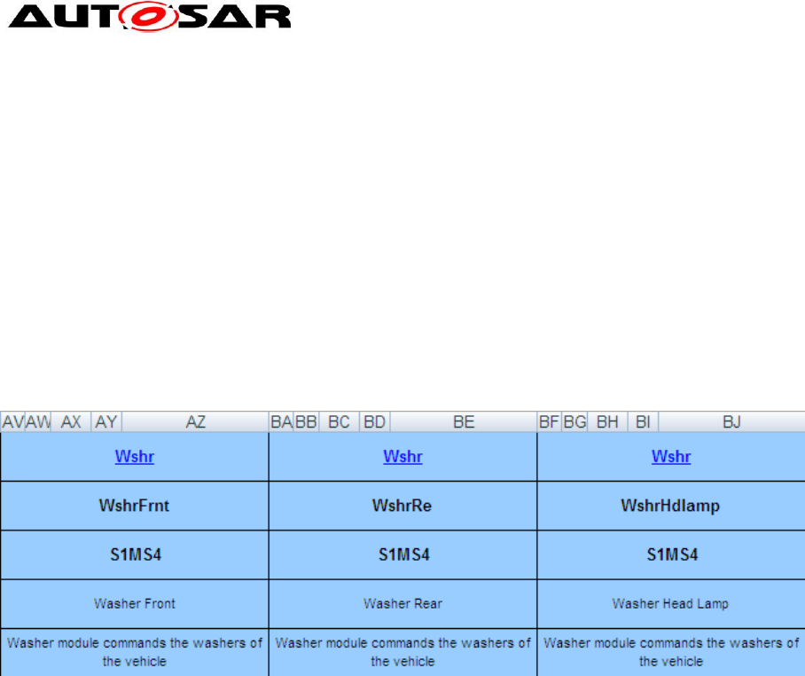
Application Interfaces User Guide
AUTOSAR CP Release 4.4.0
81 of 102 Document ID 442: AUTOSAR_EXP_AIUserGuide
- AUTOSAR confidential -
<TYPE-TREF
DEST="COMPOSITION-SW-COMPONENT-TYPE"
BASE="SwComponentTypes">
WiprWshrMgr
</TYPE-TREF>
</SW-COMPONENT-PROTOTYPE>
Via a TYPE-TREF, the component prototype references a composition type, which is
generated according to the prototype definition, because the cell AB1 shown in
Figure 72 does not contain a hyperlink.
In case of multiple instances, such a description will be generated for each instance
from the comma-separated list in row 2 (e.g. AG2).
Another possibility to declare multiple instances can be achieved while defining the
same component more than once with different prototype names like in the following
example:
Figure 73: Multiple instance with one instance per column
9.3.4 Connectors
Information about connectors is taken from the connector matrix beginning in Cell Z8
(not visible in Figure 72 as the rows 8-34 are hidden). A connection can be declared
with the value X or a specific short name itself. Special values like empty cells or the
literal “N/A” won’t establish a connector. Connectors are defined as follows:
Delegation Connectors are created for each X in the blue columns that has the
same direction as the X in the yellow column, e.g. the X’s in cells AA35 and AC35 in
Figure 72 will result in the following delegation connector:
<DELEGATION-SW-CONNECTOR>
<SHORT-NAME>WipgSpdIntlFromHmiToWipgSpdIntlFromHmiOfWiprWshrMgr</SHORT-
NAME>
<INNER-PORT-IREF>
<R-PORT-IN-COMPOSITION-INSTANCE-REF>
<CONTEXT-COMPONENT-REF DEST="SW-COMPONENT-PROTOTYPE"
BASE="SwComponentTypes">WiprWshr/WiprWshrMgr</CONTEXT-COMPONENT-REF>
<TARGET-R-PORT-REF DEST="R-PORT-PROTOTYPE"
BASE="SwComponentTypes">WiprWshrMgr/WipgSpdIntlFromHmi</TARGET-R-PORT-REF>
</R-PORT-IN-COMPOSITION-INSTANCE-REF>
</INNER-PORT-IREF>
<OUTER-PORT-REF DEST="R-PORT-PROTOTYPE"
BASE="SwComponentTypes">WiprWshr/WipgSpdIntlFromHmi</OUTER-PORT-REF>
</DELEGATION-SW-CONNECTOR>
The generator creates the short name of the delegation connector according to the
rule defined below;
<outerPortName>To<innerPortName>Of<InnerComponentPrototypeName>

Application Interfaces User Guide
AUTOSAR CP Release 4.4.0
82 of 102 Document ID 442: AUTOSAR_EXP_AIUserGuide
- AUTOSAR confidential -
In the above example <outerPortName> is WipgSpdIntlFromHmi, <innerPortName> is
WipgSpdIntlFromHmi, and <InnerComponentPrototypeName> is WiprWshrMgr.
Therefore, the short name of the delegation connector shown above is
WipgSpdIntlFromHmiToWipgSpdIntlFromHmiOfWiprWshrMgr.
The inner port references the port from the component prototype found in the blue
column using an instance reference (see Section 9.2.3). Note, that the context of the
IREF is the component prototype WiprWshrMgr inside the composition WiprWshr,
while the target port references the component type WiprWshrMgr in the general
package for all composition types SwComponentTypes, thus the different path
prefixes. The outer port references the port from the yellow column, belonging to the
composition type WiprWshr.
Assembly Connectors are created for each required port (mark in the R-column)
and the corresponding P-Port of internal component prototypes from the connector
matrix, e.g. for cells AW43 and AB43 from Figure 72:
<ASSEMBLY-SW-CONNECTOR>
<!-- sheet=050108_WiperWasher, row=43, p_col=28, r_col=48-->
<SHORT-
NAME>ActvnOfWshngCmdOfWshrFrntOfWiprWshrMgrToActvnOfWshngCmdOfWshrFrnt</SHORT-
NAME>
<PROVIDER-IREF>
<CONTEXT-COMPONENT-REF DEST="SW-COMPONENT-PROTOTYPE"
BASE="SwComponentTypes">WiprWshr/WiprWshrMgr</CONTEXT-COMPONENT-REF>
<TARGET-P-PORT-REF DEST="P-PORT-PROTOTYPE"
BASE="SwComponentTypes">WiprWshrMgr/ActvnOfWshngCmdOfWshrFrnt</TARGET-P-PORT-
REF>
</PROVIDER-IREF>
<REQUESTER-IREF>
<CONTEXT-COMPONENT-REF DEST="SW-COMPONENT-PROTOTYPE"
BASE="SwComponentTypes">WiprWshr/WshrFrnt</CONTEXT-COMPONENT-REF>
<TARGET-R-PORT-REF DEST="R-PORT-PROTOTYPE"
BASE="SwComponentTypes">Wshr/ActvnOfWshngCmd</TARGET-R-PORT-REF>
</REQUESTER-IREF>
</ASSEMBLY-SW-CONNECTOR>
As can be seen from the snippet, both ports are referenced via instance references.
The generator creates the name of the assembly connector according to the rule
below;
<P-Port-ShortName>Of<P-Port-SW-C-Prototype-ShortName>To<R-Port-
ShortName>Of<R-Port-SW-C-Prototype-ShortName>
In the context of the above example <P-Port-ShortName> is
ActvnOfWshngCmdOfWshrFrnt, <P-Port-SW-C-Prototype-ShortName>, is
WiprWshrMgr, <R-Port-ShortName> is ActvnOfWshngCmd, and <R-Port_SW-C-
Prototype-ShortName> is WshrFrnt. Therefore, name of the assembly connector is
ActvnOfWshngCmdOfWshrFrntOfWiprWshrMgrToActvnOfWshngCmdOfWshrFrnt.
Multiple Instantiation is a particularity in this case. The name of the port
WipgCmdFor[Wipr] (cell B49 in Figure 72) is expanded according to the instance
names from the column referenced by Wipr. All components with this port that are
not defined in the referenced column, have multiple ports according to all instance
names, e.g. WipgCmdForWiprFrnt and WipgCmdForWiprRe for WiprWshrMgr, while
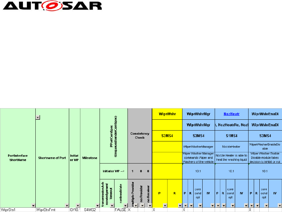
Application Interfaces User Guide
AUTOSAR CP Release 4.4.0
83 of 102 Document ID 442: AUTOSAR_EXP_AIUserGuide
- AUTOSAR confidential -
the name is contracted to WipgCmd for all components from the column providing
the instance iterator, i.e. the first column with Wipr in the first row.
Semantic Constraints: To guarantee a semantically correct generation of the
AUTOSAR XML, there may be at most one X in a P-column of the blue components.
This means that the Application Interfaces will support the generation of the
AUTOSAR XML even though the constraints are not met. The following snapshot
shows what is considered a semantic error:
Figure 74: Sheet 050108_WiperWasher – Erroneously connected P-Port
As shown in Figure 74 there are two delegations specified (two P-Columns on blue
background marked with X). As this represents an ambiguous definition of the port
prototype at composition it is considered a violation of the semantic constraint.
Therefore, the existence of multiple X marks in P-Columns is considered a semantic
error. Please note, that a generation of XML is nevertheless possible.
9.4 PortPrototypeBlueprints
It is not in the scope of the AUTOSAR Application Interfaces to define complete
system compositions. All software component composition types are defined in a
package with category EXAMPLE and meant only as illustration of usage of the
standardized elements. However, it is in the scope of the Application Interfaces to
describe the roles that interfaces can play in compositions. This can be done using
PortPrototypeBlueprints, which define potential ports of a component type and can
carry more attributes to pre-define values for usages of the blueprint, e.g. an initial
value. For details on PortPrototypeBlueprints see the Standardization Template [2].
The PortPrototypeBlueprints are collected within a single package
/AUTOSAR/AISpecification/PortPrototypeBlueprints_Blueprint:
<AR-PACKAGE>
<SHORT-NAME>PortPrototypeBlueprints_Blueprint</SHORT-NAME>
<CATEGORY>BLUEPRINT</CATEGORY>
<REFERENCE-BASES>
...
</REFERENCE-BASES>
<ELEMENTS>
<PORT-PROTOTYPE-BLUEPRINT>
<SHORT-NAME NAME-PATTERN="{anyName}"> AbsCtrlIntvg</SHORT-NAME>
<LONG-NAME><L-4 L="EN">ABS Control Intervening</L-4></LONG-NAME>

Application Interfaces User Guide
AUTOSAR CP Release 4.4.0
84 of 102 Document ID 442: AUTOSAR_EXP_AIUserGuide
- AUTOSAR confidential -
<DESC><L-2 L="EN"> Antilock Braking System's (ABS) control is
active (at least one wheel)</DESC>
<INTERFACE-REF DEST="SENDER-RECEIVER-INTERFACE"
BASE="PortInterfaces">AbsCtrlIntvg1</INTERFACE-REF>
</PORT-PROTOTYPE-BLUEPRINT>
<PORT-PROTOTYPE-BLUEPRINT>
<SHORT-NAME NAME-PATTERN="{anyName}">AbsFlgActv</SHORT-NAME>
<LONG-NAME><L-4 L="EN">AbsControlActive</L-4></LONG-NAME>
<DESC><L-2 L="EN">Anti Blocking Systems (ABS) control is active (at
least one wheel)</DESC>
<INTERFACE-REF DEST="SENDER-RECEIVER-INTERFACE"
BASE="PortInterfaces">AbsCtrlIntvg1</INTERFACE-REF>
</PORT-PROTOTYPE-BLUEPRINT>
...
</ELEMENTS>
</AR-PACKAGE>
Since the blueprint mechanism is meant as an aid for the creation of PortPrototypes
the AUTOSAR XML also provides a mapping mechanism which describes the
relation between a blueprint and a prototype. This mechanism allows decoupling of
the PortPrototype from the blueprint without interfering with architectural
requirements. The mapping is specified as a sequence of pairs as part of the
package /AUTOSAR/AISpecification/SwComponentTypes_Example like in the following
example:
<BLUEPRINT-MAPPING-SET>
<SHORT-NAME>PortPrototypeBlueprintMappings</SHORT-NAME>
<BLUEPRINT-MAPS>
<BLUEPRINT-MAPPING>
<BLUEPRINT-REF DEST="PORT-PROTOTYPE-BLUEPRINT"
BASE="PortPrototypeBlueprints_Blueprint">AbsCtrlIntvg</BLUEPRINT-REF>
<DERIVED-OBJECT-REF DEST="P-PORT-PROTOTYPE"
BASE="SwComponentTypes">Chassis/AbsCtrlIntvg</DERIVED-OBJECT-REF>
</BLUEPRINT-MAPPING>
<BLUEPRINT-MAPPING>
<BLUEPRINT-REF DEST="PORT-PROTOTYPE-BLUEPRINT"
BASE="PortPrototypeBlueprints_Blueprint">AbsCtrlIntvg</BLUEPRINT-REF>
<DERIVED-PORT-PROTOTYPE-REF DEST="R-PORT-PROTOTYPE"
BASE="SwComponentTypes">Body/AbsCtrlIntvg</DERIVED-OBJECT-REF>
</BLUEPRINT-MAPPING>
<BLUEPRINT-MAPPING>
...
</BLUEPRINT-MAPS>
</BLUEPRINT-MAPPING-SET>
9.5 PortInterfaces
The provided or required PortPrototype references a PortInterface defined in the AI
Table’s “06”-sheets, separated for Sender-Receiver- and Client-Server-Interfaces.
Both sender-receiver-interfaces and client-server-interfaces are kept in the package
/AUTOSAR/AISpecification/PortInterfaces_Blueprint. They are also part of
/AUTOSAR/AISpecification/PortInterfaces_Example, but only as a copy of the blueprint so
that they could be used for PortPrototypes.
9.5.1 Sender-Receiver-Interface
Figure 75 shows one interface from the sender-receiver-interface table, which
defines short-name, long-name, description and the contained data elements (the
table is capable of capturing up to six data elements per SenderReceiverInterface).
The direction of the dataflow is defined by the port.
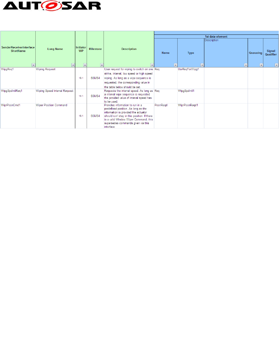
Application Interfaces User Guide
AUTOSAR CP Release 4.4.0
85 of 102 Document ID 442: AUTOSAR_EXP_AIUserGuide
- AUTOSAR confidential -
Figure 75: Structure of the sheet 06_Interface_DataElements
The XML generator generates the following output for the above table row:
<SENDER-RECEIVER-INTERFACE>
<SHORT-NAME NAME-PATTERN="{anyName}">WipgSpdIntlReq1</SHORT-NAME>
<LONG-NAME><L-4 L="EN">Wiping Speed Interval Request</L-4></LONG-NAME>
<DESC><L-2 L="EN">Requests the interval speed. As long as a interval
wipe sequence is requested the provided value of interval speed has to be
used.</L-2></DESC>
<IS-SERVICE>false</IS-SERVICE>
<DATA-ELEMENTS>
<VARIABLE-DATA-PROTOTYPE>
<SHORT-NAME NAME-PATTERN="{anyName}">Req</SHORT-NAME>
<TYPE-TREF DEST="APPLICATION-PRIMITIVE-DATA-TYPE"
BASE="ApplicationDataTypes">WipgSpdIntl1</TYPE-TREF>
</VARIABLE-DATA-PROTOTYPE>
</DATA-ELEMENTS>
</SENDER-RECEIVER-INTERFACE>
The corresponding BluprintMapping for the above interface is:
<BLUEPRINT-MAPPING-SET>
<SHORT-NAME>PortInterfaceBlueprintMappings</SHORT-NAME>
<BLUEPRINT-MAPPING>
<BLUEPRINT-REF DEST="SENDER-RECEIVER-INTERFACE"
BASE="PortInterfaces_Blueprint">WipgSpdIntlReq1</BLUEPRINT-REF>
<DERIVED-OBJECT-REF DEST="SENDER-RECEIVER-INTERFACE"
BASE="PortInterfaces">WipgSpdIntlReq1</DERIVED-OBJECT-REF>
</BLUEPRINT-MAPPING>
The Blueprint and Derived element is represented in the above XML extract. This
mapping shows that the package /AUTOSAR/AISpecification/PortInterfaces_Blueprint provide
the blueprint interfaces which are derived within the EXAMPLE categorized package
/AUTOSAR/AISpecification/PortInterfaces_Example.
The information on queuing and signal qualifiers is currently not used for XML
generation. The referenced type for each data element must be defined in the
DataType sheets.
9.5.2 Client-Server-Interface
Figure 76 shows one interface from the client-server-interface table, which defines
short-name, long-name, description and the contained operations (one operation per
row, the table is capable of capturing up to three arguments per operation) and will
merge all operations with the same interface short name into one interface.
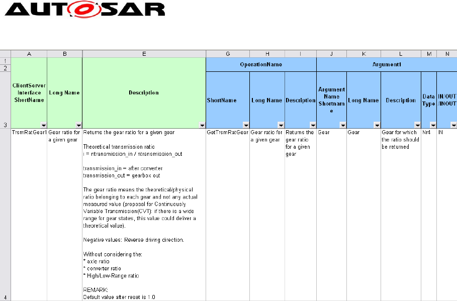
Application Interfaces User Guide
AUTOSAR CP Release 4.4.0
86 of 102 Document ID 442: AUTOSAR_EXP_AIUserGuide
- AUTOSAR confidential -
Figure 76: Structure of the sheet 06_Interface_ClientServer
The XML generator generates the following output for the above example:
<CLIENT-SERVER-INTERFACE>
<SHORT-NAME NAME-PATTERN="{anyName}">TrsmRatGear1</SHORT-NAME>
<LONG-NAME><L-4 L="EN">Transmission: Gear Ratio for a Given Gear</L-4></LONG-
NAME>
<DESC><L-2 L="EN">Returns the gear ratio for a given gear</L-2></DESC>
<INTRODUCTION>... </INTRODUCTION>
<IS-SERVICE>false</IS-SERVICE>
<OPERATIONS>
<CLIENT-SERVER-OPERATION>
<SHORT-NAME NAME-PATTERN="{anyName}">GetTrsmRatGear</SHORT-NAME>
<LONG-NAME><L-4 L="EN">Returns the Gear Ratio for a Given Gear</L-
4></LONG-NAME>
<DESC><L-2 L="EN">Returns the gear ratio for a given gear</L-
2></DESC>
<ARGUMENTS>
<ARGUMENT-DATA-PROTOTYPE>
<SHORT-NAME NAME-PATTERN="{anyName}">Gear</SHORT-NAME>
<LONG-NAME><L-4 L="EN">Gear for Which the Ratio Should Be
Returned</L-4></LONG-NAME>
<DESC><L-2 L="EN">Gear for which the ratio should be
returned</L-2></DESC>
<TYPE-TREF DEST="APPLICATION-PRIMITIVE-DATA-TYPE"
BASE="ApplicationDataTypes">Nr4</TYPE-TREF>
<DIRECTION>IN</DIRECTION>
</ARGUMENT-DATA-PROTOTYPE>
<ARGUMENT-DATA-PROTOTYPE>
<SHORT-NAME NAME-PATTERN="{anyName}">Rat</SHORT-NAME>
<LONG-NAME><L-4 L="EN">Gear Ratio of Given Gear</L-
4></LONG-NAME>
<DESC><L-2 L="EN">Gear ratio of given gear</L-2></DESC>
<TYPE-TREF DEST="APPLICATION-PRIMITIVE-DATA-TYPE"
BASE="ApplicationDataTypes">Fac1</TYPE-TREF>
<DIRECTION>OUT</DIRECTION>
</ARGUMENT-DATA-PROTOTYPE>
</ARGUMENTS>
</CLIENT-SERVER-OPERATION>
</OPERATIONS>
</CLIENT-SERVER-INTERFACE>

Application Interfaces User Guide
AUTOSAR CP Release 4.4.0
87 of 102 Document ID 442: AUTOSAR_EXP_AIUserGuide
- AUTOSAR confidential -
For details on the generation of description and introduction elements see Section
9.2.5.
9.6 Blueprint Mapping Sets
BlueprintMappingSets are used to establish a connection between a Blueprint and
element derived from this Blueprint. This helps to trace back the respective Blueprint
that was used to create this element. Blueprint Mapping Sets are used for different
elements including PortPrototypeBlueprints, PortInterfaces, Application DataTypes,
etc. They are defined in the package
/AUTOSAR/AISpecification/BlueprintMappingSets_Example. The following xml
provides an example for the Blueprint Mapping of the PortInterface and is equivalent
for other elements.
<BLUEPRINT-MAPPING-SET>
<SHORT-NAME>PortInterfaceBlueprintMappings</SHORT-NAME>
<BLUEPRINT-MAPS>
<BLUEPRINT-MAPPING>
<BLUEPRINT-REF DEST="CLIENT-SERVER-INTERFACE"
BASE="PortInterfaces_Blueprint">
TrsmRatGear1
</BLUEPRINT-REF>
<DERIVED-OBJECT-REF DEST="CLIENT-SERVER-INTERFACE"
BASE="PortInterfaces">
TrsmRatGear1
</DERIVED-PORT-INTERFACE-REF>
</BLUEPRINT-MAPPING>
<BLUEPRINT-MAPPING>
<BLUEPRINT-REF DEST="SENDER-RECEIVER-INTERFACE"
BASE="PortInterfaces_Blueprint">
ALgt2
</BLUEPRINT-REF>
<DERIVED-OBJECT-REF DEST="SENDER-RECEIVER-INTERFACE"
BASE="PortInterfaces">
ALgt2
</DERIVED-PORT-INTERFACE-REF>
</BLUEPRINT-MAPPING>
...
</BLUEPRINT-MAPS>
</BLUEPRINT-MAPPING-SET>
This mapping shows that the package /AUTOSAR/AISpecification/PortInterfaces_Blueprint
provide the blueprint interfaces which are derived within the EXAMPLE categorized
package /AUTOSAR/AISpecification/PortInterfaces_Example.
Similarly for the DataConstraints the Blueprint Mapping is as under:
<BLUEPRINT-MAPPING-SET>
<SHORT-NAME>DataConstrBlueprintMappings</SHORT-NAME>
<BLUEPRINT-MAPS>
<BLUEPRINT-MAPPING>
<BLUEPRINT-REF DEST="DATA-CONSTR"
BASE="DataConstrs_Blueprint">TrsmTyp1</BLUEPRINT-REF>
<DERIVED-OBJECT-REF DEST="DATA-CONSTR" BASE="DataConstrs">TrsmTyp1</DERIVED-
OBJECT-REF>
</BLUEPRINT-MAPPING>
...
</BLUEPRINT-MAPS>
</BLUEPRINT-MAPPING-SET>
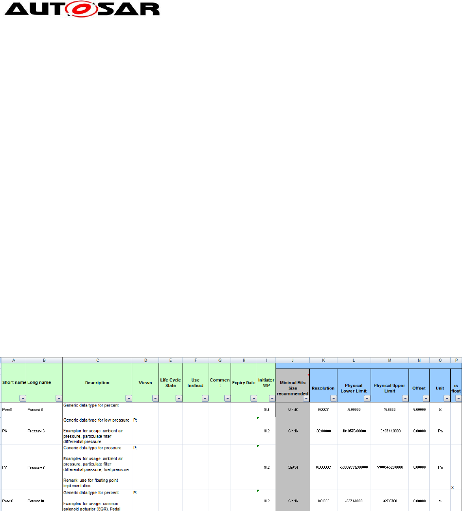
Application Interfaces User Guide
AUTOSAR CP Release 4.4.0
88 of 102 Document ID 442: AUTOSAR_EXP_AIUserGuide
- AUTOSAR confidential -
9.7 Data Types
The interfaces reference DataTypes in data elements for sender-receiver interfaces
and arguments for client-server interfaces. The DataTypes are defined in the sheets
“Sheet 07_DataTypes_ContinuousValue”, “Sheet 08_DataTypes_Enumeration”,
Sheet 09_DataTypes_Array”, “Sheet 11_DataTypes_Record”.
All DataTypes are kept in the package
/AUTOSAR/AISpecification/ApplicationDataTypes_Blueprint. They are also part
of /AUTOSAR/AISpecification/ApplicationDataTypes_Example, but as a copy of
the blueprint so that they could be used for PortInterfaces.
Application DataTypes define the data attributes which are needed from the
application point of view, in order to exchange data between software components or
between a software component and a measurement and calibration tool.
The AI Table does not standardize implementation DataTypes. For more details,
please refer [1].
9.7.1 Continuous Value Types
The continuous values need to be scaled to integer numbers; the XML generator
creates three elements for a continuous type, the type element itself, which
references a SwDataDefProps defining the scale and a data constraint defining the
limits of the integral values.
Figure 77: Structure of the sheet 07_DataTypes_ContinuousValue
The following snippets define the integer datatype Perc8.The type element gives the
name (short and long), description and uses the field “Minimal Bits Size
recommended” to provide a recommended implementation type, as well as the Unit
field for the unit reference. The references to computation method and data
constraint are generated:
<APPLICATION-PRIMITIVE-DATA-TYPE>
<SHORT-NAME NAME-PATTERN="{anyName}">Perc8</SHORT-NAME>
<LONG-NAME><L-4 L="EN">Percent 8</L-4></LONG-NAME>
<DESC><L-2 L="EN">Generic data type for percent</L-2></DESC>
<CATEGORY>VALUE</CATEGORY>
<SW-DATA-DEF-PROPS>
<SW-DATA-DEF-PROPS-VARIANTS>
<SW-DATA-DEF-PROPS-CONDITIONAL>
<SW-CALIBRATION-ACCESS>READ-ONLY</SW-CALIBRATION-ACCESS>
<COMPU-METHOD-REF DEST="COMPU-METHOD"
BASE="CompuMethods">Perc8</COMPU-METHOD-REF>

Application Interfaces User Guide
AUTOSAR CP Release 4.4.0
89 of 102 Document ID 442: AUTOSAR_EXP_AIUserGuide
- AUTOSAR confidential -
<DATA-CONSTR-REF DEST="DATA-CONSTR"
BASE="DataConstrs">Perc8</DATA-CONSTR-REF>
<SW-INTENDED-RESOLUTION>0.00031</SW-INTENDED-RESOLUTION>
<UNIT-REF DEST="UNIT" BASE="Units">Perc</UNIT-REF>
</SW-DATA-DEF-PROPS-CONDITIONAL>
</SW-DATA-DEF-PROPS-VARIANTS>
</SW-DATA-DEF-PROPS>
</APPLICATION-PRIMITIVE-DATA-TYPE>
In addition, the corresponding Blueprint Mapping for the above datatype “Percent 8”
can be found in the package
/AUTOSAR/AISpecification/ApplicationDataTypes_Example:
<BLUEPRINT-MAPPING-SET>
<SHORT-NAME>ApplicationDataTypeBlueprintMappings</SHORT-NAME>
<BLUEPRINT-MAPS>
<BLUEPRINT-MAPPING>
<BLUEPRINT-REF DEST="APPLICATION-PRIMITIVE-DATA-TYPE"
BASE="ApplicationDataTypes_Blueprint">Perc8</BLUEPRINT-REF>
<DERIVED-OBJECT-REF DEST="APPLICATION-PRIMITIVE-DATA-TYPE"
BASE="ApplicationDataTypes">Perc8</DERIVED-OBJECT-REF>
</BLUEPRINT-MAPPING>
...
</BLUEPRINT-MAPS>
</BLUEPRINT-MAPPING-SET>
Computation methods are also defined as blueprints. BlueprintMapping for
computation methods are also provided to help projects create actual Computation
methods from the blueprints. The BlueprintMappings for Computation methods are
grouped in the set CompuMethodBlueprintMappings in the package
BlueprintMappingSets_Example. The XML fragment below shows the
BlueprintMapping for the CompuMethod Perc8.
<BLUEPRINT-MAPPING>
<BLUEPRINT-REF DEST="APPLICATION-PRIMITIVE-DATA-TYPE"
BASE="ApplicationDataTypes_Blueprint"
>
Perc8
</BLUEPRINT-REF>
<DERIVED-OBJECT-REF DEST="APPLICATION-PRIMITIVE-DATA-TYPE"
BASE="ApplicationDataTypes"
>
Perc8
</DERIVED-OBJECT-REF>
</BLUEPRINT-MAPPING>
The data constraints belong to the package
/AUTOSAR/AISpecification/DataConstrs_Blueprint.
<DATA-CONSTR>
<SHORT-NAME NAME-PATTERN="{anyName}">Perc8</SHORT-NAME>
<DATA-CONSTR-RULES>
<DATA-CONSTR-RULE>
<PHYS-CONSTRS>
<LOWER-LIMIT INTERVAL-TYPE="CLOSED">-5</LOWER-LIMIT>
<UPPER-LIMIT INTERVAL-TYPE="CLOSED">15</UPPER-LIMIT>
<UNIT-REF DEST="UNIT" BASE="Units">Perc</UNIT-REF>
</PHYS-CONSTRS>
</DATA-CONSTR-RULE>
</DATA-CONSTR-RULES>
</DATA-CONSTR>

Application Interfaces User Guide
AUTOSAR CP Release 4.4.0
90 of 102 Document ID 442: AUTOSAR_EXP_AIUserGuide
- AUTOSAR confidential -
For Float generic dataconstrs for [-INF,+INF]
<DATA-CONSTR>
<SHORT-NAME NAME-PATTERN="{anyName}">FloatDataRange</SHORT-NAME> (the name
will be chosen based on naming rules)
<DATA-CONSTR-RULES>
<DATA-CONSTR-RULE>
<PHYS-CONSTRS>
<LOWER-LIMIT INTERVAL-TYPE="CLOSED">-INF</LOWER-LIMIT>
<UPPER-LIMIT INTERVAL-TYPE="CLOSED">+INF</UPPER-LIMIT>
***<UNIT-REF BASE="Units" DEST="UNIT">MtrPerSecSqd</UNIT-REF>*** (no
unit required)
</PHYS-CONSTRS>
</DATA-CONSTR-RULE>
</DATA-CONSTR-RULES>
</DATA-CONSTR>
The data constraints for the lower and upper limit for signed ranges are calculated
using to the below mentioned formulae:
lowerLimit = Round((phys_lower_limit - offset) / factor)
upperLimit = Round((phys_upper_limit - offset) / factor)
For unsigned ranges the below mentioned formulae are used:
lowerLimit = 0
upperLimit = Round((phys_lower_limit - offset) / factor)
+ Round((phys_upper_limit - offset) / factor)
+ 1
These lowerLimit and upperLimit are then used for calculation of minimum required
bits to represent the entire signal range.
In the above model element (Perc8)
Range = [15 – (-5) =20], Resolution = 0.00031
Therefore the minimal recommended bit size is [20/0.00031 = 64516] and hence
‘Uint16’. Please note that the ‘minimal recommended bit size’ is only used as
information for the specification period and will not be standardised
The Computation methods belong to the package
/AUTOSAR/AISpecification/CompuMethods_Blueprint.
<COMPU-METHOD>
<SHORT-NAME NAME-PATTERN="{anyName}">Perc8</SHORT-NAME>
<LONG-NAME><L-4 L="EN">Percent 8</L-4></LONG-NAME>
<DESC><L-2 L="EN">Generic data type for percent</L-2></DESC>
<CATEGORY>LINEAR</CATEGORY>
<UNIT-REF DEST="UNIT" BASE="Units">Perc</UNIT-REF>
<COMPU-PHYS-TO-INTERNAL>
<COMPU-SCALES>
<COMPU-SCALE>
<LOWER-LIMIT INTERVAL-TYPE="CLOSED">-5</LOWER-LIMIT>
<UPPER-LIMIT INTERVAL-TYPE="CLOSED">15</UPPER-LIMIT>
<COMPU-RATIONAL-COEFFS>
<COMPU-NUMERATOR>
<V>5</V>
<V>1</V>
</COMPU-NUMERATOR>
<COMPU-DENOMINATOR>
<V>0.00031</V>
</COMPU-DENOMINATOR>
</COMPU-RATIONAL-COEFFS>
</COMPU-SCALE>
</COMPU-SCALES>
</COMPU-PHYS-TO-INTERNAL>
</COMPU-METHOD>

Application Interfaces User Guide
AUTOSAR CP Release 4.4.0
91 of 102 Document ID 442: AUTOSAR_EXP_AIUserGuide
- AUTOSAR confidential -
In certain cases the specification of application data types that can be implemented
as floating point data types (float) is also desired. Reasons could be to avoid
resource consuming conversions between physical and internal values (for float,
physical and internal value are identical) or to achieve a higher resolution.
Such datatypes are marked with an “x” in the column “Is float”.
One of the main differences to fixed point representation (integer) is, that for floating
point representation there is no fixed resolution. The resolution for small values is
better than for large values. In AUTOSAR, however, it is only possible to give one
fixed value for the swIntentedResoultion. Therefore, it was decided to specify the
best case resolution of a single float for swIntentedResolution, which is “0.0000001”.
Consequently, all data types, which are intended to be implemented as float, have
this value specified as swIntentedResolution.
The following xml extract for “Pressure 7” marked for usage as “float” is shown.
<APPLICATION-PRIMITIVE-DATA-TYPE>
<SHORT-NAME NAME-PATTERN="{anyName}">P7</SHORT-NAME>
<LONG-NAME><L-4 L="EN">Pressure 7</L-4></LONG-NAME>
<DESC><L-2 L="EN">Generic data type for pressure</L-2></DESC>
<CATEGORY>VALUE</CATEGORY>
<INTRODUCTION>
<P><L-1 L="EN">Examples for usage: ambient air pressure, particulate filter
differential pressure, fuel pressure </L-1></P>
<P><L-1 L="EN">Remark: use for floating point implementation </L-1></P>
</INTRODUCTION>
<SW-DATA-DEF-PROPS>
<SW-DATA-DEF-PROPS-VARIANTS>
<SW-DATA-DEF-PROPS-CONDITIONAL>
<SW-CALIBRATION-ACCESS>READ-ONLY</SW-CALIBRATION-ACCESS>
<COMPU-METHOD-REF DEST="COMPU-METHOD"
BASE="CompuMethods">PaIdentcl</COMPU-METHOD-REF>
<DATA-CONSTR-REF DEST="DATA-CONSTR"
BASE="DataConstrs">P7</DATA-CONSTR-REF>
<SW-INTENDED-RESOLUTION>0.0000001</SW-INTENDED-RESOLUTION>
<UNIT-REF DEST="UNIT" BASE="Units">Pa</UNIT-REF>
</SW-DATA-DEF-PROPS-CONDITIONAL>
</SW-DATA-DEF-PROPS-VARIANTS>
</SW-DATA-DEF-PROPS>
</APPLICATION-PRIMITIVE-DATA-TYPE>
As no conversion between physical value and internal representation is necessary for
float, the compu method for these kinds of data types defines a 1:1 relationship
between physical and internal value. For this reason the category of such a compu
method is “IDENTICAL” (instead of “LINEAR”).
Additionally, generic compu methods are used in this case. As all compu methods
that define a 1:1 relationship are identical for a given unit, only one 1:1 compu
method per unit is defined. This compu method has the ShortName <short name of
unit> + Identcl (PaIdentcl in this case).
To be generic, these compu methods are also defined without any limits
i.e. from (–inf to +inf)
<COMPU-METHOD>
<SHORT-NAME NAME-PATTERN="{anyName}">KelvinIdentcl</SHORT-NAME>
<LONG-NAME>
<L-4 L="EN">Kelvin Identical</L-4>
</LONG-NAME>
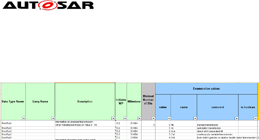
Application Interfaces User Guide
AUTOSAR CP Release 4.4.0
92 of 102 Document ID 442: AUTOSAR_EXP_AIUserGuide
- AUTOSAR confidential -
<DESC/>
<CATEGORY>IDENTICAL</CATEGORY>
<UNIT-REF BASE="Units" DEST="UNIT">Kelvin</UNIT-REF>
</COMPU-METHOD>
9.7.2 Enumeration Types
Figure 78: Structure of the sheet 08_DataTypes_Enumeration
All (consecutive) lines from the table with the same Data Type Name are contained
by one enumeration type. The type references a computation method defining the
literals, whose size is computed from the count of literals, and a data constraint for
the base type, also reflecting the count of literals.
Note: The tag <CATEGORY> </CATEGORY> will contain either “BOOLEAN” or “VALUE”
depending on whether the column “is boolean” is marked with an ‘x’ or not.
<APPLICATION-PRIMITIVE-DATA-TYPE>
<SHORT-NAME NAME-PATTERN="{anyName}">TrsmTyp1</SHORT-NAME>
<LONG-NAME><L-4 L="EN">Transmission Type</L-4></LONG-NAME>
<DESC><L-2 L="EN">Information on standard transmission. Other transmission
types on value 5 - 15</L-2></DESC>
<CATEGORY>VALUE</CATEGORY>
<SW-DATA-DEF-PROPS>
<SW-DATA-DEF-PROPS-VARIANTS>
<SW-DATA-DEF-PROPS-CONDITIONAL>
<SW-CALIBRATION-ACCESS>READ-ONLY</SW-CALIBRATION-ACCESS>
<COMPU-METHOD-REF DEST="COMPU-METHOD"
BASE="CompuMethods">TrsmTyp1</COMPU-METHOD-REF>
<DATA-CONSTR-REF DEST="DATA-CONSTR"
BASE="DataConstrs">TrsmTyp1</DATA-CONSTR-REF>
<UNIT-REF DEST="UNIT"
BASE="Units">NoUnit</UNIT-REF>
</SW-DATA-DEF-PROPS-CONDITIONAL>
</SW-DATA-DEF-PROPS-VARIANTS>
</SW-DATA-DEF-PROPS>
</APPLICATION-PRIMITIVE-DATA-TYPE>
The XML fragment below shows the BlueprintMapping for the Enumeration
DataType.
<BLUEPRINT-MAPPING>
<BLUEPRINT-REF DEST="APPLICATION-PRIMITIVE-DATA-TYPE"
BASE="ApplicationDataTypes_Blueprint"
>
TrsmTyp1
</BLUEPRINT-REF>
<DERIVED-OBJECT-REF DEST="APPLICATION-PRIMITIVE-DATA-TYPE"
BASE="ApplicationDataTypes"
>
TrsmTyp1
</DERIVED-OBJECT-REF>
</BLUEPRINT-MAPPING>

Application Interfaces User Guide
AUTOSAR CP Release 4.4.0
93 of 102 Document ID 442: AUTOSAR_EXP_AIUserGuide
- AUTOSAR confidential -
The literals of the enumeration type are encoded in a computation method, with one
COMPU-SCALE for each literal. Descriptions of the literals are not parsed into multiple
elements as described in Section 9.2.5. The long name of the computation method is
copied from its respective data type’s long name.
The Computation methods belong to the package
/AUTOSAR/AISpecification/CompuMethods_Blueprint.
<COMPU-METHOD>
<SHORT-NAME NAME-PATTERN="{anyName}">TrsmTyp1</SHORT-NAME>
<LONG-NAME><L-4 L="EN">Transmission Type</L-4></LONG-NAME>
<CATEGORY>TEXTTABLE</CATEGORY>
<COMPU-INTERNAL-TO-PHYS>
<COMPU-SCALES>
<COMPU-SCALE>
<DESC><L-2 L="EN">0 = Mt (manual transmission)</L-2></DESC>
<LOWER-LIMIT INTERVAL-TYPE="CLOSED">0</LOWER-LIMIT>
<UPPER-LIMIT INTERVAL-TYPE="CLOSED">0</UPPER-LIMIT>
<COMPU-CONST><VT>Mt</VT></COMPU-CONST>
</COMPU-SCALE>
<COMPU-SCALE>
<DESC><L-2 L="EN">1 = At (automatic transmission)</L-2></DESC>
<LOWER-LIMIT INTERVAL-TYPE="CLOSED">1</LOWER-LIMIT>
<UPPER-LIMIT INTERVAL-TYPE="CLOSED">1</UPPER-LIMIT>
<COMPU-CONST><VT>At</VT></COMPU-CONST>
</COMPU-SCALE>
<COMPU-SCALE>
<DESC><L-2 L="EN">2 = Amt (direct shift/ automated Mt)</L-2></DESC>
<LOWER-LIMIT INTERVAL-TYPE="CLOSED">2</LOWER-LIMIT>
<UPPER-LIMIT INTERVAL-TYPE="CLOSED">2</UPPER-LIMIT>
<COMPU-CONST><VT>Amt</VT></COMPU-CONST>
</COMPU-SCALE>
<COMPU-SCALE>
<DESC><L-2 L="EN">3 = Cvt (continuously variable transmission)</L-
2></DESC>
<LOWER-LIMIT INTERVAL-TYPE="CLOSED">3</LOWER-LIMIT>
<UPPER-LIMIT INTERVAL-TYPE="CLOSED">3</UPPER-LIMIT>
<COMPU-CONST><VT>Cvt</VT></COMPU-CONST>
</COMPU-SCALE>
<COMPU-SCALE>
<DESC><L-2 L="EN">4 = Dct (twin-clutch gearbox or dual or double
clutch transmission (Dct))</L-2></DESC>
<LOWER-LIMIT INTERVAL-TYPE="CLOSED">4</LOWER-LIMIT>
<UPPER-LIMIT INTERVAL-TYPE="CLOSED">4</UPPER-LIMIT>
<COMPU-CONST><VT>Dct</VT></COMPU-CONST>
</COMPU-SCALE>
</COMPU-SCALES>
</COMPU-INTERNAL-TO-PHYS>
</COMPU-METHOD>
The data constraints limit the use of the base type to the really needed values and
they belong to the package /AUTOSAR/AISpecification/DataConstrs_Blueprint.
<DATA-CONSTR>
<SHORT-NAME NAME-PATTERN="{anyName}">TrsmTyp1</SHORT-NAME>
<DATA-CONSTR-RULES>
<DATA-CONSTR-RULE>
<INTERNAL-CONSTRS>
<LOWER-LIMIT INTERVAL-TYPE="CLOSED">0</LOWER-LIMIT>
<UPPER-LIMIT INTERVAL-TYPE="CLOSED">4</UPPER-LIMIT>
</INTERNAL-CONSTRS>
</DATA-CONSTR-RULE>
</DATA-CONSTR-RULES>
</DATA-CONSTR>
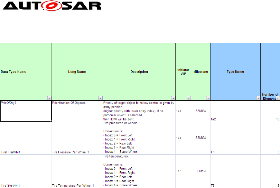
Application Interfaces User Guide
AUTOSAR CP Release 4.4.0
94 of 102 Document ID 442: AUTOSAR_EXP_AIUserGuide
- AUTOSAR confidential -
9.7.3 Array Types
Figure 79: Structure of the sheet 09_DataTypes_Array
The XML generation is straightforward from the table entries, e.g. the XML for row 5
from Figure 79 would be:
<APPLICATION-ARRAY-DATA-TYPE>
<SHORT-NAME NAME-PATTERN="{anyName}">TirePPerWhl1</SHORT-NAME>
<LONG-NAME><L-4 L="EN">Tire Pressure per Wheel 1</L-4></LONG-NAME>
<DESC><L-2 L="EN">Tire pressures at wheels.</L-2></DESC>
<CATEGORY>ARRAY</CATEGORY>
<INTRODUCTION>
<P><L-1 L="EN">Convention is: </L-1></P>
<LIST TYPE="UNNUMBER">
<ITEM><P><L-1 L="EN"> Index 0 = Front Left </L-1></P></ITEM>
<ITEM><P><L-1 L="EN"> Index 1 = Front Right </L-1></P></ITEM>
<ITEM><P><L-1 L="EN"> Index 2 = Rear Left </L-1></P></ITEM>
<ITEM><P><L-1 L="EN"> Index 3 = Rear Right </L-1></P></ITEM>
<ITEM><P><L-1 L="EN"> Index 4 = Spare Wheel </L-1></P></ITEM>
</LIST>
</INTRODUCTION>
<SW-DATA-DEF-PROPS>
<SW-DATA-DEF-PROPS-VARIANTS>
<SW-DATA-DEF-PROPS-CONDITIONAL>
<SW-CALIBRATION-ACCESS>READ-ONLY</SW-CALIBRATION-ACCESS>
</SW-DATA-DEF-PROPS-CONDITIONAL>
</SW-DATA-DEF-PROPS-VARIANTS>
</SW-DATA-DEF-PROPS>
<ELEMENT>
<SHORT-NAME NAME-PATTERN="{anyName}">TirePPerWhl1</SHORT-NAME>
<TYPE-TREF DEST="APPLICATION-PRIMITIVE-DATA-TYPE"
BASE="ApplicationDataTypes">P1</TYPE-TREF>
<ARRAY-SIZE-SEMANTICS>FIXED-SIZE</ARRAY-SIZE-SEMANTICS>
<MAX-NUMBER-OF-ELEMENTS>5</MAX-NUMBER-OF-ELEMENTS>
</ELEMENT>
</APPLICATION-ARRAY-DATA-TYPE>
The BlueprintMapping for the array DataType is as shown in the XML fragment
below.
<BLUEPRINT-MAPPING>
<BLUEPRINT-REF DEST="APPLICATION-ARRAY-DATA-TYPE"
BASE="ApplicationDataTypes_Blueprint"
>
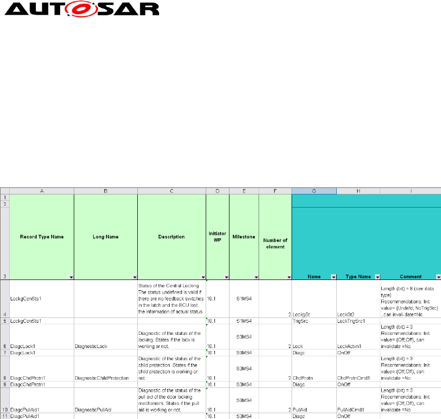
Application Interfaces User Guide
AUTOSAR CP Release 4.4.0
95 of 102 Document ID 442: AUTOSAR_EXP_AIUserGuide
- AUTOSAR confidential -
TirePPerWhl1
</BLUEPRINT-REF>
<DERIVED-OBJECT-REF DEST="APPLICATION-ARRAY-DATA-TYPE"
BASE="ApplicationDataTypes"
>
TirePPerWhl1
</DERIVED-OBJECT-REF>
</BLUEPRINT-MAPPING>
Descriptions are parsed according to Section 9.2.5.
9.7.4 Record Types
Figure 80: Structure of the sheet 11_DataTypes_Record
As with enumeration types, all consecutive lines with the same record type name are
included in one record type, with one line for each record element. E.g. rows 6 and 7
from Figure 80 will result in the following XML.
<APPLICATION-RECORD-DATA-TYPE>
<SHORT-NAME NAME-PATTERN="{anyName}">DiagcLock1</SHORT-NAME>
<LONG-NAME><L-4 L="EN">Diagnostic Lock</L-4></LONG-NAME>
<DESC><L-2 L="EN">Diagnostic of the status of the locking. States if the
lock is working or not.</L-2></DESC>
<CATEGORY>STRUCTURE</CATEGORY>
<SW-DATA-DEF-PROPS>
<SW-DATA-DEF-PROPS-VARIANTS>
<SW-DATA-DEF-PROPS-CONDITIONAL>
<SW-CALIBRATION-ACCESS>READ-ONLY</SW-CALIBRATION-ACCESS>
</SW-DATA-DEF-PROPS-CONDITIONAL>
</SW-DATA-DEF-PROPS-VARIANTS>
</SW-DATA-DEF-PROPS>
<ELEMENTS>
<APPLICATION-RECORD-ELEMENT>
<SHORT-NAME NAME-PATTERN="{anyName}">Lock</SHORT-NAME>
<TYPE-TREF DEST="APPLICATION-PRIMITIVE-DATA-TYPE"
BASE="ApplicationDataTypes">LockActvn1</TYPE-TREF>
</APPLICATION-RECORD-ELEMENT>
<APPLICATION-RECORD-ELEMENT>
<SHORT-NAME NAME-PATTERN="{anyName}">Diagc</SHORT-NAME>
<TYPE-TREF DEST="APPLICATION-PRIMITIVE-DATA-TYPE"
BASE="ApplicationDataTypes">OnOff1</TYPE-TREF>

Application Interfaces User Guide
AUTOSAR CP Release 4.4.0
96 of 102 Document ID 442: AUTOSAR_EXP_AIUserGuide
- AUTOSAR confidential -
</APPLICATION-RECORD-ELEMENT>
</ELEMENTS>
</APPLICATION-RECORD-DATA-TYPE>
BlueprintMapping for Record Data Type is as shown below.
<BLUEPRINT-MAPPING>
<BLUEPRINT-REF DEST="APPLICATION-RECORD-DATA-TYPE"
BASE="ApplicationDataTypes_Blueprint"
>
DiagcLock1
</BLUEPRINT-REF>
<DERIVED-OBJECT-REF DEST="APPLICATION-RECORD-DATA-TYPE"
BASE="ApplicationDataTypes"
>
DiagcLock1
</DERIVED-OBJECT-REF>
</BLUEPRINT-MAPPING>
Descriptions are parsed according to Section 9.2.5.
9.7.5 Float Types
Datatype definition for float representation as follow
<APPLICATION-PRIMITIVE-DATA-TYPE>
<SHORT-NAME NAME-PATTERN="{anyName}">T6</SHORT-NAME>
<LONG-NAME>
<L-4 L="EN">Temperature 6</L-4>
</LONG-NAME>
<DESC>
<L-2 L="EN">Generic data type for temperature</L-2>
</DESC>
<CATEGORY>VALUE</CATEGORY>
<INTRODUCTION>
<P>
<L-1 L="EN">Examples for usage: glow plugs temperature, oil
temperature, environment temperature, temperature differences
Remark: use for floating point implementation</L-1>
</P>
</INTRODUCTION>
<SW-DATA-DEF-PROPS>
<SW-DATA-DEF-PROPS-VARIANTS>
<SW-DATA-DEF-PROPS-CONDITIONAL>
<SW-CALIBRATION-ACCESS>READ-ONLY</SW-CALIBRATION-ACCESS>
<COMPU-METHOD-REF BASE="CompuMethods" DEST="COMPU-
METHOD">KelvinIdentcl</COMPU-METHOD-REF>
<DATA-CONSTR-REF BASE="DataConstrs" DEST="DATA-CONSTR">
FloatDatarange </DATA-CONSTR-REF>
<SW-INTENDED-RESOLUTION>0.0000001</SW-INTENDED-RESOLUTION>
<UNIT-REF BASE="Units" DEST="UNIT">Kelvin</UNIT-REF>
</SW-DATA-DEF-PROPS-CONDITIONAL>
</SW-DATA-DEF-PROPS-VARIANTS>
</SW-DATA-DEF-PROPS>
</APPLICATION-PRIMITIVE-DATA-TYPE>
9.8 Units
Figure 81: Structure of the sheet 13_Units

Application Interfaces User Guide
AUTOSAR CP Release 4.4.0
97 of 102 Document ID 442: AUTOSAR_EXP_AIUserGuide
- AUTOSAR confidential -
The Units belong to the package /AUTOSAR/AISpecification/Units. The generated
XML is derived from the table entries straight-forward according to the following
example. The Physical Dimensions are also generated in the XML and referenced to
the relevant Units. The short name of the Physical Dimensions are derived according
to the rules below
Usage of already existing keyword abbreviations
I for electrical current
Cd for luminous intensity
Ti for time
M for mass
Mol for amount of substance
T for thermodynamic temperature
Len for length
Neg for negative values
Short names are created as concatenation of the dimensions.
Long names are constructed similar to short names only that the full words are used
(Ex: Length, Mass, Time, Amount of Substance etc). The long names for the
negative units shall use ‘-‘ instead of Negative
For dimensionless Units a PhysicalDimension “NoDimension” will be used.
<UNIT>
<SHORT-NAME>KiloGr</SHORT-NAME>
<LONG-NAME><L-4 L="EN">Kilo Gram</L-4></LONG-NAME>
<DESC><L-2 L="EN">SI base unit of mass</L-2></DESC>
<DISPLAY-NAME>kg</DISPLAY-NAME>
<FACTOR-SI-TO-UNIT>1</FACTOR-SI-TO-UNIT>
<PHYSICAL-DIMENSION-REF DEST="PHYSICAL-DIMENSION"
BASE="PhysicalDimensions" >
M1
</PHYSICAL-DIMENSION-REF>
</UNIT>
The Unit KiloGr refers to the physical dimension of M1, which is represented in XML
as below.
<PHYSICAL-DIMENSION>
<SHORT-NAME>M1</SHORT-NAME>
<LONG-NAME><L-4 L="EN">Mass 1</L-4></LONG-NAME>
<MASS-EXP>1</MASS-EXP>
</PHYSICAL-DIMENSION>
9.9 Life Cycle State
The Life Cycle information is added in the column “Life Cycle State” of the AI excel
table as shown below alongwith the alternative to be used and expiry date.
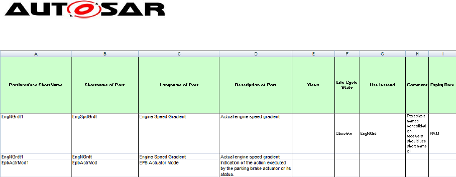
Application Interfaces User Guide
AUTOSAR CP Release 4.4.0
98 of 102 Document ID 442: AUTOSAR_EXP_AIUserGuide
- AUTOSAR confidential -
Figure 82: Life Cycle State definition in Excel table
The Life Cycle State of these elements in AI table is output in the XML file
AUTOSAR_MOD_AISpecification_Standard_LifeCycle.arxml
There shall be one Life Cycle info set per model element grouped under the
respective categories under the LifeCycleInfoSets . The Obsolete elements under
each category is labeled <category>Obslt (e.g KeywordObslt, ApplDataTypObslt,
DataConstrObslt, CompuMethodObslt, PortIfObslt, PortPrototypeBlueprintObslt).
Both the spellings "obsolete" and "Obsolete" are recognized by the XML generator
and the DEFAULT-LC-STATE-REF points to "obsolete" as seen below.
For the above example, the PortPrototype element EngSpdGrdt is set to Obsolete
under the BASE “PortPrototypeBlueprints” as seen in the XML extract below.
The PERIOD-BEGIN is used describe the expiry date of the element (R4.1.1 in the
above case) i.e. the fist AUTOSAR release for which the respective element was set
to “obsolete”.
The Comment and Use Instead columns translates to the REMARK and USE-
INSTEAD sections respectively in the XML description.
<?xml version="1.0" encoding="UTF-8"?>
<AUTOSAR
xmlns="http://autosar.org/schema/r4.0"
xmlns:xsi="http://www.w3.org/2001/XMLSchema-instance"
xsi:schemaLocation="http://autosar.org/schema/r4.0 AUTOSAR_4-1-1.xsd"
>
<ADMIN-DATA>
<LANGUAGE>EN</LANGUAGE>
<USED-LANGUAGES><L-10 L="EN" xml:space="default">English</L-10></USED-
LANGUAGES>
</ADMIN-DATA>
<AR-PACKAGES>
<AR-PACKAGE>
<SHORT-NAME>AUTOSAR</SHORT-NAME>
<LONG-NAME><L-4 L="EN">AUTOSAR</L-4></LONG-NAME>
<AR-PACKAGES>
<AR-PACKAGE>
<SHORT-NAME>AISpecification</SHORT-NAME>
<AR-PACKAGES>
<AR-PACKAGE>
<SHORT-NAME>LifeCycleInfoSets</SHORT-NAME>
<CATEGORY>STANDARD</CATEGORY>
<REFERENCE-BASES>
<ELEMENTS>
………
<LIFE-CYCLE-INFO-SET>
<SHORT-NAME>PortPrototypeBlueprintObslt</SHORT-NAME>

Application Interfaces User Guide
AUTOSAR CP Release 4.4.0
99 of 102 Document ID 442: AUTOSAR_EXP_AIUserGuide
- AUTOSAR confidential -
<DEFAULT-LC-STATE-REF DEST="LIFE-CYCLE-STATE"
BASE="LifeCycleStateDefinitionGroups">AutosarLifeCycleStates/obsolete</DEFAULT-LC-
STATE-REF>
………
<LIFE-CYCLE-INFO>
<LC-OBJECT-REF DEST="PORT-PROTOTYPE-BLUEPRINT"
BASE="PortPrototypeBlueprints">EngSpdGrdt</LC-OBJECT-REF>
<PERIOD-BEGIN>
<AR-RELEASE-VERSION>4.1.1</AR-RELEASE-VERSION>
</PERIOD-BEGIN>
<REMARK>
<P><L-1 L="EN">Port short names consolidation: receivers should
use short name of providers.</L-1></P>
</REMARK>
<USE-INSTEAD-REFS>
<USE-INSTEAD-REF DEST="PORT-PROTOTYPE-BLUEPRINT"
BASE="PortPrototypeBlueprints">EngNGrdt</USE-INSTEAD-REF>
</USE-INSTEAD-REFS>
</LIFE-CYCLE-INFO>
………
<USED-LIFE-CYCLE-STATE-DEFINITION-GROUP-REF DEST="LIFE-CYCLE-
STATE-DEFINITION-GROUP"
BASE="LifeCycleStateDefinitionGroups">AutosarLifeCycleStates</US
ED-LIFE-CYCLE-STATE-DEFINITION-GROUP-REF>
</LIFE-CYCLE-INFO-SET>
</ELEMENTS>
</AR-PACKAGE>
</AR-PACKAGES>
</AR-PACKAGE>
</AR-PACKAGES>
</AR-PACKAGE>
</AR-PACKAGES>
</AUTOSAR>
Similarly the Life Cycle state of other elements (e.g PortInterfaces, Keywords,etc..)
are also generated in the XML and the corresponding BASE is referenced.
Additionally, DataConstrs are handled in scope of PrimitiveDataTypes. The
CompuMethods are marked obsolete if they are linked to obsolete datatype. The
PortPrototypeBlueprints are also marked as obsolete if marked in 05_Sheets. The
elements marked Obsolete will not appear in the Examples package or
BlueprintMappings.
In certain cases, there may be multiple entries under the attribute “Use Instead” (see
Figure below)
Figure 83: Life Cycle State definition (Multiple entries)

Application Interfaces User Guide
AUTOSAR CP Release 4.4.0
100 of 102 Document ID 442: AUTOSAR_EXP_AIUserGuide
- AUTOSAR confidential -
For such situations, the entries are separated using a comma (,) in the “Use Instead”
column. In the above example the Keyword Short Name“Wind” is rendered Obsolete
for “Windscreen” and instead needs to be contructed from the abbreviations for
“Wind” and “Screen” (Scrn) respectively.
The corresponding XML extract results as follows:
<LIFE-CYCLE-INFO>
<LC-OBJECT-REF DEST="KEYWORD" BASE="KeywordSets">KeywordList/Wind</LC-
OBJECT-REF>
<PERIOD-BEGIN>
<AR-RELEASE-VERSION>4.1.1</AR-RELEASE-VERSION>
</PERIOD-BEGIN>
<REMARK>
<P><L-1 L="EN">correction according naming rules, To use Windscreen,
please build the short name of the keyword abbreviations of Wind and
Screen.</L-1></P>
</REMARK>
<USE-INSTEAD-REFS>
<USE-INSTEAD-REF DEST="KEYWORD"
BASE="KeywordSets">KeywordList/Wind1</USE-INSTEAD-REF>
<USE-INSTEAD-REF DEST="KEYWORD"
BASE="KeywordSets">KeywordList/Scrn</USE-INSTEAD-REF>
</USE-INSTEAD-REFS>
</LIFE-CYCLE-INFO>
9.10 Views
The View information can be added for a model element as described in the Chapter
View Concept.
To implement the view concept in the AI Excel Table a column to all port sheets (05*
Sheets), to all data type sheets is added.
The Views shall be output as
AUTOSAR_MOD_AISpecification_Collection_<view>_Blueprint.arxml file
The following views are used (ShortName/longName):
Truck (Truck), Body (Body), Pt (Powertrain), Chassis (Chassis), OccptPedSfty
(Occupant and Pedestrian Safety), MmedTelmHmi (Multimedia Telematics and HMI)
The AI table macro generates a collection marked with REF-ALL. This collection only
contains the elements that are specified for this view within the AI Table, i.e. mainly
PortPrototpyeBlueprints.
In a second step a collection marked with REF-NONE will be created. Therefore, the
generated ARXML file containing the collection marked with REF-ALL needs to be
stored and an additional automated job needs to run. It uses the collection with the
attribute REF-ALL to build the collection with the attribute REF-NONE. That means
for all elements included in the collection, the referenced elements will also be added
in case they are not yet included.
In this way the collection with the attribute REF-NONE will be built and put into the
same package within the same ARXML file. Afterwards the new file will be stored
back again.
The collection for REF-NONE contains the elements, that are specified to belong to
this view plus all derived elements, e.g. if a PortPrototypeBlueprint (DoorSts)

Application Interfaces User Guide
AUTOSAR CP Release 4.4.0
101 of 102 Document ID 442: AUTOSAR_EXP_AIUserGuide
- AUTOSAR confidential -
belongs to a certain view also the respective PortInterface, the DataTypes etc.
belonging to this collection is listed as well.
The category of the view shall be "SET" and Element role shall be
“PART_OF_SUBSET".
A comma-separated list of views is resolved into entries for individual views in the
list. For each view, an arxml output file is created.
Hence, the XML generator output is as under:
<AR-PACKAGES>
<AR-PACKAGE>
<SHORT-NAME>AISpecification</SHORT-NAME>
<AR-PACKAGES>
<AR-PACKAGE>
<SHORT-NAME>Collections_Blueprint</SHORT-NAME>
<CATEGORY>BLUEPRINT</CATEGORY>
…….
<ELEMENTS>
<COLLECTION>
<SHORT-NAME>Body</SHORT-NAME>
<CATEGORY>SET</CATEGORY>
<AUTO-COLLECT>REF-NONE</AUTO-COLLECT>
<ELEMENT-ROLE>PART_OF_SUBSET</ELEMENT-ROLE>
<ELEMENT-REFS>
<ELEMENT-REF DEST="PORT-PROTOTYPE-BLUEPRINT"
BASE="PortPrototypeBlueprints">DoorSts</ELEMENT-REF>
<ELEMENT-REF DEST="SENDER-RECEIVER-
INTERFACE" BASE="PortInterfaces">DoorSts1</ELEMENT-REF>
<ELEMENT-REF DEST="APPLICATION-
PRIMITIVE-DATA-TYPE" BASE="ApplicationDataTypes">DoorSts1</ELEMENT-REF>
<ELEMENT-REF DEST="COMPU-METHOD"
BASE="CompuMethods">DoorSts1</ELEMENT-REF>
<ELEMENT-REF DEST="UNIT"
BASE="Units">NoUnit</ELEMENT-REF>
<ELEMENT-REF DEST="PHYSICAL-DIMENSION"
BASE="PhysicalDimensions">NoDimension</ELEMENT-REF>
<ELEMENT-REF DEST="DATA-CONSTR"
BASE="DataConstrs">DoorSts1</ELEMENT-REF>
……
</ELEMENT-REFS>
</COLLECTION>
<COLLECTION>
<SHORT-NAME>BodyRefAll</SHORT-NAME>
<CATEGORY>SET</CATEGORY>
<AUTO-COLLECT>REF-ALL</AUTO-COLLECT>
<ELEMENT-ROLE>PART_OF_SUBSET</ELEMENT-ROLE>
<ELEMENT-REFS>
<ELEMENT-REF DEST="PORT-PROTOTYPE-BLUEPRINT"
BASE="PortPrototypeBlueprints">DoorSts</ELEMENT-REF>
…………
</ELEMENT-REFS>
</COLLECTION>
</ELEMENTS>
</AR-PACKAGE>
</AR-PACKAGES>
</AR-PACKAGE>
</AR-PACKAGES>
</AR-PACKAGE>
</AR-PACKAGES>

Application Interfaces User Guide
AUTOSAR CP Release 4.4.0
102 of 102 Document ID 442: AUTOSAR_EXP_AIUserGuide
- AUTOSAR confidential -
10 References
In this section, the references used in this document are listed.
10.1 Standard documents
[1] Software Component Template
[2] Standardization Template
[3] AUTOSAR XML schema
[4] Generic Structure Template
[5] Model Persistence Rules for XML
[6] AI Specification
10.2 Auxiliary documents
[7] AUTOSAR Metamodel
[8] Application Interface table (AI Table)
[9] SW-C and System Modeling Guide
[10] AUTOSAR Methodology
[11] AUTOSAR domain explanation Body and Comfort
[12] AUTOSAR domain explanation Powertrain
[13] AUTOSAR domain explanation Chassis
[14] AUTOSAR domain explanation Occupant and Pedestrian Safety
[15] AUTOSAR domain explanation Multimedia, Telematics, Human Machine
Interface.
[16] Unique Names for Documentation, Measurement and Calibration
[17] AUTOSAR Glossary
