AVN210 Installation Guide AVN420, AVN422, AVN441, AVN443 Quick Start
User Manual: AVN420, AVN422, AVN441, AVN443 - Quick Start Guide
Open the PDF directly: View PDF ![]() .
.
Page Count: 8
2060 Alameda Padre Serra, Suite 100∙ Santa Barbara, CA 93103
Tel: (805) 845-8900 ∙ Fax: (805) 845-8889 www.vsicam.com
Visionary Solutions, Inc.
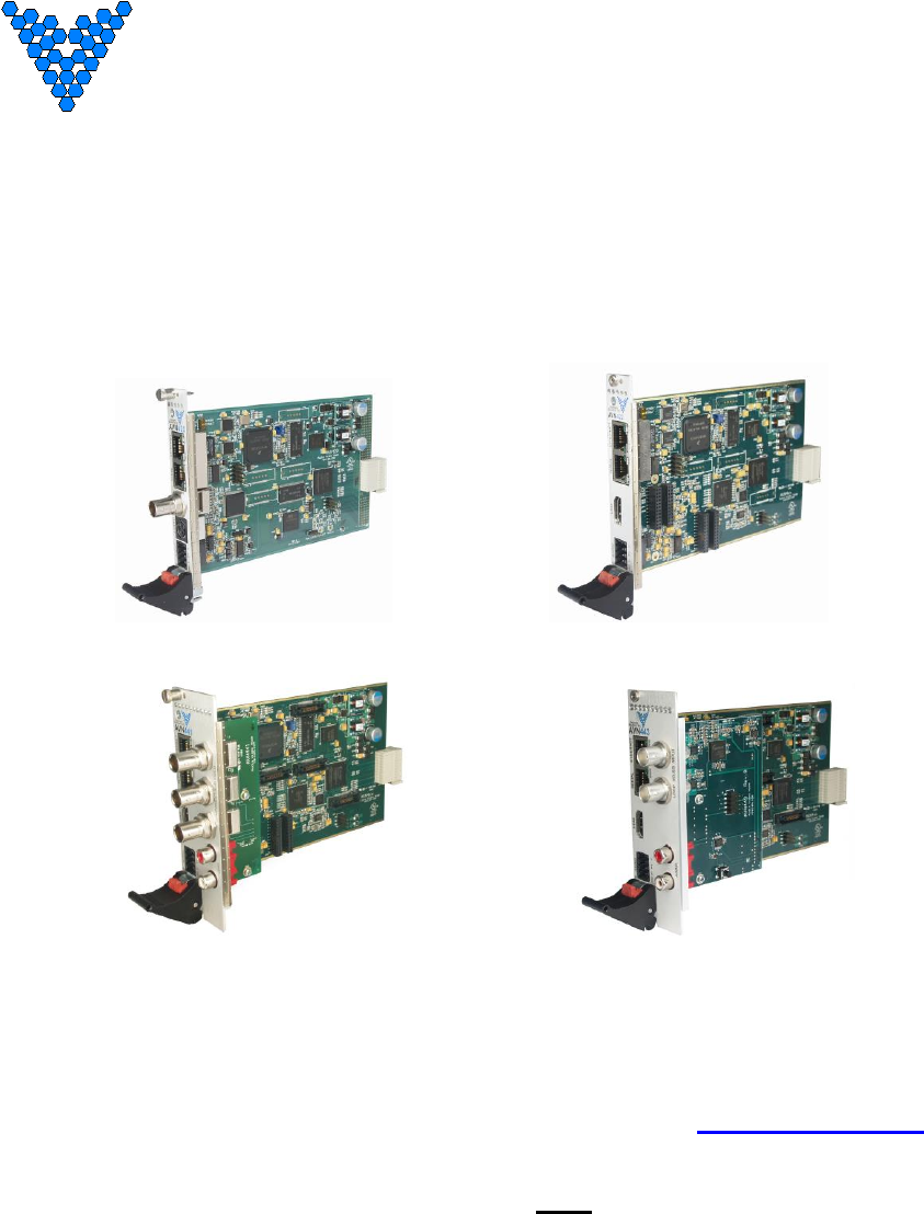
AVN4XX Quick Start Guide
(AVN420, AVN422, AVN441, and AVN443)
AVN420 AVN422
AVN441 AVN443
©2011 Visionary Solutions, Inc. All rights reserved.
Please visit the support section of our website at www.vsicam.com for
manuals, other documentation, and software downloads.
This is a Quick Start Guide only and NOT the full User’s Manual. Current
user manuals are available online.
April, 2013
Revision: 1.0.4

AVN4XX Quick Start Guide
2060 Alameda Padre Serra, Suite 100∙ Santa Barbara, CA 93103
Tel: (805) 845-8900 ∙ Fax: (805) 845-8889 www.vsicam.com
2
Introduction
This document is intended to assist users in the initial configuration and setup of the AVN4XX series of
encoders. This document is NOT intended to provide installation instructions for either the AmiNet or
other AVN products (AVN2XX).
Equipment Required
1 Blade card (AVN420, AVN422, AVN441, or AVN443)
1 MPP200 or MPP1700 Chassis with matching power supply
1 Ethernet cable
1 RJ45 to DB9 serial cable (same as Cisco console cable, only needed for initial configuration)
1 Video cable:
o AVN420 – SVideo or Composite
o AVN422 – HDMI (DVI-D with adaptor cable)
o AVN441 – HDMI (DVI-D with adaptor cable), Component or Composite
o AVN443 – HDMI (DVI-D with adaptor cable) or SDI
1 Audio connector (for balanced or unbalanced audio input), or RCA audio cable (unbalanced
only) for an AVN441 or AVN443.
Step 1: Connect AVN4XX Hardware
Note: It is important that the module be properly aligned with the slot guides before it is inserted into the
appropriate slot on the chassis. It is recommended that the user’s line of sight be level with the
middle of the backplane in order to see both slot guides clearly.
Install a VSI blade into the chassis as follows:
Caution: Use proper ESD precautions when installing or removing a VSI blade to avoid damaging the
unit’s circuitry.
1. Slide the blade, open end first, into the desired slot on the chassis until it plugs into the connector
located on the backplane at the rear of the unit.
2. Use the bottom ejector handle to securely seat the blade into the chassis and to properly mate
the rear connectors. The handle should lock closed when properly inserted to secure the unit.
3. Tighten the captive thumb screw located at the top of the blade to provide a more secure
mounting.
4. If desired, an additional Phillips screw can be installed through the handle.
5. The Status LED will blink once per second when the blade is properly installed, powered, and
operational.

AVN4XX Quick Start Guide
2060 Alameda Padre Serra, Suite 100∙ Santa Barbara, CA 93103
Tel: (805) 845-8900 ∙ Fax: (805) 845-8889 www.vsicam.com
3
Step 2: Initial AVN4XX Network Configuration
In order to configure your AVN4XX blade, you will first need to know some basic information about the
network where it is going to be installed. Specifically, would you like the unit to be configured statically or
set up to use DHCP? If static addressing is used, you will need to have an available IP address that you
can use, as well as a subnet mask, default gateway, and DNS server(s). It is highly recommended that
you assign a static IP address to your AVN4XX, because communicating and configuring a unit remotely
(over the network without having to use the serial console) requires that you know the unit’s IP address.
The AVN4XX encoders ship with DHCP turned on by default. If there is no DHCP server on the network,
the encoder defaults to IP address 192.168.1.253. To assign a static IP address to your device, use one
of the following two methods.
Method I – Console Interface (recommended method)
1. Connect the serial cable between the serial port of the AVN4XX blade and a COM port on your
PC (typically the COM1 port). The AVN4XX blade uses an RJ-45 to DB9-F serial cable (shipped
with the MPP chassis). See the appropriate AVN4XX user’s manual for information on that
particular blade.
2. Launch a terminal emulation program, such as TeraTerm (google: teraterm download).
a. Create/Open a new serial connection.
b. Specify the PC port you are connected to (typically COM1), click OK.
c. Configure the Port Settings as follows: Bits per second (38400), Data bits (8), Parity
(None), Stop bits (1), Flow Control (None). Click OK.
d. Press Enter to get the login prompt for the encoder.
3. Log in to the unit with the Username/Password. The default values are: admin/admin
4. If the unit has not been previously configured, the Network Connection Wizard automatically
appears and prompts you to enter values for the IP Address, Netmask, Gateway, and DNS. If the
unit has been previously configured, and you are not prompted to enter new network settings,
type a lower case ‘n’ into the console interface and click Enter. This will bring up the Network
Configuration Wizard and allow you to enter new values.
If you make a mistake before you have finished entering all of the new values, you can press
CTRL+C to cancel the process, and log in again to restart the Network Configuration Wizard.
a. Enter the IP Address:
i. To configure the unit for DHCP:
1) Make sure the network supports DHCP.
2) Enter 0.0.0.0.
3) You will be prompted for a backup IP address in the event that DHCP
fails. Enter a static IP address (e.g., 192.168.1.253).
ii. To statically configure the unit, enter the IP address (e.g., 192.168.1.45)
b. Enter the Subnet Mask (e.g., 255.255.255.0)
c. Enter the Default Gateway (e.g., 192.168.1.1)
d. Enter the DNS Server Address (e.g., 4.2.2.1)
5. Once the initial Network Identification data is entered, the blade will reboot and should be
accessible at its newly assigned location from a web server. Make sure to connect the
audio/video and network cables to the blade.
6. Exit the terminal emulation program and disconnect the serial cable if it is no longer needed.
AVN4XX Quick Start Guide
2060 Alameda Padre Serra, Suite 100∙ Santa Barbara, CA 93103
Tel: (805) 845-8900 ∙ Fax: (805) 845-8889 www.vsicam.com
4
Method II – Web Interface
1. For the PC that is going to do the AVN4XX network configuration, assign an IP address on the
“one” subnet (e.g. 192.168.1.100). Since the AVN4XX will default to 192.168.1.253 if it cannot
find a DHCP server, it requires a PC on the same subnet in order to “see” and configure it. Note,
that if there is a DHCP server running on the PC, disable it before connecting the AVN4XX.
2. Using any Ethernet cable (crossover or regular), connect one end to Ethernet port on the
AVN4XX and the other to the Ethernet port on the PC.
3. Open the AVN4XX’s browser interface.
a. From the configuration PC, open up a web browser.
b. Type in the AVN4XX’s default IP address (192.168.1.253) into the URL after the ‘http://”
and click Enter. The resulting URL will look like: http://192.168.1.253.
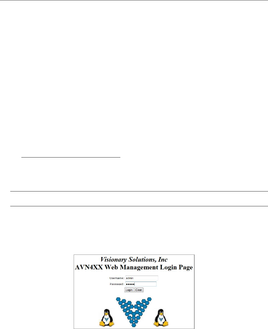
c. Login with the AVN4XX’s username/password (admin/admin by default). Refer to
Figure 1 below.
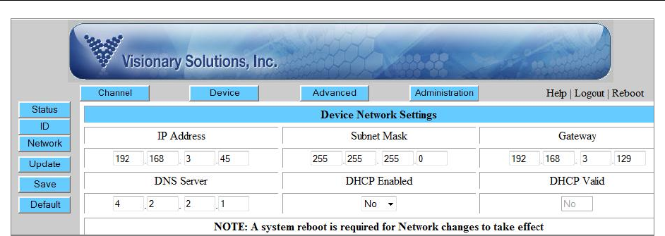
d. Navigate to the Device Network Settings page. From the main browser interface page,
click the Device button in the top row, followed by the Network button in the left hand
column. Refer to Figure 2.
4. Edit the AVN4XX’s network settings as desired: enter the IP address (e.g., 192.168.1.45), Subnet
Mask (e.g., 255.255.255.0), Gateway (e.g., 192.168.1.1), DNS Sever address (e.g., 4.2.2.1), and
make sure to set DHCP Enabled to No.
5. Save the new settings by clicking the Save button in the left hand column.
6. Reboot the unit by clicking the Reboot button/link in the upper right hand corner (see Figure 2).
7. Finished. The unit now has the new network settings.
Note: It is recommended that the browser interface be used for managing the AVN after the initial
network configuration.
Step 3: Configure the AVN4XX for Streaming
1. Enter the IP Address for the AVN4XX blade (http://xxx.xxx.xxx.xxx) into your favorite browser to
bring up the blade’s web interface. Log in using the unit’s username/password (admin/admin by
default).
Figure 1 Web Interface Login
2. The IP Address, Netmask, Gateway and DNS info should have already be configured, however
if necessary, this information can be changed from the Device> Network page.
AVN4XX Quick Start Guide
2060 Alameda Padre Serra, Suite 100∙ Santa Barbara, CA 93103
Tel: (805) 845-8900 ∙ Fax: (805) 845-8889 www.vsicam.com
5
Figure 2 Web Interface - Device Network page
3. Configure the critical Audio and Video Input settings (Video Source, Video Format and Audio
Source). From the Channel> Input page (setting options dependent upon blade type) enter the
correct input values.
a. AVN420
i. Video Source – Svideo or Composite
ii. Video Format – NTSC or PAL
iii. Audio Source – Balanced or Unbalanced
b. AVN422
i. Video Source – HDMI (DVI-D with adaptor cable)
ii. Video Format * – from 1080p to 480i or Auto
iii. Audio Source - Embedded HDMI, Balanced or Unbalanced
c. AVN441
i. Video Source – HDMI (DVI-D with adaptor cable), Component YPbPr, RGB, or
Composite
ii. Video Format * – from 1080p to 480i or Auto
iii. Audio Source – Embedded HDMI, Balanced or Unbalanced
d. AVN443
i. Video Source – HDMI (DVI-D with adaptor cable) or SDI
ii. Video Format * – from 1080p to 480i or Auto
iii. Audio Source – Embedded HDMI, Balanced or Unbalanced
* - valid video formats dependent upon optional purchased modules (720p, 1080i, 1080p)
4. Configure the Encoding settings (optional). From the Channel> Encoding page enter the desired
values.
a. AVN420
i. Video Bitrate (100-4,000 kbps)
ii. Video Size (720x480 down to 160x120)
iii. Audio Bitrate (8 to 384 kpbs)
iv. Audio Format (AAC or MPG)
b. AVN422, AVN441 and AVN443
i. Video Bitrate (Mbps) - (6-20 for >=1080i, 4-20 for 720p, and 2-10 for SD)
ii. Audio Bitrate (32 to 384 kpbs)
iii. Audio Format (AAC or MPG)
HD Encode Note: The minimum Video Bitrate value for 1080i is 6,000 kbps (6 Mbps),
which requires setting the Total Bitrate value to 7100 kbps. The Video Bitrate is based
upon the Total Bitrate minus the audio bitrate and some overhead.
AVN4XX Quick Start Guide
2060 Alameda Padre Serra, Suite 100∙ Santa Barbara, CA 93103
Tel: (805) 845-8900 ∙ Fax: (805) 845-8889 www.vsicam.com
6
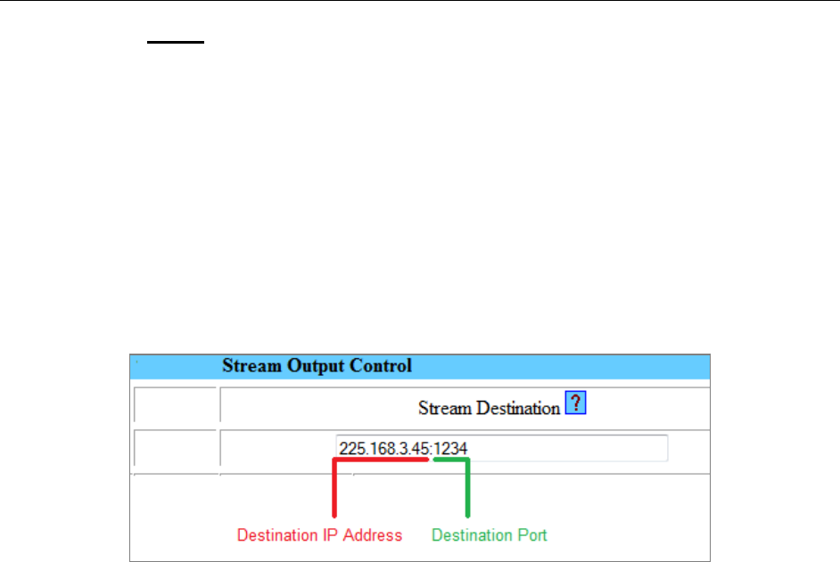
5. Configure the critical Stream Output Control setting (Stream Destination). From the
Channel>Stream page, enter the desired stream destination value. This setting controls where the
encoder sends the stream and is therefore a critical component to successful streaming.
The Stream Destination consists of two parts: the Destination IP address (underlined in Figure 3) and
the Destination Port number (underlined in Figure 3), separated by a “ : ” colon.
The destination IP address can either be a Unicast address (single point/viewer) or Multicast (many
viewers). For more information, see the section titled “Unicast and Multicast Transmissions over the
Network” below.
The Destination IP Address shown Figure 3 is a multicast address (starts with 225) and viewable to
multiple users on the network. The Destination Port is an arbitrary number (above 1024) that is
matched when configuring channels on a hardware or software decoder. The factory default
destination port number is 1234.
VSI recommends using an even number for the port.
Figure 3 Stream Destination Example
Unicast and Multicast Transmissions over the Network
A Unicast transmission sends IP packets to a single recipient on a network. A Multicast transmission
sends IP packets to a group of hosts on a network. If the streaming video is to be distributed to a single
destination, start a Unicast stream by setting the destination IP address and port on the AVN equal to the
destination's values. To view the stream at multiple concurrent locations, set the AVN's destination IP
address to a valid Multicast IP address (224.0.0.0 - 239.255.255.255).
Note that while the Multicast IP address range is from 224.0.0.0 - 239.255.255.255, the first and last
octets (224.xxx.xxx.xxx and 239.xxx.xxx.xxx) are generally reserved for administration. VSI recommends
setting the first octet to 225 and the remaining three octets to the AVN's IP address. For example, if the
AVN's IP address is 192.168.1.53, set the destination IP address to 225.168.1.53 for Multicast streaming.
Since Multicasting is a relatively new technology, some legacy devices that are part of your network might
not support Multicasting.
Before using the AVN4XX in Multicast streaming mode, check the functional specifications of your
network infrastructure to ensure that the Multicast stream will not create major traffic on your network.
Verify that your network supports Multicast/IGMP streaming to insure proper filtering and routing of
multicast traffic. If your backbone switch supports Internet Group Messaging Protocol (IGMP) snooping, it
allows the core of your network to ignore the traffic streams that Multicasting may generate.
AVN4XX Quick Start Guide
2060 Alameda Padre Serra, Suite 100∙ Santa Barbara, CA 93103
Tel: (805) 845-8900 ∙ Fax: (805) 845-8889 www.vsicam.com
7
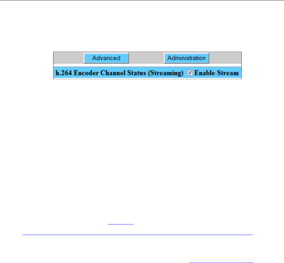
Step 4: Check the Enable Stream Checkbox
1. To begin encoding / streaming, check the Enable Stream checkbox in the upper right hand area
of the title bar on any of the AVN4XX’s Channel pages (Channel> Input, Encoding, Stream or
SAP). See Figure 4 below.
Figure 4 Enable Stream checkbox checked with successful streaming
2. If successful, the word “Streaming” will show in parenthesis next to the Stream Enable checkbox
as shown in Figure 4 above. If there is no video or invalid video detected, the AVN4XX will not
stream even if the Enable Stream checkbox is checked.
Step 5: View / Decode the AVN4XX Stream
The AVN4XX should now be streaming to the Destination IP address and Destination Port configured in
Step 3 above. To decode the stream, it is necessary to configure the decoder (whether hardware or
software) to find the stream on the network. The decoder configuration is dependent upon the decoder
being used and is therefore beyond the scope of this document.
To find out how to configure and view AVN-generated streams using Amino STBs (set top boxes) and
VLC Media Player, please review the following support documentation:
1. AmiNet STB (hardware decoders):
For instructions on configuring AmiNet hardware decoders for use with the AVN4XX, see the
“Amino Configuration Manual” ( click here ), or at the following URL:
http://www.vsicam.com/core/__downloads/Amino_140_VSI_Configuration_Manual.pdf
2. VLC Media Player:
a. To get the free VLC Media Player software decoder, go to http://www.videolan.org/ and
download the VLC media player (current version).
b. Once installed, configure the decoder to receive the AVN generated stream.
c. Select the Open Network… option, under the Media menu.
d. In the following dialog, enter the AVN4XX’s “critical” destination stream information from the
browser interface (Destination IP address and Port number, see Step 3, #5 above).
How this information is entered into the VLC varies based on the version of the player.
i. For VLC versions 1.1.0 and above: Enter: udp://@xxx.xxx.xxx.xxx:yyyy where “x”
represents the Destination IP address and “y” the Destination Port. DO NOT
FORGET THE @ sign!
ii. For VLC versions between 1.0.0 and 1.1.0: Set the protocol to UDP and enter the
Destination IP address and Port into the corresponding fields.
iii. For VLC versions pre 1.0.0: Select the UDP/RTP Multicast radio button and enter the
Destination IP address and Port into the corresponding fields.
e. Click the Play or OK button at the bottom the dialog to begin viewing.
AVN4XX Quick Start Guide
2060 Alameda Padre Serra, Suite 100∙ Santa Barbara, CA 93103
Tel: (805) 845-8900 ∙ Fax: (805) 845-8889 www.vsicam.com
8
Safety and Compliance Information
This product can only be used in a VSI blade system. Unintended use of this product, or use with
non-VSI listed components, is forbidden and violates safety approvals.
Safety Approval: UL Listed I.T.E. E257717
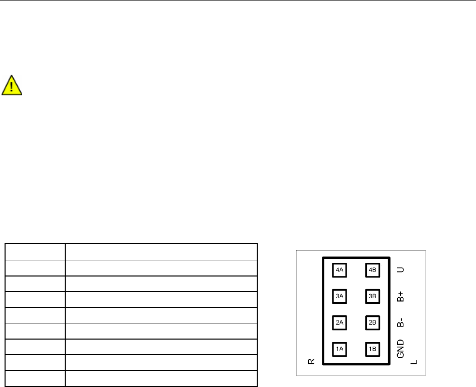
Audio Terminal Block Connector
Pinouts:
See the following paragraph for instructions on configuring the supplied audio terminal block connector
(supplied).
View is looking into the connector.
Configuration:
The following describes how to configure the audio terminal block connector:
1. Cut and strip the wires on the cable that will connect to your audio source. The strip length should
be approximately 1/4 inch long.
2. For each connection, insert a small object, such as a screw driver, into the terminal block’s latch
in order to open the wire clamp.
3. Insert each wire into its wire clamp.
4. Release the latch allowing the wire clamp to close.
Pin
Function
1A
Right Ground
2A
Right Balanced Audio Negative
3A
Right Balanced Audio Positive
4A
Right Unbalanced Audio
1B
Left Ground
2B
Left Balanced Audio Negative
3B
Left Balanced Audio Positive
4B
Left Unbalanced Audio
