AVR55 OM Harman Kardon AVR 55 Receiver Owner’s Manual OM4 98
User Manual: Harman Kardon AVR 55 Receiver Owner’s Manual Troubleshoot Harman Kardon AVR 55 Receiver |
Open the PDF directly: View PDF ![]() .
.
Page Count: 32

Harman Kardon
AVR55
Audio/VideoReceiver
Owner’s Manual
VID 1 REC. SPK. MODE SURR.OFFVID 2SURR. MODE NIGHT
Volume
Contour
Bass Treble Balance
DVD VID 1DIGITAL
Subwoofer Level
Surround Level
Center Level
PHONO TV
VIDEO 2
R VideoLMaxMinMaxMin L Audio R
RF COAX OPT
FRT/REAR DIGITAL INPUT
TAL
URCE
2
D
EC

Owner’s Manual
AVR55 Audio/Video Receiver
Table of Contents
Introduction . . . . . . . . . . . . . . . . . . . . . . . . . . . . . . . . . . 1
Safety Information . . . . . . . . . . . . . . . . . . . . . . . . . . . 2–3
Unpacking. . . . . . . . . . . . . . . . . . . . . . . . . . . . . . 3
Front Panel Controls. . . . . . . . . . . . . . . . . . . . . . . . . . 4–6
Front Panel Information Display . . . . . . . . . . . . . . . . . . 7
Rear Panel Connections. . . . . . . . . . . . . . . . . . . . . . . 8–9
Remote Control Functions . . . . . . . . . . . . . . . . . . . 10–12
Installation and Setup . . . . . . . . . . . . . . . . . . . . . . 13–14
Remote Control Programming and Operation . . . 15–16
System Configuration. . . . . . . . . . . . . . . . . . . . . . . 17–21
Operation . . . . . . . . . . . . . . . . . . . . . . . . . . . . . . . . 22–26
Source Selection . . . . . . . . . . . . . . . . . . . . . . . . 22
TV Auto-On . . . . . . . . . . . . . . . . . . . . . . . . . . . . 23
Surround Mode Selection. . . . . . . . . . . . . . 23–24
Dolby Digital. . . . . . . . . . . . . . . . . . . . . . . . . . . 24
Night Mode . . . . . . . . . . . . . . . . . . . . . . . . . . . . 24
PCM Audio Playback. . . . . . . . . . . . . . . . . . . . . 25
Tuner Operation . . . . . . . . . . . . . . . . . . . . . 25–26
Tape Recording . . . . . . . . . . . . . . . . . . . . . . . . . 26
Troubleshooting Guide . . . . . . . . . . . . . . . . . . . . . . . . . 27
Technical Specifications . . . . . . . . . . . . . . . . . . . . . . . . 28
©1998 Harman Kardon, Incorporated
250 Crossways Park Drive
Woodbury, NY 11797

Congratulations!With the purchase
of a Harman Kardon AVR55 you are
about to begin many years of listening
enjoyment. The AVR55 has been custom
designed to provide all the excitement
and detail of movie sound tracks and
every subtle nuance of musical selec-
tions. With on-board Dolby*Digital
Decoding, the AVR55 delivers six discrete
channels of audio that take advantage of
the digital sound tracks from the latest
DVD and LV releases as well as future
HDTV broadcasts.
While complex digital systems are hard
at work within the AVR55 to make all of
this happen, hookup and operation are
simple. Color-keyed connections and a
comprehensive learning remote control
make the AVR55 easy to use. To obtain
the maximum enjoyment from your
new receiver we urge you to take a few
minutes to read through this manual.
This will ensure that connections to
speakers, source playback units and other
external devices are made properly. In
addition, a few minutes spent learning
the functions of the various controls will
enable you to take advantage of all the
power the AVR55 is able to deliver.
If you have any questions about this
product, its installation or operation,
please contact your retailer or custom
installer. They are your best local source
of information.
Introduction
4
Description and Features
The AVR55 is a full-featured A/V receiver,
incorporating a wide variety of listening
options. In addition to Dolby Digital
decoding, Dolby Pro Logic*and Dolby 3
Stereo are available for compatibility with
the tens of thousands of movies and tele-
vision programs encoded with analog
surround information. A choice of Hall,
Theater, Church and Stadium modes is
also available for use with both encoded
sources and traditional two-channel
stereo recordings.
A total of four audio/video inputs, as
well as four additional audio only inputs
including a phono input and an FM
stereo/FM/AM tuner are available for the
utmost flexibility. Front panel AV inputs
simplify connections to video games or
camcorders.
The AVR55’s powerful amplifier uses
traditional Harman Kardon High-Current
design philosophies to meet the wide
dynamic range of any program selection.
Harman Kardon invented the high-
fidelity receiver over forty-five years ago.
With state-of-the-art features and time-
honored circuit designs, the AVR55 is one
of the finest receivers ever offered by
Harman Kardon.
■On-Board Dolby Digital Decoding
■Coax, Optical or RF Digital Inputs
■Six Analog Surround Modes
■Learning Remote Control
■Composite Video Switching
■Preamp Output for ALL Channels
Permits Ease of Expansion
■Phono Input
Safety Information
Important Safety Information
Verify Line Voltage Before Use
YourAVR55hasbeendesignedforuse
with120-voltACcurrent.Connectiontoa
linevoltageotherthanthatforwhichit
isintendedcancreateasafetyandfire
hazard,andmaydamagetheunit.
If you have any questions about the volt-
age requirements for your specific model,
or about the line voltage in your area,
contact your selling dealer before plug-
ging the unit into a wall outlet.
Do Not Use Extension Cords
To avoid safety hazards, use only the
power cord attached to your unit. We do
not recommend that extension cords be
used with this product. As with all electri-
cal devices, do not run power cords under
rugs or carpets or place heavy objects on
them. Damaged power cords should be
replaced immediately with cords meeting
factory specifications.
Handle the AC Power Cord Gently
When disconnecting the power cord from
an AC outlet, always pull the plug, never
pull the cord. If you do not intend to use
the unit for any considerable length of
time, disconnect the plug from the AC
outlet.
Do Not Open The Cabinet
There are no user-serviceable compo-
nents inside this product. Opening the
cabinet may present a shock hazard, and
any modification to the product will void
your guarantee. If water or any metal
object such as a paper clip, wire or a
staple accidentally falls inside the unit,
disconnect it from the AC power source
immediately, and consult an authorized
service station.
CATV or Antenna Grounding
If an outside antenna or cable system is
connected to this product, be certain that
it is grounded so as to provide some pro-
tection against voltage surges and static
charges. Section 810 of the National
Electrical Code, ANSI/NFPA No. 70-1984,
provides information with respect to
proper grounding of the mast and sup-
porting structure, grounding of the lead-
in wire to an antenna discharge unit,
size of grounding conductors, location of
antenna discharge unit, connection to
grounding electrodes and requirements
of the grounding electrode.
NOTE TO CATV SYSTEM INSTALLER:
Thisreminderisprovidedtocallthe
CATV(CableTV)systeminstaller’satten-
tiontoarticle820-40oftheNEC that
providesguidelinesforpropergrounding
and,inparticular,specifiesthatthecable
groundshallbeconnectedtotheground-
ingsystemofthebuilding,asclose tothe
pointofcableentryaspossible.
Installation Location
■To assure proper operation, and to
avoid the potential for safety hazards,
place the unit on a firm and level sur-
face. When placing the unit on a shelf,
be certain that the shelf and any
mounting hardware can support the
weight of the product.
■Make certain that proper space is pro-
vided both above and below the unit
for ventilation. If this product will be
installed in a cabinet or other enclosed
area, make certain that there is suffi-
cient air movement within the cabinet.
Under some circumstances a fan may
be required.
■Do not place the unit directly on a
carpeted surface.
■Avoid installation in extremely hot or
cold locations, or an area that is
exposed to direct sunlight or heating
equipment.
■Avoid moist or humid locations.
■Do not obstruct the ventilation slots on
the top of the unit, or place objects
directly over them.
5
CAUTION:
TO REDUCE THE RISK OF ELECTRIC SHOCK, DO NOT REMOVE
COVER (OR BACK). NO USER-SERVICEABLE PARTS INSIDE. REFER
SERVICING TO QUALIFIED SERVICE PERSONNEL.
WARNING:
TO REDUCE THE RISK OF FIRE OR ELECTRIC SHOCK,
DO NOT EXPOSE THIS APPLIANCE TO RAIN OR MOISTURE.
CAUTION:
TO PREVENT ELECTRIC SHOCK, MATCH WIDE
BLADE OF PLUG TO WIDE SLOT, FULLY INSERT.
ATTENTION:
POUR EVITER LES CHOCS ELECTRIQUES, INRODUIRE LA
LAME LA PLUS LARGE DE LA FICHE DANS LA BORNE CORRESPONDANTE DE
LA PRISE ET POUSSER JUSQU'AU FOND.
The lightning flash with arrowhead
symbol, within an equilateral triangle, is
intended to alert the user to the
presence of uninsulated “dangerous voltage”
within the product’s enclosure that may be of
sufficient magnitude to consittute a risk of
electric shock to persons.
The exclamation point within an
equilateral triangle is intended to
alert the user to the presence of
important operating and maintenance
(servicing) instructions in the literature
accompanying the appliance.
CAUTION
RISK OF ELECTRIC SHOCK
DO NOT OPEN

Safety Information
Cleaning
When the unit gets dirty, wipe it with a
clean, soft, dry cloth. If necessary, wipe it
with a soft cloth dampened with mild
soapy water, then a fresh cloth with clean
water. Wipe dry immediately with a dry
cloth. NEVER use benzene, aerosol
cleaners, thinner, alcohol or any other
volatile cleaning agent. Do not use
abrasive cleaners, as they may damage
the finish of metal parts. Avoid spraying
insecticide near the unit.
Moving The Unit
Before moving the unit, be certain to dis-
connect any interconnection cords with
other components, and make certain
that you disconnect the unit from the AC
outlet.
Important information for the user
NOTE:This equipment has been tested
and found to comply with the limits for
a Class-B digital device, pursuant to Part
15 of the FCC Rules. The limits are
designed to provide reasonable protection
against harmful interference in a
residential installation. This equipment
generates, uses and can radiate radio
frequency energy and, if not installed and
used in accordance with the instructions,
may cause harmful interference to radio
communication. However, there is no
guarantee that harmful interference will
not occur in a particular installation.
If this equipment does cause harmful
interference to radio or television recep-
tion, which can be determined by turning
the equipment off and on, the user
is encouraged to try to correct the inter-
ference by one or more of the following
measures:
■Reorient or relocate the receiving
antenna.
■Increase the separation between the
equipment and receiver.
■Connect the equipment into an outlet
on a circuit different from that to
which the receiver is connected.
■Consult the dealer or an experienced
radio/TV technician for help.
ThisdevicecomplieswithPart15ofthe
FCCRules.Operationissubjecttothe
followingtwoconditions:(1)thisdevice
maynotcauseharmfulinterference,and
(2) this device must acceptinterference
received,includinginterferencethatmay
causeundesiredoperation.
NOTE:Changes or modifications may
cause this unit to fail to comply with
Part 15 of the FCC Rules and may void
the user’s authority to operate the
equipment.
Unpacking
The carton and shipping materials used
to protect your new receiver during ship-
ment were specially designed to cushion
it from shock and vibration. We suggest
that you save the carton and packing
materials for use in shipping if you move,
or should the unit ever need repair.
To minimize the size of the carton in
storage, you may wish to flatten it. This
is done by carefully slitting the tape
seams on the bottom and collapsing the
carton down to a more two-dimensional
appearance. Other cardboard inserts may
be stored in the same manner. Packing
materials that cannot be collapsed
should be saved along with the carton in
a plastic bag.
If you do not wish to save the packaging
materials, please note that the carton
and other sections of the shipping protec-
tion are recyclable. Please respect the
environment and discard those materials
at a local recycling center.
Typographic Conventions
In order to help you use this manual
with the remote control, front panel
controls and rear panel connections,
certain conventions have been used.
EXAMPLE – (bold type) indicates a
specific remote control or front panel
button, or rear panel connection jack
EXAMPLE – (OCR type) indicates a
message that is visible on the front panel
information display
1– (number in a square) indicates a
specific front panel control
a– (number in an oval) indicates a
button or indicator on the remote
¡– (number in a circle) indicates a
rear panel connection
A– (letter in a square) indicates an
indicator in the front panel display
6
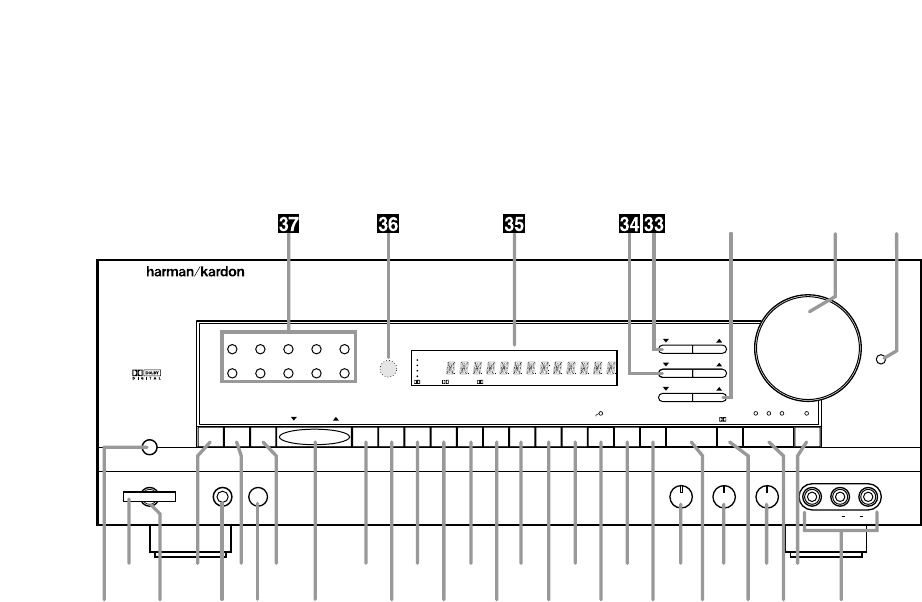
Front Panel Controls
7
1Main Power Switch
2System Power Control
3Power Indicator
4Memo Button
5Headphone Jack
6FM Mode
7Speaker Switch
8AM/FM
9Tuning Button
)CD
!Tape 1/Monitor
@Tape 2
#Phono
$TV
%DVD Input
^Vid 1
&Vid 1 Rec
*Vid 2
(Vid 2 Front/Rear
ÓSpeaker Mode Selector
ÔSurround Off
Bass Control
ÒSurround Mode
ÚTreble Control
ÛDigital Mode Selector
ÙBalance Control
ıDigital Input Selector
ˆNight Mode
˜Video 2 Inputs
¯Contour
˘Volume Control
¸Subwoofer Level Adjust
33
Center Level Adjust
34
Surround Level Adjust
35
Information Display
36
Remote Sensor Window
37
Numeric Keys
67890
AVR 55
Speaker
Headphones
TUNE VID 1 REC.
12345
SPK. MODE SURR.OFFFRT/REARVID 2SURR. MODE NIGHT
Volume
Contour
Bass Treble Balance
MEMO DVD VID 1DIGITAL INPUT
DIGITAL
Subwoofer Level
Surround Level
Center Level
FM MODE AM/FM CD T MON
•PHONO TV
VIDEO 2
R VideoLMaxMinMaxMin L Audio R
Power
RF COAX OPT
T 2
•
DIGITAL HALLTHEATER STADIUM CHURCH SLEEP
SOURCE
VID 2
DVD
TV
PRO LOGIC
VID 1 REC CONTOUR STEREO TUNED AUTO MEMORY PRESET
T MON
•
3 STEREO
-
˘¯
ˆÚ4)@$^*Ó68 Ù2
˜ıÛ57 9#%&(ÔÒ!13
¸

Front Panel Controls
8
1Main Power Switch: Press this
button to apply power to the AVR55.
When the switch is pressed the unit
is placed in a Standby mode, as
indicated by the amber LED 3sur-
rounding the System Power control
2. This button MUST be pressed in
to operate the unit. To turn the unit
off and prevent the use of the remote
control, this switch should be
pressed until it pops out to extend
from the front panel so that the word
“OFF” may be read at the top of
the switch.
NOTE: In normal operation this
switch may be left in the “ON”
position.
2System Power Control: When
the Main Power Switch 1is “ON,”
press this button to turn on the
AVR55, press it again to turn the unit
off. Note that the Power Indicator
surrounding the switch 3will turn
green when the unit is on.
3Power Indicator: This LED will
illuminate in amber when the unit is
in the Standby mode, to signal that
the unit is ready to be turned on.
When the unit is in operation the
indicator will turn green.
4Memo Button: This button is
used to enter settings for speaker
modes and tuner presets after
making the appropriate selection.
5Headphone Jack: This jack may
be used to listen to the AVR55’s out-
put through a pair of headphones.
Be certain that the headphones
have a standard 1⁄4" stereo phone
plug.
6FM Mode: Press this button to
select the stereo or mono mode for
FM tuning. In the STEREO mode a
STEREO indicator will illuminate in
the information display, and stereo
reception will be provided when sta-
tions are transmitting stereo signals.
In the MONO mode the left and right
signals from stereo broadcasts will
be mixed together and reproduced
through all channels. Select MONO
for better reception of weak signals.
7Speaker Switch: For normal
operation this switch is pressed in
and sound is heard through all
speakers. To silence the speakers,
push the button once until it is in the
“out” position. When the speakers
are turned off, sound will continue to
be heard through the headphone
jack.
8AM/FM: Press this button to
select the tuner as the AVR55’s input
source. When it is first pressed the
last station tuned will appear. Press
it again to change between AM and
FM bands.
9Tuning Button: Press the left
side of the button to tune lower
frequency stations and the right side
of the button to tune higher frequency
stations. When a station with a strong
frequency is tuned, the TUNED
indicator will illuminate in the
Information Display
35
. A brief
(1/2 second) press of the button will
manually tune to the next frequency
increment, while pressing and hold-
ing the button for a longer period will
automatically tune to the next station
with a signal strong enough for
acceptable reception.
)CD: Press this button to select
the device connected to the CD
Input jacks das the listening
source.
!Tape1/Monitor: Press this button
to select the device connected to
the Tape 1 Play jacks ⁄as the lis-
tening source. The T-Mon indicator
Kwill illuminate to indicate that the
Tape Monitor has been selected,
while the name of the input being
monitored will be displayed in the
Main Information Display F.
@Tape 2: Press this button to
select the device connected to the
Tape 2 Play jacks ªas the listening
source.
#Phono: Press this button to
select the Phono Input eas the
listening source.
$TV: Press this button to select the
device connected to the TV/Aux
jacks ¤as the listening and viewing
source.
%DVD Input: Press this button to
select the device connected to the
DVD Play jacks ‹as the listening
and viewing source.
^Vid 1: Press this button to
select the device connected to the
Video 1 In jacks °as the listening
and viewing source.
&Vid 1 Rec: Press this button
to select the device that will be
recorded by the device connected
to the Video 1 Out jacks ›. The
selected source is shown in the
Vid 1 Source indicators Ain the
Information Display
35
. Note that
this recording will take place even
if another source is selected for
listening through the system.

Front Panel Controls
*Vid 2: Press this button to select
the device connected to the Video 2
Play jacks ·as the listening and
viewing source.
(Vid 2 Front/Rear: Press this
button to choose either the rear
panel Video 2 Play jacks ·or the
front panel Video 2 Inputs ˜as the
input source. When the red light
above the button is illuminated, the
front panel jacks are selected.
ÓSpeaker Mode Selector: Press
this button to configure the AVR55
for the type of speakers used in your
system. See page 18 for details on
using this button.
ÔSurround Off: Press this button
to turn the surround modes off to
listen to a source in traditional two-
channel stereo from the front
left/right speakers only.
Bass Control: Turn this control to
modify the low frequency output of
the left/right channels by as much as
±10dB. Set this control to a suitable
position for your taste and room
acoustics.
ÒSurround Mode: Press this
button to select one of the analog
surround processing modes (Dolby
Pro Logic, Dolby 3 Stereo, Theater,
Hall, Stadium and Church) for a
listening session.
ÚTreble Control: Turn this control
to modify the high frequency output
of the left/right channels by as much
as ±10dB. Set this control to a
suitable position for your taste and
room acoustics.
ÛDigital Mode Selector: Press
this button to listen to a source when
a Dolby Digital (AC-3*) signal is
present.
NOTE: Dolby Digital may only be
used with the TV, DVD, Vid 1 and
Vid 2 inputs.
ÙBalance Control: Turn this
control to change the relative volume
for the front left/right channels.
NOTE: For proper operation of the
surround modes this control should
be at the midpoint, or “12 o’clock”
position.
ıDigital Input Selector: When the
Digital Mode Selector Ûhas been
pressed, this button is used to select
the type of digital input to be used.
NOTE: The coax or optical inputs
may be selected with the CD, TV,
DVD, Vid 1 and Vid 2 inputs. The
RF input may be used in conjunction
with the Vid 1 or Vid 2 input only.
ˆNight Mode: Press this button
to activate the “Night” mode, pre-
venting a loud playback when the
digital modes are in use.
˜Video 2 Inputs: These jacks may
be used to temporarily connect an
audio/video source such as a video
game or camcorder to the AVR55.
To select these jacks as the input,
press the Vid 2 Front/Rear button
(until the red LED above that
button is illuminated.
¯Contour: Press this button when
listening at low levels to activate
special circuits that compensate
for the response of the human ear
at lower volumes. The Contour
Indicator Mwill illuminate to remind
you when this circuit is ON. In the
OFF position the AVR55 will provide
flat frequency response.
˘Volume Control: Turn the knob
clockwise to increase volume,
counterclockwise to decrease the
volume.
¸Subwoofer Level Adjust:
Press these buttons to raise or lower
the output to the subwoofer channel.
These buttons should be used dur-
ing normal listening sessions for
touch-up adjustments, not when the
test signal is being used for major
system alignment.
33
Center Level Adjust: Press
these buttons to raise or lower the
output to the center channel. These
buttons should be used during
normal listening sessions for touch-
up adjustments, not when the test
signal is being used for major
system alignment.
34
Surround Level Adjust:
Press these buttons to raise or lower
the output to the surround channels.
These buttons should be used dur-
ing normal listening sessions for
touch-up adjustments, not when the
test signal is being used for major
system alignment.
35
Information Display: This dis-
play delivers messages and status
indications to help you operate the
receiver. See page 7 for a complete
explanation of the display.
36
Remote Sensor Window: The
sensor behind this window receives
infrared signals from the remote con-
trol. Aim the remote at this area and
do not block or cover it unless an
external remote sensor is installed.
37
Numeric Keys: Press these
buttons to enter or recall stations
entered to the tuner’s preset memory.
See page 25 for complete information
on using the tuner and the preset
memories.
9
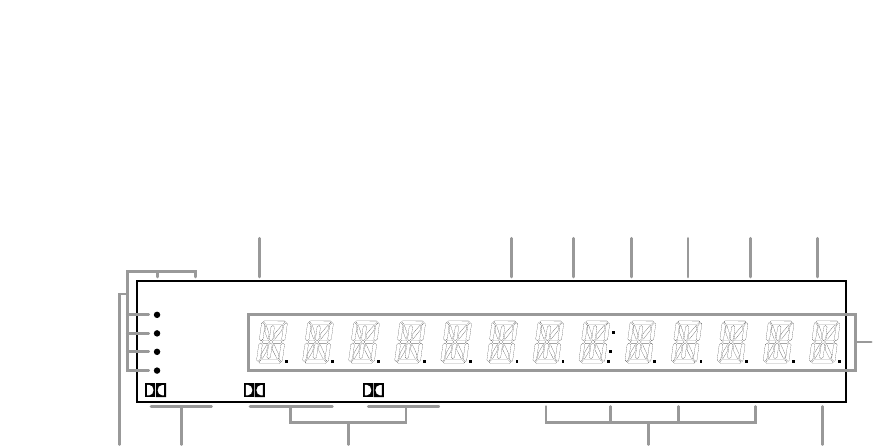
Front Panel Information Display
10
DIGITAL HALLTHEATER STADIUM CHURCH SLEEP
SOURCE
VID 2
DVD
TV
PRO LOGIC
VID 1 REC CONTOUR STEREO TUNED AUTO MEMORY PRESET
T MON
•
3 STEREO
-
F
MLKJIGH
B
ADEC
AVid 1 Record Indicators
BDolby Digital Indicator
CAnalog Dolby Surround Mode Indicators
DAnalog Surround Mode Indicators
ESleep Indicator
FMain Information Display
GPreset Indicator
HMemory Indicator
IAuto Mode In Indicator
JTuned Indicator
KT-Mon Indicator
LStereo Indicator
MContour Indicator
AVid 1 Record Indicators: A dot
appears next to one of the sources
shown in this indicator to tell you
which input has been selected as
the output to the device connected
to the Video 1 Out jacks ›. Press
the Vid 1 Rec button &to change
the source.
BDolby Digital Indicator: This
indicator illuminates when a Dolby
Digital source has been selected.
CAnalog Dolby Surround Mode
Indicators: These indicators illumi-
nate when one of the analog (matrix)
dolby Surround modes is in use.
DAnalog Surround Mode
Indicators: These indicators illumi-
nate when one of the DSP generated
analog surround modes is in use.
ESleep Indicator: This indicator is
illuminated when the Sleep function
is in use. The number that appears
above the indicator is the number of
minutes remaining before the AVR55
will return to the Standby mode.
FMain Information Display: This
display shows messages relating to
the status, input source, surround
mode, tuner, volume level or other
aspects of unit’s operation.
GPreset Indicator: This indicator
illuminates when one of the stations
entered into the preset memory is
tuned. The number that appears
below the indicator is the preset
station’s memory.
HMemory Indicator: This flashes
after the Memo button 4uhas
been pressed to indicate that you
have five seconds to select and
enter a preset memory location for a
specific radio station.
IAuto Mode In Indicator: This
indicator illuminates when the “Auto”
mode is in use for FM tuning.
JTuned Indicator: This indicator
illuminates when a station is being
received with sufficient signal
strength to allow for acceptable
listening quality.
KT-Mon Indicator: This indicator
illuminates when the Tape Monitor
function is in use to remind you that
you are listening to the record output
of the device connected to the
Tape 1 Record jacks ‚, not to the
actual input source shown in the
Information Display.
LStereo Indicator: This indicator
illuminates when an FM station is
being tuned in stereo.
MContour Indicator: This indicator
illuminates when the Contour circuits
have been engaged by pressing the
Contour button ¯.
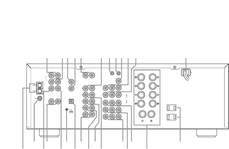
Rear Panel Connections
11
CENTER
PRE-OUT
REAR
PRE
OUT
FRONT
ANTENNA MAIN
IN
PRE
OUT
AM
LOOP
FM
75Ω
SUB
WOOFER
OUT
AC-3
RF/PCM
GND
COAXIAL/PCM
OPTICAL/PCM
MODEL NO.: AVR55
HARMAN KARDON
NORTHRIDGE
CALIFORNIA, U.S.A.
R
REAR SPEAKER (8Ω)
FRONT SPEAKER (8Ω)
CENTER SPEAKER (8Ω)
R
L
L
SWITCHED
~120V/60Hz
TOTAL 100W
1A MAX
AC OUTLETS
OUT
VIDEO
MON.
REMOTE
CONTROL
VIDEO 2
PLAY
IN
DVD
PLAY
TV
OUT
VIDEO 1
IN
R
L
L
R
VIDEO
TAPE 2
REC
TAPE 1
REC
TAPE 2
PLAY
TAPE 1
PLAY
CD
PHONO
LR
LR
L
SER. NO
R
AC INPUT
~120V/60HZ
3.2A
fl
‡°·abcedfghi
¡
™
£∞
§
¶
•
ª
‚¤
‹⁄
ݢ
fi
¡AM Antenna
™FM Antenna
£Center Channel Preamp Output
¢Rear Preamp Outputs
∞Subwoofer Output
§Ground Terminal
¶Optical/PCM Digital Input
•Tape 2 Rec
ªTape 2 Play
‚Tape 1 Rec
⁄Tape 1 Play
¤TV Inputs
‹DVD Input
›Video 1 Outputs
fiSpeaker Outputs
flSwitched Outlets
‡AC Power Cord
°Video 1 Inputs
·Video 2 Play Inputs
aVideo Monitor Output
bRemote Control Extension Output
cRemote Control Extension Input
dCD Input
ePhono Input
fCoax Digital Input
gAC-3 RF Input
hFront Channel Preamp Outputs
iFront Channel Main In Amp Inputs
¡AM Antenna: Connect the AM
loop antenna supplied with the
receiver to these terminals. If an
external AM antenna is used, make
connections to the AM and GND
terminals in accordance with the
instructions supplied with the
antenna.
™FM Antenna: Connect an indoor
or external FM antenna to this
terminal.
£Center Channel Preamp Output:
These jacks may be used to connect
the center channel to an optional,
external power amplifier.
¢Rear Preamp Outputs: These
jacks may be used to connect the
surround channels to an optional,
external power amplifier.
∞Subwoofer Output: Connect this
jack to the mono line level input of
an optional powered subwoofer, or
your optional external subwoofer
amplifier.
§Ground Terminal: Connect the
ground wire from a turntable to this
terminal to reduce system hum.
¶Optical/PCM Digital Input:
Connect the optical digital output of
a CD, LV or DVD player or HDTV
product to this jack.
•Tape 2 Rec: Connect the
RECORD/INPUT jacks of an audio
tape recorder to these jacks.

Rear Panel Connections
12
ªTape 2 Play: Connect the
PLAY/OUT jacks of an audio tape
recorder to these jacks.
‚Tape 1 Rec: Connect the
RECORD/INPUT jacks of an audio
tape recorder to these jacks.
⁄Tape 1 Play: Connect the
PLAY/OUT jacks of an audio tape
recorder to these jacks.
NOTE: The recorder connected to
the Tape 1/Mon jacks may be moni-
tored during a recording session by
pressing the Tape 1/Mon button
!d on the front panel or remote.
¤TV Inputs: Connect the audio
and video outputs from a TV,
Satellite receiver or other A/V source
to these jacks. The signal sent to the
video jack may also be used to trig-
ger the TV Auto On function. (See
page 23 for more information on TV
Auto On.)
‹DVD Input: Connect the com-
posite video and analog audio
outputs of a DVD player to these
jacks.
›Video 1 Outputs: Connect the
audio and video REC/IN jacks of
your main VCR to these jacks.
NOTE: The Video 1 jacks may be
used for any video source, but when
used with a VCR they will permit
dubbing from one source to another
while a separate source is being
listened to by selecting the VID 1
Rec button &.
fiSpeaker Outputs: Connect
these terminals to the input terminals
on your front left/right, center and
surround speakers.
flSwitched Outlets: These
outlets provide AC power only
when the AVR55 is turned on.
Note that the total power draw of
the products connected may not
exceed 100 watts.
‡AC Power Cord: Connect this
plug to an unswitched 115 volt
AC outlet.
°Video 1 Inputs: Connect the
audio and video PLAY/OUT jacks
of your main VCR to these jacks.
·Video 2 Play Inputs: Connect
the audio and video PLAY/OUT jacks
of a VCR, DVD, LD, Satellite system
or other video source to these jacks.
aVideo Monitor Output: Connect
this jack to the video input of a TV or
video projector to view the selected
source.
bRemote Control Extension
Output: This jack may be con-
nected to other compatible Harman
Kardon products so that they will
receive infrared commands
captured by the AVR55’s remote
sensor.
cRemote Control Extension
Input: If the AVR55’s front panel IR
sensor is blocked due to cabinet
doors or other obstructions, an
external IR sensor may be used.
Connect the output of the sensor to
this jack.
dCD Input: Connect the output of
your CD player or D/A converter to
these jacks.
ePhono Input: Connect the output
of your turntable or tone arm to
these jacks. Note that only Moving
Magnet (MM) type cartridges may
be used.
fCoax Digital Input: Connect
the coax digital output from a DVD
player, HDTV receiver, LV player or
CD player to this jack. The signal
may be either a Dolby Digital (AC-3)
signal or a standard PCM digital
source.
gAC-3 RF Input: Connect the
AC-3 RF output of an LV player
equipped for digital audio to this
jack.
NOTE: Do not connect standard
analog audio sources to these
jacks fg.
hFront Channel Preamp Outputs:
These jacks provide the output for
the front left and right channels to an
external amplifier or processor. In
normal operation, unless an external
power amplifier is used, the jumper
pins should remain connected
to the Front Main In jacks i.
iFront Channel Main In Amp
Inputs: These jacks are the input to
the AVR55’s front left/right channel
power amplifier. Unless an external
power amplifier is used for the
left/right channels, the jumper pins
should remain connected to the
Front Pre Out jacks h.
Remote Control Functions
13
*
PRESET
DISC
ON OFF
DISPLAY
/
MUTE
Source Power
DVD
TV
VID 1
VID 2
TAPE 2
SELECT
TAPE 1
CD
AM/FM
#
SKIP
TUNE/
SEARCH
VOLUME
+
_
SLEEP
AC-3
PHONO
NIGHT 123
STEREO MATRIX
DELAY 456
RF 789
TEST TONE
SPEAKER
CH SELECT
COAX
OPT 0
AVR 55
Sending
Use
Learning
Learn
P/L 3 ST
ON OFF
Main Power
PTY
MEMO CLEAR P-SCAN
AF
FM MODE
RDS DISP.
RDS DISP.
TUNE/
SEARCH
m
n
o
p
q
rs
t
u
v
w
y
`
MEMO CLEAR P-SCAN
x
z
b
c
e
g
h
i
k
l
a
d
d
f
j
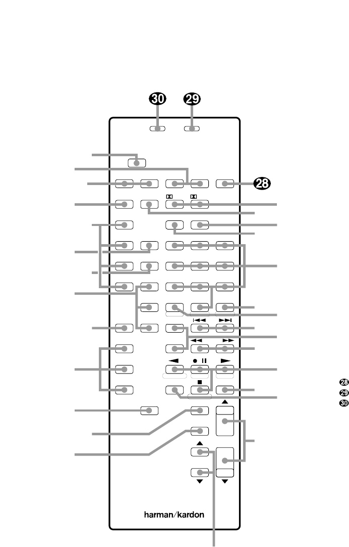
aUse/Learn
bSource Power
cMain Power
dAudio Source Selectors
eVideo Source Selectors
fNight Mode
gDelay
hDigital Audio Input Selectors
iAM/FM
jSelect
kTest Tone
lChannel Select
mSpeaker Level Adjust
nMain Volume
oDisplay
pMute
qTransport Controls
rTune/Search and Fast Forward
sPreset/Disc
tChannel/Skip
uMemo
vP-Scan
wNumber Keys
xStereo Selector
yMatrix Surround Modes
zAC-3 Select
`Dolby Surround Modes
Sleep
Learning LED
Sending LED

Remote Control Functions
aUse/Learn: This switch selects
the operation mode of the remote
control. Slide it to the left for normal
operation. Slide it to the right when
the remote is being programmed.
bSource Power: Press these
buttons to control power for the last
source device selected when power
on/off commands have been pro-
grammed into the remote’s memory.
cMain Power: Press these
buttons to turn the unit on or off.
dAudio Source Selectors: Press
these buttons to select any of the
audio only sources (CD, Phono,
Tape 1, Tape 2) as the AVR55’s input.
eVideo Source Selectors: Press
these buttons to select any of the
audio/video sources (TV, DVD, Vid 1,
Vid 2) as the AVR55’s input.
fNight Mode: Press this button
to activate the “Night” mode, pre-
venting loud playback when the
digital modes are in use without
altering the dynamic range of the
output signal.
gDelay: Press this button to
change the delay time, after the
Delay function has been initiated by
first pressing the Select button j.
hDigital Audio Input Selectors:
Press one of these buttons to select
a digital audio input.
iAM/FM: Press this button to
select the AVR55’s tuner as an input
source. Pressing this button when
the tuner is in use will switch
between the AM and FM bands.
jSelect: Press this button to initi-
ate the process that changes the
delay time (see page 20).
kTest Tone: Press this button to
begin the adjustment of the output
levels. A test tone will circulate
among the speakers. Press this but-
ton to select the individual channels
for output-level adjustments (see
page 19).
lChannel Select: Press this
button to view the output level for the
surround or center channels. When
the Test Tone button khas been
pressed so that the Tone is audible,
pressing this button will change the
channel available for adjustment
(see page 19).
mSpeaker Level Adjust: When
setting the system output levels,
press these buttons to increase or
decrease the output level.
nMain Volume: These buttons
control the unit’s volume. Note
that all channels are controlled
simultaneously.
oDisplay: Press this button
to reduce the brightness of the
front panel display, or to turn it off
completely.
pMute: Press this button to tem-
porarily cut the audio output of the
receiver. Press it again to return to
the previous volume level.
qTransport Controls: These
buttons may be programmed to
control the tape or disc motion of the
last playback source selected with
the Source Selection buttons d.
Use them as you would the Play,
Stop, Pause, Record, Reverse Play
and Forward Play buttons on any
VCR, CD, cassette, DVD or LD
remote control. The Reverse Play
button fialso operates the FM
Mode function of the AVR55’s tuner.
rTune/Search and Fast
Forward: These buttons may be
programmed to have multiple
functions, which vary according to
the input device selected.
a. When the TUNER has been
selected, these buttons are used
to tune stations.
b. When CD, Tape, DVD, LD or
VCR is the input source, these
buttons act as the Fast Scan
Forward —or Fast Scan
Reverse ‚controls.
14
Remote Control Functions
sPreset/Disc: These buttons
have multiple functions, which
vary according to the input device
selected.
a. When the TUNER has been
selected, these buttons will scroll
up ·or down ‡through
the stations that have been pro-
grammed in the preset memory.
b. When CD is selected and the unit
is a CD changer, these buttons
will change to the next disc ∏or
previous disc Â.
c. When Tape 1 or Tape 2 is the
input source, and the tape
machine is a compatible Harman
Kardon dual cassette deck, these
buttons will switch between the
“A” and “B” sides.
tChannel/Skip: These buttons
have multiple functions, which
vary according to the input device
selected and the codes pro-
grammed from another remote.
a. When TV, Vid 1 or Vid 2 are
selected, they may function as
the channel up ·or channel
down ‡tuning buttons when
programmed with the codes from
another unit’s remote.
b. When CD is selected these
buttons act as forward and
reverse “Skip” buttons to move
to the next track or chapter on
the disc.
c. When a compatible Harman
Kardon cassette player has been
selected as Tape 1 or Tape 2,
these buttons move the tape
forward ·or backwards ‡to
the next selection using the Music
Scan feature.
uMemo: The memo button is
used to enter settings for the tuner’s
preset memory and when entering
speaker types. It is also used when
clearing the memory.
vP-Scan: Press this button to
automatically scan through the sta-
tions preset into the tuner memory.
Press the button again to end the
scan when the tuner stops at the
desired station.
wNumber Keys: These buttons
serve as a ten-button numeric key-
pad to enter tuner preset positions.
They are also to be used to select
channel numbers when TV has
been selected on the remote, or to
select track numbers on a CD, DVD
or LD player, depending on how the
remote has been programmed.
xStereo Selector: Press this but-
ton to turn the surround processing
off and listen to an input in traditional
two-channel (front left/right) audio.
yMatrix Surround Modes: Press
this button to select the Theater,
Hall, Stadium or Church surround
modes. Each press of the button
cycles through the four modes
(see page 23).
zAC-3 Select: Press this button to
activate the Dolby Digital mode when
an appropriate digital audio source is
present and the correct digital input
is selected (see page 24).
`Dolby Surround Modes: Press
these buttons to select the Dolby Pro
Logic or Dolby 3 Stereo modes. Use
Pro Logic when surround speakers
are installed, and Dolby 3 Stereo when
only front speakers are available.
Sleep: Press this button to
activate the sleep timer. Each press
of the button will increase the time
increment before the AVR55 goes
into the Standby mode in the
following order:
Note that the front panel display will
dim when the Sleep function is active.
Learning LED: This indicator
will illuminate when a button on the
remote is being programmed with
signals from another remote during
the “learning” mode. The light will go
out when the signal is received and
memorized.
Sending LED: This indicator
should flash any time a button is
pressed to confirm that a command
is being sent to the receiver or
another unit. If the light is dim or
does not illuminate when a button is
pressed the batteries in the remote
should be replaced.
10
min 20
min 30
min 60
min 90
min OFF
15

Installation and Setup
System Installation
After unpacking the unit, and placing it
on a solid surface capable of supporting
its weight, you will need to make the
connections to your audio and video
equipment. These steps need to be done
only when the receiver is first installed,
or when a change is made to the input
source equipment.
Audio Input and Output Connections
We recommend that you use high-quality
cables when making connections to
source equipment and recorders to
preserve the quality of the signals.
When making connections to audio
source equipment or speakers it is always
a good practice to unplug the unit from
the AC wall plug. This prevents any possi-
bility of accidentally sending audio or
transient signals to the speakers that may
damage them.
1. For playback-only audio sources, such
as a CD player, CD changer, tape deck or
phono cartridge, connect the output
jacks of the player to the appropriately
labeled inputs on the rear panel de.
NOTE:When the source device has both
fixed and variable audio outputs it is best
to use the fixed output unless you find
that the input to the receiver is so low
that the sound is noisy, or high that the
signal is distorted.
2. If a turntable is connected to the
Phono input e, connect the ground
wire from the cartridge or tone arm to
the Ground terminal§.
3. When connecting audio recording
devices such as cassette recorders, open
reel audio tape decks, DAT or MD, con-
nect the PLAY/OUT jacks of the recorder
to the Play jacks ª⁄on the AVR55.
Connect the RECORD/IN jacks on the
recorder to the Tape Rec jacks •‚
on the AVR55.
4. Connect the output of any digital
sources to be used to the appropriate
connections on the AVR55 rear panel.
The Optical and Coaxial digital inputs
¶fmay be used with either a Dolby
Digital (AC-3) source or the output of a
conventional CD or LV player’s PCM
(S/P-DIF) output. The AC-3 RF input
gmay ONLY be connected to the special
AC-3 RF output of a laser disc player.
5. Assemble the AM Loop Antenna sup-
plied with the unit as shown below.
Connect it to the AM and GND screw
terminals ¡.
6. Connect an FM antenna to the
FM (75 ohm) connection ™. The
FM antenna may be an external roof
antenna, an inside powered or wire lead
antenna, or a connection from a cable
TV system. Note that if the antenna or
connection uses 300-ohm twin lead
cable, you must use the 300-ohm to
75-ohm adapter supplied with the unit
to make the connection.
7. Connect the front, center and surround
speaker outputs fito the respective
speakers.
To assure that all the audio signals are
carried to your speakers without loss of
clarity or resolution, we suggest that you
use high-quality speaker cable. Many
brands of cable are available, and the
choice of cable may be influenced by the
distance between your speakers and this
receiver, the type of speakers you use,
personal preferences and other factors.
Your dealer or installer is a valuable
resource to consult in selecting the
proper cable.
Regardless of the brand of cable selected,
we recommend that you use a cable con-
structed of fine, multistrand copper with
a gauge of 14 or smaller. Remember that
in specifying cable, the lower the gauge
number, the thicker the cable.
Cables that are run inside walls should
have the appropriate markings to indicate
listing with UL, CSA or other appropriate
testing agency standards. Questions about
running cables inside walls should be
referred to your installer or a licensed
electrical contractor who is familiar with
the NEC and/or the applicable local
building codes in your area.
16

Installation and Setup
When connecting wires to the speakers,
be certain to observe proper polarity.
Remember to connect the “negative” or
“black” wire to the same terminal on the
receiver and the speaker. Similarly, the
“positive” or “red” wire should be con-
nected to the like terminal on the AVR55
and speaker.
NOTE:While most speaker manufacturers
adhere to an industry convention of using
black terminals for negative and red ones
for positive, some manufacturers may
vary from this configuration. To assure
proper phase, and optimal performance,
consult the identification plate on your
speaker, or the speaker’s manual to verify
polarity. If you do not know the polarity
of your speaker, ask your dealer for advice
before proceeding, or consult the speaker’s
manufacturer.
8. Connections to a subwoofer are made
via an audio connection from the
Subwoofer Output ∞to the line level
input of a subwoofer with a built-in
amplifier. If a passive subwoofer is used,
the connection first goes to a power
amplifier, which will be connected to one
or more subwoofer speakers.
Video Input and Output Connections
Video connections are made in a similar
fashion as those for audio components.
Again, the use of high-quality intercon-
nect cables is recommended to preserve
signal quality.
1. Connect your VCR’s audio and video
OUT jacks to the Video 1 In jacks °on
the rear panel. The audio and video IN
jacks on the VCR should be connected to
the Video 1 Out jacks ›on the AVR55.
2. Connect the audio and video outputs
of a satellite receiver, cable TV converter
or television set or any other video source
to the TV jacks ¤.
3. Connect the audio and video outputs
of a DVD or laser disc player to the DVD
jacks ‹.
4. Connect the Video Mon ajack on
the receiver to the video input of your
television monitor or video projector.
System and Power Connections
The AVR55 is designed for flexible use
with external control components and
power amplifiers. These connections are
easy to make during an initial installa-
tion, or at a later date should you choose
to upgrade your system.
Remote Control Extension
If the receiver is placed behind a solid or
smoked glass cabinet door, the obstruc-
tion may prevent the internal remote
sensor from receiving commands. In this
event, an optional remote sensor may be
used. Connect the output of the remote
sensor to the Remote Cont. In jack c.
If other components are also prevented
from receiving remote commands, only
one sensor is needed. They may use the
AVR55’s sensor or a remote eye to send
commands to other products by running
a connection from the Remote Cont.
Out jack bto the Remote In jack on
Harman Kardon or other compatible
equipment.
External Audio Power
Amplifier Connections
If desired, optional, external power audio
power amplifiers may be used with the
AVR55. Connections may be made by con-
necting the Preamp Outputs £¢h
of the AVR55 to the inputs of the external
amplifier. Before connecting the front
channels to an external amplifier, remove
the jumper pins connecting the Front
Channel Inputs and Outputs hi
and save them for future use.
AC Power Connections
This unit is equipped with two accessory
AC outlets. They may be used to power
accessory devices, but they should not be
used with high-current draw equipment
such as power amplifiers. Their total
power draw may not exceed 100 watts.
These Outlets flwill receive power
only when the unit is on. These recom-
mended for devices that have no power
switch, or a mechanical power switch
that may be left in the “ON” position.
NOTE:Devices with electronic power
switches may only go into a Standby
mode when plugged in here.
Finally, when all connections are com-
plete, plug the AC Power Cord ‡into
a non-switched120-volt AC wall outlet.
You’re almost ready to enjoy the AVR55!
17
Remote Control Programming and Operation
Thisproductisequippedwithapowerful
remotecontrol.Assupplied,itwilloperate
thereceiver,aswellasmostCDplayers
andtapedecksmanufacturedbyHarman
Kardon.Ifyourequipmentrequiresdiffer-
entcodes,itmaybeprogrammedtocopy
thecodesfrommostinfraredremotes.
Loading Batteries
Thelifeofthebatteriesfortheremote
controlisaboutoneyearinnormaloper-
ation.IftheamberSending indi-
catordoesnotflashwhenremotebuttons
arepushed,thatisanindicationthatthe
batteriesneedtobereplaced.
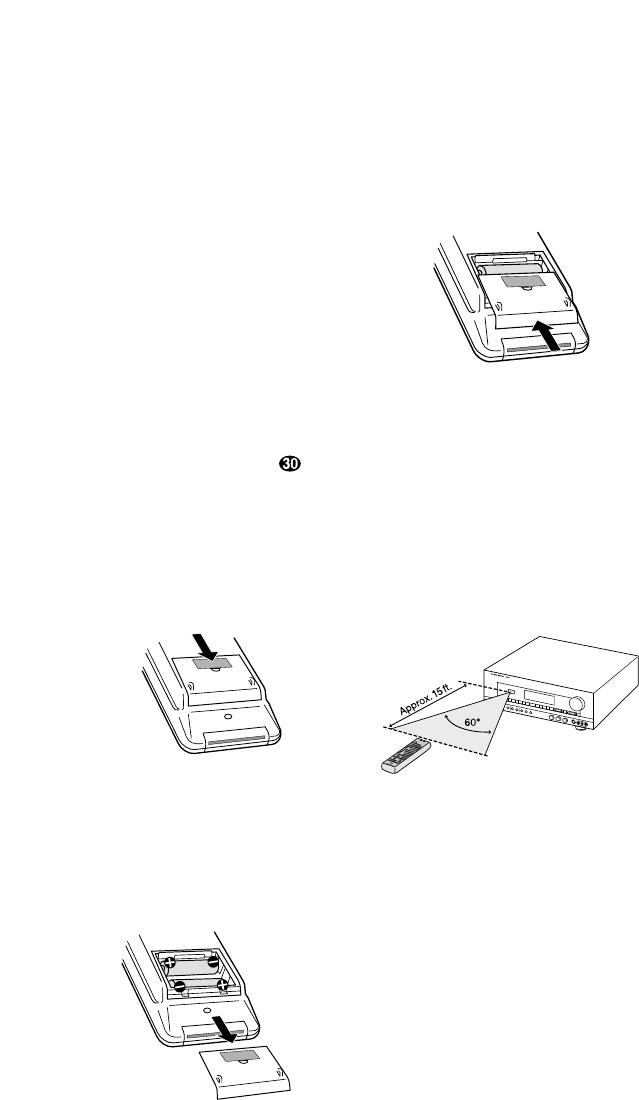
To change the batteries:
1. Remove the back cover by sliding it in
the direction of the arrows.
2. Remove the old batteries and insert
fresh AAA type cells. Be certain to observe
the correct polarity by noting the (+)
and (–) marks on both the inside of the
case and on the battery cells. It is recom-
mended that both batteries be changed at
the same time.
3. Close the cover until it clicks shut.
NOTE:It is important that the batteries
be replaced within ten minutes after the
old batteries are removed to avoid losing
any remote codes that have been pro-
grammed into the remote’s memory.
Remote Control Range
The remote will operate at a range of up
to 15 feet from the unit, when the batter-
ies are fully charged. The remote will
also operate at an angle of up to 30° to
either side of the unit.
Always point the remote transmitter at
the front of the unit when issuing com-
mands. If you find that remote com-
mands are not being received by the
remote, it may be necessary to use a
remote IR sensor.
Remote Programming
Programmable Keys
Many of the buttons on the remote
control may be user programmed to new
functions to operate virtually any compo-
nent in your system. Eleven CANNOT be
programmed with a new code, as they
control high-level functions of the
AVR55. These keys are Main Power ON,
Main Power OFF, and the source
input keys: TV, DVD, VID 1, VID 2,
Phono, CD, Tape 1, Tape 2 .
Programmable keys are divided into two
groups. Some keys may be programmed
with a separate function for each of the
inputs. Thus, these keys may change
their code when the input source is
changed. (e.g., The Play key may trans-
mit a different code when CD is selected
as opposed to when VCR is selected.)
The keys that may be programmed with
multiple codes are the following:
All Numeric Keys (0– 9)
Forward Play fl
Source Power On
Reverse Play fi
Source Power Off
Stop Í
Preset Disc ∏
Record Î
Preset Disc Â
Pause ±
Channel/Skip ·
Channel/Skip ‡
Tune/Search —
Memo
Tune/Search ‚
P-Scan
18

Remote Control Programming and Operation
All other keys may only be programmed
with one remote code. The code
contained in these keys remains the
same regardless of the source selection.
WARNING: These keys transmit codes
that are vital to the operation of the
product. It is not recommended that they
be programmed with alternative codes,
as it may then be impossible to operate
certain functions of the receiver.
Night
Delay
RF
Opt
Coax
Select
All Mode Selectors
*
#
Display
Speaker ⁄¤
CH Select
Volume ⁄¤
Test Tone
Mute
To programtheremote,followthesesteps.
Notethatitisnotnecessarytoprogram
allkeys,onlythosethatarerequiredto
operatethesubjectdevice.Keysnot
programmedwillretainthecodes
preprogrammedatthefactory.
1. Slide Use/Learn aswitch at the
top left corner of the remote to the right
so that it is next to Learn.
2. If one of the multifunction buttons
is being programmed press the source
button (e.g. CD, VID1) you wish to
have this function associated with. If you
are programming a single function key,
proceed to the next step.
3. Press the button on the remote that is
to be programmed. Note that the
LearningLED will illuminate.
4. Place the remote head to head with the
remote control whose function is being
learned. The two remotes should be no
more than 8 inches apart.
5. Press and hold the button on the
remote corresponding to the function
to be memorized until the Learning
LED starts to blink. When the LED goes
out, release the button on the transmit-
ting remote. The function code has been
successfully captured by the remote.
NOTE:If both LEDs flash during a pro-
gramming operation, it indicates that
the remote’s memory is full or that the
remote codes from the transmitting
remote are not compatible with the unit’s
signal format.
6.Continuetoprogramanyadditional
remotecommandsrequiredusingsteps
2through5.Whenyouhavefinished
programmingtheremote,slidethe
Use/Learn switchtotheleftsothatit
isintheUse position.
Clearing the Remote Memory
In normal operation, codes for a new
device may be programmed “over” the
codes that have been previously pro-
grammed into the remote. It is also pos-
sible to clear the memory for individual
keys, or for the entire remote. When a
memory position is cleared, the remote
will return to the original factory preset
command.
To clear the memory for a specific indi-
vidual key location, put the Use/Learn
switch in the Learn position. Press the
Main Power Off cbutton and the
button to be cleared at the same time.
Both the Sending and Learning indi-
cators will light momentarily. When the
lights go out, the memory has been
cleared of the user programmed code
and returned to the factory preset. Return
the Use/Learn aswitch to the Use
position when you are finished.
To clear the remote’s entire memory
and return all keys to their factory preset
commands, first put the Use/Learn a
switch in the Learn position. Then press
the Main Power On button cand
confirm that the Learningindicator
has illuminated. While continuing
to press the Main Power On button,
press and hold the Main Power Off
cbutton until the Learn indicator
goes off for about 3 seconds. It will then
blink twice. Then release the two buttons.
This indicates that the memory has been
cleared of any user programmed com-
mands and that the original commands
have been restored. Slide the Use/Learn
switch aback to the Use position to
return the remote to normal operation.
19
System Configuration
After completing all audio, video and
system connections, there are a few con-
figuration adjustments that must be
made. A few minutes spent to correctly
configure and calibrate the unit will
greatly add to your listening experience.
Speaker Selection
The placement of speakers in a multi-
channel home theater system can have
a noticeable impact on the quality of
sound reproduced.
No matter which type or brand of speakers
is used, the same model or brand of
speaker should be used for the front left,
center and right speakers. This creates a
seamless front soundstage, and elimi-
nates the possibility of distracting sonic
disturbances that occur when a sound
moves across mismatched front channel
speakers.
Speaker Placement
Depending on the type of center channel
speaker in use and your viewing device,
place the center speaker directly above or
below your TV or in the center behind a
perforated front projection screen.
Once the center channel speaker is
installed, position the left and right front
speakers so that they are as far away
from one another as the center channel
speaker is from the preferred listening
position. Ideally, the front channel
speakers should be placed so that their
tweeters are no more than 24" off center
from the tweeter in the center channel
speaker.
Depending on the specifics of your
room acoustics and the type of speakers
in use, you may find that imaging is
improved by moving the front left and
right speakers slightly forward of the
center channel speaker. If possible, adjust
all front loudspeakers so that they are
aimed at ear height when you are seated
in the listening position.
Using these guidelines, you’ll find that it
takes some experimentation to find the
correct location for the front speakers in
your particular installation. Don’t be
afraid to move things around until the
system sounds correct. Optimize your
speakers so that pans across the front of
the room sound smooth, and that sounds
from all speakers appear to arrive at the
listening position at the same time with-
out delay from the center speaker as
opposed to the left and right speakers.
Surround speakers should be placed on
the side walls of the room, at or slightly
behind the listening position. The center
of the speaker should face into the room.
The speakers should be located so that
the bottom of the cabinet is at least two
feet higher than the listeners’ ears when
in the desired area.
If side wall mounting is not practical, the
speakers may be placed on a rear wall,
behind the listening position. Again, they
should be located so that the bottom of
the cabinet is at least two feet higher
than the listeners’ ears. The speakers
should be no more than six feet behind
the rear of the seating area.
Subwoofers produce non-directional
sound, so they may be placed almost
anywhere in a room. Subwoofer place-
ment is highly influenced by room size
and shape, and the type of subwoofer
used. Follow the instructions of the sub-
woofer’s manufacturer, or experiment
with the best location for a subwoofer in
your listening room.
20
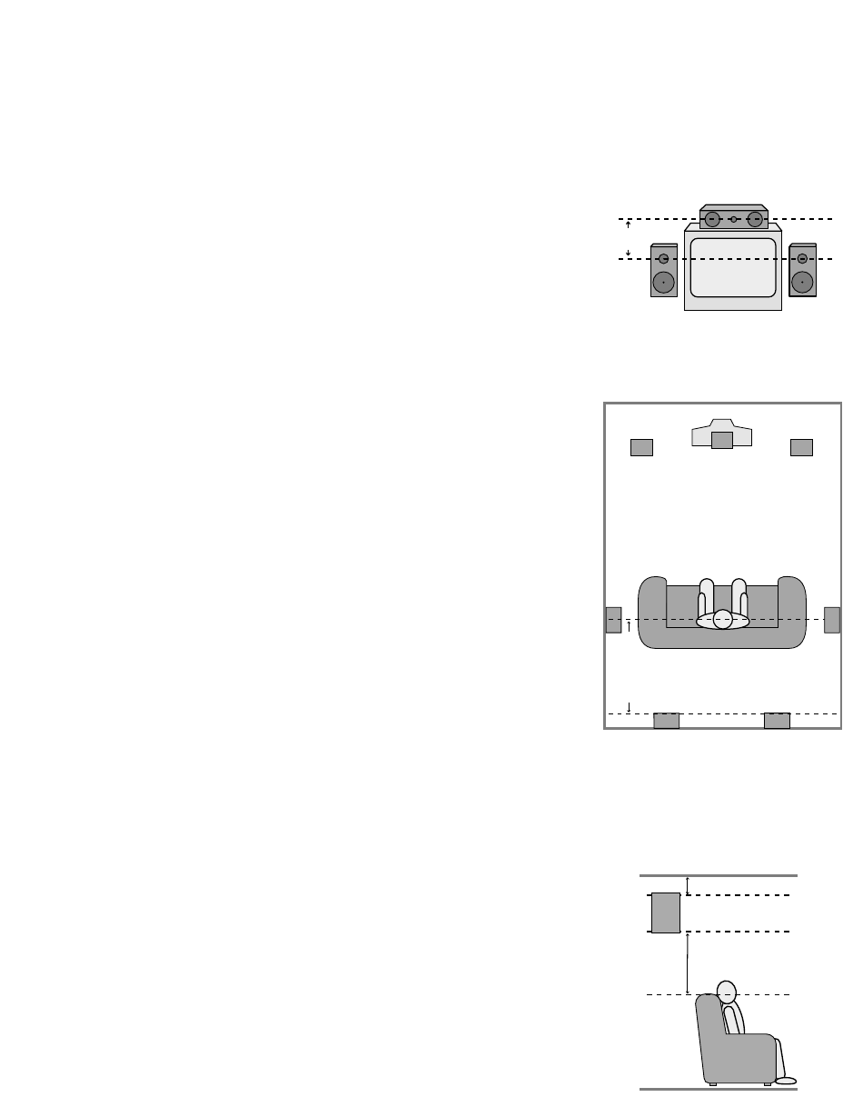
Right Front
Speaker
Left Front
Speaker
No more
than 24″
Center Front Speaker
A) Front Channel Speaker Installation
with Direct-View TV Sets or Rear-Screen
Projectors
Center Front
Speaker
Optional Rear Wall Mounting
TV or Projection Screen
Right Front
Speaker
Left Front
Speaker
No more than 6 feet
when rear-mounted
speakers are used
At least 2 feet
At least 6 inches from ceiling
B) The distance between the left and right
speakers should be equal to the distance
from the seating position to the viewing
screen. You may also experiment with
placing the left and right speakers slightly
forward of the center speaker.

System Configuration
21
System Configuration
Once the speakers have been placed
in their proper positions and connected
to the AVR55, the final steps in the instal-
lation process involve configuration of
the unit for the specific speaker types
in use and the balancing of speaker
output levels.
Before proceeding, check to make
certain that all connections are secure
and follow these steps:
1. Plug the unit into an unswitched AC
outlet and press the Main Power
button 1until it is flush with the
front panel. Note that the Power
Indicator 3will turn amber.
2. Install the supplied AAA batteries in the
remote control, as shown on page 15.
3. Press the System Power Control
2on the front panel or the Main
Power On button con the remote
and note that the Power Indicator
3will turn green.
Bass Management
The settings made during the speaker
configuration process will determine
which speakers receive low-frequency
information, which are those sounds
below 100Hz. If a subwoofer is installed,
it will receive low-frequency information,
and none will be sent to the front
left/right speakers. If you do NOT have
full-range front speakers, it is important
that “YES” be selected as the subwoofer
setting option to prevent damage to your
front speakers.
Speaker Configuration
The next few steps tell the AVR55 which
type of speakers are installed. This, in
turn, configures the bass management
system so that low-frequency sounds are
directed to the proper speaker location.
1. Press the front panel Surround
Mode button Òuntil DOLBY PRO
LOGIC appears as the Surround mode.
2. Press and hold the Speaker Mode
Selector Óuntil the word CENTER
appears in the Information Display F.
The word LARGE, SMALL or NONE
will also appear, and blink to indicate the
current setting. Release the button for a
second, and while the current choice is still
blinking in the display, press the Speaker
Mode Selector Óagain until the word
describing the type of center speaker
installed in your system appears.
•Select LARGE if your center channel
speaker is a traditional full-range
speaker capable of reproducing
frequencies below 100Hz.
•Select SMALL if your center channel
speaker is a smaller “satellite” type
speaker not capable of extended bass
response or reproducing frequencies
below 100Hz.
•Select NONE if no center channel
speaker is installed.
3. Once you have made your selection,
immediately press the Memo button 4
while the display is still blinking. Note
that the speaker selection will change to
SUBWOOFER. The word Yes or NO
will blink indicating the current setting.
4. Press the Speaker Mode Selector
Óagain until the appropriate selection
is made.
•Select YES if a subwoofer is installed.
When YES is selected all low-frequency
information will be sent to the sub-
woofer, and the front, center and
surround speakers will only receive
audio information above 100Hz.
•Select NO if no subwoofer is present.
When NO is selected the front left/right
and surround speakers will receive a
full-range signal, and the feed to the
center speaker will be based on the
selection mode in the previous step.
5. While your choice is blinking in the
display, press the Memo button 4to
enter the selection. The display will stop
blinking to indicate that the setting is
entered and then return to normal.
NOTES:
•In order to enter the speaker configura-
tion, the Speaker Switch 7must be
in the “in” position.
•In order to enter information for the
center speaker, the AVR55 must be in
the Dolby Pro Logic or Dolby 3 Stereo
mode. To select either of these modes,
press the front panel Surround
Mode Selector Òor one of the
Dolby Surround Mode buttons `
on the remote.

System Configuration
22
Speaker Output Adjustments
Adjustments and calibration of the
speaker output levels is important to
proper surround operation. During this
process, the unit is adjusted so that the
output levels from each channel have
a reference level that is as close to one
another as possible. A small amount of
time spent to properly calibrate the
AVR55’s output levels will enable the
unit to deliver all the performance it is
capable of within the environment of
your specific listening room.
IMPORTANT NOTE: Many listeners
are often confused aboutthe operation
of the rear (surround)channels. While
someassumethatsoundshouldalways
becomingfromeachspeaker,mostofthe
timetherewillbelittleornosoundin
thesurroundchannels.Thisisbecause
theyareonlyusedwhenamoviedirector
orsoundmixerspecificallyplacessound
there to create ambiance,an effect or to
continue action from the front of the
room to the rear. Whenthe output levels
are properly set itis normal forrear/
surround speakers to operate only
occasionally.Artificiallyincreasingthe
volumetotherearspeakersmaydestroy
theillusionofanenvelopingsoundfield
thatduplicatesthewayyouhearsound
inamovietheaterorconcerthall.
Before beginning the adjustment process
make certain that all speaker connections
have be properly made. The system
volume should be set to the level that
you will use during a typical listening
session. Finally, make certain that the
Balance Control Ùis set to the center
“12 o’clock” position.
1. Press the Test Tone button k
on the remote to begin the adjustment
process. A test noise will circulate from
one speaker channel to the next, as indi-
cated in the Information Display F.
2. Take a minute to listen to the test
noise from each speaker as the location
indicated in the display changes. Check
to make certain that, for example, when
the display reads TEST-FRONT L,
that the test noise is coming from the
front left speaker. If the test tone’s loca-
tion does not match the display for any
channel, press the Test Tone button
kto end the adjustment and turn
the unit off using the Main Power
Switch 1. Check all connections to
maker certain the Speaker Outputs
fiare connected to the proper speaker.
Installation Hint:While the test tone is
circulating among the channels, make
a note if it sounds reasonably equal in
volume, or if one channel or more
channels seems significantly louder than
the others.
3. When you have verified that all
channels are properly connected, press
the Channel Select button lto
begin the adjustment process.
4. When the Channel Select button
lis pressed, the test tone will stop
circulating and will be heard in the front
left channel only. Use the Volume
Controls ˘nto adjust the test noise
so that it approximates a normal listening
level. If you are using a sound pressure
level meter to calibrate the system, set the
volume level so that the meter reads 75dB,
C-Weighting, Slow.
5. Press the Channel Select button l
again, and note that the test tone will
move to the center channel, as indicated
by the TEST-CENTER indication in the
Information Display. Use the Speaker
Level Adjust buttons mto raise or
lower the sound level so that it is equal to
the level just established in the front left
channel. DO NOT use the Volume
Controls ˘nfor this adjustment, as
they control the main system level, not the
individual channel outputs. As the adjust-
ments are made, the display will indicate
the positive or negative offset from the
reference level set in the previous step as
CENTER : +2 DB. When the adjust-
ment is complete, press the Channel
Select button lagain to move to the
next channel.

System Configuration
23
6. The test tone will now be heard
through the front right speaker. Once
again, first listen to the test noise to
determine if it is louder or softer than the
previous two channels. If an adjustment
is required, use the Speaker Level
Adjust buttons muntil the level is
matched. In this case, the offset level for
both front channels will be shown in the
display, such as FL0FR+0. Only
the FR indication will change, as only
the front right channel is being adjusted
at this time. When the level is equal to
the front left and center channels, press
the Channel Select button lto
move to the next channel.
7. The test tone will now be heard from
the right rear (surround) channel.
Follow the instructions shown in the pre-
vious step until the volume level for this
channel is equal to the others. Press the
Channel Select button lafter you
have finished with the right rear to move
to the final channel.
8. Adjust the output from the left rear
(surround) channel as shown in the pre-
vious steps. Remember, the goal is to
have the sound level equal to all previous
channels, using the Speaker Level
Adjust buttons mto make any needed
changes.
9. At this point, you should make a final
check on the adjustments. Press the
Channel Select button lquickly so
that you circulate the test noise among
all the channels. Make a note of which
channels need fine adjustments to raise
or lower their level so that they are
brought into line with the others. When
an adjustment is needed, simply stop
pressing the button and make the level
change using the Speaker Level
Adjust buttons m.
10. When you are satisfied that all
channels have the same output level,
press the Test Tone button ito
return the AVR55 to normal operation.
Delay Settings
Oneaspectofthesurroundmodesis the
delayofaudiosignalsbetweenthefront
speakersandtherearspeakers.Each
surroundmodeisfactorypresetwitha
specificdelaytime,butitispossible to
individuallyadjustthedelaytimingto
customtailorthesoundtoyourindivid-
ualtasteandtheacousticconditionsin
yourlisteningroomorhometheater.
Thefactorysettingisappropriatefor
mostrooms,butsomeinstallations
createanuncommondistancebetween
thefrontandsurroundspeakersthatmay
causethearrivaloffrontchannelsounds
tobecomedisconnectedfromsurround
channelsounds.
To resynchronizethefrontandsurround
channels,followthesesteps:
1.Measurethedistancefromthe
listening/viewingpositiontothe
frontspeakers.
2.Measurethedistancefromthe
listening/viewingpositiontothe
surroundspeakers.
3.Subtractthedistancetothe
surroundspeakersfromthedistance
tothefrontspeakers.
a. When setting the delay time for
the Dolby Digital surround mode,
the optimal delay time is the result-
ing figure. For example, if the front
speakers are ten feet away and the
surround speakers are five feet
away, the optimal delay time is
figured as 10-5=5. Thus, in this
example, the delay should be set at
five milliseconds.
b. When setting the delay time for
the analog Pro Logic mode, take
the result of the subtraction and
add 15 to obtain the optimal delay
time. For example, if the front
speakers are ten feet away and the
surround speakers are five feet
away, the optimal delay time is
figured as 10-5+15=20. Thus in
this example, the delay should be
set at twenty milliseconds.

System Configuration
With the correct delay time figures for
your listening room calculated, first make
certain that the unit is in the Dolby Pro
Logic mode by pressing the Surround
Mode button Òor Dolby Surround
Mode buttons `until the Pro Logic
indicator Cis illuminated.
Press the Select button jto begin the
adjustment process. The Information
Display Fwill show the current delay
setting, such as REAR - 15mS. If
adjustment is required, immediately
press the Delay button gon the
remote to change the setting until it is
closest to the desired time. Within five
seconds the display will return to normal
readout and the setting will be entered.
The Dolby Digital mode also provides a
separate setting for the center channel
delay mode, since the discrete nature
of Dolby Digital signals makes the
location of the center channel speaker
more critical. To set the delay for the
center channel, measure the distance
from the preferred listening position in
the center of the room to both the center
channel speaker and either the left or
right speaker.
If the distances are equal, no further
adjustment is required, and the center
delay should be set to zero. If the
distance to the front speakers is greater
than the distance to the center speaker
you may wish to reposition the speakers
by moving the front left/right speakers
closer to the listening position or the
center speaker further away from the
listening position.
If repositioning of the speakers is not
possible, adjust the center delay time
so that you add one millisecond of center
channel delay for each foot that the dis-
tance to the center speaker lags behind
the front speakers. For example, if the
front left/right speakers are each 10 feet
from the listening position and the center
channel speaker is 8 feet away, the delay
is figured as 10-8=2, suggesting an
optimal center delay of 2 milliseconds.
To change the delay settings for Dolby
Digital operation, first calculate the
correct timings as outlined above. Next,
make certain that the AVR55 is in the
Dolby Digital mode by pressing the
Dolby Digital/AC-3 button Ûzon
the front panel or remote. Make certain
that the Dolby Digital Indicator B
is illuminated.
Press the Select button jand note
that the Information Display Fwill
show the settings for both the center and
rear/surround delay as
C-0mS R-10mS.
The center channel delay figure will
blink, indicating that you may change
the setting.
Press the Delay button gto change
the center delay time to the desired
setting. When the appropriate number
is shown press the Select button j
once so that the number for rear/
surround delay time on the right side
of the display blinks.
Use the Delay button gto change
the rear/surround delay to the desired
setting.
When both settings are correct, press the
Select button jagain and note that
the display will stop blinking. After a few
seconds the display will return to normal
operation and the settings will be entered
to memory.
24

Operation
Basic Operation
Once you have completed the setup and
configuration of your new receiver, it is
simple to operate and enjoy. The follow-
ing instructions will provide the steps
needed to enjoy the AVR55:
•When using the AVR55 for the first
time, it is necessary to press the Main
Power button 1on the front panel to
turn the unit on. This places the unit in a
standby mode, as indicated by the amber
color of the Power Indicator 3. Once
the unit is in standby, you may begin a
listening session by pressing the System
Power Control 2on the front panel or
the Main Power button con the
remote. Note that the Power Indicator
3will turn green. This will turn the unit
on and return it to the input source that
was last used. The unit may also be
turned on from standby by pressing any
of the Source Selector buttons on the
remote deior front panel 8)
!@#$%^*
.
To turn the unit off at the end of a listen-
ing session simply press the System
Power Control 2on the front panel
or the Main Power Off button con
the remote. Power to any equipment
plugged into the rear panel Switched
Outlet flwill be shut off and the
Power Indicator 3will turn amber.
When the remote is used to turn the unit
“off” it is actually placing the system in a
standby mode, as indicated by the amber
color of the Power Indicator 3.
When you will be away from home for
an extended period of time it is always
a good idea to completely turn the
unit off using the front panel Main
Power Switch 1. Note that all preset
memories are lost if the unit is left
turned off with the Main Power
Switch 1for more than two weeks.
Source Selection
•To select a source at any time, press
any of the Source Selector buttons on
the remote deior front panel 8
)!@#$%^*
.
•The front panel Audio/Video
Inputs ˜may be used to connect a
device such as a video game or cam-
corder to your home entertainment
system on a temporary basis. To listen
to and view the output of the playback
unit connected to these inputs, first press
the Vid 2 Input Selector *e
,
and then press the Vid 2 Front/Rear
button (. When the front panel inputs
are selected, a red LED will illuminate
above the selector button.
•When an audio source is selected the
last video input used remains routed to
the Video 1 and Monitor Outputs ›
a. This permits simultaneous viewing
and listening to different sources.
•During a listening session you may
wish to adjust the Bass and Treble
Úcontrols to suit your listening tastes.
•At lower volume levels you may wish
to engage the Contour button ¯. This
boosts the low- and high-frequency
sounds in accordance with what are
known as the Fletcher-Munson hearing
curves to compensate for the response of
human hearing at low sound levels.
•Adjust the volume to a comfortable
level using the front panel Volume
Control ˘or remote Volume
Up/Down nbuttons.
•To temporarily silence all speaker
outputs press the Mute button p.
This will cut the output to all speakers,
but it will not effect any recording or
dubbing that may be in progress. When
the system is muted the word MUTE
will flash in the information display.
Press the Mute pbutton again to
return to normal operation.
•For private listening, plug the 1/4"
stereo phone plug from a pair of stereo
headphones into the front panel
Headphone jack 5. To cut the speaker
output when using headphones, press the
Speaker button 7so that it is in the
extended position from the front panel.
•When one of the Video inputs $%
^*eis selected the video signal for
that input will be routed to the Video
Monitor output jack aand will be view-
able on a TV monitor connected to the
AVR55. Make certain that your TV is set to
the proper input to view the signal.
•In some installations it may be desir-
able to dim or extinguish the front panel
lights. This may be done by pressing and
holding the Display button oon the
remote. The first press will dim the lights
to one half normal brightness, and a
second press will turn them totally off.
Press the button again to return the
lights to normal brightness. Note that the
Power Indicator 3will remain lit at
all times as a reminder that the unit is
turned on.
25
Operation
•To program the AVR55 for automatic
turn off, press the Sleep button on
the remote. Each press of the button will
increase the time before shut down in the
following sequence:
After a GOOD NIGHT message the sleep
time will be displayed on the right side of
the Information Display F, and it
will count down until the time
has elapsed.
When the programmed time has elapsed
the unit will automatically turn off. Note
that the front panel display will dim to
one half brightness when the Sleep func-
tion is programmed. To cancel the Sleep
function, press the Sleep button
until the information display returns to
normal brightness and the Sleep
indicator numbers disappear.
TV Auto-On
The AVR55 is capable of automatic
operation that turns it on in response to
the operation of a video source such as
the TV. This eliminates the need to man-
ually turn on the AVR55 with a separate
remote command. While this feature is
most commonly used with a TV, it may
be used with any video source such as a
satellite receiver or VCR. To use the TV
Auto-On feature follow these steps:
1. Connect the video source that will be
used to trigger the Auto-On feature to the
TV Inputs ¤.
2. Activate the feature by pressing and
holding the TV Input button $e
on the front panel or remote until the
words AUTO-OFF appear in the
Information Display F.
10
min 20
min 30
min 60
min 90
min OFF
3. Release the button, and then press it
again within 2.5 seconds until the dis-
play changes to read AUTO-ON and
then release the button.
4. The TV Auto-On feature is now engaged.
Whenever a video source is present at the
TV Inputs ¤and the AVR55 is in the
Standby mode the unit will automatically
turn on and switch to the TV input.
5. Unless another input source is selected,
the unit will automatically return to the
Standby mode approximately five min-
utes after the audio source connected to
the TV input is turned off.
NOTE:Remember that when the TV Auto
feature is engaged, the AVR55 will turn
off whenever the TV input has been
selected and the video source feeding that
input is not active. To disable this feature
follow steps 2 and 3 above, but toggle the
buttons so that the words AUTO-OFF
appear in the Information Display F.
Surround Mode Selection
One of the most important features of
the AVR55 is its ability to reproduce a full
multichannel surround sound field from
Dolby Digital sources, analog matrix
surround encoded programs, and stan-
dard stereo programs. In all a total of
seven listening modes are available on
the AVR55.
Selection of a surround mode is based
on personal taste, as well as the type of
program source material being used.
For example, motion pictures or TV pro-
grams bearing the logo of one of the
major surround encoding processes, such
as Dolby Surround, DTS†Stereo or
UltraStereo††may be played in either the
Dolby Digital, Dolby Pro Logic or Movie
Surround depending on the source
material.
NOTE:Once a program has been
encoded with surround information, it
retains the surround matrix as long as
the program is broadcast in stereo. Thus,
movies with surround sound will carry
surround information when they are
broadcast via conventional TV stations,
cable, pay TV and satellite transmission.
In addition, a growing number of made-
for-television programs, sports broad-
casts, radio dramas and music CDs are
also recorded in surround sound. You
may obtain a list of these programs and
discs from the Dolby Laboratories web
site at www.dolby.com
Surround modes for conventional analog
audio inputs are selected by pressing the
Surround Mode button Òon the
front panel or the Matrix and Dolby
Mode buttons y`on the remote. As
described above, when a “Surround
Sound” logo is associated with the pro-
gram you are listening to, it is always
best to start with Dolby Pro Logic, or
Dolby 3-Stereo when there are no sur-
round speakers. However, you may wish
to experiment with the Theater, Hall,
Church or Stadium modes to see if you
find that sound more pleasing.
Remember, you can’t break anything by
trying a different surround mode.
When a program is not listed as carrying
intentional surround information, you
may find that Pro Logic or Dolby 3-
Stereo often delivers enveloping surround
presentations through the use of the
natural information present in all stereo
recordings.
26

Operation
To listen to a program in traditional two-
channel stereo, with only the front left
and right speakers plus the subwoofer, if
installed, press the Stereo button x
on the remote or the Surround Off
button Ôon the front panel.
Dolby Digital
Dolby Digital (also known as AC-3) is the
latest advancement in surround sound
technology, delivering up to five full-
range surround channels (left, center,
right, left surround and right surround)
plus a special dedicated Low-Frequency
Effects (LFE) channel. This represents a
major advancement over traditional
analog surround in that each surround
channel is fully discrete and capable of
full bandwidth reproduction. Dolby
Digital is available on DVD and LV discs,
and it will be a part of the new high-
definition television (HDTV) system
when digital broadcasting begins in late
1998. Dolby Digital for the home is based
on the same system used to deliver digital
audio sound tracks in movie theaters,
enabling true cinema reproduction in
your home.
To utilize the Dolby Digital mode you
must have a digital source properly
connected to the AVR55. The RF digital
output of a laser disc player should be
connected to the AC-3 RF jack gon the
rear panel. Note that this jack is for use
only with the AC-3 RF output from an LV
player and should not be connected to
any other audio, video or digital device.
Digital datastream outputs from DVD
players, HDTV receivers and CD players
should be connected to the AC-3/PCM
Optical or Coaxial inputs ¶fon the
rear panel. In order to provide a backup
signal and a source for recording, the
analog outputs provided on digital source
equipment should also be connected to
their appropriate rear panel inputs
(e.g., connect the analog stereo audio
output from a DVD to the DVD inputs ‹
on the rear panel when you connect the
digital outputs).
Dolby Digital sources must be used in
conjunction with one of the video related
inputs: DVD, TV, Vid 1 or Vid 2. Make sure
that the source is on and video is playing
before selecting a digital audio source.
Next, press the Digital Input button ı
hthat corresponds to the type of digital
input used. A red LED will light above the
data type selected, and a message will
scroll across the Information Display
Fto confirm your choice.
Finally, press the AC-3/Dolby Digital
button zÛto select Dolby Digital.
The mode name will briefly scroll
in the Information Display F,
and the Dolby Digital indicator B
will illuminate.
NOTE:If a Dolby Digital signal that
matches the selected input type is not pre-
sent, the red LED indicator above the
Digital Input button ıwill flash to
remind you of the input error. Remember,
with digital sources such as a DVD player,
the data input stops when a disc is in
Pause or a Search mode. It is normal for
the light to flash in those conditions.
Night Mode
A special feature of Dolby Digital is the
Night mode, which enables AC-3 input
sources to be played back with their full
range while reducing the minimum peak
level by 1/4 to 1/3. This prevents abruptly
loud transitions from causing distur-
bances without reducing the impact of
the digital source. The Night mode is
available only when AC-3 signals with
special data are being played.
To engage the Night mode, press the
Night button ˆfand note that the
indicator will illuminate above the
Night button on the front panel.
IMPORTANT NOTES ON
DOLBY DIGITAL PLAYBACK:
1. The AVR55 will decode digital audio
sources with a sampling frequency of
32kHz, 44.1kHz and 48kHz. Although
this will enable it to decode virtually all
DVD movies and HDTV sources, it is pos-
sible that some digital sources may not
be compatible with the AVR55.
2. The AVR55 will automatically detect
most Dolby Digital sources. It is possible,
however, that future source equipment
that could not be anticipated at this time,
may require manual surround mode
selection or analog playback.
3. Note that not all programs recorded in
Dolby Digital contain full 5.1 channel
audio. Consult the program guide that
accompanies the DVD or Laser Disc to
determine which type of audio has been
recorded on the disc. The AVR55 will
automatically sense the type of digital
surround encoding used on an AC-3
program source and adjust to
accommodate it.
4. When a Dolby Digital source is
playing, you may not select one of the
analog surround modes.
5. It is not possible to record the output
of a Dolby Digital program.
27

Operation
6. NOTE:The design of some early DVD
players is such that you may occasionally
hear a click or pop when the player starts
after being paused or after a Search mode
is used. This is a function of the format
and does not indicate any problem with
your AVR55.
PCM Audio Playback
PCM (Pulse Code Modulation) is the
non-compressed digital audio system
used for compact discs and non-AC-3
laser discs. The digital circuits in the
AVR55 are capable of high-quality digital-
to-analog decoding, and they may be
connected directly to the digital audio
output of your CD or LV player.
Connections should be made to the
AC-3/PCM Optical or Coaxial inputs
¶fon the rear panel, using whichever
input is not occupied by an AC-3 source
such as a DVD player.
To play a PCM source, first select the
desired input using the Input
Selectors )$%^*de.
Next, choose either an Optical or Coaxial
digital source using the Digital Input
Selector hı. Finally, select any
Surround mode other than Dolby Digital.
Tuner Operation
The AVR55’s tuner is capable of tuning
AM, FM and FM Stereo broadcast stations.
Stations may be tuned manually, or they
may be stored as favorite station presets
and recalled from a 30 position memory.
Station Selection
1. Press the AM/FM button 8ito
select the tuner as an input.
2. Press the AM/FM button 8i again
to switch between AM and FM so that the
desired frequency band is selected.
3. Press the Tuning Mode button 6q
to select manual or automatic tuning.
When the AUTO indicator is illuminated
in the main information display the
tuner will only stop at those stations that
have a strong enough signal to be
received with acceptable quality.
If the AUTO indicator is NOT illumin-
ated, the tuner is in a manual mode and
will stop at each frequency increment in
the selected band.
4. To manually tune stations, press the
right side of the Tune button 9to tune
a station with a higher frequency, or the
left side to tune a station with a lower fre-
quency. When the TUNED indicator
illuminates, the station is properly tuned
and should be heard with clarity. To
automatically search for the next station
with acceptable signal strength, press
and hold the Tune button 9until the
AUTO indicator lights. Release it and the
tuner will stop when it finds a station.
When a station is weak, audio quality
will be improved by pressing the FM
Mode button 6until the STEREO
indicator Lgoes out.
5. To select stations using the remote,
press the Manual Tune ‹‹ /›› but-
tons rto select stations one at a time.
Alternatively, the Automatic Tune
‹‹ /››
buttons tmay be used to
scan only those stations with sufficient
strength for proper reception. Each press
of these buttons will advance the tuner to
the next station. For FM stereo reception
press the FM Mode button quntil the
STEREO indicator is illuminated.
NOTE:When the FM reception of a
station is weak, audio quality will be
increased by switching to mono mode
by pressing the Tuning Mode button
6quntil the STEREO indicator goes
out.
Preset Tuning
Up to 30 stations may be stored in the
AVR55’s memory for easy recall using the
front panel controls or the remote.
To enter a station to the memory, first
tune the station using the steps outlined
above. Then:
1. Press the Memo button 4uon
the front panel or remote. Note that the
MEMORY indicator will illuminate and
flash in the information display.
2. Within five seconds, press the
Numeric Buttons
37
wcorrespond-
ing to the location where you wish to
store this station’s frequency. To enter a
station to memory location “30,”press
only the 0button.
3. Repeat the process after tuning any
additional stations to be preset.
28

Operation
Recalling Preset Stations
•To manually select a station previously
entered in the preset memory, press the
Numeric Buttons
37
wcorrespond-
ing to the desired station’s location. To
select the station in location “30,” press
the 0button only.
•To manually tune through the list of
stored preset stations one by one, press
the Preset/Disc Skip buttons son
the remote.
•To automatically scan through the
stations entered in the preset memory,
press the P.Scan button von the
remote. The tuner will run through the
list of preset stations, stopping for five
seconds at each one. Press the P.Scan
button again to stop the scan at your
desired station.
Tape Recording
In normal operation, the audio or video
source selected for listening through the
AVR55 is sent to the record outputs.
This means that any program you are
watching or listening to may be recorded
simply by placing machines connected
to the outputs for Tape 1 or Tape 2
‚•in the record mode.
When a tape recorder with separate
record and playback heads is used, you
may monitor the output of the recording
by selecting the Tape 1/Monitor input
!d
. Note that the T•MON indicator
Kwill illuminate in the front panel dis-
play to remind you that you are listening
to the record playback instead of the
actual input source being recorded.
NOTE:When a Dolby Digital source is
playing, the output may not be recorded.
Video Recording
The AVR55 permits you to make a video
recording from one of the input sources
while another source is being listened to
through the unit’s main amplifiers.
To make a video recording, press the
Video 1 Record button &and
observe the indicator dot at the far left
side of the front panel Information
Display
35
. As you press the Record
button, the Video 1 Record indicator
Awill change to show which output is
being sent to the Video 1 Out jacks ›.
The output may be either the current
listening source, or one of the other video
inputs (TV, DVD, Video 2).
IMPORTANT NOTE: Please make cer-
tain that you are aware of the copyright
restrictions on any material you copy.
Unauthorized duplication of copyrighted
materials is prohibited by Federal law.
Output Level Trim Adjustment
Normal output level adjustment for the
AVR55 is established using the Test Tone,
as outlined on page 19. In some cases,
however, it may be desirable to adjust the
output levels using program material
such as a test disc, or a selection you are
familiar with.
To adjust the output levels using pro-
gram material, first set the reference
volume for the front left/right channels
using the Volume Control ˘n
. If
you wish to vary the difference between
the left and right channels, use the
Balance Control Ù.
To change the level for the channels you
wish to adjust use the appropriate front
panel level adjust control for the
Subwoofer, Center or Surround
channels ¸˝
34
.
Memory Backup
This product is equipped with a memory
backup system that preserves tuner pre-
sets and system configuration informa-
tion if the unit is accidentally unplugged
or subject to a power outage. This mem-
ory will last for approximately two weeks,
after which time all information must be
reentered.
29

Troubleshooting Guide
30
SYMPTOM
No front panel lights when power
switch is pressed
Display lights, but no sound
or picture
No sound from any speaker.
Light around power switch is red
No sound from surround or
center speakers
Unit does not respond to
remote commands
Intermittent buzzing in tuner
CAUSE
• No AC Power
• Intermittent input connections
• Mute is on
• Volume control is down
• Amplifier is in protection mode
due to possible short
• Amplifier is in protection mode
due to internal problems
• Incorrect surround mode
• Input is monaural
• Incorrect configuration
• Stereo or Mono program material
• Weak batteries in remote
• Remote is in Learn position
• Remote sensor is obscured
• Local interference
SOLUTION
• Make certain AC power cord is plugged into
a live outlet
• Check to see if outlet is switch controlled
• Make certain that all input and speaker connections
are secure
• Press Mute button
• Turn up volume control
• Check speaker-wire connections
at receiver and speaker ends for shorts
• Contact your local Harman Kardon service depot
• Select a mode other than Stereo
• There is no surround information from mono sources
• Check speaker mode
• The surround decoder may not create center or rear
channel information from non-encoded programs
• Change remote batteries
• Slide Use/Learn switch to Use
• Make certain front panel sensor is visible to remote
or connect remote sensor
• Move unit or antenna away from computers, fluorescent
lights, motors or other electrical appliances
Troubleshooting Guide

Technical Specifications
31
Audio Section
Stereo Mode
Continuous Average Power (FTC)
65 Watts per channel 20Hz–20kHz:
@ < 0.07% THD, both channels driven into 8 Ohms
Five-Channel Surround Mode
Power Per Individual Channel
Front L&R channels:
55 Watts per channel,
@ 0.07% THD, 20Hz–20kHz into 8 ohms
Center channel:
55 Watts, 20Hz–20kHz into 8 ohms
Surround channels:
55 Watts per channel, 40Hz–20kHz into 8 ohms
Input Sensitivity/Impedance
Linear (High Level) 200mV/32 Kohms
Phono 3mV/47Kohms
Signal-to-Noise Ratio (IHF-A)
Linear (CD) 95dB
Phono 73dB
Surround System Adjacent Channel Separation
Analog Decoding (Pro Logic, etc.) 40dB
Dolby Digital (AC-3) 55dB
Frequency Response
@ 1W (+0, –3dB) 8Hz–100kHz
High Instantaneous
Current Capability (HCC) ±35 Amps
Transient Intermodulation
Distortion (TIM) Unmeasurable
Rise Time 16µsec
Slew Rate 40 V/µsec
FM Tuner Section
Frequency Range 87.5–108 MHz
Usable Sensitivity IHF 1.3 µV/14.2dBf
Signal-to-Noise Ratio Mono/Stereo 70/68dB
Distortion Mono/Stereo 0.3/0.5%
Stereo Separation 1kHz, 40dB
Selectivity ±400kHz 65dB
Image Rejection 98MHz 65dB
Tuner Output Level 1kHz, ±75kHz Dev 500mV
AM Tuner Section
Frequency Range 520–1710kHz
Signal-to-Noise Ratio 45dB
Usable Sensitivity Loop 500µV
Distortion 1kHz, 50% Mod 0.8%
Selectivity ±9kHz, 25dB
General
Power Requirement AC 120V 60Hz
Power Consumption 60W idle, 325W maximum
(2 channels driven)
Dimension (Max)
Width 17.4 inches (440 mm)
Height 6.3 inches (160 mm)
Depth 16.0 inches (406 mm)
Weight 32.6 lbs. (14.8 kg)
Depth measurement includes knobs, buttons and terminal connections.
All features and specifications are subject to change without notice.
*Trademarks of Dolby Laboratories.
†DTS is a trademark of Digital Theater Systems.
††UltraStereo is a trademark of UltraStereo Corp.

Staple or clip original invoice here. ▼
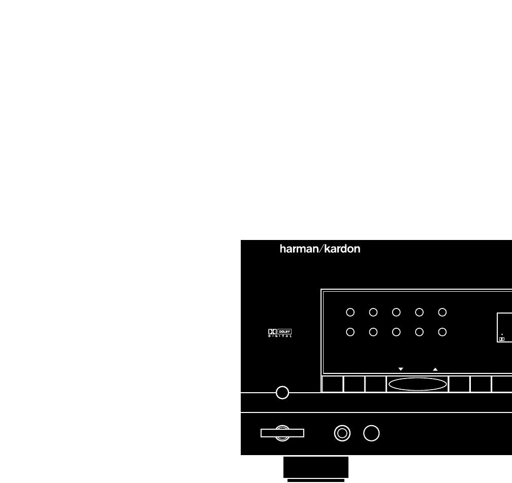
67890
AVR 55
Speaker
Headphones
TUNE
12345
MEMO FM MODE AM/FM CD T MON
•
Power
T 2
•
DIGIT
SOU
VID
DVD
TV
VID 1 RE
Printed in Korea Part #1111-AVR55REVOM
5707046840021
