AWG5200 Series Arbitrary Waveform Generators Programmer Manual 077133700
User Manual:
Open the PDF directly: View PDF ![]() .
.
Page Count: 421 [warning: Documents this large are best viewed by clicking the View PDF Link!]
- toc
- Preface
- Getting Started
- Syntax and Commands
- Command syntax
- Command groups
- Auxiliary out commands
- Basic waveform editor commands
- Calibration group commands
- Capture and playback group commands
- Clock group commands
- Control group commands
- Diagnostic group commands
- Display group commands
- Function generator group commands
- IEEE mandated and optional group commands
- Instrument group commands
- Mass memory group commands
- Output group commands
- S-Parameters group commands
- Sequence group commands
- Source group commands
- Status group commands
- Synchronization group commands
- System group commands
- Trigger group commands
- Waveform group commands
- Waveform plug-in group commands
- Command descriptions
- ABORt (No Query Form)
- ACTive:MODE
- AUXoutput[n]:SOURce
- AUXoutput[n]:SOURce:CMAPping
- AWGControl:ARSettings
- AWGControl[:CLOCk]:DRATe
- AWGControl:CLOCk:PHASe[:ADJust]
- AWGControl[:CLOCk]:SOURce
- AWGControl:COMPile (No Query Form)
- AWGControl:CONFigure:CNUMber? (Query Only)
- AWGControl:PJUMp:JSTRobe
- AWGControl:PJUMp:SEDGe
- AWGControl:RMODe
- AWGControl:RSTate? (Query Only)
- AWGControl:RUN[:IMMediate] (No Query Form)
- AWGControl:SNAMe? (Query Only)
- AWGControl:SREStore (No Query Form)
- AWGControl:SSAVe (No Query Form)
- AWGControl:STOP[:IMMediate] (No Query Form)
- BWAVeform:AMPLitude
- BWAVeform:AUTO
- BWAVeform:COMPile (No Query Form)
- BWAVeform:COMPile:CASSign
- BWAVeform:COMPile:CHANnel
- BWAVeform:COMPile:NAME
- BWAVeform:COMPile:PLAY
- BWAVeform:CYCLe
- BWAVeform:FDRange
- BWAVeform:FREQuency
- BWAVeform:FUNCtion
- BWAVeform:HIGH
- BWAVeform:LENGth
- BWAVeform:LOW
- BWAVeform:OFFSet
- BWAVeform:RESet (No Query Form)
- BWAVeform:SRATe
- *CAL? (Query Only)
- CALibration:ABORt (No Query Form)
- CALibration[:ALL]
- CALibration:CATalog? (Query Only)
- CALibration:LOG? (Query Only)
- CALibration:LOG:CLEar (No Query Form)
- CALibration:LOG:FAILuresonly
- CALibration:RESTore (No Query Form)
- CALibration:RESult? (Query Only)
- CALibration:RESult:TEMPerature? (Query Only)
- CALibration:RESult:TIME? (Query Only)
- CALibration:RUNNing? (Query Only)
- CALibration:STARt (No Query Form)
- CALibration:STATe:FACTory? (Query Only)
- CALibration:STATe:USER? (Query Only)
- CALibration:STOP:STATe? (Query Only)
- CLOCk:ECLock:DIVider
- CLOCk:ECLock:FREQuency
- CLOCk:ECLock:FREQuency:DETect (No Query Form)
- CLOCk:ECLock:MULTiplier
- CLOCk:EREFerence:DIVider
- CLOCk:EREFerence:FREQuency
- CLOCk:EREFerence:FREQuency:DETect
- CLOCk:EREFerence:MULTiplier
- CLOCk:JITTer
- CLOCk:OUTPut:FREQuency? (Query Only)
- CLOCk:OUTPut[:STATe]
- CLOCk:PHASe[:ADJust[:DEGRees]]
- CLOCk:PHASe[:ADJust]:TIMe
- CLOCk:SOURce
- CLOCk:SOUT[:STATe]
- CLOCk:SRATe
- *CLS (No Query Form)
- CPLayback:CAPTure:FILE (No Query Form)
- CPLayback:CAPTure:INSTrument:OSCilloscope (No Query Form)
- CPLayback:CAPTure:INSTrument:RSA (No Query Form)
- CPLayback:CLISt:NAME? (Query Only)
- CPLayback:CLISt:SIGNal:DELete (No Query Form)
- CPLayback:CLISt:SIGNal:SCOMpile
- CPLayback:CLISt:SIGNal:WAVeform:FOFFset
- CPLayback:CLISt:SIGNal:WAVeform:NAME? (Query Only)
- CPLayback:CLISt:SIGNal:WAVeform:OTIMe
- CPLayback:CLISt:SIGNal:WAVeform:SRATe
- CPLayback:CLISt:SIGNal:WCOunt? (Query Only)
- CPLayback:CLISt:SIZE? (Query Only)
- CPLayback:COMPile (No Query Form)
- CPLayback:COMPile:CFRequency
- CPLayback:COMPile:LSEQuence
- CPLayback:COMPile:NORMalize
- CPLayback:COMPile:SRATe
- CPLayback:COMPile:SRATe:AUTO
- DIAGnostic:ABORt (No Query Form)
- DIAGnostic:CATalog? (Query Only)
- DIAGnostic:CONTrol:COUNt
- DIAGnostic:CONTrol:HALT
- DIAGnostic:CONTrol:LOOP
- DIAGnostic:DATA? (Query Only)
- DIAGnostic[:IMMediate]
- DIAGnostic:LOG? (Query Only)
- DIAGnostic:LOG:CLEar (No Query Form)
- DIAGnostic:LOG:FAILuresonly
- DIAGnostic:LOOPs? (Query Only)
- DIAGnostic:RESult? (Query Only)
- DIAGnostic:RESult:TEMPerature? (Query Only)
- DIAGnostic:RESult:TIME? (Query Only)
- DIAGnostic:RUNNing? (Query Only)
- DIAGnostic:SELect (No Query Form)
- DIAGnostic:SELect:VERify? (Query Only)
- DIAGnostic:STARt (No Query Form)
- DIAGnostic:STOP (No Query Form)
- DIAGnostic:STOP:STATe? (Query Only)
- DIAGnostic:TYPE
- DIAGnostic:TYPE:CATalog? (Query Only)
- DIAGnostic:UNSelect (No Query Form)
- DISPlay[:PLOT][:STATe]
- *ESE
- *ESR? (Query Only)
- FGEN:[CHANnel[n]]:AMPLitude:POWer
- FGEN[:CHANnel[n]]:AMPLitude[:VOLTage]
- FGEN[:CHANnel[n]]:DCLevel
- FGEN[:CHANnel[n]]:FREQuency
- FGEN[:CHANnel[n]]:HIGH
- FGEN[:CHANnel[n]]:LOW
- FGEN[:CHANnel[n]]:OFFSet
- FGEN[:CHANnel[n]]:PATH
- FGEN[:CHANnel[n]]:PERiod? (Query Only)
- FGEN[:CHANnel[n]]:PHASe
- FGEN[:CHANnel[n]]:SYMMetry
- FGEN[:CHANnel[n]]:TYPE
- *IDN? (Query Only)
- INSTrument:COUPle:SOURce
- INSTrument:MODE
- MMEMory:CATalog? (Query Only)
- MMEMory:CDIRectory
- MMEMory:DATA
- MMEMory:DATA:SIZE? (Query Only)
- MMEMory:DELete (No Query Form)
- MMEMory:IMPort (No Query Form)
- MMEMory:IMPort[:PARameter]:NORMalize
- MMEMory:MDIRectory (No Query Form)
- MMEMory:MSIS
- MMEMory:OPEN (No Query Form)
- MMEMory:OPEN[:PARameter]:NORMalize
- MMEMory:OPEN[:PARameter]:SIQ
- MMEMory:OPEN:SASSet:SEQuence (No Query Form)
- MMEMory:OPEN:SASSet:SEQuence:MROPened? (Query Only)
- MMEMory:OPEN:SASSet[:WAVeform] (No Query Form)
- MMEMory:OPEN:SETup (No Query Form)
- MMEMory:OPEN:TXT (No Query Form)
- MMEMory:SAVE:SEQuence (No Query Form)
- MMEMory:SAVE:SETup (No Query Form)
- MMEMory:SAVE[:WAVeform]:MAT (No Query Form)
- MMEMory:SAVE[:WAVeform]:TIQ (No Query Form)
- MMEMory:SAVE[:WAVeform]:TXT (No Query Form)
- MMEMory:SAVE[:WAVeform]:WFM (No Query Form)
- MMEMory:SAVE[:WAVeform][:WFMX] (No Query Form)
- *OPC
- *OPT? (Query Only)
- OUTPut:OFF
- OUTPut[n]:PATH
- OUTPut[n][:STATe]
- OUTPut[n]:SVALue[:ANALog][:STATe]
- OUTPut[n]:SVALue:MARKer[m]
- OUTPut[n]:WVALue[:ANALog][:STATe]
- OUTPut[n]:WVALue:MARKer[m]
- *RST (No Query Form)
- SLISt:NAME? (Query Only)
- SLISt:SEQuence:AMPLitude
- SLISt:SEQuence:DELete (No Query Form)
- SLISt:SEQuence:EVENt:JTIMing
- SLISt:SEQuence:EVENt:PJUMp:DEFine
- SLISt:SEQuence:EVENt:PJUMp:ENABle
- SLISt:SEQuence:EVENt:PJUMp:SIZE? (Query Only)
- SLISt:SEQuence:FREQuency
- SLISt:SEQuence:LENGth? (Query Only)
- SLISt:SEQuence:NEW (No Query Form)
- SLISt:SEQuence:OFFSet
- SLISt:SEQuence:RFLag
- SLISt:SEQuence:SRATe
- SLISt:SEQuence:STEP:ADD (No Query Form)
- SLISt:SEQuence:STEP:MAX? (Query Only)
- SLISt:SEQuence:STEP:RCOunt:MAX? (Query Only)
- SLISt:SEQuence:STEP[n]:EJINput
- SLISt:SEQuence:STEP[n]:EJUMp
- SLISt:SEQuence:STEP[n]:GOTO
- SLISt:SEQuence:STEP[n]:RCOunt
- SLISt:SEQuence:STEP[n]:TASSet:SEQuence (No Query Form)
- SLISt:SEQuence:STEP[n]:TASSet[m]? (Query Only)
- SLISt:SEQuence:STEP[n]:TASSet[m]:TYPE? (Query Only)
- SLISt:SEQuence:STEP[n]:TASSet[m]:WAVeform (No Query Form)
- SLISt:SEQuence:STEP[n]:TFLag[m]:AFLag
- SLISt:SEQuence:STEP[n]:TFLag[m]:BFLag
- SLISt:SEQuence:STEP[n]:TFLag[m]:CFLag
- SLISt:SEQuence:STEP[n]:TFLag[m]:DFLag
- SLISt:SEQuence:STEP[n]:WINPut
- SLISt:SEQuence:TRACk? (Query Only)
- SLISt:SEQuence:TRACk:MAX? (Query Only)
- SLISt:SEQuence:TSTamp? (Query Only)
- SLISt:SEQuence:WMUSage? (Query Only)
- SLISt:SIZE? (Query Only)
- [SOURce:]FREQuency[:CW]|[:FIXed]
- [SOURce[n]:]POWer[:LEVel][:IMMediate][:AMPLitude]
- [SOURce:]RCCouple
- [SOURce:]ROSCillator:MULTiplier
- [SOURce[n]:]CASSet? (Query Only)
- [SOURce[n]:]CASSet:CLEar (No Query Form)
- [SOURce[n]:]CASSet:SEQuence (No Query Form)
- [SOURce[n]:]CASSet:TYPE? (Query Only)
- [SOURce[n]:]CASSet:WAVeform (No Query Form)
- [SOURce[n]:]CFRequency
- [SOURce[n]:]DAC:RESolution
- [SOURce[n]:]DDR
- [SOURce[n]:]DMODe
- [SOURce:]IQIMode
- [SOURce[n]]:JUMP:FORCe (No Query Form)
- [SOURce[n]]:JUMP:PATTern:FORCe (No Query Form)
- [SOURce[n]:]MARKer[m]:DELay
- [SOURce[n]:]MARKer[m]:VOLTage[:LEVel][:IMMediate][:AMPLitude]
- [SOURce[n]:]MARKer[m]:VOLTage[:LEVel][:IMMediate]:HIGH
- [SOURce[n]:]MARKer[m]:VOLTage[:LEVel][:IMMediate]:LOW
- [SOURce[n]:]MARKer[m]:VOLTage[:LEVel][:IMMediate]:OFFSet
- [SOURce[n]:]RMODe
- [SOURce[n]:]SCSTep? (Query Only)
- [SOURce[n]:]SKEW
- [SOURce[n]:]TINPut
- [SOURce[n]:]VOLTage[:LEVel][:IMMediate][:AMPLitude]
- [SOURce[n]:]VOLTage[:LEVel][:IMMediate]:BIAS
- [SOURce[n]:]VOLTage[:LEVel][:IMMediate]:BIAS:ENABle
- [SOURce[n]:]VOLTage[:LEVel][:IMMediate]:HIGH
- [SOURce[n]:]VOLTage[:LEVel][:IMMediate]:LOW
- [SOURce[n]:]VOLTage[:LEVel][:IMMediate]:OFFSet
- [SOURce[n]:]WAVeform
- *SRE
- STATus:OPERation:CONDition? (Query Only)
- STATus:OPERation:ENABle
- STATus:OPERation[:EVENt]? (Query Only)
- STATus:OPERation:NTRansition
- STATus:OPERation:PTRansition
- STATus:PRESet (No Query Form)
- STATus:QUEStionable:CONDition? (Query Only)
- STATus:QUEStionable:ENABle
- STATus:QUEStionable[:EVENt]? (Query Only)
- STATus:QUEStionable:NTRansition
- STATus:QUEStionable:PTRansition
- *STB? (Query Only)
- SYSTem:DATE
- SYSTem:ERRor:ALL? (Query Only)
- SYSTem:ERRor:CODE:ALL? (Query Only)
- SYSTem:ERRor:CODE[:NEXT]? (Query Only)
- SYSTem:ERRor:COUNt? (Query Only)
- SYSTem:ERRor:DIALog
- SYSTem:ERRor[:NEXT]? (Query Only)
- SYSTem:TIME
- SYSTem:VERSion? (Query Only)
- SYNChronize:ENABle
- SYNChronize:TYPE
- *TRG (No Query Form)
- TRIGger[:IMMediate] (No Query Form)
- TRIGger:IMPedance
- TRIGger:INTerval
- TRIGger:LEVel
- TRIGger:MODE
- TRIGger:SLOPe
- TRIGger:SOURce
- TRIGger:WVALue
- *TST? (Query Only)
- *WAI (No Query Form)
- WLISt:LAST? (Query Only)
- WLISt:LIST? (Query Only)
- WLISt:NAME? (Query Only)
- WLISt:SIZE? (Query Only)
- WLISt:SPARameter:APPLy (No Query Form)
- WLISt:SPARameter:BANDwidth
- WLISt:SPARameter:BANDwidth:AUTO
- WLISt:SPARameter:CASCading:AGGRessor2[:ENABle]
- WLISt:SPARameter:CASCading:AGGRessor[n]:AMPLitude
- WLISt:SPARameter:CASCading:AGGRessor[n]:CTALk
- WLISt:SPARameter:CASCading:AGGRessor[n]:DRATe
- WLISt:SPARameter:CASCading:AGGRessor[n]:SIGNal
- WLISt:SPARameter:CASCading:AGGRessor[n]:SIGNal:FILE
- WLISt:SPARameter:CASCading:AGGRessor[n]:SIGNal:PRBS
- WLISt:SPARameter:CASCading:DEEMbed
- WLISt:SPARameter:CASCading:STAGe[m]:DRX[n]
- WLISt:SPARameter:CASCading:STAGe[m]:DTX[n]
- WLISt:SPARameter:CASCading:STAGe[m]:ENABle
- WLISt:SPARameter:CASCading:STAGe[m]:FILE
- WLISt:SPARameter:CASCading:STAGe[m]:RX[n]
- WLISt:SPARameter:CASCading:STAGe[m]:SSCHeme
- WLISt:SPARameter:CASCading:STAGe[m]:TX[n]
- WLISt:SPARameter:CASCading:STYPe
- WLISt:SPARameter:CASCading:TYPE
- WLISt:SPARameter:MODE
- WLISt:SPARameter:NCAScading:AGGRessor2[:ENABle]
- WLISt:SPARameter:NCAScading:AGGRessor[n]:AMPLitude
- WLISt:SPARameter:NCAScading:AGGRessor[n]:CTALk
- WLISt:SPARameter:NCAScading:AGGRessor[n]:DRATe
- WLISt:SPARameter:NCAScading:AGGRessor[n]:SIGNal
- WLISt:SPARameter:NCAScading:AGGRessor[n]:SIGNal:FILE
- WLISt:SPARameter:NCAScading:AGGRessor[n]:SIGNal:PRBS
- WLISt:SPARameter:NCAScading:DEEMbed
- WLISt:SPARameter:NCAScading:DRX[n]
- WLISt:SPARameter:NCAScading:DTX[n]
- WLISt:SPARameter:NCAScading:FILE
- WLISt:SPARameter:NCAScading:LAYout
- WLISt:SPARameter:NCAScading:RX[n]
- WLISt:SPARameter:NCAScading:SSCHeme
- WLISt:SPARameter:NCAScading:STYPe
- WLISt:SPARameter:NCAScading:TX[n]
- WLISt:SPARameter:NCAScading:TYPE
- WLISt:SPARameter:SFORmat
- WLISt:WAVeform:ACFile (No Query Form)
- WLISt:WAVeform:ACFile:GAUSsian
- WLISt:WAVeform:ACFile:GAUSsian:BANDwidth
- WLISt:WAVeform:ACFile:RSINc
- WLISt:WAVeform:ACFile:SKEW
- WLISt:WAVeform:AMPLitude
- WLISt:WAVeform:DATA
- WLISt:WAVeform:DATA:I
- WLISt:WAVeform:DATA:Q
- WLISt:WAVeform:DELete (No Query Form)
- WLISt:WAVeform:FREQuency
- WLISt:WAVeform:GRANularity? (Query Only)
- WLISt:WAVeform:INVert (No Query Form)
- WLISt:WAVeform:LENGth? (Query Only)
- WLISt:WAVeform:LMAXimum? (Query Only)
- WLISt:WAVeform:LMINimum? (Query Only)
- WLISt:WAVeform:MARKer:DATA
- WLISt:WAVeform:MIQ (No Query Form)
- WLISt:WAVeform:NEW (No Query Form)
- WLISt:WAVeform:NORMalize (No Query Form)
- WLISt:WAVeform:OFFSet
- WLISt:WAVeform:RESample (No Query Form)
- WLISt:WAVeform:REVerse (No Query Form)
- WLISt:WAVeform:ROTate (No Query Form)
- WLISt:WAVeform:SFORmat
- WLISt:WAVeform:SHIFt (No Query Form)
- WLISt:WAVeform:SRATe
- WLISt:WAVeform:TSTamp? (Query Only)
- WLISt:WAVeform:TYPE? (Query Only)
- WPLugin:ACTive
- WPLugin:PLUGins? (Query Only)
- Status and Events
- Appendices

xx
AWG5200 Series
Arbitrary Waveform Generators
ZZZ
Programmer
*P077133700*
077-1337-00

AWG5200 Series
Arbitrary Waveform Generators
ZZZ
Programmer
xx
www.tek.com
077-1337-00

Copyright © Tektronix. All rights reserved. Licensed software products are owned by Tektronix or its subsidiaries
or suppliers, and are protected by national copyright laws and international treaty provisions.
Tektronix products are covered by U.S. and foreign patents, issued and pending. Information in this publication
supersedes that in all previously published material. Specifications and price change privileges reserved.
TEKTRONIX and TEK are registered trademarks of Tektronix, Inc.
Supports product software version 6.0 and above.
Contacting Tektronix
Tektronix, Inc.
14150 SW Karl Braun Drive
P.O. Box 500
Beaverton, OR 97077
USA
For product information, sales, service, and technical support:
In North America, call 1-800-833-9200.
Worldwide, visit www.tek.com to find contacts in your area.

Table of Contents
Preface.............................................................................................................. iii
Getting Started
Introduction ....................................................................................................... 1-1
Remote control.................................................................................................... 1-2
Ethernet control ......................................................................................... 1-2
GPIB control............................................................................................. 1-2
Syntax and Commands
Command syntax ................................................................................................. 2-1
Syntax overview ............................................................................................. 2-1
Command and query structure ............................................................................. 2-1
Clearing the instrument ..................................................................................... 2-2
Command entry.............................................................................................. 2-3
Parameter types .............................................................................................. 2-4
SCPI commands and queries ............................................................................... 2-8
Sequential, blocking, and overlapping commands....................................................... 2-9
Command groups............................................................................................... 2-13
Auxiliary out commands ............... ... ... .............. ... ... ............ ... ... .............. ... ... ... 2-13
Basic waveform editor commands....................................................................... 2-13
Calibration group commands............................................................................. 2-14
Capture and playback group commands ................................................................ 2-15
Clock group commands................................................................................... 2-16
Control group commands ................................................................................. 2-17
Diagnostic group commands ............................................................................. 2-18
Display group commands................................................................................. 2-19
Function generator group commands.................................................................... 2-20
IEEE mandated and optional group commands ........................................................ 2-20
Instrument group commands ............................................................................. 2-21
Mass memory group commands ......................................................................... 2-21
Output group commands.................................................................................. 2-23
S-Parameters group commands .......................................................................... 2-23
Sequence group commands............................................................................... 2-25
Source group commands.................................................................................. 2-27
Status group commands................................................................................... 2-29
Synchronization group commands....................................................................... 2-29
System group commands ................................................................................. 2-30
Trigger group commands ................................................................................. 2-31
AWG5200 Series Programmer Manual i

Table of Contents
Waveform group commands.............................................................................. 2-31
Waveform plug-in group commands..................................................................... 2-33
Command descriptions......................................................................................... 2-35
Status and Events
Status and events ................................................................................................. 3-1
Status and event reporting system ......................................................................... 3-1
Status byte .................................................................................................... 3-3
Standard Event Status Block (SESB)............... ................................ ....................... 3-4
Operation status block....................................................................................... 3-5
Questionable status block................................................................................... 3-6
Queues ........................................................................................................ 3-7
Status and event processing sequence ..................................................................... 3-8
Synchronizing execution.................................................................................... 3-9
Error messages and codes ..................................................................................... 3-11
Command errors ........................................................................................... 3-11
Execution errors............................................................................................ 3-12
Devicespecific errors ..................................................................................... 3-14
Query and system errors .................................................................................. 3-15
Instrument specific error codes........................................................................... 3-15
Appendices
Appendix A: Character charts.................................................................................. A-1
Appendix B: Raw socket specification........................................................................ B-1
Appendix C: Factory initialization settings............... .......................... .......................... C-1
ii AWG5200 Series Programmer Manual

Preface
This programmer guide provides you with the information required to remotely
control your instrument.
In addition to this manual, other resources available about your instrument include
the following documents.
Documentation Review the following table to locate more information about this product.
You c an download PDF files of the documents from
www.tek.com/manual/downloads.
To read about Use these documents
Installation and Safety Read the Installation and Safety manual for proper instrument
installation and general safety information.
This document is provided with the instrument and is available
for download.
Operation and User
Interface Help
Access the user help from the Help menu for information on
controls and screen elements.
The user help information is also available as a PDF file and is
available for download.
Programmer
commands
The Programmer document provides the proper syntax of remote
commands.
Specifications
and Performance
Verification procedures
This Technical Reference document provides the specifications
and the performance verification procedures.
AWG5200 Series Programmer Manual iii

Preface
iv AWG5200 Series Programmer Manual

Getting Started

Introduction
This programmer guide provides you with the information required to use
Programmable Interface (PI) commands for remotely controlling your instrument
over a LAN electronic interface. With this information, you can write computer
programs that perform functions such as setting the front-panel controls, selecting
clock source, setting sampling rate, and exporting data for use in other programs.
In addition to the LAN electronic interface, your AWG is provided with a TekVISA
GPIB-compatible interface, (referred to as the virtual GPIB interface).
The programmer guide is divided into the following major sections:
Getting Started: provides basic information about setting up your AWG for
remote control.
Syntax and Commands: provides an overview of the command syntax used
to communicate with the instrument and other general information about
commands, such as how commands and queries are constructed, how to enter
commands, constructed mnemonics, and argument types.
Command syntax:
Command groups: contains all the commands listed in functional groups.
Each group consists of an overview of the commands in that group and a
table that lists all the commands and queries for that group.
Status and Events: discusses the status and event reporting system for the
LAN interface. This system informs you of certain significant events that
occur within the instrument.
Appendices: contains miscellaneous information, such as LAN interface
specifications that may be helpful when using remote commands.
AWG5200 Series Programmer Manual 1-1
Remote control
Remote control
You can remotely control communications between your instrument and a PC via
Ethernet or GPIB cables. Refer to the following sections describing the setups and
connections required.
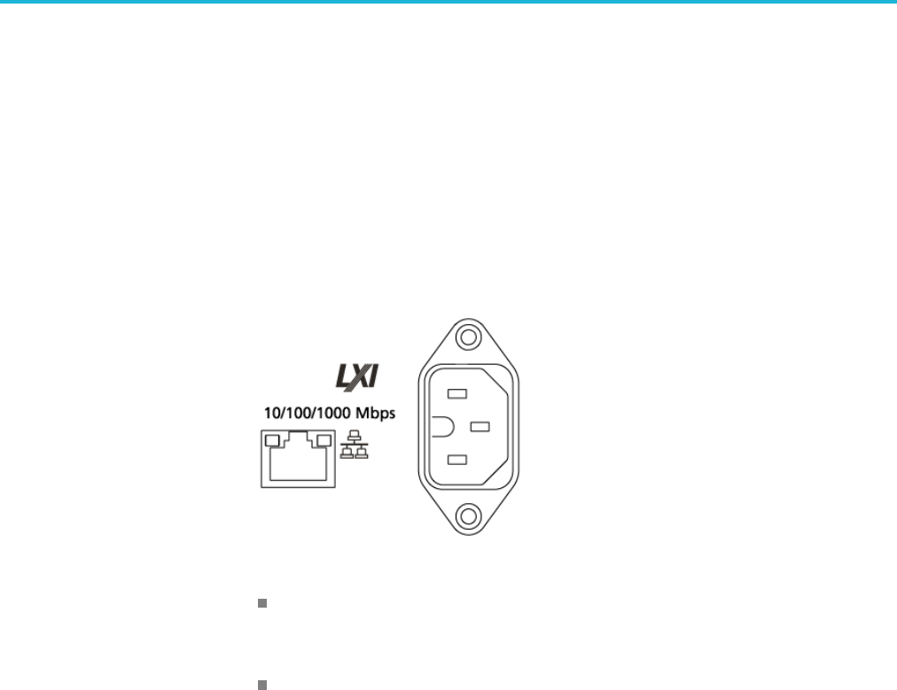
Ethernet control If you are using Ethernet, start by connecting an appropriate Ethernet cable to the
Ethernet port (RJ-45 connector) on the rear panel of the instrument. This connects
the instrument to a 10BASE-T/100BASE-TX/1000BASE-T local area network.
The AWG accepts two types of Ethernet LAN connections:
VXI-11 Server: VXI-11 protocol is used through TekVISA. TekVISA is
preinstalled on the instrument, but to use this protocol, TekVISA must also be
installed on the remote controller (PC).
Raw Socket: Raw Socket is used through TekVISA. To use this protocol,
TekVISA must also be installed on the remote controller (PC).
IP address. By default, the AWGs are specified to automatically acquire an IP
address by DHCP. Refer to Windows documentation regarding network-related
parameters.
GPIB control The AWG has a USB 2.0 high-speed (HS) Device port to control the instrument
through USBTMC or GPIB with a TEK-USB-488 Adapter. The USBTMC
protocol allows USB devices to communicate using IEEE488 style messages.
This lets you run your GPIB software applications on USB hardware.
To use GPIB (General Purpose Interface Bus), start by connecting an appropriate
USB cable to the USB 2.0 high-speed (HS) device port on the rear panel of the
AWG. Connect the other end to the TEK-USB-488 Adapter host port. Then
connect a GPIB cable from the TEK-USB-488 Adapter to your PC.
Before setting up the instrument for remote communication using the electronic
(physical) GPIB interface, you should familiarize yourself with the following
GPIB requirements:
1-2 AWG5200 Series Programmer Manual
Remote control
A unique device address must be assigned to each device on the bus. No two
devices can share the same device address.
No more than 15 devices can be connected to any one line.
One device should be connected for every 6 feet (2 meters) of cable used.
No more than 65 feet (20 meters) of cable should be used to connect devices
to a bus.
At least two-thirds of the devices on the network should be powered on while
using the network.
Connect the devices on the network in a star or linear configuration. Do not
use loop or parallel configurations.
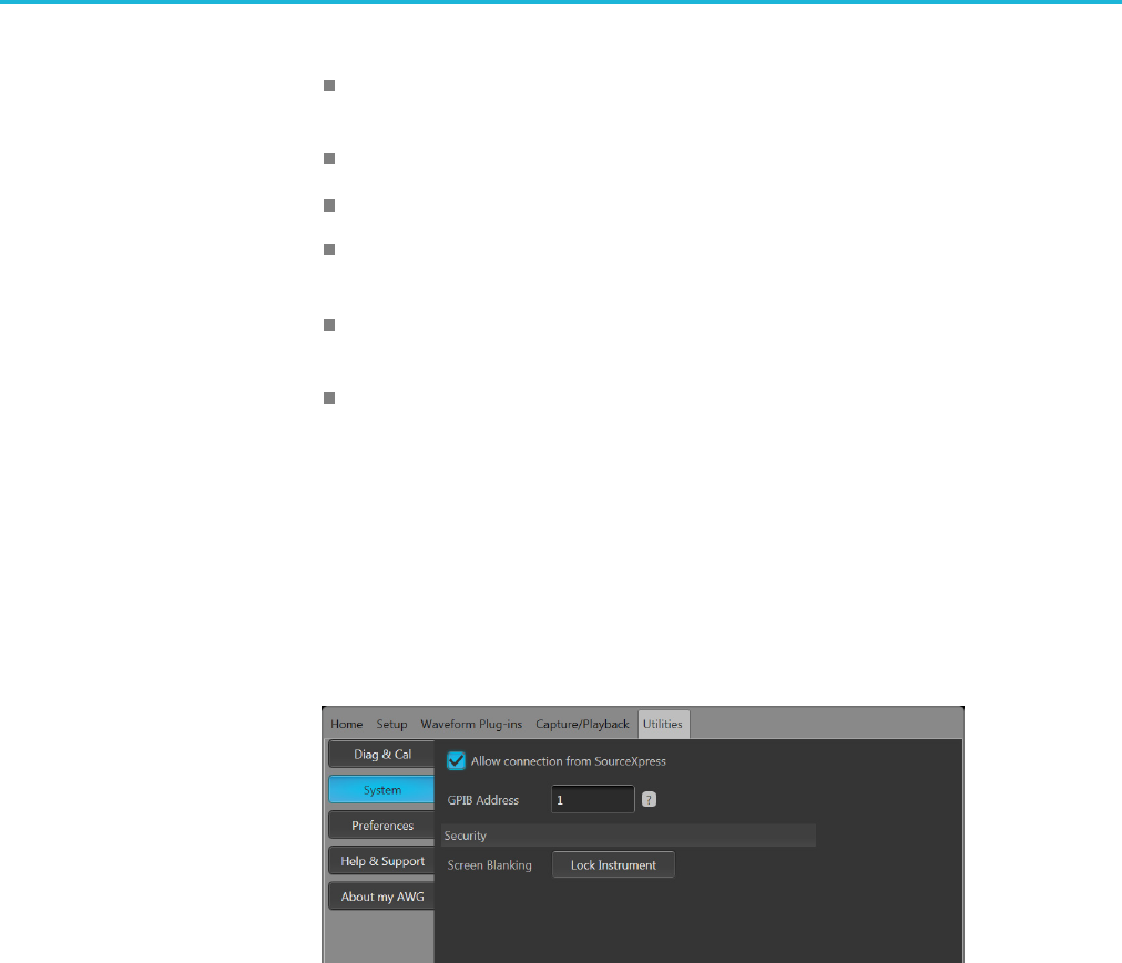
The default setting for the GPIB configuration is GPIB Address 1. If you need to
change the GPIB address, do the following:
1. Display the Utilities screen and select System.
2. Set the GPIB address.
3. If the TEK-USB-488 adapter is connected to the instrument, disconnect and
reconnect the adapter to ensure the new address is acquired.
AWG5200 Series Programmer Manual 1-3

Remote control
1-4 AWG5200 Series Programmer Manual

Syntax and Commands

Command syntax
Syntax overview
Control the operations and functions of the AWG through the LAN interface
using commands and queries. The related topics listed below describe the syntax
of these commands and queries. The topics also describe the conventions that the
AWG uses to process them. See the Command Groups topic for a listing of the
commands by command group or use the index to locate a specific command.
Refer to the following table for the symbols that are used.
Table 2-1: Syntax symbols and their meanings
Symbol Meaning
<> Defined element
::= Is defined as
| Exclusive OR
{ } Group; one element is required
[] Optional; can be omitted
... Previous elements can be repeated
( ) Comment
Command and query structure
Overview Commands consist of set commands and query commands (usually called
commands and queries). Commands modify instrument settings or tell the
instrument to perform a specific action. Queries cause the instrument to return
data and status information.
Most commands have both a set form and a query form. The query form
of the command differs from the set form by its question mark on the end.
For example, the set command AWGControl:RSTate has a query form
AWGControl:RSTate?. Not all commands have both a set and a query form.
Some commands have only set and some have only query.
Messages A command message is a command or query name followed by any information
the instrument needs to execute the command or query. Command messages may
contain five element types, defined in the following table.
AWG5200 Series Programmer Manual 2-1

Command syntax
Table 2-2: Message symbols and their meanings
Symbol Meaning
<Header> This is the basic command name. If the header ends with a
question mark, the command is a query. The header may begin
with a colon (:) character. If the command is concatenated with
other commands, the beginning colon is required. Never use the
beginning colon with command headers beginning with a star (*).
<Mnemonic> This is a header subfunction. Some command headers have only
one mnemonic. If a command header has multiple mnemonics, a
colon (:) character always separates them from each other.
<Argument>This is a quantity, quality, restriction, or limit associated with the
header. Some commands have no arguments while others have
multiple arguments. A <space> separates arguments from the
header. A <comma> separates arguments from each other.
<Comma> A single comma is used between arguments of multiple-argument
commands. Optionally, there may be white space characters
before and after the comma.
<Space> A white space character is used between a command header and
the related argument. Optionally, a white space may consist of
multiple white space characters.
Commands Commands cause the instrument to perform a specific function or change one of
the settings. Commands have the structure:
[:]<Header>[<Space><Argument>[<Comma><Argument>]...]
A command header consists of one or more mnemonics arranged in a hierarchical
or tree structure. The first mnemonic is the base or root of the tree and each
subsequent mnemonic is a level or branch off the previous one. Commands at a
higher level in the tree may affect those at a lower level. The leading colon (:)
always returns you to the base of the command tree.
Queries Queries cause the instrument to return status or setting information. Queries
have the structure:
[:]<Header>?
[:]<Header>?[<Space><Argument>[<Comma><Argument>]...]
Clearing the instrument
Use the Device Clear (DCL) or Selected Device Clear (SDC) functions to clear
the Output Queue and reset the instrument to accept a new command or query.
2-2 AWG5200 Series Programmer Manual

Command syntax
Command entry
Rules The following rules apply when entering commands:
You can enter commands in upper or lower case.
You can precede any command with white space characters. White space
characters include any combination of the ASCII control characters 00 through
09 and 0B through 20 hexadecimal (0 through 9 and 11 through 32 decimal).
The instrument ignores commands consisting of any combination of white
space characters and line feeds.
Abbreviating You can abbreviate many instrument commands. Each command in this
documentation shows the abbreviations in capitals. For example, enter the
command TRIGger:LEVel simply as TRIG:LEV.
Concatenating Use a semicolon (;) to concatenate any combination of set commands and queries.
The instrument executes concatenated commands in the order received. When
concatenating commands and queries, follow these rules:
1. Separate completely different headers by a semicolon and by the beginning
colon on all commands except the first one. For example, the commands
TRIGger:IMPedance 50 and SOURce:RMODe TRIGgered, can be
concatenated into the following single command:
TRIGger:IMPedance 50;:RMODe TRIGgered
2. If concatenated commands have headers that differ by only the last mnemonic,
you can abbreviate the second command and eliminate the beginning
colon. For example, you can concatenate the commands TRIGger:SOURCE
EXTernal and TRIGger:SLOPe NEGative into a single command:
TRIGger:SOURce EXTernal; SLOPe NEGative
The longer version works equally well:
TRIGger:SOURCE EXTernal;:TRIGger:SLOPe NEGative
3. Never precede a star (*) command with a semicolon (;) or colon (:).
AWG5200 Series Programmer Manual 2-3

Command syntax
4. When you concatenate queries, the responses to all the queries are
concatenated into a single response message. For example, if the
high level of marker one of channel one is 1.0 V and the low level is
0.0 V, the concatenated query SOURce1:MARKer1:VOLTage:HIGH?;
SOURce1:MARKer1:VOLTage:LOW? will return the following:
1.0;0.0
5. Set commands and queries may be concatenated in the same message. For
example, TRIGger:SOURce EXTernal; SLOPe? is a valid message that
sets the trigger source to External. The message then queries the external
trigger slope. Concatenated commands and queries are executed in the order
received.
Terminating This documentation uses <EOM> (end of message) to represent a message
terminator.
Table 2-3: Message terminator and meaning
Symbol Meaning
<EOM> Message terminator
For messages sent to the instrument, the end-of-message terminator must be the
END message (EOI asserted concurrently with the last data byte). The instrument
always terminates messages with LF and EOI. It allows white space before the
terminator. For example, it allows CR LF.
Parameter types
Parameters are indicated by angle brackets, such as <file_name>. There are
several different types of parameters, as listed in the following table. The
parameter type is listed after the parameter. Some parameter types are defined
specifically for the instrument command set and some are definedbySCPI.
Table 2-4: Parameter types, their descriptions, and examples
Parameter type Description Example
Arbitrary block A block of data bytes #512234xxxxx... where 5
indicates that the following
5 digits (12234) specify the
length of the data in bytes;
xxxxx... indicates actual data
or #0xxxxx...<LF><&EOI>
Boolean Boolean numbers or values ON or ≠0
OFF or 0
Discrete Alistofspecific values MINimum, MAXimum
NaN Not a Number 9.91 37
2-4 AWG5200 Series Programmer Manual

Command syntax
Table 2-4: Parameter types, their descriptions, and examples (cont.)
Parameter type Description Example
NR1 numeric Integers 0, 1, 15, –1
NR2 numeric Decimal numbers 1.2, 3.141,–6.5
NR3 numeric Floating point numbers 3.1415E+9
NRf numeric Flexible decimal numbers
that may be type NR1, NR2,
or NR3
See NR1, NR2, and NR3
examples in this table
String Alphanumeric characters
(must be within quotation
marks)
"Testing 1, 2, 3"
About MIN, MAX You can also use MINimum and MAXimum keywords in the commands with
the "Numeric" parameter. Set the minimum value or the maximum value using
these keywords and query these values.
Block Several instrument commands use a block argument form (see the following table).
Table 2-5: Block symbols and their meanings
Symbol Meaning
<NZDig> A nonzero digit character in the range of 1–9
<Dig> <Dig> A digit character, in the range of 0–9
<DChar> A character with the hexadecimal equivalent of 00 through FF (0
through 255 decimal) that represents actual data
<Block> Ab
lock of data bytes defined as:
<Block> ::={#<NZDig><Dig>[<Dig>...][<DChar>...]
|#0[<DChar>...]<terminator>}
AWG5200 Series Programmer Manual 2-5

Command syntax
Arbitrary block An arbitrary block argument is defined as:
#<NZDig><Dig>[<Dig>...][<DChar>...]
or
#0[<DChar>...]<terminator>
<NZDig> specifies the number of <Dig> elements that follow. Taken together,
the <NZDig> and <Dig> elements form a decimal integer that specifies how
many <DChar> elements follow.
#0 means that the <Block> is an indefinite length block. The <terminator> ends
the block.
NOTE. The AWGs do not support the indefinite format (a block starts with #0).
Quoted string Some commands accept or return data in the form of a quoted string, which is
simply a group of ASCII characters enclosed by a single quote (') or double quote
("). For example: "this is a quoted string". This documentation represents these
argumentsasfollows:
Table 2-6: String symbol and meaning
Symbol Meaning
<QString > Quoted string of ASCII text
A quoted string can include any character defined in the 7-bit ASCII character
set. Follow these rules when you use quoted strings:
1. Use the same type of quote character to open and close the string. For
example: "this is a valid string".
2. You can mix quotation marks within a string as long as you follow the
previous rule. For example, "this is an 'acceptable' string".
3. You can include a quote character within a string simply by repeating the
quote.
For example: "here is a "" mark".
4. Strings can have upper or lower case characters.
5. A carriage return or line feed embedded in a quoted string does not terminate
the string, but is treated as just another character in the string.
6. The maximum length of a quoted string returned from a query is 1000
characters.
2-6 AWG5200 Series Programmer Manual

Command syntax
Here are some invalid strings:
"Invalid string argument' (quotes are not of the same type)
"test<EOI>" (termination character is embedded in the string)
Units and SI prefixIf the decimal numeric argument refers to voltage, frequency, impedance, or time,
express it using SI units instead of using the scaled explicit point input value
format <NR3>. (SI prefixes are standardized for use in the International System
of Units by the International Bureau of Weights and Measures.) For example, use
the input format 200 mV or 1.0 MHz instead of 200.0E-3 or 1.0E+6, respectively,
to specify voltage or frequency.
Omit the unit when you describe commands, but include the SI unit prefix. Enter
both uppercase and lowercase characters. The following list shows examples of
units you can use with the commands.
V for voltage (V).
HZ for frequency (Hz).
OHM for impedance (ohm).
S for time (s).
DBM for power ratio.
PCT for %.
VPP for Peak-to-Peak Voltage (V p-p).
UIPP for Peak-to-Peak, Unit is UI (UI p-p).
UIRMS for RMS, Unit is UI (UIrms).
SPP for Peak-to-Peak, Unit is second (s p-p).
SRMS for RMS, Unit is second (srms).
V/NS for SLEW’s unit (V/ns).
The SI prefixes, which must be included, are shown in the following table. You
can enter both uppercase and lowercase characters.
Table 2-7: SI prefixes and their indexes
SI prefix1Corresponding power
EX 1018
PE 1015
T10
12
G109
MA 106
K10
3
AWG5200 Series Programmer Manual 2-7
Command syntax
Table 2-7: SI prefixes and their indexes (cont.)
SI prefix1Corresponding power
M10
–3
U210–6
N10
–9
P10
–12
F10
–15
A10
–18
1Note that the prefixm/Mindicates10
–3 when the decimal numeric argument denotes voltage or time, but
indicates 106when it denotes frequency.
2Note that the prefix u/U is used instead of "μ".
Since M (m) can be interpreted as 1E-3 or 1E6 depending on the units, use mV
for V, and MHz for Hz.
The SI prefixes need units.
correct: 10MHz, 10E+6Hz, 10E+6
incorrect: 10M
SCPI commands and queries
The AWG uses a command language based on the SCPI standard. The SCPI
(Standard Commands for Programmable Instruments) standard was created by
a consortium to provide guidelines for remote programming of instruments.
These guidelines provide a consistent programming environment for instrument
control and data transfer. This environment uses defined programming messages,
instrument responses and data formats that operate across all SCPI instruments,
regardless of manufacturer.
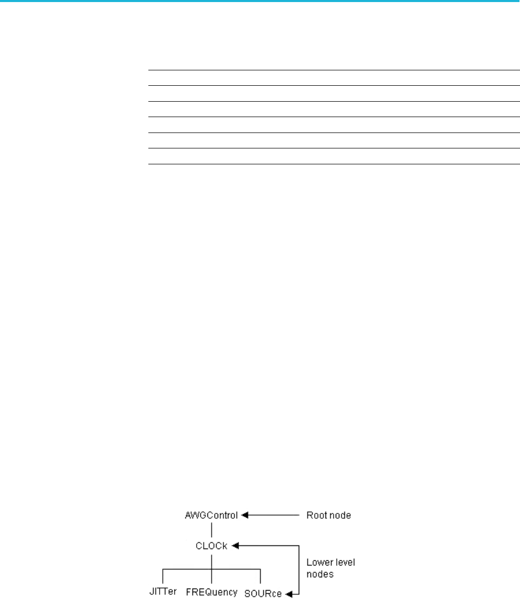
The SCPI language is based on a hierarchical or tree structure that represents a
subsystem (see following figure). The top level of the tree is the root node; it is
followed by one or more lower-level nodes.
You can create commands and queries from these subsystem hierarchy trees.
Commands specify actions for the instrument to perform. Queries return
measurement data and information about parameter settings.
2-8 AWG5200 Series Programmer Manual
Command syntax
Sequential, blocking, and overlapping commands
Programming commands (and queries) fall into three command type categories:
Sequential
Blocking
Overlapping
Thetypeofcommand is important to consider when programming since they
could cause unexpected results if not handled correctly. See the following
explanations and examples.
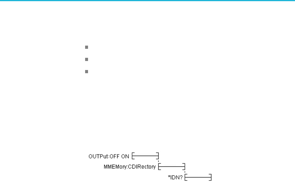
Sequential commands Most of the programming commands are sequential type commands. This simply
means a command will not start until the previous command has finished.
Following is an example of a series of sequential commands.
In normal operation, these commands could all be sent at once and they would be
queued up and executed sequentially.
Blocking commands The AWG5200 series instruments have several commands that are blocking. A
blocking command does not allow any further commands to be executed until it is
finished performing its task, such as a command that changes a hardware setting.
Blocking commands perform similar to sequential commands, but they tend to
take a longer amount of time to complete. Because of the time for a blocking
command to complete, if a number of blocking commands are run in a sequence
followed by a query, the query could time out because the previous blocking
commandshavenotfinished.
Blocking commands are noted in their command descriptions.
AWG5200 Series Programmer Manual 2-9
Command syntax
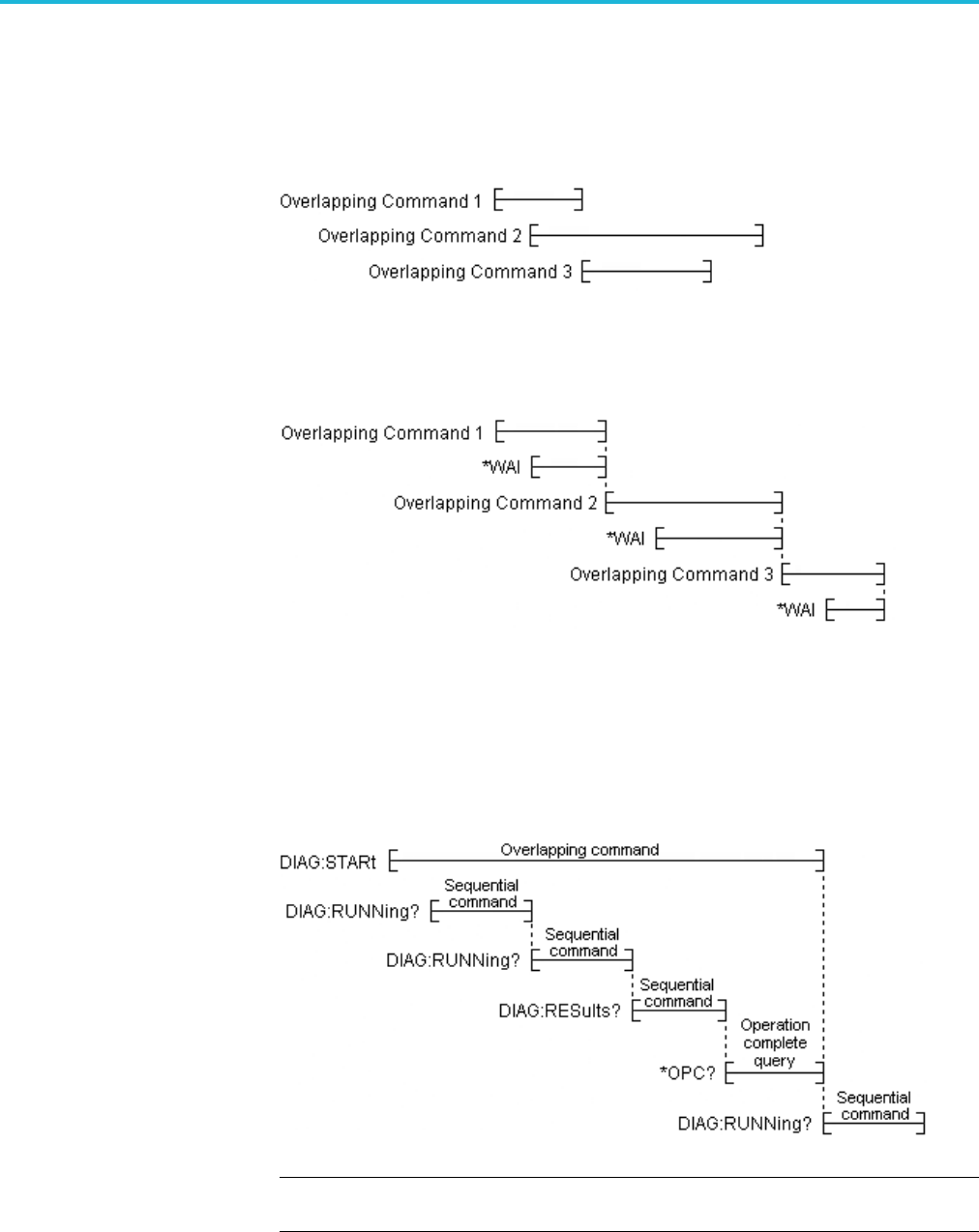
Overlapping commands Overlapping commands run concurrently with other commands, allowing
additional commands to start before the overlapping command has finished. The
illustration below shows how a series of overlapping commands might start and
end.
In some instances, you may want to make an overlapping command perform
similarly to a sequential command. This is simply done by placing a *WAI
command after the overlapping command as illustrated below.
You always want to ensure the overlapping command has completed. This is
done by using the *OPC? command. When an overlapping command starts, the
operation complete status event is cleared. When the overlapping command
completes, the operation complete status event is set. The *OPC? command
requirementistoreturna1whentheoperation complete status event is set. In the
illustration below, the OPC? command blocks any further commands from being
executed until the operation complete status event is set.
NOTE. Always ensure overlapping commands have completed by placing an
*OPC? command after the overlapping command.
2-10 AWG5200 Series Programmer Manual
Command syntax
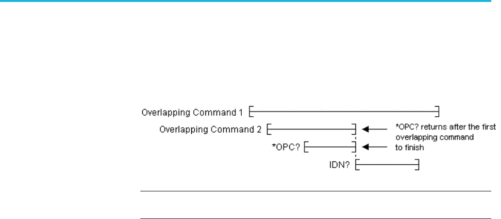
The AWG5200 series instruments are limited to one outstanding overlapping
command per *OPC?. If two or more overlapping commands are sent and
followedbyan*OPC?,thenthefirst overlapped command to finish will set the
operation complete status event and *OPC? will return 1. This early return may
produce undesirable results. The following illustration shows this behavior.
NOTE. The *OPC? query only supports one overlapping command, not the two or
more overlapping commands as defined in the IEEE Std 488.2 standard.
Overlapping commands are noted in their command descriptions.
AWG5200 Series Programmer Manual 2-11

Command syntax
2-12 AWG5200 Series Programmer Manual

Command groups
This section contains tables that divide the commands into common groups. A
brief description of the command is provided. Use the link provided to jump
directly to the command description, providing: a detailed description, syntax,
and examples.
Commands noted for backwards compatibility should not be used for new
programming applications.
Auxiliary out commands
Use the Auxiliary out commands to setup and control the Auxiliary outputs on
the rear panel.
Table 2-8: Auxiliary output group commands and their descriptions
Command Description
AUXoutput[n]:SOURce Sets or returns the signal source for the specified Auxiliary Output
connector.
AUXoutput[n]:SOURce:CMAPping Sets or returns the Auxiliary Output channel mapping.
Basic waveform editor commands
Use the Basic waveform editor commands to setup and create waveforms using
the Basic waveform editor plug-in.
Table 2-9: Basic waveform editor group commands and their descriptions
Command Description
BWAVeform:AMPLitude Sets or returns the peak-to-peak Amplitude value for the waveform created
by the Basic Waveform editor plug-in.
BWAVeform:AUTO Sets or returns the Basic Waveform editor plug-in Auto Calculate setting,
determining which value is automatically calculated.
BWAVeform:COMPile Initiates the Basic Waveform editor plug-in compile process.
BWAVeform:COMPile:CASSign Sets or returns the state (enabled or disabled) of the Basic Waveform
editor to compile the waveform and immediately assign it to a specified
channel (enabled) or just compile the waveform (disabled).
BWAVeform:COMPile:CHANnel Sets or returns playout the channel intended for the compiled waveform of
the Basic Waveform editor plug-in. The selected channel is also used to
set the amplitude and offset range.
BWAVeform:COMPile:NAME Sets or returns the name of the Basic Waveform editor plug-in compiled
waveform.
BWAVeform:COMPile:PLAY Sets or returns the state (enabled or disabled) of the Basic Waveform editor
to either immediately play the waveform after compile or just compile.
AWG5200 Series Programmer Manual 2-13

Command groups
Table 2-9: Basic waveform editor group commands and their descriptions (cont.)
Command Description
BWAVeform:CYCLe Sets or returns the Cycle value (number of times the waveform repeats) for
the waveform created by the Basic Waveform editor plug-in.
BWAVeform:FDRange Sets or returns the state (enabled or disabled) of the Basic Waveform
editor plug-in to use or not use the full DAC range during compile. Using
the full DAC range when compiling waveforms results in waveforms with
the best resolution.
BWAVeform:FREQuency Sets or returns the Frequency for the waveform created by the Basic
Waveform editor plug-in.
BWAVeform:FUNCtion Sets or returns the Basic Waveform editor plug-in waveform type.
BWAVeform:HIGH Sets or returns the High voltage value for the waveform created by the
Basic Waveform editor plug-in.
BWAVeform:LENGth Sets or returns the Length for the waveform created by the Basic Waveform
editor plug-in.
BWAVeform:LOW Sets or returns the Low voltage value for the waveform created by the
Basic Waveform editor plug-in.
BWAVeform:OFFSet Sets or returns the Offset voltage value for the waveform created by the
Basic Waveform editor plug-in.
BWAVeform:RESet Resets the Basic Waveform editor plug-in to its default values.
BWAVeform:SRATe Sets or returns the Sample Rate for the waveform created by the Basic
Waveform editor plug-in.
Calibration group commands
Use the calibration commands to calibrate the arbitrary waveform generator and
obtain calibration data.
Table 2-10: Calibration group commands and their descriptions
Command Description
CALibration:ABORt Stops the self calibration process and restores the previous calibration
constants.
CALibration[:ALL] Performs a full calibration of the AWG. The query form performs a full
calibration and returns a status of the operation.
CALibration:CATalog? Returns the list of subsystems, areas, or procedures.
CALibration:LOG? Returns a string of continuous concatenated calibration results.
CALibration:LOG:CLEar Clears the results log.
CALibration:LOG:FAILuresonly Sets and returns the flag that controls the amount of result information
saved into the log.
CALibration:RESTore Restores the calibration constants from the factory non-volatile memory
and copied to user storage.
2-14 AWG5200 Series Programmer Manual

Command groups
Table 2-10: Calibration group commands and their descriptions (cont.)
Command Description
CALibration:RESult? Returns the status about the results of the last start of a set of selected
calibration procedures.
CALibration:RESult:TEMPerature? Returns the temperature from the results of the last start of a set of
selected procedures.
CALibration:RESult:TIME? Returns the time from the results of the last start of a set of selected
procedures.
CALibration:RUNNing? Returns the name of the subsystem, area, and procedure in progress.
CALibration:STARt Starts the selected set of calibrations.
CALibration:STATe:FACTory? Returns the current factory state of the calibration for the AWG.
CALibration:STATe:USER? Returns the current factory state of the calibration for the AWG.
CALibration:STOP:STATe? Returns the state of the calibration procedure.
Capture and playback group commands
Use the capture and playback commands to import I/Q data files to compile into
RF waveform files for playout.
Table 2-11: Capture and playback group commands and their descriptions
Command Description
CPLayback:CAPTure:FILE Imports baseband IQ waveform data and adds the waveform to the
specified Signal Name in the captured signal list.
CPLayback:CAPTure:INSTrument:OSCilloscope Connects to the specified oscilloscope, transfers the existing acquisition
from the oscilloscope to the AWG, and adds it to the specified signal.
CPLayback:CAPTure:INSTrument:RSA Connects to the specified RSA (Realtime Spectrum Analyzer), transfers
the existing acquisition to the AWG, and adds it to the specified signal.
CPLayback:CLISt:NAME? Returns the name of a signal from the Captured Signal List in the position
specified by the index value.
CPLayback:CLISt:SIGNal:DELete Removes the specified signal from the Captured Signal List.
CPLayback:CLISt:SIGNal:SCOMpile Selects or deselects a signal from the captured signal list to be compiled.
The query form returns the list of selected files.
CPLayback:CLISt:SIGNal:WAVeform:FOFFset This command sets or returns the frequency offset of the specified
waveform segment of the specified signal in the Captured Signal List.
CPLayback:CLISt:SIGNal:WAVeform:NAME? Returns the name of the specified waveform segment of the specified
signal in the Captured Signal List.
CPLayback:CLISt:SIGNal:WAVeform:OTIMe Sets or returns the Off time between waveform segments of the specified
signal in the Captured Signal List.
CPLayback:CLISt:SIGNal:WAVeform:SRATe Sets or returns the sample rate of a waveform segment of a signal in the
captured signal list.
CPLayback:CLISt:SIGNal:WCOunt? Returns the number of waveforms in the specified signal in the Captured
Signal List.
AWG5200 Series Programmer Manual 2-15

Command groups
Table 2-11: Capture and playback group commands and their descriptions (cont.)
Command Description
CPLayback:CLISt:SIZE? Returns the number of signals in the Captured Signal List.
CPLayback:COMPile Resamples and upconverts the selected signal to the specified carrier
frequency. A sequence will be generated if selected signal contains more
than one waveform or off time is specified. Otherwise, a waveform will be
generated.
CPLayback:COMPile:CFRequency Sets or returns the carrier frequency for the compiled signals.
CPLayback:COMPile:LSEQuence Sets or returns if the compiled sequence should loop on itself.
CPLayback:COMPile:NORMalize Sets or returns if the IQ waveforms will be normalized during import.
CPLayback:COMPile:SRATe Sets or returns the output sampling rate for the compiled signals.
CPLayback:COMPile:SRATe:AUTO Sets or returns if the system will calculate the output sampling rate
automatically when compiling the selected signals.
Clock group commands
Use the clock commands to define the instrument’s sampling rate and adjust clock
and reference sources.
Table 2-12: Clock group commands and their descriptions
Command Description
CLOCk:ECLock:DIVider Sets or returns the divider rate of the external clock.
CLOCk:ECLock:FREQuency Sets or returns the expected frequency being provided by the external
clock.
CLOCk:ECLock:FREQuency:DETect Detects the frequency of the signal applied to the Clock In connector and
adjusts the system to use the signal.
CLOCk:ECLock:MULTiplier Sets or returns the multiplier rate of the external clock.
CLOCk:EREFerence:DIVider Sets or returns the divider rate of the external reference oscillator.
CLOCk:EREFerence:FREQuency Sets or returns the expected frequency of the signal applied to the EXT
REF input connector.
CLOCk:EREFerence:FREQuency:DETect Detects the frequency of the signal applied to the EXT REF input connector
and adjusts the system to use the signal.
CLOCk:EREFerence:MULTiplier Sets or returns the multiplier rate of the variable external reference signal.
CLOCk:JITTer Sets or returns the state (enabled or disabled) to apply or not apply jitter
reduction to the internal system clock or the clock signal applied to the
Reference In connector.
CLOCk:OUTPut:FREQuency? Returns the frequency of the output clock.
CLOCk:OUTPut[:STATe] Sets or returns the output state of the clock output.
CLOCk:PHASe[:ADJust[:DEGRees]] Sets or returns the phase adjustment, in units of degrees, to synchronize
multiple AWGs when using an external trigger.
CLOCk:PHASe[:ADJust]:TIMe Sets or returns the internal clock phase adjustment of the AWG.
2-16 AWG5200 Series Programmer Manual

Command groups
Table 2-12: Clock group commands and their descriptions (cont.)
Command Description
CLOCk:SOURce Sets or returns the source of the clock.
CLOCk:SOUT[:STATe] Sets or returns the state (enabled or disabled) of the Sync Clock Out output.
CLOCk:SRATe Sets or returns the sample rate for the clock.
Control group commands
Use the control commands to control operating modes, such as the run state,
and pattern jump.
The commands noted for backwards compatibility should not be used for new
programming applications.
Table 2-13: Control group commands and their descriptions
Command Description
AWGControl:ARSettings Sets or returns the state (enabled or disabled) of whether or not to apply
the recommended settings of waveforms and sequences when they are
assigned to a channel.
AWGControl[:CLOCk]:DRATe NOTE. This command exists for backwards compatibility.
Use the command CLOCk:ECLock:DIVider.
Sets or returns the divider rate for the external clock.
AWGControl:CLOCk:PHASe[:ADJust] NOTE. This command exists for backwards compatibility.
Use the command CLOCk:PHASe[:ADJust]:TIMe.
Sets or returns the phase of the internal clock.
AWGControl[:CLOCk]:SOURce NOTE. This command exists for backwards compatibility.
Use the command CLOCk:SOURce.
Sets or returns the clock source.
AWGControl:COMPile Compiles an equation file and imports the waveforms (created by the
equation file) into the arbitrary waveform generator.
AWGControl:CONFigure:CNUMber? Returns the number of channels available on the AWG.
AWGControl:PJUMp:JSTRobe Sets or returns if the pattern jump is set (enabled or disabled) to always
occur on the strobe signal.
AWGControl:PJUMp:SEDGe Sets or returns the active Strobe Edge to use for Pattern Jump when
Pattern Jump is enabled for Sequencing.
AWGControl:RMODe NOTE. This command exists for backwards compatibility.
Use the command [SOURce[n]:]RMODe.
Sets or returns the run mode of the AWG.
AWGControl:RSTate? Returns the state of the AWG.
AWG5200 Series Programmer Manual 2-17

Command groups
Table 2-13: Control group commands and their descriptions (cont.)
Command Description
AWGControl:RUN[:IMMediate] Initiates the output of a waveform or sequence.
AWGControl:SNAMe? Returns the most recently saved setup location.
AWGControl:SREStore NOTE. This command exists for backwards compatibility.
Use the command MMEMory:OPEN:SETup.
Opens a setup file into the AWG’s setup memory.
AWGControl:SSAVe NOTE. This command exists for backwards compatibility.
Use the command MMEMory:SAVE:SETup
Saves the AWG's setup with waveforms.
AWGControl:STOP[:IMMediate] Stops the output of a waveform or sequence.
Diagnostic group commands
Use the diagnostic commands to control self-test diagnostic routines.
Table 2-14: Diagnostic group commands and their descriptions
Command Description
ACTive:MODE Enables and disables access to diagnostics or calibration.
DIAGnostic:ABORt Stops the current diagnostic test.
DIAGnostic:CATalog? Returns the list of all diagnostic tests per selected type.
DIAGnostic:CONTrol:COUNt Sets or returns the number of loop counts used when the selected loop
mode is "COUNt".
DIAGnostic:CONTrol:HALT Determines or returns whether the next execution of diagnostics looping
stops on the first diagnostic failure that occurs or continues to loop on the
selected set of diagnostic functions.
DIAGnostic:CONTrol:LOOP Determines or queries whether the next start of diagnostics runs once, runs
continuous loops, or loops for a number times for the selected set of tests.
DIAGnostic:DATA? Returns the results of last executed tests for the NORMal diagnostic type.
DIAGnostic[:IMMediate] Executes all of the NORMal diagnostic tests. The query form executes the
selected tests and returns the results.
DIAGnostic:LOG? Returns a string of continuous concatenated test results.
DIAGnostic:LOG:CLEar Clears the diagnostics results log.
DIAGnostic:LOG:FAILuresonly Sets or returns the flag that controls the amount of result information saved
into the log.
DIAGnostic:LOOPs? Returns the number of times that the selected diagnostics set was
completed during the current running or the last diagnostic running of the
set.
DIAGnostic:RESult? Returns the status about the results of the last start of a set of selected
tests.
2-18 AWG5200 Series Programmer Manual

Command groups
Table 2-14: Diagnostic group commands and their descriptions (cont.)
Command Description
DIAGnostic:RESult:TEMPerature? Returns the temperature from the results of the last start of a set of
selected tests.
DIAGnostic:RESult:TIME? Returns the time from the results of the last start of a set of selected tests.
DIAGnostic:RUNNing? Returns the name of the subsystem, area, and test of the current diagnostic
test.
DIAGnostic:SELect Selects one or more tests of the current test list.
DIAGnostic:SELect:VERify? Returns selection status of one specifictest.
DIAGnostic:STARt This command starts the execution of the selected set of diagnostic tests.
DIAGnostic:STOP Stops the diagnostic tests from running, after the diagnostic test currently
in progress completes.
DIAGnostic:STOP:STATe? Returns the current state of diagnostic testing.
DIAGnostic:TYPE Sets or returns the diagnostic type.
DIAGnostic:TYPE:CATalog? Returns a list of diagnostic types available depending on the end user.
DIAGnostic:UNSelect Unselects one or more tests of the current test list.
Display group commands
Use the display commands to adjust the display plot area.
Table 2-15: Display group commands and their descriptions
Command Description
DISPlay[:PLOT][:STATe] Minimizes or restores the plot’s display area on the Home screen's channel
window of the AWG.
AWG5200 Series Programmer Manual 2-19

Command groups
Function generator group commands
Use the function generator commands to generate basic waveshapes.
Table 2-16: Function generator group commands and their descriptions
Command Description
FGEN:[CHANnel[n]]:AMPLitude:POWer Sets or returns the function generator’s waveform amplitude value of the
specified channel in units of dBm.
FGEN[:CHANnel[n]]:AMPLitude[:VOLTage] Sets or returns the amplitude of the generated waveform of the selected
channel in units of volts.
FGEN[:CHANnel[n]]:DCLevel Sets or returns the DC level of the generated waveform of the selected
channel.
FGEN[:CHANnel[n]]:FREQuency Sets or returns the frequency of the generated waveform.
FGEN[:CHANnel[n]]:HIGH Sets or returns the generated waveform's high voltage value of the
selected channel.
FGEN[:CHANnel[n]]:LOW Sets or returns the generated waveform's low voltage value of the selected
channel.
FGEN[:CHANnel[n]]:OFFSet Sets or returns the offset of the generated waveform of the selected
channel.
FGEN[:CHANnel[n]]:PATH Sets or returns the function generator’s signal path for the specified
channel.
FGEN[:CHANnel[n]]:PERiod? Returns the generated waveform's period.
FGEN[:CHANnel[n]]:PHASe Sets or returns the generated waveform's phase of the selected channel.
FGEN[:CHANnel[n]]:SYMMetry Sets or returns the generated waveform's symmetry value of the selected
channel.
FGEN[:CHANnel[n]]:TYPE Sets or returns the waveform type (shape) of the selected channel.
IEEE mandated and optional group commands
All AWG IEEE mandated and optional command implementations are based on
the SCPI standard and the specifications for devices in IEEE 488.2.
Table 2-17: IEEE mandated and optional group commands and their descriptions
Command Description
*CAL? Runs all self calibrations and returns the result. Same as CALibration[:ALL].
*CLS Clears all event registers and queues.
*ESE Sets or returns the Event Status Enable Register (ESER).
*ESR? Returns the current contents of the Event Status Register (ESR).
*IDN? Returns identification information for the AWG.
2-20 AWG5200 Series Programmer Manual

Command groups
Table 2-17: IEEE mandated and optional group commands and their descriptions (cont.)
Command Description
*OPC This command causes the AWG to sense the internal flag referred to as
the “No-Operation-Pending” flag. The command sets bit 0 in the Standard
Event Status Register when pending operations are complete.
The query form returns a “1” when the last overlapping command operation
is finished.
*OPT? Returns the implemented options for the AWG.
*RST Resets the AWG to its default state.
*SRE Sets or returns the bits in the Service Request Enable Register (SRER).
*STB? Returns the contents of Status Byte Register (SBR).
*TRG Generates a trigger event for Trigger A only.
*TST? Executes a power-on self test and returns the results.
*WAI Ensures the completion of the previous command before the next
command is issued.
Instrument group commands
Use the instrument commands to set the coupled state and set the mode (function
mode or arbitrary waveform generator mode).
Table 2-18: Instrument group commands and their descriptions
Command Description
INSTrument:COUPle:SOURce Sets or returns the coupled state of the channel’s Analog and Marker
output controls.
INSTrument:MODE Sets or returns the operating mode (AWG mode or the Function generator
mode).
Mass memory group commands
Use the mass memory commands to read/write data from/to hard disk on the
instrument.
Commands noted for backwards compatibility should not be used for new
programming applications.
Table 2-19: Mass memory group commands and their descriptions
Command Description
MMEMory:CATalog? Returns the current contents and state of the mass storage media.
MMEMory:CDIRectory Sets or returns the current directory of the file system on the AWG.
MMEMory:DATA Sets or returns block data to/from file in the current mass storage device.
AWG5200 Series Programmer Manual 2-21

Command groups
Table 2-19: Mass memory group commands and their descriptions (cont.)
Command Description
MMEMory:DATA:SIZE? Returns the size in bytes of a selected file.
MMEMory:DELete Deletes a file or directory from the AWG's hard disk.
MMEMory:IMPort NOTE. This command exists for backwards compatibility.
Use the command MMEMory:OPEN.
Loads a file into the AWG waveform list.
MMEMory:IMPort[:PARameter]:NORMalize NOTE. This command exists for backwards compatibility. Use
the command MMEMory:OPEN[:PARameter]:NORMalize.
Sets or returns if the imported data is normalized during select file format
import operations. The imported waveform data (for select file formats) is
normalized based on the option set in this command.
MMEMory:MDIRectory Creates a new directory in the current path on the mass storage system.
MMEMory:MSIS Sets or returns a mass storage device used by all MMEMory commands.
MMEMory:OPEN Loads a file into the AWG waveform list.
MMEMory:OPEN[:PARameter]:NORMalize Sets or returns if the imported data is normalized during select file format
import operations.
MMEMory:OPEN[:PARameter]:SIQ Sets or returns if the IQ waveform (from supported formats) is separated
into two separate _I and _Q waveforms while importing.
MMEMory:OPEN:SASSet:SEQuence Loads all sequences or a single desired sequence from a file into the
AWG’s sequences list.
MMEMory:OPEN:SASSet:SEQuence:MROPened? Returns which sequence was most recently added or replaced from the
most recently opened or imported sequence file.
MMEMory:OPEN:SASSet[:WAVeform] Loads all waveforms or a single desired waveform from a file into the
AWG’s waveforms list.
MMEMory:OPEN:SETup Opens a setup file into the AWG’s setup memory.
MMEMory:OPEN:TXT Loads a file into the AWG’s waveform list.
MMEMory:SAVE:SEQuence Exports a sequence given a unique name to an eligible storage location as
the .SEQX file type.
MMEMory:SAVE:SETup Saves the AWG's setup and optionally includes the waveforms.
MMEMory:SAVE[:WAVeform]:MAT Exports a waveform given a unique waveform name to an eligible storage
location from the AWG’s waveforms with the AWG Specific MATLAB file
format (MAT 5).
MMEMory:SAVE[:WAVeform]:TIQ Exports a waveform given a unique waveform name to an eligible storage
location from the AWG’s waveforms as the .TIQ file type.
MMEMory:SAVE[:WAVeform]:TXT Exports a waveform given a unique waveform name to an eligible storage
location from the AWG’s waveforms as the .TXT file type.
MMEMory:SAVE[:WAVeform]:WFM Exports a waveform given a unique waveform name to an eligible storage
location from the AWG’s waveforms as the .WFM file type.
MMEMory:SAVE[:WAVeform][:WFMX] Exports a waveform given a unique waveform name to an eligible storage
location from the AWG’s waveforms as the .WFMX file type.
2-22 AWG5200 Series Programmer Manual

Command groups
Output group commands
Use the output commands to set or return the characteristics of the output of the
arbitrary waveform generator.
Table 2-20: Output group commands and their descriptions
Command Description
OUTPut:OFF Sets or returns the state (enabled or disabled) of the 'All Outputs Off'
control. Enabled causes each channel’s output and markers to go to an
ungrounded (or open) state.
OUTPut[n]:PATH Sets or returns the output signal path of the specified channel.
OUTPut[n][:STATe] Sets or returns the output state of the specified channel.
OUTPut[n]:SVALue[:ANALog][:STATe] Sets or returns the output condition of a waveform of the specified channel
while the instrument is in the stopped state.
OUTPut[n]:SVALue:MARKer[m] Sets or returns the output condition of the specified marker of the specified
channel while the instrument is in the stopped state.
OUTPut[n]:WVALue[:ANALog][:STATe] Sets or returns the output condition of a waveform of the specified channel
while the instrument is in the waiting-for-trigger state.
OUTPut[n]:WVALue:MARKer[m] Sets or returns the output condition of the specified marker of the specified
channel while the instrument is in the waiting-for-trigger state.
S-Parameters group commands
Use these commands to control and apply the S-Parameter to waveforms.
Table 2-21: S-parameters group commands and their descriptions
Command Description
WLISt:SPARameter:APPLy Applies S-Parameters to the named waveform that exists in the waveform
list of the current setup.
WLISt:SPARameter:BANDwidth Sets or returns the S-Parameter bandwidth value when the bandwidth is
set to use a manual entry.
WLISt:SPARameter:BANDwidth:AUTO Sets or returns how the S-Parameter bandwidth is defined.
WLISt:SPARameter:CASCading:AGGRessor2[:
ENABle]
Sets or returns whether the aggressor 2 signal type state (enabled or
disabled) in Cascading mode. Aggressor2 signals are available when the
number of ports is set to 12.
WLISt:SPARameter:CASCading:AGGRessor[n]:
AMPLitude
Sets or returns the specified Aggressor's amplitude, in Cascading mode.
WLISt:SPARameter:CASCading:AGGRessor[n]:
CTALk
Sets or returns the specified Aggressor's crosstalk type, in Cascading
mode.
WLISt:SPARameter:CASCading:AGGRessor[n]:
DRATe
Sets or returns the specified Aggressor's data rate, in Cascading mode.
WLISt:SPARameter:CASCading:AGGRessor[n]:
SIGNal
Sets or returns specified Aggressor's signal type, in Cascading mode.
AWG5200 Series Programmer Manual 2-23

Command groups
Table 2-21: S-parameters group commands and their descriptions (cont.)
Command Description
WLISt:SPARameter:CASCading:AGGRessor[n]:
SIGNal:FILE
Sets or returns the filepath to the aggressor file for the specified Aggressor,
in Cascading mode.
WLISt:SPARameter:CASCading:AGGRessor[n]:
SIGNal:PRBS
Sets or returns the specified Aggressor's PRBS signal type, in Cascading
mode.
WLISt:SPARameter:CASCading:DEEMbed Sets or returns whether the Cascading S-Parameters is to de-embed
(invert) the S-Parameters, in Cascading mode.
WLISt:SPARameter:CASCading:STAGe[m]:DRX[n] Sets or returns the S-Parameter port assignment of the specified Stage
and the channel’s specified receiver port number (Rx-Port) in Cascading
mode and Differential Signalling Scheme (where applicable).
WLISt:SPARameter:CASCading:STAGe[m]:DTX[n] Sets or returns the S-Parameter port assignment of the specified Stage and
the channel’s specified transmission port number (Tx-Port) in Cascading
mode and Differential Signalling Scheme (where applicable).
WLISt:SPARameter:CASCading:STAGe[m]:ENABle Sets or returns the state of the specified Cascaded S-Parameter stage
(enabled or disabled).
WLISt:SPARameter:CASCading:STAGe[m]:FILE Sets or returns the Filepath for the specified S-Parameters Cascading
Stage, in Cascading mode.
WLISt:SPARameter:CASCading:STAGe[m]:RX[n] Sets or returns the S-Parameter port assignment of the specified Stage
and the channel’s specified receiver port number (Rx-Port) in Cascading
mode and Single-Ended Signalling Scheme (where applicable).
WLISt:SPARameter:CASCading:STAGe[m]:SSCHeme Sets or returns the S-Parameter Signalling Scheme, in Cascading mode.
Signalling Scheme is only available when the Number of Ports is set to
4, 8, or 12.
WLISt:SPARameter:CASCading:STAGe[m]:TX[n] Sets or returns the S-Parameter port assignment of the specified Stage and
the channel’s specified transmission port number (Tx-Port) in Cascading
mode and Single-Ended Signalling Scheme (where applicable).
WLISt:SPARameter:CASCading:STYPe Sets or returns S-Parameter signal type (victim or aggressor), in Cascading
mode. The number of ports must be either 8 or 12.
WLISt:SPARameter:CASCading:TYPE Sets or returns the S-Parameter number of ports, in Cascading mode.
WLISt:SPARameter:MODE Sets or returns the S-Parameter mode (Cascading or Non-Cascading).
WLISt:SPARameter:NCAScading:AGGRessor2[:
ENABle]
Sets or returns the aggressor 2 signal type state (enabled or disabled) in
Non-Cascading mode. Aggressor2 signals are available when the number
of ports is set to 12.
WLISt:SPARameter:NCAScading:AGGRessor[n]:
AMPLitude
Sets or returns the specified Aggressor's amplitude, in Non-Cascading
mode.
WLISt:SPARameter:NCAScading:AGGRessor[n]:
CTALk
Sets or returns the specified Aggressor's crosstalk type, in Non-Cascading
mode.
WLISt:SPARameter:NCAScading:AGGRessor[n]:
DRATe
Sets or returns the specified Aggressor's data rate, in Non-Cascading
mode.
WLISt:SPARameter:NCAScading:AGGRessor[n]:
SIGNal
Sets or returns specified Aggressor's signal type, in Non-Cascading mode.
WLISt:SPARameter:NCAScading:AGGRessor[n]:
SIGNal:FILE
Sets or returns the filepath to the aggressor file for the specified Aggressor,
in Non-Cascading mode.
2-24 AWG5200 Series Programmer Manual

Command groups
Table 2-21: S-parameters group commands and their descriptions (cont.)
Command Description
WLISt:SPARameter:NCAScading:AGGRessor[n]:
SIGNal:PRBS
Sets or returns the specified Aggressor's PRBS signal type, in
Non-Cascading mode.
WLISt:SPARameter:NCAScading:DEEMbed Sets or returns whether the Non-Cascading S-Parameters is to de-embed
(invert) the S-Parameters, in Non-Cascading mode.
WLISt:SPARameter:NCAScading:DRX[n] Sets or returns the S-Parameter port assignment of the channel’s specified
receiver port number (Rx-Port) in Non-Cascading mode and Differential
Signalling Scheme (where applicable).
WLISt:SPARameter:NCAScading:DTX[n] Sets or returns the S-Parameter port assignment of the channel’s
specified transmission port number (Tx-Port) in Non-Cascading mode and
Differential Signalling Scheme (where applicable).
WLISt:SPARameter:NCAScading:FILE Sets or returns the filepath and file name of the S-Parameter file, in
Non-Cascading mode.
WLISt:SPARameter:NCAScading:LAYout Sets or returns the 4 port S-Parameter Matrix Configuration, in
Non-Cascading mode.
WLISt:SPARameter:NCAScading:RX[n] Sets or returns the S-Parameter port assignment of the channel’s specified
receiver port number (Rx-Port) in Non-Cascading mode and Single-Ended
Signalling Scheme (where applicable).
WLISt:SPARameter:NCAScading:SSCHeme Sets or returns the S-Parameter Signalling Scheme, in Non-Cascading
mode. Signalling Scheme is only available when the Number of Ports
issetto4,8,or12.
WLISt:SPARameter:NCAScading:STYPe Sets or returns S-Parameter signal type (victim or aggressor), in
Non-Cascading mode. The number of ports must be either 8 or 12.
WLISt:SPARameter:NCAScading:TX[n] Sets or returns the S-Parameter port assignment of the channel’s
specified transmission port number (Tx-Port) in Non-Cascading mode and
Single-Ended Signalling Scheme (where applicable).
WLISt:SPARameter:NCAScading:TYPE Sets or returns the S-Parameter number of ports, in Non-Cascading mode.
WLISt:SPARameter:SFORmat Sets or returns the currently used signal format for setting the S-Parameter
values.
Sequence group commands
Use the sequence commands to define create and define waveform sequences
and subsequences.
Table 2-22: Sequence group commands and their descriptions
Command Description
SLISt:NAME? Returns the name of the sequence corresponding to the specified index
in the sequence list.
SLISt:SEQuence:AMPLitude Sets or returns the Recommended Amplitude (peak-to-peak) of the
specified sequence.
SLISt:SEQuence:DELete Deletes a specific sequence or all sequences from the sequence list.
AWG5200 Series Programmer Manual 2-25

Command groups
Table 2-22: Sequence group commands and their descriptions (cont.)
Command Description
SLISt:SEQuence:EVENt:JTIMing Sets or returns the jump timing of a sequence.
SLISt:SEQuence:EVENt:PJUMp:DEFine Sets or returns the pattern jump targets in the pattern jump table.
SLISt:SEQuence:EVENt:PJUMp:ENABle Sets or returns the pattern jump for a sequence.
SLISt:SEQuence:EVENt:PJUMp:SIZE? Returns number of patterns in the pattern table.
SLISt:SEQuence:FREQuency Sets or returns the recommended frequency of the specified sequence
when the sequence contains IQ waveforms.
SLISt:SEQuence:LENGth? Returns the total number of steps in the named sequence.
SLISt:SEQuence:NEW Creates a new sequence.
SLISt:SEQuence:OFFSet Sets or returns the Recommended Offset of the specified sequence.
SLISt:SEQuence:RFLag Sets or returns the Enable Flag Repeat value for the sequence.
SLISt:SEQuence:SRATe Sets or returns the Recommended Sampling Rate of the specified
sequence.
SLISt:SEQuence:STEP:ADD Adds steps to an existing sequence.
SLISt:SEQuence:STEP:MAX? Returns the maximum number of steps allowed in a sequence.
SLISt:SEQuence:STEP:RCOunt:MAX? Returns the maximum number of repeats allowed for a step in a sequence.
SLISt:SEQuence:STEP[n]:EJINput Sets or returns weather the sequence of play will jump when it receives
Trigger A, Trigger B, or not jump at all.
SLISt:SEQuence:STEP[n]:EJUMp Sets or returns the step that the sequence of play will jump to on a trigger
event.
SLISt:SEQuence:STEP[n]:GOTO Sets or returns the Goto target for a step.
SLISt:SEQuence:STEP[n]:RCOunt Sets or returns the repeat count.
SLISt:SEQuence:STEP[n]:TASSet:SEQuence Assigns a subsequence for a specific sequence's step and track.
SLISt:SEQuence:STEP[n]:TASSet[m]? Returns the name of the waveform assigned to a step.
SLISt:SEQuence:STEP[n]:TASSet[m]:TYPE? Returns the type of asset assigned at the step and track for a specified
sequence.
SLISt:SEQuence:STEP[n]:TASSet[m]:WAVeform Assigns a waveform to the specified track of a step.
SLISt:SEQuence:STEP[n]:TFLag[m]:AFLag Sets or returns the Flag A value of the track in a sequence step.
SLISt:SEQuence:STEP[n]:TFLag[m]:BFLag Sets or returns the Flag B value of the track in a sequence step.
SLISt:SEQuence:STEP[n]:TFLag[m]:CFLag Sets or returns the Flag C value of the track in a sequence step.
SLISt:SEQuence:STEP[n]:TFLag[m]:DFLag Sets or returns the Flag D value of the track in a sequence step.
SLISt:SEQuence:STEP[n]:WINPut Sets or returns the wait input for a step.
SLISt:SEQuence:TRACk? Returns the total number of tracks in the named sequence.
SLISt:SEQuence:TRACk:MAX? Returns the maximum number of tracks allowed in a sequence.
SLISt:SEQuence:TSTamp? Returns the timestamp of the named sequence.
SLISt:SEQuence:WMUSage? Returns the total waveform memory usage (in sample points) for the
specified sequence track for the named sequence.
SLISt:SIZE? Returns the number of sequences in the sequence list.
2-26 AWG5200 Series Programmer Manual

Command groups
Source group commands
Use the source commands to define the waveform and marker outputs and
parameters.
Commands noted for backwards compatibility should not be used for new
programming applications.
Table 2-23: Source group commands and their descriptions
Command Description
[SOURce:]FREQuency[:CW]|[:FIXed] Sets or returns the clock sample rate of the AWG.
NOTE. This command exists for backwards compatibility.
Use the command CLOCk:SRATe.
[SOURce[n]:]POWer[:LEVel][:IMMediate][:AMPLitude] Sets or returns the amplitude for the waveform associated with the
specified channel in units of dBm.
[SOURce:]RCCouple Sets or returns the Coupled state (enabled or disabled) of the Run Mode
control. The Run controls consist of the Run Mode and Trigger Input.
[SOURce:]ROSCillator:MULTiplier Sets or returns the multiplier of the external reference oscillator.
NOTE. This command exists for backwards compatibility.
Use the command CLOCk:EREFerence:MULTiplier.
[SOURce[n]:]CASSet:CLEar This command removes the asset (waveform or sequence) from the
specified channel.
[SOURce[n]:]CASSet? Returns the waveform or sequence name assigned to a channel.
[SOURce[n]:]CASSet:CLEar Assigns a sequence to a channel.
[SOURce[n]:]CASSet:TYPE? Returns the type of the asset (waveform or sequence) assigned to a
channel.
[SOURce[n]:]CASSet:WAVeform Assigns a waveform to a channel.
[SOURce[n]:]CFRequency Sets or returns the center frequency for the IQ waveform associated with
the specified channel. Option DIGUP (Digital Up Converter) is required.
[SOURce[n]:]DAC:RESolution Sets or returns the DAC resolution.
[SOURce[n]:]DDR sets or returns the DDR (2x interpolation) state (enabled or disabled) for
the specified channel.
[SOURce[n]:]DMODe Sets or returns DAC output mode type for the specified channel.
[SOURce:]IQIMode Sets or returns the Baseband IQ Interpolation mode. IQ Interpolation mode
is coupled for all channels.
[SOURce[n]]:JUMP:FORCe Forces the sequencer to jump to the specified step for the specified
channel.
[SOURce[n]]:JUMP:PATTern:FORCe Generates an event forcing the sequencer to the step specified by pattern
in the pattern jump table.
[SOURce[n]:]MARKer[m]:DELay Sets or returns the marker delay.
[SOURce[n]:]MARKer[m]:VOLTage[:LEVel][:
IMMediate][:AMPLitude]
Sets or returns the marker amplitude.
AWG5200 Series Programmer Manual 2-27

Command groups
Table 2-23: Source group commands and their descriptions (cont.)
Command Description
[SOURce[n]:]MARKer[m]:VOLTage[:LEVel][:
IMMediate]:HIGH
Sets or returns the marker high level.
[SOURce[n]:]MARKer[m]:VOLTage[:LEVel][:
IMMediate]:LOW
Sets or returns the marker low level.
[SOURce[n]:]MARKer[m]:VOLTage[:LEVel][:
IMMediate]:OFFSet
Sets or returns the marker offset.
[SOURce[n]:]RMODe Sets or returns the run mode of the AWG.
[SOURce[n]:]SCSTep? Returns the current step of the sequence while system is running.
[SOURce[n]:]SKEW Sets or returns the skew (relative timing of the analog output) for the
waveform associated with the specified channel.
[SOURce[n]:]TINPut Sets or returns the trigger input source.
[SOURce[n]:]VOLTage[:LEVel][:IMMediate][:
AMPLitude]
Sets or returns the amplitude for the waveform associated with a channel
in units of volts.
[SOURce[n]:]VOLTage[:LEVel][:IMMediate]:BIAS Sets or returns the Bias (for AC output paths) for the waveform associated
with the specified channel.
[SOURce[n]:]VOLTage[:LEVel][:IMMediate]:BIAS:
ENABle
Sets or returns the state (enabled or disabled) of the Bias control. When
enabled, a bias level can be added to the output. The Output Path must be
set to one of the AC output paths.
[SOURce[n]:]VOLTage[:LEVel][:IMMediate]:HIGH Sets or returns the high voltage level for the waveform associated with
the specified channel.
The value is affected by the Offset setting (for DC modes) or the Bias
setting (for AC modes).
[SOURce[n]:]VOLTage[:LEVel][:IMMediate]:LOW Sets or returns the low voltage level for the waveform associated with a
channel.
The value is affected by the Offset setting (for DC modes) or the Bias
setting (for AC modes).
[SOURce[n]:]VOLTage[:LEVel][:IMMediate]:OFFSet Sets or returns the Offset (for DC output paths) for the waveform associated
with the specified channel.
[SOURce[n]:]WAVeform Sets or returns the name of the waveform assigned to a channel.
NOTE. This command exists for backwards compatibility.
See the command description for preferred commands.
2-28 AWG5200 Series Programmer Manual

Command groups
Status group commands
The external controller uses the status commands to coordinate operation between
the AWG and other devices on the bus. The status commands set and query the
registers/queues of the AWG event/status reporting system. For more information
about registers and queues, see the Status and Event reporting section.
Table 2-24: Status group commands and their descriptions
Command Description
STATus:OPERation:CONDition? Returns the contents of the Operation Condition Register (OCR).
STATus:OPERation:ENABle Sets or returns the mask for the Operation Enable Register (OENR).
STATus:OPERation[:EVENt]? Returns the contents of Operation Event Register (OEVR).
STATus:OPERation:NTRansition Sets or returns the negative transition filter value of the Operation
Transition Register (OTR).
STATus:OPERation:PTRansition Sets or returns the positive transition filter value of the Operation Transition
Register (OTR).
STATus:PRESet Sets the OENR and QENR registers.
STATus:QUEStionable:CONDition? Returns the status of the Questionable Condition Register (QCR).
STATus:QUEStionable:ENABle Sets or returns the mask for Questionable Enable Register (QENR).
STATus:QUEStionable[:EVENt]? Returns the contents of the Questionable Event (QEVR) Register and
clears it.
STATus:QUEStionable:NTRansition Sets or returns the negative transition filter value of the Questionable
Transition Register (QTR).
STATus:QUEStionable:PTRansition Sets or returns the positive transition filter value of the Questionable
Transition Register (QTR).
Synchronization group commands
Use the synchronization commands to enable synchronizing AWG5200 series
instruments together in a synchronized system.
Table 2-25: Synchronization group commands and their descriptions
Command Description
SYNChronize:ENABle Sets or returns the synchronization state (enabled or disabled). When
enabled, the instrument can be used as part of a synchronized system of
other AWG5200 series instruments.
SYNChronize:TYPE This command sets or returns the instrument type (master or slave) when
synchronization is enabled.
AWG5200 Series Programmer Manual 2-29

Command groups
System group commands
Use the system commands to control miscellaneous instrument functions and
obtain instrument information.
Table 2-26: System group commands and their descriptions
Command Description
SYSTem:DATE Sets or returns the system date.
SYSTem:ERRor:ALL? Returns the error and event queue for all the unread items and removes
them from the queue.
SYSTem:ERRor:CODE:ALL? Returns the error and event queue for the codes of all the unread items
and removes them from the queue.
SYSTem:ERRor:CODE[:NEXT]? Returns the error and event queue for the next item and removes it from
the queue.
SYSTem:ERRor:COUNt? Returns the error and event queue for the number of unread items.
SYSTem:ERRor:DIALog Sets or returns the error dialog display status.
SYSTem:ERRor[:NEXT]? Returns data from the error and event queue.
SYSTem:TIME Sets or returns the system time.
SYSTem:VERSion? Returns the SCPI version number to which the command conforms.
2-30 AWG5200 Series Programmer Manual

Command groups
Trigger group commands
Use the trigger commands synchronize the arbitrary waveform generator actions
with events.
Commands noted for backwards compatibility should not be used for new
programming applications.
Table 2-27: Trigger group commands and their descriptions
Command Description
ABORt Stops waveform playout when the Run Mode is set to Gated. This is
equivalent to releasing the Force Trig button on the front panel when the
instrument is in gated mode.
TRIGger[:IMMediate] Generates a trigger event.
TRIGger:IMPedance Sets or returns the impedance of the external triggers.
TRIGger:INTerval Sets or returns the internal trigger interval.
TRIGger:LEVel Sets or returns the external trigger input levels (threshold).
TRIGger:MODE Sets or returns the trigger timing used when an external trigger source is
being used.
TRIGger:SLOPe Sets or returns the external trigger slopes.
TRIGger:SOURce Sets or returns the trigger source.
NOTE. This command exists for backwards compatibility.
Use the command [SOURce[n]:]TINPut.
TRIGger:WVALue Sets or returns the output data position of a waveform while the instrument
is in the waiting-for-trigger state
NOTE. This command exists for backwards compatibility.
Use the commands OUTPut[n]:WVALue[:ANALog][:STATe]
and OUTPut[n]:WVALue:MARKer[m].
Waveform group commands
Use the waveform commands to create and transfer waveforms between the
instrument and the external controller.
Table 2-28: Waveform group commands and their descriptions
Command Description
WLISt:LAST? Returns the name of the most recently added waveform in the waveform
list.
WLISt:LIST? Returns a list of all waveform names in the waveform list.
WLISt:NAME? Returns the waveform name of an element in the waveform list.
WLISt:SIZE? Returns the size of the waveform list.
AWG5200 Series Programmer Manual 2-31

Command groups
Table 2-28: Waveform group commands and their descriptions (cont.)
Command Description
WLISt:WAVeform:ACFile Applies user supplied correction coefficients from an external
(precompensation) file to the specified waveform (or waveforms).
WLISt:WAVeform:ACFile:GAUSsian Sets or returns whether a gaussian filter will be applied during the
application of a precompensation file (correction coefficients file).
WLISt:WAVeform:ACFile:GAUSsian:BANDwidth Sets or returns the bandwidth of the gaussian filter that is to be applied
during application of a precompensation file (correction coefficients file).
WLISt:WAVeform:ACFile:RSINc Sets or returns whether or not corrections for Sin(x)/x distortions will be
removed during application of a correction file.
WLISt:WAVeform:ACFile:SKEW Sets or returns whether the measured Skew will be applied during
application of a precompensation file (correction coefficients file).
WLISt:WAVeform:AMPLitude Sets or returns the Recommended Amplitude (peak-to-peak) of the
specified waveform.
WLISt:WAVeform:DATA Transfers analog waveform data from the external controller into the
specified waveform or from a waveform to the external control program.
WLISt:WAVeform:DATA:I Transfers I waveform data from the external controller into the specified
waveform or from a waveform to the external control program.
WLISt:WAVeform:DATA:Q Transfers Q waveform data from the external controller into the specified
waveform or from a waveform to the external control program.
WLISt:WAVeform:DELete Deletes the waveform from the currently loaded setup.
WLISt:WAVeform:FREQuency Sets or returns the Recommended Center Frequency of the named IQ
waveform.
WLISt:WAVeform:GRANularity? Returns the granularity of sample points required for the waveform to be
valid.
WLISt:WAVeform:INVert Inverts the named waveform (in the waveform list).
WLISt:WAVeform:LENGth? Returns the size of the waveform.
WLISt:WAVeform:LMAXimum? Returns the maximum number of waveform sample points allowed.
WLISt:WAVeform:LMINimum? Returns the minimum number of waveform sample points required for a
valid waveform.
WLISt:WAVeform:MARKer:DATA Sets or returns the waveform marker data.
WLISt:WAVeform:MIQ Creates an IQ waveform from two real waveforms.
WLISt:WAVeform:NEW Creates a new empty waveform in the waveform list of current setup.
WLISt:WAVeform:NORMalize Normalizes a waveform that exists in the waveform list.
WLISt:WAVeform:OFFSet Sets or returns the Recommended Offset of the specified waveform.
WLISt:WAVeform:RESample Resamples a waveform that exists in the waveform list.
WLISt:WAVeform:REVerse Reverses the order of the named waveform (in the waveform list).
WLISt:WAVeform:ROTate Rotates the named waveform (in the waveform list).
WLISt:WAVeform:SFORmat Sets or returns the signal format listed as part of the properties of the
specified waveform.
WLISt:WAVeform:SHIFt Shifts the phase of a waveform that exists in the waveform list.
2-32 AWG5200 Series Programmer Manual

Command groups
Table 2-28: Waveform group commands and their descriptions (cont.)
Command Description
WLISt:WAVeform:SRATe Sets or returns the Recommended Sampling Rate of the specified
waveform.
WLISt:WAVeform:TSTamp? Returns the timestamp of the waveform.
WLISt:WAVeform:TYPE? Returns the type of the waveform.
NOTE. This command exists for backwards compatibility.
Waveform data format The AWG supports the Floating Point format of waveform data.
Floating data format is the same as the IEEE 754 single precision format. It
occupies 4 bytes per waveform data point. It stores normalized data without any
scaling. When the waveform in real data format is output, the data is rounded off
to the nearest integer value and clipped to fit the DAC range.
The waveforms in the real format retains normalized values. The format for the
waveform analog data in the real format is IEEE754 single precision.
The real data format is shown in the following table.
Table 2-29: Real data format
Byte offset 3 Byte offset 2 Byte offset 1 Byteoffset0
IEEE754 single precision format (32 bits)
DAC resolution affects the way hardware interprets the bits in the waveform.
Therefore it is necessary to reload waveforms once the DAC resolution
is modified. To understand how to change the DAC resolution, see the
[SOURce[n]:]DAC:RESolution command. To understand how to load a
waveform into hardware memory, see the [SOURce[n]:]WAVeform command.
Byte order during transfer Waveform data is always transferred in LSB first format.
Waveform plug-in group commands
Use the waveform plug-in commands to set the active waveform plug-in.
Table 2-30: Waveform plug-in group commands and their descriptions
Command Description
WPLugin:ACTive Sets or returns the active waveform creation plug-in.
WPLugin:PLUGins? Returns all the available waveform creation plug-ins.
AWG5200 Series Programmer Manual 2-33

Command groups
2-34 AWG5200 Series Programmer Manual

Command descriptions
This section contains all available commands. They are presented in alphabetical
order.
Use the Command Groups section to simplify navigating to specific groups
of commands.
ABORt (No Query Form)
This command stops waveform playout when the Run Mode is set to Gated.
This is equivalent to releasing the Force Trig button on the front panel when the
instrument is in gated mode.
Conditions This is a blocking command. (See page 2-9, Sequential, blocking, and overlapping
commands.)
Group Trigger
Syntax ABORt [{ATRigger|BTRigger}]
Related Commands [SOURce[n]:]RMODe
Arguments ATRigger: Aborts waveform playout for all channels with the Run Mode set to
Gated and Trigger set to A.
BTRigger: Aborts waveform playout for all channels with the Run Mode set
to Gated and Trigger set to B.
Defaults to trigger A if not specified.
Examples ABORT ATRIGGER stops the waveform playout on all channels with their Run
Mode set to Gated and Trigger set to A.
AWG5200 Series Programmer Manual 2-35

Command descriptions
ACTive:MODE
This command enables and disables access to diagnostics or calibration. When
the active mode is DIAGnostic or CALibration, all other non-diagnostic and
non-calibration commands are ignored and no action occurs.
If a test or procedure is in progress, errors are not returned; they are added to
the system error queue, which can be accessed with SYSTem:ERRor[:NEXT]?.
For example:
-200, "[D|C] are still running;"
-300,"Device-specific error; Diagnostics tests still in progress - act:mode diag"
-300,"Device-specific error; Calibration procedures still in progress -
act:mode cal"
To avoid this error, use the command DIAGnostic:STOP:STATe? or
CALibration:STOP:STATe? to test for this condition.
This command blocks when changing any state. Changing the state to NORMal
causes a hardware initialization process and any related system settings are
restored.
If any diagnostic tests are in progress, then the request to change the active mode
fails and the mode will not change.
When changing the active mode, it’s recommended to follow the action with an
operation complete command (*OPC) to ensure the command has finished before
other commands are processed.
Conditions This is a blocking command. (See page 2-9, Sequential, blocking, and overlapping
commands.)
Group Diagnostic
Syntax ACTive:MODE {NORMal|CALibration|DIAGnostic}
ACTive:MODE?
Related Commands DIAGnostic:ABORt,DIAGnostic:STOP,CALibration:ABORt
Arguments NORMal disables any active state for either calibration or diagnostics. When
entering the active state of normal, the hardware is set to a default state and the
previous system state is restored and waveform playout is set to off.
CALibration enables the active state for the calibration. Entering the active state
of calibration turns waveform playout off.
2-36 AWG5200 Series Programmer Manual

Command descriptions
DIAGnostic enables the active state for the diagnostics. Entering the active state
of diagnostics turns waveform playout off.
*RST sets this to NORM.
Returns NORM
CAL
DIAG
Examples ACTIVE:MODE DIAGNOSTIC enables the diagnostics mode.
ACTIVE:MODE? might return DIAG if in the diagnostics mode.
AWG5200 Series Programmer Manual 2-37

Command descriptions
AUXoutput[n]:SOURce
This command sets or returns the signal source for the specified Auxiliary Output
connector.
Group Auxiliary output
Syntax AUXoutput[n]:SOURce {AFLag|BFLag|CFLag|DFLag}
AUXoutput[n]:SOURce?
Related Commands AUXoutput[n]:SOURce:CMAPping
Arguments AFLag (A Flag)
BFLag (B Flag)
CFLag (C Flag)
DFLag (D Flag)
[n] determines the Auxiliary Output connector. If omitted, interpreted as 1.
Range of [n] is instrument dependent:
AWG5202: 1 – 4
AWG5204: 1 – 4
AWG5208: 1 – 8
Returns AFL (A sequencer flag)
BFL (B sequencer flag)
CFL (C sequencer flag)
DFL (D sequencer flag)
Examples AUXOUTPUT1:SOURCE AFLAG sets the Auxiliary 1 connector to output Sequencer
Flag A.
AUXOUTPUT2:SOURCE? might return CFL, indicating that the Auxiliary 2
connector is set to output Sequencer Flag C.
2-38 AWG5200 Series Programmer Manual

Command descriptions
AUXoutput[n]:SOURce:CMAPping
This command sets or returns the Auxiliary Output channel mapping.
Group Auxiliary output
Syntax AUXoutput[n]:SOURce:CMAPping <channel>
AUXoutput[n]:SOURce:CMAPping?
Related Commands AUXoutput[n]:SOURce
Arguments <channel>::={1|2} for AWG5202
<channel>::={1|2|3|4} for AWG5204
<channel>::={1|2|3|4|6|6|7|8} for AWG5208
[n] determines the Auxiliary Output connector. If omitted, interpreted as 1.
Range of [n] is instrument dependent:
AWG5202: 1 – 4
AWG5204: 1 – 4
AWG5208: 1 – 8
Returns A single <NR1> value.
Examples AUXOUTPUT1:SOURCE:CMAPPING 2 maps channel 2 to the Auxiliary 1 output
connector.
AUXOUTPUT1:SOURCE:CMAPPING? might return 1, indicating that channel 1 is
mapped to the Auxiliary 1 output connector.
AWG5200 Series Programmer Manual 2-39

Command descriptions
AWGControl:ARSettings
This command sets or returns the state (enabled or disabled) of whether or not
to apply the recommended settings of waveforms and sequences when they are
assigned to a channel.
When enabled, the system attempts to use the waveform’s recommended settings
(sample rate, amplitude, and offset) when the waveform is assigned to a channel.
This includes waveforms within sequence tracks assigned to a channel.
Recommended settings are defined as part the waveform properties and sequence
properties.
Conditions If the waveform is of an IQ type, the recommended frequency is also used.
If a recommended value is not included with the waveform, the current system
values remains unchanged.
Group Control
Syntax AWGControl:ARSettings {0|1|ON|OFF}
Arguments OFF or 0 causes the system to ignore the recommended settings.
OFF or 0 is the default value.
ON or 1 causes the system to attempt to use the recommended settings.
Returns A single <Boolean> value.
Examples AWGCONTROL:ARSETTINGS ON applies the recommended settings when
waveforms are assigned to a channel.
AWGCONTROL:ARSETTINGS? might return 0, indicating that the recommended
settings will be ignored when waveforms are assigned to a channel.
2-40 AWG5200 Series Programmer Manual

Command descriptions
AWGControl[:CLOCk]:DRATe
NOTE. This command exists for backwards compatibility. Use the command
CLOCk:ECLock:DIVider.
This command sets or returns the divider rate for the external clock.
ConditionsSetting the clock divider rate forces the clock multiplier rate to a value of 1.
This is an overlapping command. (See page 2-9, Sequential, blocking, and
overlapping commands.)
Group Control
Syntax AWGControl[:CLOCk]:DRATe <NR1>
AWGControl[:CLOCk]:DRATe?
Related Commands CLOCk:ECLock:MULTiplier,
CLOCk:SRATe,
AWGControl[:CLOCk]:SOURce
Arguments A single <NR1> value that is a power of 2.
Range: 1 to 2n
(Where the maximum n value is the External Clock Rate/2n.
The minimum n value is ≥the minimum sample rate).
*RST sets this to 1.
Returns A single <NR1> value.
Examples AWGCONTROL:CLOCK:DRATE 4
*OPC?
sets the external clock divider rate to 4. The overlapping command is followed
with an Operation Complete query.
AWGCONTROL:CLOCK:DRATE? might return 4.
AWG5200 Series Programmer Manual 2-41

Command descriptions
AWGControl:CLOCk:PHASe[:ADJust]
NOTE. This command exists for backwards compatibility. Use the command
CLOCk:PHASe[:ADJust]:TIMe.
This command sets or returns the internal clock phase adjustment of the AWG.
Conditions This is a blocking command. (See page 2-9, Sequential, blocking, and overlapping
commands.)
Group Control
Syntax AWGControl:CLOCk:PHASe[:ADJust] <NR1>
AWGControl:CLOCk:PHASe[:ADJust]?
Arguments A single <NR1> value.
Range: –8640 degrees to +8640 degrees.
Returns A single <NR1> value.
Examples AWGCONTROL:CLOCK:PHASE:ADJUST 100
sets the clock phase to 100 degrees.
AWGCONTROL:CLOCK:PHASE:ADJUST? might return 100, indicating the clock
phase is set to 100 degrees.
2-42 AWG5200 Series Programmer Manual

Command descriptions
AWGControl[:CLOCk]:SOURce
NOTE. This command exists for backwards compatibility. Use the command
CLOCk:SOURce.
This command sets or returns the source of the clock.
ConditionsThis is an overlapping command. (See page 2-9, Sequential, blocking, and
overlapping commands.)
Group Control
Syntax AWGControl[:CLOCk]:SOURce
{INTernal|EXTernal|EFIXed|EVARiable}
AWGControl[:CLOCk]:SOURce?
Related Commands CLOCk:SOURce
Arguments INTernal – clock signal is generated internally and the reference frequency is
derived by the internal oscillator.
EFIXed – clock is generated internally and the reference frequency is derived
from a fixed 10 MHz reference supplied at the Reference In connector.
EVARiable – clock is generated internally and the reference frequency is derived
from a variable reference supplied at the Reference In connector.
EXTernal – clock signal supplied by the Clock In connector and the reference
frequency is derived from the internal precision oscillator.
*RST sets this to INT.
Returns INT
EXT
EFIXed
EVAR
Examples AWGCONTROL:CLOCK:SOURCE INTERNAL
*OPC? sets the clock source to internal. The overlapping command is followed
with an Operation Complete query.
AWGCONTROL:CLOCK:SOURCE? might return EXT, indicating that the clock
source is set to use the Clock In connector.
AWG5200 Series Programmer Manual 2-43

Command descriptions
AWGControl:COMPile (No Query Form)
This command compiles an equation file and imports the waveforms (created by
the equation file) into the arbitrary waveform generator.
Conditions Only excepts equation files, with the ".equ" suffix.
Group Control
Syntax AWGControl:COMPile <filename>
Arguments <filename>::= <string>
File names may include full and relative paths. If a path is not specified, then the
path of "C:\ProgramData\Tektronix\AWG\model\EquationEditor" is assumed.
"model" is the model is the instrument family type.
Examples AWGCONTROL:COMPILE “SIN.EQU” compiles the equation file named “sin.equ”.
The default path is assumed.
AWGControl:CONFigure:CNUMber? (Query Only)
This command returns the number of channels available on the AWG.
Group Control
Syntax AWGControl:CONFigure:CNUMber?
Returns A single <NR1> value.
Examples AWGCONTROL:CONFIGURE:CNUMBER? might return 2.
2-44 AWG5200 Series Programmer Manual

Command descriptions
AWGControl:PJUMp:JSTRobe
This command sets or returns if the pattern jump is set (enabled or disabled) to
always occur on the strobe signal. With this setting disabled, the pattern jump
requiresast
robe signal and a pattern address change to initiate a jump. With this
setting enabled, the pattern jump disregards the pattern address change condition,
causing the jump to always occur on the strobe signal.
Group Control
Syntax AWGControl:PJUMp:JSTRobe {0|1|OFF|ON}
AWGControl:PJUMp:JSTRobe?
Arguments OFF or 0: A jump requires both a strobe signal and an address change.
ON or 1: Enables the Jump on Strobe Always condition; only requiring a strobe
signal to jump.
Returns A single Boolean value.
Examples AWGCONTROL:PJUMP:JSTROBE ON enables the pattern jump to occur on every
strobe.
AWGCONTROL:PJUMP:JSTROBE? might return 0, indicating that pattern jump is
enabled.
AWG5200 Series Programmer Manual 2-45

Command descriptions
AWGControl:PJUMp:SEDGe
This command sets or returns the active Strobe Edge to use for Pattern Jump when
Pattern Jump is enabled for Sequencing.
Group Control
Syntax AWGControl:PJUMp:SEDGe {FALLing|RISing}
AWGControl:PJUMp:SEDGe?
Arguments FALLing sets the falling edge of the strobe signal to the active edge. 256 input
patterns are available.
RISing sets the rising edge of the strobe signal to the active edge. 256 input
patterns are available.
Returns FALL (Falling)
RIS (Rising)
Examples AWGCONTROL:PJUMP:SEDGE FALLING sets the pattern jump to occur on the
falling edge of the strobe signal.
AWGCONTROL:PJUMP:SEDGE? might return FALL, indicating the pattern jump
occurs on the falling edge of the strobe signal.
2-46 AWG5200 Series Programmer Manual

Command descriptions
AWGControl:RMODe
NOTE. This command exists for backwards compatibility. Use the command
[SOURce[n]:]RMODe.
This command sets or returns the run mode of the AWG for Channel 1.
Group Control
Syntax AWGControl:RMODe {CONTinuous|TRIGgered|GATed}
AWGControl:RMODe?
Related Commands [SOURce[n]:]RMODe
Arguments CONTinuous sets the Run Mode to Continuous (not waiting for a trigger event).
TRIGgered sets the Run Mode to Triggered, waiting for a trigger event. One
waveform play out cycle completes, then play out stops, waiting for the next
trigger event.
GATed sets the Run Mode to only playout a waveform while the trigger is enabled.
*RST setsthistoCONT.
Returns CONT
TRIG
GAT
Examples AWGCONTROL:RMODE TRIGGERED sets the Channel 1 Run mode to Triggered.
AWGCONTROL:RMODE? might return CONT, indicating that the Channel 1 Run
mode is set to Continuous.
AWG5200 Series Programmer Manual 2-47

Command descriptions
AWGControl:RSTate? (Query Only)
This command returns the run state of the AWG.
Group Control
Syntax AWGControl:RSTate?
Related Commands [SOURce[n]:]RMODe
Returns A single <NR1> value.
0 indicates that the AWG has stopped.
1 indicates that the AWG is waiting for trigger.
2indic
ates that the AWG is running.
Examples AWGCONTROL:RSTATE? might return 0, indicating that waveform generation is
stopped.
AWGControl:RUN[:IMMediate] (No Query Form)
This command initiates the output of a waveform or sequence. This is equivalent
to pushing the play button on the front-panel or display. The AWG can be put
in the run state only when waveforms or sequences are assigned to channels.
Conditions This is an overlapping command. (See page 2-9, Sequential, blocking, and
overlapping commands.)
Group Control
Syntax AWGControl:RUN[:IMMediate]
Related Commands AWGControl:STOP[:IMMediate]
Examples AWGCONTROL:RUN:IMMEDIATE
puts the AWG in the run state.
2-48 AWG5200 Series Programmer Manual

Command descriptions
AWGControl:SNAMe? (Query Only)
This command returns the AWG's most recently saved setup location.
The response contains the full path for the file, including the disk drive letter
(msus or, mass storage unit specifier).
Group Control
Syntax AWGControl:SNAMe?
Returns Returns <file_name>,<msus>
<file_name> ::= <string>
a<msus> (mass storage unit specifier) ::= <string>
By default (when there has been no save setup command), this value is "","C:"
Examples AWGCONTROL:SNAME? might return the following response:
"\my\project\setups\mySetup.awgx","D:"
AWG5200 Series Programmer Manual 2-49

Command descriptions
AWGControl:SREStore(NoQueryForm)
NOTE. This command exists for backwards compatibility. Use the command
MMEMory:OPEN:SETup.
This command opens a setup file into the AWG’s setup memory.
Conditions This is a blocking command. (See page 2-9, Sequential, blocking, and overlapping
commands.)
Group Control
Syntax AWGControl:SREStore <filepath>[,<msus>]
Related Commands MMEMory:OPEN:SETup
Arguments <filepath>::=<string>
<msus> (mass storage unit specifier) ::=<string>
Examples With mass storage unit specifier specified as a parameter:
AWGCONTROL:SRESTORE "\TestFiles\mySetup.awgx","C:"
With mass storage unit specifier specified within the file path:
AWGCONTROL:SRESTORE "C:\TestFiles\mySetup.awgx"
2-50 AWG5200 Series Programmer Manual

Command descriptions
AWGControl:SSAVe (No Query Form)
NOTE. This command exists for backwards compatibility. Use the command
MMEMory:SAVE:SETup.
This command saves the AWG's setup with waveforms.
Conditions This is a blocking command. (See page 2-9, Sequential, blocking, and overlapping
commands.)
Group Control
Syntax AWGControl:SSAVe <filepath>[,<msus>]
Related Commands MMEMory:SAVE:SETup
Arguments <filepath>::=<string>
<msus> (mass storage unit specifier)::=<string>
Examples AWGCONTROL:SSAVE "C:\TestFiles\mySetup.awgx"
AWGCONTROL:SSAVE "\TestFiles\mySetup.awgx","C:"
AWG5200 Series Programmer Manual 2-51

Command descriptions
AWGControl:STOP[:IMMediate] (No Query Form)
This command stops the output of a waveform or a sequence.
Conditions This is a blocking command. (See page 2-9, Sequential, blocking, and overlapping
commands.)
Group Control
Syntax AWGControl:STOP[:IMMediate]
Related Commands AWGControl:RUN[:IMMediate]
Examples AWGCONTROL:STOP:IMMEDIATE
*OPC?
stops the output of a waveform or sequence.
2-52 AWG5200 Series Programmer Manual

Command descriptions
BWAVeform:AMPLitude
This command sets or returns the peak-to-peak Amplitude value for the waveform
created by the Basic Waveform editor plug-in.
This setting can be affected if the system is set to use the full DAC range.
Using the full DAC range is the default setting. Refer to the command
BWAVeform:FDRange for more information.
Conditions The amplitude settings for Offset, High, and Low voltage values can be affected
by the Amplitude setting.
Group Basic waveform editor
Syntax BWAVeform:AMPLitude <amplitude>
Related Commands BWAVeform:OFFSet,
BWAVeform:HIGH,
BWAVeform:LOW
BWAVeform:FDRange
Arguments <amplitude>::= <NR3> value.
Returns A single <NR3> value.
Examples BWAVEFORM:AMPLITUDE 200E-3 sets the Amplitude to 200 mVpp.
BWAVEFORM:AMPLITUDE? might return 500.0000000000E-3, indicating the
Amplitude for the compiled waveforms is set to 500 mVpp.
AWG5200 Series Programmer Manual 2-53

Command descriptions
BWAVeform:AUTO
This command sets or returns the Basic Waveform editor plug-in Auto Calculate
setting, determining which value is automatically calculated.
Conditions When the function is set to DC or Noise the options are: Length, Duration,
or Sample Rate.
When the function is set to Sine, Square, Triangle, or Ramp the options are:
Length, Cycle, Frequency, or Sample Rate.
Group Basic waveform editor
Syntax BWAVeform:AUTO {LEN|CYCLE|DUR|FREQ|SR}
BWAVeform:AUTO?
Related Commands BWAVeform:FUNCtion
Arguments LEN: Length is automatically calculated based on the other available waveform
properties.
CYCLE: Cycles is automatically calculated based on the other available waveform
properties.
DUR: Duration is automatically calculated based on the other available waveform
properties.
FREQ: Frequency is automatically calculated based on the other available
waveform properties.
SR: Sample Rate is automatically calculated based on the other available
waveform properties.
*RST sets this to Cycle.
Returns LEN: Length
CYCLE: Cycle
DUR: Duration
FREQ: Frequency
SR: Sample Rate
Examples BWAVEFORM:AUTO LEN sets the Basic Waveform editor plug-in to automatically
calculate the waveform Length.
BWAVEFORM:AUTO? might return CYCLE, indicating that the Basic Waveform
editor plug-in is set to automatically calculate the number of Cycles.
2-54 AWG5200 Series Programmer Manual

Command descriptions
BWAVeform:COMPile (No Query Form)
This command initiates the Basic Waveform editor plug-in compile process. The
created waveform is placed in the Waveform List.
Group Basic waveform editor
Syntax BWAVeform:COMPile
Examples BWAVEFORM:COMPILE starts compiling the waveform as defined by the Basic
Waveform editor.
BWAVeform:COMPile:CASSign
This command sets or returns the state (enabled or disabled) of the Basic
Waveform editor to either compile the waveform and immediately assign it to a
specified channel (enabled) or just compile the waveform (disabled).
Group Basic waveform editor
Syntax BWAVeform:COMPile:CASSign {0|1|OFF|ON}
BWAVeform:COMPile:CASSign?
Related Commands BWAVeform:COMPile:CHANnel,
BWAVeform:COMPile:PLAY
Arguments 0 or OFF sets the Basic Waveform editor to compile only.
1 or ON sets the Basic Waveform editor to compile and assign the waveform
to a channel.
Returns A single <Boolean> value.
Examples BWAVEFORM:COMPILE:CASSIGN 1 enables the compile and assign function.
BWAVEFORM:COMPILE:CASSIGN? might return 0, indicating that the compile
and assign function is disabled.
AWG5200 Series Programmer Manual 2-55

Command descriptions
BWAVeform:COMPile:CHANnel
This command sets or returns the playout channel intended for the compiled
waveform of the Basic Waveform editor plug-in. The selected channel is also used
to set the amplitude and offset range.
Group Basic waveform editor
Syntax BWAVeform:COMPile:CHANnel {<channel_number>}
Arguments<channel_number>::= <NR1> value. This enables the Compile and Assign setting
and sets the specified channel assignment and uses the channel’s settings for
amplitude and offset values.
The channel value can not exceed the number of available channels.
Returns A single <NR1> value.
Examples BWAVEFORM:COMPILE:CHANNEL 2 sets the Basic Waveform editor to compile
the waveform, use channel 2 to define the amplitude and offset, and assign the
waveform to channel 2.
BWAVEFORM:COMPILE:CHANNEL? might return NONE, indicating that the Basic
Waveform editor will only compile the waveform, and not assign the waveform
to a channel.
2-56 AWG5200 Series Programmer Manual

Command descriptions
BWAVeform:COMPile:NAME
This command sets or returns the name of the Basic Waveform editor plug-in
compiled waveform.
If the name already exists in the Waveform List, the name is appended with an
underscore suffixsuchas“Waveform_1”.
Group Basic waveform editor
Syntax BWAVeform:COMPile:NAME <waveform_name>
BWAVeform:COMPile:NAME?
Arguments <waveform_name>::= <string>
Examples BWAVEFORM:COMPILE:NAME “Basic_Waveform” sets name of the compiled
waveform from the Basic Waveform editor plug-in to “Basic_Waveform”.
BWAVEFORM:COMPILE:NAME? might return “Basic_Waveform” as the name of
the compiled waveform from the Basic Waveform editor plug-in.
AWG5200 Series Programmer Manual 2-57

Command descriptions
BWAVeform:COMPile:PLAY
This command sets or returns the state (enabled or disabled) of the Basic
Waveform editor to either immediately play the waveform after compile or just
compile.
Conditions This command requires that the compiled waveform is assigned to a channel.
Group Basic waveform editor
Syntax BWAVeform:COMPile:PLAY {0|1|OFF|ON}
BWAVeform:COMPile:PLAY?
Related Commands BWAVeform:COMPile:CHANnel
Arguments 0 or OFF disables Play After Assign.
1 or ON enables Play After Assign.
Returns A single <Boolean> value.
Examples BWAVEFORM:COMPILE:PLAY 1 enables the play after assign function.
BWAVEFORM:COMPILE:PLAY? might return 0, indicating that play after assign
function is disabled.
2-58 AWG5200 Series Programmer Manual

Command descriptions
BWAVeform:CYCLe
This command sets or returns the Cycle value (number of times the waveform
repeats) for the waveform created by the Basic Waveform editor plug-in.
Conditions This command has no effect if "Cycle" is set to auto-calculate.
Group Basic waveform editor
Syntax BWAVeform:CYCLe <cycle>
Related Commands BWAVeform:AUTO
Arguments <cycle>::= <NR2> value.
Returns A single <NR2> value.
Examples BWAVEFORM:CYCLE 100 sets the number of Cycles to 100.
BWAVEFORM:CYCLE? might return 500.0000000000, indicating the Cycle value
for the compiled waveforms is set to 500.
AWG5200 Series Programmer Manual 2-59

Command descriptions
BWAVeform:FDRange
This command sets or returns the state (enabled or disabled) of the Basic
Waveform editor plug-in to use or not use the full DAC range during compile.
Using the full DAC range when compiling waveforms results in waveforms with
the best resolution.
When enabled, if the selected offset and amplitude are within the range of the
instrument’s hardware, then the compiled waveform is compiled using the full
DAC range and the compiled waveform’s recommended amplitude and offset
properties are set to the requested amplitude and offset values. If the selected
offset and amplitude will result in a compiled waveform that does not take
advantage of the full DAC range, the instrument adjusts the compiled waveform’s
recommended amplitude and offset values to use the full DAC range. If the
system cannot achieve the full DAC range, a warning message is displayed.
When disabled, the waveform is compiled using the specified amplitude and
offset values and the compiled waveform’s recommended amplitude is set to
the maximum value and the recommended offset is set to 0. The control is not
available for a DC waveform.
Conditions This setting is not applied for DC waveforms.
Group Basic waveform editor
Syntax BWAVeform:FDRange {0|1|OFF|ON}
Arguments 0 or OFF disables Use full DAC range.
1 or ON enables Use full DAC range.
Returns A single <Boolean> value.
Examples BWAVEFORM:FDRANGE 1 enables the “Use full DAC range” state.
BWAVEFORM:FDRANGE? might return 0, indicating the “Use full DAC range”
state is disabled.
2-60 AWG5200 Series Programmer Manual

Command descriptions
BWAVeform:FREQuency
This command sets or returns the Frequency for the waveform created by the
Basic Waveform editor plug-in.
Conditions This command has no effect if "Frequency" is set to auto-calculate.
Group Basic waveform editor
Syntax BWAVeform:FREQuency <frequency>
Related Commands BWAVeform:AUTO
Arguments <frequency>::= <NRf> value.
Returns A single <NR3> value.
Examples BWAVEFORM:FREQUENCY 1E9 sets the Frequency to 1 GHz.
BWAVEFORM:FREQUENCY? might return 1.0000000000E+9, indicating the
Frequency for the compiled waveforms is set to 1 GHz.
AWG5200 Series Programmer Manual 2-61

Command descriptions
BWAVeform:FUNCtion
This command sets or returns the Basic Waveform editor plug-in waveform type.
Group Basic waveform editor
Syntax BWAVeform:FUNCtion {sine|square|triangle|ramp|noise|DC}
BWAVeform:FUNCtion?
Arguments *RST sets this to SINE.
Returns Sine
Square
Triangle
Ramp
Noise
DC
Examples BWAVEFORM:FUNCTION "sine" sets the Basic Waveform editor plug-in
waveform type to a Sinewave.
BWAVEFORM:FUNCTION? might return "Sine", indicating that the Basic
Waveform editor plug-in waveform type is set to Sinewave.
2-62 AWG5200 Series Programmer Manual

Command descriptions
BWAVeform:HIGH
This command sets or returns the High voltage value for the waveform created
by the Basic Waveform editor plug-in.
Conditions The High and Low values are initially one half the amplitude of the waveform
(with an offset of 0 V). Changing these values causes the Amplitude value to
adjust. Changing the High and Low to uneven values cause a change to the
Offset value.
Group Basic waveform editor
Syntax BWAVeform:HIGH <high>
Related Commands BWAVeform:OFFSet,
BWAVeform:HIGH,
BWAVeform:LOW
Arguments <high>::= <NRf> value.
Returns A single <NR3> value.
Examples BWAVEFORM:HIGH 200E-3 sets the High value to 200 mV.
BWAVEFORM:HIGH? might return 250.0000000000E-3, indicating the High for
the compiled waveforms is set to 250 mV.
AWG5200 Series Programmer Manual 2-63

Command descriptions
BWAVeform:LENGth
This command sets or returns the Length for the waveform created by the Basic
Waveform editor plug-in.
Conditions This command has no effect if "Length" is set to auto-calculate.
Group Basic waveform editor
Syntax BWAVeform:LENGth <length>
Related Commands BWAVeform:AUTO
Arguments <frequency>::= <NR3> value.
Returns A single <NR3> value.
Examples BWAVEFORM:LENGTH 1E9 sets the Length to 1 GSamples.
BWAVEFORM:LENGTH? might return 2.0000000000E+9, indicating the Length
for the compiled waveforms is set to 2 GSamples.
2-64 AWG5200 Series Programmer Manual

Command descriptions
BWAVeform:LOW
This command sets or returns the Low voltage value for the waveform created
by the Basic Waveform editor plug-in.
Conditions The High and Low values are initially one half the amplitude of the waveform
(with an offset of 0 V). Changing these values causes the Amplitude value to
adjust. Changing the High and Low to uneven values cause a change to the
Offset value.
Group Basic waveform editor
Syntax BWAVeform:LOW <low>
Related Commands BWAVeform:OFFSet,
BWAVeform:HIGH,
BWAVeform:LOW
Arguments <low>::= <NRf> value.
Returns A single <NR3> value.
Examples BWAVEFORM:LOW 200E-3 sets the Low value to 200 mV.
BWAVEFORM:LOW? might return 250.0000000000E-3, indicating the Low for
the compiled waveforms is set to 250 mV.
AWG5200 Series Programmer Manual 2-65

Command descriptions
BWAVeform:OFFSet
This command sets or returns the Offset voltage value for the waveform created
by the Basic Waveform editor plug-in.
This setting can be affected if the system is set to use the full DAC range.
Using the full DAC range is the default setting. Refer to the command
BWAVeform:FDRange for more information.
Conditions The amplitude settings for High and Low voltage values can be affected by the
Offset setting.
Group Basic waveform editor
Syntax BWAVeform:OFFSet <offset>
Related Commands BWAVeform:OFFSet,
BWAVeform:HIGH,
BWAVeform:LOW,
BWAV
eform:FDRange
Arguments <offset>::= <NRf> value.
Returns A single <NR3> value.
Examples BWAVEFORM:OFFSET 2E-3 sets the Offset to 2 mV.
BWAVEFORM:OFFSET? might return 5.0000000000E-3, indicating the Offset for
the compiled waveforms is set to 5 mV.
2-66 AWG5200 Series Programmer Manual

Command descriptions
BWAVeform:RESet (No Query Form)
This command resets the Basic Waveform editor plug-in to its default values.
Group Basic waveform editor
Syntax BWAVeform:RESet
Examples BWAVEFORM:RESET sets the Basic Waveform editor plug-in parameters to their
default values.
BWAVeform:SRATe
This command sets or returns the Sample Rate for the waveform created by the
Basic Waveform editor plug-in.
Conditions This command has no effect if "Sample Rate" is set to auto-calculate.
GroupBasic waveform editor
Syntax BWAVeform:SRATe <sample_rate>
Related Commands BWAVeform:AUTO
Arguments <sample_rate>::= <NR3> value.
Range: Min = 298 S/s, Max = 2.5 GS/s (option 25) or 5 GS/s (option 50)
Other waveform settings may restrict minimum and maximum values.
Returns A single <NR3> value.
Examples BWAVEFORM:SRATE 1E9 sets the Sample Rate to 1 GS/s.
BWAVEFORM:SRATE? might return 2.0000000000E+9, indicating the Sample
Rate for the compiled waveforms is set to 2 GS/s.
AWG5200 Series Programmer Manual 2-67

Command descriptions
*CAL? (Query Only)
This query runs all selected calibrations and returns a status code indicating the
success or failure of all calibrations. Any single calibration failure returns a failure
code. *CAL? is equivalent to the CALibration[:ALL] command.
Use CALibration:RESult? to retrieve more detailed error information.
Conditions All calibrations are selected by default and cannot be modified by the user.
Group IEEE mandated and optional
Syntax *CAL?
Related Commands CALibration[:ALL],
CALibration:RESult?
Returns A single <NR1> value, {0|-340}
Examples *CAL? might return -340 on any failure, 0on all pass.
2-68 AWG5200 Series Programmer Manual

Command descriptions
CALibration:ABORt (No Query Form)
This command stops the self calibration process and restores the previous
calibration constants.
Conditions Setting only works in the active mode for calibration. See the ACTive:MODE
command.
This command does not abort the CALibration[:ALL] command.
This is an overlapping command. (See page 2-9, Sequential, blocking, and
overlapping commands.)
Group Calibration
Syntax CALibration:ABORt
Related Commands ACTive:MODE,
CALibration:STARt
Examples CALIBRATION:ABORT
*OPC?
stops the calibration process. The overlapping command is followed with an
Operation Complete query.
AWG5200 Series Programmer Manual 2-69

Command descriptions
CALibration[:ALL]
This command does a full calibration of the AWG. In its query form, the command
does a full calibration and returns a status indicating the success or failure of the
operation. This command is equivalent to the *CAL? command.
Conditions This command cannot be aborted.
This is a blocking command. (See page 2-9, Sequential, blocking, and overlapping
commands.)
Group Calibration
Syntax CALibration[:ALL]
CALibration[:ALL]?
Related Commands *CAL?
Returns <calibration error code> ::= <NR1>
0 indicates no error
–340 indicates an error
Examples CALIBRATION:ALL performs a calibration.
CALIBRATION:ALL? performs a calibration and returns results. For example, it
might return 0, indicating that the calibration completed without any errors.
2-70 AWG5200 Series Programmer Manual

Command descriptions
CALibration:CATalog? (Query Only)
This command returns the list of calibration procedures.
All tests are grouped by areas. All areas are grouped by subsystems. The available
subsystems, areas, and tests depend on the type of testing (such as POST or ALL).
Group Calibration
Syntax CALibration:CATalog? [{ALL|<subsystem>}[,{ALL|<area>}]]
Arguments ALL – Keyword or as a string.
<subsystem> – a subsystem as a string.
<area> – an area as a string.
If there are no parameters, then the list of subsystems is returned.
If there is a valid subsystem parameter, then the list of areas for that subsystem is
returned.
If the subsystem parameter is "ALL", then all the procedures of all the
areas of all the subsystems is returned. Each procedure is prefixed with
"<subsystem>:<area>:" and separated by a comma. Lists are always in priority of
desired execution.
If the area parameter is "ALL", then all the procedures of all the areas for a
specified subsystem is returned. Each procedure is prefixed with "<area>:" and
separated by a comma. Lists are always in priority of desired execution.
If the subsystem and area parameters are valid, then the list of procedures for that
subsystem and area is returned.
Returns String of all calibration "subsystems", "areas" and/or "procedures" separated
by commas.
Examples CALIBRATION:CATALOG? might return
"Initialization,Channel1,Channel2,System".
CALIBRATION:CATALOG? "Channel1" might return
"Dc,Adc,Clock,Align,Dac,Marker1,Marker2"
CALIBRATION:CATALOG? "ALL" might return
"Initialization:Init:Calibration
Initialization,Channel1:Dc:Differential
Offset,Channel1:Dc:Common
Mode,Channel1:Dc:Amplitude,Channel1:Adc:Adc
Internal,Channel1:Clock:Clock Amplitude,Channel1:Clock:Clock
Offset, Channel1:Align:Sample Point, Channel1:Dac:Speed"
AWG5200 Series Programmer Manual 2-71

Command descriptions
CALibration:LOG? (Query Only)
This command returns a string of continuous concatenated calibration results.
The start time is recorded plus one or more <cal path>:<cal name> <result>.
This command can be issued while calibration is still in progress. Use the
CALibration:LOG:CLEar command to start a fresh log and provide additional
information.
Log results are still valid if the calibration is aborted and the calibration constants
are restored.
NOTE. The returned string is limited, which can cause lost results. Only the first
64K of text is recorded.
Group Calibration
Syntax CALibration:LOG?
Related Commands CALibration:LOG:CLEar
Returns <string>::="<Started timestamp><LF delimiter><calibration name and
result>[<LF delimiter><calibration name and result>]"
Examples CALIBRATION:LOG? might return "Channel1:Dc:Amplitude
Started 6/14/2011 10:19 AM<LFCR>Channel1:Dc:Amplitude
FAIL<LFCR>Channel1:Dc:Common Mode Offset Started 6/14/2011
10:23 AM<LFCR>Channel1:Dc:Common Mode Offset PASS<LFCR>"
2-72 AWG5200 Series Programmer Manual

Command descriptions
CALibration:LOG:CLEar (No Query Form)
This command clears the results log.
The command works when in the active mode for calibration. See the
ACTive:MODE command.
Group Calibration
Syntax CALibration:LOG:CLEar
Related Commands ACTive:MODE
ExamplesCALIBRATION:LOG:CLEAR clears the results log.
AWG5200 Series Programmer Manual 2-73

Command descriptions
CALibration:LOG:FAILuresonly
This command sets or returns the flag that controls the amount of result
information saved into the log. This controls all tests that pass or fail or only tests
that fail. It is important to note, that details are generated during the test, and need
to be saved during the test execution.
Conditions The set form of this command only works in the active mode for calibration. See
the ACTive:MODE command.
Group Calibration
Syntax CALibration:LOG:FAILuresonly {OFF|ON|0|1}
CALibration:LOG:FAILuresonly?
Related Commands ACTive:MODE
Arguments OFF disables the failures only mode.
ON enables the failures only mode.
<Boolean> {0|1}. 0 and 1 are the equivalent of OFF and ON respectively.
*RST sets this to 0.
Returns A single <Boolean> value representing current calibration log failures only state
{0|1}.
Examples CALIBRATION:LOG:FAILURESONLY OFF disables the failure only log mode.
CALIBRATION:LOG:FAILURESONLY 1 enables the failure only log mode.
CALIBRATION:LOG:FAILURESONLY? might return 1, indicating the failure only
log mode is enabled.
2-74 AWG5200 Series Programmer Manual

Command descriptions
CALibration:RESTore(NoQueryForm)
This command restores the calibration constants from the factory non-volatile
memory and copied to user storage.
Conditions Setting only works in the active mode for calibration. See the ACTive:MODE
command.
This is a blocking command. (See page 2-9, Sequential, blocking, and overlapping
commands.)
Group Calibration
Syntax CALibration:RESTore
Related Commands ACTive:MODE
Examples CALIBRATION:RESTORE sets all calibration constants to their factory settings.
AWG5200 Series Programmer Manual 2-75

Command descriptions
CALibration:RESult? (Query Only)
This command returns the status of the last calibration procedure. This query-only
command can be issued while calibration is in progress.
Group Calibration
Syntax CALibration:RESult?
Returns "<result record>"
<result record>::= <subsystem>:[<area>:[<procedure>:]]<details>
<details>::= <Status>,<Loop Count>,<Pass>,<Fail>
<Status>::= S(C|R|U) Reflexs the "current" or "last" state. Currently by
request, when the status reflects only the subsystem or area, then a U for
Unknown/Uncalibrated will be set for any of the procedures that are unknown
even if it is only 1 out of 10 selected procedures.
<Loop Count> ::= LC(#)
<Pass> ::= P(#)
<Fail> ::= F(#)
C ::= Calibrated
I ::= Initialized (selected) but has not run
R ::= Running
U ::= Unknown or Uncalibrated
#::=<NR1>
Examples Query a specific calibration result: CAL:RESult?
"Channel1""Clock","Amplitude" might return might return
"Channel1:Clock:Clock Amplitude::=S(C),LC(0),P(0),F(0);"
Query all calibration results: CAL:RESult? "INT::=(C);" signifying internal
calibration completed and passed.
Query a specificarearesult: CAL:RESult? "Channel1" "Clock" might
return "Channel1:Clock::=(C);"
Query a specific subsystem result: CAL:RESult? "Channel1" might return
"Channel1::=(R);"
Query all calibration results of a specificarea:
CAL:RESult? "Channel1","Clock",ALL
might return "Channel1:Clock:Clock
Amplitude::=S(C),LC(0),P(0),F(0);Channel1:Clock:Clock
Offset::=S(U),LC(0),P(0),F(0);"
Asking for all calibration results of a specific subsystem: CAL:RESult?
"Channel1",ALL might return
2-76 AWG5200 Series Programmer Manual

Command descriptions
"Channel1:Dc::=(U);Channel1:Adc::=(U);Channel1:Clock::=(U);
Channel1:Align::=(U);Channel1:Dac::=(U);Channel1:Marker1::=(U);
Channel1:Marker2::=(U);"
AWG5200 Series Programmer Manual 2-77

Command descriptions
CALibration:RESult:TEMPerature? (Query Only)
This command returns the temperature of the last calibration. All temperatures
are in °C.
Group Calibration
Syntax CALibration:RESult:TEMPerature?
Returns <T> ::= {<NR1>} Returns the temp in °C. Uncalibrated returns an empty string.
Examples Query a temperature result:
CAL:RES:TEMP? might return "INT::=Temp(33),".
CALibration:RESult:TIME? (Query Only)
This command returns the time of the last calibration.
Group Calibration
Syntax CALibration:RESult:TIME?
Returns <T> ::= "mm/dd/yyyy hh:mm {A|P}M"
Examples Query a specific time result: CAL:RES:TIM? might return
"INT::=Time(2/6/2013 8:38:34 AM),".
2-78 AWG5200 Series Programmer Manual

Command descriptions
CALibration:RUNNing? (Query Only)
This command returns the name of the subsystem, area, and procedure in progress.
This command can be issued while procedure is in progress.
Group Calibration
Syntax CALibration:RUNNing?
Returns A string of colon separated "subsystem", "area:" and "procedure".
Examples CALIBRATION:RUNNING? might return "Channel1:Dc:Amplitude",
indicating the subsystem, area, and procedure in progress. A return of "" indicates
there isn't a currently running procedure.
CALibration:STARt (No Query Form)
This command starts the calibration.
Conditions Setting only works in the active mode for calibration. See the ACTive:MODE
command.
This is an overlapping command. (See page 2-9, Sequential, blocking, and
overlapping commands.)
Group Calibration
Syntax CALibration:STARt
Related Commands ACTive:MODE,
CALibration:ABORt
Examples CALIBRATION:START
*OPC?
starts the execution of calibration routines. The overlapping command is followed
with an Operation Complete query.
AWG5200 Series Programmer Manual 2-79

Command descriptions
CALibration:STATe:FACTory? (Query Only)
This command returns the current factory state of the calibration for the AWG.
A calibration state will be Calibrated or Uncalibrated.
Areas will be calibrated when all procedures for that area have been executed
and passed.
Subsystems will be calibrated when all areas for that subsystem are calibrated.
Each calibrated (as opposed to uncalibrated) state will have a temperature
and date time.
An uncalibrated state will not have a valid temperature or date time and
should be ignored.
Conditions Results will be undetermined if there is a calibration procedure in progress.
Group Calibration
Syntax CALibration:STATe:FACTory?[<subsystem>][,<area>]]
Arguments <subsystem> :::= <string>
<area> ::= <string>
<test> ::= <string>
Returns "<State>"
<State> ::= S(C|U) Reflects the "current" state.
C ::= Calibrated
U ::= Uncalibrated
D::= Date and time
T ::= Temperature in °C
Examples Query the factory calibration state of the system: CALIBRATION:STATE:
FACTORY? might return "INT::=S(C),D(2/1/2013 12:00:00 AM),T(44)"
Query a specificareastate: CALIBRATION:STATE:FACTORY?
"Channel1","Dc" might return "Channel1:Dc::=S(U),D(1/1/1970
12:00:00 AM),T(0)".
2-80 AWG5200 Series Programmer Manual

Command descriptions
CALibration:STATe:USER? (Query Only)
This command returns the current user state of the calibration for the AWG.
A calibration state will be Calibrated or Uncalibrated.
Areas will be calibrated when all procedures for that area have been executed
and passed.
Subsystems will be calibrated when all areas for that subsystem are calibrated.
Each calibrated (as opposed to uncalibrated) state will have a temperature
and date time.
An uncalibrated state will not have a valid temperature or date time and
should be ignored.
Group Calibration
Syntax CALibration:STATe:USER? [<subsystem>[,<area>]]
Arguments <subsystem> ::= <string>
<area> ::= <string>
Returns "<State>"
<State> ::= S(C|U) Reflects the "current" state.
C ::= Calibrated
U ::= Uncalibrated
D:
:= Date and time
T ::= Temperature in °C
Examples Asking for a specific subsystem state: CALIBRATION:STATE:USER?
"Channel1" might return "Channel1::=S(C),D(1/1/2013 12:01:52 AM),T(112)"
Query a specificareastate:CALIBRATION:STATE:USER? "Channel1","Dc"
might return "Channel1:Dc::=S(C),D(1/1/2013 12:00:02 AM),T(32)".
AWG5200 Series Programmer Manual 2-81

Command descriptions
CALibration:STOP:STATe? (Query Only)
This command returns the state of the calibration procedure.
Group Calibration
Syntax CALibration:STOP:STATe?
Returns A single <Boolean> value, {0|1} 1 is stopped and 0 is not stopped.
Examples CALIBRATION:STOP:STATE? might return 1.
2-82 AWG5200 Series Programmer Manual

Command descriptions
CLOCk:ECLock:DIVider
This command sets or returns the divider rate for the external clock.
Conditions Setting the external clock divider rate forces the external clock multiplier rate to
a value of 1.
This command is only valid if the clock source is set to External. See the
CLOCk:SOURce command.
This is an overlapping command. (See page 2-9, Sequential, blocking, and
overlapping commands.)
Group Clock
Syntax CLOCk:ECLock:DIVider <NR1>
CLOCk:ECLock:DIVider?
Related Commands CLOCk:ECLock:MULTiplier,
CLOCk:SRATe,
CLOCk:SOURce
Arguments A single <NR1> value that is a power of 2.
Range: 1 to 2n
(Where the maximum n value is the External Clock Rate/2n.
The minimum n value is ≥the minimum sample rate).
*RST sets this to 1.
Returns A single <NR1> value.
Examples CLOCK:ECLOCK:DIVIDER 4
*OPC?
sets the external clock divider rate to 4. The overlapping command is followed
with an Operation Complete query.
CLOCK:ECLOCK:DIVIDER? might return 4, indicating the external clock divider
rate is set to 4.
AWG5200 Series Programmer Manual 2-83

Command descriptions
CLOCk:ECLock:FREQuency
This command sets or returns the expected frequency being provided by the
external clock.
Conditions This is an overlapping command. (See page 2-9, Sequential, blocking, and
overlapping commands.)
Group Clock
Syntax CLOCk:ECLock:FREQuency <NR3>
CLOCk:ECLock:FREQuency?
Related Commands CLOCk:SOURce
Arguments A single <NR3> value.
Range: 2.5 GHz to 5 GHz
*RST setsthisto2.5GHz
Returns A single <NR3> value.
Examples CLOCK:ECLOCK:FREQUENCY 1E9
*OPC?
sets the expected frequency of the external clock to 1 GHz. The overlapping
command is followed with an Operation Complete query.
LOCK:ECLOCK:FREQUENCY? might return 1.0000000000E+9, indicating that
the expected frequency of the external clock is 1 GHz.
2-84 AWG5200 Series Programmer Manual

Command descriptions
CLOCk:ECLock:FREQuency:DETect (No Query Form)
This command detects the frequency of the signal applied to the Clock In
connector and adjusts the system to use the signal. The frequency is detected
once each time the command executes.
An error message is generated if no frequency is detected or is out of range.
Conditions This command is only valid if the clock source is set to External. See the
CLOCk:SOURce command.
This is an overlapping command. (See page 2-9, Sequential, blocking, and
overlapping commands.)
Group Clock
Syntax CLOCk:ECLock:FREQuency:DETect
Related Commands CLOCk:SOURce
Examples CLOCK:ECLOCK:FREQUENCY:DETECT
*OPC?
detects the clock frequency applied to the Clock In connector. The overlapping
command is followed with an Operation Complete query.
AWG5200 Series Programmer Manual 2-85

Command descriptions
CLOCk:ECLock:MULTiplier
This command sets or returns the multiplier rate of the external clock.
Conditions This command is only valid if the clock source is set to External. See the
CLOCk:SOURce command.
This is an overlapping command. (See page 2-9, Sequential, blocking, and
overlapping commands.)
Group Clock
Syntax CLOCk:ECLock:MULTiplier <NR1>
CLOCk:ECLock:MULTiplier?
Related Commands CLOCk:ECLock:DIVider,
CLOCk:SRATe,
CLOCk:SOURce
Arguments <NR1> ::= 1
*RST sets this to 1.
Returns A single <NR1> value
Examples CLOCK:ECLOCK:MULTIPLIER 1
*OPC?
sets the external clock multiplier to 1. The overlapping command is followed with
an Operation Complete query.
CLOCK:ECLOCK:MULTIPLIER? might return 1.0000000000, indicating the
clock multiplier is set to 1.
2-86 AWG5200 Series Programmer Manual

Command descriptions
CLOCk:EREFerence:DIVider
This command sets or returns the divider rate of the external reference signal
when the external reference is variable.
Conditions Setting the external reference divider rate forces the external reference multiplier
rate to a value of 1.
This is an overlapping command. (See page 2-9, Sequential, blocking, and
overlapping commands.)
Group Clock
Syntax CLOCk:EREFerence:DIVider <NR1>
CLOCk:EREFerence:DIVider?
Arguments A single <NR1> value that is a power of 2.
Range: (External Reference Frequency/2n) > minimum sample rate.
*RST sets this to 1.
Returns A single <NR1> value.
Examples CLOCK:EREFERENCE:DIVIDER 1
*OPC?
sets the external reference divider to 1. The overlapping command is followed
with an Operation Complete query.
CLOCK:EREFERENCE:DIVIDER? might return 1, indicating the divider rate is
set to 1.
AWG5200 Series Programmer Manual 2-87

Command descriptions
CLOCk:EREFerence:FREQuency
This command sets or returns the expected frequency of the signal applied to the
Reference In connector.
Conditions This is an overlapping command. (See page 2-9, Sequential, blocking, and
overlapping commands.)
Group Clock
Syntax CLOCk:EREFerence:FREQuency <NRf>
CLOCk:EREFerence:FREQuency?
Arguments A single <NRf> value.
Range: 35 MHz to 250 MHz.
*RST sets this to 35 MHz.
Returns A single <NRf> value.
Examples CLOCK:EREFERENCE:FREQUENCY 35E6
*OPC?
sets the expected reference frequency applied to the Reference In connector to
be 35 MHz. The overlapping command is followed with an Operation Complete
query.
CLOCK:EREFERENCE:FREQUENCY? might return 200.0000000000E+6,
indicating that the expected frequency of the signal applied to the Reference In
connector is set to 200 MHz.
2-88 AWG5200 Series Programmer Manual

Command descriptions
CLOCk:EREFerence:FREQuency:DETect
This command detects the frequency of the signal applied to the Reference In
connector and adjusts the system to use the signal. The frequency is detected
once each time the command executes.
An error message is generated if no frequency is detected, is out of range, or
if the adjustment fails.
This command is only valid when the clock source is external.
Conditions This is an overlapping command. (See page 2-9, Sequential, blocking, and
overlapping commands.)
Group Clock
Syntax CLOCk:EREFerence:FREQuency:DETect
Examples CLOCK:EREFERENCE:FREQUENCY:DETECT
*OPC?
detects the clock frequency applied to the Reference In connector. The
overlapping command is followed with an Operation Complete query.
AWG5200 Series Programmer Manual 2-89

Command descriptions
CLOCk:EREFerence:MULTiplier
This command sets or returns the multiplier rate of the variable external reference
signal.
Conditions Setting the external reference multiplier rate forces the external reference divider
rate to a value of 1.
This is an overlapping command. (See page 2-9, Sequential, blocking, and
overlapping commands.)
Group Clock
Syntax CLOCk:EREFerence:MULTiplier <NR1>
CLOCk:EREFerence:MULTiplier?
Arguments A single <NR1> value.
Range:
Min = 1. Max: Multiplier * External Reference must be ≤to the maximum
sample rate of the instrument.
*RST sets this to 1.
Returns A single <NR1> value.
Examples CLOCK:EREFERENCE:MULTIPLIER 50
*OPC?
sets the multiplier to 50. The overlapping command is followed with an Operation
Complete query.
CLOCK:EREFERENCE:MULTIPLIER? might return 100, indicating that the
external clock multiplier rate is set to 100.
2-90 AWG5200 Series Programmer Manual

Command descriptions
CLOCk:JITTer
This command sets or returns the state (enabled or disabled) to apply or not apply
jitter reduction to the internal system clock or the clock signal applied to the
Reference In connector.
When enabled, the chosen sample rate value will be adjusted to achieve the best
performance.
Conditions This is a blocking command. (See page 2-9, Sequential, blocking, and overlapping
commands.)
Group Clock
Syntax CLOCk:JITTer {0|1|OFF|ON}
Arguments 0 or OFF disables jitter reduction.
1 or ON enables jitter reduction.
*RST sets this to 0.
Returns Asin
gle <Boolean> value.
Examples CLOCK:JITTER ON
enables the jitter reduction mode for system clock.
CLOCK:JITTER? might return 0, indicating that the jitter reduction mode is not
enabled for the system clock.
AWG5200 Series Programmer Manual 2-91

Command descriptions
CLOCk:OUTPut:FREQuency? (Query Only)
This command returns the frequency at Clock Out connector. The Clock Out
frequency matches the clock rate.
Group Clock
Syntax CLOCk:OUTPut:FREQuency?
Returns A single <NR3> value.
A value between 2.5 GHz and 5 GHz is returned, depending on the sample rate.
Examples CLOCK:OUTPUT:FREQUENCY? might return 4.0000000000E+9, indicating that
the frequency at the clock output connector is 4 GHz.
2-92 AWG5200 Series Programmer Manual

Command descriptions
CLOCk:OUTPut[:STATe]
This command sets or returns the state of the output clock (enabled or disabled).
Enabling Clock Out provides a high speed clock (that is related to sample rate)
to drive other devices or to measure.
Conditions This is a blocking command. (See page 2-9, Sequential, blocking, and overlapping
commands.)
Group Clock
Syntax CLOCk:OUTPut[:STATe] {0|1|OFF|ON}
CLOCk:OUTPut[:STATe]?
Related Commands CLOCk:SOURce
Arguments A single <Boolean> value.
0 or OFF disables the clock out.
1 or ON enables the clock out.
*RST sets this to 0.
Returns A single <Boolean> value.
Examples CLOCK:OUTPUT:STATE ON
sets the Clock Output to ON.
CLOCK:OUTPUT:STATE? might return 1, indicating that the output clock is
enabled.
AWG5200 Series Programmer Manual 2-93

Command descriptions
CLOCk:PHASe[:ADJust[:DEGRees]]
This command sets or returns the phase adjustment, in units of degrees, to
synchronize multiple AWGs when using an external trigger. Setting the phase
adjusts the phase of all signal outputs relative to the system clock.
Conditions This is a blocking command. (See page 2-9, Sequential, blocking, and overlapping
commands.)
Group Clock
Syntax CLOCk:PHASe[:ADJust[:DEGRees]] <NR1>
CLOCk:PHASe[:ADJust[:DEGRees]]?
Related Commands CLOCk:SOUT[:STATe]
Arguments A single <NR1> value.
Range: –8640 to +8640.
*RST sets this to 0.
Returns A single <NR1> value.
Examples CLOCK:PHASE:ADJUST 100
*OPC?
sets the clock phase to 100 degrees. The blocking command is followed with
an Operation Complete query.
CLOCK:PHASE:ADJUST? might return 1, indicating the clock phase is set to
1degree.
2-94 AWG5200 Series Programmer Manual

Command descriptions
CLOCk:PHASe[:ADJust]:TIMe
This command sets or returns the phase adjustment, in units of time, to
synchronize multiple AWGs when using an external trigger. Setting the phase
adjusts the phase of all signal outputs relative to the system clock.
Conditions This is a blocking command. (See page 2-9, Sequential, blocking, and overlapping
commands.)
Group Clock
Syntax CLOCk:PHASe[:ADJust]:TIMe <NRf>
CLOCk:PHASe[:ADJust]:TIMe?
Related Commands CLOCk:SOUT[:STATe]
Arguments A single <NR3> value.
Range is based on the system clock.
At 5 GS/s, the range is ±4.8 ns.
At 2.5 GS/s, the range is 9.6 ns
*RST sets this to 0 s.
Returns A single <NR3> value.
Examples CLOCK:PHASE:ADJUST:TIME 100
*OPC?
sets the clock phase to 100 ps. The blocking command is followed with an
Operation Complete query.
CLOCK:PHASE:ADJUST? might return 1E-12, indicating the clock phase is set
to1ps.
AWG5200 Series Programmer Manual 2-95

Command descriptions
CLOCk:SOURce
This command sets or returns the source of the clock.
Conditions This is an overlapping command. (See page 2-9, Sequential, blocking, and
overlapping commands.)
Group Clock
Syntax CLOCk:SOURce {INTernal|EFIXed|EVARiable|EXTernal}
CLOCk:SOURce?
Arguments INTernal - Clock signal is generated internally and the reference frequency is
derived from the internal oscillator.
EFIXed – Clock is generated internally and the reference frequency is derived
from a fixed 10 MHz reference supplied at the Reference In connector.
EVARiable – Clock is generated internally and the reference frequency is derived
from a variable reference supplied at the Reference In connector.
EXTernal – Clock signal supplied by the Clock In connector. The reference
frequency is deactivated.
*RST sets this to INT.
Returns INT, EFIX, EVAR, EXT
Examples CLOCK:SOURCE INTERNAL
*OPC?
sets the clock source to internal. The overlapping command is followed with
an Operation Complete query.
CLOCK:SOURCE? might return EFIX, indicating that the clock source is set to
use the Reference In connector.
2-96 AWG5200 Series Programmer Manual

Command descriptions
CLOCk:SOUT[:STATe]
This command sets or returns the state (enabled or disabled) of the Sync Clock
Out output.
Conditions This is an overlapping command. (See page 2-9, Sequential, blocking, and
overlapping commands.)
Group Clock
Syntax CLOCk:SOUT[:STATe] {0|1|OFF|ON}
CLOCk:SOUT[:STATe]?
Arguments 0 or OFF disables the Sync Clock Out.
1 or ON enables the Sync Clock Out.
*RST sets this to 0.
Returns A single <Boolean> value.
Examples CLOCK:SOUT:STATE 1 sets the Sync Clock Out output to ON.
CLOCK:SOUT:STATE? might return 0, indicating that the Sync Clock Out output
is off.
AWG5200 Series Programmer Manual 2-97

Command descriptions
CLOCk:SRATe
This command sets or returns the sample rate for the clock.
This command is not valid if CLOCk:SOURce is set to EXTernal.
Conditions This is an overlapping command. (See page 2-9, Sequential, blocking, and
overlapping commands.)
Group Clock
Syntax CLOCk:SRATe <NRf>
CLOCk:SRATe?
Related Commands CLOCk:SOURce
Arguments A single <NRf> value.
Range: 298 S/s to 2.5 G/s (option 25)
298 S/s to 5 G/s (option 50)
*RST sets this to the maximum value.
Returns A single <NR3> value.
Examples CLOCK:SRATE 5E8
*OPC?
sets the clock sample rate to 500 MS/s. The overlapping command is followed
with an Operation Complete query.
CLOCK:SRATE? might return 2.0000000000E+9, indicating the clock sample
rate is set to 2 GS/s.
2-98 AWG5200 Series Programmer Manual


Command descriptions
CPLayback:CAPTure:FILE (No Query Form)
The command imports baseband IQ waveform data and adds the waveform to the
specified Signal Name in the captured signal list. If the specified Signal Name
does not exist, it is created and added to the captured signal list.
You can import a single IQ file, containing both the I and Q data, or you can
import separate I and Q data files.
When importing a single IQ file, the following file types are supported:
.IQT - RSA3000 Series waveform file format
.TIQ - RSA6000 Series waveform file format
.MAT - MATLAB file format
.TMP - Midas Blue file format
.PRM - Midas Blue file format
When importing individual I and Q data files, the following file types are
supported:
.WFMX - AWG70000 Series waveform file format
.TXT - AWG400/AWG500/AWG600/AWG700/AWG5000/AWG7000 Series
waveform
.WFM - AWG400/AWG500/AWG600/AWG700/AWG5000/AWG7000
Series waveform
.MAT - MATLAB file format
.RFD - RFXpress waveform file format
Conditions This is an overlapping command. (See page 2-9, Sequential, blocking, and
overlapping commands.)
Group Capture and playback
Syntax CPLayback:CAPTure:FILE
<signal_name>,{SIQ|CIQ},<file_path>[,<file_path>]
Arguments <signal_name>::=<string> defines the signal name to be created andaddedto
the captured signal list.
SIQ sets the command to import separate I and Q waveform files. TheIandQ
files are combined into one file during the import and retains the name of the
first specified waveform.
CIQ sets the command to import a combined waveform file containing both
IandQdata.
<file_path>::=<string>
2-100 AWG5200 Series Programmer Manual

Command descriptions
Examples CPLAYBACK:CAPTURE:FILE
"chirp",SIQ,"C:\TestFiles\chirp_I.wfmx","C:\TestFiles\
chirp_Q.wfmx" imports the I and Q waveform data files named chirp_I.wfmx
and chirp_Q.wfmx.
CPLAYBACK:CAPTURE:FILE "chirp",CIQ,"C:\TestFiles\chirp.tiq"
imports waveform file chirp.tiq containing both I and Q data.
AWG5200 Series Programmer Manual 2-101

Command descriptions
CPLayback:CAPTure:INSTrument:OSCilloscope (No Query Form)
This command connects to the specified oscilloscope, transfers the existing
acquisition from the oscilloscope to the AWG, and adds it to the specified signal.
If the specified signal does not exist, it is created and added to the captured
signal list.
Group Capture and playback
Syntax CPLayback:CAPTure:INSTrument:OSCilloscope <signal_name>
,<instrument_name>,<source_1>,<source_2>
Arguments <signal_name>::=<string> Name of the signal to be modified or created.
<instrument_name>::=<string> Specifies the host name of the acquisition
instrument to connect to. The host name can be in the form of an IP Address or
a Visa Alias.
<source_1>::=<string> Specifies the I signal source in the Oscilloscope.
<source_2>::=<string> Specifies the Q signal source in the Oscilloscope.
Sources can be imported from oscilloscope channels, references, or math
signals.
Channel syntax = <Chn> where n represents the channel source.
Reference syntax = <Refn> where n represents the reference signal
source.
Math syntax = <Mathn> where n represents the math signal source.
Examples CPLAYBACK:CAPTURE:INSTRUMENT:OSCILLOSCOPE "chirp",
"MyDpo","Ch1","Ch2" imports I and Q signal from Channel 1 and Channel 2
(respectively) of the oscilloscope named MyDpo and adds it to the signal named
chirp.
2-102 AWG5200 Series Programmer Manual

Command descriptions
CPLayback:CAPTure:INSTrument:RSA (No Query Form)
This command connects to the specified RSA (Realtime Spectrum Analyzer),
transfers the existing acquisition to the AWG, and adds it to the specified signal. If
the specified signal does not exist, it is created and added to the captured signal list.
Group Capture and playback
Syntax CPLayback:CAPTure:INSTrument:RSA
<signal_name>,<instrument_name>
Arguments <signal_name>::=<string> Name of the signal to be modified or created.
<instrument_name>::=<string> Specifies the host name of the acquisition
instrument to connect to. The host name can be in the form of an IP Address or
a Visa Alias.
Examples CPLAYBACK:CAPTURE:INSTRUMENT:RSA "chirp","MyRSA" imports the
signal from that analyzer named MyRSA and adds it to the signal named chirp.
CPLayback:CLISt:NAME? (Query Only)
This command returns the name of a signal from the Captured Signal List in the
position specified by the index value.
Group Capture and playback
Syntax CPLayback:CLISt:NAME? <index>
Arguments <index>::=<NR1>
Returns <string>::=<signal_name> is the signal name specified by <index>.
Examples CPLAYBACK:CLIST:NAME? 1 might return "Signal_1", indicating that the file
named Signal_1 is the first file listed in the Captured Signal List.
AWG5200 Series Programmer Manual 2-103

Command descriptions
CPLayback:CLISt:SIGNal:DELete (No Query Form)
This command removes the specified signal from the Captured Signal List.
Group Capture and playback
Syntax CPLayback:CLISt:SIGNal:DELete {ALL|signal_name}
Arguments ALL - Removes all signals from the Captured Signal List.
<signal_name>::=<string>
Examples CPLAYBACK:CLIST:SIGNAL:DELETE "Signal_1" removes the signal named
Signal_1 from the Captured Signal List.
2-104 AWG5200 Series Programmer Manual

Command descriptions
CPLayback:CLISt:SIGNal:SCOMpile
This command selects or deselects a signal from the captured signal list to be
compiled. Single signals are selected with the command but more than one signal
can be selected for compilation by sending multiple commands. Signals remain
selected until deselected with this command.
The query form returns the list of selected signals.
Group Capture and playback
Syntax CPLayback:CLISt:SIGNal:SCOMpile <signal_name>,{OFF|ON|1|0}
CPLayback:CLISt:SIGNal:SCOMpile?
Arguments <signal_name>::=<string>
0 or OFF disables the compile selection.
1 or ON enables the compile selection.
*RST sets this to 0.
Returns A single <Boolean> value.
Examples CPLAYBACK:CLIST:SIGNAL:SCOMPILE "Signal_1",1 selects "Signal_1" to
be compiled.
CPLAYBACK:CLIST:SIGNAL:SCOMPILE? "Signal_1" might return 1,
indicating "Signal_1" is selected to be compiled.
AWG5200 Series Programmer Manual 2-105

Command descriptions
CPLayback:CLISt:SIGNal:WAVeform:FOFFset
This command sets or returns the frequency offset of the specified waveform
segment of the specified signal in the Captured Signal List.
Group Capture and playback
Syntax CPLayback:CLISt:SIGNal:WAVeform:FOFFset
<signal_name>,<ALL|NR1>,<NRf>
CPLayback:CLISt:SIGNal:WAVeform:FOFFset?
<signal_name>,<NR1>
Arguments <signal_name>::=<string>
<NR1> - Specifies the index number of a specified waveform.
ALL - Specifies all waveforms of a specified signal.
<NRf> - The frequency offset. Range equals 0 to 20 GHz.
Returns A single <NRf> value indicating the frequency offset for the specified waveform
in the specified signal.
Examples CPLAYBACK:CLIST:SIGNAL:WAVEFORM:FOFFSET "Signal_1",1,1E6 sets
the frequency offset to 1 MHz for the first waveform contained in the signal
named Signal_1.
CPLAYBACK:CLIST:SIGNAL:WAVEFORM:FOFFSET? "Signal_1",1 might
return 1.0000000000E+6, indicating a frequency offset of 1 MHz for the first
waveform contained in the signal named Signal_1.
2-106 AWG5200 Series Programmer Manual

Command descriptions
CPLayback:CLISt:SIGNal:WAVeform:NAME? (Query Only)
This command returns the name of the specified waveform segment of the
specified signal in the Captured Signal List.
Group Capture and playback
Syntax CPLayback:CLISt:SIGNal:WAVeform:NAME? <signal_name>,<NR1>
Related Commands CPLayback:CLISt:SIGNal:WCOunt?
Arguments <signal_name>::=<string>
<NR1> - The index number of the waveform in the specified signal.
Returns <signal_name>::=<string>
Examples CPLAYBACK:CLIST:SIGNAL:WAVEFORM:NAME? "Signal_1",1 might return
"pulse_1", which is the name of the first waveform in the signal named Signal_1.
AWG5200 Series Programmer Manual 2-107

Command descriptions
CPLayback:CLISt:SIGNal:WAVeform:OTIMe
This command sets or returns the Off time between waveform segments of the
specified signal in the Captured Signal List.
Group Capture and playback
Syntax CPLayback:CLISt:SIGNal:WAVeform:OTIMe
<signal_name>,<ALL|<NR1>,<NRf>
CPLayback:CLISt:SIGNal:WAVeform:OTIMe? <signal_name>,<NR1>
Arguments <signal_name>::= <string>
A single <NRf> value.
Range: 1 ns to 1 s.
Returns A single <NR3> value.
Examples CPLAYBACK:CLIST:SIGNAL:WAVEFORM:OTIME "Signal_1",1e-3 sets the
off time for the signal named Signal_1 to 1 ms.
CPLAYBACK:CLIST:SIGNAL:WAVEFORM:OTIME? "Signal_1" might return
1.0000000000E-3, indicating the off time for the signal named Signal_1 is set
to1ms.
2-108 AWG5200 Series Programmer Manual

Command descriptions
CPLayback:CLISt:SIGNal:WAVeform:SRATe
This command sets or returns the baseband sample rate of a waveform segment of
a signal in the Captured Signal List.
Group Capture and playback
Syntax CPLayback:CLISt:SIGNal:WAVeform:SRATe
<signal_name>,<ALL|NR1>,<NRf>
CPLayback:CLISt:SIGNal:WAVeform:SRATe? <signal_name>,<NR1>
Arguments <signal_name>::=<string>
<NR1> - Specifies the index number of a specified waveform.
ALL - Specifies all waveforms of a specified signal.
<NRf>-Thesamplerate.
Range: 298 S/s to 2.5 G/s (option 25)
298 S/s to 5 G/s (option 50)
Returns A single <NR3> value indicating the sample rate for the specified waveform
in the specified signal.
Examples CPLAYBACK:CLIST:SIGNAL:WAVEFORM:SRATE "Signal_1",1,25E9 sets
thesamplerateto25GHzforthefirst waveform contained in the signal named
Signal_1.
CPLAYBACK:CLIST:SIGNAL:WAVEFORM:SRATE? "Signal_1",1 might return
1.0000000000E+6, indicating sample rate of the first waveform contained in
the signal named Signal_1 is 1 MHz.
AWG5200 Series Programmer Manual 2-109

Command descriptions
CPLayback:CLISt:SIGNal:WCOunt? (Query Only)
This command returns the number of waveform segments in the specified signal
in the Captured Signal List.
Group Capture and playback
Syntax CPLayback:CLISt:SIGNal:WCOunt? <signal_name>
Arguments <signal_name>::=<string>
Returns A single <NR1> value indicating the number of waveform segments in the
specified signal.
Examples CPLAYBACK:CLIST:SIGNAL:WCOUNT? "Signal_1" might return 2, indicating
that the signal named Signal_1 contains 2 waveform segments.
CPLayback:CLISt:SIZE? (Query Only)
This command returns the number of signals in the Captured Signal List.
Group Capture and playback
Syntax CPLayback:CLISt:SIZE?
Returns A single <NR1> value.
Examples CPLAYBACK:CLIST:SIZE? might return 2, indicating there are two signals in the
Captured Signal List.
2-110 AWG5200 Series Programmer Manual

Command descriptions
CPLayback:COMPile (No Query Form)
The command resamples and upconverts the selected signal to the specified
carrier frequency.
With Option 03 (Sequencing) enabled: A sequence is generated containing
all waveform segments in the signal (even if the signal contains only one
waveform segment.
Without Option 03 (Sequencing): A waveform is generated if there is only
one waveform segment in the signal. If the signal contains multiple waveform
segments, the compile fails and an error message is generated.
You can select to compile more than one signal at a time. The compile process
generates a sequence (or waveform) for each of the selected signals.
Conditions This is an overlapping command. (See page 2-9, Sequential, blocking, and
overlapping commands.)
Group Capture and playback
Syntax CPLayback:COMPile
Related Commands CPLayback:COMPile:CFRequency,
CPLayback:CLISt:SIGNal:SCOMpile,
CPLayback:CLISt:SIGNal:WAVeform:OTIMe
Examples CPLAYBACK:COMPILE initiates the compile process on all selected signals in the
Captured Signal List.
AWG5200 Series Programmer Manual 2-111

Command descriptions
CPLayback:COMPile:CFRequency
This command sets or returns the Carrier Frequency for the compiled signals.
Group Capture and playback
Syntax CPLayback:COMPile:CFRequency <carrier_frequency>
CPLayback:COMPile:CFRequency?
Arguments <carrier_frequency>::= <NR3> value.
Range: 1kHzto20GHz
*RST sets this to 1 GHz.
Returns A single <NR3> value.
Examples CPLAYBACK:COMPILE:CFREQUENCY 1E9 sets the carrier frequency to 1 GHz.
CPLAYBACK:COMPILE:CFREQUENCY? might return 1.0000000000E+9,
indicating the carrier frequency for the compiled signals is set to 1 GHz.
2-112 AWG5200 Series Programmer Manual

Command descriptions
CPLayback:COMPile:LSEQuence
This command sets or returns if the compiled sequence should loop on itself,
setting the GoTo of last sequence step to First.
Group Capture and playback
Syntax CPLayback:COMPile:LSEQuence {OFF|ON|0|1}
CPLayback:COMPile:LSEQuence?
Arguments OFF disables the loop mode. This is the default value.
ON enables the loop mode.
<Boolean> of 0 or 1 only. 0 and 1 are equivalent to OFF and ON respectively.
Returns A single <Boolean> value {0|1}.
Examples CPLAYBACK:COMPILE:LSEQUENCE ON enables the loop mode of the compiled
sequence.
CPLAYBACK:COMPILE:LSEQUENCE? might return 1, indicating the loop mode
is enabled for the compiled sequence.
AWG5200 Series Programmer Manual 2-113

Command descriptions
CPLayback:COMPile:NORMalize
This command sets or returns if the IQ waveforms will be normalized during
import.
Group Capture and playback
Syntax CPLayback:COMPile:NORMalize {NONE|FSCale|ZREFerence}
CPLayback:COMPile:NORMalize?
Arguments NONE – The imported data is not normalized. The resulting waveform may
contain points outside of the instruments amplitude range.
FSCale – The imported data is normalized with the full amplitude range.
ZREFerence–Theimporteddataisnormalized and the offset is preserved.
Returns NONE
FSC (Full Scale
ZREF (Z Reference)
Examples CPLAYBACK:COMPILE:NORMALIZE NONE will not normalize the imported IQ
waveforms when importing.
CPLAYBACK:COMPILE:NORMALIZE? might return ZREF, indicating that the IQ
waveforms will be normalized to the full amplitude range and the offset will
be preserved when importing.
2-114 AWG5200 Series Programmer Manual

Command descriptions
CPLayback:COMPile:SRATe
This command sets or returns the output sampling rate for the compiled signals.
Conditions This command is ignored if the Auto calculate sample rate is enabled.
Group Capture and playback
Syntax CPLayback:COMPile:SRATe <NRf>
CPLayback:COMPile:SRATe?
Related Commands CPLayback:COMPile:SRATe:AUTO
Arguments A single <NRf> value.
Range: 298 S/s to 2.5 G/s (option 25)
298 S/s to 5 G/s (option 50)
*RST sets this to the maximum sample rate.
Returns A single <NR3> value.
Examples CPLAYBACK:COMPILE:SRATE 2E9 sets the output sample rate to 2 GS/s.
CPLAYBACK:COMPILE:SRATE? might return 1.0000000000E+9, indicating
the output sample rate is set to 1 GS/s.
AWG5200 Series Programmer Manual 2-115

Command descriptions
CPLayback:COMPile:SRATe:AUTO
This command sets or returns if the system will calculate the output sampling rate
automatically when compiling the selected signals.
Group Capture and playback
Syntax CPLayback:COMPile:SRATe:AUTO {0|1|OFF|ON}
CPLayback:COMPile:SRATe:AUTO?
Arguments 0 or OFF disables the automatic calculation of the sample rate for Capture and
Playback.
1 or ON enables the automatic calculation of the sample rate for Capture and
Playback.
Returns A single <Boolean> value.
Examples CPLAYBACK:COMPILE:SRATE:AUTO 1 enables the automatic calculation of the
sample rate for Capture and Playback.
CPLAYBACK:COMPILE:SRATE:AUTO? might return 1, indicating that the
automatic calculation of the sample rate for Capture and Playback is enabled.
2-116 AWG5200 Series Programmer Manual

Command descriptions
DIAGnostic:ABORt (No Query Form)
This command attempts to stop the current diagnostic test and stops the execution
of any additional selected tests.
This may result in loss of logging information collected for the current test that
responds to the abort event.
Conditions This command requires that ACTive:MODE is set to DIAGnostic.
This is an overlapping command. (See page 2-9, Sequential, blocking, and
overlapping commands.)
Group Diagnostic
Syntax DIAGnostic:ABORt
Related Commands ACTive:MODE,
DIAGnostic:STARt
Examples DIAGNOSTIC:ABORT
*OPC?
stops the current diagnostic test. The overlapping command is followed with
an Operation Complete query.
AWG5200 Series Programmer Manual 2-117

Command descriptions
DIAGnostic:CATalog? (Query Only)
This command returns the list of all diagnostic tests per selected type per
subsystems, areas, or ALL. All tests are grouped by areas. All areas are grouped
by subsystems. The available subsystems, areas, and tests depend on the type of
testing (such as POST only or Full diagnostics).
The selected type is set with the command DIAGnostic:TYPE.
Conditions NOTE. This can be queried anytime and does not depend on ACTive:MODE
being set to DIAGnostic.
It does however depend on the DIAG:TYPE which can only be changed if the
ACTive:MODE is set to DIAGnostic.
Group Diagnostic
Syntax DIAGnostic:CATalog? [{ALL|<subsystem>}[,{ALL|<area>}]]
Related Commands DIAGnostic:TYPE
Arguments This works in the current context as set by the DIAG:TYPE command.
ALL – Keyword or as a string.
<subsystem> – A subsystem as a string.
<area>–Anareaasastring.
If there are no parameters, then the list of subsystems is returned.
If there is a valid subsystem parameter, then the list of areas for that subsystem is
returned.
If the subsystem parameter is "ALL", then all the tests of all the areas of all the
subsystems are returned. Each test is prefixed with "<subsystem>:<area>:" and
separated by a comma. Lists are always in priority of the desired execution.
If the area parameter is "ALL", then all the tests of all the areas for a specified
subsystem are returned. Each test is prefixedwith"<area>:"andseparatedbya
comma. Lists are always in priority of the desired execution.
If the subsystem and area parameters are valid, then the list of tests for that
subsystem and area are returned.
Returns String of diagnostic "subsystems", "areas" and/or "procedures" separated by
commas.
2-118 AWG5200 Series Programmer Manual

Command descriptions
Examples DIAGNOSTIC:CATALOG? might return "System,Clock1,Channel1,Channel2"
DIAGNOSTIC:CATALOG? "Channel1" might return "Host
Communications,Waveform Memory,Real Time,Marker1,Marker2"
DIAGNOSTIC:CATALOG? "Channel1","Waveform Memory" might return
"Calibration,Data Lines,Address Lines,Cells"
DIAGNOSTIC:CATALOG? "ALL" might return "…,Channel1:Waveform
Memory:Calibration,Channel1:Waveform Memory:Data
Lines,Channel1:Waveform Memory:Address Lines,Channel1:Waveform
Memory:Cells,…"
AWG5200 Series Programmer Manual 2-119

Command descriptions
DIAGnostic:CONTrol:COUNt
This command sets or returns the number of loop counts used when the loop mode
is set to COUNt. See DIAGnostic:CONTrol:LOOP.
Conditions DIAGnostic:CONTrol:LOOP must be set to COUNt.
The set form of this command requires that ACTive:MODE is set to DIAGnostic.
Group Diagnostic
Syntax DIAGnostic:CONTrol:COUNt <NR1>
DIAGnostic:CONTrol:COUNt?
Related Commands ACTive:MODE,
DIAGnostic:CONTrol:LOOP
Arguments A single <NR1> value.
Range: ≥0 to 1073741823 or 0x3FFFFFFF(2^30 – 1). A count of 0 is the same as
a count of 1.
*RST sets this to 0.
Returns A single <NR1> value.
Examples DIAGNOSTIC:CONTROL:COUNT 1000 sets the diagnostic looping to occur for
1000 times before exiting.
DIAGNOSTIC:CONTROL:COUNT? might return 1000, indicating that the
diagnostic tests will loop 1000 times before halting.
2-120 AWG5200 Series Programmer Manual

Command descriptions
DIAGnostic:CONTrol:HALT
This command sets or returns whether the next execution of diagnostics looping
stops on the first diagnostic failure that occurs or continues to loop on the selected
set of diagnostic functions.
Group Diagnostic
Syntax DIAGnostic:CONTrol:HALT {0|1|OFF|ON}
Arguments0 or OFF disables the halt function, allowing the AWG to continue to loop on the
entire set of diagnostics, even if a diagnostic failure occurs.
1 or ON enables the halt function, causing the execution of diagnostics looping to
halt at the first diagnostic failure that occurs.
*RST sets this to 0.
Returns A single <Boolean> value, 0 or 1.
Examples DIAGNOSTIC:CONTROL:HALT ON enables the halt function, causing the
execution of diagnostics looping to halt at the first diagnostic failure.
DIAGNOSTIC:CONTROL:HALT? might return 0, indicating that the halt function
is disabled.
AWG5200 Series Programmer Manual 2-121

Command descriptions
DIAGnostic:CONTrol:LOOP
This command sets or returns whether the next start of diagnostics runs once,
runs continuous loops, or loops for a number times for the selected set of tests.
All loops may be affected by the DIAGnostic:CONTrol:HALT command which
determines what happens if an error occurs.
Conditions This command requires that ACTive:MODE is set to DIAGnostic.
Group Diagnostic
Syntax DIAGnostic:CONTrol:LOOP {ONCE|CONTinuous|COUNt}
DIAGnostic:CONTrol:LOOP?
Related Commands ACTive:MODE,DIAGnostic:CONTrol:COUNt,DIAGnostic:CONTrol:HALT
Arguments ONCE disables the loop function, causes the execution of selected test(s), which
may be one or more, of diagnostics once and then halt.
CONTinuous enables the loop function, causing the execution of diagnostics
to continuously loop.
COUNt enables the loop function, causing the execution of diagnostics to loop for a
predefined count. Exit of the loop happens when the predefined loop count occurs.
*RST sets this to ONCE.
Returns ONCE
CONT
COUN
Examples DIAGNOSTIC:CONTROL:LOOP CONTinuous enables the diagnostics loop
continuously.
DIAGNOSTIC:CONTROL:LOOP? might return ONCE, indicating that the test or
tests will execute a single time before halting.
2-122 AWG5200 Series Programmer Manual

Command descriptions
DIAGnostic:DATA? (Query Only)
This command returns the results of last executed tests for the NORMal diagnostic
type in the form of a numeric value of 0 for no errors or -330 for one or more
tests failed.
Additional error details can be found by using the subsystem, area, and test queries
such as DIAGnostic:RESult? <subsystem>[,<area>[,<test>]].
Group Diagnostic
Syntax DIAGnostic:DATA?
Related Commands DIAGnostic:TYPE,
DIAGnostic:RESult?
ReturnsA single <NR1> value.
0 indicates no error.
–330 indicates that the self test failed.
Examples DIAGNOSTIC:DATA? might return 0, indicating that the diagnostics completed
without any errors.
AWG5200 Series Programmer Manual 2-123

Command descriptions
DIAGnostic[:IMMediate]
This command executes all of the NORMal diagnostic tests. The query form of
this command executes all of the NORMal diagnostics and returns the results in
the form of numeric of values of 0 for no errors or -330 for one or more tests failed.
This changes the active mode to DIAGnostic, if necessary, and returns back to
the original active mode when done.
This makes a single pass of all of the NORMal diagnostics.
Conditions This is a blocking command. (See page 2-9, Sequential, blocking, and overlapping
commands.)
Group Diagnostic
Syntax DIAGnostic[:IMMediate]
DIAGnostic[:IMMediate]?
Related Commands DIAGnostic:DATA?,
DIAGnostic:RESult?
Returns A single <NR1> value.
0 indicates no error.
–330 indicates that the test failed.
Examples DIAGNOSTIC executes the NORMal test routines.
DIAGNOSTIC? executes the NORMal test routines and might return 0, indicating
there are no errors.
2-124 AWG5200 Series Programmer Manual

Command descriptions
DIAGnostic:LOG? (Query Only)
This command returns a string of continuous concatenated test results. The start
time is recorded for each of the selected tests.
This command can be issued at any time including while diagnostics are in
progress.
Conditions The return string is limited to only the first 64K of text, which can cause a loss of
results. Use the DIAGnostic:LOG:CLEar command to start a fresh log.
Group Diagnostic
Syntax DIAGnostic:LOG?
Related Commands DIAGnostic:LOG:CLEar
Returns <string> ::= "<Started timestamp><LF delimiter><test name and result>[<LF
delimiter><test name and result>]
Examples DIAGNOSTIC:LOG? might return "Channel1:Memory:Data Lines
Started 6/14/2011 10:19 AM Channel1:Memory:DataLines PASS
Channel1:Memory:Address Lines Started 6/14/2011 10:20 AM
Channel1:Memory:Address Lines PASS"
AWG5200 Series Programmer Manual 2-125

Command descriptions
DIAGnostic:LOG:CLEar (No Query Form)
This command clears the diagnostics results log.
Conditions This command requires that ACTive:MODE is set to DIAGnostic.
Group Diagnostic
Syntax DIAGnostic:LOG:CLEar
Related Commands ACTive:MODE
Examples DIAGNOSTIC:LOG:CLEAR deletes the contents of the diagnostics log.
2-126 AWG5200 Series Programmer Manual

Command descriptions
DIAGnostic:LOG:FAILuresonly
This command sets or returns the flag that controls the amount of result
information saved into the diagnostic log. This controls all tests that pass or fail
or only tests that fail.
The flag must be set before starting the diagnostic tests to obtain the expected data.
Conditions The set form of this command only works when ACTive:MODE is set to
DIAGnostic.
Group Diagnostic
Syntax DIAGnostic:LOG:FAILuresonly {0|1|OFF|ON}
DIAGnostic:LOG:FAILuresonly?
Related Commands ACTive:MODE,
DIAGnostic:LOG?,
DIAGnostic:LOG:CLEar
Arguments 0 or OFF disables the failure only mode.
1 or ON enables the failure only mode.
*RST sets this to 0.
Returns A single <Boolean> value, 0 or 1.
Examples DIAGNOSTIC:LOG:FAILURESONLY OFF disables the failure only mode.
DIAGNOSTIC:LOG:FAILURESONLY 1 enables the failure only mode.
DIAGNOSTIC:LOG:FAILURESONLY? might return 1, showing the failure only
mode is enabled.
AWG5200 Series Programmer Manual 2-127

Command descriptions
DIAGnostic:LOOPs? (Query Only)
This command returns the number of times that the selected diagnostics set was
completed during the current running or the last diagnostic running of the set. The
current loop is reset after every start.
This command can be issued while diagnostics are still in progress.
Group Diagnostic
Syntax DIAGnostic:LOOPs?
Returns A single <NR1> value, representing the number of loops completed.
Examples DIAGNOSTIC:LOOPS? might return 5, indicating that the selected set of
diagnostics has completed five times.
2-128 AWG5200 Series Programmer Manual

Command descriptions
DIAGnostic:RESult? (Query Only)
This command returns the status about the results of the last start of a set of
selected tests.
An individual test result can have a status of Pass, Fail or Running.
Status for an area or a subsystem have the following requirements:
The results only reflect the "selected" tests.
The selected tests have to have results of pass or fail or be in the running state.
Only selected tests in an area or subsystem contribute to the result. As an
example, if 3 of the 4 tests in an area has been selected, then only those
3 contribute to the "area" result. If only 2 of the selected 3 have run and
completed (a stop event occurred) then only those 2 contribute to the result.
If all contributors have passed, then the result is passed. If any contributor
has failed, then the result is failed. If any contributor is running, then the
result is running.
Group Diagnostic
Syntax DIAGnostic:RESult? [{ALL|<path>}]
Arguments ALL: Keyword as a string.
<path> = <subsystem>[,<area>[,<test>]]
<subsystem>: One of the strings listed by DIAGnostic:CATalog?
<area>: One of the strings listed by DIAGnostic:CATalog? <subsystem>
<test>: One of the strings listed by DIAGnostic:CATalog? <subsystem>,<area>
Returns "<result record>"
<result record>: = <subsystem>:[<area>:[<test>:]] <details>
<details>: <Status>,<Loop Count>,<Pass>,<Fail>
<Status>: S(P|F|R) Reflects the "current" or "last" state. When the status reflects
only the subsystem or area, then an F for Fail will be set for any of the tests that
have failed.
<Loop Count> ::= LC(#)
<Pass> ::= P(#)
<Fail> ::= F(#)
P ::= Pass
F ::= Fail
R ::= Running
#: <NR1>
AWG5200 Series Programmer Manual 2-129

Command descriptions
Examples Asking for a specific test result:
DIAGNOSTIC:RESULT? "Channel1","Waveform
Memory","Calibration" might return "Channel1:Waveform
Memory:Calibration::=S(F),LC(1),P(0),F(1)".
Asking for a specificarearesult:
DIAGNOSTIC:RESULT? "Channel1","Waveform Memory" might return
"Channel1:Waveform Memory::=S(F)".
Asking for a specific subsystem result:
DIAGNOSTIC:RESULT? "Channel1" might return "Channel1::=S(F)".
Asking for all test results of a specificarea:
DIAGNOSTIC:RESULT? "Channel1","Waveform
Memory",ALL might return "Channel1:Waveform
Memory:Calibration::=S(F),LC(1),P(0),F(1);Channel1:Waveform Memory:Data
Lines::=S(P),LC(1),P(1),F(0);Channel1:Waveform Memory:Address
Lines::=S(P),LC(1),P(1),F(0);".
2-130 AWG5200 Series Programmer Manual

Command descriptions
DIAGnostic:RESult:TEMPerature? (Query Only)
This command returns the temperature from the results of the last start of a set of
selected tests. All temperatures will be in °C.
Temperature for an area or subsystem have the following requirements.
The temperature only reflects the "selected" tests.
The "selected" tests must have results of pass or fail. As an example, if 3 of
the 4 tests in an area has been selected, then only those 3 contribute to the
"area"result.Ifonly2oftheselected3haverunandcompleted(astopevent
occurred) then only those 2 contribute to the result.
The highest temperature is returned when the results for more than one test
is requested (as in an area). The time will also be recorded for the highest
temperature and may be found with the Diag:Result:Time? query.
Group Diagnostic
Syntax DIAGnostic:RESult:TEMPerature?
"<subsystem>"[,"<area>"[,"<test>"]]
Related Commands DIAGnostic:RESult:TIME?
Arguments <subsystem> ::= <string>
<area> ::= <string>
<test> ::= <string>
Returns "<temperature>"
<temperature> ::= <string>
<string> ::= Ascii text where a number will be in °C or "NA".
Examples Asking for a specific temperature result:
DIAGNOSTIC:RESULT:TEMPERATURE? "Channel1","Waveform
Memory","Calibration" might return "32".
AWG5200 Series Programmer Manual 2-131

Command descriptions
DIAGnostic:RESult:TIME? (Query Only)
This command returns the time from the results of the last start of a set of selected
tests. Time is returned as a date time string as in the following example of
"3/14/2013 10:19 AM".
Time for an area or subsystem have the following requirements:
The time only reflects the "selected" tests.
The "selected" tests must have results of pass or fail. As an example, if 3 of
the 4 tests in an area has been selected, then only those 3 contribute to the
"area" result. If only 2 of the selected 3 have run and completed (a stop event
occurred) then only those 2 contribute to the result.
The time returned, which is associated with the highest temperature of any
selected test, is returned when the results for more than one test is requested
as in an area.
Group Diagnostic
Syntax DIAGnostic:RESult:TIME? "<subsystem>"[,"<area>"[,"<test>"]]
Arguments <subsystem> ::= <string>
<area> ::= <string>
<test> ::= <string>
Returns "<time>"
<time> ::= <string>
<string> ::= Ascii text in the form of mm/dd/yy followed by the time in hr:min as
in the example of "3/14/2013 10:19 AM".
Examples DIAGNOSTIC:RESULT:TIME? "Channel1","Waveform
Memory","Calibration" might return "Channel1:Waveform
Memory:Calibration::=Time(2/5/2013 4:51:53 PM)".
2-132 AWG5200 Series Programmer Manual

Command descriptions
DIAGnostic:RUNNing? (Query Only)
This command returns the name of the subsystem, area, and test of the current
diagnostic test. This command can be issued at any time.
Group Diagnostic
Syntax DIAGnostic:RUNNing?
Returns String of the path of the test which includes subsystem, area and test names of
currently running test. If there is no currently running test, then the string is empty.
Examples DIAGNOSTIC:RUNNING? might return "Channel1:Waveform
Memory:Calibration", indicating the currently running diagnostic test by the
subsystem name, area name, and test name.
AWG5200 Series Programmer Manual 2-133

Command descriptions
DIAGnostic:SELect (No Query Form)
This command (no query form) selects one or more tests of the current test list.
Tests can be selected by the keyword ALL, by "subsystem", by "area", or by
"test". The selection by "area" requires "subsystem" and a "test" requires both
the "subsystem" and "area".
NOTE. The keywords may be in quotes but is not necessary.
This command requires that ACTive:MODE is set to DIAGnostic. If not, the
following error is generated:
-300,"Device-specific error; Not in Diagnostics mode - diag:sel ""Channel1"""
If in the proper active of DIAGnostic, then an invalid string generates the
following error:
-220,"Parameter error; Invalid subsystem - diag:sel ""Channel2"""
Group Diagnostic
Syntax DIAGnostic:SELect {ALL|<path>}
Related Commands ACTive:MODE,
DIAGnostic:UNSelect
Arguments ALL selects all available tests
<path> ::= <subsystem>[,<area>[,<test>]]
<subsystem> One of the strings listed by the DIAGnostic:CATalog? command.
<area> One of the strings listed by the DIAGnostic:CATalog?<subsystem>
command.
<test> One of the strings listed by the DIAGnostic:CATalog?<subsystem>,<area>
command.
Examples DIAGNOSTIC:SELECT All selects all available tests.
DIAGNOSTIC:SELECT "System" selects all tests in System subsystem.
DIAGNOSTIC:SELECT "Clock1","Clock Internal" selects all tests in the
Clock Internal area of the Clock1 subsystem.
DIAGNOSTIC:SELECT "Clock1","Clock Internal","ALL" selects all tests
in the Clock Internal area of the Clock1 subsystem.
2-134 AWG5200 Series Programmer Manual

Command descriptions
DIAGNOSTIC:SELECT "Channel1","Waveform Memory","Data Lines"
selects one test.
AWG5200 Series Programmer Manual 2-135

Command descriptions
DIAGnostic:SELect:VERify? (Query Only)
This command returns selection status of one specific test. A specific test requires
the "subsystem", "area", and "test".
This is context sensitive and is dependent on the type as set with the command
DIAGnostic:TYPE.
Group Diagnostic
Syntax DIAGnostic:SELect:VERify? <subsystem>,<area>,<test>
Related Commands DIAGnostic:TYPE,
DIAGnostic:UNSelect
Arguments <subsystem> One of subsystems listed in by the system:catalog
<area> One of the areas listed by the area:catalog
<test> One of the tests listed by the test:catalog
Returns A single <Boolean> value, 0 or 1. 0 is not selected, 1 is selected.
Examples DIAGNOSTIC:SELECT "Channel1","Waveform Memory","Data Lines"
selects one test.
DIAGNOSTIC:SELECT:VER? "Channel1","Waveform Memory","Data
Lines" returns 1.
DIAG:UNS "Channel1", "Waveform Memory", "Data Lines" unselects one test.
DIAG:SEL:VER? "Channel1", "Waveform Memory", "Data Lines" returns 0.
2-136 AWG5200 Series Programmer Manual

Command descriptions
DIAGnostic:STARt (No Query Form)
This command starts the execution of the selected set of diagnostic tests.
Conditions This command requires that ACTive:MODE is set to DIAGnostic.
This is an overlapping command. (See page 2-9, Sequential, blocking, and
overlapping commands.)
Group Diagnostic
Syntax DIAGnostic:STARt
Related Commands ACTive:MODE,
DIAGnostic:ABORt,
DIAGnostic:STOP
Examples DIAGNOSTIC:START
*OPC?
starts the execution of the selected set of tests. The overlapping command is
followed with an Operation Complete query.
AWG5200 Series Programmer Manual 2-137

Command descriptions
DIAGnostic:STOP (No Query Form)
This command stops the diagnostic tests from running, after the diagnostic test
currently in progress completes.
This also terminates diagnostic test looping.
Conditions This command requires that ACTive:MODE is set to DIAGnostic.
This is an overlapping command. (See page 2-9, Sequential, blocking, and
overlapping commands.)
Group Diagnostic
Syntax DIAGnostic:STOP
Related Commands ACTive:MODE,
DIAGnostic:ABORt,
DIAGnostic:STOP,
DIAGnostic:STOP:STATe?
Examples DIAGNOSTIC:STOP
*OPC?
stops the execution of the selected set of tests. The overlapping command is
followed with an Operation Complete query.
2-138 AWG5200 Series Programmer Manual

Command descriptions
DIAGnostic:STOP:STATe? (Query Only)
This command returns the current state of diagnostic testing.
Group Diagnostic
Syntax DIAGnostic:STOP:STATe?
Returns A single <Boolean> value, 0 or 1. 1 represents a stopped state and 0 represents
running state.
Examples DIAGNOSTIC:STOP:STATE? might return 1, indicating that testing has stopped.
AWG5200 Series Programmer Manual 2-139

Command descriptions
DIAGnostic:TYPE
This command sets or returns the diagnostic type. The diagnostics work on a list
of tests that support different types of testing.
This sets the context for other commands such as selecting a test to run.
Conditions This command requires that ACTive:MODE is set to DIAGnostic. If not, the
following error is generated:
-300,"Device-specific error;Not in Diagnostics mode - diag:type post"’
The diagnostic type can only be changed if no testing is currently in progress. If
there is, the following error is generated:
-300,"Device-specific error;Diagnostics procedures still in progress -
diag:type post"’
Group Diagnostic
Syntax DIAGnostic:TYPE {NORMal|POST}
DIAGnostic:TYPE?
Related Commands DIAGnostic:SELect,
DIAGnostic:UNSelect,
DIAGnostic:STARt
Arguments NORMal – Normal operating mode
POST – Power On Self Test
*RST setsthistoNORM.
Returns NORM
POST
Examples DIAGNOSTIC:TYPE NORMAL sets the AWG to normal operating mode.
DIAGNOSTIC:TYPE? might return NORM.
2-140 AWG5200 Series Programmer Manual

Command descriptions
DIAGnostic:TYPE:CATalog? (Query Only)
This command returns a list of diagnostic types available.
NOTE. This can be queried anytime and does not depend on ACTive:MODE
being set to DIAGnostic.
Group Diagnostic
Syntax DIAGnostic:TYPE:CATalog?
Returns NORM – Normal operating mode
POST –PowerOnSelfTest
Examples DIAGNOSTIC:TYPE:CATALOG? might return NORM.
AWG5200 Series Programmer Manual 2-141

Command descriptions
DIAGnostic:UNSelect (No Query Form)
This command unselects one or more tests of the current test list.
Tests can be unselected by the keyword ALL, by "subsystem", by "area", or by
"test". To unselect an "area", the "subsystem" is required. To unselect a "test"
requires both the "subsystem" and "area".
Conditions This command requires that ACTive:MODE is set to DIAGnostic.
Group Diagnostic
Syntax DIAGnostic:UNSelect {ALL|<"subsystem">,<"area">,<"test">}
Related Commands DIAGnostic:CATalog?,
ACTive:MODE,
DIAGnostic:SELect
Arguments <subsystem> One of subsystems listed by the system:catalog
<area> One of the areas listed by the area:catalog
<test> One of the tests listed by the test:catalog
ALL selects all available tests
Examples DIAGNOSTIC:UNSELECT "ALL" unselects all available tests.
DIAGNOSTIC:UNSELECT "System" unselects all the tests in System subsystem.
DIAGNOSTIC:UNSELECT "Channel1","Host Communications" unselects
all the tests in the Host Communications area of in the Channel1 subsystem.
DIAGNOSTIC:UNSELECT "Channel1","Host Communications","ALL"
unselects all the tests in Host Communications area of the Channel1 subsystem.
DIAGNOSTIC:UNSELECT "Channel1","Host Communications", "Local
Bus" unselects the single test named Local Bus in the Host Communications
area of the Channel1 subsystem.
2-142 AWG5200 Series Programmer Manual

Command descriptions
DISPlay[:PLOT][:STATe]
This command minimizes or restores the plot’s display area on the Home screen's
channel window of the AWG. This command only minimizes or restores the
display area; it does not close the window.
Plots in the Function generator window are not affected.
Group Display
Syntax DISPlay[:PLOT][:STATe] {0|1|OFF|ON}
DISPlay[:PLOT][:STATe]?
Arguments 0 or OFF minimizes the plot display.
1 or ON restores the plot display.
*RST sets this to 1.
Returns A single <NR1> value 0 or 1.
Examples DISPLAY:PLOT:STATE 0 minimizes the plots on the Home screen window.
DISPLAY:PLOT:STATE? might return 1, indicating that the plot display area
on the Home screen is not minimized.
AWG5200 Series Programmer Manual 2-143

Command descriptions
*ESE
This command sets or returns the status of Event Status Enable Register (ESER).
(See page 3-1, Status and events.)
Group IEEE mandated and optional
Syntax *ESE <NR1>
*ESE?
Related Commands *CLS,*ESR?,*SRE,*STB?
Arguments A single <NR1> value.
Returns A single <NR1> value.
Examples *ESE 177 sets the ESER to 177 (binary 10110001), which sets the PON, CME,
EXE, and OPC bits.
*ESE? might return 177.
*ESR? (Query Only)
This command returns the status of Standard Event Status Register (SESR). (See
page 3-1, Status and events.)
Group IEEE mandated and optional
Syntax *ESR?
Related Commands *CLS,*ESE,*SRE,*STB?
Returns A single <NR1> value.
Examples *ESR? might return 181, which indicates that the SESR contains the binary
number 10110101.
2-144 AWG5200 Series Programmer Manual

Command descriptions
FGEN:[CHANnel[n]]:AMPLitude:POWer
This command sets or returns the function generator’s waveform amplitude value
for the specified channel in units of dBm.
Group Function generator
Syntax FGEN:[CHANnel[n]]:AMPLitude:POWer <NRf>
FGEN:[CHANnel[n]]:AMPLitude:POWer?
Related Commands INSTrument:MODE,
FGEN[:CHANnel[n]]:HIGH,
FGEN[:CHANnel[n]]:LOW,
FGEN[:CHANnel[n]]:OFFSet,
FGEN[:CHANnel[n]]:AMPLitude[:VOLTage]
Arguments A single <NRf> value.
[n] determines the channel number. If omitted, interpreted as 1.
Range: is dependent on the Output Path selection.
Returns A single <NR3> value.
Examples FGEN:CHANNEL1:AMPLITUDE:POWER 2 sets the function generator output for
channel 1 to 2 dBm.
FGEN:CHANNEL1:AMPLITUDE:VOLTAGE? might return 2.0000000000,
indicating that the function generator output for channel 1 is set to 2 dBm.
AWG5200 Series Programmer Manual 2-145

Command descriptions
FGEN[:CHANnel[n]]:AMPLitude[:VOLTage]
This command sets or returns the function generator’s waveform amplitude value
for the specified channel in units of volts.
Group Function generator
Syntax FGEN[:CHANnel[n]]:AMPLitude[:VOLTage] <NRf>
FGEN[:CHANnel[n]]:AMPLitude[:VOLTage]?
Related Commands INSTrument:MODE,
FGEN[:CHANnel[n]]:HIGH,
FGEN[:CHANnel[n]]:LOW,
FGEN[:CHANnel[n]]:OFFSet,
FGEN:[CHANnel[n]]:AMPLitude:POWer
Arguments A single <NRf> value.
[n] determines the channel number. If omitted, interpreted as 1.
Range: is dependent on the Output Path selection.
*RST sets this to the maximum amplitude of the selected Output Path.
Returns A single <NR3> value.
Examples FGEN:CHANNEL1:AMPLITUDE:VOLTAGE 0.35 sets the function generator
output for channel 1 to 350 mVpp.
FGEN:CHANNEL1:AMPLITUDE:VOLTAGE? might return 250.0000000000E-3,
indicating that the function generator output for channel 1 is set to 250 mV.
2-146 AWG5200 Series Programmer Manual

Command descriptions
FGEN[:CHANnel[n]]:DCLevel
This command sets or returns the DC level of the generated waveform for the
specified channel.
Conditions If the value exceeds the designated maximum or minimum offset, then the
respective max/min values are used.
Group Function generator
Syntax FGEN[:CHANnel[n]]:DCLevel <NRf>
FGEN[:CHANnel[n]]:DCLevel?
Arguments A single <NRf> value.
Range: –750 mV to 750 mV.
[n] determines the channel number. If omitted, interpreted as 1.
*RST sets this to 0.
Returns A single <NR3> value.
Examples FGEN:CHANNEL1:DCLEVEL 0.12 sets the function generator DC level for
channel 1 to 120 mV.
FGEN:CHANNEL1:DCLEVEL? might return 250.0000000000E-3, indicating that
the function generator DC level for channel 1 is set to 250 mV.
AWG5200 Series Programmer Manual 2-147

Command descriptions
FGEN[:CHANnel[n]]:FREQuency
This command sets or returns the function generator’s waveform frequency for
the specified channel.
All channels use the same frequency setting.
Conditions If the value entered is higher than the designated maximum frequency or lower
than the designated minimum, then the respective max/min values are used.
Group Function generator
Syntax FGEN[:CHANnel[n]]:FREQuency <NRf>
FGEN[:CHANnel[n]]:FREQuency?
Related Commands INSTrument:MODE
Arguments A single <NRf> value.
Waveform type Range
Sine
Square
Exp Rise
Exp Decay
Gaussian
1 Hz to 1.25 GHz (Option 25) or 2.5 GHz (Option 40)
Triangle 1 Hz to 625 MHz (Option 25) or 1.25 GHz (Option 40)
*RST sets this to the maximum value.
Returns A single <NR3> value.
Examples FGEN:CHANNEL1:FREQUENCY 1.25E6 sets the function generator frequency for
channel 1 to 1.25 MHz.
FGEN:CHANNEL1:FREQUENCY? might return 1.2000000000E+6, indicating that
the function generator frequency for channel 1 is set to 1.2 MHz.
2-148 AWG5200 Series Programmer Manual

Command descriptions
FGEN[:CHANnel[n]]:HIGH
This command sets or returns the function generator’s waveform high voltage
value for the specified channel.
Group Function generator
Syntax FGEN[:CHANnel[n]]:HIGH <NRf>
FGEN[:CHANnel[n]]:HIGH?
Related Commands INSTrument:MODE,
FGEN[:CHANnel[n]]:AMPLitude[:VOLTage],
FGEN[:CHANnel[n]]:LOW,
FGEN[:CHANnel[n]]:OFFSet
Arguments A single <NRf> value.
[n] determines the channel number. If omitted, interpreted as 1.
*RST sets this to 1/2 the Amplitude setting.
Returns A single <NR3> value.
Examples FGEN:CHANNEL1:HIGH 0.25 sets the function generator waveform high voltage
value for channel 1 to 250 mV.
FGEN:CHANNEL1:HIGH? might return 200.0000000000E-3, indicating that the
function generator waveform high voltage value for channel 1 is 200 mV.
AWG5200 Series Programmer Manual 2-149

Command descriptions
FGEN[:CHANnel[n]]:LOW
This command sets or returns the function generator’s waveform low voltage
value for the specified channel.
Group Function generator
Syntax FGEN[:CHANnel[n]]:LOW <NRf>
FGEN[:CHANnel[n]]:LOW?
Related Commands INSTrument:MODE,
FGEN[:CHANnel[n]]:AMPLitude[:VOLTage],
FGEN[:CHANnel[n]]:HIGH,
FGEN[:CHANnel[n]]:OFFSet
Arguments A single <NRf> value.
[n] determines the channel number. If omitted, interpreted as 1.
*RST sets this to minus 1/2 the Amplitude setting.
Returns A single <NRf> value
Examples FGEN:CHANNEL1:LOW -0.25 sets the function generator waveform low voltage
value for channel 1 to -250 mV.
FGEN:CHANNEL1:LOW? might return -200.0000000000E-3, indicating that the
function generator waveform low voltage value for channel 1 is –200 mV.
2-150 AWG5200 Series Programmer Manual

Command descriptions
FGEN[:CHANnel[n]]:OFFSet
This command sets or returns the function generator’s waveform offset value for
the specified channel.
If the offset value is higher than the designated maximum offset or lower than the
designated minimum offset, then the respective max/min values are used.
Group Function generator
Syntax FGEN[:CHANnel[n]]:OFFSet <NR3>
FGEN[:CHANnel[n]]:OFFSet?
Related Commands INSTrument:MODE,
FGEN[:CHANnel[n]]:AMPLitude[:VOLTage],
FGEN[:CHANnel[n]]:HIGH,
FGEN[:CHANnel[n]]:LOW
Arguments A single <NR3> value.
[n] determines the channel number. If omitted, interpreted as 1.
Output Path Range
DC High BW –2.75 V to 2.75 V
AC Direct –5.178 V to 5.178 V
AC Amplified –6Vto6V
*RST sets this to 0.
Returns A single <NR3> value.
Examples FGEN:CHANNEL1:OFFSET 0.1 sets the function generator offset for channel
1to100mV.
FGEN:CHANNEL1:OFFSET? might return 100.0000000000E-3, indicating that
the function generator offset for channel 1 is 100 mV.
AWG5200 Series Programmer Manual 2-151

Command descriptions
FGEN[:CHANnel[n]]:PATH
This command sets or returns the function generator’s signal path of the specified
channel.
Conditions This is a blocking command. (See page 2-9, Sequential, blocking, and overlapping
commands.)
Group Function generator
Syntax FGEN[:CHANnel[n]]:PATH {DCHB|ACDirect|ACAMplified}
FGEN[:CHANnel[n]]:PATH?
Arguments DCHB sets the signal path to DC High Bandwidth, going directly from the DAC to
the + and – differential outputs.
ACDirect sets signal path to go to the channel’s (+) connector (single-ended AC
output).
ACAMplified sets signal path to go through the attenuators and amplifiers, then
to the channel’s (+) connector (single-ended AC output). Option AC is required.
[n] determines the channel number. If omitted, interpreted as 1.
Returns DCHB (DC High Bandwidth)
ACD (AC Direct)
ACAM (AC Amplified)
Examples FGEN:CHANNEL1:PATH DCHB sets the function generator output path for channel
1 to DC High Bandwidth.
FGEN:CHANNEL1:PATH? might return ACD, indicating the signal path for channel
1 is set to use the single ended AC Direct output (channel 1 (+) connector).
2-152 AWG5200 Series Programmer Manual

Command descriptions
FGEN[:CHANnel[n]]:PERiod? (Query Only)
This command returns the function generator’s waveform period for the specified
channel.
Group Function generator
Syntax FGEN[:CHANnel[n]]:PERiod?
Returns A single <NR3> value.
Examples FGEN:CHANNEL1:PERIOD? might return 1.0000000000E-6, indicating that the
function generator waveform period for channel 1 is set to 1.0 μs.
AWG5200 Series Programmer Manual 2-153

Command descriptions
FGEN[:CHANnel[n]]:PHASe
This command sets or returns the function generator’s waveform phase value for
the specified channel.
Conditions If the value is higher than the designated maximum phase or lower than the
designated minimum, then the respective max/min values are used.
Group Function generator
Syntax FGEN[:CHANnel[n]]:PHASe <NRf>
FGEN[:CHANnel[n]]:PHASe?
Arguments A single <NRf> value.
[n] determines the channel number. If omitted, interpreted as 1.
Range: –180.0 degrees to +180.0 degrees.
*RST sets this to 0.
Returns A single <NRf> value.
Examples FGEN:CHANNEL1:PHASE 10 sets the phase of the function generator for
channel 1 to 10°.
FGEN:CHANNEL1:PHASE? might return 1.0000000000, indicating the function
generator phase is set to 1° for channel 1.
2-154 AWG5200 Series Programmer Manual

Command descriptions
FGEN[:CHANnel[n]]:SYMMetry
This command sets or returns the function generator’s triangle waveform
symmetry value for the specified channel.
Conditions If the value is higher than the designated maximum symmetry value or lower than
the designated minimum, then the respective max/min values are used.
Group Function generator
Syntax FGEN[:CHANnel[n]]:SYMMetry <NR1>
FGEN[:CHANnel[n]]:SYMMetry?
Arguments A single <NR1> value.
[n] determines the channel number. If omitted, interpreted as 1.
Range: 0 to 100%.
*RST sets this to 100.
Returns A single <NR1> value
Examples FGEN:CHANNEL1:SYMMETRY 10 sets the function generator symmetry for
channel 1 to 10%.
FGEN:CHANNEL1:SYMMETRY? might return 100, indicating the function
generator symmetry for channel 1 is set to 100%.
AWG5200 Series Programmer Manual 2-155

Command descriptions
FGEN[:CHANnel[n]]:TYPE
This command sets or returns the function generator’s waveform type (shape) for
the specified channel.
Group Function generator
Syntax FGEN[:CHANnel[n]]:TYPE {SINE|SQUare|TRIangle|NOISe|DC
|GAUSsian|EXPRise|EXPDecay|NONE}
FGEN[:CHANnel[n]]:TYPE?
Arguments SINE, SQUare, TRIangle, NOISe, DC, GAUSsian, EXPRise, EXPDecay, NONE
[n] determines the channel number. If omitted, interpreted as 1.
*RST sets this to SINE.
Returns SINE – Sinewave
SQU – Square wave
TRI – Triangle wave
NOIS – Noise
DC – DC
GAUS – Gaussian
EXPR – Exponential Rise
EXPD – Exponential Decay
NONE
Examples FGEN:CHANNEL1:TYPE "SINE" sets the function generator waveform type
for channel 1 to a Sinewave.
FGEN:CHANNEL1:TYPE? might return "SINE", indicating that the function
generator waveform type for channel 1 is set to Sinewave.
2-156 AWG5200 Series Programmer Manual

Command descriptions
*IDN? (Query Only)
This command returns identification information for the AWG. Refer to Std IEEE
488.2 for additional information.
Group IEEE mandated and optional
Syntax *IDN?
Returns <Manufacturer>, <Model>, <Serial number>, <Firmware version>
<Manufacturer>:: = TEKTRONIX
<Model>:: = XXXXXXX (indicates the actual instrument model number)
<Serial number>:: = XXXXXXX (indicates the actual serial number)
<Firmware version>:: = SCPI:99.0 FW:x.x.x.x (x.x.x.x is software version)
Examples *IDN? returns <Manufacturer>, <Model>, <Serial number>, <Firmware version>.
AWG5200 Series Programmer Manual 2-157

Command descriptions
INSTrument:COUPle:SOURce
This command sets or returns the coupled state of the channel’s Analog and
Marker output controls.
Coupling links the following channel and marker settings together.
Channel Amplitude Marker Voltage High DDR
Channel Output Mode Marker Voltage Low DAC Mode
Channel Offset Analog Stop and Wait
states
Channel Resolution Marker Stop and Wait
states
DC Bias
Group Instrument
Syntax INSTrument:COUPle:SOURce {NONE|ALL|PAIR}
INSTrument:COUPle:SOURce?
Arguments NONE - Disables coupling of all channel’s analog and marker output settings.
ALL - Couples all channel’s analog and marker output settings. The initial
settings are derived from channel 1.
After the initial coupling of the settings, changes made to any channel settings
affect all channels.
PAIR - Couples the analog channel and marker output settings in pairs. The initial
settings are derived from the odd numbered channel of each pair. (For example,
CH1 to CH2, CH3 to CH4, etc. for all available channels.)
After the initial coupling of the settings, changes made to either channel
settings in the pair affect both channels.
*RST sets this to NONE.
Returns NONE
ALL
PAIR
Examples INSTRUMENT:COUPLE:SOURCE ALL couples all channel analog and marker
output settings together.
INSTRUMENT:COUPLE:SOURCE? might return NONE, indicating that coupling is
disabled.
2-158 AWG5200 Series Programmer Manual

Command descriptions
INSTrument:MODE
This command sets or returns the operating mode, either the AWG mode or the
Function generator mode.
Group Instrument
Syntax INSTrument:MODE {AWG|FGEN}
INSTrument:MODE?
Arguments AWG sets the instrument to the Arbitrary Waveform Generator mode.
FGEN sets the instrument to the Function generator mode.
*RST setsthistoAWG.
Returns {AWG|FGEN}
Examples INSTRUMENT:MODE FGEN sets the AWG to the function generator mode.
INSTRUMENT:MODE? might return FGEN, indicating the AWG is in the function
generator mode.
AWG5200 Series Programmer Manual 2-159

Command descriptions
MMEMory:CATalog? (Query Only)
This command returns the current contents and state of the mass storage media.
Conditions Directories will not have their size determined. Directory's <file size> will always
be 0.
Group Mass memory
Syntax MMEMory:CATalog? [<msus>]
Related Commands MMEMory:CDIRectory,
MMEMory:MSIS
Arguments <msus> (mass storage unit specifier) ::= <string>.
Returns <NR1>,<NR1> [,<file_entry>]
The first <NR1> indicates the total amount of storage currently used in bytes.
The second <NR1> indicates the free space of the mass storage in bytes.
<file_entry> ::= "<file_name>,<file_type>,<file_size>"
<file_name> ::= the exact name of the file
<file_type> ::= is DIR for an entry that is a directory, empty/blank otherwise
<file_size> ::= <NR1> is the size of the file in bytes. For <file_type> marked DIR,
the file size will always be 0.
Examples MMEMORY:CATALOG? might return
484672,3878652,"SAMPLE1.AWG,,2948","aaa.txt,,1024",
"ddd,DIR,0","zzz.awg,,2948".
2-160 AWG5200 Series Programmer Manual

Command descriptions
MMEMory:CDIRectory
This command sets or returns the current directory of the file system on the AWG.
The current directory for the programmatic interface is different from the currently
selected directory in the Windows Explorer on the AWG.
Conditions The<msus>cannotbespecified in the CDIR action.
Group Mass memory
Syntax MMEMory:CDIRectory [<directory_name>]
MMEMory:CDIRectory?
Arguments <directory_name> ::= <string>
Returns <directory_name>
Examples Assuming the current <msus> is "C:"
MMEMORY:CDIRECTORY "\Users" changes the current directory to C:\Users.
If the current directory is C:\Program Files
MMEMORY:CDIRECTORY "..\Program Files" changes the current directory
to C:\Program Files
MMEMORY:CDIRECTORY? returns "\Program Files" if the current directory is
C:\Program Files.
MMEMORY:CDIRECTORY "\\Windows" changes the current directory to
C:\Windows.
AWG5200 Series Programmer Manual 2-161

Command descriptions
MMEMory:DATA
This command sets or returns block data to/from a file in the current mass storage
device.
NOTE. The file path may contain a full file path. However, if the file path only
contains a file name, the current directory is assumed.
Conditions As the IEEE 488.2 is a limitation that the largest read or write that may occur in a
single command is 999,999,999 bytes as the structure is defined as a '#' followed
by a byte to determine the number of bytes to read '9'. '9' indicates that we need
to read 9 bytes to determine the length of the following data block: 999,999,999
(separated by commas to help separate - they will not be present normally).
Because of the size limitation, it is suggested that the user make use of the starting
index (and size for querying) to append data in multiple commands/queries.
NOTE. If querying a size that is larger than the remaining data on the file
(according to the size of the file and/or the starting index) the returned size will
be all of the remaining data (size will be truncated to the size of the remaining
number of bytes left in the file).
Group Mass memory
Syntax MMEMory:DATA <file_path>[,<start_index>],<block_data>
MMEMory:DATA? <file_path>[,<start_index>[,<size>]]
Related Commands MMEMory:CDIRectory,MMEMory:MSIS
Arguments <file_path> ::= <string>
<start_index> ::= <NR1> is the byte index where writing/reading will commence
in the desired <file_path>.
<size> ::= <NR1> is the size, in bytes, to read.
<block_data> ::= IEEE 488.2 data block.
Returns <block_data>
Examples MMEMORY:DATA "123.TXT",#13ABC loads "ABC" into 123.TXT in the current
directory.
Assuming C:\123.txt already contains "ABC":
2-162 AWG5200 Series Programmer Manual

Command descriptions
MMEMORY:DATA "C:\123.txt",3,#223DEFGHIJKLMNOPQRSTUVWXYZ starts
loading (appends) the data at byte index 3 of C:\123.txt. The file will now contain:
"ABCDEFGHIJKLMNOPQRSTUVWXYZ"
Assuming C:\123.txt contains the final text in the example above:
MMEMORY:DATA? "C:\123.txt" Return is:
"#226ABCDEFGHIJKLMNOPQRSTUVWXYZ
Assuming C:\123.txt contains the final text in the example above:
MMEMORY:DATA? "C:\123.txt",3,15 returns, starting at index 3 for 15 bytes,
"#215DEFGHIJKLMNOPQR".
Following these principles, you can edit or append large or small segments in
existing files and alternatively read smaller or large sections in a currently existing
file.
AWG5200 Series Programmer Manual 2-163

Command descriptions
MMEMory:DATA:SIZE? (Query Only)
This command returns the size in bytes of a selected file.
Group Mass memory
Syntax MMEMory:DATA:SIZE? <file_path>
Related Commands MMEMory:CDIRectory,MMEMory:MSIS
Arguments <file_path> ::= <string>
Returns <NR1> is the size, in bytes, of the selected file
Examples Assuming that the current file is in the current directory:
MMEMORY:DATA:SIZE? "waveform1.wfm" might return 1024.
MMEMORY:DATA:SIZE? "C:\Tektronix\Waveforms\myFile.wfm" might
return 65535.
2-164 AWG5200 Series Programmer Manual

Command descriptions
MMEMory:DELete (No Query Form)
This command deletes a file or directory from the AWG's hard disk. When used
on a directory, this command succeeds only if the directory is empty.
Group Mass memory
Syntax MMEMory:DELete <file_name>[,<msus>]
Related Commands MMEMory:CDIRectory,
MMEMory:MSIS
Arguments <file_name> ::= <string>
<msus> (mass storage unit specifier) ::= <string>
Examples MMEMORY:DELETE "SETUP1.AWG" deletes SETUP1.AWG in the current
directory.
MMEMORY:DELETE "\my\proj\awg\test.awg","D:" deletes
D:\my\proj\awg\test.awg, regardless of the current directory and msus.
AWG5200 Series Programmer Manual 2-165

Command descriptions
MMEMory:IMPort (No Query Form)
NOTE. This command exists for backwards compatibility. Use the command
MMEMory:OPEN.
This command imports a file into the AWG’s waveform list.
NOTE. If the waveform name already exists, it is overwritten without warning.
The file name must contain a path and drive letter.
File formats supported:
ISF - TDS3000 and DPO4000 waveform format
TDS - TDS5000/TDS6000/TDS7000, DPO7000/DPO70000/DSA70000 Series
waveform
TXT - Text file with analog data
TXT8 - Text file with 8 bit DAC resolution
TXT9 - Text file with 9 bit DAC resolution
TXT10 - Text file with 10 bit DAC resolution
TXT14 - Text file with 14 bit DAC resolution
WFM - AWG400/AWG500/AWG600/AWG700 Series waveform
PAT - AWG400/AWG500/AWG600/AWG700 Series pattern file
TFW - AFG3000 Series waveform file format
IQT - RSA3000 Series waveform file format
TIQ - RSA6000 Series waveform file format
Conditions IQT and TIQ files produce separate _I and _Q waveforms unless otherwise
specified by the MMEMory:OPEN[:PARameter]:SIQ command.
This is an overlapping command. (See page 2-9, Sequential, blocking, and
overlapping commands.)
Group Mass memory
Syntax MMEMory:IMPort <wfm_name>,<filepath>,<type>
Related Commands MMEMory:OPEN,
MMEMory:OPEN[:PARameter]:SIQ
2-166 AWG5200 Series Programmer Manual

Command descriptions
Arguments <wfm_name> ::=<string>
<filepath> ::=<string>
<type>
::={ISF|TDS|TXT|TXT8|TXT9|TXT10|TXT14|WFM|PAT|TFW|IQT|TIQ}
Examples To import the waveform file named "MyWaveform":
MMEMORY:IMPORT "MyWaveform","C:\TestFiles\WFM#001.wfm",WFM
*OPC?
The overlapping command is followed with an Operation Complete query.
To import a TXT file:
MMEMORY:IMPORT "MyWaveform","C:\TestFiles\my8bit.txt",TXT8
*OPC?
The overlapping command is followed with an Operation Complete query.
AWG5200 Series Programmer Manual 2-167

Command descriptions
MMEMory:IMPort[:PARameter]:NORMalize
NOTE. This command exists for backwards compatibility. Use the command
MMEMory:OPEN[:PARameter]:NORMalize.
This command sets or queries if the imported data is normalized during select file
format import operations. The imported waveform data (for select file formats) is
normalized based on the option set in this command.
File Formats supported:
.WFM - AWG400/AWG500/AWG600/AWG700 Series waveform
.AWG - AWG5000,AWG7000 Series waveforms
.TXT - Analog text files from AWG
.RFD - RFXpress AWG Series waveforms
Conditions Normalization will not be carried out on file formats which are not supported.
Group Mass memory
Syntax MMEMory:IMPort[:PARameter]:NORMalize <Type>
MMEMory:IMPort[:PARameter]:NORMalize?
Related Commands MMEMory:OPEN[:PARameter]:NORMalize
Arguments <type> ::= {NONE|FSCale|ZREFerence}
NONE will not normalize the imported data. The data may contain points outside
of the AWG’s amplitude range.
FSCale normalizes the imported data to the full amplitude range.
ZREFerence normalizes the imported data while preserving the offset.
Returns NONE
FSC – Full Scale
ZREF – Preserve Offset
Examples MMEMORY:IMP:NORM NONE imports the waveform with no normalization.
MMEMORY:IMP:NORM? might return ZREF, indicating that imported data is
normalized while preserving the offset.
2-168 AWG5200 Series Programmer Manual

Command descriptions
MMEMory:MDIRectory (No Query Form)
This command creates a new directory in the current path on the mass storage
system.
Group Mass memory
Syntax MMEMory:MDIRectory <directory_name>
Related Commands MMEMory:CDIRectory,
MMEMory:MSIS
Arguments <directory_name> ::= <string>
Examples MMEMORY:MDIRECTORY "Waveform" makes the directory "Waveform" in the
current directory.
MMEMory:MSIS
This command selects or returns a mass storage device used by all MMEMory
commands. <msus> specifies a drive using a drive letter. The drive letter can
represent hard disk drives, network drives, external DVD/CD-RW drives, or USB
memory.
Group Mass memory
Syntax MMEMory:MSIS [<msus>]
MMEMory:MSIS?
Arguments <msus> (mass storage unit specifier) ::= <string>
Returns <msus>
NOTE. If the mass storage device has not been defined, the returned <msus>
value is the system’s default drive which is typically the :C drive.
Examples MMEMORY:MSIS? might return "X:", assuming the current MSUS is the X: drive.
MMEMORY:MSIS "D:" changes the MSUS to the D: drive.
AWG5200 Series Programmer Manual 2-169

Command descriptions
MMEMory:OPEN (No Query Form)
This command loads a file into the AWG waveform list.
File formats supported:
.WFMX - AWG70000/AWG5200 Series waveform file format
.ISF - TDS3000 and DPO4000 waveform file format
.TDS - TDS5000/TDS6000/TDS7000, DPO7000/DPO70000/DSA70000 Series
waveform file format
.WFM - AWG400/AWG500/AWG600/AWG700/AWG5000/AWG7000 Series
waveform file format
.PAT - AWG400/AWG500/AWG600/AWG700 Series pattern file
.TFW - AFG3000 Series waveform file format
.IQT - RSA3000 Series waveform file format
.TIQ - RFXpress waveform file format
.TIQ - RSA6000 Series waveform file format
.WFM - MDO waveform file format
.SEQX - AWG70000/AWG5200 Series sequence file format
.SEQ - AWG400/AWG500/AWG600 sequence format
.TMP – Midas BLUE file format
.PRM – Midas BLUE file format
NOTE.If the waveform name already exists, it will be overwritten without
warning. The file name must contain a path and drive letter.
Conditions IQT,TIQ,andComplexMIDASfiles produce separate _I and _Q waveforms
unless otherwise specified by the MMEMory:OPEN[:PARameter]:SIQ command.
AWG5000/7000 setup (*.AWG) will not work using this command. Use the
command MMEMory:OPEN:SASSet:SEQuence
.TXT will not work using this command. Use the command
MMEMory:OPEN:TXT.
AWG70000/AWG5200 setup (*.AWGX) files will not work using this command.
Use the command MMEMory:OPEN:SETup.
This is an overlapping command. (See page 2-9, Sequential, blocking, and
overlapping commands.)
Group Mass memory
Syntax MMEMory:OPEN <filepath>
2-170 AWG5200 Series Programmer Manual

Command descriptions
Related Commands MMEMory:OPEN:SASSet[:WAVeform],
MMEMory:OPEN[:PARameter]:NORMalize,
MMEMory:OPEN[:PARameter]:SIQ
Arguments <filepath> ::= <string>
Examples MMEMORY:OPEN "C:\TestFiles\WFM#001.wfm"
*OPC?
loads the WFM#001 waveform into the AWG waveform list. The overlapping
command is followed with an Operation Complete query.
AWG5200 Series Programmer Manual 2-171

Command descriptions
MMEMory:OPEN[:PARameter]:NORMalize
This command sets or queries if the imported data is normalized during select file
format import operations. The imported waveform data (for select file formats) is
normalized based on the option set in this command.
File formats supported:
.WFM - AWG400/AWG500/AWG600/AWG700 Series waveform
.AWG - AWG5000, AWG7000 Series waveform
.TXT - Analog text files from AWG
.RFD - RFXpress AWG Series waveforms
.MAT - Matlab files
Conditions Normalization will not be carried out on file formats which are not supported.
Group Mass memory
Syntax MMEMory:OPEN[:PARameter]:NORMalize <Type>
Arguments <type> ::= {NONE|FSCale|ZREFerence}
NONE will not normalize the imported data. The data may contain points outside
of the AWG’s amplitude range.
FSCale normalizes the imported data to the full amplitude range.
ZREFerence normalizes the imported data while preserving the offset.
*RST sets the arguments to NONE.
Returns NONE
FSC – Full Scale
ZREF – Preserve Offset
Examples MMEMORY:OPEN:NORM NONE imports the waveform with no normalization.
MMEMORY:OPEN:NORM? might return ZREF, indicating that imported data is
normalized while preserving the offset.
2-172 AWG5200 Series Programmer Manual

Command descriptions
MMEMory:OPEN[:PARameter]:SIQ
This command sets or returns if the IQ waveform (from supported formats) is
separated into two separate _I and _Q waveforms while importing.
File formats supported:
.TMP - Midas BLUE waveform
.PRM - Midas BLUE waveform
.IQT - Tektronix RSA IQ Pair
.TIQ - IQ Pair
.MAT - .Matlab files from Tektronix RSA instruments
Conditions Separating I and Q components is not performed on unsupported file format types.
Group Mass memory
Syntax MMEMory:OPEN[:PARameter]:SIQ {0|1|OFF|ON}
MMEMory:OPEN[:PARameter]:SIQ?
Arguments 0 or OFF disables separating the IQ data into two separate files.
1 or ON enables separating the IQ data into two separate files.
Returns single <Boolean> value.
Examples MMEMORY:OPEN:PARAMETER:SIQ 1 enables the separation of I and Q data,
importing as separate I and Q waveforms.
MMEMORY:OPEN:PARAMETER:SIQ? might return 0, indicating that I and Q data
will not be separated into I and Q waveforms when importing a waveform.
AWG5200 Series Programmer Manual 2-173

Command descriptions
MMEMory:OPEN:SASSet:SEQuence (No Query Form)
This command loads all sequences, or a single sequence if <desired_sequence>
is designated, into the Sequences list and all associated (used) sequences and
waveforms within the designated file in <filepath>.
File formats supported:
.AWG - AWG7000 Series setup
.AWGX - AWG70000/AWG5200 Series setup
.SEQ - AWG400, AWG500, AWG600 Series sequence
.SEQX - AWG70000/AWG5200 Series sequence
NOTE. If the sequence, any subsequent sequence, or any associated waveform
name already exists, it will be overwritten without warning.
Conditions This is an overlapping command. (See page 2-9, Sequential, blocking, and
overlapping commands.)
Group Mass memory
Syntax MMEMory:OPEN:SASSet:SEQuence <filepath>[,<desired_sequence>]
Arguments <filepath> ::= <string>, must contain the complete path (with drive letter) and file
name.
<desired_sequence> ::= <string>
Examples Assuming the file AWG_w_2seqs.awgx has two sequences named Sequence1 and
Sequence2 in it:
MMEMORY:OPEN:SASSET:SEQUENCE
"C:\TestFiles\AWG_w_2seqs.awgx","Sequence1"
*OPC?
imports Sequence1 alone and all waveforms used by Sequence1. The overlapping
command is followed with an Operation Complete query.
Assuming the file AWG_w_2seqs.awgx has waveforms Sequence1 and Sequence2
in it:
MMEMORY:OPEN:SASSET:SEQUENCE "C:\TestFiles\AWG_w_2seqs.awgx"
*OPC?
imports both Sequence1 and Sequence2 and all waveforms used by both
sequences. The overlapping command is followed with an Operation Complete
query.
Assuming the file AWG_w_2seqs.awgx has two sequences named SequenceA
and SequenceB in it and SequenceA uses SequenceB as a subsequence:
2-174 AWG5200 Series Programmer Manual

Command descriptions
MMEM:OPEN:SASSET:SEQUENCE
"C:\TestFiles\AWG_w_2seqs.awgx","SequenceA"
*OPC?
imports SequenceA as a separate sequence, SequenceB as separate sequence, and
all waveforms used by both sequences. The overlapping command is followed
with an Operation Complete query.
AWG5200 Series Programmer Manual 2-175

Command descriptions
MMEMory:OPEN:SASSet:SEQuence:MROPened? (Query Only)
This command returns which sequence was most recently added or replaced from
the most recently opened or imported sequence file.
NOTE. This command does not return sequence names that were part of a restored
setup.
Group Mass memory
Syntax MMEMory:OPEN:SASSet:SEQuence:MROPened?
Returns <sequence_name::= the name of the sequence that was most recently imported.
Examples MMEMORY:OPEN:SASSET:SEQUENCE:MROPENED? might return "Sequence_1"
indicating that the sequence named Sequence_1 was the most recent sequence
imported.
If no sequences have been imported, "" is returned and an error is entered in the
error queue.
2-176 AWG5200 Series Programmer Manual

Command descriptions
MMEMory:OPEN:SASSet[:WAVeform] (No Query Form)
This command loads a single waveform if <desired_waveform> is designated.
Otherwise the command imports all waveforms within the designated file in
<filepath>.
File formats supported:
.AWG - AWG5000, AWG7000 Series waveforms
.AWGX - AWG70000/AWG5200 Series waveforms
.MAT - M AT L AB files
.SEQX - AWG70000/AWG5200 Series sequences
NOTE. If the waveform name already exists, it is overwritten without warning.
Conditions This is an overlapping command. (See page 2-9, Sequential, blocking, and
overlapping commands.)
Group Mass memory
Syntax MMEMory:OPEN:SASSet[:WAVeform]
<filepath>[,<desired_waveform>]
Related Commands MMEMory:OPEN[:PARameter]:NORMalize
Arguments <filepath> ::= <string>, must contain the complete path (with drive letter) and file
name.
<desired_waveform> ::= <string>
Examples Assuming the test file AWG_x000_4CH.awg has waveforms Untitled36 and
Untitled37 in it:
MMEMORY:OPEN:SASSET:WAVEFORM
"C:\TestFiles\AWG_x000_4CH.awg","Untitled36"
*OPC?
imports Untitled36 alone. The overlapping command is followed with an
Operation Complete query.
MMEMORY:OPEN:SASSET:WAVEFORM "C:\TestFiles\AWG_x000_4CH.awg"
*OPC?
imports both Untitled36 and Untitled37. The overlapping command is followed
with an Operation Complete query.
AWG5200 Series Programmer Manual 2-177

Command descriptions
MMEMory:OPEN:SETup (No Query Form)
This command restores a setup file designated by the <filepath>.
The supported file format is the native setup format (.AWGX).
Conditions This is a blocking command. (See page 2-9, Sequential, blocking, and overlapping
commands.)
Group Mass memory
Syntax MMEMory:OPEN:SETup <filepath>
Arguments <filepath> ::= <string>, must contain the complete path (with drive letter) and
file name.
Examples MMEMORY:OPEN:SETUP "C:\TestFiles\mySetup.awgx" opens the setup file
named mySetup.awgx.
2-178 AWG5200 Series Programmer Manual

Command descriptions
MMEMory:OPEN:TXT (No Query Form)
This command loads a waveform from a .TXT file into the AWG’s waveform list.
NOTE. If the waveform name already exists, it is overwritten without warning.
Conditions Only AWG TXT compatible files can be opened using this method.
This is an overlapping command. (See page 2-9, Sequential, blocking, and
overlapping commands.)
Group Mass memory
Syntax MMEMory:OPEN:TXT <filepath>,<bitdepth>
Related Commands MMEMory:OPEN[:PARameter]:NORMalize
Arguments <filepath> ::= <string>, must contain the complete path (with drive letter) and file
name.
<bitdepth> ::= {ANALog, DIG8, DIG9, DIG10}
Examples MMEMORY:OPEN:TXT "C:\TestFiles\my8bitTXTfile.txt",DIG8
*OPC?
opens the digital eight bit file named my8bitTXTfile. The overlapping command
is followed with an Operation Complete query.
MMEMORY:OPEN:TXT "C:\TestFiles\myAnalogTXTfile.txt”,ANALOG
*OPC?
opens the analog file named myAnalogTXTfile.txt. The overlapping command is
followed with an Operation Complete query.
AWG5200 Series Programmer Manual 2-179

Command descriptions
MMEMory:SAVE:SEQuence (No Query Form)
This command exports a sequence given a unique name to an eligible storage
location as the .SEQX file type.
NOTE. If a file already exists in the selected file path, it is overwritten without
warning. If the save fails, the file is deleted.
NOTE. The waveform name is renamed to the filename (without extension) if the
waveform source is different from the selected file path.
Conditions This is an overlapping command. (See page 2-9, Sequential, blocking, and
overlapping commands.)
Group Mass memory
Syntax MMEMory:SAVE:SEQuence <sequence>,<filepath>
Arguments <sequence> ::= <string>
<filepath> ::= <string>, must contain the complete path (with drive letter) and
file name.
Examples MMEMORY:SAVE:SEQUENCE "mySequence","C:\mySequence.SEQX"
*OPC?
saves the sequence named mySequence to the filepath and names the sequence
to mySequence. The overlapping command is followed with an Operation
Complete query.
2-180 AWG5200 Series Programmer Manual

Command descriptions
MMEMory:SAVE:SETup (No Query Form)
This command saves the AWG's setup and optionally includes the assets
(waveforms and sequences).
NOTE. If a file already exists in the selected file path, it is overwritten without
warning. If the save fails, the file is deleted.
This command supports the native setup file format (.AWGX).
Conditions This is an overlapping command. (See page 2-9, Sequential, blocking, and
overlapping commands.)
Group Mass memory
Syntax MMEMory:SAVE:SETup <filepath>[,<with_assets>]
Arguments <filepath> ::= <string>, must contain the complete path (with drive letter) and file
name.
<with_assets> ::= <Boolean>
0 indicates that the setup file be saved without waveforms and sequences.
1 indicates that the setup file will be saved with waveforms and sequences.
NOTE. By default, if <with_assets> is not included, then the setup will be saved
with assets.
Examples To save the setup with waveforms and sequences, use one of the two following
commands:
MMEMORY:SAVE:SETUP "C:\mySetup.awgx"
*OPC?
MMEMORY:SAVE:SETUP "C:\mySetup.awgx",1
*OPC?
The overlapping commands are followed with an Operation Complete query.
To save the setup without waveforms and sequences, use the following command:
MMEMORY:SAVE:SETUP "C:\mySetup.awgx",0
*OPC?
The overlapping command is followed with an Operation Complete query.
AWG5200 Series Programmer Manual 2-181

Command descriptions
MMEMory:SAVE[:WAVeform]:MAT (No Query Form)
This command exports a waveform given a unique waveform name to an eligible
storage location from the AWG’s waveforms with the AWG Specific MATLAB
file format (MAT 5).
NOTE. If a file already exists in the selected file path, it is overwritten without
warning. If the save fails, the file is deleted.
NOTE. The waveform name is renamed to the filename (without extension) if the
waveform source is different from the selected file path.
Conditions This is an overlapping command. (See page 2-9, Sequential, blocking, and
overlapping commands.)
Group Mass memory
Syntax MMEMory:SAVE[:WAVeform]:MAT <wfm_name>,<filepath>
Arguments <wfm_name> ::= <string>
<filepath> ::= <string>, must contain the complete path (with drive letter) and
file name.
Examples MMEMORY:SAVE:WAVEFORM:MAT
"myWFM","C:\TestFiles\myNewWFM.MAT"
*OPC?
saves the waveform named "myWFM" to the filepath and renames the
waveform to “myNewWFM”. The overlapping command is followed with
an Operation Complete query.
2-182 AWG5200 Series Programmer Manual

Command descriptions
MMEMory:SAVE[:WAVeform]:TIQ (No Query Form)
This command exports an IQ waveform given a unique waveform name to an
eligible storage location from the arbitrary waveform generator’s assets as the
.TIQ file type.
NOTE. If a file already exists in the selected file path, it is overwritten without
warning. If the save fails, the file is deleted.
NOTE. The waveform name is renamed to the filename (without extension) if the
waveform source is different from the selected file path.
Conditions This is an overlapping command. (See page 2-9, Sequential, blocking, and
overlapping commands.)
Group Mass memory
Syntax MMEMory:SAVE[:WAVeform]:TIQ <wfm_name>,<filepath>
Related Commands
Arguments <wfm_name> ::= <string>
<filepath> ::= <string>, must contain the complete path (with drive letter) and
file name.
Examples MMEMORY:SAVE:WAVEFORM:TIQ
"myComplexWFM","C:\TestFiles\myNewTIQ.TIQ"
*OPC?
saves the waveform named "myComplexWFM" to the desired location as
"myNewTIQ.TIQ".
The overlapping command is followed with an Operation Complete query.
AWG5200 Series Programmer Manual 2-183

Command descriptions
MMEMory:SAVE[:WAVeform]:TXT (No Query Form)
This command exports a waveform given a unique waveform name to an eligible
storage location from the AWG’s waveforms as a text file as the .TXT file type.
NOTE. If a file already exists in the selected file path, it is overwritten without
warning. If the save fails, the file is deleted.
NOTE. The waveform name is renamed to the filename (without extension) if the
waveform source is different from the selected file path.
Conditions When Saving an I or Q component of a complex waveform, only the Analog data
format can be used for saving text files. This is the only format that can save I or
Q components of a complex waveform.
IQ waveforms cannot be saved using this command. Use the optional parameter
to select an I or Q component if you want to select part of the waveform, or save
as a WFMX for full complex waveform storage.
This is an overlapping command. (See page 2-9, Sequential, blocking, and
overlapping commands.)
Group Mass memory
Syntax MMEMory:SAVE[:WAVeform]:TXT
<wfm_name>,<filepath>,<bitdepth>[,<IQ_Component>]
Arguments <wfm_name> ::= <string>
<filepath> ::= <string>, must contain the complete path (with drive letter) and file
name.
<bitdepth> ::= {ANALog|DIG8|DIG9|DIG10}
<IQ_Component>] ::= {I |Q}
Examples Assuming the desired waveform has an asset name of "myWFM" and saving it
as an 8 bit digital file:
MMEMORY:SAVE:WAVEFORM:TXT
"myWFM","C:\myNewTXTfile.TXT",DIGI8
*OPC?
saves the digital, eight bit waveform file named “myWFM” to the filepath
and renames the waveform to “myNewTXTfile”. The overlapping command
is followed with an Operation Complete query.
2-184 AWG5200 Series Programmer Manual

Command descriptions
Assuming the desired complex waveform has the name of "myIQ_WFM" and
saving it as an analog file for the Quadrature component:
MMEMORY:SAVE:WAVEFORM:TXT
"myIQ_WFM","C:\myNewTXTfile.TXT",ANALOG,Q
AWG5200 Series Programmer Manual 2-185

Command descriptions
MMEMory:SAVE[:WAVeform]:WFM (No Query Form)
This command exports a waveform given a unique waveform name to an eligible
storage location from the AWG’s waveforms as the .WFM file type.
The .WFM file type is compatible with the AWG 400/500/600/700/5000/7000
instruments.
NOTE. If a file already exists in the selected file path, it is overwritten without
warning. If the save fails, the file is deleted.
NOTE. The waveform name is renamed to the filename (without extension) if the
waveform source is different from the selected file path.
Conditions IQ waveforms cannot be saved with this command.
This is an overlapping command. (See page 2-9, Sequential, blocking, and
overlapping commands.)
Group Mass memory
Syntax MMEMory:SAVE[:WAVeform]:WFM <wfm_name>,<filepath>[,<IQ
Component>]
Arguments <wfm_name> ::= <string>
<filepath> ::= <string>, must contain the complete path (with drive letter) and file
name.
<IQ_Component>] ::= {I |Q}
Examples MMEMORY:SAVE:WAVEFORM:WFM
"myWFM","C:\TestFiles\myNewWFM.WFM"
*OPC?
saves the waveform named "myWFM" to the filepath and renames the
waveform to “myNewWFM”. The overlapping command is followed with
an Operation Complete query.
MMEMORY:SAVE:WAVEFORM:WFM
"my_IQ_WFM","C:\TestFiles\myNew_Q_WFM.WFM,Q"
*OPC?
saves the waveform named "my_IQ_WFM" to the filepath and renames the
waveform to “myNewQ_WFM”. The overlapping command is followed with
an Operation Complete query.
2-186 AWG5200 Series Programmer Manual

Command descriptions
MMEMory:SAVE[:WAVeform][:WFMX] (No Query Form)
This command exports a waveform given a unique waveform name to an eligible
storage location from the AWG’s waveforms as the .WFMX file type.
NOTE. If a file already exists in the selected file path, it is overwritten without
warning. If the save fails, the file is deleted.
NOTE. The waveform name is renamed to the filename (without extension) if the
waveform source is different from the selected file path.
Conditions This is an overlapping command. (See page 2-9, Sequential, blocking, and
overlapping commands.)
Group Mass memory
Syntax MMEMory:SAVE[:WAVeform][:WFMX] <wfm_name>,<filepath>
Arguments <wfm_name> ::= <string>
<filepath> ::= <string>, must contain the complete path (with drive letter) and
file name.
Examples MMEMORY:SAVE:WAVEFORM:WFMX
"myWFM","C:\TestFiles\myNewWFMX.WFMX"
*OPC?
saves the waveform named "myWFM" to the filepath and renames the
waveform to “myNewWFMX”. The overlapping command is followed with
an Operation Complete query.
AWG5200 Series Programmer Manual 2-187

Command descriptions
*OPC
This command causes the AWG to sense the internal flag referred to as the
“No-Operation-Pending” flag. The command sets bit 0 in the Standard Event
Status Register when pending operations are complete.
The query form returns a “1” when the last overlapping command operation is
finished.
Conditions *OPC is limited to one overlapping command. (See page 2-9, Sequential,
blocking, and overlapping commands.)
Group IEEE mandated and optional
Syntax *OPC
*OPC?
Related Commands *WAI
Returns A single <NR1> value.
Examples *OPC? returns 1 to indicate that the last issued overlapping command is finished.
2-188 AWG5200 Series Programmer Manual

Command descriptions
*OPT? (Query Only)
This command returns the installed options and application licenses for the AWG.
(See page 3-1, Status and events.)
Group IEEE mandated and optional
Syntax *OPT?
Returns <opt>[,<opt> [,<opt>] ] ]
<opt> ::= {0|xx|xx|xx} where xx is the option or application identifier
Examples *OPT? might return "0" to indicate that no options or application licenses are
installed in the AWG.
*OPT? might return "150,MTONE", indicating that the instrument contains option
150 (50 GS/s sampling rate) and a Multitone license.
AWG5200 Series Programmer Manual 2-189

Command descriptions
OUTPut:OFF
This command sets or returns the state (enabled or disabled) of the 'All Outputs
Off' control.
Enabling All Output Off causes each channel’s output and markers to go to an
ungrounded (or open) state. Disabling the control causes each channel to go
to its currently defined state. A channel’s defined state can be changed while
the All Outputs Off is in effect, but the actual output remains open until the All
Outputs Off is disabled.
Conditions This is a blocking command. (See page 2-9, Sequential, blocking, and overlapping
commands.)
Group Output
Syntax OUTPut:OFF {0|1|OFF|ON}
OUTPut:OFF?
Arguments 0or OFF disables the All Output Off function, allowing the channel and marker
outputs to go to their defined state.
1or ON enables the All Output Off function, disabling all channel outputs and
marker outputs.
*RST sets all channels to 0.
Returns A single <Boolean> value.
Examples OUTPUT:OFF ON
enables All Outputs Off.
OUTPUT:OFF? might return 0, indicating the All Outputs Off control is not
enabled and each individual channel output will function as set.
2-190 AWG5200 Series Programmer Manual

Command descriptions
OUTPut[n]:PATH
This command sets or returns the output signal path of the specified channel.
Conditions This is a blocking command. (See page 2-9, Sequential, blocking, and overlapping
commands.)
Group Output
Syntax OUTPut[n]:PATH {DCHB|ACDirect|ACAMplified|DCHV}
OUTPut[n]:PATH?
Arguments DCHB sets the signal path to DC High Bandwidth, going directly from the DAC to
the channel’s (+) and (–) differential outputs.
DCHV sets the signal path to DC High Voltage, going from the DAC through an
additional amplifier, then to the channel’s (+) and (–) differential outputs. This
setting is optional and requires an HV license to endable.
ACDirect sets signal path to go to the channel’s (+) connector (single-ended AC
output).
ACAMplified sets signal path to go through the attenuators and amplifiers, then
to the channel’s (+) connector (single-ended AC output). This setting is optional
and requires an AC license to endable.
[n] determines the channel number. If omitted, interpreted as 1.
Returns DCHB (DC High Bandwidth)
DCHV (DC High Voltage)
ACD (AC Direct)
ACAM (AC Amplified)
Examples OUTPUT1:PATH DCHB sets the channel 1 signal path to DC High Bandwidth,
using the (+) and (–) output connectors directly from the DAC.
OUTPUT2:PATH? might return ACD, indicating the signal path for channel 2 is set
to use the single ended AC Direct output (channel 1 (+) connector).
AWG5200 Series Programmer Manual 2-191

Command descriptions
OUTPut[n][:STATe]
This command sets or returns the output state of the specified channel.
Conditions This is a blocking command. (See page 2-9, Sequential, blocking, and overlapping
commands.)
Group Output
Syntax OUTPut[n][:STATe] {0|1|OFF|ON}
OUTPut[n][:STATe]?
Arguments 0or OFF disables the channel’s output.
1or ON enables the channel’s output.
[n] determines the channel number. If omitted, interpreted as 1.
*RST sets all channels to 0.
Returns A single <Boolean> value.
Examples OUTPUT1:STATE ON
sets the analog output state of channel 1 to on.
OUTPUT2:STATE? might return 0, indicating channel 2 output is off.
2-192 AWG5200 Series Programmer Manual

Command descriptions
OUTPut[n]:SVALue[:ANALog][:STATe]
This command sets or returns the output condition of a waveform of the specified
channel while the instrument is in the stopped state.
Group Output
Syntax OUTPut[n]:SVALue[:ANALog][:STATe] {OFF|ZERO}
OUTPut[n]:SVALue[:ANALog][:STATe]?
Related Commands [SOURce[n]:]RMODe
Arguments OFF sets the stop state output for channel "n" to open (electrically disconnected).
ZERO sets the stop state output value for channel "n" to 0 volts.
[n] determines the channel number. If omitted, interpreted as 1.
*RST sets all channels to ZERO.
Returns OFF
ZERO
Examples OUTPUT1:SVALUE:ANALOG:STATE OFF sets channel 1's output to be
disconnected when in the stopped state.
OUTPUT1:SVALUE:ANALOG:STATE? might return ZERO, indicating that when
channel 1 is in the stopped state, the output will be 0 volts.
AWG5200 Series Programmer Manual 2-193

Command descriptions
OUTPut[n]:SVALue:MARKer[m]
This command sets or returns the output data position of the specified marker of
the specified channel when in the stopped state.
Conditions This command is only valid when the Run Mode is set to Triggered or Gated.
Group Output
Syntax OUTPut[n]:SVALue:MARKer[m] {OFF|LOW}
OUTPut[n]:SVALue:MARKer[m]?
Arguments OFF sets the stop state marker output for channel "n" to open (electrically
disconnected).
LOW sets the stop state marker output for channel "n" value to 0 volts.
[n] determines the channel number. If omitted, interpreted as 1.
[m] determines the marker number. If omitted, interpreted as 1.
*RST sets all channel markers to LOW.
Returns OFF
LOW
Examples OUTPUT1:SVALUE:MARKER1 OFF sets the marker 1 for channel 1 to be
disconnected when in the stopped state.
OUTPUT2:SVALUE:MARKER1? might return LOW, indicating that marker 1 for
channel 2 will be a logic level low when in the stopped state.
2-194 AWG5200 Series Programmer Manual

Command descriptions
OUTPut[n]:WVALue[:ANALog][:STATe]
This command sets or returns the output condition of a waveform of the specified
channel while the instrument is in the waiting-for-trigger state or for a brief period
after the waveform loads to the DAC and before the first point plays.
Conditions This is valid only when the Run Mode is Triggered.
When synchronization is enabled and playing, this command is not available.
Group Output
Syntax OUTPut[n]:WVALue[:ANALog][:STATe] {FIRSt|ZERO}
OUTPut[n]:WVALue[:ANALog][:STATe]?
Related Commands OUTPut[n]:SVALue[:ANALog][:STATe],
OUTPut[n]:SVALue[:ANALog][:STATe]
Arguments FIRSt sets the output level for channel "n" to match the first point in the
waveform when channel "n" is in the Waiting-for-trigger state.
ZERO sets the output level for channel "n" to 0 volts when channel "n" is in the
Waiting-for-trigger state.
[n] determines the channel number. If omitted, interpreted as 1.
*RST sets all channels to ZERO.
Returns FIRS
ZERO
Examples OUTPUT1:WVALUE:ANALOG:STATE FIRST sets the output level for channel 1 to
match the first point in the waveform when channel 1 is in the Waiting-for-trigger
state.
OUTPUT2:WVALUE:ANALOG:STATE? might return ZERO, indicating that when
channel 2 is in the Waiting-for-trigger state, the output will be 0 volts.
AWG5200 Series Programmer Manual 2-195

Command descriptions
OUTPut[n]:WVALue:MARKer[m]
This command sets or returns the output condition of the specified marker of the
specified channel while the instrument is in the waiting-for-trigger state or for a
brief period after the waveform loads to the DAC and before the first point plays.
Conditions ThisisvalidonlywhentheRunModeisinatriggeredmode.
Group Output
Syntax OUTPut[n]:WVALue:MARKer[m] {FIRSt|LOW|HIGH}
OUTPut[n]:WVALue:MARKer[m]?
Related Commands OUTPut[n]:WVALue[:ANALog][:STATe]
Arguments FIRSt sets the marker output level to match the first point in the waveform when
the channel is in the waiting-for-trigger state.
LOW sets the marker output to a logic level low for when the channel is in the
waiting-for-trigger state.
HIGH sets the marker output to a logic level high when the channel is in the
waiting-for-trigger state.
[n] determines the channel number. If omitted, interpreted as 1.
[m] determines the marker number. If omitted, interpreted as 1.
*RST sets all channels to LOW.
Returns FIRS
LOW
HIGH
Examples OUTPUT1:WVALUE:MARKER1 FIRST sets the output state for marker 1 of channel
1tothefirst point of the waveform to play while in the waiting-for-trigger state.
OUTPUT1:WVALUE:MARKER2? might return LOW, indicating that marker 2 of
channel 1 will be a logic level low while channel 1 is in the waiting-for-trigger
state.
2-196 AWG5200 Series Programmer Manual

Command descriptions
*RST (No Query Form)
This command resets the AWG to its default state. Waveform plug-ins are not
affected.(See page C-1, Factory initialization settings.)
Conditions This is a blocking command. (See page 2-9, Sequential, blocking, and overlapping
commands.)
Group IEEE mandated and optional
Syntax *RST
Examples *RST resets the AWG.
SLISt:NAME? (Query Only)
This command returns the name of the sequence at the specified sequence list
index.
Group Sequence
Syntax SLISt:NAME? <sequence_list_index>
Related Commands SLISt:SIZE?
Arguments <sequence_list_index> := <NR1>
Returns <sequence_name> := <string>
NOTE. If there is not a sequence at the chosen index, an empty string is returned.
Examples SLIST:NAME? 45 might return "AnotherSequence" which is the name of
the 45th sequence in the current sequence list, where SLISt:SIZE? returned a
value greater than 45.
AWG5200 Series Programmer Manual 2-197

Command descriptions
SLISt:SEQuence:AMPLitude
The command sets or returns the Recommended Amplitude (peak-to-peak) of
the specified sequence.
Conditions If a recommended amplitude is not specified, a query returns the value for Not a
Number (9.9100E+037).
Group Sequence
Syntax SLISt:SEQuence:AMPLitude <sequence_name>,<amplitude>
SLISt:SEQuence:AMPLitude? <sequence_name>
Related Commands SLISt:SEQuence:OFFSet,
SLISt:SEQuence:SRATe
Arguments <sequence_name>::= <string>
<amplitude>::= <NR3>
Returns A single <NR3> value.
Examples SLIST:SEQUENCE:AMPLITUDE "Sequence_1",500E-3 sets the recommended
offset for the sequence named Sequence_1 to 500 mV.
SLIST:SEQUENCE:AMPLITUDE? might return 10.0000000000E-3, indicating
that the recommended offset for the sequence named Sequence_1 is set to 10 mV.
2-198 AWG5200 Series Programmer Manual

Command descriptions
SLISt:SEQuence:DELete (No Query Form)
This command deletes a specific sequence or all sequences from the sequence list.
Group Sequence
Syntax SLISt:SEQuence:DELete {<sequence_name>|ALL}
Arguments <sequence_name> := {<string>|ALL}
Examples SLIST:SEQUENCE:DELETE ALL deletes all sequences from the current sequence
list.
SLIST:SEQUENCE:DELETE "MySequence" deletes the sequence named
MySequence.
AWG5200 Series Programmer Manual 2-199

Command descriptions
SLISt:SEQuence:EVENt:JTIMing
This command sets or returns the condition of when the sequencer jumps upon
a logic event, pattern jump, or software forced jump. The jump can occur
immediately or at the end of the current sequence step.
Group Sequence
Syntax SLISt:SEQuence:EVENt:JTIMing <sequence_name>,
{END|IMMediate}
SLISt:SEQuence:EVENt:JTIMing? <sequence_name>
Arguments END – on receiving an event, wait until the end of current step before jumping to
specified event jump step
IMMediate –onreceivinganevent,immediatelyjumptospecified event jump
step
Returns END
IMM
Examples SLIST:SEQUENCE:EVENT:JTIMING "MySequence", END requires all event
jumps to wait for the end of current sequence step before jumping to the event
jump step.
SLIST:SEQUENCE:EVENT:JTIMING? "MySequence" might return IMM,
indicating that all event jumps are to be processed immediately in sequence.
2-200 AWG5200 Series Programmer Manual

Command descriptions
SLISt:SEQuence:EVENt:PJUMp:DEFine
This command associates an event pattern with the jump-to-step for Pattern Jump.
The query returns the jump step associated to the specified pattern.
The event pattern is read from the Pattern Jump In connector on the rear panel.
Eight bits of data and a strobe are required. When the strobed event pattern
is received, an event pattern jump is created, moving the sequence to the step
defined in this command.
Conditions The pattern jump feature for the sequence must be set to enabled. See
SLISt:SEQuence:EVENt:PJUMp:ENABle.
Group Sequence
Syntax SLISt:SEQuence:EVENt:PJUMp:DEFine <sequence_name>,
<pattern>, <jump_step>
SLISt:SEQuence:EVENt:PJUMp:DEFine? <sequence_name>,
<pattern>
Related Commands SLISt:SEQuence:EVENt:PJUMp:ENABle
Arguments <sequence_name> := <string>
<pattern>:=<NR1>. The value range is between 0 and 255. This parameter
specifies the event pattern to make an event jump. The pattern bits are mapped to
theintegervalueasfollows:
Event bits
MSB LSB
76543210
<jump_step>::=<NR1> between 1 and 16383.
Returns <NR1> ::= <jump_step>
Examples SLIST:SEQUENCE:EVENT:PJUMP:DEFINE "MySequence", 15, 3 sets the
jump target index to the third sequence step of "MySequence" for the event
pattern 00001111.
SLIST:SEQUENCE:EVENT:PJUMP:DEFINE? "MySequence", 84 might return
1200, indicating that at pattern event 84, the sequence will jump to step 1200
of "MySequence".
AWG5200 Series Programmer Manual 2-201

Command descriptions
SLISt:SEQuence:EVENt:PJUMp:ENABle
This command sets or returns the Event Pattern Jump state (enabled or disabled)
for the named sequence.
When enabled, the data at the Pattern Jump In connector can be strobed in, causing
asequencetojumptoadefined step. The sequence and step are defined with the
command SLISt:SEQuence:EVENt:PJUMp:DEFine.
Group Sequence
Syntax SLISt:SEQuence:EVENt:PJUMp:ENABle <sequence_name>,
{0|1|OFF|ON}
SLISt:SEQuence:EVENt:PJUMp:ENABle? <sequence_name>
Related Commands SLISt:SEQuence:EVENt:PJUMp:DEFine
Arguments <sequence_name> ::= <string>
OFF or 0 disables pattern jump as an event source independent of any values
present at the Pattern Jump In connector.
ON or 1 enables pattern jump as an event source.
*RST sets this to 0.
Returns A single <Boolean> value.
Examples SLIST:SEQUENCE:EVENT:PJUMP:ENABLE "MySequence", ON enables the
pattern jump.
SLIST:SEQUENCE:EVENT:PJUMP:ENABLE? "MySequence" might return 1,
indicating the pattern jump is enabled.
2-202 AWG5200 Series Programmer Manual

Command descriptions
SLISt:SEQuence:EVENt:PJUMp:SIZE? (Query Only)
This command returns the maximum number of entries in the pattern jump table.
Group Sequence
Syntax SLISt:SEQuence:EVENt:PJUMp:SIZE?
Returns A single <NR1> value of 256.
Examples SLIST:SEQUENCE:EVENT:PJUMP:SIZE? will return 256, indicating the
maximum number of entries in the pattern jump table.
AWG5200 Series Programmer Manual 2-203

Command descriptions
SLISt:SEQuence:FREQuency
The command sets or returns the recommended frequency of the specified
sequence when the sequence contains IQ waveforms.
Conditions If a recommended frequency is not specified, a query returns the value for Not a
Number (9.9100E+037).
Group Sequence
Syntax SLISt:SEQuence:FREQuency <seq_name>,<frequency>
SLISt:SEQuence:FREQuency? <seq_name>
Related Commands
Arguments <sequence_name>::= <string>
<amplitude>::= <NR3>
Returns A single <NR3> value.
Examples SLIST:SEQUENCE:FREQUENCY "Sequence_1",1E-3 sets the recommended
frequency for the sequence named Sequence_1 to 1 kHz.
SLIST:SEQUENCE:FREQUENCY? might return 100.0000000000, indicating that
the recommended frequency for the sequence named Sequence_1 is set to 100 Hz.
2-204 AWG5200 Series Programmer Manual

Command descriptions
SLISt:SEQuence:LENGth? (Query Only)
This command returns the total number of steps in the named sequence.
Group Sequence
Syntax SLISt:SEQuence:LENGth? <sequence_name>
Arguments <sequence_name> := <string>
Returns <number_of_steps> := <NR1>
Examples SLIST:SEQUENCE:LENGTH? "LongSequence" might return 10000, indicating
there are 10,000 steps in the sequence named “LongSequence”.
AWG5200 Series Programmer Manual 2-205

Command descriptions
SLISt:SEQuence:NEW (No Query Form)
This command creates a new sequence with the selected name, number of steps,
and number of tracks.
Group Sequence
Syntax SLISt:SEQuence:NEW <sequence_name>,<number_of_steps>
[,<number_of_tracks>]
Arguments <sequence_name> := <string>
<number_of_steps> := <NR1> maximum of 16383 steps and a minimum of 1
<number_of_tracks> := <NR1> maximum of 8 and minimum of 1 (Defaults to
number of available channels)
Examples SLIST:SEQUENCE:NEW "LongSequence", 16000, 4 creates a second
sequence named LongSequence with 16000 steps and four tracks.
2-206 AWG5200 Series Programmer Manual

Command descriptions
SLISt:SEQuence:OFFSet
The command sets or returns the Recommended Offset of the specified sequence.
Conditions If a recommended offset is not specified, a query returns the value for Not a
Number (9.9100E+037).
Group Sequence
Syntax SLISt:SEQuence:OFFSet <sequence_name>,<offset>
SLISt:SEQuence:OFFSet? <sequence_name>
Related Commands SLISt:SEQuence:AMPLitude,
SLISt:SEQuence:SRATe
Arguments <sequence_name>::=<string>
<offset>::= <NRf>
Returns A single <NR3> value.
Examples SLIST:SEQUENCE:OFFSET "Sequence_1",100E-3 sets the recommended
offset to 100 mV for the sequence named Sequence_1.
SLIST:SEQUENCE:OFFSET? "Sequence_1" might return
10.0000000000E-3, indicating the recommended offset for the
sequence named Sequence_1 is set to 10 mV.
AWG5200 Series Programmer Manual 2-207

Command descriptions
SLISt:SEQuence:RFLag
This command sets or returns the Enable Flag Repeat value for the sequence. If
the value is ON, then the flags will change each time that the step plays out. For
example if Wfm1 is at a step in Sequence with repeat 2 and one of the flags is
set to Toggle, then the flag state will toggle twice at this step if the Enable Flag
Repeat value is ON.
Group Sequence
Syntax SLISt:SEQuence:RFLag <sequence_name>, {0|1|OFF|ON}
SLISt:SEQuence:RFLag? <sequence_name>
Arguments <sequence_name>::= <string>
0 or OFF disables the Flag Repeat. This is the default value.
1 or ON enables the Flag Repeat.
Returns A single <Boolean> value.
Examples SLISt:SEQuence:RFLag “MyTest”, ON enables the Repeat Flag.
SLISt:SEQuence:RFLag? “MyTest” returns 0if the Repeat Flag is not set.
2-208 AWG5200 Series Programmer Manual

Command descriptions
SLISt:SEQuence:SRATe
The command sets or returns the Recommended Sampling Rate of the specified
sequence.
Conditions If a recommended sampling rate is not specified, a query returns the value for
Not a Number (9.9100E+037).
Group Sequence
Syntax SLISt:SEQuence:SRATe <sequence_name>,<sample_rate>
SLISt:SEQuence:SRATe? <sequence_name>
Related Commands SLISt:SEQuence:AMPLitude,
SLISt:SEQuence:OFFSet
Arguments <sequence_name>::=<string>
<sample_rate>::= <NR3>
Returns A single <NR3> value.
Examples SLIST:SEQUENCE:SRATE "Sequence_1",2E9 sets the recommended
samplingrateto2GS
/s for the sequence named Sequence_1.
SLIST:SEQUENCE:SRATE? "Sequence_1" might return 25.0000000000E+9,
indicating the recommended sampling rate is set to 25 GS/s for the sequence
named Sequence_1 is set to 25 GS/s.
AWG5200 Series Programmer Manual 2-209

Command descriptions
SLISt:SEQuence:STEP:ADD (No Query Form)
This command adds steps to the named sequence.
If the specified location is occupied, the step(s) are inserted prior to the
specified step.
If the specified location is the first unoccupied step in the sequence, the step(s)
are appended to the sequence.
If the specified location would result in a gap within the sequence, steps are
added to bridge the gap in addition to the number of steps specified to add.
For example, if you have a sequence with 25 steps, and you specify to add
5 steps beginning at location 30, steps will be added to fill the gap between
steps 25 and 30.
Group Sequence
Syntax SLISt:SEQuence:STEP:ADD <sequence_name>,<location>[,<steps
to add>]
Arguments <sequence_name>:=<string>
<location>:= location to add/insert the step(s)
<steps to add> := number of steps to add
Examples SLIST:SEQUENCE:STEP:ADD "MySequence", 2, 1 inserts a single step prior
to the existing step 2 of the sequence named "MySequence".
2-210 AWG5200 Series Programmer Manual

Command descriptions
SLISt:SEQuence:STEP:MAX? (Query Only)
This command returns the maximum number of steps allowed in a sequence.
Group Sequence
Syntax SLISt:SEQuence:STEP:MAX?
Returns A single <NR1> value of 16383.
Examples SLIST:SEQUENCE:STEP:MAX? will return 16383, indicating the maximum
number of steps allowed in a sequence.
SLISt:SEQuence:STEP:RCOunt:MAX? (Query Only)
This command returns the maximum numberofrepeatsallowedforastepina
sequence.
GroupSequence
Syntax SLISt:SEQuence:STEP:RCOunt:MAX?
Related Commands SLISt:SEQuence:STEP[n]:RCOunt
Returns A single <NR1> value of 4294967295.
Examples SLIST:SEQUENCE:STEP:RCOUNT:MAX? will return 4294967295, indicating the
maximum number of repeats of a step in a sequence.
AWG5200 Series Programmer Manual 2-211

Command descriptions
SLISt:SEQuence:STEP[n]:EJINput
This command sets or returns wether the sequence will jump when it receives
Trigger A, Trigger B, Internal Trigger, or no jump at all. This is settable for every
step in a sequence.
Group Sequence
Syntax SLISt:SEQuence:STEP[n]:EJINput
<sequence_name>,{ATRigger|BTRigger|OFF|ITRigger}
SLISt:SEQuence:STEP[n]:EJINput? <sequence_name>
Arguments [n]::= <NR1> value specifying a sequence step, not to exceed the number of
steps in the sequence. [n] is required.
<sequence_name> := <string>
ATRigger – This enables the sequencer to jump to the event of a ATRIG.
BTRigger – This enables the sequencer to jump to the event of a BTRIG.
ITRigger – This enables the sequencer to jump to the event of an Internal Trigger.
OFF – Ignores all events, even if an event occurs during that step.
*RST sets this to OFF.
Returns ATR
BTR
ITR
OFF
Examples SLISt:SEQuence:STEP1:EJINput "MySequence", ATR allows the
sequencer to jump to step 1 after receiving a Trigger A event from Force Trig A or
a signal on the Trigger A input connector.
SLISt:SEQuence:STEP1:EJINput? "MySequence" might return BTR,
indicating this step will only jump after receiving a Trigger B event from a Force
Trig B or a signal on the Trig B input connector.
2-212 AWG5200 Series Programmer Manual

Command descriptions
SLISt:SEQuence:STEP[n]:EJUMp
This command sets or returns the step that the specified sequence will jump to
on a trigger event. This setting is only available if the event jump input has been
selected as TriggerAorTriggerBforthespecified step.
Conditions The Event Input must be set at the same step with the command
SLISt:SEQuence:STEP[n]:EJINput.
Group Sequence
Syntax SLISt:SEQuence:STEP[n]:EJUMp <sequence_name>,
{<NR1>|NEXT|FIRSt|LAST|END}
SLISt:SEQuence:STEP[n]:EJUMp? <sequence_name>
Related Commands SLISt:SEQuence:STEP[n]:EJINput
Arguments [n]::= <NR1> value specifying a sequence step, not to exceed the number of
steps in the sequence. [n] is required.
<sequence_name> := <string>
<NR1> - This enables the sequencer to jump to the specified step, where the value
is between 1 and 16383.
NEXT – This enables the sequencer to jump to the next sequence step.
FIRSt – This enables the sequencer to jump to first step in the sequence.
LAST – This enables the sequencer to jump to the last step in the sequence.
END – This enables the sequencer to jump to the end and play 0 V until play is
stopped.
Returns A single <NR1> value.
LAST
FIRS
NEXT
END
Examples SLISt:SEQuence:STEP1:EJUMp "MySequence", 6 causes the sequencer to
jump to the sixth step after executing the first step after the trigger event.
SLISt:SEQuence:STEP1:EJUMp? "MySequence" might return 6, indicating
that when step 1 completes, the sequence will jump to step 6 after the trigger event.
SLISt:SEQuence:STEP1:EJUMp "MySequence", LAST allows the
sequencer to jump to last step in the sequence after executing step 1.
AWG5200 Series Programmer Manual 2-213

Command descriptions
SLISt:SEQuence:STEP1:EJUMp? "MySequence" might return NEXT,
indicating the sequencer will proceed to the next step after the trigger event.
2-214 AWG5200 Series Programmer Manual

Command descriptions
SLISt:SEQuence:STEP[n]:GOTO
This command sets or returns the target step for the GOTO command of the
sequencer at the specified step.
After generating the waveform(s) specified in a sequence step, the sequencer
jumps to the step specified as the GOTO step. This is an unconditional jump.
If the GOTO step is not specified, the sequencer moves to the next step. If the
Repeat Count is Infinite, the specified GOTO step is not used.
Group Sequence
Syntax SLISt:SEQuence:STEP[n]:GOTO <sequence_name>,
{<NR1>|LAST|FIRSt|NEXT|END}
SLISt:SEQuence:STEP[n]:GOTO? <sequence_name>
Related Commands SLISt:SEQuence:STEP[n]:RCOunt
Arguments [n]::= <NR1> value specifying a sequence step, not to exceed the number of
steps in the sequence. [n] is required.
<sequence_name> := <string>
<NR1> – This enables the sequencer to go to the specified step, where the value is
between 1 and 16383.
LAST – This enables the sequencer to go to the last step in the sequence.
FIRSt – This enables the sequencer to go to first step in thesequence.
NEXT – This enables the sequencer to go to the next sequence step. (The
SLISt:SEQuence:STEP[n]:EJUMp:STEP setting is ignored.)
END – This enables the sequencer to go to the end and play 0 V until play is
stopped.
Returns A single <NR1> value.
LAST
FIRS
NEXT
END
Examples SLISt:SEQuence:STEP1:GOTO "MySequence", 6 causes the sequencer to
jump to the sixth step after executing the first step.
SLISt:SEQuence:STEP1:GOTO? "MySequence" might return LAST,
indicating that after playing this step, it will proceed to the last step of the
sequence.
AWG5200 Series Programmer Manual 2-215

Command descriptions
SLISt:SEQuence:STEP[n]:RCOunt
This command sets or returns the repeat count, which is the number of times the
assigned waveform(s) play before proceeding to the next step in the sequence.
Group Sequence
Syntax SLISt:SEQuence:STEP[n]:RCOunt <sequence_name>,
{ONCE|INFinite|<NR1>}
SLISt:SEQuence:STEP[n]:RCOunt? <sequence_name>
Arguments [n]::= <NR1> value specifying a sequence step, not to exceed the number of
steps in the sequence. [n] is required.
<sequence_name> := <string>
ONCE – Plays the waveform one time during this sequence step.
INFinte – Plays the waveform continuously during this sequence step.
<NR1> - Plays this waveform the selected number of times during this sequence
step. The allowed value is between 1 and 2^32–1.
Returns ONCE
INF
A single <NR1> value.
Examples SLIST:SEQUENCE:STEP1:RCOUNT "MySequence", 55 sets the repeat count
to 55 for step 1.
SLIST:SEQUENCE:STEP1:RCOUNT? "MySequence" might return ONCE,
indicating that a waveform(s) in the track(s) will only play once before continuing
to the next specified step.
SLIST:SEQUENCE:STEP12:RCOUNT "MySequence", INFINTE sets the
repeat count to Infinite on step 12, indicating that a waveform(s) in track(s)
will play until stopped externally by the AWGControl:STOP command or the
SLISt:SEQuence:JUMP:IMMediate command.
2-216 AWG5200 Series Programmer Manual

Command descriptions
SLISt:SEQuence:STEP[n]:TASSet:SEQuence (No Query Form)
This command assigns a subsequence for a specific sequence's step and track.
Group Sequence
Syntax SLISt:SEQuence:STEP[n]:TASSet:SEQuence <sequence_name>,
<subsequence_name>
Arguments <sequence_name> ::= <string>
<subsequence_name> ::= <string>
[n]::= <NR1> value specifying a sequence step, not to exceed the number of
steps in the sequence. [n] is required.
Examples SLISt:SEQuence:STEP5:TASSet:SEQuence “MyTest”,“Seq360” sets
the subsequence “Seq360” to the fifth step of all tracks in the sequence named
“MyTest”.
AWG5200 Series Programmer Manual 2-217

Command descriptions
SLISt:SEQuence:STEP[n]:TASSet[m]? (Query Only)
This command returns the name of the waveform or subsequence at the specified
sequence's step number and track asset value.
Waveform or subsequence can be distinguished by the SLISt:SEQuence:STEP[n]:
TASSet[m]:TYPE? query.
Group Sequence
Syntax SLISt:SEQuence:STEP[n]:TASSet[m]? <sequence_name>
Related Commands SLISt:SEQuence:STEP[n]:TASSet[m]:TYPE?
Arguments <sequence_name> ::= <string>
[n]::= <NR1> value specifying a sequence step, not to exceed the number of steps
in the sequence. [n] is required.
[m]::= <NR1> value specifying a track in a sequence, not to exceed the number of
tracks in the sequence. [m] is required.
Returns <asset_name> ::= <string>
An empty string is returned if no waveform has been assigned to this track and
step.
Examples SLISt:SEQuence:STEP5:TASSet2? “MyTest” might return “Sin360”
which is the waveform assigned to the fifthstepoftrack2ofthesequencenamed
“MyTest”.
SLISt:SEQuence:STEP5:TASSet? “MyTest” might return “Seq1”,which
is a subsequence set at the fifth step of all tracks of the sequence named “MyTest”.
2-218 AWG5200 Series Programmer Manual

Command descriptions
SLISt:SEQuence:STEP[n]:TASSet[m]:TYPE? (Query Only)
This command returns the type of asset assigned at the step and track for a
specified sequence. The types of assets are waveform and subsequence.
Group Sequence
Syntax SLISt:SEQuence:STEP[n]:TASSet[m]:TYPE? <sequence_name>
Arguments <sequence_name> ::= <string>
[n]::= <NR1> value specifying a sequence step, not to exceed the number of steps
in the sequence. [n] is required.
[m]::= <NR1> value specifying a track in a sequence, not to exceed the number of
tracks in the sequence. [m] is required.
[n] and [m] values are required.
Returns WAV – si g n i fies a waveform loaded at the step and track for the sequence.
SEQ – signifies a subsequence is loaded at the step and track for the sequence.
Examples SLISt:SEQuence:STEP5:TASSet2:TYPE? “MyTest” might return WAV
because “Sin360” was the waveform set at the fifthstepofTrack2tothesequence
named “MyTest”.
SLISt:SEQuence:STEP10:TASSet1:TYPE? “MyTest” might return SEQ
because “Seq6” was the waveform set at the tenth step of Track 1 to the sequence
named “MyTest”.
AWG5200 Series Programmer Manual 2-219

Command descriptions
SLISt:SEQuence:STEP[n]:TASSet[m]:WAVeform (No Query Form)
This command assigns a waveform for a specific sequence's step and track. This
waveform is played whenever the playing sequence reaches this step. A track in a
sequence is assigned to a channel with the command [SOURce[n]]:CASSET:SEQ.
Group Sequence
Syntax SLISt:SEQuence:STEP[n]:TASSet[m]:WAVeform <sequence_name>,
<waveform_name>
Related Commands [SOURce[n]:]CASSet:CLEar
Arguments <sequence_name> ::= <string>
<waveform_name> ::= <string>
[n]::= <NR1> value specifying a sequence step, not to exceed the number of steps
in the sequence. [n] is required.
[m]::= <NR1> value specifying a track in a sequence, not to exceed the number of
tracks in the sequence. [m] is required.
[n] and [m] values are required.
Examples SLIST:SEQUENCE:STEP5:TASSET2:WAVEFORM “MyTest”,“Sine360”
assigns the waveform “Sine360” to the step 5 of track 2 of the sequence named
“MyTest”.
2-220 AWG5200 Series Programmer Manual

Command descriptions
SLISt:SEQuence:STEP[n]:TFLag[m]:AFLag
This command sets or returns the Flag A value of the track in a sequence step.
Conditions Flags are not allowed in sequence steps containing a subsequence.
Group Sequence
Syntax SLISt:SEQuence:STEP[n]:TFLag[m]:AFLag <sequence_name>,
{NCHange|HIGH|LOW|TOGGle|PULSe}
SLISt:SEQuence:STEP[n]:TFLag[m]:AFLag? <sequence_name>
Arguments [n]::= <NR1> value specifying a sequence step, not to exceed the number of steps
in the sequence. [n] is required.
[m]::= <NR1> value specifying a track in a sequence, not to exceed the number of
tracks in the sequence. [m] is required.
<sequence_name> ::= <string>
NCHange –Theflag state continues to be in the state is defined in the previous
step Default value.
HIGH –Theflag signal transitions to the high state.
LOW –Theflag signal transitions to the low state.
TOGGle –Theflag signal transitions to the high state if the previous step defined
the flag to be in the low state and vice versa.
PULSe –Theflag signal outputs a pulse signal of a fixed width.
Returns NCH
HIGH
LOW
TOGG
PULS
Examples SLISt:SEQuence:STEP5:TFLAG1:AFLag “MyTest”,HIGH sets the Flag
output of Flag A to high when the instrument is playing out the fifthstepofthe
first track of sequence "MyTest".
SLISt:SEQuence:STEP2:TFLAG3:AFLag? “MyTest” might return "LOW"
when Flag A of sequence "MyTest" is set to "LOW" in the second step of track 3.
AWG5200 Series Programmer Manual 2-221

Command descriptions
SLISt:SEQuence:STEP[n]:TFLag[m]:BFLag
This command sets or returns the Flag B value of the track in a sequence step.
Conditions Flags are not allowed in sequence steps containing a subsequence.
Group Sequence
Syntax SLISt:SEQuence:STEP[n]:TFLag[m]:BFLag <sequence_name>,
{NCHange|HIGH|LOW|TOGGle|PULSe}
SLISt:SEQuence:STEP[n]:TFLag[m]:BFLag? <sequence_name>
Arguments [n]::= <NR1> value specifying a sequence step, not to exceed the number of steps
in the sequence. [n] is required.
[m]::= <NR1> value specifying a track in a sequence, not to exceed the number of
tracks in the sequence. [m] is required.
<sequence_name> ::= <string>
NCHange –Theflag state continues to be in the state is defined in the previous
step Default value.
HIGH –Theflag signal transitions to the high state.
LOW –Theflag signal transitions to the low state.
TOGGle –Theflag signal transitions to the high state if the previous step defined
the flag to be in the low state and vice versa.
PULSe –Theflag signal outputs a pulse signal of a fixed width.
Returns NCH
HIGH
LOW
TOGG
PULS
Examples SLISt:SEQuence:STEP5:TFLAG1:BFLag “MyTest”,HIGH sets the Flag
output of Flag B to high when the instrument is playing out the fifthstepofthe
first track of sequence "MyTest".
SLISt:SEQuence:STEP2:TFLAG3:BFLag? “MyTest” might return "LOW"
when Flag B of sequence "MyTest" is set to "LOW" in the second step of track 3.
2-222 AWG5200 Series Programmer Manual

Command descriptions
SLISt:SEQuence:STEP[n]:TFLag[m]:CFLag
This command sets or returns the Flag C value of the track in a sequence step.
Conditions Flags are not allowed in sequence steps containing a subsequence.
Group Sequence
Syntax SLISt:SEQuence:STEP[n]:TFLag[m]:CFLag <sequence_name>,
{NCHange|HIGH|LOW|TOGGle|PULSe}
SLISt:SEQuence:STEP[n]:TFLag[m]:CFLag? <sequence_name>
Arguments [n]::= <NR1> value specifying a sequence step, not to exceed the number of steps
in the sequence. [n] is required.
[m]::= <NR1> value specifying a track in a sequence, not to exceed the number of
tracks in the sequence. [m] is required.
<sequence_name> ::= <string>
NCHange –Theflag state continues to be in the state is defined in the previous
step Default value.
HIGH –Theflag signal transitions to the high state.
LOW –Theflag signal transitions to the low state.
TOGGle –Theflag signal transitions to the high state if the previous step defined
the flag to be in the low state and vice versa.
PULSe –Theflag signal outputs a pulse signal of a fixed width.
Returns NCH
HIGH
LOW
TOGG
PULS
Examples SLISt:SEQuence:STEP5:TFLAG1:CFLag “MyTest”,HIGH sets the Flag
output of Flag C to high when the instrument is playing out the fifth step of the
first track of sequence "MyTest".
SLISt:SEQuence:STEP2:TFLAG3:CFLag? “MyTest” might return "LOW"
when Flag C of sequence "MyTest" is set to "LOW" in the second step of track 3.
AWG5200 Series Programmer Manual 2-223

Command descriptions
SLISt:SEQuence:STEP[n]:TFLag[m]:DFLag
This command sets or returns the Flag D value of the track in a sequence step.
Conditions Flags are not allowed in sequence steps containing a subsequence.
Group Sequence
Syntax SLISt:SEQuence:STEP[n]:TFLag[m]:DFLag <sequence_name>,
{NCHange|HIGH|LOW|TOGGle|PULSe}
SLISt:SEQuence:STEP[n]:TFLag[m]:DFLag? <sequence_name>
Arguments [n]::= <NR1> value specifying a sequence step, not to exceed the number of steps
in the sequence. [n] is required.
[m]::= <NR1> value specifying a track in a sequence, not to exceed the number of
tracks in the sequence. [m] is required.
<sequence_name> ::= <string>
NCHange –Theflag state continues to be in the state is defined in the previous
step Default value.
HIGH –Theflag signal transitions to the high state.
LOW –Theflag signal transitions to the low state.
TOGGle –Theflag signal transitions to the high state if the previous step defined
the flag to be in the low state and vice versa.
PULSe –Theflag signal outputs a pulse signal of a fixed width.
Returns NCH
HIGH
LOW
TOGG
PULS
Examples SLISt:SEQuence:STEP5:TFLAG1:DFLag “MyTest”,HIGH sets the Flag
output of Flag D to high when the instrument is playing out the fifthstepofthe
first track of sequence "MyTest".
SLISt:SEQuence:STEP2:TFLAG3:DFLag? “MyTest” might return "LOW"
when Flag D of sequence "MyTest" is set to "LOW" in the second step of track 3.
2-224 AWG5200 Series Programmer Manual

Command descriptions
SLISt:SEQuence:STEP[n]:WINPut
This command sets or returns the trigger source for the wait input state for a step.
Send a trigger signal in one of the following ways:
Use an external trigger signal.
Push the Force Trigger button on the front panel.
Send the *TRG or TRIGger[:IMMediate] remote commands.
Use the Internal Trigger.
Group Sequence
Syntax SLISt:SEQuence:STEP[n]:WINPut <sequence_name>,
{ATRigger|BTRigger|ITRigger|OFF}
SLISt:SEQuence:STEP[n]:WINPut? <sequence_name>
Related Commands TRIGger[:IMMediate],
*TRG
Arguments [n]::= <NR1> value specifying a sequence step, not to exceed the number of
steps in the sequence. [n] is required.
<sequence_name> ::= <string>
ATRigger – This enables the sequencer to move due to a trigger event from the A
Trigger Input connector or the A Force Trigger front panel button.
BTRigger – This enables the sequencer to move due to a trigger event from the B
Trigger Input connector or the B Force Trigger front panel button.
ITRigger – This enables the sequencer to move due to an Internal Trigger event.
OFF – Disables the wait for trigger event, allowing the waveforms(s) of this step
to be played immediately.
Returns ATR
BTR
ITR
OFF
Examples SLIST:SEQUENCE:STEP1:WINPUT "MYSEQUENCE", ATR allows the
sequencer play the waveform(s) specified in this step after receiving a trigger
event from the Trigger A Input connector or a Force A Trigger.
AWG5200 Series Programmer Manual 2-225

Command descriptions
SLIST:SEQUENCE:STEP1:WINPUT? "MySequence" might return BTR,
indicating this step will only play the waveform(s) specified after receiving a
trigger event from the Trigger B Input connector or a Force B Trigger.
2-226 AWG5200 Series Programmer Manual

Command descriptions
SLISt:SEQuence:TRACk? (Query Only)
This command returns the number of tracks definedinthespecified sequence.
Group Sequence
Syntax SLISt:SEQuence:TRACk? <sequence_name>
Related Commands SLISt:SEQuence:NEW
Arguments <sequence_name> ::= <string>
Returns A single <NR1> value.
Examples SLIST:SEQUENCE:TRACK? "MySequence" might return 4, indicating the
number of tracks defined in this sequence.
SLISt:SEQuence:TRACk:MAX? (Query Only)
This command returns the maximum number of tracks allowed in a sequence.
Group Sequence
Syntax SLISt:SEQuence:TRACk:MAX?
Returns A single <NR1> value of 8.
Examples SLIST:SEQUENCE:TRACK:MAX? will return 8, indicating the maximum number
of tracks allowed in a sequence.
AWG5200 Series Programmer Manual 2-227

Command descriptions
SLISt:SEQuence:TSTamp? (Query Only)
This command returns the timestamp of the named sequence. Every sequence has
a timestamp that indicates when the sequence was created or last modified.
Group Sequence
Syntax SLISt:SEQuence:TSTamp? <sequence_name>
Arguments <sequence_name> ::= <string>
Returns String with "yyyy/mm/dd hh:mm:ss" as the sequence timestamp.
Where:
yyyy refers to a four-digit year number.
mm refers to two-digit month number from 01 to 12.
dd refers to two-digit day number in the month.
hh refers to two-digit hour number.
mm refers to two-digit minute number.
ss refers to two-digit second number.
Examples SLIST:SEQUENCE:TSTAMP? "MySequence" might return "2012/07/25
9:05:21" which is the date and time the sequence named "MySequence" was
created or last modified.
2-228 AWG5200 Series Programmer Manual

Command descriptions
SLISt:SEQuence:WMUSage? (Query Only)
This command returns the total waveform memory usage (in sample points) for
the specified sequence track for the named sequence.
Group Sequence
Syntax SLISt:SEQuence:WMUSage? <sequence_name>,<track_number>
Arguments <sequence_name> := <string>
<track number> := <NR1>
Returns A single <NR1> value.
Examples SLIST:SEQUENCE:WMUSAGE? ”MySequence",1 might return 84000,
indicatingthatthetotalwaveformmemoryusedbytrack1inthesequencenamed
MySequence is 84 kb.
SLISt:SIZE? (Query Only)
This command returns the number sequences in sequence list.
Group Sequence
Syntax SLISt:SIZE?
Returns A single <NR1> value.
Examples SLIST:SIZE? might return 4500, which is the number of existing sequences in
the sequence list.
AWG5200 Series Programmer Manual 2-229

Command descriptions
[SOURce:]FREQuency[:CW]|[:FIXed]
NOTE. This command exists for backwards compatibility. Use the command
CLOCk:SRATe.
This command sets or returns the clock sample rate of the AWG.
[:CW] and [:FIXed] are optional to provide legacy support but provide no added
functionality.
Conditions This command is not valid when CLOCk:SOURce is set to EXTernal.
This is an overlapping command. (See page 2-9, Sequential, blocking, and
overlapping commands.)
Group Source
Syntax [SOURce:]FREQuency[:CW]|[:FIXed] <frequency>
[SOURce:]FREQuency[:CW]|[:FIXed]?
Related Commands CLOCk:SOURce,
CLOCk:SRATe
Arguments <frequency>::= <NRf> value.
Range: 298 S/s to 2.5 GS/s (option 25).
Range: 298 S/s to 5 G S/s (option 50).
*RST sets the frequency to 5 GHz.
Returns A single <NR3> value.
Examples SOURCE:FREQUENCY 10E6
*OPC?
sets the clock sample rate to 10 MS/s. The overlapping command is followed with
an Operation Complete query.
SOURCE:FREQUENCY? might return 2.0000000000+E9, indicating that the clock
sample rate is set to 2 GS/s.
2-230 AWG5200 Series Programmer Manual

Command descriptions
[SOURce[n]:]POWer[:LEVel][:IMMediate][:AMPLitude]
This command sets or returns the amplitude for the waveform associated with
the specified channel in units of dBm.
Conditions This is a blocking command. (See page 2-9, Sequential, blocking, and overlapping
commands.)
Group Source
Syntax [SOURce[n]:]POWer[:LEVel][:IMMediate][:AMPLitude] <NRf>
[SOURce[n]:]POWer[:LEVel][:IMMediate][:AMPLitude]?
Related Commands OUTPut[n]:PATH
Arguments A single <NRf> value.
[n] determines the channel number. If omitted, interpreted as 1.
Range is dependent on the Output Path selection.
Output Path Range
DC High BW
(With DC Amplified license)
–28.06 dBm to 1.48 dBm
–28.06 dBm to 7.50 dBm
AC Direct –17 dBm to –5 dBm
AC Amplified
(AC Amplified license required)
–85 dBm to +10 dBm
Returns A single <NR3> value representing power ratio in dBm.
Examples SOURCE1:POWER:LEVEL:IMMEDIATE:AMPLITUDE –6 sets the amplitude of
channel 1 to –6 dBm.
SOURCE2:POWER:LEVEL:IMMEDIATE:AMPLITUDE? might return
-5.0000000000, indicating that the channel 2 amplitude level is set to –5 dBm.
AWG5200 Series Programmer Manual 2-231

Command descriptions
[SOURce:]RCCouple
This command sets or returns the Coupled state (enabled or disabled) of the Run
Mode control. The Run controls consist of the Run Mode and Trigger Input.
The set form of the command forces all channels to match channel 1.
After the initial coupling of the settings, changes made to the Run Mode of any
channel affects all channels.
Group Source
Syntax [SOURce:]RCCouple {0|1|ON|OFF}
Arguments 0orOFF
1orON
*RST sets this to 0.
Returns A single <Boolean> value.
Examples SOURCE:RCCOUPLE 1 sets the Run Control Coupled state to On.
SOURCE:RCCOUPLE? might return 0, indicating that the Run Control Coupled
state is Off.
2-232 AWG5200 Series Programmer Manual

Command descriptions
[SOURce:]ROSCillator:MULTiplier
NOTE. This command exists for backwards compatibility. Use the command
CLOCk:EREFerence:MULTiplier.
This command sets or returns the multiplier of the external reference signal when
the external reference is variable.
Conditions Setting the external reference multiplier rate forces the external reference divider
rate to a value of 1.
This is an overlapping command. (See page 2-9, Sequential, blocking, and
overlapping commands.)
Group Source
Syntax [SOURce:]ROSCillator:MULTiplier <NR1>
[SOURce:]ROSCillator:MULTiplier?
Related Commands CLOCk:EREFerence:MULTiplier
Arguments A single <NR1> value.
Range:
Min = 1. Max: Multiplier * External Reference must be ≤to the maximum
sample rate of the instrument.
Returns A single <NR1> value.
Examples SOURCE:ROSCILLATOR:MULTIPLIER 50
*OPC?
sets the multiplier to 50. The overlapping command is followed with an Operation
Complete query.
SOURCE:ROSCILLATOR:MULTIPLIER? might return 100.
AWG5200 Series Programmer Manual 2-233

Command descriptions
[SOURce[n]:]CASSet? (Query Only)
This command returns the asset name (waveform or sequence) assigned to the
specified channel.
Group Source
Syntax [SOURce[n]:]CASSet?
Arguments [n] determines the channel number. If omitted, interpreted as 1.
Returns If a waveform is assigned to the channel, a single <string> value representing a
waveform name is returned. If an I or Q component of an IQ waveform is assigned,
then the returned <string> value includes an I or Q, separated by a comma.
If a sequence is assigned to the channel, a single <string> value is returned
representing the sequence name and the track number separated by a comma
("sequence_name,track_number"). If an I or Q component of an IQ sequence is
assigned, the returned <string> value includes an I or Q, separated by a comma.
Examples SOURCE1:CASSET? might return "SINE100" if waveform "SINE100" is assigned
to channel 1.
SOURCE1:CASSET? might return "SEQ100,1" if track 1 of SEQ100 is assigned
to channel 1.
SOURCE1:CASSET? might return "IQ_Sequence,1,Q" if track 1 of
IQ_Sequence is assigned to channel 1 and it is the Q component of the IQ
sequence.
2-234 AWG5200 Series Programmer Manual

Command descriptions
[SOURce[n]:]CASSet:CLEar (No Query Form)
This command removes the asset (waveform or sequence) from the specified
channel.
Group Source
Syntax [SOURce[n]:]CASSet:CLEar
Arguments [n] determines the channel number. If omitted, interpreted as 1.
Examples SOURCE2:CASSET:CLEAR removes the asset assigned to Channel 2.
AWG5200 Series Programmer Manual 2-235

Command descriptions
[SOURce[n]:]CASSet:SEQuence (No Query Form)
This command assigns a track of a sequence (from the sequence list) to the
specified channel.
Conditions A sequence track containing an IQ waveforms cannot be assigned to a channel
unless the Digital Up Converter (DIGUP) is licensed. Without the license, the I or
Q component must be selected for playout.
Group Source
Syntax [SOURce[n]:]CASSet:SEQuence <sequence_name>,
<track_number>[,<component_type>]
Arguments [n] determines the channel number. If omitted, interpreted as 1.
<sequence_name> ::= <string>
<track_number> ::= <NR1>
<component_type> ::= {I|Q} Use the component type to select either the I
components or the Q components if the track contains IQ waveforms. If the
Digital Up Converter is licensed, you can omit the component type and playout
the IQ waveform.
Examples SOURCE1:CASSET:SEQUENCE "Sequence10", 1 assigns track 1 of
"Sequence10" to Channel 1.
SOURCE1:CASSET:SEQUENCE "My_IQ_seq", 1, Q assigns the Q waveforms
in track 1 of "My_IQ_seq" to Channel 1.
2-236 AWG5200 Series Programmer Manual

Command descriptions
[SOURce[n]:]CASSet:TYPE? (Query Only)
This command returns the type of the asset (waveform or sequence) assigned
to a channel.
Group Source
Syntax [SOURce[n]:]CASSet:TYPE?
Arguments [n] determines the channel number. If omitted, interpreted as 1.
Returns WAV – a waveform is assigned to the specified channel.
SEQ – a sequence is assigned to the specified channel.
NONE – nothing is assigned to the specified channel.
Examples SOURCE1:CASSET:TYPE? might return WAV, indicating that a waveform is
assigned to Channel 1.
AWG5200 Series Programmer Manual 2-237

Command descriptions
[SOURce[n]:]CASSet:WAVeform (No Query Form)
This command assigns a waveform (from the waveform list) to the specified
channel.
Group Source
Syntax [SOURce[n]:]CASSet:WAVeform <wfm_name>[,<component_type>]
Arguments <wfm_name>::=<string>
<component_type>::= {I,Q}. Choose which component of the named IQ
waveform to assign to the channel. The waveform must be an IQ waveform.
[n] determines the channel number. If omitted, interpreted as 1.
Examples SOURCE1:CASSET:WAVEFORM "SINE100" assigns waveform "SINE100" to
Channel 1.
SOURCE1:CASSET:WAVEFORM "My_IQ_waveform",Q assigns the Q
component of the waveform nemed "My_IQ_waveform" to Channel 1.
2-238 AWG5200 Series Programmer Manual

Command descriptions
[SOURce[n]:]CFRequency
This command sets or returns the center frequency for the IQ waveform associated
with the specified channel. Option DIGUP (Digital Upconverter) is required.
Conditions The waveform associated with the specified waveform must be an IQ waveform.
Group Source
Syntax [SOURce[n]:]CFRequency <center_frequency>
Arguments <center_frequency>::= <NRf> value.
[n] determines the channel number. If omitted, interpreted as 1.
Returns A single <NR3> value.
Examples SOURCE1:CFREQUENCY 1E9 sets the center frequency for the channel 1 IQ
waveform to 1 GHz.
SOURCE1:CFREQUENCY? might return 2.0000000000E9, indicating that the
center frequency for the channel 1 IQ waveform is set to 2 GHz.
AWG5200 Series Programmer Manual 2-239

Command descriptions
[SOURce[n]:]DAC:RESolution
This command sets or returns the DAC resolution.
Conditions This is an overlapping command. (See page 2-9, Sequential, blocking, and
overlapping commands.)
Group Source
Syntax [SOURce[n]:]DAC:RESolution {12|13|14|15|16}
[SOURce[n]:]DAC:RESolution?
Arguments 12 indicates 12 bit DAC Resolution + 4 Marker bits.
13 indicates 13 bit DAC Resolution + 3 Marker bit.
14 indicates 14 bit DAC Resolution + 2 Marker bits.
15 indicates 15 bit DAC Resolution + 1 Marker bits.
16 indicates 16 bit DAC Resolution + 0 Marker bits.
[n] determines the channel number. If omitted, interpreted as 1.)
*RST sets this to 16.
Returns A single <NR1> value.
Examples SOURCE1:DAC:RESOLUTION 16
*OPC?
sets the channel 1 DAC resolution to 16 bits + 0 marker bits. The overlapping
command is followed with an Operation Complete query.
SOURCE1:DAC:RESOLUTION? might return 12, indicating that channel 1 is set to
12 bit DAC resolution + 4 marker bits.
2-240 AWG5200 Series Programmer Manual

Command descriptions
[SOURce[n]:]DDR
This command sets or returns the DDR (2x interpolation) state (enabled or
disabled) for the specified channel.
Conditions Options 50 and DIGUP are required.
The DAC Mode must be either NRZ or RZ.
Group Source
Syntax [SOURce[n]:]DDR {OFF|ON|0|1}
[SOURce[n]:]DDR?
Related Commands [SOURce[n]:]DMODe
Arguments [n] determines the channel number. If omitted, interpreted as 1.
0 or OFF disables DDR (2x interpolation).
1 or ON enables DDR (2x interpolation).
Returns A single <Boolean> value.
Examples SOURCE1:DDR 1 enables DDR (2x interpolation) for channel 1.
SOURCE1:DDR? might return 0, indicating that DDR (2x interpolation) is disabled
for channel 1.
AWG5200 Series Programmer Manual 2-241

Command descriptions
[SOURce[n]:]DMODe
This command sets or returns DAC output mode type for the specified channel.
Conditions MIX is not available if DDR (2x interpolation) is enabled.
Group Source
Syntax [SOURce[n]:]DMODe {NRZ|MIX|RZ}
[SOURce[n]:]DMODe?
Related Commands [SOURce[n]:]DDR
Arguments [n] determines the channel number. If omitted, interpreted as 1.
NRZ – Non-Return to Zero. Normal operating mode.
MIX – The falling edge sample is the complement of the rising edge sample value.
(Not available when DDR is enabled.)
RZ – Return to Zero. The rising edge clocks data and the falling edge clocks zero.
*RST sets this to NRZ.
Returns NRZ
MIX
RZ
Examples SOURCE1DMODE NRZ sets the Channel 1 DAC output mode type to Non-Return
to Zero.
SOURCE2DMODE? might return RZ, indicating that the Channel 2 DAC output
mode type to Return to Zero.
2-242 AWG5200 Series Programmer Manual

Command descriptions
[SOURce:]IQIMode
This command sets or returns the Baseband IQ Interpolation mode. IQ
Interpolation mode is coupled for all channels.
Conditions The command is only valid if an IQ waveforms are assigned the channels. Option
50 is required.
Group Source
Syntax [SOURce:]IQIMode {I2X|I4X}
[SOURce:]IQIMode?
Arguments I2X – 2X Interpolation
I4X – 4X Interpolation
Returns I2X
I4X
Examples SOURCE:IQIMODE I2X sets the interpolation mode to 2x interpolation for all
channels.
SOURCE:IQIMODE? might return I4X, indicating that the interpolation mode is
set to 4x interpolation.
AWG5200 Series Programmer Manual 2-243

Command descriptions
[SOURce[n]]:JUMP:FORCe (No Query Form)
This command forces the sequencer to jump to a specific sequence step for the
specified channel. A force jump does not require a trigger event to execute the
jump.
Conditions All channels playing the same sequence jump simultaneously to the same
sequence step.
This is a blocking command. (See page 2-9, Sequential, blocking, and overlapping
commands.)
Group Source
Syntax [SOURce[n]]:JUMP:FORCe {FIRSt|CURRent|LAST|END|<NR1>}
Arguments [n] determines the channel number. If omitted, interpreted as 1.
FIRSt - This enables the sequencer to jump to first step in the sequence.
CURRent - This enables the sequencer to jump to the current sequence step,
essentially starting the current step over.
LAST - This enables the sequencer to jump to the last step in the sequence.
END - This enables the sequencer to go to the end and play 0 V until play is
stopped.
<NR1> - This enables the sequencer to jump to the specified step, where the
value is between 1 and 16383.
Examples SOURCE1:JUMP:FORCE 240 specifies that Channel 1 will jump to step 240 at
the end of the current sequence step or immediately, depending on the state of
SLISt:SEQuence:EVENt:JTIMing.
SOURCE2:JUMP:FORCE CURRENT starts playing the current step on Channel 2
based on the SLISt:SEQuence:EVENt:JTIMing value.
2-244 AWG5200 Series Programmer Manual

Command descriptions
[SOURce[n]]:JUMP:PATTern:FORCe (No Query Form)
This command generates an event, forcing the sequencer to the step specified by
the pattern in the pattern jump table. If the sequence is playing on both channels,
the force jump is applied to both channels simultaneously.
Conditions This is a blocking command. (See page 2-9, Sequential, blocking, and overlapping
commands.)
Group Source
Syntax [SOURce[n]]:JUMP:PATTern:FORCe <pattern>
Arguments [n] determines the channel number. If omitted, interpreted as 1.
<pattern>:=<NR1>. The values ranges between 0 and 255. This parameter
specifies the event pattern to make an event jump. The pattern bits are mapped to
theintegervalueasfollows:
Event bits
MSB LSB
76543210
Examples SOURCE2:JUMP:PATTERN:FORCE 15 jumps to the location chosen in the
definition of event pattern 00001111 for channel 2.
If SLIST:SEQUENCE:EVENT:PJUMP:DEFINE "MySequence", 255, 4 and
"MySequence" is playing, then SOURCE1:JUMP:PATTern:FORCe 255 the
sequence will jump to step 4 for channel 1.
AWG5200 Series Programmer Manual 2-245

Command descriptions
[SOURce[n]:]MARKer[m]:DELay
This command sets or returns the delay for the specified marker of the specified
channel. Marker delay is independent for each channel.
Conditions This is a blocking command. (See page 2-9, Sequential, blocking, and overlapping
commands.)
Group Source
Syntax [SOURce[n]:]MARKer[m]:DELay <NR3>
[SOURce[n]:]MARKer[m]:DELay?
Related Commands [SOURce[n]:]DAC:RESolution
Arguments [n] determines the channel number. If omitted, interpreted as 1.
[m] determines the marker number. If omitted, interpreted as 1.
A single <NR3> value.
Range: –3 ns to 3 ns
*RST sets all channel marker delays to 0.
Returns A single <NR3> value.
Examples SOURCE1:MARKER1:DELAY 20PS
sets the marker 1 delay for channel 1 to 20 picoseconds.
SOURCE1:MARKER1:DELAY? might return 10.0000000000E-12, indicating that
marker 1 delay for channel 1 is set to 10 ps.
2-246 AWG5200 Series Programmer Manual

Command descriptions
[SOURce[n]:]MARKer[m]:VOLTage[:LEVel][:IMMediate][:AMPLitude]
This command sets or returns the marker voltage amplitude of the specified
marker of the specified channel.
NOTE. The following commands may overwrite the values set with this command:
[SOURce[n]:]MARKer[m]:VOLTage[:LEVel][:IMMediate]:HIGH,
[SOURce[n]:]MARKer[m]:VOLTage[:LEVel][:IMMediate]:LOW,
[SOURce[n]:]MARKer[m]:VOLTage[:LEVel][:IMMediate]:OFFSet
Conditions This is an overlapping command. (See page 2-9, Sequential, blocking, and
overlapping commands.)
Group Source
Syntax [SOURce[n]:]MARKer[m]:VOLTage[:LEVel][:IMMediate][:
AMPLitude] <NRf>
[SOURce[n]:]MARKer[m]:VOLTage[:LEVel][:IMMediate][:
AMPLitude]?
Related Commands [SOURce[n]:]DAC:RESolution,
[SOURce[n]:]MARKer[m]:VOLTage[:LEVel][:IMMediate]:HIGH,
[SOURce[n]:]MARKer[m]:VOLTage[:LEVel][:IMMediate]:LOW,
[SOURce[n]:]MARKer[m]:VOLTage[:LEVel][:IMMediate]:OFFSet
Arguments [n] determines the channel number. If omitted, interpreted as 1.
[m] determines the marker number. If omitted, interpreted as 1.
A single <NRf> value.
*RST sets this to 1 V for all markers.
Returns A single <NR3> value.
Examples SOURCE1:MARKER1:VOLTAGE:LEVel:IMMediate:AMPLITUDE 0.5V
*OPC?
sets the marker 1 amplitude to 500 mV for channel 1. The overlapping command
is followed with an Operation Complete query.
SOURCE1:MARKER1:VOLTAGE:LEVel:IMMediate:AMPLITUDE? might return
500.0000000000E-3, indicating that the amplitude for marker 1 of channel 1
is set to 500 mV.
AWG5200 Series Programmer Manual 2-247

Command descriptions
[SOURce[n]:]MARKer[m]:VOLTage[:LEVel][:IMMediate]:HIGH
This command sets or returns the marker high voltage level of the specified
marker of the specified channel.
NOTE. The following command may overwrite the values set with this command:
[SOURce[n]:]MARKer[m]:VOLTage[:LEVel][:IMMediate][:AMPLitude]
Conditions This is a blocking command. (See page 2-9, Sequential, blocking, and overlapping
commands.)
Group Source
Syntax [SOURce[n]:]MARKer[m]:VOLTage[:LEVel][:IMMediate]:HIGH <NRf>
[SOURce[n]:]MARKer[m]:VOLTage[:LEVel][:IMMediate]:HIGH?
Related Commands [SOURce[n]:]DAC:RESolution,
[SOURce[n]:]MARKer[m]:VOLTage[:LEVel][:IMMediate]:LOW,
[SOURce[n]:]MARKer[m]:VOLTage[:LEVel][:IMMediate][:AMPLitude]
Arguments [n] determines the channel number. If omitted, interpreted as 1.
[m] determines the marker number. If omitted, interpreted as 1.
A single <NRf> value.
Range:–300mVto1.75V.
*RST sets all markers to 1 V.
Returns A single <NR3> value.
Examples SOURCE1:MARKER1:VOLTAGE:LEVel:IMMediate:HIGH 0.75
sets the channel 1, marker 1, high level to 750 mV.
SOURCE1:MARKER1:VOLTAGE:LEVel:IMMediate:HIGH? might return
500.0000000000E-3, indicating the channel 1, marker 1, high level is set to
500 mV.
2-248 AWG5200 Series Programmer Manual

Command descriptions
[SOURce[n]:]MARKer[m]:VOLTage[:LEVel][:IMMediate]:LOW
This command sets or returns the marker low voltage level of the specified marker
of the specified channel.
NOTE. The following command may overwrite the values set with this command:
[SOURce[n]:]MARKer[m]:VOLTage[:LEVel][:IMMediate][:AMPLitude]
Conditions This is a blocking command. (See page 2-9, Sequential, blocking, and overlapping
commands.)
Group Source
Syntax [SOURce[n]:]MARKer[m]:VOLTage[:LEVel][:IMMediate]:LOW <NRf>
[SOURce[n]:]MARKer[m]:VOLTage[:LEVel][:IMMediate]:LOW?
Related Commands [SOURce[n]:]DAC:RESolution,[SOURce[n]:]MARKer[m]:VOLTage[:LEVel][:
IMMediate]:HIGH,
[SOURce[n]:]MARKer[m]:VOLTage[:LEVel][:IMMediate][:AMPLitude]
Arguments A single <NRf> value.
Range: –500 mV to 1.55 V.
[n] determines the channel number. If omitted, interpreted as 1.
[m] determines the marker number. If omitted, interpreted as 1.
*RST sets this to 0 V.
Returns A single <NR3> value.
Examples SOURCE1:MARKER1:VOLTAGE:LEVel:IMMediate:LOW 0.5
sets the channel 1, marker 1, low level to 500 mV.
SOURCE1:MARKER1:VOLTAGE:LEVel:IMMediate:LOW? might return
500.0000000000E-3, indicating that the channel 1, marker 1, low level is set to
500 mV.
AWG5200 Series Programmer Manual 2-249

Command descriptions
[SOURce[n]:]MARKer[m]:VOLTage[:LEVel][:IMMediate]:OFFSet
This command sets or returns the offset voltage of the selected marker of the
selected channel.
NOTE. The following commands may affect the offset value:
[SOURce[n]:]MARKer[m]:VOLTage[:LEVel][:IMMediate][:AMPLitude],
[SOURce[n]:]MARKer[m]:VOLTage[:LEVel][:IMMediate]:HIGH,
[SOURce[n]:]MARKer[m]:VOLTage[:LEVel][:IMMediate]:LOW
Group Source
Syntax [SOURce[n]:]MARKer[m]:VOLTage[:LEVel][:IMMediate]:OFFSet
<NR3>
[SOURce[n]:]MARKer[m]:VOLTage[:LEVel][:IMMediate]:OFFSet?
Related Commands [SOURce[n]:]DAC:RESolution,
[SOURce[n]:]MARKer[m]:VOLTage[:LEVel][:IMMediate]:HIGH,
[SOURce[n]:]MARKer[m]:VOLTage[:LEVel][:IMMediate]:LOW
Arguments A single <NR3> value.
Range:–400mVto1.65V.
[n] determines the channel number. If omitted, interpreted as 1.
[m] determines the marker number. If omitted, interpreted as 1.
*RST sets this to 500 mV.
Returns A single <NR3> value.
Examples SOURCE1:MARKER1:VOLTAGE:LEVel:IMMediate:OFFSET 0.005 sets the
channel 1, marker 1, offset to 5 mV.
SOURCE1:MARKER1:VOLTAGE:LEVel:IMMediate:OFFSET? might return
50.0000000000E-3, indicating that the channel 1, marker 1, offset is set to 50
mV.
2-250 AWG5200 Series Programmer Manual

Command descriptions
[SOURce[n]:]RMODe
This command sets or returns the run mode of the specified channel.
Group Source
Syntax [SOURce[n]:]RMODe {CONTinuous|TRIGgered|TCONtinuous|GATed}
[SOURce[n]:]RMODe?
Related Commands [SOURce[n]:]TINPut,
*TRG
Arguments CONTinuous sets the Run Mode to Continuous (not waiting for trigger).
TRIGgered sets the Run Mode to Triggered, waiting for a trigger event. One
waveform play out cycle completes, then play out stops, waiting for the next
trigger event.
TCONtinuous sets the Run Mode to Triggered Continuous, waiting for a trigger.
Once a trigger is received, the waveform plays out continuously.
GATed sets the Run Mode to only playout a waveform while the trigger is enabled.
[n] determines the channel number. If omitted, interpreted as 1.
*RST setsthistoCONT.
Returns CONT
TRIG
TCON
GAT
Examples SOURCE1:RMODE TRIG sets the AWG Run mode for channel 1 to wait for a
trigger.
SOURCE1:RMODE? might return CONT, indicating that the Run mode for channel
1 is set to continuous.
AWG5200 Series Programmer Manual 2-251

Command descriptions
[SOURce[n]:]SCSTep? (Query Only)
Thiscommandallowsyoutoreadthecurrent step of the sequence while the
system is running.
Conditions The return value is between 0 and 16383 or END. A 0 indicates that the sequence
is not playing or is waiting for a trigger.
Group Source
Syntax [SOURce[n]:]SCSTep?
Arguments [n] determines the channel number. If omitted, interpreted as 1.
Returns <string>
END indicates the sequence has reached the end of the sequence and the outputs
are defined by the Output Options for Sequence End.
Examples :SCST? might return 4, indicating that channel 1 is currently at step 4 of the
sequencer.
SOURCE2:SCSTEP? might return 12, indicating that channel 2 is currently at
step 12 of the sequencer.
SOURCE2:SCSTEP? might return Sequence_1,2, indicating that channel 2 is
currently at step 2 of the subsequence named Sequence_1.
SOURCE1:SCSTEP? might return END, indicating that channel 1 is playing 0 V
until the play ends.
SOURCE1:SCSTEP? might return <Subsequence_Name>,<Step_Index> when
playing out step <Step_Index> of subsequence <Sequence_Name>.
2-252 AWG5200 Series Programmer Manual

Command descriptions
[SOURce[n]:]SKEW
This command sets or returns the skew (relative timing of the analog output) for
the waveform associated with the specified channel.
Group Source
Syntax [SOURce[n]:]SKEW <skew>
[SOURce[n]:]SKEW?
Arguments <skew>::= <NR3> value.
Range: –2 ns to 2 ns. Minimum increments is 0.5 ps.
[n] determines the channel number. If omitted, interpreted as 1.
*RST sets this to 0.
Returns A single <NR3> value.
Examples SOURCE1:SKEW 75PS sets the skew for channel 1 to 75 ps.
SOURCE2:SKEW? might return 75.0000000000E-12, indicating that the skew
for channel 2 is set to 75 ps.
AWG5200 Series Programmer Manual 2-253

Command descriptions
[SOURce[n]:]TINPut
This command sets or returns the trigger input source of the specified channel.
Group Source
Syntax [SOURce[n]:]TINPut {ITRigger|ATRigger|BTRigger}
[SOURce[n]:]TINPut?
Arguments ITRigger selects the internal trigger signal as the trigger source. (The A and B
Force Trigger buttons are not active.)
ATRigger selects trigger input A.
BTRigger selects trigger input B.
[n] determines the channel number. If omitted, interpreted as 1.
*RST sets this to ATR.
Returns ATR
BTR
Examples SOURce1:TINPut BTRIGGER selects Trigger B as the external trigger input
source for channel 1.
SOURce1:TINPut? might return BTR, indicating that Trigger B is the external
trigger input source for channel 1.
2-254 AWG5200 Series Programmer Manual

Command descriptions
[SOURce[n]:]VOLTage[:LEVel][:IMMediate][:AMPLitude]
This command sets or returns the amplitude for the waveform associated with a
channel in units of volts.
Conditions This is a blocking command. (See page 2-9, Sequential, blocking, and overlapping
commands.)
Group Source
Syntax [SOURce[n]:]VOLTage[:LEVel][:IMMediate][:AMPLitude] <NRf>
[SOURce[n]:]VOLTage[:LEVel][:IMMediate][:AMPLitude]?
Related Commands OUTPut[n]:PATH
Arguments A single <NRf> value.
[n] determines the channel number. If omitted, interpreted as 1.
Range is dependent on the Output Path selection.
Output Path Range
DC High BW
(With DC Amplified license)
25 mV to 750 mV
25 mV to 1.5 V
AC Direct 89.34 mVpp to 355.7 mVpp
AC Amplified
(AC Amplified license required)
35.57 μVpp to2V
Returns A single <NR3> value.
Examples SOURCE1:VOLTAGE:LEVel:IMMediate:AMPLITUDE 0.25
sets the output amplitude of channel 1 to 250 mVpp.
SOURCE1:VOLTAGE:LEVel:IMMediate:AMPLITUDE? might return
350.0000000000E-3, indicating that the amplitude output for channel 1 is set
to 350 mVpp.
AWG5200 Series Programmer Manual 2-255

Command descriptions
[SOURce[n]:]VOLTage[:LEVel][:IMMediate]:BIAS
This command sets or returns the Bias (for AC output paths) for the waveform
associated with the specified channel.
Conditions Output path must be an AC path.
This value has no effect unless BIAS is enabled.
This is a blocking command. (See page 2-9, Sequential, blocking, and overlapping
commands.)
Group Source
Syntax [SOURce[n]:]VOLTage[:LEVel][:IMMediate]:BIAS <NRf>
[SOURce[n]:]VOLTage[:LEVel][:IMMediate]:BIAS?
Related Commands OUTPut[n]:PATH,
[SOURce[n]:]VOLTage[:LEVel][:IMMediate]:BIAS:ENABle
Arguments A single <NRf> value.
[n] determines the channel number. If omitted, interpreted as 1.
Range: –2 V to 2 V. Reset sets it to 0 V.
Returns A single <NR3> value representing volts of offset or DC bias.
Examples SOURCE1:VOLTAGE:LEVEL:IMMEDIATE:BIAS 4.E-3 sets the bias for channel
1to4mV.
SOURCE1:VOLTAGE:LEVEL:IMMEDIATE:BIAS? might return
4.0000000000E-3, indicating that the bias for channel 1 is set to 4 mV.
2-256 AWG5200 Series Programmer Manual

Command descriptions
[SOURce[n]:]VOLTage[:LEVel][:IMMediate]:BIAS:ENABle
This command sets or returns the state (enabled or disabled) of the Bias control.
When enabled, a bias level can be added to the output. The Output Path must
be set to one of the AC output paths.
Conditions delete if no conditions
Group Source
Syntax [SOURce[n]:]VOLTage[:LEVel][:IMMediate]:BIAS:ENABle
{0|1|OFF|ON}
[SOURce[n]:]VOLTage[:LEVel][:IMMediate]:BIAS:ENABle?
Related Commands OUTPut[n]:PATH,
[SOURce[n]:]VOLTage[:LEVel][:IMMediate]:BIAS
Arguments [n] determines the channel number. If omitted, interpreted as 1.
0or OFF disables using an AC bias setting.
1or ON enables using an AC bias setting.
*RST sets this to 0.
Returns A single <Boolean> value.
Examples SOURCE1:VOLTAGE:LEVEL:IMMEDIATE:BIAS:ENABLE ON enables the
channel 1 bias setting for AC output paths.
SOURCE1:VOLTAGE:LEVEL:IMMEDIATE:BIAS:ENABLE? might return 0,
indicating that the channel 1 bias setting is disabled.
AWG5200 Series Programmer Manual 2-257

Command descriptions
[SOURce[n]:]VOLTage[:LEVel][:IMMediate]:HIGH
This command sets or returns the high voltage level for the waveform associated
with the specified channel.
The value is affected by the Offset setting (for DC modes) or the Bias setting
(for AC modes).
Conditions This is a blocking command. (See page 2-9, Sequential, blocking, and overlapping
commands.)
Group Source
Syntax [SOURce[n]:]VOLTage[:LEVel][:IMMediate]:HIGH <NRf>
[SOURce[n]:]VOLTage[:LEVel][:IMMediate]:HIGH?
Related Commands [SOURce[n]:]VOLTage[:LEVel][:IMMediate]:LOW,
OUTPut[n]:PATH
Arguments A single <NRf> value.
[n] determines the channel number. If omitted, interpreted as 1.
*RST sets this to 250 mV.
Returns A single <NR3> value.
Examples SOURCE1:VOLTAGE:LEVEL:IMMEDIATE:HIGH 0.125
sets the amplitude high of channel 1 to 125 mV.
SOURCE2:VOLTAGE:LEVEL:IMMEDIATE:HIGH? might return
250.0000000000E-3, indicating that the high voltage output voltage level for
channel 2 is set to 250 mV.
2-258 AWG5200 Series Programmer Manual

Command descriptions
[SOURce[n]:]VOLTage[:LEVel][:IMMediate]:LOW
This command sets or returns the low voltage level for the waveform associated
with a channel.
The value is affected by the Offset setting (for DC modes) or the Bias setting
(for AC modes).
Conditions This is a blocking command. (See page 2-9, Sequential, blocking, and overlapping
commands.)
Group Source
Syntax [SOURce[n]:]VOLTage[:LEVel][:IMMediate]:LOW <NRf>
[SOURce[n]:]VOLTage[:LEVel][:IMMediate]:LOW?
Related Commands [SOURce[n]:]VOLTage[:LEVel][:IMMediate]:HIGH,
OUTPut[n]:PATH
Arguments A single <NRf> value.
[n] determines the channel number. If omitted, interpreted as 1.
*RST sets this to -250 mV.
Returns A single <NR3> value.
Examples SOURCE1:VOLTage:LEVEL:IMMEDIATE:LOW -0.125
sets the amplitude low of Channel 1 to -125 mV.
SOURCE1:VOLTage:LEVEL:IMMEDIATE:LOW? might return
–250.0000000000E-3, indicating that the low voltage output voltage level for
channel 1 is set to –250 mV.
AWG5200 Series Programmer Manual 2-259

Command descriptions
[SOURce[n]:]VOLTage[:LEVel][:IMMediate]:OFFSet
This command sets or returns the Offset (for DC output paths) for the waveform
associated with the specified channel.
Conditions This is a blocking command. (See page 2-9, Sequential, blocking, and overlapping
commands.)
Group Source
Syntax [SOURce[n]:]VOLTage[:LEVel][:IMMediate]:OFFSet <NRf>
[SOURce[n]:]VOLTage[:LEVel][:IMMediate]:OFFSet?
Related Commands OUTPut[n]:PATH
Arguments A single <NRf> value.
[n] determines the channel number. If omitted, interpreted as 1.
Range: –2 V to 2 V. Reset sets it to 0 V.
Returns A single <NR3> value representing volts of offset or DC bias.
Examples SOURCE1:VOLTAGE:LEVEL:IMMEDIATE:OFFSET 4.E-3 sets the offset for
channel 1 to 4 mV.
SOURCE1:VOLTAGE:LEVEL:IMMEDIATE:OFFSET? might return
4.0000000000E-3, indicating that the offset for channel 1 is set to 4 mV.
2-260 AWG5200 Series Programmer Manual

Command descriptions
[SOURce[n]:]WAVeform
NOTE. This command exists for backwards compatibility. Use these commands to
work with channel assignments:
[SOURce[n]:]CASSet:WAVeform,
[SOURce[n]:]CASSet:CLEar,
[SOURce[n]:]CASSet?
This command sets or returns the name of the waveform assigned to the specified
channel.
Group Source
Syntax [SOURce[n]:]WAVeform <wfm_name>
[SOURce[n]:]WAVeform?
Arguments <wfm_name> ::= <string>
[n] determines the channel number. If omitted, interpreted as 1.
Returns A single <string> value representing a waveform name.
Examples SOURCE1:WAVEFORM "SINE100" assigns waveform "Sine100" to channel 1.
SOURCE1:WAVEFORM? might return "Sine100".
AWG5200 Series Programmer Manual 2-261

Command descriptions
*SRE
This command sets or returns the bits in the Service Request Enable register. (See
page 3-1, Status and events.)
Group IEEE mandated and optional
Syntax *SRE <NR1>
*SRE?
Related Commands *CLS,
*ESE,
*ESR?,
*STB?
Arguments A single <NR1> value.
Returns A single <NR1> value.
Examples *SRE 48 sets the bits in the SRER to the binary value 00110000.
*SRE? might return a value of 32, showing that the bits in the SRER have the
binary value 00100000.
STATus:OPERation:CONDition? (Query Only)
This command returns the contents of the Operation Condition Register (OCR).
Group Status
Syntax STATus:OPERation:CONDition?
Returns A single <NR1> value showing the contents of the OCR.
Examples STATUS:OPERATION:CONDITION? might return 0, showing that the bits in the
OCR have the binary value 0000000000000000.
2-262 AWG5200 Series Programmer Manual

Command descriptions
STATus:OPERation:ENABle
This command sets or returns the mask for the Operation Enable Register.
Conditions The most-significant bit cannot be set true.
Group Status
Syntax STATus:OPERation:ENABle <NR1>
STATus:OPERation:ENABle?
Arguments A single <NR1> value.
Range: 0 to 65535
Returns A single <NR1> value.
Examples STATUS:OPERATION:ENABLE 1 enables the Calibrating bit.
STATUS:OPERATION:ENABLE? might return 1, showing that the bits in the
OENR have the binary value 00000000 00000001, which means that the
Calibrating bit is valid.
STATus:OPERation[:EVENt]? (Query Only)
This command returns the contents of the Operation Event Register (OEVR).
Reading the OEVR clears it.
Group Status
Syntax STATus:OPERation[:EVENt]?
Returns A single <NR1> value showing the contents of the OEVR.
Examples STATUS:OPERATION:EVENT? might return 1, showing that the bits in the OEVR
have the binary value 00000000 00000001, which means that the CALibrating
bit is set.
AWG5200 Series Programmer Manual 2-263

Command descriptions
STATus:OPERation:NTRansition
This command sets or returns the negative transition filter value of the Operation
Transition Register (OTR).
Conditions The most-significant bit cannot be set true.
Group Status
Syntax STATus:OPERation:NTRansition <bit_value>
STATus:OPERation:NTRansition?
Arguments <bit_value> ::= <NR1> is the negative transition filter value.
Range: 0 to 65535
Returns A single <NR1> value showing the contents of the OTR.
Examples STATUS:OPERATION:NTRANSITION 17 sets the negative transition filter value
to 17.
STATUS:OPERATION:NTRANSITION? might return 17.
2-264 AWG5200 Series Programmer Manual

Command descriptions
STATus:OPERation:PTRansition
This command sets or returns the positive transition filter value of the Operation
Transition Register (OTR).
Conditions The most-significant bit cannot be set true.
Group Status
Syntax STATus:OPERation:PTRansition <bit_value>
STATus:OPERation:PTRansition?
Arguments <bit_value> ::= <NR1> is the positive transition filter value.
Range: 0 to 65535.
Returns A single <NR1> value showing the contents of the OTR.
Examples STATUS:OPERATION:PTRANSITION 0 sets the positive transition filter value
to 17.
STATUS:OPERATION:PTRANSITION? might return 0.
AWG5200 Series Programmer Manual 2-265

Command descriptions
STATus:PRESet(NoQueryForm)
This command sets the Operation Enable Register (OENR) and Questionable
Enable Register (QENR).
Group Status
Syntax STATus:PRESet
Examples STATUS:PRESET resets the SCPI enable registers.
STATus:QUEStionable:CONDition? (Query Only)
This command returns the status of the Questionable Condition Register.
Group Status
Syntax STATus:QUEStionable:CONDition?
Related Commands STATus:QUEStionable:ENABle,
STATus:QUEStionable[:EVENt]?
Returns A single <NR1> value.
Examples STATUS:QUESTIONABLE:CONDITION? might return 0.
2-266 AWG5200 Series Programmer Manual

Command descriptions
STATus:QUEStionable:ENABle
This command sets or returns the enable mask of the Questionable Enable
Register (QENR) which allows true conditions in the Questionable Event Register
to be reported in the summary bit.
Refer to the Status and event reporting system section for additional information.
Group Status
Syntax STATus:QUEStionable:ENABle <bit_value>
STATus:QUEStionable:ENABle?
Arguments <bit_value> ::= <NR1> is the enable mask of the QENR.
Range: 0 to 65535.
Returns A single <NR1> value showing the contents of the QENR.
Examples STATUS:QUESTIONABLE:ENABLE 64 enables the FREQuency bit.
STATUS:QUESTIONABLE:ENABLE? might return 64, showing that the bits in
the QENR have the binary value 00000000 00100000, which means that the
FREQuency bit is valid.
AWG5200 Series Programmer Manual 2-267

Command descriptions
STATus:QUEStionable[:EVENt]? (Query Only)
This command returns the contents of the Questionable Event Register (QEVR).
Reading the QEVR clears it.
Refer to the Status and event reporting system section for additional information.
Group Status
Syntax STATus:QUEStionable[:EVENt]?
Returns A single <NR1> value showing the contents of the QEVR.
Examples STATUS:QUESTIONABLE:EVENT? might return 64, showing that the bits in
the QEVR have the binary value 00000000 00100000, which means that the
FREQuency bit is set.
STATus:QUEStionable:NTRansition
This command sets or returns the negative transition filter value of the
Questionable Transition Register (QTR).
Refer to the Status and event reporting system section for additional information.
Group Status
Syntax STATus:QUEStionable:NTRansition <bit_value>
STATus:QUEStionable:NTRansition?
Arguments <bit_value> ::= <NR1> is the negative transition filter value.
Range: 0 to 65535.
Returns A single <NR1> value showing the contents of the QTR.
Examples STATUS:QUESTIONABLE:NTRANSITION 32 sets the negative transition filter
value to 32.
STATUS:QUESTIONABLE:NTRANSITION? might return 32, indicating the
negative transition filter value is 32.
2-268 AWG5200 Series Programmer Manual

Command descriptions
STATus:QUEStionable:PTRansition
This command sets or queries the positive transition filter value of the
Questionable Transition Register (QTR).
Refer to the Status and event reporting system section for additional information.
Group Status
Syntax STATus:QUEStionable:PTRansition <bit_value>
STATus:QUEStionable:PTRansition?
Arguments <bit_value> ::= <NR1> is the positive transition filter value.
Range: 0 to 65535.
Returns A single <NR1> value showing the contents of the QTR.
Examples STATUS:QUESTIONABLE:PTRANSITION 0 sets the positive transition filter
value to 0.
STATUS:QUESTIONABLE:PTRANSITION? might return 0, indicating that the
positive transition filter value is 0.
AWG5200 Series Programmer Manual 2-269

Command descriptions
*STB? (Query Only)
This command returns the contents of Status Byte Register. (See page 3-1, Status
and events.)
Group IEEE mandated and optional
Syntax *STB?
Related Commands *CLS,
*ESE,
*ESR?,
*SRE
Returns A single <NR1> value.
Examples *STB? might return 96, which indicates that the SBR contains the binary number
0110 0000.
SYSTem:DATE
This command sets or returns the system date. When the values are nonintegers,
they are rounded off to nearest integral values.
Group System
Syntax SYSTem:DATE <year>,<month>,<day>
Arguments <year>::=<NR1> (Four digit number)
<month>::=<NR1> from 1 to 12
<day>::=<NR1> from 1 to 31
Returns <year>,<month>,<day>
Examples SYSTEM:DATE 2012,11,20 sets the date to November 20, 2012.
2-270 AWG5200 Series Programmer Manual

Command descriptions
SYSTem:ERRor:ALL? (Query Only)
This command returns the error and event queue for all the unread items and
removes them from the queue.
Group System
Syntax SYSTem:ERRor:ALL?
Returns <ecode>,"<edesc>[;<einfo>]"{,<ecode>,"<edesc>[;<einfo>]"}
Where:
<ecode> ::= <NR1> is the error/event code.
<edesc> ::= <string> is the description on the error/event.
<einfo> ::= <string> is the detail of the error/event.
If the queue is empty, the response is 0, "No error".
Examples SYSTEM:ERROR:ALL? might return -113, "Undefined header", indicating
the command was not a recognized command.
SYSTem:ERRor:CODE:ALL? (Query Only)
This command returns the error and event queue for the codes of all the unread
items and removes them from the queue.
Group System
Syntax SYSTem:ERRor:CODE:ALL?
Returns <ecode>{,<ecode>}
Where:
<ecode> ::= <NR1> is the error/event code.
If the queue is empty, the response is 0.
Examples SYSTEM:ERROR:CODE:ALL? might return -101,-108.
AWG5200 Series Programmer Manual 2-271

Command descriptions
SYSTem:ERRor:CODE[:NEXT]? (Query Only)
This command returns the error and event queue for the next item and removes
it from the queue.
Group System
Syntax SYSTem:ERRor:CODE[:NEXT]?
Returns <ecode> ::= <NR1> is the error and event code.
Examples SYSTEM:ERROR:CODE:NEXT? might return -101.
SYSTem:ERRor:COUNt? (Query Only)
This command returns the error and event queue for the number of unread items.
Group System
Syntax SYSTem:ERRor:COUNt?
Returns <enum> ::= <NR1> is the number of errors/events.
If the queue is empty, the response is 0.
Examples SYSTEM:ERROR:COUNT? might return 3.
2-272 AWG5200 Series Programmer Manual

Command descriptions
SYSTem:ERRor:DIALog
This command enables or disables error dialogs from displaying on the UI when
an error condition occurs on the AWG.
Group System
Syntax SYSTem:ERRor:DIALog <show_dialog>
SYSTem:ERRor:DIALog?
Arguments <show_dialog> ::= <Boolean>
0 hides the error dialogs.
1 displays the error dialogs.
*RST sets this value to 1.
Returns A single <NR1> value.
Examples SYSTEM:ERROR:DIALOG 0 hides the error dialogs from display.
SYSTEM:ERROR:DIALOG? might return 1, indicating that error messages will be
displayed on the AWG.
SYSTem:ERRor[:NEXT]? (Query Only)
This command returns data from the error and event queues.
Group System
Syntax SYSTem:ERRor[:NEXT]?
Returns <Error number>, <error description>
Errornumber<NR1>.
error description <string>.
Examples SYSTEM:ERROR:NEXT? might return 0,"No error", indicating there are not
errors.
AWG5200 Series Programmer Manual 2-273

Command descriptions
SYSTem:TIME
This command sets or returns the system time (hours, minutes and seconds). This
command is equivalent to the time setting through the Windows Control Panel.
Group System
Syntax SYSTem:TIME <hour>,<minute>,<second>
SYSTem:TIME?
Arguments <hour>,<minute>,<second>
<hour> ::= <NR1> specifies the hours. Range: 0 to 23.
<minute> ::= <NR1> specifies the minutes. Range: 0 to 59.
<second> ::= <NR1> specifies the seconds. Range: 0 to 59.
Returns <hour>,<minute>,<second>
<hour> ::= <NR1> specifies the hours.
<minute> ::= <NR1> specifies the minutes.
<second> ::= <NR1> specifies the seconds.
These values are rounded to the nearest integer.
Examples SYSTEM:TIME 10,15,30 sets the time to 10:15:30.
SYSTEM:TIME? might return 12,20,32, indicating the system time is 12:20:32.
2-274 AWG5200 Series Programmer Manual

Command descriptions
SYSTem:VERSion? (Query Only)
This command returns the SCPI version number to which the command conforms.
Group System
Syntax SYSTem:VERSion?
Returns A single <NR2> value.
<NR2> ::= YYYY.V where YYYY is the year version and V is revision number
for that year.
Examples SYSTEM:VERSION? might return 1999.0.
AWG5200 Series Programmer Manual 2-275

Command descriptions
SYNChronize:ENABle
This command sets or returns the synchronization state (enabled or disabled).
When enabled, the instrument can be used as part of a synchronized system of
other AWG5200 series instruments.
Conditions You must identify the instrumenttype(masterorslave).
When enabled, the Sync In (rear panel connector) is enabled.
This is an overlapping command. (See page 2-9, Sequential, blocking, and
overlapping commands.)
Group Synchronization
Syntax SYNChronize:ENABle {0|1|OFF|ON}
SYNChronize:ENABle?
Related Commands SYNChronize:TYPE
Arguments OFF or 0 disables synchronization. OFF or 0 is the default value.
ON or 1 enables synchronization.
Returns A single <Boolean> value.
Examples SYNCHRONIZE:ENABLE ON
*OPC?
enables synchronization in the instrument to be part of a synchronized system.
The overlapping command is followed with an Operation Complete query.
SYNCHRONIZE:ENABLE? might return 0, indicating that synchronization is not
enabled.
2-276 AWG5200 Series Programmer Manual

Command descriptions
SYNChronize:TYPE
This command sets or returns the instrument type (master or slave) when
synchronization is enabled.
Conditions The following conditions result when set to master:
Sync Clock Out (rear panel connector) is enabled.
Flags from the Aux Out connectors are not available.
Group Synchronization
Syntax SYNChronize:TYPE {MASTer|SLAVe}
SYNChronize:TYPE?
Related Commands SYNChronize:ENABle
Arguments MASTer: Configures the AWG5200 as a Master in the synchronized system and
is the source of the synchronizing signal.
SLAVe: Configures the AWG5200 as a Slave in the synchronized system and
receives a synchronizing signal from a master.
Returns MAST: Master
SLAV: Slave
Examples SYNCHRONIZE:TYPE MASTER sets the instrument to be the master in a
synchronized system.
SYNCHRONIZE:TYPE? might return MAST, indicating that the instrument is the
master in a synchronized system.
AWG5200 Series Programmer Manual 2-277

Command descriptions
*TRG (No Query Form)
This command generates a trigger event for Trigger A only. This is equivalent to
pressing the Trig A button on the front panel.
Any channel that has the Run Mode set to Gated and the trigger input set to A,
this command will immediately start playout on those channels.
Conditions This is a blocking command. (See page 2-9, Sequential, blocking, and overlapping
commands.)
Group IEEE mandated and optional
Syntax *TRG
Related Commands TRIGger[:IMMediate],
[SOURce[n]:]RMODe
Examples *TRG generates a trigger event.
2-278 AWG5200 Series Programmer Manual

Command descriptions
TRIGger[:IMMediate] (No Query Form)
This command generates a trigger A or B event.
If a trigger is not specified, the command is then equivalent to the *TRG command.
Conditions This is a blocking command. (See page 2-9, Sequential, blocking, and overlapping
commands.)
Group Trigger
Syntax TRIGger[:IMMediate] {ATRigger|BTRigger}
Related Commands *TRG,
[SOURce[n]:]TINPut
Arguments ATRigger
BTRigger
Defaults to trigger A if not specified.
Examples TRIGGER:IMMEDIATE ATRIGGER generates a trigger A event.
AWG5200 Series Programmer Manual 2-279

Command descriptions
TRIGger:IMPedance
This command sets or returns the external trigger impedance. It applies only
to the external trigger.
Group Trigger
Syntax TRIGger:IMPedance <impedance>[,<input_trigger>]
TRIGger:IMPedance? [<input_trigger>]
Arguments <impedance> ::= <NR1> the value will be 50 or 1000.
<input_trigger> ::= {ATRigger|BTRigger}, Defaults to trigger A if not specified.
*RST sets this to 50.
Returns <NR1>
Examples TRIGGER:IMPEDANCE 50 selects 50 Ωimpedance for the external trigger A
input.
TRIGGER:IMPEDANCE 50,BTRIGGER selects 50 Ωimpedance for the external
trigger B input.
TRIGGER:IMPEDANCE? BTRIGGER might return 1000, indicating impedance for
external trigger B input is set to 1 kΩ.
2-280 AWG5200 Series Programmer Manual

Command descriptions
TRIGger:INTerval
This command sets or returns the internal trigger interval.
Group Trigger
Syntax TRIGger:INTerval <NR3>
TRIGger:INTerval?
Arguments A single <NR3> value.
Range: 1 μsto10s.
Returns A single <NR3> value.
Examples TRIGGER:INTERVAL 5E-6 sets the internal trigger interval to 5 μs.
TRIGGER:INTERVAL? might return 8.0000000000E-6, indicating 8 μs.
AWG5200 Series Programmer Manual 2-281

Command descriptions
TRIGger:LEVel
This command sets or returns the external trigger input level (threshold).
Group Trigger
Syntax TRIGger:LEVel <NRf>[,ATRigger|BTRigger]
TRIGger:LEVel? [ATRigger|BTRigger]
Related Commands TRIGger:SOURce
Arguments A single <NRf> value.
Range: –5Vto5V.
ATRigger selects trigger input A.
BTRigger selects trigger input B.
Defaults to ATR if not specified.
*RST sets this to 1.4 V.
Returns A single <NRf> value.
Examples TRIGGER:LEVEL 0.2 sets the trigger A level to 200 mV.
TRIGGER:LEVEL? ATRIGGER might return 200.0000000000E-3, indicating
the Trigger A input level is 200 mV.
2-282 AWG5200 Series Programmer Manual

Command descriptions
TRIGger:MODE
This command sets or returns the trigger timing used for the specified A or B
external trigger source.
Conditions The trigger run mode must be set to Triggered or Trig’d Continuous.
Synchronous triggering for the B external trigger source is available only for
the AWG5208.
Group Trigger
Syntax TRIGger:MODE {SYNChronous|ASYNchronous}[,<input_trigger>]
TRIGger:MODE? <input_trigger>
Arguments SYNChronous: Synchronous triggering. This is the recommended trigger type
when using the Sync Clock Out to synchronize with external devices.
ASYNchronous: Asynchronous triggering. This is the fastest triggering type.
<input_trigger> ::= {ATRigger|BTRigger}
Defaults to trigger A if not specified.
*RST sets this to ASYNchronous.
Returns ASYN
SYNC
Examples TRIGGER:MODE ASYNCHRONOUS sets the trigger timing to asynchronous type.
TRIGGER:MODE? ATR might return ASYN, indicating that the trigger mode is set
to Asynchronous triggering for the A external trigger input.
AWG5200 Series Programmer Manual 2-283

Command descriptions
TRIGger:SLOPe
This command sets or returns the polarity of the external trigger slope. Use this
command to set the polarity in modes other than gated mode.
Group Trigger
Syntax TRIGger:SLOPe {POSitive|NEGative}[,<input_trigger>]
TRIGger:SLOPe? [<input_trigger>]
Related Commands TRIGger:SOURce
Arguments POSitive specifies a trigger on the rising edge of the external trigger signal.
NEGative specifies a trigger on the falling edge of the external trigger signal.
<input_trigger> ::= {ATRigger|BTRigger}, defaults to ATR if not specified.
*RST sets all external trigger slopes to POSitive.
Returns POS
NEG
Examples TRIGGER:SLOPE NEGATIVE selects the Negative slope for Trigger A.
TRIGGER:SLOPE NEGATIVE,BTRIGGER selects the Negative slope for Trigger
B.
TRIGGER:SLOPE? ATRIGGER might return POS for Trigger A.
2-284 AWG5200 Series Programmer Manual

Command descriptions
TRIGger:SOURce
This command sets or returns the trigger source.
NOTE. This command exists for backwards compatibility. Use the command
[SOURce[n]:]TINPut.
Group Trigger
Syntax TRIGger:SOURce {EXTernal|INTernal}
TRIGger:SOURce?
Arguments EXTernal selects external trigger as the trigger source.
INTernal select internal interval timing as the trigger source.
*RST sets this to EXT.
Returns EXT
INT
Examples TRIGGER:SOURCE EXTERNAL selects the internal interval timing as the trigger
source.
TRIGGER:SOURCE? might return EXT, indicating the trigger source is set to
external trigger.
AWG5200 Series Programmer Manual 2-285

Command descriptions
TRIGger:WVALue
NOTE. This command exists for backwards compatibility. Use the commands
OUTPut[n]:WVALue[:ANALog][:STATe] and OUTPut[n]:WVALue:MARKer[m].
This command sets or returns the channel's output state when in the
Waiting-for-trigger mode.
This value is applied to all channels and markers.
Group Trigger
Syntax TRIGger:WVALue {FIRSt}
TRIGger:WVALue?
Related Commands OUTPut[n]:WVALue[:ANALog][:STATe],
OUTPut[n]:WVALue:MARKer[m]
Arguments FIRSt specifies the first value of the waveform as the output level.
*RST setsthistoZERO.
Returns FIRS: Output is set to the first value of the waveform
ZERO: Output is set to zero volts.
Examples TRIGGER:WVALUE FIRST selects the first value of the waveform as the output
level.
TRIGGER:WVALUE? might return FIRS, indicating that the trigger value while in
the wait state is set to the first value of the waveform.
2-286 AWG5200 Series Programmer Manual

Command descriptions
*TST? (Query Only)
This command executes the Power On Self Test (POST) and returns the results.
Use DIAGnostic:RESult? to retrieve more detailed error information.
Group IEEE mandated and optional
Syntax *TST?
Related Commands DIAGnostic[:IMMediate],DIAGnostic:DATA?,DIAGnostic:RESult?
Returns A single <NR1> value.
Aretur
ned value of 0 indicates no error.
Examples *TST? might return –330, indicating that the self test failed.
*WAI (No Query Form)
This command is used to ensure that the previous command is complete before
the next command is issued.
(See page 2-9, Sequential, blocking, and overlapping commands.)
Group IEEE mandated and optional
Syntax *WAI
Related Commands *OPC
Examples Assuming that you want to use the DIAG:START command, followed by
the DIAG:RES? command. To ensure the DIAG:START command finishes
before starting the next command, insert the *WAI command between the two
commands, such as:
DIAG:START
*WAI
DIAG:RES?
AWG5200 Series Programmer Manual 2-287

Command descriptions
WLISt:LAST? (Query Only)
This command returns the name of the most recently added waveform in the
waveform list.
Group Waveform
Syntax WLISt:LAST?
Returns <string> ::= <wfm_name>
Examples WLIST:LAST? might return "waveform2", indicating this was the last waveform
added to the waveform list..
WLISt:LIST? (Query Only)
This command returns a list of all waveform names in the waveform list.
Group Waveform
Syntax WLISt:LIST?
Returns <string> ::= <wfm_name>,<wfm_name> is the waveform name specified by
<index>.
Examples WLIST:LIST? 21 might return "waveform1,waveform2".
2-288 AWG5200 Series Programmer Manual

Command descriptions
WLISt:NAME? (Query Only)
This command returns the waveform name from the waveform list at the position
specified by the index value.
Group Waveform
Syntax WLISt:NAME? <Index>
Arguments <Index> ::= <NR1>
Returns <string> ::= <wfm_name>.
ExamplesWLIST:NAME? 21 might return "waveform21" asthenameofthewaveform
located at index of the waveform list.
WLISt:SIZE? (Query Only)
This command returns the number of waveforms in the waveform list.
Group Waveform
Syntax WLISt:SIZE?
Returns A single <NR1> value.
Examples WLIST:SIZE? might return 2, indicating there are two waveforms in the
waveform list.
AWG5200 Series Programmer Manual 2-289

Command descriptions
WLISt:SPARameter:APPLy (No Query Form)
This command applies S-Parameters to the named waveform that exists in the
waveform list of the current setup.
Conditions This is an overlapping command. (See page 2-9, Sequential, blocking, and
overlapping commands.)
Requires an S-Parameters license.
Group S-Parameters
Syntax WLISt:SPARameter:APPLy <filename>
Arguments <filename> ::= <string>
Examples WLIST:SPARAMETER:APPLY "MyWaveform25" applies the S-parameter
settings to the waveform named MyWaveform25 in the waveform list.
2-290 AWG5200 Series Programmer Manual

Command descriptions
WLISt:SPARameter:BANDwidth
This command sets or returns the S-Parameter bandwidth when setting manually.
Conditions Requires an S-Parameters license.
Group S-Parameters
Syntax WLISt:SPARameter:BANDwidth {FULL|<bandwidth>}
WLISt:SPARameter:BANDwidth?
Related Commands WLISt:SPARameter:BANDwidth:AUTO
Arguments FULL – The bandwidth is set to ½ of the waveform’s sample rate (i.e. Nyquist
Frequency).
<bandwidth>::= <NR3>
Range: 1 Hz to ½ of the maximum sample rate of the instrument.
If the set Bandwidth is greater than the Nyquist (Sample rate of the waveform/2),
then the software limits the bandwidth to ½ of the waveform’s sample rate.
Returns FULL
A single <NR3> value.
Examples WLIST:SPARAMETER:BANDWIDTH 60E6 sets the S-Parameter Bandwidth Value
to 60 MHz.
WLIST:SPARAMETER:BANDWIDTH? might return 1.0000000000E+9, indicating
the S-Parameter Bandwidth is set to 1 GHz.
AWG5200 Series Programmer Manual 2-291

Command descriptions
WLISt:SPARameter:BANDwidth:AUTO
This command sets or returns the S-Parameter automatic bandwidth calculation
setting. The bandwidth is defined at the point where the signal rolls off to –60 dB.
If this results in a bandwidth greater than the instrument supports, the bandwidth
is set to ½ of the waveform’s sample rate (i.e. Nyquist Frequency).
Conditions Requires an S-Parameters license.
Group S-Parameters
Syntax WLISt:SPARameter:BANDwidth:AUTO {0|1|OFF|ON}
WLISt:SPARameter:BANDwidth:AUTO?
Related Commands WLISt:SPARameter:BANDwidth
Arguments ON or 1 enables automatic bandwidth calculation. ON or 1 is the default value.
OFF or 0 disables automatic bandwidth calculation and sets the Bandwidth setting
to Manual, requiring a value.
Returns A single <Boolean> value.
Examples WLIST:SPARAMETER:BANDWIDTH:AUTO 0 disables the S-Parameter automatic
bandwidth calculation and sets it to use a manual value.
WLIST:SPARAMETER:BANDWIDTH:AUTO? might return 1, indicating the
S-Parameter automatic bandwidth calculation is enabled.
2-292 AWG5200 Series Programmer Manual

Command descriptions
WLISt:SPARameter:CASCading:AGGRessor2[:ENABle]
This command sets or returns whether the aggressor 2 signal type state (enabled
or disabled) in Cascading mode. Aggressor2 signals are available when the
number of ports is set to 12.
Conditions S-Parameter Mode must be set to Cascading.
Number of Ports must be set to 12.
Requires an S-Parameters license.
Group S-Parameters
Syntax WLISt:SPARameter:CASCading:AGGRessor2[:ENABle] {0|1|ON|OFF}
WLISt:SPARameter:CASCading:AGGRessor2[:ENABle]?
Related Commands WLISt:SPARameter:MODE
Arguments OFF or 0 disables the aggressor 2 signal type. OFF or 0 is the default value.
ON or 1 enables the aggressor 2 signal type.
Returns A single <Boolean> value.
Examples WLIST:SPARAMETER:CASCADING:AGGRESSOR2:ENABLE ON enables the
aggressor 2 signal type, in Cascading mode.
WLIST:SPARAMETER:CASCADING:AGGRESSOR2:ENABLE? might return 0,
indicating that the aggressor 2 signal type is disabled, in Cascading mode.
AWG5200 Series Programmer Manual 2-293

Command descriptions
WLISt:SPARameter:CASCading:AGGRessor[n]:AMPLitude
This command sets or returns the specified Aggressor's amplitude, in Cascading
mode.
Conditions S-Parameter Mode must be set to Cascading.
Number of ports must be either 8 or 12.
Requires an S-Parameters license.
Group S-Parameters
Syntax WLISt:SPARameter:CASCading:AGGRessor[n]:AMPLitude
<amplitude>
WLISt:SPARameter:CASCading:AGGRessor[n]:AMPLitude?
Related Commands WLISt:SPARameter:MODE
Arguments [n] ::= {1|2} (“n” determines the aggressor signal (1 or 2). 2 is only valid if the
number of ports is set to 12.)
If omitted, n is interpreted as 1.
<amplitude> ::= <NRf>
Returns A single <NR3> value.
Examples WLIST:SPARAMETER:CASCADING:AGGRESSOR1:AMPLITUDE 200E-3 sets the
first Aggressor's amplitude to 200 mV, in Cascading mode.
WLIST:SPARAMETER:CASCADING:AGGRESSOR2:AMPLITUDE? might return
100.0000000000E-3, indicating that the 2nd Aggressor's amplitude is set to
100 mV, in Cascading mode.
2-294 AWG5200 Series Programmer Manual

Command descriptions
WLISt:SPARameter:CASCading:AGGRessor[n]:CTALk
This command sets or returns the specified Aggressor's crosstalk type, in
Cascading mode.
Conditions S-Parameter Mode must be set to Cascading.
Number of ports must be either 8 or 12.
Requires an S-Parameters license.
Group S-Parameters
Syntax WLISt:SPARameter:CASCading:AGGRessor[n]:CTALk
{NEXT|FEXT|BOTH}
WLISt:SPARameter:CASCading:AGGRessor[n]:CTALk?
Related Commands WLISt:SPARameter:MODE
Arguments [n] ::= {1|2} (“n” determines the aggressor signal (1 or 2). 2 is only valid if the
number of ports is set to 12.)
If omitted, n is interpreted as 1.
NEXT – Near-End Crosstalk
FEXT – Far-End Crosstalk
BOTH – Near and Far-End Crosstalk
Returns NEXT
FEXT
BOTH
Examples WLIST:SPARAMETER:CASCADING:AGGRESSOR1:CTALK FEXT sets the first
Aggressor's Crosstalk type to Far End Crosstalk, in Cascading mode.
WLIST:SPARAMETER:CASCADING:AGGRESSOR2:CTALK? might return NEXT,
indicating that the 2nd Aggressor crosstalk type is set to Far End Crosstalk, in
Cascading mode.
AWG5200 Series Programmer Manual 2-295

Command descriptions
WLISt:SPARameter:CASCading:AGGRessor[n]:DRATe
This command sets or returns the specified Aggressor's data rate, in Cascading
mode.
Conditions S-Parameter Mode must be set to Cascading.
Number of ports must be either 8 or 12.
Requires an S-Parameters license.
Group S-Parameters
Syntax WLISt:SPARameter:CASCading:AGGRessor[n]:DRATe <data_rate>
WLISt:SPARameter:CASCading:AGGRessor[n]:DRATe?
Related Commands WLISt:SPARameter:MODE
Arguments [n] ::= {1|2} (“n” determines the aggressor signal (1 or 2). 2 is only valid if the
number of ports is set to 12.)
If omitted, n is interpreted as 1.
<data_rate> ::= <NRf>
Returns A single <NR3> value.
Examples WLIST:SPARAMETER:CASCADING:AGGRESSOR1:DRATE 4E9 sets the first
Aggressor's data rate to 4 Gbps, in Cascading mode.
WLIST:SPARAMETER:CASCADING:AGGRESSOR2:DRATE? might return
500.0000000000E+3, indicating that the 2nd Aggressor's data rate is set to
500 kbps, in Cascading mode.
2-296 AWG5200 Series Programmer Manual

Command descriptions
WLISt:SPARameter:CASCading:AGGRessor[n]:SIGNal
This command sets or returns specified Aggressor's signal type, in Cascading
mode.
Conditions S-Parameter Mode must be set to Cascading.
Number of ports must be either 8 or 12.
Requires an S-Parameters license.
Group S-Parameters
Syntax WLISt:SPARameter:CASCading:AGGRessor[n]:SIGNal
{CLOCk|PRBS|FILE|SAVictim}
WLISt:SPARameter:CASCading:AGGRessor[n]:SIGNal?
Related Commands WLISt:SPARameter:MODE
WLISt:SPARameter:CASCading:AGGRessor[n]:SIGNal:FILE
Arguments [n] ::= {1|2} (“n” determines the aggressor signal (1 or 2). 2 is only valid if the
number of ports is set to 12.)
If omitted, n is interpreted as 1.
CLOCk – Indicates that the aggressor signal is a clock pattern.
PRBS – Indicates that the aggressor signal is a PBRS pattern. You also must
set the PBRS type.
FILE – Aggressor is set to use a file. You must set the file path.
SAVictim – Aggressor is the same as the victim.
Returns CLOC
PRBS
FILE
SAV
Examples WLIST:SPARAMETER:CASCADING:AGGRESSOR1:SIGNAL SAVICTIM sets the
aggressor signal to be the same as the victim, in Cascading mode.
WLIST:SPARAMETER:CASCADING:AGGRESSOR2:SIGNAL? might return FILE,
indicating that 2nd Aggressor has a signal type set to use a file, in Cascading mode.
AWG5200 Series Programmer Manual 2-297

Command descriptions
WLISt:SPARameter:CASCading:AGGRessor[n]:SIGNal:FILE
This command sets or returns the filepath to the aggressor file for the specified
Aggressor, in Cascading mode.
Conditions S-Parameter Mode must be set to Cascading.
Number of ports must be either 8 or 12.
Aggressor signal type must be File.
Requires an S-Parameters license.
Group S-Parameters
Syntax WLISt:SPARameter:CASCading:AGGRessor[n]:SIGNal:FILE
<filepath>
WLISt:SPARameter:CASCading:AGGRessor[n]:SIGNal:FILE?
Related Commands WLISt:SPARameter:MODE,
WLISt:SPARameter:CASCading:AGGRessor[n]:SIGNal
Arguments [n] ::= {1|2} (“n” determines the aggressor signal (1 or 2). 2 is only valid if the
number of ports is set to 12.)
If omitted, n is interpreted as 1.
<filepath> ::= <string>
Returns <filepath> ::= <string>
Examples WLIST:SPARAMETER:CASCADING:AGGRESSOR1:SIGNAL:FILE
"C:\temp\myFile.s12p" sets the first Aggressor's file and filepath when the
aggressor is set to use a file, in Cascading mode.
WLIST:SPARAMETER:CASCADING:AGGRESSOR2:SIGNAL:FILE? might return
"C:\temp\myFile.s12p" indicating that the 2nd Aggressor has a signal type
filepath set to "C:\temp\myFile.s12p", in Cascading mode.
2-298 AWG5200 Series Programmer Manual

Command descriptions
WLISt:SPARameter:CASCading:AGGRessor[n]:SIGNal:PRBS
This command sets or returns the specified Aggressor's PRBS signal type, in
Cascading mode.
Conditions S-Parameter Mode must be set to Cascading.
Number of ports must be either 8 or 12.
Aggressor signal type must be PRBS.
Requires an S-Parameters license.
Group S-Parameters
Syntax WLISt:SPARameter:CASCading:AGGRessor[n]:SIGNal:PRBS
{PRBS7|PRBS9|PRBS15|PRBS16|PRBS20|PRBS21|PRBS23|PRBS29|PRBS31}
WLISt:SPARameter:CASCading:AGGRessor[n]:SIGNal:PRBS?
Related Commands WLISt:SPARameter:MODE,
WLISt:SPARameter:CASCading:AGGRessor[n]:SIGNal
Arguments [n] ::= {1|2} (“n” determines the aggressor signal (1 or 2). 2 is only valid if the
number of ports is set to 12.)
If omitted, n is interpreted as 1.
Patterns available include: PRBS7, PRBS9, PRBS15, PRBS16, PRBS20,
PRBS21, PRBS23, PRBS29, PRBS31
Returns PRBS7, PRBS9, PRBS15, PRBS16, PRBS20, PRBS21, PRBS23, PRBS29,
PRBS31
Examples WLIST:SPARAMETER:CASCADING:AGGRESSOR1:SIGNAL:PRBS PRBS31 sets
the first Aggressor's Signal type's PRBS value to PRBS31, in Cascading mode.
WLIST:SPARAMETER:CASCADING:AGGRESSOR2:SIGNAL:PRBS? might return
PRBS15, indicating that the 2nd Aggressor has a signal type PRBS value set to
PRBS15, in Cascading mode.
AWG5200 Series Programmer Manual 2-299

Command descriptions
WLISt:SPARameter:CASCading:DEEMbed
This command sets or returns whether the Cascading S-Parameters is to de-embed
(invert) the S-Parameters, in Cascading mode.
Conditions S-Parameter Mode must be set to Cascading.
Requires an S-Parameters license.
Group S-Parameters
Syntax WLISt:SPARameter:CASCading:DEEMbed {0|1|OFF|ON}
WLISt:SPARameter:CASCading:DEEMbed?
Related Commands WLISt:SPARameter:MODE
Arguments OFF or 0 disables de-embedding. OFF or 0 is the default value.
ON or 1 enables de-embedding.
Returns A single <Boolean> value.
Examples WLIST:SPARAMETER:CASCADING:DEEMBED 1 will de-embed the S-Parameters
for Cascading mode.
WLIST:SPARAMETER:CASCADING:DEEMBED? might return 0, indicating that
S-Parameters will not be de-embedded for Cascading mode.
2-300 AWG5200 Series Programmer Manual

Command descriptions
WLISt:SPARameter:CASCading:STAGe[m]:DRX[n]
This command sets or returns the S-Parameter port assignment of the specified
Stage and the channel’s specified receiver port number (Rx-Port) in Cascading
mode and Differential Signalling Scheme (where applicable).
Conditions S-Parameter Mode must be set to Cascading.
S-Parameter Signalling Scheme must be set to Differential (where applicable).
Requires an S-Parameters license.
Group S-Parameters
Syntax WLISt:SPARameter:CASCading:STAGe[m]:DRX[n] <port_number>
WLISt:SPARameter:CASCading:STAGe[m]:DRX[n]?
Related Commands WLISt:SPARameter:MODE,
WLISt:SPARameter:CASCading:STYPe,
WLISt:SPARameter:CASCading:TYPE,
WLISt:SPARameter:CASCading:STAGe[m]:DTX[n]
Arguments [m] ::= {1|2|3|4|5|6}. A variable value to define the Stage.
If omitted, interpreted as 1
[n] ::= <NR1>. A variable value to define the receiver port number (Rx-Port) of
the channel.
The actual range is dependent on the Number of Ports (Type).
Type = 4, then n = {1}
Type = 8 then n = {1 – 2}
Type=12thenn={1–3}
If omitted, n is interpreted as 1.
<port_number> ::= <NR1>. A variable value to define the S-Parameter Port
assigned to the specified Rx-Port of the channel.
The actual range is dependent on the Number of Ports (Type).
Type = 4 then <port number> = {1 – 2}
Type = 8 then <port_number> = {1 – 4}
Type=12then<port_number>={1–6}
Returns A single <NR1> value.
AWG5200 Series Programmer Manual 2-301

Command descriptions
Examples WLIST:SPARAMETER:CASCADING:STAGE2:DRX2 4 assigns S-Parameter port 4
to the channel’s receiver port 2 for Stage 2, in the Differential, Cascading mode.
WLIST:SPARAMETER:CASCADING:STAGE6:RX3? might return 10, indicating
that S-Parameter Port 10 is assigned to the channel’s receiver port 3 for Stage 6,
in the Differential, Cascading mode.
2-302 AWG5200 Series Programmer Manual

Command descriptions
WLISt:SPARameter:CASCading:STAGe[m]:DTX[n]
This command sets or returns the S-Parameter port assignment of the specified
Stage and the channel’s specified transmission port number (Tx-Port) in Cascading
mode and Differential Signalling Scheme (where applicable).
Conditions S-Parameter Mode must be set to Cascading.
S-Parameter Signalling Scheme must be set to Differential (where applicable).
Requires an S-Parameters license.
Group S-Parameters
Syntax WLISt:SPARameter:CASCading:STAGe[m]:DTX[n] <port number>
WLISt:SPARameter:CASCading:STAGe[m]:DTX[n]?
Related Commands WLISt:SPARameter:MODE,
WLISt:SPARameter:CASCading:STYPe,
WLISt:SPARameter:CASCading:TYPE,
WLISt:SPARameter:CASCading:STAGe[m]:DRX[n]
Arguments [m] ::= {1|2|3|4|5|6}. A variable value to define the Stage.
If omitted, interpreted as 1
[n] ::= <NR1>. A variable value to define the transmission port number (Tx-Port)
of the channel.
The actual range is dependent on the Number of Ports (Type).
Type = 4, then n = {1}
Type = 8 then n = {1 – 2}
Type=12thenn={1–3}
If omitted, n is interpreted as 1.
<port number> ::= <NR1>. A variable value to define the S-Parameter Port
assigned to the specified Tx-Port of the channel.
The actual range is dependent on the Number of Ports (Type).
Type = 4 then <port number> = {1 – 2}
Type = 8 then <port number> = {1 – 4}
Type=12then<portnumber>={1–6}
Returns A single <NR1> value.
AWG5200 Series Programmer Manual 2-303

Command descriptions
Examples WLIST:SPARAMETER:CASCADING:STAGE2:DTX2 4 assigns S-Parameter port
4 to the channel’s transmission port 2 for Stage 2, in the Differential, Cascading
mode.
WLIST:SPARAMETER:CASCADING:STAGE6:TX3? might return 10, indicating
that S-Parameter Port 10 is assigned to the channel’s transmission port 3 for Stage
6, in the Differential, Cascading mode.
2-304 AWG5200 Series Programmer Manual

Command descriptions
WLISt:SPARameter:CASCading:STAGe[m]:ENABle
This command sets or returns the state of the specified Cascaded S-Parameter
stage (enabled or disabled).
Conditions S-Parameter Mode must be set to Cascading.
Requires an S-Parameters license.
Group S-Parameters
Syntax WLISt:SPARameter:CASCading:STAGe[m]:ENABle {0|1|OFF|ON}
WLISt:SPARameter:CASCading:STAGe[m]:ENABle?
Related Commands WLISt:SPARameter:MODE,
WLISt:SPARameter:NCAScading:FILE
Arguments [m] ::= {1 – 6} ("m" determines the stage number)
If omitted, m is interpreted as 1.
OFF or 0 disables the specified Cascading Stage. OFF or 0 is the default value.
ON or 1 enables the Stage.
Returns A single <Boolean> value.
Examples WLIST:SPARAMETER:CASCADING:STAGE6:ENABLE 1 enables Stage 6 in
Cascading mode.
WLIST:SPARAMETER:CASCADING:STAGE6:ENABLE? might return 0, indicating
that Stage 6 is not enabled in Cascading mode.
AWG5200 Series Programmer Manual 2-305

Command descriptions
WLISt:SPARameter:CASCading:STAGe[m]:FILE
This command sets or returns the Filepath for the specified S-Parameters
Cascading Stage, in Cascading mode.
Conditions S-Parameter Mode must be set to Cascading.
Requires an S-Parameters license.
Group S-Parameters
Syntax WLISt:SPARameter:CASCading:STAGe[m]:FILE <filepath>
WLISt:SPARameter:CASCading:STAGe[m]:FILE
Related Commands WLISt:SPARameter:MODE
Arguments [m] ::= {1 – 6} ("m" determines the stage number)
If omitted, m is interpreted as 1.
<filepath>::= <string> defines the path to the S-Parameter file.
Returns <filepath> ::= <string>
Examples WLIST:SPARAMETER:CASCADING:STAGE1:FILE "C:\temp\myFile.s12p"
sets the filepath to "C:\temp\myFile.s12p" for use during compilation for Stage 1.
WLIST:SPARAMETER:CASCADING:STAGE1:FILE? might return
"C:\temp\myFile.s12p" indicating the filepath for Stage 1.
2-306 AWG5200 Series Programmer Manual

Command descriptions
WLISt:SPARameter:CASCading:STAGe[m]:RX[n]
This command sets or returns the S-Parameter port assignment of the specified
Stage and the channel’s specified receiver port number (Rx-Port) in Cascading
mode and Single-Ended Signalling Scheme (where applicable).
Conditions S-Parameter Mode must be set to Cascading.
S-Parameter Signalling Scheme must be set to Single-Ended (where applicable).
Requires an S-Parameters license.
Group S-Parameters
Syntax WLISt:SPARameter:CASCading:STAGe[m]:RX[n] <port number>
WLISt:SPARameter:CASCading:STAGe[m]:RX[n]?
Related Commands WLISt:SPARameter:MODE,
WLISt:SPARameter:CASCading:STYPe,
WLISt:SPARameter:CASCading:TYPE,
WLISt:SPARameter:CASCading:STAGe[m]:TX[n]
Arguments [m] ::= {1|2|3|4|5|6}. A variable value to define the Stage.
If omitted, interpreted as 1
[n] ::= <NR1>. A variable value to define the receiver port number (Rx-Port) of
the channel.
The actual range is dependent on the Number of Ports (Type).
Type = 1, then n = no value
Type = 2, then n = {1}
Type = 4 then n = {1 – 2}
Type = 6 then n = {1 – 3}
Type = 8 then n = {1 – 4}
Type=12thenn={1–6}
<port number> ::= <NR1>. A variable value to define the S-Parameter Port
assigned to the specified Tx-Port of the channel.
The actual range is dependent on the Number of Ports (Type).
Type = 1, then <port number> = no value
Type = 2, then <port number> = {1 – 2}
Type = 4 then <port number> = {1 – 4}
Type = 6 then <port number> = {1 – 6}
AWG5200 Series Programmer Manual 2-307

Command descriptions
Type = 8 then <port number> = {1 – 8}
Type = 12 then <port number> = {1 – 12}
Returns A single <NR1>value.
Examples WLIST:SPARAMETER:CASCADING:STAGE2:RX2 4 assigns S-Parameter port 4
to the channel’s receiver port 2 for Stage 2, in the Single-Ended, Cascading mode.
WLIST:SPARAMETER:CASCADING:STAGE6:RX3? might return 10, indicating
that S-Parameter Port 10 is assigned to the channel’s receiver port 3 for Stage 6,
in the Single-Ended, Cascading mode.
2-308 AWG5200 Series Programmer Manual

Command descriptions
WLISt:SPARameter:CASCading:STAGe[m]:SSCHeme
This command sets or returns the S-Parameter Signalling Scheme, in Cascading
mode. Signalling Scheme is only available when the Number of Ports is set to 4,
8, or 12.
Conditions S-Parameter Mode must be set to Cascading.
Requires an S-Parameters license.
Group S-Parameters
Syntax WLISt:SPARameter:CASCading:STAGe[m]:SSCHeme
{SENDed|DIFFerential}
WLISt:SPARameter:CASCading:STAGe[m]:SSCHeme?
Related Commands WLISt:SPARameter:MODE
Arguments [m] ::= {1 – 6} ("m" determines the stage number)
If omitted, m is interpreted as 1.
SENDed – Single Ended Signal Scheme
DIFFerential – Differential Signal Scheme
Returns SEND
DIFF
Examples WLIST:SPARAMETER:CASCADING:STAGE2:SSCHEME DIFF sets the Stage 2
Signalling Scheme to Differential, in Cascading mode.
WLIST:SPARAMETER:CASCADING:STAGE3:SSCHEME? might return SEND,
indicating that the Stage 3 Signalling Scheme is set to Single Ended, in Cascading
mode.
AWG5200 Series Programmer Manual 2-309

Command descriptions
WLISt:SPARameter:CASCading:STAGe[m]:TX[n]
This command sets or returns the S-Parameter port assignment of the specified
Stage and the channel’s specified transmission port number (Tx-Port) in Cascading
mode and Single-Ended Signalling Scheme (where applicable).
Conditions S-Parameter Mode must be set to Cascading.
S-Parameter Signalling Scheme must be set to Single-Ended (where applicable).
Requires an S-Parameters license.
Group S-Parameters
Syntax WLISt:SPARameter:CASCading:STAGe[m]:TX[n] <port number>
WLISt:SPARameter:CASCading:STAGe[m]:TX[n]?
Related Commands WLISt:SPARameter:MODE,
WLISt:SPARameter:CASCading:STYPe,
WLISt:SPARameter:CASCading:TYPE,
WLISt:SPARameter:CASCading:STAGe[m]:RX[n]
Arguments [m] ::= {1|2|3|4|5|6}. A variable value to define the Stage.
If omitted, interpreted as 1
[n] ::= <NR1>. A variable value to define the transmission port number (Tx-Port)
of the channel.
The actual range is dependent on the Number of Ports (Type).
Type=1,thenn=novalue
Type=2,thenn={1}
Type = 4 then n = {1 – 2}
Type = 6 then n = {1 – 3}
Type = 8 then n = {1 – 4}
Type=12thenn={1–6}
<port number> ::= <NR1>. A variable value to define the S-Parameter Port
assigned to the specified Tx-Port of the channel.
The actual range is dependent on the Number of Ports (Type).
Type = 1, then <port number> = no value
Type = 2, then <port number> = {1 – 2}
Type = 4 then <port number> = {1 – 4}
Type = 6 then <port number> = {1 – 6}
2-310 AWG5200 Series Programmer Manual

Command descriptions
Type = 8 then <port number> = {1 – 8}
Type = 12 then <port number> = {1 – 12}
Returns Asingle<NR1
>value.
Examples WLIST:SPARAMETER:CASCADING:STAGE2:TX2 4 assigns S-Parameter port 4
to the channel’s transmission port 2 for Stage 2, in the Single-Ended, Cascading
mode.
WLIST:SPARAMETER:CASCADING:STAGE6:TX3? might return 10, indicating
that S-Parameter Port 10 is assigned to the channel’s transmission port 3 for Stage
6, in the Single-Ended, Cascading mode.
AWG5200 Series Programmer Manual 2-311

Command descriptions
WLISt:SPARameter:CASCading:STYPe
This command sets or returns S-Parameter signal type (victim or aggressor), in
Cascading mode. The number of ports must be either 8 or 12.
Conditions S-Parameter Mode must be set to Cascading.
Number of Ports must be either 8 or 12.
Requires an S-Parameters license.
Group S-Parameters
Syntax WLISt:SPARameter:CASCading:STYPe {VICTim|AGGRessor|BOTH}
WLISt:SPARameter:CASCading:STYPe?
Related Commands WLISt:SPARameter:MODE
Arguments VICTim – enables the victim signal type.
AGGRessor – enables the aggressor signal type.
BOTH – enables the victim and aggressor signal types.
Returns VICT
AGGR
BOTH
Examples WLIST:SPARAMETER:CASCADING:STYPE BOTH sets the signal type to include
both the Victim and Aggressor signal types, in Cascading mode.
WLIST:SPARAMETER:CASCADING:STYPE? might return AGGR, indicating that
the S-Parameter signal type is currently set to be Aggressor, in Cascading mode.
2-312 AWG5200 Series Programmer Manual

Command descriptions
WLISt:SPARameter:CASCading:TYPE
This command sets or returns the S-Parameter number of ports, in Cascading
mode.
Conditions Requires an S-Parameters license.
Group S-Parameters
Syntax WLISt:SPARameter:CASCading:TYPE {1|2|4|6|8|12}
WLISt:SPARameter:CASCading:TYPE?
Arguments {1|2|4|6|8|12} – defines the number of S-Parameter ports.
Returns A single <NR1> value.
Examples WLIST:SPARAMETER:CASCADING:TYPE 12 sets the S-Parameter type to a
12-Port system for the cascading mode.
WLIST:SPARAMETER:CASCADING:TYPE? might return 6, indicating that the
S-Parameter type is a 6-Port system for Cascading mode.
AWG5200 Series Programmer Manual 2-313

Command descriptions
WLISt:SPARameter:MODE
This command sets or returns the S-Parameter mode (Cascading or
Non-Cascading).
Conditions Requires an S-Parameters license.
Group S-Parameters
Syntax WLISt:SPARameter:MODE {CASC|NCAS}
WLISt:SPARameter:MODE?
Arguments CASCading sets the S-Parameter mode to cascading. allowing you to cascade up
to six S-parameter files and apply the characteristics on the waveform.
NCASCading sets the S-Parameter mode to non-cascading, allowing you to apply
S-parameter characteristics on the waveform from only one S-parameter file.
Returns CASC
NCASC
Examples WLIST:SPARAMETER:MODE CASCADING sets the S-Parameter mode to
cascading.
WLIST:SPARAMETER:MODE? might return NCAS, indicating that the S-Parameter
mode is set to Non-Cascading mode.
2-314 AWG5200 Series Programmer Manual

Command descriptions
WLISt:SPARameter:NCAScading:AGGRessor2[:ENABle]
This command sets or returns the aggressor 2 signal type state (enabled or
disabled) in Non-Cascading mode. Aggressor2 signals are available when the
number of ports is set to 12.
Conditions S-Parameter Mode must be set to Non-Cascading.
Number of Ports must be set to 12.
Requires an S-Parameters license.
Group S-Parameters
Syntax WLISt:SPARameter:NCAScading:AGGRessor2[:ENABle] {0|1|ON|OFF}
WLISt:SPARameter:NCAScading:AGGRessor2[:ENABle]?
Related Commands WLISt:SPARameter:MODE
Arguments OFF or 0 disables the aggressor 2 signal type. OFF or 0 is the default value.
ON or 1 enables the aggressor 2 signal type.
Returns A single <Boolean> value.
Examples WLIST:SPARAMETER:NCASCADING:AGGRESSOR2:ENABLE ON enables the
aggressor 2 signal type, in Non-Cascading mode.
WLIST:SPARAMETER:NCASCADING:AGGRESSOR2:ENABLE? might return 0,
indicating that the aggressor 2 signal type is disabled, in Non-Cascading mode.
AWG5200 Series Programmer Manual 2-315

Command descriptions
WLISt:SPARameter:NCAScading:AGGRessor[n]:AMPLitude
This command sets or returns the specified Aggressor's amplitude, in
Non-Cascading mode.
Conditions S-Parameter Mode must be set to Non-Cascading.
Number of ports must be either 8 or 12.
Requires an S-Parameters license.
Group S-Parameters
Syntax WLISt:SPARameter:NCAScading:AGGRessor[n]:AMPLitude
<amplitude>
WLISt:SPARameter:NCAScading:AGGRessor[n]:AMPLitude?
Related Commands WLISt:SPARameter:MODE
Arguments [n] ::= {1|2} (“n” determines the aggressor signal (1 or 2). 2 is only valid if the
number of ports is set to 12.)
If omitted, n is interpreted as 1.
<amplitude> ::= <NRf>
Returns A single <NR3> value.
Examples WLIST:SPARAMETER:NCASCADING:AGGRESSOR1:AMPLITUDE 200E-3 sets
the 1st Aggressor's amplitude to 200 mV, in Non-Cascading mode.
WLIST:SPARAMETER:NCASCADING:AGGRESSOR2:AMPLITUDE? might return
100.0000000000E-3, indicating that the 2nd Aggressor's amplitude is set to 100
mV, in Non-Cascading mode.
2-316 AWG5200 Series Programmer Manual

Command descriptions
WLISt:SPARameter:NCAScading:AGGRessor[n]:CTALk
This command sets or returns the specified Aggressor's crosstalk type, in
Non-Cascading mode.
Conditions S-Parameter Mode must be set to Non-Cascading.
Number of ports must be either 8 or 12.
Requires an S-Parameters license.
Group S-Parameters
Syntax WLISt:SPARameter:NCAScading:AGGRessor[n]:CTALk
{NEXT|FEXT|BOTH}
WLISt:SPARameter:NCAScading:AGGRessor[n]:CTALk?
Related Commands WLISt:SPARameter:MODE
Arguments [n] ::= {1|2} (“n” determines the aggressor signal (1 or 2). 2 is only valid if the
number of ports is set to 12.)
If omitted, n is interpreted as 1.
NEXT – Near-End Crosstalk
FEXT – Far-End Crosstalk
BOTH – Near and Far-End Crosstalk
Returns NEXT
FEXT
BOTH
Examples WLIST:SPARAMETER:NCASCADING:AGGRESSOR1:CTALK FEXT sets the 1st
Aggressor's Crosstalk type to Far End Crosstalk, in Non-Cascading mode.
WLIST:SPARAMETER:NCASCADING:AGGRESSOR2:CTALK? might return NEXT,
indicating that the 2nd Aggressor crosstalk type is set to Far End Crosstalk, in
Non-Cascading mode.
AWG5200 Series Programmer Manual 2-317

Command descriptions
WLISt:SPARameter:NCAScading:AGGRessor[n]:DRATe
This command sets or returns the specified Aggressor's data rate, in
Non-Cascading mode.
Conditions S-Parameter Mode must be set to Non-Cascading.
Number of ports must be either 8 or 12.
Requires an S-Parameters license.
Group S-Parameters
Syntax WLISt:SPARameter:NCAScading:AGGRessor[n]:DRATe <data_rate>
WLISt:SPARameter:NCAScading:AGGRessor[n]:DRATe?
Related Commands WLISt:SPARameter:MODE
Arguments [n] ::= {1|2} (“n” determines the aggressor signal (1 or 2). 2 is only valid if the
number of ports is set to 12.)
If omitted, n is interpreted as 1.
<data_rate> ::= <NRf>
Returns A single <NR3> value.
Examples WLIST:SPARAMETER:NCASCADING:AGGRESSOR1:DRATE 4E9 sets the 1st
Aggressor's data rate to 4 Gbps, in Non-Cascading mode.
WLIST:SPARAMETER:NCASCADING:AGGRESSOR2:DRATE? might return
500.0000000000E+3, indicating that the 2nd Aggressor's data rate is set to 500
kbps, in Non-Cascading mode.
2-318 AWG5200 Series Programmer Manual

Command descriptions
WLISt:SPARameter:NCAScading:AGGRessor[n]:SIGNal
This command sets or returns specified Aggressor's signal type, in Non-Cascading
mode.
Conditions S-Parameter Mode must be set to Non-Cascading.
Number of ports must be either 8 or 12.
Requires an S-Parameters license.
Group S-Parameters
Syntax WLISt:SPARameter:NCAScading:AGGRessor[n]:SIGNal
{CLOCk|PRBS|FILE|SAVictim}
WLISt:SPARameter:NCAScading:AGGRessor[n]:SIGNal?
Related Commands WLISt:SPARameter:MODE,
WLISt:SPARameter:CASCading:AGGRessor[n]:SIGNal:FILE,
Arguments [n] ::= {1|2} (“n” determines the aggressor signal (1 or 2). 2 is only valid if the
number of ports is set to 12.)
If omitted, n is interpreted as 1.
CLOCk–Indicatesthat the aggressor signal is a clock pattern.
PRBS – Indicates that the aggressor signal is a PBRS pattern. You also must
set the PBRS type.
FILE – Aggressor is set to use a file. You must set the file path.
SAVictim – Aggressor is the same as the victim.
Returns CLOC
PRBS
FILE
SAV
Examples WLIST:SPARAMETER:NCASCADING:AGGRESSOR1:SIGNAL SAVICTIM sets the
1st aggressor signal to be the same as the victim, in Non-Cascading mode
WLIST:SPARAMETER:NCASCADING:AGGRESSOR2:SIGNAL? might return FILE,
indicating that 2nd Aggressor has a signal type set to use a file, in Non-Cascading
mode.
AWG5200 Series Programmer Manual 2-319

Command descriptions
WLISt:SPARameter:NCAScading:AGGRessor[n]:SIGNal:FILE
This command sets or returns the filepath to the aggressor file for the specified
Aggressor, in Non-Cascading mode.
Conditions S-Parameter Mode must be set to Non-Cascading.
Number of ports must be either 8 or 12.
Aggressor signal type must be File.
Requires an S-Parameters license.
Group S-Parameters
Syntax WLISt:SPARameter:NCAScading:AGGRessor[n]:SIGNal:FILE
<filepath>
WLISt:SPARameter:NCAScading:AGGRessor[n]:SIGNal:FILE?
Related Commands WLISt:SPARameter:MODE,
WLISt:SPARameter:NCAScading:AGGRessor[n]:SIGNal
Arguments [n] ::= {1|2} (“n” determines the aggressor signal (1 or 2). 2 is only valid if the
number of ports is set to 12.)
If omitted, n is interpreted as 1.
<filepath> ::= <string>
Returns <filepath> ::= <string>
Examples WLIST:SPARAMETER:NCASCADING:AGGRESSOR1:SIGNAL:FILE
"C:\temp\myFile.s12p" sets the 1st Aggressor's file and filepath when the
aggressor is set to use a file, in Non-Cascading mode.
WLIST:SPARAMETER:NCASCADING:AGGRESSOR2:SIGNAL:FILE? might return
"C:\temp\myFile.s12p" indicating that the 2nd Aggressor has a signal type
filepath set to "C:\temp\myFile.s12p", in Non-Cascading mode.
2-320 AWG5200 Series Programmer Manual

Command descriptions
WLISt:SPARameter:NCAScading:AGGRessor[n]:SIGNal:PRBS
This command sets or returns the specified Aggressor's PRBS signal type, in
Non-Cascading mode.
Conditions S-Parameter Mode must be set to Non-Cascading.
Number of ports must be either 8 or 12.
Aggressor signal type must be PRBS.
Requires an S-Parameters license.
Group S-Parameters
Syntax WLISt:SPARameter:NCAScading:AGGRessor[n]:SIGNal:PRBS
{PRBS7|PRBS9|PRBS15|PRBS16|PRBS20|PRBS21|PRBS23|PRBS29|PRBS31}
WLISt:SPARameter:NCAScading:AGGRessor[n]:SIGNal:PRBS?
Related Commands WLISt:SPARameter:MODE
WLISt:SPARameter:NCAScading:AGGRessor[n]:SIGNal
Arguments [n] ::= {1|2} (“n” determines the aggressor signal (1 or 2). 2 is only valid if the
number of ports is set to 12.)
If omitted, n is interpreted as 1.
Patterns available include: PRBS7, PRBS9, PRBS15, PRBS16, PRBS20,
PRBS21, PRBS23, PRBS29, PRBS31
Returns PRBS7, PRBS9, PRBS15, PRBS16, PRBS20, PRBS21, PRBS23, PRBS29,
PRBS31
Examples WLIST:SPARAMETER:NCASCADING:AGGRESSOR1:SIGNAL:PRBS PRBS31 sets
the 1st Aggressor's Signal type's PRBS value to PRBS31, in Non-Cascading mode.
WLIST:SPARAMETER:NCASCADING:AGGRESSOR2:SIGNAL:PRBS? might return
PRBS15, indicating that the 2nd Aggressor has a signal type PRBS value set
to PRBS15, in Non-Cascading mode.
AWG5200 Series Programmer Manual 2-321

Command descriptions
WLISt:SPARameter:NCAScading:DEEMbed
This command sets or returns whether the Non-Cascading S-Parameters is to
de-embed (invert) the S-Parameters, in Non-Cascading mode.
Conditions S-Parameter Mode must be set to Non-Cascading.
Requires an S-Parameters license.
Group S-Parameters
Syntax WLISt:SPARameter:NCAScading:DEEMbed {0|1|OFF|ON}
WLISt:SPARameter:NCAScading:DEEMbed?
Related Commands WLISt:SPARameter:MODE
Arguments OFF or 0 disables de-embedding. OFF or 0 is the default value.
ON or 1 enables de-embedding.
Returns A single <Boolean> value.
Examples WLIST:SPARAMETER:NCASCADING:DEEMBED 1 will de-embed the
S-Parameters for Non-Cascading mode.
WLIST:SPARAMETER:NCASCADING:DEEMBED? might return 0, indicating that
S-Parameters will not be de-embedded for Non-Cascading mode.
2-322 AWG5200 Series Programmer Manual

Command descriptions
WLISt:SPARameter:NCAScading:DRX[n]
This command sets or returns the S-Parameter port assignment of the channel’s
specified receiver port number (Rx-Port) in Non-Cascading mode and Differential
Signalling Scheme (where applicable).
Conditions S-Parameter Mode must be set to Non-Cascading.
S-Parameter Signalling Scheme must be set to Differential.
Requires an S-Parameters license.
Group S-Parameters
Syntax WLISt:SPARameter:NCAScading:DRX[n] <port number>
WLISt:SPARameter:NCAScading:DRX[n]?
Related Commands WLISt:SPARameter:MODE,
WLISt:SPARameter:CASCading:STYPe,
WLISt:SPARameter:NCAScading:TYPE,
WLISt:SPARameter:NCAScading:RX[n]
Arguments [n] ::= <NR1>. A variable value to define the reciever port number (Tx-Port) of
the channel.
The actual range is dependent on the Number of Ports (Type).
Type = 4, then n = {1}
Type = 8 then n = {1 – 2}
Type=12thenn={1–3}
If omitted, n is interpreted as 1.
<port number> ::= <NR1>. A variable value to define the S-Parameter Port
assigned to the specified Rx-Port of the channel.
The actual range is dependent on the Number of Ports (Type).
Type=4,thenn={1–2}
Type = 8 then <port number> = {1 – 4}
Type=12then<p
ort number> = {1 – 6}
Returns A single <NR1> value.
Examples WLIST:SPARAMETER:NCASCADING:DTX2 4 assigns S-Parameter port 4 to
channel’s receiver port 2, in the Differential, Non-Cascading mode.
AWG5200 Series Programmer Manual 2-323

Command descriptions
WLIST:SPARAMETER:NCASCADING:DTX3? might return 6, indicating that
S-Parameter Port 6 is assigned to the channel’s receiver port 3, in the Differential,
Non-Cascading mode.
2-324 AWG5200 Series Programmer Manual

Command descriptions
WLISt:SPARameter:NCAScading:DTX[n]
This command sets or returns the S-Parameter port assignment of the channel’s
specified transmission port number (Tx-Port) in Non-Cascading mode and
Differential Signalling Scheme (where applicable).
Conditions S-Parameter Mode must be set to Non-Cascading.
S-Parameter Signalling Scheme must be set to Differential.
Requires an S-Parameters license.
Group S-Parameters
Syntax WLISt:SPARameter:NCAScading:DTX[n] <port number>
WLISt:SPARameter:NCAScading:DTX[n]?
Related Commands WLISt:SPARameter:MODE,
WLISt:SPARameter:NCAScading:STYPe,
WLISt:SPARameter:NCAScading:TYPE,
WLISt:SPARameter:NCAScading:DRX[n]
Arguments [n] ::= <NR1>. A variable value to define the transmission port number (Tx-Port)
of the channel.
The actual range is dependent on the Number of Ports (Type).
Type = 4, then n = {1}
Type = 8 then n = {1 – 2}
Type=12thenn={1–3}
If omitted, n is interpreted as 1.
<port number> ::= <NR1>. A variable value to define the S-Parameter Port
assigned to the specified Tx-Port of the channel.
The actual range is dependent on the Number of Ports (Type).
Type = 4 then <port number> = {1 – 2}
Type = 8 then <port number> = {1 – 4}
Type=12then<p
ort number> = {1 – 6}
Returns A single <NR1> value.
Examples WLIST:SPARAMETER:NCASCADING:DTX2 4 assigns S-Parameter port 4 to
channel’s transmission port 2, in the Differential, Non-Cascading mode.
AWG5200 Series Programmer Manual 2-325

Command descriptions
WLIST:SPARAMETER:NCASCADING:DTX3? might return 6, indicating that
S-Parameter Port 6 is assigned to the channel’s transmission port 3, in the
Differential, Non-Cascading mode.
2-326 AWG5200 Series Programmer Manual

Command descriptions
WLISt:SPARameter:NCAScading:FILE
This command sets or returns the filepath and file name of the S-Parameter file, in
Non-Cascading mode.
Conditions S-Parameter Mode must be set to Non-Cascading.
Requires an S-Parameters license.
Group S-Parameters
Syntax WLISt:SPARameter:NCAScading:FILE <filepath>
Related Commands WLISt:SPARameter:MODE
Arguments <filepath> ::= <string>
Returns <filepath> ::= <string>
Examples WLIST:SPARAMETER:NCASCADING:FILE "C:\temp\myFile.s12p" sets the
filepath to "C:\temp\myFile.s12p" for use during compilation.
WLIST:SPARAMETER:NCASCADING:FILE? might return
"C:\temp\myOtherFile.s6p", indicating the current filepath.
AWG5200 Series Programmer Manual 2-327
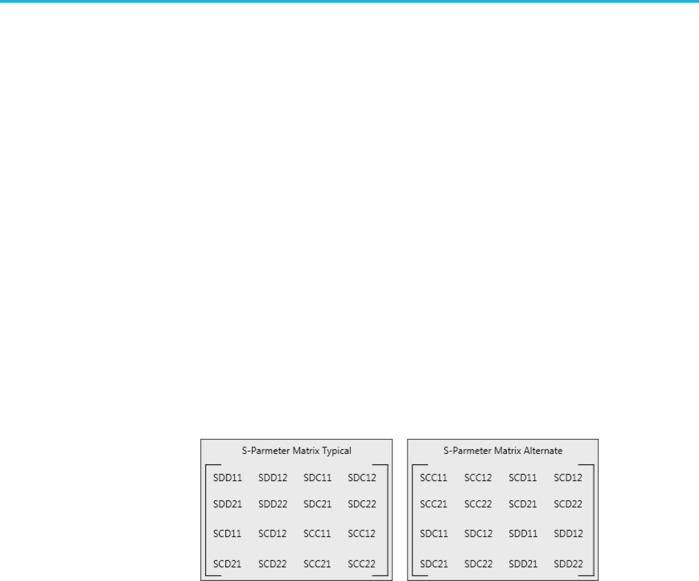
Command descriptions
WLISt:SPARameter:NCAScading:LAYout
This command sets or returns the 4 port S-Parameter Matrix Configuration, in
Non-Cascading mode.
Conditions S-Parameter Mode must be set to Non-Cascading.
Number of Ports must be set to 4.
Requires an S-Parameters license.
Group S-Parameters
Syntax WLISt:SPARameter:NCAScading:LAYout {TYPical|ALTernate}
WLISt:SPARameter:NCAScading:LAYout?
Related Commands WLISt:SPARameter:MODE
Arguments TYPical or ALTernate: selects the S-Parameter Matrix.
Returns TYP
ALT
Examples WLIST:SPARAMETER:NCASCADING:LAYOUT TYPICAL sets the 4 port
configuration's Layout to Typical, in Non-Cascading mode.
WLIST:SPARAMETER:NCASCADING:LAYOUT? might return TYP, indicating that
configuration's Layout for port 4 is set to Typical, in Non-Cascading mode.
2-328 AWG5200 Series Programmer Manual

Command descriptions
WLISt:SPARameter:NCAScading:RX[n]
This command sets or returns the S-Parameter port assignment of the channel’s
specified receiver port number (Rx-Port) in Non-Cascading mode and
Single-Ended Signalling Scheme (where applicable).
Conditions S-Parameter Mode must be set to Non-Cascading.
S-Parameter Signalling Scheme must be set to Single-Ended.
Requires an S-Parameters license.
Group S-Parameters
Syntax WLISt:SPARameter:NCAScading:RX[n] <port number>
WLISt:SPARameter:NCAScading:RX[n]?
Related Commands WLISt:SPARameter:MODE,
WLISt:SPARameter:CASCading:STYPe,
WLISt:SPARameter:NCAScading:TYPE,
WLISt:SPARameter:NCAScading:TX[n]
Arguments [n] ::= <NR1>. A variable value to define the receiver port number (Rx-Port) of
the channel.
The actual range is dependent on the Number of Ports (Type).
Type = 1, then n = no value
Type = 2, then n = {1}
Type = 4 then n = {1 – 2}
Type = 6 then n = {1 – 3}
Type = 8 then n = {1 – 4}
Type=12thenn={1–6}
If omitted, n is interpreted as 1.
<port number> ::= <NR1>. A variable value to define the S-Parameter Port
assigned to the specified Rx-Port of the channel.
The actual range is dependent on the Number of Ports (Type).
Type = 1, then <port number> = no value
Type = 2, then <port number> = {1 – 2}
Type = 4 then <port number> = {1 – 4}
Type = 6 then <port number> = {1 – 6}
Type = 8 then <port number> = {1 – 8}
Type = 12 then <port number> = {1 – 12}
AWG5200 Series Programmer Manual 2-329

Command descriptions
Returns A single <NR1> value.
Examples WLIST:SPARAMETER:NCASCADING:RX2 4 assigns S-Parameter port 4 to the
channel’s receiver port 2, in the Single-Ended, Non-Cascading mode.
WLIST:SPARAMETER:NCASCADING:RX4? might return 6, indicating
that S-Parameter Port 6 is assigned to the channel’s receiver port 4, in the
Single-Ended, Non-Cascading mode.
2-330 AWG5200 Series Programmer Manual

Command descriptions
WLISt:SPARameter:NCAScading:SSCHeme
This command sets or returns the S-Parameter Signalling Scheme, in
Non-Cascading mode. Signalling Scheme is only available when the Number
ofPortsisse
tto4,8,or12.
Conditions S-Parameter Mode must be set to Non-Cascading.
Requires an S-Parameters license.
Group S-Parameters
Syntax WLISt:SPARameter:NCAScading:SSCHeme {SENDed|DIFFerential}
WLISt:SPARameter:NCAScading:SSCHeme?
Related Commands WLISt:SPARameter:MODE
Arguments SENDed – Single Ended Signal Scheme
DIFFerential – Differential Signal Scheme
Returns SEND
DIFF
Examples WLIST:SPARAMETER:NCASCADING:SSCHEME DIFF sets the Signalling Scheme
to Differential, in Non-Cascading mode.
WLIST:SPARAMETER:NCASCADING:SSCHEME? might return SEND, indicating
that the Signalling Scheme is set to Single Ended, in Non-Cascading mode.
AWG5200 Series Programmer Manual 2-331

Command descriptions
WLISt:SPARameter:NCAScading:STYPe
This command sets or returns S-Parameter signal type (victim or aggressor), in
Non-Cascading mode. The number of ports must be either 8 or 12.
Conditions S-Parameter Mode must be set to Non-Cascading.
Number of Ports must be either 8 or 12.
Requires an S-Parameters license.
Group S-Parameters
Syntax WLISt:SPARameter:NCAScading:STYPe {VICTim|AGGRessor|BOTH}
WLISt:SPARameter:NCAScading:STYPe?
Related Commands WLISt:SPARameter:MODE
Arguments VICTim – enables the victim signal type.
AGGRessor – enables the aggressor signal type.
BOTH – enables the victim and aggressor signal types.
Returns VICT
AGGR
BOTH
Examples WLIST:SPARAMETER:NCASCADING:STYPE BOTH sets the signal type to include
both the Victim and Aggressor signal types, in Non-Cascading mode.
WLIST:SPARAMETER:NCASCADING:STYPE? might return AGGR, indicating that
the S-Parameter signal type is currently set to be Aggressor, in Non-Cascading
mode.
2-332 AWG5200 Series Programmer Manual

Command descriptions
WLISt:SPARameter:NCAScading:TX[n]
This command sets or returns the S-Parameter port assignment of the channel’s
specified transmission port number (Tx-Port) in Non-Cascading mode and
Single-Ended Signalling Scheme (where applicable).
Conditions S-Parameter Mode must be set to Non-Cascading.
S-Parameter Signalling Scheme must be set to Single-Ended (where applicable).
Requires an S-Parameters license.
Group S-Parameters
Syntax WLISt:SPARameter:NCAScading:TX[n] <port number>
WLISt:SPARameter:NCAScading:TX[n]?
Related Commands WLISt:SPARameter:MODE,
WLISt:SPARameter:CASCading:STYPe,
WLISt:SPARameter:NCAScading:TYPE,
WLISt:SPARameter:NCAScading:RX[n]
Arguments [n] ::= <NR1>. A variable value to define the transmission port number (Tx-Port)
of the channel.
The actual range is dependent on the Number of Ports (Type).
Type = 1, then n = no value
Type = 2, then n = {1}
Type = 4 then n = {1 – 2}
Type = 6 then n = {1 – 3}
Type = 8 then n = {1 – 4}
Type=12thenn={1–6}
If omitted, n is interpreted as 1.
<port number> ::= <NR1>. A variable value to define the S-Parameter Port
assigned to the specified Tx-Port of the channel.
The actual range is dependent on the Number of Ports (Type).
Type = 1, then <port number> = no value
Type = 2, then <port number> = {1 – 2}
Type = 4 then <port number> = {1 – 4}
Type = 6 then <port number> = {1 – 6}
Type = 8 then <port number> = {1 – 8}
Type = 12 then <port number> = {1 – 12}
AWG5200 Series Programmer Manual 2-333

Command descriptions
Returns A single <NR1> value.
Examples WLIST:SPARAMETER:NCASCADING:TX2 4 assigns S-Parameter port 4 to the
channel’s transmission port 2, in the Single-Ended, Non-Cascading mode.
WLIST:SPARAMETER:NCASCADING:TX4? might return 6, indicating that
S-Parameter Port 6 is assigned to the channel’s transmission port 4, in the
Single-Ended, Non-Cascading mode.
2-334 AWG5200 Series Programmer Manual

Command descriptions
WLISt:SPARameter:NCAScading:TYPE
This command sets or returns the S-Parameter number of ports, in Non-Cascading
mode.
Conditions Requires an S-Parameters license.
Group S-Parameters
Syntax WLISt:SPARameter:NCAScading:TYPE {1|2|4|6|8|12}
Arguments {1|2|4|6|8|12} – defines the number of S-Parameter ports.
Returns A single <NR1> value.
Examples WLIST:SPARAMETER:NCASCADING:TYPE 12 sets the S-Parameter type to a
12-Port system for Non-Cascading mode.
WLIST:SPARAMETER:NCASCADING:TYPE? might return 6, indicating that the
S-Parameter type is a 6-Port system for Non-Cascading mode.
AWG5200 Series Programmer Manual 2-335

Command descriptions
WLISt:SPARameter:SFORmat
This command sets or returns the currently used signal format for setting the
S-Parameter values.
Conditions Requires an S-Parameters license.
Group S-Parameters
Syntax WLISt:SPARameter:SFORmat {REAL|I|Q|IQ}
WLISt:SPARameter:SFORmat?
Arguments REAL: RF waveform.
I: I data of an IQ waveform.
Q:QdataofanIQwaveform.
IQ: Waveform combining I and Q data.
Returns REAL
I
Q
IQ
Examples WLIST:SPARAMETER:SFORMAT Q sets the current S-Parameter format to Q so
that values are set to the Q S-Parameters.
WLIST:SPARAMETER:SFORMAT? might return IQ, which indicates that current
S-ParametervaluesareappliedtobothIandQ.
2-336 AWG5200 Series Programmer Manual

Command descriptions
WLISt:WAVeform:ACFile (No Query Form)
This command applies user supplied correction coefficients from an external
(precompensation) file to the specified waveform (or waveforms) in the waveform
list. Corrections from a precompensation file can be applied to a maximum of
two waveforms.
Conditions When applying correction coefficients to two waveforms, it is assumed the
specified waveforms are I and Q data signals. The order of the I and Q data
signals is not specific.
This is an overlapping command. (See page 2-9, Sequential, blocking, and
overlapping commands.)
Group Waveform
Syntax WLISt:WAVeform:ACFile <file_path>,<wfm_name>[,<wfm_name2>]
Arguments <file_path>::=<string> This is the complete path to the correction file, including
the correction file name.
<wfm_name>::=<string> This is the name of the waveform (in the waveform
list) to apply the correction coefficients.
<wfm_name2>::=<string> This is the name of the second waveform (in the
waveform list) to apply the correction coefficients.
Examples WLIST:WAVEFORM:ACFILE
"C:\Corrections\Ch1Corrections.corr","myWaveform" applies the
correction coefficients in the file Ch1Corrections to myWaveform waveform.
WLIST:WAVEFORM:ACFILE
"C:\Corrections\Ch1Corrections.corr","myWaveform","myWaveform2"
applies the correction coefficients in the file Ch1Corrections to
thetwonamedIandQwaveforms.
AWG5200 Series Programmer Manual 2-337

Command descriptions
WLISt:WAVeform:ACFile:GAUSsian
This command sets or returns whether a gaussian filter will be applied during the
application of a precompensation file (correction coefficients file).
Conditions The precompensation file must have been generated with the Generic
Precompensation Type set to RF.
Group Waveform
Syntax WLISt:WAVeform:ACFile:GAUSsian {0|1|OFF|ON}
WLISt:WAVeform:ACFile:GAUSsian?
Arguments OFF or 0 disables the application of a gaussian filter. OFF or 0 is the default value.
ON or 1 enables the application of a gaussian filter.
Returns A single <Boolean> value.
Examples WLIST:WAVEFORM:ACFILE:GAUSSIAN 0 sets the system so that during
application of a precompensation file, a gaussian filter will not be applied.
WLIST:WAVEFORM:ACFILE:GAUSSIAN? might return 1, indicating that the
system will apply a gaussian filter when applying a precompensation file.
2-338 AWG5200 Series Programmer Manual

Command descriptions
WLISt:WAVeform:ACFile:GAUSsian:BANDwidth
This command sets or returns the bandwidth of the gaussian filter that is to be
applied during application of a precompensation file (correction coefficients file).
Conditions The precompensation file must have been generated with the Generic
Precompensation Type set to RF and Apply Gaussian Filter selected.
Group Waveform
Syntax WLISt:WAVeform:ACFile:GAUSsian:BANDwidth <bandwidth>
WLISt:WAVeform:ACFile:GAUSsian:BANDwidth?
Related Commands WLISt:WAVeform:ACFile:GAUSsian
Arguments <bandwidth>::=<NR3> value.
Returns A single <NRf> value indicating the actual Gaussian Filter Bandwidth.
Examples WLIST:WAVEFORM:ACFILE:GAUSSIAN:BANDWIDTH 2E9 sets the gaussian filter
bandwidth to 2 GHz.
WLIST:WAVEFORM:ACFILE:GAUSSIAN:BANDWIDTH? might return
1.0000000000E+9, indicating that the gaussian filter bandwidth is set to 1 GHz.
AWG5200 Series Programmer Manual 2-339

Command descriptions
WLISt:WAVeform:ACFile:RSINc
This command sets or returns whether or not corrections for Sin(x)/x distortions
will be removed during application of a correction file.
Conditions The correction file must have been generated with the Generic Precompensation
Type set to RF and the distortions have not already been removed.
Group Waveform
Syntax WLISt:WAVeform:ACFile:RSINc {0|1|OFF|ON}
WLISt:WAVeform:ACFile:RSINc?
Arguments OFF or 0 will not remove the Sin(x)/x distortions from the correction file. OFF or
0 is the default value.
ON or 1 removes the Sin(x)/x distortions from the correction file.
Returns A single <Boolean> value.
Examples WLIST:WAVEFORM:ACFILE:RSINC 1 sets the system to remove corrections for
Sin(x)/x distortions from when a precompensation file is applied.
WLIST:WAVEFORM:ACFILE:RSINC? might return 0, indicating that the system
will not remove corrections for Sin(x)/x distortions.
2-340 AWG5200 Series Programmer Manual

Command descriptions
WLISt:WAVeform:ACFile:SKEW
This command sets or returns whether the measured Skew will be applied during
application of a precompensation file (correction coefficients file).
Conditions The precompensation file must have been generated with the Generic
Precompensation Type set to IQ and the skew was measured.
Group Waveform
Syntax WLISt:WAVeform:ACFile:SKEW {0|1|OFF|ON}
WLISt:WAVeform:ACFile:SKEW?
Arguments OFF or 0 will not apply the measured Skew during the application of a
precompensation file. OFF or 0 is the default value.
ON or 1 applies the measured Skew during the application of a precompensation
file.
Returns A single <Boolean> value.
Examples WLIST:WAVEFORM:ACFILE:SKEW 1 applies the skew if it is available in the
correction file.
WLIST:WAVEFORM:ACFILE:SKEW? might return 0, indicating that skew will
not be applied.
AWG5200 Series Programmer Manual 2-341

Command descriptions
WLISt:WAVeform:AMPLitude
This command sets or returns the Recommended Amplitude (peak-to-peak) of the
specified waveform in the waveform list.
Conditions If a recommended amplitude is not specified, a query returns the value for Not a
Number (9.9100E+037).
Group Waveform
Syntax WLISt:WAVeform:AMPLitude <wfm_name>,<amplitude>
WLISt:WAVeform:AMPLitude? <wfm_name>
Related Commands WLISt:WAVeform:OFFSet
Arguments <wfm_name>::=<string>
<amplitude>::= <NRf>
Returns A single <NR3> value.
Examples WLIST:WAVEFORM:AMPLITUDE "Ramp1000",500E–3 sets the recommended
amplitude to 500 mVp-p for the waveform named Ramp1000.
WLIST:WAVEFORM:AMPLITUDE? "Ramp1000" might return
200.0000000000E-3, indicating that the amplitude for the waveform named
Ramp1000 is 200 mVp-p.
2-342 AWG5200 Series Programmer Manual

Command descriptions
WLISt:WAVeform:DATA
This command transfers analog waveform data from the external controller into
the specified waveform or from a waveform to the external control program.
If the waveform is of the Signal Format type IQ use the commands to write to
IandQdata.
NOTE. Before transferring data to the instrument, a waveform must be created
using the WLISt:WAVeform:NEW command.
Using StartIndex and Size, part of a waveform can be transferred at a time. Very
large waveforms can be transferred in chunks.
Waveform data is always transferred in the LSB first format.
The format of the transferred data depends on the waveform type.
If Size is omitted, the length of waveform is assumed to be the value of the Size
parameter.
Transferring large waveforms in chunks allows external programs to cancel the
operation before it is completed.
The instrument supports floating point format. Floating point waveform data
points occupy four bytes. So the total bytes will be four times the size of the
waveform.
The minimum size of the waveform must be 1 and the maximum size depends on
the instrument model and configuration.
This command has a limit of 999,999,999 bytes of data.
The IEEE 488.2 limits that the largest read or write that may occur in a single
command is 999,999,999 bytes.
Because of the size limitation, it is suggested that the user make use of the starting
index (and size for querying) to append data in multiple commands/queries.
To set marker data, use the command WLISt:WAVeform:MARKer:DATA.
Group Waveform
Syntax WLISt:WAVeform:DATA
<wfm_name>[,<StartIndex>[,<Size>]],<block_data>
WLISt:WAVeform:DATA? <wfm_name>[,<StartIndex>[,<Size>]]
Related Commands WLISt:WAVeform:NEW,
WLISt:WAVeform:MARKer:DATA,
AWG5200 Series Programmer Manual 2-343

Command descriptions
WLISt:WAVeform:DATA:I,
WLISt:WAVeform:DATA:Q
Arguments StartIndex, Size,<block_data>
<wfm_name> ::= <string>
<StartIndex> ::= <NR1>
<Size> ::= <NR1>
<block_data> ::= <IEEE 488.2 block>
Returns <block_data>
Examples WLIST:WAVEFORM:DATA "TestWfm",0,1024,#44096xxxx… transfers the
waveform data to a waveform named "TestWfm". The data size is 1024 points
(4096 bytes) and the start index is 0 (the first data point).
2-344 AWG5200 Series Programmer Manual

Command descriptions
WLISt:WAVeform:DATA:I
This command transfers waveform data from the external controller into the
specified waveform or from a waveform to the external control program.
This command writes the data to I. The waveform must be of the Signal Format
type IQ. To write to Q data, use the command WLISt:WAVeform:DATA:Q.
NOTE. Before transferring data to the instrument, a waveform must be created
using the WLISt:WAVeform:NEW command.
Using StartIndex and Size, part of a waveform can be transferred at a time. Very
large waveforms can be transferred in chunks.
Waveform data is always transferred in the LSB first format.
The format of the transferred data depends on the waveform type.
If Size is omitted, the length of waveform is assumed to be the value of the Size
parameter.
Transferring large waveforms in chunks allows external programs to cancel the
operation before it is completed.
The instrument supports floating point format. Floating point waveform data
points occupy four bytes. So the total bytes will be four times the size of the
waveform.
The minimum size of the waveform must be 1 and the maximum size depends on
the instrument model and configuration.
This command has a limit of 999,999,999 bytes of data.
As the IEEE 488.2 is a limitation that the largest read or write that may occur in a
single command is 999,999,999 bytes as the structure is defined as a '#' followed
by a byte to determine the number of bytes to read '9'. '9' indicates that we need
to read 9 bytes to determine the length of the following data block: 999,999,999
(separated by commas to help separate - they will not be present normally).
Because of the size limitation, it is suggested that the user make use of the starting
index (and size for querying) to append data in multiple commands/queries.
To set marker data, use the command WLISt:WAVeform:MARKer:DATA.
Group Waveform
Syntax WLISt:WAVeform:DATA:I
<wfm_name>[,<StartIndex>[,<Size>]],<block_data>
WLISt:WAVeform:DATA:I? <wfm_name>[,<StartIndex>[,<Size>]]
AWG5200 Series Programmer Manual 2-345

Command descriptions
Related Commands WLISt:WAVeform:NEW,WLISt:WAVeform:MARKer:DATA,
WLISt:WAVeform:DATA,
WLISt:WAVeform:DATA:Q
Arguments StartIndex, Size,<block_data>
<wfm_name> ::= <string>
<StartIndex> ::= <NR1>
<Size> ::= <NR1>
<block_data> ::= <IEEE 488.2 block>
Returns <block_data>
ExamplesWLIST:WAVEFORM:DATA:I "TestWfm_I",0,1024,#44096xxxx… transfers
the I waveform data to a waveform called "TestWfm_I". The data size is 1024
points (4096 bytes) and the start index is 0 (the first data point).
2-346 AWG5200 Series Programmer Manual

Command descriptions
WLISt:WAVeform:DATA:Q
This command transfers waveform data from the external controller into the
specified waveform or from a waveform to the external control program.
This command writes the data to Q. The waveform must be of the Signal Format
type IQ. To write to I data, use the command WLISt:WAVeform:DATA:I.
NOTE. Before transferring data to the instrument, a waveform must be created
using the WLISt:WAVeform:NEW command.
Using StartIndex and Size, part of a waveform can be transferred at a time. Very
large waveforms can be transferred in chunks.
Waveform data is always transferred in the LSB first format.
The format of the transferred data depends on the waveform type.
If Size is omitted, the length of waveform is assumed to be the value of the Size
parameter.
Transferring large waveforms in chunks allows external programs to cancel the
operation before it is completed.
The instrument supports floating point format. Floating point waveform data
points occupy four bytes. So the total bytes will be four times the size of the
waveform.
The minimum size of the waveform must be 1 and the maximum size depends on
the instrument model and configuration.
This command has a limit of 999,999,999 bytes of data.
As the IEEE 488.2 is a limitation that the largest read or write that may occur in a
single command is 999,999,999 bytes as the structure is defined as a '#' followed
by a byte to determine the number of bytes to read '9'. '9' indicates that we need
to read 9 bytes to determine the length of the following data block: 999,999,999
(separated by commas to help separate - they will not be present normally).
Because of the size limitation, it is suggested that the user make use of the starting
index (and size for querying) to append data in multiple commands/queries.
To set marker data, use the command WLISt:WAVeform:MARKer:DATA.
Group Waveform
Syntax WLISt:WAVeform:DATA:Q
<wfm_name>[,<StartIndex>[,<Size>]],<block_data>
WLISt:WAVeform:DATA:Q? <wfm_name>[,<StartIndex>[,<Size>]]
AWG5200 Series Programmer Manual 2-347

Command descriptions
Related Commands WLISt:WAVeform:NEW,WLISt:WAVeform:MARKer:DATA,
WLISt:WAVeform:DATA,
WLISt:WAVeform:DATA:I
Arguments StartIndex, Size,<block_data>
<wfm_name> ::= <string>
<StartIndex> ::= <NR1>
<Size> ::= <NR1>
<block_data> ::= <IEEE 488.2 block>
Returns <block_data>
ExamplesWLIST:WAVEFORM:DATA:Q "TestWfm_Q",0,1024,#44096xxxx… transfers
the Q waveform data to a waveform called "TestWfm_Q". The data size is 1024
points (4096 bytes) and the start index is 0 (the first data point).
2-348 AWG5200 Series Programmer Manual

Command descriptions
WLISt:WAVeform:DELete(NoQueryForm)
This command deletes a single waveform from the waveform list or all waveforms.
NOTE. When ALL is specified, all user-defined waveforms in the list are deleted
in a single action. Note that there is no "UNDO" action once the waveforms are
deleted. Use caution before issuing this command.
If the deleted waveform is currently loaded into waveform memory, it is unloaded.
If the RUN state of the AWG is ON, the state is turned OFF. If the channel is on,
it will be switched off.
Group Waveform
Syntax WLISt:WAVeform:DELete {<wfm_name>|ALL}
Related Commands WLISt:SIZE?,
WLISt:NAME?,
WLISt:LAST?
Arguments <wfm_name> ::= <string>
Examples WLIST:WAVEFORM:DELETE ALL deletes all waveforms from the waveform list.
WLIST:WAVEFORM:DELETE "Test1" deletes the waveform named Test1 from
the waveform list.
AWG5200 Series Programmer Manual 2-349

Command descriptions
WLISt:WAVeform:FREQuency
The command sets or returns the Recommended Center Frequency of the named
IQ waveform.
Conditions If the Recommended Frequency is not specified, a query will return the value
for Not a Number: 9.91E+37.
Group Waveform
Syntax WLISt:WAVeform:FREQuency <wfm_name>,<frequency>
WLISt:WAVeform:FREQuency?
Arguments <wfm_name>::=<string>.
<frequency>::= <NR3> value.
Returns A single <NR3> value.
Examples WLIST:WAVEFORM:FREQUENCY "Ramp1000", 1E9 sets the Center Frequency
of the IQ waveform “Ramp1000” to 1 GHz.
WLIST:WAVEFORM:FREQUENCY? “Ramp1000” might return
1.0000000000E+9, indicating the Center Frequency for the IQ waveform
“Ramp1000” is set to 1 GHz.
WLIST:WAVEFORM:FREQUENCY? “Ramp1000” might return 9.91E+37 if no
Recommended Center Frequency is not defined.
2-350 AWG5200 Series Programmer Manual

Command descriptions
WLISt:WAVeform:GRANularity? (Query Only)
This command returns the granularity of sample points required for the waveform
to be valid. The number of sample points of a single channel instrument must
be divisible by 2.
Group Waveform
Syntax WLISt:WAVeform:GRANularity?
Related Commands WLISt:WAVeform:LMINimum?,WLISt:WAVeform:LMAXimum?
Returns A single <NR1> value.
Examples WLIST:WAVEFORM:GRANULARITY? might return 2, indicating that the number of
sample points must be divisible by 2.
WLISt:WAVeform:INVert (No Query Form)
This command inverts the named waveform (in the waveform list) and preserves
the offset.
Group Waveform
Syntax WLISt:WAVeform:INVert <wfm_name>
Arguments <wfm_name>::= <string>
Examples WLIST:WAVEFORM:INVERT “wave2” inverts the waveform titled "wave2", if
it exists in the waveform list,, preserving the offset.
AWG5200 Series Programmer Manual 2-351

Command descriptions
WLISt:WAVeform:LENGth? (Query Only)
This command returns the size of the specified waveform in the waveform list.
The returned value represents data points (not bytes).
Group Waveform
Syntax WLISt:WAVeform:LENGth? <wfm_name>
Arguments <wfm_name> ::= <string>
Returns A single <NR1> value.
ExamplesWLIST:WAVEFORM:LENGTH? "waveform2" might return 360, indicating the
waveform contains 360 data points.
WLISt:WAVeform:LMAXimum? (Query Only)
This command returns the maximum number of waveform sample points allowed.
Conditions The returned value is dependent on the instrument model, the installed options,
and sampling rate setting.
Group Waveform
Syntax WLISt:WAVeform:LMAXimum?
Related Commands WLISt:WAVeform:LMINimum?
Returns A single <NR1> value.
Examples WLIST:WAVEFORM:LMAXIMUM? might return 2000000000, indicating that the
maximum number of allowed waveform sample points is 2 G samples.
2-352 AWG5200 Series Programmer Manual

Command descriptions
WLISt:WAVeform:LMINimum? (Query Only)
This command returns the minimum number of waveform sample points required
for a valid waveform. The number of required sample points is dependent on
the instrument model.
Group Waveform
Syntax WLISt:WAVeform:LMINimum?
Related Commands WLISt:WAVeform:LMAXimum?
Returns A single <NR1> value.
Examples WLIST:WAVEFORM:LMINIMUM? might return 2400, indicating that the minimum
number of waveform sample points required is 2.4 k.
AWG5200 Series Programmer Manual 2-353

Command descriptions
WLISt:WAVeform:MARKer:DATA
This command sets or returns the waveform marker data.
NOTE. This command returns or sends only marker data for the waveform.
Each marker data occupies one bit. Four most significant bits of each byte are
used for markers. Bit 7 for marker 1 and bit 6 for marker 2, bit 5 for marker 3,
and bit 4 for marker 4.
You will have to use bit masks to obtain the actual value.
When used on a waveform with n data points, you get only n bytes, each byte
having values for both markers.
Block data can be sent in batches using "Size" and "StartIndex" parameters.
This command has a limit of 999,999,999 bytes of data. If this limit is insufficient,
consider the following alternatives:
Send a more efficient file format using MMEM:DATA.
Use Ethernet (ftp, http, or file sharing) to transfer the file.
Group Waveform
Syntax WLISt:WAVeform:MARKer:DATA
<wfm_name>[,<StartIndex>[,<Size>]],<block_data>
WLISt:WAVeform:MARKer:DATA?
<wfm_name>[,<StartIndex>[,<Size>]]
Related Commands WLISt:WAVeform:DATA,
WLISt:WAVeform:DATA,
WLISt:WAVeform:NEW
Arguments <wfm_name> ::= <string>
<StartIndex> ::= <NR1>
<Size> ::= <NR1>
<block_data> ::= <IEEE 488.2 block>
Returns <block_data>
Examples WLIST:WAVEFORM:MARKER:DATA "myWaveform",0,1000,#41000….
transfers the marker data to the waveform named myWaveform.
2-354 AWG5200 Series Programmer Manual

Command descriptions
WLIST:WAVEFORM:MARKER:DATA? "myWaveform",0,1000 returns 1000
marker values from myWaveform starting at the first sample.
AWG5200 Series Programmer Manual 2-355

Command descriptions
WLISt:WAVeform:MIQ (No Query Form)
This command creates an IQ waveform from two real waveforms. The name
is derived from the I waveform name.
Conditions You cannot make an IQ waveform from existing IQ waveforms.
Group Waveform
Syntax WLISt:WAVeform:MIQ <I_wfm_name>,<Q_wfm_name>
Arguments <I_wfm_name>::=<string>
<Q_wfm_name>::=<string>
Examples WLIST:WAVEFORM:MIQ “Test_I”,"Test_Q" creates an IQ waveform named
"Test_I" using "Test_I" as the I component and "Test_Q" as the Q component.
2-356 AWG5200 Series Programmer Manual

Command descriptions
WLISt:WAVeform:NEW (No Query Form)
This command creates a new empty waveform in the waveform list of the current
setup.
Group Waveform
Syntax WLISt:WAVeform:NEW <wfm_name>,<Size>[,<format>]
Related Commands WLISt:WAVeform:DATA
Arguments <wfm_name> ::= <string>
<Size> ::= <NR1>
<format>::= {REAL|IQ}
Examples WLIST:WAVEFORM:NEW "Test1", 1024 creates a new waveform called Test1
with 1024 points.
AWG5200 Series Programmer Manual 2-357

Command descriptions
WLISt:WAVeform:NORMalize (No Query Form)
This command normalizes a waveform in the waveform list.
Conditions This is an overlapping command. (See page 2-9, Sequential, blocking, and
overlapping commands.)
Group Waveform
Syntax WLISt:WAVeform:NORMalize <wfm_name>,{FSCale|ZREFerence}
Arguments <wfm_name> ::= <string>
FSCale normalizes the waveform to the full amplitude range.
ZREFerence normalizes the waveform while preserving the offset.
Examples WLIST:WAVEFORM:NORMALIZE "Untitled25",FSCALE
*OPC?
normalizes the waveform titled "Untitled25", if it exists, using full scale. The
overlapping command is followed with an Operation Complete query.
2-358 AWG5200 Series Programmer Manual

Command descriptions
WLISt:WAVeform:OFFSet
This command sets or returns the Recommended Offset of the specified waveform
in the waveform list.
Conditions If a recommended offset is not specified, a query returns the value for Not a
Number (9.9100E+037).
Group Waveform
Syntax WLISt:WAVeform:OFFSet <wfm_name>,<offset>
WLISt:WAVeform:OFFSet? <wfm_name>
Related Commands WLISt:WAVeform:AMPLitude
Arguments <wfm_name>::=<string>
<offset>::= <NR3>
Returns A single <NR3> value.
Examples WLIST:WAVEFORM:OFFSET "Ramp1000",100E-3 sets the recommended offset
to 100 mV for the waveform named Ramp1000.
WLIST:WAVEFORM:OFFSET? "Ramp1000" might return 10.0000000000E-3,
indicating that the offset for the waveform named Ramp1000 is 10 mV.
AWG5200 Series Programmer Manual 2-359

Command descriptions
WLISt:WAVeform:RESample (No Query Form)
This command resamples the number of points in a waveform in the waveform list.
Conditions This is an overlapping command. (See page 2-9, Sequential, blocking, and
overlapping commands.)
Group Waveform
Syntax WLISt:WAVeform:RESample <wfm_name>,<size>
Arguments <wfm_name ::= <string>
<size>::=<NR1>
Examples WLIST:WAVEFORM:RESAMPLE "Untitled25", 1024
*OPC?
resamples the waveform titled "Untitled25" to 1024 points. The overlapping
command is followed with an Operation Complete query.
2-360 AWG5200 Series Programmer Manual

Command descriptions
WLISt:WAVeform:REVerse (No Query Form)
This command reverses the order of the named waveform (in the waveform list).
Group Waveform
Syntax WLISt:WAVeform:REVerse <wfm_name>
Arguments <wfm_name>::= <string>
Examples WLIST:WAVEFORM:REVERSE “wave2” reverses the order of the waveform titled
"wave2", if it exists in the waveform list.
WLISt:WAVeform:ROTate (No Query Form)
This command rotates the named waveform (in the waveform list).
Conditions This is an overlapping command. (See page 2-9, Sequential, blocking, and
overlapping commands.)
Group Waveform
Syntax WLISt:WAVeform:ROTate <wfm_name>,<phase>
Arguments <wfm_name> ::= <string>
<phase> ::= <NR3>
Range: –360 to 360
Examples WLIST:WAVEFORM:ROTATE "Wave1",90 rotates the waveform named Wave1
by 90 degrees.
AWG5200 Series Programmer Manual 2-361

Command descriptions
WLISt:WAVeform:SFORmat
This command sets or returns the signal format of the specified waveform in
the waveform list.
Group Waveform
Syntax WLISt:WAVeform:SFORmat <wfm_name>,{REAL|I|Q}
WLISt:WAVeform:SFORmat? <wfm_name>
Arguments <wfm_name ::= <string>
REAL identifies this as a waveform type other than I or Q.
I identifies this as I data.
Q identifies this as Q data.
Returns REAL
I
Q
Examples WLIST:WAVEFORM:SFORMAT "Waveform1", REAL sets the signal format
properties of the waveform names "Waveform1" to REAL.
WLIST:WAVEFORM:SFORMAT?"WaveformData1" might return Q, indicating the
signal format properties of "WaveformData1" is set to Q to identify this as Q data.
2-362 AWG5200 Series Programmer Manual

Command descriptions
WLISt:WAVeform:SHIFt (No Query Form)
This command shifts the phase of a waveform in the waveform list.
Conditions This is an overlapping command. (See page 2-9, Sequential, blocking, and
overlapping commands.)
Group Waveform
Syntax WLISt:WAVeform:SHIFt <wfm_name>,<phase>
Arguments <wfm_name ::= <string>
<phase> ::= <NR1>
Returns <wfm_name::=<string>
<Size>::=<NR3>
Examples WLIST:WAVEFORM:SHIFT "Untitled25",180
*OPC?
shifts the waveform titled "Untitled25" (if it exists) by 180 degrees. The
overlapping command is followed with an Operation Complete query.
AWG5200 Series Programmer Manual 2-363

Command descriptions
WLISt:WAVeform:SRATe
The command sets or returns the Recommended Sampling Rate of the specified
waveform in the waveform list
Conditions If the Recommended Sampling Rate is not specified, then the result of a query
will return the value for Not a Number: 9.91E+37.
Group Waveform
Syntax WLISt:WAVeform:SRATe <wfm_name>,<sample_rate>
WLISt:WAVeform:SRATe? <wfm_name>
Arguments <wfm_name>::=<string>
<sample_rate>::= <NRf>
Returns A single <NR3> value
Examples WLIST:WAVEFORM:SRATE "Ramp1000", 2E9 sets the Recommended
Sampling Rate of waveform "Ramp1000" to 2 GHz.
WLIST:WAVEFORM:SRATE? "Ramp1000" might return 50.0000000000E+9,
indicating that the Recommended Sampling Rate of waveform "Ramp1000" is
50 GHz.
2-364 AWG5200 Series Programmer Manual

Command descriptions
WLISt:WAVeform:TSTamp? (Query Only)
This command returns the timestamp of the specified waveform in the waveform
list.
NOTE. The timestamp is updated whenever the waveform is created (added) or
changed.
The command returns the date as a string in the form yyyy/mm/dd hh:mm:ss (a
blank space between date and time).
Group Waveform
Syntax WLISt:WAVeform:TSTamp? <wfm_name>
Arguments <wfm_name> ::= <string>
Returns "yyyy/mm/dd hh:mm:ss" is the waveform timestamp.
Where
yyyy refers to a four-digit year number mm refers to two-digit month number
from 01 to 12.
dd refers to two-digit day number in the month.
hh refers to two-digit hour number mm refers to two-digit minute number.
ss refers to two-digit second number.
Examples WLIST:WAVEFORM:TSTAMP? "Sine" might return "2012/07/25 9:05:21",
which is the date and time the "Sine" waveform was added or last modified.
AWG5200 Series Programmer Manual 2-365

Command descriptions
WLISt:WAVeform:TYPE? (Query Only)
This command returns the type of the waveform.
NOTE. This command exists for backwards compatibility with the AWG5000 and
AWG7000 series instruments.
Group Waveform
Syntax WLISt:WAVeform:TYPE? <wfm_name>
Arguments <wfm_name> ::= <string>
Returns REAL
Examples WLIST:WAVEFORM:TYPE? "Ramp1000" returns REAL.
WPLugin:ACTive
This command sets or returns the active waveform creation plug-in.
Conditions The Sequencing option must be enabled.
This is an overlapping command. (See page 2-9, Sequential, blocking, and
overlapping commands.)
Group Waveform plug-in
Syntax WPLugin:ACTive <plugin_name>
Arguments <plugin_name>::=<string>
Returns A single string representing the active waveform creation plug-in.
Examples WPLUGIN:ACTIVE "Multitone" sets Multitone plug-in as the active plug-in.
WPLUGIN:ACTIVE? might return "Multitone", indicating the Multitone plug-in
is currently active.
2-366 AWG5200 Series Programmer Manual

Command descriptions
WPLugin:PLUGins? (Query Only)
This command returns all the available waveform creation plug-ins installed. The
response returns a comma separated string with all the plug-in names.
Group Waveform plug-in
Syntax WPLugin:PLUGins?
Returns <string>::= <plugin_name>,<plugin_name>, ....
Plugin_name is the waveform plug-in name(s).
Examples WPLUGIN:PLUGINS? might return "Basic Waveform,Multitone" indicating
that the Basic Waveform and Multitone plug-ins are installed.
AWG5200 Series Programmer Manual 2-367

Command descriptions
2-368 AWG5200 Series Programmer Manual

Status and Events

Status and events
The SCPI interface in the instrument includes a status and event reporting system
that enables the user to monitor crucial events that occur in the instrument. The
instrument is equipped with four registers and one queue that conform to IEEE
Std 488.2. This section discusses these registers and queues along with status
and event processing.
Status and event reporting system
The following figure outlines the status and event reporting mechanism offered in
the arbitrary waveform generators. It contains three major blocks
Standard Event Status
Operation Status
Questionable Status (fan-out structure)
The processes performed in these blocks are summarized in the Status Byte. The
three blocks contain four types of registers as shown in the following table.
Table 3-1: Register type
Register Description
Condition register Records event occurrence in the instrument. Read only.
Transition register
(positive/negative)
A positive transition filter allows an event to be reported when a
condition changes from false to true.
A negative filter allows an event to be reported when a condition
changes from true to false.
Setting both positive and negative filters true allows an event to
be reported anytime the condition changes.
Clearing both filters disables event reporting.
Event register Records events filtered by the transition register. Read only.
Enable register Masks the event register to report in the summary bit.
User-definable.
AWG5200 Series Programmer Manual 3-1
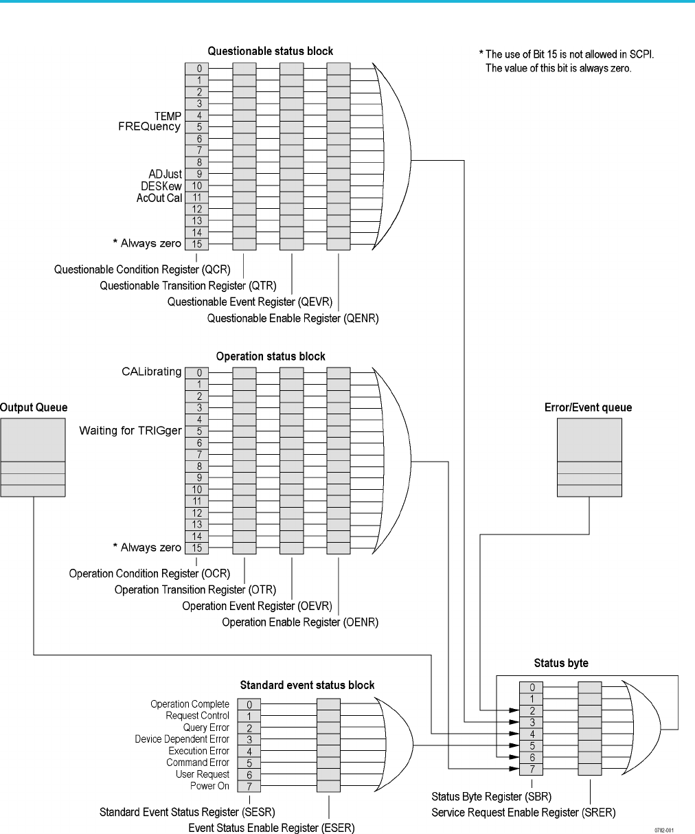
Status and events
Figure 3-1: Status/Event reporting mechanism
3-2 AWG5200 Series Programmer Manual
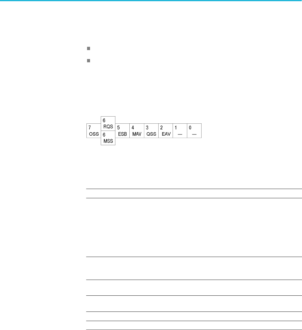
Status and events
Status byte
The Status Byte contains the following two registers
Status Byte Register (SBR)
Service Request Enable Register (SRER)
Status Byte Register (SBR) The SBR is made up of 8 bits. Bits 4, 5 and 6 are defined in accordance with
IEEE Std 488.2. These bits are used to monitor the output queue, SESR and
service requests, respectively. The contents of this register are returned when the
*STB? query is used.
Figure 3-2: Status Byte Register (SBR)
Table 3-2: SBR bit functions
Bit Description
7Operation Summary Status (OSS). Summary of the operation status register.
6Request Service (RQS)/Master Status Summary (MSS). When the instrument is
accessed using the serial poll command, this bit is called the Request Service
(RQS) bit and indicates to the controller that a service request has occurred.
The RQS bit is cleared when serial poll ends.
When the instrument is accessed using the *STB? query, this bit is called the
Master Status Summary (MSS) bit and indicates that the instrument has issued
a service request for one or more reasons. The MSS bit is never cleared to
0 by the *STB? query.
5Event Status Bit (ESB). This bit indicates whether or not a new event has
occurred after the previous Standard Event Status Register (SESR) has been
cleared or after an event readout has been performed.
4Message Available Bit (MAV). This bit indicates that a message has been
placed in the output queue and can be retrieved.
3Questionable Summary Status (QSS). Summary of the Questionable Status
Byte register.
2Event Quantity Available (EAV). Summary of the Error Event Queue.
1-0 Not used
Service Request Enable
Register (SRER)
The SRER is made up of bits defined exactly the same as bits 0 through 7 in
the SBR as shown in the following figure. This register is used by the user to
determine what events will generate service requests.
The SRER bit 6 cannot be set. Also, the RQS is not maskable.
AWG5200 Series Programmer Manual 3-3
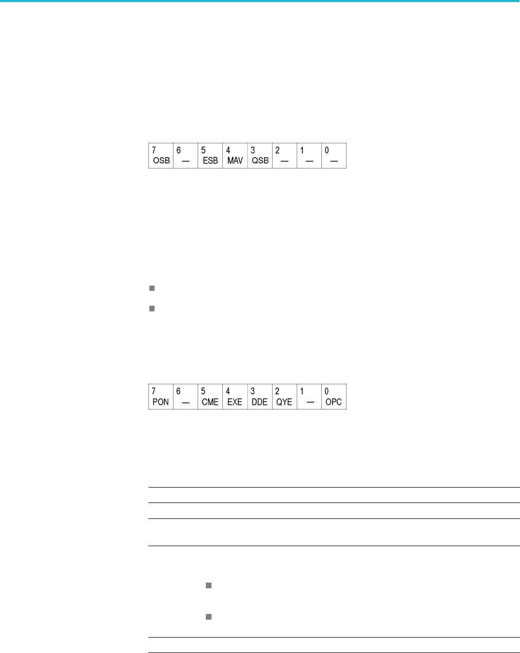
Status and events
The generation of a service request with the GPIB interface involves changing
the SRQ line to LOW and making a service request to the controller. The result
is that a status byte for which an RQS has been set is returned in response to
serial polling by the controller.
Use the *SRE command to set the bits of the SRER. Use the *SRE? query to read
the contents of the SRER. Bit 6 must normally be set to 0.
Figure 3-3: Service Request Enable Register (SRER)
Standard Event Status Block (SESB)
Reports the power on/off state, command errors, and the running state. It consists
of the following registers
Standard Event Status Register (SESR)
Event Status Enable Register (ESER)
These registers are made up of the same bits definedinthefollowingfigure and
table. Use the *ESR? query to read the contents of the SESR. Use the *ESE()
command to access the ESER.
Figure 3-4: Standard event status register
Table 3-3: Standard event status register bit definition
Bit Description
7Power On (PON). Indicates that the power to the instrument is on.
6 Not used.
5Command Error (CME). Indicates that a command error has occurred while
parsing by the command parser was in progress.
4Execution Error (EXE). Indicates that an error occurred during the execution of
a command. Execution errors occur for one of the following reasons
When a value designated in the argument is outside the allowable range of
the instrument, or is in conflict with the capabilities of the instrument.
When the command could not be executed properly because the conditions
for execution differed from those essentially required.
3Device-Dependent Error (DDE). An instrument error has been detected.
3-4 AWG5200 Series Programmer Manual
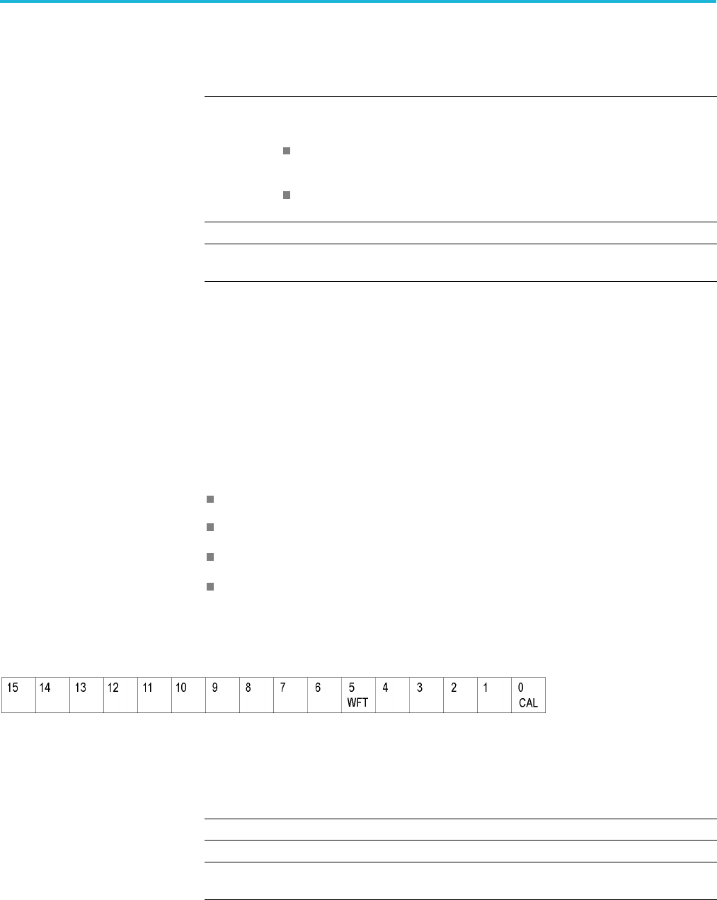
Status and events
Table 3-3: Standard event status register bit definition (cont.)
Bit Description
2Query Error (QYE). Indicates that a query error has been detected by the output
queue controller. Query errors occur for one of the following reasons
An attempt was made to retrieve messages from the output queue, despite
the fact that the output queue is empty or in pending status.
The output queue messages have been cleared despite the fact that they
have not been retrieved.
1 Not used.
0Operation Complete (OPC). This bit is set with the results of the execution of the
*OPC command. It indicates that all pending operations have been completed.
When an event occurs, the SESR bit corresponding to the event is set, resulting in
the event being stacked in the Error/Event Queue. The SBR OAV bit is also set. If
the bit corresponding to the event has also been set in the ESER, the SBR ESB bit
is also set. When a message is sent to the Output Queue, the SBR MAV bit is set.
Operation status block
The operation status block contains conditions that are part of the instrument's
normal operation. It consists of the following registers
Operation Condition Register (OCR)
Operation Positive/ Negative Transition Register (OPTR/ONTR)
Operation Event Register (OEVR)
Operation Enable Register (OENR)
These registers are made up of the same bits defined in the following table and
figure. Use the STATus:OPERation commands to access the operation status
register set.
Figure 3-5: Operation status register
Table 3-4: Operation status register bit definition
Bit Description
15 Always zero (0).
14 - 6 Not used.
5Waiting for trigger (WFT). Indicates that the instrument is waiting for a trigger
event to occur.
AWG5200 Series Programmer Manual 3-5
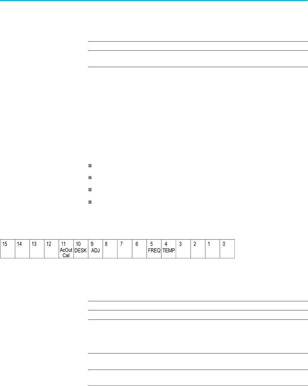
Status and events
Table 3-4: Operation status register bit definition (cont.)
Bit Description
4 - 1 Not used.
0Calibrating (CAL). Indicates that the instrument is currently performing a
calibration.
When the specified state changes in the OCR, its bit is set or reset. This change is
filtered with a transition register, and the corresponding bit of the OEVR is set.
If the bit corresponding to the event has also been set in the OENR, the SBR
OSS bit is also set.
Questionable status block
The questionable status register set contains bits which give an indication of the
quality of various aspects of the signal together with the fanned out registers as
described in the next subsections. It consists of the following registers
Questionable Condition Register (QCR)
Questionable Positive/Negative Transition Register (QPTR/QNTR)
Questionable Event Register (QEVR)
Questionable Enable Register (QENR)
These registers are made up of the same bits defined in the following table and
figure. Use the STATus:QUEStionable commands to access the questionable
status register set.
Figure 3-6: Questionable status register
Table 3-5: Questionable status register bit definition
Bit Description
15 Always zero (0).
14 – 12 Not used.
11 AcOut Calibration (AC)
AC output is operating outside of calibrated limits.
Adjustments of A1, A2, A3, and Dac may create amplitudes that are above or
below calibrated limits.
10 DESKew
Deskew calibration required due to temperature out of range.
9ADJust (ADJ).
External clock adjustment required.
3-6 AWG5200 Series Programmer Manual

Status and events
Table 3-5: Questionable status register bit definition (cont.)
Bit Description
8–6 Notused
5FREQuency (FREQ).
Using External Reference or frequency is out of range.
4TEMPerature (TEMP).
Calibration required due to instrument temperature change.
3–0 Notused.
When the specified state changes in the QCR, its bit is set or reset. This change is
filtered with a transition register, and the corresponding bit of the QEVR is set.
If the bit corresponding to the event has also been set in the QENR, the SBR
QSS bit is also set.
Queues
There are two types of queues in the status reporting system used in the
instrument: output queues and event queues.
Output queue The output queue is a FIFO (first in, first out) queue and holds response messages
to queries, where they await retrieval. When there are messages in the queue,
the SBR MAV bit is set.
The output queue will be emptied each time a command or query is received, so
the controller must read the output queue before the next command or query
is issued. If this is not done, an error will occur and the output queue will be
emptied; however, the operation will proceed even if an error occurs.
Event queue The event queue is a FIFO queue and stores events as they occur in the
instrument. If more than 32 events occur, event 32 will be replaced with event
code -350 ("Queue Overflow"). The error code and text are retrieved using the
SYSTem:ERRor queries.
AWG5200 Series Programmer Manual 3-7
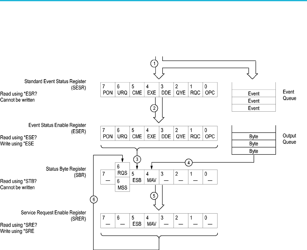
Status and events
Status and event processing sequence
The following figure shows an outline of the sequence for status and event
processing.
Figure 3-7: Status and event processing sequence
1. If an event has occurred, the SESR bit corresponding to that event is set and
the event is placed in the event queue.
2. A bit corresponding to that event in the ESER has is set.
3. The SBR ESB bit is set to reflect the status of the ESER.
4. When a message is sent to the output queue, the SBR MAV bit is set.
5. Setting either the ESB or MAV bits in the SBR sets the respective bit in the
SRER.
6. When the SRER bit is set, the SBR MSS bit is set and a service request is
generated when using the GPIB interface.
3-8 AWG5200 Series Programmer Manual

Status and events
Synchronizing execution
Almost all commands are executed in the order in which they are sent from the
controller. However, some commands perform data analysis in another thread, and
another command can thus be executed concurrently. These types of commands
are called overlapping commands. (See page 2-9, Sequential, blocking, and
overlapping commands.)
Some examples of these types of commands include the following.
AWGControl:RUN
CLOCk:JITTer
MMEMory:SAVE:WFMX
You have two options to achieve command synchronization.
Using the status and event reporting function
Using synchronizing commands
Using the status and event
reporting function
In the following example, the Operation Condition Register (OCR) is being used
to provide synchronization.
STATus:OPERation:NTRansition 32
// Set the filter of the OCR Waiting for Trigger bit
STATus:OPERation:ENABle 32
// Enable the filter of the OCR Waiting for Trigger bit
*SRE 128
// Set the SRER OSS bit
The command waits for generation of SRQ.
Using synchronizing
commands
The IEEE-488.2 common commands include the following synchronizing
commands
*OPC
*OPC?
*WAI
Using the *OPC command. The*OPCcommandcausestheAWGtosensethe
internal flag referred to as the “No-Operation-Pending” flag. (An on-going
overlapped command would be an operation that is pending.) When the pending
operation has completed, the Operation Complete (OPC) bit in the Event Status
Register (ESR) is set. The user can poll the ESR register (*ESR?) or enable the
service request process to be notified.
Using the *OPC? query. The *OPC? query causes the AWG to sense the internal
flag referred to as the “No-Operation-Pending flag (same as the *OPC command).
AWG5200 Series Programmer Manual 3-9

Status and events
When the pending operation has completed, a “1” will be returned to the client.
This query does not use the ESR register and the service request process does
not work.
Using the *WAI command. The *WAI command causes the AWG to sense the
same internal flag, referred to as the No-Operation-Pending” flag. The *WAI
command prevents any command or query from executing until any pending
operation completes.
3-10 AWG5200 Series Programmer Manual

Error messages and codes
Error messages and codes
Error codes with negative values are SCPI standard codes. Error codes with
positive values are unique to the AWG5200 Series Arbitrary Waveform
Generators.
Event codes and messages can be obtained by using the queries SYSTem:ERRor?
and SYSTem:ERRor:ALL? These are returned in the following format
Command errors
Command errors are returned when there is a syntax error in the command.
Table 3-6: Command errors
Error code Error message
-100 Command
-101 Invalid character
-102 Syntax
-103 Invalid separator
-104 Data type
-105 GET not allowed
-108 Parameter not allowed
-109 Missing parameter
-110 Command header
-111 Header separator
-112 Program mnemonic too long
-113 Undefined header
-114 Header suffix out of range
-120 Numeric data
-121 Invalid character in number
-123 Exponent too large
-124 Too many digits
-128 Numeric data not allowed
-130 Suffix
-131 Invalid suffix
-134 Suffix too long
-138 Suffix not allowed
AWG5200 Series Programmer Manual 3-11

Error messages and codes
Table 3-6: Command errors (cont.)
Error code Error message
-140 Character data
-141 Invalid character data
-144 Character data too long
-148 Character data not allowed
-150 String data
-151 Invalid string data
-158 String data not allowed
-160 Block data
-161 Invalid block data
-168 Block data not allowed
-170 Expression
-171 Invalid expression
-178 Expression data not allowed
-180 Macro
-181 Invalid outside macro definition
-183 Invalid inside macro definition
-184 Macro parameter
Execution errors
These error codes are returned when an error is detected while a command is
being executed.
Table 3-7: Execution errors
Error code Error message
-200 Execution
-201 Invalid while in local
-202 Settings lost due to RTL
-210 Trigger
-211 Trigger ignored
-212 Arm ignored
-213 Init ignored
-214 Trigger deadlock
-215 Arm deadlock
3-12 AWG5200 Series Programmer Manual

Error messages and codes
Table 3-7: Execution errors (cont.)
Error code Error message
-220 Parameter
-221 Settings conflict
-222 Data out of range
-223 Too much data
-224 Illegal parameter value
-225 Out of memory
-226 Lists not same length
-230 Data corrupt or stale
-231 Data questionable
-240 Hardware
-241 Hardware missing
-250 Mass storage
-251 Missing mass storage
-252 Missing media
-253 Corrupt media
-254 Media full
-255 Directory full
-256 Filename not found
-257 Filename
-258 Media protected
-260 Execution expression
-261 Math in expression
-270 Execution macro
-271 Macro syntax
-272 Macro execution
-273 Illegal macro label
-274 Execution macro parameter
-275 Macro definition too long
-276 Macro recursion
-277 Macro redefinition not allowed
-278 Macro header not found
-280 Program
-281 Cannot create program
-282 Illegal program name
-283 Illegal variable name
-284 Program currently running
-285 Program syntax
AWG5200 Series Programmer Manual 3-13

Error messages and codes
Table 3-7: Execution errors (cont.)
Error code Error message
-286 Program runtime
-290 Memory use
-291 Out of memory
-292 Referenced name does not exist
-293 Referenced name already exists
-294 Incompatible type
Device specific errors
These error codes are returned when an internal instrument error is detected. This
type of error can indicate a hardware problem or programming error.
Table3-8: Devicespecificerrors
Error code Error message
-300 Device specific or sequence step error
-310 System
-311 Memory
-312 PUD memory lost
-313 Calibration memory lost
-314 Save/Recall memory lost
-315 Configuration memory lost
-320 Storage fault
-321 Out of memory
-330 Self test failed
-340 Calibration failed
-350 Queue overflow
-360 Communication
-361 Parity in program message
-362 Framing in program message
-363 Input buffer overrun
3-14 AWG5200 Series Programmer Manual

Error messages and codes
Query and system errors
These error codes are returned in response to an unanswered query.
Table 3-9: Query errors
Error code Error message
-400 Query error
-410 Query interrupted
-420 Query unterminated
-430 Query deadlocked
-440 Query unterminated after indefinite period
-500 Power on
-600 User request
-700 Request control
-800 Operation complete
Instrument specific error codes
These error codes and messages are unique to the AWG5200 Series instruments.
Table 3-10: Device errors
Error code Error message
500 Calibration in process.
501 Waiting for trigger.
550 Lost frequency lock with External Reference source.
551External Reference frequency out of range.
552 Calibration recommended, temperature change.
553 Ext Clk adjustment recommended for frequency change.
554 Ext Clk adjustment recommended for temperature change.
555 Deskew Calibration recommended.
556 Synchronization Adjust recommended on master.
557 Sync Clock unlocked. Lost frequency lock with Clock In provided
by the system – unable to play.
558 Sync Frequency out of range. Clock In frequency is higher or
lower than the specified range or the value specified by the
system.
559 Configuration recommended on Master. Configure the system
on the Master or adjust if already configured to properly
synchronize the system.
AWG5200 Series Programmer Manual 3-15

Error messages and codes
Table 3-10: Device errors (cont.)
Error code Error message
560 AC Out amplitude beyond calibrated range.
A1, A2, A3 and Dac are adjusted such that the amplitude/power
is above the calibrated limit.
1000 Waveform allocation failed.
Not enough memory for waveform – unable to complete the
operation.
1001 Registry write failed.
1002 Option 03 (Sequencing) not enabled – unable to complete the
operation.
1100 Function generator failed.
Unable to generate the defined waveform.
1101 Clock settings changed. Functions mode uses internal clock
and no jitter reduction.
1102 Function generator frequency too high; waveform too short.
1103 Function generator frequency too low; waveform too long
1104 Function generator hardware failed.
1200 Load failure, unable to load waveform or sequence.
1201 Waveform load max length error, waveform length exceeds
maximum samples - unable to load waveform.
Maximum length is based on sample rate and options.
1202 Waveform load min length error, waveform length less than
minimum samples - unable to load waveform.
Use Modify waveform to increase the number of waveform
points by adding points or repeating the waveform.
1203 Waveform load granularity error, length is not divisible by
granularity - unable to load waveform.
Use Modify waveform to add or subtract one point or repeat the
waveform for 2 cycles.
1204 Play failed, no waveform assigned; not all enabled channels
have waveforms assigned.
1205 Play failed, no waveform assigned to enabled channel.
1206 Play failed, resampled waveform exceeds maximum.
Use Modify waveform to decrease the number of waveform
points.
1207 Play failed, resampled waveform too small.
Use Modify waveform to increase the number of waveform
points.
1208 Play failed, waveform granularity error. Resampled waveform
length not divisible by granularity.
1209 Play failed, hardware failure.
1210 Play failed to stop, hardware failure.
3-16 AWG5200 Series Programmer Manual

Error messages and codes
Table 3-10: Device errors (cont.)
Error code Error message
1212 Sample rate not available, requested sample rate is not
available; sample rate set to nearest value.
1213 Failed to load sequence, sequence step count exceeds
hardware limit.
1214 Failed to load sequence, sequence step has no asset assigned.
1215 Failed to load sequence, repeat count of Sequence step
exceeds hardware limit.
1216 Failed to load sequence, sequence step contains invalid Goto
step.
1217 Failed to load sequence, sequence step contains invalid Event
Jump step.
1218 Failed to load sequence, pattern jump table contains invalid
jump target.
1219 Hardware error, unable to load waveform or sequence due to
hardware error.
1220 Empty sequence, sequence is empty - unable to load.
1221 Failed to load sequence, sequence step must contain waveforms
of equal length.
1222 Failed to load sequence, pattern jump table size exceeds
hardware limit.
1223 Failed to load sequence, total waveform(s) length exceeds
maximum samples.
1224 Failed to find sequence, no sequence definition was found in
the file.
1225 Failed to load sequence, subsequence step has no waveform
assigned
1226 Failed to load sequence, repeat count of subsequence exceeds
hardware limit.
1227 Failed to load sequence, subsequence step contains invalid
Goto step.
1228 Failed to load sequence, subsequence step must contain
waveforms of equal length.
1229 Failed to play, sample rate must be set without failure before
play may begin.
1230 Failed to play, AWG is in calibration/diagnostic mode.
1231 Failed to play, clock must be locked before play may begin.
1232 Failed to load sequence, subsequence does not contain track.
1300 Unknown exception, unable to save file.
1301 File save error, unknown error - unable to save waveform.
1302 File restore error, unknown error - unable to open asset from
setup file.
AWG5200 Series Programmer Manual 3-17

Error messages and codes
Table 3-10: Device errors (cont.)
Error code Error message
1303 Unknown exception, unable to open waveform.
1304 Duplicate waveform name, a waveform with that name is already
in the Waveform List.
1307 File access error, cannot access the file because it is being used
by another process.
1308 Recall waveform failed, missing parameter.
1309 Recall waveform failed, unsupported number of bits.
1310 Recall waveform failed, invalid marker type. Marker data must
be UInt8.
1311 Recall waveform failed, invalid marker data length.
1312 Recall waveform failed, waveform name and/or data not found.
1313 Recall waveform failed, unsupported waveform file type.
1314 Recall waveform failed, invalid sample data.
1315 Recall waveform failed, unable to read sample data.
1316 Recall waveform failed, unable to read Matlab HDF5 data set.
1317 Recall waveform failed, invalid IQ data format.
1318 Recall waveform failed, invalid DPX spectral data format.
1319 Recall waveform failed, invalid RSA header format.
1320 Recall waveform failed, data length error.
1321 Recall waveform failed, invalid data format.
1322 Recall waveform failed, invalid marker data format.
1323 Recall waveform failed, invalid file extension.
1324 Recall waveform failed, invalid file header.
1325 Recall waveform failed, file type unknown.
1326 Recall waveform failed, file version not supported.
1327 Recall waveform failed, no waveform data.
1328 Asset not found, unable to import asset(s).
1329 Recall waveform failed, unable to open waveform from RSA file.
1330 Recall waveform failed, waveform format not supported.
1331 Invalid operation.
1332 Read failed, unable to open file.
1333 Export failed to write file.
1334 Recall waveform failed, unable to read filed.
1335 Export failed, out of disk space.
1336 File not found.
1337 File format error, file format not valid - unable to open file.
1338 Failed to delete file.
3-18 AWG5200 Series Programmer Manual

Error messages and codes
Table 3-10: Device errors (cont.)
Error code Error message
1340 Invalid save type, save type not valid - unable to save file.
1341 Asset name error, asset list already has an asset with that name
- unable to save file.
1342 Asset not found, item is not in the Asset List - unable to save file.
1343 Recall failed, IQ waveform error.
1344 Restore setup failed, unable to open setup file.
1345 Error in file format or data, unable to restore the sequence and
it's assets.
1346 Subsequences not supported, restored subsequences will
be added to the Sequence List, but the sequence steps they
occupied will be shown as Empty.
1347 Missing asset file(s), waveform or sequence file(s) not found;
shown as Empty in the sequence table.
1348 Restore pattern table error, Pattern Jump table has too many
rows; Restored the first 256 patterns only.
1349 Failed to open waveform in editor, Waveform was not created
by this editor.
1400 Waveform Editor error, unable to start waveform editor.
1500 Capture and Playback, compile failed.
1501 Capture and Playback, failed to add signal.
1502 Capture and Playback, compiled failed.
More than one signal selected to compile and assign to channel;
Select only one signal to assign to channel.
1503 Capture and Playback, compile failed.
Invalid channel ID.
1504 Capture and Playback, compile failed.
No signal selected to compile.
1600 Timing error, unable to change clock setting.
1601 Timing error, lost timing lock.
1602 Channel error, unable to change channel parameter.
1603 USB lock/unlock failed.
Administrator permissions are required to lock or unlock the
USB ports. Check the Windows security settings or contact your
network administrator.
1604 Force Jump error, unable to force jump to specified step.
1605 External Clock adjustment failed, check the Clock In signal.
1606 External Clock error, clock In differs from external clock
adjustments - Check the Clock In signal or Adjust.
1607 External Clock detection and adjustment failed, check the Clock
In signal.
AWG5200 Series Programmer Manual 3-19

Error messages and codes
Table 3-10: Device errors (cont.)
Error code Error message
1608 External Clock detection failed, Clock In signal outside of range.
1609 External Reference detection failed, Reference In signal outside
of range.
1701 Waveform Editor failure.
Failed to resample waveform.
1702 Waveform Editor failure.
Resampling ratio too small - unable to resample the waveform.
1703 Waveform Editor failure.
Resampling ratio too large - unable to resample the waveform.
1704 Waveform Editor failure.
Shift/rotate failed - unable to modify waveform.
1705 Waveform Editor failure.
Compile failed - another compile operation already in progress.
1707 Waveform Editor failure.
Compile failed - can't modify a waveform that is being played out.
1708 Waveform Editor failure.
Compiler warning, clock pattern truncated.
1709 Waveform Editor failure.
Compile error - cursor values out of range
1710 Waveform Editor failure.
Compile error - number of steps must be a positive number.
1750 Step number exceeds max, exceeds max number of steps -
failed to add step(s).
1751 Invalid step, invalid step specified.
1752 Add step(s) failure, failed to add step(s) to sequence.
1753 Insert step(s) failure, failed to insert step(s) to sequence.
1754 Remove step(s) failure, failed to remove step(s) from sequence.
1755 Failed to add track, exceeded maximum number of tracks.
1756 Failed to remove track, sequence must have at least one track.
1757 Invalid track number, invalid track number specified.
1758 Add track error, failed to add track.
1759 Remove track error, failed to remove track.
1760 Sequence name in use, name already used in Sequence List
- unable to create sequence.
1761 Sequence creation failed, unable to create sequence.
1762 Paste error, clipboard values do not match paste area data
type(s).
3-20 AWG5200 Series Programmer Manual

Error messages and codes
Table 3-10: Device errors (cont.)
Error code Error message
1763 Unable to set subsequence, a waveform cannot be set as a
subsequence.
1764 Unable to set subsequence, the sequence already contains a
subsequence.
1765 Unable to set subsequence, this sequence is already a
subsequence.
1766 Unable to set subsequence, you cannot set a sequence as a
subsequence of itself.
1767 Unable to set subsequence, the total number of steps exceeds
the maximum number of steps.
1768 Unable to set flag definition, step has a subsequence.
1800 Invalid name, invalid name or handle for asset.
1801 Renaming error, no name given - unable to rename asset.
1802 Asset name in use, name already used in list - unable to rename
asset.
1803 Rename failed, linked file missing.
1804 File name in use, unable to rename asset.
1805 Waveform name in use, name already used in list - unable to
create waveform.
1806 Waveform creation failed, unable to create waveform.
1900 No tests selected in Diagnostics, select one or more tests and
try again.
1902 Diagnostics are still running, abort and try again.
1903 Calibrations are still running. Abort and try again.
2005 Failed to set sample rate on Port 2.
2006 Failed to set sample rate on Port 3.
2007 Failed to set sample rate on Port 4.
2200 Batch Compiler.
Compile failed, failed to parse definition file.
2201 Batch Compiler.
Compile failed, failed to parse definition file.
2202 Batch Compiler.
Compile failed, definition file does not have sample rate
information.
2203 Batch Compiler.
Compile failed, definition file does not contain sequence track
information.
2204 Batch Compiler.
Compile failed, failed to parse definition file: tracks must contain
same number of steps.
AWG5200 Series Programmer Manual 3-21

Error messages and codes
Table 3-10: Device errors (cont.)
Error code Error message
2205 Batch Compiler.
Compile failed, failed to compile waveforms.
2207 Batch Compiler.
Compile failed, invalid definition file"
2208 Batch Compiler.
Compile failed, sequence name in use.
3-22 AWG5200 Series Programmer Manual

Appendices
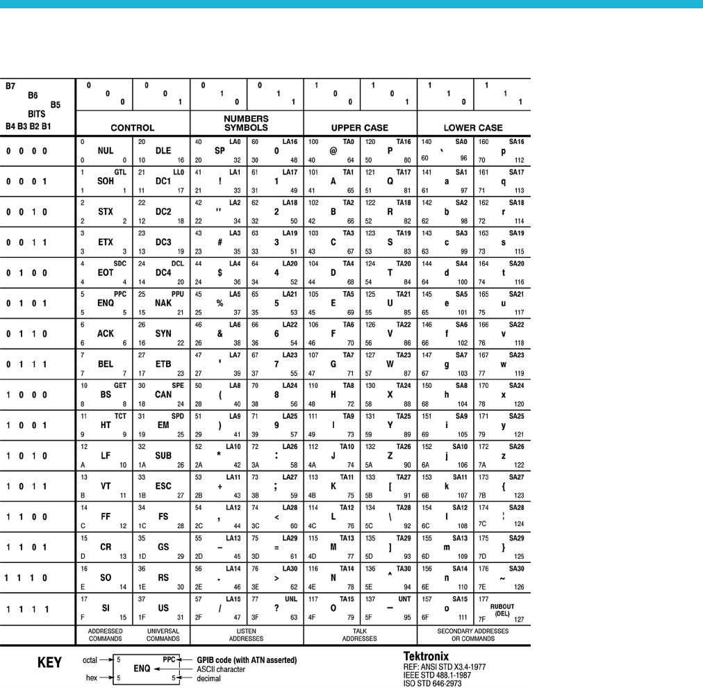
Appendix A: Character charts
AWG5200 Series Programmer Manual A-1

Appendix A: Character charts
A-2 AWG5200 Series Programmer Manual

Appendix B: Raw socket specification
TCP/IP is used as the network protocol, and the port number is variable.
Commands can be sent from the application program through the TCP/IP socket
interface, and queries can be received through the interface.
The Line Feed (LF) code is needed as a terminator at the end of a message.
The IEEE 488.1 standard (for example, Device Clear or Service Request)
is not supported.
The Message Exchange Control Protocol in the IEEE 488.2 is not supported.
However, common commands such as *ESE and the event handling features
are supported.
The Indefinite format (the block start at #0) in the <ARBITRARY BLOCK
PROGRAM DATA> of the IEEE 488.2 is not supported.
AWG5200 Series Programmer Manual B-1

Appendix B: Raw socket specification
B-2 AWG5200 Series Programmer Manual

Appendix C: Factory initialization settings
Commands affected by a factory initialization (*RST command) are listed in the
following table and are also noted in their command description.
NOTE. *RST does not affect waveform plug-ins.
Table C-1: Factory initialization settings
Command Default value
ACTive:MODE NORMal
AWGControl:RMODe CONTinuous
CALibration:LOG:FAILuresonly 0(off)
CLOCk:ECLock:DIVider 1
CLOCk:ECLock:MULTiplier 1
CLOCk:EREFerence:DIVider 1
CLOCk:EREFerence:FREQuency 35 MHz
CLOCk:EREFerence:MULTiplier 1
CLOCk:JITTer 0(off)
CLOCk:OUTPut[:STATe] 0(off)
CLOCk:PHASe[:ADJust[:DEGRees]] 0°
CLOCk:SOURce INTernal
CLOCk:SOUT[:STATe] 0(off)
CLOCk:SRATe 2.5 GS/s
DIAGnostic:CONTrol:COUNt 0
DIAGnostic:CONTrol:HALT 0(off)
DIAGnostic:CONTrol:LOOP ONCE
DIAGnostic:LOG:FAILuresonly 0(off)
DIAGnostic:TYPE NORMal
DISPlay[:PLOT][:STATe] 1 (on)
FGEN[:CHANnel[n]]:AMPLitude[:VOLTage] 500 mV
FGEN[:CHANnel[n]]:FREQuency 1.2 MHz
FGEN[:CHANnel[n]]:DCLevel 0V
FGEN[:CHANnel[n]]:HIGH 250 mV
FGEN[:CHANnel[n]]:LOW –250 mV
FGEN[:CHANnel[n]]:OFFSet 0V
FGEN[:CHANnel[n]]:PHASe 0°
FGEN[:CHANnel[n]]:SYMMetry 100%
FGEN[:CHANnel[n]]:TYPE SINE
INSTrument:COUPle:SOURce 0(off)
AWG5200 Series Programmer Manual C-1

Appendix C: Factory initialization settings
Table C-1: Factory initialization settings (cont.)
Command Default value
INSTrument:MODE AWG
MMEMory:OPEN[:PARameter]:NORMalize NONE
OUTPut:OFF 0(off)
OUTPut[n][:STATe] 0(off)
OUTPut[n]:SVALue[:ANALog][:STATe] ZERO
OUTPut[n]:SVALue:MARKer[m] LOW
OUTPut[n]:WVALue[:ANALog][:STATe] ZERO
OUTPut[n]:WVALue:MARKer[m] LOW
SLISt:SEQuence:EVENt:JTIMing END
SLISt:SEQuence:EVENt:PJUMp:ENABle 0(off)
SLISt:SEQuence:RFLag 1 (on)
SLISt:SEQuence:STEP[n]:EJINput 0(off)
[SOURce:]FREQuency[:CW]|[:FIXed] 8GHz
[SOURce[n]:]DAC:RESolution 10
[SOURce[n]:]MARKer[m]:DELay 0 seconds
[SOURce[n]:]MARKer[m]:VOLTage[:LEVel][:
IMMediate][:AMPLitude]
1V
[SOURce[n]:]MARKer[m]:VOLTage[:LEVel][:
IMMediate]:HIGH
1V
[SOURce[n]:]MARKer[m]:VOLTage[:LEVel][:
IMMediate]:LOW
0V
[SOURce[n]:]MARKer[m]:VOLTage[:LEVel][:
IMMediate]:OFFSet
500 mV
[SOURce:]RCCouple 0(off)
[SOURce[n]:]RMODe CONTinuous
[SOURce[n]:]SKEW 0 seconds
[SOURce[n]:]TINPut ATRigger
[SOURce[n]:]VOLTage[:LEVel][:IMMediate][:
AMPLitude]
500 mV
[SOURce[n]:]VOLTage[:LEVel][:IMMediate]:HIGH 250 mV
[SOURce[n]:]VOLTage[:LEVel][:IMMediate]:LOW –250 mV
SYSTem:ERRor:DIALog 1 (enabled)
TRIGger:IMPedance 50 Ω
TRIGger:LEVel 1.4 V
TRIGger:MODE ASYNchronous
TRIGger:SLOPe POSitive.
TRIGger:SOURce EXTernal
TRIGger:WVALue ZERO
C-2 AWG5200 Series Programmer Manual

Index
A
ABORt, 2-35
ACTive:MODE,2-36
AUXoutput[n]:SOURce, 2-38
AUXoutput[n]:SOURce:CMAPping, 2-39
AWGControl[:CLOCk]:DRATe, 2-41
AWGControl[:CLOCk]:SOURce, 2-43
AWGControl:ARSettings, 2-40
AWGControl:CLOCk:PHASe[:ADJust], 2-42
AWGControl:COMPile, 2-44
AWGControl:CONFigure:CNUMber?, 2-44
AWGControl:PJUMp:JSTRobe, 2-45
AWGControl:PJUMp:SEDGe, 2-46
AWGControl:RMODe, 2-47
AWGControl:RSTate?, 2-48
AWGControl:RUN[:IMMediate], 2-48
AWGControl:SNAMe?, 2-49
AWGControl:SREStore, 2-50
AWGControl:SSAVe, 2-51
AWGControl:STOP[:IMMediate], 2-52
B
BWA
Veform:AMPLitude, 2-53
BWAVeform:AUTO, 2-54
BWAVeform:COMPile, 2-55
BWAVeform:COMPile:CASSign, 2-55
BWAVeform:COMPile:CHANnel, 2-56
BWAVeform:COMPile:NAME, 2-57
BWAVeform:COMPile:PLAY, 2-58
BWAVeform:CYCLe, 2-59
BWAVeform:FDRange, 2-60
BWAVeform:FREQuency, 2-61
BWAVeform:FUNCtion, 2-62
BWAVeform:HIGH, 2-63
BWAVeform:LENGth, 2-64
BWAVeform:LOW, 2-65
BWAVeform:OFFSet, 2-66
BWAVeform:RESet, 2-67
BWAVeform:SRATe, 2-67
C
*CAL?, 2-68
CALibration[:ALL], 2-70
CALibration:ABORt, 2-69
CALibration:CATalog?, 2-71
CALibration:LOG?, 2-72
CALibration:LOG:CLEar, 2-73
CALibration:LOG:FAILuresonly, 2-74
CALibration:RESTore, 2-75
CALibration:RESult?, 2-76
CALibration:RESult:TEMPerature?, 2-78
CALibration:RESult:TIME?, 2-78
CALibration:RUNNing?, 2-79
CALibration:STARt, 2-79
CALibration:STATe:FACTory?, 2-80
CALibration:STATe:USER?, 2-81
CALibration:STOP:STATe?, 2-82
character charts, A-1
CLOCk:ECLock:DIVider, 2-83
CLOCk:ECLock:FREQuency, 2-84
CLOCk:ECLock:FREQuency:DETect, 2-85
CLOCk:ECLock:MULTiplier, 2-86
CLOCk:EREFerence:DIVider, 2-87
CLOCk:EREFerence:FREQuency, 2-88
CLOCk:EREFerence:FREQuency:DETect, 2-89
CLOCk:EREFerence:MULTiplier, 2-90
CLOCk:JITTer, 2-91
CLOCk:OUTPut[:STATe], 2-93
CLOCk:OUTPut:FREQuency?, 2-92
CLOCk:PHASe[:ADJust[:DEGRees]], 2-94
CLOCk:PHASe[:ADJust]:TIMe, 2-95
CLOCk:SOURce, 2-96
CLOCk:SOUT[:STATe], 2-97
CLOCk:SRATe, 2-98
*CLS, 2-99
CPLayback:CAPTure:FILE, 2-100
CPLayback:CAPTure:INSTrument:
OSCilloscope, 2-102
CPLayback:CAPTure:INSTrument:RSA, 2-103
CPLayback:CLISt:NAME?, 2-103
CPLayback:CLISt:SIGNal:DELete, 2-104
CPLayback:CLISt:SIGNal:SCOMpile, 2-105
CPLayback:CLISt:SIGNal:WAVeform:
FOFFset, 2-106
CPLayback:CLISt:SIGNal:WAVeform:
NAME?, 2-107
CPLayback:CLISt:SIGNal:WAVeform:OTIMe, 2-108
AWG5200 Series Programmer Manual Index-1

Index
CPLayback:CLISt:SIGNal:WAVeform:SRATe, 2-109
CPLayback:CLISt:SIGNal:WCOunt?, 2-110
CPLayback:CLISt:SIZE?, 2-110
CPLayback:COMPile, 2-111
CPLayback:COMPile:CFRequency, 2-112
CPLayback:COMPile:LSEQuence, 2-113
CPLayback:COMPile:NORMalize, 2-114
CPLayback:COMPile:SRATe, 2-115
CPLayback:COMPile:SRATe:AUTO, 2-116
D
DIAGnostic[:IMMediate], 2-124
DIAGnostic:ABORt, 2-117
DIAGnostic:CATalog?, 2-118
DIAGnostic:CONTrol:COUNt, 2-120
DIAGnostic:CONTrol:HALT, 2-121
DIAGnostic:CONTrol:LOOP, 2-122
DIAGnostic:DATA?, 2-123
DIAGnostic:LOG?, 2-125
DIAGnostic:LOG:CLEar, 2-126
DIAGnostic:LOG:FAILuresonly, 2-127
DIAGnostic:LOOPs?, 2-128
DIAGnostic:RESult?, 2-129
DIAGnostic:RESult:TEMPerature?, 2-131
DIAGnostic:RESult:TIME?, 2-132
DIAGnostic:RUNNing?, 2-133
DIAGnostic:SELect, 2-134
DIAGnostic:SELect:VERify?, 2-136
DIAGnostic:STARt, 2-137
DIAGnostic:STOP, 2-138
DIAGnostic:STOP:STATe?, 2-139
DIAGnostic:TYPE, 2-140
DIAGnostic:TYPE:CATalog?, 2-141
DIAGnostic:UNSelect, 2-142
DISPlay[:PLOT][:STATe], 2-143
E
error codes, 3-11
*ESE, 2-144
*ESR?, 2-144
F
factory settings, C-1
FGEN[:CHANnel[n]]:AMPLitude[:VOLTage], 2-146
FGEN:[CHANnel[n]]:AMPLitude:POWer, 2-145
FGEN[:CHANnel[n]]:DCLevel, 2-147
FGEN[:CHANnel[n]]:FREQuency, 2-148
FGEN[:CHANnel[n]]:HIGH, 2-149
FGEN[:CHANnel[n]]:LOW, 2-150
FGEN[:CHANnel[n]]:OFFSet, 2-151
FGEN[:CHANnel[n]]:PATH, 2-152
FGEN[:CHANnel[n]]:PERiod?, 2-153
FGEN[:CHANnel[n]]:PHASe, 2-154
FGEN[:CHANnel[n]]:SYMMetry, 2-155
FGEN[:CHANnel[n]]:TYPE, 2-156
I
*IDN?, 2-157
INSTrument:COUPle:SOURce, 2-158
INSTrument:MODE, 2-159
M
MMEMory:CATalog?, 2-160
MMEMory:CDIRectory, 2-161
MMEMory:DATA, 2-162
MMEMory:DATA:SIZE?, 2-164
MMEMory:DELete, 2-165
MMEMory:IMPort, 2-166
MMEMory:IMPort[:PARameter]:NORMalize, 2-168
MMEMory:MDIRectory, 2-169
MMEMory:MSIS, 2-169
MMEMory:OPEN, 2-170
MMEMory:OPEN[:PARameter]:NORMalize, 2-172
MMEMory:OPEN[:PARameter]:SIQ, 2-173
MMEMory:OPEN:SASSet[:WAVeform], 2-177
MMEMory:OPEN:SASSet:SEQuence, 2-174
MMEMory:OPEN:SASSet:SEQuence:
MROPened?, 2-176
MMEMory:OPEN:SETup, 2-178
MMEMory:OPEN:TXT, 2-179
MMEMory:SAVE[:WAVeform][:WFMX], 2-187
MMEMory:SAVE[:WAVeform]:MAT, 2-182
MMEMory:SAVE[:WAVeform]:TIQ, 2-183
MMEMory:SAVE[:WAVeform]:TXT, 2-184
MMEMory:SAVE[:WAVeform]:WFM, 2-186
MMEMory:SAVE:SEQuence , 2-180
MMEMory:SAVE:SETup, 2-181
O
*OPC, 2-188
operation status block, 3-5
*OPT?, 2-189
Index-2 AWG5200 Series Programmer Manual

Index
OUTPut[n][:STATe ] , 2 - 1 9 2
OUTPut[n]:PATH, 2-191
OUTPut[n]:SVALue[:ANALog][:STATe], 2-193
OUTPut[n]:SVALue:MARKer[m], 2-194
OUTPut[n]:WVALue[:ANALog][:STATe], 2-195
OUTPut[n]:WVALue:MARKer[m], 2-196
OUTPut:OFF,2-190
Q
questionable status block, 3-6
queues, 3-7
event, 3-7
output, 3-7
R
raw socket specification, B-1
*RST, 2-197
S
service request enable register (SRER), 3-3
SLISt:NAME?, 2-197
SLISt:SEQuence:AMPLitude, 2-198
SLISt:SEQuence:DELete, 2-199
SLISt:SEQuence:EVENt:JTIMing, 2-200
SLISt:SEQuence:EVENt:PJUMp:DEFine, 2-201
SLISt:SEQuence:EVENt:PJUMp:ENABle, 2-202
SLISt:SEQuence:EVENt:PJUMp:SIZE?, 2-203
SLISt:SEQuence:FREQuency, 2-204
SLISt:SEQuence:LENGth?, 2-205
SLISt:SEQuence:NEW, 2-206
SLISt:SEQuence:OFFSet, 2-207
SLISt:SEQuence:RFLag, 2-208
SLISt:SEQuence:SRATe, 2-209
SLISt:SEQuence:STEP:ADD, 2-210
SLISt:SEQuence:STEP:MAX?, 2-211
SLISt:SEQuence:STEP[n]:EJINput, 2-212
SLISt:SEQuence:STEP[n]:EJUMp, 2-213
SLISt:SEQuence:STEP[n]:GOTO, 2-215
SLISt:SEQuence:STEP[n]:RCOunt, 2-216
SLISt:SEQuence:STEP[n]:TASSet[m]?, 2-218
SLISt:SEQuence:STEP[n]:TASSet[m]:TYPE?, 2-219
SLISt:SEQuence:STEP[n]:TASSet[m]:
WAVeform, 2-220
SLISt:SEQuence:STEP[n]:TASSet:SEQuence, 2-217
SLISt:SEQuence:STEP[n]:TFLag[m]:AFLag, 2-221
SLISt:SEQuence:STEP[n]:TFLag[m]:BFLag, 2-222
SLISt:SEQuence:STEP[n]:TFLag[m]:CFLag, 2-223
SLISt:SEQuence:STEP[n]:TFLag[m]:DFLag, 2-224
SLISt:SEQuence:STEP[n]:WINPut, 2-225
SLISt:SEQuence:STEP:RCOunt:MAX?, 2-211
SLISt:SEQuence:TRACk?, 2-227
SLISt:SEQuence:TRACk:MAX?, 2-227
SLISt:SEQuence:TSTamp?, 2-228
SLISt:SEQuence:WMUSage?, 2-229
SLISt:SIZE?, 2-229
[SOURce:]FREQuency[:CW]|[:FIXed], 2-230
[SOURce:]IQIMode, 2-243
[SOURce:]RCCouple, 2-232
[SOURce:]ROSCillator:MULTiplier, 2-233
[SOURce[n]:]CASSet?, 2-234
[SOURce[n]:]CASSet:CLEar, 2-235
[SOURce[n]:]CASSet:SEQuence, 2-236
[SOURce[n]:]CASSet:TYPE?, 2-237
[SOURce[n]:]CASSet:WAVeform, 2-238
[SOURce[n]:]CFRequency, 2-239
[SOURce[n]:]DAC:RESolution, 2-240
[SOURce[n]:]DDR, 2-241
[SOURce[n]:]DMODe, 2-242
[SOURce[n]]:JUMP:FORCe, 2-244
[SOURce[n]]:JUMP:PATTern:FORCe, 2-245
[SOURce[n]:]MARKer[m]:DELay, 2-246
[SOURce[n]:]MARKer[m]:VOLTage[:LEVel][:
IMMediate][:AMPLitude], 2-247
[SOURce[n]:]MARKer[m]:VOLTage[:LEVel][:
IMMediate]:HIGH, 2-248
[SOURce[n]:]MARKer[m]:VOLTage[:LEVel][:
IMMediate]:LOW, 2-249
[SOURce[n]:]MARKer[m]:VOLTage[:LEVel][:
IMMediate]:OFFSet, 2-250
[SOURce[n]:]POWer[:LEVel][:IMMediate][:
AMPLitude], 2-231
[SOURce[n]:]RMODe, 2-251
[SOURce[n]:]SCSTep?, 2-252
[SOURce[n]:]SKEW, 2-253
[SOURce[n]:]TINPut, 2-254
[SOURce[n]:]VOLTage[:LEVel][:IMMediate][:
AMPLitude], 2-255
[SOURce[n]:]VOLTage[:LEVel][:IMMediate]:
BIAS, 2-256
[SOURce[n]:]VOLTage[:LEVel][:IMMediate]:BIAS:
ENABle, 2-257
[SOURce[n]:]VOLTage[:LEVel][:IMMediate]:
HIGH, 2-258
AWG5200 Series Programmer Manual Index-3

Index
[SOURce[n]:]VOLTage[:LEVel][:IMMediate]:
LOW, 2-259
[SOURce[n]:]VOLTage[:LEVel][:IMMediate]:
OFFSet, 2-260
[SOURce[n]:]WAVeform, 2-261
*SRE, 2-262
standard event status block (SESB), 3-4
status and event,
processing sequence, 3-8
status and events, 3-1
reporting system, 3-1
status byte register (SBR), 3-3
STATus:OPERation[:EVENt]?, 2-263
STATus:OPERation:CONDition?, 2-262
STATus:OPERation:ENABle, 2-263
STATus:OPERation:NTRansition, 2-264
STATus:OPERation:PTRansition, 2-265
STATus:PRESet, 2-266
STATus:QUEStionable[:EVENt]?, 2-268
STATus:QUEStionable:CONDition?, 2-266
STATus:QUEStionable:ENABle, 2-267
STATus:QUEStionable:NTRansition, 2-268
STATus:QUEStionable:PTRansition, 2-269
*STB?, 2-270
SYNChronize:ENABle, 2-276
SYNChronize:TYPE, 2-277
synchronizing execution, 3-9
SYSTem:DATE, 2-270
SYSTem:ERRor[:NEXT]?, 2-273
SYSTem:ERRor:ALL?, 2-271
SYSTem:ERRor:CODE[:NEXT]?, 2-272
SYSTem:ERRor:CODE:ALL?, 2-271
SYSTem:ERRor:COUNt?, 2-272
SYSTem:ERRor:DIALog, 2-273
SYSTem:TIME, 2-274
SYSTem:VERSion?, 2-275
T
*TRG, 2-278
TRIGger[:IMMediate], 2-279
TRIGger:IMPedance, 2-280
TRIGger:INTerval, 2-281
TRIGger:LEVel, 2-282
TRIGger:MODE, 2-283
TRIGger:SLOPe, 2-284
TRIGger:SOURce, 2-285
TRIGger:WVALue, 2-286
*TST?, 2-287
W
*WAI, 2-287
WLISt:LAST?, 2-288
WLISt:LIST?, 2-288
WLISt:NAME?, 2-289
WLISt:SIZE?, 2-289
WLISt:SPARameter:APPLy, 2-290
WLISt:SPARameter:BANDwidth, 2-291
WLISt:SPARameter:BANDwidth:AUTO, 2-292
WLISt:SPARameter:CASCading:AGGRessor[n]:
AMPLitude, 2-294
WLISt:SPARameter:CASCading:AGGRessor[n]:
CTALk, 2-295
WLISt:SPARameter:CASCading:AGGRessor[n]:
DRATe, 2-296
WLISt:SPARameter:CASCading:AGGRessor[n]:
SIGNal, 2-297
WLISt:SPARameter:CASCading:AGGRessor[n]:
SIGNal:FILE, 2-298
WLISt:SPARameter:CASCading:AGGRessor[n]:
SIGNal:PRBS, 2-299
WLISt:SPARameter:CASCading:AGGRessor2[:
ENABle], 2-293
WLISt:SPARameter:CASCading:DEEMbed, 2-300
WLISt:SPARameter:CASCading:STAGe[m]:
DRX[n], 2-301
WLISt:SPARameter:CASCading:STAGe[m]:
DTX[n], 2-303
WLISt:SPARameter:CASCading:STAGe[m]:
ENABle, 2-305
WLISt:SPARameter:CASCading:STAGe[m]:
FILE, 2-306
WLISt:SPARameter:CASCading:STAGe[m]:
RX[n], 2-307
WLISt:SPARameter:CASCading:STAGe[m]:
SSCHeme, 2-309
WLISt:SPARameter:CASCading:STAGe[m]:
TX[n], 2-310
WLISt:SPARameter:CASCading:STYPe, 2-312
WLISt:SPARameter:CASCading:TYPE, 2-313
WLISt:SPARameter:MODE, 2-314
WLISt:SPARameter:NCAScading:AGGRessor[n]:
AMPLitude, 2-316
WLISt:SPARameter:NCAScading:AGGRessor[n]:
CTALk, 2-317
Index-4 AWG5200 Series Programmer Manual

Index
WLISt:SPARameter:NCAScading:AGGRessor[n]:
DRATe, 2-318
WLISt:SPARameter:NCAScading:AGGRessor[n]:
SIGNal, 2-319
WLISt:SPARameter:NCAScading:AGGRessor[n]:
SIGNal:FILE, 2-320
WLISt:SPARameter:NCAScading:AGGRessor[n]:
SIGNal:PRBS, 2-321
WLISt:SPARameter:NCAScading:AGGRessor2[:
ENABle], 2-315
WLISt:SPARameter:NCAScading:DEEMbed, 2-322
WLISt:SPARameter:NCAScading:DRX[n], 2-323
WLISt:SPARameter:NCAScading:DTX[n], 2-325
WLISt:SPARameter:NCAScading:FILE, 2-327
WLISt:SPARameter:NCAScading:LAYout, 2-328
WLISt:SPARameter:NCAScading:RX[n], 2-329
WLISt:SPARameter:NCAScading:SSCHeme, 2-331
WLISt:SPARameter:NCAScading:STYPe, 2-332
WLISt:SPARameter:NCAScading:TX[n], 2-333
WLISt:SPARameter:NCAScading:TYPE, 2-335
WLISt:SPARameter:SFORmat, 2-336
WLISt:WAVeform:ACFile, 2-337
WLISt:WAVeform:ACFile:GAUSsian, 2-338
WLISt:WAVeform:ACFile:GAUSsian:
BANDwidth, 2-339
WLISt:WAVeform:ACFile:RSINc, 2-340
WLISt:WAVeform:ACFile:SKEW, 2-341
WLISt:WAVeform:AMPLitude, 2-342
WLISt:WAVeform:DATA, 2-343
WLISt:WAVeform:DATA:I, 2-345
WLISt:WAVeform:DATA:Q, 2-347
WLISt:WAVeform:DELete, 2-349
WLISt:WAVeform:FREQuency, 2-350
WLISt:WAVeform:GRANularity?, 2-351
WLISt:WAVeform:INVert, 2-351
WLISt:WAVeform:LENGth?, 2-352
WLISt:WAVeform:LMAXimum?, 2-352
WLISt:WAVeform:LMINimum?, 2-353
WLISt:WAVeform:MARKer:DATA, 2-354
WLISt:WA
Veform:MIQ, 2-356
WLISt:WAVeform:NEW, 2-357
WLISt:WAVeform:NORMalize, 2-358
WLISt:WAVeform:OFFSet, 2-359
WLISt:WAVeform:RESample, 2-360
WLISt:WAVeform:REVerse, 2-361
WLISt:WAVeform:ROTate, 2-361
WLISt:WAVeform:SFORmat, 2-362
WLISt:WAVeform:SHIFt, 2-363
WLISt:WAVeform:SRATe, 2-364
WLISt:WAVeform:TSTamp?, 2-365
WLISt:WAVeform:TYPE?, 2-366
WPLugin:ACTive, 2-366
WPLugin:PLUGins?, 2-367
AWG5200 Series Programmer Manual Index-5
