A528 Cov 1584 AWS A5 28 1996
User Manual: 1584
Open the PDF directly: View PDF ![]() .
.
Page Count: 43
Specification for
Low-Alloy Steel
Electrodes and
Rods for Gas
Shielded Arc
Welding
ANSI/AWS A5.28-96
An American National Standard
COPYRIGHT 2003; American Welding Society, Inc.
Document provided by IHS Licensee=abb offshore/5925731102, User=, 05/20/2003
05:22:29 MDT Questions or comments about this message: please call the Document
Policy Management Group at 1-800-451-1584.
--``,`,`,,`,`,,`,,,,`,`,`,,``,-`-`,,`,,`,`,,`---
550 N.W. LeJeune Road, Miami, Florida 33126
ANSI/AWS A5.28-96
An American National Standard
Approved by
American National Standards Institute
March 29, 1996
Specification for
Low-Alloy Steel Electrodes and Rods
for Gas Shielded Arc Welding
Supersedes AWS A5.28-79
Prepared by
AWS Committee on Filler Metal
Under the Direction of
AWS Technical Activities Committee
Approved by
AWS Board of Directors
Abstract
Classification requirements are specified for solid low-alloy steel electrodes and rods, composite stranded low-alloy
steel electrodes, and composite metal cored low-alloy steel electrodes for gas shielded arc welding.
The requirements for electrodes include chemical composition of the electrode for solid electrodes and rods, and of
the weld metal for composite stranded and composite metal cored electrodes.
Key Words — Filler metal specifications, low-alloy
steel welding electrodes, gas metal
arc welding, plasma arc welding,
low-alloy steel welding rods, metal
cored electrodes, high-strength steel,
solid electrode, gas tungsten arc
welding, stranded electrodes
COPYRIGHT 2003; American Welding Society, Inc.
Document provided by IHS Licensee=abb offshore/5925731102, User=, 05/20/2003
05:22:29 MDT Questions or comments about this message: please call the Document
Policy Management Group at 1-800-451-1584.
--``,`,`,,`,`,,`,,,,`,`,`,,``,-`-`,,`,,`,`,,`---

Statement on Use of AWS American National Standards
All standards (codes, specifications, recommended practices, methods, classifications, and guides) of the American
Welding Society (AWS) are voluntary consensus standards that have been developed in accordance with the rules of the
American National Standards Institute (ANSI). When AWS standards are either incorporated in, or made part of, docu-
ments that are included in federal or state laws and regulations, or the regulations of other governmental bodies, their
provisions carry the full legal authority of the statute. In such cases, any changes in those AWS standards must be ap-
proved by the governmental body having statutory jurisdiction before they can become a part of those laws and regula-
tions. In all cases, these standards carry the full legal authority of the contract or other document that invokes the AWS
standards. Where this contractual relationship exists, changes in or deviations from requirements of an AWS standard
must be by agreement between the contracting parties.
International Standard Book Number: 0-87171-469-8
American Welding Society, 550 N.W. LeJeune Road, Miami, FL 33126
© 1996 by American Welding Society. All rights reserved
Printed in the United States of America
Second Printing
AWS American National Standards are developed through a consensus standards development process that brings
together volunteers representing varied viewpoints and interests to achieve consensus. While AWS administers the process
and establishes rules to promote fairness in the development of consensus, it does not independently test, evaluate, or
verify the accuracy of any information or the soundness of any judgments contained in its standards.
AWS disclaims liability for any injury to persons or to property, or other damages of any nature whatsoever, whether spe-
cial, indirect, consequential or compensatory, directly or indirectly resulting from the publication, use of, or reliance on this
standard. AWS also makes no guaranty or warranty as to the accuracy or completeness of any information published herein.
In issuing and making this standard available, AWS is not undertaking to render professional or other services for or on
behalf of any person or entity. Nor is AWS undertaking to perform any duty owed by any person or entity to someone
else. Anyone using these documents should rely on his or her own independent judgment or, as appropriate, seek the advice
of a competent professional in determining the exercise of reasonable care in any given circumstances.
This standard may be superseded by the issuance of new editions. Users should ensure that they have the latest edition.
Publication of this standard does not authorize infringement of any patent. AWS disclaims liability for the infringement
of any patent resulting from the use or reliance on this standard.
Finally, AWS does not monitor, police, or enforce compliance with this standard, nor does it have the power to do so.
On occasion, text, tables, or figures are printed incorrectly (errata). Such errata, when discovered, are shown on the
American Welding Society web page (www.aws.org) under “Technical” in the Departments column.
Official interpretations of any of the technical requirements of this standard may be obtained by sending a request, in writing,
to the Managing Director, Technical Services Division, American Welding Society, 550 N.W. LeJeune Road, Miami, FL
33126 (see Annex B). With regard to technical inquiries made concerning AWS standards, oral opinions on AWS standards
may be rendered. However, such opinions represent only the personal opinions of the particular individuals giving them.
These individuals do not speak on behalf of AWS, nor do these oral opinions constitute official or unofficial opinions or inter-
pretations of AWS. In addition, oral opinions are informal and should not be used as a substitute for an official interpretation.
This standard is subject to revision at any time by the AWS A5 Committee on Filler Metal. It must be reviewed every
five years, and if not revised, it must be either reapproved or withdrawn. Comments (recommendations, additions, or de-
letions) and any pertinent data that may be of use in improving this standard are required and should be addressed to
AWS Headquarters. Such comments will receive careful consideration by the AWS A5 Committee on Filler Metal and
the author of the comments will be informed of the Committee’s response to the comments. Guests are invited to attend
all meetings of the AWS A5 Committee on Filler Metal to express their comments verbally. Procedures for appeal of
an adverse decision concerning all such comments are provided in the Rules of Operation of the Technical Activities
Committee. A copy of these Rules can be obtained from the American Welding Society, 550 N.W. LeJeune Road,
Miami, FL 33126.
Photocopy Rights
Authorization to photocopy items for internal, personal, or educational classroom use only, or the internal, personal, or
educational classroom use only of specific clients, is granted by the American Welding Society (AWS) provided that the
appropriate fee is paid to the Copyright Clearance Center, 222 Rosewood Drive, Danvers, MA 01923, Tel: 978-750-8400;
online: http://www.copyright.com.
COPYRIGHT 2003; American Welding Society, Inc.
Document provided by IHS Licensee=abb offshore/5925731102, User=, 05/20/2003
05:22:29 MDT Questions or comments about this message: please call the Document
Policy Management Group at 1-800-451-1584.
--``,`,`,,`,`,,`,,,,`,`,`,,``,-`-`,,`,,`,`,,`---

iii
*Advisor
**Deceased
Personnel
AWS Committee on Filler Metal
D. J. Kotecki, Chairman The Lincoln Electric Company
R. A. LaFave, 1st Vice Chairman Elliott Company
J. P. Hunt, 2nd Vice Chairman Inco Alloys International, Incorporated
J. C. Meyers, Secretary American Welding Society
B. E. Anderson AlcoTec Wire Company
R. L. Bateman* Electromanufacturas S. A.
R. Bonneau U.S. Army Research Laboratory
R. S. Brown Carpenter Technology Corporation
R. A. Bushey ESAB Welding and Cutting Products
J. Caprarola, Jr. Consultant
L. J. Christensen* Consultant
R. J. Christoffel Consultant
D. J. Crement Precision Components Corporation
D. D. Crockett The Lincoln Electric Company
R. A. Daemen Hobart Brothers Company
D. A. DelSignore Westinghouse Electric Corporation
H. W. Ebert Exxon Research and Engineering
J. G. Feldstein Foster Wheeler Energy Corporation
S. E. Ferree ESAB Welding and Cutting Products
D. A. Fink The Lincoln Electric Company
G. Hallstrom, Jr. Hallstrom Consultants
R. L. Harris* Consultant
D. C. Helton Consultant
W. S. Howes National Electrical Manufacturers Association
R. W. Jud Chrysler Corporation
R. B. Kadiyala Techalloy Company
G. A. Kurisky Maryland Specialty Wire
N. E. Larson Consultant
A. S. Laurenson Consultant
G. H. MacShane MAC Associates
L. M. Malik* Arctec Canada Limited
M. T. Merlo Consultant
S. J. Merrick McKay Welding Products
A. R. Mertes Ampco Metal, Incorporated
J. W. Mortimer Consultant
C. L. Null Department of the Navy
Y. Ogata* Kobe Steel Limited
J. J. Payne Sverdrup Technology Incorporated
R. L. Peaslee Wall Colmonoy Corporation
E. W. Pickering, Jr. Consultant
M. A. Quintana The Lincoln Electric Company
H. F. Reid* Consultant
S. D. Reynolds, Jr.* Consultant
L. F. Roberts Canadian Welding Bureau
COPYRIGHT 2003; American Welding Society, Inc.
Document provided by IHS Licensee=abb offshore/5925731102, User=, 05/20/2003
05:22:29 MDT Questions or comments about this message: please call the Document
Policy Management Group at 1-800-451-1584.
--``,`,`,,`,`,,`,,,,`,`,`,,``,-`-`,,`,,`,`,,`---

iv
AWS Committee on Filler Metal (continued)
D. Rozet** Consultant
P. K. Salvesen Det Norske Veritas (DNV)
O. W. Seth Chicago Bridge and Iron Company
W. A. Shopp* Consultant
M. S. Sierdzinski ESAB Group, Incorporated
R. G. Sim The Lincoln Electric Company
L. R. Soisson** Welding Consultants, Incorporated
R. W. Straiton* Bechtel Corporation
R. A. Sulit Sulit Engineering
R. D. Sutton ESAB Group, Incorporated
R. A. Swain Euroweld, Limited
J. W. Tackett Consultant
R. D. Thomas, Jr. R. D. Thomas and Company
R. Timerman* Conarco, S. A.
R. T. Webster** Consultant
H. D. Wehr Arcos Alloys
A. E. Wiehe* Consultant
W. L. Wilcox* Consultant
F. J. Winsor* Consultant
K. G. Wold Siemens Power Corporation
AWS Subcommittee on Carbon and Low-Alloy Steel
Electrodes and Rods for Gas Shielded Arc Welding
D. A. Fink, Chairman The Lincoln Electric Company
J. C. Meyers, Secretary American Welding Society
J. C. Bundy Hobart Brothers Company
P. R. Grainger* Continental Steel Corporation
R. B. Kadiyala Techalloy Company
R. H. Kratzenberg Edison Welding Institute
R. A. LaFave Elliott Company
W. A. Marttila Chrysler Corporation
M. T. Merlo Consultant
Y. Ogata* Kobe Steel Limited
C. F. Padden Ford Motor Company
M. P. Parekh Hobart Brothers Company
D. M. Parker MAO/Westinghouse
L. J. Privoznik* Consultant
L. F. Roberts Canadian Welding Bureau
R. B. Smith ESAB Group, Incorporated
R. Timerman* Conarco, S. A.
C. R. Webb Caterpillar, Incorporated
W. L. Wilcox* Consultant
D. W. Yonker, Jr. National Standard Company
*Advisor
**Deceased
COPYRIGHT 2003; American Welding Society, Inc.
Document provided by IHS Licensee=abb offshore/5925731102, User=, 05/20/2003
05:22:29 MDT Questions or comments about this message: please call the Document
Policy Management Group at 1-800-451-1584.
--``,`,`,,`,`,,`,,,,`,`,`,,``,-`-`,,`,,`,`,,`---

v
Foreword
(This Foreword is not a part of ANSI/AWS A5.28-96, Specification for Low-Alloy Steel Electrodes and Rods for Gas
Shielded Arc Welding, but is included for information purposes only.)
The first edition of A5.28 was issued in 1979 as an American Welding Society (AWS) standard. This current docu-
ment is the first revision issued. The format of this standard has been changed to conform to that being used for all filler
metal specifications revised since 1984.
The history of the A5.28 document may be summarized as follows:
AWS A5.28-79 Specification for Low Alloy Steel Filler Metals for Gas Shielded Metal Arc Welding
Comments and suggestions for the improvement of this standard are welcome. They should be sent to the Secretary,
Filler Metal Committee, Technical Services Division, American Welding Society, 550 N.W. LeJeune Road, Miami, FL
33126.
Official interpretations of any of the technical requirements of this standard may be obtained by sending a request, in
writing, to the Managing Director, Technical Services Division, American Welding Society, 550 N.W. LeJeune Road,
Miami, FL 33126. A formal reply will be issued after is has been reviewed by the appropriate personnel following estab-
lished procedures.
COPYRIGHT 2003; American Welding Society, Inc.
Document provided by IHS Licensee=abb offshore/5925731102, User=, 05/20/2003
05:22:29 MDT Questions or comments about this message: please call the Document
Policy Management Group at 1-800-451-1584.
--``,`,`,,`,`,,`,,,,`,`,`,,``,-`-`,,`,,`,`,,`---

vi
Table of Contents
Page No.
Personnel.................................................................................................................................................................... iii
Foreword ................................................................................................................................................................... v
List of Tables ..............................................................................................................................................................vii
List of Figures ............................................................................................................................................................vii
1. Scope.................................................................................................................................................................. 1
Part A—General Requirements
2. Classification ..................................................................................................................................................... 1
3. Acceptance ......................................................................................................................................................... 1
4. Certification ....................................................................................................................................................... 1
5. Units of Measure and Rounding-Off Procedure ................................................................................................ 1
Part B—Tests, Procedures, and Requirements
6. Summary of Tests............................................................................................................................................... 5
7. Retest.................................................................................................................................................................. 5
8. Weld Test Assemblies ........................................................................................................................................ 7
9. Chemical Analysis ............................................................................................................................................. 7
10. Radiographic Test............................................................................................................................................... 9
11. Tension Test .......................................................................................................................................................12
12. Impact Test.........................................................................................................................................................12
13. Diffusible Hydrogen Test...................................................................................................................................12
Part C—Manufacture, Identification, and Packaging
14. Method of Manufacture .....................................................................................................................................15
15. Standard Sizes ....................................................................................................................................................15
16. Finish and Uniformity........................................................................................................................................15
17. Standard Package Forms ....................................................................................................................................15
18. Winding Requirements.......................................................................................................................................15
19. Filler Metal Identification ..................................................................................................................................17
20. Packaging ...........................................................................................................................................................20
21. Marking of Packages..........................................................................................................................................20
Annex—Guide to AWS Specification for Low-Alloy Steel Electrodes and Rods for Gas Shielded Arc Welding
A1. Introduction......................................................................................................................................................21
A2. Classification System ......................................................................................................................................21
A3. Acceptance.......................................................................................................................................................23
A4. Certification .....................................................................................................................................................23
A5. Ventilation During Welding.............................................................................................................................23
A6. Welding Considerations...................................................................................................................................23
A7. Description and Intended Use of Electrodes and Rods ...................................................................................25
A8. Special Tests ....................................................................................................................................................28
A9. Discontinued Classifications ...........................................................................................................................28
A10. General Safety Considerations ........................................................................................................................29
AWS Filler Metal Specifications and Related Documents ........................................................................................33
COPYRIGHT 2003; American Welding Society, Inc.
Document provided by IHS Licensee=abb offshore/5925731102, User=, 05/20/2003
05:22:29 MDT Questions or comments about this message: please call the Document
Policy Management Group at 1-800-451-1584.
--``,`,`,,`,`,,`,,,,`,`,`,,``,-`-`,,`,,`,`,,`---

vii
List of Tables
Table Page No.
1 Chemical Composition Requirements for Solid Electrodes and Rods ........................................................ 2
2 Chemical Composition Requirements for Weld Metal from Composite Electrodes ................................... 3
3 Tension Test Requirements .......................................................................................................................... 4
4 Impact Test Requirements............................................................................................................................ 5
5 Required Tests.............................................................................................................................................. 6
6 Base Metal for Test Assemblies...................................................................................................................10
7 Preheat, Interpass, and Postweld Heat Treatment Temperatures ................................................................. 11
8 Optional Diffusible Hydrogen Requirements ..............................................................................................12
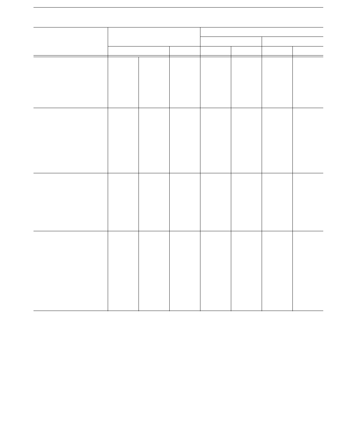
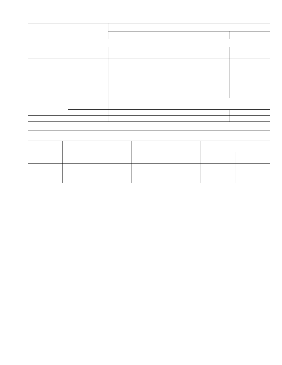
9 Standard Sizes ..............................................................................................................................................16
10 Packaging Requirements..............................................................................................................................17
List of Figures
Figure Page No.
1 Groove Weld Test Assembly for Mechanical Properties and Soundness .................................................... 8
2 Pad for Chemical Analysis of Weld Metal from Composite Electrodes...................................................... 9
3 Radiographic Acceptance Standards............................................................................................................13
4 Tension Test Specimen.................................................................................................................................14
5 Charpy V-Notch Impact Test Specimen.......................................................................................................14
6A Standard Spools—Dimensions of 4 in. Spools............................................................................................18
6B Standard Spools—Dimensions of 8, 12, and 14 in. Spools.........................................................................18
6C Standard Spools—Dimensions of 22, 24, and 30 in. Spools.......................................................................19
A1 Classification System...................................................................................................................................22
A2 Optional GTAW Groove Weld Test Assembly for Mechanical Properties and Soundness .........................24
A3 Optional Tension Test Specimen for Gas Tungsten Arc Welding................................................................26
COPYRIGHT 2003; American Welding Society, Inc.
Document provided by IHS Licensee=abb offshore/5925731102, User=, 05/20/2003
05:22:29 MDT Questions or comments about this message: please call the Document
Policy Management Group at 1-800-451-1584.
--``,`,`,,`,`,,`,,,,`,`,`,,``,-`-`,,`,,`,`,,`---

COPYRIGHT 2003; American Welding Society, Inc.
Document provided by IHS Licensee=abb offshore/5925731102, User=, 05/20/2003
05:22:29 MDT Questions or comments about this message: please call the Document
Policy Management Group at 1-800-451-1584.
--``,`,`,,`,`,,`,,,,`,`,`,,``,-`-`,,`,,`,`,,`---

1
1. Scope
This specification prescribes requirements for the
classification of low-alloy steel electrodes (solid, com-
posite stranded, and composite metal cored) and rods
(solid) for gas metal arc welding (GMAW), gas tungsten
arc welding (GTAW), and plasma arc welding (PAW).
Part A
General Requirements
2. Classification
2.1 The solid electrodes (and rods) covered by this speci-
fication are classified according to the chemical compo-
sition of the electrode, as specified in Table 1, and the
mechanical properties of the weld metal, as specified in
Tables 3 and 4. The composite metal cored and stranded
electrodes covered by this specification are classified
according to the chemical composition and mechanical
properties of the weld metal, as specified in Tables 2, 3,
and 4, and the shielding gas employed.
2.2 Electrodes and rods under one classification shall not
be classified under any other classification in this specifi-
cation, except that ER80S-D2 may also be classified as
ER90S-D2, provided that classification requirements for
both are met.
2.3 The welding electrodes and rods classified under this
specification are intended for gas shielded arc welding,
but that is not to prohibit their use with any other process
(or any other shielding gas or combination of shielding
gases) for which they are found suitable.
3. Acceptance
Acceptance1 of the electrodes and rods shall be in
accordance with the provisions of ANSI/AWS A5.01,
Filler Metal Procurement Guidelines.2
4. Certification
By affixing the AWS specification and classification
designations to the packaging or the classification to the
product, the manufacturer certifies that the product meets
the requirements of this specification.3
5. Units of Measure and Rounding-
Off Procedure
5.1 U.S. customary units are the standard units of mea-
sure in this specification. The SI units are given as equiv-
alent values to the U.S. customary units. The standard
sizes and dimensions in the two systems are not identical
and, for this reason, conversion from a standard size or
dimension in one system will not always coincide with a
standard size or dimension in the other. Suitable conver-
sions, encompassing standard sizes of both, can be made,
however, if appropriate tolerances are applied in each
case.
1. See Section A3, Acceptance (in the Annex), for further
information concerning acceptance, testing of the material
shipped, and ANSI/AWS A5.01, Filler Metal Procurement
Guidelines.
2. AWS standards can be obtained from the American Welding
Society, 550 N.W. LeJeune Road, Miami, FL 33126.
3. See Section A4, Certification (in the Annex) for further
information concerning certification and the testing called for
to meet this requirement.
Specification for Low-Alloy Steel Electrodes
and Rods for Gas Shielded Arc Welding
COPYRIGHT 2003; American Welding Society, Inc.
Document provided by IHS Licensee=abb offshore/5925731102, User=, 05/20/2003
05:22:29 MDT Questions or comments about this message: please call the Document
Policy Management Group at 1-800-451-1584.
--``,`,`,,`,`,,`,,,,`,`,`,,``,-`-`,,`,,`,`,,`---
2
Table 1
Chemical Composition Requirements for Solid Electrodes and Rods
Weight Percenta, b
AWS
ClassificationcUNS
NumberdCMnSiPSNiCrMoVTiZrAlCu
e
Other
Elements
Total
Carbon–Molybdenum Steel Electrodes and Rods
ER70S-A1 K11235 0.12 1.30 0.30–0.70 0.025 0.025 0.20 — 0.40–0.65 — — — — 0.35 0.50
Chromium–Molybdenum Steel Electrodes and Rods
ER80S-B2 K20900 0.07–0.12 0.40–0.70 0.40–0.70 0.025 0.025 0.20 1.20–1.50 0.40–0.65 — — — — 0.35 0.50
ER70S-B2L K20500 0.05 0.40–0.70 0.40–0.70 0.025 0.025 0.20 1.20–1.50 0.40–0.65 — — — — 0.35 0.50
ER90S-B3 K30960 0.07–0.12 0.40–0.70 0.40–0.70 0.025 0.025 0.20 2.30–2.70 0.90–1.20 — — — — 0.35 0.50
ER80S-B3L K30560 0.05 0.40–0.70 0.40–0.70 0.025 0.025 0.20 2.30–2.70 0.90–1.20 — — — — 0.35 0.50
ER80S-B6fS50280 0.10 0.40–0.70 0.50 0.025 0.025 0.604.50–6.00 0.45–0.65 — — — — 0.35 0.50
ER80S-B8gS50480 0.10 0.40–0.70 0.50 0.025 0.025 0.508.00–10.5 0.8–1.2 — — — — 0.35 0.50
ER90S-B9h,i S50482 0.07–0.13 1.25 0.15–0.30 0.010 0.010 1.00 8.00–9.50 0.80–1.10 0.15–0.25 — — 0.04 0.20 0.50
Nickel Steel Electrodes and Rods
ER80S-Ni1 K11260 0.12 1.25 0.40–0.80 0.025 0.025 0.80–1.10 0.15 0.35 0.05 — — — 0.35 0.50
ER80S-Ni2 K21240 0.12 1.25 0.40–0.80 0.025 0.025 2.00–2.75 — — — — — — 0.35 0.50
ER80S-Ni3 K31240 0.12 1.25 0.40–0.80 0.025 0.025 3.00–3.75 — — — — — — 0.35 0.50
Manganese–Molybdenum Steel Electrodes and Rods
ER80S-D2j
ER90S-D2 K10945 0.07–0.12 1.60–2.10 0.50–0.80 0.025 0.025 0.15 — 0.40-0.60 — — — — 0.50 0.50
Other Low-Alloy Steel Electrodes and Rods
ER100S-1 K10882 0.08 1.25–1.80 0.20–0.55 0.010 0.010 1.40–2.10 0.30 0.25–0.55 0.05 0.10 0.10 0.10 0.25 0.50
ER110S-1 K21015 0.09 1.40–1.80 0.20–0.55 0.010 0.010 1.90–2.60 0.50 0.25–0.55 0.04 0.10 0.10 0.10 0.25 0.50
ER120S-1 K21030 0.10 1.40–1.80 0.25–0.60 0.010 0.010 2.00–2.80 0.60 0.30–0.65 0.03 0.10 0.10 0.10 0.25 0.50
ERXXS-G — Not Specifiedk
Notes:
a. The filler metal shall be analyzed for the elements for which values are shown in this table. If the presence of other elements is indicated in the course of this work, the amount of those elements shall
be determined to ensure that their total (excluding iron) does not exceed the limits specified for “Other Elements, Total.”
b. Single values are maximums.
c. The suffixes B2, Ni1, etc., designate the chemical composition of the electrode and rod classification.
d. SAE/ASTM Unified Numbering System for Metals and Alloys.
e. Copper due to any coating on the electrode or rod plus the copper content of the filler metal itself, shall not exceed the stated limit.
f. Similar to former class ER502 in AWS Specification A5.9-81.
g. Similar to former class ER505 in AWS Specification A5.9-81.
h. Niobium (Columbium) 0.02–0.10%
i. Nitrogen 0.03–0.07%
j. This composition was formerly classified E70S-1B in AWS Specification A5.18-69.
k. In order to meet the requirements of the “G” classification, the electrode must have a minimum of one or more of the following: 0.50 percent nickel, 0.30 percent chromium, or 0.20 percent molybde-
num. Composition shall be reported; the requirements are those agreed to by the purchaser and supplier.
COPYRIGHT 2003; American Welding Society, Inc.
Document provided by IHS Licensee=abb offshore/5925731102, User=, 05/20/2003
05:22:29 MDT Questions or comments about this message: please call the Document
Policy Management Group at 1-800-451-1584.
--``,`,`,,`,`,,`,,,,`,`,`,,``,-`-`,,`,,`,`,,`---
3
Table 2
Chemical Composition Requirements for Weld Metal from Composite Electrodesa
Weight Percentb, c
AWS
ClassificationdUNS
NumbereCMnSiPSNiCrMoVTiZrAlCu
Other
Elements
Total
Manganese–Molybdenum Weld Metal
E90C-D2 W19230 0.12 1.00–1.90 0.90 0.025 0.030 — — 0.40–0.60 — — — — 0.35 0.50
Chromium–Molybdenum Weld Metal
E70C-B2L W52130 0.05 0.40–1.00 0.25–0.60 0.025 0.030 0.20 1.00–1.50 0.40–0.65 — — — — 0.35 0.50
E80C-B2 W52030 0.05–0.12 0.40–1.00 0.25–0.60 0.025 0.030 0.20 1.00–1.50 0.40–0.65 — — — — 0.35 0.50
E80C-B3L W53130 0.05 0.40–1.00 0.25–0.60 0.025 0.030 0.20 2.00–2.50 0.90–1.20 — — — — 0.35 0.50
E90C-B3 W53030 0.05–0.12 0.40–1.00 0.25–0.60 0.025 0.030 0.20 2.00–2.50 0.90–1.20 — — — — 0.35 0.50
Nickel Steel Weld Metal
E80C-Ni1 W21030 0.12 1.50 0.90 0.025 0.030 0.80–1.10 — 0.30 — — — — 0.35 0.50
E70C-Ni2 W22030 0.08 1.25 0.90 0.025 0.030 1.75–2.75 — — — — — — 0.35 0.50
E80C-Ni2 W22030 0.12 1.50 0.90 0.025 0.030 1.75–2.75 — — — — — — 0.35 0.50
E80C-Ni3 W23030 0.12 1.50 0.90 0.025 0.030 2.75–3.75 — — — — — — 0.35 0.50
Other Low-Alloy Weld Metal
EXXC-G Not Specifiedf
Notes:
a. Chemical requirements for composite electrodes are based on analysis of their weld metal in the as-welded condition and using the shielding gas specified in Table 3.
b. The weld metal shall be analyzed for the specific elements for which values are shown in this table. If the presence of other elements is indicated in the course of this work, the amount of these elements
shall be determined to ensure that their total (excluding iron) does not exceed the limit specified for “Other Elements, Total.”
c. Single values shown are maximums.
d. Solid electrodes are generally recommended for gas tungsten arc welding (GTAW) or plasma arc welding (PAW).
e. SAE/ASTM Unified Numbering System for Metals and Alloys.
f. In order to meet the requirements of the G classification, the electrode must have as a minimum of one or more of the following: 0.50 percent nickel, 0.30 percent chromium, or 0.20 percent molybde-
num. Composition shall be reported; the requirements are those agreed to by the purchaser and supplier.
COPYRIGHT 2003; American Welding Society, Inc.
Document provided by IHS Licensee=abb offshore/5925731102, User=, 05/20/2003
05:22:29 MDT Questions or comments about this message: please call the Document
Policy Management Group at 1-800-451-1584.
--``,`,`,,`,`,,`,,,,`,`,`,,``,-`-`,,`,,`,`,,`---
4
Table 3
Tension Test Requirements
AWS
Classification Shielding Gasa
Tensile Strength (minimum) Yield Strength (minimum) Elongation
Percent
(minimum)
Testing
Conditionpsi MPa psi MPa
ER70S-B2Lf
E70C-B2Lf
ER70S-A1
Argon/1–5% O2
75 000 515 58 000 400 19
PWHTc
ER80S-B2
E80C-B2 80 000 550 68 000 470 19
ER80S-B3Lf
E80C-B3Lf80 000 550 68 000 470 17
ER90S-B3
E90C-B3 90 000 620 78 000 540 17
ER80S-B6
ER80S-B8 80 000 550 68 000 470 17
ER90S-B9 Argon/5% CO290 000 620 60 000 410 16
E70C-Ni2
Argon/1–5% O2
70 000 480 58 000 400 24 PWHTc
ER80S-Ni1
E80C-Ni1 80 000 550 68 000 470 24 As-Welded
ER80S-Ni2
E80C-Ni2
ER80S-Ni3
E80C-Ni3
80 000 550 68 000 470 24 PWHTc
ER80S-D2 CO280 000 550 68 000 470 17 As-Welded
ER90S-D2
E90C-D2 Argon/1–5% O290 000 620 78 000 540 17 As-Welded
ER100S-1
Argon/2% O2
100 000 690 88 000 610 16
As-WeldedER110S-1 110 000 760 95 000 660 15
ER120S-1 120 000 830 105 000 730 14
ER70S-G
E70C-G (d) 70 000 480 (e) (e) (e) (e)
ER80S-G
E80C-G (d) 80 000 550 (e) (e) (e) (e)
ER90S-G
E90C-G (d) 90 000 620 (e) (e) (e) (e)
ER100S-G
E100C-G (d) 100 000 690 (e) (e) (e) (e)
ER110S-G
E110C-G (d) 110 000 760 (e) (e) (e) (e)
ER120S-G
E120C-G (d) 120 000 830 (e) (e) (e) (e)
Notes:
a. The use of a particular shielding gas for classification purposes shall not be construed to restrict the use of shielding gas mixtures. A filler metal
tested with other gas blends, such as Argon/O2 or Argon/CO2 may result in weld metal having different strength and elongation. Classification with
other gas blends shall be as agreed upon between the purchaser and supplier.
b. Yield strength at 0.2% offset and elongation in 2 in. (51 mm) gage length.
c. Postweld heat-treated condition in accordance with Table 7.
d. Shielding gas shall be as agreed to between purchaser and supplier.
e. Not specified (As agreed to between purchaser and supplier).
f. These classifications were previously ER80S-B2, E80C-B2, ER90S-B3L, and E90C-B3L respectively in AWS A5.28-79. The strength levels have
been adjusted downward as shown, in order to accurately reflect the capability of the classification’s chemical composition ranges.
COPYRIGHT 2003; American Welding Society, Inc.
Document provided by IHS Licensee=abb offshore/5925731102, User=, 05/20/2003
05:22:29 MDT Questions or comments about this message: please call the Document
Policy Management Group at 1-800-451-1584.
--``,`,`,,`,`,,`,,,,`,`,`,,``,-`-`,,`,,`,`,,`---

5
5.2 For the purpose of determining conformance with
this specification, an observed or calculated value shall
be rounded to the nearest 1000 psi for tensile and yield
strength, and to the “nearest unit” in the last right-hand
place of figures used in expressing the limiting value for
other quantities in accordance with the rounding-off
method given in ASTM E29, Recommended Practice for
Using Significant Digits in Test Data to Determine Con-
formance with Specifications.4
Part B
Tests, Procedures, and Requirements
6. Summary of Tests
6.1 The tests required for each classification are speci-
fied in Table 5. The purpose of these tests is to determine
the chemical composition, the mechanical properties,
and soundness of the weld metal. The base metal for the
weld test assemblies, the welding and testing procedures
to be employed, and the results required are given in Sec-
tions 8 through 12.
6.2 The optional test for diffusible hydrogen in Section
13, Diffusible Hydrogen Test, is not required for classifi-
cation [see note (a) of Table 5].
7. Retest
If the results of any test fail to meet the requirement,
that test shall be repeated twice. The results of both
retests shall meet the requirement. Specimens for retest
may be taken from the original test assembly or from one
or two new test assemblies. For chemical analysis, retest
need be only for those specific elements that failed to
meet the test requirement. If the results of one or both
retests fail to meet the requirement, the material under
test shall be considered as not meeting the requirements
of this specification for that classification.
In the event that, during preparation or after comple-
tion of any test, it is clearly determined that prescribed or
proper procedures were not followed in preparing the
weld test assembly or test specimen(s), or in conducting
the test, the test shall be considered invalid, without
regard to whether the test was actually completed, or
whether test results met, or failed to meet, the require-
ment, that test shall be repeated, following proper
prescribed procedures. In this case, the requirement
for doubling the number of test specimens does not
apply.
Table 4
Impact Test Requirements
AWS
Classification
Average Impact Strengtha
(minimum)
Testing
Condition
ER70S-A1
ER70S-B2L
E70C-B2L
ER80S-B2
E80C-B2
ER80S-B3L
E80C-B3L
ER90S-B3
E90C-B3
ER80S-B6
ER80S-B8
ER90S-B9
Not Required —
ER80S-Ni1
E80C-Ni1 20 ft⋅lbf at –50°F (27 J @ –46°C) As-Welded
ER80S-Ni2
E70C-Ni2
E80C-Ni2
20 ft⋅lbf at –80°F (27 J @ –62°C) PWHTb
ER80S-Ni3
E80C-Ni3 20 ft⋅lbf at –100°F (27 J @ –73°C) PWHTb
ER80S-D2
ER90S-D2
E90C-D2
20 ft⋅lbf at –20°F (27 J @ –29°C) As-Welded
ER100S-1
ER110S-1
ER120S-1
50 ft⋅lbf at –60°F (68 J @ –51°C) As-Welded
ERXXXS-G
EXXC-G
As agreed between
purchaser and supplier. —
Notes:
a. Both the highest and lowest of the five test values obtained shall be
disregarded in computing the impact strength.
For classifications requiring 20 ft⋅lbf (27 J): Two of the remaining
three values shall equal or exceed 20 ft⋅lbf (27J); one of the three
remaining values may be lower than 20 ft⋅lbf (27J) but not lower
than 15 ft⋅lbf (20J). The average of the three shall not be less than
the 20 ft⋅lbf (27 J) specified.
For classifications requiring 50 ft⋅lbf (68 J): Two of the remaining
three values shall equal or exceed 50 ft⋅lbf (68 J); one of the three
remaining values may be lower than 50 ft⋅lbf (68 J) but not lower
than 40 ft⋅lbf (54 J). The average of the three shall not be less than
the 50 ft⋅lbf (68 J) specified.
b. Postweld heat treated in accordance with Table 7.
4. ASTM specifications may be obtained from the American
Society for Testing and Materials (ASTM), 100 Barr Harbor
Drive, Conshohocken, PA 19428-2959.
COPYRIGHT 2003; American Welding Society, Inc.
Document provided by IHS Licensee=abb offshore/5925731102, User=, 05/20/2003
05:22:29 MDT Questions or comments about this message: please call the Document
Policy Management Group at 1-800-451-1584.
--``,`,`,,`,`,,`,,,,`,`,`,,``,-`-`,,`,,`,`,,`---
6
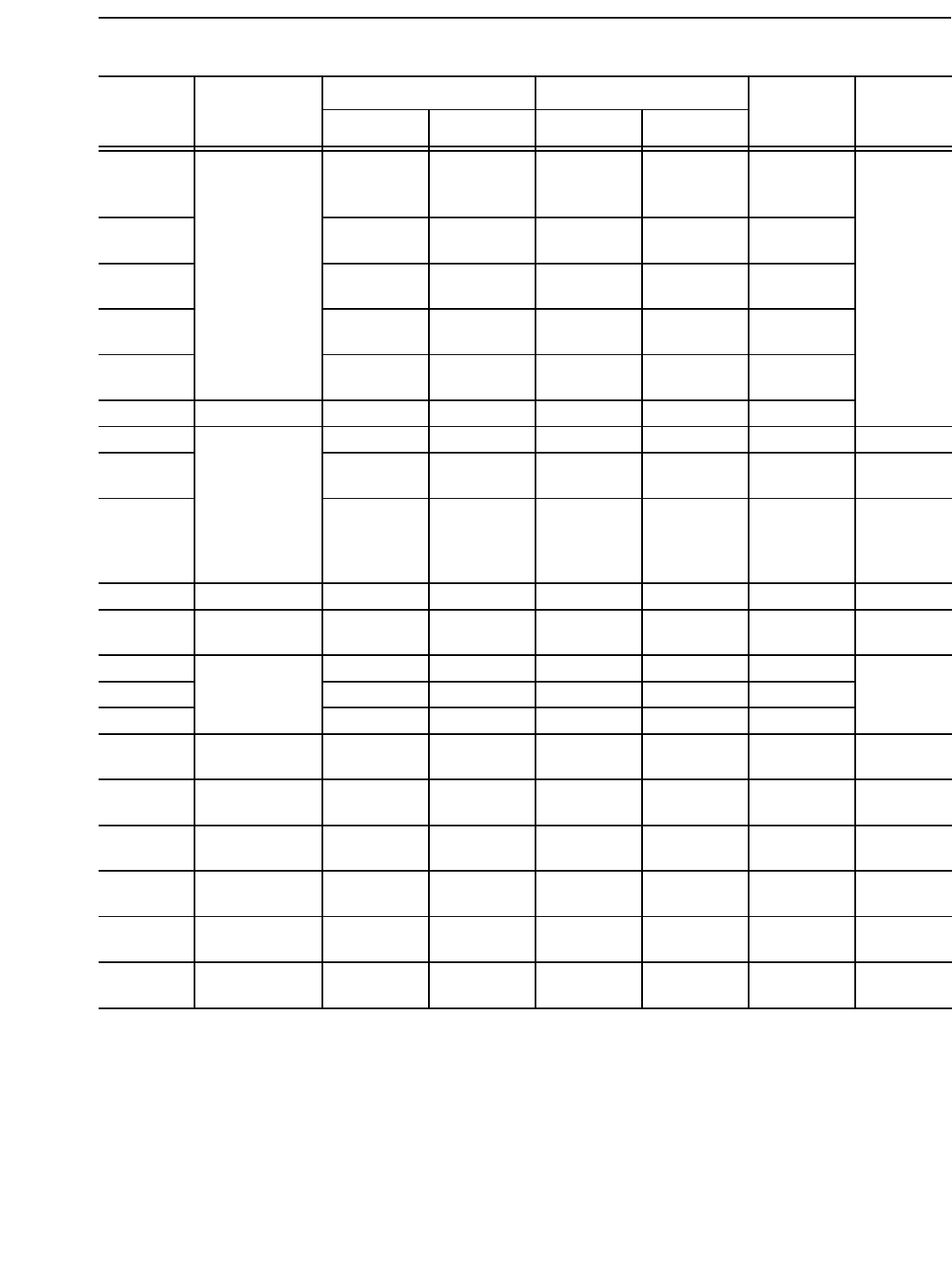
Table 5
Required Tests
AWS
Classification
Chemical Analysis
Radiographic Test Tension Test Impact Test
Diffusible
Hydrogen TestElectrode Weld Metal
Solid Electrodes
ER70S-A1
ER70S-B2L
ER80S-B2
ER80S-B3L
ER90S-B3
ER80S-B6
ER80S-B8
ER90S-B9
Required Not Required Required Required Not Required a
ER80S-Ni1
ER80S-Ni2
ER80S-Ni3
Required Not Required Required Required Required a
ER80S-D2
ER90S-D2 Required Not Required Required Required Required a
ER100S-1
ER110S-1
ER120S-1
Required Not Required Required Required Required a
ERXXS-G RequiredbNot Required Required Required Not Required a
Composite Metal Cored Electrodes
E70C-B2L
E80C-B2
E80C-B3L
E90C-B3
Not Required Required Required Required Not Required a
E70C-Ni2
E80C-Ni1
E80C-Ni2
E80C-Ni3
Not Required Required Required Required Required a
E90C-D2 Not Required Required Required Required Required a
EXXC-G Not Required RequiredbRequired Required Not Required a
Notes:
a. Optional diffusible hydrogen test is required only when specified by the purchaser and the manufacturer puts the diffusible hydrogen designator on
the label (See A2.2 and A8.2 in the Annex).
b. To be reported. See A7.15 in the Annex.
COPYRIGHT 2003; American Welding Society, Inc.
Document provided by IHS Licensee=abb offshore/5925731102, User=, 05/20/2003
05:22:29 MDT Questions or comments about this message: please call the Document
Policy Management Group at 1-800-451-1584.
--``,`,`,,`,`,,`,,,,`,`,`,,``,-`-`,,`,,`,`,,`---

7
8. Weld Test Assemblies
8.1 At least one weld test assembly is required, and two
may be required (depending on the electrode—solid as
opposed to composite—and the manner in which the
sample for chemical analysis is taken), as specified in
Table 5. They are as follows:
(1) The groove weld in Figure 1 for mechanical prop-
erties and soundness of the weld metal for both compos-
ite and solid electrodes
(2) The weld pad in Figure 2 for chemical analysis of
the weld metal from composite stranded and composite
metal cored electrodes
The sample for chemical analysis of weld metal from
composite electrodes may be taken from the reduced sec-
tion of the fractured all-weld-metal tension test specimen
or from the corresponding location in the groove weld in
Figure 1, thereby avoiding the need to make a weld pad.
Alternatively, the sample from the groove weld may be
taken from any location in the weld metal above the ten-
sion test specimen. In case of dispute, the weld pad in
Figure 2 shall be the referee method.
8.2 Preparation of each weld test assembly shall be as
prescribed in 8.3, 8.4, and 8.5. The base metal for each
assembly shall be as required in Table 6, and shall meet
the requirements of the ASTM specification shown
there, or an equivalent specification. Testing of the
assembly shall be as prescribed in 9.2, 9.3, and Sections
10 through 12.
8.3 Groove Weld
8.3.1 For all classifications, a test assembly shall be
prepared and welded as specified in Figure 1, using base
metal of the appropriate type specified in Table 6, and
the preheat and interpass temperature specified in
Table 7. The electrode used shall be 0.045 in. (1.1 mm)
or 1/16 in. (1.6 mm) size (or the size that the manufac-
turer produces that is closest to one of these, if these
sizes are not produced).
Welding shall be in the flat position, and the assembly
shall be restrained (or preset) during welding to prevent
warpage in excess of 5 degrees. An assembly that has
warped more than 5 degrees from plane shall be dis-
carded. It shall not be straightened. The test assembly
shall be tack welded, and welding shall begin at the pre-
heat temperature specified in Table 7.
This interpass temperature shall be maintained for the
remainder of the weld. Should it be necessary to interrupt
welding, the assembly shall be allowed to cool in still air
to room temperature. The assembly shall be preheated to
the temperature shown in Table 7 before welding is
resumed. When welding has been completed and the
assembly has cooled, the assembly shall be prepared and
tested as specified in Sections 10, 11, and 12 in the as-
welded or postweld heat-treated condition, as specified
in Tables 3 and 4.
8.3.2 When required, the test assembly shall be
postweld heat-treated before removal of mechanical test
specimens. This postweld heat treatment may be done
either before or after the radiographic examination.
8.3.2.1 The furnace shall be at a temperature not
higher than 600°F (320°C) when the test assembly is
placed in it. The heating rate, from that point to the spec-
ified holding temperature in Table 7, shall not exceed
400°F per hour (220°C per hour).
8.3.2.2 The test assembly shall be maintained at
the temperature specified in Table 7 for 1 hour (–0, +15
minutes).
8.3.2.3 When the one hour holding time has been
completed, the assembly shall be allowed to cool in the
furnace to a temperature below 600°F (320°C) at a rate
not exceeding 350°F (190°C) per hour. The assembly
may be removed from the furnace at any temperature
below 600°F (320°C) and allowed to cool in still air to
room temperature. Testing of the assembly shall be as
specified in Sections 10 through 12.
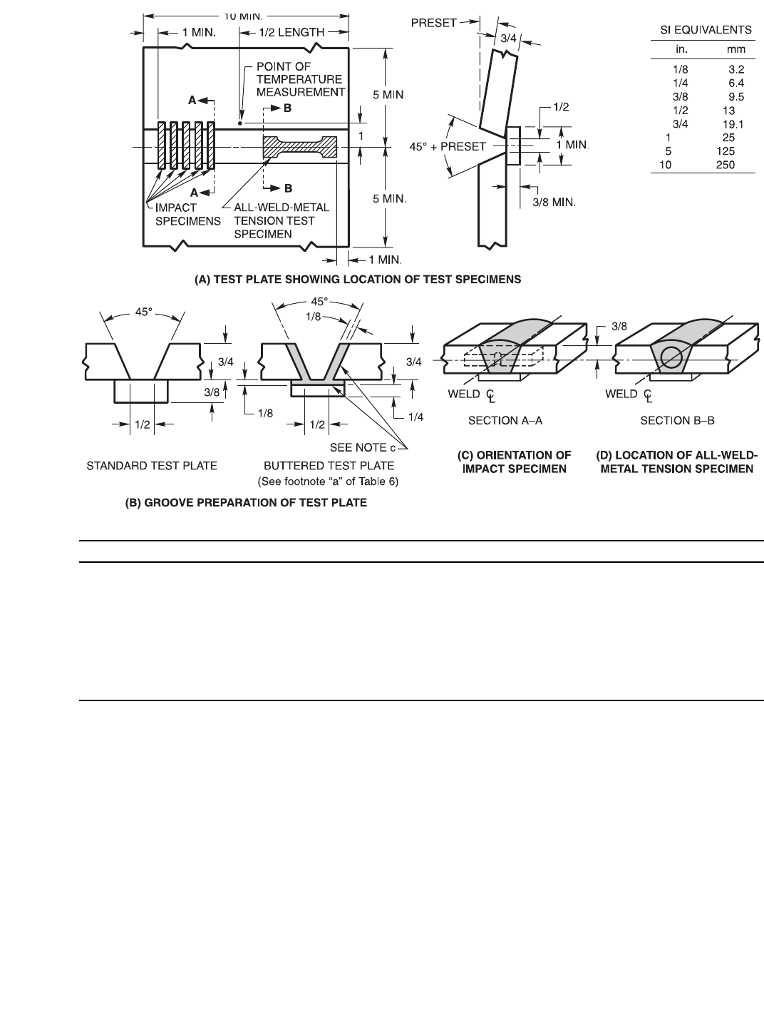
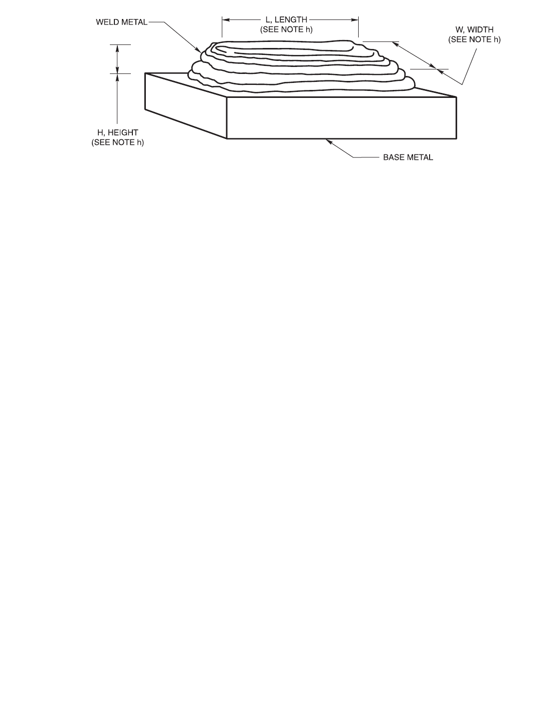
8.4 Weld Pad. A weld pad shall be prepared using com-
posite stranded and composite metal cored electrodes as
shown in Figure 2, except when, as permitted in 8.1, the
sample for analysis is taken from the groove weld (Fig-
ure 1) or the fractured tension test specimen. Base metal
of any convenient size which will satisfy the minimum
requirements of Figure 2, and is of a type specified in
Table 6, shall be used as the base for the weld pad. The
surface of the base metal on which the filler metal is
deposited shall be clean. The pad shall be welded in the
flat position with multiple layers to obtain undiluted
weld metal (4 layers minimum thickness). The electrode
size shall be 0.045 in. (1.1 mm) or 1/16 in. (1.6 mm), or
the size that the manufacturer produces that is closest to
one of these, if these sizes are not produced. The preheat
temperature shall not be less than 60°F (16°C) and the
interpass temperature shall not exceed that specified in
Table 7. Any slag shall be removed after each pass. The
pad may be quenched in water between passes (tempera-
ture of the water is not specified). The dimensions of the
completed pad shall be as shown in Figure 2. Testing of
this assembly shall be as specified in 9.2 and 9.3. The
results shall meet the requirements of 9.4.
9. Chemical Analysis
9.1 A sample of the solid electrode or rod shall be
prepared for chemical analysis. Solid filler metal, when
COPYRIGHT 2003; American Welding Society, Inc.
Document provided by IHS Licensee=abb offshore/5925731102, User=, 05/20/2003
05:22:29 MDT Questions or comments about this message: please call the Document
Policy Management Group at 1-800-451-1584.
--``,`,`,,`,`,,`,,,,`,`,`,,``,-`-`,,`,,`,`,,`---
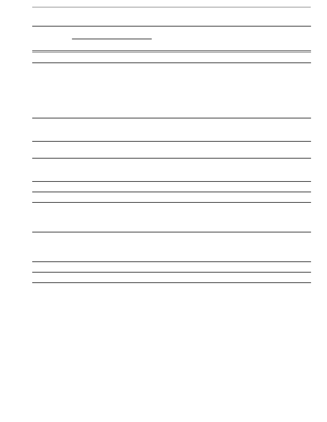
8
Test Conditions for Solid Electrodes (i)
Standard Size (h) 0.045 in. (1.1 mm) 1/16 in. (1.6 mm)
Shielding Gas (g) See Table 3 See Table 3
Wire Feed Rate 450 in./min (190 mm/sec) ±5% 240 in./min (102 mm/sec) ±5%
Nominal Arc Voltage 27 to 32 V 25 to 30 V
Approx. Resulting Current, DCEP (d)
(DCEP = electrode positive) 300 to 360A (e) 340 to 420A (e)
Tip-to-Work Distance (f) 7/8 ± 1/8 in. (22 ± 3 mm) 7/8 ± 1/8 in. (22 ± 3 mm)
Travel Speed 13 ± 2 in./min (5.5 ± 1.0 mm/sec) 13 ± 2 in./min (5.5 ± 1.0 mm/sec)
Preheat and Interpass Temperature See Table 7 See Table 7
Notes:
a. All dimensions (excluding angles) are in inches.
b. Prior to welding, the assembly may be preset as shown so that the welded joint will be sufficiently flat to facilitate test specimen
removal. As an alternative, restraint or a combination of restraint and preset may be used.
c. When required, edges of the grooves and the contacting face of the backing shall be buttered as shown. Any size of the electrode
being tested may be used for buttering. See Table 6, Note (a).
d. The required combinations of electrode feed rate, arc voltage, and tip-to-work distance should produce welding currents in the ranges
shown. Currents substantially outside these ranges suggest errors in feed rate, tip-to-work distance, voltage settings, or in instrumentation.
e. For ER80S-D2 classification, the amperage range for 0.045" (1.1 mm) shall be 260 to 320A and for 1/16 in. (1.6 mm) dia., 330 to 410A.
f. Distance from the contact tip to work, not from the shielding gas cup to the work.
g. If shielding gases or blends other than those shown in Table 3 are used, the wire feed speed (and resulting current), arc voltage, and
travel speed are to be as agreed to between purchaser and supplier.
h. If sizes other than 0.045 in. (1.1 mm) and 1/16 in. (1.6 mm) are tested, wire feed speed (and resulting current), arc voltage, and tip-to-
work distance shall be changed as needed.This joint configuration is not recommended for sizes smaller than 0.035 in. (0.9 mm).
i. Test conditions for composite stranded and metal cored electrodes shall be as recommended by the manufacturer. Preheat and inter-
pass temperature shall be in accordance with Table 7.
Figure 1—Groove Weld Test Assembly for Mechanical Properties and Soundness
COPYRIGHT 2003; American Welding Society, Inc.
Document provided by IHS Licensee=abb offshore/5925731102, User=, 05/20/2003
05:22:29 MDT Questions or comments about this message: please call the Document
Policy Management Group at 1-800-451-1584.
--``,`,`,,`,`,,`,,,,`,`,`,,``,-`-`,,`,,`,`,,`---
9
analyzed for elements that are present in a coating (cop-
per flashing, for example), shall be analyzed without
removing the coating. When the filler metal is analyzed
for elements other than those in the coating, the coating
shall be removed if its presence affects the results of the
analysis for the other elements.
9.2 Composite stranded and metal cored electrodes shall
be analyzed in the form of weld metal, not filler metal.
The sample for analysis shall be taken from weld metal
obtained with the electrode and a shielding gas as speci-
fied in Tables 2 and 3. The sample may be taken from the
weld pad prepared in accordance with 8.4, from an area
of the groove weld as specified in 8.1, or from the
reduced section of the fractured tension test specimen. In
case of dispute, the weld pad is the referee method.
The top surface of the pad described in 8.4 and shown
in Figure 2 shall be removed and discarded. A sample for
analysis shall be obtained from the underlying metal, no
closer than 3/8 in. (9.5 mm) to the surface of the base
metal in Figure 2, by any appropriate mechanical means.
The sample shall be free of slag.
When the sample is taken from the groove weld or the
reduced section of the fractured tension test specimen,
that material shall be prepared for analysis by any suit-
able mechanical means.
9.3 The sample obtained as specified in 9.1 or 9.2 shall
be analyzed by accepted analytical methods. The referee
method shall be ASTM E350, Standard Method for
Chemical Analysis of Carbon Steel, Low Alloy Steel, Sili-
con Electrical Steel, Ingot Iron and Wrought Iron.
9.4 The results of the analysis shall meet the require-
ments of Table 1 for solid electrode or Table 2 for com-
posite electrodes for the classification of electrode under
test.
10. Radiographic Test
10.1 The groove weld described in 8.3.1 and shown in
Figure 1 shall be radiographed to evaluate the soundness
of the weld metal. In preparation for radiography, the
backing shall be removed, and both surfaces of the weld
shall be machined or ground smooth. Both surfaces of
the test assembly, in the area of the weld, shall be smooth
enough to avoid difficulty in interpreting the radiograph.
10.2 The weld shall be radiographed in accordance with
ASTM E142, Standard Method for Controlling Quality
of Radiographic Testing. The quality level of inspection
shall be 2-2T.
Notes:
a. Base metal of any convenient size, of any type, specified in Table 6, shall be used as the base metal for the weld pad.
b. The surface of the base metal on which the filler metal is to be deposited shall be clean.
c. The pad shall be welded in the flat position with successive layers to obtain weld metal of sufficient height.
d. The number and size of the beads will vary according to the size of the electrode and the width of the weave, as well as the amperage
employed.
e. The preheat temperature shall not be less than 60°F (16°C) and the interpass temperature shall not exceed 325°F (164°C).
f. Any slag shall be removed after each pass.
g. The test assembly may be quenched in water between passes to control interpass temperature.
h. The minimum completed pad size shall be at least four layers in height (H). Length (L), after allowance for start and stop areas, and
width (W) shall be sufficient to perform analysis. The sample for analysis shall be taken at least 3/8 in. (9 mm) above the original base
metal surface.
Figure 2—Pad for Chemical Analysis of Weld Metal from Composite Electrodes
COPYRIGHT 2003; American Welding Society, Inc.
Document provided by IHS Licensee=abb offshore/5925731102, User=, 05/20/2003
05:22:29 MDT Questions or comments about this message: please call the Document
Policy Management Group at 1-800-451-1584.
--``,`,`,,`,`,,`,,,,`,`,`,,``,-`-`,,`,,`,`,,`---
10
Table 6
Base Metal for Test Assemblies
AWS Classification Base Metal ASTM StandardaBase Metal UNS Numberb
ER70S-B2L
E70C-B2L
ER80S-B2
E80C-B2
A387 Grade 11 K11789
ER80S-B3L
E80C-B3L
ER90S-B3
E90C-B3
A387 Grade 22 K21590
ER80S-B6 A387 Grade 5 S50200
ER80S-B8 A387 Grade 9 S50400
ER90S-B9 A387 Grade 91 S50460
ER80S-Ni1
E80C-Ni1
A516 Grade 60, 65, or 70 K02100, K02403, or K02700
A537 Class 1 or 2 K12437, K21703, or K22103
A203 Grade A or B, or HY-80 steel
in accordance with MIL-S-16216 J42015
E70C-Ni2
ER80S-Ni2
E80C-Ni2
A203 Grade A or B or HY-80 steel
in accordance with MIL-S-16216 K22103, K21703, or J42015
ER80S-Ni3
E80C-Ni3
A203 Grade D or E or HY80 steel
in accordance with MIL-S-16216
K31718 or K32018
J42015
ER70S-A1
ER80S-D2
E90C-D2
ER90S-D2
ASTM A36, A285 Grade C,
A515 Grade 70, or
A516 Grade 70
K02600,
K03101,
K02700,
ER100S-1
ER100S-G
E100C-G
ER110S-1
ER110S-G
E110C-G
ER120S-1
ER120S-G
E120C-G
HY-80 or HY100 steel
in accordance with MIL-S-16216 J42015 or J42240
ERXXS-G
EXXC-G See notea
Notes:
a. For any weld metal classification in this specification, ASTM A36, A285 Grade C, A515 Grade 70, or A516 Grade 70 may be used. In that case, the
groove faces and the contacting face of the backing shall be buttered, as shown in Figure 1, using the electrode being classified or an electrode of the
same weld metal composition as that specified for the electrode being tested, or using an electrode of the specified composition classified in another
AWS low-alloy steel filler metal specification. Alternately, for the indicated weld metal classification, the corresponding base metals may be used
for weld test assemblies without buttering. In case of dispute, buttered A36 steel shall be the referee material.
b. ASTM/SAE Unified Numbering System for Metals and Alloys.
COPYRIGHT 2003; American Welding Society, Inc.
Document provided by IHS Licensee=abb offshore/5925731102, User=, 05/20/2003
05:22:29 MDT Questions or comments about this message: please call the Document
Policy Management Group at 1-800-451-1584.
--``,`,`,,`,`,,`,,,,`,`,`,,``,-`-`,,`,,`,`,,`---
11
Table 7
Preheat, Interpass, and Postweld Heat Treatment Temperatures
AWS Classification
Preheat and Interpass TemperatureaPWHT Temperaturea
°F °C °F °C
ER70S-A1
ER80S-B2
ER70S-B2L
E80C-B2
E70C-B2L
275–325 135–165 1150 ± 25 620 ± 15
ER90S-B3
ER80S-B3L
E90C-B3
E80C-B3L
375–425 185–215 1275 ± 25 690 ± 15
ER80S-B6 350–450 177–232 1375 ± 25 745 ± 15
ER80S-B8 400–500 205–260 1375 ± 25 745 ± 15
ER90S-B9 300–500 150–260 1375 ± 25 745 ± 15
ER80S-Ni2
ER80S-Ni3
E70C-Ni2
E80C-Ni2
E80C-Ni3
275–325 135–165 1150 ± 25 620 ± 15
ER80S-D2
ER90S-D2
E90C-D2
ER80S-Ni1
E80C-Ni1
ER100S-1
ER110S-1
ER120S-1
275–325 135–165 NonebNoneb
ERXXXS-G
EXXC-G Conditions as agreed upon between supplier and purchaser
Notes:
a. These temperatures are specified for testing under this specification and are not to be considered as recommendations for preheat, interpass, and
postweld heat treatment in production welding. The requirements for production welding must be determined by the user. They may or may not
differ from those called for here.
b. These classifications are normally used in the as-welded condition.
COPYRIGHT 2003; American Welding Society, Inc.
Document provided by IHS Licensee=abb offshore/5925731102, User=, 05/20/2003
05:22:29 MDT Questions or comments about this message: please call the Document
Policy Management Group at 1-800-451-1584.
--``,`,`,,`,`,,`,,,,`,`,`,,``,-`-`,,`,,`,`,,`---

12
10.3 The soundness of the weld metal meets the require-
ments of this specification if the radiograph shows no
cracks, no incomplete fusion, and no rounded indications
in excess of those permitted by the radiographic stan-
dards in Figure 3. In evaluating the radiograph, 1 in.
(25 mm) of the weld on each end of the test assembly
shall be disregarded.
10.3.1 A rounded indication is an indication (on the
radiograph) whose length is no more than 3 times its
width. Rounded indications may be circular, elliptical,
conical, or irregular in shape, and they may have tails.
The size of a rounded indication is the largest dimension
of the indication, including any tail that may be present.
The indication may be of porosity or slag. Indications
whose largest dimension does not exceed 1/64 in.
(0.4 mm) shall be disregarded. Test assemblies with indi-
cations larger than the largest indications permitted in the
radiographic standards (Figure 3) do not meet the
requirements of this specification.
11. Tension Test
11.1 One all-weld-metal tension test specimen shall be
machined from the groove weld described in 8.3.1 and
shown in Figure 1 as required in Table 5. The dimensions
of the specimen shall be as shown in Figure 4.
11.2 Before testing, the specimen may be aged at 200 to
220°F (93 to 104°C) for up to 48 hours, then allowed to
cool to room temperature. Refer to A8.3 for a discussion
on the purpose of aging treatments.
11.3 The specimen shall be tested in the manner
described in the tension test section of ANSI/AWS B4.0,
Standard Methods for Mechanical Testing of Welds.
11.4 The results of the all-weld-metal tension test shall
meet the requirements specified in Table 3. Test reports
shall indicate if the specimen was tested in the aged
condition.
12. Impact Test
12.1 Five Charpy V-notch impact test specimens (Fig-
ure 5) shall be machined from the test assembly shown in
Figure 1, for those classifications for which impact test-
ing is required in Table 5.
12.2 The five specimens shall be tested in accordance
with the impact test section of ANSI/AWS B4.0, Stan-
dard Methods for Mechanical Testing of Welds. The test
temperature shall be that specified in Table 4 for the clas-
sification under test.
12.3 In evaluating the test results, the lowest and the
highest values obtained shall be disregarded. For classifi-
cations requiring 20 ft⋅lbf (27 J), two of the remaining
three values shall equal, or exceed, the specified 20 ft⋅lbf
(27 J) energy level. One of the three may be lower, but
not lower than 15 ft⋅lbf (20 J), and the average of the
three shall be not less than the required 20 ft⋅lbf (27 J)
energy level. For classifications requiring 50 ft⋅lbf (68 J),
two of the remaining three values shall equal, or exceed,
the specified 50 ft⋅lbf (68 J) energy level. One of the
three may be lower, but not lower than 40 ft⋅lbf (54 J),
and the average of the three shall be not less than the
required 50 ft⋅lbf (68 J) energy level.
13. Diffusible Hydrogen Test
13.1 For each electrode to be identified by an optional
diffusible hydrogen designator, the 0.045 in. (1.1 mm) or
1/16 in. (1.6 mm) size (or the size that the manufacturer
produces that is closest to one of these, if these sizes are
not produced) shall be tested according to one of the
methods given in ANSI/AWS A4.3, Standard Methods
for Determination of the Diffusible Hydrogen Content of
Martensitic, Bainitic, and Ferritic Steel Weld Metal Pro-
duced by Arc Welding. The optional supplemental diffus-
ible hydrogen designator may be added to the
classification according to the average test value as com-
pared to the requirements of Table 8. If the actual test
results for an electrode meet the requirements for the
lower or lowest hydrogen designator as specified in
Table 8, the electrode also meets the requirements for all
higher hydrogen designators in Table 8 without the need
for retest.
Table 8
Optional Diffusible Hydrogen
Requirementsa
AWS
Electrode
Classification
Optional
Supplemental
Diffusible Hydrogen
Designatorb
Average Diffusible
Hydrogen, Maximum
(ml/100g Deposited
Metal)c
All
All
All
All
H16
H8
H4
H2
16.0
8.0
4.0
2.0
Notes:
a. See Note a to Table 5.
b. This designator is added to the end of the complete electrode classi-
fication designation.
c. Some classifications may not meet the lower average diffusible hy-
drogen levels (H8, H4, and H2).
COPYRIGHT 2003; American Welding Society, Inc.
Document provided by IHS Licensee=abb offshore/5925731102, User=, 05/20/2003
05:22:29 MDT Questions or comments about this message: please call the Document
Policy Management Group at 1-800-451-1584.
--``,`,`,,`,`,,`,,,,`,`,`,,``,-`-`,,`,,`,`,,`---
13
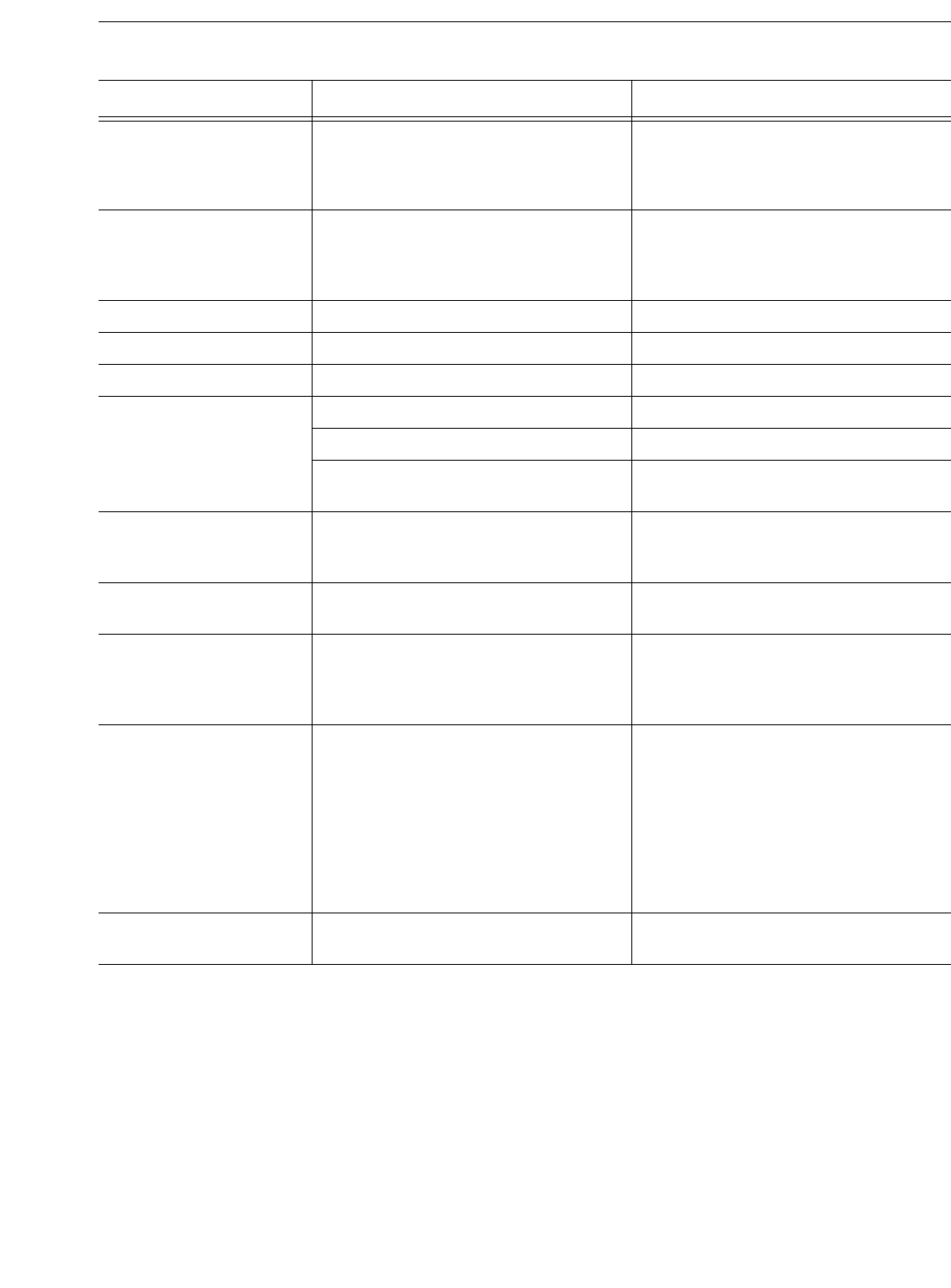
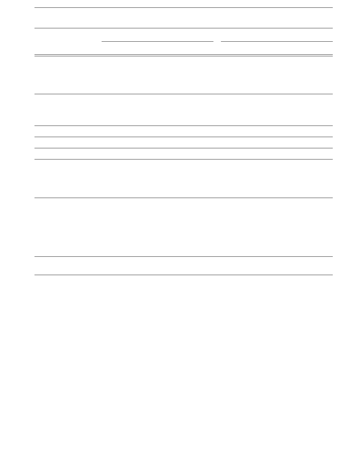
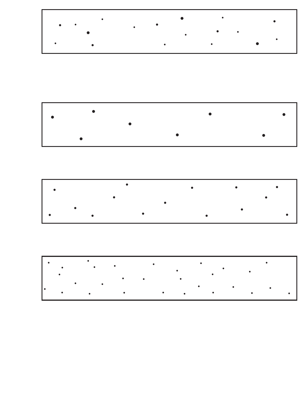
(A) ASSORTED ROUNDED INDICATIONS
SIZE 1/64 in. (0.4 mm) TO 1/16 in. (1.6 mm) IN DIAMETER OR IN LENGTH.
MAXIMUM NUMBER OF INDICATIONS IN ANY 6 in. (150 mm) OF WELD = 18, WITH THE FOLLOWING RESTRICTIONS:
MAXIMUM NUMBER OF LARGE 3/64 in. (1.2 mm) TO 1/16 in. (1.6 mm) IN DIAMETER OR IN LENGTH INDICATIONS = 3.
MAXIMUM NUMBER OF MEDIUM 1/32 in. (0.8 mm) TO 3/64 in. (1.2 mm) IN DIAMETER OR IN LENGTH INDICATIONS = 5.
MAXIMUM NUMBER OF SMALL 1/64 in. (0.4 mm) TO 1/32 in. (0.8 mm) IN DIAMETER OR IN LENGTH INDICATIONS = 10.
(B) LARGE ROUNDED INDICATIONS
SIZE 3/64 in. (1.2 mm) TO 1/16 in. (1.6 mm) IN DIAMETER OR IN LENGTH.
MAXIMUM NUMBER OF INDICATIONS IN ANY 6 in. (150 mm) OF WELD = 8.
(C) MEDIUM ROUNDED INDICATIONS
SIZE 1/32 in. (0.8 mm) TO 3/64 in. (1.2 mm) IN DIAMETER OR IN LENGTH.
MAXIMUM NUMBER OF INDICATIONS IN ANY 6 in. (150 mm) OF WELD = 15.
(D) SMALL ROUNDED INDICATIONS
SIZE 1/64 in. (0.4 mm) TO 1/32 in. (0.8 mm) IN DIAMETER OR IN LENGTH.
MAXIMUM NUMBER OF INDICATIONS IN ANY 6 in. (150 mm) OF WELD = 30.
Notes:
1. In using these standards, the chart which is most representative of the size of the rounded indications present in the test specimen
radiograph shall be used for determining conformance to these radiographic standards.
2. Since these are test welds specifically made in the laboratory for classification purposes, the radiographic requirements for these test
welds are more rigid than those which may be required for general fabrication.
3. Indications whose largest dimension does not exceed 1/64 in. (0.4 mm) shall be disregarded.
4. These standards are equivalent to the Grade 1 standards of ANSI/AWS A5.1, Specification for Carbon Steel Electrodes for Shielded
Metal Arc Welding.
Figure 3—Radiographic Acceptance Standards
COPYRIGHT 2003; American Welding Society, Inc.
Document provided by IHS Licensee=abb offshore/5925731102, User=, 05/20/2003
05:22:29 MDT Questions or comments about this message: please call the Document
Policy Management Group at 1-800-451-1584.
--``,`,`,,`,`,,`,,,,`,`,`,,``,-`-`,,`,,`,`,,`---
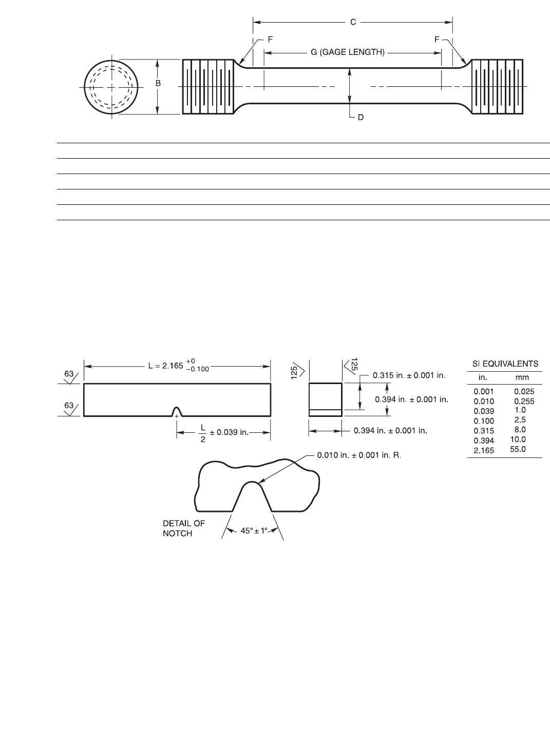
14
Figure 4—Tension Test Specimen
Notes:
1. The notched surface and the surface to be struck shall be parallel within 0.002 in. (0.05 mm) and have at least 63 µin. (1.6 µm) finish.
The other two surfaces shall be square with the notched or struck surface within ±10 minutes of the degree and have at least 125 µin.
(3.2 µm) finish.
2. The notch shall be smoothly cut by mechanical means and shall be square with the longitudinal edge of the specimen within one
degree.
3. The geometry of the notch shall be measured on at least one specimen in a set of five specimens. Measurement shall be done at
minimum 50 times magnification on either a shadowgraph or a metallograph.
4. The correct location of the notch shall be verified by etching before or after machining.
5. If a specimen does not break upon being struck, the value for energy absorbed shall be reported as the capacity of the impact testing
machine followed by a plus sign (+).
Figure 5—Charpy V-Notch Impact Test Specimen
Dimensions of Specimen, in.
DGCBF, min.
0.500 ± 0.010 2.000 ± 0.005 2-1/4 3/4 0.375
Dimensions of Specimen, mm
DGCBF, min.
12.7 ± 0.2 50.8 ± 0.1 57 19 9.5
Notes:
a. Dimensions G and C shall be as shown, but ends may be of any shape to fit the testing machine holders as long as the load is axial.
b. The diameter of the specimen within the gage length shall be slightly smaller at the center than at the ends. The difference shall not
exceed one percent of the diameter.
c. When the extensometer is required to determine yield strength, dimension C may be increased. However, the percent of the elonga-
tion shall be based on dimension G.
d. The surface finish within the C dimension shall be no rougher than 63 µin. (1.6 µm).
COPYRIGHT 2003; American Welding Society, Inc.
Document provided by IHS Licensee=abb offshore/5925731102, User=, 05/20/2003
05:22:29 MDT Questions or comments about this message: please call the Document
Policy Management Group at 1-800-451-1584.
--``,`,`,,`,`,,`,,,,`,`,`,,``,-`-`,,`,,`,`,,`---

15
13.2 Testing shall be done without rebaking, or otherwise
conditioning the electrode, unless the manufacturer rec-
ommends otherwise. If the electrode is rebaked, that fact,
along with the method used for rebaking, shall be noted
on the test report.
13.3 For purposes of certifying compliance with optional
diffusible hydrogen requirements, the reference atmo-
spheric condition shall be an absolute humidity of 10
grains of water vapor per pound (1.43 g/kg) of dry air at
the time of welding. The actual atmospheric conditions
shall be reported, along with the average value for the
test according to ANSI/AWS A4.3.5
13.4 When the absolute humidity equals or exceeds the
reference condition at the time of preparation of the test
assembly, the test shall be acceptable as demonstrating
compliance with the requirements of this specification,
provided the actual test results satisfy the diffusible
hydrogen requirements for the applicable optional sup-
plemental designator.
Part C
Manufacture, Identification, and
Packaging
14. Method of Manufacture
The electrodes and rods classified according to this
specification may be manufactured by any method that
will produce electrodes and rods that meet the require-
ments of this specification.
15. Standard Sizes
15.1 Standard sizes for electrodes and rods in the differ-
ent package forms (straight lengths, coils with support,
coils without support, drums and spools—see Section
17, Standard Package Forms) are shown in Table 9.
16. Finish and Uniformity
16.1 All electrodes and rods shall have a smooth finish
which is free from slivers, depressions, scratches, scale,
seams, laps (exclusive of the longitudinal joint in com-
posite metal cored electrodes), and foreign matter that
would adversely affect the welding characteristics, the
operation of the welding equipment, or the properties of
the weld metal.
16.2 Each continuous length of filler metal shall be from
a single heat or lot of material, and welds, when present,
shall have been made so as not to interfere with the uni-
form, uninterrupted feeding of the filler metal on auto-
matic and semiautomatic equipment.
16.3 The components in composite electrodes (including
the core ingredients in metal cored electrodes) shall be
distributed with sufficient uniformity throughout the
length of the electrode so as not to adversely affect the
performance of the electrode or the properties of the
weld metal.
16.4 A suitable protective coating may be applied to any
filler metal in this specification. Copper may be used as a
coating for any classification.
17. Standard Package Forms
17.1 Standard package forms are straight lengths, coils
with support, coils without support, spools, and drums.
Standard package dimensions and weights for each form
are given in Table 10. Package forms, sizes, and weights
other than these shall be as agreed between purchaser
and supplier.
17.2 The liners in coils with support shall be designed
and constructed to prevent distortion of the coil during
normal handling and use and shall be clean and dry
enough to maintain the cleanliness of the filler metal.
17.3 Spools shall be designed and constructed to prevent
distortion of the filler metal during normal handling and
use and shall be clean and dry enough to maintain the
cleanliness of the filler metal.
18. Winding Requirements
18.1 Electrodes on spools and in coils (including drums
and reels) shall be wound so that kinks, waves, sharp
bends, overlapping or wedging are not encountered,
leaving the filler metal free to unwind without restric-
tion. The outside end of the filler metal (the end with
which welding is to begin) shall be identified so it can be
readily located and shall be fastened to avoid unwinding.
18.2 The cast and helix of electrodes in coils, spools, and
drums shall be such that the electrode will feed in an
uninterrupted manner in automatic and semiautomatic
equipment.
18.3 The cast and helix of solid filler metal in 4 in.
(100 mm) spools shall be such that a specimen long
5. See A8.2 (in the Annex).
COPYRIGHT 2003; American Welding Society, Inc.
Document provided by IHS Licensee=abb offshore/5925731102, User=, 05/20/2003
05:22:29 MDT Questions or comments about this message: please call the Document
Policy Management Group at 1-800-451-1584.
--``,`,`,,`,`,,`,,,,`,`,`,,``,-`-`,,`,,`,`,,`---
16
Table 9
Standard Sizesa
Standard Package Form
Diameter
Tolerance (±)
Solid Composite
in. mm in. mm in. mm
Straight Lengthsb
0.045 1.1 0.001 0.02 0.002 0.05
1/16 0.062 1.6 0.002 0.05 0.002 0.05
5/64 0.078 2.0 0.002 0.05 0.003 0.08
3/32 0.094 2.4 0.002 0.05 0.003 0.08
1/8 0.125 3.2 0.002 0.05 0.003 0.08
5/32 0.156 4.0 0.002 0.05 0.003 0.08
3/16 0.188 4.8 0.002 0.05 0.003 0.08
Coils with and without Support
0.030 0.8 0.001 0.02 0.002 0.05
0.035 0.9 0.001 0.02 0.002 0.05
0.045 1.1 0.001 0.02 0.002 0.05
0.052 1.3 0.002 0.05 0.002 0.05
1/16 0.062 1.6 0.002 0.05 0.002 0.05
5/64 0.078 2.0 0.002 0.05 0.003 0.08
3/32 0.094 2.4 0.002 0.05 0.003 0.08
7/64 0.109 2.8 0.002 0.05 0.003 0.08
1/8 0.125 3.2 0.002 0.05 0.003 0.08
Drums
0.035 0.9 0.001 0.02 0.002 0.05
0.045 1.1 0.001 0.02 0.002 0.05
0.052 1.3 0.002 0.05 0.002 0.05
1/16 0.062 1.6 0.002 0.05 0.002 0.05
5/64 0.078 2.0 0.002 0.05 0.003 0.08
3/32 0.094 2.4 0.002 0.05 0.003 0.08
7/64 0.109 2.8 0.002 0.05 0.003 0.08
1/8 0.125 3.2 0.002 0.05 0.003 0.08
Spools
0.020 0.5 0.001 0.02 0.002 0.05
0.025 0.6 0.001 0.02 0.002 0.05
0.030 0.8 0.001 0.02 0.002 0.05
0.035 0.9 0.001 0.02 0.002 0.05
0.045 1.1 0.001 0.02 0.002 0.05
0.052 1.3 0.002 0.05 0.002 0.05
1/16 0.062 1.6 0.002 0.05 0.002 0.05
5/64 0.078 2.0 0.002 0.05 0.003 0.08
3/32 0.094 2.4 0.002 0.05 0.003 0.08
7/64 0.109 2.8 0.002 0.05 0.003 0.08
1/8 0.125 3.2 0.002 0.05 0.003 0.08
Notes:
a. Dimensions, sizes, tolerances, and package forms other than those shown shall be as agreed by purchaser and supplier.
b. Length shall be 36 in. ± 1/2 in. (approximately 900 mm ± 15 mm).
COPYRIGHT 2003; American Welding Society, Inc.
Document provided by IHS Licensee=abb offshore/5925731102, User=, 05/20/2003
05:22:29 MDT Questions or comments about this message: please call the Document
Policy Management Group at 1-800-451-1584.
--``,`,`,,`,`,,`,,,,`,`,`,,``,-`-`,,`,,`,`,,`---
17
enough to produce a single loop, when cut from the spool
and laid unrestrained on a flat surface, will:
(1) form a circle not less than 4 in. (100 mm) nor
more than 9 in. (230 mm) in diameter, and
(2) rise above the flat surface no more than 1/2 in.
(13 mm) at any location.
18.4 The cast and helix of solid filler metal on all other
package forms shall be such that a specimen long enough
to produce a single loop, when cut from the package and
laid unrestrained on a flat surface, will:
(1) form a circle not less than 12 in. (305 mm) for
0.030 in (0.8 mm) and smaller sizes; or not less than
15 in. (380 mm) for 0.035 in. (0.9 mm) and larger sizes,
and
(2) rise above the flat surface no more than 1 in.
(25 mm) at any location.
Certain bulk packages may contain wire that has been
elastically twisted or otherwise mechanically treated in
order to provide straighter wire feed. The wire from
these packages will not form a circle when cut. Tradi-
tional cast and helix measurements may have no rele-
vance. Wire thus treated shall conform to the winding
requirements of 18.1 and 18.2. Any method of wire form
inspection shall be as agreed between purchaser and
supplier.
19. Filler Metal Identification
19.1 The product information and the precautionary
information required in Section 21 for marking each
package shall also appear on each coil, spool, and drum.
Table 10
Packaging Requirementsa
Type of Package
Package Size Net Weight of Electrodeb
in. mm lb. kg (approx.)
Coils without Support As Specified by Purchaserc
Coils with Support
(See below)
ID
ID
6-3/4
12
170
300
14
25, 30, 50, and 60
6.4
11, 14, 23, and 27
Spoolsd
OD
OD
OD
OD
OD
OD
OD
4
8
12
14
22
24
30
100
200
300
360
560
610
760
1-1/2 and 2-1/2
10, 12, and 15
25, 30, 35 and 44
50 and 60
250
300
600, 750, and 1000
0.7 and 1.1
4.5, 5.5, and 6.8
11, 14, 16, and 20
23 and 27
110
140
270, 340, and 454
Drums
OD
OD
15-1/2
20
400
500 As Specified by Purchaserc
OD 23 600 300 and 600 140 and 270
Straight Lengths 36 (long) 900 (long) 10 and 50 4.5 and 22.7
Coils with Support—Standard Dimensions and Weights
Electrode Size
Coil Net Weight Inside Diameter of Liner Width of Wound Electrode
lb kg (approx.) in. mm in., max. mm, max.
All
14
25 and 30
50, 60, and 65
6.4
11 and 14
23, 27, and 30
6-3/4 ± 1/8
12 ± 1/8
12 ± 1/8
170 ± 3
305 ± 3
305 ± 3
3
2-1/2 or 4-5/8
4-5/8
75
65 or 120
120
Notes:
a. Sizes and net weights other than those specified may be supplied as agreed between supplier and purchaser.
b. Tolerance on net weight shall be ±10 percent.
c. As agreed between supplier and purchaser.
d. See Figure 6.
COPYRIGHT 2003; American Welding Society, Inc.
Document provided by IHS Licensee=abb offshore/5925731102, User=, 05/20/2003
05:22:29 MDT Questions or comments about this message: please call the Document
Policy Management Group at 1-800-451-1584.
--``,`,`,,`,`,,`,,,,`,`,`,,``,-`-`,,`,,`,`,,`---
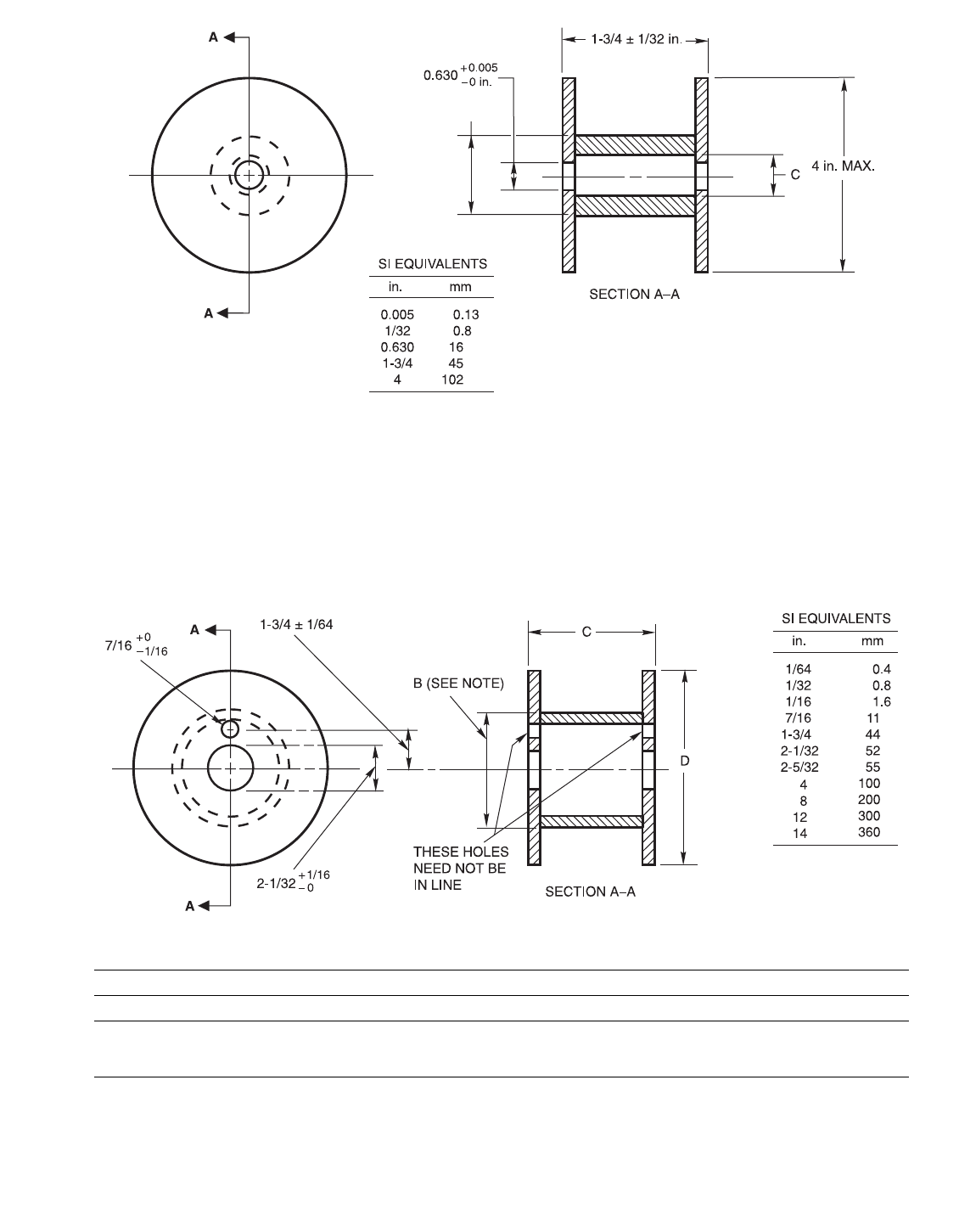
18
Notes:
a. Dimension B, outside diameter of barrel, shall be such as to permit proper feeding of the filler metals.
b. Dimension C, inside diameter of barrel, shall be such that swelling of the barrel or misalignment of the barrel and flanges will not
result in the inside diameter of the barrel being less than the inside diameter of the flanges.
Figure 6(a)—Standard Spools—Dimensions of 4 in. Spools
Note: Dimension B, outside diameter of barrel, shall be such as to permit proper feeding of the filler metals.
Figure 6(b)—Standard Spools—Dimensions of 8, 12, and 14 in. Spools
Dimensions
Spool Size, in. C, in. D, maximum, in.
8
12
14
2-5/32 ± 1/32
0-0/04 ± 1/16
0-0/04 ± 1/16
8
12
14
COPYRIGHT 2003; American Welding Society, Inc.
Document provided by IHS Licensee=abb offshore/5925731102, User=, 05/20/2003
05:22:29 MDT Questions or comments about this message: please call the Document
Policy Management Group at 1-800-451-1584.
--``,`,`,,`,`,,`,,,,`,`,`,,``,-`-`,,`,,`,`,,`---
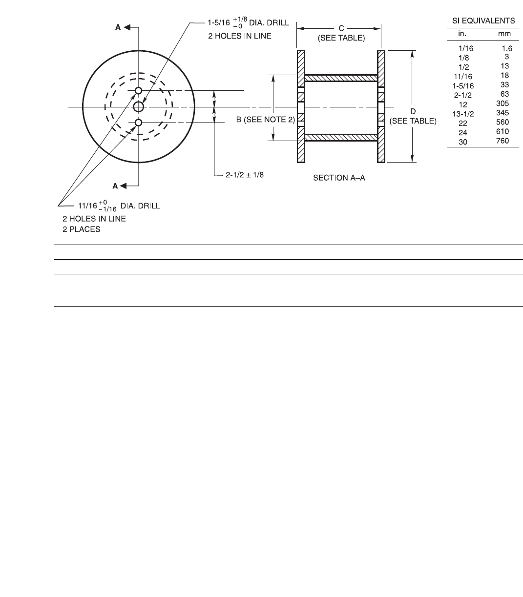
19
Figure 6(c)—Standard Spools—Dimensions of 22, 24, and 30 in. Spools
Dimensions
Spool Size, in. D, in. C, maximum, in.
22
24
30
22 ± 1/2
24 ± 1/2
30 ± 1/2
12-0/0
13-1/2
13-1/2
Notes:
1. All dimensions are in inches.
2. Dimension B, outside diameter of barrel, shall be such as to permit proper feeding of the electrode.
COPYRIGHT 2003; American Welding Society, Inc.
Document provided by IHS Licensee=abb offshore/5925731102, User=, 05/20/2003
05:22:29 MDT Questions or comments about this message: please call the Document
Policy Management Group at 1-800-451-1584.
--``,`,`,,`,`,,`,,,,`,`,`,,``,-`-`,,`,,`,`,,`---
20
19.2 Coils without support shall have a tag containing
this information securely attached to the filler metal at
the inside end of the coil.
19.3 Coils with support shall have the information
securely affixed in a prominent location on the support.
19.4 Spools shall have the information securely affixed
in a prominent location on the outside of at least one
flange of the spool.
19.5 Drums shall have the information securely affixed
in a prominent location on the side of the drum.
20. Packaging
Filler metal shall be suitably packaged to ensure
against damage during shipment and storage under nor-
mal conditions.
21. Marking of Packages
21.1 The following product information (as a minimum)
shall be legibly marked so as to be visible from the out-
side of each unit package:
(1) AWS specification (year of issue may be
excluded) and AWS classification numbers, along with
any optional supplemental designators, if applicable
(2) Supplier’s name and trade designation
(3) Size and net weight
(4) Lot, control, or heat number
21.2 The following precautionary information (as a mini-
mum) shall be prominently displayed in legible print on
all packages of electrodes and rods, including individual
unit packages enclosed within a larger package:
WARNING:
• Protect yourself and others. Read and understand
this information. FUMES AND GASES can be
hazardous to your health. ARC RAYS can injure
eyes and burn skin. ELECTRIC SHOCK can kill.
• Before use, read and understand the manufac-
turer’s instructions, Material Safety Data Sheets
(MSDSs), and your employer’s safety practices.
• Keep your head out of the fumes.
• Use enough ventilation, exhaust at the arc, or both,
to keep fumes and gases away from your breathing
zone and the general area.
• Wear correct eye, ear, and body protection.
• Do not touch live electrical parts.
• See American National Standard Z49.1, Safety in
Welding, Cutting, and Allied Processes, published
by the American Welding Society, 550 N.W.
LeJeune Road, Miami, Florida 33126; OSHA
Safety and Health Standards, 29 CFR 1910, avail-
able from the U.S. Government Printing Office,
Washington, DC 20402.
DO NOT REMOVE THIS INFORMATION
COPYRIGHT 2003; American Welding Society, Inc.
Document provided by IHS Licensee=abb offshore/5925731102, User=, 05/20/2003
05:22:29 MDT Questions or comments about this message: please call the Document
Policy Management Group at 1-800-451-1584.
--``,`,`,,`,`,,`,,,,`,`,`,,``,-`-`,,`,,`,`,,`---

21
A1. Introduction
The purpose of this guide is to correlate the electrode
and rod classifications with their intended applications so
the specification can be used effectively. Reference to
appropriate base metal specifications is made whenever
that can be done and when it would be helpful. Such ref-
erences are intended only as examples rather than com-
plete listings of the materials for which each filler metal
is suitable.
A2. Classification System
A2.1 The system for identifying the electrode classifica-
tions in this specification follows the standard pattern
used in other AWS filler metal specifications as shown in
Figure A1.
A2.2 The prefix “E” designates an electrode as in other
specifications. The letters “ER” indicate that the filler
metal may be used either as an electrode or a rod. The
digits following (70, 80, 90, 100, 110, or 120) indicate
the required minimum tensile strength of the weld metal
in multiples of 1000 psi [6.9 MPa]; the minimum tensile
strength is determined from a test weld made using the
electrode in accordance with the welding conditions in
the specification. The letter “S” designates a solid elec-
trode or rod. The letter “C” designates a composite
stranded or metal cored electrode. The suffix following
the hyphen indicates the chemical composition of the
filler metal itself, in the case of solid electrodes and rods,
or the weld metal under certain test conditions, in the
case of the composite stranded or metal cored electrodes.
An optional supplemental diffusible hydrogen desig-
nator (H16, H8, H4, or H2) may follow, indicating
whether the electrode will meet a maximum diffusible
hydrogen level of 16, 8, 4, or 2 ml/100 g of weld metal
when tested as outlined in this specification.
A2.3 “G” Classification and the Use of “Not Specified”
and “Not Required”
A2.3.1 This specification includes filler metals classi-
fied as ERXXS-G, and EXXC-G. The “G” indicates that
the filler metal is of a general classification. It is “gen-
eral” because not all of the particular requirements speci-
fied for each of the other classifications are specified for
this classification. The intent in establishing these classi-
fications is to provide a means by which filler metals that
differ in one respect or another (chemical composition,
for example) from all other classifications (meaning that
the composition of the filler metal, in the case of the
example, does not meet the composition specified for
any of the classifications in the specification) can still be
classified according to the specification. The purpose is
to allow a useful filler metal, one that otherwise would
have to await a revision of the specification, to be classi-
fied immediately under the existing specification. This
means, then, that two filler metals, each bearing the same
“G” classification, may be quite different in some partic-
ular respect (chemical composition, again, for example).
A2.3.2 The point of difference (although not neces-
sarily the amount of the difference) referred to above will
Annex
Guide to AWS Specification for Low-Alloy Steel
Electrodes and Rods for Gas Shielded Arc Welding
(This Annex is not a part of ANSI/AWS A5.28-96, Specification for Low-Alloy Electrodes and Rods for Gas Shielded
Arc Welding, but is included for information only.)
COPYRIGHT 2003; American Welding Society, Inc.
Document provided by IHS Licensee=abb offshore/5925731102, User=, 05/20/2003
05:22:29 MDT Questions or comments about this message: please call the Document
Policy Management Group at 1-800-451-1584.
--``,`,`,,`,`,,`,,,,`,`,`,,``,-`-`,,`,,`,`,,`---
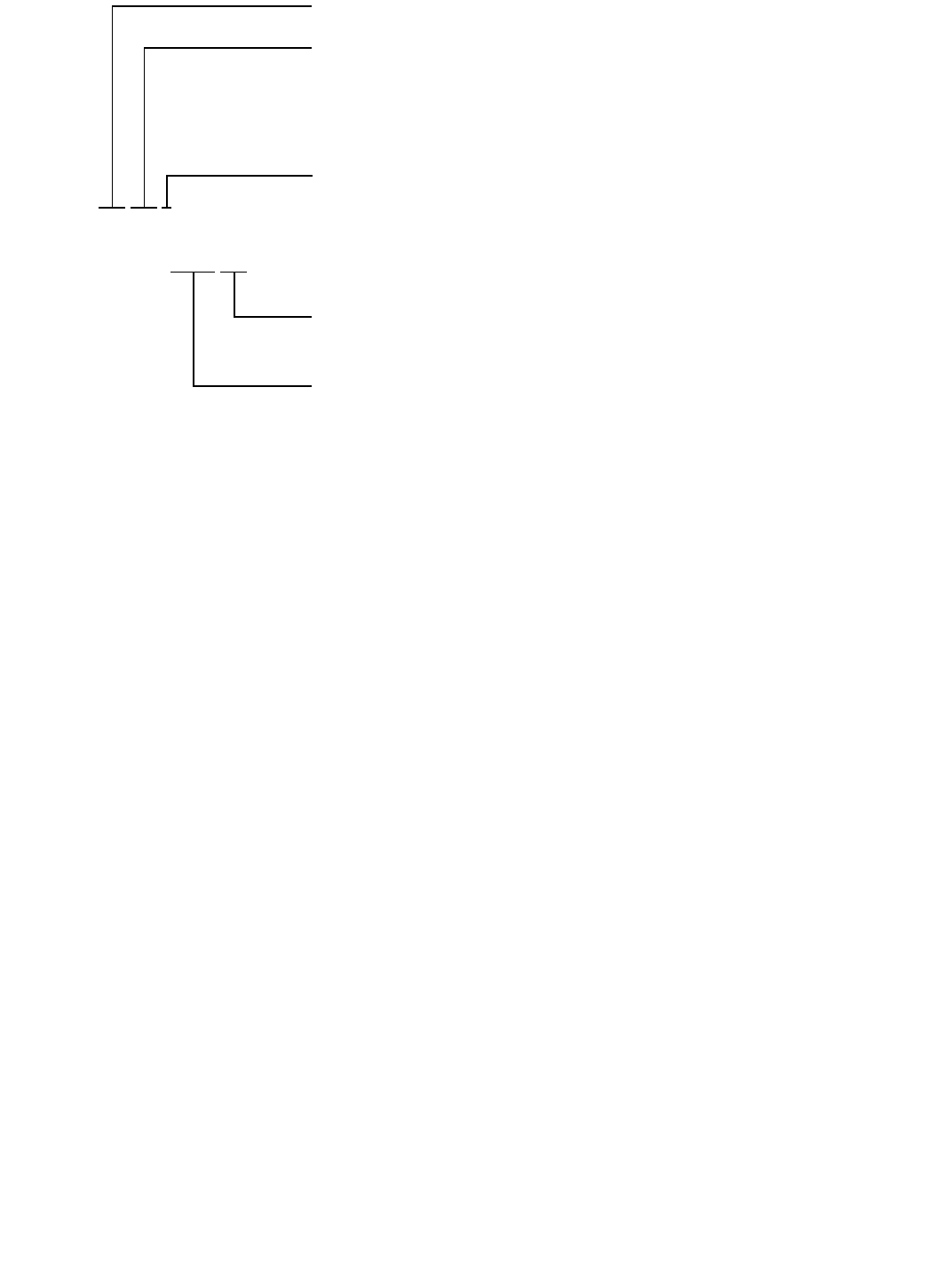
22
be readily apparent from the use of the words “not
required” and “not specified” in the specification. The
use of these words is as follows:
Not Specified is used in those areas of the specifica-
tion that refer to the results of some particular test. It
indicates that the requirements for that test are not speci-
fied for that particular classification.
Not Required is used in those areas of the specifica-
tion that refer to the tests that must be conducted in order
to classify a filler metal. It indicates that the test is not
required because the requirements (results) for the test
have not been specified for that particular classification.
Restating the case, when a requirement is not specified, it
is not necessary to conduct the corresponding test in
order to classify a filler metal to that classification. When
a purchaser wants the information provided by that test,
in order to consider a particular product of that classifica-
tion for a certain application, the purchaser will have to
arrange for that information with the supplier of the
product. The purchaser will have to establish with that
supplier just what the testing procedures and the accep-
tance requirements are to be for that test. The purchaser
may want to incorporate that information (via
ANSI/AWS A5.01, Filler Metal Procurement Guide-
lines) into the purchase order.
A2.3.3 Request for Filler Metal Classification
A2.3.3.1 When a filler metal cannot be classified
according to some classification other than a “G” classi-
fication, the manufacturer may request that a classifica-
tion be established for that filler metal. The manufacturer
may do this by following the procedure given here.
When the manufacturer elects to use the “G” classifica-
tion, the Filler Metal Committee recommends that the
manufacturer still request that a classification be estab-
lished for that filler metal, as long as the filler metal is of
commercial significance.
A2.3.3.2 A request to establish a new filler metal
classification shall be a written request, and it needs to
provide sufficient detail to permit the Filler Metal Com-
mittee or the Subcommittee to determine whether a new
classification or the modification of an existing classifi-
cation is more appropriate, and whether either is neces-
sary to satisfy the need. The request shall state the
variables and their limits for such a classification or
modification. The request should contain some indica-
tion of the time by which completion of the new classifi-
cation or modification is needed.
A2.3.3.3 The request should be sent to the Secre-
tary of the Filler Metal Committee at AWS Headquarters.
Upon receipt of the request, the Secretary will:
(1) Assign an identifying number to the request. This
number shall include the date the request was received.
(2) Confirm receipt of the request and give the identi-
fication number to the person who made the request.
(3) Send a copy of the request to the Chairman of the
Filler Metal Committee and to the Chairman of the par-
ticular Subcommittee involved.
Indicates use as both an electrode or rod (ER), or use only as an electrode (E).
Indicates, in 1000 psi (6.9 MPa) increments, the minimum tensile strength of the
weld metal produced by the electrode when tested according to this specification.
Three digits are used for weld metal of 100 000 psi (690 MPa) tensile strength and
higher (see Table 3). (Note that in this specification the digits “70” may represent
75 000 psi (515 MPa) rather than 70 000 psi (480 MPa) (see Table 3).
Indicates whether the filler metal is solid (S) or composite stranded or metal cored (C).
ERXXS-XXXHZ (for solid wire)
EXXC-XXXHZ (for composite wire)
Optional supplemental diffusible hydrogen designator (see Table 8), where Z repre-
sents 16, 8, 4, or 2.
Indicates the chemical composition of a solid electrode or the chemical composition of
the weld metal produced by a composite stranded or metal cored electrode (see Tables
1 and 2).
Figure A1—Classification System
COPYRIGHT 2003; American Welding Society, Inc.
Document provided by IHS Licensee=abb offshore/5925731102, User=, 05/20/2003
05:22:29 MDT Questions or comments about this message: please call the Document
Policy Management Group at 1-800-451-1584.
--``,`,`,,`,`,,`,,,,`,`,`,,``,-`-`,,`,,`,`,,`---

23
(4) File the original request.
(5) Add the request to the log of outstanding requests.
A2.3.3.4 All necessary action on each request will be
completed as soon as possible. If more than 12 months
lapse, the Secretary shall inform the requestor of the sta-
tus of the request, with copies to the Chairman of the
Committee and the Subcommittee. Requests still out-
standing after 18 months shall be considered not to have
been answered in a “timely manner” and the Secretary
shall report these to the Chairman of the Filler Metal
Committee, for action.
A2.3.3.5 The Secretary shall include a copy of the
log of all requests pending and those completed during
the preceding year with the agenda for each Filler Metal
Committee meeting. Any other publication of requests
that have been completed will be at the option of the
American Welding Society, as deemed appropriate.
A3. Acceptance
Acceptance of all welding materials classified under
this specification is in accordance with ANSI/AWS
A5.01 Filler Metal Procurement Guidelines, as the spec-
ification states. Any testing a purchaser requires of the
supplier, for material shipped in accordance with this
specification, shall be clearly stated in the purchase
order, according to the provisions of ANSI/AWS A5.01
Filler Metal Procurement Guidelines. In the absence of
any such statement in the purchase order, the supplier
may ship the material with whatever testing the supplier
normally conducts on material of that classification, as
specified in Schedule F, Table 1, of ANSI/AWS A5.01
Filler Metal Procurement Guidelines. Testing in accor-
dance with any other schedule in that table must be spe-
cifically required by the purchase order. In such cases,
acceptance of the material shipped will be in accordance
with those requirements.
A4. Certification
A4.1 The act of placing the AWS specification and clas-
sification designations on the packaging enclosing the
product, or the classification on the product itself, con-
stitutes the supplier’s (manufacturer’s) certification that
the product meets all of the requirements of the
specification.
The only testing requirement implicit in the certifica-
tion is that the manufacturer has actually conducted the
tests required by the specification on material that is rep-
resentative of that being shipped, and that the material
met the requirements of the specification.
Representative material, in this case, is any produc-
tion run of that classification using the same formulation.
“Certification” is not to be construed to mean that tests of
any kind were necessarily conducted on samples of the
specific material shipped. Tests on such material may or
may not have been made. The basis for the certification
required by the specification is the classification test of
“representative material” cited above, and the “Manufac-
turer’s Quality Assurance System” in ANSI/AWS A5.01
Filler Metal Procurement Guidelines.
A4.2 (Optional) At the option and expense of the pur-
chaser, acceptance may be based on the results of any or
all of the tests required by this specification made on the
gas tungsten arc welding (GTAW) test assembly
described in Figure A2, with tension specimen as
described in Figure A3 (and the impact specimen
described in Figure 5). Solid Electrodes are generally
recommended for GTAW and PAW.
A5. Ventilation During Welding
A5.1 Five major factors govern the quantity of fumes in
the atmosphere to which welders and welding operators
are exposed during welding:
(1) Dimensions of the space in which welding is done
(with special regard to the height of the ceiling)
(2) Number of welders and welding operators work-
ing in that space
(3) Rate of evolution of fumes, gases, or dust, accord-
ing to the materials and processes used
(4) The proximity of the welders or welding operators
to the fumes as the fumes issue from the welding zone,
and to the gases and dusts in the space in which they are
working
(5) The ventilation provided to the space in which the
welding is done
A5.2 American National Standard Z49.1, Safety in Weld-
ing, Cutting, and Allied Processes (published by the
American Welding Society), discusses the ventilation
that is required during welding and should be referred to
for details. Attention is particularly drawn to the section
entitled “Health Protection and Ventilation.”
A6. Welding Considerations
A6.1 Gas metal arc welding (GTAW) can be divided into
four categories based on the mode of metal transfer: (1)
spray, (2) pulsed spray, (3) globular, and (4) short circuit-
ing transfer. In the spray, pulsed spray, and globular
modes, transfer occurs as distinct droplets that are
detached from the electrode, transferring along the arc
column into the weld pool. In the short circuiting mode,
COPYRIGHT 2003; American Welding Society, Inc.
Document provided by IHS Licensee=abb offshore/5925731102, User=, 05/20/2003
05:22:29 MDT Questions or comments about this message: please call the Document
Policy Management Group at 1-800-451-1584.
--``,`,`,,`,`,,`,,,,`,`,`,,``,-`-`,,`,,`,`,,`---
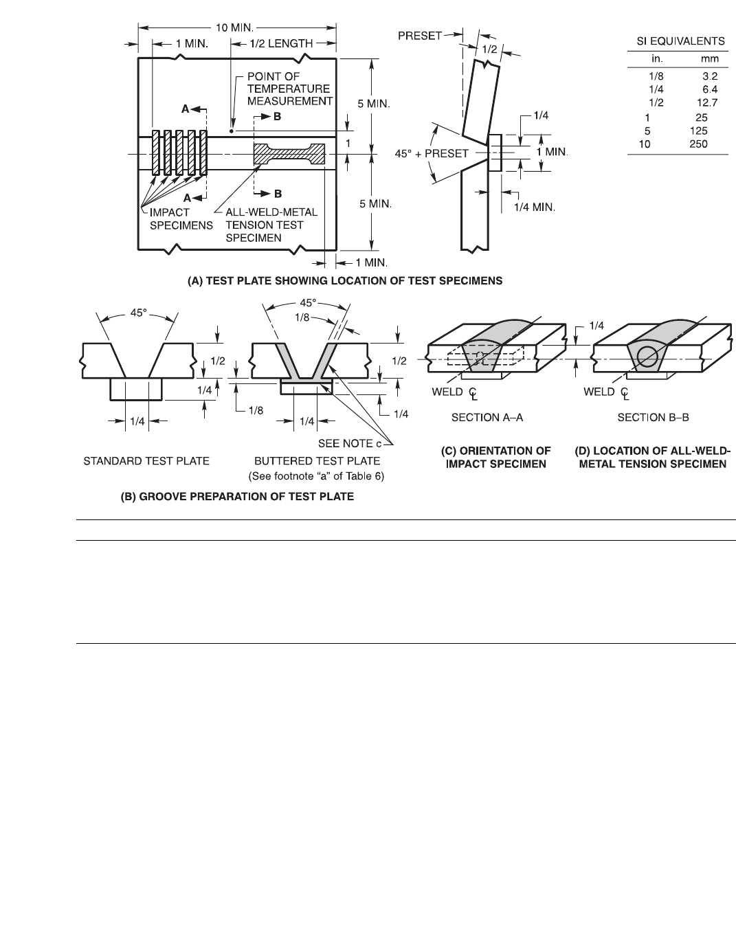
24
Test Conditions
Standard Size 3/32 in. (2.4 mm) 1/8 in. (3.2 mm)
Shielding Gas Argon Argon
Travel Speed 4 to 6 in./min (0.17 to 0.25 mm/sec) 4 to 6 in./min (0.17 to 0.25 mm/sec)
Nominal Arc Voltage 13 to 16 V 16 to 19 V
Nominal Current, DCEN)
(DCEN = electrode negative) 220 to 250 A 250 to 280 A
Preheat and Interpass Temperature See Table 7 See Table 7
Notes:
a. All dimensions (excluding angles) are in inches.
b. Prior to welding, the assembly may be preset as shown so that the welded joint will be sufficiently flat to facilitate test specimen
removal. As an alternative, restraint or a combination of restraint and preset may be used.
c. When required, edges of the grooves and the contacting face of the backing shall be buttered as shown. Any size of the electrode or
rod being tested may be used for buttering. See Table 6, Note (a).
d. If sizes other than those shown above are used, nominal current and arc voltage shall be changed as needed.
e. Postweld heat treatment shall be as specified in Table 7 for the classification under test.
Figure A2—Optional GTAW Groove Weld Test Assembly for
Mechanical Properties and Soundness
COPYRIGHT 2003; American Welding Society, Inc.
Document provided by IHS Licensee=abb offshore/5925731102, User=, 05/20/2003
05:22:29 MDT Questions or comments about this message: please call the Document
Policy Management Group at 1-800-451-1584.
--``,`,`,,`,`,,`,,,,`,`,`,,``,-`-`,,`,,`,`,,`---

25
the metal is deposited during frequent short circuiting of
the electrode in the molten pool.
A6.2 Spray Transfer
A6.2.1 The spray transfer mode, for low-alloy steel, is
most commonly obtained with argon shielding gas mix-
tures with up to 5 percent oxygen or carbon dioxide. A
characteristic of these shielding gas mixtures is the
smooth arc plasma through which hundreds of very fine
droplets are transferred to the weld pool each second.
A6.2.2 Spray transfer with argon-oxygen or argon-
carbon dioxide shielding gas is, primarily, a function of
current density, polarity, and resistance heating of the
electrode. The high droplet rate (approximately 250
droplets per second) develops suddenly above a critical
current level, commonly referred to as the transition cur-
rent (for each size electrode). Below this current, the
metal is transferred in drops generally larger in diameter
than the electrode at a rate of from 10 to 20 per second
(globular transfer). The transition current is also depen-
dent, to some extent, on the chemical composition of the
electrode. For 1/16 in. (1.6 mm) diameter low-alloy steel
electrodes, a transition current of 270 amperes (direct
current electrode positive [DCEP]) is common. Alternat-
ing current is not recommended for this type of welding
because it does not produce a stable arc.
A6.2.3 Pulsed Spray Transfer. Metal transfer in
pulsed spray welding is similar to that of the spray trans-
fer described above, but it occurs at a lower average cur-
rent. The lower average current is made possible by rapid
pulsing of the welding current between a high level,
where metal will transfer rapidly in the spray mode, and
a low level, where no transfer will take place. At a typi-
cal rate of 60 to 120 pulses per second, a melted drop is
formed by the low-current arc, which is then “squeezed
off” by the high-current pulse. This permits all-position
welding.
A6.3 Globular Transfer. The mode of transfer that char-
acterizes 100 percent CO2 as a shielding gas is globular.
Common practice with globular transfer is to use low arc
voltage to minimize spatter. This buries the arc and pro-
duces deep penetration. Electrodes of 0.045 and 1/16 in.
(1.1 and 1.6 mm) diameter normally are used at welding
currents in the range of 275–400 amperes (DCEP), for
this type of transfer. The rate at which droplets (globules)
are transferred ranges from 20 to 70 per second, depend-
ing on the size of the electrode, the amperage, polarity,
and arc voltage.
A6.4 Short Circuiting Transfer. This mode of transfer
is obtained with small diameter electrodes (0.030 to
0.045 in. [0.8 to 1.1 mm]) using low arc voltages and
amperages, and a power source designed for short cir-
cuiting transfer. The electrode short-circuits to the weld
metal, usually at a rate of from 50 to 200 times per sec-
ond. Metal is transferred with each short circuit, but not
across the arc. Short circuiting gas metal arc welding of
low-alloy steel is done most commonly with mixtures of
argon and CO2 as the shielding gas, with CO2 alone, and
occasionally with mixtures of helium-argon-CO2. Pene-
tration of welds made with CO2 shielding gas is greater
than with argon-CO2 mixtures, but mixtures containing
substantial amounts of argon or helium generally result
in superior weld metal impact properties. Shielding gas
mixtures of 50 to 90 percent argon-remainder CO2 or 50
to 90 percent helium-remainder CO2 result in higher
short circuiting rates and lower minimum currents and
voltages than does CO2 shielding alone. This can be an
advantage when welding thin plate or in the achievement
of superior impact properties.
A7. Description and Intended Use of
Electrodes and Rods
A7.1 The following is a description of the characteristics
and intended use of the filler metals classified by this
specification. The designations and the chemical compo-
sition requirements for all classifications are given in
Tables 1 and 2 of this specification. The mechanical
properties of weld metals from filler metals of the vari-
ous classifications will conform to the minimum require-
ments stated in Tables 3 and 4 of the specification.
A7.2 It should be noted that weld properties may vary
appreciably depending on filler metal size and current
used, plate thickness, joint geometry, preheat and inter-
pass temperatures, surface conditions, base-metal com-
position and extent of alloying with the filler metal, and
shielding gas. For example, when filler metals having an
analysis within the range of Table 1 are deposited, the
weld metal chemical composition will not vary greatly
from the as-manufactured composition of the filler metal
when used with argon-oxygen shielding gas. However,
they will show a considerable reduction in the content of
manganese, silicon, and other deoxidizers when used
with CO2 as the shielding gas.
A7.3 ER70S-A1 Classification (1/2 Mo). Filler metal of
this classification is similar to many of the carbon steel
filler metals classified in ANSI/AWS A5.18, except that
1/2 percent molybdenum has been added. This addition
increases the strength of the weld metal, especially at
elevated temperatures, and provides some increase in
corrosion resistance; however, it will likely reduce the
notch toughness of the weld metal. Typical applications
COPYRIGHT 2003; American Welding Society, Inc.
Document provided by IHS Licensee=abb offshore/5925731102, User=, 05/20/2003
05:22:29 MDT Questions or comments about this message: please call the Document
Policy Management Group at 1-800-451-1584.
--``,`,`,,`,`,,`,,,,`,`,`,,``,-`-`,,`,,`,`,,`---
26
include the welding of C-Mo base metals such as ASTM
204 plate and A335-P1 pipe.
A7.4 ER80S-B2 and E80C-B2 Classifications (1-1/4
Cr-1/2 Mo). Filler metals of these classifications are
used to weld 1/2Cr-1/2Mo, 1Cr-1/2Mo, and 1-1/4Cr-
1/2Mo steels for elevated temperatures and corrosive
service. They are also used for joining dissimilar combi-
nations of Cr-Mo and carbon steels. All transfer modes
of the GMAW process may be used. Careful control of
preheat, interpass temperatures, and postheat is essential
to avoid cracking. These electrodes are classified after
postweld heat treatment. Special care must be used when
using them in the as-welded condition due to higher
strength levels.
A7.5 ER70S-B2L and E70C-B2L Classifications
(1-1/4 Cr-1/2 Mo). These filler metals are identical to
the types ER80S-B2 and E80C-B2 except for the low-
carbon content (0.05 percent maximum) and thus the
lower strength levels. This alloy exhibits greater resis-
tance to cracking and is more suitable for welds to be left
in the as-welded condition or when the accuracy of the
postweld heat treatment operation is questionable. These
classifications were previously ER80S-B2L and E80C-
B2L in the previous edition of this specification. The
strength requirements and classification designator have
been changed to reflect the true strength capabilities of
the chemical composition.
A7.6 ER90S-B3 and E90C-B3 Classifications (2-1/4
Cr-1 Mo). Filler metals of these classifications are used
to weld the 2-1/4Cr-1Mo steels used for high-tempera-
ture/high-pressure piping and pressure vessels. These
may also be used for joining combinations of Cr-Mo and
carbon steel. All GMAW modes may be used. Careful
control of preheat, interpass temperatures, and postweld
heat treatment is essential to avoid cracking. These elec-
trodes are classified after postweld heat treatment. Spe-
cial care must be used when using them in the as-welded
condition due to higher strength levels.
A7.7 ER80S-B3L and E80C-B3L Classifications
(2-1/4 Cr-1 Mo). These filler metals are identical to the
types ER90S-B3 and E90C-B3 except for the low-carbon
content (0.05 percent maximum) and, therefore, the
lower strength levels. These alloys exhibit greater resis-
tance to cracking and are more suitable for welds to be
Dimensions of Specimen, in.
DGCBF, min.
0.350 ± 0.007 1.400 ± 0.005 1-3/4 1/2 0.25
Dimensions of Specimen, mm
DGCBF, min.
8.90 ± 0.1 35.5 ± 0.1 44 12.7 6.4
Notes:
a. Dimensions G and C shall be as shown, but ends may be of any shape to fit the testing machine holders as long as the load is axial.
b. The diameter of the specimen within the gage length shall be slightly smaller at the center than at the ends. The difference shall not
exceed one percent of the diameter.
c. When the extensometer is required to determine yield strength, dimension C may be increased. However, the percent of the elonga-
tion shall be based on dimension G.
d. The surface finish within the C dimension shall be no rougher than 63 µin. (1.6 µm).
Figure A3—Optional Tension Test Specimen for Gas Tungsten Arc Welding
COPYRIGHT 2003; American Welding Society, Inc.
Document provided by IHS Licensee=abb offshore/5925731102, User=, 05/20/2003
05:22:29 MDT Questions or comments about this message: please call the Document
Policy Management Group at 1-800-451-1584.
--``,`,`,,`,`,,`,,,,`,`,`,,``,-`-`,,`,,`,`,,`---

27
left in the as-welded condition. These classifications
were previously ER90S-B3L and E90C-B3L in the pre-
vious edition of this specification. The strength require-
ments and classification designator have been changed
to reflect the true strength capabilities of the chemical
composition.
A7.8 ER80S-Ni1 and E80C-Ni1 Classifications (1.0
Ni). These filler metals deposit weld metal similar to
E8018-C3 covered electrodes, and are used for welding
low-alloy high-strength steels requiring good toughness
at temperatures as low as –50°F (–46°C).
A7.9 ER80S-Ni2, E70C-Ni2, and E80C-Ni2 Classifi-
cations (2-1/4 Ni). These filler metals deposit weld
metal similar to E8018-C1 electrodes. Typically, they are
used for welding 2-1/2 percent nickel steels and other
materials requiring good toughness at temperatures as
low as –80°F (–62°C).
A7.10 ER80S-Ni3 and E80C-Ni3 Classifications
(3-1/4 Ni). These filler metals deposit weld metal similar
to E8018-C2 electrodes. Typically they are used for
welding 3-1/2 percent nickel steels for low-temperature
service.
A7.11 ER80S-D2, ER90S-D2, and E90C-D2 Classifi-
cations (1/2 Mo). The ER80S-D2 and ER90S-D2 classi-
fications have the same chemical requirements as the
E70S-1B classification of AWS A5.18-69. The differ-
ences between the ER80S-D2 and the ER90S-D2 classi-
fications are the change in shielding gas and the
mechanical property requirements specified in Table 3.
Filler metals of these classifications contain molybde-
num for increased strength and a high level of deoxidiz-
ers (Mn and Si) to control porosity when welding with
CO2 as the shielding gas. They will give radiographic
quality welds with excellent bead appearance in both
ordinary and difficult-to-weld carbon and low-alloy
steels. They exhibit excellent out-of-position welding
characteristics with the short circuiting and pulsed arc
processes.
The combination of weld soundness and strength makes
filler metals of these classifications suitable for single
and multiple-pass welding of a variety of carbon and
low-alloy, higher strength steels in both the as welded
and postweld heat-treated conditions. The chemical
composition of these classifications differs from those
of the “-D2” type electrodes in AWS A5.5.
A7.12 ER100S-1, ER110S-1, and ER120S-1 Classifi-
cations. These filler metals deposit high-strength, very
tough weld metal for critical applications. Originally
developed for welding HY80 and HY100 steels for mili-
tary applications, they are also used for a variety of struc-
tural applications where tensile strength requirements
exceed 100 ksi (690 MPa), and excellent toughness is
required to temperatures as low as –60°F (–51°C).
Mechanical properties obtained from weld deposits made
with electrodes of these classifications will vary depend-
ing on the heat input used.
A7.13 ER80S-B6 Classification (5 Cr-1/2 Mo). This
classification contains 4.0 to 6.0 percent chromium and
about 0.50 percent molybdenum. It is used for welding
material of similar composition, usually in the form of
pipe or tubing. The alloy is an air-hardening material
and, therefore, when welding with this filler metal, pre-
heat and postweld heat treatment are required. This elec-
trode is similar to that previously classified as ER502 in
AWS A5.9-81.
A7.14 ER80S-B8 Classification (9 Cr-1 Mo). This clas-
sification contains 8.0 to 10.5 percent chromium and
about 1.0 percent molybdenum. Filler metal of this clas-
sification is used for welding base metal of similar com-
positions, usually in the form of pipe or tubing. The alloy
is an air-hardening material and, therefore, when welding
with this filler metal, preheating and postweld heat treat-
ment are required. This electrode is similar to that previ-
ously classified as ER505 in AWS A5.9-81.
A7.15 ER90S-B9 Classification (9 Cr-1 Mo-0.2V-
0.07Nb(Cb)). ER90S-B9 is a 9Cr-1Mo solid wire modi-
fied with niobium (columbium) and vanadium designed
to provide strength, toughness, fatigue life, oxidation
resistance and corrosion resistance at elevated tempera-
tures. Due to the higher elevated temperature properties
of this alloy, components that are now fabricated from
stainless and ferritic steels may be fabricated from a sin-
gle alloy, eliminating problems associated with dissimi-
lar welds.
In addition to the classification requirements in this
specification, either impact toughness or high-tempera-
ture creep strength properties should be determined. Due
to the influence of various levels of carbon and niobium
(columbium), specific values and testing must be agreed
to by the supplier and purchaser.
A7.16 ERXXS-G and EXXC-G Classifications. Elec-
trodes and rods of the ERXXS-G and electrodes of the
EXXC-G classifications are those filler metals not
included in the preceding classes and for which only cer-
tain mechanical property requirements are specified. The
electrodes are intended for single and multiple-pass
applications. The filler metal supplier should be con-
sulted for the composition, properties, characteristics,
and intended use of these classifications (see A2.3 for
further information).
COPYRIGHT 2003; American Welding Society, Inc.
Document provided by IHS Licensee=abb offshore/5925731102, User=, 05/20/2003
05:22:29 MDT Questions or comments about this message: please call the Document
Policy Management Group at 1-800-451-1584.
--``,`,`,,`,`,,`,,,,`,`,`,,``,-`-`,,`,,`,`,,`---

28
A8. Special Tests
A8.1 It is recognized that supplementary tests may be
required to determine suitability of these filler metals for
certain applications involving properties not considered
in this specification. In such cases, additional tests to
determine specific properties of the weld metal, such as
hardness, corrosion resistance, mechanical properties at
higher or lower service temperatures, may be required.
Those tests may be conducted as agreed between sup-
plier and purchaser. ANSI/AWS A5.01 contains provi-
sions for ordering such tests.
A8.2 Diffusible Hydrogen. Solid, composite stranded,
and composite metal cored GMAW electrodes are gener-
ally considered to be low hydrogen consumables. When
joining carbon steels containing 0.30 percent or less car-
bon, hydrogen-assisted cracking is unlikely to be of con-
cern. However, when joining high-strength, low-alloy
steel, weld metal or heat-affected-zone cracking associ-
ated with diffusible hydrogen tends to become more of a
problem. Crack susceptibility increases as does the alloy
content, weld metal strength, heat-affected-zone hardness,
and diffusible hydrogen content. Susceptibility to hydro-
gen cracking is also greater when the preheat and inter-
pass temperatures are decreased, or the time at or above
the interpass temperature is shortened during welding.
The appearance of hydrogen cracking is usually delayed
some hours after cooling. It may appear as transverse weld
cracks, longitudinal cracks (especially in root beads), and
toe or underbead cracks in the heat-affected zone.
Since the available diffusible hydrogen level strongly
influences the tendency towards hydrogen-assisted
cracking, it may be desirable to measure the diffusible
hydrogen content resulting from a particular electrode.
Accordingly, the use of optional supplemental designa-
tors for diffusible hydrogen is introduced to indicate the
maximum average value obtained under a clearly defined
test condition in ANSI/AWS A4.3, Standard Methods for
Determination of the Diffusible Hydrogen Content of
Martensitic, Bainitic, and Ferritic Steel Weld Metal Pro-
duced by Arc Welding. Electrodes that are designated as
meeting the lower or lowest hydrogen limits, as specified
in Table 8, are also understood to be able to meet any
higher electrode hydrogen limits, even though these are
not necessarily designated along with the electrode clas-
sification. Therefore, as an example, an electrode being
designated as “H4” also meets “H8” requirements with-
out being designated as such.
The user of this information is cautioned that actual
fabrication conditions may result in different diffusible
hydrogen values than those indicated by the designator.
The use of a reference atmospheric condition during
welding is necessary because the arc always is imper-
fectly shielded. Moisture from the air, distinct from that
in the electrode or gas, can enter the arc and subse-
quently the weld pool, contributing to the resulting
observed diffusible hydrogen. This effect can be mini-
mized by maintaining a suitable gas-flow rate and as
short an arc length as possible, consistent with a steady
arc. At times, some air will mix with the gas and add its
moisture to the other sources of diffusible hydrogen. It is
possible for this extra diffusible hydrogen to signifi-
cantly affect the outcome of a diffusible hydrogen test.
For this reason, it is appropriate to specify a reference
atmospheric condition. The reference atmospheric condi-
tion of 10 grains of moisture per pound (1.43 grams per
kilogram) of dry air is equivalent to 10 percent relative
humidity at 70°F (21°C) at 29.92 in. Hg (760 mm) baro-
metric pressure. Actual conditions, measured using a cal-
ibrated psychrometer that equal or exceed this reference
condition, provide assurance that the conditions during
welding will not diminish the final results of the test.
A8.3 Aging of Tensile Specimens. Weld metals may
contain significant quantities of hydrogen for some time
after they have been made. Most of this hydrogen gradu-
ally escapes over time. This may take several weeks at
room temperature or several hours at elevated tempera-
tures. As a result of this eventual change in hydrogen
level, ductility of the weld metal increases towards its
inherent value, while yield, tensile, and impact strengths
remain relatively unchanged. This specification permits
the aging of the tensile test specimens at elevated temper-
atures up to 220°F (104 °C) for up to 48 hours before sub-
jecting them to tension testing. The purpose of this
treatment is to facilitate removal of hydrogen from the
test specimen in order to minimize discrepancies in
testing.
Aging treatments are sometimes used for low-hydro-
gen electrode deposits, especially when testing high-
strength deposits. Note that aging may involve holding
test specimens at room temperature for several days or
holding at a higher temperature for a shorter period of
time. Consequently, users are cautioned to employ ade-
quate preheat and interpass temperatures to avoid the
deleterious effects of hydrogen in production welds.
A9. Discontinued Classifications
The following classifications have been discontinued
over the life of this specification:
Discontinued
Classification Published Replaced With
ER100S-2 1979 —
ER80S-B2L 1979 ER70S-B2L
E80C-B2L 1979 E70C-B2LS
ER90S-B3L 1979 ER80S-B3L
E90C-B3L 1979 E80C-B3LS
COPYRIGHT 2003; American Welding Society, Inc.
Document provided by IHS Licensee=abb offshore/5925731102, User=, 05/20/2003
05:22:29 MDT Questions or comments about this message: please call the Document
Policy Management Group at 1-800-451-1584.
--``,`,`,,`,`,,`,,,,`,`,`,,``,-`-`,,`,,`,`,,`---

29
A10. General Safety Considerations
A10.1 Burn Protection. Molten metal, sparks, slag, and
hot-work surfaces are produced by welding, cutting, and
allied processes. These can cause burns if precautionary
measures are not used. Workers should wear protective
clothing made of fire-resistant material. Pant cuffs, open
pockets, or other places on clothing that can catch and
retain molten metal or sparks should not be worn. High-
top shoes or leather leggings and fire-resistant gloves
should be worn. Pant legs should be worn over the out-
side of high-top shoes. Helmets or hand shields that pro-
vide protection for the face, neck, and ears, and a head
covering to protect the head should be used. In addition,
appropriate eye protection should be used.
When welding overhead or in confined spaces, ear
plugs to prevent weld spatter from entering the ear canal
should be worn in combination with goggles or equiva-
lent to give added eye protection. Clothing should be
kept free of grease and oil. Combustible materials should
not be carried in pockets. If any combustible substance
has been spilled on clothing, a change to clean, fire resis-
tant clothing should be made before working with open
arcs or flame. Aprons, cape-sleeves, leggings, and shoul-
der covers with bibs designed for welding service should
be used.
Where welding or cutting of unusually thick base
metal is involved, sheet metal shields should be used for
extra protection. Mechanization of highly hazardous pro-
cesses or jobs should be considered. Other personnel in
the work area should be protected by the use of noncom-
bustible screens or by the use of appropriate protection as
described in the previous paragraph.
Before leaving a work area, hot workpieces should be
marked to alert other persons of this hazard. No attempt
should be made to repair or disconnect electrical equip-
ment when it is under load.
Disconnection under load produces arcing of the con-
tacts and may cause burns or shock, or both. Note: Burns
can be caused by touching hot equipment such as elec-
trode holders, tips, and nozzles. Therefore, insulated
gloves should be worn when these items are handled,
unless an adequate cooling period has been allowed
before touching.
The following sources are for more detailed informa-
tion on personal protection:
(1) American National Standards Institute. ANSI
Z41.1, Safety-Toe Footwear. New York: American
National Standards Institute.6
(2) ——. ANSI Z49.1, Safety in Welding, Cutting,
and Allied Processes. Miami, FL: American Welding
Society.
(3) ——. ANSI Z87.1, Practice for Occupational and
Educational Eye and Face Protection. New York: Amer-
ican National Standards Institute.
(4) Occupational Safety and Health Administration.
Code of Federal Regulations, Title 29 Labor, Chapter
XVII, Part 1910. Washington, DC: U.S. Government
Printing Office.7
A10.2 Electrical Hazards. Electric shock can kill; how-
ever, it can be avoided. Live electrical parts should not
be touched. The manufacturer’s instructions and recom-
mended safe practices should be read and understood.
Faulty installation, improper grounding, and incorrect
operation and maintenance of electrical equipment are all
sources of danger.
All electrical equipment and the workpieces should
be grounded. The workpiece lead is not a ground lead.
It is used only to complete the welding circuit. A sepa-
rate connection is required to ground the workpiece.
The workpiece should not be mistaken for a ground
connection.
The correct cable size should be used, since sustained
overloading will cause cable failure and result in possible
electrical shock or fire hazard. All electrical connections
should be tight, clean, and dry. Poor connections can
overheat and even melt. Further, they can produce dan-
gerous arcs and sparks. Water, grease, or dirt should not
be allowed to accumulate on plugs, sockets, or electrical
units. Moisture can conduct electricity.
To prevent shock, the work area, equipment, and
clothing should be kept dry at all times. Welders should
wear dry gloves and rubber-soled shoes, or stand on a dry
board or insulated platform. Cables and connections
should be kept in good condition. Improper or worn elec-
trical connections may create conditions that could cause
electrical shock or short circuits. Worn, damaged, or bare
cables should not be used. Open-circuit voltage should
be avoided. When several welders are working with arcs
of different polarities, or when a number of alternating
current machines are being used, the open-circuit volt-
ages can be additive. The added voltages increase the
severity of the shock hazard.
In case of electric shock, the power should be turned
off. If the rescuer must resort to pulling the victim from
the live contact, nonconducting materials should be used.
If the victim is not breathing, cardiopulmonary resuscita-
tion (CPR) should be administered as soon as contact
with the electrical source is broken. A physician should
6. ANSI documents are available from the American National
Standards Institute, 11 West 42 Street, New York, NY 10036
7. OSHA documents are available from U.S. Government
Printing Office, Washington, DC 20402
COPYRIGHT 2003; American Welding Society, Inc.
Document provided by IHS Licensee=abb offshore/5925731102, User=, 05/20/2003
05:22:29 MDT Questions or comments about this message: please call the Document
Policy Management Group at 1-800-451-1584.
--``,`,`,,`,`,,`,,,,`,`,`,,``,-`-`,,`,,`,`,,`---

30
be called and CPR continued until breathing has been
restored, or until a physician has arrived. Electrical burns
are treated as thermal burns; that is, clean, cold (iced)
compresses should be applied. Contamination should be
avoided; the area should be covered with a clean, dry
dressing; and the patient should be transported to medi-
cal assistance.
Recognized safety standards such as ANSI/ASC
Z49.1, Safety in Welding, Cutting, and Allied Processes,
and NFPA No. 70, National Electrical Code, should be
followed.8
A10.3 Fumes and Gases. Many welding, cutting, and
allied processes produce fumes and gases which may be
harmful to health. Fumes are solid particles which origi-
nate from welding filler metals and fluxes, the base
metal, and any coatings present on the base metal. Gases
are produced during the welding process or may be pro-
duced by the effects of process radiation on the surround-
ing environment. Management personnel and welders
alike should be aware of the effects of these fumes and
gases. The amount and composition of these fumes and
gases depend upon the composition of the filler metal
and base metal, welding process, current level, arc
length, and other factors.
The possible effects of over-exposure range from irri-
tation of eyes, skin, and respiratory system to more
severe complications. Effects may occur immediately or
at some later time. Fumes can cause symptoms such as
nausea, headaches, dizziness, and metal fume fever. The
possibility of more serious health effects exists when
especially toxic materials are involved. In confined
spaces, the shielding gases and fumes might displace
breathing air and cause asphyxiation. One’s head should
always be kept out of the fumes. Sufficient ventilation,
exhaust at the arc, or both, should be used to keep fumes
and gases from your breathing zone and the general area.
In some cases, natural air movement will provide
enough ventilation. Where ventilation may be question-
able, air sampling should be used to determine if correc-
tive measures should be applied.
More detailed information on fumes and gases pro-
duced by the various welding processes may be found in
the following:
(1) The permissible exposure limits required by
OSHA can be found in Code of Federal Regulations,
Title 29, Chapter XVII, Part 1910.
(2) The recommended threshold limit values for
fumes and gases may be found in Threshold Limit Values
for Chemical Substances and Physical Agents in the
Workroom Environment, published by the American
Conference of Governmental Industrial Hygienists
(ACGIH).9
(3) The results of an AWS-funded study are available
in a report entitled, Fumes and Gases in the Welding
Environment, available from the American Welding
Society.
(4) Manufacturer’s Material Safety Data Sheet for the
product.
A10.4 Radiation. Welding, cutting, and allied operations
may produce radiant energy (radiation) harmful to
health. One should become acquainted with the effects of
this radiant energy.
Radiant energy may be ionizing (such as x-rays), or
nonionizing (such as ultraviolet, visible light, or infra-
red). Radiation can produce a variety of effects such as
skin burns and eye damage, depending on the radiant
energy’s wavelength and intensity, if excessive exposure
occurs.
A10.4.1 Ionizing Radiation. Ionizing radiation is
produced by the electron beam welding process. It is
ordinarily controlled within acceptance limits by use of
suitable shielding enclosing the welding area.
A10.4.2 Nonionizing Radiation. The intensity and
wavelengths of nonionizing radiant energy produced
depend on many factors, such as the process, welding
parameters, electrode and base-metal composition,
fluxes, and any coating or plating on the base metal.
Some processes such as resistance welding and cold
pressure welding ordinarily produce negligible quantities
of radiant energy. However, most arc welding and cutting
processes (except submerged arc when used properly),
laser welding and torch welding, cutting, brazing, or sol-
dering can produce quantities of nonionizing radiation
such that precautionary measures are necessary.
Protection from possible harmful effects caused by
nonionizing radiant energy from welding include the fol-
lowing measures:
(1) One should not look at welding arcs except
through welding filter plates which meet the require-
ments of ANSI Z87.1, Practice for Occupational and
Educational Eye and Face Protection, published by
American National Standards Institute. It should be
noted that transparent welding curtains are not intended
as welding filter plates, but rather are intended to protect
a passerby from incidental exposure.
(2) Exposed skin should be protected with adequate
gloves and clothing as specified in ANSI Z49.1, Safety in
8. NFPA documents are available form the National Fire Pro-
tection Association, 1 Batterymarch Park, Quincy, MA 02269.
9. ACGIH documents are available form the American Con-
ference of Governmental Industrial Hygienists, Kemper Woods
Center, 1330 Kemper Meadow Drive, Cincinnati, OH 45240.
COPYRIGHT 2003; American Welding Society, Inc.
Document provided by IHS Licensee=abb offshore/5925731102, User=, 05/20/2003
05:22:29 MDT Questions or comments about this message: please call the Document
Policy Management Group at 1-800-451-1584.
--``,`,`,,`,`,,`,,,,`,`,`,,``,-`-`,,`,,`,`,,`---

31
Welding, Cutting, and Allied Processes, published by
American Welding Society.
(3) Reflections from welding arcs should be avoided,
and all personnel should be protected from intense
reflections. (Note: Paints using pigments of substantially
zinc oxide or titanium dioxide have a lower reflectance
for ultraviolet radiation.)
(4) Screens, curtains, or adequate distance from
aisles, walkways, etc., should be used to avoid exposing
passersby to welding operations.
(5) Safety glasses with UV protective side shields
have been shown to provide some beneficial protection
from ultraviolet radiation produced by welding arcs.
A10.4.3 Ionizing radiation information sources
include the following:
(1) AWS F2.1, Recommended Safe Practices for Elec-
tron Beam Welding and Cutting, available from the
American Welding Society.
(2) Manufacturer’s product information literature.
A10.4.4 The following include nonionizing radiation
information sources:
(1) American National Standards Institute. ANSI
Z136.1, Safe Use of Lasers, New York, NY: American
National Standards Institute.
(2) ——. ANSI Z87.1, Practice for Occupational and
Educational Eye and Face Protection. New York, NY:
American National Standards Institute.
(3) ——. ANSI Z49.1, Safety in Welding, Cutting,
and Allied Processes. (published by AWS) Miami, FL:
American Welding Society.
(4) Hinrichs, J. F. “Project committee on radiation-
summary report.” Welding Journal, January 1978.
(5) Moss, C. E. “Optical radiation transmission levels
through transparent welding curtains.” Welding Journal,
March 1979.
(6) Moss, C. E. and Murray, W. E. “Optical radiation
levels produced in gas welding, torch brazing, and oxy-
gen cutting.” Welding Journal, September 1979.
(7) Marshall, W. J., Sliney, D. H. and others. “Optical
radiation levels produced by air-carbon arc cutting
processes.” Welding Journal, March 1980.
(8) National Technical Information Service. Non-
ionizing radiation protection special study no. 42-0053-
77, “Evaluation of the potential hazards from actinic
ultraviolet radiation generated by electric welding and
cutting arcs.” Springfield, VA: National Technical Infor-
mation Service. ADA-033768.
(9) ——. Non-ionizing radiation protection special
study no. 42-0312-77, “Evaluation of the potential retina
hazards from optical radiation generated by electrical
welding and cutting arcs.” Springfield, VA: National
Technical Information Service, ADA-043023.
COPYRIGHT 2003; American Welding Society, Inc.
Document provided by IHS Licensee=abb offshore/5925731102, User=, 05/20/2003
05:22:29 MDT Questions or comments about this message: please call the Document
Policy Management Group at 1-800-451-1584.
--``,`,`,,`,`,,`,,,,`,`,`,,``,-`-`,,`,,`,`,,`---
32
AWS Filler Metal Specifications Listed by Material and Welding Process
Relationships of A5
Documents OFW SMAW
GTAW
GMAW
PAW FCAW SAW ESW EGW Brazing
Carbon Steel A5.2 A5.1 A5.18 A5.20 A5.17 A5.25 A5.26 A5.8, A5.31
Low-Alloy Steel A5.2 A5.5 A5.28 A5.29 A5.23 A5.25 A5.26 A5.8, A5.31
Stainless Steel — A5.4 A5.9 A5.22 A5.9 A5.9 A5.9 A5.8, A5.31
Cast Iron A5.15 A5.15 A5.15 A5.15 — — — A5.8, A5.31
Nickel Alloys — A5.11 A5.14 — A5.14 — — A5.8, A5.3
Aluminum Alloys —A5.3A5.10————A5.8, A5.3
Copper Alloys —A5.6A5.7————A5.8, A5.3
Titanium Alloys ——A5.16————A5.8, A5.31
Zirconium Alloys ——A5.24————A5.8, A5.31
Magnesium Alloys ——A5.19————A5.8, A5.31
Tungsten Electrodes ——A5.12———— —
Brazing Alloys and Fluxes ———————A5.8, A5.31
Surfacing Alloys ,A5.13,
A5.21
,A5.13,
A5.21
,A5.13,
A5.21 ———— —
Consumable Inserts A5.30
Shielding Gases A5.32 A5.32 A5.32
COPYRIGHT 2003; American Welding Society, Inc.
Document provided by IHS Licensee=abb offshore/5925731102, User=, 05/20/2003
05:22:29 MDT Questions or comments about this message: please call the Document
Policy Management Group at 1-800-451-1584.
--``,`,`,,`,`,,`,,,,`,`,`,,``,-`-`,,`,,`,`,,`---
33
For ordering information, contact the Order Department, American Welding Society, 550 N.W. LeJeune Road Miami,
FL 33126. Phone: 1-800-334-9353.
AWS Filler Metal Specifications and Related Documents
AWS Designation Title
FMC Filler Metal Comparison Charts
A4.2 Standard Procedures for Calibrating Magnetic Instruments to Measure the Delta Ferrite Content of Austenitic and
Duplex Austenitic-Ferritic Stainless Steel Weld Metal
A4.3 Standard Methods for Determination of the Diffusible Hydrogen Content of Martensitic, Bainitic, and Ferritic
Steel Weld Metal Produced by Arc Welding
A5.01 Filler Metal Procurement Guidelines
A5.1 Specification for Carbon Steel Electrodes for Shielded Metal Arc Welding
A5.2 Specification for Carbon and Low Alloy Steel Rods for Oxyfuel Gas Welding
A5.3 Specification for Aluminum and Aluminum Alloy Electrodes for Shielded Metal Arc Welding
A5.4 Specification for Stainless Steel Welding Electrodes for Shielded Metal Arc Welding
A5.5 Specification for Low-Alloy Steel Electrodes for Shielded Metal Arc Welding
A5.6 Specification for Covered Copper and Copper Alloy Arc Welding Electrodes
A5.7 Specification for Copper and Copper Alloy Bare Welding Rods and Electrodes
A5.8 Specification for Filler Metals for Brazing and Braze Welding
A5.9 Specification for Bare Stainless Steel Welding Electrodes and Rods
A5.10 Specification for Bare Aluminum and Aluminum Alloy Welding Electrodes and Rods
A5.11 Specification for Nickel and Nickel Alloy Welding Electrodes for Shielded Metal Arc Welding
A5.12 Specification for Tungsten and Tungsten Alloy Electrodes for Arc Welding and Cutting
A5.13 Specification for Solid Surfacing Welding Rods and Electrodes
A5.14 Specification for Nickel and Nickel Alloy Bare Welding Electrodes and Rods
A5.15 Specification for Welding Electrodes and Rods for Cast Iron
A5.16 Specification for Titanium and Titanium Alloy Welding Electrodes and Rods
A5.17 Specification for Carbon Steel Electrodes and Fluxes for Submerged Arc Welding
A5.18 Specification for Carbon Steel Electrodes and Rods for Gas Shielded Arc Welding
A5.19 Specification for Magnesium Alloy Welding Electrodes and Rods
A5.20 Specification for Carbon Steel Electrodes for Flux Cored Arc Welding
A5.21 Specification for Composite Surfacing Welding Rods and Electrodes
A5.22 Specification for Stainless Steel Electrodes for Flux Cored Arc Welding and Stainless Steel Flux Cored Rods for
Gas Tungsten Arc Welding
A5.23 Specification for Low Alloy Steel Electrodes and Fluxes for Submerged Arc Welding
A5.24 Specification for Zirconium and Zirconium Alloy Welding Electrodes and Rods
A5.25 Specification for Carbon and Low Alloy Steel Electrodes and Fluxes for Electroslag
A5.26 Specification for Carbon and Low Alloy Steel Electrodes for Electrogas Welding
A5.28 Specification for Low-Alloy Steel Electrodes and Rods for Gas Shielded Arc Welding
A5.29 Specification for Low Alloy Steel Electrodes for Flux Cored Arc Welding
A5.30 Specification for Consumable Inserts
A5.31 Specification for Fluxes for Brazing and Braze Welding
COPYRIGHT 2003; American Welding Society, Inc.
Document provided by IHS Licensee=abb offshore/5925731102, User=, 05/20/2003
05:22:29 MDT Questions or comments about this message: please call the Document
Policy Management Group at 1-800-451-1584.
--``,`,`,,`,`,,`,,,,`,`,`,,``,-`-`,,`,,`,`,,`---

COPYRIGHT 2003; American Welding Society, Inc.
Document provided by IHS Licensee=abb offshore/5925731102, User=, 05/20/2003
05:22:29 MDT Questions or comments about this message: please call the Document
Policy Management Group at 1-800-451-1584.
--``,`,`,,`,`,,`,,,,`,`,`,,``,-`-`,,`,,`,`,,`---
