AWS G500 V2.1
awsg500 manual awsg500 manual
User Manual: AWS-G500 v2.1
Open the PDF directly: View PDF ![]() .
.
Page Count: 296 [warning: Documents this large are best viewed by clicking the View PDF Link!]
- Table of Contents
- Usage Notes
- Chapter 1 Overview
- Chapter 2 Preparations
- Chapter 3 Operations
- Video Switching
- Basics of Video Switching
- Changing the Video With a Cut
- Changing the Video With a Effect Transition
- Changing the Transition Time
- Changing the Effect Pattern
- Using Picture-in-Picture (PinP) for Combining Videos
- Adjusting the Picture-in-Picture (PinP)
- Using Fade-to-Black (FTB)
- Using Color Bars and Color Mattes
- Using the Downstream Key (DSK) Function To Add Text or an Image
- Accessing Graphics Files Quickly
- Showing a Logo on the Screen
- Using Luminance Keying
- Using Chroma Keying
- Cropping Unwanted Portions From the Video Being Combined
- Applying Edge Effects
- Checking the Results of Combining Videos (Effect Preview)
- Giving Priority to Displaying the PVW Viewer
- Creating a Title Graphic With the Text Typing Tool
- Features of the Text Typing Tool Software
- Flow of Operations
- Starting Up
- Closing Down
- Standard Operations
- File Operations
- Working on Text Objects
- Working on Line Objects
- Shadow Operations
- Background Color Operations (Creating Telop and Flip)
- Color Operations
- Object Layout
- Adding and Deleting Sheets
- Simulating the Keying Effects
- Key Combination in the Anycast Station Main Software
- Importing a Font File
- Deleting a Font File
- Controlling Cameras
- Using the FACTORY USE Connector
- Audio Mixing
- Recording Video and Audio to an External Hard Disk
- Formatting an External Hard Disk
- Preparing for Recording to an External Hard Disk
- Simultaneously Recording Input Material and Program Output to an External Hard Disk (ON LINE Recording)
- Manually Recording Program Output on an External Hard Disk
- Manually Recording Each Input Material on an External Hard Disk
- Operations on Files on the External Hard Disk
- Recording Video and Audio to a VCR
- Controlling VCR Playback From the Unit
- Using a Computer To Play Files Recorded on an External Hard Disk
- Using the Intercom Function
- Monitoring Audio
- Video/Audio Signal Adjustments and Settings
- Adjusting Analog Video Input Signals
- Making the Gradation of SDI Input Signals Appear Smooth (When Using a Serial Digital Interface Module or HD Serial Digital Interface Module)
- Converting 4:3 Source Materials to Wide Screen
- Adjusting the Clock Phase of RGB Signals
- Adjusting the Screen Size of RGB Signals
- Adjusting the Screen Position of RGB Signals
- Adjusting Color Matte
- Applying an Offset to the Program Output Video
- Setting the RGB Output Signal Format
- Adding Aspect Ratio Information to Composite/S-Video Output Signals
- Applying Filters to the Program Output Video
- Adjusting the Audio Input Signal Levels
- Cutting High Frequency or Low Frequency
- Adjusting the Equalizer
- Using the Limiter or Compressor
- Adjusting the Audio Left and Right Channel Balance
- Adjusting the Output Levels for Each Destination
- If the Output Video Is Delayed With Respect to the Audio
- Adjusting the Output Using the Oscillator Signal
- Saving and Loading Various Settings
- Using the Switching Information of the Unit on a Nonlinear Editing System
- Importing, Renaming, and Deleting Files
- Formatting a “Memory Stick”
- Formatting a USB Flash Memory
- Streaming
- Setting Live Streaming Transmission
- Activating Each Function Simultaneously With the ON LINE Button
- Video Switching
- Appendix

3-869-710-19(1)
Live Content
Producer
©2005 Sony Corporation
Operating Instructions
Software Version 2.1
AWS-G500

2
Table of Contents
Usage Notes ..........................................................................10
Precautions for Products With Built-In HDD................................. 10
Chapter 1 Overview
Features of This System .......................................................13
Example Applications ...........................................................15
Names and Functions of Parts ............................................17
Front Panel............................................................................ 17
Rear Panel............................................................................. 22
Side Panel ............................................................................. 26
Other Parts ............................................................................ 27
Operation Screen .................................................................. 28
Menu Operations .................................................................. 34
Operation Screen (Text Typing Tool Software)................... 37
Chapter 2 Preparations
Installation/Default Settings .................................................45
Installing the Unit ................................................................. 45
Fitting a Keyboard................................................................ 46
Starting and Closing Down the Unit .................................... 48
Selecting the Language......................................................... 50
Setting the Time Zone .......................................................... 50
Setting the Date and Time .................................................... 51
Adjusting the Display Brightness......................................... 51
Selecting the Video Output Signal Format........................... 52
Setting the PGM Output Aspect Ratio ................................. 52
Setting the System Timecode ............................................... 54
Connections ..........................................................................56
Connecting a Camera With VISCA Support........................ 58
Connecting a Microphone .................................................... 59
Connecting a Computer (RGB Input)................................... 59
Connecting a Camcorder ...................................................... 60
Connecting a VCR................................................................ 61
Connecting an External Hard Disk....................................... 62
Connecting a Plasma Display/Projector/Monitor................. 63
Connecting an Amplifier ...................................................... 64
Preventing Accidental Cable Disconnection ........................ 64
Installing Option Modules.................................................... 65
Settings Related To Input Signals .......................................66
Relation Between Input Signals and System Components... 66
Video Signal Related Settings .............................................. 67
Registering Cameras To Be Controlled................................ 69

3
Stretching 16:9 SQ Source Materials Into 16:9
Aspect Ratio.................................................................... 70
Audio Signal Related Settings.............................................. 71
Chapter 3 Operations
Video Switching ....................................................................77
Basics of Video Switching .................................................... 77
Changing the Video With a Cut............................................ 78
Changing the Video With a Effect Transition....................... 80
Changing the Transition Time.............................................. 84
Changing the Effect Pattern.................................................. 85
Using Picture-in-Picture (PinP) for Combining Videos....... 85
Adjusting the Picture-in-Picture (PinP)................................ 87
Using Fade-to-Black (FTB).................................................. 89
Using Color Bars and Color Mattes ..................................... 90
Using the Downstream Key (DSK) Function To Add Text
or an Image ..................................................................... 90
Accessing Graphics Files Quickly........................................ 94
Showing a Logo on the Screen............................................. 97
Using Luminance Keying..................................................... 99
Using Chroma Keying ........................................................ 103
Cropping Unwanted Portions From the Video
Being Combined ........................................................... 109
Applying Edge Effects ....................................................... 109
Checking the Results of Combining Videos
(Effect Preview)............................................................ 110
Giving Priority to Displaying the PVW Viewer................. 113
Creating a Title Graphic With the Text Typing Tool .........114
Features of the Text Typing Tool Software ....................... 114
Flow of Operations ............................................................. 115
Starting Up.......................................................................... 117
Closing Down..................................................................... 118
Standard Operations ........................................................... 118
File Operations ................................................................... 121
Working on Text Objects ................................................... 127
Working on Line Objects ................................................... 134
Shadow Operations............................................................. 136
Background Color Operations (Creating Telop and Flip) .. 138
Color Operations ................................................................ 141
Object Layout ..................................................................... 145
Adding and Deleting Sheets ............................................... 148
Simulating the Keying Effects............................................ 148
Key Combination in the Anycast Station Main Software .. 150
Importing a Font File.......................................................... 152
Deleting a Font File ............................................................ 153
Controlling Cameras ...........................................................155
Controlling Camera Manually ............................................ 155
Storing a Camera Preset ..................................................... 157

4
Setting the Camera Control ................................................ 160
Resetting the Camera.......................................................... 162
Linking the VISCA Camera’s Power to the
Unit’s Power ................................................................. 163
Using the FACTORY USE Connector ................................164
Using Camera Tallies ......................................................... 164
Operating the PGM and NEXT Selection Buttons From an
External Device............................................................. 166
Audio Mixing ........................................................................168
Recording Video and Audio to an External Hard Disk ....169
Formatting an External Hard Disk ..................................... 169
Preparing for Recording to an External Hard Disk ............ 171
Simultaneously Recording Input Material and Program Output
to an External Hard Disk (ON LINE Recording) ......... 174
Manually Recording Program Output on an External
Hard Disk...................................................................... 174
Manually Recording Each Input Material on an External
Hard Disk...................................................................... 175
Operations on Files on the External Hard Disk ................178
Playing Files ....................................................................... 178
Other Playback Operations................................................. 180
Auto Repeat Playback ........................................................ 181
Closing a File...................................................................... 183
About Deleting Files........................................................... 183
Displaying the System Timecode in Viewers .................... 183
Registering Cue-Up Points ................................................. 184
Accessing Cue-Up Points ................................................... 185
Deleting Cue-Up Points...................................................... 185
Disconnecting the External Hard Disk ............................... 186
Recovering an External Hard Disk..................................... 186
Recording Video and Audio to a VCR ...............................188
Recording Program Output to a VCR ................................ 188
Operating the Unit to Record Program Outputs to a
VCR .............................................................................. 192
Controlling VCR Playback From the Unit .........................194
Registering the VCR to be Controlled................................ 194
Performing Playback .......................................................... 194
Other Playback Operations................................................. 195
Registering Cue-Up Points ................................................. 196
Accessing Cue-Up Points ................................................... 198
Deleting Cue-Up Points...................................................... 198
Using a Computer To Play Files Recorded on an External
Hard Disk ........................................................................199
Using the Intercom Function .............................................200
Connecting the Intercom System........................................ 200
Speaking on the Intercom System ...................................... 201
Monitoring Audio ................................................................202
Determining the Audio Signal Output Destinations........... 202

5
Displaying the Audio Signal Output Destinations ............. 203
Monitoring Output Audio................................................... 204
Monitoring the Audio of a Particular Channel Only .......... 205
Video/Audio Signal Adjustments and Settings ................206
Adjusting Analog Video Input Signals............................... 206
Making the Gradation of SDI Input Signals Appear Smooth
(When Using a Serial Digital Interface Module or HD
Serial Digital Interface Module) ................................... 207
Converting 4:3 Source Materials to Wide Screen .............. 207
Adjusting the Clock Phase of RGB Signals ....................... 208
Adjusting the Screen Size of RGB Signals ........................ 208
Adjusting the Screen Position of RGB Signals .................. 208
Adjusting Color Matte........................................................ 209
Applying an Offset to the Program Output Video.............. 209
Setting the RGB Output Signal Format.............................. 210
Adding Aspect Ratio Information to Composite/S-Video
Output Signals............................................................... 211
Applying Filters to the Program Output Video .................. 211
Adjusting the Audio Input Signal Levels ........................... 212
Cutting High Frequency or Low Frequency....................... 213
Adjusting the Equalizer ...................................................... 213
Using the Limiter or Compressor ....................................... 214
Adjusting the Audio Left and Right Channel Balance....... 214
Adjusting the Output Levels for Each Destination............. 215
If the Output Video Is Delayed With Respect to the
Audio ............................................................................ 216
Adjusting the Output Using the Oscillator Signal.............. 216
Saving and Loading Various Settings ...............................218
Storable Data ...................................................................... 218
Saving Various Settings Data............................................. 219
Loading Various Saved Settings Data................................ 219
Deleting Various Saved Settings Data ............................... 220
Exporting Various Settings Data ........................................ 221
Importing Various Settings Data ........................................ 222
Using the Switching Information of the Unit on a Nonlinear
Editing System ...............................................................223
Creating EDL...................................................................... 223
Exporting EDL ................................................................... 225
Deleting EDL Files............................................................. 226
Using an EDL Created on the Unit on a Nonlinear Editing
System........................................................................... 226
Importing, Renaming, and Deleting Files .........................228
Importable Files.................................................................. 228
Importing Graphics Files.................................................... 228
Importing Logo Files.......................................................... 230
Renaming Files................................................................... 231
Exporting VOD Files.......................................................... 231
Deleting Files...................................................................... 233
Checking the Internal Hard Disk Remaining Capacity ...... 235

6
Formatting a “Memory Stick” ............................................236
Formatting a USB Flash Memory .......................................238
Streaming .............................................................................240
What Is Streaming? ............................................................ 240
Configuring the Network Settings...................................... 241
Setting Live Streaming Transmission ...............................244
Saving Live Streaming Transmissions as Files for VOD... 251
Starting and Stopping Streaming........................................ 254
Settings Required for Viewing Streaming.......................... 256
Placing Streaming Links in a Web Site.............................. 257
Activating Each Function Simultaneously With the ON LINE
Button .............................................................................259
Activating the Functions With the ON LINE Button......... 259
Deactivating the Functions With the ON LINE Button ..... 260
Chapter 4 Appendix
Maintenance ........................................................................261
Checking the Operating Software Version......................... 261
Upgrading the Operating Software..................................... 262
Messages .............................................................................266
Message Structure .............................................................. 266
List of Messages................................................................. 268
Troubleshooting ..................................................................275
“Memory Stick” Media ........................................................279
Notes on Using “Memory Stick” Media....................................... 279
About Data.................................................................................... 279
Notes on Using “Memory Stick Duo” .......................................... 279
Notes on Using the Memory Select Function............................... 279
Specifications ......................................................................280
Dimensions ..........................................................................284
Glossary ...............................................................................285
Index .....................................................................................289

7
Owner’s Record
The model and serial numbers are located at the
bottom.
Record these numbers in the spaces provided
below. Refer to them whenever you call upon your
Sony dealer regarding this product.
Model No. Serial No.
To reduce the risk of fire or electric
shock, do not expose the unit to rain
or moisture.
To avoid electrical shock, do not open
the cabinet. Refer servicing to
qualified personnel only.
THIS APPARATUS MUST BE
EARTHED.
Um Feuergefahr und die Gefahr eines
elektrischen Schlages zu vermeiden,
darf das Gerät weder Regen noch
Feuchtigkeit ausgesetzt werden.
Um einen elektrishen Schlag zu
vermeiden, darf das Gehäuse nicht
geöffnet werden. Überlassen Sie
Wartungsarbeiten stets nur
qualifiziertem Fachpersonal.
DIESES GERÄT MUSS GEERDET
WERDEN.
Afin d’éviter tout risque d’incendie ou
d’électrocution, ne pas exposer cet
appareil à la pluie ou à l’humidité.
Afin d’écarter tout risque
d’électrocution, garder le coffret
fermé. Ne confier l’entretien de
l’appareil qu’à un personnel qualifié.
CET APPAREIL DOIT ÊTRE RELIÉ À
LA TERRE.
WARNING
This unit has no power switch.
When installing the unit, incorporate a readily
accessible disconnect device in the fixed wiring,
or connect the power cord to a socket-outlet which
must be provided near the unit and easily
accessible.
If a fault should occur during operation of the unit,
operate the disconnect device to which the power
supply off, or disconnect the power cords.
WARNUNG
Dieses Gerät hat keinen Netzschalter.
Beim Einbau des Geräts ist daher im Festkabel ein
leicht zugänglicher Unterbrecher einzufügen, oder
das Netzkabel muß mit einer in der Nähe des
Geräts befindlichen, leicht zugänglichen
Wandsieckdose verbunden werden.
Wenn während des Betriebs eine
Funktionsstörung auftritt, ist der Unterbrecher zu
betätigen bzw. das Netzkabel abzuziehen, damit
die Stromversorgung zum Gerät unterbrochen
wird.
AVERTISSEMENT
Cet appareil ne possède pas d’interrupteur
d’allmentation.
Lors de l’lnstallation de l’appareil, incorporer un
dispositif de coupre dans le cablage fixe ou
brancher le cordon d’alimentation dans une prise
murale proche de l’appareil et facilement
accessible.
En cas de problème lors du fonctionnement de
l’appareil, enclencher le dispositif de coupre
d’alimentation ou dèbrancher le cordon de la prise.
WARNING: THIS WARNING IS
APPLICABLE FOR USA ONLY.
If used in USA, use the UL LISTED power cord
specified below.
DO NOT USE ANY OTHER POWER CORD.
Plug Cap Parallel blade with ground pin
(NEMA 5-15P Configuration)
Cord Type SJT, three 16 or 18 AWG wires
WARNING
WARNUNG
AVERTISSEMENT

8
Length Minimum 1.5 m, Less than 2.5 m
(8 ft 3 in)
Rating Minimum 10 A, 125 V
Using this unit at a voltage other than 120 V may
require the use of a different line cord or
attachment plug, or both. To reduce the risk of fire
or electric shock, refer servicing to qualified
service personnel.
WARNING: THIS WARNING IS
APPLICABLE FOR OTHER COUNTRIES.
1. Use the approved Power Cord (3-core mains
lead) / Appliance Connector / Plug with
earthing-contacts that conforms to the safety
regulations of each country if applicable.
2. Use the Power Cord (3-core mains lead) /
Appliance Connector / Plug conforming to the
proper ratings (Voltage, Ampere).
If you have questions on the use of the above
Power Cord / Appliance Connector / Plug, please
consult a qualified service personnel.
AVERTISSEMENT:
1. Utiliser un cordon d’alimentation approuvé
(conducteur d’alimentation 3 âmes)/
connecteur d’appareil/prise avec contacts de
mise à la terre conforme aux règles de sécurité
de chaque pays si applicable.
2. Utiliser un cordon d’alimentation approuvé
(conducteur d’alimentation 3 âmes)/
connecteur d’appareil/prise conforme aux
valeurs nominales (tension, ampérage)
correctes.
S’adresser à un personnel de service qualifié pour
toute question concernant l’emploi du cordon
d’alimentation/connecteur d’appareil/prise
cidessus.
WARNUNG:
1. Verwenden Sie Netzkabel(dreiadrig),
Geräteanschlüsse und Netzkabelstecker mit
Masseleitung, die den Sicherheitsrichtlinien
des jeweiligen Landes entspricht.
2. Verwenden Sie Netzkabel (dreiadrig),
Geräteanschlüsse und Netzkabelstecker mit
Masseleitung, die den vor Ort herrschenden
Spannungsanforderungen (Spannug,
Stromstärke) entsprechen.
Bei Frage über die Eignung und Sicherheit von
Netzkabeln (dreiadrig), Geräteanschlüssen und
Netzkabelsteckern wenden Sie sich bitte an einen
qualifizierten Electrotechniker.
For the customers in the USA
This equipment has been tested and found to
comply with the limits for a Class A digital device,
pursuant to Part 15 of the FCC Rules. These limits
are designed to provide reasonable protection
against harmful interference when the equipment
is operated in a commercial environment. This
equipment generates, uses, and can radiate radio
frequency energy and, if not installed and used in
accordance with the instruction manual, may
cause harmful interference to radio
communications. Operation of this equipment in a
residential area is likely to cause harmful
interference in which case the user will be required
to correct the interference at his own expense.
You are cautioned that any changes or
modifications not expressly approved in this
manual could void your authority to operate this
equipment.
All interface cables used to connect peripherals
must be shielded in order to comply with the limits
for a digital device pursuant to Subpart B of Part
15 of FCC Rules.
IMPORTANT
The nameplate is located on the bottom.
CAUTION
Danger of explosion if battery is incorrectly
replaced.
Replace only with the same or equivalent type
recommended by the manufacturer.
Dispose of used batteries according to the
manufacturer’s instructions.
For the customers in the USA
This product contains mercury. Disposal of this
product may be regulated if sold in the United
States. For disposal or recycling information,
please contact your local authorities or the
Electronics Industries Alliance (www.eiae.org
http://www.eiae.org).

9
For the State of California, USA only
Perchlorate Material - special handling may apply,
See
www.dtsc.ca.gov/hazardouswaste/perchlorate
Perchlorate Material : Lithium battery contains
perchlorate.
IMPORTANT
La plaque signalétique se situe sous l’appareil.
ATTENTION
Risque d’explosion si la batterie n’est pas
remplacée correctement.
Utilisez uniquement le même type de batterie ou
une batterie équivalente recommandée par le
fabricant.
Jetez les batteries usagées selon les instructions du
fabricant.
WICHTIG
Das Namensschild befindet sich auf der Unterseite
des Gerätes.
VORSICHT
Explosionsgefahr bei Verwendung falscher
Batterien.
Batterien nur durch den vom Hersteller
empfohlenen oder einen gleichwertigen Typ
ersetzen.
Verbrauchte Batterien entsprechend den
Anweisungen des Herstellers entsorgen.
For the customers in Europe
WARNING
This is a Class A product. In a domestic
environment, this product may cause radio
interference in which case the user may be
required to take adequate measures.
Pour les utilisateurs en Europe
AVERTISSEMENT
Il s’agit d’un produit de Classe A. Dans un
environnement domestique, cet appareil peut
provoquer des interférences radio, dans ce cas
l’utilisateur peut être amené à prendre des mesures
appropriées.
Für Kunden in Europa
Warnung
Dies ist eine Einrichtung, welche die Funk-
Enstörung nach Klasse A besitzt. Diese
Einrichtung kann im Wohnbereich Funkstörungen
verursachen; in diesem Fall kann vom Betreiber
verlangt werden, angemessene Maßnahmen
durchzuführen und dafür anfzukommen.
Für Kunden in Deutschland
Dieses Gerät ist nur für den Gebrauch in Gewerbe
und Leichtindustrie bestimmt.
Voor de klanten in Nederland
• Dit apparaat bevat een vast ingebouwde batterij
die niet vervangen hoeft te worden tijdens de
levensduur van het apparaat.
• Raadpleeg uw leverancier indien de batterij toch
vervangen moet worden.
De batterij mag alleen vervangen worden door
vakbekwaam servicepersoneel.
• Gooi de batterij niet weg maar lever deze in als
klein chemisch afval (KCA).
• Lever het apparaat aan het einde van de
levensduur in voor recycling, de batterij zal dan
op correcte wijze verwerkt worden.
For Customers in Taiwan only

10 Usage Notes
Usage Notes
Copyright
Using this unit for video and/or audio switching,
or distribution over the Internet or otherwise may
in some cases require the permission of the
copyright holder of the video or audio.
To protect copyright, observe the following points
carefully when using this unit.
• When connecting a recording device to this and
recording video or audio, carefully observe laws
relating to copyright.
• Without the permission of the copyright holder,
the showing or distribution of video or audio
material of which the copyright is held by a third
party, or the act of recording on the hard disk of
this unit, sharing folders, and permitting of
access to a private group or to the public is
prohibited by law.
• Even with the right to show or distribute, the act
of using this unit to edit original content with
wipes or dissolves, for example, may be
prohibited by law.
• With a software upgrade or functional
extension, with the object of protecting
copyright, the specifications for the video and
audio signals that can be input may be changed
without notice.
• Under copyright law, you may not use recorded
video or audio other than for your personal
enjoyment without the permission of the
copyright holder. Note that at live performances,
shows and exhibitions, even for your personal
entertainment shooting may be restricted.
Points To Check Before Using
Devices
• When recording or streaming valuable data, be
sure to check the device connections
beforehand, or carry out a streaming test, to
make sure that the system is operating normally.
• If when using a camera or videocassette
recorder, tape or similar there should be a failure
in another device preventing recording, no
responsibility can be taken for any loss of the
material which was to have been recorded.
Regarding Cables
Use cables (particularly generic RGB) which are
as short as possible.
IEEE1394 (i.LINK) Cables
Use cables with enhanced shielding, ferrite cores,
and similar noise-reduction measures.
About the LCD Display
• Do not wipe the surface of the LCD display with
a wet object. Water that gets inside the unit may
cause it to malfunction.
• Do not set or drop objects on the LCD display.
Also, do not put pressure on the display, such as
by leaning on it with your hand or elbow.
• Condensation may form on the LCD display
when the unit is moved from a cold place to a
warm place, such as from the outdoors to room
temperature. If condensation forms, thoroughly
wipe off any moisture before using the unit. We
recommend using tissues to wipe up any
condensed moisture. If you wipe up the
condensed moisture while the LCD display is
still cold, the condensation may form again.
Therefore it is best to wait until the LCD display
has warmed up to room temperature.
• The LCD panel fitted to this unit is
manufactured with high precision technology,
giving a functioning pixel ratio of at least
99.99%. Thus a very small proportion of pixels
may be “stuck”, either always off (black),
always on (red, green, or blue), or flashing. In
addition, over a long period of use, because of
the physical characteristics of the liquid crystal
display, such “stuck” pixels may appear
spontaneously. These problems are not a
malfunction.
Precautions for Products With
Built-In HDD
This unit has a built-in hard disk drive (HDD). The
HDD is a precision device. If subject to shock,
vibration, static electricity, high temperature or
humidity, data loss can occur. When installing and
using the unit, closely observe the following
precautions.

11
Usage Notes
Protect from shocks and vibrations
When subject to shocks or vibrations, the HDD
can be damaged and loss of data on the HDD can
occur.
• When transporting the unit, use the specified
packing material. When transporting on a dolly
or similar, use a type which does not transmit
excessive vibrations. Excessive shocks and
vibrations can damage the HDD.
• Never move the unit while it is powered.
• Do not remove panels or outer parts of the unit.
• When placing the unit on a floor or other
surface, make sure to put the unit down
carefully.
• Do not place the unit near other devices that may
become a source of vibrations.
Wait for 30 seconds after turning
power off
For a brief interval after the power is turned off,
the platters inside the HDD will still keep spinning
and the heads will be in an insecure position.
During this interval, the unit is more susceptible to
shocks and vibrations than during normal
operation. For a period of at least 30 seconds after
turning power off, avoid subjecting the unit even
to very light shocks. After this period, the hard
disk will be fully stopped and the unit can be
manipulated.
When HDD seems to be faulty
Even if the HDD is showing signs of malfunction,
be sure to observe all the above precautions. This
will prevent further damage from occurring until
the problem can be diagnosed and corrected.
HDD replacement
The HDD, fan, and battery of the unit are
consumable parts that will need periodic
replacement. When operating at room
temperature, a normal replacement cycle will be
about three years (five years for the built-in
lithium battery). However, this represents only a
general guideline and does not imply that the life
expectancy of these parts is guaranteed. Regarding
parts replacement, consult your dealer or your
Sony service representative.
External Hard Disk
• The hard disk is vulnerable to vibration and
shock. Be sure to install the hard disk in the best
possible environment, following the operating
instructions supplied with the drive.
• Even using the recommended hard disk,
depending on the operating environment or
conditions, or in the event of deterioration
because of age, the full performance of the hard
disk may not always be obtained.
• Even when using the recommended hard disk to
store material, the characteristics of the hard
disk mean that frame drop or other problems
may occur.
• To connect the recommended hard disk to this
unit, use the interface cable supplied with the
recommended hard disk.
Ensuring Good Performance
From This Unit
Operation and storage
Avoid using or storing the unit in the following
places.
• Where it is subject to extremes of cold or heat
(operating temperature 0ºC to 40ºC (32ºF to
104ºF))
• Where it is subject to direct sunlight for
extended periods, or close to heating equipment
(Note that the temperature inside a car with the
windows closed on a summer day can exceed
60ºC (140ºF))
• In conditions of high humidity or much dust
• Where it is subject to severe vibration
• Close to a source of strong magnetic fields
• Close to a radio, television, or other source of
powerful electromagnetic radiation
Install in a level place
This unit is designed to be operated in a level
place. Do not turn it vertically, or incline at an
angle of 20 degrees or more.
Do not apply strong shocks
Dropping the unit, or subjecting it to other strong
shocks may cause it to break.
Do not obstruct the ventilation holes
To prevent the temperature from rising, do not, for
example, wrap the unit in a blanket while
operating.

12 Usage Notes
Care of the unit
Clean dirt from the cabinet and panel by wiping
gently with a dry cloth. If the unit is very dirty,
wipe with a cloth steeped in a little neutral
detergent, then wipe dry. Do not use alcohol,
thinners, insecticides, or other volatile solvents, as
this may cause the case to deform or damage the
finish.
Shipping
Pack in the original carton, or similar packaging,
to cushion the unit from violent shocks.

Chapter 1 Overview
13
Features of This System
Chapter 1
Overview
Features of This
System
The Anycast Station Live Content Producer
AWS-G500 is an audiovisual production system
including camera control, video switching, and a
live distribution system for the Internet.
The following are the principal features.
All-in-One
AWS-G500 is light and conveniently portable,
while combining video switching and audio
mixing functions with video monitor and camera
control, to provide an inclusive package for live
content generation. Whereas previously it was
necessary to assemble various devices, this is no
longer necessary, and the time and effort required
to install, connect, and adjust the equipment has
been greatly reduced.
Video Switching
• You can switch between a maximum of six
analog, DV, SDI (when using a serial digital
interface module), HD analog (when using an
HD video interface module), HD SDI (when
using an HD serial digital interface module), or
RGB input images.
• The system provides both mix (dissolve) and
wipe transition effects, Picture-in-Picture for
combining videos, and luminance and chroma
keying functions.
• Before carrying out a switching operation, you
can preview the next selected image in the PVW
viewer.
• You can mix video using a maximum of five
effects at one time, such as incorporating
(keying) a separate video clip when switching
between two video clips with a wipe or other
transition effect, as well as superimposing text
(downstream key) and displaying a copyright
logo.
Text Typing Tool Software
The system includes installed Text Typing Tool
software, which allows easy creation of titles.
Titles created with the Text Typing Tool software
can be used in the DSK (downstream key) or as
luminance keys.
Audio Mixing
You can mix up to six audio inputs.
Each channel is provided with a range of
functions, including fader, input trim, filter
equalizer, limiter, and compressor pan (balance),
allowing the sound quality and level to be adjusted
on each channel separately.
In addition, each channel has a prefader listen
function, allowing you to monitor the input audio
before any effects are applied by the fader, and
each output has a delay function to correct any
discrepancies between the audio and video timing.
Remote Camera Control
• Using a camera with VISCA support, you can
remotely control the camera movements,
including panning, tilting, and zoom.
• The camera preset function allows you to store
camera pan, tilt, and zoom settings. Using the
camera preset function, you can immediately set
the camera to the preset state when required just
by pressing a button.
LogoImage keyed in
Superimposed text
(downstream key)

Chapter 1 Overview
14 Features of This System
Recording on an External
Hard Disk
You can record (.avi) program outputs and video
material (video and audio) being input to the unit
to an external hard disk connected to the i.LINK
connector. By connecting the external hard disk
containing the recorded material to a nonlinear
editing system, you can go straight into editing
operations, without the need to transfer data from
video tape to the nonlinear editing system.
You can also play files recorded on the external
hard disk as input source material.
This system can use two external hard disks as
standard, or three with the addition of an option
module, recording four channels (maximum six
channels) simultaneously.
Creating and Exporting EDL
You can save the switching information
performed on this unit as an EDL (Edit Decision
List), export it to a “Memory Stick” or USB flash
memory, and then use it on a nonlinear editing
system.
If you perform switching while creating an EDL,
and simultaneously record material (video and
audio) to an external hard disk, there is no need to
start editing work from the beginning because you
can transfer the EDL you created and the external
hard disk to a nonlinear editing system.
Streaming Broadcast
You can encode in Real Media streaming file
format (.rm) in real time, for a live broadcast. In
addition, you can store live broadcasts as VOD
files on the unit’s internal hard disk and transmit
them using the internal server, or you can export
the VOD files and transmit them from a separate
server.
Switching the Aspect Ratio
for PGM Output
The system supports both 4:3 and 16:9 output
aspect ratios.
Menu items, viewer displays, and program outputs
from the system are all adjusted according to the
aspect ratio mode selected. Input materials of
different aspect ratios can coexist regardless of the
mode selected.
VCR Playback Operations
You can perform playback operations for VCRs
connected to the DV connectors of the SD video
interface module (BKAW-570) from this unit.
You can also register specific positions on a
videotape and access them whenever necessary.
15
Example Applications
Chapter 1 Overview
Example Applications
The following are examples of applications utilizing the functions of AWS-
G500.
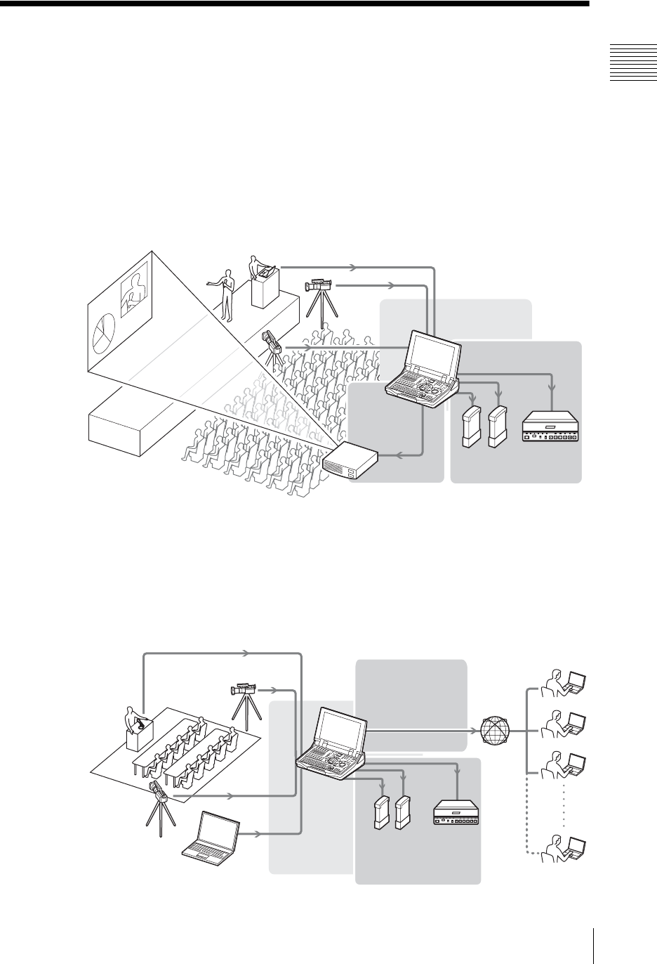
Event and presentation support
At seminars, events, and presentations you can use this unit to switch among
camera inputs and data from a computer, while displaying the output on a
projector or large monitor.
Principal functions used: video switching (such as cut switching or picture-in-
picture), audio mixing, RGB input/output
Internet live broadcast
This unit includes a streaming server function. For broadcast to small audiences
(about 20 people) over an intranet, this unit can be used as the streaming server
without requiring an external server.
Principal functions used: video switching (such as a wipe transition), audio
mixing, streaming encode, streaming server
RGB input
Switching
, (page 77)
Video output
, (page 209)
RGB output
External hard
disk
VCR
Recording
, (page 188)
Streaming settings/
broadcast
, (page 240)
Switching
, (page 77)
External
hard disk
VCR
Recording
, (page 188)
Chapter 1 Overview
16 Example Applications
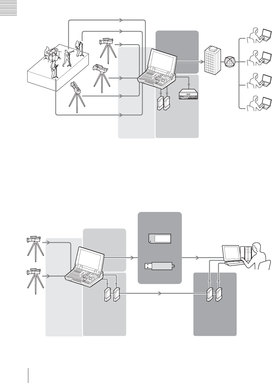
For the broadcast of things like live events to large audiences, you can broadcast
via a streaming server (Helix server).
Principal functions used: video switching (such as a mix transition), audio
mixing, streaming encode, camera presets
Simplification of re-editing after events
If you export an EDL (Edit Decision List) file with switching information from
an event saved and then use it on a nonlinear editing system in combination with
a material file recorded on an external hard disk, you can complete re-editing
work by just modifying the EDL.
Principal functions used: creating EDL, exporting EDL
Streaming
, (page 240)
External
hard disk
VCR
Recording
, (page 188)
Internet
provider
Broad-
cast
Switching
, (page 77)
External hard
disk
“Memory Stick”
Recording
, (page 188)
Nonlinear
editing system
Switching
, (page 77)
Creating EDL
, (page 223)
Exporting EDL
, (page 225)
USB flash memory
External hard
disk used for
recording the
material
17
Names and Functions of Parts
Chapter 1 Overview
Names and Functions of Parts
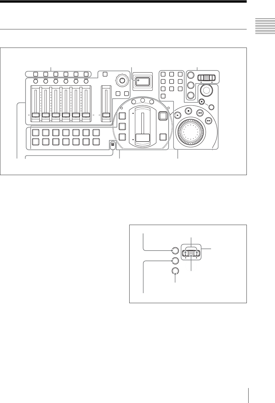
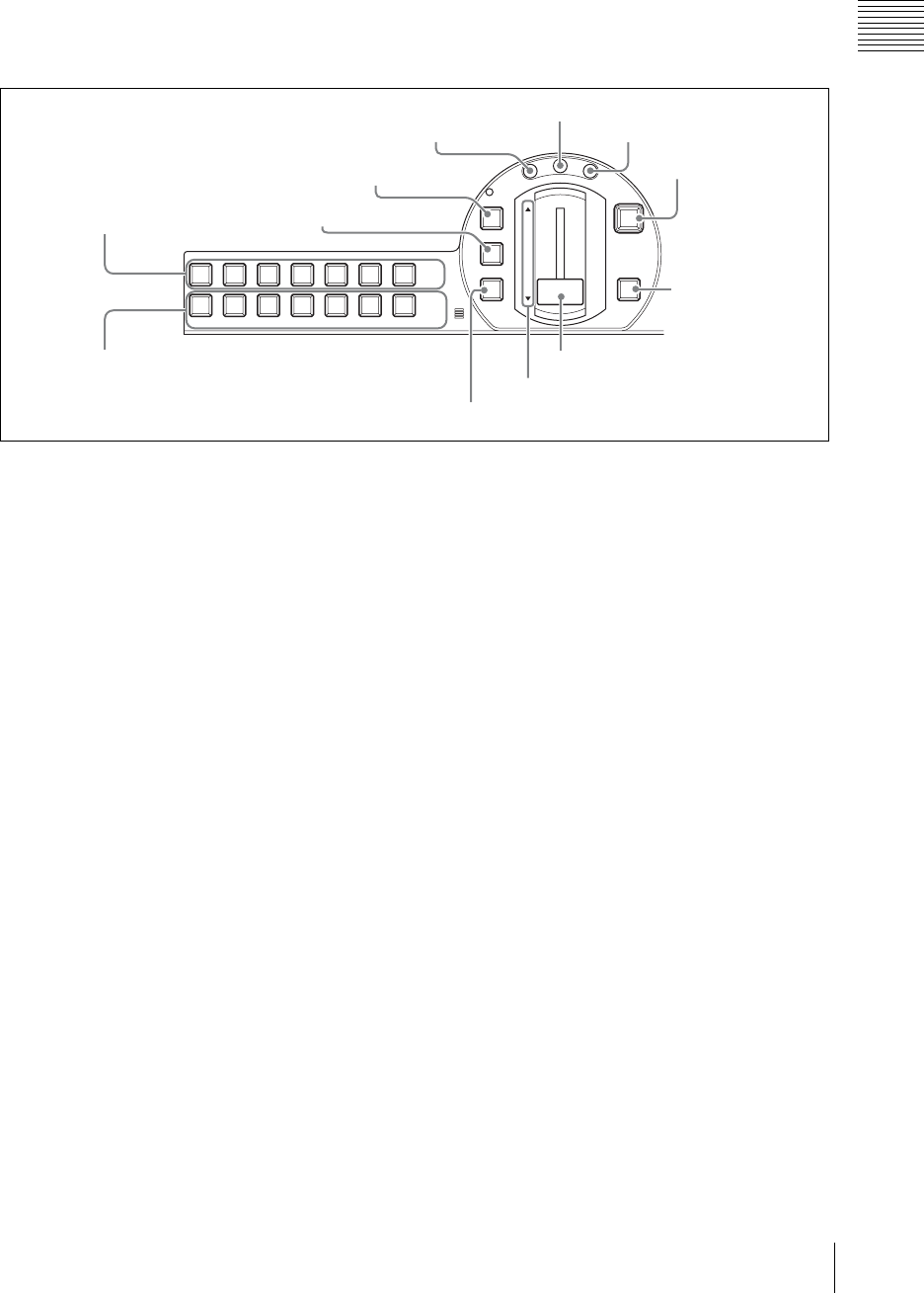
Front Panel
aACCESS buttons
These buttons are used for displaying the
ACCESS menu (page 35) and monitoring audio
(page 205). When you press an ACCESS button in
one of columns 1 to 6, the ACCESS menu appears
allowing adjustment of the related video and audio
settings.
Information on input signals appears on the left
side of the menu. If you hold down the ACCESS
button in one of columns 1 to 6 for 0.5 seconds or
more, you can monitor the audio assigned to the
channel fader in the same column, and display the
audio level meter for that channel only.
By holding down two or more ACCESS buttons
simultaneously, you can monitor multiple audio
channels.
bON LINE button
This button has the following functions.
• Execute/stop streaming broadcast (page 254)
• Start/stop recording of material and program
output to external hard disks (page 174)
• Start/stop recording to VCRs connected to the
DV connectors (page 192)
• Start/end EDL creation (page 225)
You can also start all these functions
simultaneously.
1 Menu control block
Use these controls to access the menus and
settings.
For details of operations, see “Menu Operations”
(page 34).
aENTER button
This button confirms an item or input value in
menu operations.
bESC button
This button closes the top menu and ACCESS
menu or cancels numeric and character input and
returns to one level above.
AUDIO MONITOR
CH ON
ACCESS/
PFL
MONI LEVEL
010
ON LINE
DIM TB
789
456
1
0
23
ESC
ENTER
MENU
X
-
Y
REC
SHIFT
JOG/SHUTTLE
MIC
NEXT
INT
654321
PGM
FTB
DSK
KEY
CUT
AUTO
TRANS
M
I
X
E
F
F
E
C
T
P
V
W
654321
+10
+5
0
-
5
-
10
-
20
-
30
-
40
-
60
-
+10
+5
0
-
5
-
10
-
20
-
30
-
40
-
60
-
PGM
+10
+5
0
-
5
-
10
-
20
-
30
-
40
-
60
-
1 Menu control section
2Audio operation section
(see page 18)
3Video switcher section
(see page 19)
4Device control section
(see page 20)
2 ON LINE button1 ACCESS buttons
ESC
ENTER
MENU
1 ENTER button Arrow buttons
Roller
4 Jog roller
3 MENU button
2 ESC button
Chapter 1 Overview
18 Names and Functions of Parts
Furthermore, pressing the ON LINE button while
holding down the ESC button enables you to
forcibly stop the following operations.
cMENU button
This toggles the top menu on or off.
dJog roller
Turn the roller up and down to select a menu item.
Pressing the roller like a button has the same effect
as pressing the ENTER button.
Use the arrow buttons when a menu operation
requires movement to left or right.
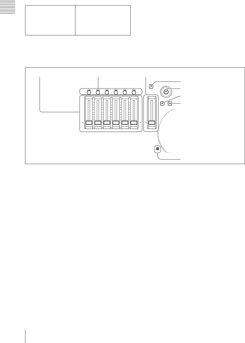
2 Audio operation section
Use these controls for audio settings and
operations.
aAudio channel faders
These buttons adjust the input levels of the audio
assigned to channels 1 to 6, in the range from –∞
to +10 dB (page 168).
For details of audio signal assignment, see “Audio
Signal Related Settings” (page 71).
bCH ON buttons
These buttons select whether the audio channels 1
to 6 are enabled or disabled.
Pressing a button enables the audio assigned to the
corresponding audio channel. Channels for which
the button is not lit are disabled (page 168).
You can also link the enabling of the audio
channels with the switching of the PGM selection
buttons (page 74).
cPGM fader
This button adjusts the overall audio output level
of the program output, in the range from –∞ to +10
dB (page 168).
dAUDIO MONITOR button
This button switches the monitoring target.
Pressing if cycles the audio to be monitored
through the sequence PGM t AUX1 t AUX2
t MIX t PGM (page 204).
eMonitor level adjustment knob
This button adjusts the level of the monitor output
and the output from the internal speakers and from
the headphones (page 204).
fDIM button
This button enables the “audio attenuate” function.
This reduces each of the level of the monitor
output and the output from the internal speakers
and from the headphones by 20 dB.
gTB button
This button lets you to speak while
communicating on an external intercom system.
While the TB button is lit, sound from the front
panel microphone and headset microphone is
output over the intercom system (page 201).
ESC + ON LINE buttons • Stop recording to an
external hard disk
• Stop recording to a VCR
• Stop streaming
• Stop EDL creation
CH ON
MONI LEVEL
010
DIM TB
MIC
654321
+10
+5
0
-
5
-
10
-
20
-
30
-
40
-
60
-
+10
+5
0
-
5
-
10
-
20
-
30
-
40
-
60
-
PGM
+10
+5
0
-
5
-
10
-
20
-
30
-
40
-
60
-
1 Audio channel faders 2 CH ON buttons 3 PGM fader
7 TB button
6 DIM button
8 Microphone
4 AUDIO MONITOR button
5 Monitor level adjustment knob
19
Names and Functions of Parts
Chapter 1 Overview
hMicrophone
This button lets you speak on an external intercom
system. While the TB button is lit, sound from the
microphone is output over the intercom system
(page 201).
3 Video switcher section
This switches video.
aPGM selection buttons
These buttons select the video which will be
displayed on the program output (page 78).
Buttons 1 to 6 select the corresponding assigned
video, and the INT button selects a video image
generated internally by this unit (color matte, color
bars, graphics files).
When you press one of these buttons, lighting it
red, the video assigned to the button is sent to the
program output.
For details of video assignment, see “Video Signal
Related Settings” (page 67).
bNEXT selection buttons
The NEXT selection buttons have the following
functions.
• Selecting the video to be output on the program
output after next switching transition (page 79)
• Selecting the video to be used for picture-in-
picture (page 86)
• Selecting the video to be used when inserting a
key in the program output (page 99)
• Specifying a camera to be controlled during
camera control operations (page 155)
• Selecting the video for recording or playback
(page 176, 178)
Buttons 1 to 6 select the corresponding assigned
video, and the INT button selects a video image
generated internally by this unit (color matte, color
bars, graphics files).
A graphic file (SD_Safe_Area.tga) is provided for
displaying safe areas.
cCUT button
This button instantaneously switches the video
(page 77).
dKEY button
This button effectuates keying (page 99). When
this key lights green, the NEXT selection buttons,
MIX button, AUTO TRANS button, CUT button,
and transition lever are then assigned to keying.
eMIX button
This button effectuates a dissolve (gradually
blending a new video into the existing image).
When applying an effect it gradually blends in the
effect (page 81).
fEFFECT button
This button enables an effect other than dissolve in
a transition or when applying an effect (page 82).
You can also use it as a shortcut to the [Effect
Pattern] menu (page 85).
gPVW button
With this button you can check the result of keying
and picture-in-picture before switching it to
program output, on the PVW viewer (page 110).
hFTB button
This button fades the video in from or out to a
black screen (“fade-to-black”) (page 89).
MIC
NEXT
INT
654321
PGM
FTB
DSK
KEY
CUT
AUTO
TRANS
M
I
X
E
F
F
E
C
T
P
V
W
1 PGM selection buttons
2 NEXT selection buttons
qs AUTO TRANS button
qa Indicators
0 Transition lever
9 DSK button
8 FTB button
6 EFFECT button
7 PVW button5 MIX button
4 KEY button
3 CUT button
Chapter 1 Overview
20 Names and Functions of Parts
iDSK button
This button add is used to images or text to the
program output video (page 90). You can use it to
superimpose text and so on.
jTransition lever
This lever allows you to manually execute a
transition or effect (page 81).
kIndicators (Ff)
These indicators show the direction in which the
transition lever is being moved. Moving the
transition lever in the direction of the lit indicator
starts the transition or effect.
However, supposing you press the AUTO TRANS
button after moving the transition lever to the
middle, for example, an inconsistency between the
position of the fader and the application of the
effect will arise and both indicators will light.
lAUTO TRANS button
This button carries out an automatic transition
with a preset transition time, either from one video
to another or when applying an effect (page 81).
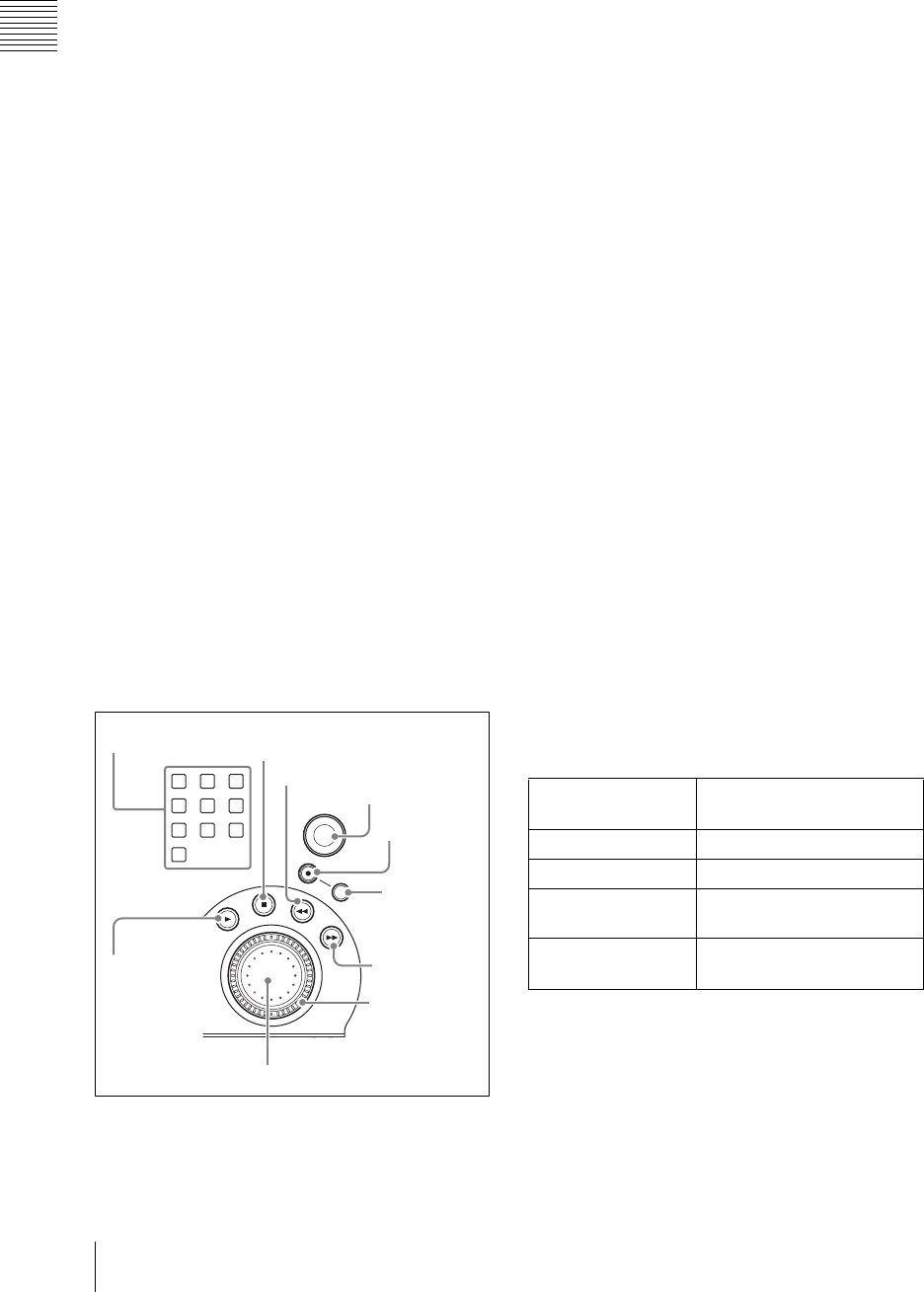
4 Device control section
Use these controls to remotely control a camera
with VISCA support connected to this unit (page
155), perform hard disk operations (material
recording, file playback) (page 176, 178), perform
VCR playback operations (page 194), or to access
graphics files quickly (page 94).
aNumeric buttons
These buttons are used to access graphics files
quickly, store and recall camera presets, reset
cameras, and cue up files (page 94, 157, 162, 184).
bPLAY button
This button plays back a file at normal speed.
Hold down the REC button and press this button,
to start recording on the hard disk (page 175).
cSTOP button
This button stops file playback. Press shift and
then press this button to switch the source viewer
back from viewing a file on the hard disk to normal
input (page 180).
While recording to an external hard disk, press this
button while holding down the REC button to stop
recording (page 177).
While recording program output, press this button
while holding down the SHIFT and REC buttons
to stop recording (page 175).
dREW button
During file playback, play back fast in the reverse
direction. Each time you press, the reverse speed
increases (in six steps) (page 180).
eFFWD button
During file playback, play back fast in the forward
direction. Each time you press, the playback speed
increases (in six steps) (page 180).
fREC button
This button is used to start or stop the external hard
disk recording (page 176).
gSHIFT button
This button is pressed while using other controls to
perform the following operations.
789
456
123
ENTER
X
-
Y
REC
SHIFT
JOG/SHUTTLE
FTB
DSK
3 STOP button
4 REW button
6 REC button
7 SHIFT
button
9 Shuttle dial
0 Jog dial
5 FFWD
button
2 PLAY
button
8 Positioner
1 Numeric buttons
REC + NEXT
selection buttons
Reserve or cancel material
recording
REC + PLAY buttons Start material recording
REC + STOP buttons Stop material recording
SHIFT + REC +
PLAY buttons
Start program output
recording
SHIFT + REC +
STOP buttons
Stop program output
recording

21
Names and Functions of Parts
Chapter 1 Overview
hPositioner
This control is used to pan or tilt the camera. You
can also control the speed of the camera by
adjusting how hard you press this button (page
156).
This control can also be used to change the display
positions for picture-in-picture and logos
(page 88, 99), and to move the Auto Chroma Key
cursor (page 106).
iShuttle dial (outer ring)
This dial controls the camera zoom.
During file or VCR playback, turning this dial
clockwise plays the file in the forward direction at
a speed that corresponds to the amount the dial
was turned and turning this dial counterclockwise
plays the file in the reverse direction at a speed that
corresponds to the amount the dial was turned
(page 156, 180).
jJog dial (inner dial)
This dial controls the camera focus and iris (page
156) and performs playback operations for VCRs
or files stored on the external hard disk (page 180).
SHIFT + jog dial Aperture (iris) adjustment on
camera with VISCA support
SHIFT + numeric
buttons (1 to 6)
• Set camera presets
• Register hard disk and
VCR cue-up points
SHIFT + numeric
buttons (1 to 9)
Register quick access
graphics files
SHIFT + numeric
buttons (0)
Camera reset
SHIFT + numeric
buttons (8)
Register a start point for auto
repeat
SHIFT + numeric
buttons (9)
Register an end point for auto
repeat
SHIFT + REW
buttons
• Skip to the beginning of a
file
• Move back one frame on a
VCR
SHIFT + FFWD
buttons
• Skip to the end of a file
• Move forward one frame on
a VCR
SHIFT + STOP
buttons
• Close a file
• Pause playback on a VCR
SHIFT + ENTER
buttons
• Delete preset data
simultaneously
• Process all files including
files that will be
overwritten
SHIFT + ESC buttons Process all files excluding
files that will be overwritten
SHIFT + REC +
PLAY buttons
Start program output
recording
SHIFT + REC +
STOP buttons
Stop program output
recording
Chapter 1 Overview
22 Names and Functions of Parts
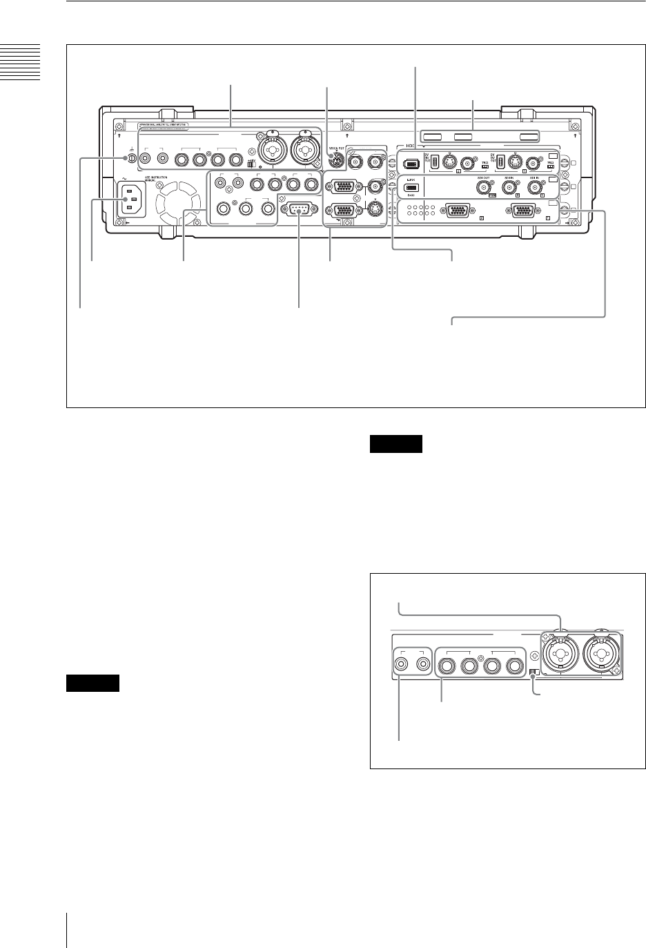
Rear Panel
aVISCA connector
To connect the chain of cameras with VISCA
support to this unit for remote control operation,
connect the VISCA cable (page 58).
bCable clips
Use these clips to prevent cables from accidentally
disconnecting (page 64).
cIntercom interface connector
Connect an external intercom system (page 201).
dPower supply connector (~AC IN)
Use to connect to an AC outlet (page 45).
When using a DC-AC inverter, the use of a 50 Hz
(±3%) or 60 Hz (±3%) sine wave is recommended.
Do not use a general-purpose inverter with a
square output waveform.
eGround terminal
When using this unit, connect the ground terminal
to a grounding lead.
The ground terminal is close to the audio input
connectors, so when connecting the grounding
lead be careful not to touch the audio input
connectors.
1 Audio inputs
aMicrophone/line input connectors (MIC/
LINE) 1/2 (XLR 3-pin, TRS shared
balanced type)
Input an analog audio signal from a microphone or
audio device.
AC IN
LINE MIC/LINE
MIX
HEADPHONES
MONI INTERCOM
15
69
RGB PGM
S VIDEO
AUX PGM RGB
I.LINK
S VIDEO
COMPOSITE
S VIDEO
COMPOSITE
S400
RGB RGB
COMPOSITE
MIC/LINE
PUSH PUSH
AUDIO IN
VIDEO IN
AUDIO OUT VIOEO OUT
87 6 5 4 3
RRLL
RL
21
21
OFF
ON
SD
OFF
ON
OFF
ON
PC
1
2
3
SDI
4Power supply
connector
(~AC IN)
1Audio inputs 1
VISCA
connector
4SD video interface module
(see page 24)
6 PC video interface module
(see page 24)
7HD video interface module
(option) (see page 25)
8HD serial digital interface
module (option) (see page 25)
3 Video outputs
(see page 23)
3 Intercom interface connector
2 Audio outputs
(see page 23)
2
Cable clips
5 Ground terminal
5 Serial digital interface
module (option)
(see page 24)
* This figure is when an optional serial digital interface module (BKAW-580)
is installed in slot 2 of the AWS-G500. An SD video interface module is
installed in slot 2 of the AWS-G500 at the time of shipment.
Caution
Caution
LINE MIC/LINE
MIC/LINE
PUSH PUSH
+
45V
AUDIO IN
87 6 5 4 3
21
OFF
ON
4Line input connectors (LINE) 7/8
1Microphone/line input connectors
(MIC/LINE) 1/2
3Microphone/line input connectors
(MIC/LINE) 3/4/5/6
2 +48V switch
23
Names and Functions of Parts
Chapter 1 Overview
b+48V switch
Use this switch when a capacitor microphone
requiring a power supply is connected to the
microphone/line input connectors (MIC/LINE) 1/
2. When this is in the ON position, +48V is
supplied.
cMicrophone/line input connectors (MIC/
LINE) 3/4/5/6 (TRS balanced type)
Input an analog audio signal from a dynamic
microphone or audio device.
dLine input connectors (LINE) 7/8 (RCA)
Input an analog audio signal from an audio device.
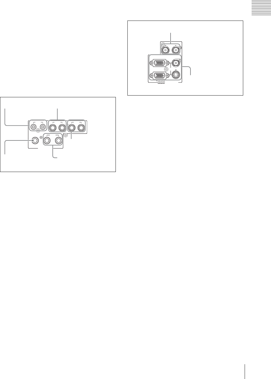
2 Audio outputs
aMIX output connector (MIX) L/R (RCA)
These connect to an external acoustic device to
output audio signals (page 203).
bAUX output connector (AUX) 1/2 (TRS,
balanced)
These connect to an external acoustic device to
output audio signals. The output level can be
adjusted (page 202).
cPGM audio output connectors (PGM) L/
R (TRS, balanced)
These output the final audio (program audio)
created by this unit (page 202).
dMonitor output connectors (MONI) L/R
(TRS, balanced)
These provide monitor outputs of any of the PGM/
AUX1/AUX2/MIX audio (page 204).
eHeadphone connector (HEADPHONES)
(standard phone jack)
This outputs one of the PGM/AUX1/AUX2/MIX
audio (page 203).
The output level can be adjusted with the front
panel monitor level adjustment knob (MONI
LEVEL) (page 204).
3 Video outputs
aReference output connectors (REF OUT)
× 2
These output either a 60 Hz (NTSC) or 50 Hz
(PAL) reference signal to match the program
output signal.
bPGM video output connectors (PGM)
• Composite video output connector
(COMPOSITE) (BNC) × 1
• S-video output connector (S VIDEO) (S
connector) × 1
These output the final program (PGM) video.
You can switch to NTSC (60 Hz) or PAL (50
Hz) (page 71).
• RGB output connectors (RGB) (D-sub 15-pin) ×
2
These output the final program (PGM) video as
analog RGB signals and video RGB signals.
Connect a projector or external display.
The following signals can be output (page 71).
- XGA (1,024 × 768) 60 Hz/75 Hz
- SXGA (1,280 × 1,024) 60 Hz
- WXGA (1,280 × 768) 60 Hz/75 Hz
- 15k RGB 50 Hz/59.94 Hz
MIX
HEADPHONES
MONI
AUX PGM
AUDIO OUT
RRL
RL
L21
1MIX output connector
(MIX)
2AUX output connector
(AUX) 1/2
3PGM audio output
connectors (PGM)
5
Headphone connector
(HEADPHONES)
4Monitor output
connectors (MONI)
RGB PGM
S VIDEO
RGB
REF OUT
COMPOSITE
VIOEO OUT
1 Reference output
connectors (REF OUT)
2PGM video output
connectors (PGM)
Chapter 1 Overview
24 Names and Functions of Parts
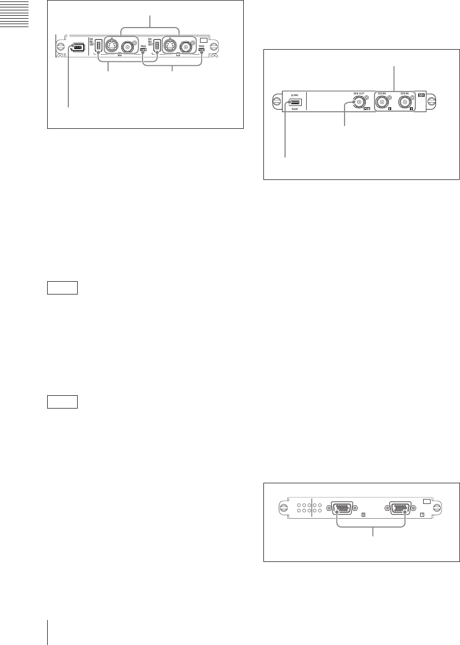
4 SD video interface module
(BKAW-570)
aAnalog video input connectors
Composite video input connectors
(COMPOSITE) (BNC) × 2
S-video input connectors (S connector) × 2
Input analog video signals.
b75-Ω termination switch
Set this switch to the OFF position when using a
loop-through connection for a video monitor or the
like by connecting a branch connector to the
composite video input connector (COMPOSITE).
The factory default setting is ON.
Use the end of a sharp implement such as a pen to
operate the switch.
cDV connectors (DV IN/DV PGM OUT)
(i.LINK 6-pin) × 2
Input and output digital video audio signals.
• Only one of the Composite/S Video/DV inputs
can be used for each of IN1and IN2.
• If the DV connector is set as the output, material
cannot be recorded from composite and S-video
connectors (page 190).
di.LINK connector (HDD) (i.LINK 6-pin)
× 1
If an external hard disk is connected, material and
program output can be recorded.
The following three types of recording are
available for an external hard disk.
• Manually record video input to the same
interface module in combination with audio that
has the same source number as the video (page
175).
• Manually record program output (page 174).
• Simultaneously record material and program
output (ON LINE recording) (page 174).
5 Serial digital interface module
(BKAW-580) (Option)
aSDI input connectors (SDI IN) (BNC) × 2
Inputs SDI signals.
bSDI output connector (SDI OUT) (BNC)
× 1
Outputs final video and audio (program video +
audio) as SDI signals (page 190).
ci.LINK connector (HDD) (i.LINK 6 pins)
× 1
If an external hard disk is connected, material and
program output can be recorded.
The following three types of recording are
available for an external hard disk.
• Manually record video input to the same
interface module in combination with audio that
has the same source number as the video (page
175).
• Manually record program output (page 174).
• Simultaneously record material and program
output (ON LINE recording) (page 174).
6 PC video interface module
(BKAW-550)
Note
Notes
I.LINK
S VIDEO
COMPOSITE
S VIDEO
COMPOSITE
S400
SD
OFF
ON
OFF
ON
SD
4 i.LINK connector (HDD)
1 Analog video input
connectors
2 75-Ω termination
switch
3DV connectors
(DV IN/
DV PGM OUT)
2SDI output connector
(SDI OUT)
1SDI input
connectors
(SDI IN)
3i.LINK connector (HDD)
RGB RGB
PC
RGB input connectors
(RGB)
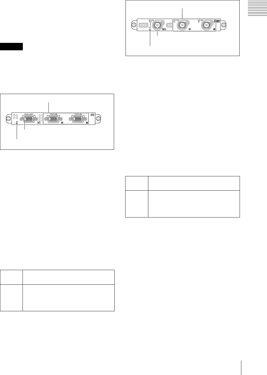
25
Names and Functions of Parts
Chapter 1 Overview
RGB input connectors (RGB) (D-sub 15-
pin) × 2
Input analog RGB signals from a computer or
other source. The following image size and
frequency combinations are supported.
• XGA (1,024 × 768) 60 Hz, 75 Hz
• SXGA (1,280 × 1,024) 60 Hz, 75 Hz
• WXGA (1,280 × 768) 60 Hz
WXGA inputs will be vertically reduced
approximately 6%.
7HD video interface module
(BKAW-560) (option)
aHD analog input connectors (YPBPR IN)
(D-sub 15-pin) × 2
These input HD analog signals. The following
signal formats for input are supported.
• 720/60p, 720/50p
• 1080/60i, 1080/50i
bHD analog output connector (YPBPR
OUT) (D-sub 15-pin) × 1
This outputs HD analog signals. The following
signal formats for output are supported.
• 720/60p, 720/50p
• 1080/60i, 1080/50i
cHD indicator
This lights or turns off in the following situations.
8HD serial digital interface module
(BKAW-590) (option)
aHD SDI input connectors (HD SDI IN)
(BNC) × 2
These input HD SDI signals. The following signal
formats for input are supported.
• 720/60p, 720/50p
• 1080/60i, 1080/50i
bHD SDI output connector (HD SDI OUT)
(BNC) × 1
This outputs HD SDI signals. The following signal
formats for output are supported.
• 720/60p, 720/50p
• 1080/60i, 1080/50i
cHD indicator
This lights or turns off in the following situations.
Caution
Lights When output of HD analog signals is
possible (16:9 HD mode (page 53)).
Turns off When output of HD analog signals is not
possible (4:3 and 16:9 SD modes (page
53)).
A black image signal is output.
HD
1HD analog input
connectors (YPBPR IN)
2HD analog output connector (YPBPR OUT)
3HD indicator
Lights When output of HD SDI signals is possible
(16:9 HD mode (page 53)).
Turns off When output of HD SDI signals is not
possible (4:3 and 16:9 SD modes (page
53)).
A black image signal is output.
1HD SDI input connectors
(HD SDI IN)
2HD SDI output connector (HD SDI
OUT)
3HD indicator
Chapter 1 Overview
26 Names and Functions of Parts
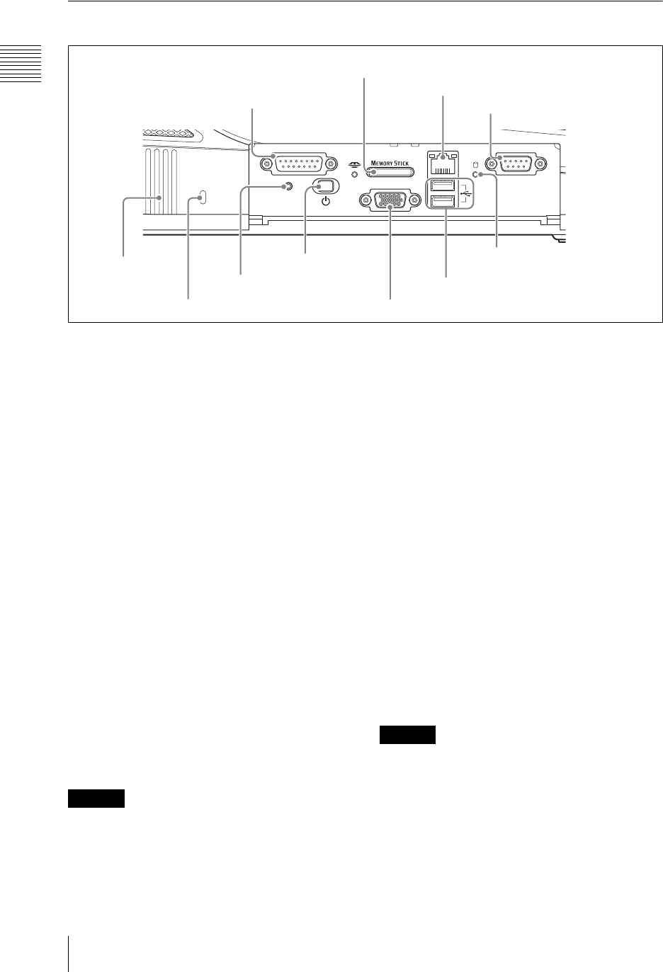
Side Panel
a FACTORY USE connector
Inputs and outputs GPI signals.
• Connecting this connector and the tally
connector of a CCU (camera control unit) or
other device enables the tally lamp of the camera
to light (page 164).
• When an external device is connected, you can
perform PGM and NEXT selection button
operations from the external device (page 166).
b“Memory Stick” slot
This slot takes a “Memory Stick.” Use it for
upgrading the operating software (page 262),
importing font files (page 152), exporting/
importing job data (page 221 and 222), exporting
EDL, importing graphics and logo files (page
228), exporting graphics files created with Text
Typing Tool (page 126), exporting VOD files
(page 231), etc.
While the “Memory Stick” is being accessed, the
access indicator to the left of the slot lights.
cNETWORK connector (RJ-45)
Connect an external network adaptor or router.
This supports 10Base-T and 100Base-TX
Ethernet.
The green indicator blinks while the network is
active.
An amber LED lights while the unit is connected
by 100Base-TX.
When making Network connections
For safety, do not connect the Network connector
to circuits which may be subjected to excessive
voltage.
d REMOTE (remote control) connector
This connector is provided for future functional
expansion.
e Internal hard disk access indicator
This indicator lights while the internal hard disk is
being accessed.
f USB connectors (USB) (USB
compatible)
The upper connector is number 1, and the lower
connector is number 2.
Use these connectors to connect a USB keyboard.
Also use them for connecting USB flash memory,
upgrading the operating software (page 262),
importing font files (page 152), exporting/
importing job data (page 221 and 222), exporting
EDL, importing graphics and logo files (page
228), exporting graphics files created with Text
Typing Tool (page 126), exporting VOD files
(page 231), etc.
For details of the keyboards that can be used,
consult your dealer or your Sony service
representative.
When using the Text Typing Tool software, you
can connect and use a USB mouse.
• These do not support input from a USB camera.
• A USB mouse cannot be used with the main
software.
gOperating monitor connector (RGB
(GUI)) (D-Sub 15-pin)
This connector outputs the operation screen to an
external display at WXGA (1,280 × 800) size, at
60 Hz.
FACTORY USE REMOTE
RGB
(
GUI
)
RESET
USB
NETWORK
18
15 9
15
96
0 Hole for anti-theft wire
2 “Memory Stick” slot
3NETWORK connector
4REMOTE (remote control)
connector
5Internal hard disk
access indicator
6 USB connectors
7 Operating monitor connector (RGB (GUI))
8 1 (power)
button
9 RESET button
1 FACTORY USE
connector
qa Ventilation
holes
With the protective panel opened
Caution
Caution
27
Names and Functions of Parts
Chapter 1 Overview
For information on which devices can be used,
consult your dealer or your Sony service
representative.
h1 (power) button
This button powers the unit on or off. If you hold
down the power button for at least 4 seconds, this
forces a shutdown.
After a forced shutdown, the settings of the unit
may not be preserved.
iRESET button
This button is provided for future functional
expansion.
j Hole for anti-theft wire
This hole accepts a standard anti-theft wire (3 mm
× 7 mm).
kVentilation holes
Be careful not to obstruct the ventilation holes. If
the ventilation holes are obstructed, the unit may
overheat, leading to fire or breakdown.
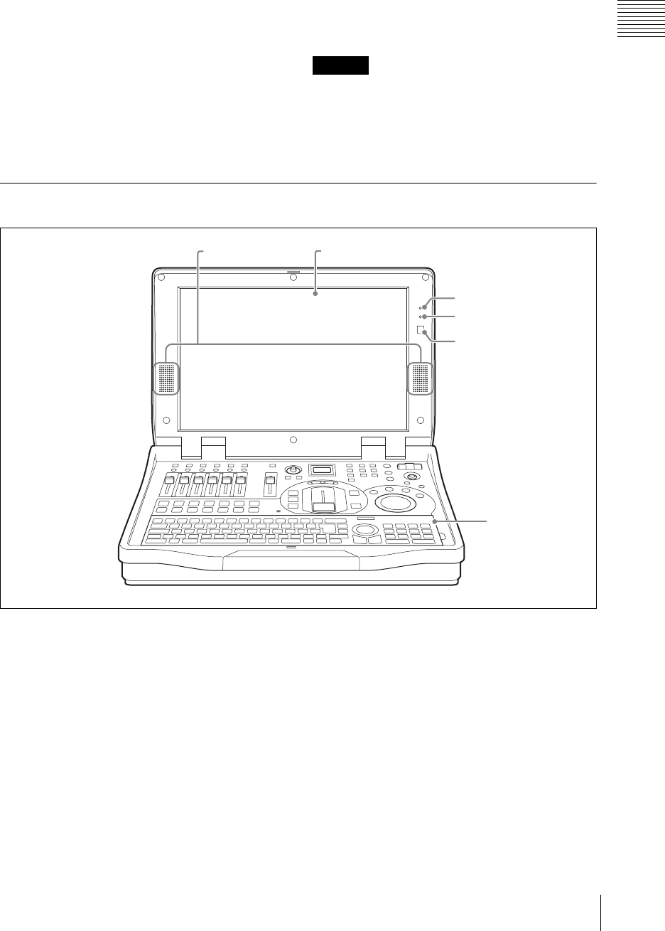
Other Parts
aBuilt-in speakers
You can monitor the audio using these speakers.
There is no output from the built-in speakers when
a headphone is connected to the headphone
connector.
bDisplay
This shows the operation screen (page 28).
cNum Lock indicator
This lights green when the unit is in Num Lock
mode.
dCaps Lock indicator
This lights green when the unit is in Caps Lock
mode.
eInfrared receptor
This accepts signals from the keyboard supplied
with this unit (page 48).
Caution
6 Keyboard
5 Infrared receptor
3 Num Lock indicator
4 Caps Lock indicator
2 Display1 Built-in speakers
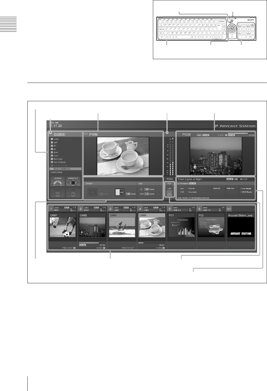
Chapter 1 Overview
28 Names and Functions of Parts
fKeyboard
Use this for text and numeric input.
You can also use the keyboard for menu
operations (page 35).
While the keyboard is mounted to the unit, the
EXT POWER indicator on the keyboard lights
green.
When using Esc and the F1 to F12 keys, hold
down the Fn key and press the required key in the
topmost row.
For details on changing the keyboard language,
see “Selecting the Language” (page 50).
Operation Screen
aMenu display
This displays the top menus (page 34), the INT
material selection menu (pages 91, 209), the
graphics preset menu (page 94), the camera guide
menu (pages 155, 157), the HDD guide menu
(page 178), and the VCR guide menu (page 194).
bGuidance object indication
The color of the guidance object indication has the
following significance.
Amber: When a video subject to camera control
(page 155), external hard disk control (page
175), or VCR playback control (page 194), or
INT is selected with the NEXT selection
buttons (while the KEY button is not lit).
Green: When a video subject to camera control,
external hard disk control, or VCR playback
control, or INT is specified with the NEXT
selection buttons (while the KEY button is lit).
EXT POWER indicator
Infrared receptor
Numeric
keys
PointerCharacter input keys
3 Audio level meter
4 Source viewer5 Effect display
3 Streaming display
2 PVW viewer
1 Menu display 1 PGM viewer
2 Guidance object
indication
* This example screen shows the streaming settings displayed.
Normally the streaming display cannot be viewed.
4 KEY ON
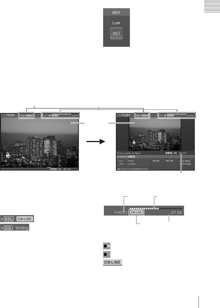
29
Names and Functions of Parts
Chapter 1 Overview
Off: When other than a video subject to camera
control and external hard disk control or INT
is specified with the NEXT selection buttons.
cAudio level meter
When monitoring the any of the PGM/AUX1/
AUX2/MIX audio outputs or Pre Fader Listen
(PFL) result, this shows the audio level. An
indication below the meter shows which of PGM/
AUX1/AUX2/MIX or PFL is being monitored.
When the level exceeds the meter range, the
uppermost indicator lights red (page 204).
dKEY status display
The indicator lights red during keying to program
output video. The number (1 to 6) or “INT” of the
source selected for keying appears.
In addition, when [Chroma Key] (page 103) or
[Luminance Key] (page 99) is selected for [Key
Type] in the Video Effect menu, “Chroma” or
“Lum” appears respectively.
1 PGM viewer
This shows a program output.
aEDL status
During EDL creation, this shows the status of the
creation operation.
Creation operation indications
: ON LINE reservation status
: ON LINE execution status
(EDL creation in progress)
bHard disk status
During program output recording, this shows the
hard disk status, remaining capacity, and
recording operation.
Recording operation indications
REC PAUSE: Recording on standby
REC: Recording
: ON LINE recording reservation (press
the ON LINE button to enter a recording start
state)
Unformatted: Formatting required
Normal When configuring streaming settings
3Program
video
2Hard disk status1EDL status
4VCR status
Recording
operation
Hard disk
drive number
Remaining time
Remaining capacity is
indicated by a progress bar
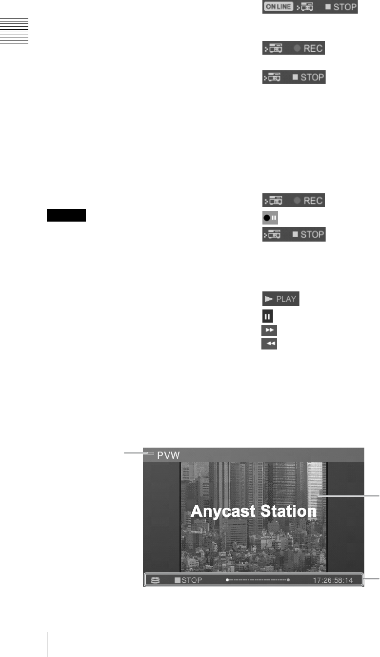
Chapter 1 Overview
30 Names and Functions of Parts
Disk Full: No disk space left (200 MB or less)
File Number Full: The number of files that can
be recorded has been exceeded
Device Error: It became impossible to recognize
the hard disk during recording
REC Error: Recording error
cProgram video
Displays the program output video. The size of the
video differs, depending on the PGM output
aspect ratio setting (page 52).
•When using 4:3 mode
The video is displayed at 480 × 360 pixels at
about 30 fps (about 25 fps for PAL). During
streaming, the size is 320 × 240 pixels.
•When using 16:9 SD or 16:9 HD mode
The video is displayed at 426 × 240 pixels at
about 30 fps (about 25 fps for PAL).
• Video displayed on the PGM viewer lags several
frames behind the video output from the PGM
video output connectors.
• In any of the video viewers displayed on the
operation screen (PGM/PVW/source) the video
may deteriorate, but this is an artifact of the
display system. There is no effect on the video
output from the program video output
connectors.
dVCR status
While recording to a VCR, this shows the status of
the recording operation.
Recording operation indications
: ON LINE reservation
status (You can start recording by pressing the
ON LINE button.)
: ON LINE execution status
(Recording to VCR in progress.)
: Recording has stopped due to
reasons including the tape ending
No Cassette: There is no videocassette, disc, or
other medium inserted
No Response: Cannot control playback from
the unit
Indications when manual playback
controls are performed during recording
control
: Recording
REC PAUSE: Recording on standby
: Stopped
No Cassette: There is no videocassette, disc, or
other medium inserted
No Response: Interface has not been
established
PLAY: Playback
STILL: Paused
: Fast forward
: Fast reverse
2 PVW viewer
This shows a preview of the video.
This allows you to check the input video selected to be shown next, keying, or picture-in-picture result
before switching to program output.
Caution
1What the preview
is showing
2 Preview video
3 Status
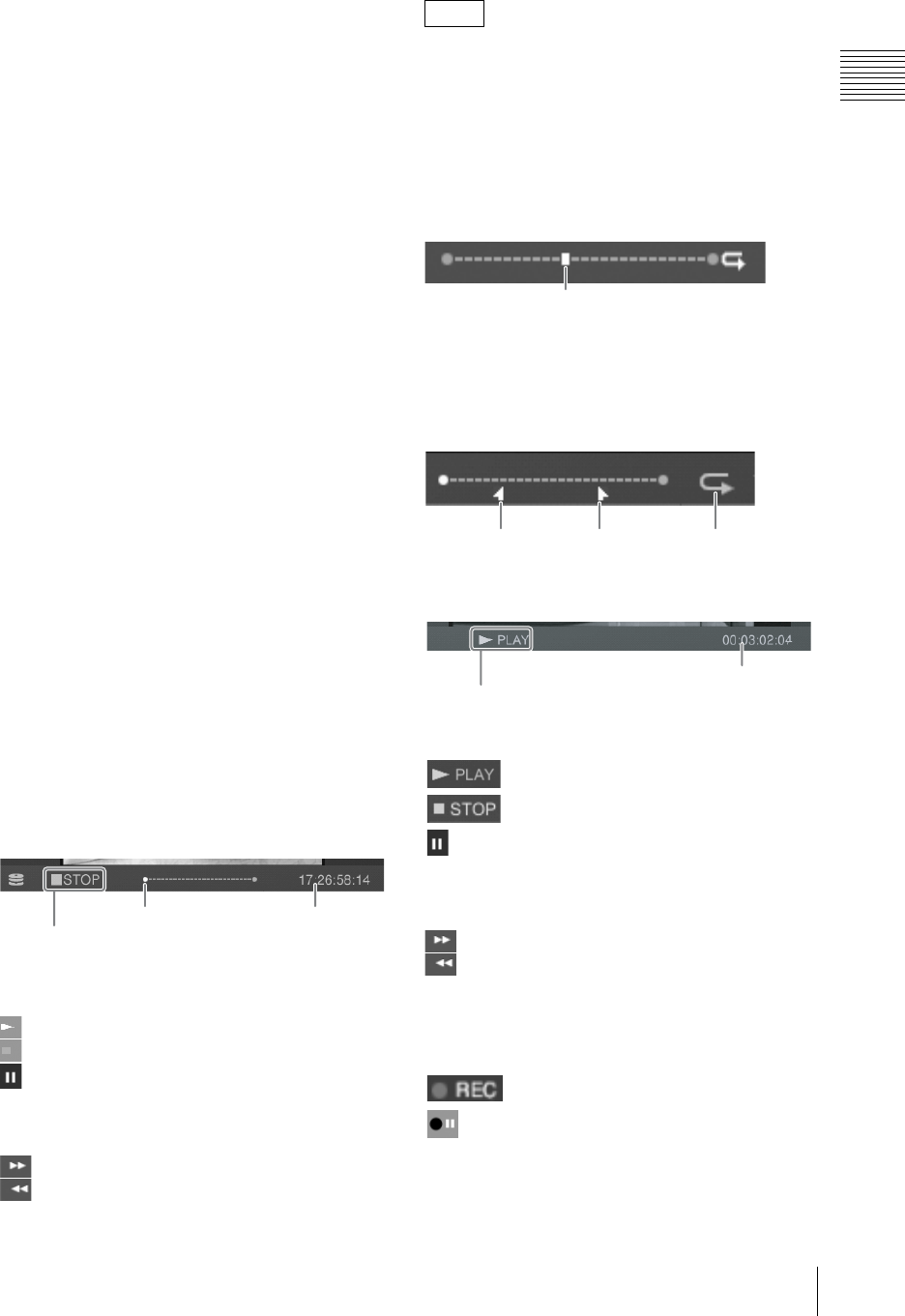
31
Names and Functions of Parts
Chapter 1 Overview
aWhat the preview is showing
Amber: When showing the video selected by the
NEXT selection button.
Green: When showing the video selected by the
NEXT selection button when the KEY button
is lit (video with a key inserted).
bPreview video
Under normal conditions, this displays the video
selected with the NEXT selection buttons. The
size of the video differs, depending on the PGM
output aspect ratio setting (page 52).
•When using 4:3 mode
The video is displayed at 320 × 240 pixels at
about 15 fps (about 12 to 13 fps for PAL).
•When using 16:9 SD or 16:9 HD mode
The video is displayed at 426 × 240 pixels at
about 15 fps (about 12 to 13 fps for PAL).
cStatus
The status shown here differs as follows
depending on the video to be previewed.
When showing video from a remotely
controlled VISCA compliant camera
The status of the VISCA compliant camera is
shown.
No Response: Communication cannot be
established with the camera.
Initializing: Appears at system startup and during
camera reset.
When showing an INT graphics file
Loading: While file is loading
When playing a file on an external hard
disk
The status of file operations is shown.
File operation indications
Opening: Opening a file
PLAY: Playback
STOP: Stopped
STILL: Playback speed is set to zero with the
shuttle dial, or playback is stopped with the
jog dial
JOG: Using the jog dial
x2: Fast forward (x2, x4, x8, x16, x32, x64)
x2: Fast reverse (x2, x4, x8, x16, x32, x64)
The x1/8, x1/2, and x1 indications are also
displayed while you are using the shuttle dial for
playback operations.
Play position
This shows the file play position.
When the play position is at the beginning or end,
z of each end lights.
While auto repeat playback is set, an icon is
displayed on the right side, and the positions of the
start and end points are indicated if they have been
set (page 181).
When performing playback on a VCR
VCR playback indications
PLAY: Playback
: Stopped
STILL: Playback speed has been set to zero
with the shuttle dial, or playback has been
stopped with the jog dial
JOG: The jog dial operation in progress
: Fast forward
: Fast reverse
No Cassette: There is no videocassette, disc, or
other medium inserted
No Response: Interface has not been
established
: Recording
REC PAUSE: Recording on standby
File operation
Play position Timecode
Note
Play position
Start point End point Icon
VCR playback operation
Timecode
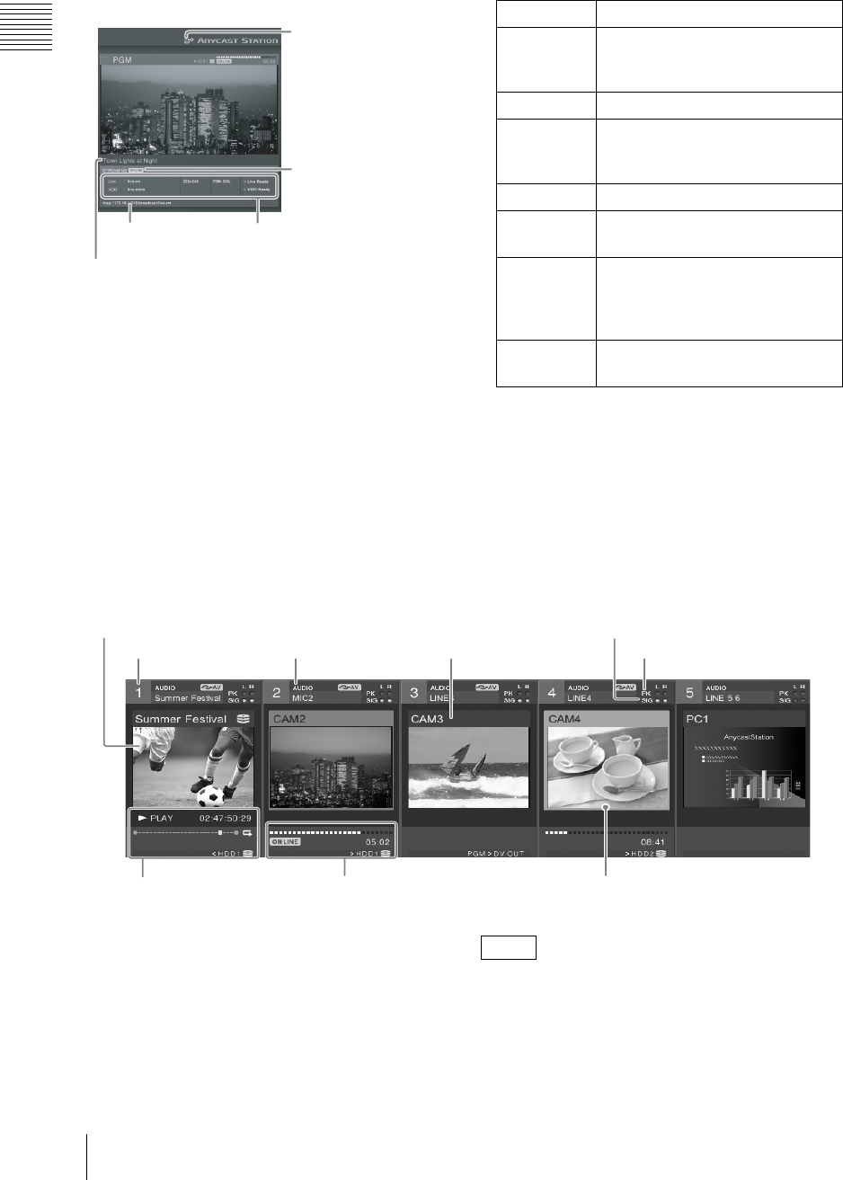
Chapter 1 Overview
32 Names and Functions of Parts
3 Streaming display
This shows the settings and status of the streaming
broadcast.
aVOD icon
This appears when a VOD file has been saved and
the internal server is running.
bON LINE icon
This appears when streaming can be started after
the ON LINE button has been pressed.
cInformation display
This shows the following information:
• the file name registered in the top menu
• video size set in the top menu
• transfer rate set in the top menu
• the status of the server or encoder
dLive access URL
This appears when the unit is used as a server for
a broadcast. Audience members can view the
broadcast by accessing this URL.
eTitle
This shows the streaming title.
4 Source viewer
aThumbnails
These show the video assigned to the selection
buttons at 160 × 120 pixels, at about 10 fps (about
8 to 9 fps for PAL). The video display is squeezed for 16:9 input
materials.
bSource number
This is the number (1 to 6 and INT) assigned to the
source (video or audio).
1 VOD icon
3Information display4 Live access
URL
2 ON LINE icon
5Title
Initializing Starting server or encoder
Live Ready
and/or VOD
Ready
Server started up, and encoder ready
Starting Encoder connecting to server
Broadcasting
and/or
Recording
Encoding
Stopping Ending the encoder
Reconnecting While re-establishing a connection
to the server.
Failed When a connection failed to be
established because of the settings
of the unit, the status of the network
or external server, etc.
Error The encoder had failed to end, or an
error occurred.
1 Thumbnails
2 Source number 3 Audio source name 4 Video source name
5 Input signal indication
6 Peak indication
9 Device status 7 Selection frame8 Hard disk status
Note
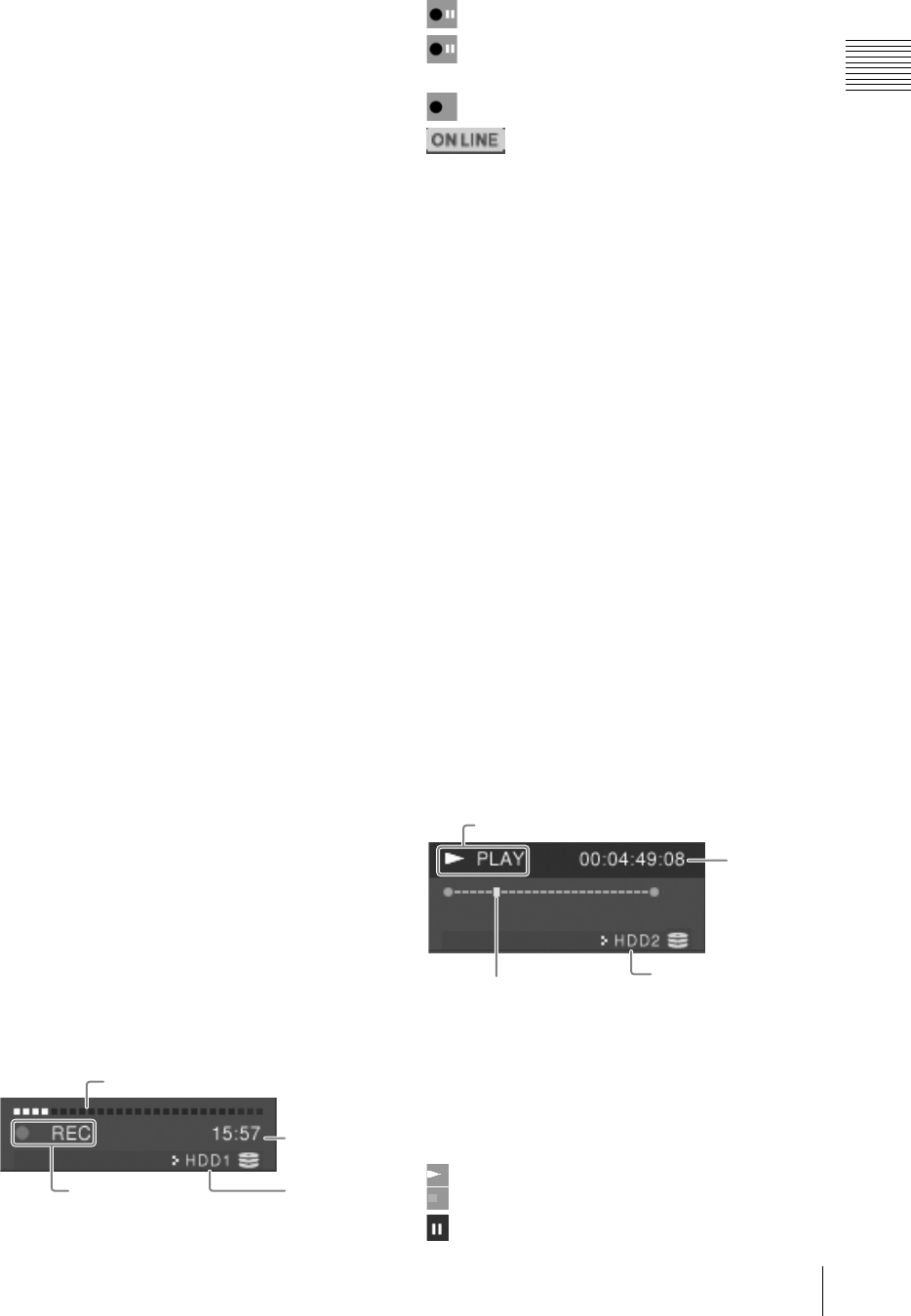
33
Names and Functions of Parts
Chapter 1 Overview
These correspond to the PGM selection button, the
NEXT selection button, and the audio channel
fader numbers.
cAudio source name
This shows the name of the audio signal assigned
to the channel fader (page 71) or the file name on
the external hard disk (page 178).
dVideo source name
In viewers 1 to 6, this shows the name of the video
signal assigned to the selection button (page 67) or
the file name on the external hard disk (page 178).
For the INT viewer, this displays the color matte
and color bars, or the graphics file name selected
in the INT source selection menu.
eInput signal indication
If the input level of the audio assigned to a channel
fader is -60 dBFS or more, this lights green, and
you can check that there is an audio input.
For stereo you can check left and right channels
separately; for monaural both channels are shown
the same.
fPeak indication
If the input level of the audio assigned to a channel
fader is -8 dBFS or more, this lights red.
For stereo you can check left and right channels
separately; for monaural both channels are shown
the same.
gSelection frame
Depending on the selection state, the frame color
changes.
Red: Video selected with PGM selection button
Amber: Video selected with NEXT selection
button
Green: Video selected with NEXT selection
button when the KEY button is lit (video with
a key inserted)
hHard disk status
When an external hard disk is connected, this
shows the status of the hard disk, the remaining
recording capacity, and the recording operations.
Recording operation indications
REC PAUSE: Recording on standby
No Signal: Recording is stopped because
there is no video signal input
REC: Recording
: ON LINE recording reservation (press
the ON LINE button to enter a recording start
state)
Unformatted: Error requiring formatting
Disk Full: No disk space left (200 MB or less)
File Number Full: The number of files that can be
recorded has been exceeded
Device Error: It became impossible to recognize
the hard disk during recording
REC Error: Recording error
iDevice status
The content displayed differs as follows
depending on the material.
Video from a VISCA-compatible camera
being controlled remotely
Displays the VISCA-compatible camera’s status.
No Response: Communication cannot be
established with the camera.
Initializing: Appears at system startup and during
camera reset.
INT graphics file
Loading: File is loading
When playing a file on the external hard
disk
Displays the status during file operation or VCR
playback.
File operation and VCR playback
indications
No Response: The VCR is not responding
No Cassette: There is no videocassette inside the
VCR
Opening: Opening a file
PLAY: Playback
STOP: Stopped
STILL: During file operation
Hard disk
drive number
Remaining capacity shown by progress bar
Available
recording time
Recording
operations
Play position Corresponding hard
disk number
Timecode
File operation
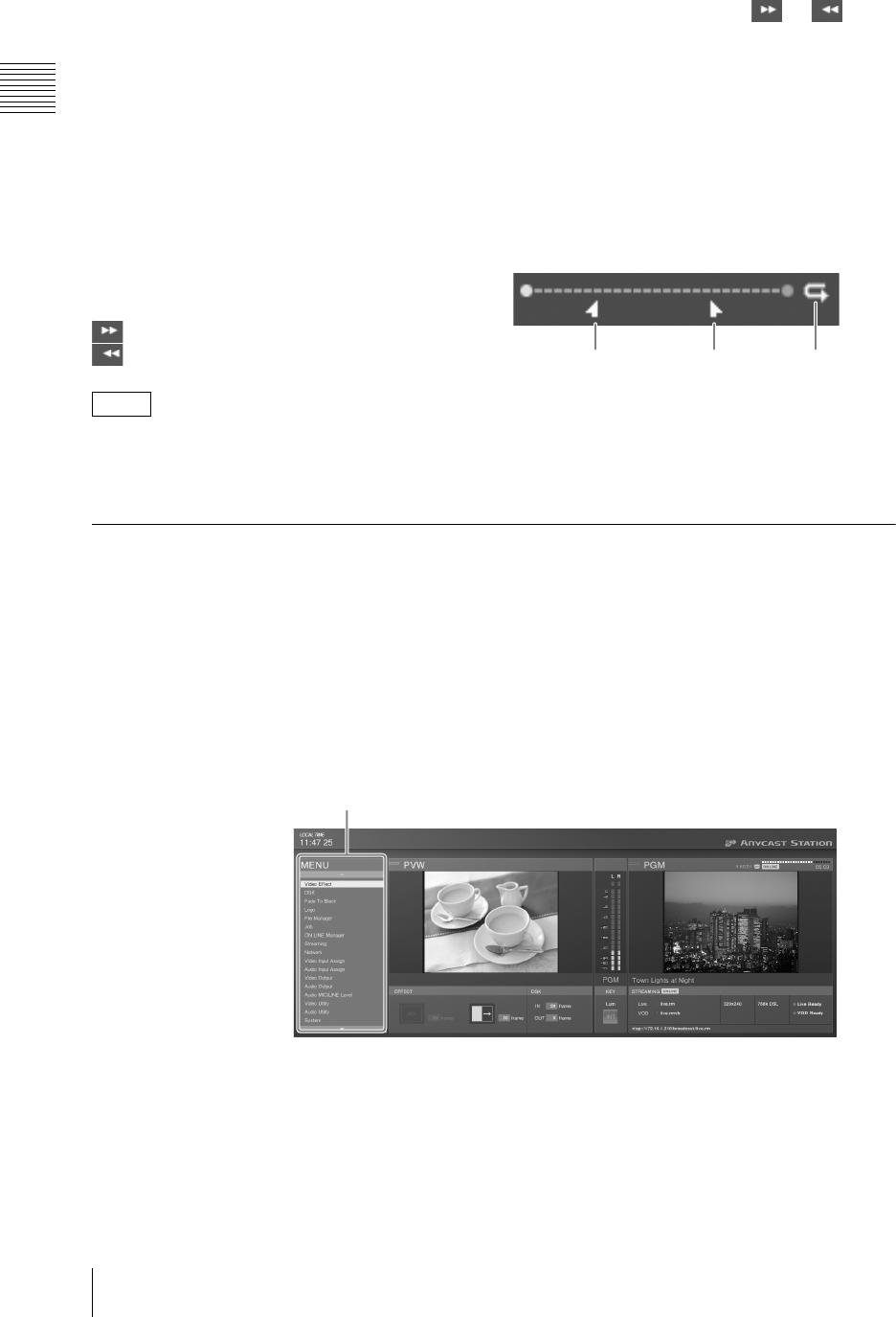
Chapter 1 Overview
34 Names and Functions of Parts
• Playback speed has been set to zero with the
shuttle dial
• Playback has been stopped with the jog dial
During VCR playback
• Playback speed has been set to zero with the
shuttle dial
• Playback has been stopped with the jog dial
• Playback has been paused with the SHIFT +
STOP buttons
• Moved back one frame with the SHIFT +
REW buttons
• Moved forward one frame with the SHIFT +
FFWD buttons
JOG: Using the jog dial
x8: Fast forward (x2, x4, x8, x16, x32, x64)
x8: Fast reverse (x2, x4, x8, x16, x32, x64)
• The x1/8, x1/2, and x1 indications are also
displayed while you are using the shuttle dial for
playback operations.
• During VCR playback, only or
appears.
Play position
This shows the file play position.
When the play position is at the beginning or end,
z of each end lights.
While auto repeat playback is set, an icon is
displayed on the right side, and the positions of the
start and end points are indicated if they have been
set (page 181).
5 Effect display
This shows the video transition effect types and
patterns and transition time (page 84).
Menu Operations
This unit includes top menus, which are used to make various operational
settings, and ACCESS menus, which are used to make adjustments to the video
and audio being input to this unit.
This section describes the basic operations common to these menus.
Displaying top menus and ACCESS menus
Top menus
Press the MENU button, to display the top menu in the menu display.
Notes
Start point End point Icon
Top menu
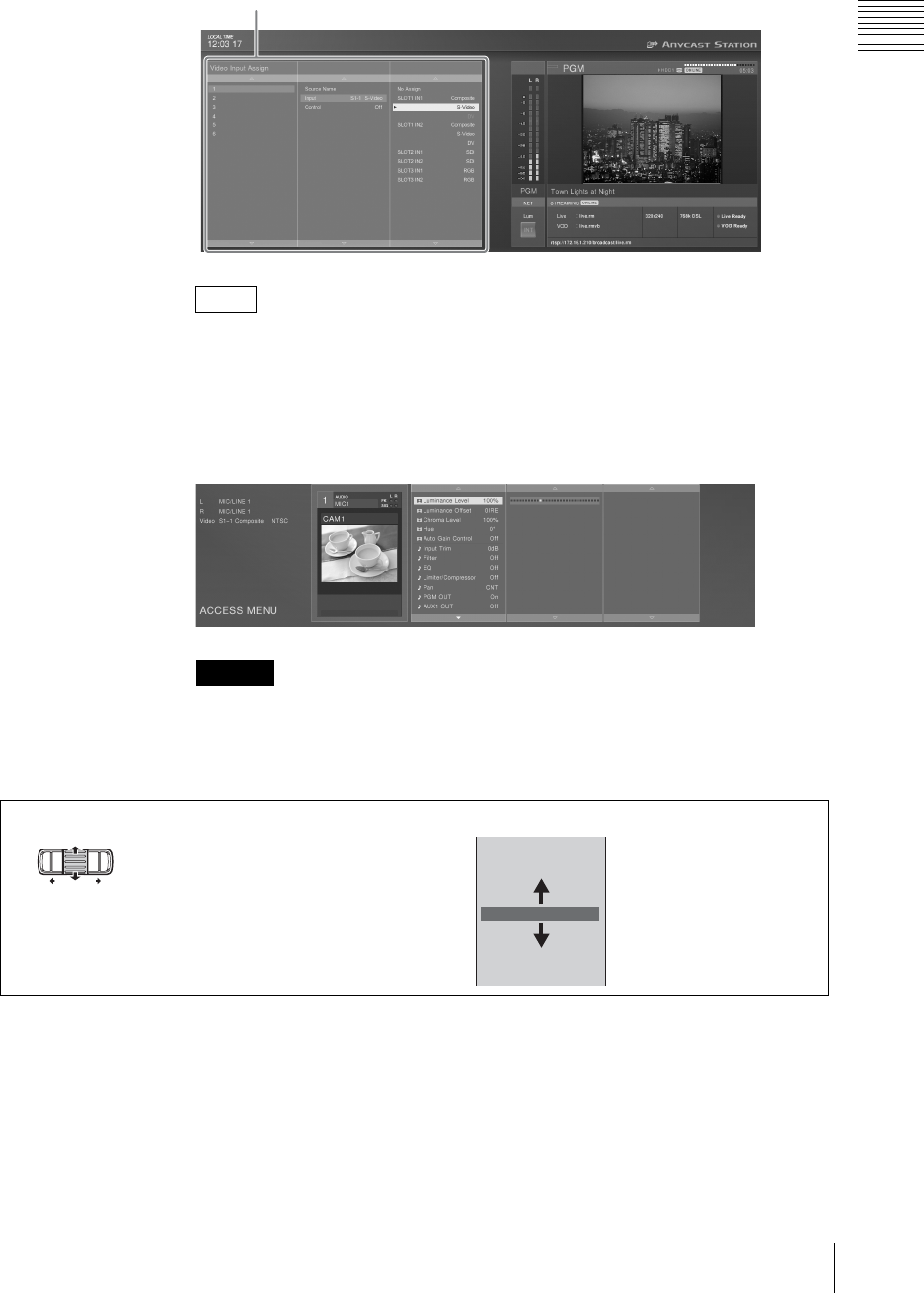
35
Names and Functions of Parts
Chapter 1 Overview
When you select and confirm an item in the top menu, submenus appear, three
levels deep.
You can set priority to be given to displaying the PVW viewer while submenus
are open (page 113).
ACCESS menu
Press the ACCESS button corresponding to the number of input you want to
adjust, to display the ACCESS menus, three levels deep, in the source viewer
together with the viewer for that number.
Starting with Software Version 2.00, the menu displays will differ depending on
the interface module in use and video signal assignments.
Menu operations
Sub-menu
Note
Caution
Video Effect
DSK
Fade To Black
Logo
File Manager
ON LINE Manager
Streaming
Network
Video Input Assign
Selecting a menu item
Turn the jog roller up or down.
You can also use the R and r keys on the
keyboard.
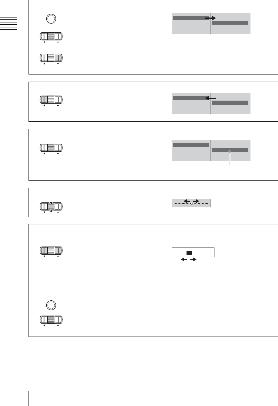
Chapter 1 Overview
36 Names and Functions of Parts
Zoom Enable
Focus Auto
lris Auto
White Balance Auto
Disable
Enable
ENTER
Confirming an item and proceeding to the next layer
Press the ENTER button.
or
Press the jog roller.
or
Press the t button by the jog roller.
You can also use the t key or ENTER key
on the keyboard.
Zoom Enable
Focus Auto
lris Auto
White Balance Auto
Disable
Enable
Returning to the higher level
Press the T button by the jog roller.
You can also use the T key on the
keyboard.
Zoom Enable
Focus Auto
lris Auto
White Balance Auto
Disable
Enable
Confirmation
Confirming a selection
Press the ENTER button.
or
Press the jog roller.
You can also use the ENTER key on the
keyboard.
Slider operation
Turn the jog roller up or down.
You can also press R or r on the keyboard.
Moving the cursor to the next item:
Press the T or t button by the jog roller.
You can also press the T or t keys while
holding down Ctrl on the keyboard.
Entering numeric or text values:
Enter with the keyboard.
Confirmation:
Press the ENTER button.
or
Press the jog roller.
You can also use the ENTER key on the
keyboard.
2004/05/18 12:25
Entering numeric or text values
ENTER
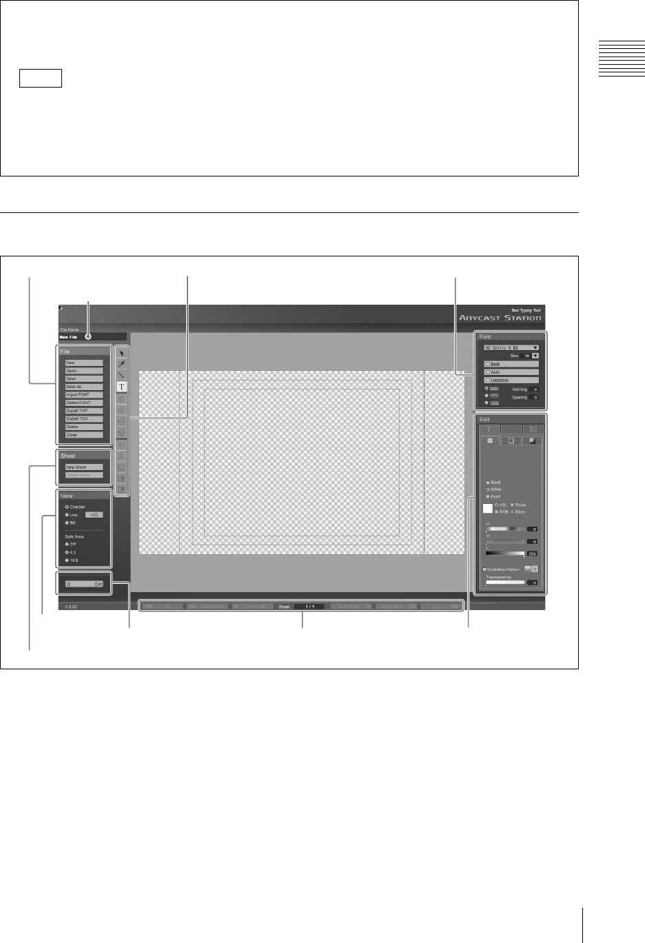
37
Names and Functions of Parts
Chapter 1 Overview
Operation Screen (Text Typing Tool Software)
aFile name
This shows the name of the open file.
bExit button
Click this to exit the Text Typing Tool software,
and start the Anycast Station main software.
Closing a menu
For a top menu: Press the MENU button or ESC button.
For an ACCESS menu: Press the same ACCESS button used to display, or the ESC button.
• Pressing an ACCESS button while the top menu is displayed closes the top menu and opens the
ACCESS menu.
• Pressing the MENU button while the ACCESS menu is displayed closes the ACCESS menu and
opens the top menu.
Notes
1 File operation section
1 File name
3 Font operation section2 Tool operation section
7 Sheet operation section
2 Exit button
6View operation
section 5 Page operation section 4Modifier operation
section
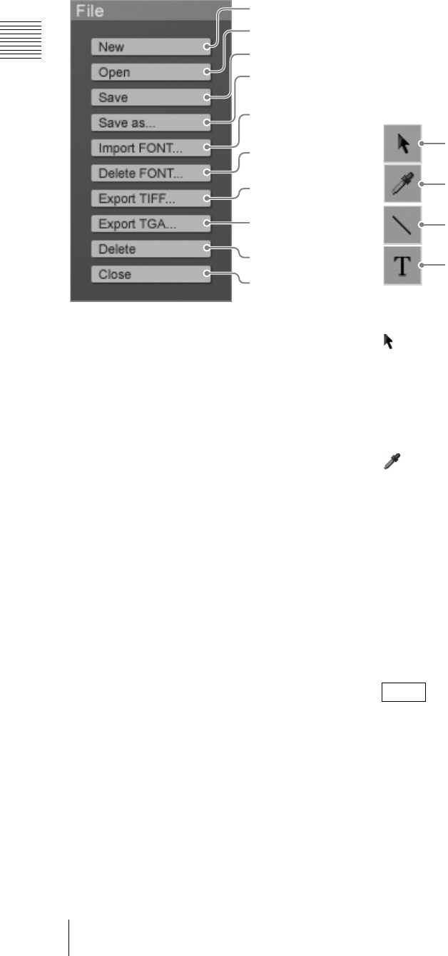
Chapter 1 Overview
38 Names and Functions of Parts
1File operation section
aNew button
This creates a new file (page 121).
bOpen button
This opens a previously saved file. A list of
existing files appears (page 122).
cSave button
This saves a file (page 122).
The file is also simultaneously saved in the
Anycast Station main software, and the file name
appears in the INT selection menu.
dSave as... button
This saves the file with a different name (page
124).
eImport FONT... button
This imports a font file from a “Memory Stick” or
USB flash memory (page 152).
fDelete FONT button
This deletes unwanted font files (page 153).
gExport TIFF... button
This saves the open file to a “Memory Stick” or
USB flash memory in TIFF format (page 126).
hExport TGA... button
This saves the open file to a “Memory Stick” or
USB flash memory in TARGA format (page 126).
iDelete button
This deletes unwanted files (page 125).
jClose button
This closes the open file, and displays a new sheet.
2Tool operation section
Select the tools needed to create and edit an object.
aSelection tool
When you click this, the mouse pointer changes to
, and you can select, adjust, and move an object
(page 120).
An orange frame appears around the selected
object.
bEyedropper tool
When you click this, the mouse pointer changes to
, and you can set the color of the selected object
to be the same as the color of another object or the
background image (page 142).
cLine tool
You can create a straight line (page 134).
You can create three types of line: solid, broken,
and dotted.
dText tool
When you click this, you can create a text object
(page 127).
When the selection tool is selected, you can move
the selected object with the keyboard arrow keys.
Hold down the Shift key while pressing the arrow
keys to speed up the movement.
1New button
2Open button
3Save button
4Save as...
button
6Delete FONT
button
0Close button
9Delete button
8Export TGA...
button
5Import FONT...
button
7Export TIFF...
button
Note
1Selection tool
2Eyedropper tool
3Line tool
4Text tool
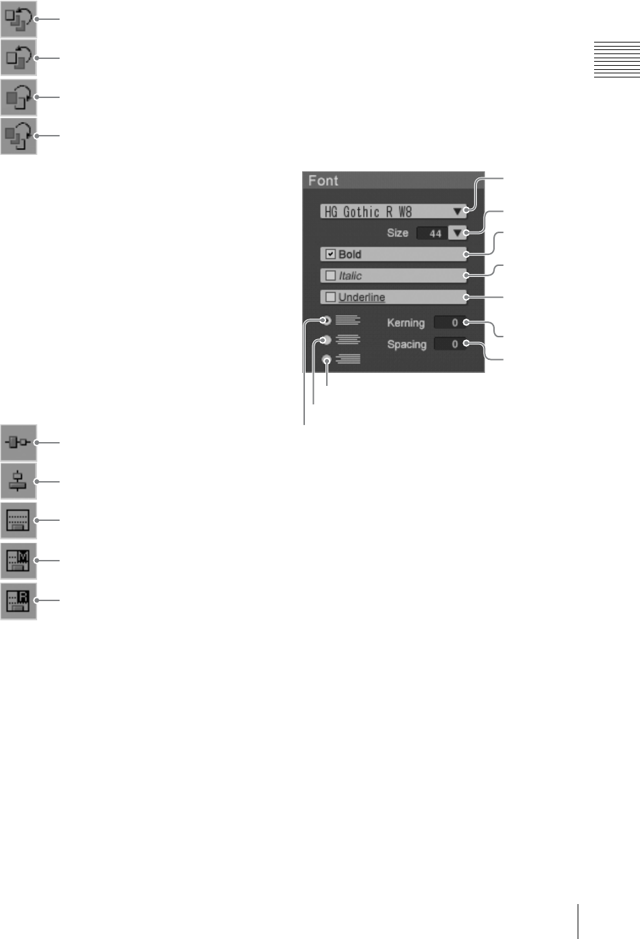
39
Names and Functions of Parts
Chapter 1 Overview
eBring to front tool
This brings the selected object to the front (page
145).
fBring forward tool
This brings the selected object one level forward
(page 145).
gMove backward tool
This moves the selected object one level back
(page 145).
hMove to back tool
This moves the selected object to the back (page
145).
iVertical centering tool
This moves the selected object to the vertical
center of the screen (page 146).
jHorizontal centering tool
This moves the selected object to the horizontal
center of the screen (page 146).
kLower/third positioning tool
This moves the selected object so that its lowest
part is aligned to a predetermined position (page
146).
lLower-third memory tool
If you select an object and then click this tool, the
lowest part of the selected object is set as the
lower-third position.
mLower-third reset tool
Restores the lower-third position to its default
setting.
3Font operation section
aFont name
This selects the font for a text object (page 128).
The currently selected font always appears.
bSize
This selects the size of a text object (page 129).
cBold button
This sets the text object to bold face (page 130).
dItalic button
This sets the text object to italic face (page 130).
eUnderline button
This underlines the text object (page 130).
fKerning
This sets the inter-character spacing of the text
object (page 131).
gSpacing
This sets the line spacing of the text object (page
131).
5Bring to front tool
6Bring forward tool
7Move backward tool
8Move to back tool
9Vertical centering tool
0Horizontal centering tool
qa Lower/third positioning tool
qs Lower-third memory tool
qd Lower-third reset tool
1Font
name
2Size
3Bold
button
4Italic
button
5Underline
button
6Kerning
7Spacing
8Left align button
9Center align button
0Right align button
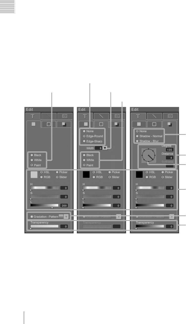
Chapter 1 Overview
40 Names and Functions of Parts
hLeft align button
Aligns a text object comprising multiple lines to
the left (page 131).
iCenter align button
Aligns a text object comprising multiple lines to
the center (page 131).
jRight align button
Aligns a text object comprising multiple lines to
the right (page 131).
4Modifier operation section
Click the mark on a tab to select it, and bring it to the front.
The modifier operation section has three tabs: [Text], [Line], and [BG]. The [Text] tab and [Line] tab are
further divided into three tabs.
xText tab
You can set the color and other settings of a text object. This tab is divided into the Color tab, Edge tab,
and Shadow tab.
aText color selection buttons
Select the color of a text object (page 132).
bEdge style selection buttons
Select whether the object has an outline ([None]
for no outline), and select the shape of corners
(page 133).
cWidth
Set the width of the outline. Select or enter a
numeric value (page 133).
dEdge color selection buttons
Select the color of the outline (page 133).
2
Edge style selection buttons
4Edge color selection buttons
3Width
1
Text color selection
buttons
5Shadow style
selection button
6Shadow creation
section
7Color creation section
8Gradation pattern
9Transparency
Color tab Edge tab Shadow tab
Direction indicator
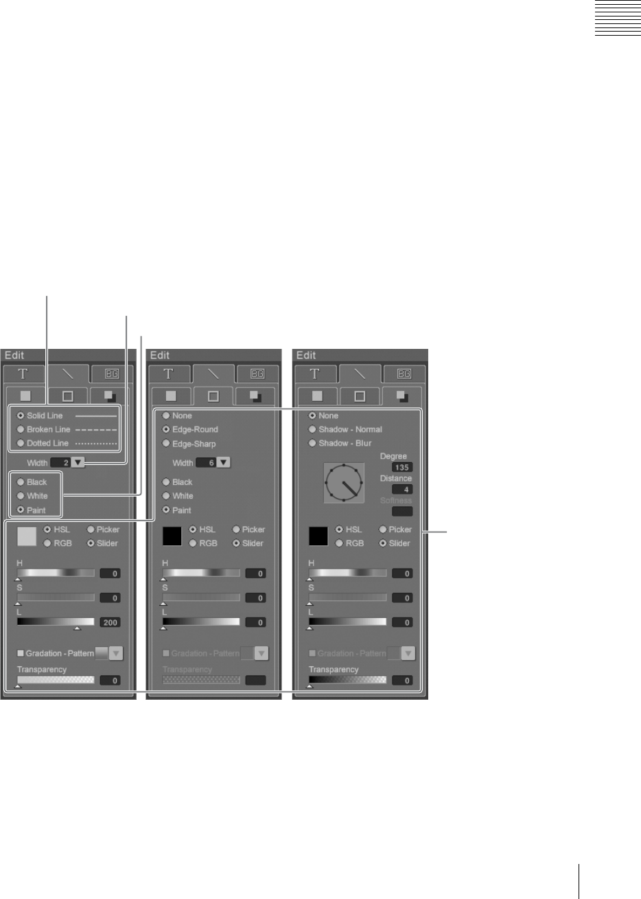
41
Names and Functions of Parts
Chapter 1 Overview
eShadow style selection button
Select whether the object has a shadow ([None] for
no shadow), and select the style of the shadow
(page 136).
fShadow creation section
Adjust the angle, distance, and degree of blurring
of the shadow (page 136).
Direction indicator: Click this to move the
needle, and change the direction of the
shadow of the object to that of the needle.
Degree: Set a numerical value for the direction of
the shadow.
Distance: Set a numerical value for the distance of
the shadow.
Softness: Set a numerical value for the degree of
blurring of the shadow.
gColor creation section
When [Paint] is selected in the Color tab and Edge
tab, you can create your own color for the outline
and shadow of the object (page 141).
hGradation pattern
Apply gradation to the color of the object (page
144).
iTransparency
Set the transparency of each of the color and
shadow of the object and the background created
with paint (page 143).
xLine tab
You can set the color and other settings of a line object. This tab is divided into the Color tab, Edge tab,
and Shadow tab.
jLine style selection buttons
Select the color of the line object (page 135).
kWidth
Set the line width of the line object. Select or enter
a numeric value (page 135).
lLine color selection buttons
Select the line style of the line object (page 136).
0Line style selection buttons
These sections are
the same as 2 to
9 of the [Text] tab.
qa Width
qs Line color selection buttons
Color tab Edge tab Shadow tab
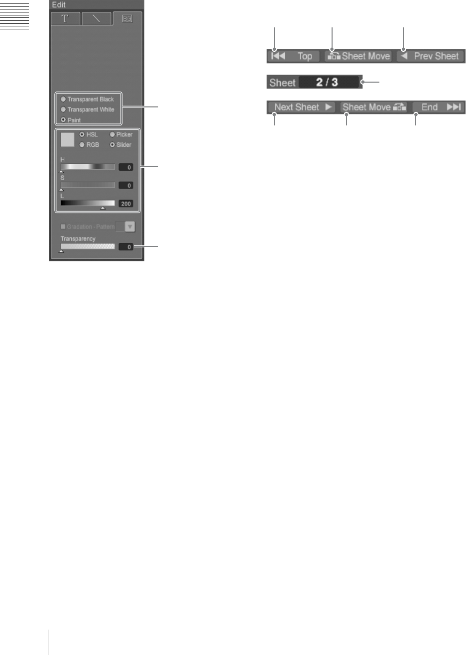
Chapter 1 Overview
42 Names and Functions of Parts
xBG tab
You can set the background color.
mBackground color selection buttons
Select the background color (page 138).
nTransparency
Set the transparency of the background created
with paint.
5Page operation section
This is used for sheet display, sheet turning, and
resequencing.
aTop button
Click this to display the first sheet.
bSheet Move button (forward)
Click this to exchange the currently displayed
sheet with the previous sheet.
cPrev Sheet button
Click this to display the previous sheet.
dPage display
This shows the sheet number of the currently
displayed sheet.
eNext Sheet button
Click this to display the next sheet.
fSheet Move button (rearward)
Click this to exchange the currently displayed
sheet with the next sheet.
gEnd button
Click this to display the last sheet.
This section is the
same as 7 of the
[Text] tab.
qf Transparency
qd Background color
selection buttons
1Top button 2Sheet Move
button (forward)
3Prev Sheet
button
5Next sheet
button
6Sheet Move
button
(rearward)
7End button
4Page display
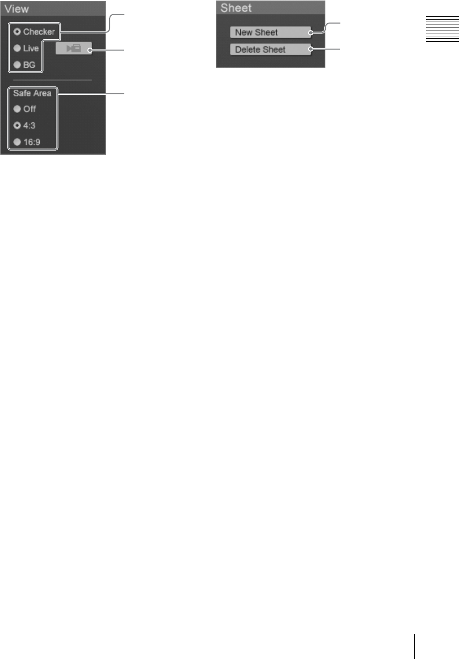
43
Names and Functions of Parts
Chapter 1 Overview
6View operation section
aBackground display selection button
Set the background display (page 149).
Checker: Displays a checkered pattern as the
background.
Live: Displays the program output video of the
main software (page 148).
BG: Displays the background selected on the
[BG] tab (page 148 and 148).
bCapture button
The program output video image of the main
software is captured each time this button is
clicked (page 149).
cSafe Area
When this is selected, a dotted line shows the safe
area (page 150).
Off: Does not display the safe area.
4:3: Displays a dotted line showing the safe area
for 4:3 aspect ratio.
16:9: Displays a dotted line showing the safe area
for 16:9 aspect ratio.
7Sheet operation section
aNew Sheet button
This adds a sheet to the open file (page 148). You
can create up to 99 sheets.
bDelete Sheet button
This deletes the open sheet (page 148).
1Background
display
selection button
2Capture button
3Safe Area
2Delete Sheet
button
1New Sheet
button

Chapter 1 Overview
44 Names and Functions of Parts
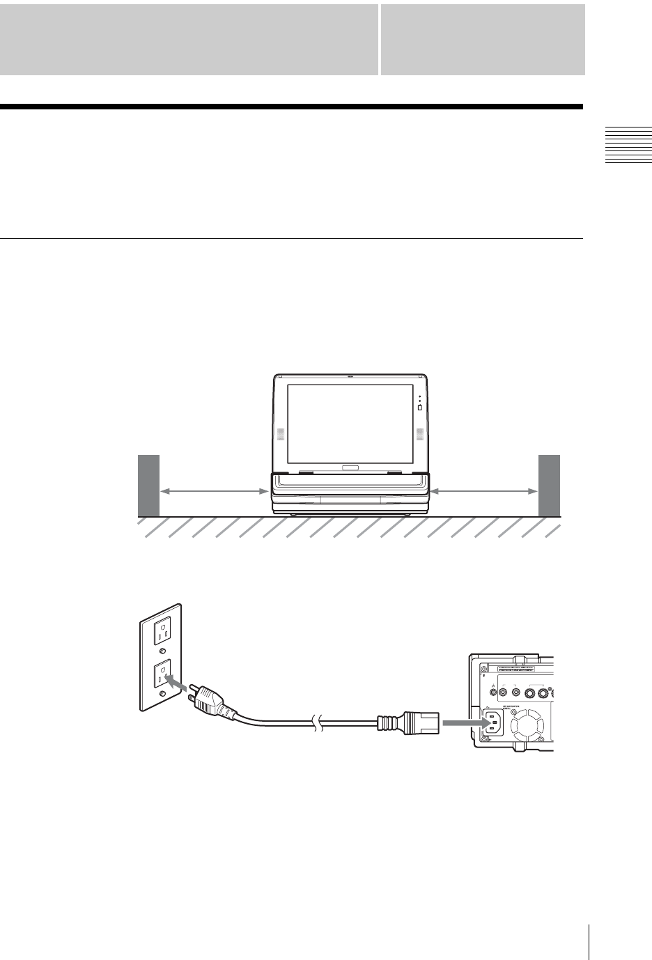
Chapter 2 Preparations
45
Installation/Default Settings
Chapter
2
Preparations
Installation/Default Settings
This section describes the procedure for installing the unit, connecting the power
cord, starting up the system, and setting the date, time, and video output signal
format.
Installing the Unit
Install the unit in a level place. The unit weighs about 17.7 lbs (8 kg). Check that
the installation location is strong and spacious enough to accommodate the unit
before installing.
There are ventilation holes on both sides of the unit. To ensure adequate air flow,
there must be a space of at least 12 inches (300 mm) on each side of the unit.
Connecting the power
Connect the power cord to the power inlet on the unit and the wall outlet.
Num
Caps
12 inches
(300 mm)
12 inches
(300) mm
AC IN
LINE MIC/LI
N
87 6 5
4
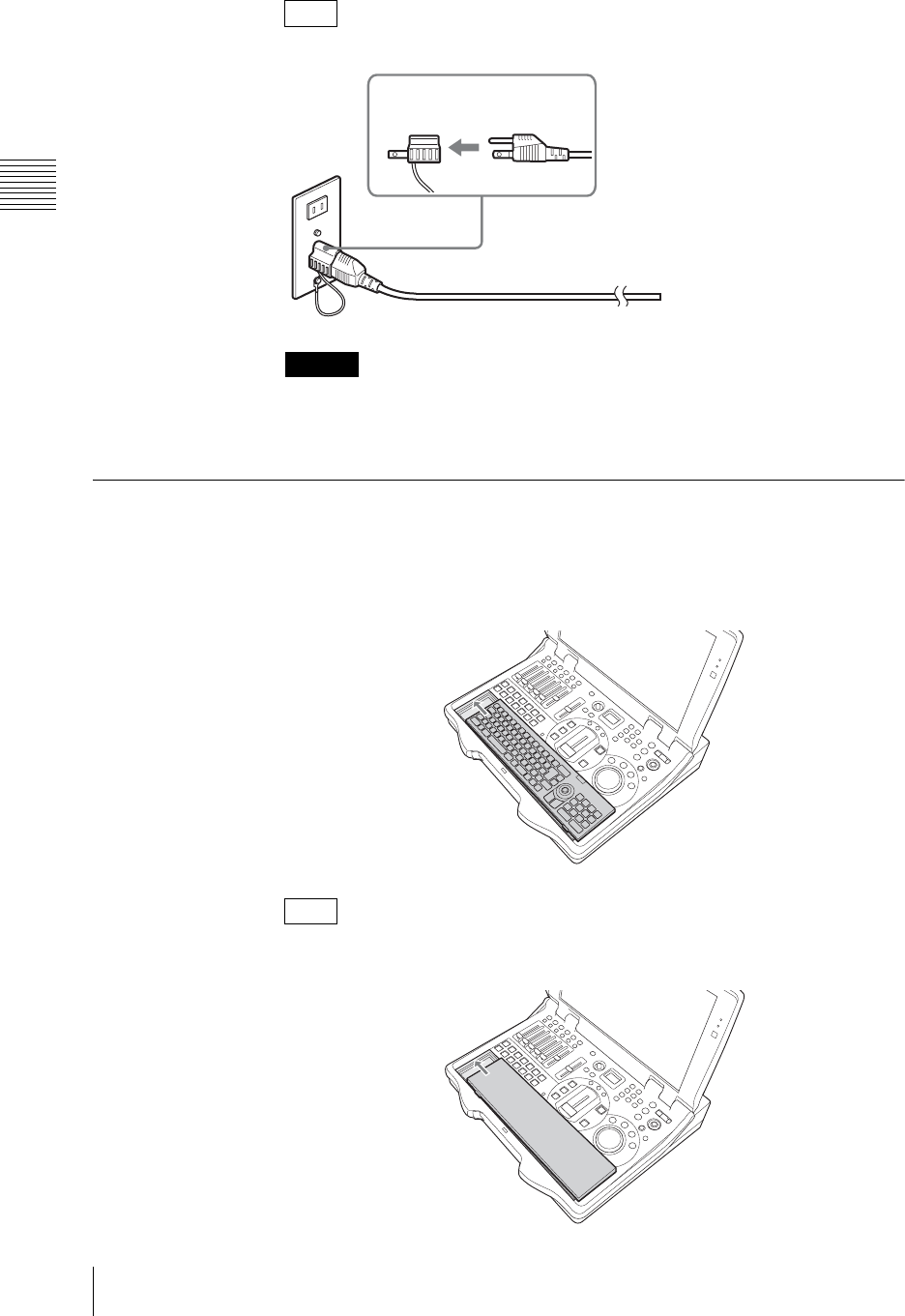
Chapter 2 Preparations
46 Installation/Default Settings
Use a 3-pin - 2-pin conversion adaptor, if required.
Connect the grounding lead of the 3-pin/2-pin adaptor to the ground terminal.
If grounding is not possible, consult your dealer or your Sony service
representative.
Fitting a Keyboard
To install the keyboard in this unit, align it with the keyboard space, with the keys
upward, and slide in the direction shown by the arrow. Power is supplied to the
keyboard from the main unit, and the EXT POWER indicator on the keyboard
lights.
When not using the keyboard, you can insert it upside down. In this case, no
power is supplied to the keyboard.
Note
Caution
Note
3-pin - 2-pin
conversion adaptor
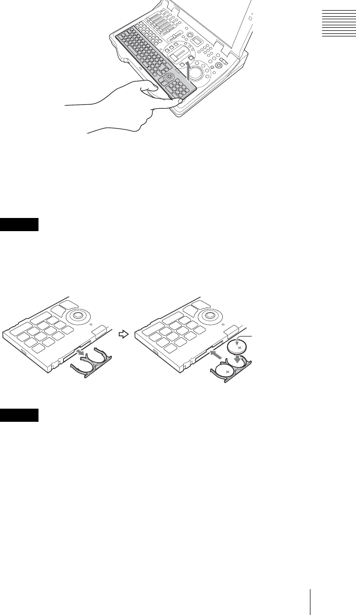
47
Installation/Default Settings
Chapter 2 Preparations
Using the keyboard away from the unit
You can use the keyboard away from the unit. In this case, it is necessary to insert
a pair of standard batteries (CR2032) to power the keyboard.
To detach the keyboard
Using the groove locating at the right of the keyboard space, lift the keyboard out.
To insert batteries in the keyboard
1
Detach the keyboard from the main unit.
2
Detach the battery holder from the keyboard.
To remove the battery holder, use the end of a sharp implement such as a pen.
3
Load two batteries (CR2032) in the battery holder, and insert in the
keyboard.
If batteries are inserted incorrectly, this may lead to electrolyte leakage or
other damage. Note the following carefully.
• Check that the polarity is correct.
• Do not use new and old batteries together, or batteries of different types.
• Do not attempt to charge the batteries.
• When not using the keyboard for a long period, remove the batteries.
• If a battery should leak, remove any spilled fluid from the battery holder,
before inserting a new battery.
Caution
Caution
Make sure the
positive (+)
terminal of
each battery is
facing upward.
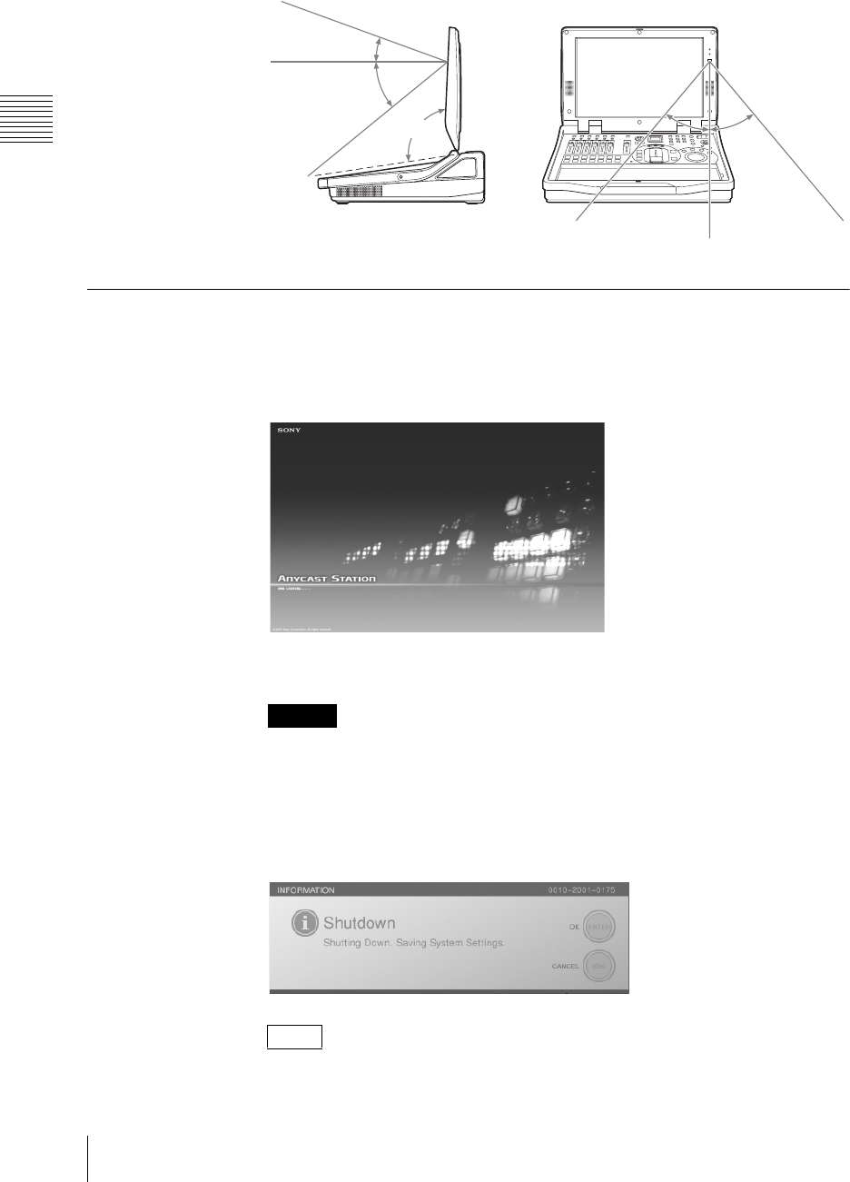
Chapter 2 Preparations
48 Installation/Default Settings
Infrared transmitting range
The range over which the keyboard can operate with infrared control is shown in
the following figure.
Starting and Closing Down the Unit
Starting
Press the 1 (power) button on the side panel.
The startup screen appears.
When the startup completes, the operation screen appears.
If the display is closed while the unit is operating, the temperature will rise, and
this may cause failure.
Closing down
Press down the 1 (power) button on the side panel.
The following message appears.
• The last set data is saved.
• If an external hard disk is connected, it is automatically unmounted (page 186).
Caution
Notes
Within 6 feet
6 inches (2 m) 20°
40°
0 - 95°
60°
40°
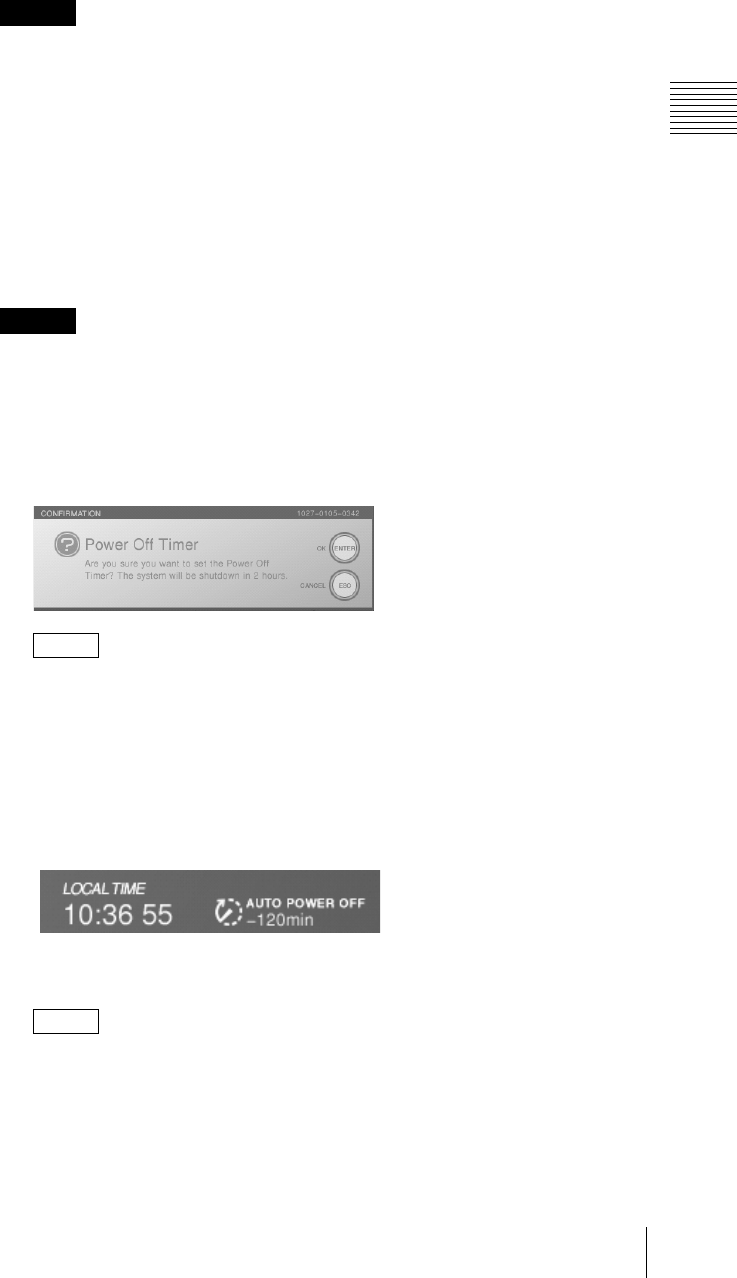
49
Installation/Default Settings
Chapter 2 Preparations
This closes down the operating software, and powers off.
It takes a little while before the power turns off after the screen disappears.
• If you hold down the power button for at least 4 seconds, this forces a
shutdown. After a forced shutdown, the settings of the unit may not be
preserved.
• When restarting the unit immediately after shutting down, wait at least 5
seconds after shutdown before pressing the power button.
• Button operations performed while an application is closing will not be
properly reflected on the system.
Using the timer to shut down the system/Releasing the timer setting
You can use a timer to shut down the unit.
Do not shut down the system using the timer while recording to an external hard
disk. The recorded file may become damaged and unusable.
1
While the Anycast Station main software is running, hold down the keyboard
Alt and Ctrl keys, and press the T key.
The following confirmation message appears.
It is not possible to use this function while the Text Typing Tool software is
running.
2
To set the timer, press the ENTER button.
To release the timer, press the ESC button.
When setting the timer
The timer indication appears to the right of “LOCAL TIME.”
When the text entry tool is started, the timer display disappears, but the timer
function continues to operate.
The countdown appears from -120 min.
After two hours the system is powered off.
When releasing the timer
The timer display disappears.
Caution
Caution
Note
Note
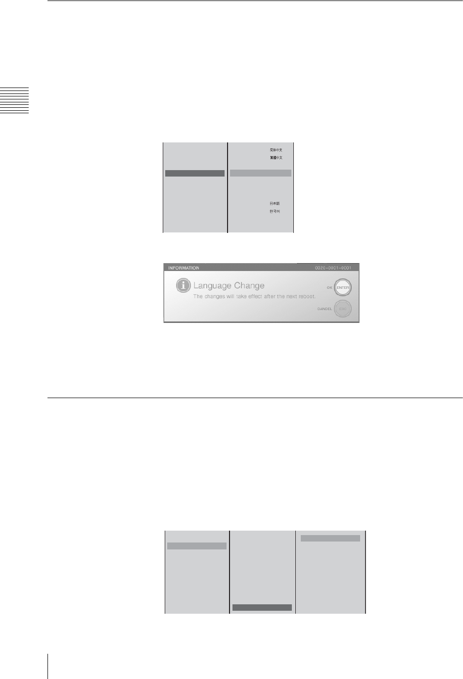
Chapter 2 Preparations
50 Installation/Default Settings
Selecting the Language
Set the language to correspond to the keyboard being used.
The default setting is “English (US).”
1
Press the MENU button.
2
In the top menu, select [System].
3
1 Select [Language], and confirm; 2 select the appropriate language from
the list, and confirm.
The operation screen appears as shown below.
4
Confirm the message that appears, and press the ENTER button.
5
Press the MENU button to close the menu.
6
Restart the system.
Setting the Time Zone
Set the time zone for your geographical location.
1
Press the MENU button.
2
In the top menu, select [System].
3
1 Select [Time Zone], and confirm; 2 select the area, and confirm;
3 select the region, and confirm.
4
Press the MENU button to close the menu.
Date/Time
Time Zone
System TC xx:xx:xx:xx
Language
Chinese (Simplified)
Chinese
(Traditional)
English
(UK) English
(UK)
B English
(US) English
(US)
French Français
German Deutsch
Italian Italiano
Japanese
Korean
Portuguese Português
Spanish Español
12
Data/Time
Time Zone
System TC xx:xx:xx:xx
Language
America
US Time Zones
Canada Time Zones
Asia
Atlantic Ocean
Australia
Europe
Indian Ocean
Pacific Ocean
B None of the above
B GMT
GMT + 0
GMT + 1
GMT + 2
GMT + 3
GMT + 4
GMT + 5
GMT + 6
GMT + 7
GMT + 8
123
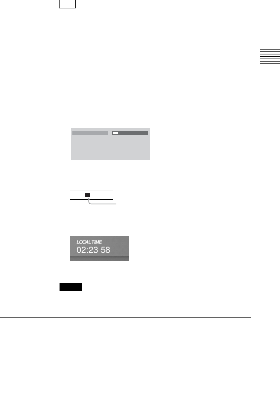
51
Installation/Default Settings
Chapter 2 Preparations
The notation system for displaying time zone data in relation to GMT is based on
the form POSIX minutes-west-of-GMT in which the hour decreases as you move
east and increases as you move west.
Setting the Date and Time
Set the internal clock.
1
Press the MENU button.
2
In the top menu, select [System].
3
1 Select [Date/Time], and confirm; 2 enter the date and time in the input
box, and confirm.
Using the arrow buttons on the jog roller (or the T and t keys while
holding the Ctrl key on the keyboard), select the item to change and enter a
numeric value with the keyboard.
The time set in “LOCAL TIME” appears at the upper left of the operation
screen.
4
Press the MENU button to close the menu.
If this unit is operated for a long period, the clock may drift out of its correct
setting. Resetting the clock at regular intervals is recommended.
Adjusting the Display Brightness
Adjust the brightness of the display on which the operation screen is shown.
1
Press the MENU button.
2
In the top menu, select [Display].
Note
Caution
Data/Time
Time Zone
System TC
Language
2004 /05/18 12:25
GMT
12
2004/05/18 12:25
Each whole value between the separators (/, :, or space) is selected.
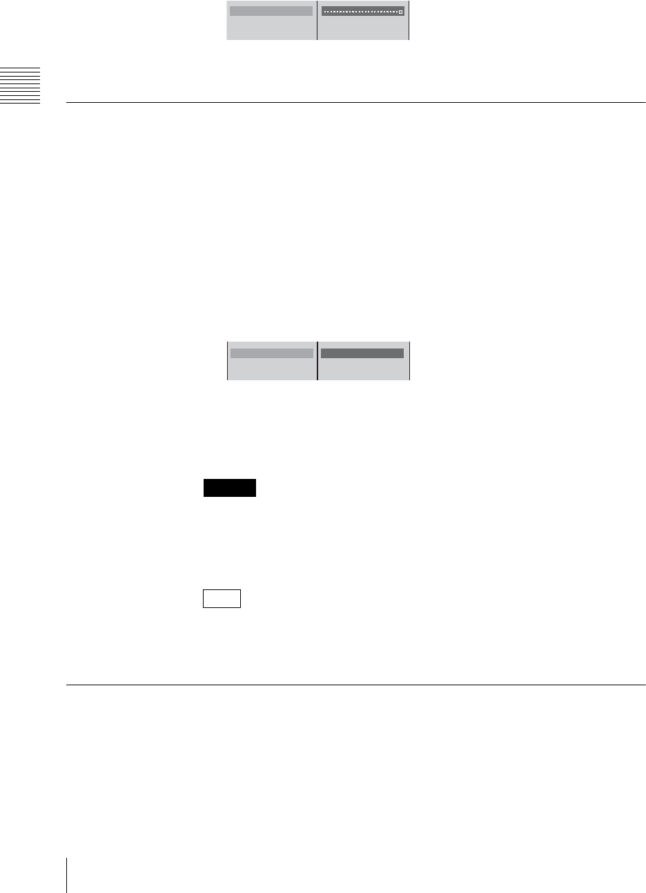
Chapter 2 Preparations
52 Installation/Default Settings
3
1 Select [LCD Backlight], and confirm; 2 move the slider to adjust
brightness.
4
Press the MENU button to close the menu.
Selecting the Video Output Signal Format
Select the format for the signals output from the PGM output connectors
(COMPOSITE/S VIDEO), the SD video interface module’s DV connectors, and
the SDI output, HD analog output, HD SDI output, and reference output
connectors on the rear panel.
1
Press the MENU button.
2
In the top menu, select [Video Output].
3
1 Select [PGM OUT], and confirm; 2 select the signal format, and
confirm.
A confirmation message appears.
4
Press the ENTER button.
A shutdown message appears, and the system shuts down.
• Carrying out this selection may cause momentary breakup of the output video.
• When [PAL/50Hz] is selected, small portions of the top and bottom of PAL
input videos will be missing. To avoid this, set the RGB output signal format
to [Video RGB] (page 210).
Video input in a different signal format than this setting can still be displayed
(i.e., displaying a PAL video input when set to “NTSC” or vice versa), but the
video quality cannot be guaranteed.
Setting the PGM Output Aspect Ratio
Select the size (ratio between width and height) of the program output video.
1
Press the MENU button.
2
In the top menu, select [Video Output].
Caution
Note
LCD Backlight
Viewer Priority PVW
File TC Off
12
PGM OUT NTSC/60Hz
PGM OUT Aspect 4:3
PGM OUT Level
B NTSC/60Hz
PAL/50Hz
12
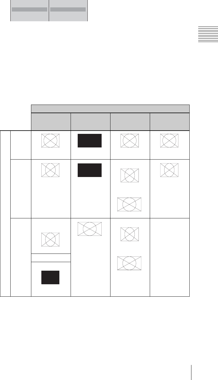
53
Installation/Default Settings
Chapter 2 Preparations
3
1 Select [PGM OUT Aspect], and confirm; 2 select a size for the program
output video, and confirm.
[4:3]: Creates programs in the 4:3 aspect ratio.
Select this when the output destinations are primarily SD (4:3).
[16:9 SD]: Creates programs in the 16:9 aspect ratio.
Select this when the output destinations are primarily SD (4:3) or when
giving priority to PGM recording to external hard disks.
[16:9 HD]: Creates programs in the 16:9 aspect ratio.
Select this when the output destinations are primarily HD (16:9).
4
Press the MENU button to close the menu.
Relation between aspect ratio settings and output signals
*1 Output from the built-in composite or S-Video output connector, the SD video
interface module or serial digital interface module.
*2 Output from the HD video interface module or HD serial digital interface module.
*3 Output from the built-in RGB output connector.
Output connector / PGM recording to HDD
SD output*1 HD output*2 RGB output*3 PGM recording
to external hard
disk drives
4:3
mode 4:3 Black &
silent signal
4:3 4:3
16:9 SD
mode
16:9 squeeze Black &
silent signal
XGA/SXGA
16:9 squeeze
WXGA
16:9
16:9 squeeze
16:9 HD
mode
Composite,
S-video
16:9 squeeze
16:9
XGA/SXGA
16:9 squeeze
WXGA
16:9
PGM recording to
external hard disk
drives is
unavailable
No signal for DV
SDI
Black & silent
signal
B 4:3
16:9 SD
16:9 HD
PGM OUT NTSC/60Hz
PGM OUT Aspect 4:3
PGM OUT Level
DV OUT
12
Output signals
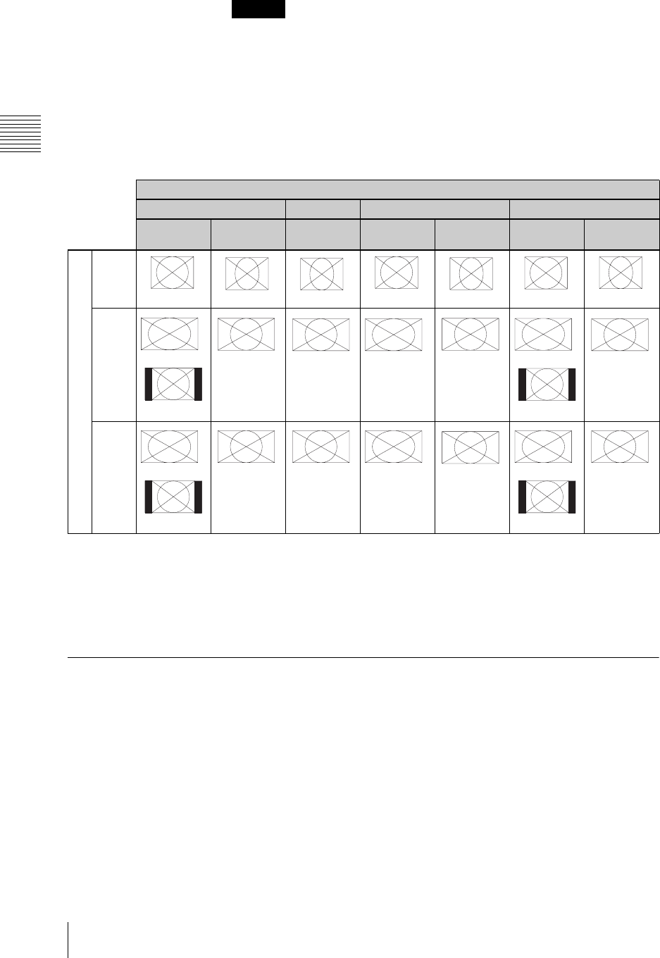
Chapter 2 Preparations
54 Installation/Default Settings
• When [4:3] or [16:9 SD] is selected, program output from the HD video
interface module (BKAW-560) or HD serial digital interface module
(BKAW-590) is disabled.
• When [16:9 HD] is selected, program output from the SD video interface
module (BKAW-570) or serial digital interface module (BKAW-580) and
recording to external hard disks are disabled.
Relation between aspect ratio settings, input signals, and viewer
displays
*1 Specify the aspect ratio of the input signals in the top menu with [Source Aspect] of [Video Input
Assign].
*2 Changes depending on the [Wide Zoom] setting in the ACCESS menu.
*3 Adjust [Resize] in the ACCESS menu to convert to center display.
*4 Changes depending on the [CG Wide Zoom] setting in the INT source selection menu.
Setting the System Timecode
Set the system timecode to add to files and output signals recorded on an external
hard disk.
The system timecode is used for the following functions.
• The timecode of a file recorded for program output
• The timecode of an EDL
• The timecode of a file recorded for material (except DV material)
• The timecode to add to DV signals output from a DV output connector
• The timecode to add to SDI signals output from a PGM SDI output connector
Caution
Input signals
SD input HD input RGB input CG
4:3*116:9
squeeze*116:9 XGA/SXGA WXGA 4:3/5:4 16:9/16:10/
5:3
4:3
mode
4:3 16:9 squeeze 16:9 squeeze 4:3 16:9 squeeze 4:3 16:9 squeeze
16:9
SD
mode
*
2
Wide screen
Center
16:9 16:9
*
3
Wide screen 16:9
*
4
Wide screen
Center
16:9
16:9
HD
mode
*
4
Wide screen
Center
16:9 16:9
*
3
Wide screen 16:9
*
4
Wide screen
Center
16:9
PGM/PVW viewer display
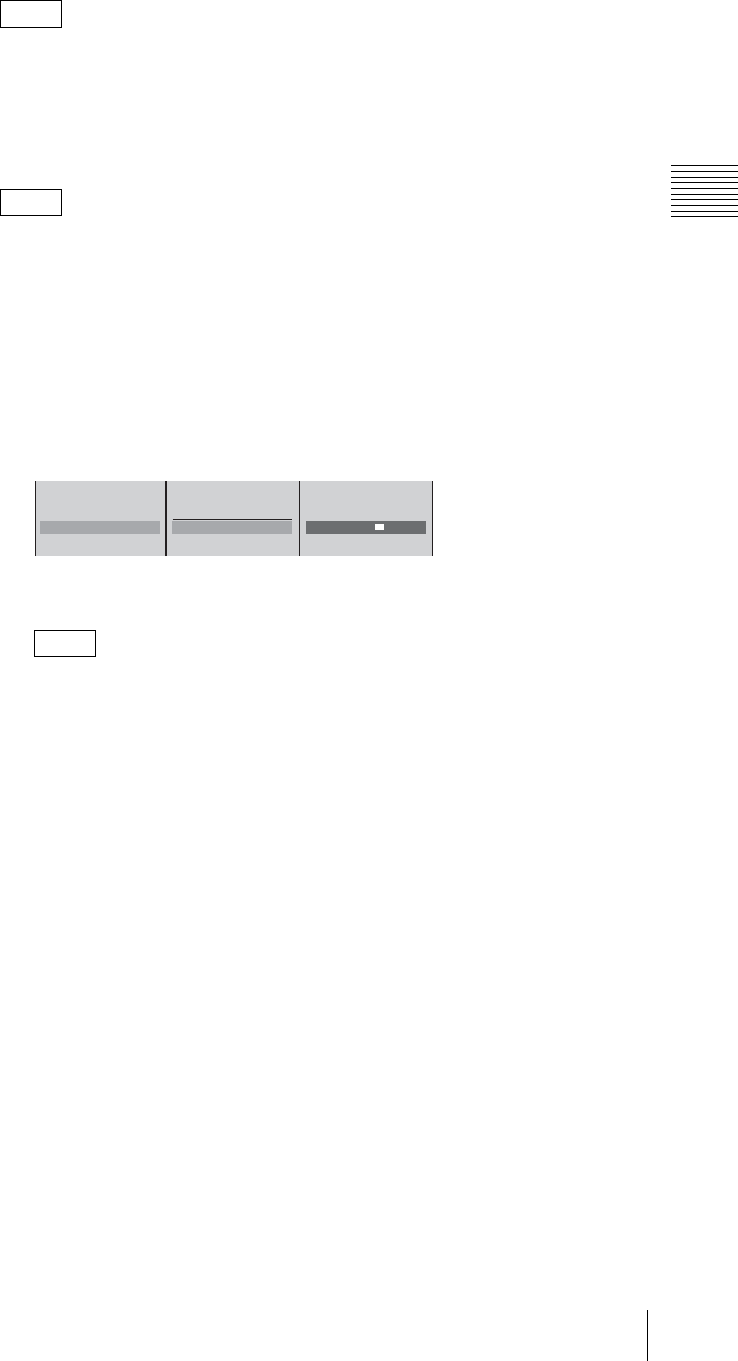
55
Installation/Default Settings
Chapter 2 Preparations
The system timecode added with this unit is a drop frame timecode (except when
PAL is set).
Setting the time to use as the system timecode
You can set the time to use as the system timecode.
At the time of purchase, the time set for [Date/Time] (local time) in the top menu
is configured to be used as the system timecode.
1
Press the MENU button.
2
Select [System] in the top menu.
3
1 Select [System TC], and confirm; 2 select [User Preset], confirm, and
select [Timecode]; 3 set a time in the input box, and confirm.
The timecode display for [System TC] is updated to the set value.
When you configure this setting, the timecode is preset at the time of
configuration and when the unit is started, and from then on, the count
increases.
4
Press the MENU button to close the menu.
Note
Note
Note
Date/Time
Time Zone
System TC 00:00:00:00
Language
00: 00: 00: 00
Local Time
B User Preset
Timecode
123
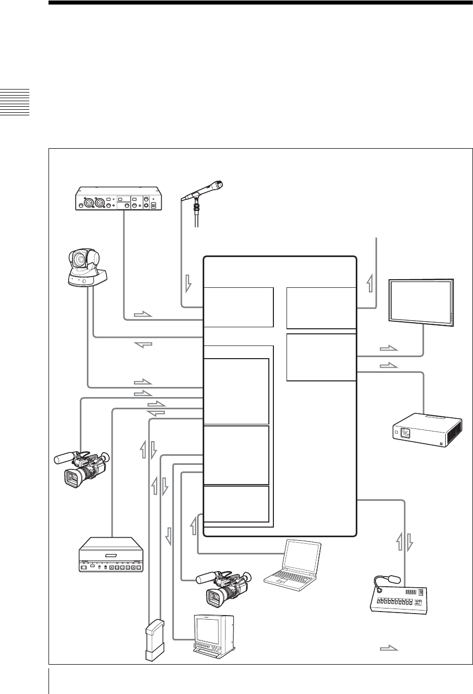
Chapter 2 Preparations
56 Connections
Connections
This section describes how to connect devices for video and audio input and
output. The following figure shows an example system configuration and signal
flow. Refer to the pages indicated for details of how to make connections.
In addition, after connecting each device, you must configure settings on the unit
for each input and output signal. See page 66 for details on the settings of each
input and output signal.
System configuration example 1: When a serial digital interface module is connected
AUDIO IN
Anycast Station
MIC/LINE
LINE
AUDIO OUT
VIDEO OUT
PGM
RGB
INTERCOM
VIDEO IN (OUT)
S VIDEO
COMPOSITE
DV (IN/OUT)
HDD (IN/OUT)
PC Video
Interface Module
(BKAW-550)
SD Video
Interface Module
(BKAW-570)
Serial Digital
Interface Module
(BKAW-580)
RGB
VISCA
HDD (IN/OUT)
SDI OUT
SDI IN
* Depending on the device, signal
input/output settings may be
required.
Refer also to the manuals provided
with the devices you are connecting.
Microphone (page 59)
Amplifier (page 64)
Camera with
VISCA support
(page 58)
Camcorder
(page 60)
VCR (page 61)
External hard disk
(page 62)
Intercom system (page 200)
Projector (page 63)
Plasma display (page 63)
Speaker
Signal flow
Computer (page 59)
Camcorder
(page 60)
Monitor
(page 63)
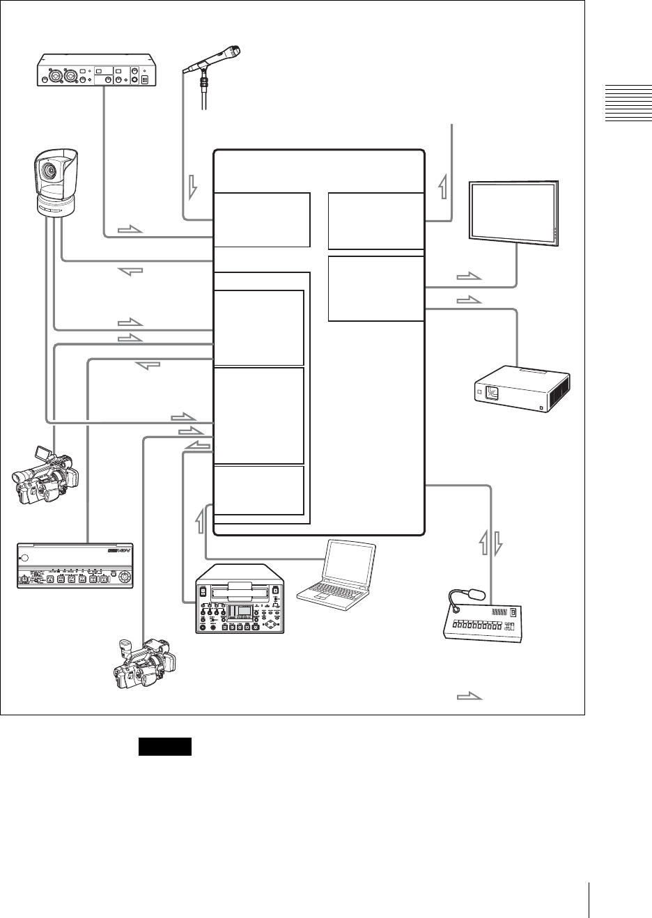
57
Connections
Chapter 2 Preparations
System configuration example 2: When an HD video interface or HD serial digital
interface module is connected
• Use the shortest possible cable type (especially with unregulated RGB).
Shorter cables are recommended because, in general, using long cables to
connect devices increases the risk of signal noise. Even when connecting this
unit to another, it is best to use the shortest cables possible.
• Be careful with the connector portions of the interface modules, which may
become hot depending on the conditions of operation.
Caution
AUDIO IN
Anycast Station
MIC/LINE
LINE
AUDIO OUT
VIDEO OUT
PGM
RGB
INTERCOM
VIDEO IN (OUT)
YP
B
P
R
IN
YP
B
P
R
IN
YP
B
P
R
OUT
RGB
(BKAW-560)
VISCA
HD SDI IN
HD SDI IN
HD SDI OUT
HD Video
Interface module
(BKAW-590)
HD Serial Digital
Interface module
(BKAW-550)
PC Video
Interface module
* Depending on the device, signal
input/output settings may be
required.
Refer also to the manuals provided
with the devices you are connecting.
Microphone (page 59)
Amplifier (page 64)
Camera with
VISCA support
(page 58)
Camcorder
(page 60)
VCR (page 61)
VCR (page 61) Intercom system (page 200)
Projector (page 63)
Plasma display (page 63)
Speaker
Signal flow
Computer (page 59)
Camcorder
(page 60)
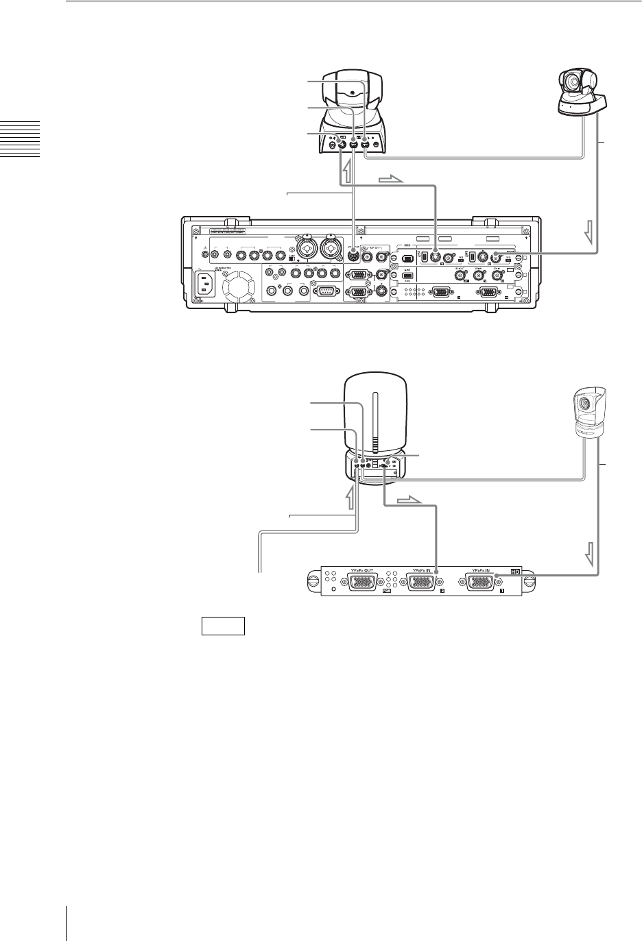
Chapter 2 Preparations
58 Connections
Connecting a Camera With VISCA Support
When an HD video interface module is connected
• VISCA cables up to 15 m (50 ft) are recommended to operate correctly.
• When connecting a BNC cable, an RCA-BNC adaptor is required.
• When connecting a BRC-300 camera, connect to the DV, RGB, and SDI input
connectors in accordance with the camera’s option board.
• When connecting a BRC-700 camera, connect to the RGB, SDI, and HD
analog input connectors in accordance with the camera’s option board.
Notes
AC IN
LINE MIC/LINE
MIX
HEADPHONES
MONI INTERCOM
15
69
RGB PGM
S VIDEO
AUX PGM RGB
I.LINK
S VIDEO
COMPOSITE
S VIDEO
COMPOSITE
S400
RGB RGB
COMPOSITE
MIC/LINE
PUSH PUSH
AUDIO IN
VIDEO IN
AUDIO OUT VIOEO OUT
87 6 5 4 3
RRLL
RL
21
21
OFF
ON
SD
OFF
ON
OFF
ON
PC
1
2
3
SDI
Color video camera
BRC-H700, BRC-300, EVI-D100, EVI-D70 etc.
VISCA OUT
VISCA IN
VIDEO OUT
VISCA cable To S-Video input
connectors
To Composite
input connectors
BNC
cable
HD
VISCA OUT
VISCA IN
VIDEO OUT
VISCA cable
To HD analog
input connectors
To HD analog
input connectors
VGA
cable
To VISCA
connector
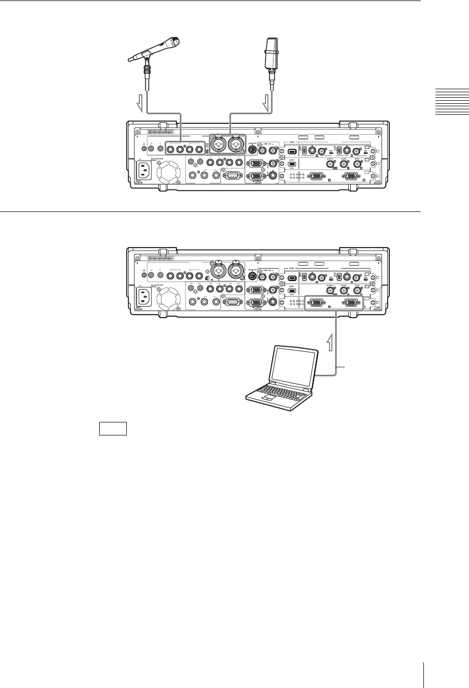
59
Connections
Chapter 2 Preparations
Connecting a Microphone
Connecting a Computer (RGB Input)
To reduce the effects of external noise, use a cable with an attached ferrite core.
Note
AC IN
LINE MIC/LINE
MIX
HEADPHONES
MONI INTERCOM
15
69
RGB PGM
S VIDEO
AUX PGM RGB
I.LINK
S VIDEO
COMPOSITE
S VIDEO
COMPOSITE
S400
RGB RGB
COMPOSITE
MIC/LINE
PUSH PUSH
AUDI O IN
VIDEO IN
AUDIO OUT VIOEO OUT
87 6 5 4 3
RRLL
RL
21
21
OFF
ON
SD
OFF
ON
OFF
ON
PC
1
2
3
SDI
Capacitor microphone
(C-38B, etc.)
Dynamic microphone
(F-720/2, etc.)
To Microphone/line input connectors
AC IN
LINE MIC/LINE
MIX
HEADPHONES
MONI INTERCOM
15
69
RGB PGM
S VIDEO
AUX PG M RG B
I.LINK
S VIDEO
COMPOSITE
S VIDEO
COMPOSITE
S400
RGB RGB
COMPOSITE
MIC/LINE
PUSH PUSH
AUDIO IN
VIDEO IN
AUDIO OUT VIOEO OUT
87 6 5 4 3
RRLL
RL
21
21
OFF
ON
SD
OFF
ON
OFF
ON
PC
1
2
3
SDI
Computer
To RGB input
connectors
RGB cable
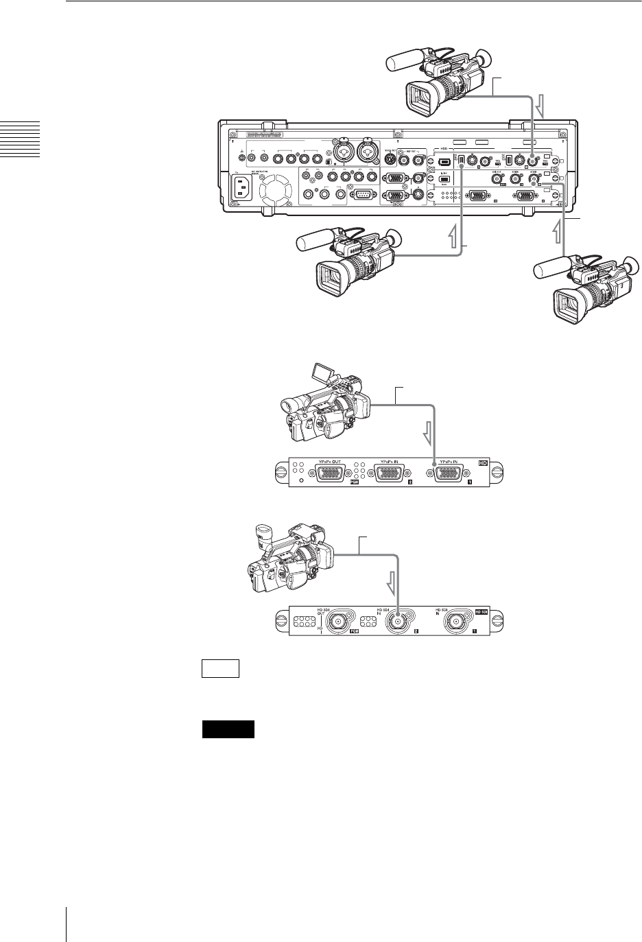
Chapter 2 Preparations
60 Connections
Connecting a Camcorder
When an HD video interface module is connected
When an HD serial digital interface module is connected
i.LINK cables between 80 cm and 3.5 m (2.5 to 11.5 ft) are recommended.
• The frequency precision of the reference output signal is within 50 ppm. When
building a system that includes devices such as a camera with a Gen Lock
input, be sure to test it thoroughly before use.
• The color frame of the program output signal does not reflect the color frame
sequence of the reference output signal.
• If video or audio is not output or signal noise occurs when connected to another
DV device, the problem can often be resolved by reconnecting the cables or
turning the DV device or the unit off and then on again.
Note
Caution
AC IN
LINE MIC/LINE
MIX
HEADPHONES
MONI INTERCOM
15
69
RGB PGM
S VIDEO
AUX PG M RG B
I.LINK
S VIDEO
COMPOSITE
S VIDEO
COMPOSITE
S400
RGB RGB
COMPOSITE
MIC/LINE
PUSH PUSH
AUDIO IN
VIDEO IN
AUDIO OUT VIOEO OUT
87 6 5 4 3
RRLL
RL
21
21
OFF
ON
SD
OFF
ON
OFF
ON
PC
1
2
3
SDI
DVCAM camcorder
(DSR-PD170, etc.)
For DV connection
BNC cable
To Composite
input connectors
i.Link cable
To DV connectors
For analog connection
BNC cable
For SDI connection
HD
To HD analog
input connectors
VGA cable
BNC cable
To HD SDI input
connectors
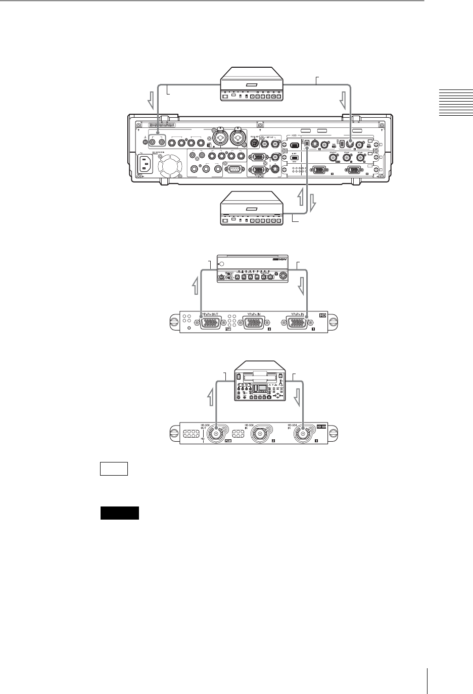
61
Connections
Chapter 2 Preparations
Connecting a VCR
When an HD video interface module is connected
When an HD serial digital interface module is connected
i.LINK cables between 80 cm and 3.5 m (2.5 to 11.5 ft) are recommended.
• If when connected to another DV device the video or audio is not output, or
there is noise, reconnect the cable, or power the DV device or this unit off and
on again. This may solve the problem.
• It is not possible to connect more than one VCR to a single DV connector.
Note
Caution
AC IN
LINE MIC/LINE
MIX
HEADPHONES
MONI INTERCOM
15
69
RGB PGM
S VIDEO
AUX PG M RG B
I.LINK
S VIDEO
COMPOSITE
S VIDEO
COMPOSITE
S400
RGB RGB
COMPOSITE
MIC/LINE
PUSH PUSH
AUDIO IN
VIDEO IN
AUDIO OUT VIOEO OUT
87 6 5 4 3
RRLL
RL
21
21
OFF
ON
SD
OFF
ON
OFF
ON
PC
1
2
3
SDI
Digital video cassette
recorder (DSR series, etc.)
For DV connection
For analog connection
To S-Video input
connectors
Audio cable
To Line input
connectors
S-Video cable
i.Link cable
To DV connectors
HD
To HD analog
input connectors
VGA cableVGA cable
To HD SDI input
connectors
BNC cableBNC cable
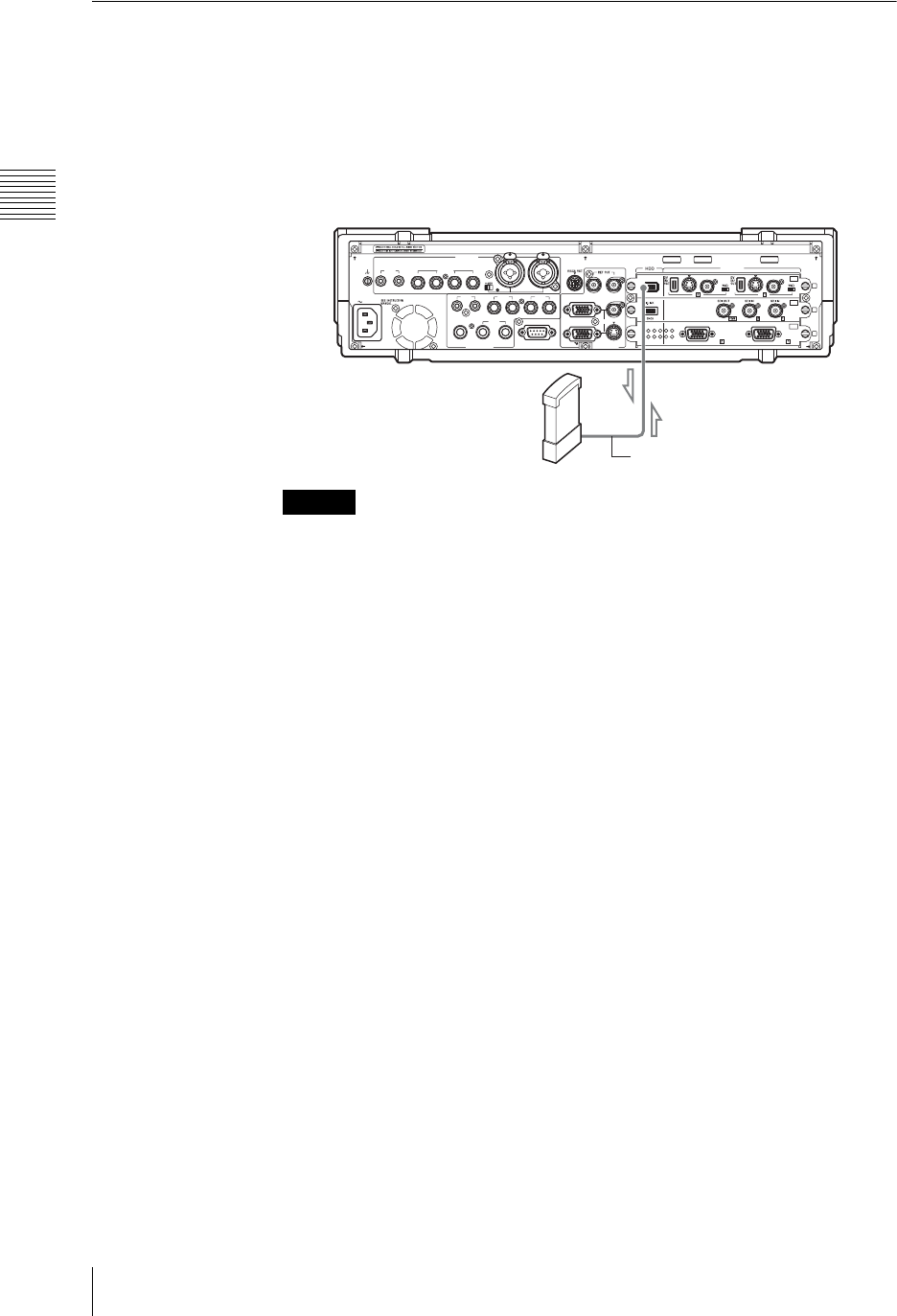
Chapter 2 Preparations
62 Connections
Connecting an External Hard Disk
For information about external hard disks, visit the following Anycast Station
portal site:
https://servicesplus.us.sony.biz/SoftwarePlusSerch.aspx (for customers in
U.S.A.)
https://www.sony.biz.net/anycast (for customers in Europe, Middle East and
Africa)
https://www.ecspert.sony.biz/ecsite/ (for the other customers)
• If using a hard disk with a standby function, make sure that the standby
function is disabled before connecting to this unit.
• Power on the connected hard disk before powering on this unit.
• Connect the i.LINK connector directly to the hard disk.
• It is not possible to connect more than one hard disk to a single i.LINK
connector (daisy-chaining connection not possible).
• If you disconnect the i.LINK cable, or power off the hard disk without carrying
out the necessary preparations for disconnecting the disk, then files may be
corrupted, or the disk may need to be recovered. For details of unmounting, see
“Disconnecting the External Hard Disk” (page 186).
Caution
AC IN
LINE MIC/LINE
MIX
HEADPHONES
MONI INTERCOM
15
69
RGB PGM
S VIDEO
AUX PG M RG B
I.LINK
S VIDEO
COMPOSITE
S VIDEO
COMPOSITE
S400
RGB RGB
COMPOSITE
MIC/LINE
PUSH PUSH
AUDIO IN
VIDEO IN
AUDIO OUT VIOEO OUT
87 6 5 4 3
RRLL
RL
21
21
OFF
ON
SD
OFF
ON
OFF
ON
PC
1
2
3
SDI
i.Link cable
From i.Link connectors
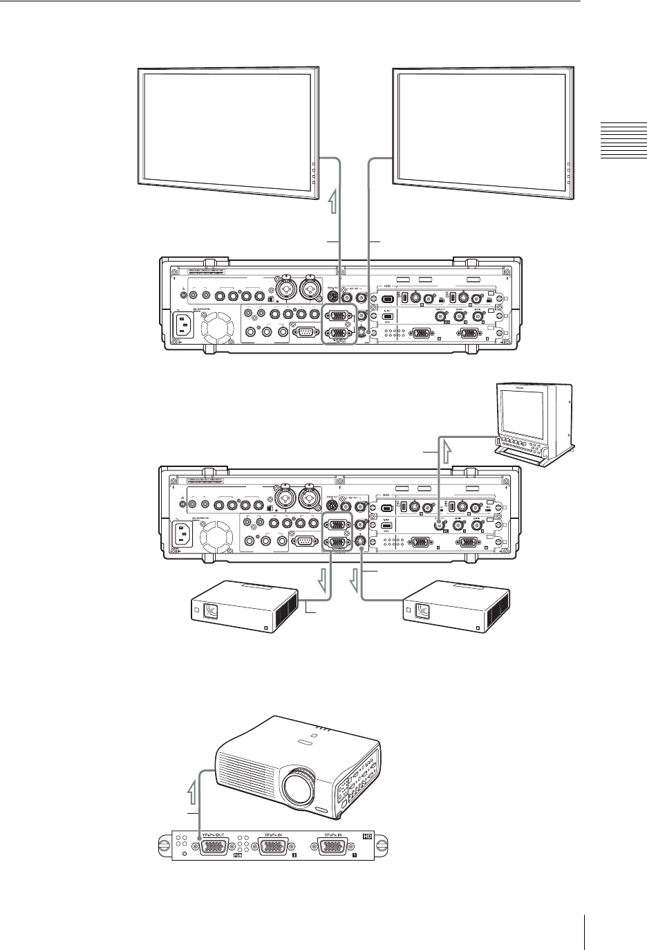
63
Connections
Chapter 2 Preparations
Connecting a Plasma Display/Projector/Monitor
When an HD video interface module is connected
AC IN
LINE MIC/LINE
MIX
HEADPHONES
MONI INTERCOM
15
69
RGB PGM
S VIDEO
AUX PG M RG B
I.LINK
S VIDEO
COMPOSITE
S VIDEO
COMPOSITE
S400
RGB RGB
COMPOSITE
MIC/LINE
PUSH PUSH
AUDIO IN
VIDEO IN
AUDIO OUT VIOEO OUT
87 6 5 4 3
RRLL
RL
21
21
OFF
ON
SD
OFF
ON
OFF
ON
PC
1
2
3
SDI
Flat panel display
(FWD series, etc.)
To RGB IN connectors
RGB cable S-Video cable
For RGB connection For analog connection
AC IN
LINE MIC/LINE
MIX
HEADPHONES
MONI INTERCOM
15
69
RGB PGM
S VIDEO
AUX PGM RGB
I.LINK
S VIDEO
COMPOSITE
S VIDEO
COMPOSITE
S400
RGB RGB
COMPOSITE
MIC/LINE
PUSH PUSH
AUDIO IN
VIDEO IN
AUDIO OUT VIOEO OUT
87 6 5 4 3
RRLL
RL
21
21
OFF
ON
SD
OFF
ON
OFF
ON
PC
1
2
3
SDI
Projector
(VPL series, etc.)
For RGB connection For analog connection
RGB Cable
S-Video cable
BNC cable
Monitor
(LMD series, etc.)
HD
VGA cable
Projector
(VPL series, etc.)
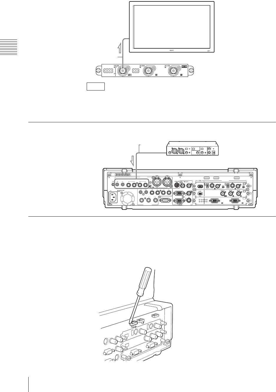
Chapter 2 Preparations
64 Connections
When an HD serial digital interface module is connected
• For more information on setting the resolution/clock phase and format, see
“Setting the RGB Output Signal Format” (page 210).
• To reduce the effects of external noise, use a cable with an attached ferrite core.
Connecting an Amplifier
Preventing Accidental Cable Disconnection
Use the cable clip as necessary to secure cables and prevent accidental
disconnection.
1
Using a flat head screwdriver, open the lever compartment as illustrated
below.
Notes
Flat panel display
(FWD series, etc.)
BNC cable
AC IN
LINE MIC/LINE
MIX
HEADPHONES
MONI INTERCOM
15
69
RGB PGM
S VIDEO
AUX PG M RG B
I.LINK
S VIDEO
COMPOSITE
S VIDEO
COMPOSITE
S400
RGB RGB
COMPOSITE
MIC/LINE
PUSH PUSH
AUDIO IN
VIDEO IN
AUDIO OUT VIOEO OUT
87 6 5 4 3
RRLL
RL
21
21
OFF
ON
SD
OFF
ON
OFF
ON
PC
1
2
3
SDI
Audio cable
To Line input connectors or Microphone/line input connectors
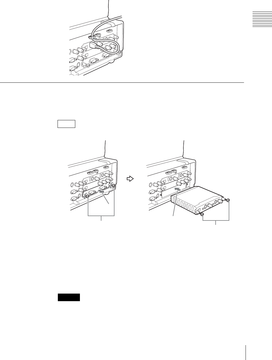
65
Connections
Chapter 2 Preparations
2
Pass the cables through the cable clip.
Allow some slack when routing the cables to prevent them from bending
sharply.
3
Close the lever compartment.
Installing Option Modules
To install an option module, first remove the interface module fitted to the unit
as standard, and install the new interface in the slot.
You can install an option module in any slot.
1
Loosen the two screws fixing the interface module fitted as standard.
2
Pull out the interface module.
3
Insert the option module into the slot.
4
Tighten the screws.
When installing an option module, always turn the unit off first. If you install an
option module with the unit powered on, this may damage the option module.
Note
Caution
1
2
3
4
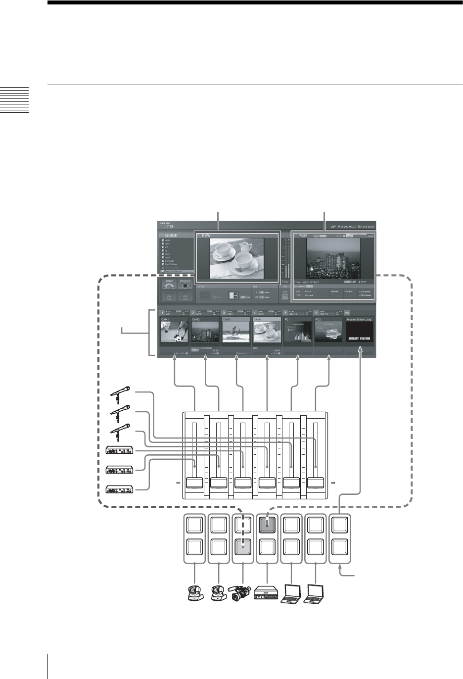
Chapter 2 Preparations
66 Settings Related To Input Signals
Settings Related To Input Signals
These settings allow video and audio signals input from devices connected to the
unit to be handled within the unit.
Relation Between Input Signals and System Components
You can assign input video and audio signals to buttons on the front panel and
channel faders, then operate these to carry out switching, mixing, and combining.
The operation screen continuously displays information about the video and
audio input to this unit, and the video and audio program output.
The following figure shows the relation between the input signals and system
components, and the display on the operation screen.
NEXT
INT
654321
PGM
654321
+
10
+
5
0
-
5
-
10
-
20
-
30
-
40
-
60
-
+
10
+
5
0
-
5
-
10
-
20
-
30
-
40
-
60
-
PGM
+
10
+
5
0
-
5
-
10
-
20
-
30
-
40
-
60
-
Next selection video selected
with the NEXT selection buttons
Program output video selected
with the PGM selection buttons
Shows video
and audio for
each source
number
Microphones
and acoustic
devices
Cameras, VCR.
Video signals generated
internally by this unit
• Color mattes
• Color bars
• Imported graphics files
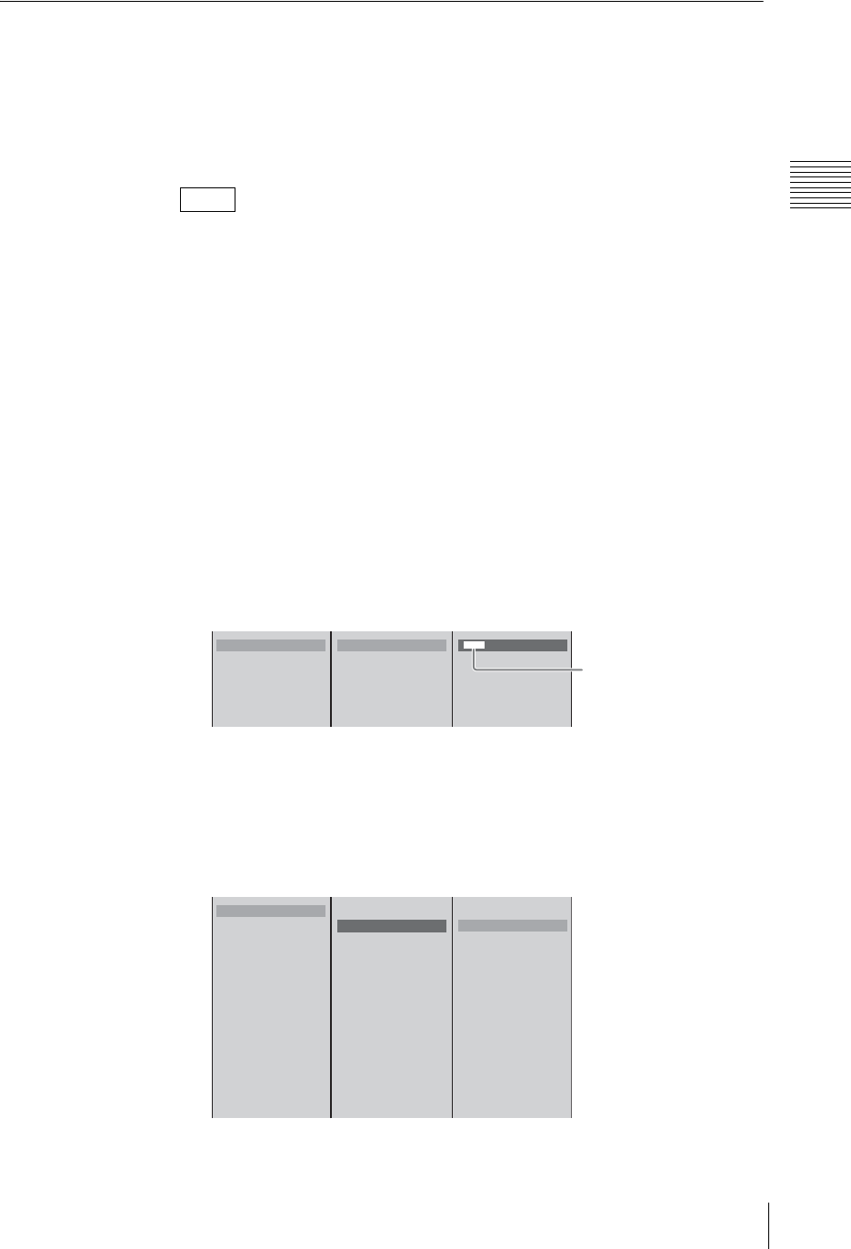
67
Settings Related To Input Signals
Chapter 2 Preparations
Video Signal Related Settings
These are preparations for handling video signals with the unit.
Assigning video input signals to the selection buttons
Assign video signals to the selection buttons 1 - 6 (PGM selection and NEXT
selection buttons).
You can confirm assignments and information on input signals using each of the
corresponding ACCESS menus. The signal names displayed in the menus are
those of signals that are capable of being accepted as determined by the unit. Not
all standard signal names are displayed.
1
Press the MENU button.
2
In the top menu, select [Video Input Assign].
3
From the list select the number of the selection button, and confirm, then set
the following items in the submenu.
Assigning a name for the video
Assign a name for the video. The name assigned here appears in the source
viewer with the same number as the selection button.
1 Select [Source Name], and confirm; 2 enter the name in the input box,
and confirm.
Specifying a video input connector
Specify the video input connector to which the video signals assigned to the
selection button are input.
1 Select [Input], and confirm; 2 select the video input connector from the
list, and confirm.
Note
1
2
3
4
5
6
Source Name CAM1
Input S1-1 Composite
Source Aspect 4:3
Control Off
[ CAM1 ]
12
Enter up to 20
alphanumeric characters.
* The source viewer can only
display a limited number of
characters.
1
2
3
4
5
6
Source Name CAMERA1
Input S1-1 Composite
Source Aspect 4:3
Control Off
No Assign
B SLOT1 IN1 Composite
S-Video
DV
SLOT1 IN2 Composite
S-Video
DV
SLOT2 IN1 Composite
S-Video
DV
SLOT2 IN2 Composite
S-Video
DV
SLOT3 IN1 RGB
SLOT3 IN2 RGB
12
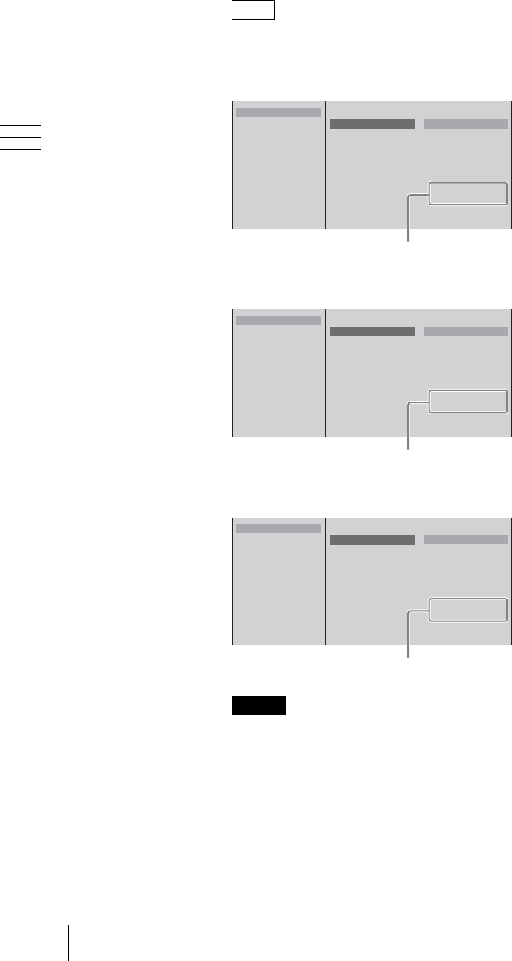
Chapter 2 Preparations
68 Settings Related To Input Signals
When optional modules are installed, the connectors for the optional
modules appear in the list.
•When a serial digital interface module is installed
The SDI input connectors appear.
•When an HD video interface module is installed
The HD analog input connectors appear.
•When an HD serial digital interface module is installed
The HD SDI input connectors appear.
• You can only use one of the following from the same video input on the
same interface module: Composite (Composite video input connector), S-
Video (S-Video input connector), or DV (DV connector).
• It is not possible to assign more than one selection button to a single video
input connector. If you attempt to assign to a different selection button a
video input connector which has already been assigned to a selection
button, a confirmation message appears. If you then select [OK], the
assignment switches to the new selection button, and the source viewer for
the originally assigned selection button shows the indication “No Input
Assign.”
Notes
Caution
1
2
3
4
5
6
Source Name CAMERA1
Input S1-1 Composite
Source Aspect 4:3
Control Off
No Assign
B SLOT1 IN1 Composite
S-Video
DV
SLOT1 IN2 Composite
S-Video
DV
SLOT2 IN1 SDI
SLOT2 IN2 SDI
SLOT3 IN1 RGB
SLOT3 IN2 RGB
When installed in slot 2
1
2
3
4
5
6
Source Name CAMERA1
Input S1-1 Composite
Source Aspect 4:3
Control Off
No Assign
B SLOT1 IN1 Composite
S-Video
DV
SLOT1 IN2 Composite
S-Video
DV
SLOT2 IN1 HD Analog
SLOT2 IN2 HD Analog
SLOT3 IN1 RGB
SLOT3 IN2 RGB
When installed in slot 2
1
2
3
4
5
6
Source Name CAMERA1
Input S1-1 Composite
Source Aspect 4:3
Control Off
No Assign
B SLOT1 IN1 Composite
S-Video
DV
SLOT1 IN2 Composite
S-Video
DV
SLOT2 IN1 HD SDI
SLOT2 IN2 HD SDI
SLOT3 IN1 RGB
SLOT3 IN2 RGB
When installed in slot 2
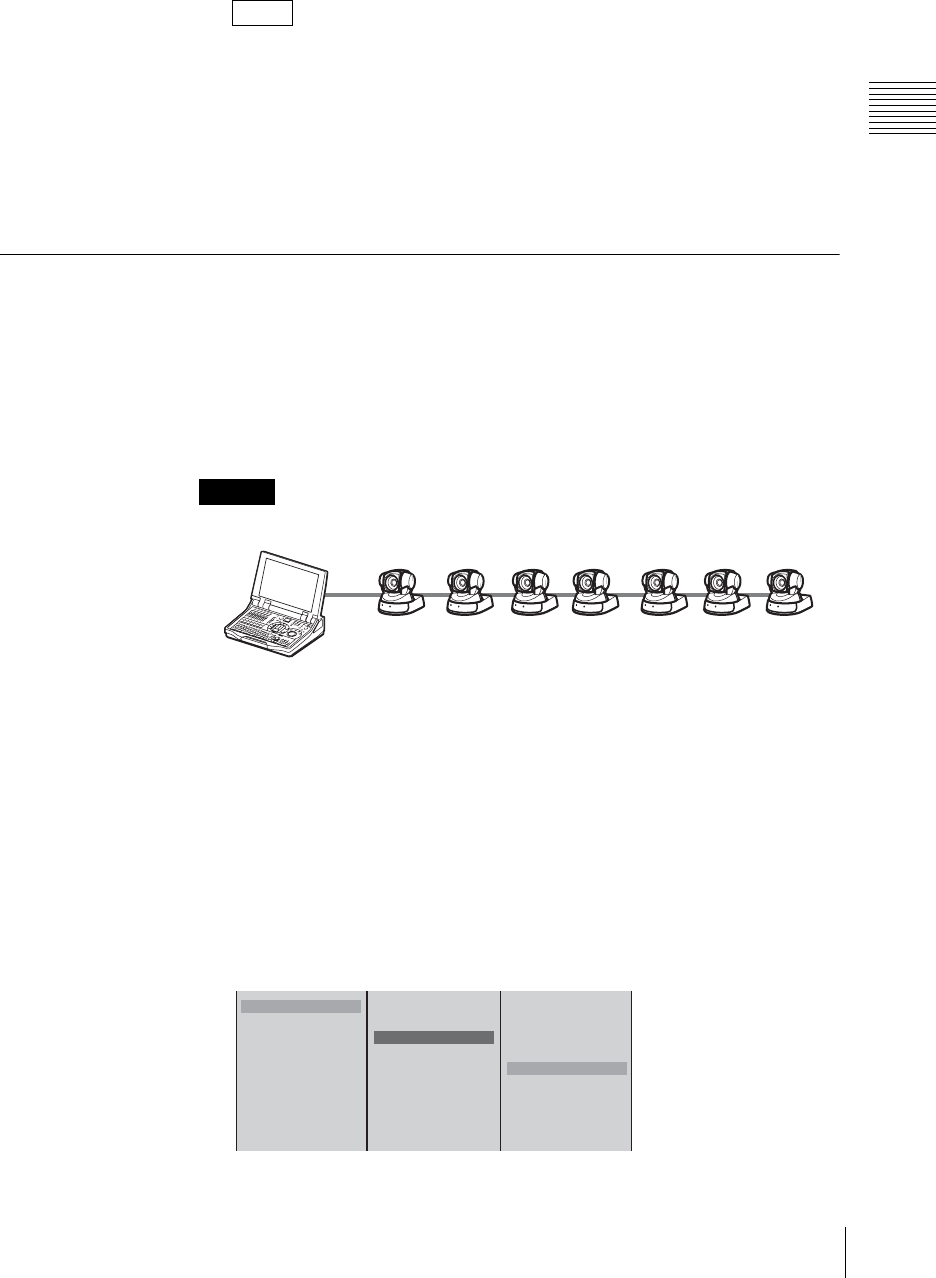
69
Settings Related To Input Signals
Chapter 2 Preparations
• About the DV signal lock time
When DV is selected for the input video, there is a delay until the DV
signal locks and the video appears.
• The items in the list depend on the interface module installed in this unit.
• For details on [Control] and [Source Aspect] in the menu for 1, see
“Controlling Camera Manually” (page 155) and “Converting 4:3 Source
Materials to Wide Screen” (page 207), respectively.
4
If required, repeat step 3 similarly for the remaining selection buttons.
5
Press the MENU button to close the menu.
Registering Cameras To Be Controlled
By registering a camera supporting the VISCA protocol with this unit you can
control it from the unit.
You can connect up to seven cameras supporting VISCA protocol to this unit in
a daisy-chain, and control the cameras from this unit at addresses VISCA 1 to
VISCA 7 in sequence. In this unit, you control a camera by specifying one of
these addresses.
The maximum number of simultaneous video signal inputs to this unit is six.
1
Connect the camera(s) supporting VISCA protocol to this unit.
For camera connection, see “Connecting a Camera With VISCA Support”
(page 58).
2
Assign the input signal from the camera to a selection button.
For assigning the input signal, see “Assigning video input signals to the
selection buttons” (page 67).
3
1 Select the number of the selection button assigned to the camera
supporting VISCA protocol, and confirm; 2 select [Control], and confirm;
3 select the camera address, and confirm.
Notes
Caution
12 3456 7
1
2
3
4
5
6
Source Name
Input S1-1 S-Video
Control Off
OFF
VISCA 1
VISCA 2
VISCA 3
B VISCA 4
VISCA 5
VISCA 6
VISCA 7
AV/C Player
123
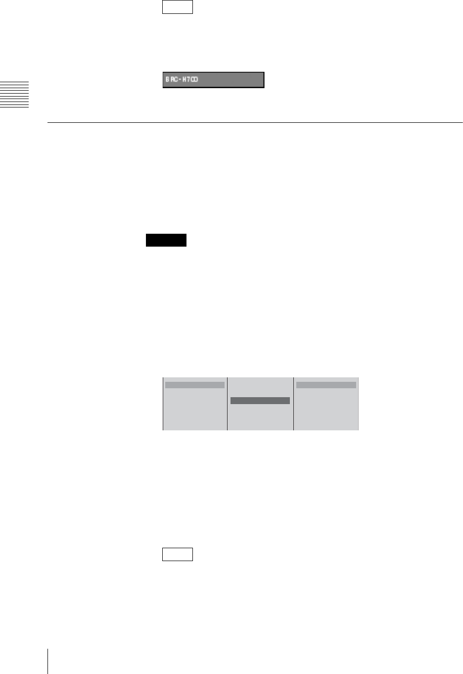
Chapter 2 Preparations
70 Settings Related To Input Signals
VISCA camera information display
By pressing the t button on the jog roller or the t key on the keyboard
while the camera address is selected, you can display the model name for the
camera, as shown below, for as long as you hold down the button or key.
4
Press the MENU button to close the menu.
Stretching 16:9 SQ Source Materials Into 16:9 Aspect Ratio
When the output aspect ratio setting is set to 16:9 SD or 16:9 HD mode, you can
configure settings to stretch 16:9 SQ materials from the analog video input and
SDI input connectors into normal 16:9 aspect ratio.
In addition, when you record material for which this setting has been configured
to an external hard disk and play them back on the unit or certain computers, the
material will automatically be stretched into 16:9 aspect ratio.
The aspect type of source materials inputted is not detected automatically.
1
Press the MENU button.
2
In the top menu, select [Video Input Assign].
3
1 Select the number for the selection button from the list, and confirm; 2
select [Source Aspect], and confirm; 3 select the aspect type for the
materials to be input, and confirm.
The functions of the setting items are as follows.
[4:3]: Select this when the SD/SDI signals input are 4:3 source materials.
The materials input are handled as they are as 4:3 materials.
[16:9 SQ]: Select this when the SD/SDI signals input are 16:9 squeeze
source materials.
The materials input are handled as 16:9 materials. When you select [16:9
SQ] and record materials to an external hard disk, the materials are
automatically played back in 16:9 aspect ratio during playback.
When DV is input, 4:3 is automatically selected.
4
Press the MENU button to close the menu.
Note
Caution
Note
1
2
3
4
5
6
Source Name CAMERA1
Input S1-1 Composite
Source Aspect 4:3
Control Off
B 4:3
16:9 SQ
123
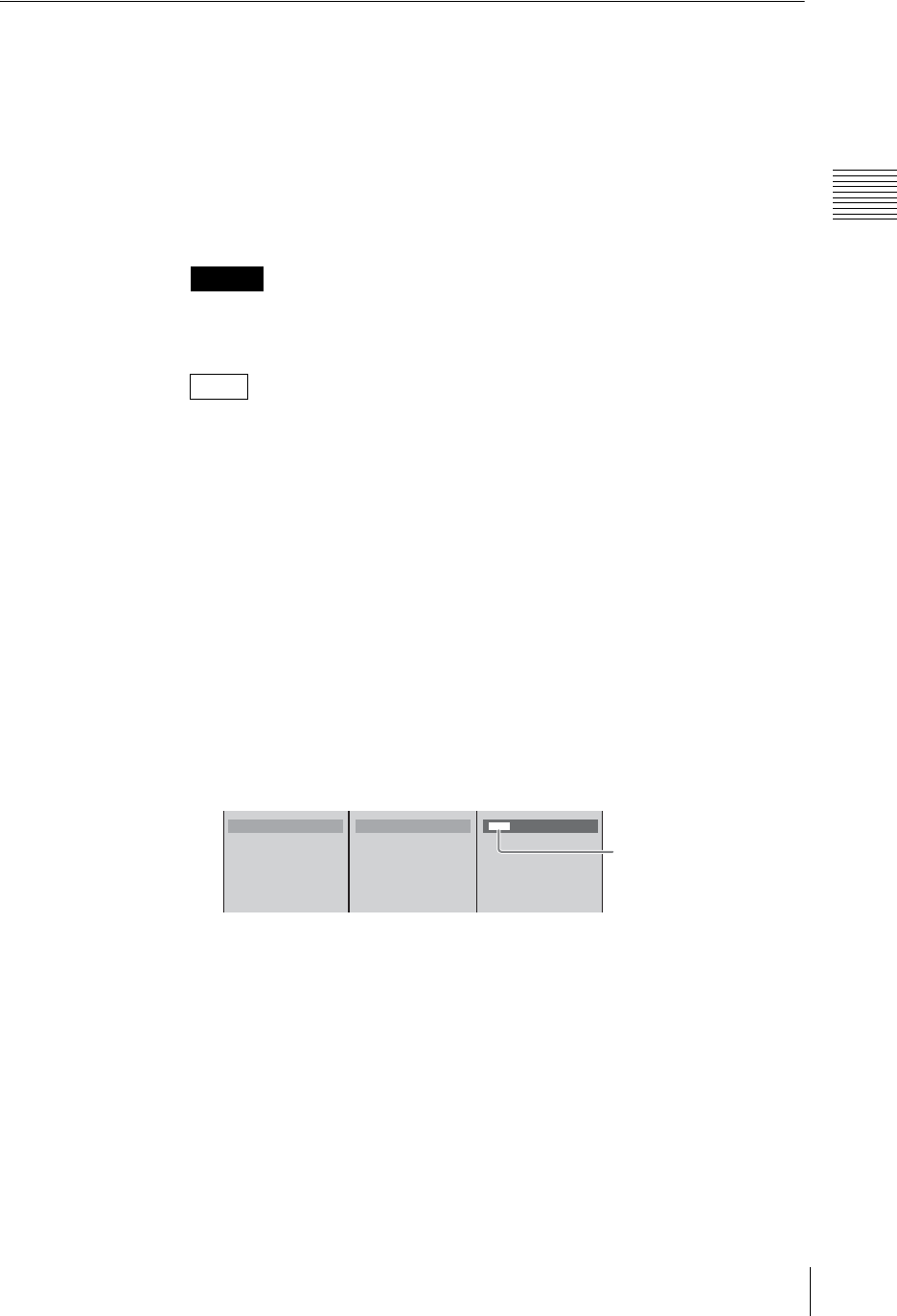
71
Settings Related To Input Signals
Chapter 2 Preparations
Audio Signal Related Settings
These are preparations for handling audio signals on the unit.
Assigning audio input signals to channel faders
Assign audio signals input from the audio input connectors or signals input from
the interface modules of the rear panel to channel faders 1 to 6.
If you assign different audio signals to the left and right channels (L/R) of the
channel faders, they become stereo faders, and if you assign the same audio
signal to both channels, they become monaural faders.
If you assign DV signals, SDI signals, or HD SDI signals, they become stereo
faders.
You can confirm assignments and information on input signals using each of the
corresponding ACCESS menus.
1
Press the MENU button.
2
In the top menu, select [Audio Input Assign].
3
Select the channel fader number from the list, and confirm, then set the
following items in the submenu.
Assigning a name
Assign a name to the audio signal. The name assigned here appears in the
source viewer with the same number as the channel fader.
1 Select [Source Name], and confirm; 2 enter the name in the input box,
and confirm.
Specifying an audio input connector
Specify the audio signal to be assigned to the channel fader. For stereo audio,
specify the source for each of the left and right channels separately.
For monaural audio, specify the same input for both left and right channels.
Caution
Note
1
2
3
4
5
6
Source Name MICI
Input (L) MIC/LINE
Input (R) Assign(R)
Link to Video Off
[ MIC1 ]
12
Enter up to 20
alphanumeric characters.
* The source viewer can only
display a limited number of
characters.
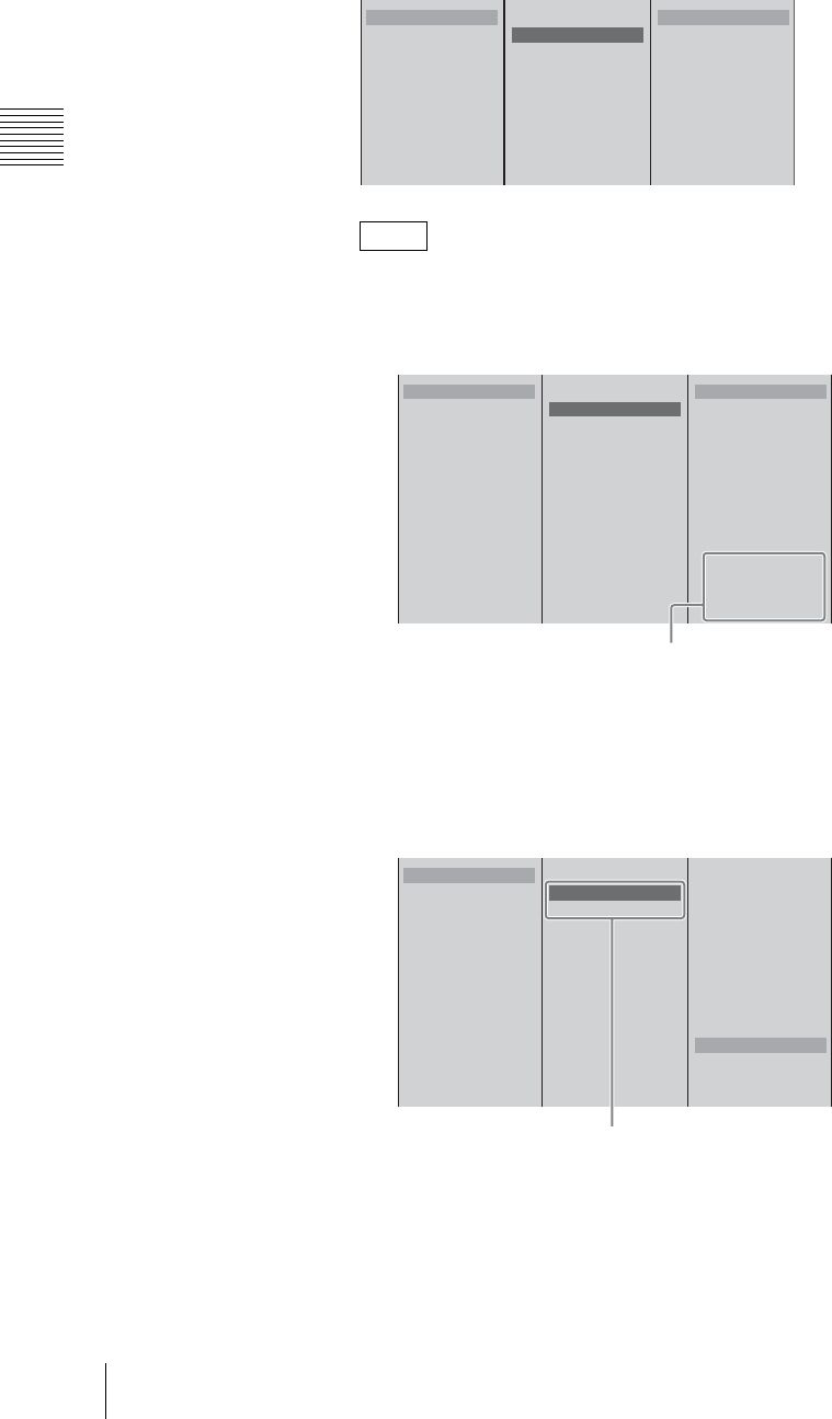
Chapter 2 Preparations
72 Settings Related To Input Signals
1 Select [Input (L)], and confirm; 2 select the audio input connector from
the list, and confirm.
• If in [Input (L)] you select the DV input connector, the same input
connector is automatically assigned to [Input (R)].
• When a serial digital interface module is installed
- The SDI input connectors for individual channels are displayed.
- If you select CH (1/2) of the SDI input connector for either [Input (L)]
or [Input (R)], CH (1) and CH (2)are assigned automatically to [Input
(L)] and [Input (R)], respectively.
When you select CH (3/4) of the SDI input connector, CH (3) and CH
(4) are assigned automatically to [Input (L)] and [Input (R)],
respectively.
• When an HD serial digital interface module is installed
- The HD SDI input connectors for individual channels are displayed.
Notes
1
2
3
4
5
6
Source Name MIC1
Input (L) MIC/LINE1
Input (R) MIC/LINE1
Link to Video Off
B MIC/LINE 1
MIC/LINE 2
MIC/LINE 3
MIC/LINE 4
MIC/LINE 5
MIC/LINE 6
LINE 7
LINE 8
SLOT1 DV IN1
SLOT1 DV IN2
12
1
2
3
4
5
6
Source Name
Input (L) MIC/LINE1
Input (R) MIC/LINE1
Link to Video Off
B MIC/LINE 1
MIC/LINE 2
MIC/LINE 3
MIC/LINE 4
MIC/LINE 5
MIC/LINE 6
LINE 7
LINE 8
SLOT1 DV IN1
SLOT1 DV IN2
SLOT2 SDI IN1 CH(1/2)
SDI IN1 CH(3/4)
SLOT2 SDI IN2 CH(1/2)
SDI IN2 CH(3/4)
When installed in slot 2
1
2
3
4
5
6
Source Name
Input (L) SDI IN1 CH1
Input (R) SDI IN1 CH2
Link to Video Off
MIC/LINE 1
MIC/LINE 2
MIC/LINE 3
MIC/LINE 4
MIC/LINE 5
MIC/LINE 6
LINE 7
LINE 8
SLOT1 DV IN1
SLOT1 DV IN2
B SLOT2 SDI IN1 CH(1/2)
SDI IN1 CH(3/4)
SLOT2 SDI IN2 CH(1/2)
SDI IN2 CH(3/4)
When CH (1/2) of SDI IN1 is assigned

73
Settings Related To Input Signals
Chapter 2 Preparations
- If you select CH (1/2) of the HD SDI input connector for either [Input
(L)] or [Input (R)], CH (1) and CH (2) are assigned automatically to
[Input (L)] and [Input (R)], respectively.
When you select CH (3/4) of the HD SDI input connector, CH (3) and
CH (4) are assigned automatically to [Input (L)] and [Input (R)],
respectively.
• For DV input, it is not possible to assign more than one selection button to
a single DV input connector. If you attempt to assign to a different
selection button a DV input connector which has already been assigned to
a selection button, a confirmation message appears. If you then select
[OK], the assignment switches to the new selection button, and the
originally assigned selection button returns to the default setting.
•About the DV signal locking time
When DV is selected for the input audio, there is a delay until the DV
signal locks and the audio can be heard.
• When a serial digital interface module or HD serial digital interface
module is installed
- SDI/HD SDI embedded audio can only be assigned to the channel fader
of the source number assigned to video that is input to the same SDI
input connector or HD SDI input connector. It cannot be combined with
analog input video, DV input video, or video of the other SDI input
connector or HD SDI input connector.
- SDI embedded audio cannot be assigned simultaneously to CH (1/2) and
CH (3/4) of the same SDI input connector or HD SDI input connector.
Caution
1
2
3
4
5
6
Source Name
Input (L) MIC/LINE1
Input (R) MIC/LINE1
Link to Video Off
B MIC/LINE 1
MIC/LINE 2
MIC/LINE 3
MIC/LINE 4
MIC/LINE 5
MIC/LINE 6
LINE 7
LINE 8
SLOT1 DV IN1
SLOT1 DV IN2
SLOT2 HD SDI IN1 CH(1/2)
HD SDI IN1 CH(3/4)
SLOT2 HD SDI IN2 CH(1/2)
HD SDI IN2 CH(3/4)
When installed in slot 2
1
2
3
4
5
6
Source Name
Input (L) HD SDI IN1 CH1
Input (R) HD SDI IN1 CH2
Link to Video Off
MIC/LINE 1
MIC/LINE 2
MIC/LINE 3
MIC/LINE 4
MIC/LINE 5
MIC/LINE 6
LINE 7
LINE 8
SLOT1 DV IN1
SLOT1 DV IN2
B SLOT2 HD SDI IN1 CH(1/2)
HD SDI IN1 CH(3/4)
SLOT2 HD SDI IN2 CH(1/2)
HD SDI IN2 CH(3/4)
When CH (1/2) of HD SDI IN1 is assigned
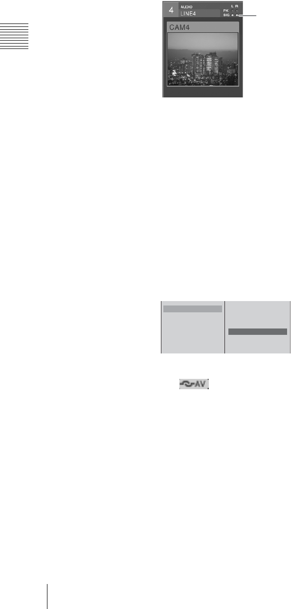
Chapter 2 Preparations
74 Settings Related To Input Signals
Similarly, select [Input (R)], and confirm; select the audio input connector
from the list, and confirm.
When the input audio signal reaches the reference level, the input signal
indication in the source viewer lights green and you can confirm that there is
an audio input.
4
Press the MENU button to close the menu.
Linking program output video to audio of the same source number and
outputting simultaneously
When video is switched over to program output, you can set audio that has been
assigned to the same source number as the video to be enabled and output
simultaneously with this setting.
1
Press the MENU button.
2
In the top menu, select [Audio Input Assign].
3
1 From the list, select the number for the channel fader to link to the video,
and confirm; 2 select [Link to Video], and confirm.
The setting turns on or off each time it is selected.
4
Press the MENU button to close the menu.
The icon appears in the source viewer of the source number for
which the link was set.
When the video of the viewer in which the icon appears is program output,
the CH ON button lights and the audio channel is enabled simultaneously.
When program is not output, the CH ON button dims.
Setting the MIC/LINE level of an audio input
If the peak indication appears (when set to the default MIC/LINE
level of “Middle (-20 dB)”)
If the input audio signal is too loud, the peak indication in the source viewer lights
red.
In this case, since the MIC/LINE level exceeds the standard input level, use the
following procedure to adjust it.
Input signal indication
1
2
3
4
5
6
Source Name MIC1
Input (L) MIC/LINE1
Input (R) MIC/LINE1
Link to Video Off
12
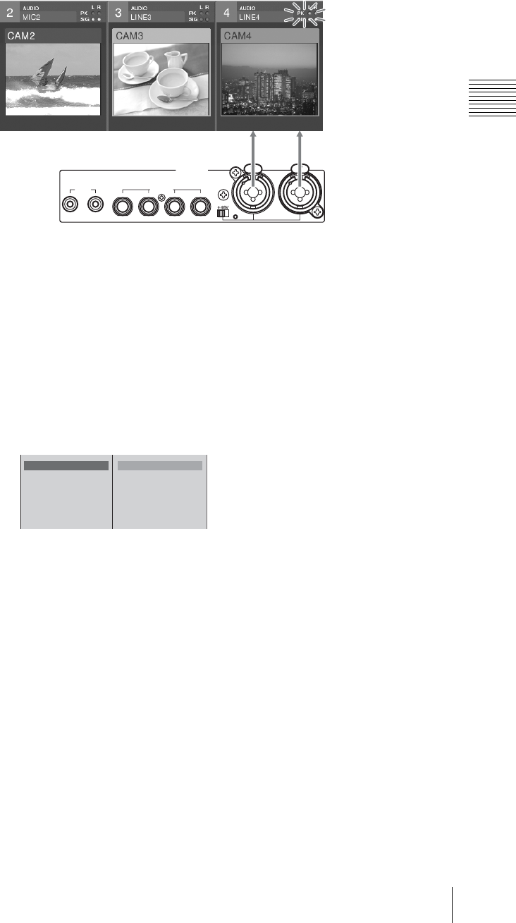
75
Settings Related To Input Signals
Chapter 2 Preparations
Example: When the peak indication has lit with MIC/LINE 2 connected to R and
MIC/LINE 1 connected to L, as illustrated below.
1
Press the MENU button.
2
In the top menu select [Audio MIC/LINE Level].
3
1 Select the number of the MIC/LINE input connector to which is
connected the target audio signal, and confirm; 2 select [High(+4dB)], and
confirm.
In this example, both [MIC/LINE 1] and [MIC/LINE 2] are set to [High
(+4dB)].
4
Press the MENU button to close the menu.
If no input signal indication appears (when set to the default
microphone/line level of “Middle (-20 dB)”)
If no input signal indication appears in the source viewer even though an audio
signal is input, the microphone/line level is not reaching the reference level.
Using the same procedure as detailed in “If the peak indication appears” above,
select the number of the microphone/line input connector, and at step 3-2, select
[Low (-44dB)], and confirm.
LINE MIC/LINE
MIC/LINE
PUSH PUSH
AUDIO IN
876543
21
OFF
ON
MIC/LINE
2
MIC/LINE
1
RL
MIC/LINE 1 Middle
MIC/LINE 2 Middle
MIC/LINE 3 Middle
MIC/LINE 4 Middle
MIC/LINE 5 Middle
MIC/LINE 6 Middle
B High(+4dB)
Middle(-20dB)
Low(-44dB)
12

Chapter 2 Preparations
76 Settings Related To Input Signals
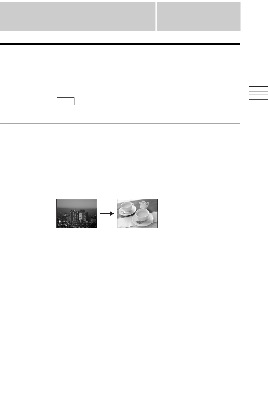
Chapter 3 Operations
77
Video Switching
Chapter
3
Operations
Video Switching
This section describes how to switch the video signals input to the unit, and
output the final video (output program) from the PGM output connectors.
With this unit, you can also apply some video effects.
First, make the settings described in “Video Signal Related Settings” (page 67).
Basics of Video Switching
This section describes only the most basic switching operations. See the relevant
sections for details of switching and effect operations.
Cut switching
This is the most basic and commonly used type of switching. The video changes
instantaneously from A to B.
For details, see “Changing the Video With a Cut” (page 78).
Switching with a transition effect
In a transition effect, the image gradually switches from one video to another
through the application of one of various effects.
For details, see “Changing the Video With a Effect Transition” (page 80).
Note
AB
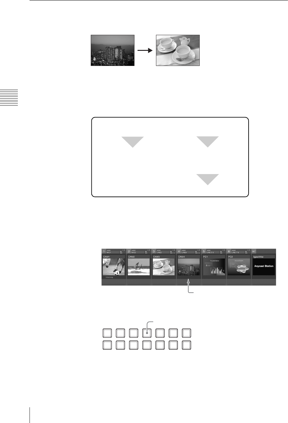
Chapter 3 Operations
78 Video Switching
Changing the Video With a Cut
This switches the video instantaneously, with no added effects. This is the most
basic form of switching.
Basic operation for a video cut
There are two methods of making a cut, as follows.
• Switching directly by pressing a PGM selection button
• Checking the next video in the PVW viewer, then pressing the CUT button
The following diagram shows the flow of operations in carrying out a video cut.
Switching directly by pressing a PGM selection button
To switch from one video to another, you can simply press the PGM selection
button to which the new video is assigned.
1
In the source viewer, select the video for program output.
2
Press the PGM selection button with the same number as the selected video.
The PGM selection button you pressed lights red, and the selected video
appears in the PGM viewer.
The same video as shown in the PGM viewer is now output from the PGM
output connectors.
Press the PGM selection buttons to select the program
output video.
Press a different PGM
selection button to
switch the video.
Press a NEXT selection
button to select the next
output.
Press the CUT button.
Example: You may select video 4.
NEXT
INT
654321
PGM
Press button 4.
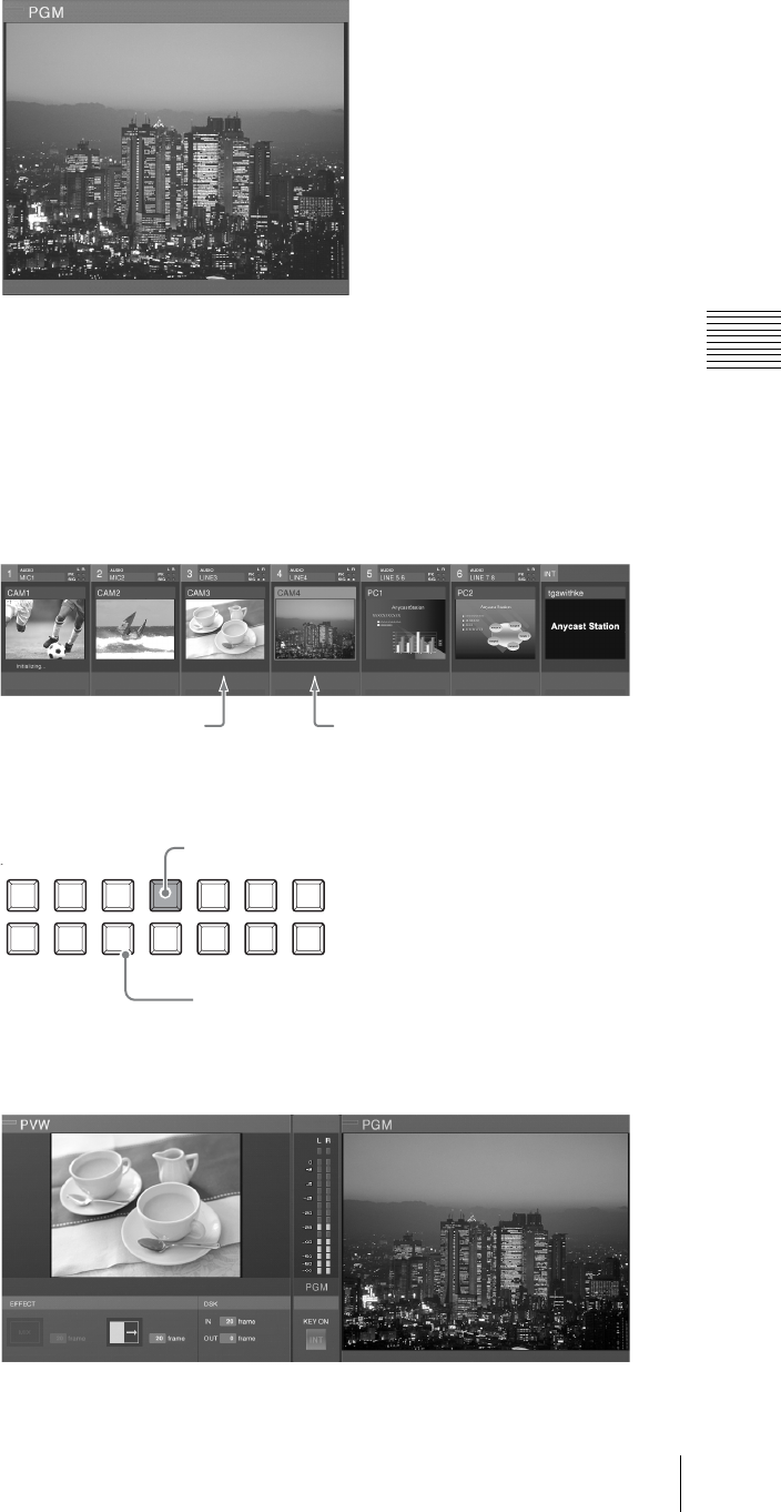
79
Video Switching
Chapter 3 Operations
A red frame appears around the source viewer for the selected video.
3
Determine on the next video, then repeat the procedure in step 2.
Switching with the CUT button after checking the next video in the PVW viewer
To switch while checking the new video in the PVW viewer, use the CUT button.
1
In the source viewer, select the video you want to switch to (the next program
output).
2
Press the NEXT selection button with the same number as this video.
The NEXT selection button you pressed lights amber, and the selected video
appears in the PVW viewer.
An amber frame appears around the source viewer for the next video.
Example: You may want
to switch to video 3.
Current program output video
NEXT
INT
654321
PGM
Lit red.
Press button 3.
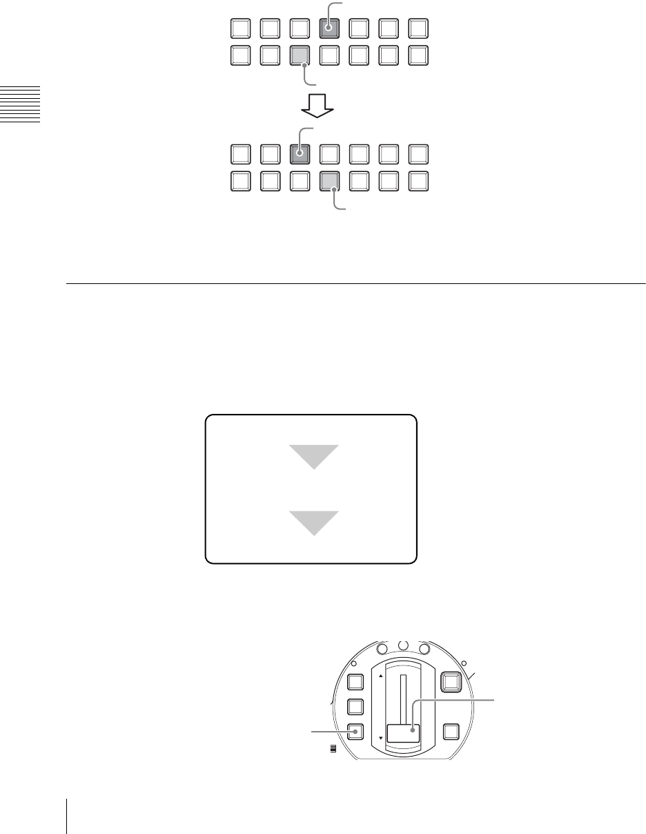
Chapter 3 Operations
80 Video Switching
3
Press the CUT button.
This interchanges the video in the PGM viewer and PVW viewer, and
switches the program output video.
At the same time, the lit PGM selection button and NEXT selection button
interchange, and the colors of the frames in the source viewer also
interchange.
Each press of the CUT button interchanges the program output video and the
NEXT selection video.
Changing the Video With a Effect Transition
Instead of an instantaneous cut, you can gradually switch from one video to
another through the application of one of various effects.
Basic transition effect operations
The basic procedure for applying an effect to a transition is as follows.
There are two ways of executing a transition:
• Automatic execution with the AUTO TRANS button
• Manual execution using the transition lever
NEXT
INT
654321
PGM
NEXT
INT
654321
PGM
Lit red.
Lit amber.
Lit red.
Lit amber.
Before you press the CUT button
After you pressed the CUT button
Select the next video to be output
using the NEXT selection buttons.
Carry out the transition.
Set the transition effect.
0
M
IC
FTB
DSK
KEY
CUT
AUTO
TRANS
M
I
X
E
F
F
E
C
T
P
V
W
AUTO TRANS button
Transition lever
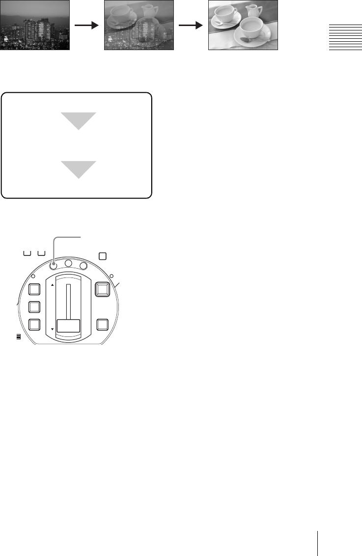
81
Video Switching
Chapter 3 Operations
AUTO TRANS button
Pressing the AUTO TRANS button carries out the transition automatically, using
the preset transition time.
Transition lever
Moving the transition lever in the direction shown by the LED indicators (fF)
progresses the transition in sync with the lever movement.
Switching with a dissolve
In a dissolve, one video image fades into another.
Basic operation for a dissolve
The basic procedure for a dissolve is as follows.
1
Press the MIX button.
The MIX button lights amber, and the effect indication on the operation
screen shows the current mix state (progress of the dissolve).
Carry out the transition.
Press the MIX button.
Select the next video to be output
using the NEXT selection buttons.
DIM TB
0
M
IC
FTB
DSK
KEY
CUT
AUTO
TRANS
M
I
X
E
F
F
E
C
T
P
V
W
MIX button
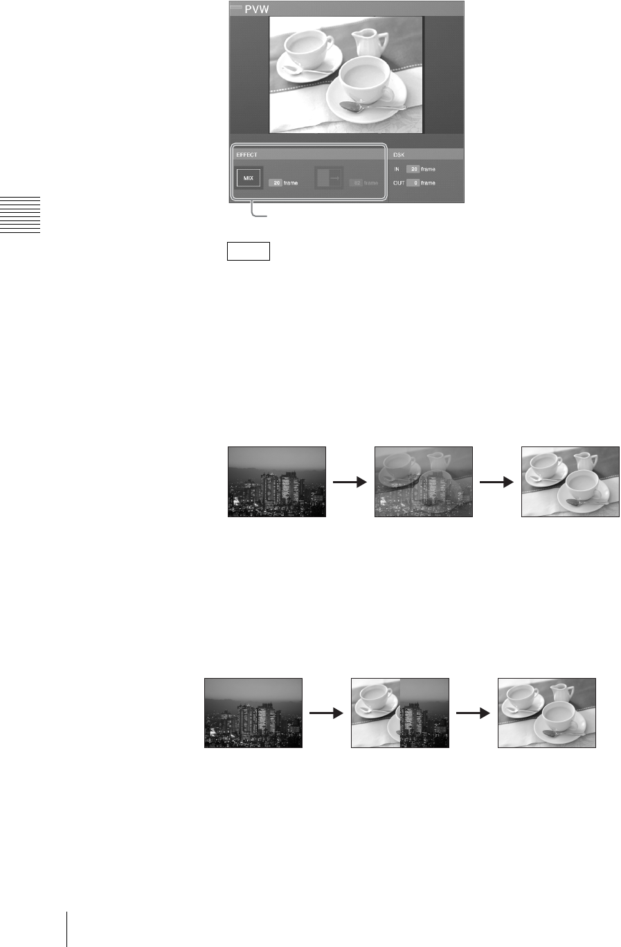
Chapter 3 Operations
82 Video Switching
• The mix state shows the current transition time setting.
• You can still change the transition time at this point. To make this change,
follow the procedure in “Changing the Transition Time” (page 84).
2
Determine the next program output video, and select this with the NEXT
selection button.
The selected video appears in the PVW viewer.
3
Carry out the transition with the AUTO TRANS button or transition lever.
The NEXT selection video dissolves into the program output video.
Each press of the AUTO TRANS button, or operation of the transition lever,
carries out a dissolve transition from the program output video to the NEXT
selection video.
Switching with a wipe
In a wipe, two video images occupy the display simultaneously, with the area
occupied by one growing until if wipes out the other. You can choose from
sixteen different wipe patterns.
Notes
Current mix state
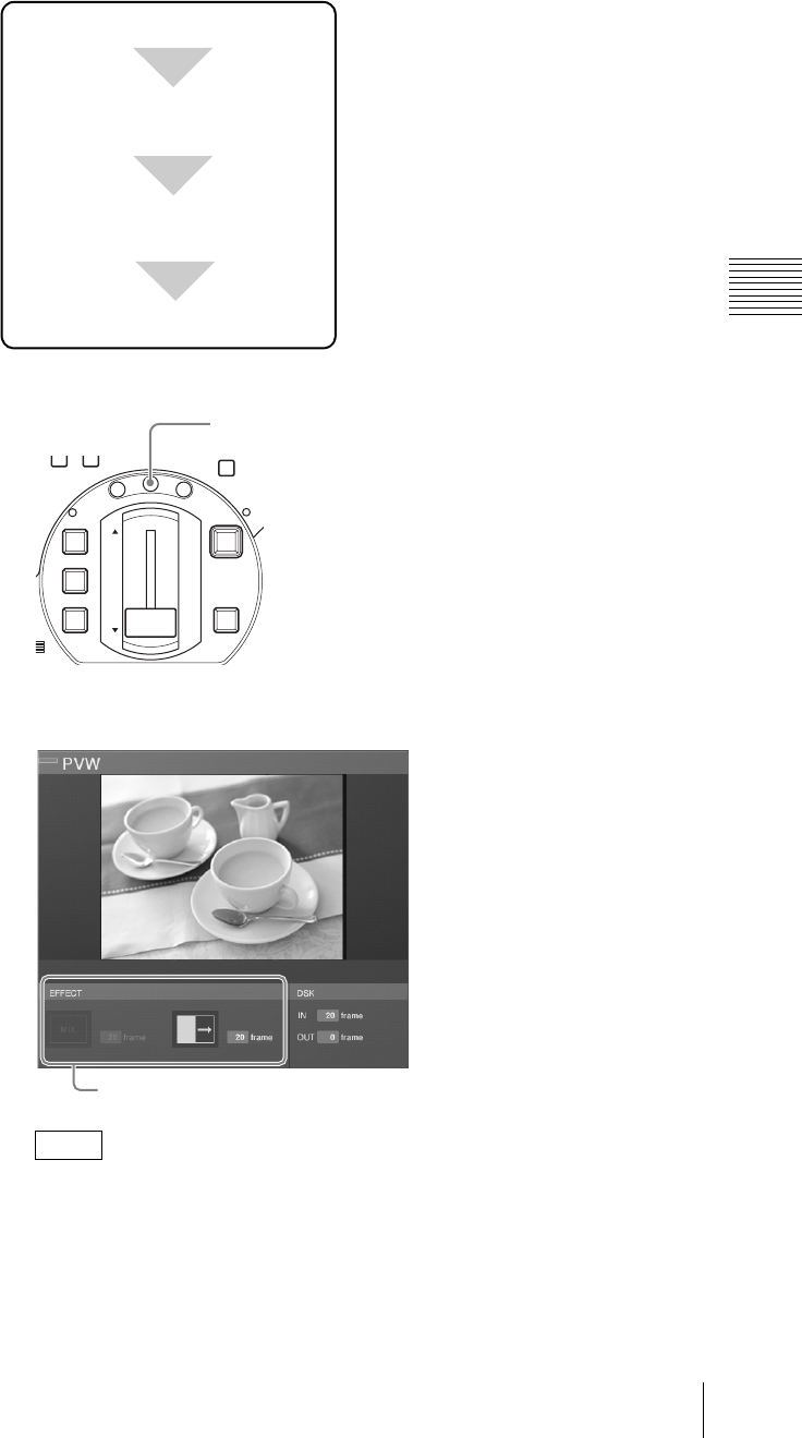
83
Video Switching
Chapter 3 Operations
Basic operation for a wipe transition
The basic procedure for a wipe transition is as follows.
1
Press the EFFECT button.
The EFFECT button lights amber, and the effect indication shows the current
effect state.
• The current effect state shows the transition time and effect pattern
settings.
• You can change the transition time. To change the setting, follow the
procedure in “Changing the Transition Time” (page 84).
Notes
Press the EFFECT button.
Select the effect pattern in the top
menu with [Effect Pattern].
Carry out the transition.
Select the next video to be output
using the NEXT selection buttons.
DIM TB
0
M
IC
FTB
DSK
KEY
CUT
AUTO
TRANS
M
I
X
E
F
F
E
C
T
P
V
W
EFFECT button
Current effect state
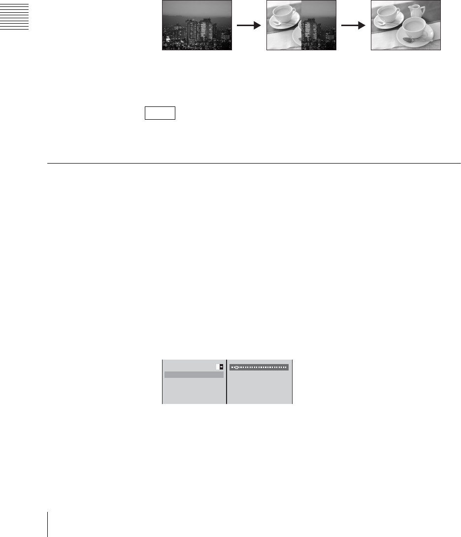
Chapter 3 Operations
84 Video Switching
2
Select the effect pattern.
To change the effect pattern, follow the procedure in “Changing the Effect
Pattern” (page 85).
3
Determine the next program output video, and select this with the NEXT
selection button.
The selected video appears in the PVW viewer.
4
Carry out the transition with the AUTO TRANS button or transition lever.
The program output video changes to the NEXT selection video by a wipe
transition.
Each press of the AUTO TRANS button, or operation of the transition lever,
the program output video changes to the NEXT selection video by a wipe
transition.
You can apply an edge effect to the wipe pattern. For details, see “Applying Edge
Effects” (page 109).
Changing the Transition Time
Before carrying out a transition with the AUTO TRANS button, set the transition
time.
1
Press the MIX button or EFFECT button.
The current settings appear in the effect display.
2
Press the MENU button.
3
In the top menu, select [Video Effect].
4
1 Select [Transition Time], and confirm; 2 move the slider to set the
transition time.
The transition time is set in frame units.
5
Press the MENU button to close the menu.
The set transition time appears in the effect display.
Note
Effect Pattern T
Transition Time 30 F
Edge Off
Key Type Luminance
Key Adjust
12
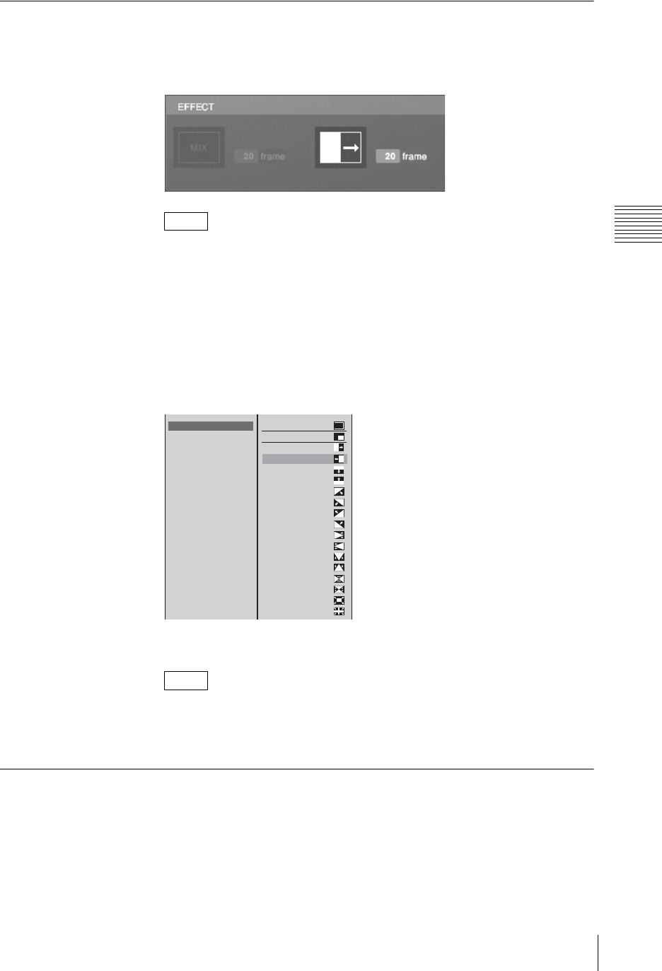
85
Video Switching
Chapter 3 Operations
Changing the Effect Pattern
1
Press the EFFECT button.
The current settings appear in the effect display.
Here you can also press the EFFECT button once more to recall the [Effect
Pattern] menu, and skip from step 2 below as far as 1 within step 4.
2
Press the MENU button.
3
In the top menu, select [Video Effect].
4
1 Select [Effect Pattern], and confirm; 2 select the wipe pattern from the
list, and confirm.
5
Press the MENU button to close the menu.
You can also close the menu by pressing the EFFECT button.
The selected effect pattern appears in the effect display.
Using Picture-in-Picture (PinP) for Combining Videos
You can generate a picture-in-picture effect by embedding a video within another
video.
Note
Note
Effect Pattern 0001
Transition Time 30F
Edge Off
Key Type Luminance
Key Adjust
Auto Chroma Key
Crop Off
Size Small
Location
1080 T
1100 A
B 0001 T
0002 T
0003 T
0004 T
0009 T
0010 T
0011 T
0012 T
0013 T
0014 T
0015 T
0016 T
0019 T
0020 T
0021 T
0022 T
MIX
12
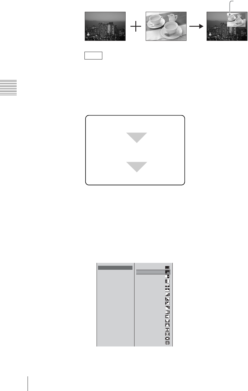
Chapter 3 Operations
86 Video Switching
When you use a picture-in-picture for combining videos, you can check the
results in the PVW viewer before program output. For details, see “Checking the
Results of Combining Videos (Effect Preview)” (page 110).
Basic picture-in-picture operations
The basic procedure for using a picture-in-picture for combining videos is as
follows.
For details on executing transitions, see “Basic transition effect operations”
(page 80).
1
Press the MENU button.
2
In the top menu, select [Video Effect].
3
1 Select [Effect Pattern] and confirm; 2 select a picture-in-picture from the
list and confirm.
The picture-in-picture information appears in the effect display.
Note
Embedded
video
Select a picture-in-picture from [Effect
Pattern] of the top menu.
Press a NEXT selection button to select
a video to embed within the video.
Execute the transition.
Effect Pattern 0003
Transition Time 30F
Edge Off
Key Type Luminance
Key Adjust
Auto Chroma Key
Crop Off
Size Small
Location
1080 T
1100 A
0001 T
0002 T
B 0003 T
0004 T
0009 T
0010 T
0011 T
0012 T
0013 T
0014 T
0015 T
0016 T
0019 T
0020 T
0021 T
0022 T
MIX
12
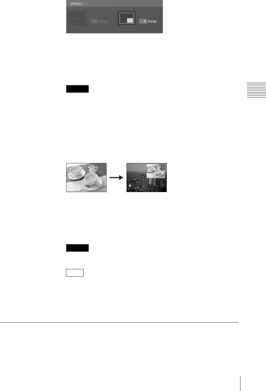
87
Video Switching
Chapter 3 Operations
4
Press the MENU button to close the menu.
5
Decide which video to embed, and then press the corresponding NEXT
selection button to specify the video.
The selected video is displayed in the PVW viewer.
When the following material is selected, the NEXT selection button flashes
and the picture-in-picture effect is not applied.
• Material assigned to INT
• Material being used for program output
• Material being used for keying
6
Use the AUTO TRANS button, CUT button, or transition lever to execute
the transition.
The NEXT selection video is embedded in the program output video.
The NEXT selection button changes to red when the transition is complete.
Press the AUTO TRANS button or CUT button once more or move the
transition lever in the opposite direction to remove the embedded video and
return the color of the NEXT selection button to orange.
The transition time is always 0.
• You can crop the unwanted portions from the embedded video. For details,
see “Cropping Unwanted Portions From the Video Being Combined”
(page 109).
• You can apply an edge to the frame of the video to be embedded. For
details, see “Applying Edge Effects” (page 109).
Adjusting the Picture-in-Picture (PinP)
You can set the size and display position of the video embedded using a picture-
in-picture.
Caution
Caution
Notes
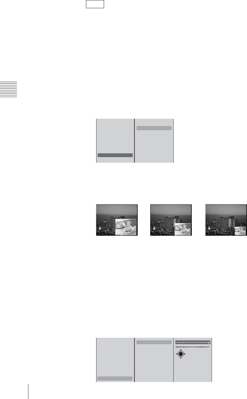
Chapter 3 Operations
88 Video Switching
You can make picture-in-picture adjustments while viewing the results in the
PVW viewer before program output. For details, see “Checking the Results of
Combining Videos (Effect Preview)” (page 110) and “Giving Priority to
Displaying the PVW Viewer” (page 113).
Changing the size of the video embedded
1
Perform steps 1 to 6 of “Basic picture-in-picture operations” (page 86).
2
Press the MENU button.
3
In the top menu, select [Video Effect].
4
1 Select [Size] and confirm; 2 select a size and confirm.
The functions of the setting items are as follows.
[Large]: 1/4 of size
[Medium]: 9/64 of size
[Small]: 1/16 of size
5
Press the MENU button to close the menu.
Specifying the position to embed the video
1
Perform steps 1 to 6 of “Basic picture-in-picture operations” (page 86).
2
Press the MENU button.
3
In the top menu, select [Video Effect].
4
1 Select [Location] and confirm; 2 select [X] or [Y] and confirm; 3
specify the position with the slider.
Note
Effect Pattern 0004
Transition Time 30F
Edge Off
Key Type Luminance
Key Adjust
Auto Chroma Key
Crop Off
Size Small
Location
Large
B Medium
Small
12
Large Medium Small
Effect Pattern 0004
Transition Time 30F
Edge Off
Key Type Luminance
Key Adjust
Auto Chroma Key
Crop Off
Size Small
Location
X 200
Y -150
X-Y
123
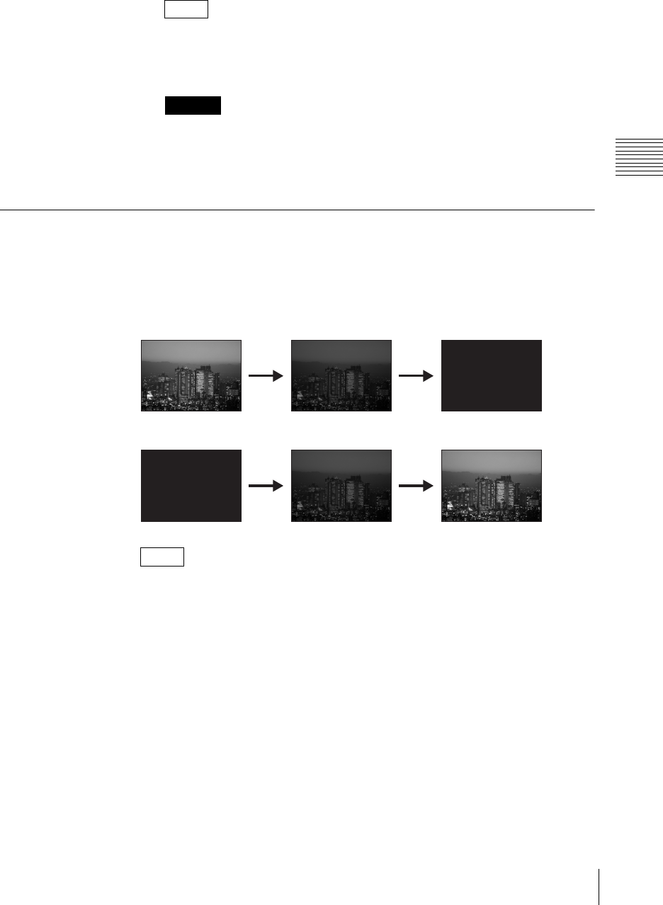
89
Video Switching
Chapter 3 Operations
The functions of the setting items are as follows.
[X]: Specifies the horizontal position.
[Y]: Specifies the vertical position.
After step 1, you can specify the vertical or horizontal position by pressing
up, down, left, or right on the positioner. (When using the positioner, you do
not need to select [X] and [Y].)
When adjusting the position of the picture-in-picture image up, down, left, or
right, the image shifts in 10-point increments.
5
Press the MENU button to close the menu.
Using Fade-to-Black (FTB)
This fades the video in from or out to a black screen.
Press the FTB button.
This fades out the program output to a black screen, except for any superimposed
logo.
Press the FTB button once more to fade in the video from the black screen.
While the screen is black, the PGM selection buttons change to amber.
Fading in a different video after fading out
1
After fading to a black screen, select a different video with the PGM
selection buttons.
2
Press the FTB button.
This fades in the newly selected video.
Setting the fade to black transition time
1
Press the MENU button.
2
In the top menu, select [Fade To Black].
Note
Caution
Note
LOGO LOGO LOGO
LOGO LOGO LOGO
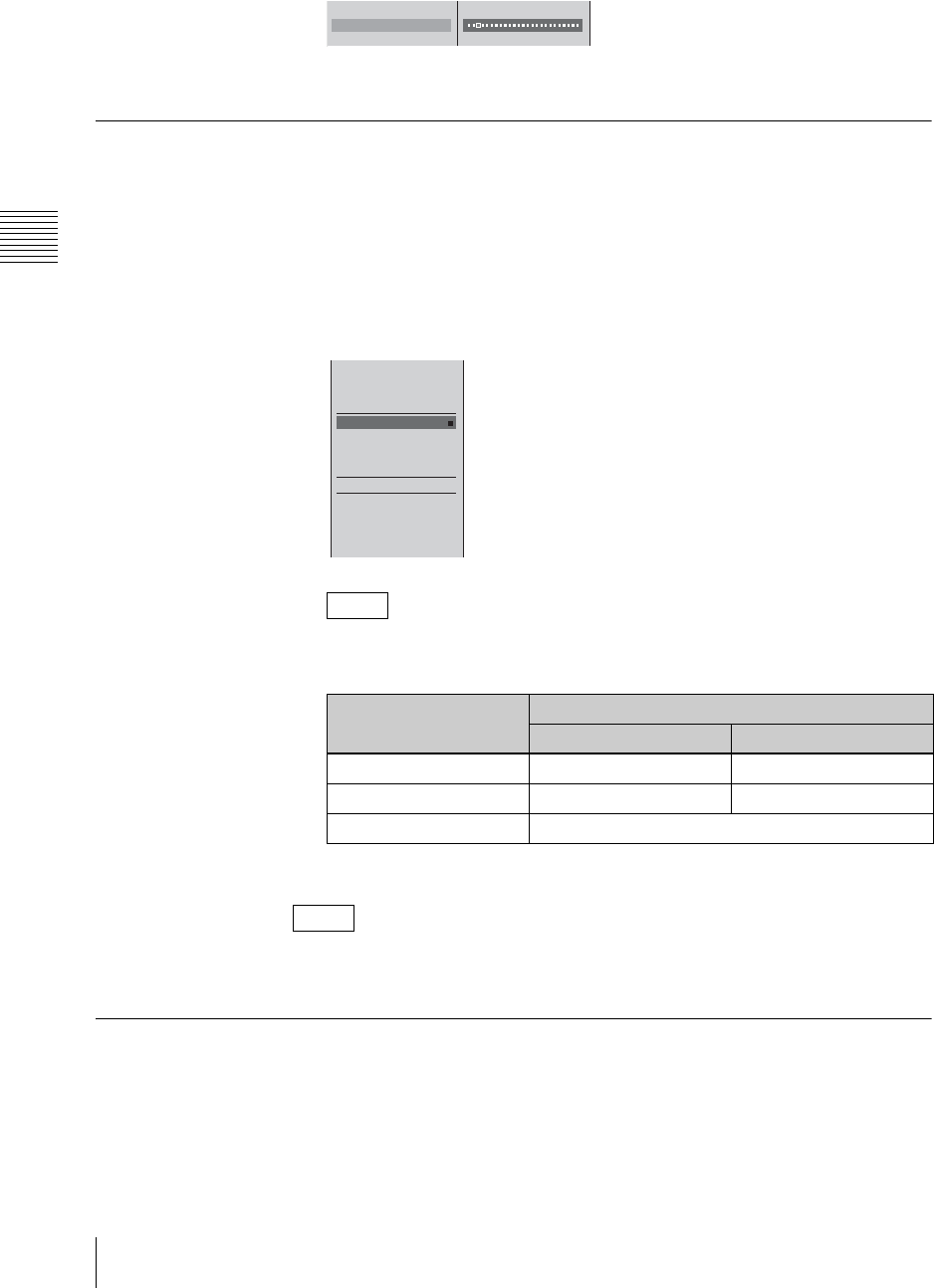
Chapter 3 Operations
90 Video Switching
3
1 Select [Transition Time], and confirm; 2 move the slider to set the
transition time.
4
Press the MENU button to close the menu.
Using Color Bars and Color Mattes
The Internal Color Bar is provided for adjustment and test transmission. The
Internal Color Matte is provided for a background.
1
Press INT in the NEXT selection buttons.
The INT source selection menu appears in the menu display.
2
Select the color bars or color matte you want to show, and confirm.
This unit can output the following color bars for each video output signal
format and PGM output aspect ratio setting.
The selected internal video signal appears in the “INT” source viewer.
You can change the color of the color matte. For details, see “Adjusting Color
Matte” (page 209).
Using the Downstream Key (DSK) Function To Add Text or an
Image
You can add text or an image to video that already includes an effect or
combination.
This is useful for adding subtitles, for example.
Note
PGM output aspect
ratio
Video output signal format
NTSC/60 Hz PAL/50 Hz
4:3 mode SMPTE color bar (75%) EBU color bar (100%)
16:9 SD mode SMPTE color bar EBU color bar
16:9 HD mode EBU color bar
Note
12
Transition Time 20 F
Black
White
Color Bars
B Color Matte
Lum 11%
Sat 95%
Hue 351˚
Text Typing Tool F5
aaaaaaaa
bbbbbbbb
cccccccc
SD_Safe_Area.tga
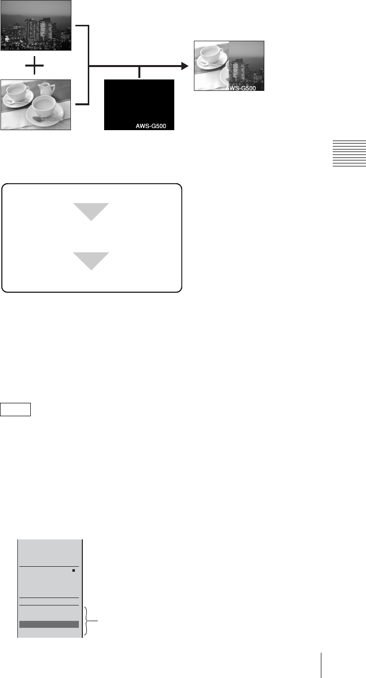
91
Video Switching
Chapter 3 Operations
Basic downstream key operations
The basic procedure for downstream keying is as follows.
Inserting a downstream key
In order to use a downstream key for text or graphics, it must first be imported
onto the internal hard disk of this unit.
For details on creating a graphics file, see “Creating a Title Graphic With the Text
Typing Tool” (page 114).
For details on importing a graphics file, see “Importing Graphics Files” (page 228).
You can also register graphics files to the numeric buttons on the front panel and
access them whenever necessary. For details, see “Accessing Graphics Files
Quickly” (page 94).
1
Press INT in the NEXT selection buttons.
The INT source selection menu appears.
2
Use the jog roller to select a graphics file displayed in the lower part of the
INT source selection menu, and confirm.
Note
DSK (downstream) key
Select the image to be imported.
Select a graphics file from the INT source
selection menu.
Press the DSK button to insert the key.
Black
White
Color Bars
Color Matte
Lum 0%
Sat 0%
Hue 0%
Text Typing Tool F5
aaaaaaaa
bbbbbbbb
ccccccccc b
SD_Safe_Area.tga
Graphics files
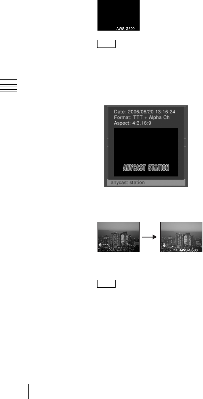
Chapter 3 Operations
92 Video Switching
The selected graphics file appears in the “INT” source viewer.
• While the graphics file is being read in, the message “Loading...” appears
at the bottom of the PVW viewer and in the device status in the source
viewer.
•File information display
Press the t button on the jog roller or the t key on the keyboard while
a graphics file is selected, and the following information about the graphics
file and a thumbnail will display for as long as the button or key is pressed.
3
Press the DSK button.
DSK button lights red, and the graphics file image appears in the PGM
viewer.
If you press the DSK button once more, the inserted image is removed. Each
press of the DSK button alternately inserts or removes the image.
If you change the video to a black screen using FTB, no downstream key is
output. In this case, the DSK button lights amber.
Setting the downstream key transition times
You can set the DSK transition times which are the times taken for the text or
image to be gradually inserted, or to be gradually removed. These are set in frame
units.
1
Press the MENU button.
2
In the top menu, select [DSK].
Note
Note
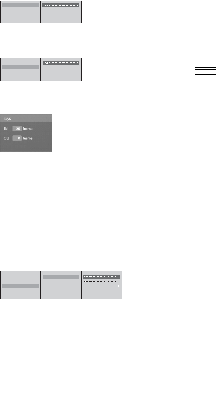
93
Video Switching
Chapter 3 Operations
3
1 Select [IN Trans. Time], and confirm; 2 move the slider to set the time
until the image appears.
4
1 Select [OUT Trans. Time], and confirm; 2 move the slider to set the time
to disappear.
5
Press the MENU button to close the menu.
The DSK transition time setting appears in the DSK display of the effect
display in the operation screen.
Adjusting the downstream key
You can adjust the parameters for inserting text or image, or crop unwanted
portions.
1
Press the DSK button to insert the image.
2
Press the MENU button.
3
In the top menu, select [DSK].
4
In the submenu, set the following adjustment items.
Adjusting the outline of the text or image
1 Select [Key Adjust], and confirm; 2 select the item to adjust, and
confirm; 3 adjust the sliders.
The functions of the setting items are as follows.
[Clip]: Adjusts the threshold level for keying.
[Gain]: Adjusts the sharpness of the key outline.
[Density]: Adjusts the density of the text or image to be inserted.
If you have recalled and adjusted a graphics file, the adjusted values of the
graphics file change as follows depending on the next file recalled:
Note
IN Trans. Time 20 F
OUT Trans. Time 0 F
Key Adjust
Crop Off
12
IN Trans. Time 20 F
OUT Trans. Time 0 F
Key Adjust
Crop Off
12
IN Trans. Time 20 F
OUT Trans. Time 0 F
Key Adjust
Crop Off
Clip 0%
Gain 0
Density 100%
Key Invert Off
123
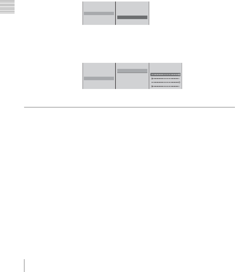
Chapter 3 Operations
94 Video Switching
• When a file with no alpha channel is recalled: adjusted values remain
unchanged.
• When a file with an alpha channel is recalled: values return to their default
settings.
Inverting the key
You can invert the displayed parts and non-displayed parts of the combined
material.
1 Select [Key Adjust], and confirm; 2 select [Key Invert], and confirm.
[Key Invert] turns on or off each time it is selected.
Cropping unwanted portions of the text or image
1 Select [Crop], and confirm; 2 select [On], and confirm; 3 select the side
(top, bottom, left, or right) to be displayed, and confirm; 4 move the slider
to crop.
5
Press the MENU button to close the menu.
Accessing Graphics Files Quickly
If you register a graphics file to one of the numeric buttons on the front panel, you
can quickly access that file whenever necessary.
Registering graphics files as presets
1
Press INT in the NEXT selection buttons, and press it again after the INT
source selection menu appears.
The graphics preset menu appears.
IN Trans. Time 20 F
OUT Trans. Time 0 F
Key Adjust
Crop Off
Clip 0%
Gain 0
Density 100%
Key Invert Off
12
IN Trans. Time 20 F
OUT Trans. Time 0 F
Key Adjust
Crop Off
Off
B On
Top 320
Left -400
Right 400
Bottom -320
123 4
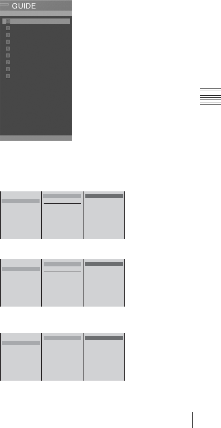
95
Video Switching
Chapter 3 Operations
2
1 Select the number to register the graphics file to, and confirm; 2 select
[Preset], and confirm.
A list of graphics files that you can register appears.
Example: When registering to numeric button [2].
3
Select a graphics file, and confirm.
The graphics file is registered as a preset, and the file name appears next to
the number selected previously.
4
Press the MENU button to close the menu.
1
2
3
4
5
6
7
8
9
Anycast Station b
Anycast Station_001
Anycast Station_002
aaaaaaa.tif
bbbbbbb.tif
SD_Safe_Area.tga
Preset
Delete
Data Name
12
1
2
3
4
5
6
7
8
9
B Anycast Station b
Anycast Station_001
Anycast Station_002
aaaaaaa.tif
bbbbbbb.tif
SD_Safe_Area.tga
Preset
Delete
Data Name
1
2 Anycast Station
3
4
5
6
7
8
9
B Anycast Station b
Anycast Station_001
Anycast Station_002
aaaaaaa.tif
bbbbbbb.tif
SD_Safe_Area.tga
Preset
Delete
Data Name
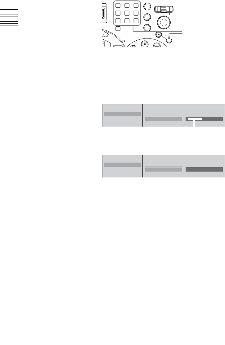
Chapter 3 Operations
96 Video Switching
Registering graphics files without displaying the menu
You can also register graphics files without displaying the graphics preset menu.
1
Press INT in the NEXT selection buttons.
The menu that appears next is unimportant.
2
Display the graphics file to register in the INT source viewer.
3
Press a numeric button (from 1 to 9) while holding down the SHIFT
button.
Applying a name to the preset
In the graphics preset menu, 1 select the number of the preset to apply a name
to, and confirm; 2 select [Data Name], and confirm; 3 enter the data name in
the input box, and confirm.
The data name is registered.
Accessing the graphics files
1
Press INT in the NEXT selection buttons.
The menu that appears next is unimportant.
2
Press the numeric button to which the graphics file is assigned.
The accessed graphics file appears in the INT source viewer.
Deleting a registered preset
1
Press INT in the NEXT selection buttons, and press it again after the INT
source selection menu appears.
The graphics preset menu appears.
2
1 Select the number for the preset you want to delete, and confirm; 2 select
[Delete], and confirm.
789
456
1
0
23
ESC
ENTER
MENU
X
-
Y
REC
SHIFT
P
V
W
Hold down the SHIFT button, and press one of
numeric buttons 1 to 9.
1
2 Anycast Station
3
4
Preset
Delete
Data Name [ aaaaaaaaaa ]
123
Enter up to 20 alphanumeric characters.
1
2 aaaaaaaaaa
3
4
Preset
Delete
Data Name [ aaaaaaaaaa ]
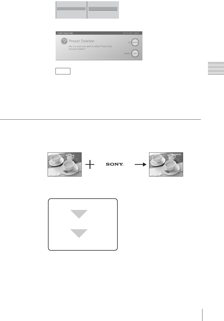
97
Video Switching
Chapter 3 Operations
The following confirmation message appears.
By pressing the ENTER button while holding down the SHIFT button, you
can delete all of the presets registered to the numeric buttons 1 to 9
simultaneously.
3
Press the ENTER button.
The preset is deleted, and the number display turns gray.
Showing a Logo on the Screen
For copyright protection purposes, you can superimpose a logo (160×120 pixel
graphic) on the video.
When the logo is enabled, the logo is superimposed on the program output video.
Basic operation for showing a logo
The basic procedure for showing a logo is as follows.
Showing a logo in the video
To show a logo, first it is necessary to import the logo file to the internal hard disk
of this unit.
For details on importing a logo file, see “Importing Logo Files” (page 230).
1
Press the MENU button.
2
In the top menu, select [Logo].
Note
1
2 Anycast Station
3
4
Preset
Delete
Data Name
12
Select the logo source file.
The logo is displayed.
Import a logo.

Chapter 3 Operations
98 Video Switching
3
1 Select [Logo Source], and confirm; 2 select the logo file from the list,
and confirm.
The image is inserted in both the PGM viewer and PVW viewer.
• By selecting a logo file from the list, it always appears in the program
output video. If you do not want to show the logo, select [None].
•File information display
By pressing the t button on the jog roller or the t key on the keyboard
while a logo file is selected, you can display information on the logo file
and a thumbnail, as shown below, for as long as you hold down the button
or key.
4
Press the MENU button to close the menu.
Adjusting the logo display
Adjust the parameters for logo insertion, and set the logo position.
1
Show the logo.
For details of the operation, see “Showing a logo in the video” (page 97).
2
Press the MENU button.
3
In the top menu, select [Logo].
4
In the submenu, set the following adjustment items.
Adjusting the outline of the logo
1 Select one of [Clip], [Gain], and [Density], and confirm; 2 adjust the
slider.
Notes
Logo Source None
Clip 0%
Gain 0
Density 100%
Location
None
B aaaaaaaa.tif
bbbbbbbb.tif
ccccccccc.bmp
dddddddd.bmp
12
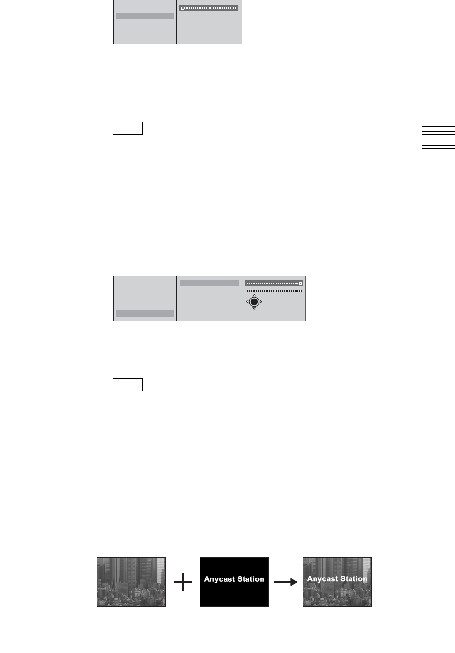
99
Video Switching
Chapter 3 Operations
The functions of the setting items are as follows.
[Clip]: Adjusts the threshold level for the logo key.
[Gain]: Adjusts the sharpness of the outline.
[Density]: Adjusts the density of the text to be inserted.
When you have recalled a logo file and made adjustments, the logo file
adjustment values for the logo file depend on the next recalled file as follows:
• When a file with no alpha channel is recalled: the adjustments are
maintained as is.
• When a file with an alpha channel is recalled: the adjustments are returned
to their default values.
Specifying the position of the logo display
1 Select [Location], and confirm; 2 select [X] or [Y], and confirm; 3
specify the position with the sliders.
The functions of the setting items are as follows.
[X]: Specifies the horizontal position.
[Y]: Specifies the vertical position.
After Step 1, you can specify the vertical or horizontal position by just
pressing the top, bottom, left, or right part of the positioner. (If you use the
positioner, there is no need to select [X] and [Y].)
5
Press the MENU button to close the menu.
Using Luminance Keying
Video A and video B images are combined by comparing the components of
brightness (luminance) to cut unneeded portions of the video B image.
Generally, bright lettering is drawn on a black background, and this is used as the
key.
Note
Note
Logo Source None
Clip 0%
Gain 0
Density 100%
Location
12
Logo Source None
Clip 0%
Gain 0
Density 100%
Location
X 320
Y 280
X-Y
123
ABAB
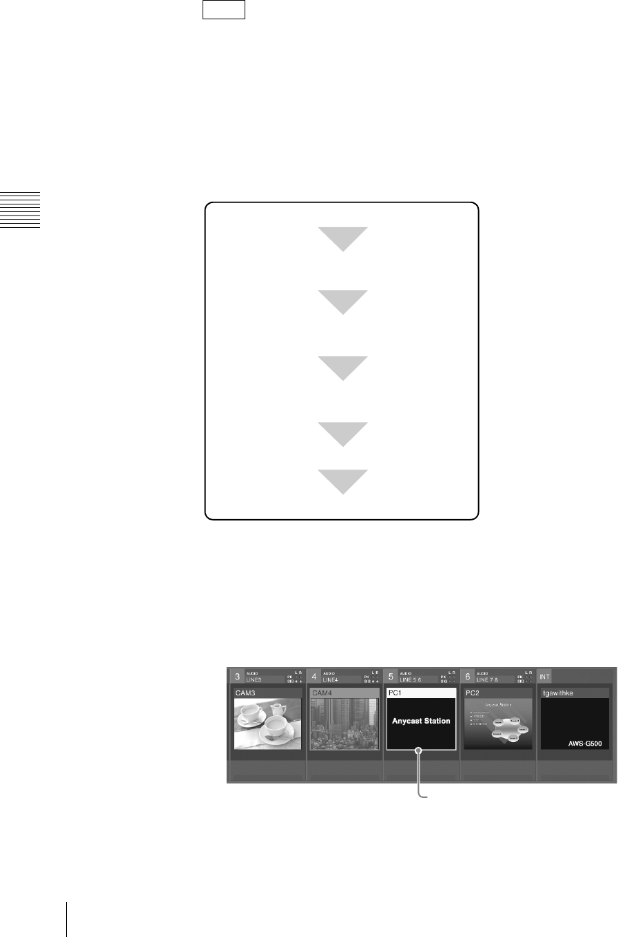
Chapter 3 Operations
100 Video Switching
• Pressing the KEY button switches to key mode (the KEY button, NEXT
selection buttons, MIX button or EFFECT button light green, and the AUTO
TRANS button, CUT button, and transition lever now apply a keying
operation).
• You can also register graphics files to the numeric buttons on the front panel
and access them whenever necessary. For details, see “Accessing Graphics
Files Quickly” (page 94).
Basic operation for luminance keying
The basic procedure for luminance keying is as follows.
1
Press the KEY button.
The KEY button, NEXT selection buttons, and the MIX or EFFECT button
light green and are now used for video keying.
2
Select the video for keying by pressing the NEXT selection button assigned
to it.
A green frame appears around the selected video in the source viewer.
3
Press the MENU button.
4
In the top menu, select [Video Effect].
Notes
Press the KEY button (Switches to key mode).
Select the key video with a NEXT selection
button.
Carry out the transition.
Select the effect pattern with the MIX button
or EFFECT button.
Adjust the key video.
Select [Luminance Key] for [Key Type] in the
top menu.
When 5 is selected
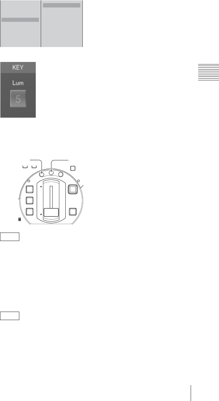
101
Video Switching
Chapter 3 Operations
5
1 Select [Key Type], and confirm; 2 select [Luminance Key], and
confirm.
“Lum” appears in the key status display area of the operation screen.
6
Press the MIX button or EFFECT button.
The button green, and the details of the current effect appear in the effect
display.
• You can change the transition time for the effect. To make this change,
follow the procedure in “Changing the Transition Time” (page 84).
• You can change the effect pattern. To make this change, follow the
procedure in “Changing the Effect Pattern” (page 85).
• In key mode, you can maintain the transition time, effect pattern, and edge
setting adjustments for keying.
7
Select [Key Adjust], confirm, and adjust the key video with the submenu.
You can make keying adjustments while viewing the results in the PVW
viewer before program output. For details, see “Checking the Results of
Combining Videos (Effect Preview)” (page 110) and “Giving Priority to
Displaying the PVW Viewer” (page 113).
Notes
Note
Effect Pattern 0003
Transition Time 30F
Edge Off
Key Type Chroma
Key Adjust
Auto Chroma Key
Crop Off
Size Small
Location
Luminance Key
B Chroma Key
12
DIM TB
0
M
IC
FTB
DSK
KEY
CUT
AUTO
TRANS
M
I
X
E
F
F
E
C
T
P
V
W
EFFECT buttonMIX button
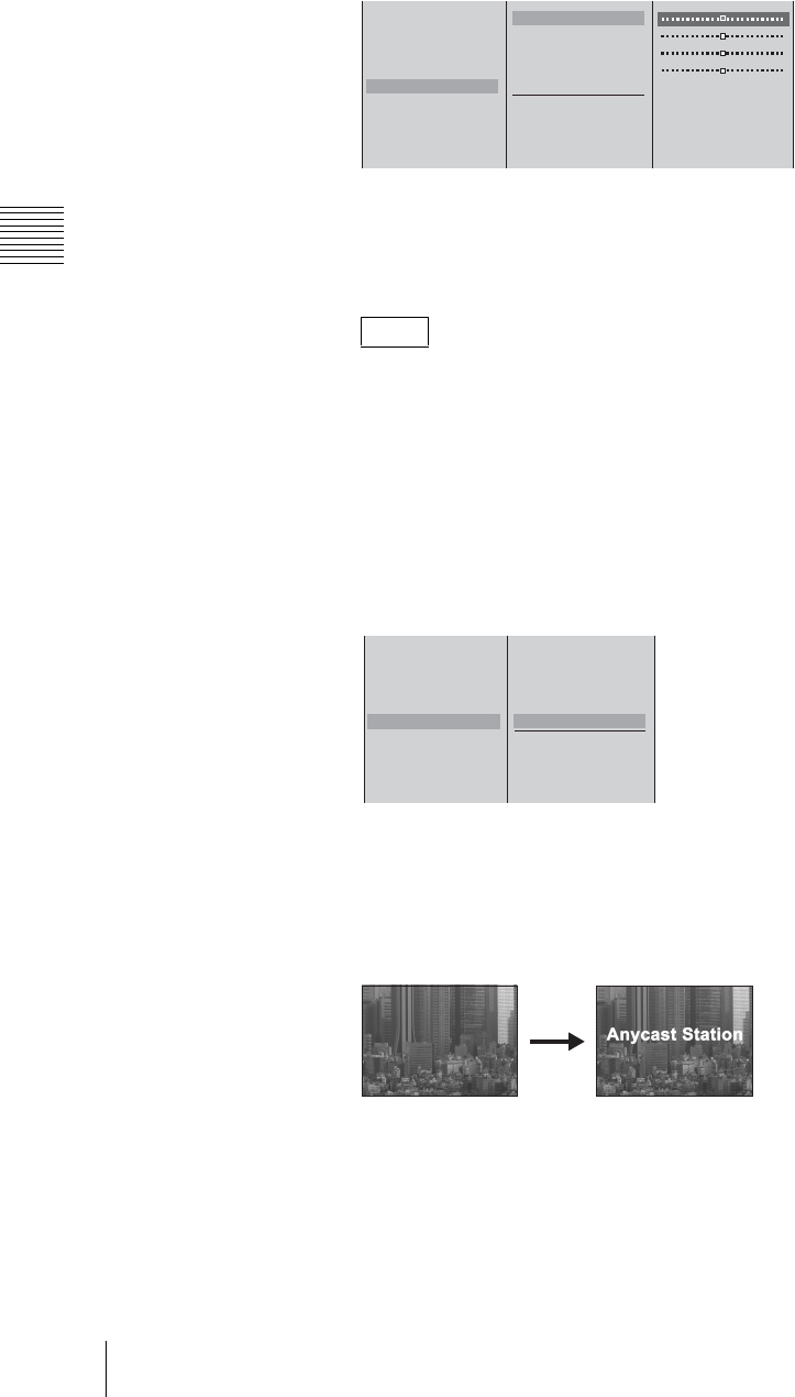
Chapter 3 Operations
102 Video Switching
Sharpening the outline of the key
1 Select one of [Clip], [Gain], and [Density], and confirm; 2 adjust the
slider.
The functions of the setting items are as follows.
[Clip]: Adjusts the threshold for background cutout.
[Gain]: Adjusts the sharpness of the outline.
[Density]: Adjust the density of the video to be combined.
If you have recalled and adjusted a graphics file, the adjusted values of the
graphics file change as follows depending on the next file recalled:
• When a file with no alpha channel is recalled: adjusted values remain
unchanged.
• When a file with an alpha channel is recalled: values return to their default
settings.
Inverting the luminance key
Select [Key Invert] from the list of items to adjust, and confirm.
[Key Invert] turns on or off each time it is selected.
8
Press the MENU button to close the menu.
9
Apply the video effect using the AUTO TRANS button, CUT button, or
transition lever.
This keys the NEXT selection into the program output video.
The “KEY” indicator on the operation screen lights red.
Note
Effect Pattern 0003
Transition Time 30F
Edge Off
Key Type Luminance
Key Adjust
Auto Chroma Key
Crop Off
Size Small
Location
Clip 0%
Gain 50
Hue 0˚
Density 100%
Key Invent Off
Color Cancel Off
12
Effect Pattern 0003
Transition Time 30F
Edge Off
Key Type Luminance
Key Adjust
Auto Chroma Key
Crop Off
Size Small
Location
Clip 0%
Gain 50
Hue 0˚
Density 100%
Key Invent On
Color Cancel Off
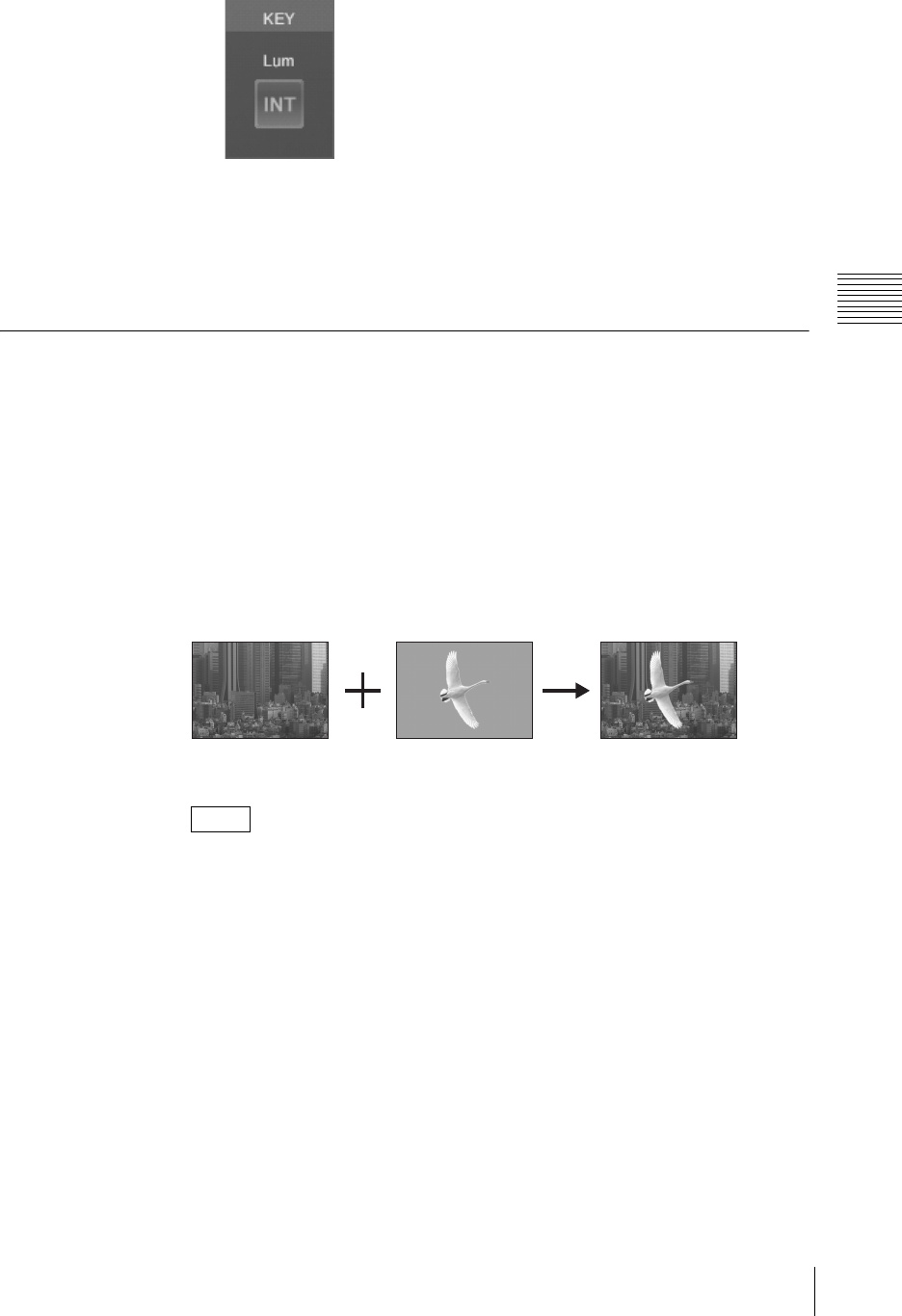
103
Video Switching
Chapter 3 Operations
Press the AUTO TRANS button or CUT button once more, or operate of the
transition lever in the opposite direction, to remove the combined video
effect.
The “KEY” indicator on the operation screen also turns off.
Each press of the AUTO TRANS button or CUT button or operation of the
transition level alternately inserts or removes the video effect.
Using Chroma Keying
Two video images are combined by removing portions of video signal B that
include a particular color (chroma) and superimposing that image onto video A.
Typically, a subject is captured in front of a blue background (called a “blue
screen”). Any portion of the background containing blue is then removed, and
only the subject is combined with the background video (A).
You can set the chroma key by automatically specifying a color from the key
image with the cursor or by manually specifying each color setting. Manual
specification of settings is possible after performing automatic specification as
well.
• Pressing the KEY button switches to key mode (the KEY button, NEXT
selection buttons, MIX button or EFFECT button light green, and the AUTO
TRANS button, CUT button, and transition lever now apply a keying
operation).
• You can also register graphics files to the numeric buttons on the front panel
and access them whenever necessary. For details, see “Accessing Graphics
Files Quickly” (page 94).
Basic operation for chroma keying
The basic procedure for chroma keying is as follows.
Notes
ABAB
Background Foreground
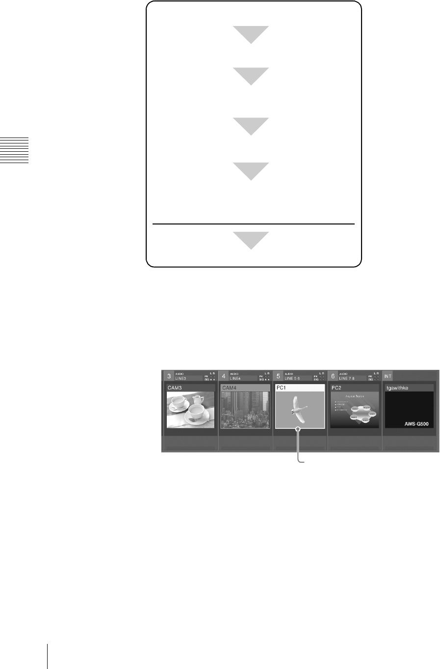
Chapter 3 Operations
104 Video Switching
1
Press the KEY button.
The KEY button, NEXT selection buttons, and MIX or EFFECT button light
green and are now used for video keying.
2
Select the video for keying by pressing the NEXT selection button assigned
to it.
A green frame appears around the selected video in the source viewer.
3
Press the MENU button.
4
In the top menu, select [Video Effect].
5
1 Select [Key Type], and confirm; 2 select [Chroma Key], and confirm.
Press the KEY button (Switches to key mode).
Select [Chroma Key] for [Key Type] in the top
menu.
Select the key video with a NEXT selection button.
Adjust the chroma key settings.
Carry out the transition.
Select the effect pattern with the MIX button or
EFFECT button.
* If no further adjustment is necessary, this concludes operation
during the broadcast.
When 5 is selected

105
Video Switching
Chapter 3 Operations
“Chroma” appears in the key status display area of the operation screen.
6
Press the MIX button or EFFECT button.
The button green, and the details of the current effect appear in the effect
display.
• You can change the transition time for the effect. To make this change,
follow the procedure in “Changing the Transition Time” (page 84).
• You can change the effect pattern. To make this change, follow the
procedure in “Changing the Effect Pattern” (page 85).
• In key mode, you can maintain the transition time, effect pattern, and edge
setting adjustments for keying operations.
7
Apply the effect using the AUTO TRANS button, CUT button, or transition
lever.
The keying results using the default or previously used settings displays.
8
Adjust the chroma key settings.
To adjust the settings automatically, see “Adjusting the chroma key
automatically” (page 106).
To adjust the settings manually, see “Adjusting each setting manually” (page
107).
Notes
Effect Pattern 0003
Transition Time 30F
Edge Off
Key Type Luminance
Key Adjust
Auto Chroma Key
Crop Off
Size Small
Location
B Luminance Key
Chroma Key
12
DIM TB
0
M
IC
FTB
DSK
KEY
CUT
AUTO
TRANS
M
I
X
E
F
F
E
C
T
P
V
W
EFFECT buttonMIX button
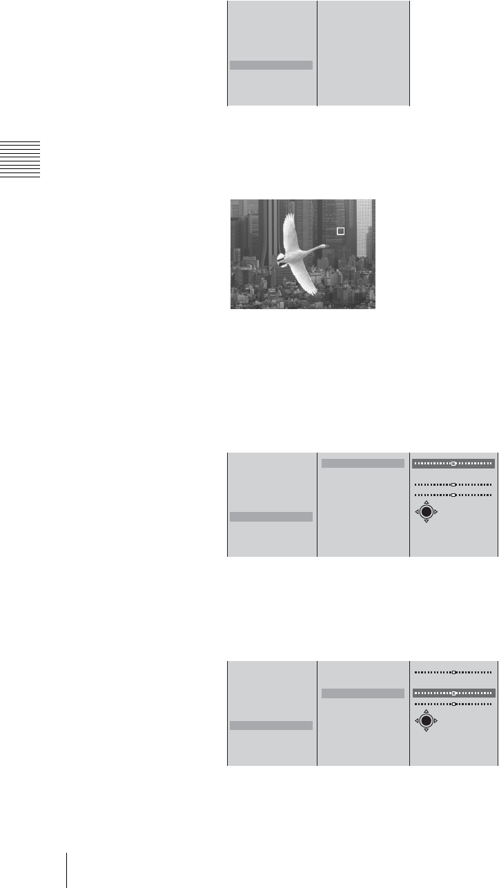
Chapter 3 Operations
106 Video Switching
Adjusting the chroma key automatically
1
Select [Auto Chroma Key], and confirm.
Auto Chroma Key Mode is enabled, and a cursor appears in the PGM viewer.
An image with the color specified by the cursor removed appears in the PGM
viewer.
2
Move the cursor, and specify the color to remove.
You can adjust the size of the frame used to specify the color and adjust the
position of the cursor with the following procedures.
To adjust the size of the frame
1 Select [Size], and confirm; 2 adjust the size with the slider.
To adjust the position of the cursor
1 Select [Location], and confirm; 2 select [X] or [Y], and confirm;
3 specify the position with the slider.
The functions of the setting items are as follows.
[X]: Specifies the horizontal position of the cursor.
Effect Pattern 0003
Transition Time 30F
Edge Off
Key Type Chroma
Key Adjust
Auto Chroma Key
Crop Off
Size Small
Location
Size 50
Location
X 320
Y 240
PGM viewer
Effect Pattern 0003
Transition Time 30F
Edge Off
Key Type Chroma
Key Adjust
Auto Chroma Key
Crop Off
Size Small
Location
Size 50
Location
X 320
Y 240
X-Y
12
Effect Pattern 0003
Transition Time 30F
Edge Off
Key Type Chroma
Key Adjust
Auto Chroma Key
Crop Off
Size Small
Location
Size 50
Location
X 320
Y 240
X-Y
12 3
First menu
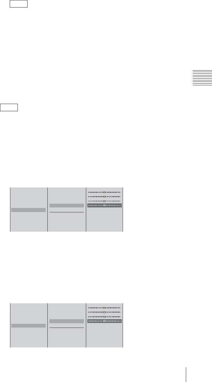
107
Video Switching
Chapter 3 Operations
[Y]: Specifies the vertical position of the cursor.
During Auto Chroma Key mode, you can adjust the vertical and horizontal
position of the cursor by pressing up, down, left, or right on the positioner.
3
Press the T button on the jog roller or T key on the keyboard to return to
the first menu.
Auto Chroma Key mode ends.
Adjusting each setting manually
When you want to fine-tune the results of automatic chroma key adjustment, you
can specify each chroma key setting manually. You can also replace background
colors (typically blue) that seep into the outline of the key video (such as into a
subject’s hair) with colors such as gray to make them less conspicuous.
After Auto Chroma Key is performed, the Auto Chroma Key values appear for
the [Clip], [Gain], and [Hue] settings.
1
Select [Key Adjust], confirm, and configure the following settings in the
submenu.
Fine-tuning the results from automatic adjustment
1 Select [Clip], [Gain], or [Hue] from the list of items to adjust, and
confirm; 2 adjust the setting with the slider.
The functions of the setting items are as follows.
[Clip]: Adjusts the threshold level for the background cutout.
[Gain]: Adjusts the sharpness of the outline.
[Hue]: Adjusts the hue.
Adjusting the density of the key video
1 Select [Density] from the list of items to adjust, and confirm; 2 adjust
the setting with the slider.
Note
Note
Effect Pattern 0003
Transition Time 30F
Edge Off
Key Type Chroma
Key Adjust
Auto Chroma Key
Crop Off
Size Small
Location
Clip 0%
Gain 50
Hue 0˚
Density 100%
Key Invent Off
Color Cancel Off
12
Effect Pattern 0003
Transition Time 30F
Edge Off
Key Type Chroma
Key Adjust
Auto Chroma Key
Crop Off
Size Small
Location
Clip 0%
Gain 50
Hue 0˚
Density 100%
Key Invent Off
Color Cancel Off
12

Chapter 3 Operations
108 Video Switching
Inverting the key
Select [Key Invert] from the list of items to adjust, and confirm.
[Key Invert] turns on or off each time it is selected.
Making background colors that seep into the key video less
conspicuous
Select [Color Cancel] from the list of items to adjust, and confirm.
[Color Cancel] turns on or off each time it is selected.
Use this function for adjustment after performing Auto Chroma Key.
If you use this function after adjusting the chroma key manually, you may
not get the correct results.
2
Press the MENU button to close the menu.
Adjusting key settings during program output
You can adjust the key settings without affecting the program output.
Be sure give display priority to the PVW viewer. For details, see “Giving Priority
to Displaying the PVW Viewer” (page 113).
1
Perform steps 1 to 5 of “Basic operation for chroma keying” (page 103).
2
Press the PVW button.
3
Adjust the chroma key settings.
For details on how to make adjustments, see steps 1 to 2 of “Adjusting the
chroma key automatically” (page 106) or step 1 of “Adjusting each setting
manually” (page 107).
Caution
Note
Effect Pattern 0003
Transition Time 30F
Edge Off
Key Type Chroma
Key Adjust
Auto Chroma Key
Crop Off
Size Small
Location
Clip 0%
Gain 50
Hue 0˚
Density 100%
Key Invent On
Color Cancel Off
Effect Pattern 0003
Transition Time 30F
Edge Off
Key Type Chroma
Key Adjust
Auto Chroma Key
Crop Off
Size Small
Location
Clip 0%
Gain 50
Hue 0˚
Density 100%
Key Invent Off
Color Cancel On
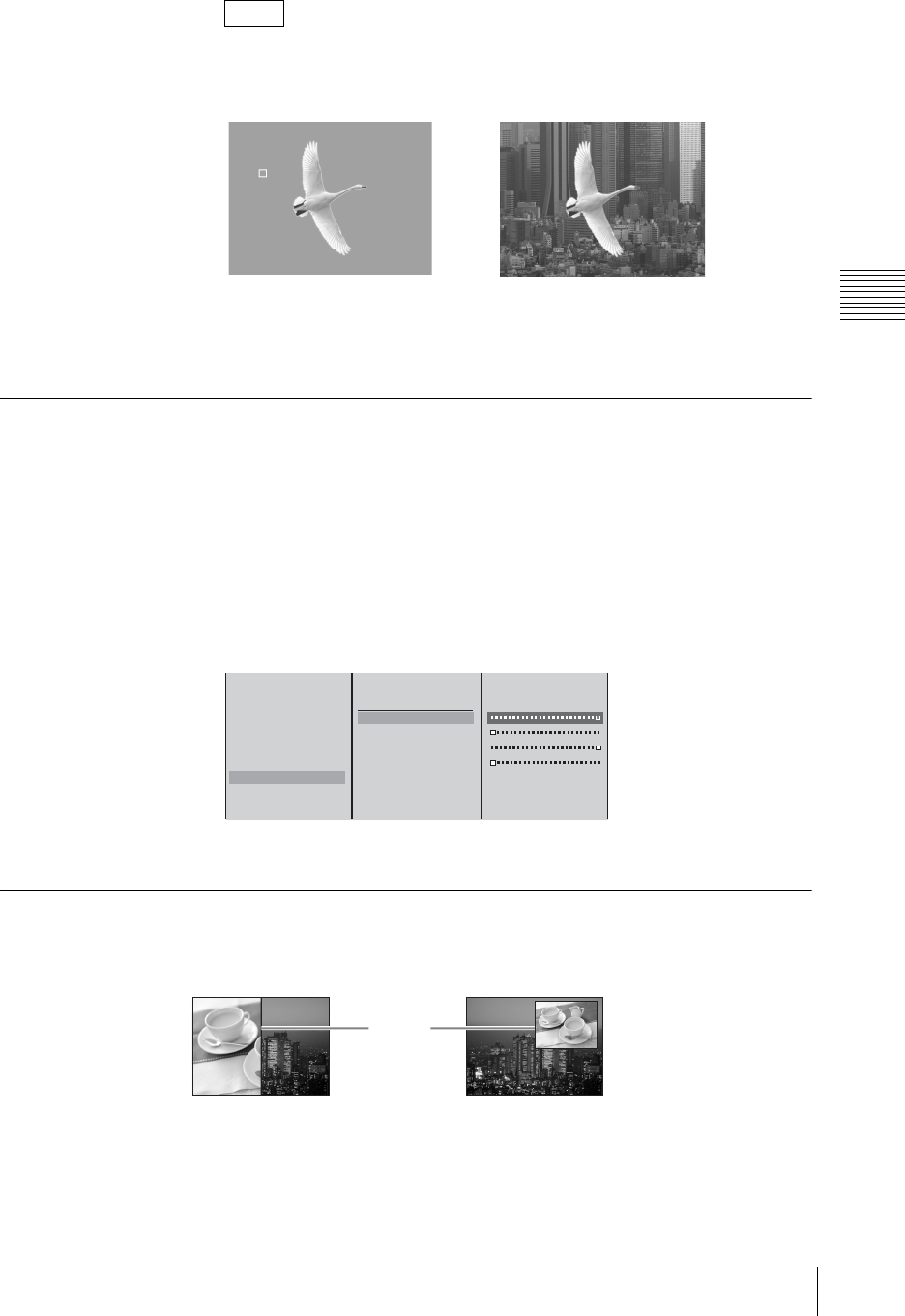
109
Video Switching
Chapter 3 Operations
The cursor appears when Auto Chroma Key is set to “On” during priority
display for the PVW viewer.
4
Apply the effect using the AUTO TRANS button, CUT button, or transition
lever.
Cropping Unwanted Portions From the Video Being Combined
1
Combine videos using a picture-in-picture or keying.
2
Press the MENU button.
3
In the top menu, select [Video Effect].
4
1 Select [Crop], and confirm; 2 select [On], and confirm; 3 select the side
(top, bottom, left, or right) to crop, and confirm; 4 move the slider to crop.
5
Press the MENU button to close the menu.
Applying Edge Effects
Apply an edge to a video border when using a wipe effect or to a picture-in-
picture frame.
1
First set the effect pattern.
2
Press the MENU button.
Note
When [Auto Chroma Key] is On When [Auto Chroma Key] is Off
PVW viewer PVW viewer
Effect Pattern 0004
Transition Time 30F
Edge Off
Key Type Luminance
Key Adjust
Auto Chroma Key
Crop Off
Size Small
Location
Off
B On
Top -270
Left -350
Right 350
Bottom -270
1
23 4
Edge
For a wipe For a picture-in-picture
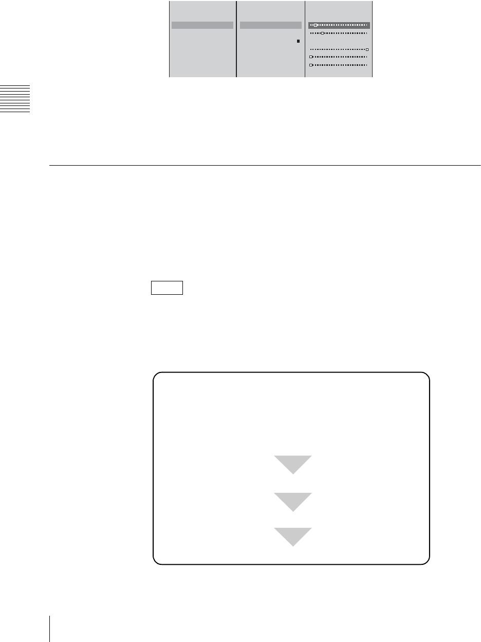
Chapter 3 Operations
110 Video Switching
3
In the top menu, select [Video Effect].
4
1 Select [Edge], and confirm; 2 select [On], and confirm; 3 select the
item to be set, and confirm; 4 adjust the slider.
The functions of the setting items are as follows.
[Width]: Adjusts the width of the border.
[Softness]: Adjusts the blurriness of the edge.
[Color Matte]: Changes the color of the border. Select [Lum] (luminance),
[Sat] (saturation), or [Hue], and adjust the slider.
Checking the Results of Combining Videos (Effect Preview)
You can preview and adjust the results of executing picture-in-pictures and
keying in the PVW viewer before program output.
You can set the PVW viewer to not be hidden while the menu is displayed when
you are making adjustments. For details, see “Giving Priority to Displaying the
PVW Viewer” (page 113).
Press the PVW button to switch to PVW mode (in which the PVW viewer is used
for effect preview).
Basic operation for previewing in the PVW viewer
The basic procedure for previewing in the PVW viewer is as follows.
Note
Effect Pattern 0004
Transition Time 30F
Edge Off
Key Type Luminance
Key Adjust
Auto Chroma Key
Crop Off
Size Small
Location
Off
B On
Width 5
Softness 20%
Color Matte
Lum 100%
Sat 0%
Hue 0%
123 4
Press the PVW button (switch to PVW mode).
Select the key video with a NEXT selection button.
Carry out the transition (switch to program output).
For picture-in-picture
Select a picture-in-picture from [Video Effect] of the top menu.
For keying
Press the KEY button (the NEXT selection buttons switch to
keying video selection).
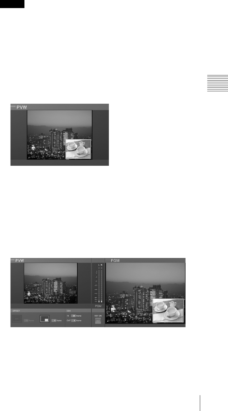
111
Video Switching
Chapter 3 Operations
For picture-in-picture
Noise may appear in the back image in the following cases, but this does not
affect program output.
• When displaying video from analog video input and SDI input connectors
in picture-in-picture.
• When the size of the embedded video is “Medium”.
• When displaying in the PVW viewer.
1
Perform Steps 1 to 5 of “Basic picture-in-picture operations” (page 86).
2
Press the PVW button.
The PVW button lights orange and a preview of the results of combining
videos is displayed in the PVW viewer.
Check and adjust the results of combining videos and perform the following
operation to execute program output.
For details on making picture-in-picture adjustments, see “Adjusting the
Picture-in-Picture (PinP)” (page 87).
3
Use the AUTO TRANS button, CUT button, or transition lever to combine
the videos.
The results of combining videos are sent as program output and displayed in
the PGM viewer.
The preview in the PVW viewer disappears (changes to the results of the next
transition).
4
Press the PVW button to end PVW mode.
The PVW viewer returns to the video selected with the NEXT selection
button.
Caution
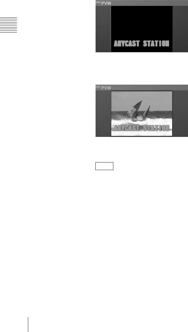
Chapter 3 Operations
112 Video Switching
For keying
1
Press the KEY button.
The KEY button, NEXT selection buttons, and MIX or EFFECT button light
green, and are now used for keying video.
2
Press the NEXT selection button assigned to the video to be combined.
A green border appears around the selected video in the source viewer, and
the video appears in the PVW viewer.
3
Press the PVW button to switch to PVW mode.
The PVW button lights orange, and a preview of the combined result appears
in the PVW viewer.
Adjustments with Auto Chroma Key
Be sure give display priority to the PVW viewer. For details, see “Giving
Priority to Displaying the PVW Viewer” (page 113).
When Auto Chroma Key is executed during PVW priority display, the video
currently selected with the NEXT selection button displays along with the
color specification cursor.
After you specify a color and exit Auto Chroma Key mode, you can confirm
the combined results.
Check and adjust the combined result, and follow step 4 to switch to program
output.
For details on making luminance key adjustments, see “Sharpening the
outline of the key” (page 102).
For details on making chroma key adjustments manually, see “Adjusting
each setting manually” (page 107).
4
Apply the effect using the AUTO TRANS button, CUT button, or transition
lever.
Note
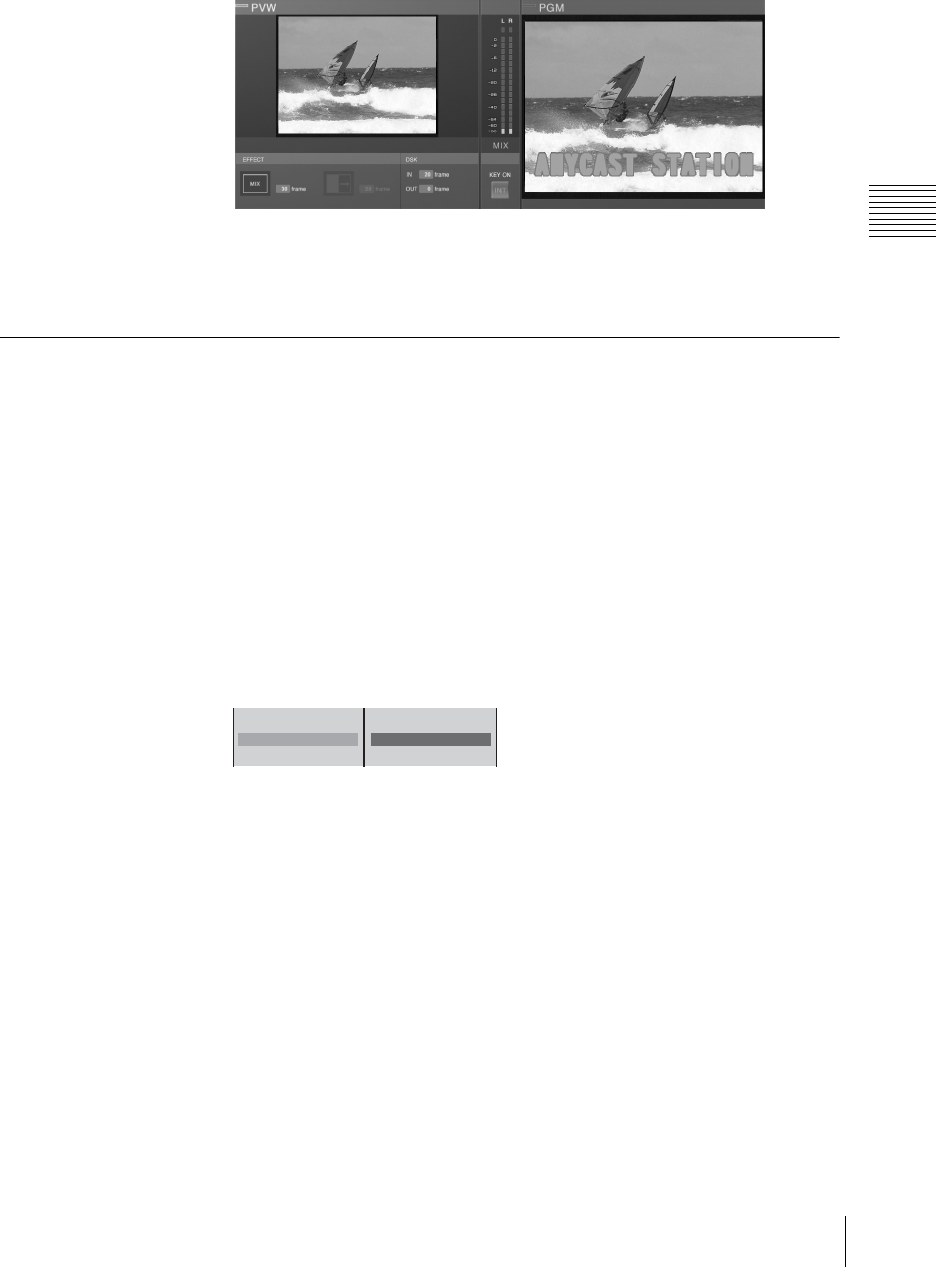
113
Video Switching
Chapter 3 Operations
The combined result is sent to program output, and appears in the PGM
viewer.
The preview in the PVW viewer disappears (changes to the result of the next
transition).
5
Press the PVW button, to end PVW mode.
The PVW viewer returns to the video selected from the NEXT selection
buttons.
Giving Priority to Displaying the PVW Viewer
With the default setting, the PVW viewer on the left is hidden when three levels
of submenus of the top menu are displayed. If you give priority to displaying the
PVW viewer, the preview is always viewable because the PVW viewer shifts to
the right (and the PGM viewer is hidden) when three levels of submenus are
displayed. The effect display below the PVW viewer also moves with the PVW
viewer.
1
Press the MENU button.
2
Select [Display] in the top menu.
3
1 Select [Viewer Priority] and confirm; 2 select [PVW] and confirm.
LCD Backlight
Viewer Priority PGM
File TC Off
B PGM
PVW
12
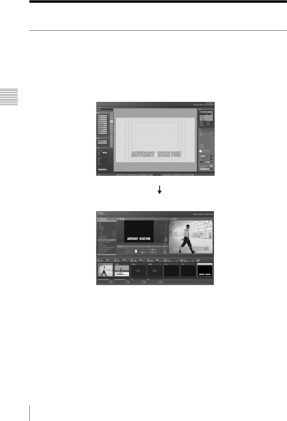
Chapter 3 Operations
114 Creating a Title Graphic With the Text Typing Tool
Creating a Title Graphic With the Text Typing Tool
Features of the Text Typing Tool Software
The Text Typing Tool software is an application for creating simple titles.
You can switch between the Anycast Station main software (the main software)
and this application as you proceed.
• A file created with the Text Typing Tool software is simultaneously saved in
the Anycast Station main software, and can be used as a DSK (downstream
key) or luminance key source.
• By capturing one scene of the program output video and showing it as a
background, you can get an impression of the final result of superimposing of
the key, and position objects (characters and lines) accurately.
Text Typing Tool software
Anycast Station main software
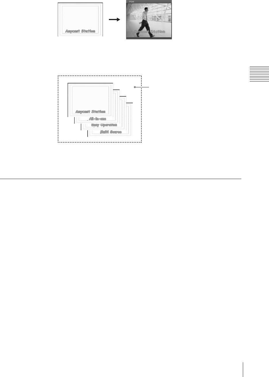
115
Creating a Title Graphic With the Text Typing Tool
Chapter 3 Operations
Sheets and files
In the Text Typing Tool software, you create one title as a single sheet.
You can save multiple related sheets (for example, for a single program) together
in a file.
When creating similar title, you can copy a object to create the sheet, and
therefore eliminate the trouble of creating a new file from scratch.
Flow of Operations
To use the Text Typing Tool software, it is first necessary to upgrade the
operating software (When the software version you are using is 1.00).
For details of how to upgrade, see “Upgrading the Operating Software” (page
262).
1
Press the 1 (power) button on the side panel.
The operation screen appears.
2
Press the keyboard F5 (Fn+5) key.
You can work by switching between the Anycast Station main software and
the Text Typing Tool software.
Created sheet superimposed result
File
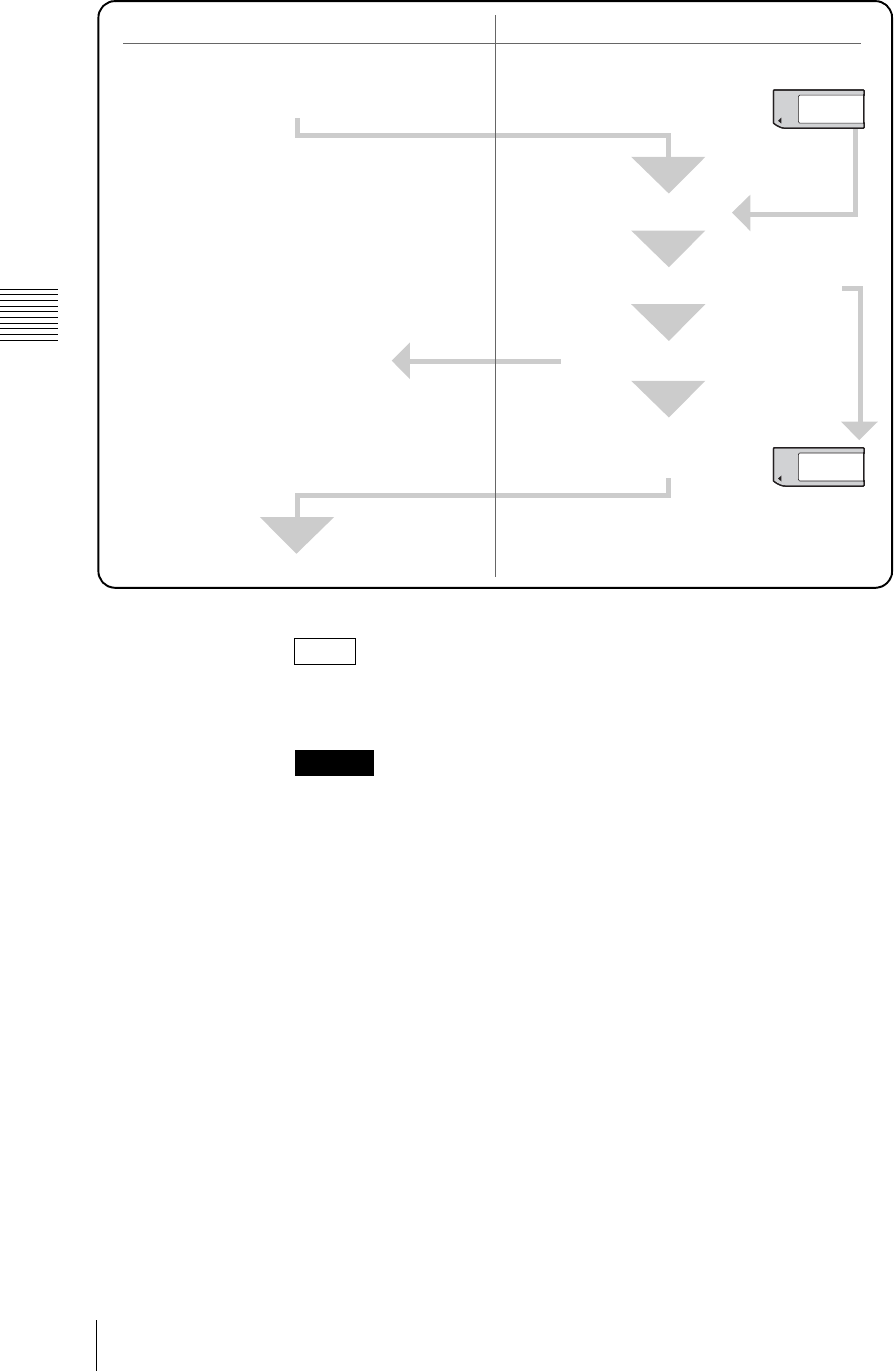
Chapter 3 Operations
116 Creating a Title Graphic With the Text Typing Tool
With a “Memory Stick” or USB flash memory, you can import font files, and
export created titles. You can use exported files on such as a computer.
• It is not possible to use a USB mouse with the Anycast Station main software.
• If the USB mouse does not respond in the Text Typing Tool software, try
disconnecting it and connecting to the other USB connector.
• The PGM output aspect ratio setting is carried over from the setting configured
with the Anycast Station main software. However, changes to the setting made
with the Text Typing Tool software do not carry over to the main software.
Note
Caution
Anycast Station main software Text Typing Tool software
1Carry out the operation to start the Text
Typing Tool, and switch to the Text Typing
Tool.
2Create an object.
Edit the object, to complete a title.
3Save the file.
4Carry out the close down
operation, and switch to
the main software.
Saved simultaneously
5Key combination.
“Memory Stick” or USB flash memory
Font
“Memory Stick”
or USB flash
memory
File
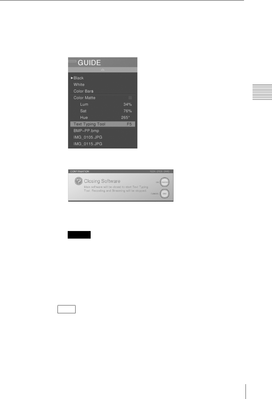
117
Creating a Title Graphic With the Text Typing Tool
Chapter 3 Operations
Starting Up
1
In the Anycast Station main software, press the “INT” NEXT selection
button.
The INT material selection menu appears in the menu display.
2
Select [Text Typing Tool].
The following confirmation message appears.
3
Press the ENTER button on the front panel.
The screen goes black and the Text Typing Tool software starts.
• If you switch while using the Anycast Station main software, the image or
sound may be distorted.
• If you switch while the Anycast Station main software is starting up, the
system may not function correctly. Check that all viewers (PGM/PVW/
material) have started up before switching to the Text Typing Tool
software.
• Button operations performed while an application is closing will not be
properly reflected on the system.
You can also use the keyboard F5 (Fn+5) key to switch to the Text Typing Tool
software.
Caution
Note
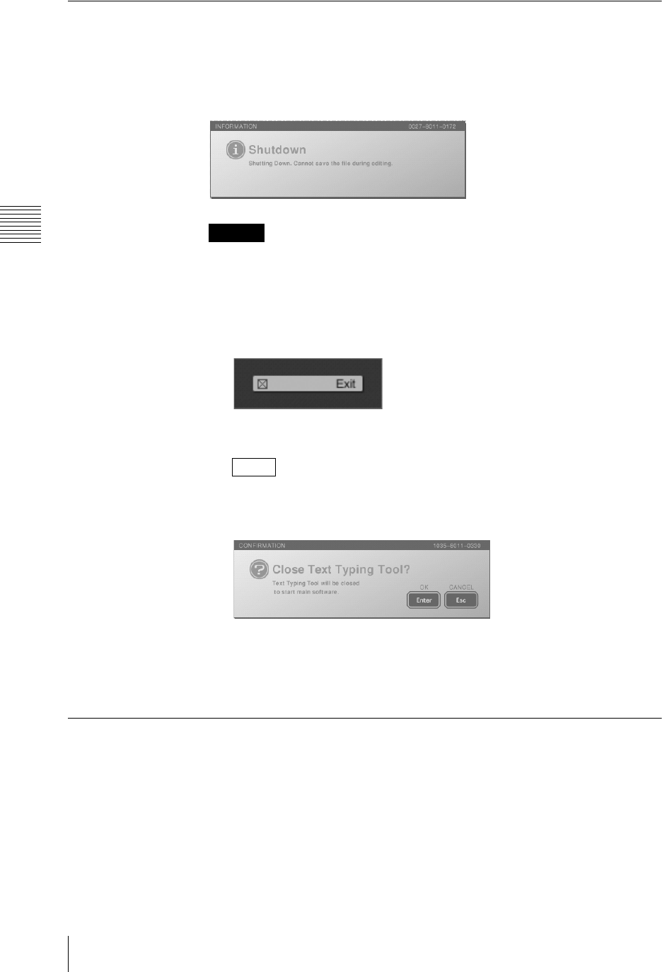
Chapter 3 Operations
118 Creating a Title Graphic With the Text Typing Tool
Closing Down
To power off the unit
Press the 1 power button on the side panel.
The following message appears, the Text Typing Tool software ends, and the
power is turned off.
If there is a file in the process of creation, the program will end without saving it.
To close the Text Typing Tool software and start the Anycast Station main
software
1
Click the [Exit] button at the lower left of the screen.
The screen goes black and the Anycast Station main software starts.
You can also use the keyboard F5 (Fn+5) key to switch to the Anycast
Station main software.
In this case, following confirmation message appears.
If a file is being created, a message appears to confirm whether to save the
file.
2
Click the [Enter].
Standard Operations
This section describes standard operations used as various points in the Text
Typing Tool software.
Mouse operations
• By connecting a USB mouse to the USB connector on the side panel, you can
carry out mouse operations.
• You can also carry out mouse operations with the pointer of the supplied
keyboard.
Caution
Note
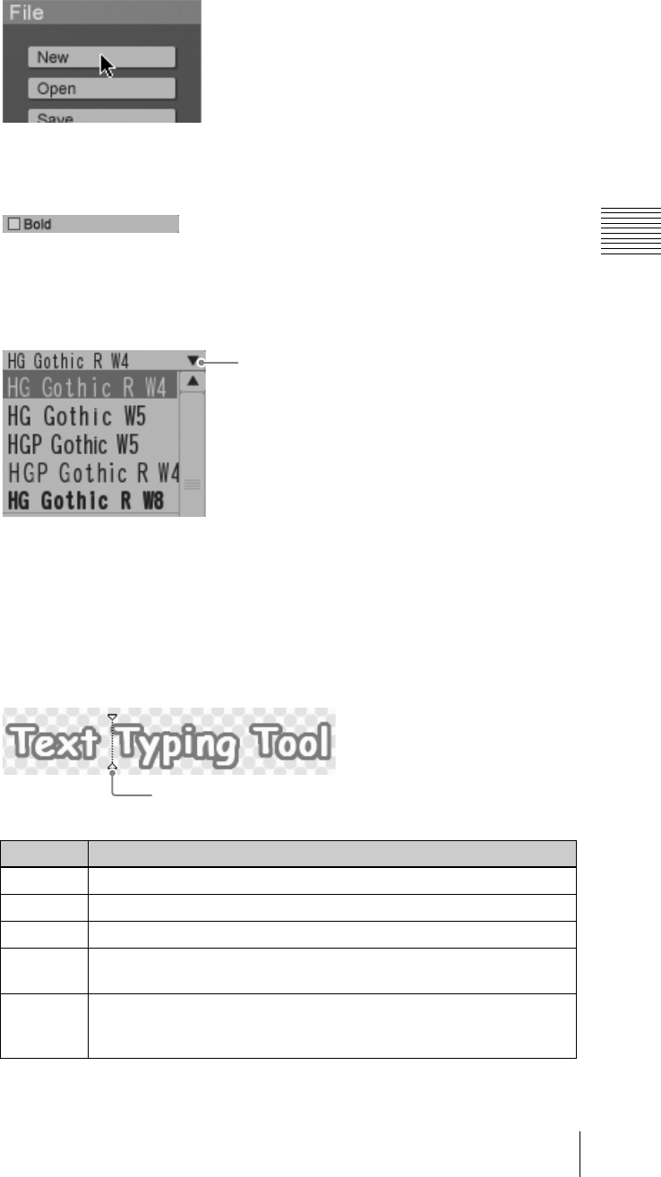
119
Creating a Title Graphic With the Text Typing Tool
Chapter 3 Operations
Standard button operations
Click a button to carry out its function.
Standard checkbox operations
Click a checkbox to insert or remove the check mark. The function is active as
long as a check mark is present.
Standard pull-down list operations
This section describes standard pull-down list operations.
Click the V button to display the pull-down list.
Standard keyboard operations
•The R and r keys move the focus (in reverse video) within the pull-down list.
• Press the Enter key to confirm the item which currently has the focus.
• Press the Fn+~` key (Esc) to cancel the selection, and close the pull-down list.
Standard operations for text input
The following are standard keyboard operations for text input.
Key Operation
T, tMove the cursor horizontally one position at a time.
RMove the cursor up one position at a time.
rMove the cursor down one position at a time.
Shift + T,
Shift + t
Select one character at a time, horizontally from the cursor position.
Delete When there is a character selection: delete the selection.
When there is no character selection: delete the character following the
cursor.
V button
Cursol
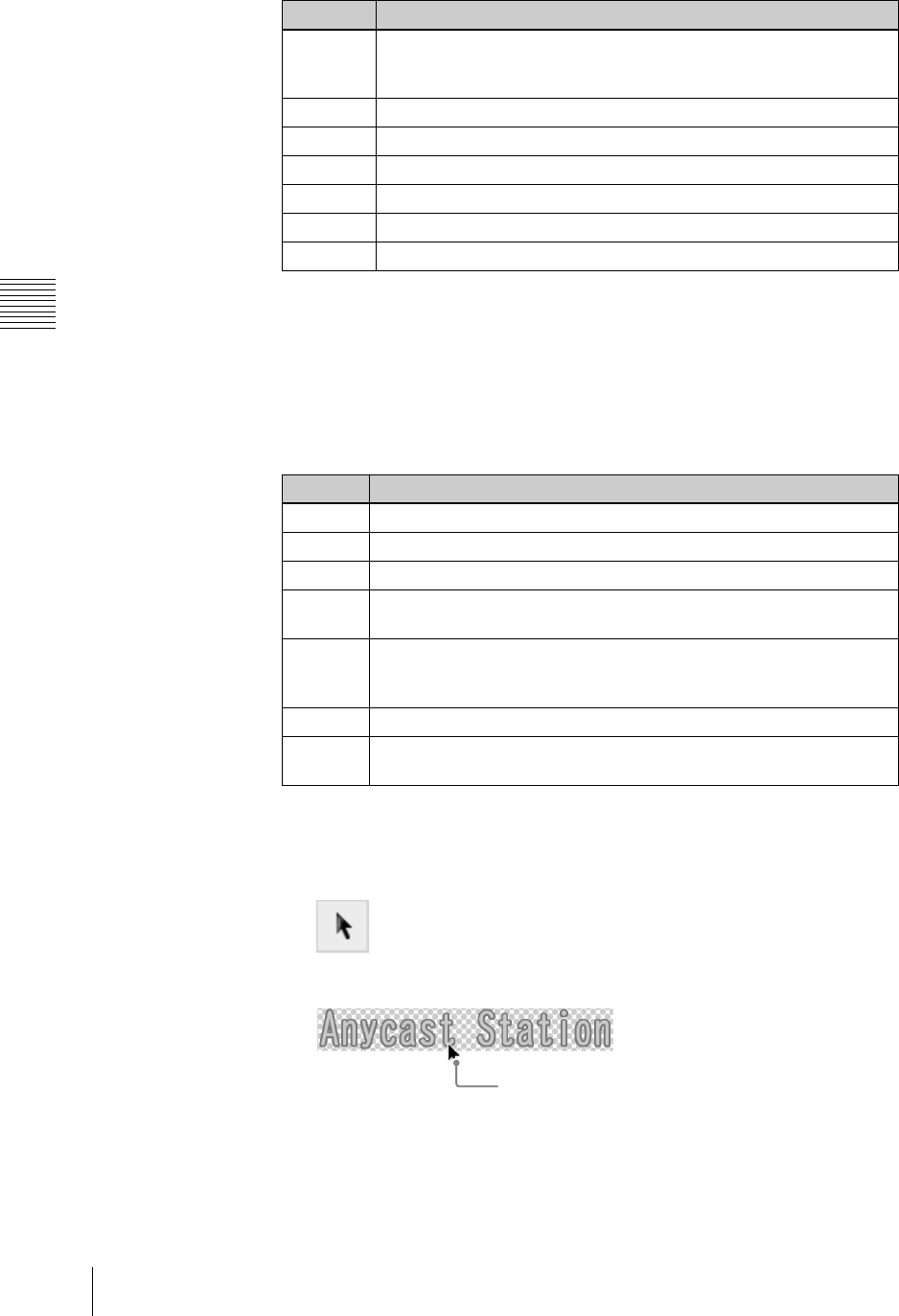
Chapter 3 Operations
120 Creating a Title Graphic With the Text Typing Tool
Standard tool operations
By clicking a tool in the tool operation section, you can use the function provided
by the tool.
The tool operation continues until you select a different tool.
Other standard operations
The following standard operations can be carried out with the keyboard alone.
Object selection operations
1
Click the selection tool.
The icon turns green, and you can now select an object.
2
Click an object, or define a range by dragging.
Backspace When there is a character selection: delete the selection.
When there is no character selection: delete the character before the
cursor.
Enter Newline
Esc Remove the cursor leaving the characters unchanged.
Space Insert a space.
Home Move the cursor to the beginning.
End Move the cursor to the end.
Alt + Enter Confirm the entered text and exit the text input mode.
Key Operation
Ctrl + z Return to the previous state (Undo function)
Ctrl + y Advance to the next state (Redo function)
Ctrl + x Cut out an object
Ctrl + c Copy an object
In text input mode: copy the selected text
Ctrl + v Paste an object
In text input mode: paste the copied or cut text with the existing attributes
where it is being pasted
Ctrl + a Select all objects
Delete,
Backspace
Delete an object
Key Operation
Click
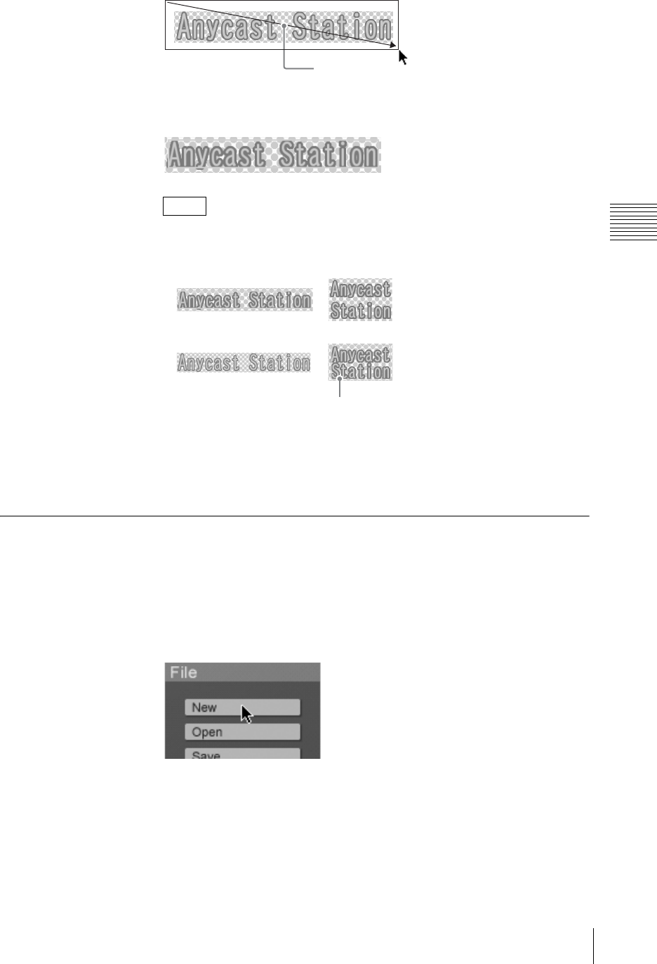
121
Creating a Title Graphic With the Text Typing Tool
Chapter 3 Operations
An orange border appears around the object.
This is the selected state.
• If you drag over a range, this selects all objects within the range.
• When there are multiple objects, you can use the keyboard Tab key to
move the selection to the next object.
Press the Shift+Tab keys to move the selection in the reverse direction.
• Hold down the Shift key and click an object to add to the selection.
• Double-click on the selected text object to switch to text input mode (page
129).
File Operations
This section describes file operations, including saving and deleting titles created
with the typing tool software, export, and so on.
Creating a new file
1
In the file operation section, click the [New] button.
A new sheet appears.
Notes
Drag
Tab
Selection moves
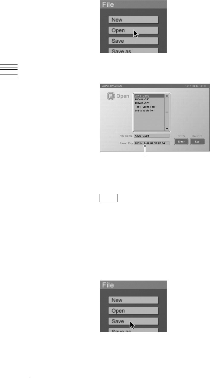
Chapter 3 Operations
122 Creating a Title Graphic With the Text Typing Tool
Opening an existing file
1
In the file operation section, click the [Open] button.
The [Open] screen appears.
2
Select the file name from the list.
3
Click the [Enter].
This opens the selected file.
If even one of the fonts used by the file you are opening has been deleted
from the unit, a message appears to confirm whether to substitute any
missing font with another font on the unit when displaying the file.
Clicking [Enter] displays the font selection list. If you select a font and click
enter, the selected font is used and the file opens. If multiple fonts have been
deleted, all the fonts are substituted with the selected font.
Saving a file
1
In the file operation section, click the [Save] button.
The [Save] screen appears.
Note
Last saved date of selected file
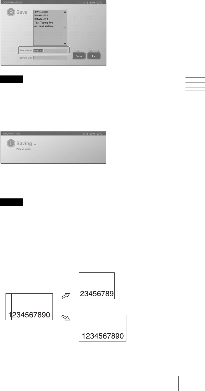
123
Creating a Title Graphic With the Text Typing Tool
Chapter 3 Operations
2
Enter the file name in [File Name].
You can enter a file name as up to 20 alphanumeric characters, but there may
not be room for the full name in text boxes or lists, or in the Anycast Station
main software INT material selection menu.
3
Click the [Enter].
A message appears while saving, and the file is saved.
The file is simultaneously saved in the Anycast Station main software. In the
Anycast Station main software, the saved file appears if you press the “INT”
NEXT selection button.
• If a file of the same name exists in the Anycast Station main software, it
will be overwritten.
• The appearance of graphics files created in a 16:9 aspect ratio with the Text
Typing Tool software may be different, depending on the PGM output
aspect ratio setting. Be aware that their appearance differs from that of
standard graphics file imports.
Caution
Caution
Graphics file created with
Text Typing Tool
When 4:3 mode is selected as
the PGM output setting
When 16:9 mode is selected as
the PGM output setting
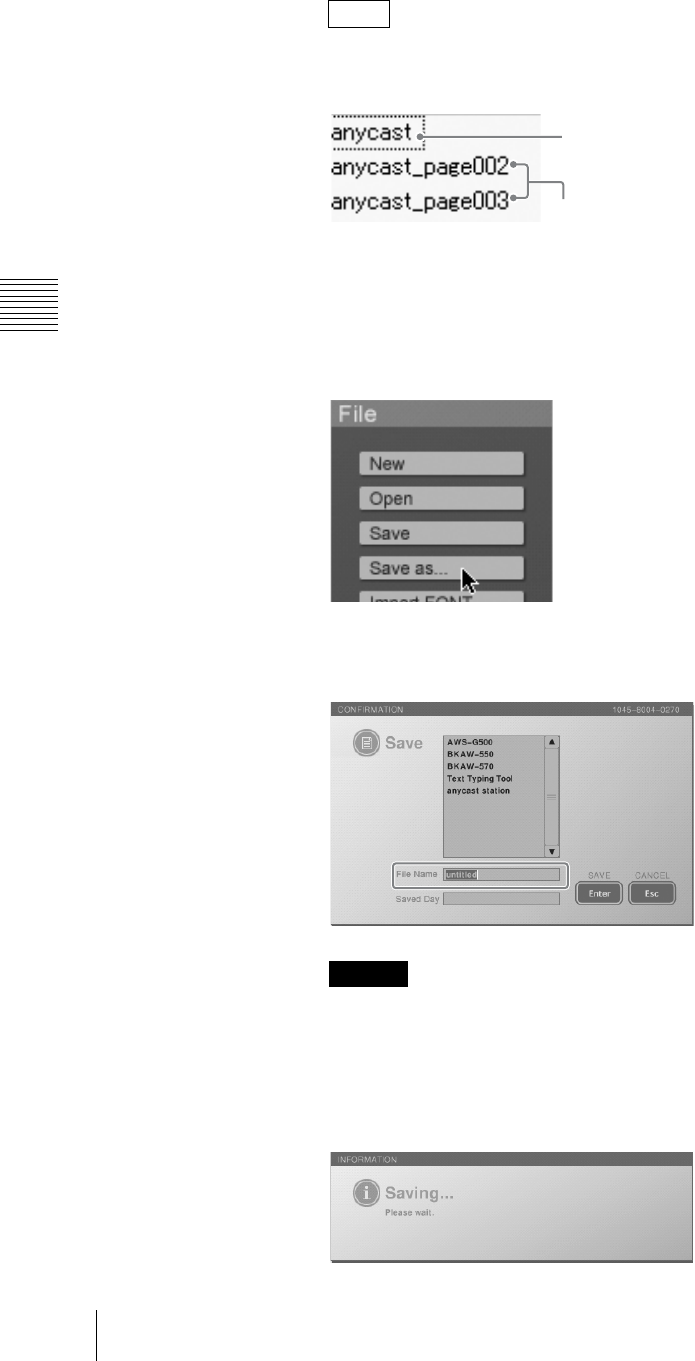
Chapter 3 Operations
124 Creating a Title Graphic With the Text Typing Tool
• When a file consisting of multiple sheets is saved, the second and
subsequent sheets are named as follows with the file name + sheet number
in the Anycast Station main software.
• A saved TIFF/TARGA file is saved with an alpha channel.
Saving a file with a new name
1
In the file operation section, click the [Save as...] button.
The [Save] screen appears.
2
Enter the file name in [File Name].
You can enter a file name as up to 20 alphanumeric characters, but there may
not be room for the full name in text boxes or lists, or in the Anycast Station
main software INT material selection menu.
3
Click the [Enter].
A message appears while saving, and the file is saved.
Notes
Caution
First sheet (file name
only)
Second sheet (file
name + sheet number)
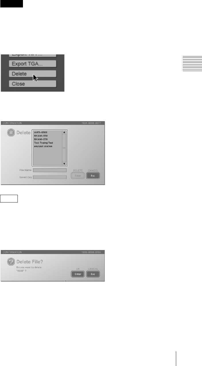
125
Creating a Title Graphic With the Text Typing Tool
Chapter 3 Operations
The file is simultaneously saved in the Anycast Station main software. In the
Anycast Station main software, the saved file appears if you press the “INT”
NEXT selection button.
If a file of the same name exists in the Anycast Station main software, it will
be overwritten.
Deleting a file
1
In the file operation section, click the [Delete] button.
The [Delete] screen appears.
2
Select the file name from the list.
You can select multiple files by clicking (or pressing the R and r keys) to
select file names while holding down the Shift key or by dragging to select
file names.
3
Click the [Enter].
The following confirmation message appears.
4
Click the [Enter].
This deletes the selected file.
Caution
Note
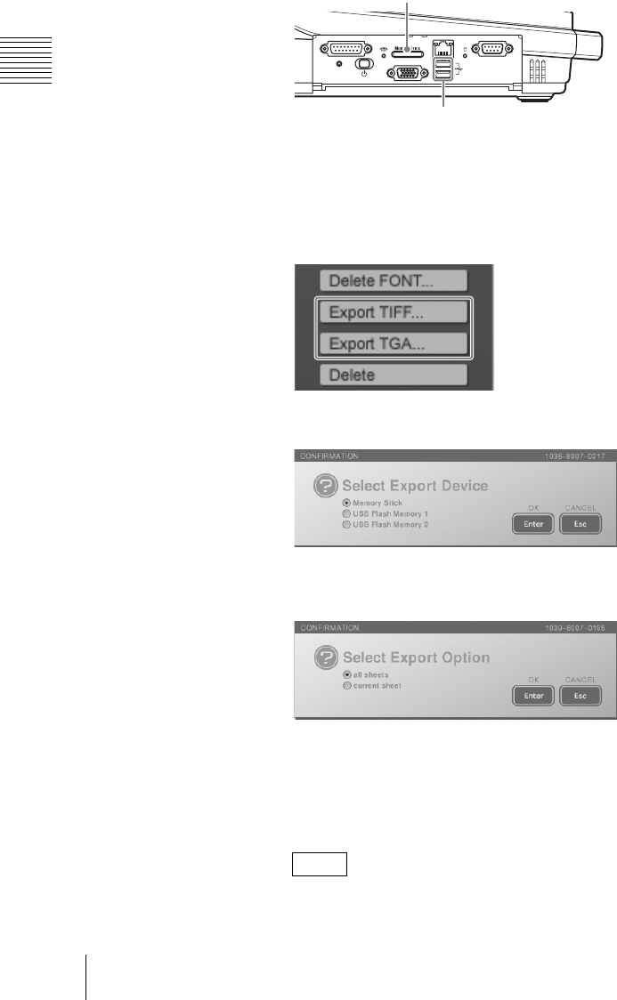
Chapter 3 Operations
126 Creating a Title Graphic With the Text Typing Tool
Exporting a file
By exporting a file created in the Text Typing Tool software to a “Memory Stick”
or USB flash memory, you can use the file in another system.
You can export the file in TIFF format or TARGA format at 1,280×960 (4:3) or
1,706×960 (16:9) size.
1
Insert the “Memory Stick” or USB flash memory in the side panel “Memory
Stick” slot or USB connector.
The upper USB connector is number 1, and the lower connector is number 2.
2
Open the file to be exported.
For the method of opening a file see “Opening an existing file” (page 122).
3
In the file operation section, click the [Export TIFF...] button, or [Export
TGA...] button.
The following confirmation message appears.
4
Select where to save the file, and click [Enter].
The following confirmation message appears.
5
If the opened file includes multiple sheets, select either [all sheets] or
[current sheet].
[all sheets]: Exports all sheets within the file.
[current sheets]: Exports the currently displayed sheet only.
If there is only one sheet in the file, this message does not appear.
Note
FACTORY USE REMOTE
RGB
(
GUI
)
RESET
USB
NETWORK
18
15 9
1
5
“Memory Stick” slot
USB connector
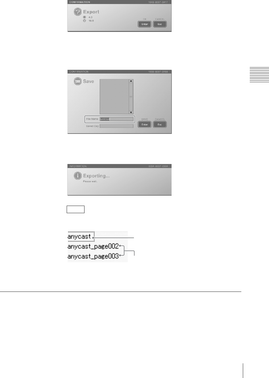
127
Creating a Title Graphic With the Text Typing Tool
Chapter 3 Operations
6
Click the [Enter].
The following message appears.
7
Select an aspect ratio, and click [Enter].
The [Save] screen appears.
8
Enter the file name in [File Name].
9
Click the [Enter].
The following message appears, and the file is exported to the “Memory
Stick” or USB flash memory.
• When a file consisting of multiple sheets is exported, the second and
subsequent sheets are named as follows with the file name + sheet number.
• An exported TIFF/TARGA file is saved with an alpha channel.
Working on Text Objects
This section describes how to create a text object, and then apply modifiers to the
text.
Creating a text object
1
Click the text tool.
Notes
First sheet (file name
only)
Second sheet (file
name + sheet number)
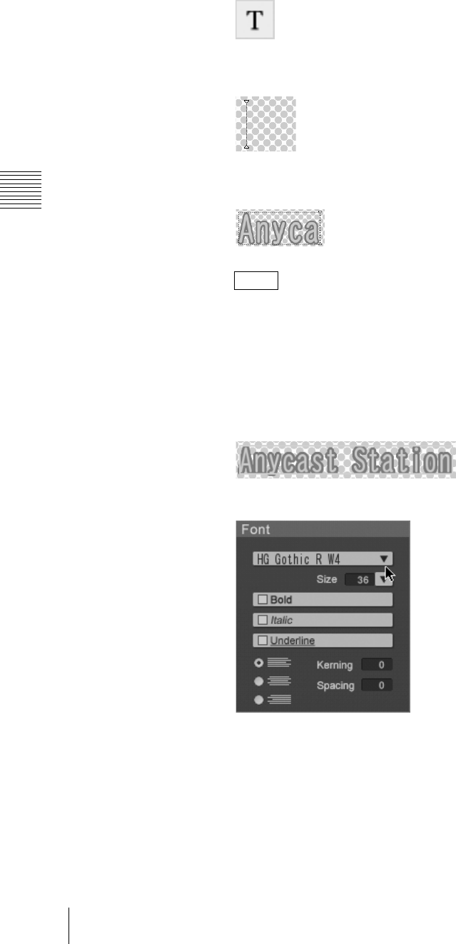
Chapter 3 Operations
128 Creating a Title Graphic With the Text Typing Tool
The icon turns green, and the system is now in text input mode (in which text
input is possible).
2
Click where you want to enter text.
The cursor appears.
3
Enter text from the keyboard.
As you enter text, it appears in a pink and black dotted frame.
• For details of confirming the text, see “Standard operations for text input”
(page 119).
• If input with a font only supporting numerals, spaces are input.
Changing the text font
1
Click the selection tool, to select the text object (page 120).
An orange frame appears around the text object.
2
Click the V button by the font name in the font operation section.
The pull-down list appears.
3
Select a font.
Notes
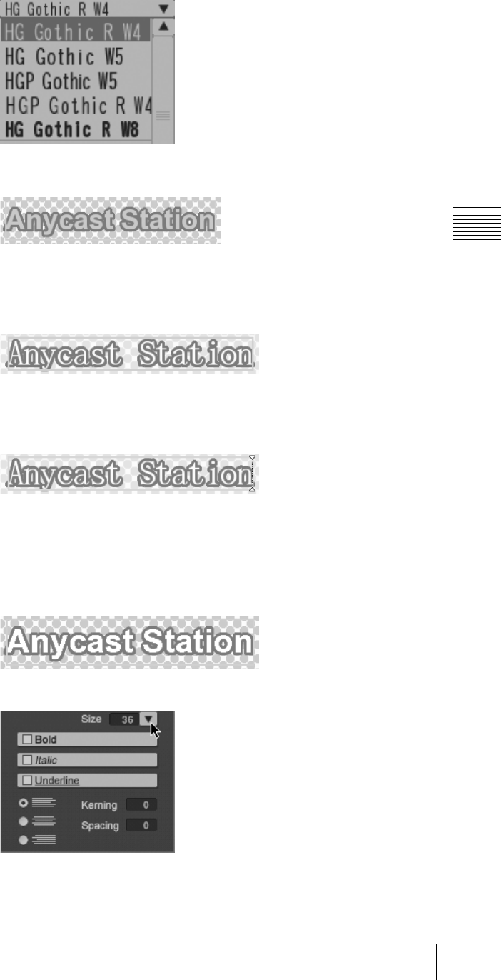
129
Creating a Title Graphic With the Text Typing Tool
Chapter 3 Operations
This changes the selected font.
Editing the text
1
Click the selection tool, to select the text object (page 120).
An orange border appears around the text object.
2
Double-click the selected text object.
The frame changes to a pink and black dotted line, and the cursor appears,
switching to text input mode.
3
Edit the text.
Changing the font size
1
Click the selection tool, to select the text object (page 120).
An orange border appears around the text object.
2
Click the [Size] V button in the font operation section.
3
Select the size.
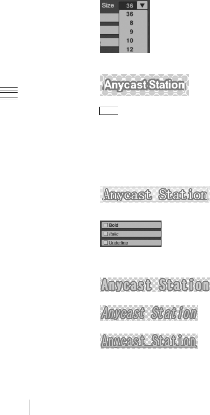
Chapter 3 Operations
130 Creating a Title Graphic With the Text Typing Tool
This changes the selected size.
You can also change the size by directly entering a numeric value in the
[Size] box.
Click the box, enter the numeric value from the keyboard, then press the
Enter key.
Changing the font style
1
Click the selection tool, to select the text object (page 120).
An orange border appears around the text object.
2
Select a style in the font operation section.
This changes the selected style.
Bold
Italic
Underline
Changing the spacing between characters
1
Click the selection tool, to select the text object (page 120).
An orange border appears around the text object.
Note
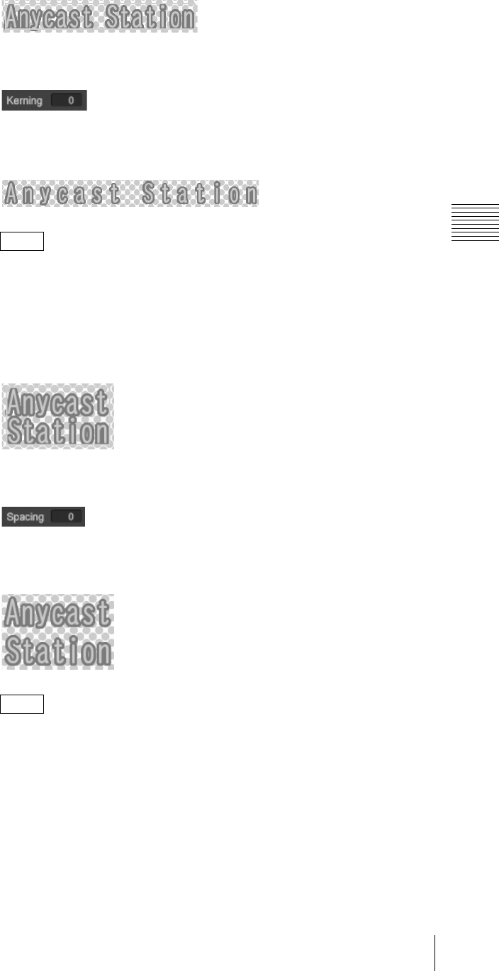
131
Creating a Title Graphic With the Text Typing Tool
Chapter 3 Operations
2
Click the [Kerning] input box in the font operation section, and enter the
numeric value from the keyboard.
3
Press the Enter key.
This changes to the selected spacing.
The numeric value zero is the basepoint for the spacing. By entering a
negative value, you can make the spacing narrower.
Changing the spacing between lines
1
Click the selection tool, to select the text object (page 120).
An orange border appears around the text object.
2
Click the [Spacing] input box in the font operation section, and enter the
numeric value from the keyboard.
3
Press the Enter key.
This changes to the selected spacing.
The numeric value zero is the basepoint for the spacing. By entering a
negative value, you can make the spacing narrower.
Aligning text
You can align a text object with multiple lines to the left, to the right, or in the
center.
1
Click the selection tool, and select the text object with multiple lines (page
120).
An orange border appears around the text object.
Note
Note
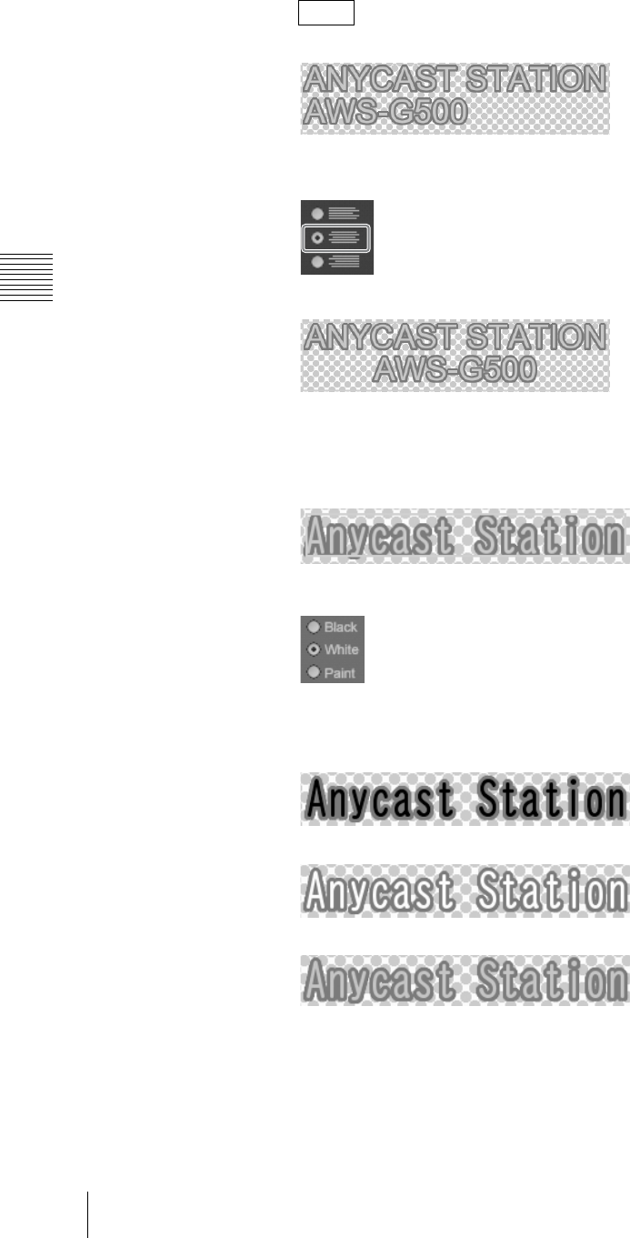
Chapter 3 Operations
132 Creating a Title Graphic With the Text Typing Tool
The following figure shows left alignment as an example.
2
Click the center align button in the font operation section.
This center-aligns the text.
Changing the text color
1
Click the selection tool, to select the text object (page 120).
An orange border appears around the text object.
2
Click one of the text color selection buttons in the Color tab of the [Text] tab.
The text appears as follows.
Black
White
Paint
For details on adjusting the color when [Paint] is selected, see “Creating a
color in the color creation section” (page 141).
Note
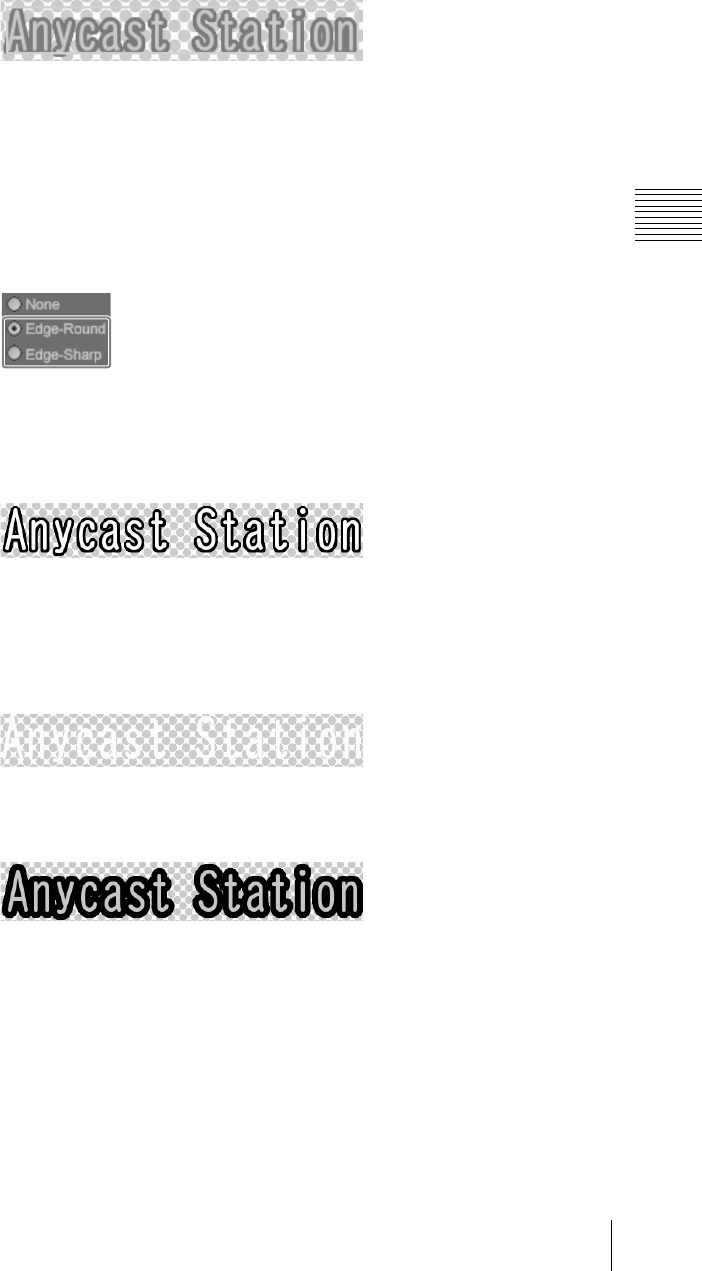
133
Creating a Title Graphic With the Text Typing Tool
Chapter 3 Operations
Making changes to the character outlines
1
Click the selection tool, to select the text object (page 120).
An orange border appears around the text object.
2
Select the Edge tab of the [Text] tab.
3
Make the following settings for the outline desired.
To change the style of the outline
Select the [Edge-Round] edge selection button for an outline with round
corners and select the [Edge-Sharp] edge selection button for an outline with
sharp corners.
To change the color of the outline
For black or white, select the [Black] or [White] edge color selection button.
To change the color to a desired color, create the color in the color creation
section.
For details, see “Creating a color in the color creation section” (page 141).
To remove the character outlines
Select the [None] edge style selection button.
The outlines disappear.
To change the thickness of the outlines
Click the [Width] V button, and select the thickness.
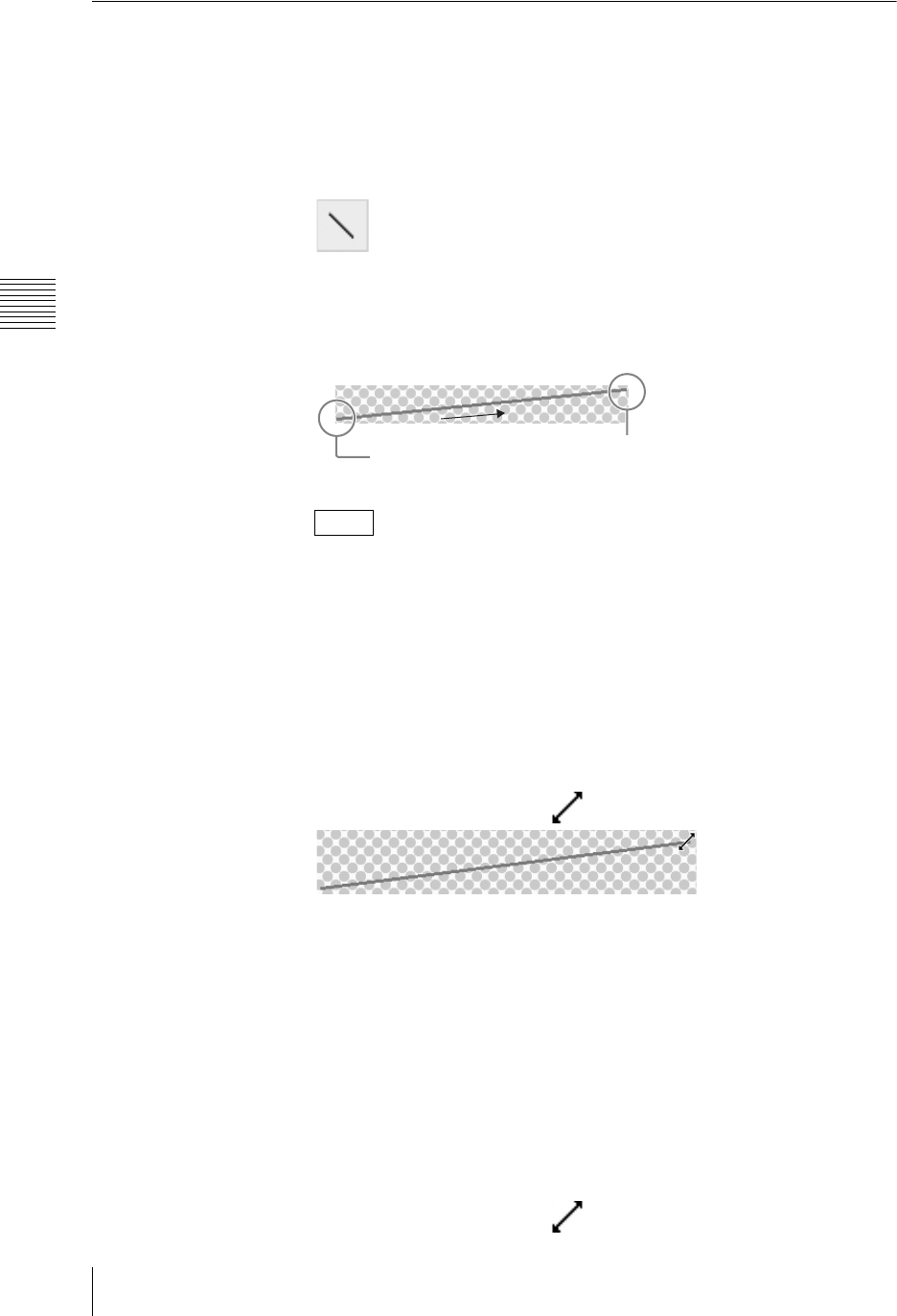
Chapter 3 Operations
134 Creating a Title Graphic With the Text Typing Tool
Working on Line Objects
This section describes how to create a line object, and then change the line style
or color.
Creating a straight line
1
Click the line tool.
The icon turns green, and you can now draw a line.
2
Draw a line.
Click at the start position, and drag to draw the line.
• If you drag with the Shift key held down, you can draw horizontal or
vertical lines.
• Right-click to cancel the orange color selection frame.
Changing the length and direction of a straight line
Directly after creating a line object
You can change the length and direction of a line object while the line tool
remains selected after the line object is created.
1
Point at either end of the line using the mouse.
The mouse pointer changes to .
2
Click and drag.
An orange border appears around the line object, and you can change the
length or direction of the line.
Already created line object
Use the selection tool to change the length and direction of a line object that has
already been created.
1
Click the selection tool and select the line object (page 120).
An orange border appears around the line object.
2
Place the mouse pointer over either end of the line.
The mouse pointer changes to .
Notes
Click
Drag Release
finger
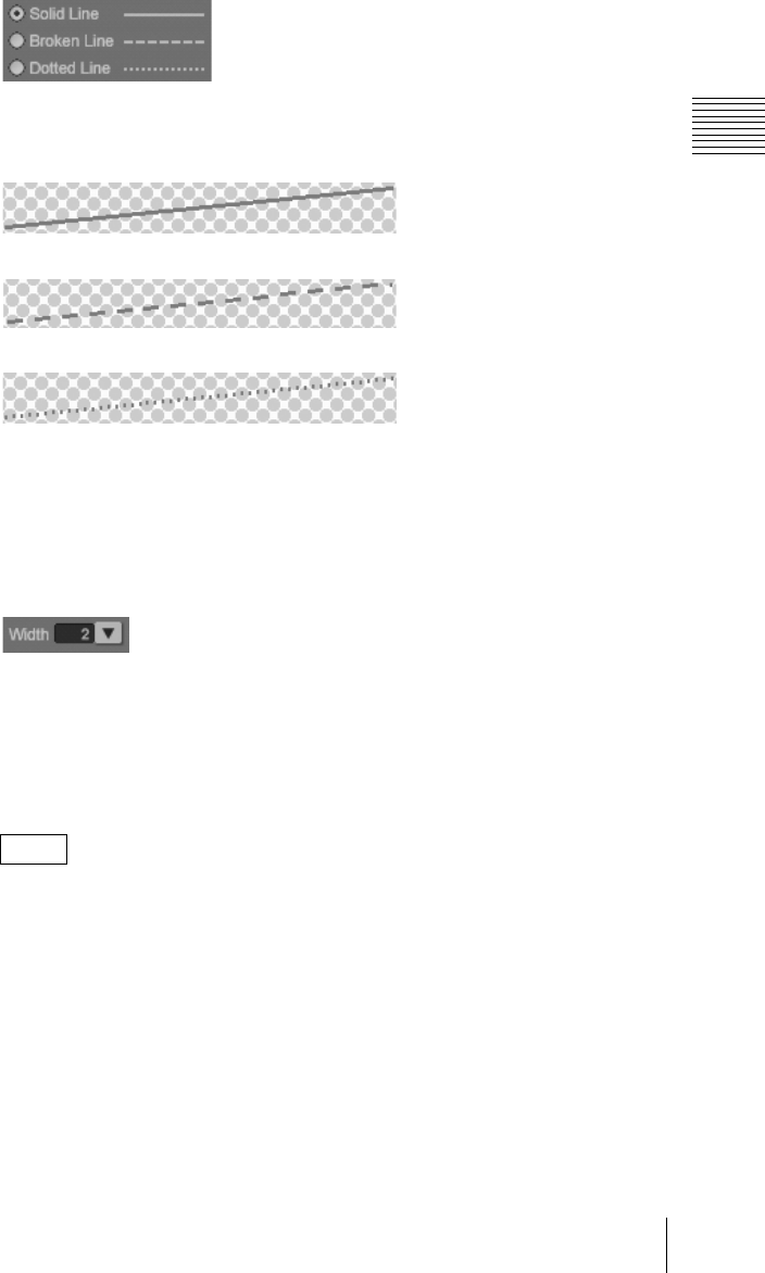
135
Creating a Title Graphic With the Text Typing Tool
Chapter 3 Operations
3
Click and drag.
Changing the line style
1
Click the selection tool, to select the line object (page 120).
An orange border appears around the line object.
2
Click one of the line style selection buttons on the Color tab of the [Line] tab.
The line appears as follows.
Solid Line
Broken Line
Dotted Line
Changing the line thickness
1
Click the selection tool, to select the line object (page 120).
An orange border appears around the line object.
2
Click the [Width] V button on the Color tab of the [Line] tab.
The pull-down list appears.
3
Select the thickness.
This changes the line to the selected thickness.
You can also change the size by directly entering a numeric value in the
[Width] box.
Click the box, enter the numeric value from the keyboard, then press the
Enter key.
Changing the line color
1
Click the selection tool, to select the line object (page 120).
An orange border appears around the line object.
2
Click one of the line color selection buttons on the Color tab of the [Line] tab.
Note
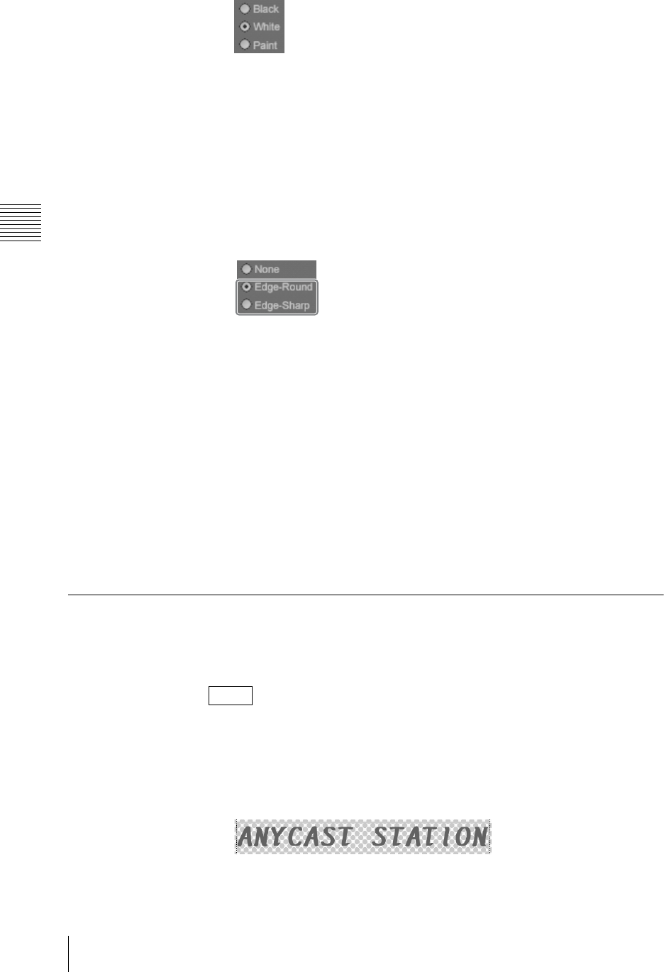
Chapter 3 Operations
136 Creating a Title Graphic With the Text Typing Tool
For details of color adjustment when the [Paint] is selected, see “Creating
a color in the color creation section” (page 141).
Adding outlines to line objects
1
Click the selection tool and select the line object (page 120).
An orange border appears around the line object.
2
Click the [Edge-Round] or [Edge-Sharp] edge style selection button on the
Edge tab of the [Line] tab.
Select the [Edge-Round] edge selection button for an outline with round
corners and select the [Edge-Sharp] edge selection button for an outline with
sharp corners.
3
Set the color and width of the outline as necessary.
To change the color of an outline
For black or white, select the [Black] or [White] edge color selection button.
To change the color to a desired color, create the color in the color creation
section.
For details, see “Creating a color in the color creation section” (page 141).
To change the width of an outline
Click the [Width] V button and select a width.
Shadow Operations
This section describes how to create shadows, and set the direction and distance,
and adjust the degree of blurring.
This section describes the example of a text object.
Applying a shadow
1
Click the selection tool, and select the object (page 120).
An orange border appears around the object.
2
Select the [Shadow] tab on the [Text] tab.
Note
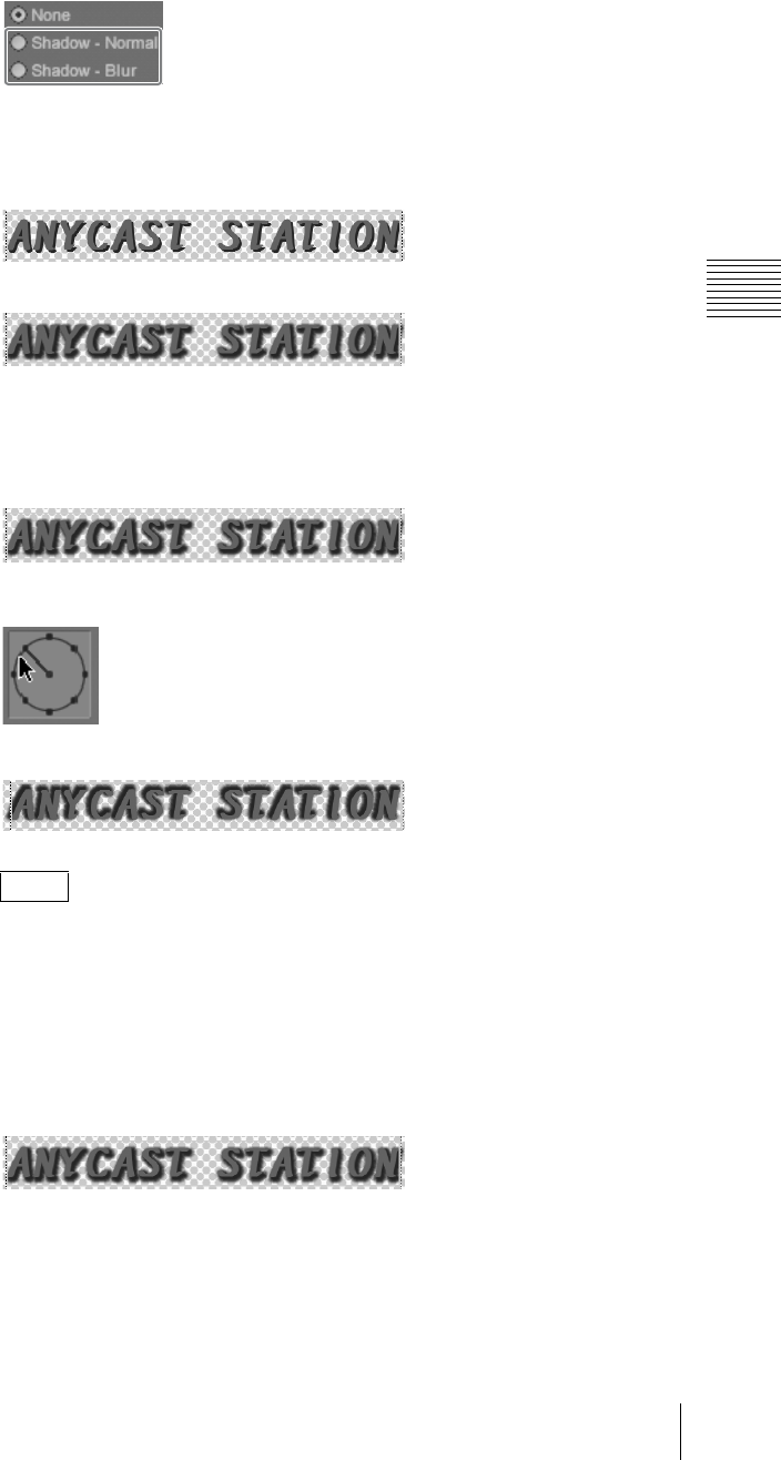
137
Creating a Title Graphic With the Text Typing Tool
Chapter 3 Operations
3
Select the [Shadow-Normal] or [Shadow-Blur] shadow type selection
button.
The following display appears.
Shadow - Normal
Shadow - Blur
Changing the shadow angle
1
Click the selection tool, and select the object with the shadow (page 120).
An orange border appears around the object.
2
Drag the direction indicator to the desired direction.
The shadow direction changes as follows.
• You can move the direction indicator needle in increments of 45º by
dragging it while holding down the Shift key.
• You can also enter a numeric value in [Degree], to change the direction.
Changing the shadow distance
1
Click the selection tool, and select the object with the shadow (page 120).
An orange border appears around the object.
2
Enter a numeric value in [Distance].
Notes
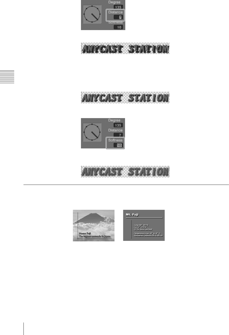
Chapter 3 Operations
138 Creating a Title Graphic With the Text Typing Tool
The shadow distance changes as follows.
Changing the degree of blurring of a shadow
1
Click the selection tool, and select an object with shadow (Shadow - Blur)
applied (page 120).
An orange border appears around the object.
2
Enter a numeric value in [Softness].
The degree of blurring of the shadow changes as follows.
Background Color Operations (Creating Telop and Flip)
Creating a telop for keying (transparent for keying)
When the created title is used as a key source in the Anycast Station main
software, the background is transparent (alpha value 100%), so that the
background does not appear.
Telop Flip
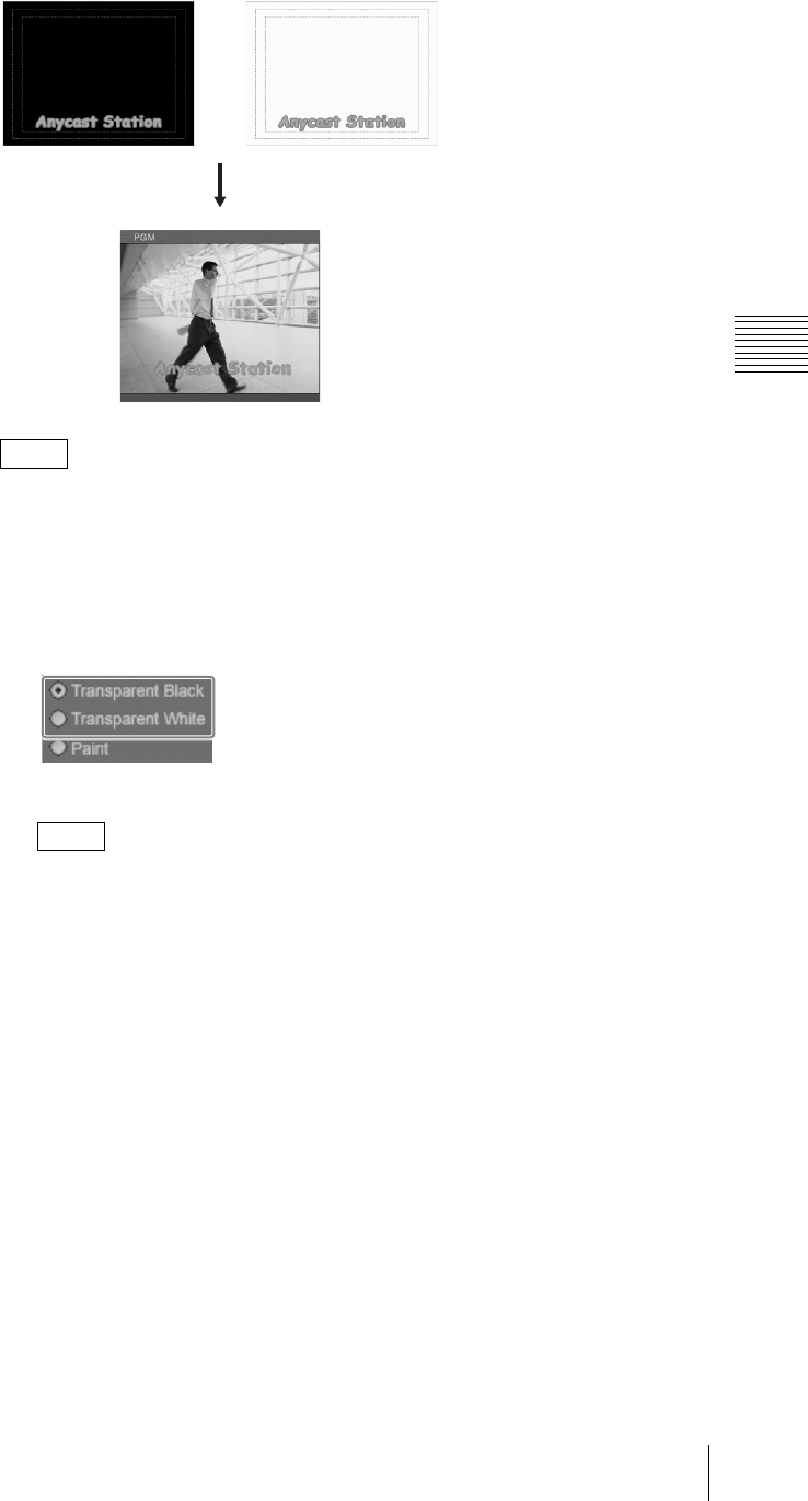
139
Creating a Title Graphic With the Text Typing Tool
Chapter 3 Operations
In the Anycast Station main software viewer, the background appears as
whichever of black and white it is set to, but when used as a key source, the
background is transparent.
1
Select the [BG] tab.
2
Select the [Transparent Black] or [Transparent White] color selection button.
To create a flip with a solid white or black background, select [Paint], and set
black or white. For more details, see “Creating a flip (for keying with a
background color)” (page 140).
Note
Note
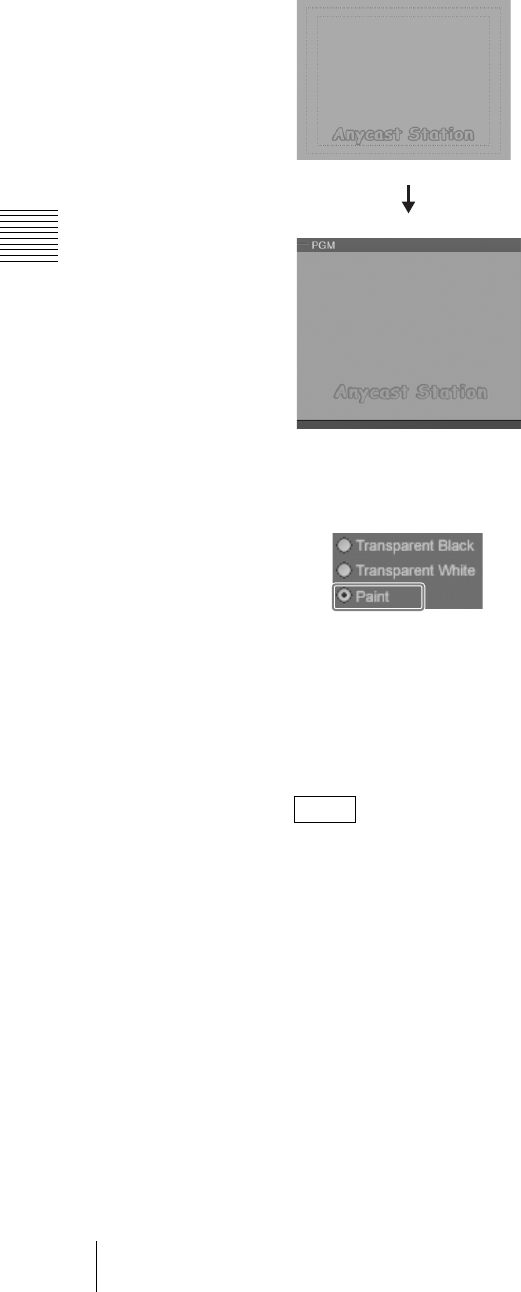
Chapter 3 Operations
140 Creating a Title Graphic With the Text Typing Tool
Creating a flip (for keying with a background color)
If you set any color for the background, when used as a key source in the Anycast
Station main software, the background color appears unchanged.
1
Select the [BG] tab.
2
Select the [Paint] color selection button.
3
Create a color in the color creation section.
For details of color creation, see “Creating a color in the color creation
section” (page 141).
The background changes to the selected color.
• If transparency is set, select [Live] and check the effect of the transparency.
• The screen and main software viewer are displayed without transparency when
[BG] button of the view operation section is selected even if transparency is set.
However, background transparency is set for actual keying.
• You can set a different background color for each sheet.
Notes
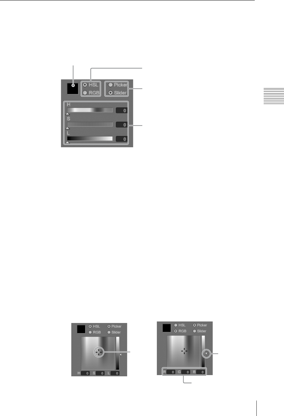
141
Creating a Title Graphic With the Text Typing Tool
Chapter 3 Operations
Color Operations
This section describes how to create a color.
Creating a color in the color creation section
In the color creation section of each tab of the modifier operation section, you can
create any desired color.
Use the following procedure to create a color.
1
Select [HSL] or [RGB] as the color system.
In each of these systems, you specify three parameters to create the color.
[HSL]
H: Hue
S: Saturation
L: Luminance
[RGB]
R: Red
G: Green
B: Blue
2
Select [Picker] or [Slider] depending on which color selection method you
want to use.
Use the following procedure to specify the color.
When [Picker] is selected
Move the mouse pointer to the desired point in the color field and click, or
specify the color by numeric value input.
Color preview
Color system
selection buttons
Color selection
method buttons
Color display
Click
When [HSL] is selected
Slider to change
the brightness.
Numeric value input
When [RGB] is selected
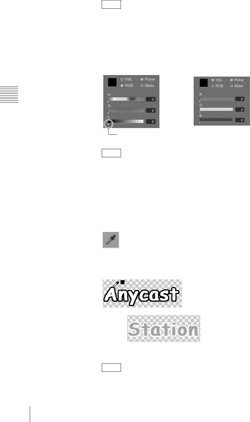
Chapter 3 Operations
142 Creating a Title Graphic With the Text Typing Tool
If you move the slider (on the right of the color field) toward the top or
bottom, then whatever color you select, only white or black will appear.
Setting a value of about 200 makes it easiest to distinguish the colors.
When [Slider] is selected
Move the sliders, or specify the color by numeric value input.
When [HSL] and [Slider] are selected, setting the [L] and [S] numeric value
to about 200, and then moving the [H] slider makes it easier to distinguish
the colors.
Changing the color using the eyedropper tool
You can pick the color used by another object and then set that color as the color
of the object.
1
Click the eyedropper tool.
The mouse pointer changes to an eyedropper.
2
Left-click the color you want to pick.
The color of the eyedropper width window changes to the color you picked.
You can pick the color with the eyedropper from any part of the screen:
background, text, character outline, line object, or captured image.
Note
Note
Note
When [HSL] is selected
Slider
When [RGB] is selected
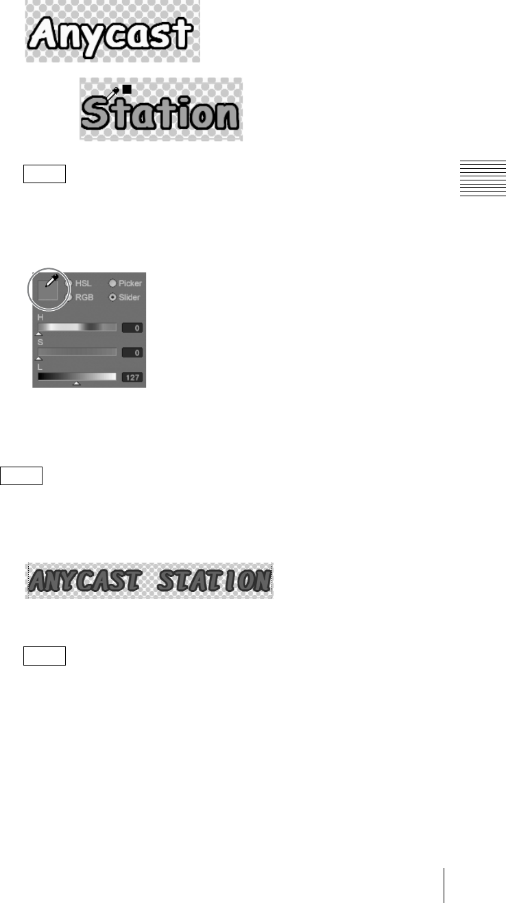
143
Creating a Title Graphic With the Text Typing Tool
Chapter 3 Operations
3
Right-click the place you want to change.
The color changes to the color you picked.
After you select a color with the eyedropper tool, you can change the color
of the color selection area to the color selected with the eyedropper tool if
you place the mouse pointer within the color preview square in the color
creation section and then right-click.
Changing the transparency
You can set a transparency value for the color of an object.
This section describes the example of a text object color.
1
Click the selection tool, and select the object (page 120).
An orange border appears around the object.
2
Select the Color tab of the [Text] tab.
• To set color transparency for the shadow of an object, select the Shadow
tab of the [Text] tab.
• To set color transparency for a line object, select the Color tab or Shadow
tab of the [Line] tab.
• To set color transparency for the background, select the [BG] tab.
Note
Note
Notes
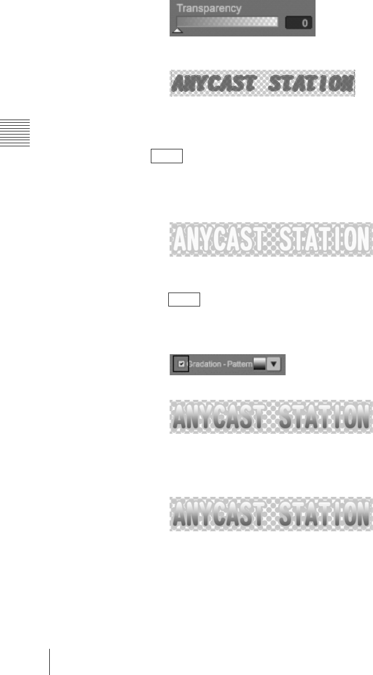
Chapter 3 Operations
144 Creating a Title Graphic With the Text Typing Tool
3
Move the [Transparency] slider, or enter a numeric value for the
transparency.
The color of the text becomes transparent as follows.
Applying a color gradation
You can apply a gradation to the color of an object.
This section describes the example of a text object color.
1
Click the selection tool, and select the object (page 120).
An orange border appears around the object.
2
Select the Color tab of the [Text] tab.
To set gradation for a line object, select the Color tab of the [Line] tab.
3
Select the [Gradation-Pattern] check box.
This applies the color gradation as follows.
Changing the gradation pattern
1
Click the selection tool, and select the object with the gradation (page 120).
An orange border appears around the object.
2
Select the Color tab of the [Text] tab.
Note
Note
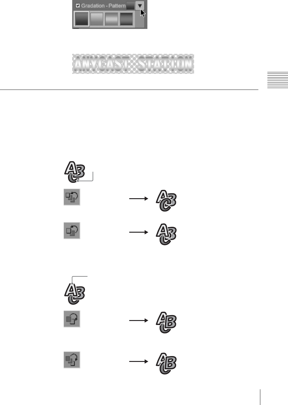
145
Creating a Title Graphic With the Text Typing Tool
Chapter 3 Operations
3
Click the [Gradation-Pattern] V button.
The following patterns appear.
4
Select a pattern.
This changes the pattern.
Object Layout
This section describes how to change the object front-to-back positioning, and
adjust the layout.
Changing the object front-to-back positioning
The tools used to carry out front-to-back positioning and their functions are as
follows.
C brings to the front.
C brings forward by one
level.
A moves back by one
level.
A moves to the back.
When C is selected
Bring to front
Bring forward
When A is selected
Move backward
Move to back
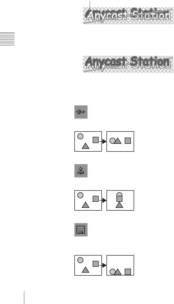
Chapter 3 Operations
146 Creating a Title Graphic With the Text Typing Tool
Example:
To move the object from the back to the front
1
Click the selection tool, and select the object to be moved.
o
An orange frame appears around the object, and it appears at the front.
2
Click the Move to front tool.
This moves the selected object to the front.
Positioning objects
You can center the selected object vertically or horizontally within the frame.
The tools used to carry out centering and their functions are as follows.
This centers vertically within the frame.
This centers horizontally within the frame.
This positions the object so that its lowest part is aligned to a predetermined
position.
Select the object at the back
Vertical centering
Horizontal centering
Lower/third positioning
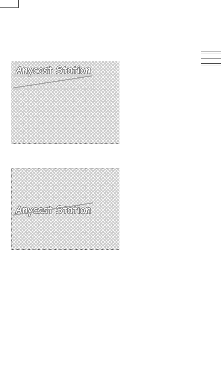
147
Creating a Title Graphic With the Text Typing Tool
Chapter 3 Operations
Setting the lower third position
Selecting an object and then clicking the lower third memory tool sets the lowest
part of the selected object as the lower third position. To restore the lower third
position to its default setting, click the lower third reset tool.
With the default setting, the object is moved so that its lowest part is aligned to a
position at the bottom of the safe zone inside the sheet.
Example:
Centering an object vertically
1
Click the selection tool, to select the object you want to position.
2
Click the vertical centering tool.
This centers the selected object vertically.
Note
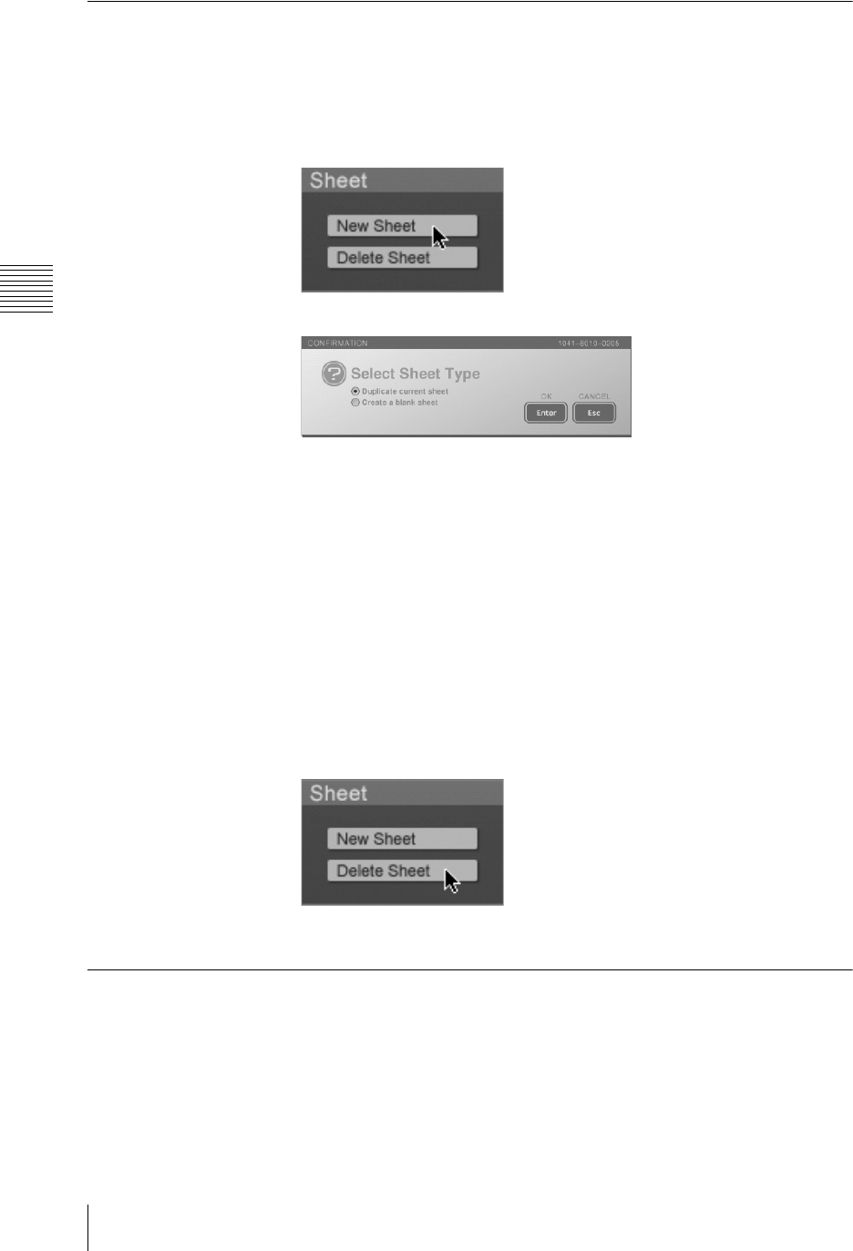
Chapter 3 Operations
148 Creating a Title Graphic With the Text Typing Tool
Adding and Deleting Sheets
In the Text Typing Tool software you can handle multiple sheets in a single file.
Adding a new sheet
1
Click the [New Sheet] button in the sheet operation section.
The following confirmation message appears.
2
Select [Duplicate current sheet] or [Create a blank sheet].
Duplicate current sheet: Creates a new sheet as a copy of the currently
open sheet object.
Create a blank sheet: Creates a new, blank sheet.
3
Click the [Enter].
The new sheet is inserted as the next page after the open sheet.
Deleting a sheet
1
With the page operation section (page 42), display the sheet you want to
delete.
2
Click the [Delete Sheet] button in the sheet operation section.
This deletes the displayed sheets.
Simulating the Keying Effects
By displaying an image captured from the program output video, or the
checkered pattern as the background, you can check the keying effect of a created
object.
Displaying a captured program output video image as the background
1
Open the file you want to simulate a keying effect.
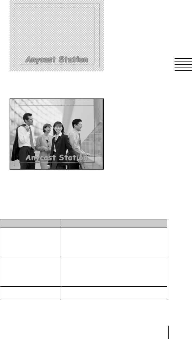
149
Creating a Title Graphic With the Text Typing Tool
Chapter 3 Operations
For the method of opening the file, see “Opening an existing file” (page
122).
2
Select [Live] of the view operation section.
When you select [Live], the image captured from program output video
when you switched from the main software appears in the background.
3
Click the [Capture] button in the view operation section.
Each time you click, this captures the current image.
Setting background display
You can set the background display as follows by selecting a background display
selection button in the view operation section.
For details on the [BG] tab settings and background display settings, see
“Background Color Operations (Creating Telop and Flip)” (page 138).
Background setting Display effect
Checker
Checkered pattern + object
When the color selection button in the [BG]
tab is [Paint]: checkered pattern + background of
user-created background color (transparency and
gradation settings: can be checked) + object
Live
Program output capture image + object
If the [BG] tab color selection button is [Paint]:
Program output capture image + background of user-
created background color (transparency and gradation
settings: can be checked) + object
BG Background color set on the [BG] tab (transparency
setting: cannot be checked) + object
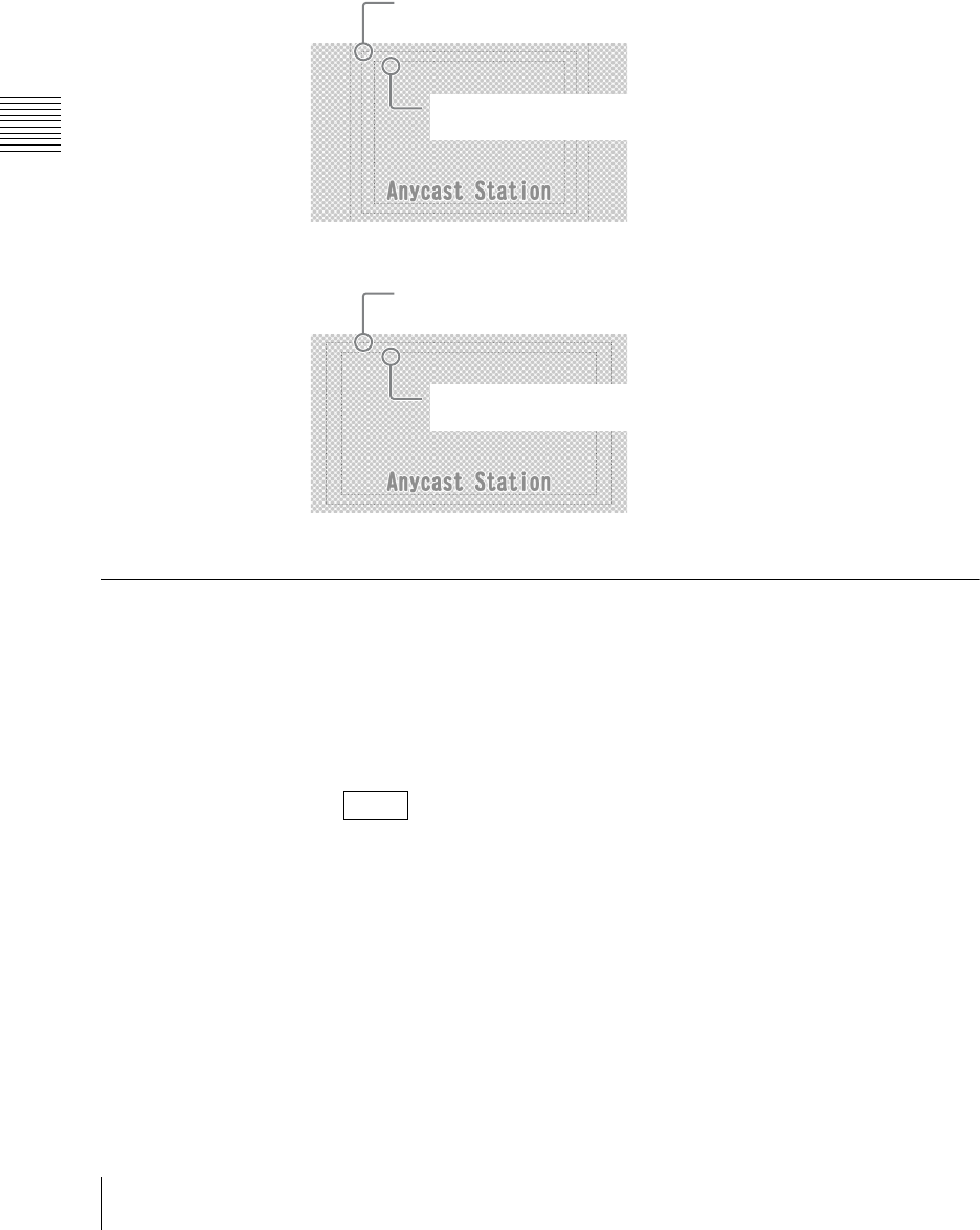
Chapter 3 Operations
150 Creating a Title Graphic With the Text Typing Tool
Displaying the safe area
The “safe area” refers to the area of the frame within which an object can be
inserted as a key in the program output video without risk of being outside the
viewing limits on a connected output device.
When a button in the view operation section is selected, the safe area appears.
Select “Off” to hide the safe area.
Key Combination in the Anycast Station Main Software
Start the Anycast Station main software, and use the file created in the Text
Typing Tool software for a keying.
1
Click the [Exit] button at the lower left of the screen.
This starts the Anycast Station main software.
You can also use the keyboard F5 (Fn+5) key to switch to the Anycast
Station main software.
For details, see “To close the Text Typing Tool software and start the
Anycast Station main software” (page 118).
2
Press the “INT” NEXT selection button.
The INT material selection menu appears.
Note
The outer dotted line indicates the extremity of the frame.
If outside this line, the image will certainly be cropped.
Within the inner dotted line is the safe
area.
4:3 mode
The outer dotted line indicates the extremity of the frame.
If outside this line, the image will certainly be cropped.
Within the inner dotted line is the safe
area.
16:9 mode
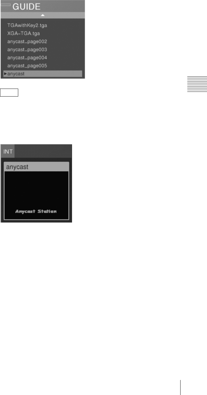
151
Creating a Title Graphic With the Text Typing Tool
Chapter 3 Operations
3
Select the file or sheet, and confirm.
• If the file consists of multiple sheets, the first sheet is identified as the file
name, and the second and subsequent sheets are identified as the file name
+ sheet number.
• Files created in the Text Typing Tool software have no extension.
The selected sheet appears as the “INT” source viewer and PVW viewer.
You can combine as a downstream key (DSK) or luminance key.
For details, see “Using the Downstream Key (DSK) Function To Add Text
or an Image” (page 90) and “Using Luminance Keying” (page 99).
Notes
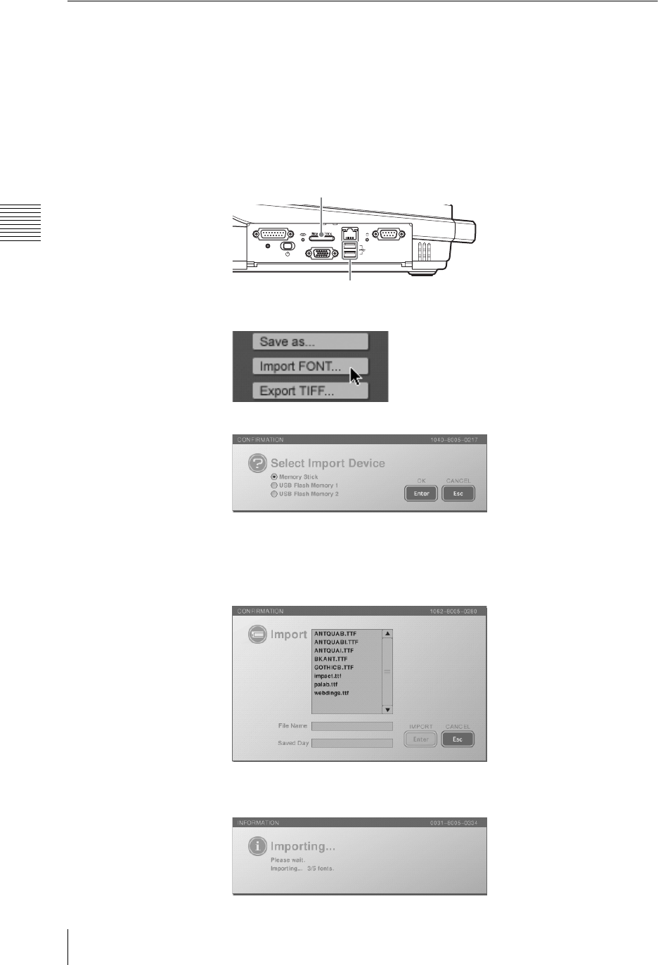
Chapter 3 Operations
152 Creating a Title Graphic With the Text Typing Tool
Importing a Font File
You can import a font file that has been saved on a “Memory Stick” or USB flash
memory.
The font file must have been saved in the dedicated folder for fonts: MSSONY/
PRO/LPS/ANYCAST/FONT.
1
Insert the “Memory Stick” or USB flash memory in the side panel “Memory
Stick” slot or USB connector.
The upper USB connector is number 1, and the lower connector is number 2.
2
In the file operation section, click the [Import FONT...] button.
The following confirmation message appears.
3
Select the inserted media, and click [Enter].
The font list appears.
4
Select the font file to import from the font list.
5
Click [Enter].
While importing, the following message appears.
FACTORY USE REMOTE
RGB
(
GUI
)
RESET
USB
NETWORK
18
15 9
1
5
“Memory Stick” slot
USB connectors
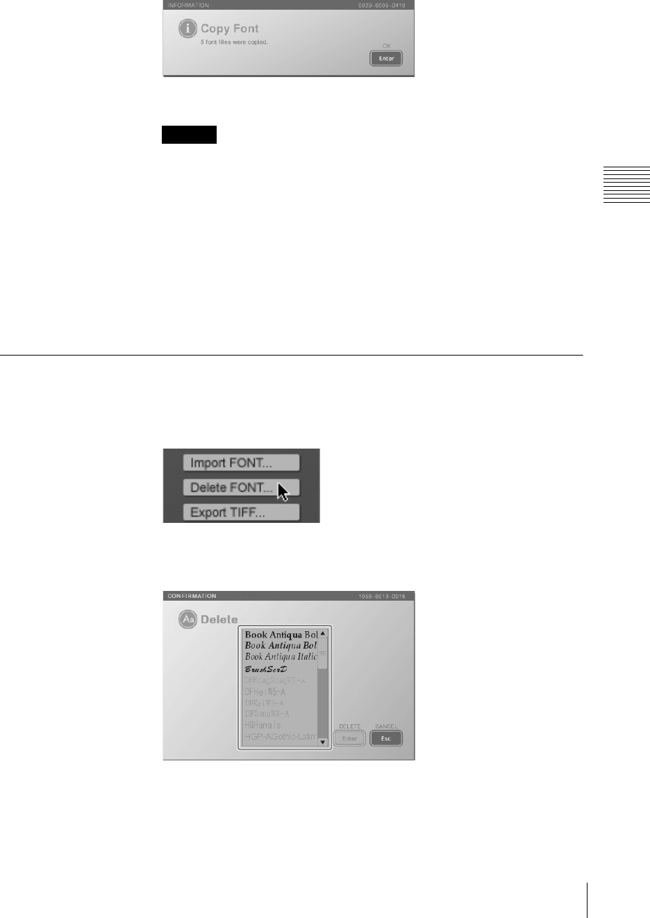
153
Creating a Title Graphic With the Text Typing Tool
Chapter 3 Operations
When the import is completed, a completion message appears, and the font
is added to the [Font Name] list.
6
Click the [Enter].
• This imports all font files within the FONT directory of the “Memory
Stick” or USB flash memory. If the same font file exists in this unit, it is
overwritten.
• The only font files that can be imported are TrueType fonts, with a file
extension “.ttf” or “.ttc.”
• Even if an imported font is one the user has purchased, for commercial use,
such as providing telop on a broadcast, the permission of the provider of
the font for commercial use of the font may be necessary.
Note that the nine fonts provided with the Text Typing Tool may be used
for commercial purposes without further formality. These fonts are true
type fonts developed and sold by Ricoh Company, Ltd.
Deleting a Font File
You can delete a font file that was imported into the unit.
1
Click the [Delete FONT] button in the file operation section.
The font list appears.
2
Select the font file to delete from the font list.
Caution

Chapter 3 Operations
154 Creating a Title Graphic With the Text Typing Tool
• You can select multiple font files by clicking (or pressing the r and R keys)
to select file names while holding down the Shift key or by dragging to
select file names.
• If you attempt to delete a font file while a file is open, the font files of fonts
used by the file currently open cannot be selected.
• Fonts included in the same .ttc file are selected at the same time.
3
Click [Enter].
A confirmation message appears.
4
Click [Enter].
The specified font file is deleted.
Deleting a font clears the information for Undo and Redo operations.
Notes
Caution

155
Controlling Cameras
Chapter 3 Operations
Controlling Cameras
This unit is equipped with a VISCA controller. VISCA (VIdeo System Control
Architecture) is a technology used for connecting a video device to a controller,
and controlling the video device from the controller. In this unit, you can
remotely control a camera supporting VISCA protocol connected to the VISCA
connector.
The remote control operations available include the following.
•Pan
• Tilt
•Zoom
• Focus
• Aperture (iris) control
• White balance adjustment
• Backlight
The controllable range depends on the camera you are using.
Controlling Camera Manually
Control a camera manually supporting the VISCA protocol from this unit.
With the default settings of this unit, focus and iris settings are set to auto, and
white balance setting is set to “no operation.” To control these manually, you
need to set them in the menu.
Carrying out manual control
1
Press the NEXT selection button to which the camera video is assigned.
The camera guide menu appears in the menu display.
If the camera guide menu does not appear, follow the procedure in
“Registering Cameras To Be Controlled” (page 69).
A guide to operations appears in the camera control guide.
Note
Note
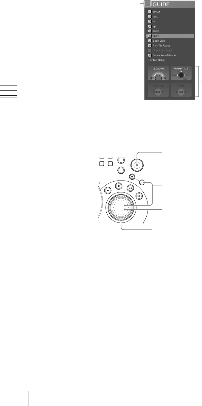
Chapter 3 Operations
156 Controlling Cameras
If the focusing and iris control are set to auto, then “AUTO” appears.
To change the settings manually, see “Setting the Camera Control” (page
160).
2
Following the guide, control the camera, using the front panel buttons and
dials.
Using the backlight function
You can use the backlight function when [Iris (Exposure)] is set to [Auto] (page
161). When there is a source of light behind the shooting subject and the subject
appears dark, you can brighten the subject’s appearance by enabling the backlight
function.
1
Press the NEXT selection button to which the camera video is assigned.
The camera guide menu appears in the menu display.
2
Select [7 Back Light], and confirm.
The setting turns on or off each time it is selected.
Camera control guide
Guided item
56
23
ESC
MENU
X
-
Y
REC
SHIFT
JOG/SHUTTLE
Move the positioner for pan (moving the camera
shooting direction horizontally) and tilt (moving the
camera shooting direction vertically) control.
Hold down the SHIFT button and turn the jog dial to
adjust the iris (aperture). Turning clockwise opens the
iris, and turning counterclockwise stops down the iris
(when setting manually).
Turn the jog dial to adjust the focus. Turning clockwise
focuses further away, and turning counterclockwise
focuses closer (when setting manually).
Turn the shuttle dial to control the zoom. Turning clockwise
zooms in (telephoto), and turning counterclockwise zooms
out (wide angle).
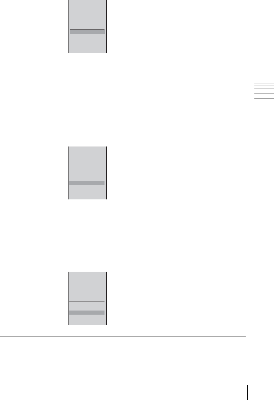
157
Controlling Cameras
Chapter 3 Operations
Resetting pan and tilt positions
When [Pan-Tilt] (page 161) is set to [Enable], you can reset pan and tilt to their
default positions.
Use this function when the camera head is moved during operation, when the
camera’s STANDBY indicator flashes for reasons including fingers or objects
getting caught in the camera, or when pan and tilt operations stop functioning.
1
Press the NEXT selection button to which the camera video is assigned.
A camera guide menu appears in the menu display.
2
Select [8 Pan-Tilt Reset], and confirm.
Adjusting the white balance automatically
When [White Balance] (page 161) is set to [One Push], you can specify when to
perform automatic white balance adjustment by pressing the numeric buttons.
1
Press the NEXT selection button to which the camera video is assigned.
A camera guide menu appears in the menu display.
2
Select [9 One Push AWB], and confirm.
Storing a Camera Preset
The camera preset function allows you to save the state of the camera supporting
VISCA protocol to one of the numeric buttons on the front panel. Then by
pressing the numeric button, you can automatically set the camera to the saved
state.
1 Center
2 Base Guitear
3 Drum
4 Right
5 Vocal
6
7 Back Light
8 Pan-Tilt Reset
9 One Push AWB
-
Focus Auto/Manual
Control Setup
1 Center
2 Base Guitear
3 Drum
4 Right
5 Vocal
6
7 Back Light
8 Pan-Tilt Reset
9 One Push AWB
-
Focus Auto/Manual
Control Setup
1 Center
2 Base Guitear
3 Drum
4 Right
5 Vocal
6
7 Back Light
8 Pan-Tilt Reset
9 One Push AWB
-
Focus Auto/Manual
Control Setup
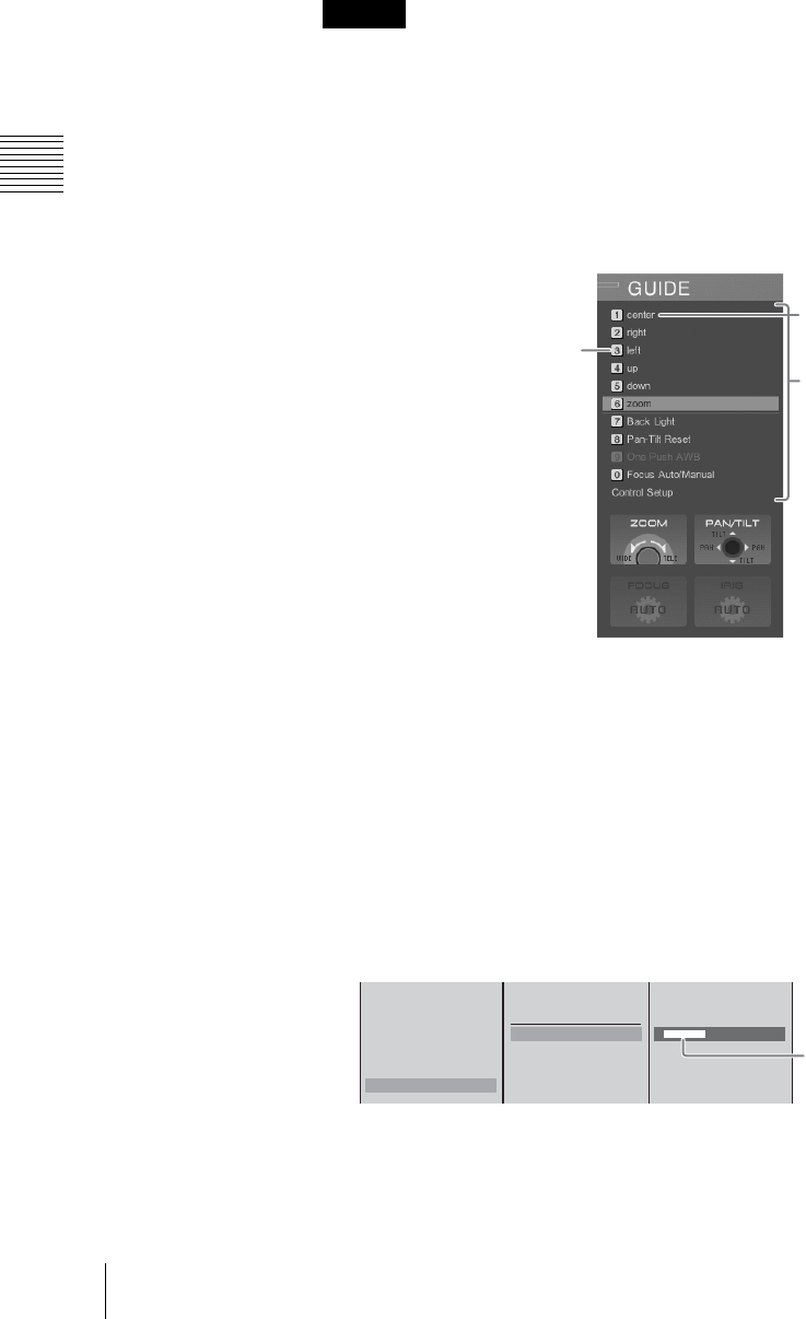
Chapter 3 Operations
158 Controlling Cameras
For example, during a lecture relay, you can store settings for standard shots,
such as a speaker close-up, speaker full-body shot, guest panel, or audience view,
simplifying the work of switching among these views.
In the camera preset, you can save the pan, tilt, zoom, and focus settings, the
aperture (iris) status, the white balance adjustment, the control mode (auto/
manual, etc.).
If the camera you are using is an EVI-D100/EVI-D100P, set the camera BACK
UP switch to the ON position before storing.
Storing a camera preset
1
Press the NEXT selection button to which the camera video is assigned.
The camera guide menu appears in the menu display.
Camera presets appear at the top of the camera guide menu.
2
Control the camera to determine the shot.
3
With the jog roller, select the camera preset number (from 1 to 6), and
confirm.
The camera preset settings menu appears.
4
Set the following items as required.
Applying a name to the preset
1 Select [Data Name], and confirm; 2 enter the name in the input box, and
confirm.
5
Select [Preset], and confirm.
Caution
Numeric button numbers
Data name
Camera preset
1 Center
2 Base Guitear
3 Drum
4 Right
5 Vocal
6
Preset
Delete
Data Name [ xxxxxxxxxx ]
12
Enter up to 20
alphanumeric characters.
* The camera guide menu can only
display a limited number of
characters.
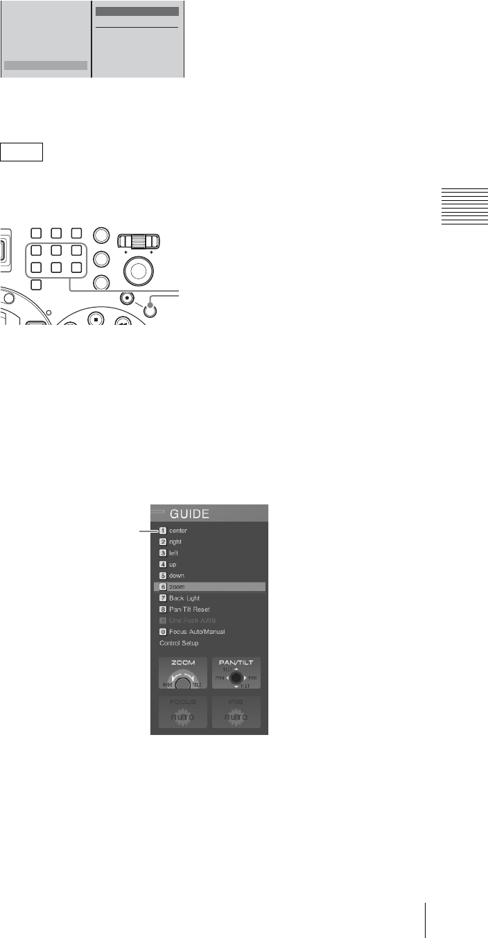
159
Controlling Cameras
Chapter 3 Operations
This saves the preset in the numeric button.
The saved preset appears in the camera guide menu.
Even if the camera guide menu is not displayed, you can register a camera
preset by holding down the Shift button and pressing any numeric button
(between 1 and 6).
Recalling a preset
1
Press the NEXT selection button to which the camera video is assigned.
The camera guide menu appears in the menu display.
2
Using the numeric buttons on the front panel, press the number in which the
preset is saved.
The numeric button lights amber, and the camera is set to the preset state.
Deleting a saved preset
1
Press the NEXT selection button to which the camera video is assigned.
A camera guide menu appears in the menu display.
2
Select the number of the preset you want to delete with the jog roller, and
confirm.
Note
1 Center
2 Base Guitear
3 Drum
4 Right
5 Vocal
6
Preset Shift z+6
Delete
Data Name
789
456
1
0
23
ESC
ENTER
MENU
X
-
Y
REC
SHIFT
P
V
W
Hold down the SHIFT button, and press
one of numeric buttons 1 to 6.
The selected number
appears in amber.
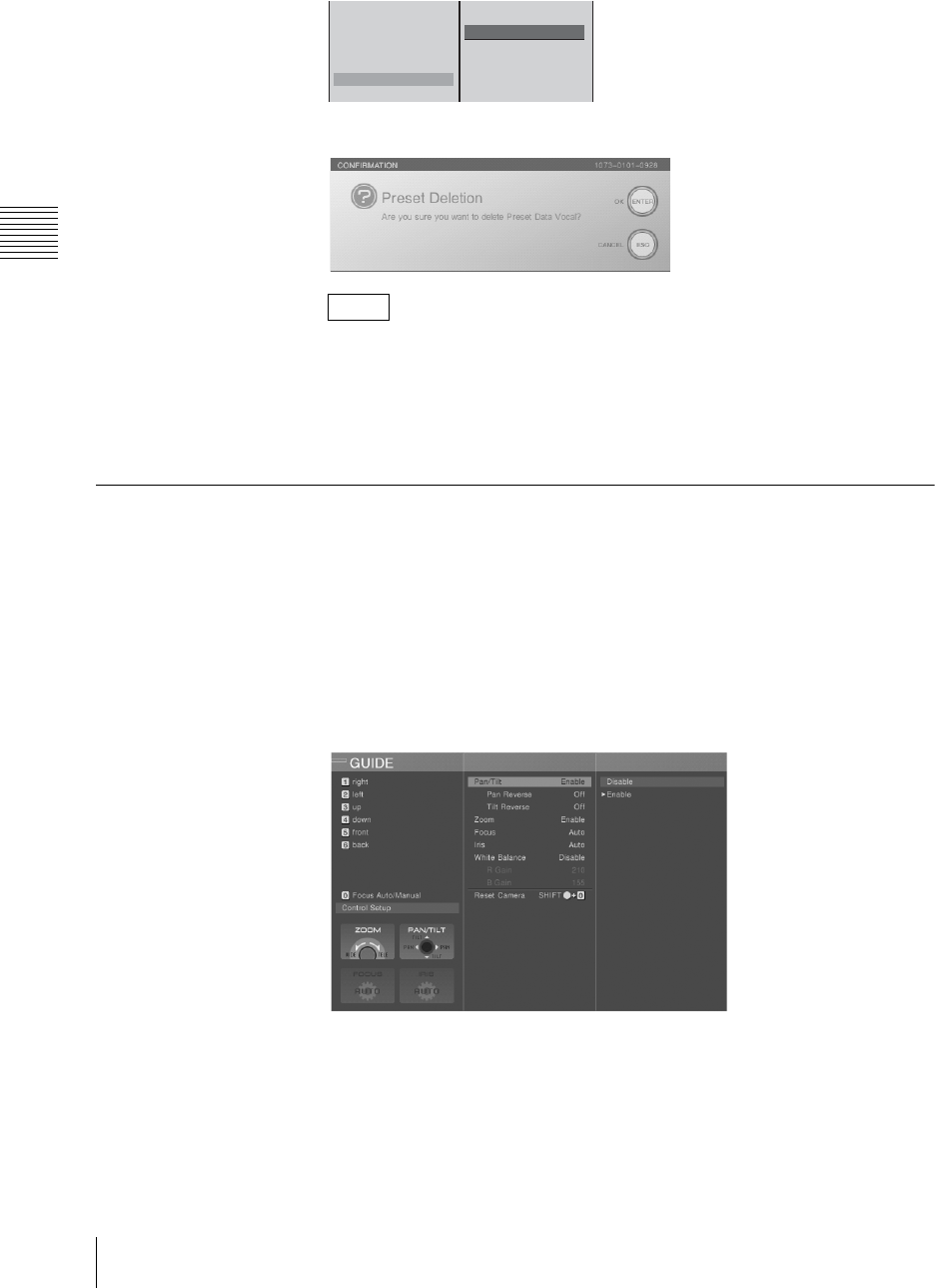
Chapter 3 Operations
160 Controlling Cameras
The camera preset settings menu appears.
3
Select [Delete], and confirm.
The following confirmation message appears, as follows.
By pressing the ENTER button while holding down the SHIFT button, you
can delete all of the presets simultaneously.
4
Press the ENTER button.
The preset is deleted, and the number display turns gray.
Setting the Camera Control
To change the default settings of this unit, or to enable pan, tilt and zoom for a
ceiling-mounted camera, use the following procedure.
1
Press the NEXT selection button to which the camera video is assigned.
A camera guide menu appears in the menu display.
2
With the jog roller, select [Control Setup], and confirm.
The submenu appears.
3
Set the following items in the submenu.
Note
1 Center
2 Base Guitear
3 Drum
4 Right
5 Vocal
6
Preset
Delete
Data Name
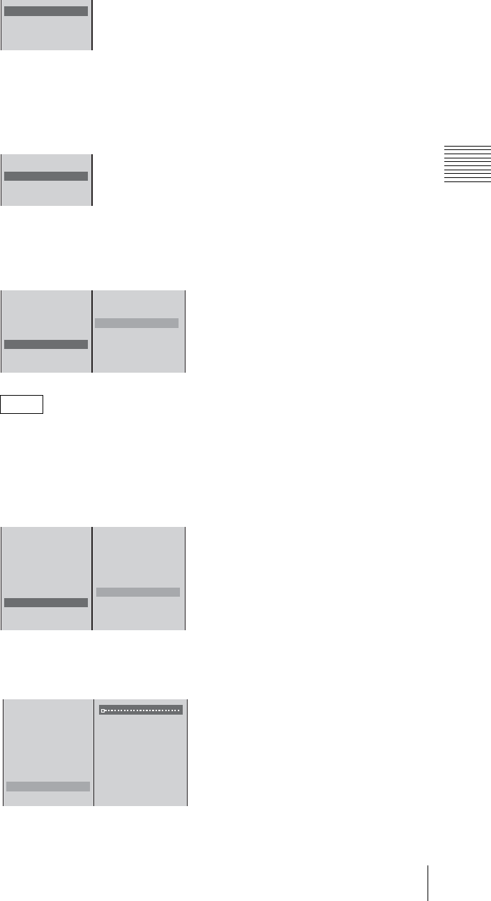
161
Controlling Cameras
Chapter 3 Operations
Disabling remote control of pan and tilt, or zoom
Select [Pan-Tilt] or [Zoom] to set it to [Disable], and confirm.
The setting switches between [Enable] and [Disable] each time it is selected.
Reversing directions for ceiling-mounted cameras
When a camera is ceiling-mounted, you can reverse the pan and tilt
directions.
Select [Pan Reverse] or [Tilt Reverse] to set it [On], and confirm.
The setting turns on or off each time it is selected.
Enabling manual focus and iris control
1 Select [Focus] or [Iris (Exposure)], and confirm; 2 select [Manual], and
confirm.
You can switch the auto focus and manual focus by pressing “0” of the
numeric keys.
Manually controlling white balance
1 Select [White Balance], and confirm; 2 set [Manual], and confirm.
3 Select [R Gain] or [B Gain], and confirm; 4 move the slider to adjust the
values.
Note
Pan - Tilt Enable
Pan Reverse Off
Tilt Reverse Off
Zoom Enable
Pan - Tilt Enable
Pan Reverse Off
Tilt Reverse Off
Zoom Enable
Pan - Tilt Enable
Pan Reverse Off
Tilt Reverse Off
Zoom Enable
Focus Auto
lris(Exposure) Auto
White Balance Auto
Disable
Auto
B Manual
12
Pan - Tilt Enable
Pan Reverse Off
Tilt Reverse Off
Zoom Enable
Focus Auto
lris(Exposure) Auto
White Balance Auto
R Gain 0
B Gain 0
Disable
Auto
Indoor
Outdoor
One Push
B Manual
12
Pan - Tilt Enable
Pan Reverse Off
Tilt Reverse Off
Zoom Enable
Focus Auto
lris(Exposure) Auto
White Barance Manual
R Gain 0
B Gain 0
34
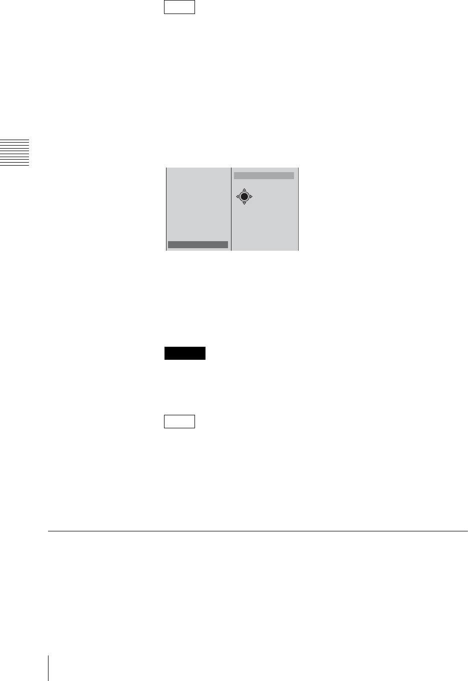
Chapter 3 Operations
162 Controlling Cameras
• When not using control from this unit, select [Disable].
• Select [Indoor] to adjust to a white balance for indoor use, and select
[Outdoor] to adjust to a white balance for outdoor use.
• Select [One Push] to adjust white balance automatically. For details see
“Adjusting the white balance automatically” (page 157).
Performing onscreen the operations of the supplied camera
remote control (RM-EV100)
This function may not be available depending on the camera type.
1 Select [On-Screen Menus], and confirm; 2 select the item you want to
operate with the positioner, and configure.
The functions of the setting items are as follows.
[Data Screen]: Displays/hides the Data Screen (the menu that appears on
video images from the VISCA camera) and advances the menu level (the
same function as the Data Screen button on the RM-EV100).
[HOME]: Lowers the menu level (the same function as the HOME button on
the RM-EV100).
Be aware that when configuring setting items that can be changed on the unit
from [On-Screen Menus] or the remote control, the setting values on the unit
will no longer match those on the camera.
• Pressing up and down on the positioner moves the cursor up and down,
while pressing left and right changes the settings (the same functions as the
pan-tilt buttons on the RM-EV100).
• You cannot pan and tilt the camera with the positioner while the [Data
Screen] is displayed.
4
Press the ESC button to close the submenu.
Resetting the Camera
After starting up this unit, carry out this procedure after powering the camera
supporting the VISCA protocol off and on again, or disconnecting and
reconnecting the VISCA cable.
Perform this operation even if “No Response” appears as the camera status.
1
Press the NEXT selection button to which the camera video is assigned.
Notes
Caution
Notes
Pan - Tilt Enable
Pan Reverse Off
Tilt Reverse Off
Zoom Enable
Focus Auto
lris(Exposure) Auto
White Balance Auto
R Gain 0
B Gain 0
On-Screen Menus
B Data Screen
HOME
X-Y
12

163
Controlling Cameras
Chapter 3 Operations
A camera guide menu appears in the menu display.
2
With the jog roller, select [Control Setup], and confirm.
3
In the submenu, select [Reset Camera], and confirm.
You can also reset the camera by holding down the Shift button and pressing
the numeric 0 button.
Linking the VISCA Camera’s Power to the Unit’s Power
By linking the power, you can have the VISCA camera’s power turn off when the
unit is turned off.
When the unit is turned on, all of the VISCA cameras connected to the VISCA
connector will also turn on.
1
Press the MENU button.
2
In the top menu, select [Video Utility].
3
Select [VISCA Power Control] to set it [On], and confirm.
The setting turns on or off each time it is selected.
4
Press the MENU button to close the menu.
Note
Note
Pan - Tilt Enable
Pan Reverse Off
Tilt Reverse Off
Zoom Enable
Focus Auto
Iris(Exposure) Auto
White Balance Disable
R Gain 0
B Gain 0
Reset Camera SHIFT z+ -
Remote Switching
VISCA Power Control On
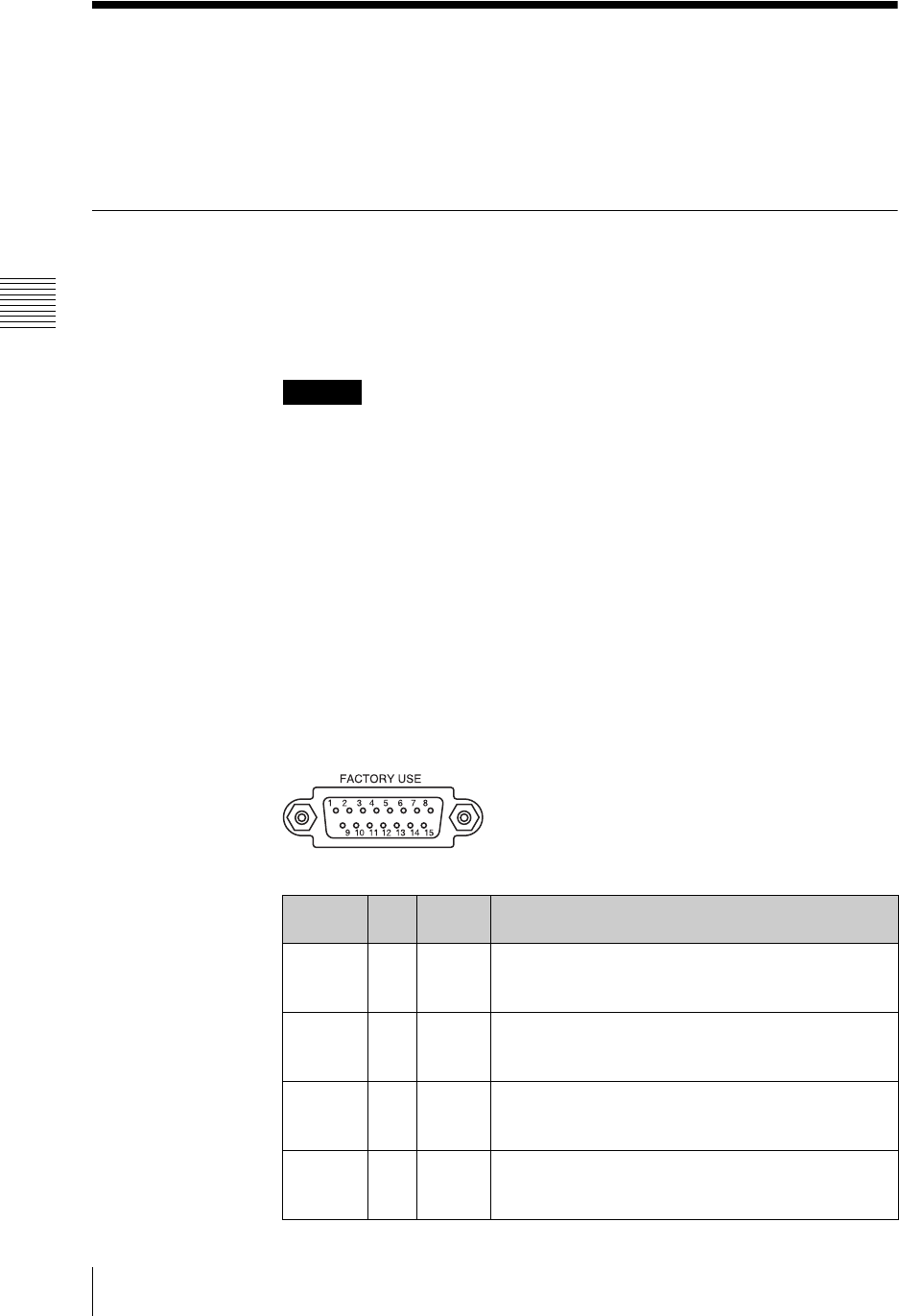
Chapter 3 Operations
164 Using the FACTORY USE Connector
Using the FACTORY USE Connector
Connecting the FACTORY USE connector on the unit to the tally connector on
a CCU (camera control unit) or other device allows you to use the tally lamps on
the camera and switch between PGM and NEXT selection buttons from an
external device when one is connected.
Using Camera Tallies
When the camera supports the camera tally function (BRC series,
etc.)
The camera tally lamp lights when the input from the camera is being used as
program output.
• Multiple settings are possible for the [Video Input Assign] of the [Control]
setting. In this case, the camera tally lights when the video from any of the
source viewers for which the [Control] setting is made is being used for
program output.
• Tally outputs do not transmit properly when the unit is starting up.
When using CCU, etc.
If the FACTORY USE connector of the unit is connected to the tally connector
of a CCU (camera control unit), the tally lamp lights for any camera that is
assigned to a PGM selection button or NEXT selection button on the front panel,
as long as video from that camera is being used as program output (the button
lights red).
Specifications of the FACTORY USE connector
The specification of each pin is as shown below.
Caution
Pin
Number I/O Signal
Name Description
1 I GPI0 GPI IN1: Switches to the PGM or NEXT selection button
assigned to source number 1.
5V TTL
2 I GPI1 GPI IN2: Switches to the PGM or NEXT selection button
assigned to source number 2.
5V TTL
3 I GPI2 GPI IN3: Switches to the PGM or NEXT selection button
assigned to source number 3.
5V TTL
4 I GPI3 GPI IN4: Switches to the PGM or NEXT selection button
assigned to source number 4.
5V TTL
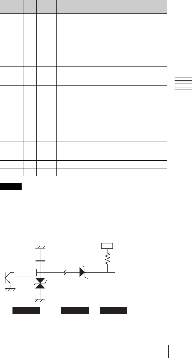
165
Using the FACTORY USE Connector
Chapter 3 Operations
Because the GPO of the FACTORY USE connector on the unit has a built-in
protection circuit, it may not operate properly depending on the input circuit
configuration of the device to be connected.
Refer to the diagram below to prepare the cables.
* When using an HFU-X310, couple directly without using a diode.
5 I GPI4 GPI IN5: Switches to the PGM or NEXT selection button
assigned to source number 5.
5V TTL
6 I GPI5 GPI IN6: Switches to the PGM or NEXT selection button
assigned to source number 6.
5V TTL
7 - GND GROUND
8 - GND GROUND
9 O GPO0 GIP OUT1: Controls the tally of the camera assigned to
source number 1.
On: GND; Off: Open
10 O GPO1 GIP OUT2: Controls the tally of the camera assigned to
source number 2.
On: GND; Off: Open
11 O GPO2 GIP OUT3: Controls the tally of the camera assigned to
source number 3.
On: GND; Off: Open
12 O GPO3 GIP OUT4: Controls the tally of the camera assigned to
source number 4.
On: GND; Off: Open
13 O GPO4 GIP OUT5: Controls the tally of the camera assigned to
source number 5.
On: GND; Off: Open
14 - GND GROUND
15 - GND GROUND
Caution
Pin
Number I/O Signal
Name Description
AWS-G500 Cable
Connected device
10000 pF R
Vcc
NOISE FILTER
RSB6.8SFTE
Vz=±5.78 V
~
7.82 V
Sample circuit diagram (CCU-D50/CCU-M7/CCU-M5/HFU-X310)
* For details on other device
models, consult your
dealer or your Sony
service representative.
Zener diode
(Vz=3.2 V~7.42 V)*
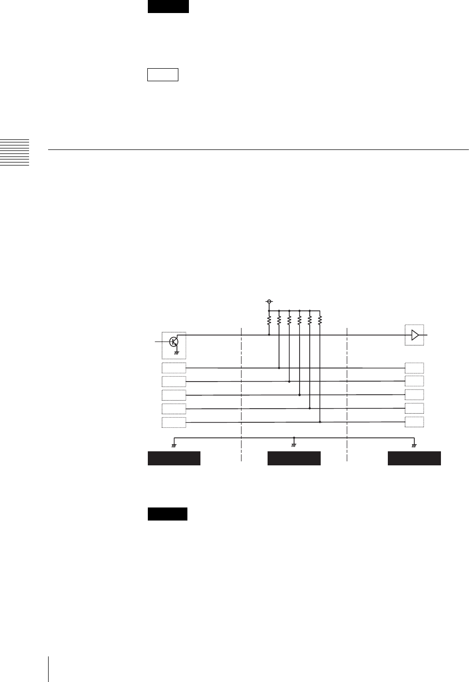
Chapter 3 Operations
166 Using the FACTORY USE Connector
When using the CCU, the camera tally control is possible for the camera assigned
to source number 1 to 5. When the camera is assigned to source number 6, the
camera tally cannot be lit.
• When the video from a camera with the tally lit is being used for program
output, then if you press the FTB button, the tally goes off.
• If you open a file on the hard disk in the source viewer assigned to the video
from a camera with the tally lit, the tally goes off.
Operating the PGM and NEXT Selection Buttons From an
External Device
When you connect an external device to the FACTORY USE connector on the
unit, you can perform switching for the PGM and NEXT selection buttons from
the external device.
Refer to the diagram below to prepare the cables.
• Pull-up of all signal lines is necessary.
• On the unit, set [Trigger] under [Remote Switching] of [Video Utility] to
[Low-Level].
• On the RM-BR300, set the TALLY/CONTACT switch to CONTACT.
1
Connect the external device to the FACTORY USE connector.
2
Press the MENU button.
Caution
Notes
Caution
RM-BR300 AWS-G500Cable
+5V
1KΩ
1
2
3
4
5
6
1
2
3
4
5
6
8,9
CAMERA 1
CAMERA 2
CAMERA 3
CAMERA 4
CAMERA 5
CAMERA 6
GND 7,8,14,15 GND
GPI 0
GPI 1
GPI 2
GPI 3
GPI 4
GPI 5
Sample circuit diagram (RM-BR300)
* For details on other device models, consult your
dealer or your Sony service representative.
TALLY/CONTACT connector
Open-collector output
FACTORY USE connector
TTL input
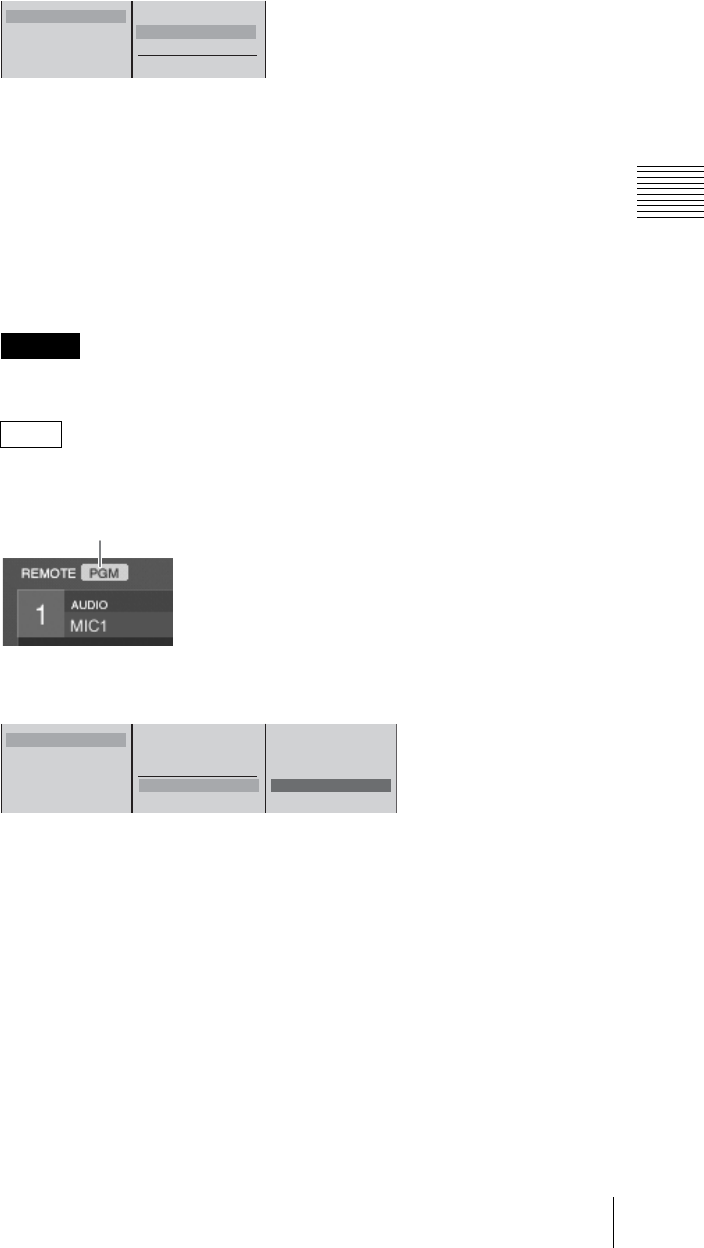
167
Using the FACTORY USE Connector
Chapter 3 Operations
3
In the top menu, select [Video Utility].
4
1 Select [Remote Switching], and confirm; 2 select the buttons to be
controlled by the external device, and confirm.
The functions of the setting items are as follows.
[Off]: Disables switching from the external device.
[PGM]: Enables switching operations for PGM selection buttons 1 to 6
from the external device.
[NEXT]: Enables switching operations for NEXT selection buttons 1 to 6
from the external device.
Use this to perform VISCA camera control.
When the KEY button is lit, you can make key source selections.
Connect the external device before configuring this setting.
When [Remote Switching] is enabled, the following icon appears.
Example: When [PGM] is selected.
5
1 Select [Trigger], and confirm; 2 select an input level, and confirm.
The functions of the setting items are as follows.
[Low Level]: Triggers remote switching when input levels become low.
[High Level]: Triggers remote switching when input levels become high.
6
Press the MENU button to close the menu.
Caution
Note
Remote Switching
VISCA Power Control On
Off
B PGM
NEXT
Trigger
12
Icon
Remote Switching
VISCA Power Control On
Off
B PGM
NEXT
Trigger Low Level B Low Level
High Level
12
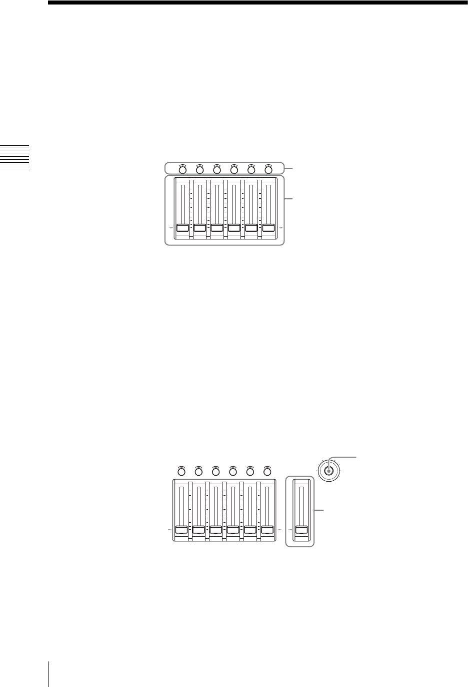
Chapter 3 Operations
168 Audio Mixing
Audio Mixing
This section describes how to perform mixing on the audio signals input to the
unit, and output the final audio (output program) from the PGM output
connectors.
First assign the audio signals to channel faders, as described in “Audio Signal
Related Settings” (page 71).
1
Press the CH ON button on the front panel to select the channels that you
want to mix.
2
Adjust the levels with the audio channel faders, and carry out mixing.
For audio input/output signal fine adjustment settings, see “Video/Audio
Signal Adjustments and Settings” (page 206).
Adjusting the PGM output audio level
Use the PGM fader on the front panel to adjust the level of audio from the PGM
output connectors.
Adjusting the monitored audio levels
Adjust the levels of the built-in speakers, headphones, and devices connected to
the monitor output connectors with the monitor level adjustment knob on the
front panel.
For the selection of audio to be monitored, see “Monitoring Output Audio”
(page 204).
CH ON
654321
+10
+5
0
-
5
-
10
-
20
-
30
-
40
-
60
-
+10
+5
0
-
5
-
10
-
20
-
30
-
40
-
60
-
CH ON buttons
Audio channel faders
CH ON
MONI LEVEL
010
DIM TB
654321
+10
+5
0
-
5
-
10
-
20
-
30
-
40
-
60
-
+10
+5
0
-
5
-
10
-
20
-
30
-
40
-
60
-
PGM
+10
+5
0
-
5
-
10
-
20
-
30
-
40
-
60
-
PGM fader
Monitor level adjustment knob
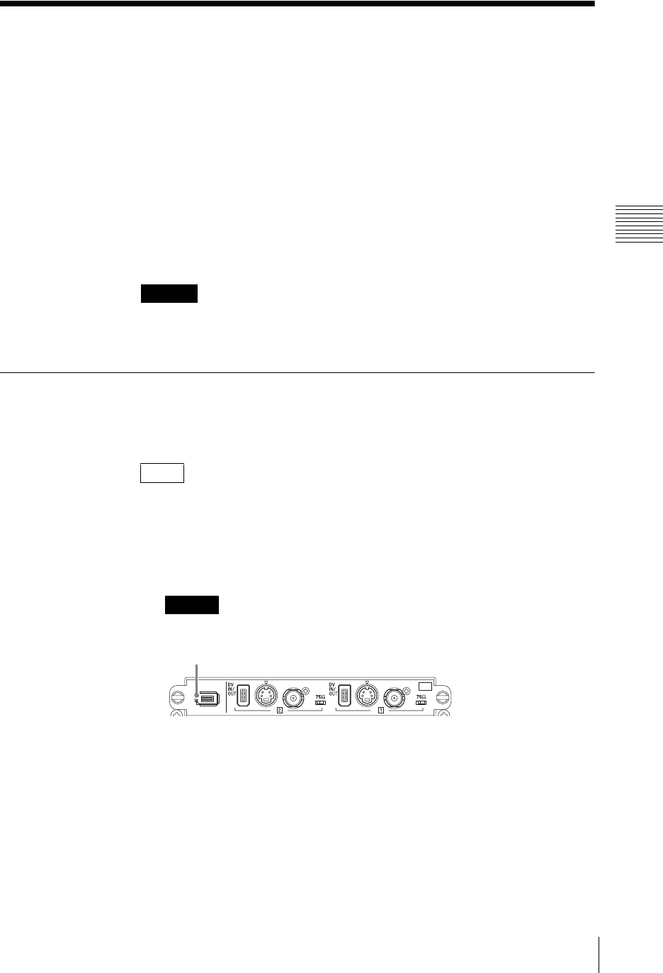
169
Recording Video and Audio to an External Hard Disk
Chapter 3 Operations
Recording Video and Audio to an External Hard
Disk
Using the i.LINK connector (HDD) on an SD video interface module (BKAW-
570) or serial digital interface module (BKAW-580), you can record to an
external hard disk the program outputs from the unit and all the input sources to
the unit.
i.LINK connector (HDD): connect an external hard disk to record each input
material (video + audio) (page 175) and record program output (video +
audio) (page 174). Perform recording operations on this unit.
You can also simultaneously record program output and each input material
(ON LINE recording) (page 174).
When recording on the hard disk, be sure to read the section, “External Hard
Disk” (page 11).
Formatting an External Hard Disk
Format an external hard disk in order to use it with this unit.
This unit uses the ext3 file system format.
We recommend that you reformat the external hard disk at regular intervals in
order to avoid a drop in performance due to file fragmentation.
1
Connect the external hard disk to the i.LINK connector (6-pin) of the
interface module.
Be sure to connect the hard disk before powering on this unit.
2
Power on the hard disk.
3
Press the 1 (power) button on the side panel, to start up this unit.
The operation screen appears.
4
Press the MENU button.
5
In the top menu, select [File Manager].
Caution
Note
Caution
I.LINK
S VIDEO
COMPOSITE
S VIDEO
COMPOSITE
S400
SD
OFF
ON
OFF
ON
SD
i.LINK connector (6-pin)
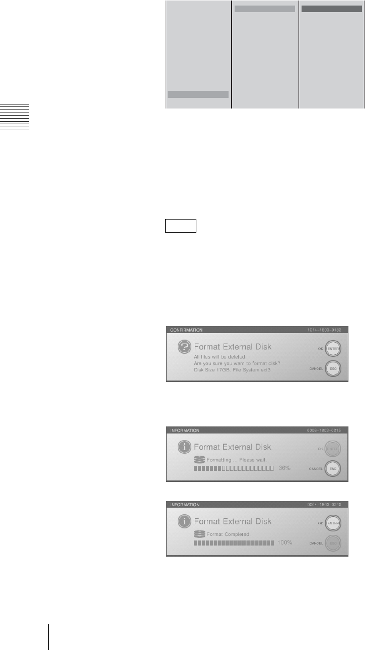
Chapter 3 Operations
170 Recording Video and Audio to an External Hard Disk
6
1 Select [Format] and confirm; 2 Select the hard disk number and confirm;
3 select the size, and confirm.
The functions of the items are as follows.
[Full]: Formats the entire disk.
[270 GB]: Formats so that 270 GB of space is available (approximately 20
hours of recording is possible).
[140 GB]: Formats so that 140 GB of space is available (approximately 10
hours of recording is possible).
[90 GB]: Formats so that 90 GB of space is available (approximately 7 hours
of recording is possible).
Depending on the computer, the maximum size of hard disks capable of
being connected is predetermined. When using multiple hard disks, format
them using the appropriate method for your computer.
Example: When connecting three hard disks to a Windows computer, format
so that 90 GB of space is available.
The following message appears.
7
Press the ENTER button.
Formatting starts.
When formatting is completed, the following message appears.
8
Press the ENTER button, to close the message.
9
Press the MENU button, to close the menu.
Note
Delete
Disconnect
Recover
Rename
Export EDL Type 1
Export EDL Type 2
Export VOD File
Export Job
Import Job
Import CG File
Import Logo File
Format
Local Disk Remain
HDD1
HDD2
HDD3
Memory Stick
USB Flash Memory 1
USB Flash Memory 2
Full
270 GB
140 GB
90 GB
123
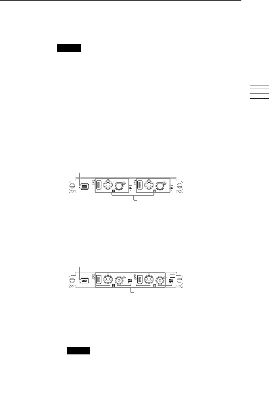
171
Recording Video and Audio to an External Hard Disk
Chapter 3 Operations
Preparing for Recording to an External Hard Disk
When you want to record program output or material to an external hard disk,
follow the procedure below to connect the external hard disk and configure the
settings for recording.
Always format an external hard disk from the unit before starting to record.
For details of formatting an external hard disk, see “Formatting an External
Hard Disk” (page 169).
Connecting an external hard disk
1
Connect the external hard disk to the 6-pin i.LINK connector (HDD) of the
interface module.
When recording program output
Although the external hard disk can be connected to any interface module,
one of the two inputs of the interface module it is connected to will no longer
be available for recording input material or for DV input. Therefore, we
recommend connecting the external hard disk to an interface module
inputting analog material that is not going to be recorded.
* You can also record by connecting to the 6-pin i.LINK connector of the serial digital interface
module.
When recording material
Connect the disk to the same interface module as the input you want to
record.
* You can also record by connecting to the 6-pin i.LINK connector of the serial digital interface
module.
2
Power on the hard disk.
Always connect the hard disk and power it on before starting up this unit.
Caution
Caution
I.LINK
S VIDEO
COMPOSITE
S VIDEO
COMPOSITE
S400
SD
OFF
ON
OFF
ON
SD
i.LINK connector (6-pin)
Either [1] or [2] is used for program output
recording and becomes unavailable for recording
input material or for DV input.
I.LINK
S VIDEO
COMPOSITE
S VIDEO
COMPOSITE
S400
SD
OFF
ON
OFF
ON
SD
i.LINK connector (6-pin)
The material to be recorded to the hard disk must be
input into one of these connectors.
Both the [1] and [2] inputs can also be recorded
simultaneously.
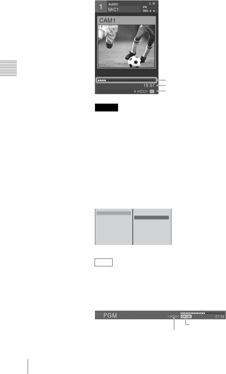
Chapter 3 Operations
172 Recording Video and Audio to an External Hard Disk
3
Press the 1 (power) button on the side panel, to start up this unit.
The operation screen appears, and the source viewer shows the hard disk
number, remaining capacity, and available recording time.
When recording two sources simultaneously, the indicated remaining
capacity diminishes at twice the normal rate, and therefore the actual
remaining recording time is approximately half of that shown.
Selecting the connector to use for program output recording
1
Press the MENU button.
2
Select [ON LINE Manager] in the top menu.
3
1 Select [PGM Recording], and confirm; 2 select both the external hard
disk to record program output and the input to use for recording, and confirm.
When the PGM output aspect ratio is set to 16:9 HD, [PGM Recording] does
not appear.
The target hard disk number and ON-LINE recording reservation icon
appear in the hard disk status display of the PGM viewer.
Caution
Note
Remaining capacity
Available recording time
Hard disk number
PGM Recording
Source Recording
EDL Off
Streaming Off
DV OUT Recording Off
B Off
HDD1 SLOT1-1
HDD1 SLOT1-2
HDD2 SLOT2-1
HDD2 SLOT2-2
HDD3 SLOT3-1
HDD3 SLOT3-2
12
ON LINE recording reservation icon
Target hard disk drive number
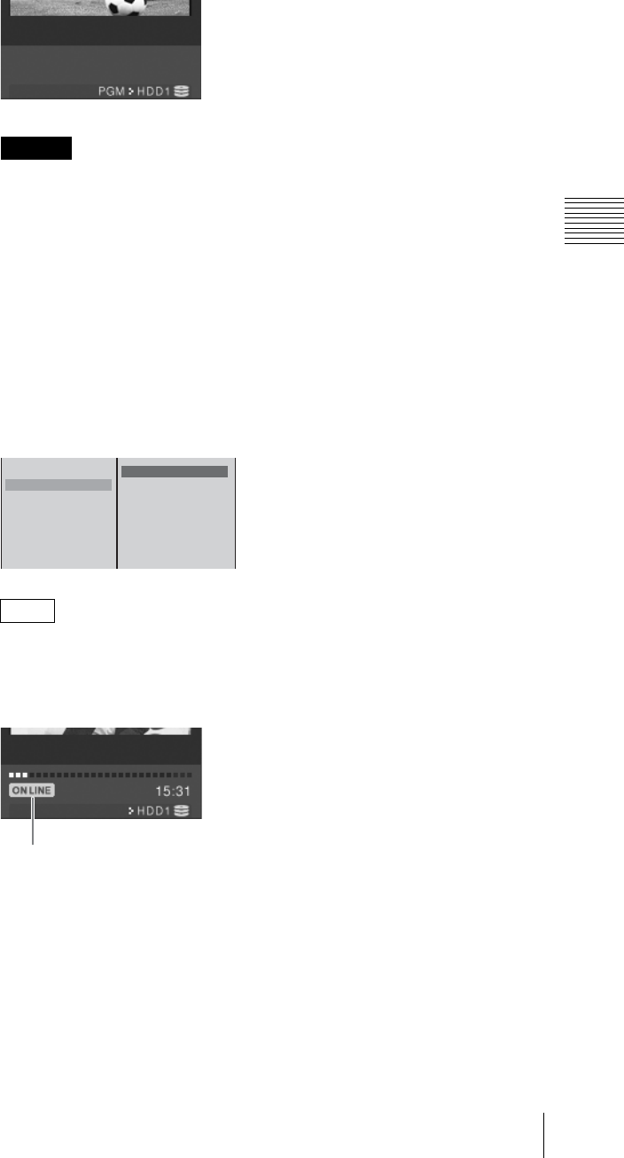
173
Recording Video and Audio to an External Hard Disk
Chapter 3 Operations
The source viewer of the input (SLOT x-x) specified for program output
recording changes to the device status for program output recording.
The connector selected here will be used for recording program output and
will no longer be available for recording input signals or for DV input.
4
Press the MENU button to close the menu.
Selecting the material to record
1
Press the MENU button.
2
Select [ON LINE Manager] in the top menu.
1 Select [Source Recording], and confirm; 2 select the source number of
the input video to record, and confirm.
You can select multiple materials to record.
The ON LINE recording reservation icon appears in the device status display
of the source viewer of the selected number.
3
Press the MENU button to close the menu.
Material selection shortcut
In addition to selecting material to record via the top menu as described above,
you can use the following shortcut.
Press a NEXT selection button while holding down the REC button to select the
material assigned to that button for ON LINE recording.
Caution
Note
PGM Recording
Source Recording
EDL Off
Streaming Off
DV OUT Recording Off
s 1
s 2
s 3
s 4
s 5
s 6
12
ON LINE recording reservation icon

Chapter 3 Operations
174 Recording Video and Audio to an External Hard Disk
To cancel the selection, press the NEXT selection button again while holding
down the REC button.
Simultaneously Recording Input Material and Program Output
to an External Hard Disk (ON LINE Recording)
You can use the ON LINE button to simultaneously record each input material
and program output to the external hard disk drive.
For details on operations for ON LINE recording, see “Activating Each Function
Simultaneously With the ON LINE Button” (page 259).
• When the PGM output aspect ratio is set to 16:9 HD, you cannot record
program output.
• Before starting ON LINE recording, preset the system timecode. If you do not
preset the system timecode, there may be a slight difference in the timecode of
each source material. For details on operations, see “Setting the System
Timecode” (page 54).
• See “Recorded settings and file details” (page 176) for details on files for
recorded input material and “Recording files” (page 174) for details on files for
recorded program output.
• If streaming, EDL creation, and DV OUT recording have been reserved, they
are also started simultaneously when the ON LINE button is pressed.
• You can manually record additional input material (page 176), even while ON
LINE recording is in progress, and vice versa.
Manually Recording Program Output on an External Hard Disk
You can manually record program output (video + audio) on an external hard
disk connected to the i.LINK connector (HDD) of the interface module.
Use this function if ON LINE recording did not start for some reason or if you
want to start recording program output again afterwards.
• For program output recording, the external hard disk can be connected to any
interface module, but one of the two inputs of the interface module it is
connected to will be used for recording program output and will no longer be
able to be used for recording input signals.
• When the PGM output aspect ratio is set to 16:9 HD, you cannot record
program output.
Recording files
Caution
Notes
Caution
File name YYMMDD-P-(3-digit suffix number).avi
File format DV format (.avi)
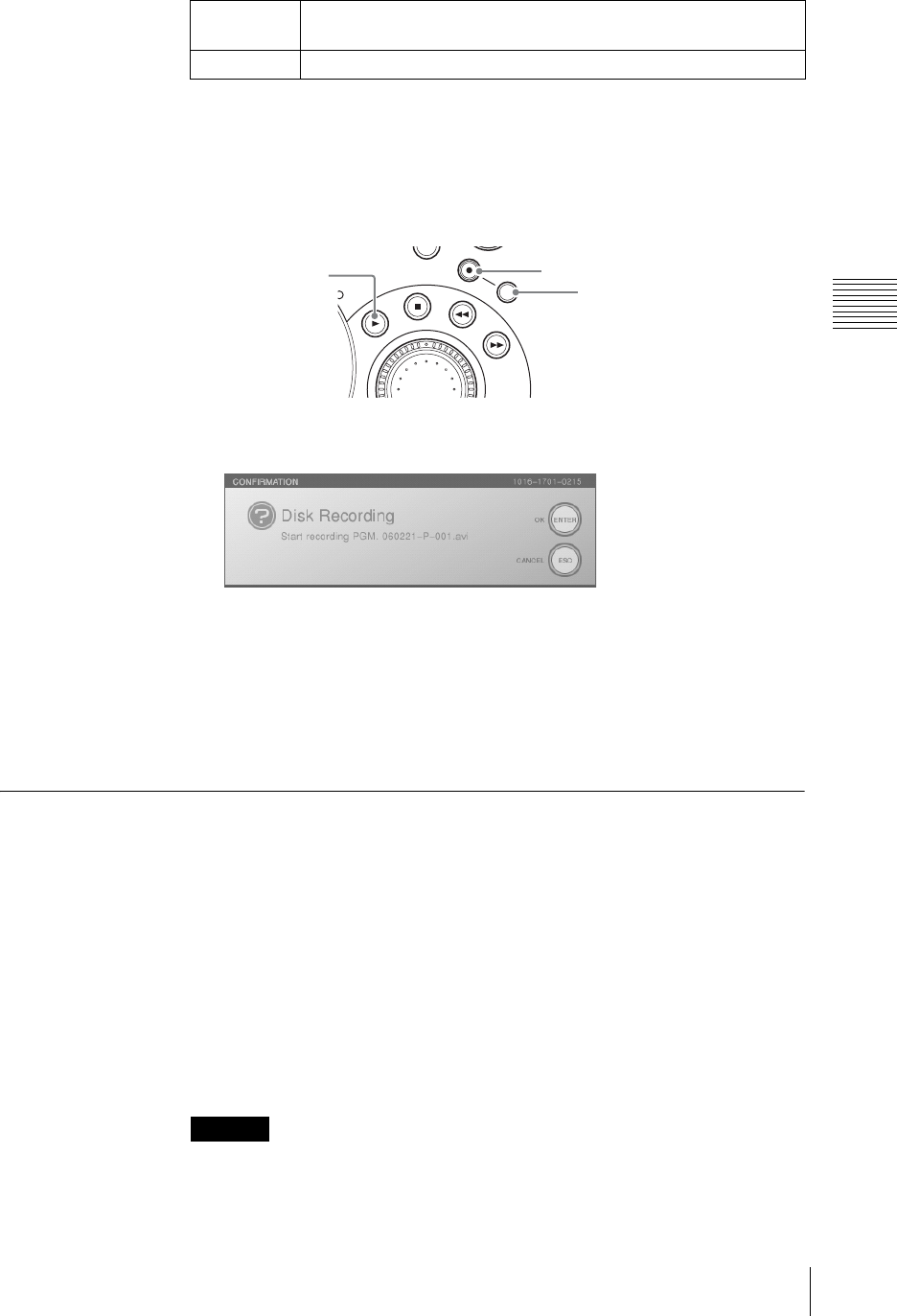
175
Recording Video and Audio to an External Hard Disk
Chapter 3 Operations
Starting program output recording
1
Configure the settings in “Preparing for Recording to an External Hard Disk”
(page 171).
2
Press the PLAY button while holding down the SHIFT and REC buttons.
“REC PAUSE” appears in the hard disk status display of the PGM viewer
and the following confirmation message appears.
3
Press the ENTER button or PLAY button.
The hard disk status indication changes to “REC,” and recording starts.
Stopping of program output recording
Press the STOP button while holding down the SHIFT and REC buttons to stop
recording.
Manually Recording Each Input Material on an External Hard
Disk
On an external hard disk connected to the i.LINK connector (HDD) of the
interface module, you can manually record video inputted to the same interface
model in combination with audio that has the same source number as the video.
Use this function if ON LINE recording did not start for some reason or if you
want to start recording material again afterwards.
Furthermore, you can simultaneously record two inputs of the interface module
to one external hard disk.
For details of formatting an external hard disk, see “Formatting an External
Hard Disk” (page 169).
It is not possible to record the material with an external recorder connected to the
i.LINK connector (HDD).
Signal format
(NTSC/PAL) Same as the setting of [PGM OUT] of [Video Output] in the top menu.
Timecode System timecode (page 54)
Caution
MENU
X
-
Y
REC
SHIFT
REC button
PLAY button
SHIFT button
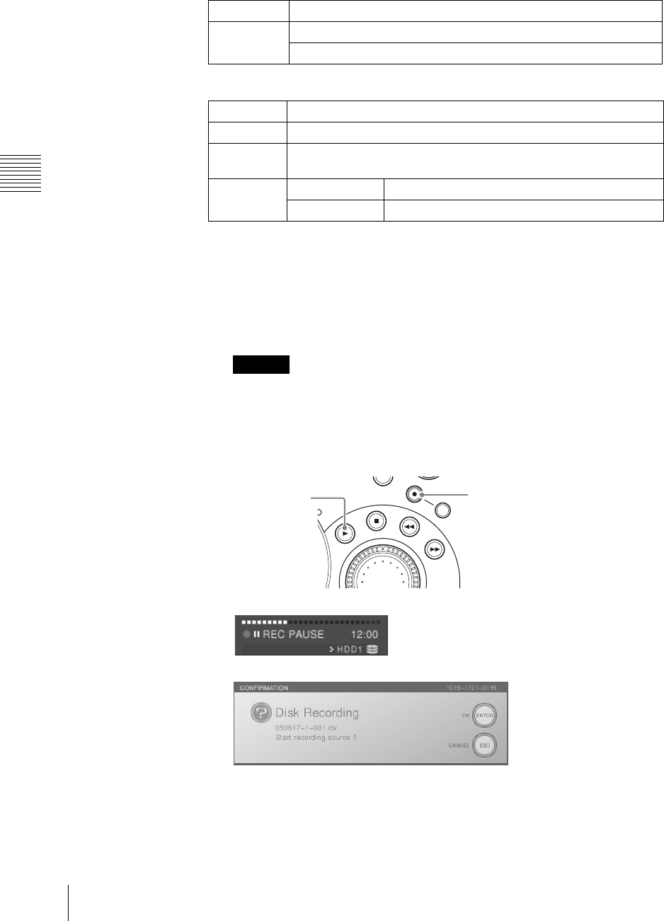
Chapter 3 Operations
176 Recording Video and Audio to an External Hard Disk
Recorded settings and file details
Recorded settings
File details
Starting recording of material
1
Configure the settings in “Preparing for Recording to an External Hard Disk”
(page 171).
2
Select the source to be recorded in the NEXT selection buttons.
The inputs that can be recorded are only those to the interface module to
which the external hard disk is connected (inputs for which the source viewer
shows the hard disk number and recording status).
3
Hold down the REC button and press the PLAY button.
The source viewer device status shows “REC PAUSE.”
The following confirmation message also appears at the same time.
Video ACCESS menu settings (Adjustment is not possible for DV video)
Audio ACCESS menu [Input Trim] setting (analog audio only)
Top menu [Audio MIC/LINE Level] setting
File name YYMMDD-(source number)–(3-digit suffix) (.avi)
File format DV format (.avi)
Signal format
(NTSC/PAL) Same as the setting of [PGM OUT] of [Video Output] in the top menu.
Timecode DV material The timecode included with DV material is recorded.
Non DV material System timecode (page 54)
Caution
MENU
X
-
Y
REC
SHIFT
REC button
PLAY button
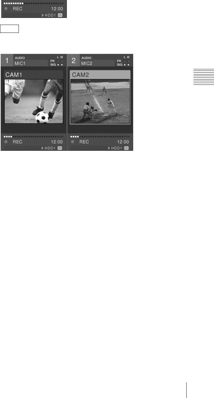
177
Recording Video and Audio to an External Hard Disk
Chapter 3 Operations
4
Press the ENTER button or PLAY button.
The device status indication changes to “REC”, and recording starts.
You can repeat steps 1 to 3 for a different source, for simultaneous recording
of multiple inputs.
Material recorded
Audio:
• The audio is recorded together with the video assigned to the same source
number. It is not possible to record audio only.
• It is not possible to record DV video and analog audio together.
If you start recording of DV video and analog audio, a confirmation
message appears and DV audio is recorded combined with DV video.
Stopping recording of material
1
Select the source to be stopped recording in the NEXT selection buttons.
2
Hold down the REC button and press the STOP button.
In the device status of the source viewer, the “REC” indication disappears,
and recording stops.
Note
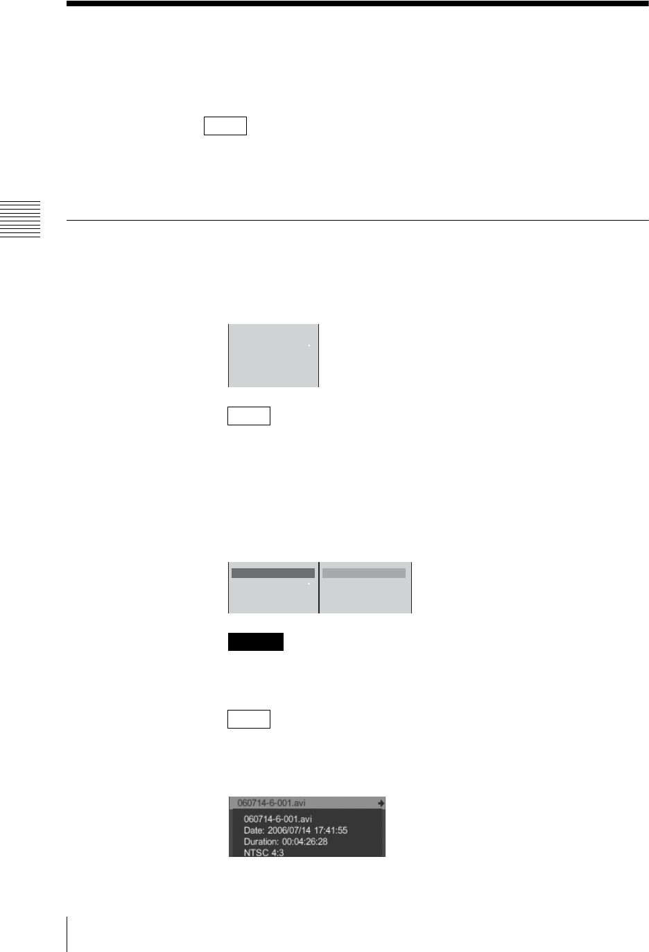
Chapter 3 Operations
178 Operations on Files on the External Hard Disk
Operations on Files on the External Hard Disk
You can carry out operations on files stored on an external hard disk connected
to the interface module.
Operations can also carried out on .dv files recorded with an older version.
For the method of connection, see “Connecting an external hard disk” (page
171)
Playing Files
1
Press the NEXT selection button for the source viewer showing the hard disk
number.
The HDD file guide menu appears in the menu display.
When a DV connector of the SD video interface module with an external
hard disk drive connected is set to be used for program output recording in
[PGM Output] of [DV OUT] in the Video Output menu, the HDD file guide
menu is not displayed.
2
Select [File Open] and confirm.
The file list appears.
• Only files recorded on this unit appear.
• It is not possible to open a file while it is being recorded.
File information
Information on the selected file is displayed as shown below if you press and
hold down the jog roller t button or the t key on the keyboard.
Note
Note
Caution
Note
File Open
File Close SHIFT
z
+
z
1
2
3
File Open
File Close SHIFT
z+z
1
2
060714-6-001.avi b
060720-3-003.avi
060720-3-004.avi
060720-4-001.avi
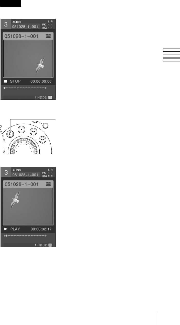
179
Operations on Files on the External Hard Disk
Chapter 3 Operations
3
Select a file and confirm.
The frame of the file appears in the source viewer and PVW viewer,
stationary.
There may be a delay until the file opens.
4
Press the PLAY button.
Playback starts in the source viewer and PVW viewer.
Rapid recall of the last file played
You can recall the last file played without needing to select it from the file
list. In this case, press the NEXT selection button for the source viewer on
which you played the file, then press the PLAY button to continue playback
(without displaying a file list).
Caution
REC
SHIFT
PLAY button

Chapter 3 Operations
180 Operations on Files on the External Hard Disk
Other Playback Operations
1
Press the NEXT selection button with the same number as the source viewer
for the file on which you want to operate.
2
Press any of the following buttons to carry out the operation.
STOP button
Press this during file playback to stop playback of the file.
REW button
Press this while a file is open to play back in the reverse direction.
• Each time you press, the reverse speed increases (x2, x4, x8, x16, x32,
x64).
• If you press the REW button while holding down the SHIFT button, the
play position skips to the beginning of the file.
FFWD button
Press this while a file is open to play back fast in the forward direction.
• Each time you press, the fast forward speed increases (x2, x4, x8, x16, x32,
x64).
• If you press the FFWD button while holding down the SHIFT button, the
play position skips to the end of the file.
Shuttle dial
Turning this dial clockwise plays a file in the forward direction at one of
seven speeds corresponding to the amount the dial is turned (x1/8, x1/2, x1,
x2, x4, x8, or x16). Turning this dial counterclockwise plays the file in the
reverse direction at one of seven speeds corresponding to the amount the dial
is turned (x1/8, x1/2, x1, x2, x4, x8, or x16).
Jog dial
Turning this dial while a file is open plays the file at a slow speed that
corresponds to the speed at which the dial is turned.
The speed by each operation appears in the device status of the source viewer
and PVW viewer.
Notes
Note
Note
REC
SHIFT
REW button
STOP button
FFWD button
Shuttle dial
Jog dial
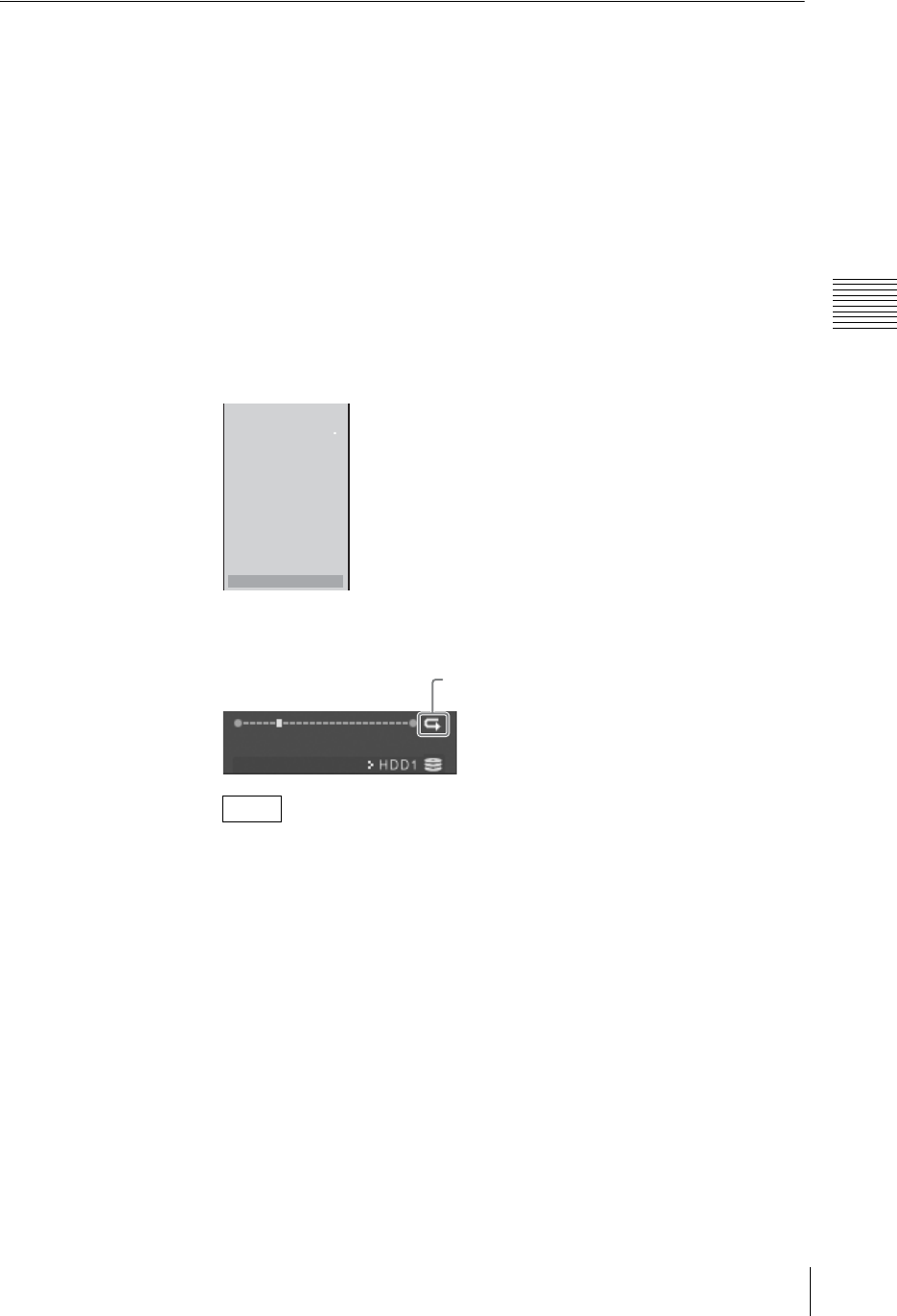
181
Operations on Files on the External Hard Disk
Chapter 3 Operations
Auto Repeat Playback
You can set playback of a file to start again automatically from the beginning
each time playback ends.
Specifying a playback start point and end point enables auto repeat playback of
only part of the file.
1
Press the NEXT selection button of the source viewer displaying the hard
disk number.
The HDD file guide menu appears in the menu display.
2
Open a file.
For details on opening files, see “Playing Files” (page 178).
3
Select [Auto Repeat].
Selecting this item toggles auto repeat On and Off.
[8 Start] and [9 End] become selectable, and an icon appears in the device
status of the source viewer and PVW viewer.
You can switch auto repeat on/off by pressing the [0] numeric button.
Setting the auto repeat range
Set a playback start point and end point for auto repeat playback of part of a file.
1
Set [Auto Repeat] to On.
2
At the position you want auto repeat playback to start, press the [8] numeric
button while holding down the SHIFT button.
Note
File Open
File Close SHIFT z+z
1
2
3
4
5
6
8 Start
9 End
- Auto Repeat On
Icon
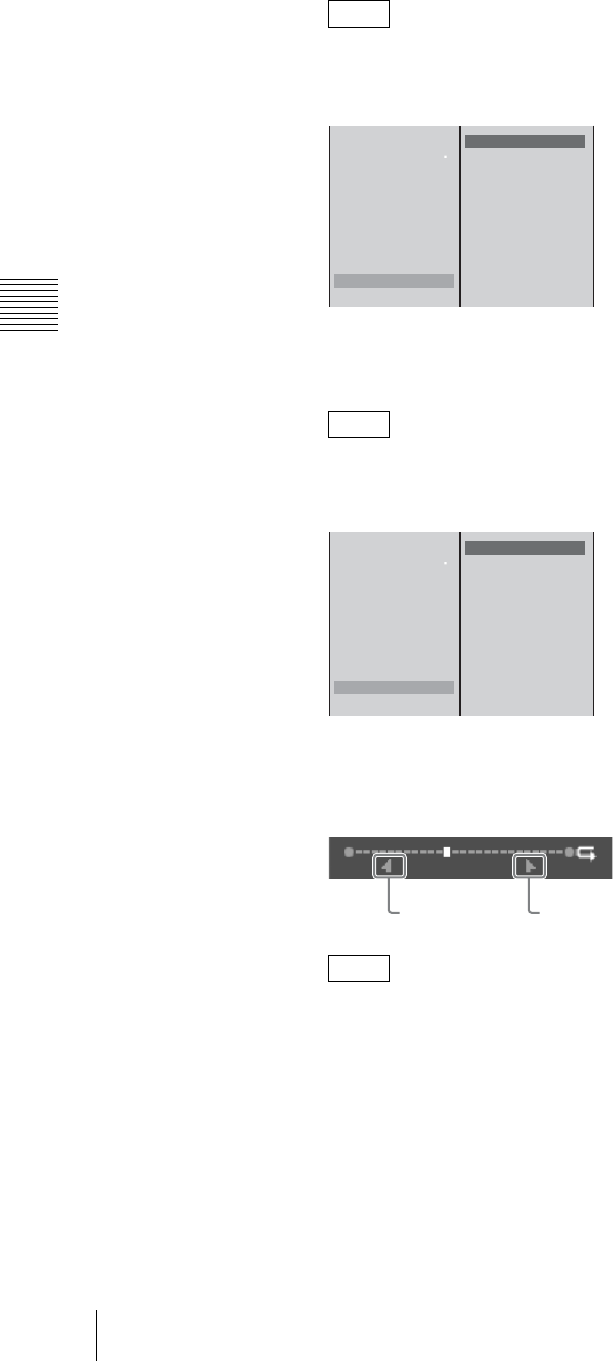
Chapter 3 Operations
182 Operations on Files on the External Hard Disk
You can also specify start and end points via the HDD file guide menu.
1 Select [8 Start], and confirm; 2 select [Mark Start], and confirm.
3
At the position you want auto repeat playback to end, press the [9] numeric
button while holding down the SHIFT button.
You can also specify start and end points via the HDD file guide menu.
1 Select [9 End], and confirm; 2 select [Mark End], and confirm.
When setting the auto repeat range, the timecodes for the start and end points
appear in [8 Start] and [9 End] in the HDD file guide menu.
Furthermore, the start point and end point are displayed in the playback
position display of the source viewer and PVW viewer.
When a start point and end point are set, pressing the [8] or [9] numeric
button moves the playback position of the file to the start or end point. If they
are not set, the playback position moves to the beginning or end of the file.
Clearing the start point and end point
1
Open the file in which the start and end points are set.
Note
Note
Note
File Open
File Close SHIFT
z
+
z
1 aaaaaaaa
2 bbbbbbbb
3 ccccccccc
4
5
6
8 Start xx:xx:xx:xx
9 End
Mark Start SHIFT
z
+8
Clear Start
12
File Open
File Close SHIFT
z
+
z
1 aaaaaaaa
2 bbbbbbbb
3 ccccccccc
4
5
6
8 Start xx:xx:xx:xx
9 End
Mark End SHIFT
z
+9
Clear End
12
Start point End point
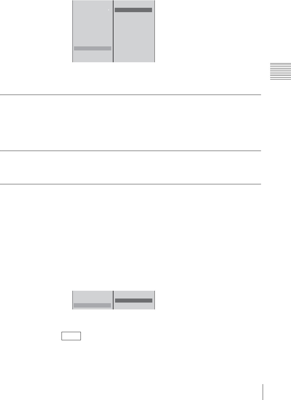
183
Operations on Files on the External Hard Disk
Chapter 3 Operations
2
To clear the start point, 1 select [8 Start], and confirm; 2 select [Clear
Start], and confirm.
3
To clear the end point, 1 select [9 End], and confirm; 2 select [Clear
End], and confirm.
Closing a File
You can close a file in any of the following ways. Closing a file returns to the
video and audio of the assigned input.
• Select [File Close] from the HDD file guide menu.
• Press the STOP button while holding down the SHIFT button.
About Deleting Files
For details on deleting files, see “Deleting Files” (page 233).
Displaying the System Timecode in Viewers
You can set the system timecode added to files to be displayed in the source
viewer and PVW viewer during file playback.
For details on playing files, see “Operations on Files on the External Hard Disk”
(page 178).
1
Press the MENU button.
2
Select [Display] in the top menu.
3
1 Select [File TC], and confirm; 2 select [On], and confirm.
4
Press the MENU button to close the menu.
If [File TC] is set to [Off], a timecode starting at 00:00:00:00 is displayed at the
beginning of the file.
Note
File Open
File Close SHIFT
z
+
z
1 aaaaaaaa
2 bbbbbbbb
3 ccccccccc
4
5
6
8 Start xx:xx:xx:xx
9 End yy:yy:yy:yy
- Auto Repeat On
Mark Start SHIFT
z
+8
Clear Start
12
LCD Backlight
Viewer Priority PVW
File TC Off
Off
On
12
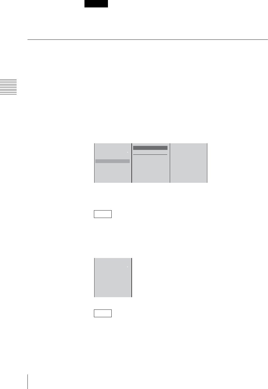
Chapter 3 Operations
184 Operations on Files on the External Hard Disk
If the version of the software used to record the file is prior to 1.40, a timecode
starting at 00:00:00:00 is always displayed at the beginning of the file even if
[File TC] is set to [On].
Registering Cue-Up Points
If you register any position of the file to one of the numeric buttons from 1 to 6,
you can access that position by simply pressing that numeric button.
1
Open the file.
For details on opening files, see “Playing Files” (page 178).
2
Play to the position to be cued up.
3
In the HDD file guide menu, 1 select the number to register the cue-up point
to, and confirm; 2 select [Preset], and confirm.
Example: When registering to numeric button [2].
The cue-up point is registered to the corresponding numeric button on the
front panel.
You can also register the point by pressing numeric button [2] while holding
down the SHIFT button.
The cue-up point is registered and the timecode of the position to be cued up
is displayed.
To change the position to be cued up, repeat steps 2 and 3 above.
Naming cue-up points
1
Open the file in which the cue-up point is registered.
Caution
Note
Note
Preset SHIFT
z
+2
Delete
Data Name [ ]
File Open
File Close SHIFT
z
+
z
1
2
3
4
5
6
12
File Open
File Close SHIFT z+z
1
2 00:04: 00: 00
3
4
5
6
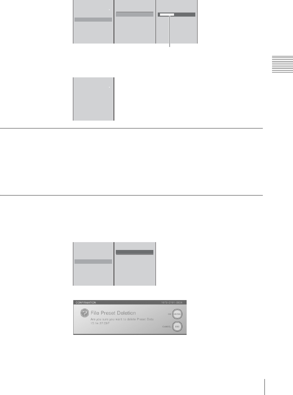
185
Operations on Files on the External Hard Disk
Chapter 3 Operations
2
In the HDD file guide menu, 1 select the cue-up point, and confirm; 2
select [Data Name], and confirm; 3 enter the name of the cue-up point in
the input box, and confirm.
The display for the number selected in step 2 changes from the timecode to
the cue-up point name.
Accessing Cue-Up Points
1
Open the file containing the registered cue-up point.
2
Press the numeric button to which the cue-up point is registered.
The video of the cue-up point appears and the screen stops.
The numeric button you pressed lights.
Deleting Cue-Up Points
1
Select the cue-up point you want to delete in the HDD file guide menu.
2
Select [Delete], and confirm.
The following confirmation message appears.
File Open
File Close SHIFT
z
+
z
1
2 00:04: 00: 00
3
4
5
6
[ aaaaaaaaaa ]
Preset SHIFT
z
+2
Delete
Data Name
23
Enter up to 20 alphanumeric characters.
1
File Open
File Close SHIFT z+z
1
2 aaaaaaaaaa
3
4
5
6
File Open
File Close SHIFT
z
+
z
1
2 00:04: 00: 00
3
4
5
6
Preset SHIFT
z
+2
Delete
Data Name
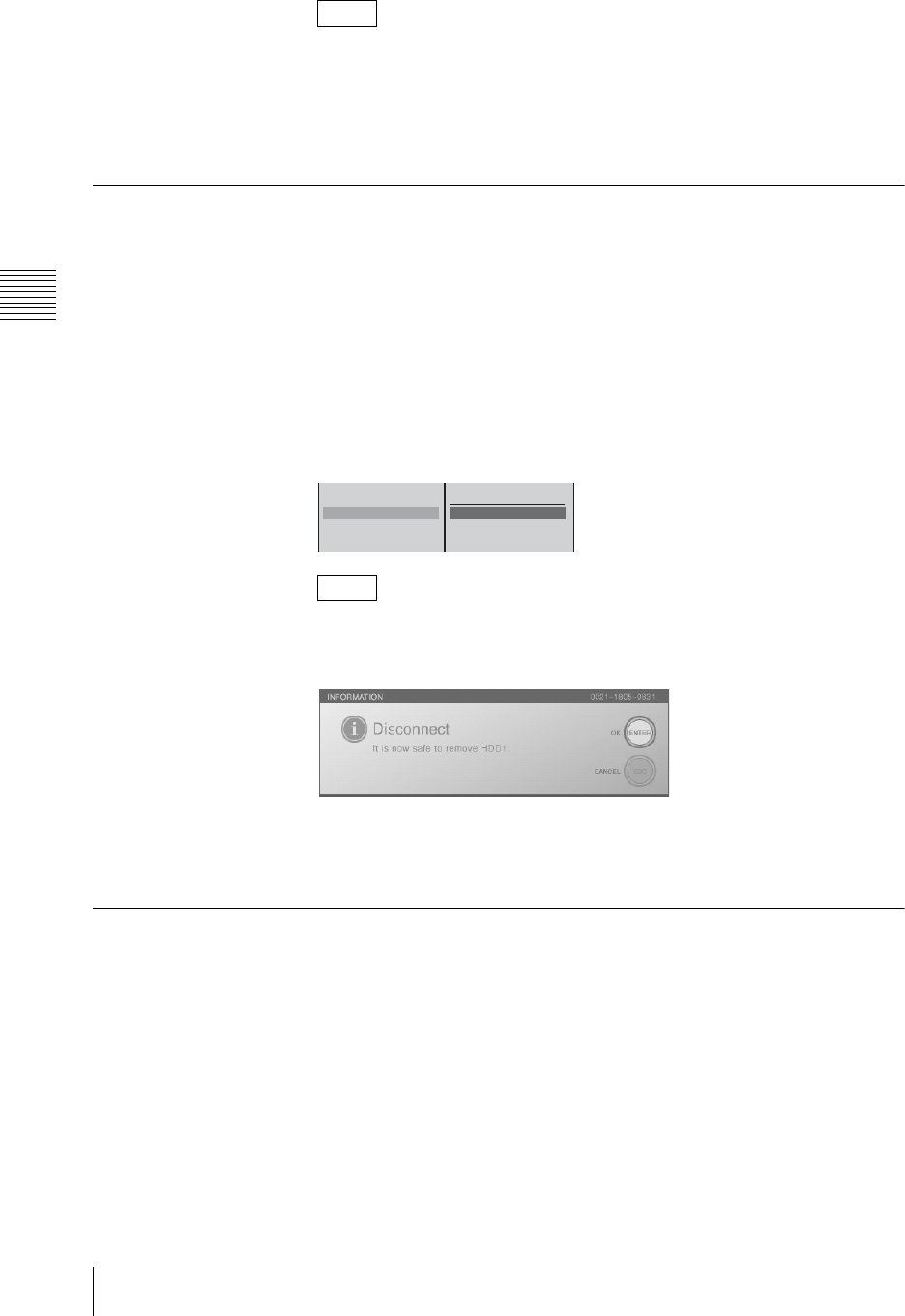
Chapter 3 Operations
186 Operations on Files on the External Hard Disk
By pressing the ENTER button while holding down the SHIFT button, you
can delete all of the cue-up points simultaneously.
3
Press the ENTER button.
The cue-up point is deleted.
Disconnecting the External Hard Disk
When disconnecting the external hard disk, use the following procedure to
disconnect safely.
1
Press the MENU button.
2
In the top menu, select [File Manager].
3
1 Select [Disconnect] and confirm; 2 Select the hard disk to disconnect,
and confirm.
To disconnect all of the hard disks together, select [All].
The following message appears.
4
Press the ENTER button, to close the message.
5
Power off the hard disk, and disconnect.
Recovering an External Hard Disk
If as the result of one of the following operations the external hard disk has
become inaccessible from another computer or from this unit, then carry out disk
recovery.
• If the hard disk is disconnected without carrying out the proper procedure for
disconnection on this unit
• If the hard disk is disconnected from a computer without the proper procedure
for disconnection
1
Press the MENU button.
2
In the top menu, select [File Manager].
Note
Note
Delete
Disconnect
Recover
Rename
All
HDD1
HDD2
HDD3
12

187
Operations on Files on the External Hard Disk
Chapter 3 Operations
3
1 Select [Recover] and confirm; 2 Select [HDD1] and confirm.
The following confirmation message appears.
4
Press the ENTER button.
Recovery starts.
When recovery is completed, the following message appears.
5
Press the ENTER button to close the message.
6
Press the MENU button, to close the menu.
If the hard disk was disconnected without carrying out the proper procedure,
follow the messages that appear to carry out recovery. It may be possible to
access files on the hard disk without carrying out the recovery procedure, but the
content of such files is not guaranteed.
Caution
Delete
Disconnect
Recover
HDD1
HDD2
HDD3
12

Chapter 3 Operations
188 Recording Video and Audio to a VCR
Recording Video and Audio to a VCR
Using the DV connectors on an SD video interface module (BKAW-570), the
PGM SDI output connector on a serial digital interface module (BKAW-580), the
HD analog output connector on an HD video interface module (BKAW-560), or
the HD SDI output connector on an HD serial digital interface module
(BKAW-590), you can record to a VCR the program outputs from the unit.
• The types of devices and recording data supported differ among the DV, PGM
SDI output, HD analog output, and HD SDI output connectors.
• For details on adding the system timecode, see “Setting the System Timecode”
(page 54).
DV connector (DV IN/OUT DV PGM): connect a VCR to record program
output (video + audio). Perform recording operations on the VCR or unit.
PGM SDI output connector (SDI OUT): connect an SDI input compatible
VCR to record program output (video + audio). Perform recording
operations on the VCR.
HD analog output connector (YPBPR OUT): connect to an HD analog input
compatible VCR to record program output (video). The supported signal
formats are 720p and 1080i. Perform recording operations on the VCR.
HD SDI output connector (HD SDI OUT):
connect to an HD SDI input
compatible VCR to record program output (video + audio). The supported
signal formats are 720p and 1080i. Perform recording operations on the VCR.
If a signal subjected to special processing is input to the synchronization signal,
normal recording may not be possible.
Recording Program Output to a VCR
When using the DV connector
By connecting a VCR to the DV connector (DV IN/OUT) of the SD video
interface module (BKAW-570) on the rear panel, you can record the program
output video in DV format.
Procedure for recording on a VCR
To begin recording to a VCR, select the DV connector to be used for recording.
You can also simultaneously record input material and program output to a VCR
using the ON LINE button.
For details, see “Operating the Unit to Record Program Outputs to a VCR”
(page 192).
• If a DV connector is set to be used for recording, you cannot record onto the
hard disk the material input from the composite video input connector and S-
video input connector of the same module.
Notes
Caution
Caution
189
Recording Video and Audio to a VCR
Chapter 3 Operations
• When the PGM output aspect ratio is set to 16:9 HD, output from a DV
connector is not available.
1
Connect the VCR to the DV connector.
Depending on the model of VCR, signal input/output settings may be
required. Refer to the Operating Instructions for the device to be connected.
2
Press the MENU button.
3
In the top menu, select [Video Output].
4
1 Select [DV OUT], and confirm; 2 Select [PGM Output] and confirm; 3
Select the DV connector to which the VCR is connected from the list and
confirm.
This sets the selected DV connector for program output, and program video
is output.
• At this point, the selected DV connector is grayed out and unavailable in
the [Video Input Assign] menu and [Audio Input Assign] menu.
• When an external hard disk is connected to an i.LINK connector of the
same interface module as the selected DV connector, the hard disk status
of the source viewer assigning images from each of the input connectors
on that module disappears.
5
1 Select [Audio Mode] and confirm; 2 select the audio sampling rate for
the program output and confirm.
The functions of the setting items are as follows.
FS32K(4ch): 12 bit, 32 kHz sampling, 4-channel output (select this item if
you want to later record to channels 3 and 4 on a device with an audio
dubbing function).
The audio output is as follows.
1 ch: L
2 ch: R
3 ch: L (the same 1 ch)
4 ch: R (the same 2 ch)
FS48K(2ch): 16 bit, 48 kHz sampling, 2-channel output
Note
Notes
PGM Output Off
Audio Mode Fs48kHz(2ch)
PGM OUT NTSC/60Hz
PGM OUT Aspect 4:3
PGM OUT Level
DV OUT
RGB OUT SXGA (60 Hz)
Add TC
Add Aspect ID Off
Filter Mode
B Off
SLOT1 OUT1 DV
OUT2 DV
SLOT2 OUT1 DV
OUT2 DV
SLOT3 OUT1 DV
OUT2 DV
123
PGM Output SLOT1 OUT2 DV
Audio Mode FS48K(2ch)
PGM OUT NTSC/60Hz
PGM OUT Aspect 4:3
PGM OUT Level
DV OUT
FS32K(4ch)
B FS48K(2ch)
12

Chapter 3 Operations
190 Recording Video and Audio to a VCR
6
Press the MENU button, to close the menu.
7
Operate the VCR to start recording.
• To add a timecode, be aware that you may need to configure settings on
the device to be connected.
• When connecting to DV devices, if the video or audio output is lost, or
there is noise, disconnecting and reconnecting the cable, or powering the
DV device or this unit off and on again may solve the problem.
When using the SDI connector
By connecting a VCR that supports SDI input to the PGM SDI output connector
(SDI OUT) of the serial digital interface module, you can record program output.
Procedure for recording on a VCR
Program video and audio are always output as SDI signals from the PGM SDI
output connector.
Connect the VCR to the PGM SDI output connector, and operate the VCR to start
recording.
When the PGM output aspect ratio is set to 16:9 HD, program output from the
PGM SDI output connector is not available (a black image and silent audio signal
is output).
Adding the system timecode to SDI signals (when using a serial digital interface
module)
1
Press the MENU button.
2
In the top menu, select [Video Output].
3
1 Select [Add TC], and confirm; 2 select [SDI] to set it [On], and confirm.
The setting turns on or off each time it is selected.
[On]: Adds the system timecode to SDI signals.
[Off]: Does not add the system timecode to SDI signals.
4
Press the MENU button to close the menu.
When using the HD analog output connector
When an HD video interface module is installed on the unit, you can record
program output by connecting a VCR that supports HD analog input to the HD
analog output connector (YPBPR OUT).
Notes
Caution
PGM OUT NTSC/60Hz
PGM OUT Aspect 4:3
PGM OUT Level
DV OUT
RGB OUT SXGA (60Hz)
Add TC
Add Aspect ID Off
Filter Mode
s SDI On
12

191
Recording Video and Audio to a VCR
Chapter 3 Operations
Procedure for recording on a VCR
Program video is always output as HD analog signals from the HD analog output
connector.
Connect the VCR to the HD analog output connector, and operate the VCR to
start recording.
Recording is possible when the PGM output aspect ratio setting is 16:9 HD.
When recording is possible, the HD indicator to the left of the HD analog output
connector is lit.
When using the HD SDI output connector
When an HD serial digital interface module is installed on the unit, you can
record program output by connecting a VCR that supports HD SDI input to the
HD SDI output connector (HD SDI OUT).
Procedure for recording on a VCR
Program video and audio are always output as HD SDI signals from the HD SDI
output connector.
Connect the VCR to the HD SDI output connector, and operate the VCR to start
recording.
Recording is possible when the PGM output aspect ratio setting is 16:9 HD.
When recording is possible, the HD indicator to the left of the HD SDI output
connector is lit.
Setting the HD output signal format (when using an HD video interface module or
HD serial digital interface module)
Select the format for the signal output from the HD analog output connector when
the PGM output aspect ratio is set to 16:9 HD.
1
Press the MENU button.
2
In the top menu, select [Video Output].
3
1 Select [HD OUT], and confirm; 2 select a signal format, and confirm.
[1080i]: Outputs 1080 interlace signals.
[720p]: Outputs 720 progressive signals.
For more on the NTSC (60 Hz) and PAL (50 Hz) setting, see “Selecting the
Video Output Signal Format” (page 52).
4
Press the MENU button to close the menu.
Note
Note
PGM OUT NTSC/60Hz
PGM OUT Aspect 16:9 HD
PGM OUT Level
RGB OUT SXGA (60Hz)
HD OUT
B 1080i
720p
12
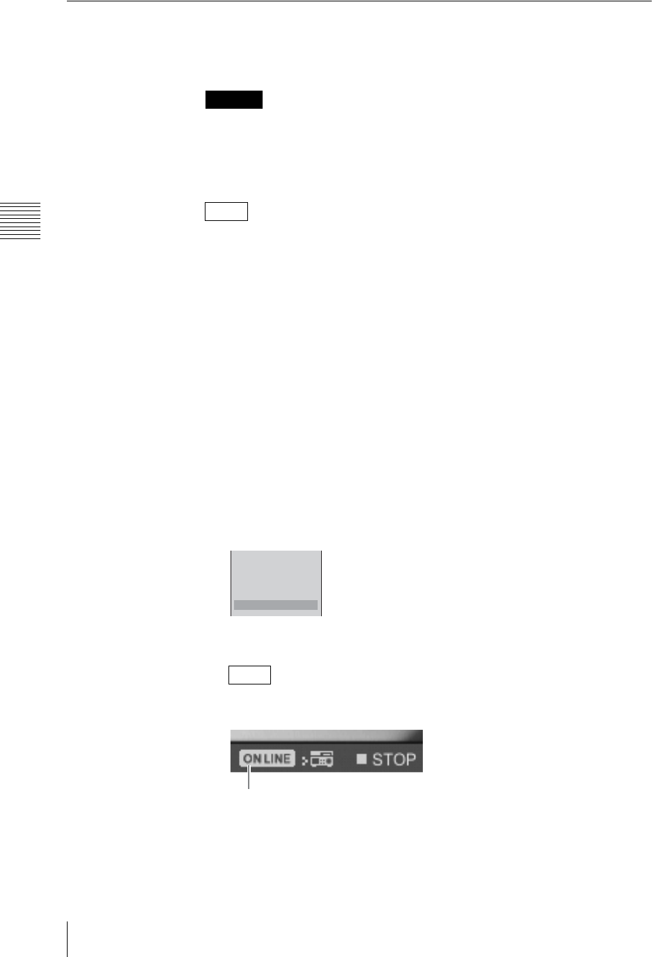
Chapter 3 Operations
192 Recording Video and Audio to a VCR
Operating the Unit to Record Program Outputs to a VCR
You can record program output to a VCR connected to the DV connectors on an
SD video interface module (BKAW-570) through operations on the unit.
• When the PGM output aspect ratio is set to 16:9 HD, you cannot record
program output.
• If the status of the VCR is anything other than “STOP”, you cannot start
recording.
• If recording to a hard disk, streaming, and EDL creation have been reserved,
they are also started simultaneously when the ON LINE button is pressed.
For details on operations, see “Activating Each Function Simultaneously With
the ON LINE Button” (page 259).
• You cannot control the following devices.
- Cameras (with playback functions) that are set to camera mode
- Devices with remote switching functions, but with unconfigured remote
settings
- Devices that do not support AV/C protocol
1
Configure the settings in “When using the DV connector” (page 188) of
“Recording Program Output to a VCR”.
2
Press the MENU button.
3
In the top menu, select [ON LINE Manager].
4
Select [DV OUT Recording] to set it [On], and confirm.
The setting turns on or off each time it is selected.
5
Press the MENU button to close the menu.
When [DV OUT Recording] is set to [On], the ON LINE icon for VCRs
appears in the PGM viewer.
6
Press the ON LINE button.
Caution
Notes
Note
PGM Recording
Source Recording
EDL Off
Streaming Off
DV OUT Recording On
ON LINE icon

193
Recording Video and Audio to a VCR
Chapter 3 Operations
The ON LINE icon for VCRs disappears from the PGM viewer, “REC”
appears in the VCR status display, and recording begins.
MONI LEVEL
010
ON LINE
DIM TB
789
456
1
0
23
M
I
X
E
F
F
E
C
T
P
V
W
ON LINE button
Chapter 3 Operations
194 Controlling VCR Playback From the Unit
Controlling VCR Playback From the Unit
Playback operations for VCRs connected to the DV connectors on an SD video
interface module (BKAW-570) can be performed from the unit. You can also
register specific positions on a videotape to the numeric buttons, 1 to 6, and
access them whenever necessary.
You cannot control the following devices.
• Cameras (with playback functions) that are set to camera mode
• Devices with remote switching functions, but with unconfigured remote
settings
• Devices that do not support AV/C protocol
Registering the VCR to be Controlled
1
Connect the VCR to the DV connectors on the SD video interface module.
For details on VCR connection, see “Connecting a VCR” (page 61).
2
Assign input signals from the VCR to the selection buttons.
For details on assigning input signals, see “Assigning video input signals to
the selection buttons” (page 67).
3
1 Select the number of the selection button that the VCR is assigned to, and
confirm; 2 select [Control], and confirm; 3 select [AV/C Player], and
confirm.
4
Press the MENU button to close the menu.
Performing Playback
1
Press the NEXT selection button to which the VCR to be controlled is
assigned.
The VCR guide menu appears in the menu display.
Note
1
2
3
4
5
6
Source Name CAMERA1
Input S1-1 DV
Source Aspect 4:3
Control Off
OFF
VISCA 1
VISCA 2
VISCA 3
B VISCA 4
VISCA 5
VISCA 6
VISCA 7
AV/C Player
123
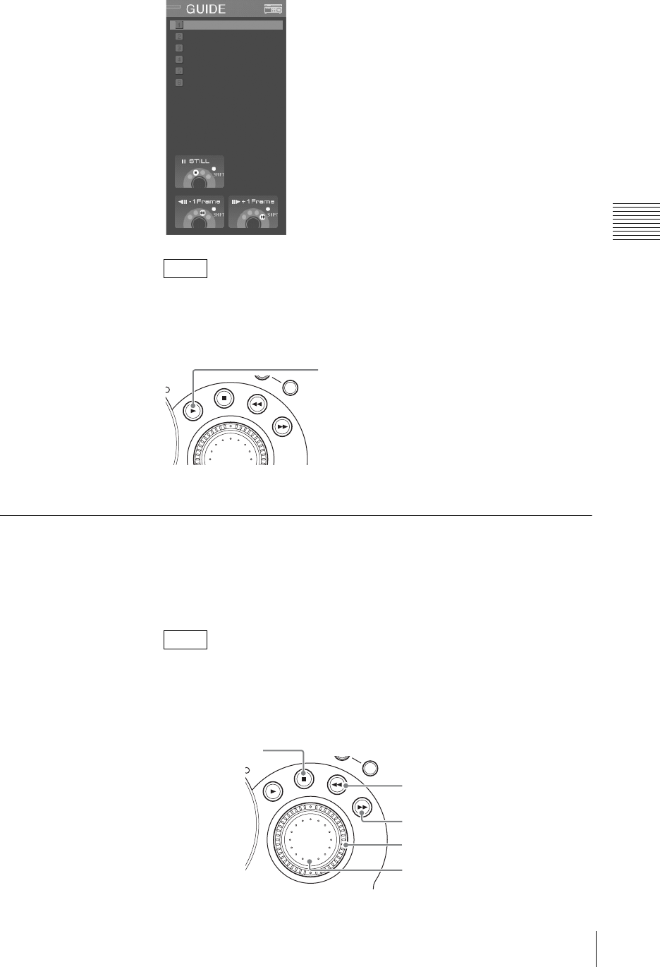
195
Controlling VCR Playback From the Unit
Chapter 3 Operations
If a VCR is connected and the VCR guide menu does not appear, press the
NEXT selection button again.
2
Press the PLAY button.
Playback starts in the source viewer and PVW viewer.
Other Playback Operations
1
Press the NEXT selection button to which the VCR to be controlled is
assigned.
The VCR guide menu appears in the menu display.
If a VCR is connected and the VCR guide menu does not appear, press the
NEXT selection button again.
2
Press any of the following buttons to carry out the operation.
Note
Note
REC
SHIFT
PLAY button
REC
SHIFT
STOP button
REW button
FFWD button
Shuttle dial
Jog dial

Chapter 3 Operations
196 Controlling VCR Playback From the Unit
STOP button
Stops playback.
If you press the STOP button while holding down the SHIFT button, the
video pauses.
REW button
Rewinds the videotape.
If you press the REW button while holding down the SHIFT button, the
video moves back one frame (and then pauses).
FFWD button
Fast-forwards the videotape.
If you press the FFWD button while holding down the SHIFT button, the
video moves forward one frame (and then pauses).
Shuttle dial
Turning this dial clockwise plays the video in the forward direction speed
corresponding to the amount the dial is turned. Turning this dial
counterclockwise plays the video in the reverse direction speed
corresponding to the amount the dial is turned.
Jog dial
Plays the video at a slow speed that corresponds to the speed at which the dial
is turned.
• Performance of the preceding functions is not guaranteed on all VCRs.
• Function speeds vary depending on the device.
Registering Cue-Up Points
If you register a position on the videotape to one of the numeric buttons from 1
to 6, you can access that position by simply pressing that numeric button.
1
Press the NEXT selection button to which the VCR to be controlled is
assigned.
2
Play to the position to be cued up, and pause the video (STILL).
If the video is not in a pause (STILL) state, the cue-up point will not be
registered accurately. Even in pause state, the accuracy of cue-up registration
varies depending on the type of device used.
Note
Note
Note
Notes
Caution
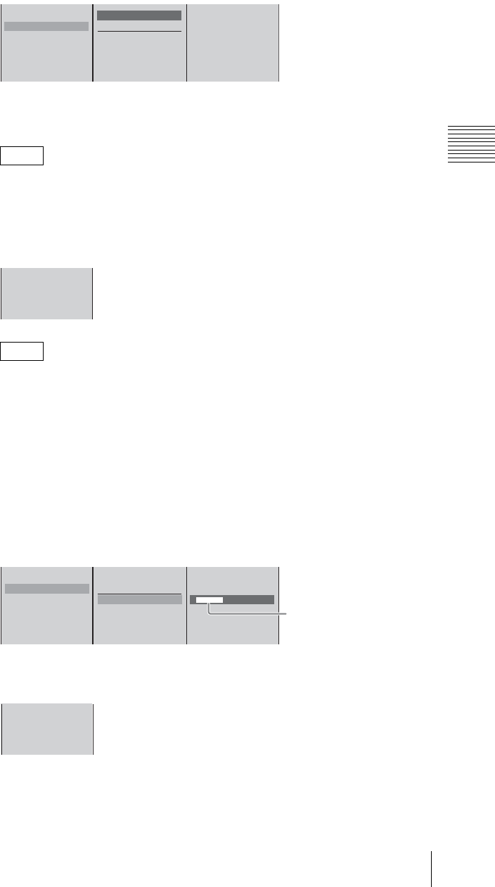
197
Controlling VCR Playback From the Unit
Chapter 3 Operations
3
In the VCR guide menu, 1 select the number to register the cue-up point to,
and confirm; 2 select [Preset], and confirm.
Example: When registering to numeric button [2].
The cue-up point is registered to the corresponding numeric button on the
front panel.
You can also register the point by pressing numeric button [2] while holding
down the SHIFT button.
The cue-up point is registered and the timecode of the position to be cued up
is displayed.
To change the position to be cued up, repeat steps 2 and 3 above.
Naming cue-up points
1
Press the NEXT selection button to which the VCR to be controlled is
assigned.
2
In the VCR guide menu, 1 select the cue-up point, and confirm; 2 select
[Data Name], and confirm; 3 enter the name of the cue-up point in the input
box, and confirm.
The display for the number selected in step 2 changes from the timecode to
the cue-up point name.
Note
Note
1
2
3
4
5
6
Preset Shift z+2
Delete
Data Name [ ]
12
1
2 00:00:40:00
3
4
1
2 00:00:40:00
3
4
5
6
Preset Shift z+4
Delete
Data Name [ aaaaaaaa ]
12 3
Enter up to 20
alphanumeric characters.
* The VCR guide menu can only
display a limited number of
characters.
1
2 aaaaaaaa
3
4
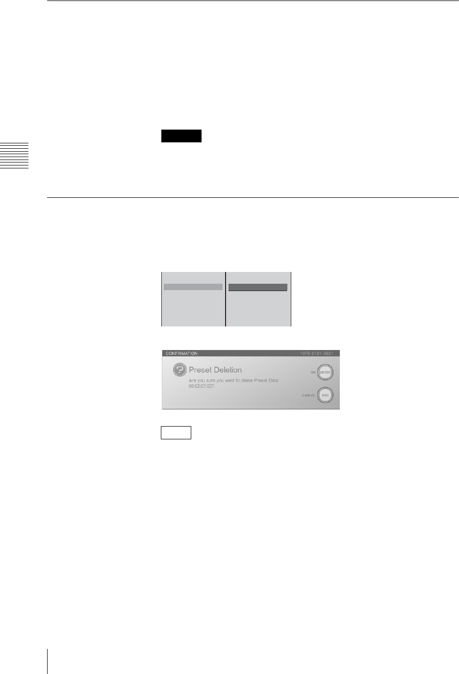
Chapter 3 Operations
198 Controlling VCR Playback From the Unit
Accessing Cue-Up Points
1
Press the NEXT selection button to which the VCR to be controlled is
assigned.
The VCR guide menu appears in the menu display.
2
Press the numeric button to which the cue-up point is registered.
The video of the cue-up point appears and the screen is stopped.
The numeric button you pressed lights.
Operations that can make cue-up impossible such as inserting a different
videotape from the one inserted at the time of cue-up point registration will
have differing results depending on the VCR.
Deleting Cue-Up Points
1
Select the cue-up point you want to delete in the VCR guide menu.
2
Select [Delete], and confirm.
The following confirmation message appears.
By pressing the ENTER button while holding down the SHIFT button, you
can delete all of the cue-up points simultaneously.
3
Press the ENTER button.
The cue-up point is deleted.
Caution
Note
1
2 aaaaaaaa
3
4
5
6
Preset Shift z+2
Delete
Data Name

199
Using a Computer To Play Files Recorded on an External Hard Disk
Chapter 3 Operations
Using a Computer To Play Files Recorded on an
External Hard Disk
You can play files recorded with this unit, using a computer.
1
Install a driver software in the computer.
The following site provides links to the portal site and information about the
driver software and the file format (.avi).
https://servicesplus.us.sony.biz/SoftwarePlusSerch.aspx (for customers in
U.S.A.)
https://www.sony.biz.net/anycast (for customers in Europe, Middle East and
Africa)
https://www.ecspert.sony.biz/ecsite/ (for the other customers)
2
With an IEEE1394 cable, connect the hard disk to the computer.
The disk is mounted as two drives, with volume labels “system” and “data.”
• If the external hard disk is not mounted automatically, use the driver
software to mount it manually.
• It may not be possible to mount an external hard disk, depending on its
size. Format the external hard disk to match its size capable of being
connected to a computer. For details, see “Formatting an External Hard
Disk” (page 169).
• Depending on the application in use, the timecode recorded on the file may
not be readable. In such a case, a timecode starting at 00:00:00:00 is
displayed at the beginning of the file.
3
Select files from the folder anycast/data in the drive with volume label
“data,” and play them back.
Disk partitioning
When the external hard disk is formatted on this unit, two partitions are created:
a meta partition and a data partition.
Meta partition: administrative information; volume label: “system”
Data partition: storage for created files; volume label: “data”
On the computer, if you alter the administrative information, or change file
names, this will render the files unplayable on this unit.
Note
Caution
Caution
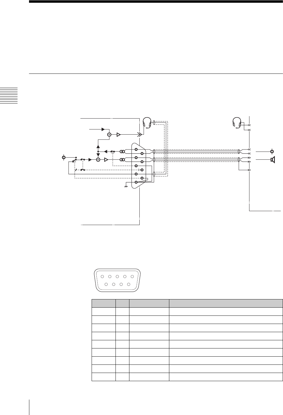
Chapter 3 Operations
200 Using the Intercom Function
Using the Intercom Function
Connecting an external intercom system requires a connection operation by the
customer.
An intercom system allows the operator to confer with camera operators and
others in remote locations. You can use the built-in speakers of this unit and the
front panel microphone.
Connecting the Intercom System
Connect the intercom system to the INTERCOM connector on the rear panel.
The following shows a connection example of an intercom system.
When using a headset, connect the microphone connector to the INTERCOM
connector, and connect the headphone connector to the HEADPHONES
connector.
Pin No. I/O Signal name Description
1 I AUDIO IN (H) INTERCOM AUDIO SIGNAL INPUT (H)
2 O AUDIO OUT (H) INTERCOM AUDIO SIGNAL OUTPUT(H)
3 I CONTROL IN INTERCOM RECEIVE CONTROL (LOW ACTIVE)
4 I MIC IN (+) ELECTRET CONDENSER MICROPHONE INPUT
5 - GND GROUND
6 I AUDIO IN (C) INTERCOM AUDIO SIGNAL INPUT (L)
7 O AUDIO OUT (C) INTERCOM AUDIO SIGNAL OUTPUT (L)
8 O CONTROL OUT TB CONTROL (LOW ACTIVE)
9 I CONTROL IN EXT MIC ACTIVE CMD (LOW ACTIVE)
1
2
3
4
5
6
7
8
9
Monitor input
(PGM/MIX/AUX)
Internal
micro-
phone
Head set
Micro-
phone Camera
head set
Intercom output
Intercom
input
Operator
Unit GND
External microphone
input (Electret
condenser microphone)
(Controls Low: Active)
AWS-G500
Intercom
System
12345
6789
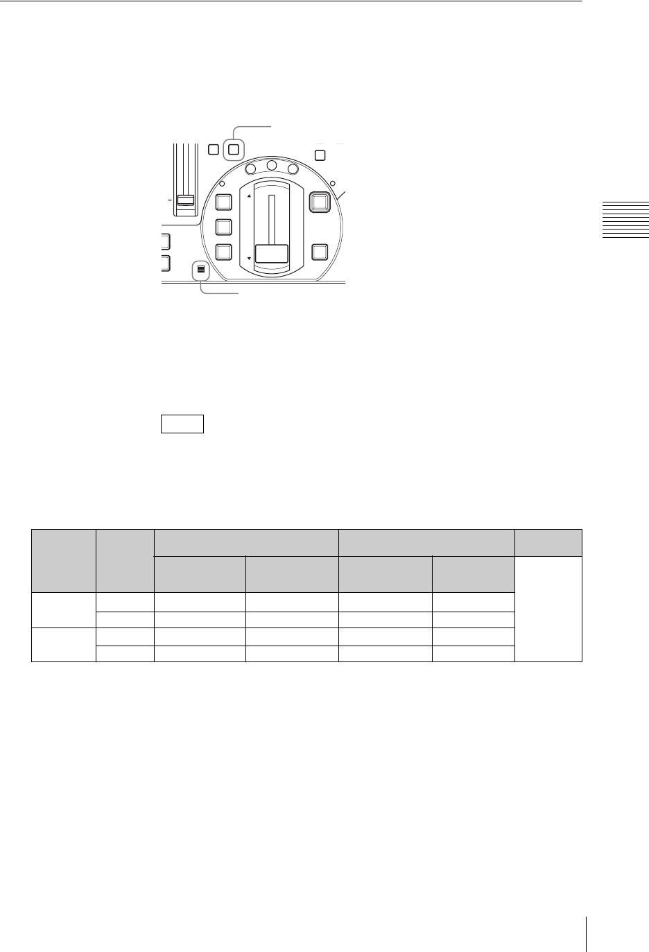
201
Using the Intercom Function
Chapter 3 Operations
Speaking on the Intercom System
1
Connect the external intercom system.
2
Press the TB (Talk Back) button, and speak into the front panel microphone
(or headset microphone).
This transmits on the external intercom system.
You can listen on the external intercom system using the built-in speakers of
this unit or headphones.
3
Press the TB button to finish conversation.
While the TB button is lit, the DIM button lights. The relationship between
the state of the TB button and the built-in speakers, headphones, and monitor
output is as follows.
Monitoring state when using the intercom
*This indicates whichever of PGM, AUX1, AUX2, and MIX is selected for [Audio Monitor] in the [Audio Utility] top menu.
** The audio attenuation (“DIM”) function reduces the output level by 20 dB from the normal value.
Note
Monitor
output
connector
connection
TB button
state
Internal speakers Headphone output Monitor
output
Output to be
monitored *Sound from the
intercom system Output to be
monitored *
Sound from the
intercom
system Output to be
monitored *
only is output
continuously.
Yes On (lit) Silence Attenuated output ** Attenuated output ** Output
Off Silence Output Output Output
No On (lit) Attenuated output ** Attenuated output ** Attenuated output ** Output
Off Output Output Output Output
DIM TB
1
0
2
MIC
NEXT
N
T
PGM
FTB
DSK
KEY
CUT
AUTO
TRANS
M
I
X
E
F
F
E
C
T
P
V
W
PGM
+10
+5
0
-
5
-
10
-
20
-
30
-
40
-
60
-
TB button
Microphone
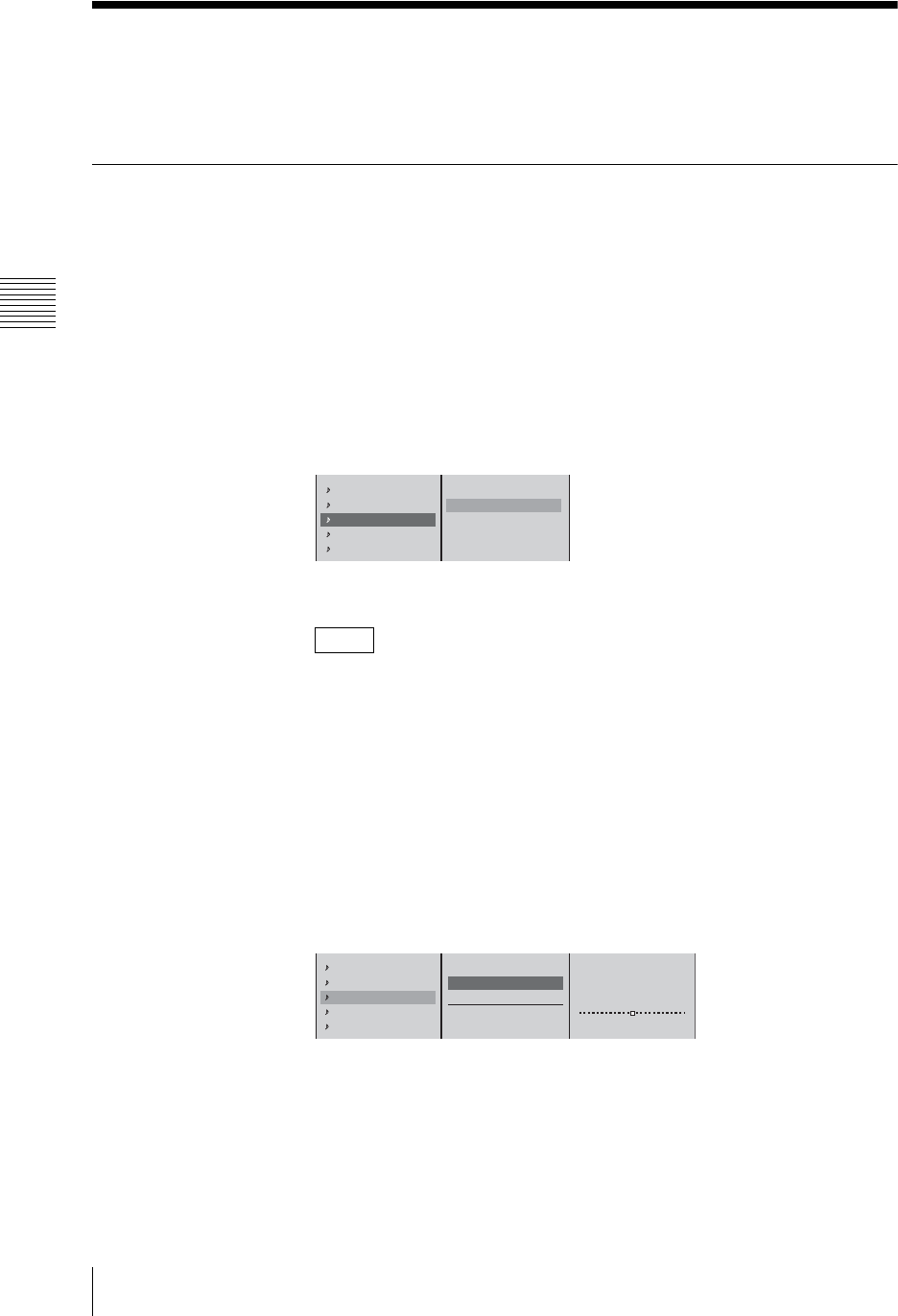
Chapter 3 Operations
202 Monitoring Audio
Monitoring Audio
Use the internal speakers or the connected headphones to monitor the audio input
to the unit or the audio output from the unit.
Determining the Audio Signal Output Destinations
Select which output destinations to which the audio assigned for each channel
fader should be routed. For the output destination, you can select the PGM output
connectors, AUX output connectors, or MIX output connectors.
Output from the PGM output connectors
1
Press the ACCESS button in the same column of the channel fader to which
the audio you want to be the program output is assigned.
2
1
In the top menu, select [PGM OUT];
2
select [On], and confirm.
3
Press the ESC button to close the ACCESS menu.
You can also close the menu by pressing the same ACCESS button again.
Output from the AUX output connectors
This unit has two sets of AUX output connectors (AUX1, AUX2), and you can
create a mix balance with levels different from those of the PGM/MIX output.
1
Press the ACCESS button in the same column of the channel fader to which
the audio you want to be the AUX output is assigned.
2
1 In the top menu, select [AUX1 OUT] or [AUX2 OUT]; 2 in the
submenu, select [Pre-Fader] or [Post-Fader], and confirm.
The functions of the setting items are as follows.
[Pre-Fader]: Outputs the audio before adjustment by the channel faders. In
this case, the audio is output even when the CH ON button is Off.
[Post-Fader]: Outputs the audio after adjustment by the channel faders.
Note
Limiter/Compressor Off
Pan CNT
PGM OUT On
AUX1 OUT Off
AUX2 OUT Off
Off
B On
12
Pan CNT
PGM OUT On
AUX1 OUT Off
AUX2 OUT Off
MIX OUT On
Off
Pre-Fader
Post-Fader
Send Level 0dB
12
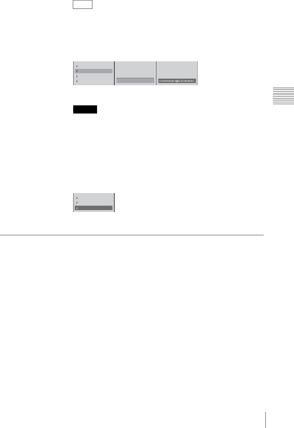
203
Monitoring Audio
Chapter 3 Operations
In either case, when adjusting with the ACCESS menu, the output includes
these adjustments (excluding pan).
3
After selecting [Pre-Fader] or [Post-Fader] and confirming, 1 select [Send
Level], and confirm; 2 adjust the output level with the slider.
Press the ESC button, to close the ACCESS menu.
The AUX output connectors output the audio of mixing the left and right
audio channels.
Output from the MIX output connectors
1
Press the ACCESS button in the same column as the channel fader to which
the audio you want to be the MIX output is assigned.
2
In the top menu, select [MIX OUT] to set it [On], and confirm.
The setting turns on or off each time it is selected.
3
Press the ESC button to close the ACCESS menu.
Displaying the Audio Signal Output Destinations
Check where the output destinations are set.
1
Press the MENU button.
2
In the top menu, select [Audio Output].
3
Check the output destination display.
The display lights green when set to [ON] in the audio signal output
destination settings (page 202).
Note
Caution
PGM OUT On
AUX1 OUT Off
AUX2 OUT Off
MIX OUT On
Off
Pre-Fader
Post-Fader
Send Level 0dB
12
AUX1 OUT Off
AUX2 OUT Off
MIX OUT On
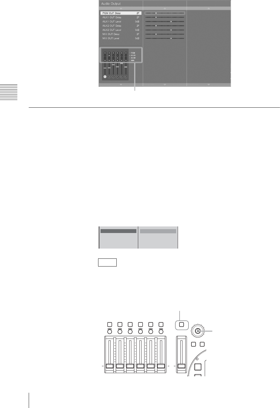
Chapter 3 Operations
204 Monitoring Audio
Monitoring Output Audio
You can select one audio output from this unit (program (PGM) output, AUX
output, or MIX output), and listen to it on the internal speakers, speakers
connected to the monitor output connectors, or headphones connected to the
HEADPHONES connector.
Output sound level can be monitored using the audio level meters on the
operation screen.
1
Press the MENU button.
2
In the top menu, select [Audio Utility].
3
1 Select [Audio Monitor], and confirm; 2 select the output to be
monitored.
• Use the monitor level adjustment knob to adjust the level.
• Each time you press the AUDIO MONITOR button, the monitoring cycles
through the following sequence. The output destination indication below
the audio level meters also changes.
Notes
Output destination indication
Audio Monitor
OSC
TB
B PGM
AUX1
AUX2
MIX
12
AUDIO MONITOR
CH ON
ACCESS/
PFL
MONI LEVEL
010
DIM TB
KEY
654321
+10
+5
0
-
5
-
10
-
20
-
30
-
40
-
60
-
+10
+5
0
-
5
-
10
-
20
-
30
-
40
-
60
-
PGM
+10
+5
0
-
5
-
10
-
20
-
30
-
40
-
60
-
AUDIO MONITOR button
Monitor level adjustment knob
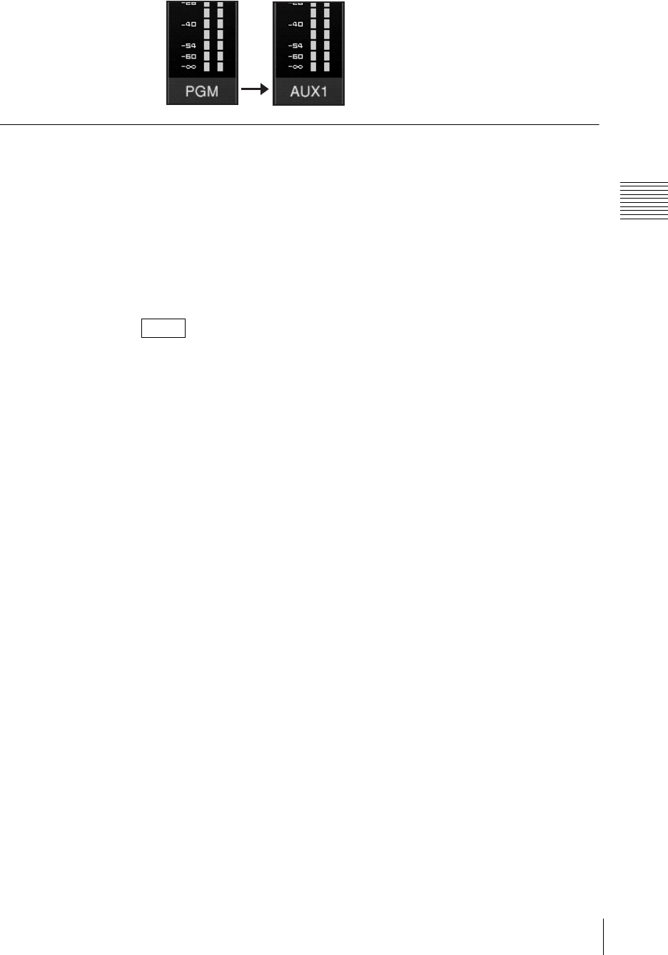
205
Monitoring Audio
Chapter 3 Operations
PGM t AUX1 t AUX2 t MIX t PGM ...
Monitoring the Audio of a Particular Channel Only
Use the Pre-Fader Listening (PFL) function to check the audio on a channel
without the channel fader adjustments. You can do this, for example, on the
internal speakers.
Hold down the ACCESS button for the channel you want to monitor for at least
0.5 seconds. While the button is held down, the audio for that channel is
monitored.
When you release the ACCESS button, the monitoring is ended.
• If you press another ACCESS button for at least 0.5 second during PFL, the
sound of the subsequently specified channel is added.
• This does not affect the program output, AUX output, or MIX output.
Notes
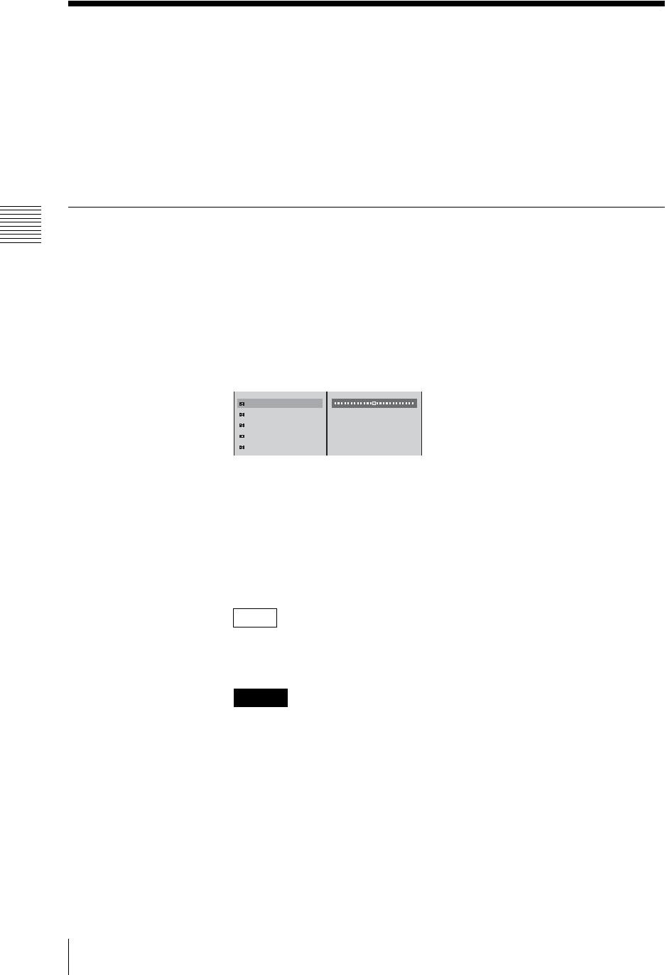
Chapter 3 Operations
206 Video/Audio Signal Adjustments and Settings
Video/Audio Signal Adjustments and Settings
This section describes adjustments to the video and audio signals.
The image quality and sound quality of the inputs to this unit vary depending on
factors such as the shooting conditions. This unit therefore has functions to adjust
the video and audio of each input to this unit separately.
When using the ACCESS menu to adjust the video input, we recommend
outputting the program video to an external monitor and confirming the results
as you make adjustments.
Adjusting Analog Video Input Signals
The image quality of an analog video signal input from a composite input or S-
video input connector may be adjusted.
1
Press the ACCESS button in the same column as the selection button for the
video you want to adjust.
2
1 In the top menu, select the desired item; 2 adjust with the sliders.
The functions of the setting items are as follows.
[Luminance Level]: Adjusts the luminance.
[Luminance Offset]: When inputting video with a 7.5 IRE setting to this
unit, select [7.5 IRE].
[Chroma Level]: Adjusts the saturation.
[Hue]: Adjusts the hue.
[Auto Gain Control]: Adjusts the luminance signal to an optimal level.
When applying an offset to the program output video, see “Applying an
Offset to the Program Output Video” (page 209).
• The adjustment values given here are for reference only. Actual values
may not match these theoretical values during operation.
• When [Auto Gain Control] is set to [On] and a dark object enters the frame
while shooting with a bright background or a signal exceeding acceptable
luminance levels is input, there may be a disturbance in video image
quality. If this occurs, lower the [Luminance Level] slightly. If the problem
persists, set [Auto Gain Control] to [Off].
3
Press the ESC button to close the ACCESS menu.
Note
Caution
Luminance Level 100%
Luminance Offset 0 IRE
Chroma Level 100%
Hue 0˚
Auto Gain Control On
12
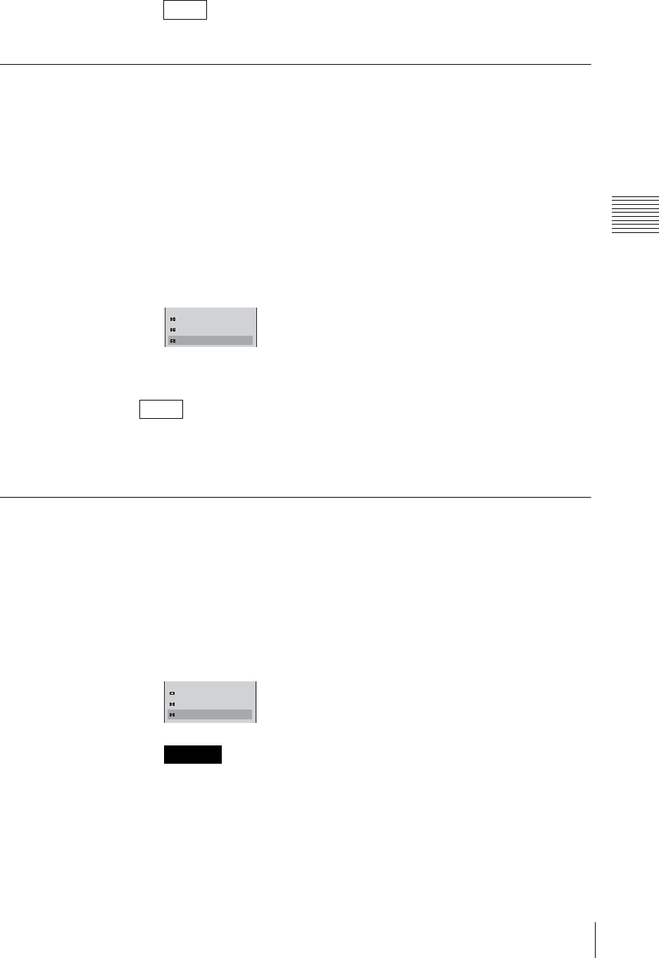
207
Video/Audio Signal Adjustments and Settings
Chapter 3 Operations
You can also close the menu by pressing the same ACCESS button again.
Making the Gradation of SDI Input Signals Appear Smooth
(When Using a Serial Digital Interface Module or HD Serial
Digital Interface Module)
Apply dynamic rounding to video signals input from an SDI or HD SDI
connector to make the gradation appear smooth.
Dynamic rounding is applied by default. If you do not want to apply dynamic
rounding, set this setting to [Off].
1
Press the ACCESS button in the same column as the selection button for the
video signal you want to adjust.
2
In the top menu, select [Dynamic Rounding] to set it [Off], and confirm.
3
Press the ESC button to close the ACCESS menu.
If dynamic rounding is not performed, the video gradation will have visible
contouring artifacts because this unit drops the lower 2 bits of 10 bit SDI or HD
SDI input signals.
Converting 4:3 Source Materials to Wide Screen
Configure the following settings to convert 4:3 input materials to wide screen
when the PGM output aspect ratio is set to 16:9 SD or 16:9 HD mode.
1
Press the ACCESS button in the same column as the selection button for the
video you want to configure.
2
In the top menu, select [Wide Zoom] to set it [On], and confirm.
The setting turns on or off each time it is selected.
You cannot confirm this setting in the source viewer.
3
Press the ESC button to close the ACCESS menu.
Note
Note
Caution
Luminance Level 100%
Chroma Level 100%
Dynamic Rounding Off
Luminance Level 100%
Chroma Level 100%
Wide Zoom On
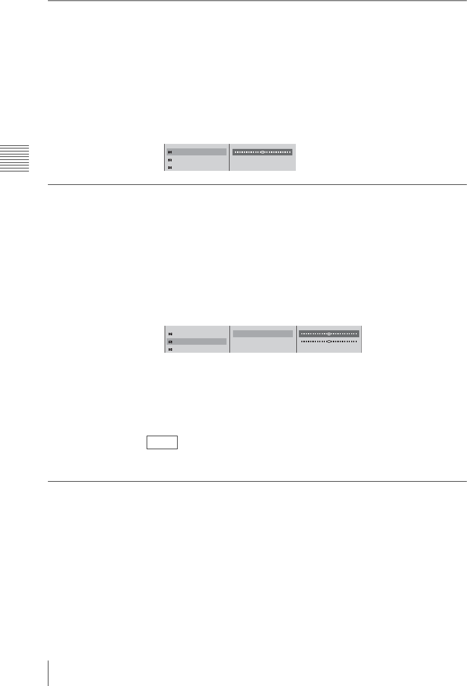
Chapter 3 Operations
208 Video/Audio Signal Adjustments and Settings
Adjusting the Clock Phase of RGB Signals
Of the video signals assigned to the selection buttons, adjust the RGB signals
input to the RGB input connectors.
Perform this adjustment to display small characters clearly.
1
Press the ACCESS button in the same column as the selection button for the
RGB signal you want to adjust.
2
1 In the top menu, select [Phase], and confirm; 2 adjust with the slider.
Adjusting the Screen Size of RGB Signals
You can adjust the screen size of RGB signals input from the RGB input
connectors.
1
Press the ACCESS button in the same column as the selection button for the
RGB signal you want to adjust.
2
1 Select [Resize] in the top menu, and confirm; 2 select [H] or [V], and
confirm; 3 adjust with the slider.
The functions of the setting items are as follows.
[H]: Adjusts the width reduction rate.
[V]: Adjusts the height reduction rate.
3
Press the MENU button to close the menu.
These settings are maintained even if the format of input RGB signals is changed.
Adjusting the Screen Position of RGB Signals
You can adjust the screen position of RGB signals input from the RGB input
connectors.
1
Press the ACCESS button in the same column as the selection button for the
RGB signal you want to adjust.
2
1 Select [Reposition] in the top menu, and confirm; 2 select [H] or [V],
and confirm; 3 adjust the position with the slider.
Note
Phase 16
Resize
Reposition
12
Phase 16
Resize
Reposition
H 100.0%
V 100.0%
123
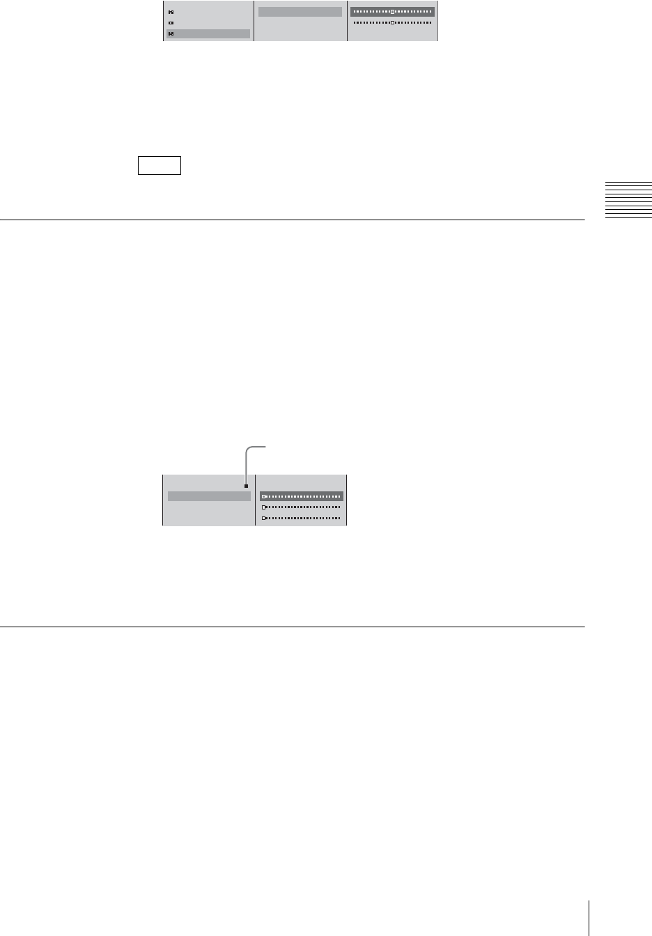
209
Video/Audio Signal Adjustments and Settings
Chapter 3 Operations
The functions of the setting items are as follows.
[H]: Adjusts the horizontal position.
[V]: Adjusts the vertical position.
3
Press the MENU button to close the menu.
These settings are maintained even if the format of input RGB signals is changed.
Adjusting Color Matte
Adjust the colors used for color matte, used as single-color backgrounds and so
on.
1
Press INT in the NEXT selection buttons.
The INT source selection menu appears.
2
1 Select the item (displayed under [Color Matte]) to be adjusted, and
confirm; 2 adjust with the sliders.
As you move the sliders, the sample colors shown in the menu change, so you
can check while making the adjustment.
The functions of the setting items are as follows.
[Lum]: Adjusts the luminance.
[Sat]: Adjusts the saturation.
[Hue]: Adjusts the hue.
Applying an Offset to the Program Output Video
You can apply a 7.5 IRE offset to the program output video.
1
Press the MENU button.
2
In the top menu, select [Video Output].
3
1 Select [PGM OUT Level], and confirm; 2 select [Luminance Offset]
from the submenu, and confirm; 3 select [7.5 IRE], and confirm.
Note
Phase 16
Resize
Reposition
H 50
V 50
123
B Color Matte
Lum 0%
Sat 0%
Hue 0%
Sample colors
12
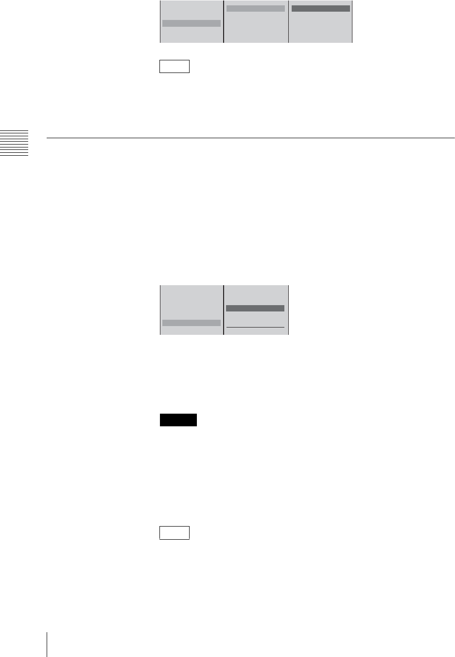
Chapter 3 Operations
210 Video/Audio Signal Adjustments and Settings
Because there is no offset function for PAL, this setting is only enabled when
[PGM OUT] is set to [NTSC].
4
Press the MENU button to close the menu.
Setting the RGB Output Signal Format
Set the format of the signal output from the RGB output connectors on the rear
panel.
1
Press the MENU button.
2
In the top menu, select [Video Output].
3
1 Select [RGB OUT], and confirm; 2 select the combination of image size
and frequency or [Video RGB], and confirm.
[XGA], [SXGA], [WXGA]: Output format for a computer monitor
(computer RGB signals).
[Video RGB]: Output format for a video monitor (video RGB signals).
4
Press the MENU button to close the menu.
• Changing this setting may cause temporary breakup of the output video
and the output reference signal.
• If the video output signal format is PAL, then when the [XGA], [SXGA],
or [WXGA] setting is used, the top and bottom portions of the image will
be missing in the output from the composite video and S video output
connectors. This can be remedied by setting [Video RGB], but in this case
the computer monitor output will not be available.
• When selecting [XGA], [SXGA], or [WXGA], we recommend that you
select 60 Hz when the video output signal is NTSC format, and 75 Hz
when the signal is PAL format.
• When [Video RGB] is selected, the number of valid scan lines is
automatically set to 480 and the frequency to 60 Hz if the output signal
format is NTSC, or to 576 lines and 50 Hz when the format is PAL.
Note
Caution
Notes
PGM OUT NTSC/60Hz
PGM OUT Aspect 4:3
PGM OUT Level
DV OUT
RGB OUT SXGA (60Hz)
Luminance Offset 7.5 IRE B 0 IRE
7.5 IRE
12
3
PGM OUT NTSC/60Hz
PGM OUT Aspect 4:3
PGM OUT Level
DV OUT
RGB OUT SXGA (60Hz)
XGA(1024 x 768) 60Hz
75Hz
B SXGA(1280 x 1024) 60Hz
WXGA(1280 x 798) 60Hz
75Hz
Video RGB
12
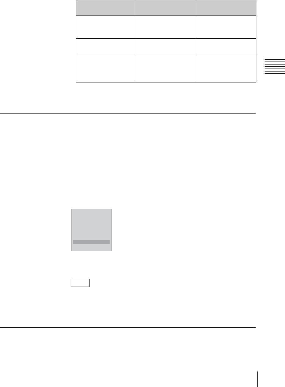
211
Video/Audio Signal Adjustments and Settings
Chapter 3 Operations
• For details of the output signal format, see under video outputs in the
Specification (page 280).
• The video image quality for each signal is as follows. Select the best
setting for a particular requirement.
* This occurs if the original frame frequency of the shot video and the RGB output
frame frequency or signal processing frequency of a plasma display or projector
are not in a whole number ratio.
Adding Aspect Ratio Information to Composite/S-Video Output
Signals
Aspect ratio information configured on the unit can be added to composite and
S-video output signals.
1
Press the MENU button.
2
In the top menu, select [Video Output].
3
Select [Add Aspect ID] to set it [On], and confirm.
The setting turns on or off each time it is selected.
When the [PGM OUT Aspect] setting is 4:3, the ID added is also 4:3. When
the setting is 16:9 SD or 16:9 HD, the ID added is 16:9 squeeze.
On devices capable of receiving aspect ratio information, signals with a 16:9
squeeze ID attached are automatically stretched to 16:9 display.
4
Press the MENU button to close the menu.
Applying Filters to the Program Output Video
Adjust this setting when the program output video appears blurry or the picture
flickers.
Signal name
(connector name) RGB video including
fine text and similar Video including
motion
Computer RGB signal
(RGB output connector)
Very clear Depending on the
combination, the motion
may be slightly jerky*
Video RGB signal (RGB
output connector)
Standard video quality
(very slightly blurred)
Smooth
Composite/S-Video
signal (composite video
output connector/S-video
output connector)
Standard video quality
(somewhat more blurred
than the Video RGB
signal)
Smooth
Note
PGM OUT NTSC/60Hz
PGM OUT Aspect 4:3
PGM OUT Level
DV OUT
RGB OUT SXGA (60 Hz)
Add TC
Add Aspect ID On
Filter Mode
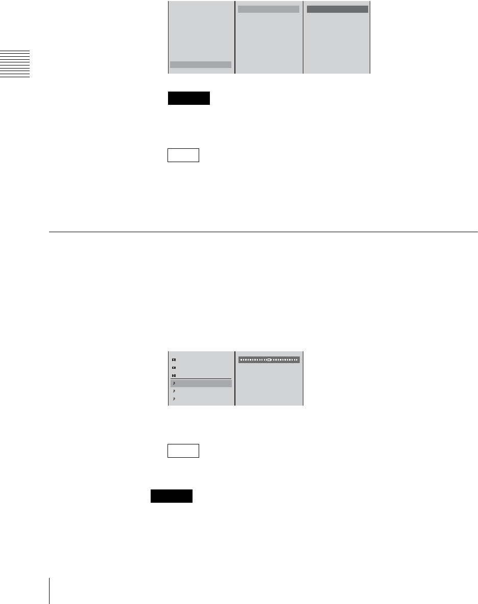
Chapter 3 Operations
212 Video/Audio Signal Adjustments and Settings
1
Press the MENU button.
2
In the top menu, select [Video Output].
3
1 Select [Filter Mode], and confirm; 2 select [SD Video] or [RGB] from
the submenu, and confirm; 3 select [Soft], [Normal] (when [SD Video] is
selected), or [Sharp], and confirm.
When [SXGA] or [WXGA] is selected for the RGB output signal format
setting, you cannot apply a filter.
• Select [Sharp] when the picture is blurry and [Soft] when the picture
flickers.
• When [Video RGB] is selected for the RGB output signal format setting,
the [SD Video] filter settings is applied.
Adjusting the Audio Input Signal Levels
You can adjust individual channels of the audio signals input to this unit.
1
Press the ACCESS button for the channel fader to which the audio you want
to adjust is assigned.
2
1 In the top menu, select [Input Trim]; 2 adjust with the sliders.
3
Press the ESC button to close the ACCESS menu.
You can also close the menu by pressing the same ACCESS button again.
When a file on an external hard disk is open, the adjustment value of [Input Trim]
is used for file playback.
Caution
Notes
Note
Caution
PGM OUT NTSC/60Hz
PGM OUT Aspect 4:3
PGM OUT Level
DV OUT
RGB OUT SXGA (60Hz)
Add TC
Add Aspect ID Off
Filter Mode
SD Video Soft
RGB Sharp
B Soft
Sharp
123
Chroma Level 100%
Hue 0
˚
Auto Gain Control On
Input Trim 0dB
Filter
EQ Off
12
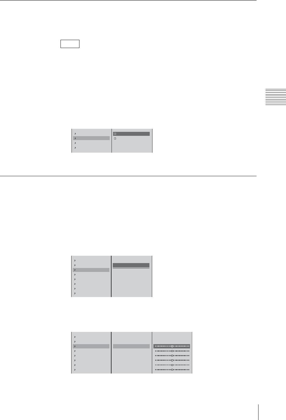
213
Video/Audio Signal Adjustments and Settings
Chapter 3 Operations
Cutting High Frequency or Low Frequency
This cuts high frequencies or low frequencies.
Use these settings to suppress noise.
• To cut high frequencies select [High Cut], and to cut low frequencies select
[Low Cut].
• You can set both [High Cut] and [Low Cut].
1
Press the ACCESS button in the same column as the channel fader to which
the audio you want to adjust is assigned.
2
1 In the top menu, select [Filter]; 2 select [High Cut (8kHz)] or [Low Cut
(100Hz)].
3
Press the ESC button to close the ACCESS menu.
Adjusting the Equalizer
You can adjust the audio quality by using the equalizer to set frequencies in the
high, middle, and low audio ranges.
1
Press the ACCESS button in the same column as the channel fader to which
the audio you want to adjust is assigned.
2
1 In the top menu, select [EQ]; 2 select [On], and confirm.
3
1 Select an adjustment item from the list, select [On], and confirm; 2
adjust with the slider.
The functions of the setting items are as follows.
Notes
Input Trim 0dB
Filter Off
EQ Off
Limiter/Compressor Off
High Cut (8kHz)
Low Cut (100Hz)
12
Input Trim 0dB
Filter
EQ Off
Limiter/Compressor Off
Pan CNT
PGM OUT On
AUX1 OUT Off
AUX2 OUT Off
Off
On
High Freq. XXkHz
High Level XXdB
Middle Freq. XXkHz
Middle Level XXdB
Low Freq. XXkHz
Low Level XXdB
12
Input Trim 0dB
Filter
EQ Off
Limiter/Compressor Off
Pan CNT
PGM OUT On
AUX1 OUT Off
AUX2 OUT Off
Off
On
High Freq. XXkHz
High Level XXdB
Middle Freq. XXkHz
Middle Level XXdB
Low Freq. XXkHz
Low Level XXdB
1
2
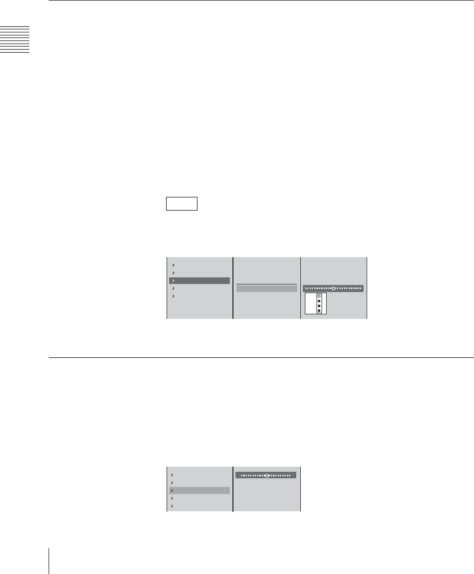
Chapter 3 Operations
214 Video/Audio Signal Adjustments and Settings
[High Freq.]: Adjusts the center frequency of the high-frequency band.
[High Level]: Adjusts the level of the high-frequency band.
[Middle Freq.]: Adjusts the center frequency of the middle-frequency
band.
[Middle Level]: Adjusts the level of the middle-frequency band.
[Low Freq.]: Adjusts the center frequency of the low-frequency band.
[Low Level]: Adjusts the level of the low-frequency band.
4
Press the ESC button to close the ACCESS menu.
Using the Limiter or Compressor
Use the limiter or compressor when inputting audio with large level differences.
The limiter restricts the peak components of an audio signal with large level
differences. It also compresses the sound exceeding a certain threshold volume
so that the threshold level is not exceeded, thus preventing excess outputs.
The compressor gently compresses the level of audio at and above the threshold
level, thus smoothing out an audio signal with large level differences.
1
Press the ACCESS button in the same column as the channel fader to which
the audio you want to adjust is assigned.
2
1 In the top menu, select [Limiter/Compressor]; 2 select [Limiter] or
[Compressor], and confirm; 3 with the threshold slider set the level at which
the limiter or compressor takes effect.
A gain reduction meter appears to the right of the menu, and shows the
current compression.
3
Press the ESC button to close the ACCESS menu.
Adjusting the Audio Left and Right Channel Balance
1
Press the ACCESS button in the same column as the channel fader to which
the audio you want to adjust is assigned.
2
1 In the top menu, select [Pan]; 2 adjust the left and right channel balance
with the slider.
Note
Filter
EQ Off
Limiter/Compressor Off
Pan CNT
PGM OUT On
Off
Limiter (100:1)
Compressor (2:1)
Threshold -20dB
-2
-6
-12
-18
123
EQ Off
Limiter/Compressor Off
Pan CNT
PGM OUT On
AUX1 OUT On
L R
12
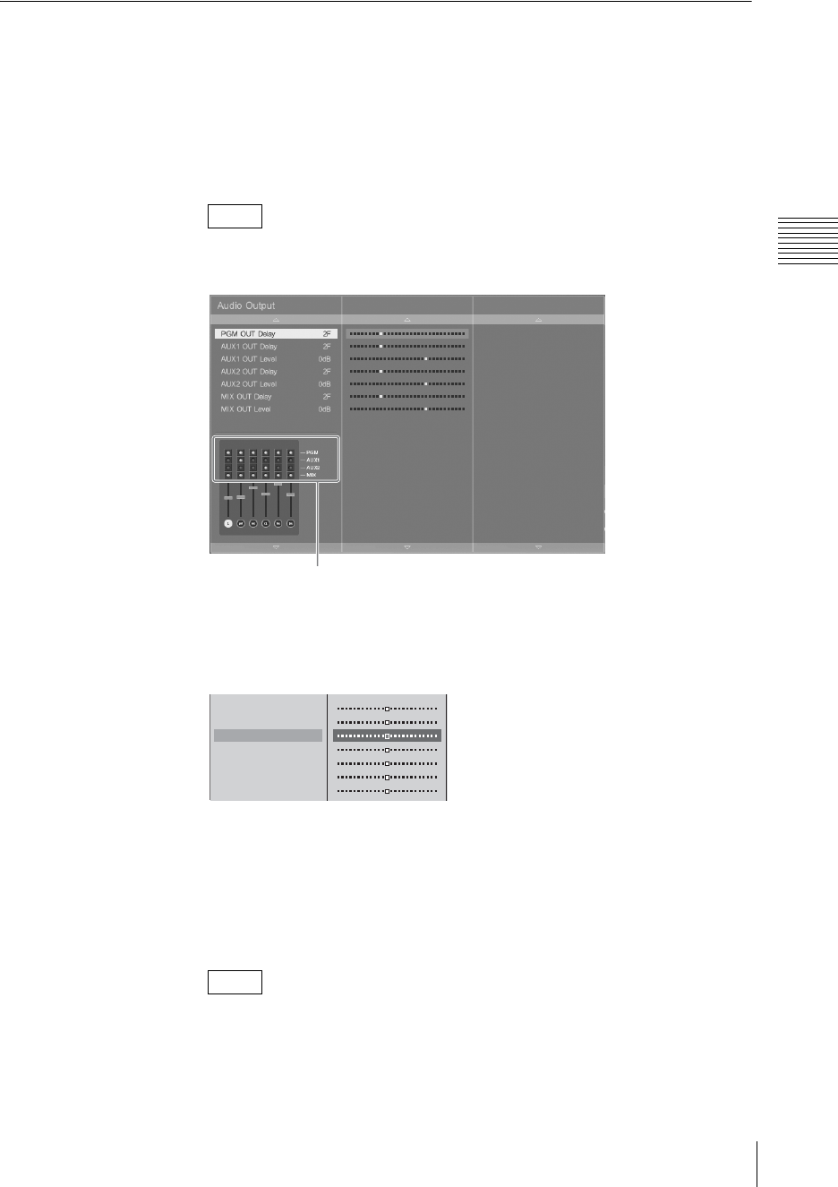
215
Video/Audio Signal Adjustments and Settings
Chapter 3 Operations
3
Press the ESC button to close the ACCESS menu.
Adjusting the Output Levels for Each Destination
Adjust the output audio level for each destination.
1
Press the MENU button.
2
In the top menu, select [Audio Output].
The [Audio Output] menu appears.
This menu graphically displays the output destination for each channel set in
“Determining the Audio Signal Output Destinations” (page 202).
3
1 Select the item you wish to adjust the level, and confirm; 2 adjust with
the slider.
The items for which you can adjust the level are as follows.
[AUX1 OUT Level]: Sets the output level for the audio output from the
AUX1 connector.
[AUX2 OUT Level]: Sets the output level for the audio output from the
AUX2 connector.
[MIX OUT Level]: Sets the output level for the audio from the MIX output.
Adjust the audio level output from the PGM audio output connectors using
the PGM fader on the front panel (page 168).
4
Press the MENU button to close the menu.
Note
Note
Output destination indication
PGM OUT Delay 2F
AUX1 OUT Delay 2F
AUX1 OUT Level 0dB
AUX2 OUT Delay 2F
AUX2 OUT Level 0dB
MIX OUT Delay 2F
MIX OUT Level
12
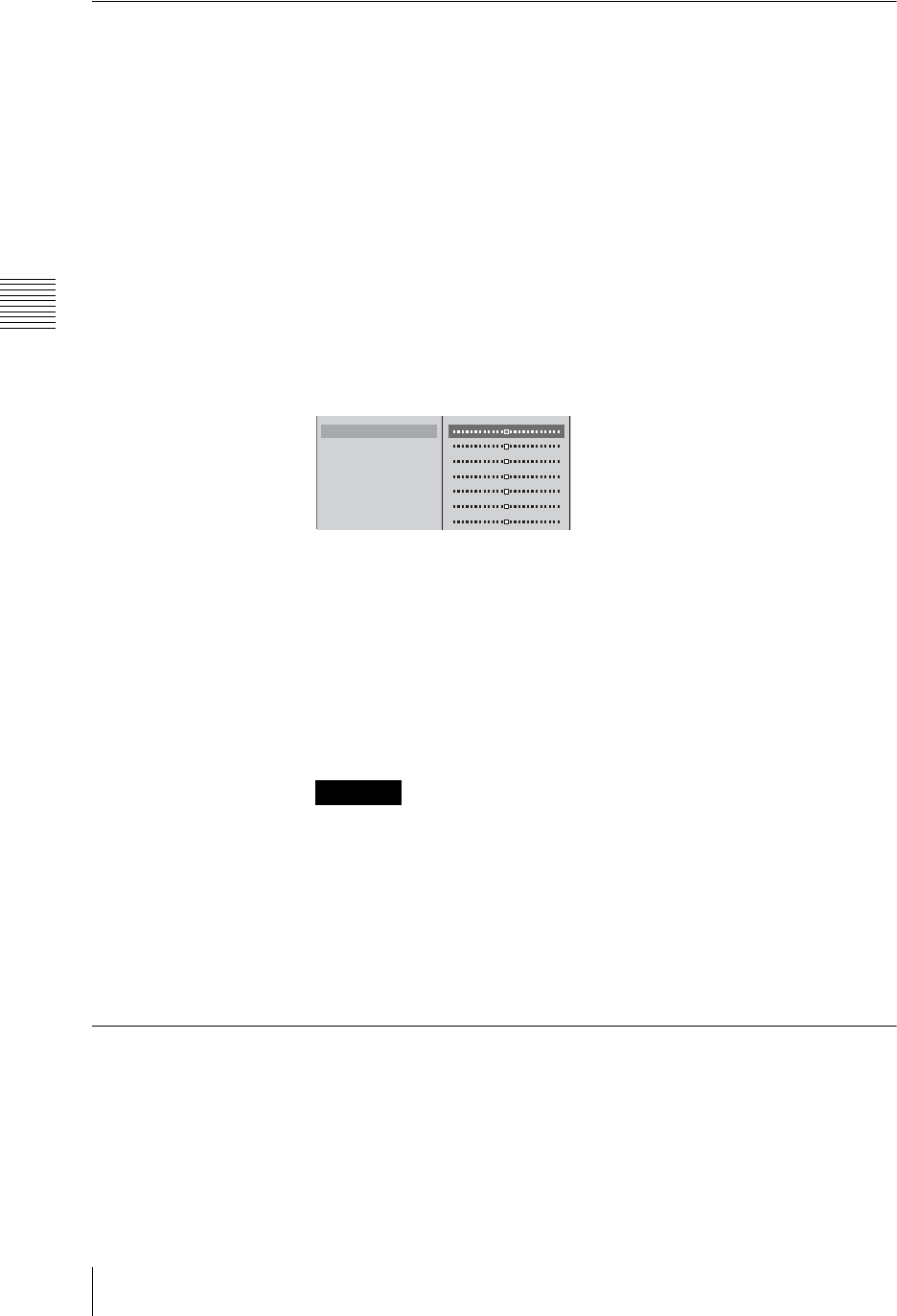
Chapter 3 Operations
216 Video/Audio Signal Adjustments and Settings
If the Output Video Is Delayed With Respect to the Audio
If the output video is delayed with respect to the audio, by delaying the audio you
can resynchronize it with the video.
1
Connect monitor devices to the PGM video output connectors.
2
Connect devices to the PGM/AUX/MIX audio output connectors.
3
Press the MENU button.
4
In the top menu select [Audio Output].
The [Audio Output] menu appears.
5
1 Select the item connected to the connector in step 2, and confirm;
2 while watching the video connected in step 1, adjust it with the slider.
The items for which you can adjust the delay time are as follows.
[PGM OUT Delay]: Sets the delay time for the program output audio in
frame units.
[AUX1 OUT Delay]: Sets the delay time for the audio output from the
AUX1 connector in frame units.
[AUX2 OUT Delay]: Sets the delay time for the audio output from the
AUX2 connector in frame units.
[MIX OUT Delay]: Sets the delay time for the audio from the MIX output
in frame units.
• As the duration for one frame in 720p signal format is half of that in 1080i
format, you must set the audio delay time to half the value set for 1080i
when using 720p.
• Adjusting the delay time may cause noise to occur.
• Video displayed on the PGM viewer lags several frames behind the video
output from the PGM video output connectors.
6
Press the MENU button, to close the menu.
Adjusting the Output Using the Oscillator Signal
This is for setting the output oscillator signal for use during adjustment.
1
Press the MENU button.
2
In the top menu, select [Audio Utility].
3
Select [OSC], and confirm, and set the oscillator signal output.
Caution
PGM OUT Delay 2F
AUX1 OUT Delay 2F
AUX1 OUT Level 0dB
AUX2 OUT Delay 2F
AUX2 OUT Level 0dB
MIX OUT Delay 2F
MIX OUT Level
12
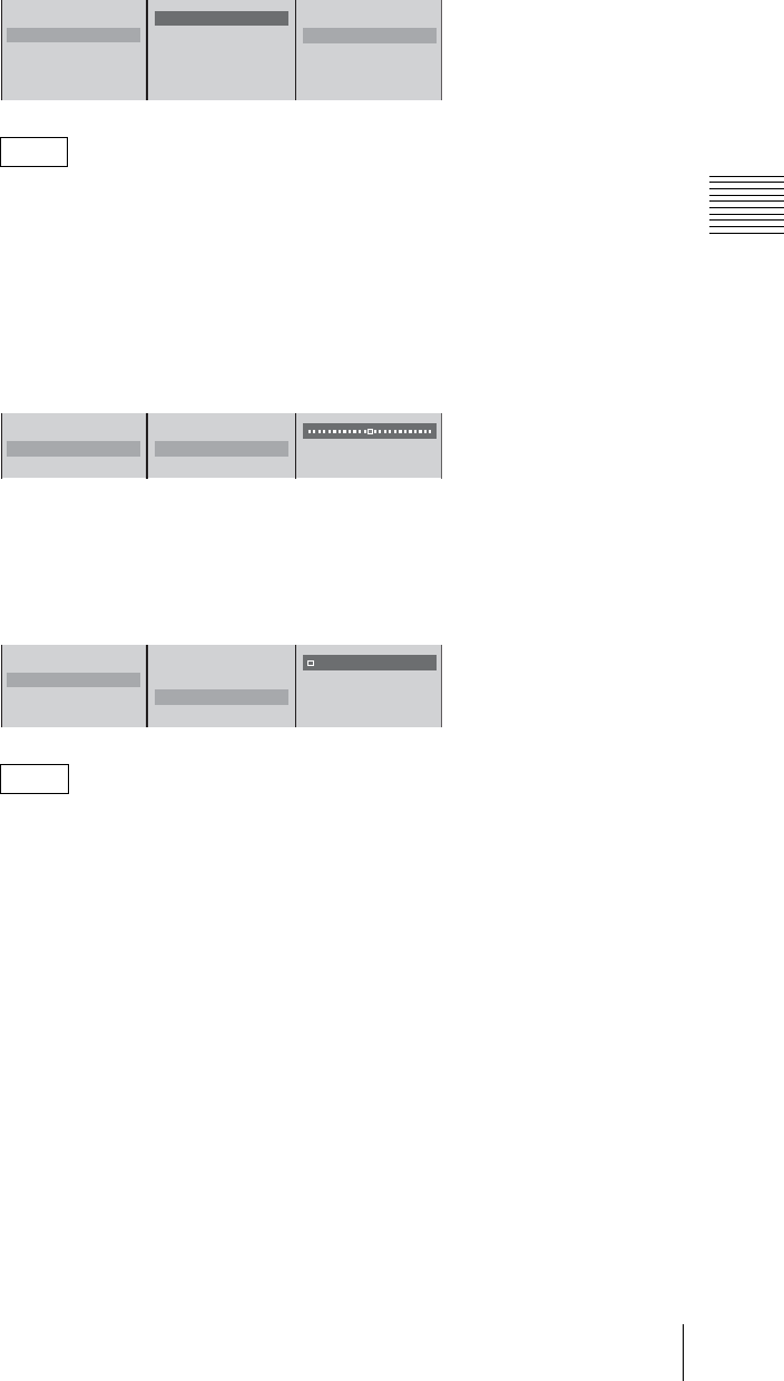
217
Video/Audio Signal Adjustments and Settings
Chapter 3 Operations
Setting the oscillator signal frequency
1 Select [OSC Freq.], and confirm; 2 select the frequency from the
submenu, and confirm.
When the output destination is set with [OSC OUT], and a selection other
than [Off] is made, the DIM button lights, and the levels of the internal
speakers, the headphones, and monitor outputs are automatically reduced.
Setting the oscillator signal output level
1 Select [OUT Level], and confirm; 2 adjust the output level with the
slider.
Setting the oscillator signal output destination
1 Select [OSC OUT], and confirm; 2 select the output destination to
output the oscillator signal, and confirm.
You can select multiple output destination.
4
Press the MENU button to close the menu.
Note
Note
Audio Monitor
OSC
TB
OSC Freq. Off
OUT Level -20dBFS
OSC OUT
Off
B 100Hz
440Hz
1kHz
10kHz
12
Audio Monitor
OSC
TB
OSC Freq. Off
OUT Level -20dBFS
OSC OUT
12
Audio Monitor
OSC
TB
OSC Freq. Off
OUT Level -20dBFS
OSC OUT
PGM
s AUX1
s AUX2
s MIX
12
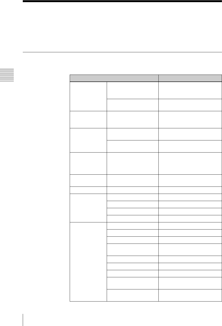
Chapter 3 Operations
218 Saving and Loading Various Settings
Saving and Loading Various Settings
You can simultaneously save various settings of the unit and information of
camera presets, and then load them when necessary. Saving the optimal settings
beforehand eliminates the need to reconfigure settings each time you, for
example, work on site or use multiple configurations for events.
Storable Data
You can save the following settings and adjustment data.
Storable settings and adjustments Details of settings
Input/output Audio input/output settings
and adjustments
[Audio Input Assign] settings
[Audio MIC/LINE Level] settings
[Audio Output] settings
Video input/output settings
and adjustments
[Video Input Assign] settings
[Video Output] settings
Camera preset data Settings of the camera presets
registered to the numeric buttons 1
to 6
Var io us
adjustments
Audio adjustments ACCESS menu settings for the
inputs 1 to 6
Video adjustments ACCESS menu settings for the
inputs 1 to 6
Streaming Streaming configuration file [Streaming] settings
However, the [Output] setting is
not applicable (it is set to [Off] for
loading data).
Video utility Settings of the [VISCA Power
Control] menu
Audio utility [Audio Utility] settings
Effects Video effect settings [Video Effect] settings
Downstream key settings [DSK] settings
Fade to black settings [Fade To Black] settings
Streaming file settings [LOGO] settings
Other Network settings [Network] settings
EDL file name [File Name] setting of [EDL]
Camera control settings Settings of the camera guide menu
File control settings of
external hard disks
[Auto Repeat] settings of the HDD
file guide menu
System timecode settings [System TC] settings of [System]
Language settings [Language] settings
Display settings [Display] settings
Aspect ratio for 4:3 graphics
files
[Wide Zoom] settings of the INT
guide menu
Selection status of audio
channels
On/Off status of the CH ON button
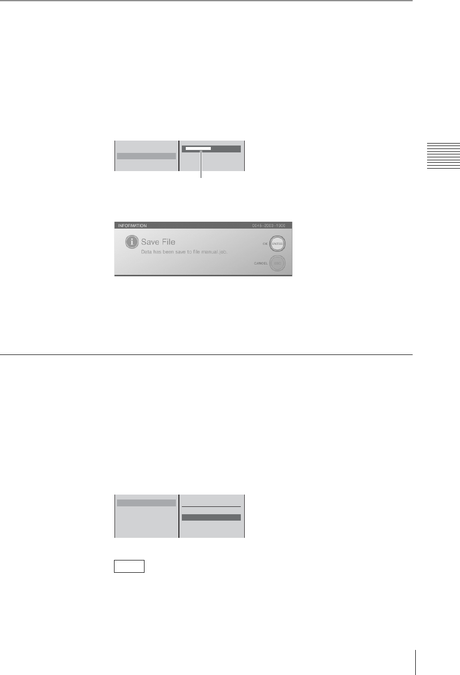
219
Saving and Loading Various Settings
Chapter 3 Operations
Saving Various Settings Data
You can simultaneously save the current settings of the unit.
1
Press the MENU button.
2
Select [Job] in the top menu.
3
1 Select [Save] and confirm; 2 enter the name of the data in the input box
and confirm.
The following confirmation message appears.
4
Press the ENTER button.
The message closes and saving completes.
5
Press the MENU button to close the menu.
Loading Various Saved Settings Data
You can load saved job data.
1
Press the MENU button.
2
Select [Job] in the top menu.
3
1 Select [Load] and confirm; 2 select the name of the data to load and
confirm.
• The data names are sorted in alphabetical order from top to bottom.
• You can restore the default settings by selecting [Default].
Notes
Load
Save
Delete
[ XXXXXXXXXX ]
Enter up to 20 alphanumeric characters.
12
Load
Save
Delete
Default
xxxxxxxxxx.job
xxxxxxxxxx.job
xxxxxxxxxx.job
xxxxxxxxxx.job
12
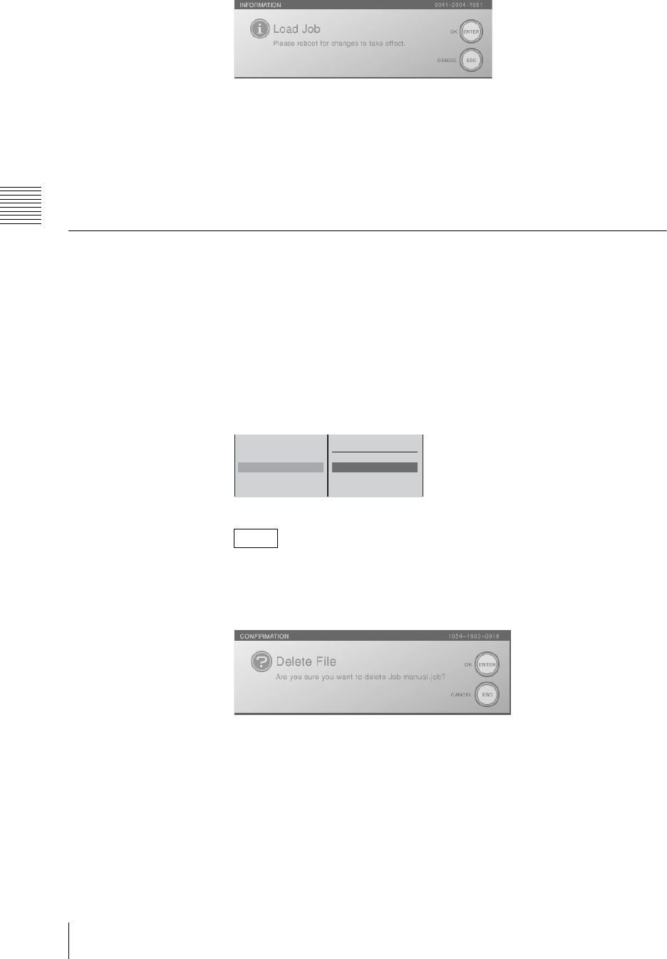
Chapter 3 Operations
220 Saving and Loading Various Settings
The following confirmation message appears.
4
Press the ENTER button.
The end message appears.
The operating software ends and the power turns off.
5
Press the 1 power button on the side panel.
The unit starts and the settings you loaded are applied.
Deleting Various Saved Settings Data
You can delete the job data you no longer require.
1
Press the MENU button.
2
Select [Job] in the top menu.
3
1 Select [Delete] and confirm; 2 select the name of the data to delete and
confirm.
• The data names are sorted in alphabetical order from top to bottom.
• You can delete all of the job data by selecting [All].
The following confirmation message appears.
4
Press the ENTER button.
The job data is deleted.
5
Press the MENU button to close the menu.
Notes
Load
Save
Delete
All
xxxxxxxxxx.job
xxxxxxxxxx.job
xxxxxxxxxx.job
xxxxxxxxxx.job
12
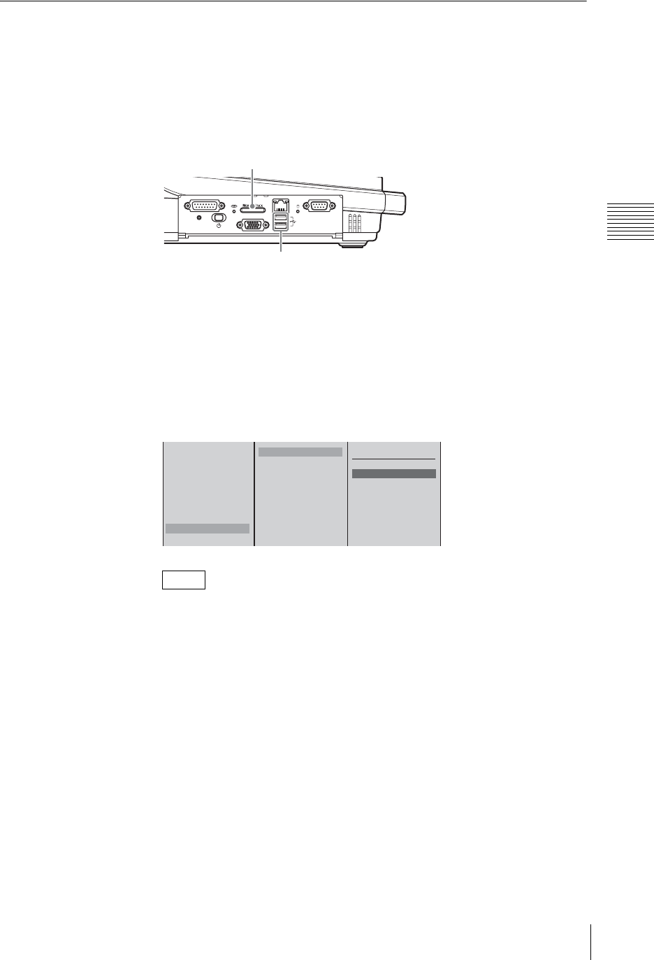
221
Saving and Loading Various Settings
Chapter 3 Operations
Exporting Various Settings Data
You can export the job data saved on the unit to a “Memory Stick” or USB flash
memory.
1
Insert the “Memory Stick” or USB flash memory in the “Memory Stick” slot
or USB connector on the side panel.
The upper USB connector is number 1 and the lower connector is number 2.
2
Press the MENU button.
3
Select [File Manager] in the top menu.
4
1 Select [Export Job] and confirm; 2 select [Memory Stick], [USB Flash
Memory 1], or [USB Flash Memory 2] and confirm; 3 select the job data to
export and confirm.
• The data names are sorted in alphabetical order from top to bottom.
• If you select [All] in 3, all files are exported. If files of the same name
already exist on the “Memory Stick” or USB flash memory when
exporting all files, an overwrite confirmation message appears. When you
want to overwrite all of the existing files with the same name, press the
ENTER button while holding down the SHIFT button. When you want to
skip all of the files with the same name and only export file names that do
not already exist, press the ESC button while holding down the SHIFT
button.
The job data is exported to the “Memory Stick” or USB flash memory.
When the export is complete, a completion message appears.
5
Press the ENTER button.
6
Press the MENU button to close the menu.
Notes
FACTORY USE REMOTE
RGB
(
GUI
)
RESET
USB
NETWORK
18
15 9
1
5
USB connectors
“Memory Stick” slot
Delete
Disconnect
Recover
Rename
Export EDL Type 1
Export EDL Type 2
Export VOD File
Export Job
Import Job
Memory Stick
USB Flash Memory 1
USB Flash Memory 2
All
xxxxxxxxxx.job
xxxxxxxxxx.job
xxxxxxxxxx.job
xxxxxxxxxx.job
123
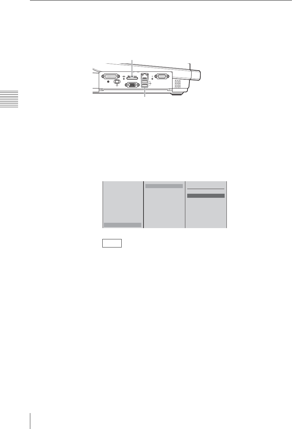
Chapter 3 Operations
222 Saving and Loading Various Settings
Importing Various Settings Data
You can import the job data saved on a “Memory Stick” or USB flash memory.
Insert the “Memory Stick” or USB flash memory containing the job data in the
“Memory Stick” slot or USB connector on the side panel. The upper USB
connector is number 1 and the lower connector is number 2.
1
Press the MENU button.
2
Select [File Manager] in the top menu.
3
1 Select [Import Job] and confirm; 2 select [Memory Stick], [USB Flash
Memory 1], or [USB Flash Memory 2] and confirm; 3 select the job data to
import and confirm.
• The data names are sorted in alphabetical order from top to bottom.
• If you select [All] in 3, all of the job data is imported. If files of the same
name already exist on the internal hard disk when importing all files, an
overwrite confirmation message appears. When you want to overwrite all
of the existing files with the same name, press the ENTER button while
holding down the SHIFT button. When you want to skip all of the files
with the same name and only import file names that do not already exist,
press the ESC button while holding down the SHIFT button.
The job data is imported.
When the import is complete, a completion message appears.
4
Press the ENTER button.
5
Press the MENU button to close the menu.
Notes
FACTORY USE REMOTE
RGB
(
GUI
)
RESET
USB
NETWORK
18
15 9
1
5
USB connectors
“Memory Stick” slot
Delete
Disconnect
Recover
Rename
Export EDL Type 1
Export EDL Type 2
Export Real Media File
Export Job
Import Job
Memory Stick
USB Flash Memory 1
USB Flash Memory 2
All
xxxxxxxxxx.job
xxxxxxxxxx.job
xxxxxxxxxx.job
xxxxxxxxxx.job
123

223
Using the Switching Information of the Unit on a Nonlinear Editing System
Chapter 3 Operations
Using the Switching Information of the Unit on a
Nonlinear Editing System
You can save the timing of switching performed on this unit or information on
used materials as an EDL (Edit Decision List).
To make the editing process easier, the created EDL can be exported to a
“Memory Stick” or USB flash memory and then used on a nonlinear editing
system together with material recorded to an external hard disk.
Creating EDL
Created EDL
The created EDL is saved in the CMX3600 format.
Information on nonlinear editing systems and other information related to EDLs
can be found on the following Anycast Station portal sites.
https://servicesplus.us.sony.biz/SoftwarePlusSerch.aspx (for customers in
U.S.A.)
https://www.sony.biz.net/anycast (for customers in Europe, Middle East and
Africa)
https://www.ecspert.sony.biz/ecsite/ (for the other customers)
Conditions of EDL
• Audio combined with video signals is output as data at the same timing as
video switching.
• Mix, wipe, and picture-in-picture are replaced with the cut information.
• Information such as keying, downstream keying, logos, and fade to black is not
output.
• When using an EDL on a nonlinear editing system, use a file recorded on an
external hard disk with simultaneous ON LINE recording. A file that has been
recorded manually may not be able to be used properly due to timecode
inconsistencies between the EDL and the file.
• Use the reference signals output from the unit’s reference output connectors to
synchronize the unit with input devices such as cameras.
Preparing for EDL creation
1
Press the MENU button.
2
Select [ON LINE Manager] in the top menu.
3
1 Select [EDL], and confirm; 2 select [On], and confirm.
Caution
PGM Recording
Source Recording
EDL Off
Streaming Off
DV OUT Recording Off
B Off
On
File Name
12
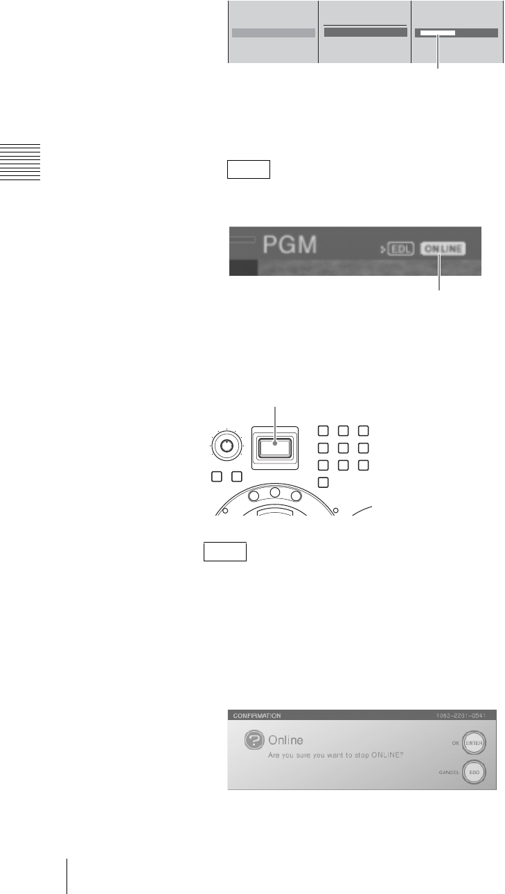
Chapter 3 Operations
224 Using the Switching Information of the Unit on a Nonlinear Editing System
4
1 Select [File Name], and confirm; 2 enter the name of the EDL file in the
input box, and confirm.
5
Press the MENU button to close the menu.
You are now ready to start creating an EDL.
When [Output] for [EDL] is set to [On], the ON LINE icon for VCRS
appears in the PGM viewer.
Starting EDL creation
If you press the ON LINE button, EDL creation starts and subsequent switching
operation information is recorded.
You can also activate all of the reserved functions for the ON LINE button
simultaneously. For details, see “Activating Each Function Simultaneously With
the ON LINE Button” (page 259).
Ending EDL creation
1
Press the ON LINE button.
The following confirmation message appears.
2
Press the ENTER button.
Note
Note
[ XXXXXXXXXX ]
PGM Recording
Source Recording
EDL On
Streaming Off
DV OUT Recording Off
B Off
On
File Name
12
Enter up to 20 alphanumeric characters.
ON LINE icon
MONI LEVEL
010
ON LINE
DIM TB
789
456
1
0
23
M
I
X
E
F
F
E
C
T
P
V
W
ON LINE button
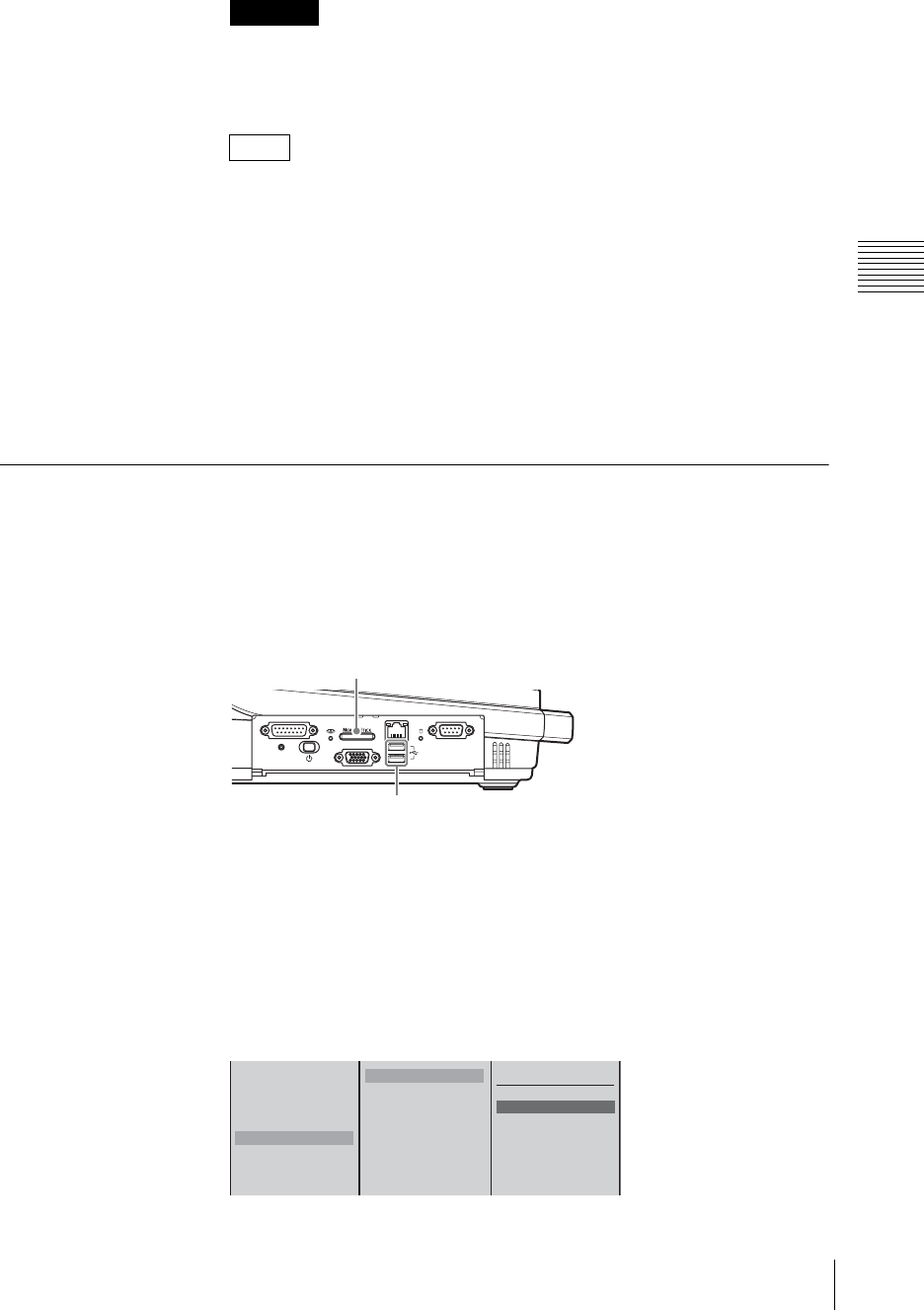
225
Using the Switching Information of the Unit on a Nonlinear Editing System
Chapter 3 Operations
EDL creation ends.
After pressing the ENTER button, EDL creation will take approximately 10
seconds to end completely. Do not perform operations such as system
shutdown or starting up the Text Typing Tool during this period.
• If you press the ON LINE button while holding down the ESC button in
step 1, EDL creation ends without a confirmation message display.
• A consecutive number (1 to 999) is added automatically to each EDL file
name to enable the next EDL to be created.
Creating the next new EDL
To create another EDL, press the ON LINE button.
There is no need to enter a new file name because a consecutive number is added
automatically to each EDL file name.
To create an EDL with a different file name, repeat step 4 of “Preparing for EDL
creation” (page 223).
Exporting EDL
You can export an EDL file to a “Memory Stick” or USB flash memory.
1
Insert the “Memory Stick” or USB flash memory in the “Memory Stick” slot
or USB connector on the side panel.
The upper USB connector is number 1, and the lower connector is number 2.
2
Press the MENU button.
3
In the top menu, select [File Manager].
4
1 Select [Export EDL Type 1] or [Export EDL Type 2], and confirm; 2
select [Memory Stick], [USB Flash Memory 1], or [USB Flash Memory 2],
and confirm; 3 select the EDL file and confirm.
Caution
Notes
FACTORY USE REMOTE
RGB
(
GUI
)
RESET
USB
NETWORK
18
15 9
1
5
USB connectors
“Memory Stick” slot
Delete
Disconnect
Recover
Rename
Export EDL Type 1
Export EDL Type 2
Export VOD File
Export Job
Memory Stick
USB Flash Memory 1
USB Flash Memory 2
All
xxxxxxxxxx.edl
xxxxxxxxxx.edl
xxxxxxxxxx.edl
xxxxxxxxxx.edl
123
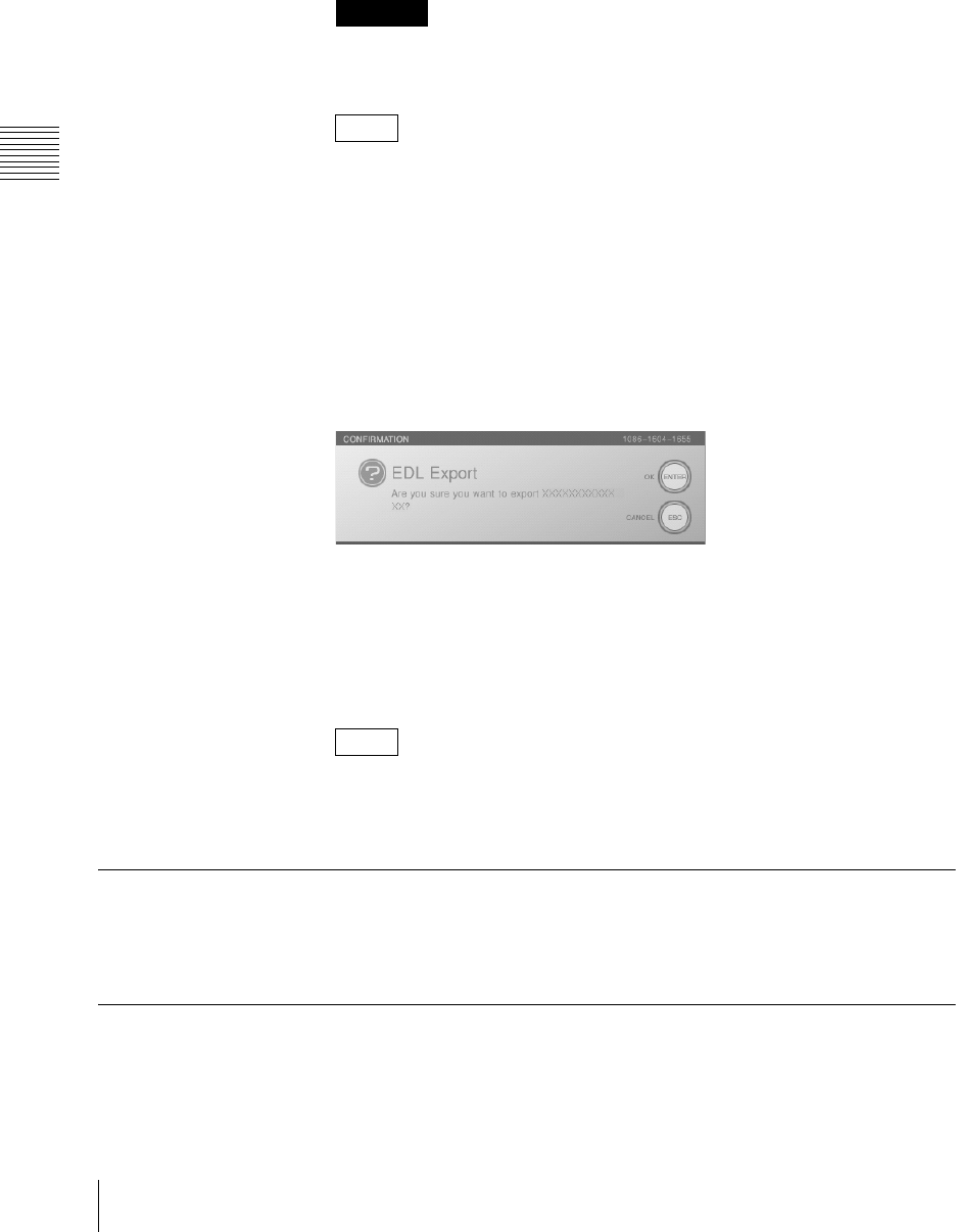
Chapter 3 Operations
226 Using the Switching Information of the Unit on a Nonlinear Editing System
Type1: This EDL is compatible with Final Cut Pro 5.
Final Cut Pro is a registered trademark of Apple Computer, Inc. in the
United States and other countries.
Tyep2: This EDL is compatible with Adobe Premiere Pro 2.0.
Adobe Premiere Pro is a registered trademark of Adobe Systems
Incorporated in the United States and other countries.
Compatibility of EDL files exported from this unit is not guaranteed by
Apple Computer, Inc. or Adobe Systems Incorporated.
• The file names are arranged in alphabetical order.
• If you select [All] in 3, all files are exported. If files of the same name
already exist on the “Memory Stick” or USB flash memory when
exporting all files, an overwrite confirmation message appears. When you
want to overwrite all of the existing files with the same name, press the
ENTER button while holding down the SHIFT button. When you want to
skip all of the files with the same name and only export file names that do
not already exist, press the ESC button while holding down the SHIFT
button.
The following confirmation message appears.
5
Press the ENTER button.
The EDL file is exported to the “Memory Stick” or USB flash memory.
When the export is complete, a completion message appears.
6
Press the MENU button to close the menu.
The “type” for the exported file is added to the file name.
Example: When a file, “aaa.edl”, is exported as Type 1, the file name
becomes “aaa-type1.edl”.
Deleting EDL Files
For details on deleting EDL files on the internal hard disk of this unit, see
“Deleting Files” (page 233).
Using an EDL Created on the Unit on a Nonlinear Editing
System
An EDL file created by the unit can be used on a nonlinear editing system
together with input materials recorded by the unit through ON LINE recording.
Caution
Notes
Note

227
Using the Switching Information of the Unit on a Nonlinear Editing System
Chapter 3 Operations
1
Install a driver software in the computer.
2
Insert the “Memory Stick” or USB flash memory containing the EDL file
into the computer, and connect the external hard disk containing the recorded
materials to the computer.
Make sure that hard disk is mounted as two drives with the volume labels
“system” and “data.”
3
Start up the nonlinear editing system.
4
Load the EDL.
5
Perform a media link (reconnection) for each .avi file found in each of the
input materials displayed.
6
Perform editing.
Information on this function, including the driver software information, can be
found on the following Anycast Station Web portals.
https://servicesplus.us.sony.biz/SoftwarePlusSerch.aspx (for customers in
U.S.A.)
https://www.sony.biz.net/anycast (for customers in Europe, Middle East and
Africa)
https://www.ecspert.sony.biz/ecsite/ (for the other customers)
Note
Note
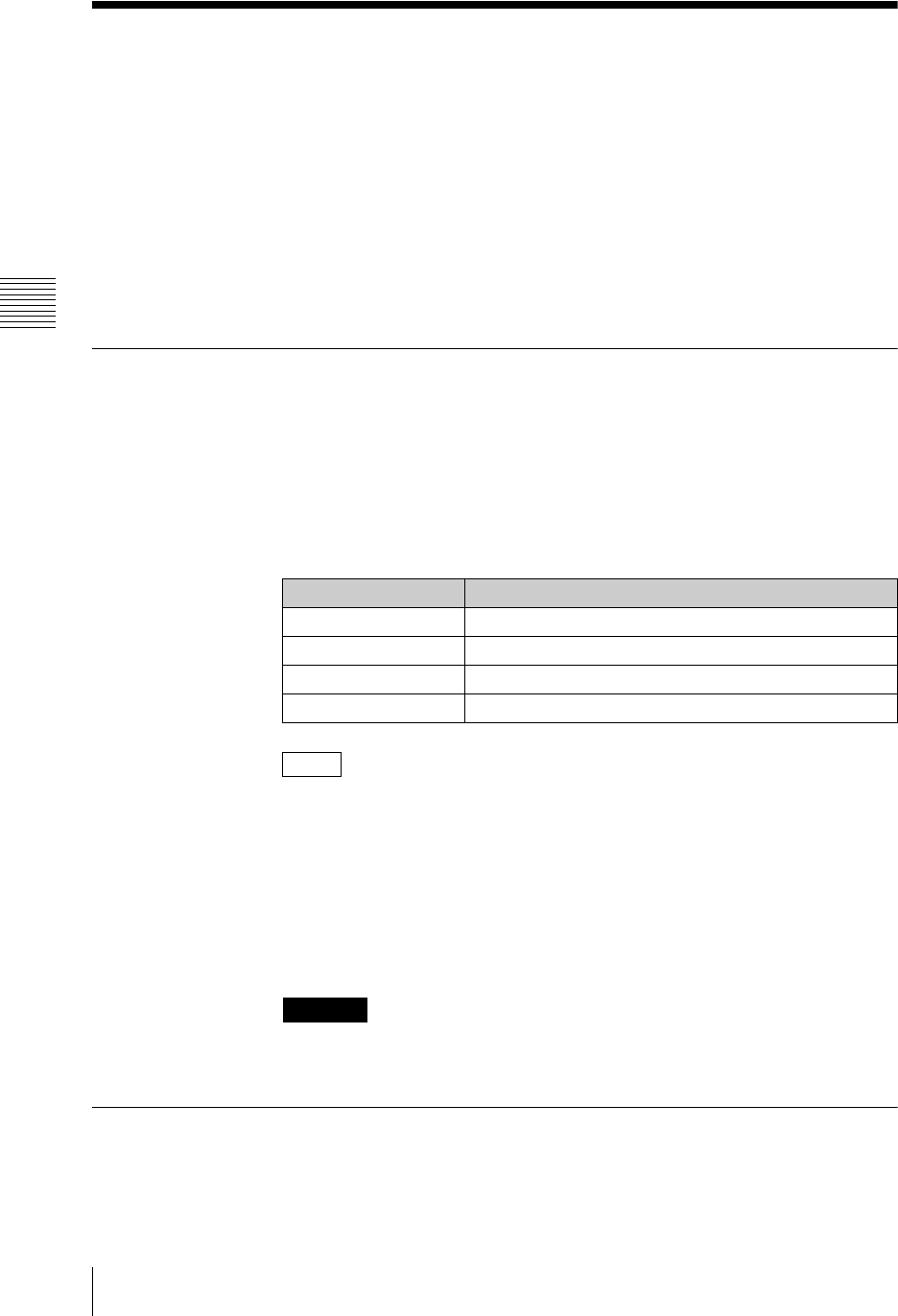
Chapter 3 Operations
228 Importing, Renaming, and Deleting Files
Importing, Renaming, and Deleting Files
Using the [File Manager] menu, you can carry out the following file operations.
• Importing graphics files and logo files from a “Memory Stick” or USB flash
memory
• Renaming files
• Exporting VOD files
• Deleting EDL files, graphic files, and logo files saved on the internal hard disk
of this unit
• Deleting files recorded on an external hard disk
• Checking the remaining capacity of the internal hard disk
• Formatting a “Memory Stick,” USB flash memory, or external hard disk
Importable Files
You can import graphics files in the sizes listed below. Depending on the size of
a graphics file, it may be resized on import.
Sizes allowed for import
You can import any files with a width of 720 to 1,920 and an aspect ratio of one
of the following: 4:3, 5:4, 5:3, 16:9, or 16:10.
Importable file types and extensions
• You can use the alpha channel of a graphics file as the key source, allowing for
higher quality materials to be inserted.
• For details on the output display of graphics files, see “Relation between aspect
ratio settings and output signals” (page 53).
• The unit may not support some graphics files in which centimeters (cm) were
specified during creation in Microsoft PowerPoint. Files in which inches were
specified are ok. If you do specify centimeters, the recommended size is 45.14
cm × 25.4 cm.
If you create a graphics file with Microsoft PowerPoint for use in downstream
keying or luminance keying, save it in BMP format.
Importing Graphics Files
By importing a graphics file to the internal hard disk, you can use it for
downstream keying or luminance keying.
File type File extension
Targa .tga .vda .icb .vst
Tiff .tif .tiff
BMP .bmp
JPEG .jpeg .jpg .jpe
Notes
Caution
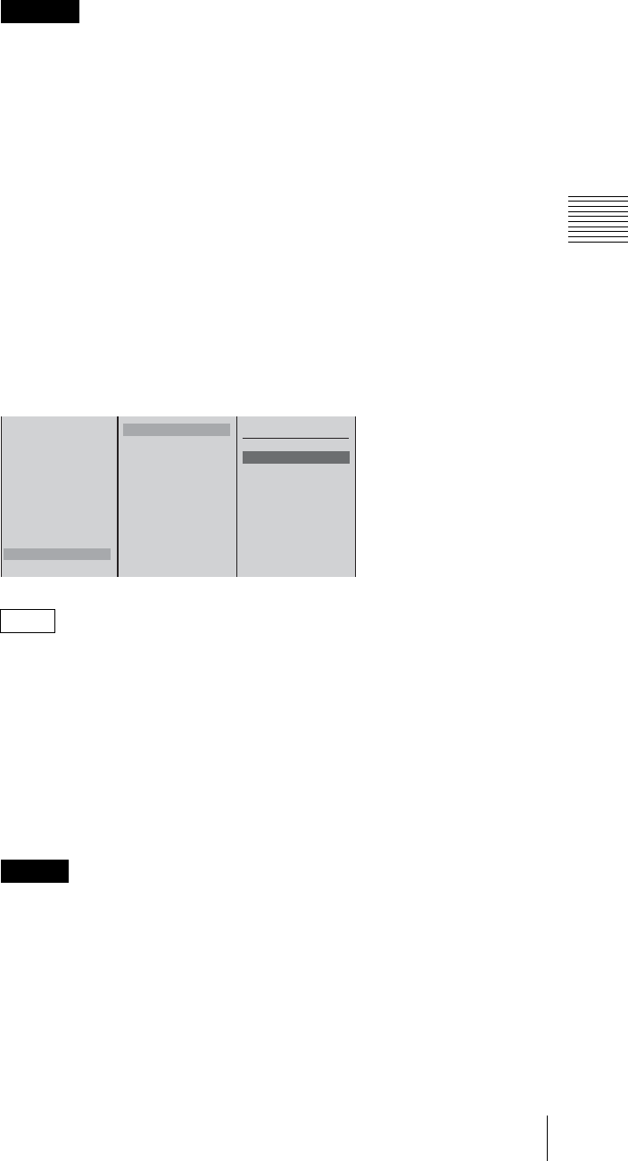
229
Importing, Renaming, and Deleting Files
Chapter 3 Operations
1
Insert the “Memory Stick” or USB flash memory holding the graphics file in
the “Memory Stick” slot or USB connector in the side panel.
• Use a “Memory Stick” or USB flash memory that has been formatted using
this unit.
• The graphics file must have been placed in the designated folder
MSSONY/PRO/LPS/ANYCAST/CG for graphics files.
For details of formatting a “Memory Stick,” see “Formatting a “Memory
Stick” (page 236), and for details of formatting a USB flash memory, see
“Formatting a USB Flash Memory” (page 238).
2
Press the MENU button.
3
In the top menu, select [File Manager].
4
1 Select [Import CG File] and confirm; 2 Select [Memory Stick], [USB
Flash Memory 1], or [USB Flash Memory 2] and confirm; 3 Select the
graphics file to be imported and confirm.
The upper USB connector is number 1, and the lower connector is number 2.
If you select [All] in step 3, all of the files are imported. If files of the same
name already exist on the internal hard disk when importing all files, an
overwrite confirmation message appears. When you want to overwrite all of
the existing files with the same name, press the ENTER button while holding
down the SHIFT button. When you want to skip all of the files with the same
name and only import file names that do not already exist, press the ESC
button while holding down the SHIFT button. However, depending on the
list order of the files on the internal hard disk, the overwrite confirmation
message may appear again.
Characters other than alphanumeric characters cannot be displayed correctly.
This imports the graphics file.
When the import is completed, a completion message appears.
5
Press the ENTER button.
6
Press the MENU button to close the menu.
Caution
Note
Caution
Delete
Disconnect
Recover
Rename
Export EDL Type 1
Export EDL Type 2
Export VOD File
Export Job
Import Job
Import CG File
Import Logo File
Memory Stick
USB Flash Memory 1
USB Flash Memory 2
All
xxxxxxxxxx.job
xxxxxxxxxx.job
xxxxxxxxxx.job
xxxxxxxxxx.job
123
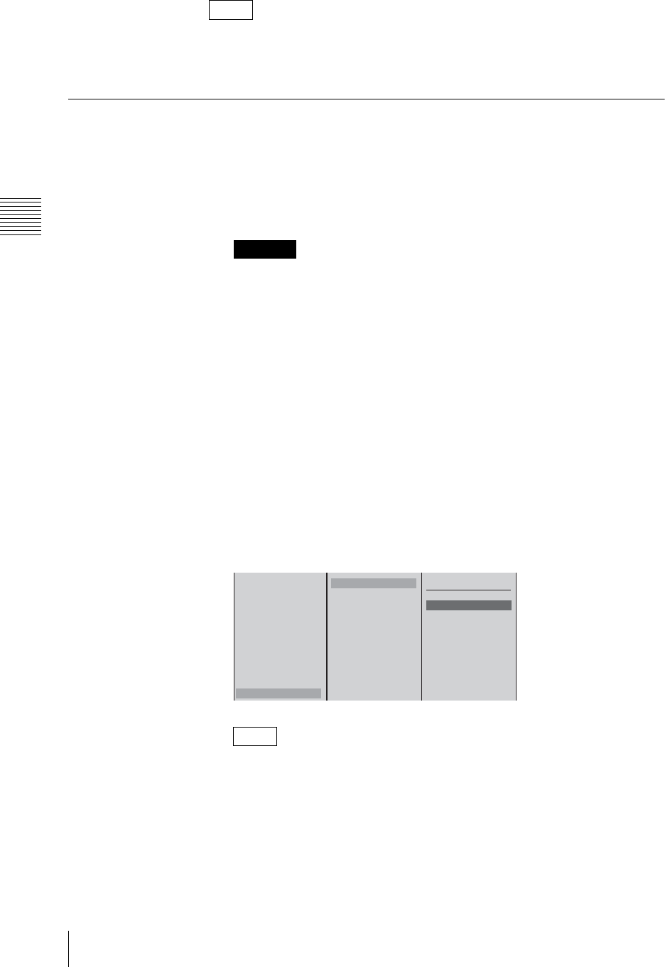
Chapter 3 Operations
230 Importing, Renaming, and Deleting Files
The imported graphics file can be used in “Using the Downstream Key (DSK)
Function To Add Text or an Image” (page 90), “Using Luminance Keying” (page
99), or “Using Chroma Keying” (page 103).
Importing Logo Files
By importing a logo file to the internal hard disk, you can display an image (logo)
for the purpose of copyright protection.
1
Insert the “Memory Stick” or USB flash memory holding the logo file in the
“Memory Stick” slot or USB connector in the side panel.
• Use a “Memory Stick” or USB flash memory that has been formatted using
this unit.
• The logo file must have been placed in the designated folder MSSONY/
PRO/LPS/ANYCAST/LOGO for logo files.
For details of formatting a “Memory Stick,” see “Formatting a “Memory
Stick”” (page 236), and for details of formatting a USB flash memory, see
“Formatting a USB Flash Memory” (page 238).
2
Press the MENU button.
3
In the top menu, select [File Manager].
4
1 Select [Import Logo File] and confirm; 2 Select [Memory Stick], [USB
Flash Memory 1], or [USB Flash Memory 2] and confirm; 3 Select the logo
file to be imported and confirm.
The upper USB connector is number 1, and the lower connector is number 2.
If you select [All] in step 3, all of the files are imported. If files of the same
name already exist on the internal hard disk when importing all files, an
overwrite confirmation message appears. When you want to overwrite all of
the existing files with the same name, press the ENTER button while holding
down the SHIFT button. When you want to skip all of the files with the same
name and only import file names that do not already exist, press the ESC
button while holding down the SHIFT button.
Note
Caution
Note
Delete
Disconnect
Recover
Rename
Export EDL Type 1
Export EDL Type 2
Export VOD File
Export Job
Import Job
Import CG File
Import Logo File
Memory Stick
USB Flash Memory 1
USB Flash Memory 2
All
xxxxxxxxxx.job
xxxxxxxxxx.job
xxxxxxxxxx.job
xxxxxxxxxx.job
123
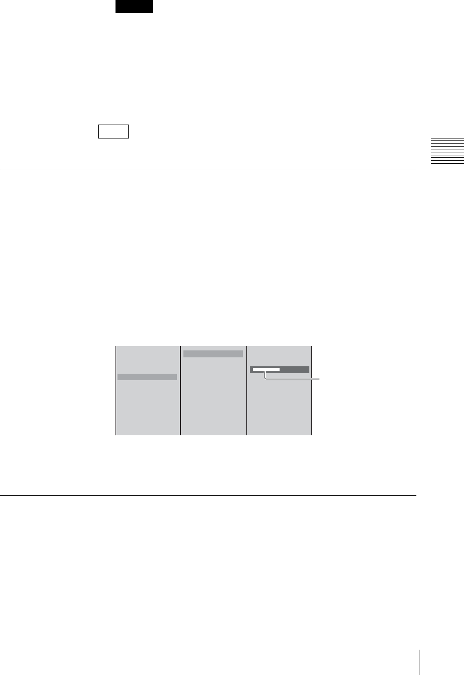
231
Importing, Renaming, and Deleting Files
Chapter 3 Operations
Characters other than alphanumeric characters cannot be displayed correctly.
This imports the logo file.
When the import is completed, a completion message appears.
5
Press the ENTER button.
6
Press the MENU button to close the menu.
The imported logo file can be used in “Showing a Logo on the Screen” (page 97).
Renaming Files
You can rename the following file types.
• AVI files (.avi) stored on an external hard disk
• VOD files (.rmvb)
1
Press the MENU button.
2
In the top menu, select [File Manager].
3
1 Select [Rename], and confirm; 2 select a hard disk number or [VOD
File], and confirm; 3 select the file to rename, input the new name, and
confirm.
4
Press the ENTER button.
5
Press the MENU button to close the menu.
Exporting VOD Files
You can export a VOD file to a “Memory Stick” or USB flash memory.
1
Insert the “Memory Stick” or USB flash memory in the “Memory Stick” slot
or USB connector on the side panel.
The upper USB connector is number 1, and the lower connector is number 2.
Caution
Note
Delete
Disconnect
Recover
Rename
Export EDL Type 1
Export EDL Type 2
Export VOD File
Export Job
Import Job
Import CG File
Import Logo File
HDD1
HDD2
HDD3
Real Madia File
[ aaaaaaaa.avi ]
bbbbbbbb.avi
[ ccccccccc.avi ]
123
Enter up to 20
alphanumeric characters
for AVI files and up to 24
alphanumeric characters
for VOD files.
* The camera guide menu can only
display a limited number of
characters.
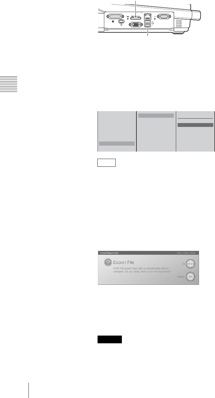
Chapter 3 Operations
232 Importing, Renaming, and Deleting Files
2
Press the MENU button.
3
In the top menu, select [File Manager].
4
1 Select [Export VOD File], and confirm; 2 select [Memory Stick], [USB
Flash Memory 1], or [USB Flash Memory 2], and confirm; 3 select the
VOD file to export, and confirm.
• The file names are arranged in alphabetical order.
• If you select [All] in step 3, all of the files are exported. If files of the same
name already exist on the “Memory Stick” or USB flash memory when
exporting all files, an overwrite confirmation message appears. When you
want to overwrite all of the existing files with the same name, press the
ENTER button while holding down the SHIFT button. When you want to
skip all of the files with the same name and only export file names that do
not already exist, press the ESC button while holding down the SHIFT
button.
The following confirmation message appears.
5
Press the ENTER button.
The VOD file is exported to the “Memory Stick” or USB flash memory.
When the export is complete, a completion message appears.
6
Press the MENU button to close the menu.
Exporting VOD files can take time. A 128 MB file takes about 3 minutes to
export, while a 2 GB file takes about 1 hour.
Notes
Caution
FACTORY USE REMOTE
RGB
(
GUI
)
RESET
USB
NETWORK
18
15 9
1
5
“Memory Stick” slot
USB connectors
Delete
Disconnect
Recover
Rename
Export EDL Type 1
Export EDL Type 2
Export VOD File
Export Job
Memory Stick
USB Flash Memory 1
USB Flash Memory 2
All
xxxxxxxxxx.edl
xxxxxxxxxx.edl
xxxxxxxxxx.edl
xxxxxxxxxx.edl
123
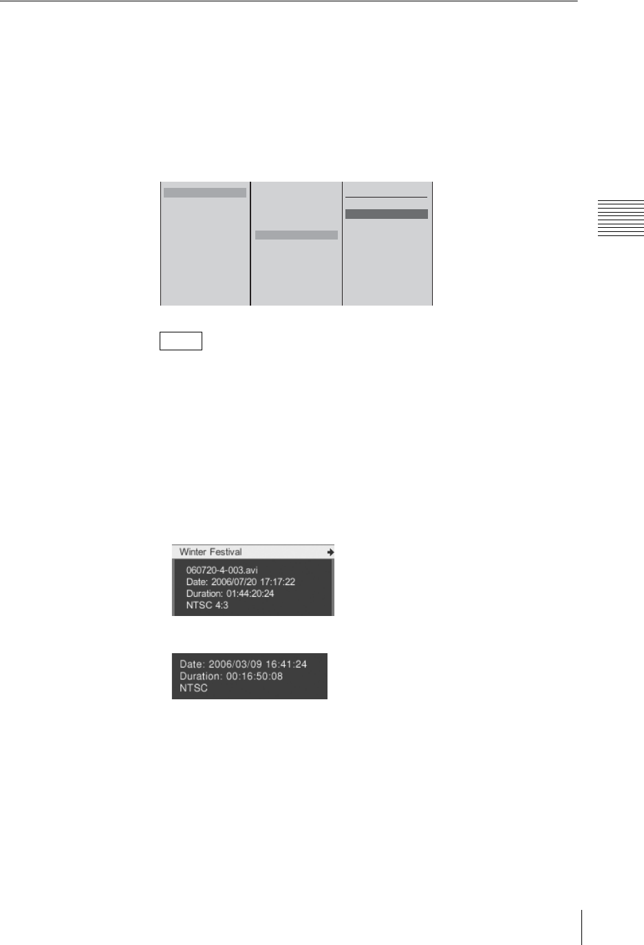
233
Importing, Renaming, and Deleting Files
Chapter 3 Operations
Deleting Files
1
Press the MENU button.
2
In the top menu, select [File Manager].
3
1 Select [Delete], and confirm; 2 select [EDL File], [CG File], [Logo File]
or the hard disk No., and confirm; 3 select the file to be deleted, and
confirm.
• It is not possible to delete files on the hard disk that are being used for
recording. End the recording before deleting them.
• The file names are arranged in alphabetical order.
• If you select [All] at step 3, all files are deleted.
•File information (for the hard disk, EDL file, graphics file, LOGO
file, and VOD file)
Information on the selected hard disk or EDL file and a thumbnail are
displayed as shown below if you press and hold down the t button of the
jog roller or the t key on the keyboard.
Hard disk
EDL file
Notes
Delete
Disconnect
Recover
Rename
Export EDL Type 1
Export EDL Type 2
Export VOD File
Export Job
Import Job
Import CG File
Import Logo File
HDD1
HDD2
HDD3
EDL File
CG File
Logo File
All
aaaaaaaa.avi
bbbbbbbb.avi b
ccccccccc.avi
123
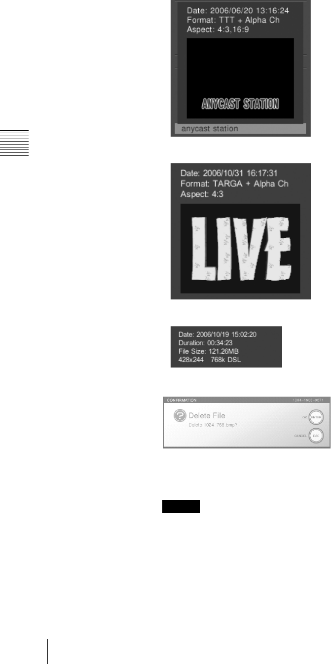
Chapter 3 Operations
234 Importing, Renaming, and Deleting Files
Graphics file
LOGO file
VOD file
The following confirmation message appears.
4
Press the ENTER button.
The deletion message appears and the file is deleted.
If the system is shut down or Text Typing Tool is started while a file in the
internal hard disk is being deleted, the hard disk will need to be recovered.
5
Press the MENU button to close the menu.
Caution

235
Importing, Renaming, and Deleting Files
Chapter 3 Operations
Checking the Internal Hard Disk Remaining Capacity
1
Press the MENU button.
2
In the top menu, select [File Manager].
In the [File Manager] menu, the remaining capacity is shown as [Local Disk
Remain].
17.215MB
Delete
Disconnect
Recover
Rename
Export EDL Type 1
Export EDL Type 2
Export VOD File
Export Job
Import Job
Import CG File
Import Logo File
Format
Local Disk Remain
Remaining capacity
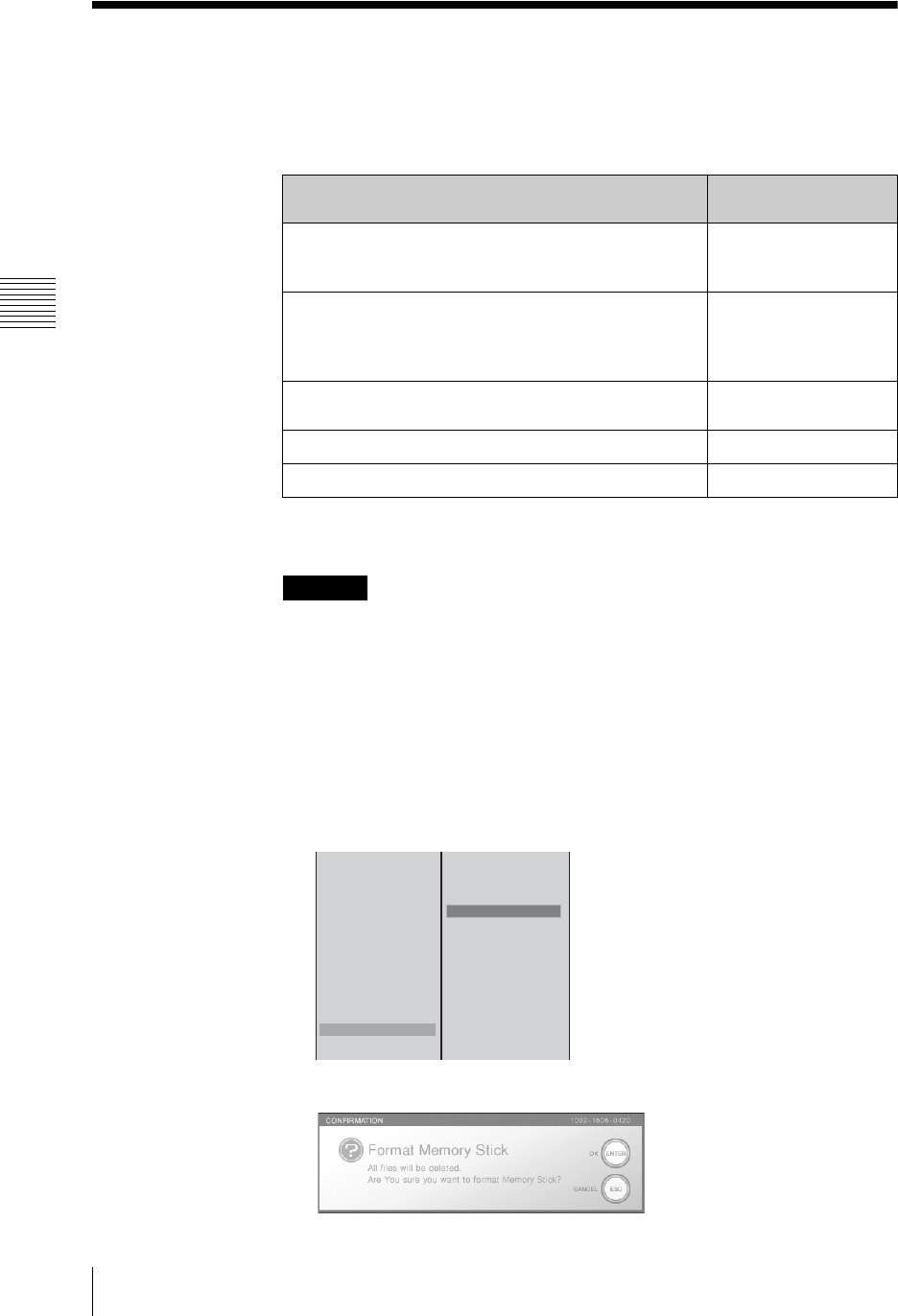
Chapter 3 Operations
236 Formatting a “Memory Stick”
Formatting a “Memory Stick”
Format a “Memory Stick” so that it can be used with this unit.
In this unit, use the following “Memory Stick” types.
* It is not possible to read or write data that requires the Magicgate function.
** This unit does not support parallel data transfer (high-speed data transfer).
Operation with all types of “Memory Stick” media is not guaranteed.
1
Insert the “Memory Stick” in the “Memory Stick” slot on the side panel.
2
Press the MENU button.
3
In the top menu, select [File Manager].
4
1 Select [Format], and confirm; 2 [Memory Stick], and confirm.
The following message appears.
“Memory Stick” type Use for reading/
writing on this unit
“Memory Stick”
“Memory Stick” (with memory select function)
“Memory Stick Duo”
Yes
“Memory Stick” (Magicgate/high-speed data transfer
support)
“Memory Stick Duo” (Magicgate/high-speed data transfer
support)
Ye s *
Magicgate “Memory Stick”
Magicgate “Memory Stick Duo” Ye s *
“Memory Stick PRO” Ye s *, **
“Memory Stick PRO Duo” Ye s *, **
Caution
Delete
Disconnect
Recover
Rename
Export EDL Type 1
Export EDL Type 2
Export VOD File
Export Job
Import Job
Import CG File
Import Logo File
Format
Local Disk Remain
HDD1
HDD2
HDD3
Memory Stick
USB Flash Memory 1
USB Flash Memory 2
12

237
Formatting a “Memory Stick”
Chapter 3 Operations
5
Press the ENTER button.
The formatting begins.
When the formatting ends, the following message appears.
6
Press the ENTER button, to close the message.
Formatting a “Memory Stick” on this unit automatically creates the
following directory structure on the “Memory Stick.”
MSSONY/PRO/LPS/ANYCAST/INSTALL
/JOB
/LICENCE
/CG
/LOGO
/VOD
/EDL
/FONT
7
Press the MENU button to close the menu.
Note
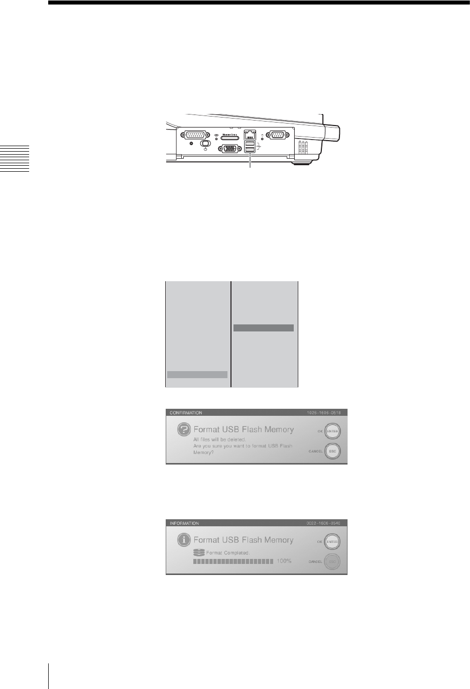
Chapter 3 Operations
238 Formatting a USB Flash Memory
Formatting a USB Flash Memory
Format a USB flash memory in order to use it with this unit.
1
Insert the USB flash memory into the USB connector on the side panel.
The upper USB connector is number 1, and the lower connector is number 2.
2
Press the MENU button.
3
In the top menu, select [File Manager].
4
1 Select [Format] and confirm; 2 Select [USB Flash Memory 1] or [USB
Flash Memory 2] and confirm.
The following confirmation message appears.
5
Press the ENTER button.
Formatting starts.
When formatting is completed, the following message appears.
6
Press the ENTER button, to close the message.
FACTORY USE REMOTE
RGB
(
GUI
)
RESET
USB
NETWORK
18
15 9
1
5
USB connector
Delete
Disconnect
Recover
Rename
Export EDL Type 1
Export EDL Type 2
Export VOD File
Export Job
Import Job
Import CG File
Import Logo File
Format
Local Disk Remain
HDD1
HDD2
HDD3
Memory Stick
USB Flash Memory 1
USB Flash Memory 2
12

239
Formatting a USB Flash Memory
Chapter 3 Operations
Formatting USB flash memory on this unit automatically creates the
following folder structure in the USB flash memory.
MSSONY/PRO/LPS/ANYCAST/INSTALL
/JOB
/LICENCE
/CG
/LOGO
/VOD
/EDL
/FONT
7
Press the MENU button, to close the menu.
Note
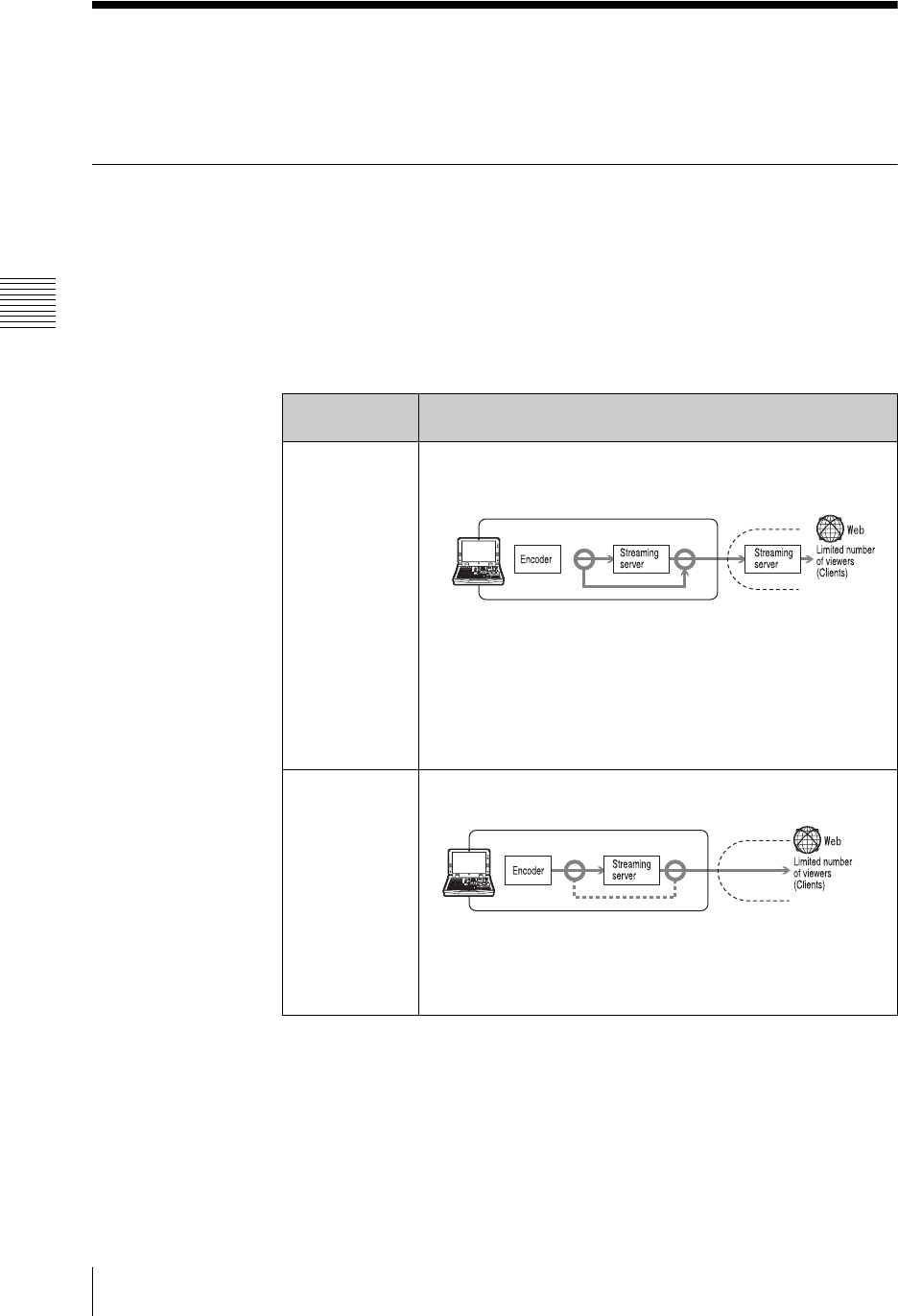
Chapter 3 Operations
240 Streaming
Streaming
You can encode the program output into Real Media streaming file format (.rm)
within this unit, and broadcast it on the network.
What Is Streaming?
Streaming is one method of the transmitting multimedia data. Video and audio
data is sent across a network, and may be played in real time.
To carry out live streaming with this unit, the program video and audio is encoded
in the format used by Real Player, and transmitted.
Encoding takes place on the unit. There are the following two transmission
methods.
Live Streaming
Transmission
method Features
Using your
provider’s
streaming server
• The results of encoding are sent from the unit to your provider’s
streaming server, and the viewers access the streaming server to
view the live content.
• To some extent you can select such things as the number of
clients that can view the content and delivery transfer rate
because it is possible to obtain high network bandwidth,
depending on your subscription with the provider.
• There is a cost for use of a streaming server.
• Obtain a subscription with a provider that provides a server that
supports the RealMedia streaming file format (.rm).
Using this unit as
the server
• The results of encoding are sent to the streaming server in the
unit, and the viewers access this unit to view the live contents.
• Since viewers directly access this unit, the number of viewing
clients and the data transfer rates are limited by the network
linking this unit to the viewers.
• There is no cost for a streaming server.
Provider
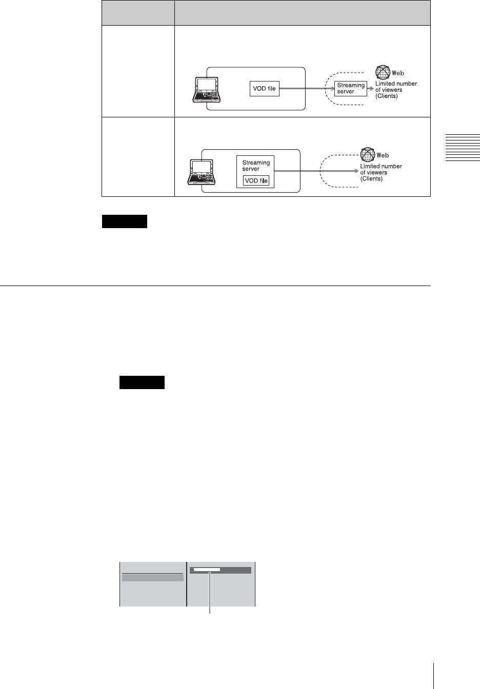
241
Streaming
Chapter 3 Operations
Using VOD
You cannot encode the program output into a format other than Real Media
streaming file format (.rm). If you want to encode into another format, you need
to input the program output of this unit into another encoder and encode it.
Configuring the Network Settings
With the network environment set up, make the network settings for this unit.
Ask your network administrator for further information about your network.
1
Connect a network cable to the NETWORK connector of this unit.
In order to meet EMC standards, use an STP (shielded twisted pair) type
Ethernet cable.
2
Press the MENU button.
3
In the top menu, select [Network].
4
Set the following items in the submenu.
Entering the host name
1 Select [Host Name], and confirm; 2 enter the host name in the input box,
and confirm.
Transmission
method Features
Using your
provider’s
streaming server
• Export a VOD file created on the unit, and place it on your
provider’s streaming server. Viewers access the streaming server
and view the content.
Using this unit as
the server
• Viewers access the VOD files stored on the unit’s internal
streaming server and view the content.
Caution
Caution
Provider
Apply
Host Name
IP Setting DHCP
DNS Setting DHCP
MAC Address
[ XXXXXXXXXX ]
Enter up to 15 alphanumeric characters.
The first character must be a letter.
12
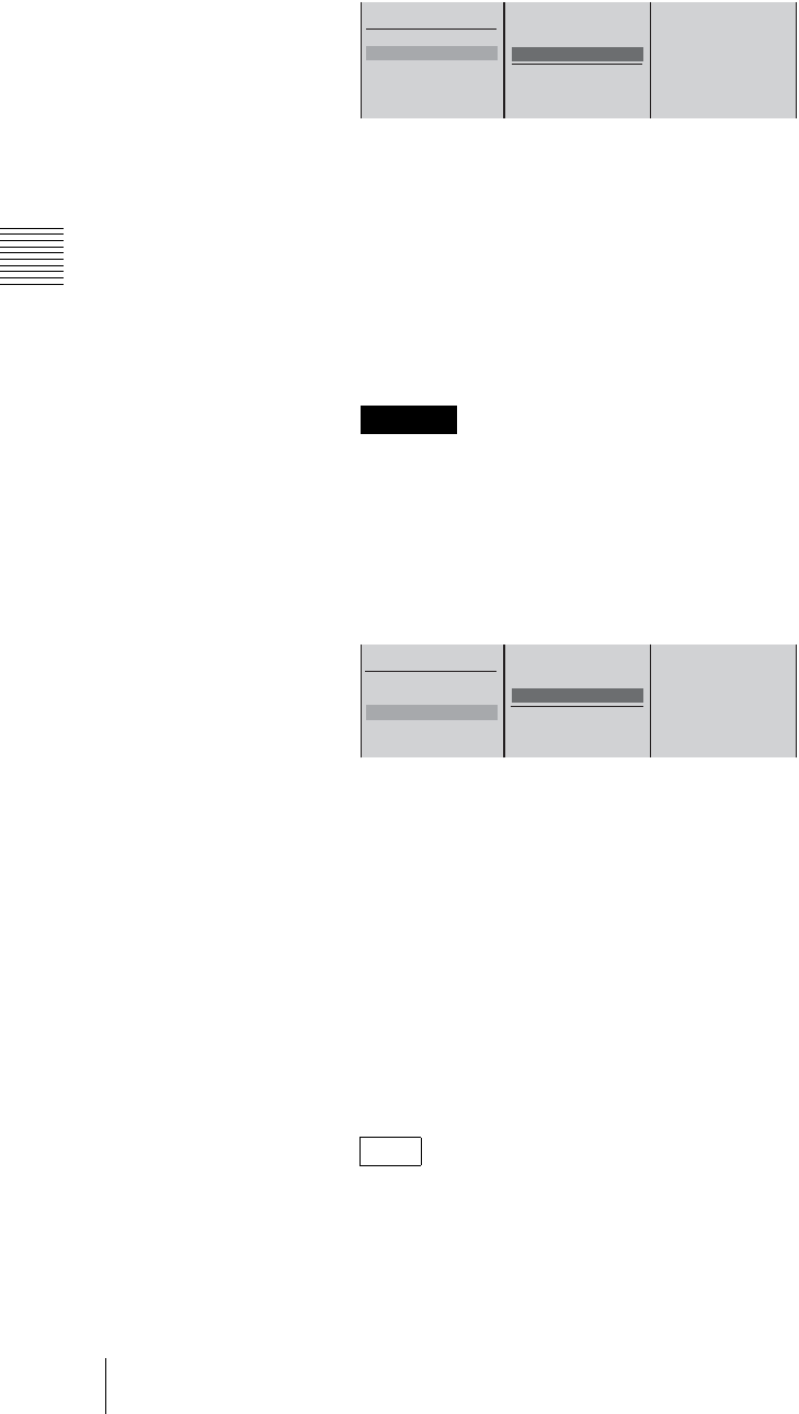
Chapter 3 Operations
242 Streaming
Setting the IP address
1 Select [IP Setting], and confirm; 2 make a selection, and confirm.
[Off]: When not setting an IP address
[DHCP]: When the address is automatically obtained from the DHCP server
[Manual]: When inputting the address manually
When [Manual] is selected, enter the following items, and confirm.
Input the default gateway if required.
[IP Address]: Enter the IP address.
[Subnet Mask]: Enter the subnet mask.
[Default Gateway]: Enter the default gateway address.
Because the unit uses “172.27.72.0 netmask 255.255.255.0” internally, the
unit will not operate correctly if settings are configured to include
“172.27.72.0 netmask 255.255.255.0.”
Making DNS settings
1 Select [DNS Setting], and confirm; 2 make a selection, and confirm.
[Off]: When not setting an IP address
[DHCP]: When the address is automatically obtained from the DHCP server
[Manual]: When inputting the address manually
When [Manual] is selected, enter the following items, and confirm.
[Domain Name]: Enter the domain name. Enter from 3 to 63 alphanumeric
characters. The first character must be a letter.
[Primary DNS]: Enter the address of the primary DNS server.
[Secondary DNS]: Enter the address of the secondary DNS server (Enter
as required).
5
Select [Apply], and confirm.
A network setting update message appears.
If the network settings are not changed, [Apply] is grayed out, and cannot be
selected.
Displaying the MAC address
Select [MAC Address] to display the MAC address of the internal network
card.
Caution
Note
Apply
Host Name
IP Setting DHCP
DNS Setting DHCP
MAC Address
Off
DHCP
Manual
IP Address
Subnet Mask
Default Gateway
XXX.XXX.XXX.XXX
XXX.XXX.XXX.XXX
XXX.XXX.XXX.XXX
12
Apply
Host Name
IP Setting DHCP
DNS Setting DHCP
MAC Address
Off
DHCP
Manual
Domain Name
Primary DNS
Secondary DNS
[ ]
. . .
. . .
12

243
Streaming
Chapter 3 Operations
6
Press the MENU button to close the menu.
Apply
Host Name
IP Setting DHCP
DNS Setting DHCP
MAC Address
XX:XX:XX:XX:XX:XX
12
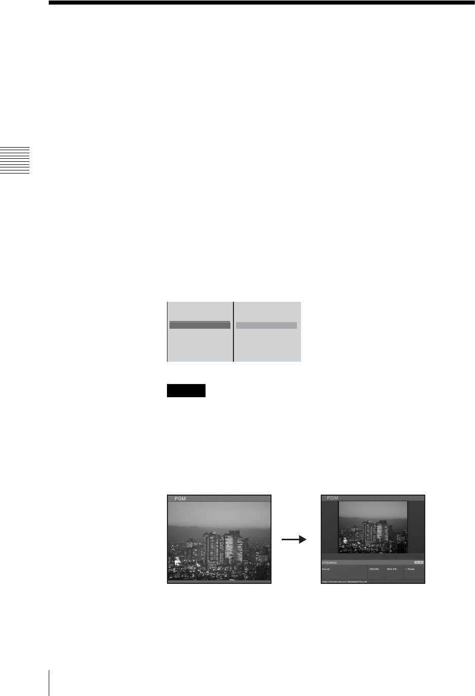
Chapter 3 Operations
244 Setting Live Streaming Transmission
Setting Live Streaming Transmission
Setting the menu
These settings make it possible for the program output from this unit to be
encoded in Real Media streaming file format (.rm), and transmitted by live
streaming.
You can also configure settings to save the contents of live streaming onto the
unit’s internal hard disk as files for VOD (Video On Demand) while the contents
are being transmitted.
1
Press the MENU button.
2
In the top menu, select [Streaming].
3
Set the following items in the submenu.
Selecting live transmission
1 Select [Output], and confirm; 2 select [Live] or [Live/VOD], and
confirm.
Select [Live/VOD] when saving the VOD file onto the internal hard disk
while transmitting live.
• When the above operation is done, the PGM viewer on the operation
screen becomes smaller.
• Even if left set to [Live] or [Live/VOD], when this unit is powered on
again, the setting returns to [Off].
• If VOD file creation stops after the internal hard disk becomes full while
transmitting live and creating the VOD file at the same time, the live
transmission will also stop.
Entering the file name
1 Select [Stream Name] and confirm; 2 select [Live File Name], and
confirm; 3 enter the file name in the input box, and confirm.
Caution
Off
Live/VOD
Live
VOD
START
STOP
Output Off
Stream Name
Size 320x240
Bit Rate 384k DSL
Clip Information
12
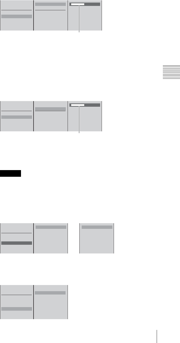
245
Setting Live Streaming Transmission
Chapter 3 Operations
Setting the streaming output path
If multiple encoders connect to the streaming server, enter the path for
identification. Set the path as necessary.
1 Select [Stream Name] and confirm; 2 select [Path] and confirm; 3 enter
the path following the default mount point (/broadcast/) in the input box and
confirm.
Example:
If “anycast/test” was entered, access and view material by entering rtsp://
xxx.xxx.xxx.xxx/broadcast/anycast/test/xxx.rm on a client.
You cannot set paths for VOD files.
Setting the video size
1 Select [Size], and confirm; 2 select the size of video to be output, and confirm.
Setting the transfer rate
1 Select [Bit Rate], and confirm; 2 select the transfer rate, and confirm.
Caution
Live File Name
Path
VOD File Name
[ XXXXXXXXXX ]
START
STOP
Output Live/VOD
Stream Name
Size 320x240
Bit Rate 384k DSL
Clip Information
Enter up to 20 alphanumeric characters.
123
Live File Name
Path
VOD File Name
[ XXXXXXXXXX ]
START
STOP
Output Live/VOD
Stream Name
Size 320x240
Bit Rate 384k DSL
Clip Information
Enter up to 50 alphanumeric characters.
123
START
STOP
Output Live/VOD
Stream Name
Size 320x240
Bit Rate 384k DSL
Clip Information
B 320 x 240
240 x 180
160 x 120
12
4:3 mode
B 426 x 240
320 x 180
212 x 120
2
16:9 mode
START
STOP
Output Live/VOD
Stream Name
Size 320x240
Bit Rate 768k DSL
Clip Information
1M Download
B 768k DSL
512k DSL
384k DSL
256k DSL
150k LAN
64k ISDN
56k Dial-up
12
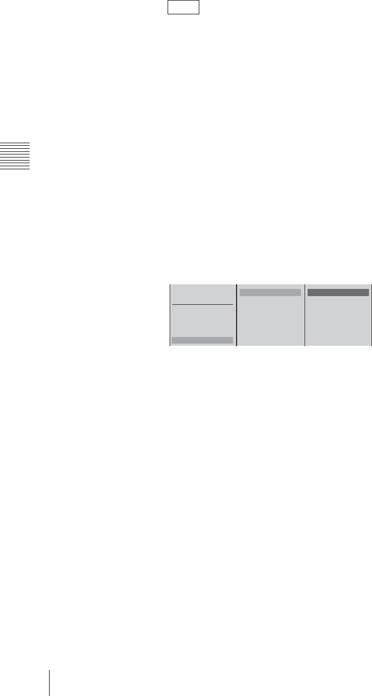
Chapter 3 Operations
246 Setting Live Streaming Transmission
• The actual transfer rates are as follows.
1M Download t1000 kbps (Video: 903.5 kbps Audio: 96.5 kbps)
768k DSL t700 kbps (Video: 603.5 kbps Audio: 96.5 kbps)
512k DSL t450 kbps (Video: 353.5 kbps Audio: 96.5 kbps)
384k DSL t350 kbps (Video: 285.9 kbps Audio: 64.1 kbps)
256k DSL t225 kbps (Video: 180.9 kbps Audio: 44.1 kbps)
150k LAN t150 kbps (Video: 118.0 kbps Audio: 32.0 kbps)
64k ISDN t50 kbps (Video: 39.0 kbps Audio: 11.0 kbps)
56k Dial-up t34 kbps (Video: 26.0 kbps Audio: 8.0 kbps)
• The following are recommended for combinations of video size and
transfer rate:
320 × 240 (428 × 240) t384 k DSL
240 × 180 (320 × 180) t256 k DSL
160 × 120 (212 × 120) t150 k DSL
Entering content information
1 Select [Clip Information], and confirm; 2 select the item to set, and
confirm; 3 enter the information in the input box, and confirm.
The items you can set are as follows.
[Title]: Enter a title of not more than 50 characters.
[Author]: Enter an author name of not more than 100 characters.
[Copyright]: Enter an owner name of not more than 100 characters.
4
Press the MENU button to close the menu.
Configuring the settings for connecting to a server
When using the internal server
Use the internal server of the unit for streaming transmission.
1
Press the MENU button.
2
Select [Streaming] in the top menu.
3
1 Select [Server Setting] and confirm; 2 select [Own] and confirm.
Notes
START
STOP
Output Live/VOD
Stream Name
Size 320x240
Bit Rate 768k DSL
Clip Information
[ ]
[ ]
[ ]
Title Summer Festa..
Author Wai-Wai..
Copyright © 2003 Sony
123
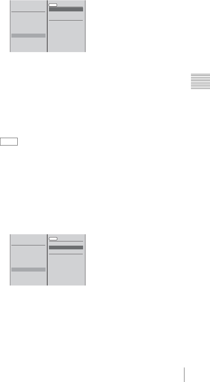
247
Setting Live Streaming Transmission
Chapter 3 Operations
4
Select [Apply] and confirm.
When using an external server
Configure the settings to enable a connection to be established to the external
server (Helix server of RealNetworks, inc.) to be used for streaming
transmission. There are two methods: Account-based login and password-only
login.
For the following procedure, select [Ext (Account)] for account-based login or
select [Ext (Password)] for password-only login. Then, contact the server
administrator for details on the information to set (IP address, port, listen address,
port range, protocol, user name, and password).
“Helix Administrator” mentioned in the following procedure refers to the
configuration and administration screen for Helix Server.
1
Press the MENU button.
2
Select [Streaming] in the top menu.
3
1 Select [Server Setting] and confirm; 2 select [Ext (Account)] or [Ext
(Password)] and confirm.
The subsequent setting items differ for [Ext (Account)] and [Ext
(Password)].
It is now possible to configure [Server Address] and the items below.
4
1 Select [Server Address] and confirm; 2 enter the IP address of the
external server in the input box and confirm.
Note
START
STOP
Output Live/VOD
Stream Name
Size 320x240
Bit Rate 768k DSL
Clip Information
Server Setting
VOD File Setting
VOD File Distribution
Connection Check
Apply
Own
Ext (Account)
Ext (Password)
Server Address
HTTP Port
RTSP Port
12
START
STOP
Output Live/VOD
Stream Name
Size 320x240
Bit Rate 768k DSL
Clip Information
Server Setting
VOD File Setting
VOD File Distribution
Connection Check
Apply
Own
Ext (Account)
Ext (Password)
Server Address
HTTP Port
RTSP Port
12
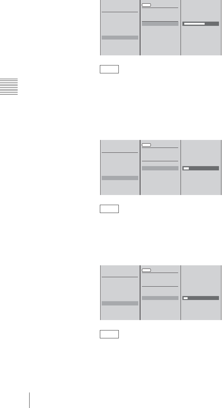
Chapter 3 Operations
248 Setting Live Streaming Transmission
For [Ext (Password)], enter the IP address of the unit (which is seen from the
external server when network address translation [NAT] is used) in
[Transmitter Address] of [Receiver] in the [Broadcast-Distribution] settings
of Helix Administrator.
5
1 Select [HTTP Port] and confirm; 2 enter the HTTP port set on the
external server in the input box and confirm.
Enter the HTTP port in [Ports] in the [Server Setup] settings of Helix
Administrator.
6
1 Select [RTSP Port] and confirm; 2 enter the RTSP port set on the
external server in the input box and confirm.
Enter the RTSP port in [Ports] in the [Server Setup] settings of Helix
Administrator.
Note
Note
Note
START
STOP
Output Live/VOD
Stream Name
Size 320x240
Bit Rate 768k DSL
Clip Information
Server Setting
VOD File Setting
VOD File Distribution
Connection Check
XXX.XXX.XXX.XXX
8080
554
Apply
Own
Ext (Account)
Ext (Password)
Server Address
HTTP Port
RTSP Port
12
START
STOP
Output Live/VOD
Stream Name
Size 320x240
Bit Rate 768k DSL
Clip Information
Server Setting
VOD Fil Settinge
VOD File Distribution
Connection Check
XXX.XXX.XXX.XXX
8080
554
Apply
Own
Ext (Account)
Ext (Password)
Server Address
HTTP Port
RTSP Port
12
START
STOP
Output Live/VOD
Stream Name
Size 320x240
Bit Rate 384k DSL
Clip Information
Server Setting
VOD File Setting
VOD File Distribution
Connection Check
XXX.XXX.XXX.XXX
8080
554
Apply
Own
Ext (Account)
Ext (Password)
Server Address
HTTP Port
RTSP Port
12
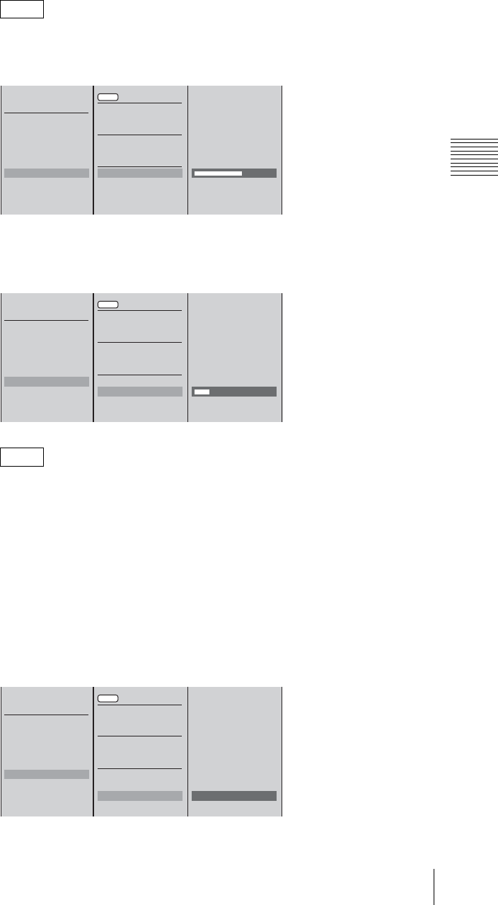
249
Setting Live Streaming Transmission
Chapter 3 Operations
7
For [Ext (Account)], 1 select [Listen Address] and confirm; 2 enter the IP
address of the unit which is seen from the external server when network
address translation [NAT] is used and confirm.
There is no need to enter an IP address if network address translation will not
be used.
8
For [Ext (Password)], 1 select [Port Range] and confirm; 2 enter the port
range set on the external server in the input box and confirm.
• Enter the same port range as that in [Receiver] of the [Broadcast-
Distribution] settings of Helix Administrator. Also, make sure the firewall
and other settings are configured so that communication between the unit
and Helix Administrator is not rejected.
• For [Ext (Account)], there is no need to configure the port range setting on
the unit, but match the firewall and other settings to the port range of
[RealNetworks Encoding] in the [Broadcasting] settings of the Helix
Administrator with which the unit will communicate.
9
1 Select [Transport] and confirm; 2 select the protocol to use for
communication with the external server and confirm.
Note
Note
START
STOP
Output Live/VOD
Stream Name
Size 320x240
Bit Rate 384k DSL
Clip Information
Server Setting
VOD File Setting
VOD File Distribution
Connection Check
XXX.XXX.XXX.XXX
5050
554
XXX.XXX.XXX.XXX
Apply
Own
Ext (Account)
Ext (Password)
Server Address
HTTP Port
RTSP Port
Listen Address
12
START
STOP
Output Live/VOD
Stream Name
Size 320x240
Bit Rate 384k DSL
Clip Information
Server Setting
VOD File Setting
VOD File Distribution
Connection Check
XXX.XXX.XXX.XXX
8080
554
. . .
30001 to 30020
Apply
Own
Ext (Account)
Ext (Password)
Server Address
HTTP Port
RTSP Port
Listen Address
Port Range
12
START
STOP
Output Live/VOD
Stream Name
Size 320x240
Bit Rate 384k DSL
Clip Information
Server Setting
VOD File Setting
VOD File Distribution
Connection Check
XXX.XXX.XXX.XXX
8080
554
. . .
[ 30001 ] to 30020
B UDP
TCP
Apply
Own
Ext (Account)
Ext (Password)
Server Address
HTTP Port
RTSP Port
Listen Address
Port Range
Transport UDP
12
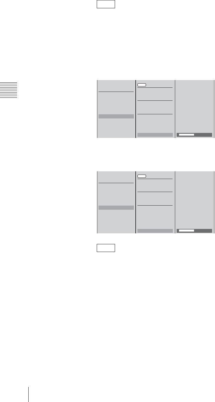
Chapter 3 Operations
250 Setting Live Streaming Transmission
For [Ext (Password)], set the same protocol as that set in [Receiver] in the
[Broadcast-Distribution] settings of Helix Administrator.
UDP communicates with “udp/unicast.” Also check other settings such as
the firewall settings.
10
For [Ext (Account)], 1 select [Username] and confirm; 2 enter the user
name to use for connecting to the external server in the input box and
confirm.
11
1 Select [Password] and confirm; 2 enter the password to use for
connecting to the external server in the input box and confirm.
Set the same password as that set in [Receiver] in the [Broadcast-
Distribution] settings of Helix Administrator.
12
Select [Apply] and confirm if you modified any settings in Steps 3, 4, 5, and
6.
This operation is not required if you only modified settings in Steps 7, 8, 9,
10, and 11.
13
Press the MENU button to close the menu.
Checking connections to other devices
You can check whether it is possible to connect to the default gateway set for [IP
Setting] of [Network] in the top menu, the external server set for [Server Setting]
of [Streaming] in the top menu, or another computer.
1
Press the MENU button.
Note
Note
START
STOP
Output Live/VOD
Stream Name
Size 320x240
Bit Rate 384k DSL
Clip Information
Server Setting
VOD File Setting
VOD File Distribution
Connection Check
XXX.XXX.XXX.XXX
8080
554
. . .
[ 30001 ] to 30020
B UDP
TCP
[ XXXXXXXXXX ]
Apply
Own
Ext (Account)
Ext (Password)
Server Address
HTTP Port
RTSP Port
Listen Address
Port Range
Transport UDP
Username
12
START
STOP
Output Live/VOD
Stream Name
Size 320x240
Bit Rate 384k DSL
Clip Information
Server Setting
VOD File Setting
VOD File Distribution
Connection Check
XXX.XXX.XXX.XXX
8080
554
. . .
[ 30001 ] to 30020
B UDP
TCP
[ XXXXXXXXXX ]
[ XXXXXXXXXX ]
Apply
Own
Ext (Account)
Ext (Password)
Server Address
HTTP Port
RTSP Port
Listen Address
Port Range
Transport UDP
Username
Password
12
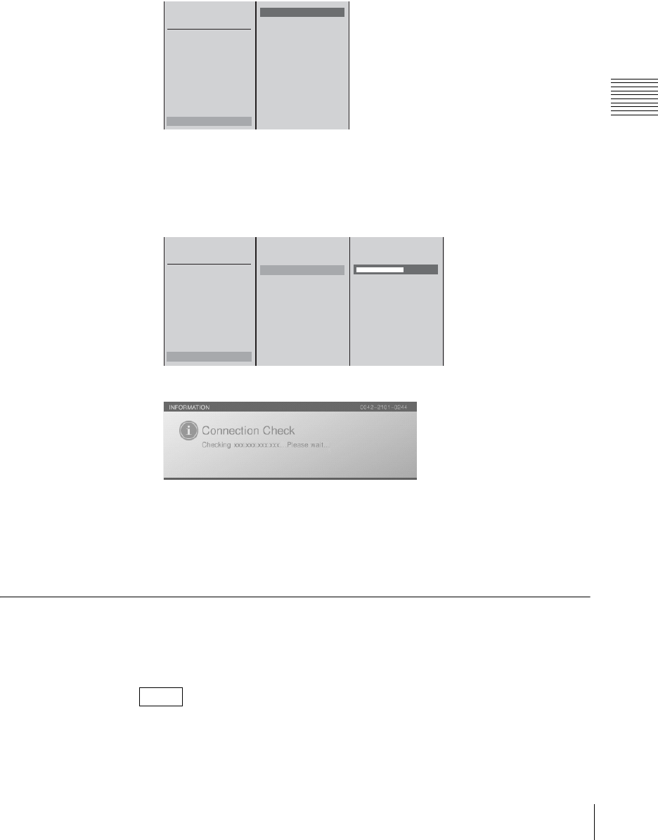
251
Setting Live Streaming Transmission
Chapter 3 Operations
2
Select [Streaming] in the top menu.
3
Check the connection to each computer in the submenu.
For the default gateway or external server
1 Select [Connection Check] and confirm; 2 select the device for which to
check the connection from the list and confirm.
For a device other than the above
1 Select [Connection Check] and confirm; 2 select [Other] and confirm;
3 enter the IP address of the device for which to check the connection in the
input box and confirm.
The following message appears and the communication check begins.
A message notifies you whether the connection succeeded or failed.
4
Press the ENTER button.
5
Press the MENU button to close the menu.
Saving Live Streaming Transmissions as Files for VOD
You can save live streaming transmissions onto the unit’s internal hard disk as
files for VOD.
You can confirm the list of saved files under [Rename] of [File Manager] or
[Export VOD File].
Note
START
STOP
Output Live/VOD
Stream Name
Size 320x240
Bit Rate 384k DSL
Clip Information
Server Setting
VOD File Setting
VOD File Distribution
Connection Check
External Server
Default Gateway
Other
12
START
STOP
Output Live/VOD
Stream Name
Size 320x240
Bit Rate 384k DSL
Clip Information
Server Setting
VOD File Setting
VOD File Distribution
Connection Check
External Server
Default Gateway
Other XXX.XXX.XXX.XXX
12 3
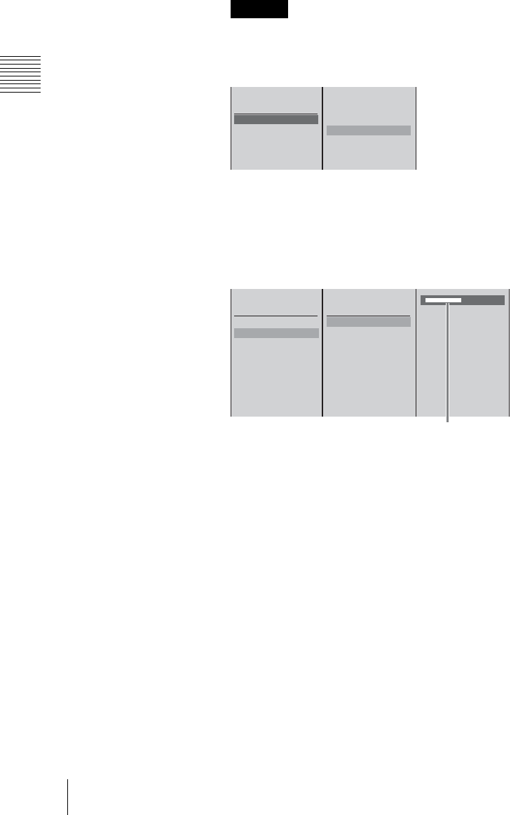
Chapter 3 Operations
252 Setting Live Streaming Transmission
Configuring settings for VOD file creation
1
Press the MENU button.
2
Select [Streaming] in the top menu.
3
1 Select [Output], and confirm; 2 select [VOD] or [Live/VOD], and
confirm.
If live transmission stops due to an error on the server while creating a VOD
file and transmitting live at the same time, VOD file creation will also stop.
4
Configure the settings for creating a VOD file.
Entering the file name
1 Select [Stream Name], and confirm; 2 select [VOD File Name], and
confirm; 3 enter the file name in the input box, and confirm.
Selecting the video size, transfer rate, and content
information
Configuration procedures are the same as those for live transmission.
For details, see “Setting the video size” (page 245), “Setting the transfer
rate” (page 245), and “Entering content information” (page 246) under step
3 of “Setting the menu”.
Selecting the frame rate
1 Select [VOD File Setting], and confirm; 2 select [Frame Rate], and
confirm; 3 select a frame rate, and confirm.
Caution
Off
Live/VOD
Live
VOD
START
STOP
Output Off
Stream Name
Size 320x240
Bit Rate 384k DSL
Clip Information
12
Live File Name
Path
VOD File Name
[ XXXXXXXXXX ]
START
STOP
Output Live/VOD
Stream Name
Size 320x240
Bit Rate 384k DSL
Clip Information
Server Setting
VOD File Setting
VOD File Distribution
Connection Check
12 3
Enter up to 20 alphanumeric characters.
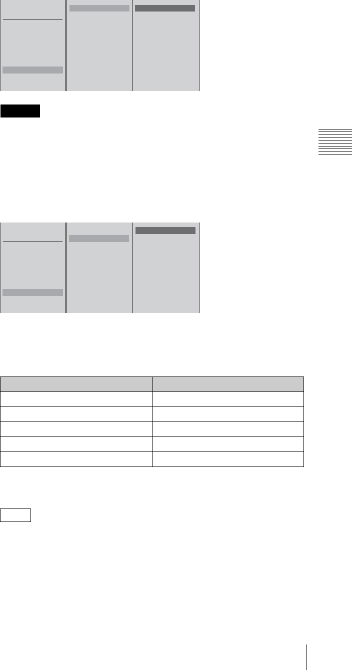
253
Setting Live Streaming Transmission
Chapter 3 Operations
If [Live/VOD] is selected for [Output], you cannot configure the frame rate.
Selecting the file size
When recording for long periods of time, select a size for the created files to
be broken up to.
1 Select [VOD File Setting], and confirm; 2 select [Export Size], and
confirm; 3 select a size for each segment, and confirm.
The following is a guide for the lengths of time the recording will be broken
up to.
Example: When [Size] is set to “320×240”, [Bit Rate] is set to “1M
Download”, and [Frame Rate] is set to “30 fps”.
* The lengths of time vary depending on the video and settings. Use this only as
a guide.
When the size of a file reaches the size you specify, that file completes and
file creation continues with a new file. A number (starting with 1 and
increasing with each successive file) follows the file name you specify.
Example:
live1.rmvb
5
Press the MENU button to close the menu.
Caution
File Size Length
2 GB 4 hours
1 GB 2 hours
512 MB 1 hour
256 MB 30 minutes
128 MB 20 minutes
Note
Frame Rate 30fps
Export Size 2GB
30fps
15fps
10fps
START
STOP
Output Live/VOD
Stream Name
Size 320x240
Bit Rate 384k DSL
Clip Information
Server Setting
VOD File Setting
VOD File Distribution
Connection Check
12 3
Frame Rate 30fps
Export Size 2GB
B 2GB
1GB
512MB
256MB
128MB
START
STOP
Output LiveLive/VOD
Stream Name
Size 320x240
Bit Rate 384k DSL
Clip Information
Server Setting
VOD File Setting
VOD File Distribution
Connection Check
12 3
Chapter 3 Operations
254 Setting Live Streaming Transmission
Transmitting a stored VOD file
Start the unit’s internal server to transmit VOD files stored on the unit’s internal
hard disk.
1
Press the MENU button.
2
Select [Streaming] in the top menu.
3
Select [VOD File Distribution], and confirm.
The VOD file is transmitted.
Viewers can view the content of the VOD file by accessing “rtsp://the unit’s
address/VOD/the specified file name.rmvb” from Real Player.
While the internal server is running, the VOD icon appears as follows. The
icon is grayed out while the internal server is running.
To close accessibility to stored content, delete or rename that content’s file.
Starting and Stopping Streaming
If you import a graphics file while streaming is in progress, the image will distort.
Be aware of this especially when creating VOD files.
Starting streaming
1
Make the settings described in “Configuring the Network Settings” (page
241) and “Setting Live Streaming Transmission” (page 244).
2
Press the MENU button.
3
In the top menu, select [ON LINE Manager].
Note
Caution
Caution
START
STOP
Output Live/VOD
Stream Name
Size 320x240
Bit Rate 768k DSL
Clip Information
Server Setting
VOD File Setting
VOD File Distribution
Connection Check
VOD icon
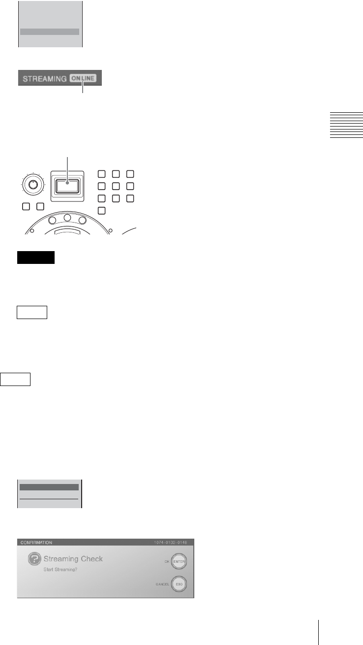
255
Setting Live Streaming Transmission
Chapter 3 Operations
4
Select [Steaming] to set it [On], and confirm.
The setting turns on or off each time it is selected.
When [Streaming] is set to [On], the ON LINE icon for streaming appears.
5
Press the ON LINE button.
The ON LINE button lights red, and a transmission starts.
Be sure to have a client computer available to check that a signal is being
transmitted, using Real Player.
You can also activate all of the reserved functions for the ON LINE button
simultaneously. For details, see “Activating Each Function Simultaneously
With the ON LINE Button” (page 259).
You can also start streaming via the top menu.
1
Press the MENU button.
2
Select [Streaming] in the top menu.
3
Select [START], and confirm.
The following confirmation message appears.
Caution
Note
Note
PGM Recording
Source Recording
EDL Off
Streaming On
DV OUT Recording Off
ON LINE icon
MONI LEVEL
010
ON LINE
DIM TB
789
456
1
0
23
M
I
X
E
F
F
E
C
T
P
V
W
ON LINE button
START
STOP
Output

Chapter 3 Operations
256 Setting Live Streaming Transmission
4
Press the ENTER button.
Streaming starts.
Stopping streaming
1
Press the ON LINE button.
A confirmation message appears.
2
Press the ENTER button.
The ON LINE button dims, and transmission ends.
If you press the ON LINE button while holding down the ESC button in step
1, transmission stops without a confirmation message being displayed.
You can also end streaming via the top menu.
1
Press the MENU button.
2
Select [Streaming] in the top menu.
3
Select [STOP], and confirm.
Streaming ends.
This section describes how to configure settings on the computer for viewing
material streamed from this unit. Perform these settings on network-ready
computers.
Downloading Real Player
Download Real Player from the Web site of RealNetworks, Inc.
Viewing streamed material from the unit
1
Start Real Player.
2
Click [Open] on the [File] menu.
3
Follow the procedure below to enter an URL.
When using the rtsp protocol for access
rtsp://Server Address[:Port]/broadcast/[Stream Path]/File Name.rm
* If port number 554 is to be used, you can omit [:Port] after the server
address.
Note
Note
Settings Required for Viewing Streaming
START
STOP
Output
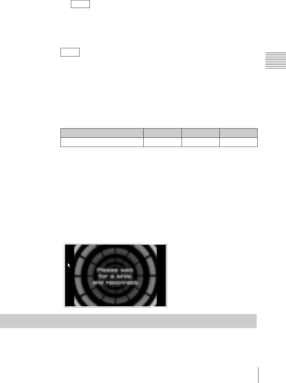
257
Setting Live Streaming Transmission
Chapter 3 Operations
When using the http protocol for access
http://Server Address[:Port]/ramgen/broadcast/[Stream Path]/File Name.rm
* If port number 80 is to be used, you can omit [:Port] after the server
address.
For “Server Address,” “Stream Path,” and “File Name,” enter the character
strings set on the unit.
4
Press the Enter key.
Select [Preferences] on the [Tools] menu in Real Player, and configure your
connection settings in accordance with your network environment.
Guidelines for number of Real Player connections depending on
transfer rate (for Own)
The following table shows the number of Real Player connections possible for
each transfer rate.
The figures are guidelines only, and depend on the operating conditions of the
network.
When video/audio deteriorates or stops during streaming
Streaming video/audio deteriorates or stops primarily due to network traffic, the
player software or settings, or insufficient processing power in the computer
running the player software.
If such problems occur, check the above.
When the message “Please wait for a while and reconnect.”
appears (for Own)
If Real Player connects to the unit when the ON LINE button of [Live] or [Live/
VOD] of [Output] in the internal server settings (Own) is not pressed, the
following “Please wait for a while and reconnect.” standby clip is played. The
standby clip is not played when the external server (Ext) settings are configured.
This section describes how to offer streaming material to viewers using a Web
page.
Perform these settings on network-ready computers.
Note
Note
Transfer rate 768k/512k 384k/256k 150k/64k/56k
Number of Real Player connections 5 10 20
Placing Streaming Links in a Web Site

Chapter 3 Operations
258 Setting Live Streaming Transmission
1
Open a text editor such as Notepad, and enter the URL for the streaming
content in Real Media format as shown below.
rtsp://IP address of the unit or the external server (Helix Server)/broadcast
(path)/specified filename.rm
Example: rtsp://xxx.xxx.xxx.xxx/broadcast/live.rm
2
Save the file with the extension “.ram.”
This file becomes the metafile of the Real Media format.
3
Upload to the Web server the metafile saved in step 2.
4
Insert a link to the metafile in the Web page on which you want to publish
the stream.
Note
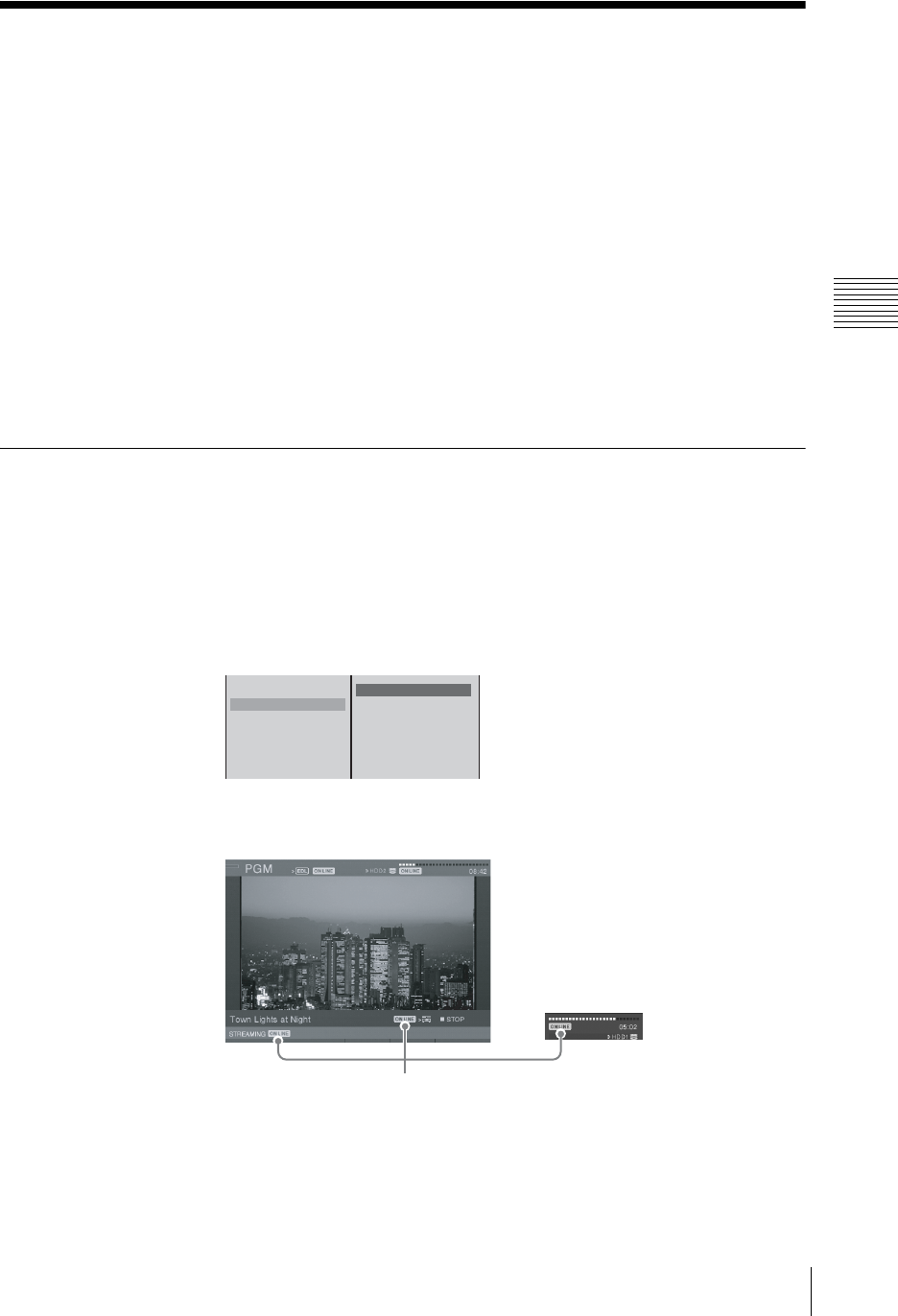
259
Activating Each Function Simultaneously With the ON LINE Button
Chapter 3 Operations
Activating Each Function Simultaneously With
the ON LINE Button
You can activate all five of the reserved functions for the ON LINE button
simultaneously.
Preparation
See the following sections to prepare each function and allow them to be
activated with the ON LINE button
• For [PGM Recording] and [Source Recording], see “Preparing for Recording
to an External Hard Disk” (page 171).
• For [EDL], see “Preparing for EDL creation” (page 223).
• For [Streaming], see “Setting Live Streaming Transmission” (page 244).
• For [DV OUT Recording], see “Operating the Unit to Record Program Outputs
to a VCR” (page 192) and “Configuring settings for VOD file creation” (page
252).
Activating the Functions With the ON LINE Button
1
Perform preparations for each of the functions.
2
Press the MENU button.
3
In the top menu, select [ON LINE Manager].
4
Confirm that the functions you want to activate are selected or set to [On].
5
Press the MENU button to close the menu.
The ON LINE icon for activation appears.
6
Press the ON LINE button.
PGM Recording HDD1
Source Recording
EDL On
Streaming On
DV OUT Recording On
s 1
s 2
s 3
s 4
s 5
s 6
ON LINE icon
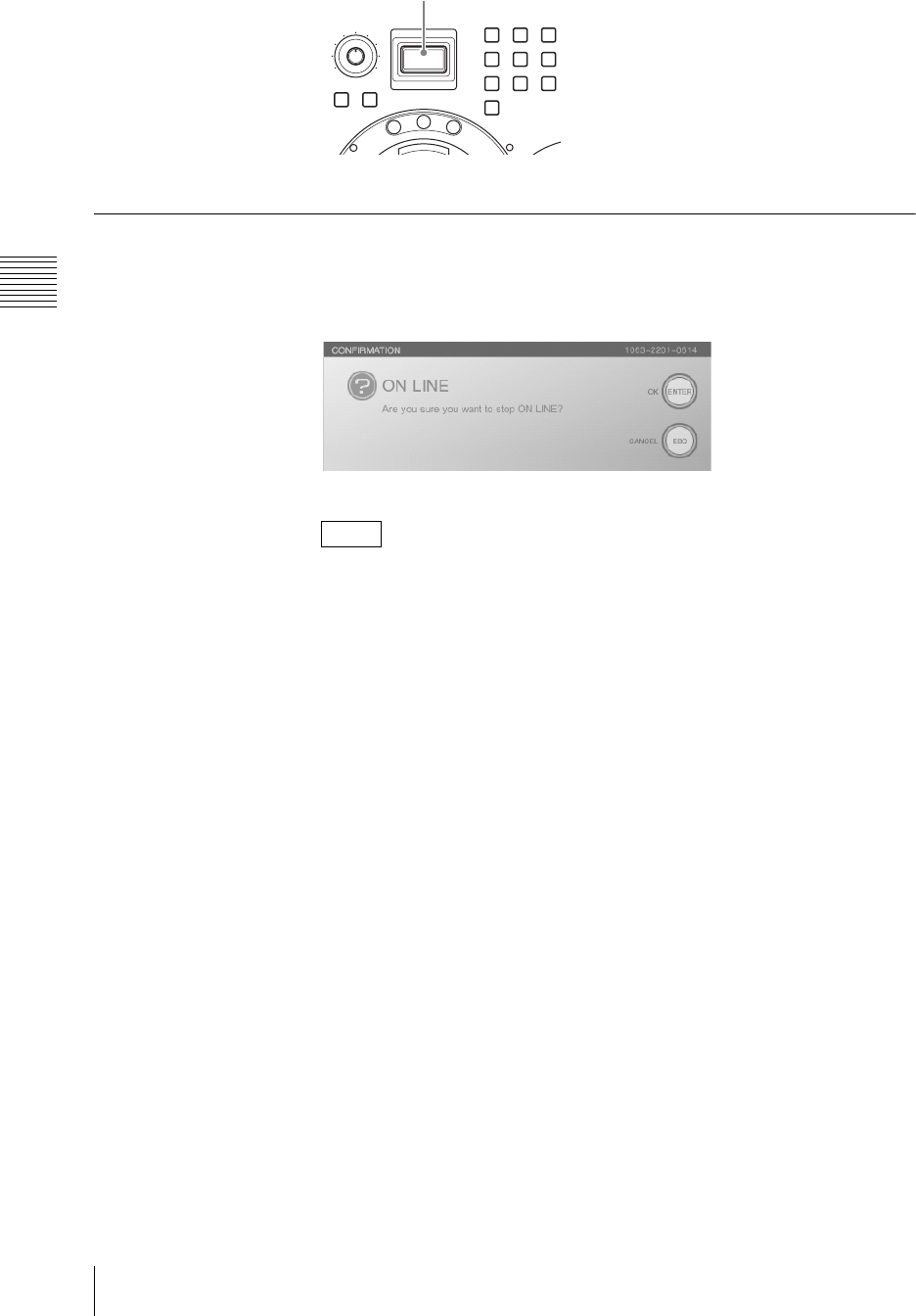
Chapter 3 Operations
260 Activating Each Function Simultaneously With the ON LINE Button
The ON LINE icon disappears, and the various status displays change.
Deactivating the Functions With the ON LINE Button
1
Press the ON LINE button.
The following confirmation message appears.
The ON LINE icon flashes while this message is displayed.
If you press the ON LINE button while holding down the ESC button, each
function deactivates without a confirmation message being displayed.
2
Press the ENTER button.
Each of the functions deactivate, and the ON LINE icon appears.
Note
MONI LEVEL
010
ON LINE
DIM TB
789
456
1
0
23
M
I
X
E
F
F
E
C
T
P
V
W
ON LINE button

Appendix
261
Maintenance
Appendix
Maintenance
This section describes how to check the operating software version, and upgrade.
Checking the Operating Software Version
You can check the version number of the operating software and hardware
constituting this unit and the interfaces modules installed in this unit, as well as
the unit’s serial number.
1
Press the MENU button.
2
In the top menu, select [Version], and then check the displayed version
information.
The items you can check are as follows.
Main Application: You can check the version number of the operating
software.
Text Typing Tool: You can check the version number of the Text Typing
Tool software.
Effect Board: You can check the firmware and hardware version of the
effects board.
Audio Board: You can check the firmware and hardware version of the
audio board.
Interface Modules 1 to 3: You can check the firmware and hardware
version of the rear panel interface modules.
Panel: You can check the firmware version of the front panel.
Serial No. XXXXX
The interface module version only appears when the module is installed.
3
Press the MENU button to close the menu.
Caution
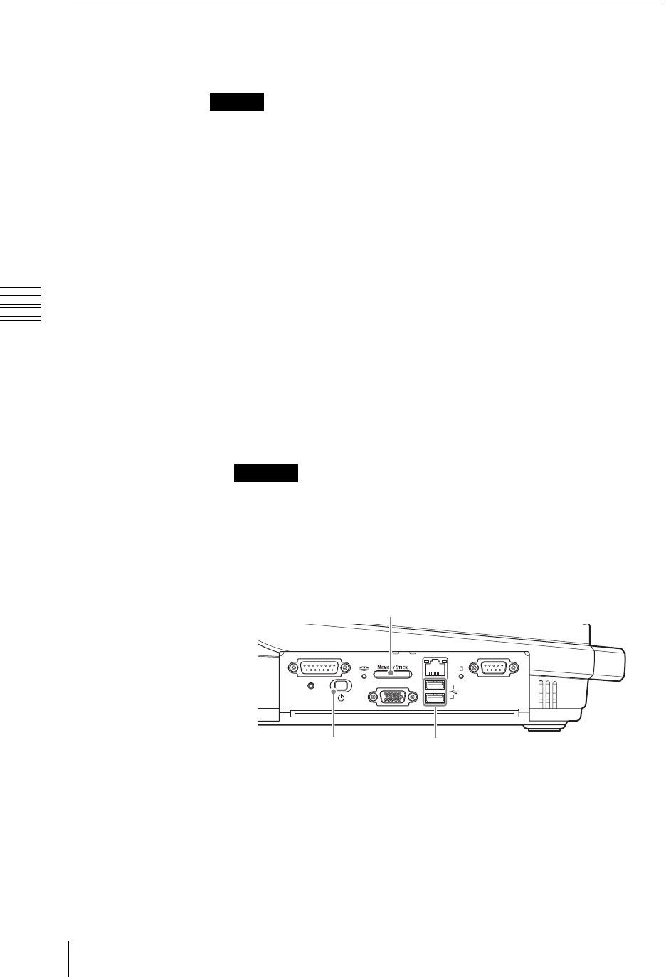
Appendix
262 Maintenance
Upgrading the Operating Software
This section describes how to upgrade when there are improvements to the
operating software and hardware firmware.
When the external hard disk is connected to the unit, always disconnect it before
upgrading the operating software.
Information on upgrades
Information on software upgrades is available from the Anycast Station portal
site operated by Sony.
The following site also provides links to the portal site and information on
upgrades.
https://servicesplus.us.sony.biz/SoftwarePlusSerch.aspx (for customers in
U.S.A.)
https://www.sony.biz.net/anycast (for customers in Europe, Middle East and
Africa)
https://www.ecspert.sony.biz/ecsite/ (for the other customers)
Download to a “Memory Stick” or USB flash memory.
Upgrade procedure
1
Insert a “Memory Stick” or USB flash memory holding the installation
program in the “Memory Stick” slot or USB connector on the side panel.
Before carrying out the following operation, plug the device into the
“Memory Stick” slot or USB connector used for installation only, and
remove other devices.
2
Press the 1 (power) button on the side panel.
This powers on the unit.
Caution
Caution
FACTORY USE REMOTE
RGB
(
GUI
)
RESET
USB
NETWORK
18
15 9
15
96
“M
emory
S
t
i
c
k”
s
l
ot
1 (power) button USB connector
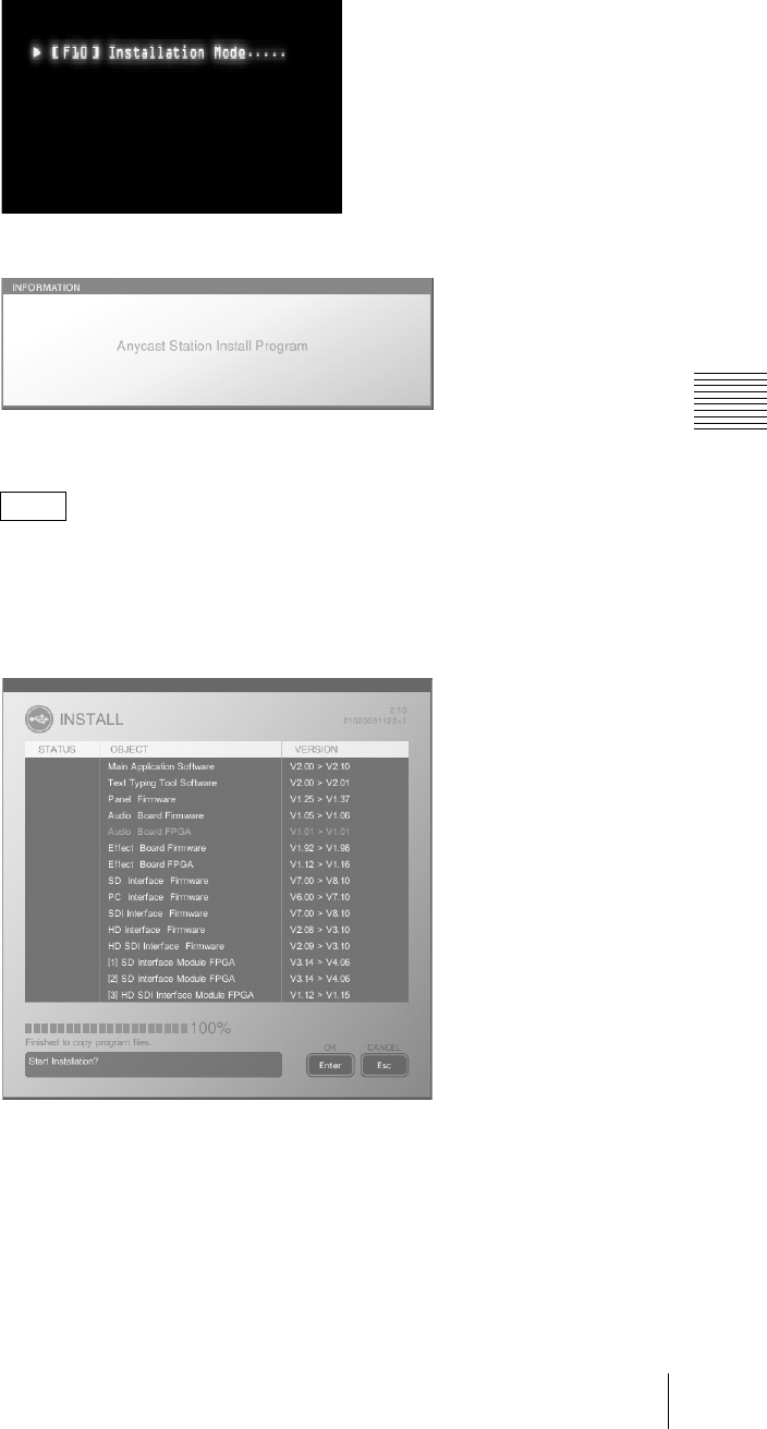
263
Maintenance
Appendix
3
After the startup screen, press the F10 (Fn+0) key on the keyboard while the
message is displayed indicating that function key input is possible.
The following screen appears.
The “INSTALL” screen appears after a few moments, and “C:Copying
Program files...” appears.
• If the same version is already installed, this object is grayed out, and
excluded from the upgrade.
• The “C:” in “C: Copying Program files...” refers to the “Memory Stick,”
and “D:” and “E:” refer respectively to the upper and lower ports to which
the USB flash memory is connected.
Notes
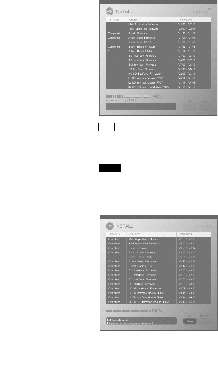
Appendix
264 Maintenance
4
Check that the progress indication has reached 100%, and press the keyboard
ENTER key.
The installation starts.
Installation does not begin if you click the Enter button on the front panel.
In the “STATUS” column, an asterisk (*) blinks while the operating software
is being installed. When installation ends successfully, “Completed” is
displayed, and if installation has failed, “Error” is displayed instead.
Do not turn the unit off or remove a “Memory Stick” or USB flash memory
from the unit while data is being read or written; otherwise the file may be
destroyed.
When the installation completes, the following message appears.
Note
Caution

265
Maintenance
Appendix
5
Check the installation completed message, then press the keyboard ENTER
key.
This powers off the unit.
When you next power on the unit, the operating software starts.
• During the installation, if the “STATUS” indication shows “Error”, repeat
the installation process from the beginning. If this does not clear the
problem, consult your dealer or your Sony service representative.
• Users who purchased the optional BKAW-550/BKAW-560/BKAW-570/
BKAW-580/BKAW-590 should install the optional equipment and then
perform the same version upgrade.
When an interface module with older software is installed
The software versions of installed interface modules are automatically compared
to that of the unit during startup, and if there is an interface module running on
older software, the following message appears.
Press the enter button, and perform the procedure from step 3 (after pressing the
F10 (Fn+0) key) of “Upgrade procedure” (page 262). After performing this
procedure, the software versions of the interface module and unit will match.
Caution
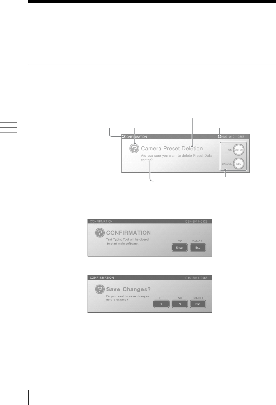
Appendix
266 Messages
Messages
If any problem occurs during operation of this unit, a message appears. Before
asking your dealer for help, use the information in this section to try to solve the
problem. If this is not successful, make a note of the displayed message number,
and consult your dealer or your Sony service representative.
Message Structure
The messages that appear during operation of this unit consist of the following
parts.
Anycast Station main software messages
To select [OK], press the ENTER button or Enter key on the keyboard.
To select [Cancel], press the ESC button or Esc key on the keyboard.
Text Typing Tool software messages
To select [OK], click the [Enter], or press the keyboard Enter key.
To select [CANCEL], click the [Esc], or press the keyboard Esc key (Fn+~/` key).
To select [YES], click the [Y], or press the keyboard Y key.
To select [NO], click the [N], or press the keyboard N key.
To select [CANCEL], click the [Esc], or press the keyboard Esc key (Fn+~/` key).
Message types
The significance of the message type is as follows.
Error message
Message type: ERROR
Message type Message symbol (error)
Location (function) where message occurred
Response to foregone
message
Message details
Message number
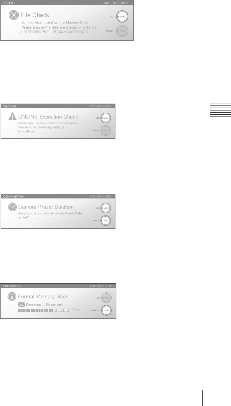
267
Messages
Appendix
Message number: 4XXX-YYYY-ZZZZ (begins with 4)
As a result of an operation, an error occurred.
Warning message
message type: WARNING
message number: 2XXX-YYYY-ZZZZ (begins with 2)
This appears when a preliminary check before carrying out an operation
discovered a problem.
Confirmation message
Message type: CONFIRMATION
Message number: 1XXX-YYYY-ZZZZ (begins with 1)
This type of message requests user confirmation, and can be cancelled.
Informational message
Message type: INFORMATION
Message number: 0XXX-YYYY-ZZZZ (begins with 0)
This provides information to the user.

Appendix
268 Messages
List of Messages
If a message on this list is displayed and still appears after trying the operation
again, consult your dealer or your Sony service representative.
Number Message text
0001 Data has been exported to directory xx.
0002 Deleting ... Please wait. xx
0003 Exporting... Please wait. xx
0004 Format completed.
0005
0006 Formatting ... Please wait.
0007
0008 Import completed.
0009 Importing... Please wait. xx
0010 Shutting Down. Saving System Settings.
0011 Updating Network Settings.
0012 Installation finished. Please reboot for changes to take effect.
0013 Anycast Station Install Program
0014 Checking Memory Device.
0015 “Memory Stick” device was found.
0016 USB Flash Memory device was found.
0017 Installation canceled. Shutting down.
0018 Shutting Down.
0020 The changes will take effect after the next reboot.
0021 It is now safe to remove HDDX.
0022 Format Completed.
0023 Formatting ... Please wait.
0024 To re-mount the HDD, Please ensure it is properly connected and re-start the unit.
0025 Recovery completed.
0026 Recovering ... Please wait.
0027 Shutting Down. Cannot save the file during editing.
0028 One font file was copied.
0029 xx font files were copied.
0030 Please wait.
0031 Please wait. Importing... xx/xx fonts.
0032 Please wait.
0033
0034 Please wait. Exporting... xx/xx sheets.
0035 Please wait.
0036 Please wait. Saving... xx/xx sheets.
0038 One or more frames were dropped during recording file xx. Please check that the recording
quality is sufficient.
0039 Deleting... Please wait. xx
0040 Loading has been canceled.
0041 Please reboot for changes to take effect.
0042 Checking xxx.xxx.xxx.xxx ...Please wait.
0043 No answer from xxx.xxx.xxx.xxx.
0044 xxx.xxx.xxx.xxx is alive.
0045 Data has been save to file xx.
0046 File xx has not been recorded because video input signal was not detected.
0047 EDL data has been divided into the following files. xx-xx.
0048 EDL data has been divided into some files.
0049 An error occurred again. The problem persists.
Please contact the service center.
0050 CIME was permitted, please set CIME on again.
0052 Installing... Please wait.

269
Messages
Appendix
0053 Setting has been canceled.
0054 CIME is not available, please input the Key Code for available.
0055 Aborting... Please wait.
0058 The changes will take effect after the next reboot.
0059 Starting
0060 VOD File Distribution will also be started simultaneously.
0061 Deleting... Please wait.
1001 Abort Installation?
All Software will be returned to Previous Version.
1002 All files will be deleted. Are you sure you want to format “Memory Stick”?
1003 Are you sure you want to delete Preset Data xx?
1004 Delete xx?
1005 File xx already exists. Overwrite?
1006 xx is currently being used as the LOGO or INT source. Do you really wish to delete this file?
1007 xx is currently being used as the LOGO or INT source. Do you really wish to overwrite this
file?
1009 Start Installation?
1010 Audio Source also will be set to Analog. L:xx R:xx
1011 When selecting DV Audio, Embedded DV Video will be selected automatically.
1012 When selecting DV Video, Embedded DV Audio will be selected automatically.
1013 Delete xx? All files on HDDX will be closed.
1014 All files will be deleted. Are you sure you want to format disk? Disk Size: xxGB, File
System: ext3
1015 A file on HDDX is currently being used. Do you really wish to format the HDD?
1016 Start recording X.xxxx.avi
1017 Slot xx-xx DV interface has already been assigned as an input. Would you like to cancel the
assignment and re-assign to the PGM Output.
1018 When the audio input assignment is changed, opened files will be closed automatically.
1020 When the PGM Output assignment is changed, any opened files will be closed automatically.
1021 When the video input assignment is changed, opened files will be closed automatically.
1024 Main software will be closed to start Text Typing Tool. Recording and Streaming will be
stopped.
1025 A file in HDDxx is currently being used. Do you really wish to disconnect the HDD?
1026 All files will be deleted. Are you sure you want to format USB Flash Memory?
1027 Are you sure you want to set the Power Off Timer? The system will be shutdown in 2 hours.
1029 Recording of the audio assigned to Source xx is not currently supported. The DV embedded
audio will be recorded.
1030 This source has already been assigned to Source No. xx. Would you like to assign it to
Source No. xx instead?
1031 Disk recovery may take a considerable time to complete. Do you really wish to run the
recovery tool?
1032 Disk recovery may take a considerable time to complete. Do you really wish to run the
recovery tool? All files will be closed.
1033 Do you want to delete xx?
1034 File Name, Saved Day
1035 Text Typing Tool will be closed to start main software.
1036
aMemory Stick
aUSB Flash Memory 1
aUSB Flash Memory 2
1037 File Name, Saved Day
1038
1039 aall sheets
acurrent sheet
1040
aMemory Stick
aUSB Flash Memory 1
aUSB Flash Memory 2
1041 aDuplicate current sheet
aCreate a blank sheet
Number Message text

Appendix
270 Messages
1042 Do you want to save changes before creating a new file?
1043 Do you want to save changes before opening a new file?
1044 A file with this name already exists.
Overwrite?
1045 File Name, Saved Day
1046 Do you want to save changes before exiting?
1047 File Name, Saved Day
1048 a4:3
a16:9
1051 When selecting SDI Audio, Embedded SDI Video will be selected automatically.
1052 When selecting SDI Video, Embedded SDI Audio will be selected automatically.
1053 CH1/2 and CH3/4 of the same source may not be assigned simultaneously. X/X is already
assigned. Would you like to assign Y/Y instead?
1054 Are you sure you want to delete xx?
1055 xx already exists. Overwrite?
1057 Do you want to delete xx?
1059 xx were not found. Do you want to select an alternative font?
1060 One or more interface modules require a firmware upgrade.
1061 File Name, Saved Day
1062
1063 Are you sure you want to stop ON LINE?
1064 Slot xx-xx DV interface has already been assigned as an input. Would you like to cancel the
assignment and record PGM Output?
1065 When the PGM Output is assigned, recording of xx will be canceled.
1066 Slot xx-xx DV interface has already been assigned as DV OUT. Would you like to cancel the
assignment and record PGM Output?
1067 When the PGM Recording is assigned, recording of xx will be canceled.
1069 xx already exists. Overwrite?
1070 An error occurred during installation. Retry installation?
1071 Please reboot for changes to take effect.
1073 Are you sure you want to delete Preset Data xx?
1074 Start Streaming?
1075 When selecting HD SDI Audio, Embedded Video will be selected automatically.
1076 When selecting HD SDI Video, Embedded Audio will be selected automatically.
1077 When selecting 16:9HD, DV / SDI Output and PGM recording will be not available.
1078 When the input assignment is changed, recording of source xx xx will be canceled.
1079 When selecting “Live”, the transmission rate of 1M cannot be selected. It changes the
maximum rate which can be selected.
1080 Are you sure you want to abort?
1083 Distribution of VOD File is stopped.
1084 xx was not found. Do you want to select an alternative font?
1085 Slot xx-xx DV interface has already been scheduled for DV OUT recording. Would you like
to cancel recording?
1086 Are you sure you want to export EDL for xx?
1087 One or more interface modules require a firmware upgrade. Start Installation?
1088 Are you sure you want to delete all Preset Data (1 - xx)?
1090 Streaming of ON LINE Manager will also be halted.
1091 VOD File export may take a considerable time to complete. Do you really wish to run the
export tool?
1092 The settings of Streaming will also be halted.
2001 Could not find file xx.
2002 Please insert “Memory Stick” or USB flash memory containing Installation Software and
select OK to retry installation.
2004 Cannot read this type of “Memory Stick”.
2005 This “Memory Stick” needs formatting by the Anycast Station.
2006 This USB Flash Memory needs formatting by the Anycast Station.
2007 This “Memory Stick” needs formatting by the Anycast Station.
2008 Cannot read this type of “Memory Stick”.
Number Message text

271
Messages
Appendix
2009 This type of compressed image file is not supported. xx
2011 Insufficient Space on “Memory Stick”. xx (xx)
2012 Internal Disk Full.
2013
2014 Invalid Date and Time. YYYY/MM/DD HH:MM
2015 Less than 500MB of free space remaining on Internal Hard Disk.
2016 “Memory Stick” is Write Protected. Please remove Write Protection and re-insert.
2018 Only images of size 160×120 are supported.
2019 Only the following sizes of CG file are supported.
Width 720 - 1920 Aspect 4:3 5:4 5:4 16:9 16:10
2020 Please complete the current transiting before pressing the KEY button.
2021 Please complete the Network Settings before starting streaming.
2022 Please complete the Streaming Settings before starting streaming.
2024 Please enter Network Settings for Streaming.
2025 Please insert a USB Flash Memory and select OK to retry.
2026 The characters ¥ / : , ; * ? " < > | [ ] = cannot be used.
2027 Streaming, EDL and Recording functions currently unavailable. Please enter the necessary
settings to continue.
2031 To use the DSK, a CG file must be selected as the INT source. Please select a CG file.
2035 HDDX has been removed. To avoid file corruption before removing the HDD, please
execute “Disconnect” from the File Manager menu.
2036 HDDX is full.
2037 Cannot record to HDDX. The disk is not formatted, or has been formatted with an
unrecognized file system.
2038 HDDX is not recognized.
2041 The number of files on HDDX has exceeded the system limit.
2042 Cannot change the audio input assignment while recording to HDD.
2043 Cannot change the video input assignment while recording to HDD.
2044 Cannot change the PGM Output assignment while recording to HDD.
2046 Insufficient Space on USB Flash Memory. xx (xx)
2047 This USB Flash Memory needs formatting by the Anycast Station.
2048 Cannot change Disk Recording Settings while recording to HDD.
2049 Please insert a “Memory Stick” and select OK to retry.
2051 USB Flash Memory is Write Protected. Please remove Write Protection and re-insert.
2052 Problems have been found on HDDX. To avoid errors during HDD recording and playback,
please run the recover tool from the File Manager menu.
2053 More than one device is connected to the HDD port (HDDX). Only one HDD can be
connected.
2054 Capture function is not ready.
Please start main application first.
2055 Internal Disk Full.
2056 Could not create directory xx.
2057 USB Flash Memory full.
2058 “Memory Stick” full.
2059 This USB Flash Memory is write protected.
Please remove Write Protection and re-insert.
2060 This “Memory Stick” is write protected.
Please remove Write Protection and re-insert.
2062 This USB Flash Memory needs formatting by the Anycast Station.
2063 This “Memory Stick” needs formatting by the Anycast Station.
2065 Please insert a USB Flash Memory and select OK to retry.
2066 Please insert a “Memory Stick” and select OK to retry.
2067 There was a invalid Font file, “xx.ttf.”
2068
No Font files were found on the USB Flash Memory.
Please ensure the Font files are placed in directory.
xx:/MSSONY/PRO/LPS/ANYCAST/FONT/
Number Message text

Appendix
272 Messages
2069
No Font files were found on the “Memory Stick”.
Please ensure the Font files are placed in directory.
c:/MSSONY/PRO/LPS/ANYCAST/FONT/
2070 File Name contains illegal characters.
The characters ¥ / : , ; * ? " < > | [ ] = % cannot be used.
2071 There were invalid Font files, “xx.ttf, xx.ttc, ...”.
2072 Recording of this type of source to HDD is not possible.
2073 No files were found on the “Memory Stick”. Please ensure the files are placed in directory.
c:xx
2074 No files were found on the USB Flash Memory. Please ensure the files are placed in
directory.x:xx
2075 Recording of this source to HDD is not possible while DV (SlotX-X) is being used for DV
OUT.
2076 Could not find file xx.
2077 HDDX has been formatted by a later version of Anycast Station, and is incompatible with
this version.
2078 More than two storage devices were found. Please ensure only one device is inserted.
2079 Internal Disk Full. Please delete unwanted files.
2080 Please enter the Job file name.
2081 Could not find Job xx.
2082 Please enter xx Settings, then select “Apply”.
2083 Please enter Default Gateway Settings, then execute “Connection Check”.
2084 Please enter Other Settings, then execute “Connection Check”.
2085 Please enter Server Address Settings, then execute “Connection Check”.
2086 Connection to external server failed. Please check the Anycast Station Setup, and the status
of the External Server and Network. (xx)
2087 Please enter xx Settings, then select “Live”.
2090 Please turn off the PinP effect before pressing the PVW button.
2093 Please enter IP Address Settings, then select “Apply”.
2094 Please enter Primary DNS Settings, then select “Apply”.
2095 Please enter Subnet Mask Settings, then select “Apply”.
2096 The Subnet Mask contains an invalid bit pattern. Please re-enter then select “Apply”.
2097 Invalid Default Gateway address. Please re-enter then select “Apply”.
2098 When using DHCP to assign DNS Server settings, IP address settings must also be assigned
by DHCP. Please re-enter then select “Apply”.
2099 Domain Names must be 3 characters or longer. Please re-enter then select “Apply”.
2100 Domain Names must start with an alphabetic character. Please re-enter then select “Apply”.
2101 Host Names must start with an alphabetic character. Please re-enter then select “Apply”.
2102 Domain Name cannot end with a hyphen or a period. Please re-enter then select “Apply”.
2103 Host Names cannot end with a hyphen. Please re-enter then select “Apply”.
2105 Please close opened file before performing this operation.
2106 Please set Streaming Output to “Off” before performing this operation.
2108 Recording of this source to HDD is not possible while Slot xx-xx is being used for PGM
Recording.
2109 Please access to the URL below to get a Key Code to activate Chinese IME. It would be
issued free of charge. Following code is required for admittance.
2111 Please make sure the device is ready to record before executing ON LINE.
2112 Please select DV OUT port before performing this operation.
2114 Recording PGM Output to HDD is not possible while DV (Slot xx-xx) is being recorded.
2115 It is the incorrect Key Code. CIME is not permitted.
2117 Please set Streaming Output before performing this operation.
2118 The character “ cannot be used.
2119 File xx already exists. Please input other file names.
2120 Less than 500 MB of free space remaining on Internal Disk. Please ensure this is sufficient.
2121 Less than 500 MB of free space remaining on Internal Disk. Live distribution is also stopped
when capacty is lost during file creation.Do you wish to continue?
2122 It is incompatible with this version.
Number Message text
273
Messages
Appendix
2123 Filename xx has been reserved for VOD generation. Please input other file name.
4001 An error occurred during formatting.
4002 An error occurred when loading file.
4003 An error occurred when reading file.
4004 An error occurred when writing file.
4005 An error occurred while deleting the file. xx
4006 An error occurred while exporting. xx
4007 An error occurred while importing. xx
4008 An error occurred while opening CG file.
4009 Cannot execute encode process. Please restart the unit.
4010 An error occurred while applying Network Settings.
4012
Unable to start due to Hardware Fault.4013
4014
4015 FATAL ERROR:Helix DNA Server.
4016
Unable to start due to Hardware Fault.
4017
4020
4021
4023
4025
4026
4027
4028
4029
4030
4031
4032
4033
4034
4035
4036
4037
4038
4039
4040
4041
Unable to start due to Hardware Fault.
4042
4043
4047
4048
4049 Failed to acquire Network Settings from DHCP server. To retry please select “Apply” from
the Network Menu.
4051 Unable to start due to Hardware Fault. Installation Canceled.
4062 Invalid executable program for installation.
4063 Unable to start due to Hardware Fault.
4064 Invalid program file was detected.
Installation canceled. Shutting down.
4069 Unable to start due to Hardware Fault.
4070 HDDX is full. Recording stopped.
4071 HDDX is not recognized. Recording stopped.
4072 Recording failed due to unspecified error.
4075 An error occurred during disconnecting. (HDDX)
4077 HDDX is not recognized.
4078 An error occurred while recovering.
Number Message text
Appendix
274 Messages
If the following message appears, immediately turn off the power to the unit and consult
your dealer or your Sony service representative.
4079 More than one device is connected to the HDD port (HDDX). Only one HDD can be
connected. Recording Stopped.
4080 An error occurred while deleting xx.
4081 A fault has developed with the internal fan. To avoid damage please shutdown the system as
soon as possible.
4082 An error occurred when opening xx.
4083 An error occurred when reading xx.
4084 An error occurred when writing xx.
4085 Memory allocation error.
4086 An error occurred while opening TTF font file xx .
4087 An error occurred while reading file xx.
Read permission denied or file does not exist.
4088 An error occurred while checking the version compatibility of xx.
4089 Opening file failed.
4091 Signal format of input source xx has been changed. Recording stopped.
4092 Connection timeout between encoder and server.
4093 The unusual end of the encoder was carried out.
4094 Cannot connect to the wnn server.
4095 An error occurred connecting to the wnn server.
4096 An error occurred while loading Job.
4097 An error occurred while saving Job.
4098 The system had failed in last shutdown.
Please restart the unit.
4101 Cannot start recording xx. HDDX is not recognized.
4102
4103 Cannot start recording xx. HDDX is full.
4104 Cannot start recording xx. A file is opened.
4105 An error occurred while saving EDL.
4106 Cannot start recording xx. The number of files on HDDX has exceeded the system limit.
4107 An error occurred while setting.
4111 An error occurred while renaming.
4113 Cannot start recording. The device is not ready to record.
4114 Cannot read Timecode.
4115 Internal disk is full. Creating file was stopped.
4116 The devise is not recognized. DV OUT recording stopped.
Number Message text
4045 A fault has developed with the internal fan.
To avoid damage please shutdown the system as soon as possible.
4046
Number Message text
275
Troubleshooting
Appendix
Troubleshooting
Check this section before consulting your dealer or your Sony service
representative. If the unit still does not function properly, consult your dealer or
your Sony service representative.
Problem Possible causes Possible solutions See
page
Video-related
Video does not appear in the
source viewer.
The connected device is not
turned on.
Turn the connected device on. –
The cables are not connected
properly.
Check that the cables are
connected properly.
56
The input signal is not assigned
correctly.
Check that the input signal is
assigned correctly.
66
Video does not appear in the
PGM viewer.
The FTB button is lit. Turn off the FTB button. 89
The PGM does not switch. The [KEY ON] indicator on the
operation screen is lit red.
While the KEY button on the
front panel is lit green, press the
CUT button.
99
The video in the source viewer is
compressed.
In 4:3 mode, 16:9 video material
displays are squeezed.
Set to 16:9 mode. 52
4:3 materials display in wide
screen.
In 16:9 mode, 4:3 video material
displays appear in wide screen.
Set to 4:3 mode. 54
The selection buttons switch on
their own.
[Remote Switching] of [Video
Utility] is set to something other
than [Off], even when there is no
external device connected to the
FACTORY USE connector.
Set [Remote Switching] to [Off]. 166
Audio-related
No sound is emitted from the
speakers or headphones (the
audio level meter does not move).
The connected device is not
turned on.
Turn the connected device on. –
The cables are not connected
properly.
Check that the cables are
connected properly.
56
The input signal is not assigned
correctly.
Check that the input signal is
assigned correctly.
66
The CH ON button is not lit. Turn on the CH ON button. 168
The audio channel fader has been
left turned down.
Turn up the audio channel fader. 168
The PGM fader has been left
turned down.
Turn up the PGM fader. 168
The monitor target is set to AUX. Set the monitor destination
displayed below the audio level
meter to PGM.
204
No sound is emitted from the
speakers or headphones (the
audio level meter moves).
The monitor output level is
turned down.
Turn up the monitor output level
with the monitor level adjustment
knob.
168
The TB button or the DIM button
is lit.
Turn off the TB button or the
DIM button.
201
No sound is emitted from the
internal speakers.
A device is connected to the
monitor output connector.
–
The peak indication does not
disappear.
The control of the peak
indication is not possible if the
input audio is DV or SDI.
Check the input signal. –
Appendix
276 Troubleshooting
DV input
Noise occurs in the video or
audio. No video or audio is
output.
The signal is not being received
clearly.
Disconnect and then reconnect
the cables. After reconnecting the
cables, restart the connected DV
device and the unit.
–
DV output
DV signals are not output. The DV output settings are not
configured.
Configure the DV output settings. 188
The aspect ratio is set to 16:9 HD
mode.
Set to 4:3 or 16:9 SD mode. 52
SDI output
SDI signals are not output. The aspect ratio is set to 16:9 HD
mode.
Set to 4:3 or 16:9 SD mode. 52
Picture-in-picture
The NEXT selection button
flashes and the picture-in-picture
effect is not applied.
An attempt was made to use the
same image for picture-in-picture
as the one being used for keying.
Select a different image. 87
An attempt was made to use the
image assigned to INT for
picture-in-picture.
Select a different image. 87
An attempt was made to use the
same image for picture-in-picture
as the one being used for
program output.
Select a different image. 87
Luminance keying, chroma keying, and downstream keying
Keying does not work. Keying is hidden because of the
Crop setting.
Change the Crop setting. 109
Keying is hidden because of the
Clip, Gain, or Density settings.
Change the values set for Clip,
Gain, or Density.
93, 102
Keying adjustments do not take
effect.
A keying source created with
PowerPoint was saved in Tiff
format.
Save keying sources created with
PowerPoint in BMP format.
228
Keying does not disappear when
the KEY button is pressed.
The KEY button is not an On/Off
button for keying.
Make the KEY button light
green, and perform a transition,
such as with the CUT button.
100
Keying does not disappear when
the DSK button is pressed.
Luminance or chroma keying is
being performed.
Make the KEY button light
green, and perform a transition,
such as with the CUT button.
100
Keying does not disappear when
a transition is performed with the
KEY button lit.
Downstream keying is being
performed.
Turn off the DSK button. 92
Colors specified with the cursor
are not removed.
The correct color cannot be
determined because the cursor
frame is too small.
Enlarge the cursor frame. 106
Logos
Keying does not work. Keying is hidden because of the
Clip, Gain, or Density settings.
Change the values set for Clip,
Gain, or Density.
98
Problem Possible causes Possible solutions See
page
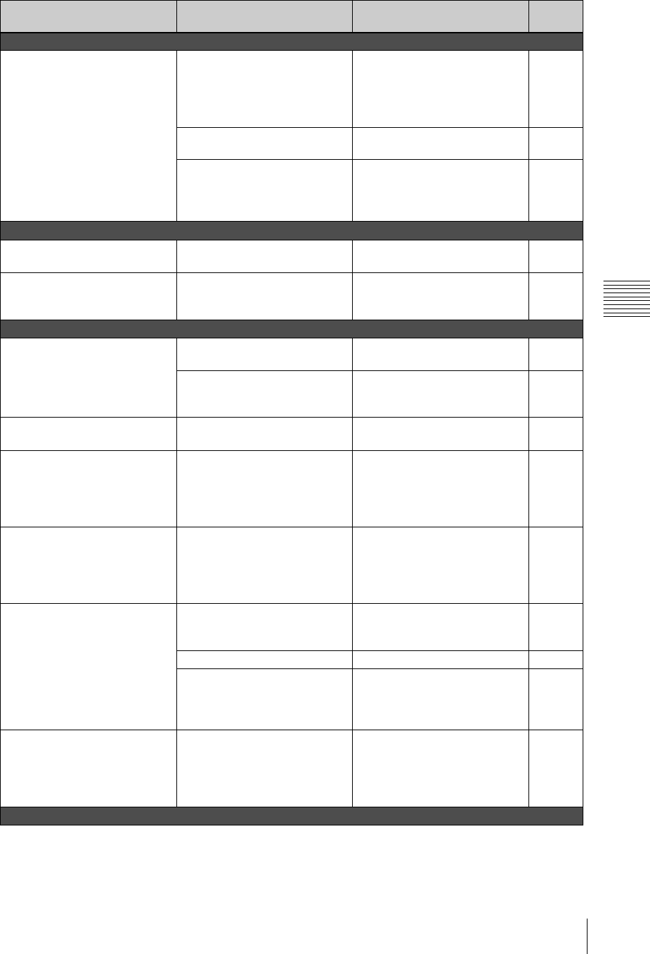
277
Troubleshooting
Appendix
Camera controls
The camera cannot be controlled. The VISCA cables are not
connected properly.
Check that the VISCA cables are
connected properly (to the
VISCA connector on the unit and
the VISCA IN connector on the
camera).
56
The camera has not been
registered for control.
Register the camera for control. 69
The NEXT selection button
assigned to the video feed from
the camera you want to control is
not selected.
Select the NEXT selection button
assigned to the video feed from
the camera you want to control.
157
Camera controls (continued)
The camera cannot be controlled.
(continued)
The camera status is No
Response.
Reset the camera. 162
The camera preset disappears. The backup switch on the camera
(EVI-D100/EVI-D100P) is not
set to ON.
Set the backup switch on the
camera (EVI-D100/EVI-D100P)
to ON before saving the preset.
157
Streaming media
The video message “Please wait
for a while and reconnect”
appears in Real Player.
The ON LINE button has not
been pressed.
Press the ON LINE button. 254
The file name is wrong. Check that the file name set on
this unit and the file name set in
Real Player are the same.
244,
256, 257
The ON LINE button does not
turn off.
Only the ON LINE button is
pressed.
Hold down the ESC button and
press the ON LINE button.
256
The message “Streaming
functions currently unavailable.
Please enter Streaming settings to
continue.” appears, the ON LINE
button does not be pressed.
The streaming server is not
started.
Set for [Live] in [Output] on the
top menu under [Streaming].
244
The message “Starting Server.
Please restart the streaming after
a while.” appears, the ON LINE
button does not be pressed.
It is a waiting time of the
processing that the streaming
“STATUS” changes “Initializing”
for “Ready.” A waiting time
depends on the parameters.
Wait several times, or once set for
[Off] in [Output] on the top menu
under [Streaming], and then set
for [Live] or [Live/VOD] again.
244
The live contents can not be view
using Real Player.
The necessary settings for
viewing the live contents are not
set.
Set the necessary settings for
viewing the live contents.
256
Real Player is stopped. Start Real Player playback. –
The streaming server does not
transmit the live contents on the
network.
Once set for [Off] in [Output] on
the top menu under [Streaming],
and then set for [Live] or [Live/
VOD] again.
244
[Reconnecting] keeps appearing
for the status.
A connection cannot be
established because of the
settings of the unit, network
environment, status of the
external server, etc.
Check the settings of the unit,
network environment, and status
of the external server.
–
USB device connection
Problem Possible causes Possible solutions See
page
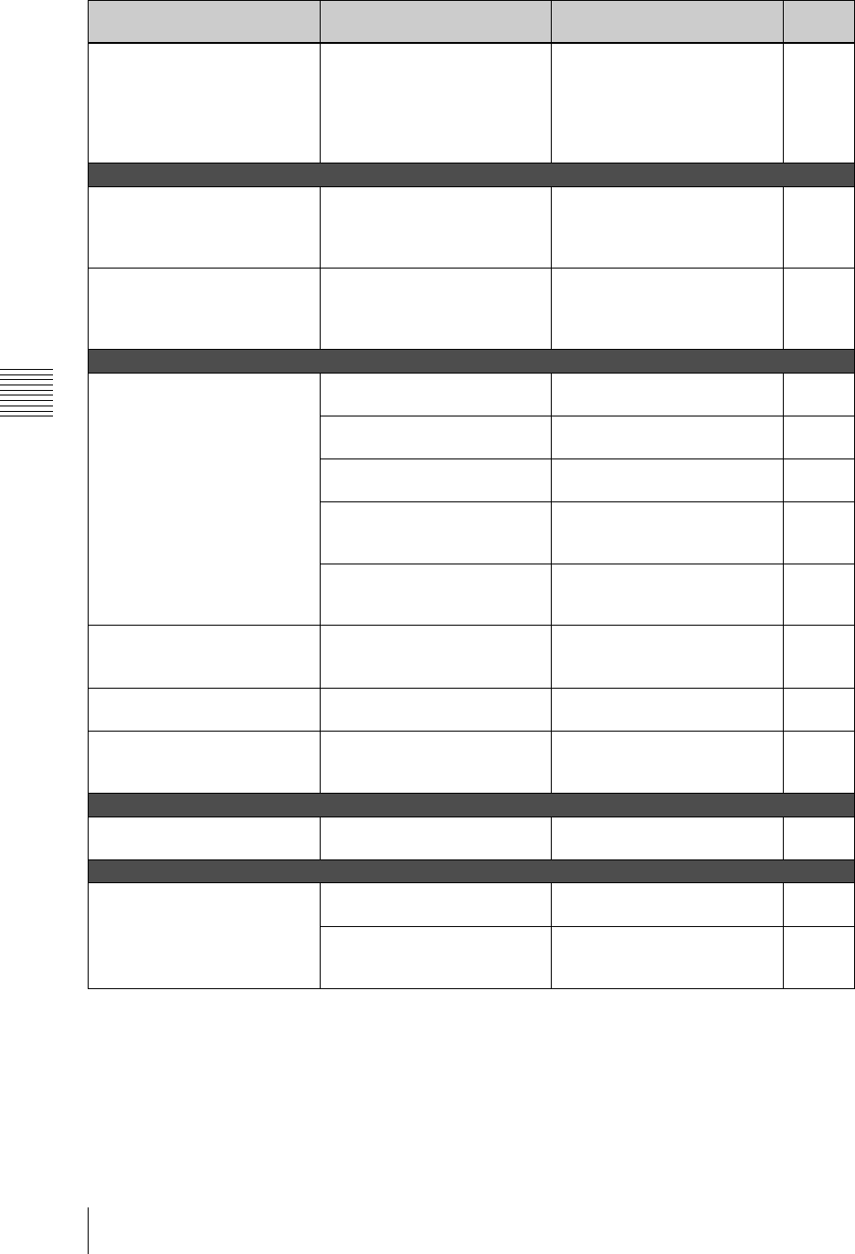
Appendix
278 Troubleshooting
Cannot enter characters from a
USB keyboard, even after
disconnecting and reconnecting
it.
The USB keyboard was not
recognized because it was
connected when the computer
was busy performing processing
for the software.
Try connecting to the other USB
connector, or once set for [Off] in
[Output] on the top menu under
[Streaming]. Or, connect the
USB keyboard beforehand when
turning on the power.
26, 244
Text Typing Tool
Even with [Paint] selected and a
transparency set in the [BG] tab,
the background is not
transparent.
[BG] is selected in the view
operation section.
Select [Checker] or [Live] in the
view operation section.
138, 149
Even with [Transparent Black] or
[Transparent White] selected in
the [BG] tab, the background is
not black or white.
[Checker] or [Live] is selected in
the view operation section.
Select [BG] in the view operation
section.
138, 149
External hard disk
The hard disk number does not
appear in the source viewer.
The source viewer is set to “No
Assign.”
Set the input with [Video Input
Assign] on the top menu.
67
The source viewer shows “No
Interface Module.”
Connect the interface module
correctly.
65
The hard disk is not recognized. Disconnect the cable, then
reconnect, and restart this unit.
175, 186
Program output recording is
reserved.
Set [ON LINE Manager] of [Disk
Recording] in the top menu to
[Off].
172
The DV connector is set for
program output recording.
Set [PGM Output] of [DV OUT]
of [Video Output] in the top
menu to [Off].
188
Attempts at recovery yield
repeated messages, “An error
occurred while recovering.”
The hard disk data is
unrecoverable.
Use [File Manager] on the top
menu t [Format].
* This erases the data.
169
The [PGM Recording] menu
does not appear.
The aspect ratio is set to 16:9 HD
mode.
Set to 4:3 or 16:9 SD mode. 52
The hard disk number remains
grayed out.
The hard disk is being recovered
automatically.
If the hard disk number does not
display properly after waiting a
few moments, restart the unit.
–
HD video interface module or HD serial digital interface module
The HD indicator does not light. The aspect ratio is not set to 16:9
HD mode.
Set to 16:9 HD mode. 25, 52
Keyboard
The keyboard does not work. The keyboard is out of range of
the infrared sensor.
Use the keyboard within range of
the infrared sensor.
48
The keyboard batteries are
depleted (when the keyboard is
detached for use).
Replace the batteries. 47
Problem Possible causes Possible solutions See
page
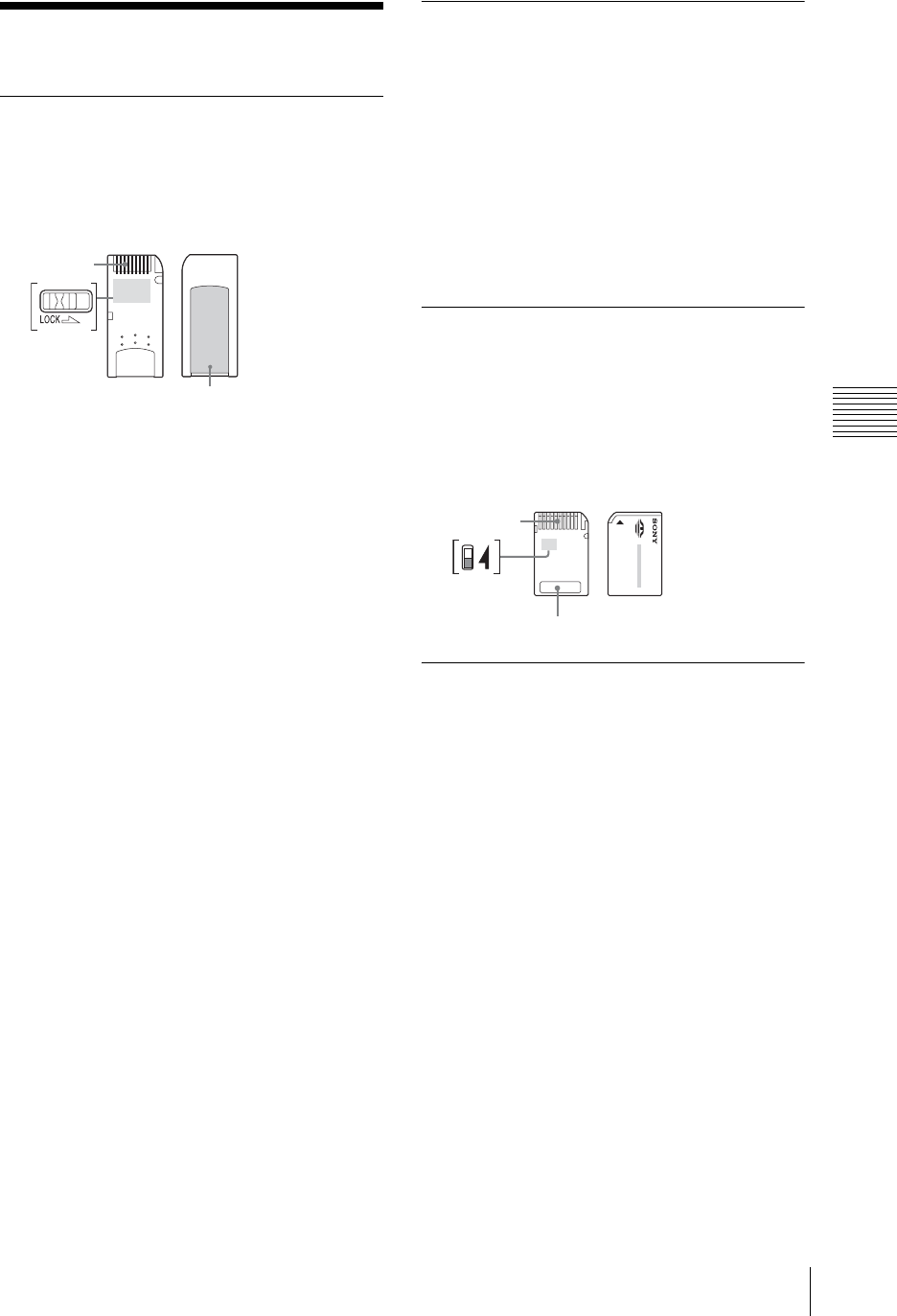
279
“Memory Stick” Media
Appendix
“Memory Stick” Media
Notes on Using “Memory
Stick” Media
• When you set the “Memory Stick” erasure
prevention switch to “LOCK”, data cannot be
recorded, edited, or deleted.
The position and shape of the write-protect switch
may differ between the various types of “Memory
Stick.”
• Do not remove the “Memory Stick” while it is
reading or writing data.
• Data may be damaged if:
- The “Memory Stick” is removed or the
AWS-G500 is turned off while reading or
writing.
- You use the “Memory Stick” in a location
subject to the effects of static electricity or
electric noise.
• We recommend that you back up important data
recorded on the “Memory Stick.”
• Do not affix anything other than the supplied
label to the “Memory Stick” label area.
• Affix the label so that it does not stick out
beyond the label area.
• When storing or carrying a “Memory Stick”,
keep it in its original case.
• Do not touch the terminal of the “Memory
Stick” with anything, including your fingers or
metallic objects.
• Do not strike, bend, or drop the “Memory
Stick.”
• Do not disassemble or modify the “Memory
Stick.”
• Do not allow the “Memory Stick” to get wet.
• Do not use or store the “Memory Stick” in
locations subject to:
- Extreme heat, such as in a closed car parked
in the sun.
- Direct sunlight.
- Humidity or corrosive substances.
About Data
• When you set the “Memory Stick” erasure
prevention switch to “LOCK”, data such as
images and mails cannot be recorded, edited, or
deleted. Be sure to unlock the switch before
transferring or copying data on the AWS-G500
to the “Memory Stick”, or erasing data on the
“Memory Stick.”
• We recommend that you make a backup copy of
important data on another “Memory Stick” or on
a hard disk using a computer.
Notes on Using “Memory
Stick Duo”
• Use a pointed object, such as a ballpoint pen, to
move the “Memory Stick Duo” write-protect
switch.
• Do not write forcefully on the “Memory Stick
Duo” memo area.
Notes on Using the Memory
Select Function
• You cannot use multiple memory blocks
simultaneously or continuously.
• Never operate the Memory Select switch when
the “Memory Stick” is inserted in the slot of the
AWS-G500, as it may cause damage. Sony
Corporation assumes no liability for failure
resulting from such operation.
• Make sure that the Memory Select switch is
properly positioned to the side. When the switch
is not positioned properly, the AWS-G500 may
be damaged or malfunction.
• Before inserting the “Memory Stick” in the slot
of the AWS-G500, make sure that the memory
you want to use is already selected.
• A “Memory Stick” with the Memory Select
function allows the user to select the internal
memory of the “Memory Stick” with the
selector switch. Care must be taken in the
following cases as the supported devices only
detect the selected memory:
- Formatting is only processed for the selected memory.
Te r m i n a l
Erasure
prevention
switch
Label area
Terminal
Write-protect
switch
Memo area

Appendix
280 Specifications
- The remaining memory is only indicated for
the selected memory.
- Errors are only displayed for the selected
memory and are detected separately from
the unselected memory.
Specifications
General
Power Requirements
AC 100 V to 240 V, 50/60 Hz
Power Consumption
1.6 A-0.8 A
Operating Temperature
5ºC to 40ºC (41 to 104ºF)
Dimensions (w × h × d)
424 × 114 × 339 mm
Mass Approximately 17 lb 10 oz
(8.0 kg)
Video Signals
VIDEO INPUTS (standard configuration)
Composite BNC type × 4
Video: 1.0 Vp-p, 75 Ω,
Sync negative
S-video DIN type × 4
Y: 1.0 Vp-p, 75 Ω,
Sync negative
C: 0.286 Vp-p at burst, 75 Ω,
(NTSC)
C: 0.3 Vp-p at burst, 75 Ω,
(PAL)
DV IN* i.LINK IEEE 1394 6-pin Type ×
4
IEC 61883-2 equiv.
* DV IN/OUT connectors
RGB D-Sub Shrink 15-pin
Type × 2 (Female)
XGA (1,024 × 768, 60 Hz
75 Hz),
SXGA (1,280 × 1,024, 75 Hz
60 Hz)
VESA (DMT) compliant
* Input from Macintosh computers is not supported.
VIDEO OUTPUTS
Composite BNC type × 1
Video: 1.0 Vp-p, 75 Ω,
Sync negative
Table of PC RGB input
Format
fH fV Dot
clock
Sync
polarity
(kHz) (Hz) (MHz) Hori-
zontal
Ve r t i -
cal
1,024×768
XGA VESA 60 Hz 48.363 60.004 65 Nega-
tive
Nega-
tive
XGA VESA 75 Hz 60.023 75.029 78.75 Posi-
tive
Posi-
tive
1,280×1,024
SXGA VESA 60 Hz 63.981 60.02 108 Posi-
tive
Posi-
tive
SXGA VESA 75 Hz 79.976 75.025 135 Posi-
tive
Posi-
tive
1,280×768 WXGA* 60 Hz 47.693 59.992 80.125 Nega-
tive
Posi-
tive
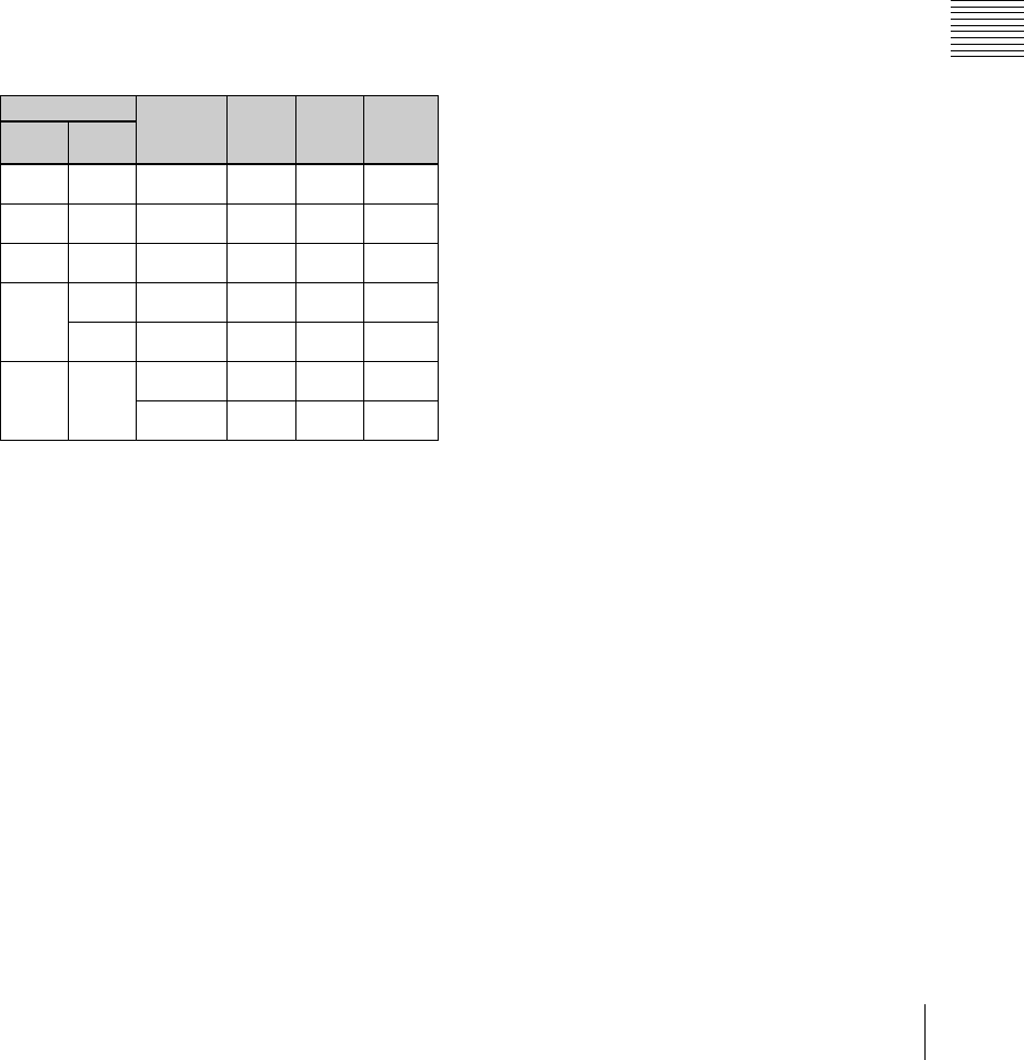
281
Specifications
Appendix
S-video DIN type × 1
Y: 1.0 Vp-p, 75 Ω,
Sync negative
C: 0.286 Vp-p at burst, 75 Ω,
(NTSC)
C: 0.3 Vp-p at burst, 75 Ω,
(PAL)
DV OUT*
i.Link IEEE 1394 6-pin Type
×
4
IEC 61883-2 equiv.
* DV IN/OUT connectors
RGB (VIDEO OUT) 15 k RGB (50 Hz/59.94 Hz)
R: 0.7 Vp-p (75Ω)
G: 0.7 Vp-p (75Ω)
B: 0.7 Vp-p (75Ω)
SYNC: Composite sync TTL
output - audio output
RGB D-Sub Shrink 15-pin Type × 2
(Female)
XGA (1,024
×
768 60 Hz, 75Hz)
SXGA (1,280 × 1,024 60Hz)
* For details of RGB OUT settings, see “Setting the RGB Output
Signal Format” (page 210).
** For details of RGB OUT settings, see “Selecting the Video Output
Signal Format” (page 52).
REF OUT BNC Type × 2
Sync: 0.286 Vp-p, 75
Ω
, (NTSC)
Sync: 0.3 Vp-p, 75 Ω, (PAL)
C: 0.286 Vp-p at burst, 75 Ω,
(NTSC)
C: 0.3 Vp-p at burst, 75
Ω
, (PAL)
Recorder Port
HDD (in exfactory configuration)
i.LINK: IEEE 1394 6-pin
Type × 2
HDD IF: SBP2
Audio Signals
AUDIO INPUTS
Analog Inputs 1-2
XLR/TRS Combo Type × 2
Ref. Level:
+4 dBu, −20 dBu, −44 dBu
Mic. Power:
+48 V
Analog Inputs 3-6
TRS Type × 4 / Ref. Level:
+4 dBu, −20 dBu, −44 dBu
Analog Inputs 7-8
Pin × 2 / Ref. Level: −10 dBu
DV IN* i.LINK: IEEE 1394 (6 pins) × 4
IEC 61883−2 compliant
Audio standard level: −20 dBFS
Sampling rate:
12 bit 32 kHz 4ch (uses only
ch 1 and 2)
16 bit 48 kHz 2ch
* DV IN/OUT connectors
AUDIO OUTPUTS
PGM OUT TRS Type × 2 / Ref.: +4 dBu /
Impedance: 150 Ω
MIX OUT Pin Type × 2 / Ref.: −10 dBu /
Impedance: 470 Ω
AUX OUT TRS Type × 2 / Ref.: +4 dBu /
Impedance: 150 Ω
MONITOR OUT
TRS Type × 2 / Ref.: +4 dBu /
Impedance: 150 Ω
DV OUT* i.LINK: IEEE 1394 (6 pins) × 4
IEC 61883−2 compliant
Audio standard level: −20 dBFS
Sampling rate: 12 bit 32 kHz
4ch, 16 bit 48 kHz 2ch
* DV IN/OUT connectors
HEADPHONES
1/4”
Stereo Phone Jack Type
×
1
70 mW × 2 / Impedance: 47 Ω
INTERCOM
D-Sub 9-pin Type (Female) /
Original Parallel I/O
Other Interfaces
NETWORK RJ-45 Type × 1, 10 Base-T/
100 Base-TX
USB USB A type × 2, USB equiv.
RGB(GUI) D-Sub Shrink 15-pin × 1
(Female),
WXGA 1,280 × 800 60 Hz
Menu setting Signal
format FH (kHz) FV (Hz) Sync
RGB
OUT *PGM
OUT **
XGA
60 Hz -XGA VESA
(DMT) 60 Hz 48.363 60.004 H-negative
V-negative
XGA
75 Hz -XGA VESA
(DMT) 75 Hz 60.023 75.029 H-positive
V-positive
SXGA
60 Hz -SXGA VESA
(DMT) 60 Hz 67.500 75.000 H-positive
V-positive
Video
RGB
NTSC 15k RGB
60 Hz 15.734 59.940 Composite
sync
PAL 15k RGB
50 Hz 15.625 50.000 Composite
sync
RGB
OUT -
WXGA 60 Hz 47.693 59.992 H-negative
V-positive
WXGA 75 Hz 60.091 74.926 H-negative
V-positive
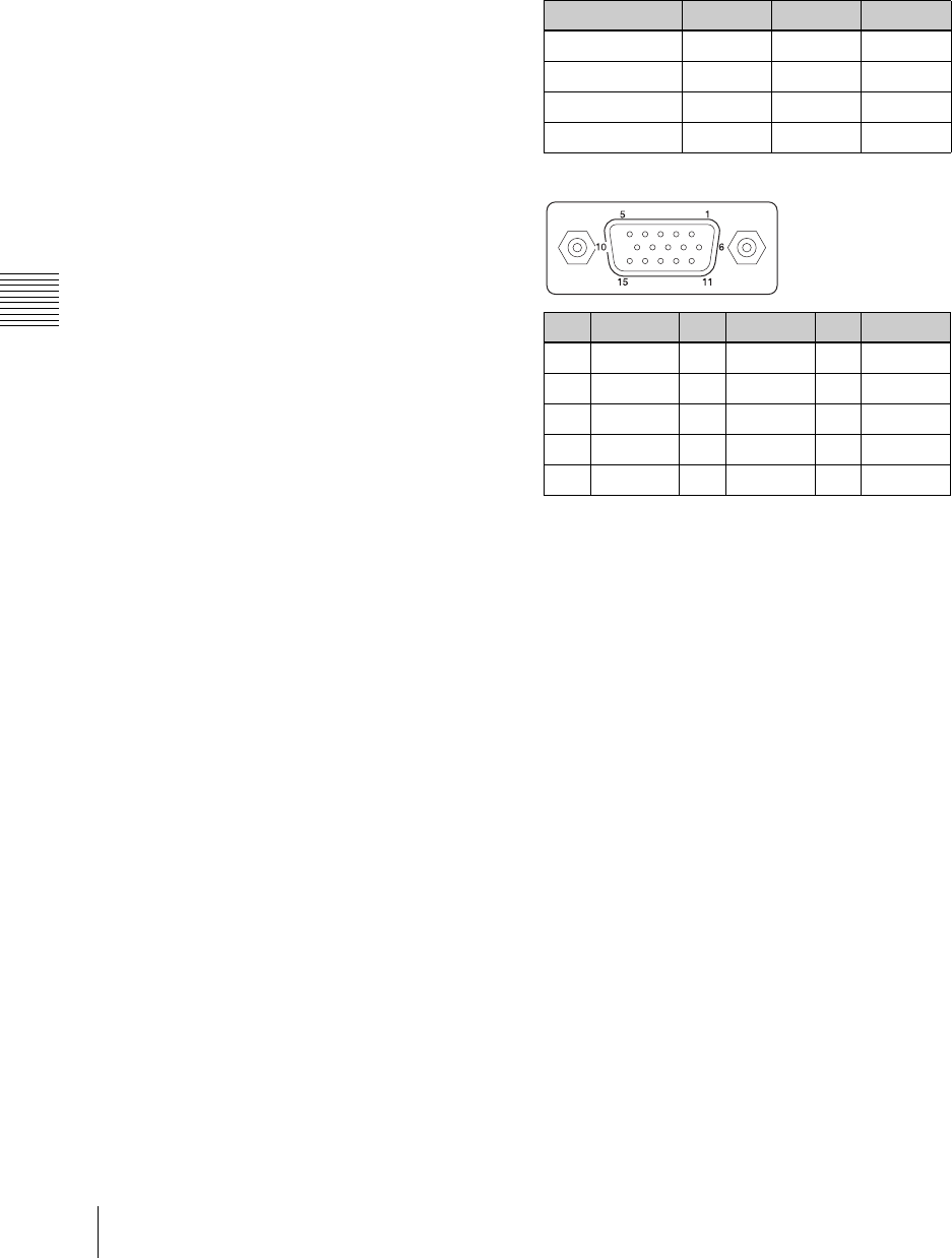
Appendix
282 Specifications
REMOTE
(Provided for future functional expansion.)
D-Sub 9-pin (Male) × 1,
RS-232C
FACTORY USE
D-Sub 15-pin × 1 (Male),
Original Parallel I/O
MEMORY STICK
“Memory Stick” Slot
“Memory Stick Pro” and
“Memory Stick Pro Duo” are
not supported.
VISCA DIN 8-pin type × 1, RS-232C
Sony VISCA camera
commands are supported.
LCD 15.4” High Brightness LCD,
WXGA (1,280 × 800 60 Hz)
Speaker Built-In Speaker × 2,
Size: 20 × 40 mm
Supplied Accessories
CD-ROM (× 1)
Notes on using the CD-ROM (× 1)
Pin to BNC connector (× 4)
Battery: CR2032
Operating instruction (× 1)
Keyboard (× 1) 85 keys + Pointer /
Infrared communication
Powered from
AWS-G500: +5 V
Battery operation: CR2032 or
2032 H × 2
Optional Accessories
BKAW-550 PC Video Interface Module
(mounted in slot 3 of this unit)
RGB D-Sub Shrink 15-pin
Type × 2 (Female),
XGA (60 Hz, 75 Hz),
SXGA (60 Hz, 75 Hz)
VESA (DMT) compliant
BKAW-560 HD Video Interface Module
YPBPR IN D-Sub Shrink 15-pin Type ×
2 (Female)
720p, 1080i
Y: 1.0 Vp-p, 75 Ω, with Sync
PB: 0.7 Vp-p (75 Ω)
PR: 0.7 Vp-p (75 Ω)
YPBPR OUT D-Sub Shrink 15-pin Type ×
1 (Female)
720p, 1080i
Y: 1.0 Vp-p, 75 Ω, with Sync
PB: 0.7 Vp-p (75 Ω)
PR: 0.7 Vp-p (75 Ω)
HD input signals
Pin assignment
BKAW-570 SD Video Interface Module
(mounted in slots 1 and 2 of this unit)
Composite BNC type × 2
Video: 1.0 Vp-p, 75 Ω,
Sync negative
S-video DIN type × 2
Y: 1.0 Vp-p, 75 Ω,
Sync negative
C: 0.286 Vp-p at burst, 75 Ω,
(NTSC)
C: 0.3 Vp-p at burst, 75
Ω
, (PAL)
DV IN/OUT
i.LINK: IEEE 1394 6-pin Type
×
2
IEC 61883-2 equiv.
HDD i.LINK: IEEE 1394 6-pin
Type × 1
HDD IF: SBP2
BKAW-580 Serial Digital Interface Module
SDI IN BNC × 2
VIDEO: 800 m Vp-p (75 Ω)
SMPTE259M-C ITU-R656 compliant
AUDIO:
Audio sampling rate:
20 bit 48 kHz 2 channels
(channels 1 and 2 or 3 and 4)
SMPTE272M-A compliant
Video format fH (kHz) fV (Hz) Sync
1080/60i 33.750 60.000 S on Y
1080/50i 28.130 50.000 S on Y
720/60p 45.000 60.000 S on Y
720/50p 37.500 50.000 S on Y
Pin Signal Pin Signal Pin Signal
1 Pr (X) 6 Pr (GND) 11 NC
2 Y (X) 7 Y (GND) 12 NC
3 Pb (X) 8 Pb (GND) 13 Reserved
4NC 9NC 14Reserved
5 GND 10 GND 15 NC

283
Specifications
Appendix
SDI OUT* BNC × 1
VIDEO: 800m Vp-p (75 Ω)
SMPTE259M-C ITU-R656 compliant
AUDIO:
Audio sampling rate:
20 bit 48 kHz 2 channels
(channels 1 and 2)
SMPTE272M-A compliant
HDD HDD i.LINK: IEEE 1394 S400
(6 pins) × 1
HDD IF: SBP2
BKAW-590 HD Serial Digital Interface Module
HD SDI IN BNC × 2
720p, 1080i
VIDEO: 800 m Vp-p (75 Ω)
SMPTE292M compliant
AUDIO:
Audio sampling rate: 20 bit
48 kHz 2 channels (channels
1 and 2 or 3 and 4)
SMPTE299M compliant
HD SDI OUT* BNC × 1
720p, 1080i
VIDEO: 800 m Vp-p (75 Ω)
SMPTE292M compliant
AUDIO:
Audio sampling rate: 20 bit
48 kHz 2 channels (channels
1 and 2)
SMPTE299M compliant
*The output may be limited when this module is
used in combination with other interface
modules provided in the future.
Due to the internal video processing of AWS-
G500, the output SDI signal is not guaranteed to
be identical to the input SDI signal.
Recommended power cord
NA Part No. 1-551-812-11
Europe Part No. 1-782-929-22
Design and specifications are subject to change
without notice.
Caution
Notes
• Always make a test recording, and verify that it
was recorded successfully.
SONY WILL NOT BE LIABLE FOR
DAMAGES OF ANY KIND INCLUDING,
BUT NOT LIMITED TO, COMPENSATION
OR REIMBURSEMENT ON ACCOUNT OF
FAILURE OF THIS UNIT OR ITS
RECORDING MEDIA, EXTERNAL
STORAGE SYSTEMS OR ANY OTHER
MEDIA OR STORAGE SYSTEMS TO
RECORD CONTENT OF ANY TYPE.
• Always verify that the unit is operating properly
before use. SONY WILL NOT BE LIABLE FOR
DAMAGES OF ANY KIND INCLUDING,
BUT NOT LIMITED TO, COMPENSATION
OR REIMBURSEMENT ON ACCOUNT OF
THE LOSS OF PRESENT OR PROSPECTIVE
PROFITS DUE TO FAILURE OF THIS UNIT,
EITHER DURING THE WARRANTY PERIOD
OR AFTER EXPIRATION OF THE
WARRANTY, OR FOR ANY OTHER
REASON WHATSOEVER.
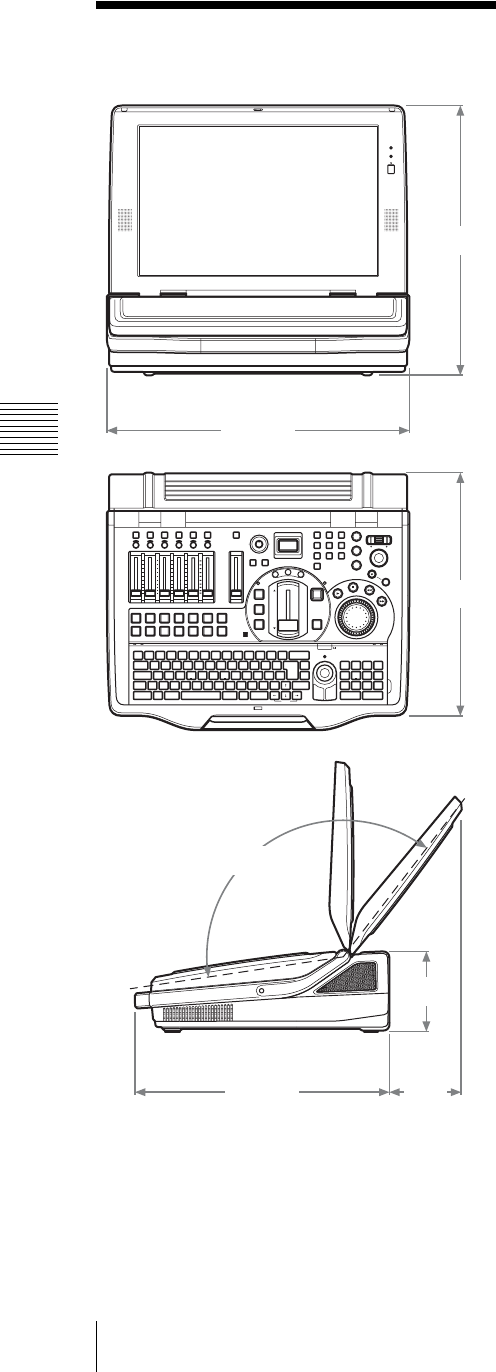
Appendix
284 Dimensions
Dimensions
375 mm
424 mm
339 mm
133°
114 mm
93
mm
354 mm

285
Glossary
Appendix
Glossary
16:9 squeeze
An SD video signal with a 16:9
aspect ratio that is squeezed into
a 4:3 aspect ratio.
Auto gain control
A function which uses the
luminance signal’s sync level as
a basis for adjusting the
luminance signal to an
appropriate level. Use this when
the luminance signal level is off
by a significant margin.
Black burst signal
A reference signal used to
achieve external
synchronization (GenLock).
Chroma key
A method of creating a
composite picture by deleting
components that contain a
specified color (chroma).
Typically, a subject is captured
in front of a blue background,
commonly referred to as a “blue
screen,” and the blue
background is removed, leaving
only to subject for compositing.
Color bars
A test signal which displays
vertical colored stripes on a
monitor. Used to adjust the hue
and saturation of colors on
video cameras and monitors.
Color matte
A color signal generated by this
unit. The hue, saturation, and
luminance of color mattes can
be adjusted.
Compressor
A function which smoothly
limits audio signals exceeding a
certain threshold. Used to even
out audio signals which contain
large differences in amplitude.
Default gateway
A router or computer on a
network which serves as an
entrance to an outside network.
Other computers in the network
access the outside network via
the default gateway.
Delay
A function which delays audio
to bring it into synchronization
with video, used when video is
input later than the
corresponding audio.
DHCP (Dynamic Host
Configuration Protocol)
A protocol for automatically
assigning IP addresses to clients
when they connect to a network,
and recovering the addresses
when they disconnect.
Dimmer
A function which slightly dims
a picture or slightly lowers
audio levels.
DNS (Domain Name
System)
A system which allows Internet
domain names to be translated
into IP addresses.
Domain name
An identifier assigned to a
group of computers and
networks on the Internet.
Domain names are delimited by
periods (.), and arranged from
the left in the order top level
domain, second level domain,
third level domain, and so forth.
Downstream key (DSK)
A function which allows
pictures to be composed by
taking video to which an effect
has already been applied and
adding further images and text.
It is called downstream key
because this processing is done
at the very end of the processing
stream.
EDL (Edit Decision List)
Data containing edit
instructions that use timecodes
(time clock information
attached to images) to specify
the order of cuts to be taken
from images.
Embedded audio
Audio that is embedded into a
video signal.
EMC (Electro-Magnetic
Compatibility)
The properties of an electrical
device of electromagnetic non-
interference and
electromagnetic immunity.
Electromagnetic non-
interference means that when
the device operates it does not
impair the operation of other
devices, and does not act as a
source of interference over a
certain level that would be
harmful to human health.
Electromagnetic immunity is
the property of electromagnetic
susceptibility such that the
device can operate without
interference from
electromagnetic radiation and
so forth emitted by other
devices.
Encode
To use compression technology
to create streaming files with
appropriate bitrates for different
bandwidths.
Equalizer (EQ)
A function which controls
specific audio frequencies in the
high, mid, and low regions.
Used to strengthen or delete
specific frequencies in order to
improve the audio.

Appendix
286 Glossary
ext3
A file system widely used with
Linux, which adds a journaling
function (allowing data changes
to be handled as transactions) to
the ext2 file system. It requires a
shorter time to recover from
hardware problems.
Fade to Black (FTB)
An effect in which video fades
out to a black screen.
Filter
A function which removes high
or low frequencies. Used to
remove cable noise and other
kinds of noise.
Flip
Screen explanatory diagrams,
including text, illustrations,
graphics, and maps. A flip is
displayed in the video and is
used to explain the video
content.
IEEE1394 (Institute of
Electrical and Electronics
Engineers 1394)
A standard for a high-speed
serial bus for connection not
only of computer peripherals,
but also of digital devices to
each other. Known as FireWire
by Apple Computer, and as
i.LINK by Sony Corporation.
FTB (Fade to Black)
See “Fade to Black.”
GPI (General Purpose
Interface)
A general purpose interface that
is used to communicate controls
to devices that do not have
standard interfaces.
GUI (Graphical User
Interface)
A user interface which, unlike
traditional text-based interfaces,
is designed around graphical
elements such as buttons and
menus.
Intercom
A network that allows staff
members to talk to each other
during program production.
Host name
A name assigned to a computer
on a network to make it easier to
identify. Usually consisting of
alphanumeric characters,
although conventions differ
according to the system. The
most commonly used types are
the terminal identifiers to the
left of Internet domain names.
i.LINK
The high-speed serial bus
standard IEEE 1394.
Also called FireWire. Allows
connections between computers
and peripherals, and also direct
connections between digital
devices such as digital cameras.
IPv6
The next-generation Internet
Protocol, the successor to the
current IPv4 protocol.
IRE (International Radio
Engineers)
A measure of the brightness
level of video on the grayscale,
ranging from 0 to 100. The
brightness level of black is
sometimes set at 0 IRE and
sometimes set at 7.5 IRE.
Limiter
A function which prevents
audio levels from exceeding a
specified threshold. Used to
suppress peaks in audio with
large differences in amplitude.
Logo
A permanently visible mark
shown in video for the purpose
of copyright protection.
Luminance key
A method of creating a
composite picture by deleting
components of a specified
luminance (brightness).
Typically used to extract bright
characters from a dark
background, so that only the
characters can be added to the
composed picture.
Mix
A type of transition effect. A
new picture is mixed into an old
picture, eventually replacing the
old picture.
Monitor
To listen to audio and view
video. Or a device for viewing
and listening.
Motion JPEG2000
An extension to the JPEG2000
image compression format that
enables video recording. It
provides picture quality
comparable to the DV format,
with file sizes that are smaller
than DV. It is noted for high
compression ratios in scenes
with rapid movement, which are
problematic for the MPEG
format.
Oscillator
A transmitter that oscillates at a
fixed frequency, such as a sine
wave. This unit is equipped with
an internal audio oscillator.
Pan
In audio, to adjust the right/left
balance.
In video, to move the camera to
the left and right.

287
Glossary
Appendix
PFL (Pre-Fader Listen)
Monitoring audio before level
adjustments with the audio
channel faders. Used to check
the input audio. On this system,
pan and level control are not
applied to PFL audio, even if
trim, filter, EQ, pan, and level
control settings have been
made.
Picture-in-Picture (PinP)
An effect achieved by
embedding a video within
another video.
Post-Fader
Audio signals after the
application of all adjustments
except pan.
Pre-Fader
Audio signals before the
application of any adjustments
with audio channel faders. All
other adjustments are the same
as those for Post-fader. Pre-
fader audio can be output from
the AUX output connector.
Preset
A function which allows a set of
electrical settings to be saved
and reproduced as a single set of
data. This system has a camera
preset function.
Program (PGM) signal
output
The final video and audio
signals output from this system,
after the application of effects.
The video seen by viewers.
RCA pin
A connector used on consumer
audio equipment. Connectors
come in color-coded pairs
(often white for left and red for
right). Also used for video
signals (color yellow).
RGB
An output signal format which
displays pictures by using the
three primary colors: Red,
Green, and Blue.
Serial digital interface
(SDI)
A standard for transmitting
uncompressed digital video
signals and embedded audio
over a single coaxial cable.
STP (Shielded Twisted Pair
cable)
A type of cable for
communications. Copper wires
are twisted in pairs, and then
shielded.
Streaming
Real-time playback of audio
and data received over a
network. Compared to
“download” playback, which
starts after all the data has been
received, streaming allows
playback of data received up to
now. Formats which enable
streaming include RealMedia,
Windows Media, and Quick
Time. This system supports the
RealMedia streaming file
format (.rm).
Subnet mask
An IP address, which indicates
the address of a device in a
network, has two components: a
network address (the address of
the network) and a host address
(the address of an individual
computer). A subnet mask is a
value used to specify how many
bits in the IP address are
reserved for the network
address. A subnet is a smaller
network created by dividing a
large network into two or more
parts.
Superimpose
A type of special effect in video
editing, used to display text and
pictures over other pictures.
Talk back (TB)
To pass along instructions, for
example from a director. In this
system, when you talk into the
microphone on the front panel,
your voice is output to the
connected intercom system,
allowing you to converse with
other people on the intercom
system.
TB (Talk Back)
See Talk back.
Telop (Television Opaque
Projector)
Superimposed text and image
resources, such as television
subtitles. This also refers to text
and images that have been
combined with video.
Threshold
The level at which a limiter or
compressor is activated.
Thumbnail
An image which has been
reduced in size for the purpose
of displaying a list of many
images.
Tilt
To move a camera up and down.
Transition
To switch from one video to a
different video over a certain
time interval. Transitions can be
used together with text and
image keys to compose and
erase pictures.
Transition effect
Gradually switching from one
video to another through the
application of one of various
effects. This systems supports
two type of transition effects:
mix and wipe.

Appendix
288 Glossary
Trim
To adjust the input level of
audio signals. These
adjustments are performed at
the input stage, before level
adjustments with the audio
channel faders.
TRS
A jack used in headphones and
other devices.
VISCA
A protocol developed by Sony
which allows video equipment
to be connected to computers.
VOD (Video On Demand)
A system that allows video
content to be placed on a
network, which viewers can
access freely. Viewers can also
download data for viewing onto
their computers from the
Internet.
Wipe
A type of transition effect. A
new picture moves in to replace
an old picture, as if wiping the
old picture away.
XLR
A 3-pin connector, often called
a Cannon connector. A locking
mechanism keeps the connector
securely connected even when
the cable is pulled. Very stable
despite its simple structure, and
often used on microphones to
suppress handling noise.

289
Index
Appendix
Index
Symbols
+48V switch ......................23
Numerics
16:9 HD mode ...................53
16:9 SD mode ...................53
75-W termination switch .... 24
A
ACCESS buttons ...............17
ACCESS menu .................. 35
Auto Gain Control ..... 206
AUX1 OUT ..............202
AUX2 OUT ..............202
Chroma Level ...........206
Dynamic Rounding ....207
EQ ........................... 213
Filter ........................ 213
Hue .......................... 206
Input Trim ................ 212
Limiter/Compressor ... 214
Luminance Level .......206
Luminance Offset ......206
MIX OUT .................203
Pan ........................... 214
PGM OUT ................ 202
Phase ........................ 208
Reposition ................ 208
Resize ......................208
Wide Zoom ............... 207
Adjusting Analog Video Input
Signals ........................ 206
Adjusting Color Matte ...... 209
Adjusting the Audio Left and
Right Channel Balance ..214
Adjusting the equalizer .....213
Adjusting the Output Levels for
Each Destination ..........215
Adjusting the Program Output
Video Image Quality .....209
Analog video input connectors
.....................................24
Audio channel faders .........18
Audio Input Assign
Input (L) .....................72
Input (R) .....................72
Link to Video ............. 74
Source Name .............. 71
Audio level meter .............. 29
Audio MIC/LINE Level
High (+4dB) ............... 75
Low (-44dB) ............... 75
MIC/LINE ................. 75
Middle (-20 dB) .......... 74
AUDIO MONITOR button
.................................... 18
Audio Output .................. 203
Audio Output ............ 215
AUX OUT Delay ...... 216
AUX OUT Level ...... 215
MIX OUT Delay ....... 216
MIX OUT Level ....... 215
PGM OUT Delay ...... 216
Audio Signal Related Settings
.................................... 71
Audio Utility
Audio Monitor .......... 204
Chroma Level ........... 206
Hue ......................... 206
Luminance Level ...... 206
Luminance Offset ..... 206
OSC ........................ 216
OSC Freq. ................ 217
OSC OUT ................ 217
OUT Level ............... 217
TB ........................... 201
AUTO TRANS button
.............................. 20, 80
AUX OUT
Post-Fader ................ 202
Pre-Fader ................. 202
AUX output connector (AUX)
1/2 (TRS, balanced) ....... 23
C
Cable clip ......................... 22
Camera guide menu
B Gain ..................... 161
Back Light ............... 156
Control Setup ... 160, 163
Data Screen .............. 162
Delete ...................... 160
Focus ....................... 161
HOME ..................... 162
Iris (Exposure) .......... 161
Manual ..................... 161
One Push AWB ......... 157
On-Screen Menus ...... 162
Pan Reverse .............. 161
Pan-Tilt .................... 161
Pan-Tilt Reset ........... 157
R Gain ...................... 161
Reset Camera ............ 163
Tilt Reverse .............. 161
White Balance ........... 161
Zoom ....................... 161
Camera Preset ................. 157
Camera preset settings menu
Data Name ................ 158
Preset ....................... 158
Camera supporting VISCA
protocol ......................... 69
CH ON buttons ................. 18
channel faders ................... 71
Chroma Keying ............... 103
Closing down .................... 48
Color Bars ........................ 90
Color Cancel ................... 108
Color Mattes ..................... 90
Compressor ..................... 214
Connecting a Camera With
VISCA Support .............. 58
Connecting a Computer ...... 59
Connecting a Microphone .. 59
Connecting a Plasma Display/
Projector ........................ 63
Connecting a VCR ............. 61
Connecting an amplifier ..... 64
Connections ...................... 56
Controlling Cameras ........ 155
Cropping ........................ 109
Cut ................................... 78
CUT button .................19, 79
Cut switching .................... 77
Cutting High Frequency or Low
Frequency .................... 213

290 Index
Appendix
D
Deleting Files .................. 233
Determining the Audio Signal
Output Destinations ...... 202
DIM button .......................18
Dimensions .....................284
Display
File TC ..................... 183
LCD Backlight ............ 52
PVW ........................ 113
Viewer Priority .........113
DSK
Clip ............................93
Crop ...........................94
Density ....................... 93
Gain ........................... 93
IN Trans. Time ............93
Key Adjust .................94
Key Invert ..................94
OUT Trans. Time ........93
DSK button .......................20
DV connectors (DV IN/OUT)
.............................24, 188
E
Edge ............................... 109
EDL ............................... 223
EFFECT button
.............. 19, 83, 101, 105
Effect display .................... 34
Effect preview ................. 110
ENTER button .................. 17
EQ
High Freq. ................214
High Level ................ 214
Low Freq. ................. 214
Low Level ................ 214
Middle Freq. ............. 214
Middle Level ............ 214
ESC button .......................17
Example Applications ........15
External Hard Disk ....62, 169
F
FACTORY USE connector
.....................................26
Fade in .............................89
Fade To Black
Transition Time ...........90
Fades out .......................... 89
Fade-to-Black ................... 89
File Manager
CG File .................... 233
Delete ...................... 233
Disconnect ............... 186
EDL File .................. 233
Export EDL Type ..... 225
Export Job ................ 221
Export VOD File ...... 232
Format ..... 170, 236, 238
Import CG File ......... 229
Import Job ................ 222
Import Logo File ....... 230
Local Disk Remain ... 235
Logo File ................. 233
Recover ................... 187
Rename .................... 231
VOD File ................. 231
Filter
High Cut (8kHz) ....... 213
Low Cut (100Hz) ...... 213
Front Panel ....................... 17
FTB ................................. 89
FTB button ....................... 19
G
Graphics preset menu
Data Name ................. 96
Delete ........................ 96
Preset ......................... 95
Ground terminal ................ 22
H
HDD file guide menu
Auto Repeat ............. 181
Data Name ............... 185
Delete ...................... 185
File Open ................. 178
Preset ....................... 184
Headphone connector
(HEADPHONES)
(standard phone jack) ..... 23
I
i.LINK connector (HDD)
............................ 24, 169
Importing Graphics Files .228
Importing Logo Files ....... 230
Indicators ......................... 20
Input Trim ...................... 212
Input/Output Signals .......... 66
Installing the Unit .............. 45
Intercom ......................... 200
Intercom interface connector
..................................... 22
J
Job
Delete ...................... 220
Load ........................ 219
Save ......................... 219
Jog dial ............................. 21
Jog roller .......................... 18
K
KEY button ....................... 19
Keyboard .......................... 46
L
Limiter ........................... 214
Limiter/Compressor
Compressor .............. 214
Limiter ..................... 214
Line input connectors (LINE)
7/8 (RCA) ...................... 23
Logo
Clip ............................ 98
Density ....................... 98
Gain ........................... 98
Location ..................... 99
Logo Source ............... 98
Luminance Keying ............ 99
M
“Memory Stick” .............. 279
“Memory Stick Duo” ....... 279
“Memory Stick” slot .......... 26
MENU button ................... 18
Menu operations ................ 35
Microphone ...................... 19
Microphone/line input connec-
tors (MIC/LINE) 1/2 ....... 22
Microphone/line input
connectors (MIC/LINE)
3/4/5/6 ........................... 23
MIX button .................19, 81

291
Index
Appendix
MIX output connector (MIX)
L/R (RCA) .....................23
Mixing ........................... 168
Monitor level adjustment knob
.....................................18
Monitor output connectors
(MONI) (RCA) ..............23
N
Names and Functions of Parts
.....................................17
Network
Default Gateway ....... 242
DHCP ...................... 242
DNS Setting .............. 242
Domain Name ........... 242
Host Name ................ 241
IP Address ................ 242
IP Setting ..................242
MAC Address ........... 242
Primary DNS ............ 242
Secondary DNS .........242
Subnet Mask .............242
NETWORK connector ....... 26
Network Settings .............241
NEXT selection buttons ..... 19
Numeric buttons ................20
O
ON LINE button ................17
ON LINE Manager
DV OUT Recording ...192
EDL .........................223
File Name .................224
PGM Recording ........ 172
Source Recording ......173
Steaming ..................255
Operating monitor connector
(RGB (GUI)) ..................26
OPTIONAL ACCESSORIES
...................................282
Oscillator Signal .............. 216
Output from the AUX output
connectors ................... 202
Output from the MIX output
connectors ................... 203
Output from the PGM output
connectors ................... 202
Output program .................77
P
Pan ................................ 214
PC video interface module .24
PGM audio output connectors
(PGM) L/R (TRS, balanced)
.................................... 23
PGM fader ....................... 18
PGM OUT ..................... 202
PGM selection button ........ 78
PGM selection buttons ....... 19
PGM video output connectors
(PGM) .......................... 23
PGM viewer ..................... 29
Picture-in-Picture .............. 87
Positioner ......................... 21
Power button .................... 27
Power supply connector
(~AC IN) ...................... 22
PVW button ..................... 19
PVW viewer
.............. 30, 79, 110, 113
R
Real Player ..................... 256
Recording ....................... 188
Reference output connectors
(REF OUT) ................... 23
RESET button .................. 27
RGB input connectors (RGB)
.................................... 25
RGB Output ................... 210
RGB output connectors (RGB)
.................................... 23
S
SD video interface module
.................................... 24
Serial digital interface module
.................................... 24
Setting the Date and Time .. 50
Setting the microphone/line
level ............................. 74
Settings .......................... 218
SHIFT button ................... 20
Showing a Logo on the Screen
.................................... 97
Shuttle dial ....................... 21
Software Version ............. 261
Source viewer ................... 32
Specifications .................. 280
Starting ............................. 48
Streaming ....................... 240
Bit Rate .................... 245
Clip Information ........ 246
Connection Check ..... 251
Ext (Account) ...247, 249
Ext (Password) ..247, 249
Frame Rate ............... 252
HTTP Port ................ 248
Listen Address .......... 249
Live ......................... 244
Live File Name .........244
Live/VOD ................ 244
Output ..............244, 252
Password .................. 250
Path ......................... 245
Port Range ................ 249
RTSP Port ................ 248
Server Address .......... 247
Server Setting ........... 247
Size .......................... 245
Stream Name ....245, 252
Transport .................. 249
Username ................. 250
VOD File Distribution
............................. 254
VOD File Name ........ 252
VOD File Setting ...... 252
Streaming display .............. 32
SUPPLIED ACCESSORIES
................................... 282
Switching a wipe ............... 82
Switching with a dissolve ... 81
System
Date/Time .................. 51
Language .................... 50
System TC .................. 55
Time Zone .................. 50
Timecode ................... 55
User Preset ................. 55
System timecode ............... 54
T
TB button ......................... 18
Time ................................ 51
Timecode .......................... 55
Add TC .................... 190
File TC ..................... 183

292 Index
Appendix
Top menu .........................34
Audio Input Assign ......71
Audio MIC/LINE Level
...............................75
Audio Output
............ 203, 215, 216
Audio Utility .............216
Date/Time ...................51
Display ..................... 113
DSK .....................92, 93
Fade To Black ............. 89
File Manager ....169, 186,
....................229, 230,
............ 235, 236, 238
Job ...........................219
Logo ....................97, 98
Network ...................241
Streaming .................244
System .......................50
Version ..................... 261
Video Effect
.............. 85, 109, 110
Video Input Assign ......67
Video Output
...... 52, 189, 209, 210
Transition .........................80
Transition effect ................80
Transition lever ...........20, 80
Transition time ............84, 92
U
Upgrading the Operating
Software ......................262
USB connector (USB) ........26
V
VCR guide menu
Data Name ................ 197
Delete ....................... 198
Preset ....................... 197
Version
Audio Board .............261
Effect Board ............. 261
Interface Modules ......261
Main Application ...... 261
Panel ........................ 261
Serial No. .................261
Text Typing Tool ......261
Video Effect
Auto Chroma Key .....106
Chroma Key ............. 104
Clip ................. 102, 107
Color Matte .............. 110
Crop ........................ 109
Density ............ 102, 107
Edge ........................ 110
Effect Pattern ........ 85, 86
Gain ................ 102, 107
Hue ......................... 107
Key Adjust ............... 107
Key Invert ................ 108
Key Type ................. 104
Location ............. 88, 106
Luminance Key ........ 101
Size ................... 88, 106
Softness ................... 110
Transition Time .......... 84
Width ...................... 110
Video Input Assign
AV/C Player ............. 194
Control .............. 69, 194
Input .................... 67, 72
Source Aspect ............. 70
Source Name ........ 67, 71
Video Output
1080i ....................... 191
16:9 HD ..................... 53
16:9 SD ...................... 53
4:3 ............................. 53
720p ........................ 191
Add Aspect ID .......... 211
Add TC .................... 190
Audio Mode ............. 189
DV OUT .................. 189
Filter Mode .............. 212
HD OUT .................. 191
Luminance Offset ..... 209
Normal .................... 212
PGM OUT ................. 52
PGM OUT Aspect ...... 53
PGM OUT Level ...... 209
PGM Output ............. 189
RGB ........................ 212
RGB OUT ................ 210
SD Video ................. 212
Sharp ....................... 212
Soft ......................... 212
Video RGB .............. 210
Video Signal Related Settings
.................................... 67
Video Switching ............... 77
Video Utility
High Level ............... 167
Low Level ................ 167
NEXT ...................... 167
PGM ........................ 167
Remote Switching ..... 167
Trigger ..................... 167
VISCA Power Control
............................. 163
Viewing Streamed Material
................................... 256
VISCA connector .............. 22

Trademarks
• Anycast Station and are registered trademarks of Sony Corporation.
• “Memory Stick”, , “MagicGate Memory Stick” and are registered
trademarks of Sony Corporation.
• “Memory Stick Duo” and are trademarks of Sony Corporation.
• “MagicGate Memory Stick Duo” is a trademark of Sony Corporation.
• “Memory Stick PRO” and are trademarks of Sony Corporation.
• “Memory Stick PRO Duo” and are trademarks of Sony Corporation.
• i.LINK and the iLINK logo “ ” are trademarks of Sony Corporation.
• All other company names and product names mentioned here may be the trademarks or registered
trademarks of their respective companies.
• The symbols for ™ and ® are omitted in these instructions.
Sony Corporation
