AX200 IBOX Installation User Guide 07072010
User Manual: AX200
Open the PDF directly: View PDF ![]() .
.
Page Count: 132 [warning: Documents this large are best viewed by clicking the View PDF Link!]
www.axxessid.com
Installation & User Guide
AX200 & IBOX Installation & User Guide – July 10
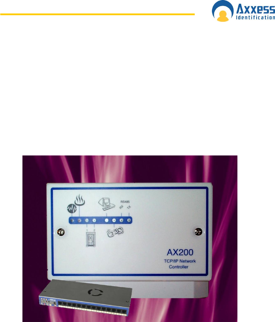
AX200 & i-BOX
Installation &
User Guide
Axxess Identification Ltd
27-28 Shrivenham Hundred Business Park,
Watchfield, Swindon, Wiltshire SN6 8TZ
United Kingdom
Tel: +44 (0)1793 784002
Fax: +44 (0)1793 784005
Email: info@axxessid.com

www.axxessid.com
Installation & User Guide
AX200 & IBOX Installation & User Guide – July 10
Microsoft® is a registered trademark of Microsoft Corporation.
Windows™ is a registered trademark of Microsoft Corporation.
Document Title: AX200 & I-BOX Installation & User Guide 7-Jul-10
This document contains proprietary information of Axxess Identification Ltd. Unauthorised
reproduction of any portion of this manual without the written authorisation of Axxess
Identification Ltd is prohibited. The information in this manual is for informational purposes
only. It is subject to change without notice. Companies, names and data used in examples
herein are fictitious unless otherwise noted. Axxess assumes no responsibility for incorrect
information this manual may contain.
©2010 by Axxess Identification Ltd
27-28 Shrivenham Hundred Business Park, Watchfield, Swindon SN6 8TZ United Kingdom
Telephone +44 (0)1793 784002
Fax +44 (0)1793 784005
Email info@axxessid.com
Web www.axxessid.com

www.axxessid.com
Installation & User Guide
AX200 & IBOX Installation & User Guide – July 10
L i c e n s e A g r e e m e n t
NOTICE TO USER: THIS SOFTWARE PACKAGE IS A CONTRACT. BY INSTALLING THE
SOFTWARE YOU ACCEPT ALL THE TERMS AND CONDITIONS OF THIS AGREEMENT.
1. Use of the Software. You may install and use the software only for the purpose
intended.
2. Copyright. You may not duplicate or copy the software or documentation, except that
you may make one backup copy of the software. All copies must bear copyright
notices contained in the original copy.
3. Limited Warranty. Axxess Identification warrants that the software will perform
substantially in accordance with the printed documentation when correctly installed
on a properly configured computer for which it is intended. Axxess Identification
warrants the compact disc upon which this product is recorded to be free from defects
in materials and workmanship under normal use for a period of five years from the
date of purchase. During the warranty period Axxess Identification will replace
compact discs, which prove to be defective.
4. Axxess Identification does not warrant and cannot warrant the performance or results
you obtain by using the software or documentation. In no event will Axxess
Identification be liable to you for any consequential, incidental or special damages.
For further warranty information, please contact Axxess Identification.

www.axxessid.com
Installation & User Guide
AX200 & IBOX Installation & User Guide – July 10
C o n t e n t s
AX200 Installation .................................................................................................................... 1
AX200 Software Setup .......................................................................................................... 1
TCP/IP Configuration (Fixed IP Address) .............................................................................. 3
IP Definitions Applicable to the AX200 ................................................................................. 4
Configuring AX200 on WAN / VPN Tunnels .......................................................................... 5
Configuring AX200 to run as a service ................................................................................. 6
AX200 & i-BOX Connections .................................................................................................. 7
Cat 5 Cable ........................................................................................................................... 7
How to wire a Straight through RJ45 plug correctly? ....................................................... 7
How to wire a Crossover RJ45 plug correctly? ................................................................. 8
9 Way i-BOX I/O Connection ................................................................................................ 9
AX100i Wiring Connection to i-Box ..................................................................................... 10
Sounder /Beacon for i-BOX (IC-ASB) ................................................................................. 11
AX200 Expander Board Connections ................................................................................. 11
Breakglass Wiring AX200 ................................................................................................... 12
Breakglass wiring AX50/AX100 .......................................................................................... 13
AX200 Software...................................................................................................................... 16
Operating Systems .............................................................................................................. 16
Software Installation ............................................................................................................. 16
Starting the AX200 Software ................................................................................................ 19
Language Selection............................................................................................................. 20
Password Reminder ............................................................................................................ 20
Backup & Restore .................................................................................................................. 21
Email Backup Settings ........................................................................................................ 22
Standard Query Language (SQL) ....................................................................................... 23
Database Integrity Check .................................................................................................... 23
Communication between the AX200 Software and Controller ............................................ 23
Plug & Play Devices ............................................................................................................ 24
Controller Status & Control .................................................................................................. 25
High Security Mode (HSM) ................................................................................................. 26
Door Unlock Mode ............................................................................................................... 26
Date and Time ..................................................................................................................... 26
On & Offline Operation ........................................................................................................ 27
Force Download & Clear Controller .................................................................................... 27
Performance Analyzer ......................................................................................................... 27
Transaction Screen ............................................................................................................. 28
Who‟s In/Out List ................................................................................................................. 29
Display Filters ...................................................................................................................... 30
Photo Display .................................................................................................................. 30
Email ............................................................................................................................... 30
Save on Exit .................................................................................................................... 32
Test Wizard ..................................................................................................................... 32
Cardholder .............................................................................................................................. 36
Main Settings ....................................................................................................................... 36
Card Number .................................................................................................................. 37
Imprint Number ............................................................................................................... 37
Employment .................................................................................................................... 37
Department ..................................................................................................................... 37
Access Group ................................................................................................................. 37
Card Type ....................................................................................................................... 37
Card Status ..................................................................................................................... 37

www.axxessid.com
Installation & User Guide
AX200 & IBOX Installation & User Guide – July 10
Pin Code ......................................................................................................................... 37
Time Zone ....................................................................................................................... 37
Photo ............................................................................................................................... 39
Photo ID .......................................................................................................................... 40
Add a Photo .................................................................................................................... 40
Capture Picture from Camera ......................................................................................... 40
Import Picture from File ................................................................................................... 41
Templates ....................................................................................................................... 41
Add New Card Wizard .................................................................................................... 41
Card Replacement Wizard .............................................................................................. 42
Card Diagnostics ............................................................................................................. 43
Search ............................................................................................................................. 44
Card 0 Function .............................................................................................................. 45
Print Current Card Details ............................................................................................... 45
Database Fields per Cardholder ..................................................................................... 45
Main Settings Tab ........................................................................................................... 45
Other Info ............................................................................................................................ 46
Employer ......................................................................................................................... 47
Mode Settings ..................................................................................................................... 47
High Security (Hi Sec) ..................................................................................................... 48
Extended Door Open Time (Ext‟d Door) ......................................................................... 48
Set High Security Mode (Set Hi Sec) .............................................................................. 48
Set Latch ......................................................................................................................... 48
Time Zone ....................................................................................................................... 49
Personal Info ....................................................................................................................... 49
Vehicle info .......................................................................................................................... 50
Access Point Configuration ................................................................................................. 51
Access Point Settings.......................................................................................................... 51
Access Identity ................................................................................................................ 51
Access Point Name ......................................................................................................... 51
Door Comments .............................................................................................................. 51
Door Release Time ......................................................................................................... 52
Start-up Mode Settings ................................................................................................... 52
Door Contact Settings ..................................................................................................... 53
PIN Settings .................................................................................................................... 54
Device Parameters .............................................................................................................. 54
Device Group .................................................................................................................. 55
Device Type .................................................................................................................... 55
Hardware Version ........................................................................................................... 55
Firmware Version ............................................................................................................ 55
Batch Number ................................................................................................................. 55
Serial Number in Batch ................................................................................................... 55
Database Stamp ............................................................................................................. 55
Access Groups .................................................................................................................... 55
Creating a new access group ......................................................................................... 56
Device Manager .................................................................................................................. 57
Automatic IP Setup .............................................................................................................. 58
Device Status Indication ................................................................................................. 60
Device Settings ............................................................................................................... 62
Fire alarm ........................................................................................................................ 63
Test Connection .............................................................................................................. 63
System Settings ..................................................................................................................... 64
Site Info ............................................................................................................................... 64
Test Wizard ......................................................................................................................... 65
E-Mail Facilities ................................................................................................................... 66
E-Mail Unknown Format to Axxess ID ............................................................................ 66
DB Maintenance .................................................................................................................. 67

www.axxessid.com
Installation & User Guide
AX200 & IBOX Installation & User Guide – July 10
Compact Database ......................................................................................................... 68
Backup Settings .............................................................................................................. 68
Database Restore ........................................................................................................... 68
Export Cardholders ......................................................................................................... 68
Import Cardholders ......................................................................................................... 68
Export Photo ID Templates ............................................................................................. 68
Import Photo ID Templates ............................................................................................. 68
Firmware Settings ............................................................................................................... 69
Rollback .......................................................................................................................... 70
Hidden Functions ................................................................................................................ 70
General Settings .................................................................................................................. 71
Maximum PIN Number 1~6 ............................................................................................ 71
Number of Lines in Screen ............................................................................................. 71
Transaction Screen Pause.............................................................................................. 71
COM Port Timeout .......................................................................................................... 71
COM Port Retry Times .................................................................................................... 71
Link Alive Retry Times .................................................................................................... 72
Function Settings ............................................................................................................ 72
COM Port Settings .......................................................................................................... 73
SNMP (Simple Network Management Protocol) ................................................................. 74
How to set up SNMP ........................................................................................................... 74
Advanced SNMP Features .................................................................................................... 76
Multiple/Single Card Format ........................................................................................... 77
Default Access Level ...................................................................................................... 78
Default Time Zone .......................................................................................................... 78
Default ............................................................................................................................. 78
Third Party File ................................................................................................................ 78
Format & Statistics ................................................................................................................ 78
Card Type Information......................................................................................................... 79
Facility Code ................................................................................................................... 79
Card Matching ..................................................................................................................... 80
Card Format Analyzer & Format Configuration ................................................................... 80
Security Settings ................................................................................................................... 81
Adding a New User ............................................................................................................. 81
Adding a New Authorisation Group ..................................................................................... 82
Reports ................................................................................................................................... 82
Cardholder Brief .............................................................................................................. 84
Cardholder Details .......................................................................................................... 84
Log File ........................................................................................................................... 84
Dossier ............................................................................................................................ 85
Work Spell ....................................................................................................................... 85
Operators ........................................................................................................................ 85
Environmental ................................................................................................................. 86
System Summary ............................................................................................................ 86
Quick View ...................................................................................................................... 86
Printing ............................................................................................................................ 86
Format Types .................................................................................................................. 86
Destination ...................................................................................................................... 87
i - BOX ..................................................................................................................................... 88
Environmental ........................................................................................................................ 90
i- BOX Parameters .............................................................................................................. 90
Sensor Settings ................................................................................................................... 90
Alarms ................................................................................................................................. 91
i- BOX Settings .................................................................................................................... 92
PDU (Power Distribution Unit) ............................................................................................. 94
Details ............................................................................................................................. 94
Sensor .............................................................................................................. 97

www.axxessid.com
Installation & User Guide
AX200 & IBOX Installation & User Guide – July 10
Hardware Connection Details ......................................................................................... 97
Sensor Settings ............................................................................................................... 97
Isolate.............................................................................................................................. 98
PIR....................................................................................................................................... 99
Dust Particle Sensor.......................................................................................................... 101
Mains Present Sensor ....................................................................................................... 102
DTU (Data Transfer Unit) ..................................................................................................... 104
Connecting the DTU .......................................................................................................... 104
Add a New Door using a DTU ........................................................................................... 106
Adding Card Formats using a DTU ................................................................................... 107
DTU Step by Step ............................................................................................................. 107
DTU Operation .................................................................................................................. 108
DTU LED Indicators .......................................................................................................... 108
Clearing the DTU ............................................................................................................... 109
Removing the AX200 Program ........................................................................................... 110
Anti-Virus .............................................................................................................................. 111
Readers ................................................................................................................................. 112
Fingerprint Reader ............................................................................................................ 112
Connection Details ........................................................................................................ 112
Proximity Readers ............................................................................................................. 116
How to connect the reader to the host .......................................................................... 116
Software Configuration ................................................................................................. 116
AXM Readers .................................................................................................................... 118
Output Type .................................................................................................................. 118
Connection Details ........................................................................................................ 118
Proximity Request to Exit .................................................................................................. 119
Technical Details ........................................................................................................... 119
Product Maintenance .......................................................................................................... 120
Flood Sensor – part number IC-FS-FLD ........................................................................... 120
Flood Sensor Maintenance Checklist - Table FSC 1.1 ..................................................... 123
Product Conformities .......................................................................................................... 124
www.axxessid.com
Installation & User Guide
AX200 & IBOX Installation & User Guide – July 10 - 1 -
AX200 Installation
This Installation Guide details the initial setup and steps to get the AX200 software
operational. For further information and additional features please refer to the AX200 software
manual.
Complete software installation and TCP/IP configuration must be performed whilst logged into
Windows with full Windows Administration rights.
Recommended Hardware Specification:
Processor: Intel Pentium 2.0 GHz (or equivalent) (Core 2 Duo Recommended)
Memory: 1GB of RAM (2GB Recommended)
Hard Disk: 2GB of Free Disk Space (dependant on size of database and amount of backups)
CDROM Drive
Screen Resolution: 1024x768
Operating System: Windows NT, 2000, XP Professional (SP2), Vista and Server 2003
COM Port if stand alone AX100 and AX150 are used
Ethernet Port
AX200 Software Setup
1. Install the AX200 software. Insert
the CD, if auto run is disabled then
click Start and select Run. Enter
d:\setup.exe in the text box and
click OK. (Note substitute the CD-
ROM drive letter in place of d)
Follow the on screen instructions to
complete the installation.
2. Ensure that the PC is connected to
the network and the AX200‟s are
connected to the network but
powered off.
3. Ensure that the PC has a fixed IP
address.
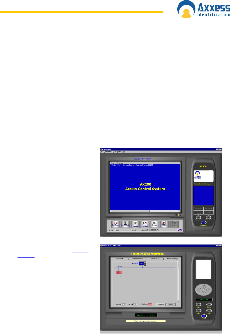
4. Start the AX200 software and enter
the user name and password to
login. The default user name is “1”
and the default password is “1”.
Allow the software to initialise.
5. Power up the first AX200 and the
AX100(s) connected to this
controller.
6. Click on the Access point button
located near the bottom left on the
screen.
7. Click on the last Tab Sheet labelled as Device Manager.
www.axxessid.com
Installation & User Guide
AX200 & IBOX Installation & User Guide – July 10 - 2 -
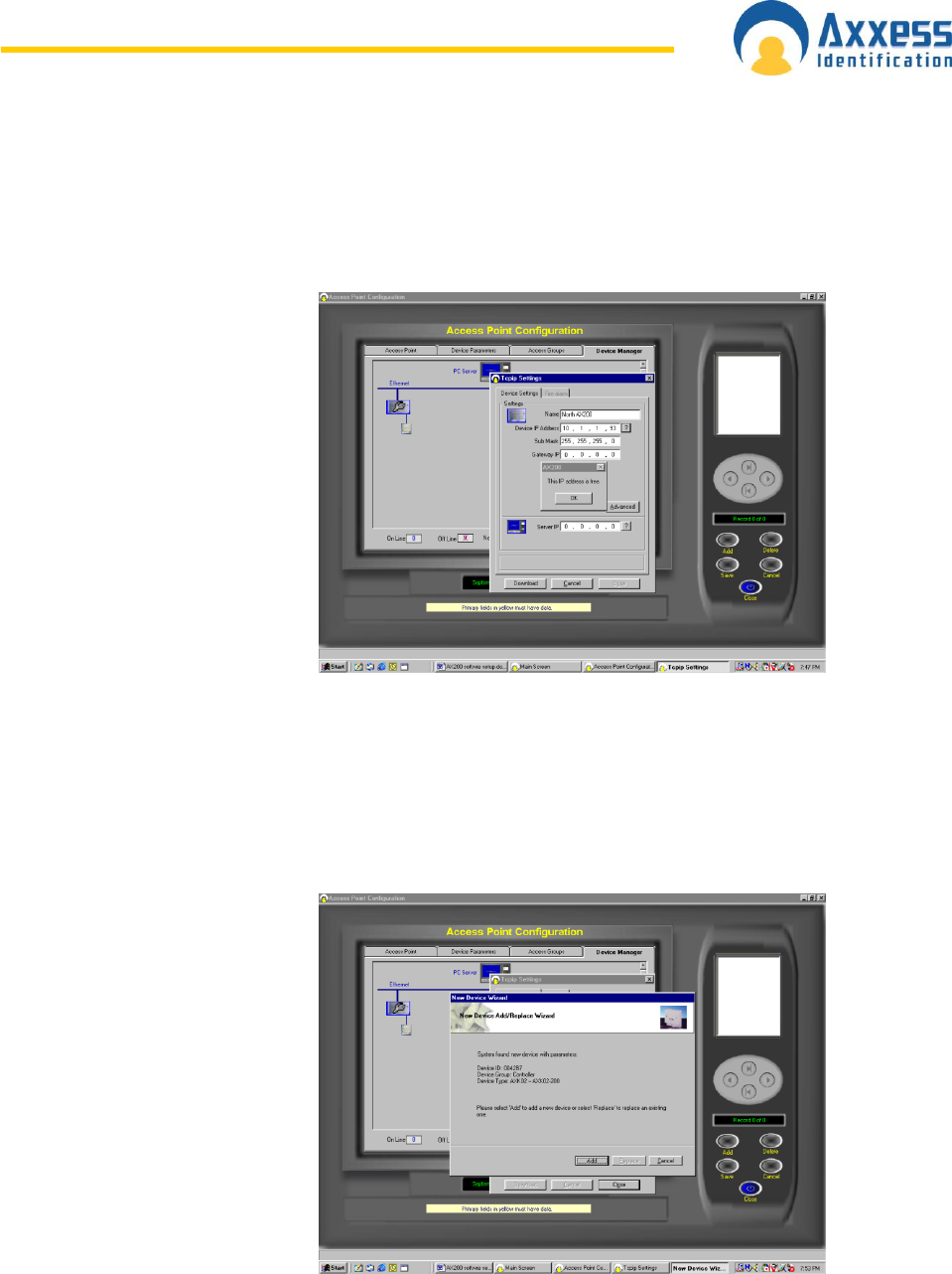
8. Wait for approximately 10 seconds and the device manager will seek all of the
AX200‟s connected to the network that are powered on. New AX200‟s will be
displayed in red; previously configured AX200‟s will be displayed grey. (AX200‟s
previously configured but not online will be displayed as Grey with a red cross)
Double click on the Red AX200.
9. Click on the ? at the end
of the Server IP address.
The Server IP address
will fill in. On local area
networks (LAN) the
Device IP address and
the Server IP address will
match for the first 3
numbers (Segment
address) and the last
number will be unique to
the AX200.
10. Enter a name for the AX200 and an IP address for the device. To ensure that this IP
address is not already assigned click on the ? next to the device IP address. Do not
use an IP address that is already assigned as this will cause the system not to
operate correctly. Enter the subnet mask and if advised by the network administration
manager, enter the gateway IP address for this device.
11. Click on the download
button and confirm by
clicking yes. After
approximately 5 seconds
the AX100 add wizard
will appear.
www.axxessid.com
Installation & User Guide
AX200 & IBOX Installation & User Guide – July 10 - 3 -
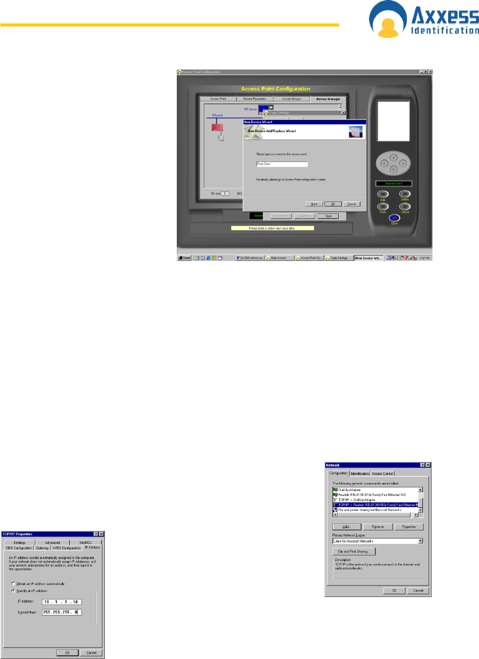
12. Click Add. Select the type of
reader (with or without PIN)
then click next. Enter a
suitable name for the door
location being added. Then
click OK. After a brief period
of time the add wizard will be
completed. Access point
specific settings such as lock
times, IN/Out configuration
may be set under Access
point / Access point. When a
new AX100 is added the
access point screen will be
displayed. Note if two
AX100‟s are connected to
the AX200 after 15 seconds
the Add wizard will appear again for Device two to be added.
13. Close the TCP/IP settings screen and close the device manager screen or access
point screen.
14. From the main screen click on the cardholder button and add a card(s) When the
cardholder screen is exited the information will be downloaded to the relevant
controllers and the door will lock.
15. Power up the next AX200 to be added and repeat steps 6 – 13 until all controllers are
configured.
T C P / I P C o n f i g u r a t i o n ( F i x e d I P A d d r e s s )
Refer to this section if the PC does not have a fixed IP address or for additional IP address
information.
To specify a fixed IP address
Click the Windows Start button then select setting and select control
panel. Double Click on the Network icon. In the components box scroll
down to TCP/IP Network card name and click on it. (On Windows XP
the control panel may be displayed directly
from the Windows Start button) Click on
Properties Button.
Select the IP Address Tab
Ensure that the system is set to specify an IP Address and that a
valid IP address is in the IP address box. (Note – most
organisations allow fixed IP address ranges, and a suitable IP
number is normally obtained from the network administration
manager) Enter a valid subnet mask address. Typically this is set to 255.255.255.0
Click OK or Apply.
Click OK to exit the network setup and close the system control panel window. If prompted to
reboot or to insert the Windows installation disk please follow the on-screen prompts.

www.axxessid.com
Installation & User Guide
AX200 & IBOX Installation & User Guide – July 10 - 4 -
IP Definitions Applicable to the AX200
IP Address
An IP address is a unique identifier for each controller, PC or other Ethernet device.
The IP address range is fro 0 to 255, where 0 is null, 1 to 254 are valid numbers and 255 is a
broadcast number. (Example – 10.1.1.25) Note – Consult with the Network Administrator
before using any IP address to avoid duplicate numbers
Subnet Mask
This is the mask or range of address that the device is allowed to talk to, typically the
broadcast number is used (Example 255.255.255.0 in this example permission is granted to
talk to all devices on the network)
LAN
Local Area Network refers to structured Ethernet cabling within a local area such as a single
building.
WAN
Wide Area Network, refers to a group of LAN‟s connected together such as a group of
buildings.
VPN
Virtual Private Network, refers to a separate IP numbering system applied on WAN‟s that
allows different equipment in various locations to communicate as a LAN
Gateway
The Gateway is the device used to channel IP traffic between LAN‟s over a WAN.
IP Port number
The IP port number is the number assigned for the communications over TCP to that specific
IP address. The AX200 uses Port numbers 4848 for the controller and 1818 for the AX200
software.
Firewall
A firewall may comprise of a physical device or software on a PC and it is designed to stop
malicious attacks by computer hackers or virus. Note Firewalls may also stop communication
between the AX200 and the software unless the specified IP port numbers are listed in both
the TCP and UDP protocol safe list on the firewall.
LAN Configuration
When working on a local area network (LAN) all devices that are configured to operate with
fixed IP address such as the AX200 controller, will require the same segment address. So if
the Server (PC) IP address is 10.1.1.15 then the AX200 will require an IP address with the
same segment such as 10.1.1.52. When building a private network (if there is not already one
there) it is recommended that the segment address is 10.1.1.x Use the subnet mask as
255.255.255.0 and the gateway IP address should be 0.0.0.0
WAN Configuration
When working on a wide area network (WAN) all devices that are configured to operate with
fixed IP address such as the AX200 controller, will probably have a different segment
address. So if the Server (PC) IP address is 10.1.1.15 then the AX200 will require an IP
address with the appropriate segment such as 10.1.2.52. Use the subnet mask as
255.255.255.0 and the gateway IP address must be configured (Please consult the Network
Administrator for all IP Settings)
www.axxessid.com
Installation & User Guide
AX200 & IBOX Installation & User Guide – July 10 - 5 -
VPN Configuration
Generally configure Virtual Private networks as per the LAN Configuration setup. (Please
consult the Network Administrator for all IP Settings)
Example IP Address Table
Device Name
Location
IP Address
Gateway
Address
Subnet Mask
Address
File & Printer Server
Sales PC
AX200 PC
AX200 Controller
AX200 Controller
File & Printer Server
Sales PC
AX200 Controller
AX200 Controller
London
London
London
London
London
New York
New York
New York
New York
10.1.1.10
DHCP
10.1.1.35
10.1.1.36
10.1.1.37
10.1.2.10
DHCP
10.1.2.55
10.1.2.56
10.1.1.1
DHCP
10.1.1.1
0.0.0.0
0.0.0.0
10.1.2.1
DHCP
10.1.2.1
10.1.2.1
255.255.255.0
DHCP
255.255.255.0
255.255.255.0
255.255.255.0
255.255.255.0
DHCP
255.255.255.0
255.255.255.0
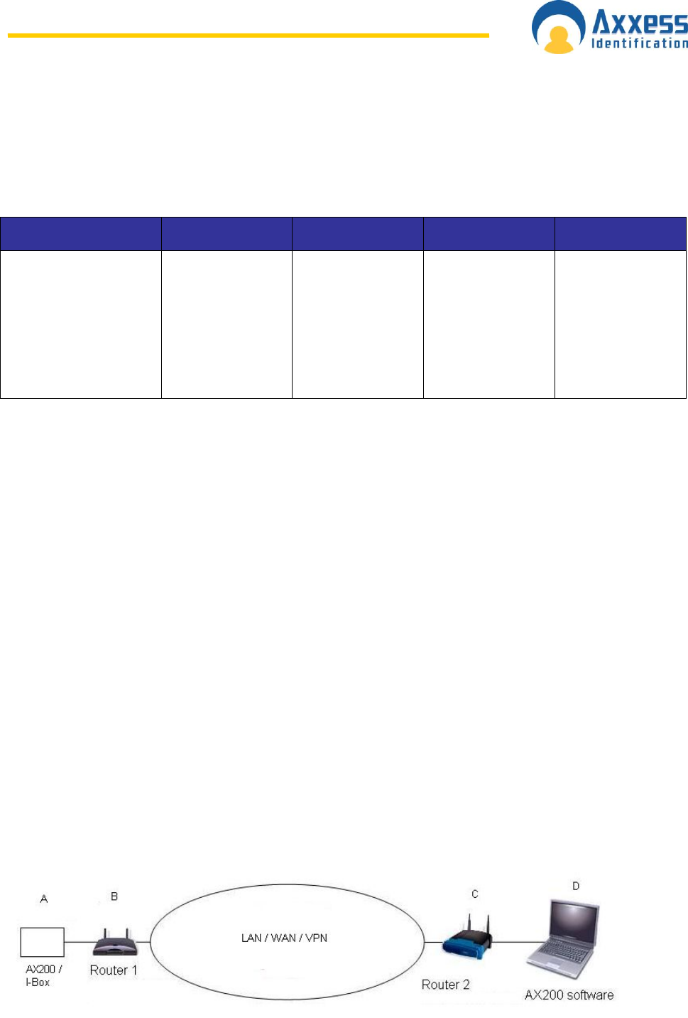
C o n f i g u r i n g A X 2 0 0 o n W A N / V P N
T u n n e l s
The device manager use's a broadcast address to discover the AX200, the broadcast
address will be blocked over the internet.
Once a static IP address is assigned to the controller use the static IP address to search for it
over the internet.
To search a static IP address click on access point > device manager > Click the PC Icon and
select WAN (and close)
Then click on device searching and enter the IP address of the controller in from IP address
(leave to IP address blank or enter the next IP address)
If the AX200 controller is reachable then it will now be added in the software.
Example:

www.axxessid.com
Installation & User Guide
AX200 & IBOX Installation & User Guide – July 10 - 6 -
Remote site
1 - Plug laptop into the switch B using DHCP to find the IP address range suitable for the
remote site and the gateway IP address
2 - Configure the AX200 controller with an IP address in the range, a subnet mask typically
255.255.0.0 and the gateway IP address (Router B) - The server IP address is the PC at D (
you may need to come back to this)
Host site
1 - Plug laptop into C using DHCP to find the IP address range for this location and the
gateway address.
2 - Assign a static IP address within windows to the PC along with the gateway address for C
(Router C)
3 - Use device manager to search the WAN to find the AX200 controller.
Notes
If you are using wireless then configure B and C to talk to each other.
If you are connecting B and C over the internet you will need to set up an IP tunnel (such as
IKE policy) The IP address of the PC and controller must be within the DHCP address range
of the gateway and you will need to reserve the IP address's that are in use.
C o n f i g u r i n g A X 2 0 0 t o r u n a s a s e r v i c e
AX200 can be configured to run as a service and start automatically on start up. When it is
configured as a service it is included in the windows service list. AX200 will automatically
login using the guest account, therefore remaining secure. You will have to logout and login
as your own account to be able to access all the features.
To configure AX200 to run as a service, do the following:
1. Open a command prompt, by clicking start -> Run -> type cmd then press enter ->
this will bring up a command prompt.
2. Within the command prompt change to the AX200 directory. By default the command
would be: cd “C:\Program Files\AX200”
3. Then enter the command: xyntservice.exe –i
4. Press enter
5. Close the command prompt.
6. Click start -> control panel -> Administrative tools -> services
7. From here you will see a service named AX200. Start this service.
Should you wish to uninstall AX200 as a service, stop the service then:
1. Open a command prompt, by clicking start -> Run -> type cmd then press enter ->
this will bring up a command prompt.
2. Within the command prompt change to the AX200 directory. By default the command
would be: cd “C:\Program Files\AX200”
3. Then enter the command: xyntservice.exe –u
Press enter
4. Close the command prompt.
www.axxessid.com
Installation & User Guide
AX200 & IBOX Installation & User Guide – July 10 - 7 -
AX200 & i-BOX Connections
Cat 5 Cable
CAT5 cable, 4 pairs of 24 gauge twisted copper shielded pairs
CAT5 cable is a current low cost industry standard for network connections
Axxess Identification products use 10mb Ethernet TCP/IP communication with Cat-5
cabling allowing up to 100mb
Cable maximum length from the origin to the final destination is up to 100m
About - CAT5 cable can be used to connect a network controller to an existing local and wide
area network. This forms the network and allows central control from a PC.
Installation - Internal or external CAT5 is used as required (Note: it is recommended that in
the installation of CAT5 cable should be connected using either T568A or T568B and not a
mix of both connection types). A single data line can be extended up to 100m.
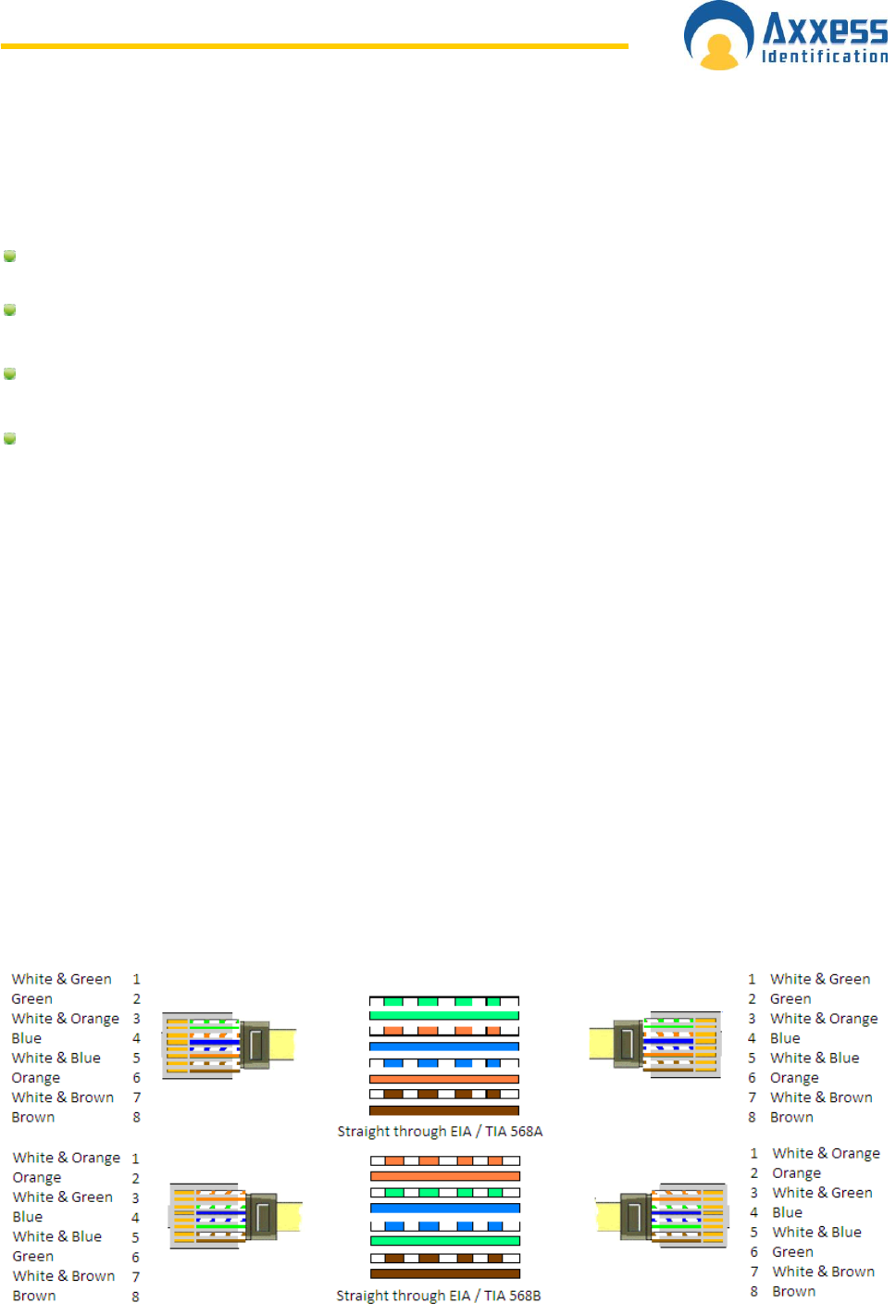
How to wire a Straight through RJ45 plug correctly?
Ethernet LAN wiring is reasonably straightforward but the correct colour coded wires must be
wired to the pins of the jack.
Not all Ethernet cable strands are alike so correct colour allocation to the RJ45 Jack is
key.
There are two accepted RJ45 pin to wire colour allocations T568A or T568B (see diagrams
below). In both of the diagrams the cable is to be connected to the plug according to the
network you will be using. The 8-way RJ45 plug is placed onto the cable with the hook
underneath. This makes it easier to see which colours go to which pins in the clear plastic of
the plug.
www.axxessid.com
Installation & User Guide
AX200 & IBOX Installation & User Guide – July 10 - 8 -
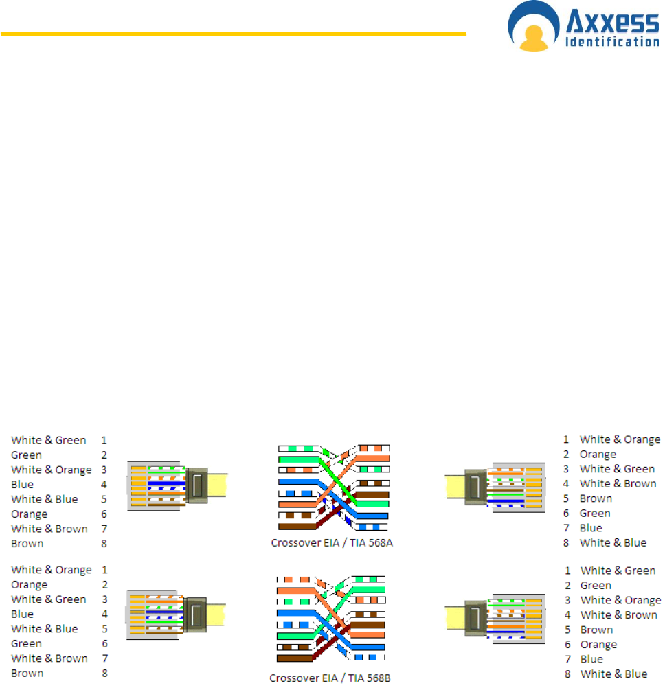
How to wire a Crossover RJ45 plug correctly?
Basic Description:
A crossover cable maps input signals of one connector to the output signals of another
connector. This allows two devices to communicate in a full-duplex manner through their
network adapters. The terminal devices are connected to a hub or a switch through CAT5
crossover cable and it is required that the transmit pair of the device is connected to the
receiving pair of the other device. Each pin of the connector at one end is connected to the
corresponding pin of the other connector.
A two computer network called a peer-to-peer network may also be formed using Cat 5
Crossover Cable. The reverse colour coded wires are seen at both the ends of the cable.
The 1st and 3rd as well as the 2nd and 6th wires are crossed in the crossover wires. These
cables follow a particular sequence of wires at each end. The crossover cables should be
used for only direct connections. If you try to connect a computer to a hub through a
crossover cable, the link may not function properly.
A basic connection is the TX (transmit) of one end to the RX (receive) at the other end or a
568A at one end to a 568B at the other...
Please see below for the correct crossover wiring diagram:
www.axxessid.com
Installation & User Guide
AX200 & IBOX Installation & User Guide – July 10 - 9 -
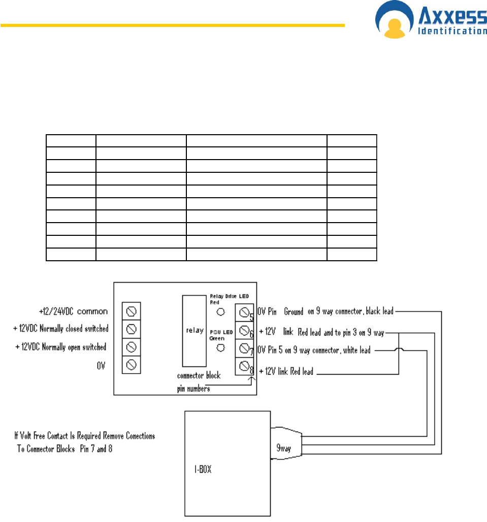
9 Way i-BOX I/O Connection
Table below describes the 9 way connector on the i-BOX and states the functionality of each
pin.
9 WAY D DESCRIPTION NOTES COLOUR
1 Not connected
2 Breakglass 2 (switched) + 12v (pin 3) Blue
3 + 12v D.C Red
4 External Sounder Output goes low when active Purple
5 * Ground White
6 Fire Input (switched) + 12v (pin 3) Orange
7 Breakglass 1 (switched) + 12v (pin 3) Green
8 Access Granted Output goes low when active Yellow
9 External Strobe Output goes low when active Black
www.axxessid.com
Installation & User Guide
AX200 & IBOX Installation & User Guide – July 10 - 10-
AX100i Wiring Connection to i-Box
12VDC
Door 1Door 2
INPUT/OUTPUT
\
DC Voltage Only
Green = Power OK
Red = wires reversed, re-wire
Orange = AC voltage, change PSU
To reset the electronic fuse,
disconnect the power, wait 30
seconds and then reconnect
the power.
Reader wiring connections
shown are for standard
AXP readers.
Reader
White
Red
Black
0V LED D1 D0 +12V Door
C'tct C REX 0V +12V
Power In
DC
>65mA
Blue &
Yellow
NO
NC
C
Lock Relay
Green
3 2 5
N/A
0V
TX
RX
RS232 to
PC for
standalone
AX100
max. 15
metres
AX200
to AX100i for door 2
Red Power In +12vDC
Black Power In 0V
Blue Door Contact
Green TX
White RX
DIN cable supplied with
AX100i
www.axxessid.com
Installation & User Guide
AX200 & IBOX Installation & User Guide – July 10 - 11-
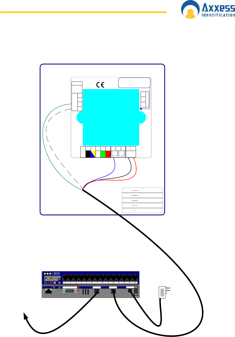
Sounder /Beacon for i-BOX (IC-ASB)
The sounder /Beacon for the i-BOX connects directly to the i-BOX and will sound the alarm
and flash the strobe for a pre-programmed period of time when an alarm condition occurs on
the i-BOX.
Connect the 9 way D connector to the i-BOX.
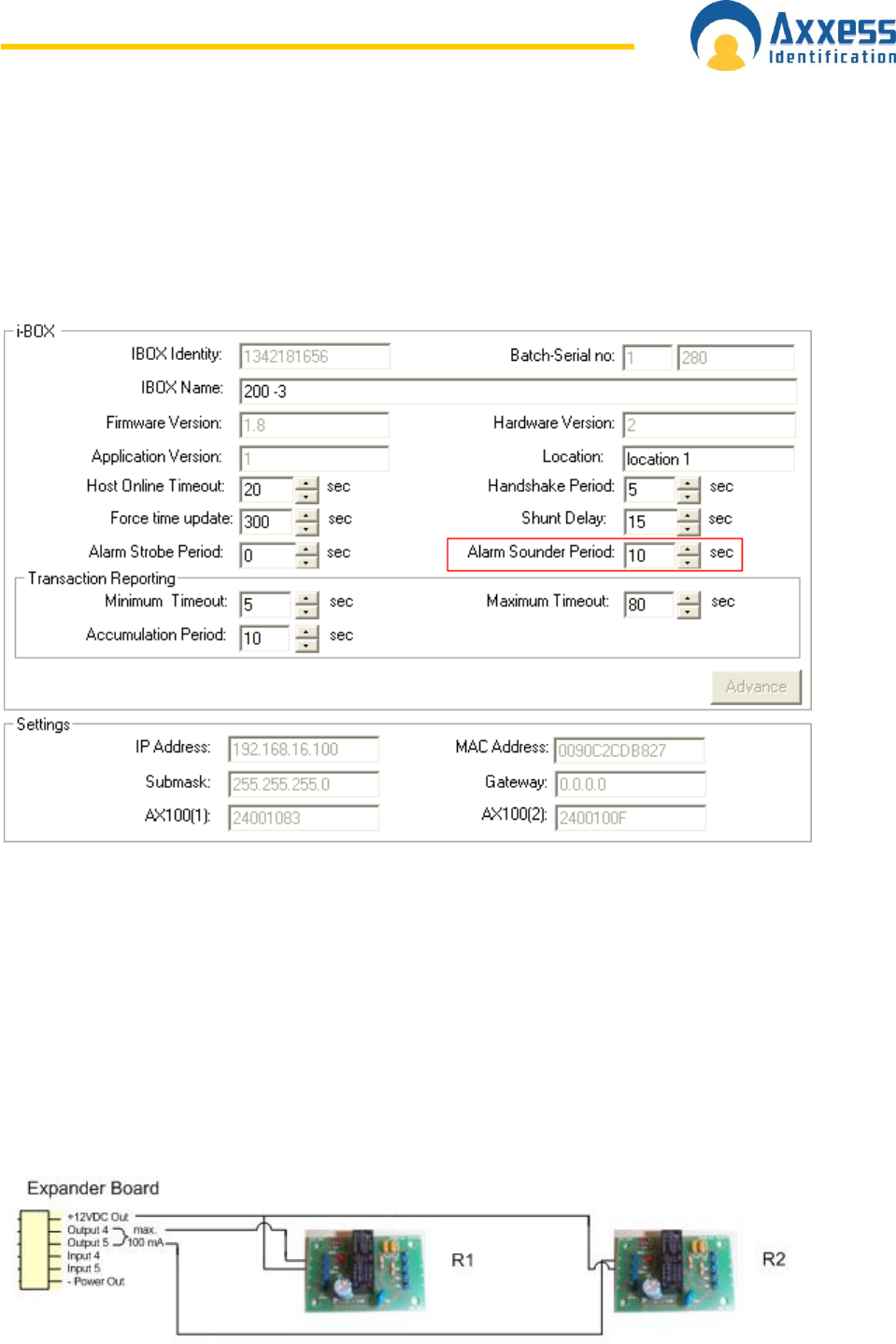
To configure the duration select the environment button in the software.
Click on the I-box in the tree menu.
Adjust the alarm sounder period time to the desired length of time and click Save.
AX200 Expander Board Connections
Expander Board connections are located at the top-right corner of the AX200 board. Output 4
(associated with door 1) & output 5 (associated with door 2) are activated once the “Door
forced/held open alarm” is triggered on the appropriate controller and will stay active until
the alarm is cleared either by using a valid card or by using the clear alarm button on the main
screen.
Note: the alarm is cleared only when the “Door forced/held open alarm cleared” transaction
appears on the main screen.
www.axxessid.com
Installation & User Guide
AX200 & IBOX Installation & User Guide – July 10 - 12-
Expander Board R1 R2
12 VDC Out PIN 6 PIN 6
Output 4 PIN 5 -
Output 5 - PIN 5
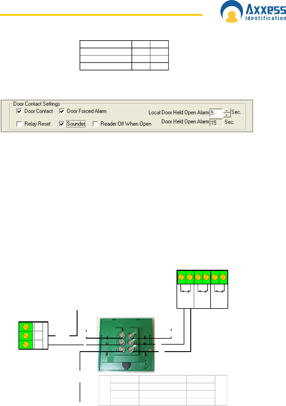
Door forced / held open alarm settings can be accessed through Main Screen → Access
Point → (Enable) Door Contact.
For more information about these settings please refer to Access Point Configuration →
Access Point Settings on this manual.
Note: Relay No.3 generates a 1 second pulse through the Access Granted connection block,
located at the top of AX200 board. The connection is normally closed and the pulse is
generated once the access is granted through either door.
Diagrams on the following pages illustrate the connections between the AX200 components.
Please note that if you are installing a brand new unit, the Fire Alarm, Break glass & PSU
Monitoring links will not be activated until the first time they are used.
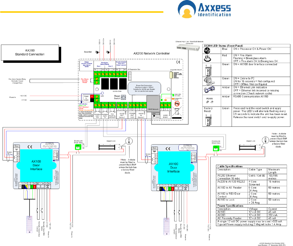
Breakglass Wiring AX200
Breakglass
Door 1
OUT
Breakglass
Door 2
IN
PSU
Monitoring
Volt Free
NC
C NC2A 2A3A 3A
2A
3A
3
to lock
2
AX200
Power In
+12vDC
Double Pole
Breakglass
Breakglass Wiring AX200
Terminal Function Terminal
1 Normally Open 1A
2 Common 2A
3 Normally Closed 3A
Switch 1
Switch 2
AX100
NO
NC
C
Lock Relay
11A
for monitoring of
breakglass
www.axxessid.com
Installation & User Guide
AX200 & IBOX Installation & User Guide – July 10 - 13-
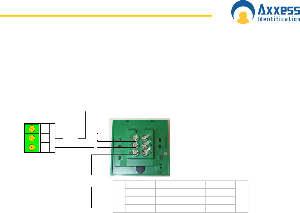
Breakglass wiring AX50/AX100
3
to lock
2
Double Pole
Breakglass
Terminal Function Terminal
1 Normally Open 1A
2 Common 2A
3 Normally Closed 3A
Switch 1
not in use
Power In
+12vDC
AX50 / AX100
NO
NC
C
Lock Relay
1
AX50 / AX100
www.axxessid.com
Installation & User Guide
AX200 & IBOX Installation & User Guide – July 10 - 14-
www.axxessid.com
Installation & User Guide
AX200 & IBOX Installation & User Guide – July 10 - 15-

www.axxessid.com
Installation & User Guide
AX200 & IBOX Installation & User Guide – July 10 - 16-
AX200 Software
The AX200 software is where all the programming data and cardholder information is entered.
It consists of the following:
Cardholder
Access Point
System Settings
Format & Statistics
Security
Reports
Environment
The PC is where all the system configuration and data management is stored. The optional
data transfer unit (DTU) enables the data that has been entered at the PC to be downloaded
to the controller without the need of a physical PC connection.
The AX200 system supports a wide variety of card technologies, including proximity,
magnetic stripe (AX Series), Wiegand and Wiegand compatible card types.
Operating Systems
The AX series supports a wide range of operating systems and can run on Windows NT
Workstation, NT Server, 2000 Professional and Advanced, ME, XP and Vista without the
need for different CD‟s or drivers. A number of checks are implemented within the software to
ensure that the correct files for the operating system are present. The installation process
automatically detects the operating system and installs the correct files and drivers.
If you are using windows Vista please note:
The recommended screen resolution for running the AX200
software on Windows Vista is 1024768.
If you receive a message at the start-up saying that the “User does
not have write access to the database”, right click on the AX200
icon and select “Run as Administrator”. After doing so, this icon
might appear in front of the AX200 icon.
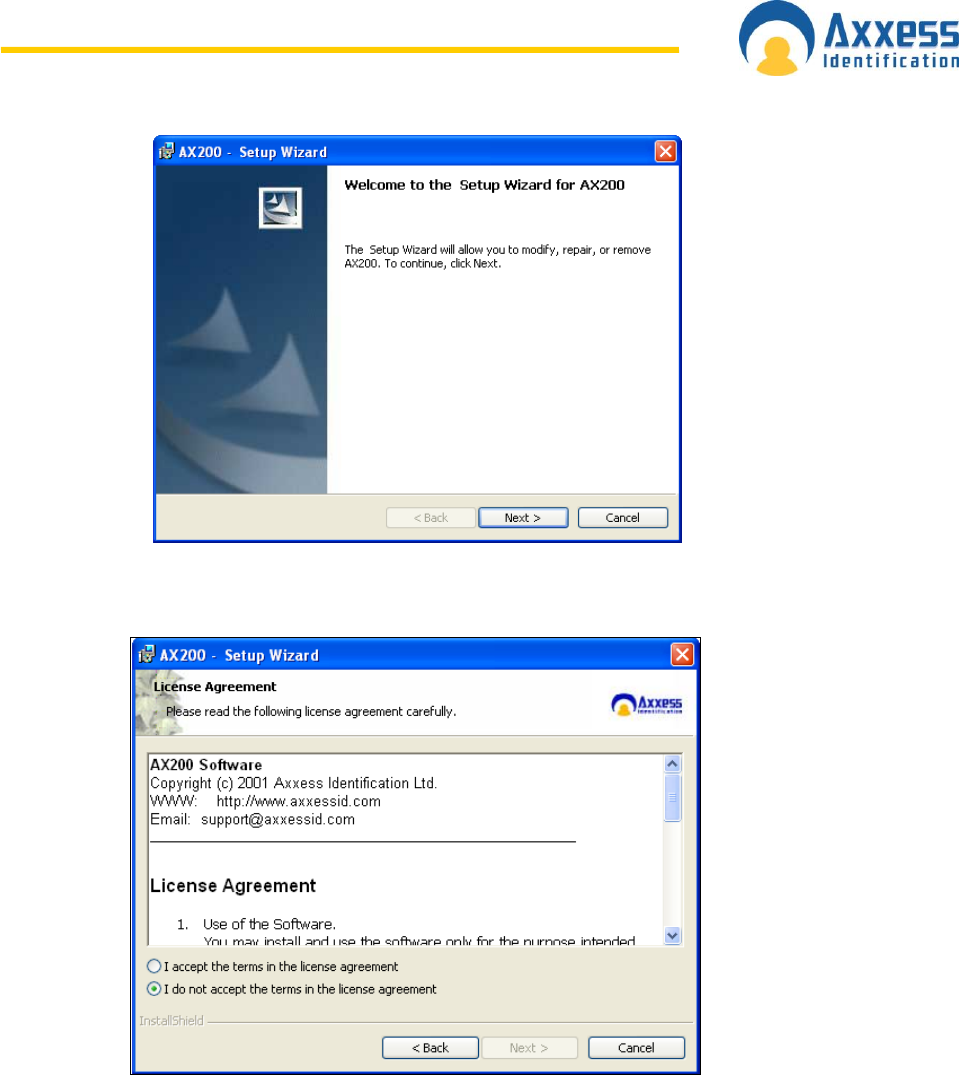
S o f t w a r e I n s t a l l a t i o n
Put the AX200 CD in your CD drive. If the CD doesn‟t run automatically, click on the Start
button and select Run. Type in x:\setup.exe on the command line (replace x with the letter
of your CD-ROM drive).
Click Next > to continue with the AX200 Setup Wizard.
www.axxessid.com
Installation & User Guide
AX200 & IBOX Installation & User Guide – July 10 - 17-
Please read the License Agreement, to accept the terms select I accept… then click on Next
>.
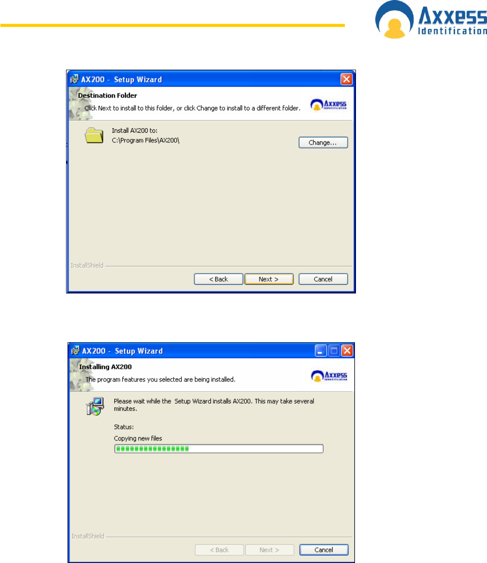
The default directory where program files are installed is C:\Program Files\AX200\ If
required, click on Change to choose a different folder. Click on Next > to accept the default,
or when you‟ve entered a different destination folder.
www.axxessid.com
Installation & User Guide
AX200 & IBOX Installation & User Guide – July 10 - 18-
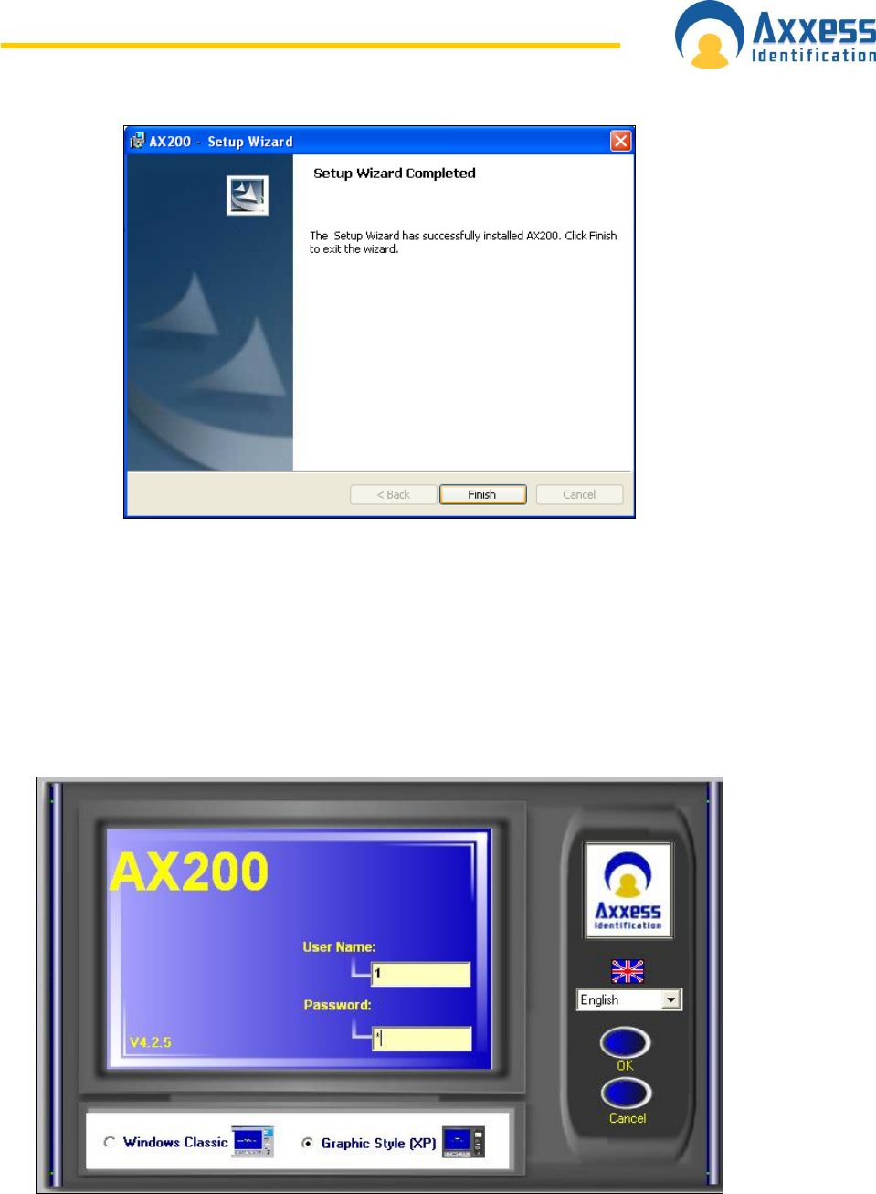
The AX200 program files will now be installed.
The AX200 installation is now complete. Select Finish to exit the setup wizard.
www.axxessid.com
Installation & User Guide
AX200 & IBOX Installation & User Guide – July 10 - 19-
Some operating systems also require Microsoft Data Access Components to support SQL.
This is automatically installed if required. Please follow the on-screen instructions.
Starting the AX200 Software
Connect your AX200 controller to the PC using the communication cable supplied.
Go to Start → All Programs, left click on AX200 Access Control System and it will launch
the AX200 software, alternatively double click the AX200 logo from the Windows desktop.
The AX200‟s default user name is 1 and the default password is 1. The user names and
passwords are not case sensitive. Enter the default user name and password and select OK.
www.axxessid.com
Installation & User Guide
AX200 & IBOX Installation & User Guide – July 10 - 20-
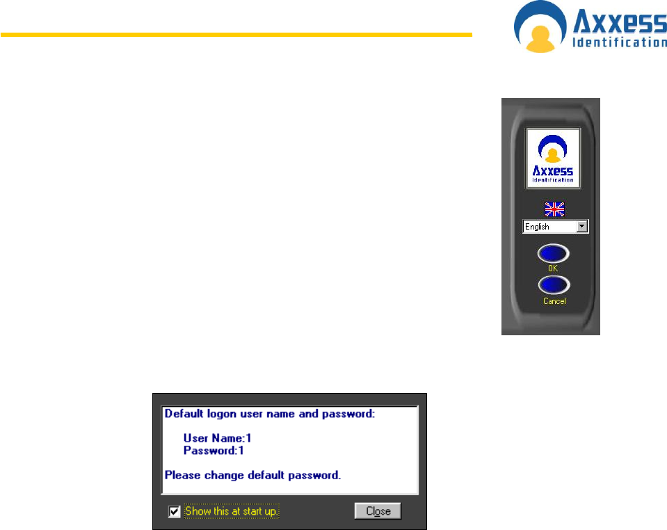
Language Selection
Installation and operation of the software can be selected in different
languages. Changing the language can be done from the login screen as well
as within the program on the main screen, without the need to restart the
software or the computer.
Password Reminder
A password reminder box displaying the factory default reminds the user to
change the default password. This reminder box disappears automatically when the default
password has been changed.
www.axxessid.com
Installation & User Guide
AX200 & IBOX Installation & User Guide – July 10 - 21-
B a c k u p & R e s t o r e
The AX software has a built-in backup utility. Backups can be done automatically at preset
times and days, or manually with network backup support. Backups from older software
versions are automatically converted avoiding the need for multiple steps to restore the
software.
A backup can be restored in one single step. Automatic backups are numbered using the
date and time the backup took place. If you wish to delete older backups, highlight the
appropriate file by clicking on it and press delete, confirmation of this action is requested. It is
useful to create a complete system backup as soon as all the system settings have been
entered. Create a backup as normal, go to restore, highlight the newly created file and right
click with the mouse and select rename – rename the file e.g. Master settings. This backup
will allow you to restore the system back to its original programmed settings, if required. To
restore an existing database go to the File menu → Database Restore.
When exiting the software, if any data has changed, the application will automatically perform
the database backup. There is no need to close the program or cardholder screen for the
automatic backup to execute. Partial backups can also be selected for database or history
files only.
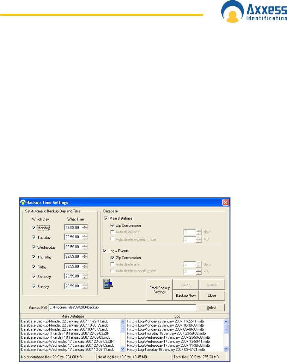
Backup time settings window can be reached through the File menu. The default day and
time for automatic backup is displayed on the left side of the window. By default, the
application will take a backup of your database at 23:59:00 every night.
Settings on the right hand side give you more options on how to manage your backup files.
Normally the backup process saves both, the Main Database and Log & Events; however
you can exclude either of them from the backup process simply by removing the tick in the
check box.
www.axxessid.com
Installation & User Guide
AX200 & IBOX Installation & User Guide – July 10 - 22-
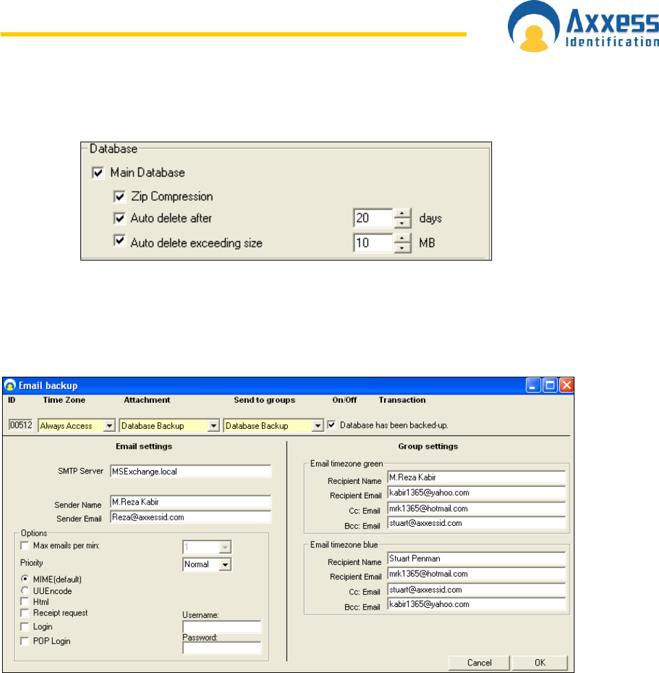
You can also set the application to automatically delete the backup files after a specific
number of days or once they exceed a certain size (in MB).
Once the Zip Compression is enabled, the software will automatically compress the backup
file into a zip file. Since the .mdb file cannot get through the fire wall, zip compression is very
helpful when you wish to email the backup settings.
Email Backup Settings
Email settings could be sent to a specific group of people via Email. You need to specify the
time period during which you would like the email to be sent out (Time Zone), the information
you want to include (Attachments) and the name of the recipients (Groups).
Enter the name and email address of the sender on the left. If you’re using a local server
enter the name of your local SNMP server for email.
Group settings on the right include the name and email address of the people who will receive
the email. These settings are divided into to blocks. The people on the top section will only
receive the email if the backup has taken place during a green time zone and the people in
the bottom section will receive the email if the database has been backed up during a blue
time zone (exception monitoring).
A number of optional settings are also included in this screen. You can set priorities for your
emails and choose the maximum email messages sent in a minute. There are also a number
of different options for email format. MIME is the default.
MIME (default): Multipurpose Internet Mail Extensions (MIME) is an Internet Standard that
extends the format of e-mail to support text in character sets other than US-ASCII, non-text
attachments, multi-part message bodies, and header information in non-ASCII character sets
www.axxessid.com
Installation & User Guide
AX200 & IBOX Installation & User Guide – July 10 - 23-
UU Encode: UUencoding is a form of binary to text encoding that originated in the Unix
program uuencode, for encoding binary data for transmission over the UUCP mail system.
The name "UUencoding" is derived from "Unix-to-Unix encoding".
Standard Query Language (SQL)
The database structure is based on Microsoft SQL. This ensures stability and a high data
throughput with easy interfacing to other applications. The database handles up to 65,525
cardholder records with over 60 fields per cardholder. Card numbering is up to 10 digits
allowing support for a wide variety of formats e.g. existing cards or multi-purpose cards
(vending machines etc.)
Database Integrity Check
A mains failure or system crash with an open database normally requires running a separate
application to repair the data. All data in the AX200 database is automatically checked on
start up and repaired if necessary.
At the start-up, the software automatically checks the database version. If the database is too
old and not supported by the new version of software the following transaction will appear on
the screen asking you to check the version of the database.
You can view the version of your database in the Performance Analyzer screen; under Tools
→ Enable Optional Software. This problem usually occurs when you manually copy a new
database over the old database in the AX200 folder. That’s why we strongly recommend
that you use the restore function only!
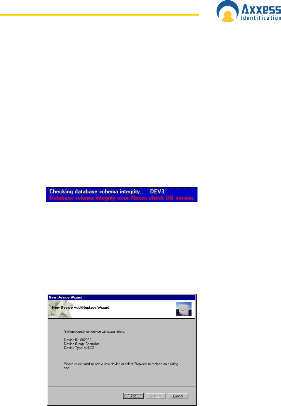
Communication between the AX200 Software and Controller
A benefit of the AX200 software is its plug and play ability to detect new devices when they
are installed. The New Device Wizard will automatically detect the controller and its unique
device ID. Follow the on-screen prompt by selecting Add.
www.axxessid.com
Installation & User Guide
AX200 & IBOX Installation & User Guide – July 10 - 24-
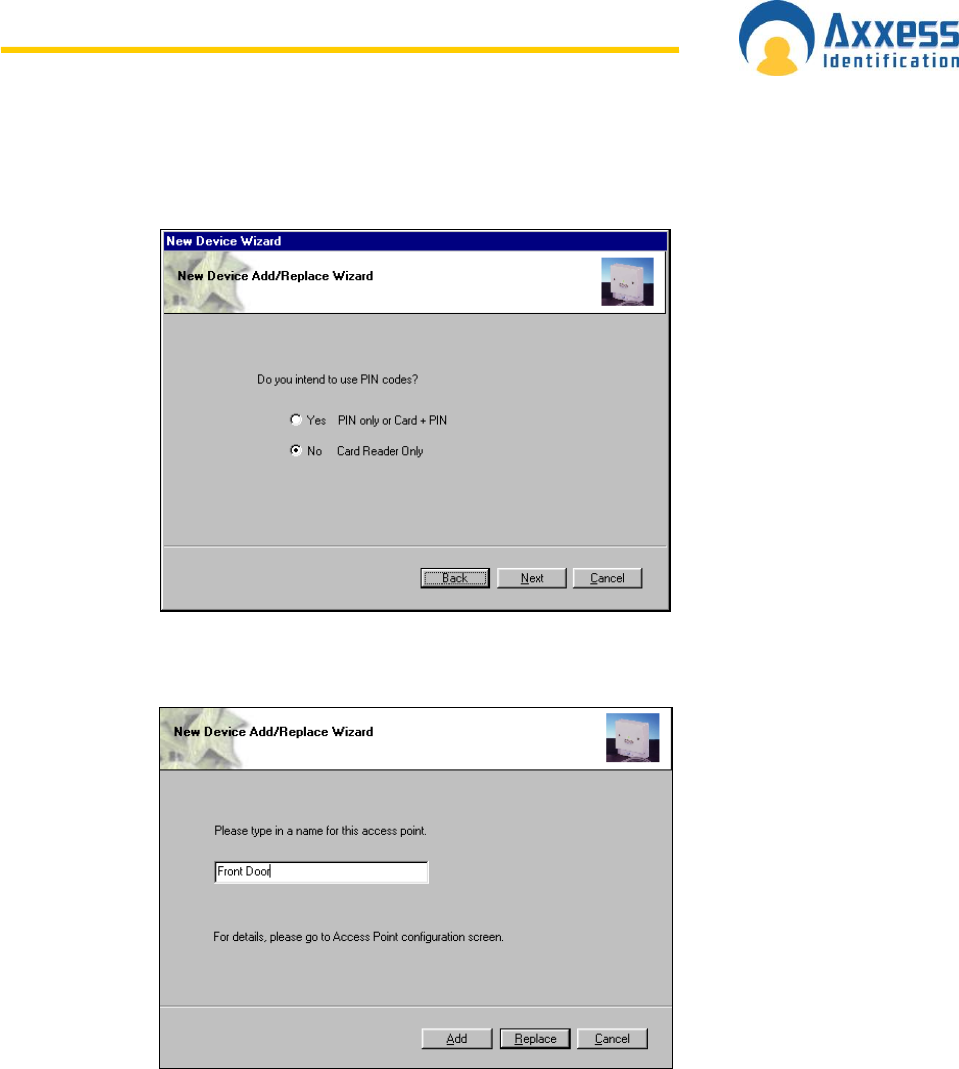
The following screen will ask whether you are using PIN codes only, a card reader and a PIN
code or a card reader only. Please select the appropriate radio button for your installation,
followed by Next.
Provide a name for the access point i.e. the location and select OK.
Plug & Play Devices
The PC communication port is automatically setup and new devices connected will be
automatically detected and can be added (or replaced) using the new device wizard, which
allows setting up a new controller in seconds. When enabled under system settings, Plug &
Play is active at all times and does not require a restart of the application or computer. This
allows addition of new controllers on the fly. AX readers are also entirely Plug & Play being
automatically identified with the relevant information displayed under access points. COM
ports 1 to 16 and TCP/IP (TCP/IP AX200 only) addresses can also be set up manually if
required. Error correction, speed, bit length, parity etc are all automatically set up for the
optimum performance of the system. Once the controllers are in the system, the new device
wizard also allows auto-replace. This feature allows replacement of controller data with the
press of a single button.
www.axxessid.com
Installation & User Guide
AX200 & IBOX Installation & User Guide – July 10 - 25-
All the Plug & Play devices have a unique identity number so no jumpers or switches have to
be set on either controllers or readers.
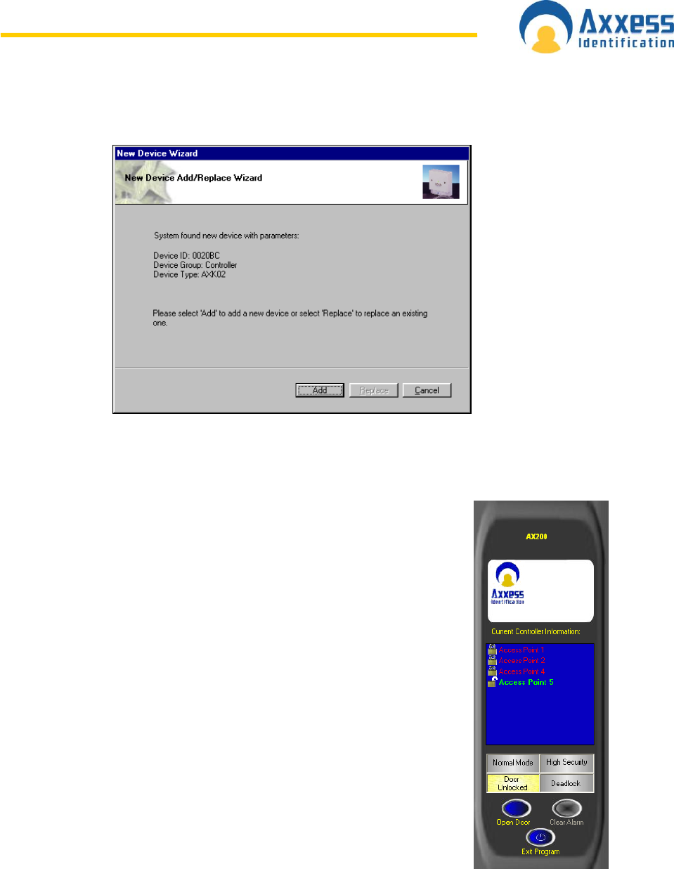
C o n t r o l l e r S t a t u s & C o n t r o l
Devices connected are highlighted and display the door status in real-time on the main
screen. Doors can be controlled directly from the main screen.
Commands can only be given to controllers online and functionality is
greyed out if the controller is not available online to avoid any uncertainty.
Door open
Opens the door for a set time e.g. 5 seconds
Normal mode
Standard mode
Door unlocked
Door permanently unlocked
High security mode
Only cardholders with high security mode valid
will have access
Deadlock
Locks door for all cardholders, request to exit is
still active. Please exercise care when using the
feature.
Clear alarm
Door reset, door forced, door held open alarm
www.axxessid.com
Installation & User Guide
AX200 & IBOX Installation & User Guide – July 10 - 26-
High Security Mode (HSM)
This feature allows individual doors to be enabled where standard cards no longer have
access. Only cardholders with the high security mode set (HSM) have access whilst this
feature is enabled. The HSM feature can be switched on by using a card which has the “set
high security” enabled, four times consecutively at the reader. To change back to the normal
mode use a card with the HSM feature four times consecutively.
Door Unlock Mode
This feature can be activated from the PC
or cards with the “set unlock” feature
enabled. Using a card with this feature
twice consecutively at the reader will
permanently unlock the door. To return to
the normal mode, use the card again
twice consecutively. Typical applications
include reception doors during normal
office hours or for goods inward
deliveries.
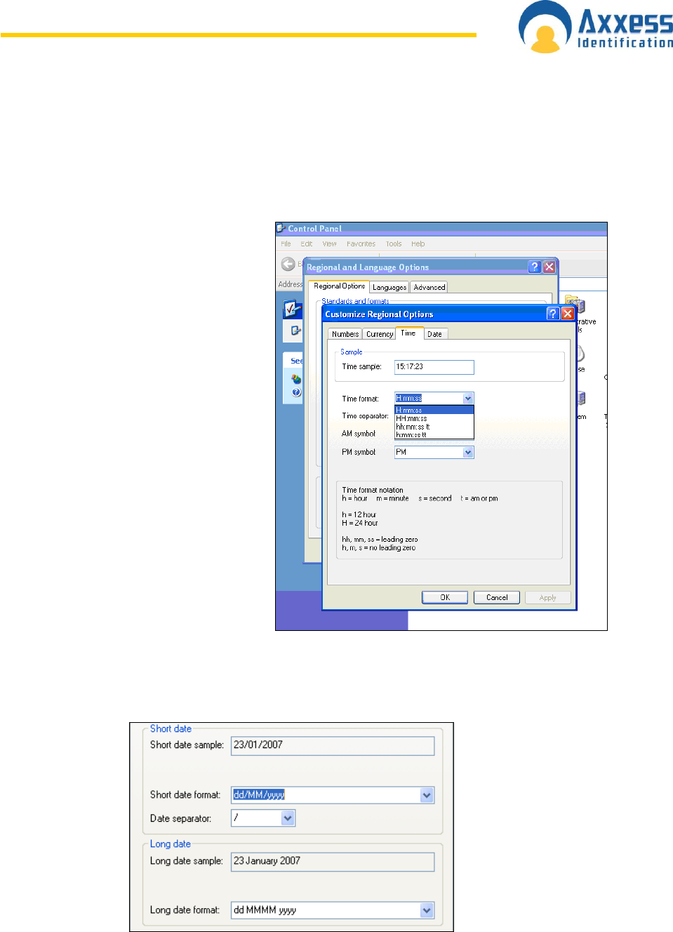
Date and Time
The date and time formats are obtained
by default from the operating system and
therefore no user intervention is required.
The 12 hour time format is NOT
supported by this application. If you are
using the 12h time format you need to go
to Control Panel → Regional and
Language Options → Regional Options
→ Customize… → Time and choose the
24 hour (H) time format. You also need to
make sure that your PC is set to UK time format which is (dd/MM/yyyy).
You can change the date settings in the same window under the Date tab.
www.axxessid.com
Installation & User Guide
AX200 & IBOX Installation & User Guide – July 10 - 27-
On & Offline Operation
The AX software enables the use of on and offline controllers from within the same software
simultaneously. The AX100 controller can also be updated using a portable data transfer unit
(DTU). This allows the use of remote doors or doors not requiring online information to be
used at the same time as doors with real-time online information. This reduces costs
substantially with full control from a single software package.
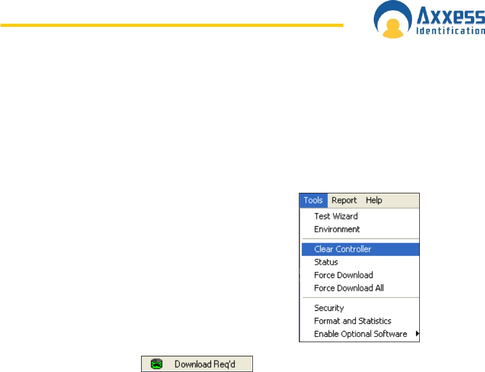
Force Download & Clear Controller
Clear controller deletes the database that has been stored in the
controller. Once the controller is cleared, the door becomes
permanently unlocked. At this time if a card is presented to the
reader, a transaction will appear on the screen saying “Door is
unlocked” followed by the cardholder‟s name, card number and
the door‟s name. To clear a controller highlight the appropriate
access point on the current controller list (on the right) and
select Clear Controller from the Tools menu.
If for whatever reason the automatic download doesn‟t take
place, you can always select individual controllers and click on
the Force Download on the tools menu or choose Force
Download All instead and have the database downloaded on
all the controllers. You can find out which controller(s) needs a
download by double clicking on the Download Required icon at
the bottom of the main screen.
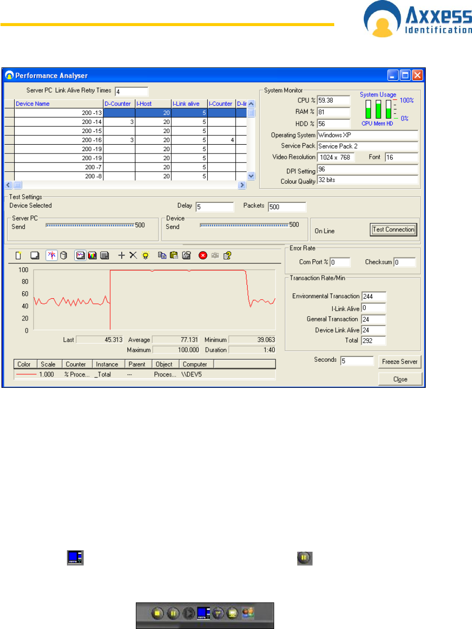
Performance Analyzer
One of the optional features in AX200 software. Performance analyzer is a collection of the
features that demonstrate the performance of the system. These features are scattered in the
software and can be found in different parts of the application. Performance analyzer could be
accessed through Tools → Enable Optional Software.
www.axxessid.com
Installation & User Guide
AX200 & IBOX Installation & User Guide – July 10 - 28-
The list on the top shows all the units that have been configured on your PC at some point.
This can also be found in Access Point → Device Manager. You can also test the connection
between the online units and the PC by pressing the Test Connection button.
The graph on the bottom, demonstrates the performance of different elements of your system
such as the CPU, hard disk and ….. To add a new graph click on the “+” button and select the
appropriate object from the menu.
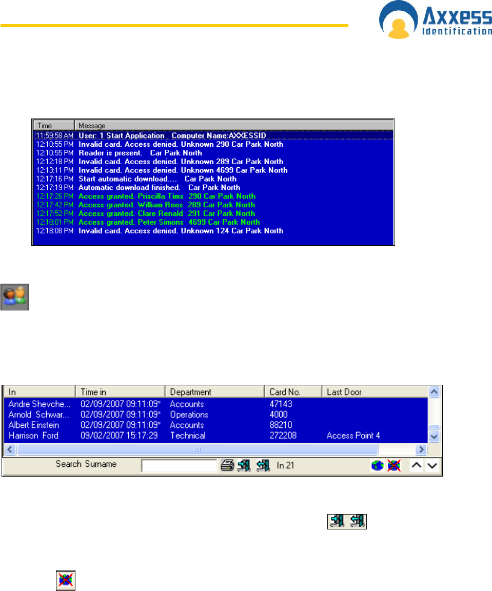
Transaction Screen
All system transactions are displayed on the main screen with time and date stamp. A
detailed description is given for each transaction e.g. No access, invalid PIN code.
For diagnostic and security purposes, the transaction screen can be cleared, by clicking on
the blue button under the window. The transaction pause button will temporarily freeze
the screen without losing any data. Transactions will continue to be registered in the log file.
The stop button will block the new transactions; however they are still stored in the log file.
The date and time column can be shortened or extended by clicking on the column header. If
a large number of transactions are logged, the date field can be hidden to extend the length of
the field. All system transactions are colour-coded, valid entries are displayed in green,
access denied transactions etc in red and system messages in yellow.
www.axxessid.com
Installation & User Guide
AX200 & IBOX Installation & User Guide – July 10 - 29-
The number of transactions kept in memory for quick overview on the main screen can be set
under “System Settings”. The larger the number, the more memory will be required.
Transactions are always stored and can be viewed or printed under “Reports”.
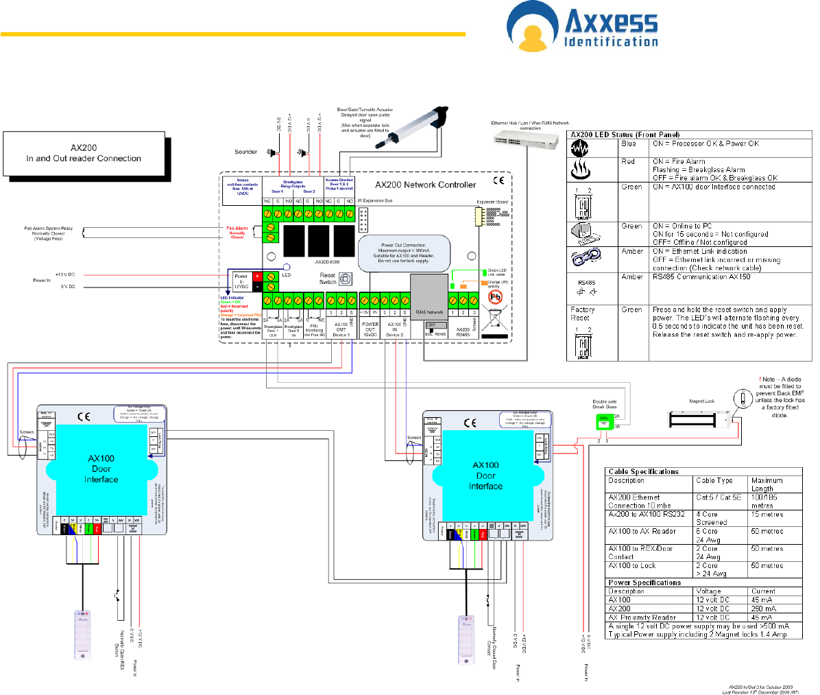
Who’s In/Out List
In order to use the who‟s in/out list, you need to have at least one reader configured
as In Reader and one reader configured as Out Reader on your PC. To do this, go
to the Access Point screen. Select the appropriate reader from the list on the right. Change
the settings to In or Out Reader and click Save. Once you‟ve done this the in/out list becomes
active. If someone opens the door with a valid card his/her name will appear on the who‟s in
list, along with the card number, department name, time of entrance and the last door which
he/she passed through. This list could be printed by clicking on the printer icon.
The number of people inside the building is displayed on the bottom. You also have the ability
to search people by their surname.
It is also possible to book people in/out manually if necessary. Click on icons for
Manual Book In/Out. Select the appropriate people and the appropriate doors from the lists
and press Book In/Out.
Clicking on would open the who‟s out list which basically shows the list of the people
who are not in the building. When a person presents his card to the out reader his name will
be removed from the in list and appear on the out list.
The total number of hours that an individual or a group of people have spent in the building
can be calculated in Reports → Work spell.
Note: in order to program the software to print out the who‟s in list when the fire alarm goes
off go to Display Filters → Printer → Setup and enable the Auto print on fire alarm.
www.axxessid.com
Installation & User Guide
AX200 & IBOX Installation & User Guide – July 10 - 30-
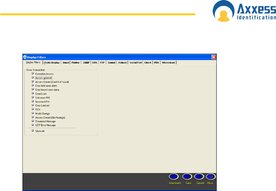
Display Filters
This screen includes 13 different tabs, however only 4of them are included in the AX200
software. The other 9 features are only available in the AX500 software.
The Display Filters tab contains a list of 14 different types of transactions that appear on the
main screen. Please note that these are not individual messages. Each one is a type of
transaction which may include several messages that are similar to each other. For instance;
“Access granted” type includes access granted with card, PIN & card + PIN. If you don‟t wish
to see any of these transaction types just remove the tick from the check box.
Photo Display
You can decide weather or not you would like the cardholder‟s photo to be displayed on the
main screen once a valid card is presented at a particular door. If you decide not to display
the cardholder‟s photo, company‟s logo will be displayed instead along with the card number,
cardholder‟s name, department and the name of the access point.
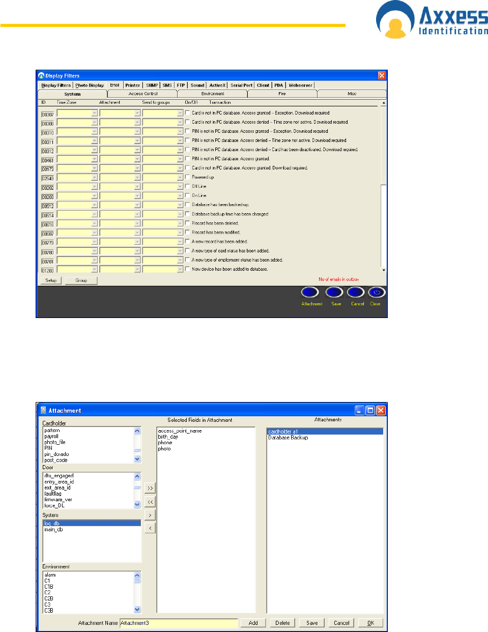
Email
The AX200 application could be programmed to create an email message to be sent to a
single or a group of users once a particular transaction appears on the main screen.
www.axxessid.com
Installation & User Guide
AX200 & IBOX Installation & User Guide – July 10 - 31-
Select the appropriate transaction simply by ticking the check box next to it. From the time
zone column select the time zone during which you would like the email to be sent out.
Selecting “Always Access” would send the email at any time. The attachment menu gives you
the ability to specify what information you would like to be included in the email. To add a new
attachment click on the Attachment button on the bottom of the screen.
To create a new attachment press “Add” and enter an appropriate name. from the four lists on
the left hand side select the information that you would like to appear in the email and move
them over to the middle list by clicking on the > button. Once you‟ve completed the selection
of your fields click Save & OK and go back to the email tab. Now you can select the
attachment that you just made from the drop-down list.
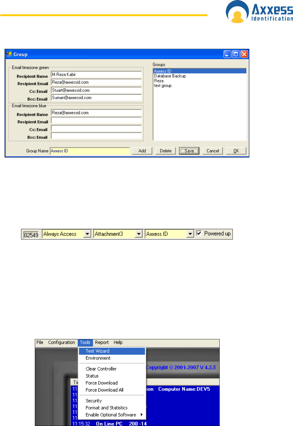
The next drop-down list includes the person or the group of users whom the email will be sent
to. To add a new group click Group on the bottom of the screen.
www.axxessid.com
Installation & User Guide
AX200 & IBOX Installation & User Guide – July 10 - 32-
To create a new group click on “Add” and enter an appropriate name. Enter the name and the
email address of the recipient. When you‟re finished click Save & OK.
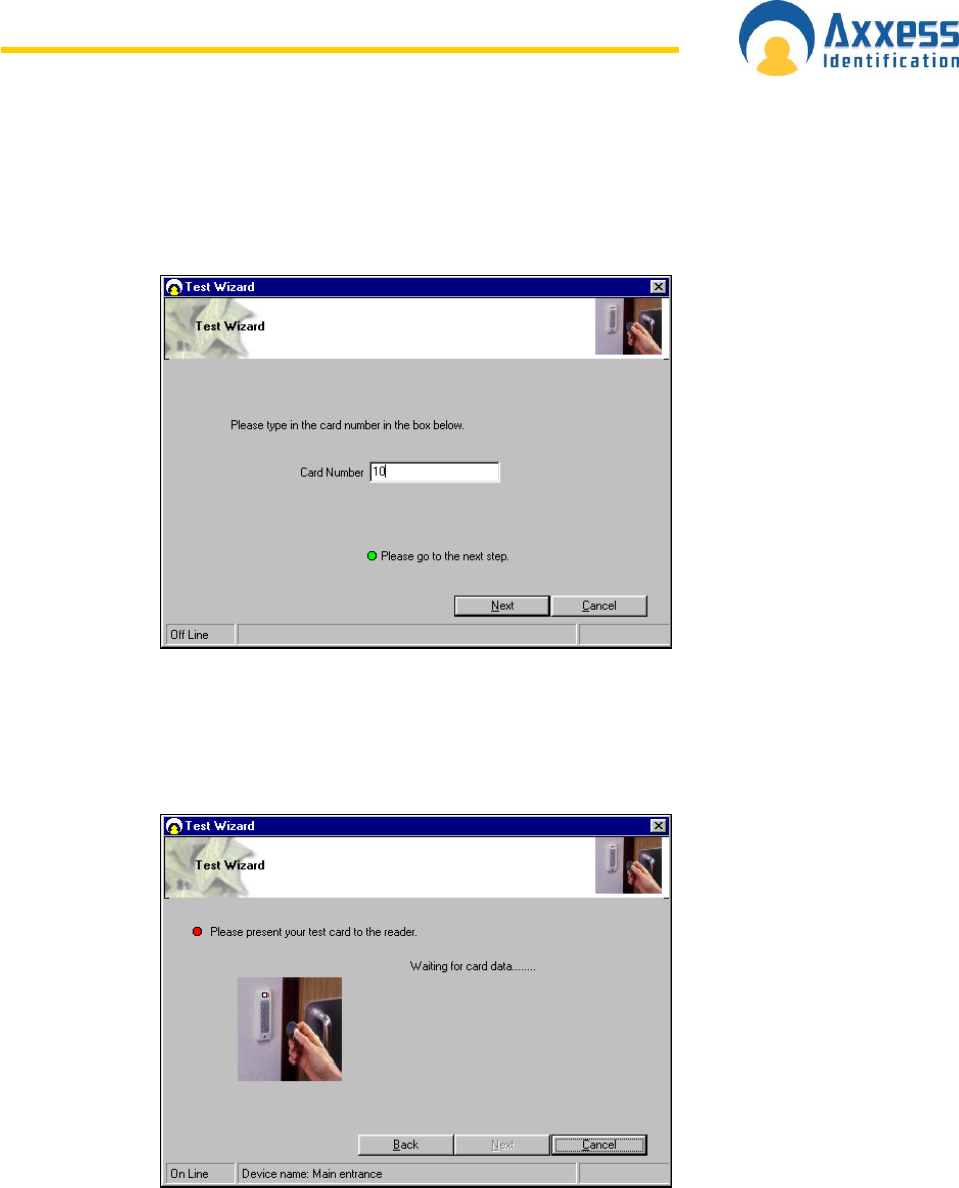
You have not completed the email configuration. For instance in this case, if the “Powered
up” transaction appears on the screen during the time zone “Always Access”, an email
message containing the information included in “Attachment 3” will be created and sent to
the people listed in the “Axxess ID” group. If you would like the same settings on other
transactions, you can right click on ID and copy, then right click on the ID you wish to copy to
and click paste.
Save on Exit
Preferences selected are automatically saved. Under General Settings, a factory default
button restores all the important system settings. If any system or card changes have been
made, the system will automatically backup the data when exiting the program.
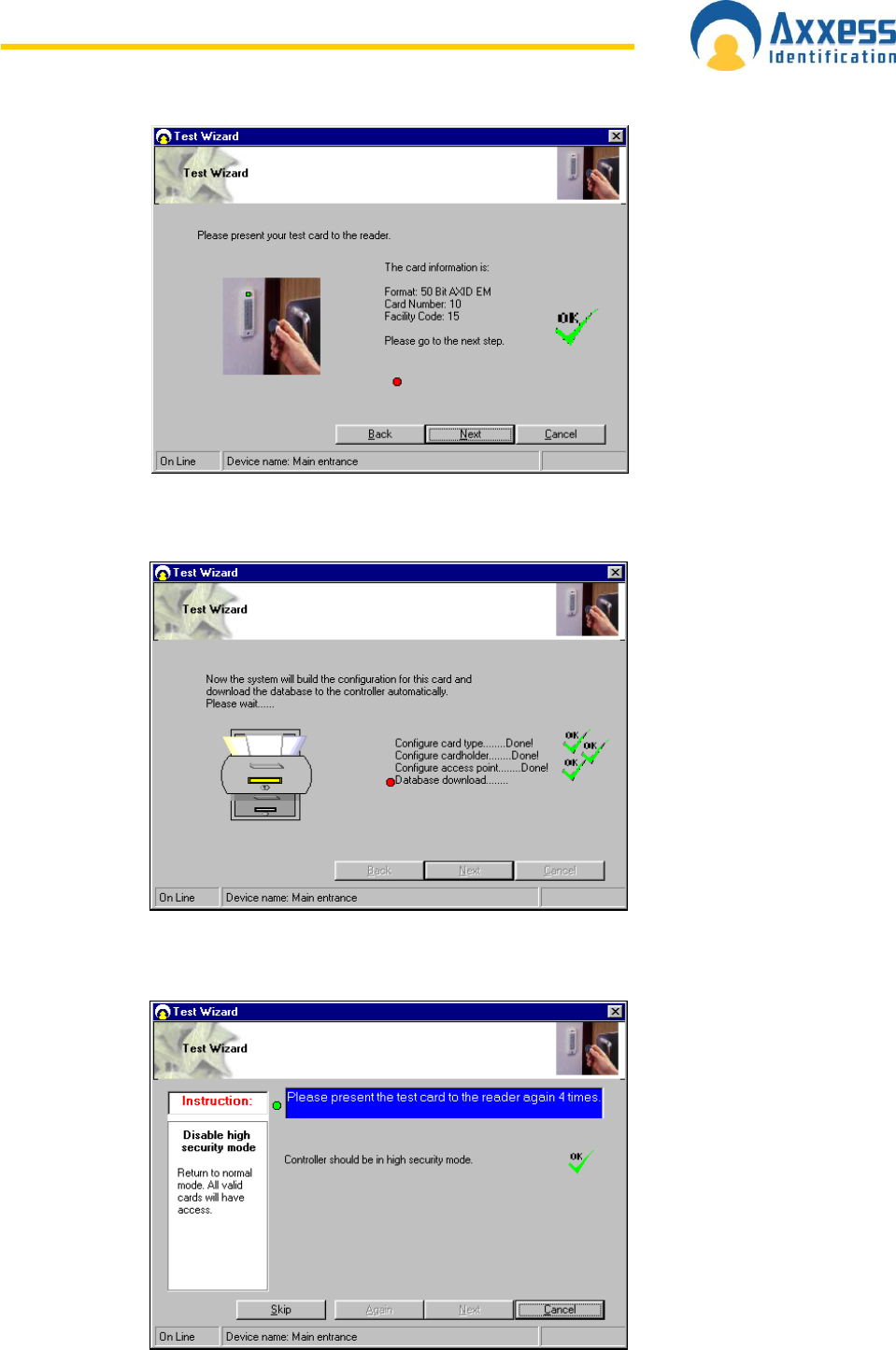
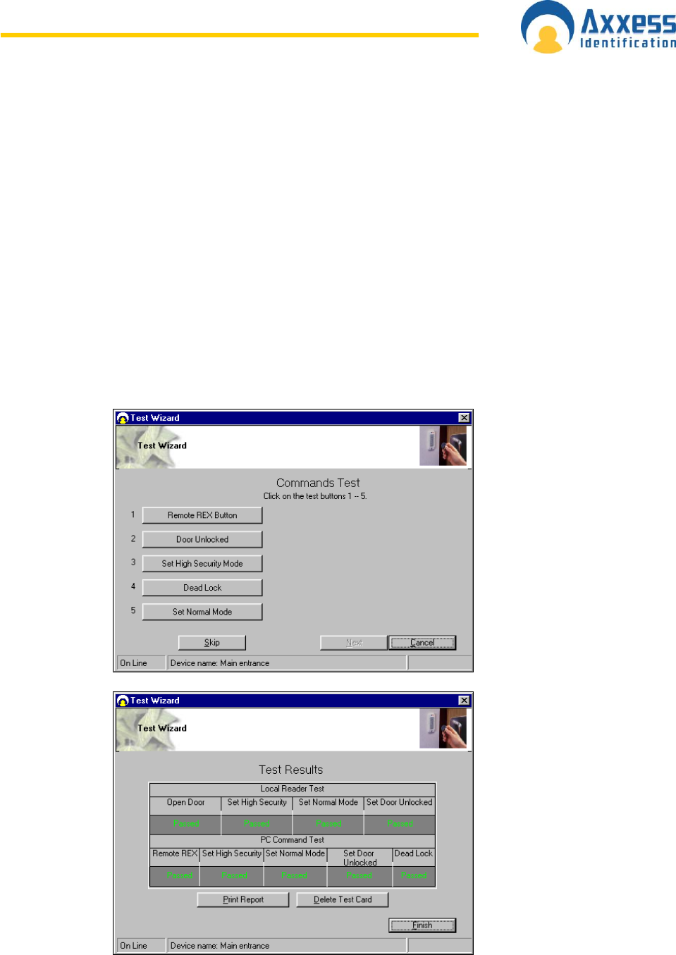
Test Wizard
The test wizard can be selected from the Tools drop-down list on the top menu bar.
www.axxessid.com
Installation & User Guide
AX200 & IBOX Installation & User Guide – July 10 - 33-
The test wizard will guide you through automatic setup of the card formats and a complete
hardware and software test.
On the Test Wizard screen type in the card number of one of the cards which you would like
to test and select Next.
Ensure your AX200 controller is still connected to the PC – the Test Wizard will now check
and communicate with the controller. If the controller is communicating correctly a green
acceptance tick is displayed.
The Test Wizard now requests that a card is swiped or presented to the reader.
The Test Wizard will now check and verify the card format, facility code and card number.
Select Next to continue.
www.axxessid.com
Installation & User Guide
AX200 & IBOX Installation & User Guide – July 10 - 34-
The Test Wizard will now configure the card format, cardholder, and access point and
download the data to the controller. Select Next to continue.
Now the Test Wizard will complete a number of hardware tests – please follow the on-screen
prompts.
www.axxessid.com
Installation & User Guide
AX200 & IBOX Installation & User Guide – July 10 - 35-
Unlock Door – presenting your card to the reader once will unlock the door, the
controller LED should stay on green for 5 seconds
High Security Mode – presenting your card to the reader 4 times will test the high
security mode, the controller LED will flash 4 times red every 5 seconds
Normal Mode – presenting your card to the reader again 4 times will put the system
back to normal mode, the controller LED flashes green every 5 seconds
Door Latched Open – presenting your card to the reader twice will latch the door open,
the controller LED will flash green twice every 5 seconds
Door Locked – presenting your card to the reader twice again will lock the door, the
controller LED flashes green every 5 seconds.
Select Next to continue.
www.axxessid.com
Installation & User Guide
AX200 & IBOX Installation & User Guide – July 10 - 36-
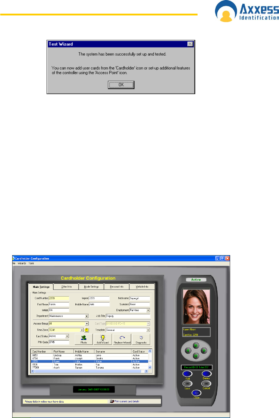
Once completed, additional cardholders can be added by selecting the cardholder icon or
through the cardholder configuration screen. Optional features can be set through the access
point configuration.
Cardholder
Cardholder configuration consists of five elements
Main Settings
Other Info
Mode Settings
Personal Info
Vehicle Info
Adding new cardholders can be done from the main settings screen. The other tabs are for
extra features and additional database fields.
Main Settings

www.axxessid.com
Installation & User Guide
AX200 & IBOX Installation & User Guide – July 10 - 37-
Card Number
Unique card number – maximum 10 digit number. This number excludes the facility and site
code number which is defined in card type.
If you change the card number to 0 (= no card), data can be left on the database in case the
person requires a card again or, if all the data is entered first and cards are issued at a later
stage. This feature is specifically useful for frequent visitors and contractors.
Imprint Number
If the number on the card is not the „true‟ number in the card, then this printed number can be
entered here. Alternatively this field can be used for other data e.g. membership numbers
etc.
Employment
To indicate the type of cardholder, fields can be selected from the drop-down box or entered
manually. When entered manually it will ask for confirmation when you save the record and
can be selected the next time from the drop-down box.
Department
Select a department from the pop-up window, departments can be added or deleted as
required.
Access Group
An access group is a collection of doors. When a group is selected, the cardholder will have
access to the doors assigned in the access group. Two groups are fixed and cannot be
deleted – All and None. The group All automatically includes all the doors including those
added by the device wizard. If the group None is selected, the cardholder will not have
access to any of the doors.
Card Type
The card type is by default greyed out. If under System Settings, General Settings the
Multiple Card Format is enabled, then this field can be used if you require cards from other
system to work as well.
A card type is the name given to the card format and facility code combined. It is
recommended that you use the card format wizard if you wish to add new card types.
Card Status
This field overrides all settings, if the card is set to: Destroyed, Inactive, Lost, Stolen or
Suspended. The card will not have access unless set to Active.
It is recommended that you use this field if a card is for instance stolen instead of deleting the
whole cardholder record. By using this method, you can always see at a later stage why the
card was inactive.
Pin Code
1 to 6 numbers – the default setting is 4.
This field is required if PIN Settings (found on the Access Point screen) is enabled and a
keypad or reader with keypad is used. If a reader with PIN is selected, the card is presented
to the reader first followed by entry of the PIN code.
Time Zone
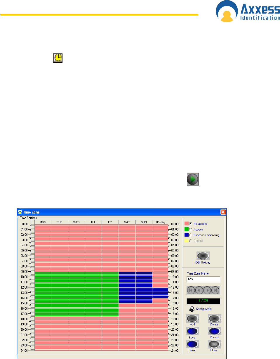
www.axxessid.com
Installation & User Guide
AX200 & IBOX Installation & User Guide – July 10 - 38-
An important part of the AX200 software; this feature allows you to determine exactly when a
card holder is allowed to have access through a particular door. To open the time zone
window click on the icon.
This page contains a time table which includes eight columns representing seven days of the
week plus an extra column for holidays.
To create a new time zone press add and enter an appropriate name for the time zone. You
can program up to 256 different time zones. Any record after the 256th time zone will not be
downloaded onto the controller. Every day of the week has been divided into the periods of 15
minutes. Red zone is when the card holder will not gain access through the door. If the
cardholder presents his/her card during this period the message on the screen will say that
the time zone is not active and therefore access will be denied. To grant access to a
cardholder during a specific period of time, click on the start time, hold the left click down and
drag the mouse to the end time. The selected period will be displayed in green. Alternatively
you can give exception access to the cardholder by selecting the “Exception Monitoring” and
follow the same procedure. In this case the selected area is displayed in blue. So when the
cardholder presents his/her card to the reader the transaction on the main screen will be of
“Access granted – Exception” type.
Access granted – Exception <Cardholder’s Name> <Card No.> <Door’s Name>
Once you‟ve finished programming your time zone press Save. Use the button to scroll
through the existing time zones. The first 9 records including No Access, Always Access,
Always Exception and TZ1 → TZ6 are the defaults and included in the blank database.
Access on holidays could be programmed separately. To change the holiday settings press
“Edit Holiday”. Mark the holidays in the calendar simply by clicking on them. Once you‟ve
highlighted a date, it is added to the selected holidays list on the right. If you need to take a
day off the list click on it once more. Some holidays are not fixed and move every year. Tick
the check box next to the regular holidays (like Christmas) so you won‟t have to program
them again next year. You can enter a brief description for each holiday by pressing the “Edit
Description” button. Click save and close the screen when you‟re finished.
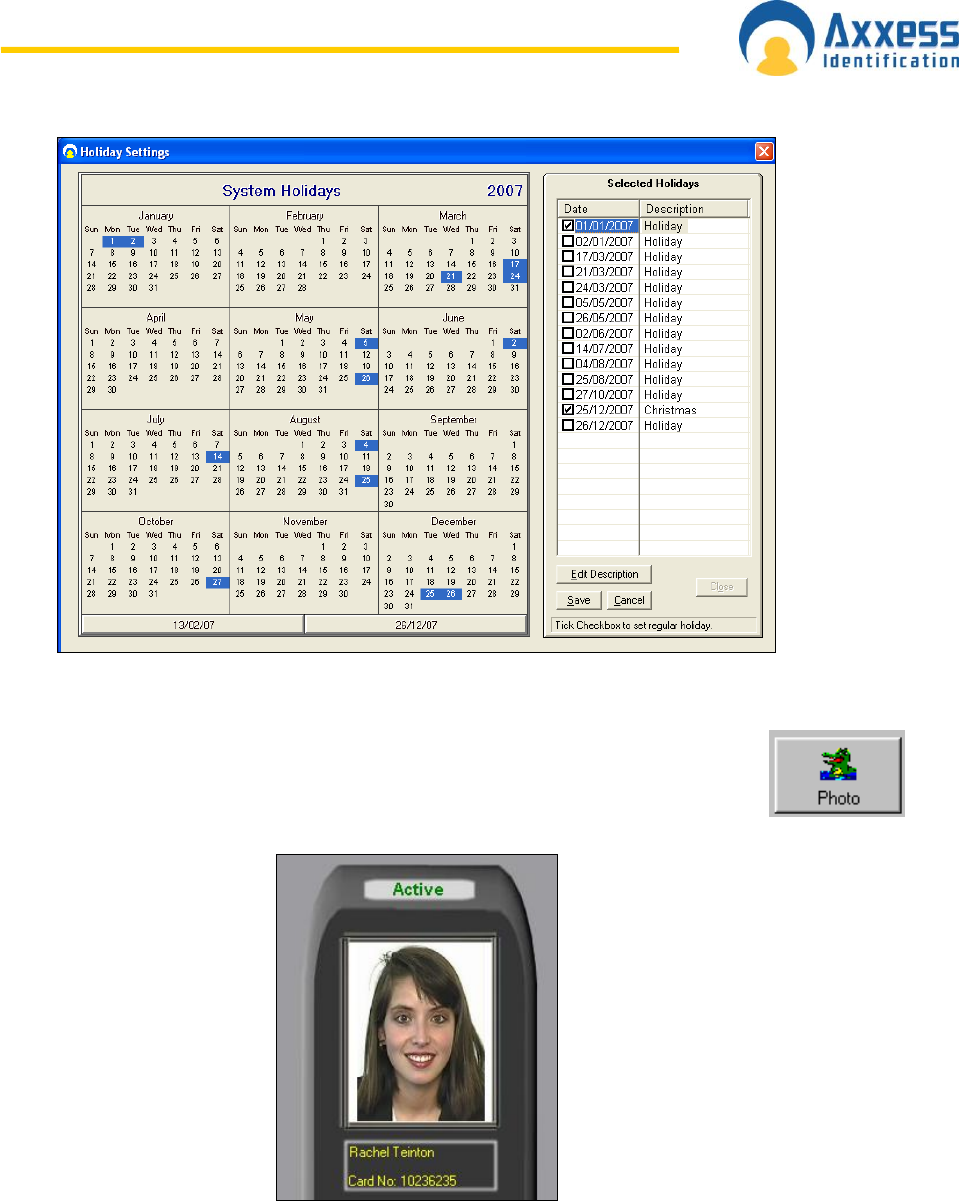
www.axxessid.com
Installation & User Guide
AX200 & IBOX Installation & User Guide – July 10 - 39-
Photo
A digital photo can be added in the following formats – JPEG, GIF and BMP. To add
a cardholder photograph, click on the Photo button and select the file using the
browser. If the controller is used on-line then every time a cardholder presents a
card, the transaction including the photo will show on the Main Screen.
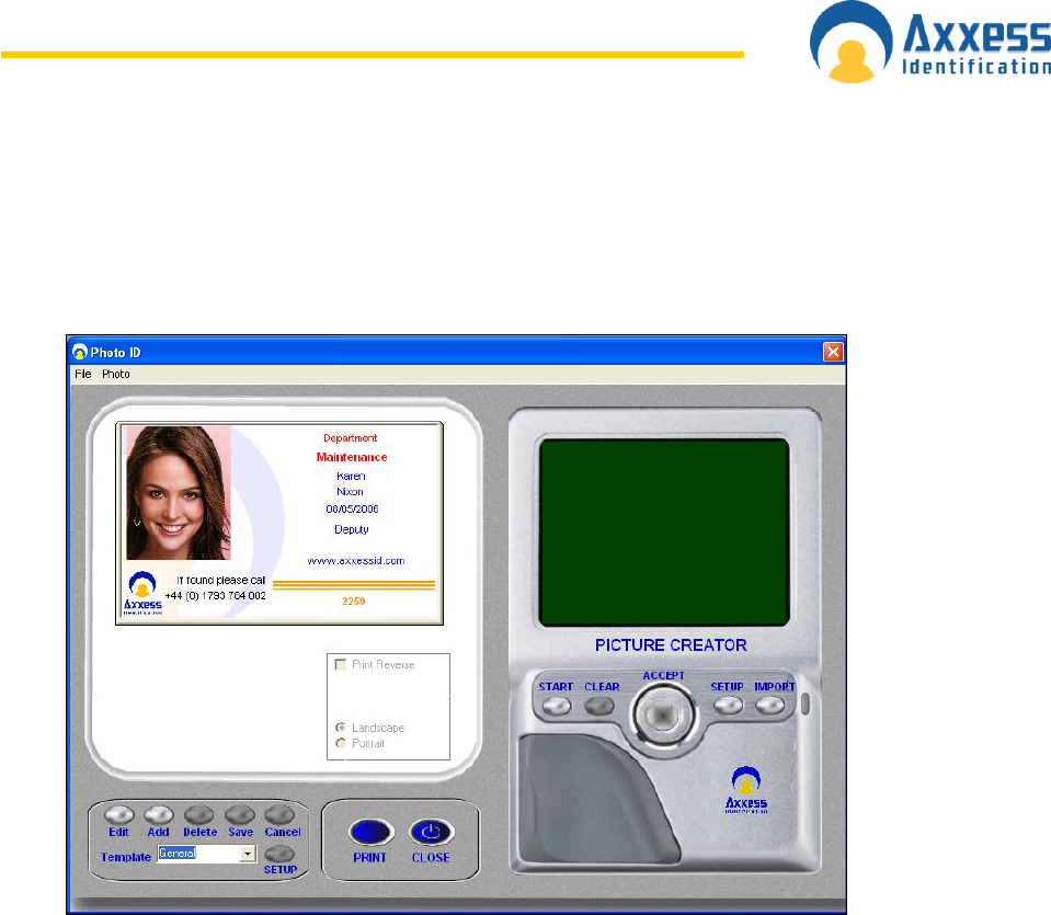
www.axxessid.com
Installation & User Guide
AX200 & IBOX Installation & User Guide – July 10 - 40-
Photo ID
To access the Photo ID window click on the “Photo” button under the “Main Settings” tab in
the Cardholder screen.
Photo ID window is where you can add a picture or change the template on your card.
Add a Photo
There are two ways of adding a new photo to your card. You can either import a photo from a
file or use a camera.
Capture Picture from Camera
If there is a camera connected to your PC you can have live picture on your screen. Just click
on the Start button in the Picture Creator section on the right hand side. A new window will
be opened where you can capture an image from the live picture. The captured picture will
then appear in the picture creator window. After selecting the appropriate part of the picture
click “Accept”. Your picture will now be printed on the card.
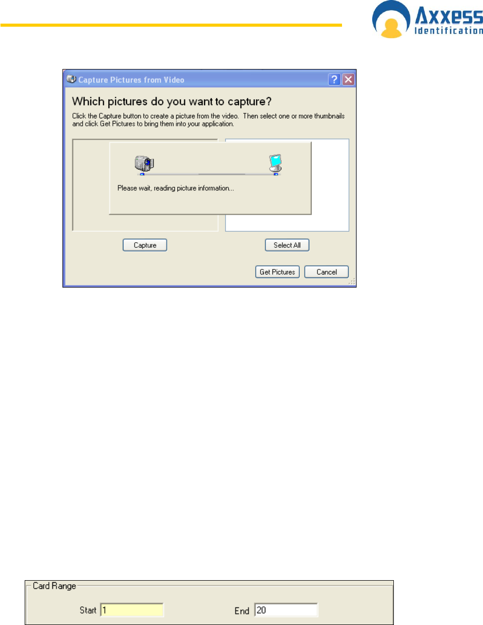
www.axxessid.com
Installation & User Guide
AX200 & IBOX Installation & User Guide – July 10 - 41-
Import Picture from File
You can also import a photo from a jpg, gif or a bmp file on your PC. Just click on the import
button, select the file on your hard disc then click open.
Templates
To create a new template click Add. By default the company‟s logo would be displayed
instead of the cardholder‟s photo unless you import a picture either from a camera or a file on
your PC. The text fields displayed on the right hand side could be moved simply by clicking
and dragging. Click Save once you‟re finished. To edit an existing template press the Edit
button.
Add New Card Wizard
It is a simple way to add a single or a block of cards at once. Start field definitely needs to be
field in. the value in the start field will be the first card number. If you‟re planning to add a
block of cards you need to fill in the End field as well. The number in the second field will be
the last card number.
Any other information entered in the other sections will be applied to all new cards. If the high
security and door unlocked feature are selected then these will be for all the doors in the
access group.
Individual settings per door can also be made using Mode Settings.
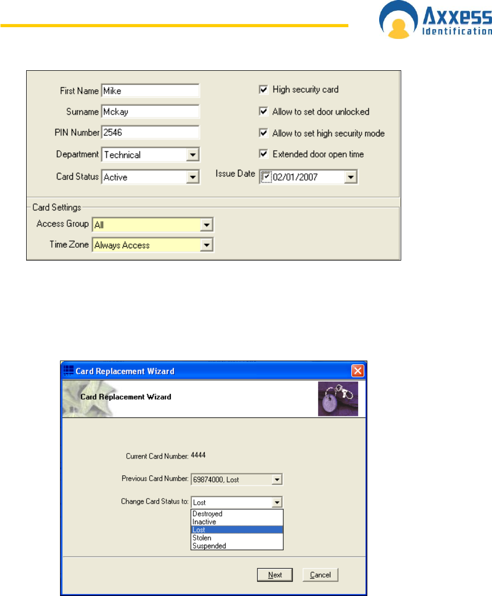
www.axxessid.com
Installation & User Guide
AX200 & IBOX Installation & User Guide – July 10 - 42-
Card Replacement Wizard
Card replacement wizard will substitute the current card with a new one. You can specify
which card status you want the current card to change to.
After clicking Next the current card will be deactivated. All you have to do now is to enter a
new card number.
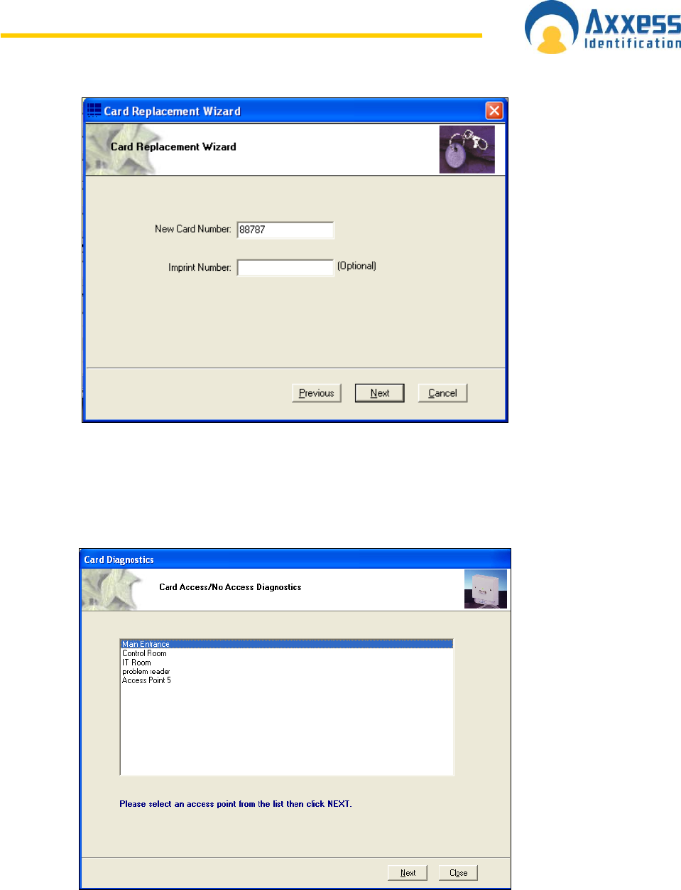
www.axxessid.com
Installation & User Guide
AX200 & IBOX Installation & User Guide – July 10 - 43-
Card Diagnostics
Card diagnostics gives you a summary of the current cardholder setting details. If a card does
not have access to a door, then the diagnostic button is a quick and easy way to see why.
After selecting the appropriate door click Next.
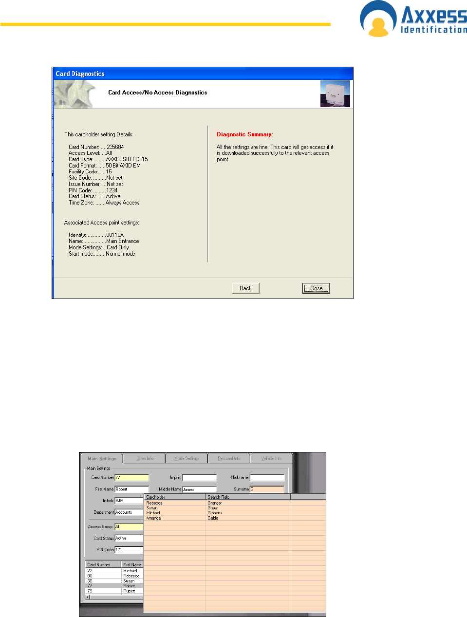
www.axxessid.com
Installation & User Guide
AX200 & IBOX Installation & User Guide – July 10 - 44-
The information on the left is a brief summary of cardholder setting details and the associated
access point settings which can also be found under cardholder Configuration → Main
Settings & Access Point Configuration → Access Point.
Diagnostic summary on the right explains weather or not the current card holder will get
access through the selected door.
Search
Searches can be performed on the cardholder record by clicking with the mouse on the field
label. The mouse pointer changes to a magnifying glass on field labels which are searchable.
You can specify certain criteria when performing a search for example on the card number
field
>5 will produce a result of all cards greater than 5
<5 will produce a result of all cards less than 5
1-5 will produce a range of cards from 1 to 5
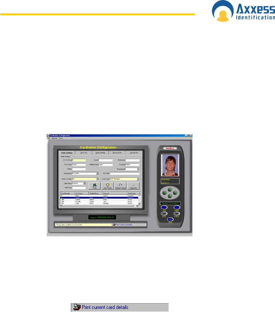
www.axxessid.com
Installation & User Guide
AX200 & IBOX Installation & User Guide – July 10 - 45-
From the search list you can either select the required record or press Escape key (Esc.) to
exit.
The search facility also allows partial searches e.g. by clicking on the surname field label you
can enter the first letter (or more) of the surname and the results will automatically be
displayed on screen. By clicking in the search list will display the appropriate cardholder
record.
Card 0 Function
Cardholder details remain on the system without deleting the information. This feature is
especially useful for frequent visitors or contractors. Simply change the card number to 0
when the person leaves, upon their return simply change the card number from 0 to the actual
card number issued.
Print Current Card Details
On the cardholder screen, there is a printer icon, which allows the user to print the
current cardholder record without going to the report menu. This feature is especially
useful if the cardholder has to sign for the card issued to them and a hard copy is
kept.
Database Fields per Cardholder
A card number and access group are the minimum fields required to activate a card. All the
other database fields are optional and are grouped over a number of easy to navigate tabs.
Main Settings Tab
Card number up to 10 digits
Imprint number 20 characters – usually the number printed on the card
First name 30 characters maximum
Middle name 30 characters maximum
Last name 30 characters maximum
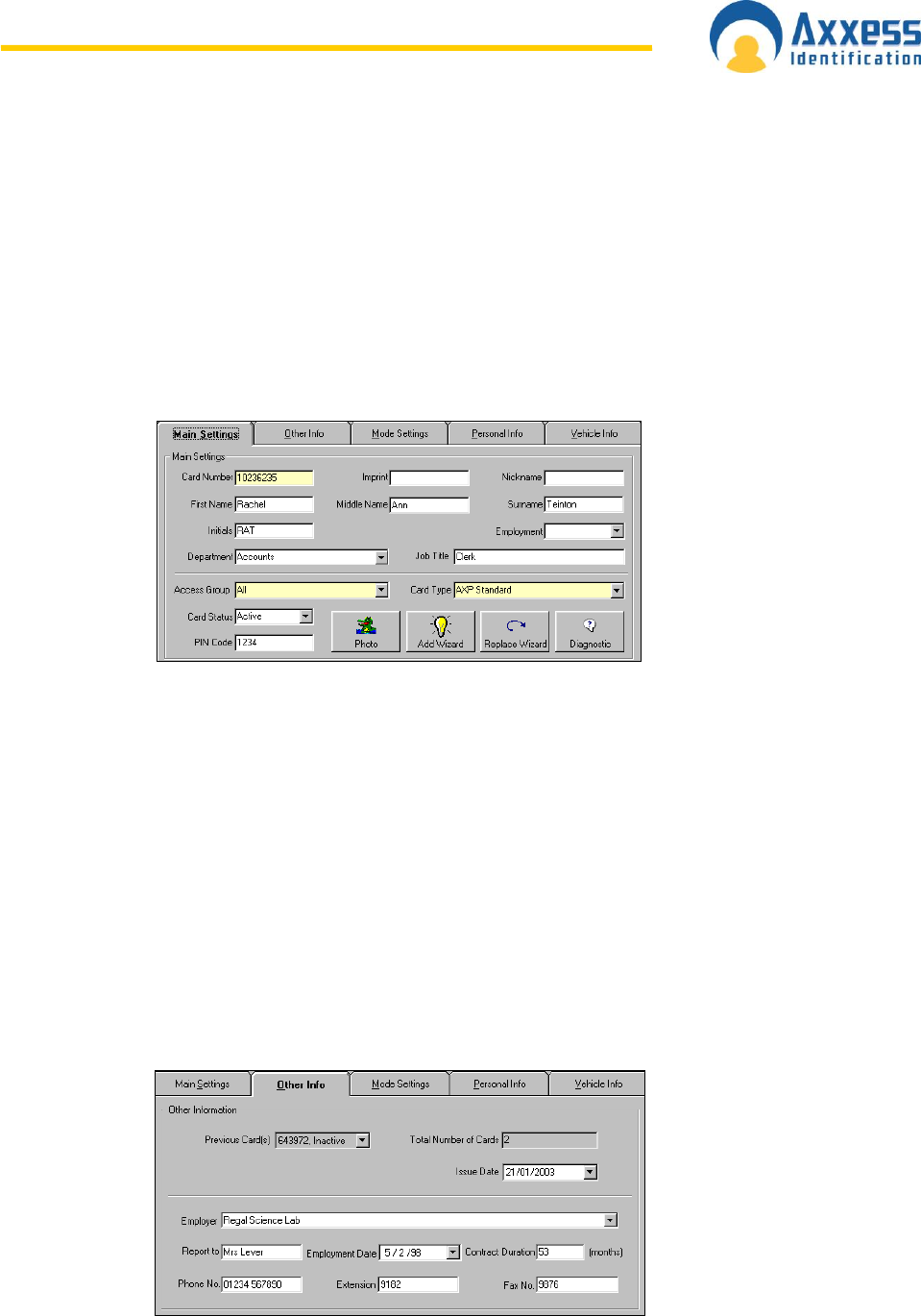
www.axxessid.com
Installation & User Guide
AX200 & IBOX Installation & User Guide – July 10 - 46-
Nickname 30 characters maximum
Initials 10 characters maximum
Employment type e.g. contractor, visitor, part-time - unlimited number of
characters
Department 50 characters e.g. Administration, Sales
Job title 20 characters maximum
Access group 50 characters - which doors the cardholder has access
Card type each card can be a different format or facility code, allowing
use of a variety of existing cards within the same technology
Card status active, lost, stolen, suspended, destroyed, inactive
PIN code from 1 to 6 digits (individual per user)
Photo graphic file e.g. BMP, JPEG, GIF
Other Info
Includes a few more details about the cardholder and the employer.
Previous card(s) previously issued card numbers and reasons for cancellation
e.g. lost
Total number of cards total number of cards issued to this person
Issue date records the date the card is entered onto the system
Employer multi-company support for shared entrances etc or site
contractors
Report to manager‟s name
Employment date use drop down calendar or type in date
Contract duration enter number of months
Phone number 30 characters maximum
Extension number 50 characters maximum
Fax number 30 characters maximum
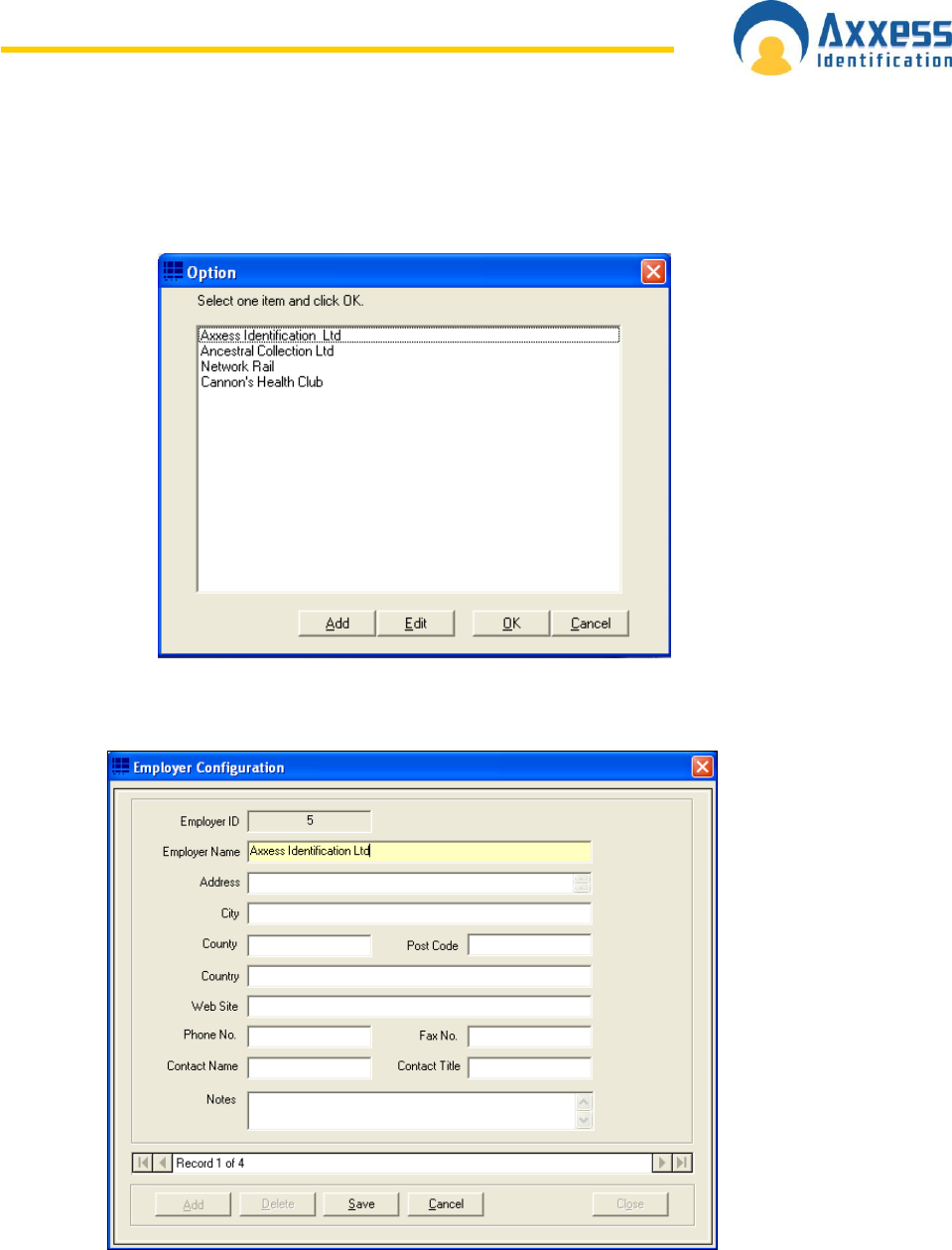
www.axxessid.com
Installation & User Guide
AX200 & IBOX Installation & User Guide – July 10 - 47-
Employer
To add a new employer click on the drop down menu. Once the employer list has been
opened click Add.
You must enter an Employer Name in the Employer Configuration window. Once you‟re
finished click save and exit. You can edit an existing employer by clicking on the Edit button.
Mode Settings
Individual setting per door and per user for High Security and Latch function
authorised to set Latch function
authorised to set High Security mode
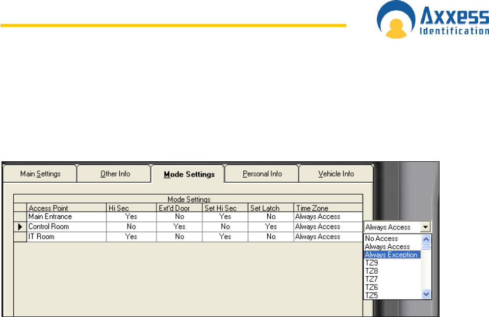
www.axxessid.com
Installation & User Guide
AX200 & IBOX Installation & User Guide – July 10 - 48-
access granted in High Security mode
extended door open time on valid card use
Mode settings tab is an important section of cardholder configuration. It allows you to
programme a card to have a specific effect when presented to each reader. The
access point column includes the list of all the readers configured on your PC.
High Security (Hi Sec)
If a door is set on high security mode, you need to have a high security card to
unlock it. Mode settings section is the place to create a high security card. By default
no card has the permission to open a high security door. However you can grant this
permission simply by changing the text NO to Yes (by clicking on it) under the Hi Sec
column.
Extended Door Open Time (Ext’d Door)
Activates the Extended Door Release Time function. To change the Ext‟d door
release time please refer to Access Point configuration → Access Point.
Set High Security Mode (Set Hi Sec)
There are to ways to set a door on high security mode. You can use the High
Security button located on the right hand side of the main screen under the list of
controllers or you can use a card. Once the “Set Hi Sec” is activated; if you present
your card to the appropriate reader, 4 times within eight seconds, the reader will
automatically go on the high security mode. To restore the normal mode repeat the
same procedure. Activating “set high security” mode also activates the “high security”
option.
Set Latch
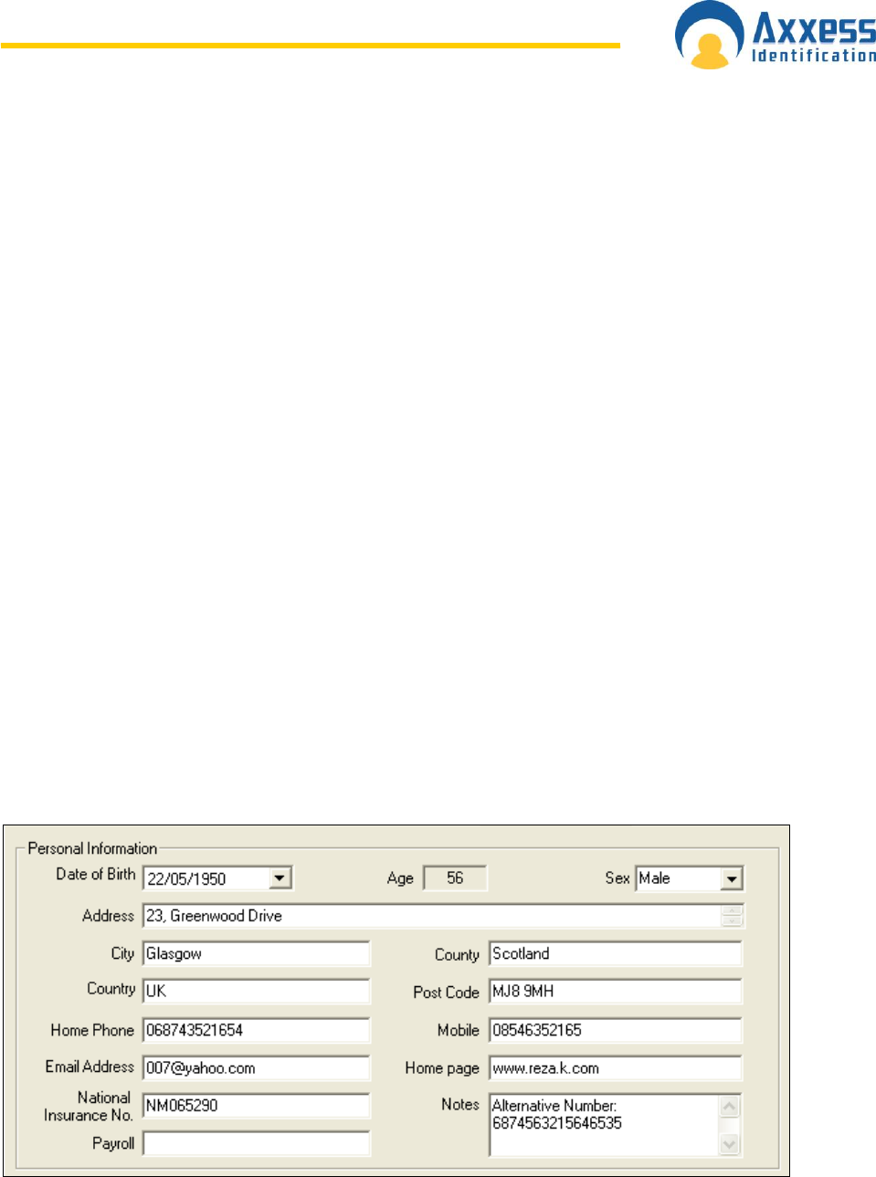
www.axxessid.com
Installation & User Guide
AX200 & IBOX Installation & User Guide – July 10 - 49-
Once the set latch is activated; if you present the card to the appropriate reader twice
within four seconds, the door will be unlocked and it will remain open until it is put
back to normal mode, either by using the same card twice or by pressing the normal
mode button on the main screen.
Time Zone
Allows you to choose a different time zone for every door.
Personal Info
Includes additional information about the cardholder such as: date of birth, address, e-mail
and …
Date of birth use drop down calendar or type in date
Age automatically calculated using the date of birth field
Sex male, female, other
Address maximum 101 characters over 28 lines
City text field maximum 30 characters
County text field maximum 30 characters
Country text field maximum 20 characters
Postcode text field maximum 20 characters
Home phone text field maximum 30 characters
Mobile text field maximum 30 characters
Email address text field maximum 50 characters
Home page text field maximum 50 characters
National Insurance No text field maximum 20 characters
Payroll text field maximum 20 characters
Notes text field maximum 255 characters
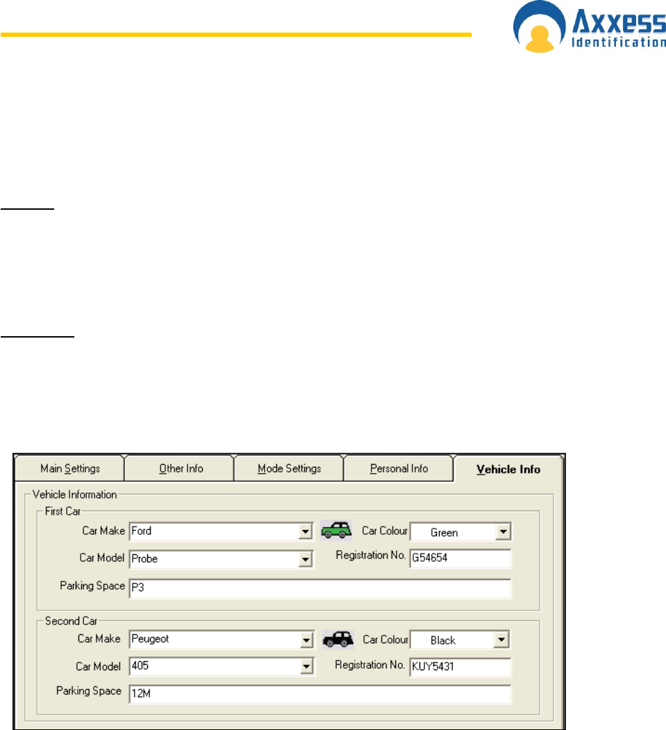
www.axxessid.com
Installation & User Guide
AX200 & IBOX Installation & User Guide – July 10 - 50-
Vehicle info
Contains details about the cardholders vehicle. You can choose your car make and model
from the appropriate list. Press Add (in the car make/model list) if you need to add a new car
or press Edit if you need to change the details of an existing model.
First Car
Car make select from drop down list
Car model select from drop down list
Car colour select from drop down list, pre-defined with car shown in
selected colour
Registration number text field 30 characters maximum
Parking space text field 50 characters maximum
Second Car
Car make select from drop down list
Car model select from drop down list
Car colour select from drop down list, pre-defined with car shown in
selected colour
Registration number text field 30 characters maximum
Parking space text field 50 characters maximum
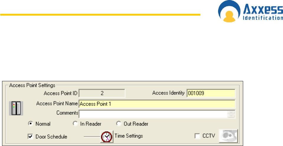
www.axxessid.com
Installation & User Guide
AX200 & IBOX Installation & User Guide – July 10 - 51-
Access Point Configuration
Access Point Settings
Access Identity
Every device has a unique “Access Identity” and is given a distinctive “Access Point ID”
when connected to the PC. Each controller has a serial number and this is used to
communicate with the PC. If the identity has been entered manually during a system setup or
where controllers are connected using a DTU, then the replace function should be used when
the controllers are operational.
Access Point Name
Access Point Name is specified by the user and could be changed at any time. The
extended length of the field allows up to 50 characters e.g. Building 1 Section West Door 28
Admin. The first 20 characters are displayed on the current controller information.
Door Comments
This memo field can store additional details regarding the location or any other use e.g.
temporarily out of use due to building work
Every reader can be programmed as Normal, In Reader and Out Reader.
If a reader is set to operate as an In Reader, the card number and the person‟s name would
appear on the “who’s in list” when the card is presented to it.
If a reader is programmed to be an Out Reader, the card number and the person‟s name
would be removed from the “who’s in list” and appear on the “who’s out list” when the card is
presented to the reader.
If a reader is set on Normal mode, access will be granted to the person holding a valid card.
However it doesn‟t affect the who’s in/out list. In other words it doesn‟t influence the count of
the people inside the building.
Time settings button becomes active by ticking the Door schedule box and clicking on the
save button.
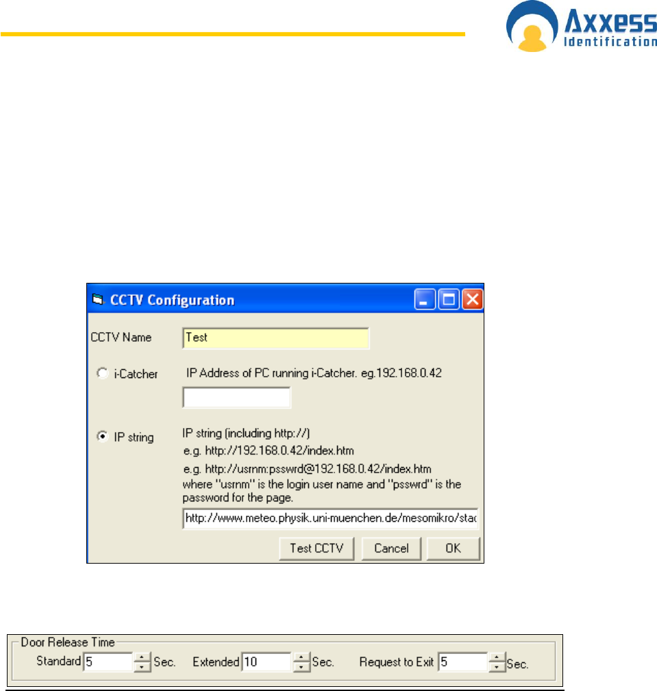
www.axxessid.com
Installation & User Guide
AX200 & IBOX Installation & User Guide – July 10 - 52-
You can schedule a door to be open during a specific period of time by clicking on the “Time
Settings” button. The door can be programmed simply by clicking and dragging the mouse.
The green zone is the time period during which the door will be unlocked.
Note: Please note that the door status selected in the main screen overrides the door
schedule. This means that once the door has been unlocked by using the controller buttons
on the main screen, it will remain open even thought it has been scheduled to be closed.
CCTV: opens the CCTV configuration window. You will then have to either enter the IP
address of the PC running the I-Catcher software or enter address of the web page containing
the camera.
Door Release Time
Standard door release time is the amount of time it takes for the door to be locked again,
after being opened by a valid card. (Range: 1→255s)
If the “Extended door open time” option has been activated in the mode settings of a card;
then the door will remain open for the amount of time entered in the Extended field. (Range:
1→255s). It allows individual cardholders to have the door open for a longer period of time
e.g. disabled or elderly people.
Request to Exit This time can be individually set and is often set longer when the REX is
used at the reception allowing visitors a slightly longer entry time. When the REX Button is
used, the reader fitted outside can be set to sound twice to indicate the door has been
released for visitors. This feature is particularly useful when used with magnet locks since
their operation is totally silent.
Start-up Mode Settings
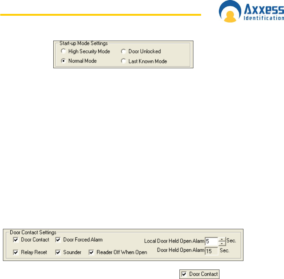
www.axxessid.com
Installation & User Guide
AX200 & IBOX Installation & User Guide – July 10 - 53-
The start-up mode settings enable you to determine how the door operates in case of total
power failure, including exhaustion of the battery back-up. All the data is stored permanently
in the controller for up to 100 years without the need for any power and upon power-up will
continue to operate without the need for a database download.
High security mode
Only cardholders with the high security mode
enabled will have access.
Normal mode
Returns to normal mode from whatever the
status was prior to power failure.
Door unlocked
The door unlocks permanently until a valid
card with the unlock feature is used twice, or
the door is changed to normal mode from the
PC.
Last known mode
This will return to the status the door was set
to prior to power failure.
Group(s) contain this point displays the list of the access groups which the current access
point is assigned to.
Door Contact Settings
Door contact settings are enabled by ticking the Door Contact box.
Door Forced Alarm: generates an alarm immediately after the door has been opened by
using force. The alarm is cleared automatically as soon as the door has been closed.
However the sounder remains active until you select the appropriate reader from the menu
on the right hand side of the main screen and press “Clear Alarm”, or present a valid card.
Relay Reset: De-activates the relay timer instantly when the door is opened. By choosing this
option only one person gets access after presenting a valid card and the possibility of
tailgating is reduced.
Reader off When Open: the reader will be disabled (not the REX) if the door contact is open.
This feature can be used for alarm systems e.g. the alarm is on so the door cannot be
opened, Parking application - there is no car on the presence loop, so the barrier cannot be
activated by a pedestrian or for air locks, one of the two doors is open so the second remains
closed.
Door Held Open Alarm: the length of time after the relay expires the door is allowed to be
open
before an alarm is generated.
Local door held open: This is a local alarm activating the sounder in the reader but does not

www.axxessid.com
Installation & User Guide
AX200 & IBOX Installation & User Guide – July 10 - 54-
send an alarm to the PC (if online).This feature is normally used in conjunction with door held
open alarm and warns people local to the door to close the door or a full alarm will be raised.
This feature is particularly useful with online systems where security guards are called out a
number of times whilst people are talking in the doorway.
PIN Settings
Card Only: PIN pad is deactivated when the Card Only mode is selected. Access is granted
only when a valid card is presented.
PIN Only: A Personal Identification Number (PIN) only is required to open the door. This can
be an individual number per user or a number for a group of users. The system supports
2,000 PIN only or 2,000 card and PIN users. In this mode, if different PIN lengths are used
per person, less than the maximum PIN length set under “general settings” the number
requires # to complete the entry. If the maximum length is set to four then only four digits
have to be entered.
Card + PIN: First a valid card must be presented to the reader followed by the individual PIN
of the cardholder. In this mode the controller will know from the card what the PIN length will
be and no # will be required
PIN Timeout: Indicates in seconds, the time required to enter the PIN number before clearing
the buffer or sending the data as invalid or incomplete. A longer time might be required for
elderly, disabled or specific locations i.e. car parks.
High Security activates PIN: The system normally operates in card only mode and changes
to card + PIN when a High Security card is used four times at the reader. This is normally
used at the end of the day to increase security after normal office hours.
Device Parameters
Device name & Identity are displayed on the top left of the screen. Device name could be
specified in the Access Point Settings section under the Access Point tab. Do not attempt to
change the Identity manually; it may no longer be recognized by the application.
Every device is given a specific name when connected to the PC. Device Name could be
changed in the Device Manager tab.
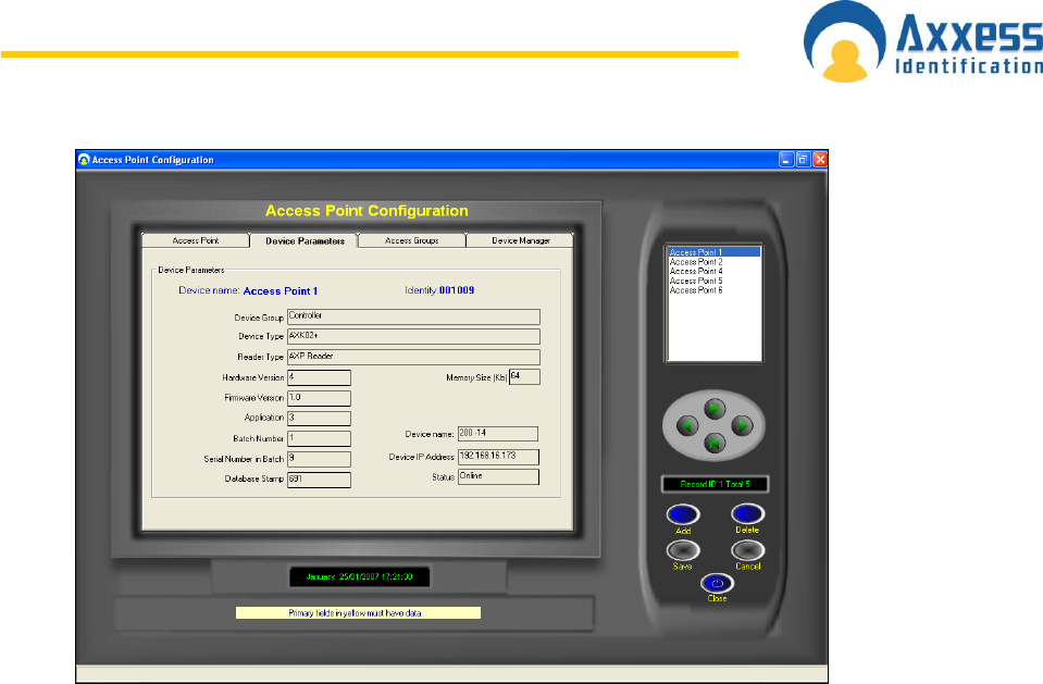
www.axxessid.com
Installation & User Guide
AX200 & IBOX Installation & User Guide – July 10 - 55-
Device Group
This specifies the type of device connected.
Device Type
Within the device group the type of unit
Hardware Version
Hardware revision number
Firmware Version
Firmware revision number in AX100 PCB
Batch Number
Production identity number
Serial Number in Batch
Serial number to be used with batch number
Database Stamp
This number is automatically generated and ensures the correct data is automatically
downloaded. If another PC is connected, this number is different and a forced download is
required since the data held on the PC and the AX100 controller are different.
Access Groups
Access groups give you the possibility to gain access through more than one door by using a
single card. Once the access group is assigned to a card (in the card holder section) you can
open all the doors listed in the access group.
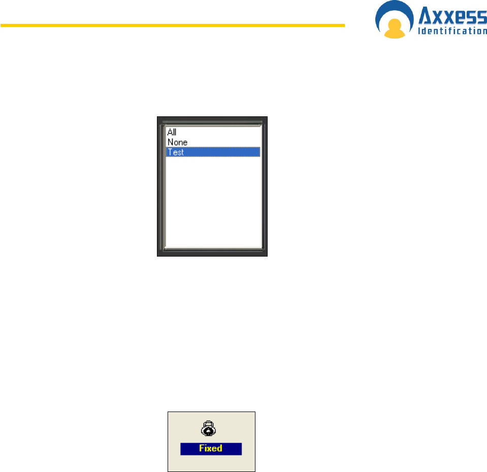
www.axxessid.com
Installation & User Guide
AX200 & IBOX Installation & User Guide – July 10 - 56-
The menu on the right hand side of the screen contains all the access groups created in the
software. All & None are the defaults. The first group in the list is automatically highlighted
when you open the Access groups tab.
Access group tab contains two separate lists: Controller(s) available & Selected
Controller(s) in Group. The first list contains all the access points that have not yet been
assigned to the highlighted access group. Therefore if group “All” was highlighted the
“Controller(s) available” list would be blank. The access group „All‟ gives access automatically
to all AX200 controllers including new ones added at a later date and cannot be deleted or
altered.
The Fixed sign in the Group Configuration section means you cannot change any information
displayed on the screen.
Creating a new access group
Making a new access group is very easy and quick. All you have to do is to click on the “Add”
button and transfer the appropriate doors from the “Controller(s) available” list over to
“Controllers in group” list. In order to move an access point across; you can either double click
on it or highlight it and press the > button. Clicking on the >> button would transfer all the
access points at once.
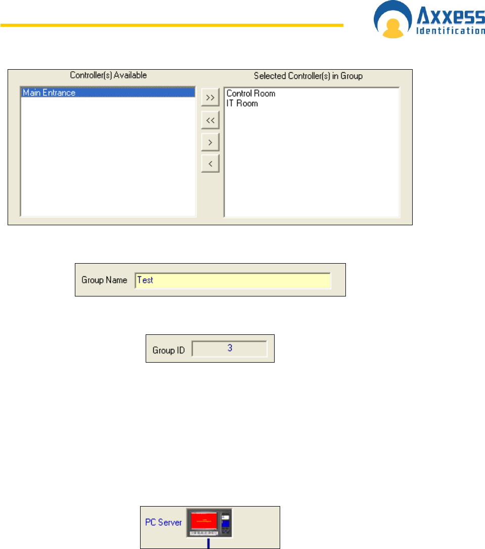
www.axxessid.com
Installation & User Guide
AX200 & IBOX Installation & User Guide – July 10 - 57-
When finished, type in a name for your group and click “Save”.
After saving, the software will automatically give your group and ID number.
Device Manager
Device manager displays all the devices that are or have been connected to the local network
at some point.
The PC server icon on the top opens the Server IP Configuration window where you can
configure the network settings of your PC. If the icon becomes red it means there is
something wrong with the network settings of the PC. This usually happens when the IP
address of the server is incorrect.
So if the PC server icon is red open the server configuration window by double clicking on the
icon.
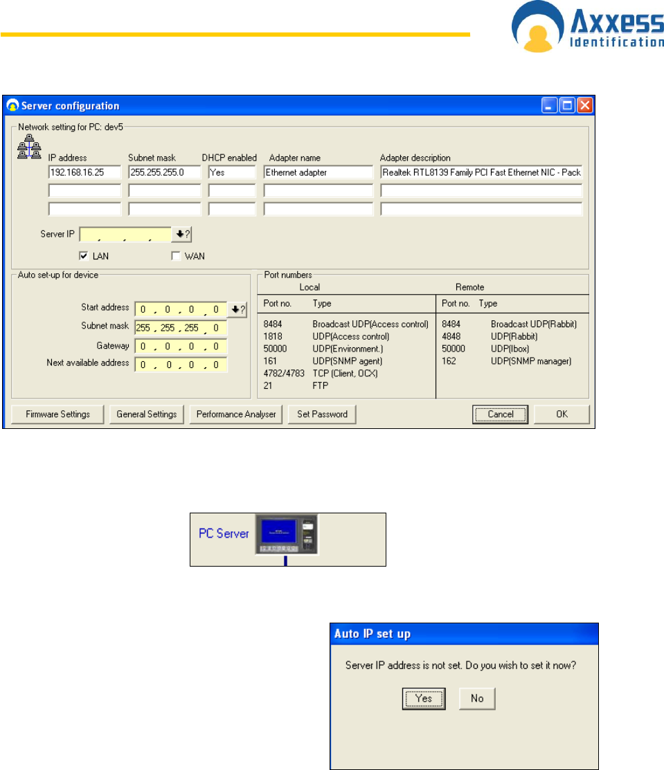
www.axxessid.com
Installation & User Guide
AX200 & IBOX Installation & User Guide – July 10 - 58-
If the Server IP field is blank or contains a number which is different from the IP address of
your PC click on the ↓? Button. The software will automatically obtain the correct IP address
of your PC. When you‟re done click OK. The PC server icon should now be blue.
Automatic IP Setup
The IP address of the server stored in the database
is automatically checked against the IP address of
the PC every time the application is restarted. If the
IP address has not been set, the software will notify
the user by displaying a message box asking if they
want to obtain the correct IP address.
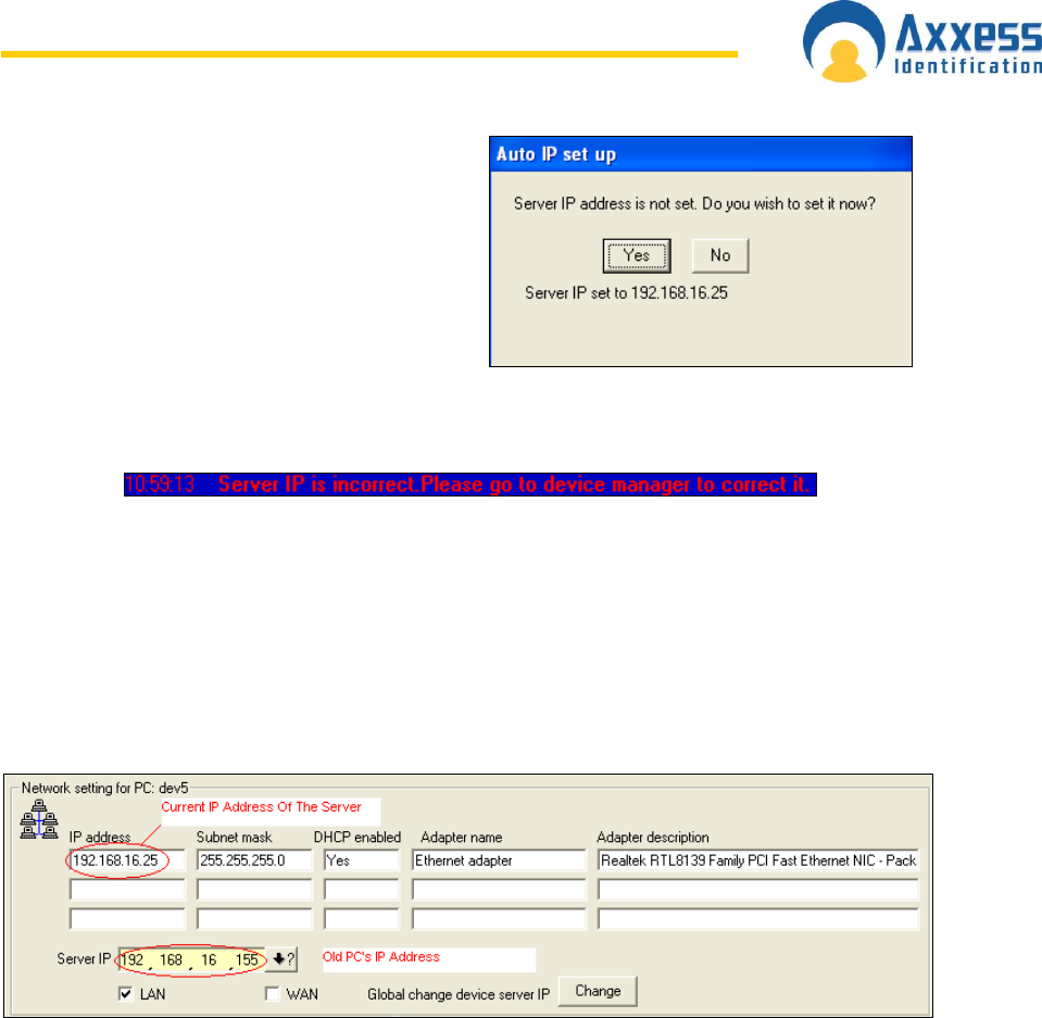
www.axxessid.com
Installation & User Guide
AX200 & IBOX Installation & User Guide – July 10 - 59-
After pressing Yes, the correct IP address is
automatically detected and displayed. This IP
address will be recorded in the database as the
server IP.
If the IP address of the PC does not match with what's been recorded in the database, the
software will warn the user at the startup by displaying the following transaction.
To get to the Server IP Configuration click on Access Point on the main screen; under the Device
Manager tab click on server IP icon at the top. In this screen you can obtain the correct IP
address by pressing the ↓? Button. This usually happens when the database is moved to a
different PC.
If the database has been restored on another PC the server IP address in the database will not
match the IP address of the new PC. If you press the Change button in the server IP
configuration the software will automatically download the IP address of the new PC onto
all the devices connected to the local area network. In other words all the devices on the
network are now configured to communicate with the new server (current PC).
If however the IP address of the server is changed while the DHCP is not running; you will have 2
options available: 1) you can download the current server IP onto all the devices connected to
LAN, by pressing Global change device server IP; or 2) you can change the current IP address
of the PC, back to the last recorded IP address in the database, by pressing Set PC IP address
to last stored. Once the PC is set the old IP address you will be able to communicate with all the
devices that had previously been configured on your PC.
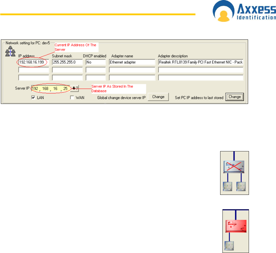
www.axxessid.com
Installation & User Guide
AX200 & IBOX Installation & User Guide – July 10 - 60-
Device Status Indication
If a device has been disconnected from the network it goes off-line and is
displayed with a red cross on it.
If a device icon is red it means the controller is connected to the network but is not
programmed to communicate with your PC.
In order to configure a device on your PC open the Tcpip Settings window by double clicking on
the device icon.
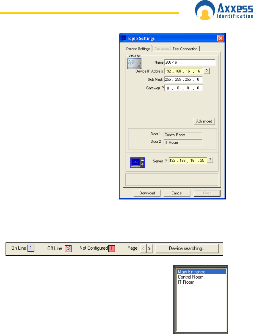
www.axxessid.com
Installation & User Guide
AX200 & IBOX Installation & User Guide – July 10 - 61-
In the TCPIP settings window, under the Device
settings tab; click on “?” in front of the Server IP
field (on the bottom) to obtain the server PC IP
address.
The device IP address is made up of 4 numbers
separated by “,” and is located in the top half of
the screen. The first three numbers of the
device IP address must match the first three
numbers of the Server IP address. However the
fourth number could be anything between 1 and
254.
After entering the device IP, click on the
question mark to make sure the IP you‟ve
entered is free. If the message says the IP
address is in use, change the last number of the
IP address and try again. Choosing a duplicate
IP address could cause conflicts in the network.
When you‟re finished click download.
The numbers of Online, Offline & Not Configured units are displayed on the bottom of the
window. You can use the Device Searching button to refresh the screen.
The menu on the right shows the list of all the configured access points.
Double clicking on any of them will open the Tcpip settings window of
the unit which the access point is connected to.
Double clicking on any of the units in the device manager screen will open the Tcpip Settings
Window.
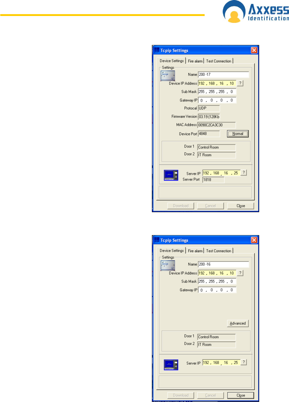
www.axxessid.com
Installation & User Guide
AX200 & IBOX Installation & User Guide – July 10 - 62-
Device Settings
Device settings tab mainly provides you with the
network settings of the selected unit. Every unit is
given a unique name by the application when
connected to the net work. You can change this name
at any time. To avoid any possible conflicts in the
network make sure you don‟t choose a duplicate
name.
The IP address of the server is displayed at the
bottom of the page. The correct IP could easily be
obtained by clicking on the ? Button.
The Device IP Address however should be entered
manually. The first three numbers are identical with
the first three numbers of the Server IP. The fourth
number could be anything from 1 to 254. The question
mark is to make sure that the device IP address is not
in use.
The name of the doors connected to the controller is
shown in the middle of the screen. To change them
you need to go back to the Access Point tab.
Clicking on the Advanced button provides you with
more information about the current device such as the
firmware version or the MAC address.
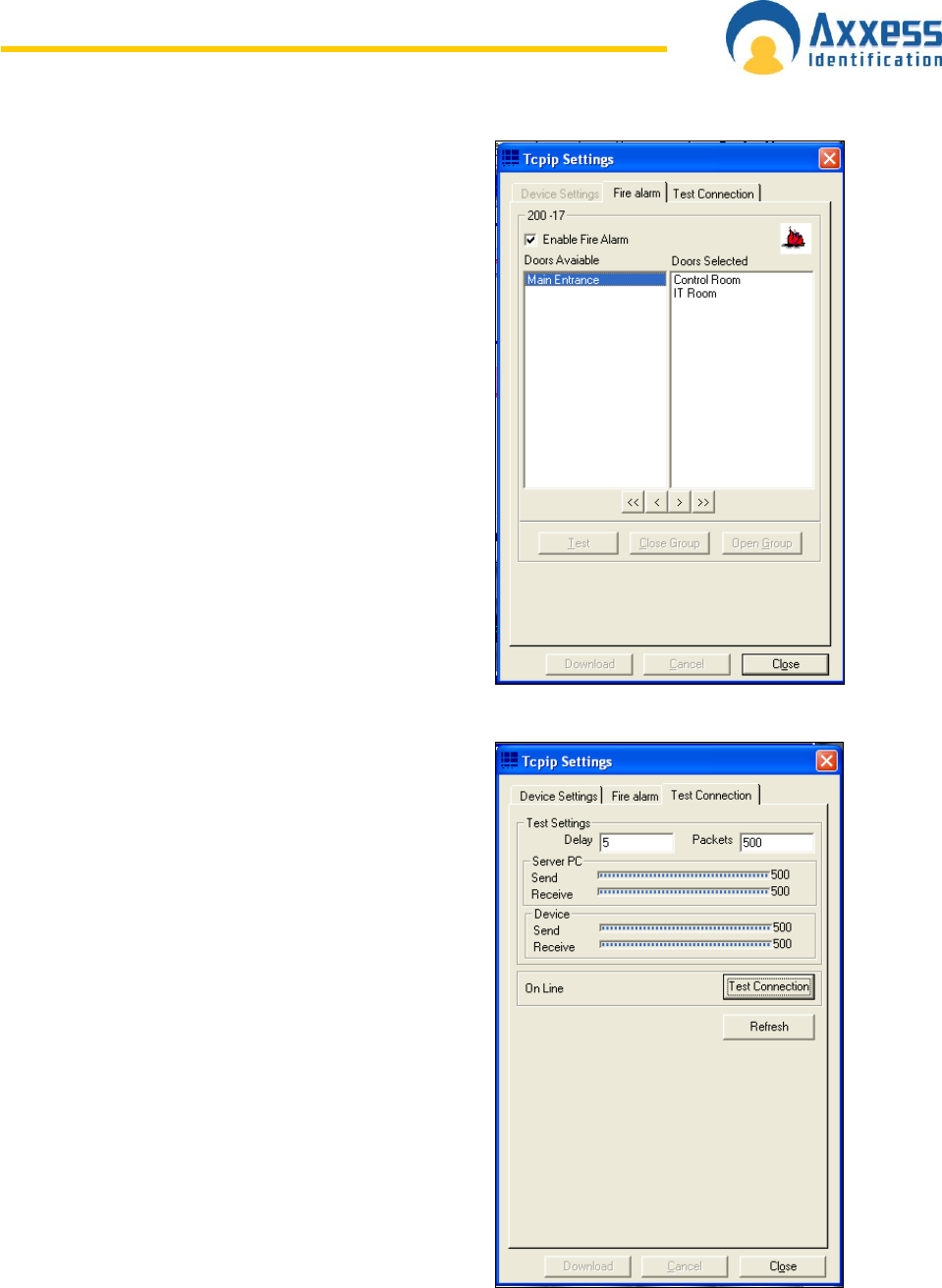
www.axxessid.com
Installation & User Guide
AX200 & IBOX Installation & User Guide – July 10 - 63-
Fire alarm
This section gives you the ability to unlock all the
doors in your building simultaneously by using only
one controller. The way it works is that, if the fire
alarm is triggered on the current controller all the
access points listed in the doors selected list will be
opened at once. To enable the settings tick the
Enable Fire Alarm box.
Doors available list contains all the access point
configured on your PC. By default the Doors selected
list contains only the reader(s) that are connected to
the current controller and you cannot remove them.
You can add more doors to your list by double clicking
on them or using the buttons bellow the list. Press the
download button once you‟re finished.
Test Connection
Test communication checks the communication
between the PC and the device through transmitting
messages from one to the other. The number of these
messages is given in the Packets field.
When you press the Test Connection button the PC
will start sending 500 (default) packets to the device
and the device responds by sending 500 packets
back to the PC.
You can control the speed of the process by
specifying the delay between 2 packets. The number
in the delay field is in milliseconds.
The connection is considered to be in a good
condition, provided that no more than 15% of the sent
packets are lost.
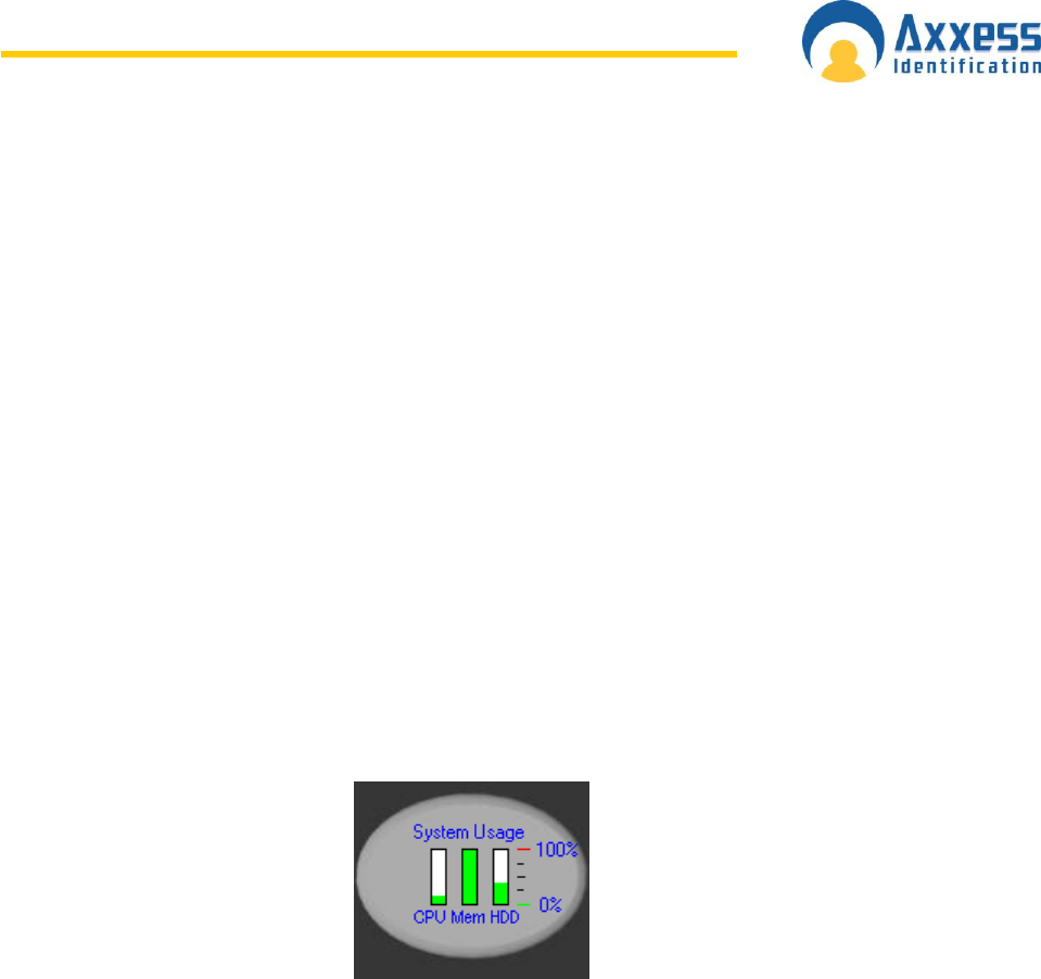
www.axxessid.com
Installation & User Guide
AX200 & IBOX Installation & User Guide – July 10 - 64-
S y s t e m S e t t i n g s
A continuous check is carried out on the PC‟s system resources. These graph bars are located
under the system settings menu and indicate the performance of the system. Often systems grow
bit by bit and no care is given to memory, hard disk space or CPU usage. This can result in very
slow operation or, in the case of lack of hard disk space, a computer crash.
Real-time indicators are:
CPU usage The CPU usage displays how hard the processor is working. If this is
continuously on 100% the system will be slow and would improve substantially if
the processor is upgraded. During backups etc. this indicator will go to 100%
which is quite normal since these tasks are processor intensive.
Memory This displays the amount of RAM in use by the computer in total. Often other
applications running in the background occupy a lot of memory leaving less than
expected for the access control application. A continuous 100% bar shows that
adding memory will improve performance substantially.
HDD Usage This should never come to close to 90%. Clean up unwanted and very old files
on the computer to free up disk space. If there is not sufficient hard disk space
available, the computer will become very slow and eventually will stop operating.
Refer to your Windows manual for further details.
Site Info
The site info tab under “general settings” contains 11 data fields including contact name, address,
telephone and system reference numbers. This information is automatically included in various
reports and email functions e.g. card re-ordering and System Settings report.
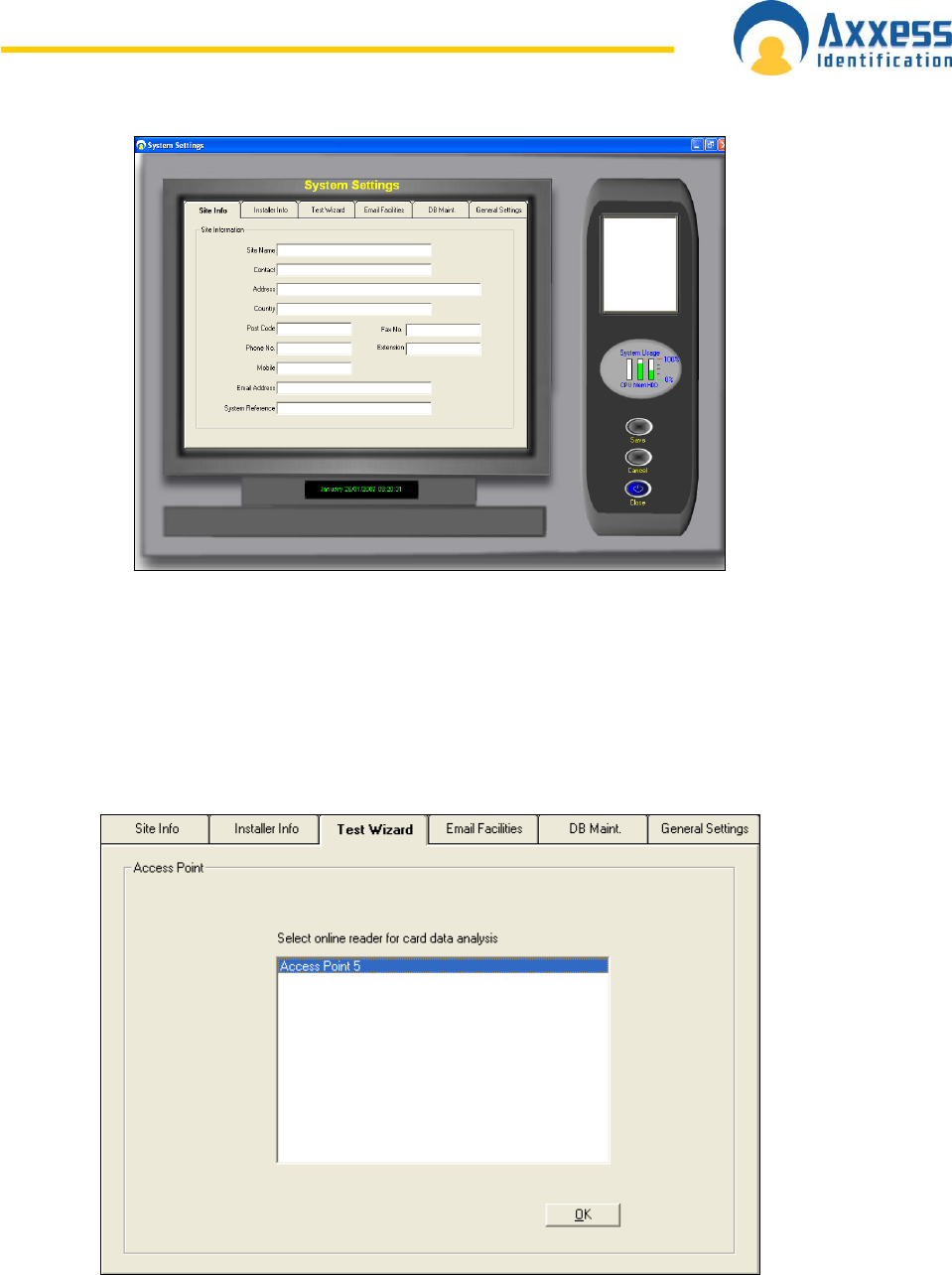
www.axxessid.com
Installation & User Guide
AX200 & IBOX Installation & User Guide – July 10 - 65-
Test Wizard
The test wizard provides an easy and effective way to setup the AX200 system. Together with
hardware and software tests, the test wizard enables you to setup the appropriate card format.
The card used for testing will have access to all doors with high security and latched (door
unlocked) functions enabled. At the end of the wizard, the test report can be printed to a default
printer and the test card can be deleted if required.
Select the appropriate door from the list and press OK. The list contains only the doors that are
online and communicating to your PC.
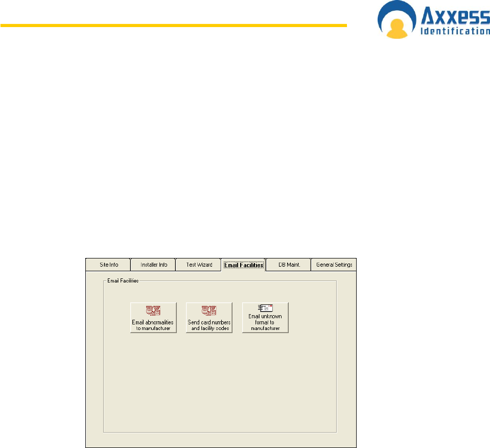
www.axxessid.com
Installation & User Guide
AX200 & IBOX Installation & User Guide – July 10 - 66-
Test wizard is also accessible under Tools menu on the main screen.
E-Mail Facilities
When additional cards need to be re-ordered, it is often difficult to know the type of card, facility
code etc. which can result in delays of card supply or the supply of incorrect cards for the system.
The send card numbers and facility code, emails all the relevant data to the installer. This feature
requires an internet connection.
E-Mail Unknown Format to Axxess ID
If existing cards are used which are not known to the AX200, the data collected under Format and
Statistics – Card Matching can be e-mailed from here. This avoids the need to send cards in the
post for verification. New formats created can then be e-mailed back.
When you press one of these buttons, the program will try to send the relevant information to the
manufacturer (support@axxessid.com) on your behalf. The application will use Microsoft Office
Outlook to transmit e-mail messages.
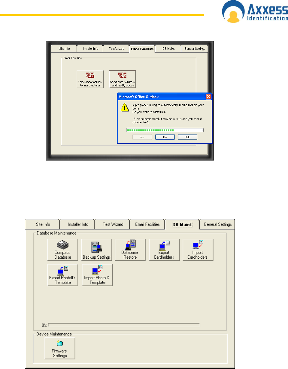
www.axxessid.com
Installation & User Guide
AX200 & IBOX Installation & User Guide – July 10 - 67-
DB Maintenance
Database maintenance is normally done by the AX200 automatically. If data is corrupted
because of an unexpected shutdown of the PC this is repaired automatically when the software is
restarted. All erase functions require an override password and are normally never used. After
each backup, files are automatically deleted.

www.axxessid.com
Installation & User Guide
AX200 & IBOX Installation & User Guide – July 10 - 68-
Compact Database
The database can become slow if a large number of additions and deletions of records occur.
The compact database function reorganises the database which reduces the database size and
improves the speed. Compacting the database is recommended every three months or every 500
cardholder changes.
Backup Settings
It is strongly recommended to backup the system frequently. This can be done manually or
automatically at preset times and days. The backup path is by default to the same hard disk as
the AX200 software (C:\Program Files\AX200\backup). It is recommended to backup to tape in
case of hard disk failure.
Log and event files can be deleted after a specified amount of time (Backup settings), to prevent
the hard disk becoming full. Using the report module, backup events can be viewed and printed.
Database Restore
In the unlikely event that a database corruption cannot be repaired, (automatically on start-up),
this feature allows you to restore a backup database. Cardholders or system changes made since
the last backup will be lost.
Export Cardholders
Cardholder details can be exported in standard .CSV files for use in other software programs.
You will need Microsoft Excel to open that file.
Import Cardholders
Contact factory for details.
All of the above features are also accessible under the File menu in the main screen.
Export Photo ID Templates
Exports all the photo ID templates in a mdb file. You will need Microsoft Access to open that file.
Import Photo ID Templates
Contact factory for details.
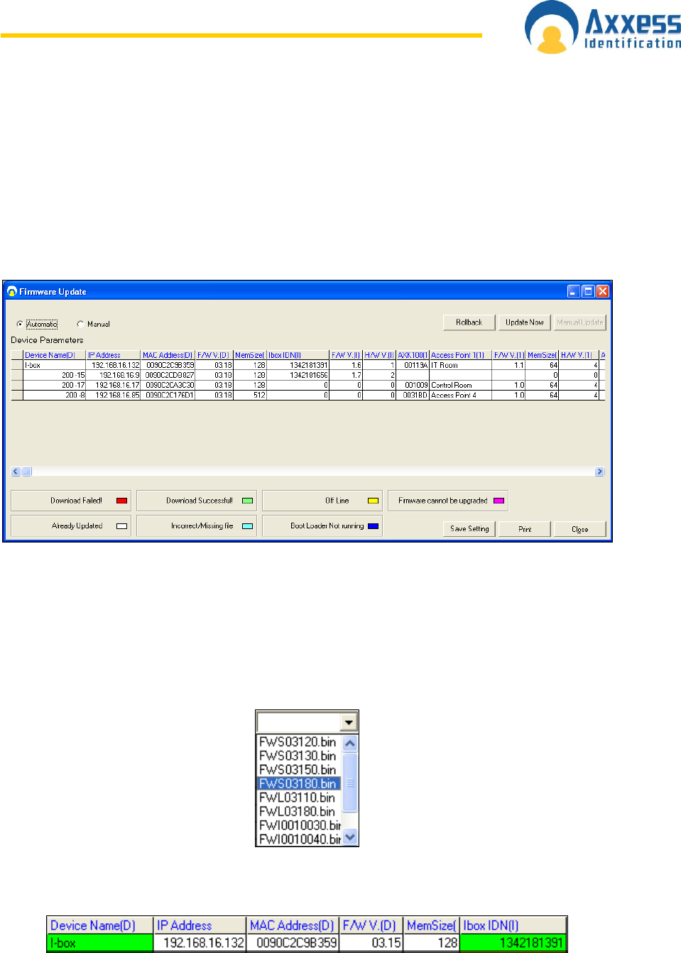
www.axxessid.com
Installation & User Guide
AX200 & IBOX Installation & User Guide – July 10 - 69-
Firmware Settings
Firmware update window contains a list of all the devices on the network and the relevant
information about the network settings and the firmware on each unit.
Firmware update functions both manually and automatically. If the automatic option is selected all
the units on the network will be upgraded to the latest version of firmware on 11:00 PM at night.
Both rabbit FW and I-box FW will be automatically upgraded. If a device already has the latest
version of firmware, it will not be affected.
If the manual option is selected, a drop-down menu will appear on the screen where you can
download the appropriate firmware on individual units. The menu contains every version of
firmware on your PC. You have to upgrade the rabbit firmware and the I-box firmware separately.
If the download is successful, the cell containing the device name will become green. Other
colours are explained on the bottom of the screen.
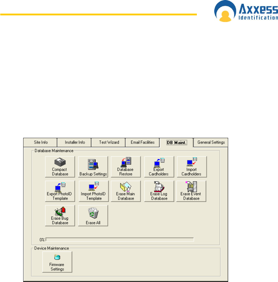
www.axxessid.com
Installation & User Guide
AX200 & IBOX Installation & User Guide – July 10 - 70-
Rollback
Rollback button is an automatic function. When you press the rollback button the software will
downgrade both the rabbit firmware and the I-box firmware by one version on every unit
connected to the local network.
Hidden Functions
Hidden functions are only displayed when the Special Functions in the General Settings tab are
enabled. These features are for engineering purposes only. That‟s why by default these functions
are disabled.
These functions include: Erase Main Database, Erase Log Database, Erase Event Database,
Erase Bug Database and Erase All. Erase All includes all the other erase functions and will
replace your current database with a default (blank) one. You need to enter 1234 as the override
password to use any of the above mentioned functions.
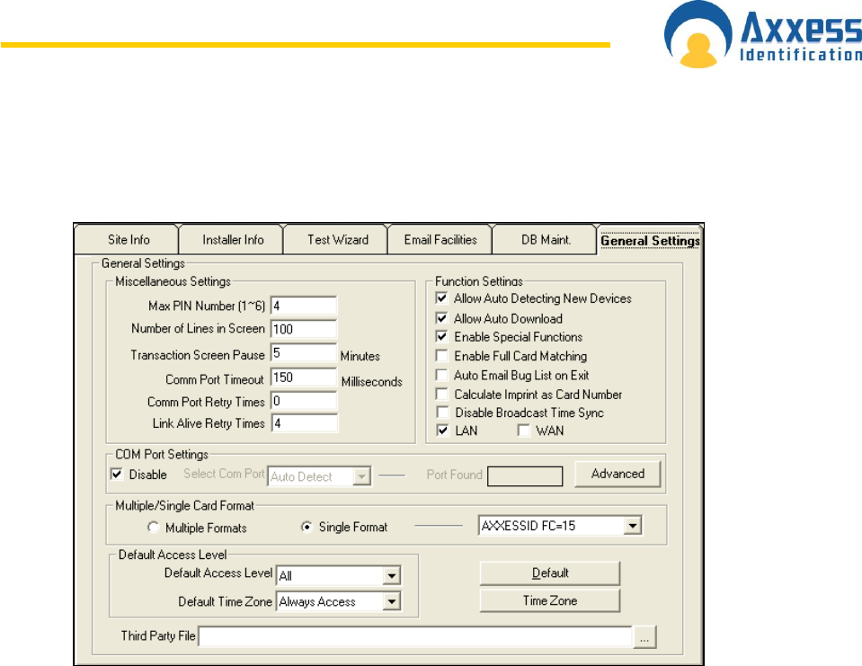
www.axxessid.com
Installation & User Guide
AX200 & IBOX Installation & User Guide – July 10 - 71-
General Settings
Maximum PIN Number 1~6
This option sets the maximum number of digits required when using a PIN code. If a PIN only is
being used and the PIN code is less than the number of digits set under this setting, the # key is
required to complete the action.
Number of Lines in Screen
This is the number of transactions kept in active memory, allowing the user to see them instantly
on the main screen. A larger number will use more memory and can affect the speed of the
software.
Transaction Screen Pause
When the main screen is full with transactions, yellow buttons appear allowing you to temporarily
stop incoming transactions. Transactions will still be stored on the hard disk for viewing at a later
stage through the report module. After the set time, the system will automatically resume. The
default setting is 5 minutes.
COM Port Timeout
This is one of the special functions which is hidden until the Special Functions are enabled in the
software. If a device which is communicating trough the COM port doesn‟t get a respond in a
certain amount of time, the communication will stop. The recommended time is 150 milliseconds.
COM Port Retry Times
This is the number of times that the software will try to reconnect to the device after the COM port
timeout. The default value is 0.
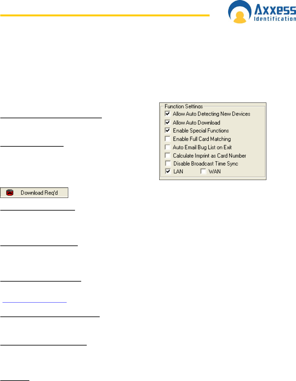
www.axxessid.com
Installation & User Guide
AX200 & IBOX Installation & User Guide – July 10 - 72-
Link Alive Retry Times
The AX200 and the I-box units send a link alive message to the PC every 5 seconds to confirm
that the communication is stable. If the PC doesn‟t receive this message it assumes that the unit
has gone off-line. This option specifies the number times that the PC will attempt to get a link
alive message before the “PC Off-line” transaction appears on the main screen.
Function Settings
Allow Auto Detecting New Devices
Auto detect can be switched off if required.
Allow Auto Download
System and cardholder data is automatically
downloaded to the controller when you close and go
back to the main screen. When switched off, a red icon
will appear on the bottom of the main screen; if a
download is required. In this case downloads have to be done
manually using the Utilities, Download menu.
Enable Special Functions
This feature is mostly used for engineering purposes. It enables the hidden features embedded in
different parts of the software. The default setting is off.
Enable Full Card Matching
This feature allows the use of facility code, site code, card number and issue number. Site code
and issue number are occasionally used by some card manufacturers. The default setting is off.
Auto Email Bug List on Exit
Uses the default e-mail facility on your PC to email the Bug list to the manufacturer
(support@axxessid.com) when you attempt to quit the software. The default setting is off.
Calculate Imprint as Card Number
Calculates the imprint as reverse mifare and works out the correct card number.
Disable Broadcast Time Sync
Disables the broadcast of the time synchronization. This feature is used for older firmware
versions.
LAN/WAN
You can select between the Local Area Network and the Wide Area Network. This option is also
available in the Device Manager → Server Configuration.
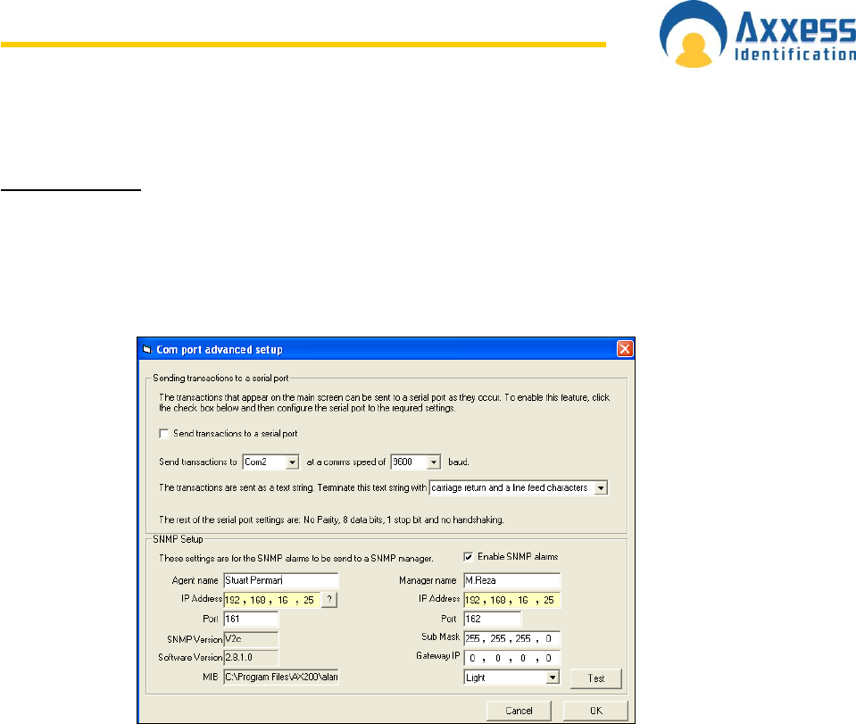
www.axxessid.com
Installation & User Guide
AX200 & IBOX Installation & User Guide – July 10 - 73-
COM Port Settings
Select COM Port
The AX200 software on start-up will automatically scan COM ports 1 to 4, and if found, display
the port found. Consequent start-up of the AX200 software will look at the port found address
only. By selecting auto-detect, the software will scan all ports and find the appropriate COM port.
Manually ports 1 to 16 can be selected if required. Baud rate and parity settings are
automatically configured. The default setting is “Disable”.
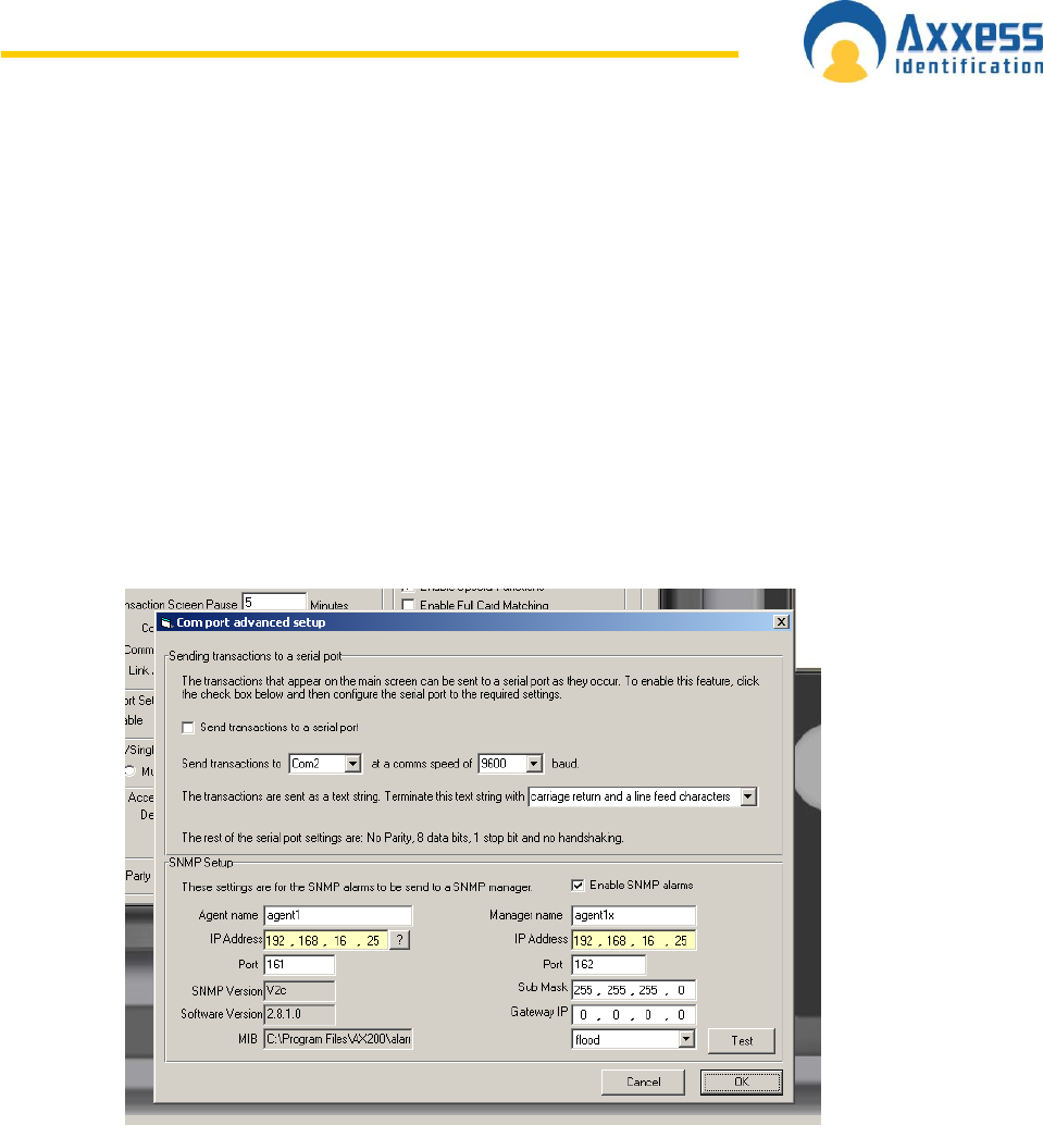
www.axxessid.com
Installation & User Guide
AX200 & IBOX Installation & User Guide – July 10 - 74-
S N M P ( S i m p l e N e t w o r k M a n a g e m e n t
Protocol)
SNMP is used in network management systems to monitor network-attached devices for
conditions that warrant administrative attention. This is commonly used for monitoring mission
critical routers and servers. Through the AX200 software it is possible to use an SNMP manager
to monitor door status and IBOX sensor readings. The AX200 software acts as the agent for all
the sensors, therefore minimising network traffic. AX200 supports version 2.0C of SNMP.
How to set up SNMP
From the Main screen in the AX200 software click on system settings, then click on the general
settings tab. In the general settings tab under the com port sections, click on advanced button.
This will bring up the following screen:
In this screen place enable SNMP alarms by placing a tick in the checkbox next to the text. Give
names to the Agent and Manager. Fill in the IP addresses for the agent (the agent will be the IP
address of the machine that the AX200 software is installed on, clicking on the “?” will fill this in
automatically). Complete the rest of the fields with the correct sub net mask and gateway IP if
needed. To test communication with your manager, you can select a sensor from the drop down
box and click test. This will simulate data being sent to your manager from that particular sensor.
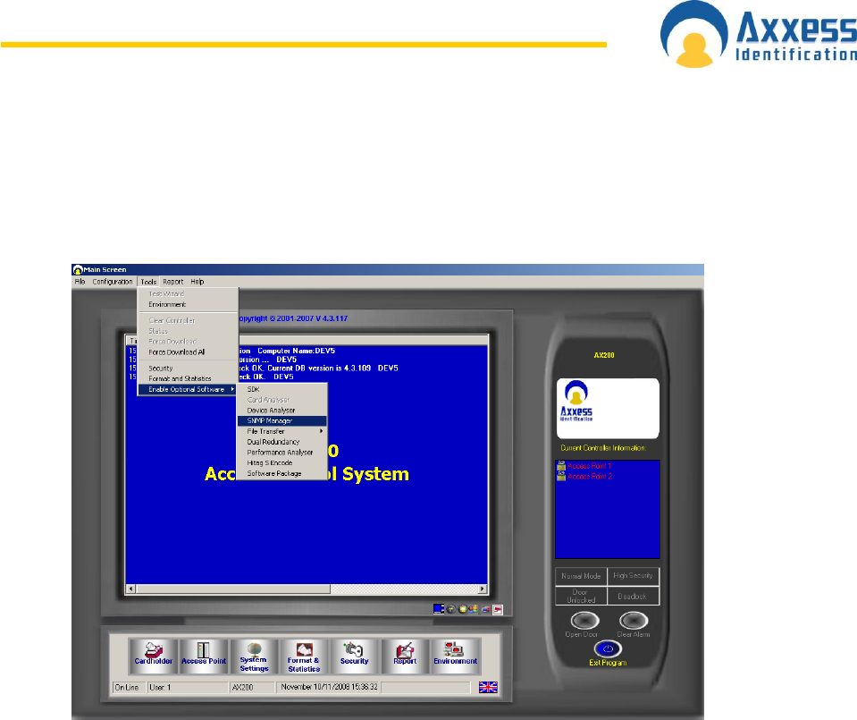
www.axxessid.com
Installation & User Guide
AX200 & IBOX Installation & User Guide – July 10 - 75-
AX200 also has a built in SNMP manager for test purposes only, with no support for third party
devices or alarm handling. This can be found on the main screen under tools -> SMNP manager.
This will then bring up the SNMP manager when you click start the screen is as below:
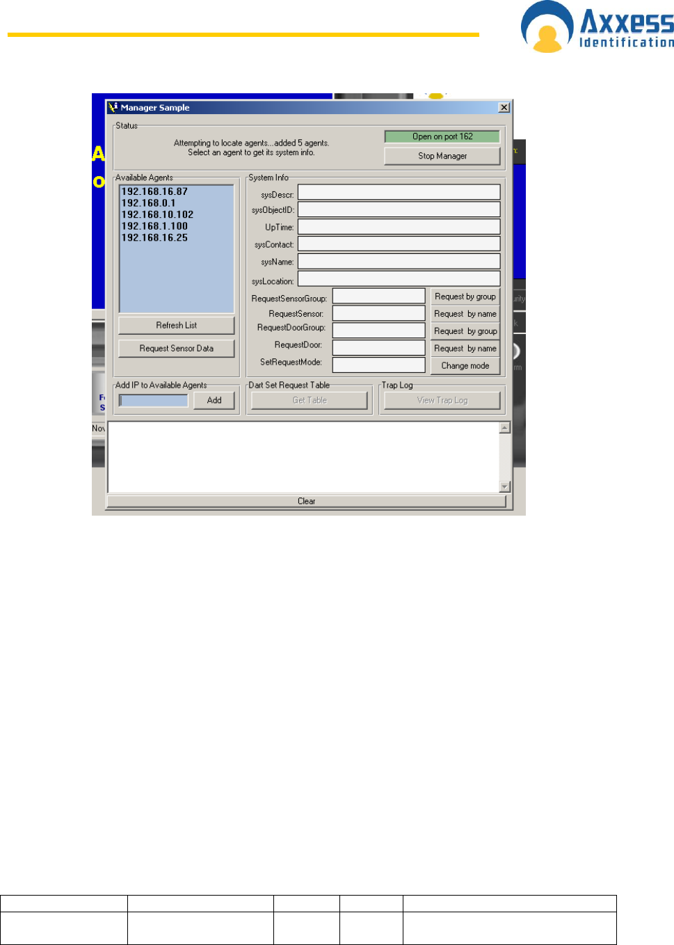
www.axxessid.com
Installation & User Guide
AX200 & IBOX Installation & User Guide – July 10 - 76-
This shows the available SMNP agents on the network. When you select the IP address of the
system with AX200 software installed, you can then see alarm data coming in the bottom of this
screen. Should you wish to make a request for a particular sensor data, you would fill the
requestSensor field with the name that you have given a sensor and click Request by name.
Sensors can be grouped together, allowing the use of a single GET command. Once the sensors
have been grouped you can request that group by using the RequestSensorGroup field, and
filling in the name of the group you wish to request.
A d v a n c e d S N M P F e a t u r e s
Ax200 software Version 4.3.118 onwards uses alarm.mib which is in Ax200 folder as the MIB file
for SNMP.
Your SNMP Manager should compile alarm.mib to get SNMP traps and request data.
There is also Manager Utility in Ax200 software for test purposes only.
alarm.mib :
OIDs in the MIB file are:
The following are send on sensor alarm as Trap:
Variable
OID
Type
Access
Description
AlarmIbox
1.3.6.1.4.1.25206.5.2
Octet
string
Read
only
Identity(IDN) no of ibox

www.axxessid.com
Installation & User Guide
AX200 & IBOX Installation & User Guide – July 10 - 77-
AlarmDescription
1.3.6.1.4.1.25206.5.1
Octet
string
Read
only
Alarm of sensor
AlarmSensorPoint
1.3.6.1.4.1.25206.5.3
Octet
string
Read
only
Sensor identity no.(SDN)
AlarmLocation
1.3.6.1.4.1.25206.5.4
Octet
string
Read
only
Name of the sensor
AlarmDate
1.3.6.1.4.1.25206.5.7
Octet
string
Read
only
Reading timestamp
Alarm status
1.3.6.1.4.1.25206.5.5
Octet
string
Read
only
Readings
To request reading from sensor:
Variable
OID
Type
Access
Description
RequestSensor
1.3.6.1.4.1.25206.6.1
Octet
string
Read
write
Set the name of the sensor
to be requested for sensor
reading (SetRequest)
RequestSensorGroup
1.3.6.1.4.1.25206.6.4
Octet
string
Read
write
Name of the sensor group
to be requested for reading
(setRequest)
RequestReading
1.3.6.1.4.1.25206.6.2
Octet
string
Read
only
Reading of sensor as
response for the above set
request
RequestReadTime
1.3.6.1.4.1.25206.6.3
Octet
string
Read
only
Timestamp of the sensor as
response for set request
To request access point mode:
Variable
OID
Type
Access
Description
RequestAccessPoint
1.3.6.1.4.1.25206.7.1
Octet
string
Read
write
Set the name of the door to
be requested for door mode
(name case sensitive)
(SetRequest)
RequestDoorGroup
1.3.6.1.4.1.25206.7.4
Octet
string
Read
write
Name of the door group to
be requested for door
mode(name case sensitive)
(setRequest)
Multiple/Single Card Format
Multiple Formats – The AX200 software allows that each cardholder has a unique format. If
selected, then a card type (this includes format and facility code) should be selected for each
cardholder.
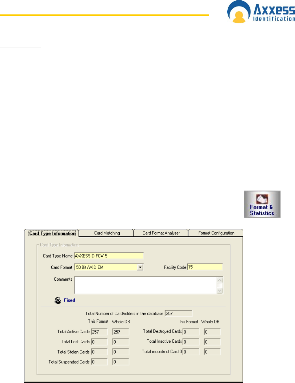
www.axxessid.com
Installation & User Guide
AX200 & IBOX Installation & User Guide – July 10 - 78-
Single Format – Normally cards are of the same format and facility code. If cards of the same
technology/manufacturer are used from other systems then multiple formats can be used. Single
format is the default setting.
Default Access Level
This is the access level which by default is displayed in the Cardholder screen.
Default Time Zone
When adding a new card in the cardholder screen the default time zone is Always Access. You
can choose a different time zone from the list to be the default or you can create a new time zone
by clicking on the time zone button.
Default
Selecting this will set all the software settings back to factory default.
Third Party File
Allows you to lunch another software package like the i-Catcher for the CCTV.
F o r m a t & S t a t i s t i c s
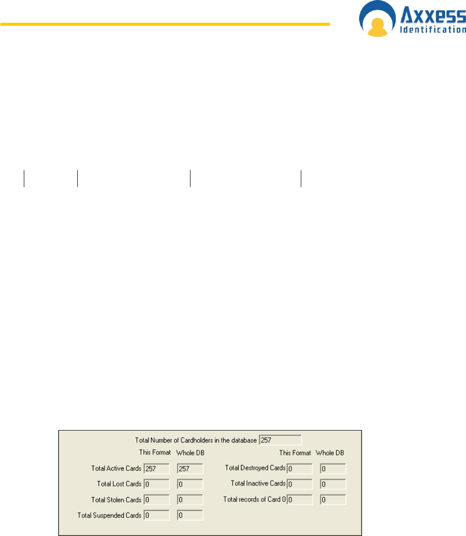
www.axxessid.com
Installation & User Guide
AX200 & IBOX Installation & User Guide – July 10 - 79-
Card Type Information
The AX200 supports up to 4,000 different card formats and facility codes. The format and facility
code combined is called a card type.
Format is the number of bits programmed in a card and the location of parity checks.
E.g. 26 bits
O F FFF FFFF C CCC CCC CC CCCCC CC E
odd parity
1 to 13 facility code even parity
14 to 26
card number
The first and last bit check that the data received is correct.
8 x F indicates facility code
16 x C indicates card number location
The card type information tab under Formats and Statistics gives a total system overview of the
number of cards and records in the system.
Details are provided per card format/facility code on:
Total Cardholders in the database
Total active cards
Total lost cards
Total stolen cards
Total suspended cards
Total destroyed cards
Total inactive cards
Total records of card 0 (cardholder details with no card issued)
Facility Code
Is a number allocated to a specific customer to avoid that card 1 would have access also on
another system which uses card 1. A 26 bit format is not recommended since it allows only 256
different facility codes worldwide.
Most card manufacturers have their own specific format, providing a higher security than the
„open standard‟, which is not as secure.
The default facility code is 50 bit card format, providing the highest level of card number security.
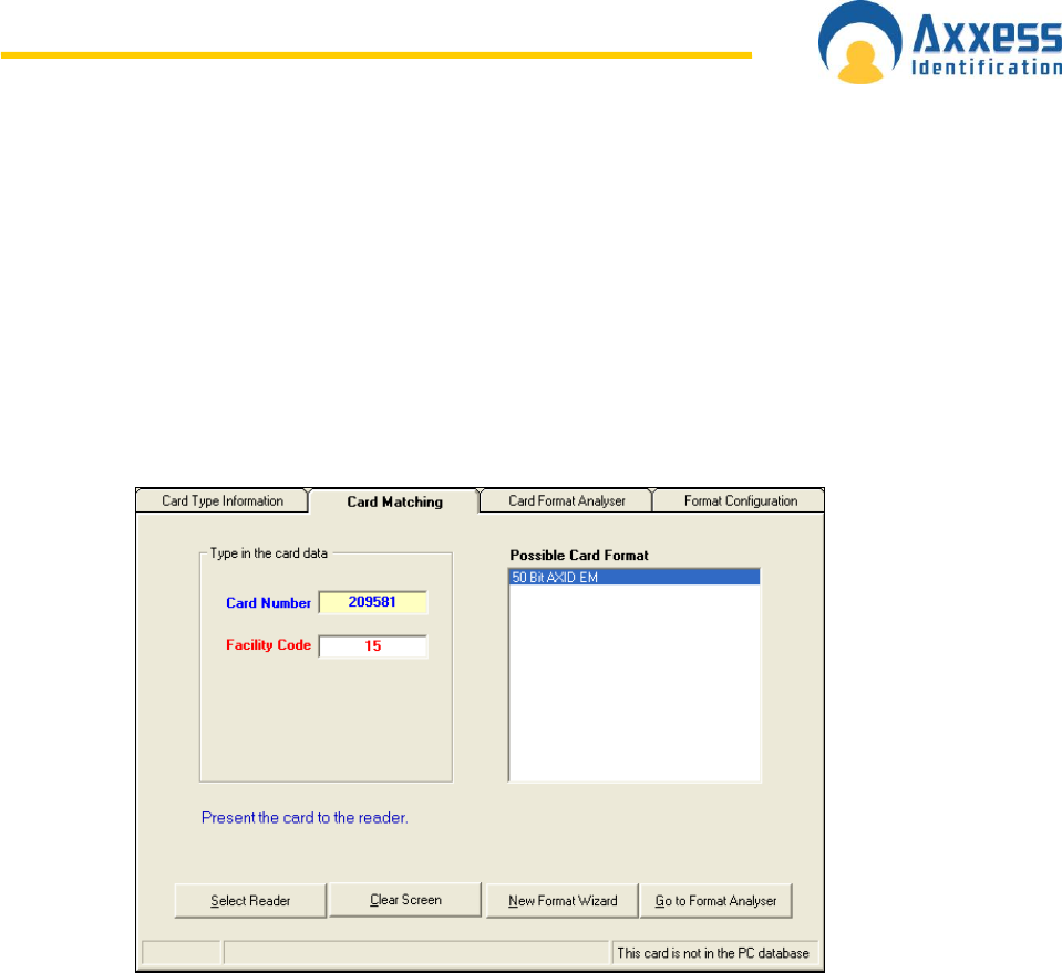
www.axxessid.com
Installation & User Guide
AX200 & IBOX Installation & User Guide – July 10 - 80-
Card Matching
The AX200 supports a number of well known formats. Enter the card number and if known, the
facility code. Present the card to the reader (systems should be online). If know, it will display
the possible format. Ensure that multiple cards from the same batch are used to verify the card
format. You can then use the New Format wizard to add this to the AX200.
The card matching feature automatically identifies known formats and displays the card number
and facility code. The Card format wizard allows the simple addition and quick addition of new
facility codes or card formats by presenting the card to the reader. Unknown Card formats can be
added using the optional Card Analyser Program or by contacting the factory.
Card Format Analyzer & Format Configuration
These features are hidden and for engineering uses only. For more information please contact
your manufacturer.
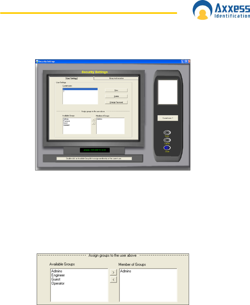
www.axxessid.com
Installation & User Guide
AX200 & IBOX Installation & User Guide – July 10 - 81-
S e c u r i t y S e t t i n g s
Individual passwords can be issued to different users with different rights to view and edit.
Passwords are not case sensitive. The default user 1 cannot be deleted however the password
can be changed.
Adding a New User
To add a new user, select New, enter the user name, password and confirm the user
password. You are asked to select an existing group authorisation or alternatively you can setup
a new group by selecting the Group Authorisation tab. To assign a group to a user, select a group
from the Available Groups list. You can double click on the group or use > button to move it
across to the other list. Click save when you‟re finished.
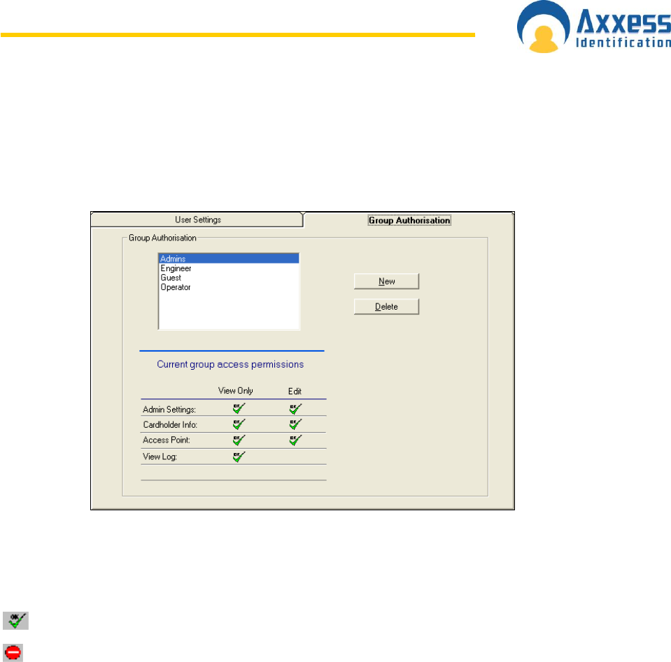
www.axxessid.com
Installation & User Guide
AX200 & IBOX Installation & User Guide – July 10 - 82-
Adding a New Authorisation Group
Select the Group Authorisation tab, select New, type in the new Group Name.
Double click on the current group access permission symbols to enable or disable the
permissions.
Access enabled
Access disabled
Select save.
R e p o r t s
The AX series has a built in report generator which allows full or filtered information to be viewed
on screen or printed. Colour printers are supported and give the benefit of alarm messages
printed in red. Reports can also easily be e-mailed or exported in a large number of different
formats.
Formats supported are:
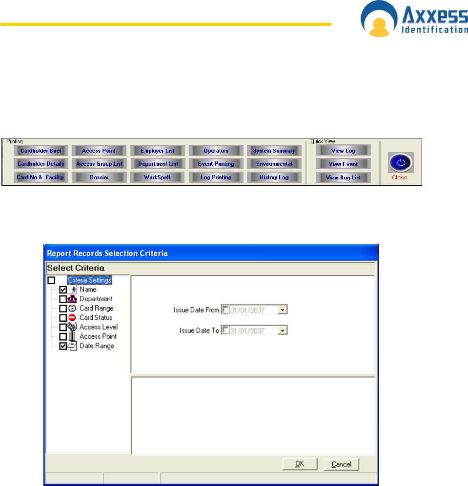
www.axxessid.com
Installation & User Guide
AX200 & IBOX Installation & User Guide – July 10 - 83-
Lotus mail
Microsoft Mail
Microsoft Excel
Microsoft Access
Microsoft Word
Text files
CSV files
ODBC
ASCII file
Comma delimited file
Standard reports
Rich Text Format
Powerful reports are easily obtained entering selection criteria. The report will only include the
information obtained up to the last backup.
Brief Cardholder Summary
Detailed Cardholder Summary
Card Number & Facility Code
Access Points
Access Group List
Dossier Report
Employer Details
Department List
WorkSpell
Operators
Event Printing
Log Printing
System Summary
Environmental
View Log
History Log
View Events
View Bug List
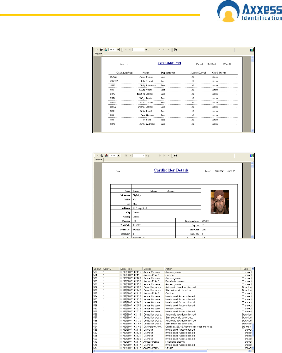
www.axxessid.com
Installation & User Guide
AX200 & IBOX Installation & User Guide – July 10 - 84-
Cardholder Brief
Gives a brief account of the
information about the cardholder
including: Card Number, Name,
Department, Access Level &
Card Status.
Cardholder Details
Displays all the information in the
cardholder screen in details
along with the picture of the card
holder.
Log File
All the system transactions from
the online controllers are stored,
including all operator actions.
Cardholder, system changes
and operator commands are all
stored in the log file with date,
time and the type of transaction.
eg 12:00 05/12/2002 card 52
added. The log file can be
viewed or printed using selection
criteria e.g. from / to date,
cardholder, department Etc.
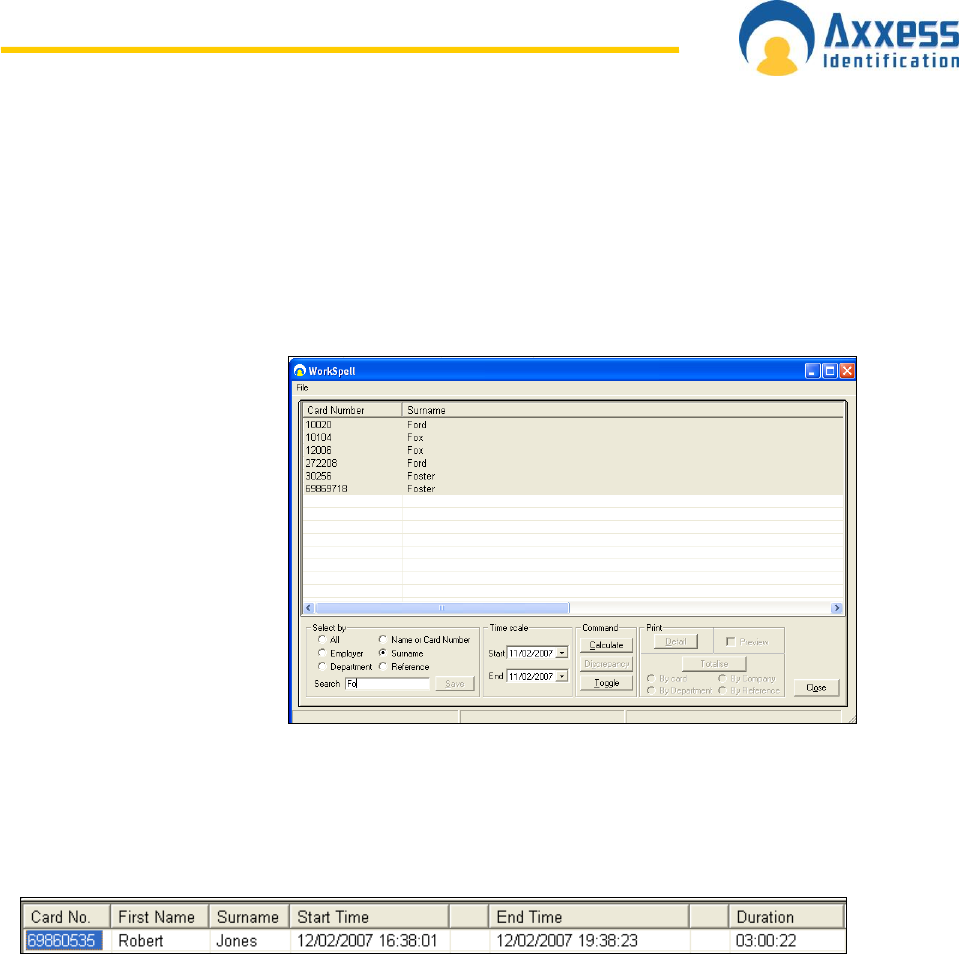
www.axxessid.com
Installation & User Guide
AX200 & IBOX Installation & User Guide – July 10 - 85-
Dossier
The dossier provides a brief description of the people working in the same department. This
information includes name, department, job title, employer and contact details along with photo
display for each person.
Work Spell
An exclusive feature in the
AX200 application gives you
the possibility to calculate the
total number of hours which
an individual or a group of
cardholders have spent inside
the building. You can search
a cardholder by their name or
card number and workout the
number of hours they have
spent in the building, during a
specific period of time.
Alternatively you can carry out this calculation for the people working in the same department or
under the same employment.
Select the appropriate criteria from the options on the left. Type the correct name in the search
field. Select the correct record from the list and press save. Now specify the correct time period
and press calculate. The result will appear on the list providing the cardholder‟s name, card
number, start time, end time, duration, employer, department and ….
If you‟re running the report for more than one person or a cardholder who‟s been booked in & out
more than once; you can sum up the total number of hours they have been present by pressing
Totalise. You will have the option of totalising by card, company, department or by reference.
This list can be printed out or exported in a number of different formats.
Discrepancy tells you when the cardholder has been booked in/out.
Operators
Presents a list of the users allowed to use the application. To add a new user, go to Security →
User Settings.
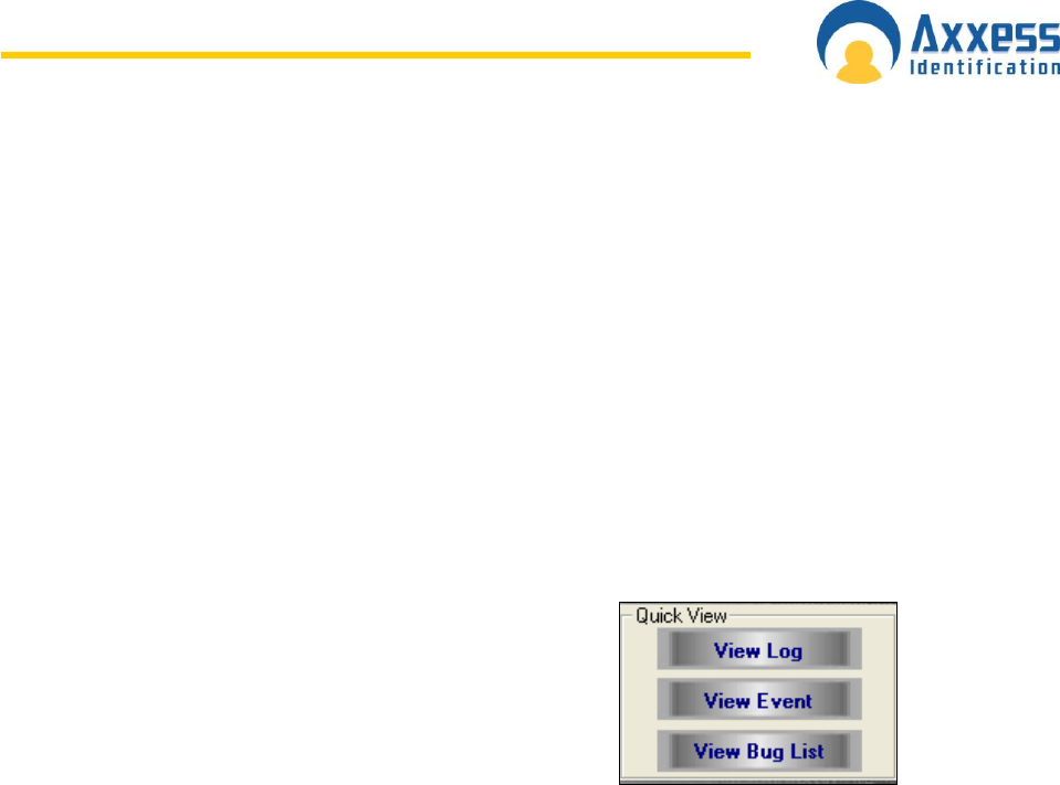
www.axxessid.com
Installation & User Guide
AX200 & IBOX Installation & User Guide – July 10 - 86-
Environmental
You can run detailed reports on the i-Box activities. These reports can be filtered by i-Box name &
ID, Location, Sensor Type, Name & ID, Transaction type and Time range.
System Summary
System summary prints out the Site Information, Installer Information, System Settings, List of
Card Types, Access Point and the list of Operators.
Quick View
This feature enables immediate retrieval of the last events
for quick viewing. The event and log files are cleared after
each backup however can be viewed using history event or
history log.
Printing
This will provide a selection of reports, all the data is sorted on the screen. To print, select the
print icon or select the envelope icon to export the data from the report.
Reports can be exported to a number of spreadsheet and word processor formats as well as
ODBC and common data interchange formats. This makes the distribution of information easier.
The export process requires you to specify a format and a destination. The format determines
the file type and the destination determines where the file is located.
Format Types
Character-separated values
Comma-separated values (CSV)
Crystal Reports (RPT)
Crystal Reports 7 (RPT)
Data Interchange Format (DIF)
Microsoft® Excel
Lotus® 1-2-3
ODBC
Paginated Text
Record style (columns of values)
Report Definition
Rich Text Format

www.axxessid.com
Installation & User Guide
AX200 & IBOX Installation & User Guide – July 10 - 87-
Tab-separated text
Tab-separated values
Text
Word for Windows
In addition to the standard export format types installed on your PC, you may find additional
export format types are available to you. These are determined by the DLL files on your PC.
Note: - When you export a report to a file format other than Crystal Reports format (RPT), you
may lose some or all of the formatting that appears in your report. However, the program
attempts to preserve as much formatting as the export format allows.
Note: Transaction date and times are issued by the PC. Events are not stored in the AX200.
Destination
The destination determines the export location of your report.
Application
Disk File
Microsoft® Exchange folder
Lotus® Domino
Microsoft Mail™ (MAPI)
All operation commands/database or system changes are stored and can be previewed in
Reports.

www.axxessid.com
Installation & User Guide
AX200 & IBOX Installation & User Guide – July 10 - 88-
i - BOX
The i-BOX provides both access control
security and environmental monitoring.
Each i-BOX includes a built in
temperature, humidity, light and voltage
sensor with 14 additional ports for plug
and play connections of additional smart
sensors, together with 2 access control
ports.
When presenting a card to a reader connected to the i- BOX, the transaction will be recorded,
providing a date and time stamp. Detailed reports of all the transactions can be filtered by single
or a group of doors, employee name, company or department, individual date or date range.
These reports can be printed or exported into a database or spreadsheet for analysis. Just go to
Reports → Environment and select the appropriate criteria.
In addition to the Light/Voltage & Temperature/Humidity sensors placed inside the i-BOX during
manufacturing; there are 16 different types of plug & play smart sensors which can be plug into
one of the 14 ports on the back of the i-BOX. Each sensor can be programmed to take readings
as frequent as 1 every second. Maximum and minimum values could be set for every sensor and
once the reading exceeds the limits an alarm transaction will be generated and displayed on the
main screen, providing the time, date, type of the alarm, I-BOX and the sensor‟s name. Accurate
reports of all the readings taken by all the sensors could be obtained in Reports → Environment.
These reports can be filtered by a single or a group of locations, sensor‟s type, name & ID and I-
box Name & ID.
The following table contains the list of all the plug & play smart sensors supplied by Axxess
Identification.
Door Panel Position Sensor
Detects the position of side panels and doors
Vibration / Shock Sensor
Detects Vibrations from intrusion attempts
Temperature Sensor
Standard temperature sensor range -20C to +80C
Temperature & Humidity Sensor
High accuracy temperature, condensation and humidity sensor
Temperature & Door Contact Sensor
Combined standard temperature and door position sensor
Mains Present Monitoring Sensor
Monitors the availability of mains power
Hot Spot Temperature Sensor
Early warning temperature sensing of equipment
High Level & Door Contact Sensor
Combined light level and door position sensor
Flood Sensor
Flood sensor with 5 meters of water sensing cable
Smoke & Temperature Detector
Combined optical smoke and temperature detector
Intrusion / Movement PIR
Detection of people for intrusion or presence
Sounder / Beacon Module
Combined sounder and beacon for audio and visual warning
Fan Fail Sensor
Fixed temperature alarm for temperature and fan fail sensor
Inputs / Output Module
Two general purpose inputs and 1 relay output module
General Input Module
Two volt-free general purpose input module
Dust Particle Sensor
Monitors the concentration of dust particles in the air flow
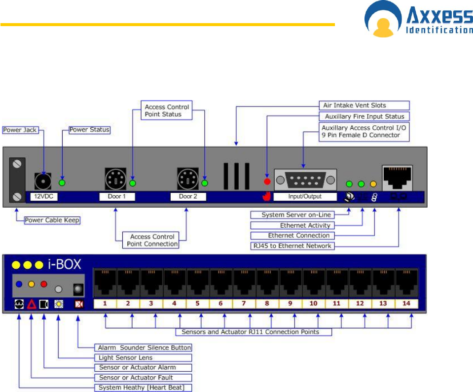
www.axxessid.com
Installation & User Guide
AX200 & IBOX Installation & User Guide – July 10 - 89-
The picture gives a brief description of the ports and LEDs on the i-BOX.
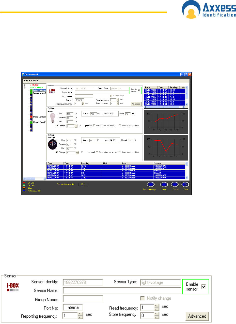
www.axxessid.com
Installation & User Guide
AX200 & IBOX Installation & User Guide – July 10 - 90-
Environmental
An essential part of the AX200 software which is exclusive to the i-BOX. Environment screen
contains settings and configurations for the i-BOX activities.
i- BOX Parameters
The diagram on the left shows all the i-box units configured on your PC. On-line units are
displayed in green. Clicking on + will display all the sensors connected to that i-box. Other than
the first two sensors which are already in the i-box, there are 14 empty ports for smart sensors to
be plugged in. Once a new sensor is plugged in, a new device wizard will be opened and you can
easily configure your sensor. Once a sensor is highlighted on the diagram, all the sensor settings
will be displayed on the screen.
The blue list on the bottom of the screen displays all the readings taken by all the online sensors.
Sensor Settings
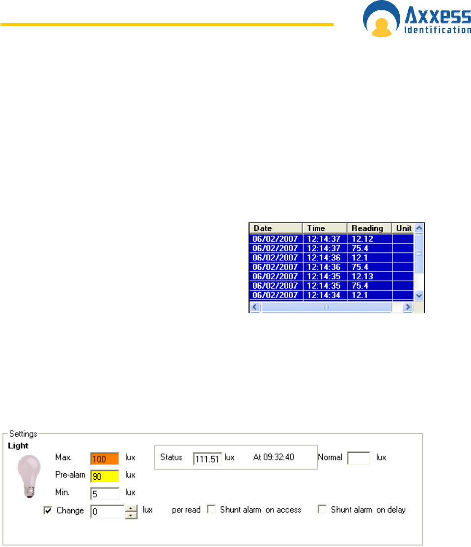
www.axxessid.com
Installation & User Guide
AX200 & IBOX Installation & User Guide – July 10 - 91-
Sensor specifications are displayed on the top of the page. Sensor Identity and Sensor Type
are automatically detected by the application once the sensor is connected to the i-box. These
values cannot be changed.
Note: the Serial Number of the sensor is not shown on this page however it is displayed on the
new device wizard once you plug in the sensor for the first time.
Sensor Name is specified by the user and can be changed at any time.
Port No displays the number of the port which the sensor is connected to (1→14). In the case of
a built-in sensor like Temperature/ Humidity, it shows Internal.
To enable a sensor tick the check box and click the save button on the bottom of the page. Once
the sensor is enabled it will start taking readings.
Read frequency specifies how often you want the
sensor to take a reading. This number is in seconds
and could be in the range of 1 → 255.
Reporting frequency tells you how often the reading
is displayed on the screen. The blue list on the right
hand side shows all the readings taken by the current
sensor.
Store frequency is how often the reading is stored in the i-box. This option is only applicable for
certain types of sensor.
Advanced settings include more information on sensor‟s name and identity, hardware and the
firmware version. It also includes the calibration settings for the sensor. Do not attempt to change
these settings if you‟re not sure as this will affect the performance of the sensor.
Alarms
Any sensor could be given a maximum and minimum reading value. Once the current reading
exceeds those limits, it will generate an alarm. In the case of High/Low limit alarms the Max/Min
fields will become amber. In the case of the pre-alarm they become yellow. Simultaneously, an
alarm transaction will appear on the main screen providing the sensor‟s type, alarm description, i-
BOX name and sensor ID. An “Alarm cleared” transaction will follow once the current reading falls
back within the limits.

www.axxessid.com
Installation & User Guide
AX200 & IBOX Installation & User Guide – July 10 - 92-
You can also program a sensor to generate an alarm once the reading changes considerably.
Once you‟ve ticked the check box you can specify the magnitude of this change in the “Change”
field.
Shunt alarm on access
When a door is opened there might be a dramatic change in the sensor readings (especially
temperature and light sensors), which may results in generating a false alarm. By enabling this
feature the application will ignore the alarm generated by that sensor once the door has been
opened.
Shunt alarm on delay
In the same way, when the door is closed the reading will go back to its original status quickly
which may cause in generating an alarm. To avoid this; once you have activated this feature, you
can specify the shunt delay time in the i-BOX settings. To view these settings just click on the i-
box name. As the result, when the door is closed, any generated alarm would be ignored until the
delay time is over.
i- BOX Settings
More information on the i-box such as i-BOX identity, firmware version or the serial number could
be obtained by clicking on the i-box name (on the diagram on the left).
Host Online Timeout
Is the number of seconds after which the I-box assumes that the PC is offline when it does not
receive a response for the link-alive. So during this time if the I-box does not receive any
response for link alive the software will report “PC off line”!
Force time Update
Specifies the amount of time before the clock on I-box is synchronized with the PCs clock!
Alarm Strobe Period
Indicates how long the strobe light will flash once the alarm goes off. (Triggered by Pin 9 on the 9
way connector on the i-BOX [Ref. page 12])
Handshake Period
Determines the period of the initial interaction when two units on the network start communicating
with each other.
Shunt Delay
The period of time during which any alarms generated by the sensors connected to this i-box
would be ignored after the door is closed. (Shunt alarm on delay needs to be enabled)
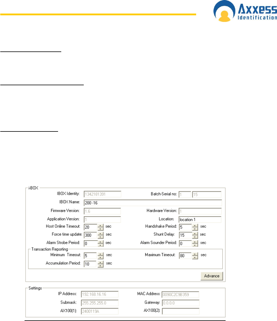
www.axxessid.com
Installation & User Guide
AX200 & IBOX Installation & User Guide – July 10 - 93-
Alarm Sounder Period
The amount of time that the sounder is activated when the alarm is generated. This alarm is
triggered by Pin 4 on the 9 way connector on the i-BOX [Ref. page 12])
Minimum & Maximum Timeout
The default maximum value is 5 seconds. This means, when the I-box sends a transaction to the
PC it will wait for a response from the PC. If it does not receive any response it will wait for 5
seconds before sending another message. This number is doubled with every try, until it reaches
80 seconds (Minimum Timeout).
Accumulation Period
Number of seconds that the transactions will be accumulated in the transaction queue in the I-box
before they are sent (applicable in case of block transaction: max 15 transactions can be in a
block). If it is set to 2 sec then all the transactions accumulated during 2 sec will be sent.
It‟s the delay period of block transaction but if the queue is already filled with 15 transactions it is
sent anyway.
The bottom part of the page contains some information about the network settings on the i-box
such as the IP address, MAC Address and… it also displays the access identity of the readers
connected to the access control ports on the back of the i-box.
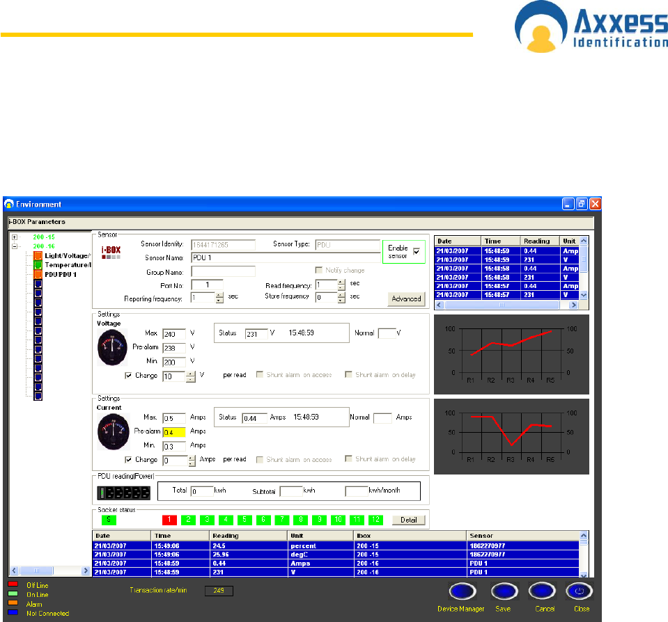
www.axxessid.com
Installation & User Guide
AX200 & IBOX Installation & User Guide – July 10 - 94-
PDU (Power Distribution Unit)
The Power Distribution Units (PDU) are part of the family of plug & play sensors manufactured by
Axxess Identification; representing a streamlined and more efficient use of power delivery into the
rack environment.
High and low limits could be defined for both voltage and current. Once the reading exceeds
these limits it will trigger an alarm and the appropriate transaction will appear on the main screen,
providing the sensor‟s type, alarm description, i-BOX name and sensor ID.
Details
The status of the sockets is displayed on the left hand side. Each status has a unique colour.
Colour green means that the socket is switched on and colour red indicates that the socket is
switched off. If there is a fuse failure in any of the sockets, it will be displayed in amber and the
appropriate transaction will appear in the main screen. There is a space in front of every socket to
enter a brief description of the equipment connected to that particular socket.
The Delay Start-up column includes the number of seconds before a socket is activated when
the PDU is switched on. If the input value is zero, the socket will not be switched on. (Range: 0s
→ 255s)
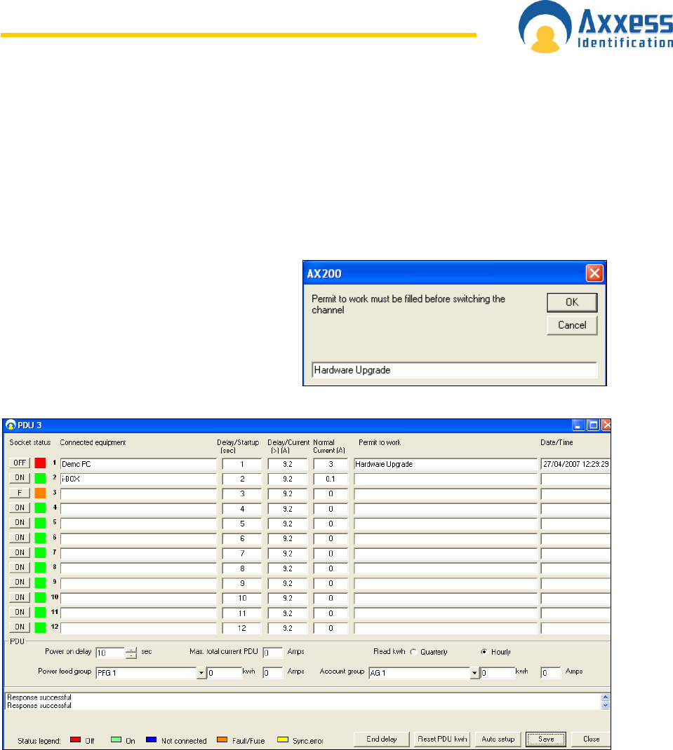
www.axxessid.com
Installation & User Guide
AX200 & IBOX Installation & User Guide – July 10 - 95-
The Delay/Current column indicates the upper limit of the current in the unit before a particular
socket is switched on. For example if the input value for a particular socket is 5, it will not be
switched on until the current in the unit has dropped down to 5 amps or less.
If there is a mismatch between the database and the PDU settings, these fields become yellow.
All you need to do is to press the save button to synchronize the database.
Normal Current: shows the normal amount of current consumed by each device. This value is
determined by the user and is merely for user‟s information and has no effect on the operation of
the PDU.
Permit to work & Date/Time: the last two
columns are for entering a brief explanation in
case of a socket being switched of by the
user. To switch off a socket remotely click on
the ON/OFF buttons on the left hand side.
Once you click on the ON/OFF button a
separate window will be opened asking you to
enter the “Permit to work”.
Power on delay is the amount of time before any of the PDU sockets becomes activated. Please
note that once the unit is switched on, this delay time is applied before the delay time set for
individual sockets. For instance if the overall delay is 10 seconds and the delay time for the first
socket is 1 second; once the unit is switched on it will take the first socket 11 seconds to be
activated. To set the overall delay enter the appropriate number of seconds in the field, and press
save.
Power feed group
The units connected to the same power line could be classified into a separate feed group.

www.axxessid.com
Installation & User Guide
AX200 & IBOX Installation & User Guide – July 10 - 96-
To create a new feed group enter an appropriate name inside the Power feed group field and
press save. When you add the next PDU, you can select the feed group that you have just
created and the new unit will be assigned to that group.
There is also a way to categorize the units that are being fed through different power lines. In this
case you need to create an Account group which can contain the units that are not connected to
the same power line.
Pressing the End delay button will terminate any delay time and all the sockets in the unit will be
switched on. Reset Power button will bring the value of total power back to zero.
Voltage, current and the power readings are displayed on the LCD screen on the PDU. If you
press button No.4 you‟ll be able to view the Serial Number. Button No. 5 will display the channel
status for all the sockets. The status of each channel is reported in the following way:
0 Switched Off
1 Switched On
F Fuse Fault
Mains present on the output but the relay is off.
Button No.6 displays the Hardware and the Firmware version inside the unit. In order to reset the
PDU to its default settings press and hold buttons 1, 3, 4 and 6. After resetting the unit, the time
interval between the sockets being switched on (in the start-up sequence) increases to 3
seconds.
States to be indicated on PDU relay LED:
1. Normal: Power switched on, power sensed – LED on solid
2. Fault Feedback: Power switched off, power sensed – 0.5 sec on/off flash for 3
seconds, off 2 seconds
3. Fuse Fault: Power switched on, power not sensed – 80 ms seconds on/off flash
4. Socket Off: Power switched off, power not sensed – LED off.
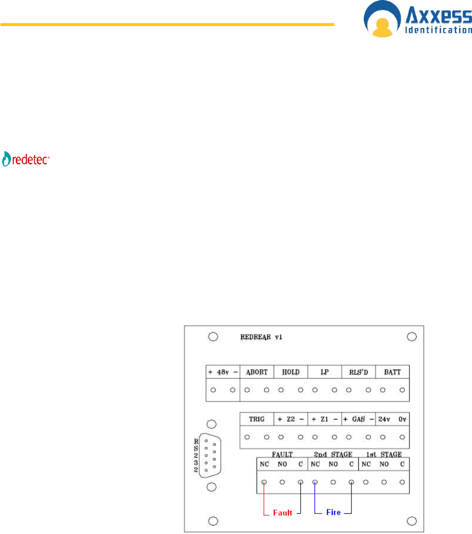
www.axxessid.com
Installation & User Guide
AX200 & IBOX Installation & User Guide – July 10 - 97-
Sensor
FiretecPro sensors are Input/output modules specifically designed to be used with FiretecPro
units to provide the ultimate cabinet protection. FiretecPro is a self-contained automatic fire
extinguishing unit, which can be used in many industry sectors.
Like all the other plug & play smart sensors, redetect sensor is connected to the I-box using a
standard sensor cable only. The unit takes 2 inputs, Faults & Fire. The output signal is the
Isolate command which puts the extinguishing circuit in complete isolation. This disables the
extinguishing section for maintenance purposes.
Hardware Connection Details
Fault and fire inputs are taken from one
of the external connector blocks
located at the rear of the FiretecPro
unit. Both of these connections are
normally closed. The opposite diagram
illustrates the external connections
between the rear connecting block and
the FiretecPro sensor.
The output relay on the sensor should
be connected to the key switch located
in front of the FiretecPro unit. There
are six wires connected to the key
switch 5 of which are connected to the
main processor card located at the
front. These connections are in 2
separate rows. Looking from the top,
from the 3 wires that are closer to the
main processor card, the bottom 2
(Black & Blue) are the ones that need to be connected to the output relay on the FiretecPro
sensor. Please note that there are 2 blue wires connected to the key switch; one of which is
connected to the relay card on the side. The connection should be made between the blue wire
going to the main processor card and the out put relay on the sensor.
Sensor Settings
Once you‟ve plugged the sensor into the I-box a new device wizard will appear and the sensor
will automatically be added to the database. To view the sensor settings go to the environment
screen, click on the appropriate I-box and select the FiretecPro sensor.
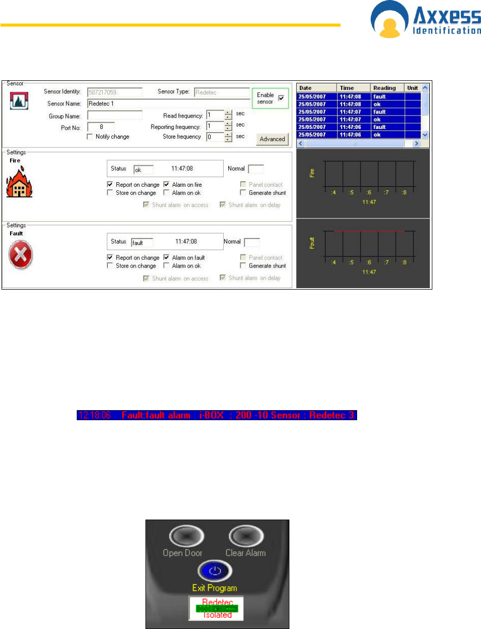
www.axxessid.com
Installation & User Guide
AX200 & IBOX Installation & User Guide – July 10 - 98-
Sensor‟s specifications are displayed at the top of the screen. You could specify how frequent
you would like the sensor to take readings and how often you‟d like the readings to be reported.
All the reported and unreported data will be stored in the log file and can be accessed via the
report section.
If the Alarm on Fault/Fire is ticked, once there is a fire or fault in the unit, an alarm transaction will
be generated and displayed on he main screen. This message will include the I-box and the
sensor‟s name + type and the time of the alarm. The AX200 software now has the ability to send
these alarm messages along with all the necessary information via email.
Isolate
In order to switch on the isolate, click on the advanced button. The output settings are located on
the bottom of the screen. The software will ask you to enter a brief explanation called “permit to
work” before switching on the isolate. The software reports the isolate state by showing a flashing
icon below the controller buttons on the main screen.
Please note that the Isolate is considered an alarm condition so as long as the unit is in isolate
the sensor‟s symbol in the environment screen will remain amber, even if all the other alarms
have been cleared!
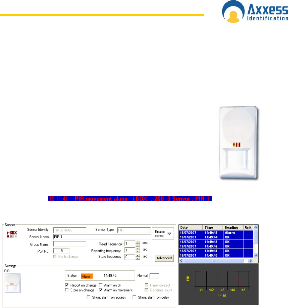
www.axxessid.com
Installation & User Guide
AX200 & IBOX Installation & User Guide – July 10 - 99-
Once you switch on the isolate the isolate light on the FiretecPro unit comes on. Please note that
the isolate command from the software overrides the position of the keys switch.
Note: if the FiretecPro sensor goes off line for any reason, it will lose control over the FiretecPro
unit. This means if the unit has been isolated by the sensor, it will come out of isolate once the
sensor is disconnected. Therefore we strongly recommend using the key switch for isolation
before starting any maintenance work.
PIR
PIR sensors have been designed to detect movements in an adjustable range
of 5 to 15 meters.
PIR sensor is connected directly into one of the free ports on the back of the i-
BOX using the standard sensor cable only. Once the sensor is connected to
the i-BOX a New Device Wizard will appear on the screen. Follow the on-
screen prompts to add the new sensor to the database. To access the settings
for the PIR sensors go to the environment section, select the appropriate i-
BOX from the tree menu on the left hand side and select the PIR sensor.
Once the sensor has been programmed to trigger the alarm on movement, an
alarm transaction will appear on the main screen when the movement is
detected. This transaction will include the I-box name, sensor type and the
type of the alarm.
All the readings from the PIR sensor could be accessed through the Reports section.
The three LEDs on the PIR sensor are colour coded as follows:
PIR Detection: Green/Blue Flash
Microwave Detection = Orange
Alarm = Red
No Movement = Blue (Steady on with short flash)
No Communication = Blue (Fast Flash)
Note: To avoid any potential false alarms:
Make sure the sensor is not under direct sunlight.
Do not mount detectors near heaters.

www.axxessid.com
Installation & User Guide
AX200 & IBOX Installation & User Guide – July 10 - 100-
Open windows may induce false alarms caused by draughts and moving objects.
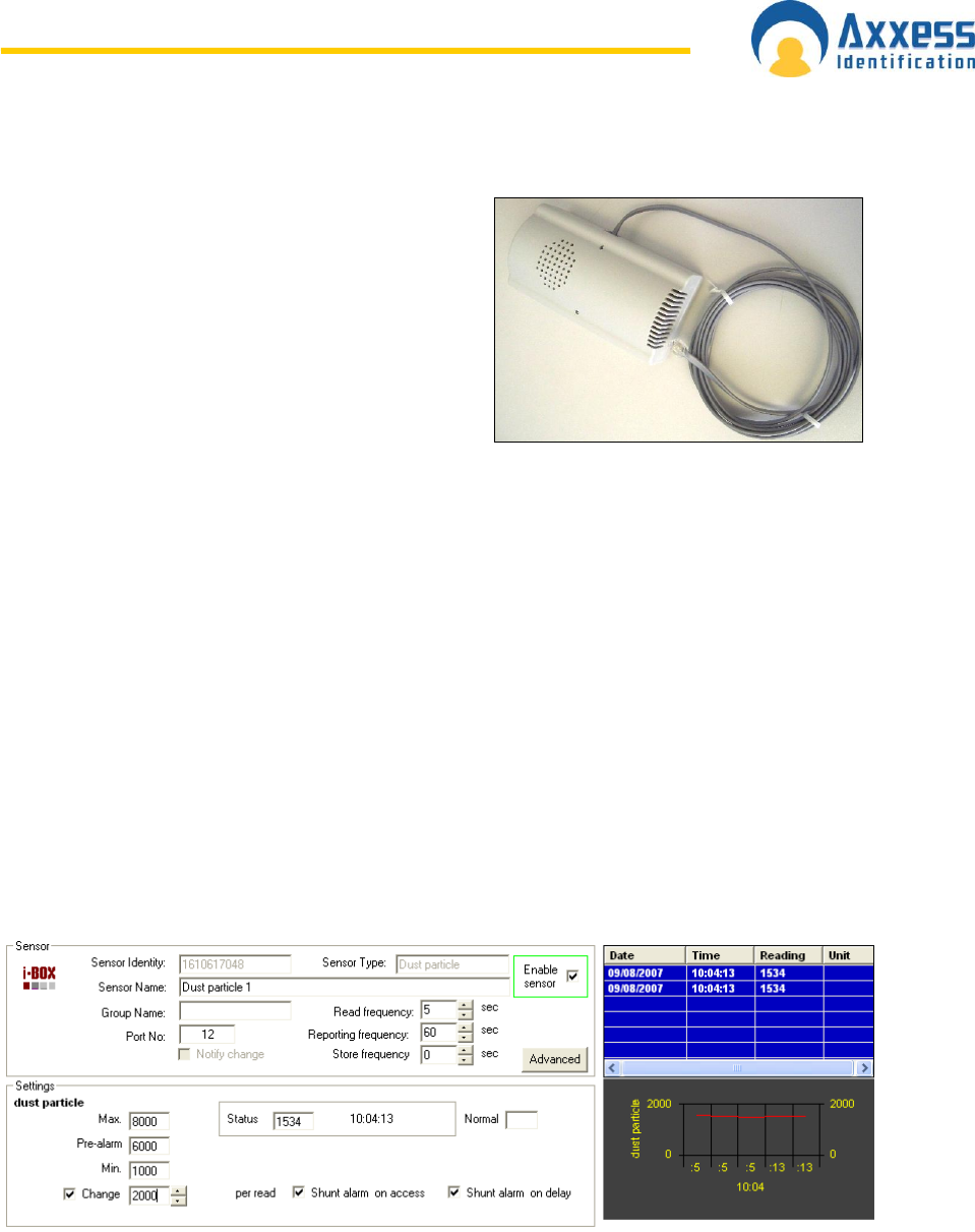
www.axxessid.com
Installation & User Guide
AX200 & IBOX Installation & User Guide – July 10 - 101-
Dust Particle Sensor
Dust sensor has been designed to detect the level
of dust particles in the air. The air is sucked in
through the air inlet on the side and released
through the outlet on the top. Once the air comes in
contact with the sensor the level of dust particles is
measured and reported through the software.
Please note that the dust sensor must be fitted
sideways and the air inlet and outlet should not be
blocked.
Dust sensor is directly connected to the i-BOX
through one of the 14 ports on the back using a standard sensor cable. Once the sensor is
detected by the i-BOX, a new device wizard will appear on the screen. Follow the on-screen
prompts to add the sensor to the database.
Dust sensor settings could be accessed in the environment section. On the main screen click on
the environment button. Select the appropriate i-BOX from the menu on the left and click on the
dust particle sensor.
You may use the default settings by pressing the Auto Setup button at the bottom of the screen;
or you can use alternative settings due to different environmental conditions. Read frequency
indicates how often the sensor measures the level of particles in the air; Reporting frequency
shows how often the reading is reported & Store frequency indicates how often the reading is
stored in the log file. The status reading could be in the range of 1000 to 8500. If you wish to
lower this figure go to the calibration settings by clicking on the advanced button. The status
reading is directly affected by the value of C2. That means by decreasing the value of C2, you
could lower the range of status reading.
By enabling the Change function the software will notify you if there is a sudden change in the
level of dust particles in the air. Define the minimum and maximum limits and press save.
Depending on the environmental conditions the normal reading varies in the range of 1500 to
2500.
If the level of particles in the air exceeds the defined limits, the software will notify the user by
going into the alarm mode. Instantly an alarm transaction will appear on the main screen stating
the date & time and the type of the alarm. All the alarms and routine readings can be observed in
the Reports section.
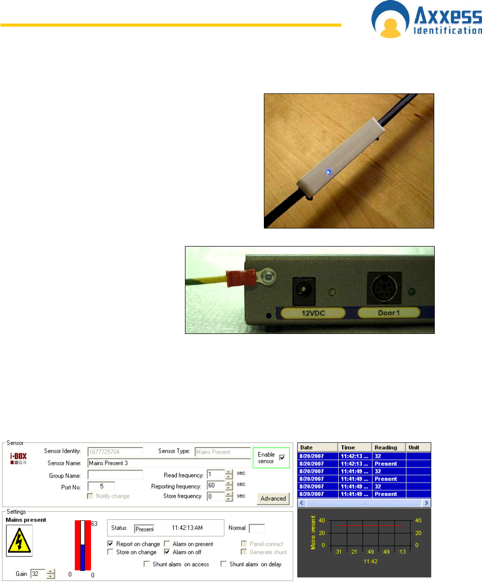
www.axxessid.com
Installation & User Guide
AX200 & IBOX Installation & User Guide – July 10 - 102-
Mains Present Sensor
Mains Present sensor is directly connected to the i-BOX
through one of the 14 ports on the back using a standard
sensor cable. Once the sensor has been detected by the
i-BOX, a new device wizard will appear on the screen.
Follow the on-screen prompts to add the sensor to the
database. Use the cable ties on the sensor to strap the
sensor onto the mains cable.
Please note: in order for the mains
present sensor to work reliably, the i-
BOX must be earthed. Every mains
present sensor is supplied with an
earth cable & plug. Connect the earth
cable to the i-BOX as demonstrated in
the picture and plug the other end into
the electrical socket.
Settings for the Mains Present sensor could be accessed in the environment section. In the main
screen click on the environment button. Select the appropriate i-BOX from the menu on the left
and click on the mains present sensor.
The default settings are displayed in the screen-shot below. You may use alternative settings if
you wish. Remember you have to press “Save” for the new settings to take effect. If at any time
you wish to restore the default settings press the Auto Setup button located at the bottom of the
screen.
Read frequency indicates how often the sensor checks the presence of mains in the cable;
Reporting frequency shows how often the reading is reported & Store frequency indicates how
often the reading is stored in the log file. The Gain value (0<Gain<63) determines the level of
sensitivity of the sensor. You may need to change this value depending on the thickness of the
insulation on the mains cable. As this value increases the sensor becomes more sensitive. In
order to tune the sensor you need to change the value of Gain and try to find the point where the
sensor starts to detect the mains. Try to find the point where you‟re getting Off/Present readings

www.axxessid.com
Installation & User Guide
AX200 & IBOX Installation & User Guide – July 10 - 103-
from the sensor, then add one to whatever the value of Gain is at that moment. For example if the
sensor starts detecting the mains at Gain = 33, then the suitable sensitivity would be Gain = 34.
If “Alarm on off” is ticked in the sensor‟s settings; once the mains in the cable is lost; an alarm
transaction will appear on the main screen stating the date & time and the type of the alarm. All
the alarms and routine readings can be observed in the Reports section.

www.axxessid.com
Installation & User Guide
AX200 & IBOX Installation & User Guide – July 10 - 104-
D T U ( D a t a T r a n s f e r U n i t )
Originally introduced as an AX100 component, the data transfer unit is available as an option, to
transfer database changes from the PC to the controller without the need for a direct PC
connection.
After the initial programming, the AX100 controller can be disconnected from the PC and the
controller will perform all access control functions autonomously. The controller can open and
close doors without computer intervention.
The PC is where all the system configuration and data management is stored. The optional data
transfer unit (DTU) enables the data that has been entered at the PC to be downloaded to the
controller without the need of a physical PC connection.
One data transfer unit can be used for up to 255 controllers, or a total of 16,000 cardholders
distributed over multiple controllers in a single download. E.g. 10 controllers each with 1,600
cardholders can be downloaded in one go, without the need to go backwards and forwards
between the PC and controller. Similarly 255 controllers each with 60 cardholders can be
downloaded to each controller without returning to the PC. Only valid cardholders are
downloaded to the controller.
The Data Transfer Unit is fully plug and play at the controller and PC. The AX200 PC software
allows multiple DTU‟s to be used.
Connecting the DTU
Make sure the COM port settings are enabled in
System Settings → General Settings. Connect the
power supply to the communication cable at the
15 way connector. Plug in the 9 way connector to the serial port of the PC. Start the AX200
software. Connect the DTU to the RJ45 connector, follow the on-screen instructions of the install
wizard.
After configuring the DTU, the following window will appear on the screen. This window contains
the list of the doors that require download.
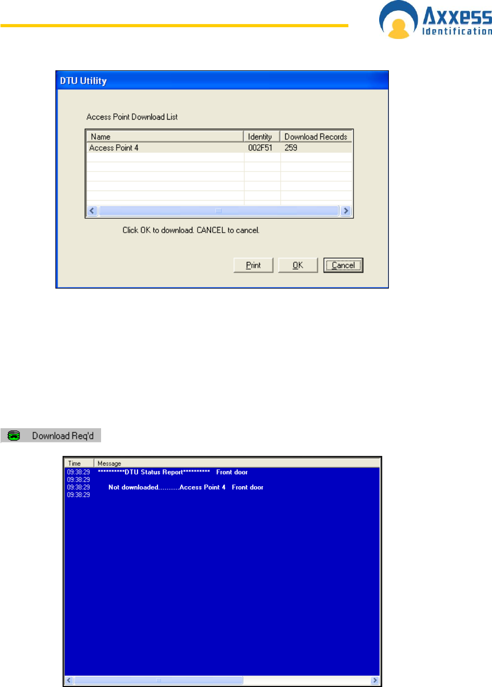
www.axxessid.com
Installation & User Guide
AX200 & IBOX Installation & User Guide – July 10 - 105-
By pressing OK, database changes are automatically downloaded into the DTU. A list of
controllers requiring a download can be printed using the reporting function.
Once the data has been downloaded into the DTU, disconnect and plug the unit into the AX100
controller directly (no cable or power supply is required). The data is now automatically
transferred into the controller. Once downloaded the LED will go to green (completed) or if
flashing green then it is completed but other downloads to controllers are still in the DTU.
Complete downloads to all the controllers until the LED is permanent green. Once complete, go
back to the PC plug in the DTU. This will confirm all the downloads and remove them from the
pending list.
Any outstanding downloads can be viewed by clicking on the green icon.
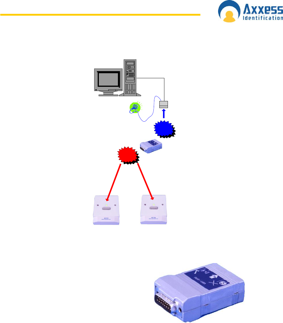
www.axxessid.com
Installation & User Guide
AX200 & IBOX Installation & User Guide – July 10 - 106-
RJ45
Connector
DTU
Power Supply
9 or 25 Way to
COM1 or COM2
Download
data to AX100
Upload data
to the DTU
The DTU is fully automatic without any buttons or other
complicated things to do. Connect the DTU to the PC
and once the information is loaded walk to each door
and insert the DTU in the 15 way connector. The DTU
will automatically know which information has to be
downloaded. If the controller is unknown it will
automatically collect all the data and report this back to
the PC when connected. If a door is forgotten the
download required icon remains visible on the main
screen and by double clicking this, a list is shown with outstanding controllers. The list with
outstanding controllers can also be printed off as a reminder which doors require a download.
When a cardholder is added to the database, downloads are only required to those doors the
cardholder requires access.
Add a New Door using a DTU
New doors can be added by simply plugging the DTU into the controller and returning back to the
PC. This will automatically start the new device wizard, which allows you to add the new
controller. There is no need to pre-program the controller at the PC first; all settings are handled
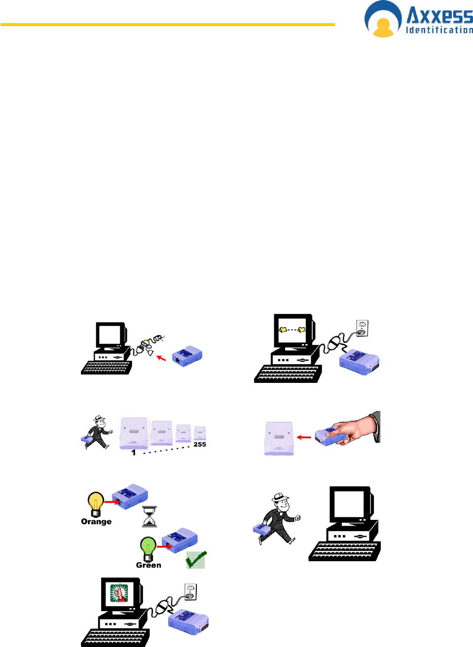
www.axxessid.com
Installation & User Guide
AX200 & IBOX Installation & User Guide – July 10 - 107-
by the DTU. Note: - the DTU must be in the current controller list however it does not need to be
active for this function to work.
Adding Card Formats using a DTU
A single transaction can also be brought back to the PC by inserting the DTU into the controller
and whilst inserted, use a card at the reader. When you return to the PC the transaction will show
on the transaction screen. If it is an unknown card type, it will automatically start the card format
wizard allowing the addition of the card type to the database (subject to technology type).
The DTU does not contain any batteries, which might need replacing. It is powered directly from
the controller and at the PC by the plug-in power supply which connects to the RJ45 connecter
plug.
Data is permanently stored in the DTU without the need for batteries; this means the DTU can
easily be sent in the post to update for instance remote sites. On and offline controllers can be
combined within one system.
DTU Step by Step
1
2
3
4
5
6
7

www.axxessid.com
Installation & User Guide
AX200 & IBOX Installation & User Guide – July 10 - 108-
DTU Operation
1. Start the AX200 software on the PC.
2. Connect the DTU to the serial port on the PC.
3. The auto detect hardware device wizard will start within 10 seconds.
4. Follow the on-screen prompts to add the DTU into the software.
5. Remove the DTU from the PC and plug into a controller.
6. Wait 10 seconds
7. Remove the DTU from the controller and plug it back into the PC.
8. The auto detect hardware device wizard will start within 10 seconds.
9. Follow the on-screen prompts to add the controller.
10. Click on the cardholder button and add new cards as required.
11. Upon exiting the cardholder screen, the new cards will automatically be downloaded to
the DTU.
12. Click OK and wait for the on-screen message for the download to be completed.
13. Remove the DTU from the PC and plug it into the controller.
14. When the cards have been transferred from the DTU to the controller, the LED on the
DTU will turn green.
15. Remove the DTU from the controller and plug it into the PC.
16. The software will report that the download has been completed successfully.
DTU LED Indicators
Blue
DTU Power OK
Blue/Red
Flashing
No Communication
Red
Flashing
Wait
Constant
Error
Orange
Data download in progress
Green
Flashing
Data downloaded to this controller –
data to be downloaded to others
Constant
Data downloaded and complete

www.axxessid.com
Installation & User Guide
AX200 & IBOX Installation & User Guide – July 10 - 109-
Clearing the DTU
This command can be found on the main screen toolbar. If the
DTU has been used for testing purposes with other controllers not
belonging to the customers‟ site, then the DTU will inform you that
there is a new device, until you clear the DTU. Just highlight the
DTU in the current controllers list on the main screen. Now click on
tools on the toolbar and select Clear DTU.
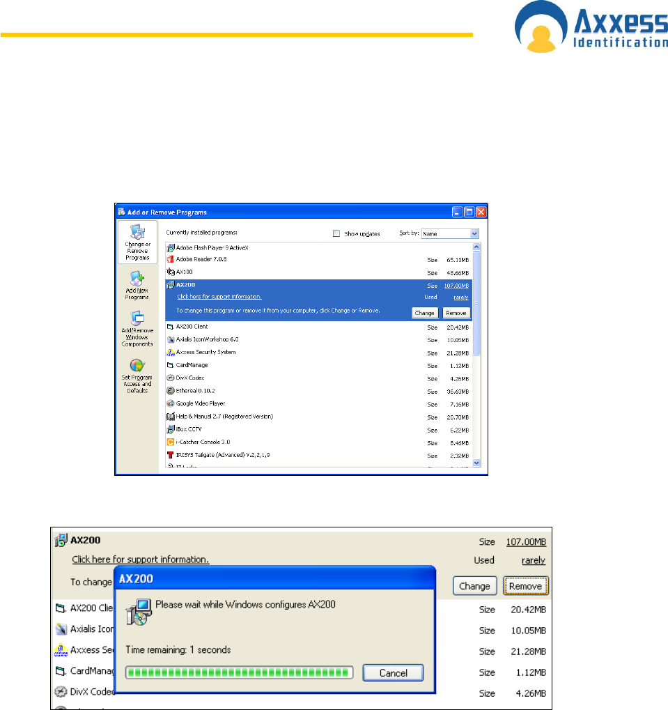
www.axxessid.com
Installation & User Guide
AX200 & IBOX Installation & User Guide – July 10 - 110-
Removing the AX200 Program
To remove the AX200 program from your PC, click on the Windows Start button, select Control
Panel, double-click Add/Remove Programs, select AX200 from the list, select Remove…
The AX200 has now been removed from your PC.

www.axxessid.com
Installation & User Guide
AX200 & IBOX Installation & User Guide – July 10 - 111-
A n t i - Virus
Sometimes the activities carried out by the AX200 software can be disrupted either by the firewall
or the antivirus software which is protecting your PC. This section is intended to provide you with
the solutions to some of the problems caused by the most popular antivirus packages.
If you are trying to configure an SMTP server for e-mail in the AX2000 software, when you do a
test send, you may encounter an error the instant the AX200 connects to the sever; "Email
aborted due to a timeout or other issue". When you click on ok the server disconnects and
does not send the email!
The issue is caused by MacAfee Virus scan Enterprise version 8 or higher.
By default the SMTP port in the AX200 is port 25. The antivirus blocks all mass mail processes
on port 25.
In order to change the antivirus settings, perform the following steps (On the PC that the AX200 is
running):
I. Select virus scan console from the system tray.
II. Select access protection
III. Select the Rule "Prevent mass mail worms from sending email Port 25" and click edit.
IV. Add axid.exe (in lower case) to the excluded process's - note if this is not enabled then
enable it, if more than one process is in the list each process is separated with a comma.
V. Restart the PC
E-mails should now go out correctly.

www.axxessid.com
Installation & User Guide
AX200 & IBOX Installation & User Guide – July 10 - 112-
R e a d e r s
Fingerprint Reader
The Verid + fingerprint verification units are
standalone devices, designed to provide access
control system with instant improved security, or to
act as a means of identity verification in a wide range
of different applications.
The Verid + fingerprint verification units are available
as 3 variants: 1. Verid +, 2.Verid + PIN and 3.Verid +
PROX.
When used in an access control system, Verid + is
installed between the existing PIN device and door
controller, and confirms the identity of the person.
Connection Details
12V input power must be connected to J2 terminal
block located on the rear plate of the fingerprint
reader. Data0 (D0) & Clock (D1) connections on J3
terminal block are wired into Data0 (D0) & Data1
(D1) connections on the AX100 Controller
respectively.
The Power for AXP Proximity reader is taken from J6
block and D0 & D1 wires are connected to J7 terminal block. The required connections to and
from Verid+ are listed in the table below.
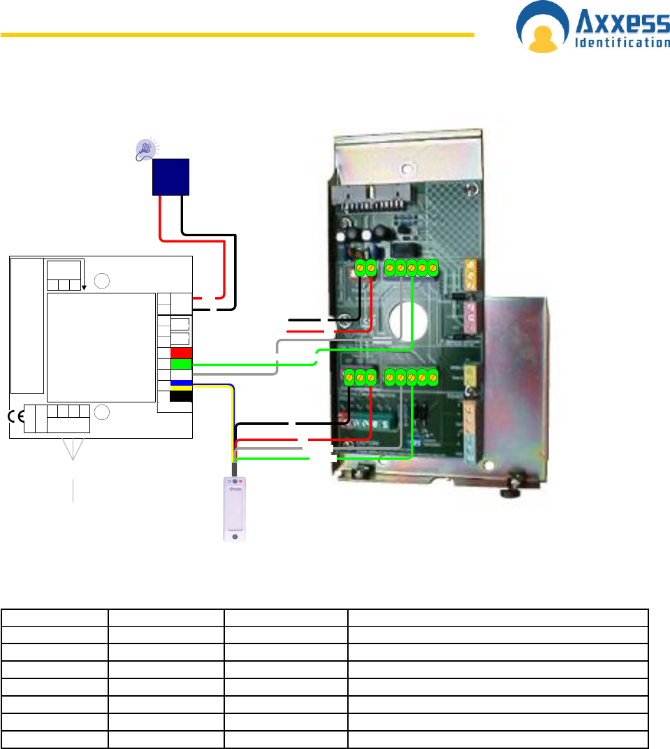
www.axxessid.com
Installation & User Guide
AX200 & IBOX Installation & User Guide – July 10 - 113-
Tel: +44 (0)1793 784002 www.axxessid.com
NO
NC
C
Lock Relay
Gâche
Electrique
To reset the electronic fuse, disconnect
the power, wait 30 seconds and then
reconnect the power.
Pour remettre à
zéro le fusible électronique, débranchez
la puissance, attendez 30 secondes et
puis rebranchez la puissance.
TX
0V
N/A
9 Way FD
RX
3 2 5
RS232 to
PC
max. 15
metres
DC Voltage Only/
Tension CC Seulement
Green/
Vert
= Power OK/
OK de puissance
Red/
Rouge
= wires reversed, re-wire/
les fils se sont inversés
Orange = AC voltage, change PSU/
tension CA, changez le
fourniture d'electricité
Reader wiring connections shown are for
standard AX readers.
Les raccordements
de câblage de lecteur montrés sont pour
les lecteurs standard AX.
Clock (D1) Data (D0)
+12v
0v
Reader/
Lecteur
White
Blue +
Yellow
Red
Black
0V LED D1 D0 +12V
Green
Door
C'tct C REX 0V +12V
Power In/
Puissance
DC>65mA
Power
Supply
+12VDC
+ -
Connection Diagram
AX100 to Verid+
J2
Power Input J3
Door Controller
J7
J6
Power Output
0v
12v
Clock (D1)
Data (D0)
0v
12v
AX200
J2 0V Power Input Power Supply Input: 0V
J2 12V Power Input Power Supply Input: 12V
J3 Clock(D1) Door Controller Output to door controller Clock or Wiegand 1
J3 Data (D0) Door Controller Output to door controller Data or Wiegand 0
J6 0V PIN Power Output Output to external device 0V
J6 12V PIN Power Output Output to external device 12V
J7 Clock(D1) PIN Device Input from PIN-Clock or Wiegand 1
J7 Data (D0) PIN Device Input from PIN-Data or Wiegand 0
Configuring Verid+
Verid+ has been designed to support PIN entry from a variety of devices – track 2 card readers,
proximity readers, and keypad with Wiegand or track 2 outputs water mark and Wiegand readers.
All new Verid+ units are delivered to accept input from Wiegand input device .Verid+ will need to
be configured to expect the appropriate PIN input device. The appropriate data format for the
finger print reader in order to be compatible with the AX200 system is Wiegand 2601. Therefore
the reader connected to Verid+ unit needs to be programmed to have Wiegand 2601 output. To
do this you need to present the appropriate configuration card within 10 seconds of reader start-
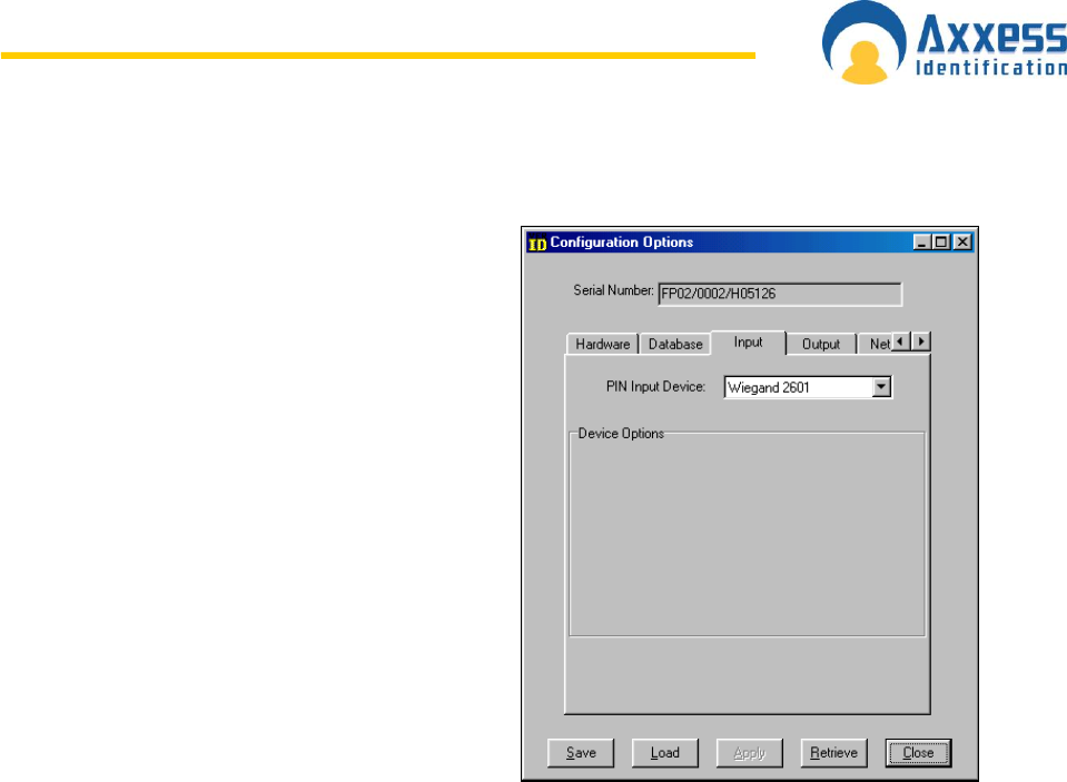
www.axxessid.com
Installation & User Guide
AX200 & IBOX Installation & User Guide – July 10 - 114-
up. Note that the card number should be smaller than 65535 otherwise the card number that
appears on the screen would not be correct.
To program Verid+ to expect Wiegand 2601
format you need to use Verid + software (Win 95,
98) provided with the unit. Use the provided cable
to connect the unit to the serial port on the back of
the PC. Then open the software and click on
Connect in the Connection menu. To enter the
Configuration mode open the Mode menu. The
required password is “Config”. Once in the
configuration mode go to Configuration Options
and make sure that the input and output formats
(under Input & Output tabs) are Wiegand 2601.
You will have more option available to you in the
Supervisor mode (password: SysManager)
Remember that these configurations must be
done on a blank database (you can erase the
database while you’re in the configuration mode.
Just go to the database menu).
Programming a New User
To program a new user make sure that the database in the reader is empty. When you power up
the unit it will automatically enter the Super User mode. When “Add a new User” is displayed
press enter. Select super user if you‟re about to enter the first record. Then Select Global
Settings. The unit will scan your fingerprint 3 times and create a record known as a template. You
will have the option of adding a second template for your user. When “Enter PIN is displayed”
swipe your card or enter a PIN number and press Enter. If “invalid PIN” is shown on the screen
while swiping a card, either the card has not been swiped correctly or Verid+ has not understood
the card format or data signals. RE-swipe the card a couple of times. Then check the wiring and
the configuration settings. You can always go back to the super user mode by holding the cancel
button while swiping a valid card or entering a valid PIN.
Once you‟ve programmed the first user successfully, you can use your valid PIN to unlock the
door through the AX200 system. To set up a cardholder in the AX200 software you need to
choose the correct card format through the Format and Statistics section.
In the Format and statistics go to card matching and swipe your valid card. After the fingerprint
verification the correct card format will appear on the screen.
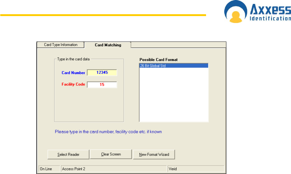
www.axxessid.com
Installation & User Guide
AX200 & IBOX Installation & User Guide – July 10 - 115-
You need to add this format through the New Format Wizard.
Getting Started Quickly
1. Do the connections according to the table provided in the first page.
2. Install the Verid software provided with the unit and connect the unit to the serial port on
the back of the PC.
3. Enter the configuration mode (password: Config)
4. Make sure that the database is empty. (If the database is empty the unit will automatically
enter the super user mode at the start up.) If the database is not empty you can erase it
in the database menu.
5. Under Options → Configuration Options → Input, select Wiegand 2601 from the drop-
down menu. Make sure the out-put is the same.
6. Before exiting the software go to Mode → Start Verification.
7. Once the unit has been programmed to accept Wiegand 2601 format. Power up the unit
and add your first user.
8. In the AX200 software add the correct format through “format & statistics” (26bit Global
Std)
9. Setup a cardholder with the correct card number & card format.
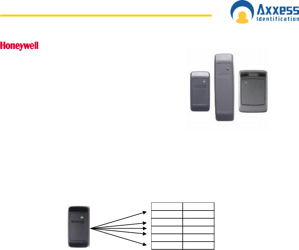
www.axxessid.com
Installation & User Guide
AX200 & IBOX Installation & User Guide – July 10 - 116-
Proximity Readers
Honeywell proximity readers have been designed to be installed
for use with access control systems. The following instructions
outline the connections between the reader and the AX200 access
control system as well as the software configurations that need to
be carried out in order to make the system ready to operate.
How to connect the reader to the host
The reader is supplied with an 18-inch pigtail, having a 6-
conductor cable. To connect the reader to the AX200 system, perform the following steps:
1. If there is a connector on the end of the cable (used during manufacture for testing
purposes), cut it off. Prepare the reader cable by cutting the cable jacket back 1.25
inches and strip the wires 0.5 inch.
2. The reader is connected directly to the AX100 controller. The table below shows the
connections on the AX100 controller and the corresponding wires on the Honeywell
proximity reader.
Colour AX100
Red 12V
Black 0V
White D1
Green D0
Brown LED
When using a separate power supply for the reader, power supply and the AX100 must
have a common ground.
3. Do not connect the Tamper (purple) lead to the AX100.
4. Trim and cover all conductors that are not used.
Software Configuration
Once the reader & the AX100 controller have been connected to the AX200 unit you should be
able to see it on the controllers menu on the right hand side of the main screen. In order to
program a valid card with the ability to have access through a Honeywell proximity reader you
need to choose the correct format.
1. On the main screen click on the Format & Statistics.
2. Under the Card Matching tab press “Select Reader”
3. Choose the appropriate reader from the list and present the card to the reader
4. The software will automatically display the card number, Facility Code and the possible
card formats.
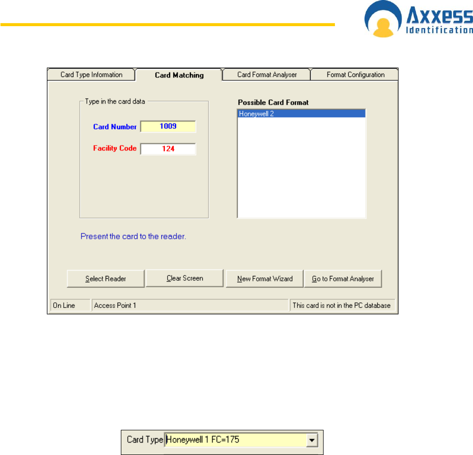
www.axxessid.com
Installation & User Guide
AX200 & IBOX Installation & User Guide – July 10 - 117-
5. The most common card formats associated with Honeywell proximity readers are
Honeywell 1 & 2 which are included in the default database.
6. If the format displayed on the screen is correct, press New Format Wizard.
7. Follow the on-screen prompts to add the new card format.
8. Once the correct card format is added, go to the cardholder screen and add your new
card and choose the correct card type.
9. To be able to see other card formats in the card type menu you need to enable “Multiple
Card Formats” under System Settings → General Settings.
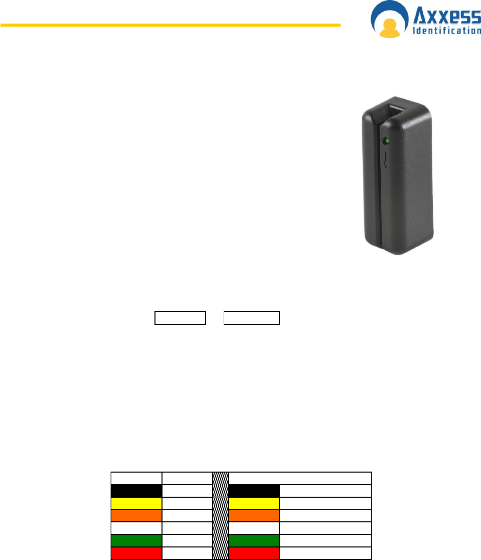
www.axxessid.com
Installation & User Guide
AX200 & IBOX Installation & User Guide – July 10 - 118-
AXM Readers
The AXM magstripe readers provide high performance and reliability for high
security access control. AXM readers are completely weatherproof and
suitable for in-door and out-door applications.
Output Type
Wiegand 50 bit (Type 5)
Other output formats available for most OEM applications
Magstripe cards supplied by Axxess Identification are encoded in order to work
with 77 format. In this type of encoding the first 7 digits are used to calculate
the card number and the rest makes up the facility code. For example if the
card has a 10 digit number; using the 7 7 format, the first 7 digit will form the
card number and the last 3 digits will form the facility code. If the number of digits is less than 7
then the facility code will be zero.
77
0000FFF CCCCCCC
All the standard cards supplied by Axxess ID are recognized by the AX200 software and ready to
be programmed. If you have not purchased your card from Axxess Identification, you may have to
use the card matching function and activate the appropriate card format in order to make the card
valid. Card matching feature is available in the Format & Statistics section. For more information
please refer to the Format & Statistic section on this manual.
Connection Details
The following table explains the connections between the AXM reader and the AX100 controller:
Colour AX100
Black 0V Black 0VDC Signal Gnd
Yellow Buzzer Yellow Buzzer Control
Orange LED Orange Green/Yellow LED
White D1 White Data (Weigand 1)
Green D0 Green Clock (Weigand 0)
Red 12V Red VDC Supply (5-18)
Reader
Yellow and Orange wires are both connected to the LED socket on the AX100 controller.
You may disconnect the yellow lead if you wish to disable the buzzer.
DO NOT connect the purple wire as it is only used for programming.
Blue wire is for card present indication. (DO NOT connect)
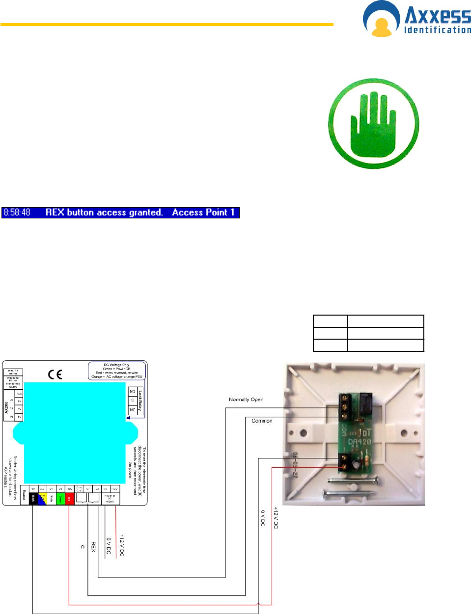
www.axxessid.com
Installation & User Guide
AX200 & IBOX Installation & User Guide – July 10 - 119-
Proximity Request to Exit
The proximity REX detects the hand within the range of approximately
5cm. Once the hand has been detected, the relay goes off and closes
the connection between the relay board and the request to exit terminal
on the AX100 controller. The Proximity REX acts exactly like the REX
Button and once the request to exit has been granted, the appropriate
transaction appears on the main screen stating the time and the name of
the access point. Please note that this product is based on infrared
technology; therefore other infrared light sources may affect the
performance of this detector.
Technical Details
Power Requirement: 10-14 VDC (15mA Quiescent. 35mA Operated)
Changeover relay contacts rated 30VDC Max. 1A non-inductive.
The diagram below shows the connections between the proximity
REX and the AX100 controller.
AX100 Proximity REX
C COM
REX NO

www.axxessid.com
Installation & User Guide
AX200 & IBOX Installation & User Guide – July 10 - 120-
Product Maintenance
Flood Sensor – part number IC-FS-FLD
The flood sensor is supplied with 5 metres of water
sensing cable and is connected to an i-BOX
environmental monitoring unit with the 2.5 metre
FCC68 terminated lead. The flood sensing cable is
held in position using the 15 cable clips supplied.
For correct operation the flood sensor should be
calibrated to ensure the correct amount of moisture
is detected to indicate a flood alert.
If the calibration is incorrect then the sensor can
generate alarms based on a minimal amount of
moisture, leading to false alarms, or not generating
an alarm when there is a flood.
It is recommended that annually or after a flood alarm the flood sensor is checked, using this
guideline.
The flood sensor cable has been designed to be located where water or flooding is most likely to
occur. Typically the flood sensor cable will be along the floor, next to a wall or circling valuable IT
equipment. Some applications may require a more creative approach, for example, if monitoring
for leakage in a drop ceiling, you might run the flood sensor cable along a plastic trough or inside
a collection tray positioned to collect dripping water (eg. from an air conditioning unit). If water
runs along pipes, you could coil the flood sensor cable around the pipe so that water is detected
as it runs down the pipe.
The maintenance procedure comprises of four categories – inspection, check, calibrate and test.
Table FSC 1.1 should be completed for each sensor, the table can be photocopied and retained
for future reference.
1. Inspection
a. Check the flood sensor back box and faceplate are fitted securely. In the event
that this is not correctly fitted, disconnect the sensor from the I-BOX and ensure
that the back box is securely fitted and the faceplate is attached with 2 x 2.5mm
screws.
b. Visually check that the flood sensor back box is fitted above the level that the
water will rise to - not that the sensor cable is above a false floor and the flood
sensor device is below the false floor. CAUTION: The flood sensor cable has
been designed to be located where water or flooding is most likely to occur. The
actual flood sensor device is NOT designed to come into contact with water.
Mount the flood sensor device (i.e. the back box) to a vertical surface like a wall
or pillar using the mounting screws provided. As the flood sensor device uses
mains power via 12 volt power adapter, it is NOT appropriate to allow the device
to be located where it may be submerged under water or come into contact with
water for any length of time.
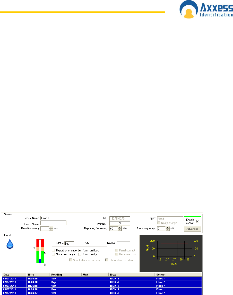
www.axxessid.com
Installation & User Guide
AX200 & IBOX Installation & User Guide – July 10 - 121-
c. Visually check that the sensor cable does not have any visible damage. The fibre
braid outer sheath needs to be intact. Inside the braid are 6 cores: 4 are colour
coded (red/yellow/black/blue) and 2 are polymer coated with white fibre braid.
Check for damage to the outer braids and if the inner cores are exposed the
flood sensing cable should be replaced.
d. Calibration of the flood sensing cable is based on a 5 metre length of sensor
cable. Ensure that the cable is 5 metres in length and terminated with a rubber
cap at the end. If the cable is cut short and / or the termination cap is missing the
sensor cable should be replaced.
e. The flood sensing cable should be fitted in position using the cable clips
provided. These clips allow the sensor cable to be located where required but do
not clamp onto or over tighten the sensing cable as this will impair the reliability.
Cable clips are provided to fit the flood sensor cable, and are designed to be a
“loose” fit. When fitting the sensor cable do not clamp or squash the cable. Avoid
sharp corners, tight bend or folds in the cable as this will produce false alarms.
Check that the sensor cable is suitably fitted and repair / replace as necessary.
f. The flood sensing cable should be free from chemicals and other containments
such as oil, paint or bleach, these chemicals will impede or corrode the sensor
operation. If the cable has been contaminated replace the sensor cable.
g. The flood sensor should not be fitted to a moving or vibrating device. Check that
the sensor is not fitted to a vibrating device, and refit / move as necessary.
2. Check
a. LED check: The LED on the front of the flood sensor device will indicate the
following colours during the test, check that the correct LED indication is
displayed on the front of the device.
Green – Normal dry
Red – Alarm wet
Amber – Drying
b. Check and record the standard reading for the sensor. Typically this is around
165 to 175. In the software select the environment screen and select the I-BOX
and the flood sensor that is being checked. In this screen shot the reading is
169.
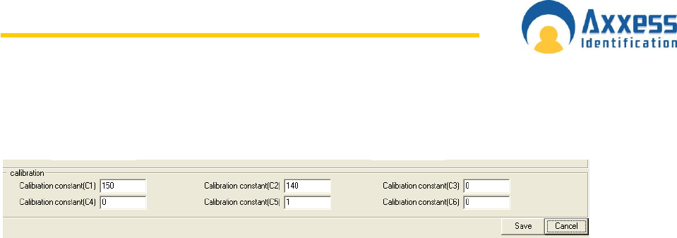
www.axxessid.com
Installation & User Guide
AX200 & IBOX Installation & User Guide – July 10 - 122-
3. Calibrate
a. In the flood sensor screen, click on the advanced button and record the current
calibration settings. C1 to C6.
The default values are:
C1 = 150
C2 = 140
C3 = 0
C4 = 0
C5 = 1
C6 = 0
4. Test and Calibrate
Before testing the flood sensor it is essential to notify all persons that may
receive the alarms, that a test is about to take place. This should include ARC
(alarm receiving centre), E-mail contact for alarms, SNMP management systems
for alarms. Check the advanced section of each sensor to be tested and take
suitable steps to avoid the test causing undesired results.
a. To test the flood sensor place a section of the sensing cable onto a tray or
bucket, so that when water is added it will not damage the surrounding area.
Measure out an amount of water, this amount should be the required amount that
is expected to be present for a flood alarm to be generated. A generic volume of
water is typically 200ml over a 120mm length of the sensing cable. Pour the
water onto the sensing cable, taking care to ensure that the water enters the tray
or bucket and avoid damage to the surrounding area. As the water soaks into
the sensor cable the water reading will rise and generate an alarm. There may be
a delay of up to 30 seconds as the water soaks in. If a smaller amount of water
is used and the sensing cable has not generated an alarm, make a note of the
reading and adjust C1 and C2 so that the reading falls bellow C2.
C1 = Dry Zone (Acceptable range 120 – 180)
C2 = Wet Zone (Acceptable range 120 – 180)
b. Record the final values.
c. Drying Time - Remove the surplus water and allow the sensor cable to dry, which
may take a couple of hours and check that the reading is back to around 170.
d. ARC Response - When an alarm receiving centre has been configured to receive
the alarms, when the flood alarm was generated it is essential to confirm with the
ARC that the correct sensor was identified and that the appropriate action to be
taken is confirmed.
e. E-mail Response - When E-mail alerts have been configured, ensure that all
personnel have been notified of an alarm correctly.
f. SNMP Traps - When SNMP traps have been configured to generate flood alerts,
after the test is complete, ensure that the SNMP manager has received the alert
correctly.

www.axxessid.com
Installation & User Guide
AX200 & IBOX Installation & User Guide – July 10 - 123-
Flood Sensor Maintenance Checklist - Table FSC 1.1
General
Date
Sensor name
Sensor ID
Read Freq.
Reporting Freq.
Port No
Enabled
Yes / No
1. Inspection
a. Is the back box and faceplate secure
Yes / No
Comments
b. Is the back box above the level of the water when flooded
Yes / No
Comments
c. Visual check is sensor cable OK
Yes / No
Comments
d. Inspect and check correct termination cap at sensor end
Yes / No
Comments
e. Sensor cable correctly secured and connected
Yes / No
Comments
f. Ensure the sensor cable is free from containments
Yes / No
Comments
g. Ensure the sensor is not fitted on a vibrating surface
Yes / No
Comments
2. Check
a. Green LED check = Normal
Yes / No
Red LED check = Alarm / Wet
Yes / No
Amber LED check = Drying
Yes / No
b. What is the standard reading value (Typical = 170)
3. Calibration
Record calibration settings at start of check
C1
C2
C3
C4
C5
C6
4. Test and Calibrate
a. Flood sensor generates alarm
Pass / Fail
Record calibration settings at end of check
C1
C2
C3
C4
C5
C6
c. Confirm sensor has dried
Yes / No
Comments
d. ARC - where applicable confirm correct operation.
Yes / No
Comments
e. E-mail - where applicable confirm correct operation.
Yes / No
Comments
f. SNMP - where applicable confirm correct operation.
Yes / No
Comments
Tested By
Date
Signature

www.axxessid.com
Installation & User Guide
AX200 & IBOX Installation & User Guide – July 10 - 124-
Product Conformities

www.axxessid.com
Installation & User Guide
AX200 & IBOX Installation & User Guide – July 10 - 125-
