Main Improvements Within APZ AXE 810 Chapter 3
User Manual: AXE 810 Chapter 3 APZ
Open the PDF directly: View PDF ![]() .
.
Page Count: 19

Improvements Within APZ
Chapter 3
This chapter is designed to provide the student with knowledge
about the main changes within the APZ system. The chapter
describes important improvements within all different areas of
APZ, not only the Central Processor.
OBJECTIVES:
Upon completion of this chapter the student will be able to:
• account for improvements in capacity in APZ 212 33
• account for improvements in capacity and footprint for all
types of regional processors such as RPP, RPG, EMRP and
RP
• account for improvements in the APG40.

AXE 810 Delta
EN/LZT 123 6389 R1A
Intentionally Blank

3 Improvements Within APZ
EN/LZT 123 6389 R1A – i –
3 Improvements Within APZ
Table of Contents
Topic Page
CENTRAL PROCESSORS, CP.............................................................1
CAPACITY......................................................................................................................1
HARDWARE...................................................................................................................1
NEW HARDWARE .........................................................................................................4
OTHER NEWS AND IMPROVEMENTS ........................................................................4
COMPATIBILITY ............................................................................................................5
REGIONAL PROCESSOR, RP .............................................................6
RPP, PCI BUS BASED REGIONAL PROCESSOR ..............................7
THE BASIC CONFIGURATION .....................................................................................7
THE MODEM CONFIGURATION ..................................................................................8
THE PMC CONFIGURATION ........................................................................................8
THE EPSB, ETHERNET PACKET SWITCH BOARD....................................................9
APPLICATIONS..............................................................................................................9
RPG .....................................................................................................11
EMRP...................................................................................................12
APG40 .................................................................................................13
SYSTEM CAPABILITIES..............................................................................................13
THE HARDWARE.........................................................................................................14

AXE 810 Delta
– ii – EN/LZT 123 6389 R1A
Intentionally Blank
3 Improvements Within APZ
EN/LZT 123 6389 R1A – 1 –
CENTRAL PROCESSORS, CP
CAPACITY
The main improvement within the CP area is a new Central
Processor referred to as APZ 212 33. It is basically the same
hardware as APZ 212 30 but with some improvements.
Increased clock speed and the removal of some internal
bottlenecks are the two main reasons for the improved capacity.
The capacity increase from APZ 212 30 to 212 33 is some 70%
and the first field trials of the system will be during end of year
2000.
A completely new central processor is being developed at the
same time. The name will be APZ 212 40 (not part of AXE 810)
and it will be the first CP from Ericsson built with a commercial
micro processor. By using a commercial CPU, the hardware
development of external CPUs can be followed and Ericsson
does not need to keep up with this pace (doubled capacity every
18 month as in Moore’s law). The price for the processor can
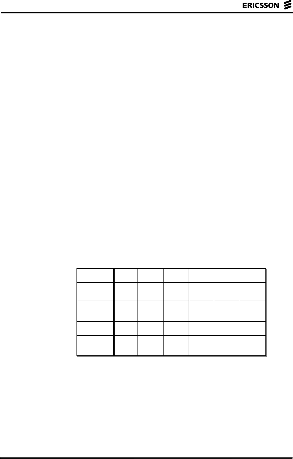
also be reduced with this solution. The capacity comparison
between all available processors can be seen in the figure below.
Please note that the capacity comparison is only valid within
this figure and cannot be used to compare, for example, a CP
with an RP.
212 11 212 20 212 25 212 30 212 33 212 40
Relative
Capacity
141.7142342
DS Memory
(M word)
228 1532 252 4096 4096 8000
Power (W) 1750 800 60 470 470 510
Number in
Service
3000 4500 1000 500 - -
Figure 3- 1 Capacity of different APZ versions
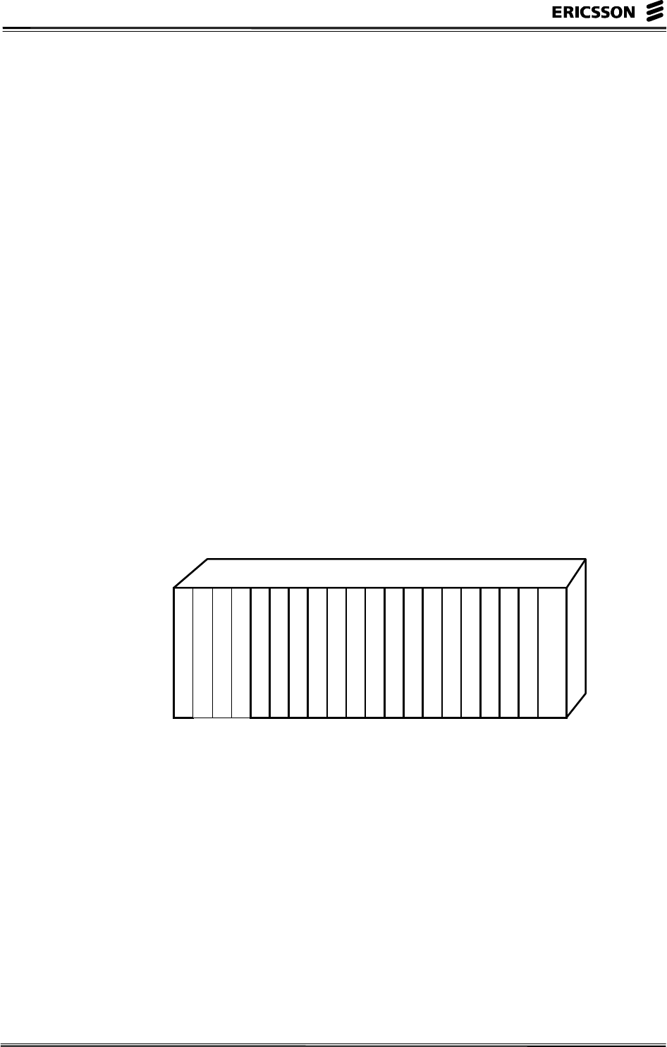
HARDWARE
The hardware of APZ 212 33 is on high level exactly the same
as the hardware in APZ 212 30. The figure below gives an
overview of the cabinet.

AXE 810 Delta
– 2 – EN/LZT 123 6389 R1A
Front View Side View
CPU-A
CPU-B
RPH-A
FAN FAN FAN
FAN FAN FAN
FAN FAN FAN
FAN FAN
FAN FAN
FAN FAN
CPU-A
CPU-B
RPH-A RPH-B
600 mm 800 mm
1800 mm
Figure 3- 2 The APZ 212 33 cabinet
The CPU Subrack
On a subrack level, the hardware of the CPU Subrack looks like
in the figure below.
MAU
STUDI-0
STUDI-1
STUDI-2
STUDI-3
IPU
STUDI-4
STUDI-5
STUDI-6
STUDI-7
SPU
POWC (MAI)
POU
Figure 3- 3 The CPU Subrack
There are basically three processor boards:
• Instruction Processor Unit (IPU)
• Signal Processor Unit (SPU)
• Power Control Unit (POWC) including the Maintenance
Interface (MAI)
There is one power unit (POU) in each subrack. The MAU,
Maintenance Unit, is only present in the B-side (CP-B) as there
is one MAU per CP pair. The eight slots for Data Store boards
(STUD, Storage Unit Data) can either be of DRAM or SRAM
type. In both APZ 212 30 and in 212 33 there are three different
types of boards that can be used:
3 Improvements Within APZ
EN/LZT 123 6389 R1A – 3 –
• SRAM with 32 MW 16 bit (fast)
• DRAM with 512 MW 16 bit (slower)
• SDRAM with 1025 MW 16 bit (slower)
Note that it is not possible to mix DRAM and SDRAM in the
same CPU subrack. Further, the maximum number of SDRAM
boards is 4, since the IPU addressing system only handles up to
4 GW 16. However, the hardware can have some SRAM boards
for increased speed. In APZ 212 33, there is an extended IPU
cache memory of 8 MW 16 bit so the usage of SRAM only
increases the capacity with a few percent.
On the IPU board, a data cash memory has been implemented,
called L2CD, with the size of 8 MW 16.
The empty slot in the right part of the subrack is reserved for a
BRU board (Bus Recording Unit) which can be used to find
complicated hardware faults in the CP.
The RPH Subrack
The boards inside the RPH subrack can be seen in the figure
below.
RPIO
RPBI-P 0 / RPBI-S 0
POU-R
RPBI-P 1 / RPBI-S 1
RPBI-P 2 / RPBI-S 2
RPBI-P 3 / RPBI-S 3
RPBI-P 4 / RPBI-S 4
RPBI-P 5 / RPBI-S 5
RPBI-P 6 / RPBI-S 6
RPBI-P 7 / RPBI-S 7
RPBI-P 8
RPBI-P 9
RPBI-P 10
RPBI-P 11
RPBI-P 12
RPBI-P 13
RPBI-P 14
RPBI-P 15
Figure 3- 4 The RPH Subrack
The board to the left in the subrack is the RPH interface board
(RPIO). Inside the RPH, there is a possibility to mix between
parallel and serial RP bus. The parallel bus is used in BYB 202
and is a slower bus. The following alternatives are available:
• Up to 16 RPBI-P boards for connection of 2 parallel RP
busses to each board (totally 32 RP bus branches with 32
RPs on each branch).
• Up to 8 RPBI-S boards for connection of 4 serial busses to
each board (totally 32 bus branches with 32 RPs on each
branch).

AXE 810 Delta
– 4 – EN/LZT 123 6389 R1A
• Mixture of boards for serial or parallel RP busses but the
total number of bus branches cannot exceed 32 (1024 RPs)
NEW HARDWARE
To upgrade form APZ 212 30 to the new APZ 212 33, only the
two boards IPU and POWC have to be changed.
OTHER NEWS AND IMPROVEMENTS
The hardware of APZ 212 33 is prepared for a new high-speed
data bus that will be used in the future for various functions. The
bus is referred to as IPN, Inter-Platform Network, and it is a
high-speed Ethernet operating at 100 Mbit/s in the first releases
and then 1 Gbit/s. The system is duplicated for reliability
reasons. The IPN will be available when the new software APZ
11.0 is released (more about APZ 11 in Chapter 5). The IPN
will be used for:
• Communication between the CP and the APG. For example,
the high-speed bus makes reload faster. This will be the first
use of IPN available already in APZ.
• Communication between AXE and AXD 301 as part of
ENGINE (hybrid system)
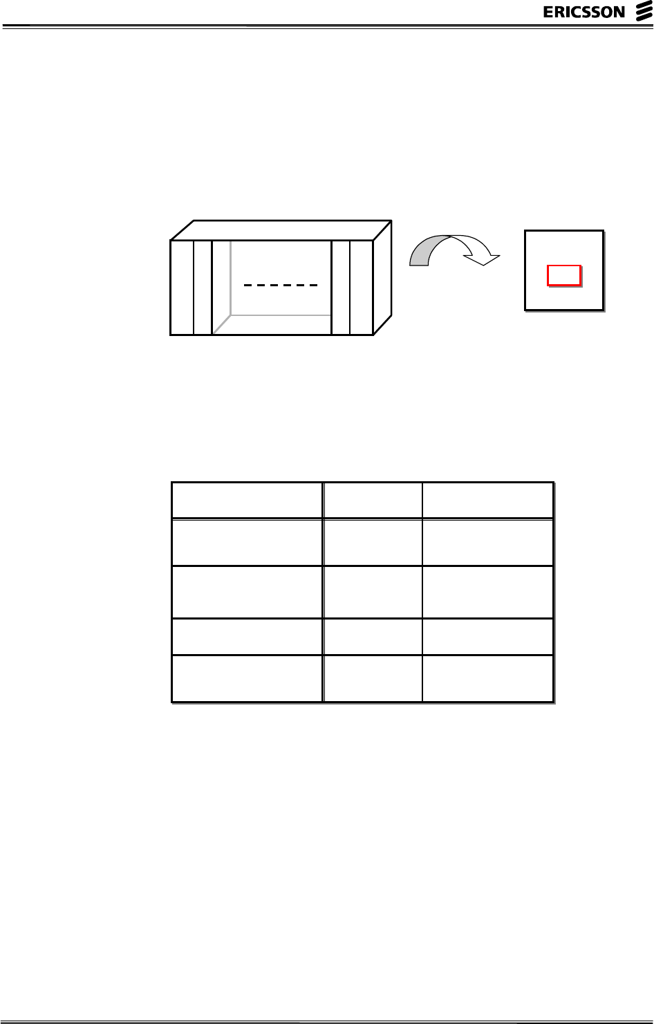
The figure below shows the main principle of the IPN. Please
note that the hardware in the figure shows some examples of
usage of IPN.
APZ 212 33
100 Mbit/s Ethernet
APG AXD
301
IPN
APG
Figure 3- 5 The IPN, Inter-Platform Network
The APZ 212 33 needs, as already mentioned, new software for
supporting the IPN. It also needs new hardware:

3 Improvements Within APZ
EN/LZT 123 6389 R1A – 5 –
• One position in the RPH subrack (next to the POU-R board)
is equipped with the IPN Ethernet switch (IPNX). This is an
8 port 100BaseT Ethernet Switch used for interconnecting
all IPN equipment.
• An empty slot in the RPH subrack is equipped with the IPN
Interface Board (IPNA).
• The SPU, IPU and the MAU board also needs hardware
upgrades.
COMPATIBILITY
The APZ 212 30 and the new APZ 212 33 are compatible with
each other in many different respects:
• The same Data Store boards (STU) can be used.
• The CP is compatible on binary code level meaning that the
same load file can be used on both machines. Notice that
some additional blocks for the L2CD are needed.
• The same operator interface is used meaning no additional
training. (Only three new commands are existing: LADCC,
LADCP & LADCL).
AXE 810 Delta
– 6 – EN/LZT 123 6389 R1A
REGIONAL PROCESSOR, RP
There will be a completely new Regional Processor available for
the new GEM based boards (GS, ET155, ECP and TRA boards).
This processor will be integrated on the board and the name will
for that reason be RPI, Regional Processor Integrated.
RP4
Device
Device
RP4
Device board
RPI
Figure 3- 6 Integration of RP
The processor will be more powerful and decrease
manufacturing costs for Ericsson (which can result in a lower
price to our customers). The table below compares the old RP4
with the new RPI.
RP4 RPI
Relative Capacity 1 16
Processor Ericsson,
5 MHz
PowerPC,
80 MHz
Device bus EM-bus Board internal
Operating
System
Ericsson OSE Delta
Figure 3- 7 The new RPI compared with the older RP4
The new RPI will only be used in the GEM subrack which
means that the GDM subracks, holding ET devices and RPG,
will still use the “old” RP4 for some communication between
the CP and the devices. There are no changes in RP capacity for
the RP4 in the GDM subracks.

3 Improvements Within APZ
EN/LZT 123 6389 R1A – 7 –
RPP, PCI BUS BASED REGIONAL PROCESSOR
The RPP is a new type of regional processor that opens up AXE
for new types of data communication possibilities. This will be
particularly important when migrating from existing 2:nd
generation mobile networks (e.g. GSM) to 2.5 generation
mobile networks based upon GPRS and EDGE. A general
demand for more powerful processors is also a reason for
developing the new RPP platform. The RPP has existed some
time in the GDM hardware of BYB 501 but is now part of AXE
810.
PCI, which stands for Peripheral Component Interconnect, is an
interconnect system between a micro processor and attached
devices in expansion slots. By using PCI, a computer can
connect both the new PCI cards and at the same time support
ISA cards (Industry Standard Architecture).
The RPP is based upon a 333 MHz PowerPC and a number of
DSPs (digital signalling processors) which will be used for
bit/byte stream oriented protocols such as modems, echo
cancellation, speech coding and similar protocols/functions.
There are basically three different configurations of RPPs which
will be used by different applications:
• a basic configuration
• a modem configuration
• a PMC configuration (PCI Mezzanine Card)
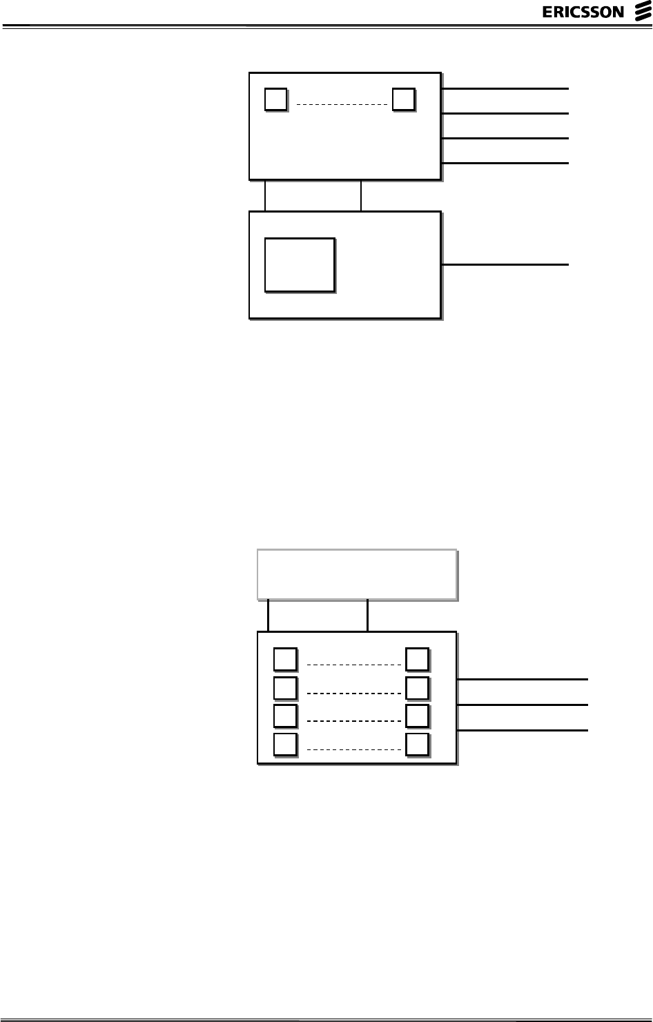
THE BASIC CONFIGURATION
A basic RPP configuration include 8 x DSP as well as 2 x DL2
interfaces of 2 Mbit/s via the back plane. This configuration
needs two slots in the GDM-H subrack. If the Ethernet switch is
used (EPSB), the GDDM-H subrack is needed and in that case it
need 60 mm of space in the subrack. The figure below shows
the main parts of an RPP.
AXE 810 Delta
– 8 – EN/LZT 123 6389 R1A
DL2 (2 Mbit/s)
RP Bus (RPB-S)
M-Bus
PCI bus
2 x 100 Base-TX
I/O Board
CPU Board
Micro
Processor
333 MHz
8 x DSP (66 MIPS)
2 Mbit/s
DL2 (2 Mbit/s)
18
Figure 3- 8 The basic configuration of the RPP
THE MODEM CONFIGURATION
This configuration has 32 x DSP and 3 x DL2 interfaces. Each
DSP can process 66 MIPS making it suitable for modem traffic
or protocol conversions. The protocol implemented determines
the number of MIPS needed and in that way the number of
potential users per RPP. Please study the figure below.
DL2 (2 Mbit/s)
DSP Board
8 x DSP (66 MIPS)
18
8 x DSP (66 MIPS)
916
8 x DSP (66 MIPS)
17 24
8 x DSP (66 MIPS)
25 32
DL2 (2 Mbit/s)
DL2 (2 Mbit/s)
PCI bus
CPU Board
2 Mbit/s
Figure 3- 9 The modem configuration of the RPP
THE PMC CONFIGURATION
This configuration is used when a standard PCI card should be
included. The configuration includes a PMC carrier board which
can host externally sourced PMC cards. This configuration
needs 80 mm of space in the GDM-H subrack.

3 Improvements Within APZ
EN/LZT 123 6389 R1A – 9 –
THE EPSB, ETHERNET PACKET SWITCH BOARD
The EPSB is a non-blocking Ethernet switch which can be used
to create a local data network between RPPs. EPSB is both
selflearning and unmanaged. The core of the board is the switch
and the interfaces as can be seen in the figure below.
13 x 10Base-T
(10 Mbit/s Ethernet)
EPSB Board
1 x 100Base-TX
(100 Mbit/s Ethernet)
Front Back
2 x 100Base-TX
(100 Mbit/s Ethernet)
Figure 3- 10 The Ethernet Packet Switch Board
The EPSB can be used to create a high-speed communication
path between the RPPs within the same exchange. By having
that possibility, almost any type of local network can be created.
The figure below shows an example.
RPP
RPP
EPSB
RPP
RPP
EPSB
ETC GS
CP
DL2 Ethernet
Figure 3- 11 Example of usage of the EPSB boards and internal
Ethernet connections between them
APPLICATIONS
The RPP will be used for applications where high processing
power is needed or where protocol conversion is needed:

AXE 810 Delta
– 10 – EN/LZT 123 6389 R1A
• GPRS Packet Control Unit (PCU)
This unit is located in the Base Station Controller and
handles the packet data to and from the mobile subscribers.
• IWF functions within GSM and TDMA
The Inter-working Function is a protocol converter. A
special mobile data protocol is terminated in the IWF which
is located in the MSC.
• High-Speed Link Signalling Terminal
In some applications, there is a need for a signalling link
with a bit rate of 2.048 Mbit/s. One such signalling link is
handled by one RPP.

3 Improvements Within APZ
EN/LZT 123 6389 R1A – 11 –
RPG
The RPG (Regional Processor with Group Switch Interface) is
today used in a many different applications. The main
application area is for signalling protocol handling such as SS7,
V5 and V3 signalling. The current version of RPG is referred to
as RPG2. A new RPG, consequently referred to as RPG3, will
be released as part of AXE 810. The main characteristics of
RPG are:
• 3 times as powerful as RPG2
• half the size
• same power consumption
The heart of the RPG is a 200 MHz PowerPC and 32 Mbytes of
memory. The RPG3 also has 8 Mbytes of Flash memory for pre-
load of software as well as a DSP (Digital Signal Processor). A
picture of the new RPG3 can be seen below.
Figure 3- 12 RPG3
Ethernet connections from the PRG3 board will not be used
initially but are used to prepare the hardware for clustering of
RPGs. Internal communication between the RPGs in the cluster
will be possible.
The capacity of RPG3 makes it possible to connect 4 x 64 kbit/s
SS7 signalling links to every RPG3 for all traffic mixes. In case
of mobile applications, the Transceiver Handler is based upon
the RPG platform. The RPG3 will be able to handle 32
transceivers instead of 24 with RPG2.
The RPG3 requires APZ 11.0. Both RPG2 and RPG3 may be
used within the same magazine. However, it is not possible to
use a RPG3 as a spar part for RPG2.

AXE 810 Delta
– 12 – EN/LZT 123 6389 R1A
EMRP
The EMRP is mainly used in the subscriber switch of AXE and
in older types of radio base stations. Lately, a new access
product was released: the ENGINE Access Ramp. This product
contains a new EMRP referred to as EMRPI which is 16 times
more powerful than the EMRP4. The EMRPI is based upon a
PowerPC running at 50 MHz with a 16 Mbytes memory.
3 Improvements Within APZ
EN/LZT 123 6389 R1A – 13 –
APG40
APG40 is the name of the new I/O system in AXE. It will
replace not only the existing IOG20 but also the AP platform
(Adjunct Processor). It will also be the platform for the element
manager. The main driver behind the development of a new I/O
platform is increased capacity demands and standardisation of
operating system and hardware. The latter giving access to
standard software and functions developed by 3:rd party
suppliers and system integrators. The main building blocks of
APG40 are:
• New microprocessors based upon Intel processors.
The first release will be based upon a 333 MHz processor
while second generation will have a processor with 500
MHz.
• New operating system based upon Windows NT 4.0
Enterprise Edition.
This simplifies design of software and sourced software can
easily be integrated.
• High availability with disk mirroring.
• Clustering of nodes for increased capacity and availability.
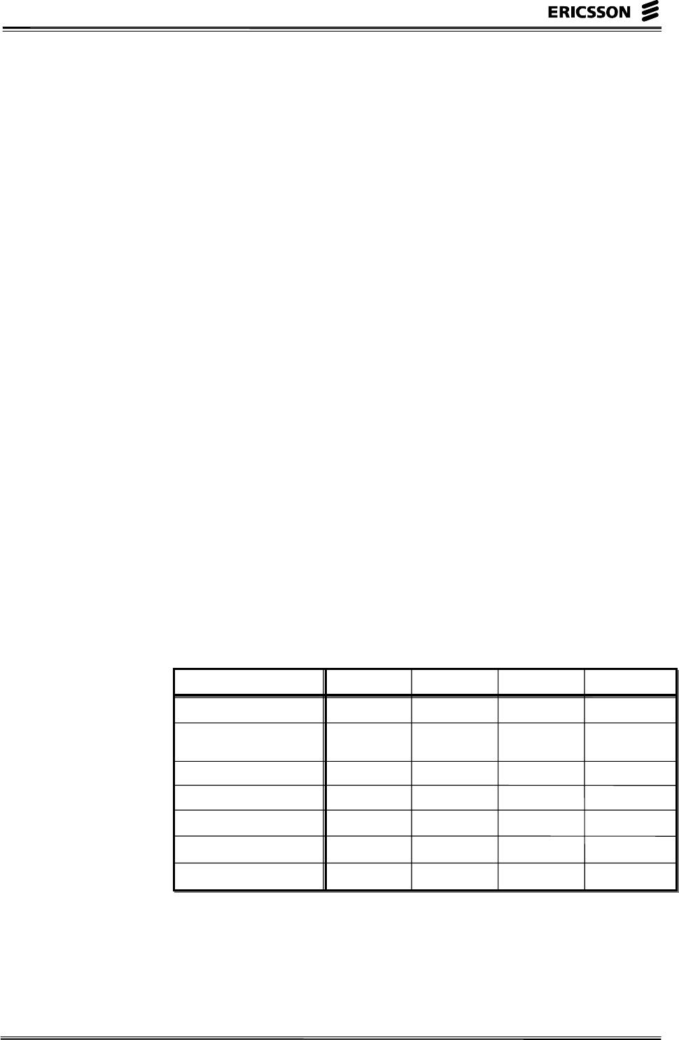
SYSTEM CAPABILITIES
One way to study the new APG40 is to compare it with its
predecessors IOG11, IOG20 and APG30. Please study the table
below.
IOG11 IOG20 (B,C) APG30/33 APG40
Throughput, kByte/s 20 150 135/250 400
CP Reload kBytes/s 80 470 200 >500
5000 with IPN
HD Capacity, Gbyte 2 18 40 54
External Ethernet - 10 Mbit/s 100 Mbit/s 100 Mbit/s
TCP/IP - (Yes) Yes Yes
Portable Media (OD) 2 x 325 Mb 1.3 Gb - -
Portable Media (DAT) - - 4 Gb 24 Gb
Figure 3- 13 System Capabilities
AXE 810 Delta
– 14 – EN/LZT 123 6389 R1A
THE HARDWARE
The hardware is as already mentioned based upon Intel standard
processors. This will reduce manufacturing costs and it is
possible to follow “Moore's Law” by simply upgrading the
hardware. Initially, the processor will be running at 333 MHz
with an upgrade to 500 MHz with a later release.
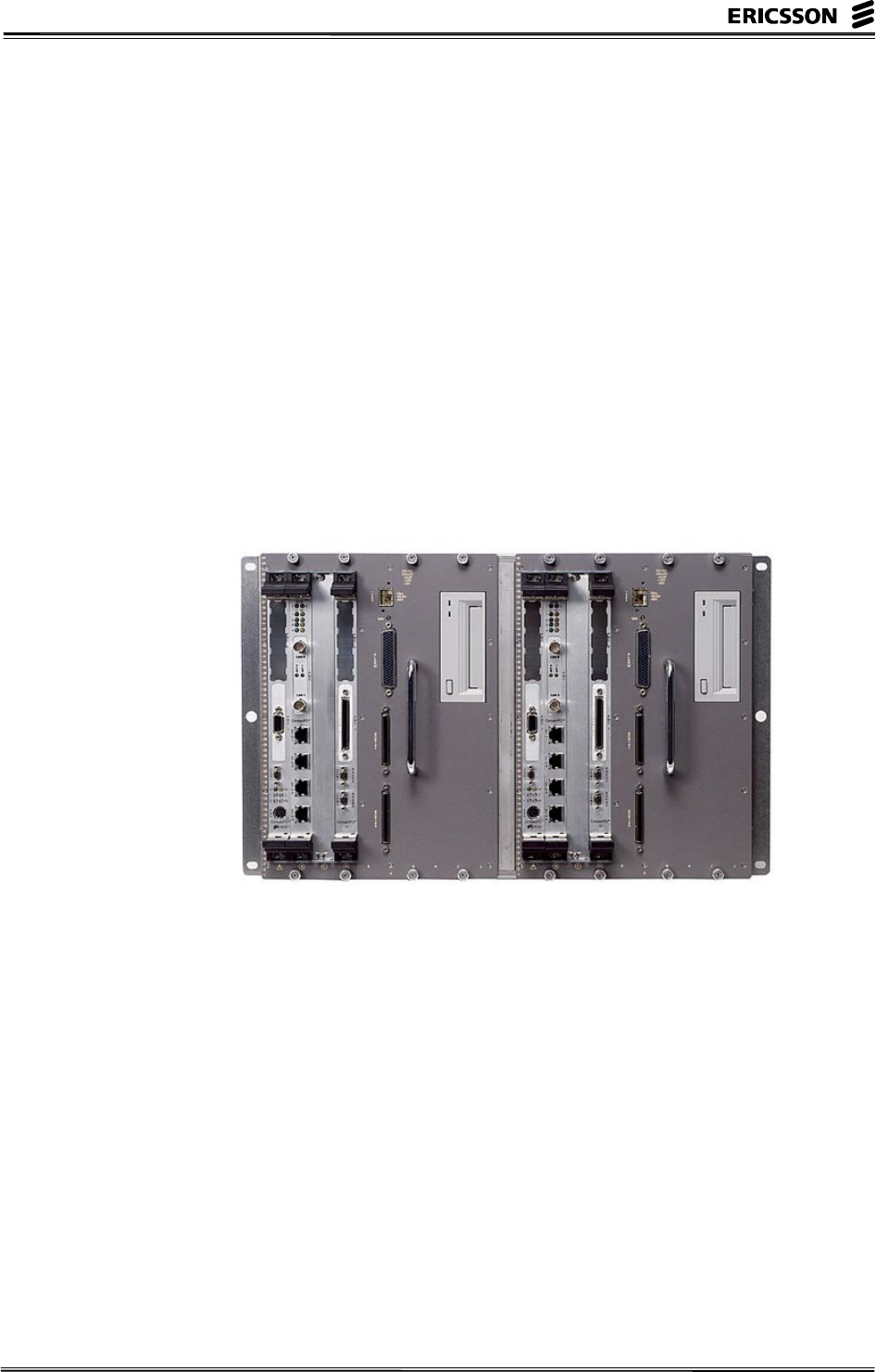
The APG40 is prepared for the IPN, Inter-Platform Network,
which will connect the APG40 with the CP via a high-speed
Ethernet connection. This will sped-up reload and dumping
considerably. For example, the total throughput for reload will
be about 10 times higher when IPN is available. The photo
below shows the hardware of APG40.
Figure 3- 14 APG 40 Hardware

3 Improvements Within APZ
EN/LZT 123 6389 R1A – 15 –
Intentionally Blank
