Basic Operation Activities (Module 1) AXE And Maint Module 1
User Manual: AXE Operation And Maint Module 1
Open the PDF directly: View PDF ![]() .
.
Page Count: 77
- Title Page
- Preface
- Table of Contents
- 1. Introduction
- 2. Introduction to Operation and Maintenance Activities
- 3. Exchange Handling Basics
- 4. Communication with the System
- 4.1 AXE Terminal Controls
- 4.2 Communication Program FIOL/DocView
- 4.3 Using the Communication Program FIOL /
- 4.4 Using the Communication Program AXEUSE
- 4.4.1 General
- 4.4.2 The DynaText Browser
- 4.4.3 The AXE Application Window
- 4.4.4 Interactive Communication
- 4.4.5 The Active Window
- 4.4.6 The Command Line
- 4.4.7 The Command History List
- 4.4.8 Quick Commands
- 4.4.9 Command Files - Recording and Transmission
- 4.4.10 Logging Communication
- 4.4.11 On Screen Documentation
- 4.4.12 Interactive Access
- 4.4.13 Access to Technology Based Training (TBT) Sessions
- 4.4.14 Online Help and Tutorial
- 4.5 Connection to TMOS
- 4.6 Chapter Summary
- 5. Hardware Orientation
- HELP


Ericsson Telecom AB 1996, Stockholm, Sweden
All rights reserved. No part of this document may be reproduced in any
form without the written permission of the copyright holder.
PREFACE
Target Audience
This book is preliminary intended to be used as a course manual in the
Ericsson AXE Operation and Maintenance training program. The book is
a training document and is not to be considered as a specification of any
Ericsson language or system.
Identification
EN/LZT 101 105 /1, R1A
Responsibility
Training Supply
ETX/TK/XM

03802-EN/LZM 112 17 R1 lxi
Table of Contents
1. Introduction 1
1.1 Module Objectives . . . . . . . . . . . . . . . . . . . . . . . . . . . . . . . . . . . . . 1
1.2 General . . . . . . . . . . . . . . . . . . . . . . . . . . . . . . . . . . . . . . . . . . . . . 2
2. Introduction to Operation and Maintenance
Activities 3
2.1 APT Source System . . . . . . . . . . . . . . . . . . . . . . . . . . . . . . . . . . . 3
2.2 Description of Operational Activities . . . . . . . . . . . . . . . . . . . . . . . 5
2.2.1 Maintenance Activities. . . . . . . . . . . . . . . . . . . . . . . . . . . . . . . . . . 6
2.3 Chapter Summary . . . . . . . . . . . . . . . . . . . . . . . . . . . . . . . . . . . . . 8
3. Exchange Handling Basics 9
3.1 Overview of the Exchange Library. . . . . . . . . . . . . . . . . . . . . . . . . 9
3.1.1 AXE 10 Documentation Principles. . . . . . . . . . . . . . . . . . . . . . . . . 9
3.2 The Structure of the Exchange Library . . . . . . . . . . . . . . . . . . . . 14
3.3 Handling the Exchange Library . . . . . . . . . . . . . . . . . . . . . . . . . . 15
3.4 B-Module Overview . . . . . . . . . . . . . . . . . . . . . . . . . . . . . . . . . . . 15
3.5 Using the B-Module . . . . . . . . . . . . . . . . . . . . . . . . . . . . . . . . . . . 16
3.5.1 O&M Documentation Structure . . . . . . . . . . . . . . . . . . . . . . . . . . 16
3.5.2 Locating the Documentation . . . . . . . . . . . . . . . . . . . . . . . . . . . . 18
3.5.3 Accessing Information in the B-Module . . . . . . . . . . . . . . . . . . . . 18
3.6 Using FIOL / DocView . . . . . . . . . . . . . . . . . . . . . . . . . . . . . . . . . 19
3.7 Using AXEUSE / Dynatext. . . . . . . . . . . . . . . . . . . . . . . . . . . . . . 19
3.8 The Exchange Log Book . . . . . . . . . . . . . . . . . . . . . . . . . . . . . . . 20
3.9 The Command Language and Printouts . . . . . . . . . . . . . . . . . . . 20
3.9.1 Command Structure. . . . . . . . . . . . . . . . . . . . . . . . . . . . . . . . . . . 21
3.10 Chapter Summary . . . . . . . . . . . . . . . . . . . . . . . . . . . . . . . . . . . . 24
4. Communication with the System 25
4.1 AXE Terminal Controls. . . . . . . . . . . . . . . . . . . . . . . . . . . . . . . . . 25
4.1.1 Making Contact with the System . . . . . . . . . . . . . . . . . . . . . . . . . 25
4.1.2 Seizure and Release of Terminal. . . . . . . . . . . . . . . . . . . . . . . . . 26
4.1.3 The Label Printout . . . . . . . . . . . . . . . . . . . . . . . . . . . . . . . . . . . . 26

AXE 10, Basic Operation and Maintenance Activities
lxii03802-EN/LZM 112 17 R1
4.1.4 Ready Indicator . . . . . . . . . . . . . . . . . . . . . . . . . . . . . . . . . . . . . . 27
4.1.5 End of Text Character . . . . . . . . . . . . . . . . . . . . . . . . . . . . . . . . . 27
4.1.6 The Check Printout . . . . . . . . . . . . . . . . . . . . . . . . . . . . . . . . . . . 27
4.1.7 Authority Check . . . . . . . . . . . . . . . . . . . . . . . . . . . . . . . . . . . . . . 27
4.1.8 The Time-Out Printout . . . . . . . . . . . . . . . . . . . . . . . . . . . . . . . . . 28
4.1.9 Blocking and De-blocking of the Terminal . . . . . . . . . . . . . . . . . . 28
4.1.10 Queue System. . . . . . . . . . . . . . . . . . . . . . . . . . . . . . . . . . . . . . . 28
4.2 Communication Program FIOL/DocView. . . . . . . . . . . . . . . . . . . 28
4.2.1 Basic Functions of FIOL/DocView . . . . . . . . . . . . . . . . . . . . . . . . 28
4.2.2 Window Screen . . . . . . . . . . . . . . . . . . . . . . . . . . . . . . . . . . . . . . 28
4.2.3 The Status Line . . . . . . . . . . . . . . . . . . . . . . . . . . . . . . . . . . . . . . 29
4.2.4 The Command Line . . . . . . . . . . . . . . . . . . . . . . . . . . . . . . . . . . . 30
4.2.5 The Function Keys . . . . . . . . . . . . . . . . . . . . . . . . . . . . . . . . . . . . 30
4.2.6 Practical Examples of Using FIOL . . . . . . . . . . . . . . . . . . . . . . . . 32
4.3 Using the Communication Program FIOL / DocView. . . . . . . . . . 33
4.3.1 The User Interface . . . . . . . . . . . . . . . . . . . . . . . . . . . . . . . . . . . . 34
4.3.2 Loading a Document from a Database . . . . . . . . . . . . . . . . . . . . 34
4.3.3 Searching Functions . . . . . . . . . . . . . . . . . . . . . . . . . . . . . . . . . . 36
4.4 Using the Communication Program AXEUSE . . . . . . . . . . . . . . . 38
4.4.1 General . . . . . . . . . . . . . . . . . . . . . . . . . . . . . . . . . . . . . . . . . . . . 38
4.4.2 The DynaText Browser. . . . . . . . . . . . . . . . . . . . . . . . . . . . . . . . . 38
4.4.3 The AXE Application Window . . . . . . . . . . . . . . . . . . . . . . . . . . . 38
4.4.4 Interactive Communication . . . . . . . . . . . . . . . . . . . . . . . . . . . . . 39
4.4.5 The Active Window . . . . . . . . . . . . . . . . . . . . . . . . . . . . . . . . . . . 40
4.4.6 The Command Line . . . . . . . . . . . . . . . . . . . . . . . . . . . . . . . . . . . 40
4.4.7 The Command History List . . . . . . . . . . . . . . . . . . . . . . . . . . . . . 41
4.4.8 Quick Commands . . . . . . . . . . . . . . . . . . . . . . . . . . . . . . . . . . . . 41
4.4.9 Command Files - Recording and Transmission . . . . . . . . . . . . . . 42
4.4.10 Logging Communication . . . . . . . . . . . . . . . . . . . . . . . . . . . . . . . 42
4.4.11 On Screen Documentation . . . . . . . . . . . . . . . . . . . . . . . . . . . . . 43
4.4.12 Interactive Access . . . . . . . . . . . . . . . . . . . . . . . . . . . . . . . . . . . . 44
4.4.13 Access to Technology Based Training (TBT) Sessions . . . . . . . . 44
4.4.14 Online Help and Tutorial . . . . . . . . . . . . . . . . . . . . . . . . . . . . . . . 44
4.5 Connection to TMOS . . . . . . . . . . . . . . . . . . . . . . . . . . . . . . . . . . 45
4.5.1 MML Commands . . . . . . . . . . . . . . . . . . . . . . . . . . . . . . . . . . . . . 46
4.5.2 Delayed Responses. . . . . . . . . . . . . . . . . . . . . . . . . . . . . . . . . . . 46
4.5.3 Spontaneous Reports . . . . . . . . . . . . . . . . . . . . . . . . . . . . . . . . . 46
4.5.4 File Output from the AXE 10 Exchange. . . . . . . . . . . . . . . . . . . . 46
4.5.5 File Information from TMOS to the AXE 10 Exchange . . . . . . . . 46
4.6 Chapter Summary . . . . . . . . . . . . . . . . . . . . . . . . . . . . . . . . . . . . 47

Table of Contents
03802-EN/LZM 112 17 R1 lxiii
5. Hardware Orientation 49
5.1 Mechanical Structure. . . . . . . . . . . . . . . . . . . . . . . . . . . . . . . . . . 49
5.1.1 Introduction . . . . . . . . . . . . . . . . . . . . . . . . . . . . . . . . . . . . . . . . . 49
5.2 Development of the Packaging System . . . . . . . . . . . . . . . . . . . . 50
5.2.1 BYB 101 and BYB 102 . . . . . . . . . . . . . . . . . . . . . . . . . . . . . . . . 50
5.2.2 BYB 202. . . . . . . . . . . . . . . . . . . . . . . . . . . . . . . . . . . . . . . . . . . . 50
5.2.3 The Building Module . . . . . . . . . . . . . . . . . . . . . . . . . . . . . . . . . . 54
5.3 The Cabinet . . . . . . . . . . . . . . . . . . . . . . . . . . . . . . . . . . . . . . . . . 54
5.3.1 Magazines . . . . . . . . . . . . . . . . . . . . . . . . . . . . . . . . . . . . . . . . . . 55
5.3.2 Magazine Devices . . . . . . . . . . . . . . . . . . . . . . . . . . . . . . . . . . . . 58
5.3.3 Printed Circuit Boards (PCBs) . . . . . . . . . . . . . . . . . . . . . . . . . . . 58
5.4 Localization of hardware units . . . . . . . . . . . . . . . . . . . . . . . . . . . 60
5.5 Chapter Summary . . . . . . . . . . . . . . . . . . . . . . . . . . . . . . . . . . . . 60

03802-EN/LZM 112 17 R1 1
1. Introduction
1.1 Module Objectives
Figure 1.1
Module Objectives
Module Objectives
After completing this module the participant will be able to:
• Describe what is meant by AXE 10 System Operation and Mainte-
nance Activities
• Describe the general structure of the Exchange Library and main-
tain the library through the use of the OPI “Handling of the
Exchange Library”
• Describe the layout and contents of the B-Module and its use
• Understand the AXE 10 document numbering
• Understand the basic principles of AXEUSE, FIOL and DocView
• Describe the AXE 10 command structure
• Identify the operational activities that are to be performed based on
information that is supplied in a specific work order and the con-
tents of the associated B-module
• Understand the basic principles of operator-system communication
and the role of I/O devices enabling such communication
• Understand the purpose of using communications programs FIOL
and AXEUSE
• Communicate with the AXE system with the help of FIOL and
AXEUSE
• Locate hardware units in the exchange through the use of com-
mands.

AXE 10 Basic Operation and Maintenance Activities
203802-EN/LZM 112 17 R1
1.2 General
AXE 10 Operation and Maintenance training consists of three courses.
AXE 10, Operation and Maintenance Platform. .... LZU 108 1451
AXE 10, Operation Handling................................. LZU 108 1452
AXE 10, Hardware Maintenance ........................... LZU 108 1453
This document describes the basic operational and maintenance activities
that are related toAXE 10 exchanges. The information included corre-
sponds to the AXE 10, O&M Platform course, LZU 108 1451. The course
is intended to be used as a platform for the majority of AXE job-catego-
ries.
After completing this course, the participants will have a basic understand-
ing of the most frequently performed activities at AXE 10 exchanges.
They can thereafter continue their training by attending either the Opera-
tion Handling or the Hardware Maintenance course, or both.

03802-EN/LZM 112 17 R1 3
2. Introduction to Operation and Mainte-
nance Activities
Figure 2.1
Chapter Objectives.
2.1 APT Source System
This document deals with the new overall source system which is called
APT 210 12.
The differences between APT 210 08/R5 and APT 210 12 are also pointed
out when applicable.
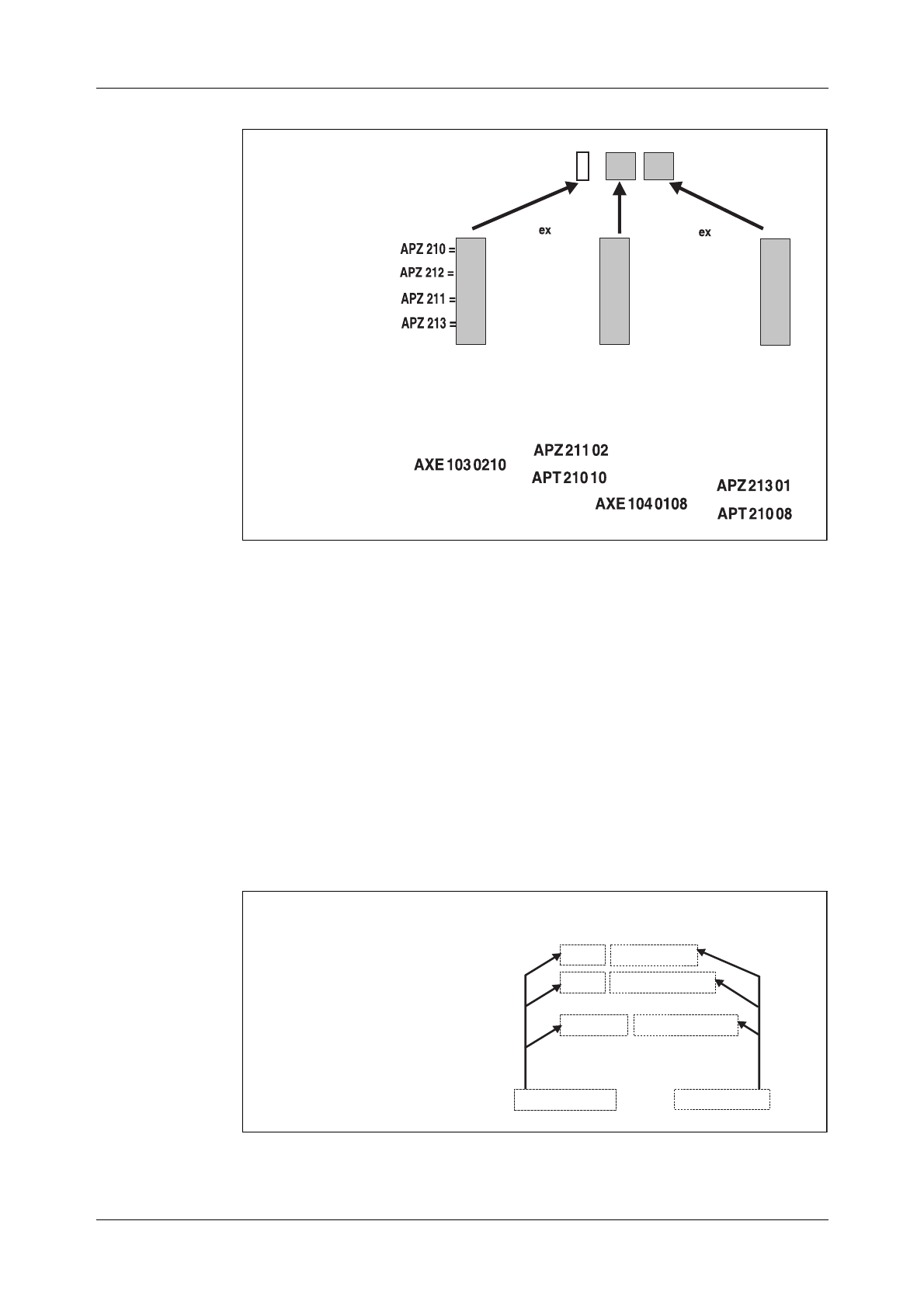
APT 210 12 (see figure 1.2) contains the functionality of :
•APT 210 08 R5 POTS (Plain Ordinary Telephone Service)
•4/APT 210 10 R3 ISDN (Integrated Services Digital Network)
Chapter Objectives
After completing this chapter the participant will be able to:
• Describe what is meant by AXE 10 Operation and Maintenance
Activities.

AXE 10 Basic Operation and Maintenance Activities
403802-EN/LZM 112 17 R1
Figure 2.2
APT 210 12
Three variants have been developed:
•APT 210 12/1 R1 for France.
•APT 210 12/2 R1 for Norway and Spain.
•APT 210 12/3 R1 for the Netherlands and Switzerland.
Note that the countries referred to above were the first to implement the
system. Numerous other countries have subsequently selected AXE local
exchanges.
APT 210 12/1
APT 210 12/1 was originally developed for the French market. It is used
when installing new local AXE exchanges or when upgrading existing
local AXE switches requiring ISDN functionality integrated with POTS.
APT 210 12/2
APT 210 12/2 is a general application, developed initially for the Norwe-
gian and Spanish markets. It is used when installing new local AXE
exchanges or when upgrading existing local AXE exchanges requiring
ISDN functionality integrated with POTS.
In terms of ISDN, both basic rate access (BA) and primary rate access
(PRA) are provided.
APT 210 12/3
APT 210 12/3 is the latest release of the source system APT 210 12 mar-
keted under the product name AXE Local 12.3. Close to complete back-
POTS
ISDN
APT 210 08 R5
4/APT 210 10 R3
APT 210 12/1-n
POTS/
ISDN
Introduction to Operation and Maintenance Activities
5
ward compatibility with the earlier released source systems (APT 210 08
R1-R5 and APT 210 12 R1-R2) has been maintained.
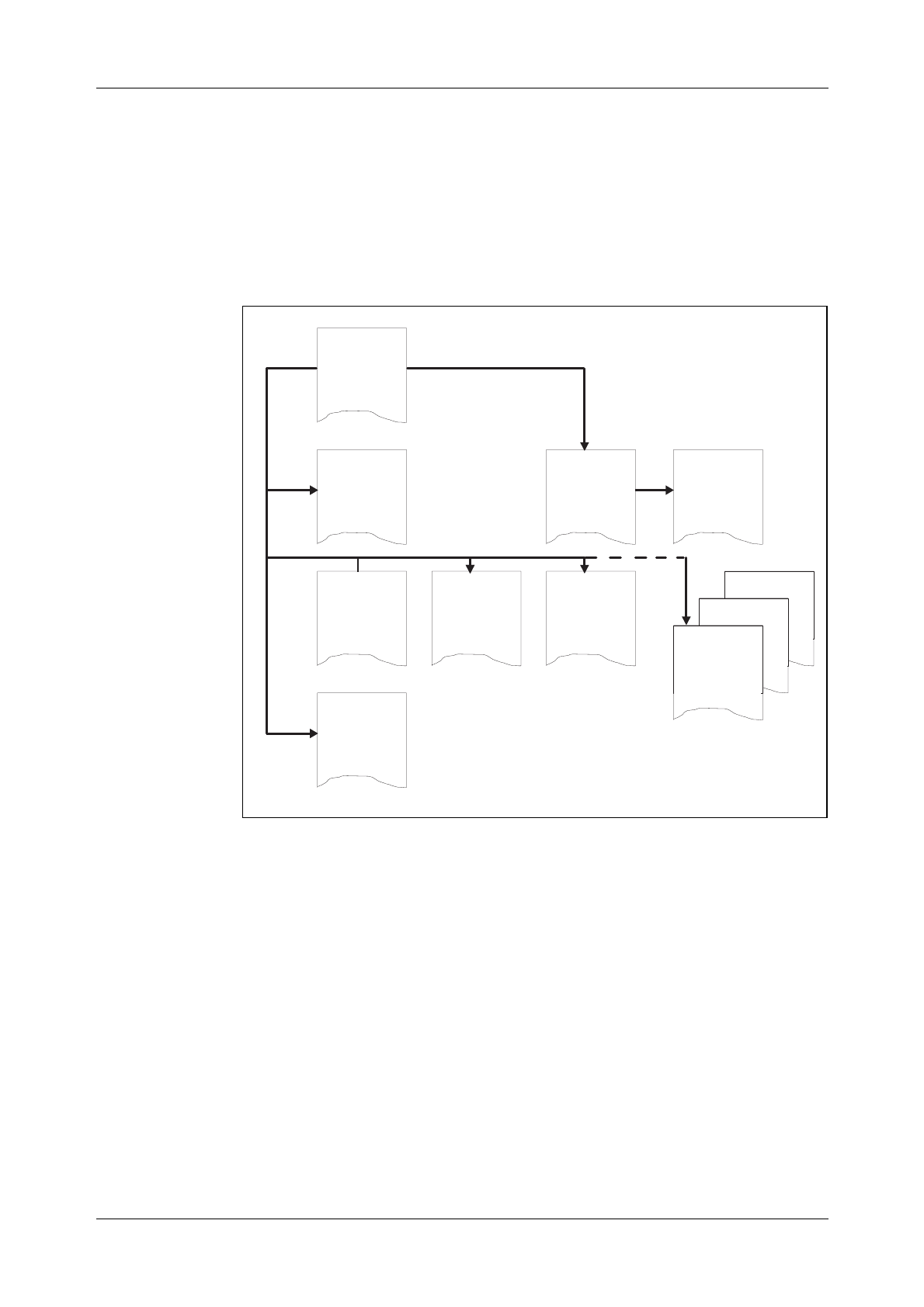
2.2 Description of Operational Activities
Operation is the normal, everyday running of the exchange when every-
thing is working as it should. The purpose of the tasks included in the
operational activities is to adapt the exchange to the continuously chang-
ing demands placed on it.
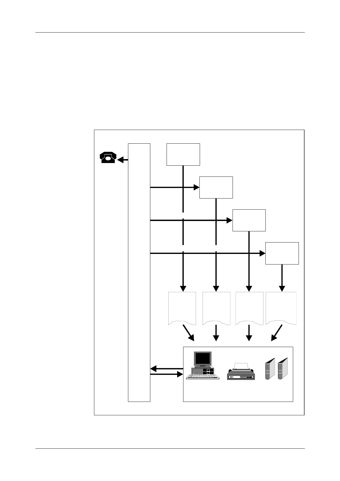
Figure 2.3
Operational Activities
A
X
E
PC Printers
Commands
Printouts
Charging
Data
Orders
Operational
Statistics
Orders
Operational
Manuals
Sales
Office
Planning
Office
TrafficData
ChargingData
TrafficMeasurement&Statistics
Exchange
Data
Office
Charging
Office
Subscriber
Service
Orders
Exchange
Data
Order
Changes

AXE 10 Basic Operation and Maintenance Activities
603802-EN/LZM 112 17 R1
Operational activities, (see figure 2.3), are normally initiated by work
orders. Work orders may be the result of operator or subscriber demands.
In either case, a work order instructs the AXE staff to carry out modifica-
tions to the exchange, that are required for its adaption to the newly arisen
needs.
Work orders are executed in accordance with the procedures defined in the
AXE B-Module exchange documentation.
Operation staff communicate with the exchange by means of the AXE
Input/Output system.
The following are a number of examples of operational activities:
•Changing subscriber data, e.g. activating a new subscriber line, provid-
ing a new service or changing the subscriber class of an existing sub-
scriber
•Changing routing data, e.g. initiating a new route
•Recording statistics, e.g. traffic recording, such as monitoring of traffic
measurements for a period and reporting or, in some cases, evaluating
the result.
2.2.1 Maintenance Activities
The purpose of maintenance activities is essentially the prevention and
correction of faults.
One can subdivide maintenance activities into two types:
1. Preventive Maintenance entails the performance of a set of routine
tasks that involves checking for suspected fault sources of faults and
their neutralization before such sources give rise to serious system
consequences.
2. Corrective Maintenance involves responding to actual faults by
removing or repairing their immediate causes. Upon the occurrence
of a fault, the system will notify the staff by generating an alarm and
alarm printouts.
Staff may also be notified of the exsistence of a fault as a result of sub-
scriber complaints. Information relating to faults external to the exchange
may also be received from subscribers.
The Ericsson Maintenance Philosophy, Controlled Corrective Mainte-
nance (CCM), seeks to achieve a balance between these two types of
maintenance.
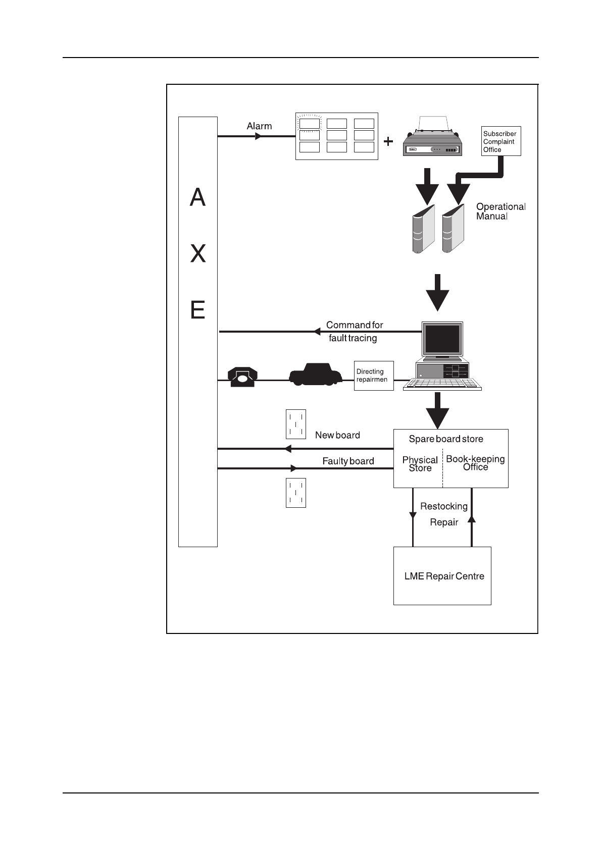
Whatever the source of information, once the existence of a fault is
known, action must be taken to eliminate it. Maintenance Staff use the B-
Module of the exchange documentation to interpret fault information.The
B-Module also contains the procedures, Operational Instructions (OPIs),
required when dealing with faults, (see figure 2.4).
Introduction to Operation and Maintenance Activities
03802-EN/LZM 112 17 R1 7
Figure 2.4
Maintenance Activities
When performing the tasks outlined by an OPI, Maintenance Staff com-
municate with the exchange using the AXE command language, often
referred to as the Man-Machine Language (MML).

AXE 10 Basic Operation and Maintenance Activities
803802-EN/LZM 112 17 R1
The following are a number of examples of various maintenance tasks:
•Fault-finding, testing and repair of subscriber lines
•Fault- finding, testing and repair of trunks
•Fault-finding, testing and repair of the GSS and SSS units
•Maintenance of the AXE power supply and power distribution system
•APZ Maintenance.
2.3 Chapter Summary
APT 210 12/1
Used when existing local AXE switches requiring ISDN functionality inte-
grated with POTS.
Only PRA, Primary Rate Access is provided..
APT 210 12/2
Used when existing local AXE switches requiring ISDN functionality inte-
grated with POTS.
In terms of ISDN both BA and PRA are provided.
APT 210 12/3
Marketed under product name AXE Local 12.3.
Backward compatibility with APT 210 08 R1 - R5 and APT 210 12 R1- R2.
By Operational Activities is meant normal everyday running of the switch
when everything is working as it should.
By Maintenance Activities means prevention and correction of faults within
the exchange with the help of relevant OPIs.

03802-EN/LZM 112 17 R1 9
3. Exchange Handling Basics
Figure 3.1
Chapter Objectives
3.1 Overview of the Exchange Library
3.1.1 AXE 10 Documentation Principles
Before proceeding with the description of the exchange library and its con-
tents, a summary of the main principles employed in AXE 10 documenta-
tion are provided below.
The system employed for document identification is built on a close rela-
tion between the products found in the system and the documents associ-
ated with each product.
The system hierarchy defines the products found at the different levels.
From the point of view of documentation identification, all products from
the system level to the individual printed circuit board level are treated
equally, (see figure 3.2).
Chapter Objectives
After completing this chapter the participant will be able to:
• Describe the general structure of the Exchange Library and main-
tain the library through the use of the OPI “Handling of the
Exchange Library”
• Describe the layout and contents of the B-Module and its use
• Understand AXE 10 document numbering
• Understand the basic principles of AXEUSE, FIOL and DocView
• Describe the AXE 10 command structure
• Identify the operational activities that are to be performed based on
information that is supplied in a specific work order and the con-
tents of the associated B-module.
Book Title
10
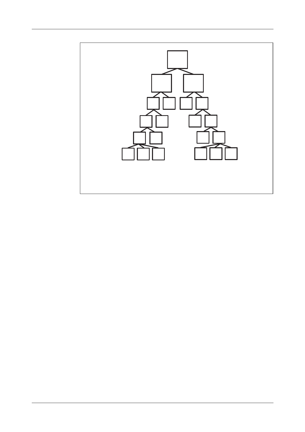
Figure 3.2
System Structure
A product is identified by a unique Article Code. An individual Article
Code or individual identity consists of a number of letters and digits that
are combined in accordance with the numbering system rules. The num-
bering system classifies and groups the products and documents in accord-
ance with their use, system association, their location in the product
hierarchy and their factual contents. Pre-defined basic numbers and classes
are registered in a database which is continuously updated to include new
items.
Figure 3.2 illustrates the hierarchial construction of the system and dis-
plays some examples of the logical construction of the identification sys-
tem:
•The AXE system has article codes including APT and APZ codes.
•All APT subsystems have article codes including ANT prefixes and all
APZ subsystems have article codes including ANZ prefixes.
•The Function Block Group represents a recent addition to the product
level structure in which Function blocks having related functionality
are grouped together, (CRT and CRZ). The Function Block Group level
does not exist in APT 210 08/R5.
•All APT function blocks have article codes including CNT prefixes and
all function blocks in APZ have article codes including CNZ prefixes.
•All function blocks in subsystem ANT 216 xx have article codes
CNT 216 yy zz.
AXE
APZ APT
ANT ANTANZ ANZ
CRZ CRZ CRT CRT
Systemlevel1
Systemlevel2
Subsystem
ExamplesofArticleCode:
AXE1030210
APT21010
ANT21608
CNZ CNZ
BFD CAA CAA
FunctionBlock
FunctionUnit
CNT CNT
BFD CAA CAA
CNT2161012
Function Block
Group*
Note*: The product level Function Block Group does not exist in APT 210 08/R5.
CRT 257 01
Exchange Handling Basics
11
Figure 3.3
AXE Product Number, includes APT and APZ codes
Different versions of the same product are distinguished by the Revision
State. Revision states are advanced in accordace with a given set of rules
and is related to an important product, namely interchangeability, e.g. Arti-
cle Code: CNT 216 1012, Rev. State: R3.
A document is identified by a prefix and an unique number. Different ver-
sions of the same document are distinguished by a revision letter. Docu-
ment numbers for documentation relating to products usually consist of
the decimal class and the article code.
The decimal class indicates the type of document, and the article code
indicates the product associated with the document , (see figure 3.4).
Figure 3.4
Example of Document Numbering
{
AXE1011
Example:
AXE1020108
{{
APZ21201
APT21008
xx
yy
03
04
05
06
APZ210
-"-
-"-
-"-
05
06
07
08
APT210
-"-
-"-
-"-
1
2
3
4
Document
1. Descriptionofsubsystem OMS
Documentnumber
A
B
A
-ANT216 081551
-CNT216 10121551
-CNT216 10121/19082
2. Descriptionoffunction block
ROSA
3. Descriptionofa commandthat
belongstofunction blockROSA
Revision
DecimalClass Article Code
Book Title
12
A document structure exists for each product category which specifically
states the documentation required by the different product handling
phases, i.e. design, manufacturing, etc.
Certain document types are mandatory for every product. Others are
drafted when necessary, depending on the product’s functions, design and
characteristics. Figure 3.5 shows an example of document structure for a
function block.
Figure 3.5
Document Structure for a Function Unit
Table 3:1 ( shown on the next page) contains a list of the most frequently
used decimal classes and their contents.
n/19082-
Command
description
n/19083-
Printout
description
15514-
Signal
survey
n/15514-
Signal
description
15518-
1/15518-
2/15518-
1095-
Document
survey
13161-
Structure
spec.
1551-
Description
10921
Product
revision
information
Application
information

Exchange Handling Basics
03802-EN/LZM 112 17 R1 13
Table 3.1
Decimal Classes
Decimal class Contents of document
107 39 Wiring information
107 5 Cabling tables
107 8 Mounting drawings for printed circuits
109 21 Product revision information
109 5 Document surveys
130 1 Article, type and class specification
131 22 Article lists
131 32 Manufacturing specifications
151 80 General instructions
151 87 Mounting drawings
151 88 Assembly drawings
154 31 Operation directions
155 1 Description of articles
155 16 Function description
155 17 Function specification
155 18 Application information
155 19 Interworking description
155 42 Conditions information
155 61 List of contents and documents
190 55 Program source document
190 59 Parameter list
190 72 Signal distribution
190 74 Commands
190 82 Command descriptions
190 83 Printouts
190 84 Command parameter descriptions
190 92 Program information
191 1 Circuit diagrams
193 01 Trunking diagrams
193 04 Block diagrams
193 05 Floor plan drawings
193 06 Floor plan specifications
193 10 Cable group lists
193 11 Cabling tables
193 15 Cabling lists
193 17 Programming documents
193 19 Allocation documents (MDF)
193 25 Allocation documents (Power)
195 1 Allocation documents
195 2 Numbering documents

AXE 10 Basic Operation and Maintenance Activities
14 03802-EN/LZM 112 17 R1
3.2 The Structure of the Exchange Library
All documents relating to the exchange are gathered together to form the
exchange library. The contents range from descriptions of the layout of the
building and floor plans for the exchange equipment to instructions on
how to trace and eliminate software faults. Such a wide range of material
obviously requires some sort of structure so that the information is easily
accessible by AXE staff.
The documents are distributed throughout a set of functionally defined
modules, each of them being contained in one or more binders. Some of
the longer, less frequently used modules may be stored in microfiche for-
mat to save space. Today, it is all stored on CD-ROM.
With reference to the basic operation and maintenance of the exchange,
the modules vary a great deal in terms of importance; some will be con-
sulted daily, others never. With this in mind, we will now describe the
modules to a degree of detail corresponding to their importance as regards
the O&M job:
Four of the modules, likely to be used by AXE staff on daily basis, will be
are fully described. They are:
A-Module Library Survey.
B-Module Operation and Maintenance Manuals (Operational
Instructions, Command Descriptions, Printout Descrip-
tions and Application Information).
C-Module Exchange Description (hardware, cabling etc.).
Another three modules are used occasionally by the O&M staff and hence
are dealt with more briefly. They are:
D-Module Functional Product Documents (software descriptions and
flowcharts).
E-Module Software Documents (source and assembly codes).
F-Module Hardware Documents (magazine and circuit layouts).
I-Module Exchange Data (MML commands configurating an
exchange), also known as the Data Transcript.
Finally, there remain six modules which are practically never needed by
the staff dealing with basic O&M. They are listed below:
G-Module Mounting Details.
H-Module Installation Test Instructions.
K-Module Power Supply Documents.
M-Module Signalling Inter-work Information.
S-Module Software Fault Location.
T-Module Correction of Central Software.

Exchange Handling Basics
03802-EN/LZM 112 17 R1 15
3.3 Handling the Exchange Library
The OPI “Handling of the Exchange Library” found in sub-module B01,
deals with the procedures for:
•Checking documents received
•Inserting and replacing documents
•Filing delivery notes
•Borrowing documents from the exchange library.
Library maintenance may at first glance appear to be a trivial task. Reality
is however quite the contrary. The complexity of the information coupled
with the need for its frequent updating would quickly lead to complete
chaos without the existence of and compliance with strict document main-
tenance procedures.
Electronically stored information, (e.g. DocView, AXEUSE) allows the
saving of countless hours of work each time the documentation requires
updating. Instead of thumbing through reams of paper you simply load a
new CD- ROM disk into your PC.
3.4 B-Module Overview
The B-Module (OPERATION AND MAINTENANCE MANUALS).
The B-Module is the most frequently consulted module in the library. It
consists of instructions for administrative routines, product handling, man-
machine communication, supervision, fault reporting, fault location and
elimination, exchange data modification, spare-part handling, operational
reporting, etc.
The information contained in this module is used both by O&M staff in
their daily work and by the operator when, for example, modifying
exchange data.
The major portion of the B-Module concerns the Operational Instructions
(OPIs) which guide the staff in carrying out their various tasks.
Operational instructions generally refer the staff-member to Command and
Printout Descriptions. Although the experienced user usually manages
with the Operational Instructions alone, others require the help of the
Command and Printout Descriptions.
Because the instructions and descriptions are of a comprehensive nature
and handle a variety of different functions, the B-Module is subdivided
into seven sub-modules. These are listed below:
B01 General Operational Instructions.
B02 Operations Instructions.
B03 Maintenance Instructions.
B04 Test Instructions.

AXE 10 Basic Operation and Maintenance Activities
16 03802-EN/LZM 112 17 R1
B11 Command Descriptions.
B13 Printout Descriptions.
B14 Adaptation Directions, Application Information.
Note: In certain instances the B-Module is subdivided as follows:
•B03 contains B01 - B03
•B14 contains Adaptation Directions
•B15 contains Application Information.
3.5 Using the B-Module
3.5.1 O&M Documentation Structure
We have mentioned earlier that the B-Module is divided into seven sub-
modules, B01 to B04, B11, B13 and B14. The major portion of these sub-
modules is made up of Operational Instructions (OPIs). With the help of
flow charts provided in the OPIs, the operator is guided through the opera-
tion and maintenance tasks in a step-by-step fashion. The information
included in each submodule is summarized as follows:
Submodule B01 (General Operational Instructions):
•Administrative routines
•Product-handling instructions for magazines, printed board assemblies,
cables, I/O devices and spare parts
•Man-machine Communications including operating instructions for
panels, I/O devices and alarm system and command language rules.
Submodule B02 (Operations Instructions):
•Subscriber-associated changes
•Changes in the exchange data
•Collection of statistics
•Output of charging data
•Size alteration
•Functional changes.
Submodule B03 (Maintenance Instructions):
•Time schedule for inspection
•Instructions for performing inspection of panels, I/O devices, sub-

Exchange Handling Basics
03802-EN/LZM 112 17 R1 17
scriber line test-equipment
•Procedure in event of alarm
•Procedure in event of fault-observation
•Instructions for fault-localization and repair.
Submodule B04 (Test Instructions):
•Testing the APT, APZ, and power equipment in an in-service exchange.
Submodule B11 (Command Descriptions):
•Functional descriptions of commands
•Brief descriptions of parameters
•Parameter combinations and formats
•Examples
•Expected types of printout after command input
•Fault codes and their interpretations
•Command category numbers.
The commands are listed in alphabetical order.
Submodule B13 (Printout Descriptions):
•Functional descriptions of printouts
•Print headings
•Interpretations of abbreviations
•Procedure to be followed upon the receipt of a printout
•Printout groups.
The printouts are listed in alphabetical order.
Submodule B14 (Adaptation Directions):
•Adaptation Directions
•Application Information
•Command Tables
•Various lists including parameter lists, subscriber categories, alarm cat-
egories, size alteration events, end-of-selection codes (in both alpha-
betic and numerical order).
Adaptation Directions contain detailed functional descriptions of the com-
mands and their parameters.
Application Information consists of documents which provide detailed
information, for each function block, as to the allowable value ranges that
may be assigned to parameters.
Command tables are rarely used.

AXE 10 Basic Operation and Maintenance Activities
18 03802-EN/LZM 112 17 R1
3.5.2 Locating the Documentation
As we know now, the B-Module fills a big part of the exchange library.
Each B-submodule consists of one or several binders. They are divided
into sections (grey dividers). Each section is divided into subsections
(green dividers) and sometimes the subsections are divided into parts
(orange dividers). The dividers are numbered from 0 to 9.
The first binder of each sub-module contains a document list. This list pro-
vides the contents of all the binders contained in the particular submodule.
3.5.3 Accessing Information in the B-Module
The steps involved in accessing information in the B-Module are as fol-
lows:
1. Finding the Title of the Operational Instruction
There are two ways in which the operator is assigned a task and each way
contains the relevant Operational Instruction.
•If the task is a response to an alarm, the operational personnel is to
access the OPI containing the same title as that found on the Alarm
Printout.
•All other tasks are initiated as the result of Work Orders, the contents of
which will indicate the name of the necessary OPI.
Whatever the origin of the task, the OPI will be found in submodules B01
to B04:
Type of Task Submodule
Administrative activities B01
Handling I/O devices B01
Operational tasks B02
Maintenance B03
Testing B04
2. Finding Additional Information
Operational Instructions direct the staff to Command Descriptions
(CODs), found in B11, by listing the commands that may be needed. The
Command Description usually suffices, but if more details are required,
they are to be found in the Application Information document identified by
the Command Receiving Block named in the COD.
This course includes a number of operational activity related exercises
which will provide practice in the use of the B-Module.

Exchange Handling Basics
03802-EN/LZM 112 17 R1 19
3.6 Using FIOL / DocView
DocView is a document retrieval tool for EDML-based Ericsson docu-
mentation, such as the Operation and Maintenance (O&M) documents.
EDML stands for Ericsson Document Mark-up Language. EDML was
developed by Ericsson and is an internal documentation standard.
DocView replaces the printed document binders and offers features for
browsing, searching and printing. The application is intended for any user
(designer, test and maintenance personnel) requiring flexible access to the
documents stored in the DocView databases.
The information stored in this document databases is easily accessed.
There are several hierarchical levels and a possibility to use context sensi-
tive searches. Hypertext and Find features are provided to speed up access
to requested document. Any portion of the information may be accessed at
speeds that far surpass manual look-ups in printed binders. AXEUSE /
Dynatex will replace DocView and FIOL in the future.
Chapter 4 describes in detatailed the handling of DocView.
3.7 Using AXEUSE / Dynatext
Up to now, Ericsson has provided FIOL as the only standard communica-
tion program for local AXE Operation and Maintenance. FIOL was origi-
nally designed as a test tool for internal usage within Ericsson, no focus
was originally placed on the needs of AXE 10 end-users.
AXEUSE (AXE USer Environment) is a Microsoft Windows application
that provides multi-channel communication with target systems. It is a
successor to FIOL and is a communication program combined with a
“Browser” for an On-screen Operation and Maintenance manual, running
under the MS Windows Graphical User Interface, GUI.
The AXEUSE package includes a copy of the Dynatext Browser, an appli-
cation which enables the user to view “electronic books”. Using the Dyna-
text Browser, the user can read documentation pertaining to the
application system.
The approach used when designing AXEUSE was to create an environ-
ment which would increase the productivity of the Operation and Mainte-
nance personnel. This is achieved by a graphical user interface designed in
accordance with current standards that meet known customer needs. The
environment also includes on-line documentation retrieval , Dynatext,
which provides context-linked information retrieval removing the tedious
task of browsing through the pile of binders just to perform a maintenance
task.
AXEUSE is described in more detail in chapter 4.4 of this document.

AXE 10 Basic Operation and Maintenance Activities
20 03802-EN/LZM 112 17 R1
3.8 The Exchange Log Book
AXE Operation and Maintenance Staff use the Exchange Log Book to
record all important events.
The following are examples of occurrences that should always be
recorded:
•High-priority alarms
•Operational disturbances
•Intervention and fault-repair performed on the APZ and common units
of APT, e.g. the GSS
•Output of call-charging records and statistics
•Activation of new lines and extensions
•Activation of new traffic cases and routes
•Addition of new functions, programs or data.
Some occurrences and actions, such as the repair of faults - especially
those which were traced to the exchange itself - need to be entered into the
log book after the exchange is returned to service.
The log book should always contain information concerning the latest
dump, together with details of any changes made in connection with the
dump, and any other information that could be useful in restoring the
exchange after a breakdown.
The OPI for using the Exchange Log Book is entitled ”Keeping a Journal”
and is located in submodule B01 of the B-Module.
3.9 The Command Language and Printouts
Communication between the AXE system and the AXE staff is carried out
by means of commands and printouts.
The staff members enter commands to perform O&M tasks in the
exchange and the exchange responds with printouts. In addition, the
exchange will automatically generate printouts to indicate faults or other
important events within the system.
The dialogue between the staff members and the AXE system requires a
language. This language is called MML (Man-Machine Language) and is
written in accordance with ITU-T recommendations.

Exchange Handling Basics
03802-EN/LZM 112 17 R1 21
3.9.1 Command Structure
In general, commands are structured in the following manner:
COMMAND CODE:PARAMETER NAME=PARAMETER VALUE;
Command Code
The command code defines the task to be executed. This code normally
consists of 5 characters:
XXYYZ
XX indicates the function group, YY specifies the function, and Z is an
abbreviation of the verb indicating which action will be taken, e.g. I for
Initiate, P for Print etc.
Parameters
Parameters are supplied following the command code in order to specify
how and where the order defined by the command code should be exe-
cuted.
If more than one parameter is necessary, the parameters are separated by
commas. The order in which different parameters within the same block
are arranged is not significant.
Commands may be written:
•Without parameters IOROP;
•With parameters (see below).
Commands requiring parameters may be written as follows:
•Without a value IODAC:ATT;
•With a single value EXRPP:RP=1;
STDEP:DEV=LI2-5;
•With several values EXRPP:RP=1&3&5;
STDEP:DEV=LI2-1&-3&-5;
•With a range of values EXRPP:RP=1&&5;
STDEP:DEV=LI2-1&&-5;
Square brackets [ ] denote optional parameters.
Braces { } enclose alternative parameters and indicate that one of the
parameters must be entered when using the command.
Square brackets which enclose braces imply that it is not necessary to indi-
cate any of the alternative parameters.
Command Descriptions (CODs), found in B11, are used to describe the
parameter combinations that may be used in conjuction with a particular
command.

AXE 10 Basic Operation and Maintenance Activities
22 03802-EN/LZM 112 17 R1
Printouts
There AXE system incorporates two types of printouts:
Automatically initiated printouts and command-initiated printouts:
1. Automatically Initiated Printouts
•Alarm Printouts
These are initiated either by a fault in the system or by supervision limits
having been exceeded due to disturbances. The printout usually follows
visual, or visual and audible alarms, depending on the alarm level.
•Alarm List Printouts
An alarm list printout is received automatically at intervals specified by
command ALLTC. The alarm list output contains a list of all active alarms.
The alarm list can be printed manually at any time by entering the com-
mand ALLIP.
•System Restart Printouts
A system restart printout is received after each system restart. The mes-
sage SYSTEM RESTART will be printed on all terminals.
2. Command-Initiated Printouts
This type of printouts can be divided into:
•Check Printouts
Check printouts repeat the command exactly as it is entered by the techni-
cian. The technician is required to confirm or inhibit the execution of the
command. To confirm the command, a semi-colon (;) is entered. If any
other characters are entered, the command will be inhibited. A check print-
out is given primarily by commands that could affect the traffic and by
commands that have been corrected by the technician.
Example:
<SYREI:RANK=rank;
SYREI:RANK=rank;
<; (to confirm the command)

Exchange Handling Basics
03802-EN/LZM 112 17 R1 23
•Procedure Printouts
A procedure printout is received immediately after entering a command.
Examples:
EXECUTED
or
ORDERED (F1 to release and wait for execution)
or
NOT ACCEPTED (followed by the reason)
The procedure output acknowledges a command input or a cancellation. A
command is always acknowledged by a procedure output or by a result or
answer printout.
•Answer printouts
Answer printouts are received directly after a print command.
Example:
EXEMP:RP=40,EM=0; (Print command)
EM DATA (Answer printout)
RP TYPE EM EQM TWIN CNTRL PP STATE
40 RPM6A 0 ET7-0&&-31 41 PRIM WO
END
•Result Printouts
Result printouts are given as a result of a command but normally at a later
time and always on a new page. The result printout is always preceded by
the procedure printout “ORDERED”.
Example:
ORDERED (F1 to release)
SIZE ALTERATION RESULT
SAE BLOCK NI FCODE UCODE
504 BT2 6
END
The title of the result printout is provided for interpretation purposes, see
binder B13.

AXE 10 Basic Operation and Maintenance Activities
24 03802-EN/LZM 112 17 R1
3.10 Chapter Summary
•A product within the AXE system is identified by a unique article code
e.g. ANT, CNT, CRZ etc.
•The decimal class indicates the type of document, and the article code
indicates the the product associated with the document
•The function group CRZ is a new addition to the product level structure
in AXE Local 12.4.
•A, B and C-modules are normally used by the AXE- staff on daily
basis.
•D, E, F and J modules are used occasionally.
•G, H, K, M, S, and the T modules are practically never used by the O &
M staff..
•If the task is a response to an alarm the operational staff is to access the
OPI with the same title as that found on the alarm printout
•The log book should always contain the latest activities within the
exchange and any other information that could be useful in restoring the
exchange after a breakdown
•The command code defines the task to be executed. This code normally
consists of 5 characters in accordance with the ITU-T standards.

Communication with the System
03802-EN/LZM 112 17 R1 25
4. Communication with the System
Figure 4.1
Chapter objectives
4.1 AXE Terminal Controls
4.1.1 Making Contact with the System
The I/O system handles data to and output from the AXE system.
Examples of input data to the exchange include:
•Commands to change exchange data
•Commands to change exchange hardware
•Commands to generate statistics
Examples of outputs from the exchange include:
•Printouts in reply to commands
•Alarm printouts indicating faults in the exchange
•Alarm indications displayed on an alarm panel.
The I/O system consists of various types of hardware. These may include
Hard Disks, Floppy Disks, Magnetic Tapes, Alpha Numerical Teminals,
Visual Display units, Printers, Personal Computers, Alarm Panels and
Data Links.
Chapter Objectives
After completing this chapter the participant will be able to:
• Understand the basic principle of how to communicate with the
system with the help of I/O devices
• Understand the use of the communication programs FIOL and
AXEUSE
• Communicate with the AXE system with the help of FIOL and
AXEUSE.
Book Title
26
4.1.2 Seizure and Release of Terminal
When not in use, the terminal is normally in an idle state and data can nei-
ther be sent to nor received from the exchange.
The process of establishing a link between the terminal and the AXE sys-
tem is called seizure.
The process of disconnecting the link between a seized terminal and the
AXE system is called release.
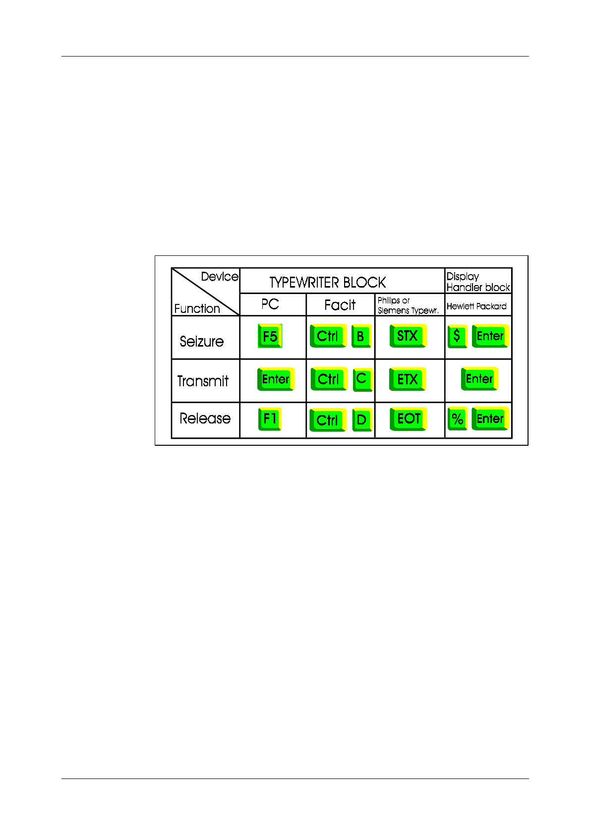
Seizure and release can be performed manually or automatically. Manual
seizure and release are performed either by using special keys or charac-
ters. Figure 4.2 illustrates a number of examples:
Figure 4.2
Examples of Seizure and Release
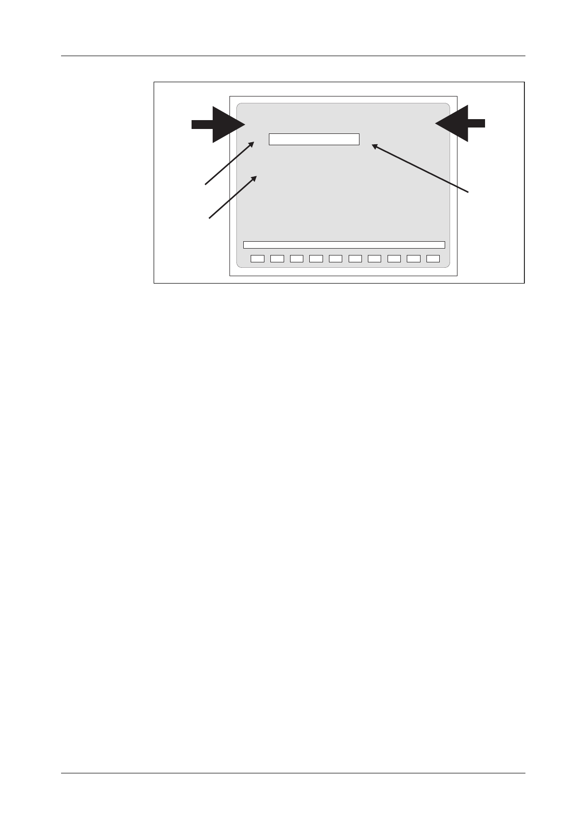
4.1.3 The Label Printout
Immediately after manual seizure of a terminal, the system transmits a
standard printout called Label Printout (also called the Header). As seen
in figure 4.3, this Label Printout contains:
•The operational state of the processor, in the figure: WO means the cen-
tral processors are working in parallel
•The exchange identity, in the figure: TRX A, i.e. Training Exchange A.
•The terminal identity, in the figure: AT-4
•The current date and time, in the figure: 951106 1545.
Communication with the System
27
Figure 4.3
Label Printout
4.1.4 Ready Indicator
Immediately after the Label, the left bracket which is called Ready Indica-
tor (also called Cursor or Prompt) is transmitted by the system to indicate
that it is ready to receive a command.
4.1.5 End of Text Character
The end of a block of characters, i.e. the command, is indicated by the
semicolon “;” which is called End of Text Character.
4.1.6 The Check Printout
When the AXE system receives a critical command, it sends the command
back to the terminal where it is presented as a Check Printout. The staff
member who entered the command can then confirm or inhibit it. The
command is confirmed by a semi-colon.
4.1.7 Authority Check
Sometimes access is allowed to the system only by authorized persons.
This is performed via the use of Passwords.
If an authority check is required, the system will automatically order the
operator to enter a password.
Even if the check is not required, it may not be possible for everybody to
use all existing commands. Each terminal can be given a key which limits
the number of possible commands to certain groups. Only authorized per-
sons will be allowed to change the key. An attempted execution of a
restricted command results in the message “COMMAND RESTRICTED”.
WO TRXA AT-4 TIME951106 1545 .....
<
;
TIMEOUT
Ready
TimeOut
Indication
Endoftext
character
Labe
l
blockofcharacters(command)
Indicator

Book Title
28
4.1.8 The Time-Out Printout
When a seized terminal is not used for a certain time (typically five min-
utes), the system releases the terminal automatically and transmits a Time-
Out Printout.
4.1.9 Blocking and De-blocking of the Terminal
If the AXE system detects a fault in the I/O path, the terminal is automati-
cally blocked, and an alarm is issued. The system will normally de-block
the terminal when the fault is cleared.
Manual removal of the block is also possible from the blocked terminal by
entering a character and then pressing ENTER. The character may be dif-
ferent for different terminals. For example, for the HP264 terminal, the
character is a question mark “?”.
Blocking may also be performed manually, via command. This is done e.g.
before testing a terminal. After the test, the terminal has to be manually de-
blocked.
4.1.10 Queue System
Some requested printouts are not generated immediately. In such cases, the
system compiles the information and puts it in a queue for later output.
Output of a queue starts automatically when the I/O device is released.
Output may also be ordered when in command mode by sending a special
character. Printouts may be sent to more than one terminal if needed.
4.2 Communication Program FIOL/DocView
4.2.1 Basic Functions of FIOL/DocView
FIOL is a program which makes it possible to use a personal computer as a
terminal for communication with the AXE system. The main advantage of
FIOL is that it simplifies command handling.
FIOL is an abbreviation of the program name, “FIle transfer and online
editor”.
DocView replaces the printed document binders and offers features for
browsing, searching and printing the documents. This application is
intended for any user needing a flexible access to the documents stored in
DocView databases (CD-ROM).
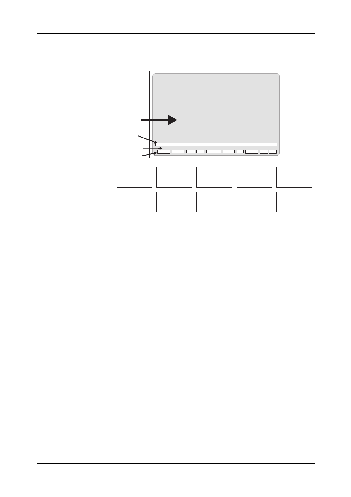
4.2.2 Window Screen
A window appears on the screen when the program is started. Three lines
are found at the bottom of the screen (see figure 4.4).
•The status line
•The command line
•The pre-defined main menu function-keys line.
Communication with the System
29
Figure 4.4
The FIOL Window
The window consists of a maximum of 22 lines which can be divided into
two windows when the user is communicating with two channels at the
same time.
4.2.3 The Status Line
The status line consists of the following information:
•Active channel CH0/CH1
•Text mode INSERT(i)/
OVERWRITE(o)
•Printer status ON/OFF
•Name of the log file
•Name of the transmit-file
•Communication mode BUF/TTY
Communication may either be performed in BUFFER mode (BUF) or in
ONLINE mode (TTY). In BUF mode it is possible to edit the command on
the command line before it is sent into the system. In the TTY mode the
characters are sent immediately to the system when entered.
RELEASE CH0/CH1 VIEW FILE CONNECT PRINTER EDIT CONFIG HELP EXIT
CHANNEL=0 i PRN=OFF LOGFILE= TRANSFER BUF
Statusline
Commandline
Predefined
functionkeyline
Window
F2
CH0/CH1
F3
VIEW
F4
FILE
F7
EDIT
F8
CONFIG
F10
EXIT
F9
HELP
F5
CONNECT
F1
RELEASE
F6
PRINTER

AXE 10 Basic Operation and Maintenance Activities
30 03802-EN/LZM 112 17 R1
4.2.4 The Command Line
The command line is a combined command and error-message line. All
commands are entered from this line. The twenty latest commands sent are
stored in a circular buffer. The commands can be reached with the up and
down keys, and will be presented on the command line when they are
stepped.
The function “END OF TEXT” is implemented in FIOL for entering com-
mands by just pressing the ENTER key.
4.2.5 The Function Keys
The function keys are pre-defined in the main menu as follows:
F1: Release. This is the “END OF TRANSMISSION” function when
it is implemented in FIOL. This function releases the terminal, i.e.
marks a seized terminal as idle.
F2: This function key works as a switch between channel window 0
and window 1. The STATUS LINE displays the active channel.
FIOL allows concurrent communication with two connected
systems.
F3: Entrance to the VIEW MENU.
−Scroll up/down on the screen
−Page up/down
−Short commands
−Save
−Print, for further information use “help”.
F4: Entrance to the FILE MENU. File menu functions are:
−Log and transmit file-handling
−Execution of DOS commands.
Pre-defined function keys in FILE MENU:
F1-DOS Makes it possible to temporarily
leave FIOL to execute DOS
commands.
F2-CH0/CH1 Indicates which channel is active.
F3-LOGFILE Supply name and start a log file.
F4-CLOSE Close active log file.
F5- No function.
F6-TRANSMIT Transmits a file.
F7-STOP Stop transmission of file.

Communication with the System
03802-EN/LZM 112 17 R1 31
F8-PAUSE Pause. Active file transmission.
F9-HELP
F10-RETURN
F5: Connect is the “START OF TEXT” function when it is imple-
mented in FIOL, i.e terminal seizure. This function returns the
the LABEL and activates the READY INDICATOR.
F6: Printer ON/OFF, which is shown on the STATUS LINE.
F7: EDIT is a full-screen editor. This online editor allows you to:
−Create and save command files
−Edit command files
−Transmit complete command files or sections of them to the
AXE system.
The editor can only handle ASCII-files. If you temporarily leave the EDI-
TOR, the cursor will be positioned where you left it.
Pre-defined function keys in EDIT mode:
F1-BLOCK Mark beginning of a block.
ACTION
F2-PRINT Print the contents of the edit buffer.
F3-STOP Stop transmission of edit buffer.
F4-SEND Send edit buffer, the contents in the EDITOR
will be sent as a transmit file.
F5-SENDLINE You will automatically be returned to the main
menu and the line pointed to by the cursor
will be sent to the connected system.
F6-LOAD Load a file to the edit buffer.
F7-SAVE Save the contents of the edit buffer to a file.
The file will be added to existing contents of
the buffer.
F8-CLEAR All lines from the top line to the bottom line
will be deleted.
F9-HELP
F10-RETURN
F8: Entrance to the CONFIG MENU. This function is used when you
install FIOL. It is here that the parameters are adapted to the con-
nected system/systems, such as: window size, protocol name, baud
rate, buffer size, language etc.

AXE 10 Basic Operation and Maintenance Activities
32 03802-EN/LZM 112 17 R1
Pre-defined function keys in CONFIG MENU:
F1-COLOUR
F2-CH0/CH1
F4-PROTOCOL Select parameters from the protocol list.
F5-FILES Select parameters from the files list.
F7-SAVECNF Save configuration parameters to a file.
F9-HELP
F10-RETURN
F9: HELP gives you access to information about FIOL.
F10: EXIT allows you to exit from FIOL.
4.2.6 Practical Examples of Using FIOL
1. Transmitting a Command File
Perform the following to transmit a command file:
a) Press the F4(FILE) key to enter the FILE menu
b) Press the F6(TRANSMIT) key to transmit a command file
c) Enter the name of the file to be transmitted
d) Press the F7 key to close the file and stop the transmission.
2. Creating a Log file
Perform the following to create a log file:
a) Press the F4(FILE) key to access the file menu
b) Press the F3(LOGFILE) key
c) Enter the name and location of a file e.g. A:EXCHDATA
d) Enter the commands to be stored in the log file by transmitting
a command file or by entering a number of commands from
the main FIOL menu
e) Press the F4(CLOSE) key on the file menu to close and store
the log file.
Communication with the System
33
4.3 Using the Communication Program FIOL /
DocView
The DocView application is designed to replace the paper document bind-
ers in much the same way as does AXEUSE .
Any documentation available in EDML (Ericsson Document Markup Lan-
guage) format can be handled electronically with DocView.
The DocView Browser allows one to easily browse through and search for
information contained in Operation and Maintenance documents (B-Mod-
ules). Savings in time and effort are remarkable when using DocView in
comparison with the handling of paper documents.
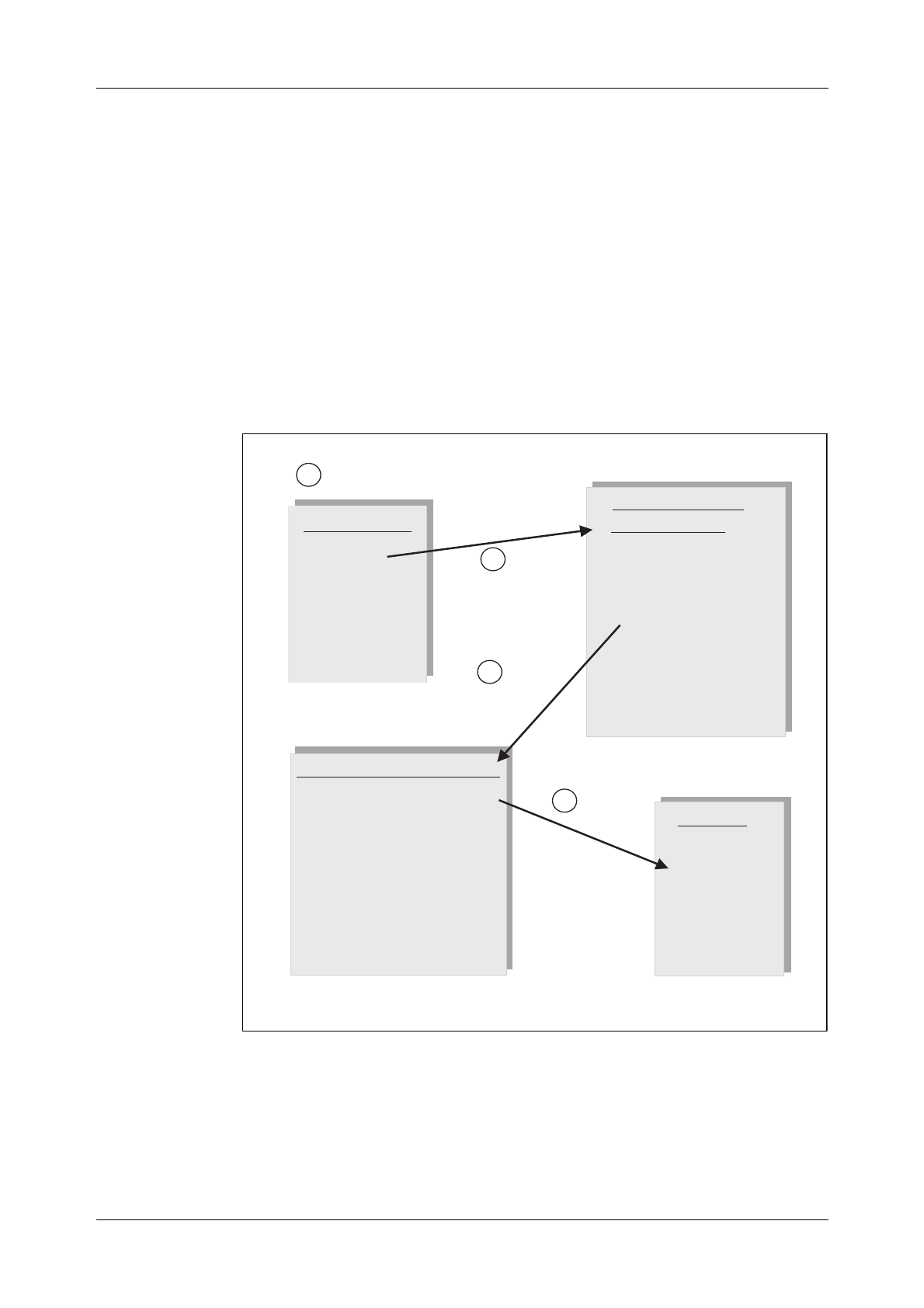
Figure 4.5 shows the hierarchy of the document information levels that are
used in the DocView databases for an Application System, AS.
Figure 4.5
DocView Information Levels
Recent configuration changes make it possible to run DocView in a Win-
dows environment. This way, you can have other tools (PlexView, FIOL
etc.) running at the same time and maintain the adequate speed of operat-
ing. CD-ROM drives enable it to change the database beeing used quickly.
Content List
Version 1
Version 2
Version 3
Version 4
.
.
.
AS Versions Contents of the
AS Version 1
A Library Survey
B Maintenance Manual
Operational Instructions
Command Descriptions
Printout Descriptions
Adaptation Directions
Document Survey
D Functional prod. APT
Functional prod. APZ
Command Descriptions
AC
AD
AN
BG
BL
CH
CL
CT
Accounting func.
Accounting case
Analysis of...
Business group
Blocking func.
Charging func.
Network clock...
Call part func.
ACCSE
Format
Function
Examples
Printouts
Content List
Document List Document
1. Start DocView
2. Select
AS Version
4. Select
document
3. Select
module
AXE 10 Basic Operation and Maintenance Activities
34 03802-EN/LZM 112 17 R1
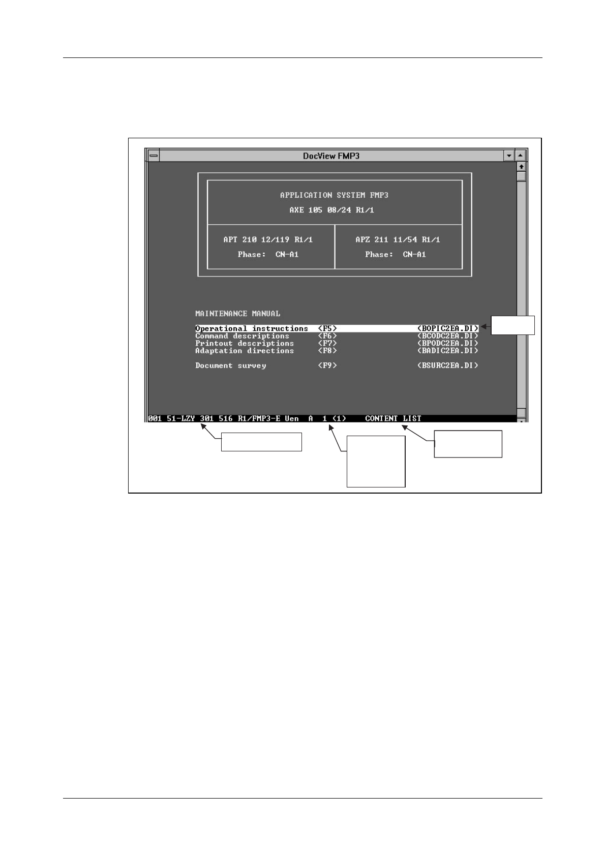
4.3.1 The User Interface
The following image is displayed when DocView is started,
(figure 4.6):
Figure 4.6
DocView User Interface
The DOS view only allows keyboard control. Help is available through the
Help key <F1>. Pressing the <Alt> or the <Ctrl> keys will display the
code executed by the function keys.
There are several pop-up windows that provide DocView operational
information such as document information, previous documents, book-
marks and printing options.
4.3.2 Loading a Document from a Database
All documents are loaded for view directly or indirectly through an index
(document list). The background is changed on a colour monitor when
viewing the main (Content List) or another index for easy identification.
A document index is handled by DocView as an ordinary document except
when a line containing a valid document or database reference is recog-
nized. The line contents are then highlighted (Inverted) and act as a cursor.
Name of the
current section
Document number Page number
and total
number of
pages
Cursor line
Communication with the System
03802-EN/LZM 112 17 R1 35
Pressing the <Enter> key when the cursor is positioned to a requested doc-
ument will cause the document to be loaded for viewing. If a database is
selected, the corresponding index file is loaded. Any number of document
databases can easily be accessed from DocView. The database files can be
updated independently of each other. The maximum number of simultane-
ously loaded document files is set to 10.
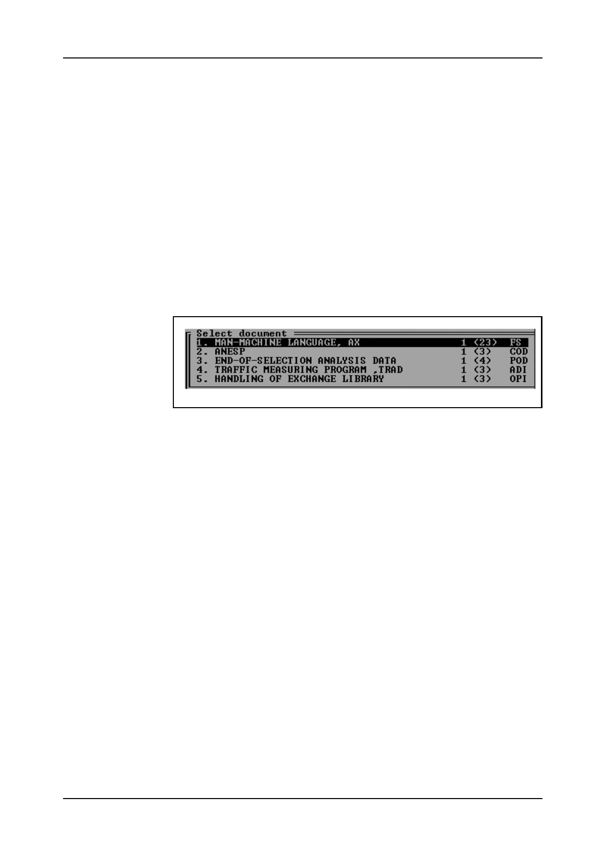
<Shift> - Displays index of previously viewed documents
Pressing the <shift F10> keys will cause a pop-up menu to be displayed
which contains references to previously viewed documents. The menu will
display document title (as given in the document index), page reference
and document type. Document type usually consists of two to three char-
acters, e.g. COD=Command Description.
The display below is an example of the contents of the pop-up menu fol-
lowing the load of five database documents:
Figure 4.7
List of Previously Opened Documents
Enter the number of a document or use the arrow keys <↑↓> to make a
selections from the menu. Then press the <Enter> key and the selected
document is loaded and displayed.
<Shift-Home/End> - Switch to previously viewed documents
Pressing the <Shift-Home> or the <Shift-End> key-combinations will
switch the currently displayed document to a previously viewed document,
found in the list of currently loaded documents, i.e. previous/next docu-
ment in the list. The current position in the document is retained when
switching from document to document.
However, this function does not switch back to a directly accessible docu-
ment index. These indexes are always easily accessed through function
keys <F5...F10>.
<F10> - Return to main document index for the databases
Pressing the <F10> function key will cause DocView to return directly to
the main index, displaying the content list of the accessible document data-
bases. As an option, FIOLSYSTEM features may optionally be listed in
the main index and may be executed directly from that index.
AXE 10 Basic Operation and Maintenance Activities
36 03802-EN/LZM 112 17 R1
4.3.3 Searching Functions
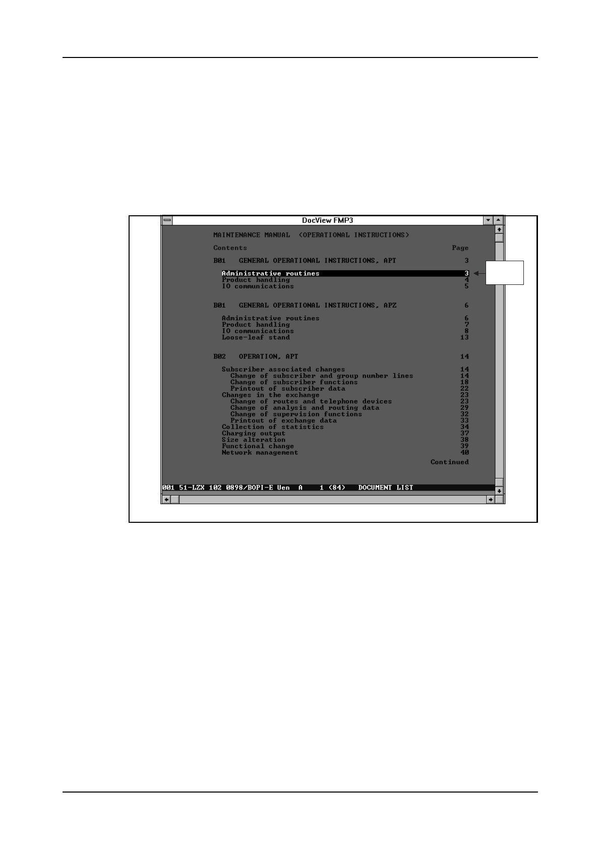
Page Search Using the Content List
When viewing a document with a content list, the list is recognized by
DocView and can be used as a fast way of jumping to the correct page in a
document. A cursor (inverted line), see figure 4.8, is visible on a line with
a page reference. A direct jump to the page is launched with the <Enter>
key.
Figure 4.8
Page Search
Search for a String in a Document
A search is started by pressing <F3> and typing the search string into the
search text field. Pressing the <Enter> key will initiate the search.
Note: a search for a string can only be performed inside one document at a
time.
Remember the following rules when searching for document strings:
•The Search feature is not case sensitive
•The Search is started from the line following the current cursor position
on the viewed page and continued until the end of the document is
reached
•Search direction may be changed. Press the <Shift> key before press-
Linked to
page 3

Communication with the System
03802-EN/LZM 112 17 R1 37
ing the <Enter> key to change search direction.
•The last ten strings searched are kept in a circular buffer and can be
used again with the arrow keys <↑↓>
•The Search can also be started from the beginning of any directly acces-
sible document index by selecting the appropriate index using the <F5>
- <F10> function keys.
Find a Document from a Document Index
This feature is used for finding a specific document from one of the
directly accessible document indexes. When a requested document title is
known, the document title can be rapidly searched for in a selected docu-
ment index.
The Search is performed as follows:
First press <F4> and type the searched title into the search text field. Then
press <Enter> to search inside the current index or select the appropriate
index using the <F5> - <F10> function keys.
When using the Search feature, keep in mind that:
•The search is started in a selected document index from the page fol-
lowing the Content List and continues until the end of the document is
encountered
•The Find feature differs from the Search feature in that the Find feature
skips the Content List and only the beginning of the line is matched
with the string in the search text field.
<A...Z> - Find line in content list
The alphanumeric keys (A...Z) can be used in the content list as a fast
search forward on a line starting with the same character(s) as pressed.
Also the numeric keys (0...9) can be used when the find feature is acti-
vated.
The character find is not case sensitive and the entire content list is
searched regardlessof the length of the list. When viewing the document
index for a COD (Command Description), extra database options have
been added to speed up COD document load time regardless of its position
in the document index.

AXE 10 Basic Operation and Maintenance Activities
38 03802-EN/LZM 112 17 R1
4.4 Using the Communication Program AXEUSE
4.4.1 General
AXEUSE is a Microsoft Windows application that provides multi-
exchange communication to target systems, such as the Ericsson AXE 10
exchange. It offers the following communication features:
•Interactive communication through the use of command line, command
history buffer and quick command files
•A facility for the recording and transmission of command files
•On-screen and printer logging of communications, and a communica-
tion log file recording facility.
In addition, AXEUSE provides the following range of support services:
•Access to on screen documentation using the included DynaText
Browser application
•Access to TBT (Technology Based Training) sessions from within the
application
•Online help and online tutorial.
4.4.2 The DynaText Browser
The AXEUSE package includes a copy of the DynaText Browser, an
application which enables you to view “electronic books”. If requested,
the Browser is loaded on to your PC as part of the AXEUSE installation
process. If installed, the Browser application will be loaded whenever you
start AXEUSE. It runs in background mode until you select it.
Using the DynaText Browser, you can read documentation regarding your
application systems, which is stored on the On-Screen Documentation
CD-ROM.
4.4.3 The AXE Application Window
After you have started AXEUSE (double-clicked on AXEUSE ), the appli-
cation window will open and occupy part of your Windows desktop (see
figure 4.9.).
The menu bar is located along the top of the application window and pro-
vides access to the AXEUSE command set. Many of these commands can
also be activated by function keys.
Communication with the System
03802-EN/LZM 112 17 R1 39
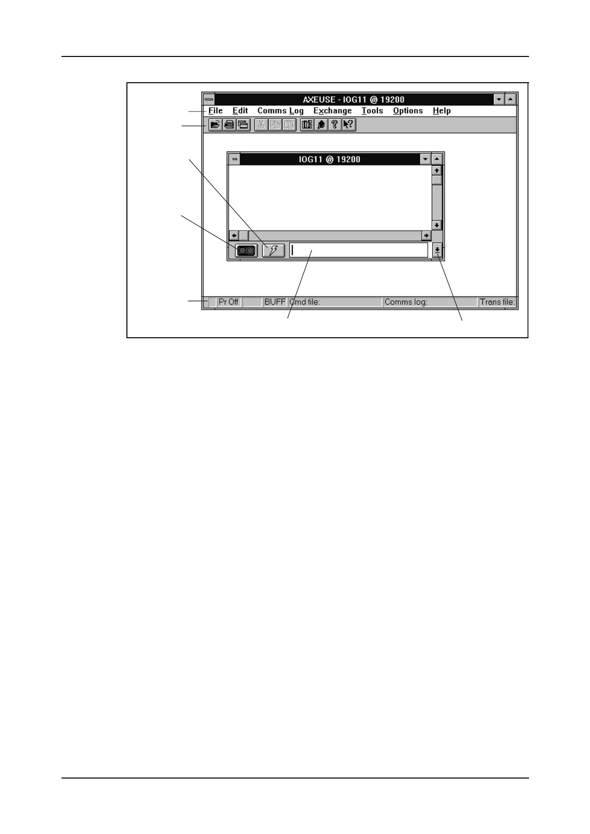
Figure 4.9
The AXEUSE Application Window
Beneath the Menu bar is the Toolbar, a series of icons providing fast
access to the most commonly used AXEUSE functions.
The Quick Commands icon is used to display the current quick command
file.
Pressing the Connect/Release icon will cause the application to transmit
the connect character to the AXE 10 system. Pressing the same icon while
the exchange is connected will release the connection.
Along the bottom of the application window is the Status Line, which dis-
plays a range of information regarding the currently active exchange win-
dow.
The Command Line may be used for direct entery of commands to the
AXE 10 system.
The Command History List button recalls commands previously entered
on the command line. Up to 40 commands may be stored in the history list.
4.4.4 Interactive Communication
Interactive communication with the AXE 10 system is performed via
Exchange Windows (see figure 4.10). You may have up to nine exchange
windows opened at the same time, one window for each of the ports COM
1-9.
After opening an exchange window you can then connect that window to
the AXE 10 system, so that commands may be sent to that exchange port.
When finished, you may release and close the relevant exchange windows
Menu bar
Toolbar
Quick Commands
icon
Connect/Release
icon
Status Line
Command Line Command History List button
AXE 10 Basic Operation and Maintenance Activities
40 03802-EN/LZM 112 17 R1
individually.
Exchange windows can be re-sized, re-positioned and minimized to icons
if required.
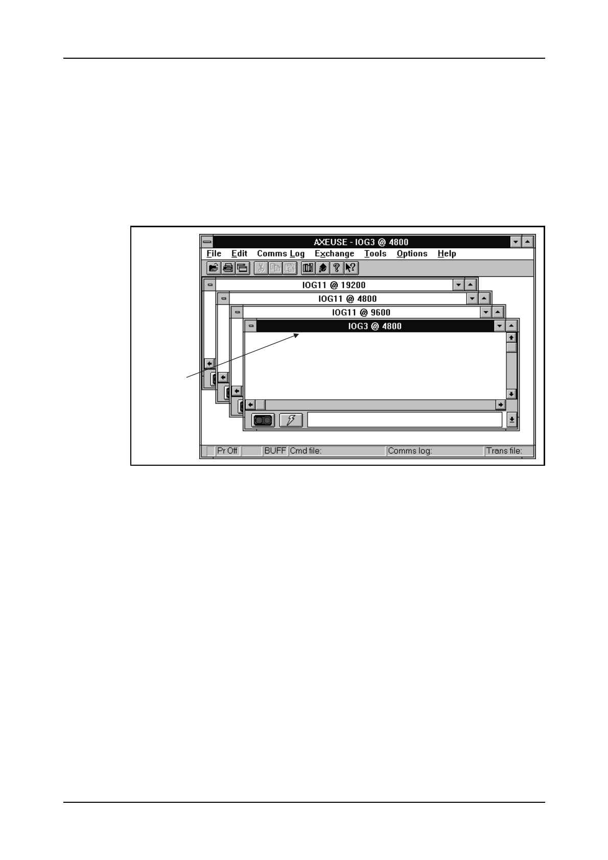
4.4.5 The Active Window
Although multiple exchange windows are opened and simultaneously con-
nected to the AXE system, only one of them can be the active window,
(see figure 4.10). The active exchange window is the one which may initi-
ate exchange-related commands or actions.
Figure 4.10
The Exchange Windows
You activate an exchange window by clicking on any part of it. The title
bar with the exchange name will then be highlighted.
4.4.6 The Command Line
AXEUSE allows you to type in commands and parameters, and send them
directly to the AXE 10 system. You input these on the command line of the
active exchange window, (see figure 4.11). Press the ENTER key to trans-
mit them. Command-line editing features are provided. The most recently
entered command is highlighted and can be copied to the command line.
Active exchange
window
Communication with the System
03802-EN/LZM 112 17 R1 41
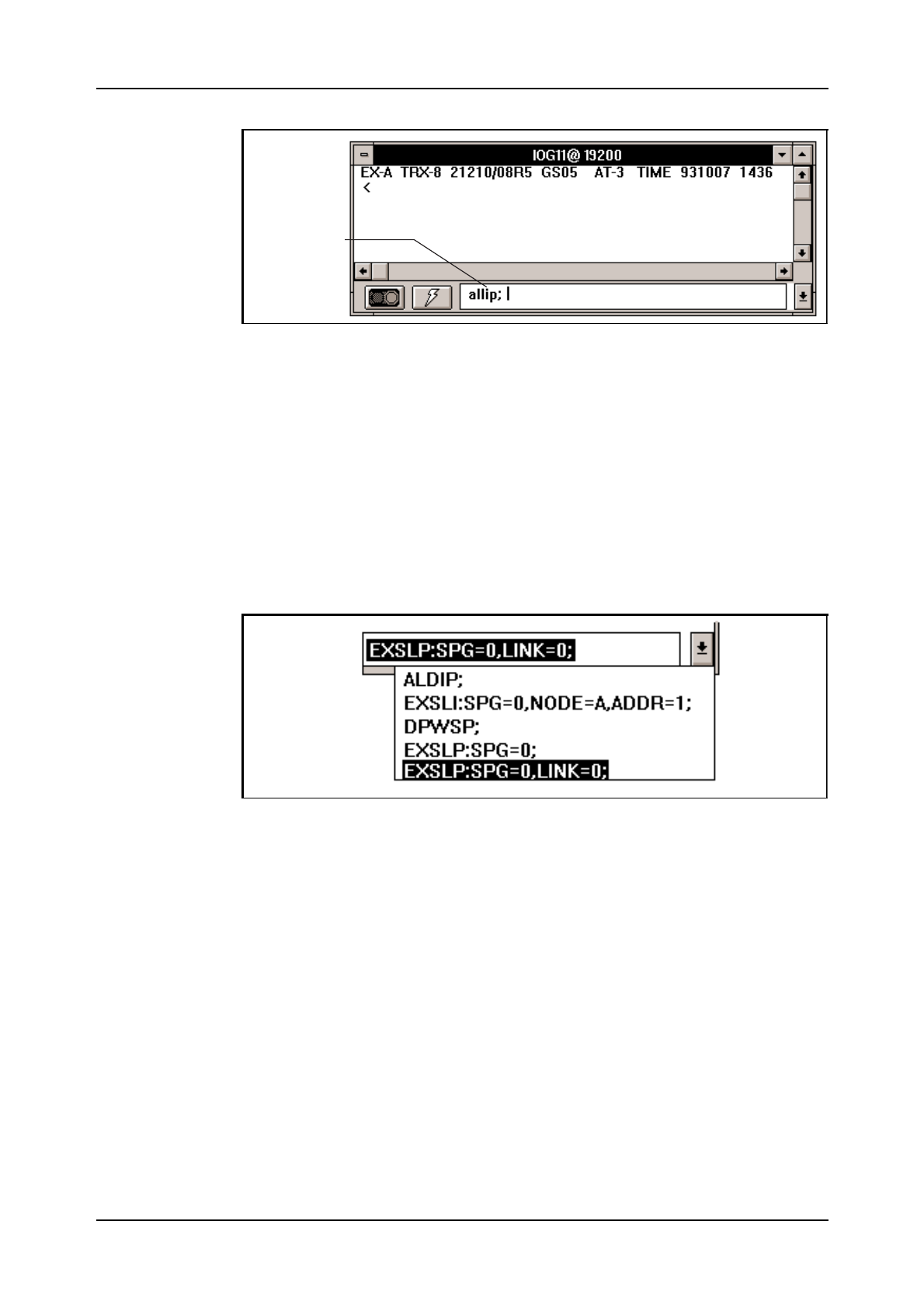
Figure 4.11
The Command Line
4.4.7 The Command History List
A Command History List is associated with a command line. The list is
made up of a buffer which contains the last 40 commands you have
entered on the command line.(see figure 4.12).
To open the command history list, click on the Command History List But-
ton (see figure 4.9) at the bottom right hand corner of the exchange win-
dow. You can access the history list at any stage, and recall and re-transmit
any previously entered command.
Figure 4.12
The Command History List
4.4.8 Quick Commands
The Quick Commands function enables you to store the most commonly
used commands and parameters in one or a number of files. To access the
quick commands function, click on the Quick Commands Icon
(see figure 4.9).
Each file could represent a different task or job. While performing that job,
you can pre-load the appropriate file into the quick commands dialog box.
The file may be edited within the quick command dialog window.
Command typed
by user
AXE 10 Basic Operation and Maintenance Activities
42 03802-EN/LZM 112 17 R1
4.4.9 Command Files - Recording and Transmission
AXEUSE enables you to record command files - ASCII files containing
one or a sequence of AXE commands and any associated parameters - for
transmission to the AXE 10 system.
Transmitting a command file to the AXE 10 system is faster and more con-
venient than typing the relevant commands and their parameters a second
time on the command line of an exchange window.
You can create and edit command files within AXEUSE, or you can use a
word processor or text editor which offers the option to save files in ASCII
format code.
A command file is always transmitted from a connected exchange win-
dow, and the window responds to the transmission in the same way as it
would had the contents of the command file been typed on the command
line.
If the situation so requires, you can temporarily interrupt command file
transmission to the AXE 10 system.
To facilitate automatic testing, command files can be created and sent to
the AXE 10 system.
4.4.10 Logging Communication
AXEUSE offers three different options when logging communication with
the AXE 10 system. In each case it is irrelevant how the communication
takes place. Whether a command is entered on the command line, recalled
from the command history list, selected from the quick commands file or
transmitted from a command file, the full details of the communication are
logged by AXEUSE.
Options for logging communications are briefly described below.
The Exchange Window
All commands sent from AXEUSE to AXE 10 pass via an open and con-
nected exchange window, and that window always displays full details of
the communication. (see figure 4.13).
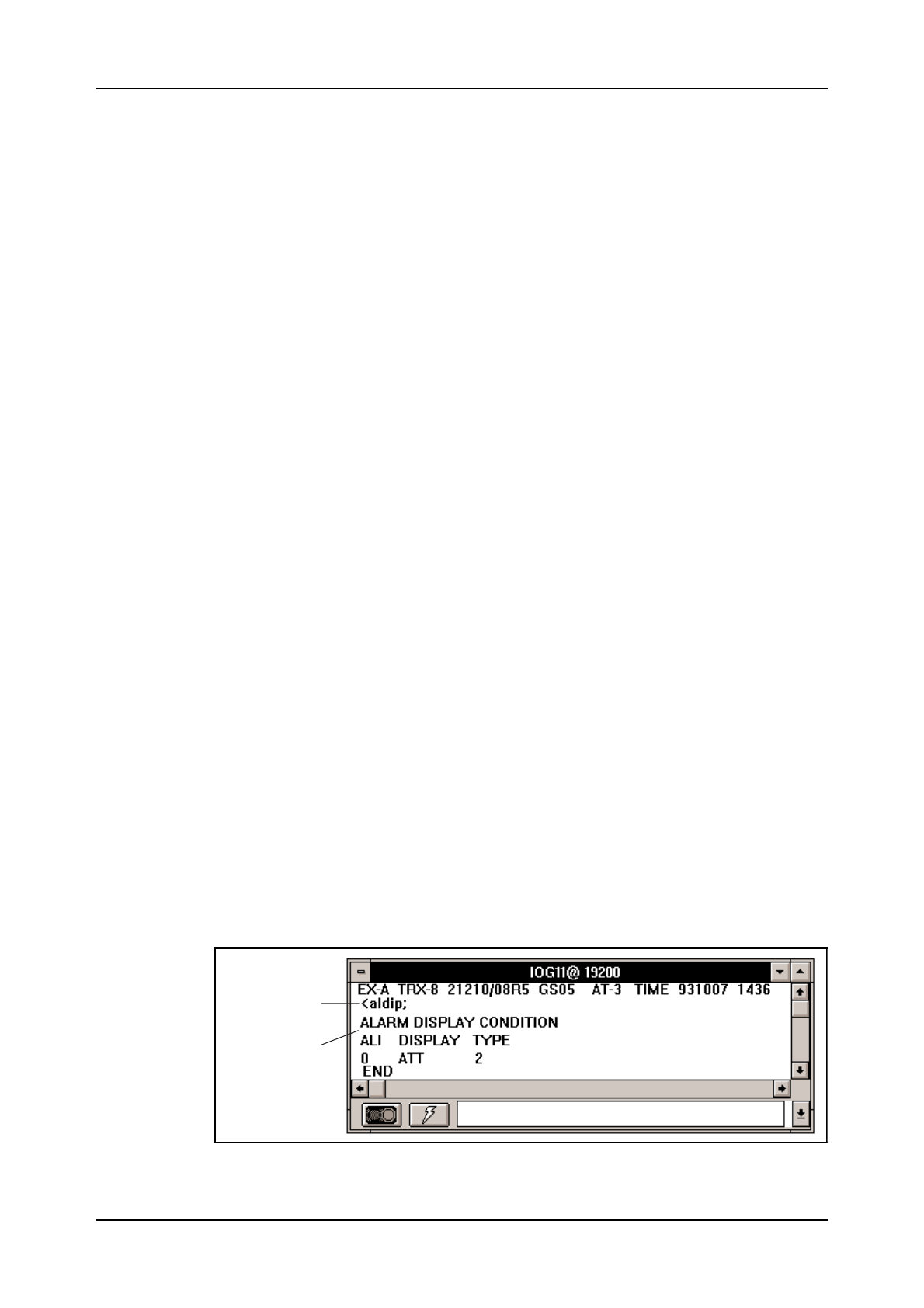
Figure 4.13.
Exchange Window
Entered command
Feedback from
target system
Communication with the System
03802-EN/LZM 112 17 R1 43
Vertical and horizontal scroll bars are provided with the exchange window
to enable you to move through a list of communication details, particulary
useful when the entire area of text does not fit within the window.
Printer Logging
At any stage of communication between an exchange and the AXE sys-
tem, you can log details of the communication to a print spool. The infor-
mation may then be printed directly.
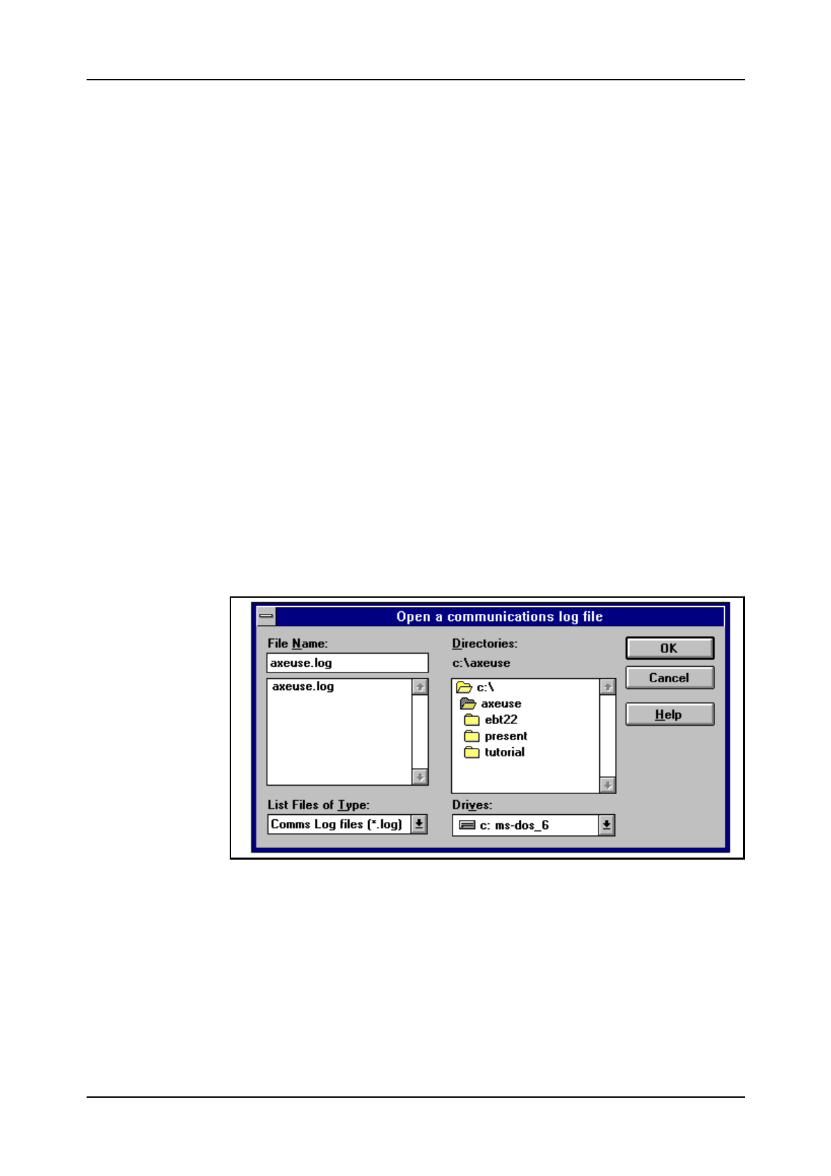
Communication Logs
You can create a communication log file for recording the commands sent
to the AXE system and the feedback generated by the system in response.
The log file will record all commands and feedback, regardless of whether
the commands are entered directly on the command line, recalled from the
command history list, sent as quick commands, or transmitted within com-
mand files.
You can temporarily interrupt the recording at any stage and resume it
again when appropriate (see figure 4.14 ).
It is recommended that you add the file extension .log to the name of
your log file when saving it.
Once you have recorded and saved a communication log, you can display
the log on the screen or output it to a printer.
Figure 4.14
Open a Log File Dialog Box
4.4.11 On Screen Documentation
Whenever you start AXEUSE on your PC, the browser application is also
started. It runs in the background until you select it.
Using the DynaText Browser, you can read documentation regarding your

AXE 10 Basic Operation and Maintenance Activities
44 03802-EN/LZM 112 17 R1
application system. This is stored on the CD-ROM which you will have
received from your supplier. Of course, the on-screen documentation CD-
ROM must be loaded via your PC’s CD-ROM drive in order to enable
AXEUSE to access the information that it contains.
You can access the Browser from within AXEUSE, or you can simply
switch between AXEUSE and the Browser using the Windows task-
switching facility.
4.4.12 Interactive Access
AXEUSE provides the user with interactive access to the DynaText
Browser.
Whenever feedback containing a command-related fault code is displayed
in the exchange window, the program can automatically retrieve and dis-
play the relevant Command Description.
4.4.13 Access to Technology Based Training (TBT) Sessions
TBT sessions may be accessed from within AXEUSE, there is therefor no
need to terminate the current application when entering a training session.
AXEUSE is, at the moment, supplied with three TBT courses: C7 Signal-
ling in AXE, C7 in the Telecommunications Network and IOG11 Hard-
ware.
Future additions on TBT will include operator aids applicable to the han-
dling of emergency situations.
4.4.14 Online Help and Tutorial
In addition to printed documentation, AXEUSE offers on-line help for all
commands and commonly performed functions. You can access this mate-
rial at any stage by pressing the standard Windows help key, F1.
The online tutorial enables you to learn the basics of AXEUSE by practis-
ing interactively with a copy of the real application.
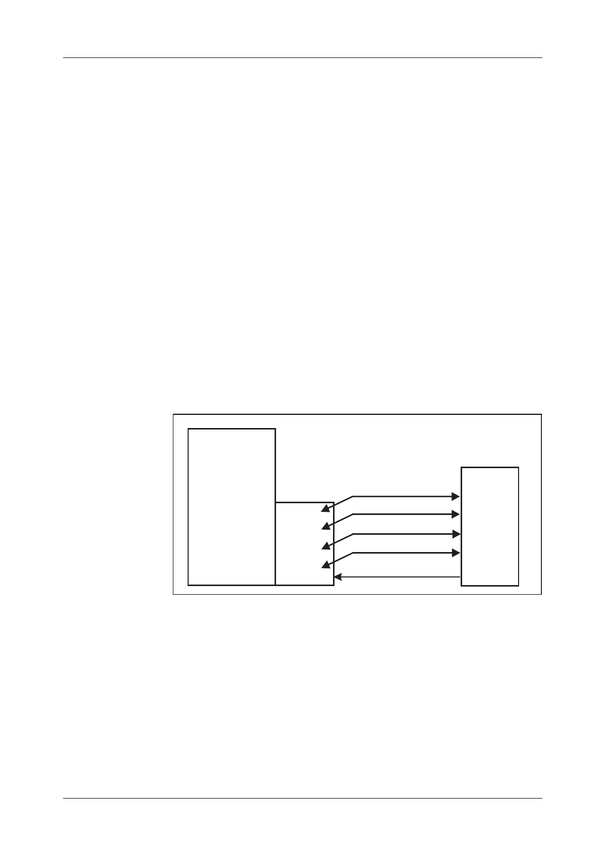
Communication with the System
45
4.5 Connection to TMOS
Communication with TMOS, (Telecommunication Management and
Operation Support) presupposes a standard for the sending and receiving
of information. TMOS uses several different standard communication pro-
tocols to communicate with AXE 10.
•X.25 for the link communication (Layer 3)
•MTP for application communication (Layer 4 - 7).
The physical connection to TMOS is performed via one of the physical
ports in the IOEXT magazine located in the IOG11 (Input / Output Sys-
tem).
Communication between the AXE 10 and TMOS, (see figure 4.15), can be
divided into the following five traffic cases:
•MML- Commands
•Delayed Responses
•Spontaneous Reports
•File output from the AXE 10 Exchange
•File information from TMOS to the AXE 10 Exchange.
Figure 4.15
Traffic Cases
AXE 10
IOG11 TMOS
File Information
MML-Commands
Delayed Response
Spontaneous Response
File Output

03802-EN/LZM 112 17 R1 46
4.5.1 MML Commands
The MML language used for normal handling of AXE 10 Exchanges can
also be used for communication via TMOS.
Immediate Response
All MML commands result in some sort of immediate response from the
AXE 10 Exchange. Immediate responses are received as ASCII characters
and may therefore be displayed via character terminals.
TMOS designates immediate output as an immediate response.
There are four types of immediate responses:
•Procedure Printouts
•Interactive Printouts
•Answer Printouts
•Check Printouts.
4.5.2 Delayed Responses
A response is often delayed due to the fact that the action requested
requires the AXE system to collect data (traffic recording etc.), which
takes a varying amount of time.
4.5.3 Spontaneous Reports
This report category represents reports produced by the AXE system that
were not solicited by the TMOS system. Alarm situations are examples of
situations resulting in such reports.
4.5.4 File Output from the AXE 10 Exchange
File outputs from AXE 10 are binary ASCII files and are converted by the
TMOS system (statistic measurement etc.).
4.5.5 File Information from TMOS to the AXE 10 Exchange
Any files that are similar in syntax to the file output from the AXE 10 sys-
tem can be sent from TMOS to the AXE 10 Exchange.

Communication with the System
03802-EN/LZM 112 17 R1 47
4.6 Chapter Summary
•FIOL/Docview is using EDML, Ericsson Document Mark-up Lan-
guage
•FIOL is a program witch makes it possible to use a personal computer
as a terminal for communication with AXE
•FIOL can be used for e.g. transmitting a command file, creating a log
file
•AXEUSE is a Microsoft Window application that provides multiex-
change communication with the AXE system
•Only documentation available in SGML, Standard General Mark-up
Language can be handled by AXEUSE
•Communication with TMOS is performed via the X.25 protocol con-
nected to IOG 11 (IOEXT magazine)
•File outputs from AXE to TMOS are binary ASCII files.

AXE 10 Basic Operation and Maintenance Activities
48 03802-EN/LZM 112 17 R1

Hardware Orientation
03802-EN/LZM 112 17 R1 49
5. Hardware Orientation
Figure 5.1
Chapter Objectives
5.1 Mechanical Structure
5.1.1 Introduction
The mechanical organization of the AXE system is based on a concept
called the Packaging System or the BYB-Structure. This system offers a
high degree of flexibility which is well suited to the AXE system’s overall
modularity. Packaging system size standardization contributes to the sim-
plification of the handling required during the variousd phases of design,
manufacture, documentation, installation, and operation and maintenance
activities related to the AXE system.
The AXE equipment is delivered in Magazines equipped with Printed
Board Assemblies. These magazines are the basic building blocks of the
packaging system.
The magazines are installed on Shelves housed in Racks or Cabinets. The
racks or cabinets are arranged in Rows in the exchange room.
Chapter Objectives
After completing this chapter the participant will be able to:
• Locate Hardware units in the exchange through the use of com-
mands
• Identify the operational activities that are to be performed based on
information in a specific work order and the contents of the associ-
ated B-Module.

AXE 10 Basic Operation and Maintenance Activities
50 03802-EN/LZM 112 17 R1
5.2 Development of the Packaging System
5.2.1 BYB 101 and BYB 102
The first packaging structure developed was called BYB 101. Certain
objectives were particularly considered during the design of this package:
•The structure was to be suited to electronic equipment units made up of
integrated circuits, miniaturized electromechanical components and
power supply units.
•It was to be possible to use computerized aids to facilitate the design,
production and documentation of the system.
•The processing time and cost were to be kept as low as possible.
•The structure should not to restrict the use of existing and future com-
ponents.
•Cooling was to be achived by natural air circulation (selfconvection)
for most of the cabinets, (With the exeption of the IOG and CP).
Basically, the BYB 102 has retained the basic structure of its predecessor,
the BYB 101. Its primary objective was to simplify installation methods
and operations, thereby reducing installation time.
Modified elements of the BYB 102 structure may be applied when exist-
ing BYB 101 installatons are expanded.
Both BYB 101 and BYB 102 structures use racks to house the shelves car-
rying the magazines.
5.2.2 BYB 202
The BYB 202 is designed to meet the requirements for a flexible cabinet-
type structure. The designers of this system seized the opportunity, while
maintaining the basic design of the BYB structure, to make a number of
improvements:
Screening
The BYB 202 cabinet structure ensures effective protection against ESD
(Electrostatic Discharge) and EMI (Electromagnetic Interference). The
cabinets are electrically screened to comply with international standards.
The front doors have special features to optimize both EMI and air ventila-
tion(see figure 5.2).
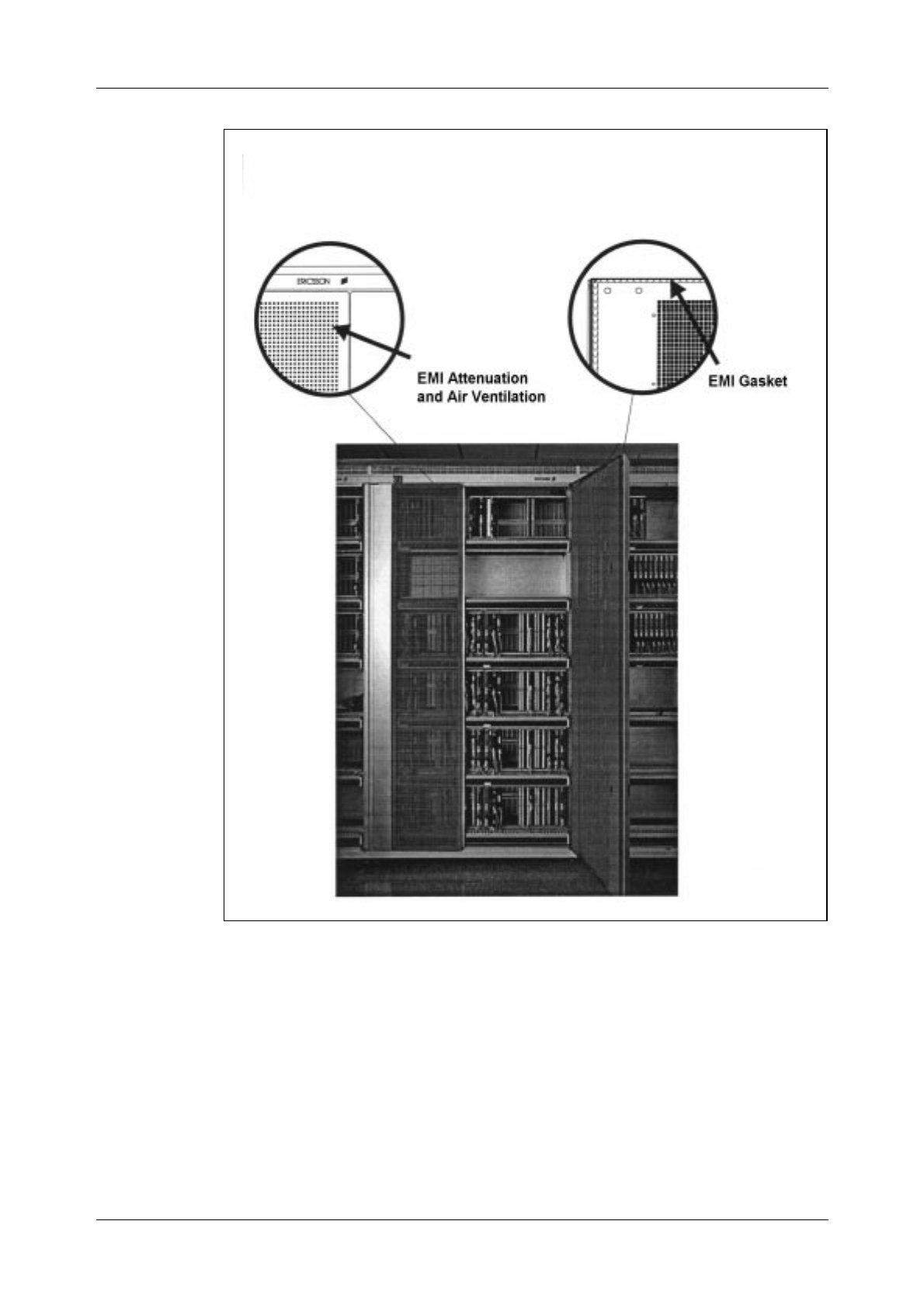
Hardware Orientation
51
.
Figure 5.2
Screening
Heat Dissipation
The main objective in the thermal dimensioning of the cabinets was to
keep component temperature as low as possible. An efficient combination
of series and parallel natural convection, with its known advantages (no
noise, no fan maintenance, etc.), was used to achieve greater heat dissipa-
tion than that achieved with earlier designs (see figure 5.3).
Cabinets requiring extreme heat dissipation make use of fans that support
natural convection.
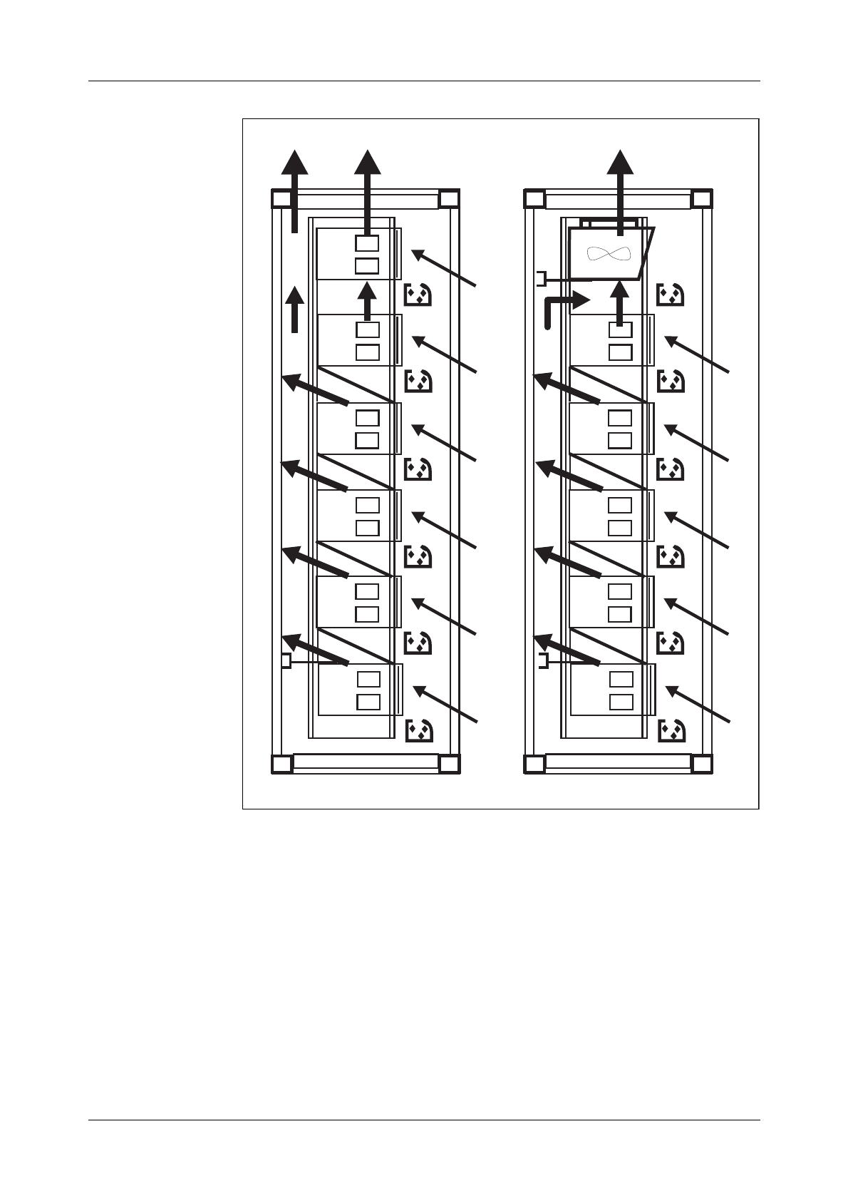
AXE 10 Basic Operation and Maintenance Activities
52 03802-EN/LZM 112 17 R1
Figure 5.3
Heat Dissipation
Earthing
The combination of the material and the excellent mechanical design of
the contact points employed in the earthing system of each cabinet, cou-
pled with the inter-cabinet earth connection scheme, ensures good zero-
level stability.
Cable Running
As in the case of rack design, the exchange cables can be run in screened
cable chutes mounted on top of the cabinets or between a raised deck and
the actual floor of the switching room (see figure 5.4).
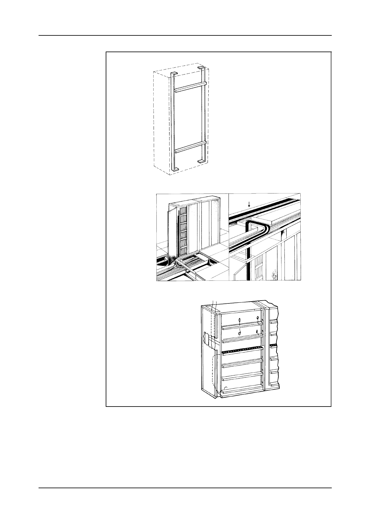
Hardware Orientation
03802-EN/LZM 112 17 R1 53
Figure 5.4.
Cable Chutes
Interior cabinet cabling is distributed so that it is run in both the horizontal
cable chutes and in the vertical space at the left side of the cabinet.
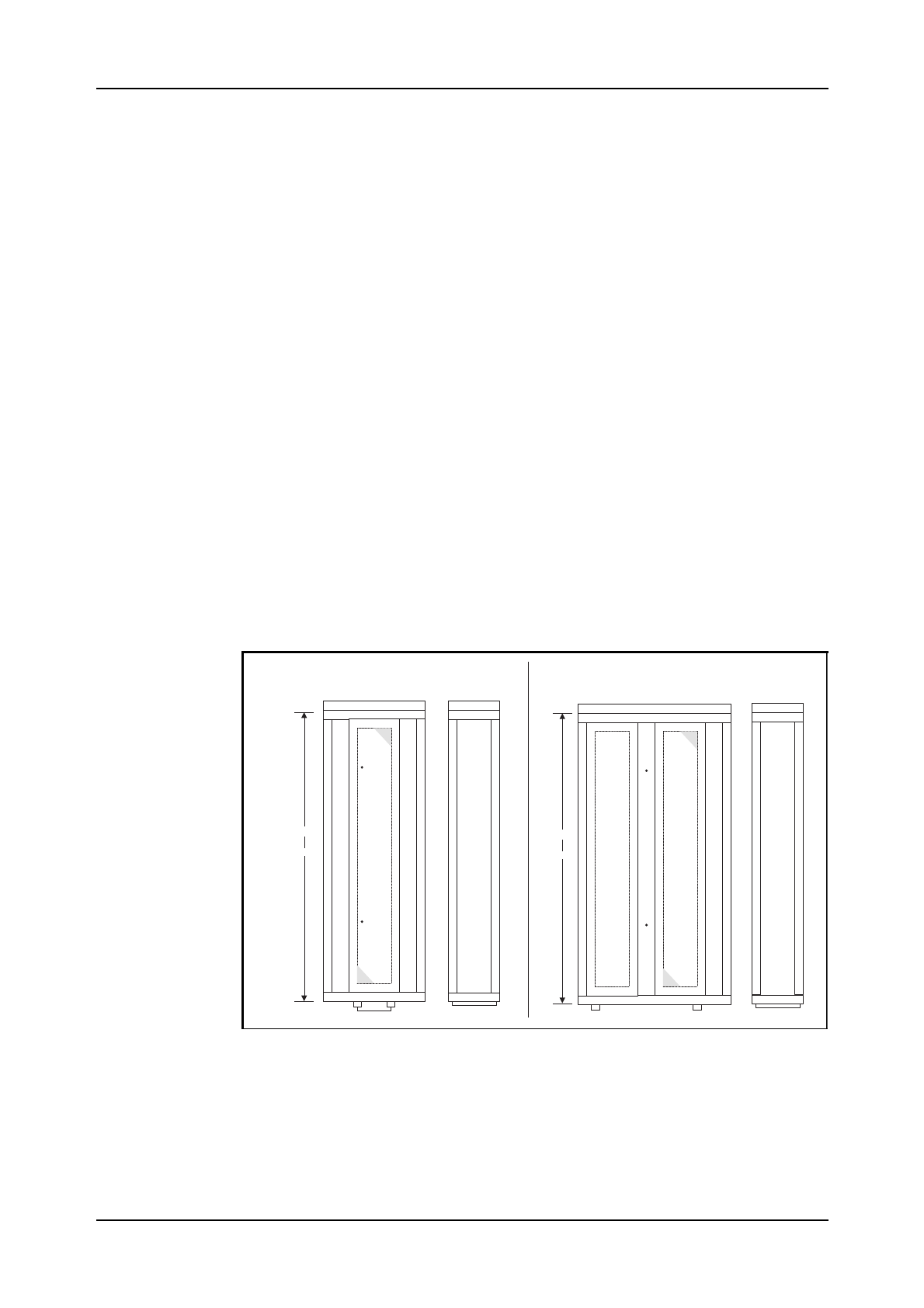
AXE 10 Basic Operation and Maintenance Activities
54 03802-EN/LZM 112 17 R1
Earthquake Resistance
Anchoring arrangements and the design of the cabinet ensure resistance to
earthquakes, in line with international requirements.
5.2.3 The Building Module
Instead of inches or centimetres, Ericsson uses a standard unit of length
which is called a “Module”, designated (M) in mechanical structures.
1 M = 0.1 Inch = 2.54 mm
This unit is a bit too small for practical use, so another unit which is called
a “Building Module”, designated (BM), is used.
1 BM = 16 M = 1.6 Inches = 40.64 mm
5.3 The Cabinet
Cabinets are manufactured in two different widths. The narrower of them
is 720 mm wide, has only one door, and is used for magazines of up to 12
BM. The broader version is 1200 mm wide, has two doors and is used for
magazines up to 24 BM ( See Fig. 5.5).
Figure 5.5
Cabinets for magazines of 12 BM and 24 BM
The cabinets can be delivered in two heights; 2135 mm or 1810 mm.
The depth of the cabinets is 400 mm.
There is a maximum of 6 shelves in BYB 202 cabinets.
720mm 400mm 1200mm 400 mm
Cabinetformagazinesof12BM Cabinetfor magazinesof24BM
or
2135mm
1810mm or
2135mm
1810mm
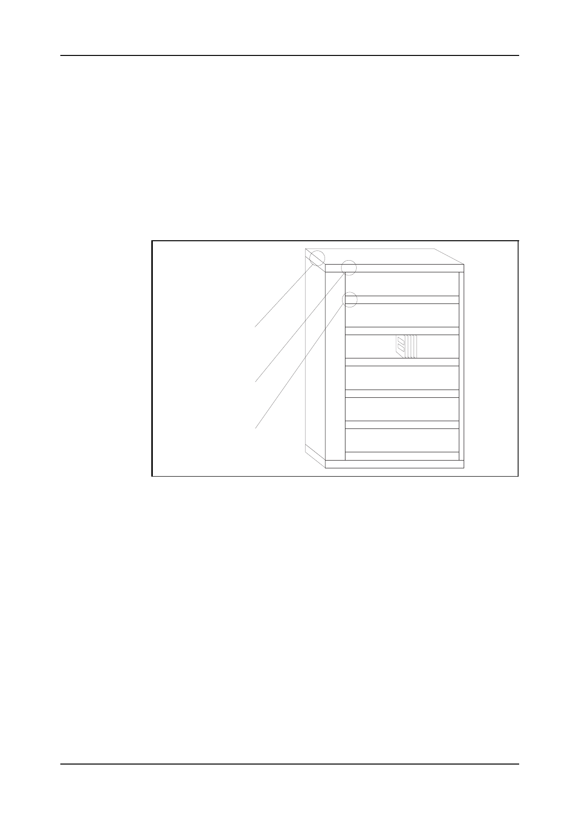
Hardware Orientation
03802-EN/LZM 112 17 R1 55
Required ceiling height is, on a raised floor, a minimum of 2697 mm, and
with overhead cabling a minimum 3100 mm.
The cabinets may be mounted in double-sided rows (back-to-back), in sin-
gle sided rows, or single against a wall. The required maintenance aisle is
minimum 800 mm.
The rows, cabinets and shelf numbering are shown in figure 5.6. The row
numbering (3-digit) is marked on the end of the cabinet at the beginning of
each row. The first digit is normally the floor number, the second and third
digits indicate the actual row number. In this example, this particular row
is located on the first floor in row no. 21.
Figure 5.6
Row, Cabinet and Shelf Numbering
Each cabinet has its own number at the front upper corner which indicates
its position within the row. Numbering starts at the beginning of each row,
which is always indicated on the layout by a line.
The shelves are labelled alphabetically, with the top shelf as A, the second
as B, and so forth, down to the letter F as we use a maximum of 6 shelves.
5.3.1 Magazines
A magazine consists of two main components:
•The board frame including slots that hold and guide the printed boards
•The backplane which contains the magazine’s internal wiring and cir-
cuit board connectors.
121 01
A0102
B
C
D
E
F
ROWNUMBER
CABINETNUMBER
SHELFLABEL
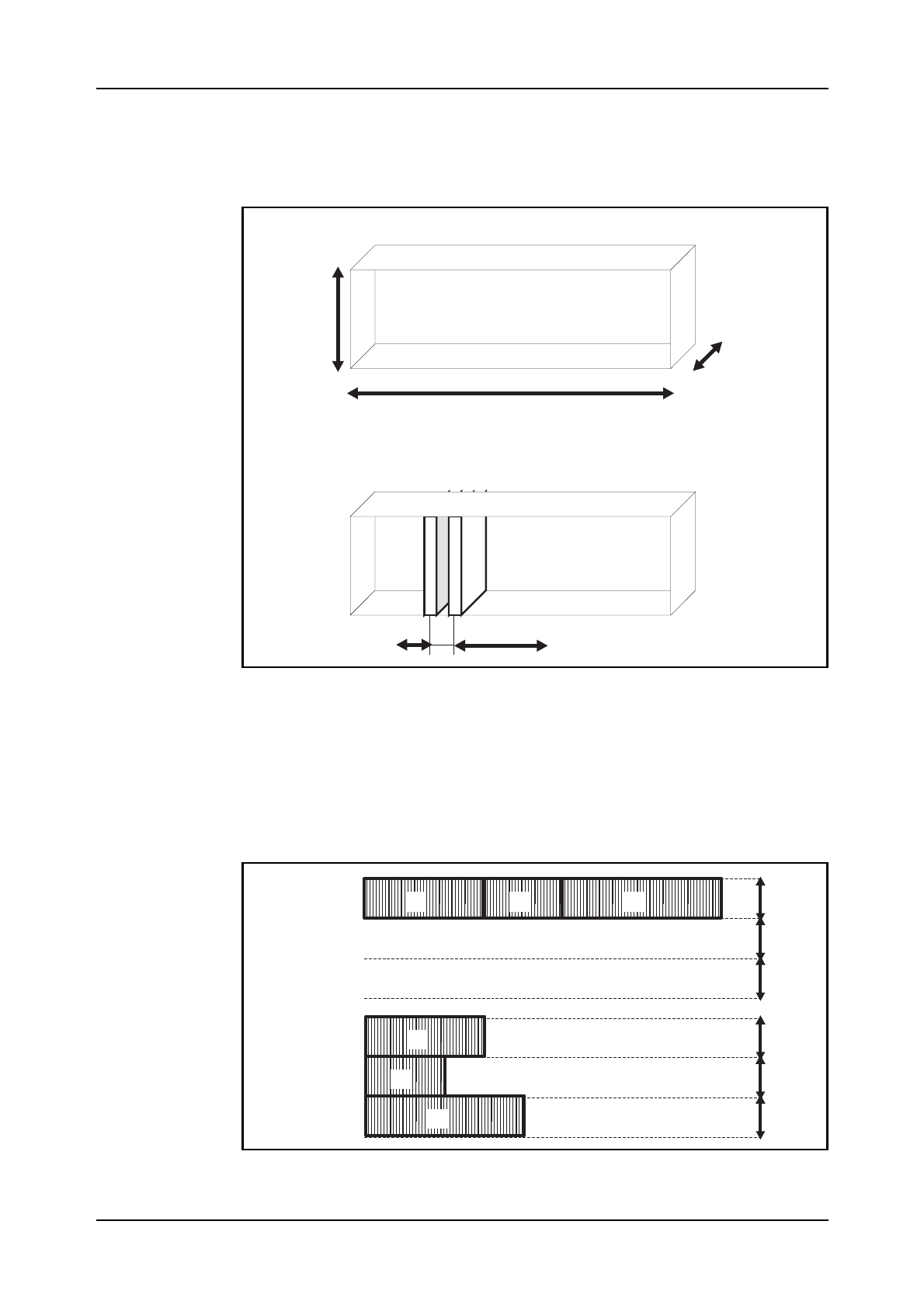
Hardware Orientation
03802-EN/LZM 112 17 R1 56
The magazines with circuit boards are placed on the shelves. The maga-
zines correspond to function units and therefore vary in size, (see figure
5.7).
Figure 5.7
Magazines in BYB System
The packaging structure permits flexible positioning of the magazines, i.e.
they can be placed side by side or on top of each other, or on a combina-
tion of the two arrangements, (see figure 5.8). This permits the cabinets to
be equipped in the easiest and most economical way.
Figure 5.8
6BM
220mm
n*3BM
n=1,2,3,.....,8
6or8M
Magazinemeasures
Boardspacing
1
2
3
1 2 3
shelf
shelf
shelf
shelf
shelf
shelf
D
E
F
D
E
F

Hardware Orientation
03802-EN/LZM 112 17 R1 57
Positioning of Magazines
The magazines are interconnected by means of front connections and can
thus be moved or replaced without necessitating any change of the cabinet
layout.
The magazines are assigned type-codes BFD XYZ, in which:
X denotes magazine type,
= 1 for magazine with PCBs or
= 2 for magazine devices such as power units.
Y denotes board spacing,
= 1 for 6M or
= 2 for 8M.
Z denotes magazine width,
= 2 for 3BM,
= 3 for 6BM,
= 4 for 9BM, etc.
Looking at figure 5.9 we see how the magazines are differentiated by their
width, and thus the number and type of printed circuit boards (PCBs) they
can contain.
Figure 5.9
Magazine types B F D
Magazinetype Width
6M 8M BM
BFD112
BFD122
BFD113
BFD123
BFD114
BFD124
BFD115
BFD125
BFD116
BFD126
BFD117
BFD127
BFD118
BFD128
BFD119
BFD129
7
15
23
31
38
46
54
62
5
11
17
23
28
34
40
46
3
6
9
12
15
18
21
24
3
6
9
12
15
18
21
24
Numberof
Boardpositions
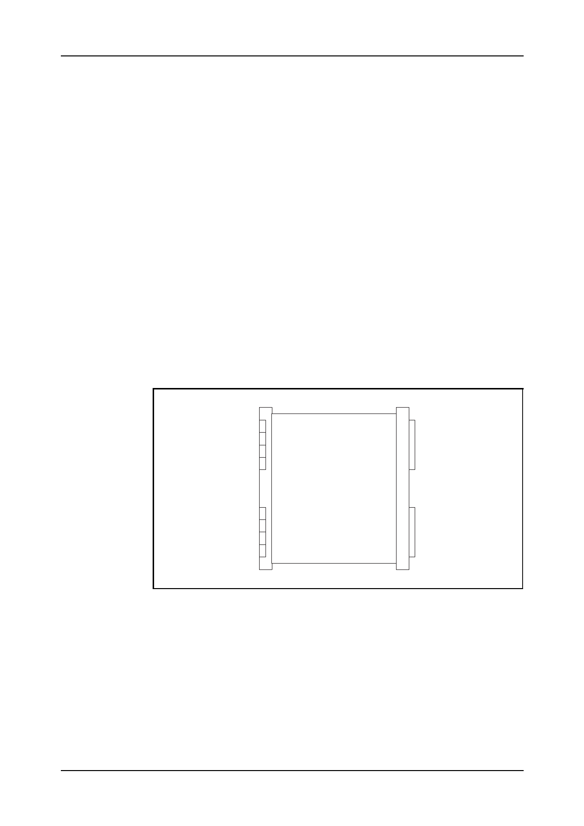
Hardware Orientation
03802-EN/LZM 112 17 R1 58
Each magazine is equipped with the PCBs that are required by the particu-
lar function unit in which the magazine is included. Each PCB has its pre-
defined position in the magazine. All magazines are equipped with one or
more power boards to supply power to the individual magazine. These
power boards have a toggle switch for turning power on and off. Some
boards are equipped with a fuse mounted on the power plug.
5.3.2 Magazine Devices
These are units which require a space-equivalent of an entire magazine
and are placed on shelves in the same way as magazines containing PCBs.
Examples of these units are the DC/DC converter unit, the ringing genera-
tor, the distribution unit, etc.
5.3.3 Printed Circuit Boards (PCBs)
The Printed Circuit Boards are installed in slots in the magazines. Each
board has room for two connectors at the back side and two connectors at
its front, (see figure 5.10). When the boards are put into place in the maga-
zine, they are plugged into the backplane by means of the back connectors.
Figure 5.10
Printed Circuit Board (PCB)
The front connector positions on the printed boards in a magazine are allo-
cated in two rows (A and B), (see figure 5.11).
Front Back
2
4
ROF137...
Componentside
1
3
up
intomagazine
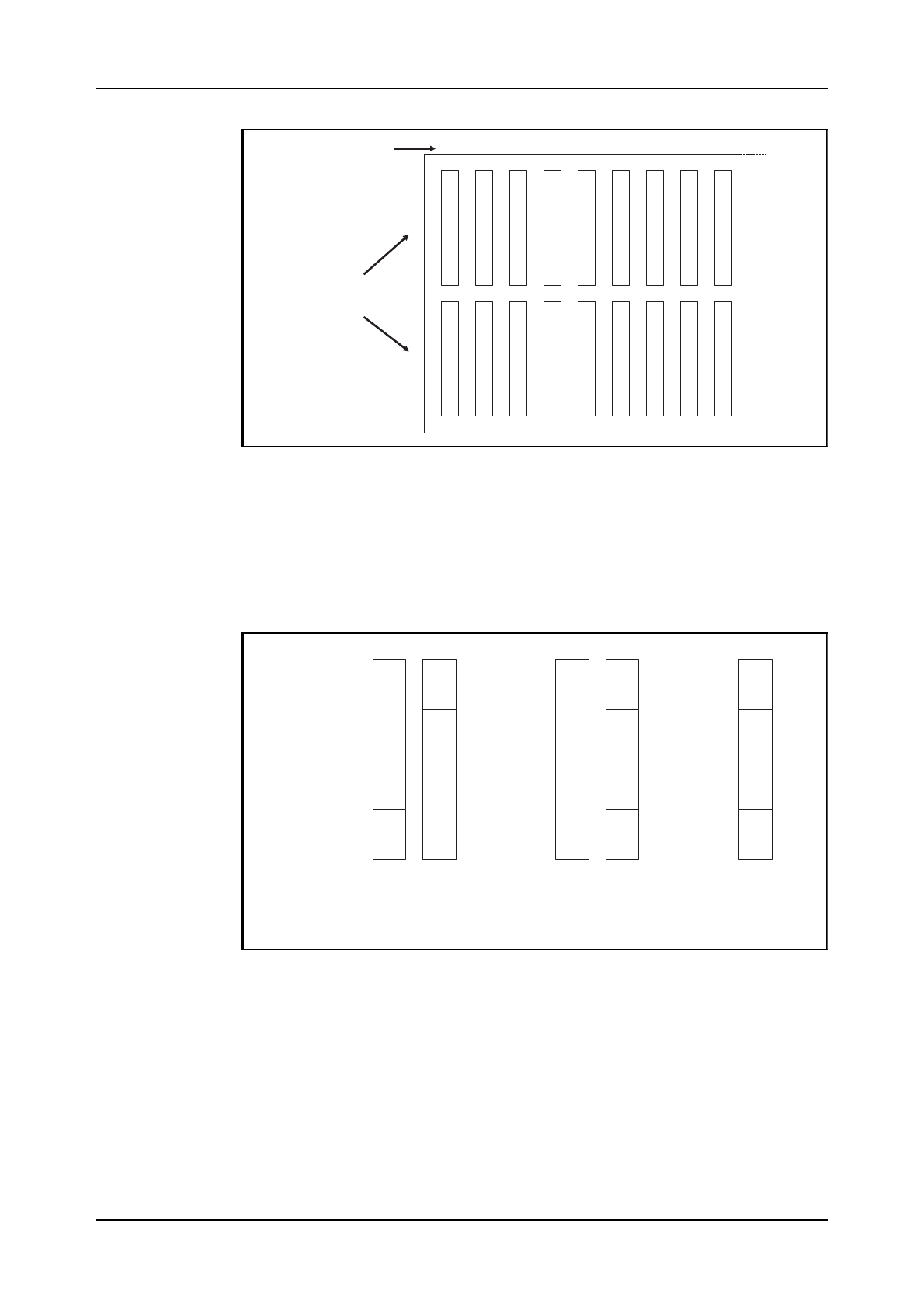
Hardware Orientation
03802-EN/LZM 112 17 R1 59
Figure 5.11
Connector Row
The backplane connectors on the circuit board have position C and D.
The connectors can be positioned in a number of ways within these two
rows, (see figure 5.12).
Figure 5.12
Connector Positions
The standard PCBs are assigned type-code ROF 13 ... except for CP
boards which are assigned ROF 16 ....
Depending on the size of the components mounted on a board, boards
require magazine space amounting to 6M or 8M. Components are
mounted only on one side of the board.
01 02 03 04 05 06 07 08 09
Boardpos.
Connector
row
A
B
1
2
1
3
2
1
2
3
4
3/4
Connector 1/2
Connector 1/4
Connector
Connector
pos.A(B)

AXE 10 Basic Operation and Maintenance Activities
60 03802-EN/LZM 112 17 R1
5.4 Localization of hardware units
In order to locate the physical position of a Magazine, RP, EM, DEV etc,
in an exchange, an operator can use the command EXPOP and study the
printout for localization of the suspected unit.
Example:
EXPOP: TSM=TSM-B-2;
Time Switch Module number 2 in the digital group switch, plane B, is
pointed out.
New equipment added to an exchange must be initiated via the command
EXPOI.
Example:
EXPOI:DEV=KR-0&&-15,POS=CITY-24B-6-C;
For KR individuals 0-15 the following position is defined: Building CITY,
row 34B, section 6 and shelf C.
Position information defined in the system can be removed by command
EXPOE.
Example:
EXPOE:DEV=KR-0&&-15;
Position information for the Hardware entity KR 0-15 is removed.
5.5 Chapter Summary
•Communication with TMOS is performed via the X.25 protocol con-
nected to IOG 11 (IOEXT magazine).
•The BYB 202 cabinet structure ensures effective protection against
ESD, Electrostatic Discharge and EMI, Electromagnetic Interference
•Anchoring arrangements and the design of the cabinet ensure resistance
to earthquakes, in line with international requirements.
•1 BM = 16 M = 1.6 Inches = 40.64 mm
Using the Acrobat Reader
This electronic (on-line) document is stored in Adobe Acrobat format.
To view the document you use the Acrobat Reader 3.0 program (the
one you are using right now) together with the Acrobat Search Plug-in.
The following pages briefly describe the
Acrobat Reader functions used in this
application. Click the next page button at
the top of the page to continue.
More detailed information to help you use
the Acrobat Reader program is found in the
Acrobat Reader Online Guide. Select
Help from the menu bar at the top of the
Acrobat Reader window. Then click on
Reader Online Guide.

Page navigation
The page navigation buttons on the toolbar are
used to move between pages within the document.
The Previous Page and Next Page buttons are used to move
within the document backward or forward, one page at a time.
Use the First Page or Last Page button to move to the first or
last page.
Use the Go Back and Go Forward buttons to retrace your steps
in a document, moving to each view in the order visited.
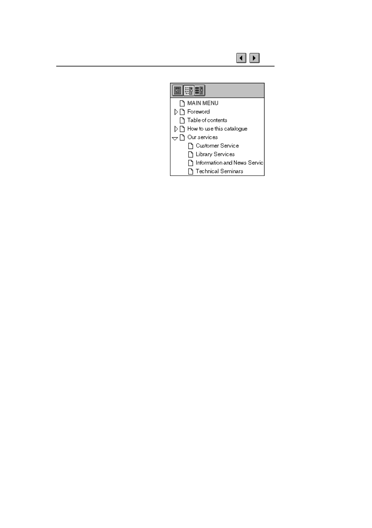
Document overview
On the left-hand side of the Acrobat
window you find the document
overview area. In this application the
area contains the table of contents or
page thumbnails (miniatures) for all
pages in the document. In Acrobat
terminology the items in the content
list are called bookmarks. Click a
paragraph title to go to the
corresponding paragraph. Clicking
one of the small triangles in the list
will show or hide subordinate
headings (bookmarks).
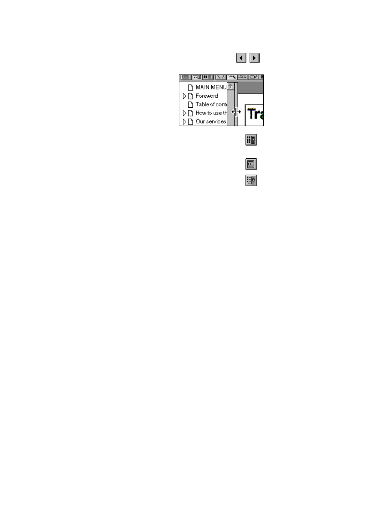
Document overview (cont.)
You can click and drag (see the cursor in
the figure) the border between the
overview area and the page area to
change the area proportions (size relation
between areas).
Click the Thumbnails and Page button to display the
thumbnails.
Click the Page Only button to close the overview area of the
window.
Click the Bookmarks and Page button to open the overview area
and show the table of contents (display bookmarks).
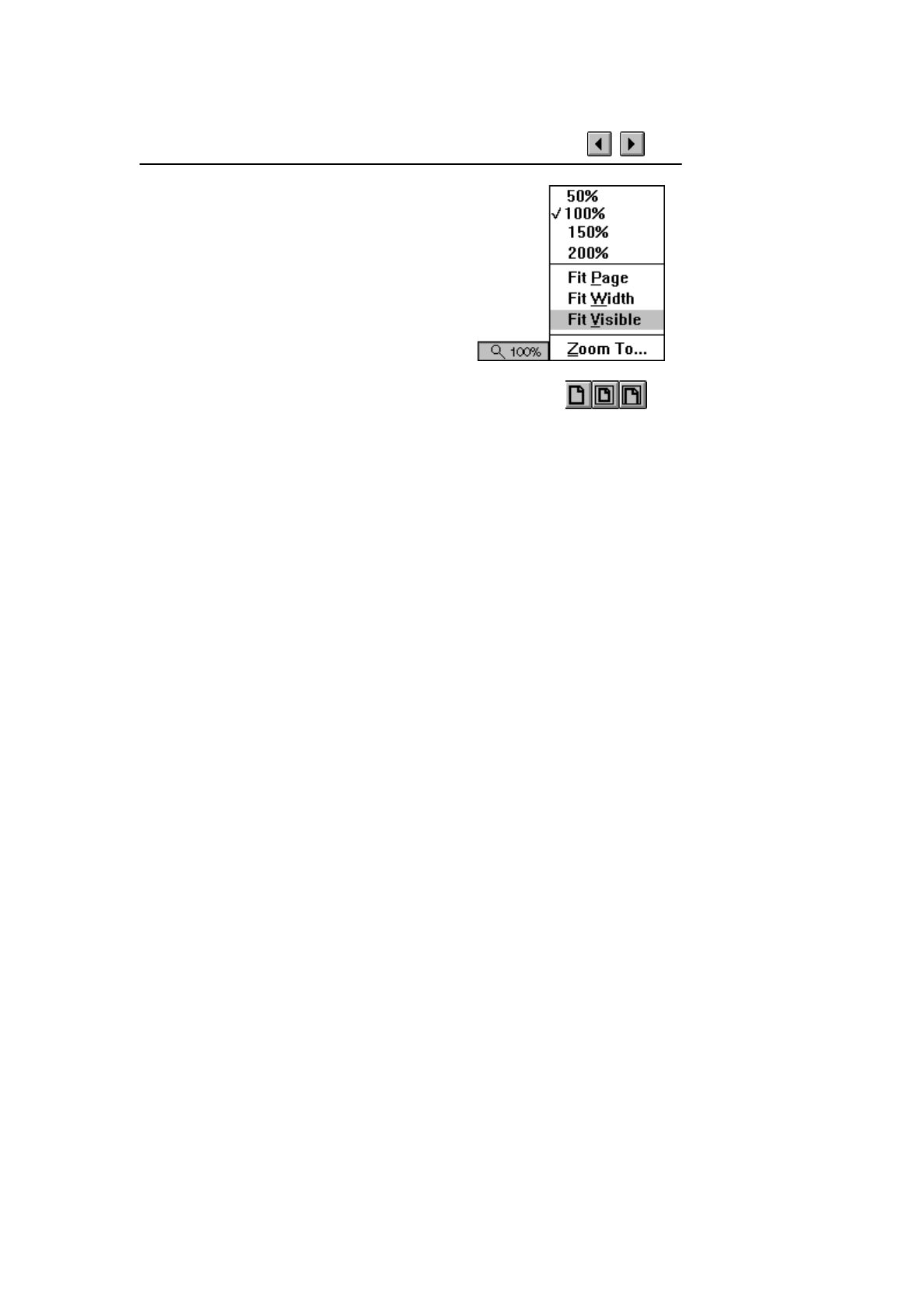
Page magnification
The magnification box at the bottom of the
screen displays the current page magnification
and lets you select various magnifications.
Fit Visible is the default magnification for
this electronic document application.
You can also use the Actual Size, Fit Page, and Fit Width
toolbar buttons to change the screen magnification.

Find
There are two functions to locate a word or a phrase when using the
Acrobat Reader. One function is called Find and the other is called
Search. Find is the slowest and processes the text in a sequential way.
Search is much quicker and is the recommended method. See next page
for details.
(Step-by Step instructions for the Find function)
1. Click the Find button and enter keyword(s).
2. If necessary, press F3 to find next occurrence.

Search
It is recommended that
Acrobat Reader 3.0 with the
Search Plug-In is used to
view this electronic
document. The plug-in
enables the Acrobat Reader
to use the Search function to
very quickly find the
information you are looking
for.
Select Plug-In Help from the Help Menu and then click on Using
Acrobat Search to read about advanced uses of the Search function.
There is also a Find function (see previous page) but Search is the
recommended method as it is much quicker than Find and it also
includes more advanced search functions.


Cutting and pasting text
(Step-by Step instructions)
1. Click the Select Text button and select the text you want to
copy into another Windows application.
2. Select Copy from the Edit Menu to copy the text to the
Windows clipboard.
3. Go to the target Windows application (e.g. Windows Write
or WordPad).
4. Paste the text into your target application.
Important: This function may only be used to create notes or summaries
for personal use. Beware of copyright rules.
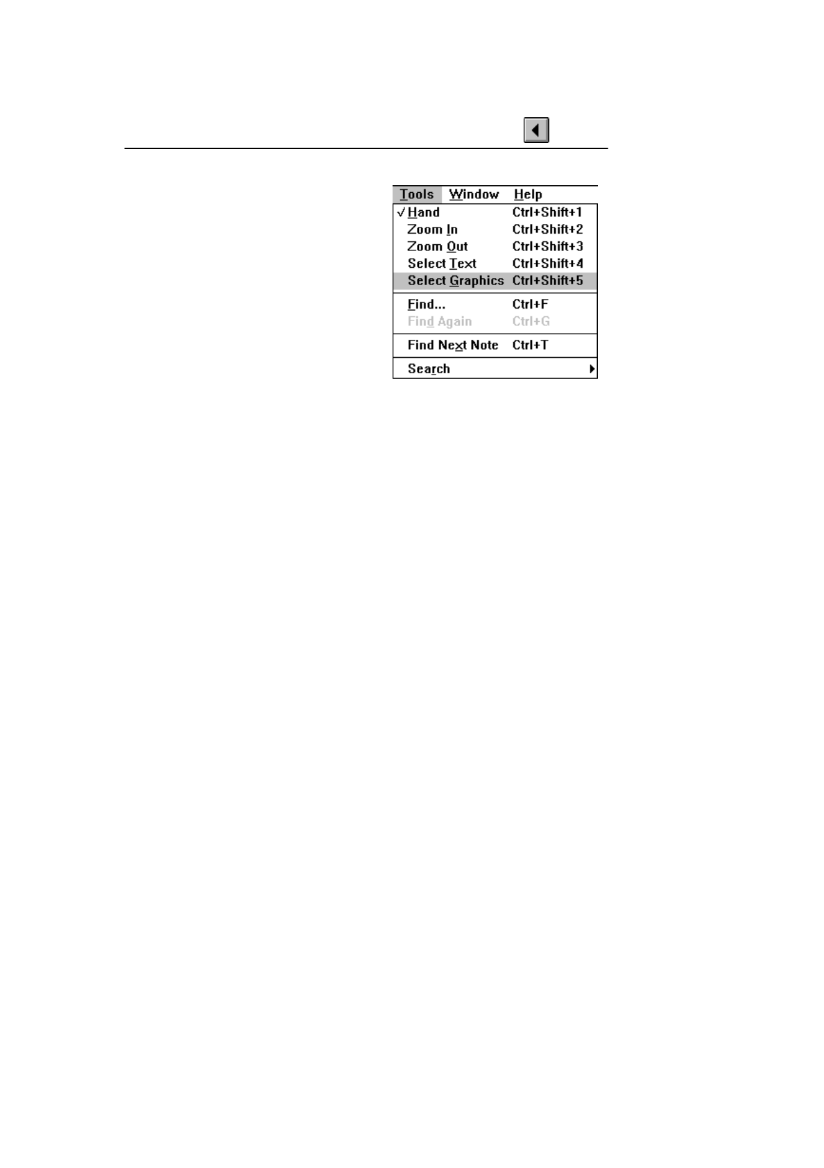
Cutting and pasting graphics
(Step-by Step instructions)
1. Choose Select Graphics from the
Tools Menu to select the graphics
item you want to copy into another
Windows application.
2. Select Copy from the Edit Menu to
copy the graphics to the clipboard.
3. Go to the target Windows
application (e.g. Windows Write or
WordPad).
4. Paste the graphics into your target application.
Important: This function may only be used to create notes or summaries
for personal use. Beware of copyright rules.
