CRT3945 AXMP90RS
User Manual: AXMP90RS
Open the PDF directly: View PDF ![]() .
.
Page Count: 59
- SAFETY INFORMATION
- CONTENTS
- 1. SERVICE PRECAUTIONS
- 2. SPECIFICATIONS
- 2.1 SPECIFICATIONS
- 2.2 PANEL FACILITIES
- 2.3 CONNECTION DIAGRAM
- 3. BASIC ITEMS FOR SERVICE
- 3.1 CHECK POINTS AFTER SERVICING
- 3.2 PCB LOCATIONS
- 4. BLOCK DIAGRAM
- 5. DIAGNOSIS
- 5.1 OPERATIONAL FLOWCHART
- 5.2 CONNECTOR FUNCTION DESCRIPTION
- 5.3 SIMPLE OPERATION CHECK METHOD
- 6. SERVICE MODE
- 7. DISASSEMBLY
- 8. EACH SETTING AND ADJUSTMENT
- 8.1 MASTER CLOCK ADJUSTMENT
- 9. EXPLODED VIEWS AND PARTS LIST
- 9.1 PACKING
- 9.2 EXTERIOR
- 9.3 DISPLAY UNIT AND ACCESSORY
- 10. SCHEMATIC DIAGRAM
- 10.1 OVERALL CONNECTION DIAGRAM(GUIDE PAGE)
- 10.2 DISPLAY UNIT(GUIDE PAGE)
- 11. PCB CONNECTION DIAGRAM
- 11.1 MAIN PCB
- 11.2 CONNECTOR PCB1
- 11.3 CONNECTOR PCB2
- 11.4 DISPLAY UNIT
- 12. ELECTRICAL PARTS LIST
ORDER NO.
PIONEER CORPORATION 4-1, Meguro 1-chome, Meguro-ku, Tokyo 153-8654, Japan
PIONEER ELECTRONICS (USA) INC. P.O. Box 1760, Long Beach, CA 90801-1760, U.S.A.
PIONEER EUROPE NV Haven 1087, Keetberglaan 1, 9120 Melsele, Belgium
PIONEER ELECTRONICS ASIACENTRE PTE. LTD. 253 Alexandra Road, #04-01, Singapore 159936
PIONEER CORPORATION 2007
AXM-P90RS/EW5
CRT3945
AUDIO MASTER UNIT
AXM-P90RS
/EW5
For details, refer to "Important Check Points for Good Servicing".
K-ZZW. MAY 2007 Printed in Japan

AXM-P90RS/EW5
2
1234
1234
C
D
F
A
B
E
SAFETY INFORMATION
CAUTION
This service manual is intended for qualified service technicians; it is not meant for the casual do-it-yourselfer.
Qualified technicians have the necessary test equipment and tools, and have been trained to properly and safely repair
complex products such as those covered by this manual.
and refer the repair to a qualified service technician.
Improperly performed repairs can adversely affect the safety and reliability of the product and may void the warranty.
If you are not qualified to perform the repair of this product properly and safely, you should not risk trying to do so
AXM-P90RS/EW5 3
5 678
5678
C
D
F
A
B
E
[Important Check Points for Good Servicing]
In this manual, procedures that must be performed during repairs are marked with the below symbol.
Please be sure to confirm and follow these procedures.
1. Product safety
Please conform to product regulations (such as safety and radiation regulations), and maintain a safe servicing environment by
following the safety instructions described in this manual.
1 Use specified parts for repair.
Use genuine parts. Be sure to use important parts for safety.
2 Do not perform modifications without proper instructions.
Please follow the specified safety methods when modification(addition/change of parts) is required due to interferences such as
radio/TV interference and foreign noise.
3 Make sure the soldering of repaired locations is properly performed.
When you solder while repairing, please be sure that there are no cold solder and other debris.
Soldering should be finished with the proper quantity. (Refer to the example)
4 Make sure the screws are tightly fastened.
Please be sure that all screws are fastened, and that there are no loose screws.
5 Make sure each connectors are correctly inserted.
Please be sure that all connectors are inserted, and that there are no imperfect insertion.
6 Make sure the wiring cables are set to their original state.
Please replace the wiring and cables to the original state after repairs.
In addition, be sure that there are no pinched wires, etc.
7 Make sure screws and soldering scraps do not remain inside the product.
Please check that neither solder debris nor screws remain inside the product.
8 There should be no semi-broken wires, scratches, melting, etc. on the coating of the power cord.
Damaged power cords may lead to fire accidents, so please be sure that there are no damages.
If you find a damaged power cord, please exchange it with a suitable one.
9 There should be no spark traces or similar marks on the power plug.
When spark traces or similar marks are found on the power supply plug, please check the connection and advise on secure
connections and suitable usage. Please exchange the power cord if necessary.
a Safe environment should be secured during servicing.
When you perform repairs, please pay attention to static electricity, furniture, household articles, etc. in order to prevent injuries.
Please pay attention to your surroundings and repair safely.
2. Adjustments
To keep the original performance of the products, optimum adjustments and confirmation of characteristics within specification.
Adjustments should be performed in accordance with the procedures/instructions described in this manual.
4. Cleaning
For parts that require cleaning, such as optical pickups, tape deck heads, lenses and mirrors used in projection monitors, proper
cleaning should be performed to restore their performances.
3. Lubricants, Glues, and Replacement parts
Use grease and adhesives that are equal to the specified substance.
Make sure the proper amount is applied.
5. Shipping mode and Shipping screws
To protect products from damages or failures during transit, the shipping mode should be set or the shipping screws should be
installed before shipment. Please be sure to follow this method especially if it is specified in this manual.

AXM-P90RS/EW5
4
1234
1234
C
D
F
A
B
E
CONTENTS
SAFETY INFORMATION..................................................................................................................................... 2
1. SERVICE PRECAUTIONS ............................................................................................................................... 5
2. SPECIFICATIONS............................................................................................................................................ 6
2.1 SPECIFICATIONS ..................................................................................................................................... 6
2.2 PANEL FACILITIES.................................................................................................................................... 7
2.3 CONNECTION DIAGRAM ......................................................................................................................... 9
3. BASIC ITEMS FOR SERVICE........................................................................................................................ 13
3.1 CHECK POINTS AFTER SERVICING..................................................................................................... 13
3.2 PCB LOCATIONS .................................................................................................................................... 14
4. BLOCK DIAGRAM.......................................................................................................................................... 16
5. DIAGNOSIS.................................................................................................................................................... 18
5.1 OPERATIONAL FLOWCHART ................................................................................................................ 18
5.2 CONNECTOR FUNCTION DESCRIPTION ............................................................................................. 19
5.3 SIMPLE OPERATION CHECK METHOD................................................................................................ 20
6. SERVICE MODE ............................................................................................................................................ 21
7. DISASSEMBLY .............................................................................................................................................. 22
8. EACH SETTING AND ADJUSTMENT ........................................................................................................... 23
8.1 MASTER CLOCK ADJUSTMENT............................................................................................................ 23
9. EXPLODED VIEWS AND PARTS LIST.......................................................................................................... 26
9.1 PACKING ................................................................................................................................................. 26
9.2 EXTERIOR............................................................................................................................................... 28
9.3 DISPLAY UNIT AND ACCESSORY......................................................................................................... 30
10. SCHEMATIC DIAGRAM............................................................................................................................... 32
10.1 OVERALL CONNECTION DIAGRAM(GUIDE PAGE) ........................................................................... 32
10.2 DISPLAY UNIT(GUIDE PAGE) .............................................................................................................. 38
11. PCB CONNECTION DIAGRAM.................................................................................................................... 44
11.1 MAIN PCB .............................................................................................................................................. 44
11.2 CONNECTOR PCB1.............................................................................................................................. 48
11.3 CONNECTOR PCB2.............................................................................................................................. 49
11.4 DISPLAY UNIT ....................................................................................................................................... 50
12. ELECTRICAL PARTS LIST .......................................................................................................................... 52
AXM-P90RS/EW5 5
5 678
5678
C
D
F
A
B
E
1. SERVICE PRECAUTIONS
1. You should conform to the regulations governing the product (safety, radio and noise, and other regulations),
and should keep the safety during servicing by following the safety instructions described in this manual.
NOTES ON SOLDERING
For environmental protection, lead-free solder is used on the printed circuit boards mounted in this unit.
Be sure to use lead-free solder and a soldering iron that can meet specifications for use with lead-free solders for repairs
accompanied by reworking of soldering.
Compared with conventional eutectic solders, lead-free solders have higher melting points, by approximately 40 C.
Therefore, for lead-free soldering, the tip temperature of a soldering iron must be set to around 373 C in general, although
the temperature depends on the heat capacity of the PC board on which reworking is required and the weight of the tip of
the soldering iron.
Compared with eutectic solders, lead-free solders have higher bond strengths but slower wetting times and higher melting
temperatures (hard to melt/easy to harden).
The following lead-free solders are available as service parts:
Parts numbers of lead-free solder:
GYP1006 1.0 in dia.
GYP1007 0.6 in dia.
GYP1008 0.3 in dia.

AXM-P90RS/EW5
6
1234
1234
C
D
F
A
B
E
2. SPECIFICATIONS
2.1 SPECIFICATIONS
General
Power source ............................. 14.4 V DC (10.8 V to 15.1 V allowable)
Grounding system ................... Negative type
Max. current consumption
..................................................... 1.0 A
Backup current ............................ 3.0 mA or less
Display unit:
Dimensions (W × H × D)
........................................... 165 × 44 × 16.4 mm
Weight ................................ 0.13 kg
Hideaway unit:
Dimensions (W × H × D)
........................................... 252 × 40 × 152 mm
Weight ................................ 1.5 kg
Audio
Input
Analogue
Line ............................. 1.5 V
Speaker (AUX1, AUX2)
................................. 10 V
Digital
LPCM ......................... 44.1 kHz to 96 kHz
Output
Digital
LPCM ......................... 44.1 kHz
Note
Specifications and the design are subject to modifications
without notice due to improvements.
- CONTROLABLE MODELS
This unit can control following Pioneer Audio Processors.
RS-A9
RS-P90
DEQ-P9
DEQ-P90
AXM-P90RS/EW5 7
5 678
5678
C
D
F
A
B
E
2.2 PANEL FACILITIES
1
234
5
6
7
8
9
0
!
@
#
$
%
as
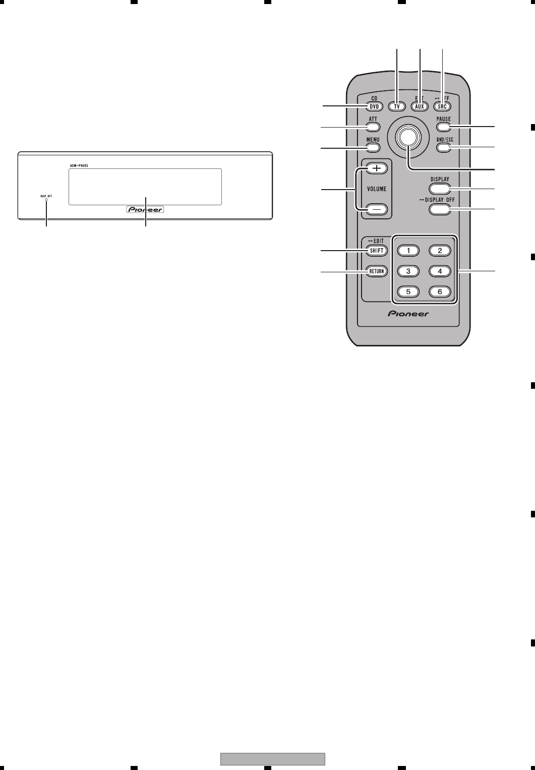
Display unit
a Display off indicator
Lights up when the display indication is
turned off.
s Information display
Display information for each connectedsource
and its settings.
Card remote control
1 CD/DVD button
Press to select a iPod (iPod), Multi CD (CD
player) or DVD (DVD player) source .
2 TV button
Press to select a TV (TV) source.
3 AUX/EXT button
Press to select an AUX (AUX) or External
(external) source.
4 SOURCE button
Press to cycle through all the available
sources. Press and hold to turn the source
off.
5 PAUSE button
Press to turn pause on or off.
6 BAND button
Press to select among two TV bands and to
cancel the control mode of functions.
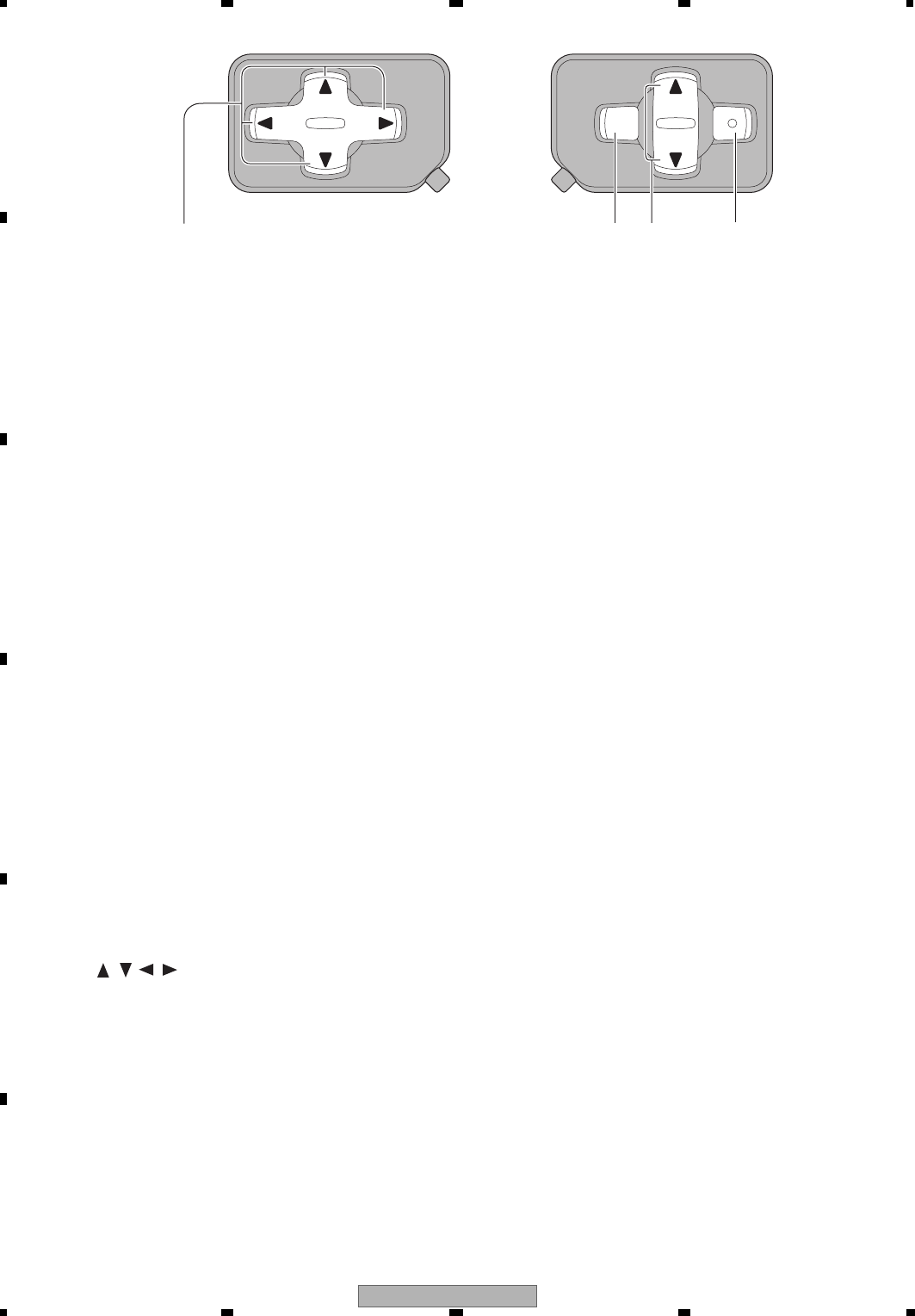
7 Thumb pad
Move to perform manual seek tuning, fast
forward, reverse and track search controls.
Also used for controlling functions.
Click and hold to change between normal
playback display and menu setting display.
AXM-P90RS/EW5
8
1234
1234
C
D
F
A
B
E
^#% 4
8 DISPLAY button
Press to display different information on the
selected channel. Press and hold to switch
the scroll setting.
9 DISPLAY OFF button
Press and hold to turn the display indication
off or on to reduce noise.
0 FUNC 1 to FUNC 6 buttons
Press to select and control functions.
! RETURN button
Press to change to the menu setting display
from the detail setting display.
@ SHIFT button
Press to change to the detail setting display
from the menu setting display.
# VOLUME buttons
Press to increase or decrease the volume.
$ MENU button
Press to cycle through audio menus; Main
(main menu), Equalizer (equalizer menu) or
Network (network menu).
% ATT button
Press to quickly lower the volume level by
about 90%. Press once more to return to the
original volume level.
Steering remote control
^ / / / buttons
Press to perform manual seek tuning, fast
forward, reverse and track search controls.
Also used for controlling functions.
AXM-P90RS/EW5 9
5 678
5678
C
D
F
A
B
E
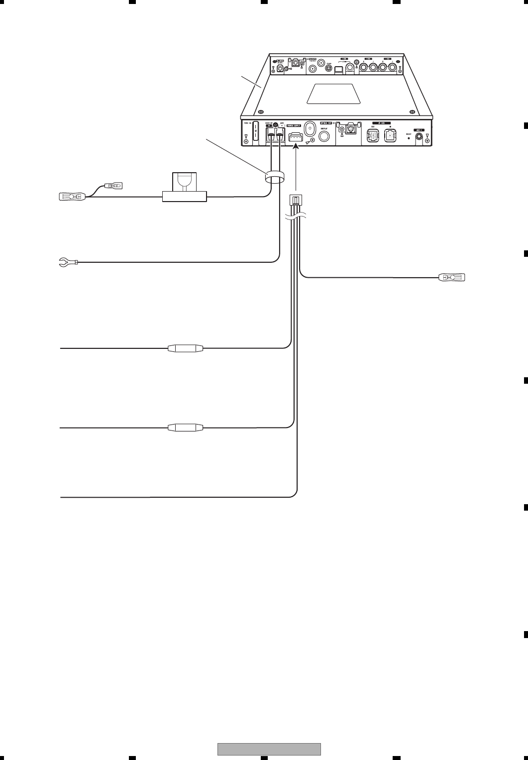
2.3 CONNECTION DIAGRAM
Translucent with black stripe
(chassis ground)
Connect to a clean, paint-free
metal location.
Fuse (4 A)
Translucent with yellow stripe
Connect to the constant
12 V supply terminal.
Red
Connect to terminal controlled
by ignition switch (12 V DC).
Yellow/black
If you use a device with a Mute function, connect
this lead to the Audio Mute lead on that device.
If not, keep the Audio Mute lead free of any connections.
Blue/white
Connect to system control
terminal of the power amp
(max. 300 mA 12 V DC).
Orange/white
Connect to lighting switch terminal.
Fuse resistor
Fuse resistor
This unit
Covering
- Connecting the power cable
AXM-P90RS/EW5
10
1234
1234
C
D
F
A
B
E
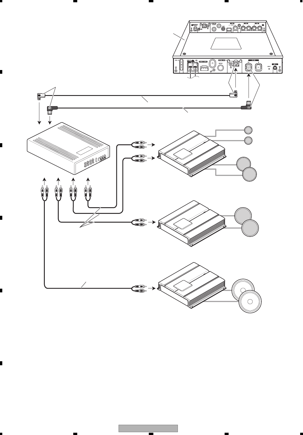
- Connecting the audio processor
This unit
Tweeter
Mid-range
Low-range
Subwoofer
Power amplifier
(e.g. PRS-A500) (sold separately)
Power amplifier
(e.g. PRS-A500) (sold separately)
Power amplifier
(e.g. PRS-A700) (sold separately)
Audio processor
(e.g. DEQ-P90) (sold separately)
Black
Black
Blue
IP-BUS cable
Optical cable
RCA cable
(sold separately)
RCA cable
(sold separately)
AXM-P90RS/EW5 11
5 678
5678
C
D
F
A
B
E
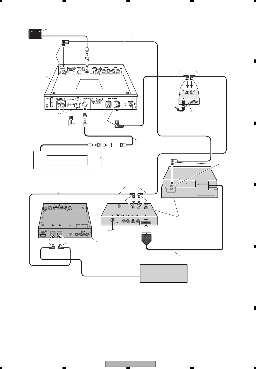
- Connecting the Pioneer IP-BUS devices
This unit
Display unit
Optical cable
Black
Hide-away TV tuner
(e.g. GEX-P5700TV)
(sold separately)
Multi-DVD player
(e.g. XDV-P6)
(sold separately)
iPod adapter
(e.g. CD-IB100II)
(sold separately)
Remote control sensor
IP-BUS cable
IP-BUS cable
Blue
Blue
Black
IP-BUS cable
Blue Black
Black
Multi-CD Player
(sold separately)
Blue
25 pin cable
Blue
Display unit
extension cable
AXM-P90RS/EW5
12
1234
1234
C
D
F
A
B
E
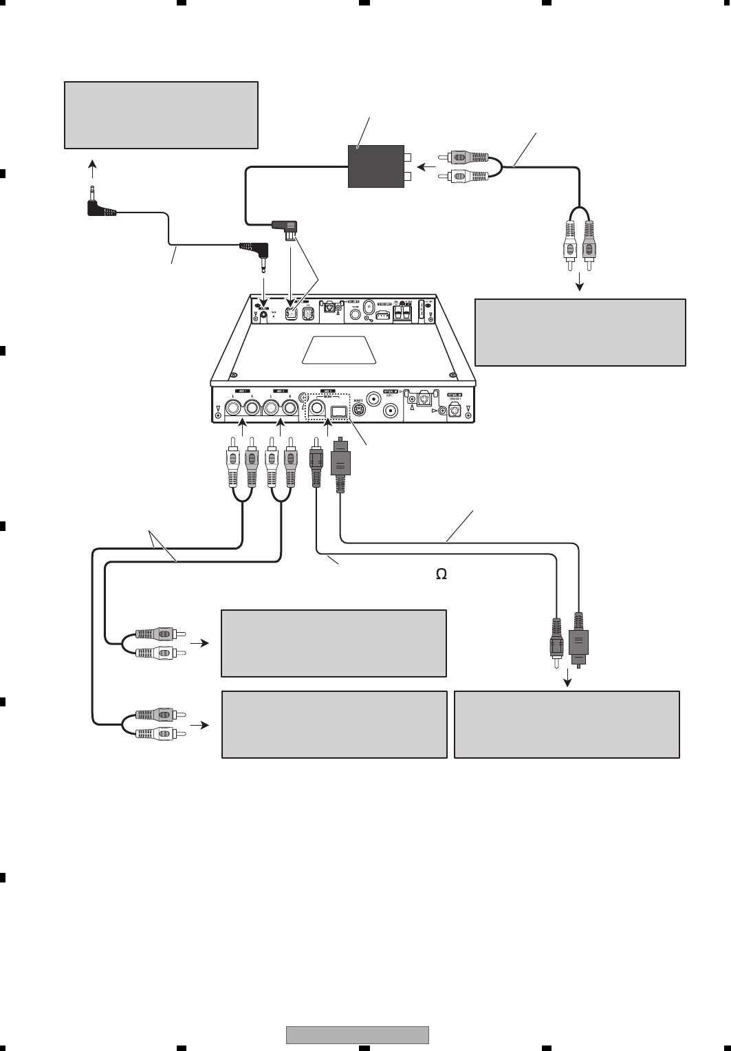
- Connecting the AUX devices
AUX 4 unit
(mini-plug-equipped unit)
(sold separately)
IP-BUS-RCA interconnector
(CD-RB10/CD-RB20) (sold separately)
AUX 5 unit
(RCA-output-equipped unit)
(sold separately)
AUX 3 unit
(optical-output-equipped unit)
(sold separately)
AUX 2 unit
(RCA-output-equipped unit)
(sold separately)
AUX 1 unit
(RCA-output-equipped unit)
(sold separately)
RCA cable
(sold separately)
TOSLINK digital cable
(sold separately)
COAXIAL (75 ) digital cable
(sold separately)
RCA cable
(sold separately)
mini plug (3.5 mm) cable
(sold separately) Blue
*
* Select COAX-input or TOSLINK-input depending on the connected device’s digital output.
AXM-P90RS/EW5 13
5 678
5678
C
D
F
A
B
E
3. BASIC ITEMS FOR SERVICE
3.1 CHECK POINTS AFTER SERVICING
To keep the product quality after servicing, please confirm following check points.
RemarkItem to be confirmedProceduresON
1The customer complain must not be reappeared.
2
No scratches or dirt on its appearance after receiving
it for service.
Appearance check3
See the table below for the items to be checked regarding video and audio:
Item to be checked regarding audio
Distortion
Noise
Volume too low
Volume too high
Volume fluctuating
Sound interrupted
Audio and operations must be normal.
Check the output sound.
Confirm whether the customer complain has been
solved.
AXM-P90RS/EW5
14
1234
1234
C
D
F
A
B
E
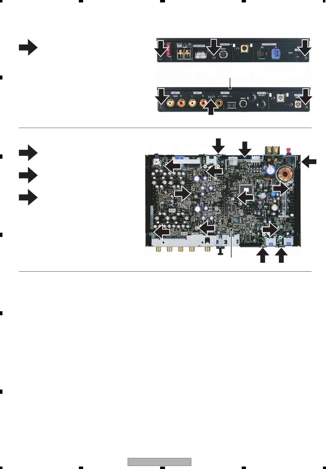
3.2 PCB LOCATIONS
A
Connector
PCB2
C
D
Connector
PCB1
B
Displsy Unit
Main PCB
Main Unit
Consists of
Main PCB
Connector PCB1
Connector PCB2
Unit Number : CWN2574
Unit Name : Main Unit
Unit Number : CWN2571
Unit Name : Display Unit

AXM-P90RS/EW5 15
5 678
5678
C
D
F
A
B
E
AXM-P90RS/EW5
16
1234
1234
C
D
F
A
B
E
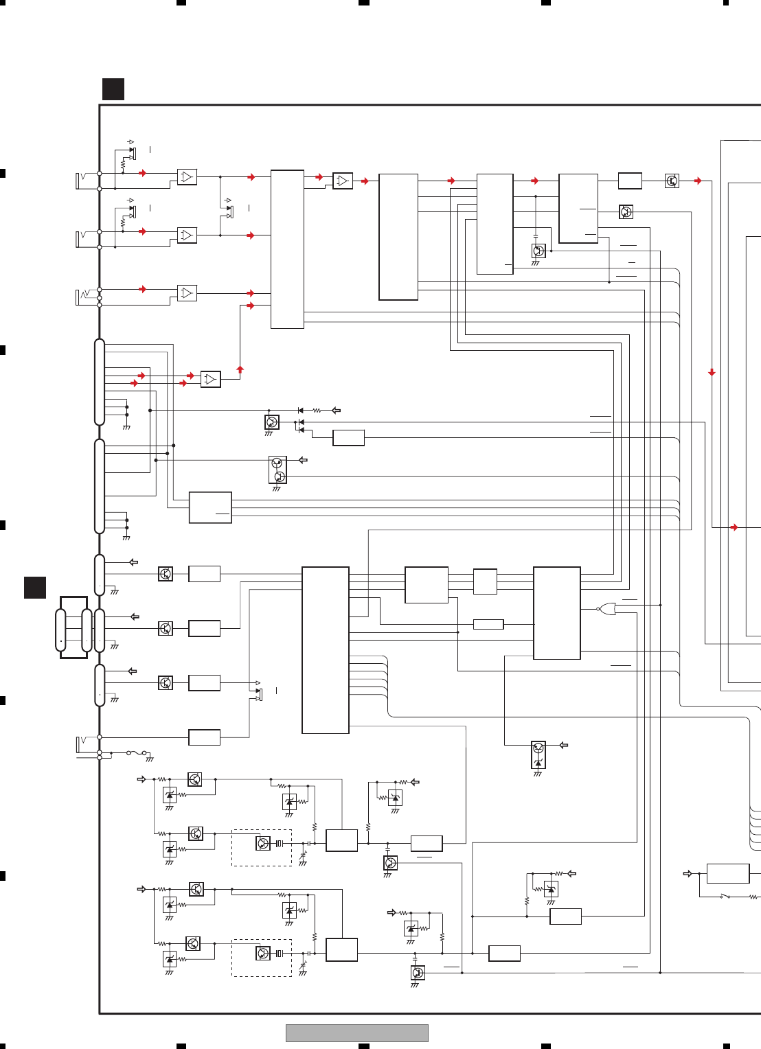
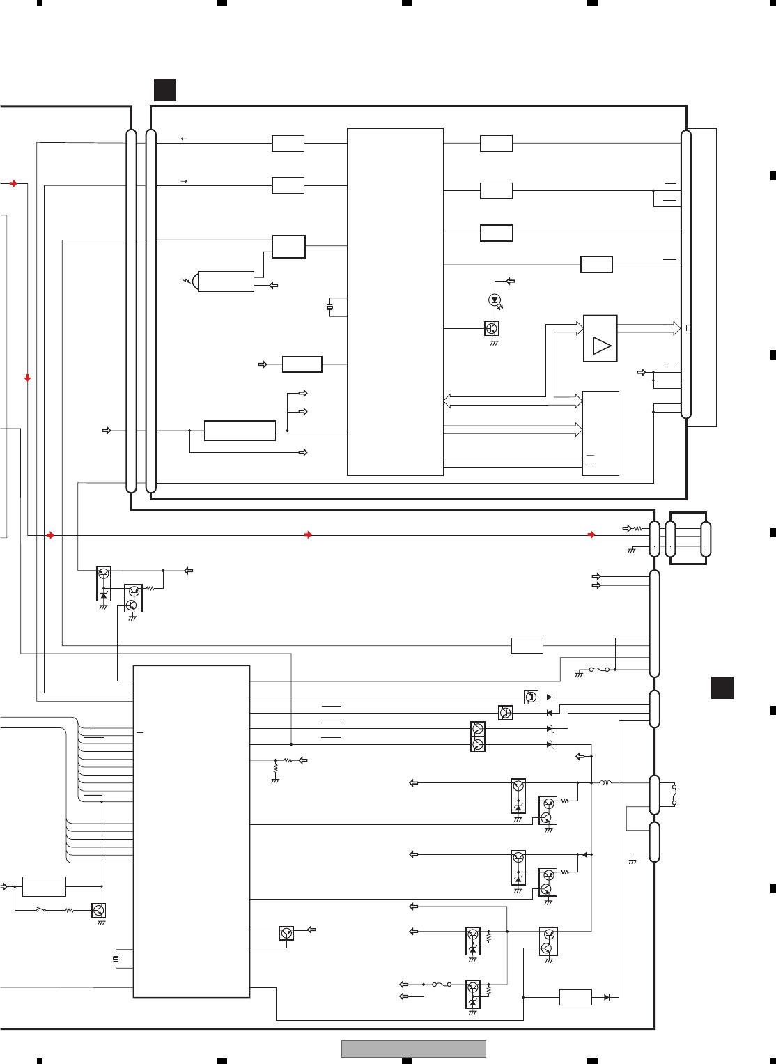
4. BLOCK DIAGRAM
A
DPDT
KYDT
S701
RESET
DI
R
DI
R
DI
R
DI
R
D
E
AU
DIRDO
DIRDI
DIRCL
DIRCE
DIRR
AUDIO
MAIN PCB
BUFFER
IC201
NJM2794RB2
OEM
INPUT
RCA
INPUT
Minijack
7
6
S201
5
Hi(SP)
Hi/Low SWITCH
Low(RCA)
7
6
BUFFER
IC202
NJM2794RB2
S202
5
Hi(SP)
Hi/Low SWITCH
Low(RCA)
S203
MIX_OFF
MIXING SWITCH
MIX_ON
7
6
BUFFER
IC203
NJM2794RB2
5
OUTa
IN1a
IN2a
3
IN3a
13
IN4a
5
Vref
CONT1
CONT2
12
15
1
JA302
6
5
3
2
1
8
JA301
JA202
JA203
JA201
BUS+
BUS-
BUSL2
ASENB1
BUSL1
BUS+
GND
GND
BUS-
GND
ASENB1
IPMUTE
7
6
5
3
2
1
8
11
IP-BUS DRIVER
IC302
HA12187FPS1
AUDIO SELECTOR
IC204
NJM2750M
IP-BUS IN
IP-BUS OUT 6
5
1
2
8
4
4
BUS+
BUS- ROUT
DIN1 TX
RX
IPPW
STBY
7
6
IC301
NJM2794RB2
5
2
4
2
4
2
4
Q402
CN402
JA412 IC402
TC7SH32FUS1
14
INB OUTY
D5R0
2
4
Q401
JA401
MMC
OPT-IN IC401
TC7SH32FUS1
14
INB OUTY
D5R0
Q403
JA403
CN411
External TOS
OPT-IN
Terrestial
Digital
OPT-IN
External
Coaxial
IC403
TC7SH32FUS1
14
INB OUTY
D5R0
VCC
OUT
JA404 1
1
2
3
2
1A 3Y
IC404
TC7WU04FU
P401
2
3
AMP
IC501
OPA2134UA
1DOUTVINL
BCK 14
LRCK 13
2
4
SYSCK 16
RSTB
DOUT
6
ADC
IC502
PCM1800S1
15
11Y
2Y
3Y
1B
1A
3B
3A
2B
2A
2
10
6
11
5
SELECT
7
1
ST 15
SELECTOR
IC504
TC74HCT157AF
4
3TX+
SDATA
SCLK
SYNC
12
911
MCLK
DSEL
EMPHA
EMPH 23
6
RST 15
DIT
IC511
DIT4096IPW
18
13
DATAO
BCK
LRCK
CKOUT
DIN0
OPT1
OPT2
OPT3 DIN1
4
EMPHA
DIN2
23
5
XSTATE 17
XMODE 48
36
35
38
37
34
24
DIR
IC503
LC89055WHS-RA8
16
14
15
13
3DOUT
BCKO
LRCKO
DI
BCKI
3
OCLK
LRCI
63
4
ICLK
6
RSIN
VDD
48
1,21,41,61
SRC
IC509
SM5849BF
IC508
TC7SH02FUS1
67
66
65
2
COAX
S401
TOS/COAX
SWITCH
TOS
IC901
TC7WU04FU Q901
12
1A 3Y
DIR CLOCK
GENERATOR
X101
12.288MHz
TC101
SYS+B
Q107
IC105
TC7SHU04FUS1
2
5
4
INA OUTY
Q114
IC110
TC7SET04FUS1
24
INA
DSEL
OUTY
D5R0
DIT CLOCK
GENERATOR
X102
11.2896MHz
TC102
SYS+B
Q112
IC109
TC7SHU04FUS1
2
5
4
INA OUTY
Q113
IC510
TC7SET04FUS1
24
INA
DSEL
DIRCLK
MCK2
MCK1
MCK1
MCK
MCK1
MCK
OUTY
IC512
TC7SET04FUS1
24
INA OUTY
DATAODATAI
BCKOBCKI 715
LRCKOLRCKI 5
11
XRST 18
HI-BIT
IC506
PD0236BM
814 2A 2Y
35
1A 1Y
17
3A 3Y
6
2
2
IC507
TC7WH34FU
INA OUTY 4
IC505
TC7SH08FUS1
Q503
Q502
DGRST
ASEL1
ASEL2
RESET
BSENS
ASENBO
DSEL
DGRST
DSEL
D5R0
D5R0
32
1
S
DI
DO
CL
CE
ERROR
AUDIO
22
XIN
ST
RESET
21
IC701
BD4841G
VDD5
3V REGULATOR
Q501
D5R0
Q301
Q302
Q303
SWD+B
IC303
TC7S04FU
42
OUTY INA
B.UP
VINL
5
4
2
SHUNT
REGULATOR
IC514
NJM2373AF
SHUNT
REGULATOR
IC513
NJM2373AF
5
4
2
SHUNT
REGULATOR
IC108
NJM2373AF
5
4
2
SHUNT
REGULATOR
IC104
NJM2373AF
5
4
2
SHUNT
REGULATOR
IC101
NJM2373AF
5
4
2
Q103,104
SHUNT
REGULATOR
IC103
NJM2373AF
5
4
2
Q105,106
SHUNT
REGULATOR
IC106
NJM2373AF
5
4
2
Q109,111
SHUNT
REGULATOR
IC107
NJM2373AF
5
4
2
Q108,110
SHUNT
REGULATOR
IC515
NJM2373AF
5
4
2
OPT1
OPT2
3
1
2
4
1
2
1
2
6
5
4
6
5
4
3
2
1
2
3
1
IPMUTE
GND
GND
GND
1
3
GND
1
3
1
3
1
3
GND
GND
COAIN
COAG
3
2
1
VCC
VCC
DMUTE 22 DMUTE
MCK2
CONNECTOR PCB1
B
AXM-P90RS/EW5 17
5 678
5678
C
D
F
A
B
E
SYSTEM CONTROL
IC602
PE5612A
X1
X2
DSEL
52
16
15
25
12.58291MHz
X601
100
PEE PEE
21
SYSPWR
SYSPW
CN901
JA802
CN703
H701
JA702
CN911 JA912
OPTICAL
OUT
1
2
GND 1
2
B.UP
B.UP
REMOTE
I/F
93
78
BSENS
4TELIN
91 ISENS
92 ASENS
BSENS
BATT
TELIN
ISENS
ASENS
1
71
96 TXD
95 RXD
DPDT
KYDT
46
99 ST
51
75
28
86
85
27
11
10 DIRDO
9DIRDI
8DIRCL
20 DIRCE
7DERR
26 AUDIO
S701
RESET
DIRDO
DIRDI
DIRCL
DIRCE
DERR
AUDIO
TX
ST
DGRST
ASEL1
ASEL2
ASENBO
DRST1
ASEL
NC7
ASENBO
RX
IPPW
RESET RESET
TX
RX
IPPW
P70/SINO
X0
VDD VOUT
25
P71/SOTO
26
P80/IRQ0
45
X1
81
80
RST
75
X1801
3.77MHz
DISPLAY
CONTROLLER
IC1801
PD6573A
CN1863JA801
ROM
IC1821
PD8176A
P51/RD
P93/FRCK/ADTG/CS3
D0-14,
D15/A-1
D0-15
P01-07,10-17/
AD00-15/
D00-15
CE
A0-19
DATA BUS
ADDRESS BUS
14
12 OE
A0-19
D0-15
D0-7
A0-19
P31-37/A01-07/
P40-47/A08-15
P20-24/A16-20
69
59
DB0-7
RDY
RST
RS
RD
CE2
SWVDD
OELB
OELB
IC1887
TC74VHCT541AFTS1
OEL MODULE
CN1861
Y1-8
A1-8
IC1885
TC7SET08FUS1
24
IC1884
TC7SET08FUS1
24
INA OUTY
IC1886
TC7SET08FUS1
24
INA OUTY
IC1893
TC7SH08FUS1
274
67
70
4INA
P56/RDY
P30/A00/AIN0
64
PA0/OUT0
P52/WRL
7
PA3/OUT3
OUTY
IC1891
TC7SH08FUS1
24
INA OUTY
IC1892
TC7SET08FUS1
2
4INA
OUTY
KYDT
DPDT
REMIN
SWVDD
OELBOELB
9
22
2
1
19
20
21
6
WR 18
8
16
RESET
21
IC1889
BD4827G
+3.3V
IC1894
GP1UX51RK
REMOTE CONTROL
SENSOR
OPT IN 3
1
SWVDD
IC1890
TC7SH08FUS1
2
1
4
3
2
7
4
5
3
2
7
4
5
SWVDD
CE1 17
3.3V REGULATOR
4,5 1
IC1883
S-818A33AUC-BGN
+3.3V
+3.3OUT
SWVDD
DISPLAY UNIT
D
Q1881
SWVDD
A
2
4
2
4
2
4
2
3
4
1
D5R0
6
4
5
8
P801
IC902
TC7SH08FUS1
42
INA
REMPW
2
BEEP
REMIN
TELIN
ILM
ACC
BREM
REMGND
MMC_GND
LEDV
REMIN OUTY
SWVDD1
1
D5R0
SWVDD1
Q803
OELPW
Q804
OEL 8.9V REGULATOR
B.UP
Q801
Q702
4A
Q709
+5V REGULATOR
Q707
8.3V REGULATOR
Q703
Q708
SYS+B
A5R0(ANALOG5V)
D5R0(DIGITAL5V)
Q705
Q706
Q710
P702
SWVDD1
VDD5
SWD+B
SWVDD
SWVDD
Q802
DALMON
DALMON
Q704
IC702
TPD1018F
61
IN OUT
Q701
RESET
21
IC701
BD4841G
D0-7
5.1V REGULATOR
SYSTEM 5V REGULATOR
1
3
1
3
KYDT
DPDT
REMIN
47 DMUTE
DMUTE
Q601
VDD5
83
AVREF
81
ADPW
GND 1
3
INB OUTY
INA
VCC5
21
INA OUTY
CONNECTOR PCB2
C
AXM-P90RS/EW5
18
1234
1234
C
D
F
A
B
E
5. DIAGNOSIS
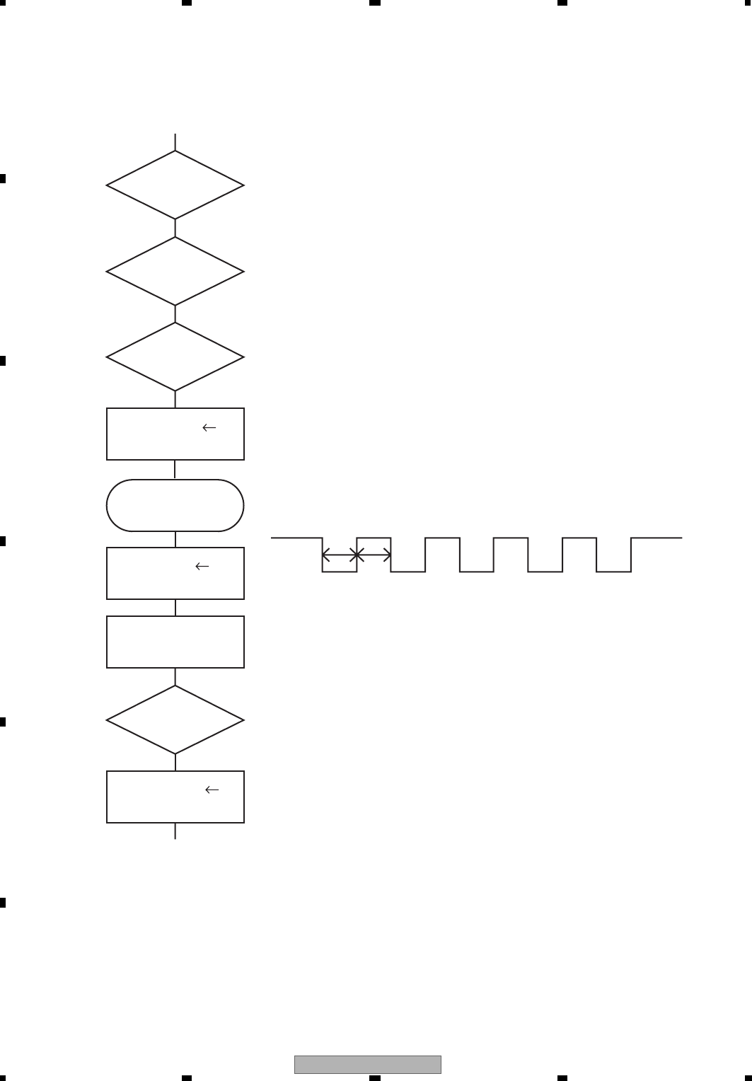
5.1 OPERATIONAL FLOWCHART
VDD1, 2 = 5 V
Pin 19, 41
Power ON
BSENS
Pin 93
ASENS
Pin 92
SWVDD L
Pin 1
ASENBO H
Pin 28
Source keys
operative
Completes power-on operation.
(After that, proceed to each source operation)
SYSPWR H
Pin 21
Starts
communication
with Grille
microcomputer.
Source ON
300 ms
300 ms
In case of the above signal, the communication
with Grille microcomputer may fail.
If the time interval is not 300 msec, the oscillator
may be defective.
AXM-P90RS/EW5 19
5 678
5678
C
D
F
A
B
E
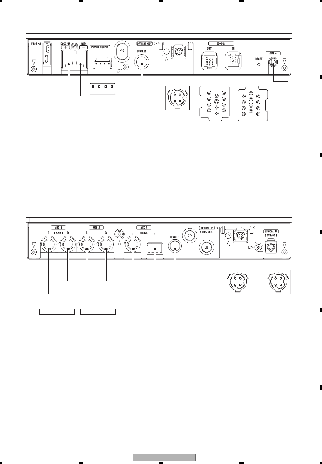
5.2 CONNECTOR FUNCTION DESCRIPTION
AUX1
INPUT L
AUX1
INPUT R
B. UP
GND
1. BUS+
2. GND
3. GND
4. IPMUTE
5. BUS-
6. GND
7. BUSL2
8. ASENB
9. BUSR2
10. BUSR1
11. BUSL1
1
2
3
4
5
6
7
8
9
10
11
IP-BUS IN
DIGITAL IN
1
24
1 : OPTG
2 : OPT
3 : GND
4 : OPT5V
1. BUS+
2. GND
3. GND
4. IPMUTE
5. BUS-
6. GND
7. NC
8. ASENB
9. NC
10. NC
11. NC
1
2
3
4
5
6
7
8
9
10
11
IP-BUS OUT
3
OPTCAL IN
1
24
1 : OPTG
2 : OPT
3 : GND
4 : OPT5V
3
AUX2
INPUT L
AUX2
INPUT R
AUX4
MINI JACK
1234
1. TEL IN
2. ILM
3. ACC
4. REMOTE
OPTCAL OUT
1
24
1 : OPTG
2 : OPT
3 : GND
4 : OPT5V
3
AUX3
EXTERNAL
COAXIAL
AUX3
OPT INPUT
REMOTE
I/F
DISPLAY
UNIT
RCA /
SP IN
RCA /
SP IN
AUX1 & 2 can be mixed
(Setting SW is on the bottom)
AXM-P90RS/EW5
20
1234
1234
C
D
F
A
B
E
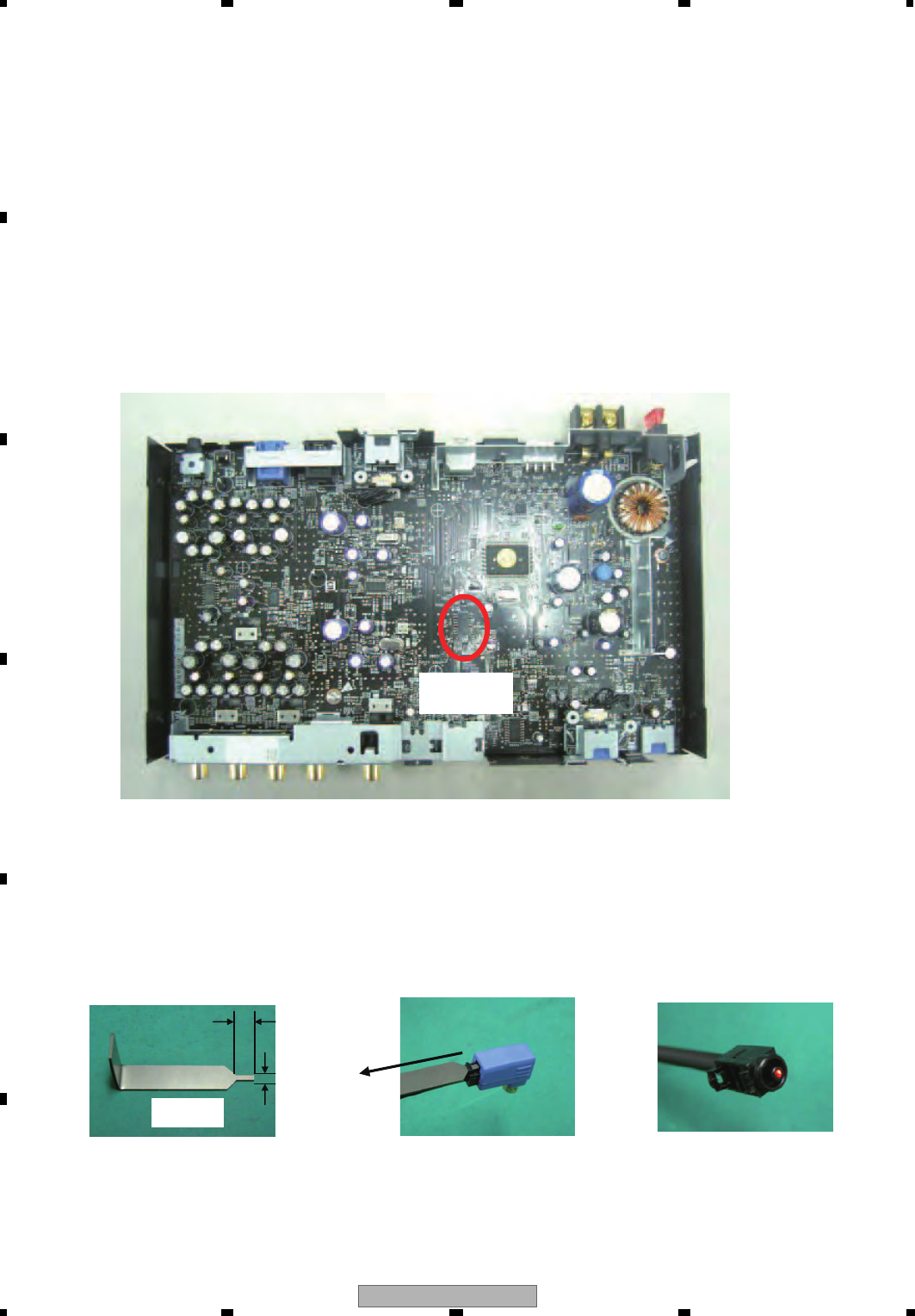
5.3 SIMPLE OPERATION CHECK METHOD
You can perform simple operation check by the following procedure without Pioneer Audio Processor.
(1) Connect Display Unit and the power supply. And, connect analog audio signal to AUX1 input.
(2) Press [SHIFT] button to display the initial setting display.
(3) Press [3] button to switch to the general setting screen (GENERAL).
(4) Press [1] button to switch to the auxiliary setting screen (AUX).
(5) Press [1] button to turn ON MAIN (AUX1) input.
(6) Press [SRC](SOURCE) button to switch to the MAIN (AUX1) input.
(7) By applying 5V to the pin 1 of the IC504, this unit will output the digital audio signal (A/D converted
the analog audio signal of AUX1 input) from the digital signal output terminal.
Then, you can confirm whether the digital audio output signal is correct, by connecting Digital
Audio Checker, GGW1003 or Home use DAC built-in AV amplifier etc.
IC504
NOTE)
You can check the optical digital output by removing the connector of the optical digital cable. (The output
terminal is blue.)
You can easily remove the connector by using the removing tool included ADDOL Processing Kit, PC034A
or something similar.
The digital output signal can be checked by fitting the optical output to the optical digital input terminal of a
DAC built-in product after removing the connector.
Pull out
Connector was removedRemoving Tool
2 mm
7 mm
t: 1 mm

AXM-P90RS/EW5 21
5 678
5678
C
D
F
A
B
E
6. SERVICE MODE
There is not information to be shown in this chapter.
AXM-P90RS/EW5
22
1234
1234
C
D
F
A
B
E
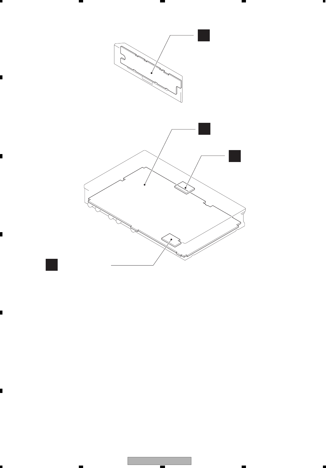
7. DISASSEMBLY
1
1
-
Removing the Case and Panel (Fig.1)
-
Removing the Main Unit (Fig.2)
Remove the six screws and then remove
the Case and Panel.
Remove the five screws.
Fig.1
Fig.2
Case and Panel
2
Straighten the tabs at six locations
indicated.
3
Remove the two screws and then
remove the Main Unit.
1
1
Main Unit
32
3
2
11
11
2
2
2
2
11
1 1
1
AXM-P90RS/EW5 23
5 678
5678
C
D
F
A
B
E
8. EACH SETTING AND ADJUSTMENT
8.1 MASTER CLOCK ADJUSTMENT
TC101
TC102
CLKF
CLK6
- Adjustment point
SIDE B
SIDE A
MAIN PCB
MAIN PCB

AXM-P90RS/EW5
24
1234
1234
C
D
F
A
B
E
- Audio Master Clock frequency adjustment
No. Measuring point Adjusting point Content of adjustment
TC101 Frequency counter : 11.289 6 MHz ± 20 Hz
1 CLKF
TC102 Frequency counter : 12.288 MHz ± 20 Hz
2 CLK6
1. Source ON.
2. Monitor CLKF (frequency counter and high frequency probe are required) and adjust TC101 to match
the frequency.
3. Monitor CLK6 (frequency counter and high frequency probe are required) and adjust TC102 to match
the frequency.

AXM-P90RS/EW5 25
5 678
5678
C
D
F
A
B
E
AXM-P90RS/EW5
26
1234
1234
C
D
F
A
B
E
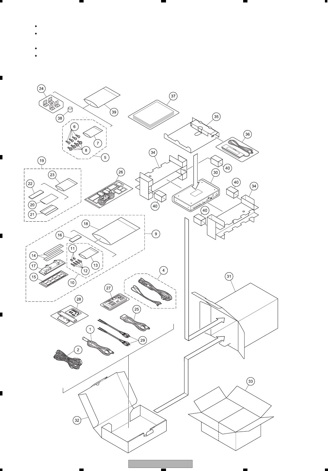
9. EXPLODED VIEWS AND PARTS LIST
9.1 PACKING
N
OTES : Parts marked by " * " are generally unavailable because they are not in our Master Spare Parts List.
The > mark found on some component parts indicates the importance of the safety factor of the part.
Therefore, when replacing, be sure to use parts of identical designation.
Screw adjacent to mark on the product are used for disassembly.
For the applying amount of lubricants or glue, follow the instructions in this manual.
(In the case of no amount instructions,apply as you think it appropriate.)
""

AXM-P90RS/EW5 27
5 678
5678
C
D
F
A
B
E
PACKING SECTION PARTS LIST
Mark No. Description Part No.
1 Cord CDP1035
2 Cord Assy CDP1037
3 •••••
4 Cord Assy CDP1044
5 Screw Assy CEA5278
6 Screw BNC40P120FTB
* 7 Polyethylene Bag CEG1158
8 Screw HMF40P080FTB
9 Accessory Assy CEA7806
10 Screw Assy CEA7809
11 Screw BMZ26P050FTB
12 Screw BPZ30P120FTB
* 13 Polyethylene Bag CEG1158
14 Holder CND4103
15 Double Sided Tape CNN1684
16 Cushion CNN1809
17 Panel CNS9055
* 18 Polyethylene Bag E36-634
19 Accessory Assy CEA7807
20 Fastener CNN1685
21 Fastener CNN1686
22 Double Sided Tape CNN1808
23 Polyethylene Bag CEG1011
24 Angle Assy CXC6835
25 Receiver Assy CXC7915
26 Remote Control Assy CXC8163
27 Remote Control Assy CXC8171
28 Bracket Assy CXC8262
29 Cord Assy YDE5010
* 30 Polyethylene Bag CEG1226
31 Unit Box CHG6200
32 Sub Unit Box CHA3639
33 Contain Box CHL6200
34 Protector CHP3371
35 Protector CHP3372
* 36 Polyethylene Bag CEG1391
37-1 Owner's Manual(English) CRB2420
37-2 Owner's Manual(Spanish) CRB2421
37-3 Owner's Manual(German) CRB2422
37-4 Owner's Manual(French) CRB2423
37-5 Owner's Manual(Italian) CRB2424
37-6 Owner's Manual(Dutch) CRB2425
37-7 Owner's Manual(Russian) CRB2426
* 37-8 Warranty Card CRY1157
37-9 Polyethylene Bag CEG1116
38 Cover CNS9266
* 39 Polyethylene Bag CEG1250
40 Protector CHP3460
AXM-P90RS/EW5
28
1234
1234
C
D
F
A
B
E
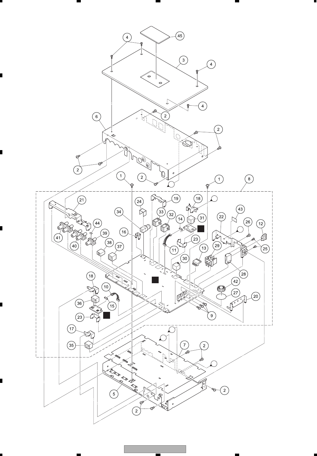
9.2 EXTERIOR
A
B
C
A
B
B
C
C
A
AXM-P01_J.2_2
18%

AXM-P90RS/EW5 29
5 678
5678
C
D
F
A
B
E
EXTERIOR SECTION PARTS LIST
Mark No. Description Part No.
1 Screw ASZ26P055FTC
2 Screw BSZ26P060FTB
3 Panel CAH2005
4 Screw CBA1993
5 Chassis CNA3013
6 Case CNB3460
7 Insulator CNN1681
8 Main Unit CWN2574
9 Screw BSZ26P080FTC
10 Cord(CN402) CDE8464
11 Cord(CN901) CDE8464
>12 Fuse(4 A) CEK1001
13 Plug(CN703) CKS-461
14 Connector(CN911) CKS4979
15 Connector(CN411) CKS4979
16 Holder CNC8205
17 Holder CNC9451
18 Holder CNC9452
19 Holder CNC9810
20 Holder CND3297
21 Holder CND4067
22 Holder CND4068
23 Holder CND4069
24 Insulator CNN1744
25 Screw PPZ20P060FTB
26 Screw PPZ30P080FTB
27 Insulator XNM7031
28 Fuse Holder(H701) CKR1021
29 Terminal(JA702) CKE1030
30 Plug(JA801) CKS2589
31 Connector(JA912) CKS1940
32 Connector(JA302) CKS3413
33 Connector(JA301) CKS3410
34 Connector(JA202) CKS4124
35 Connector(JA401) CKS2600
36 Connector(JA412) CKS2600
37 Connector(JA802) CKS5768
38 Connector(JA403) CKS5728
39 Pin Jack(JA404) CKB1081
40 Pin Jack(JA203) CKB1080
41 Pin Jack(JA201) CKB1080
42 Chock Coil(L702) CTH1280
43 Cushion CNN1907
44 Cushion CNN1910
* 45 Badge CAH2003
AXM-P90RS/EW5
30
1234
1234
C
D
F
A
B
E
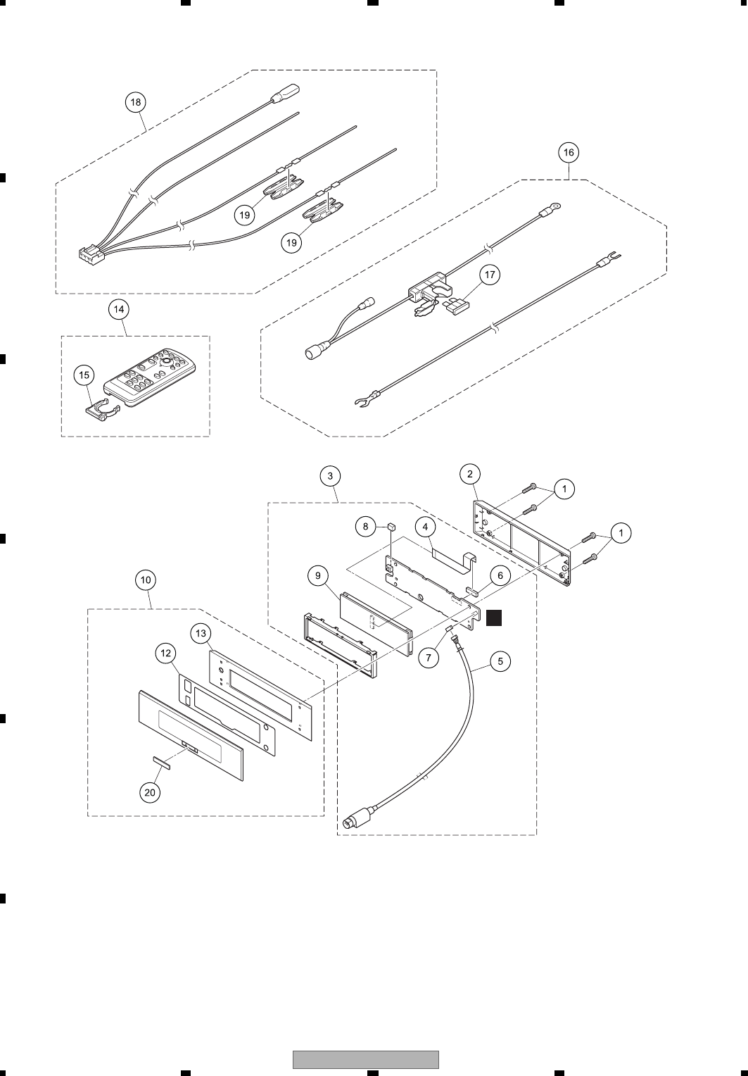
9.3 DISPLAY UNIT AND ACCESSORY
D
18%
AXM_P01_J.1_2

AXM-P90RS/EW5 31
5 678
5678
C
D
F
A
B
E
DISPLAY UNIT AND ACCESSORY SECTION PARTS LIST
Mark No. Description Part No.
1 Screw BPZ20P100FTB
2 Cover CNS9035
3 Display Unit CWN2571
4 Flat Cable CDE6700
5 Cord CDE8466
6 Connector(CN1861) CKS5640
7 Connector(CN1863) CKS5769
8 Spacer CNM8418
9 OEL Module MXK8203
10 Grille Assy CXC8311
11 •••••
12 Double Sided Tape CNN1683
13 Grille CNS9032
14 Remote Control Assy CXC8171
15 Cover CZN7006
16 Cord Assy CDP1044
>17 Fuse(4 A) CEK1001
18 Cord Assy CDP1037
19 Cap CNS1472
* 20 Badge CAH2015
AXM-P90RS/EW5
32
1234
1234
C
D
F
A
B
E
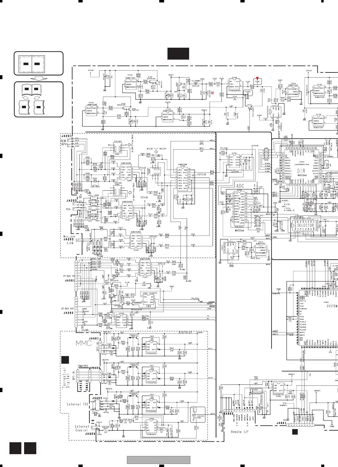
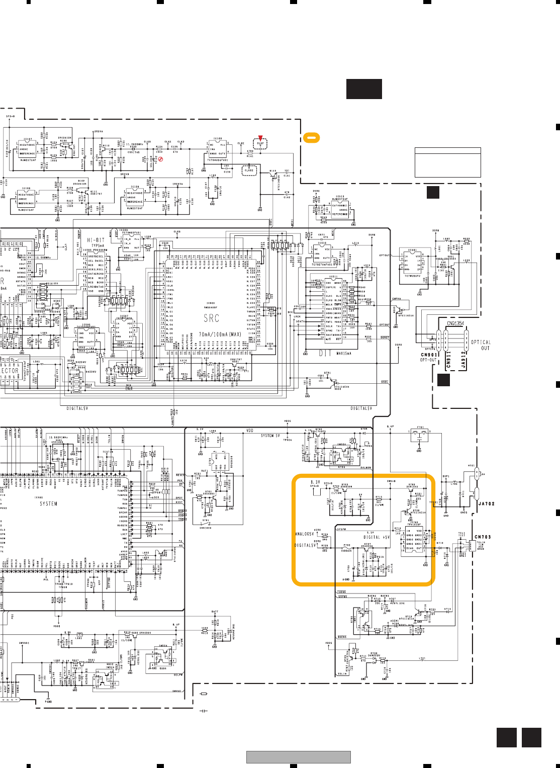
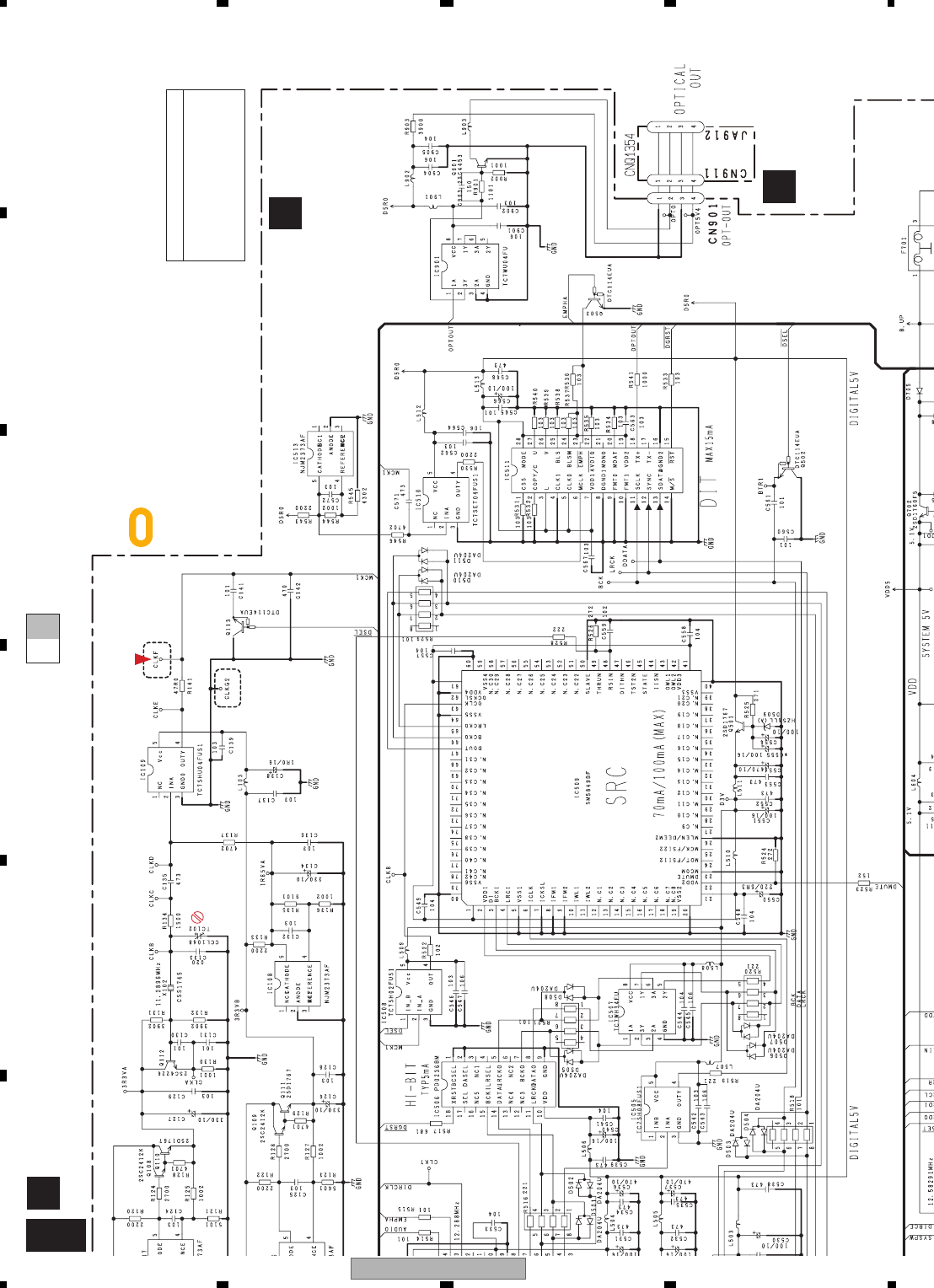
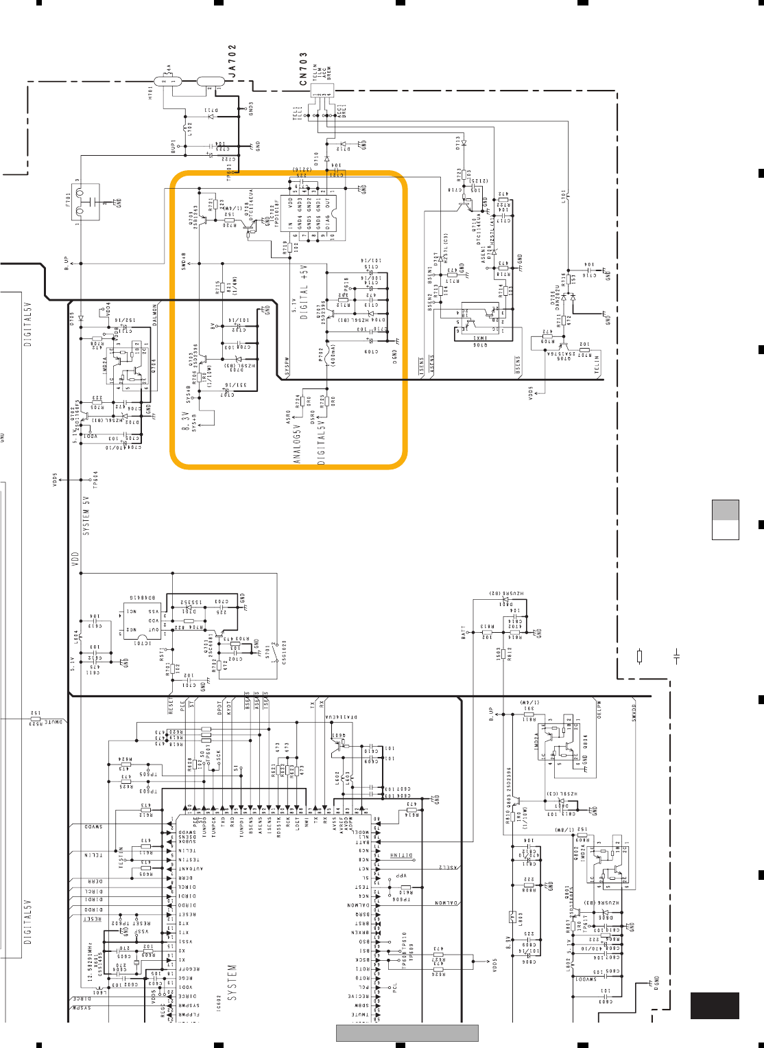
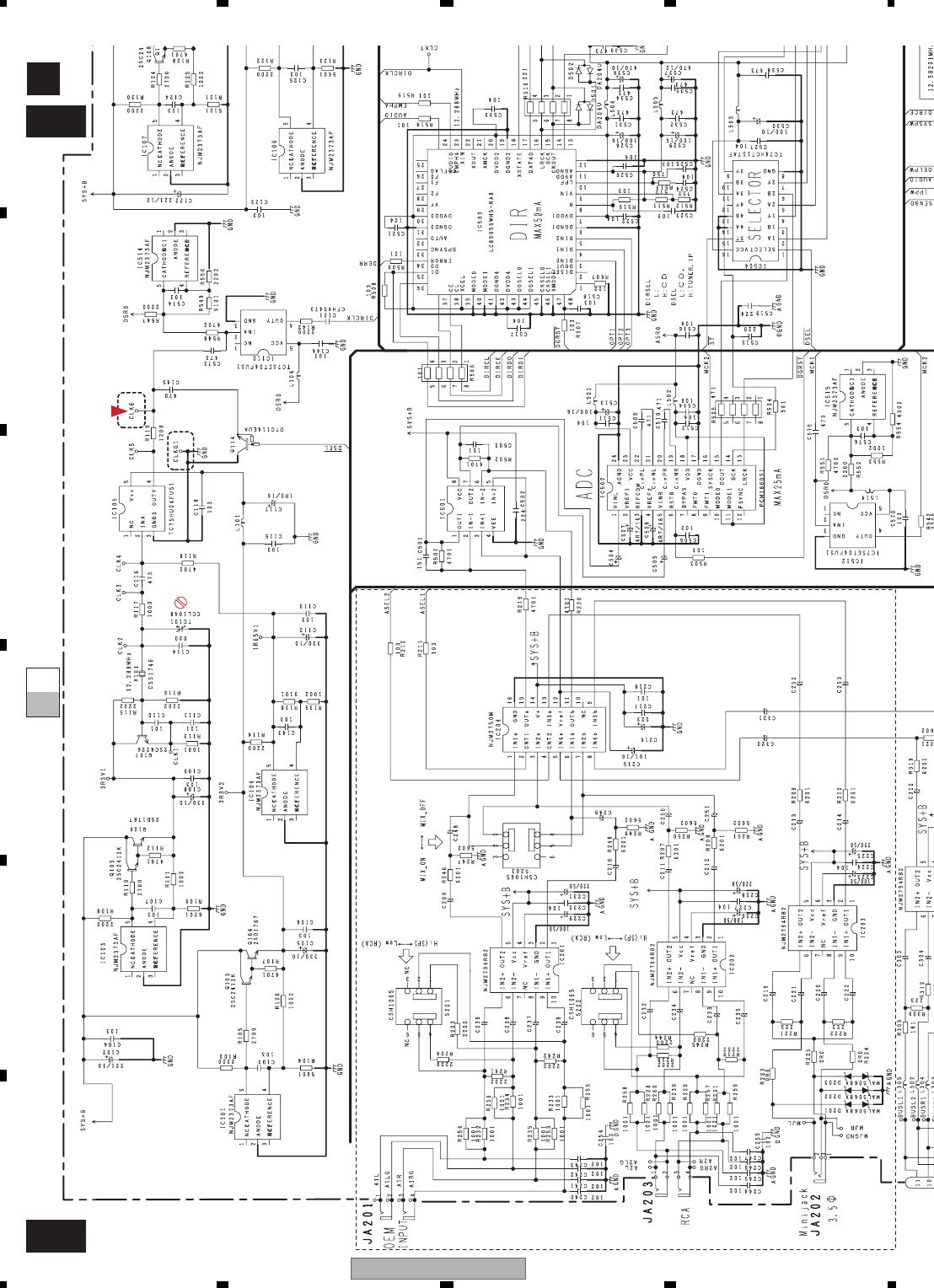
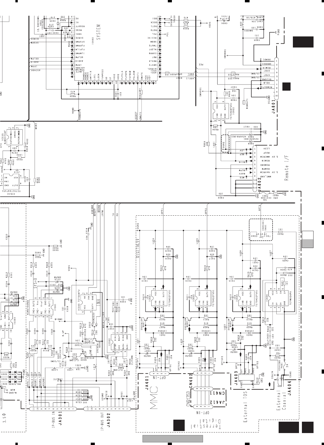
10. SCHEMATIC DIAGRAM
10.1 OVERALL CONNECTION DIAGRAM(GUIDE PAGE)
A-a
A-a
A-b
A-b
A-a
A-a
A-b
A-b
A-b
A-b
A-a
A-a
Large size
SCH diagram
Guide page
Detailed page
Note: When ordering service parts, be sure to refer to " EXPLODED VIEWS AND PARTS LIST" or
"ELECTRICAL PARTS LIST".
A-a
A B
100/16
220/16
100/16
100/16
100/16
100/16
100/16
100/16
100/16
100/16
220/16
220/16
100/16
100/16
220/16
100/16
220/16
100/16
100/16
100/16
100/16
220/16
220/16
100/16
100/16
100/16
100/16
100/16
100/16
100/16
100/16
220/16
220/16
HA12187FPS1
PE5612A
10/50
10/50
OPA2134UA
C821 473
DIGITAL INPUT
DIGITAL INPUT
CLK for DIR
MIXING SWITCH
L side R side
HI/LOW SWITCH
DIR_CLK
for ADJ TP
HOT side
DIR_CLK
for ADJ TP
GND
ANALOG INPUT PART
L side R side
HI/LOW SWITCH
General
purpose
DIGITAL INPUT PART
TOS/COAX SWITCH
BCONNECTOR
PCB 1
>
>
D
CN1863
AXM-P90RS/EW5 33
5 678
5678
C
D
F
A
B
E
A-b
A-a A-b
A-a A-b
A-b
A-a
A C
PE5612A
DIT4096IPW
ERA15-02VH
FUSE
CEK1001
ERA15-02VH
472/16
600µH
ERA15-02VH
ERA15-02VH
ERA15-02VH
470/25
CEK1250
0R0
CLK for DIT
DIT_CLK
for ADJ TP
HOT side
DIT_CLK
for ADJ TP
GND
RESET VOLTAGE
It changes to 4.1V.
101~200 : CLOCK
201~300 : ANALOG INPUT
301~400 : IP-BUS
401~500 : DIGITAL INPUT
501~600 : DIGITAL AUDIO
601~700 : SYSTEM MICROCOMPUTER
701~800 : POWER SUPPLY
801~900 : GRILLE JOINT
901~999 : OPTICAL OUTPUT
CCONNECTOR
PCB 2
The > mark found on some component parts indicates
the importance of the safety factor of the part.
Therefore, when replacing, be sure to use parts of
identical designation.
Symbol indicates a resistor.
No differentiation is made between chip resistors and
discrete resistors.
NOTE :
Symbol indicates a capacitor.
No differentiation is made between chip capacitors and
discrete capacitors.
For resistors and capacitors in the circuit diagrams, their resistance values or
capacitance values are expressed in codes:
Ex. *Resistors
Code Practical value
123 12k ohms
103 10k ohms
*Capacitors
Code Practical value
103 0.01µF
101/10 100µF/10V
>
>
AMAIN PCB
: The power supply is shown with the marked box.
N
1863
MAIN UNIT
Consists of
MAIN PCB
CONNECTOR PCB1
CONNECTOR PCB2
AXM-P90RS/EW5
34
1234
1234
C
D
F
A
B
E
A-a A-b
A-b
C
DIT4096IPW
ERA15-02VH
CLK for DIT
DIT_CLK
for ADJ TP
HOT side
DIT_CLK
for ADJ TP
GND
CCONNECTOR
PCB 2
The > mark found on some component parts indicates
the importance of the safety factor of the part.
Therefore, when replacing, be sure to use parts of
identical designation.
AMAIN PCB
: The power supply is shown with the marked box.
MAIN UNIT
Consists of
MAIN PCB
CONNECTOR PCB1
CONNECTOR PCB2
AXM-P90RS/EW5 35
5 678
5678
C
D
F
A
B
E
A-a A-b
A-b
PE5612A
ERA15-02VH
FUSE
CEK1001
ERA15-02VH
472/16
600µH
ERA15-02VH
ERA15-02VH
ERA15-02VH
470/25
CEK1250
0R0
RESET VOLTAGE
It changes to 4.1V.
101~200 : CLOCK
201~300 : ANALOG INPUT
301~400 : IP-BUS
401~500 : DIGITAL INPUT
501~600 : DIGITAL AUDIO
601~700 : SYSTEM MICROCOMPUTER
701~800 : POWER SUPPLY
801~900 : GRILLE JOINT
901~999 : OPTICAL OUTPUT
Symbol indicates a resistor.
No differentiation is made between chip resistors and
discrete resistors.
NOTE :
Symbol indicates a capacitor.
No differentiation is made between chip capacitors and
discrete capacitors.
For resistors and capacitors in the circuit diagrams, their resistance values or
capacitance values are expressed in codes:
Ex. *Resistors
Code Practical value
123 12k ohms
103 10k ohms
*Capacitors
Code Practical value
103 0.01µF
101/10 100µF/10V
>
>
AXM-P90RS/EW5
36
1234
1234
C
D
F
A
B
E
A-bA-a
A-a
A-b
C
100/16
220/16
100/16
100/16
100/16
100/16
100/16
100/16
100/16
100/16
220/16
220/16
100/16
100/16
220/16
100/16
220/16
100/16
100/16
100/16
100/16
220/16
220/16
100/16
100/16
100/16
100/16
100/16
100/16
220/16
10/50
10/50
OPA2134UA
DIGITAL INPUT
DIGITAL INPUT
CLK for DIR
MIXING SWITCH
L side R side
HI/LOW SWITCH
DIR_CLK
for ADJ TP
HOT side
DIR_CLK
for ADJ TP
GND
ANALOG INPUT PART
L side R side
HI/LOW SWITCH
General
purpose
AXM-P90RS/EW5 37
5 678
5678
C
D
F
A
B
E
A-a
A-b
A-bA-a
B
100/16
220/16
100/16
100/16
100/16
100/16
100/16
100/16
220/16
220/16
HA12187FPS1
PE5612A
C821 473
ANALOG INPUT PART
DIGITAL INPUT PART
TOS/COAX SWITCH
BCONNECTOR
PCB 1
>
>
DCN1863
AXM-P90RS/EW5
38
1234
1234
C
D
F
A
B
E
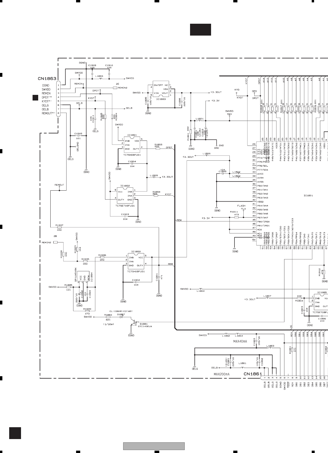
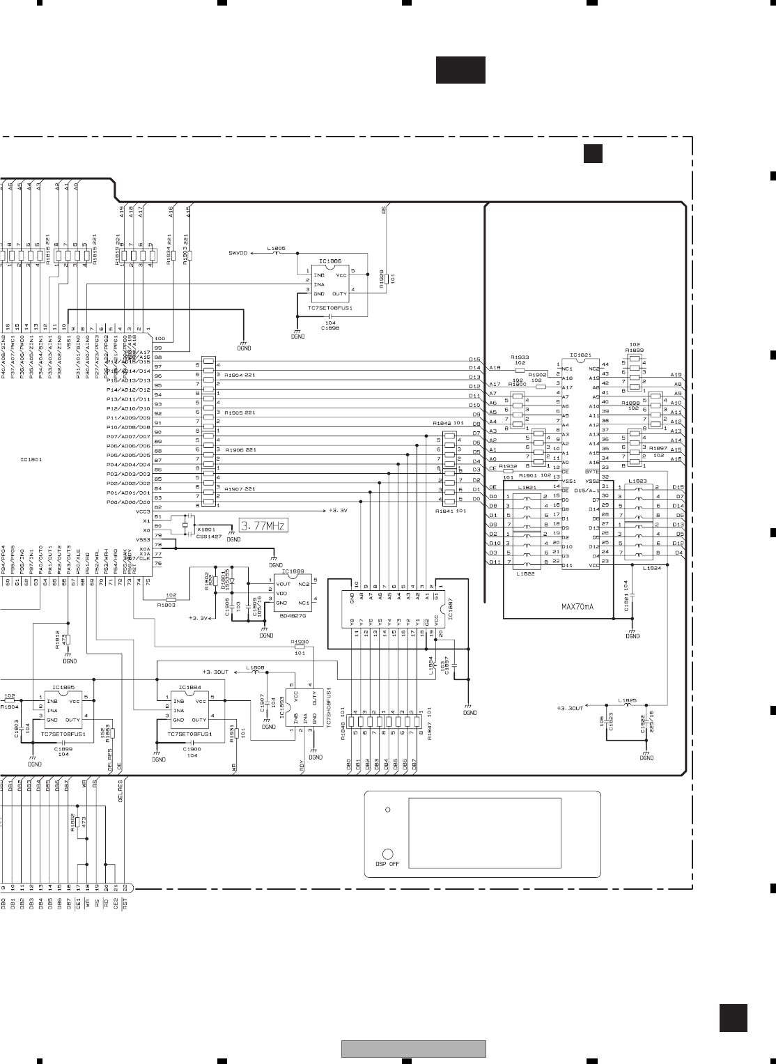
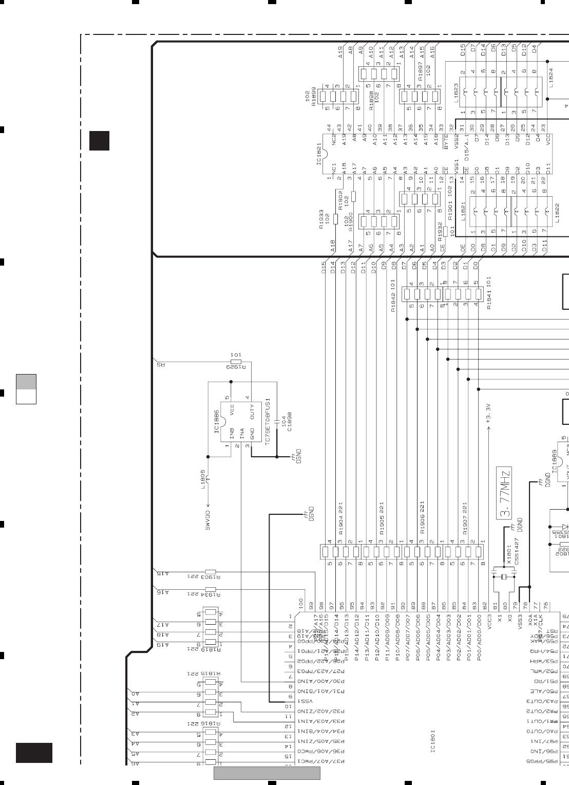
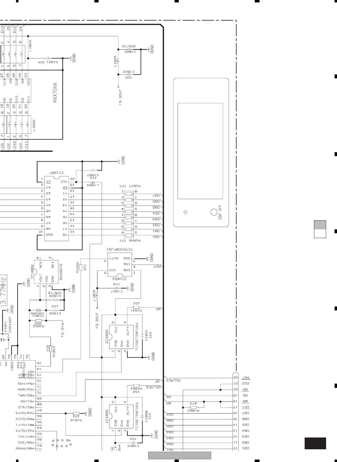
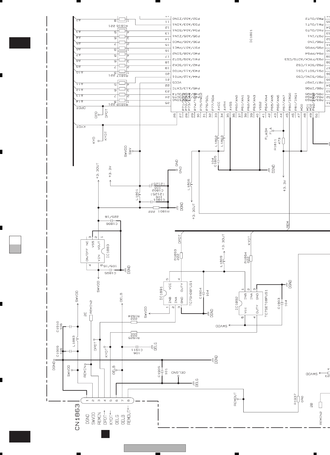
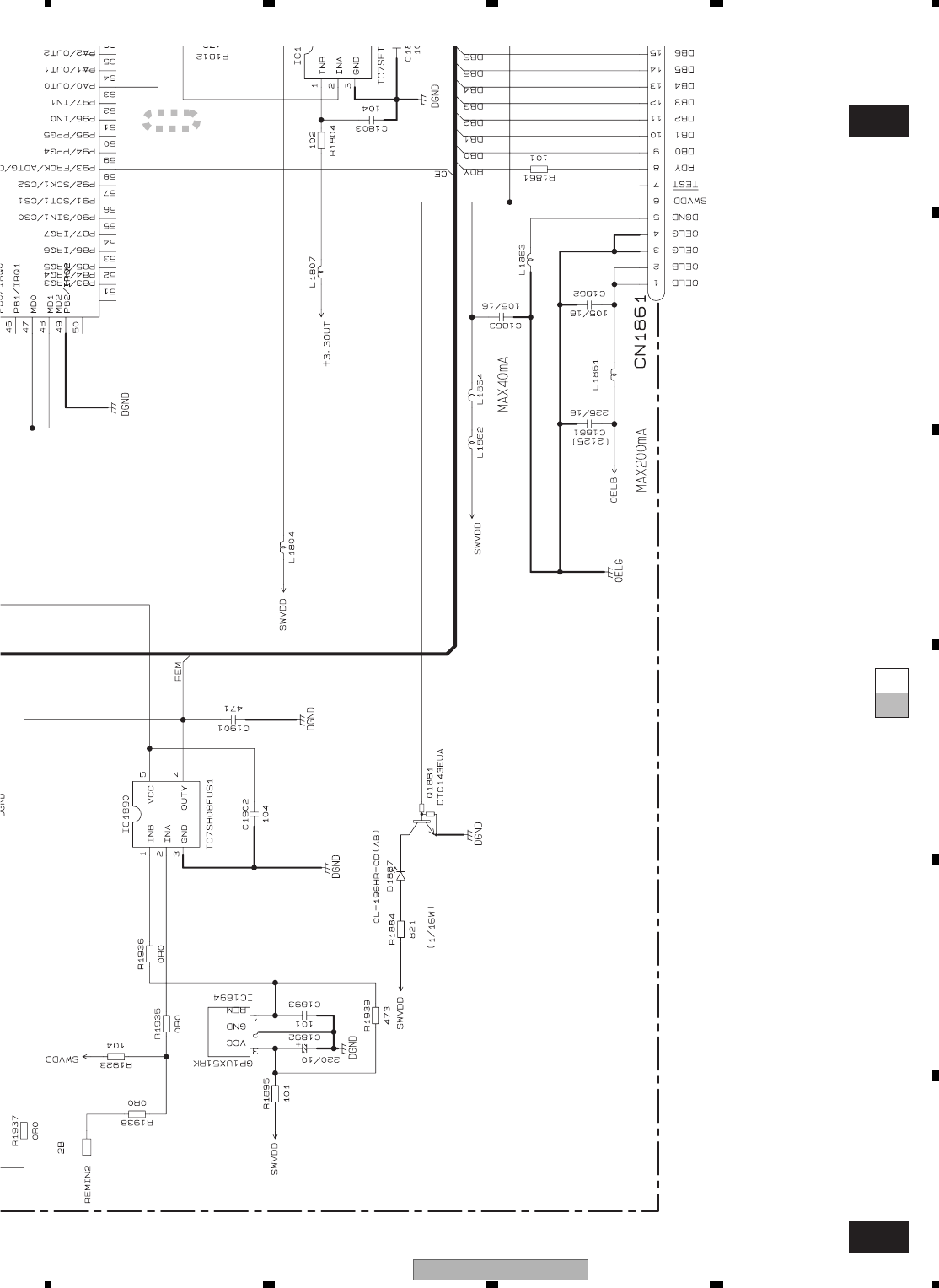
10.2 DISPLAY UNIT(GUIDE PAGE)
D-a
D
PD6573A
S-818A33AUC-BGN
MXK8203
OEL MODULE
A
JA801
AXM-P90RS/EW5 39
5 678
5678
C
D
F
A
B
E
D-b
D
PD8176A
TC74VHCT541AFTS1
PD6573A
MXK8203
O
EL MODULE
DDISPLAY UNIT
1801~1820 : KEY µCON
1821~1840 : ROM
1841~1860 : DISPLAY COMMUNICATION INTERFACE
1861~1880 : OEL MODULE JOINT
1881~1923 : LED, SW, OTHERS
AXM-P90RS/EW5
40
1234
1234
C
D
F
A
B
E
D-a D-b
D-b
PD8176A
PD6573A
DDISPLAY UNIT
1801~1820 : KEY µCON
1821~1840 : ROM
1841~1860 : DISPLAY COMMUNICATION INTERFACE
1861~1880 : OEL MODULE JOINT
1881~1923 : LED, SW, OTHERS
AXM-P90RS/EW5 41
5 678
5678
C
D
F
A
B
E
D-a D-b
D-b
1
PD8176A
TC74VHCT541AFTS1
M
XK8203
L MODULE
AXM-P90RS/EW5
42
1234
1234
C
D
F
A
B
E
D-bD-a
D-a
D-b
PD6573A
S-818A33AUC-BGN
A
JA801
AXM-P90RS/EW5 43
5 678
5678
C
D
F
A
B
E
D-a
D-b
D-bD-a
1
MXK8203
OEL MODULE
AXM-P90RS/EW5
44
1234
1234
C
D
F
A
B
E
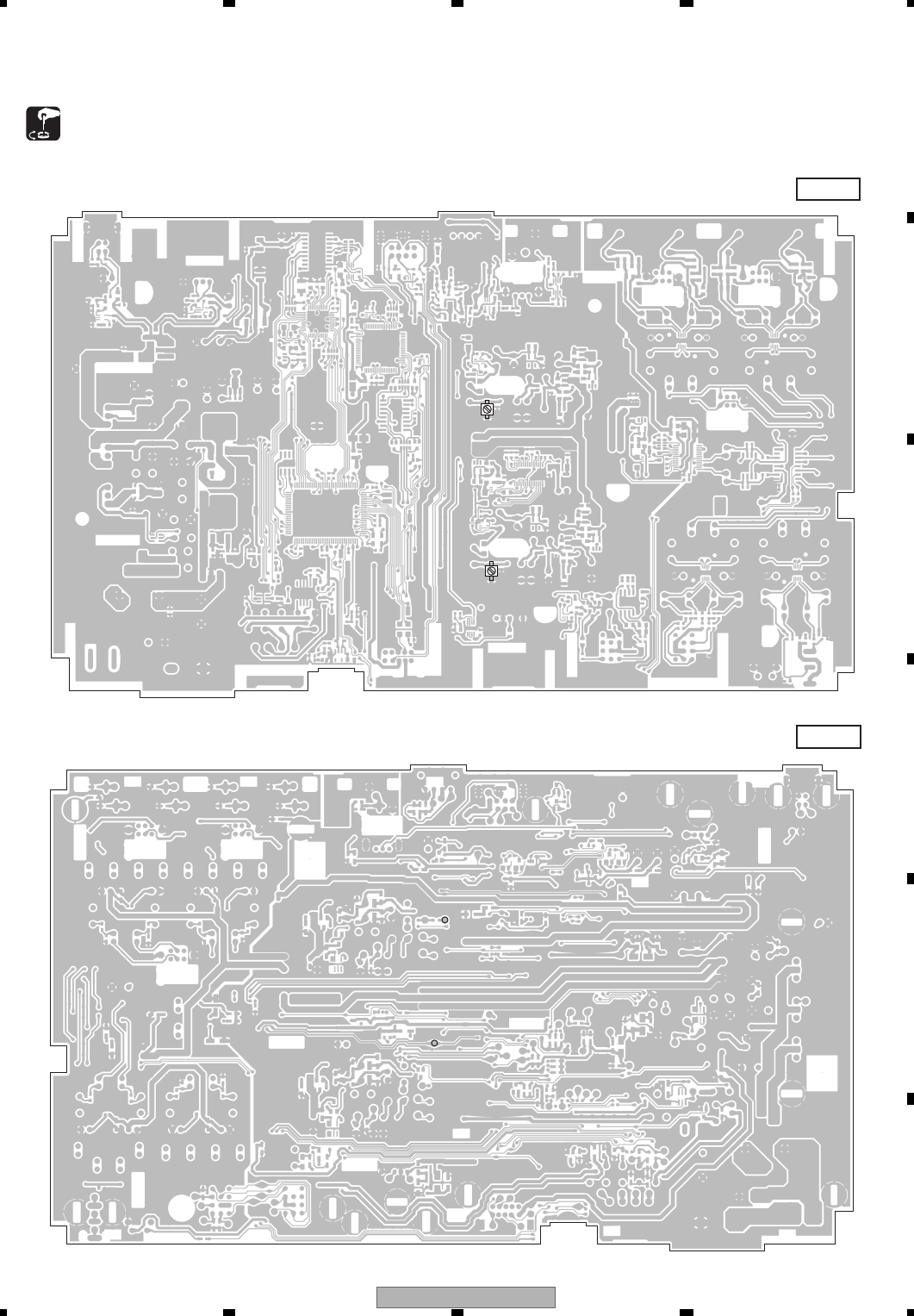
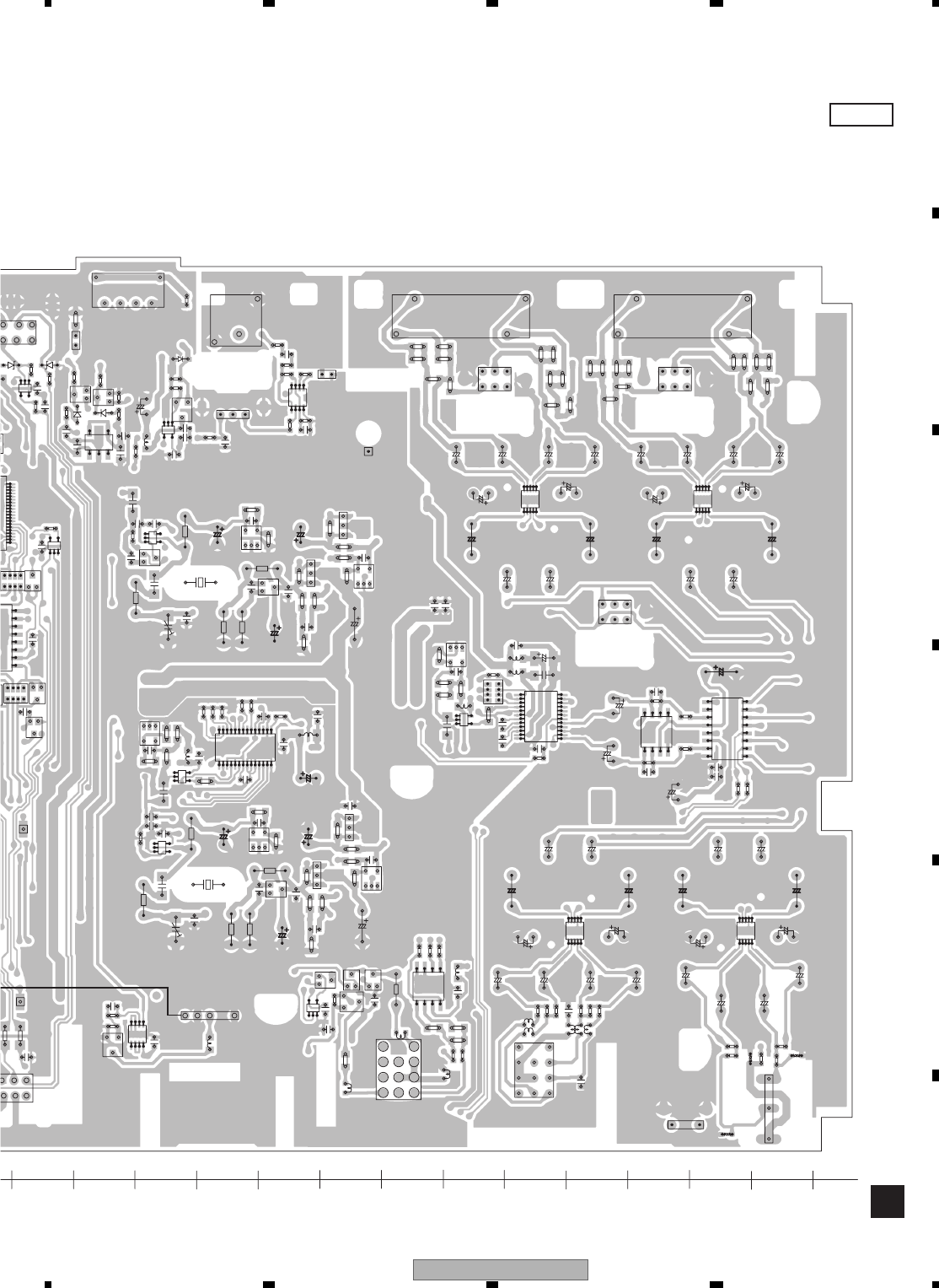
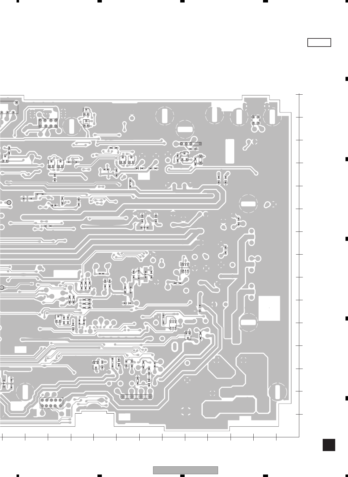
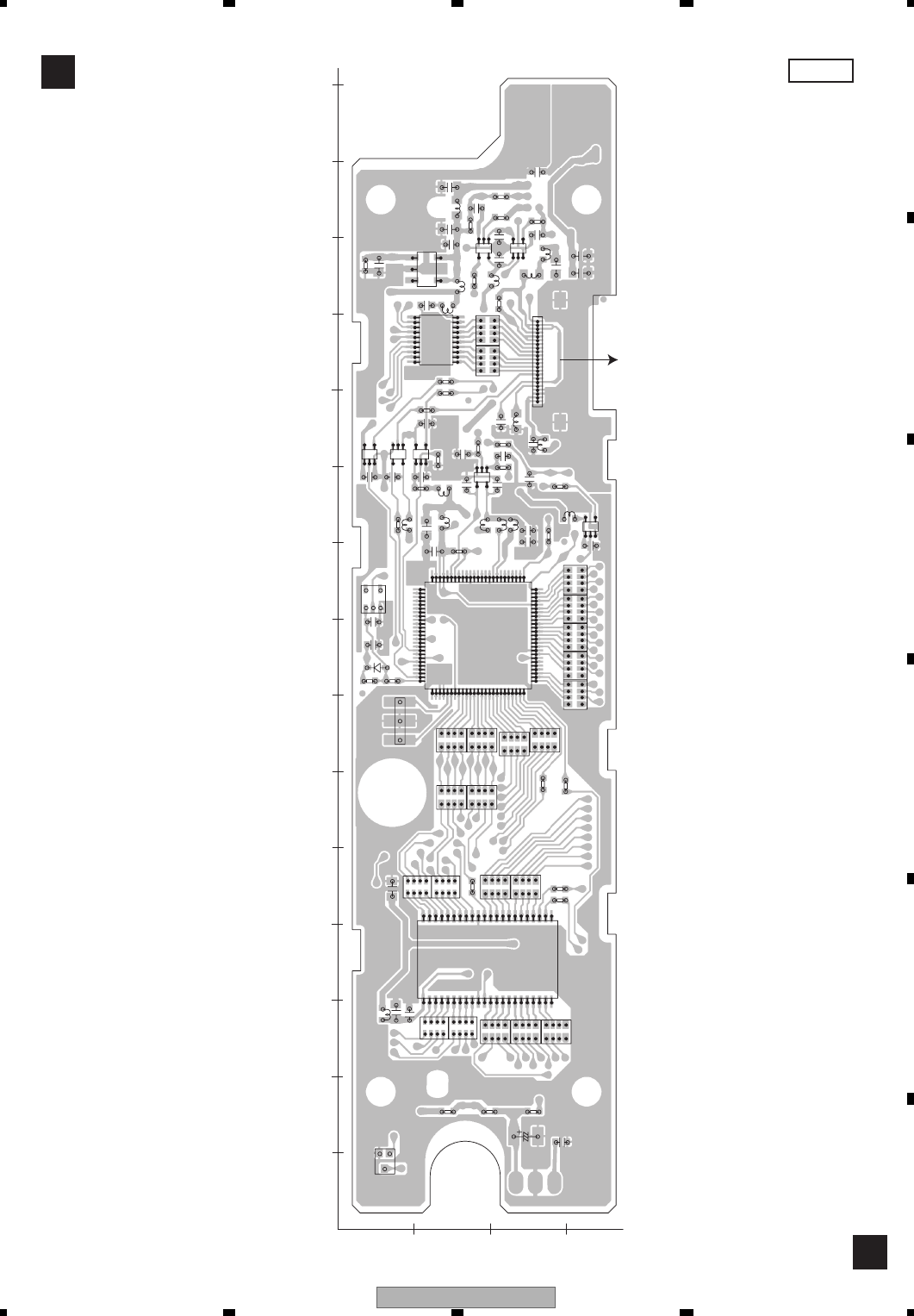
11. PCB CONNECTION DIAGRAM
11.1 MAIN PCB
A
A
MAIN PCB
Capacitor
Connector
P.C.Board Chip Part SIDE B
SIDE A
NOTE FOR PCB DIAGRAMS
1.The parts mounted on this PCB
include all necessary parts for
several destination.
For further information for
respective destinations, be sure
to check with the schematic dia-
gram.
2.Viewpoint of PCB diagrams
1
1
5
15
1
E
E
E
E
E
E
E
1
5
E
E
E
1
5
1
5
1
5
1
35 40
55 60 65
85 90 100
1
1
1
1
1
1
1
E
E
E
1
5
E
1
5
1
15 20
25
40
15
10
15
1
5
1
1015
1
5
1
1
5
1
25 30 35
45
65
1
15
10
1
5
1
5
R401
R402
R404
R405
R407
R601
R602
R603
R410
R411
R606
R607
R413
R414
R609
R801
R802
R803
R804
R610
R806
CN402
R807
R808
JA401
R810
R811
R812
R813 R814
R621
R622
R623
R
R626
R627
R628
R820
CN804
R821
JA801
JA802
C401
C402
C404
C407
C408
C604
C410
C605
C411
P702
C607
C413
C608
C416
C417
C802
C803
X601
C805
C806
C807
C808
C810
EF701
C811
C812
C813
C814
C817
C818
C820
D401
Q501
Q502
Q503
Q701
Q702
Q703
Q705
Q706
Q707
D801
Q709
L503
L504 L505
D805
L506
D806
L507
D807
L508
Q710
D808
IC401
IC402
L701
L702
L510
D811
IC601
IC602
I
C
R506
R507
R508
R509
R701
R703
R704
R510
R705
R511
R706
R512
R707
R708
R514
R709
R515
R516
R517
R518
R
9
R519
R
9
R904
R711
R905
R712
R520
R715
R521
R716
R522
R717
R523
R524
R719
R525
R526
R527
R529
R142
CN703
R720
JA702
R724
R725
H701
C121
R547 R548
C701
R549
C702
C703
C704
C705
P8
0
C706
C707
R550
C709
C515
C517
C518
C710
C711
C712
C906
C907
C714
C908
C715
C521
C523
C524
C525
C526
C528
C144
C722
C723
C530
C534
C535
C536
C537
C538
C539
C540 C541
C542
C544
C545
C546
C548
C550
C551
C554
C555
C556
Q401
C559
C561
D503 D504
D509
L401
D701
L402
D702
D703
L404
D704
D510
Q801
L405
D705
D511
Q803
D707
Q804
D708
C574
Q807
IC110
L602
L603
D710
D711
D712
D713
IC503
IC504
L801
IC505
L802
IC506
L803
IC507
IC508
IC509
IC701
IC702
IC514
IC902
C529
10
5
35
30
45 5
155 10 20
70 75 80
6050 55
40
510 15 20 25 30
45 50
70 75 80
95
10
3
10 20 30 40 50 60 70 80 90 100 110 120
X
150
140
130
120
110
100
90
80
70
60
50
40
30
20
10
0
Y
B
CN411
C
CN911
D
CN1863
REMOTE I/F
MMC
AXM-P90RS/EW5 45
5 678
5678
C
D
F
A
B
E
A
SIDE A
11
1
5
6
1
1
5
15
1
5
1
5
1
5
1
E
E
E
E
EE
E
E
E
E
E
51
10
51
10
51
10
1
1015
E
1
5
1
5
1
1
4
5
7
8
11
1
5
4
7
8
11
1
1
1
1
E
1
5
1
5
1
5
1
5
1
5
1
5
51
10
E
1
5
E
1
5
1
5
1
1520
10
15
1
5
65
1
5
1
152025
1
5
1
5
1
5
1
5
1
5
R211
R212
R409
R219
CN202
R412
R220
R415
R221
JA201
R222
R416
R223
R417
JA203
R224
R418
R801
R225
R419
802
R803
R804
R228
R229
R421
R422
JA403
R230
R424
JA404
R231
R232
R233
R234
R235
R238
R239
R815
R817
R818
R819
R241
R242
CN803
R244
R820
C209
R245
R821
8
01
A
802
C210
C211C212
C213 C214
C409
C215
C216 C217
R253
C218
R254
C219
R255
R256
R257
R258
R259
C412
C220
C415
C221
C222
C223
C418
R260
S201
C225
C226
S202
S203
C228
C229
C421
C423
C424
S401
C231
C232C233 C234C235 C236C237 C238C239
C816
C818
C819
C820
C248
C249
C250
C251
C252
Q104
Q106
Q107
D201
D202
D203
Q301
Q302
Q110
Q111
Q112
Q114
D403
Q502
L301
L302
L303
L304
L305
L308
IC201
L309
IC202
IC203
IC204
L501
L502
L310
Q901
D805
L312
D808
IC403
IC404
D810
D811
L512
L513
L514
L903
IC801
R103
R105
R106
R107
R109
R301
R302
R303R304
R110
R305
R111
R306
R112
R113
R308
R309
R115
R116
R117
R118
R501
R119
R502
R503
R504
R310
R505
R311
R312
R313
R121 R316
R122
R317
R318
R124
R125
R126
R127
R128
R129
JA301
JA302
R323
R518
R130
R324
R901
R131
R902
R132
R134
R904
R135
R905
R136
R137
R138
R139
R522
C102
C103
C105
R529
R141
C107
C108
C109
R530
C301
C302
C303
R533
C304
C110
R534
X101
CN901
C305
R535
P401
C306
C112
X102
C307
C308
C114
R538
R539
C116
C118
TC101
C501
C119
TC102
C503
C504
C310
R540
C505
C506
C312
R542
C313
R543
C314
R544
C509
C315
R545
C122
R546
C123
C317
C124
C125
C126
C127
C510
C129
P801
C513
C514
C320
C515
R551
C321
C516
R552
R553
C130
R554
C519
C902
C132
C903
C133
C134
C135
C906
C907
C520
C908
C139
C141
C142
C143
C145
S701
C546
D302
Q403
C561
C562
C563
D504
C565
C566
C567
C568
IC101
IC104
IC105
IC106
L403
IC108
IC109
D511
C571
C572
C573
IC301
C575
IC302
Q806
C576
IC303
Q807
IC501
IC502
4
1
IC508
IC510
IC511
IC512
IC513
IC515
IC901
C
902 R203
R204
4
70 75 80
0
510
10
5
5
C253
Q303
1
10 120 130 140 150 160 170 180 190 200 210 220 230 240
FRONT
IP-BUS IN
IP-BUS OUT
OEM INPUT
RCA
HI/LOW
HI/LOW
MIXING ON/OFF
TOS/COAX
EXTERNAL
COAXIAL
TOS
O
TE I/F
RESET
AXM-P90RS/EW5
46
1234
1234
C
D
F
A
B
E
A
A
MAIN PCB
120130140150
160170180190200
210220230240
E
E
E
E
E
1
1
5
1
5
E
R403
R210
R406
R423
R816
C201
C202
R246
R247
R248
R249
C403
R250 R251
C224
C227
C422
C230
C425
C240
C241
C242
C243
C244
C245
C246
C247
C254
C255
Q103
Q105
Q108
Q109
Q113
L101
L103
L901
L902
R104
R108
R307
R114
R314
R120
R315
R123
R319
R702
R320
R321
R322
R903
R133
C104
C106
R531
R532
C111
R536
C113
R537
C309
C115
C117
C502
C311
R541
C507
C508
C316
C318
C319
C128
C511
C512
C901
C131
C904
C905
C136
C137
C138
C547
D301
C560
C564
IC103
IC107
C570
L406
L407 Q805
R207 R208
R209
111
1
1
1
1
CLKF
CLK6
AXM-P90RS/EW5 47
5 678
5678
C
D
F
A
B
E
A
SIDE B
10203040506070809010011012030
X
150
140
130
120
110
100
90
80
70
60
50
40
30
20
10
0
Y
1
1
5
E
E
E
1
5
E
R408
R604
R605
R608
R611
R612
R613
R614
R809
R618
R619
R620
R816
R624
R625
403
C405
C601
C602
C603
C606
C414
C609
C419
C610
C611
C612
C613
C420
C809
D402
L104
Q704
Q708
L509
L511
L901
R513
R710
R713
R714
R718
R528
R721
R722
R723
C708
C901
C713
C716
C522
C717
C718
C719
C527
C721
C531C532
C533
C543
C547
C549
C552C553
C557
C558
Q402
D501
Q601
D505
D506
D508
Q802
D706
Q805
L601
L604
D507
D502
1
1
1
1
1
L
KF
CLK6
AXM-P90RS/EW5
48
1234
1234
C
D
F
A
B
E
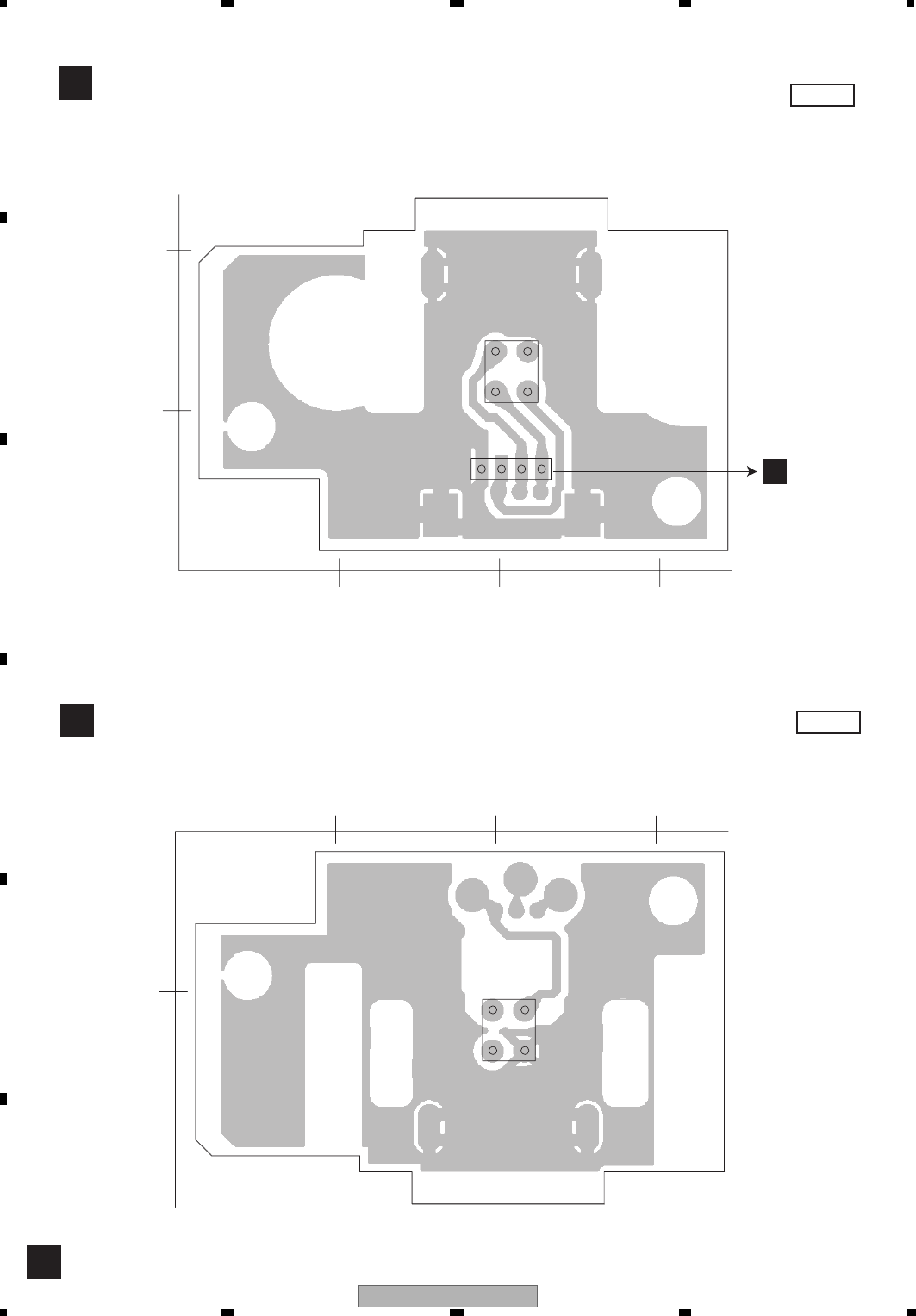
11.2 CONNECTOR PCB1
B
SIDE B
SIDE A
B
CONNECTOR PCB 1
B
CONNECTOR PCB 1
1
CN411
JA412
10
20
10 20 30
0
X
Y
20
10
10 20 30
0
X
Y
4
42
31
A
CN402
OPT-IN
1
AXM-P90RS/EW5 49
5 678
5678
C
D
F
A
B
E
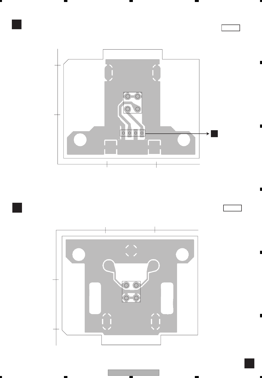
11.3 CONNECTOR PCB2
C
SIDE B
SIDE A
C
CONNECTOR PCB 2
C
CONNECTOR PCB 2
10
20
10
0
X
Y
1
1
CN911
JA912
4
2
3
4
20
10
20
10
0
X
Y
20
A
CN901
OPT-OUT
1
AXM-P90RS/EW5
50
1234
1234
C
D
F
A
B
E
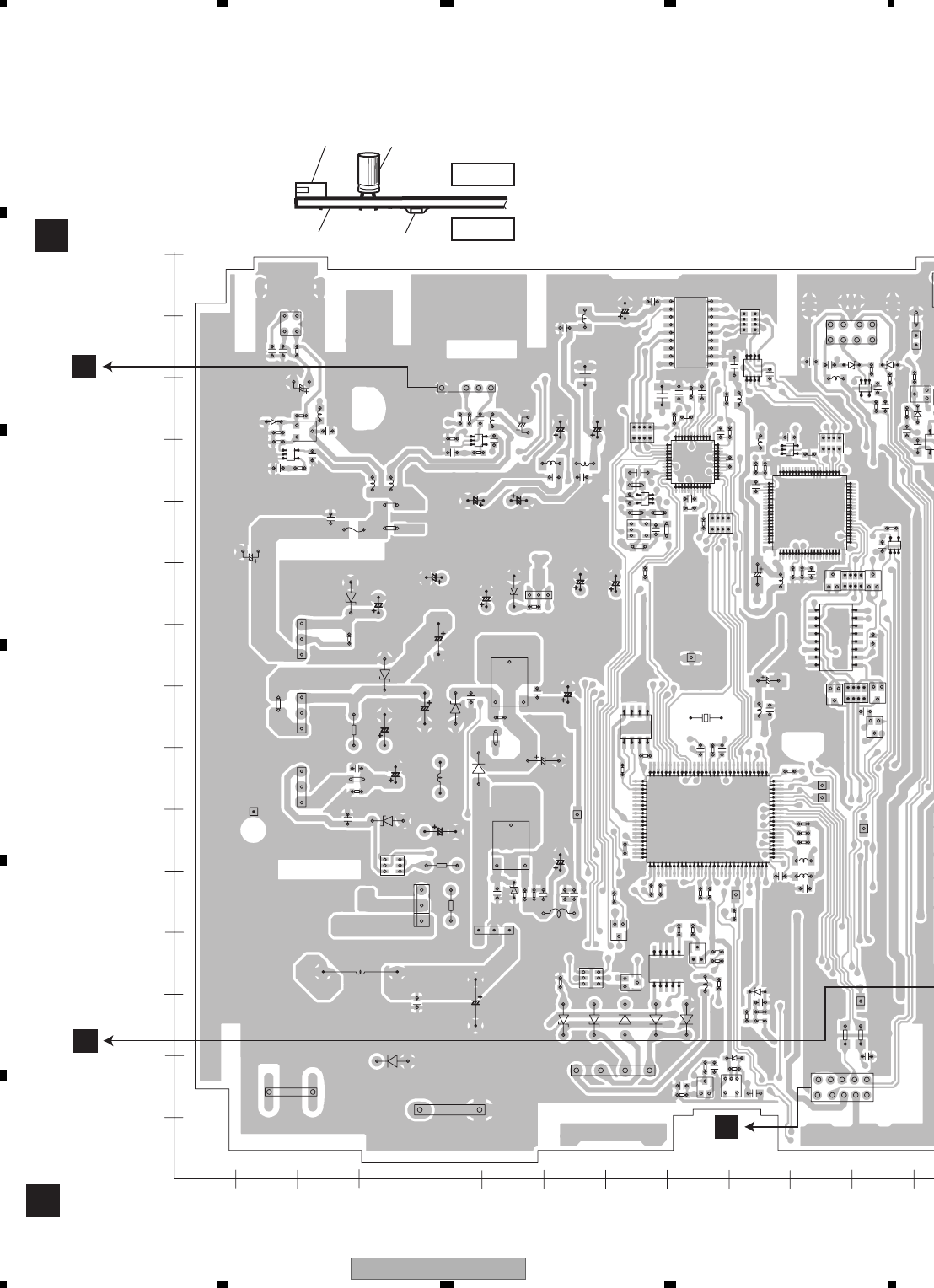
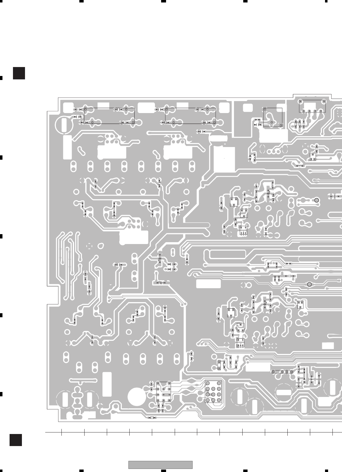
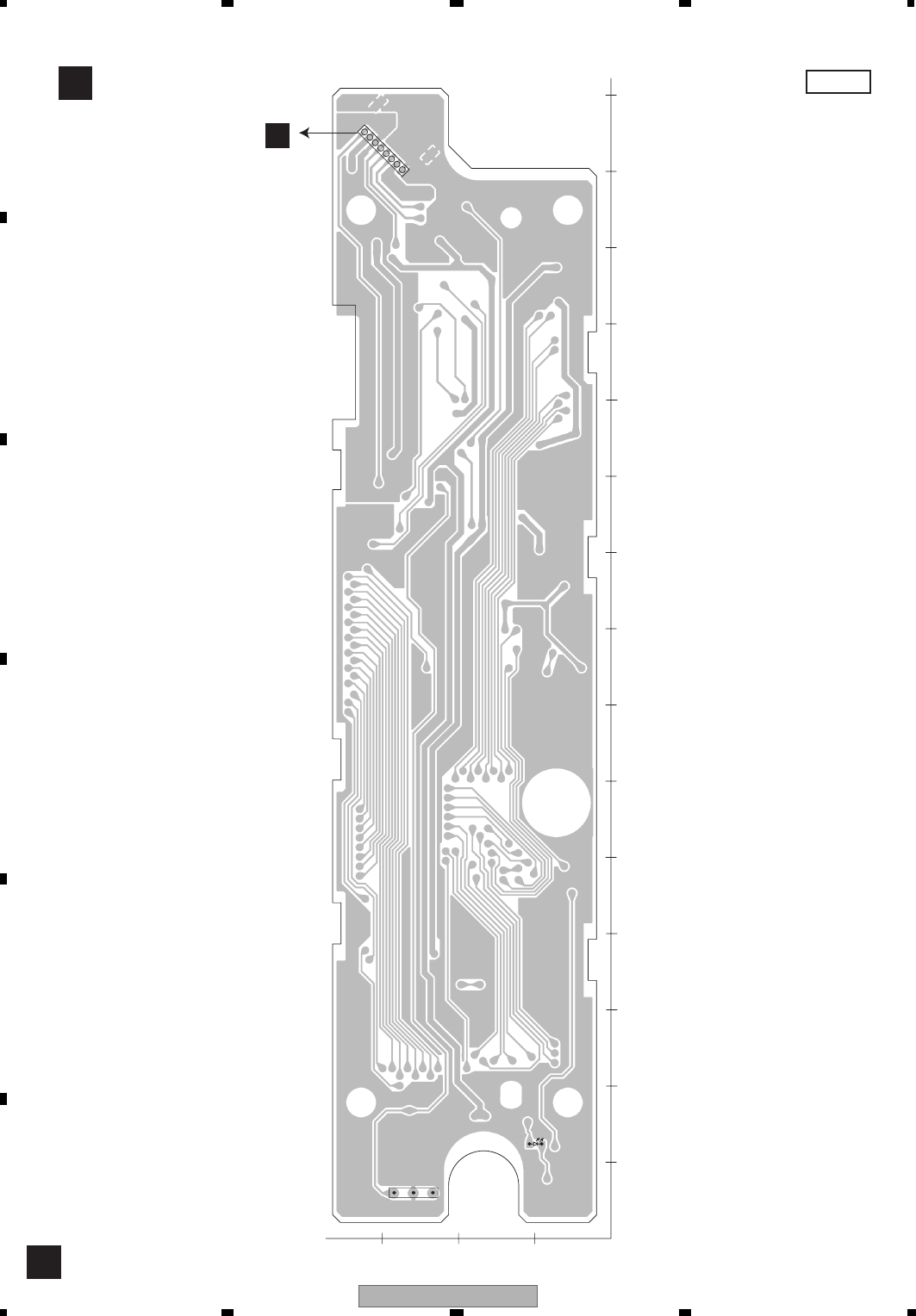
11.4 DISPLAY UNIT
D
SIDE A
D
DISPLAY UNIT
1
1
CN1863
D1887
IC1894
58
10 20 30 40 50 60 70 80 90 100
X
30
20
10
0
Y
110 120 130 140 150
A
CN801
AXM-P90RS/EW5 51
5 678
5678
C
D
F
A
B
E
D
SIDE B
D
DISPLAY UNIT
150 140 130 120 110 100 90 80 70 60
X
30
20
10
0
Y
50 40 30 20 10
1510
15
20
1520
25
30
35
40
1
30
35
40
45
50
556065
70
75
80
85
90
95
100
1
E
1
1
5
1
5
1
5
1
5
1
5
1
5
1
5
1
1
C1900
C1901
X1801
C1902
C1903 C1904
C1905
C1906
C1907
C1909
C1910
C1911
C1912
C1913
C1914
C1915
C1916
R1900
R1902
R1903
R1904 R1905 R1906 R1907
L1801
L1802
L1803
L1804
L1805
L1806
L1807
R1923
L1808
R1924
L1809
R1925
R1929
R1930
R1931
R1932
R1933
R1934
R1935
R1936
R1937
R1938
R1939
L1821 L1822
L1823 L1824
L1825
L1861
L1862
L1863
L1864
L1883
L1884
C1801
C1802
C1803
C1805
C1806
C1809
C1821
C1822
C1823
D1801
R1801 R1802
R1803
R1804
IC1801
R1811
R1812
R1815
R1816
R1817
R1818 R1819
IC1821
CN1861
C1861
C1862
C1863
C1864
R1841
R1842
R1847 R1848
Q1881
R1861
R1862
R1863
C1892
C1893
C1895
C1896
C1897
C1898
C1899
R1884
IC1883
IC1884
IC1885
IC1886
IC1887
IC1889
R1893
R1894
R1895
R1897
R1898
IC1890
R1899
IC1891
IC1892
IC1893
15
10
R1901
510 15 20 25
5
10
15
20
OEL MODULE

AXM-P90RS/EW5
52
1234
1234
C
D
F
A
B
E
12. ELECTRICAL PARTS LIST
N
OTE:
Parts whose parts numbers are omitted are subject to being not supplied.
The part numbers shown below indicate chip components.
Chip Resistor
RS1/_S___J,RS1/__S___J
Chip Capacitor (except for CQS.....)
CKS....., CCS....., CSZS.....
The > mark found on some component parts indicates the importance of the safety factor of the part.
Therefore, when replacing, be sure to use parts of identical designation.
Meaning of the figures and others in the parentheses in the parts list.
Example) IC 301 is on the point (face A, 91 of x-axis, and 111 of y-axis) of the corresponding
PC board.
IC 301 (A, 91, 111) IC NJM2068V
Circuit Symbol and No. Part No.
Unit Number : CWN2574
Unit Name : Main Unit
Unit Number : CWN2571
Unit Name : Display Unit
Main Unit
Consists of
Main PCB
Connector PCB1
Connector PCB2
ABC
Unit Number : CWN2574
Unit Name : Main Unit
MISCELLANEOUS
IC 101 (A,167,98) IC NJM2373AF
IC 103 (B,159,89) IC NJM2373AF
IC 104 (A,149,104) IC NJM2373AF
IC 105 (A,133,104) Logic IC TC7SHU04FUS1
IC 106 (A,168,49) IC NJM2373AF
IC 107 (B,161,40) IC NJM2373AF
IC 108 (A,150,55) IC NJM2373AF
IC 109 (A,134,54) Logic IC TC7SHU04FUS1
IC 110 (A,76,110) IC TC7SET04FUS1
IC 201 (A,222,110) IC NJM2794RB2
IC 202 (A,194,110) IC NJM2794RB2
IC 203 (A,229,40) IC NJM2794RB2
IC 204 (A,226,73) Audio Selector IC NJM2750M
IC 301 (A,201,40) IC NJM2794RB2
IC 302 (A,178,31) IC HA12187FPS1
IC 303 (A,159,28) IC TC7S04FU
IC 401 (A,19,118) 1 Chip or Gate TC7SH32FUS1
IC 402 (A,49,120) 1 Chip or Gate TC7SH32FUS1
IC 403 (A,135,122) 1 Chip or Gate TC7SH32FUS1
IC 404 (A,156,127) IC TC7WU04FU
IC 501 (A,215,73) IC OPA2134UA
IC 502 (A,196,75) IC PCM1800S1
IC 503 (A,84,116) IC LC89055WHS-RA8
IC 504 (A,107,88) IC TC74HCT157AF
IC 505 (A,100,118) IC TC7SH08FUS1
IC 506 (A,84,137) IC PD0236BM
IC 507 (A,94,132) IC TC7WH34FU
IC 508 (A,117,103) IC TC7SH02FUS1
IC 509 (A,103,108) IC SM5849BF
IC 510 (A,138,65) IC TC7SET04FUS1
IC 511 (A,148,70) IC DIT4096IPW
IC 512 (A,183,75) IC TC7SET04FUS1
IC 513 (A,132,72) IC NJM2373AF
IC 514 (A,75,105) IC NJM2373AF
IC 515 (A,182,85) IC NJM2373AF
IC 602 (A,87,58) IC PE5612A
IC 701 (A,90,15) IC BD4841G
IC 702 (A,80,34) IC TPD1018F
IC 901 (A,130,24) IC TC7WU04FU
IC 902 (A,112,128) IC TC7SH08FUS1
Q 103 (B,164,102) Transistor 2SC2412K
Q 104 (A,166,106) Transistor 2SD1767
Q 105 (B,159,97) Transistor 2SC2412K
Q 106 (A,160,98) Transistor 2SD1767
Q 107 (A,152,96) Transistor 2SC4226
Q 108 (B,161,46) Transistor 2SC2412K
Q 109 (B,165,53) Transistor 2SC2412K
Q 110 (A,161,49) Transistor 2SD1767
Q 111 (A,167,57) Transistor 2SD1767
Q 112 (A,153,47) Transistor 2SC4226
Q 113 (B,134,56) Chip Transistor DTC114EUA
Q 114 (A,132,101) Chip Transistor DTC114EUA
Q 301 (A,165,29) Transistor 2SA1037K
Q 302 (A,165,32) Chip Transistor DTC124EUA
Q 303 (A,169,32) Transistor 2SC4081
Q 401 (A,21,121) Transistor 2SC2412K
Q 402 (B,50,123) Transistor 2SC2412K
Q 403 (A,138,125) Transistor 2SC2412K
Q 501 (A,59,97) Transistor 2SD1767
Q 502 (A,114,73) Chip Transistor DTC114EUA
Q 503 (A,72,40) Chip Transistor DTC114EUA
Circuit Symbol and No. Part No.

AXM-P90RS/EW5 53
5 678
5678
C
D
F
A
B
E
Q 601 (B,105,52) Chip Transistor DTA114EUA
Q 701 (A,86,15) Transistor 2SC4081
Q 702 (A,54,82) Transistor 2SD1760F5
Q 703 (A,21,76) Transistor 2SD2396
Q 704 (B,50,74) Transistor IMD2A
Q 705 (A,85,37) Transistor 2SA1576A
Q 706 (A,68,33) Transistor IMX1
Q 707 (A,21,88) Transistor 2SD2396
Q 708 (B,49,44) Chip Transistor DTC114EUA
Q 709 (A,40,44) Transistor 2SB1243
Q 710 (A,74,32) Chip Transistor DTC114EUA
Q 801 (A,55,56) Transistor 2SD1760F5
Q 802 (B,55,49) Transistor IMD2A
Q 803 (A,21,64) Transistor 2SD2396
Q 804 (A,35,51) Transistor IMD2A
Q 901 (A,126,22) Transistor 2SC4453
D 201 (A,226,7) Diode MALS068X
D 202 (A,237,20) Diode MALS068X
D 203 (A,230,20) Diode MALS068X
D 301 (B,170,30) Diode 1SS352
D 302 (A,161,32) Diode DAN202U
D 401 (A,16,123) Diode 1SS352
D 402 (B,43,121) Diode 1SS352
D 403 (A,137,133) Diode 1SS352
D 501 (B,77,121) Diode Network DA204U
D 502 (B,73,121) Diode Network DA204U
D 503 (A,107,79) Diode Network DA204U
D 504 (A,114,79) Diode Network DA204U
D 505 (B,93,142) Diode Network DA204U
D 506 (B,108,120) Diode Network DA204U
D 507 (B,104,120) Diode Network DA204U
D 508 (B,93,137) Diode Network DA204U
D 509 (A,55,95) Diode HZS4LL(A)
D 510 (A,107,97) Diode Network DA204U
D 511 (A,113,97) Diode Network DA204U
D 701 (A,91,20) Diode 1SS352
D 702 (A,46,76) Diode HZS6L(B1)
D 703 (A,34,82) Diode HZS9L(B3)
D 704 (A,29,94) Diode HZS6L(B1)
D 705 (A,49,67) Diode ERA15-02VH
D 706 (B,89,31) Diode DAN202U
D 707 (A,63,26) Diode HZS7L(C3)
D 708 (A,68,26) Diode HZS7L(A1)
D 710 (A,78,26) Diode ERA15-02VH
D 711 (A,35,19) Diode ERA15-02VH
D 712 (A,83,26) Diode ERA15-02VH
D 713 (A,73,26) Diode ERA15-02VH
D 801 (A,95,30) Diode HZU5R6(B2)
D 805 (A,116,132) Diode HZU6R8(B2)
D 806 (A,55,47) Diode HZU5R6(B3)
D 807 (A,35,58) Diode HZS9L(C3)
D 808 (A,110,132) Diode HZU6R8(B2)
L 101 (B,146,109) Inductor CTF1305
L 103 (B,147,60) Inductor CTF1305
L 104 (B,74,111) Inductor CTF1305
L 301 (A,182,34) Inductor LCTC3R3K2125
L 302 (A,194,24) Inductor CTF1473
L 303 (A,202,24) Inductor CTF1473
L 304 (A,204,24) Inductor CTF1473
L 305 (A,194,25) Inductor CTF1473
Circuit Symbol and No. Part No.
L 308 (A,164,15) Inductor CTF1473
L 309 (A,200,24) Inductor CTF1473
L 310 (A,173,24) Inductor CTF1473
L 312 (A,180,17) Inductor CTF1473
L 401 (A,24,124) Inductor LCTC1R8K2125
L 402 (A,52,123) Inductor LCTC1R8K2125
L 403 (A,132,120) Inductor LCTC1R8K2125
L 404 (A,32,113) Inductor LCTC120K2125
L 405 (A,35,113) Inductor LCTC120K2125
L 406 (B,134,118) Inductor LCTC120K2125
L 407 (B,154,122) Inductor LCTC120K2125
L 501 (A,192,85) Inductor CTF1305
L 502 (A,192,82) Inductor CTF1305
L 503 (A,95,76) Inductor CTF1305
L 504 (A,61,116) Inductor LCTAW1R0J3225
L 505 (A,67,116) Inductor LCTAW1R0J3225
L 506 (A,67,140) Inductor LCTAW1R0J3225
L 507 (A,95,120) Inductor CTF1305
L 508 (A,92,127) Inductor CTF1305
L 509 (B,113,106) Inductor CTF1305
L 510 (A,98,97) Inductor CTF1305
L 511 (B,68,92) Inductor LCTAW1R0J3225
L 512 (A,139,69) Inductor LCYC100K2125
L 513 (A,158,72) Inductor LCTAW1R0J3225
L 514 (A,183,77) Inductor CTF1305
L 601 (B,74,64) Inductor LCTAW2R2J2520
L 602 (A,102,52) Inductor LCTAW2R2J2520
L 603 (A,102,49) Inductor LCTAW2R2J2520
L 604 (B,67,71) Chip Coil LCTAW100J2520
L 701 (A,86,32) Inductor LCTAW2R2J2520
L 702 (A,23,34) Choke Coil 600 µH CTH1280
L 801 (A,107,130) Chip Coil LCTAW3R3J2520
L 802 (A,62,43) Inductor CTF1614
L 803 (A,43,65) Inductor CTF1489
L 901 (B,129,23) Inductor LCTAW1R0J3225
L 902 (B,135,28) Inductor LCTC2R7K2125
L 903 (A,142,22) Inductor CTF1407
TC101 (A,135,90) Trimmer CCL1048
TC102 (A,137,41) Trimmer CCL1048
X 101 (A,141,97) Oscillator 12.288 MHz CSS1746
X 102 (A,142,48) Oscillator 11.289 6 MHz CSS1745
X 601 (A,86,75) Radiator 12.582 9 MHz CSS1495
F 701 EMI Filter CCG1175
S 201 (A,218,130) Slide Switch(HI/LOW) CSH1065
S 202 (A,188,130) Slide Switch(HI/LOW) CSH1065
S 203 (A,208,92) Slide Switch(MIXING) CSH1065
S 401 (A,146,124) Slide Switch(TOS/COAX) CSH1051
S 701 (A,219,9) Switch(RESET) CSG1020
>P401 (A,161,131) Fuse 3 A CEK1286
>P702 (A,29,105) Fuse 400 mA CEK1250
>P801 (A,120,136) Fuse 3 A CEK1286
>Fuse 4 A CEK1001
RESISTORS
R 103 (A,164,98) RN1/10SE2200D
R 104 (B,169,100) RN1/10SE5601D
R 105 (A,164,101) RS1/10S2700D
R 106 (A,164,103) RN1/10SE1002D
R 107 (A,162,106) RN1/10SE4701D
Circuit Symbol and No. Part No.

AXM-P90RS/EW5
54
1234
1234
C
D
F
A
B
E
R 108 (B,163,93) RN1/10SE2200D
R 109 (A,157,87) RN1/10SE6201D
R 110 (A,159,94) RS1/10S2700D
R 111 (A,157,94) RN1/10SE1002D
R 112 (A,157,98) RN1/10SE4701D
R 113 (A,147,90) RN1/4PC1001F
R 114 (B,154,103) RN1/10SE2200D
R 115 (A,151,99) RN1/4PC2202F
R 116 (A,144,90) RN1/4PC2202F
R 117 (A,130,94) RN1/4PC1000F
R 118 (A,138,105) RN1/4PC4702F
R 119 (A,130,104) RN1/16SE1200D
R 120 (B,164,44) RN1/10SE2200D
R 121 (A,159,38) RN1/10SE5101D
R 122 (A,166,49) RN1/10SE2200D
R 123 (B,170,51) RN1/10SE5601D
R 124 (A,160,45) RS1/10S2700D
R 125 (A,158,45) RN1/10SE1002D
R 126 (A,165,52) RS1/10S2700D
R 127 (A,165,54) RN1/10SE1002D
R 128 (A,158,49) RN1/10SE4701D
R 129 (A,163,57) RN1/10SE4701D
R 130 (A,149,41) RN1/4PC1001F
R 131 (A,152,50) RN1/4PC3902F
R 132 (A,146,41) RN1/4PC3902F
R 133 (B,155,54) RN1/10SE2200D
R 134 (A,131,45) RN1/4PC1500F
R 135 (A,150,60) RN1/10SE9101D
R 136 (A,153,55) RN1/10SE1002D
R 137 (A,139,56) RN1/4PC4702F
R 138 (A,149,109) RN1/10SE9101D
R 139 (A,152,104) RN1/10SE1002D
R 141 (A,131,55) RS1/16S47R0D
R 142 (A,75,113) RN1/10SE2200D
R 203 (A,209,129) RN1/10SE2200D
R 204 (A,233,129) RN1/10SE2200D
R 207 (B,201,101) RN1/16SE6201D
R 208 (B,187,100) RN1/16SE6201D
R 209 (B,222,49) RN1/16SE6201D
R 210 (B,234,49) RN1/16SE6201D
R 211 (A,229,63) RS1/16S103J
R 212 (A,228,63) RS1/16S103J
R 219 (A,219,70) RN1/16SE4701D
R 220 (A,219,75) RN1/16SE4701D
R 221 (A,227,22) RS1/16S223J
R 222 (A,235,22) RS1/16S223J
R 223 (A,227,20) RS1/16S0R0J
R 224 (A,234,19) RS1/16S0R0J
R 225 (A,232,20) RS1/16S0R0J
R 228 (A,198,134) RN1/10SE1001D
R 229 (A,176,135) RN1/10SE1001D
R 230 (A,197,130) RN1/10SE1001D
R 231 (A,180,135) RN1/10SE1001D
R 232 (A,227,133) RN1/10SE1001D
R 233 (A,206,132) RN1/10SE1001D
R 234 (A,233,133) RN1/10SE1001D
R 235 (A,208,132) RN1/10SE1001D
R 238 (A,198,126) RN1/10SE2202D
R 239 (A,178,130) RN1/10SE2202D
R 241 (A,230,129) RN1/10SE2202D
Circuit Symbol and No. Part No.
R 242 (A,207,127) RN1/10SE2202D
R 244 (A,201,126) RN1/10SE2200D
R 245 (A,181,129) RN1/10SE2200D
R 246 (B,231,101) RN1/16SE6201D
R 247 (B,229,97) RN1/16SE5602D
R 248 (B,217,101) RN1/16SE6201D
R 249 (B,217,97) RN1/16SE5602D
R 250 (B,200,97) RN1/16SE5602D
R 251 (B,188,98) RN1/16SE5602D
R 253 (A,210,132) RN1/10SE1001D
R 254 (A,229,133) RN1/10SE1001D
R 255 (A,204,132) RN1/10SE1001D
R 256 (A,231,133) RN1/10SE1001D
R 257 (A,176,133) RN1/10SE1001D
R 258 (A,196,134) RN1/10SE1001D
R 259 (A,180,133) RN1/10SE1001D
R 260 (A,199,130) RN1/10SE1001D
R 301 (A,164,19) RS1/10S152J
R 302 (A,182,23) RS1/10S620J
R 303 (A,178,25) RS1/10S101J
R 304 (A,182,25) RS1/10S101J
R 305 (A,195,27) RS1/16S181J
R 306 (A,205,27) RS1/16S181J
R 307 (B,165,32) RS1/10S562J
R 308 (A,162,29) RS1/16S332J
R 309 (A,197,27) RS1/16S223J
R 310 (A,204,27) RS1/16S223J
R 311 (A,202,27) RS1/16S102J
R 312 (A,198,27) RS1/16S102J
R 313 (A,172,31) RD1/4PU560J
R 314 (B,163,30) RS1/16S104J
R 315 (B,168,30) RS1/16S472J
R 316 (A,176,37) RS1/16S103J
R 317 (A,179,37) RS1/16S681J
R 318 (A,178,37) RS1/16S681J
R 319 (B,194,50) RN1/16SE6201D
R 320 (B,208,50) RN1/16SE6201D
R 321 (B,194,54) RN1/16SE5602D
R 322 (B,206,53) RN1/16SE5602D
R 323 (A,182,20) RS1/16S0R0J
R 324 (A,183,20) RS1/16S0R0J
R 401 (A,20,134) RS1/16S102J
R 402 (A,48,123) RS1/16S102J
R 403 (B,134,136) RS1/16S102J
R 404 (A,21,124) RS1/16S102J
R 405 (A,46,123) RS1/16S102J
R 406 (B,136,136) RS1/16S102J
R 407 (A,17,121) RS1/16S473J
R 408 (B,45,121) RS1/16S473J
R 409 (A,137,130) RS1/16S473J
R 410 (A,17,120) RS1/16S102J
R 411 (A,45,120) RS1/16S102J
R 412 (A,137,128) RS1/16S102J
R 413 (A,20,115) RS1/16S470J
R 414 (A,49,118) RS1/16S470J
R 415 (A,142,120) RS1/16S470J
R 416 (A,138,143) RS1/16S0R0J
R 417 (A,153,135) RS1/16S0R0J
R 418 (A,155,132) RS1/16S101J
R 419 (A,155,131) RS1/16S104J
Circuit Symbol and No. Part No.

AXM-P90RS/EW5 55
5 678
5678
C
D
F
A
B
E
R 421 (A,158,131) RS1/16S101J
R 422 (A,155,122) RS1/16S101J
R 423 (B,153,138) RS1/16S750J
R 424 (A,158,123) RS1/16S222J
R 501 (A,213,68) RN1/16SE4701D
R 502 (A,215,78) RN1/16SE4701D
R 503 (A,196,68) RS1/16S103J
R 504 (A,188,82) RS1/16S561J
R 505 (A,188,79) RAB4C471J
R 506 (A,89,106) RAB4C101J
R 507 (A,90,121) RS1/16S103J
R 508 (A,84,109) RS1/16S103J
R 509 (A,86,106) RS1/16S101J
R 510 (A,81,123) RS1/16S103J
R 511 (A,83,124) RS1/16S512J
R 512 (A,84,128) RS1/16S752J
R 513 (B,81,127) RS1/16S750J
R 514 (A,76,98) RS1/16S101J
R 515 (A,71,46) RS1/16S101J
R 516 (A,76,121) RAB4C221J
R 517 (A,90,127) RS1/16S681J
R 518 (A,111,79) RAB4C101J
R 519 (A,103,118) RS1/16S221J
R 520 (A,107,119) RAB4C221J
R 521 (A,93,139) RAB4C101J
R 522 (A,116,106) RS1/16S102J
R 523 (A,94,115) RS1/16S152J
R 524 (A,96,115) RS1/16S272J
R 525 (A,58,93) RS1/16S271J
R 526 (A,102,98) RS1/16S272J
R 528 (B,104,103) RS1/16S222J
R 529 (A,110,97) RAB4C101J
R 530 (A,141,65) RN1/10SE2200D
R 531 (B,144,68) RS1/16S103J
R 532 (B,145,68) RS1/16S103J
R 533 (A,154,75) RS1/16S103J
R 534 (A,149,77) RS1/16S103J
R 535 (A,147,77) RS1/16S103J
R 536 (B,148,74) RS1/16S103J
R 537 (B,145,74) RS1/16S103J
R 538 (A,144,76) RS1/16S103J
R 539 (A,143,76) RS1/16S103J
R 540 (A,141,76) RS1/16S103J
R 541 (B,139,75) RN1/16SE1000D
R 542 (A,187,75) RN1/10SE2200D
R 543 (A,137,72) RN1/10SE2200D
R 544 (A,132,68) RN1/10SE1002D
R 545 (A,135,72) RN1/10SE4302D
R 546 (A,135,69) RN1/10SE4702D
R 547 (A,75,108) RN1/10SE2200D
R 548 (A,79,108) RN1/10SE4702D
R 549 (A,80,105) RN1/10SE9101D
R 550 (A,75,103) RN1/10SE2202D
R 551 (A,180,79) RN1/10SE4702D
R 552 (A,183,80) RN1/10SE2200D
R 553 (A,180,81) RN1/10SE1002D
R 554 (A,179,85) RN1/10SE4302D
R 603 (A,73,54) RS1/16S681J
R 604 (B,76,64) RS1/16S473J
R 605 (B,92,66) RS1/16S473J
Circuit Symbol and No. Part No.
R 606 (A,77,47) RS1/16S102J
R 607 (A,79,47) RS1/16S102J
R 609 (A,87,70) RS1/16S102J
R 610 (A,91,43) RS1/16S0R0J
R 611 (B,93,66) RS1/16S473J
R 612 (B,95,66) RS1/16S473J
R 614 (B,94,50) RS1/16S473J
R 618 (B,93,60) RS1/16S473J
R 619 (B,93,58) RS1/16S473J
R 620 (B,93,57) RS1/16S473J
R 621 (A,102,58) RS1/16S473J
R 622 (A,102,56) RS1/16S473J
R 623 (A,102,55) RS1/16S473J
R 624 (B,100,60) RS1/16S473J
R 625 (B,99,60) RS1/16S473J
R 626 (A,85,46) RS1/16S473J
R 627 (A,87,46) RS1/16S473J
R 628 (A,100,66) RS1/16S102J
R 701 (A,86,18) RS1/16S102J
R 702 (B,200,6) RS1/16S472J
R 703 (A,82,14) RS1/16S473J
R 704 (A,91,18) RS1/16S822J
R 705 (A,53,75) RS1/16S223J
R 706 (A,17,77) RS1/10S1R0J
R 707 (A,84,40) RS1/16S102J
R 708 (A,52,72) RS1/10S472J
R 709 (A,88,37) RS1/16S472J
R 711 (A,88,35) RS1/16S472J
R 712 (A,28,88) RS1/16S392J
R 713 (B,63,32) RS1/16S104J
R 714 (B,68,32) RS1/16S103J
R 715 (A,29,73) RD1/4PU821J
R 716 (A,88,32) RS1/16S153J
R 717 (A,63,32) RS1/16S473J
R 718 (B,66,29) RS1/16S473J
R 719 (A,82,40) RS1/16S102J
R 720 (A,45,44) RD1/4PU152J
R 721 (B,43,44) RS1/16S223J
R 722 (B,71,25) RS1/16S472J
R 723 (B,73,32) RS1/16S103J
R 724 (A,35,106) RS1/10S0R0J
R 725 (A,35,109) RS1/10S0R0J
R 801 (A,120,140) RS1/10S2R2J
R 802 (A,109,23) RS1/8S222J
R 803 (A,111,23) RS1/8S222J
R 804 (A,116,130) RS1/16S102J
R 806 (A,58,46) RS1/16S222J
R 807 (A,57,46) RS1/16S1R0J
R 808 (A,30,63) RS1/16S222J
R 809 (B,59,52) RS1/8S152J
R 810 (A,30,65) RS1/10S1R0J
R 811 (A,43,51) RD1/4PU391J
R 812 (A,95,26) RS1/16S1503D
R 813 (A,93,26) RS1/16S102J
R 814 (A,95,27) RS1/16S4702D
R 901 (A,126,27) RN1/16SE1101D
R 902 (A,126,25) RN1/16SE1001D
R 903 (B,132,27) RN1/16SE3900D
R 904 (A,113,131) RS1/16S104J
R 905 (A,114,125) RS1/16S102J
Circuit Symbol and No. Part No.

AXM-P90RS/EW5
56
1234
1234
C
D
F
A
B
E
CAPACITORS
C 102 (A,166,90) CASA221M10
C 103 (A,167,101) CKSRYB103K50
C 104 (B,168,90) CKSRYB103K50
C 105 (A,157,105) CASAQ330M10
C 106 (B,159,104) CKSRYB103K50
C 107 (A,158,90) CKSRYB103K50
C 108 (A,153,89) CASAQ330M10
C 109 (A,155,95) CKSRYB103K50
C 110 (A,149,96) CCSRCH101J50
C 111 (B,149,89) CCSRCH101J50
C 112 (A,143,105) CASAQ330M10
C 113 (B,146,104) CKSRYB103K50
C 114 (A,138,91) CCSRCK2R0C50
C 115 (B,154,108) CKSRYB103K50
C 116 (A,133,97) CFHXS473J16
C 117 (B,148,106) CSZS1R0M16
C 118 (A,133,106) CKSRYB103K50
C 121 (A,75,115) CFHXS473J16
C 122 (A,167,41) CASA221M10
C 123 (A,165,61) CKSRYB103K50
C 124 (A,159,41) CKSRYB103K50
C 125 (A,168,52) CKSRYB103K50
C 126 (A,158,56) CASAQ330M10
C 127 (A,154,40) CASAQ330M10
C 128 (B,155,59) CKSRYB103K50
C 129 (A,156,46) CKSRYB103K50
C 130 (A,150,47) CCSRCH101J50
C 131 (B,151,40) CCSRCH101J50
C 132 (A,150,58) CKSRYB103K50
C 133 (A,140,42) CCSRCK2R0C50
C 134 (A,144,56) CASAQ330M10
C 135 (A,134,48) CFHXS473J16
C 136 (B,147,55) CKSRYB103K50
C 137 (B,160,55) CKSRYB103K50
C 138 (B,150,57) CSZS1R0M16
C 139 (A,135,56) CKSRYB103K50
C 141 (A,133,59) CCSRCH101J50
C 142 (A,133,57) CCSRCH470J50
C 143 (A,149,107) CKSRYB103K50
C 144 (A,74,110) CKSRYB103K50
C 145 (A,129,101) CCSRCH470J50
C 209 (A,233,104) 22 µF/16 V CCH1748
C 210 (A,215,104) 22 µF/16 V CCH1748
C 211 (A,204,104) 22 µF/16 V CCH1748
C 212 (A,185,104) 22 µF/16 V CCH1748
C 213 (A,219,47) 22 µF/16 V CCH1748
C 214 (A,237,47) 22 µF/16 V CCH1748
C 215 (A,225,82) CEJQ101M16
C 216 (A,218,63) 22 µF/16 V CCH1577
C 217 (A,224,65) CKSRYB223K50
C 218 (A,224,67) CCSRCH101J50
C 219 (A,219,33) 10 µF/16 V CCH1747
C 220 (A,232,29) 10 µF/16 V CCH1747
C 221 (A,225,29) 10 µF/16 V CCH1747
C 222 (A,238,33) 10 µF/16 V CCH1747
C 223 (A,236,39) 10 µF/50 V CCH1759
C 224 (B,226,41) CKSRYB104K50
C 225 (A,221,39) 22 µF/50 V CCH1757
Circuit Symbol and No. Part No.
C 226 (A,186,111) 10 µF/50 V CCH1759
C 227 (B,197,110) CKSRYB104K16
C 228 (A,200,111) 22 µF/50 V CCH1757
C 229 (A,214,111) 10 µF/50 V CCH1759
C 230 (B,225,110) CKSRYB104K16
C 231 (A,229,111) 22 µF/50 V CCH1757
C 232 (A,205,118) 10 µF/16 V CCH1747
C 233 (A,190,118) 10 µF/16 V CCH1747
C 234 (A,197,118) 10 µF/16 V CCH1747
C 235 (A,182,118) 10 µF/16 V CCH1747
C 236 (A,235,118) 10 µF/16 V CCH1747
C 237 (A,220,118) 10 µF/16 V CCH1747
C 238 (A,227,118) 10 µF/16 V CCH1747
C 239 (A,212,118) 10 µF/16 V CCH1747
C 240 (B,215,143) CCSRCH102J50
C 241 (B,212,137) CCSRCH102J50
C 242 (B,230,137) CCSRCH102J50
C 243 (B,233,143) CCSRCH102J50
C 244 (B,194,137) CCSRCH102J50
C 245 (B,197,143) CCSRCH102J50
C 246 (B,176,137) CCSRCH102J50
C 247 (B,179,143) CCSRCH102J50
C 248 (A,227,97) 10 µF/16 V CCH1747
C 249 (A,220,97) 10 µF/16 V CCH1747
C 250 (A,197,97) 10 µF/16 V CCH1747
C 251 (A,190,97) 10 µF/16 V CCH1747
C 252 (A,225,54) 10 µF/16 V CCH1747
C 253 (A,232,54) 10 µF/16 V CCH1747
C 254 (B,233,140) CCSRCH102J50
C 255 (B,178,133) CCSRCH102J50
C 301 (A,200,27) CKSRYB104K16
C 302 (A,161,24) CKSRYB104K16
C 303 (A,189,32) 10 µF/16 V CCH1747
C 304 (A,196,32) 10 µF/16 V CCH1747
C 305 (A,211,32) 10 µF/16 V CCH1747
C 306 (A,204,32) 10 µF/16 V CCH1747
C 307 (A,182,30) CKSRYB104K16
C 308 (A,169,29) CCSRCH101J50
C 309 (B,182,34) CCSRCH101J50
C 310 (A,208,39) 10 µF/50 V CCH1759
C 311 (B,199,41) CKSRYB473K50
C 312 (A,191,47) 22 µF/16 V CCH1748
C 313 (A,210,47) 22 µF/16 V CCH1748
C 314 (A,161,28) CKSRYB104K50
C 315 (A,193,39) 22 µF/50 V CCH1757
C 316 (B,197,11) CCSRCH102J50
C 317 (A,202,16) CCSRCH102J50
C 318 (B,200,20) CCSRCH102J50
C 319 (B,195,11) CCSRCH102J50
C 320 (A,197,54) 10 µF/16 V CCH1747
C 321 (A,204,54) 10 µF/16 V CCH1747
C 401 (A,18,134) CKSRYB104K16
C 402 (A,50,123) CKSRYB104K16
C 403 (B,133,136) CKSRYB104K16
C 404 (A,16,134) CKSRYB104K16
C 405 (B,46,126) CKSRYB104K16
C 407 (A,21,129) 10 µF/50 V CCH1756
C 408 (A,57,122) 10 µF/50 V CCH1756
C 409 (A,132,125) 10 µF/50 V CCH1756
C 410 (A,22,117) CKSRYB104K16
Circuit Symbol and No. Part No.

AXM-P90RS/EW5 57
5 678
5678
C
D
F
A
B
E
C 411 (A,52,120) CKSRYB104K16
C 412 (A,136,118) CKSRYB104K16
C 413 (A,25,121) CKSRYB104K16
C 414 (B,53,122) CKSRYB104K16
C 415 (A,138,122) CKSRYB104K16
C 416 (A,17,115) CCSRCH220J50
C 417 (A,45,118) CCSRCH220J50
C 418 (A,145,120) CCSRCH220J50
C 419 (B,32,113) CKSRYB104K16
C 420 (B,35,113) CKSRYB104K16
C 421 (A,138,120) CKSRYB104K16
C 422 (B,153,136) CCSRCH102J50
C 423 (A,155,134) CKSRYB103K50
C 424 (A,158,122) CCSRCH470J50
C 425 (B,156,122) CKSRYB104K16
C 501 (A,213,66) CCSRCH151J50
C 502 (B,215,74) CKSRYB224K16
C 503 (A,215,79) CCSRCH151J50
C 504 (A,208,69) 1 µF/50 V CCH1725
C 505 (A,208,77) 1 µF/50 V CCH1725
C 506 (A,196,70) CCSRCH102J50
C 507 (B,196,66) CSZS4R7M16
C 508 (B,196,77) CSZS4R7M16
C 509 (A,190,71) CCSRCH471J50
C 510 (A,190,74) CCSRCH471J50
C 511 (B,191,72) CKSRYB104K16
C 512 (B,191,74) CKSRYB104K16
C 513 (A,196,85) CSZSR100M16
C 514 (A,196,82) CKSYB106K6R3
C 515 (A,113,88) CCSRCH220J50
C 516 (A,192,87) CKSRYB104K50
C 517 (A,90,116) CKSRYB104K16
C 518 (A,89,121) CKSRYB103K50
C 519 (A,180,93) CKSRYB224K16
C 521 (A,84,110) CKSRYB104K16
C 522 (B,84,117) CKSRYB104K16
C 523 (A,86,128) CFHXSQ103J16
C 524 (A,79,127) CFHXSP104J16
C 525 (A,82,128) CFHXSQ103J16
C 526 (A,67,130) CFHXSP104J16
C 527 (B,110,92) CKSRYB104K50
C 528 (A,63,122) CEJQ100M16
C 529 (A,69,122) CEJQ100M16
C 530 (A,96,81) 10 µF/10 V CCH1424
C 531 (B,64,118) CKSRYB473K50
C 532 (B,70,118) CKSRYB473K50
C 533 (B,80,116) CKSRYB104K16
C 534 (A,66,114) CKSRYB473K50
C 535 (A,62,114) CKSRYB473K50
C 536 (A,56,110) CEJQ470M10
C 537 (A,49,110) CEJQ470M10
C 538 (A,97,76) CKSRYB473K50
C 539 (A,63,138) CKSRYB473K50
C 540 (A,73,141) CEJQ100M16
C 541 (A,78,142) CKSRYB104K50
C 542 (A,100,120) CKSRYB103K50
C 543 (B,99,120) CKSYB106K6R3
C 544 (A,97,131) CKSRYB104K50
C 545 (A,91,132) CKSYB106K6R3
C 546 (A,115,103) CKSRYB103K50
Circuit Symbol and No. Part No.
C 547 (B,119,104) CKSYB106K6R3
C 548 (A,94,112) CKSRYB104K50
C 549 (B,107,114) CKSRYB104K50
C 550 (A,95,98) 22 µF/6.3 V CCH1426
C 551 (A,72,97) CEJQ100M16
C 552 (B,69,96) CKSRYB473K50
C 553 (B,63,96) CKSRYB473K50
C 554 (A,66,97) CEJQ470M10
C 555 (A,51,94) CEJQ100M16
C 556 (A,42,98) CASA100M10
C 557 (B,107,101) CKSRYB104K50
C 558 (B,96,103) CKSRYB104K50
C 559 (A,103,98) CCSRCH102J50
C 560 (B,140,62) CCSRCH101J50
C 561 (A,112,76) CCSRCH101J50
C 562 (A,140,68) CKSRYB103K50
C 563 (A,151,75) CKSRYB103K50
C 564 (B,139,69) CKSYB106K6R3
C 565 (A,154,71) CCSRCH101J50
C 566 (A,158,65) CASA100M10
C 567 (A,148,65) CKSRYB103K50
C 568 (A,160,75) CKSRYB473K50
C 570 (B,184,76) CKSRYB103K50
C 571 (A,135,63) CFHXS473J16
C 572 (A,132,70) CKSRYB103K50
C 573 (A,130,110) CFHXS473J16
C 574 (A,78,105) CKSRYB103K50
C 575 (A,181,74) CFHXS473J16
C 576 (A,182,82) CKSRYB103K50
C 601 (B,75,59) CKSRYB103K50
C 602 (B,83,67) CKSRYB103K50
C 603 (B,85,67) CKSRYB105K10
C 604 (A,85,70) CCSRCH270J50
C 605 (A,89,70) CCSRCH270J50
C 606 (B,101,51) CKSRYB103K50
C 607 (A,98,49) CKSRYB103K50
C 609 (B,103,51) CCSRCH101J50
C 610 (B,99,48) CCSRCH101J50
C 611 (B,70,71) CKSYB475K10
C 612 (B,72,71) CKSRYB103K50
C 613 (B,65,71) CKSRYB104K16
C 701 (A,88,18) CCSRCH102J50
C 702 (A,82,15) CKSRYB103K50
C 703 (A,94,14) CKSQYB225K10
C 704 (A,64,79) CEJQ470M10
C 705 (A,59,79) CKSRYB103K50
C 706 (A,48,78) CKSRYB472K50
C 707 (A,43,88) 330 µF/16 V CCH1754
C 708 (B,32,82) CKSRYB103K50
C 709 (A,12,102) 47 µF/25 V CCH1538
C 710 (A,25,107) CKSRYB103K50
C 711 (A,60,68) 1 500 µF/16 V CCH1312
C 712 (A,41,76) CEJQ101M16
C 713 (B,26,94) CKSRYB472K50
C 714 (A,33,93) CEJQ100M16
C 715 (A,34,73) CEJQ101M16
C 716 (B,86,32) CKSRYB104K16
C 717 (B,66,24) CKSRYB104K16
C 718 (B,76,32) CKSQYB105K16
C 719 (B,82,33) CKSYB225K16
Circuit Symbol and No. Part No.

AXM-P90RS/EW5
58
1234
1234
C
D
F
A
B
E
C 721 (B,79,33) CKSRYB104K16
C 722 (A,49,29) 4 700 µF/16 V CCH1752
C 723 (A,39,29) CKSRYB104K16
C 802 (A,106,132) CKSRYB103K50
C 803 (A,65,46) CCSRCH101J50
C 805 (A,63,46) CKSRYB105K6R3
C 806 (A,43,56) CEJQ101M16
C 807 (A,60,46) CKSRYB104K16
C 808 (A,63,51) CEJQ470M10
C 809 (B,43,56) CKSQYB225K10
C 810 (A,52,46) CKSRYB103K50
C 811 (A,36,66) CEJQ470M10
C 812 (A,30,67) CKSRYB104K16
C 813 (A,28,58) CKSRYB103K50
C 814 (A,95,29) CKSRYB104K50
C 816 (A,128,118) CKSQYB105K16
C 817 (A,103,133) CKSRYB103K50
C 821 () CKSRYB473K50
C 901 (B,126,23) CKSYB106K6R3
C 902 (A,133,22) CKSRYB103K50
C 903 (A,126,28) CCSRCH150J50
C 904 (B,135,22) CKSYB106K6R3
C 905 (B,132,23) CKSRYB104K16
C 907 (A,115,125) CCSRCH102J50
C 908 (A,114,128) CKSRYB104K50
D
Unit Number : CWN2571
Unit Name : Display Unit
MISCELLANEOUS
IC 1801 (B,78,18) IC PD6573A
IC 1821 (B,35,20) IC PD8176A
IC 1883 (B,126,12) IC S-818A33AUC-BGN
IC 1884 (B,102,4) L-MOS And Gate TC7SET08FUS1
IC 1885 (B,102,11) L-MOS And Gate TC7SET08FUS1
IC 1886 (B,92,33) L-MOS And Gate TC7SET08FUS1
IC 1887 (B,117,13) IC TC74VHCT541AFTS1
IC 1889 (B,83,5) IC BD4827G
IC 1890 (B,99,19) IC TC7SH08FUS1
IC 1891 (B,129,19) IC TC7SH08FUS1
IC 1892 (B,129,24) L-MOS And Gate TC7SET08FUS1
IC 1893 (B,102,8) IC TC7SH08FUS1
IC 1894 (A,11,26) Remote IC GP1UX51RK
Q 1881 (B,9,6) Digital Transistor DTC143EUA
D 1801 (B,74,5) Diode 1SS355
D 1887 (A,12,10) LED CL-196HR-CD(AB)
L 1801 (B,93,14) Inductor LCYBR22J1608
L 1802 (B,92,23) Inductor LCYBR22J1608
L 1803 (B,92,21) Inductor LCYBR22J1608
L 1804 (B,124,16) Inductor LCYBR22J1608
L 1805 (B,93,30) Inductor LCYBR22J1608
L 1806 (B,92,20) Inductor LCYBR22J1608
L 1807 (B,97,14) Inductor LCYBR22J1608
L 1808 (B,92,9) Inductor LCYBR22J1608
L 1809 (B,124,20) Inductor LCYBR22J1608
L 1821 (B,45,14) Inductor-Array CTF1421
L 1822 (B,45,10) Inductor-Array CTF1421
L 1823 (B,26,16) Inductor-Array CTF1421
Circuit Symbol and No. Part No.
L 1824 (B,26,13) Inductor-Array CTF1421
L 1825 (B,28,6) Inductor LCYBR22J1608
L 1861 (B,103,27) Inductor LCYBR22J1608
L 1862 (B,128,27) Inductor LCYBR22J1608
L 1863 (B,106,23) Inductor CTF1295
L 1864 (B,125,25) Inductor CTF1305
L 1883 (B,134,16) Inductor CTF1305
L 1884 (B,121,14) Inductor CTF1389
X 1801 (B,67,8) Radiator 3.77 MHz CSS1427
OEL Module MXK8203
RESISTORS
R 1801 (B,126,4) RS1/16S222J
R 1802 (B,72,4) RS1/16S822J
R 1803 (B,72,7) RS1/16S102J
R 1804 (B,97,11) RS1/16S102J
R 1811 (B,89,16) RS1/16S473J
R 1812 (B,101,13) RS1/16S473J
R 1815 (B,74,31) RAB4C221J
R 1816 (B,78,31) RAB4C221J
R 1817 (B,81,31) RAB4C221J
R 1818 (B,85,31) RAB4C221J
R 1819 (B,70,31) RAB4C221J
R 1841 (B,57,15) RAB4C101J
R 1842 (B,57,19) RAB4C101J
R 1847 (B,118,20) RAB4C101J
R 1848 (B,114,20) RAB4C101J
R 1861 (B,107,12) RS1/16S101J
R 1862 (B,121,21) RS1/16S473J
R 1863 (B,110,14) RS1/16S152J
R 1884 (B,15,14) RS1/16S821J
R 1893 (B,124,18) RS1/16S222J
R 1894 (B,91,28) RS1/16S222J
R 1895 (B,15,20) RS1/16S101J
R 1897 (B,26,21) RAB4C102J
R 1898 (B,26,25) RAB4C102J
R 1899 (B,26,29) RAB4C102J
R 1900 (B,45,25) RAB4C102J
R 1901 (B,45,21) RAB4C102J
R 1902 (B,45,29) RS1/16S102J
R 1903 (B,58,27) RS1/16S221J
R 1904 (B,64,27) RAB4C221J
R 1905 (B,64,23) RAB4C221J
R 1906 (B,64,19) RAB4C221J
R 1907 (B,64,15) RAB4C221J
R 1923 (B,132,17) RS1/16S104J
R 1924 (B,133,21) RS1/16S222J
R 1925 (B,132,26) RS1/16S222J
R 1929 (B,97,29) RS1/16S101J
R 1930 (B,92,8) RS1/16S101J
R 1931 (B,111,14) RS1/16S101J
R 1932 (B,45,18) RS1/16S101J
R 1933 (B,43,29) RS1/16S102J
R 1934 (B,58,30) RS1/16S221J
R 1935 (B,102,18) RS1/16S0R0J
R 1936 (B,100,22) RS1/16S0R0J
R 1937 (B,103,22) RS1/16S0R0J
R 1938 (B,135,21) RS1/16S0R0J
R 1939 (B,15,26) RS1/16S473J
Circuit Symbol and No. Part No.

AXM-P90RS/EW5 59
5 678
5678
C
D
F
A
B
E
CAPACITORS
C 1801 (B,92,12) CKSQYB106K6R3
C 1802 (B,89,13) CKSQYB106K6R3
C 1803 (B,99,11) CKSRYB104K50
C 1805 (B,90,25) CKSRYB104K50
C 1809 (B,80,5) CKSRYB105K16
C 1821 (B,28,9) CKSRYB104K50
C 1822 (B,28,8) CKSQYB225K16
C 1823 (B,45,7) CKSQYB106K6R3
C 1861 (B,125,32) CKSQYB225K16
C 1862 (B,103,26) CKSRYB105K16
C 1863 (B,106,21) CKSRYB105K16
C 1892 (B,12,25) CSZSR220M10
C 1893 (B,11,29) CCSRCH101J50
C 1895 (B,129,15) CKSRYB105K16
C 1896 (B,126,5) CKSQYB225K16
C 1897 (B,121,12) CKSRYB103K50
C 1898 (B,90,33) CKSRYB104K50
C 1899 (B,106,12) CKSRYB104K50
C 1900 (B,99,4) CKSRYB104K50
C 1901 (B,98,17) CCSRCH471J50
C 1902 (B,98,21) CKSRYB104K50
C 1903 (B,130,21) CKSRYB104K50
C 1904 (B,127,21) CKSRYB104K50
C 1905 (B,139,26) CCSRCH101J50
C 1906 (B,77,5) CKSRYB103K50
C 1907 (B,99,7) CKSRYB104K50
C 1909 (B,137,15) CKSQYB106K6R3
C 1910 (B,131,15) CKSQYB106K6R3
C 1911 (B,128,32) CKSQYB106K6R3
Circuit Symbol and No. Part No.
