PanCam/Pantel/Pancode Access Control Door Phone Manual
PanCam - Pancode - Pantel Install And Program R3 PanCam - Pancode - Pantel Install And Program R3
User Manual: Access Control Door Phone Manual
Open the PDF directly: View PDF ![]() .
.
Page Count: 34

ACCESS
CONTROL
DOOR PHONES
Installation and
Programming Manual
for
PanCam-C
PanCam-T
Pantel
Pancode

PanCam-C
PanCam-T
Pantel
Pancode
Installation and Programming Manual
Release 3, May 2003
NOTICE
This manual describes the PanCam/Pantel/Pancode Access
Control Door Phones system.
The hardware and software described in the manual can be
changed without prior notice. However, changes made to the
hardware or software described does not necessarily render
this publication invalid.
Table of Contents
1
Introduction...................................................1
1.1
PanCam............................................................1
1.2
Pantel ...............................................................4
1.3
Pancode............................................................6
2
Installation .....................................................9
2.1
Installation Instructions....................................9
2.2
Adjacent Access Control Device ...................12
2.3
Connection Schematic ...................................14
2.4
Volume Control .............................................14
3
Programming...............................................15
3.1
Day/Night Mode Selection ............................15
3.2
Entering Programming Mode ........................15
3.3
Resetting the PanCam/Pantel/Pancode ..........16
3.4
PanCam-T/Pantel Setup and Operation .........16
3.5
PanCam-C/Pancode Setup .............................18
3.6
Entering Special DTMF Characters...............23
4
Specifications ...............................................25
4.1
General Specifications ...................................25
4.2
Camera Specifications ...................................26
5
Comparison Table.......................................29

PanCam/Pantel/Pancode Installation and Programming Manual 1
1 Introduction
We offer a wide range of Access Control Door Phones for
indoor and outdoor entry control. These solutions range from
the simplest one button unit to the most sophisticated unit with
a keypad and built-in camera to monitor visitors at the
entrance. All of the Access Control Door Phones incorporate
cutting edge technology, providing a high quality
speakerphone and a built-in electromagnetic lock controller.
All the Access Control Door Phones are easy to set-up,
modern and durable in design and provide “plug and play”
installation.
This guide provides installation and programming instructions
for the following products:
• PanCam unit
• Pantel Outdoor unit
• Pantel Indoor unit
• Pancode Outdoor unit
• Pancode Indoor unit
1.1 PanCam
The PanCam unit is available in two versions: PanCam-C
(with keypad) and PanCam-T (one button). Both are wall
mounted access control door phones, connected to an analog
port of a PBX or a Key Telephone System, with an internal
black & white or color high-quality pinhole camera encased
within the unit. Both, PanCam-C and T are vandal and weather
resistant, suitable for outdoor installation.
General Features
The PanCam controls the camera, providing three different
modes of operation:
• Always on
• Powered by pressing any button
• Powered by pressing the call button
Calling the PanCam unit from any extension will activate its
camera, enabling the door supervisor to see who is in the direct
neighbourhood of the unit.
PanCam-C Features
The PanCam-C unit has the following features:
• Direct dialing to any extension
• Speed-dial to internal or external subscribers
• Automatic Busy & Disconnect Cadence Detection

Introduction
2
PanCam/Pantel/Pancode Installation and Programming Manual
• Door opening from any extension
• Programmable day and night destinations
• Two different operation modes, standard/speed-dial
• High quality speaker phone with volume control
• Entry access code
• Works in conjunction with card readers and security
devices
• Simple to operate and program
• Smart looking durable design
• Internal black & white or color high-quality pinhole
camera
PanCam-T Features
The PanCam-T unit has the following features:
• Dialing to a pre-defined extension/subscriber
• Door opening from any extension
• Programmable day and night destinations
• Automatic Busy & Disconnect Cadence Detection
• Designed for wall mounting
• Works in conjunction with card readers and security
devices
• High quality speaker phone with volume control
• Simple to operate and program
• Internal black & white or color high-quality pinhole
camera
Introduction
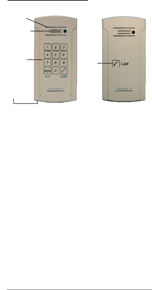
PanCam Physical Description
The following figure describes both units.
Speaker
PanCam-C PanCam-T
Figure 2-1. PanCam Front Panel
Camera
Key-pad Call
button
Micro-
phone
The front panel of the PanCam-T unit incorporates a speaker
and a Call button. The microphone can be found at the bottom
of the unit. The PanCam-C unit also features a keypad. The
front panel is attached to the wall using a bracket and screws.
The PanCam units are hardwired units, powered by an external
12V AC transformer, included in the package.
Optionally, you may use a 12-24V DC adapter.
PanCam/Pantel/Pancode Installation and Programming Manual 3

Introduction
4
PanCam/Pantel/Pancode Installation and Programming Manual
1.2 Pantel
The Pantel is a wall mounted access control door phone, which
is connected to an analog port of a PBX or a Key Telephone
System. The Pantel is compatible with most known telephone
systems and PBX types.
With the press of a button, the Pantel dials a pre-defined
extension number of up to 20 digits, allowing a conversation
to take place and then enables the dialed party to open the door
for the caller by pressing touch tone digit(s).
The Pantel is available in either an aluminum unit for outdoor
installation, which is weather and vandal resistant, or a plastic
unit for indoor installation.
Features
The outdoor and indoor Pantel units have the following
features:
• Dialing to a pre-defined extension/subscriber
• Door opening from any extension
• Programmable day and night destinations
• Automatic Busy & Disconnect Cadence Detection
(outdoor unit only)
• Designed for wall mounting
• Works in conjunction with card readers and security
devices
• High quality speaker phone with volume control
• Simple to operate and program
• Outdoor or indoor installation
Introduction
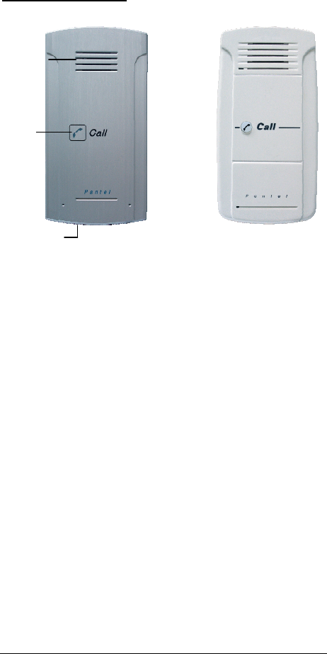
Physical Description
Outdoor Unit
Indoor Unit
Figure 1-2. Pantel Front Panel
Speake
r
Microphone
Call
button
The front panel of the Pantel unit incorporates a speaker and a
Call button. The microphone can be found at the bottom of the
unit. The front panel is attached to the wall using a bracket and
screws.
The Pantel unit is a hardwired unit powered by an external
12V AC transformer, included in the package.
Optionally, you may use a 12-24V DC adapter (for outdoor
unit only).
PanCam/Pantel/Pancode Installation and Programming Manual 5

Introduction
6
PanCam/Pantel/Pancode Installation and Programming Manual
1.3 Pancode
The Pancode is a smart wall mounted access control door
phone that is connected to an analog port of a PBX or a Key
Telephone System, allowing door entry control.
The Pancode is available in either an aluminum unit for
outdoor installation, which is weather and vandal resistant, or
a plastic unit for indoor installation.
Features
The outdoor and indoor Pancode units have the following
features:
• Direct dialing to any extension
• Entry access code
• Speed-dial to internal or external subscribers
• Automatic Busy & Disconnect Cadence Detection
(outdoor unit only)
• Door opening from any extension
• Programmable day and night destinations
• Two different operation modes, standard/speed-dial
• High quality speaker phone with volume control
• Outdoor or indoor installation
• Works in conjunction with card readers and security
devices
• Simple to operate and program
• Smart looking durable design
Introduction
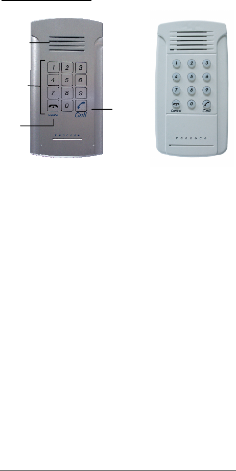
Physical Description
Outdoor Unit
Indoor Unit
Figure 1-3. Pancode Front Panel
Speake
r
Keypad
Cancel
button
Call
button
The front panel of the Pancode unit incorporates a speaker and
a keypad. The microphone can be found at the bottom of the
unit. The front panel is attached to the wall using a bracket and
screws.
The Pancode unit is a hardwired unit powered by an external
12V AC transformer, which is provided in the package.
Optionally, you may use a 12-24V DC adapter (For outdoor
unit only)
PanCam/Pantel/Pancode Installation and Programming Manual 7

Introduction
8
PanCam/Pantel/Pancode Installation and Programming Manual
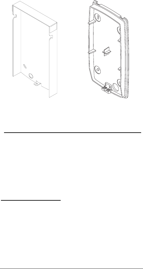
2 Installation
The PanCam/Pantel/Pancode is mounted to the installation
bracket provided; this mounting bracket should be installed
with the arms of the bracket positioned at the bottom.
Outdoor Unit Bracket
Indoor Unit Bracket
Figure 2-1. Installation brackets
To Install the PanCam/Pantel/Pancode wall bracket
1. Measure and mark the location on the wall where the
holes will be drilled for the mounting bracket.
2. Drill the holes and insert the wall anchors into the holes.
The wall anchors should be flush with the wall.
3. Attach the mounting bracket using the wall screws
provided.
2.1 Installation Instructions
Installing the PanCam
Power (12V DC) is provided to the camera via an extended
connector in the PanCam. The camera is activated, once the
relevant instruction is given (e.g. push on the call button, etc.).
PanCam/Pantel/Pancode Installation and Programming Manual 9
Installation
Caution
To avoid damage to the camera, make sure to connect the
correct polarity to the connector (see Figure 2-2).
Camera connector 12V DC
GND
+12V
Figure 2-2. Camera connector
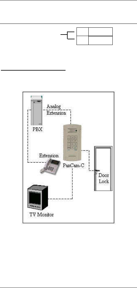
PanCam Schematic setup
The following pictures show the schematic setup of the
PanCam unit.
Figure 2-3. PanCam Schematic setup
The video signal is independent and connected directly to
third-party video equipment (e.g. a video recorder, monitor,
multiplexer, PC, etc.).
The unit is connected to the PBX as an analog extension.
The unit powers the Door Lock and the Camera.
10 PanCam/Pantel/Pancode Installation and Programming Manual

Installation
Installing the Pantel/Pancode
The Pantel/Pancode can be installed as the individual access
control or can be used with adjacent access-control devices,
such as card reading devices. For more information on
adjacent access-control device installation, see section 2.2,
Adjacent Access Control Device.
A 12V AC external power supply is included with the
Pantel/Pancode unit. A 12 to 24V DC/1.6A power adapter,
which provides a quieter door-lock action, can also power the
Pantel/Pancode. The power adapter should not be located
further than 10m (30ft) from the Pantel/Pancode.
The following figure shows the terminal locations on the wire
connector provided with the Pantel/Pancode. This connector is
attached at the base of the internal component. All wiring to
the Pantel/Pancode is attached to the wire connector.
The Pantel/Pancode supports a bypass switch installation. This
allows opening the door with a hardwired switch. A bypass
switch should be connect to the SW and /SW terminals.
~12V
~12V
N.C.
CMN
N.O.
DLR
~DLR
/DLR
SW
/SW
LINE
LINE
Power Supply
Normally
Open/Closed
Outputs
Door Lock
Relay
Terminals
Switch
Terminals
Phone
Line/Extension
Figure 2-4. Connector Wiring
Note: For the installation of the powered-unlocked-state, use
DLR and ~DLR. For the installation of the powered-
locked-state, use /DLR and ~DLR (this is
recommended for safety purposes).
PanCam/Pantel/Pancode Installation and Programming Manual 11

Installation
12 PanCam/Pantel/Pancode Installation and Programming Manual
The wiring connector is a screw connector type. In order to
attach a wire you must insert the stripped end of the wire into
the proper terminal and tighten the terminal screw. This will
crimp the wire connection.
Caution
To avoid damage to the Pantel/Pancode, the power supply
should be removed prior to connecting wires to the
Pantel/Pancode unit.
To Install the Pantel/Pancode
1. Remove the cover from the Pantel/Pancode unit and
disconnect the wire connector, found at the base of the
internal component.
2. Connect the two 12V lead wires from the 12V AC
power adapter (or the 12-24V DC adapter), one to each
of the “~12V” terminals.
3. Connect the two PBX extension wires, one to each of the
“LINE” terminals.
4. Connect the door-lock relay wires to the “DLR” and
“~DLR” terminals
-or-
If the door-lock relay is a powered-locked-state type
lock, connect the door-lock relay wires to the “/DLR”
and “~DLR” terminals.
5. If a push button switch is used, connect the push button
wires to the “SW” and the “/SW” terminals.
6. Plug the wire connector to the base of the
Pantel/Pancode inner component.
7. Place the Pantel/Pancode onto the mounting bracket.
8. Switch on the power to the 12V adapter.
After installation, you can now program the Pantel/Pancode
unit. For details on programming, see section 3, Programming.
2.2 Adjacent Access Control Device
This section describes adding an access-control device to an
existing Pantel/Pancode, and adding a Pantel/Pancode to an
existing access-control device. The key difference between
these two installations is which Access-control device controls
the door lock relay.
Installation
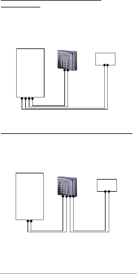
Adding an Access Control Device to the
Pantel/Pancode
When activated, the access-control triggers the Pantel/Pancode
“SW” terminal, which activates the door-lock relay and opens
the door.
For this type of installation, the access-control device “N.O.”
output wires are connected to the Pantel/Pancode Switch
terminals (see Figure 2-5.)
N.O.
Output
Switch
Pancode/
Pantel
Lock
Relay
Figure 2-5. Pantel/Pancode – Controlling Lock Relay
Adding Pantel/Pancode to an Access Control Device
The access control device opens the door when the
Pantel/Pancode triggers the access-control device.
For this installation, the access-control device bypass
“Switch” wires are connected to the “N.O.” and “CMN”
terminals of the Pantel/Pancode. The door-lock relay wires are
connected to the access-control device (see Figure 2-6.)
N.O. and
CMN
Pancode/
Pantel
Lock
Relay
Figure 2-6. Access Control - Controlling Lock Relay
PanCam/Pantel/Pancode Installation and Programming Manual 13
Installation
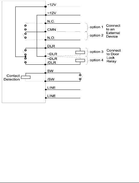
2.3 Connection Schematic
The Pantel/Pancode offers multiple wiring options.
• Option 1: For use with an external device, which
requires the Pancode to be set up as “Normally
Closed”
• Option 2: For use with an external device, which
requires the Pancode to be set up as “Normally
Open”
• Option 3: For use with the powered-unlocked-state
lock relay (most common)
• Option 4: For use with the powered-locked-state
lock relay
(recommended for safety purposes)
The following schematic diagram shows the wiring plan for
these four options.
Figure 2-7. PanCam/Pantel/Pancode Wiring Schematics
2.4 Volume Control
The volume of the PanCam/Pantel/Pancode speaker can be
adjusted using the volume controller located on the unit’s back
panel.
After installing the unit, test the volume. In case it is too
low/high, remove the unit from the mounting bracket and
adjust the volume using a small screwdriver.
14 PanCam/Pantel/Pancode Installation and Programming Manual

PanCam/Pantel/Pancode Installation and Programming Manual 15
3 Programming
Programming can be done from any telephone or extension on
the PBX, using keypad DTMF tones. The following
programming functions are discussed in this section:
• Day/Night Mode Selection
• Entering Programming Mode
• Resetting the PanCam/Pantel/Pancode
3.1 Day/Night Mode Selection
Day and Night mode specify which of the programmed
destination numbers, Day or Night number, will be called
when the Call button is pressed. The operator can manually
change the Day/Night mode.
To Change the Day/Night Mode
1. Dial the PanCam/Pantel/Pancode line/extension
from any touch-tone telephone.
2. Wait until the PanCam/Pantel/Pancode answers and
beeps.
3. Enter *80 for Day Mode
-or-
enter *81 for Night Mode.
3.2 Entering Programming Mode
Note: You will hear a confirmation tone every time you enter
a programming command.
To Enter Programming Mode
1. Dial the PanCam/Pantel/Pancode line/extension from
any touch-tone telephone.
2. Wait until the PanCam/Pantel/Pancode answers and
beeps.
3. Dial *900.
4. Enter the Programming Access Password (default
password is 1234).
To Exit Programming Mode
• Dial *900
–or–
if no dialing occurs within 45 seconds, the program
mode automatically exits.

Programming
16 PanCam/Pantel/Pancode Installation and Programming Manual
3.3 Resetting the PanCam/Pantel/Pancode
Resetting the PanCam/Pantel/Pancode will automatically
change the parameters in the unit to the manufacturers default.
To Reset the Unit
1. Enter programming mode (see section 3.2, Entering
Programming Mode).
2. Dial *151.
3. A confirmation tone will be heard.
4. Exit programming mode.
To Reset the Unit in “speed dial” mode (only
PanCam-C and Pancode)
1. Enter programming mode (see section 3.2,
Entering Programming Mode).
2. Dial *152.
3. A confirmation tone will be heard.
4. Exit programming mode.
3.4 PanCam-T/Pantel Setup and Operation
The following table contains programming functions, which
can be accessed in the programming mode for Setup and
operation.
PBX Parameter Commands
OPERATION COMMAND DEFAULT
Day, Night
destination
numbers
*360 + X + DN + #
where:
X = 1; Day destination
X = 2; Night destination
DN = Up to 20 digits.
For special character
input, see section 3.6
Entering Special DTMF
Characters.
Day = 0
Night = 0
Delete the
destination
assignments
*360 + X + #
where:
X = 1; Day destination
X = 2; Night destination

Programming
PanCam/Pantel/Pancode Installation and Programming Manual 17
OPERATION COMMAND DEFAULT
*For Pantel
Indoor ONLY:
Busy off/on time
cadence setups for
disconnecting the
line when the
destination is busy
*371 + X + YYYY
where:
X = 1; off time setup
X = 2; on time setup
YYYY = Cadence in
steps of 20 milliseconds
500 msec
500 msec
Digit(s) to open
the door from any
extension
*441 +XXXX + #
where:
XXXX = Digits (0-9)
Note: Up to 4 digits
8
*For Outdoor
units ONLY
Time between
DTMF’s
*460 + X
where:
X = 1-9
(Each step is 200 msec)
2 (400ms)
Maximum time
for the line to be
opened (sec)
*462 + XX
XX = Seconds (10-99)
00 = Unlimited
45 sec
Door opening
time limit (sec)
*464 + X
X = Seconds (1-9)
3 sec
Change the
system
administrator’s
password
*600 + New password
(must be 4 digits).
Warning: Do not use
the * or # keys
1234
*For PanCam-T
ONLY
Camera
instructions
*620 + X
X = 0 camera off
X = 1 camera on
X = 2 camera powered
when call button is
pressed
0

Programming
18 PanCam/Pantel/Pancode Installation and Programming Manual
3.5 PanCam-C/Pancode Setup
The PanCam-C/Pancode can work in two modes of operation:
Standard and Speed-dial.
In Standard mode, which is the default, the keypad requires
direct dialing of extensions and numbers.
In Speed-Dial mode, keys 1-9 can be assigned destination
phone numbers. When a key is pressed, the assigned
destination number is dialed.
To Set the PanCam-C/Pancode Operation Mode
1. Dial the PanCam-C/Pancode line/extension from any
touch-tone telephone.
2. Wait until the PanCam-C/Pancode answers and
beeps.
3. Dial *900.
4. Enter the Programming Access Password (default
password is 1234.)
5. For Standard Mode, dial *151 (See 3.5.2 for
programming)
-or-
for Speed-Dial Mode, dial *152 (See 3.5.3 for
programming).
Note: When selecting or changing the operation mode with
*151 or *152, all previously programmed information
will automatically be deleted. The unit will provide
you with it’s default values.
Standard Setup
The following table contains programming functions, which
can be accessed in the programming mode for Standard Setup
operation.

Programming
PanCam/Pantel/Pancode Installation and Programming Manual 19
PBX Parameter Commands
OPERATION COMMAND DEFAULT
The Day/Night
DN will be dialed
when the Call
button is pressed,
respective to
Day/Night mode.
The Error DN is
dialed after
receiving three
invalid Access
Code entries in a
row
*360 + X + DN + #
where:
X = 1 Day
X = 2 Night
X = 3 Error
Destination number
(DN) = Up to 20 digits,
including *, #, Pause,
and A-D characters. For
special character input,
see section 3.6 Entering
Special DTMF
Characters.
Day = 0
Night = 0
Error =
No default
Delete a
destination
number assigned
to Day, Night, or
Error DNs. This
command must be
entered separately
for each X value
*360 + X + #
where:
X = 1 Day
X = 2 Night
X = 3 Error
Programming the
prefix-digit(s) for
PBX extensions
dialing. When
input to the
PanCam-C/
Pancode begins
with these digits,
the PanCam-C/
Pancode will
process them as
extension dialing
*170 + prefix-digit(s) +
#
Maximum 4 digits
(Do Not use * or # as
prefix digit)
To cancel this
operation, enter:
*170 + #
No default
Digit(s) to open
the door from any
extension
*441 +XXXX + #
where:
XXXX= Digits (0-9)
Note: Up to 4 digits.
8

Programming
20 PanCam/Pantel/Pancode Installation and Programming Manual
OPERATION COMMAND DEFAULT
Changing the
Opening door
Access Code
*442 + (New Access
Code)
Access Codes can be up
to four numeric digits.
If the New Access Code
is less than four
numeric digits, press the
# following the entry of
the digits. Allowable
characters are 0 through
9. Do not use the * or #
keys.
Note: The access code
cannot begin with the
same prefix digits as
PBX extension numbers
9876
*For Outdoor
units ONLY
Time between
DTMF’s
*460 + X
where:
X = 1-9
(each step is 200 msec)
2 (400)
Conversation time
limit (sec)
*462 + XX
where:
XX = Seconds (10-99)
00 = Unlimited
45 sec
Door opening
time limit (sec)
*464 + X
where:
X = Number of seconds
(1-9)
3 sec
Changing the
programming
password
*600 + (new password)
Programming access
password must be four
numeric digits.
Allowable characters
are 0 through 9. Do not
use the * or # keys.
1234
*For PanCam-C
ONLY
Camera
instructions
*620 + X
X = 0 camera off
X = 1 camera on
X = 2 camera powered
when call button is
pressed
X = 3 camera powered
when any key is pressed
0

Programming
PanCam/Pantel/Pancode Installation and Programming Manual 21
Speed-Dial Setup
The following table contains programming functions, which
can be accessed in the programming mode for Speed-Dial
mode operation.
PBX Parameter Commands
OPERATION COMMAND DEFAULT
Assigning a
Speed-dial
destination
number.
This command
must be entered
separately for
each X value
*120 + X + DN + #
X = a digit 1 through 9
DN = Destination
number (DN) = Up to
20 digits, including *, #,
Pause, and A-D
characters.
For special character
input, see section 3.6
Entering Special DTMF
Characters.
No default
Cancelling a
Speed-dial
destination
number.
This command
must be entered
separately for
each X value
*120 + X + #
X = a digit 1 through 9
No default
The Day/Night
DN will be dialed
when the Call
button is pressed,
respective to
Day/Night mode.
The Error DN is
dialed after
receiving three
invalid Access
Code entries in a
row
*360 + X + DN + #
where:
X = 1 Day
X = 2 Night
X = 3 Error
Destination number
(DN) = Up to 20 digits,
including *, #, Pause,
and A-D characters. For
special character input,
see section 3.6 Entering
Special DTMF
Characters.
Day = 0
Night = 0
Error =
No default

Programming
22 PanCam/Pantel/Pancode Installation and Programming Manual
OPERATION COMMAND DEFAULT
Delete a
destination
number assigned
to Day, Night, or
Error DNs. This
command must be
entered separately
for each X value
*360 + X + #
where:
X = 1 Day
X = 2 Night
X = 3 Error
Defining the
digit(s) to open
the door from any
extension
*441 + XXXX + #
XXXX= Digits (0-9)
Note: Up to 4 digits
8
Changing the
Opening door
Access Code
*442 + 0XXX+#
0XXX = New Access
Code up to four digits.
The first digit of the
access code in Speed-
dial mode must be 0.
If the new access code
is less than four
numeric digits, press the
# key following entry of
the digits. The
allowable characters are
0 through 9. Do not use
the * or # keys.
0123
*For Outdoor
units ONLY
Time between
DTMF’s
*460 + X
where:
X = 1-9
(each step is 200 msec)
2 (400)
Conversation time
limit (sec)
*462 + XX
XX = Seconds (10-99)
00 = Unlimited
45 sec
Door opening
time limit (sec)
*464 + X
XX = Number of
seconds (1-9)
3 sec
Changing the
programming
password
*600 + (new password)
Programming access
passwords must be four
numeric digits. The
allowable characters are
0 through 9. Do not use
the * or # keys.
1234

Programming
PanCam/Pantel/Pancode Installation and Programming Manual 23
OPERATION COMMAND DEFAULT
*For PanCam-C
Camera
instructions
*620 + X
X = 0 camera off
X = 1 camera on
X = 2 camera powered
when call button is
pressed
X = 3 powered by any
touch on unit keypad
0
3.6 Entering Special DTMF Characters
Special characters can be entered using the keypad. The
following table shows the corresponding keypad entries
needed for creating special DTMF characters.
DTMF CHAR. NUMBER TO DIAL
Digits 0-9 0-9
* **
Pause *1, indicates a 1 second pause
# *4
A *5
B *6
C *7
D *8

Programming
24 PanCam/Pantel/Pancode Installation and Programming Manual

PanCam/Pantel/Pancode Installation and Programming Manual 25
4 Specifications
4.1 General Specifications
Power Supply (External) 12V AC@1.6A (supplied with unit)
12-24V DC@1.6A (optional)
Line Voltage 24-72V DC
DC Leakage < 10 µA
On-Hook Insulation
(Resistance Between Line
Terminal and Ground)
0-100V DC > 5MΩ
100-200 V DC > 30 KΩ
500V AC/50Hz > 20KΩ
100V AC/25Hz > 100KΩ
Ring Capacitor 0.47 µF ±10%
On-Hook Impedance @50V DC, 40V AC/25Hz>3000Ω
Ring Detect 27-100 V AC/16-60 Hz
DC Resistance (Off-Hook) 24-66V DC @ 20-100mA/350Ω
Impedance (Off-Hook) 300-3400Hz 500-700Ω
Imbalance Ratio 300-3400Hz > 46dB
Return Loss 300-3400Hz > 18dB
Current During Break < 700 µA
DTMF Transmission:
Frequency Tolerance
Frequency Level (High)
Frequency Level (Low)
±1.5%
-6 to –8dBm
-8 to –10dBm
Inter-Digit Pause Time 70-80ms
Relay Switching Current 2A max
Dimensions
Outdoor Unit
Indoor Unit
19.4cm x 10.2cm/7.6inch x 4.0inch
18.5cm x 9.5cm/7.3inch x 9.5inch
Operating Temperature Outdoor: -20ºC to +50ºC/4ºF to
122ºF
Indoor: 0ºC to +35ºC/32ºF to 95ºF

Specifications
26 PanCam/Pantel/Pancode Installation and Programming Manual
4.2 Camera Specifications
Black and White Camera
Model no. MK-03261C
TV System EIA/CCIR
Image Sensor Device 1/3” interline transfer CCD
Image Sensor Area 4.8mm x 3.6mm
Horizontal Frequency 15.625KHz
Vertical Frequency 50Hz
Total Pixels 542(H) x 582(V)
Scanning System 625 lines, 50 fields/sec CCIR
Resolution 420 TVL horizontal
Minimum Illumination 0.5 Lux at F2.0
Electronic Shutter Auto Electronic Shutter 1/50
to 1/100000 sec. Continual
S/N Ratio Better than 48 dB
Video Signal Output 1.0Vp-p composite video
signal at 75 ohm load
Gamma Correction 0.45
Gain Control Auto Gain Control (AGC)
Lens & View Angle 5.5 mm F5.5 / 60°

Specifications
PanCam/Pantel/Pancode Installation and Programming Manual 27
Color Camera
Model no. MTV-54KOPI
TV System PAL/NTSC
Image Sensor ¼-inch CCD Image Sensor
CCD Total Pixels 542(H) x 586(V)
SYNC System Internal
Minimum Illumination 0.5 Lux F1.2 5600°K
Resolution 380 TVL/470 TVL
(Enhanced)
S/N Ratio 52dB (MIN)/60dB(TYP)
(AGC OFF)
White Balance ATW/AWB/FIX (Zero color
rolling)
White Balance Range AWB, ATW(3200---10000°K)
/FIX(3299°K)/
Electronic Shutter 1/50-1/120000 sec.
Video Output 1.0Vp-p composite video
signal at 75 ohm
Gamma Correction 0.45
Gain Control AGC
Lens & View Angle 45° > 0.7 mm

Specifications
28 PanCam/Pantel/Pancode Installation and Programming Manual
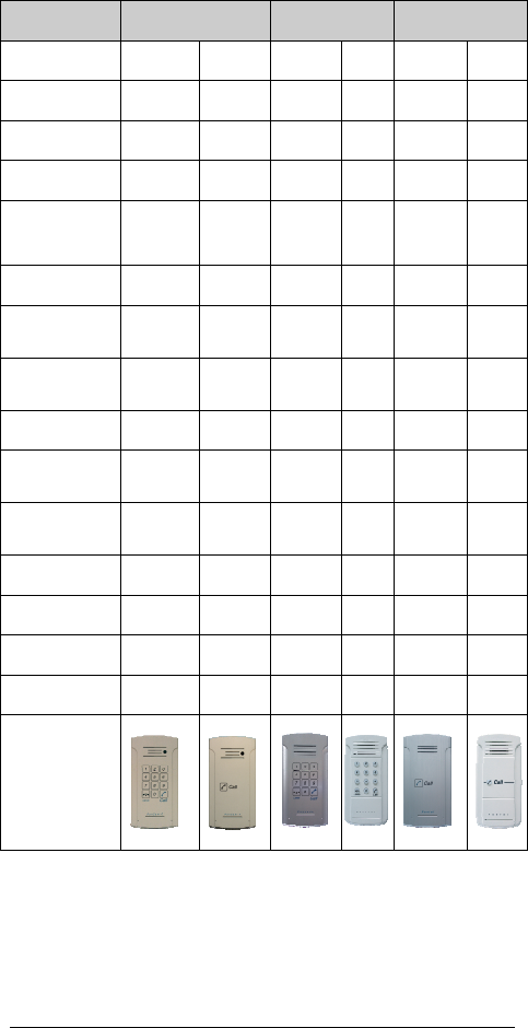
5 Comparison Table
PanCam Pancode Pantel
PanCam-C PanCam-T Outdoor Indoor Outdoor Indoor
Installation Outdoor Outdoor Outdoor Indoor Outdoor Indoor
Case Type Aluminum Aluminum Aluminum Plastic Aluminum Plastic
Entry Access Code Yes N/A Yes Yes N/A N/A
Internal Door Opening
Code from Any
Extension
Yes Yes Yes Yes Yes Yes
Day/Night Mode Yes Yes Yes Yes Yes Yes
Direct Dialing to any
Extension
Yes N/A Yes Yes N/A N/A
Busy and Disconnect
Detection
Auto Auto Auto No Auto Manual
Speed Dial Mode Yes N/A Yes Yes N/A N/A
16 DTMF Character
Support
Yes Yes Yes Yes Yes Yes
High Quality
Speakerphone
Yes Yes Yes Yes Yes Yes
Volume Control Yes Yes Yes Yes Yes Yes
Vandal Resistant Yes Yes Yes No Yes No
Supports 12V AC/DC Yes Yes Yes Yes Yes Yes
Supports 24V DC Yes Yes Yes No Yes No
PanCam/Pantel/Pancode Installation and Programming Manual 29

