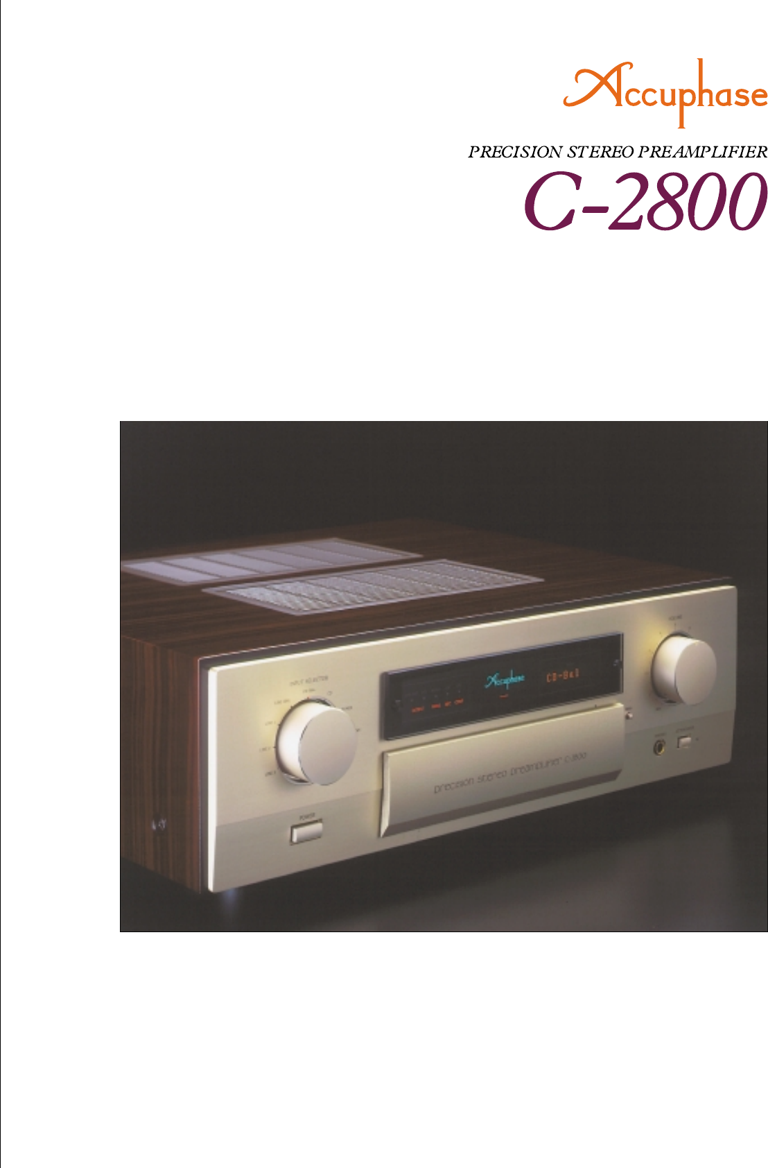
Accuphase C 2800 Brochure
User Manual: Accuphase-C-2800-Brochure
Open the PDF directly: View PDF ![]() .
.
Page Count: 4
m Revolutionary AAVA volume control m Printed circuit boards using
Teflon base with low dielectric constant and low loss m Separate
R-toroidal transformers for left and right channels m Fully modular
construction with individual amplifier units for each stage m Logic-
controlled relays for shortest signal paths m Optional analog record
playback capability m Massive cabinet of natural persimmons wood
The analog preamplifier has just been redefined Revolutionary AAVA
type volume control. Fully modular construction with Teflon-based printed
circuit boards. Dual mono configuration with separate R-toroidal
transformers for left and right channels. Optional dedicated phono equalizer
unit allows analog record reproduction with superb fidelity.
The two most basic tasks of a preamplifier are
selecting the input source and adjusting the volume.
How the volume adjustment is achieved has a
significant bearing on sound quality. The C-2800
introduces a novel concept called AAVA (Accuphase
Analog Vari-gain Amplifier). This circuit differs radically
from conventional variable-resistor type volume
controls. Amplification and volume control are fully
unified, eliminating all mechanical contact points. Pure
analog processing ensures optimum performance and
superb sound. Doing away with the variable resistor
in the signal path has numerous advantages and
brings the amplifier a significant step closer to
absolute purity in signal transmission.
The power transformer, filtering capacitors and all
other parts of the power supply are duplicated for the
left and right channel. What's more, all unit amplifiers
such as for line input, balanced output, and AAVA are
also entirely separate for the two channels, arranged
on a high-quality motherboard. This fully monaural
construction prevents unwanted crosstalk and
interaction both on the electrical and the physical
plane. The result is utterly stable playback sound of
impeccable quality. Logic relay control is used for
source switching to implement the shortest possible
signal paths. The printed circuit boards are an
important element of a preamplifier both regarding
electrical performance as well as sound quality. In the
C-2800, these are made from a Teflon material (glass
fluorocarbon resin) with low dielectric constant and
minimum loss. Each and every part used in this top-
notch analog preamplifier has been carefully selected
on the basis of sonic performance. The overall result
is a flagship product that represents the best that
Accuphase has to offer.
* Teflon is a registered trademark of DuPont USA.
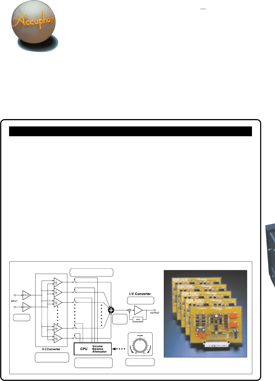
AAVA (Accuphase Analog Vari-gain Amplifier) volume control
The newly developed volume control called AAVA (Accuphase Analog Vari-gain Amplifier) is totally different from conventional controls using resistors. It allows
precise listening level adjustment while maintaining top-notch performance and sound quality over the entire range. Because the music signal does not pass
through variable resistors, it is not affected by changes in impedance. This means that high signal-to-noise ratio and low distortion of the signal are maintained.
Internally, a dedicated CPU selects the current switches that determine the gain of the amplifier. With regard to the music signal, the AAVA circuit is a fully analog
volume control.
nAAVA operation principle
AAVA operates by feeding the music signal to a V-I (voltage - current) converter
where it is weighted in 16 steps [1/2, 1/22, ... 1/215, 1/216]. The 16 current steps
are turned on or off by 16 current switches, and the combination of switch
settings determines the overall volume. The switching operation is controlled
by a CPU according to the position of the volume control knob. The combined
signal current forms a variable gain circuit that adjusts volume. Finally, the
combined current is converted back into a voltage by an I-V (current - voltage)
converter.
nAAVA resolution
AAVA adjusts the listening volume by means of 16 current switches. The
number of possible volume steps set by the combination of these switches is
2 to the power of 16 = 65,536. When maximum output voltage is 5 V, resolution
is an amazing 0.07 mV.
nMinimal distortion and no thermal noise
Because AAVA is an electronic circuit, the music signal does not pass through
any variable resistors. Thermal noise caused by resistors is totally absent.
Because there is no impedance that affects the signal, S/N ratio remains at
the logical optimum. The circuit configuration also assures ultra-low distortion.
nSimple circuit configuration
AAVA unifies the amplifier and volume control functions, resulting in a circuit
that is electrically very simple. Right and left channels are fully independent,
and frequency response does not change regardless of the volume control
knob position. Channel separation is excellent, and sonic performance remains
totally uniform over the entire range.
nAAVA means analog processing
The AAVA circuit converts the music signal from a voltage into a current, alters
gain by means of current switches, and then reconverts the current into a
voltage.
nSame operation feel as a conventional high-quality volume control
The actual volume control knob is linked to a variable resistor. However, this
resistor is only used to detect the absolute position of the knob. Operating the
control therefore feels exactly the same as with a conventional control, and
operation via the remote commander is also possible.
nAttenuator and balance control also realized via AAVA
The functions of the attenuator and the left/right balance control are covered
by the AAVA circuit as well, eliminating the need for additional stages. Keeping
the configuration simple helps to maintain high performance and sonic purity.
Fig. 1 AAVA Principle
Input music
signal
Conversion into current
with 16 weighting stages
(1/2 - 1/216)
16 current switches
(65,536 possible combinations)
Position detection of
volume control knob
CPU controls current
switches according to knob
position
Current
values are
added
Reconversion of
current into voltage
AAVA unit amplifier (one channel). PCB employs
Teflon and gold-plated copper
Separate unit amplifiers for left/right mounted on
sturdy 8-mm aluminum chassis
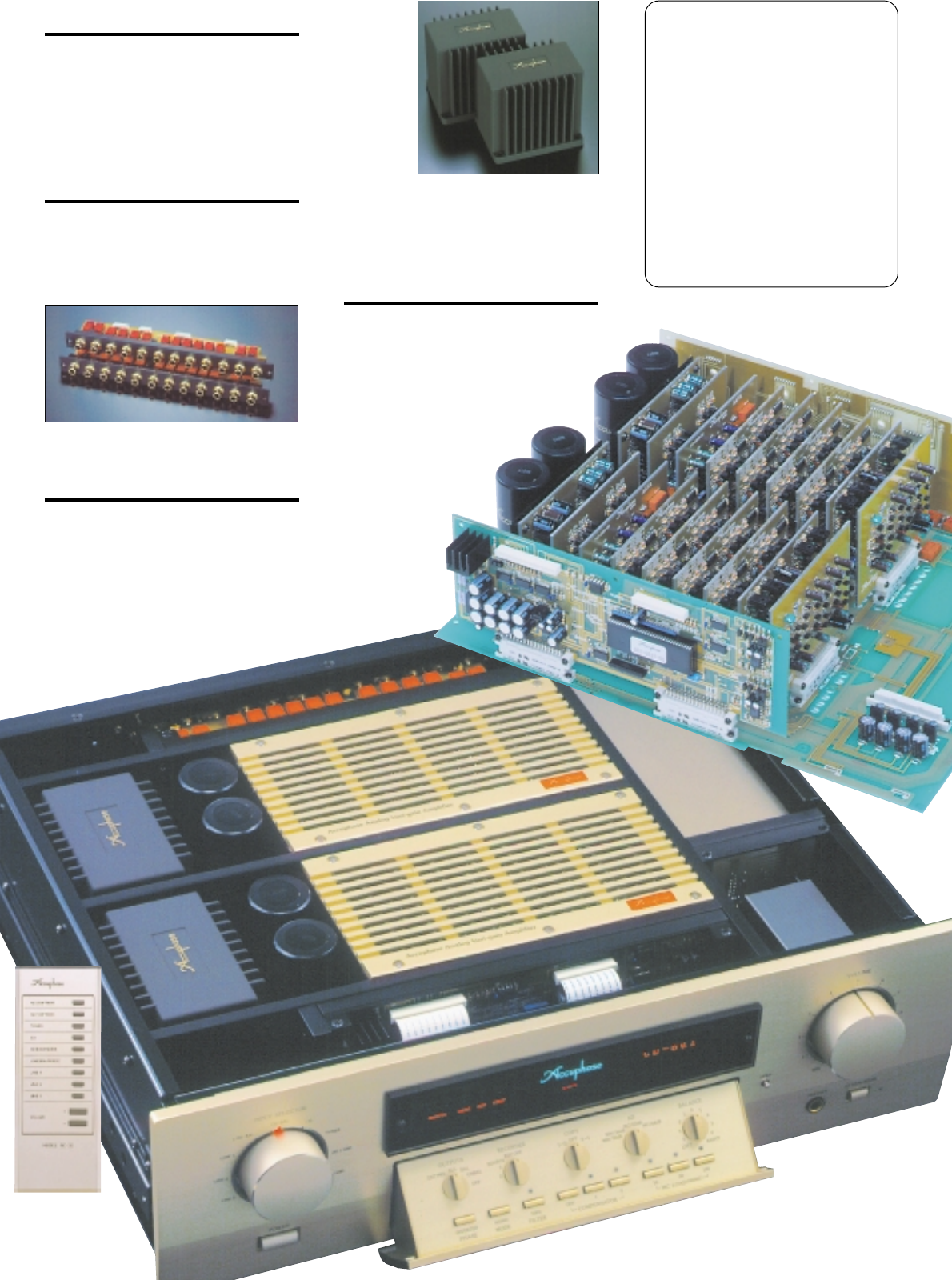
The C-2800 contains a total of 18 unit amplifiers,
comprising modules for input buffer, AAVA circuit,
balanced output, etc. These units are housed in solid
enclosures made of sturdy 8-mm thick aluminum and
mounted to a glass epoxy motherboard. This prevents
electrical interference and guards against mechanical
vibrations.
Logic-controlled relays assure high sound quality
and long-term reliability
The strategically placed relays of the C-2800 prevent
any signal degradation that could occur if the signal
has to travel a long way for input and output connection
and function switching. Optimum signal flow is
maintained at all times.
Ideal power supply uses newly developed
"R-toroidal transformers" in fully monaural
configuration
The power supply not only serves as the energy
source of an amplifier, the quality of the current
supplied to the various loads also has a considerable
bearing on sound quality. In the C-2800, newly
developed R-toroidal transformers and dedicated
filtering capacitors are used for each of the two stereo
channels, resulting in a fully monaural construction.
The R-toroidal transformer uses a core with a circular
cross-section designed to reduce
magnetic
losses and
improve
efficiency.
Leakage flux
is virtually
absent. The
transformer is
housed in a
dual-wall
enclosure
with a glass
fiber core and
strong resin coating. Epoxy filler with superior
vibration-damping characteristics is used to further
isolate the transformer, resulting in highly effective
triple insulation.
Printed circuit boards made from Teflon with low
dielectric constant and low loss
The printed circuit boards for the signal-carrying
circuits are made of Teflon, a glass fluorocarbon
resin material. Teflon has extremely low
specific inductive capacity which is
desirable for fast signal transmission
and a low dielectric dissipation
factor which results in minimal
transmission losses. High-
frequency characteristics
and heat resistance
are also excellent.
For further
improved sound
quality, the
copper foil side is
gold plated.
nSwitchable preamplifier gain: 12/18/24 dB
(standard position 18 dB)
nVersatile array of inputs and outputs (character
label display for inputs)
nDedicated headphone amplifier optimized for
sound quality
nEXT PRE function allows use of external
preamplifier
nUseful range of functions
mProvisions for recording/playback/copying with two
recorders
mLoudness compensator augments bass and treble
at low listening volume
mPhase selector
mAttenuator
mSubsonic filter removes ultra low frequency noise
nMassive cabinet of natural persimmons wood
nSupplied remote
commander RC-32
allows volume control
and input source
selection
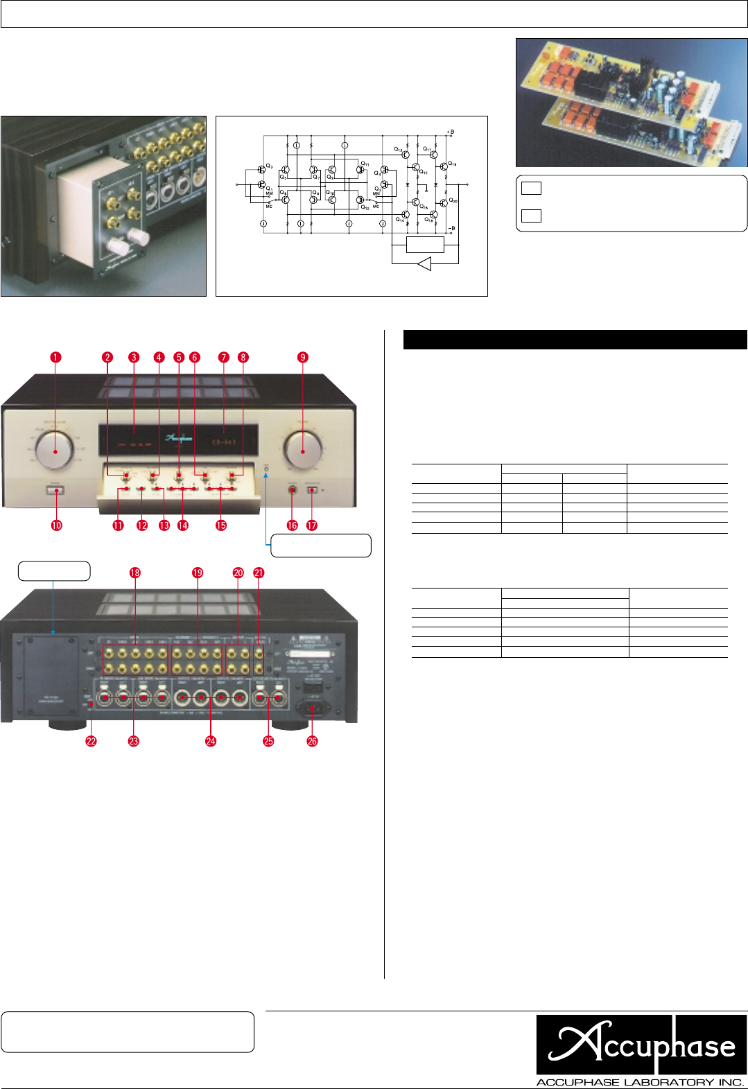
Analog records can be reproduced by installing the dedicated phono equalizer unit AD-2800 in a rear-
panel slot. The AD-2800 uses printed circuit boards made from Teflon material (glass fluorocarbon resin)
and is housed in a sturdy aluminum case for complete protection against any external interference. Highly
reliable DIN connectors make the shortest possible connection between input and amplification circuits, to
assure outstanding S/N ratio.
Dedicated Phono Equalizer Unit AD-2800 (Optional)
0
n Front panel
n Supplied accessories: • AC power cord
• Audio cable with plugs (1 m)
• Remote commander RC-32
GUARANTEED SPECIFICATIONS
• Specifications and design subject to change without notice for improvements.
G0205Y PRINTED IN JAPAN 851-0127-00 (AD1)http://www.accuphase.com/
Remarks
0
This product is available in versions for 120/230 V AC. Make sure that the voltage shown on
the rear panel matches the AC line voltage in your area.
0
The shape of the AC inlet and plug of the supplied power cord depends on the voltage rating
and destination country.
✽ Guaranteed specifications are measured according to EIA standard RS-490. ✽ AD stands for
"Analog Disc" ✽ Specifications are shown for phono equalizer unit AD-2800 installed.
mFrequency Response
BALANCED INPUT/UNBALANCED: 03 ~ 200,000 Hz +0 dB –3.0 dB
20 ~ 020,000 Hz +0 dB –0.2 dB
AD INPUT: [MM/36 dB, MC]:
20 ~ 020,000 Hz ±0.2 dB
AD INPUT: [MM/30 dB]:
20 ~ 020,000 Hz ±0.3 dB
mTotal Harmonic Distortion 0.005% (for all inputs)
mInput Sensitivity, Input Impedance
mRated Output Voltage, BALANCED/UNBALANCED OUTPUT: 2 V, 50 ohms
Output Impedance REC (with AD input): 252 mV, 200 ohms
mSignal-to-Noise Ratio
mMaximum Output Level BALANCED/UNBALANCED OUTPUT: 7.0 V
REC (with AD input): 6.0 V
mLINE maximum input level BALANCED/ UNBALANCED INPUT: 6.0 V
mMaximum AD Input Level MM [30/36 dB] INPUT: 300 mV/150 mV
(0.005% THD) MC [62/68 dB] INPUT: 7.5 mV/3.75 mV
mMinimum Load Impedance BALANCED/UNBALANCED OUTPUT: 600 ohms
REC: 10 kilohms
mGain (gain selector: 18 dB) ✽ Gain switch positions: 12/18/24 dB
BALANCED/UNBALANCED INPUT
➝
BALANCED/UNBALANCED OUTPUT:
18 dB
UNBALANCED INPUT ➝REC OUTPUT: 0 dB
AD (MM 30/36dB) INPUT ➝
BALANCED/UNBALANCED OUTPUT:
48/54 dB
AD (MM 30/36dB) INPUT ➝REC OUTPUT: 30/36 dB
AD (MC 62/68dB) INPUT ➝
BALANCED/UNBALANCED OUTPUT:
80/86 dB
AD (MC 62/68dB) INPUT ➝REC OUT: 62/68 dB
mLoudness Compensation 1: +3 dB (100 Hz), 2: +8 dB (100 Hz) +6 dB (20 kHz)
mSubsonic Filter 10 Hz:
–
18 dB/octave
mAttenuator
–
20 dB
mHeadphone Jack Suitable impedance: 8 - 100 ohms
mPower Requirements AC 120 V / 230 V, 50/60 Hz (Voltage as indicated on rear panel)
mPower Consumption 48 watts
mMaximum Dimensions Width: 477 mm (18-3/4")
Height: 156 mm (6-1/8")
Depth: 412 mm (16-1/4")
mWeight 21.2 kg (46.7 lbs) net (22.1 kg with AD installed)
28.0 kg (61.7 lbs) in shipping carton
MM Gain: 30/36 dB, switchable
Input impedance: 47 kilohms
MC Gain: 62/68 dB, switchable
Input impedance: 10/30/100 ohms, switchable
✽ The phono equalizer units AD-290 and AD-290V
designed for the Accuphase models C-290 and
C-290V can also be used in the C-2800.
✽The AD-2800 can also be used in the Accuphase
models C-290 and C-290V.
Output
Equalizer
elements
DC servo amplifier
Input
n Rear panel
Expansion slot for
AD-2800
Pressing this button gives
access to the sub panel
AInput Selector
LINE3 LINE2 LINE1 LINE-BAL CD-BAL
CD TUNER AD1 (OP) AD2 (OP)
BOutput Selector
EXT PRE ALL BAL UNBAL OFF
CFunction Display
DRecorder Selector
2 1 SOURCE REC OFF
ECopy Selector 1 ➝ 2 OFF 2 ➝ 1
FAnalog Disc Equalizer Gain Selector
MM/30 dB MM/36 dB
MC/62 dB MC/68 dB
GInput Display
HBalance Control
IVolume Control
JPower Switch
KOutput Phase Selector Button
LStereo/Mono Mode Selector Button
MSubsonic Filter Button
NLoudness Compensator Buttons
OFF 1 2
OMC Cartridge Load Impedance Selector
Buttons
PHeadphone Jack
QAttenuator Button
RLine Input Jacks
CD TUNER LINE1, 2, 3
SRecorder Input/Output Jacks
TUnbalanced Output Jacks
UExternal Preamplifier Input Jacks
(Unbalanced)
UGain Selector 24 dB 18 dB 12 dB
UCD/LINE Balanced Input Connectors
a Ground b Inverted (–)
c Non-invert (+)
UBalanced Output Connectors (OUTPUT 1, 2)
UExternal Preamplifier Input Jacks (Balanced)
UAC Inlet0
21
22
23
24
25
26
Circuit diagram of phono equalizer
unit AD-2800 (one channel)
Input Sensitivity Input impedance
For rated output For 0.5 V output
AD:MM/30 dB INPUT 8.0 mV 2.0 mV 47 kΩ
AD:MM/36 dB INPUT 4.0 mV 1.0 mV 47 kΩ
AD:MC/62 dB INPUT 0.2 mV 0.05 mV 10/30/100 Ω, switchable
AD:MC/68 dB INPUT 0.1 mV 0.025 mV 10/30/100 Ω, switchable
BALANCED/UNBALANCED
252 mV 63 mV 40 kΩ/20 kΩ
Input terminal Input shorted, IHF-A weighting S/N ratio (EIA)
S/N ratio at rated output
AD:MM/30 dB INPUT 95 dB 91 dB
AD:MM/36 dB INPUT 89 dB 92 dB
AD:MC/62 dB INPUT 80 dB 87.5 dB
AD:MC/68 dB INPUT 75 dB 88.5 dB
BALANCED/UNBALANCED
111 dB 110 dB
(
(
