MDB_UG Advanced Users Microchip Debugger User's Guide DS50002102E
User Manual:
Open the PDF directly: View PDF ![]() .
.
Page Count: 39
- Table of Contents
- Preface
- Introduction
- Document Layout
- Conventions Used in This Guide
- Recommended Reading
- Chapter 1. How to Use Microchip Debugger
- 1.1 Introduction
- 1.2 Installation and Documentation
- 1.3 Getting Started
- 1.4 Debugging Methods
- 1.5 Running a Command File Method
- 1.6 Using Multiple Instances of the MDB
- Chapter 2. MDB Reference
- 2.1 Help Commands
- 2.2 Classes of Commands
- 2.3 List of Commands within Classes
- Table 2-2: Breakpoints Commands
- Table 2-3: Data Commands
- Table 2-4: Device and tool Commands
- Table 2-5: Others Commands
- Table 2-6: Tool-Property-Name Options Used with the Set Command
- Table 2-7: Simulator Options Used With the Set Command
- Table 2-8: Programming Commands
- Table 2-9: Running Commands
- Table 2-10: Stack Commands
- Appendix A. Revision History
- Revision History
- Index
- AMERICAS
- ASIA/PACIFIC
- ASIA/PACIFIC
- EUROPE
- Austria - Wels
- Denmark - Copenhagen
- Finland - Espoo
- France - Paris
- Germany - Garching
- Germany - Haan
- Germany - Heilbronn
- Germany - Karlsruhe
- Germany - Munich
- Germany - Rosenheim
- Israel - Ra’anana
- Italy - Milan
- Italy - Padova
- Netherlands - Drunen
- Norway - Trondheim
- Poland - Warsaw
- Romania - Bucharest
- Spain - Madrid
- Sweden - Gothenberg
- Sweden - Stockholm
- UK - Wokingham
- Worldwide Sales and Service

2012-2018 Microchip Technology Inc. DS50002102E
Microchip Debugger (MDB)
User’s Guide

DS50002102E-page 2 2012-2018 Microchip Technology Inc.
Information contained in this publication regarding device
applications and the like is provided only for your convenience
and may be superseded by updates. It is your responsibility to
ensure that your application meets with your specifications.
MICROCHIP MAKES NO REPRESENTATIONS OR
WARRANTIES OF ANY KIND WHETHER EXPRESS OR
IMPLIED, WRITTEN OR ORAL, STATUTORY OR
OTHERWISE, RELATED TO THE INFORMATION,
INCLUDING BUT NOT LIMITED TO ITS CONDITION,
QUALITY, PERFORMANCE, MERCHANTABILITY OR
FITNESS FOR PURPOSE. Microchip disclaims all liability
arising from this information and its use. Use of Microchip
devices in life support and/or safety applications is entirely at
the buyer’s risk, and the buyer agrees to defend, indemnify and
hold harmless Microchip from any and all damages, claims,
suits, or expenses resulting from such use. No licenses are
conveyed, implicitly or otherwise, under any Microchip
intellectual property rights unless otherwise stated.
Note the following details of the code protection feature on Microchip devices:
• Microchip products meet the specification contained in their particular Microchip Data Sheet.
• Microchip believes that its family of products is one of the most secure families of its kind on the market today, when used in the
intended manner and under normal conditions.
• There are dishonest and possibly illegal methods used to breach the code protection feature. All of these methods, to our
knowledge, require using the Microchip products in a manner outside the operating specifications contained in Microchip’s Data
Sheets. Most likely, the person doing so is engaged in theft of intellectual property.
• Microchip is willing to work with the customer who is concerned about the integrity of their code.
• Neither Microchip nor any other semiconductor manufacturer can guarantee the security of their code. Code protection does not
mean that we are guaranteeing the product as “unbreakable.”
Code protection is constantly evolving. We at Microchip are committed to continuously improving the code protection features of our
products. Attempts to break Microchip’s code protection feature may be a violation of the Digital Millennium Copyright Act. If such acts
allow unauthorized access to your software or other copyrighted work, you may have a right to sue for relief under that Act.
Microchip received ISO/TS-16949:2009 certification for its worldwide
headquarters, design and wafer fabrication facilities in Chandler and
Tempe, Arizona; Gresham, Oregon and design centers in California
and India. The Company’s quality system processes and procedures
are for its PIC® MCUs and dsPIC® DSCs, KEELOQ® code hopping
devices, Serial EEPROMs, microperipherals, nonvolatile memory and
analog products. In addition, Microchip’s quality system for the design
and manufacture of development systems is ISO 9001:2000 certified.
QUALITY MANAGEMENT S
YSTEM
CERTIFIED BY DNV
== ISO/TS 16949 ==
Trademarks
The Microchip name and logo, the Microchip logo, AnyRate, AVR,
AVR logo, AVR Freaks, BitCloud, chipKIT, chipKIT logo,
CryptoMemory, CryptoRF, dsPIC, FlashFlex, flexPWR, Heldo,
JukeBlox, KeeLoq, Kleer, LANCheck, LINK MD, maXStylus,
maXTouch, MediaLB, megaAVR, MOST, MOST logo, MPLAB,
OptoLyzer, PIC, picoPower, PICSTART, PIC32 logo, Prochip
Designer, QTouch, SAM-BA, SpyNIC, SST, SST Logo,
SuperFlash, tinyAVR, UNI/O, and XMEGA are registered
trademarks of Microchip Technology Incorporated in the U.S.A.
and other countries.
ClockWorks, The Embedded Control Solutions Company,
EtherSynch, Hyper Speed Control, HyperLight Load, IntelliMOS,
mTouch, Precision Edge, and Quiet-Wire are registered
trademarks of Microchip Technology Incorporated in the U.S.A.
Adjacent Key Suppression, AKS, Analog-for-the-Digital Age, Any
Capacitor, AnyIn, AnyOut, BodyCom, CodeGuard,
CryptoAuthentication, CryptoAutomotive, CryptoCompanion,
CryptoController, dsPICDEM, dsPICDEM.net, Dynamic Average
Matching, DAM, ECAN, EtherGREEN, In-Circuit Serial
Programming, ICSP, INICnet, Inter-Chip Connectivity,
JitterBlocker, KleerNet, KleerNet logo, memBrain, Mindi, MiWi,
motorBench, MPASM, MPF, MPLAB Certified logo, MPLIB,
MPLINK, MultiTRAK, NetDetach, Omniscient Code Generation,
PICDEM, PICDEM.net, PICkit, PICtail, PowerSmart, PureSilicon,
QMatrix, REAL ICE, Ripple Blocker, SAM-ICE, Serial Quad I/O,
SMART-I.S., SQI, SuperSwitcher, SuperSwitcher II, Total
Endurance, TSHARC, USBCheck, VariSense, ViewSpan,
WiperLock, Wireless DNA, and ZENA are trademarks of
Microchip Technology Incorporated in the U.S.A. and other
countries.
SQTP is a service mark of Microchip Technology Incorporated in
the U.S.A.
Silicon Storage Technology is a registered trademark of
Microchip Technology Inc. in other countries.
GestIC is a registered trademark of Microchip Technology
Germany II GmbH & Co. KG, a subsidiary of Microchip
Technology Inc., in other countries.
All other trademarks mentioned herein are property of their
respective companies.
© 2018, Microchip Technology Incorporated, All Rights
Reserved.
ISBN: 978-1-5224-3562-4

MDB USER’S GUIDE
2012-2018 Microchip Technology Inc. DS50002102E-page 3
Table of Contents
Preface ........................................................................................................................... 5
Chapter 1. How to Use Microchip Debugger
1.1 Introduction ..................................................................................................... 9
1.2 Installation and Documentation .................................................................... 10
1.3 Getting Started ............................................................................................. 10
1.4 Debugging Methods ..................................................................................... 12
1.5 Running a Command File Method ................................................................ 15
1.6 Using Multiple Instances of the MDB ........................................................... 16
Chapter 2. MDB Reference
2.1 Help Commands ........................................................................................... 17
2.2 Classes of Commands ................................................................................. 17
2.3 List of Commands within Classes ................................................................ 18
Appendix A. Revision History
Index ............................................................................................................................. 35
Worldwide Sales and Service .................................................................................... 39

MDB User’s Guide
DS50002102E-page 4 2012-2018 Microchip Technology Inc.

MDB USER’S GUIDE
2012-2018 Microchip Technology Inc. DS50002102E-page 5
Preface
INTRODUCTION
This chapter contains general information that will be helpful to know before using the
Microchip Debugger (PIC18F1220/1320). Items that are discussed include:
• Document Layout
• Conventions Used in This Guide
• Recommended Reading
DOCUMENT LAYOUT
This document is organized as follows:
•Chapter 1. How to Use Microchip Debugger – describes how to get started with
the MDB, invoking the MDB, and the debugging methods that are available.
•Chapter 2. MDB Reference – details the classes of commands and describes the
available lists of commands.
•Appendix A. Revision History – identifies the changes that have been made to the
document.
NOTICE TO CUSTOMERS
All documentation becomes dated, and this manual is no exception. Microchip tools and
documentation are constantly evolving to meet customer needs, so some actual dialogs and/
or tool descriptions may differ from those in this document. Please refer to our web site
(www.microchip.com) to obtain the latest documentation available.
Documents are identified with a “DS” number. This number is located on the bottom of each
page, in front of the page number. The numbering convention for the DS number is
“DSXXXXXXXXA”, where “XXXXXXXX” is the document number and “A” is the revision level
of the document.
For the most up-to-date information on development tools, see the MPLAB® X IDE help. Select
the Help menu, and then Topics to open a list of available help files.
MDB User’s Guide
DS50002102E-page 6 2012-2018 Microchip Technology Inc.
CONVENTIONS USED IN THIS GUIDE
The following conventions may appear in this documentation:
TABLE 1: DOCUMENTATION CONVENTIONS
Description Represents Examples
Arial font:
Italic Referenced books MPLAB® X IDE User’s Guide
Emphasized text ...is the only compiler...
Initial caps A window the Output window
A dialog the Settings dialog
A menu selection select Enable Programmer
Quotes A field name in a window or
dialog
“Save project before build”
Underlined, italic text with
right angle bracket
A menu path File>Save
Bold A dialog button Click OK
A tab Click the Power tab
Text in angle brackets < > A key on the keyboard Press <Enter>, <F1>
Courier font:
Plain Sample source code #define START
Filenames autoexec.bat
File paths c:\mcc18\h
Keywords _asm, _endasm, static
Command-line options -Opa+, -Opa-
Bit values 0, 1
Constants 0xFF, ’A’
Italic A variable argument file.o, where file can be
any valid filename
Square brackets [ ] Optional arguments mpasmwin [options]
file [options]
Curly brackets and pipe
character: { | } Choice of mutually exclusive
arguments; an OR selection
errorlevel {0|1}
Ellipses... Replaces repeated text var_name [,
var_name...]
Represents code supplied by
user
void main (void)
{ ...
}

Preface
2012-2018 Microchip Technology Inc. DS50002102E-page 7
RECOMMENDED READING
This document describes how to use the PIC18F1220/1320. Other useful documents
are listed below. The following Microchip presentation and documents are available
and recommended as supplemental reference resources.
Microchip Command-line Debugger Webinar
This webinar gives an introduction to the command-line debugger and provides useful
examples. The webinar is available on Microchip’s web site:
www.microchip.com/webinars.microchip.com/WebinarDetails.aspx?dDocName=en565588
Multi-Tool Design Advisory (DS51764)
This small document presents guidelines and implementation considerations to ensure
proper interfacing to the various development tools.
Processor Extension Pak and Header Specification (DS50001292)
This booklet describes how to install and use Processor Extension Paks (PEPs) and
related debug headers to better debug selected devices without the loss of pins or
resources. See also the PEP and Header online help file.
Transition Socket Specification (DS51194)
Consult this document for information on the transition sockets that are available for
use with headers.
Release Notes for MDB
For the latest information on using the MDB, go to the MPLAB X IDE Learn & Discover
tab, click the Users Guide & Release Notes icon, and locate the Readme for MDB. The
release notes (readme) contain updated information and known issues that may not be
included in this user’s guide.
MDB Online Help File
A comprehensive help file for the MDB is included with MPLAB X IDE. This help file
may be more up-to-date than the printed documentation.
Release Notes for MPLAB IPE
For the latest information on using the MPLAB® Integrated Programming Environment
(IPE), go to the MPLAB X IDE Learn & Discover tab and click the Users Guide &
Release Notes icon, and locate the Readme for MPLAB IPE. The release notes
(readme) contain updated information and known issues that may not be included in
the user’s guide.
MPLAB IPE Online Help File
A comprehensive help file is included with MPLAB IPE under the Help menu. This help
file may be more up-to-date than the printed documentation.

MDB User’s Guide
DS50002102E-page 8 2012-2018 Microchip Technology Inc.
NOTES:

MDB USER’S GUIDE
2012-2018 Microchip Technology Inc. DS50002102E-page 9
Chapter 1. How to Use Microchip Debugger
1.1 INTRODUCTION
The Microchip Debugger (MDB) is a command-line debugger interface to Microchip’s
hardware and software development tools. As an alternative to using the Microchip
MPLAB® X IDE (Integrated Development Environment) graphical interface, the MDB
facilitates debugging devices through a Command Prompt interface and can program
a production image for testing purposes.
The MDB is designed for engineers who prefer to use the Command Prompt. The
command-line interface to the debugger is faster and allows more extensive testing to
be performed. This is especially helpful when a task is repetitive, such as debugging
an issue that is difficult to resolve, or when there is automation of a testing procedure.
The MDB can be used with a script or batch file. The MDB can be used with these tools:
• MPLAB ICD 3 In-Circuit Debugger
• MPLAB ICD 4 In-Circuit Debugger
• PICkit™ 3 In-Circuit Debugger/Programmer
• MPLAB PICkit™ 4 In-Circuit Debugger
• MPLAB Snap In-Circuit Debugger
• MPLAB REAL ICE™ In-Circuit Emulator
• MPLAB PM3 Device Programmer
• MPLAB SIM Software Simulator
• Licensed third party programmers and debuggers

MDB User’s Guide
DS50002102E-page 10 2012-2018 Microchip Technology Inc.
1.2 INSTALLATION AND DOCUMENTATION
1.2.1 Install MPLAB X IDE
The MDB is automatically installed with the MPLAB X IDE. To download the latest
version, go to the Microchip web site (www.microchip.com).
Generate a .cof or .elf file for debugging. (If simply programming a device, a hex file is
sufficient.) The project can be built with MPLAB X IDE or using third-party compilers,
as long as a .cof or .elf file is generated. The .cof/.elf file is a linked executable file that
contains symbolic debugging information.
1.2.2 Find MDB Documentation
The MDB supporting documentation are automatically installed with the MPLAB X IDE.
There are several ways to access MDB documentation: (1) through the MDB utility, (2)
through the MPLAB X IDE, and (3) through the installation directory on your computer.
1. After invoking the MDB (see Section 1.3.2 “Invoking the MDB”), type help doc.
This command displays the instructions on where to locate MDB documentation.
2. After launching MPLAB X IDE, click the Learn & Discover tab, then in the Getting
Started area, the icon labeled Users Guide & Release Notes. A new window
opens with a list of User’s Guides, Release Notes and Support Documentation.
Locate the links to the MDB User’s Guide, MDB Help and Readme for MDB.
3. To find documentation on your computer, the MDB User’s Guide (filename
MDBUserGuide.pdf) can be found in the default location where the MPLAB X
IDE was installed:
Program Files (x86)\Microchip\MPLABX\vx.xx\docs
The online help is located in the same location in a folder MDB_Help, filename
MDBX_SA.jar. Double-click the filename to open the online help.
The Readme for MDB.htm contains the latest release notes.
1.3 GETTING STARTED
Typically, you can use the defaults when invoking the MDB. More detailed information
is available in Section 1.4 “Debugging Methods”.
1.3.1 Command Line Parameters
Before invoking the MDB, you may want to set certain command line options and
arguments.
To view the options, type mdb --help in the Command Prompt.This only displays help
information (refer to Table 1-1 “Command Line Parameters Help”) for the command line
parameters (options and arguments) and then exits MDB. To find documentation about
the MDB, such as online help, user’s guide (PDF) or the Readme for MDB, type help
doc (see Table 1-1 “Command Line Parameters Help”). This command displays the
instructions on where to locate MDB documentation.
To set any parameters, use the following format in the Command Prompt (put a space
between the entries as shown):
mdb [options] [commandFile]
You can use these commands to pass a command file to the MDB.
2012-2018 Microchip Technology Inc. DS50002102E-page 11
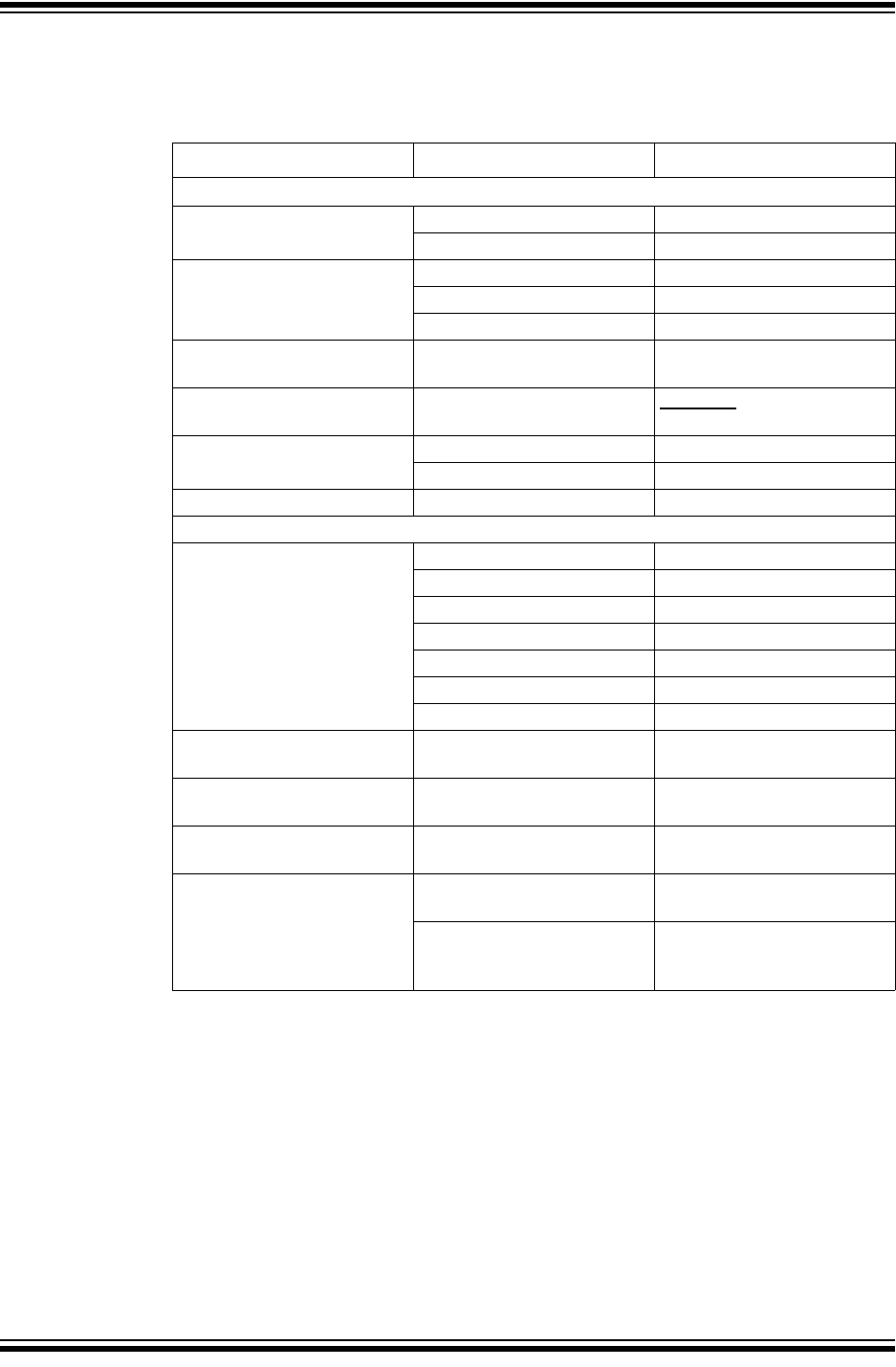
TABLE 1-1: COMMAND LINE PARAMETERS HELP
1.3.2 Invoking the MDB
Use the Command Prompt to invoke MDB.
In Windows 7, the Command Prompt must be opened in Administrator mode:
Start>All Programs>Accessories>Command Prompt, right click and select “Run as
Administrator.” This opens the Administrator: Command Prompt.
The path to the MDB may vary depending on where the MPLAB X IDE is installed and
which operating system is installed. See the following table for the various operating
systems and paths. The vn.nn in the path represents the version number, for example
v3.00. These paths are long so you may want to add them to your path variable.
Option Meaning Examples
-h,--help Show the list of classes of commands mdb -h
or
mdb --help
Argument Meaning Example
commandFile Run specified file with MDB commands
for scripting.
Also see Section 1.5 “Running a
Command File Method”
mdb MyScriptingFile.txt
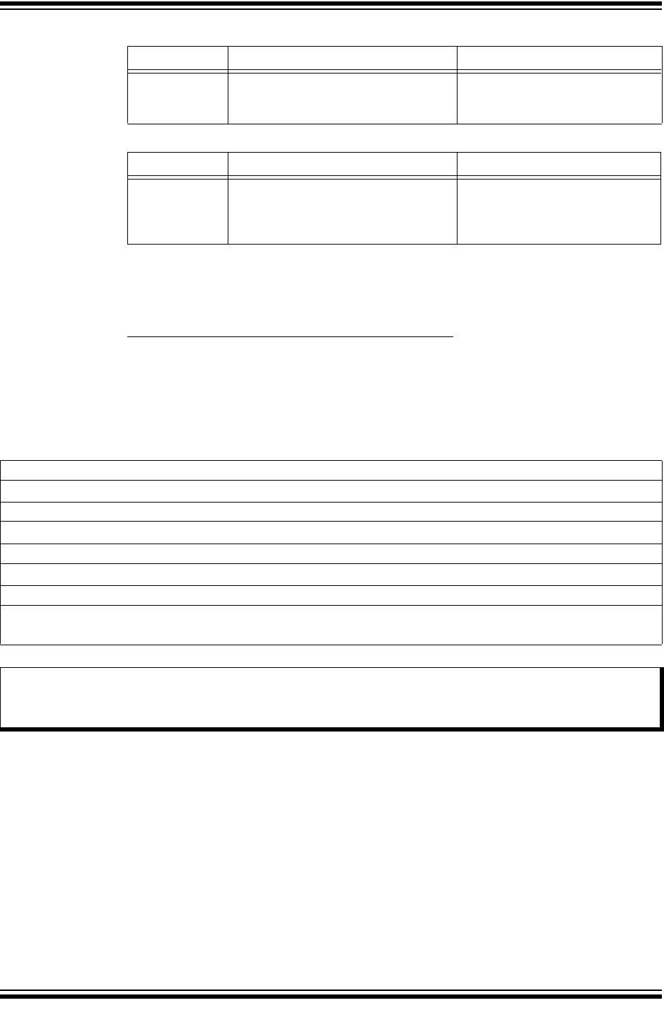
TABLE 1-2: PATHS TO THE MDB BY OPERATING SYSTEM
Windows 32-bit Operating System
c:\Program Files\Microchip\MPLABX\vn.nn\mplab_platform\bin>mdb.bat
Windows 64-bit Operating System
c:\Program Files (x86)\Microchip\MPLABX\vn.nn\mplab_platform\bin>mdb.bat
Linux Operating System
/opt/microchip/mplabx/vn.nn/mplab_platform/bin/mdb.sh
Apple OS X
/Applications/microchip/mplabx/vn.nn/mplab_ide.app/Contents/Resources/
mplab_platform/bin/mdb.sh
Note: The mdb.bat and mdb.sh scripts do not need to be run from the directory where they were
installed. If the directory where these scripts are installed is added to the system path, then
mdb.bat and msb.sh may run from any directory.
MDB User’s Guide
DS50002102E-page 12 2012-2018 Microchip Technology Inc.
1.4 DEBUGGING METHODS
You can run a test using either of the following methods:
•Entering Commands Method
•Running a Command File Method
Entering commands is the preferred method to run a test with MDB. It allows you to
interact with the target application as it executes in simulation or on actual hardware.
The result of each command is displayed one at a time, so that mistakes are more
easily understood and corrected (see “Entering Commands Method”).
The Running a Command File method cannot be used after the MDB has been
invoked. The command file is included as a parameter in the command line when
invoking the MDB (see “Running a Command File Method”).
1.4.1 Entering Commands Method
Entering commands is a step-by-step method to run a test with MDB. Once the MDB
is running, you can start entering commands. Note that while the MDB commands are
not case-sensitive, the property options and file names are case-sensitive.
Type help for a list of classes of commands in MDB. Refer to Chapter 2. “MDB
Reference”, Table 2-1 “MDB Classes of Commands”.
For other commands available, see Chapter 2. “MDB Reference”, Table 2-2 through
Table 2-10.
The following sections describe these topics:
•Programming a Production Image for Testing Purposes
•Debugging a Device
Note: Although the MPLAB X IDE can run multiple tools simultaneously, the MDB
will run only one tool at a time. However, you can have multiple instances
of the MDB running.
Refer to Section 1.6 “Using Multiple Instances of the MDB” for details.

2012-2018 Microchip Technology Inc. DS50002102E-page 13
1.4.2 Programming a Production Image for Testing Purposes
The MDB can be used to program a production image for testing purposes.
The file or hardware tool you need to use for MDB cannot be active or open
simultaneously in the MPLAB X IDE, IPE, or a third party program. Make sure you close
(or make inactive) the file or hardware tool before you attempt to use it with the MDB.
1. Select the device by entering the command:
Device [device name]
For example: Device PIC18F66K22
2. Use the set command to select any options you want to use (see Table 2-6
“Tool-Property-Name Options Used with the Set Command” or Table 2-7 “Simu-
lator Options Used With the Set Command”).
3. Select the hardware tool. To verify the supported tools, type:
Help Hwtool
The MPLAB ICD 3, MPLAB REAL ICE, PICkit 3 and Simulator are for
programming and debugging, while the MPLAB PM3 is for programming only. To
select the hardware tool, type the command:
Hwtool [tool name]
For example: Hwtool SIM
4. If the project was already built, a cof or elf file was generated. To program the
device with the cof, elf or hex file, enter the command:
Program “[location of the cof or elf or hex file]”.
For example:
Program "C:\MDBTestExample\Build\test\preprocess\files\dist\
test_IO_Button.cof".
If you are using SIM (Simulator) as the hardware tool and the project needs an
scl file, it can be set up by using the command:
Stim “[location of the scl file]”
For more information, use the command Help Stim. You can use Stimulus to set
pin injection and/or register injection.
A “Program succeeded” message displays after programming is complete. A verify is
automatically performed during a programming sequence.
Note: The MDB should be used for debugging purposes.
For programming devices, use the IPECMD tool or the IPECMDBoost (for
improved speed). Refer to the Release Notes for IPE Command Line
Interface (Readme for IPECMD) located in the MPLABX install folder, for
example, \Microchip\MPLABX\vx.xx\docs, where vx.xx represents
the version of MPLAB X IDE.
Note: When programming a device, you must select a device first.

MDB User’s Guide
DS50002102E-page 14 2012-2018 Microchip Technology Inc.
1.4.3 Debugging a Device
Use the following commands to debug a device.
• Reset – refer to the device data sheet for Reset information. If a Reset is needed
for debugging purposes: first, halt the target; then, enter the command:
Reset
• Set Breakpoint – there are two ways to set a breakpoint for debugging:
- Set a breakpoint by source-line-number using the command:
Break filename: linenumber
For example: Break main.c:53
- Set a breakpoint at an absolute address using command:
Break *address
For example: Break *0x108
• Set Watchpoint – to set a watchpoint for debugging:
- Set a watchpoint by specifying an address and the type of watch using the
command:
Watch address breakontype
For example: Watch 0xa0007ff0 R
or
Watch address breakontype[:value] [passcount]
For example: Watch 0xa0007ff0 R:0xf 1
• Delete Breakpoint – to delete a breakpoint, use the command:
Delete [breakpoint number]
If no argument is specified in this command, it will delete all breakpoints.
• Run Program – the Run command can be used to run the program until it reaches
a breakpoint.
• Step Through – to step through the program, use the Step command or Next
command.
• See Variable Value – a Print [variable] command can be used to see the
value of a variable or an SFR.
• Exit – use the Quit command to exit the MDB.
2012-2018 Microchip Technology Inc. DS50002102E-page 15
1.5 RUNNING A COMMAND FILE METHOD
If programming and debugging needs to be done frequently or multiple times, run the
test by running a command file. This is more efficient than entering the commands
repeatedly. Put all the commands in a file and run the MDB using this command file in
the Command Prompt, for example:
C:\Program Files\Microchip\MPLABX\vn.nn\mplab_ide\bin>mdb.bat
<commandfile.txt>
The following is an example of a command file:
C:\MDB-SIMCommand_Target.txt
A line starting with # means that it is a comment. A Sleep command should be added
to make sure the MDB has enough time to finish the previous command before it
executes the next command. The MDB will run all the commands in the command file
sequentially.
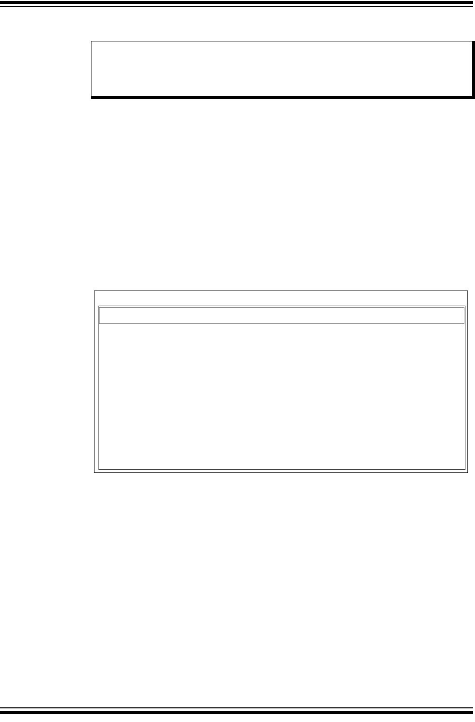
FIGURE 1-1: EXAMPLE OF RUNNING A COMMAND FILE
Creating a Printable Log File
Redirecting output to a file is a general option that can be executed from the command
prompt and is not specific to the MDB batch file. Redirecting output to a printable text
file can be more useful for examining errors than looking at the Command Prompt
window.
To create a printable file, open the MDB.bat file, and modify it by adding
>>%mplabx_dir%\bin\mdblog.txt at the end of the batch file. This instructs the
batch file to create the mdblog.txt file, which can be printed.
Note: Although the MPLAB X IDE can run multiple tools simultaneously, the MDB
will run only one tool at a time. However, you can have multiple instances
of the MDB running.
Refer to Section 1.6 “Using Multiple Instances of the MDB” for details.
MDB-SIMCommand_Target.txt - Notepad
Device PIC18F66K22
Hwtool SIM
Program "C:\MDBTestExample\Build\test\preprocess\files\dist\test_IO_Button.cof"
Reset MCLR
Sleep 1500
# set breakpoint at 0x108
#Break simulator.c:53
Break *0x108
Run
Wait 600000
#Sleep 6000
Print PROD
Quit
File Edit Format View Help

MDB User’s Guide
DS50002102E-page 16 2012-2018 Microchip Technology Inc.
1.6 USING MULTIPLE INSTANCES OF THE MDB
Using multiple instances of the MDB is similar to using multiple instances of the MPLAB
X IDE. Some set up is required before using hardware tools (PICkit 3, etc.) with an
instance of the MDB. Refer to the MPLAB X IDE online help “Before You Begin”, and
“Launch Multiple Instances of the IDE” for instructions on setting up the hardware tools
and formatting the MCHPDEFPORT file. After any hardware tool setup is complete (to
assign the appropriate driver for the tool), an instance of the MDB may be invoked from
the bin directory of the installation.
MDB USER’S GUIDE
2012-2018 Microchip Technology Inc. DS50002102E-page 17
Chapter 2. MDB Reference
2.1 HELP COMMANDS
There are help commands available in MDB.
Type help followed by a class name for a list of commands in that class (see
Section 2.2 “Classes of Commands”).
Type help followed by a command name for full documentation (see Section 2.3 “List
of Commands within Classes”).
Type help doc to see how to access MDB documentation. There are three ways to
access documentation for the MDB:
1. The MDB Help file provides the most up-to-date information and is located in the
same docs folder:
…>docs>MDB_Help>MDBX_SA.jar
2. The Microchip Debugger (MDB) User’s Guide is located in the default location
where the MPLAB X IDE was installed:
Program Files>Microchip>MPLABX>vx.xx>docs>MDBUserGuide.pdf
Where vx.xx represents the MPLAB X IDE version.
3. The MDB User’s Guide (.pdf) and MDB Help (.jar) can also be accessed by
launching the MPLAB X IDE, clicking the Learn & Discover tab, then clicking on
User’s Guide & Release Notes in the Getting Started area. A new window opens
showing a list of User’s Guides, Release Notes and Support Documentation
where you can find links to the MDB User’s Guide and MDB Help.
2.2 CLASSES OF COMMANDS
Type help for a list of classes of commands in MDB.
TABLE 2-1: MDB CLASSES OF COMMANDS
Class Description
breakpoints Making program stop at certain points
data Examining/changing data
deviceandtool Selecting debug tool and device
others Miscellaneous commands
programming Programming device and its relative functions
running Running the program
stack Examining stack

MDB User’s Guide
DS50002102E-page 18 2012-2018 Microchip Technology Inc.
2.3 LIST OF COMMANDS WITHIN CLASSES
For a list of all commands within a particular class, type help followed by the class
name. The help command can also be abbreviated to h. See the following tables for
information about each class of commands.
For documentation on a particular command, type help [command or class of
commands] to display information about the command. For example, if you type:
help breakpoints or h Breakpoints
the MDB displays information about the break, watch, delete and halt commands.
The following tables provide information on these commands:
•Breakpoints Commands
•Data Commands
•Device and Tool Commands
•Others Commands
•Tool Property Options Used with the Set Command
•Simulator Options Used with the Set Command
•Programming Commands
•Running Commands
•Stack Commands
Note: MDB commands are not case-sensitive. However, when using the SET
command, where tool option properties are passed as parameters, the
parameter portion of the command line entered is case-sensitive.

2012-2018 Microchip Technology Inc. DS50002102E-page 19
2.3.1 Breakpoints Commands
To display information about the breakpoints commands available in MDB, type help breakpoints.
Table 2-2 provides additional information for this command.
TABLE 2-2: BREAKPOINTS COMMANDS
Command Description
Break Sets a breakpoint at the specified source line number
Command format:
break filename:linenumber [passCount]
Example:
break newmain.c:142 4
Sets a breakpoint at an absolute address
Command format:
break *address [passCount]
•address – the address of the program memory to break on – use the command: 'print /a' to get a
symbol address.
•passCount – the parameter is optional
Indicates the number of times the break ‘on condition’ is met before the program halts.
Example:
break *0x9d0000cc 5
MDB assigns a breakpoint number and returns:
Breakpoint 0 at 0x9d0000cc: file newmain.c, line 16.
Sets a breakpoint at the beginning of the function
Command format:
break function_name [passCount]
Example:
break function_foo 5
Delete Deletes a breakpoint – if no argument is specified, this deletes all breakpoints
You can abbreviate this command as d.
Command format:
delete [breakpoint number]
d [breakpoint number]
The breakpoint number is generated by MDB for the Break and/or Watch commands.
Examples:
delete or D
delete 1 or d 1
Halt Stops the debugged program
Watch Sets a data breakpoint at the specified memory address, variable name, or an SFR (special function register)
Command format:
Watch address breakonType[:value] [passCount]
•address – the name of a global variable, SFR, or data memory address to be watched
Use command 'print /a' to get a variable address.
•breakonType:
R -- Read.
W -- Write.
RW -- Read or Write.
•value – this parameter is optional
If it is specified, the program will break only when the value held in the data memory matches the specified
value.
•passCount – this parameter is optional
The number of times the breakon condition is met before the program breaks.
Examples:
watch 0xa0007ff0 R:0xf 1
watch 0xa0007ff0 R:10 1
watch my_Variable W 4
MDB will assign and return the watchpoint number, for example: Watchpoint 1.

MDB User’s Guide
DS50002102E-page 20 2012-2018 Microchip Technology Inc.
2.3.2 Data Commands
To display information about the data commands available in the MDB, type help data. Table 2-3 provides
additional information for this command.
TABLE 2-3: DATA COMMANDS
Command Description
Print Prints a variable with optional formatting
Command format:
print [/f] [/datasize:value] variable
•f - Optional format letter
The format letters supported are:
x - Print as integer in signed hexadecimal
d - Print as integer in signed decimal
a - Print the address of a symbol
•datasize:value – optional data size
Variable in assembly code might not have data size information. The user can specify the data size if the
.cof or .elf file does not have the size information.
The values supported are:
1 - The data size is 1 byte.
2 - The data size is 2 bytes.
4 - The data size is 4 byte.
Use this command (not case sensitive) to display the pin information.
Command format:
print pin pinName
Example:
print pin RA0
This command will print Pin, Mode, Value, and Owner or Mapping:
• For Pin, it displays the name of the signal that the user types to find the pin
• For Mode, it displays the A/D state and I/O state
• For Value, it displays HIGH/LOW for Digital mode or the HIGH/LOW nominal voltage for Analog mode
• For Owner or Mapping, it displays the pin owner and all the signals in this pin
The owner of the pin is the signal with parentheses.
Stim Specifies a simulator SCL stimulus file to use
This loads the specified SCL stimulus file into the simulator, or if no path to the file is specified, it clears a loaded file.
(Note: if the path or filename has spaces in it, you must use the quotation marks, as shown below. If there are no
spaces in the path of filename, the quotation marks are not needed.)
Command format:
Stim “[path to file]”
Stim

2012-2018 Microchip Technology Inc. DS50002102E-page 21
Write Use this command to write to memory.
Command format:
write [/t] addr word1 word2 ... wordn
•t - the type of memory
The type of memory is any of the following:
r – File Registers (RAM) memory
This is the initial default.
p – Program (flash) memory
e – EE Data memory
Each time you specify a memory type with write, that type becomes the default memory the next time you
use write.
•addr – the starting address where you want MDB to begin writing to memory
•word – the following values will be written to successive words of memory
Use this command to set a pin high or low when the simulator is used as a debug tool.
Command format:
write pin pinName pinState
Example:
write pin RA0 high
Use this command to set a the voltage of a pin when the simulator is used as a debug tool.
Command format:
write pin pinName pinVoltage
Example:
write pin RA0 3.3V
xExamine memory
You can use the command x (for examine) to examine memory in any of several formats, independent of your pro-
gram’s data types.
Command format:
x [/tnfu] [addr]
•t – the type of memory
Each time you specify a memory type with x, that type becomes the default memory the next time you use
x.The type of memory is any of the following:
r – File Registers (RAM) memory. This is the initial default.
p – Program (flash) memory.
m – Memory-mapped control registers (PIC32 peripheral memory)
e – EE Data memory.
•n – the repeat count
The repeat count is a decimal integer; the default is 1. It specifies how much memory (counting by units u) to
display.
•f – the display format.
The display format is one of the formats used by print (x, d, o, f, s), and in addition “i” (for machine
instructions). The default is ‘x’ (hexadecimal) initially. The default changes each time you use x.
•u – the unit size
Each time you specify a unit size with x, that size becomes the default unit the next time you use x. (For the
‘s’ and ‘i’ formats, the unit size is ignored and is normally not written.)
The unit size is any of following:
b – Bytes.
h – Halfwords (two bytes).
w – Words (four bytes). This is the initial default.
•addr - the starting display address where you want MDB to begin displaying memory
The addr can be a literal or a symbol name. The default for addr, if not specified, is taken as the value just after
the last address examined.
However, several other commands also set the default address: info breakpoints (to the address of the last
breakpoint listed); info line (to the starting address of a line); and print (if you use it to display a value from
memory).
TABLE 2-3: DATA COMMANDS (CONTINUED)
Command Description

MDB User’s Guide
DS50002102E-page 22 2012-2018 Microchip Technology Inc.
2.3.3 Device and Tool Commands
To display information about the device and tool commands available in MDB, type help device, help
hwtool or help deviceandtool. Table 2-4 provides additional information about these commands.
TABLE 2-4: DEVICE AND TOOL COMMANDS
Command Description
Device Sets the name of the target device
Command format:
Device devicename
Example:
Device PIC32MX795F512L
Hwtool Sets the debug tool or list all the available hardware tools on the system
(The device must be set with the Device command before a tool can be used/set.)
Command format:
Hwtool [toolType] [-p] [index]
Following are the supported tool names (not case-sensitive):
•ICD3 – MPLAB ICD 3 In-Circuit Debugger
•ICD4 – MPLAB ICD 4 In-Circuit Debugger
•RealICE – MPLAB REAL ICE In-Circuit Emulator
•PICkit3 – PICkit 3 In-Circuit Debugger
•PICkit4 – MPLAB PICkit 4 In-Circuit Debugger
•SIM – Simulator
•PM3 – MPLAB PM3 Programmer
•LicensedDebugger – third party debugger
•LicensedProgrammer – third party programmer
•SK – Microchip Starter Kit (PICkit On Board – PKOB)
•SNAP – MPLAB Snap In-Circuit Debugger
To set the tool for programming only, a space must precede the -p option.
Command format:
Hwtool [toolType] -p
Example:
Hwtool ICD3 -p
Use the index option to select the tool if there are more than one instance of a tool type. If you have two
MPLAB ICD 3 units connected to the PC, use the hwtool command to find the assigned index number of the
tool.
Example:
>hwtool
index Description
0 MPLAB ICD 3 tm (MRK1000000000)
1 MPLAB ICD 3 tm (MRK1000001111)
Example:
Hwtool ICD3 -p 1
Note: By default, when a hardware tool is selected, it is loaded as a debugger. This means that it always
programs the device and adds the necessary debug requirements to enable the image to be
debugged.
To use a tool for programming only, use the -p option when setting the hardware tool.
Deviceandtool Displays both the Device and Hwtool command information

2012-2018 Microchip Technology Inc. DS50002102E-page 23
2.3.4 Others Commands
To display information about the others commands available in MDB, type help others. Table 2-5 provides
additional information for this command.
TABLE 2-5: OTHERS COMMANDS
Command Description
Echo Echo is a command typically used in command files and batch files to output status text to the screen or a file. The
echo command will print text surrounded by /* */. Use \n in the text to print a new line.
Command format:
echo text
Example:
echo Hello World
Result:
/*Hello World*/
This command prints text only. To print variables or other information, use commands such as print, info, list,
etc.
Help help others – Prints a list of commands
Quit quit - Exits the debugger
Set The tool property name and value are from the project properties that are selected when creating the project in
MPLAB X IDE.
IMPORTANT: The Set command, including the tool property options, must be executed before the program
command is issued, otherwise the changes to the tool properties will be ignored.
Command format:
Set tool-property-name value
Example:
Set programoptions.eraseb4program true
Refer to Table 2-6 for other tool properties options that can used with the Set command.
Refer to Table 2-7 for simulator options that can be used with the Set command.
Sleep Makes the current script processor sleep until specified milliseconds have elapsed
Command format:
Sleep milliseconds
Example:
Sleep 10
Wait The Wait command makes the current script processor wait until the debugger halts before processing the next com-
mand.
Command format:
Wait
Wait Milliseconds makes the processor process the next command if the debugger does not halt and millisec-
onds have elapsed.
Command format:
Wait [milliseconds]
cd This command changes the directory that you are currently working in to the directory you designate.
Command format:
cd [directory]

MDB User’s Guide
DS50002102E-page 24 2012-2018 Microchip Technology Inc.
info Prints a table of all breakpoints that have been set and not deleted
Optional argument n means “print information only” about the specified breakpoint.
For each breakpoint the following columns are printed:
• Breakpoint Numbers
• Enabled or Disabled
Enabled breakpoints are marked with ‘y’
Disabled breakpoints are marked with ‘n’
• Address
Where the breakpoint is in your program, as a memory address.
• What
Where the breakpoint is in the source for your program: as a file and line number.
Command format:
info breakpoints [n]
info break [n]
list\ The list command prints (displays) the source code for the current PC location, or a different file, if specified.
The list command displays lines from a source file.
By default, 10 lines are displayed.
list
displays 10 lines (5 above, 5 below) around the current line
list linenum
displays 10 lines around a given line
list first,
displays 10 lines from first line specified
list ,last
displays 10 lines up to last line specified
list first,last
displays all lines from the first to the last line specified
list -
displays 10 previous lines from the last output
list +
displays 10 more lines from the last output
list function
displays 10 lines around the given function
list file:linenum
displays 10 lines around the given line in a given file
list file:function
displays 10 lines around the given function in a given file
set system.listsize count
changes the number of lines shown.
Using 0 or -1 means unlimited list size
pwd The pwd command displays the current working directory.
Command format:
pwd
TABLE 2-5: OTHERS COMMANDS (CONTINUED)
Command Description

2012-2018 Microchip Technology Inc. DS50002102E-page 25
2.3.4.1 TOOL PROPERTY OPTIONS USED WITH THE SET COMMAND
Table 2-6 provides additional information for tool property options used with the Set command.
IMPORTANT: The Set command, including the tool property options, must be executed before the program
command is issued, otherwise the changes to the tool properties will be ignored.
Note 1: MDB commands are not case-sensitive. However, when using the set command, where tool
option properties are passed as parameters, the parameter portion of the command line
entered is case-sensitive.
2: Tool property options that you want to use with the set command must be selected before
using the hwtool command.
TABLE 2-6: TOOL-PROPERTY-NAME OPTIONS USED WITH THE SET COMMAND
Tool Property Name Value Tool
AutoSelectMemRanges
Determines whether the debugger will automatically select the areas of memory and pro-
gram memory ranges to program
If set to auto, the debugger will automatically select the memory and ranges. Manual
means the memories and ranges will be determined by the memories properties below.
Example:
set AutoSelectMemRanges auto
auto or
manual
MPLAB ICD3,
MPLAB ICD4,
MPLAB REAL
ICE, PICkit 3,
MPLAB PICkit 4,
MPLAB PM3,
MPLAB Snap
debugoptions.useswbreakpoints
True indicates that software breakpoints will be used for program address breakpoints,
false indicates that hardware breakpoints will be used (does not apply to PICkit 3).
Example:
set debugoptions.useswbreakpoints true
true or
false
MPLAB ICD3,
MPLAB ICD4,
MPLAB REAL
ICE, MPLAB
PICkit 4, MPLAB
Snap
memories.programmemory
If true, the program memory will be programmed; if false, it will not.
Example:
set memories.programmemory true
true or
false
MPLAB ICD3,
MPLAB ICD4,
MPLAB REAL
ICE, PICkit 3,
MPLAB PICkit 4,
MPLAB PM3,
MPLAB Snap
memories.programmemory.start
The value represents the starting program memory address that the debug tool will begin
programming.
Example:
set memories.programmemory.start 0x0000
a string
representing
a long value
MPLAB ICD3,
MPLAB ICD4,
MPLAB REAL
ICE, PICkit 3,
MPLAB PICkit 4,
MPLAB PM3,
MPLAB Snap
memories.programmemory.end
The value represents the ending program memory address that the debug tool will end
programming.
Example:
set memories.programmemory.end 0xFFFF
a string
representing
a long value
MPLAB ICD3,
MPLAB ICD4,
MPLAB REAL
ICE, PICkit 3,
MPLAB PICkit 4,
MPLAB PM3,
MPLAB Snap
memories.eeprom
If true, the EEPROM memory will be programmed; if false, it will not.
Example:
set memories.eeprom true
true or
false
MPLAB ICD3,
MPLAB ICD4,
MPLAB REAL
ICE, PICkit 3,
MPLAB PICkit 4,
MPLAB PM3,
MPLAB Snap

MDB User’s Guide
DS50002102E-page 26 2012-2018 Microchip Technology Inc.
memories.id
If true, the user ID memory will be programmed; if false, it will not.
Example:
set memories.id true
true or
false
MPLAB ICD3,
MPLAB ICD4,
MPLAB REAL
ICE, PICkit 3,
MPLAB PICkit 4,
MPLAB PM3,
MPLAB Snap
memories.bootflash
If true, the boot flash (PIC32 only) memory will be programmed; if false, it will not.
Example:
set memories.bootflash true
true or
false
MPLAB ICD3,
MPLAB ICD4,
MPLAB REAL
ICE, PICkit 3,
MPLAB PICkit 4,
MPLAB PM3,
MPLAB Snap
memories.aux
If true, the auxiliary program memory (dsPIC/PIC24 EP parts only) will be programmed;
if false, it will not.
Example:
set memories.aux true
true or
false
MPLAB ICD3,
MPLAB ICD4,
MPLAB REAL
ICE, PICkit 3,
MPLAB PICkit 4,
MPLAB PM3,
MPLAB Snap
programoptions.eraseb4program
If true, the device will be erased before it is programmed; if false it will not.
Example:
set programoptions.eraseb4program true
true or
false
MPLAB ICD3,
MPLAB ICD4,
MPLAB REAL
ICE, PICkit 3,
MPLAB PICkit 4,
MPLAB PM3,
MPLAB Snap
programoptions.ledbrightness
Sets the brightness of the LEDs on the MPLAB ICD 4. Setting 1 is darkest and 10 is the
brightest. The default is 5.
Example:
set programoptions.ledbrightness 7
1 to 10 MPLAB ICD4,
MPLAB PICkit 4
programoptions.pgcconfig
Sets the type of resistance to be applied to the PGC line. The default is pull down.
The value of the resistance is set by the PGC resistor option.
Example:
set programoptions.pgcconfig pullup
none or
pull up or
pull down
MPLAB ICD4,
MPLAB PICkit 4
programoptions.pgcresistor.value
Sets the value of the resistance on the PGC line. Maximum value is 50 kohms. If PGC
configuration is set to none, this value is ignored.
Example:
set programoptions.pgcresistor.value 4.7
0.1 to 50.0 MPLAB ICD4,
MPLAB PICkit 4
programoptions.pgdconfig
Sets the type of resistance to be applied to the PGD line. The default is pull down.
The value of the resistance is set by the PGD resistor option.
Example:
set programoptions.pgdconfig pullup
none or
pull up or
pull down
MPLAB ICD4,
MPLAB PICkit 4
programoptions.pgdresistor.value
Sets the value of the resistance on the PGD line. Maximum value is 50 kohms. If PGD
configuration is set to none, this value is ignored.
Example:
set programoptions.pgdresistor.value 4.7
0.1 to 50.0 MPLAB ICD4,
MPLAB PICkit 4
TABLE 2-6: TOOL-PROPERTY-NAME OPTIONS USED WITH THE SET COMMAND (CONTINUED)
Tool Property Name Value Tool

2012-2018 Microchip Technology Inc. DS50002102E-page 27
programoptions.pgmentry.voltage
Sets the method the MPLAB ICD 4 will use to put the target device in programming mode.
For the low voltage method, VPP will not exceed the VDD supply voltage. Instead, a test
pattern will be used on VPP. For the high voltage method, a voltage in excess of 9 volts
will be placed on VPP.
Example:
set programoptions.pgmentry.voltage low
Low or
High
MPLAB ICD4,
MPLAB PICkit 4
MPLAB Snap
programoptions.pgmspeed
Sets the speed that the MPLAB ICD 4 will use to program the target. If programming fails,
try a slower speed. The default is Med.
Example:
set programoptions.pgmspeed Min
Min or
Med or
Max
MPLAB ICD4,
MPLAB PICkit 4
MPLAB Snap
poweroptions.powerenable
If true, the debug tool will supply target power at the default voltage for the tool. If false
it will not supply target power.
Note: This property does not apply to MPLAB REAL ICE.
To set a non-default voltage for the target power, first set the
poweroptions.powerenable to true, then set the voltage value where n.n rep-
resents the desired voltage:
set voltagevalue n.n
Example:
set poweroptions.powerenable true
set voltagevalue 3.3
true or
false
MPLAB ICD3,
MPLAB ICD4,
PICkit 3, MPLAB
PICkit 4, MPLAB
PM3
SecureSegment.SegmentProgramming SegmentProgrammingAll
If true, it permits programming to “Program Over Secure and Protected FLASH.” This
property must be set prior to using the program operation on the MDB. Use the -p option
to set the tool as a programmer if it’s for a production final image and not just a debug
image.
Example:
set SecureSegment.SegmentProgramming SegmentProgrammingAll true
true or
false
MPLAB ICD3,
MPLAB ICD4,
MPLAB REAL
ICE, PICkit 3,
MPLAB PICkit 4
system.disableerrormsg
Note: This option has been deprecated as of v3.15 but will still function with
existing projects. For new projects, use the system.disableoutput and
system.yestoalldialog options.
If true, the system will disable warnings and error messages and answer “yes” to all dia-
logs; if false the system will enable warning and error messages (this is the default).
Example:
set system.disableerrormsg true
true or
false
Not tool
dependent
system.disableoutput
If true, the system will disable warnings and error message outputs but not disable dia-
logs; if false the system will enable warning and error message outputs and dialogs (this
is the default).
Example:
set system.disableoutput true
true or
false
Not tool
dependent
system.yestoalldialog
If true, the system will disable dialogs and answer “yes” to all of them; if false the
system will enable dialogs (this is the default).
Example:
set system.yestoalldialog true
true or
false
Not tool
dependent
TABLE 2-6: TOOL-PROPERTY-NAME OPTIONS USED WITH THE SET COMMAND (CONTINUED)
Tool Property Name Value Tool

MDB User’s Guide
DS50002102E-page 28 2012-2018 Microchip Technology Inc.
2.3.4.2 SIMULATOR OPTIONS USED WITH THE SET COMMAND
Table 2-7 provides additional information for simulator options used with the set command.
IMPORTANT: The Set command, including the tool property options, must be executed before the program
command is issued, otherwise the changes to the tool properties will be ignored.
Note: For the following table, the break options allow you to set the conditions that will cause program
execution to halt. In general, the program will either break on option, ignore the option, or report
the option.
TABLE 2-7: SIMULATOR OPTIONS USED WITH THE SET COMMAND
Simulator Options Values Device or
Runtime
Dependent
breakoptions.coreerrors
Sets the condition if core errors occur
Example:
set breakoptions.coreerrors Break
Break, Ignore, Report No
breakoptions.corewarnings
Sets the condition if core warnings occur
Example:
set breakoptions.corewarnings Ignore
Break, Ignore, Report No
breakoptions.peripheralerrors
Sets the condition if peripheral errors occur
Example:
set breakoptions.peripheralerrors Report
Break, Ignore, Report No
breakoptions.peripheralwarnings
Sets the condition if peripheral warnings occur
Example:
set breakoptions.peripheralwarnings Break
Break, Ignore, Report No
breakoptions.stimulusmessages.notes
Sets the condition if stimulus notes occur
Example:
set breakoptions.stimulusmessages.notes Ignore
Break, Ignore, Report No
breakoptions.stimulusmessags.errors
Sets the condition if stimulus errors occur
Example:
set breakoptions.stimulusmessages.errors Report
Break, Ignore, Report No
breakoptions.stimulusmessags.warnings
Sets the condition if stimulus warnings occur
Example:
set breakoptions.stimulusmessages.warnings Ignore
Break, Ignore, Report No
breakoptions.wdtwarnings
Sets the condition if watchdog timer warnings occur
Example:
set breakoptions.wdtwarnings Ignore
Break, Ignore, Report No
codecoverage.enabled
Enables or disables code coverage
Example:
set codecoverage.enabled Disable
Disable,
Enabled_Reset_on_POR
Enabled_Reset_on_Run
No
codecoverage.enableoutputtofile
Enables write to file
Example:
set codecoverage.enableoutputtofile true
true, false No

2012-2018 Microchip Technology Inc. DS50002102E-page 29
codecoverage.outputtofile
Absolute path to output file
Example:
set codecoverage.outputtofile “c:\path\to\file.txt”
String path No
oscillator.auxfrequency
Auxiliary PLL Frequency, used by PWM and ADC
Example:
set oscillator.auxfrequency 4400
Numeric Yes
oscillator.auxfrequencyunit
Auxiliary PLL Frequency Units
Example:
set oscillator.auxfrequencyunit None
Mega, Kilo, None Yes
oscillator.frequency
Instruction Execution Frequency
Example:
set oscillator.frequency 4700
numeric No
oscillator.frequencyunit
Instruction Frequency Units
Example:
set oscillator.frequencyunit Kilo
Mega, Kilo, None No
oscillator.rcfrequency
RC Oscillator Frequency
Example:
set oscillator.rcfrequency 4500
Numeric No
oscillator.rcfrequencyunit
RC Oscillator Frequency Units
Example:
set oscillator.rcfrequencyunit None
Mega, Kilo, None No
periphADC1.altscl
Use MPLAB 8 style ADC
Example:
set periphADC1.altscl true
true, false Yes
periphADC1.minTacq
Specifies minimum acquisition time (Tacq) in seconds
Example:
set periphADC1.minTacq 10
Numeric Yes
periphADC1.tacqunits
Units for minimum acquisition time (Tacq)
Example:
set periphADC1.tacqunits nanoseconds
milliseconds, micro-
seconds, nanoseconds
Yes
periphADC2.altscl
Use MPLAB 8 style ADC
Example:
set periphADC2.altscl true
true, false Yes
periphADC2.minTacq
Specifies minimum acquisition time (Tacq) in seconds
Example:
set periphADC2.minTacq 20
Numeric Yes
periphADC2.tacqunits
Units for minimum acquisition time (Tacq)
Example:
set periphADC2.tacqunits milliseconds
milliseconds, micro-
seconds, nanoseconds
Yes
TABLE 2-7: SIMULATOR OPTIONS USED WITH THE SET COMMAND (CONTINUED)
Simulator Options Values Device or
Runtime
Dependent

MDB User’s Guide
DS50002102E-page 30 2012-2018 Microchip Technology Inc.
uartNio.output
Specifies location of UART output
N represents the UART number 1 through 6
Example:
set uart1io.output file
file, window Yes
uartNio.uartioenabled
If true, the system will enable the UART I/O; if false the system will disable it
N represents the UART number 1 through 6
Example:
set uart1io.uartioenabled false
true, false Yes
uartNio.outputfile
Passes in a string containing the root (absolute path) of the file system to the
file used for UART output
N represents the UART number 1 through 6
Example:
set uart1io.outputfile “c:\path\to\outputfile.txt”
Absolute path to file Yes
TABLE 2-7: SIMULATOR OPTIONS USED WITH THE SET COMMAND (CONTINUED)
Simulator Options Values Device or
Runtime
Dependent
2012-2018 Microchip Technology Inc. DS50002102E-page 31
2.3.5 Programming Commands
To display information about the programming commands available in the MDB, type
help [programming option]. Table 2-8 provides additional information for these
commands.
IMPORTANT: The Set command, including the tool property options, must be executed
before the program command is issued, otherwise the changes to the tool properties will
be ignored.
2.3.6 Running Commands
To display information about the running commands available in the MDB, type help
running. Table 2-9 provides additional information for these commands.
TABLE 2-8: PROGRAMMING COMMANDS
Command Description
Program Programs device memory with the image specified by the file
Note: if the path or filename has spaces in it, you must use the quotation marks. If there
are no spaces in the path of filename, the quotation marks are not needed, as shown
below.
Command format:
Program executableImageFile
Upload Uploads the executable image to MDB memory
The source of the instructions to be loaded is the contents of the memory of an attached
PIC device through the programmer or debugger.
Command format:
Upload
Dump Writes the device memory to a hex file
Command format:
Dump [-m] filename
The m is an optional argument that specifies which memories to write to the hex file. It
can be any combination of the following:
•p - Program Memory (Flash)
•e - EE Data
•c - Configuration Bits
•u - User ID memory
•b - Boot Memory
•f - Flash Data
The filename is the full path and name to the hex file.
TABLE 2-9: RUNNING COMMANDS
Command Description
Continue Resumes program being debugged, after breakpoint
Command format:
Continue
Halt Stops the debugged program
Command format:
Halt
Next Step program, proceeding through subroutine calls
Like the “step” command as long as subroutine calls do not happen; when they do, the call
is treated as one instruction.
Command format:
Next
Run Start the debugged program
Command format:
Run
MDB User’s Guide
DS50002102E-page 32 2012-2018 Microchip Technology Inc.
2.3.7 Stack Commands
To display information about the stack commands available in MDB, type help
backtrace. Table 2-10 provides additional information for these commands.
Step Step program until it reaches a different source line
The step command only enters a function if there is a line number information for the
function.
Command format:
Step
Stepi Execute one machine instruction, then stop and return to the debugger
The optional argument count is a repeat count.
Command format:
Stepi [count]
TABLE 2-10: STACK COMMANDS
Command Description
Backtrace Print a backtrace of the entire stack, one line per frame for all frames in the stack
Command format:
Backtrace [full] [<n, -n>]
•full – prints the values of local variables
•n – prints the innermost n frames
•-n – prints the outermost n frames
TABLE 2-9: RUNNING COMMANDS
Command Description

MDB USER’S GUIDE
2012-2018 Microchip Technology Inc. DS50002102E-page 33
Appendix A. Revision History
REVISION HISTORY
Revision A (November 2012) - initial release of this document.
Revision B (April 2013)
• added note in Invoking the MDB section
• added Tool Property Name Options for the Set command
• added Simulator Options for the Set command
• added -p option
• added note on running multiple tools
• removed example of using commands to debug a project
• added section on creating a printable log file
Revision C (March 2014)
• relocated Revision History from Preface to it’s own appendix.
• added a Document Layout section to the Preface.
• added new Section 1.6 “Using Multiple Instances of the MDB”.
• moved reference tables to Chapter 2. “MDB Reference”.
• added notes about case-sensitivity for commands in Chapter 2. “MDB
Reference”.
• added tool column to Table 2-6: “Tool-Property-Name Options Used with the Set
Command”
• added new Table 2-7: “Simulator Options Used With the Set Command”.
Revision D (February 2017)
• added more documents to the Recommended Reading section in Preface.
• revised the title of Chapter 1 to “How to Use Microchip Debugger”, revised the
description of the MDB and added a note to the revised Programming a
Production Image for Testing Purposes section.
• revised Section 1.3 “Getting Started” to add information on Command Line
Parameters.
• added information in the Help Commands section.
• revised multiple tables in the MDB Reference chapter.
Revision E (October 2018)
• added information for the MPLAB PICkit 4 and MPLAB Snap In-Circuit Debuggers
in Section 1.1 “Introduction” .
• renamed, reorganized and added information in Section 1.2 “Installation and
Documentation” and Section 1.3 “Getting Started”.
• updated paths in Table 1-2: “Paths to the MDB by Operating System”
• updated tools in Table 2-4: “Device and tool Commands” and Ta ble
2-6: “Tool-Property-Name Options Used with the Set Command”

MDB User’s Guide
DS50002102E-page 34 2012-2018 Microchip Technology Inc.
NOTES:

MDB USER’S GUIDE
2012-2018 Microchip Technology Inc. DS50002102E-page 35
Index
A
AutoSelectMemRanges ........................................... 25
B
Backtrace ................................................................. 32
Break...................................................................14, 19
breakoptions.coreerrors ........................................... 28
breakoptions.corewarnings ...................................... 28
breakoptions.peripheralerrors .................................. 28
breakoptions.peripheralwarnings ............................. 28
breakoptions.stimulusmessages.notes .................... 28
breakoptions.stimulusmessags.errors...................... 28
breakoptions.stimulusmessags.warnings................. 28
breakoptions.wdtwarnings ....................................... 28
Breakpoints
Break ................................................................ 19
Delete ............................................................... 19
Halt ................................................................... 19
Watch................................................................ 19
breakpoints .............................................................. 17
C
cd ............................................................................. 23
Classes of Commands............................................. 17
breakpoints ....................................................... 17
data................................................................... 17
deviceandtool.................................................... 17
others................................................................ 17
programming..................................................... 17
running.............................................................. 17
stack ................................................................. 17
codecoverage.enabled............................................. 28
codecoverage.enableoutputtofile ............................. 28
codecoverage.outputtofile........................................ 29
cof file....................................................................... 13
Command
Delete ............................................................... 14
Device............................................................... 13
list ..................................................................... 24
Print .................................................................. 14
Program............................................................ 13
Quit ................................................................... 14
Reset MCLR ..................................................... 14
Run ................................................................... 14
Sleep................................................................. 15
Step .................................................................. 14
Stim................................................................... 13
help .......................................................................... 18
Command Line Parameters..................................... 10
Command Prompt.................................................... 11
Continue................................................................... 31
Creating a Printable Log File.................................... 15
D
Data
Print................................................................... 20
Stim................................................................... 20
Write.................................................................. 21
x ........................................................................ 21
data .......................................................................... 17
Debugging a Device................................................. 14
debugoptions.useswbreakpoints.............................. 25
Delete....................................................................... 19
Delete Breakpoint..................................................... 14
Device ...................................................................... 22
Device and Tool
Device............................................................... 22
Deviceandtool ................................................... 22
Hwtool............................................................... 22
Deviceandtool .......................................................... 22
deviceandtool........................................................... 17
Documentation
Conventions ........................................................ 6
Dump........................................................................ 31
E
Echo......................................................................... 23
elf file........................................................................ 13
Entering Commands Method ................................... 12
Exit ........................................................................... 14
H
Halt..................................................................... 19, 31
Header Specification.................................................. 7
Help.......................................................................... 23
Help Commands ...................................................... 17
Hwtool ...................................................................... 22
M
MDB ........................................................................... 9
mdb --help................................................................ 10
MDB.bat file.............................................................. 15
mdblog.txt file........................................................... 15
memories.aux........................................................... 26
memories.bootflash.................................................. 26
memories.eeprom .................................................... 25
memories.id.............................................................. 26
memories.programmemory ...................................... 25
memories.programmemory.end............................... 25
memories.programmemory.start .............................. 25
Microchip Debugger................................................... 9

MDB User’s Guide
DS50002102E-page 36 2012-2018 Microchip Technology Inc.
N
Next.......................................................................... 31
O
oscillator.auxfrequency............................................. 29
oscillator.auxfrequencyunit....................................... 29
oscillator.frequency .................................................. 29
oscillator.frequencyunit............................................. 29
oscillator.rcfrequency ............................................... 29
oscillator.rcfrequencyunit.......................................... 29
Others
cd ...................................................................... 23
Echo.................................................................. 23
Help................................................................... 23
List .................................................................... 24
pwd ................................................................... 24
Quit ................................................................... 23
Set..................................................................... 23
Sleep................................................................. 23
Wait................................................................... 23
others ....................................................................... 17
P
periphADC1.altscl..................................................... 29
periphADC1.minTacq............................................... 29
periphADC1.tacqunits .............................................. 29
periphADC2.altscl..................................................... 29
periphADC2.minTacq............................................... 29
periphADC2.tacqunits .............................................. 29
poweroptions.powerenable ...................................... 27
Print.......................................................................... 20
Processor Extension Pak Specification...................... 7
Program ................................................................... 31
Programming
Dump ................................................................ 31
Program ............................................................ 31
Upload............................................................... 31
programming ............................................................ 17
Programming a Device............................................. 13
programoptions.eraseb4program............................. 26
programoptions.ledbrightness.................................. 26
programoptions.pgcconfig........................................ 26
programoptions.pgcresistor.value ............................ 26
programoptions.pgdconfig........................................ 26
programoptions.pgdresistor.value............................ 26
programoptions.pgmebtry ........................................ 27
programoptions.pgmspeed....................................... 27
pwd........................................................................... 24
Q
Quit........................................................................... 23
R
Reading, Recommended............................................ 7
Readme...................................................................... 7
Reset........................................................................ 14
Run........................................................................... 31
Run Program............................................................ 14
Running
Continue............................................................ 31
Halt.................................................................... 31
Next................................................................... 31
Run....................................................................31
Step................................................................... 32
Stepi..................................................................32
running ..................................................................... 17
Running a Command File Method............................ 15
S
scl file ....................................................................... 13
SecureSegment.SegmentProgramming...................27
See Variable Value...................................................14
Set............................................................................23
Tool Property Name Options.............................25
Set Breakpoint.......................................................... 14
Set Watchpoint.........................................................14
Simulator .................................................................. 13
Simulator Options
breakoptions.coreerrors ....................................28
breakoptions.corewarnings ...............................28
breakoptions.peripheralerrors ...........................28
breakoptions.peripheralwarnings ......................28
breakoptions.stimulusmessages.notes ............. 28
breakoptions.stimulusmessags.errors...............28
breakoptions.stimulusmessags.warnings..........28
breakoptions.wdtwarnings.................................28
codecoverage.enabled......................................28
codecoverage.enableoutputtofile ...................... 28
codecoverage.outputtofile .................................29
oscillator.auxfrequency .....................................29
oscillator.auxfrequencyunit................................29
oscillator.frequency ...........................................29
oscillator.frequencyunit .....................................29
oscillator.rcfrequency ........................................29
oscillator.rcfrequencyunit .................................. 29
periphADC1.altscl ............................................. 29
periphADC1.minTacq........................................29
periphADC1.tacqunits .......................................29
periphADC2.altscl ............................................. 29
periphADC2.minTacq........................................29
uart1io.output ....................................................30
uart1io.outputfile................................................ 30
uart1io.uartioenabled ........................................30
Sleep ........................................................................ 23
Stack
Backtrace ..........................................................32
stack.........................................................................17
Step..........................................................................32
Step Through............................................................14
Stepi ......................................................................... 32
Stim .......................................................................... 20
Stimulus.................................................................... 13
system.disableerrormsg ...........................................27
system.disableoutput................................................ 27
system.yestoalldialog ............................................... 27
T
Target Device Reset.................................................14
Tool Property Name Options....................................25
AutoSelectMemRanges .................................... 25
debugoptions.useswbreakpoints....................... 25
memories.aux....................................................26

Index
2012-2018 Microchip Technology Inc. DS50002102E-page 37
memories.bootflash .......................................... 26
memories.eeprom............................................. 25
memories.id ...................................................... 26
memories.programmemory............................... 25
memories.programmemory.end........................ 25
memories.programmemory.start....................... 25
poweroptions.powerenable............................... 27
programoptions.eraseb4program ..................... 26
programoptions.ledbrightness .......................... 26
programoptions.pgcconfig ................................ 26
programoptions.pgcresistor.value..................... 26
programoptions.pgdconfig ................................ 26
programoptions.pgdresistor.value .................... 26
programoptions.pgmentry................................. 27
programoptions.pgmspeed ............................... 27
SecureSegment.SegmentProgramming ........... 27
system.disableerrormsg.................................... 27
system.disableoutput ........................................ 27
system.yestoalldialog........................................ 27
voltagevalue...................................................... 27
Transition Socket
Specification ....................................................... 7
U
uart1io.output ........................................................... 30
uart1io.outputfile ...................................................... 30
uart1io.uartioenabled ............................................... 30
Upload...................................................................... 31
V
voltagevalue............................................................. 27
W
Wait.......................................................................... 23
Watch....................................................................... 19
Write......................................................................... 21
X
x ............................................................................... 21

MDB User’s Guide
DS50002102E-page 38 2012-2018 Microchip Technology Inc.

DS50002102E-page 39 2012-2018 Microchip Technology Inc.
AMERICAS
Corporate Office
2355 West Chandler Blvd.
Chandler, AZ 85224-6199
Tel: 480-792-7200
Fax: 480-792-7277
Technical Support:
http://www.microchip.com/
support
Web Address:
www.microchip.com
Atlanta
Duluth, GA
Tel: 678-957-9614
Fax: 678-957-1455
Austin, TX
Tel: 512-257-3370
Boston
Westborough, MA
Tel: 774-760-0087
Fax: 774-760-0088
Chicago
Itasca, IL
Tel: 630-285-0071
Fax: 630-285-0075
Dallas
Addison, TX
Tel: 972-818-7423
Fax: 972-818-2924
Detroit
Novi, MI
Tel: 248-848-4000
Houston, TX
Tel: 281-894-5983
Indianapolis
Noblesville, IN
Tel: 317-773-8323
Fax: 317-773-5453
Tel: 317-536-2380
Los Angeles
Mission Viejo, CA
Tel: 949-462-9523
Fax: 949-462-9608
Tel: 951-273-7800
Raleigh, NC
Tel: 919-844-7510
New York, NY
Tel: 631-435-6000
San Jose, CA
Tel: 408-735-9110
Tel: 408-436-4270
Canada - Toronto
Tel: 905-695-1980
Fax: 905-695-2078
ASIA/PACIFIC
Australia - Sydney
Tel: 61-2-9868-6733
China - Beijing
Tel: 86-10-8569-7000
China - Chengdu
Tel: 86-28-8665-5511
China - Chongqing
Tel: 86-23-8980-9588
China - Dongguan
Tel: 86-769-8702-9880
China - Guangzhou
Tel: 86-20-8755-8029
China - Hangzhou
Tel: 86-571-8792-8115
China - Hong Kong SAR
Tel: 852-2943-5100
China - Nanjing
Tel: 86-25-8473-2460
China - Qingdao
Tel: 86-532-8502-7355
China - Shanghai
Tel: 86-21-3326-8000
China - Shenyang
Tel: 86-24-2334-2829
China - Shenzhen
Tel: 86-755-8864-2200
China - Suzhou
Tel: 86-186-6233-1526
China - Wuhan
Tel: 86-27-5980-5300
China - Xian
Tel: 86-29-8833-7252
China - Xiamen
Tel: 86-592-2388138
China - Zhuhai
Tel: 86-756-3210040
ASIA/PACIFIC
India - Bangalore
Tel: 91-80-3090-4444
India - New Delhi
Tel: 91-11-4160-8631
India - Pune
Tel: 91-20-4121-0141
Japan - Osaka
Tel: 81-6-6152-7160
Japan - Tokyo
Tel: 81-3-6880- 3770
Korea - Daegu
Tel: 82-53-744-4301
Korea - Seoul
Tel: 82-2-554-7200
Malaysia - Kuala Lumpur
Tel: 60-3-7651-7906
Malaysia - Penang
Tel: 60-4-227-8870
Philippines - Manila
Tel: 63-2-634-9065
Singapore
Tel: 65-6334-8870
Taiwan - Hsin Chu
Tel: 886-3-577-8366
Taiwan - Kaohsiung
Tel: 886-7-213-7830
Taiwan - Taipei
Tel: 886-2-2508-8600
Thailand - Bangkok
Tel: 66-2-694-1351
Vietnam - Ho Chi Minh
Tel: 84-28-5448-2100
EUROPE
Austria - Wels
Tel: 43-7242-2244-39
Fax: 43-7242-2244-393
Denmark - Copenhagen
Tel: 45-4450-2828
Fax: 45-4485-2829
Finland - Espoo
Tel: 358-9-4520-820
France - Paris
Tel: 33-1-69-53-63-20
Fax: 33-1-69-30-90-79
Germany - Garching
Tel: 49-8931-9700
Germany - Haan
Tel: 49-2129-3766400
Germany - Heilbronn
Tel: 49-7131-67-3636
Germany - Karlsruhe
Tel: 49-721-625370
Germany - Munich
Tel: 49-89-627-144-0
Fax: 49-89-627-144-44
Germany - Rosenheim
Tel: 49-8031-354-560
Israel - Ra’anana
Tel: 972-9-744-7705
Italy - Milan
Tel: 39-0331-742611
Fax: 39-0331-466781
Italy - Padova
Tel: 39-049-7625286
Netherlands - Drunen
Tel: 31-416-690399
Fax: 31-416-690340
Norway - Trondheim
Tel: 47-7288-4388
Poland - Warsaw
Tel: 48-22-3325737
Romania - Bucharest
Tel: 40-21-407-87-50
Spain - Madrid
Tel: 34-91-708-08-90
Fax: 34-91-708-08-91
Sweden - Gothenberg
Tel: 46-31-704-60-40
Sweden - Stockholm
Tel: 46-8-5090-4654
UK - Wokingham
Tel: 44-118-921-5800
Fax: 44-118-921-5820
Worldwide Sales and Service
08/15/18
