User Agilent E3640A Manual
User Manual:
Open the PDF directly: View PDF ![]() .
.
Page Count: 200 [warning: Documents this large are best viewed by clicking the View PDF Link!]
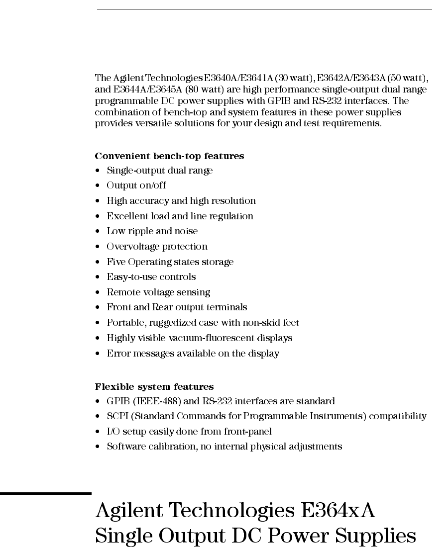
- The Front Panel at a Glance
- Front-Panel Menu/Key Reference
- Front-Panel Voltage and Current Limit Settings
- Display Annunciators
- The Rear Panel at a Glance
- In This Book
- Contents
- Quick Start
- General Information
- Front-Panel Operation and Features
- Front-Panel Operation Overview
- Constant Voltage Operation
- Constant Current Operation
- Configuring the Remote Interface
- Storing and Recalling Operating States
- Programming Overvoltage Protection
- Disabling the Output
- System-Related Operations
- GPIB Interface Reference
- RS-232 Interface Reference
- Calibration Overview
- Remote Interface Reference
- SCPI Command Summary
- Simplified Programming Overview
- Using the APPLy Command
- Output Setting and Operation Commands
- Triggering
- System-Related Commands
- State Storage Commands
- Calibration Commands
- Interface Configuration Commands
- The SCPI Status Registers
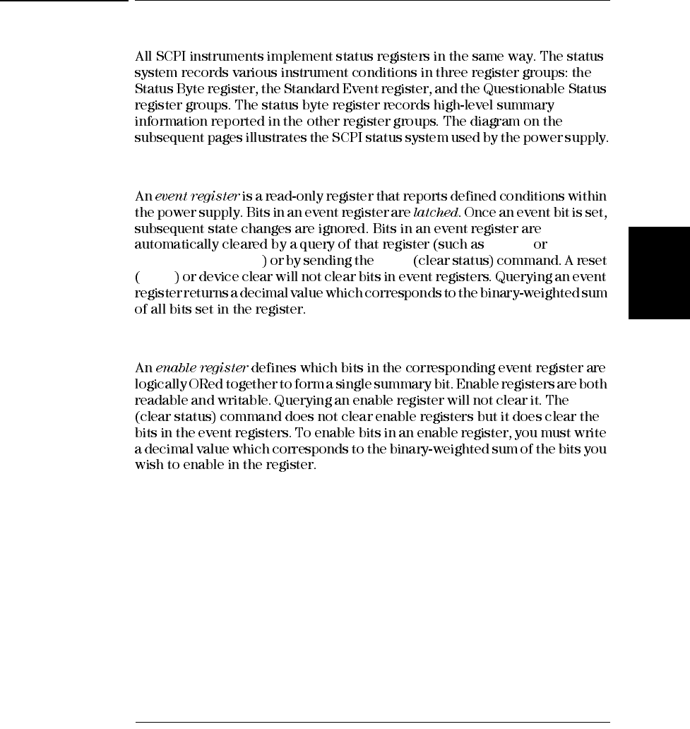
- What is an Event Register?
- What is an Enable Register?
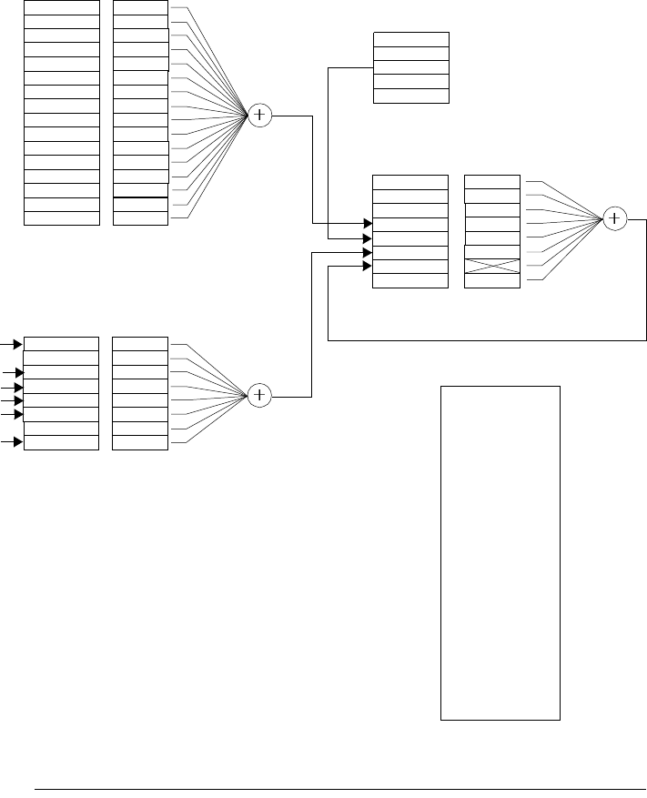
- SCPI Status System
- The Questionable Status Register
- The Standard Event Register
- The Status Byte Register
- Using Service Request (SRQ) and Serial POLL
- Using *STB? to Read the Status Byte
- Using the Message Available Bit (MAV)
- To Interrupt Your Bus Controller Using SRQ
- To Determine When a Command Sequence is Completed
- Using *OPC to Signal When Data is in the Output Buffer
- Status Reporting Commands
- An Introduction to the SCPI Language
- Halting an Output in Progress
- SCPI Conformance Information
- IEEE-488 Conformance Information
- Error Messages
- Application Programs
- Tutorial
- Specifications
- Service Information
- Operating Checklist
- Types of Service Available
- Repacking for Shipment
- Electrostatic Discharge (ESD) Precautions
- Surface Mount Repair
- To Replace the Power-Line Fuse
- Troubleshooting Hints
- Self-Test Procedures
- General Disassembly
- Recommended Test Equipment
- Test Considerations
- Operation Verification and Performance Tests
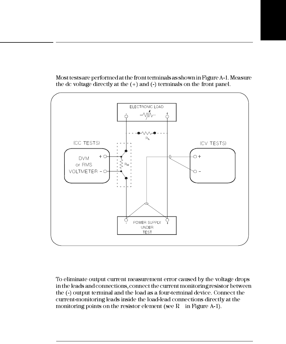
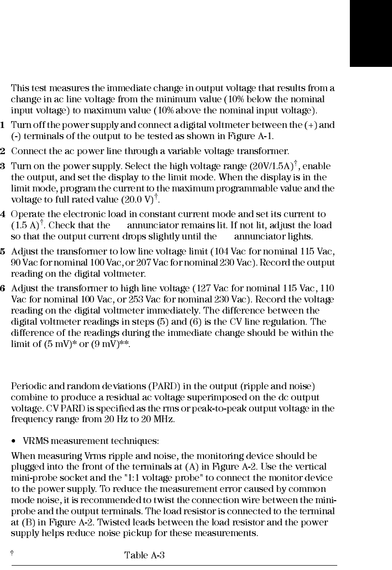
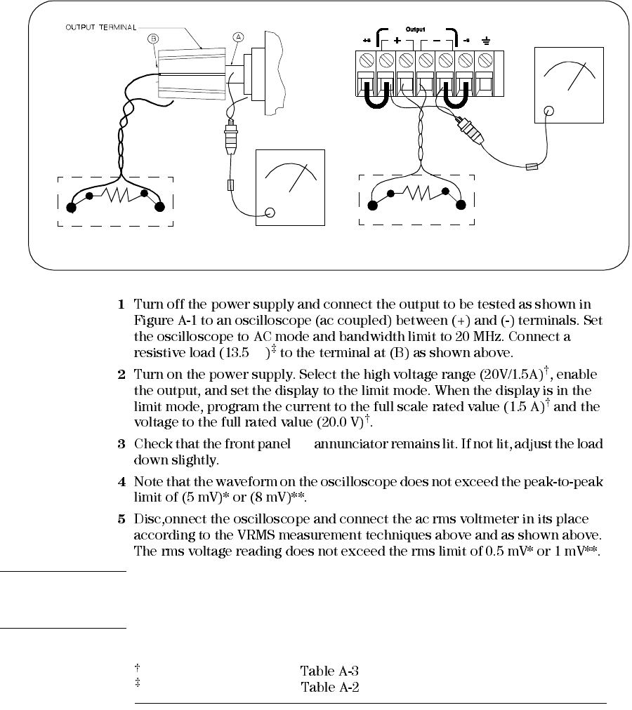
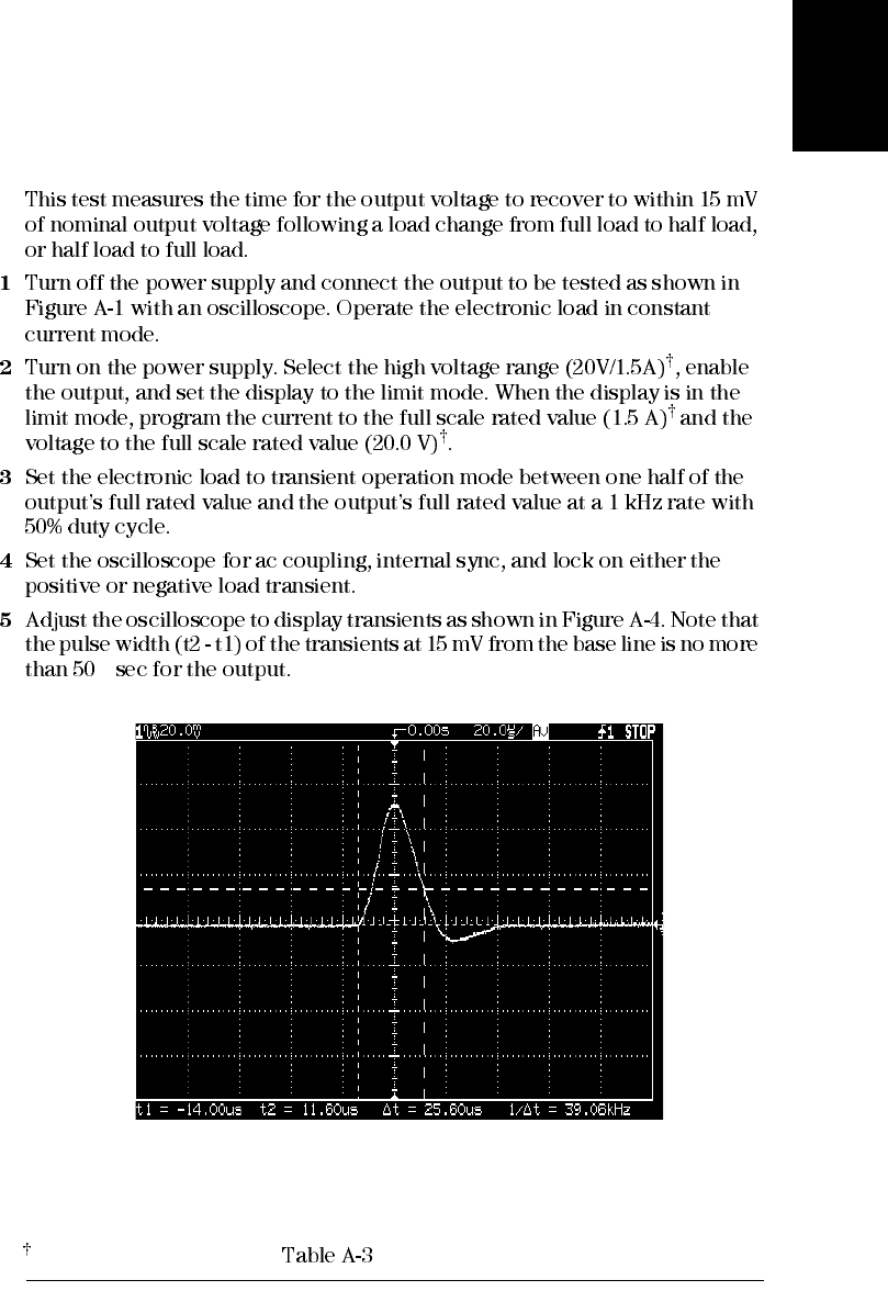
- Measurement Techniques
- Constant Voltage (CV) Verifications
- Constant Current (CC) Verifications
- Common Mode Current Noise
- Performance Test Record for Your Power Supply
- Calibration Reference
- General Calibration/Adjustment Procedure
- Calibration Record for Your Power Supply
- Calibration Error Messages
- Schematics
- Index
User’s Guide
2
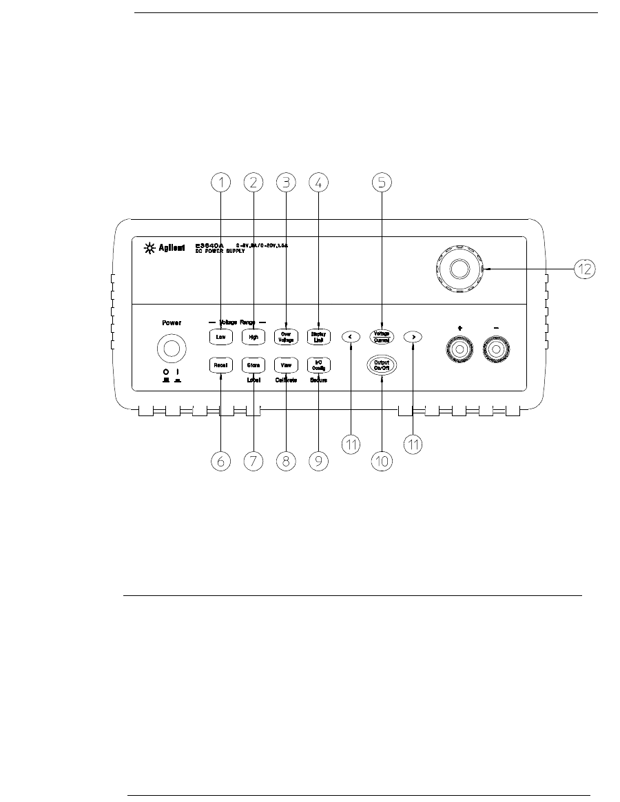
The Front Panel at a Glance
1 Low voltage range selection Key
2 High voltage range selection Key
3 Overvoltage protection Key
4 Display limit Key
5 Voltage/Current adjust selection Key
6 Stored state Recall/Reset Menu
7 State storage menu/Local Key
8 View menu/Calibrate Key
9 I/O Configuration menu/Secure Key
10 Output On/Off Key
11 Resolution selection Keys
12 Knob
3
Front-Panel Menu/Key Reference
1 Low voltage range selection key Selects the low voltage range and allows
its full rated output to the output terminals.
2 High voltage range selection key Selects the high voltage range and allows
its full rated output to the output terminals.
3 Overvoltage protection key Enables or disables the overvoltage protection
function, sets trip voltage level, and clears the overvoltage condition.
4 Display limit key Shows voltage and current limit values on the display and
allows the knob adjustment for setting limit values.
5 Voltage/Current adjust selection key Selects the knob control function for
voltage or current adjustment.
6 Stored state recall menu Recalls a stored operating state from location ‘‘1’’
through ‘‘5’’ and resets the power supply to the power-on state (*RST
command) from the front panel by selecting the ‘‘RESET’’ from this menu.
7 State storage menu / Local key1 Stores up to five power supply’s states in
non-volatile memory and assigns a name to each of the storage locations / or
returns the power supply to local mode from remote interface mode.
8 View menu / Calibrate key2 Views the error codes and the text of the error
message, calibration string, and system firmware revision / or enables
calibration mode.
9 I/O Configuration / Secure key3 Configures the power supply for remote
interfaces / or secures or unsecures the power supply for calibration.
10 Output On/Off key Enables or disables the power supply output. This key
toggles between on and off.
11 Resolution selection keys Move the flashing digit to the right or left and
adjust the scrolling speed of the text being displayed in the View menu.
12 Knob Increases or decreases the value of the flashing digit by turning
clockwise or counter clockwise.
1Local
2
3
4
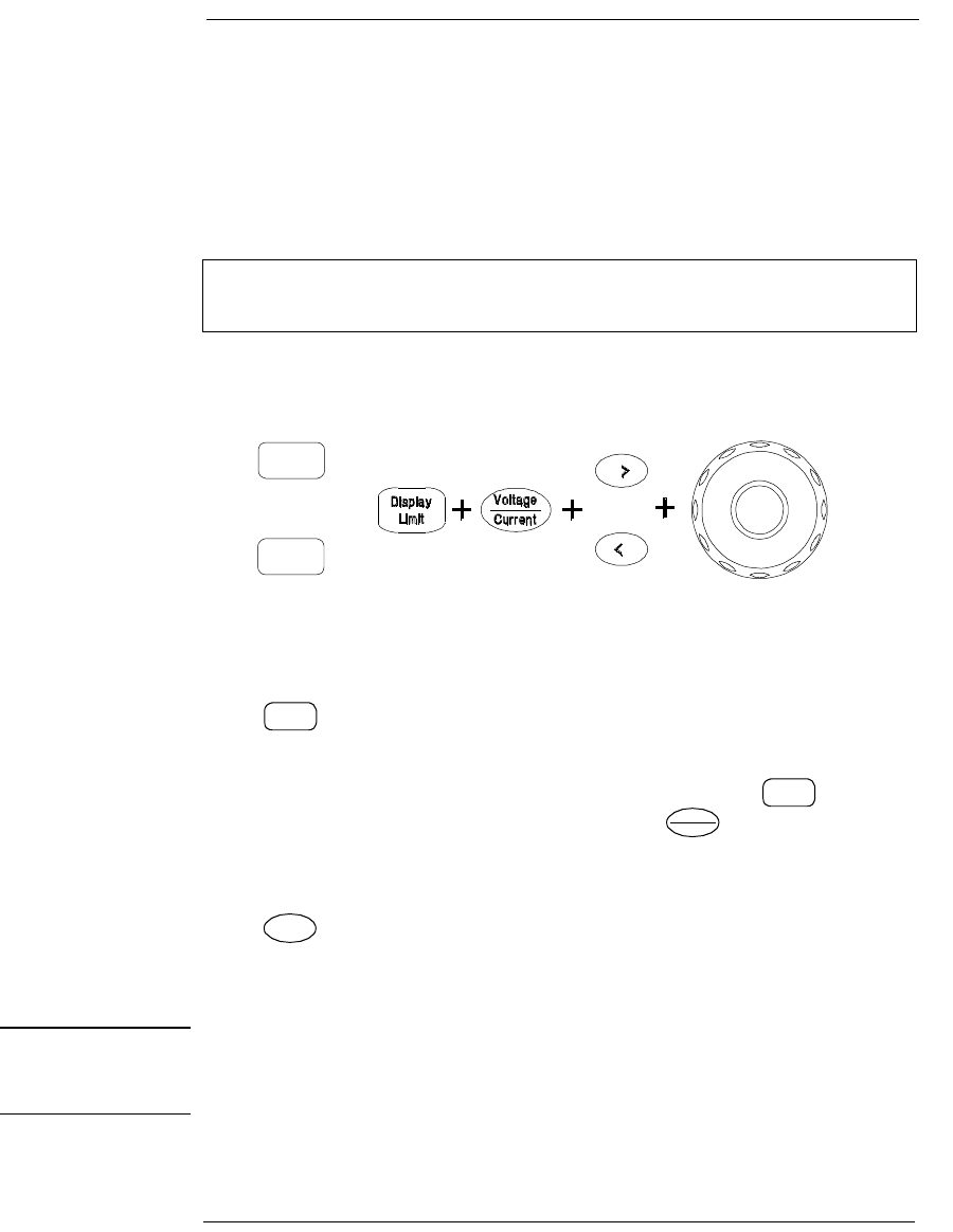
Front-Panel Voltage and Current Limit Settings
You can set the voltage and current limit values from the front panel using the
following method.
1Select the desired voltage range using the voltage range selection keys after
turning on the power supply.
2Press key to show the limit values on the display.
3Move the blinking digit to the appropriate position using the resolution
selection keys and change the blinking digit value to the desired voltage limit
by turning the control knob. If the display limit times out, press key again.
4Set the knob to current control mode by pressing key.
5Move the blinking digit to the appropriate position using the resolution
selection keys and change the blinking digit value to the desired current limit
by turning the control knob.
6Press key to enable the output. After about 5 seconds, the display will
go to output monitoring mode automatically to display the voltage and current
at the output.
Note All front panel keys and controls can be disabled with remote interface commands.
The power supply must be in "Local" mode for the front panel keys and controls to
function.
Use the voltage/current adjust selection key, the resolution selection keys,
and the control knob to change the voltage and current limit values.
+
Low
High
Or
Display
Limit
Display
Limit
Current
Voltage
On/Off
Output
5
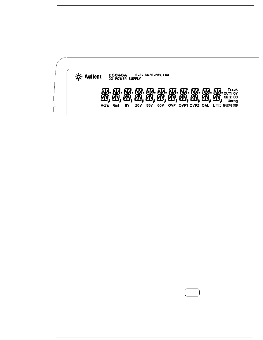
Display Annunciators
Adrs Power supply is addressed to listen or talk over a remote interface.
Rmt Power supply is in remote interface mode.
8V* Shows the low voltage range is selected.
20V* Shows the high voltage range is selected.
35V** Shows the low voltage range is selected.
60V** Shows the high voltage range is selected.
OVP The overvoltage protection function is enabled when the
annunciator turns on or the overvoltage protection circuit has
caused the power supply to shutdown when the annunciator blinks.
CAL The power supply is in calibration mode.
Limit The display shows the limit values of voltage and current.
ERROR Hardware or remote interface command errors are detected and
the error bit has not been cleared.
OFF The output of the power supply is disabled (See page 54 for more
information).
Unreg The output of the power supply is unregulated (output is neither CV
nor CC).
CV The power supply is in constant voltage mode.
CC The power supply is in constant current mode.
To review the display annunciators, hold down key as you turn on
the power supply.
Display
Limit
*For E3640A/42A/44A model. **For E3641A/43A/45A model.
6
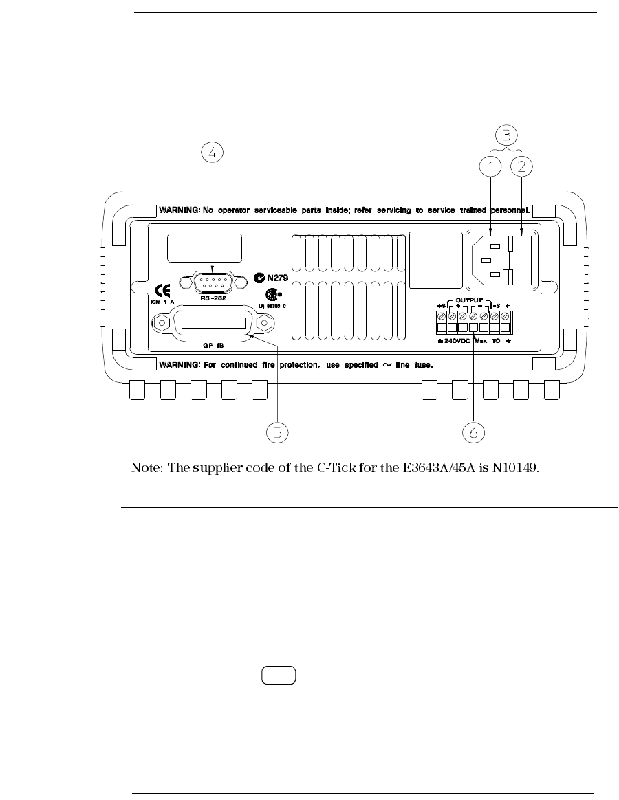
The Rear Panel at a Glance
Use the front-panel key to:
• Select the GPIB or RS-232 interface (see chapter 3).
• Set the GPIB address (see chapter 3).
• Set the RS-232 baud rate and parity (see chapter 3).
1 AC inlet
2 Power-line fuse-holder assembly
3 Power-line module
4 RS-232 interface connector
5 GPIB (IEEE-488) interface connector
6 Rear output terminals
I/O
Config
7
In This Book
If you have questions relating to the operation of the power supply, call
1-800-829-4444 in the United States, or contact your nearest Agilent
Technologies Sales Office.
If your power supply fails within one year of purchase, Agilent will repair
or replace it free of charge. Call 1-800-258-5165 ("Express Exchange") in
the United States, or contact your nearest Agilent Technologies Sales Office.
8
DECLARATION OF CONFORMITY
According to ISO/IEC Guide 22 and CEN/CENELEC EN 45014
Revision: B.00.00 Issue Date: Created on 11/24/2003 3:07
PM
Document No. KIO_40-49.11.24.doc
Manufacturer’s Name and Addresss
Responsible Party Alternate Manufacturing Site
Agilent Technologies, Inc. Agilent Technologies (Malaysia) Sdn. Bhd
550 Clark Drive, Suite 101
Budd Lake, New Jersey 07828
USA
Malaysia Manufacturing
Bayan Lepas Free Industrial Zone, PH III
11900 Penang,
Malaysia
Declares under sole responsibility that the product as originally delivered
Product Name: a) Single Output dc Power Supplies
b) Multiple Output dc Power Supplies
c) Single Output System Power Supply
Model Nu mber: a) E3640A, E3641A, E3642A, E3643A, E3644A, E3645A
b) E3646A, E3647A, E3648A, E3649A
c) E3633A, E3634A
Product Options: This declaration covers all options of the above product(s).
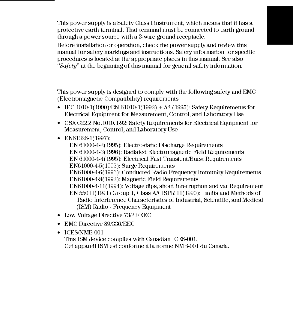
Complies with the essential requirements of the Low Voltage Directive 73/23/EEC and the EMC
Directive 89/336/EEC (including 93/68/EEC) and carries the CE Marking accordingly.
EMC Information ISM Group 1 Class A Emissions
As detailed in Electromagnetic Compatibility (EMC), Certificate of Conformance Number
CC/TCF/00/102 based on Technical Construction File (TCF) ANJ12, dated Dec
20, 2000.
Assessed by: Celestica Ltd, Appointed Competent Body
Westfields House, West Avenue
Kidsgrove, Stoke-on-Trent
Straffordshire, ST7 1TL
United Kingdom
Safety Information and Conforms to the following safety standards.
IEC 61010-1:2001 / EN 61010-1:2001
CSA C22.2 No. 1010.1:1992
This DoC applies to above-listed products placed on the EU market after:
January 1, 2004
Date Bill Darcy/ Regulations Manager
For further information, please contact your local Agilent Technologies sales office, agent or distributor, or
Agilent Technologies Deutschland GmbH, Herrenberger Stra
β
e 130, D71034 Böblingen, Germany


14
Contents
Contents

1
Quick Start
16
Quick Start
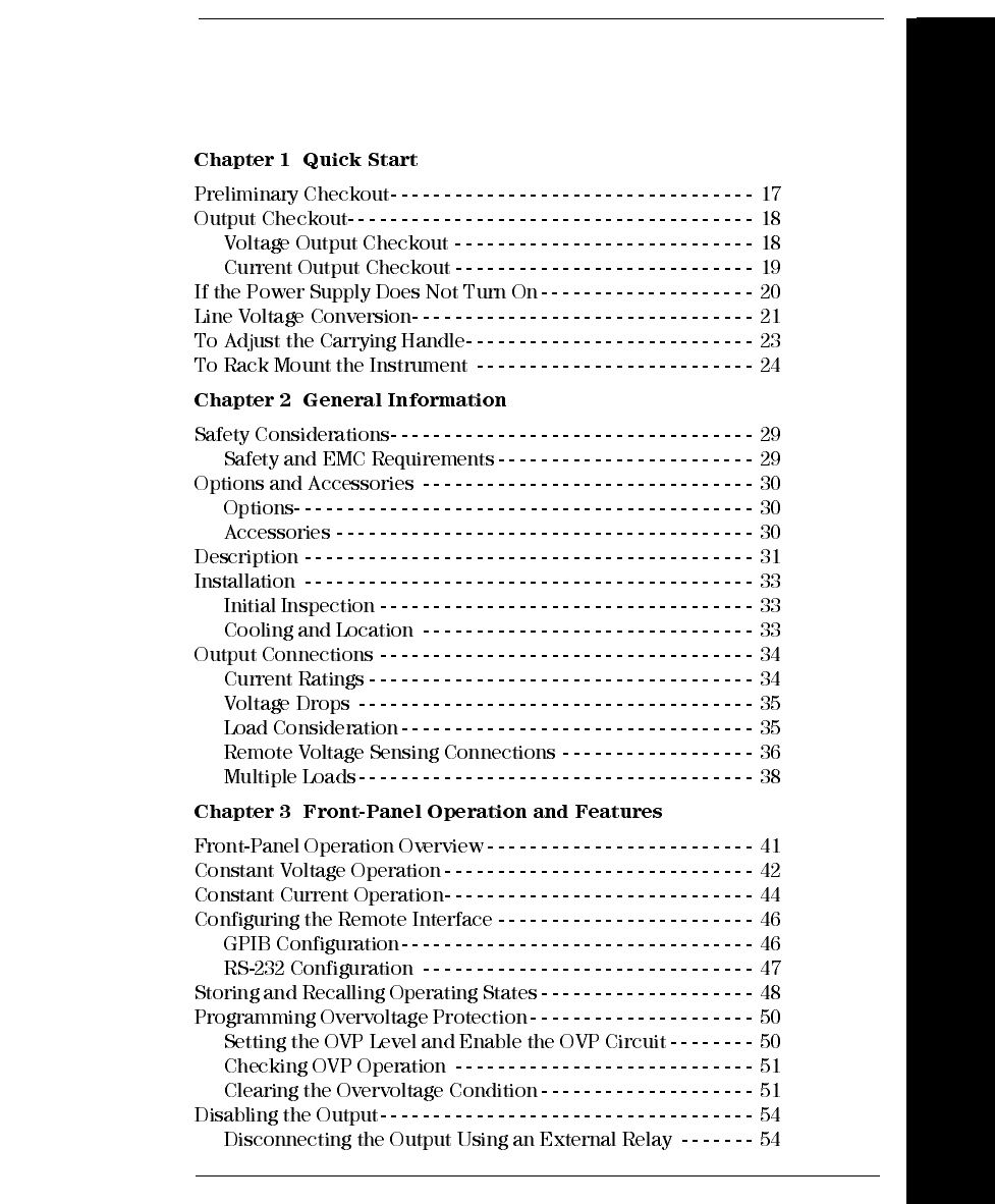
Chapter 1 Quick Start
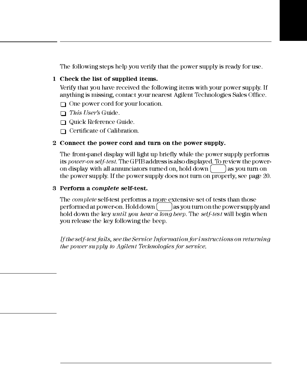
Preliminary Checkout
17
1
Preliminary Checkout
Note The power supply is shipped from the factory with a power-line cord that has a plug
appropriate for your location. Your power supply is equipped with a 3-wire grounding
type power cord; the third conductor being the ground. The power supply is grounded
only when the power-line cord is plugged into an appropriate receptacle. Do not
operate your power supply without adequate cabinet ground connection.
Display
Limit
Display
Limit
Chapter 1 Quick Start
If the Power Supply Does Not Turn On
20
If the Power Supply Does Not Turn On
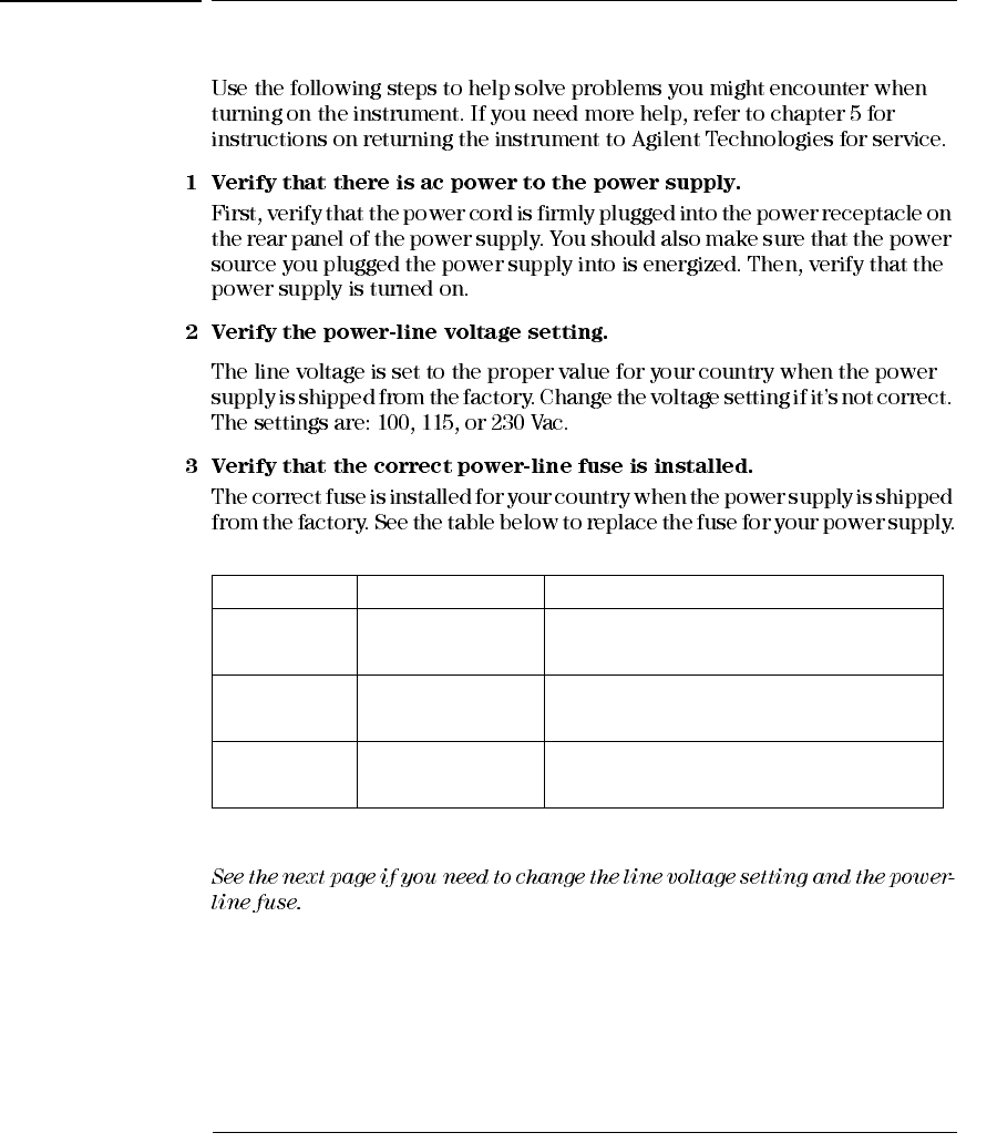
Model Agilent Part Number Part Description
E3640A/41A 2110-1069 Fuse 1.5A T 125V for 100 and 115 Vac
E3640A/41A 2110-0457 Fuse 1A T 250V for 230 Vac
E3642A/43A 2110-1070 Fuse 2.5A T 125V for 100 and 115 Vac
E3642A/43A 2110-0457 Fuse 1A T 250V for 230 Vac
E3644A/45A 2110-1071 Fuse 3.15A T 125V for 100 and 115 Vac
E3644A/45A 2110-1068 Fuse 2A T 250V for 230 Vac
Chapter 1 Quick Start
Line Voltage Conversion
22
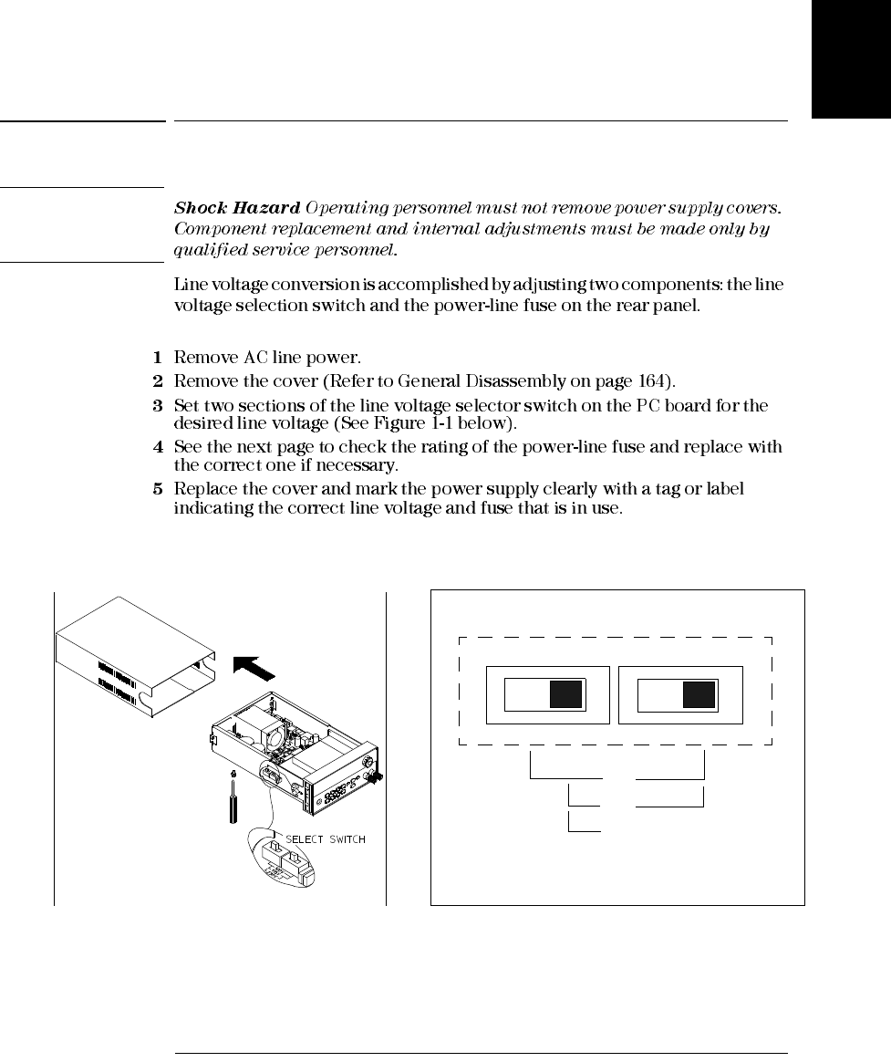
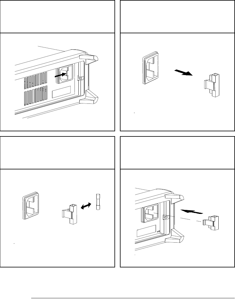
1 Remove the power cord. Remove
the fuse-holder assembly with a flat-
blade screwdriver from the rear panel.
2 Remove the fuse-holder from the
assembly.
3 Replace with the correct fuse. 4 Replace the fuse-holder assembly in
rear panel.
Verify that the correct line voltage is selected and the power-line fuse is good.
Chapter 1 Quick Start
To Adjust the Carrying Handle
23
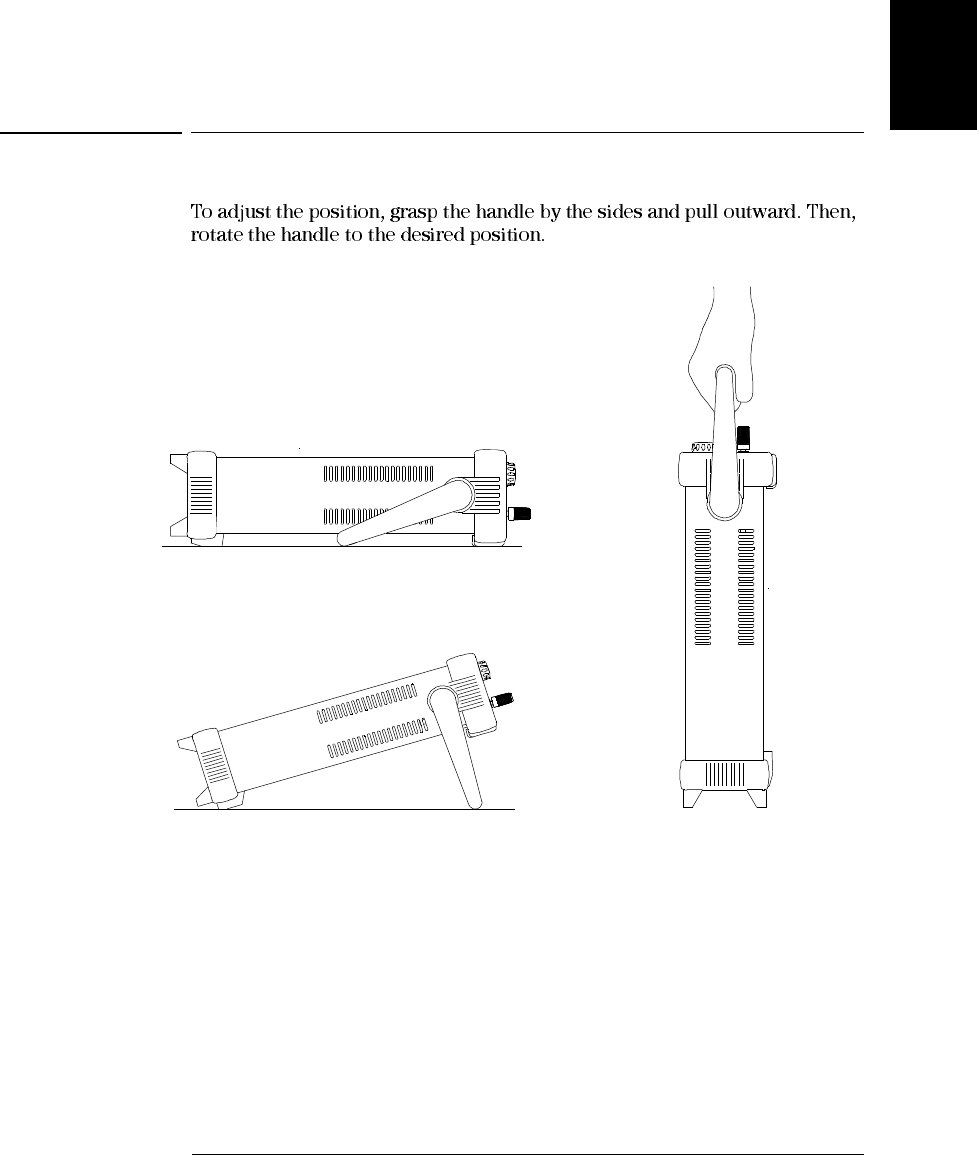
1
To Adjust the Carrying Handle
Bench-top viewing positions Carrying position
Chapter 1 Quick Start
To Rack Mount the Instrument
24
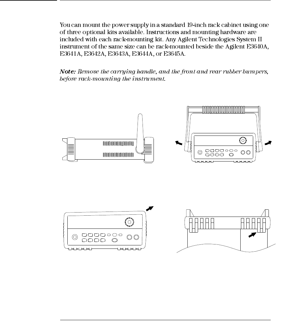
To Rack Mount the Instrument
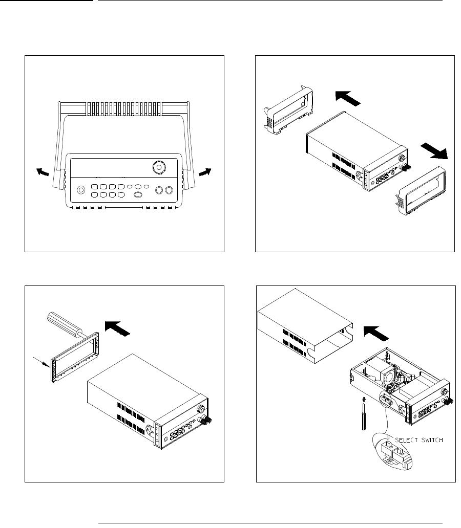
To remove the handle, rotate it to the vertical position and pull the ends outward.
To remove the rubber bumper, stretch a corner and then slide it off.
Front Rear (bottom view)
Chapter 1 Quick Start
To Rack Mount the Instrument
25
1
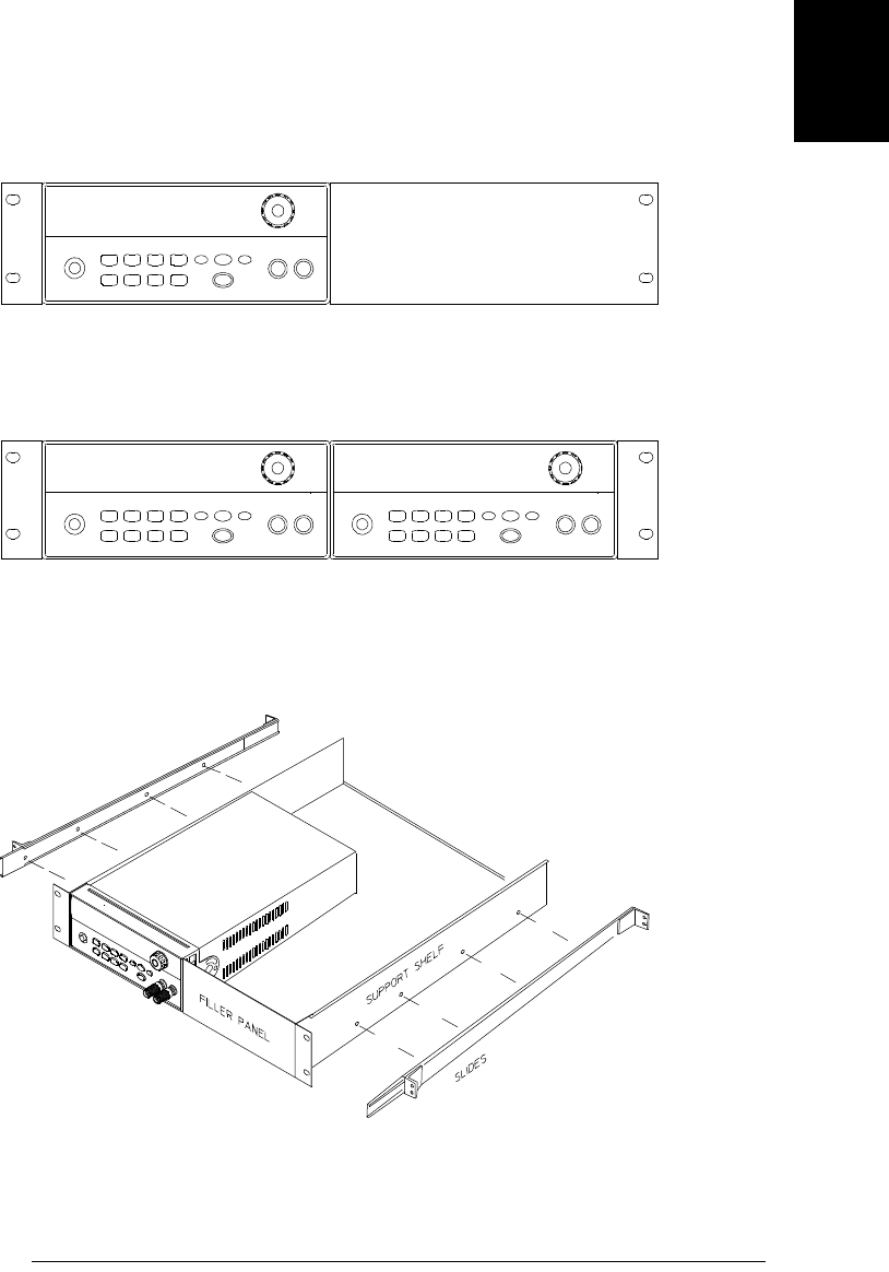
To rack mount a single instrument, order adapter kit 5063-9240.
To rack mount two instruments side-by-side, order lock-link kit 5061-9694 and
flange kit 5063-9212. Be sure to use the support rails inside the rack cabinet.
To install two instruments in a sliding support shelf, order support shelf 5063-9255,
and slide kit 1494-0015.

Chapter 1 Quick Start
To Rack Mount the Instrument
26

2
General Information
Chapter 2 General Information
Safety Considerations
29
2
Safety Considerations
Safety and EMC Requirements

Chapter 2 General Information
Description
31
2
Description
Chapter 2 General Information
Description
32
Warning Floating the power supply output more than ±60 Vdc from the chassis presents an
electric shock hazard to the operator. Do not float the outputs more than ±60 Vdc
when uninsulated sense wires are used to connect the (+) output to the (+) sense and
the (-) output to the (-) sense terminals on the back of the unit.
1. Float voltage +/-60 Vdc Max to ( )
(shorting conductors without insulation)
2. Float voltage +/-240 Vdc Max to ( )
(Insulated shorting conductors)
(Rear Output Terminals)
Chapter 2 General Information
Installation
33
2
Installation
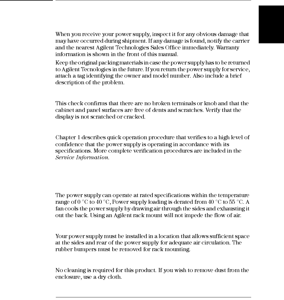
Initial Inspection
Mechanical Check
Electrical Check
Cooling and Location
Cooling
Bench Operation
Cleaning
Chapter 2 General Information
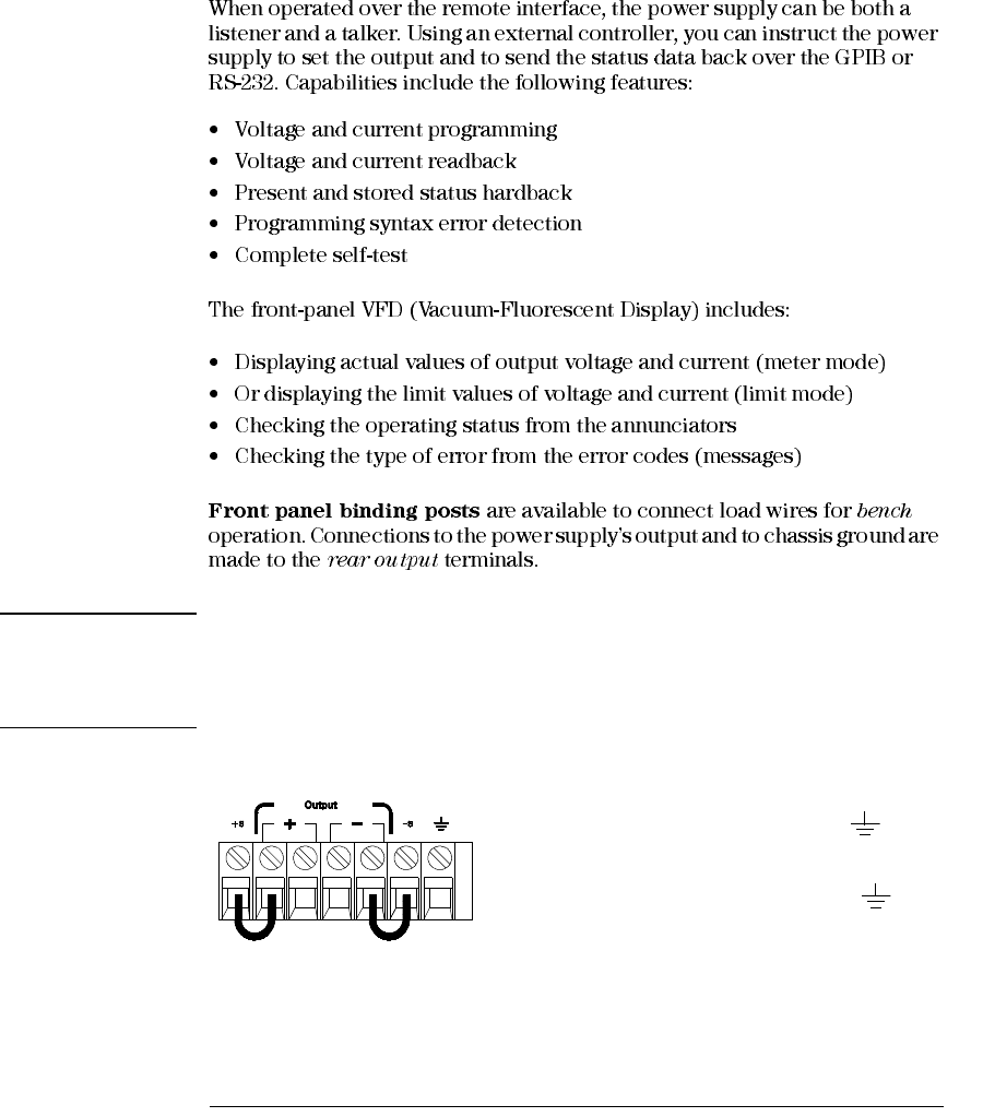
Output Connections
34
Output Connections
Warning Before attempting to connect wires to the rear output terminals, make sure to turn
off the power supply first to avoid damage to the circuits being connected.
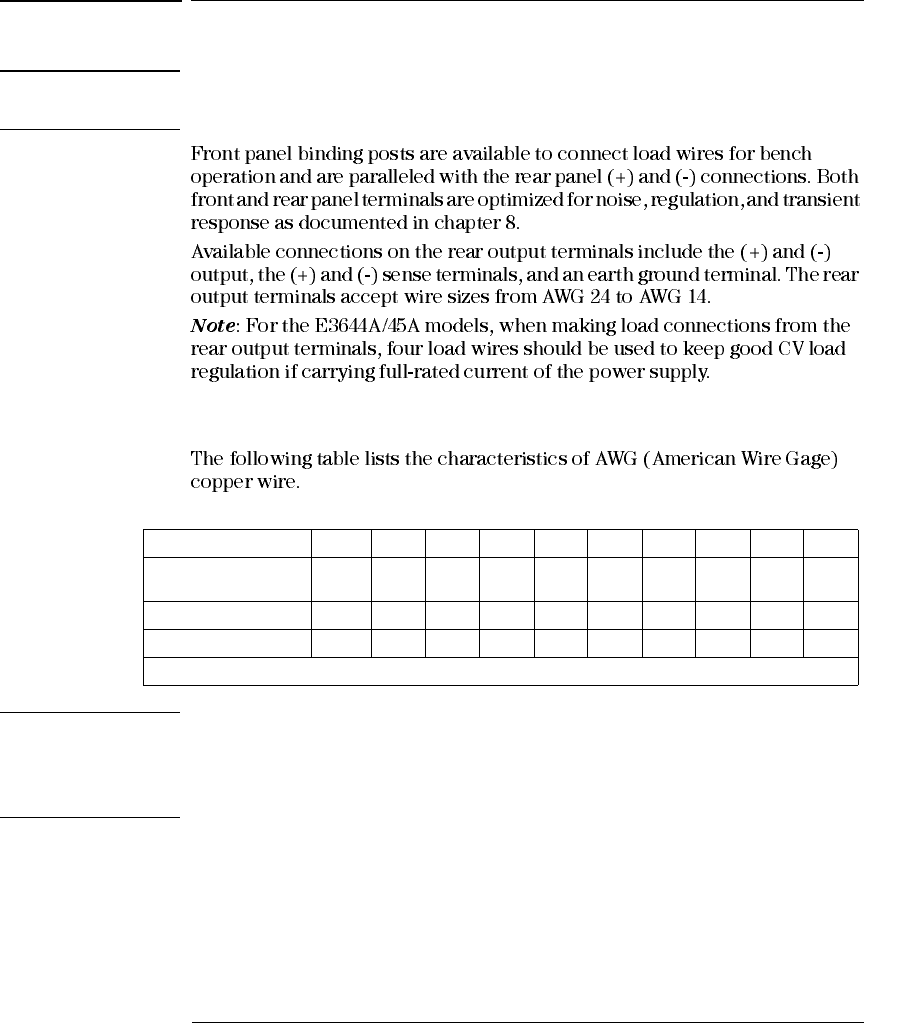
Current Ratings
Table 2-1 Wire Rating
Warning To satisfy safety requirements, load wires must be heavy enough not to overheat when
carrying the maximum short-circuit output current of the power supply. If there is
more than one load, then any pair of load wires must be capable of safety carrying
the full-rated current of the power supply.
AWG 10 12 14 16 18 20 22 24 26 28
Suggested maximum
Current(amps)* 40 25 20 13 10 7 5 3.5 2.5 1.7
mΩ/ft 1.00 1.59 2.53 4.02 6.39 10.2 16.1 25.7 40.8 64.9
mΩ/m3.3 5.2 8.3 13.2 21.0 33.5 52.8 84.3 133.9 212.9
*Single conductor in free air at 30 °C with insulation

Chapter 2 General Information
Output Connections
35
2
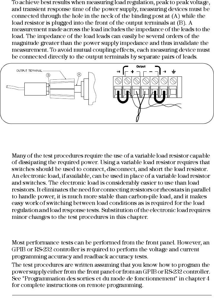
Voltage Drops
Load Consideration
Capacitive Loading
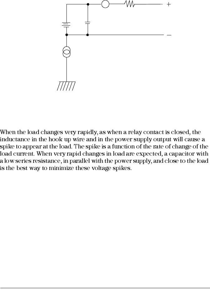
Inductive loading
Pulse Loading
Chapter 2 General Information
Output Connections
36
Reverse Current Loading
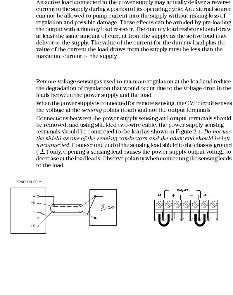
Remote Voltage Sensing Connections
Figure 2-1. Remote Voltage Sensing Connections Figure 2-2. Local Sensing Connections
Chapter 2 General Information
Output Connections
37
2
Stability
Note During remote sensing setup, it is strongly recommended to power off (by presssing
power ON/OFF button) the power supply to avoid undesirable damage to the load or
the power supply.
CV Regulation
Ω
Output Rating
Unreg
Output Noise
Chapter 2 General Information
Output Connections
38
Multiple Loads

3
Front-Panel Operation and Features
Chapter 3 Front-Panel Operation and Features
Constant Voltage Operation
42
Constant Voltage Operation
OFF
8V
20V 60V
Limit
Limit
Power
High
Display
Limit
Current
Voltage
Chapter 3 Front-Panel Operation and Features
Constant Voltage Operation
43
3
Limit
Limit
OUTPUT OFF
OFF CV
CV CC
Note During actual CV operation, if a load change causes the current limit to be exceeded,
the power supply will automatically crossover to the constant current mode at the
preset current limit and the output voltage will drop proportionately.
CURRent {<current>|MIN|MAX} Set the current
VOLTage {<voltage>|MIN|MAX} Set the voltage
OUTPut ON Enable the output
Current
Voltage
Display
Limit
Display
Limit
On/Off
Output
Chapter 3 Front-Panel Operation and Features
Constant Current Operation
44
Constant Current Operation
OFF
8V
20V 60V
Limit
Limit
Power
High
Display
Limit
Chapter 3 Front-Panel Operation and Features
Constant Current Operation
45
3
Limit
Limit
OUTPUT OFF
OFF CC
CC CV
Note During actual CC operation, if a load change causes the voltage limit to be exceeded,
the power supply will automatically crossover to constant voltage mode at the preset
voltage limit and the output current will drop proportionately.
VOLTage {<voltage>|MIN|MAX} Set the voltage
CURRent {<current>|MIN|MAX} Set the current
OUTPut ON Enable the output
1
Current
Voltage
Display
Limit
Display
Limit
On/Off
Output
Chapter 3 Front-Panel Operation and Features
Configuring the Remote Interface
46
Configuring the Remote Interface
NO
CHANGE
*RST
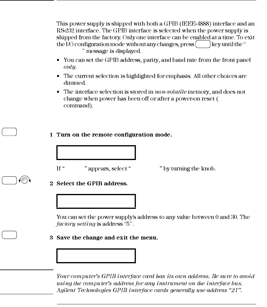
GPIB Configuration
RS-232 GPIB / 488
Note
GPIB / 488
ADDR 05
SAVED
I/O
Config
I/O
Config
I/O
Config
I/O
Config
Chapter 3 Front-Panel Operation and Features
Configuring the Remote Interface
47
3
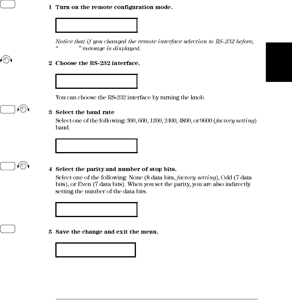
RS-232 Configuration
RS-232
GPIB / 488
RS-232
9600 BAUD
NONE 8 BITS
SAVED
I/O
Config
I/O
Config
I/O
Config
I/O
Config
Chapter 3 Front-Panel Operation and Features
Storing and Recalling Operating States
48
Storing and Recalling Operating States
EXIT
NAME STATE
Storing Operating State
STORE STATE
Name STATE
1:p15v_test
2: STatE2
Store
Store
Store
Store
Chapter 3 Front-Panel Operation and Features
Storing and Recalling Operating States
49
3
RESET
*RST
*RST
*SAV {1|2|3|4|5} Store an operating state to a specified location
*RCL {1|2|3|4|5} Recall a previously stored state from a specified
location
MEM:STATE:NAME 1, P15V_TEST
Name the storage location 1 as P15V_TEST .
DONE
Recalling a Stored State
1: p15v_test
2: state2
reset
done
Store
Recall
Recall
Chapter 3 Front-Panel Operation and Features
Programming Overvoltage Protection
50
Programming Overvoltage Protection
Setting the OVP Level and Enable the OVP Circuit
NO CHANGE
OVP
LEVEL 22.0V (E3640A)
OVP ON
CHANGED
Power
Over
Voltage
<
>
Over
Voltage
Over
Voltage
Chapter 3 Front-Panel Operation and Features
Programming Overvoltage Protection
51
3
Checking OVP Operation
OVP
CC OVP TRIPPED
Clearing the Overvoltage Condition
OVP
OVP TRIPPED
OVP Limit
OVP
By Adjusting output voltage level
OVP ON
OVP CLEAR
done
Display
Limit
Display
Limit
Over
Voltage
Over
Voltage
Over
Voltage
Chapter 3 Front-Panel Operation and Features
Programming Overvoltage Protection
52
OVP
VOLT:PROT {<voltage>|MIN|MAX} Set the OVP level
VOLT:PROT:STAT {OFF|ON) Disable or enable the OVP circuit
VOLT:PROT:CLE Clear the tripped OVP circuit
By Adjusting OVP trip level
OVP ON
OVP CLEAR
done
Over
Voltage
Over
Voltage
Over
Voltage
Chapter 3 Front-Panel Operation and Features
Programming Overvoltage Protection
53
3
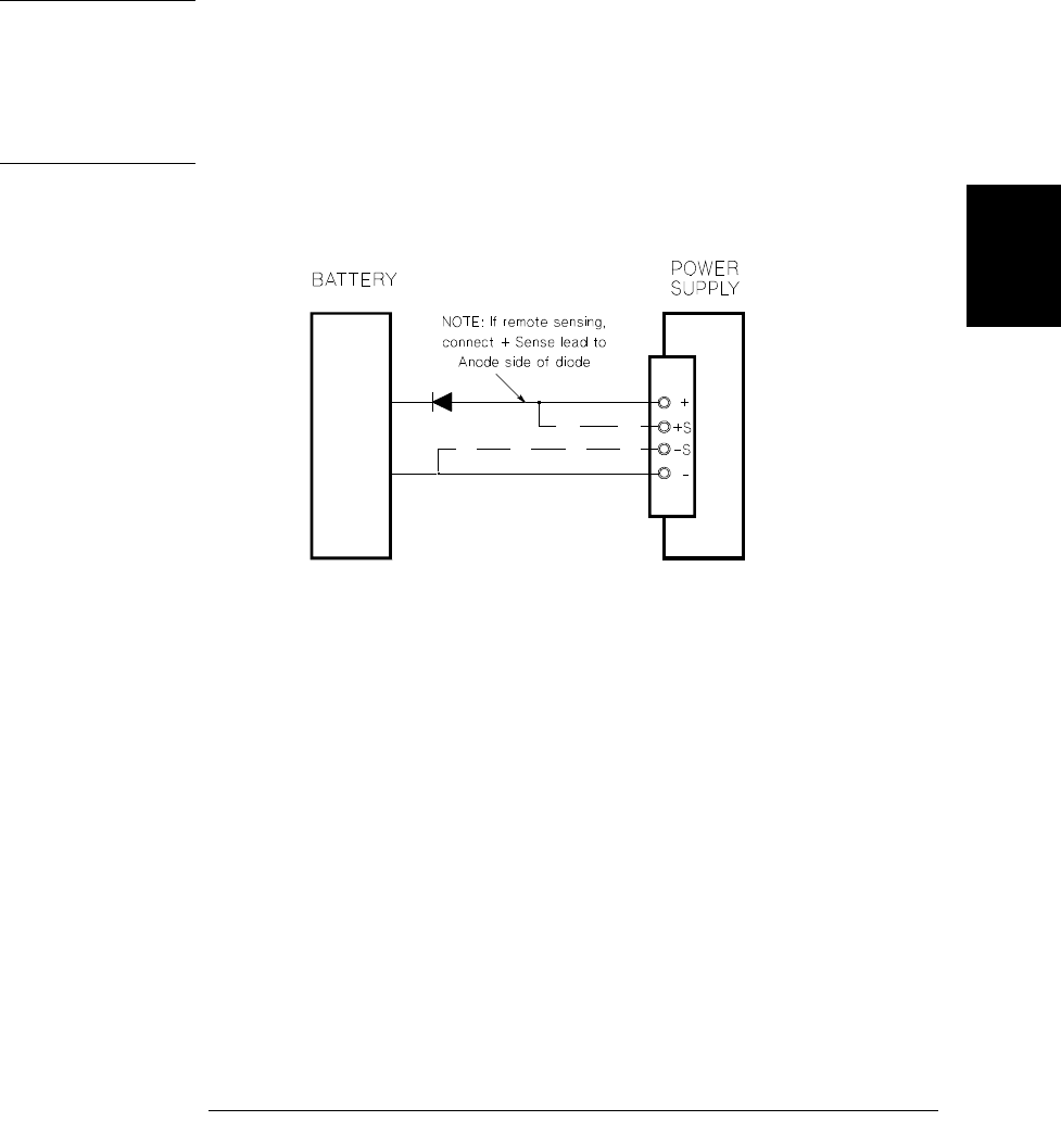
Note The power supply’s OVP circuit contains a crowbar SCR, which effectively shorts the
output of the power supply whenever the overvoltage condition occurs. If external
voltage source such as a battery is connected across the output, and the overvoltage
condition inadvertently occurs, the SCR will continuously sink a large current from
the source; possibly damaging the power supply. To avoid this a diode must be
connected in series with the output as shown in Figure 3-1.
Figure 3-1. Recommended Protection Circuit for Battery Charging
Chapter 3 Front-Panel Operation and Features
Disabling the Output
54
Disabling the Output
OFF
OFF
output Off
OUTP {OFF|ON}
Disconnecting the Output Using an External Relay
OUTPut:RELay {OFF|ON}
OUTPut:RELay
OUTPut:RELay
Note Do not use the RS-232 interface if you have configured the power supply to output
relay control signals. Internal components on the RS-232 circuitry may be damaged.
<
>
Display
Limit
On/Off
Output
Chapter 3 Front-Panel Operation and Features
System-Related Operations
55
3
System-Related Operations
State Storage
*RST
STORE STATE, NAME STATE, EXIT
*RST RESET
5 states, RESET, exit
Store
Recall
Chapter 3 Front-Panel Operation and Features
System-Related Operations
57
3
Firmware Revision Query
REV X.X-Y.Y-Z.Z
*IDN?
Agilent Technologies,E3640A,0,X.X-Y.Y-Z.Z
SCPI Language Version
SYST:VERS? Query the SCPI version
View
View
Chapter 3 Front-Panel Operation and Features
RS-232 Interface Reference
60
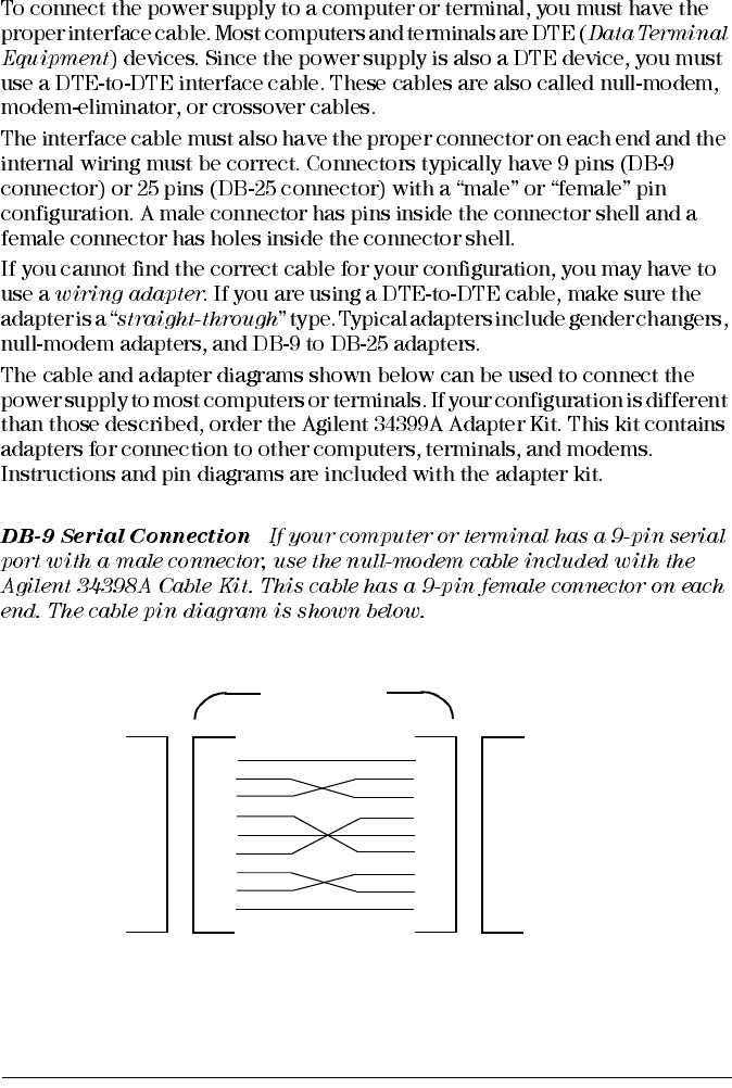
Connection to a Computer or Terminal
Instrument PC
DB9
Male DB9
Female DB9
Female DB9
Male
DCD
RX
TX
DTR
1
2
3
4
5
6
7
8
9
GND
DSR
RTS
CTS
RI
1
2
3
4
5
6
7
8
9
DCD
RX
TX
DTR
GND
DSR
RTS
CTS
RI
5182-4794
Cable
Chapter 3 Front-Panel Operation and Features
RS-232 Interface Reference
61
3
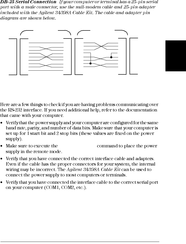
RS-232 Troubleshooting
SYSTem:REMote
Instrument PC
DB9
Male DB9
Female DB9
Female DB9
Male
DCD
RX
TX
DTR
1
2
3
4
5
6
7
8
9
GND
DSR
RTS
CTS
RI
TX
RX
RTS
CTS
DSR
GND
DCD
DTR
5182-4794
Cable 5181-6641
Adapter
1
2
3
4
5
6
7
8
9
1
2
3
4
5
6
7
8
9
2
3
4
5
6
7
8
20
DB25
Female DB25
Male
Chapter 3 Front-Panel Operation and Features
Calibration Overview
62
Calibration Overview
Calibration Security
*RST
e3640A
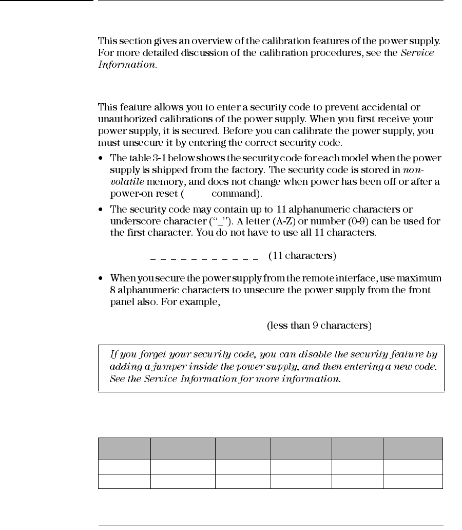
Table 3-1. Factory setting security codes
Model Security
Code Model Security
Code Model Security
Code
E3640A 003640 E3641A 003641 E3642A 003642
E3643A 003643 E3644A 003644 E3645A 003645
Chapter 3 Front-Panel Operation and Features
Calibration Overview
63
3
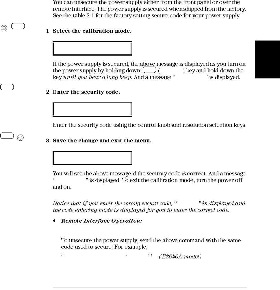
To Unsecure for Calibration
Calibrate
CAL MODE
CAL MODE
INVALID
CAL:SEC:STAT {OFF|ON},<code> Secure or unsecure the power supply
CAL:SEC:STAT OFF, 003640
SECURED
000000
UNSECURED
Power
Calibrate
View
Calibrate
View
Secure
Config
I/O
Secure
Config
I/O
Power
Chapter 3 Front-Panel Operation and Features
Calibration Overview
65
3
Secure
CAL MODE
Secure
CAL:SEC:CODE <new code> Change the security code
CAL:SEC:STAT OFF, 003640 Unsecure with old code
CAL:SEC:CODE ZZ001443 Enter new code
CAL:SEC:STAT ON, ZZ001443 Secure with new code
Calibration Count
CAL:COUN? Query the number of times of calibration
Secure
Config
I/O
Secure
Config
I/O
Chapter 3 Front-Panel Operation and Features
Calibration Overview
66
Calibration Message
CAL STRING
CAL STRING
To store the calibration message, send
CAL:STR CAL 06-01-99
View
View
>
View
View

4
Remote Interface Reference

Chapter 4 Remote Interface Reference
SCPI Command Summary
70
APPLy {<voltage>|DEF|MIN|MAX}[,{<current>|DEF|MIN|MAX}]
APPLy?
[SOURce:]
CURRent[:LEVel][:IMMediate][:AMPLitude]{<current>|MIN|MAX|UP|DOWN}
CURRent[:LEVel][:IMMediate][:AMPLitude]? [MIN|MAX]
CURRent[:LEVel][:IMMediate]:STEP[:INCRement]
{<numeric value> |DEFault}
CURRent[:LEVel][:IMMediate]:STEP[:INCRement]? [DEFault]
CURRent[:LEVel]:TRIGgered[:AMPLitude] {<current>|MIN|MAX}
CURRent[:LEVel]:TRIGgered[:AMPLitude]? [MIN|MAX]
VOLTage[:LEVel][:IMMediate][:AMPLitude]
{<voltage>|MIN|MAX|UP|DOWN}
VOLTage[:LEVel][:IMMediate][:AMPLitude]? [MIN|MAX]
VOLTage[:LEVel][:IMMediate]:STEP[:INCRement]
{<numeric value>|DEFault}
VOLTage[:LEVel][:IMMediate]:STEP[:INCRement]? [DEFault]
VOLTage[:LEVel]:TRIGgered[:AMPLitude] {<voltage>|MIN|MAX}
VOLTage[:LEVel]:TRIGgered[:AMPLitude]? [MIN|MAX]
VOLTage:PROTection[:LEVel] {<voltage>|MIN|MAX}
VOLTage:PROTection[:LEVel]? [MIN|MAX]
VOLTage:PROTection:STATe {0|1|OFF|ON}
VOLTage:PROTection:STATe?
VOLTage:PROTection:TRIPped?
VOLTage:PROTection:CLEar
VOLTage:RANGe {P8V*|P20V*|P35V**|P60V**|LOW|HIGH}
VOLTage:RANGe?
MEASure
[:SCALar]
:CURRent[:DC]?
[:VOLTage][:DC]?
Output Setting and Measurement Commands
*For Agilent E3640A/42/44A Models **For Agilent E3641A/43A/45A Models
(see page 78 for more information)

Chapter 4 Remote Interface Reference
SCPI Command Summary
71
4
INITiate[:IMMediate]
TRIGger[:SEQuence]
:DELay {<seconds>|MIN|MAX}
:DELay?[MIN|MAX]
:SOURce {BUS|IMM}
:SOURce?
*TRG
DISPlay[:WINDow]
[:STATe] {OFF|ON}
[:STATe]?
:TEXT[:DATA] <quoted string>
:TEXT[:DATA]?
:TEXT:CLEar
SYSTem
:BEEPer[:IMMediate]
:ERRor?
:VERSion?
:COMMunicate:GPIB:RDEVice:ADDRess <numeric value>
:COMMunicate:GPIB:RDEVice:ADDRess?
OUTPut
:RELay[:STATe] {OFF|ON}
:RELay[:STATe]?
[:STATe] {OFF|ON}
[:STATe]?
*IDN?
*RST
*TST?
Triggering Commands
System-Related Commands
(see page 82 for more information)
(see page 85 for more information)

Chapter 4 Remote Interface Reference
SCPI Command Summary
72
CALibration
:COUNt?
:CURRent[:DATA] <numeric value>
:CURRent:LEVel {MIN|MID|MAX}
:SECure:CODE <new code>
:SECure:STATe {OFF|ON},<quoted code>
:SECure:STATe?
:STRing <quoted string>
:STRing?
:VOLTage[:DATA] <numeric value>
:VOLTage:LEVel {MIN|MID|MAX}
:VOLTage:PROTection
STATus:QUEStionable
:CONDition?
[:EVENt]?
:ENABle <enable value>
:ENABle?
SYSTem:ERRor?
*CLS
*ESE <enable value>
*ESE?
*ESR?
*OPC
*OPC?
*PSC {0|1}
*PSC?
*SRE <enable value>
*SRE?
*STB?
*WAI
Calibration Commands
Status Reporting Commands
(see page 101 for more information)
(see page 89 for more information)
Chapter 4 Remote Interface Reference
SCPI Command Summary
73
4
SYSTem
:INTerface {GPIB|RS232}
:LOCal
:REMote
:RWLock
*SAV {1|2|3|4|5}
*RCL {1|2|3|4|5}
MEMory:STATe
:NAME {1|2|3|4|5} ,<quoted name>
:NAME? {1|2|3|4|5}
*CLS
*ESR?
*ESE <enable value>
*ESE?
*IDN?
*OPC
*OPC?
*PSC {0|1}
*PSC?
*RST
*SAV {1|2|3|4|5}
*RCL {1|2|3|4|5}
*STB?
*SRE <enable value>
*SRE?
*TRG
*TST?
*WAI
Interface Configuration Commands
State Storage Commands
IEEE-488.2 Common Commands
(see page 92 for more information)
(see page 88 for more information)
(see page 112 for more information)
Chapter 4 Remote Interface Reference
Simplified Programming Overview
74
Simplified Programming Overview
Using the APPLy Command
APPLy
APPL 3.0, 1.0
Using the Low-Level Commands
APPLy
VOLT 3.0 Set output voltage to 3.0 V
CURR 1.0 Set output current to 1.0 A
Chapter 4 Remote Interface Reference
Simplified Programming Overview
75
4
Reading a Query Response
dimension statement Dimension string array (80 elements)
SYST:ERR? Read error queue
bus enter statement Enter error string into computer
print statement Print error string
Selecting a Trigger Source
IMMediate
VOLT:TRIG 3.0 Set the triggered voltage level to 3.0 V
CURR:TRIG 1.0 Set the triggered current level to 1.0 A
TRIG:SOUR IMM Select the immediate trigger as a source
INIT Cause the trigger system to initiate
Chapter 4 Remote Interface Reference
Simplified Programming Overview
76
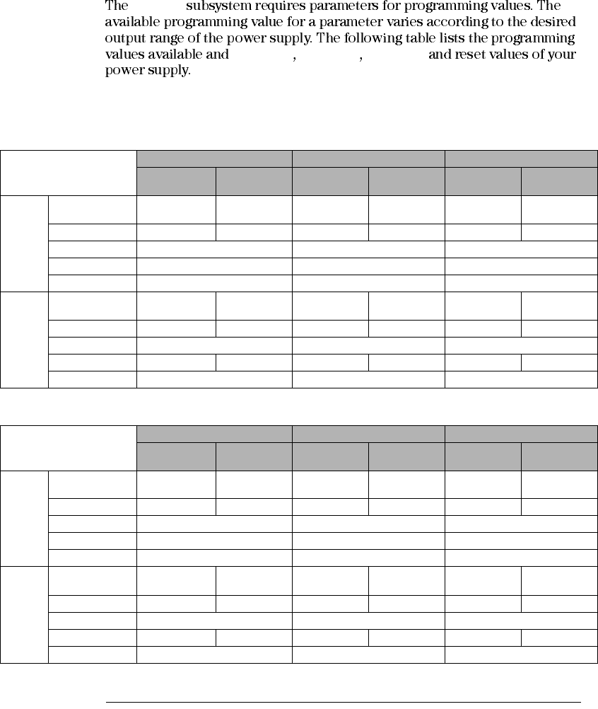
Power Supply Programming Ranges
SOURce
MINimum MAXimum DEFault
Refer to this table to identify programming values when programming the power
supply.
Table 4-1. Agilent E3640A/42A/44A Programming Ranges
Table 4-2. Agilent E3641A/43A/45A Programming Ranges
E3640A E3642A E3644A
0 - 8V/3A
Range 0 - 20V/1.5A
Range 0 - 8V/5A
Range 0 - 20V/2.5A
Range 0 - 8V/8A
Range 0 - 20V/4A
Range
Voltage Programming
Range 0 V to 8.24V 0 V to 20.60 V 0 V to 8.24V 0 V to 20.60 V 0 V to 8.24V 0 V to 20.60 V
MAX Value 8.24 V 20.60 V 8.24 V 20.60 V 8.24 V 20.60 V
MIN Value 0 V 0 V 0 V
DEFault Value 0 V 0 V 0 V
*RST Value 0 V 0 V 0 V
Current Programming
Range 0 A to 3.09 A 0 A to 1.545 A 0 A to 5.15 A 0 A to 2.575 A 0 A to 8.24 A 0 A to 4.12 A
MAX Value 3.09 A 1.545 A 5.15 A 2.575 A 8.24 A 4.12 A
MIN Value 0 A 0 A 0 A
DEFault Value 3 A 1.5 A 5 A 2.5 A 8 A 4 A
*RST Value 3.00 A 5.00 A 8.00 A
E3641A E3643A E3645A
0 - 35V/0.8A
Range 0 - 60V/0.5A
Range 0 - 35V/1.4A
Range 0 - 60V/0.8A
Range 0 - 35V/2.2A
Range 0 - 60V/1.3A
Range
Voltage Programming
Range 0 V to 36.05V 0 V to 61.8 V 0 V to 36.05V 0 V to 61.8 V 0 V to 36.05V 0 V to 61.8 V
MAX Value 36.05 V 61.8 V 36.05 V 61.8 V 36.05 V 61.8 V
MIN Value 0 V 0 V 0 V
DEFault Value 0 V 0 V 0 V
*RST Value 0 V 0 V 0 V
Current Programming
Range 0 A to 0.824 A 0 A to 0.515 A 0 A to 1.442 A 0 A to 0.824 A 0 A to 2.266 A 0 A to 1.339 A
MAX Value 0.824 A 0.515 A 1.442 A 0.824 A 2.266 A 1.339 A
MIN Value 0 A 0 A 0 A
DEFault Value 0.8 A 0.5 A 1.4 A 0.8 A 2.2 A 1.3 A
*RST Value 0.8 A 1.4 A 2.2 A

Chapter 4 Remote Interface Reference
Using the APPLy Command
77
4
Using the APPLy Command
APPLy
APPLy {<voltage>| DEF | MIN | MAX}[,{<current>| DEF | MIN | MAX}]
VOLTage CURRent
APPLy
MINimum MAXimum DEFault
APPLy
APPLy?
Chapter 4 Remote Interface Reference
Output Setting and Operation Commands
78
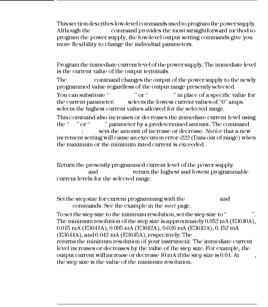
Output Setting and Operation Commands
APPLy
CURRent{<current>| MINimum | MAXimum | UP | DOWN}
CURRent
MINimum MAXimum
MIN MAX
UP DOWN
CURRent STEP
CURRent? [MINimum | MAXimum]
CURR? MAX CURR? MIN
CURRent:STEP {<numeric value>| DEFault}
CURRent UP CURRent
DOWN
DEFault
CURR:STEP? DEF
*RST
Chapter 4 Remote Interface Reference
Output Setting and Operation Commands
79
4
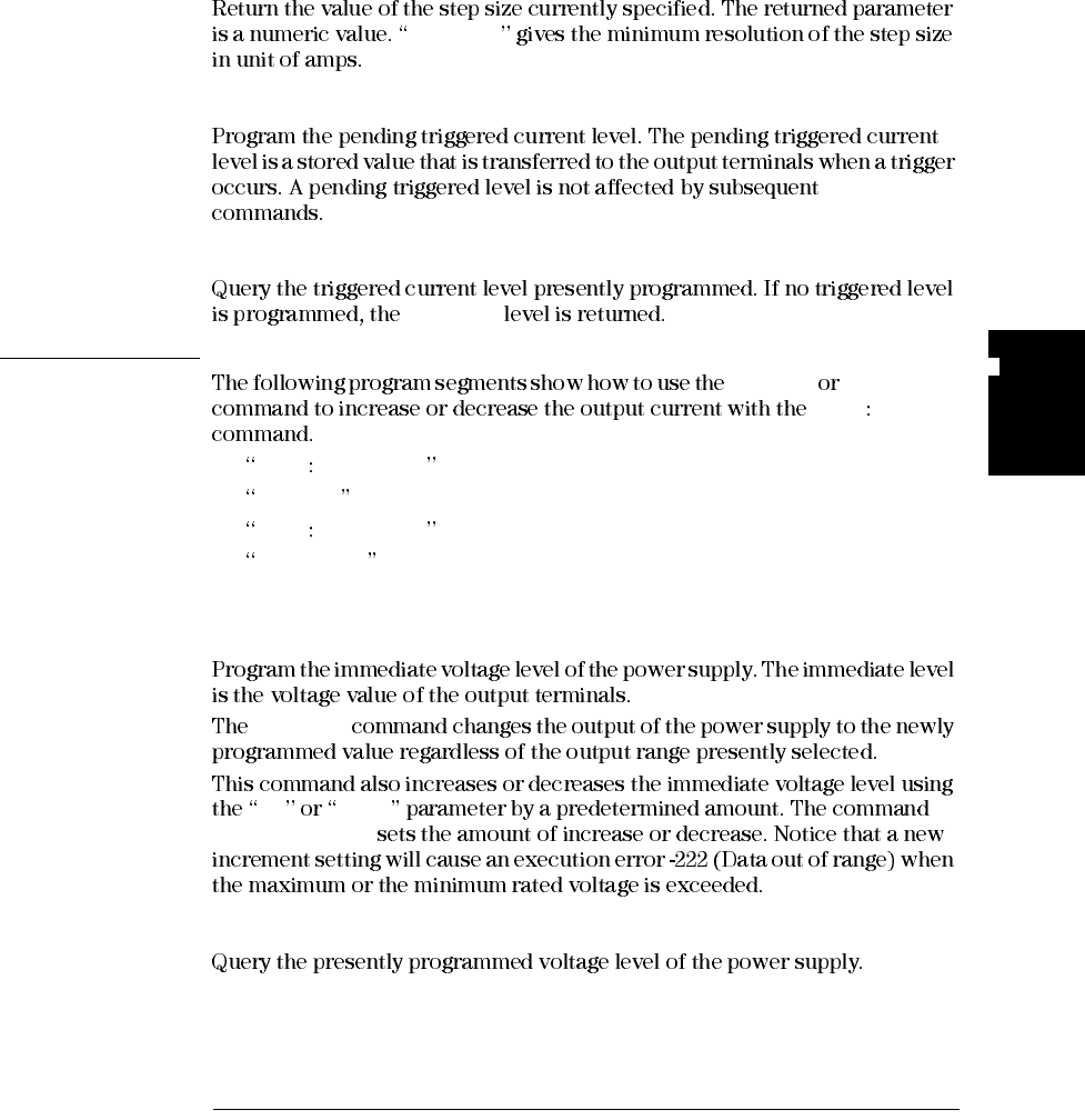
CURRent:STEP? [DEFault]
DEFault
CURRent:TRIGgered {<current>| MINimum | MAXimum}
CURRent
CURRent:TRIGgered? [MINimum | MAXimum]
CURRent
Example CURR UP CURR DOWN
CURR STEP
CURR STEP 0.01 Set the step size to 0.01 A
CURR UP Increase the output current
CURR STEP 0.02 Set the step size to 0.02 A
CURR DOWN Decrease the output current
VOLTage {<voltage>| MINimum | MAXimum | UP | DOWN}
VOLTage
UP DOWN
VOLTage:STEP
VOLTage? [MINimum | MAXimum]
Chapter 4 Remote Interface Reference
Output Setting and Operation Commands
80
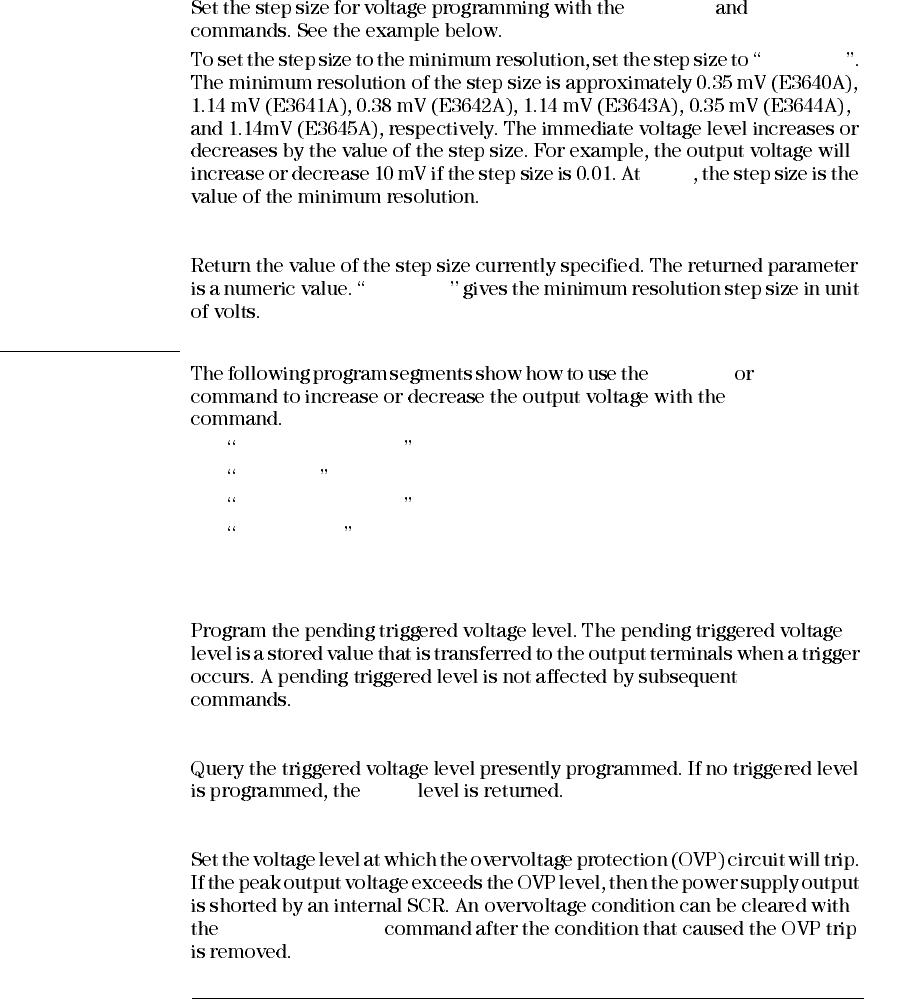
VOLTage:STEP {<numeric value> | DEFault}
VOLT UP VOLT DOWN
DEFault
*RST
VOLTage:STEP? [DEFault]
DEFault
Example VOLT UP VOLT DOWN
VOLT:STEP
VOLT:STEP 0.01 Set the step size to 0.01 V
VOLT UP Increase the output voltage
VOLT:STEP 0.02 Set the step size to 0.02 V
VOLT DOWN Decrease the output voltage
VOLTage:TRIGgered {<voltage>| MINimum | MAXimum}
VOLTage
VOLTage:TRIGgered? [MINimum | MAXimum]
VOLT
VOLTage:PROTection {<voltage>|MINimum|MAXimum}
VOLT:PROT:CLE
Chapter 4 Remote Interface Reference
Output Setting and Operation Commands
81
4
VOLTage:PROTection? [MINimum | MAXimum]
VOLTage:PROTection:STATe {0 | 1 | OFF | ON}
*RST
VOLTage:PROTection:STATe?
VOLTage:PROTection:TRIPped?
VOLTage:PROTection:CLEar
VOLTage:RANGe {P8V* | P20V* | P35V** | P60V** | LOW | HIGH}
*RST
VOLTage:RANGe?
MEASure:CURRent?
MEASure[:VOLTage]?
* For E3640A/42A/44A models **For E3641A/43A/45A models
Chapter 4 Remote Interface Reference
Triggering
82
Triggering
Notice that the time delay is valid for only the bus trigger source.
INITiate IMMediate
*TRG
Trigger Source Choices
Bus (Software) Triggering
TRIG:SOUR BUS
*TRG
*TRG
TRIGGER 705
Chapter 4 Remote Interface Reference
Triggering
83
4
*WAI
*WAI
TRIG:SOUR BUS;*TRG;*WAI;*TRG;*WAI
*OPC? *OPC
*OPC?
*OPC
Immediate Triggering
TRIG:SOUR IMM
IMMediate INITiate
VOLT:TRIG CURR:TRIG
VOLT CURR
Chapter 4 Remote Interface Reference
Triggering
84
Triggering Commands
INITiate
TRIGger:DELay {<seconds>| MINimum | MAXimum}
MIN MAX
*RST
TRIGger:DELay?[MINimum | MAXimum]
TRIGger:SOURce {BUS | IMMediate}
*RST
TRIGger:SOURce?
*TRG
(TRIG:SOUR BUS)
SYST:REM
Chapter 4 Remote Interface Reference
System-Related Commands
85
4
System-Related Commands
DISPlay {OFF | ON}
ERROR
Local
DISPlay?
DISPlay:TEXT <quoted string>
DISPlay:TEXT?
DISPlay:TEXT:CLEar
OUTPut {OFF | ON}
*RST
OUTPut?
OUTPut:RELay {OFF | ON}
*RST
OUTPUT:RELay
Note Do not use the RS-232 interface if you have configured the power supply to output
relay control signals. Internal components on the RS-232 circuitry may be damaged.
Local
Store
Chapter 4 Remote Interface Reference
System-Related Commands
87
4
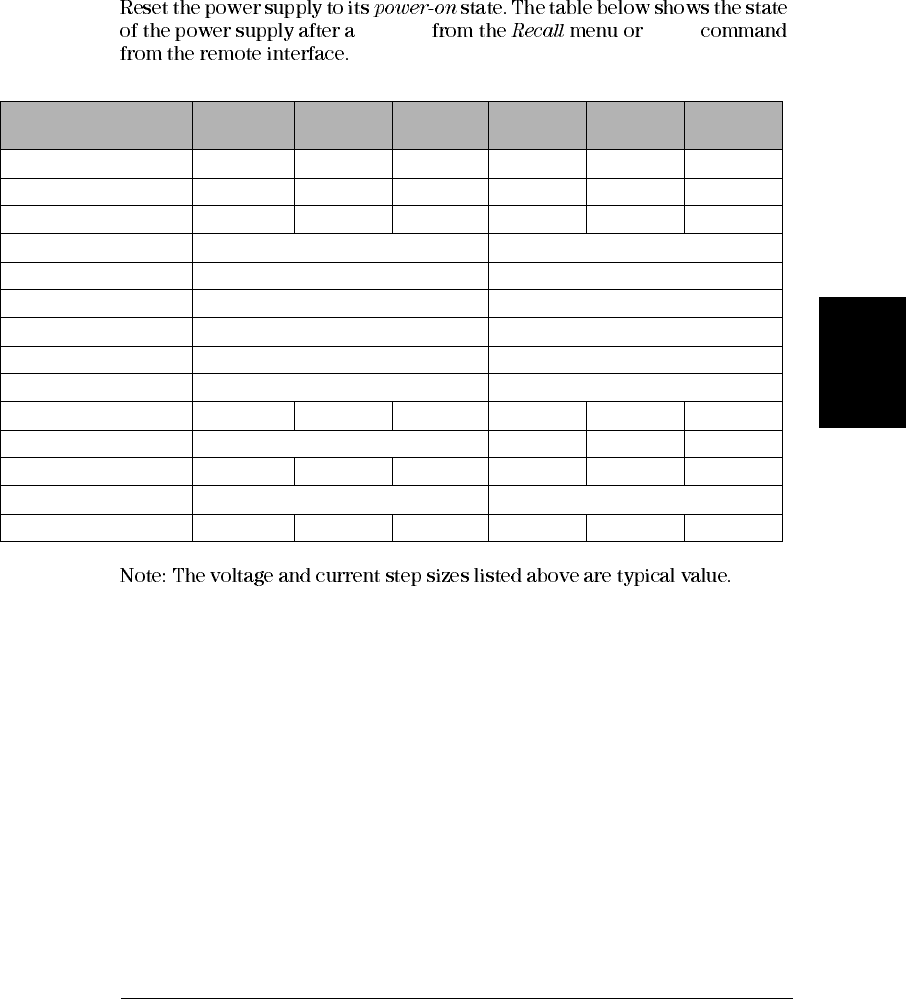
*RST
RESET *RST
Command E3640A
state E3641A
state E3642A
state E3643A
state E3644A
state E3645A
state
CURR 3 A 0.8 A 5 A 1.4 A 8 A 2.2 A
CURR:STEP 0.052 mA 0.015 mA 0.095 mA 0.026 mA 0.152 mA 0.042 mA
CURR:TRIG 3 A 0.8 A 5 A 1.4 A 8 A 2.2 A
DISP ON ON
OUTP OFF OFF
OUTP:REL OFF OFF
TRIG:DEL 0 0
TRIG:SOUR BUS BUS
VOLT 0 V 0 V
VOLT:STEP 0.35 mV 1.14 mV 0.38 mV 1.14 mV 0.35 mV 1.14 mV
VOLT:TRIG 0 V 0 V 0 V 0 V
VOLT:PROT 22.0 V 66.0 V 22.0 V 66.0 V 22.0 V 66.0 V
VOLT:PROT:STAT ON ON
VOLT:RANG P8V (Low) P35V (Low) P8V (Low) P35V (Low) P8V (Low) P35V (Low)
Chapter 4 Remote Interface Reference
State Storage Commands
88
State Storage Commands
*SAV { 1 | 2 | 3 | 4 | 5 }
*RST
CURR, CURR:STEP, CURR:TRIG, OUTP, OUTP:REL, TRIG:DEL,
TRIG:SOUR, VOLT, VOLT:STEP, VOLT:TRIG, VOLT:PROT,
VOLT:PROT:STAT, VOLT:RANG
*RCL { 1 | 2 | 3 | 4 | 5 }
DISP {OFF|ON
MEMory:STATe
:NAME { 1 | 2 | 3 | 4 | 5} , <quoted name>
:NAME? { 1 | 2 | 3 | 4 | 5}
:NAME?
MEM:STATE:NAME 1,‘P15V_TEST’
Chapter 4 Remote Interface Reference
Calibration Commands
89
4
Calibration Commands
Note When you calibrate the power supply, you should NOT set the OVP to ON state in
order to prevent OVP from tripping.
CALibration:COUNt?
CALibration:CURRent[:DATA] <numeric value>
CAL:CURR:LEV
MIN
CAL:CURR:LEV MID CAL:CURR:LEV MAX
CALibration:CURRent:LEVel {MINimum | MIDdle | MAXimum}
CAL:CURR
CALibration:SECure:CODE <quoted new code>
Chapter 4 Remote Interface Reference
Calibration Commands
90
CALibration:SECure:STATe {OFF | ON},<quoted code>
CALibration:SECure:STATe?
CALibration:STRing <quoted string>
CALibration:STRing?
CALibration:VOLTage[:DATA] <numeric value>
CAL:VOLT:LEV
MIN
CAL:VOLT:LEV MID CAL:VOLT:LEV MAX
CALibration:VOLTage:LEVel {MINimum | MIDdle | MAXimum}
CAL:VOLT
CALibration:VOLTage:PROTection
Chapter 4 Remote Interface Reference
Calibration Commands
91
4
Calibration
Example
OUTP ON
VOLT:PROT:STAT OFF
CAL:SEC:STAT OFF, <code>
CAL:VOLT:LEV MIN
CAL:VOLT:DATA 0.549
CAL:VOLT:LEV MID
CAL:VOLT:DATA 11.058
CAL:VOLT:LEV MAX
CAL:VOLT:DATA 21.566
CAL:VOLT:PROT
CURR VOLT
CAL:CURR:LEV MIN
CALibration:STRing <string>
Chapter 4 Remote Interface Reference
The SCPI Status Registers
93
4
The SCPI Status Registers
What is an Event Register?
*ESR?
STAT:QUES:EVEN? *CLS
*RST
What is an Enable Register?
*CLS
Chapter 4 Remote Interface Reference
The SCPI Status Registers
94
SCPI Status System
Binary Weight
20 = 1
21 = 2
22 = 4
23 = 8
24 = 16
25 = 32
26 = 64
27 = 128
28 = 256
29 = 512
210 = 1024
211 = 2048
212 = 4096
213 = 8192
214 = 16384
215 = 32768
QUEStionable Status
Event Register Enable Registers
4
"OR"
Not Used
Not Used
Temperature
Not Used
Not Used
Not Used
Not Used
Not Used
Not Used
Not Used
Not Used
Not Used
Not Used
9
"OR"
OPC
Not Used
QYE
DDE
EXE
CME
PON
Not Used
5
"OR"
Current
Voltage
Overvoltage
Standard Event
Event Register Enable Registers
Operation Complete
Query Error
Device Depenent Error
Execution Error
Command Error
Power On
0
7
2
3
4
STAT:QUES? STAT:QUES:ENAB <value>
STAT:QUES:ENAB?
*ESR? *ESE <value>
*ESE?
Not Used
QUES
MAV
ESB
Not Used
Not Used
Not Used
RQS
5
6
3
4
Serial Poll(SPOLL) *SRE <value>
*STB? *SRE?
Status Byte
Summary Register Enable Register
Output Buffer
0
1
Chapter 4 Remote Interface Reference
The SCPI Status Registers
95
4
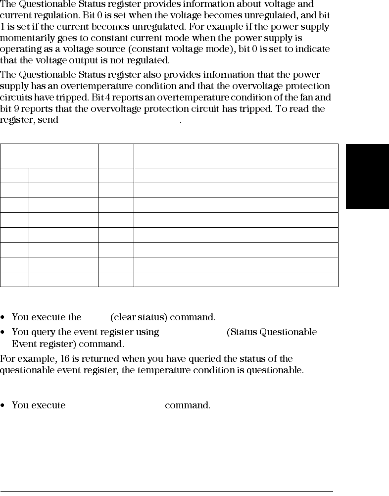
The Questionable Status Register
STATus:QUEStionable?
Table 4-3. Bit Definitions - Questionable Status Register
The Questionable Status Event register is cleared when:
*CLS
STAT:QUES?
The Questionable Status Enable register is cleared when:
STAT:QUES:ENAB 0
Bit Decimal
Value Definition
0Voltage 1The power supply is/was in the constant current mode.
1Current 2The power supply is/was in the constant voltage mode.
2-3 Not Used 0Always set to 0.
4Overtemperature 16 The fan has a fault condition.
5-8 Not Used 0Always set to 0.
9Over Voltage 512 The overvoltage protection circuit has tripped.
10 Not Used 0Always set to 0.
11-15 Not Used 0Always set to 0.
Chapter 4 Remote Interface Reference
The SCPI Status Registers
96
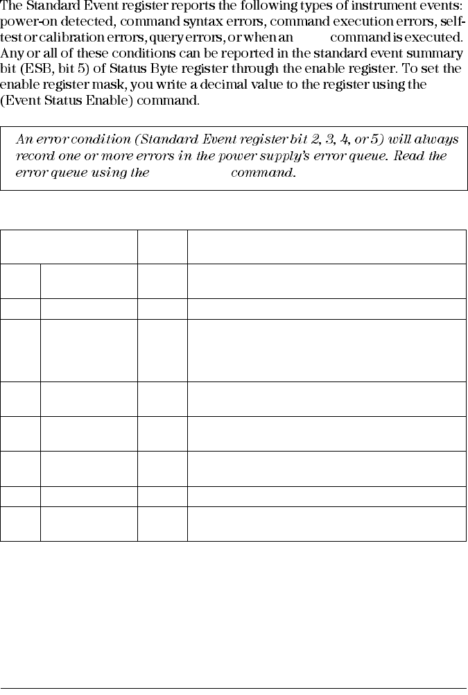
The Standard Event Register
*OPC
*ESE
Table 4-4. Bit Definitions – Standard Event Register
SYST:ERR?
Bit Decimal
Value Definition
0OPC 1Operation Complete. All commands prior to and
including an *OPC command have been executed.
1Not Used 0Always set to 0.
2QYE
4
Query Error. The power supply tried to read the output
buffer but it was empty. Or, new command line was
received before a previous query had been read. Or, both
the input and output buffers are full.
3DDE 8Device Error. A self-test or calibration error occurred
(see error numbers 601 through 750 in chapter 5).
4EXE 16 Execution Error. An execution error occurred (see error
numbers -211 through -224 in chapter 5).
5CME 32 Command Error. A command syntax error occurred (see
error numbers -101 through -178 in chapter 5).
6Not Used 0Always set to 0.
7PON 128 Power On. Power has been turned off and on since the
last time the event register was read or cleared.
Chapter 4 Remote Interface Reference
The SCPI Status Registers
97
4
The Standard Event register is cleared when:
*CLS
*ESR?
The Standard Event Enable register is cleared when:
*ESE 0
*PSC 1
*PSC 0
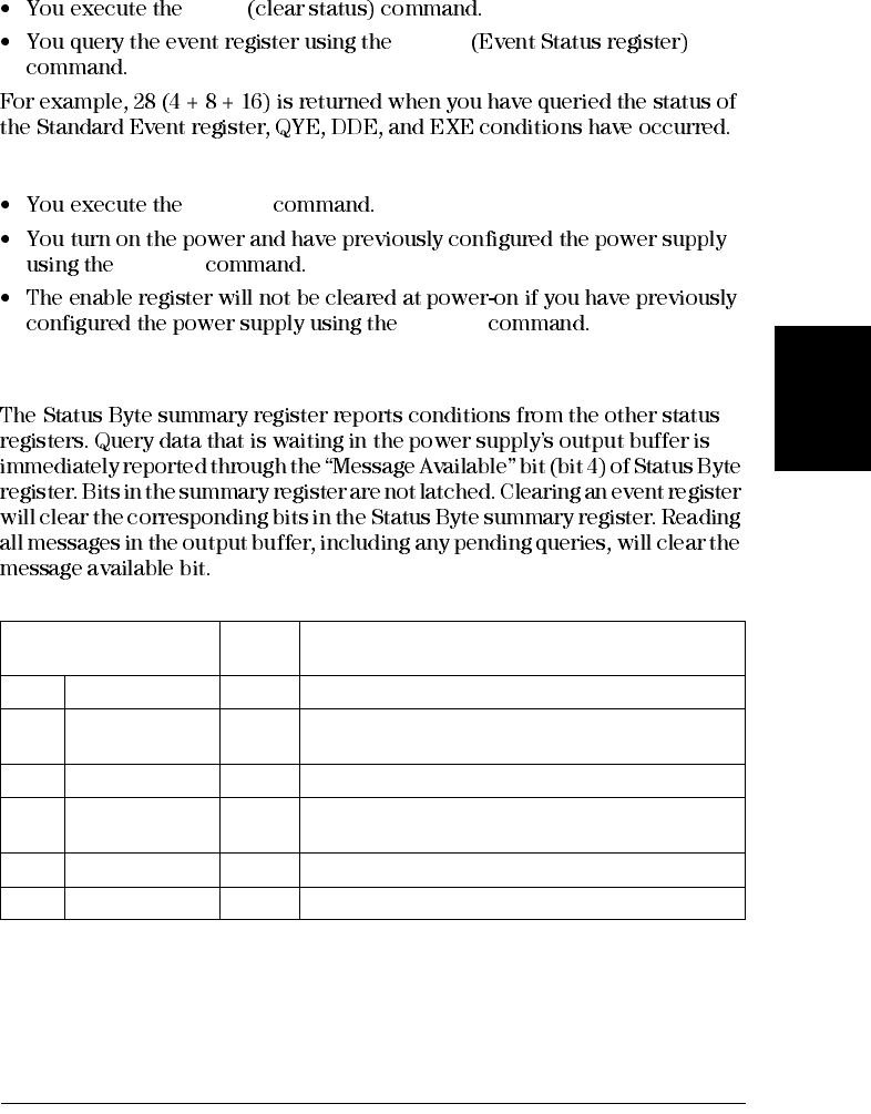
The Status Byte Register
Table 4-5. Bit Definitions – Status Byte Summary Register
Bit Decimal
Value Definition
0-2 Not Used 0Always set to 0.
3QUES 8One or more bits are set in the questionable status
register (bits must be “enabled” in the enable register).
4MAV 16 Data is available in the power supply output buffer.
5ESB 32 One or more bits are set in the standard event register
(bits must be “enabled” in the enable register).
6RQS 64 The power supply is requesting service (serial poll).
7Not Used 0Always set to 0.
Chapter 4 Remote Interface Reference
The SCPI Status Registers
98
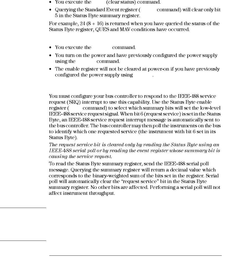
The Status Byte Summary register is cleared when:
*CLS
*ESR?
The Status Byte Enable register (Request Service) is cleared when:
*SRE 0
*PSC 1
*PSC 0
Using Service Request (SRQ) and Serial POLL
*SRE
Caution The IEEE-488 standard does not ensure synchronization between your bus controller
program and the instrument. Use the *OPC? command to guarantee that commands
previously sent to the instrument have completed. Executing a serial poll before a
*RST, *CLS, or other commands have completed can cause previous conditions
to be reported.
Chapter 4 Remote Interface Reference
The SCPI Status Registers
99
4
Using *STB? to Read the Status Byte
*STB?
*STB?
*STB?
*STB?
*STB?
Using the Message Available Bit (MAV)
To Interrupt Your Bus Controller Using SRQ
CLEAR 705
*CLS
*ESE
*SRE
*OPC?
Chapter 4 Remote Interface Reference
The SCPI Status Registers
100
To Determine When a Command Sequence is Completed
CLEAR 705
*CLS
*ESE 1
*OPC?
*OPC
*SRE 32
Using *OPC to Signal When Data is in the Output Buffer
*OPC
*OPC
*OPC

Chapter 4 Remote Interface Reference
Status Reporting Commands
102
*ESE?
*ESR?
*OPC
*OPC?
*PSC { 0 | 1 }
*PSC 1
*PSC 0
*PSC?
(*PSC 0 *PSC 1
*SRE <enable value>
*SRE?
*STB?
*STB?
*STB?
*WAI
Chapter 4 Remote Interface Reference
An Introduction to the SCPI Language
103
4
An Introduction to the SCPI Language
SOURce
[SOURce:]
CURRent {<current>|MIN|MAX|UP|DOWN}
CURRent? [MIN|MAX]
CURRent:
TRIGgered {<current>|MIN|MAX}
TRIGgered?{MIN|MAX}
VOLTage {<voltage>|MIN|MAX|UP|DOWN}
VOLTage? [MIN|MAX]
VOLTage:
TRIGgered {<voltage>|MIN|MAX}
TRIGgered? {MIN|MAX}
SOURce CURRent VOLTage
TRIGgered
Chapter 4 Remote Interface Reference
An Introduction to the SCPI Language
105
4
Command Separators
SOURce:CURRent:TRIGgered
SOUR:VOLT MIN;CURR MAX
SOUR:VOLT MIN
SOUR:CURR MAX
DISP:TEXT:CLE;:SOUR:CURR MIN
Using the MIN and MAX Parameters
MINimum MAXimum
CURRent {<current>|MIN|MAX}
MINimum
MAXimum
Chapter 4 Remote Interface Reference
An Introduction to the SCPI Language
106
Querying Parameter Settings
CURR 5
CURR?
CURR? MAX
CURR? MIN
Caution If you send two query commands without reading the response from the first, and then
attempt to read the second response, you may receive some data from the first response
followed by the complete second response. To avoid this, do not send a query
command without reading the response. When you cannot avoid this situation, send
a device clear before sending the second query command.
SCPI Command Terminators
IEEE-488.2 Common Commands
*RST; *CLS; *ESE 32; *OPC?
Chapter 4 Remote Interface Reference
An Introduction to the SCPI Language
107
4
SCPI Parameter Types
MINimum MAXimum DEFault
CURR {<current>|MIN|MAX|UP|DOWN}
BUS IMM
TRIG:SOUR {BUS|IMM}
DISP {OFF|ON}
DISP:TEXT <quoted string>
Chapter 4 Remote Interface Reference
Halting an Output in Progress
108
Halting an Output in Progress
CLEAR 705 IEEE-488 Device Clear
IOCLEAR (705)
Note All remote interface configurations can be entered only from the front panel. See
‘‘Remote Interface Configuration’’ in chapter 3 to configure for GPIB or RS-232
interface before operating the power supply remotely.
Chapter 4 Remote Interface Reference
SCPI Conformance Information
109
4
SCPI Conformance Information
SCPI Confirmed Commands
DISPlay
[:WINDow][:STATe] {OFF|ON}
[:WINDow][:STATe]?
[:WINDow]:TEXT[:DATA] <quoted string>
[:WINDow]:TEXT[:DATA]?
[:WINDow]:TEXT:CLEar
INITiate[:IMMediate]
MEASure
:CURRent[:DC]?
[:VOLTage][:DC]?
OUTPut
[:STATe] {OFF|ON}
[:STATE]?
[SOURce]
:CURRent[:LEVel][:IMMediate][:AMPLitude] {<current>|MIN|MAX|UP|DOWN}
:CURRent[:LEVel][:IMMediate][:AMPLitude]? [MIN|MAX]
:CURRent[:LEVel][:IMMediate]:STEP[:INCRement] {<numeric value>|DEFault}
:CURRent[:LEVel][:IMMediate]:STEP[:INCRement]? {DEFault}
:CURRent[:LEVel]:TRIGgered[:AMPLitude] {<current>|MIN|MAX}
:CURRent[:LEVel]:TRIGgered[:AMPLitude]?[MIN|MAX]

Chapter 4 Remote Interface Reference
SCPI Conformance Information
110
SCPI Confirmed Commands (continued)
[SOURce]
:VOLTage[:LEVel][:IMMediate][:AMPLitude] {<voltage>|MIN|MAX|UP|DOWN}
:VOLTage[:LEVel][:IMMediate][:AMPLitude]?[MIN|MAX]
:VOLTage[:LEVel][:IMMediate]:STEP[:INCRement] {<numeric value>|DEFault}
:VOLTage[:LEVel][:IMMediate]:STEP[:INCRement]? {DEFault}
:VOLTage[:LEVel]:TRIGgered[:AMPLitude] {<voltage>|MIN|MAX}
:VOLTage[:LEVel]:TRIGgered[:AMPLitude]?[MIN|MAX]
:VOLTage:PROTection[:LEVel] {<voltage>|MIN|MAX}
:VOLTage:PROTection[:LEVel]? {MIN|MAX}
:VOLTage:PROTection:STATe {0|1|OFF|ON}
:VOLTage:PROTection:STATe?
:VOLTage:PROTection:TRIPped?
:VOLTage:PROTection:CLEar
:VOLTage:RANGe {P8V|P20V|LOW|HIGH} (E3640A/42A/44A models)
:VOLTage:RANGe {P35V|P60V|LOW|HIGH} (E3641A/43A/45A models)
:VOLTage:RANGe?
STATus
:QUEStionable:CONDition?
:QUEStionable[:EVENt]?
:QUEStionable:ENABle <enable value>
:QUEStionable:ENABle?
SYSTem
:BEEPer[:IMMediate]
:ERRor?
:VERSion
TRIGger
[:SEQuence]:DELay {<seconds>|MIN|MAX}
[:SEQuence]:DELay?
[:SEQuence]:SOURce{BUS|IMM}
[:SEQuence]:SOURce?
Chapter 4 Remote Interface Reference
SCPI Conformance Information
111
4
Device Specific Commands
Non-SCPI Commands
APPLy {<voltage>|DEF|MIN|MAX>}[,{<current>|DEF|MIN|MAX}]
APPLy?
CALibration
:COUNt?
:CURRent[:DATA] <numeric value>
:CURRent:LEVel {MIN|MID|MAX}
:SECure:CODE <new code>
:SECure:STATe {OFF|ON},<code>
:SECure:STATe?
:STRing <quoted string>
:STRing?
:VOLTage[:DATA] <numeric value>
:VOLTage:LEVel {MIN|MID|MAX}
:VOLTage:PROTection
OUTPut
:RELay[:STATe] {OFF|ON}
:RELay[:STATE]?
SYSTem
:LOCal
:REMote
:RWLock
Chapter 4 Remote Interface Reference
IEEE-488 Conformance Information
112
IEEE-488 Conformance Information
Dedicated Hardware Lines
ATN Attention
IFC Interface Clear
REN Remote Enable
SRQ Service Request Enable
Addressed Commands
DCL Device Clear
EOI End or Identify
GET Group Execute Trigger
GTL Go To Local
LLO Local Lockout
SDC Selected Device Clear
SPD Serial Poll Disable
SPE Serial Poll Enable
IEEE-488 Common Commands
*CLS
*ESE <enable value>
*ESE?
*ESR?
*IDN?
*OPC
*OPC?
*PSC {0|1}
*PSC?
*RST
*SAV {1|2|3|4|5}
*RCL {1|2|3|4|5}
*SRE < >
*SRE?
*STB?
*TRG
*TST?
*WAI

5
Error Messages
114
Error Messages
ERROR
NO ERRORS
*CLS
*RST
Local
ERRORS
ERROR
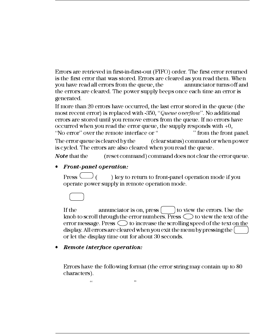
SYSTem:ERRor? Read and clear one error from the error queue
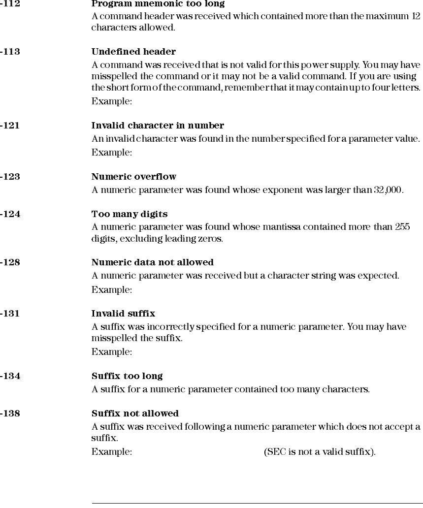
-102, Syntax error
Local
Store
View
View
>
>
View
Chapter 5 Error Messages
Execution Errors
115
5
Execution Errors
OUTP:STAT #ON
VOLT:LEV ,1
TRIG:SOUR,BUS or APPL 1.0 1.0
APPL? 10
APPL
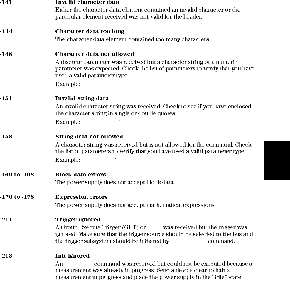
Chapter 5 Error Messages
Execution Errors
116
TRIGG:DEL 3
*ESE #B01010102
DISP:TEXT 123
TRIG:DEL 0.5 SECS
STAT:QUES:ENAB 18 SEC
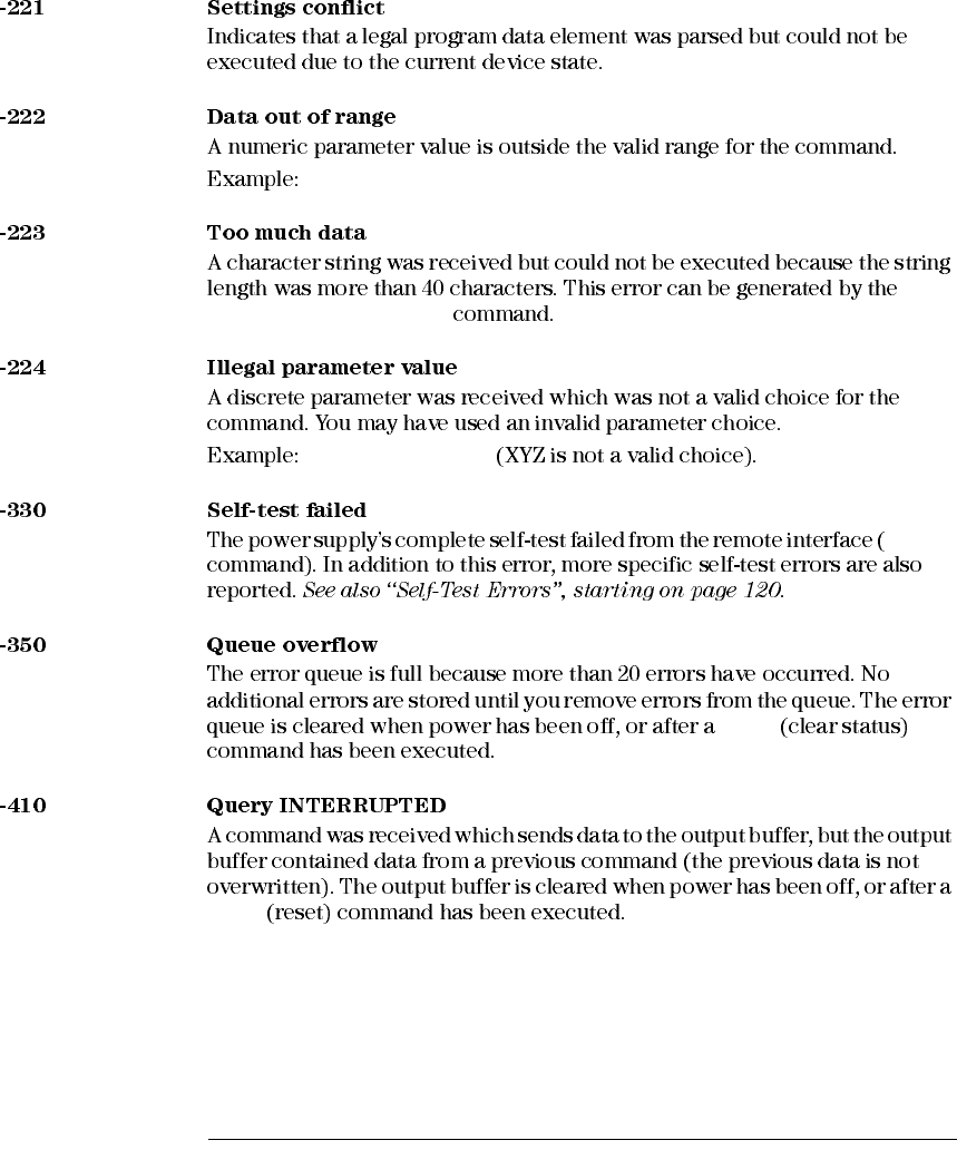
Chapter 5 Error Messages
Execution Errors
117
5
DISP:TEXT ON
DISP:TEXT ON
TRIG:DEL zero
*TRG
INIT[:IMM]
INITiate
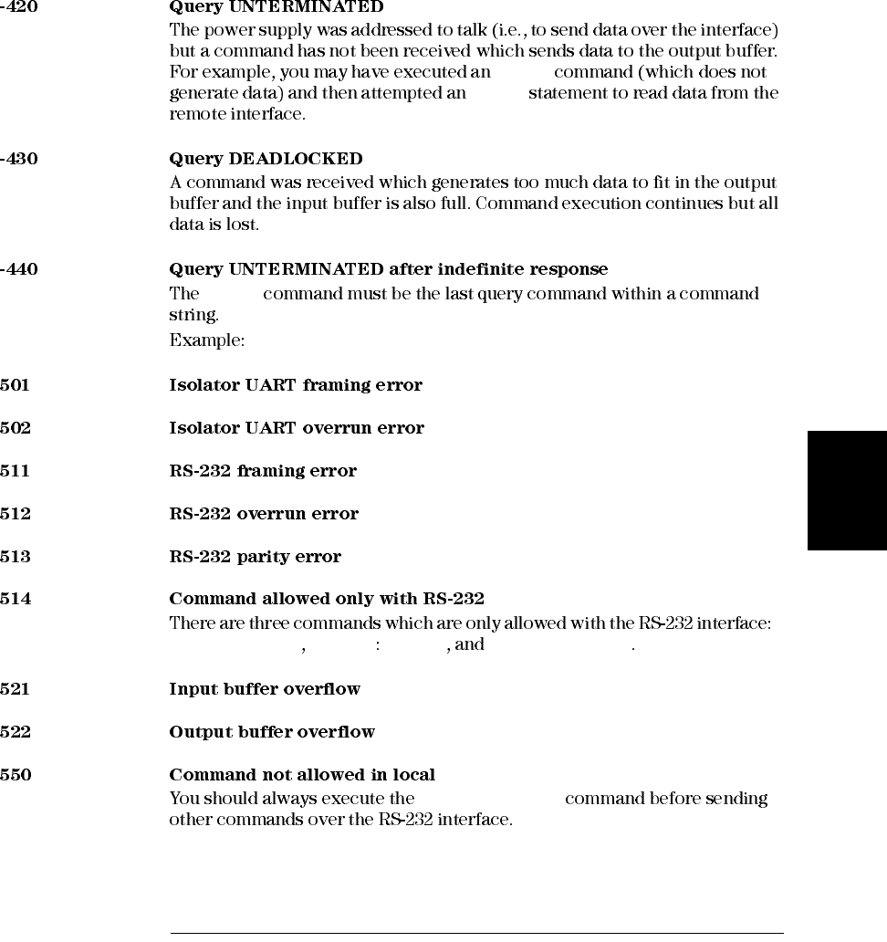
Chapter 5 Error Messages
Execution Errors
119
5
APPLy
ENTER
*IDN?
*IDN?;:SYST:VERS?
SYSTem:LOCal SYSTem REMote SYSTem:RWLock
SYSTem:REMote
Chapter 5 Error Messages
Self-Test Errors
120
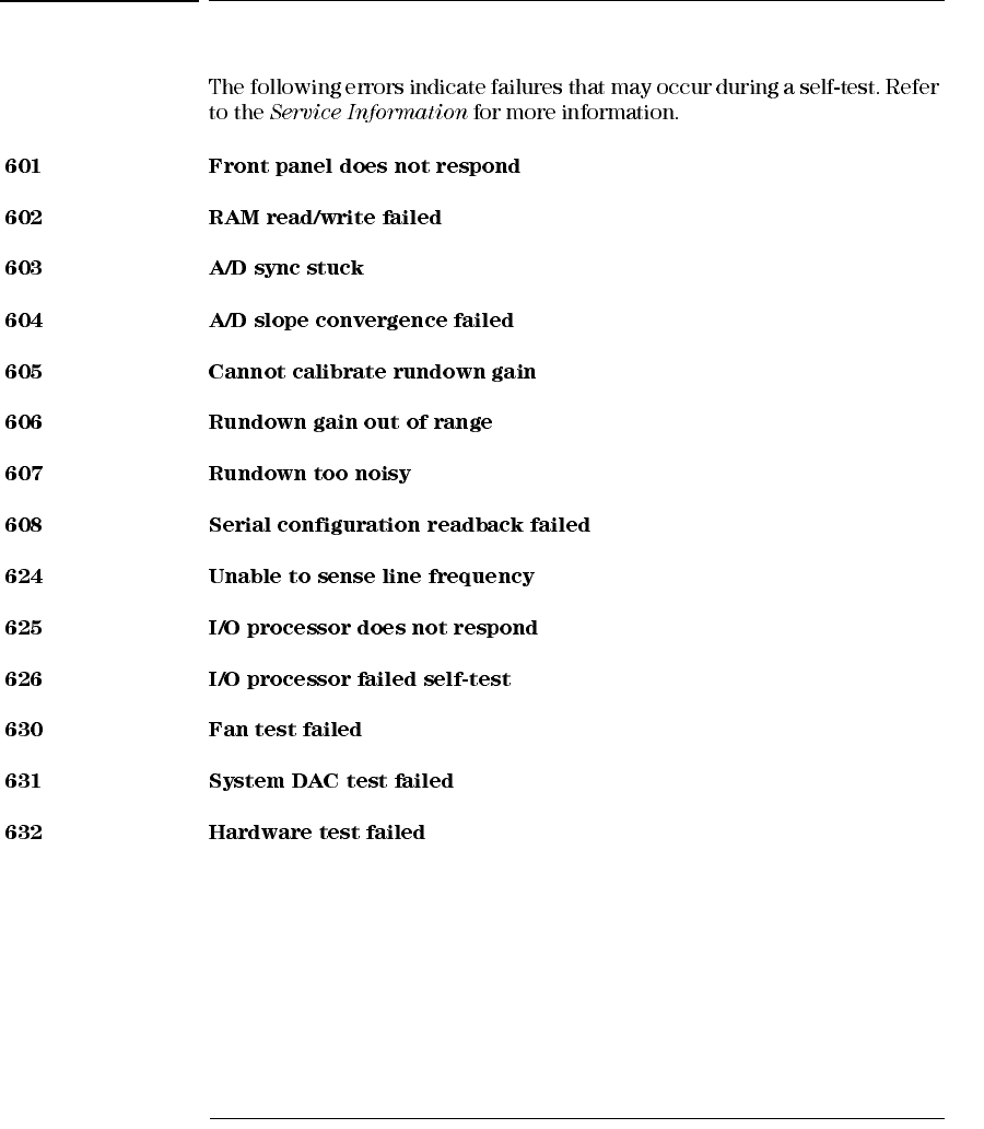
Self-Test Errors
Chapter 5 Error Messages
Calibration Errors
121
5
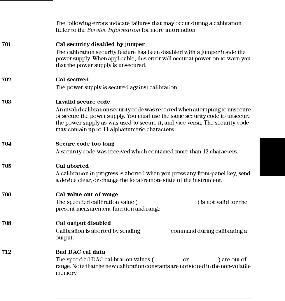
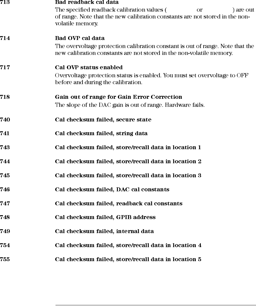
Calibration Errors
CALibration:VALue
OUTP OFF
CAL:VOLT CAL:CURR
Chapter 5 Error Messages
Calibration Errors
122
CAL:VOLT CAL:CURR

6
Application Programs
Chapter 6 Application Programs
Example Program for C and C++
125
6
Example Program for C and C++
User’s Guide ®
®
®
c:\vxipnp\win(win95 winnt)\lib\msc
c:\vxipnp\win (win95 winnt)\include
Diode.c
/*Diode.C
This example program steps the power supply through 11 voltages and measures the current
response. It prints the voltage step and the current response as a table. Note that the
GPIB address is the default address from the factory for the power supply.*/
#include <visa.h>
#include <stdio.h>
#include <string.h>
#include <time.h>
#include <conio.h>
#include <stdlib.h>
ViSession defaultRM; /* Resource manager id */
ViSession power_supply; /* Identifies power supply */
int bGPIB = 1; /* Set the number to 0 for use with the RS-232 */
long ErrorStatus; /* VISA Error code */
char commandString[256];
char ReadBuffer[256];
void delay(clock_t wait);
void SendSCPI(char* pString);
void CheckError(char* pMessage);
void OpenPort();
void main()
{
double voltage; /* Value of voltage sent to power supply */
char Buffer[256]; /* String returned from power supply */
double current; /* Value of current output of power supply */
Continued on next page

Chapter 6 Application Programs
Example Program for C and C++
126
OpenPort();
/* Query the power supply id, read response and print it */
sprintf(Buffer,"*IDN?");
SendSCPI(Buffer);
printf("Instrument identification string:\n %s\n\n",Buffer);
SendSCPI("*RST"); /* Set power-on condition */
SendSCPI("Current 2"); /* Set current limit to 2A */
SendSCPI("Output on"); /* Turn output on */
printf("Voltage Current\n\n"); /* Print heading */
/*Step from 0.6 to 0.8 volt in 0.02 steps */
for(voltage = 0.6; voltage <=0.8001; voltage +=0.02)
{
printf("%.3f",voltage); /* Display diode voltage*/
/* Set output voltage */
ErrorStatus = viPrintf(power_supply,"Volt %f\n",voltage);
if(!bGPIB)
delay(500);/* 500 msec wating for RS-232 port*/
CheckError("Unable to set voltage");
/* Measure output current */
ErrorStatus = viPrintf(power_supply,"Measure:Current?\n");
CheckError("Unable to write device");
delay(500); /* Allow output to wait for 500 msec */
/* Retrieve reading */
ErrorStatus = viScanf(power_supply,"%lf",¤t);
CheckError("Unable to read voltage");
printf("%6.4f\n",current); /* Display diode current */
}
SendSCPI("Output off"); /* Turn output off */
ClosePort();
}
/* Build the address required to open commnuication with GPIB card or RS-232.*/
/* The address format looks like this: "GPIB0::5::INSTR". */
/* To use the RS-232 interface using COM1 port, change it to "ASRL1::INSTR" */
/* address format */
void OpenPort()
{
char GPIB_Address[3];
char COM_Address[2];
char VISA_address[40]; /* Complete VISA address sent to card */
if(bGPIB)
strcpy(GPIB_Address,"5"); /* Select GPIB address between 0 to 30*/
else
strcpy(COM_Address,"1"); /* Set the number to 2 for COM2 port */
Continued on next page

Chapter 6 Application Programs
Example Program for C and C++
127
6
if(bGPIB){ /* For use with GPIB 7 address, use "GPIB::7::INSTR" address format */
strcpy(VISA_address,"GPIB::");
strcat(VISA_address,GPIB_Address);
strcat(VISA_address,"::INSTR");
}
else{ /* For use with COM2 port, use "ASRL2::INSTR" address format */
strcpy(VISA_address,"ASRL");
strcat(VISA_address,COM_Address);
strcat(VISA_address,"::INSTR");
}
/* Open communication session with the power supply */
ErrorStatus = viOpenDefaultRM(&defaultRM);
ErrorStatus = viOpen(defaultRM,VISA_address,0,0,&power_supply);
CheckError("Unable to open port");
if(!bGPIB)
SendSCPI("System:Remote");
}
void SendSCPI(char* pString)
{
char* pdest;
strcpy(commandString,pString);
strcat(commandString,"\n");
ErrorStatus = viPrintf(power_supply,commandString);
CheckError("Can’t Write to Driver");
if (bGPIB == 0)
delay(1000); /* Unit is milliseconds */
pdest = strchr(commandString, ’?’); /* Search for query command */
if( pdest != NULL ){
ErrorStatus = viScanf(power_supply,"%s",&ReadBuffer);
CheckError("Can’t Read From Driver");
strcpy(pString,ReadBuffer);
}
}
void ClosePort()
{
/* Close the communication port */
viClose(power_supply);
viClose(defaultRM);
}
Continued on next page

Chapter 6 Application Programs
Example Program for C and C++
128
void CheckError(char* pMessage)
{
if (ErrorStatus < VI_SUCCESS){
printf("\n %s",pMessage);
ClosePort();
exit(0);
}
}
void delay(clock_t wait)
{
clock_t goal;
goal = wait + clock();
while( goal > clock() ) ;
}
End of Program
Chapter 6 Application Programs
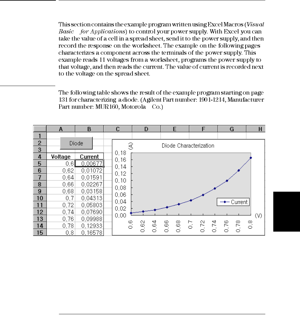
Example Program for Excel 97
130
®
Note To use the example with Window® 3.1, you will need to modify the declarations at
the top of the module. Change ‘visa32.dll’ to ‘visa.dll’ in all declarations.

Chapter 6 Application Programs
Example Program for Excel 97
131
6
Diode Macro
'"""""""""""""""""""""""""""""""""""""""""""""""""""""""""""""""""""""""
' This is the subroutine first executed. Modify this routine to suit
' your needs. To change the GPIB address, go to the module OpenPort, and
' change the variable GPIB_Address = "5” to the required GPIB address.
' To change the RS-232 port, go to the moudle OpenPort, and change the
' variable COM_Address = "1” to the required port
'"""""""""""""""""""""""""""""""""""""""""""""""""""""""""""""""""""""""
Global defaultRM As Long ' Resource manager id for VISA GPIB
Global power_supply As Long ' Identifies power supply
Global bGPIB As Boolean ' A flag using of GPIB or RS-232
Global ErrorStatus As Long ' VISA Error code
Sub Diode_Click()
Range("B5:B15").ClearContents
Dim I As Integer
bGPIB = True ' To use RS-232, set the bGPIB to False
OpenPort
SendSCPI "*RST" ' Set power-on condition
SendSCPI "Output on" ' Turn on the output
For I = 5 To 15
SendSCPI "Volt " & Str$(Cells(I, 1))
Cells(I, 2) = Val(SendSCPI("Meas:Current?"))
Next I
SendSCPI "Output off" ' Turn off the output
ClosePort
End Sub
Private Function OpenPort()
Dim GPIB_Address As String
Dim COM_Address As String
If bGPIB Then
GPIB_Address = "5" ' Select GPIB address between 0 to 30
Else
COM_Address = "1" ' Set the number to 2 for COM2 port
End If
ErrorStatus = viOpenDefaultRM(defaultRM) ' Open the VISA session
If bGPIB Then
ErrorStatus = viOpen(defaultRM, "GPIB0::" & GPIB_Address & "::INSTR", _
0, 1000, power_supply)
Else
ErrorStatus = viOpen(defaultRM, "ASRL" & COM_Address & "::INSTR", _
0, 1000, power_supply)
SendSCPI "System:Remote"
End If
CheckError "Unable to open port"
End Function
Continued on next page

Chapter 6 Application Programs
Example Program for Excel 97
132
'*********************************************************************************
' This routine send a SCPI command string to the GPIB port or RS-232 port.
' If the command contains a question mark, the response is read, and returned
'**********************************************************************************
Private Function SendSCPI(command As String) As string
Dim commandString As String ' Command passed to power supply
Dim ReturnString As String ' Store the string returned
Dim crlfpos As Integer ' Location of any nul’s in Read Buffer
Dim ReadBuffer As String * 512 ' Buffer used for returned string
Dim actual As Long ' Number of characters sent/returned
commandString = command & Chr$(10) ' The instrumented by linefeed
ErrorStatus = viWrite(power_supply, ByVal commandString, Len(commandString), _
actual)
CheckError "Can’t Write to Device"
If bGPIB = False Then
delay 0.5
End If
If InStr(commandString, "?") Then
ErrorStatus = viRead(power_supply, ByVal ReadBuffer, 512, actual)
CheckError "Can’t Read From Device"
ReturnString = ReadBuffer
crlfpos = InStr(ReturnString, Chr$(0))
If crlfpos Then
ReturnString = Left(ReturnString, crlfpos - 1)
End If
SendSCPI = ReturnString
End If
End Function
Private Function ClosePort()
ErrorStatus = viClose(power_supply)
ErrorStatus = viClose(defaultRM)
End Function
Private Function delay(delay_time As Single)
Dim Finish As Single
Finish = Timer + delay_time
Do
Loop Until Finish <= Timer
End Function
Private Function CheckError(ErrorMessage As String)
If ErrorStatus < VI_SUCCESS Then
Cells(5, 2) = ErrorMessage
ClosePort
End
End If
End Function
End of Program

Chapter 6 Application Programs
Example Program for Excel 97
133
6
Declaration for Windows 3.1
'************************************************************************************
' This routine requires the file VISA.dll. It typically resides in the
' c:\windows\system directory. Additional declations for VISA.DLL are usally in file
' visa.bas under c:\vxipnp\win31\include directory on your PC. This routine uses the
' VTL Library to send commands to an instrument. A description of these and additional
' VTL commands are contained in the Agilent Technologies Visa Transition Library book
' Agilent Part Number E2094-90002.
'************************************************************************************
Declare Function viOpenDefaultRM Lib "VISA.DLL" Alias "#141" (viDefaultRM As Long) As Long
Declare Function viOpen Lib "VISA.DLL" Alias "#131" (ByVal viDefaultRM As Long, ByVal viDesc
As String, ByVal mode As Long, ByVal timeout As Long, vi As Long) As Long
Declare Function viClose Lib "VISA.DLL" Alias "#132" (ByVal vi As Long) As Long
Declare Function viRead Lib "VISA.DLL" Alias "#256" (ByVal vi As Long, ByVal Buffer As
String, ByVal count As Long, retCount As Long) As Long
Declare Function viWrite Lib "VISA.DLL" Alias "#257" (ByVal vi As Long, ByVal Buffer As
String, ByVal count As Long, retCount As Long) As Long
Declare Function viClear Lib "VISA.DLL" Alias "#260" (ByVal vi As Long) As Long
Declaration for Windows 95/NT 4.0
'************************************************************************************
' Additional declations for VISA32.DLL are usally in file visa32.bas under
' c:\vxipnp\win95(or winNT)\include directory on your PC. Also see the VISA manual
'************************************************************************************
Declare Function viOpenDefaultRM Lib "visa32.dll" (instrumentHandle As Long) As Long
Declare Function viOpen Lib "visa32.dll" (ByVal instrumentHandle As Long, _
ByVal viDesc As String, ByVal mode As Long, ByVal timeout As Long, _
vi As Long) As Long
Declare Function viClose Lib "visa32.dll" (ByVal vi As Long) As Long
Declare Function viWrite Lib "visa32.dll" (ByVal vi As Long, ByVal Buffer As String, _
ByVal count As Long, retCount As Long) As Long
Declare Function viRead Lib "visa32.dll" (ByVal vi As Long, ByVal Buffer As String, _
ByVal count As Long, retCount As Long) As Long

Chapter 6 Application Programs
Example Program for Excel 97
134

7
Tutorial
Chapter 7 Tutorial
Overview of this Power Supply Operation
137
7
Overview of this Power Supply Operation
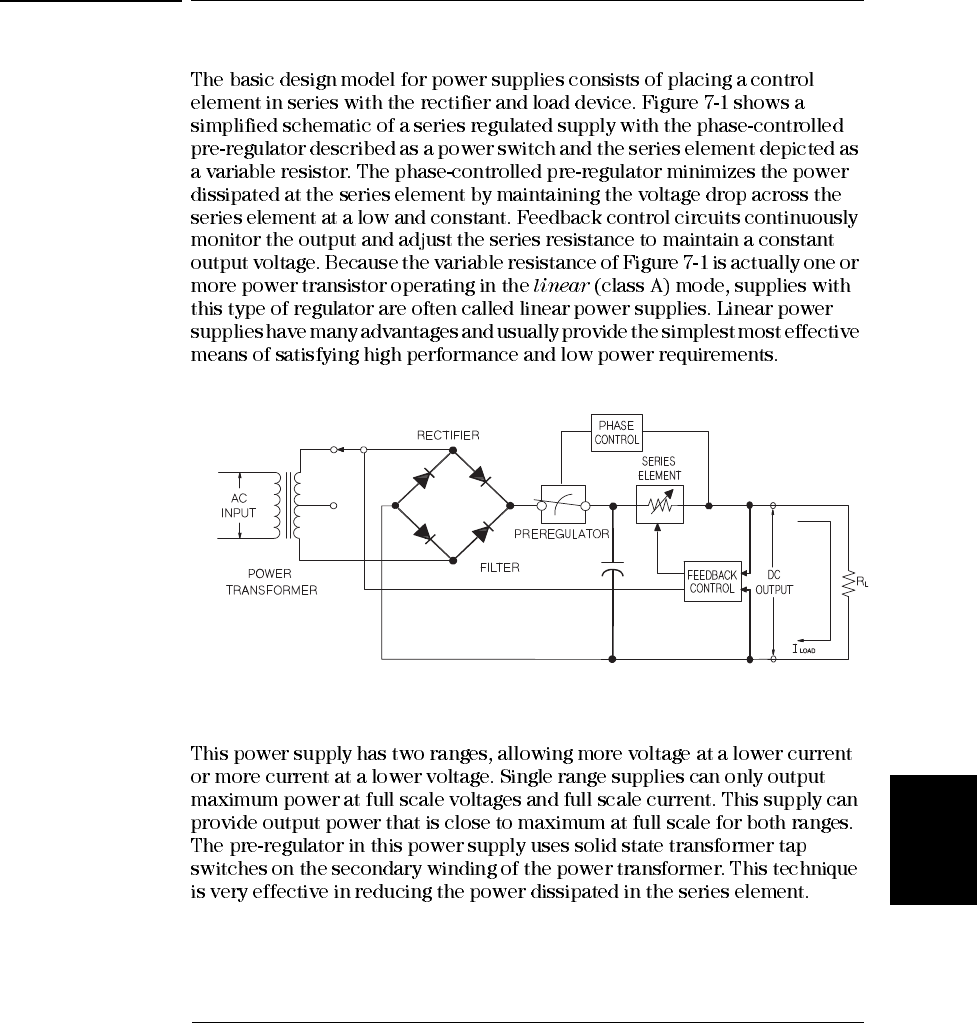
Figure 7-1. Diagram of Simple Series Power Supply
Chapter 7 Tutorial
Overview of this Power Supply Operation
138
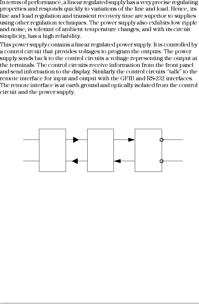
Figure 7-2. Block Diagram of the Power Supply Showing the Optical Isolation
GPIB
RS-232
OPTICAL
ISOLATION
POWER
SUPPLY
OUTPUT
CONTROL
DISPLAY
-
+
Chapter 7 Tutorial
Output Characteristics
139
7
Output Characteristics
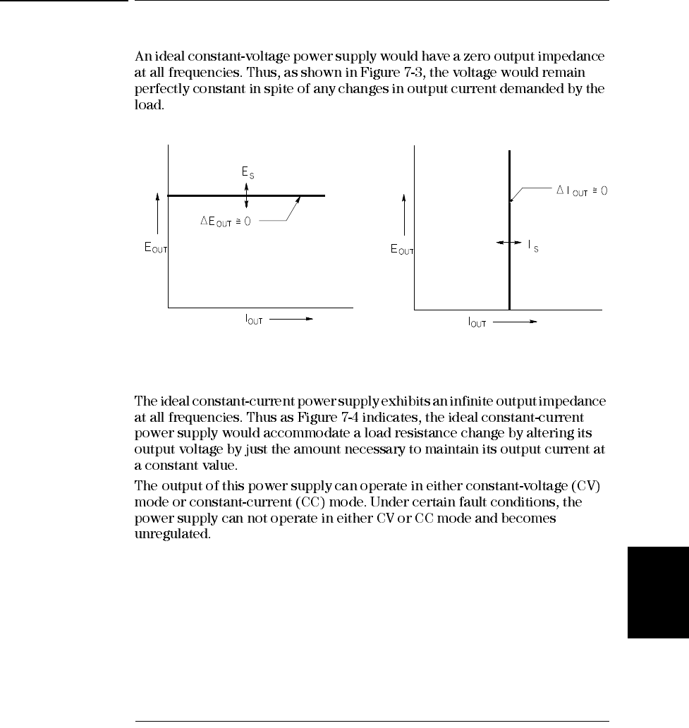
Figure 7-3. Ideal Constant Voltage Figure 7-4. Ideal Constant Current
Power Supply Power Supply
Chapter 7 Tutorial
Output Characteristics
140
L C
L C
C
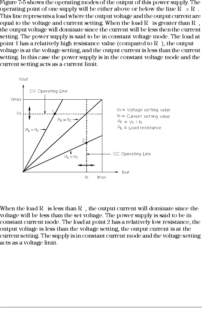
Figure 7-5. Output Characteristics
L C

Chapter 7 Tutorial
Output Characteristics
141
7
Unregulated State
Unwanted Signals
Chapter 7 Tutorial
Output Characteristics
142
Figure 7-6. Simplified Diagram of Common Mode and Normal Mode
Sources of Noise
OUTPUT
TERMINAL
OUTPUT
VOLTAGE
COMMON
MODE
NOISE
<1.5 uArms
NORMAL
MODE
NOISE R
<5mVpp*
<0.5mVrms*
<8mVpp**
<1mVrms**
*E3640A/41A/44A models
**E3641A/43A/45A models

Chapter 7 Tutorial
Extending the Voltage and Current Range
143
7
Extending the Voltage and Current Range
Series Connections
Parallel Connections
Chapter 7 Tutorial
Remote Programming
144
Remote Programming
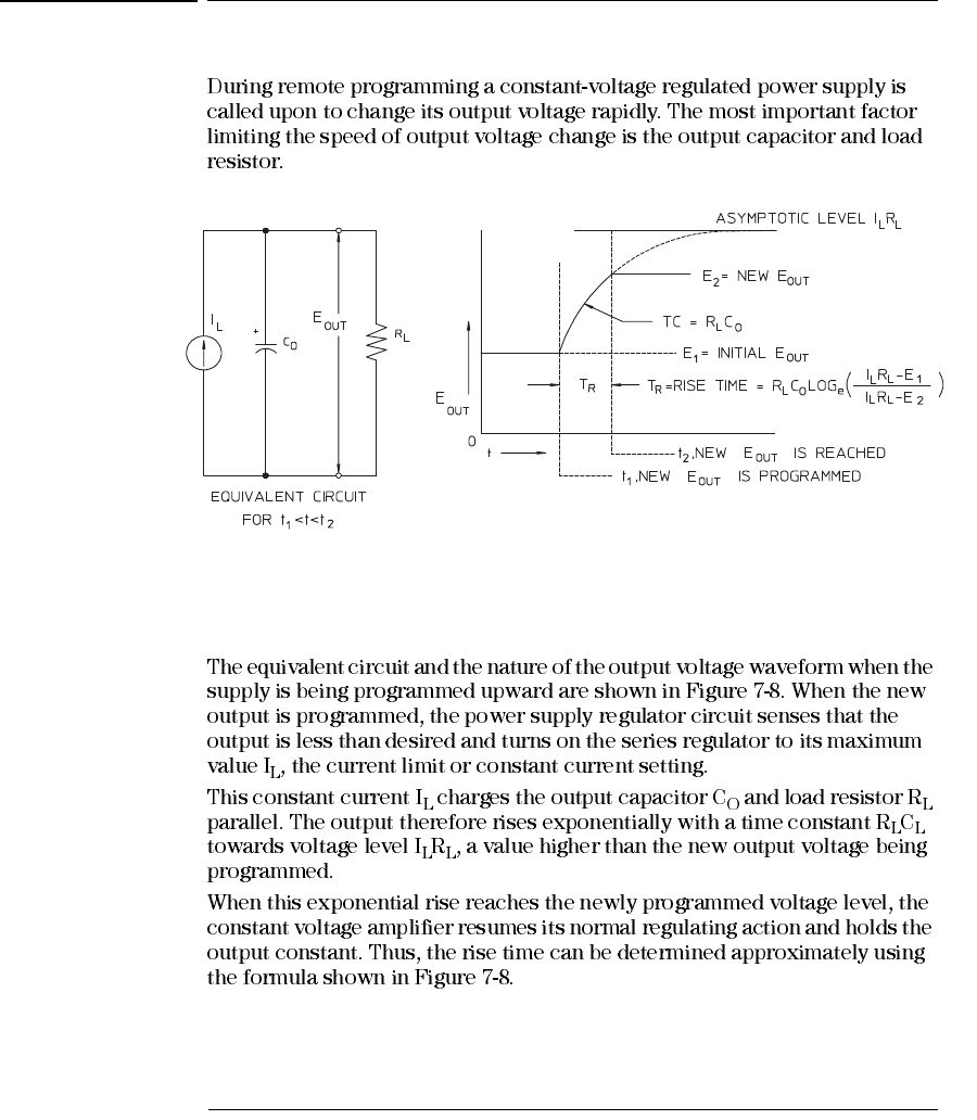
Figure 7-7. Speed of Response - Programming Up (Full Load)
Chapter 7 Tutorial
Remote Programming
145
7
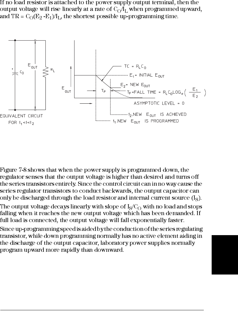
Figure 7-8. Speed of Response - Programming Down

Chapter 7 Tutorial
Remote Programming
146

8
Specifications
148
Specifications
Chapter 8 Specifications
Performance Specifications
149 8
Performance Specifications
Table 8-1 Performance Specifications
Parameter E3640A E3641A E3642A E3643A E3644A E3645A
Output Ratings
(@ 0 °C - 40 °C) Low
Range 0 to +8 V/
0 to 3 A 0 to +35 V/
0 to 0.8 A 0 to +8 V/
0 to 5 A 0 to +35 V/
0 to 1.4 A 0 to +8 V/
0 to 8 A 0 to +35 V/
0 to 2.2 A
High
Range 0 to +20 V/
0 to 1.5 A 0 to +60 V/
0 to 0.5 A 0 to +20 V/
0 to 2.5 A 0 to +60 V/
0 to 0.8 A 0 to +20 V/
0 to 4 A 0 to +60 V/
0 to 1.3 A
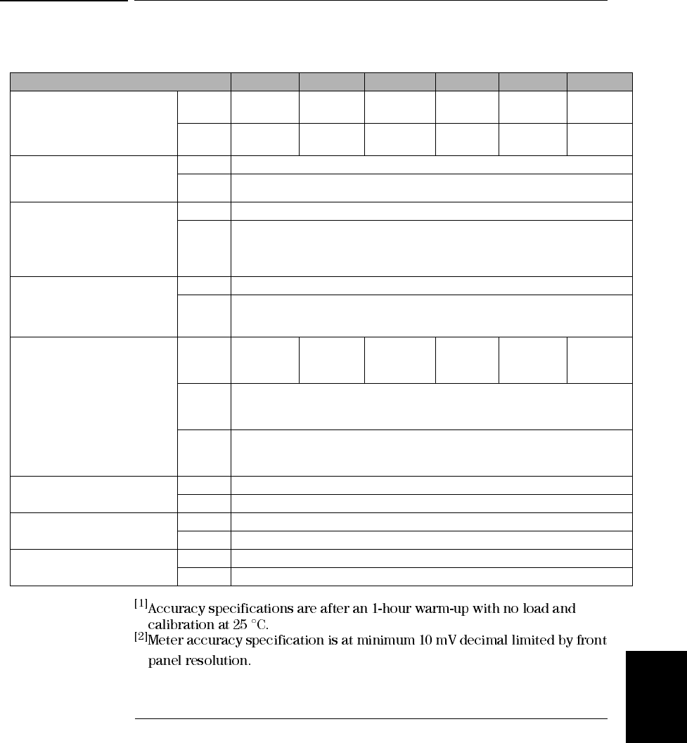
Programming Accuracy[1]
12 months (@ 25 °C ± 5 °C),
±(% of output + offset)
Voltage <0.05% + 10 mV
Current <0.2% + 10 mA
Readback Accuracy[1]
12 months (over GPIB and
RS-232 with respect to actual
output (@ 25 °C ± 5 °C), ±(% of
output + offset)
Voltage <0.05% + 5 mV
Current <0.15% + 5 mA
Meter Accuracy[1] [2]
12 months (overfront panel with
respect to actual output (@ 25 °C
± 5 °C), ±(% of output + offset)
Voltage < (0.05% + 2 counts)
Current <0.15% + 5 mA
Ripple and Noise
(with outputs ungrounded, or
with either output terminal
grounded, 20 Hz to 20 MHz)
Normal
mode
voltage
<0.5 mVrms
and
5 mVp-p
<1 mVrms
and
8 mVp-p
<0.5 mV rms
and
5 mVp-p
<1 mVrms
and
8 mVp-p
<0.5mVrms
and
5 mVp-p
<1 mVrms
and
8 mVp-p
Normal
mode
current
<4 mA rms
Common
mode
current
<1.5 uA rms
Load Regulation,
±(% of output + offset) Voltage <0.01% + 3 mV
Current <0.01% + 250 uA
Line Regulation,
±(% of output + offset) Voltage <0.01% + 3 mV
Current <0.01% + 250 uA
Programming Resolution Voltage <5 mV
Current <1 mA
Chapter 8 Specifications
Performance Specifications
150
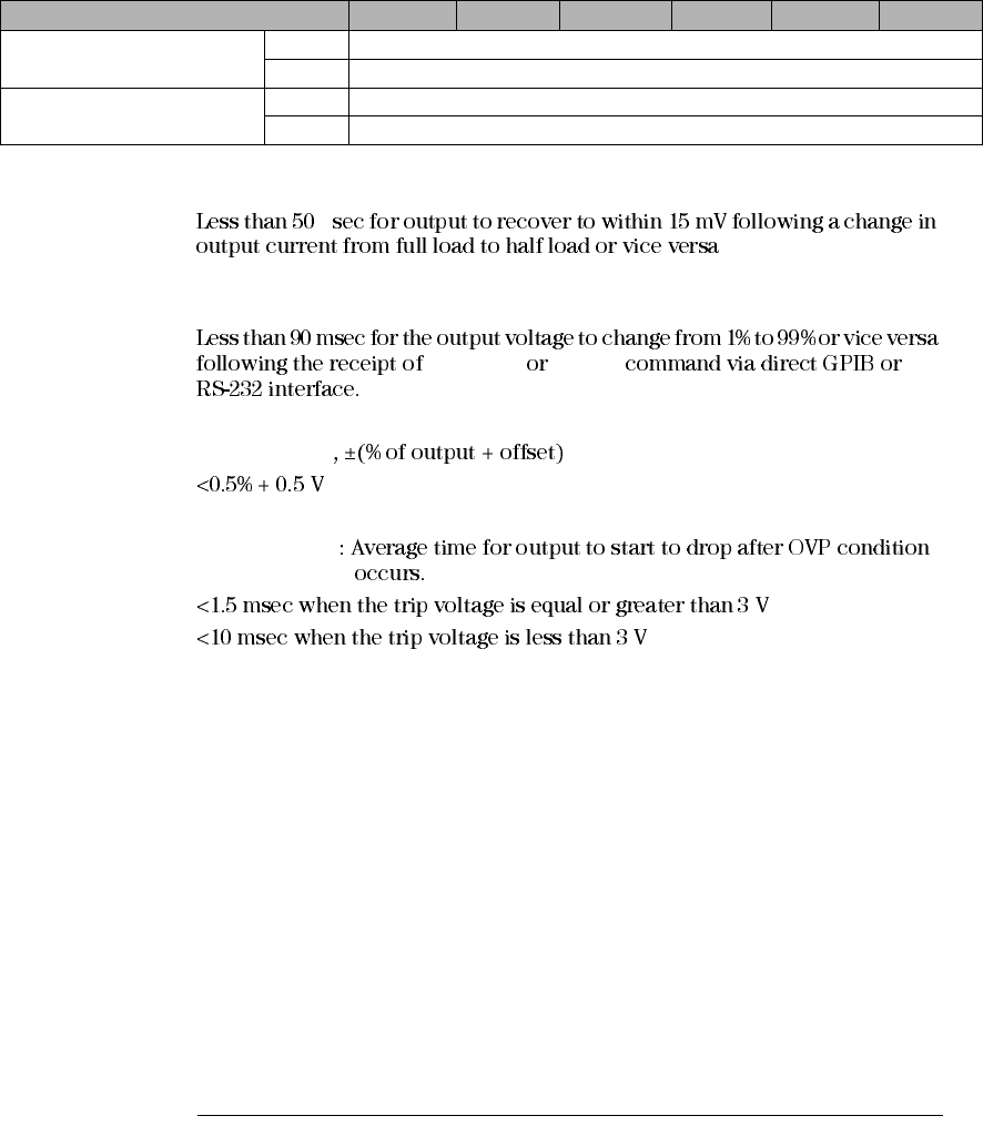
Transient Response Time
μ
Settling Time
VOLTage APPLy
OVP Accuracy
Activation time
Parameter E3640A E3641A E3642A E3643A E3644A E3645A
Readback Resolution Voltage <2 mV
Current <1 mA
Front Panel Resolution Voltage 10 mV
Current 1 mA
Chapter 8 Specifications
Supplemental Characteristics
151 8
Supplemental Characteristics
Table 8-2. Supplemental Characteristics
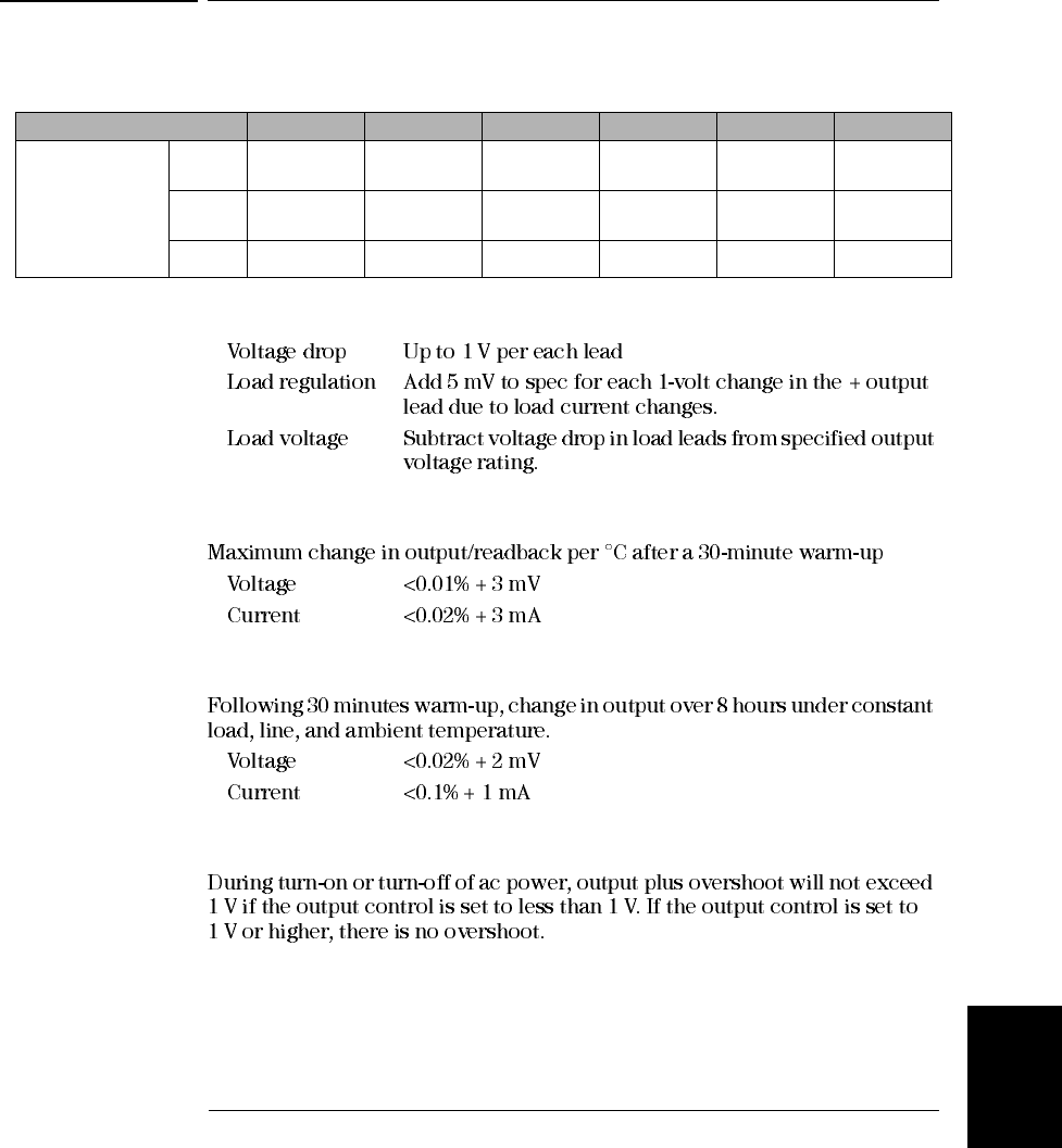
Remote Sensing Capability
Temperature Coefficient, ±(% of output + offset)
Stability, ±(% of output + offset)
Output Voltage Overshoot
Parameter E3640A E3641A E3642A E3643A E3644A E3645A
Output
Programming
Range
(maximum
programmable
values)
Low
Range 0 to +8.24 V/
0 to 3.09 A 0 to +36.05 V/
0 to 0.824 A 0 to +8.24 V/
0 to 5.15 A 0 to +36.05 V/
0 to 1.442 A 0 to +8.24 V/
0 to 8.24 A 0 to +36.05 V/
0 to 2.266 A
High
Range 0 to +20.6 V/
0 to 1.545 A 0 to +61.8V/
0 to 0.515 A 0 to +20.6V/
0 to 2.575 A 0 to +61.8V/
0 to 0.824 A 0 to +20.6 V/
0 to 4.12 A 0 to +61.8V/
0 to 1.339 A
OVP 1 V to 22 V 1 V to 66 V 1 V to 22 V 1 V to 66 V 1 V to 22 V 1 V to 66 V
Chapter 8 Specifications
Supplemental Characteristics
152
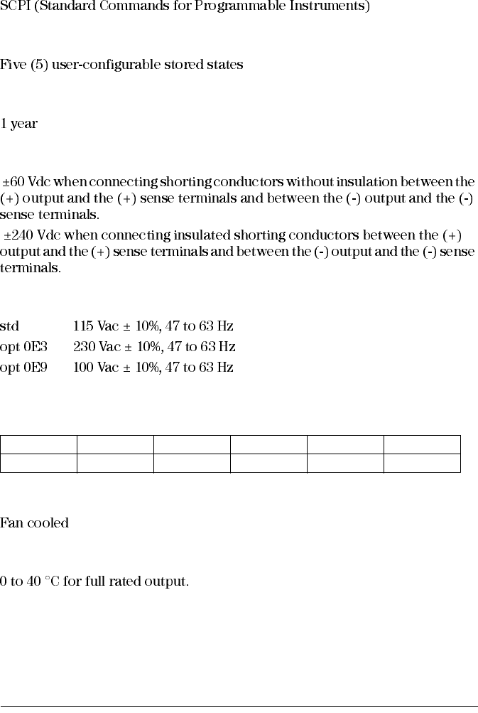
Programming Language
State Storage Memory
Recommended Calibration Interval
Output Terminal Isolation (maximum, from chassis ground)
AC Input Ratings (selectable via two switches on PC board)
Maximum Input Power
Cooling
Operating Temperature
E3640A E3641A E3642A E3643A E3644A E3645A
105 VA 105 VA 205 VA 175 VA 300 VA 270 VA
Chapter 8 Specifications
Supplemental Characteristics
153 8
Storage Temperature
Environmental Conditions
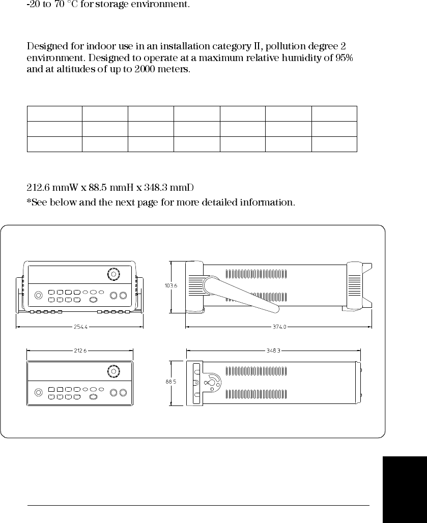
Weight
Dimensions*
Figure 8-1. Dimensions of Agilent E3640A/41A/42A/43A/44A/45A Power Supply
E3640A E3641A E3642A E3643A E3644A E3645A
Net 5.3 Kg 5.2 Kg 6.3 Kg 6.2 Kg 6.6 Kg 6.7 Kg
Shipping 7.2 Kg 7.1 Kg 8.2 Kg 8.1 Kg 8.5 Kg 8.6 Kg
Chapter 8 Specifications
Supplemental Characteristics
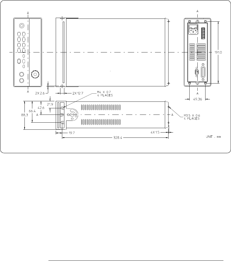
154
Figure 8-2. Dimensions for Rack mounting

Appendix
Service Information
Appendix Service Information
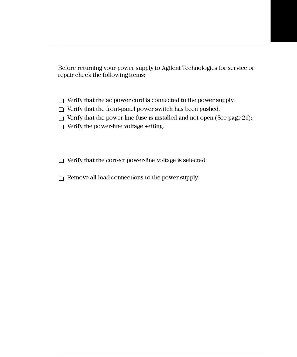
Operating Checklist
157
Service
Information
Operating Checklist
Is the Power Supply Inoperative?
See “Si l’alimentation ne se met pas sous tension” on page 20.
Does the Power Supply Fail Self-Test?
See “If the Power Supply Does Not Turn On” on page 20.
Ensure that all terminal connections are removed while the self-test is
performed.
Appendix Service Information
Types of Service Available
158
Types of Service Available
Standard Repair Service (worldwide)
Express Exchange (U.S.A. only)
Appendix Service Information
Repacking for Shipment
159
Service
Information
Repacking for Shipment

Appendix Service Information
Troubleshooting Hints
161
Service
Information
Troubleshooting Hints
Unit Reports Errors 740 to 750
Unit Fails Self-Test
Bias Supplies Problems
Table A-1 Bias Supplies Voltages
Bias Supply Minimum Maximum Check At
+5V Floating +4.75 V +5.25 V U110 pin 2
-5.1V Floating -4.75 V -5.25 V Anode of CR114
+15V Floating +14.25 V +15.75 V Anode of CR104
-15V Floating -14.25 V -15.75 V Cathode of CR105
Appendix Service Information
Self-Test Procedures
162
Self-Test Procedures
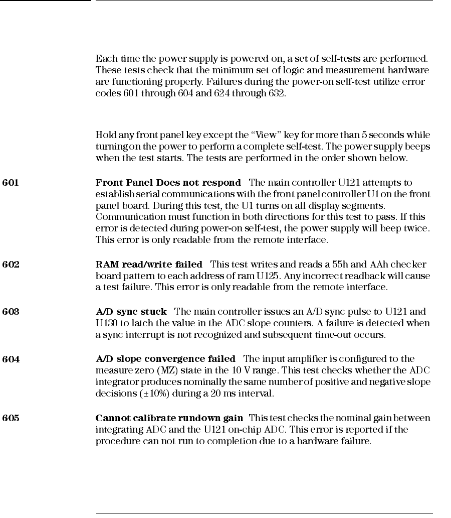
Power-On Self-Test
Complete Self-Test
Appendix Service Information
Self-Test Procedures
163
Service
Information
Appendix Service Information
General Disassembly
164
General Disassembly
Appendix Service Information
165
Service
Information
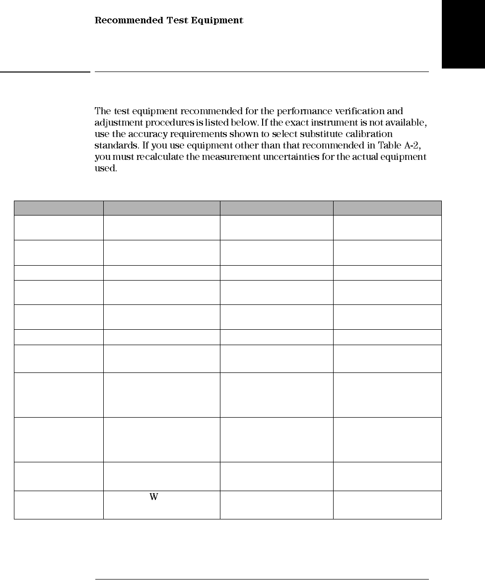
Recommended Test Equipment
Table A-2 Recommended Test Equipment
* To find the accurate resistance, it is recommended to use a current monitoring resistor after calibration.
1E3640A model, 2E3641A model, 3E3642A model, 4E3644A, 5E3643A, 6E3645A model.
Instrument Requirements Recommended Model Use
GPIB controller Full GPIB or RS-232
capabilities Agilent 82341C interface card
or equivalent Programming and readback
accuracy
Oscilloscope 100 MHz with 20 MHz
bandwidth Agilent 54602B Display transient response
and ripple & noise waveform
RMS Voltmeter 20 Hz to 20 MHz Measure rms ripple & noise
Cable (BNC to BNC) 50 ohm, 9 inch (23 Cm) Agilent 10502A or 10503A if
the 10502A is not available Measure rms ripple & noise
(CV PARD, CC PARD)
BNC (Female)
Bulkhead Receptacle Isolated Ground.
Nominal impedance: 50 Ohm Pomona Model 5148 Measure rms ripple & noise
(CV PARD, CC PARD)
Split Ferrites For use with round cable Steward Co. 28A2029-0A0 Noise coupling reduction
Digital Voltmeter Resolution: 0.1 mV
Accuracy: 0.01%
Agilent 34401A Measure dc voltages
Electronic Load Voltage Range: 240 Vdc
Current Range: 10 Adc
Open and Short Switches
Transient On/Off
Agilent 60503B Measure load and line
regulations and transient
response time.
Resistive Loads (RL)(2.7 Ω, 150 W/13.5 Ω, 150 W)1
(43.8 Ω, 300 W/120 Ω, 300 W)2
(1.6 Ω, 300 W/8.0 Ω, 300 W)3
(1.0 Ω, 300 W/5.0 Ω, 300 W)4
(25 Ω, 300 W/75 Ω, 300 W)5
(15.9Ω, 300W/46.2Ω, 300W)6Measure ripple and noise
Current monitoring
Resistor (Shunt) - RM1
(0.01 Ω, 0.1%)*ISOTEK Co. Model: A-H or
equivalent Constant current test setup
Current monitoring
Resistor (Shunt) - RM2
(0.2 Ω/250 , 0.1%)*ISOTEK Co. Model: RUG-Z
or equivalent Measure current rms ripple &
noise
Appendix Service Information
Test Considerations
166
Test Considerations
Caution The tests should be performed by qualified personnel. During performance
verification tests, hazardous voltages may be present at the outputs of the power
supply.
Operation Verification and Performance Tests
Operation Verification Tests
Performance Tests
Performance
Specifications
Appendix Service Information
Measurement Techniques
168
General Measurement Techniques
Figure A-2 Front/Rear Panel Terminal Connections
Electronic Load
Programming
TO MONITORING
DEVICE
TO LOAD OR
CURRENT
RESISTOR
[Front Panel (Side View)] (Rear Panel)
Appendix Service Information
Constant Voltage (CV) Verifications
169
Service
Information
Constant Voltage (CV) Verifications
Constant Voltage Test Setup
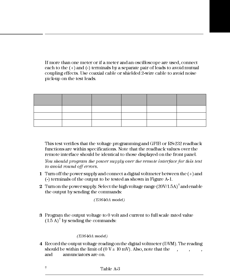
Table A-3 Verification Programming Values
Voltage Programming and Readback Accuracy
VOLT:RANG P20V
OUTP ON
VOLT 0
CURR 1.5
CV Adrs Limit
Rmt
Model Low voltage
range High voltage
range Model Low voltage
range High voltage
range
E3640A 8V/3A 20V/1.5A E3643A 35V/1.4A 60V/0.8A
E3641A 35V/0.8A 60V/0.5A E3644A 8V/8A 20V/4A
E3642A 8V/5A 20V/2.5A E3645A 35V/2.2A 60V/1.3A
For E3640A model, and see for other models
Appendix Service Information
Constant Voltage (CV) Verifications
172
Ω
CV
Note: For better measurement result, it is recommended to make the connection between
the BNC receptacle and the output terminals shorter as much as possible, and to use
the recommended split ferrites with the cable (BNC to BNC) as shown above.
Load Resistor
RMS voltmeter
RMS voltmeter
(Front Panel Connections) (Rear Panel Connections)
BNC Cable
BNC
Receptacle
Split Ferrites*
Input
Load Resistor
Input
*For E3640A/42A/44A models. **For E3641A/43A/45A models.
For E3640A model, and see for other models.
For E3640A model, and see for other models.
Appendix Service Information
Constant Current (CC) Verifications
175
Service
Information
O
CURR 3.0
M O
MEAS:CURR?
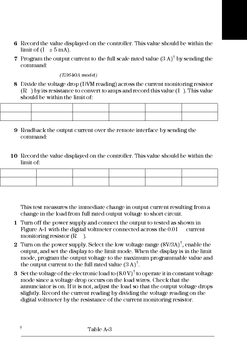
CC Load Effect (Load Regulation)
Ω
M1
CC
E3640A E3641A E3642A E3643A E3644A E3644A
3 A ± 16 mA 0.8 A ± 11.6 mA 5 A ± 20 mA 5 A ± 20 mA 8 A ± 26 mA 8 A ± 26 mA
E3640A E3641A E3642A E3643A E3644A E3642A
(IO ± 9.5 mA) (IO ± 6.2 mA) (IO ± 12.5 mA) (IO ± 7.1 mA) (IO ± 17 mA) (IO ± 8.3 mA)
For E3640A model, and see for other models
Appendix Service Information
Constant Current (CC) Verifications
176
CC Source Effect (Line Regulation)
M1
CC
CC
E3640A E3641A E3642A E3643A E3644A E3645A
0.55 mA 0.33 mA 0.75 mA 0.39 mA 1.05 mA 0.47 mA
E3640A E3641A E3642A E3643A E3644A E3645A
0.55 mA 0.33 mA 0.75 mA 0.39 mA 1.05 mA 0.47 mA
For E3640A model, and see for other models
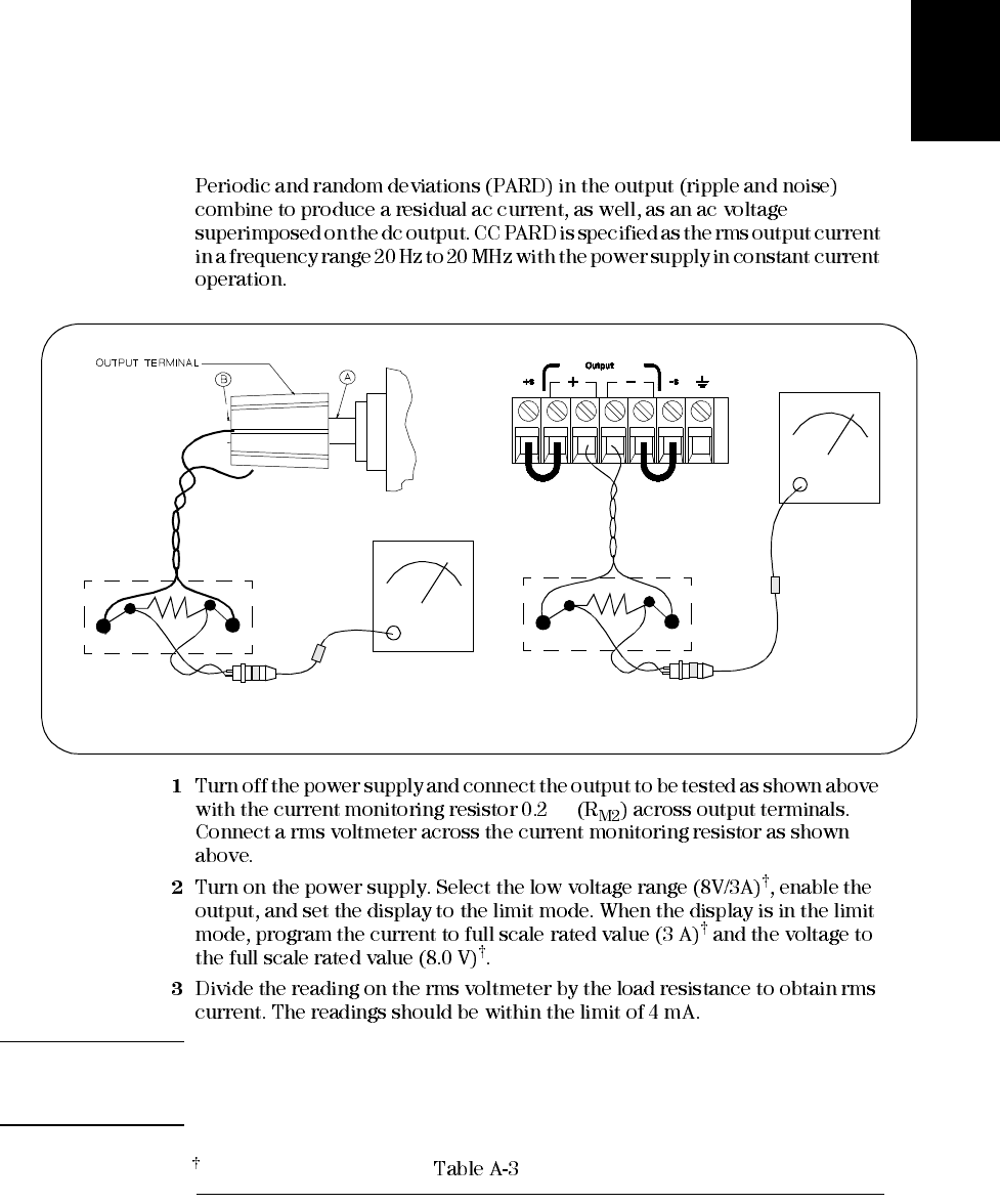
Appendix Service Information
Constant Current (CC) Verifications
177
Service
Information
CC PARD (Ripple and Noise)
Ω
Note: For better measurement result, it is recommended to make the connection between
the BNC receptacle and the output terminals shorter as much as possible, and to use
the recommended split ferrites with the cable (BNC to BNC) as shown above.
Input
RMS voltmeter
RMS voltmeter
(Front Panel Connections) (Rear Panel Connections)
Current
Monitoring
Resistor
Current
Monitoring
Resistor
BNC Cable
BNC
Receptacle
Split
Ferrites Input
For E3640A model, and see for other models
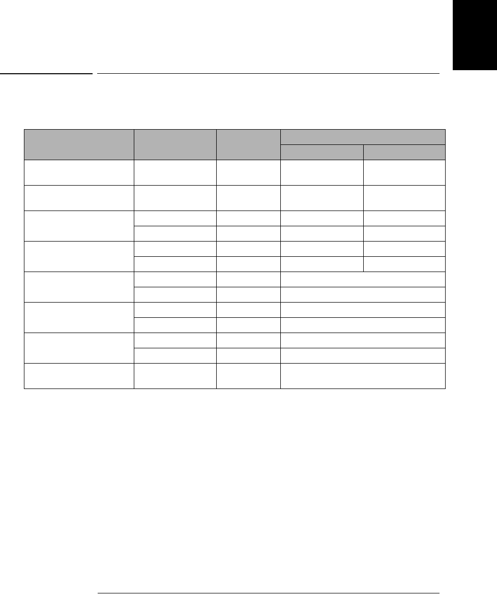
Appendix Service Information
Performance Test Record for Your Power Supply
179
Service
Information
Performance Test Record for Your Power Supply
CV Performance Test Record
Test Description Models Actual Result Specifications
Upper Limit Lower Limit
CV Programming Accuracy
@ 0 volts (DVM reading) all +0.0100 V -0.0100 V
CV Readback Accuracy
@ 0 volts all DVM +0.0050 V DVM -0.0050 V
CV Programming Accuracy
@ Full Scale (DVM reading) E3640A/42A/44A +20.0200 V +19.9800 V
E3641A/43A/45A +60.0400 V +59.9600 V
CV Readback Accuracy
@ Full Scale E3640A/42A/44A DVM + 0.0150 V DVM - 0.0150 V
E3641A/43A/45A DVM + 0.0350 V DVM - 0.0350 V
CV Load Effect (Load
Regulation) E3640A/42A/44A Maximum change: < 5 mV
E3641A/43A/45A Maximum change: < 9 mV
CV Source Effect (Line
Regulation) E3640A/42A/44A Maximum change: < 5 mV
E3641A/43A/45A Maximum change: < 9 mV
CV PARD (Normal mode) E3640A/42A/44A < 5 mVp-p / 0.5 mVrms
E3641A/43A/45A < 8 mVp-p / 1 mVrms
Load Transient Response
Time all < 50 μsec

Appendix Service Information
Performance Test Record for Your Power Supply
180
CC Performance Test Record
Test Description Models Actual
Result
Specifications
Upper Limit Lower Limit
CC Programming Accuracy
@ 0 amps (IO)all +0.0100 A -0.0100 A
CC Readback Accuracy @ 0 amps all IO + 0.0050 A IO - 0.0050 A
CC Programming Accuracy
@ Full Scale (IO)(E3640A) 3.01600 A 2.9840 A
(E3641A) 0.8116 A 0.7884 A
(E3642A) 5.02 A 4.98 A
(E3643A) 1.4128 A 1.3872 A
(E3644A) 8.026 7.974 A
(E3645A) 2.2144 2.1856 A
CC Readback Accuracy @ Full Scale (E3640A) IO + 0.0095 A IO - 0.0095 A
(E3641A) IO + 0.0062 A IO - 0.0062 A
(E3642A) IO + 0.0125 A IO - 0.0125 A
(E3643A) IO + 0.0071 A IO - 0.0071 A
(E3644A) IO + 0.0170 A IO - 0.0170 A
(E3645A) IO + 0.0083 A IO - 0.0083 A
CC Load Effect (Load Regulation) (E3640A) Maximum change: < (0.55 mA)
(E3641A) Maximum change: < (0.33 mA)
(E3642A) Maximum change: < (0.75 mA)
(E3643A) Maximum change: < (0.39 mA)
(E3644A) Maximum change: < (1.05 mA)
(E3645A) Maximum change: < (0.47 mA)
CC Source Effect (Line Regulation) (E3640A) Maximum change: < (0.55 mA)
(E3641A) Maximum change: < (0.33 mA)
(E3642A) Maximum change: < (0.75 mA)
(E3643A) Maximum change: < (0.39 mA)
(E3644A) Maximum change: < (1.05 mA)
(E3645A) Maximum change: < (0.47 mA)
CC PARD (Normal mode) all < 4 mA rms
CC PARD (Common mode) all < 1.5 μA rms
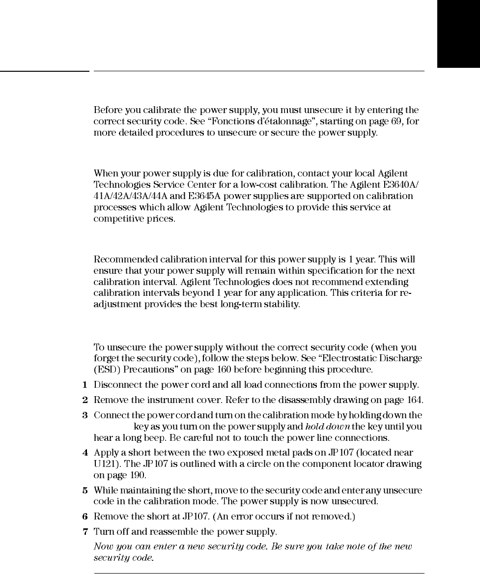
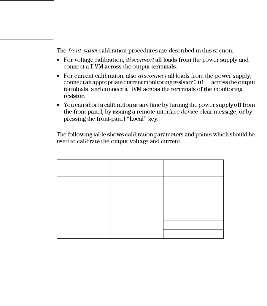
Appendix Service Information
General Calibration/Adjustment Procedure
182
General Calibration/Adjustment Procedure
Note The power supply should be calibrated after 1-hour warm-up with no load connected.
And Perform the voltage calibration prior to the OVP calibration.
Ω
Table 3-2 Parameters for Calibration
Calibration
Parameter
Voltage/
Current
Calibration Point
mnemonic
VOLTAGE CAL Voltage
V LO
V MI
V HI
OVP CAL OVP None
CURRENT CAL Current
I LO
I MI
I HI
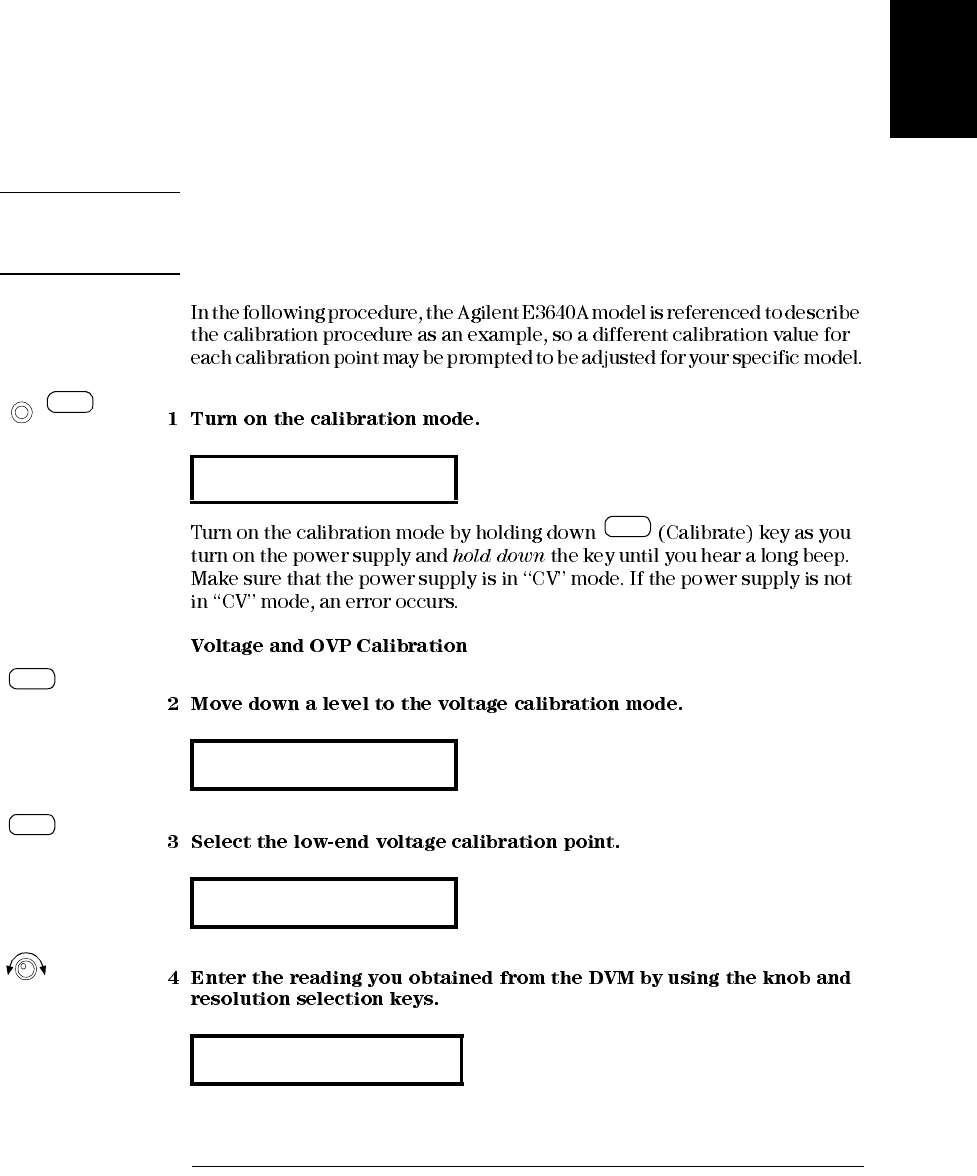
Appendix Service Information
General Calibration/Adjustment Procedure
183
Service
Information
Front Panel Voltage and Current Calibration
Note Before attempting to calibrate the power supply, you must unsecure the power supply,
and disconnect all loads from the power supply and connect a DVM across the output
terminals. See “Fonctions d’étalonnage”, starting on page 69 to unsecure.
CAL MODE
voltage cal
V LO 0.5000
V LO 0.4500
Power
Calibrate
View
Calibrate
View
Calibrate
View
Calibrate
View
Appendix Service Information
General Calibration/Adjustment Procedure
184
ENTERED
VOLTAGE CAL
V MI 10.000
V MI 11.058
V HI 19.500
V HI 19.495
ovp cal
Calibrate
View
Calibrate
View
Calibrate
View
Appendix Service Information
General Calibration/Adjustment Procedure
185
Service
Information
÷
CALibrating
Ω
Current cal
I LO 0.2000
I LO 0.1900
Calibrate
View
Calibrate
View
Appendix Service Information
General Calibration/Adjustment Procedure
186
ENTERED
÷
÷
CURRENT CAL
I MI 1.5000
I MI 1.5400
I HI 2.8000
I HI 2.789 A
CAL mode
Calibrate
View
Calibrate
View
Calibrate
View
Power

Appendix Service Information
Calibration Record for Your Power Supply
187
Service
Information
Calibration Record for Your Power Supply
Step Calibration Description Measurement
Mode (DVM) Supply Being
Adjusted
1Turn on the calibration mode by holding down the "Calibrate" key as you
turn on the power supply until you hear a long beep.
2Unsecure the power supply if secured. (See page 69)
3Press "Calibrate" key to move down menu to voltage calibration menu.
A "VOLTAGE CAL" is displayed. Press "Calibrate" key to select the
low voltage calibration point.
Voltage
Calibration
4A low voltage calibration point is displayed. Enter the DVM reading by
using the knob and resolution keys. Press "Calibrate" key to save the
changes and select the middle calibration point. VLow voltage
calibration
5A middle voltage calibration point is displayed. Enter the DVM reading
by using the knob and resolution selection keys. Press "Calibrate" key to
save the changes and select the high calibration point. VMiddle voltage
calibration
6A high voltage calibration point is displayed. Enter the DVM reading by
using the knob and resolution selection keys. Press "Calibrate" key to
save the changes and select the OVP calibration. VHigh voltage
calibration
7"OVP CAL" is displayed. Press "Calibrate" key to run the overvoltage
calibration. A "CALIBRATING" is displayed to indicate that the
calibration is progressing. VOVP calibration
8Connect shunt resistor (0.01 Ω) across the output terminals. And press
"Calibrate" key to select the current calibration. Current calibration
9
A low current calibration point is displayed. Enter the computed value
(DVM reading / by shunt resistance) by using the knob and resolution
keys. Press "Calibrate" key to save the changes and select the middle
calibration point.
ALow current
calibration
10
A middle current calibration point is displayed. Enter the computed value
(DVM reading / by shunt resistance) by using the knob and resolution
keys. Press "Calibrate" key to save the changes and select the high
calibration point.
AMiddle current
calibration
11 A high current calibration point is displayed. Enter the computed value
(DVM reading / by shunt resistance) by using the knob and resolution
keys. Press "Calibrate" key to save the changes AHigh current
calibration
13 Turn off the "Power" switch to exit the calibration menu. Exit CAL MODE
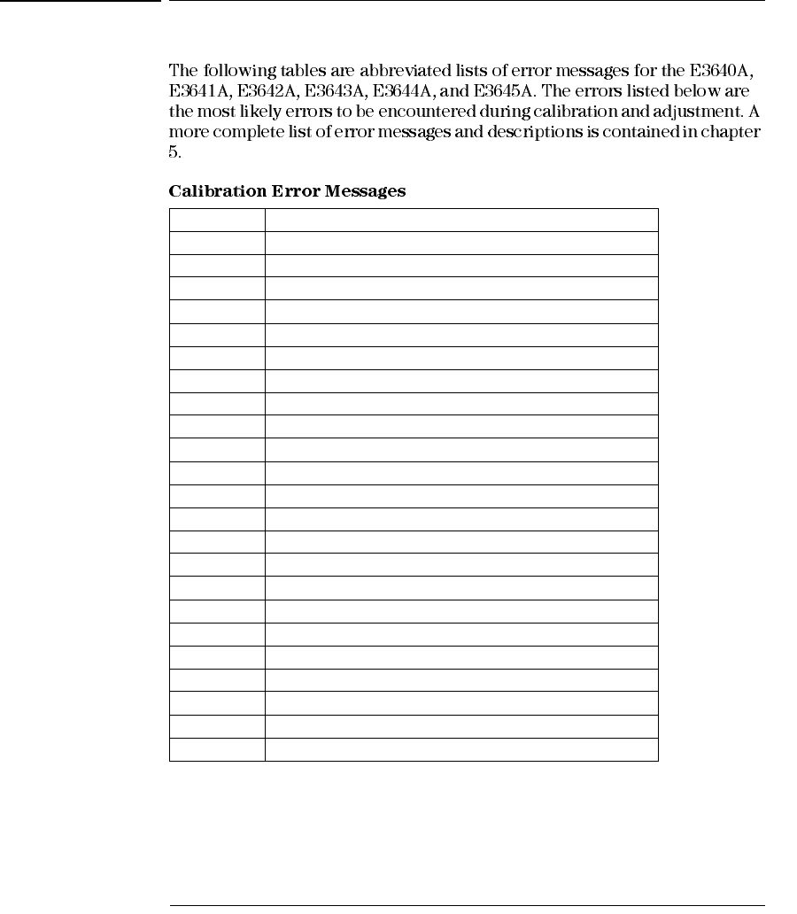
Appendix Service Information
Calibration Error Messages
188
Calibration Error Messages
Error Error Messages
701 Cal security disabled by jumper
702 Cal secured
703 Invalid secure code
704 Secure code too long
705 Cal aborted
706 Cal value out of range
708 Cal output disabled
712 Bad DAC cal data
713 Bad readback cal data
714 Bad OVP cal data
717 Cal OVP status enabled
718 Gain out of range for gain error correction
740 Cal checksum failed, secure state
741 Cal checksum failed, string data
743 Cal checksum failed, store/recall data in location 1
744 Cal checksum failed, store/recall data in location 2
745 Cal checksum failed, store/recall data in location 3
746 Cal checksum failed, DAC cal constants
747 Cal checksum failed, readback cal constants
748 Cal checksum failed, GPIB address
749 Cal checksum failed, internal data
754 Cal checksum failed, store/recall data in location 4
755 Cal checksum failed, store/recall data in location 5

Appendix Service Information
Schematics
189
Service
Information
Schematics
Schematics and Diagrams
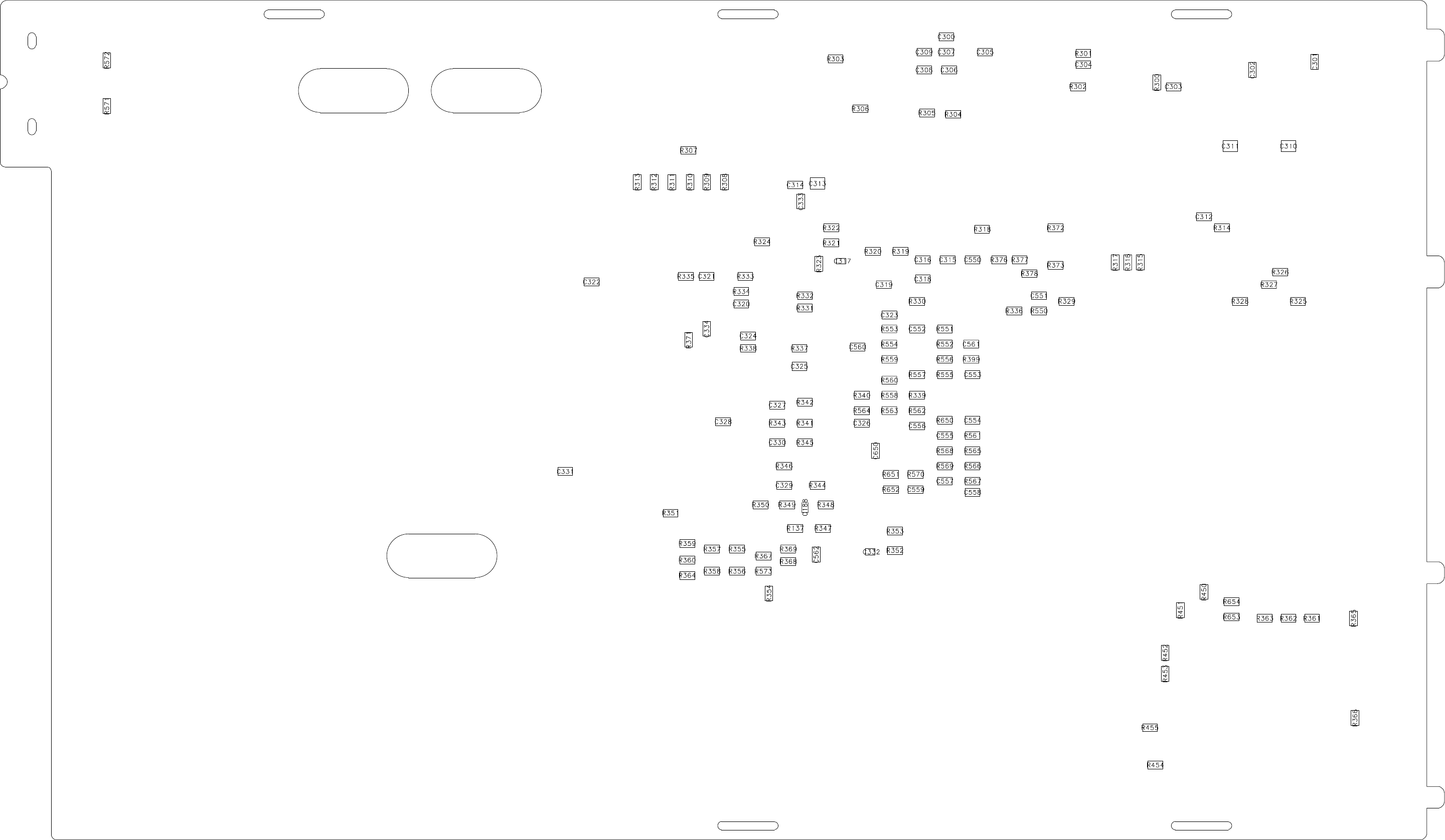
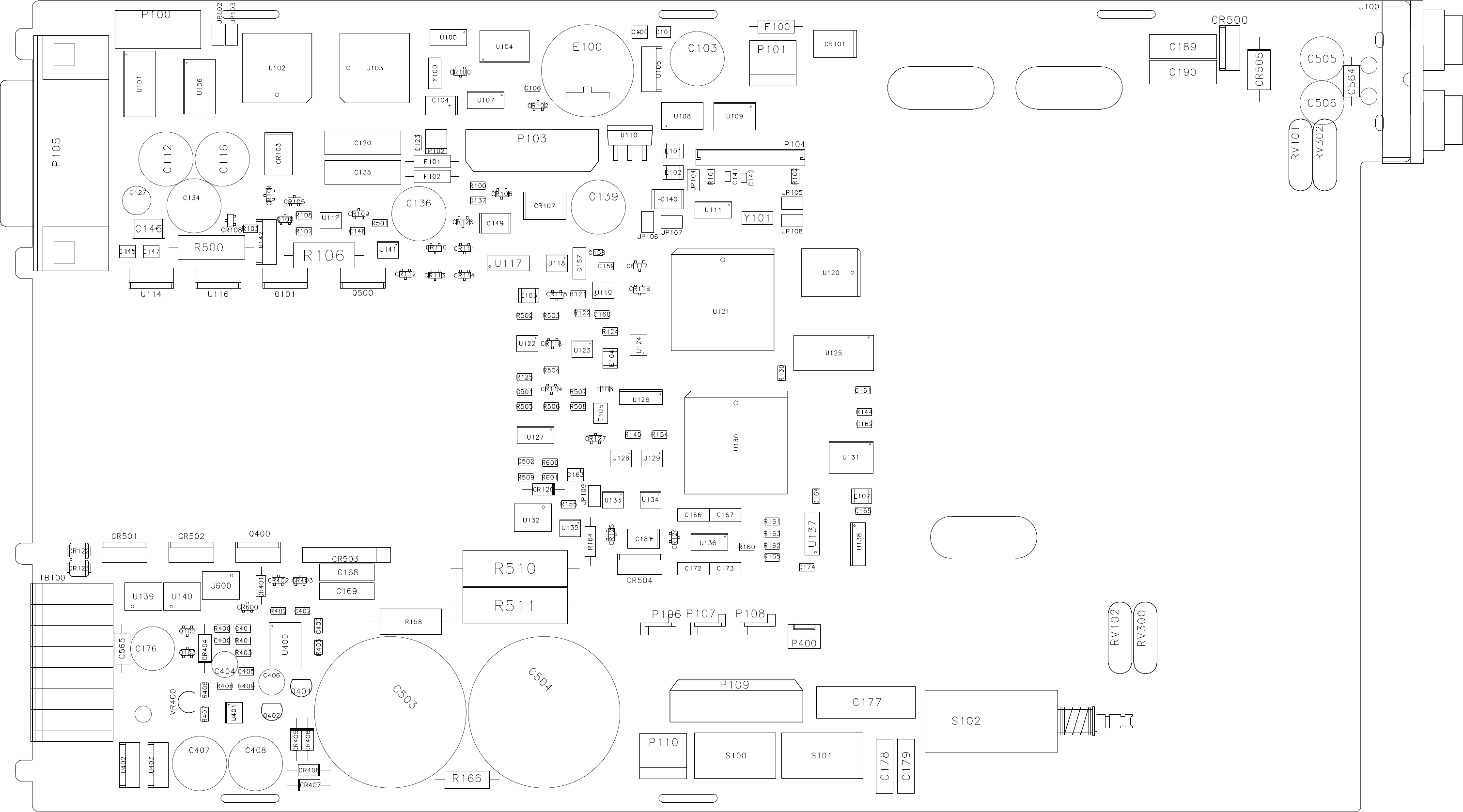
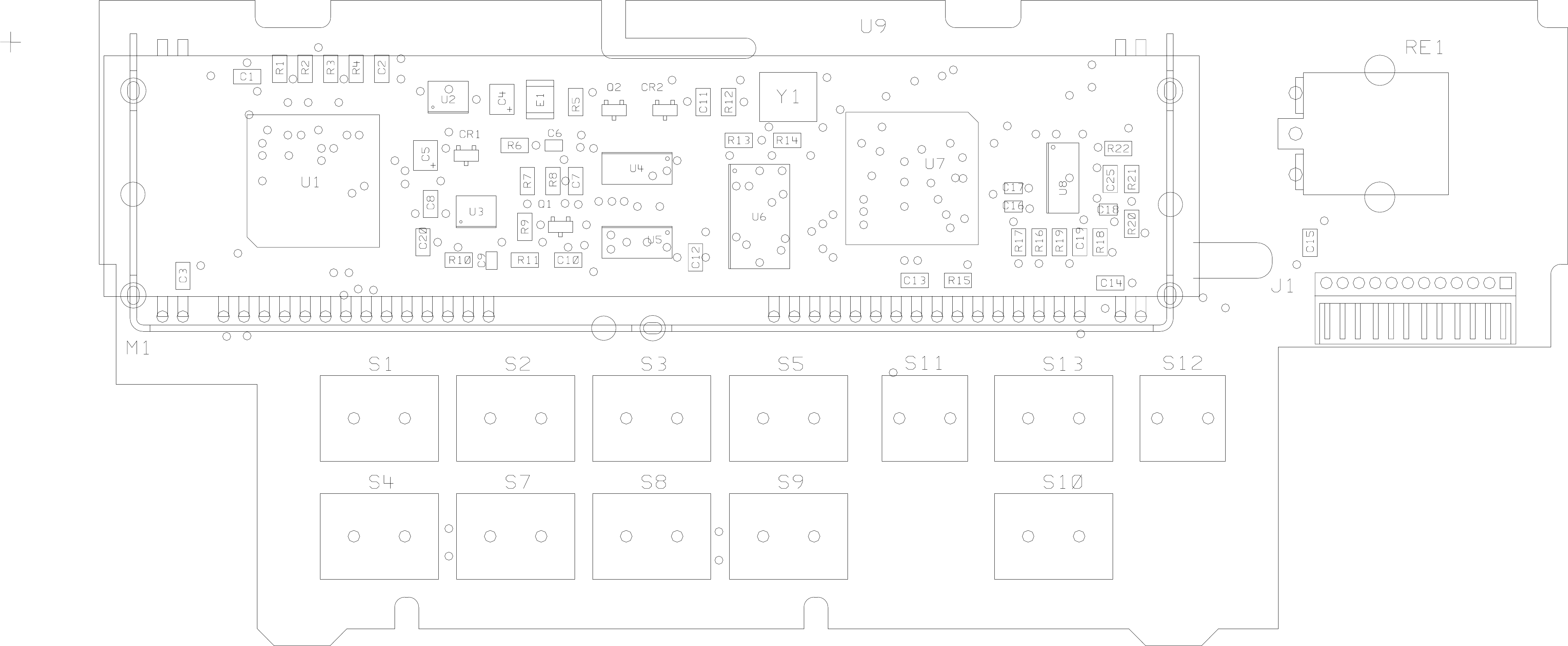
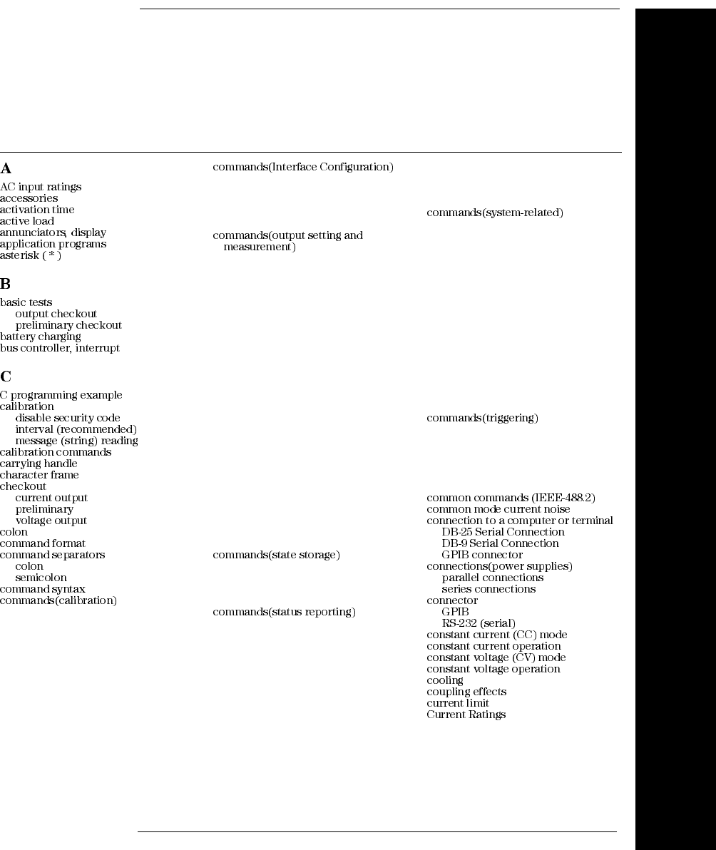
193
Index
If you have questions relating to the operation of the power supply,
call 1-800-829-4444 in the United States, or contact your nearest
Agilent Technologies Sales Office.
Index
152
30 150
36 5
124
106
18, 19
17
53 99
125
62 62 152
66
89
23
59
19
17
18
105 104
105 105
104
CALibration:COUNt? 89
CALibration:CURRent:LEVel
89
CALibration:CURRent[:DATA]
89
CALibration:SECure:CODE 89
CALibration:SECure:STATe 90
CALibration:SECure:STATe?
90
CALibration:STRing 90
CALibration:STRing? 90
CALibration:VOLTage:LEVel
90
CALibration:VOLTage:PRO-
Tection 90
CALibration:VOLTage[:DATA]
90
<Ctrl-C> 92
SYSTem:INTerface 92
SYSTem:LOCal 92
SYSTem:REMote 92
SYSTem:RWLock 92
APPLy 77
APPLy? 77
CURRent 78
CURRent:STEP 78
CURRent:STEP? 79
CURRent:TRIGgered 79
CURRent:TRIGgered? 79
CURRent? 78
MEASure:CURRent? 81
MEASure[:VOLTage]? 81
VOLTage 79
VOLTage:PROTection 80
VOLTage:PROTection:CLEar 81
VOLTage:PROTection:STATe 81
VOLTage:PROTection:STATe?
81
VOLTage:PROTec-
tion:TRIPped? 81
VOLTage:PROTection? 81
VOLTage:RANGe 81
VOLTage:RANGe? 81
VOLTage:STEP 80
VOLTage:STEP? 80
VOLTage:TRIGgered 80
VOLTage:TRIGgered? 80
VOLTage? 79
*RCL { 1 | 2 | 3 | 4 | 5 } 88
*SAV { 1 | 2 | 3 | 4 | 5 } 88
MEMory:STATe:NAME { 1 | 2 |
3 | 4 | 5} 88
*CLS 101
*ESE 101
*ESE? 102
*ESR? 102
*OPC 102
*OPC? 102
*PSC { 0 | 1 } 102
*PSC? 102
*SRE 102
*SRE? 102
*STB? 102
*WAI 102
STATus:QUEStionable:CONDi-
tion? 101
STATus:QUEStionable:ENABle
101
STATus:QUEStionable:EN-
ABle? 101
STATus:QUEStionable? 101
SYSTem:ERRor? 101
*IDN? 86
*RST 87
*TST? 86
DISPlay {OFF | ON} 85
DISPlay:TEXT 85
DISPlay:TEXT:CLEar 85
DISPlay:TEXT? 85
DISPlay? 85
OUTPut {OFF | ON} 85
OUTPut:RELay {OFF | ON} 85
OUTPut:RELay? 86
OUTPut? 85
SYSTem:BEEPer 86
SYSTem:COMMunicate:GPIB
RDEVice 86
SYSTem:ERRor? 86
SYSTem:VERSion? 86
*TRG 84
INITiate 84
TRIGger:DELay 84
TRIGger:DELay? 84
TRIGger:SOURce 84
TRIGger:SOURce? 84 106
141
61
60
58
143
143
58 59 139, 140
44, 45
139, 140
42, 43
33, 152
38
44 34
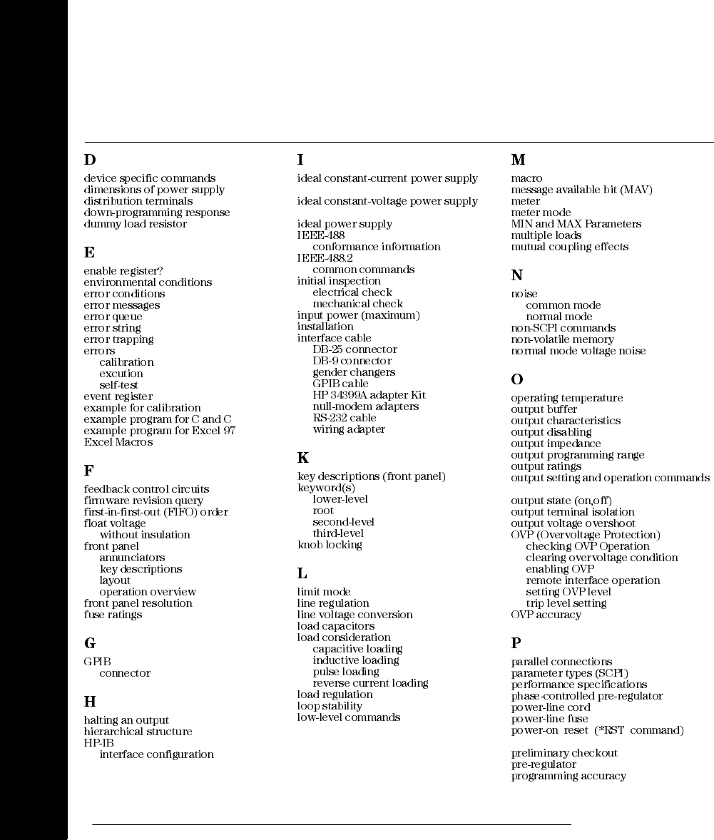
194
Index
Index
111
153
38 145
36
93 153
56
114
114
114
125
121
115
120
93 91 125
129
129
137
57 114
32
5 3
2 41
149
20
58
108 103
58
139
139 141
112
106
33
33 152
33
60
60
60
30 60
60
30
60
3
103
103 103
103
54
41, 42
149 21
35
35
35
35 36
149
35 74
130 99
41 18 105
38 38
142
142 111
48 141
152
97 139
54
139 151
149
78 54 152
151
51 51
50 52
50
50
150
143
107
149
137
17
20 87,
88 17
137 149
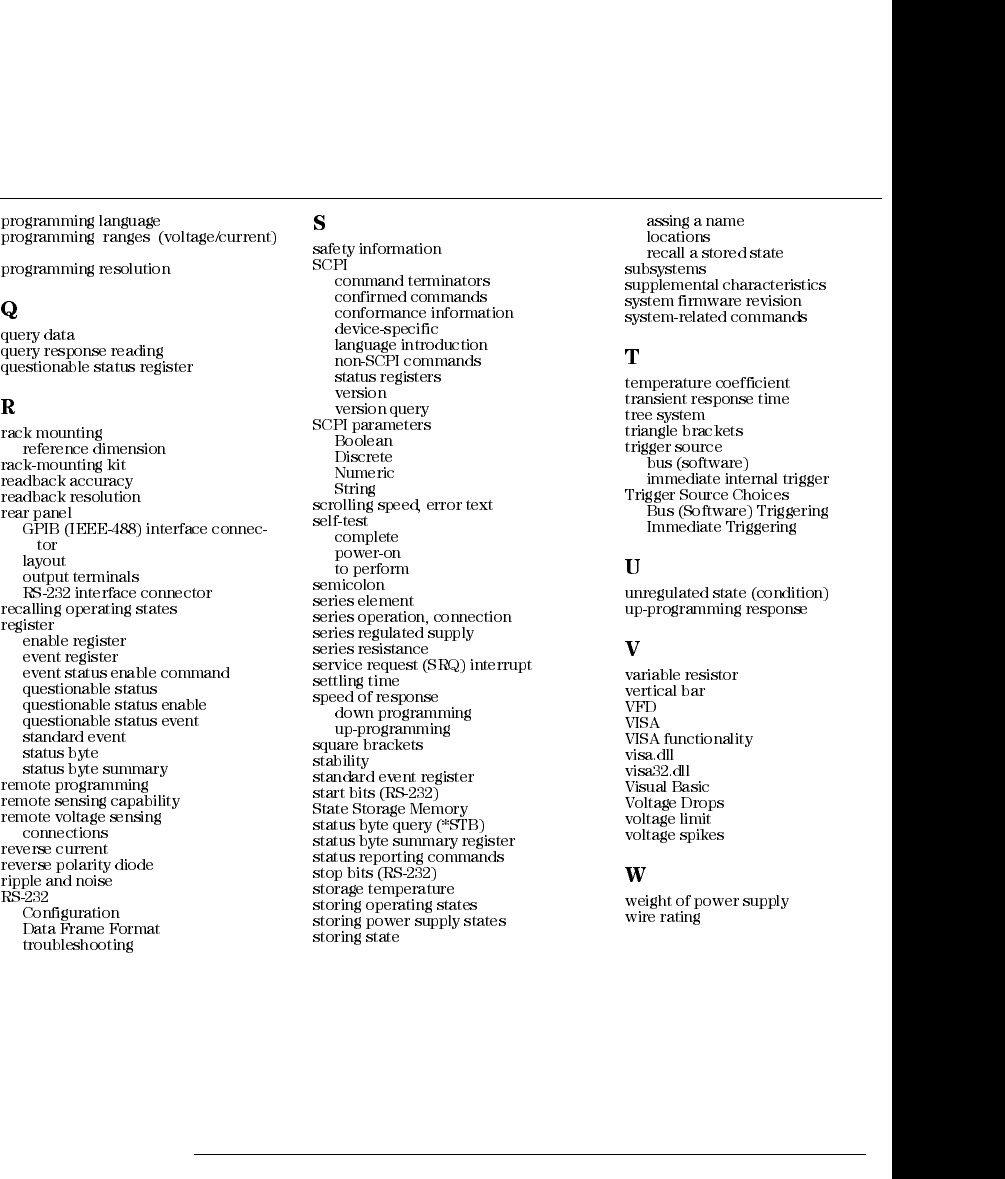
195
Index
Index
152
76 149
97 75 95
24 154
24
149
149
6
6 6 6
48
93
93 96
95 95
95
96
97 97
144
151
36
36 143
149
59 59
61
29
106
109, 110
109
111 103
111
93
57, 109
57
107
107
107
107 114
17, 56
56
56
105
137 143
137
137 98
150
145
144
69
35, 151 96
59 152
99 97
101
59
153
48 55
55
55 55
103 151
57
85
151
150
103 69
75 75
82
83
141
144
137
69
32
124 125
124
124
129
35
42
142
153
34

196
Index
Index
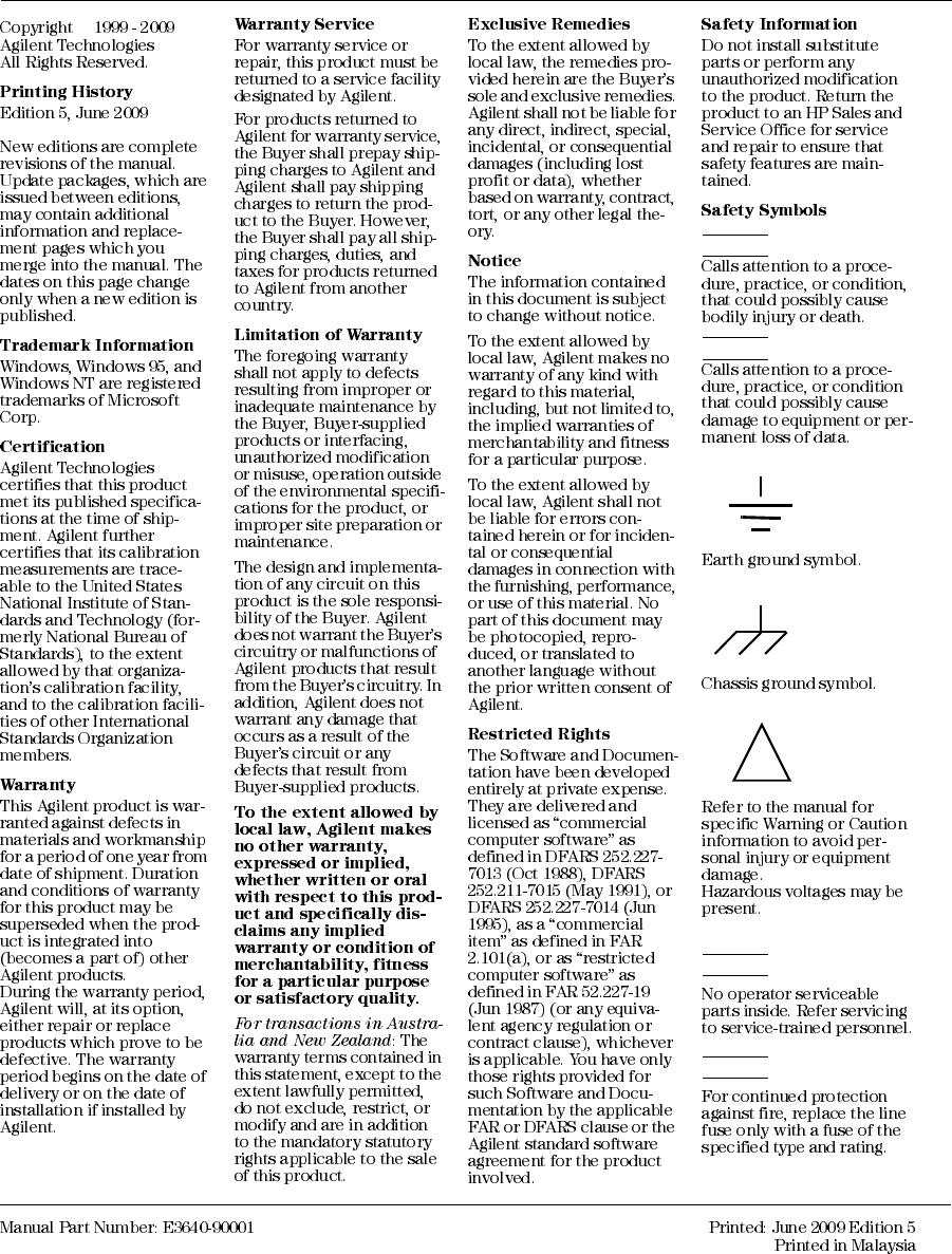
©
Warning
Caution
Warning
Warning
!
DECLARATION OF CONFORMITY
According to ISO/IEC Guide 22 and CEN/CENELEC EN 45014
Revision: B.00.00 Issue Date: Created on 11/24/2003 3:07
PM Document No. KIO_40-49.11.24.doc
Manufacturer’s Name and Addresss
Responsible Party Alternate Manufacturing Site
Agilent Technologies, Inc. Agilent Technologies (Malaysia) Sdn. Bhd
550 Clark Drive, Suite 101
Budd Lake, New Jersey 07828
USA
Malaysia Manufacturing
Bayan Lepas Free Industrial Zone, PH III
11900 Penang,
Malaysia
Declares under sole responsibility that the product as originally delivered
Product Name: a) Single Output dc Power Supplies
b) Multiple Output dc Power Supplies
c) Single Output System Power Supply
Model Nu mber: a) E3640A, E3641A, E3642A, E3643A, E3644A, E3645A
b) E3646A, E3647A, E3648A, E3649A
c) E3633A, E3634A
Product Options: This declaration covers all options of the above product(s).
Complies with the essential requirements of the Low Voltage Directive 73/23/EEC and the EMC
Directive 89/336/EEC (including 93/68/EEC) and carries the CE Marking accordingly.
EMC Information ISM Group 1 Class A Emissions
As detailed in Electromagnetic Compatibility (EMC), Certificate of Conformance Number
CC/TCF/00/102 based on Technical Construction File (TCF) ANJ12, dated Dec
20, 2000.
Assessed by: Celestica Ltd, Appointed Competent Body
Westfields House, West Avenue
Kidsgrove, Stoke-on-Trent
Straffordshire, ST7 1TL
United Kingdom
Safety Information and Conforms to the following safety standards.
IEC 61010-1:2001 / EN 61010-1:2001
CSA C22.2 No. 1010.1:1992
This DoC applies to above-listed products placed on the EU market after:
January 1, 2004
Date Bill Darcy/ Regulations Manager
For further information, please contact your local Agilent Technologies sales office, agent or distributor, or
Agilent Technologies Deutschland GmbH, Herrenberger Straβe 130, D71034 Böblingen, Germany

© Agilent Technologies, Inc. 1999-2009
Printed in Malaysia
Fifth Edition, June 2009
E3640-90001
www.agilent.com
Agilent Technologies
Contact us
To obtain service, warranty or technical support
assistance, contact us at the
following phone numbers:
United States:
(tel) 800 829 4444 (fax) 800 829 4433
Canada:
(tel) 877 894 4414 (fax) 800 746 4866
China:
(tel) 800 810 0189 (fax) 800 820 2816
Europe:
(tel) 31 20 547 2111
Japan:
(tel) (81) 426 56 7832 (fax) (81) 426 56 7840
Korea:
(tel) (080) 769 0800 (fax) (080) 769 0900
Latin America:
(tel) (305) 269 7500
Ta i w an :
(tel) 0800 047 866 (fax) 0800 286 331
Other Asia Pacific Countries:
(tel) (65) 6375 8100 (fax) (65) 6755 0042
Or visit Agilent worlwide Web at:
www.agilent.com/find/assist
Product specifications and descriptions in this
document are subject to change without notice.
