OmniSwitch 6600/6800/6850/6855/9000 Troubleshooting Guide 6800 Alcatel Omni Switches TS
User Manual: 6800
Open the PDF directly: View PDF ![]() .
.
Page Count: 764 [warning: Documents this large are best viewed by clicking the View PDF Link!]
- Home
- Front Matter
- Contents
- About This Guide
- 1.
Troubleshooting the Switch System
- In This Chapter
- Introduction
- Troubleshooting System on OS-6624/6648 and OS-7/8XXX Switches
- Advanced Troubleshooting
- Dshell Troubleshooting
- Using AlcatelDebug.cfg
- Troubleshooting IPC on OS-6/7/8XXX Switches
- Port Numbering Conversion Overview
- Troubleshooting System on OmniSwitch 6850/ 9000 Series
- OS-6850/9000 Dshell Troubleshooting
- 2. Troubleshooting Switched Ethernet Connectivity
- 3. Troubleshooting Source Learning
- 4. Troubleshooting Spanning Tree
- 5. Troubleshooting BOOTP/ DHCP/UDP Relay
- 6. Troubleshooting DNS
- 7. Troubleshooting Link Aggregation
- In This Chapter
- Troubleshooting Link Aggregation on OmniSwitch 6000/7000/8000
- Troubleshooting a Link Aggregation Failure
- Advanced Link Aggregation Troubleshooting
- OS-6800 Link Aggregation Debug Functions
- Troubleshooting Link Aggregation on OmniSwitch 6850/9000 Series
- 8. Troubleshooting 802.1Q
- 9. Troubleshooting Port Mobility
- 10. Troubleshooting QoS
- In This Chapter
- QoS Behavior
- Troubleshooting QoS
- Information Gathering on Symptoms and Recent Changes
- Starting the Troubleshooting Procedure
- QoS Activation
- QoS Apply
- Invalid Policies
- Rules Order
- Viewing QoS Settings
- Viewing QoS Policy Rules
- Validation
- Correction
- Reflexive Rules
- QoS Log
- QoS Statistics
- Debug QoS
- Debug QoS Internal
- OmniSwitch 6624/6648 Dshell Troubleshooting
- Troubleshooting QoS on OmniSwitch 6850/9000 Series
- Example QoS Rules
- 11. Troubleshooting ARP
- 12. Troubleshooting IP Routing
- In This Chapter
- Introduction
- IP Routing Protocol Failure
- Troubleshooting via the CLI
- Troubleshooting with Debug CLI
- RIP Troubleshooting
- OSPF Troubleshooting
- BGP Troubleshooting
- ISIS Troubleshooting
- Dshell Troubleshooting Advanced IP Routing
- 13. Troubleshooting Virtual Router Redundancy Protocol (VRRP)
- 14. Troubleshooting IP Multicast Switching (IPMS)
- 15. Troubleshooting DVMRP
- 16. Alcatel-Lucent Trouble shooting PIM-SM
- 17. Troubleshooting Server Load Balancing
- 18. Troubleshooting Authenticated VLANs
- 19. Troubleshooting 802.1X
- 20. Troubleshooting SNMP
- 21. Troubleshooting Power Over Ethernet
- A. OS6600/OS7700/OS8800 Architecture Overview
- In This Chapter
- The MAC ASIC
- Queue Driver Interaction
- Link Aggregation
- Coronado Tables
- Source Learning
- Hardware Routing Engine (HRE)
- QoS/Policy Manager
- Coronado Egress Logic
- The Fabric Architecture
- Nantucket ASIC
- Roma
- Chassis Management Module (CMM)
- Packet Walk
- Specific Packet Flows
- Unknown Destination
- Hardware Buses on OmniSwitch 7700/7800/ 8800 Switches
- Bus Mapping on OmniSwitch 7700/7800/8800 Switches
- OS6624/6648 Architecture
- CMM Functionality for OS6600
- OS6600 IPC Communication
- OS6600 BOOT Sequence
- B. Debug Commands
- C. Technical Support Commands
- D. Modifying Files with VI Editor
- Index

OmniSwitch Troubleshooting Guide July 2008 i
Part No. 031496-00, Rev. D
July 2008
OmniSwitch 6624/6648/
6800/6850/7700/7800/
8800/9000
Troubleshooting Guide
www.alcatel-lucent.com

ii OmniSwitch Troubleshooting Guide July 2008
This troubleshooting guide documents OmniSwitch 6624/6648/6850/7700/7800/8800/9000
hardware, including chassis and associated components, and Release 5.1 and Release 6 software.
The specifications described in this guide are subject to change without notice.
Copyright © 2008 by Alcatel-Lucent Internetworking, Inc. All rights reserved. This document may not be
reproduced in whole or in part without the express written permission of Alcatel-Lucent Internetworking,
Inc.
Alcatel-Lucent® and the Alcatel-Lucent logo are registered trademarks of Alcatel-Lucent. Xylan®,
OmniSwitch®, OmniStack®, and Alcatel-Lucent OmniVista® are registered trademarks of Alcatel-Lucent
Internetworking, Inc.
OmniAccess™, Omni Switch/Router™, PolicyView™, RouterView™, SwitchManager™, VoiceView™,
WebView™, X-Cell™, X-Vision™, and the Xylan logo are trademarks of Alcatel-Lucent Internetwork-
ing, Inc.
This OmniSwitch product contains components which may be covered by one or more of the following
U.S. Patents:
• U.S. Patent No. 6,339,830
• U.S. Patent No. 6,070,243
• U.S. Patent No. 6,061,368
• U.S. Patent No. 5,394,402
• U.S. Patent No. 6,047,024
• U.S. Patent No. 6,314,106
• U.S. Patent No. 6,542,507
26801 West Agoura Road
Calabasas, CA 91301
(818) 880-3500 FAX (818) 880-3505
support@ind.alcatel.com
US Customer Support—(800) 995-2696
International Customer Support—(818) 878-4507
Internet—service.esd.alcatel-lucent.com or www.businesspartner.alcatel-lucent.com

OmniSwitch Troubleshooting Guide July 2008 iii
Contents
About This Guide .......................................................................................................xvii
Supported Platforms .......................................................................................................xvii
Who Should Read this Manual? ....................................................................................xviii
When Should I Read this Manual? ................................................................................xviii
What is in this Manual? .................................................................................................xviii
What is Not in this Manual? ............................................................................................xix
How is the Information Organized? ................................................................................xix
Related Documentation ...................................................................................................xix
Before Calling Alcatel-Lucent’s Technical Assistance Center ......................................xxii
Chapter 1 Troubleshooting the Switch System ......................................................................1-1
In This Chapter ................................................................................................................1-1
Introduction .....................................................................................................................1-2
Troubleshooting System on OS-6624/6648 and OS-7/8XXX Switches .........................1-3
Advanced Troubleshooting .............................................................................................1-9
Dshell Troubleshooting .................................................................................................1-11
Troubleshooting NIs on OmniSwitch 7700/7800/8800 .........................................1-21
OmniSwitch 6624/6648 Dshell Troubleshooting ...................................................1-23
Accessing Dshell on Idle Switches ..................................................................1-25
Using AlcatelDebug.cfg ................................................................................................1-26
Troubleshooting IPC on OS-6/7/8XXX Switches ........................................................1-27
Debugging IPC .......................................................................................................1-27
OmniSwitch 6624/6648 Example ..........................................................................1-34
Port Numbering Conversion Overview .........................................................................1-36
ifindex to gport .......................................................................................................1-36
gport to ifindex .......................................................................................................1-36
Converting from lport .............................................................................................1-36
OmniSwitch 7700/7800/8800 (Falcon/Eagle) Example ..................................1-36
OmniSwitch 6624/6648 (Hawk) Example ......................................................1-37
Troubleshooting System on OmniSwitch 6850/9000 Series ........................................1-38
Power Supply Shutdown Distribution: Shut-down Starting from Inside to
Outside ..................................................................................................................1-39
9800 Full Chassis Power Shut-down: .............................................................1-39
9700 Half Chassis Power Shut-down: .............................................................1-39
CPU Utilization ......................................................................................................1-39
Switch Log .............................................................................................................1-40

iv OmniSwitch Troubleshooting Guide July 2008
File System .............................................................................................................1-40
Unable to FTP to the Switch ..................................................................................1-41
OS-6850/9000 Dshell Troubleshooting ........................................................................1-42
High CPU Utilization .............................................................................................1-48
Additional Dshell Commands ................................................................................1-50
Chapter 2 Troubleshooting Switched Ethernet Connectivity ..............................................2-1
In This Chapter ................................................................................................................2-1
Overview of Troubleshooting Approach ........................................................................2-2
Verify Physical Layer Connectivity ................................................................................2-3
Verify Current Running Configuration ...........................................................................2-5
Verify Source Learning ...................................................................................................2-6
Verify Switch Health .......................................................................................................2-7
Verify ARP ......................................................................................................................2-7
Using the Log File ...........................................................................................................2-8
Checking the OS-7700/7800 Nantucket Fabric .......................................................2-8
Checking the OS-7700/7800 Nantucket Fabric for Interrupts, Data Counts and
Error Counts ............................................................................................................2-9
Checking the Traffic Queue on the NI .....................................................................2-9
Check for Catalina (MAC) or Port Lockup ............................................................2-10
Troubleshooting OmniSwitch 6850/9000 Series ..........................................................2-11
Chapter 3 Troubleshooting Source Learning .........................................................................3-1
In This Chapter ................................................................................................................3-1
Introduction .....................................................................................................................3-2
Troubleshooting a Source Learning Problem .................................................................3-3
Advanced Troubleshooting .............................................................................................3-5
Dshell Troubleshooting ...................................................................................................3-7
OS-6600 .................................................................................................................3-10
Troubleshooting Source Learning on OmniSwitch 6800/6850/9000 Series .................3-12
Chapter 4 Troubleshooting Spanning Tree ............................................................................4-1
In This Chapter ................................................................................................................4-1
Introduction .....................................................................................................................4-1
Troubleshooting Spanning Tree ......................................................................................4-2
Dshell ..............................................................................................................................4-5
Generic Troubleshooting in Dshell ...............................................................................4-10
Event Trace (stpni_traceprint) ................................................................................4-10
PORTATCH ....................................................................................................4-11
PORTDELE .....................................................................................................4-11
ADDVLAN .....................................................................................................4-11
MODVLADM .................................................................................................4-12

OmniSwitch Troubleshooting Guide July 2008 v
MODVLSTP ....................................................................................................4-12
ADDQTAG .....................................................................................................4-12
DELQTAG ......................................................................................................4-12
MDEFVLAN ...................................................................................................4-13
PORTAGGR ....................................................................................................4-13
PORTDISG ......................................................................................................4-13
AGGR_UP .......................................................................................................4-13
AGGRDOWN .................................................................................................4-13
PORTJOIN ......................................................................................................4-14
PORTLEAV ....................................................................................................4-14
BRGPARAM ...................................................................................................4-14
PTSTPMOD ....................................................................................................4-15
PORTMOD ......................................................................................................4-15
PORTVLBK ....................................................................................................4-15
PVLANBLK ....................................................................................................4-15
GMBPDU ........................................................................................................4-16
GMIGBPDU ....................................................................................................4-16
GM2FIXED .....................................................................................................4-17
VMADDVPA ..................................................................................................4-17
VMDELVPA ...................................................................................................4-17
VMDEFVPA ...................................................................................................4-17
TOPOCHGT ....................................................................................................4-18
LINK_UP ........................................................................................................4-18
LINKDOWN ...................................................................................................4-18
NI_UP ..............................................................................................................4-18
NI_DOWN ......................................................................................................4-18
Physical and Logical Port Dumps ..........................................................................4-19
Logical Ports (stpni_debugLport) ....................................................................4-19
Physical Port (stpni_debugPport) ....................................................................4-20
Physical and Logical Port Trace Display (stpni_debugport) ...........................4-22
Socket Handler Traces ...........................................................................................4-22
stpNISock_globals ...........................................................................................4-22
stpNISock_warningprint ..................................................................................4-23
stpNISock_traceprint .......................................................................................4-23
Inter-NI Trace (stpNISock_intraceprint) .........................................................4-24
Time-out Trace (stpNISock_totraceprint) .......................................................4-24
Board Up (stpNISock_boardupprint) ..............................................................4-24
stpNISock_printon ...........................................................................................4-24
StpNISock_printoff .........................................................................................4-24
CMM Spanning Tree Traces ..................................................................................4-25
Trace Menu ......................................................................................................4-25
stpCMM_traceprint .........................................................................................4-25
Writing a PR for Spanning Tree ....................................................................................4-26
Exception in Spanning Tree (NI and CMM case) ..................................................4-26
Port Does Not Forward ..........................................................................................4-26
Spanning Tree Unchanged When Port State Has Changed ....................................4-27
Other Cases ............................................................................................................4-27
Troubleshooting Spanning Tree on OmniSwitch 6850/9000 Series .............................4-28

vi OmniSwitch Troubleshooting Guide July 2008
Chapter 5 Troubleshooting BOOTP/DHCP/UDP Relay ........................................................5-1
In This Chapter ................................................................................................................5-1
Starting the Troubleshooting Procedure ..........................................................................5-1
Use a Network Diagram ...........................................................................................5-2
Use the OSI Model to Guide Your Troubleshooting ...............................................5-2
UDP Relay Configuration Problems ........................................................................5-2
Incorrect Server IP Address ...............................................................................5-2
Forward Delay Timer ........................................................................................5-3
Displaying DHCP Statistics ..............................................................................5-3
UDP Relay and Group Mobility ...............................................................................5-4
Advanced Troubleshooting for UDP Relay ....................................................................5-5
Dshell ..............................................................................................................................5-6
Chapter 6 Troubleshooting DNS ................................................................................................6-1
In This Chapter ................................................................................................................6-1
Introduction .....................................................................................................................6-1
Troubleshooting a DNS Failure ......................................................................................6-2
Starting the Troubleshooting Procedure ...................................................................6-2
Layer 7 DNS or Name Resolution Issue ..................................................................6-2
DNS Configuration Considerations ................................................................................6-3
Chapter 7 Troubleshooting Link Aggregation .......................................................................7-1
In This Chapter ................................................................................................................7-1
Troubleshooting Link Aggregation on OmniSwitch 6000/7000/8000 ...........................7-2
OmniSwitch 6624/6648 Restrictions .......................................................................7-2
Troubleshooting a Link Aggregation Failure ..................................................................7-3
Verify the Configuration ..........................................................................................7-3
Source Learning .......................................................................................................7-5
Link Aggregation Affecting Other Traffic ...............................................................7-5
Problems Creating a Group ......................................................................................7-5
Problems Deleting a Group ......................................................................................7-5
LACP 802.3AD ........................................................................................................7-5
Advanced Link Aggregation Troubleshooting ................................................................7-6
OS-6800 Link Aggregation Debug Functions ................................................................7-9
la_ni_agg_prt ............................................................................................................7-9
la_ni_port_prt ...........................................................................................................7-9
la_ni_port_up_prt ...................................................................................................7-10
la_ni_port_stats_prt ................................................................................................7-10
la_ni_info ...............................................................................................................7-10
lagg_ni_Sock_help .................................................................................................7-10
la_ni_trace_freeze ..................................................................................................7-11
la_ni_trace_unfreeze ..............................................................................................7-11
la_ni_kite_help .......................................................................................................7-11
Troubleshooting Link Aggregation on OmniSwitch 6850/9000 Series ........................7-12
Link Aggregation Limits and Guidelines ...............................................................7-12

OmniSwitch Troubleshooting Guide July 2008 vii
Static Link Aggregation Default Values ................................................................7-12
Dynamic Link Aggregation Specifications (LACP) ..............................................7-12
Troubleshooting Linkagg .......................................................................................7-13
Verify the Configuration .................................................................................7-13
Verify the 802.1q Configuration Associated with the Linkagg Number ........7-13
Advanced Link Aggregation Troubleshooting .......................................................7-15
Troubleshooting Commands Table ........................................................................7-18
Chapter 8 Troubleshooting 802.1Q ..........................................................................................8-1
In This Chapter ................................................................................................................8-1
Troubleshooting 802.1Q .................................................................................................8-2
Default VLAN Traffic ..............................................................................................8-3
Tagged Packet on an Untagged Port ........................................................................8-3
802.1Q with VLAN ID of 0 ..............................................................................8-4
802.1Q and 64 Byte Packets ..............................................................................8-4
Advanced Troubleshooting .............................................................................................8-5
Dshell Commands ...........................................................................................................8-7
Chapter 9 Troubleshooting Port Mobility ................................................................................9-1
In This Chapter ................................................................................................................9-1
Troubleshooting a Port Mobility Failure .........................................................................9-2
Binding Rules ...........................................................................................................9-3
Port Rules .................................................................................................................9-3
Precedence ................................................................................................................9-4
Advanced Troubleshooting .............................................................................................9-5
Dshell ..............................................................................................................................9-6
NI Debug Dshell .......................................................................................................9-6
Troubleshooting Port Mobility on OS-6800 Switches ....................................................9-7
show vlan rules .........................................................................................................9-7
gmHelp .....................................................................................................................9-7
gmcKiteDebug .........................................................................................................9-8
gmcShowPorts ..........................................................................................................9-8
gmcShowRules .........................................................................................................9-8
gmnKiteDebug .........................................................................................................9-9
gmnKiteShowRules ..................................................................................................9-9
gmnMacVlanShowBuffer ........................................................................................9-9
Troubleshooting Port Mobility on OmniSwitch 6850/9000 Series ...............................9-10
Chapter 10 Troubleshooting QoS ...............................................................................................10-1
In This Chapter ..............................................................................................................10-1
QoS Behavior ................................................................................................................10-2
Default ....................................................................................................................10-2
QoS Queues and Ports ............................................................................................10-2
Troubleshooting QoS ....................................................................................................10-3
Information Gathering on Symptoms and Recent Changes ...................................10-3

viii OmniSwitch Troubleshooting Guide July 2008
Starting the Troubleshooting Procedure .................................................................10-3
QoS Activation .......................................................................................................10-3
QoS Apply ..............................................................................................................10-4
Invalid Policies .......................................................................................................10-4
Rules Order ............................................................................................................10-4
Viewing QoS Settings ............................................................................................10-5
Viewing QoS Policy Rules .....................................................................................10-5
Validation ...............................................................................................................10-6
Example 1 ........................................................................................................10-6
Example 2 ........................................................................................................10-6
Example 3 ........................................................................................................10-7
Correction ...............................................................................................................10-8
Reflexive Rules ......................................................................................................10-8
QoS Log .................................................................................................................10-9
QoS Statistics .......................................................................................................10-11
Debug QoS ...........................................................................................................10-11
Debug QoS Internal ..............................................................................................10-12
OmniSwitch 6624/6648 Dshell Troubleshooting .................................................10-13
qosIxHelp ......................................................................................................10-13
qosDBState ....................................................................................................10-13
QoS Dump .....................................................................................................10-13
Troubleshooting QoS on OmniSwitch 6850/9000 Series ...........................................10-15
QoS Log Validation and Packet Filter .................................................................10-17
Mirror Port Policy ................................................................................................10-18
IP Phone QoS .......................................................................................................10-18
Limitations ...........................................................................................................10-19
Example QoS Rules ....................................................................................................10-20
Chapter 11 Troubleshooting ARP ...............................................................................................11-1
In This Chapter ..............................................................................................................11-1
ARP Protocol Failure ....................................................................................................11-2
Common Error Conditions ............................................................................................11-5
Advanced ARP Troubleshooting ..................................................................................11-6
Dshell Troubleshooting .................................................................................................11-8
Viewing the ARP Table on OS-6624/6648 Switches ..........................................11-10
Troubleshooting ARP on OmniSwitch 6850/9000 Series ..........................................11-11
Advanced Troubleshooting ..................................................................................11-13
Advanced Troubleshooting in Dshell ...................................................................11-14
ARP Poisoning .....................................................................................................11-18
Chapter 12 Troubleshooting IP Routing ...................................................................................12-1
In This Chapter ..............................................................................................................12-2
Introduction ...................................................................................................................12-3
IP Routing Protocol Failure ..........................................................................................12-3
Troubleshooting via the CLI .........................................................................................12-3
Troubleshooting OmniSwitch 6850/9000 Series via the CLI ..............................12-10

OmniSwitch Troubleshooting Guide July 2008 ix
Troubleshooting with Debug CLI ...............................................................................12-11
RIP Troubleshooting ...................................................................................................12-13
Troubleshooting RIP on OmniSwitch 6850/9000 Series .....................................12-19
Troubleshooting RIPng on OmniSwitch 6850/9000 Series .................................12-23
OSPF Troubleshooting ................................................................................................12-29
OSPF Debug CLI ..........................................................................................12-34
Troubleshooting OSPF on OmniSwitch 6850/9000 Series ..................................12-37
OSPF Debug CLI ..........................................................................................12-42
Troubleshooting OSPFv3 on OmniSwitch 6850/9000 Series ..............................12-45
Sample OSPFv3 Configuration .....................................................................12-56
BGP Troubleshooting ..................................................................................................12-57
Troubleshooting BGP on OmniSwitch 6850/9000 Series ....................................12-58
BGP Debug CLI ............................................................................................12-62
ISIS Troubleshooting ..................................................................................................12-66
Dshell Troubleshooting Advanced IP Routing ...........................................................12-75
ipdbg=x .................................................................................................................12-75
ifShow ..................................................................................................................12-75
iprmShowRoutes ..................................................................................................12-76
iprmCountRoutes .................................................................................................12-76
ipni_ifShow ..........................................................................................................12-76
Iprm_routeShow ...................................................................................................12-77
Ipni_routeCount ...................................................................................................12-77
ospfDbgDumpEnv ................................................................................................12-77
Dshell Troubleshooting Advanced IP Routing on OmniSwitch 6850/9000
Series ...................................................................................................................12-80
ipdbg=x ..........................................................................................................12-80
iprmHelp ........................................................................................................12-81
iprmDumpTasks ............................................................................................12-81
iprmDumpRetryPools ....................................................................................12-82
iprmDump ......................................................................................................12-82
iprmRouteCounts ...........................................................................................12-82
iprmDumpRetryPools ....................................................................................12-82
iprmStatsDump ..............................................................................................12-82
ipniHelp .........................................................................................................12-83
ipdbg_ifstats ..................................................................................................12-83
ipdbg_arpstats ................................................................................................12-83
ipdbg_rtstats ..................................................................................................12-84
ipni_ifShow ...................................................................................................12-84
ipni_routeShow ..............................................................................................12-84
ipni_arpShow .................................................................................................12-85
ipni_arpShow “x.x.x.x” .................................................................................12-85
ipni_rtlkup “x.x.x.x” ......................................................................................12-85
ipni_arp_count ...............................................................................................12-85
ipni_arptimeoutdump ....................................................................................12-85
ipni_ifShow ...................................................................................................12-86
ipni_routeCount .............................................................................................12-86

x OmniSwitch Troubleshooting Guide July 2008
Chapter 13 Troubleshooting Virtual Router Redundancy Protocol (VRRP) ....................13-1
In This Chapter ..............................................................................................................13-1
Overview .......................................................................................................................13-2
Protocol Information .....................................................................................................13-3
IP Field Descriptions ..............................................................................................13-3
VRRP Field Descriptions .......................................................................................13-3
VRRP States ...........................................................................................................13-3
OmniSwitch 7700/7800/8800 Implementation .............................................................13-4
VRRP Security .......................................................................................................13-4
OmniSwitch VRRP Limitations .............................................................................13-4
CMM Failover ...............................................................................................................13-5
OmniSwitch VRRP Troubleshooting ............................................................................13-9
ARP Table ...................................................................................................................13-10
Dshell Troubleshooting ...............................................................................................13-11
Chapter 14 Troubleshooting IP Multicast Switching (IPMS) ...............................................14-1
In This Chapter ..............................................................................................................14-1
Troubleshooting a Device that Cannot Join an IP Multicast Stream ............................14-2
Troubleshooting a Device that Drops Out of an IP Multicast Stream ..........................14-3
Troubleshooting IPMS in Debug CLI ...........................................................................14-7
Dshell Troubleshooting .................................................................................................14-9
Troubleshooting IPMS on OmniSwitch 6850/9000 Series .........................................14-16
Chapter 15 Troubleshooting DVMRP ........................................................................................15-1
In This Chapter ..............................................................................................................15-1
Introduction ...................................................................................................................15-2
DVMRP Troubleshooting .............................................................................................15-2
DVMRP Global and Interface Commands .............................................................15-2
DVMRP Debug Commands ...................................................................................15-4
Troubleshooting DVRMP on OmniSwitch 6800/6850/9000 Series ...........................15-21
Debugging DRC IPMRM/DVRMP on OS-6800/6850/9000 Switches ...............15-23
Chapter 16 Troubleshooting PIM-SM ........................................................................................16-1
In This Chapter ..............................................................................................................16-1
Introduction ...................................................................................................................16-2
Definition of Terms .......................................................................................................16-2
Protocol Overview ........................................................................................................16-3
DR Election ............................................................................................................16-3
Simplified Hello Message Format ...................................................................16-3
Debugging Hello Messages .............................................................................16-4
Related CLI Command ....................................................................................16-5

OmniSwitch Troubleshooting Guide July 2008 xi
BSR Election .................................................................................................................16-6
Simplified Packet Format .......................................................................................16-7
Debugging BSR/Bootstrap .....................................................................................16-7
Election of a New BSR ....................................................................................16-8
Related CLI Command ....................................................................................16-9
C-RP Advertisements ..................................................................................................16-10
Simplified RP-Advertisement Packet Format ......................................................16-10
Debugging C-RP-Adv ..........................................................................................16-11
Related CLI Command ..................................................................................16-12
RP-SET .......................................................................................................................16-13
Simplified Bootstrap RP-SET Packet Taken on a 192.168.12/24 Network .........16-14
Debugging RP-SET ..............................................................................................16-16
On Non BSR You Should See .......................................................................16-16
Related CLI Command ..................................................................................16-17
Join/Prune ....................................................................................................................16-18
Simplified Join Packet ..........................................................................................16-18
Simplified PRUNE Packet ...................................................................................16-20
Debugging JOIN/PRUNE Event ..........................................................................16-20
Register .......................................................................................................................16-21
Simplified REGISTER Packet Format .................................................................16-22
Shared Tree .................................................................................................................16-23
Related CLI Command ..................................................................................16-24
Source-Based Tree ......................................................................................................16-25
Related CLI Command ..................................................................................16-26
Troubleshooting Examples: Limitations .....................................................................16-27
Incorrect BSR ID ..................................................................................................16-27
Multicast Group Status is Shown as Disabled .....................................................16-27
PIM-SM Limitations ............................................................................................16-28
Upstream Neighbor/Next Hop Debug Commands ...............................................16-28
Troubleshooting PIM on OS-6800/6850/9000 Switches ............................................16-29
Verifying the PIM Configuration with CLI Show Commands .....................16-33
Chapter 17 Troubleshooting Server Load Balancing ...........................................................17-1
In This Chapter ..............................................................................................................17-1
Introduction ...................................................................................................................17-2
Server Load Balance Failure .........................................................................................17-2
What is an SLB Failure? ........................................................................................17-2
Description of a Complete Failure of Service ........................................................17-2
Description of a Partial Failure of Service .............................................................17-2
Troubleshooting Commands .........................................................................................17-3
Troubleshooting a Complete Failure .............................................................................17-4
Troubleshooting a Partial Failure ..................................................................................17-5
The Troubleshooting Procedure ....................................................................................17-5

xii OmniSwitch Troubleshooting Guide July 2008
Chapter 18 Troubleshooting Authenticated VLANs ..............................................................18-1
In This Chapter ..............................................................................................................18-1
Introduction ...................................................................................................................18-1
Troubleshooting AVLAN .............................................................................................18-2
DHCP Request Failure ...........................................................................................18-2
Authentication Failure ............................................................................................18-3
Problem Communicating Using Multiple Protocols Simultaneously ....................18-4
Useful Notes on Client Issues ................................................................................18-5
Troubleshooting Using Debug Systrace ........................................................................18-5
Telnet Authentication and De-authentication ........................................................18-5
Get the IP Address from Default VLAN .........................................................18-5
Initiate the Telnet Authentication ....................................................................18-6
Release/Renew IP ............................................................................................18-7
De-Authenticating ...........................................................................................18-7
Release/Renew to Go Back to Default VLAN ................................................18-7
HTTP/S Authentication ..........................................................................................18-8
Start of Authentication using https://x.x.x.253 ................................................18-8
De-Authenticate using https://x.x.x.253 ..........................................................18-9
AVClient ..............................................................................................................18-10
AVClient Authentication Start ......................................................................18-10
AVClient logout: ...........................................................................................18-11
Dshell Troubleshooting ...............................................................................................18-12
Authentication Dispatcher (AD) Debugging Help ...............................................18-12
The Authenticated VLAN adDebugShowContext Function ................................18-13
Troubleshooting AVLAN on OmniSwitch 6850/9000 Series ....................................18-16
DHCP Request Failure ........................................................................................18-16
Authentication Failure ..........................................................................................18-17
Useful Notes and Guidelines ................................................................................18-18
Chapter 19 Troubleshooting 802.1X .........................................................................................19-1
In This Chapter ..............................................................................................................19-1
Troubleshooting with the CLI .......................................................................................19-2
Troubleshooting Using Debug CLI ...............................................................................19-4
Dshell Troubleshooting .................................................................................................19-7
Troubleshooting 802.1x on OmniSwitch 6850/9000 Series .......................................19-10
Dshell Troubleshooting 802.1x on OmniSwitch 6850/9000 Series ............................19-14
Chapter 20 Troubleshooting SNMP ...........................................................................................20-1
In This Chapter ..............................................................................................................20-1
Troubleshooting SNMP on OmniSwitch 6850/9000 Series .........................................20-2
SNMP Security .......................................................................................................20-5
SNMP Statistics ......................................................................................................20-6
Dshell Troubleshooting .................................................................................................20-7

OmniSwitch Troubleshooting Guide July 2008 xiii
Chapter 21 Troubleshooting Power Over Ethernet ..............................................................21-1
In This Chapter ..............................................................................................................21-1
Troubleshooting PoE on OmniSwitch 6850/9000 Series ..............................................21-2
Power Status ...........................................................................................................21-2
Power Priority Status ..............................................................................................21-3
Setting the Capacitor Detection Method ................................................................21-3
Dshell Troubleshooting ..........................................................................................21-3
Appendix A OS6600/OS7700/OS8800 Architecture Overview ............................................A-1
In This Chapter ...............................................................................................................A-1
The MAC ASIC .............................................................................................................A-2
Catalina ....................................................................................................................A-2
Firenze .....................................................................................................................A-4
The Coronado ASIC ................................................................................................A-5
Functional Description ............................................................................................A-6
Coronado: The “Brain” of the System ..............................................................A-7
Coronado Specifications ...................................................................................A-7
Software Module Interaction ............................................................................A-8
Queue Driver Interaction ................................................................................................A-8
Ethernet Driver ........................................................................................................A-8
Queue Dispatcher ....................................................................................................A-8
NI Supervision .........................................................................................................A-9
Source Learning ......................................................................................................A-9
L3 Manager/IPMS ...................................................................................................A-9
QoS Manager ...........................................................................................................A-9
Destination MAC Learning ..............................................................................A-9
L3 Pseudo CAM Learning ................................................................................A-9
QoS Policy Change ...........................................................................................A-9
QoS Policy Deleted ........................................................................................A-10
L2 destination MAC Aged/Deleted ................................................................A-10
L3 PseudoCAM Entry Aged/Deleted .............................................................A-10
Request to Free Queues Sent to QoS Manager ..............................................A-10
Link Goes Up/Down .......................................................................................A-10
Link Aggregation .........................................................................................................A-11
Coronado Tables ..........................................................................................................A-11
Layer 2 Tables .......................................................................................................A-11
Layer 3 Tables .......................................................................................................A-11
Source Learning ...........................................................................................................A-12
Hardware Routing Engine (HRE) ................................................................................A-13
QoS/Policy Manager ....................................................................................................A-15
Coronado Egress Logic ................................................................................................A-15
The Fabric Architecture ...............................................................................................A-16
Nantucket ASIC ...........................................................................................................A-17
Additional Nantucket Specifications .....................................................................A-17
Functional Description: ..................................................................................A-18

xiv OmniSwitch Troubleshooting Guide July 2008
Data Flow .......................................................................................................A-18
Calendar Manager Module ....................................................................................A-19
Data Port Output Module ......................................................................................A-19
Nantucket Redundancy .........................................................................................A-19
Roma ............................................................................................................................A-22
Functional Description ..........................................................................................A-23
Initialization ....................................................................................................A-24
NI Slot Insertion .............................................................................................A-25
Setup Calendars and Flow Control for New NI .............................................A-25
NI Slot Extraction ...........................................................................................A-25
CMM Takeover and Hot Swap .............................................................................A-25
Framing Error ........................................................................................................A-26
Chassis Management Module (CMM) .........................................................................A-26
OS7000 CMM .......................................................................................................A-27
OS8800 CMM .......................................................................................................A-27
Functional Description of CMM ...........................................................................A-28
CMM Software Startup Process .....................................................................A-28
AOS ................................................................................................................A-29
MiniBoot ........................................................................................................A-30
AOS Start ........................................................................................................A-30
Chassis Manager Component of System Services ................................................A-30
CMM Reload of NI Module ..................................................................................A-30
Overall System Architecture .................................................................................A-32
Packet Walk .................................................................................................................A-34
Packet Walk Principles ..........................................................................................A-34
Data Flow Overview .............................................................................................A-34
Specific Packet Flows ..................................................................................................A-35
Unknown L2 Source, Known L2 Destination .......................................................A-35
The Catalina ASIC .........................................................................................A-35
The Coronado ASIC .......................................................................................A-35
The Nantucket ASIC ......................................................................................A-35
The Coronado ASIC .......................................................................................A-35
The Catalina ASIC .........................................................................................A-35
Unknown Destination ...................................................................................................A-36
Known L2 Source, Unknown L2 Destination .......................................................A-36
The Catalina ASIC .........................................................................................A-36
The Coronado ASIC .......................................................................................A-36
The Nantucket ASIC ......................................................................................A-36
The Coronado ASIC .......................................................................................A-37
The Catalina ASIC .........................................................................................A-37
Traffic is Being Passed; the Switch is Attempting to Put a Correct L2 DA
Entry on the NI .....................................................................................................A-37
The Coronado ASIC .......................................................................................A-37
Unknown L3 DA ...................................................................................................A-38
The Coronado ASIC .......................................................................................A-38
Hardware Buses on OmniSwitch 7700/7800/8800 Switches .......................................A-41
Xybus ....................................................................................................................A-41
Fbus .......................................................................................................................A-41
Bbus .......................................................................................................................A-41

OmniSwitch Troubleshooting Guide July 2008 xv
Bus Mapping on OmniSwitch 7700/7800/8800 Switches ...........................................A-42
Xybus Mapping .....................................................................................................A-42
Fbus Mapping ........................................................................................................A-42
Falcon (OmniSwitch 7700/7800) Fbus Mapping ...........................................A-42
Eagle (OmniSwitch 8800) Fbus Mapping ......................................................A-42
OS6624/6648 Architecture ...........................................................................................A-43
Hardware Architectural Overview ........................................................................A-44
Layer 2 Forwarding ...............................................................................................A-46
Address Resolution Protocol ..........................................................................A-46
Address Learning ............................................................................................A-47
Location of Address Tables ............................................................................A-47
Address Look-up Methodology ......................................................................A-48
L2 Data Structures ..........................................................................................A-48
3-Protocol Entry .............................................................................................A-49
Layer 3 Forwarding ...............................................................................................A-50
VLANs ..................................................................................................................A-51
Port Based VLANs .........................................................................................A-51
Protocol Based VLANs ..................................................................................A-51
Address Based VLANs ...................................................................................A-51
Tag Net ID Entry ............................................................................................A-52
Priority ............................................................................................................A-52
802.1p Priority ................................................................................................A-52
Rules-Based Priority .......................................................................................A-53
QOS Flow .......................................................................................................A-53
Bandwidth Management and QoS ..................................................................A-53
CMM Functionality for OS6600 ..................................................................................A-54
OS6600 IPC Communication .......................................................................................A-58
OS6600 BOOT Sequence ............................................................................................A-59
Appendix B Debug Commands ..................................................................................................... B-1
Appendix C Technical Support Commands ............................................................................... C-1
Appendix D Modifying Files with VI Editor ................................................................................D-1
In This Chapter ...............................................................................................................D-1
Useful VI Commands .....................................................................................................D-2
Sample VI Session .........................................................................................................D-3
Index ...................................................................................................................... Index-1

xvi OmniSwitch Troubleshooting Guide July 2008

OmniSwitch Troubleshooting Guide July 2008 page -xvii
About This Guide
This OmniSwitch Troubleshooting Guide describes how to use Command Line Interface (CLI) and Dshell
commands available on the OmniSwitch 6600 Family, OmniSwitch 6800 Series, OmniSwitch 6850 Series,
OmniSwitch 7700/7800, OmniSwitch 8800, and the OmniSwitch 9000 Series, to troubleshoot switch and
network problems.
Supported Platforms
This information in this guide applies to the following products:
•OmniSwitch 6624 (OmniSwitch 6600-24)
•OmniSwitch 6648 (OmniSwitch 6600-48)
•OmniSwitch 6600-P24
•OmniSwitch 6600-U24
•OmniSwitch 6602-24
•OmniSwitch 6602-48
•OmniSwitch 6850
•OmniSwitch 6800
•OmniSwitch 7700
•OmniSwitch 7800
•OmniSwitch 8800
•OmniSwitch 9000
Note. All references to OmniSwitch 6624 and 6648 switches also apply to the OmniSwitch 6600-P24,
OmniSwitch 6600-U24, OmniSwitch 6602-24, and OmniSwitch 6602-48 unless specified otherwise.
Unsupported Platforms
The information in this guide does not apply to the following products:
•OmniSwitch (original version with no numeric model name)
•Omni Switch/Router
•OmniStack

page -xviii OmniSwitch Troubleshooting Guide July 2008
•OmniAccess
Note. Troubleshooting documentation for legacy products (e.g., Omni Switch/Router) can be downloaded
at http://service.esd.alcatel-lucent.com
Who Should Read this Manual?
The principal audience for this user guide is Service and Support personnel who need to troubleshoot
switch problems in a live network. In addition, network administrators and IT support personnel who need
to configure and maintain switches and routers can use this guide to troubleshoot a problem upon advice
from Alcatel-Lucent Service and Support personnel..
However, this guide is not intended for novice or first-time users of Alcatel-Lucent OmniSwitches. Misuse
or failure to follow procedures in this guide correctly can cause lengthy network down time and/or perma-
nent damage to hardware. Caution must be followed on distribution of this document.
When Should I Read this Manual?
Always read the appropriate section or sections of this guide before you log into a switch to troubleshoot
problems. Once you are familiar with the commands and procedures in the appropriate sections you can
use this document as reference material when you troubleshoot a problem.
What is in this Manual?
The principal sections (i.e., the chapters numbered numerically) use CLI and Dshell commands to analyze
and troubleshoot switch problems. Each section documents a specific switch feature (e.g., hardware, server
load balancing, routing).
Note. Dshell commands should only be used by Alcatel-Lucent personnel or under the direction of Alca-
tel-Lucent. Misuse or failure to follow procedures that use Dshell commands in this guide correctly can
cause lengthy network down time and/or permanent damage to hardware.
Appendix A provides an architecture overview for the OmniSwitch 6600 Family, OmniSwitch 7700/7800,
and the OmniSwitch 8800.
Appendices B and C provide the following for debug and technical support CLI commands:
•Command description.
•Syntax.
•Description of keywords and variables included in the syntax.
•Default values.
•Usage guidelines, which include tips on when and how to use the command.

OmniSwitch Troubleshooting Guide July 2008 page -xix
•Examples of command lines using the command.
•Related commands.
•Release history, which indicates the release when the command was introduced.
Appendix D provides a list of useful VI editor commands and a sample VI session that modifies the
boot.params file.
What is Not in this Manual?
This guide is intended for troubleshooting switches in live networks. It does not provide step-by-step
instructions on how to set up particular features on the switch or a comprehensive reference to all CLI
commands available in the OmniSwitch. For detailed syntax on non debug CLI commands and compre-
hensive information on how to configure particular software features in the switch, consult the user
guides, which are listed in “Related Documentation” on page xix.
How is the Information Organized?
Each chapter in this guide includes troubleshooting guidelines related to a single software feature, such as
server load balancing or link aggregation.
Related Documentation
The following are the titles and descriptions of all the Release 5.1 and later OmniSwitch user guides:
•OmniSwitch 6600 Family Getting Started Guide
Describes the hardware and software procedures for getting an OmniSwitch 6624 or 6648 up and
running. Also provides information on fundamental aspects of OmniSwitch software and stacking
architecture.
•OmniSwitch 6800 Series Getting Started Guide
Describes the hardware and software procedures for getting an OmniSwitch 6800 up and running. Also
provides information on fundamental aspects of OmniSwitch software and stacking architecture.
•OmniSwitch 7700/7800 Getting Started Guide
Describes the hardware and software procedures for getting an OmniSwitch 7700 or 7800 up and
running. Also provides information on fundamental aspects of OmniSwitch software architecture.
•OmniSwitch 8800 Getting Started Guide
Describes the hardware and software procedures for getting an OmniSwitch 8800 up and running. Also
provides information on fundamental aspects of OmniSwitch software architecture.
•OmniSwitch 6600 Family Hardware Users Guide
Complete technical specifications and procedures for all OmniSwitch 6624 and 6648 chassis, power
supplies, fans, uplink modules, and stacking modules.

page -xx OmniSwitch Troubleshooting Guide July 2008
•OmniSwitch 6800 Series Hardware Users Guide
Complete technical specifications and procedures for all OmniSwitch 6800 chassis, power supplies,
fans, uplink modules, and stacking modules.
•OmniSwitch 7700/7800 Hardware Users Guide
Complete technical specifications and procedures for all OmniSwitch 7700 and 7800 chassis, power
supplies, fans, and Network Interface (NI) modules.
•OmniSwitch 8800 Hardware Users Guide
Complete technical specifications and procedures for all OmniSwitch 8800 chassis, power supplies,
fans, and Network Interface (NI) modules.
•OmniSwitch CLI Reference Guide
Complete reference to all CLI commands supported on the OmniSwitch 6624/6648, 7700/7800, and
8800. Includes syntax definitions, default values, examples, usage guidelines and CLI-to-MIB variable
mappings.
•OmniSwitch 6600 Family Switch Management Guide
Includes procedures for readying an individual switch for integration into a network. Topics include the
software directory architecture, image rollback protections, authenticated switch access, managing
switch files, system configuration, using SNMP, and using web management software (WebView).
•OmniSwitch 6800 Series Switch Management Guide
Includes procedures for readying an individual switch for integration into a network. Topics include the
software directory architecture, image rollback protections, authenticated switch access, managing
switch files, system configuration, using SNMP, and using web management software (WebView).
•OmniSwitch 7700/7800/8800 Switch Management Guide
Includes procedures for readying an individual switch for integration into a network. Topics include the
software directory architecture, image rollback protections, authenticated switch access, managing
switch files, system configuration, using SNMP, and using web management software (WebView).
•OmniSwitch 6600 Family Network Configuration Guide
Includes network configuration procedures and descriptive information on all the major software
features and protocols included in the base software package. Chapters cover Layer 2 information
(Ethernet and VLAN configuration), Layer 3 information (RIP and static routes), security options
(authenticated VLANs), Quality of Service (QoS), and link aggregation.
•OmniSwitch 6800 Series Network Configuration Guide
Includes network configuration procedures and descriptive information on all the major software
features and protocols included in the base software package. Chapters cover Layer 2 information
(Ethernet and VLAN configuration), Layer 3 information (RIP and static routes), security options
(authenticated VLANs), Quality of Service (QoS), and link aggregation.

OmniSwitch Troubleshooting Guide July 2008 page -xxi
•OmniSwitch 7700/7800/8800 Network Configuration Guide
Includes network configuration procedures and descriptive information on all the major software
features and protocols included in the base software package. Chapters cover Layer 2 information
(Ethernet and VLAN configuration), Layer 3 information (routing protocols, such as RIP and IPX),
security options (authenticated VLANs), Quality of Service (QoS), link aggregation, and server load
balancing.
•OmniSwitch 6600 Family Advanced Routing Configuration Guide
Includes network configuration procedures and descriptive information on the software features
included in the advanced routing software package (OSPF).
•OmniSwitch 6800 Series Advanced Routing Configuration Guide
Includes network configuration procedures and descriptive information on the software features and
protocols included in the advanced routing software package (OSPF, DVMRP, PIM-SM).
•OmniSwitch 7700/7800/8800 Advanced Routing Configuration Guide
Includes network configuration procedures and descriptive information on all the software features and
protocols included in the advanced routing software package. Chapters cover multicast routing
(DVMRP and PIM-SM) and OSPF.
•Technical Tips, Field Notices
Includes information published by Alcatel’s Service and Support group.
•Release Notes
Includes critical Open Problem Reports, feature exceptions, and other important information on the
features supported in the current release and any limitations to their support.
These user guides are included on the Alcatel-Lucent Enterprise User Manual CD that ships with every
switch. You can also download these guides at http://www.alcatel-lucent.com.

page -xxii OmniSwitch Troubleshooting Guide July 2008
Before Calling Alcatel-Lucent’s Technical Assis-
tance Center
Before calling Alcatel-Lucent’s Technical Assistance Center (TAC), make sure that you have read through
the appropriate section (or sections) and have completed the actions suggested for your system’s problem.
Additionally, do the following and document the results so that the Alcatel-Lucent TAC can better assist
you:
•Have a network diagram ready. Make sure that relevant information is listed, such as all IP addresses
and their associated network masks.
•Have any information that you gathered while troubleshooting the issue to this point available to
provide to the TAC engineer.
•If the problem appears to be with only a few-fewer than four-switches, capture the output from the
<black bold>show tech-support<Default ¶ <black<blue b<black bold>old sm> bold> CLI command on
these switches. (See Appendix C, “Technical Support Commands,” for more information on show
tech-support CLI commands.)
When calling Alcatel-Lucent TAC in order to troubleshoot or report a problem following information can
be helpful to get a quick resolution:
•All the dump files that were created, if any
•Output of switch log ‘show log swlog’ and the switch log files swlog1.log and swlog2.log
•Configuration file boot.cfg
•A capture of the show microcode command
•A capture of the show module long command
•A capture of the show tech-support, show tech-support layer2, and show tech-support layer3
commands from CLI. If RIP, PIMSM, OSPF, DVMRP, or BGP are configured, then run show tech-
support layer3 <protocol>.
•A capture of the following commands: ls -r, rls /flash, show configuration status, show command-
log, show hardware info, show system, show module status, show microcode loaded and show
stack topology (if stack)
•If a CMM fail over to the redundant CMM happened because of this failure then include this informa-
tion from both of the CMMs.

OmniSwitch Troubleshooting Guide July 2008 page -xxiii
The following table provides a list of commands used to capture information from the secondary NI or
switch.
The “allfiles.pmd” refers to any file with a “pmd” or “dmp” extension. The “x” denotes the unit number of
the stack except the Primary unit.
Dial-in or Telnet access can also provide effective problem resolution.
9000 •rls /
•rls /working
•rcp cmm-b:swlog1.log swlog1.sec
•rcp cmm-b:swlog2.log swlog2.sec
•rcp cmm-b:allfiles.pmd allfiles.sec.pmd
6850 •rls x /
•rls x /working
•rls x /certified
•rcp x.swlog1.log swlog1.x.log
•rcp x.swlog2.log swlog2.x.log
•rcp x:allfiles.pmd allfiles.x.pmd

page -xxiv OmniSwitch Troubleshooting Guide July 2008

OmniSwitch Troubleshooting Guide July 2008 page 1-1
1 Troubleshooting the Switch
System
In order to troubleshoot the system, a basic understanding of the operation of Chassis Management
Modules (CMMs) and their interaction with Network Interface (NI) modules is required. Some concepts
are covered in this chapter:
•Understanding of the “Diagnosing Switch Problems” chapter in the appropriate OmniSwitch Switch
Management Guide.
•Understanding of the “Using Switch Logging” from the appropriate OmniSwitch Network Configura-
tion Guide is highly recommended.
In This Chapter
“Introduction” on page 1-2
“Troubleshooting System on OS-6624/6648 and OS-7/8XXX Switches” on page 1-3
“Advanced Troubleshooting” on page 1-9
“Dshell Troubleshooting” on page 1-11
“Using AlcatelDebug.cfg” on page 1-26
“Troubleshooting IPC on OS-6/7/8XXX Switches” on page 1-27
“Port Numbering Conversion Overview” on page 1-36
“Troubleshooting System on OmniSwitch 6850/9000 Series” on page 1-38
“OS-6850/9000 Dshell Troubleshooting” on page 1-42

Introduction Troubleshooting the Switch System
page 1-2 OmniSwitch Troubleshooting Guide July 2008
Introduction
The CMM is the Management Module of the switch. All of the critical operations of the switch including
the monitoring is the responsibility of the CMM. CMM not only provides monitoring but also synchro-
nizes all of the NI for different operations. The operation of the CMM is the same in OS-6/68XX/7/8XXX/
9000 switches. The only difference is that OS-6/68XX/7XXX/9000 has the switching fabric inherent to the
module whereas OS-8800 has fabric at the back of the chassis.
NI has a build in CPU. Each NI has its own CPU, which acts independently of the CMM. The CPU of the
NI has to interact with the CPU on the CMM for certain operations. If this operation becomes out of sync
then it can create problems specific to that NI.
In order to troubleshoot the system, an understanding of the CMM and NI operation is essential.

Troubleshooting the Switch System Troubleshooting System on OS-6624/6648 and OS-7/8XXX Switches
OmniSwitch Troubleshooting Guide July 2008 page 1-3
Troubleshooting System on OS-6624/6648 and
OS-7/8XXX Switches
If the switch is having any problems the first place to look for is the CMM. All the task are supervised by
CMM. Any in coherency between CMM and the NI can cause problems to appear.
1The first step for troubleshooting problems with the switch is to look at the overall general health of the
switch.
OmniSwitch 7700/7800/8800
Verify that all of the modules in the chassis are up and operational, using the command:
-> show module status
Operational Firmware
Slot Status Admin-Status Rev MAC
------+-------------+------------+---------+-----------------
CMM-A UP POWER ON 36 00:d0:95:6b:09:40
NI-1 UP POWER ON 5 00:d0:95:6b:22:5c
NI-3 UP POWER ON 5 00:d0:95:6b:23:2e
NI-5 UP POWER ON 5 00:d0:95:6b:3a:20
OmniSwitch 6624/6648
If the switch is having any problems the first place to look for is the CMM. All the task are supervised by
CMM. Any in coherency between CMM and the NI can cause problems to appear. For OS-6600 with 8
units stacked together, the CMM will be:
•Primary
•Secondary
•Idle
The switch with the lowest ID will become the primary CMM.
The first step for troubleshooting problems with the switch is to look at the overall general health of the
switch.
Verify that all of the modules in the chassis are up and operational, using the command:
-> show module status
Operational Firmware
Slot Status Admin-Status Rev MAC
------+-------------+------------+---------+-----------------
CMM-1 UP POWER ON N/A 00:d0:95:84:4b:d2
CMM-2 SECONDARY POWER ON N/A 00:d0:95:84:4b:d2
NI-1 UP POWER ON N/A 00:d0:95:84:4b:d4
NI-2 UP POWER ON N/A 00:d0:95:84:3d:26
NI-3 UP POWER ON N/A 00:d0:95:86:50:f4
NI-4 UP POWER ON N/A 00:d0:95:84:49:be

Troubleshooting System on OS-6624/6648 and OS-7/8XXX Switches Troubleshooting the Switch System
page 1-4 OmniSwitch Troubleshooting Guide July 2008
NI-5 UP POWER ON N/A 00:d0:95:84:39:be
NI-6 UP POWER ON N/A 00:d0:95:84:4a:90
NI-7 UP POWER ON N/A 00:d0:95:84:39:f4
NI-8 UP POWER ON N/A 00:d0:95:84:3c:44
OmniSwitch 6600 with 8 stackable switches show up. Notice that the switch with ID 1 is the primary
CMM and the switch with ID of 2 is the secondary. All the switch also show up as NI because each switch
has a CPU and is also a NI.
To verify the stacking topology, use the following command:
-> show stack topology
Link A Link A Link A Link B Link B Link B
NI Role State RemoteNI RemoteLink State RemoteNI RemoteLink
---+-----------+---------+---------+-----------+---------+---------+----------
1 PRIMARY ACTIVE 8 51 ACTIVE 2 52
2 SECONDARY ACTIVE 3 27 ACTIVE 1 52
3 IDLE ACTIVE 2 51 ACTIVE 4 52
4 IDLE ACTIVE 5 51 ACTIVE 3 28
5 IDLE ACTIVE 4 51 ACTIVE 6 52
6 IDLE ACTIVE 7 51 ACTIVE 5 52
7 IDLE ACTIVE 6 51 ACTIVE 8 52
8 IDLE ACTIVE 1 51 ACTIVE 7 2
The above command shows the stacking topology. Switch 1 is the primary connected to Switch 8 on port
51 and Switch 2 on port 52. The state of CPUs for all the switches in the stack is shown by the output of
this command.
2Verify the power supply (or supplies).
OmniSwitch 7700/7800/8800
Omni Switch 7/8XXX has build-in mechanism to power off the modules if the power supply is not
enough. Switching off a power supply in a chassis which does not have redundant power supply will result
in power off of the modules. Make sure that there is no power involvement.
Check the power supply status, using the command:
-> show power supply 1
Module in slot PS-1
Model Name: OSR-PS-06,
Description: OSR-PS-06,
Part Number: 901750-10,
Hardware Revision: ,
Serial Number: B42N101P2,
Manufacture Date: OCT 18 2001,
Firmware Version: ,
Admin Status: POWER ON,
Operational Status: UP
Make sure that all the known good power supplies are operational.
OmniSwitch 6624/6648
Check the power supply status, using the command:

Troubleshooting the Switch System Troubleshooting System on OS-6624/6648 and OS-7/8XXX Switches
OmniSwitch Troubleshooting Guide July 2008 page 1-5
-> show power supply
Power Supplies in chassis 1
PS Operational Status
-----+-------------------
PS-1 UP
PS-2 NOT PRESENT
Power Supplies in chassis 2
PS Operational Status
-----+-------------------
PS-1 UP
PS-2 NOT PRESENT
Power Supplies in chassis 3
PS Operational Status
-----+-------------------
PS-1 UP
PS-2 NOT PRESENT
Power Supplies in chassis 4
PS Operational Status
-----+-------------------
PS-1 UP
PS-2 NOT PRESENT
Power Supplies in chassis 5
PS Operational Status
-----+-------------------
PS-1 UP
PS-2 NOT PRESENT
Power Supplies in chassis 6
PS Operational Status
-----+-------------------
PS-1 UP
PS-2 NOT PRESENT
Power Supplies in chassis 7
PS Operational Status
-----+-------------------
PS-1 UP
PS-2 NOT PRESENT
Power Supplies in chassis 8
PS Operational Status
-----+-------------------
PS-1 UP
PS-2 NOT PRESENT
Make sure that all the known good power supplies are operational.
3Verify the CPU utilization.
OmniSwitch 6624/6648 and 7700/7800/8800
The CPU utilization of CMM can be viewed by using the command:

Troubleshooting System on OS-6624/6648 and OS-7/8XXX Switches Troubleshooting the Switch System
page 1-6 OmniSwitch Troubleshooting Guide July 2008
-> show health
* - current value exceeds threshold
Device Min 1 Hr 1 Hr
Resources Limit Curr Avg Avg Max
----------------+-------+-----+------+-----+-----+-------
Receive 80 00 00 00 0
Transmit/Receive 80 00 00 00 00
Memory 80 43 43 43 43
Cpu 80 02 06 05 07
Temperature Cmm 50 38 37 37 37
Temperature Cmm Cpu 50 32 32 31 32
The above command shows the receive, transmit/receive, memory, CPU, temperature CMM and tempera-
ture CMM CPU statistics for current, 1 minimum average, 1 hour average and 1 hour maximum. All the
values should be within the threshold. Anything above the threshold depicts that some abnormal behavior.
Normally 1 hour average maximum might be high if the switch was booted up in the last hour but it should
be fairly steady during normal operation.
If none of the above are above the threshold then the next step is to try to isolate the problem to a particu-
lar NI. Due to the distributed architecture every NI has it own CPU to perform some operations locally. It
is possible that a particular NI might be at high CPU utilization at a time when other NI as well as the CPU
are within the thresholds.
If none of the above are above the threshold then the next step is to try to isolate the problem to a particu-
lar NI (or a switch within an OmniSwitch 6624/6648 stack) with the show health slot_number CLI
command:
-> show health 5
* - current value exceeds threshold
Slot 05 1 Min 1 Hr 1 Hr
Resources Limit Curr Avg Avg Max
----------------+-------+-----+------+-----+-----+-------
Receive 80 01 01 01 01
Transmit/Receive 80 01 01 01 01
Memory 80 39 39 39 39
Cpu 80 21 22 21 24
The principle for the health of an NI is the same as for CMM.
The average on one minute is calculated from the average of 12 samples. Each sample is an average of the
CPU utilization during 5 seconds. Those values are stored in a table. The current minute (1 Min Avg or
“min”) displays the average of the last 12 samples.
Every 60 seconds the average of the 12 samples is recorded into the average value for this minute. Those
values are stored in a form of 60 samples which represent one hour.
Most probably one of the above would help to localize the problem to a particular NI or to CMM. For
more details see, Section “Monitoring Switch Health” in the chapter titled “Diagnosing Switch Problems”
in the appropriate OmniSwitch Network Configuration Guide.
4Check the switch log.

Troubleshooting the Switch System Troubleshooting System on OS-6624/6648 and OS-7/8XXX Switches
OmniSwitch Troubleshooting Guide July 2008 page 1-7
OmniSwitch 6624/6648 and 7700/7800/8800
Now, one of the most important things to check is the switch log. Switch log would contain the error
messages depending on the settings of the log levels and applications configured to generate error
messages. Default settings of the log switch log can be view using the command:
-> show swlog
Switch Logging is:
- INITIALIZED
- RUNNING
Log Device(s)
----------------
flash
console
Only Applications not at the level ‘info’ (6) are shown
Application ID Level
----------------------------
CHASSIS (64) debug3 (9)
By default, log devices are set to be flash and console. This can be changed and specific log servers can be
used to log the messages, please refer to the Switch Management Guide for further details. The applica-
tion trace level is set for ‘info’. Any error messages or informational messages would be logged in the
switch log.
Switch log should be viewed to see if any errors messages were generated by the switch. The command to
use is:
-> show log swlog
Displaying file contents for 'swlog2.log'
FILEID: fileName[swlog2.log], endPtr[32]
configSize[64000], currentSize[64000], mode[2]
Displaying file contents for 'swlog1.log'
FILEID: fileName[swlog1.log], endPtr[395]
configSize[64000], currentSize[64000], mode[1]
Time Stamp Application Level Log Message
------------------------+--------------+-------+--------------------------------
MON AUG 21 23:09:57 2023 HSM-CHASSIS info == HSM == GBIC extraction detect
ed on NI slot 1, GBIC port 2
MON AUG 21 23:28:33 2023 HSM-CHASSIS info == HSM == GBIC Insertion detecte
d on NI slot 1, GBIC port 1
MON AUG 21 23:28:33 2023 HSM-CHASSIS info == HSM == GBIC Insertion detecte
d on NI slot 1, GBIC port 2
MON AUG 21 23:28:39 2023 HSM-CHASSIS info == HSM == GBIC extraction detect
ed on NI slot 5, GBIC port 2
MON AUG 21 23:30:39 2023 HSM-CHASSIS info == HSM == GBIC Insertion detecte
d on NI slot 5, GBIC port 2
MON AUG 21 23:30:41 2023 HSM-CHASSIS info == HSM == GBIC extraction detect
ed on NI slot 1, GBIC port 1
MON AUG 21 23:30:45 2023 HSM-CHASSIS info == HSM == GBIC extraction detect
ed on NI slot 1, GBIC port 2
TUE AUG 22 00:05:45 2023 CSM-CHASSIS info == CSM == !!!ACTIVATING!!!
TUE AUG 22 00:05:45 2023 CSM-CHASSIS info == CSM == !!! REBOOT !!!
TUE AUG 22 00:05:53 2023 SYSTEM alarm System rebooted via ssReboot(),
restart type=0x2 (COLD)

Troubleshooting System on OS-6624/6648 and OS-7/8XXX Switches Troubleshooting the Switch System
page 1-8 OmniSwitch Troubleshooting Guide July 2008
The log message are kept in two log files: swlog1.log and swlog2.log in flash. In the above example, log
messages show that some GBICs were extracted and inserted at a particular time. In addition, the switch
was rebooted. This information helps to relate the time of the problem together with the events happening
at the switch. In addition, it also provides an idea about if the source of the problem was external or inter-
nal to the switch.
If the log messages do not show enough information then they can be changed for specific applications to
a higher log level or for all the applications running in the switch. For setting up different log levels in
switch log, please refer to the “Using Switch Logging” chapter in the appropriate OmniSwitch Network
Configuration Guide.
If the switch is running in redundant configuration make sure that the two CMMs are completely synchro-
nized. This can be done using the command:
-> show running-directory
Running CMM : PRIMARY,
Running configuration : WORKING,
Certify/Restore Status : CERTIFIED,
Synchronization Status : SYNCHRONIZED
If the two CMMs are not synchronized and the problem leads to the failure of Primary CMM then it will
result in re-initialization of all of the modules. If the two CMMs are properly synchronized and primary
CMM failed, the take over mechanism will be transparent to the end user. So, for complete redundancy
keep the two CMMs synchronized.
Look for any post-mortem dump files that may be created due to the problem with the switch. Post
Mortem Dump files have an extension of *.dmp and are created in /flash directory of the CMM (be sure to
check the secondary CMM, if running in redundant mode). System dump files are normally named as
“cs_system.dmp”, Memory related dump files are normally created as “MemMon000.dmp” and NI related
dump files are named as “SloXSliYver1.dmp”, where X is the slot number and Y is the slice number.
The creation of a dump file indicates a problem with the switch. System related dump files can be viewed
through CLI but other dump files cannot. For system related dump files use the command:
-> show log pmd cs_system.pmd
Capture the output of this command. In addition, if there are any dump files created in the switch, they
should be downloaded through FTP to forward them to technical support. Technical Support can have
them analyzed to find the source of the problem.

Troubleshooting the Switch System Advanced Troubleshooting
OmniSwitch Troubleshooting Guide July 2008 page 1-9
Advanced Troubleshooting
One level of switch logging is stored in the two log files located in the /flash directory. There is another
low level debug that can be enabled and used for diagnosing the problems. This debug is known as
“systrace”, meaning system trace. The information in this trace is stored in NVRAM on the CMM, so it is
valid until powered off. Soft reboot of the switch will retain the trace information but powering off the
switch will result in loosing all of the information. This is less CMM intensive so can be used to collect all
the background information about the different tasks running in the switch.
The command to look at the default settings for systrace is
-> debug systrace show
sysTrace is:
- INITIALIZED
- RUNNING
- configured to TRACE CALLERS
- configured to NOT WATCH on stdout
All Applications have their trace level set to level ’info’ (6)
Systrace is set for the level of “info” for all the applications. Any application with trace level other than 6
is displayed in the above command output. Notice that it is initialized by default and is running in the
background. By default it is configured not to display messages on the console. The purpose of systrace is
to track all the system processes called and the caller.
Application log levels can be changed and specific applications can also be set for the logging purposes.
The commands are similar to switch log.
-> debug systrace appid ?
WEB VRRP VLAN TRAP TELNET SYSTEM STP SSL SSH
SNMP SMNI SLB SESSION RSVP RMON QOS QDRIVER
QDISPATCHER PSM PRB-CHASSIS PORT-MGR POLICY PMM
NOSNMP NI-SUPERVISION NI-INTERFACE NAN-DRIVER
MODULE MIPGW LINKAGG LDAP IPX IPMS IPC-MON
IPC-LINK IPC-DIAG IP-HELPER IP INTERFACE
HSM-CHASSIS HEALTH GMAP GM FTP EPILOGUE EIPC
DRC DISTRIB DIAG CVM-CHASSIS CSM-CHASSIS CONFIG
CMS-CHASSIS CMM-INTERFACE CLI CHASSIS
CCM-CHASSIS BRIDGE AMAP ALL AAA 802.1Q <num>
(System Service & File Mgmt Command Set)
The applications and the log levels are the same as switch log applications. Please refer to the “Section
Switch Logging Commands Overview” section in the “Using Switch Logging” chapter in the appropriate
OmniSwitch Network Configuration Guide.
Systrace can be enabled using the command:
-> debug systrace enable
To look at the systrace log file use the following command:
swnygb02 > debug systrace show log
TStamp(us) AppId Level Task Comment
----------+------+------+----------+---------------------------------------
3349119104 CSM-CH info tCsCSMtask ***HELLO FSM TRACE***
3349118980 CSM-CH info tCsCSMtask csCsmHelloReceptio - -> Event = CS_CSM_HELLO

Advanced Troubleshooting Troubleshooting the Switch System
page 1-10 OmniSwitch Troubleshooting Guide July 2008
_SM_IPCUP_TIMEOUT
3349118948 CSM-CH info tCsCSMtask csCsmHelloReceptio - -> CS_TIMEOUT
3345200526 CSM-CH info tCsCSMtask ***HELLO FSM TRACE***
3342928783 CSM-CH info tCsCSMtask ***HELLO FSM TRACE***
3342928661 CSM-CH info tCsCSMtask csCsmHelloReceptio - -> Event = CS_CSM_HELLO
_SM_IPCUP_TIMEOUT
3342928628 CSM-CH info tCsCSMtask csCsmHelloReceptio - -> CS_TIMEOUT
3336738410 CSM-CH info tCsCSMtask ***HELLO FSM TRACE***
3336738287 CSM-CH info tCsCSMtask csCsmHelloReceptio - -> Event = CS_CSM_HELLO
_SM_IPCUP_TIMEOUT
3336738256 CSM-CH info tCsCSMtask csCsmHelloReceptio - -> CS_TIMEOUT
3334849145 CSM-CH info tCsCSMtask ***HELLO FSM TRACE***
3330548020 CSM-CH info tCsCSMtask ***HELLO FSM TRACE***
3330547902 CSM-CH info tCsCSMtask csCsmHelloReceptio - -> Event = CS_CSM_HELLO
_SM_IPCUP_TIMEOUT
3330547869 CSM-CH info tCsCSMtask csCsmHelloReceptio - -> CS_TIMEOUT
3324495309 CSM-CH info tCsCSMtask ***HELLO FSM TRACE***
3324357940 CSM-CH info tCsCSMtask ***HELLO FSM TRACE***
3324357816 CSM-CH info tCsCSMtask csCsmHelloReceptio - -> Event = CS_CSM_HELLO
_SM_IPCUP_TIMEOUT
3324357782 CSM-CH info tCsCSMtask csCsmHelloReceptio - -> CS_TIMEOUT
3318167293 CSM-CH info tCsCSMtask ***HELLO FSM TRACE***
3318167171 CSM-CH info tCsCSMtask csCsmHelloReceptio - -> Event = CS_CSM_HELLO
_SM_IPCUP_TIMEOUT
3318167139 CSM-CH info tCsCSMtask csCsmHelloReceptio - -> CS_TIMEOUT
This information is useful to analyze the different processes taking place in the switch.
Other useful command to use in case of problem is:
-> show tech-support
This command captures all of the information from the chassis, including the hardware information,
configuration, software release active and some other statistics about the number of buffers being used at
the time of the use of command. The output of the command is saved in /flash as “tech_support.log”.
Other variation of this command is:
-> show tech-support layer2
This command collects Layer 2 data only.
-> show tech-support layer3
This command collects Layer 3 data only.

Troubleshooting the Switch System Dshell Troubleshooting
OmniSwitch Troubleshooting Guide July 2008 page 1-11
Dshell Troubleshooting
To further diagnose the task consuming the CPU on the CMM one needs to use the following Dshell
commands:
Note. Dshell commands should only be used by Alcatel-Lucent personnel or under the direction of Alca-
tel-Lucent. Misuse or failure to follow procedures that use Dshell commands in this guide correctly can
cause lengthy network down time and/or permanent damage to hardware.
Working: [Kernel]->spyReport
NAME ENTRY TID PRI total % (ticks) delta % (ticks)
-------- -------- ----- --- --------------- ---------------
tExcTask excTask 7545100 0 0% ( 179) 0% ( 0)
tLogTask logTask 753f800 0 0% ( 0) 0% ( 0)
tShell shell 41b1600 1 0% ( 25) 1% ( 1)
tWdbTask 73ae6a0 3 0% ( 0) 0% ( 0)
IPC_tick IPC_tick 6862660 4 6% ( 11855) 0% ( 0)
tSpyTask spyComTask 41aab10 5 0% ( 0) 0% ( 0)
tAioIoTask1 aioIoTask 7528580 50 0% ( 0) 0% ( 0)
tAioIoTask0 aioIoTask 75212d0 50 0% ( 0) 0% ( 0)
tNetTask netTask 741c820 50 1% ( 2047) 10% ( 7)
tIpedrMsg ipedrKerne 53043b0 50 0% ( 25) 0% ( 0)
tAioWait aioWaitTas 752f830 51 0% ( 0) 0% ( 0)
bbussIntMoni tBbusIntMo 6864a00 70 0% ( 0) 0% ( 0)
ipc_monitor ipc_monito 67ff4a0 70 0% ( 10) 0% ( 0)
tL2Stat esmStatMsg 57626b0 70 0% ( 701) 0% ( 0)
Gateway mipGateway 67e1770 80 0% ( 2) 0% ( 0)
EIpc eipcMgr_ma 678ac10 80 0% ( 0) 0% ( 0)
EsmDrv esmDrv 579f990 80 0% ( 124) 0% ( 0)
tMemMon memMonTask 7230d60 90 0% ( 0) 0% ( 0)
tCS_PTB csPtbMain 67ee930 93 0% ( 19) 0% ( 0)
tCS_CCM csCcmMain 722d590 93 0% ( 18) 0% ( 0)
tCS_PRB csPrbMain 72299f0 93 0% ( 132) 0% ( 0)
tCS_CMS csCmsMain 7227720 93 0% ( 0) 0% ( 0)
tCS_HSM Letext 7225420 93 0% ( 438) 0% ( 0)
tCsCSMtask Letext 67f3c10 94 0% ( 207) 0% ( 0)
tNanISR nanProcInt 4ae2660 95 0% ( 0) 0% ( 0)
SwLogging swLogTask 724b900 100 0% ( 4) 0% ( 0)
DSTwatcher dstWatcher 7214f00 100 0% ( 0) 0% ( 0)
tWhirlpool batch_entr 71fb210 100 0% ( 4) 0% ( 0)
ipc_tests ipc_tests_ 67fd1f0 100 0% ( 3) 0% ( 0)
PortMgr pmMain 67df2f0 100 0% ( 6) 0% ( 0)
PsMgr psm_main 67d9030 100 0% ( 0) 0% ( 0)
VlanMgr Letext 678f1d0 100 0% ( 292) 0% ( 0)
TrapMgr trap_task 6774fc0 100 0% ( 10) 0% ( 0)
PartMgr partm_eup_ 675fcf0 100 0% ( 0) 0% ( 0)
SNMPagt snmp_task 6980d70 100 0% ( 93) 0% ( 0)
SesMgr sesmgr_mai 697b8a0 100 0% ( 1) 0% ( 0)
SsApp tssAppMain 59126b0 100 0% ( 11) 0% ( 0)
Ftpd cmmFtpd 58f3a80 100 0% ( 38) 0% ( 0)
NanDrvr nanDriver 58da2b0 100 0% ( 0) 0% ( 0)
Health healthMonM 58d7b70 100 0% ( 414) 0% ( 0)
L3Hre l3hre_cmm_ 58709d0 100 0% ( 7) 0% ( 0)
DbgNiGw dbgGw_main 585f170 100 0% ( 0) 0% ( 0)
SrcLrn slCmmMain 5798ab0 100 0% ( 91) 0% ( 0)

Dshell Troubleshooting Troubleshooting the Switch System
page 1-12 OmniSwitch Troubleshooting Guide July 2008
GrpMob gmcControl 5793320 100 0% ( 80) 0% ( 0)
Stp stpCMM_mai 56b3eb0 100 0% ( 82) 0% ( 0)
8021q main_8021q 5841290 100 0% ( 0) 0% ( 0)
LnkAgg la_cmm_mai 543dbc0 100 0% ( 57) 0% ( 0)
tSlcMsgHdl slcMsgProc 54397f0 100 0% ( 70) 0% ( 0)
AmapMgr xmap_main_ 53f0140 100 0% ( 924) 0% ( 0)
GmapMgr gmap_main_ 535c750 100 0% ( 164) 0% ( 0)
PMirMon pmmMain 5340e20 100 0% ( 3) 0% ( 0)
Ipedr ipedrMain 5327730 100 3% ( 6664) 26% ( 17)
AAA aaa_main 5324110 100 0% ( 152) 0% ( 0)
stpTick stpcmm_tim 5316800 100 0% ( 27) 0% ( 0)
tIpedrPkt ipedrPktDu 52f3d90 100 0% ( 0) 0% ( 0)
AVLAN aaaAvlanMa 5256670 100 0% ( 7) 0% ( 0)
onex onex_main 52513e0 100 0% ( 15) 0% ( 0)
Ipmem ipmem_main 522fad0 100 0% ( 398) 0% ( 0)
la_cmm_tick la_cmm_tic 522b370 100 0% ( 19) 0% ( 0)
ipmfm ipmfm_main 51e7cc0 100 0% ( 23) 0% ( 0)
ipmpm ipmpm_main 58b99e0 100 0% ( 24) 0% ( 0)
Ipx ipxMain 4fbd180 100 0% ( 41) 0% ( 0)
Vrrp vrrpMain 4fba330 100 0% ( 1318) 9% ( 6)
UdpRly udpRlyMain 4f926d0 100 0% ( 804) 0% ( 0)
Qos qos_main 4f70ac0 100 0% ( 36) 0% ( 0)
PolMgr pyPolicyMa 4e7cdb0 100 0% ( 3) 0% ( 0)
SlbCtrl slbcMain 4e787f0 100 0% ( 4) 0% ( 0)
WebView tEmWeb 4e74000 100 0% ( 2) 0% ( 0)
SNMP GTW snmp_udp_g 4add0a0 100 0% ( 1) 0% ( 0)
SNMP TIMER snmp_timer 4ada6e0 100 0% ( 2) 0% ( 0)
GmapTimer gmap_proc_ 4ad7080 100 0% ( 2) 0% ( 0)
DrcTm tmMain 4acf630 100 0% ( 28) 0% ( 0)
tDrcIprm iprmMain 499bba0 100 0% ( 336) 0% ( 0)
tOspf ospfMain 4898d60 100 1% ( 3419) 16% ( 11)
tPimsm pimsmMain 46d39e0 100 0% ( 371) 0% ( 0)
tDrcIpmrm ipmrmMain 46132e0 100 0% ( 66) 0% ( 0)
cliConsole clishell_m 44b3b00 100 0% ( 0) 0% ( 0)
tWebTimer web_timer 4b7e520 107 0% ( 2) 0% ( 0)
tssApp_SNMP_ tssAppChil 58fbbf0 110 0% ( 0) 0% ( 0)
tssApp_3_4 tssAppChil 4251500 110 0% ( 0) 0% ( 0)
CfgMgr confMain 67ec480 120 0% ( 455) 0% ( 0)
tCS_CCM2 csCcmChild 4ae03b0 130 0% ( 0) 0% ( 0)
Sshd cmmsshd 5b38d50 150 0% ( 0) 0% ( 0)
Telnetd cmmtelnetd 590d420 150 0% ( 13) 0% ( 0)
Rmon rmonMain 5873ff0 150 0% ( 86) 0% ( 0)
tCS_CVM csCvmMain 72194a0 200 0% ( 0) 0% ( 0)
SmNiMgr smNiTask 586e060 200 0% ( 0) 0% ( 0)
tIpxTimer ipxTimer 4f83f90 200 0% ( 8) 0% ( 0
tIpxGapper ipxGapper 4f7b1c0 200 0% ( 0) 0% ( 0)
SesMon_3 Letext 429ef90 200 0% ( 0) 0% ( 0)
tTelnetOut0 cmmtelnetO 429c5d0 200 0% ( 0) 0% ( 0)
tTelnetIn0 cmmtelnetI 42652e0 200 0% ( 0) 0% ( 0)
CliShell0 clishell_m 42611b0 200 0% ( 0) 0% ( 0)
tPolMonSvr pyMonitorM 4e45ae0 210 0% ( 1) 0% ( 0)
tDcacheUpd dcacheUpd 74f8e70 250 0% ( 41) 0% ( 0)
KERNEL 3% ( 6051) 23% ( 15)
INTERRUPT 0% ( 19) 0% ( 0)
IDLE 79% ( 154794) 12% ( 8)
TOTAL 93% ( 193565) 97% ( 65)

Troubleshooting the Switch System Dshell Troubleshooting
OmniSwitch Troubleshooting Guide July 2008 page 1-13
2 tasks were created.
2 tasks were deleted.
spyStop
value = 0 = 0x0
It seems that the CPU task is high because of tNetTask, Ipedr, and tOSPF.
Check to see if any of the task is suspended on the CMM.
Working: [Kernel]->i
NAME ENTRY TID PRI STATUS PC SP ERRNO DELAY
---------- ------------ -------- --- ---------- -------- -------- ------- -----
tExcTask excTask 7545100 0 PEND 17fd68 7544d40 3d0001 0
tLogTask logTask 753f800 0 PEND 17fd68 753f430 0 0
tShell shell 41b1600 1 READY 15c0e0 41b09a0 30065 0
tWdbTask 150520 73ae6a0 3 PEND 158540 73ae130 0 0
IPC_tick IPC_tick 6862660 4 READY 158540 6862340 0 0
tDrcIprm iprmMain 499bba0 100 PEND+T 158540 499b520 b 243
tOspf ospfMain 4898d60 100 SUSPEND 158540 48986d0 b 299
value = 0 = 0x0
Working: [Kernel]->
In the above example, the OSPF task is suspended. Typically when a task is suspended, the system will
automatically reboot and generate a system dump file. In the event that the system does not reboot, then
try to gather the task trace and memory dump for that specific task using the following command:
Working: [Kernel]->tt 0x4898d60
108e9c vxTaskEntry +c : Letext (&dataInfo, 67f3920, 67f3a20, 34000000, 66ff800,
6a69800)
66b69b4 Letext +2d4: zcSelect (5, 67f3a20, 0, 0, 6a6c800, 247)
6ff56f8 zcSelect +458: semTake (67eedc0, ffffffff, a, 28, a, 0)
158b4c semTake +2c : semBTake (67eedc0, ffffffff, &semTakeTbl, 0, &semBTake,
264c00)
value = 0 = 0x0
Working: [Kernel]->ti 0x4898d60
NAME ENTRY TID PRI STATUS PC SP ERRNO DELAY
---------- ------------ -------- --- ---------- -------- -------- ------- -----
tOspf ospfMain 4898d60 100 SUSPEND 13e060 490f920 b 0
stack: base 0x49103d0 end 0x49009d0 size 63312 high 10036 margin 53276
options: 0x4
VX_DEALLOC_STACK
%pc = 13e060 %npc = 13e064 %ccr = 0 %y = 0
%asi = 0 %cwp = 0 %tt = 0 %tl = 0
%pil = 0 %pstate = 1e
%g0 = 0 %g1 = 0 %g2 = 0
%g3 = 0 %g4 = 0 %g5 = 0
%g6 = 0 %g7 = 0 %i0 = 0
%i1 = 0 %i2 = 0 %i3 = 0
%i4 = 0 %i5 = 0 %fp = 490f9e0
%i7 = 0 %l0 = 0 %l1 = 0
%l2 = 0 %l3 = 0 %l4 = 0
%l5 = 0 %l6 = 0 %l7 = 0

Dshell Troubleshooting Troubleshooting the Switch System
page 1-14 OmniSwitch Troubleshooting Guide July 2008
%o0 = 490f9e0 %o1 = 0 %o2 = 0
%o3 = 0 %o4 = 0 %o5 = 0
%sp = 490f920 %o7 = 0
value = 76612560 = 0x49103d0
Certified: [Kernel]->
To troubleshoot a CPU or memory spike with 5.1.5.X, you can start a software routine in dshell and it will
log the task name to the swlog whenever there is a spike in CPU or memory usage.
Switch/> dshell
Certified: [Kernel]->lkup "Hog"
catchCpuHog 0x00152700 text => to turn on CPU watch
catchMemHog 0x0013fa80 text => to turn on Memory watch
releaseCpuHog 0x00152720 text => to turn off CPU watch
releaseMemHog 0x0013fb60 text => to turn off Memory watch
value = 58685232 = 0x37f7730
Certified: [Kernel]->
To troubleshoot a problem related to stack overflow:
Working: [Kernel]->checkStack
NAME ENTRY TID SIZE CUR HIGH MARGIN
------------ ------------ -------- ----- ----- ----- ------
tExcTask excTask 7525070 19992 960 4344 15648
tLogTask logTask 751f750 8184 976 2176 6008
tPingTmo854 0x0000103d60 3d9c580 8184 800 1068 7116
tShell shell 3c13ef0 19048 6368 8644 10404
tWdbTask 0x0000168200 7395dc0 7904 1392 2060 5844
IPC_tick IPC_tick 6efb040 32760 800 4952 27808
tCsCSMtask2 csCsmHelloBa 7214c40 19992 1200 4264 15728
tCS_PTB csPtbMain 5ca5960 8184 800 5152 3032
tCS_CCM csCcmMain 720f8e0 13312 1632 9436 3876
tCS_PRB csPrbMain 720bc50 9320 1504 5588 3732
tCS_CMS csCmsMain 7209240 8176 1872 3044 5132
tCS_HSM csHsmMain 7206f20 29320 1472 7556 21764
tCsCSMtask csCsmMain 5cb2240 29320 2304 14516 14804
tCsCSMtask3 csCsmChecksu 5caaa40 19984 848 6724 13260
tAioIoTask1 aioIoTask 7508450 28664 944 1136 27528
tAioIoTask0 aioIoTask 7501180 28656 944 1136 27520
tNetTask netTask 74040a0 14992 944 5204 9788
tIpedrMsg ipedrKernelM 4d4a7a0 19984 944 2828 17156
tTrapPing 0x0005b89e60 3aa7830 19984 2864 3172 16812
OmniSwitch 7700/7800/8800 Dshell Task Definitions
tExcTask Exception Handling Task
tLogTask Log Task
tShell Shell Task
tWdbTask Wind Debug Agent
IPC_tick IPC ticks
tSpyTask Spy Task monitor the system utilization
tAioIoTask1 Asynchronous I/O Support

Troubleshooting the Switch System Dshell Troubleshooting
OmniSwitch Troubleshooting Guide July 2008 page 1-15
tAioIoTask0 Asynchronous I/O Support
tNetTask Routing Task
tIpedrMsg IP Ethernet Driver Message Handle Task
tAioWait Asynchronous I/O Support
bbussIntMoni BBUS monitor Task
ipc_monitor IPC monitor Task
tL2Stat L2 statistics gathering task
Gateway Management Information Protocol Gateway
EIpc Extended IPC task
EsmDrv Ethernet switching manager Driver Task
tMemMon Memory Monitor Task
tCS_PTB Chassis Supervision Pass-through Support
tCS_CCM Chassis Configuration Manager
tCS_PRB Chassis Supervision Prober Task
tCS_CMS Chassis MAC Server
tCS_HSM Chassis Supervision Hardware Services Manager
tCsCSMtask Chassis Supervision Chassis State Manager
tNanISR Nantucket Interrupt Service Routine
SwLogging Switch Logging Task
DSTwatcher Clock Task of the switch
tWhirlpool Encryption Support
ipc_tests IPC debugging and test support
PortMgr Port Manager Task
PsMgr Power Supply Manager Task
VlanMgr VLAN Manager Task
TrapMgr Trap Manager Task
PartMgr Partition management task
SNMPagt SNMP agent task
SesMgr Session Manager Task
SsApp Session Application Task
Ftpd FTP Daemon Task
NanDrvr Nantucket Driver Task

Dshell Troubleshooting Troubleshooting the Switch System
page 1-16 OmniSwitch Troubleshooting Guide July 2008
Health Health Task
L3Hre Layer 3 HRE Task
DbgNiGw NI Debug support
SrcLrn Source Learning Task
GrpMob Group Mobility Task
Stp Spanning Tree Task
8021q 802.1Q Task
LnkAgg Link Aggregation Task
tSlcMsgHdl Source Learning Message Handler Task
AmapMgr AMAP Manager Task
GmapMgr GMAP Manager Task
PMirMon Port Mirror Monitoring Task
Ipedr IP Extended Dynamic Routing Task
AAA AAA task
stpTick STP Timing Task
tIpedrPkt IP Ethernet Driver Task
AVLAN Authenticated VLAN Task
onex 802.1X Task
Ipmem IP Multicast Task
la_cmm_tick CMM Link Aggregation Timer
ipmfm IP Multicast Forwarding
ipmpm IP Multicast Management
Ipx IPX Task
Vrrp VRRP Task
UdpRly UDP Relay Task
Qos QOS Task
PolMgr Policy Manager Task
SlbCtrl Server Load Balancing Control Task
WebView WebView Task
SNMP GTW SNMP Gateway
SNMP TIMER SNMP Timer
GmapTimer GMAP Timer Task

Troubleshooting the Switch System Dshell Troubleshooting
OmniSwitch Troubleshooting Guide July 2008 page 1-17
DrcTm Dynamic Routing Control Timer Task
tDrcIprm Dynamic Routing Control Task for IP Route Manager
tOspf OSPF Task
tPimsm PIM SIM Task
tDrcIprm Dynamic Routing Control IP Route Manager task
cliConsole CLI Console Task
tWebTimer Web Session Timer
tssApp_SNMP Temporary System Services task to support SNMP
tssApp_3_4 Temporary System Services task to support CLI
CfgMgr Configuration Manager Task
tCS_CCM2 Chassis Configuration Manager
Sshd Secure Shell Daemon Task
Telnetd Telnet Task
Rmon RMON Task
tCS_CVM Chassis Version Manager Task
SmNiMgr CMM-NI Shared Memory Manager
TIpxTimer IPX Timer
TIpxGapper IPX Routing Protocol InterPacket Gap Control
SesMon_3 Session Monitor for Session Number
tTelnetOut0 Telnet Session 0 out task
tTelnetIn0 Telnet Session 0 in Task
CliShell0 CLI session 0 shell Task
TPolMonSvr Policy Manager Monitor LDAP Servers
TDcacheUpd FPGA Support
OmniSwitch 6624/6648 Dshell Task Definitions
tExcTask Exception Handling Task
tLogTask Log Task
tShell Shell Task
tNetTask Routing Task
qdrCpu Queue Driver of from CPU queues
qdsCpu Queue Dispatcher of to CPU queues

Dshell Troubleshooting Troubleshooting the Switch System
page 1-18 OmniSwitch Troubleshooting Guide July 2008
tIpedrMsg IP Ethernet Driver Task Message handler
tahw_sch Spanning Tree Support
qdsUnr Queue Dispatcher of unresolved queues
taSM_DVR NI Stack Manager
ipcReceive IPC Receive Task
taSM_NI NI Stack Manager
la_ni_tick_ NI Link Aggregation Timer
tahw_stp Spanning Tree Support
IPCHAWKTIME IPC Timer
ipc_monitor IPC monitor task
tNiSup&Prb NI supervision and Prober task
tL2Stat L2 statistics gathering task
taEipc Extended IPC task
CfgMgr Configuration Manager Task
Gateway MIP gateway
EIpc Extended IPC task
Ftpd FTP Daemon Task
taStp Spanning Tree task
tMemMon Memory Monitor task
tssApp_SNMP Temporary task to support SNMP
tssApp_12_4 Temporary task to support CLI
tCS_CCM Chassis Configuration Manager
tCS_PRB Chassis supervision Prober task
tCS_CMS Chassis MAC Server
tCS_HSM Chassis Supervision Hardware Services Manager
tCsCSMtask Chassis Supervision Chassis State Manager
SwLogging Switch Logging task
DSTwatcher Daylight saving task
tWhirlpool Encryption Support
ipc_tests IPC debugging and test support
ipc_ping IPC ping task
IXE2424_ IXE2424 task

Troubleshooting the Switch System Dshell Troubleshooting
OmniSwitch Troubleshooting Guide July 2008 page 1-19
taNiEsmDrv NI Ethernet switching driver task
tsLnkState Link State monitor task
PortMgr Port manager task
PsMgr Power supply Manager task
VlanMgr VLAN Manager task
TrapMgr Trap manager task
SM_CMM CMM Stack Manager
PartMgr Partition Manager task
SNMPagt SNMP agent
SNMP GTW SNMP Gateway
SNMP TIMER SNMP Agent Timer
SesMgr Session Manager Task
SsApp Session Application Task
Ntpd NTP Daemon Task
Health Health Monitor task
EsmDrv Ethernet NI software (ESM) driver task
SrcLrn Source learning task
tSlcMsgHdl Source learning message handler task
GrpMob Group Mobility task
Stp Spanning tree task
stpTick CMM Spanning tree timer
8021q 802.1Q task
LnkAgg Link Aggregation task
la_cmm_tick CMM Link Aggregation timer
AmapMgr AMAP manager task
GmapMgr GMAP manager task
GmapTimer GMAP timer task
PMirMon Port Mirroring task
Ipedr IP Ethernet driver task
tIpedrPkt IP ethernet packet handler task
AAA AAA task
AVLAN Authenticated VLAN task

Dshell Troubleshooting Troubleshooting the Switch System
page 1-20 OmniSwitch Troubleshooting Guide July 2008
onex 802.1X
Vrrp VRRP task
UdpRly UDP Relay task
Qos CMM QOS
PolMgr Policy Manager task
Ipmem IP Multicast Task
ipmfm IP Multicast Forwarding
ipmpm IP Multicast Management
DrcTm Dynamic Routing Control Timer task
TDrcIprm Dynamic Routing Control IP Route Manager task
taDot1q_ 802.1Q task
taSLNEvent Source learning event handler
taGmnCtrl NI group mobility
taVmnCtrl NI VLAN manager
taLnkAgg NI link aggregation
taQoS NI QOS task
taIpni IP task on a NI
taIpms IPMS task
taXMAP_ni XMAP task on a NI
taUdpRelay NI UDP relay
taAvlan NI Authenticated VLAN
taPortMir NI Port Mirroring
taQFab Software fabric for stacks
tSLNAdrLrn NI source learning task
RADIUS Radius task
cliConsole Console
tWebTimer Web Session Timer
tCS_CCM2 Chassis Configuration Manager
Sshd SSH daemon (secure shell)
NtpDaemon NTP daemon (network time protocol)
Rmon RMON task
WebView WebView Task

Troubleshooting the Switch System Dshell Troubleshooting
OmniSwitch Troubleshooting Guide July 2008 page 1-21
tCS_CVM Chassis Version Manager
SesMon_12 Session Monitor
tTelnetOut0e4208c Telnet Outgoing
tTelnetIn0 Telnet Incoming
CliShell0 CLI session 0 shell Task
tPolMonSvr Policy Manager Monitor LDAP Servers
tDcacheUpd FPGA Support
To further qualify the source of the problem we need to look at each and every NI.
Troubleshooting NIs on OmniSwitch 7700/7800/8800
Looking at the health statistics of each NI would give an idea about which one is causing the problem.
Following CLI command can be used to diagnose:
Show health <slot number>
Example:
-> show health 5
* - current value exceeds threshold
Slot 05 1 Min 1 Hr 1 Hr
Resources Limit Curr Avg Avg Max
----------------+-------+-----+------+-----+-----+-------
Receive 80 01 01 01 01
Transmit/Receive 80 01 01 01 01
Memory 80 39 39 39 39
Cpu 80 21 22 21 24
The NI Debugger software can be launched in Dshell using the following command:
Working: [dshell]-> <nidebug
This will launch the NI Debugger. To change to a specific slot and slice (Coronado) the following
command can be used:
changeSlot slot,slice
Now the processor on that slot can be accessed just like CMM to see all tasks (running or suspended),
tasks consuming the CPU the most, and other commands like task trace (tt) or task info (ti).
Working: [Kernel]->NiDebug
1:0 nidbg>
1:0 nidbg> nisup_cpuShow
1:0
1:0 Task Cpu
1:0 Id Name Abs Rel
1:0 -------- ----------- ---- ----
1:0 017fd170 tsHw_qdisp 13% 13%
1:0 015ea1c0 taIpni 2% 9%
1:0 015fae50 taVmnCtrl 0% 2%

Dshell Troubleshooting Troubleshooting the Switch System
page 1-22 OmniSwitch Troubleshooting Guide July 2008
1:0 0160cef8 t_ipc_cmm_p 1% 1%
1:0 015f61d0 taL3Hre 0% 1%
1:0 015ee670 taXMAP_ni 0% 1%
1:0 015f7768 taStp 0% 0%
1:0 015f4080 taQoS 0% 0%
1:0 015ed4c0 taIpms 0% 0%
1:0 017fb470 tExcTask 0% 0%
1:0 017f8fb8 tDBG_sp_tk 0% 0%
1:0 017f6290 tNiSup&Prb 0% 0%
1:0 01602bf8 taHw_qdrv 0% 0%
1:0 01601e30 taIpc_ni 0% 0%
1:0 01601450 taEipc 0% 0%
1:0 015fed08 taSLNEvent 0% 0%
1:0 015fbc18 taGmnCtrl 0% 0%
1:0 015fa088 taLnkAgg 0% 0%
1:0 015f0f90 taDot1q_ni 0% 0%
1:0 015eb370 taIpx 0% 0%
1:0 015e70d0 taUdpRelay 0% 0%
1:0 015e47b0 taAvlan 0% 0%
1:0 015e2e30 taPortMir 0% 0%
1:0 015e1030 tQDriverSub 0% 0%
1:0 015c09e0 la_ni_tick_ 0% 0%
1:0 015a2b28 taEniMsgHdl 0% 0%
1:0 015a16d0 tahw_stp 0% 0%
1:0 015a0ca0 tahw_sch 0% 0%
1:0 01593e98 tSLNAdrLrn 0% 0%
1:0 01590da8 tSLNDAMgr 0% 0%
1:0 014f5e80 tsLnkState 0% 0%
1:0 014f4cd0 tsStatistic 0% 0%
1:0 KERNEL 1% 1%
1:0 INTERRUPT 0% 0%
1:0 IDLE 78% 69%
1:0 value = 0 = 0x0
To force a NI to create a dump file the following command can be used in Dshell:
Working: [Kernel]->pmdni_generate 1,0,"slo1slic0.pmd"
Syntax is pmdni_generate slot,slice, file_name.
This will result in generating a PMD file for slot 1 slice 0 in /flash directory, which can then be forwarded
to Engineering for analysis. In addition, there is a software available known as “ni_pmdexploit” which can
be used on UNIX OS to exploit the PMD files in VI format. The OMD files generated on the switch for NI
are in binary format and cannot be viewed by switch log commands on the switch. These files need to be
converted to VI format to be analyzed.
The format to exploit a NI pmd file is “ni_pmdexploit <filename> < <new filename”. Once it is exploited,
it can be viewed using normal UNIX editors.

Troubleshooting the Switch System Dshell Troubleshooting
OmniSwitch Troubleshooting Guide July 2008 page 1-23
OmniSwitch 6624/6648 Dshell Troubleshooting
One of the important things in OS-6600 is to confirm the stack topology. This can be confirmed using the
command:
Working: [Kernel]->smctx
****************************************************
local_slot=1 * base_mac= 00:d0:95:84:4b:d2 * local_mac=0000 1111 1111 * TYPE_48
* heart_beat=19007
state=SUPERV role=PRIMARY (primary_slot=1 secondary_slot=2) opposite_way=0
nb=7 elements=0x300ff in_loop=1 supervision=ON (check=0x10100 change=0x0)
gport1=0x1a lport1=0x1a status=1 * gport2=0x1b lport2=0x1b status=1
neighbor1 (nb1=7) [0]=0|0 [1]=8|1a [2]=7|1b [3]=6|1a [4]=5|1b [5]=4|1a [6]=3|1b
[7]=2|1a
neighbor2 (nb2=7) [0]=2|1b [1]=2|1b [2]=3|1a [3]=4|1b [4]=5|1a [5]=6|1b [6]=7|1a
[7]=8|1b
topology role [1]=1 [2]=2 [3]=3 [4]=3 [5]=3 [6]=3 [7]=3 [8]=3
topology outport [1]=ff [2]=1b [3]=1b [4]=1b [5]=1a [6]=1a [7]=1a [8]=1a
topology base mac
[2]= 00:d0:95:84:3d:24
[3]= 00:d0:95:86:50:f2
[4]= 00:d0:95:84:49:bc
[5]= 00:d0:95:84:39:bc
[6]= 00:d0:95:84:4a:8e
[7]= 00:d0:95:84:39:f2
[8]= 00:d0:95:84:3c:42
netid [1]=1|1 [2]=0|0 [3]=0|0 [4]=0|0 [5]=0|0 [6]=0|0 [7]=0|0 [8]=0|0
lookup [1]=ff [2]=1b [3]=1b [4]=1b [5]=1b [6]=1b [7]=1b [8]=1a
subrole [1]=2 [2]=4 [3]=7 [4]=7 [5]=7 [6]=7 [7]=6 [8]=5
list [1]=1 [2]=2 [3]=3 [4]=4 [5]=5 [6]=6 [7]=7 [8]=8 [0]=8
hop [0] [1] [2] [3] [4] [5] [6] [7] [8]
[0] -1 -1 -1 -1 -1 -1 -1 -1 -1
[1] -1 0 1 2 3 4 5 6 1
[2] -1 1 0 1 2 3 4 5 6
[3] -1 2 1 0 1 2 3 4 5
[4] -1 3 2 1 0 1 2 3 4
[5] -1 4 3 2 1 0 1 2 3
[6] -1 5 4 3 2 1 0 1 2
[7] -1 6 5 4 3 2 1 0 1
[8] -1 1 6 5 4 3 2 1 0
*****************************************************************
value = 2 = 0x2
This command indicates the role of the local stack.
output definitions
Local slot Local Stack ID.
Base Mac Base Mac Address of this Stack.

Dshell Troubleshooting Troubleshooting the Switch System
page 1-24 OmniSwitch Troubleshooting Guide July 2008
To view the stack topology in detail, use the following command:
Working: [Kernel]->stack_topo
local_slot=1 role=PRIMARY P=1 S=2 (elements=0x300ff nb=8 loop=1 sup=2 type=2)
7 elements seen by link1 (gport=0x1a lport=0x1a status=1)
slot=8 originate_port=26 role=IDLE
slot=7 originate_port=27 role=IDLE
slot=6 originate_port=26 role=IDLE
slot=5 originate_port=27 role=IDLE
slot=4 originate_port=26 role=IDLE
slot=3 originate_port=27 role=IDLE
slot=2 originate_port=26 role=SECONDARY
7 elements seen by link2 (gport=0x1b lport=0x1b status=1)
slot=2 originate_port=27 role=SECONDARY
slot=3 originate_port=26 role=IDLE
slot=4 originate_port=27 role=IDLE
slot=5 originate_port=26 role=IDLE
slot=6 originate_port=27 role=IDLE
slot=7 originate_port=26 role=IDLE
slot=8 originate_port=27 role=IDLE
NI=1 CMM=65 role=1
* state_linkA=1 remote_slotA=8 remote_linkA=51
* state_linkB=1 remote_slotB=2 remote_linkB=52
NI=2 CMM=66 role=2
* state_linkA=1 remote_slotA=3 remote_linkA=27
* state_linkB=1 remote_slotB=1 remote_linkB=52
NI=3 CMM=0 role=3
* state_linkA=1 remote_slotA=2 remote_linkA=51
* state_linkB=1 remote_slotB=4 remote_linkB=52
Local Mac Local Mac address used for IPC communication across the stacking
cables.
Role Primary or Secondary.
Nb Neighbor ID (1-Based).
In_loop 1 if the stacks are connected in a loop for redundant path.
Neighbor1 Shows the connections to other stacks through the port number.
Topology Role 1=Primary, 2= Secondary, 3=Idle.
Topology Outport Displays the port used to access the other stacks.
Topology base Mac Displays the base mac addresses of all the other stacks.
Lookup The stacking port to be used to do a lookup for another stack.
Hop Displays the hops for each stack to the other stack.
Gport Global port used for stacking (either stack_number a or stack_number
b).
Lport Logical port used for stacking (either stack_number a or stack_number
b).
Status 1=up, 0=down.
output definitions (continued)

Troubleshooting the Switch System Dshell Troubleshooting
OmniSwitch Troubleshooting Guide July 2008 page 1-25
NI=4 CMM=0 role=3
* state_linkA=1 remote_slotA=5 remote_linkA=51
* state_linkB=1 remote_slotB=3 remote_linkB=28
NI=5 CMM=0 role=3
* state_linkA=1 remote_slotA=4 remote_linkA=51
* state_linkB=1 remote_slotB=6 remote_linkB=52
NI=6 CMM=0 role=3
* state_linkA=1 remote_slotA=7 remote_linkA=51
* state_linkB=1 remote_slotB=5 remote_linkB=52
NI=7 CMM=0 role=3
* state_linkA=1 remote_slotA=6 remote_linkA=51
* state_linkB=1 remote_slotB=8 remote_linkB=52
NI=8 CMM=0 role=3
* state_linkA=1 remote_slotA=1 remote_linkA=51
* state_linkB=1 remote_slotB=7 remote_linkB=52
Accessing Dshell on Idle Switches
OS6600 in standalone environment is like one NI for OmniSwitch 7000 and 8000 series switches. Just
going into Dshell will allow the use of normal Vx Works commands.
There are two ways to access Dshell. One is using the dshell command from CLI or pressing control-w,
control-w (twice). The second method is used when the console or telnet is not accessible. However,
before doing so, it must be enabled by following the steps below on the primary and secondary switches:
1From the CLI prompt enter:
->dshell
2From the Dshell prompt enter
Certified: [Kernel]->WWON=1
output definitions
local slot number Local stack number.
role Either Primary, secondary or idle.
nb Number of stacks.
loop If redundant path is available
elements seen by link Number of elements seen by the link with the global/local port number
as 1a, in the order they are seen and the role of each stack
NI NI number of the switch in the stack.
CMM CMM number of the switch in the stack. CMM number can be 65 (Pri-
mary), 66 (Secondary) or 0 (Idle). Role can be 1 (Primary), 2 (Second-
ary) or 3 (Idle).
state_link Status of link A and B which can be 1 if up or 0 if down.
remote_slot Remote slot number.
remote_link Remote link number.

Using AlcatelDebug.cfg Troubleshooting the Switch System
page 1-26 OmniSwitch Troubleshooting Guide July 2008
In stacking environment, only the primary and secondary switches have console enabled whereas console
is disabled for the idle switches. To enable the Dshell access to the idle switches use the following
command on primary stack:
Nisup_control_WW_on slot
You must execute this command on each idle switch in the stack. Please note that these switches will not
allow to exit with the exit command. To restore normal Dshell access you will need to reboot the switch.
Using AlcatelDebug.cfg
When you are using IPMS/DVMRP with 802.1Q it is recommended that debug interfaces set backpres-
sure enable be used. This command can be put in the boot.cfg file, but it is overwritten as soon as write
memory is issued, since it is a debug command and the setting is lost after a reboot. To retain the debug
settings after a system reboot, put debug commands into a file called AlcatelDebug.cfg in both the work-
ing and certified directories. Use Notepad or VI editor to create the AlcatelDebug.cfg file.
Example:
-> vi AlcatelDebug.cfg
-> debug set WWON 1 => to allow dshell access in the event of the console lockup
-> debug set esmDebugLevel 4 => see port up/down event on swlog
-> debug interfaces set backpressure enable => to enable system backpressure

Troubleshooting the Switch System Troubleshooting IPC on OS-6/7/8XXX Switches
OmniSwitch Troubleshooting Guide July 2008 page 1-27
Troubleshooting IPC on OS-6/7/8XXX Switches
IPC (Inter Process Communication) is should by the system to communicate between different software
modules. This communication can be between different processes in the same software module or between
two entirely separate modules. This process can be between NI and CMM or between CMM to CMM.
Burst Bus commonly known as BBUS (management bus) is used for the IPC communication. IPC uses
connectionless build-in Vx Works sockets to communicate.
Typical problems that can arise because of the problems with IPC can cause the following symptoms:
•Loss of access to the console of the switch
•Loss of messages between CMM and NI resulting in switching and routing problems.
•High CPU utilization on CMM
Debugging IPC
IPC has 5 different buffer pools:
•Urgent Pools
•Control Pools for control messages
•Normal Pools for some control messages as well as other messages
•Jumbo Pools
•Local Pools
Each of these pools have some dedicated buffers available. Once any of these processes initiates a socket
to communicate, it is suppose to tear the socket down after the communication is done. If it does not tear
the socket then it might result in occupying the buffer space which will not be available for other
processes.
IPC pools can be looked in dshell using the command:
Working: [Kernel]->ipc_pools
UrgentPool: Full size is 1024, remaining: 1024
In socket queues: 0 Not queued: 0:
In DMA queues: 0
ControlPool: Full size is 5096, remaining: 5090
In socket queues: 1 Not queued: 3:
In DMA queues: 2
NormalPool: Full size is 2024, remaining: 2022
In socket queues: 0 Not queued: 2:
In DMA queues: 0
JumboPool: Full size is 256, remaining: 255
In socket queues: 1 Not queued: 0:
In DMA queues: 0
LocalPool: Full size is 64, remaining: 64
In socket queues: 0 Not queued: 0:
In DMA queues: 0

Troubleshooting IPC on OS-6/7/8XXX Switches Troubleshooting the Switch System
page 1-28 OmniSwitch Troubleshooting Guide July 2008
Each type of pool has the following listed in the command output:
•Maximum size of buffers available
•Currently available buffers
•Socket Queues being used
•Not Queued in pool
•Direct Memory Access Queues
Currently available buffers should always be around the maximum available in normal operation. In some
scenarios, it might happen that the remaining pools are decrementing at a fast rate and are never freeing up
the buffers. This can lead to problem with IPC.
Iterative use of the command will help to identify the situation.
An example is as follows:
Working: [Kernel]->ipc_pools
UrgentPool: Full size is 1024, remaining: 1024
In socket queues: 0 Not queued: 0:
In DMA queues: 0
ControlPool: Full size is 5096, remaining: 5062
In socket queues: 4 Not queued: 20:
In DMA queues: 10
NormalPool: Full size is 2024, remaining: 2022
In socket queues: 0 Not queued: 2:
In DMA queues: 0
JumboPool: Full size is 256, remaining: 255
In socket queues: 1 Not queued: 0:
In DMA queues: 0
LocalPool: Full size is 64, remaining: 64
In socket queues: 0 Not queued: 0:
In DMA queues: 0
Working: [Kernel]->ipc_pools
UrgentPool: Full size is 1024, remaining: 1024
In socket queues: 0 Not queued: 0:
In DMA queues: 0
ControlPool: Full size is 5096, remaining: 5060
In socket queues: 6 Not queued: 20:
In DMA queues: 10
NormalPool: Full size is 2024, remaining: 2022
In socket queues: 0 Not queued: 2:
In DMA queues: 0
JumboPool: Full size is 256, remaining: 255
In socket queues: 1 Not queued: 0:
In DMA queues: 0
LocalPool: Full size is 64, remaining: 64
In socket queues: 0 Not queued: 0:
DMA queues: 0

Troubleshooting the Switch System Troubleshooting IPC on OS-6/7/8XXX Switches
OmniSwitch Troubleshooting Guide July 2008 page 1-29
In the above two outputs it seems that the control pool is stuck and the socket queues are incrementing. In
order to find out which task is using these queues we need to look at the socket information.
To look in detail about these pools the following commands can be used in Dshell:
•Ipc_urgent_pools_detail number
•Ipc_control_pools_detail number
•Ipc_normal_pools_detail number
•Ipc_jumbo_pools_detail number
•Ipc_local_pools_detail number
The above commands have an option to specify the number of sockets to be displayed in Dshell. If no
number is specified then it will display all the sockets in use which can be real problem in case of thou-
sands of sockets being used.
Working: [Kernel]->ipc_control_pools_detail
ipc_control_pools_details
ControlPool: Full size is 5096, remaining: 5090
Socket ID = 0x3, dest slot = 66, remote addr = 0x0, ipc status = D
Task ID = 0x67f3c10, PayLoad Len= 68, ipc priority = 0x1, data ptr = 0x5e09f9
8
next = 0x0, pFreeQ = 0x6f565d0, data_offset = 0, free_list_num = 3
Socket ID = 0x5, dest slot = 66, remote addr = 0x8400041, ipc status = D
Task ID = 0x67f3c10, PayLoad Len= 68, ipc priority = 0x1, data ptr = 0x5e09ff
8
next = 0x0, pFreeQ = 0x6f565d0, data_offset = 0, free_list_num = 3
Socket ID = 0x8, dest slot = 66, remote addr = 0xf400042, ipc status = G
Task ID = 0x6862660, PayLoad Len= 64, ipc priority = 0x1, data ptr = 0x5e0a1d
8
next = 0x6818ba4, pFreeQ = 0x6f565d0, data_offset = 0, free_list_num = 3
Socket ID = 0x8, dest slot = 66, remote addr = 0xf400042, ipc status = G
Task ID = 0x6862660, PayLoad Len= 64, ipc priority = 0x1, data ptr = 0x5e1ba5
8
next = 0x68231d8, pFreeQ = 0x6f565d0, data_offset = 0, free_list_num = 3
Socket ID = 0x8, dest slot = 65, remote addr = 0x5090041, ipc status = S
Task ID = 0x6862660, PayLoad Len= 68, ipc priority = 0x1, data ptr = 0x5e202b
8
next = 0x0, pFreeQ = 0x6f565d0, data_offset = 0, free_list_num = 3
Socket ID = 0x1, dest slot = 66, remote addr = 0x10400042, ipc status = G
Task ID = 0x6862660, PayLoad Len= 64, ipc priority = 0x1, data ptr = 0x5e6999
8
next = 0x0, pFreeQ = 0x6f565d0, data_offset = 0, free_list_num = 3
In socket queues: 1 Not queued: 3:
In DMA queues: 2
value = 10 = 0xa
Working: [Kernel]->

Troubleshooting IPC on OS-6/7/8XXX Switches Troubleshooting the Switch System
page 1-30 OmniSwitch Troubleshooting Guide July 2008
The above command displays a lot of information but we are interested in the most repeating socket ID. In
the above example it is 0x8. To look into what does this socket means the following command can be used
in Dshell:
Working: [Kernel]->ipc_socket_info 0x8
ipc_socket_info
Socket 8:
LocalSocketID = 0x8, localidx = 0x8, Local_address = 0xf400041
RemoteSocketID = 0x8, Remote_Address = 0xf400042
QnumBufs = 1, NumBufs = 1588, seqSent = 1588, seqRecv = 1588
USRnumBufs = 1, State = 0x3, OptionFlgs = 0x0, priority = 1
blk_timeout = 0, LingerTime = 0, RxQ_Full_Threshold = 65536,
RxQ_Numbuf_Threshold = 128 congestion = 0, SockMask = 0x100,
SockMsbs = 0x0, use_sw_buf = 1
remote_cong = 0, init_done = 13, sem_use = 0, alignmentSpace = 0
Task id = 0x67f3c10 (tCsCSMtask), LastTimeStamp = 1046954691
recvErrs = 0, txCnt = 1588, txErr = 0, eagainCnt = 0
xoffsent = 0, xonsent = 0, xoffrecv = 0, xonrecv = 0, congcount = 0
value = 8 = 0x8
Working: [Kernel]->
The output of the above command shows that tCsCSMtask is the one consuming this socket.
Older versions of the code might not show the task name in the task ID so the following command can be
used to find out the tasked:
Working: [Kernel]->ti 0x67f3c10
NAME ENTRY TID PRI STATUS PC SP ERRNO DELAY
---------- ------------ -------- --- ---------- -------- -------- ------- -----
tCsCSMtask csCsmMain 67f3c10 94 PEND 158540 67f34a0 3d0002 0
stack: base 0x67f3c10 end 0x67eede8 size 19320 high 15072 margin 4248
options: 0x4
VX_DEALLOC_STACK
%pc = 158540 %npc = 158544 %ccr = 44 %y = 0
%asi = 15 %cwp = 0 %tt = 0 %tl = 0
%pil = 0 %pstate = 1e
%g0 = 0 %g1 = 0 %g2 = 0
%g3 = 0 %g4 = 0 %g5 = 0
%g6 = 0 %g7 = 0 %i0 = 67eedc0
%i1 = ffffffffffffffff %i2 = 1e5c54 %i3 = 0
%i4 = 158440 %i5 = 264c00 %fp = 67f3560
%i7 = 158b4c %l0 = 0 %l1 = 67eedc0
%l2 = 0 %l3 = 14 %l4 = 66fc800
%l5 = 6a62038 %l6 = 66ff810 %l7 = 4
%o0 = 0 %o1 = 0 %o2 = 0
%o3 = 0 %o4 = 0 %o5 = 0
%sp = 67f34a0 %o7 = 0
value = 109001744 = 0x67f3c10
Working: [Kernel]->
Now doing a task trace on this task can be helpful to see if the task is moving:

Troubleshooting the Switch System Troubleshooting IPC on OS-6/7/8XXX Switches
OmniSwitch Troubleshooting Guide July 2008 page 1-31
Working: [Kernel]->tt 0x67f3c10
108e9c vxTaskEntry +c : Letext (&dataInfo, 67f3920, 67f3a20, 34000000, 66ff8
00, 6a69800)
66b69b4 Letext +2d4: zcSelect (5, 67f3a20, 0, 0, 6a6c800, 247)
6ff56f8 zcSelect +458: semTake (67eedc0, ffffffff, a, 28, a, 0)
158b4c semTake +2c : semBTake (67eedc0, ffffffff, &semTakeTbl, 0, &semBTa
ke, 264c00)
value = 0 = 0x0
Working: [Kernel]->
Using this command multiple times will give an idea if the task is stuck in some routine.
Gathering this data and attaching in the Problem Report will help Engineering to identify the source of the
problem.
The CMM also keeps a prospective of NI for their IPC Pools. These can be displayed using the following
commands:
•IpcSlotPools slot,slice
•IpcSlotUrgentPoolsDetail slot,slice
•IpcSlotControlPoolsDetail slot,slice
•IpcSlotNormalPoolsDetail slot,slice
•IpcSlotJumboPoolsDetail slot,slice
•IpcSlotLocalPoolsDetail slot,slice
Rest of the information about the sockets and the tasks can be found using the same commands as
discussed above.
If a NI generating many IPC messages then CMM might not be able to see the IPC pools of that and as
well as any other NI. E.g.
Certified: [Kernel]->ipcSlotPools 6,0
ipcSlotPools slot 6, slice 0
UrgentPool: Full size is 0, remaining: 256
In socket queues: 0 Not queued: 0:
In DMA queues: 0
ControlPool: Full size is 0, remaining: 1024
In socket queues: 0 Not queued: 0:
In DMA queues: 0
NormalPool: Full size is 0, remaining: 255
In socket queues: 0 Not queued: 0:
In DMA queues: 0
JumboPool: Full size is 0, remaining: 64
In socket queues: 0 Not queued: 0:
In DMA queues: 0
LocalPool: Full size is 0, remaining: 1024
In socket queues: 0 Not queued: 0:
In DMA queues: 0

Troubleshooting IPC on OS-6/7/8XXX Switches Troubleshooting the Switch System
page 1-32 OmniSwitch Troubleshooting Guide July 2008
value = 6 = 0x6
The above display of the command does not show the Full size of any of the pools. This indicates that
CMM is unable to view the IPC pools of the NI. In this scenario, one needs to load the NI Debugger and
go to the NI and look at the IPC Pools. One of the NI would be generating many IPC messages that would
result in IPC sockets to be eaten up by that NI resulting in flooding of enormous amount of IPC messages
and in turn loosing communication with the CMM.
The following is an example of using the NiDebug command to display the IPC pools of all NIs.
Certified:[Kernel]->NiDebug
nidbg> ipc_pools
ipc_pools
UrgentPool: Full size is 256, remaining: 256
In socket queues: 0 Not queued: 0:
In DMA queues: 0
ControlPool: Full size is 1024, remaining: 1024
In socket queues: 0 Not queued: 0:
In DMA queues: 0
NormalPool: Full size is 256, remaining: 131
In socket queues: 123 Not queued: 2:
In DMA queues: 0
JumboPool: Full size is 64, remaining: 64
In socket queues: 0 Not queued: 0:
In DMA queues: 0
LocalPool: Full size is 1024, remaining: 1024
In socket queues: 0 Not queued: 0:
In DMA queues: 0
value = 0 = 0x0
nidbg> ipc_normal_pools_detail 10
ipc_normal_pools_details
NormalPool: Full size is 256, remaining: 135
Socket ID = 0x19, dest slot = 2, remote addr = 0x3030002, ipc status = S
Task ID = 0x17fd170, PayLoad Len= 128, ipc priority = 0x1, data ptr = 0x1
62d108
next = 0x17ca60c, pFreeQ = 0x2fc7a8, data_offset = 0, free_list_num = 6
Socket ID = 0x19, dest slot = 2, remote addr = 0x3030002, ipc status = S
Task ID = 0x17fd170, PayLoad Len= 128, ipc priority = 0x1, data ptr = 0x1
630108
next = 0x17c8bec, pFreeQ = 0x2fc7a8, data_offset = 0, free_list_num = 6
Socket ID = 0x19, dest slot = 2, remote addr = 0x3030002, ipc status = S
Task ID = 0x17fd170, PayLoad Len= 128, ipc priority = 0x1, data ptr = 0x1
631908
next = 0x17c8c44, pFreeQ = 0x2fc7a8, data_offset = 0, free_list_num = 6
Socket ID = 0x19, dest slot = 2, remote addr = 0x3030002, ipc status = S
Task ID = 0x17fd170, PayLoad Len= 128, ipc priority = 0x1, data ptr = 0x1

Troubleshooting the Switch System Troubleshooting IPC on OS-6/7/8XXX Switches
OmniSwitch Troubleshooting Guide July 2008 page 1-33
632108
next = 0x17caab0, pFreeQ = 0x2fc7a8, data_offset = 0, free_list_num = 6
Socket ID = 0x19, dest slot = 2, remote addr = 0x3030002, ipc status = S
Task ID = 0x17fd170, PayLoad Len= 128, ipc priority = 0x1, data ptr = 0x1
632908
next = 0x17c98d0, pFreeQ = 0x2fc7a8, data_offset = 0, free_list_num = 6
Socket ID = 0x19, dest slot = 2, remote addr = 0x3030002, ipc status = S
Task ID = 0x17fd170, PayLoad Len= 128, ipc priority = 0x1, data ptr = 0x1
633908
next = 0x17c9d1c, pFreeQ = 0x2fc7a8, data_offset = 0, free_list_num = 6
Socket ID = 0x19, dest slot = 2, remote addr = 0x3030002, ipc status = S
Task ID = 0x17fd170, PayLoad Len= 128, ipc priority = 0x1, data ptr = 0x1
634108
next = 0x17c9e7c, pFreeQ = 0x2fc7a8, data_offset = 0, free_list_num = 6
Socket ID = 0x19, dest slot = 2, remote addr = 0x3030002, ipc status = S
Task ID = 0x17fd170, PayLoad Len= 128, ipc priority = 0x1, data ptr = 0x1
634908
next = 0x17ca244, pFreeQ = 0x2fc7a8, data_offset = 0, free_list_num = 6
Socket ID = 0x19, dest slot = 2, remote addr = 0x3030002, ipc status = S
Task ID = 0x17fd170, PayLoad Len= 128, ipc priority = 0x1, data ptr = 0x1
635908
next = 0x17ca1ec, pFreeQ = 0x2fc7a8, data_offset = 0, free_list_num = 6
Socket ID = 0x19, dest slot = 2, remote addr = 0x3030002, ipc status = S
Task ID = 0x17fd170, PayLoad Len= 128, ipc priority = 0x1, data ptr = 0x1
636908
next = 0x0, pFreeQ = 0x2fc7a8, data_offset = 0, free_list_num = 6
In socket queues: 119 Not queued: 2:
In DMA queues: 0
value = 10 = 0xa
LocalSocketID = 0x19, localidx = 0x19, Local_address = 0x100b0002
RemoteSocketID = 0x0, Remote_Address = 0x0
QnumBufs = 124, NumBufs = 4276, seqSent = 0, seqRecv = 0
USRnumBufs = 0, State = 0x2, OptionFlgs = 0x0, priority = 1
blk_timeout = 0, LingerTime = 0, RxQ_Full_Threshold = 65536, RxQ_Numbuf_Thre
shold = 128
congestion = 0, SockMask = 0x2000000, SockMsbs = 0x0, use_sw_buf = 0
remote_cong = 0, init_done = 0, sem_use = 0, alignmentSpace = 0
Task id = 0x15f7768 (taStp), LastTimeStamp = 0
recvErrs = 0, txCnt = 68, txErr = 0, eagainCnt = 0
xoffsent = 0, xonsent = 0, xoffrecv = 0, xonrecv = 0, congcount = 0
value = 25 = 0x19
nidbg> tt 0x15f7768
1e6ce0 vxTaskEntry +c : stp_task_entry (0, 0, 0, 0,
0, 0)
f22e8 stp_task_entry +80 : stpNISock_start (22bc00, 22bea0, 22bdc4, 3, 22bd
f4, 3)

Troubleshooting IPC on OS-6/7/8XXX Switches Troubleshooting the Switch System
page 1-34 OmniSwitch Troubleshooting Guide July 2008
Multiple task trace of the task with IPC Pools should be taken. This process might have to be repeated on
multiple NI in order to find out the cause of the problem and identify the NI causing the problem to
happen.
OmniSwitch 6624/6648 Example
Follow the steps below for an example of displaying IPC pool data on an OmniSwitch 6624/6648;r
1Check the In socket queues and Not queued fields for all the pools and identify the pool that has the
highest value with the ipc_pools command as shown below:
Working: [Kernel]->ipc_pools
ipc_pools
UrgentPool: Full size is 1024, remaining: 1024
In socket queues: 0 Not queued: 0:
In DMA queues: 0
ControlPool: Full size is 4096, remaining: 3451
In socket queues: 640 Not queued: 5:
In DMA queues: 0
NormalPool: Full size is 1024, remaining: 377
In socket queues: 620 Not queued: 16:
In DMA queues: 0
JumboPool: Full size is 256, remaining: 256
In socket queues: 0 Not queued: 0:
In DMA queues: 0
LocalPool: Full size is 1024, remaining: 1024
In socket queues: 0 Not queued: 0:
In DMA queues: 0
value = 1 = 0x1
2Find the most repeated socket ID ipc_normal_pools_detail command as shown below:
Working: [Kernel]->ipc_pools_detail 1,0
NormalPool: Full size is 1024, remaining: 377
Socket ID = 0x7, dest slot = 1, remote addr = 0x60001, ipc status = G
Task ID = 0x756ba38, PayLoad Len= 20, ipc priority = 0x1, data ptr = 0x6cfcba
0
next = 0x0, pFreeQ = 0x74fb4e0, data_offset = 0, free_list_num = 6
Socket ID = 0x100, dest slot = 90, remote addr = 0x50001, ipc status = S
Task ID = 0x7571700, PayLoad Len= 812, ipc priority = 0x1, data ptr = 0x6cfd3
a0
next = 0x739fac0, pFreeQ = 0x74fb4e0, data_offset = 0, free_list_num = 6
Socket ID = 0x100, dest slot = 5, remote addr = 0x5400042, ipc status = S
Task ID = 0x7571700, PayLoad Len= 812, ipc priority = 0x1, data ptr = 0x6cfe3
a0
next = 0x739b810, pFreeQ = 0x74fb4e0, data_offset = 0, free_list_num = 6
Socket ID = 0x100, dest slot = 65, remote addr = 0x8440041, ipc status = S
Task ID = 0x7571700, PayLoad Len= 812, ipc priority = 0x1, data ptr = 0x6cfeb

Troubleshooting the Switch System Troubleshooting IPC on OS-6/7/8XXX Switches
OmniSwitch Troubleshooting Guide July 2008 page 1-35
a0
next = 0x7396da4, pFreeQ = 0x74fb4e0, data_offset = 0, free_list_num = 6
Socket ID = 0x2, dest slot = 65, remote addr = 0x11b0001, ipc status = G
Task ID = 0x5514c80, PayLoad Len= 20, ipc priority = 0x1, data ptr = 0x6cffba
0
next = 0x73a1cac, pFreeQ = 0x74fb4e0, data_offset = 0, free_list_num = 6
3Obtain the task ID with the ipc_socket_info command. Use the most-repeated socket ID discovered in
Step 2.
Certified: [Kernel]->ipc_socket_info 0x100
ipc_socket_info
Socket 100:
LocalSocketID = 0x100, localidx = 0x100, Local_address = 0x5450041
RemoteSocketID = 0x0, Remote_Address = 0x0
QnumBufs = 128, NumBufs = 193, seqSent = 0, seqRecv = 0
USRnumBufs = -65, State = 0x2, OptionFlgs = 0x0, priority = 1
blk_timeout = 0, LingerTime = 0, RxQ_Full_Threshold = 65536,
RxQ_Numbuf_Threshold = 128
congestion = 0, SockMask = 0x200, SockMsbs = 0x5, use_sw_buf = 0
remote_cong = 0, init_done = 0, sem_use = 0, alignmentSpace = 0
Task id = 0x4e105c0 (WebView), LastTimeStamp = 1063601688
recvErrs = 0, txCnt = 0, txErr = 0, eagainCnt = 0
xoffsent = 0, xonsent = 0, xoffrecv = 0, xonrecv = 0, congcount = 0
value = 68 = 0x44 = 'D'
4Dump the task ID discovered in Step 3 with the tt command as shown below:
Certified: [Kernel]->tt 0x4e105c0
Run this command 3–4 times.
On the primary switch in the stack you can execute the debugDisplayRcvDesc Dshell command to see the
near-end of IPC health as shown below:
->dshell
Certified: [Kernel]-> debugDisplayRcvDesc

Port Numbering Conversion Overview Troubleshooting the Switch System
page 1-36 OmniSwitch Troubleshooting Guide July 2008
Port Numbering Conversion Overview
The sections below document how to convert port number parameters.
Note. Dshell commands should only be used by Alcatel-Lucent personnel or under the direction of Alca-
tel-Lucent. Misuse or failure to follow procedures that use Dshell commands in this guide correctly can
cause lengthy network down time and/or permanent damage to hardware.
ifindex to gport
To convert from ifindex to global port (gport) number use the findGlobalPortFromIfIndex Dshell
command as shown below:
-> dshell
Working: [Kernel]->findGlobalPortFromIfIndex 16011
value = 505 = 0x1f9
gport to ifindex
To convert from global port (gport) to ifindex use the findIfIndexFromGlobalPort Dshell command as
shown below:
-> dshell
Working: [Kernel]->findIfIndexFromGlobalPort 505
value = 16011 = 0x3e8b
Converting from lport
The lport numbering process varies on each platform type (e.g., Falcon/Eagle or Hawk), as well as
module type (e.g., ENI-C24, GNI-C2, GNI-U12, GNI-U8, GNI-C24, GNI-U24, etc.). To determine the
lport value use two Dshell commands: dmpValidPorts and dmpAbsPort.
The following subsections describe conversions based on platform type. You need to be careful that both
commands can be used on either Dshell or Nidebug based on platform type. In addition, input values for
dmpAbsPort vary depending on platform type.
OmniSwitch 7700/7800/8800 (Falcon/Eagle) Example
The following displays all valid lport values with the dmpValidPorts command from NiDebug. After-
wards, you should do a dump for each slice.
1Use the dmpValidPorts command as shown below:
8:0 nidbg> dmpValidPorts
8:0 valid lports: [ 0 ][ 1 ][ 2 ][ 3 ][ 4 ][ 5 ]
8:0
8:0 valid uports: [ 1 ][ 2 ][ 3 ][ 4 ][ 5 ][ 6 ]
2Find the corresponding lport value from the uport value using dmpAbsPort command. Please note
that you must use the uport value for this command.
8:0 nidbg> dmpAbsPort 1

Troubleshooting the Switch System Port Numbering Conversion Overview
OmniSwitch Troubleshooting Guide July 2008 page 1-37
Note that 1 is the uport number. Output similar to the following will be displayed:
8:0
8:0 Valid 1
8:0 in LSM 0
8:0 ---------- Port Numbers ------------------
8:0 Slot 8
8:0 Slice 0
8:0 Mac 0
8:0 Bus 0
8:0 phy 0
8:0 gport 224
8:0 lport 0
8:0 iport 0
8:0 pport 0
8:0 uport 1
OmniSwitch 6624/6648 (Hawk) Example
Find all valid lports values with the dmpValidPorts command from Dshell on each element (i.e., each
slot in a stack). Afterwards, you should do a dump for each slot.
1Use the dmpValidPorts command as shown below:
Certified: [Kernel]->dmpValidPorts
valid lports: [ 0 ][ 1 ][ 2 ][ 3 ][ 4 ][ 5 ][ 6 ][ 7 ][ 8 ][ 9 ][ 10 ][ 11 ][ 12
][ 13 ][ 14 ][ 15 ][ 16 ][ 17 ][ 18 ][ 19 ][ 20 ][ 21 ][ 22 ][ 23 ][ 24 ][ 25 ][
26 ][ 27
][ 32 ][ 33 ][ 34 ][ 35 ][ 36 ][ 37 ][ 38 ][ 39 ][ 40 ][ 41 ][ 42 ][ 43 ][ 44 ][
45 ][ 46 ][ 47 ][ 48 ][ 49 ][ 50 ][ 51 ][ 52 ][ 53 ][ 54 ][ 55 ][ 58 ][ 59 ]
value = 1 = 0x1
2Find the corresponding uport value from lport value using the dmpAbsPort command. Make sure you
use the lport value as the input value. This is different from Falcon/Eagle.
Certified: [Kernel]->dmpAbsPort 49
Note that 49 is the lport number. Output similar to the following will be displayed:
Valid 1
in LSM 0
portType 4
---------- Port Numbers ------------------
Slot 3
gport 177
lport 49
dport 17
pport 17
uport 42

Troubleshooting System on OmniSwitch 6850/9000 Series Troubleshooting the Switch System
page 1-38 OmniSwitch Troubleshooting Guide July 2008
Troubleshooting System on OmniSwitch 6850/
9000 Series
If the switch is having any problems, the first place to check is the CMM. All the tasks are supervised by
the CMM. Any incoherency between CMM and the NI can cause problems to appear.
The first step for troubleshooting problems with the switch is to look at the overall general health of the
switch.
Verify that all of the modules in the chassis are up and operational using the show module status
command. For example:
9700-> show module status
Operational Firmware
Slot Status Admin-Status Rev MAC
------+-------------+------------+---------+-----------------
CMM-A UP POWER ON 36 00:d0:95:6b:09:40
NI-1 UP POWER ON 5 00:d0:95:6b:22:5c
NI-3 UP POWER ON 5 00:d0:95:6b:23:2e
NI-5 UP POWER ON 5 00:d0:95:6b:3a:20
On the AOS-6850 use the show stack topology command. For example:
-> show stack topology
Link A Link A Link B Link B
NI Role State Saved Link A Remote Remote Link B Remote Remote
Slot State NI Port State NI Port
----+-----------+--------+------+-------+-------+-------+-------+-------+-------
1 PRIMARY RUNNING 1 UP 2 StackB UP 2 StackA
2 SECONDARY RUNNING 2 UP 1 StackB UP 1 StackA
The Omni Switch 9000 has a built-in mechanism to power off the modules if the power supply is not
enough. Switching off a power supply in a chassis that does not have redundant power supplies will result
in a powering off of the modules. Make sure that there is no power involvement. The power is distributed
from outside to inside. The power down order is from Quadrant 4,3,2,1 and inside out. The power supply
is 600Watt; any value other than that, such as 255 watts, may indicate an issue. A defective power supply
can short the back plane and cause the Nis not to reboot. A bad power supply can be internal to the chassis
or on the IP-shelf.
Check the power supply status using the show power command. For example:
-> show power
Slot PS Wattage Type Status Location
----+----+---------+------+-----------+----------
1 600 AC UP Internal
2 600 AC UP Internal
3 -- -- -- --
4 600 IP UP External
5 -- -- -- --
6 -- -- -- --
7 -- -- -- --

Troubleshooting the Switch System Troubleshooting System on OmniSwitch 6850/9000 Series
OmniSwitch Troubleshooting Guide July 2008 page 1-39
Power Supply Shutdown Distribution: Shut-down Starting from
Inside to Outside
9800 Full Chassis Power Shut-down:
Quadrant 4,3,2,1 (Quadrant 1 will shutdown last)
NI shutdown: A) 13,12,5,4 (shutdown first) B) 14,11,6,3 C) 15,10,7,2 D) 16,9,8,1 (shutdown last)
9700 Half Chassis Power Shut-down:
Quadrant 2,1 (1 will shutdown last)
NI shutdown: A) 5,4,6,3 B) 7,2,8,1
CMMs will shut-down last, starting from Quadrant 2 then Quadrant 1.
CPU Utilization
The CPU utilization monitors the health of the switch. Network traffic gets forwarded to the NI or CMM
CPU for processing. This will increase the CPU utilization. In the 6850 and 9000 series, there are mecha-
nisms to prevent the switch CPU from being overwhelmed. Events that may cause high CPU utilizations
are a Loop in the network (Routing or Bridging), Virus, broadcast, ARP, or other various traffic.
-> show health all cpu
* - current value exceeds threshold
1 Min 1 Hr 1 Hr
Cpu Limit Curr Avg Avg Max
-----------------+-------+------+------+-----+----
01 80 04 04 04 05
04 80 05 06 05 06
07 80 06 04 04 05
08 80 05 05 05 06
The Health Monitoring task monitors threshold levels for the switch's consumable resources-bandwidth,
RAM memory, and CPU capacity, as well as the ambient chassis temperature. When a threshold is
exceeded, the Health Monitoring feature sends a trap to the Network Management Station (NMS).
9700-> show health 7
* - current value exceeds threshold
Slot 07 1 Min 1 Hr 1 Hr
Resources Limit Curr Avg Avg Max
-----------------+-------+------+------+-----+----
Q1 -
1,2,3,4 Q2 -
5,6,7,8
Q3 -
9,10,11,12 Q4 -
13,14,15,16
Q1 -
1,2,3,4 Q2 -
5,6,7,8

Troubleshooting System on OmniSwitch 6850/9000 Series Troubleshooting the Switch System
page 1-40 OmniSwitch Troubleshooting Guide July 2008
Receive 80 00 01 01 01
Transmit/Receive 80 01 01 01 01
Memory 80 67 67 67 67
Cpu 80 04 04 04 05
-> show health
* - current value exceeds threshold
Device 1 Min 1 Hr 1 Hr
Resources Limit Curr Avg Avg Max
-----------------+-------+------+------+-----+----
Receive 80 01 01 00 01
Transmit/Receive 80 01 01 00 01
Memory 80 56 56 56 56
Cpu 80 03 03 02 03
Switch Log
One of the most important things to check is the switch log. Switch log contains error messages, depend-
ing on the settings of the log levels and applications configured to generate error messages.
-> show log swlog
show log swlog ________
Displaying file contents for '/flash/swlog2.log'
FILEID: fileName[/flash/swlog2.log], endPtr[60], configSize[64000], mode[2]
Displaying file contents for '/flash/swlog1.log'
FILEID: fileName[/flash/swlog1.log], endPtr[460], configSize[64000], mode[1]
Time Stamp Application Level Log Message
------------------------+--------------+-------+--------------------------------
THU JUN 19 20:00:38 2008 SYSTEM info Switch Logging cleared by command.
File Size=128000 bytes
THU JUN 19 20:49:21 2008 CSM-CHASSIS info == CSM == CERTIFYing software
process started
THU JUN 19 20:49:21 2008 CSM-CHASSIS info == CSM == Setting CERTIFY Timeout
for 800 seconds
THU JUN 19 20:49:22 2008 CSM-CHASSIS info == CSM == CERTIFY process completed
successfully
THU JUN 19 20:49:22 2008 CSM-CHASSIS alert == CSM == Certify Done but not
informing appli because Config Not Saved
File System
The OmniSwitch 6800 and 6850 switches have 64 MB and the OmniSwitch 9000 switches have 128 MB
of usable flash memory. This memory is used to store files, which include executable (used to operate
switch features and applications), configuration, and log files.
/flash: swlogs, boot.slot.cfg, crashed files,
/flash/working: current running configurations
/flash/certified: read-only configurations
/flash/network: password
/flash/switch: avlan
Troubleshooting the Switch System Troubleshooting System on OmniSwitch 6850/9000 Series
OmniSwitch Troubleshooting Guide July 2008 page 1-41
OS6850 -> ls
Listing Directory /flash:
drw 1024 Mar 12 19:54 network/
drw 1024 Jun 17 02:38 working/
-rw 318 Jun 17 02:40 boot.params
-rw 64000 Jun 17 04:18 swlog1.log
drw 1024 Jun 16 03:44 switch/
-rw 64000 Jun 17 02:12 swlog2.log
drw 1024 Jun 17 02:36 certified/
-rw 12 Mar 20 23:32 boot.slot.cfg
-rw 256 Jun 16 00:59 random-seed
-rw 20 Jun 16 03:44 installed
2978816 bytes free
Unable to FTP to the Switch
If a user can not FTP to the switch, it could mean that the switch interface is configured improperly,
authentication failure, and/or the FTP port is blocked. Make sure there is physical connection from the
client to the switch. A simple ping will confirm this.
C:\>ping 10.255.113.65
Pinging 10.255.113.65 with 32 bytes of data:
Reply from 10.255.113.65: bytes=32 time=25ms TTL=59
Reply from 10.255.113.65: bytes=32 time=1ms TTL=59
Reply from 10.255.113.65: bytes=32 time=1ms TTL=59
Reply from 10.255.113.65: bytes=32 time=1ms TTL=59
Ping statistics for 10.255.13.65:
Packets: Sent = 4, Received = 4, Lost = 0 (0% l
Approximate round trip times in milli-seconds:
Minimum = 1ms, Maximum = 25ms, Average = 7ms
/Flash
/Certified /Network
/Working /Switch

OS-6850/9000 Dshell Troubleshooting Troubleshooting the Switch System
page 1-42 OmniSwitch Troubleshooting Guide July 2008
Make sure the user name and password is correct, if the user is using the local authentication database on
the switch make sure the user name is allowed.
OS6850 -> show aaa authentication
Service type = Default
1rst authentication server = local
Service type = Console
1rst authentication server = local
Service type = Telnet
Authentication = Use Default,
1rst authentication server = local
Service type = Ftp
Authentication = Use Default,
1rst authentication server = local
Service type = Http
Authentication = Use Default,
1rst authentication server = local
Service type = Snmp
Authentication = Use Default,
1rst authentication server = local
Service type = Ssh
Authentication = Use Default,
1rst authentication server = local
Note that the FTP is set to default, which is pointing to our switch local database. If this is not the case, we
can apply the following command:
OS6850 -> aaa authentication default local
OS-6850/9000 Dshell Troubleshooting
The dshell command "spyReport" will display the tasks with CPU utilization for each of those tasks. For
example:
-> dshell
Working: [Kernel]->spyReport
NAME ENTRY TID PRI total % (ticks) delta % (ticks)
-------- -------- ----- --- --------------- ---------------
tExcTask excTask efed138 0 0% ( 35627) 0% ( 0)
tLogTask logTask efe7e58 0 0% ( 0) 0% ( 0)
tShell shell 6729d18 1 0% ( 9) 0% ( 9)
tOddJob oddJobTask efea958 40 0% ( 32230) 0% ( 0)
tNiSup&Prb nisup d765090 40 1% ( 409883) 0% ( 1)
taSM_DVR stack_dvr_ d354640 40 0% ( 5435) 0% ( 0)
taSM_NI stack_ni_t d4175b8 45 0% ( 2311) 0% ( 0)
tNetTask netTask ed24d60 50 1% ( 532244) 0% ( 0)
bcmDPC sal_dpc_th d761fc0 50 0% ( 0) 0% ( 0)
bcmXGS3Async _xgs3_asyn d63a830 50 0% ( 0) 0% ( 0)
ipct ipctLoop d39dab0 50 3% ( 1238967) 0% ( 16)
tIpedrMsg ipedrKerne 8ad18b0 50 0% ( 198) 0% ( 0)
tPortmapd portmapd ed20908 54 0% ( 3) 0% ( 0)
tCsCSMtask2 csCsmSuper d33b698 60 0% ( 910) 0% ( 0)
tahw_l2 speedTask d4a2dd8 65 0% ( 5866) 0% ( 0)
tL2Stat esmStatMsg 927ebf0 70 0% ( 0) 0% ( 0)
taEipc eipcMgr_ta 6c0f520 70 0% ( 3) 0% ( 0)

Troubleshooting the Switch System OS-6850/9000 Dshell Troubleshooting
OmniSwitch Troubleshooting Guide July 2008 page 1-43
tCS_CCM csCcmMain d336650 80 0% ( 69175) 0% ( 0)
tCS_PRB csPrbMain d332d78 80 0% ( 51375) 0% ( 0)
tCS_CMS csCmsMain d3302f0 80 0% ( 1) 0% ( 0)
tCS_HSM csHsmMain d32ebf0 80 0% ( 18616) 0% ( 0)
CfgMgr confMain d322600 80 0% ( 1478) 0% ( 0)
Gateway mipGateway d31a5e8 80 0% ( 41) 0% ( 0)
EIpc eipcMgr_ma d2baf80 80 0% ( 4) 0% ( 0)
tMemMon memMonTask ee2bee0 90 0% ( 0) 0% ( 0)
tCsCSMtask csCsmMain d773e40 94 0% ( 337254) 0% ( 8)
tCsCSMtask3 csCsmCheck d76a2f0 94 0% ( 464) 0% ( 0)
tWhirlpool batch_entr efa8ca8 100 0% ( 552) 0% ( 0)
SwLogging swLogTask ee46dd8 100 0% ( 2434) 0% ( 0)
DSTwatcher dstWatcher ed053f8 100 0% ( 107) 0% ( 0)
bcmCNTR.0 soc_counte d651e58 100 1% ( 576648) 0% ( 0)
bcmLINK.0 _bcm_links d635bd8 100 5% ( 2018034) 0% ( 4)
bcmCNTR.1 soc_counte d510978 100 1% ( 633243) 0% ( 0)
bcmLINK.1 _bcm_links d4f8c38 100 4% ( 1696013) 0% ( 4)
bcmRX rx_pkt_thr d4362d8 100 1% ( 432898) 0% ( 1)
taNiEsmDrv NiEsmDrv d415390 100 0% ( 183) 0% ( 0)
softbus softbus_ma d399738 100 0% ( 8) 0% ( 0)
CsComSvr cs_com_ser d3431b0 100 0% ( 31103) 0% ( 0)
tCS_CVM csCvmMain d326c90 100 0% ( 3499) 0% ( 0)
PortMgr pmMain d308dd8 100 0% ( 149889) 0% ( 0)
PsMgr psm_main d306c70 100 0% ( 12) 0% ( 0)
VlanMgr vmcControl d2f1c08 100 2% ( 1073481) 0% ( 0)
TrapMgr trap_task d2ac530 100 0% ( 2948) 0% ( 0)
SM_CMM stack_cmm_ d29bdd8 100 0% ( 151) 0% ( 0)
PartMgr partm_eup_ d290438 100 0% ( 1) 0% ( 0)
SNMPagt snmp_task cd60340 100 0% ( 79791) 0% ( 0)
SNMP GTW snmp_udp_g cd58b68 100 0% ( 5481) 0% ( 0)
SNMP TIMER snmp_timer cd560e0 100 0% ( 2317) 0% ( 0)
SesMgr sesmgr_mai cd52f98 100 0% ( 6637) 0% ( 0)
Sshd cmmsshd cd4cc78 100 0% ( 37) 0% ( 0)
SsApp tssAppMain 93e6078 100 0% ( 6159) 0% ( 0)
tssApp_SNMP_ tssAppChil 93dee70 100 0% ( 1) 0% ( 0)
Ftpd cmmFtpd 93d54a8 100 0% ( 60673) 0% ( 0)
Ntpd ntpMain 93d1d60 100 0% ( 2) 0% ( 0)
NtpDaemon ntpd 939edd8 100 0% ( 9065) 0% ( 0)
Lpower lpMain 936ddd8 100 0% ( 1) 0% ( 0)
Telnetd cmmtelnetd 9368d90 100 0% ( 9544) 0% ( 0)
Health healthMonM 9365ab8 100 0% ( 37172) 0% ( 1)
Rmon rmonMain 9339c08 100 0% ( 36844) 0% ( 0)
EsmDrv esmDrv 9287138 100 1% ( 434316) 0% ( 0)
SrcLrn slCmmMain 927b9b8 100 0% ( 1798) 0% ( 0)
GrpMob gmcControl 91fdfe8 100 0% ( 968) 0% ( 0)
tSlcMsgHdl slcMsgProc 91cd890 100 0% ( 1020) 0% ( 0)
tSlcAgeTimer slcAgingTi 91c8848 100 0% ( 1061) 0% ( 0)
Stp stpCMM_mai 9224dd8 100 0% ( 37787) 0% ( 1)
stpTick stpcmm_tim 9350dd8 100 0% ( 28091) 0% ( 0)
8021q main_8021q 8f0a8e0 100 0% ( 43) 0% ( 0)
VstkCmm vstkCmm_ta 8f02db8 100 0% ( 11) 0% ( 0)
PMapCmm pMapMainCm 8ed9798 100 0% ( 1) 0% ( 0)
LnkAgg la_cmm_mai 8ecf608 100 0% ( 41545) 0% ( 0)
AmapMgr xmap_main_ 8cdadd8 100 0% ( 73673) 0% ( 0)
la_cmm_tick la_cmm_tic 8eb5d68 100 0% ( 27680) 0% ( 0)
LLDPMgr cmmLldpMai 8c7ddd8 100 0% ( 24515) 0% ( 0)
PMirMon pmmMain 8b4c310 100 0% ( 491) 0% ( 0)
Ipedr ipedrMain 8ad4c08 100 0% ( 32199) 0% ( 0)
tIpedrPkt ipedrPktDu 8a99700 100 0% ( 11) 0% ( 0)

OS-6850/9000 Dshell Troubleshooting Troubleshooting the Switch System
page 1-44 OmniSwitch Troubleshooting Guide July 2008
tIpedrRxPkt ipedrRxPkt 8a93870 100 0% ( 15585) 0% ( 0)
Ip6edr ip6edrMain 8a8d1e0 100 0% ( 40) 0% ( 0)
tIp6edrPkt ip6edrPack 8a823a8 100 0% ( 0) 0% ( 0)
WebView tEmWeb 8b27dd8 100 0% ( 50358) 0% ( 0)
tIpedrNiD ipedrNiDMa 8b1c3e0 100 0% ( 84586) 0% ( 0)
AAA aaa_main 8ae8dd8 100 0% ( 15235) 0% ( 0)
AVLAN aaaAvlanMa 7a3d3b0 100 0% ( 1676) 0% ( 0)
onex onex_main 7a2add8 100 0% ( 8143) 0% ( 0)
Ipx ipxMain 798abf8 100 0% ( 31850) 0% ( 0)
Vrrp vrrpMain 796bdd8 100 0% ( 168396) 0% ( 0)
Qos qos_main 78eec08 100 0% ( 11994) 0% ( 0)
UdpRly udpRlyMain 788b450 100 1% ( 504065) 0% ( 1)
SlbCtrl slbcMain 7811dd8 100 0% ( 229) 0% ( 0)
Ns nsMain 77d1dd8 100 0% ( 11986) 0% ( 0)
Ipmem ipmem_main 6fffdd8 100 0% ( 14900) 0% ( 0)
EthOAM main_ethoa 6fe9dd8 100 0% ( 7952) 0% ( 0)
tCS_CCM2 csCcmChild 6f0f6f0 100 0% ( 3) 0% ( 0)
tIprm iprmMain 6f0ab70 100 0% ( 15126) 0% ( 0)
tRdp rdpMain 6d7cdd8 100 0% ( 10260) 0% ( 0)
cliConsole clishell_m 6c32868 100 0% ( 3268) 0% ( 0)
RADIUS Cli radMain 6c1fb10 100 0% ( 6905) 0% ( 0)
taDot1q_ni main_8021q 6c0db88 100 0% ( 1) 0% ( 0)
taSLNEvent hslnMain 6c03dd8 100 0% ( 1442) 0% ( 0)
taGmnCtrl gmnControl 6c00cd0 100 0% ( 4295) 0% ( 0)
taVmnCtrl vmnControl 6c0a600 100 6% ( 2264872) 0% ( 15)
taLnkAgg la_ni_main 6bfdbc8 100 0% ( 6250) 0% ( 0)
taStp stp_task_e 6bfb290 100 0% ( 45067) 0% ( 0)
taQoS qosni_main 6bf8958 100 0% ( 21846) 0% ( 0)
taIpni ipni_main 6bf2770 100 0% ( 345222) 0% ( 0)
taIp6ni ip6ni_main 6bed728 100 0% ( 20154) 0% ( 0)
taBcd bcd_main_i 6bea620 100 1% ( 566631) 0% ( 0)
taIpms ipmni_main 6be84b8 100 0% ( 2324) 0% ( 0)
taXMAP_ni xmap_ni_ma 6be6350 100 0% ( 475) 0% ( 0)
taLLDPAgent niLldpMain 6be5128 100 0% ( 8843) 0% ( 0)
taUdpRelay main_udpre 6be3f00 100 0% ( 70) 0% ( 0)
taAvlan avlanMain 6be15c8 100 0% ( 171) 0% ( 0)
taIpx ipxNiMain 6bdfc30 100 0% ( 13623) 0% ( 0)
taPortMir NiPmm 6bddac8 100 0% ( 3719) 0% ( 0)
PMapNi pMapMainNi 6b95a98 100 0% ( 3) 0% ( 0)
taQFab qfab_main ccfaeb0 100 0% ( 2) 0% ( 0)
taPOL lpNiMain 6b919f0 100 0% ( 0) 0% ( 0)
taVstkNi vstkNi_tas 6b8f0b8 100 0% ( 0) 0% ( 0)
taGvrpNi gvrp_ni_ma 6b8cf50 100 0% ( 20760) 0% ( 11)
taUdldNi udld_ni_ma 6b88ea8 100 0% ( 1) 0% ( 0)
taEthOAM_NI ethoam_ni_ 6b85da0 100 0% ( 32267) 0% ( 0)
tIpxNiFP ipxNiFPTas d287a58 100 0% ( 0) 0% ( 0)
bcmL2X.0 _soc_l2x_t d6873c8 100 6% ( 2201373) 0% ( 4)
bcmL2X.1 _soc_l2x_t d54e6b8 100 6% ( 2206676) 0% ( 6)
tSLNAdrLrn slnAddress d6658f8 100 0% ( 122310) 0% ( 0)
tsStatistic eniStatist 67defd0 100 3% ( 1348480) 0% ( 0)
tssApp_0_4 tssAppChil 673d810 100 0% ( 14) 0% ( 0)
tWebTimer web_timer 8b125e8 107 0% ( 3796) 0% ( 0)
tNtpChild ntpChildMa 93c3370 130 0% ( 3) 0% ( 0)
tIpxTimer ipxTimer 79808e8 200 0% ( 8524) 0% ( 0)
tIpxGapper ipxGapper 797aed0 200 0% ( 26511) 0% ( 0)
tDcacheUpd dcacheUpd efb6d08 250 0% ( 20454) 0% ( 0)
KERNEL 0% ( 283052) 1% ( 283052)
INTERRUPT 0% ( 248177) 1% ( 248177)
IDLE 42% (15254873) 99% (15254873)

Troubleshooting the Switch System OS-6850/9000 Dshell Troubleshooting
OmniSwitch Troubleshooting Guide July 2008 page 1-45
TOTAL 85% (35835841) 101% (15254955)
233 tasks were created.
109 tasks were deleted.
value = 24 = 0x18
The "i" command uses to check the status of all the tasks. Any suspended can cause
system instability.
-> dshell
Working: [Kernel]->i
NAME ENTRY TID PRI STATUS PC SP ERRNO DELAY
---------- ------------ -------- --- ---------- -------- -------- ------- -----
tExcTask excTask efed138 0 PEND 3a61a8 efecfe0 0 0
tLogTask logTask efe7e58 0 PEND 3a61a8 efe7d28 0 0
tShell shell 6721ed0 1 READY 3a02f0 67211c8 0 0
tOddJob oddJobTask efea958 40 PEND 3a61a8 efea810 0 0
tNiSup&Prb nisup d765090 40 PEND 399480 d764eb0 3d0002 0
taSM_DVR stack_dvr_ta d354640 40 PEND 3a61a8 d354418 0 0
taSM_NI stack_ni_tas d4175b8 45 PEND 399480 d4172b0 3d0002 0
tNetTask netTask ed24d60 50 READY 399480 ed24c70 3d 0
bcmDPC sal_dpc_thre d761fc0 50 PEND 399480 d761ee8 0 0
bcmXGS3Asyn_xgs3_async_ d63a830 50 PEND 399d58 d63a740 0 0
ipct ipctLoop d39dab0 50 PEND+T 399480 d39d8a0 3d0002 17
tIpedrMsg ipedrKernelM 8ad18b0 50 PEND 3a61a8 8ad1778 3d0004 0
tPortmapd portmapd ed20908 54 PEND 399480 ed206b0 3d0002 0
tCsCSMtask2csCsmSupervi d33b698 60 DELAY 39f99c d33b5f8 0 250
tahw_l2 speedTask d4a2dd8 65 READY 399480 d4a2d08 0 0
tL2Stat esmStatMsgHa 927ebf0 70 PEND 399480 927e900 3d0002 0
taEipc eipcMgr_task 6c0f520 70 PEND 399480 6c0f398 3d0002 0
tCS_CCM csCcmMain d336650 80 PEND 399480 d336350 3d0002 0
tCS_PRB csPrbMain d332d78 80 PEND 399d58 d332c28 3d0002 0
tCS_CMS csCmsMain d3302f0 80 PEND 399480 d32ff68 3d0002 0
tCS_HSM csHsmMain d32ebf0 80 READY 358ff8 d32e818 3d0002 0
CfgMgr confMain d322600 80 PEND 399480 d322188 3d0002 0
Gateway mipGatewayMa d31a5e8 80 PEND 399480 d31a318 3d0002 0
EIpc eipcMgr_main d2baf80 80 PEND 399480 d2badf8 3d0002 0
tMemMon memMonTask ee2bee0 90 PEND 36bbb0 ee2bd88 0 0
tCsCSMtask csCsmMain d773e40 94 PEND+T 399480 d773a40 3d0002 31
tCsCSMtask3csCsmChecksu d76a2f0 94 PEND 399480 d76a1f0 0 0
tWhirlpool batch_entrop efa8ca8 100 DELAY 39f99c efa8bc8 0 427
SwLogging swLogTask ee46dd8 100 PEND 3a61a8 ee46c30 0 0
DSTwatcher dstWatcher ed053f8 100 DELAY 39f99c ed05310 0 426
bcmCNTR.0 soc_counter_ d651e58 100 PEND+T 399480 d651d68 3d0004 61
bcmLINK.0 _bcm_linksca d635bd8 100 PEND+T 399480 d635ab0 3d0004 25
bcmCNTR.1 soc_counter_ d510978 100 PEND+T 399480 d510888 3d0004 46
bcmLINK.1 _bcm_linksca d4f8c38 100 PEND+T 399480 d4f8b10 3d0004 10
bcmRX rx_pkt_threa d4362d8 100 PEND+T 399480 d4361e8 3d0004 7
taNiEsmDrv NiEsmDrv d415390 100 PEND 399480 d4151d8 3d0002 0
softbus _Z12softbus_ d399738 100 PEND 399480 d399510 3d0002 0
CsComSvr cs_com_servi d3431b0 100 PEND 399480 d342f88 3d0002 0
tCS_CVM csCvmMain d326c90 100 PEND 399480 d326a10 3d0002 0
PortMgr pmMain d308dd8 100 PEND+T 399480 d308ac0 3d0002 1
PsMgr psm_main d306c70 100 PEND 399480 d306b08 3d0002 0
VlanMgr vmcControlTa d2f1c08 100 PEND+T 399480 d2f19e0 3d0002 38
TrapMgr trap_task d2abdc8 100 SUSPEND 399480 d2ac2d0 3d0002 0
SM_CMM stack_cmm_ta d29bdd8 100 PEND 399480 d29bbf0 3d0002 0
PartMgr partm_eup_ma d290438 100 PEND 399480 d2901d0 3d0002 0

OS-6850/9000 Dshell Troubleshooting Troubleshooting the Switch System
page 1-46 OmniSwitch Troubleshooting Guide July 2008
SNMPagt snmp_task cd60340 100 PEND 399480 cd600d0 3d0002 0
SNMP GTW snmp_udp_gtw cd58b68 100 PEND 399480 cd58908 3d0002 0
SNMP TIMER snmp_timer cd560e0 100 DELAY 39f99c cd55f78 0 290
SesMgr sesmgr_main cd52f98 100 PEND+T 399480 cd52d20 3d0002 58
Sshd cmmsshd cd4cc78 100 PEND 399480 cd4bbd0 3d0002 0
SsApp tssAppMain 93e6078 100 PEND 399480 93e5d88 3d0002 0
tssApp_SNMPtssAppChild 93dee70 100 PEND 399480 93deb70 3d0002 0
Ftpd cmmFtpd 93d54a8 100 DELAY 39f99c 93d5290 46 2
Ntpd ntpMain 93d1d60 100 PEND 399480 93d1a00 3d0002 0
NtpDaemon ntpd 939edd8 100 PEND+T 399480 939eaa8 3d0002 13
Lpower lpMain 936ddd8 100 PEND 399480 936db18 3d0002 0
Telnetd cmmtelnetd 9368d90 100 DELAY 39f99c 93686a8 46 21
Health healthMonMai 9365ab8 100 PEND+T 399480 9365798 3d0002 141
Rmon rmonMain 9339c08 100 PEND+T 358ff8 93397e0 3d0002 184
EsmDrv esmDrv 9287138 100 PEND 399480 9286f20 3d0002 0
SrcLrn slCmmMain 927b9b8 100 PEND 399480 927b668 3d0002 0
GrpMob gmcControlTa 91fdfe8 100 PEND 399480 91fde30 3d0002 0
tSlcMsgHdl slcMsgProces 91cd890 100 PEND 399480 91cd748 0 0
tSlcAgeTimeslcAgingTime 91c8848 100 DELAY 39f99c 91c87a8 0 404
Stp stpCMM_main 9224dd8 100 PEND 399480 9224a10 3d0002 0
stpTick stpcmm_timer 9350dd8 100 DELAY 39f99c 9350d38 0 5
8021q main_8021q_c 8f0a8e0 100 PEND 399480 8f0a5c0 3d0002 0
VstkCmm vstkCmm_task 8f02db8 100 PEND 399480 8f02ac8 3d0002 0
PMapCmm pMapMainCmm 8ed9798 100 PEND 399480 8ed95f0 3d0002 0
LnkAgg la_cmm_main 8ecf608 100 PEND 399480 8ecf260 3d0002 0
AmapMgr xmap_main_lo 8cdadd8 100 PEND+T 399480 8cdaac0 3d0002 4
la_cmm_tickla_cmm_tick_ 8eb5d68 100 DELAY 39f99c 8eb5cc8 0 8
LLDPMgr cmmLldpMain 8c7ddd8 100 PEND 399480 8c7dc20 3d0002 0
PMirMon pmmMain 8b4c310 100 PEND 399480 8b4c128 3d0002 0
Ipedr ipedrMain 8ad4c08 100 PEND+T 399480 8ad4988 3d0002 3284
tIpedrPkt ipedrPktDump 8a99700 100 PEND 3a61a8 8a98dd8 0 0
tIpedrRxPktipedrRxPkt 8a93870 100 PEND 3a61a8 8a93738 0 0
Ip6edr ip6edrMain 8a8d1e0 100 PEND 399480 8a8cf80 3d0002 0
tIp6edrPkt ip6edrPacket 8a823a8 100 PEND 3a61a8 8a82290 0 0
WebView tEmWeb 8b27dd8 100 PEND 399480 8b279e8 3d0002 0
tIpedrNiD ipedrNiDMain 8b1c3e0 100 PEND 399480 8b1c1b8 3d0002 0
AAA aaa_main 8ae8dd8 100 PEND+T 399480 8ae8a98 3d0002 412
AVLAN aaaAvlanMain 7a3d3b0 100 PEND+T 399480 7a3d0a0 3d0002 176
onex onex_main 7a2add8 100 PEND+T 399480 7a2aae8 3d0002 18
Ipx ipxMain 798abf8 100 PEND 399480 798a6a8 3d0002 0
Vrrp vrrpMain 796bdd8 100 PEND 399480 796ba68 3d0002 0
Qos qos_main 78eec08 100 PEND+T 399480 78ee858 3d0002 6
UdpRly udpRlyMain 788b450 100 PEND+T 399480 788b148 3d0002 2
SlbCtrl slbcMain 7811dd8 100 PEND 399480 7811af8 3d0002 0
Ns nsMain 77d1dd8 100 PEND+T 399480 77d1b38 3d0002 2
Ipmem ipmem_main 6fffdd8 100 PEND+T 399480 6fffa88 3d0002 36
EthOAM main_ethoam_ 6fe9dd8 100 PEND+T 399480 6fe9ab0 3d0002 24
tCS_CCM2 csCcmChildMa 6f0f6f0 100 PEND 399480 6f0f578 3d0002 0
tIprm iprmMain 6f0ab70 100 PEND+T 399480 6f0a8c8 3d0002 54
tRdp rdpMain 6d7cdd8 100 PEND+T 399480 6d7cb80 3d0002 33
cliConsole clishell_mai 6c32868 100 PEND+T 399480 6c312e0 3d0002 13935
RADIUS Cli radMain 6c1fb10 100 PEND+T 399480 6c1f898 3d0002 13
taDot1q_ni main_8021q_n 6c0db88 100 PEND 399480 6c0d318 3d0002 0
taSLNEvent hslnMain 6c03dd8 100 PEND 399480 6c03a28 3d0002 0
taGmnCtrl gmnControlTa 6c00cd0 100 PEND 399480 6c00b08 3d0002 0
taVmnCtrl vmnControlTa 6c0a600 100 PEND+T 399480 6c0a418 3d0002 13
taLnkAgg la_ni_main 6bfdbc8 100 PEND 399480 6bfd820 3d0002 0
taStp stp_task_ent 6bfb290 100 PEND 399480 6bfaed8 3d0002 0
taQoS qosni_main 6bf8958 100 PEND+T 399480 6bf85d8 3d0002 20

Troubleshooting the Switch System OS-6850/9000 Dshell Troubleshooting
OmniSwitch Troubleshooting Guide July 2008 page 1-47
taIpni ipni_main 6bf2770 100 PEND+T 399480 6bf24b0 3d0002 546
taIp6ni ip6ni_main 6bed728 100 PEND+T 399480 6bed478 3d0002 7
taBcd bcd_main_ini 6bea620 100 PEND+T 399480 6bea3c0 3d0002 84
taIpms ipmni_main 6be84b8 100 PEND+T 399480 6be8178 3d0002 277
taXMAP_ni xmap_ni_main 6be6350 100 PEND 399480 6be6040 3d0002 0
taLLDPAgentniLldpMain 6be5128 100 PEND 399480 6be4f70 3d0002 0
taUdpRelay main_udprela 6be3f00 100 PEND 399480 6be3d48 3d0002 0
taAvlan avlanMain 6be15c8 100 PEND 399480 6be12e8 3d0002 0
taIpx ipxNiMain 6bdfc30 100 PEND+T 399480 6bdf8c0 3d0002 17
taPortMir NiPmm 6bddac8 100 PEND 399480 6bdd910 3d0002 0
PMapNi pMapMainNi 6b95a98 100 PEND 399480 6b958d0 3d0002 0
taQFab qfab_main ccfaeb0 100 PEND 399480 ccfad00 3d0002 0
taPOL lpNiMain 6b919f0 100 PEND 399480 6b91740 3d0002 0
taVstkNi vstkNi_task 6b8f0b8 100 PEND 399480 6b8ef58 3d0002 0
taGvrpNi gvrp_ni_main 6b8cf50 100 PEND+T 399480 6b8cd88 3d0002 297
taUdldNi udld_ni_main 6b88ea8 100 PEND 399480 6b88ba0 3d0002 0
taEthOAM_NIethoam_ni_ma 6b85da0 100 PEND+T 399480 6b85a98 3d0002 1
tIpxNiFP ipxNiFPTask d287a58 100 PEND 399d58 d287948 0 0
bcmL2X.0 _soc_l2x_thr d6873c8 100 PEND+T 399480 d6872a8 3d0004 3
bcmL2X.1 _soc_l2x_thr d54e6b8 100 PEND+T 399480 d54e598 3d0004 4
tSLNAdrLrn slnAddressLe d6658f8 100 PEND 399480 d665608 3d0002 0
tsStatisticeniStatistic 67defd0 100 DELAY 39f99c 67def10 0 51
tssApp_0_4 tssAppChild 6729df8 100 PEND 399480 6729778 30065 0
tWebTimer web_timer 8b125e8 107 DELAY 39f99c 8b12538 0 84
tNtpChild ntpChildMain 93c3370 130 PEND 36bbb0 93c3270 3d0002 0
tIpxTimer ipxTimer 79808e8 200 DELAY 39f99c 7980818 0 23
tIpxGapper ipxGapper 797aed0 200 DELAY 39f99c 797a730 0 4
tDcacheUpd dcacheUpd efb6d08 250 DELAY 39f99c efb6c58 3d0002 10
value = 0 = 0x0
In the above example, the TrapMgr task is suspended. Typically when a task is suspended, the system will
automatically reboot and generate a system dump file. In the event that the system does not reboot, then
try to gather the task trace and memory dump for that specific task. This command needs to be executed
at least three times.
->dshell
Certified: [Kernel]->tt 0xd2abdc8
310f38 vxTaskEntry + 5c: trap_task (d2ba648)
12485f4 trap_task +188: 668100 ()
668310 zcSelect +214: semTake ()
39a210 semTake + 90: semBTake ()
value = 0 = 0x0
-> dshell
Certified: [Kernel]->ti 0xd2abdc8
NAME ENTRY TID PRI STATUS PC SP ERRNO DELAY
---------- ------------ -------- --- ---------- -------- -------- ------- -----
TrapMgr trap_task d2abdc8 100 PEND 399480 d2abb68 3d0002 0
stack: base 0xd2abdc8 end 0xd2a40c8 size 31992 high 2024 margin 29968
options: 0x4
VX_DEALLOC_STACK
VxWorks Events
--------------
Events Pended on : Not Pended

OS-6850/9000 Dshell Troubleshooting Troubleshooting the Switch System
page 1-48 OmniSwitch Troubleshooting Guide July 2008
Received Events : 0x0
Options : N/A
r0 = 6665c8 sp = d2abb68 r2 = 0 r3 = 0
r4 = 3010 r5 = d280680 r6 = d28067c r7 = ec73148
r8 = ec73148 r9 = 0 r10 = 460000 r11 = 0
r12 = 24000082 r13 = 0 r14 = b010 r15 = ebf1b24
r16 = ec80000 r17 = 670fb8 r18 = 671088 r19 = ec70000
r20 = ebde720 r21 = d2abc28 r22 = d2809a0 r23 = 0
r24 = 0 r25 = ebf2200 r26 = 310000 r27 = ebf1b00
r28 = ffffffff r29 = ffffffff r30 = b010 r31 = d2a2d20
msr = b010 lr = 666590 ctr = 310ec4 pc = 399480
cr = 24004082 xer = 20000000
value = 0 = 0x0
High CPU Utilization
To further isolate the task which is causing the CPU to spike, a debug parameter must be enabled
(ctrldbg). On the 6850, hold the Control-x and Control-u keys combo. Thie command may need to be
repeated several times to capture the culprit.
->dshell->ctrldbg
->dshell
Certified: [Kernel]->Ctrl x u
The output of the above dshell command will look like the following:
Certified: [Kernel]->?
NAME ENTRY TID PRI total % (ticks) delta % (ticks)
-------- -------- ----- --- --------------- ---------------
tExcTask excTask efed138 0 0% ( 3567) 0% ( 1)
^X^U ssSpy 67fd6b0 1 0% ( 10) 0% ( 10)
tOddJob oddJobTask efea958 40 0% ( 3241) 0% ( 1)
tNiSup&Prb nisup d765158 40 1% ( 42260) 0% ( 30)
tNetTask netTask ed24d60 50 2% ( 52012) 0% ( 5)
ipct ipctLoop d39dab0 50 5% ( 124288) 0% ( 21)
tCS_PRB csPrbMain d332f00 80 0% ( 4526) 0% ( 2)
bcmCNTR.0 soc_counte d651e78 100 2% ( 58599) 0% ( 4)
bcmLINK.0 _bcm_links d635bf8 100 9% ( 196184) 0% ( 21)
bcmCNTR.1 soc_counte d510998 100 2% ( 61790) 0% ( 7)
bcmLINK.1 _bcm_links d4f8c58 100 7% ( 171855) 0% ( 16)
bcmRX rx_pkt_thr d4362d8 100 2% ( 46565) 0% ( 5)
PortMgr pmMain d305dd8 100 0% ( 14874) 0% ( 1)
VlanMgr vmcControl d2f1c08 100 3% ( 76870) 0% ( 2)
TrapMgr trap_task d2abdc8 100 0% ( 296) 0% ( 1)
Health healthMonM 9361ab8 100 0% ( 3602) 0% ( 1)
EsmDrv esmDrv 9283138 100 1% ( 42360) 0% ( 4)
Stp stpCMM_mai 91c5dd8 100 0% ( 4217) 0% ( 1)
LnkAgg la_cmm_mai 8ec9608 100 0% ( 4355) 0% ( 1)
AmapMgr xmap_main_ 8ea8e98 100 0% ( 7563) 0% ( 1)
tIpedrNiD ipedrNiDMa 86f03e0 100 0% ( 8909) 0% ( 3)
Ipx ipxMain 8b7c8f0 100 0% ( 3048) 0% ( 1)
Vrrp vrrpMain 8b2add8 100 0% ( 16898) 0% ( 1)
UdpRly udpRlyMain 7914f60 100 2% ( 50639) 0% ( 5)
taVmnCtrl vmnControl 6cf5240 100 10% ( 226440) 0% ( 11)
taQoS qosni_main 6cd9478 100 0% ( 2465) 0% ( 1)

Troubleshooting the Switch System OS-6850/9000 Dshell Troubleshooting
OmniSwitch Troubleshooting Guide July 2008 page 1-49
taIpni ipni_main 6cd4430 100 1% ( 34083) 0% ( 3)
bcmL2X.0 _soc_l2x_t d665cf0 100 10% ( 221855) 0% ( 25)
bcmL2X.1 _soc_l2x_t d543bc8 100 10% ( 219059) 0% ( 28)
tSLNAdrLrn slnAddress 6a25538 100 0% ( 13205) 0% ( 4)
tsStatistic eniStatist 68f8058 100 6% ( 133024) 0% ( 16)
tTelnetIn0 cmmtelnetI 68558d0 100 0% ( 85) 0% ( 9)
KERNEL 0% ( 28731) 1% ( 2462)
INTERRUPT 0% ( 24956) 1% ( 2079)
IDLE 12% ( 1520812) 99% ( 125834)
TOTAL 88% (12493782) 101% ( 126076)
17 tasks were created.
17 tasks were deleted.
To check which task is causing the delay, use the following dshell command:
Dshell->ctrldbg //enable task;
-> dshell
Certified: [Kernel]->Ctrl x k
The output of the above mentioned dshell command will look like the following,
Certified: [Kernel]->?
Sec. ms. us Event
621.174.070 STARTASK tNetTask @ 50 23 us PEND 0xedb9040 taIpni
621.174.093 STARTASK taIpni @ 50* 14 us READY semMGiveKern+0x154
621.174.107 STARTASK tNetTask @ 50 72 us PEND 0x48ffd4
621.174.179 STARTASK taIpni @ 100 195 us PEND+T 0x6cf3bb0
621.174.374 STARTASK tIpedrNiD @ 100 102 us READY semBGive+0x1ec
621.174.476 STARTASK tNetTask @ 50 20 us PEND 0xedb9040 tIpedrNiD
621.174.496 STARTASK tIpedrNiD @ 50* 14 us READY semMGiveKern+0x154
621.174.510 STARTASK tNetTask @ 50 41 us PEND 0x48ffd4
621.174.551 STARTASK tIpedrNiD @ 100 87 us PEND 0x8731a40
621.174.638 STARTASK tIpedrRxPk @ 100 20 us READY semBGive+0x1ec
621.174.658 STARTASK tNetTask @ 50 11 us PEND 0xedb9040 tIpedrRxPkt
621.174.669 STARTASK tIpedrRxPk @ 50* 8 us READY semMGiveKern+0x154
621.174.677 STARTASK tNetTask @ 50 43 us PEND 0x48ffd4
621.174.720 STARTASK tIpedrRxPk @ 100 12 us PEND
621.174.732 IDLE
621.178.608 TICK ticks: 1066825 timebase: 0x000000679da0d574
IDLE ( 3.939 ms)
621.178.671 STARTASK tExcTask @ 0 35 us PEND
621.178.706 STARTASK NtpDaemon @ 100 61 us PEND+T 0x93c8548
621.178.767 STARTASK la_cmm_tic @ 100 65 us DELAY 0xf
621.178.832 STARTASK stpTick @ 100 40 us DELAY 0xf
621.178.872 STARTASK tTelnetIn0 @ 100 247 us READY semBGive+0x1ec
621.179.119 STARTASK tNetTask @ 50 42 us PEND 0xedb9040 tTelnetIn0
621.179.161 STARTASK tTelnetIn0 @ 50* 24 us READY semMGiveKern+0x154
621.179.185 STARTASK tNetTask @ 50 54 us PEND 0x48ffd4
621.179.239 STARTASK LnkAgg @ 100 79 us PEND 0x8ef4de0
621.179.318 STARTASK Stp @ 100 50 us PEND 0x91d9628
621.179.368 STARTASK tTelnetIn0 @ 100 22 us DELAY 0x1
621.179.390 STARTASK taIpni @ 100 149 us READY semBGive+0x1ec
621.179.539 STARTASK tNetTask @ 50 22 us PEND 0xedb9040 taIpni
621.179.561 STARTASK taIpni @ 50* 14 us READY semMGiveKern+0x154
621.179.575 STARTASK tNetTask @ 50 41 us PEND 0x48ffd4

OS-6850/9000 Dshell Troubleshooting Troubleshooting the Switch System
page 1-50 OmniSwitch Troubleshooting Guide July 2008
621.179.616 STARTASK taIpni @ 100 425 us PEND+T 0x6cf3bb0
621.180.041 STARTASK tDcacheUpd @ 250 29 us DELAY 0xf
621.180.070 IDLE
621.195.275 TICK ticks: 1066826 timebase: 0x000000679da73106
IDLE ( 15.220 ms)
621.195.290 STARTASK PortMgr @ 100 36 us PEND+T 0xd317340
621.195.326 STARTASK UdpRly @ 100 95 us PEND+T 0x78b25b8
621.195.421 STARTASK tTelnetIn0 @ 100 7.575 ms READY taskUnlock+0xf0
621.202.996 STARTASK tExcTask @ 0 697 us PEND
621.203.693 STARTASK (null) @ 1
Additional Dshell Commands
ipc_pools Prints the number of buffers used in all the pools, status of buffers.
ipc_jumbo_pools_detail Prints number of buffers used in normal pools, status of buffers, sock-
ets/taskid, remote address,dest slot, data prt & ipc_priority.
ipc_jumbo_pools_detail Prints number of buffers used in jumbo pools, status of buffers, sockets/
taskid, remote address,dest slot, data prt & ipc_priority.
memwalk Checks for malloc header corruption.
freewalk Checks for freelist integrity.
memStats Display tasks malloc allocation in bytes and blocks.
memStatsTask [tid [,dmp]] Display malloc addresses for a given task.
leakStart Start a leak monitor daemon : tLeakMon setup a leak database (allo-
cated out of RAM).
leakStop Stop the daemon from recording info. Database is preserved.
leakClean Stop the daemon from recording info.returns database to Ram and
cleanup all other resources used.
leakDumpAll Dump all memory recorded by leak daemon from youngest alloc to old-
est that has not been freed since the last leakstart.
leakDumpTask(int tid) As in leakDumpAll except info for a given task only is output.
leakDumpSize(int sz) As in leakDumpAll except all blocks matching a size are output.
leakDumpStats Dump statistical size usage of memory.
spyReport

OmniSwitch Troubleshooting Guide July 2008 page 2-1
2 Troubleshooting Switched
Ethernet Connectivity
This chapter assumes that it has been verified that the connectivity problem is across Ethernet media and
the connection between the non-communicating devices is switched/bridged not routed (i.e., Devices are
in the same IP Subnet).
For configuration assistance in designing and configuring switched Ethernet connectivity, please refer to
the “Configuring Ethernet Ports” chapter in the appropriate OmniSwitch Network Configuration Guide.
For known specifications and limitations, Please refer to the appropriate Release Notes Revision.
In This Chapter
“Overview of Troubleshooting Approach” on page 2-2
“Verify Physical Layer Connectivity” on page 2-3
“Verify Current Running Configuration” on page 2-5
“Verify Source Learning” on page 2-6
“Verify Switch Health” on page 2-7
“Verify ARP” on page 2-7
“Using the Log File” on page 2-8
“Troubleshooting OmniSwitch 6850/9000 Series” on page 2-11
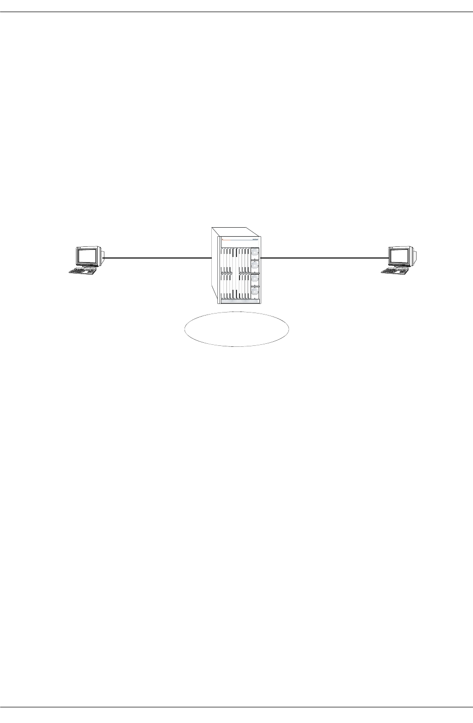
Overview of Troubleshooting Approach Troubleshooting Switched Ethernet Connectivity
page 2-2 OmniSwitch Troubleshooting Guide July 2008
Overview of Troubleshooting Approach
•Verify physical layer connectivity.
•Verify current running configuration is accurate.
•Verify source learning.
•Investigate any error conditions.
•Verify health of NIs involved.
•Verify health of CMM.
Diagram 1
OmniSwitch 7800
IP = 192.168.10.2 IP = 192.168.103
Client A Client B
VLAN 7
5/1 5/2

Troubleshooting Switched Ethernet Connectivity Verify Physical Layer Connectivity
OmniSwitch Troubleshooting Guide July 2008 page 2-3
Verify Physical Layer Connectivity
Verify that there is valid link light along the entire data path between the devices that can not switch to
each other. Make sure to include all interswitch links. Verify LED’s on all involved CMMs and NIs are
Solid OK1, Blinking OK2. If this is not the case, contact technical support.
Use the show interfaces command to verify operational status is Up, speed and duplex are correct and
match the other side of the connection. Run this command on the same interface multiple times to verify
errors (Error Frames, CRC Error Frames, Alignment Errors) are not incrementing. If the error counts are
incrementing verify the health of the cabling as well as the NIC involved. Also note that if the Collision
Frames is incrementing, this is normal for a half duplex connection. If the port is set to full duplex and
these errors are still incrementing, verify the duplex setting on the other side of the connection. Finally, if
these commands were run while the end stations were trying to ping each other, verify Bytes Received is
incrementing. If is not, verify the NIC card.
Note. Remember to do this for each port along the data path, not just the ports that directly attached to the
end stations.
-> show interfaces 5/1
Slot/Port 5/1 :
Operational Status : up,
Type : Fast Ethernet,
MAC address : 00:d0:95:7a:63:87,
BandWidth (Megabits) : 100, Duplex : Full,
Long Accept : Enable, Runt Accept : Disable,
Long Frame Size(Bytes) : 1553, Runt Size(Bytes) : 64
Input :
Bytes Received : 14397,
Lost Frames : 0,
Unicast Frames : 6,
Broadcast Frames : 93,
Multicast Frames : 7,
UnderSize Frames : 0,
OverSize Frames : 0,
Collision Frames : 0,
Error Frames : 0,
CRC Error Frames : 0,
Alignments Error : 0
Output :
Bytes transmitted : 83244,
Lost Frames : 0,
Unicast Frames : 10,
Broadcast Frames : 84,
Multicast Frames : 1106,
UnderSize Frames : 0,
OverSize Frames : 0,
Collision Frames : 0,
Error Frames : 0
If the port reports operational status down, verify the physical link, but also verify the necessary NIs and
CMM are receiving power and are up and operational. Use the show ni command followed by the slot
number and the show cmm command to verify this.

Verify Physical Layer Connectivity Troubleshooting Switched Ethernet Connectivity
page 2-4 OmniSwitch Troubleshooting Guide July 2008
-> show ni 5
Module in slot 5
Model Name: OS7-ENI-C24 ,
Description: 24PT 10/100 MOD,
Part Number: 902136-10,
Hardware Revision: A02,
Serial Number: 22030298,
Manufacture Date: MAY 18 2002,
Firmware Version: 6,
Admin Status: POWER ON,
Operational Status: UP,
Power Consumption: 44,
Power Control Checksum: 0x808,
MAC Address: 00:d0:95:7a:63:87,
ASIC - Physical: 0x1a01 0x0201 0x0201 0x001e 0x001e 0x001e
-> show cmm
Module in slot CMM-A-1
Model Name: OS7800-CMM ,
Description: BBUS Bridge,
Part Number: 901753-10,
Hardware Revision: 306,
Serial Number: 2153117A,
Manufacture Date: APR 11 2002,
Firmware Version: 38,
Admin Status: POWER ON,
Operational Status: UP,
Power Consumption: 85,
Power Control Checksum: 0x80e,
MAC Address: 00:d0:95:79:62:8a,
ASIC - Physical: 0x0801 0x0801 0x0801 0x0801 0x0801 0x0801 0x08
Module in slot CMM-A-2
Model Name: ,
Description: Processor,
Part Number: 901753-10,
Hardware Revision: 303,
Serial Number: 2133035A,
Manufacture Date: APR 11 2002,
Firmware Version: 38

Troubleshooting Switched Ethernet Connectivity Verify Current Running Configuration
OmniSwitch Troubleshooting Guide July 2008 page 2-5
Verify Current Running Configuration
If the physical layer looks OK, then verify the configuration. Use the show configuration snapshot all to
display the current running configuration. Use this command to verify the ports that are involved are in the
correct VLAN. Also review the output of the command to verify there is nothing explicit in the configura-
tion that would cause the problem, such as a deny ACL that could be found under the QoS subsection.
-> show configuration snapshot all
! Chassis :
system name OS7800
! Configuration:
! VLAN :
vlan 7 enable name "VLAN 7"
vlan 7 port default 5/1
vlan 7 port default 5/2
! 802.1Q :
! Spanning tree :
! Bridging :
! IPMS :
! AAA :
aaa authentication console "local"
! QOS :
qos apply
! Policy manager :
! Session manager :
! SNMP :
! IP route manager :
ip router router-id 127.0.0.1
ip router primary-address 127.0.0.1
! RIP :
! OSPF :
! BGP :
! IP multicast :
! Health monitor :
! Interface :
! Link Aggregate :
! Port mirroring :
! UDP Relay :
! Server load balance :
! System service :
! VRRP :
! Web :
! AMAP :
! GMAP :
! Module :

Verify Source Learning Troubleshooting Switched Ethernet Connectivity
page 2-6 OmniSwitch Troubleshooting Guide July 2008
To further verify the ports are in the correct VLAN and that they are in spanning tree forwarding instead of
blocking use the show vlan port command. Also note that the port type must match what it is connecting
to. If the port is 802.1Q tagged enabled for the required vlan, then the device it attaches to must also be Q
tagged enabled for that vlan. Remember to run this command on all ports in the data path.
-> show vlan 7 port
port type status
--------+---------+--------------
5/1 default forwarding
5/2 default forwarding
5/9 qtagged inactive
If ports that should be in forwarding are in blocking, or vice versa, please consult Chapter 4, “Trouble-
shooting Spanning Tree.”
Verify Source Learning
If the configuration looks correct, source learning should be examined. If connectivity exists but is slow,
or intermittent source learning could be the root cause, since data packets would be flooded. However, if
there is no packet throughput between the devices the problem is likely not due to a source learning prob-
lem.
To verify that the MAC addresses are being learned correctly use the show mac-address-table slot
command. Verify that the correct mac address is being learned of the correct port, in the correct vlan.
-> show mac-address-table slot 5
Legend: Mac Address: * = address not valid
Vlan Mac Address Type Protocol Operation Interface
------+-------------------+--------------+-----------+------------+-----------
7 00:00:39:73:13:0e learned 10800 bridging 5/1
7 00:b0:d0:75:f1:97 learned 10800 bridging 5/2
Total number of Valid MAC addresses above = 2

Troubleshooting Switched Ethernet Connectivity Verify Switch Health
OmniSwitch Troubleshooting Guide July 2008 page 2-7
Verify Switch Health
If source learning appears to be not working correctly, verify the health of the switch with the show health,
and show health slot commands. Be sure to run the latter command on all necessary NIs. Any variables
that have reached or exceeded their limit value could cause forwarding problems on the switch. In this
case please contact Technical Support. For more detailed source learning trouble shooting, please see
Chapter 3, “Troubleshooting Source Learning.”
-> show health
* - current value exceeds threshold
Device 1 Min 1 Hr 1 Hr
Resources Limit Curr Avg Avg Max
-----------------+-------+------+------+-----+----
Receive 80 00 00 00 00
Transmit/Receive 80 00 00 00 00
Memory 80 39 39 39 39
Cpu 80 02 02 02 03
Temperature Cmm 50 39 39 39 39
Temperature Cmm Cpu 50 31 31 31 31
-> show health 5
* - current value exceeds threshold
Slot 05 1 Min 1 Hr 1 Hr
Resources Limit Curr Avg Avg Max
-----------------+-------+------+------+-----+----
Receive 80 00 00 00 01
Transmit/Receive 80 01 01 01 01
Memory 80 16 16 16 16
Cpu 80 29 33 32 35
Verify ARP
If everything checked appears to be valid, verify that this is not an ARP problem. On the end stations
involved, enter a static mac address for the device it is trying to communicate with. If connectivity is
restored, please see Chapter 11, “Troubleshooting ARP.”

Using the Log File Troubleshooting Switched Ethernet Connectivity
page 2-8 OmniSwitch Troubleshooting Guide July 2008
Using the Log File
If none of the above suggest a reason as to why Ethernet switching is not properly working, look into the
log file and see if there are any messages that may suggest why switching is not working properly. Use the
show log swlog command to view the system log file. Look for evidence of a system or interface problem
around the time the problem began.
-> show log swlog
Displaying file contents for ’swlog2.log’
FILEID: fileName[swlog2.log], endPtr[32]
configSize[64000], currentSize[64000], mode[2]
Displaying file contents for ’swlog1.log’
FILEID: fileName[swlog1.log], endPtr[48903]
configSize[64000], currentSize[64000], mode[1]
Time Stamp Application Level Log Message
------------------------+--------------+-------+--------------------------------
THU DEC 12 08:13:51 2002 SYSTEM info Switch Logging device ’swlog1.lt
THU DEC 12 08:13:53 2002 SYSTEM info Switch Logging device ’swlog2.lt
THU DEC 12 08:13:56 2002 SYSTEM info Switch Logging device ’/dev/cont
THU DEC 12 08:13:56 2002 CSM-CHASSIS info == CSM == start up
THU DEC 12 08:13:56 2002 CSM-CHASSIS info == CSM == Activating a new vers
THU DEC 12 08:13:56 2002 CSM-CHASSIS info == CSM == The working version i
THU DEC 12 08:13:56 2002 CSM-CHASSIS info == CSM == MONITORING ON
THU DEC 12 08:13:56 2002 CSM-CHASSIS info == CSM == This CMM is primary
After following the troubleshooting steps via CLI for physical connection, configuration validation,
system health and source learning, here are the additional commands in dshell to troubleshoot problems
related connectivity problem:
Checking the OS-7700/7800 Nantucket Fabric
nanlistB04
Certified: [Kernel]->nanListB04
No SOP Interrupt: 0
Multicast FIFO Full Interrupt: 0
Multicast Buffer Full Interrupt: 0
Unicast Buffer Full Interrupt: 0
Multicast Dump Interrupt: 0
Unicast Dump Interrupt: 0
Unicast Attempt Count: 8a620
Multicast Attempt Count: acecf
Unicast In Count: 8a627
Multicast In Count: acecf
Unicast Out Count: 8a634
Multicast Out Count: 3600e
Dummy Count: 61578
Total FLength Count: 0
value = 0 = 0x0
Certified: [Kernel]->
The total Flengtlh Count value should be 0 or a small value, a large value indicating that there are frames
being back up in the fabric queue.

Troubleshooting Switched Ethernet Connectivity Using the Log File
OmniSwitch Troubleshooting Guide July 2008 page 2-9
Checking the OS-7700/7800 Nantucket Fabric for Interrupts,
Data Counts and Error Counts
Working: [Kernel]->nanListB02
HB Out of Sync Interrupts: 0
Error Count Exceeded Interrupts: 0
Framing Error Interrupts: 0
Parity Error Interrupts: 0
B02 Data Port 0 Frame Count = 690dbd37
B02 Data Port 1 Frame Count = 0
B02 Data Port 2 Frame Count = 542e70d9
B02 Data Port 3 Frame Count = 0
B02 Data Port 4 Frame Count = 0
B02 Data Port 5 Frame Count = 0
B02 Data Port 6 Frame Count = 0
B02 Data Port 7 Frame Count = 9e75d47
B02 Data Port 8 Frame Count = 690dbd39
B02 Data Port 9 Frame Count = 0
B02 Data Port 10 Frame Count = 542e70d9
B02 Data Port 11 Frame Count = 0
B02 Data Port 12 Frame Count = 0
B02 Data Port 13 Frame Count = 0
B02 Data Port 14 Frame Count = 0
B02 Data Port 15 Frame Count = 9e75d47
Checking the Traffic Queue on the NI
Working: [Kernel]->FindBuffer 3,0 => where 3 is the slot number
Queue = 0x62 length = 0x40, Address 0x6881880
Queue = 0x63 length = 0x40, Address 0x68818c0
value = 3 = 0x3
The above capture shows one of the queues is backed up on the NI. Check if the queue is sending traffic
using the following command syntax:
esmDumpCoronado slot,slice,address,bytes
Working: [Kernel]->esmDumpCoronado 3,0,0x6881880,20
6881880 : 90 0 2f906d3 0 0 0
40 0
68818a0 : 40 0 0 0 d8d0620 0
0 0
68818c0 : 10090 0 2f906d3 0
value = 3 = 0x3
Working: [Kernel]->esmDumpCoronado 3,0,0x6881880,20
6881880 : 90 0 2f906d3 0 0 0
40 0
68818a0 : 40 0 0 0 d8d0620 0
0 0
68818c0 : 10090 0 2f906d3 0
value = 3 = 0x3
The above capture shows the queue is stuck and not moving.

Using the Log File Troubleshooting Switched Ethernet Connectivity
page 2-10 OmniSwitch Troubleshooting Guide July 2008
Check for Catalina (MAC) or Port Lockup
Lab-Span1 > dshell
Working: [Kernel]->getNiResetCount
Slot 1, ASICResetCnt_p addr 0x2c3ee0
Slot 2, ASICResetCnt_p addr 0x2c3ee0
ENI HALF Duplex Reset count addr 0x2c3f60
phy 0: 0 0 0 0 0 0 0
0
phy 1: 0 0 0 0 0 0 0
0
PHY FIFO LOCKUP Reset count addr 0x2c3fc0
phy 0: 0 0 0 0 0 0 0
0
phy 1: 0 0 0 0 0 0 0
0
value = 0 = 0x0
Working: [Kernel]->

Troubleshooting Switched Ethernet Connectivity Troubleshooting OmniSwitch 6850/9000 Series
OmniSwitch Troubleshooting Guide July 2008 page 2-11
Troubleshooting OmniSwitch 6850/9000 Series
Note. This section provides additional information for troubleshooting switched Ethernet connectivity on
OS-6850/9000 switches and should be used in conjunction with information provided in the previous
sections of this chapter.
G-96/> show interfaces 1/1
Slot/Port 1/1 :
Operational Status : up,
Last Time Link Changed : SAT MAY 21 10:01:21 ,
Number of Status Change: 1,
Type : Ethernet,
SFP/XFP : GBIC_SX,
MAC address : 00:d0:95:ed:0e:f8,
BandWidth (Megabits) : 1000, Duplex : Full,
Autonegotiation : 1 [ 1000-F ],
Long Frame Size(Bytes) : 9216,
Rx :
Bytes Received : 1237654, Unicast Frames : 177,
Broadcast Frames: 77, M-cast Frames : 16931,
UnderSize Frames: 0, OverSize Frames: 0,
Lost Frames : 0, Error Frames : 0,
CRC Error Frames: 0, Alignments Err : 0,
Tx :
Bytes Xmitted : 2754024, Unicast Frames : 0,
Broadcast Frames: 1, M-cast Frames : 34427,
UnderSize Frames: 0, OverSize Frames: 0,
Lost Frames : 0, Collided Frames: 0,
Error Frames : 0
G-96/> show interfaces 1/1 status
DETECTED CONFIGURED
Slot/Port AutoNego Speed Duplex Speed Duplex Trap
(Mbps) (Mbps) LinkUpDown
----------+----------+----------+----------+----------+----------+-----------
1/1 Enable 1000 Full 1000 Full -
G-96/> show vlan port
vlan port type status
------+-------+---------+-------------
167 1/11 qtagged forwarding
167 0/1 qtagged forwarding
168 1/5 qtagged forwarding
168 1/7 qtagged forwarding
168 1/9 qtagged forwarding
169 1/5 qtagged forwarding
169 1/7 qtagged forwarding
169 0/1 qtagged forwarding
170 1/5 qtagged forwarding
170 1/7 qtagged forwarding
175 1/9 qtagged forwarding
175 1/11 qtagged forwarding
175 0/1 qtagged forwarding
176 1/5 qtagged forwarding
176 1/7 qtagged forwarding

Troubleshooting OmniSwitch 6850/9000 Series Troubleshooting Switched Ethernet Connectivity
page 2-12 OmniSwitch Troubleshooting Guide July 2008
176 0/1 qtagged forwarding
G-96/> show mac-address-table learned
Legend: Mac Address: * = address not valid
Vlan Mac Address Type Protocol Operation Interface
------+-------------------+--------------+-----------+------------+-----------
500 00:d0:95:ed:13:e0 learned --- bridging 1/1
161 00:c0:4f:12:f7:1b learned --- bridging 1/5
162 00:b0:d0:77:d1:55 learned --- bridging 1/7
161 00:d0:95:c2:dc:aa learned --- bridging 1/9
163 00:b0:d0:43:22:1d learned --- bridging 1/9
161 00:d0:95:e0:79:18 learned --- bridging 0/1
162 00:d0:95:e0:79:18 learned --- bridging 0/1
163 00:d0:95:e0:79:18 learned --- bridging 0/1
164 00:d0:95:e0:79:18 learned --- bridging 0/1
165 00:d0:95:e0:79:18 learned --- bridging 0/1
166 00:d0:95:e0:79:18 learned --- bridging 0/1
167 00:d0:95:e0:79:18 learned --- bridging 0/1
168 00:d0:95:e0:79:18 learned --- bridging 0/1
169 00:d0:95:e0:79:18 learned --- bridging 0/1
170 00:d0:95:e0:79:18 learned --- bridging 0/1
171 00:d0:95:e0:79:18 learned --- bridging 0/1
172 00:d0:95:e0:79:18 learned --- bridging 0/1
173 00:d0:95:e0:79:18 learned --- bridging 0/1
174 00:d0:95:e0:79:18 learned --- bridging 0/1
175 00:d0:95:e0:79:18 learned --- bridging 0/1
176 00:d0:95:e0:79:18 learned --- bridging 0/1
3088 00:d0:95:e0:79:18 learned --- bridging 0/1
3092 00:d0:95:e0:79:18 learned --- bridging 0/1
Check to see if ARP is learned properly.
G-96/> show arp
Total 20 arp entries
Flags (P=Proxy, A=Authentication, V=VRRP)
IP Addr Hardware Addr Type Flags Port Interface Name
-----------------+-------------------+----------+-------+--------+-----------+-----
-----
10.255.202.1 00:d0:95:e0:78:98 DYNAMIC EMP EMP
172.28.11.90 00:d0:95:e0:79:18 DYNAMIC 1/17 vlan 3088
172.28.11.94 00:d0:95:e0:79:18 DYNAMIC 1/17 vlan 3092
172.33.0.100 00:d0:95:c2:dc:aa DYNAMIC 1/9 vlan 161
Use the debug ip packet command to troubleshoot. Start the ping from the PC, this will verify if the
ICMP request comes through the switch or not.
G-96/>debug ip packet ip-address 192.168.10.2 start timeout 60
G-96/>debug ip packet ip-pair 192.168.10.2 192.168.10.3 start timeout 60

Troubleshooting Switched Ethernet Connectivity Troubleshooting OmniSwitch 6850/9000 Series
OmniSwitch Troubleshooting Guide July 2008 page 2-13
->show configuration snapshot all
! Chassis :
system name ""
system timezone PST
mac alloc 91 0 1 00:d0:95:b9:1b:35
! Configuration:
! VLAN :
ethernet-service mode vstk
vlan 1 enable name "VLAN 1"
vlan 99 enable name "VLAN 99"
vlan 99 port default 1/1
vlan 99 port default 1/2
vlan 99 port default 7/11
vlan 99 port default 7/12
vlan 99 port default 7/13
vlan 99 port default 7/14
vlan 100 enable name "VLAN 100"
vlan 101 enable name "VLAN 101"
vlan 102 enable name "VLAN 102"
! VLAN SL:
! IP :
ip service all
ip interface "vlan_99" address 192.168.120.254 mask 255.255.255.0 vlan 99 ifindex 1
ip interface "vlan_102" address 192.168.102.254 mask 255.255.255.0 vlan 102 ifin-
dex 2
! IPX :
! IPMS :
! AAA :
aaa authentication default "local"
aaa authentication console "local"
! PARTM :
! AVLAN :
! 802.1x :
! QOS :
policy condition c1 source mac 00:0E:10:11:22:33
policy action a1 disposition deny
policy rule r1 condition c1 action a1
qos apply
G-96/> dshell
Certified: [Kernel]->esmDumpPort 1,1
------- DUMP PORT 1/1--------
------- PORT INFO --------
gport = 0
ifIndex = 1001
ifDescr = Alcatel 1/1 6.1.3.886.R01
conf valid = 1
saved link state = 2
currentLinkState = 1
auto sensing = 0
auo neg = 1
cnfBandwidth = 1000
cnfDuplex = 1
cnfCrossover = 1
cnfFlow = 0

Troubleshooting OmniSwitch 6850/9000 Series Troubleshooting Switched Ethernet Connectivity
page 2-14 OmniSwitch Troubleshooting Guide July 2008
bwB4LinkDown = 1000
detected Bandwidth = 1000
detected duplex = 1
detected CrossOver = 0
detected Flow = 0
mdix status = 255
admin status = 1
floodLimitEnable = 1
mcastLimitEnable = 0
floodLimit = 496
ifgValue = 12
trapEnable = 0
flowControlState = 1
flowControlMode = 1
flowControlWait = 0
tagged = 0
longEnable = 1
sizeMtu = 9216
ledCtl = 2
hkValidPort = 1
hkPortType = 4
hybridType = 1
cnfhybridType = 1
hybridMode = 0
mac addr = 0:d0:95:ed:e:f8
Block App BitMap 0x0
ifindex = 1001
gport = 0
portType = 4
ifDescr = Alcatel 1/1 6.1.3.886.R01
Mac Addres = 0: d0: 95: ed: e: f8
admin = 1
auto = 1
bw = 1000 duplex = 1
d_bw = 1000 d_duplex = 1
crossover = 1
mtu = 9216
ifg = 12
trap = 0
mcast = 0
flood = 1 flood lmt = 496
long = 1 long sz = 9216
flowstate = 1 flowmode = 1
flowwait = 0
hybridType = 1 cnfhybridT = 1
hybridMode = 0
mdix = 1
admin = 255
auto = 255
bw = 65535
duplex = 255
crossover = 255
mtu = 65535
mcast = -1
flood = 255
flood lmt = 65535
ifg = 255
trap = 65535
long = 255

Troubleshooting Switched Ethernet Connectivity Troubleshooting OmniSwitch 6850/9000 Series
OmniSwitch Troubleshooting Guide July 2008 page 2-15
long sz = 65535
tagged = 0
runt = 255
runt sz = 65535
flowstate = 255
tflowmode = 255
flowwait = 65535
cnfhybridT = 255
hybridMode = 255
mdix = 255
undersz_frms 0 undersz_frms 0
oversz_frms 0 oversz_frms 0
64_frms 3247 64_frms 0
65_127_frms 48326 65_127_frms 0
128_255_frms 0 128_255_frms 0
256_511_frms 177 256_511_frms 0
512_1023_frms 0 512_1023_frms 0
1024_1518_frms 0 1024_1518_frms 0
unicast_frms 177 unicast_frms 0
bcast_frms 77 bcast_frms 1
mcast_frms 16976 mcast_frms 34519
total_frms 51750 pause_frms 0
rx_bytes 1240766 tx_bytes 2761378
crc_err_frms 0 lost_frms 0
err_frms 0 deffered_frms 0
jabber_frms 0 retry_cnt 0
Data address 0xc4978ec
module type 0x11020003
vendor name PICOLIGHT
Part num PL-XPL-00-S13-0
Hw Rev
Wavelength 0x352
Serial Num 305AA1SD
vendorMfgDate 030130
value = 29 = 0x1d
Certified: [Kernel]->exit
G-96/> telnet 127.2.1.1
Trying 127.2.1.1...
Connected to 127.2.1.1.
Escape character is '^]'.
[Slot 1]->kslnDumpL2
[ 416]: MAC=00:d0:95:e0:78:18 VID= 174 PORT=0x1a MODID= 0 TID= 0 HIT=1 STATIC L3
[ 520]: MAC=00:d0:95:e0:78:18 VID= 164 PORT=0x1a MODID= 0 TID= 0 HIT=1 STATIC L3
[ 640]: MAC=00:00:5e:00:01:a1 VID= 161 PORT=0x1a MODID= 0 TID= 0 HIT=0 STATIC L3
[ 1024]: MAC=00:d0:95:e0:79:18 VID= 175 PORT=0x21 MODID= 0 TID= 1 HIT=1 RT=0
[ 1216]: MAC=00:d0:95:e0:79:18 VID=3088 PORT=0x21 MODID= 0 TID= 1 HIT=1 RT=0
[ 1465]: MAC=00:00:5e:00:01:b0 VID= 176 PORT=0x1a MODID= 0 TID= 0 HIT=1 STATIC L3
[ 4208]: MAC=00:d0:95:e0:79:18 VID= 166 PORT=0x21 MODID= 0 TID= 1 HIT=1 RT=0
[ 4672]: MAC=00:b0:d0:43:22:1d VID= 163 PORT=0x 8 MODID= 0 TID= 0 HIT=1
value = 60 = 0x3c = '<'
[Slot 1]->kslnFindL2Entry 0x00b0d0,0x43221d
[ 4672]: MAC=00:b0:d0:43:22:1d VID= 163 PORT=0x 8 MODID= 0 TID= 0 S=0 HIT=1
value = 1 = 0x1

Troubleshooting OmniSwitch 6850/9000 Series Troubleshooting Switched Ethernet Connectivity
page 2-16 OmniSwitch Troubleshooting Guide July 2008
[Slot 1]->ipni_arpShow
Slot 1. NI Arp Table
memaddr destination MAC vlan port flags la_hold expire
036ff49c 172.28.11.90 00d095:e07918 3088 1/17 (gp=16) 2 0 0
036ff4d0 172.28.11.94 00d095:e07918 3092 1/17 (gp=16) 2 0 15660
036ff504 172.33.0.100 00d095:c2dcaa 161 1/ 9 (gp=8) 2 0 7831
[Slot 1]->ipni_arpShow "172.33.0.100","255.255.255.255"
Slot 1. NI Arp Table
memaddr destination MAC vlan port flags la_hold expire
036ff504 172.33.0.100 00d095:c2dcaa 161 1/ 9 (gp=8) 2 0 16858
value = 0 = 0x0
[Slot 1]->
[Slot 1]->exit
Connection closed by foreign host.
The following table contains port and VLAN specifications:
Check the interface statistics, port to VLAN associations, MAC-address table, and ARP entries using the
following commands:
Maximum VLANs per switch
and stack 4094 (based on switch configuration and available resources).
Maximum VLAN port associa-
tions 32768
Switch ports eligible for port
mobility Untagged Ethernet and Gigabit Ethernet ports that are not members of a
link aggregate.
Switch ports eligible for
dynamic VLAN assignment. Mobile ports.
Switch ports eligible for static
VLAN assignment Non-mobile (fixed) ports
Mobile ports
Uplink ports
10 gigabit ports
Link aggregate of ports
CLI Commands Description Comments
show interfaces <slot/port> Displays port status, type, MAC
address, bandwidth, duplex,
speed, long frame (jumbo), input/
output frames receives, lost
frames, collisions/error frames,
under/over size, unicast/multicast/
broadcast frames, bytes received/
transmitted.
show interfaces status Displays port settings: auto-nego-
tiation/speed/duplex/link status.

Troubleshooting Switched Ethernet Connectivity Troubleshooting OmniSwitch 6850/9000 Series
OmniSwitch Troubleshooting Guide July 2008 page 2-17
Additional Troubleshooting for Connectivity Issues
When troubleshooting a connectivity issue, verify the configuration and network settings of the following
items if there are still problems after checking the ARP and MAC entries on the switch:
•Mobile Port -- Should the port be mobile, if so, is the rule correct.
•LPS (Learn Port Security) -- Is the MAC address learned through LPS. Is the setting correct: static
vs. dynamic.
•Flood-Rate setting -- Is the flood rate setting too low.
•Auto-Negotiation (MDIX) -- MDIX will only work in auto-negotiation mode, otherwise, is a cross-
over cable needed. Are both sides set to auto-auto or fix-fix, rather than auto-fix/fix-auto which will
negotiate to half duplex.
•Q-tagged -- Is the proper VLAN Q-tagg on both ends.
•Linkagg -- Is the linkagg set correctly. Is the links connect to the right switch.
•QoS -- If QoS has been configured, try disabling QoS temporarily or disable just certain rule to do a
quick test.
•Patch Panel/Cabling/GBIC -- Bypass patch panel and connect directly; make sure that cable is good
and properly connected to the right device; verify GBIC for damage.
•Port Assignment -- Port has been assigned to proper VLAN and IP forwarding on VLAN.
•PC Configuration -- Does it have proper Gateway, Subnets, DNS, IP, etc. Disable local firewall or IP
filter setting on the PC.
•Firewall -- Bypass the firewall or disable all rules on the firewall just for testing purpose.
•TraceRoute -- Do a traceroute.
•Port Mirror -- Get a sniffer trace.
•Check for all errors -- Ports or switch log, etc.
show vlan <vid> port Displays the ports associated with
the vlan(s).
show mac-address learned <slot/port> Displays L2 MAC address.
show arp x.x.x.x Displays L3 IP/MAC address.
Advanced Troubleshooting
esmDumpPort <slot,port> Displays port information.
kslnDumpL2 Displays all L2 MAC addresses. On 9000 Series, must telnet
to individual NI to run it.
kslnFindL2Entry
<0xfirst3octets,0xlast3octets> Displays specified L2 MAC entry. On 9000 Series, must telnet
to individual NI to run it.
ipni_arpShow Displays all ARP entries. On 9000 Series, must telnet
to individual NI to run it.
ipni_arpShow
"x.x.x.x","255.255.255.255 Displays specified ARP entry.

Troubleshooting OmniSwitch 6850/9000 Series Troubleshooting Switched Ethernet Connectivity
page 2-18 OmniSwitch Troubleshooting Guide July 2008

OmniSwitch Troubleshooting Guide July 2008 page 3-1
3 Troubleshooting Source
Learning
In order to troubleshoot Source Learning problems, a basic understanding of the process is required.
A review of the “Managing Source Learning” chapter from the appropriate OmniSwitch Network Configu-
ration Guide is required. The following RFC and IEEE standards are supported:
In This Chapter
“Introduction” on page 3-2
“Troubleshooting a Source Learning Problem” on page 3-3
“Advanced Troubleshooting” on page 3-5
“Dshell Troubleshooting” on page 3-7
“Troubleshooting Source Learning on OmniSwitch 6800/6850/9000 Series” on page 3-12
RFCs supported 2674 - Definitions of Managed Objects for Bridges
with Traffic Classes, Multicast Filtering and
Virtual LAN Extensions
IEEE Standards supported 802.1Q - Virtual Bridged Local Area Networks
802.1D - Media Access Control Bridges
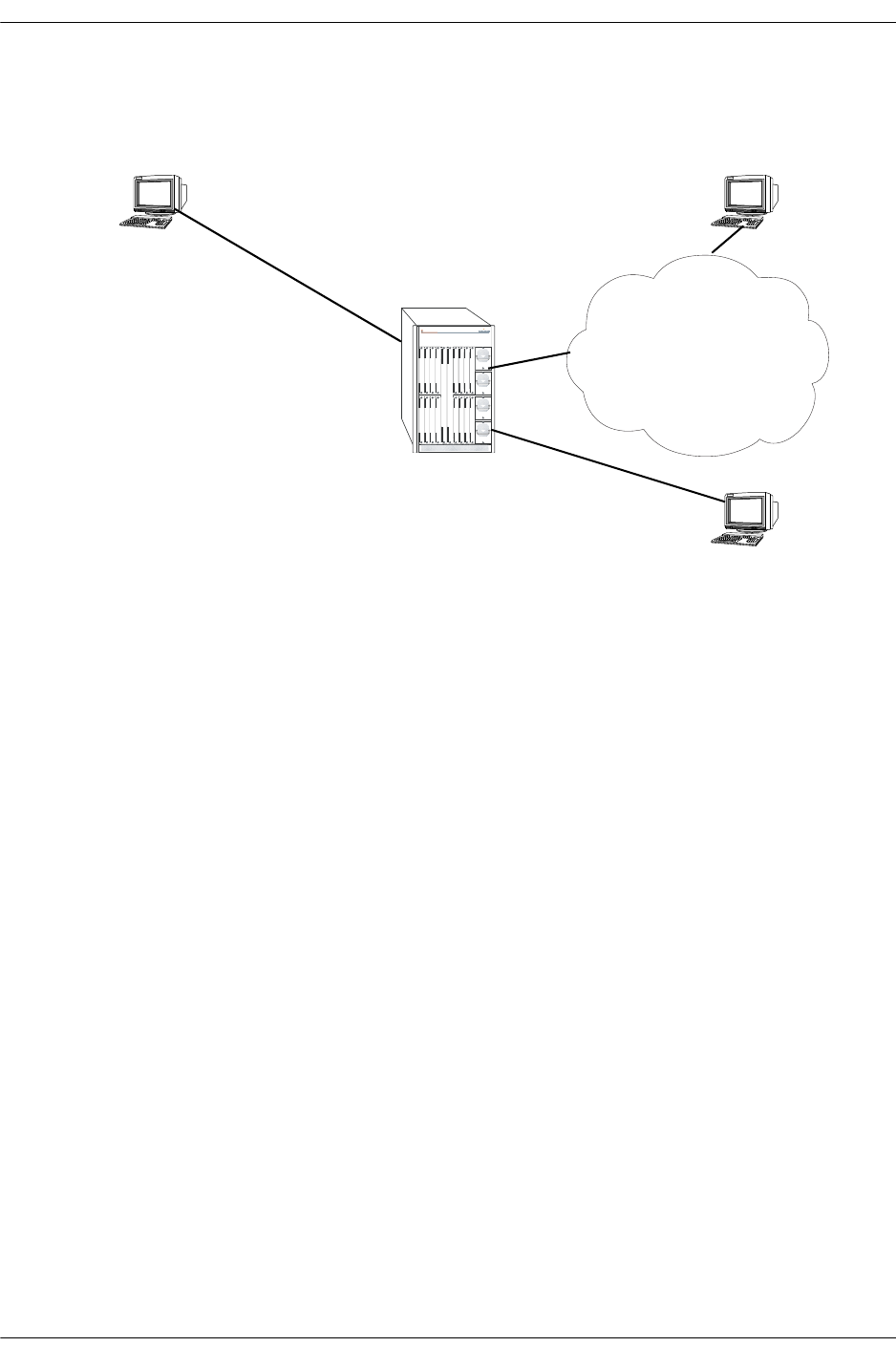
Introduction Troubleshooting Source Learning
page 3-2 OmniSwitch Troubleshooting Guide July 2008
Introduction
Source Learning Example
When a packet first arrives on NI source learning examines the packet and tries to classify the packet to
join its correct VLAN. If a port is statically defined in a VLAN, the MAC address is classified in the
default VLAN. Otherwise, if Group Mobility is being used the MAC address is classified into the correct
VLAN based on the rules defined.
As soon as the MAC address is classified in a VLAN, an entry is made in Source Address Pseudo-CAM
associating the MAC address with the VLAN ID and the Source Port. This Source Address is then relayed
to the CMM for management purposes.
If an entry already exists in MAC address database with the same VLAN ID and the same source port
number then no new entry is made. If VLAN ID or the source port is different from the existing entry in
MAC address database then the previous entry is aged out and a new entry is made in the MAC address
database. This process of adding a MAC address in the MAC address database is known as Source Learn-
ing.
A MAC address can be denied to learn on a port based on different policies configured through QOS or
Learned Port Security. A MAC address may be learned in a wrong VLAN based on the policies defined
for the port.
Note: This document does not discuss the basic operation of Source Learning. To learn about how Source
Learning works, refer to the “Managing Source Learning” in the appropriate OmniSwitch Network Config-
uration Guide.
OmniSwitch 7800
VLAN 114
Port: 8/23
IP: 10.40.114.50
MAC:00-C0-4f-12-F7-1B
VLAN 114
Port: 16/16
IP: 10.40.114.100
MAC: 00-10-A4-B5-B5-38

Troubleshooting Source Learning Troubleshooting a Source Learning Problem
OmniSwitch Troubleshooting Guide July 2008 page 3-3
Troubleshooting a Source Learning Problem
In order to troubleshoot a source learning problem the first step is to verify that the physical link is up and
the port has correctly auto-negotiated with the end-station.
The next thing is to verify that the port is a member of the right VLAN, if a port is statically configured
for a VLAN, or the Group Mobility policies are correctly defined. The workstation configuration should
also be verified.
The first thing to look for is the MAC address table to verify that the MAC address is being learned:
-> show mac-address-table
Vlan Mac Address Type Protocol Operation Interface
------+-------------------+--------------+-----------+------------+-----------
105 00:00:5e:00:01:69 learned 10800 bridging 4/2
105 00:d0:95:6b:4c:d8 learned 10800 bridging 4/2
105 00:d0:95:79:62:eb learned 10806 bridging 4/2
150 00:d0:95:6b:4c:e7 learned 10800 bridging 4/2
1 00:d0:95:79:65:ea learned 10800 bridging 6/1
108 00:d0:95:6b:4c:db learned 10800 bridging 6/1
110 00:d0:95:6b:4c:dd learned 10800 bridging 7/1
114 00:c0:4f:12:f7:1b learned 10800 bridging 8/23
112 00:d0:95:6b:4c:df learned 10800 bridging 9/2
112 00:d0:95:79:65:10 learned 10806 bridging 9/2
50 00:00:5e:00:01:32 learned 10800 bridging 11/1
50 00:d0:95:83:e7:81 learned 10800 bridging 11/1
51 00:00:5e:00:01:33 learned 10800 bridging 11/1
51 00:d0:95:83:e7:82 learned 10800 bridging 11/1
52 00:00:5e:00:01:34 learned 10800 bridging 11/1
52 00:d0:95:83:e7:83 learned 10800 bridging 11/1
53 00:00:5e:00:01:35 learned 10800 bridging 11/1
53 00:d0:95:83:e7:84 learned 10800 bridging 11/1
54 00:00:5e:00:01:36 learned 10800 bridging 11/1
54 00:d0:95:83:e7:85 learned 10800 bridging 11/1
55 00:00:5e:00:01:37 learned 10800 bridging 11/1
55 00:d0:95:83:e7:86 learned 10800 bridging 11/1
56 00:00:5e:00:01:38 learned 10800 bridging 11/1
56 00:d0:95:83:e7:87 learned 10800 bridging 11/1
57 00:00:5e:00:01:39 learned 10800 bridging 11/1
57 00:d0:95:83:e7:88 learned 10800 bridging 11/1
58 00:00:5e:00:01:3a learned 10800 bridging 11/1
58 00:d0:95:83:e7:89 learned 10800 bridging 11/1
59 00:00:5e:00:01:3b learned 10800 bridging 11/1
59 00:d0:95:83:e7:8a learned 10800 bridging 11/1
60 00:00:5e:00:01:3c learned 10800 bridging 11/1
60 00:d0:95:83:e7:8b learned 10800 bridging 11/1
61 00:00:5e:00:01:3d learned 10800 bridging 11/1
61 00:d0:95:83:e7:8c learned 10800 bridging 11/1
62 00:00:5e:00:01:3e learned 10800 bridging 11/1
62 00:d0:95:83:e7:8d learned 10800 bridging 11/1
114 00:10:a4:b5:b5:38 learned 10806 bridging 16/16
Total number of Valid MAC addresses above = 37
The above command shows all the MAC addresses learned by the switch.

Troubleshooting a Source Learning Problem Troubleshooting Source Learning
page 3-4 OmniSwitch Troubleshooting Guide July 2008
In order to narrow down to a specific NI the following command can be used (any valid slot number can
be specified):
-> show mac-address-table slot 8
Legend: Mac Address: * = address not valid
Vlan Mac Address Type Protocol Operation Interface
------+-------------------+--------------+-----------+------------+-----------
114 00:c0:4f:12:f7:1b learned 10800 bridging 8/23
Total number of Valid MAC addresses above = 1
This does show that the MAC address 00:c0:4f:12:f7:1b is learned on port 8/23, see the figure on page 3-2.
So, the source learning process for this workstation has been completed successfully.
Now, a single MAC address can be a member of multiple VLANs based on different protocols. To verify
that the MAC address has been learned in all of the VLANs, the above command can be used. The proto-
col field will be different based on different protocols being used and classified into different VLANs.
MAC addresses can also be viewed based on VLAN ID, using the following command:
->show mac-address-table 114
Legend: Mac Address: * = address not valid
Vlan Mac Address Type Protocol Operation Interface
------+-------------------+--------------+-----------+------------+-----------
114 00:c0:4f:12:f7:1b learned 10800 bridging 8/23
114 00:10:a4:b5:b5:38 learned 10806 bridging 16/16
Total number of Valid MAC addresses above = 2
The above command shows the two workstations learned in VLAN 114 on NI 8 and 16.
Whether it be a Layer 3 packet or layer 2, the first step is to have the source MAC address learned in the
MAC address table. Layer 3 involves resolution of ARP, for more details on ARP see troubleshooting
section of ARP, and then the available routes to the destination which involves routing, for more details on
Routing see troubleshooting section of Routing.
By default the MAC address aging time is set to 300 seconds. This can be viewed:
->show mac-address-table aging-time
Mac Address Aging Time (seconds) for Vlan 1 = 300
Mac Address Aging Time (seconds) for Vlan 114 = 300
This can be changed using the command:
->mac-address-table aging-time 500
Mac Address Aging Time (seconds) for Vlan 1 = 500
Mac Address Aging Time (seconds) for Vlan 114 = 500
This can also be changed on a particular VLAN:
->mac-address-table aging-time 600 vlan 114
It may be required to change the aging timer to a higher value to prevent the aging time of silent devices.
Another method by which silent devices can be accommodated is to use the permanent/static MAC
address assigned to a port using the command:
->mac-address-table permanent 00:10:a4:b5:b5:38 16/16 114

Troubleshooting Source Learning Advanced Troubleshooting
OmniSwitch Troubleshooting Guide July 2008 page 3-5
Once, the MAC addresses are learned on the ports then the devices should be able to communicate
depending on the upper layers. Variations of MAC-related commands can be viewed in the “Managing
Source Learning” chapter from the appropriate OmniSwitch Network Configuration Guide.
Advanced Troubleshooting
The advanced troubleshooting for Source learning related problems is to look whether the traffic is
coming in from a port and the NI is not learning the MAC, if not prevented by using any other rules.
->debug ip packet board ni 8 start
R 8/23 00c04f12f71b->00d0957962c4 IP 10.40.114.50->10.40.114.2 ICMP 8,0
seq=58460.
8 S 8/23 00d0957962c4->00c04f12f71b IP 10.40.114.2->10.40.114.50 ICMP 0,0
seq=58460.
ebug ip 8 R 8/23 00c04f12f71b->00d0957962c4 IP 10.40.114.50->10.40.114.2 ICMP
8,0 seq=58716.
8 S 8/23 00d0957962c4->00c04f12f71b IP 10.40.114.2->10.40.114.50 ICMP 0,0
seq=58716.
packet 8 R 8/23 00c04f12f71b->00d0957962c4 IP 10.40.114.50->10.40.114.2 ICMP 8,0
seq=58972.
8 S 8/23 00d0957962c4->00c04f12f71b IP 10.40.114.2->10.40.114.50 ICMP 0,0
seq=58972.
stop8 R 8/23 00c04f12f71b->00d0957962c4 IP 10.40.114.50->10.40.114.2 ICMP 8,0
seq=59228.
8 S 8/23 00d0957962c4->00c04f12f71b IP 10.40.114.2->10.40.114.50 ICMP 0,0
seq=59228.
->debug ip packet stop
This command shows that the packets are coming into the switch and a reply is being sent by the switch to
the end station.
Various combinations of debug ip packet command can be used to find out the incoming traffic. The
combinations possible are as follows:
debug ip packet [start] [timeout seconds] [stop] [direction {in | out | all}] [format {header | text | all}]
[output {screen | switchlog}] [board {cmm | ni [1-16] | all | none} [ether-type {arp | ip | hex [hex] |
all}] [ip-address ip_address] [ip-pair [ip1] [ip2]] [protocol {tcp | udp | icmp | igmp | num [integer] |
all}] [show-broadcast {on | off}] show-multicast {on | off}]
start Starts an IP packet debug session.
timeout Sets the duration of the debug session, in seconds. To specify a dura-
tion for the debug session, enter timeout, then enter the session length.
seconds The debug session length, in seconds.
stop Stops IP packet debug session.
direction in Debugs incoming packets
direction out Debugs outgoing packets.
direction all Debugs both incoming and outgoing packets.
format header Debugs the packet header.

Advanced Troubleshooting Troubleshooting Source Learning
page 3-6 OmniSwitch Troubleshooting Guide July 2008
format text Debugs the packet text.
format all Debugs the entire packet.
output screen Output will appear on screen.
output switchlog Output will be saved to a log file.
board cmm Debugs CMM packets.
board ni Debugs packets for a Network Interface (NI). To debug a specific inter-
face, enter ni, then enter the slot number of the NI.
board all Debugs packets for all CMMs and NIs on the switch
board none Clears the previous board settings.
If the problems are associated with the source learning on a specific NI then the limitations of the Number
of MAC addresses learned should also be considered. Current limitations are:
The total number of MAC addresses learned per switch can be viewed using the command:
-> show mac-address-table count
Mac Address Table Count:
Permanent Address Count = 0,
DeleteOnReset Address Count = 0,
DeleteOnTimeout Address Count = 0,
Dynamic Learned Address Count = 36,
Total MAC Address In Use = 36
If the problem is still not resolved then kindly contact Tech Support for further troubleshooting.
Number of learned MAC
addresses per network interface
(NI) module
32K
Number of learned MAC
addresses per switch 64K

Troubleshooting Source Learning Dshell Troubleshooting
OmniSwitch Troubleshooting Guide July 2008 page 3-7
Dshell Troubleshooting
The OmniSwitch has a distributed architecture. Source Learning is specific to a NI. Each NI has a layer 2
pseudo-cam which is which can hold 64K entries. 32K entries are reserved for L2 Source Addresses
which are local to that NI in L2SA table and the rest of 32K entries are reserved for L2 Destination
Addresses which can be from local or remote NI in L2DA table.
Note. Dshell commands should only be used by Alcatel-Lucent personnel or under the direction of Alca-
tel-Lucent. Misuse or failure to follow procedures that use Dshell commands in this guide correctly can
cause lengthy network down time and/or permanent damage to hardware.
If a problem is specific to a NI and the MAC address is not being learned by the switch, then the first step
is to verify from the pseudo-cam of that NI that the MAC address has been learned. There can be a possi-
bility that the NI has learned the MAC but CMM is not reporting that MAC because of IPC messages lost
between the CMM and NI.
The commands available to troubleshoot this problem are:
slcDumpL2SA: Display all the SA PseudoCAM entries on one slot/slice.
•Format: slcDumpL2SA slot_num, slice_num
slcDumpL2DA: Display all the Destination Address (DA) PseudoCAM entries on one slot/slice.
•Format: slcDumpL2DA slot_num, slice_num
slcLkupL2SA: Display the SA PCAM entries with MAC, VLAN) tuple on a slot/slice, the high 4 bytes of
MAC are MacHi, other 2 bytes are macLo, VLAN non-significant value is 0.
Format: slcLkupL2SA slot_num, slice_num, macHi, macLo, vlanId
slcLkupL2DA: Display the DA PCAM entries with (MAC, VLAN} tuple on a slot/slice, the high 4 bytes
of MAC are MacHi, other 2 bytes are macLo, VLAN non-significant value is 0.
•Format: slcLkupL2DA slot_num, slice_num, macHi, macLo, vlanId
Now, if device A connected on slot 8 is unable to communicate to device B in slot 16 then the following
steps can be taken to verify configuration on the NI
First look at the source MAC on slot 8 using the command:
Working: [Kernel]->slcDumpL2SA 8,0
Index Mac Address Vlan GlobalPort 4-words content
-------+-------------------+------+-----------+-----------------------------------
0x371b 00:c0:4f:12:f7:1b 114 250 007200c0 4f12f71b 00000000 0000003a
Total L2 SA entry amount = 1
Look at the source MAC on slot 16:
Working: [Kernel]->slcDumpL2SA 16,0
Index Mac Address Vlan GlobalPort 4-words content
-------+-------------------+------+-----------+-----------------------------------
0x3538 00:10:a4:b5:b5:38 114 499 00720010 a4b5b538 00000000 000001f3
Total L2 SA entry amount = 1
Both of the MAC addresses are learned in the correct VLANs on the right NI.

Dshell Troubleshooting Troubleshooting Source Learning
page 3-8 OmniSwitch Troubleshooting Guide July 2008
Now, if device A is trying to communicate to device B then the next thing to look for is the destination
MAC address table. This is to verify that the destination MAC address table has the information about the
device B.
Working: [Kernel]->slcDumpL2DA 8,0
Index Mac Address Vlan GlobalPort 4-words content
-------+-------------------+------+-----------+-----------------------------------
0x3004 00:20:da:00:70:04 1 0 00010020 da007004 c0004000 00024000
0x3538 00:10:a4:b5:b5:38 114 499 00720010 a4b5b538 00180000 1f057f3
So, the entry does show up for the destination device.
Similarly for bidirectional traffic the entry should show up on slot 16.
Working: [Kernel]->slcDumpL2DA 16,0
Index Mac Address Vlan GlobalPort 4-words content
-------+-------------------+------+-----------+-----------------------------------
0x3004 00:20:da:00:70:04 1 0 00010020 da007004 c0004000 00024000
0x371b 00:c0:4f:12:f7:1b 114 250 007200c0 4f12f71b 00180000 1f05b3a
So, the two devices should be able to communicate.
The L2SA and L2DA tables will be different for each slot. L2SA table will be based on the MAC address
learned on that slot. This will not be synchronized to all the other modules. Only the CMM will know
about it. When the request comes in from device A for device B, first a lookup is done on the local L2SA
and L2DA tables to see if there is a matching entry. If there is no matching entry then a request is sent on
the BBUS to all the other Coronados, if any Coronado has the matching entry in its L2SA table it responds
back with the Global port number of that entry. L2DA table is updated on the originating Coronado and
the packet is forwarded to the Global port to reach the destination.
If no other Coronado responds back to the request then the packet is sent over the flood queue to all the
other Coronado to be flooded out of the ports in the same VLAN. If a device responds back on the flooded
request, L2SA for that NI is updated and the Global port number is send to the originating device using the
same lookup as the response will be a unicast packet.
To see Source learning in action on an NI, set the debug level higher (levels are 1-6):
-> Sl_NiDebug=4
To see Source Learning in action on a CMM, set the debug level higher (levels are 1-6):
-> Sl_CmmDebug=5
To view the messages on the console, disable systrace:
-> Sl_no_systrace=1
The following is a sample output:
Working: [Kernel]->Sl_no_systrace=1
Sl_no_systrace = 0x56402f4: value = 1 = 0x1
Working: [Kernel]->nidbg
3:0 nidbg> Sl_NiDebug=4
3:0 Sl_NiDebug = 0x2d1fc4: value = 4 = 0x4
3:0 nidbg> 3:0
3:0 ----------------------------- HRE PACKET HRADER -----------------------
3:0 isIPMS = 0, isSAMatched = 0, isDAMatched = 0, isMcst = 1, qId = 49, isRouted =
0, isTagged = 0, isFlood = 1, protoco
l = 0, sPort = 64

Troubleshooting Source Learning Dshell Troubleshooting
OmniSwitch Troubleshooting Guide July 2008 page 3-9
3:0 payLoadLength = 66, isLocked = 0, lockId = 0
3:0 isFBMsg = 0, isIPCMsg = 0, isSTPfrm = 0, isPrtTagged = 0, sVlanId = 21, reQId =
2, mcVlanId = 21
3:0 conditionCodes = 0x180, daMac = 0x00005e000115
3:0 saMac = 0x006008:91bb72, tagType = 0x8100, taginfo = 15, ethType = 800
3:0 ------------------------------ HRE PACKET HEADER END -----------------------
3:0
3:0 sln_salrn: gport = 64, vlanId = 21
3:0
SA 00:60:08:91:bb:72 successfully added to SA CAM

Dshell Troubleshooting Troubleshooting Source Learning
page 3-10 OmniSwitch Troubleshooting Guide July 2008
OS-6600
To look at the forwarding database on OS-6600 in Dshell use the slcDumpSlotSlice command., which
displays which slot/slice is considered to be up and operational by the source learning software:
Certified: [Kernel]->slcDumpSlotSlice
Source Learning Slice Up List:
slot/slice 2/0, type = 838930434, firstgport = 64, lastgport = 123
value = 68 = 0x44 = ’D’
To look at the forwarding database on OS-6600 in Dshell use the dumpL2 command:
Certified: [Kernel]->dumpL2
Addr# VID Addr DN PN Age AVID
-----------------------------------------------
00000 0001 00:01:02:03:00:00 00 30 STATIC xxxx
00001 0001 00:10:a4:f5:89:e2 03 00 DYNAMIC xxxx
00002 0002 00:00:5e:00:01:02 02 26 DYNAMIC xxxx
00003 0002 00:d0:95:84:07:1e 02 26 STATIC xxxx
00004 0003 00:00:5e:00:01:03 02 26 DYNAMIC xxxx
00005 0003 00:d0:95:84:07:1e 02 26 STATIC xxxx
00006 0004 00:d0:95:84:07:1e 02 26 STATIC xxxx
00007 0320 00:d0:95:84:3c:ce 02 01 DYNAMIC xxxx
00008 0333 00:d0:95:84:3c:ce 02 13 DYNAMIC xxxx
00009 0334 00:d0:95:82:12:ef 02 08 STATIC xxxx
00010 0334 00:d0:95:84:3c:ce 02 08 DYNAMIC xxxx
00011 0336 00:d0:95:79:64:ab 03 24 STATIC xxxx
00012 0340 00:d0:95:84:3c:ce 03 10 DYNAMIC xxxx
00013 0451 00:d0:95:84:3c:ce 03 11 DYNAMIC xxxx
00014 0999 00:00:5e:00:01:02 02 00 STATIC xxxx
00015 0999 00:00:c0:e0:29:e6 02 00 DYNAMIC xxxx
00016 0999 00:20:da:0a:54:10 02 00 STATIC xxxx
00017 0999 00:20:da:6c:20:4c 02 00 STATIC xxxx
00018 0999 00:90:27:17:f7:eb 02 00 STATIC xxxx
00019 0999 00:a0:24:d2:3f:cb 02 00 STATIC xxxx
Do you want to printf more addresses 0 -> No 1 -> Yes a -> all 1
Addr# VID Addr DN PN Age AVID
-----------------------------------------------
00020 0999 00:b0:d0:77:3e:3d 02 00 STATIC xxxx
00021 0999 00:d0:95:2a:02:4c 02 00 STATIC xxxx
00022 0999 00:d0:95:6a:84:51 02 00 STATIC xxxx
00023 0999 00:d0:95:84:3b:a0 02 00 DYNAMIC xxxx
00024 0999 00:d0:95:84:3d:90 02 00 DYNAMIC xxxx
00025 0999 00:d0:95:88:a7:28 02 00 STATIC xxxx
00026 0999 08:00:20:87:44:61 02 00 STATIC xxxx
No more addr in Master DB.

Troubleshooting Source Learning Dshell Troubleshooting
OmniSwitch Troubleshooting Guide July 2008 page 3-11
L2 Physical Pool Stats:
Total Used Free
DstSwp Tables 16384 0 16384
NetID Tables 16384 0 16384
Protocol Tables 2046 1 2045
ASIC Rsrc Wraps 2048 26 2022
value = 294 = 0x126
Output of many fields are described below:
To see Source learning in action, set the debug level higher (levels are 1-6):
SlnDebugLevel=1
The following is a sample output:
Certified: [Kernel]->SlnDebugLevel=1
SlnDebugLevel = 0x65c8af8: value = 1 = 0x1
=============== Start of CPU Unresolved Packet ===============
TxFlags = 0x2017, BufSize = 64, DiffservCodePoint = 0x0, CpuCode = 0x20, PrtclCode
= 0x1f, RxPNum = 10
PrepRxDevNum = 1, PrepRxPNum = 10, DstUnrCode = 0x1f, SrcUnrCode = 0x0, PacketRa-
mAddr = 0x68228
DstMacAddr16_48 = 0x3d9f8000, DstMacAddr0_15 = 0xe639
SrcMacAddr32_47 = 0x8000, SrcMacAddr0_31 = 0x180a539f
IPPayLoadOffset = 38, EnetType = 0x800, TagPriority = 1, TagVID = 3072
DstIPAddr = 0xc0a80b1b, SrcIPAddr = 0xc0a80b06
SrcIPSkt = 0x7f80, DstIPSkt = 0x7d00
hslnProcessL2Packet(258): vlanid = 0, gport = 42.
hsln_core_adrlrn_handler: Get the packet from Q-Dispatcher...
=======================
address pktPtr = 0x63e255c
queue_port_id = 0x402a
length = 60
lock = 0
packet_info = 0x0
ccode = 0x80
da = 00:80:9f:3d:50:b3
sa = 00:80:9f:53:0a:18
=== End of E_FRAME_PARAMS ===
output definitions
Addr The index.
VID The VLAN ID.
Addr The MAC address learned.
DN The device number (stack number).
PN The port number.
Age The MAC address type, which can be Dynamic or Static.
AVID The Authenticated VLAN ID.
DstSwp Tables The entry for Next Hop info.
NetID Tables Contains transmit enables, prepend information, and address based
VLAN information.

Troubleshooting Source Learning on OmniSwitch 6800/6850/9000 Series Troubleshooting Source Learning
page 3-12 OmniSwitch Troubleshooting Guide July 2008
Troubleshooting Source Learning on OmniSwitch
6800/6850/9000 Series
Note. This section provides additional information for troubleshooting source learning on OS-6800/6850/
9000 switches and should be used in conjunction with information provided in the previous sections of this
chapter.
The first thing to do is to verify that the MAC address is learned in the MAC address table of the switch.
This is done using the show mac-address-table CLI command. For example:
9800-> show mac-address-table
Legend: Mac Address: * = address not valid
Vlan Mac Address Type Protocol Operation Interface
------+-------------------+--------------+-----------+------------+-----------
1 00:d0:95:ab:56:24 learned --- bridging 1/3
1 00:d0:95:c3:4d:62 learned --- bridging 1/5
1 00:d0:95:e2:6f:fe learned --- bridging 1/7
1 00:d0:95:b2:49:d7 learned --- bridging 1/9
1 00:d0:95:bd:03:5c learned --- bridging 1/11
1 00:d0:95:ed:d6:8c learned --- bridging 1/13
1 00:d0:95:b2:49:a2 learned --- bridging 1/15
1 00:d0:95:be:05:a2 learned --- bridging 1/17
1 00:d0:95:ed:14:38 learned --- bridging 3/1
1 00:d0:95:f6:f1:90 learned --- bridging 3/1
1 00:d0:95:b2:49:d6 learned --- bridging 3/9
1 00:d0:95:bd:03:5d learned --- bridging 3/11
1 00:d0:95:ed:d6:8d learned --- bridging 3/13
1 00:d0:95:b2:49:a3 learned --- bridging 3/15
1 00:d0:95:be:05:a3 learned --- bridging 3/17
101 00:00:00:00:00:02 learned 800 bridging 8/1
101 00:06:5b:79:a0:3b learned 9000 bridging 8/2
101 00:06:5b:79:9f:dd learned 9000 bridging 8/3
100 00:d0:95:e0:78:18 learned --- bridging 8/24
100 00:d0:95:e4:22:05 learned --- bridging 8/24
Total number of Valid MAC addresses above = 20
In order to narrow down to a specific NI, use the show mac-address-table command with the slot param-
eter (any valid slot number can be specified). For example:
9800-> show mac-address-table slot 8
Legend: Mac Address: * = address not valid
Vlan Mac Address Type Protocol Operation Interface
------+-------------------+--------------+-----------+------------+-----------
101 00:06:5b:79:a0:3b learned 9000 bridging 8/2
101 00:06:5b:79:9f:dd learned 9000 bridging 8/3
101 00:00:00:00:00:02 learned 203 bridging 8/13
100 00:d0:95:e0:78:18 learned --- bridging 8/24
100 00:d0:95:e4:22:05 learned --- bridging 8/24
Total number of Valid MAC addresses above = 5

Troubleshooting Source Learning Troubleshooting Source Learning on OmniSwitch 6800/6850/9000 Series
OmniSwitch Troubleshooting Guide July 2008 page 3-13
Enter a "?" to display all available parameters for the show mac-address-table command. For example:
9800-> show mac-address-table ?
^
<cr> TIMEOUT STATIC-MULTICAST SLOT RESET
PERMANENT LINKAGG LEARNED COUNT AGING-TIME <num>
<num-num> <slot/port> <mac-address>
(Source Learning Command Set)
MAC addresses can also be viewed based on VLAN ID using the following command:
9800-> show mac-address-table 101
Legend: Mac Address: * = address not valid
Vlan Mac Address Type Protocol Operation Interface
------+-------------------+--------------+-----------+------------+-----------
101 00:00:00:00:00:02 learned 800 bridging 8/1
101 00:06:5b:79:a0:3b learned 9000 bridging 8/2
101 00:06:5b:79:9f:dd learned 9000 bridging 8/3
Total number of Valid MAC addresses above = 3
The aging timer is a global parameter and is set to five minutes by default. Use the following command to
view the aging timer value. We recommend that the aging timer should not be set less than 4 minutes (240
seconds). Value set less than this may cause packets to drop due to fast aging.
9800-> show mac-address-table aging-time
Mac Address Aging Time (seconds) = 300
Use the following command to change the global aging timer value (note that his value is not config-
urable on a per VLAN basis). We recommend the aging timer should not be set less than 4 minutes (240
seconds). A value less than this may cause packets drop due to fast aging.
9800-> mac-address-table aging-time 500
Unlike previous AOS platforms, the OS-6850/9000 source learning table operates in synchronized learn-
ing mode by default. Each NI or slot will have the same exact copy of the Layer 2 table.
Starting with 6.1.3.R01, advanced source learning debugging can be done in CLI. Use the following
syntax to enable/disable and view the log.
To see the available debugging option by type (by default all type are disabled with the exception of infor-
mation and error debugging):
->debug source-learning show-option
Debug console output : Disabled
Type Enabled Limit Description
------+--------+-----+------------------------
1 SLN: Single MAC add
To enable debugging when there is any MAC addition message
2 SLN: Single MAC update
To enable debugging when there is any MAC movement message

Troubleshooting Source Learning on OmniSwitch 6800/6850/9000 Series Troubleshooting Source Learning
page 3-14 OmniSwitch Troubleshooting Guide July 2008
3 SLN: Single MAC delete
To enable debugging when there is any MAC deletion message
4 SLN: Flush
To enable debugging when flushing MAC address from source learning NI
5 SLN: LPS
To enable debugging when there is any LPS MAC addition/deletion
6 SLN: AAA
To enable debugging when there is any MAC addition/deletion by AAA
7 SLN: LinkAgg
To enable debugging when there is any LinkAgg addition/modification
10 SLN: Misc
To enable debugging when there is any message exchange between CMM and NI
Source learning task
11 CMM: CLI
NOT used
12 CMM: SNMP
To enable debugging message exchange with MIP (SNMP, CLI request, etc )
13 CMM: Event List Management
To enable debugging message for events such as memory allocation & queue creation
20 CMM: CS
To enable debugging message for chassis supervision (NI State , Takeover, Certify,
etc )
21 CMM: GM
To enable debugging message for group mobility task
22 CMM: Vlan Manager
To enable debugging for type 1 source learning message when adding MAC:
->debug source-learning add-option 1
To show the debugging option just enabled:
->debug source-learning show-option
Debug console output : Disabled
Type Enabled Limit Description
------+--------+-----+------------------------
1 X -1 SLN: Single MAC add
To see debugging messages for type 1 or see the whole event-log without specifying type:
-> debug source-learning event-log type 1
No. Time Type Log
---+--------+----+-------------------------------
1 13:07:26 1 slcMsgProcessing[1447] ********* SL_ADD_L2SA #1882
2 13:07:26 1 slCmmAddL2sa[620] vlan=101, sPort=230, agg=-1,
00065b:79a03b, MS=4, disp=0, ether=0
3 13:07:26 1 slCmmAddL2sa[668] Got oport=-1, ether_match=0
4 13:08:10 1 slcMsgProcessing[1447] ********* SL_ADD_L2SA #1883
5 13:08:10 1 slCmmAddL2sa[620] vlan=101, sPort=228, agg=-1, 00065b:799fdd,
MS=4, disp=0, ether=0
6 13:08:10 1 slCmmAddL2sa[668] Got oport=-1, ether_match=0
7 13:08:28 1 slcMsgProcessing[1447] ********* SL_ADD_L2SA #1884

Troubleshooting Source Learning Troubleshooting Source Learning on OmniSwitch 6800/6850/9000 Series
OmniSwitch Troubleshooting Guide July 2008 page 3-15
8 13:08:28 1 slCmmAddL2sa[620] vlan=101, sPort=228, agg=-1, 00065b:799fdd,
MS=4, disp=0, ether=0
9 13:08:28 1 slCmmAddL2sa[668] Got oport=228, ether_match=1
10 13:08:28 1 slCmmAddL2sa[672] Entry exists...
11 13:08:32 1 slcMsgProcessing[1447] ********* SL_ADD_L2SA #1885
12 13:08:32 1 slCmmAddL2sa[620] vlan=101, sPort=230, agg=-1, 00065b:79a03b,
MS=4, disp=0, ether=0
13 13:08:32 1 slCmmAddL2sa[668] Got oport=-1, ether_match=0
14 13:08:44 1 slcMsgProcessing[1447] ********* SL_ADD_L2SA #1886
15 13:08:44 1 slCmmAddL2sa[620] vlan=101, sPort=230, agg=-1, 00065b:79a03b,
MS=4, disp=0, ether=0
16 13:08:44 1 slCmmAddL2sa[668] Got oport=230, ether_match=1
17 13:08:44 1 slCmmAddL2sa[672] Entry exists...
-> show mac-address-table
Legend: Mac Address: * = address not valid
Vlan Mac Address Type Protocol Operation Interface
------+-------------------+--------------+-----------+------------+-----------
101 00:06:5b:79:9f:dd learned --- bridging 8/5
101 00:06:5b:79:a0:3b learned --- bridging 8/7
Total number of Valid MAC addresses above = 2
To disable logging for type 1:
->debug source-learning del-option 1
->debug source-learning show-option
Debug console output : Disabled:
Type Enabled Limit Description
------+--------+-----+------------------------
1 SLN: Single MAC add
[Slot 8]->kslnHelp
ksln_dbg_vector : Current debug level 0x11ff
kslnTrc [I,M]: Display debug trace: Idx, Max
kslnTrcLast [N]: Display last N trace: Num
kslnTrcReset [0|1]: Reset trace: 0 for TRC, 1 for ERR
kslnTrcVec : Display trace vector
kslnErr [I,M]: Display error log: Idx, Max
kslnSetDefDbg : Set Default Debug Level
kslnSetFullDbg [0|1]: Set Debug All except POLL: 0 OFF, 1 ON
kslnSetMacDbg [0|1]: Set Per MAC Debug: 0 OFF, 1 ON
kslnSetPollDbg : Set DBG_POLL: 0 OFF, 1 ON
kslnDumpCnt : Dump error count
kslnClrCnt : Clear error count
kslnGetL2Cnt [U,L,P]: Get L2 Table entry cnt: Unit,Local,Perm
kslnGetAllCnt [L,P]: Get L2 Table entry cnt for all units: Loc,Perm
kslnDumpL2 [U,L,P,S]: Dump L2 Table: Unit,Local,Perm,Sz
kslnFindL2Entry [M0,M1,V,P,U]:Find L2 Entry: Mac0,Mac1,Vlan,Port,Unit
kslnPrintBitmap [BM]: Dump BMP: BMAP
kslnDumpAggInfo [A]: Dump Sln_AggInfo: [AggID]
ksln_dumpPVT [L,V,S]: Dump Port Vlan Table: Lp,Vlan,Sz
kslnFindPvtEntry [M0,M1,L,V]: Find Port Vlan Entry: Mac0,Mac1,Lp,Vlan

Troubleshooting Source Learning on OmniSwitch 6800/6850/9000 Series Troubleshooting Source Learning
page 3-16 OmniSwitch Troubleshooting Guide July 2008
kslnGetAgingTimer [U]: Get aging timer: [Unit]
kslnPortMap : Display lport & BCM unit mapping
kslnNxtKaLport : Next Aging Local Port 28
ksln_aging_time : Aging Time 300
kslnShowMacCnt [V]: Display MAC count [Vlan]
kslnShowStopLrnTimer: Display Stop Learn Timer
kslnShowHwlrnEnable: Display current Hardware Lrning ports
kslnShowPortMode [L,NA]: Display current port mode: Lport,Non-active
kslnShowBcmFlags [F]: Display BCM flags
kslnShowVlan: Display enabled VLANs
kslnChkCml [U]: Display BCM CML Setting [Unit]
kslnSetCml [P,A,C,F]: Set BCM CML mode [Port,ARL,CPU,FWD]
slnDumpMsgStats : Display connection interfaces
slnEnableDebugMsg I : Enable msg debugging: Idx
slnDisableDebugMsg I : Disable msg debugging: Idx
[Slot 8]->kslnDumpL2
[ 280]: MAC=00:06:5b:79:9f:dd VID= 101 PORT=0x 4 MODID=28 TID= 0 HIT=1
[ 3432]: MAC=01:20:da:99:99:99 VID= 1 PORT=0x 1 MODID= 0 TID= 0 HIT=0 STATIC MC=1
[ 9000]: MAC=00:06:5b:79:a0:3b VID= 101 PORT=0x 6 MODID=28 TID= 0 HIT=1
[13816]: MAC=01:20:da:88:88:88 VID= 1 PORT=0x 0 MODID= 0 TID= 0 HIT=0 STATIC MC=0
Discovers a specific mac-address - 6.1.3:
[Slot 8]->kslnFindL2Entry 0x065b, 0x79a03b
[ 9000]: MAC=00:06:5b:79:a0:3b VID= 101 PORT=0x 1 MODID=28 TID= 0 S=0 HIT=0
value = 1 = 0x1
This command changed in 6.3.1:
[Slot 7]->kslnFindL2Entry "00:02:a5:48:10:7d"
------------------------ 00:02:a5:48:10:7d --------------------
[12832]: MAC=00:02:a5:48:10:7d VID= 99 PORT=0x c MODID=24 TID= 0 S=0 HIT=1
--------------- DONE -------------
value = 1 = 0x1
[Slot 8]->kslnDumpCnt
SLN SOCKET INFO
Sln_EventSocket - 65
sln_wsock - 67
Sln_NisupSocket - 66
Sln_ni_timer_socket - 68
slnDumpMsgStats
Msg index = ID_GM_SL_ENTRY_FLUSH [3], count = 2
Msg index = ID_SL_FLUSH_PORTVLAN [24], count = 5
Msg index = ID_SL_PORT_CONFIG_STATUS [36], count = 6
Msg index = ID_IDX_NOMATCH [39], count = 1
Dump Counts
kslnPktRcvRing = 240
slnEvtProcess = 14
sln_num_of_send = 2139
kslnFirstValidUnit=0 kslnMaxUnit=1 ksln_aging_time=300
kslnFirstGport=224 kslnLastGport=247
kslnNextSyncUnit=0 kslnNextSyncIdx=0 kslncbkCntMax=2
kslnHwlrnSrvCycle=0 kslnHwlrnSrvTick=104
kslnHwlrnEnable=1 kslnDesignatedLaSlot=0 slnDesignatedLaSlotID=2
value = 67 = 0x43 = 'C'

Troubleshooting Source Learning Troubleshooting Source Learning on OmniSwitch 6800/6850/9000 Series
OmniSwitch Troubleshooting Guide July 2008 page 3-17

Troubleshooting Source Learning on OmniSwitch 6800/6850/9000 Series Troubleshooting Source Learning
page 3-18 OmniSwitch Troubleshooting Guide July 2008

OmniSwitch Troubleshooting Guide July 2008 page 4-1
4 Troubleshooting
Spanning Tree
In order to troubleshoot spanning tree related problems an understanding of the protocol and its features
are needed. The OmniSwitch supports two Spanning Tree Algorithms; 802.1D (standard) and 802.1w
(rapid reconfiguration). In addition, the Omniswitch supports two Spanning Tree operating modes: flat
(single STP instance per switch) and 1x1 (single STP instance per VLAN).
Spanning Tree Protocol is defined in the IEEE 802.1D standard.
The 802.1w amendment to that standard, Rapid Reconfiguration of Spanning Tree, improves upon STP by
providing rapid reconfiguration capability via Rapid Spanning Tree Protocol
For configuration assistance please read the “Configuring Spanning Tree Parameters” in the appropriate
OmniSwitch Network Configuration Guide.
In This Chapter
“Introduction” on page 4-1
“Troubleshooting Spanning Tree” on page 4-2
“Dshell” on page 4-5
“Generic Troubleshooting in Dshell” on page 4-10
“CMM Spanning Tree Traces” on page 4-25
“Troubleshooting Spanning Tree on OmniSwitch 6850/9000 Series” on page 4-28
Introduction
The primary purpose for spanning tree is to allow for physical redundancy in a bridged network, while
assuring the absence of data loops. The protocol allows for dynamic fail-over as well.
One of the most important tools needed in troubleshooting a STP problem, is to be prepared before it
happens. It is essential to have a network diagram that depicts both the physical (cables) and logical
(VLANs) configurations. It also very useful to know which ports are normally in blocking/forwarding
prior to any problem.

Troubleshooting Spanning Tree Troubleshooting Spanning Tree
page 4-2 OmniSwitch Troubleshooting Guide July 2008
Troubleshooting Spanning Tree
A failure of the Spanning Tree Protocol (STP) will usually cause either a bridge loop on the LAN or
constant reconvergence of STP. This in turn can cause several resultant problems.
•If there is a bridge loop on the LAN, there can appear to be a broadcast storm since broadcast packets
will continuously loop the network. In addition, unicast traffic can be affected as the port a unicast
address is learned off of, can toggle from one port to another in a very short time period.
•If STP is constantly reconverging, this can cause temporary network outages as ports could through the
30 seconds of listening and learning as defined by 802.1D. One can see if STP is constantly reconverg-
ing that the LAN could be perpetually down.
In determining the cause of the STP problem, its useful to first verify the configuration, especially if the
network having problems has recently been installed.
Use the show spantree command to verify that STP is enabled and that both sides of the link are running
the same STP protocol.
-> show spantree
Vlan STP Status Protocol Priority
-----+----------+--------+--------
1 ON 802.1D 32768
10 ON 802.1D 32768
Use the show spantree command and specify a VLAN to verify the correct mode, designated root ID, root
port, and configurable timers. The timers need to be consistent across a physical link running STP. Also
very useful to note in this command are Topology changes and Topology age. If topology changes are
incrementing quickly, the LAN can not agree who is root. This can be caused by dropped BPDUs (which
will be discussed later), a bridge that insists it is root regardless of received BPDUs, or a physical link
going in and out of service.
-> show spantree 10
Spanning Tree Parameters for Vlan 10
Spanning Tree Status : ON,
Protocol : IEEE 802.1D,
mode : 1X1 (1 STP per Vlan),
Priority : 32768 (0x8000),
Bridge ID : 8000-00:d0:95:79:62:8a,
Designated Root : 8000-00:d0:95:79:62:8a,
Cost to Root Bridge : 0,
Root Port : None,
Next Best Root Cost : 0,
Next Best Root Port : None,
Hold Time : 1,
Topology Changes : 0,
Topology age : 0:0:0
Current Parameters (seconds)
Max Age = 20,
Forward Delay = 15,
Hello Time = 2
Parameters system uses when attempting to become root
System Max Age = 20,
System Forward Delay = 15,
System Hello Time = 2

Troubleshooting Spanning Tree Troubleshooting Spanning Tree
OmniSwitch Troubleshooting Guide July 2008 page 4-3
Use the show spantree ports command to determine if the port is in forwarding or blocking and are in the
correct VLAN. Remember that in any LAN with physical redundancy there must be at least one port in
blocking status. If it is known which ports are usually in blocking, those ports can be a good place to start
to verify they are still in blocking status.
-> show spantree ports
Vlan Port Oper Status Path Cost Role
-----+-----+------------+---------+-----
10 5/10 FORW 100 DESG
If ports that should be in blocking are now in forwarding, there are two likely causes. The first is that there
was a physical failure in a link that was previously in forwarding. The second is that the BPDUs from the
root are being dropped. If it appears that BPDUs are being dropped, troubleshoot this as if it were any
other packet being dropped.
Use the show interfaces command to look for errors incrementing on the port as well as to verify duplex
settings match on either side of the link.
-> show interfaces 5/10
Slot/Port 5/10 :
Operational Status : up,
Type : Fast Ethernet,
MAC address : 00:d0:95:7a:63:90,
BandWidth (Megabits) : 10, Duplex : Half,
Long Accept : Enable, Runt Accept : Disable,
Long Frame Size(Bytes) : 1553, Runt Size(Bytes) : 64
Input :
Bytes Received : 765702,
Lost Frames : 0,
Unicast Frames : 2317,
Broadcast Frames : 3855,
Multicast Frames : 480,
UnderSize Frames : 0,
OverSize Frames : 0,
Collision Frames : 0,
Error Frames : 0,
CRC Error Frames : 0,
Alignments Error : 0
Output :
Bytes transmitted : 566131,
Lost Frames : 0,
Unicast Frames : 2153,
Broadcast Frames : 8,
Multicast Frames : 5931,
UnderSize Frames : 0,
OverSize Frames : 0,
Collision Frames : 0,
Error Frames : 0

Troubleshooting Spanning Tree Troubleshooting Spanning Tree
page 4-4 OmniSwitch Troubleshooting Guide July 2008
Since STP is run in a distributed fashion it is important to verify that each NI that is involved is not having
a resource problem. Use the show health command to verify the resources available on an NI.
-> show health 5
* - current value exceeds threshold
Slot 05 1 Min 1 Hr 1 Hr
Resources Limit Curr Avg Avg Max
-----------------+-------+------+------+-----+----
Receive 80 01 01 01 01
Transmit/Receive 80 01 01 01 01
Memory 80 39 39 39 39
Cpu 80 26 29 28 30
If the problem has been ascertained to be layer 2 data loop, and it is needed to restore network connectiv-
ity quickly, it is recommended to disable all redundant links either administratively or by disconnecting
cables.

Troubleshooting Spanning Tree Dshell
OmniSwitch Troubleshooting Guide July 2008 page 4-5
Dshell
As mentioned previously, it is important to verify the health of the NI as well as the CMM. Please refer to
Chapter 1, “Troubleshooting the Switch System,” for directions.
Note. Dshell commands should only be used by Alcatel-Lucent personnel or under the direction of Alca-
tel-Lucent. Misuse or failure to follow procedures that use Dshell commands in this guide correctly can
cause lengthy network down time and/or permanent damage to hardware.
The commands run above to verify STP configuration on a particular port give the CMM perspective.
Since STP is run on the NI it is important to query the NI to verify what was seen from the CMM. To
verify a ports forwarding status use the esmDumpCoronado slot,slice, 0x6608000+vlan_id*4,32
command. This will indicate if the port as the NI sees it is in forwarding/blocking. The 32 in the above
command shows 32 register values starting from the vlan_id specified. If the vlan_id used is 1 then the
above command will display the values from VLAN 1 to VLAN 31. The bits are dedicated to the ports in
the following order, starting from least significant bit. The bits are set (value=1) to indicate that the ports
are forwarding for that VLAN. If 0 then the port is blocking for that VLAN.
Please note that the examples in this section have the following assumptions:
•Ports 1-12: First 12 Ethernet ports.
•Port 13: First Gigabit port.
•Ports 14,15,16: Not used.
•Ports 17-28: Second half of 12 Ethernet ports.
•Port 29: Second Gigabit port.
•Port 1/1 is a member of VLANs 1,140,141,150, and 511.
-> show vlan port 1/1
vlan type status
--------+---------+--------------
1 default forwarding
140 qtagged forwarding
141 qtagged forwarding
150 qtagged forwarding
511 qtagged forwarding
-> dshell
Working: [Kernel]->esmDumpCoronado 1,0,0x6608000+1*4,32
6608004 : 1000 0 0 0 0 0
0 0
6608024 : 0 0 0 0 0 0
0 0
6608044 : 0 0 0 0 0 0
0 0
6608064 : 0 0 0 0 0 0
0 0
value = 1 = 0x1

Dshell Troubleshooting Spanning Tree
page 4-6 OmniSwitch Troubleshooting Guide July 2008
Working: [Kernel]->esmDumpCoronado 1,0,0x6608000+140*4,32
6608230 : 1000 1000 0 0 0 0
0 0
6608250 : 0 0 1000 0 0 0
0 0
6608270 : 0 0 0 0 0 0
0 0
6608290 : 0 0 0 0 0 0
0 0
value = 1 = 0x1
Working: [Kernel]->esmDumpCoronado 1,0,0x6608000+511*4,32
66087fc : 1000 0 0 0 0 0
0 0
660881c : 0 0 0 0 0 0
0 0
660883c : 0 0 0 0 0 0
0 0
660885c : 0 0 0 0 0 0
0 0
value = 1 = 0x1
The above commands show that the spanning tree vector is set for Gigabit port 1/1 for VLANs 1, 140,
141, 150, and 511.
Now, the following:
-> show vlan port 9/1
vlan type status
--------+---------+--------------
1 default forwarding
-> show vlan port 9/2
vlan type status
--------+---------+--------------
1 default forwarding
-> show vlan port 9/24
vlan type status
--------+---------+--------------
2 default forwarding
-> show vlan 3 port
port type status
--------+---------+--------------
9/11 default forwarding
9/12 default forwarding
-> dshell
Working: [Kernel]->esmDumpCoronado 1,0,0x6608000+1*4,32
66087fc : 203 8000000 c00 0 0 0
0 0
660881c : 0 0 0 0 0 0
0 0
660883c : 0 0 0 0 0 0

Troubleshooting Spanning Tree Dshell
OmniSwitch Troubleshooting Guide July 2008 page 4-7
0 0
660885c : 0 0 0 0 0 0
0 0
value = 1 = 0x1
Binary: 0000 0000 0011
For VLAN 1 the bits set are 203 which are equivalent to binary 0000 0000 0011. Bits 1 and 2 are set indi-
cating that ports 1 and 2 have the spanning tree vector set for VLAN 1. The next register value is for
VLAN 2, hex value is 8000000.
Binary: 1000 0000 0000 0000 0000 0000 0000
Binary value indicates that bit 28 is set which means that port 24 is set for VLAN 2. The next register
value will indicate the value for VLAN 3. Hex value is c00.
Binary: 1100 0000 0000
Bits 11 and 12 are set indicating that spanning tree has been set for ports 11 and 12. These ports are
forwarding.
Each NI when boots up sends a message to every other NI indicating that it is up and running. This
message is critical for setting up the port Queues to transfer data as well as for Spanning tree. If an IPC
message is lost by a particular NI then other NI will not see that NI as being a part of spanning tree
domain. This may result in split spanning tree leading to a layer 2 loop. This kind of scenario might
happen in the case of hot swaps.
To verify that each NI known about every other NI the following command should be used in NI Debug-
ger, This should be run on all NIs that are used in STP.
Working: [Kernel]->NiDebug
1:0 nidbg> stpNISock_boardupprint
1:0
1:0 STP boards up :
1:0 board in slot : 2 slice : 0 is up
1:0 board in slot : 4 slice : 0 is up
1:0 board in slot : 5 slice : 0 is up
1:0 board in slot : 6 slice : 0 is up
1:0 board in slot : 7 slice : 0 is up
1:0 board in slot : 8 slice : 0 is up
1:0 board in slot : 9 slice : 0 is up
1:0 board in slot : 10 slice : 0 is up
1:0 board in slot : 11 slice : 0 is up
1:0 board in slot : 12 slice : 0 is up
1:0 board in slot : 13 slice : 0 is up
1:0 board in slot : 14 slice : 0 is up
1:0 board in slot : 16 slice : 0 is up
1:0 value = 0 = 0x0
This command will show all the other slots except for itself.
To look at all the BPDUs being received and transmitted on a particular slot and slice the following
command can be used in NiDebug command. This will display, BPDUs as well as notifications when
there is a topology change in real time.
1:0 nidbg> stp_printf_flag=1
1:0 *** stpkern_bpduIn stp_id=511 portid=c type=2
1:0 PIM port c state 4 1024 0

Dshell Troubleshooting Spanning Tree
page 4-8 OmniSwitch Troubleshooting Guide July 2008
1:0 Message age of received BPDU : 0
1:0 PIM port c state 5 1024 0
1:0 recordProposed operPointToPointMAC=1
1:0 PIM port c state 7 1536 0
1:0 PIM port c state 4 1536 0
1:0 port 12 is forward (5)
1:0 tick (tack) time is now 701603
1:0
1:0 RSTBPDU transmitted on port 33 on STP 57
1:0 Root bridge ID = 3200d0 95820514
1:0 Path to Root cost = 3
1:0 Designated bridge ID = 800000d0 957962aa
1:0 Designated portId = 29697
1:0 Bridge portId = 29697
1:0 Message age : 256
1:0 Proposing
1:0
1:0 RSTBPDU transmitted on port 33 on STP 51
1:0 Root bridge ID = 3200d0 95820514
1:0 Path to Root cost = 3
1:0 Designated bridge ID = 800000d0 957962aa
1:0 Designated portId = 29697
1:0 Bridge portId = 29697
1:0 Message age : 256
1:0 Proposing
1:0 tick (tack) time is now 701628
1:0 tick (tack) time is now 701634
1:0 tick (tack) time is now 701635
1:0
1:0 RSTBPDU transmitted on port 33 on STP 60
1:0 Root bridge ID = 3200d0 95820514
1:0 Path to Root cost = 3
1:0 Designated bridge ID = 800000d0 957962aa
1:0 Designated portId = 29697
1:0 Bridge portId = 29697
1:0 Message age : 256
1:0 Proposing
1:0 tick (tack) time is now 701636
1:0
1:0 RSTBPDU transmitted on port 12 on STP 140
1:0 Root bridge ID = c800d0 957962aa
1:0 Path to Root cost = 0
1:0 Designated bridge ID = c800d0 957962aa
1:0 Designated portId = 29196
1:0 Bridge portId = 29196
1:0 Message age : 0
1:0 tick (tack) time is now 701637
1:0
1:0 RSTBPDU transmitted on port 33 on STP 52
1:0 Root bridge ID = 3200d0 95820514
1:0 Path to Root cost = 3
1:0 Designated bridge ID = 800000d0 957962aa
1:0 Designated portId = 29697
1:0 Bridge portId = 29697
1:0 Message age : 256
1:0 Proposing
1:0 RSTBPDU transmitted on port 33 on STP 61
1:0 Root bridge ID = 3200d0 95820514
1:0 Path to Root cost = 3

Troubleshooting Spanning Tree Dshell
OmniSwitch Troubleshooting Guide July 2008 page 4-9
1:0 Designated bridge ID = 800000d0 957962aa
1:0 Designated portId = 29697
1:0 Bridge portId = 29697
1:0 Message age : 256
1:0 Proposing
1:0 tick (tack) time is now 701647
1:0 tick (tack) time is now 701648
1:0
1:0 RSTBPDU transmitted on port 33 on STP 53
1:0 Root bridge ID = 3200d0 95820514
1:0 Path to Root cost = 3
1:0 Designated bridge ID = 800000d0 957962aa
1:0 Designated portId = 29697
1:0 Bridge portId = 29697
1:0 Message age : 256
1:0 Proposing

Generic Troubleshooting in Dshell Troubleshooting Spanning Tree
page 4-10 OmniSwitch Troubleshooting Guide July 2008
Generic Troubleshooting in Dshell
Note. Dshell commands should only be used by Alcatel-Lucent personnel or under the direction of Alca-
tel-Lucent. Misuse or failure to follow procedures that use Dshell commands in this guide correctly can
cause lengthy network down time and/or permanent damage to hardware.
The stp_help command (executed from the NiDebug Dshell command prompt) displays the trace menu
for the Spanning Tree algorithm on NIs.
-> dshell
Working: [Kernel]->NiDebug
NiDebug>>stp_help
stpNISock_globals : Global variables
stpNISock_warningprint : warning trace
stpNISock_totraceprint : time-out trace
stpNISock_traceprint : event trace
stpNISock_intraceprint : inter-NI trace
stpNISock_boardupprint : boards up
stpNISock_printon : activates STP Socket Handler printf
stpNISock_printoff : desactivates STP Socket Handler printf
stpni_printStaFied : status field description trace
stpni_debugPport : Physical Port editing trace
stpni_debugLport : Logical Port editing trace
stpni_debugport : Physical & Logical Port editing trace
stpni_traceprint : event and warning trace
stpni_printon : activates STP NI printf
stpni_printoff : desactivates STP NI printf
These NI spanning tree trace utilities are described in the subsections that follow.
Event Trace (stpni_traceprint)
This trace includes the events received and generated by the Spanning Tree and the warning detected
while processing an event. A warning entry contains the name of the C source file and a line number. The
explanation of the warning can be given by Engineering.
Each event trace entry is built as follows:
•An ASCII pattern reflecting the event.
•Up to 4 parameters (a -1 (or 0xffffffff) indicates that the parameter is not significant).
The following is an example of the stpni_traceprint command printout:
Nidebug>> stpni_traceprint
64 - PVLANBLK (1,1000000,18,ffffffff)
65 - PORTATCH (19,1,ffffffff,ffffffff)
66 - PVLANBLK (1,2000000,19,ffffffff)
67 - PORTATCH (1a,1,ffffffff,ffffffff
68 - PVLANBLK (1,4000000,1a,ffffffff)
69 - PORTATCH (1b,1,ffffffff,ffffffff)
70 - PVLANBLK (1,8000000,1b,ffffffff)
71 - PORTATCH (1900001,1,ffffffff,ffffffff)
72 - PORTDELE (1,ffffffff,ffffffff,ffffffff)
73 - PORTATCH (1,1,ffffffff,ffffffff)

Troubleshooting Spanning Tree Generic Troubleshooting in Dshell
OmniSwitch Troubleshooting Guide July 2008 page 4-11
74 - PORTDELE (2,ffffffff,ffffffff,ffffffff)
75 - PORTATCH (2,1,ffffffff,ffffffff)
76 - LINK_UP (1,64,1,ffffffff)
77 - LINK_UP (2,64,1,ffffffff)
78 - LINK_UP (14,64,1,ffffffff)
79 - LINKDOWN (1,ffffffff,ffffffff,ffffffff)
80 - LINKDOWN (2,ffffffff,ffffffff,ffffffff
81 - LINK_UP (1,64,1,ffffffff)
82 - LINK_UP (2,64,1,ffffffff)
83 - AGGR_UP (1,120,2e,ffffffff)
84 - Warning File:stpni_bpduEvt.c line:744
85 - PORTJOIN (1,121,ffffffff,ffffffff)
Event names displayed by the stpni_traceprint command are described in the subsections that follow.
PORTATCH
This corresponds to a port attached event received from the Spanning Tree CMM. The Spanning Tree
CMM generates this event when it receives a Port attach indication from the Port Manager.
The parameters are:
•First parameter: Global port identifier.
•Second parameter: Default VLAN associated to the port.
PORTDELE
This corresponds to a port detach event received from the Spanning Tree CMM. The Spanning Tree CMM
generates this event when either it receives a Port detach indication from the Port Manager or there is
change in the port type (e.g. transition from aggregable to fixed, mobile to fixed).
•First parameter: Global port identifier.
ADDVLAN
This event is generated by the Spanning Tree CMM when it receives a VLAN added event from the
VLAN Manager. This events is sent to all the NI that are up and running by the Spanning Tree CMM.
The parameters are:
•First parameter: The VLAN identifier.
•Second parameter: The Spanning Tree type. A 1 indicates Flat Spanning Tree while a 2 indicates 1x1
Spanning Tree.
•Third parameter: The VLAN administrative state. A 1 indicates Enable while a 2 indicates Disable.
•Fourth parameter: The Spanning Tree administrative state. A 1 indicates Enable while a 2 indicates
Disable.

Generic Troubleshooting in Dshell Troubleshooting Spanning Tree
page 4-12 OmniSwitch Troubleshooting Guide July 2008
MODVLADM
This event is received is sent by the Spanning Tree CMM to the NIs when the administrative state of a
VLAN is changed (event generated by the VLAN Manager to the Spanning Tree CMM).
The parameters are:
•First parameter: The VLAN identifier.
•Second parameter: The VLAN administrative state. A 1 indicates Enable while a 2 indicates Disable.
MODVLSTP
This event is received is sent by the Spanning Tree CMM to the NIs when the Spanning Tree state of a
VLAN is changed (event generated by the VLAN Manager to the Spanning Tree CMM).
The parameters are:
•First parameter: The VLAN identifier.
•Second parameter: New Spanning Tree. A 1 indicates Enable while a 2 indicates Disable.
Note. When the Spanning Tree state is Disable, all the ports (Up) are moved to the forwarding state and
are removed from the Spanning Tree scope.
ADDQTAG
This event is received is sent by the Spanning Tree CMM to the NI when a tag is added to a port belong-
ing to that NI. This event is generated on the CMM by the 802.1Q application.
The parameters are:
•First parameter: Global port identifier.
•Second parameter: The 802.1Q tag.
Note. This event is processed by the Spanning Tree NI as a port attach event.
DELQTAG
This event is received is sent by the Spanning Tree CMM to the NI when a tag is removed a port belong-
ing to that NI. This event is generated on the CMM by the 802.1q application.
The single parameters is:
•First parameter: Global port identifier.
Note. This event is processed by the Spanning Tree NI as a port attach event.

Troubleshooting Spanning Tree Generic Troubleshooting in Dshell
OmniSwitch Troubleshooting Guide July 2008 page 4-13
MDEFVLAN
This event is received is sent by the Spanning Tree CMM to the NI when the default VLAN of a fixed or
q-tagged port is change (this also applies to logical port). This event is generated on the CMM by VLAN
Manager application.
The parameters are:
•First parameter: Global port identifier.
•Second parameter: new default VLAN.
PORTAGGR
This event is currently unused.
PORTDISG
This event is currently unused.
AGGR_UP
This event is sent by Link Aggregation NI when it detects that a aggregator comes up; It could be either a
static aggregator (OmniChannel) or a dynamic aggregator (802.3ad). This message is generated when the
first port joins the aggregator only.
The parameters are:
•First parameter: The aggregator identifier (logical port ID value between 0 and 31).
•Second parameter: The global port identifier of the physical port that has joined the aggregator.
•Third parameter: The output QID to be used by the Spanning Tree (not significant).
Note. The output QID is no more used by the Spanning Tree since at the time Link aggregation is asking
for the default queue associated to the physical port, Qdriver might not be ready the provide it. However
Link Aggregation keeps providing this parameter even if now this one is not significant.
AGGRDOWN
This event is sent by Link Aggregation NI when it detects that a aggregator goes down; It could be either a
static aggregator (OmniChannel) or a dynamic aggregator (802.3ad). This message is generated when the
last port has leaved the aggregator.
The single parameter is:
•First parameter: The aggregator identifier (logical port ID value between 0 and 31).

Generic Troubleshooting in Dshell Troubleshooting Spanning Tree
page 4-14 OmniSwitch Troubleshooting Guide July 2008
PORTJOIN
This event is sent by Link Aggregation NI when a physical port is joining an aggregator; It could be either
a static aggregator (OmniChannel) or a dynamic aggregator (802.3ad). This message is generated after the
first port has joined the aggregator (see “AGGR_UP” on page 4-13).
The parameters are:
•First parameter: The aggregator identifier (logical port ID value between 0 and 31).
•Second parameter: The global port identifier of the physical port that has joined the aggregator.
PORTLEAV
This event is sent by Link Aggregation NI when a physical port is leaving an aggregator; It could be either
a static aggregator (OmniChannel) or a dynamic aggregator (802.3ad). This message is generated after the
first port has joined the aggregator (see “AGGR_UP” on page 4-13). Link aggregation provides the aggre-
gator identifier, the global port identifier of the port which is leaving it and the global port identifier of the
newly primary port
The parameters are:
•First parameter: The aggregator identifier (logical port ID value between 0 and 31).
•Second parameter: The global port identifier of the physical port that has joined the aggregator.
•Third parameter: The global port identifier of the physical port that will have the primary port role.
•Fourth parameter: The output QID of the newly primary port (not significant; see note of “AGGR_UP”
on page 4-13).
BRGPARAM
The is event is generated by the Spanning Tree CMM when a configuration parameter of the Spanning
Tree is changed by the operator. This message is sent to all the NI that are up and running.
The parameters are:
•First parameter: The spanning identifier (i.e., VLAN identifier).
•Second parameter: The type of the parameter. A 1 indicates Spanning Protocol (802.1w(third parame-
ter=4)/802.1D(third parameter=3)), a 2 indicates Spanning Tree (Flat (third parameter=1)/ or 1x1 (third
parameter=2)/), a 3 indicates the bridge priority value, a 4 indicates the Hello timer value, and a 5 indi-
cates the forward delay value, and a 6 indicates the maximum age.
•Third parameter: The value of the parameter.

Troubleshooting Spanning Tree Generic Troubleshooting in Dshell
OmniSwitch Troubleshooting Guide July 2008 page 4-15
PTSTPMOD
The is event is generated by the Spanning Tree CMM when the Spanning Tree configuration parameter of
a port is changed by the operator.
The parameters are:
•First parameter: The spanning identifier (i.e., VLAN identifier).
•Second parameter: The global port identifier.
•Third and fourth parameters: The type of the parameter/value. A 0x11 indicates mode of the port
(dynamic(1), blocking(2), forwarding(3)), a 0x12 indicates Spanning Tree administrative state of the
port (enable(1),disable(2)), a 0x13 indicates port administrative state, a 0x14 indicates port priority, a
0x15 indicates port path cost, and a 0x16 indicates port connection type (half-duplex(1),point to point
(2),auto point to point(3),edge(4)).
PORTMOD
The is event is sent by the Spanning Tree CMM to the Spanning Tree NI when the administrative state of
a port is modified by the operator.
The parameters are:
•First parameter: The spanning identifier (i.e., VLAN identifier).
•Second parameter: The global port identifier.
•Third and fourth parameters: The type of the parameter/value. A 0x13 indicates port administrative
state (enable (1),disable(2)).
PORTVLBK
This event is an internal event which generated by the Spanning Tree when STP is processing a Port/
VLAN blocking that can take place at VLAN level or port level.
The parameters are:
•First parameter: The blocking status. A 0x44 indicates blocking already done, a 0x88 indicates nothing
to do, a 0x55 indicates blocking at port level, and a 0xaa indicates blocking at VLAN level.
•Second parameter: The local port identifier.
•Third parameter: The VLAN identifier.
PVLANBLK
This event is registered when the Spanning Tree is generated a Port VLAN Blocking message to Source
Learning NI.
The parameters are:
•First parameter: The VLAN identifier.
•Second parameter: The port vector.
•Third parameter: The local port identifier.

Generic Troubleshooting in Dshell Troubleshooting Spanning Tree
page 4-16 OmniSwitch Troubleshooting Guide July 2008
The Port VLAN blocking message sent to the Source Learning NI has the following structure:
uint16 VlanId, uint32 PortVector
This event has the following values for the message ID:
•appID: APPID_SPANNING_TREE.
•subMsgNum: STP_PortVlanBlocking.
These event fields are defined below:
•VlanId: A value 1 to 4095 identifies a VLAN (0 means that the message is applied to ports defined by
the PortVector on all VLANs).
•PortVector: A field of bits, one bit by the physical port, which indicates if the port is concerned by the
change of state.
GMBPDU
This message is sent by the Spanning tree NI to the local Group Mobility NI each time a BPDU is received
on a mobile port. Group mobility can take two actions depending on how the mobile port has been config-
ured:
•Ignore BPDU: In this case Spanning Tree will keep on sending GMBPDU each time a BPDU will be
received on the port (there is no Spanning Tree computation for the port).
•Move port to fixed: Group Mobility asks Spanning Tree to revert the mobile port to the fixed state and
the port will be added to Spanning Tree associated to VLAN 1.
The BPDUonMobPort message sent by the Spanning Tree NI has the following format:
uint8 LocalPortId, uint8 bpdu_lgth, uint8 bpdu_data[STP_BPDULGTH]
This event has the following values for the message ID:
•appID: APPID_SPANNING_TREE
•subMsgNum: STP_BPDUonMobPort
These event fields are defined below:
•LocalPortId: Identifies the physical Port (local reference: 0 to 23) which received the BPDU.
•bpdu_lgth: The length in bytes of the following BPDU.
•bpdu_data: The BPDU.
GMIGBPDU
This message is sent by Group Mobility NI in response to a BPDU on mobile port message sent by the
Spanning Tree. By sending this message group mobility tells to Spanning Tree to ignore BPDU on the
mobile port.
The single parameters is:
•First parameter: The global port identifier.

Troubleshooting Spanning Tree Generic Troubleshooting in Dshell
OmniSwitch Troubleshooting Guide July 2008 page 4-17
GM2FIXED
This message is sent by Group Mobility NI in response to a BPDU on mobile port message sent by the
Spanning Tree. By sending this message group mobility tells to Spanning Tree that the mobile port must
be reverted to the fixed state.
The parameters are:
•First parameter: The global port identifier.
•Second parameter: The default VLAN.
VMADDVPA
The event is sent by the VLAN manager NI when a new VLAN needs to be added to a mobile port (no
longer used by the VLAN manager).
The parameters are:
•First parameter: The global port identifier.
•Second parameter: The default VLAN.
VMDELVPA
The event is sent by the VLAN manager NI when a VLAN needs to be removed from a mobile port (no
more used by VLAN manager).
The parameters are:
•First parameter: The global port identifier.
•Second parameter: The default VLAN.
VMDEFVPA
The event is sent by the VLAN manager NI when a the default VLAN of a mobile port needs to be
changed.
The parameters are:
•First parameter: The global port identifier.
•Second parameter: The default VLAN.

Generic Troubleshooting in Dshell Troubleshooting Spanning Tree
page 4-18 OmniSwitch Troubleshooting Guide July 2008
TOPOCHGT
This event notifies a change of Spanning Tree topology. The format of the message is:
uint16 VlanId, uint16 aging_timer
This event has the following values for the message ID:
•appID: APPID_SPANNING_TREE
•subMsgNum: STP_TopologyChange
These event fields are defined below:
•VlanId: A value of 1 to 4095 identifies a VLAN and 0 means that the message is applied to all the
VLANs (single Spanning Tree per switch).
•aging_timer: The value in second of the aging timer.
LINK_UP
This event is sent by the ENI driver when a link goes up.
The parameters are:
•First parameter: The global port identifier.
•Second parameter: The default link bandwidth.
•Third parameter: The link mode (full-duplex(1),half-duplex(2),auto-negociate(3)).
LINKDOWN
This event is sent by the ENI driver when a link goes down.
The parameters are:
•First parameter: The global port identifier.
NI_UP
This event is sent by NI Supervision when it detects that a new NI is up and running.
The parameters are:
•First parameter: The slot number.
•Second parameter: The slice number.
NI_DOWN
This event is sent by NI Supervision when it detects that a new NI is up and running.
The parameters are:
•First parameter: The slot number.
•Second parameter: The slice number.

Troubleshooting Spanning Tree Generic Troubleshooting in Dshell
OmniSwitch Troubleshooting Guide July 2008 page 4-19
Physical and Logical Port Dumps
Logical Ports (stpni_debugLport)
Here follows the display of the Logical port seen by the Spanning Tree. Each line corresponds to the local
port identifier index.
Certified: [Kernel]->stpni_debugLport
Logical Ports array:
sta field:
- 0x80 -> 1:Point to point Port
- 0x20 -> 1:Aggregable port
- 0x02 -> 1:Link up ; 0:link Down
- 0x01 -> 1:Adm up ; 0:Adm Down
- 0x04 -> Fixed Port
- 0x08 -> Q-tagged Port
- 0x10 -> Mobile Port
sta dGid qid portid nTag vector Prim Mac Address Bw Duplex
00 0000 0000 00000000 0000 00000000 00000000 ff 00:00:00:00:00:00 0000 00
0b 0001 0233 01900001 0001 00000000 03000000 38 00:00:00:00:00:00 03e8 00
0b 0001 0187 01900002 0001 00000300 00000000 09 00:00:00:00:00:00 0064 00
0b 0001 01cb 01900003 0003 0c000000 00000000 1a 00:00:00:00:00:00 03e8 00
0b 0001 01a3 01900004 0001 00030000 00000000 10 00:00:00:00:00:00 0064 00
00 0000 0000 00000000 0000 00000000 00000000 ff 00:00:00:00:00:00 0000 00
00 0000 0000 00000000 0000 00000000 00000000 ff 00:00:00:00:00:00 0000 00
00 0000 0000 00000000 0000 00000000 00000000 ff 00:00:00:00:00:00 0000 00
00 0000 0000 00000000 0000 00000000 00000000 ff 00:00:00:00:00:00 0000 00
00 0000 0000 00000000 0000 00000000 00000000 ff 00:00:00:00:00:00 0000 00
00 0000 0000 00000000 0000 00000000 00000000 ff 00:00:00:00:00:00 0000 00
00 0000 0000 00000000 0000 00000000 00000000 ff 00:00:00:00:00:00 0000 00
00 0000 0000 00000000 0000 00000000 00000000 ff 00:00:00:00:00:00 0000 00
00 0000 0000 00000000 0000 00000000 00000000 ff 00:00:00:00:00:00 0000 00
00 0000 0000 00000000 0000 00000000 00000000 ff 00:00:00:00:00:00 0000 00
00 0000 0000 00000000 0000 00000000 00000000 ff 00:00:00:00:00:00 0000 00
00 0000 0000 00000000 0000 00000000 00000000 ff 00:00:00:00:00:00 0000 00
00 0000 0000 00000000 0000 00000000 00000000 ff 00:00:00:00:00:00 0000 00
00 0000 0000 00000000 0000 00000000 00000000 ff 00:00:00:00:00:00 0000 00
00 0000 0000 00000000 0000 00000000 00000000 ff 00:00:00:00:00:00 0000 00
00 0000 0000 00000000 0000 00000000 00000000 ff 00:00:00:00:00:00 0000 00
00 0000 0000 00000000 0000 00000000 00000000 ff 00:00:00:00:00:00 0000 00
00 0000 0000 00000000 0000 00000000 00000000 ff 00:00:00:00:00:00 0000 00
00 0000 0000 00000000 0000 00000000 00000000 ff 00:00:00:00:00:00 0000 00
00 0000 0000 00000000 0000 00000000 00000000 ff 00:00:00:00:00:00 0000 00
00 0000 0000 00000000 0000 00000000 00000000 ff 00:00:00:00:00:00 0000 00
00 0000 0000 00000000 0000 00000000 00000000 ff 00:00:00:00:00:00 0000 00
00 0000 0000 00000000 0000 00000000 00000000 ff 00:00:00:00:00:00 0000 00
00 0000 0000 00000000 0000 00000000 00000000 ff 00:00:00:00:00:00 0000 00
00 0000 0000 00000000 0000 00000000 00000000 ff 00:00:00:00:00:00 0000 00
00 0000 0000 00000000 0000 00000000 00000000 ff 00:00:00:00:00:00 0000 00
00 0000 0000 00000000 0000 00000000 00000000 ff 00:00:00:00:00:00 0000 00
value = 9 = 0x9

Generic Troubleshooting in Dshell Troubleshooting Spanning Tree
page 4-20 OmniSwitch Troubleshooting Guide July 2008
The fields displayed by the stpni_debugLport command are described below:
Physical Port (stpni_debugPport)
Here is the display of the Physical Port seen by the Spanning Tree NI:
Certified: [Kernel]->stpni_debugPport
Physical Ports array:
sta field:
- 0x80 -> 1:Point to point Port
- 0x20 -> 1:Aggregable port
- 0x02 -> 1:Link up ; 0:link Down
- 0x01 -> 1:Adm up ; 0:Adm Down
- 0x04 -> Fixed Port
- 0x08 -> Q-tagged Port
- 0x10 -> Mobile Port
sta dGid qid portid nTag lpid prim Mac Address Bw Duplex
07 03e7 0162 00000040 0000 ff ff 00:d0:95:84:3c:d0 0064 00
07 0140 0166 00000041 0000 ff ff 00:d0:95:84:3c:d1 0064 01
05 0001 016a 00000042 0000 ff ff 00:00:00:00:00:00 0000 00
05 0001 016e 00000043 0000 ff ff 00:00:00:00:00:00 0000 00
05 0001 0172 00000044 0000 ff ff 00:00:00:00:00:00 0000 00
05 0001 0176 00000045 0000 ff ff 00:00:00:00:00:00 0000 00
05 0001 017a 00000046 0000 ff ff 00:00:00:00:00:00 0000 00
05 0001 017e 00000047 0000 ff ff 00:00:00:00:00:00 0000 00
23 0000 0182 00000048 0000 82 ff 00:d0:95:84:3c:d8 0064 01
23 0000 0186 00000049 0000 82 ff 00:d0:95:84:3c:d9 0064 01
05 0001 018a 0000004a 0000 ff ff 00:00:00:00:00:00 0000 00
05 0001 018e 0000004b 0000 ff ff 00:00:00:00:00:00 0000 00
05 0001 0192 0000004c 0000 ff ff 00:00:00:00:00:00 0000 00
07 014d 0196 0000004d 0000 ff ff 00:d0:95:84:3c:dd 0064 01
05 0001 019a 0000004e 0000 ff ff 00:00:00:00:00:00 0000 00
05 0001 019e 0000004f 0000 ff ff 00:00:00:00:00:00 0000 00
23 0000 01a2 00000050 0000 84 ff 00:d0:95:84:3c:e0 0064 01
output definitions
dGid The field contains the value of the default VLAN associated to the port.
When the default GID is 0, it indicates that the port is in the IDLE state
(field sta=00).
Qid Default QID (not used).
Portid Global port identifier (0x0190xxxx indicates that it is a logical port, and
0x0001 indicates that it is logical port 1).
NTag Number of tags (802.1q) attached to that port. This field should always
be 0 when the port is FIXED or MOBILE.
Vector Bitmap of the local ports that belong to the aggregator (logical port). In
the example local port 1 and 2 belong to the aggregator (MSB= port 31
and LSB = port 0).
Prim Local port identifier of the primary port. If the primary port does not
belong to that NI, the primary reference is set to 0xff.
Bw Bandwidth as received on Link up from the ENI driver.
Duplex Duplex mode as received from ENI driver on Link Up.

Troubleshooting Spanning Tree Generic Troubleshooting in Dshell
OmniSwitch Troubleshooting Guide July 2008 page 4-21
23 0000 01a6 00000051 0000 84 ff 00:d0:95:84:3c:e1 0064 01
05 0001 01aa 00000052 0000 ff ff 00:00:00:00:00:00 0000 00
05 0001 01ae 00000053 0000 ff ff 00:00:00:00:00:00 0000 00
05 0001 01b2 00000054 0000 ff ff 00:00:00:00:00:00 0000 00
05 0001 01b6 00000055 0000 ff ff 00:00:00:00:00:00 0000 00
05 0001 01ba 00000056 0000 ff ff 00:00:00:00:00:00 0000 00
0b 0001 01be 00000057 0003 ff ff 00:d0:95:84:3c:e7 0064 00
00 0000 0000 00000000 0000 ff ff 00:00:00:00:00:00 0000 00
00 0000 0000 00000000 0000 ff ff 00:00:00:00:00:00 0000 00
23 0000 01ca 0000005a 0000 83 ff 00:d0:95:84:3d:02 03e8 01
23 0000 01ce 0000005b 0000 83 ff 00:d0:95:84:3d:03 03e8 01
00 0000 0000 00000000 0000 ff ff 00:00:00:00:00:00 0000 00
00 0000 0000 00000000 0000 ff ff 00:00:00:00:00:00 0000 00
00 0000 0000 00000000 0000 ff ff 00:00:00:00:00:00 0000 00
00 0000 0000 00000000 0000 ff ff 00:00:00:00:00:00 0000 00
07 0001 01d2 00000060 0000 ff ff 00:d0:95:84:3c:e8 000a 00
05 0001 01d6 00000061 0000 ff ff 00:00:00:00:00:00 0000 00
05 0001 01da 00000062 0000 ff ff 00:00:00:00:00:00 0000 00
05 0001 01de 00000063 0000 ff ff 00:00:00:00:00:00 0000 00
05 0001 01e2 00000064 0000 ff ff 00:00:00:00:00:00 0000 00
05 0001 01e6 00000065 0000 ff ff 00:00:00:00:00:00 0000 00
05 0001 01ea 00000066 0000 ff ff 00:00:00:00:00:00 0000 00
05 0001 01ee 00000067 0000 ff ff 00:00:00:00:00:00 0000 00
05 0001 01f2 00000068 0000 ff ff 00:00:00:00:00:00 0000 00
05 0001 01f6 00000069 0000 ff ff 00:00:00:00:00:00 0000 00
07 0154 01fa 0000006a 0000 ff ff 00:d0:95:84:3c:f2 0064 01
07 01c3 01fe 0000006b 0000 ff ff 00:d0:95:84:3c:f3 0064 01
05 0001 0202 0000006c 0000 ff ff 00:00:00:00:00:00 0000 00
05 0001 0206 0000006d 0000 ff ff 00:00:00:00:00:00 0000 00
05 0001 020a 0000006e 0000 ff ff 00:00:00:00:00:00 0000 00
05 0001 020e 0000006f 0000 ff ff 00:00:00:00:00:00 0000 00
05 0001 0212 00000070 0000 ff ff 00:00:00:00:00:00 0000 00
07 0002 0216 00000071 0000 ff ff 00:d0:95:84:3c:f9 0064 01
05 0001 021a 00000072 0000 ff ff 00:00:00:00:00:00 0000 00
07 0003 021e 00000073 0000 ff ff 00:d0:95:84:3c:fb 0064 01
05 0001 0222 00000074 0000 ff ff 00:00:00:00:00:00 0000 00
07 0004 0226 00000075 0000 ff ff 00:d0:95:84:3c:fd 0064 01
05 0001 022a 00000076 0000 ff ff 00:00:00:00:00:00 0000 00
05 0001 022e 00000077 0000 ff ff 00:00:00:00:00:00 0000 00
23 0000 0232 00000078 0000 81 ff 00:d0:95:84:3d:00 03e8 01
23 0000 0236 00000079 0000 81 ff 00:d0:95:84:3d:01 03e8 01
00 0000 0000 00000000 0000 ff ff 00:00:00:00:00:00 0000 00
00 0000 0000 00000000 0000 ff ff 00:00:00:00:00:00 0000 00
00 0000 0000 00000000 0000 ff ff 00:00:00:00:00:00 0000 00
00 0000 0000 00000000 0000 ff ff 00:00:00:00:00:00 0000 00
00 0000 0000 00000000 0000 ff ff 00:00:00:00:00:00 0000 00
00 0000 0000 00000000 0000 ff ff 00:00:00:00:00:00 0000 00
value = 9 = 0x9
The fields displayed by the stpni_debugPport command are described below:
output definitions
dGid The field contains the value of the default VLAN associated to the port.
When the default GID is 0, it indicates that the port is in the IDLE state
(field sta=00).
Qid The information displayed for the QID is significant if the Link up bit is
set (sta field).

Generic Troubleshooting in Dshell Troubleshooting Spanning Tree
page 4-22 OmniSwitch Troubleshooting Guide July 2008
Physical and Logical Port Trace Display (stpni_debugport)
This is a combination of the Logical and Physical port display. See “Logical Ports (stpni_debugLport)” on
page 4-19 and “Physical Port (stpni_debugPport)” on page 4-20 for more information.
Socket Handler Traces
These traces include Global data, warning, and event traces. They are implemented on the CMM and NI.
These traces are listed below and described in the following subsections:
stpNISock_globals
This trace handles the Socket Handler. Its components are listed below:
•sockGlobal_protThreshold: This parameter is the maximum number of message that can be
processed consecutively on the Protocol Manager channel (CMM/NI STP channel).
•sockGlobal_maxmsgprot: This counter is the maximum number of message (counter) processed
consecutively on the Protocol Manager channel (CMM/NI STP channel).
•sockGlobal_evtThreshold: This parameter is the maximum number of message that can be processed
consecutively on the Message Event Manager channel (inter-NI STP channel).
Portid Global port identifier (0x0190xxxx indicates that it is a logical port, and
0x0001 indicates that it is logical port 1).
NTag Number of tags (802.1q) attached to that port. This field should always
be 0 when the port is FIXED or MOBILE.
Vector Bitmap of the local ports that belong to the aggregator (logical port). In
the example local port 1 and 2 belong to the aggregator (MSB= port 31
and LSB = port 0).
lpid Local port identifier of the logical port to which to physical port is
bounded. In the current display, it indicates that physical ports 1 and 2
are bounded to logical port 1 (0x81). Within the Spanning Tree NI, a
logical port type is identified by setting bit 7 to 1 in the local port (1
byte field). This field is not significant if the port is not aggregable (see
the interpretation of the sta field in the display).
Prim Not significant for the physical port.
Bw Bandwidth as received on Link up from the ENI driver.
Duplex Duplex mode as received from ENI driver on Link Up.
stpNISock_globals Global variables.
stpNISock_warningprint Warning trace.
stpNISock_totraceprint Time-out trace.
stpNISock_traceprint Event trace.
stpNISock_intraceprint Inter-NI trace.
stpNISock_boardupprint Boards seen alive by the Socket Handler.
stpNISock_printon Activates STP Socket Handler printf.
stpNISock_printoff Deactivates STP Socket Handler printf.
output definitions (continued)

Troubleshooting Spanning Tree Generic Troubleshooting in Dshell
OmniSwitch Troubleshooting Guide July 2008 page 4-23
•sockGlobal_maxmsgevt: This counter is the maximum number of message (counter) processed
consecutively on the Message Event Manager channel (inter-NI STP channel).
•sockGlobal_looptick: This flag is set to 1 indicates that we loop until the maximum number of
message processed (Threshold) is overtaken.
•sockGlobal_maxtick: This counter is the maximum number of ticks processed consecutively.
•sockGlobal_maxtickact: This parameter is the maximum number of times the function attached to the
tick can be called consecutively.
•sockGlobal_tmoval: This parameter is the value of the time-out for retry mechanism.
•sockGlobal_localchannelevt: This counter is the number of message received on the Message event
channel (inter-NI STP channel).
•sockGlobal_localchannelservice: This counter is the number of message received on the service chan-
nel.
stpNISock_warningprint
A warning entry contains the name of the C source file and a line number. The explanation of the warning
is found in the STP Socket Handler source code:
/home/perforce/xxxx/engr/sw/bridging/spanning_tree/common/src/stp_sockHdl.c
stpNISock_traceprint
This trace records all the event received by the Socket Handler. This following is a sample output:
Trace Index : 4
remote_addr : 3 0 12 20
msg -> 0 or ack -> 1 : 1 seqID : 2
message ID : 0
Trace Index : 5
remote_addr : 3 0 12 20
msg -> 0 or ack -> 1 : 0 seqID : 2
message ID : c00ab
This trace displays the following parameters:
output definitions
Remote_addr Consists of the transmitting slot, transmitting slice, transmitting AppId,
transmitting SnapId.
msg or ack A 0 indicates a message while a 1 indicates an acknowledgement.
seqID The sequence identifier of the message or acknowledgement.
message ID The first word consists of the AppId of the transmitting application.
The last word consists of an event identifier message or acknowledge-
ment and sequence identifier parameters, which appear only in case of
reliable mode. The reliable mode concerns only the Protocol Manager
(CMM/NI STP) and Message event Manager (inter-NI STP) channels.

Generic Troubleshooting in Dshell Troubleshooting Spanning Tree
page 4-24 OmniSwitch Troubleshooting Guide July 2008
Inter-NI Trace (stpNISock_intraceprint)
This trace records all the inter-NI STP events received by the Socket Handler and has the following
format:
•An ASCII pattern reflecting the event.
•Up to 4 parameters (a -1 (or 0xffffffff) indicates that the parameter is not significant).
Time-out Trace (stpNISock_totraceprint)
This trace records all the time-out on the Protocol Manager channel (CMM/NI STP channel) and the
Message Event Manager channel (inter-NI STP channel). The following is a sample output:
Trace Index : 1
Slot : 255 Slice : 255 seqID : 1 eventID : 25
currentretry : 0 maxretry : 31
This trace displays the following parameters:
Board Up (stpNISock_boardupprint)
This trace indicates the boards seen alive by the Socket Handler.
stpNISock_printon
This trace activates the printf of the following traces:
•Warning trace.
•Time-out trace.
•Event trace.
•Inter-NI trace.
StpNISock_printoff
This trace deactivates the printf of the traces shown in “stpNISock_printon” on page 4-24.
output definitions
Slot Slot of the transmitting processor.
Slice Slice of the transmitting processor.
seqID The message sequence identifier.
EventID The event identifier.
Currentretry The number of time-out always appeared.
Maxretry The maximum time-out allowed.

Troubleshooting Spanning Tree Generic Troubleshooting in Dshell
OmniSwitch Troubleshooting Guide July 2008 page 4-25
CMM Spanning Tree Traces
Trace Menu
The stpCMMSock_help Dshell command displays the Spanning Tree Manager menu as shown below.
-> dshell
Certified: [Kernel]->stpCMMSock_help
CMM Slot : 65 Slice : 0
stpCMMSock_globals : Global variables
stpCMMSock_warningprint : warning trace
stpCMMSock_totraceprint : time-out trace
stpCMMSock_traceprint : event trace
stpCMMSock_ttimetraceprint : treatment time trace
stpCMMSock_boardupprint : boards up
stpCMMSock_printon : activates STP Socket Handler printf
stpCMMSock_printoff : desactivates STP Socket Handler printf
stpCMMSock_bufferprint : internal buffer statistics
value = 0 = 0x0
Note. See “Socket Handler Traces” on page 4-22 for the non CMM Spanning Tree traces.
stpCMM_traceprint
The following is an example of the stpCMM_traceprint trace display:
Certified: [Kernel]->stpCMM_traceprint
********** STP CMM TRACE **********
1 PSMREG 0 0 0
2 MACADDR 0 0 0
3 BOARDUP 1 1 302059521
4 MSGtoNI 9 1 0
5 MSGtoNI 14 1 0
6 MSGtoNI 9 1 0
7 PMATTCH 0 0 0
8 MSGtoNI 21 1 0
9 PMATTCH 1 0 0
10 MSGtoNI 21 1 0
11 PMATTCH 2 0 0
12 MSGtoNI 21 1 0
13 PMATTCH 3 0 0
14 MSGtoNI 21 1 0
15 PMATTCH 4 0 0

Writing a PR for Spanning Tree Troubleshooting Spanning Tree
page 4-26 OmniSwitch Troubleshooting Guide July 2008
Writing a PR for Spanning Tree
The following subsections describe some guidelines to follow when writing a PR that addresses Spanning
Tree. Please note that the following subsections use Dshell commands, not CLI commands.
Note. Dshell commands should only be used by Alcatel-Lucent personnel or under the direction of Alca-
tel-Lucent. Misuse or failure to follow procedures that use Dshell commands in this guide correctly can
cause lengthy network down time and/or permanent damage to hardware.
Exception in Spanning Tree (NI and CMM case)
When there is an exception in a task, the task is suspended by the Operating system. This could happen
when the application tries to access to an un-aligned memory area, release of buffer that is already release,
etc. If the Spanning Tree does not respond, ask for the task information (i Dshell command). If the task is
suspended do the following:
1Get the task registers with the ti task_id command.
2Get the task stack with the tt task_id command.
3Disassemble the code around the faulty PC (exception program counter).
Note. Perform the step above between address - 0x20 and address+0x100.
Port Does Not Forward
If the show spanning tree command indicates that the port is forwarding, but no traffic is seen through that
port do the following:
1Perform the following steps on the NI:
a Select the suspected NI (changeSlot).
bDump the event trace (stpni_traceprint).
cDump the port trace (stpni_debugport).
2Perform the following steps on the CMM.
a Dump the event trace.
bDump the Spanning Tree memory for the VLAN (0x6608000+(vlan_id*4))

Troubleshooting Spanning Tree Writing a PR for Spanning Tree
OmniSwitch Troubleshooting Guide July 2008 page 4-27
Spanning Tree Unchanged When Port State Has Changed
If the show spanning tree CLI command still displays the same information while a port state has changed
then the problem could be due to a broken communication path between the CMM and NI. In this case do
the following (for both the CMM and NI):
•Time-out trace of the socket handler (stpNISock_totraceprint or stpCMMSock_totraceprint).
•Warning trace of the socket handler (stpNISock_warningprint or stpCMMSock_warningprint).
•Event trace (stpni_traceprint and stpCMM_traceprint).
•Board-up trace (stpNISock_boardupprint or stpCMMSock_boardupprint).
Other Cases
For analysis of Spanning Tree on an NI do the following:
•Event trace (stpni_traceprint).
•Dump the port trace (stpni_debugport).
•Time-out trace of the socket handler (stpNISock_totraceprint or stpCMMSock_totraceprint).
•Warning trace of the socket handler (stpNISock_warningprint or stpCMMSock_warningprint).
•Inter-NI trace: (stpNISock_intraceprint).
•Boards seen alive by the Socket Handler (stpNISock_boardupprint or
stpCMMSock_boardupprint).
For analysis of Spanning Tree on a CMM do the following:
•Event trace (stpCMM_traceprint).
•Time-out trace of the socket handler (stpNISock_totraceprint or stpCMMSock_totraceprint).
•Warning trace of the socket handler (stpNISock_warningprint or stpCMMSock_warningprint).
•Boards seen alive by the Socket Handler (stpNISock_boardupprint or
stpCMMSock_boardupprint).

Troubleshooting Spanning Tree on OmniSwitch 6850/9000 Series Troubleshooting Spanning Tree
page 4-28 OmniSwitch Troubleshooting Guide July 2008
Troubleshooting Spanning Tree on OmniSwitch
6850/9000 Series
The Omniswitch 6850 and 9000 switches support several flavors of Spanning Tree: 802.1D (STP),
802.1W (RSTP), 802.1S (Multiple Spanning Tree), RRSTP (Rapid Ring Spanning Tree - proprietary), and
PVST+.
There are two Spanning Tree modes supported: Flat or 1x1. The Flat mode supports 802.1D, 802.1W,
RRSTP, and MSTP. The 1x1 mode supports 802.1D, 802.1W, and PVST+. Note that the 1x1 mode is
proprietary.
By default, the switch uses 802.1W and runs in the 1x1 mode. Each VLAN will have its own Spanning
Tree instance in 1x1 mode.
In flat mode, VLAN 1 will be the default VLAN where BPDU is transmitted. It is best not to disable
VLAN 1 STP for any reason. AOS switches use 802.1Q 2005 version. As per the standard, any ports
running 802.1D will not move to the operational edge port automatically. As a result, TCNs will be gener-
ated and propagated on those ports when the port changes status (up/down). The workaround is to either
set the port to edge port or use 802.1W, which is backward compatible with 802.1D.
In 1x1 mode, each VLAN can have its own Spanning Tree instance that uses either the 802.1D or 802.1W
protocol. The 1x1 mode is proprietary, so it can only talk between Alcatel-Lucent switches and is not
compatible with other vendors. The 802.1S Multiple Spanning Tree is recommended for Interoperability
with other vendors.
Use the show spantree mode command to display the current STP mode. For example:
6850-> show spantree mode
Spanning Tree Global Parameters
Current Running Mode : 1x1,
Current Protocol : N/A (Per VLAN),
Path Cost Mode : AUTO,
Auto Vlan Containment : N/A
Cisco PVST+ mode : Disabled
Vlan Consistency check: Disabled
6850-> show spantree mode
Spanning Tree Global Parameters
Current Running Mode : Flat,
Current Protocol : RSTP,
Path Cost Mode : AUTO,
Auto Vlan Containment : Disabled
The show spantree <vid> CLI command displays the Topology Changes counter. This counter only
increments when the actual ROOT port changes in the network. For example, the root port is 4/2 and the
backup is 4/1; the topology changes is 6. In the event port 4/2 goes down, port 4/1 will be the new ROOT
port and the switch will register a topology change from 6 to 7.
9800/> show spantree 101
Spanning Tree Parameters for Vlan 101
Spanning Tree Status : ON,
Protocol : IEEE Rapid STP,
mode : 1X1 (1 STP per Vlan),
Priority : 32768 (0x8000),
Bridge ID : 8000-00:d0:95:e0:79:18,

Troubleshooting Spanning Tree Troubleshooting Spanning Tree on OmniSwitch 6850/9000 Series
OmniSwitch Troubleshooting Guide July 2008 page 4-29
Designated Root : 000A-00:d0:95:ed:80:64,
Cost to Root Bridge : 19,
Root Port : Slot 4 Interface 2,
Next Best Root Cost : 38,
Next Best Root Port : Slot 4 Interface 1,
TxHoldCount : 3,
Topology Changes : 6,
Topology age : 17:37:10,
Current Parameters (seconds)
Max Age = 20,
Forward Delay = 15,
Hello Time = 2
Parameters system uses when attempting to become root
System Max Age = 20,
System Forward Delay = 15,
System Hello Time = 2
SW#3/> show spantree 101
Spanning Tree Parameters for Vlan 101
Spanning Tree Status : ON,
Protocol : IEEE Rapid STP,
mode : 1X1 (1 STP per Vlan),
Priority : 32768 (0x8000),
Bridge ID : 8000-00:d0:95:e0:79:18,
Designated Root : 000A-00:d0:95:ed:80:64,
Cost to Root Bridge : 38,
Root Port : Slot 4 Interface 1,
Next Best Root Cost : 0,
Next Best Root Port : None,
TxHoldCount : 3,
Topology Changes : 7,
Topology age : 00:00:00,
Current Parameters (seconds)
Max Age = 20,
Forward Delay = 15,
Hello Time = 2
Parameters system uses when attempting to become root
System Max Age = 20,
System Forward Delay = 15,
System Hello Time = 2
Currently there is no CLI command to display Topology Change Notification (TCN) BPDU, used to
announce changes in the network topology. When a bridge receives the TCN, it flushes the MAC
addresses associated with the port and then propagates the TCN to the Root Port and Designated Port. This
process can cause lots of flooding and network performance problems. To troubleshoot this, Dshell access
is needed.
On the OS-68xx, only the Primary and Secondary stack can access Dshell through telnet, while the other
'Idle' stack can access Dshell through console only. In the Primary stack, type dshell to access the kernel.
To access the Secondary unit from the console, telnet to 127.2.66.1. This will access the Secondary switch
prompt; type dshell to access the kernel. To access the kernel (Dshell) in the idle stacks, a flag must be
enabled. The following command must be run in Dshell on the Primary stack:
Certified: [Kernel]->stack_control_WW_on

Troubleshooting Spanning Tree on OmniSwitch 6850/9000 Series Troubleshooting Spanning Tree
page 4-30 OmniSwitch Troubleshooting Guide July 2008
Now, connect the console to the idle switch and hold the 'Control key' down and simultaneously press the
'w' character twice. Control-W and Control-W to go to the Dshell kernel. Please do not enter exit in
the idle switch once in Dshell. Once exited, there is no getting back without a reboot.
Certified:[Kernel]->
On the OmniSwitch 9000 Series, we can telnet into the NI to access the kernel. For example, telnet to
127.2.X.1, where X is the NI slot number.
To troubleshoot Spanning Tree, use the stpni_printStats X,1 command, where X is the VLAN number
and 1 is the integer detail. Look for the Flg01 or TCN changes on RX, if these are continuously incre-
ment, then topology change notifications are being received. This can cause havoc on the network where
the VLAN will flush its L2 table and cause instability.
[Slot 1]->stpni_printStats 2,1
-----------------------------------------------------------------------------------
| RX | TX |AGGR BPDU
PORT| Bpdu RBpdu MBpdu Flg80 Flg01 TCN | Bpdu RBpdu MBpdu Flg80 Flg01 TCN| Rx Tx
-----------------------------------------------------------------------------------
x16: 0 84 0 0 73 0 20 14032 0 0 3772 0 0 0
x11: 0 0 0 0 0 0 20 13600 0 0 0 0 0 0
x10: 0 21 0 0 4 0 20 14077 0 0 3807 0 0 0
x0c: 0 0 0 0 0 20 14030 0 0 3682 0 0 0 0
x0a: 0 26 0 0 8 0 20 14077 0 0 3809 0 0 0
x08: 0 19 0 0 2 0 20 14079 0 0 3813 0 0 0
x06: 0 0 0 0 0 0 20 13600 0 0 0 0 0 0
x05: 57108 0 0 168 3596 20 18834 2 0 20 515 168 0 0
-----------------------------------------------------------------------------------
The first thing to understand is how to convert the logical port number result to the physical port number
of the switch. The calculation for the first 24 ports is decimal + 1. Port 25 and above has a different calcu-
lation, which is decimal - 7.
The following table provides the calculation from logical port (hexadecimal) to actual physi-
cal port (decimal):
Flg01 802.1w Bpdus with flag 01 set (TC)
TCN 802.1d Bpdus with flag 01 set (TC)
Logical Port in Hexadecimal Physical Port in Decimal
00-19 Value +1
20-38 Value -7
Logical Port in
Hexadecimal Physical Port in
Decimal +1 Logical Port in
Hexadecimal Physical Port in
Decimal -7
00 1 20 25
01 2 21 26
02 3 22 27
03 4 23 28
04 5 24 29

Troubleshooting Spanning Tree Troubleshooting Spanning Tree on OmniSwitch 6850/9000 Series
OmniSwitch Troubleshooting Guide July 2008 page 4-31
For linkagg ID numbers, the following table provides the calculation from linkagg logical port in hexadec-
imal to actual linkagg physical port in decimal:
05 6 25 30
06 7 26 31
07 8 27 32
08 9 28 33
09 10 29 34
0A 11 2A 35
0B 12 2B 36
0C 13 2C 37
0D 14 2D 38
0E 15 2E 39
0F 16 2F 40
10 17 30 41
11 18 31 42
12 19 32 43
13 20 33 44
14 21 34 45
15 22 35 46
16 23 36 47
17 24 37 48
1a 49
1b 50
Logical LinkAgg Port
in Hexadecimal Physical LinkAgg Port
ID in Decimal - 128 Logical LinkAgg Port
in Hexadecimal Physical LinkAgg Port
ID in Decimal -7
80 0 90 16
81 1 91 17
82 2 92 18
83 3 93 19
84 4 94 20
85 5 95 21
86 6 96 22
87 7 97 23
88 8 98 24
89 9 99 25
8A 10 9A 26

Troubleshooting Spanning Tree on OmniSwitch 6850/9000 Series Troubleshooting Spanning Tree
page 4-32 OmniSwitch Troubleshooting Guide July 2008
For more detailed STP debugging information– packet tracing, events, errors, etc.–run stpDbgHelp to see
all the options (modules). STP DBG Modules (options and not the actual NI). For example:
[Slot 1]->stpDbgHelp
stpDbgHelp: Display this Help Menu
stpHelpMod: Display bit positions for Dbg Modules
stpShowMod: Display current settings for Dbg Modules & Level
stpAddMod: Add up to 5 Dbg Modules (ex. stpAddMod 0,1,2,3,4)
stpDelMod: Delete up to 5 Dbg Modules (ex. stpDelMod 0,1,2,3,4)
stpMod: Change Dbg Module Variable (0:Clear, -1: All)
stpDbgModule: Dbg Module Variable
stpDbgLevel: Dbg Level Variable
0-Emerg, 1-Alert, 2-Critical, 3-Error, 4-Warn
5-Notice, 6-Info, 7-Debug, 8-Trace
Bit Position for STP DBG Modules:
00:PIM 01:PRS 02:PRT 03:PST 04:TCM 05:PPM 06:PRX 07:PTX
08:PTI 09:KRN 10:STP 11:AGE 12:BIN 13:BOU 14:TCN 15:TCH
16:VPA 17:HWE 18:ENI 19:VLN 20:AGR 21:GMB 22:BRG 23:PMG
24:MIR 25:CMM 26:SOK 27:DBG 28:IPM 29:IPR 30:KIT 31:
PIM: Port Info Machine
PRS: Port Role Selection Machine
PRT: Port Role Transitions Machine
PST: Port State Transitions Machine
TCM: Topology Change Machine
PPM: Port Protocol Migration Machine
PRX: Port Receive Machine
PTX: Port Transmit Machine
PTI: Port Timers Machine
KRN: Kernel
STP: Spanning Tree
AGE: Aged
BIN: Ingress BPDUs
BOU: Egress BPDUs
TCN: Topology Change Notification
TCH: Aging, Flushing, TC
VPA: Vlan/Port Association
HWE: Hardware
ENI: Ethernet
VLN: Vlan
AGR: Link Aggregation
GMB: Group Mobility
BRG: Bridging
PMG: Port Manager
MIR: Mirroring
CMM: Chassis Management Module
SOK: Socket
DBG: Debug
IPM: PIM_RX_INT & PIM_TX_INT
8B 11 9B 27
8C 12 9C 28
8D 13 9D 29
8E 14 9E 30
8F 15 9F 31

Troubleshooting Spanning Tree Troubleshooting Spanning Tree on OmniSwitch 6850/9000 Series
OmniSwitch Troubleshooting Guide July 2008 page 4-33
IPR: PRT_INT
KIT: KITE
value = 0 = 0x0
The default options are 12 (BPDU ingress), 13 (BPDU egress), 14 (TCNs), and 15 (aging and flushing).
Use stpShowMod to display the options:
[Slot 1]->stpShowMod
Current STP DBG Modules: 0x0000f000, DBG Level: 2
00: 01: 02: 03: 04: 05: 06: 07:
08: 09: 10: 11: 12:BIN 13:BOU 14:TCN 15:TCH
16: 17: 18: 19: 20: 21: 22: 23:
24: 25: 26: 27: 28: 29: 30: 31:
Run the debug trace and see all the BPDUs. However, the command must be run with a task delay. Set the
debug level to 7 with a 5 seconds interval (0 = off and 300 ticks is equal to 5 seconds):
[Slot 1]->stpDbgLevel=7;taskDelay 300;stpDbgLevel=0
stpDbgLevel = 0xb946a0: value = 7 = 0x7
<== BPDU_OUT: stp=4098(2) pnum=x16 role=2 flags=x0 count=3280 @57132828
txBPDU: vid=2 port=x16 pbuf=0x19687b4 size=35 tag=0 Qid=311
IEEE BPDU vid=2
00:00:00:00:00:01:00:00: -- D0:95:E0:78:98:00:00:00:
00:01:00:00:D0:95:E0:78: -- 98:74:16:00:00:14:00:02:
00:0F:00:
<== BPDU_OUT: stp=4098(2) pnum=x10 role=2 flags=x0 count=3280 @57132828
txBPDU: vid=2 port=x10 pbuf=0x19687b4 size=35 tag=0 Qid=263
IEEE BPDU vid=2
00:00:00:00:00:01:00:00: -- D0:95:E0:78:98:00:00:00:
00:01:00:00:D0:95:E0:78: -- 98:74:10:00:00:14:00:02:
00:0F:00:
<== BPDU_OUT: stp=4098(2) pnum=xa role=2 flags=x0 count=3280 @57132829
txBPDU: vid=2 port=xa pbuf=0x19687b4 size=35 tag=0 Qid=215
IEEE BPDU vid=2
00:00:00:00:00:01:00:00: -- D0:95:E0:78:98:00:00:00:
00:01:00:00:D0:95:E0:78: -- 98:74:0A:00:00:14:00:02:
00:0F:00:
<== BPDU_OUT: stp=4098(2) pnum=x8 role=2 flags=x0 count=3280 @57132829
txBPDU: vid=2 port=x8 pbuf=0x19687b4 size=35 tag=0 Qid=199
IEEE BPDU vid=2
00:00:00:00:00:01:00:00: -- D0:95:E0:78:98:00:00:00:
00:01:00:00:D0:95:E0:78: -- 98:74:08:00:00:14:00:02:
00:0F:00:
<== BPDU_OUT: stp=4098(2) pnum=x5 role=2 flags=x0 count=22094 @57132829
txBPDU: vid=2 port=x5 pbuf=0x19687b4 size=35 tag=0 Qid=175
IEEE BPDU vid=2
00:00:00:00:00:01:00:00: -- D0:95:E0:78:98:00:00:00:
00:01:00:00:D0:95:E0:78: -- 98:74:05:00:00:14:00:02:
00:0F:00:

Troubleshooting Spanning Tree on OmniSwitch 6850/9000 Series Troubleshooting Spanning Tree
page 4-34 OmniSwitch Troubleshooting Guide July 2008
In addition, BPDU can be captured from the CLI, but doing so requires the port number and the STP
instance.
Select the port to debug:
-> debug stp bpdu-trace start all 2/17
If in Flat mode, the show 'value' is zero, otherwise, it is the VLAN-ID. Debug trace can be for RX or TX
or ALL. For example:
-> debug stp bpdu-trace show 202 ?
^
ALL RX TX
(Debug Command Set)
-> debug stp bpdu-trace show 202 all
Total Number of BPDUs received = 3
BPDU TX: slot/port 2/17 vid 202 len 64 timeTick 57480434
01:80:C2:00:00:00:00:E0: -- B1:6A:71:00:00:27:42:42:
03:00:00:02:02:7C:80:00: -- 00:D0:95:11:6B:20:00:00:
00:1D:80:00:00:D0:95:E0: -- 78:98:74:50:01:00:14:00:
02:00:0F:00:00:00:00:00: -- 00:00:00:00:00:00:00:00:
BPDU TX: slot/port 2/17 vid 202 len 64 timeTick 57480554
01:80:C2:00:00:00:00:E0: -- B1:6A:71:00:00:27:42:42:
03:00:00:02:02:7C:80:00: -- 00:D0:95:11:6B:20:00:00:
00:1D:80:00:00:D0:95:E0: -- 78:98:74:50:01:00:14:00:
02:00:0F:00:00:00:00:00: -- 00:00:00:00:00:00:00:00:
BPDU TX: slot/port 2/17 vid 202 len 64 timeTick 57480674
01:80:C2:00:00:00:00:E0: -- B1:6A:71:00:00:27:42:42:
03:00:00:02:02:7C:80:00: -- 00:D0:95:11:6B:20:00:00:
00:1D:80:00:00:D0:95:E0: -- 78:98:74:50:01:00:14:00:
02:00:0F:00:00:00:00:00: -- 00:00:00:00:00:00:00:00:
Once the information is captured, we need to decode it.
-> debug stp bpdu-trace show 202 all decode
-> debug stp bpdu-trace start all 2/17
-> debug stp bpdu-trace show 202 ?
^
ALL RX TX
(Debug Command Set)
-> debug stp bpdu-trace show 202 all
Total Number of BPDUs received = 3
BPDU TX: slot/port 2/17 vid 202 len 64 timeTick 57480434
01:80:C2:00:00:00:00:E0: -- B1:6A:71:00:00:27:42:42:
03:00:00:02:02:7C:80:00: -- 00:D0:95:11:6B:20:00:00:
00:1D:80:00:00:D0:95:E0: -- 78:98:74:50:01:00:14:00:
02:00:0F:00:00:00:00:00: -- 00:00:00:00:00:00:00:00:
BPDU TX: slot/port 2/17 vid 202 len 64 timeTick 57480554
01:80:C2:00:00:00:00:E0: -- B1:6A:71:00:00:27:42:42:
03:00:00:02:02:7C:80:00: -- 00:D0:95:11:6B:20:00:00:

Troubleshooting Spanning Tree Troubleshooting Spanning Tree on OmniSwitch 6850/9000 Series
OmniSwitch Troubleshooting Guide July 2008 page 4-35
00:1D:80:00:00:D0:95:E0: -- 78:98:74:50:01:00:14:00:
02:00:0F:00:00:00:00:00: -- 00:00:00:00:00:00:00:00:
BPDU TX: slot/port 2/17 vid 202 len 64 timeTick 57480674
01:80:C2:00:00:00:00:E0: -- B1:6A:71:00:00:27:42:42:
03:00:00:02:02:7C:80:00: -- 00:D0:95:11:6B:20:00:00:
00:1D:80:00:00:D0:95:E0: -- 78:98:74:50:01:00:14:00:
02:00:0F:00:00:00:00:00: -- 00:00:00:00:00:00:00:00:
Note: Some of the debug stp commands may have not been implemented as yet.
-> debug stp ?
^
BPDU-STATS BPDU-TRACE HEALTH LINKAGG RAW-BPDU-STATS TC-STATS
(Debug Command Set)

Troubleshooting Spanning Tree on OmniSwitch 6850/9000 Series Troubleshooting Spanning Tree
page 4-36 OmniSwitch Troubleshooting Guide July 2008

OmniSwitch Troubleshooting Guide July 2008 page 5-1
5 Troubleshooting BOOTP/
DHCP/UDP Relay
In order to troubleshoot a BOOTP/DHCP and UDP Relay, a basic understanding of the protocol is
required. Some basic concepts are covered below. The OmniSwitch supports UDP Relay.
Reading the “DHCP Relay” chapter from the appropriate OmniSwitch Network Configuration Guide is
also highly recommended.
In This Chapter
“Starting the Troubleshooting Procedure” on page 5-1
“Advanced Troubleshooting for UDP Relay” on page 5-5
“Dshell” on page 5-6
Starting the Troubleshooting Procedure
There are two key ingredients for any troubleshooting episode. These are:
•Network Diagram.
•OSI Model.

Starting the Troubleshooting Procedure Troubleshooting BOOTP/DHCP/UDP Relay
page 5-2 OmniSwitch Troubleshooting Guide July 2008
Use a Network Diagram
It is extremely important to know where the server is in relation to the client, which switch both the client
and the server is directly connected to and their port numbers. A network diagram presents this kind of
information, for example, in an easily understood matter.
Sample Diagram Showing the Relay Point, Client, and Server
Use the OSI Model to Guide Your Troubleshooting
Note that bridging cannot work unless the physical layer is working. The same is true for all layers above
the physical. Start with this layer first then work your way up through the other layers.
UDP Relay Configuration Problems
Incorrect Server IP Address
Specifying the incorrect IP address for the server is a simple and common mistake that causes UDP relay
to fail. The show ip helper CLI command lists the IP address (s) of all DHCP servers. This is the most
useful command to determine if the IP address for the server is correct.
The following is a sample of the show ip helper CLI command:
-> show ip helper
Ip helper :
Forward Delay(seconds) = 3,
Max number of hops = 4,
Forward option = standard
Forwarding Address :
10.10.10.58
Note that if the forward option is set to any thing other than standard, there will be restrictions as to which
UDP frames will be forwarded via the UDP relay function. the “DHCP Relay” chapter from the appropri-
ate OmniSwitch Network Configuration Guide.
OmniSwitch 7800
VLAN 10
VLAN 20
Client Client
DHCP Server
IP Address: 10.10.10.58
Switch VLAN IP Addresses:
10.10.10.200
20.20.20.200

Troubleshooting BOOTP/DHCP/UDP Relay Starting the Troubleshooting Procedure
OmniSwitch Troubleshooting Guide July 2008 page 5-3
Forward Delay Timer
Forward delay is the amount of time in seconds UDP relay will wait before forwarding a request to a
DHCP server, or the same DHCP server. (If only one is configured on the switch.) This allows the DHCP
server who initially got the DHCP request packet from the client to respond before the request is
forwarded to another DHCP server.
Additionally, the relay agent uses the forward delay value to determine if the client has waited long
enough before sending another DHCP request. The relay agent will discard the DHCP request packet sent
by the client if the delay variable in the DHCP request packet is less than the forward delay time.
Please note that the show ip helper CLI command is a universal command. It applies for all DHCP
server(s) configured on the switch.
Maximum number of hops
This value lists the maximum number of relays/hops a DHCP request packet will pass through before
being discarded. This prevents a DHCP request packet from looping through a network. A DHCP request
packet will be discarded if its hop count is greater than or equal to the maximum number of hops.
Displaying DHCP Statistics
The show ip helper stats CLI command lists the total number of DHCP packets sent by both the client
and the server. It also lists forward delay violations and violations for maximum hop count. This command
is especially useful to determine if the client is not incrementing its forward delay variable or if DHCP
request packets are looping through the network. And it also gives you a clear sense if the UDP Relay
agent is forwarding packets to or from either the client or the server. If there are incrementing Delay of
Hops Violations, this would explain why a pc is unable to get a DHCP address. A sniffer trace would be
useful in this instance.
The following is an example of the show ip helper stats CLI command:
-> show ip helper stats
Global Statistics :
Reception From Client :
Total Count = 567, Delta = 66,
Forw Delay Violation :
Total Count = 18, Delta = 10,
Max Hops Violation :
Total Count = 0, Delta = 0,
Server Specific Statistics :
Server 10.10.10.58
Tx Server :
Total Count = 31, Delta = 28
Note. See the “DHCP Relay Commands” chapter in the OmniSwitch CLI Reference Guide for more infor-
mation.

Starting the Troubleshooting Procedure Troubleshooting BOOTP/DHCP/UDP Relay
page 5-4 OmniSwitch Troubleshooting Guide July 2008
UDP Relay and Group Mobility
If UDP Relay is being used with a Mobile DHCP Rule, determine if the end station is simply getting the
wrong IP address scope. If this is the case, verify group mobility, as the source VLAN of the UDP request
could be wrong when it reaches the UDP Relay function.
If no address is received and AVLAN forwarding is being used, again check group mobility and verify the
UDP request is being classified into the correct VLAN. This can be done by using the show mac-address-
table CLI command.
Take a trace both on the client connection as well as on the server connection can often be helpful to illu-
minate configuration errors.

Troubleshooting BOOTP/DHCP/UDP Relay Advanced Troubleshooting for UDP Relay
OmniSwitch Troubleshooting Guide July 2008 page 5-5
Advanced Troubleshooting for UDP Relay
To monitor the UDP traffic, the debug ip packet protocol udp CLI command can be used.
Note. See the “IP Commands” chapter in the OmniSwitch CLI Reference Guide for more information.
The output below shows the entire conversation of a DHCP client with MAC address 000039:73130 in
VLAN 20 to a DHCP server in VLAN 10 with a IP address of 10.10.10.58. (Note the sequence of
“Discover-Offer-Request-Acknowledge” shown.) This network is diagramed in the figure on page 5-2.
This output can be very verbose if done on a live switch and it can be useful to type in the stop command
prior to the start command and use the arrow up key to stop the debug display. (The stop command is the
debug ip packet protocol udp stop CLI command.
-> debug ip packet protocol udp start
C R 5/3 00003973130e->ffffffffffff IP 0.0.0.0->255.255.255.255 UDP 68,67
Discover with time=0
C R 5/3 00003973130e->ffffffffffff IP 0.0.0.0->255.255.255.255 UDP 68,67
Discover
C S 5/10 00d09579628b->00c04f046c2a IP 10.10.10.200->10.10.10.58 UDP 67,67
Relayed Discover
C R 5/10 00c04f046c2a->00d09579628b IP 10.10.10.58->20.20.20.200 UDP 67,67 Offer
C S 1/F 00d09579628d->ffffffffffff IP 10.10.10.58->255.255.255.255 UDP 67,68
Relayed Offer
C R 5/3 00003973130e->ffffffffffff IP 0.0.0.0->255.255.255.255 UDP 68,67 Request
C S 5/10 00d09579628b->00c04f046c2a IP 10.10.10.200->10.10.10.58 UDP 67,67
Relayed Request
C R 5/10 00c04f046c2a->00d09579628b IP 10.10.10.58->20.20.20.200 UDP 67,67
Acknowledge
C S 1/F 00d09579628d->ffffffffffff IP 10.10.10.58->255.255.255.255 UDP 67,68
Relayed Acknowledge
5 R CMM (00d09579628b)->(00c04f046c2a) IP 10.10.10.200->10.10.10.58 UDP 67,67
5 S 5/10 00d09579628b->00c04f046c2a IP 10.10.10.200->10.10.10.58 UDP 67,67
5 R CMM (00d09579628b)->(00c04f046c2a) IP 10.10.10.200->10.10.10.58 UDP 67,67
5 S 5/10 00d09579628b->00c04f046c2a IP 10.10.10.200->10.10.10.58 UDP 67,67
5 R 5/3 00003973130e->(ffffffffffff) ARP Request 20.20.20.1->20.20.20.1

Dshell Troubleshooting BOOTP/DHCP/UDP Relay
page 5-6 OmniSwitch Troubleshooting Guide July 2008
Dshell
To send the UDP Relay debug to the console, follow the following commands:
Note. Dshell commands should only be used by Alcatel-Lucent personnel or under the direction of Alca-
tel-Lucent. Misuse or failure to follow procedures that use Dshell commands in this guide correctly can
cause lengthy network down time and/or permanent damage to hardware.
•Use the command udprelay_do_systrace = 0 to disable systrace and enable console output.
•Use the command C = x (where x=1 to 9.) This increases the levels of udprelay debug. A level of 5
will display the source, destination IP, and MAC lines seen below. A level of 8 will include the hex
dump of the packet. In addition, this level is very CPU intensive and will delay the UDP function. A
level of 9 displays all packets as well as IPC messages. At this time running a level of 9 uses up so
much of the UDP function that the relay agent can not pass traffic. A level of 9 is not recommended.
•And to turn it off use the udprelayDebugLevelCMM = -1 command.
The following is a sample UDP relay debug session:
enqueue_to_ip_using_ipc: Packet sent to IP using IPC
handle_event_udprelay_cmm(): Received on bsd socket
handle_event_bsd_udprelay_cmm: Recieved message from the bsd socket Received 284
bytes from bsd
socket 0x1a
We got in a tweaked zero IP address packet on bsd socket
Recvd on bsd socket pkt from 0.0.0.0, rtr-port addr=192.168.20.254, 0x-1062726402
Received short packet from bsd socket from 192.168.20.254, len=284 bytesReceived
request packet
for the bootp service on bsd socket BOOTP REQ: secs=0 hops=0x0
BOOTP REQ: Haven't waited long enough: secs=0 s/b >= 3
handle_event_udprelay_cmm(): received on ipc socket
handle_event_ipc_udprelay_cmm: num of bytes received = 352
handle_event_ni_udprelay_cmm: Recieved message from the NI
handle_event_ni_udprelay_cmm: Recieved message from the NI for regular UDP packet
hex_dump_udprelay_cmm: Printing the buffer at address = 0x60c3b10
00
03 00 01 01 5d 0e 70 50 -- 31 20 30 01 4a 00 00 00
14 60 14 41 00 ff ff ff -- ff ff ff 00 0b 85 03 07
f0 81 00 00 14 08 00 45 -- 00 01 38 4d cb 40 00 20
11 0b eb 00 00 00 00 ff -- ff ff ff 00 44 00 43 01
24 9e a6 01 01 06 00 73 -- 02 3f 32 00 00 00 00 00
00 00 00 00 00 00 00 00 -- 00 00 00 00 00 00 00 00
0b 85 03 07 f0 00 00 00 -- 00 00 00 00 00 00 00 00
00 00 00 00 00 00 00 00 -- 00 00 00 00 00 00 00 00
00 00 00 00 00 00 00 00 -- 00 00 00 00 00 00 00 00
00 00 00 00 00 00 00 00 -- 00 00 00 00 00 00 00 00
00 00 00 00 00 00 00 00 -- 00 00 00 00 00 00 00 00
00 00 00 00 00 00 00 00 -- 00 00 00 00 00 00 00 00
00 00 00 00 00 00 00 00 -- 00 00 00 00 00 00 00 00
00 00 00 00 00 00 00 00 -- 00 00 00 00 00 00 00 00
00 00 00 00 00 00 00 00 -- 00 00 00 00 00 00 00 00
00 00 00 00 00 00 00 00 -- 00 00 00 00 00 00 00 00
00 00 00 00 00 00 00 00 -- 00 00 00 00 00 00 00 00
00 00 00 00 00 00 00 00 -- 00 00 00 00 00 00 00 00

Troubleshooting BOOTP/DHCP/UDP Relay Dshell
OmniSwitch Troubleshooting Guide July 2008 page 5-7
00 00 00 00 00 00 00 00 -- 00 00 00 00 00 00 00 63
82 53 63 35 01 03 32 04 -- c0 a8 14 9a 36 04 c0 a8
1e 05 39 02 02 4e 37 04 -- 01 1c 03 2b 3c 10 41 69
72 65 73 70 61 63 65 2e -- 41 50 31 32 30 30 ff
In the example above, the BOOTP request was dropped because the number of seconds elapsed since the
start of the process was not incremented (secs=0), and the forward delay was set to 3 seconds.
We got in a tweaked zero IP address packet on BSD socket shown below:
Recvd on bsd socket pkt from 0.0.0.0, rtr-port addr=20.20.20.200, 0x336860360
Received request packet for the bootp service on bsd socket BOOTP REQ: secs=0
hops=0x0
The BOOTP REQ field shows that we haven’t waited long enough. (The seconds shown is 0, when it
should be greater than or equal to 3.)
handle_uevent_udprelay_cmm(d): received on ipcp socket
relayDebug
handle_event_ipc_Ludprelay_cmm: num oef bytes received = v368elCMM =-1
handle_event_ni_udprelay_cmm: Recieved message from the NI
handle_event_ni_udprelay_cmm: Recieved message from the NI for regular UDP pack
Finally, the Dshell command bootpSizeCheck turns on/off the bootpSizeCheck function. (By default it is
off.) To turn it on enter the following:
Working: [Kernel]-> bootpSizeCheck = 1
To turn it on enter the following:
Working: [Kernel]-> bootpSixeCheck = 0
Note. OS-6600 supports minimum of 64 byte size packets.

Dshell Troubleshooting BOOTP/DHCP/UDP Relay
page 5-8 OmniSwitch Troubleshooting Guide July 2008

OmniSwitch Troubleshooting Guide July 2008 page 6-1
6 Troubleshooting DNS
In order to troubleshoot a DNS problem, a basic understanding of the protocol/feature is required. Some
basic concepts are covered below. Reading the “Enabling the DNS Resolver” section in the “Logging Into
the Switch” chapter in the appropriate OmniSwitch Switch Management Guide is highly recommended.
In This Chapter
“Introduction” on page 6-1
“Troubleshooting a DNS Failure” on page 6-2
“DNS Configuration Considerations” on page 6-3
Introduction
The primary function of Domain Name Service or DNS enables the user to enter a pre-configured name
rather than an IP address to reach another host, via telnet, ftp, or ping. Once requested the switch contacts
a DNS server to find out what IP address is mapped to the name. If the server finds the entry a response is
sent to the switch indicating what IP address the name is associated with. The switch then attempts to
execute the command to the IP address. You can set up to 3 DNS servers from the CLI, WebView, or
through SNMP. If one server does not know the resolution the next server is queried to see if it knows the
resolution. You can also configure a domain name that the switch can belong to.
For example, say you want to set the domain name to “Alcatel.com” rather than entering
-> ping switch1.Alcatel.com
you could just enter
-> ping switch1
For all other domains you still need to enter the full syntax (ping switch2.xylan.com).

Troubleshooting a DNS Failure Troubleshooting DNS
page 6-2 OmniSwitch Troubleshooting Guide July 2008
Troubleshooting a DNS Failure
Starting the Troubleshooting Procedure
If you try to use DNS resolution and it does not resolve, or connect from the switch with error such as
“unknown host” take the following steps.
Verify IP connectivity from the switch in question to the DNS server by pinging the server (destination) in
question from the switch (source) by its IP address. If successful, move on to layer 7 DNS or Name resolu-
tion issue. If ping fails, verify IP configuration. If ping is successful, verify that UDP port 53 is not being
filtered.
Layer 7 DNS or Name Resolution Issue
First verify that the switch is configured properly by using the show dns CLI command. Using this
command will show you the current settings and whether it is enabled and properly configured.
-> show dns
Resolver is : enabled
domainName : Alcatel.com
nameServer(s): 10.255.10.254
: 11.255.10.254
: 12.255.10.254
If there is more than one server on the network, make sure that the switch is pointing to the proper DNS
server(s).
If it is configured properly, then verify that you can still ping the server(s) by IP address; if successful ping
by name. If a ping by IP works but name doesn’t, verify the spelling of the name and that the proper
domain has been specified (labdevice.Alcatel-Lucent.com).
If configuration appears ok to this point you may want to look at the DNS server to verify that the name
you are entering is configured in the server and is active, so that it will know how to respond properly. Can
another device use the DNS server to resolve the name in question? What about resolution of names in
other domains? If the server configuration appears ok, and other devices work with that server, then you
can take a trace (sniff) to see if the request is being sent to the server and what the server is responding
with.
A proper request and response will look similar to the following:
•In the request you should see a DLC header that has the Mac address of the switch as the source and
the MAC address of the DNS server as the destination.
•Next you will see the IP header, which should state that the protocol is UDP (17), the source IP address
should be the switch, and the destination IP address should be the DNS server.
•Next you have a UDP header that should have the DNS destination port of 53 (source port would vary).
The last portion is the DNS header, which should indicate the ID number (the response will have the
same number); it will show you the name the switch is asking to resolve to an IP address.

Troubleshooting DNS DNS Configuration Considerations
OmniSwitch Troubleshooting Guide July 2008 page 6-3
•If you find conflicting information, then see which portion has the wrong information and focus on that
layer again (layer 2, 3, or 7).
•The response packet should contain the following fields: DLC with the source Mac address of the DNS
server, and the destination MAC address of the switch. The IP header will contain the source IP
address of the DNS server, and the destination IP address of the switch. The UDP header will contain
the source port 53 (the destination port varies). The DNS header will contain a response flag, and the
answer section will contain the name and the IP address that the name references.
DNS Configuration Considerations
CLI has a limitation when entering the domain name to 126 characters. If you enter the name from
WebView you can enter up to 255 characters, and it will show up properly from the CLI. There is a limit
of up to a maximum of 3 DNS servers.

DNS Configuration Considerations Troubleshooting DNS
page 6-4 OmniSwitch Troubleshooting Guide July 2008

OmniSwitch Troubleshooting Guide July 2008 page 7-1
7 Troubleshooting Link
Aggregation
In order to troubleshoot a Link Aggregation issue a basic understanding of the protocol is required. Read-
ing the “Configuring Static Link Aggregation” and “Configuring Dynamic Link Aggregation” chapters in
the appropriate OmniSwitch Network Configuration Guide is also highly recommended.
The OmniSwitch supports two Link Aggregation Algorithms:
Two methods exist for configuring Link Aggregation:
•Static Link Aggregation Groups—Also referred to as OmniChannel used for Aggregation of Multi-
ple Link Segments between Alcatel-Lucent Omniswitches.
•Dynamic Link Aggregation Groups—Also referred to as the IEEE 802.1ad standard used for Aggre-
gation of Multiple Link Segments between Alcatel-Lucent Omniswitch and other Vendor.
In This Chapter
“Troubleshooting Link Aggregation on OmniSwitch 6000/7000/8000” on page 7-2
“Troubleshooting a Link Aggregation Failure” on page 7-3
“Advanced Link Aggregation Troubleshooting” on page 7-6
“OS-6800 Link Aggregation Debug Functions” on page 7-9
“Troubleshooting Link Aggregation on OmniSwitch 6850/9000 Series” on page 7-12

Troubleshooting Link Aggregation on OmniSwitch 6000/7000/8000 Troubleshooting Link Aggregation
page 7-2 OmniSwitch Troubleshooting Guide July 2008
Troubleshooting Link Aggregation on OmniSwitch
6000/7000/8000
Consider the following when configuring Static Link Aggregation groups:
•Maximum number of link aggregation groups: 30 (OmniSwitch 6624/6648), 32 (OmniSwitch 7700/
7800), or 16 (OmniSwitch 8800).
•Number of links per group supported: 2, 4, 8, or 16
•Link aggregation groups are identified by unique MAC addresses, which are created by the switch.
•Load balancing is performed on ingress ports by the link aggregation groups to evenly balance traffic
flows on the physical links.
•The load is to be balanced between parallel links; because of this, Spanning Tree will be shut off on all,
but one link, which belongs to a channel. This port is referred to as the Primary port and the rest of the
ports are Secondary ports.
By default, first-generation Network Interface (NI) modules are not optimized for link aggregation. Use
the show ni, show module, or show ni commands to display the part number of the NI module. Second-
generation NI modules are distinguished from first-generation NI modules by "ENI2" or "GNI2" in the
part number. (First-generation modules have ENI, GNI, or 10GNI in their part numbers instead.) If the NI
is a second-generation module you do not need to optimize it.
To modify the optimization status of an NI module use the linkagg slot optimization command. To use
this command, enter linkagg slot followed by the slot number of the NI module then optimization and
either enable or disable. For example, to enable link aggregation optimization on an NI module is Slot 5
enter:
-> linkagg slot 5 optimization enable
When a port is a member of an aggregate group and optimization is enabled on this NI, all bridged traffic
sent from any other port (not part of the aggregate group) on the same switching ASIC to the aggregate
will be dropped. In this case, traffic needs to be routed between that port and the aggregate group. In a
chassis with both first-generation and second-generation NI modules you must configure static link aggre-
gation on all of the first-generation NI modules before you must configure static link aggregation on all of
these NI modules before you configure it on any of the second-generation NI modules. In addition, hot
insertion or hot swapping of a first-generation NI module into a chassis that has only second-generation NI
modules can cause configuration problems.
OmniSwitch 6624/6648 Restrictions
You can create up to 4 link aggregation (both dynamic and static) groups on a single OmniSwitch 6624
switch, up to 8 link aggregation groups on a single 6648 switch, and up to 30 link aggregation groups per
stack. In addition, ports must be configured sequentially and the first port configured must begin with port
number 1, 9, 17, or 25 on an OmniSwitch 6624 or 1, 9, 17, 25, 33, 41, 49, or 51 on an OmniSwitch 6648.
(In a stack, ports on different switches can be assigned to the same dynamic aggregate group.)

Troubleshooting Link Aggregation Troubleshooting a Link Aggregation Failure
OmniSwitch Troubleshooting Guide July 2008 page 7-3
Troubleshooting a Link Aggregation Failure
Link Aggregation Setup
The figure above has the following setup:
•Switch A and Switch B connected back to back and Link Aggregation configured.
•Port 7/1 of Switch A is connected to port 7/1 of Switch B.
•Port 7/2 of Switch A is connected to port 7/2 of Switch B.
•VLAN 10 is assigned to this aggregate.
•PC1 connected to Switch A slot/port 1/5.
•PC2 connected to Switch B slot/port 1/5.
Verify the Configuration
First, verify that the ports and aggregates involved are assigned correctly. The CLI command show
linkagg will confirm that the aggregates are configured and are enabled and up as shown below:
-> show linkagg
Number Aggregate SNMP Id Size Admin State Oper State Att/Sel Ports
-------+----------+---------+----+------------+--------------+-------------
2 Dynamic 40000002 8 ENABLED UP 2 2
3 Static 40000003 2 ENABLED UP 2 2
The show linkagg command followed by the aggregation number will show the aggregate state, size,
number of active ports, number of inactive ports, as well as the primary port. (See the sample below.) Note
also the primary port is the port that spanning tree runs on. It is important to verify that this port is not
changing regularly as that could cause spanning tree problems.
-> show linkagg 3
SNMP Id : 40000003,
Aggregate Number : 3,
SNMP Descriptor : Omnichannel Aggregate Number 3 ref 40000003 size 2,
Name : ,
Admin State : ENABLED,
Operational State : UP,
Aggregate Size : 2,
Number of Selected Ports : 2,
Number of Reserved Ports : 2,
Number of Attached Ports : 2,
Primary Port : 7/1
OmniSwitch 7800 OmniSwitch 7800
Switch A Switch B

Troubleshooting a Link Aggregation Failure Troubleshooting Link Aggregation
page 7-4 OmniSwitch Troubleshooting Guide July 2008
The show linkagg port CLI command followed by the slot and port number will display the port and link
state as well as if it is the primary port. (See the samples below.) If the operational or administrative state
is down and the port is primary, this indicates a software problem.
-> show linkagg port 7/1
Static Aggregable Port
SNMP Id : 7001,
Slot/Port : 7/1,
Administrative State : ENABLED,
Operational State : UP,
Port State : ATTACHED,
Link State : UP,
Selected Agg Number : 3,
Port position in the aggregate: 0,
Primary port : YES
-> show linkagg 2
Dynamic Aggregate
SNMP Id : 40000002,
Aggregate Number : 2,
SNMP Descriptor : Dynamic Aggregate Number 2 ref 40000002 size 8,
Name : ,
Admin State : ENABLED,
Operational State : UP,
Aggregate Size : 8,
Number of Selected Ports : 2,
Number of Reserved Ports : 2,
Number of Attached Ports : 2,
Primary Port : 8/1
LACP
MACAddress : [00:d0:95:6b:54:0c],
Actor System Id : [00:00:00:00:00:00],
Actor System Priority : 0,
Actor Admin Key : 0,
Actor Oper Key : 2,
Partner System Id : [00:00:00:00:00:00],
Partner System Priority : 0,
Partner Admin Key : 0,
Partner Oper Key : 2
Verify spanning tree on the virtual port that represents the link aggregate is in forwarding with the show
spantree command. Note the aggregate group will be displayed as 0/aggregate ID.
-> show spantree 10 ports
Spanning Tree Port Summary for Vlan 10
Adm Oper Man. Path Desig Fw Prim. Adm Op
Port Pri St St mode Cost Cost Role Tx Port Cnx Cnx Desig Bridge ID
-----+---+---+----+----+-----+-----+----+---+-----+---+---+---------------------
- 5/1 7 ENA FORW No 19 3 DESG 1 5/1 AUT PTP C350-
00:d0:95:79:62:8a
0/3 7 ENA FORW No 3 0 ROOT 1 0/3 AUT PTP 8000-00:d0:95:88:67:ca
If there are still connectivity problems across the aggregate link, make sure to check basic Ethernet
connectivity including spanning tree

Troubleshooting Link Aggregation Troubleshooting a Link Aggregation Failure
OmniSwitch Troubleshooting Guide July 2008 page 7-5
Source Learning
When one of the primary links go down, the filtering database is purged and the process of learning the
source addresses is started again. The next available port is chosen to be the primary port. If the port that
goes down happens to be a secondary port, the MAC addresses learned on that particular port are re-
assigned to other ports evenly.
Link Aggregation Affecting Other Traffic
Note that depending on what software and hardware is being used, enabling link aggregation on a port
could affect other traffic on the same NI. Please call Customer Support if you suspect this to be the case.
Problems Creating a Group
Note that if there are problems creating a linkagg group or adding ports to an existing group the below
should be considered:
•Ports involved in a link aggregate need to all be of the same line speed.
•Mobile ports can not be a part of a link aggregate.
•There are a maximum of 32 aggregate groups allowed on an OmniSwitch 7700/7800/8800switch, 30
on a stack of OmniSwitch 6624/6648 switches, and 8 on a single OmniSwitch 6624/6648 switch. The
number goes down on OmniSwitch 7700/7800/8800 switches depending on the size of the aggregate,
see below.
Problems Deleting a Group
To delete a static link aggregate, the attached ports must first be deleted with the no static agg CLI
command. To delete a dynamic (802.3AD) aggregate, use the no lacp linkagg CLI command.
LACP 802.3AD
Most of the steps followed previously in this chapter apply to troubleshooting LACP. To verify the config-
uration use the show linkagg [agg. Number]. Again, verify the aggregate is enabled and up.
The most important aspect in troubleshooting LACP is to verify the transmission of valid LACPDUs. For
this you can go to the Dshell section as well as use a sniffer tool.

Advanced Link Aggregation Troubleshooting Troubleshooting Link Aggregation
page 7-6 OmniSwitch Troubleshooting Guide July 2008
Advanced Link Aggregation Troubleshooting
To verify that the link aggregate software recognizes all the available slices, perform the following steps:
Note. Dshell commands should only be used by Alcatel-Lucent personnel or under the direction of Alca-
tel-Lucent. Misuse or failure to follow procedures that use Dshell commands in this guide correctly can
cause lengthy network down time and/or permanent damage to hardware.
1Use the lagg_Sock_cmm_boardupprint Dshell command, which displays all Network Interface (NI)
modes that are currently operating.
2Verify that all NIs are present in the output.
-> dshell
Working: [Kernel]->lagg_Sock_cmm_boardupprint
LAGG boards up :
board in slot : 2 slice : 0 is up
board in slot : 5 slice : 0 is up
board in slot : 6 slice : 0 is up
board in slot : 7 slice : 0 is up
board in slot : 8 slice : 0 is up
value = 0 = 0x0
Working: [Kernel]->
To view the status of all ports and weather they are part of an aggregate use the la_pm_port_prt Dshell
command, which displays the status of port mirroring and whether any ports are part of a link aggregation
group. Note that status=2 indicates that port is part of an aggregate.
Working: [Kernel]->la_pm_port_prt
7/ 1 -> 0x0443e818 ifdx=7001 port_id=-1 assign=1 mirrored=0
admin_status=1 agg_status=2 bop_checked=1
7/ 2 -> 0x04442fa0 ifdx=7002 port_id=-1 assign=1 mirrored=0
admin_status=1 agg_status=2 bop_checked=1
8/ 1 -> 0x04442d30 ifdx=8001 port_id=-1 assign=1 mirrored=0
admin_status=1 agg_status=2 bop_checked=1
8/ 2 -> 0x04444090 ifdx=8002 port_id=-1 assign=1 mirrored=0
admin_status=1 agg_status=2 bop_checked=1
8/ 3 -> 0x04443ff0 ifdx=8003 port_id=-1 assign=1 mirrored=0
admin_status=1 agg_status=2 bop_checked=1
8/ 4 -> 0x044375c8 ifdx=8004 port_id=-1 assign=1 mirrored=0
admin_status=1 agg_status=2 bop_checked=1
8/ 5 -> 0x043d1348 ifdx=8005 port_id=-1 assign=1 mirrored=0
admin_status=1 agg_status=0 bop_checked=1
8/ 6 -> 0x043d1318 ifdx=8006 port_id=-1 assign=1 mirrored=0
admin_status=1 agg_status=0 bop_checked=1
To display an aggregate’s configuration use the command la_cmm_agg_prt Dshell command. This will
display the aggregate as well as the individual ports that are configured. Note the ifindex as it will be
needed.
-> dshell
Working: [Kernel]->la_cmm_agg_prt
2 -> 0x0443a958 ifindex=40000002 id=2 type=1 max_size=8 selected=2 reserved=2 a
ttached=2

Troubleshooting Link Aggregation Advanced Link Aggregation Troubleshooting
OmniSwitch Troubleshooting Guide July 2008 page 7-7
MAC=00:d0:95:6b:54:0c name=
primary_port_index=0 admin_state=1 oper_state=2
Individual=0
Actor : ID=00:00:00:00:00:00 Prio=0 Admin Key=0 Oper Key=2
Partner : ID=00:00:00:00:00:00 Prio=0 Admin Key=0 Oper Key=2
0x04442ea8 status=6 ifindex=8001 port_id=224 port_type=1 port_index=0
adminstate=1 operstate=1 link_up_down=1
activation_order=1 bandwidth=100 agg_ctx_p=0x0443a958
agg_port_ctx_p=0x04442ea8 obj_port_ctx_p=0x04442d30
0x04442c20 status=6 ifindex=8002 port_id=225 port_type=1 port_index=1
adminstate=1 operstate=1 link_up_down=1
activation_order=2 bandwidth=100 agg_ctx_p=0x0443a958
agg_port_ctx_p=0x04442c20 obj_port_ctx_p=0x04444090
3 -> 0x0443c090 ifindex=40000003 id=3 type=0 max_size=2 selected=2 reserved=2 a
ttached=2
MAC=00:d0:95:87:a5:f2 name=
primary_port_index=0 admin_state=1 oper_state=2
0x04443288 status=6 ifindex=7001 port_id=204 port_type=0 port_index=0
adminstate=1 operstate=1 link_up_down=1
activation_order=1 bandwidth=1000 agg_ctx_p=0x0443c090
agg_port_ctx_p=0x04443288 obj_port_ctx_p=0x0443e818
0x0443e7d0 status=6 ifindex=7002 port_id=220 port_type=0 port_index=1
adminstate=1 operstate=1 link_up_down=1
activation_order=2 bandwidth=1000 agg_ctx_p=0x0443c090
agg_port_ctx_p=0x0443e7d0 obj_port_ctx_p=0x04442fa0
value = 84125696 = 0x503a800
To understand the output better, note that help is available in nidebug Dshell with the command
la_ni_info.
-> dshell
Working: [Kernel]->NiDebug
:0 nidbg> la_ni_info
7:0
7:0 LAGG values translation BOOL TRUE(1) FALSE(0)
7:0 NO CONFIG(0) CONF_NOT_SAVE(0x1) CONF_SAVED(0x2) CONF_CERTIFIED(0x4)
7:0 PORT_STATUS CREATED(1) CONFIGURABLE(2) CONFIGURED(3) SELECTED(4)
RESERVED(5) ATTACHED(6)
7:0 AGGREGABLE_STATUS NS(0) NOT_AGGREGABLE(1) AGGREGABLE(2)
7:0 TOKEN MSGTYPE NS(0) TRANSIT(1) TRANSIT_RSP_NOK(2) JOIN(3) DYN_DATA_REQ(4) D
YN_DATA_RSP_OK(5) DYN_DATA_RSP_NOK(6)
7:0 TOKEN STATE IDLE(0) UPDATE(1) PASSIVE(2) READY(3) REQUEST(4) GOT(5)
7:0 value = 0 = 0x0
To look at traffic statistics per aggregate use the command la_cmm_agg_stats_prt ifindex Dshell
command.
-> dshell
Working: [Kernel]->la_cmm_agg_stats_prt 40000003
Aggregate Statistics [40000003]
agg_nb_octets_rx_ok = 0
agg_multicast_frm_rx_ok = 0
agg_broadcast_frm_rx_ok = 0
agg_unicast_frm_rx_ok = 0
agg_frm_discard_rx = 0
agg_frm_with_rx_errors = 0
agg_unknown_protocol_frms = 0
agg_nb_octets_tx_ok = 0

Advanced Link Aggregation Troubleshooting Troubleshooting Link Aggregation
page 7-8 OmniSwitch Troubleshooting Guide July 2008
agg_multicast_frm_tx_ok = 0
agg_broadcast_frm_tx_ok = 0
agg_unicast_frm_tx_ok = 0
agg_frm_discard_tx = 0
agg_frm_with_tx_errors = 0
value = 40000003 = 0x2625a03
Since LACP is run on the NI it is important to verify the NI has the proper information. Many of the same
commands run above are available in the NI debugger. (See the table below.) The syntax and output are
the same.
To look at LACP statistics use the la_ni_lacp_port_stats_prt command. It monitors real time LACP-
DUs. It is important to verify that receive and transmit are incrementing on all active ports in a LACP
aggregate.
-> dshell
Working: [Kernel]->NiDebug
8:0 nidbg> la_ni_lacp_port_stats_prt
8:0
8:0 8:0: 0
8:0 lacpdus_rx = 252289
8:0 marker_pdus_rx = 0
8:0 marker_response_pdus_rx = 0
8:0 unknown_rx = 0
8:0 illegal_rx = 0
8:0 lacpdus_tx = 252289
8:0 marker_pdus_tx = 0
8:0 marker_response_pdus_tx = 0
8:0 8:0: 1
8:0 lacpdus_rx = 252289
8:0 marker_pdus_rx = 0
8:0 marker_response_pdus_rx = 0
8:0 unknown_rx = 0
8:0 illegal_rx = 0
8:0 lacpdus_tx = 252289
8:0 marker_pdus_tx = 0
8:0 marker_response_pdus_tx = 0
Note. LACPDUs are processed on the CMM.
If writing a PR for link aggregation it can be useful to attach the output of the Dshell command
la_cmm_trace_prt, which displays the actions/events the CMM handled.
la_ni_agg_prt Displays aggregates.
la_ni_port_prt Displays ports.
la_ni_port_up_prt Displays ports up.
la_ni_lacp_port_stats_prt Displays LACP statistics.
la_ni_trace_prt Dumps link aggregation trace.
lagg_Sock_ni_traceprint An event trace.
lagg_Sock_ni_boardupprint Displays boards up.

Troubleshooting Link Aggregation OS-6800 Link Aggregation Debug Functions
OmniSwitch Troubleshooting Guide July 2008 page 7-9
OS-6800 Link Aggregation Debug Functions
The following functions are available for Link Aggregation debugging on the NI. A summary is shown
below.
Display Aggregates : la_ni_agg_prt
Display Ports : la_ni_port_prt
Display Ports Up : la_ni_port_up_prt
Display LACP stats : la_ni_lacp_port_stats_prt
Dump LA Trace : la_ni_trace_prt
Freeze LA Trace : la_ni_trace_freeze
Unfreeze LA Trace : la_ni_trace_unfreeze
Global variables : la_ni_display_add
Display Token : la_ni_token_prt
Display To unit tab : la_ni_tok_table_prt
values translation : la_ni_info
KITE debug : la_ni_kite_help
Socket Handler debug : lagg_ni_Sock_help
la_ni_agg_prt
Certified: [Kernel]->la_ni_agg_prt
-> 0x0b8203c8 status=6 ifindex=1047 port_id=55 port_type=0 port_index=2adminstate=1
operstate=1 link_up_down=1 activation_order=3 multicast_state_origin=0x0
agg_ctx_p=0x0b8
la_ni_port_prt
Certified: [Kernel]->la_ni_port_prt
1:0: 0 -> 0x0ce87d28 status=0 ifdx=-1 id=0 type=0 agg_id=-1 port_index=-1
adminstate=1 operstate=2 link_up_down=1 activation_order=0 agg_ctx_p=0x0
1:0: 2 -> 0x0ce93e98 status=0 ifdx=-1 id=2 type=0 agg_id=-1 port_index=-1
adminstate=1 operstate=2 link_up_down=1 activation_order=0 agg_ctx_p=0x0
1:0: 4 -> 0x0ce92f90 status=0 ifdx=-1 id=4 type=0 agg_id=-1 port_index=-1
adminstate=1 operstate=2 link_up_down=1 activation_order=0 agg_ctx_p=0x0
1:0: 5 -> 0x0f75fe30 status=0 ifdx=-1 id=5 type=0 agg_id=-1 port_index=-1
adminstate=1 operstate=2 link_up_down=1 activation_order=0 agg_ctx_p=0x0
1:0: 6 -> 0x0ce736e0 status=0 ifdx=-1 id=6 type=0 agg_id=-1 port_index=-1
adminstate=1 operstate=2 link_up_down=1 activation_order=0 agg_ctx_p=0x0
1:0: 7 -> 0x0ce93050 status=0 ifdx=-1 id=7 type=0 agg_id=-1 port_index=-1
adminstate=1 operstate=2 link_up_down=1 activation_order=0 agg_ctx_p=0x0
1:0:48 -> 0x0ce92bd0 status=0 ifdx=-1 id=48 type=0 agg_id=-1 port_index=-1
adminstate=1 operstate=2 link_up_down=1 activation_order=0 agg_ctx_p=0x0
value = 87 = 0x57 = 'W'

OS-6800 Link Aggregation Debug Functions Troubleshooting Link Aggregation
page 7-10 OmniSwitch Troubleshooting Guide July 2008
la_ni_port_up_prt
Certified: [Kernel]->la_ni_port_up_prt
1:0: 0 -> 0x0ce87d28 status=0 port_id=0 adminstate=1 link_up_down=1
agg_ctx=0x00000000
1:0: 2 -> 0x0ce93e98 status=0 port_id=2 adminstate=1 link_up_down=1
agg_ctx=0x00000000
1:0: 4 -> 0x0ce92f90 status=0 port_id=4 adminstate=1 link_up_down=1
agg_ctx=0x00000000
1:0: 5 -> 0x0f75fe30 status=0 port_id=5 adminstate=1 link_up_down=1
agg_ctx=0x00000000
1:0: 6 -> 0x0ce736e0 status=0 port_id=6 adminstate=1 link_up_down=1
agg_ctx=0x00000000
1:0: 7 -> 0x0ce93050 status=0 port_id=7 adminstate=1 link_up_down=1
agg_ctx=0x00000000
1:0:48 -> 0x0ce92bd0 status=0 port_id=48 adminstate=1 link_up_down=1
agg_ctx=0x00000000
value = 91 = 0x5b = '['
la_ni_port_stats_prt
Certified: [Kernel]->la_ni_lacp_port_stats_prt
value = 1 = 0x1
la_ni_info
Certified: [Kernel]->la_ni_info
LAGG values translationBOOL TRUE(1) FALSE(0)
NO CONFIG(0) CONF_NOT_SAVE(0x1) CONF_SAVED(0x2) CONF_CERTIFIED(0x4)
PORT_STATUS CREATED(1) CONFIGURABLE(2) CONFIGURED(3) SELECTED(4) RESERVED(5)
ATTACHED(6)
AGGREGABLE_STATUS NS(0) NOT_AGGREGABLE(1) AGGREGABLE(2)
TOKEN MSGTYPE NS(0) TRANSIT(1) TRANSIT_RSP_NOK(2) JOIN(3) DYN_DATA_REQ(4)
DYN_DATA_RSP_OK(5) DYN_DATA_RSP_NOK(6)
TOKEN STATE IDLE(0) UPDATE(1) PASSIVE(2) READY(3) REQUEST(4) GOT(5)
value = 69 = 0x45 = 'E'
lagg_ni_Sock_help
Certified: [Kernel]->lagg_ni_Sock_help
NI Slot : 1 Slice : 0
lagg_Sock_ni_globals : Global variables
lagg_Sock_ni_warningprint : warning trace
lagg_Sock_ni_totraceprint : time-out trace
lagg_Sock_ni_traceprint : event trace [appid]
lagg_Sock_ni_ttimetraceprint : treatment time trace
lagg_Sock_ni_intraceprint : inter-NI trace
lagg_Sock_ni_boardupprint : boards up
lagg_Sock_ni_printon : activates STP Socket Handler printf
lagg_Sock_ni_printoff : desactivates STP Socket Handler printf
lagg_Sock_ni_bufferprint : internal buffer statistics
lagg_Sock_ni_Qtraceprint : inQ trace [evtid]
lagg_Sock_dump_stats : Event Tx stats
value = 49 = 0x31 = '1'

Troubleshooting Link Aggregation OS-6800 Link Aggregation Debug Functions
OmniSwitch Troubleshooting Guide July 2008 page 7-11
la_ni_trace_freeze
Certified: [Kernel]->la_ni_trace_freeze
value = 244315184 = 0xe8ff430
la_ni_trace_unfreeze
Certified: [Kernel]->la_ni_trace_unfreeze
#_LA_SRV_TRACE_NI_LINKAGG_TRAC_UNFROZEN
value = 40 = 0x28 = '('
la_ni_kite_help
The la_ni_kite_help function may be accessed from the D-shell and will display the following output:
Working: [Kernel]->la_ni_kite_help
la_ni_kite_get_bcm_trunk_info(unit,agg_id) : display BCM info for given unit,agg
value = 83 = 0x53 = 'S'

Troubleshooting Link Aggregation on OmniSwitch 6850/9000 Series Troubleshooting Link Aggregation
page 7-12 OmniSwitch Troubleshooting Guide July 2008
Troubleshooting Link Aggregation on OmniSwitch
6850/9000 Series
Link Aggregation Limits and Guidelines
For load balancing purposes, the traffic is distributed across all the ports of an aggregate group. The actual
port selection for each frame is always made taking into account the source and destination MAC address
or Source IP and Destination IP. The load balancing is performed at the ingress side.
The link aggregation mechanism does not take into consideration the speed of the ports to distribute the
traffic. In other words, the same number of flows is distributed evenly on each port without reference to
the line speed. The links operating at different data rates (10/100/1000/10000 Mbps) can be combined into
an aggregate group. However, it is recommended to use a group of ports running at the same operational
speed. Note that no checks are performed during configuration on the auto negotiation and speed parame-
ters. Ports belonging to one link aggregation group can be located on any device or module (i.e., aggrega-
tion is supported across devices and across stack configurations with multiple 6850 modules).
Static Link Aggregation Default Values
The table below lists specifications for static linkagg aggregation groups and ports:
Dynamic Link Aggregation Specifications (LACP)
The table below lists specifications for dynamic aggregation groups and ports:
Maximum number of link aggregation groups 32 (per switch or a stack of switches)
Number of links per group supported 2, 4, or 8 (per switch or a stack of
switches)
IEEE Specifications Supported Aggregation of Multiple Link Segments
Maximum number of link aggregation groups 32 (per standalone switch or a stack of
switches)
Range for optional group name 1 to 255 characters
Number of links per group supported 2, 4, or 8
Group actor admin key 0 to 65535
Group actor system priority 0 to 65535
Group partner system priority 0 to 65535
Group partner admin key 0 to 65535
Port actor admin key 0 to 65535
Port partner admin system 0 to 255
Port actor port 0 to 65535
Port actor port priority 0 to 255
Port partner admin port 0 to 65535
Port partner admin port priority 0 to 255
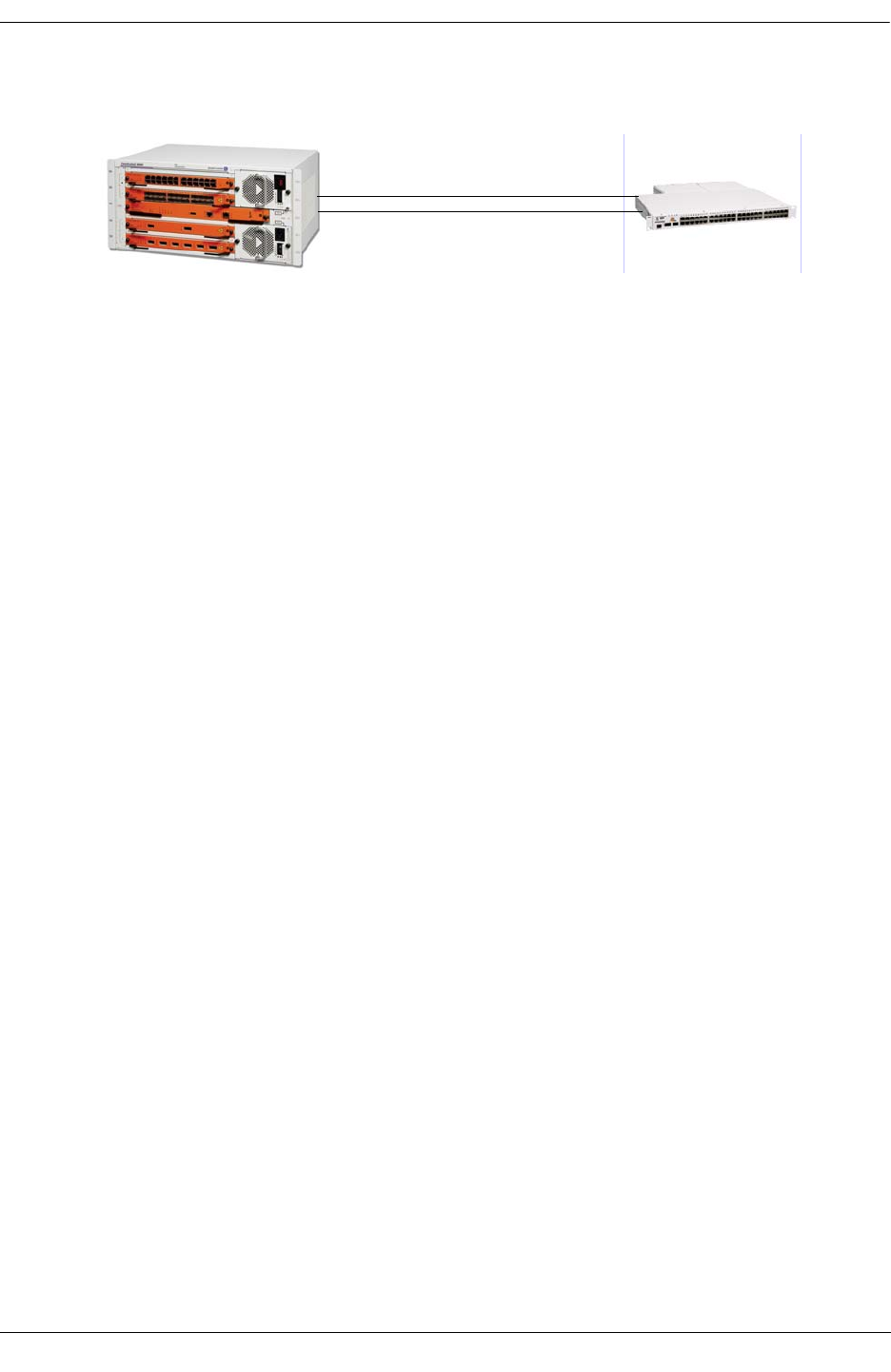
Troubleshooting Link Aggregation Troubleshooting Link Aggregation on OmniSwitch 6850/9000 Series
OmniSwitch Troubleshooting Guide July 2008 page 7-13
Troubleshooting Linkagg
Verify the Configuration
Verify the linkagg configuration to be sure that the linkagg number, size, keys, and ports are associated
correctly. If one end is connected correctly and the other end is connected to another device, Linkagg
will have no knowledge of this and the link will be up but no traffic will pass.
G-96/> show configuration snapshot linkagg
! Link Aggregate :
lacp linkagg 5 size 2 admin state enable
lacp linkagg 5 actor admin key 101
lacp agg 1/17 actor admin key 101
lacp agg 1/19 actor admin key 101
Verify the 802.1q Configuration Associated with the Linkagg Number
G-96/> show configuration snapshot 802.1q
! 802.1Q :
vlan 161 802.1q 5 "TAG AGGREGATE 5 VLAN 161"
vlan 162 802.1q 5 "TAG AGGREGATE 5 VLAN 162"
vlan 163 802.1q 5 "TAG AGGREGATE 5 VLAN 163"
vlan 164 802.1q 5 "TAG AGGREGATE 5 VLAN 164"
vlan 165 802.1q 5 "TAG AGGREGATE 5 VLAN 165"
The CLI show linkagg command will confirm that the aggregates are configured and are enabled and up
as shown below. This command displays the aggregate number, mode, SNMP ID, size, state, status, and
ports.
G-96/> show linkagg
Number Aggregate SNMP Id Size Admin State Oper State Att/Sel Ports
-------+----------+---------+----+------------+--------------+-------------
5 Dynamic 40000005 2 ENABLED UP 2 2
G-96/> show linkagg 5
Dynamic Aggregate
SNMP Id : 40000005,
Aggregate Number : 5,
SNMP Descriptor : Dynamic Aggregate Number 5 ref 40000005 size 2,
Name : ,
Admin State : ENABLED,
LACP 1/17 & 1/19 on 9600 Chassis

Troubleshooting Link Aggregation on OmniSwitch 6850/9000 Series Troubleshooting Link Aggregation
page 7-14 OmniSwitch Troubleshooting Guide July 2008
Operational State : UP,
Aggregate Size : 2,
Number of Selected Ports : 2,
Number of Reserved Ports : 2,
Number of Attached Ports : 2,
Primary Port : 1/17
LACP
MACAddress : [00:d0:95:ed:0f:08],
Actor System Id : [00:00:00:00:00:00],
Actor System Priority : 0,
Actor Admin Key : 101,
Actor Oper Key : 101,
Partner System Id : [00:00:00:00:00:00],
Partner System Priority : 0,
Partner Admin Key : 0,
Partner Oper Key : 101
The show linkagg port command displays the aggregate number, mode, snmp id, size, state, status, and
ports, primary port, LACP-mac-address, actor system id, actor system priority, actor admin key, actor oper
key, partner system id, partner system priority, partner admin key, partner oper key.
G-96/> show linkagg port 1/17
Dynamic Aggregable Port
SNMP Id : 1017,
Slot/Port : 1/17,
Administrative State : ENABLED,
Operational State : UP,
Port State : ATTACHED,
Link State : UP,
Selected Agg Number : 5,
Port position in the aggregate: 0,
Primary port : YES
LACP
Actor System Priority : 0,
Actor System Id : [00:d0:95:e0:78:18],
Actor Admin Key : 101,
Actor Oper Key : 101,
Partner Admin System Priority : 0,
Partner Oper System Priority : 0,
Partner Admin System Id : [00:00:00:00:00:00],
Partner Oper System Id : [00:d0:95:e0:79:18],
Partner Admin Key : 0,
Partner Oper Key : 101,
Attached Agg Id : 0,
Actor Port : 16,
Actor Port Priority : 0,
Partner Admin Port : 0,
Partner Oper Port : 528,
Partner Admin Port Priority : 0,
Partner Oper Port Priority : 0,
Actor Admin State : act1.tim1.agg1.syn0.col0.dis0.def1.exp0,
Actor Oper State : act1.tim1.agg1.syn1.col1.dis1.def0.exp0,
Partner Admin State : act0.tim0.agg1.syn0.col1.dis1.def1.exp0,
Partner Oper State : act1.tim1.agg1.syn1.col1.dis1.def0.exp0

Troubleshooting Link Aggregation Troubleshooting Link Aggregation on OmniSwitch 6850/9000 Series
OmniSwitch Troubleshooting Guide July 2008 page 7-15
Advanced Link Aggregation Troubleshooting
To verify that the link aggregate software recognizes all the available slices, perform the following steps:
Note. Dshell commands should only be used by Alcatel-Lucent personnel or under the direction of Alca-
tel-Lucent. Misuse or failure to follow procedures that use Dshell commands in this guide correctly can
cause lengthy network down time and/or permanent damage to hardware.
On the 9000 series, from the switch prompt, telnet to each of the NIs to troubleshoot the issue. Use IP
address 127.2.x.1, where x is the slot number
G-96/> telnet 127.2.1.1
Trying 127.2.1.1...
Connected to 127.2.1.1.
Escape character is '^]'.
Use la_ni_help to display all the help commands for static or dynamic linkagg.
[Slot 1]->la_ni_help
Link aggregation help menu [1.0]
--------------------------
Link Aggregation debug functions
Display Aggregates : la_ni_agg_prt
Display Ports : la_ni_port_prt
Display Ports Up : la_ni_port_up_prt
Display LACP stats : la_ni_lacp_port_stats_prt
Dump LA Trace : la_ni_trace_prt
Freeze LA Trace : la_ni_trace_freeze
Unfreeze LA Trace : la_ni_trace_unfreeze
Global variables : la_ni_display_add
Display Token : la_ni_token_prt
Display To unit tab : la_ni_tok_table_prt
values translation : la_ni_info
KITE debug : la_ni_kite_help
Socket Handler debug : lagg_ni_Sock_help
value = 43 = 0x2b = '+'
Use la_ni_trace_prt to dump the linkagg traces when linkagg does not join properly or when there is a
linkagg compatibility issue.
[Slot 1]->la_ni_trace_prt
____End of the NI trace dump_[NI_LINKAGG_TRAC] : 181 cells 16 free bytes
2412:: 1:TOKENLOG[1:0] -> la_ni_token_ready_process_f 2 1
2412:: 2:TOKENDBG[1:0] -> la_ni_token_find_next_tok_unit_f 1
2412:: 3:TOKENDBG[1:0] -> Exclusion OK
2412:: 4:TOKENDBG[1:0] -> la_ni_token_job_queue_out_f
2412:: 5:MGT DBG[1:0] -> la_ni_mgt_rcv_port_join_ask_f 1 18
2412:: 6:MGT DBG[1:0] -> la_ni_qd_port_assign_to_agg_f

Troubleshooting Link Aggregation on OmniSwitch 6850/9000 Series Troubleshooting Link Aggregation
page 7-16 OmniSwitch Troubleshooting Guide July 2008
2412:: 7:MGT DBG[1:0] -> la_ni_set_bc_port_index agg_id=1 primary_port=16
bcm_port:16 bcm_mod:0
2412:: 8:MGT DBG[1:0] -> la_ni_send_port_join_f
2412:: 9:TOKENDBG[1:0] -> la_ni_multicast_port_join_conf_f 1
2412:: 10:TOKENDBG[1:0] -> la_ni_to_lani_multicast_msg_f from 1/0 job_id=4
2412:: 11:TOKENDBG[1:0] -> la_ni_to_lani_send_msg_f job_id=4 slot=65535 slice=0
2412:: 12:TOKENDBG[1:0] -> la_ni_token_job_queue_out_f
2412:: 13:TOKENDBG[1:0] -> la_ni_token_auto_entry_f 3 1
2412:: 14:TOKENDBG[1:0] -> la_ni_token_got_process_f 3 1
2412:: 15:TOKENDBG[1:0] -> la_ni_tok_got_free_tok_f
794949:: 16:MGT DBG[1:0] -> la_ni_rcv_lacmm_f 0x000c008a
794949:: 17:MGT DBG[1:0] -> la_ni_mgt_rcv_port_leave_conf_f 1 18
794949:: 18:MGT DBG[1:0] -> la_ni_mgt_rcv_port_leave_conf_f 1 18 prim_port_index :0
794949:: 19:MGT DBG[1:0] -> la_ni_send_port_leave_f
794949:: 20:MGT DBG[1:0] -> la_ni_qd_port_remove_from_agg_f
794949:: 21:MGT DBG[1:0] -> la_ni_set_bc_port_index agg_id=1 primary_port=16
bcm_port:16 bcm_mod:0
794960:: 22:MGT DBG[1:0] -> la_ni_rcv_lacmm_f 0x000c008f
794960:: 23:MGT LOG[1:0] -> MY NI is alredy UP end of sync flag 1
794960:: 24:TOKENDBG[1:0] -> la_ni_token_auto_entry_f 10 1
794960:: 25:TOKENLOG[1:0] -> la_ni_token_ready_process_f 10 1
794960:: 26:MGT DBG[1:0] -> nisup_SetCnfNotCertified
794960:: 27:MGT DBG[1:0] -> la_ni_rcv_lacmm_f 0x000c0086
794960:: 28:MGT DBG[1:0] -> la_ni_mgt_del_port_f 18
795137:: 29:MGT DBG[1:0] -> la_ni_rcv_lacmm_f 0x000c008a
795137:: 30:MGT DBG[1:0] -> la_ni_mgt_rcv_port_leave_conf_f 1 16
795137:: 31:MGT DBG[1:0] -> la_ni_mgt_rcv_port_leave_conf_f 1 16 prim_port_index :0
1685116::180:FREEZE....
____End of the NI trace dump_[NI_LINKAGG_TRAC] : 181 cells 16 free bytes
value = 74 = 0x4a = 'J'
Use la_ni_agg_prt to display the linkagg ID, status, and size; similar to the show linkagg num command.
[Slot 1]->la_ni_agg_prt
5 -> 0x04a1f340 ifindex=40000005 id=5 type=1 max_size=2 selected=2 reserved=2
attached=2
primary_port_index=0 admin_state=1 oper_state=1
Individual=0
Actor : ID=[00:00:00:00:00:00] Prio=0 Admin Key=101 Oper Key=101
Actor working: ID=[00:d0:95:e0:78:18] Prio=0
Partner : ID=[00:00:00:00:00:00] Prio=0 Admin Key=0 Oper Key=101
Partner working: ID=[00:d0:95:e0:79:18] Prio=0
0 -> 0x049f3dc0 status=6 ifindex=1017 port_id=16 port_type=1 port_index=0
adminstate=1 operstate=1 link_up_down=1
activation_order=1 multicast_state_origin=0x5d
agg_ctx_p=0x04a1f340 agg_port_ctx_p=0x049f3dc0
1 -> 0x049f0bd0 status=6 ifindex=1019 port_id=18 port_type=1 port_index=1
adminstate=1 operstate=1 link_up_down=1
activation_order=2 multicast_state_origin=0x5d
agg_ctx_p=0x04a1f340 agg_port_ctx_p=0x049f0bd0
value = 9252740 = 0x8d2f84

Troubleshooting Link Aggregation Troubleshooting Link Aggregation on OmniSwitch 6850/9000 Series
OmniSwitch Troubleshooting Guide July 2008 page 7-17
Use la_ni_port_prt to display port status.
[Slot 1]->la_ni_port_prt
1:0: 0 -> 0x04a38450 status=0 ifdx=-1 id=0 type=0 agg_id=-1 port_index=-1
adminstate=1 operstate=2 link_up_down=1 activation_order=0 agg_ctx_p=0x0
1:0: 2 -> 0x04a38400 status=0 ifdx=-1 id=2 type=0 agg_id=-1 port_index=-1
adminstate=1 operstate=2 link_up_down=1 activation_order=0 agg_ctx_p=0x0
1:0: 4 -> 0x0499a4e0 status=0 ifdx=-1 id=4 type=0 agg_id=-1 port_index=-1
adminstate=1 operstate=2 link_up_down=1 activation_order=0 agg_ctx_p=0x0
1:0: 6 -> 0x0499a490 status=0 ifdx=-1 id=6 type=0 agg_id=-1 port_index=-1
adminstate=1 operstate=2 link_up_down=1 activation_order=0 agg_ctx_p=0x0
1:0: 8 -> 0x0499a440 status=0 ifdx=-1 id=8 type=0 agg_id=-1 port_index=-1
adminstate=1 operstate=2 link_up_down=1 activation_order=0 agg_ctx_p=0x0
1:0:10 -> 0x04a16a70 status=0 ifdx=-1 id=10 type=0 agg_id=-1 port_index=-1
adminstate=1 operstate=2 link_up_down=1 activation_order=0 agg_ctx_p=0x0
1:0:16 -> 0x049f3dc0 status=6 ifdx=1017 id=16 type=1 agg_id=5 port_index=0
adminstate=1 operstate=1 link_up_down=1 activation_order=1
agg_ctx_p=0x4a1f340
Actor : Sys ID=[00:d0:95:e0:78:18] Sys Prio=0 Port=16 Port Prio=0
Admin Key=101 Oper Key=101
Admin State=(act1.tim1.agg1.syn0.col0.dis0.def1.exp0)
Oper State =(act1.tim1.agg1.syn1.col1.dis1.def0.exp0)
Partner : Sys ID=[00:d0:95:e0:79:18] Sys Prio=0 Key=101 Port=528 Port Prio=0
Admin Key=0 Oper Key=101
Admin Sys ID=[00:00:00:00:00:00] Admin Sys Prio=0 Admin Port=0 Admin
Port Prio=0
Admin State=(act0.tim0.agg1.syn0.col1.dis1.def1.exp0)
Oper State =(act1.tim1.agg1.syn1.col1.dis1.def0.exp0)
Bit order : 1
1:0:18 -> 0x049f0bd0 status=6 ifdx=1019 id=18 type=1 agg_id=5 port_index=1
adminstate=1 operstate=1 link_up_down=1 activation_order=2
agg_ctx_p=0x4a1f340
Actor : Sys ID=[00:d0:95:e0:78:18] Sys Prio=0 Port=18 Port Prio=0
Admin Key=101 Oper Key=101
Admin State=(act1.tim1.agg1.syn0.col0.dis0.def1.exp0)
Oper State =(act1.tim1.agg1.syn1.col1.dis1.def0.exp0)
Partner : Sys ID=[00:d0:95:e0:79:18] Sys Prio=0 Key=101 Port=530 Port Prio=0
Admin Key=0 Oper Key=101
Admin Sys ID=[00:00:00:00:00:00] Admin Sys Prio=0 Admin Port=0 Admin
Port Prio=0
Admin State=(act0.tim0.agg1.syn0.col1.dis1.def1.exp0)
Oper State =(act1.tim1.agg1.syn1.col1.dis1.def0.exp0)
Bit order : 1
value = 19 = 0x13

Troubleshooting Link Aggregation on OmniSwitch 6850/9000 Series Troubleshooting Link Aggregation
page 7-18 OmniSwitch Troubleshooting Guide July 2008
Use la_ni_lacp_port_stats_prt to display linkagg port statistics. All RX and TX traffic is displayed.
[Slot 1]->la_ni_lacp_port_stats_prt
1:0:16
lacpdus_rx = 75287
marker_pdus_rx = 0
marker_response_pdus_rx = 0
unknown_rx = 0
illegal_rx = 0
lacpdus_tx = 75314
marker_pdus_tx = 0
marker_response_pdus_tx = 0
1:0:18
lacpdus_rx = 75283
marker_pdus_rx = 0
marker_response_pdus_rx = 0
unknown_rx = 0
illegal_rx = 0
lacpdus_tx = 75309
marker_pdus_tx = 0
marker_response_pdus_tx = 0
value = 35 = 0x23 = '#'
[Slot 1]->exit
G-96/>
Troubleshooting Commands Table
The following table provides a listing of commands and functions used to troubleshoot link aggregation:
CLI Commands Description Comments
Show linkagg Displays aggregate number,
mode, snmp id, size, state, status,
and ports.
Show linkagg <num> Displays aggregate number, mode,
snmp id, size, state, status, and
ports, primary port, LACP-mac-
address, actor system id, actor sys-
tem priority, actor admin key,
actor oper key, partner system id,
partner system priority, partner
admin key, and partner oper key.
Show linkagg port <slot/por> Displays aggregate number,
mode, snmp id, size, state, status,
and ports, primary port, LACP-
mac-address, actor system id,
actor system priority, actor admin
key, actor oper key, partner sys-
tem id, partner system priority,
partner admin key, and partner
oper key.

Troubleshooting Link Aggregation Troubleshooting Link Aggregation on OmniSwitch 6850/9000 Series
OmniSwitch Troubleshooting Guide July 2008 page 7-19
Advanced Troubleshooting
DSHELL Debugging for OS-6850
and 9000 Series switches. Commands run on individ-
ual NI - telnet from switch
console prompt to 127.2.x.1,
where x = slot number.
la_ni_help Displays help commands.
la_ni_trace_prt Dump Linkagg trace.
la_ni_agg_prt Displays aggregate.
la_ni_port_prt Displays port.
la_ni_port_up_prt Displays port up; port index is
zero base.
la_ni_lacp_port_stats_prt Displays LACP port stats.
la_ni_debug_level Displays static linkagg;
by default the value will be
0x60400. If set to 0x604FF, the
traces will display in Dshell or
console.
*** Caution ***
Once enabled, this function
will continuously scroll
information on the screen.
To avoid this, specify a
delay timer on the same
command line: [Slot 1]->
la_ni_debug_level=0x604ff;
taskDelay
300;la_ni_debug_level=0x6
0400

Troubleshooting Link Aggregation on OmniSwitch 6850/9000 Series Troubleshooting Link Aggregation
page 7-20 OmniSwitch Troubleshooting Guide July 2008

OmniSwitch Troubleshooting Guide July 2008 page 8-1
8 Troubleshooting 802.1Q
In order to troubleshoot an 802.1Q problem on a port, a basic understanding of the networking OSI model
is required to assist one with the troubleshooting steps to resolve a particular network problem.
Alcatel-Lucent’s OmniSwitch supports 802.1Q specifications as defined by RFC 2674/IEEE 802.1Q/D11.
Reading the “Configuring 802.1Q” in the appropriate OmniSwitch Network Configuration Guide is also
highly recommended.
In This Chapter
“Troubleshooting 802.1Q” on page 8-2
“Advanced Troubleshooting” on page 8-5
“Dshell Commands” on page 8-7
Note. The CLI troubleshooting sections in this chapter apply to both OS-7000/8000 and OS-6850/9000
Series switches. The 802.1Q commands and functionality did not change for the OS-6850/9000 Series.
You can configure a port to accept either tagged or non-tagged frames; the default is to accept all frames.
The Dshell troubleshooting section does not apply to OS-6850/9000 switches. Configuration of 802.1q
can be verified through the CLI; it is not necessary to go to Dshell.
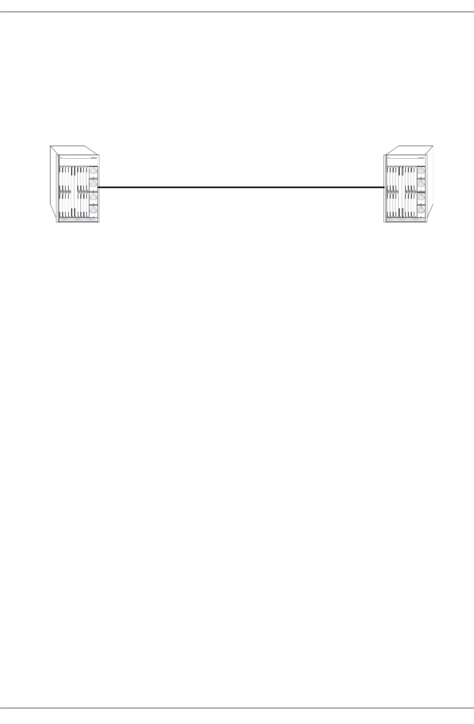
Troubleshooting 802.1Q Troubleshooting 802.1Q
page 8-2 OmniSwitch Troubleshooting Guide July 2008
Troubleshooting 802.1Q
When troubleshooting an 802.1Q problem, it is important to not only investigate the 802.1Q feature and
configuration, but also the basic Ethernet connectivity between the problematic switches. Please refer to
Chapter 2, “Troubleshooting Switched Ethernet Connectivity,” of this document.
802.1Q Example
If there is no traffic passing at all across an 802.1Q link, verify basic Ethernet connectivity.
If there are particular VLANs that are not able to pass traffic, verify the configuration on both sides of the
link using the show vlan port CLI command. This will display the 802.1Q VLANs that are configured. It
will also display the default untagged VLAN. Confirm that these are configured correctly.
-> show vlan port 1/24
vlan type status
--------+---------+--------------
1 default forwarding
30 qtagged forwarding
40 qtagged forwarding
50 qtagged forwarding
Verify the ports are in forwarding as expected. Note which bridge mode the switch is running in (1 per
VLAN or 1 per switch) If spanning tree appears to not be working correctly, please see Chapter 4, “Trou-
bleshooting Spanning Tree,” of this document.
Note that different spanning tree protocols can be used on the same tagged port.
To verify which VLAN a specific flow is being classified into, use the show mac-address-table command
shown below:
-> show mac-address-table 5/24
Legend: Mac Address: * = address not valid
Vlan Mac Address Type Protocol Operation Interface
------+-------------------+--------------+-----------+------------+-----------
30 00:d0:95:88:67:ce learned 10806 bridging 5/24
50 00:d0:95:88:67:d0 learned 10806 bridging 5/24
Total number of Valid MAC addresses above = 2
OmniSwitch 7800 OmniSwitch 7800
Switch A Switch B

Troubleshooting 802.1Q Troubleshooting 802.1Q
OmniSwitch Troubleshooting Guide July 2008 page 8-3
Default VLAN Traffic
If traffic that should be in the default VLAN is not passing properly, first verify that the default VLAN is
set correctly, as see above. Also note the switch can be configured to either accept or deny untagged pack-
ets.
When enabling a port on the OmniSwitch 7700/7800/8800 to accept tagged traffic, you can specify
whether only 802.1Q tagged traffic is allowed on the port (deny all bridged traffic), or whether the port
accepts both tagged and untagged traffic.
OmniSwitch 7700/7800/8800 has a feature that enables it to accept all data on a bridged VLAN or deny all
of the bridged traffic.
The vlan 802.1q frame type all CLI command allows all the bridged traffic to be accepted on a tagged
link. When using an OmniSwitch 7700/7800/8800 with an OmniSwitch or Omni Switch/Router where
default VLAN needs to be bridged, this command should be set to all so that the bridged traffic can be
accepted by the OmniSwitch 7700/7800/8800 in addition to the tagged traffic. On the OmniSwitch 6850/
9000, the command is vlan 802.1q <slot/port> frame type all.
For devices that cannot bridge on the tagged link, e.g. an OmniCore, the OmniSwitch 7700/7800/8800 can
be configured to accept only tagged traffic and ignore all the bridged traffic using the command. If frame
type is set to tagged, all non tagged traffic will be dropped.
The vlan 802.1q frame type tagged CLI command will deny all of the bridged traffic. Bridged traffic is
classified as traffic without a VLAN Identification (VID). Any packet without VID will be discarded.
Only tagged traffic will be accepted.
To verify if the port will receive untagged frames use the show 802.1q CLI command as shown below.
Note the Acceptable Frame Type field, Any Frame Type indicates this port will receive untagged
frames as well as tagged frames.
-> show 802.1q 5/24
Acceptable Frame Type : Any Frame Type
Force Tag Internal : on
Tagged VLANS Internal Description
-------------+------------------------------------------+
30 TAG PORT 5/24 VLAN 30
40 TAG PORT 5/24 VLAN 40
50 TAG PORT 5/24 VLAN 50
Tagged Packet on an Untagged Port
If a tagged packet comes on an untagged or group mobility port (i.e., the vlan 802.1q CLI command has
not been used), then it can be classified in a VLAN other than the VLAN it currently belongs to. If this
classified VLAN (i.e., different then the packet tag) is now tagged on the egress side, then there are two
possible options.
One option is to carry the original tag of the packet and other option is to replace it with the classified
VLAN as the tag. If the force tag internal is disabled (on), then the tag is not replaced with the classified
VLAN. If the force tag internal is enabled (off), then the tag is replaced with the classified VLAN as the
tag.
Please note the above output of show 802.1Q CLI command shown in “Default VLAN Traffic” on
page 8-3.

Troubleshooting 802.1Q Troubleshooting 802.1Q
page 8-4 OmniSwitch Troubleshooting Guide July 2008
Question: What needs to be done if the native VLAN needs to be tagged when connected to an
OmniSwitch 7700/7800/8800?
Answer: The Gigabit/Ethernet port can be moved into a different dummy VLAN, and then the tagged
service can be created for the previous native VLAN. CLI Commands are as follows:
1Dummy VLAN 99 created:
>vlan 99
2A tag service is to be created on port 99 in VLAN 1.
->vlan 99 port default 1/1
3Tag service created on VLAN 1.
->vlan 1 802.1q 1/1
4(View the 802.1Q services created on port 1/1.
->show 802.1q 1/1
802.1Q with VLAN ID of 0
A VLAN ID of 0 means that Tag Header contains only user priority information; no VLAN identifier is
present in the frame. This frame will be claimed in the default VLAN for processing.
802.1Q and 64 Byte Packets
The Omni Switch 7700/7800/8800 was designed to send out tagged frames with a minimum size of 68
bytes. If the Omni Switch 7700/7800/8800 receives a tagged packet of 64 bytes it will be padded and sent
out 68 bytes (if untagged it will be 64 bytes).

Troubleshooting 802.1Q Advanced Troubleshooting
OmniSwitch Troubleshooting Guide July 2008 page 8-5
Advanced Troubleshooting
To verify the 802.1Q configuration from the CMM perspective use the debug 802.1q CLI command.
If frame type is set to all, then the egress default VLAN will equal the ports default VLAN. If force tag
internal is set to off, e.g. force tag internal will equal 0, otherwise it will be ffffffff.
The following shows the debug 802.1q CLI command used to verify that the slot and port are up.
-> debug 802.1q 5/24
Slot Status = slot up
Port Status = port up
GENERAL INFO ESM: USER PORT 1-12 = CORONADO PORT 0-11
GENERAL INFO ESM: USER PORT 13-24 = CORONADO PORT 16-27
GENERAL INFO GSM-2: USER PORT 1 = CORONADO PORT 12
GENERAL INFO GSM-2: USER PORT 2 = CORONADO PORT 28
GENERAL INFO GSM-8: USER PORT 1 = CORONADO PORT 0
GENERAL INFO GSM-8: USER PORT 2 = CORONADO PORT 16
GENERAL INFO GSM-8: USER PORT 3 = CORONADO PORT 1
GENERAL INFO GSM-8: USER PORT 4 = CORONADO PORT 17
GENERAL INFO GSM-8: USER PORT 5 = CORONADO PORT 2
GENERAL INFO GSM-8: USER PORT 6 = CORONADO PORT 18
GENERAL INFO GSM-8: USER PORT 7 = CORONADO PORT 3
GENERAL INFO GSM-8: USER PORT 8 = CORONADO PORT 19
HARDWARE INFO for slot = 5 and port = 24:
At reg_addr = 660012c, Ingress tag-untag:= 8000000:
At reg_addr = 6a00010, Eg tag-untag: = 8000000:
At reg_addr = 660106c,for protocol = 0,ing default vlan: = a
At reg_addr = 66010ec,for protocol = 1,ing default vlan: = a
At reg_addr = 660116c,for protocol = 2,ing default vlan: = a
At reg_addr = 66011ec,for protocol = 3,ing default vlan: = a
At reg_addr = 660126c,for protocol = 4,ing default vlan: = a
At reg_addr = 66012ec,for protocol = 5,ing default vlan: = a
At reg_addr = 660136c,for protocol = 6,ing default vlan: = a
At reg_addr = 66013ec,for protocol = 7,ing default vlan: = a
At reg_addr = 660146c,for protocol = 8,ing default vlan: = a
At reg_addr = 66014ec,for protocol = 9,ing default vlan: = a
At reg_addr = 660156c,for protocol = a,ing default vlan: = a
At reg_addr = 66015ec,for protocol = b,ing default vlan: = a
At reg_addr = 660166c,for protocol = c,ing default vlan: = a
At reg_addr = 66016ec,for protocol = d,ing default vlan: = a
At reg_addr = 660176c,for protocol = e,ing default vlan: = a
At reg_addr = 66017ec,for protocol = f,ing default vlan: = a
At reg_addr = 6a7006c, egress default vlan: = a
At reg_addr = 6600118, protocol cam on/off: = 0 :
At reg_addr = 660011c, trusted/untrusted: = 0
At reg_addr = 6600130, secure/unsecure: = 0
At reg_addr = 6608078, for vlan = 1e,spanning tree vector: = 8000000
At reg_addr = 66080a0, for vlan = 28,spanning tree vector: = 8000000
At reg_addr = 66080c8, for vlan = 32,spanning tree vector: = 8000000
At reg_addr = 6a00014, Eg force tag internal: = ffffffff:

Advanced Troubleshooting Troubleshooting 802.1Q
page 8-6 OmniSwitch Troubleshooting Guide July 2008
output definitions
Aggregate/Slot Status Whether the slot or aggregate link is actively running.
Port Status Whether the port is actively running.
General Info Provides general information on the modules in the chassis, including
module type, number of ports, and ASIC.
Hardware Info Lists the various debug messages for the selected slot and port.

Troubleshooting 802.1Q Dshell Commands
OmniSwitch Troubleshooting Guide July 2008 page 8-7
Dshell Commands
Note. Dshell commands do not apply to OS-6850/9000 switches. Configuration of 802.1q can be verified
through the CLI; it is not necessary to go to Dshell.
The first step in troubleshooting for an 802.1Q problem through Dshell is to verify the configurations.
Validating the configurations in Dshell remove the chances of inconsistency between the CLI and Dshell.
Following is the list of commands to verify the configuration of the 802.1Q ports in Dshell. These
commands will verify that there is no inconsistency between the CLI and Dshell.
Note. Dshell commands should only be used by Alcatel-Lucent personnel or under the direction of Alca-
tel. Misuse or failure to follow procedures that use Dshell commands in this guide correctly can cause
lengthy network down time and/or permanent damage to hardware.
The Dshell command print_default_vlan_8021q_cmm shows the default or native VLAN for all of the
802.1Q ports. Slot and port are zero based.
-> dshell
Working: [Kernel]->print_default_vlan_8021q_cmm 4,23
For slot = 4 and port = 23, default_vlan = 10value = 4 = 0x4
Working: [Kernel]->print_port_aggregation_status_8021q_cmm 6,0
print_port_aggregation_status_8021q_cmm: Slot number = 6, Port number = 0, por
t_aggregation_status = AGGREGABLE PORT
value = 6 = 0x6
Working: [Kernel]->print_configured_list_aggregate_8021q_cmm 6,0
print_configured_list_8021q_cmm: aggregate_id = 6, number_of_configured_vlans =
0, vlan list =
value = 0 = 0x0
Note. Use the Dshell NIDebuger to run the following command.
To see the 802.1Q VLANs for a particular port use the print_configured_list_8021q_ni zero_based_port
command as shown below: ???? This command was not marked for deletion but the example below was.
Is this correct and/or is there a new example if this command should stay? ????
-> dshell
Working: [Kernel]->NiDebug
5:0 nidbg> print_configured_list_8021q_ni 23
5:0
5:0 print_configured_list_8021q_ni: Port number = 23, number_of_configured_vlan
s = 3, vlan list = 30,40,50,
5:0 value = 23 = 0x17
5:0 nidbg> print_acceptable_frame_type_8021q_ni 23
5:0
5:0 print_acceptable_frame_type_8021q_ni: Port number = 23, acceptable_frame_t

Dshell Commands Troubleshooting 802.1Q
page 8-8 OmniSwitch Troubleshooting Guide July 2008
ype = ANY FRAME TYPE
5:0 value = 23 = 0x17
5:0 nidbg> print_force_tag_internal_8021q_ni 23
5:0
5:0 print_force_tag_internal_8021q_ni: Port number = 23, force_tag_internal =
ON
5:0 value = 23 = 0x17
5:0 nidbg> print_default_vlan_8021q_ni 23
5:0
5:0 print_default_vlan_8021q_ni: For port = 23, default vlan = 10 value = 23 =
0x17
5:0 nidbg> print_configured_list_aggregate_8021q_ni 2
5:0
5:0 print_configured_list_8021q_ni: Aggregate number = 2, number_of_configured_
vlans = 3, vlan list = 30,40,50,
5:0 value = 2 = 0x2
5:0 nidbg> print_port_aggregation_status_8021q_ni 2
5:0
5:0 print_port_aggregation_status_8021q_ni: Port number = 2, port_aggregation_
status = NOT AGGREGABLE PORT
5:0 value = 2 = 0x2
5:0 nidbg> print_port_list_in_aggregate_8021q_ni 3
5:0
5:0 print_port_list_in_aggregate_8021q_ni: aggregate_id = 3, number_of_ports =
0, port_list =
5:0 value = 3 = 0x3
5:0 nidbg> print_default_vlan_aggregate_8021q_ni 2
5:0
5:0 print_default_vlan_aggregate_8021q_ni: For aggregate = 2, default vlan = 1
value = 2 = 0x2

OmniSwitch Troubleshooting Guide July 2008 page 9-1
9 Troubleshooting Port
Mobility
In order to troubleshoot a Port Mobility problem, a basic understanding of the technology is required.
Reviewing the “Assigning Ports to VLANs” and “Defining VLAN Rules” chapters in the appropriate
OmniSwitch Network Configuration Guide is highly recommended.
In This Chapter
“Troubleshooting a Port Mobility Failure” on page 9-2
“Advanced Troubleshooting” on page 9-5
“Troubleshooting Port Mobility on OS-6800 Switches” on page 9-7
“Troubleshooting Port Mobility on OmniSwitch 6850/9000 Series” on page 9-10

OmniSwitch Troubleshooting Guide July 2008 page 9-2
Troubleshooting a Port Mobility Failure
There is no systematic procedure to troubleshoot a Port Mobility issue. This section will give you a check-
list, with a generally best course of action to take to determine the source of the Port Mobility failure.
1Verify that port mobility has been turned on for a given port and is still active.
2Determine VLAN rules.
3Determine mobile port membership.
4Verify Traffic on a mobile port.
5Correct rules, or move devices appropriately.
In general, the above steps are a good guideline for determining what is causing mobile port(s) to join
incorrect VLAN(s) or to not join any VLAN(s). Most likely, all troubleshooting steps will not be needed.
After each step in the troubleshooting process, determine if a configuration modification is necessary, and
make any needed corrections.
Note that mobility is different in AOS products when compared to legacy XOS products. The newer AOS
products implement mobility on the port level. There is no longer the concept of having a “mobile group”
as there was in the legacy XOS.
For dynamic assignment of a port to a VLAN, port mobility must be enabled on a given port. To deter-
mine if port mobility is enabled for given port, issue the show vlan port mobile CLI command, or for a
specific port, use the show vlan port mobile CLI command with the slot/port option. If port mobility has
not been enabled, use the show vlan port mobile CLI command to enable it. All variables in this output
are important to understand if there are problems with group mobility. (See below for an example of this
command.)
•Verify the feature is enabled ON for this port. The default is OFF.
•If mobile is on and the feature appears to still not be working, understand that if ignore BPDU is off,
and the port is an interswitch connection, the arrival of a BPDU will turn mobility off on the port.
•If traffic is not passing on the default vlan, verify that it is configured to the correct vlan and that
Default Vlan is enabled. If it is not enable, only traffic matching a specific rule will pass.
•If there is a device such as a printer, that only sources traffic when it boots, it may be advantageous to
turn off default VLAN restore.
Note. OS-6600 supports only one rule per port. One port can only become a member of one rule unlike
OS-7700/7800/8800, which support multiple rules per port. Hubs are also not supported on a mobile port.
-> show vlan port mobile 6/1-3
Mobility : on,
Config Default Vlan: 1,
Default Vlan Enabled: on,
Default Vlan Restore: on,
Authentication : off,
Ignore BPDUs : off

Troubleshooting Port Mobility Troubleshooting a Port Mobility Failure
OmniSwitch Troubleshooting Guide July 2008 page 9-3
With Port Mobility, it is critical that the network administrator have a good understanding of the traffic on
their network in order to assign proper rules. It is not only important to verify the required rules have been
configured, but it is also important to understand the concept of precedence for rules that may overlap. In
addition, it is important not to design beyond the limitations of the software. This can be verified by refer-
encing the latest release notes for the current software revision.
To verify the rules that have been configured, use the show vlan rules CLI command as shown below:
-> show vlan rules
11.2.1.1.1.1.1 Legend: type: * = binding rule
type vlan rule
-----------------+------+-------------------------------------------------------
ip-net 255 21.0.0.0, 255.0.0.0
protocol 355 ipx-e
mac-ip-port* 1500 00:da:95:00:ce:3f, 21.0.0.43, 3/10
dhcp-mac-range 255 00:da:95:00:59:10, 00:da:95:00:59:9f
To determine if a port has seen traffic that has matched a configured rule, use the show vlan port [slot/
port] CLI command with the slot/port option shown below:
-> show vlan port 6/1
vlan type status
--------+---------+--------------
1 default forwarding
255 mobile forwarding
If the desired group is not present, and there are no other mobile groups present for the switch, verify the
port is set to mobile and that a BPDU has not turned off mobility.
If there are other groups learned on the port, but one is missing verify both the rule configuration as well
as the traffic on the ingress of that port. Note rule precedence if there is a possibility for overlapping rules.
A sniffer may be useful to verify the traffic coming into the port is what is expected.
Binding Rules
Note that for a frame to be classified into a vlan with binding rules, the frame must match ALL binding
rules, for it to be classified into that particular vlan. If it does not match all binding rules, the frame will
either be classified as default, or another vlan should it match other rules configured on the switch
Port Rules
Port rules only apply to outgoing mobile port traffic and do not classify incoming traffic. If a mobile port
is specified in a port rule, its incoming traffic is still classified for VLAN assignment in the same manner
as all other mobile port traffic.

OmniSwitch Troubleshooting Guide July 2008 page 9-4
Precedence
Due to the variety of rules that can be configured there can be traffic that can match multiple rules, i.e. an
IP frame could match a network address rule as well as a protocol rule. For this reason, all rules are
arranged in a precedence. When a frame is received on a mobile port, switch software starts with rule one
in the rule precedence table and progresses down the list until there is a successful match between rule
criteria and frame contents. The higher the rule is in the list, the higher its level of precedence. To verify
which VLAN a frame is being classified into use the show mac-address-table CLI for the MAC address
in question as shown below:
-> show mac-address-table 00:b0:d0:75:f1:97
Legend: Mac Address: * = address not valid
Vlan Mac Address Type Protocol Operation Interface
------+-------------------+--------------+-----------+------------+-----------
255 00:b0:d0:75:f1:97 learned 10800 bridging 6/1
Total number of Valid MAC addresses above = 1
Please see the “Defining VLAN Rules” chapter in the appropriate OmniSwitch Network Configuration
Guide for a detailed list of all rules and their relative precedence. has important information about VLAN
Rule precedence.

Troubleshooting Port Mobility Advanced Troubleshooting
OmniSwitch Troubleshooting Guide July 2008 page 9-5
Advanced Troubleshooting
To verify if a port is a candidate for mobility as well as if mobility as been turned on for a given port use
the debug vlan rule ports CLI command. Note that ports 6/1-2 are mobile ports. Ports 7/1-2 and 8/1-2 are
not a candidate for mobility because they are either 802.1Q ports or part of a link aggregate.
-> debug vlan rule ports
port candidate mobile
------+-----------+---------
2/1 + -
2/2 + -
6/1 + +
6/2 + +
7/1 - -
7/2 - -
8/1 - -
8/2 - -
To look at the protocol indicator map use the debug vlan rule protocol-map CLI command as shown
below. This command displays the Protocol Indicator (PI) map. In order for group mobility to classify
packets on the OmniSwitch, it needs to program the hardware with protocol type and protocol indicator.
The Protocol Indicator is later used in the CAM lookup. This command displays the protocols
programmed and the Protocol Indicator.
-> debug vlan rule protocol-map
*** Protocol Indicator Map ***
proto = Ethernet II IP Frame = E-II PI = 0
proto = Ethernet II ARP Frame = E-II PI = 0
proto = Ethernet II RARP Frame = E-II PI = 0
proto = SNAP IP Frame = 802.3PI = 1
proto = SNAP ARP Frame = 802.3 PI = 1
proto = SNAP RARP Frame = 802.3 PI = 1
proto = IPX Ethernet II Frame = E-II PI = 4
proto = IPX Novell Frame = 802.3 PI = 3
proto = IPX LLC Frame = 802.3 PI = 2
proto = IPX SNAP Frame = 802.3 PI = 5
Note. OmniSwitch 6624/6648 switches do not have the protocol CAM. Instead, database shown above is
maintained in software.
The debug vlan rule memory command displays the memory allocated for the group mobility rules, as
shown below:
-> debug vlan rule memory
*** RULE MEM BLOCKS ***
1. 4443338 1
The debug vlan rule database command displays the group mobility rules database, as shown below:
-> debug vlan rule database
IP NETWORK RULES
B ssz=2 p=56644e0 l=56644e0 r=4443364 v=60
R ssz=1 p=4443340 l=56644e0 r=56644e0 v=90
PROTOCOL RULES
B ssz=1 p=56644e0 l=56644e0 r=56644e0 v=70

OmniSwitch Troubleshooting Guide July 2008 page 9-6
Dshell
Note. Dshell commands should only be used by Alcatel-Lucent personnel or under the direction of Alca-
tel-Lucent. Misuse or failure to follow procedures that use Dshell commands in this guide correctly can
cause lengthy network down time and/or permanent damage to hardware.
NI Debug Dshell
Use the gmnSetPrintDestination command from the NiDebug Dshell command to redirect the output of
the group mobility commands to the current session.
-> dshell
Working: [dshell]->NiDebug
6:0 nidbg> gmnSetPrintDestination
6:0 value = 0 = 0x0
All NIs should have a copy of all rules configured on the switch, regardless if that NI has used the rule yet.
To verify that the rules have been loaded on the NI use the gmnShowRules command from the NiDebug
Dshell command. Use the same rule index from above, i.e. 0 = IP net address rule.
-> dshell
Working: [dshell]->NiDebug
6:0 nidbg> gmnShowRules 0
6:0
6:0 NI IP Network Address Rules (2 rules)
6:0 ---------------------------
6:0 net = 5a5a5a00 mask = ffffff00 vid = 90
6:0 net = 3c3c3c00 mask = ffffff00 vid = 60
6:0 value = 0 = 0x0
To verify that the NI sees a port as mobile use the gmnIsPortMobile (port number (zero based))
command from the NiDebug Dshell command. (Please note that 1= mobile and 0=non-mobile.)
-> dshell
Working: [dshell]->NiDebug
6:0 nidbg> gmnIsPortMobile 1
6:0 value = 1 = 0x1
This gmnClassifyDebug command displays group mobility classification process on the NI as the pack-
ets are received. This has to be issued in conjunction with the gmnPrintDestination command to see the
output on the console. This command is issued on the NiDebug prompt for the NI we want to debug.
-> dshell
Working: [dshell]->gmnPrintDestination = 0
Working: [dshell]->gmnClassifyDebug = 1

Troubleshooting Port Mobility Troubleshooting Port Mobility on OS-6800 Switches
OmniSwitch Troubleshooting Guide July 2008 page 9-7
Troubleshooting Port Mobility on OS-6800
Switches
The following commands and debugging functions are available for troubleshooting Group Mobility on
the NI. A summary is shown below.
•show vlan rules
•gmHelp
•gmcKiteDebug
•gmcShowPorts
•gmcShowRules
•gmnKiteDebug
•gmnKiteShowRules
•gmnMacVlanShowBuffer
show vlan rules
SW_2T19-> show vlan rules
Legend: type: * = binding rule
type vlan rule
-----------------+------+-------------------------------------------------------
ip-net 9 166.24.9.0, 255.255.255.0
ip-net 104 166.24.104.0, 255.255.248.0
ip-net 112 166.24.112.0, 255.255.248.0
dhcp-port 104 1/1
dhcp-port 104 1/2
dhcp-port 104 1/3
dhcp-port 104 1/4
gmHelp
Working: [Kernel]->gmHelp
***************************************************
Group Mobility Help for CMM
***************************************************
'gmcKiteDebug = 1' must be done in order to see the outputs on below debug
commands.
It also enables the real time debugger. To disable 'gmcKiteDebug = 0'.
gmcShowPorts ---------------Displays all the ports in the system
gmcShowMipTables -----------Displays all MIP tables used
gmcShowRules (GmcRuleType) -Displays all rules of specified type
gmcShowPiMap ---------------Displays Protocol Indicator Map
gmcShowConnections ---------Displays connections with all CMM interfaces
gmcShowNiConnections -------Displays connections with all NI interfaces
gmcMacVlanShowBuffer (int type) - If type=0, display macvlan_sw malloc counter only

OmniSwitch Troubleshooting Guide July 2008 page 9-8
- If type=1, display above and macvlan_sw table
gmcDebugKiteShowCML (int slot) -- Display CML setting at CMM
***************************************************
Group Mobility Help for NI
***************************************************
gmnKiteDebug = 1 ------- Enable real time debugging
gmnKiteDebug = 0 ------- Disable real time debugging
gmnKiteShowEframe = 1 -- Display E_FRAME_PARAM when gmnKiteDebug is enabled
gmnKiteShowEframe = 0 -- Do not display E_FRAME_PARAM when gmnKiteDebug is enabled
gmnKiteShowDefVlan -------- Display def vlan stored at gmn
gmnKiteShowPiMap -------- Display protoCam0 and protoCam1
gmnKiteDebugPI -------- Display the proto and port-proto rule's PI map
setting
gmnKiteShowPortSet -------- Display port configuration stored at gmn
gmn_bcm_port_ifilter_get -- Read ingress filtering setting from HW
gmn_bcm_port_learn_get ---- Read CML setting from HW
gmn_bcm_port_discard_get -- Read whether the port is tagged or untagged port
from HW
gmn_bcm_vlan_port_get (int vid) -- Read VPM for the vlan from HW
gmnKiteShowRules ----------------- Display Mobile rule table at gmn
gmnMacVlanShowBuffer (int type) -- If type=0, display macvlan_sw malloc counter
only
-- If type=1, display above and macvlan_sw table
gmcKiteDebug
Certified: [Kernel]-> gmcKiteDebug = 1
gmcShowPorts
Certified: [Kernel]->gmcShowPorts
GMC_LOG: "gmcShowPorts", gmc: 1/1 pot=1 mob=1
GMC_LOG: "gmcShowPorts", gmc: 1/2 pot=1 mob=1
GMC_LOG: "gmcShowPorts", gmc: 1/3 pot=1 mob=1
GMC_LOG: "gmcShowPorts", gmc: 1/4 pot=1 mob=1
GMC_LOG: "gmcShowPorts", gmc: 1/5 pot=1 mob=1
GMC_LOG: "gmcShowPorts", gmc: 1/6 pot=1 mob=1
GMC_LOG: "gmcShowPorts", gmc: 1/7 pot=1 mob=1
GMC_LOG: "gmcShowPorts", gmc: 1/8 pot=1 mob=1
GMC_LOG: "gmcShowPorts", gmc: 1/9 pot=1 mob=1
GMC_LOG: "gmcShowPorts", gmc: 1/10 pot=1 mob=1
GMC_LOG: "gmcShowPorts", gmc: 1/11 pot=1 mob=1
GMC_LOG: "gmcShowPorts", gmc: 1/12 pot=1 mob=1
GMC_LOG: "gmcShowPorts", gmc: 1/13 pot=1 mob=1
GMC_LOG: "gmcShowPorts", gmc: 1/14 pot=1 mob=1
GMC_LOG: "gmcShowPorts", gmc: 1/15 pot=1 mob=1
gmcShowRules
Certified: [Kernel]->gmcShowRules
GMC_LOG: "gmcShowRule", ht=1 bht=0 col=R GMC_LOG: "gmcShowRule", GMC_LOG: "gmcSh
owRule", vid = 9

Troubleshooting Port Mobility Troubleshooting Port Mobility on OS-6800 Switches
OmniSwitch Troubleshooting Guide July 2008 page 9-9
GMC_LOG: "gmcShowRule", ht=2 bht=1 col=B GMC_LOG: "gmcShowRule", GMC_LOG: "gmcSh
owRule", vid = 104
GMC_LOG: "gmcShowRule", ht=1 bht=0 col=R GMC_LOG: "gmcShowRule", GMC_LOG: "gmcSh
owRule", vid = 112
value = 12 = 0xc
gmnKiteDebug
Certified: [Kernel]->gmnKiteDebug = 1
Certified: [Kernel]->gmnKiteShowPortSet
port mobile enabled restore ignoreBPDU auth ifilter
----+------+-------+-------+----------+----+-------
0 1 1 1 0 0 0
1 1 1 1 0 0 0
2 1 1 1 0 0 0
3 1 1 1 0 0 0
4 1 1 1 0 0 0
5 1 1 1 0 0 0
6 1 1 1 0 0 0
7 1 1 1 0 0 0
gmnKiteShowRules
Certified: [Kernel]->gmnKiteShowRules
IP Network Address Rules
---------------------------
net = a6186800 mask = fffff800 vid = 104
net = a6180900 mask = ffffff00 vid = 9
net = a6187000 mask = fffff800 vid = 112
DHCP Port Rules
---------------------------
port = 74 vid = 104
port = 39 vid = 104
port = 98 vid = 104
port = 16 vid = 104
gmnMacVlanShowBuffer
Certified: [Kernel]->gmnMacVlanShowBuffer
gmnKiteMacVlan_bufferCount = 0
gmnKiteMallocCount = 0
gmnKiteFreeCount = 0
value = 31 = 0x1f

OmniSwitch Troubleshooting Guide July 2008 page 9-10
Troubleshooting Port Mobility on OmniSwitch
6850/9000 Series
Mobile ports are the only types of ports that are eligible for dynamic VLAN assignment. When traffic
received on a mobile port matches pre-defined VLAN criteria, the port and the matching traffic are
assigned to the VLAN without user intervention. By default, all switch ports are non-mobile (fixed) ports
that are statically assigned to a specific VLAN and can only belong to one default VLAN at a time.
1Verify that Port Mobility has been turned on for a given port and is still active. To verify the mobile
ports configured on the switch, use the show vlan port mobile CLI command. For example:
-> show vlan port mobile
cfg ignore ingress
port mobile def authent enabled restore bpdu filtering
-------+--------+----+--------+---------+---------+-------+----------
2/1 off on
2/2 off on
2/3 off on
2/4 off on
2/5 off on
2/6 off on
2/7 off on
2/8 off on
2/9 off on
2/10 off on
2/11 off on
2/12 off on
2/13 on 1 on-8021x on on off off
2/14 on 1 on-8021x on on off off
2/15 on 1 on-8021x on on off off
2/16 on 1 on-8021x on on off off
2/17 off on
2/18 off on
2/19 off on
2/20 off on
2/21 off on
2/22 off on
2/23 off on
2/24 off on
2/25 off on
2/26 off on
2/27 off on
2/28 off on
2/29 off on
2/30 off on
2/31 off on
2/32 off on
2/33 off on
2/34 off on
2/35 off on
2/36 off on
2/37 on 1 on-8021x on on off off
2/38 on 1 on-8021x on on off off
2/39 on 1 on-8021x on on off off
2/40 on 1 on-8021x on on off off

Troubleshooting Port Mobility Troubleshooting Port Mobility on OmniSwitch 6850/9000 Series
OmniSwitch Troubleshooting Guide July 2008 page 9-11
2/41 on 1 on-8021x on on off off
2/42 on 1 on-8021x on on off off
2/43 on 1 on-8021x on on off off
2/44 on 1 on-8021x on on off off
2/45 on 1 on-8021x on on off off
2/46 on 1 on-8021x on on off off
2/47 on 1 on-8021x on on off off
2/48 on 1 on-8021x on on off off
2Specify a slot/port number with the show vlan port mobile command to display the Port Mobility
parameter values for a mobile port. For example:
-> show vlan port mobile 2/13
Mobility : on,
Config Default Vlan: 1,
Default Vlan Enabled: on,
Default Vlan Restore: on,
Authentication : on-8021x,
Ignore BPDUs : off
Ingress Filtering : off
3Use the show vlan rules command to determine the VLAN rule configuration. For example:
-> show vlan rules
Legend: type: * = binding rule
type vlan rule
-----------------+------+-------------------------------------------------------
mac-addr 3 00:15:c5:1f:16:0e
port 4 1/10
dhcp-port 2 1/9
mac-port* 5 00:15:c5:1f:16:0e, 1/11
Port Rules
Port rules only apply to outgoing mobile port traffic and do not classify incoming traffic. If a mobile
port is specified in a port rule, its incoming traffic is still classified for VLAN assignment in the same
manner as all other mobile port traffic.
Binding Rules
Note that for a frame to be classified into a vlan with binding rules, the frame must match ALL binding
rules, for it to be classified into that particular vlan. If it does not match all binding rules, the frame will
either be classified as default, or another vlan should it match other rules configured on the switch
4Due to the variety of rules that can be configured, port traffic may match multiple rules (i.e. an IP
frame could match a network address rule as well as a protocol rule). For this reason, all rules are applied
in the order of precedence. When a frame is received on a mobile port, switch software starts with rule one
in the rule precedence table and progresses down the list until there is a successful match between rule
criteria and frame contents. The higher the rule is in the list, the higher its level of precedence. To verify
which VLAN a frame is being classified into, use the show mac-address-table CLI command for the
MAC address in question. For example:

OmniSwitch Troubleshooting Guide July 2008 page 9-12
-> show mac-address-table learned 1/9
Legend: Mac Address: * = address not valid
Vlan Mac Address Type Protocol Operation Interface
------+-------------------+--------------+-----------+------------+-----------
3 00:15:c5:1f:16:0e learned 800 bridging 1/9
Total number of Valid MAC addresses above = 1
5To determine if a port has seen traffic that has matched a configured rule, use the show vlan port CLI
command with the slot/port option. For example:
-> show vlan port 1/9
vlan type status
--------+---------+--------------
1 default forwarding
2 mobile forwarding
3 mobile forwarding
6If the desired VLAN is not present, and there are no other VLANs present for the switch, verify that the
port is set to mobile and that a BPDU has not turned off mobility on the port.
If there are other VLANs learned on the port but one is missing, verify both the rule configuration as well
as the traffic on the ingress of that port. Note that with rule precedence, there is a possibility for overlap-
ping rules.
7Use the debug vlan ports CLI command. For example:
-> debug vlan ports
ifIndex Real Admin Oper Cfg state type qport
----------+-------+--------+--------+-------+------+-----+------
2001 + + - - FIXED 0 0
2002 + + - - FIXED 0 1
2003 + + - + FIXED 0 2
2004 + + - - FIXED 0 3
2005 + + + - FIXED 0 4
2006 + + - - FIXED 0 5
2007 + + - - FIXED 0 6
2008 + + - - FIXED 0 7
2009 + + - - FIXED 0 8
2010 + + - - FIXED 0 9
2011 + + - - FIXED 0 10
2012 + + - - FIXED 0 11
2013 + + - + MOBILE 0 12
2014 + + - + MOBILE 0 13
2015 + + - + MOBILE 0 14
2016 + + - + MOBILE 0 15
2017 + + - - FIXED 0 16
2018 + + - - FIXED 0 17
2019 + + - - FIXED 0 18
2020 + + - - FIXED 0 19
2021 + + - - FIXED 0 20
2022 + + - - FIXED 0 21
2023 + + - + FIXED 0 22
2024 + + - + FIXED 0 23

Troubleshooting Port Mobility Troubleshooting Port Mobility on OmniSwitch 6850/9000 Series
OmniSwitch Troubleshooting Guide July 2008 page 9-13
2025 + + - - FIXED 0 24
2026 + + - - FIXED 0 25
2027 + + - - FIXED 0 26
2028 + + - - FIXED 0 27
2029 + + - - FIXED 0 28
2030 + + - - FIXED 0 29
2031 + + - - FIXED 0 30
2032 + + - - FIXED 0 31
2033 + + - - FIXED 0 32
2034 + + - - FIXED 0 33
2035 + + - - FIXED 0 34
2036 + + - - FIXED 0 35
2037 + + - + MOBILE 0 36
2038 + + - + MOBILE 0 37
2039 + + - + MOBILE 0 38
2040 + + - + MOBILE 0 39
2041 + + - + MOBILE 0 40
2042 + + - + MOBILE 0 41
2043 + + - + MOBILE 0 42
2044 + + - + MOBILE 0 43
2045 + + - + MOBILE 0 44
2046 + + + + MOBILE 0 45
2047 + + - + MOBILE 0 46
2048 + + - + MOBILE 0 47
8To verify if a port is a candidate for mobility, as well as if mobility has been turned on for a given port,
use the debug vlan rule ports CLI command. Note that in the example below, ports 6/1-2 are mobile
ports and ports 7/1-2 and 8/1-2 are not candidates for mobility because they are either 802.1Q ports or part
of a link aggregate:
-> debug vlan rule ports
GMC_LOG: "gmcDebugPorts", port candidate mobile
GMC_LOG: "gmcDebugPorts", ------+-----------+---------
GMC_LOG: "gmcDebugPorts", 1/1 + -
GMC_LOG: "gmcDebugPorts", 1/2 + -
GMC_LOG: "gmcDebugPorts", 1/3 + -
GMC_LOG: "gmcDebugPorts", 1/4 + -
GMC_LOG: "gmcDebugPorts", 1/5 + -
GMC_LOG: "gmcDebugPorts", 1/6 + -
GMC_LOG: "gmcDebugPorts", 1/7 + -
GMC_LOG: "gmcDebugPorts", 1/8 + -
GMC_LOG: "gmcDebugPorts", 1/9 + +
GMC_LOG: "gmcDebugPorts", 1/10 + +
GMC_LOG: "gmcDebugPorts", 1/11 + +
GMC_LOG: "gmcDebugPorts", 1/12 + +
GMC_LOG: "gmcDebugPorts", 1/13 + -
GMC_LOG: "gmcDebugPorts", 1/14 + -
GMC_LOG: "gmcDebugPorts", 1/15 + -
GMC_LOG: "gmcDebugPorts", 1/16 + -
GMC_LOG: "gmcDebugPorts", 1/17 + -
GMC_LOG: "gmcDebugPorts", 1/18 + -
GMC_LOG: "gmcDebugPorts", 1/19 + -
GMC_LOG: "gmcDebugPorts", 1/20 + -
GMC_LOG: "gmcDebugPorts", 1/21 + -
GMC_LOG: "gmcDebugPorts", 1/22 + -
GMC_LOG: "gmcDebugPorts", 1/23 + -
GMC_LOG: "gmcDebugPorts", 1/24 + -

OmniSwitch Troubleshooting Guide July 2008 page 9-14
GMC_LOG: "gmcDebugPorts", 1/25 + -
GMC_LOG: "gmcDebugPorts", 1/26 + -
GMC_LOG: "gmcDebugPorts", 1/27 + -
GMC_LOG: "gmcDebugPorts", 1/28 + -
GMC_LOG: "gmcDebugPorts", 1/29 + -
GMC_LOG: "gmcDebugPorts", 1/30 + -
GMC_LOG: "gmcDebugPorts", 1/31 + -
GMC_LOG: "gmcDebugPorts", 1/32 + -
GMC_LOG: "gmcDebugPorts", 1/33 + -
GMC_LOG: "gmcDebugPorts", 1/34 + -
GMC_LOG: "gmcDebugPorts", 1/35 + -
GMC_LOG: "gmcDebugPorts", 1/36 + -
GMC_LOG: "gmcDebugPorts", 1/37 + -
GMC_LOG: "gmcDebugPorts", 1/38 + -
GMC_LOG: "gmcDebugPorts", 1/39 + -
GMC_LOG: "gmcDebugPorts", 1/40 + -
GMC_LOG: "gmcDebugPorts", 1/41 + -
GMC_LOG: "gmcDebugPorts", 1/42 + -
GMC_LOG: "gmcDebugPorts", 1/43 + -
GMC_LOG: "gmcDebugPorts", 1/44 + -
GMC_LOG: "gmcDebugPorts", 1/45 + -
GMC_LOG: "gmcDebugPorts", 1/46 + -
GMC_LOG: "gmcDebugPorts", 1/47 + -
GMC_LOG: "gmcDebugPorts", 1/48 + -
9The debug vlan rule database CLI command displays the port mobility rules database. For example:
-> debug vlan rule database
GMC_LOG: "gmcDbgRules", MAC RULES
GMC_LOG: "gmcDbgRules", B ssz=1 p=917ad20 l=917ad20 r=917ad20 v=3
GMC_LOG: "gmcDbgRules", PORT RULES
GMC_LOG: "gmcDbgRules", B ssz=1 p=917ad20 l=917ad20 r=917ad20 v=4
GMC_LOG: "gmcDbgRules", DHCP PORT RULES
GMC_LOG: "gmcDbgRules", B ssz=1 p=917ad20 l=917ad20 r=917ad20 v=2
GMC_LOG: "gmcDbgRules", MAC-PORT BINDING RULES
GMC_LOG: "gmcDbgRules", B ssz=1 p=917ad20 l=917ad20 r=917ad20 v=5
10 To verify that the NI sees a port as mobile, use the gmnIsPortMobile (port number) Dshell command
(please note that 1= mobile and 0=non-mobile). For example:
-> dshell
Working: [Kernel]->gmnIsPortMobile 1
value = 0 = 0x0
Working: [Kernel]->gmnIsPortMobile 11
value = 1 = 0x1
In the above example, port 1/1 is NOT a mobile port, whereas 1/11 is a mobile port.
11 Enter gmnKiteDebug = 1 to enable real time debugging. Use the gmcShowPorts command to display
all the ports in the system. For example:
Working: [Kernel]->gmcShowPorts
GMC_LOG: "gmcShowPorts", gmc: 1/1 pot=1 mob=0
GMC_LOG: "gmcShowPorts", gmc: 1/2 pot=1 mob=0
GMC_LOG: "gmcShowPorts", gmc: 1/3 pot=1 mob=0
GMC_LOG: "gmcShowPorts", gmc: 1/4 pot=1 mob=0

Troubleshooting Port Mobility Troubleshooting Port Mobility on OmniSwitch 6850/9000 Series
OmniSwitch Troubleshooting Guide July 2008 page 9-15
GMC_LOG: "gmcShowPorts", gmc: 1/5 pot=1 mob=0
GMC_LOG: "gmcShowPorts", gmc: 1/6 pot=1 mob=0
GMC_LOG: "gmcShowPorts", gmc: 1/7 pot=1 mob=0
GMC_LOG: "gmcShowPorts", gmc: 1/8 pot=1 mob=0
GMC_LOG: "gmcShowPorts", gmc: 1/9 pot=1 mob=1
GMC_LOG: "gmcShowPorts", gmc: 1/10 pot=1 mob=1
GMC_LOG: "gmcShowPorts", gmc: 1/11 pot=1 mob=1
GMC_LOG: "gmcShowPorts", gmc: 1/12 pot=1 mob=1
GMC_LOG: "gmcShowPorts", gmc: 1/13 pot=1 mob=0
GMC_LOG: "gmcShowPorts", gmc: 1/14 pot=1 mob=0
GMC_LOG: "gmcShowPorts", gmc: 1/15 pot=1 mob=0
GMC_LOG: "gmcShowPorts", gmc: 1/16 pot=1 mob=0
GMC_LOG: "gmcShowPorts", gmc: 1/17 pot=1 mob=0
GMC_LOG: "gmcShowPorts", gmc: 1/18 pot=1 mob=0
GMC_LOG: "gmcShowPorts", gmc: 1/19 pot=1 mob=0
GMC_LOG: "gmcShowPorts", gmc: 1/20 pot=1 mob=0
GMC_LOG: "gmcShowPorts", gmc: 1/21 pot=1 mob=0
GMC_LOG: "gmcShowPorts", gmc: 1/22 pot=1 mob=0
GMC_LOG: "gmcShowPorts", gmc: 1/23 pot=1 mob=0
GMC_LOG: "gmcShowPorts", gmc: 1/24 pot=1 mob=0
GMC_LOG: "gmcShowPorts", gmc: 1/25 pot=1 mob=0
GMC_LOG: "gmcShowPorts", gmc: 1/26 pot=1 mob=0
GMC_LOG: "gmcShowPorts", gmc: 1/27 pot=1 mob=0
GMC_LOG: "gmcShowPorts", gmc: 1/28 pot=1 mob=0
GMC_LOG: "gmcShowPorts", gmc: 1/29 pot=1 mob=0
GMC_LOG: "gmcShowPorts", gmc: 1/30 pot=1 mob=0
GMC_LOG: "gmcShowPorts", gmc: 1/31 pot=1 mob=0
GMC_LOG: "gmcShowPorts", gmc: 1/32 pot=1 mob=0
GMC_LOG: "gmcShowPorts", gmc: 1/33 pot=1 mob=0
GMC_LOG: "gmcShowPorts", gmc: 1/34 pot=1 mob=0
GMC_LOG: "gmcShowPorts", gmc: 1/35 pot=1 mob=0
GMC_LOG: "gmcShowPorts", gmc: 1/36 pot=1 mob=0
GMC_LOG: "gmcShowPorts", gmc: 1/37 pot=1 mob=0
GMC_LOG: "gmcShowPorts", gmc: 1/38 pot=1 mob=0
GMC_LOG: "gmcShowPorts", gmc: 1/39 pot=1 mob=0
GMC_LOG: "gmcShowPorts", gmc: 1/40 pot=1 mob=0
GMC_LOG: "gmcShowPorts", gmc: 1/41 pot=1 mob=0
GMC_LOG: "gmcShowPorts", gmc: 1/42 pot=1 mob=0
GMC_LOG: "gmcShowPorts", gmc: 1/43 pot=1 mob=0
GMC_LOG: "gmcShowPorts", gmc: 1/44 pot=1 mob=0
GMC_LOG: "gmcShowPorts", gmc: 1/45 pot=1 mob=0
GMC_LOG: "gmcShowPorts", gmc: 1/46 pot=1 mob=0
GMC_LOG: "gmcShowPorts", gmc: 1/47 pot=1 mob=0
GMC_LOG: "gmcShowPorts", gmc: 1/48 pot=1 mob=0
value = 18948296 = 0x12120c8
Working: [Kernel]->gmcShowRules
GMC_LOG: "gmcShowRules",
NO IP NETWORK RULES
value = 0 = 0x0

Troubleshooting Port Mobility on OmniSwitch 6850/9000 Series Troubleshooting Port Mobility
page 9-16 OmniSwitch Troubleshooting Guide July 2008

OmniSwitch Troubleshooting Guide July 2008 page 10-1
10 Troubleshooting QoS
In order to troubleshoot Quality of Service (QoS), a basic understanding of the concept is required. Some
basic concepts are covered below.
Reading the “Configuring QoS” and “Configuring ACLs” chapters in the appropriate OmniSwitch
Network Configuration Guide is also highly recommended.
In This Chapter
“QoS Behavior” on page 10-2
“Troubleshooting QoS” on page 10-3
“Troubleshooting QoS on OmniSwitch 6850/9000 Series” on page 10-15
“Example QoS Rules” on page 10-20

QoS Behavior Troubleshooting QoS
page 10-2 OmniSwitch Troubleshooting Guide July 2008
QoS Behavior
It is important to know how QoS behaves by default in order to understand the way it works and to be able
to troubleshoot it. So first of all, a list of default behaviors.
Default
By default, flows that do not match any policies are accepted on the switch. This applies to bridged,
routed, and multicast flows.
Use the following command to change the defaults:
•qos default routed disposition deny
•qos default bridged disposition deny
•qos default multicast disposition deny
When QoS is enabled, make sure that you create policy rules on the switch to allow traffic when you
change the global disposition to deny; otherwise no traffic will go through.
When QoS is enabled and policy rules have been defined, if there is more than one policy that matches the
flow, the switch uses the policy with the highest precedence.
To view the current global configuration for QoS, use the show qos config CLI command.
Be aware of the following limitations:
•Maximum number of policy rules 2048.
•Maximum number of policy conditions 2048.
•Maximum number of policy actions 2048.
QoS Queues and Ports
There are 2048 queues per NI and by default 4 default queues per port on OmniSwitch 7700/7800/8800
switches. Default queues are created for each port on the switch at start up. The switch creates additional
queues based on policy rules that match incoming flows.
On the OmniSwitch 6624/6648, 4 default queues are created for each port at startup. Additional queues are
not created.
When a flow matches a policy, it is placed in a QoS queue. If the disposition is accept and no other action
parameters are configured, the flow is placed in a default queue.
By default, QoS is enabled on all ports. If QoS is disabled on a port, only default queues will be created on
the disabled port. However, ACL and NAT will continue to be enforced on that port.
Note. In Release 5.1.5 and later, QoS can no longer be disabled on a port.

Troubleshooting QoS Troubleshooting QoS
OmniSwitch Troubleshooting Guide July 2008 page 10-3
On the OmniSwitch 6624/6648, flows always share queues. On the OmniSwitch 7700/7800/8800, flows
may share queues if they match the same policy and the policy action is configured for sharing through the
policy action CLI command. In order to be shared, the flows must arrive on the same slice and be destined
for the same egress port.
The default maximum reserve bandwidth is the physical bandwidth allowed by the port (use the CLI
command qos port slot/port maximum default bandwidth to alter it).
By default switch ports are not trusted; that is, they do not recognize 802.1p or ToS/DSCP settings in
packets of incoming traffic. By default, the port defaults for 802.1p and ToS/DSCP are 0.
Troubleshooting QoS
Information Gathering on Symptoms and Recent Changes
The first step in any troubleshooting process is to gather information. The more information you have
about the symptoms and characteristics of a problem—including when it first occurred—the better your
chances are of solving the problem quickly and efficiently.
Starting the Troubleshooting Procedure
There is no systematic procedure to troubleshoot a QoS issue. This section will give you a checklist, reca-
pitulating some of the actions available to you to troubleshoot QoS issues.
QoS Activation
By default the QoS Manager is enabled on the switch. If QoS is disabled, policies will not work. To check
whether or not QoS is enabled, use the show qos config command. To enable QoS if it is disabled, use the
following command:
-> qos enable
Note. Use the qos enable CLI command to activate QoS globally.
When QoS is disabled globally, any flows coming into the switch are not matched to policies. Note that
individual policy rules may be enabled or disabled with the policy rule command. The global setting over-
rides the setting for individual rules.

Troubleshooting QoS Troubleshooting QoS
page 10-4 OmniSwitch Troubleshooting Guide July 2008
QoS Apply
Another common mistake for having a policy not work is to forget to apply the QoS configuration to the
configuration. Most QoS commands require a qos apply CLI command before the configuration is active.
This is valid for QoS configuration on the CLI. Loading a QoS ASCII configuration file does not require a
qos apply command.
Note. Use the qos apply CLI command to activate your QoS settings. (You still need to save on exit.)
Rebooting without applying the changes will cause the settings to return to their last applied values.
Invalid Policies
Valid condition/action combinations are listed in the user manual. The CLI prevents you from configuring
invalid condition combinations that are never allowed.
Use the Policy Condition/Action Combinations table in the user documentation as a guide when creating
policy rules.
Two important limitations to remember:
•Layer 2 and Layer 3/4 conditions should not be combined.
•Layer 2 conditions cannot combine source and destination parameters.
•On the OmniSwitch 6624/6648, source and destination parameters may not be combined in the same
condition.
Rules Order
The order of entry when defining rules use policy rule command with the precedence option. The Range
for precedence is 0-65535. The rule with the highest precedence will be applied.
When a flow comes into the switch, the Layer 2 source rules are examined first for a match. If no match is
found, the Layer 2 destination rules are examined. If no match is found, the Layer 3 rules are examined. If
a flow matches more than one rule in a particular precedence list (for example, the Layer 2 source list), the
precedence determines which rule the switch will apply to the flow.
More than one rule may have the same condition, but the rule with the highest precedence will be applied
to the flow matching the condition. If a policy is configured with the same precedence value as another
policy, the policy that was created first has the higher precedence. The new policy is considered lower
priority.
For the following rules, if condition “oktftp” and “noip” are satisfied, the rule “oktftp” would take prece-
dence over rule “nopip” because it has a higher precedence number. See the examples below:
-> policy rule oktftp precedence 200 condition oktftp action oktftp
-> policy rule noip precedence 100 condition noip action noip

Troubleshooting QoS Troubleshooting QoS
OmniSwitch Troubleshooting Guide July 2008 page 10-5
Viewing QoS Settings
When troubleshooting, it is essential to keep track of all your QoS settings that are effective; i.e. that have
been applied. A good way to display all the QoS settings is to use the show configuration snapshot qos
CLI command, which generates a snapshot file of the switch’s QoS current running configuration. See the
following example below:
-> show configuration snapshot qos
! QOS :
qos disable stats interval 30 log level 7 log console
policy condition noip source ip 192.168.10.0 mask 255.255.255.0
policy condition oktftp source ip 192.168.10.0 mask 255.255.255.0 ip protocol 17
destination ip port 69
policy action noip disposition deny
policy action oktftp
policy rule oktftp precedence 200 condition oktftp action oktftp
policy rule noip precedence 100 condition noip action noip
qos apply
Viewing QoS Policy Rules
To display all your pending and applied policy, use the show policy rule CLI command to display infor-
mation about all pending and applied policy rules or a particular policy rule. For example:
-> show policy rule
Policy From Prec Enab Inact Refl Log Save
+BLOCK_20 cli 0 Yes No No No Yes
Cnd/Act: BLOCK_20 -> BLOCK_20
The above display indicates that rule BLOCK_20 is active and is used to classify traffic on the switch (the
Inact field displays No). The rule BLOCK_20 has been configured since the last qos apply command
was entered, as indicated by the plus (+) sign. If the rule has been created recently, it will not be used to
classify traffic until the next qos apply. If the rule has been modified recently, the changes will not be
effective until the next qos apply.
output definitions
+ Indicates that the policy rule has been modified or has been created
since the last qos apply command.
From Where the rule originated.
Prec The precedence of the rule. Precedence determines the order in which
the switch will apply rules.
Enable Whether or not the rule is enabled.
Inactive Whether or not the rule is currently being enforced on the switch.
Reflexive Whether the rule is reflexive or not.
Log Whether the log is activated or not.
Cnd/Act The condition and the action associated with the rule; configured
through the policy condition and policy action commands respectively.

Troubleshooting QoS Troubleshooting QoS
page 10-6 OmniSwitch Troubleshooting Guide July 2008
Validation
In order to validate the policy which are not applied yet (pending policies) or you may want to see how
theoretical traffic would be classified by policies that are already applied on the switch, the show policy
classify CLI command can be used.
-> show policy classified L3 applied
The switch will display information about the potential L3 traffic and attempt to match it to a policy
(applied policies only).
-> show policy classified L3
The same as above but this time attempt to match to applied and pending policies.
Note. The following test might result in an invalid combination of condition/action parameters.
Example 1
This policy denies access to subnet 192.168.20.0 from any source.
-> policy condition BLOCK_20 destination ip 192.168.20.0 mask 255.255.255.0
-> policy action BLOCK_20 disposition deny
-> policy rule BLOCK_20 condition BLOCK_20 action BLOCK_20
A theoretical traffic going to 192.168.20.4 can be tested against that policy as following:
-> show policy classify L3 destination ip 192.168.20.4
Packet headers:
L2:
*Port : 0/0 (any) -> 0/0 (any)
*MAC : 000000:000000 -> 000000:000000
*VLAN : 0 -> 0
*802.1p : 0
L3/L4:
*IP : 0.0.0.0 -> 192.168.20.4
*TOS/DSCP: 0/0
Using pending l3 policies
Classify L3:
*Matches rule 'BLOCK_20': action BLOCK_20 (deny)
In this example, the display indicates that the switch found a rule, BLOCK_20, to classify destination traf-
fic with the specified Layer 3 information.
Example 2
This policy allows TFTP traffic (IP protocol = 17 =UDP; UDP port =69 = TFTP) from subnet
192.168.10.0 to the outside.
-> policy condition oktftp destination ip port 69 ip protocol 17 source ip
192.168.10.0 mask 255.255.255.0
-> policy action oktftp disposition accept
-> policy rule oktftp condition oktftp action oktftp

Troubleshooting QoS Troubleshooting QoS
OmniSwitch Troubleshooting Guide July 2008 page 10-7
What happens when some traffic comes in for ip destination port 80? Since it does not satisfy condition
“oktftp”, it depends on the global disposition for router and bridged traffic (qos default routed
disposition and qos default bridged disposition). In our case, the global disposition is default; i.e. accept.
We will receive the result below to accept the traffic when no rules are matched.
-> show policy classify L3 destination ip port 80 /* just to test the rule */
Packet headers:
L2:
*Port : 0/0 (any) -> 0/0 (any)
*MAC : 000000:000000 -> 000000:000000
*VLAN : 0 -> 0
*802.1p : 0
L3/L4:
*IP : 0.0.0.0 -> 0.0.0.0
*TOS/DSCP: 0/0
Using pending l3 policies
Classify L3:
*No rule matched: (accept)
Example 3
This policy allows TFTP traffic (specified in the condition by IP protocol 17 and UDP port 69) from
subnet 192.168.10.0 to the outside but denies any other traffic to go out from this subnet.
-> show configuration snapshot qos
qos disable stats interval 30 log level 7 log console
policy condition noip source ip 192.168.10.0 mask 255.255.255.0
policy condition oktftp source ip 192.168.10.0 mask 255.255.255.0 ip protocol 17
destination ip port 69
policy action noip disposition deny
policy action oktftp
policy rule oktftp precedence 200 condition oktftp action oktftp
policy rule noip precedence 100 condition noip action noip
-> show policy rule
Policy From Prec Enab Inact Refl Log Save
oktftp cli 200 Yes No No No Yes
Cnd/Act: oktftp -> oktftp
noip cli 100 Yes No No No Yes
Cnd/Act: noip -> noip
The policy rules can be tested for TFTP traffic coming from subnet 192.168.10.0:
-> show policy classify L3 destination ip port 69 ip protocol 17 source ip
192.168.10.0
Packet headers:
L2:
*Port : 0/0 (any) -> 0/0 (any)
*MAC : 000000:000000 -> 000000:000000
*VLAN : 0 -> 0
*802.1p : 0
L3/L4:

Troubleshooting QoS Troubleshooting QoS
page 10-8 OmniSwitch Troubleshooting Guide July 2008
*IP : 192.168.10.0 -> 0.0.0.0
*UDP : 0 -> 69
*TOS/DSCP: 0/0
Using pending l3 policies
Classify L3:
*Matches rule 'oktftp': action oktftp (accept)
In this example, the display indicates that the switch found a rule, “oktftp”, to classify destination traffic
with the specified Layer 3 information.
Correction
If the policy is found invalid, you can use the qos revert CLI command. This command ignores any pend-
ing policies (any additions, modifications, or deletions to the policy configuration since the last qos apply)
and writes the last applied policies to the pending configuration.
Note. Use the qos revert CLI command to delete any QoS configuration that has not been applied to the
configuration through the qos apply command.
In some cases, you may want to remove all of your rules (pending and applied) and start over again.
Note. Use the qos flush CLI command to deletes any QoS configuration that has been applied to the
configuration through the qos apply command.
To return the global QoS configuration to its default settings, use the qos reset CLI command. The
defaults will then be active on the switch.
Note. Use the qos reset CLI command to reset the QoS configuration to its defaults.
Reflexive Rules
Forgetting to set a rule to be reflexive could be the cause of troubles. Ask yourself when you configure a
rule, “what about the reverse flow?”
Note. The OmniSwitch 6624/6648 does not support reflexive rules; you have to configure a rule for the
reverse flow.
When implementing unidirectional layer 3 rules, make sure to address the policy for the reverse flow. By
default, the reverse flow is treated like a “standalone” flow and policy rules need to be configured to
address the reverse flow. On the other hand, implementing reflexive rules address both directions of a
flow, eliminating the need for specific rules for the reverse flow.
Reflexive policies allow a reverse flow back through the switch when the reverse flow would normally be
denied. If a rule is reflexive, the reply packets will be filtered the same as the initial flow.

Troubleshooting QoS Troubleshooting QoS
OmniSwitch Troubleshooting Guide July 2008 page 10-9
For example, a TFTP session in one direction will prompt a reply back from the host. If a policy is created
to deny traffic from that host to the switch, the replies from the host will still be accepted on the switch if
the TFTP session policy is configured as a reflexive policy.
If we do not define the rule “oktftp” below, no TFTP session would take place between TFTP client
192.168.10.4 and TFTP server 192.168.20.10.
-> policy condition noip destination ip 192.168.10.0 mask 255.255.255.0
-> policy condition oktftp source ip 192.168.10.0 mask 255.255.255.0 ip
protocol 17 destination ip port 69
-> policy action noip disposition deny
-> policy action oktftp
-> policy rule oktftp precedence 200 condition oktftp action okftp reflexive
-> policy rule noip precedence 100 condition noip action noip
-> qos apply
Another problem could be that the reflexive timer is too low. When reflexive policy rules are configured
and traffic that matches a reflexive rule arrives on the switch, the switch will wait for the reverse flow.
When the timer expires, the reflexivity will not be effective anymore. To change the timeout, enter the qos
reflexive timeout CLI command with the desired number of seconds.
Typically Layer 3 ACLs are configured to be reflexive. Reflexive policies are only supported for TCP or
UDP traffic. Dynamic port negotiation is not supported.
QoS Log
The QoS software in the switch creates its own log for QoS-specific events. By default the QoS log
displays a maximum of 256 lines. To change the maximum number of lines that may display or change the
level of detail given in the log.
To change the number of lines in the log use the qos log lines CLI command. To change the log level use
the qos log level CLI command.
Log events may also be forwarded to the console in real time by using the qos log console CLI command.
To display information about any QoS rules on the switch, use the qos debug CLI command with the
rules keyword (i.e., debug qos rules).
To change the type of debugging, use no with the relevant type of information that you want to remove.
For example:
-> debug qos no rules
To turn off debugging (which effectively turns off logging), enter the following CLI command:
-> no debug qos
Enter the qos apply CLI command to save the changes.
The qos log level CLI command configures the level of detail for these messages. The level of log detail is
in the range from 1 (least detail) to 9 (most detail).

Troubleshooting QoS Troubleshooting QoS
page 10-10 OmniSwitch Troubleshooting Guide July 2008
To view the QoS log, use the show qos log command. The display is similar to the following:
-> show qos log
**QOS Log**
Validate classify: valid
Conditionop noip (3)
Validate condition: valid
Conditionop noip (3)
Validate condition: valid
Conditionop noip (1)
Actionop noip (3)
Validate action: valid
Actionop noip (1)
Ruleop(0) noip (3)
Validate rule: valid
Ruleop(0) noip (3)
Validate rule: valid
Ruleop(0) noip (1)
Update rule 0 with flags 9000402f
Update cond noip for rule 0 (1)
Update QOS_CONDITION_NAME for rule 0 (1)
Update QOS_CONDITION_SRCIPADDRMASK for rule 0 (1)
Classify on item 75 for 0 (1,1)
Update QOS_CONDITION_L3SRCIPADDR for rule 0 (1)
Update QOS_CONDITION_L3SRCIPMASK for rule 0 (1)
Update QOS_CONDITION_STATUS for rule 0 (1)
Validate classify: valid
Validate classify: valid
Validate config: valid
Validate config: valid
Apply QoS configuration
Validate config: valid
Validate config: valid
Apply QoS configuration
Ruleop(0) oktftp (2)
Validate rule: valid
Ruleop(0) oktftp (2)
Validate rule: valid
Ruleop(1) oktftp (0)
Update cond oktftp for rule 1 (0)

Troubleshooting QoS Troubleshooting QoS
OmniSwitch Troubleshooting Guide July 2008 page 10-11
QoS Statistics
The show qos statistics CLI command displays statistics about the global QoS configuration as shown
below:
-> show qos statistics
QoS stats
Events Matches Drops
L2: 21 2 1
L3 Ingress: 0 0 0
L3 Egress: 0 0 0
IGMP Join: 0 0 0
Fragments: 0
Bad Fragments: 0
Unknown Fragments: 0
Sent NI messages: 9
Received NI messages: 4322
Failed NI messages: 0
Load balanced flows: 0
Reflexive flows: 0
Reflexive correction: 0
Flow lookups: 0
Flow hits: 0
Max PTree nodes: 0
Max PTree depth: 0
Flow hits: 0
Note. See the Omniswitch CLI Reference Guide for more information.
Debug QoS
The CLI command debug qos option configures the type of QoS events that will be displayed in the QoS
log. This command has the following syntax:
debug qos [info] [config] [rule] [main] [route] [hre] [port] [msg] [sl] [mem] [cam] [mapper] [flows]
[queue] [slot] [l2] [l3] [classifier] [nat] [sem] [pm] [ingress] [egress] [rsvp] [balance] [nimsg]
Note. See “QoS Log” on page 10-9 for more information.
output definitions
Events The number of Layer 2 or Layer 3 flows transmitted on the switch.
Matches The number of Layer 2 or Layer 3 flows that match policies.
Drops The number of Layer 2 or Layer 3 flows that were dropped.

Troubleshooting QoS Troubleshooting QoS
page 10-12 OmniSwitch Troubleshooting Guide July 2008
Debug QoS Internal
The CLI command debug qos internal displays debugging information for QoS internal to the switch.
This command has the following syntax:
debug qos internal “[slice slot/slice] [flow] [queue] [port] [l2tree] [vector] [pending] [verbose]
[mapper] [pool] [log]”
One of the most useful commands to debug all your QoS policy rules is debug qos internal slice/slot flow
where slot is the slot number and slice is the slice (ASIC) number. On the OmniSwitch 7700/7800, each
slot has one slice (slice 0). On the OmniSwitch 8800, each slot may have up to 4 slices (slices 0 to 3). On
the OmniSwitch 6624/6648, each block of 24 ports makes up a slice (slice 0 and slice 1). (The uplink slots
are part of slice 0.)
-> debug qos internal "slice 1/0 flow"
L3 Flows (3 entries):
QID CAM P Flow Timeout
*0002d: 0 TCP ( 0) 192.168.10.11:* - 192.168.20.11:20 HRE
(rule 0, flags 00006001 vpn 0 pdi 5 HREDONE accept)
*0002d: 0 TCP ( 0) 192.168.10.11:* - 192.168.20.11:21 HRE
(rule 1, flags 00006001 vpn 0 pdi 5 HREDONE accept)
*fffff: 0 UDP ( 0) 192.168.10.11:* -255.255.255.255:* 240
(rule 2, flags 00002001 vpn 29 pdi 0 FORHRE deny)
output definitions
QID Queue ID Identifying the physical port. Range 0- 512.
PThe IP port.
Rule The rule number in QoS policy configuration file.
Vpn The virtual port number.
Pdi The priority descriptor index. Used to match an entry in the PDI or
DSCP table, which contains the QoS policies.
HREDONE The result of the classification by the HRE.
Flow The flow with the format IP address:port.

Troubleshooting QoS Troubleshooting QoS
OmniSwitch Troubleshooting Guide July 2008 page 10-13
OmniSwitch 6624/6648 Dshell Troubleshooting
Note. Dshell commands should only be used by Alcatel-Lucent personnel or under the direction of Alca-
tel-Lucent. Misuse or failure to follow procedures that use Dshell commands in this guide correctly can
cause lengthy network down time and/or permanent damage to hardware.
qosIxHelp
dshell->qosIxeHelp
???? Example output of qosIxHelp needed ????
qosDBState
Shows the IP and CAM usage and Semaphore.
Working: [Kernel]->qosDBState
protectDataMutex ID: 0x0000078f
protectDataMutex : 0x6a78920
DB status:
Semaphore Id : 0x6a78920
Semaphore Type : MUTEX
Task Queuing : PRIORITY
Pended Tasks : 0
Owner : NONE
IP count 40
Mac count 79
value = 13 = 0xd
Working: [Kernel]->
QoS Dump
There are several QoS DUMP as well: qosL2Dump, qosL3Dump, and qosL4Dump. The most useful
dump is qosL3DumpC "IP", as show below:
Working: [Kernel]->qosL3DumpC "51.51.51.200"
Count IP NHMac INGR VLAN QVID EGR0 EGR1 IR TG BC
Subnet NSR
33: 051.051.051.200 00:00:00:00:00:00 3/25 0110 0000 03/25 -1/-1 0/-1 0/-1 0/-1
051.051.051.000 255
output definitions
IP IP address
NHMAC Next Hop MAC address. Should match the ARP entry for the IP
address.
INGR Ingress slot/port. The source port for the packet containing the IP
address as the source IP.
VLAN Ingress VLAN ID. The VLAN for the INGR port.

Troubleshooting QoS Troubleshooting QoS
page 10-14 OmniSwitch Troubleshooting Guide July 2008
QVID Egress VLAN ID. A value appears in this field if the packet is being
routed to the destination IP address, which is the address that appears in
the IP field.
EGR0 The egress slot/port on ASIC 0. The port that will forward a routed
packet to the destination IP address, which is the address that appears in
the IP field. EGR0 must be equal to EGR1. A -1 in this field indicates
that packets cannot be routed to the IP on this slot.
EGR1 The egress slot/port on ASIC 1. The port that will forward a routed
packet to the destination IP address, which is the address that appears in
the IP field. EGR0 must be equal to EGR1. A -1 in this field indicates
that packets cannot be routed to the IP on this slot.
IR Ignore routing. Packets to this IP are switched and not routed on this
ASIC. The value of this field is usually 1 on all ASICs, except the
ASIC where the address resides. A value of 0 on all ASICs may indi-
cate that the ARP for the IP address is not yet available.
TG Tagged, if 1 set the QVID value on the egress routed packet, if the
egress port (as indicated by EGR0 EGR1) is tagged.
BC If 1 this is an IP broadcast packet, and packets to this destination IP are
flooded out on the ports of the egress VLAN.
subnet The IP subnet.
NSR Always 255.
output definitions (continued)

Troubleshooting QoS Troubleshooting QoS on OmniSwitch 6850/9000 Series
OmniSwitch Troubleshooting Guide July 2008 page 10-15
Troubleshooting QoS on OmniSwitch 6850/9000
Series
The OmniSwitch 6850 and 9000 have a TCAM table that can support up to 2048 policy rules per slot.
However, the maximum number of configurable policy rules allowed is 1664. On the 6850-48, up to 4096
(3328 configurable) rules are allowed. Each TCAM is composed of 16 slices/classifier that support 128
rules each. But, only 13 slices are for user configurable policy rules, which is how the number 1664
(128*13) is determined. A policy rule is directly programmed into the classifier. Most of the time, one
configured policy rule takes 1 TCAM entry.
Hardware TCAM usage can be viewed using the following CLI commands:
show qos slice
show qos statistics
-> show qos slice
Slot/ Ranges Rules Counters Meters
Slice Type Total/Free CAM Total/Free Total/Free Total/Free
1/0(0) Firebolt B 16/16 0 128/124 128/124 128/128
1 128/128 128/128 128/128
2 128/128 128/128 128/128
3 128/128 128/128 128/128
4 128/128 128/128 128/128
5 128/128 128/128 128/128
6 128/128 128/128 128/128
7 128/128 128/128 128/128
8 128/128 128/128 128/128
9 128/128 128/128 128/128
10 128/128 128/128 128/128
11 128/128 128/128 128/128
12 128/128 128/128 128/128
13 128/128 128/128 128/128
14 128/124 128/124 128/128
15 128/124 128/123 128/127
Slot/ Ranges Rules Counters Meters
Slice Type Total/Free CAM Total/Free Total/Free Total/Free
2/0(0) Firebolt B 16/16 0 128/124 128/124 128/128
1 128/128 128/128 128/128
2 128/128 128/128 128/128
3 128/128 128/128 128/128
4 128/128 128/128 128/128
5 128/128 128/128 128/128
6 128/128 128/128 128/128
7 128/128 128/128 128/128
8 128/128 128/128 128/128
9 128/128 128/128 128/128
10 128/128 128/128 128/128
11 128/128 128/128 128/128
12 128/128 128/128 128/128
13 128/128 128/128 128/128
14 128/124 128/124 128/128
15 128/124 128/123 128/127

Troubleshooting QoS on OmniSwitch 6850/9000 Series Troubleshooting QoS
page 10-16 OmniSwitch Troubleshooting Guide July 2008
Slot/ Ranges Rules Counters Meters
Slice Type Total/Free CAM Total/Free Total/Free Total/Free
3/0(0) Firebolt B 16/16 0 128/124 128/124 128/128
1 128/128 128/128 128/128
2 128/128 128/128 128/128
3 128/128 128/128 128/128
4 128/128 128/128 128/128
5 128/128 128/128 128/128
6 128/128 128/128 128/128
7 128/128 128/128 128/128
8 128/128 128/128 128/128
9 128/128 128/128 128/128
10 128/128 128/128 128/128
11 128/128 128/128 128/128
12 128/128 128/128 128/128
13 128/128 128/128 128/128
14 128/124 128/124 128/128
15 128/124 128/123 128/127
The show qos statistics command displays the number of policy matches:
.
-> show qos statistics
QoS stats
Events Matches Drops
L2 : 0 0 0
L3 Inbound : 0 0 0
L3 Outbound : 317653 0 0
IGMP Join : 0 0 0
Fragments : 0
Bad Fragments : 0
Unknown Fragments : 0
Sent NI messages : 0
Received NI messages : 51130
Failed NI messages : 0
Load balanced flows : 0
Reflexive flows : 0
Reflexive correction : 0
Flow lookups : 0
Flow hits : 0
Max PTree nodes : 0
Max PTree depth : 0
Spoofed Events : 0
NonSpoofed Events : 0
DropServices : 0
Software resources
Applied Pending
Table CLI LDAP ACLM Blt Total CLI LDAP ACLM Blt Total Max
rules 0 0 0 0 0 0 0 0 0 0 2048
actions 0 0 0 0 0 0 0 0 0 0 2048
conditions 0 0 0 0 0 0 0 0 0 0 2048
services 0 0 0 0 0 0 0 0 0 0 256
service groups 1 0 0 0 1 1 0 0 0 1 1024
network groups 0 0 0 1 1 0 0 0 1 1 1024
port groups 2 0 0 16 18 2 0 0 16 18 1024
mac groups 0 0 0 0 0 0 0 0 0 0 1024
map groups 0 0 0 0 0 0 0 0 0 0 1024

Troubleshooting QoS Troubleshooting QoS on OmniSwitch 6850/9000 Series
OmniSwitch Troubleshooting Guide July 2008 page 10-17
Hardware resources TCAM Ranges
Slot Slice Unit Used Free Max Used Free Max
1 0 0 0 1664 1664 0 16 16
2 0 0 0 1664 1664 0 16 16
3 0 0 0 1664 1664 0 16 16
To validate that a rule has been applied, use the following commands:
show configuration snapshot qos
show policy classify
-> show configuration snapshot qos
policy condition c1 source ip 128.251.16.153
policy action a1 disposition drop
policy rule r1 condition c1 action a1
qos apply
qos enable
->show policy classify l3 source ip 128.251.16.153
Packet headers:
L2:
*Port : 0/0 (any) -> 0/0 (any)
*MAC : 000000:000000 -> 000000:000000
*VLAN : 0 -> 0
*802.1p : 0
L3/L4:
*IP : 128.251.16.153 -> 0.0.0.0
*TOS/DSCP: 0/0
Using pending l3 policies
Classify L3:
*Matches rule 'r1': action a1 (drop)
QoS Log Validation and Packet Filter
Another way to validate a QOS rule is to enable the QOS log. This feature can be used to validate rules
but is also a very good tool to isolate an issue and use as a packet filter. However, please limit the log
interval to 30 if the traffic level is high, otherwise, it can be set to zero. Just modify the policy rule to add
the log interval or log-interval, depending on the version used. The default interval is set to 30 seconds.
-> show configuration snapshot qos
policy condition c1 source ip 128.251.16.153
policy action a1 disposition drop
policy rule r1 condition c1 action a1 log enable log interval 0
qos apply
qos enable
To clear the QOS log, enter the following command:
-> qos clear log

Troubleshooting QoS on OmniSwitch 6850/9000 Series Troubleshooting QoS
page 10-18 OmniSwitch Troubleshooting Guide July 2008
-> show qos log
**QOS Log**
7/16/08 16:20:20 Apply QoS configuration (cli)
7/16/08 16:20:23 NI[3/0]: Apply QoS configuration (cli)
7/16/08 16:20:24 NI[1/0]: Apply QoS configuration (cli)
7/16/08 16:20:25 NI[2/0]: Apply QoS configuration (cli)
7/16/08 16:20:28 [@16:20:55] rule 'r1' matched:drop
7/16/08 16:20:28 Tagged. svlan 2 8021p 0 port 3/22 -> Switch
7/16/08 16:20:28 MAC 00:D0:95:E2:6F:94 -> 00:D0:95:E0:78:98
7/16/08 16:20:28 TOS 0x00 (ICMP 8:0) 128.251.16.153 -> 10.255.13.5
7/16/08 16:20:33 [@16:21:00] rule 'r1' matched:drop
7/16/08 16:20:33 Tagged. svlan 2 8021p 0 port 3/22 -> Switch
7/16/08 16:20:33 MAC 00:D0:95:E2:6F:94 -> 00:D0:95:E0:78:98
7/16/08 16:20:33 TOS 0x00 (ICMP 8:0) 128.251.16.153 -> 10.255.13.5
7/16/08 16:20:38 [@16:21:06] rule 'r1' matched:drop
7/16/08 16:20:38 Tagged. svlan 2 8021p 0 port 3/22 -> Switch
7/16/08 16:20:38 MAC 00:D0:95:E2:6F:94 -> 00:D0:95:E0:78:98
7/16/08 16:20:38 TOS 0x00 (ICMP 8:0) 128.251.16.153 -> 10.255.13.5
Mirror Port Policy
It is also possible to create a policy to capture traffic to a mirror port. The following policy will capture all
ingress and egress packets with a source IP of 128.251.16.153 and send them to mirro port 2/1:
policy condition c1 source ip 128.251.16.153
policy action a1 ingress egress mirror 2/1
policy rule r1 condition c1 action a1
qos apply
qos enable
IP Phone QoS
The parameter identifying traffic as Alcatel-Lucent IP phone traffic is the source MAC address. Alcatel-
Lucent IP phones use the well known MAC ranges of 00:80:9F:54:xx:xx - 00:80:9F:64:xx:xx and
00:80:9F:66:xx:xx - 00:80:9F:6F:xx:xx. Additionally, up to four user specified MACs or MAC ranges can
be defined to receive the Alcatel-Lucent IP phone QoS.
The QoS auto phones feature has three states:
•Auto phones enabled (default state) - the Alcatel-Lucent phone traffic is treated as trusted regardless of
the state of the physical input port (trusted/not trusted).
•Auto priority - the user has defined the priority to be assigned to Alcatel-Lucent Phone traffic regard-
less of the priority defined in the DSCP or 802.1p settings. Auto phones must be enabled.
•Auto phones disabled - Alcatel-Lucent Phone traffic is treated the same as non-Alcatel-Lucent phone
traffic. The input port trusted/not trusted state is applied to the traffic if 802.1p or DSCP values are
present.
When auto phone is enabled, other priority rules concerning the phone traffic do not take effect. Notice
also that qos phone trusted only makes Alcatel-Lucent IP phone traffic trusted, so if the Alcatel-Lucent
phone traffic doesn't have a high DSCP value, it won't get into the high priority queue. To set Alcatel-
Lucent IP phone traffic priority, use qos phone priority 0-7, where 7 is the highest priority. If the prior-

Troubleshooting QoS Troubleshooting QoS on OmniSwitch 6850/9000 Series
OmniSwitch Troubleshooting Guide July 2008 page 10-19
ity is not set, then it will use the DSCP value, which in the Alcatel-Lucent PCX is set to 46 (queue number
5; DSCP 0-63)
User can figure four additional MACs or MAC ranges to receive Auto Phones QoS.
-> show qos config
QoS Configuration:
Enabled : Yes
Pending changes : None
Classifier:
Default queues : 8
Default queue service : strict-priority
Trusted ports : No
NMS Priority : Yes
Phones : trusted
Default bridged disposition : accept
Default routed disposition : accept
Default IGMP/MLD disposition: accept
Logging:
Log lines : 256
Log level : 6
Log to console : No
Forward log : No
Stats interval : 60 seconds
Userports:
Filter : spoof
Shutdown: none
Debug : info
Limitations
The OmniSwitch 6800, 6850, and 9000 Series does not support the following in QoS:
•Reflexive rule except for 'established' / 'reflexive' TCP flows
•Minimum bandwidth
•IPX traffic classification
Note the following maximum supported values listed in the following table:
AOS Platform Maximum Policy Rules
(per slot/stack) Maximum TCP/UPD Port
Ranges (per slot/stack) Maximum Bandwidth
Shaping Rule (per slot/stack)
6850-24 1664 16 832
6850-48 3328 32 1664
9000 1664 16 832

Example QoS Rules Troubleshooting QoS
page 10-20 OmniSwitch Troubleshooting Guide July 2008
Example QoS Rules
See below for the steps to create a rule for blocking an offending MAC address using the CLI on the
OmniSwitch. Please note the rule does not take effect until you use the qos apply CLI command. Any time
you make a change you need to reissue the qos apply command for it to take.
To setup the Rule and have it run:
-> policy condition block_mac source mac 00:02:A5:1E:E3:6C
-> policy action block_mac disposition deny
-> policy rule block_mac condition block_mac action block_mac
-> qos apply
To view QoS policy rules (example of a traffic-shaping rule):
-> show configuration snapshot qos
! QOS :
qos stats interval 30 log level 7 log console
policy condition ip_traffic2 source ip 192.168.10.20
policy action BW maximum bandwidth 40.0M
policy rule flowShape condition ip_traffic2 action BW
qos apply
To disable the Rule:
-> policy rule block_mac disable
-> qos apply
To verify rule is active:
-> show active policy rule
Policy From Prec Enab Inact Refl Log Save Matches
block_mac cli 0 Yes No No No Yes 1
Cnd/Act: block_mac -> block_mac
To delete the rule:
-> no policy rule block_mac
-> qos apply
To delete the whole rule set:
-> no policy rule block_mac
-> no policy condition block_mac
-> no policy action block_mac
-> qos apply
To delete all QoS:
-> qos flush
-> qos apply

Troubleshooting QoS Example QoS Rules
OmniSwitch Troubleshooting Guide July 2008 page 10-21
Example of a traffic shaping rule:
-> qos stats interval 30 log level 7 log console
-> policy condition ip_traffic2 source ip 192.168.10.20
-> policy action BW maximum bandwidth 40.0M
-> policy rule flowShape condition ip_traffic2 action BW
-> qos apply
Example of a Layer 2 ACL:
-> policy condition block_mac source mac 00:02:A5:1E:E3:6C
-> policy action block_mac disposition deny
-> policy rule block_mac condition block_mac action block_mac
-> qos apply
Example of a QoS mapping rule:
-> qos trust ports
-> policy map group Group2 1-2:5 4:5 5-6:7
-> policy condition QoS_map source ip 192.168.11.0 mask 255.255.255.0
-> policy action Map1 map tos to dscp using Group2
-> policy rule R1 condition QoS_map action Map1
-> qos apply

Example QoS Rules Troubleshooting QoS
page 10-22 OmniSwitch Troubleshooting Guide July 2008

OmniSwitch Troubleshooting Guide July 2008 page 11-1
11 Troubleshooting ARP
The OmniSwitch supports Address Resolution Protocol (ARP). In order to troubleshoot issues related to
ARP, a basic understanding of the protocol is required. Some basic concepts are covered in the sections
below.
Reading the IETF RFC 826 specification is highly recommended to anyone implementing or troubleshoot-
ing an ARP issue on their network. Reading “Configuring IP” in the appropriate OmniSwitch Network
Configuration Guide is also highly recommended.
In This Chapter
“ARP Protocol Failure” on page 11-2
“Common Error Conditions” on page 11-5
“Advanced ARP Troubleshooting” on page 11-6
“Dshell Troubleshooting” on page 11-8
“Viewing the ARP Table on OS-6624/6648 Switches” on page 11-10
“Troubleshooting ARP on OmniSwitch 6850/9000 Series” on page 11-11
RFCs supported IETF RFC 826
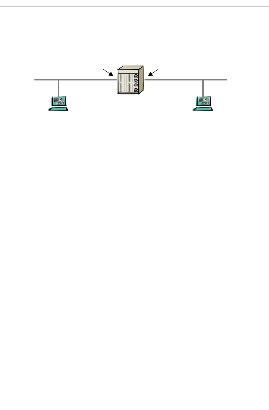
ARP Protocol Failure Troubleshooting ARP
page 11-2 OmniSwitch Troubleshooting Guide July 2008
ARP Protocol Failure
If device A is not able to communicate with device B, it could be a result of ARP resolution failure. To
troubleshoot ARP the first reference point is to make sure that the MAC address of device A and device B
are learned on the right port and in correct VLAN.
Use the following command syntax:
show mac-address-table slot number
In our case we have a device connected in slot 16, so the command to verify the MAC address is as
follows:
-> show mac-address-table slot 16
Legend: Mac Address: * = address not valid
Vlan Mac Address Type Protocol Operation Interface
------+-------------------+--------------+-----------+------------+-----------
10 08:00:20:a8:f0:8a learned 10800 bridging 16/2
Total number of Valid MAC addresses above = 1
This command displays that MAC Address 08:00:20:a8:f0:8a, belonging to Device A, is learned on port
16/2 and in VLAN 10.
A more comprehensive look for all the MAC addresses learned by the switch can be done by using the
show mac-address-table command. For example:
-> show mac-address-table
Now, verify that the gateway defined in device A points towards the correct IP address. In our case, the
gateway of device A is defined as 10.10.42.1.
Workstation: A Workstation: B
08:00:20:a8:f0:8a 00:C0:4F:04:6C:2A
Gatewa
y
Gatewa
y
Se
g
ment: A Se
g
ment: B
00:d0:95:79:62:d1
00:d0:95:79:62:8b

Troubleshooting ARP ARP Protocol Failure
OmniSwitch Troubleshooting Guide July 2008 page 11-3
When device A ARPs for the gateway IP address on the switch, an associated ARP cache entry is created
by the switch. This entry can be viewed by using the show arp command.
To search for a specific ARP entry, use the following command syntax:
show arp ip-address
For example:
-> show arp 10.255.11.219
Total 39 arp entries
Flags (P=Proxy, A=Authentication, V=VRRP)
IP Addr Hardware Addr Type Flags Port Interface
-----------------+-------------------+----------+-------+--------+-----------
10.10.42.159 08:00:20:a8:f0:8a DYNAMIC 16/ 2 vlan 10
To search for an ARP entry associated with a MAC address use the following command syntax:
show arp mac-address
For example:
-> show arp 08:00:20:a8:f0:8a
Total 39 arp entries
Flags (P=Proxy, A=Authentication, V=VRRP)
IP Addr Hardware Addr Type Flags Port Interface
-----------------+-------------------+----------+-------+--------+-----------
10.10.42.159 08:00:20:a8:f0:8a DYNAMIC 16/ 2 vlan 10
This confirms that the switch has learned the ARP entry of the device A.
Now, device A should have also resolved the ARP entry to the gateway IP address. It can be verified on
the workstation’s command prompt using the following DOS command:
C:\> arp -a
Interface: 10.10.42.1 on Interface 0x1000003
Internet Address Physical Address Type
10.10.42.1 00-d0-95-79-62-d1 dynamic

ARP Protocol Failure Troubleshooting ARP
page 11-4 OmniSwitch Troubleshooting Guide July 2008
To confirm the MAC address of the routing instance, use the following command:
-> show ip interface vlan 10
vlan 10
Link type = ETH_II,
Link status = UP,
SNMP interface index = 13600010
Interface index = 4
Enable IP forwarding = YES,
Administrative status = ENABLED,
Operational status = ACTIVATED,
Enable trap = NO,
Internet address = 10.10.42.1,
Broadcast address = 10.10.42.255,
Subnet mask = 255.255.255.0,
Hardware address = 00:d0:95:79:62:d1,
Vrrp MAC = 00:00:00:00:00:00,
Auth MAC = 00:00:00:00:00:00,
Maximum Transfer Unit (MTU) = 1500
Packets received = 1969,
Packets sent = 12094,
Bytes received = 55510,
Bytes sent = 774556,
Multicast packets received = 0,
Multicast packets sent = 10122,
Broadcast packets received = 0,
Broadcast packets sent = 4,
Input errors = 0
Output errors = 0
Collisions = 0
Dropped = 0
Similar steps should be taken to verify the ARP resolution on the other device B.

Troubleshooting ARP Common Error Conditions
OmniSwitch Troubleshooting Guide July 2008 page 11-5
Common Error Conditions
If the ARP is not getting resolved in either of the two workstations, then the following conditions may
exist:
•General health of the switch or NI.
•Physical link status might not be operational
•MAC address not learned on the port
•ARP request not reaching the switch, which may be possible because:
- The workstation is not sending an ARP request
- The workstation is not able to understand the ARP request
- ARP packet might have got corrupted
- Duplicate IP addresses configured on the workstations in the same VLAN

Advanced ARP Troubleshooting Troubleshooting ARP
page 11-6 OmniSwitch Troubleshooting Guide July 2008
Advanced ARP Troubleshooting
If the MAC addresses is already learned on the port and the ARP is not getting resolved then we can
further troubleshoot on the switch to see if the ARP request is reaching the switch and switch is respond-
ing back.
To troubleshoot the ARP packets we need to use the diagnostic CLI commands. Precaution must be taken
when using these commands as it might dump a lot of information on the screen.
The command to use is as follows:
-> debug ip packet start ip-address 10.10.42.159 start
-> 16 R 16/2 080020a8f08a->(ffffffffffff) ARP Request 10.10.42.159->10.10.42.1
16 S 16/2 00d0957962d1->080020a8f08a ARP Reply 10.10.42.1->10.10.42.159
16 R 16/2 080020a8f08a->00d0957962d1 IP 10.10.42.159->10.10.42.1 ICMP 8,0 seq=0.
16 S 16/2 00d0957962d1->080020a8f08a IP 10.10.42.1->10.10.42.159 ICMP 0,0 seq=0.
-> debug ip packet stop
The above capture shows that a request for ARP came in on slot 16 port 2 for ip address 10.10.42.1. The
reply was sent by the switch to 10.10.42.159 at MAC address 08:00:20:a8:f0:8a.
This confirms that the switch is replying back to the ARP. Now the ARP cache of the workstation should
also show the correct ARP entry for the switch. If not, then a sniffer should be placed between the switch
and the workstation to look at the packets to analyze if the packets are corrupted or either one of the
devices is not responding in the correct format.
If the debug ip packet command does not show any output when specified with IP address then other
variations like traffic from that NI can be analyzed using the command:
-> debug ip packet start board ni 16
-> debug ip packet stop
This command will show all the packets coming in NI 16, so the output will be a little confusing and pack-
ets will have to be filtered to gather the required information.
If none of the above commands show any traffic coming in from the IP address for the device, then it will
point towards the physical layer issue. The workstation as well as the physical port to which the worksta-
tion is connected needs to be examined for further analysis.

Troubleshooting ARP Advanced ARP Troubleshooting
OmniSwitch Troubleshooting Guide July 2008 page 11-7
Some devices may be silent like printers. They ARP at the time of the bootup but after that they do not
ARP at all. In order to accommodate those devices, the OmniSwitch allows different choices:
•To increase the ARP time out value. By default the ARP timeout value is set for 300 seconds. It can be
increased up to 1200 seconds using the following command:
-> arp time-out 1200
•MAC Address aging time can also be increased from the default value of 300 seconds to any higher
value using the following command:
-> mac-address-table aging-time <value>
•Silent devices MAC address can be added in the MAC address table as permanent using the following
command:
-> mac-address-table permanent 08:00:20:a8:f0:8a 16/2 10 bridging
Refer to Source learning section for more details about permanent MAC entries.
If the ARP cache of the switch is not showing the correct ARP entries for the edge devices then the
following command can be used to clear the ARP table and re-learn all the ARP entries:
-> clear arp-cache
Note. Clearing the ARP cache might cause a slight interruption in the network, if done at peak hours and
on the Core switch. This will re invoke the process of ARP learning for each and every devices associated
with that particular switch.

Dshell Troubleshooting Troubleshooting ARP
page 11-8 OmniSwitch Troubleshooting Guide July 2008
Dshell Troubleshooting
In order to troubleshoot ARP cache make sure all the steps mentioned in the earlier sections have been
taken. Dshell should be used when no more error collection can be done from the CLI and debug CLI.
Note. Dshell commands should only be used by Alcatel-Lucent personnel or under the direction of Alca-
tel-Lucent. Misuse or failure to follow procedures that use Dshell commands in this guide correctly can
cause lengthy network down time and/or permanent damage to hardware.
According to the architecture of BOP, ARP is processed on the NI. It is never sent to the CMM for
processing. This is done to prevent high CPU utilization on CMM and to have distributed ARP. This
feature was implemented in 5.1.1.R03. Software revision before 5.1.1.R03 processed ARP on the CMM,
CMM synchronized the ARP tables with all of the NIs.
With 5.1.1.R03 and onwards ARP is processed on the NI. In normal scenario ARP table on the CMM
which can be displayed using show arp command in the CLI will be the same as the NI arp table. In case,
an ARP entry is missing in the CMM arp table and debug CLI shows that the ARP is getting into the
switch and a reply is being sent by the NI then NI arp table can be viewed using the NI Debugger.
Load the NI debugger and go to the specific NI in question. One needs to be in the correct slot/slice to
view the routing table on that slice. (For more details about loading the NI debugger and going to the
correct slot/slice, please refer to the NI Debugger section.)
NiDebug>>>ipni_arpShow
NiDebug>>>
Slot 16. NI Arp Table
destination gateway port la_hold expire arp_flags rt_flags refcnt use vlan
10.10.42.159 08:00:20:a8:f0:8a 481 0x0 1948474 0 405 0 0 10
10.11.5.1 00:d0:95:6b:4c:eb 12 0x0 1948e70 0 405 0 0 511
10.40.105.1 00:00:5e:00:01:69 29 0x0 0 8e 405 0 0 105
10.40.105.4 00:d0:95:79:62:eb 124 0x0 1946736 0 405 0 0 105
10.40.106.1 00:00:5e:00:01:6a 29 0x0 0 8e 405 0 0 106
10.40.106.3 00:d0:95:6b:4c:d9 140 0x0 194827b 0 405 0 0 106
10.40.108.1 00:00:5e:00:01:6c 29 0x0 0 8e 405 0 0 108
10.40.108.3 00:d0:95:6b:4c:db 172 0x0 1948272 0 405 0 0 108
10.40.108.4 00:d0:95:79:65:f0 172 0x0 194790a 0 405 0 0 108
10.40.108.129 08:00:20:c0:92:43 172 0x0 19488e3 0 405 0 0 108
10.40.110.1 00:00:5e:00:01:6e 29 0x0 0 8e 405 0 0 110
10.40.110.3 00:d0:95:6b:4c:dd 204 0x0 19484c1 0 405 0 0 110
10.40.110.4 00:d0:95:7c:5b:9b 204 0x0 1946868 0 405 0 0 110
10.40.110.139 08:00:20:b1:1c:49 204 0x0 19484a5 0 405 0 0 110
10.40.110.240 00:00:39:2c:6d:0e 204 0x0 1947a84 0 405 0 0 110
10.40.111.3 00:d0:95:6b:4c:de 33 0x0 1948453 0 405 0 0 111
10.40.111.4 00:d0:95:79:65:67 33 0x0 194672c 0 405 0 0 111
10.40.112.1 00:00:5e:00:01:70 29 0x0 0 8e 405 0 0 112
10.40.112.3 00:d0:95:6b:4c:df 284 0x0 1948273 0 405 0 0 112
10.40.112.4 00:d0:95:79:65:10 284 0x0 194674f 0 405 0 0 112
10.40.117.3 00:d0:95:6b:4c:e3 428 0x0 194827d 0 405 0 0 117
10.40.117.4 00:d0:95:7c:48:59 428 0x0 1947cfc 0 405 0 0 117
10.40.140.1 00:00:5e:00:01:8c 29 0x0 0 8e 405 0 0 140
10.40.140.3 00:d0:95:6b:4c:e5 12 0x0 194827b 0 405 0 0 140
10.40.141.3 00:d0:95:6b:4c:e6 12 0x0 194827b 0 405 0 0 141
10.40.150.1 00:00:5e:00:01:96 29 0x0 0 8e 405 0 0 150
10.40.150.110 00:d0:95:7c:5b:9c 204 0x0 19482ff 0 405 0 1 150
10.40.211.3 00:d0:95:6b:4c:e8 268 0x0 1948273 0 405 0 0 211
10.40.211.4 00:d0:95:79:66:48 268 0x0 194757e 0 405 0 0 211
10.40.212.1 00:00:5e:00:01:d4 29 0x0 0 8e 405 0 0 212

Troubleshooting ARP Dshell Troubleshooting
OmniSwitch Troubleshooting Guide July 2008 page 11-9
10.40.212.3 00:d0:95:6b:4c:e9 300 0x0 1948275 0 405 0 0 212
10.40.212.4 00:d0:95:7c:7d:78 300 0x0 1946929 0 405 0 0 212
10.40.212.127 08:00:20:b0:ea:d1 300 0x0 1948092 0 405 0 0 212
10.40.212.238 00:c0:4f:12:f7:1b 300 0x0 1947153 0 405 0 0 212
192.168.50.1 00:d0:95:82:05:16 380 0x0 194847e 0 405 0 0 50
192.168.50.2 00:d0:95:83:e7:81 380 0x0 1948e5c 0 405 0 0 50
192.168.50.5 00:d0:95:6a:f5:bb 380 0x0 1948165 0 405 0 0 50
192.168.51.5 00:d0:95:6a:f5:bc 380 0x0 194693a 0 405 0 0 51
192.168.52.5 00:d0:95:6a:f5:bd 380 0x0 194673b 0 405 0 0 52
192.168.53.5 00:d0:95:6a:f5:be 380 0x0 1945b2a 0 405 0 0 53
192.168.54.5 00:d0:95:6a:f5:bf 380 0x0 1946746 0 405 0 0 54
192.168.56.2 00:d0:95:83:e7:87 380 0x0 19469e4 0 405 0 0 56
192.168.57.1 00:d0:95:82:05:1d 380 0x0 1948764 0 405 0 0 57
192.168.57.2 00:d0:95:83:e7:88 380 0x0 1948041 0 405 0 0 57
192.168.57.5 00:d0:95:6a:f5:c2 380 0x0 1948165 0 405 0 0 57
192.168.58.5 00:d0:95:6a:f5:c3 0380 0x0 1948165 0 405
NiDebug>>>quit
Source Port is shown as 481. It is calculated based on Coronado ports. Each Coronado has 32 ports.
32*16=512 ports is the total Coronado port that can exist on OS7800.
First 15 modules will have 480 ports. The count starts from 0 so ports 0 to 479 exist on the first 15 slots.
480 is the first port on slot 16 and 481 is the second port on slot 16. So, this does confirm that the arp was
learned on port 16/2.
The table on the NI shows all the ARP entries as on the CMM. If a particular NI is having problems to
another NI then the arp table of that NI should also be looked at. The ARP entry for device A does exist
on NI 16, source NI of the device.
If an entry exists on an NI ARP table and is not fully synchronized with all the other NIs then the problem
might be because the IPC message is lost from that NI to the CMM which holds the master ARP table.
This will result in un synchronized ARP across the NIs which will cause problems when routing between
NIs.
To look at the number of ARP entries being added and deleted in the switch use the following command:
Working: [Kernel]->ipedrArpStatShow
arp add : 3
arp add fail : 0
arp del : 3
arp del fail: 1
arp change : 0
arp refresh : 0
arp putlist : 0
value = 0 = 0x0
Working: [Kernel]->
If arp add, del and fail are changing in large numbers then it might indicate unusual activity in the network
which may be a result of some virus or spoof attack. In normal conditions the entries should be quite
stable.
If everything from the switch point of view looks fine then the best tool to find out the source of the prob-
lem is to use a sniffer.

Dshell Troubleshooting Troubleshooting ARP
page 11-10 OmniSwitch Troubleshooting Guide July 2008
Viewing the ARP Table on OS-6624/6648 Switches
To look at the ARP table on OS-6600 use the following command in Dshell:
Working: [Kernel]->ipni_arpShow
Slot 2. NI Arp Table
destination gateway port la_hold expire arp_flags rt_flags refcnt use vlan
2.2.2.100 00:00:5e:00:01:02 29 0x0 0 8e 405 0 2
4.4.4.1 00:d0:95:84:07:1e 90 0x0 1ddddf1 0 405 0 4
4.4.4.100 00:00:5e:00:01:04 29 0x0 0 8e 405 0 4
10.255.13.2 00:20:da:0a:54:10 64 0x0 1ddddd1 0 405 0 999
10.255.13.90 00:d0:95:6a:84:51 64 0x0 1dded3e 200 405 0 999
131.118.33.41 00:d0:95:79:64:ab 120 0x0 1ddec01 0 05 0 336
value = 0 = 0x0
Working: [Kernel]->
To look at the ARP statistics use the following command in Dshell:
Working: [Kernel]->ipni_arplookup "10.255.13.2"
value = 0 = 0x0
Working: [Kernel]->ipedrArpStatShow
arp add : 3161
arp add fail : 0
arp del : 3155
arp del fail: 0
arp change : 476
arp refresh : 7686
arp putlist : 0
value = 16 = 0x10

Troubleshooting ARP Troubleshooting ARP on OmniSwitch 6850/9000 Series
OmniSwitch Troubleshooting Guide July 2008 page 11-11
Troubleshooting ARP on OmniSwitch 6850/9000
Series
Note. This section provides additional information for troubleshooting ARP on OS-6850/9000 switches
and should be used in conjunction with information provided in the previous sections of this chapter.
There are a few changes to the ARP functionality on the OS-6850/9000, such as a global value for the
MAC-aging timer rather than a per VLAN value. Also, an ARP Poisoning attack feature has been added to
help protect the switch from DoS attacks.
As previously described in the “ARP Protocol Failure” on page 11-2 section, the first step in troubleshoot-
ing an ARP problem is to make sure that the MAC address of each device is learned on the right port and
in the correct VLAN. This is also true for the OS-6850/9000 switches and accomplished by using the
show mac-address-table and show arp commands. For example:
9800-> show mac-address-table slot 7
Legend: Mac Address: * = address not valid
Vlan Mac Address Type Protocol Operation Interface
------+-------------------+--------------+-----------+------------+-----------
3 00:11:8b:01:2f:10 learned --- bridging 7/21
3 00:03:ff:22:2a:ba learned --- bridging 7/22
3 00:e0:b1:75:42:d9 learned --- bridging 7/22
5 00:03:ff:21:2a:ba learned --- bridging 7/22
5 00:12:3f:2a:a2:77 learned --- bridging 7/22
3 00:00:5e:00:01:0d learned --- bridging 7/23
3 00:02:20:be:12:ac learned --- bridging 7/23
3 00:0b:86:02:f0:00 learned --- bridging 7/23
Total number of Valid MAC addresses above = 8
9800-> show mac-address-table
Legend: Mac Address: * = address not valid
Vlan Mac Address Type Protocol Operation Interface
------+-------------------+--------------+-----------+------------+-----------
1 00:d0:95:f8:54:f2 learned --- bridging 4/1
1 00:d0:95:f8:54:f3 learned --- bridging 4/2
1 00:d0:95:f8:54:fd learned --- bridging 4/11
3 00:11:8b:01:2f:10 learned --- bridging 7/21
3 00:03:ff:22:2a:ba learned --- bridging 7/22
3 00:e0:b1:75:42:a8 learned --- bridging 7/22
3 00:e0:b1:75:42:d9 learned --- bridging 7/22
5 00:03:ff:21:2a:ba learned --- bridging 7/22
5 00:12:3f:2a:a2:77 learned --- bridging 7/22
3 00:00:5e:00:01:0d learned --- bridging 7/23
3 00:02:20:be:12:ac learned --- bridging 7/23
1 00:d0:95:e1:00:16 learned --- bridging 0/9
1 00:d0:95:e1:00:17 learned --- bridging 0/9
1 00:d0:95:e9:d3:42 learned --- bridging 0/9
Total number of Valid MAC addresses above = 14

Troubleshooting ARP on OmniSwitch 6850/9000 Series Troubleshooting ARP
page 11-12 OmniSwitch Troubleshooting Guide July 2008
Enter a "?" to display all available parameters for the show mac-address-table command. For example:
9800-> show mac-address-table ?
^
<cr> TIMEOUT STATIC-MULTICAST SLOT RESET
QUARANTINED PERMANENT LINKAGG LEARNED COUNT
AGING-TIME <num> <num-num> <slot/port>
<mac-address>
9800-> show arp
Total 5 arp entries
Flags (P=Proxy, A=Authentication, V=VRRP)
IP Addr Hardware Addr Type Flags Port Interface Name
-----------------+-------------------+----------+-------+--------+-----------+-----
10.255.13.5 00:d0:95:e0:78:98 DYNAMIC 7/23 vlan 3
10.255.13.21 00:02:20:be:12:ac DYNAMIC 7/23 vlan 3
10.255.13.193 00:19:b9:25:29:12 DYNAMIC 7/22 vlan 3
10.255.13.199 00:03:ff:22:2a:ba DYNAMIC 7/22 vlan 3
192.168.5.10 00:03:ff:21:2a:ba DYNAMIC 7/22 vlan 5
To search for a specific ARP entry, specify an IP or MAC address with the show arp command. For
example:
9800-> show arp 192.168.5.10
Total 5 arp entries
Flags (P=Proxy, A=Authentication, V=VRRP)
IP Addr Hardware Addr Type Flags Port Interface Name
-----------------+-------------------+----------+-------+--------+-----------+-----
192.168.5.10 00:03:ff:21:2a:ba DYNAMIC 7/22 vlan 5
9800-> show arp 00:03:ff:21:2a:ba
Total 5 arp entries
Flags (P=Proxy, A=Authentication, V=VRRP)
IP Addr Hardware Addr Type Flags Port Interface Name
-----------------+-------------------+----------+-------+--------+-----------+-----
192.168.5.10 00:03:ff:21:2a:ba DYNAMIC 7/22 vlan 5
To verify IP interface information for the routing instance, use the show ip interface and show vlan
commands. For example:
9800-> show ip interface vlan 5
Total 1 interfaces
Name IP Address Subnet Mask Status Forward Device
--------------------+---------------+---------------+------+-------+--------
vlan5 192.168.5.3 255.255.255.0 UP YES vlan 5

Troubleshooting ARP Troubleshooting ARP on OmniSwitch 6850/9000 Series
OmniSwitch Troubleshooting Guide July 2008 page 11-13
9800-> show ip interface
Total 18 interfaces
Name IP Address Subnet Mask Status Forward Device
--------------------+---------------+---------------+------+-------+--------
EMP 192.168.255.250 255.255.255.0 DOWN NO EMP
Loopback 127.0.0.1 255.0.0.0 UP NO Loopback
dhcp-client 192.168.116.254 255.255.255.0 UP YES vlan 1
ip 0.0.0.0 0.0.0.0 DOWN NO unbound
vlan-1 192.168.11.3 255.255.255.0 UP YES vlan 1
vlan-10 192.168.10.3 255.255.255.0 DOWN NO vlan 10
vlan-191 192.168.191.98 255.255.255.0 DOWN NO vlan 191
vlan-255 0.0.0.0 0.0.0.0 DOWN NO unbound
vlan-3 10.255.13.35 255.255.255.0 UP YES vlan 3
vlan-4050 192.168.95.3 255.255.255.0 DOWN NO vlan 4050
vlan-55 192.168.55.3 255.255.255.0 DOWN NO vlan 55
vlan-65 192.168.65.3 255.255.255.0 DOWN NO vlan 65
vlan-70 192.168.70.3 255.255.255.0 DOWN NO vlan 70
vlan-75 192.168.75.3 255.255.255.0 DOWN NO vlan 75
vlan100 192.168.100.3 255.255.255.0 UP YES vlan 100
vlan150 192.168.150.3 255.255.255.0 DOWN NO vlan 150
vlan200 192.168.200.3 255.255.255.0 DOWN NO vlan 200
vlan5 192.168.5.3 255.255.255.0 UP YES vlan 5
9800-> show vlan 5
Name : VLAN 5,
Administrative State: enabled,
Operational State : enabled,
1x1 Spanning Tree State : enabled,
Flat Spanning Tree State : enabled,
Authentication : disabled,
IP Router Port : on,
IPX Router Port : none,
Mobile Tag : off
Advanced Troubleshooting
The debug ip packet CLI command will display traffic coming to and from the switch. Use this command
to validate the incoming and outgoing traffic. For example:
9800-> debug ip packet show-broadcast on start timeout 60
9800-> C R 7/23 00005e00010d->01005e000012 IP 10.255.13.90->224.0.0.18 VRRP
C R 7/23 00d095e9d6f4->ffffffffffff IP 10.255.13.90->10.255.13.255 UDP 520,520
C R 7/23 00d095e9d6f4->ffffffffffff IP 10.255.13.90->10.255.13.255 UDP 520,520
7 S FLD 00d095e9d674->01005e000005 IP 10.255.13.35->224.0.0.5 OSPF 2,1
7 R 7/22 (0019b9252aba)->(00d095e9d674) ARP Request 10.255.13.192->10.255.13.35
7 S 7/22 00d095e9d674->0019b9252aba ARP Reply 10.255.13.35->10.255.13.192
7 R 7/22 (0019b9252912)->(00d095e9d674) ARP Request 10.255.13.193->10.255.13.35
7 S 7/22 00d095e9d674->0019b9252912 ARP Reply 10.255.13.35->10.255.13.193
7 R 7/23 (00005e00010d)->(01005e000012) IP 10.255.13.90->224.0.0.18 VRRP 33,13
7 S CMM 00005e00010d->01005e000012 IP 10.255.13.90->224.0.0.18 VRRP 33,13
C S 7/F 00d095e9d674->01005e000005 IP 10.255.13.35->224.0.0.5 OSPF 2,1
p7 R CMM (00d095e9d674)->(01005e000005) IP 10.255.13.35->224.0.0.5 OSPF 2,1
7 S FLD 00d095e9d674->01005e000005 IP 10.255.13.35->224.0.0.5 OSPF 2,1
If a specific entry does not appear (for example, the MAC belongs to a silent device) it may be necessary
to increase the MAC-aging time so that the entry for that device is retained for a longer period of time. By

Troubleshooting ARP on OmniSwitch 6850/9000 Series Troubleshooting ARP
page 11-14 OmniSwitch Troubleshooting Guide July 2008
default, the MAC-aging time is set to 5 minutes and is a global value applied across all VLANs. To change
this value, use the mac-address-table aging-time command and specify a different amount of time in
seconds. For example:
9800-> mac-address-table aging-time 500
To display the current MAC-aging time value for the switch, use the show mac-address-table aging-time
command. For example:
9800-> show mac-address-table aging-time
Mac Address Aging Time (seconds) = 500
If the ARP cache of the switch is not showing the correct ARP entries, use the clear arp-cache command
to clear the ARP table and re-learn all the ARP entries. Note that clearing the ARP cache is done on a
global basis; all ARP entries are flushed on all switch ports. There is no method for clearing ARP entries
on a specific port or VLAN.
Advanced Troubleshooting in Dshell
9800-> dshell
Working: [Kernel]->arpShow
LINK LEVEL ARP TABLE
Destination LL Address (A)/R Flags Refcnt Use Interface
-----------------------------------------------------------------------------
10.255.13.5 00:d0:95:e0:78:98(p 406) (0x2)/0x405 2 0 ipif12
10.255.13.21 00:02:20:be:12:ac(p 406) (0x2)/0x405 0 0 ipif12
10.255.13.193 00:19:b9:25:29:12(p 405) (0x2)/0x405 0 134 ipif12
10.255.13.199 00:03:ff:22:2a:ba(p 405) (0x0)/0x405 0 0 ipif12
127.2.1.1 00:0a:1e:11:11:51(p 0) (0x0)/0x405 0 4615087 mottsec0
127.2.4.1 00:0a:1e:11:11:54(p 0) (0x0)/0x405 0 3431329 mottsec0
127.2.7.1 00:0a:1e:11:11:57(p 0) (0x0)/0x405 0 5094857 mottsec0
127.2.9.1 00:0a:1e:11:11:59(p 0) (0x0)/0x405 0 3327529 mottsec0
127.2.65.1 00:0a:1e:11:11:f8(p 0) (0x0)/0x405 1 13 lo0
192.168.5.3 00:d0:95:e9:d6:74(p 0) (0x0)/0x405 0 12 lo0
192.168.5.10 00:03:ff:21:2a:ba(p 405) (0x2)/0x405 0 0 ipif7
-----------------------------------------------------------------------------
Display the ARP status using ipedrArpStatShow:
Working: [Kernel]->ipedrArpStatShow
arp add : 3437
arp add fail : 0
arp del : 3502
arp del fail: 122
arp change : 0
arp refresh : 23078
arp putlist : 0
value = 16 = 0x10

Troubleshooting ARP Troubleshooting ARP on OmniSwitch 6850/9000 Series
OmniSwitch Troubleshooting Guide July 2008 page 11-15
To clear the ARP cache, use arpFlush (same as clear arp-cache from the CLI):
Working: [Kernel]->arpFlush
value = 0 = 0x0
Telnet to the NI:
9800-> telnet 127.2.7.1
Trying 127.2.7.1...
Connected to 127.2.7.1.
Escape character is '^]'.
[Slot 7]->ipniHelp
ipdbg_arpstats: IPNI Arp stats
ipdbg_rtstats: IPNI Route stats
ipni_ifShow: IPNI IP Interfaces
ipni_routeShow: IPNI Routes
ipni_arpShow("<ip>", "<mask>"): IPNI ARPs
ipni_rtlkup("<ip>"): Lookup route to a given destination
ipni_arp_count: IPNI ARP count
ipni_arptimeoutdump: ARP timeouts per interface
ipdbgHelp: ipdbg Help (Real time debug)
value = 0 = 0x0
[Slot 7]->ipdbg_arpstats
num arps : 4.
arp adds : 16.
arp add fails : 0.
arp dels : 2813.
arp del fails : 123.
arp flushes : 27.
arp retrieves : 0.
arp changes : 0.
arp chg fails : 0.
arp refresh : 3075.
arp ref fails : 0.
arp input adds: 3425.
arp input chgs: 0.
arp input refs: 20033.
arp sl learn : 0.
arp sl dels : 356.
arp sl chgs : 0.
arp expires : 424.
arp expire del: 424.
arp expire chg: 0.
arp send req : 15197.
arp send rep : 22535.
arp recv req : 54412.
arp recv rep : 11386.
value = 23 = 0x17
[Slot 7]->ipdbg_rtstats
num routes : 14.
route adds : 55.
route add fails : 0.
route dels : 42.
route del fails : 1.

Troubleshooting ARP on OmniSwitch 6850/9000 Series Troubleshooting ARP
page 11-16 OmniSwitch Troubleshooting Guide July 2008
route flushes : 0.
route retrieves : 0.
route retrieve send fails: 0.
route changes : 0.
route resolves : 0.
value = 30 = 0x1e
[Slot 7]->ipni_ifShow
10.255.13.35: if_index=13(vlan), vlan=3, flags=0x43, state=0x1
Netmask: 255.255.255.0
Broadcast address: 10.255.13.255
Ethernet Address: 00:d0:95:e9:d6:74
VRRP Ethernet Address: 00:00:00:00:00:00
Arp timeout is 500.
Maximum Transfer Unit size is 1500
192.168.5.3: if_index=8(vlan), vlan=5, flags=0x43, state=0x1
Netmask: 255.255.255.0
Broadcast address: 192.168.5.255
Ethernet Address: 00:d0:95:e9:d6:74
VRRP Ethernet Address: 00:00:00:00:00:00
Arp timeout is 500.
Maximum Transfer Unit size is 1500
192.168.10.3: if_index=9(vlan), vlan=10, flags=0x42, state=0x1
Netmask: 255.255.255.0
Broadcast address: 192.168.10.255
Ethernet Address: 00:d0:95:e9:d6:74
VRRP Ethernet Address: 00:00:00:00:00:00
Arp timeout is 500.
Maximum Transfer Unit size is 1500
value = 37 = 0x25 = '%'
[Slot 7]->ipni_routeShow
Slot 7. NI Routes
memaddr destination gateway type
04a67918 0.0.0.0/ 0 10.255.13.5 GW
04a67a50 1.1.1.1/32 192.168.5.10 GW
04a678e4 10.255.13.0/24 ---------------- ITF
04a678b0 127.0.0.1/32 ---------------- RJ
04a6794c 128.251.0.0/16 10.255.13.5 GW
04a67980 172.16.10.0/24 10.255.13.32 GW
04a67a1c 192.168.5.0/24 ---------------- ITF
04a67b88 192.168.11.0/24 ---------------- ITF
04a67a84 192.168.15.1/32 192.168.5.10 GW
04a679b4 192.168.30.0/24 10.255.13.32 GW
04a679e8 192.168.50.0/24 10.255.13.32 GW
04a67d28 192.168.100.0/24 ---------------- ITF
04a67cc0 192.168.109.0/24 192.168.11.97 GW
04a67b54 192.168.116.0/24 ---------------- ITF
value = 0 = 0x0
[Slot 7]->ipni_arpShow
Slot 7. NI Arp Table
memaddr destination MAC vlan port flags la_hold expire asked
04a67c24 10.255.13.5 00d095:e07898 3 7/23 (gp=406) 2 0 28396
04a67cf4 10.255.13.21 000220:be12ac 3 7/23 (gp=406) 2 0 16825
04a67c8c 10.255.13.193 0019b9:252912 3 7/22 (gp=405) 2 0 29477

Troubleshooting ARP Troubleshooting ARP on OmniSwitch 6850/9000 Series
OmniSwitch Troubleshooting Guide July 2008 page 11-17
04a67aec 192.168.5.10 0003ff:212aba 5 7/22 (gp=405) 2 0 27918
value = 0 = 0x0
The correct behavior, where ARP is learned:
[Slot 7]->ipni_arpShow "192.168.5.10"
Slot 7. NI Arp Table
memaddr destination MAC vlan port flags la_hold expire asked
04a67aec 192.168.5.10 0003ff:212aba 5 7/22 (gp=405) 2 0 27135
value = 0 = 0x0
ARP is NOT learned and unable to resolute. MAC address and port are incomplete and unknown, as
shown below:
[Slot 5]->ipni_arpShow "131.118.200.53"
Slot 5. NI Arp Table
memaddr destination MAC vlan port flags la_hold expire asked
04904434 131.118.200.53 INCOMPLETE 200 UNKWN (gp=UNK) 2000 48685c0 0 1
value = 0 = 0x0
To help isolate a problem with a route or if somehow the route was deleted or corrupted, determine which
route to take. For example:
[Slot 7]->ipni_rtlkup "192.168.5.10"
route 192.168.5.10
directly to vlan 5
value = 20 = 0x14
[Slot 7]->exit
[Slot 7]->ipni_arp_count
ipni_arp_count: arp_count = 4
value = 4 = 0x4
[Slot 7]->ipni_arptimeoutdump
10.255.13.35: if_index=13, vlan=3 tmo=500.
192.168.5.3: if_index=8, vlan=5 tmo=500.
192.168.10.3: if_index=9, vlan=10 tmo=500.
192.168.11.3: if_index=4, vlan=1 tmo=500.
192.168.55.3: if_index=14, vlan=55 tmo=500.
192.168.65.3: if_index=2, vlan=65 tmo=500.
192.168.70.3: if_index=16, vlan=70 tmo=500.
192.168.75.3: if_index=1, vlan=75 tmo=500.
192.168.95.3: if_index=17, vlan=4050 tmo=500.
192.168.100.3: if_index=5, vlan=100 tmo=500.
192.168.116.254: if_index=12, vlan=1 tmo=500.
192.168.150.3: if_index=6, vlan=150 tmo=500.
192.168.191.98: if_index=10, vlan=191 tmo=500.
192.168.200.3: if_index=7, vlan=200 tmo=500.
value = 0 = 0x0

Troubleshooting ARP on OmniSwitch 6850/9000 Series Troubleshooting ARP
page 11-18 OmniSwitch Troubleshooting Guide July 2008
ARP Poisoning
9800-> show ip dos config
DoS type Status
----------------------------------+---------------
port scan ENABLED
tcp sync flood ENABLED
ping of death ENABLED
smurf ENABLED
pepsi ENABLED
land ENABLED
teardrop/bonk/boink ENABLED
loopback-src ENABLED
invalid-ip ENABLED
invalid-multicast ENABLED
unicast dest-ip/multicast-mac ENABLED
ping overload DISABLED
arp flood ENABLED
arp poison ENABLED
DoS trap generation = ENABLED,
DoS port scan threshold = 1000,
DoS port scan decay = 2,
DoS port scan close port penalty = 10,
DoS port scan TCP open port penalty = 0,
DoS port scan UDP open port penalty = 0,
DoS Maximum Ping Rate = 100
DoS Maximum ARP Request Rate = 500
9800-> show ip dos ?
^
STATISTICS CONFIG ARP-POISON
(Miscellaneous Command Set)
9800-> show ip dos statistics
DoS type Attacks detected
----------------------------------+--------------------------
port scan 51
tcp sync flood 0
ping of death 0
smurf 0
pepsi 0
land 0
teardrop/bonk/boink 0
loopback-src 0
invalid-ip 0
invalid-multicast 0
unicast dest-ip/multicast-mac 242
ping overload 0
arp flood 0
arp poison 0

OmniSwitch Troubleshooting Guide July 2008 page 12-1
12 Troubleshooting
IP Routing
In order to troubleshoot an IP Routing problem, a basic understanding of the IP protocol/feature is
required. Some basic concepts are covered below. Reading RFCs 791, 1812 and 1716 are highly recom-
mended to anyone implementing or troubleshooting IP Routing on their switch/network. IP Routing is a
process by which layer 3 packets are forwarded between two different subnets or networks.
Here is a list of the IP RFCs to review:
•RFC 791 (IP)
•RFC 1812 (Requirements for IP Version 4 Routers)
•RFC 1716 (Towards Requirements for IP Routers)
Here is a list of the RIP RFCs to review:
•RFC 1058 (RIP v1)
•RFC 2453 (RIP v2)
•RFC 1722 (RIP v2 Protocol Applicability Statement)
•RFC 1723 (RIP v2 Carrying Additional Information)
•RFC 1724 (RIP v2 MIB Extension)
Here is a list of the OSPF RFCs to review:
•RFC 2328 (OSPF Version 2)
•RFC 1403 (BGP OSPF Interaction)
•RFC 1587 (The OSPF NSSA Option)
•RFC 1765 (OSPF Database Overflow)
•RFC 2370 (The OSPF Opaque LSA Option)
•RFC 1745 (BGP4/IDRP for IP-OSPF Interaction)
•RFC 1586 (Guidelines for Running OSPF Over Frame Relay Networks)
•RFC 1370 (Applicability statement for OSPF)
•RFC 1850 (OSPF v2 MIB)
Reading the “Configuring IP” chapter in the appropriate OmniSwitch Network Configuration Guide is also
highly recommended.

In This Chapter Troubleshooting IP Routing
page 12-2 OmniSwitch Troubleshooting Guide July 2008
In This Chapter
“Introduction” on page 12-3
“IP Routing Protocol Failure” on page 12-3
“Troubleshooting via the CLI” on page 12-3
“Troubleshooting OmniSwitch 6850/9000 Series via the CLI” on page 12-10
“Troubleshooting with Debug CLI” on page 12-11
“RIP Troubleshooting” on page 12-13
“Troubleshooting RIP on OmniSwitch 6850/9000 Series” on page 12-19
“Troubleshooting RIPng on OmniSwitch 6850/9000 Series” on page 12-23
“OSPF Troubleshooting” on page 12-29
“Troubleshooting OSPF on OmniSwitch 6850/9000 Series” on page 12-37
“Troubleshooting OSPFv3 on OmniSwitch 6850/9000 Series” on page 12-45
“BGP Troubleshooting” on page 12-57
“Troubleshooting BGP on OmniSwitch 6850/9000 Series” on page 12-58
“ISIS Troubleshooting” on page 12-66
“Dshell Troubleshooting Advanced IP Routing” on page 12-75
“Dshell Troubleshooting Advanced IP Routing on OmniSwitch 6850/9000 Series” on page 12-80

Troubleshooting IP Routing Introduction
OmniSwitch Troubleshooting Guide July 2008 page 12-3
Introduction
The primary function of IP Routing is processing Layer 3 IP packets and forwarding them in between two
different networks or subnets. This is broken down into two functions. First is determining the best path to
get from one network or subnet to the next and second is to forwarding the packet into that destination
network.
With that being said you need to figure out what type of routing the client is doing. This section will only
go over basic IP Routing. If the client is using an advanced routing protocol such as OSPF, VRRP, RIP II,
etc., please refer to the appropriate sections in the index.
Note. This document does not discuss the basic operation of IP. To learn about how IP works, refer to the
“Configuring IP” chapter in the appropriate OmniSwitch Network Configuration Guide.
IP Routing Protocol Failure
A failure of IP Routing would be a particular device that is unable to get out of the network; you will have
problems getting to a different subnet.
Troubleshooting via the CLI
If devices in different VLANs cannot communicate, we have a routing failure. The first thing to do is
verify the IP setup of the devices in question to make sure they are correct; check for IP address, subnet
mask, and default gateway address on both devices.
If the devices can communicate within their respective VLANs, but not outside of the VLAN, verify the
default gateway is correct for the subnet, and try pinging it. If it responds, the device should be able to get
out of its VLAN without issue.
The next step is to ping the gateway to the destination VLAN. Assuming the Falcon is doing the routing
for the VLANs, this address will show in the output of a show vlan router ip command.
-> show vlan router ip
vlan ip address ip mask encap mode oper mtu
------+-----------------+-----------------+---------+---------+------+-----
1 192.168.001.001 255.255.255.000 e2 forward on 1500
2 192.168.002.001 255.255.255.000 e2 forward off 1500
If the address does not respond to a ping, verify that a port in the VLAN is forwarding via the
show vlan port command. Without an active port in a VLAN, the router instance is not active and
will not respond to pings.
-> show vlan 1 port
port type status
--------+---------+--------------
1/1 default inactive
1/2 default inactive
1/3 default inactive

Troubleshooting via the CLI Troubleshooting IP Routing
page 12-4 OmniSwitch Troubleshooting Guide July 2008
.....
4/19 default inactive
4/20 default inactive
4/21 default inactive
4/22 default forwarding
4/23 default inactive
.....
If the destination VLAN gateway address does respond to a ping, there should be no issue with routing,
and the cause is likely to be with Source Learning assuming all other items check out properly (i.e. PC IP
setup, link status, etc.) (see Chapter 2: Managing Source Learning). If source and destination devices can
both ping their respective default gateways and the gateway address to the other VLAN/subnet, the next
step after verifying that Source Learning is functioning properly would be to take a Sniffer trace to see if
in fact the packets are arriving at the destination machine. (Refer to “Troubleshooting with Debug CLI” on
page 12-11.)
Check for physical issues via the show interfaces command to see if the switch is dropping packets.
-> show interfaces ethernet 4/2
Slot/Port 4/2 :
Operational Status : down,
Type : Fast Ethernet,
MAC address : 00:d0:95:6b:53:95,
BandWidth (Megabits) : 100, Duplex : -,
Long Accept : Enable, Runt Accept : Disable,
Long Frame Size(Bytes) : 1553, Runt Size(Bytes) : 64
Input :
Bytes Received : 14397,
Lost Frames : 0,
Unicast Frames : 6,
Broadcast Frames : 93,
Multicast Frames : 7,
UnderSize Frames : 0,
OverSize Frames : 0,
Collision Frames : 0,
Error Frames : 0,
CRC Error Frames : 0,
Alignments Error : 0
Output :
Bytes transmitted : 83244,
Lost Frames : 0,
Unicast Frames : 10,
Broadcast Frames : 84,
Multicast Frames : 1106,
UnderSize Frames : 0,
OverSize Frames : 0,
Collision Frames : 0,
Error Frames : 0
Any error conditions in this display should be corrected prior to proceeding.
If you are attempting to ping a device by name rather than by IP address, verify that the name server
configuration is correct, and that the DNS servers in question are functioning, and that the addresses it
returns are correct for the device you are trying to ping.
-> show dns
Resolver is : disabled

Troubleshooting IP Routing Troubleshooting via the CLI
OmniSwitch Troubleshooting Guide July 2008 page 12-5
domainName :
nameServer(s):
Verify that the switch has a valid route to the destination subnet via the show ip route command:
-> show ip route
Dest Address Subnet Mask Gateway Addr Age Protocol
------------------+-----------------+-----------------+---------+-----------
127.0.0.1 255.255.255.255 127.0.0.1 00:14:39 LOCAL
192.168.1.0 255.255.255.0 192.168.1.1 00:13:08 LOCAL
192.168.10.0 255.255.255.0 192.168.10.50 00:14:35 LOCAL
192.168.10.1 255.255.255.255 192.168.11.1 00:14:35 NETMGT
If a route is listed to the destination’s network, you should be able to ping it. If this ping fails, you will
need to determine why. Verify RIP, OSPF, or BGP configurations so that the unit can learn the proper
route to the destination.
The show ip protocols command will tell you what routing protocols are loaded, giving you a starting
point for investigation.
-> show ip protocols
Router ID = 192.168.1.1,
Primary addr = 192.168.1.1,
RIP status = Not Loaded,
OSPF status = Not Loaded,
BGP status = Not Loaded,
DVMRP status = Not Loaded,
PIMSM status = Not Loaded,
Debug level = 1,
Debug sections = none
A traceroute command (tracert in Windows, traceroute from a UNIX/Linux machine, and from the
Falcon CLI) should indicate where the path has failed. If it fails on an intermediate hop between the
Falcon and the destination, your efforts should be expended on the device that showed a failure in the
path. Note that this may lead you back to another device to troubleshoot some other sort of failure, such as
link down, etc. If the traceroute ends at the gateway to the destination VLAN, you do not have a routing
problem, but rather a likely problem in the destination VLAN with either physical issues (cabling, bad
NICs, dropped packets, etc.), Source Learning, or device IP setup.
-> traceroute 192.168.1.2
traceroute to 192.168.1.2, 30 hops max, 40 byte packets
192.168.1.2 50 ms 33.3333 ms 33.3333 ms
The show icmp statistics command may help by giving you an indication of redirect messages being sent.
These usually indicate that the route in question has an issue, and that the router instance knows of a
different route to get to the destination. From there you can look at the show ip route command to see
what your routing table looks like. Verify via this command that the routes you think a packet should take
are properly displayed in the table, and contrast that with any differences noted by the traceroute
command output.
-> show icmp statistics
Messages Received Sent
---------------------------+----------+-------------
Total 9579 9392
Error 0 15

Troubleshooting via the CLI Troubleshooting IP Routing
page 12-6 OmniSwitch Troubleshooting Guide July 2008
Destination unreachable 201 15
Time exceeded 0 0
Parameter problem 0 0
Source quench 0 0
Redirect 0 0
Echo request 9377 0
Echo reply 1 9377
Address mask request 0 0
Address mask reply 0 0
The show ip router database command may yield a clue, possibly telling you that an interface that is
designated as a router interface is down or disabled for some reason.
-> show ip router database
Destination Gateway Protocol Metric VLAN
-------------------+----------------+--------+------+-----
192.168.1.0/24 192.168.1.1 LOCAL 1 1
192.168.1.0/24 192.168.1.1 STATIC 1 1
Inactive Static Routes
Destination Gateway Metric
-----------------+--------------+------
If a route shows up as inactive, that must be investigated and corrected.
-> show ip interface
Total 3 interfaces
Name IP Address Subnet Mask Type Status Forward
---------+---------------+---------------+--------+--------+----------
loopback 127.0.0.1 255.0.0.0 ETH_II UP NO
EMP 24.24.24.24 255.0.0.0 ETH_II DOWN NO
vlan 1 10.255.11.224 255.255.255.0 ETH_II UP YES
Or:
-> show ip interface vlan 1
vlan 1
Link type = ETH_II,
Link status = UP,
SNMP interface index = 13600001
Interface index = 3
Enable IP forwarding = YES,
Administrative status = ENABLED,
Operational status = ACTIVATED,
Enable trap = NO,
Internet address = 10.255.11.224,
Broadcast address = 10.255.11.255,
Subnet mask = 255.255.255.0,
Hardware address = 00:d0:95:6a:f4:58,
Vrrp MAC = 00:00:00:00:00:00,
Auth MAC = 00:00:00:00:00:00,
Maximum Transfer Unit (MTU) = 1500
Packets received = 239333,
Packets sent = 168910,
Bytes received = 42210028,
Bytes sent = 100375790,
Multicast packets received = 20802,

Troubleshooting IP Routing Troubleshooting via the CLI
OmniSwitch Troubleshooting Guide July 2008 page 12-7
Multicast packets sent = 0,
Broadcast packets received = 51008,
Broadcast packets sent = 155,
Input errors = 0
Output errors = 1
Collisions = 0
Dropped = 0
The show ip traffic command gives switch-wide statistics for traffic, and the “No Route Discards” statis-
tic should somewhat resemble the “icmp stats destination unreachable” number, in that both numbers
should be increasing at a similar rate. This can be misleading, as a number of “No Route Discards” on a
network is normal; the key here is to see that the numbers are increasing in similar proportion.
-> show ip traffic
Datagrams received
------------------------+------------
Total 426277
IP header error 0
Destination IP error 2
Unknown protocol 0
Local discards 0
Delivered to users 249109
Reassemble needed 0
Reassembled 0
Reassemble failed 0
Datagrams sent
------------------------+------------
Fowarded 1
Generated 178466
Local discards 426
No route discards 15
Fragmented 1
Fragment failed 0
Fragments generated 0
The show tcp ports command displays the TCP connection table.
-> show tcp ports
Local Address Local Port Remote Address Remote Port State
------------------+------------+-----------------+--------------+-------------
0.0.0.0 21 0.0.0.0 0 LISTEN
0.0.0.0 23 0.0.0.0 0 LISTEN
0.0.0.0 80 0.0.0.0 0 LISTEN
0.0.0.0 260 0.0.0.0 0 LISTEN
0.0.0.0 6778 0.0.0.0 0 LISTEN
0.0.0.0 7170 0.0.0.0 0 LISTEN
10.255.11.228 23 128.251.17.224 1677 ESTABLISHED
10.255.11.228 443 0.0.0.0 0 LISTEN
Output fields are described below:

Troubleshooting via the CLI Troubleshooting IP Routing
page 12-8 OmniSwitch Troubleshooting Guide July 2008
The show udp statistics command displays UDP errors and statistics.
-> show udp statistics
Total datagrams received = 349,
Error datagrams received = 0,
No port datagrams received = 28,
Total datagrams sent = 317
Output fields are described below:
The show udp ports command displays the UDP Listener table. The table shows the local IP addresses
and the local port number for each UDP listener.
-> show udp ports
Local Address Local Port
------------------+--------------
0.0.0.0 67
0.0.0.0 161
Output fields are described below:
output definitions
Local Address Local IP address for this TCP connection. If a connection is in the LIS-
TEN state and will accept connections for any IP interface associated
with the node, IP address 0.0.0.0 is used.
Local Port Local port for this TCP connection.
Remote Address Remote IP address for this TCP connection.
Remote Port Remote port number for this TCP connection.
State Describes the state of the TCP connection, as defined in RFC 973. Pos-
sible values are: closed, listen, synSent, synReceived, established,
finWait1, finWait2, closeWait, lastAck, closing, timeWait, and
deleteTCB.
output definitions
Total datagrams received Total number of UDP datagrams delivered to UDP applications.
Error datagrams received Number of UDP datagrams that could not be delivered for any reason.
No port datagrams received Number of UDP datagrams that could not be delivered for reasons
other than lack of application at the destination.
Total datagrams sent Total number of UDP datagrams sent from this switch.
output definitions
Local Address Local IP address for this UDP connection.
Local Port Local port number for this UDP connection.

Troubleshooting IP Routing Troubleshooting via the CLI
OmniSwitch Troubleshooting Guide July 2008 page 12-9
The show ip config command displays IP configuration on the switch:
-> show ip config
IP directed-broadcast = ON,
IP default TTL = 64
There are user-configurable parameters that can be changed as per requirement. The vlan mtu-ip
command sets the MTU (Maximum Transmission Unit) size for a VLAN.
-> vlan 110 mtu-ip 1500
The show ip interface command displays statistics of a particular IP interface.
-> show ip interface vlan 110
vlan 110
Link type = ETH_II,
Link status = UP,
SNMP interface index = 13600110
Interface index = 26
Enable IP forwarding = YES,
Administrative status = ENABLED,
Operational status = ACTIVATED,
Enable trap = NO,
Internet address = 10.40.110.2,
Broadcast address = 10.40.110.255,
Subnet mask = 255.255.255.0,
Hardware address = 00:d0:95:79:62:c1,
Vrrp MAC = 00:00:00:00:00:00,
Auth MAC = 00:00:00:00:00:00,
Maximum Transfer Unit (MTU) = 1500
Packets received = 1094,
Packets sent = 5740,
Bytes received = 108592,
Bytes sent = 331560,
Multicast packets received = 749,
Multicast packets sent = 5424,
Broadcast packets received = 0,
Broadcast packets sent = 4,
Input errors = 2
Output errors = 0
Collisions = 0
Dropped = 0
The show ip router database command displays a list of all routes (static and dynamic) that exist in the IP
router database. This database serves as a central repository where routes are first processed for redistribu-
tion and where duplicate routes are compared to determine the best route to use. If a route does not appear
in the IP router database list, then the switch does not know about it. In the case of dynamically learned
routes, this could indicate that the route was never received by the switch.
-> show ip router database
Destination Gateway Protocol Metric VLAN
-------------------+----------------+--------+------+-----
10.1.96.0/24 192.168.59.2 OSPF 1 59
10.1.96.0/24 192.168.60.2 OSPF 1 60
10.1.96.0/24 192.168.61.2 OSPF 1 61
10.1.96.0/24 192.168.62.2 OSPF 1 62
10.1.99.0/24 192.168.59.2 OSPF 1 59

Troubleshooting via the CLI Troubleshooting IP Routing
page 12-10 OmniSwitch Troubleshooting Guide July 2008
10.1.99.0/24 192.168.60.2 OSPF 1 60
10.1.99.0/24 192.168.61.2 OSPF 1 61
10.1.99.0/24 192.168.62.2 OSPF 1 62
10.11.5.0/24 10.11.5.2 LOCAL 1 511
10.40.100.0/24 10.40.100.2 LOCAL 1 100
10.40.105.0/24 10.40.105.2 LOCAL 1 105
10.40.108.0/24 10.40.108.2 LOCAL 1 108
10.40.110.0/24 10.40.110.2 LOCAL 1 110
Troubleshooting OmniSwitch 6850/9000 Series via the CLI
The CLI commands and procedures used to troubleshoot IP routing protocol failures on OS-6850/9000
switches are similar to those described in “Troubleshooting via the CLI” on page 12-3 for other platforms.
The following table provides a list of the commands as they apply to the OS-6850/9000:
CLI Commands Description
show ip interface Displays the configuration and status of IP inter-
faces.
show ip interface vlan <vid> Displays a list of IP interfaces associated with a
VLAN.
show vlan <vid> port Displays the ports associated with the VLAN(s).
show interfaces <slot/port> Displays port status, type, MAC address, band-
width, duplex, speed, long frame (jumbo), input/
output frames receives, lost frames, collisions/
error frames, under/over size, unicast/multicast/
broadcast frames, bytes received/transmitted.
show interfaces status Displays port settings: auto-negotiation/speed/
duplex/link status.
show ip route Displays the routing table.
show ip protocols Displays switch routing protocol information and
status.
show ip router database Displays a list of all routes (static and dynamic)
that exist in the IP router database.
traceroute <ip_address> Finds the path taken by an IP packet from the
local switch to a specified destination. Displays
the individual hops to the destination as well as
some timing information.
show ip traffic Displays IP datagram traffic and errors.

Troubleshooting IP Routing Troubleshooting with Debug CLI
OmniSwitch Troubleshooting Guide July 2008 page 12-11
Troubleshooting with Debug CLI
As always, being able to obtain a trace of the traffic via a Sniffer application will tell you the bottom line.
If the packets leave the source and arrive at the destination segment properly, the issue does not lie with
routing, the switch, or any intermediate device.
In debug you can look at certain types of traffic crossing through the switch. In this instance, we are look-
ing to see if packets are being transmitted from source to destination, specifically to see if ARP request
and responses are traversing the switch. (These examples are pings being sent to a non-existent IP
address.)
debug ip packet
IP routing can be debugged in debug CLI using the following command:
debug ip packet [start] [timeout seconds] [stop] [direction {in | out | all}] [format {header | text | all}]
[output {console | file filename}] [board {cmm | ni [1-16] | all | none} [ether-type {arp | ip | hex
[hex_number] | all}] [ip-address ip_address] [ip-address ip_address] [ip-pair [ip1] [ip2]] [protocol {tcp
| udp | icmp | igmp | num [integer] | all}] [show-broadcast {on | off}] show-multicast {on | off}]
There are several options available which helps to classify the kind of traffic one may be interested in.
start Starts an IP packet debug session.
timeout Sets the duration of the debug session, in seconds. To specify a dura-
tion for the debug session, enter timeout, then enter the session length.
seconds The debug session length, in seconds.
stop Stops IP packet debug session.
direction Specifies the type of the packets you want to debug. Specify in to debug
incoming packets; specify out to debug outgoing packets; specify all to
debug both incoming and outgoing packets.
format Specifies the area of the packet you want to debug. Specify header to
debug the packets header; specify hex to debug the packet text; specify
all to debug the entire packet.
output Specifies where you want the debug information to go. Specify console
to print the output to the screen; specify file to save the output to a log
file.
filename The filename for the output file.
board Specifies the slot (board) that you want to debug. Specify cmm to
debug CMM packets; specify ni, then enter the slot number of the NI to
debug a network interface card; specify all to debug packets for all
CMMs and NIs on the switch; specify none to clear the previous board
settings.
ether-type Specifies a specific Ethernet packet type to debug. Specify arp to debug
ARP packets; specify ip to debug IP packets; specify hex and enter an
ethernet packet type in hex format (e.g., 800) to debug a specific ether-
net packet type; specify all to debug all Ethernet packet types.

Troubleshooting with Debug CLI Troubleshooting IP Routing
page 12-12 OmniSwitch Troubleshooting Guide July 2008
ip-address Specifies an IP address to debug. The debug output will only be for
packets received from this IP address. Enter ip-address, then enter the
IP address that you want to debug.
ip-pair Use this option to match packets exchanged between two network
addresses. Enter ip-pair, then enter each IP address.
protocol Specifies a protocol type to debug. Specify tcp to debug TCP packets;
specify udp to debug UPD packets; specify icmp to debug ICMP pack-
ets; specify igmp to debug IGMP packets; specify num to numerically
specify a protocol (e.g., 89); specify all to debug all protocol types.
show-broadcast Specifies whether or not to display broadcast packets. Specify on to
display broadcast packets on the screen or in the log; specify off if you
do not want to display broadcast packets.
show-multicast Specifies whether or not to display multicast packets. Specify on to
display multicast packets on the screen or in the log; specify off if you
do not want to display multicast packets.
The debug ip packet command syntax starts IP debugging on NI #1 to show only broadcast packets,
which will include ARPs, and then outputs them to console. For example:
-> debug ip packet start board ni 1 show-broadcast on output console
1 R 1/22 00d095206408->(ffffffffffff) ARP Request 192.168.1.2->192.168.1.24
1 S CMM 00d095206408->(ffffffffffff) ARP Request 192.168.1.2->192.168.1.24
1 R 1/22 00d095206408->(ffffffffffff) ARP Request 192.168.1.2->192.168.1.24
1 S CMM 00d095206408->(ffffffffffff) ARP Request 192.168.1.2->192.168.1.24
This should be done on the destination machine’s Falcon NI; if the output shows ARP Requests from your
source IP, the issue does not lie with routing.
To stop the output, use the debug ip packet stop command syntax. For example:
-> debug ip packet stop board ni 1 show-broadcast on output console
To be more specific, we can use the debug ip packet command to look only for packets destined to our
troubled destination IP address. For example:
-> debug ip packet start ip-address 192.168.1.24 output console
1 R 1/22 00d095206408->(ffffffffffff) ARP Request 192.168.1.2->192.168.1.24
1 S CMM 00d095206408->(ffffffffffff) ARP Request 192.168.1.2->192.168.1.24
1 R 1/22 00d095206408->(ffffffffffff) ARP Request 192.168.1.2->192.168.1.24
1 S CMM 00d095206408->(ffffffffffff) ARP Request 192.168.1.2->192.168.1.24
1 R 1/22 00d095206408->(ffffffffffff) ARP Request 192.168.1.2->192.168.1.24
1 S CMM 00d095206408->(ffffffffffff) ARP Request 192.168.1.2->192.168.1.24
To stop the output, enter the following command syntax:
-> debug ip packet stop ip-address 192.168.1.24 output console

Troubleshooting IP Routing RIP Troubleshooting
OmniSwitch Troubleshooting Guide July 2008 page 12-13
RIP Troubleshooting
The following commands are used to troubleshoot RIP failures:
show ip rip interface //check for status enable and version Rip V1 or V2
show ip rip redis-filter
show ip rip
show ip rip peer
show ip rip routes
show ip rip debug //level 0 is disabled
7700-> ip rip debug-type ?
^
WARNING TIME SETUP SEND REDIST RECV RDB INFO ERROR
CONFIG ALL AGE
(IP Routing & Multicast Command Set)
To debug RIP:
1) ip rip debug-level 0
2) ip rip debug-type all
3) ip rip debug-level 255
4) ip rip debug-level 0
Verify the required parameters for a RIP interface using the show ip rip interface command:
-> show ip rip interface 11.40.150.1
Interface IP Address = 11.40.150.1,
IP Interface Number (VLANId) = 6,
Interface Admin status = disabled,
IP Interface Status = enabled,
Interface Config AuthType = None,
Interface Config AuthKey = ,
Interface Config Send-Version = v1,
Interface Config Receive-Version = v1,
Interface Config Default Metric = 1,
RIP Config Status = Active,
Received Packets = 0,
Received Bad Packets = 0,
Received Bad Routes = 0,
Sent Updates = 0
This interface can be configured for RIP v 1 or RIP v 2. Now, enable the RIP interface using the
command:
-> ip rip interface 10.40.150.1 status enable
->show ip rip interface
Intf Admin IP Intf Updates
IP Address vlan status status sent/recv(bad)
----------------+-----+----------+----------+---------------
11.40.211.4 2 enabled enabled 0/0(0)
11.41.211.4 3 enabled enabled 0/0(0)
9.9.1.1 4 enabled enabled 0/0(0)

RIP Troubleshooting Troubleshooting IP Routing
page 12-14 OmniSwitch Troubleshooting Guide July 2008
11.40.150.1 6 enabled enabled 0/0(0)
The interface is enabled. Verify that local interface redistribution is enabled, using the commands:
->show ip rip redist
Status: ACT - Active NIS - Not In Service
Protocol Metric Route-Tag Status
-------------+-----------+----------+------
LOCAL 1 0 ACT
-> show ip rip redist-filter
Control: All-Sub - All Subnets No-Sub - No Subnets
Aggreg - Aggregate
Permit: Perm - Permit Deny - Deny
Status: ACT - Active NIS - Not In Service
Proto Destination Control Permit Metric Tag Status
-------+---------------------+-------+------+------+-----+------
LOCAL 0.0.0.0/0 All-Sub Perm 0 0 ACT
Verify that RIP is enabled globally and redistribution is also enabled, using the command:
-> show ip rip
Status = Enabled,
Host Route Support = Enabled,
Redistribution cfg status = Enabled,
Redistribution oper status = Enabled,
Route Tag = 0,
Hold Down Timer = 0
Now, verify if the peer relationship is established between the two routers.
-> show ip rip peer
Total Bad Bad Secs since
IP Address Recvd Packets Routes Version last update
----------------+------+-------+------+-------+-----------
9.9.1.2 10 0 0 1 17
11.40.150.2 12 0 0 1 17
11.40.150.100 10 0 0 1 12
11.40.211.1 12 0 0 1 21
11.41.211.1 12 0 0 1 12
This command shows the number of updates received as well as the time since the last update.
If the peer relationship is not formed then the next thing to look for will be the other router to check if it is
setup correctly.
Now, look at the routing table for RIP protocol, using the command:
-> show ip rip routes
Destination Mask Gateway Metric
------------------+------------------+------------------+-------
0.0.0.0 0.0.0.0 11.41.211.1 2
6.0.0.0 255.0.0.0 9.9.1.2 2
8.0.0.0 255.0.0.0 11.40.150.100 2
9.9.1.0 255.255.255.0 9.9.1.1 1
10.10.41.57 255.255.255.255 11.40.211.1 2
10.10.42.57 255.255.255.255 11.41.211.1 2

Troubleshooting IP Routing RIP Troubleshooting
OmniSwitch Troubleshooting Guide July 2008 page 12-15
10.10.42.159 255.255.255.255 11.41.211.1 2
11.40.117.0 255.255.255.0 11.40.211.1 2
11.40.150.0 255.255.255.0 11.40.150.1 1
11.40.211.0 255.255.255.0 11.40.211.4 1
11.41.117.0 255.255.255.0 11.41.211.1 2
11.41.211.0 255.255.255.0 11.41.211.4 1
192.168.10.0 255.255.255.0 11.40.150.100 2
Notice, that route 6.0.0.0 and 8.0.0.0 appears with the natural subnet mask, even though it is configured to
be class C mask. This is because RIP v1 does not advertise the mask and router always assume the natural
mask.
9.9.1.0 appears with a class C mask because it is locally defined network on the switch. If the protocol
used was RIP v2 then the routing tables will be as follows:
-> show ip rip routes
Destination Mask Gateway Metric
------------------+------------------+------------------+-------
0.0.0.0 0.0.0.0 11.41.211.1 2
6.0.0.0 255.255.255.0 9.9.1.2 2
8.0.0.0 255.255.255.0 11.40.150.100 2
9.9.1.0 255.255.255.0 9.9.1.1 1
10.10.41.57 255.255.255.255 11.40.211.1 2
10.10.42.57 255.255.255.255 11.41.211.1 2
10.10.42.159 255.255.255.255 11.41.211.1 2
11.40.117.0 255.255.255.0 11.40.211.1 2
11.40.150.0 255.255.255.0 11.40.150.1 1
11.40.211.0 255.255.255.0 11.40.211.4 1
11.41.117.0 255.255.255.0 11.41.211.1 2
11.41.211.0 255.255.255.0 11.41.211.4 1
192.168.10.0 255.255.255.0 11.40.150.100 2
At this point the route tables should be coherent and the end users should be able to reach any portion of
the network.
In case of any RIP problems debug CLI commands can be used to troubleshoot the protocol. By default,
debug of RIP is disabled with the debug-level of 0. The debug levels set by default can be seen by the
following command:
-> show ip rip debug
Debug Level = 0
Types/Sections
error = on
warning = off
recv = off
send = off
rdb = off
age = off
config = off
redist = off
info = off
setup = off
time = off
In case of any problems with protocol operation of RIP different kinds of debug messages can be turned
on to look at the protocol operations being performed by the switch. Debug level 255 is the highest.
Following is the details of the different debug-types:

RIP Troubleshooting Troubleshooting IP Routing
page 12-16 OmniSwitch Troubleshooting Guide July 2008
error Includes error conditions, failures, processing errors, etc.
warning Includes general warnings, non-fatal conditions.
recv Enables debugging in the receive flow path of the code.
send Enables debugging in the send flow path of the code.
rdb Debugs RIP database handling.
age Debugs code handling database entry aging/timeouts.
redist Debugs redistribution code.
info Provides general information.
setup Provides information during initialization.
time Debugs timeout handler.
all Enables all debug options.
Any combination of debug-types can be set.
Lets look at all the RIP debug messages by using the option all:
-> ip rip debug-type all
-> ip rip debug-level 255
tRip-: processRipNetQueue: Enter.
tRip-: processRipNetQueue: Received RIP packet:24
tRip-: ripRecv:Received packet from 11.40.211.4
tRip-: ripRecv:Received my own packet on VLAN 2
tRip-: processRipNetQueue: Received RIP packet:244
tRip-: ripRecv:Received packet from 11.40.211.1
tRip-: ripRecv: Rx: RESP ver=v1 src=11.40.211.1 inIf=11.40.211.4 port=520
tuples=12 len=244
(Received RIP packet from interface 11.40.211.1, version 1 with 12 routes.)
tRip-: ripPeerLookupEntry: looking for peer->11.40.211.1
tRip-: ripPeerAddEntry: Adding Peer->11.40.211.1 to PeerTable
tRip-: ripPeerLookupEntry: looking for peer->11.40.211.1
tRip-: ripPeerRefreshAgeoutTimer: peer->11.40.211.1 age set to 68
tRip-: ripPeerLookupEntry: looking for peer->11.40.211.1
(Looking in peer table, if the peer 11.40.211.1 already exists or not.)
tRip-: in ripRdbLookup for 0.0.0.0 (0.0.0.0)
tRip-: Adding 0.0.0.0/0->11.40.211.1 to FIB
tRip-: in ripRdbLookup for 6.0.0.0 (255.0.0.0)
tRip-: Adding 6.0.0.0/8->11.40.211.1 to FIB
tRip-: in ripRdbLookup for 8.0.0.0 (255.0.0.0)
tRip-: Adding 8.0.0.0/8->11.40.211.1 to FIB
tRip-: in ripRdbLookup for 10.10.41.57 (255.255.255.255)
tRip-: Adding 10.10.41.57/32->11.40.211.1 to FIB
tRip-: in ripRdbLookup for 10.10.42.57 (255.255.255.255)
tRip-: Adding 10.10.42.57/32->11.40.211.1 to FIB
tRip-: in ripRdbLookup for 10.10.42.159 (255.255.255.255)
tRip-: Adding 10.10.42.159/32->11.40.211.1 to FIB
tRip-: in ripRdbLookup for 11.40.1.0 (255.255.255.0)

Troubleshooting IP Routing RIP Troubleshooting
OmniSwitch Troubleshooting Guide July 2008 page 12-17
tRip-: Adding 11.40.1.0/24->11.40.211.1 to FIB
tRip-: in ripRdbLookup for 11.40.117.0 (255.255.255.0)
tRip-: Adding 11.40.117.0/24->11.40.211.1 to FIB
tRip-: in ripRdbLookup for 11.40.150.0 (255.255.255.0)
tRip-: Adding 11.40.150.0/24->11.40.211.1 to FIB
tRip-: in ripRdbLookup for 11.41.117.0 (255.255.255.0)
tRip-: Adding 11.41.117.0/24->11.40.211.1 to FIB
tRip-: in ripRdbLookup for 11.41.211.0 (255.255.255.0)
tRip-: Adding 11.41.211.0/24->11.40.211.1 to FIB
tRip-: in ripRdbLookup for 192.168.10.0 (255.255.255.0)
tRip-: Adding 192.168.10.0/24->11.40.211.1 to FIB
(Looking for all the received routes in the Routing Database and adding in Forward Information Base
(FIB).)
tRip-: processRipNetQueue: Exit after 2 msgs
tRip-: processRipMsgQ: Enter
tRip-: processRipMsgQ: Received DRC message. payload_len 4
tRip-: Got DRC msg of type 1 from tDrcTm
tRip-: processRipMsgQ: Received DRC message. payload_len 4
tRip-: Got DRC msg of type 0 from tRip
tRip-: ripRdbSendCreateRouteMsg: Adding 12 routes to IPRM database ...
(Adding the received 12 routes in IP Router Manager Database.)
tRip-: ripPeerAgeout: Currtime=69
tRip-: enqueueRipPipeMsg: Enter.
tRip-: processRipMsgQ: Exit after 2 msgs
tRip-: ripMain: Entering select.
tRip-: ripMain: select exited with n 1
tRip-: processRipMsgQ: Enter
tRip-: processRipMsgQ: Received DRC message. payload_len 4
tRip-: Got DRC msg of type 0 from tRip
tRip-: ripPeerAgeout: Currtime=70
tRip-: processRipMsgQ: Received DRC message. payload_len 4
tRip-: Got DRC msg of type 0 from tRip
tRip-: ripPeerAgeout: Currtime=71
tRip-: enqueueRipPipeMsg: Enter.
tRip-: processRipMsgQ: Exit after 2 msgs
tRip-: ripMain: Entering select.
tRip-: ripMain: select exited with n 1
tRip-: processRipMsgQ: Enter
tRip-: processRipMsgQ: Received DRC message. payload_len 4
tRip-: Got DRC msg of type 0 from tRip
tRip-: Entering ripUpdate
(Sending RIP update to the Peer.)
tRip-: ripUpdate: Sending flash update on interface=11.40.211.4, vlan=2
tRip-: ripSupply: Forcing metric for 0.0.0.0 to INFINITY (split horizon)
tRip-: ripSupply: Adding tuple(1) dst=0.0.0.0 mask=0.0.0.0 gw=0.0.0.0
met=16
tRip-: ripSupply: Forcing metric for 6.0.0.0 to INFINITY (split horizon)
tRip-: ripSupply: Adding tuple(2) dst=6.0.0.0 mask=0.0.0.0 gw=0.0.0.0
met=16
tRip-: ripSupply: Forcing metric for 8.0.0.0 to INFINITY (split horizon)
tRip-: ripSupply: Adding tuple(3) dst=8.0.0.0 mask=0.0.0.0 gw=0.0.0.0
met=16
tRip-: ripSupply: Forcing metric for 10.10.41.57 to INFINITY (split horizon)

RIP Troubleshooting Troubleshooting IP Routing
page 12-18 OmniSwitch Troubleshooting Guide July 2008
tRip-: in ripRdbLookup for 10.0.0.0 (255.0.0.0)
tRip-: ripSupply: Adding tuple(4) dst=10.10.41.57 mask=0.0.0.0
gw=0.0.0.0 met=16
tRip-: ripSupply: Forcing metric for 10.10.42.57 to INFINITY (split horizon)
tRip-: in ripRdbLookup for 10.0.0.0 (255.0.0.0)
tRip-: ripSupply: Adding tuple(5) dst=10.10.42.57 mask=0.0.0.0
gw=0.0.0.0 met=16
tRip-: ripSupply: Forcing metric for 10.10.42.159 to INFINITY (split horizon)
tRip-: in ripRdbLookup for 10.0.0.0 (255.0.0.0)
tRip-: ripSupply: Adding tuple(6) dst=10.10.42.159 mask=0.0.0.0
gw=0.0.0.0 met=16
tRip-: ripSupply: Forcing metric for 11.40.1.0 to INFINITY (split horizon)
tRip-: ripSupply: Adding tuple(7) dst=11.40.1.0 mask=0.0.0.0 gw=0.0.0.0
met=16
tRip-: ripSupply: Forcing metric for 11.40.117.0 to INFINITY (split horizon)
tRip-: ripSupply: Adding tuple(8) dst=11.40.117.0 mask=0.0.0.0
gw=0.0.0.0 met=16
tRip-: ripSupply: Forcing metric for 11.40.150.0 to INFINITY (split horizon)
tRip-: ripSupply: Adding tuple(9) dst=11.40.150.0 mask=0.0.0.0
gw=0.0.0.0 met=16
tRip-: ripSupply: Forcing metric for 11.41.117.0 to INFINITY (split horizon)
tRip-: ripSupply: Adding tuple(10) dst=11.41.117.0 mask=0.0.0.0
gw=0.0.0.0 met=16
tRip-: ripSupply: Forcing metric for 11.41.211.0 to INFINITY (split horizon)
tRip-: ripSupply: Adding tuple(11) dst=11.41.211.0 mask=0.0.0.0
gw=0.0.0.0 met=16
tRip-: ripSupply: Forcing metric for 192.168.10.0 to INFINITY (split horizon)
Notice that the routes received on the same interfaces are being sent out with metric of 16, split horizon.
tRip-:ripSupply: Adding tuple(12) dst=192.168.10.0 mask=0.0.0.0 gw=0.0.0.0
met=16
tRip-:ripSupply: Tx RESP ver=v1 dest=11.40.211.255 OutIf=11.40.211.4 dport=520
routes=12 len=244
tRip-:ripPeerAgeout: Currtime=72
This command is useful in understanding the protocol as well as troubleshooting the problem If one has
thorough understanding of the protocol then looking at this capture will help to identify the cause of the
problem.
If the advanced troubleshooting does not help to identify the cause of the problem kindly contact tech-
support for further troubleshooting.

Troubleshooting IP Routing RIP Troubleshooting
OmniSwitch Troubleshooting Guide July 2008 page 12-19
Troubleshooting RIP on OmniSwitch 6850/9000 Series
The following commands are used to troubleshoot RIP failures on OS-6850/9000 switches:
show ip rip interface
show ip route-map
show ip rip
show ip rip peer
show ip rip routes
show log swlog
show drclog rip
--> debug drclog rip ?
^
WARNING TIME SETUP SEND REDIST RECV RDB INFO ERROR
CONFIG ALL AGE
(IP Routing & Multicast Command Set)
Verify the required parameters for a RIP interface using the show ip rip interface command.
For example:
--> show ip rip interface vlan-100
Interface IP Name = vlan-100,
Interface IP Address = 102.100.0.122,
IP Interface Number (VLANId) = 100,
Interface Admin status = disabled,
IP Interface Status = enabled,
Interface Config AuthType = None,
Interface Config AuthKey Length = 0,
Interface Config Send-Version = v2,
Interface Config Receive-Version = v2,
Interface Config Default Metric = 1,
Received Packets = 21553,
Received Bad Packets = 0,
Received Bad Routes = 0,
Sent Updates = 21605
This interface can be configured for RIP v 1 or RIP v 2. Now, the RIP interface must be enabled using the
ip rip interface command. For example:
--> ip rip interface vlan-100 status enable
--> show ip rip interface
Interface Intf Admin IP Intf Updates
Name vlan status status sent/recv(bad)
---------------------+-----+----------+----------+---------------
vlan-513 513 enabled enabled 21637/0(0)
vlan-545 545 enabled disabled 0/0(0)
vlan-546 546 enabled disabled 0/0(0)
vlan-547 547 enabled disabled 0/0(0)
vlan-548 548 enabled disabled 0/0(0)
vlan-550 550 enabled enabled 21637/0(0)
vlan-551 551 enabled enabled 21643/0(0)
vlan-552 552 enabled enabled 21637/0(0)
vlan-553 553 enabled enabled 21626/0(0)
vlan-100 100 enabled enabled 21638/21608(0)

RIP Troubleshooting Troubleshooting IP Routing
page 12-20 OmniSwitch Troubleshooting Guide July 2008
vlan-101 101 enabled enabled 21626/21592(0)
vlan-102 102 enabled enabled 21631/43177(0)
The interface is enabled. Verify that local interface redistribution is enabled using the show ip route-map
command. For example:
--> show ip route-map
Route Maps: configured: 11 max: 200
Route Map: LOCAL4_RIP_1 Sequence Number: 1 Action permit
match ip-address 102.0.0.0/8 redist-control all-subnets deny
set metric 1 effect none
--> show ip route-map LOCAL4_RIP_1
Route Map: LOCAL4_RIP_1 Sequence Number: 1 Action permit
match ip-address 102.0.0.0/8 redist-control all-subnets deny
set metric 1 effect none
Verify that RIP is enabled globally and redistribution is also enabled, using the show ip rip command. For
example:
-->show ip rip
Status = Enabled,
Number of routes = 520,
Host Route Support = Enabled,
Route Tag = 0,
Update interval = 30,
Invalid interval = 180,
Garbage interval = 120,
Holddown interval = 0,
Forced Hold-Down Timer = 0
Now, verify if the peer relationship is established between the two routers using the show ip rip peer
command. For example:
--> show ip rip peer
Total Bad Bad Secs since
IP Address Recvd Packets Routes Version last update
----------------+--------+-------+------+-------+-----------
102.100.0.26 21773 0 0 2 17
102.101.0.26 21768 0 0 2 10
102.102.0.6 21760 0 0 2 27
102.102.0.26 21758 0 0 2 3
The above command output shows the number of updates received as well as the time since the last
update. If the peer relationship is not formed, then the next thing to look for will be the other router to
check if it is setup correctly.
Now, look at the routing table for RIP protocol, using the show ip rip routes command. For example:
--> show ip rip routes
Legends: State: A = Active, H = Holddown, G = Garbage
Destination Gateway State Metric Proto

Troubleshooting IP Routing RIP Troubleshooting
OmniSwitch Troubleshooting Guide July 2008 page 12-21
------------------+-----------------+----+------+------
105.0.0.0/8 +102.100.0.26 A 2 Rip
+102.101.0.26 A 2 Rip
+102.102.0.26 A 2 Rip
105.4.0.0/16 +11.102.15.1 A 1 Redist
105.12.0.0/16 +11.102.15.1 A 1 Redist
105.13.0.0/16 +11.102.15.1 A 1 Redist
105.21.0.0/16 +11.102.15.1 A 1 Redist
105.31.0.0/16 +11.102.15.1 A 1 Redist
192.168.0.0/24 +102.100.0.26 A 3 Rip
+102.101.0.26 A 3 Rip
+102.102.0.26 A 3 Rip
192.168.1.0/24 +102.100.0.26 A 3 Rip
+102.101.0.26 A 3 Rip
+102.102.0.26 A 3 Rip
192.168.2.0/24 +102.100.0.26 A 3 Rip
+102.101.0.26 A 3 Rip
+102.102.0.26 A 3 Rip
Note that starting with the 6.3.1.R01 release, ECMP on RIP-II is supported.
At this point, the route tables should be coherent and the end users should be able to reach any portion of
the network. To turn on debug to see if the switch is receiving any RIP updates, use the debug drclog rip
command. For example:
-> debug drclog rip ?
^
WARNING TIME SETUP SEND REDIST RECV RDB INFO ERROR CONFIG
ALL AGE
(Debug Command Set)
->debug drclog rip recv 255
Next, clear the switch log using the swlog clear command and then wait for a few seconds and then run
the show log swlog command. For example:
--> show log swlog
Displaying file contents for '/flash/swlog2.log'
FILEID: fileName[/flash/swlog2.log], endPtr[60], configSize[500000], mode[2]
Displaying file contents for '/flash/swlog1.log'
FILEID: fileName[/flash/swlog1.log], endPtr[1433], configSize[500000], mode[1]
Time Stamp Application Level Log Message
------------------------+--------------+-------+--------------------------------
TUE JUN 03 14:23:53 2008 SYSTEM info Switch Logging cleared by command.
File Size=1000000 bytes
TUE JUN 03 14:24:00 2008 DRC info tRip::ripRecv:Received packet from
102.102.0.26
TUE JUN 03 14:24:00 2008 DRC info tRip::ripRecv: Rx: RESP ver=v2
src=102.102.0.26 inIf=102.102.0.122 port=520 tupl
TUE JUN 03 14:24:00 2008 DRC info es=25 len=504
TUE JUN 03 14:24:00 2008 DRC info tRip::ripRecv:Received packet from
102.102.0.26
TUE JUN 03 14:24:00 2008 DRC info tRip::ripRecv: Rx: RESP ver=v2
src=102.102.0.26 inIf=102.102.0.122 port=520 tupl
TUE JUN 03 14:24:00 2008 DRC info es=25 len=504
TUE JUN 03 14:24:00 2008 DRC info tRip::ripRecv:Received packet from

RIP Troubleshooting Troubleshooting IP Routing
page 12-22 OmniSwitch Troubleshooting Guide July 2008
102.102.0.26
TUE JUN 03 14:24:00 2008 DRC info tRip::ripRecv: Rx: RESP ver=v2
src=102.102.0.26 inIf=102.102.0.122 port=520 tupl
TUE JUN 03 14:24:00 2008 DRC info es=25 len=504
TUE JUN 03 14:24:00 2008 DRC info tRip::ripRecv:Received packet from
102.102.0.26
TUE JUN 03 14:24:00 2008 DRC info tRip::ripRecv: Rx: RESP ver=v2
src=102.102.0.26 inIf=102.102.0.122 port=520 tupl
--> show drclog rip
Output = swlog
Show task name = enabled
Show funcs = disabled
Show lines = disabled
Show date = disabled
Show time = disabled
RIP debug levels
age = 0,
config = 0,
error = 0,
info = 0,
recv = 255,
rdb = 0,
redist = 0,
send = 0,
setup = 0,
time = 0,
warning = 0,

Troubleshooting IP Routing RIP Troubleshooting
OmniSwitch Troubleshooting Guide July 2008 page 12-23
Troubleshooting RIPng on OmniSwitch 6850/9000 Series
Note. RIPng is only supported on OmniSwitch 6850 and 9000 Series switches.
The following commands are used to troubleshoot RIPng failures on OS-6850/9000 switches:
show ipv6 rip interface
show ip route-map
show ipv6 rip
show ipv6 rip peer
show ipv6 rip routes
show drclog ripng
-> debug drclog ripng ?
WARNING TM TIME SUMMARY SETUP SEND ROUTE-FILTER
REDIST RECV RDB NEXTHOP-FILTER MIP INFO ERROR ALL
AGE
(Debug Command Set)
-> debug drclog output ?
TELNET-SESSION SWLOG CONSOLE BUFFER
(Debug Command Set)
Below is a sample of a RIPng configuration for IPV6. In order for IPv6 RIPng to work, both the IPV6
interface and RIPng interface must be configured.
9800-> show configuration snapshot ripng
! RIPng :
ipv6 load rip
ipv6 rip interface vlan3010-v6
ipv6 rip interface vlan3011-v6
ipv6 rip interface vlan3015-v6
ipv6 rip status enable
9800-> show configuration snapshot ipv6
! IPv6 :
ipv6 interface "vlan1001-v6" vlan 1001
ipv6 address 1001::2/64 "vlan1001-v6"
ipv6 interface "vlan1002-v6" vlan 1002
ipv6 address 1002::/64 eui-64 "vlan1002-v6"
ipv6 interface "vlan3001-v6" vlan 3001
ipv6 address 3001::2/64 "vlan3001-v6"
ipv6 interface "vlan3002-v6" vlan 3002
ipv6 address 3002::2/64 "vlan3002-v6"
ipv6 interface "vlan3010-v6" vlan 3010
ipv6 address 3010::1/64 "vlan3010-v6"
ipv6 interface "vlan3011-v6" vlan 3011
ipv6 address 3011::1/64 "vlan3011-v6"
ipv6 interface "vlan3014-v6" vlan 3014
ipv6 address 3014::2/64 "vlan3014-v6"
ipv6 interface "vlan3015-v6" vlan 3015
ipv6 address 3015::2/64 "vlan3015-v6"
ipv6 interface "vlan4001-v6" vlan 4001

RIP Troubleshooting Troubleshooting IP Routing
page 12-24 OmniSwitch Troubleshooting Guide July 2008
Verify the required parameters for an IPv6 RIPng interface using the show ipv6 rip interface command.
For example:
9800-> show ipv6 rip interface
Interface Packets
Name status Recvd Sent Metric
--------------------+----------+------+------+------
vlan3010-v6 Active 17324 17328 1
vlan3011-v6 Active 17335 17353 1
vlan3015-v6 Active 53954 17368 1
9800-> show ipv6 rip interface vlan3010-v6
Name = vlan3010-v6,
IPv6 interface index = 3010,
Interface status = Active,
Next Update = 16 secs,
Horizon Mode = Split and Poison-reverse,
MTU size = 1500,
Metric = 1,
Send status = Enabled,
Receive status = Enabled,
Packets received = 17326,
Packets sent = 17330,
The interface is enabled. Verify that local interface redistribution is enabled using the show ip route-map
commands. Note that you cannot redistribute IPV6 into IPv4 or IPv6 into IPv4. For example:
9800-> show ip route-map
Route Map: localospf Sequence Number: 50 Action permit
match ipv6-address 3010::/64 redist-control all-subnets permit
match ipv6-address 3011::/64 redist-control all-subnets permit
match ipv6-address 3013::/64 redist-control all-subnets permit
match ipv6-address 3014::/64 redist-control all-subnets permit
Route Map: staticospf Sequence Number: 50 Action permit
match ipv6-address 4444::/64 redist-control all-subnets permit
Route Map: ripngospf Sequence Number: 50 Action permit
match ipv6-address 3012::/64 redist-control all-subnets deny
match ipv6-address 4020::/16 redist-control aggregate permit
match ipv6-address 4021::/16 redist-control all-subnets deny
match ipv6-address 4021::/32 redist-control all-subnets permit
match ipv6-address 5012::/64 redist-control all-subnets permit
9800-> show ip route-map ospfripng
Route Map: ospfripng Sequence Number: 50 Action permit
match ipv6-address ::/0 redist-control all-subnets deny
match ipv6-address 3003::/64 redist-control all-subnets permit
match ipv6-address 3004::/64 redist-control all-subnets permit
match ipv6-address 3005::/64 redist-control all-subnets permit
match ipv6-address 3006::/64 redist-control all-subnets permit
match ipv6-address 3007::/64 redist-control all-subnets permit
match ipv6-address 4041::/64 redist-control all-subnets permit

Troubleshooting IP Routing RIP Troubleshooting
OmniSwitch Troubleshooting Guide July 2008 page 12-25
Verify that RIP is enabled globally and redistribution is also enabled using the show ipv6 rip command.
For example:
9800-> show ipv6 rip
Status = Enabled,
Number of routes = 29,
Route tag = 0,
Update interval = 30,
Invalid interval = 180,
Garbage interval = 120,
Holddown interval = 0,
Jitter interval = 5,
Triggered Updates = Updated Routes Only,
Now, verify if the peer relationship is established between the two routers using the show ipv6 rip peer
command. For example:
9800-> show ipv6 rip peer
Seen on Packets Last
Address Interface Recv Update
-------------------------------------+--------------------+------+------
fe80::200:1ff:feab:c94a vlan3015-v6 17081 13
fe80::200:1ff:feab:c94c vlan3015-v6 17081 13
fe80::200:1ff:feab:c94e vlan3015-v6 17081 13
fe80::200:1ff:feab:c950 vlan3015-v6 17081 13
fe80::200:1ff:feab:c952 vlan3015-v6 17081 13
fe80::200:1ff:feab:c954 vlan3015-v6 17081 13
fe80::2d0:95ff:fee0:1fa8 vlan3010-v6 6737 28
fe80::2d0:95ff:fee9:c410 vlan3011-v6 17390 14
fe80::2e0:b1ff:fe90:dd4c vlan3015-v6 17383 27
The above command output shows the number of updates received as well as the time since the last
update. If the peer relationship is not formed then the next thing to look for will be the other router to
check if it is setup correctly.
Now, look at the routing table for the RIPng protocol using the show ipv6 rip routes command. For
example:
9800-> show ipv6 rip routes
Legends: State: A = Active, H = Holddown, G = Garbage
Destination Gateway State Metric Proto
-----------------+--------------------------+----+------+------
3001::/64 +fe80::2d0:95ff:fee9:d006 A 1 Redist
3002::/64 +fe80::2d0:95ff:fee9:d006 A 1 Redist
3003::/64 +fe80::2d0:95ff:feae:7508 A 1 Redist
3004::/64 +fe80::2d0:95ff:feac:f5d4 A 1 Redist
3005::/64 +fe80::2d0:95ff:feae:7508 A 1 Redist
3006::/64 +fe80::2d0:95ff:feae:7508 A 1 Redist
3007::/64 +fe80::2d0:95ff:feae:7508 A 1 Redist
3010::/64 +fe80::2d0:95ff:fee9:d006 A 1 Local
3011::/64 +fe80::2d0:95ff:fee9:d006 A 1 Local
3012::/64 +fe80::2d0:95ff:fee0:1fa8 A 11 Rip
+fe80::2d0:95ff:fee9:c410 A 11 Rip
3013::/64 +fe80::2e0:b1ff:fe90:dd4c A 2 Rip
3015::/64 +fe80::2d0:95ff:fee9:d006 A 1 Local

RIP Troubleshooting Troubleshooting IP Routing
page 12-26 OmniSwitch Troubleshooting Guide July 2008
4020::/64 +fe80::2d0:95ff:fee9:c410 A 2 Rip
4021::/64 +fe80::2d0:95ff:fee0:1fa8 A 2 Rip
4041::/64 +fe80::2d0:95ff:feae:7508 A 1 Redist
5012::/64 +fe80::2e0:b1ff:fe90:dd4c A 3 Rip
abcd:0:0:1::/64 +fe80::200:1ff:feab:c94a A 11 Rip
+fe80::200:1ff:feab:c94c A 11 Rip
+fe80::200:1ff:feab:c94e A 11 Rip
+fe80::200:1ff:feab:c950 A 11 Rip
fe80::200:1ff:feab:c952 A 11 Rip
fe80::200:1ff:feab:c954 A 11 Rip
Note that starting with the 6.3.1.R01 release, ECMP on RIPng is supported.
If there are any RIPng problems, debug CLI commands are available for troubleshooting the protocol. By
default, debug of RIP is disabled with the debug-level of 0. The debug levels set by default can be seen
using the debug drclog ripng and show drclog ripng commands. For example:
-> debug drclog ripng ?
^
WARNING TM TIME SUMMARY SETUP SEND ROUTE-FILTER REDIST RECV
RDB NEXTHOP-FILTER MIP INFO ERROR ALL AGE
(Debug Command Set)
9800-> show drclog ripng
Output = Console
Show task name = enabled
Show funcs = disabled
Show lines = disabled
Show date = disabled
Show time = disabled
RIPNG debug levels
age = 0,
error = 1,
info = 0,
mip = 0,
nexthop-filter = 0,
rdb = 0,
redist = 0,
recv = 0,
route-filter = 0,
send = 0,
setup = 0,
summary = 0,
time = 0,
tm = 0,
warning = 0,
In case there are any operational problems with RIP, different kinds of debug messages can be turned on to
look at the protocol operations being performed by the switch. Debug level 255 is the highest.
The following table provides a list of the different debug types:
Debug Types Description
error Includes error conditions, failures, processing
errors, etc.

Troubleshooting IP Routing RIP Troubleshooting
OmniSwitch Troubleshooting Guide July 2008 page 12-27
The debug output can be directed to a buffer, swlog, telnet session, or console. The following provides an
example of how to redirect a telnet session
Use the who command to find out which telnet session we are currently on. For example:
9800-> who
Session number = 0
User name = (at login),
Access type = console,
Access port = Local,
IP address = 0.0.0.0,
Read-only domains = None,
Read-only families = ,
Read-Write domains = None,
Read-Write families = ,
End-User profile =
Session number = 1
User name = admin,
Access type = telnet,
Access port = NI,
IP address = 172.16.102.21,
Read-only domains = None,
Read-only families = ,
Read-Write domains = All ,
Read-Write families = ,
End-User profile =
The debug drclog output telnet-session 1 command will redirect all the debug to a telnet session:
9800-> debug drclog output telnet-session 1
To turn on debug to see if the switch is receving any RIP, use the following command::
9800-> debug drclog ripng recv 255
9800->
warning Includes general warnings, non-fatal conditions.
recv Enables debugging in the receive flow path of the
code.
send Enables debugging in the send flow path of the
code.
rdb Debugs RIP database handling.
age Debugs code handling database entry aging/time-
outs.
mip Debugs RIPng MIP messages.
info Provides general information.
setup Provides information during initialization.
time Debugs timeout handler.
tm Debugs RIPng Task Manager messages.
all Enables all debug options.

RIP Troubleshooting Troubleshooting IP Routing
page 12-28 OmniSwitch Troubleshooting Guide July 2008
9800-> tRipng::R: vlan3010-v6(92) p=fe80::2d0:95ff:fee0:1fa8 d=ff02::9 len=364
t=519483
tRipng::command = RESPONSE, version = 1, zeros = 0, hoplimit = 255
tRipng::Prefix #0 3001::/64, tag 0, metric 16
tRipng::Prefix #1 3002::/64, tag 0, metric 16
tRipng::Prefix #2 3003::/64, tag 0, metric 16
tRipng::Prefix #3 3004::/64, tag 0, metric 16
Setting debug drclog ripng recv to 0 will disable it, and setting debug drclog ripng all to 0 will disable
all logging.
9800-> show drclog ripng
Output = swlog
Show task name = enabled
Show funcs = disabled
Show lines = disabled
Show date = disabled
Show time = disabled
RIPNG debug levels
age = 0,
error = 0,
info = 0,
mip = 0,
nexthop-filter = 0,
rdb = 0,
redist = 0,
recv = 255,
route-filter = 0,
send = 0,
setup = 0,
summary = 0,
time = 0,
tm = 0,
warning = 0,

Troubleshooting IP Routing OSPF Troubleshooting
OmniSwitch Troubleshooting Guide July 2008 page 12-29
OSPF Troubleshooting
The following commands are used to troubleshoot OSPF failures:
show ip ospf interface x.y.z.
show ip ospf area 2.2.2.2
show ip ospf
show ip ospf neighbor
//state is FULL (connect to DR or BDR) or 2 Ways (router to router)
show ip ospf interface //DR or BDR
show ip ospf lsdb //within area
A debug-level of 50 for detail and 75 for more detail.
7700-> ip ospf debug-type ?
^
WARNING VLINK TM TIME SUMMARY STATE SPF SETUP
SEND RESTART REDIST RECV RDB MIP LSDB INTF INFO
HELPER HELLO FLOOD ERROR DBEXCH AUTH AREA ALL
AGE
(IP Routing & Multicast Command Set)
To debug OSPF:
1) show ip ospf debug //level 0 is disabled
2) ip ospf debug-level 0
3) ip ospf debug-type warning
4) ip ospf debug-type error
5) ip ospf debug-type state
6) ip ospf debug-level (50 detail; 75 more detail)
7) ip ospf debug-level 0 //to stop
Verify the required parameters for an OSPF interface using the show ip ospf interface command:
-> show ip ospf interface 10.40.110.2
VLAN Id = 110,
Interface IP Address = 10.40.110.2,
Interface IP Mask = 255.255.255.0,
Admin Status = Disabled,
Operational Status = Up,
OSPF Interface State = Down,
Interface Type = Broadcast,
Area Id = 0.0.0.5,
Designated Router IP Address = 0.0.0.0,
Designated Router RouterId = 0.0.0.0,
Backup Designated Router IP Address = 0.0.0.0,
Backup Designated Router RouterId = 0.0.0.0,
MTU (bytes) = 1492,
Metric Cost = 1,
Priority = 1,
Hello Interval (seconds) = 10,
Transit Delay (seconds) = 1,
Retrans Interval (seconds) = 5,
Dead Interval (seconds) = 40,
Poll Interval (seconds) = 120,
Link Type = Broadcast,
Authentication Type = none,
# of Events = 0,

OSPF Troubleshooting Troubleshooting IP Routing
page 12-30 OmniSwitch Troubleshooting Guide July 2008
# of Init State Neighbors = 0,
# of Exchange State Neighbors = 0,
# of Full State Neighbors = 0
This interface has been assigned to area 0.0.0.5. OSPF interface status is down because the administrative
status of the OSPF interface is down. If the priority of the interface is set to 0 then this interface will not
participate in the elections for DR and BDR.
Check to verify that the area 0.0.0.5 was created on the switch and is operational.
-> show ip ospf area 0.0.0.5
Area Id AdminStatus Type OperStatus
---------------+-------------+-------------+------------
0.0.0.0 enabled normal up
0.0.0.5 enabled normal up
Verify that the area-type on both the interfaces is same.
-> show ip ospf area 0.0.0.5
-> show ip ospf area 0.0.0.5
Area Identifier = 0.0.0.5,
Admin Status = Enabled,
Operational Status = Up,
Area Type = normal,
Area Summary = Enabled,
Time since last SPF Run = 00h:00m:00s,
# of Area Border Routers known = 0,
# of AS Border Routers known = 0,
# of Active Virtual Links = 0,
# of LSAs in area = 0,
# of SPF Calculations done = 0,
# of Incremental SPF Calculations done = 0,
# of Neighbors in Init State = 0,
# of Neighbors in Exchange State = 0,
# of Neighbors in Full State = 0,
# of Interfaces attached = 1,
Attached Interfaces =10..40.110.2
Note, that the interface 10.40.110.2 should appear in the area configuration as an attached interface.
Now, check to see if OSPF is enabled globally.
-> show ip ospf
Router Id = 192.168.50.4,
OSPF Version Number = 2,
Admin Status = Enabled,
Area Border Router ? = Yes,
AS Border Router Status = Enabled,
Route Redistribution Status = Disabled,
Route Tag = 0,
SPF Hold Time (in seconds) = 10,
SPF Delay Time (in seconds) = 5,
MTU Checking = Disabled,
# of Routes = 0,
# of AS-External LSAs = 0,
# of self-originated LSAs = 0,
# of LSAs received = 0,

Troubleshooting IP Routing OSPF Troubleshooting
OmniSwitch Troubleshooting Guide July 2008 page 12-31
External LSDB Limit = 0,
Exit Overflow Interval = 0,
# of SPF calculations done = 0,
# of Incr SPF calculations done = 0,
# of Init State Nbrs = 0,
# of Exchange State Nbrs = 0,
# of Full State Nbrs = 0,
# of attached areas = 0,
# of Active areas = 0,
# of Transit areas = 0,
# of attached NSSAs = 0
Since, OSPF is enabled globally so enable OSPF on the interface.
-> ip ospf interface 10.40.110.2 status enable
Verify the neighbor relationship between the two routers using the show ip ospf neighbor CLI command.
-> show ip ospf neighbor
IP Address Area Id Router Id Vlan State Mode
----------------+----------------+----------------+----+-------+--------
10.40.110.3 0.0.0.5 192.168.50.3 110 Full Master
The neighbor relationship is full. Neighbor relationship can be one of the following six states:
Init Initialization State
2way The two routers are able to receive hello packets from each other. This
will also be the state when neighbor adjacency is formed with a router
other than DR and BDR
Exstart Starting the synchronization process
Exchange Exchanging the database
Load Performing SPF calculations and loading routes in route table
Full Neighbors are completely synchronized
To view the DR and BDR for this interface, the following command can be used:
-> show ip ospf interface
IP DR Backup DR Admin Oper
Address Address Address Vlan Status Status State
----------------+----------------+----------------+----+--------+------+-------
10.40.110.2 10.40.110.3 10.40.110.2 110 enabled up BDR
So, the above command shows that 10.40.110.3 is the Designated Router and 10.40.110.2 is the Backup
Designated Router. So, if there were two more routers in this subnet then they should form full adjacency
with these routers but between themselves they will have 2way relationship. As, all the routes are to be
synchronized by the DR and the BDR.
To look at the Link State Database use the show ip ospf lsdb CLI command:
-> show ip ospf lsdb
Area Id Type LS Id Orig Router-Id SeqNo Age
----------------+-------+----------------+----------------+------------+-----
0.0.0.0 rtr 192.168.50.4 192.168.50.4 0x80000002 10

OSPF Troubleshooting Troubleshooting IP Routing
page 12-32 OmniSwitch Troubleshooting Guide July 2008
0.0.0.0 sumnet 10.40.0.0 192.168.50.4 0x80000002 5
0.0.0.5 rtr 11.40.211.1 11.40.211.1 0x80000041 6
0.0.0.5 rtr 11.41.211.1 11.41.211.1 0x80000033 6
0.0.0.5 rtr 192.168.50.3 192.168.50.3 0x800000b8 1
0.0.0.5 rtr 192.168.50.4 192.168.50.4 0x80000003 5
0.0.0.5 net 10.40.110.3 192.168.50.3 0x80000007 1
0.0.0.5 net 10.40.111.3 192.168.50.3 0x80000047 5
0.0.0.5 net 10.40.212.3 192.168.50.3 0x80000003 5
0.0.0.5 sumnet 10.0.128.0 192.168.50.3 0x8000007b 2
0.0.0.5 sumnet 10.10.42.0 192.168.50.4 0x80000002 5
0.0.0.5 sumnet 10.26.0.0 192.168.50.3 0x80000072 2
0.0.0.5 sumnet 10.32.64.0 192.168.50.3 0x8000007d 2
0.0.0.5 sumnet 10.190.0.0 192.168.50.3 0x80000051 5
0.0.0.5 sumnet 10.210.0.0 192.168.50.3 0x8000003e 5
0.0.0.5 sumnet 10.211.0.0 192.168.50.3 0x8000003e 5
0.0.0.5 sumnet 10.216.0.0 192.168.50.3 0x8000003d 5
0.0.0.5 sumnet 11.11.1.0 192.168.50.3 0x80000051 5
0.0.0.5 sumnet 192.168.99.0 192.168.50.3 0x8000007f 2
0.0.0.5 sumasbr 10.26.0.1 192.168.50.3 0x8000003f 5
0.0.0.5 sumasbr 10.45.192.1 192.168.50.3 0x8000003f 5
0.0.0.5 sumasbr 10.48.64.1 192.168.50.3 0x8000003b 5
0.0.0.5 sumasbr 10.190.0.5 192.168.50.3 0x8000003a 5
0.0.0.5 sumasbr 192.168.50.2 192.168.50.3 0x8000003d 5
0.0.0.5 sumasbr 192.168.50.6 192.168.50.3 0x8000003d 5
The Link State table should have all of the routes synchronized between the two neighbors. It will not have
any entries for any external protocol. To look at external link state database use the command:
-> show ip ospf ext-lsdb
LS Id Orig Router-Id SeqNo Age Protocol
-----------------+------------------+----------+--------+----------
10.0.128.0 10.26.0.1 0x80000032 123 OSPF
10.10.42.0 10.26.0.1 0x80000032 123 OSPF
10.26.64.0 10.26.0.1 0x80000072 123 OSPF
10.32.64.0 10.26.0.1 0x80000032 123 OSPF
10.40.150.0 10.26.0.1 0x80000032 123 OSPF
10.40.150.0 11.40.211.1 0x80000035 121 OSPF
10.40.150.0 11.41.211.1 0x8000002d 121 OSPF
10.190.0.0 10.26.0.1 0x80000032 123 OSPF
10.190.0.0 10.48.64.1 0x80000028 57 OSPF
10.210.0.0 10.26.0.1 0x80000032 123 OSPF
10.211.0.0 10.26.0.1 0x80000032 123 OSPF
10.212.0.0 10.26.0.1 0x80000032 123 OSPF
10.213.0.0 10.48.64.1 0x80000034 57 OSPF
10.214.0.0 10.26.0.1 0x80000032 123 OSPF
10.216.0.0 10.26.0.1 0x80000032 123 OSPF
10.217.0.0 10.26.0.1 0x80000032 123 OSPF
11.11.1.0 10.26.0.1 0x80000032 123 OSPF
11.40.1.0 11.40.211.1 0x80000036 121 OSPF
11.40.1.0 11.41.211.1 0x8000002d 121 OSPF
11.40.117.0 11.40.211.1 0x80000035 121 OSPF
11.40.211.0 11.40.211.1 0x80000036 121 OSPF
11.41.117.0 11.41.211.1 0x8000002d 121 OSPF
11.41.211.0 11.41.211.1 0x8000002f 121 OSPF
192.168.50.0 10.26.0.1 0x80000032 123 OSPF
192.168.51.0 10.26.0.1 0x80000032 123 OSPF
192.168.52.0 10.26.0.1 0x80000032 123 OSPF
192.168.53.0 10.26.0.1 0x80000032 123 OSPF

Troubleshooting IP Routing OSPF Troubleshooting
OmniSwitch Troubleshooting Guide July 2008 page 12-33
192.168.54.0 10.26.0.1 0x80000032 123 OSPF
192.168.55.0 10.26.0.1 0x80000032 123 OSPF
192.168.56.0 10.26.0.1 0x80000032 123 OSPF
192.168.57.0 10.26.0.1 0x80000032 123 OSPF
192.168.58.0 10.26.0.1 0x80000032 123 OSPF
192.168.59.0 10.26.0.1 0x80000032 123 OSPF
192.168.60.0 10.26.0.1 0x80000032 123 OSPF
192.168.61.0 10.26.0.1 0x80000032 123 OSPF
192.168.62.0 10.26.0.1 0x80000032 123 OSPF
These routes may be using RIP v1 or v2, static or local route redistribution. Therefore a separate table is
maintained for all the external link states.
The routing table can be viewed using the following commands:
Now, the routing table should have all of the OSPF routes.
-> show ip route
+ = Equal cost multipath routes
Total 14 routes
Dest Address Subnet Mask Gateway Addr Age Protocol
------------------+-----------------+-----------------+---------+-----------
10.10.42.0 255.255.255.0 10.10.42.1 23:54:47 LOCAL
10.40.108.0 255.255.255.0 10.40.110.3 00:03:07 OSPF
10.40.110.0 255.255.255.0 10.40.110.2 23:54:51 LOCAL
10.40.111.0 255.255.255.0 10.40.110.3 00:03:07 OSPF
10.40.112.0 255.255.255.0 10.40.110.3 00:03:07 OSPF
10.40.150.0 255.255.255.0 10.40.150.2 23:54:51 LOCAL
10.40.212.0 255.255.255.0 10.40.110.3 00:03:07 OSPF
10.255.13.0 255.255.255.0 10.255.13.151 23:55:57 LOCAL
11.40.1.0 255.255.255.0 10.40.110.3 00:03:02 OSPF
11.40.117.0 255.255.255.0 10.40.110.3 00:03:02 OSPF
11.40.211.0 255.255.255.0 10.40.110.3 00:03:02 OSPF
11.41.117.0 255.255.255.0 10.40.110.3 00:03:02 OSPF
11.41.211.0 255.255.255.0 10.40.110.3 00:03:02 OSPF
127.0.0.1 255.255.255.255 127.0.0.1 1d 0h LOCAL
-> show ip ospf routes
Destination/Mask Gateway Metric Vlan Type
---------------------+-----------------+--------+------+----------
10.10.42.0/24 10.10.42.1 1 10 Intra
10.40.0.0/13 127.0.0.1 2 -1 Intra
10.40.108.0/24 10.40.110.3 2 110 Intra
10.40.110.0/24 10.40.110.2 1 110 Intra
10.40.111.0/24 10.40.110.3 2 110 Intra
10.40.112.0/24 10.40.110.3 2 110 Intra
10.40.150.0/24 10.40.110.3 2 110 Intra
10.40.212.0/24 10.40.110.3 2 110 Intra
11.40.1.0/24 10.40.110.3 1 110 AS-Ext
11.40.117.0/24 10.40.110.3 1 110 AS-Ext
11.40.211.0/24 10.40.110.3 1 110 AS-Ext
11.41.117.0/24 10.40.110.3 1 110 AS-Ext
11.41.211.0/24 10.40.110.3 1 110 AS-Ext

OSPF Troubleshooting Troubleshooting IP Routing
page 12-34 OmniSwitch Troubleshooting Guide July 2008
If local, static, or any other external protocol routes needs to be redistributed into OSPF, then the first step
is to make the OSPF router an AS Border Router. This requires OSPF status to be disabled, as shown in
the following command examples:
-> ip ospf status disable
-> ip ospf asbr
-> ip ospf redist local
-> ip ospf redist-filter 0.0.0.0 0.0.0.0
-> ip ospf redist status enable
-> ip ospf status enable
For any redistribution into OSPF, OSPF status needs to be disabled and then re-enabled. This allows all of
the routing tables on the NI to get synchronized.
OSPF Debug CLI
Debug CLI has some OSPF commands just like RIP that show the setup process. Debug Level by default
is set to 0. Debug type by default is set for errors.
-> show ip ospf debug
Debug Level = 0,
Types/Sections
error = on,
warning = off,
state = off,
recv = off,
send = off,
flood = off,
spf = off,
lsdb = off,
rdb = off,
age = off,
vlink = off,
redist = off,
summary = off,
dbexch = off,
hello = off,
auth = off,
area = off,
intf = off,
mip = off,
info = off,
setup = off,
time = off,
tm = off,
error Administratively enables/disables debugging error messages only. Error
messages provide information of program faults.
warning Administratively enables/disables debugging warning messages only.
state Administratively enables/disables debugging OSPF state messages only.
State messages show the switch state in relation to its neighbors.

Troubleshooting IP Routing OSPF Troubleshooting
OmniSwitch Troubleshooting Guide July 2008 page 12-35
recv Administratively enables/disables debugging messages for packets
received by OSPF only.
send Administratively enables/disables debugging messages for packets sent
by OSPF only.
flood Administratively enables/disables debugging messages for the flooding
of Link State Advertisements (LSAs) in OSPF only.
spf Administratively enables/disables debugging messages for OSPF’s
Shortest Path First (SPF) calculations only.
lsdb Administratively enables/disables debugging messages for OSPF’s Link
State Database (LSDB) related operations only.
rdb Administratively enables/disables debugging messages for OSPF’s rout-
ing database (RDB) related operations only.
age Administratively enables/disables debugging messages for OSPF’s
aging process of LSAs only. LSAs are sent out on a periodic basis.
vlink Administratively enables/disables debugging messages for OSPF's
virtual links operations only.
redist Administratively enables/disables debugging messages for OSPF’s
route redistribution process only.
summary Administratively enables/disables debugging messages for all OSPF's
summarizations only. Summarization of routes can be set for stubby
areas and NSSAs.
dbexch Administratively enables/disables debugging messages for OSPF neigh-
bors’ database exchange only.
hello Administratively enables/disables debugging messages for OSPF's hello
handshaking process only.
auth Administratively enables/disables debugging messages for OSPF’s
authentication process only. Authentication can be simple or MD5.
area Administratively enables/disables debugging messages for OSPF's area
events only.
intf Administratively enables/disables debugging messages for OSPF’s
interface operations only.
mip Administratively enables/disables debugging messages for MIP process-
ing of OSPF specific commands only.
info Administratively enables/disables debugging messages for purpose to
provide OSPF information only.
setup Administratively enables/disables debugging messages for OSPF’s
initialization setup only.
time Administratively enables/disables debugging messages for OSPF’s time
related events only. Timers are set for interfaces and LSAs.

OSPF Troubleshooting Troubleshooting IP Routing
page 12-36 OmniSwitch Troubleshooting Guide July 2008
tm Administratively enables/disables debugging messages for OSPF’s Task
Manager communication events only.
Let’s look at all the messages that appear on the console during the setup of OSPF adjacency. The enabled
debug types are state, hello and area using the command:
This command is too verbose so special care should be taken when using this command.
-> ip ospf debug-type warning
-> ip ospf debug-type error
-> ip ospf debug-type state
-> ip ospf debug-level 255
(Building Router LSA to advertise on the interface.)
tOspf-: ospfAreaTimer:3356 ospfBuildRouterLsa(area 0.0.0.5, flags 0x5).
[curTime = 7404s]
tOspf-: ospfBuildRouterLsa: Built Router LSA: Area 5 Seq 0x80000001 numLinks 1
Age 0
tOspf-: ospfNbrStateMachine: NBR 10.40.110.3; EVENT HELLORX; STATE DOWN.
(Neighbor state is down, received Hello packet from Neighbor.)
tOspf-: ospfNbrStateMachine: (10.40.110.3) Change! PREV DOWN; EVENT HELLORX;
NEXT INIT.
tOspf-: ospfNbrStateMachine: NBR 10.40.110.3; EVENT 2WAYRX; STATE INIT.
tOspf-: ospfNbrStateMachine: (10.40.110.3) Change! PREV INIT; EVENT 2WAYRX;
NEXT 2WAY.
(Received Hello, neighbor state is 2 WAY.)
tOspf-: ospfNbrStateMachine: NBR 10.40.110.3; EVENT ADJOK; STATE 2WAY.
tOspf-: ospfNbrAdjOk: nbr 10.40.110.3: moving to EXSTART
tOspf-: ospfNbrClearAdjacency: Clearing Adjacency : NBR 10.40.110.3, Intf addr
10.40.110.2
tOspf-: ospfNbrStateMachine: (10.40.110.3) Change! PREV 2WAY; EVENT ADJOK; NEXT
EXSTART.
tOspf-: ospfBuildRouterLsa: Built Router LSA: Area 5 Seq 0x80000002 numLinks 1
Age 0
tOspf-: ospfRecvDD: EXSTART: ddPkt I_M_MS (Master, More, Init) Nbr Addr
10.40.110.3:
len = 0, nbr rtrId = 192.168.50.3, nbr seqnum = 7408000, ddPkt seqnum =
106867000
tOspf-: ospfRecvDD: EXSTART: ddPkt I_M_MS (Slave, noMore, noInit) Nbr Addr
10.40.110.3:
len = 20, nbr rtrId = 192.168.50.3, nbr seqnum = 7408000, ddPkt seqnum
= 7408000
(Negotiating for Master and Slave relationship.)
tOspf-: ospfNbrStateMachine: NBR 10.40.110.3; EVENT NEGODONE; STATE EXSTART.
tOspf-: ospfNbrStateMachine: (10.40.110.3) Change! PREV EXSTART; EVENT
NEGODONE; NEXT EXCHANGE.
tOspf-: ospfNbrStateMachine: NBR 10.40.110.3; EVENT EXCHDONE; STATE EXCHANGE.
Exchange Done with the Neighbor
tOspf-: ospfNbrStateMachine: (10.40.110.3) Change! PREV EXCHANGE; EVENT EXCH-
DONE; NEXT LOADING.

Troubleshooting IP Routing OSPF Troubleshooting
OmniSwitch Troubleshooting Guide July 2008 page 12-37
tOspf-: ospfNbrStateMachine: NBR 10.40.110.3; EVENT LOADDONE; STATE LOADING.
tOspf-: ospfBuildRouterLsa: area 0.0.0.5, lsa time = 7408, curTime =
7409.Aborting!
tOspf-: ospfNbrStateMachine: (10.40.110.3) Change! PREV LOADING; EVENT LOAD-
DONE; NEXT FULL.
(Loading of the LSAs done, spf calculations being done and the routes are getting loaded in the route
table. The state moves to Full with the neighbor.)
tOspf-: ospfAreaTimer:3356 ospfBuildRouterLsa(area 0.0.0.5, flags 0x5).
[curTime = 7410s]
tOspf-: ospfBuildRouterLsa: Built Router LSA: Area 5 Seq 0x80000003 numLinks 1
Age 0
tOspf-: ospfNbrStateMachine: NBR 10.40.110.3; EVENT HELLORX; STATE FULL.
tOspf-: ospfNbrStateMachine: NBR 10.40.110.3; EVENT 2WAYRX; STATE FULL.
tOspf-: ospfNbrStateMachine: NBR 10.40.110.3; EVENT HELLORX; STATE FULL.
Other debug-types may be enabled as per need. The output of this command is verbose so care should be
taken before enabling the debug types.
For further troubleshooting the problem contact tech support.
Troubleshooting OSPF on OmniSwitch 6850/9000 Series
The following commands are used to troubleshoot OSPF failures on OS-6850/9000 switches:
show ip ospf interface
show ip ospf area
show ip ospf
show ip ospf neighbor
show ip ospf interface
show ip ospf lsdb
show ip route
show ip ospf routes
show drclog ospf
-> debug drclog ospf ?
^
WARNING VLINK TM TIME SUMMARY STATE SPF SETUP SEND
RESTART REDIST RECV RDB MIP LSDB INTF INFO HELPER
HELLO FLOOD ERROR DB-EXCH AUTH AREA ALL AGE
(Debug Command Set)
-> debug drclog output ?
^
TELNET-SESSION SWLOG CONSOLE BUFFER
(Debug Command Set)
Verify the required parameters for an OSPF interface using the show ip ospf interface command. For
example:
- > show ip ospf interface vlan-2
Interface IP Name = vlan-2,
VLAN Id = 2,
Interface IP Address = 192.168.10.1,
Interface IP Mask = 255.255.255.0,
Admin Status = Enabled,

OSPF Troubleshooting Troubleshooting IP Routing
page 12-38 OmniSwitch Troubleshooting Guide July 2008
Operational Status = Up,
OSPF Interface State = DR,
Interface Type = Broadcast,
Area Id = 0.0.0.0,
Designated Router IP Address = 192.168.10.1,
Designated Router RouterId = 10.31.16.1,
Backup Designated Router IP Address = 192.168.10.2,
Backup Designated Router RouterId = 10.0.1.3,
MTU (bytes) = 1500,
Metric Cost = 1,
Priority = 1,
Hello Interval (seconds) = 10,
Transit Delay (seconds) = 1,
Retrans Interval (seconds) = 5,
Dead Interval (seconds) = 40,
Poll Interval (seconds) = 120,
Link Type = Broadcast,
Authentication Type = none,
# of Events = 2,
# of Init State Neighbors = 0,
# of 2-Way State Neighbors = 0,
# of Exchange State Neighbors = 0,
# of Full State Neighbors = 1
This interface has been assigned to area 0.0.0.5. OSPF interface status is down because the administrative
status of the OSPF interface is down. If the priority of the interface is set to 0 then this interface will not
participate in the elections for DR and BDR.
6850> show ip ospf interface
Interface DR Backup DR Admin Oper
Name Address Address Status Status State
---------------------+----------------+----------------+--------+------+-------
vlan-5 10.151.8.2 0.0.0.0 enabled up DR
vlan-2 192.168.10.1 192.168.10.2 enabled up BDR
Check to verify that the area 0.0.0.5 was created on the switch and is operational:
6850> show ip ospf interface
Interface DR Backup DR Admin Oper
Name Address Address Status Status State
---------------------+----------------+----------------+--------+------+-------
vlan-5 0.0.0.0 0.0.0.0 enabled up Wait
vlan-2 192.168.10.1 192.168.10.2 enabled up BDR
Verify that the area-type on both the interfaces is the same using the show ip ospf area command:
6850> show ip ospf area 0.0.0.0
Area Identifier = 0.0.0.0,
Admin Status = Enabled,
Operational Status = Up,
Area Type = normal,
Area Summary = Enabled,
Time since last SPF Run = 00h:00m:48s,
# of Area Border Routers known = 1,
# of AS Border Routers known = 2,

Troubleshooting IP Routing OSPF Troubleshooting
OmniSwitch Troubleshooting Guide July 2008 page 12-39
# of Active Virtual Links = 0,
# of LSAs in area = 4,
# of SPF Calculations done = 5,
# of Incremental SPF Calculations done = 0,
# of Neighbors in Init State = 0,
# of Neighbors in 2-Way State = 0,
# of Neighbors in Exchange State = 0,
# of Neighbors in Full State = 1,
# of Interfaces attached = 1,
Attached Interfaces = vlan-2
6850> show ip ospf area 0.0.0.5
Area Identifier = 0.0.0.5,
Admin Status = Enabled,
Operational Status = Up,
Area Type = normal,
Area Summary = Enabled,
Time since last SPF Run = 00h:00m:59s,
# of Area Border Routers known = 1,
# of AS Border Routers known = 1,
# of Active Virtual Links = 0,
# of LSAs in area = 3,
# of SPF Calculations done = 2,
# of Incremental SPF Calculations done = 0,
# of Neighbors in Init State = 0,
# of Neighbors in 2-Way State = 0,
# of Neighbors in Exchange State = 0,
# of Neighbors in Full State = 0,
# of Interfaces attached = 1,
Attached Interfaces = vlan-5
Note that the interface vlan-2 and vlan-5 should appear in the area configuration as an attached interface.
Now, check to see if OSPF is enabled globally using the show ip ospf command:
-> show ip ospf
Router Id = 10.31.16.1,
OSPF Version Number = 2,
Admin Status = Enabled,
Area Border Router ? = No,
AS Border Router Status = Enabled,
Route Tag = 0,
SPF Hold Time (in seconds) = 10,
SPF Delay Time (in seconds) = 5,
MTU Checking = Disabled,
# of Routes = 5,
# of AS-External LSAs = 4,
# of self-originated LSAs = 3,
# of LSAs received = 5,
External LSDB Limit = -1,
Exit Overflow Interval = 0,
# of SPF calculations done = 5,
# of Incr SPF calculations done = 0,
# of Init State Nbrs = 0,
# of 2-Way State Nbrs = 0,
# of Exchange State Nbrs = 0,
# of Full State Nbrs = 1,

OSPF Troubleshooting Troubleshooting IP Routing
page 12-40 OmniSwitch Troubleshooting Guide July 2008
# of attached areas = 1,
# of Active areas = 1,
# of Transit areas = 0,
# of attached NSSAs = 0,
Default Route Origination = none,
Default Route Metric-Type/Metric = type2 / 1
Since OSPF is enabled globally, enable OSPF on the interface using the ip ospf interface command:
-> ip ospf interface "vlan-2" status enable
Verify the neighbor relationship between the two routers using the show ip ospf neighbor command:
-> show ip ospf neighbor
IP Address Area Id Router Id Vlan State Type
----------------+----------------+----------------+----+-------+--------
192.168.10.2 0.0.0.0 10.0.1.3 2 Full Dynamic
The neighbor relationship is full. Neighbor relationship can be one of the following six states:
Init Initialization State
2way The two routers are able to receive hello packets from each other. This will also be
the state when neighbor adjacency is formed with a router other than DR and BDR
Exstart Starting the synchronization process
Exchange Exchanging the database
Load Performing SPF calculations and loading routes in route table
Full Neighbors are completely synchronized
To view the DR and BDR for this interface, use the following command:
-> show ip ospf interface
Interface DR Backup DR Admin Oper
Name Address Address Status Status State
-------------+----------------+----------------+---------+----------+-------
vlan-2 192.168.10.1 192.168.10.2 enabled up DR
So, the above command shows that 192.168.10.1 is the Designated Router and 192.168.10.2 is the Backup
Designated Router. If there were two more routers in this subnet then they should form Full adjacency
with these routers, but between themselves they will have a 2way relationship. All the routes are to be
synchronized by the DR and the BDR. To look at the Link State Database, use the show ip ospf lsdb
command:
-> show ip ospf lsdb
Area Id Type LS Id Orig Router-Id SeqNo Age
----------------+-------+----------------+----------------+------------+-----
0.0.0.0 rtr 10.0.1.3 10.0.1.3 0x80000006 1265

Troubleshooting IP Routing OSPF Troubleshooting
OmniSwitch Troubleshooting Guide July 2008 page 12-41
0.0.0.0 rtr 10.31.16.1 10.31.16.1 0x80000007 939
0.0.0.0 net 192.168.10.1 10.31.16.1 0x80000005 939
0.0.0.0 sumnet 10.151.8.0 10.0.1.3 0x80000002 1219
The Link State table should have all of the routes synchronized between the two neighbors. It will not
have any entries for any external protocol. To look at the external link state database, use the show ip ospf
ext-lsdb command:
-> show ip ospf ext-lsdb
LS Id Orig Router-Id SeqNo Age Protocol
-----------------+------------------+----------+--------+----------------------
0.0.0.0 10.0.1.3 0x80000002 1422 OSPF
10.0.16.0 10.31.16.1 0x80000002 719 LOCAL
10.150.8.0 10.0.1.3 0x80000003 882 OSPF
10.255.13.0 10.0.1.3 0x80000003 882 OSPF
These routes may be using RIP v1 or v2, static or local route redistribution. Therefore, a separate table is
maintained for all the external link states. The routing table can be viewed using the show ip route and
show ip ospf routes commands.
The routing table should now have all of the OSPF routes.
-> show ip route
+ = Equal cost multipath routes
Total 8 routes
Dest Address Subnet Mask Gateway Addr Age Protocol
------------------+-----------------+-----------------+---------+-----------
0.0.0.0 0.0.0.0 10.255.13.1 00:51:53 NETMGMT
10.0.16.0 255.255.248.0 192.168.10.1 00:40:11 OSPF
10.150.8.0 255.255.255.0 10.150.8.2 3d18h LOCAL
10.151.8.0 255.255.255.0 10.151.8.2 00:22:35 LOCAL
10.255.13.0 255.255.255.0 10.255.13.144 3d18h LOCAL
127.0.0.1 255.255.255.255 127.0.0.1 3d18h LOCAL
128.0.0.0 255.255.255.0 10.255.13.1 3d18h NETMGMT
192.168.10.0 255.255.255.0 192.168.10.2 01:53:56 LOCAL
-> show ip ospf routes
Destination/Mask Gateway Metric Vlan Type
---------------------+-----------------+--------+------+----------
0.0.0.0/0 192.168.10.2 1 2 AS-Ext (E2)
10.150.8.0/24 192.168.10.2 1 2 AS-Ext (E2)
10.151.8.0/24 192.168.10.2 2 2 Inter
10.255.13.0/24 192.168.10.2 1 2 AS-Ext (E2)
192.168.10.0/24 192.168.10.1 1 2 Intra
If local, static, or any other external protocol routes need to be redistributed into OSPF, then the first step
is to make the OSPF router an AS Border Router. This requires the OSPF status to be disabled.
-> show configuration snapshot ospf
! OSPF :
ip load ospf
ip ospf area 0.0.0.0

OSPF Troubleshooting Troubleshooting IP Routing
page 12-42 OmniSwitch Troubleshooting Guide July 2008
ip ospf interface "vlan-2"
ip ospf interface "vlan-2" area 0.0.0.0
ip ospf interface "vlan-2" status enable
ip ospf status enable
- >
ip static-route 0.0.0.0/0 gateway 10.0.0.5 metric 1
ip route-map LOCAL4_OSPF sequence-number 50 action permit
ip route-map LOCAL4_OSPF sequence-number 50 match ip-address 0.0.0.0/0 redist-
control all-subnets permit
ip route-map LOCAL4_OSPF sequence-number 50 set metric 1 effect add
ip route-map STATIC4_OSPF sequence-number 50 action permit
ip route-map STATIC4_OSPF sequence-number 50 match ip-address 0.0.0.0/0 redist-
control all-subnets permit
ip route-map STATIC4_OSPF sequence-number 50 set metric 1 effect add
ip redist local into ospf route-map LOCAL4_OSPF status enable
ip redist static into ospf route-map STATIC4_OSPF status enable
For any redistribution into OSPF, OSPF status needs to be disabled and then re-enabled. This allows all of
the routing tables on the NI to synchronize.
OSPF Debug CLI
Debug CLI has some OSPF commands just like RIP that show the setup process. The debug level by
default is set to 0. The debug type by default is set for errors.
6850> show drclog ospf
Output = Console
Show task name = enabled
Show funcs = disabled
Show lines = disabled
Show date = disabled
Show time = disabled
OSPF debug levels
age = 0,
area = 0,
auth = 0,
db-exch = 0,
error = 0,
flood = 0,
hello = 0,
helper = 0,
intf = 0,
info = 0,
lsdb = 0,
mip = 0,
rdb = 0,
recv = 0,
redist = 0,
restart = 0,
send = 0,
spf = 0,
state = 0,
setup = 0,
summary = 0,
time = 0,

Troubleshooting IP Routing OSPF Troubleshooting
OmniSwitch Troubleshooting Guide July 2008 page 12-43
tm = 0,
vlink = 0,
warning = 0,
error Administratively enables/disables debugging error messages only. Error messages
provide information of program faults.
warning Administratively enables/disables debugging warning messages only.
state Administratively enables/disables debugging OSPF state messages only. State
messages show the switch state in relation to its neighbors.
recv Administratively enables/disables debugging messages for packets received by OSPF
only.
send Administratively enables/disables debugging messages for packets sent by OSPF
only.
flood Administratively enables/disables debugging messages for the flooding of Link State
Advertisements (LSAs) in OSPF only.
spf Administratively enables/disables debugging messages for OSPF’s Shortest Path
First (SPF) calculations only.
lsdb Administratively enables/disables debugging messages for OSPF’s Link State Data-
base (LSDB) related operations only.
rdb Administratively enables/disables debugging messages for OSPF’s routing database
(RDB) related operations only.
age Administratively enables/disables debugging messages for OSPF’s aging process of
LSAs only. LSAs are sent out on a periodic basis.
vlink Administratively enables/disables debugging messages for OSPF's virtual links oper-
ations only.
redist Administratively enables/disables debugging messages for OSPF’s route redistribu-
tion process only.
summary Administratively enables/disables debugging messages for all OSPF's summariza-
tions only. Summarization of routes can be set for stubby areas and NSSAs.
dbexch Administratively enables/disables debugging messages for OSPF neighbors’ data-
base exchange only.
hello Administratively enables/disables debugging messages for OSPF's hello handshak-
ing process only.
auth Administratively enables/disables debugging messages for OSPF’s authentication
process only. Authentication can be simple or MD5.
area Administratively enables/disables debugging messages for OSPF's area events only.
intf Administratively enables/disables debugging messages for OSPF’s interface opera-
tions only.
mip Administratively enables/disables debugging messages for MIP processing of OSPF
specific commands only.

OSPF Troubleshooting Troubleshooting IP Routing
page 12-44 OmniSwitch Troubleshooting Guide July 2008
info Administratively enables/disables debugging messages for purpose to provide OSPF
information only.
setup Administratively enables/disables debugging messages for OSPF’s initialization
setup only.
time Administratively enables/disables debugging messages for OSPF’s time related
events only. Timers are set for interfaces and LSAs.
tm Administratively enables/disables debugging messages for OSPF’s Task Manager
communication events only.
For OSPF, the similar levels are as follows:
level=1 => info
level=50 => errors
level=60 => informative
level=75 => detailed
level=255 => all
6850> debug drclog ospf hello 255
6850> who
Session number = 0
User name = ,
Access type = console,
Access port = NS,
IP address = 0.0.0.0,
Read-only domains = None,
Read-only families = ,
Read-Write domains = None,
Read-Write families = ,
End-User profile =
Session number = 1
User name = admin,
Access type = telnet,
Access port = NI,
IP address = 10.255.13.161,
Read-only domains = None,
Read-only families = ,
Read-Write domains = All ,
Read-Write families = ,
End-User profile =
Session number = 2
User name = admin,
Access type = telnet,
Access port = NI,
IP address = 128.251.16.218,
Read-only domains = None,
Read-only families = ,
Read-Write domains = All ,
Read-Write families = ,
End-User profile =

Troubleshooting IP Routing OSPF Troubleshooting
OmniSwitch Troubleshooting Guide July 2008 page 12-45
6850> debug drclog output telnet-session 2
6850> tOspf::[curTime=335048s] intf 10.151.8.2 dest 224.0.0.5
6850> tOspf:: intf 192.168.10.2, nbr 192.168.10.1. [curTime = 335053s]
tOspf:: intf 192.168.10.2, nbr 192.168.10.1. [curTime = 335053s]
tOspf:: Discarding HELLO from 192.168.10.1 that came too soon
tOspf::[curTime=335054s] intf 192.168.10.2 dest 224.0.0.5
tOspf::[curTime=335058s] intf 10.151.8.2 dest 224.0.0.5
tOspf:: intf 192.168.10.2, nbr 192.168.10.1. [curTime = 335063s]
tOspf:: intf 192.168.10.2, nbr 192.168.10.1. [curTime = 335063s]
6850> debug drclog ospf recv 255
6850> show tOspf:: HELLO pkt, intf 192.168.10.2: ipsa 192.168.10.1, area 0.0.0.0,
ip len 48
tOspf:: HELLO pkt, intf 192.168.10.2: ipsa 192.168.10.1, area 0.0.0.0, ip len 48
6850>tOspf:: HELLO pkt, intf 192.168.10.2: ipsa 192.168.10.1, area 0.0.0.0, ip len
48
tOspf:: HELLO pkt, intf 192.168.10.2: ipsa 192.168.10.1, area 0.0.0.0, ip len 48
tOspf:: HELLO pkt, intf 192.168.10.2: ipsa 192.168.10.1, area 0.0.0.0, ip len 48
tOspf:: HELLO pkt, intf 192.168.10.2: ipsa 192.168.10.1, area 0.0.0.0, ip len 48
Troubleshooting OSPFv3 on OmniSwitch 6850/9000 Series
The following commands are used to troubleshoot OSPFv3 failures on OS-6850/9000 switches:
show ipv6 ospf
show ipv6 ospf routes
show ipv6 ospf area
show ipv6 ospf neighbor
show ipv6 ospf lsdb
show ipv6 ospf interface
show ipv6 router database
show ip route-map
show drclog ospf3
-> debug drclog ospf3 ?
^
VLINK STATE SPF SEND RECV RDB NBR MIP LSA INTF INFO
FLOOD ERROR AREA ALL
(Debug Command Set)
The differences between OSPFv3 and OSPFv2 are as follows:
•Interface ID is now a 32 bit ID.
•Hello Packet no longer contains an IP network mask.
•DR and BDR indicated by Router ID and Interface ID.
•E-bit: the interface attaches to a non-stub area.
•N-bit: the interface attaches to an NSSA area.
•DC- bit: the router wishes to suppress the sending of future Hellos over the interface.
-> show ipv6 ospf
Status = Enabled,

OSPF Troubleshooting Troubleshooting IP Routing
page 12-46 OmniSwitch Troubleshooting Guide July 2008
Router ID = 172.16.102.122,
# Areas = 1,
# Interfaces = 2,
Area Border Router = No,
AS Border Router = Yes,
External Route Tag = 0,
SPF Hold (seconds) = 10,
SPF Delay (seconds) = 5,
MTU checking = Enabled,
# SPF calculations performed = 936,
Last SPF run (seconds ago) = N/A,
# of routes = 39,
# of AS external LSAs = 25,
# of neighbors that are in:
Full state = 2,
Loading state = 0,
Exchange state = 0,
Exstart state = 0,
2way state = 0,
Init state = 0,
Attempt state = 0,
Down state = 0,
-> show ipv6 ospf routes
Metric
Prefix Path Type 1 : 2
------------------------------------------+----------+--------------------------
107:0:4::/64 TYPE1 3 : -
fe80::2d0:95ff:feac:f5d4 -> vlan3001-v6
107:0:115::/64 TYPE1 4 : -
fe80::2d0:95ff:feac:f5d4 -> vlan3001-v6
107:0:116::/64 TYPE1 4 : -
fe80::2d0:95ff:feac:f5d4 -> vlan3001-v6
107:0:117::/64 TYPE1 4 : -
fe80::2d0:95ff:feac:f5d4 -> vlan3001-v6
107:0:118::/64 TYPE1 4 : -
fe80::2d0:95ff:feac:f5d4 -> vlan3001-v6
107:0:150::/64 TYPE1 3 : -
fe80::2d0:95ff:feac:f5d4 -> vlan3001-v6
107:0:151::/64 TYPE1 3 : -
fe80::2d0:95ff:feac:f5d4 -> vlan3001-v6
107:0:200::/64 INTRA 4 : -
fe80::2d0:95ff:feac:f5d4 -> vlan3001-v6
107:0:201::/64 INTRA 4 : -
fe80::2d0:95ff:feac:f5d4 -> vlan3001-v6
107:0:210::/64 INTRA 3 : -
fe80::2d0:95ff:feac:f5d4 -> vlan3001-v6
107:0:250::/64 INTRA 3 : -
fe80::2d0:95ff:feac:f5d4 -> vlan3001-v6
107:0:510::/64 INTRA 3 : -
fe80::2d0:95ff:feac:f5d4 -> vlan3001-v6
107:0:515::/64 INTRA 3 : -
fe80::2d0:95ff:feac:f5d4 -> vlan3001-v6
107:0:517::/64 INTRA 3 : -
fe80::2d0:95ff:feac:f5d4 -> vlan3001-v6
107:0:518::/64 INTRA 4 : -
fe80::2d0:95ff:feac:f5d4 -> vlan3001-v6

Troubleshooting IP Routing OSPF Troubleshooting
OmniSwitch Troubleshooting Guide July 2008 page 12-47
-> show ipv6 ospf neighbor
Router ID Area/Transit Area State Interface
----------------+--------------------+-----+------------------------------------
172.17.108.6 0.0.0.0 FULL vlan3001-v6
2.2.2.1 0.0.0.0 FULL vlan3002-v6
-> show ipv6 ospf neighbor interface "vlan3001-v6"
Router ID Area/Transit Area State Interface
----------------+--------------------+-----+------------------------------------
172.17.108.6 0.0.0.0 FULL vlan3001-v6
-> show ipv6 ospf area
Stub Number of
Area ID Type Metric Interfaces
----------------+-------+------+----------------------------------------------
0.0.0.0 Normal NA 2
--> show ipv6 ospf lsdb
Area Type Link ID Advertising Rtr Sequence # Age
----------------+----------+------------+-----------------+----------+----------
0.0.0.0 Router 0 2.2.2.1 800003fb 1444
0.0.0.0 Router 0 172.16.102.122 800003cc 1441
0.0.0.0 Router 0 172.17.106.62 800003c9 1170
0.0.0.0 Router 0 172.17.107.71 800003e1 52
0.0.0.0 Router 0 172.17.107.72 80000408 1386
0.0.0.0 Router 0 172.17.107.102 800003f4 1146
0.0.0.0 Network 89 172.16.102.122 80000054 1489
0.0.0.0 Network 33 172.17.106.62 80000055 1336
0.0.0.0 Network 53 172.17.107.72 8000077f 1467
0.0.0.0 Network 58 172.17.107.72 80000493 843
0.0.0.0 Inter AP 1 172.17.106.62 80000254 773
0.0.0.0 Inter AP 2 172.17.106.62 80000254 773
0.0.0.0 Inter AP 3 172.17.106.62 80000254 773
0.0.0.0 Link 88 172.16.102.122 800003ad 1480
0.0.0.0 Link 24 172.17.108.6 80000029 1488
0.0.0.0 Link 22 2.2.2.1 80000029 1490
0.0.0.0 Link 89 172.16.102.122 800003ad 1479
N/A External 0 172.16.102.122 800003ac 1481
N/A External 1 172.16.102.122 80000029 1478
N/A External 2 172.16.102.122 8000039c 1464
N/A External 3 172.17.106.62 80000008 1202
N/A External 0 172.17.107.72 800003a4 1458
N/A External 1 172.17.107.72 800003a4 1458
N/A External 2 172.17.107.72 800003a4 1452
-> show ipv6 ospf interface
IPv6
Admin Intf
Name DR Router ID BDR Router ID Status Status State
---------------------+----------------+-----------------+--------+------+------
vlan3001-v6 172.17.108.6 172.16.102.122 Enabled Up BDR
vlan3002-v6 172.16.102.122 2.2.2.1 Enabled Up DR
--> show ipv6 ospf interface "vlan3001-v6"
Details for Intf 'vlan3001-v6'
Name = vlan3001-v6,
Type = BROADCAST,

OSPF Troubleshooting Troubleshooting IP Routing
page 12-48 OmniSwitch Troubleshooting Guide July 2008
Admin Status = Enabled,
IPv6 Interface Status = Up,
Oper Status = Up,
State = BDR,
Area = 0.0.0.0,
Priority = 1,
Cost = 1,
Designated Router = 172.17.108.6,
Backup Designated Router = 172.16.102.122,
Hello Interval = 10,
Router Dead Interval = 40,
Retransmit Interval = 5,
Transit Delay = 1,
Ifindex = 88,
IPv6 'ifindex' = 3001,
MTU = 1500,
# of attached neighbors = 1,
# of state changes = 4,
Globally reachable prefix #1 = 3001::2/64
Now, check to see if OSPFv3 is enabled globally.
--> show ipv6 ospf
Status = Enabled,
Router ID = 172.16.102.122,
# Areas = 1,
# Interfaces = 2,
Area Border Router = No,
AS Border Router = Yes,
External Route Tag = 0,
SPF Hold (seconds) = 10,
SPF Delay (seconds) = 5,
MTU checking = Enabled,
# SPF calculations performed = 961,
Last SPF run (seconds ago) = N/A,
# of routes = 39,
# of AS external LSAs = 25,
# of neighbors that are in:
Full state = 2,
Loading state = 0,
Exchange state = 0,
Exstart state = 0,
2way state = 0,
Init state = 0,
Attempt state = 0,
Down state = 0,
Since OSPF is enabled globally, check to see if OSPFv3 on the interface is enabled.
--> show configuration snapshot ipv6 ospf3
! IPv6 :
ipv6 interface "vlan3001-v6" vlan 3001
ipv6 address 3001::2/64 "vlan3001-v6"
ipv6 interface "vlan3002-v6" vlan 3002
ipv6 address 3002::2/64 "vlan3002-v6"
ipv6 interface "vlan3010-v6" vlan 3010

Troubleshooting IP Routing OSPF Troubleshooting
OmniSwitch Troubleshooting Guide July 2008 page 12-49
ipv6 address 3010::1/64 "vlan3010-v6"
ipv6 interface "vlan3011-v6" vlan 3011
ipv6 address 3011::1/64 "vlan3011-v6"
ipv6 interface "vlan3014-v6" vlan 3014
ipv6 address 3014::2/64 "vlan3014-v6"
ipv6 interface "vlan3015-v6" vlan 3015
ipv6 address 3015::2/64 "vlan3015-v6"
ipv6 interface "vlan4001-v6" vlan 4001
! OSPF3 :
ipv6 load ospf
ipv6 ospf area 0.0.0.0
ipv6 ospf interface vlan3001-v6 area 0.0.0.0
ipv6 ospf interface vlan3002-v6 area 0.0.0.0
-> ipv6 ospf status enable
-> show ipv6 ospf neighbor
Router ID Area/Transit Area State Interface
----------------+--------------------+-----+------------------------------------
172.17.108.6 0.0.0.0 FULL vlan3001-v6
2.2.2.1 0.0.0.0 FULL vlan3002-v6
The neighbor relationship is full. Neighbor relationship can be one of the following six states:
Init Initialization State
2way The two routers are able to receive hello packets from each other. This will also be
the state when neighbor adjacency is formed with a router other than DR and BDR
Exstart Starting the synchronization process
Exchange Exchanging the database
Load Performing SPF calculations and loading routes in route table
Full Neighbors are completely synchronized
--> show ipv6 router database
Legend: + indicates routes in-use
Total IPRM IPv6 routes: 46
Destination/Prefix Gateway Address Interface Protocol Metric Tag
------------------+------------------------+------------+--------+-------+-------
+ 107:0:4::/64 fe80::2d0:95ff:feac:f5d4 vlan3001-v6 OSPF 3 0
+ 107:0:115::/64 fe80::2d0:95ff:feac:f5d4 vlan3001-v6 OSPF 4 0
+ 107:0:116::/64 fe80::2d0:95ff:feac:f5d4 vlan3001-v6 OSPF 4 0
+ 107:0:117::/64 fe80::2d0:95ff:feac:f5d4 vlan3001-v6 OSPF 4 0
+ 107:0:118::/64 fe80::2d0:95ff:feac:f5d4 vlan3001-v6 OSPF 4 0
+ 107:0:150::/64 fe80::2d0:95ff:feac:f5d4
vlan3001-v6 OSPF 3 0
+ 107:0:151::/64 fe80::2d0:95ff:feac:f5d4
vlan3001-v6 OSPF 3 0
+ 107:0:200::/64 fe80::2d0:95ff:feac:f5d4
vlan3001-v6 OSPF 4 0
+ 107:0:201::/64 fe80::2d0:95ff:feac:f5d4
vlan3001-v6 OSPF 4 0

OSPF Troubleshooting Troubleshooting IP Routing
page 12-50 OmniSwitch Troubleshooting Guide July 2008
+ 107:0:210::/64 fe80::2d0:95ff:feac:f5d4
vlan3001-v6 OSPF 3 0
+ 107:0:250::/64 fe80::2d0:95ff:feac:f5d4
vlan3001-v6 OSPF 3 0
+ 107:0:510::/64 fe80::2d0:95ff:feac:f5d4
vlan3001-v6 OSPF 3 0
+ 107:0:515::/64 fe80::2d0:95ff:feac:f5d4
vlan3001-v6 OSPF 3 0
+ 107:0:517::/64 fe80::2d0:95ff:feac:f5d4
vlan3001-v6 OSPF 3 0
+ 107:0:518::/64 fe80::2d0:95ff:feac:f5d4
vlan3001-v6 OSPF 4 0
+ 107:0:519::/64 fe80::2d0:95ff:feac:f5d4
vlan3001-v6 OSPF 4 0
+ 107:0:521::/64 fe80::2d0:95ff:feac:f5d4
vlan3001-v6 OSPF 4 0
+ 3001::/64 fe80::2d0:95ff:fee9:d006
vlan3001-v6 LOCAL 1 0
+ 3002::/64 fe80::2d0:95ff:fee9:d006
vlan3002-v6 LOCAL 1 0
+ 3003::/64 fe80::2d0:95ff:feae:7508
vlan3002-v6 OSPF 2 0
+ 3003::/64 fe80::2d0:95ff:feac:f5d4
vlan3001-v6 OSPF 2 0
+ 3004::/64 fe80::2d0:95ff:feac:f5d4
vlan3001-v6 OSPF 2 0
+ 3005::/64 fe80::2d0:95ff:feae:7508
vlan3002-v6 OSPF 3 0
+ 3005::/64 fe80::2d0:95ff:feac:f5d4
vlan3001-v6 OSPF 3 0
+ 3006::/64 fe80::2d0:95ff:feae:7508
vlan3002-v6 OSPF 2 0
+ 3007::/64 fe80::2d0:95ff:feae:7508
vlan3002-v6 OSPF 3 0
+ 3011::/64 fe80::2d0:95ff:fee9:d006
vlan3011-v6 LOCAL 1 0
+ 3013::/64 fe80::2e0:b1ff:fe90:dd4c
vlan3015-v6 RIP 2 0
--> show ipv6 router database gateway fe80::2d0:95ff:feae:7508
Legend: + indicates routes in-use
Destination/Prefix Gateway Address
Interface Protocol Metric Tag
---------------------------------------------------+-------------------------------
--------------+------------+--------+-------+----------
+ 3003::/64 fe80::2d0:95ff:feae:7508
vlan3002-v6 OSPF 2 0
+ 3005::/64 fe80::2d0:95ff:feae:7508
vlan3002-v6 OSPF 3 0
+ 3006::/64 fe80::2d0:95ff:feae:7508
vlan3002-v6 OSPF 2 0
+ 3007::/64 fe80::2d0:95ff:feae:7508
vlan3002-v6 OSPF 3 0
+ 4040::/64 fe80::2d0:95ff:feae:7508
vlan3002-v6 OSPF 3 0
+ 4041::/64 fe80::2d0:95ff:feae:7508

Troubleshooting IP Routing OSPF Troubleshooting
OmniSwitch Troubleshooting Guide July 2008 page 12-51
vlan3002-v6 OSPF 4 0
+ 4042::/64 fe80::2d0:95ff:feae:7508
vlan3002-v6 OSPF 3 0
+ 4300::/64 fe80::2d0:95ff:feae:7508
vlan3002-v6 OSPF 3 0
--> show ipv6 router database protocol ospf
Legend: + indicates routes in-use
Destination/Prefix Gateway Address
Interface Protocol Metric Tag
---------------------------------------------------+-------------------------------
--------------+------------+--------+-------+----------
+ 107:0:4::/64 fe80::2d0:95ff:feac:f5d4
vlan3001-v6 OSPF 3 0
+ 107:0:115::/64 fe80::2d0:95ff:feac:f5d4
vlan3001-v6 OSPF 4 0
+ 107:0:116::/64 fe80::2d0:95ff:feac:f5d4
vlan3001-v6 OSPF 4 0
+ 107:0:117::/64 fe80::2d0:95ff:feac:f5d4
vlan3001-v6 OSPF 4 0
+ 107:0:118::/64 fe80::2d0:95ff:feac:f5d4
vlan3001-v6 OSPF 4 0
+ 107:0:150::/64 fe80::2d0:95ff:feac:f5d4
vlan3001-v6 OSPF 3 0
+ 107:0:151::/64 fe80::2d0:95ff:feac:f5d4
vlan3001-v6 OSPF 3 0
+ 107:0:200::/64 fe80::2d0:95ff:feac:f5d4
vlan3001-v6 OSPF 4 0
+ 107:0:201::/64 fe80::2d0:95ff:feac:f5d4
vlan3001-v6 OSPF 4 0
+ 107:0:210::/64 fe80::2d0:95ff:feac:f5d4
vlan3001-v6 OSPF 3 0
+ 107:0:250::/64 fe80::2d0:95ff:feac:f5d4
vlan3001-v6 OSPF 3 0
+ 107:0:510::/64 fe80::2d0:95ff:feac:f5d4
vlan3001-v6 OSPF 3 0
+ 107:0:515::/64 fe80::2d0:95ff:feac:f5d4
vlan3001-v6 OSPF 3 0
+ 107:0:517::/64 fe80::2d0:95ff:feac:f5d4
vlan3001-v6 OSPF 3 0
+ 107:0:518::/64 fe80::2d0:95ff:feac:f5d4
vlan3001-v6 OSPF 4 0
+ 107:0:519::/64 fe80::2d0:95ff:feac:f5d4
vlan3001-v6 OSPF 4 0
+ 107:0:521::/64 fe80::2d0:95ff:feac:f5d4
vlan3001-v6 OSPF 4 0
+ 3003::/64 fe80::2d0:95ff:feae:7508
vlan3002-v6 OSPF 2 0
+ 3003::/64 fe80::2d0:95ff:feac:f5d4
vlan3001-v6 OSPF 2 0
+ 3004::/64 fe80::2d0:95ff:feac:f5d4
vlan3001-v6 OSPF 2 0
+ 3005::/64 fe80::2d0:95ff:feae:7508
vlan3002-v6 OSPF 3 0
+ 3005::/64 fe80::2d0:95ff:feac:f5d4
vlan3001-v6 OSPF 3 0

OSPF Troubleshooting Troubleshooting IP Routing
page 12-52 OmniSwitch Troubleshooting Guide July 2008
+ 3006::/64 fe80::2d0:95ff:feae:7508
vlan3002-v6 OSPF 2 0
+ 3007::/64 fe80::2d0:95ff:feae:7508
vlan3002-v6 OSPF 3 0
+ 4001::/64 fe80::2d0:95ff:feac:f5d4
vlan3001-v6 OSPF 1 0
--> show ipv6 router database dest 3011::/64
Legend: + indicates routes in-use
Destination/Prefix Gateway Address
Interface Protocol Metric Tag
---------------------------------------------------+-------------------------------
--------------+------------+--------+-------+----------
+ 3011::/64 fe80::2d0:95ff:fee9:d006
vlan3011-v6 LOCAL 1 0
--> show ipv6 router database dest 107:0:521::/64
Legend: + indicates routes in-use
Destination/Prefix Gateway Address
Interface Protocol Metric Tag
---------------------------------------------------+-------------------------------
--------------+------------+--------+-------+----------
+ 107:0:521::/64 fe80::2d0:95ff:feac:f5d4
vlan3001-v6 OSPF 4 0
To look at the Link State Database use the show ipv6 ospf lsdb command:
--> show ipv6 ospf lsdb
Area Type Link ID Advertising Rtr Sequence # Age
----------------+----------+------------+-----------------+----------+----------
0.0.0.0 Router 0 2.2.2.1 800003fd 1189
0.0.0.0 Router 0 172.16.102.122 800003ce 1185
0.0.0.0 Router 0 172.17.106.62 800003cb 914
0.0.0.0 Router 0 172.17.107.71 800003e2 1597
0.0.0.0 Router 0 172.17.107.72 8000040a 1130
0.0.0.0 Router 0 172.17.107.102 800003f6 890
0.0.0.0 Router 0 172.17.107.103 800003ed 891
0.0.0.0 Router 0 172.17.108.6 80000419 909
0.0.0.0 Network 89 172.16.102.122 80000057 1234
0.0.0.0 Network 33 172.17.106.62 80000059 1081
0.0.0.0 Network 53 172.17.107.72 80000783 1212
0.0.0.0 Network 58 172.17.107.72 80000497 587
0.0.0.0 Network 29 172.17.107.102 80000725 1640
0.0.0.0 Network 30 172.17.107.102 80000723 1640
0.0.0.0 Network 38 172.17.107.103 80000785 1173
0.0.0.0 Intra AP 16410 172.17.108.6 8000078c 1653
0.0.0.0 Inter AP 1 172.17.106.62 80000256 517
0.0.0.0 Inter AP 2 172.17.106.62 80000256 517
0.0.0.0 Inter AP 3 172.17.106.62 80000256 517
0.0.0.0 Link 88 172.16.102.122 800003af 1224
0.0.0.0 Link 24 172.17.108.6 8000002b 1232
0.0.0.0 Link 22 2.2.2.1 8000002b 1235
0.0.0.0 Link 89 172.16.102.122 800003af 1223

Troubleshooting IP Routing OSPF Troubleshooting
OmniSwitch Troubleshooting Guide July 2008 page 12-53
N/A External 0 172.16.102.122 800003ae 1225
N/A External 1 172.16.102.122 8000002b 1222
N/A External 2 172.16.102.122 8000039e 1208
N/A External 3 172.17.106.62 8000000a 946
N/A External 0 172.17.107.72 800003a6 1202
N/A External 1 172.17.107.72 800003a6 1202
N/A External 2 172.17.107.72 800003a6 1196
N/A External 0 172.17.107.102 800003cc 1633
N/A External 1 172.17.107.102 800003cc 1633
N/A External 2 172.17.107.102 800003cc 1633
--> show ip route-map
Route Map: localospf Sequence Number: 50 Action permit
match ipv6-address 3010::/64 redist-control all-subnets permit
match ipv6-address 3011::/64 redist-control all-subnets permit
match ipv6-address 3013::/64 redist-control all-subnets permit
match ipv6-address 3014::/64 redist-control all-subnets permit
Route Map: staticospf Sequence Number: 50 Action permit
match ipv6-address 4444::/64 redist-control all-subnets permit
Route Map: ripngospf Sequence Number: 50 Action permit
match ipv6-address 3012::/64 redist-control all-subnets deny
match ipv6-address 4020::/16 redist-control aggregate permit
match ipv6-address 4021::/16 redist-control all-subnets deny
match ipv6-address 4021::/32 redist-control all-subnets permit
match ipv6-address 5012::/64 redist-control all-subnets permit
Route Map: localripng Sequence Number: 50 Action permit
match ipv6-address 3001::/64 redist-control all-subnets permit
match ipv6-address 3002::/64 redist-control all-subnets permit
match ipv6-address 3010::/64 redist-control all-subnets permit
match ipv6-address 3011::/64 redist-control all-subnets permit
Route Map: ospfripng Sequence Number: 50 Action permit
match ipv6-address ::/0 redist-control all-subnets deny
match ipv6-address 3003::/64 redist-control all-subnets permit
match ipv6-address 3004::/64 redist-control all-subnets permit
match ipv6-address 3005::/64 redist-control all-subnets permit
match ipv6-address 3006::/64 redist-control all-subnets permit
match ipv6-address 3007::/64 redist-control all-subnets permit
match ipv6-address 4041::/64 redist-control all-subnets permit
For any redistribution into OSPFv3, the OSPFv3 status needs to be disabled and then re-enabled. This
allows all of the routing tables on the NI to synchronize.
Debug CLI has some OSPFv3 commands just like RIP which shows the setup process. The debug level by
default is set to 0. The debug type by default is set for errors.
--> show drclog ospf3
Output = swlog
Show task name = enabled
Show funcs = disabled
Show lines = disabled
Show date = disabled
Show time = disabled
OSPFv3 debug levels
error = 1,
info = 0,

OSPF Troubleshooting Troubleshooting IP Routing
page 12-54 OmniSwitch Troubleshooting Guide July 2008
intf = 0,
recv = 0,
send = 0,
nbr = 0,
state = 0,
area = 0,
lsa = 0,
flood = 0,
spf = 0,
rdb = 0,
vlink = 0,
mip = 0,
Below you will see how you can debug the OSPFv3 hello packets between OSPFv3 interfaces. Enable
debug by setting the OSPFv3 recv to 50, clear the log, and then view the swlog again.
--> debug drclog ospf3 recv 50
--> swlog clear
--> show log swlog
Displaying file contents for '/flash/swlog2.log'
FILEID: fileName[/flash/swlog2.log], endPtr[60], configSize[500000], mode[2]
Displaying file contents for '/flash/swlog1.log'
FILEID: fileName[/flash/swlog1.log], endPtr[143], configSize[500000], mode[1]
Time Stamp Application Level Log Message
------------------------+--------------+-------+--------------------------------
TUE JUN 03 17:58:22 2008 SYSTEM info Switch Logging cleared by command.
File Size=1000000 bytes
--> show log swlog
Displaying file contents for '/flash/swlog2.log'
FILEID: fileName[/flash/swlog2.log], endPtr[60], configSize[500000], mode[2]
Displaying file contents for '/flash/swlog1.log'
FILEID: fileName[/flash/swlog1.log], endPtr[231], configSize[500000], mode[1]
Time Stamp Application Level Log Message
------------------------+--------------+-------+--------------------------------
TUE JUN 03 17:58:22 2008 SYSTEM info Switch Logging cleared by command.
File Size=1000000 bytes
TUE JUN 03 17:58:29 2008 DRC info tOspf3::R: HELLO
fe80::2d0:95ff:feae:7508->:: len 40 ifindex=89
--> show log swlog
Displaying file contents for '/flash/swlog2.log'
FILEID: fileName[/flash/swlog2.log], endPtr[60], configSize[500000], mode[2]
Displaying file contents for '/flash/swlog1.log'
FILEID: fileName[/flash/swlog1.log], endPtr[319], configSize[500000], mode[1]
Time Stamp Application Level Log Message
------------------------+--------------+-------+--------------------------------
TUE JUN 03 17:58:22 2008 SYSTEM info Switch Logging cleared by command.
File Size=1000000 bytes
TUE JUN 03 17:58:29 2008 DRC info tOspf3::R: HELLO
fe80::2d0:95ff:feae:7508->:: len 40 ifindex=89
TUE JUN 03 17:58:32 2008 DRC info tOspf3::R: HELLO
fe80::2d0:95ff:feac:f5d4->:: len 40 ifindex=88
--> swlog clear

Troubleshooting IP Routing OSPF Troubleshooting
OmniSwitch Troubleshooting Guide July 2008 page 12-55
--> show log swlog
Displaying file contents for '/flash/swlog2.log'
FILEID: fileName[/flash/swlog2.log], endPtr[60], configSize[500000], mode[2]
Displaying file contents for '/flash/swlog1.log'
FILEID: fileName[/flash/swlog1.log], endPtr[595], configSize[500000], mode[1]
Time Stamp Application Level Log Message
------------------------+--------------+-------+--------------------------------
TUE JUN 03 17:46:12 2008 SYSTEM info Switch Logging cleared by command.
File Size=1000000 bytes
TUE JUN 03 17:46:12 2008 DRC info tOspf3::R: LSUPDATE
fe80::2d0:95ff:feac:f5d4->:: len 52 ifindex=88
TUE JUN 03 17:46:12 2008 DRC info tOspf3::R: LSUPDATE
fe80::2d0:95ff:feae:7508->:: len 52 ifindex=89
TUE JUN 03 17:46:12 2008 DRC info tOspf3::R: LSUPDATE
fe80::2d0:95ff:feac:f5d4->:: len 64 ifindex=88
TUE JUN 03 17:46:12 2008 DRC info tOspf3::R: LSUPDATE
fe80::2d0:95ff:feae:7508->:: len 64 ifindex=89
TUE JUN 03 17:46:12 2008 DRC info tOspf3::R: HELLO
fe80::2d0:95ff:feac:f5d4->:: len 40 ifindex=88
error Administratively enables/disables debugging error messages only. Error messages
provide information of program faults.
warning Administratively enables/disables debugging warning messages only.
state Administratively enables/disables debugging OSPF state messages only. State
messages show the switch state in relation to its neighbors.
recv Administratively enables/disables debugging messages for packets received by OSPF
only.
send Administratively enables/disables debugging messages for packets sent by OSPF
only.
flood Administratively enables/disables debugging messages for the flooding of Link State
Advertisements (LSAs) in OSPF only.
spf Administratively enables/disables debugging messages for OSPF’s Shortest Path
First (SPF) calculations only.
lsdb Administratively enables/disables debugging messages for OSPF’s Link State Data-
base (LSDB) related operations only.
rdb Administratively enables/disables debugging messages for OSPF’s routing database
(RDB) related operations only.
age Administratively enables/disables debugging messages for OSPF’s aging process of
LSAs only. LSAs are sent out on a periodic basis.
vlink Administratively enables/disables debugging messages for OSPF's virtual links oper-
ations only.
redist Administratively enables/disables debugging messages for OSPF’s route redistribu-
tion process only.
summary Administratively enables/disables debugging messages for all OSPF's summariza-
tions only. Summarization of routes can be set for stubby areas and NSSAs.

OSPF Troubleshooting Troubleshooting IP Routing
page 12-56 OmniSwitch Troubleshooting Guide July 2008
dbexch Administratively enables/disables debugging messages for OSPF neighbors’ data-
base exchange only.
hello Administratively enables/disables debugging messages for OSPF's hello handshak-
ing process only.
auth Administratively enables/disables debugging messages for OSPF’s authentication
process only. Authentication can be simple or MD5.
area Administratively enables/disables debugging messages for OSPF's area events only.
intf Administratively enables/disables debugging messages for OSPF’s interface opera-
tions only.
mip Administratively enables/disables debugging messages for MIP processing of OSPF
specific commands only.
info Administratively enables/disables debugging messages for purpose to provide OSPF
information only.
setup Administratively enables/disables debugging messages for OSPF’s initialization
setup only.
time Administratively enables/disables debugging messages for OSPF’s time related
events only. Timers are set for interfaces and LSAs.
tm Administratively enables/disables debugging messages for OSPF’s Task Manager
communication events only.
Sample OSPFv3 Configuration
--> show configuration snapshot ospf3 ipv6
! IPv6 :
ipv6 interface "vlan3001-v6" vlan 3001
ipv6 address 3001::2/64 "vlan3001-v6"
ipv6 interface "vlan3002-v6" vlan 3002
ipv6 address 3002::2/64 "vlan3002-v6"
ipv6 interface "vlan3010-v6" vlan 3010
ipv6 address 3010::1/64 "vlan3010-v6"
ipv6 interface "vlan3011-v6" vlan 3011
ipv6 address 3011::1/64 "vlan3011-v6"
ipv6 interface "vlan3014-v6" vlan 3014
ipv6 address 3014::2/64 "vlan3014-v6"
ipv6 interface "vlan3015-v6" vlan 3015
ipv6 address 3015::2/64 "vlan3015-v6"
ipv6 interface "vlan4001-v6" vlan 4001
! OSPF3 :
ipv6 load ospf
ipv6 ospf area 0.0.0.0
ipv6 ospf interface vlan3001-v6 area 0.0.0.0
ipv6 ospf interface vlan3002-v6 area 0.0.0.0

Troubleshooting IP Routing BGP Troubleshooting
OmniSwitch Troubleshooting Guide July 2008 page 12-57
BGP Troubleshooting
Be sure that the BGP neighbor Operational State is 'established'. The BGP neighbor 'maximum-prefix'
default is 5000. This value may be increased to 65000, which is the limitation of the NI routing table; a
total of 64K route entries. The maximum number of BGP routes will be a subset of this number, depend-
ing on how many other routes exist (RIP, OSPF, etc.). The number of BGP routes can be learn, depends
on the system memory resources.
When the Operation State is idle or active, increasing the maximum-prefix may resolve the issue.
The following commands are used to troubleshoot BGP failures:
show ip bgp neighbors
show ip bgp routes
show ip bgp statistics
show ip bgp aggregate-address
show ip bgp path
show ip bgp network
-> show ip bgp neighbors
Legends: Nbr = Neighbor
As = Autonomous System
Nbr address As Admin state Oper state BGP Id Up/Down
---------------+-----+-----------+------------+---------------+-----------
152.23.1.9 227 enabled established 20.23.24.20 17h:00m:17s
152.23.1.10 227 enabled established 20.23.24.17 19h:21m:18s
-> show ip bgp neighbors statistics 152.23.1.9
Neighbor address = 152.23.1.9,
# of UP transitions = 4,
Time of last UP transition = 21d:11h:42m,
# of DOWN transitions = 6,
Time of last DOWN transition = 21d:11h:43m,
Last DOWN reason = hold_timeout,
# of msgs rcvd = 102904,
# of Update msgs rcvd = 4,
# of prefixes rcvd = 1,
# of Route Refresh msgs rcvd = 0,
# of Notification msgs rcvd = 1,
Last rcvd Notification reason = update message error [malformed aspath]
Time last msg was rcvd = 00h:00m:06s,
# of msgs sent = 187265,
# of Update msgs sent = 85668,
# of Route Refresh msgs sent = 0
# of Notification msgs sent = 1,
Last sent Notification reason = hold time out [none]
Time last msg was sent = 00h:00m:00s,
7700-> ip bgp debug-type ?
^
WARNINGS TM TCP SYNC SENDUPD ROUTE REDIST
RECVUPD POLICY PEER OPEN NOTIFY MIP LOCAL
KEEPALIVE INFO FSM ERRORS DAMP ALL AGGR
(IP Routing & Multicast Command Set)

BGP Troubleshooting Troubleshooting IP Routing
page 12-58 OmniSwitch Troubleshooting Guide July 2008
To debug BGP:
1) ip bgp debug-level 51
2) ip bgp debug-type peer
3) ip bgp debug-type open
4) ip bgp debug-level 0
Troubleshooting BGP on OmniSwitch 6850/9000 Series
The following commands are used to troubleshoot BGP failures on OS-6850/9000 switches:
show ip bgp
show ip bgp neighbors
show ip bgp routes
show ip bgp statistics
show ip bgp path
show ip bgp aggregate-address
show drclog bgp
show log swlog
show ip interface
ping
configuration snapshot bgp
-> debug drclog bgp ?
^
WARNING TM TCP SYNC SEND-UPD ROUTE6 ROUTE RESTART
REDIST RECV-UPD POLICY PEER6 PEER OPEN NOTIFY MIP
LOCAL KEEP-ALIVE INFO FSM ERROR DAMP ALL AGGR
(Debug Command Set)
9700-> show ip bgp
Admin Status = enabled,
Operational Status = up,
Autonomous System Number = 2222,
BGP Router Id = 2.2.2.1,
Confederation Identifier = 0,
IGP Synchronization Status = disabled,
Minimum AS Origin Interval (seconds) = 15,
Default Local Preference = 100,
Route Reflection = disabled,
Cluster Id = 0.0.0.0,
Missing MED Status = Best,
Aspath Comparison = enabled,
Always Compare MED = disabled,
Fast External FailOver = enabled,
Log Neighbor Changes = enabled,
Multiple Paths = disabled,
Graceful Restart = enabled,
Graceful Restart Status = Not Restarting,
Configured Graceful Restart Interval = 90s,
IPv4 Unicast = enabled,
IPv6 Unicast = disabled

Troubleshooting IP Routing BGP Troubleshooting
OmniSwitch Troubleshooting Guide July 2008 page 12-59
9700-> show ip bgp neighbors
Legends: Nbr = Neighbor
As = Autonomous System
Nbr address As Admin state Oper state BGP Id Up/Down
---------------+-----+-----------+------------+---------------+-----------
11.2.2.2 2222 enabled established 2.2.2.2 10d:04h:06m
11.6.12.2 5555 enabled established 172.17.108.2 19d:02h:03m
11.6.15.2 5555 enabled established 172.17.108.5 18d:01h:26m
11.6.109.2 6662 enabled active 0.0.0.0 00h:00m:00s
11.103.1.2 103 enabled established 103.1.1.31 00h:46m:19s
11.111.1.1 111 enabled established 192.168.0.213 10d:20h:51m
-> show ip bgp routes
Legends: ECL = EBGP change list, ICC = IBGP client change list
ICL = IBGP change list, LCL = local change list
AGG = Aggregation, AGC = Aggregation contribution
AGL = Aggregation list, GDL = Deletion list
AGW = Aggregation waiting, AGH = Aggregation hidden
DMP = Dampening, ACT = Active route
Address Mask ECL ICC ICL LCL AGG AGC AGL AGW AGH GDL DMP ACT
---------------+---------------+---+---+---+---+---+---+---+---+---+---+---+---
9.9.0.0 255.255.0.0 No No No No No No No No No No No Yes
11.2.2.0 255.255.255.252 No No No No No No No No No No No Yes
11.5.5.0 255.255.255.252 No No No No No No No No No No No Yes
11.6.6.0 255.255.255.252 No No No No No No No No No No No Yes
11.6.12.0 255.255.255.252 No No No No No No No No No No No Yes
11.6.15.0 255.255.255.252 No No No No No No No No No No No Yes
11.6.22.0 255.255.255.252 No No No No No No No No No No No Yes
11.6.25.0 255.255.255.252 No No No No No No No No No No No Yes
11.6.52.0 255.255.255.252 No No No No No No No No No No No Yes
11.6.55.0 255.255.255.252 No No No No No No No No No No No Yes
11.6.62.0 255.255.255.252 No No No No No No No No No No No Yes
11.6.65.0 255.255.255.252 No No No No No No No No No No No Yes
11.6.80.0 255.255.255.0 No No No No No No No No No No No Yes
11.6.81.0 255.255.255.0 No No No No No No No No No No No Yes
11.6.82.0 255.255.255.0 No No No No No No No No No No No Yes
11.6.83.0 255.255.255.0 No No No No No No No No No No No Yes
11.6.84.0 255.255.255.0 No No No No No No No No No No No Yes
-> show ip bgp neighbors statistics
Legends: Nbr = Neighbor
As = Autonomous System
RMSGS = # of received messages
SMSGS = # of sent messages
RUPDS = # of Update messages received
SUPDS = # of Update messages sent
RNOFY = # of Notify messages received
SNOFY = # of Notify messages sent
RPFXS = # of prefixes received
UPTNS = # of UP transitions
DNTNS = # of DOWN transitions
Nbr address As RMSGS SMSGS RUPDS SUPDS RNOFY SNOFY RPFXS UPTNS DNTNS
---------------+-----+-----+-----+-----+-----+-----+-----+-----+-----+-----
11.2.2.2 2222 65596 66770 2522 3640 1 1 286 2 2
11.6.12.2 5555 66961 67849 4004 5121 0 0 85 1 0

BGP Troubleshooting Troubleshooting IP Routing
page 12-60 OmniSwitch Troubleshooting Guide July 2008
11.6.15.2 5555 65427 67828 2393 5178 0 1 83 4 1
11.6.109.2 6662 0 0 0 0 0 0 0 0 0
11.103.1.2 103 19403 19911 105 472 1 19 48 21 20
11.111.1.1 111 44409 47284 155 3752 0 1 8 8 11
-> show ip bgp neighbors policy
Neighbor address = 11.2.2.2,
Neighbor autonomous system = 2222,
Neighbor output policy map name = <none>,
Neighbor input policy map name = <none>,
Neighbor output aspath-list name = <none>,
Neighbor input aspath-list name = <none>,
Neighbor output prefix-list name = <none>,
Neighbor input prefix-list name = <none>,
Neighbor output community-list name = <none>,
Neighbor input community-list name = <none>,
Neighbor soft reconfiguration = enabled
Neighbor address = 11.6.12.2,
Neighbor autonomous system = 5555,
Neighbor output policy map name = <none>,
Neighbor input policy map name = <none>,
Neighbor output aspath-list name = <none>,
Neighbor input aspath-list name = <none>,
Neighbor output prefix-list name = <none>,
Neighbor input prefix-list name = <none>,
Neighbor output community-list name = <none>,
Neighbor input community-list name = <none>,
Neighbor soft reconfiguration = enabled
Neighbor address = 11.6.15.2,
Neighbor autonomous system = 5555,
Neighbor output policy map name = <none>,
Neighbor input policy map name = <none>,
Neighbor output aspath-list name = <none>,
Neighbor input aspath-list name = <none>,
Neighbor output prefix-list name = <none>,
Neighbor input prefix-list name = <none>,
Neighbor output community-list name = <none>,
Neighbor input community-list name = <none>,
Neighbor soft reconfiguration = enabled
9700-> show ip bgp path neighbor-rcv 11.6.12.2
Legends: Sta = Path state
> = best, F = feasible, S = stale
P = policy changing, U = un-synchronized
D = dampened, N = none
Nbr = Neighbor
(O) = Path Origin (? = incomplete, i = igp, e = egp)
degPref = degree of preference
Sta Network Mask Nbr address Next Hop
(O) degPref
---+----------------+---------------+------------------------------+---------------
+---+--------
> 9.9.0.0 255.255.0.0 11.6.12.2 11.6.12.2
? 100
> 11.5.5.0 255.255.255.252 11.6.12.2 11.6.12.2
? 100
F 11.6.6.0 255.255.255.252 11.6.12.2 11.6.12.2

Troubleshooting IP Routing BGP Troubleshooting
OmniSwitch Troubleshooting Guide July 2008 page 12-61
? 100
F 11.6.12.0 255.255.255.252 11.6.12.2 11.6.12.2
? 100
F 11.6.15.0 255.255.255.252 11.6.12.2 11.6.12.2
? 100
F 11.6.22.0 255.255.255.252 11.6.12.2 11.6.12.2
? 100
F 11.6.25.0 255.255.255.252 11.6.12.2 11.6.12.2
? 100
> 11.6.52.0 255.255.255.252 11.6.12.2 11.6.12.2
? 100
> 11.6.55.0 255.255.255.252 11.6.12.2 11.6.12.2
? 100
9700-> show ip bgp neighbors statistics 11.2.2.2
Neighbor address = 11.2.2.2,
# of UP transitions = 2,
Time of last UP transition = 10d:04h:09m,
# of DOWN transitions = 2,
Time of last DOWN transition = 10d:04h:10m,
Last DOWN reason = hold_timeout,
# of msgs rcvd = 65562,
# of Update msgs rcvd = 2522,
# of prefixes rcvd = 286,
# of Route Refresh msgs rcvd = 0,
# of Notification msgs rcvd = 1,
Last rcvd Notification reason = open message error [unsupported capability]
Time last msg was rcvd = 00h:00m:10s,
# of msgs sent = 66736,
# of Update msgs sent = 3640,
# of Route Refresh msgs sent = 0
# of Notification msgs sent = 1,
Last sent Notification reason = hold time out [none]
Time last msg was sent = 00h:00m:12s,
9700-> show ip bgp aggregate-address
Network Mask Summarize As-Set Admin state Oper state
---------------+---------------+---------+--------+-----------+----------
201.1.0.0 255.255.0.0 enabled disabled enabled not-active
201.2.0.0 255.255.0.0 enabled disabled enabled not-active
201.3.0.0 255.255.0.0 enabled disabled enabled not-active
201.5.0.0 255.255.0.0 enabled disabled enabled not-active
201.6.0.0 255.255.0.0 enabled disabled enabled not-active
201.7.0.0 255.255.0.0 enabled disabled enabled not-active
202.1.0.0 255.255.0.0 enabled disabled enabled not-active
202.2.0.0 255.255.0.0 enabled disabled enabled not-active
202.4.0.0 255.255.0.0 enabled disabled enabled not-active
202.6.0.0 255.255.0.0 enabled disabled enabled not-active
202.7.0.0 255.255.0.0 enabled disabled enabled not-active

BGP Troubleshooting Troubleshooting IP Routing
page 12-62 OmniSwitch Troubleshooting Guide July 2008
BGP Debug CLI
9700-> show drclog bgp
Output = swlog
Show task name = enabled
Show funcs = disabled
Show lines = disabled
Show date = disabled
Show time = disabled
BGP debug levels
aggr = 0,
damp = 0,
error = 0,
fsm = 0,
info = 0,
keep-alive = 0,
local = 0,
mip = 0,
notify = 0,
open = 0,
policy = 0,
peer = 0,
route = 0,
redist = 0,
restart = 0,
recv-upd = 0,
send-upd = 0,
sync = 0,
tcp = 0,
tm = 0,
route6 = 0,
peer6 = 0,
warning = 0,
To turn on debugging and write to the swlog:
->debug drclog bgp info 72
->show log swlog
Time Stamp Application Level Log Message
------------------------+--------------+-------+--------------------------------
MON JUN 02 17:26:10 2008 SYSTEM info Switch Logging cleared by command.
File Size=1000000 bytes
MON JUN 02 17:26:33 2008 DRC info OSPF Nbr=11.7.102.2 RID=2.2.2.2
state DOWN
MON JUN 02 17:26:39 2008 MIPGW info === stp === stpRootPortChange trap
generated
MON JUN 02 17:28:02 2008 DRC info BGP Neighbor [peer(11.2.2.2),2222]
transitioned to IDLE state.
MON JUN 02 17:28:59 2008 MIPGW info === stp === stpRootPortChange trap
generated
MON JUN 02 17:29:03 2008 DRC info OSPF Nbr=11.7.102.2 RID=2.2.2.2
state 2WAY
MON JUN 02 17:29:38 2008 DRC info OSPF Nbr=11.7.102.2 RID=2.2.2.2
state FULL

Troubleshooting IP Routing BGP Troubleshooting
OmniSwitch Troubleshooting Guide July 2008 page 12-63
MON JUN 02 17:30:03 2008 DRC info BGP Neighbor [peer(11.2.2.2),2222]
transitioned to ESTABLISHED state.
To turn off BGP debug:
->no debug drclog bgp
The supported levels in BGP are as follows:
1. level=51 => errors
2. level=71 => informative
3. level=72 => details
4. level = 73/74 => more detailed than previous level
5. level = 83 => packet dump (open, send-upd, recv-upd) + all details of above
Exercise caution while using higher levels of debugging. It is not recommended to use higher levels when
output is set to console. Currently, the debug output can be directed to a buffer (wrap/truncate), console,
telnet session, or swlog.
In most cases, using debug levels of 51 for catching error logs and 71/72 for catching info logs is recom-
mended. Higher levels must be used 'only' in consultation with Customer Support Engineers, depending
on their analysis of the issue being debugged. For example:
->debug drclog bgp peer 72
->debug drclog output console
interfaces 1/1 admin down
interfaces 1/1 admin up
show drclog bgp
Output = Console
Show task name = enabled
Show funcs = disabled
Show lines = disabled
Show date = disabled
Show time = disabled
BGP debug levels
aggr = 0,
damp = 0,
error = 0,
fsm = 0,
info = 0,
keep-alive = 0,
local = 0,
mip = 0,
notify = 0,
open = 0,
policy = 0,
peer = 72,
route = 0,
redist = 0,

BGP Troubleshooting Troubleshooting IP Routing
page 12-64 OmniSwitch Troubleshooting Guide July 2008
restart = 0,
recv-upd = 0,
send-upd = 0,
sync = 0,
tcp = 0,
tm = 0,
route6 = 0,
peer6 = 0,
warning = 0,
Let's say you saw this in the log, this means BGP is bouncing on peer 11.103.1.2:
TUE JUN 03 09:29:40 2008 DRC info BGP Neighbor [peer(11.103.1.2),103]
transitioned to IDLE state.
TUE JUN 03 09:33:53 2008 DRC info BGP Neighbor [peer(11.103.1.2),103]
transitioned to ESTABLISHED state.
TUE JUN 03 09:37:51 2008 DRC info BGP Neighbor [peer(11.103.1.2),103]
transitioned to IDLE state.
TUE JUN 03 09:41:47 2008 DRC info BGP Neighbor [peer(11.103.1.2),103]
transitioned to ESTABLISHED state.
TUE JUN 03 10:14:06 2008 DRC info BGP Neighbor [peer(11.103.1.2),103]
transitioned to IDLE state.
TUE JUN 03 10:18:08 2008 DRC info BGP Neighbor [peer(11.103.1.2),103]
transitioned to ESTABLISHED state.
TUE JUN 03 10:34:08 2008 DRC info BGP Neighbor [peer(11.103.1.2),103]
transitioned to IDLE state.
TUE JUN 03 10:38:07 2008 DRC info BGP Neighbor [peer(11.103.1.2),103]
transitioned to ESTABLISHED state.
Determine the interface; the following show ip interface command output shows that it is “vlan-531”:
9700-> show ip interface
Total 20 interfaces
Name IP Address Subnet Mask Status Forward Device
--------------------+---------------+---------------+------+-------+--------
EMP 172.16.108.111 255.255.255.0 UP NO EMP
Loopback 127.0.0.1 255.0.0.0 UP NO Loopback
Loopback0 172.17.108.111 255.255.255.255 UP YES Loopback0
vlan-109 11.6.109.1 255.255.255.0 UP YES vlan 109
vlan-111 11.111.1.2 255.255.255.0 UP YES vlan 111
vlan-501 11.102.1.1 255.255.255.0 UP YES vlan 501
vlan-502 11.102.2.1 255.255.255.0 UP YES vlan 502
vlan-515 11.102.15.1 255.255.255.0 UP YES vlan 515
vlan-531 11.103.1.1 255.255.255.0
Ping the interface to determine that the physical layer and the data link layer are good.
9700-> ping 11.103.1.2 count 2000
PING 11.103.1.2: 56 data bytes
64 bytes from 11.103.1.2: icmp_seq=0. time=1. ms
64 bytes from 11.103.1.2: icmp_seq=1. time=4. ms
64 bytes from 11.103.1.2: icmp_seq=2. time=1. ms
----11.103.1.2 PING Statistics----
3 packets transmitted, 3 packets received, 0% packet loss
round-trip (ms) min/avg/max = 1/1/4

Troubleshooting IP Routing BGP Troubleshooting
OmniSwitch Troubleshooting Guide July 2008 page 12-65
In this case, we need to check the BGP configuration on both sides, the remote-as and the IP BGP autono-
mous-system. The local autonomous-system is 2222 and the remote-as is 103. If they don't match, it
needs to be corrected.
->show configuration snapshot bgp
ip bgp autonomous-system 2222
ip bgp neighbor 11.103.1.2 remote-as 103
ip bgp neighbor 11.103.1.2 status enable

ISIS Troubleshooting Troubleshooting IP Routing
page 12-66 OmniSwitch Troubleshooting Guide July 2008
ISIS Troubleshooting
Note. ISIS is only supported on OmniSwitch 6850 and 9000 Series switches.
The following commands are used to troubleshoot ISIS failures:
show ip isis interface
show ip isis adjacency
show ip isis statistics
show ip isis spf
show ip isis summary-address
show ip isis routes
show ip route
show ip isis database
show ip isis hostname
show ip isis status
show ip route-map
To start, create the ISIS interfaces using the following commands:
-> ip load isis
-> ip isis area-id 00.0002
-> ip isis interface "vlan-4"
-> ip isis interface "vlan-2"
-> ip isis interface "vlan-200"
After the ISIS interfaces are created, enable them using the following commands:
6850> show ip isis interface
Interface Level CircID Oper-state Admin-state L1/L2-Metric
-----------------------------------------------------------------------
vlan-2 L1L2 0 DOWN DOWN 10/10
vlan-4 L1L2 0 DOWN DOWN 10/10
6850> ip isis interface vlan-2 status enable
If ISIS is not enabled, it will show that it is down. So be sure to enable the ISIS interface, not just create
them, but also enable the interface.
- > show ip isis interface detail
ISIS Interface
Interface : vlan-4 Level Capability : L1L2
Oper State : DOWN Admin State : DOWN
Auth-Type : None
Circuit Id : 0 Retransmit Int : 5
Type : Broadcast LSP Pacing Int : 100
Mesh Group : Inactive CSNP Int : 10
Level : L1 Adjacencies : 0
Desg IS : 0000.0000.0000
Auth Type : None Metric : 10
Hello Timer : 9 Hello Mult : 3
Priority : 64 Passive : No

Troubleshooting IP Routing ISIS Troubleshooting
OmniSwitch Troubleshooting Guide July 2008 page 12-67
Level : L2 Adjacencies : 0
Desg IS : 0000.0000.0000
Auth Type : None Metric : 10
Hello Timer : 9 Hello Mult : 3
Priority : 64 Passive : No
-----------------------------------------------------------------------------
Interface : vlan-2 Level Capability : L1L2
Oper State : DOWN Admin State : DOWN
Auth-Type : None
Circuit Id : 0 Retransmit Int : 5
Type : Broadcast LSP Pacing Int : 100
Mesh Group : Inactive CSNP Int : 10
Level : L1 Adjacencies : 0
Desg IS : 0000.0000.0000
Auth Type : None Metric : 10
Hello Timer : 9 Hello Mult : 3
Priority : 64 Passive : No
Level : L2 Adjacencies : 0
Desg IS : 0000.0000.0000
Auth Type : None Metric : 10
Hello Timer : 9 Hello Mult : 3
Priority : 64 Passive : No
-----------------------------------------------------------------------------
Interface : vlan-200 Level Capability : L1L2
Oper State : DOWN Admin State : DOWN
Auth-Type : None
Circuit Id : 0 Retransmit Int : 5
Type : Broadcast LSP Pacing Int : 100
Mesh Group : Inactive CSNP Int : 10
Level : L1 Adjacencies : 0
Desg IS : 0000.0000.0000
Auth Type : None Metric : 10
Hello Timer : 9 Hello Mult : 3
Priority : 64 Passive : No
Level : L2 Adjacencies : 0
Desg IS : 0000.0000.0000
Auth Type : None Metric : 10
Hello Timer : 9 Hello Mult : 3
Priority : 64 Passive : No
------------------------------------------------------------------------------
Interfaces : 3
==============================================================================
ip load isis
ip isis area-id 00.0002
ip isis interface "vlan-4"
ip isis interface "vlan-2"
ip isis interface "vlan-200"
ip isis interface "vlan-4" status enable
ip isis interface "vlan-2" status enable
ip isis interface "vlan-200" status enable
ip isis status enable

ISIS Troubleshooting Troubleshooting IP Routing
page 12-68 OmniSwitch Troubleshooting Guide July 2008
After the ISIS interface is defined and enabled, you should start seeing the adjacencies.
- > show ip isis adjacency
===================================================================================
ISIS Adjacency
===================================================================================
System ID Type State Hold Interface Hostname
-----------------------------------------------------------------------------------
0100.0000.1003 L1 UP 8 vlan-4 Rack_EFG
0100.0000.1003 L2 UP 8 vlan-4 Rack_EFG
0100.0000.1003 L1 UP 7 vlan-2 Rack_EFG
0100.0000.1003 L2 UP 7 vlan-2 Rack_EFG
-----------------------------------------------------------------------------------
Adjacency : 4
===================================================================================
Router 1
- > ip isis level-capability level-1/2
Router 2
- > ip isis level-capability level-1/2
By default, Level-1/Level-2 is enabled on the ISIS interface.
•When the router is globally configured to act at Level-1, the potential adjacency will also be Level-1. If
the interface is configured at Level-2 capability, the router will not form potential adjacency with the
neighbor.
•When the router is globally configured to act at Level-2, the potential adjacency will also be at Level-2.
If the interface is configured at Level-1 capability, the router will not form potential adjacency with the
neighbor.
•When the level capabilities are configured both globally and on per-interface basis, the combination of
the two settings will decide the potential adjacency. The rules for deciding the potential adjacency is
explained in the following table:
•When the router is globally configured to act at both levels (Level-1/2) and the interface is configured
to act at any level, the potential adjacency will be the level adjacency of the interface.
After the network has been created, you can check various aspects of it using show commands, as
described below.

Troubleshooting IP Routing ISIS Troubleshooting
OmniSwitch Troubleshooting Guide July 2008 page 12-69
For IS-IS in general, use the show ip isis statistics command:
- > show ip isis statistics
==================================================================
ISIS Statistics
==================================================================
ISIS Instance : 1 SPF Runs : 10
Purge Initiated : 0 LSP Regens : 40
CSPF Statistics
Requests : 0 Request Drops : 0
Paths Found : 0 Paths Not Found : 0
------------------------------------------------------------------
PDU Type Received Processed Dropped Sent Retransmitted
------------------------------------------------------------------
IIH 884 884 0 480 0
LSP 60 60 0 21 0
CSNP 528 528 0 0 0
PSNP 0 0 0 4 0
UNKNOWN 0 0 0 0 0
For SPF details, use the show ip isis spf command:
- > show ip isis spf
==================================================================
ISIS Path Table
==================================================================
Node Interface Nexthop
------------------------------------------------------------------
0100.0000.1003.00 vlan-4 0100.0000.1003
0100.0000.1003.00 vlan-2 0100.0000.1003
0100.0000.1003.01 vlan-2 0100.0000.1003
0100.0000.1003.02 vlan-4 0100.0000.1003
0100.0000.1003.00 vlan-4 0100.0000.1003
0100.0000.1003.00 vlan-2 0100.0000.1003
0100.0000.1003.01 vlan-2 0100.0000.1003
0100.0000.1003.02 vlan-4 0100.0000.1003
------------------------------------------------------------------
SPF count: 8
==================================================================
For summarization details, use the show ip isis summary-address command:
- > show ip isis summary-address
=======================================
ISIS Summary Address
=======================================
Address Level
---------------------------------------
---------------------------------------
Summary Address : 0
=======================================

ISIS Troubleshooting Troubleshooting IP Routing
page 12-70 OmniSwitch Troubleshooting Guide July 2008
To check for adjacencies formed with neighbors, use the show ip isis adjacency command:
- > show ip isis adjacency
===================================================================================
ISIS Adjacency
===================================================================================
System ID Type State Hold Interface Hostname
-----------------------------------------------------------------------------------
0100.0000.1003 L1 UP 9 vlan-4 Rack_EFG
0100.0000.1003 L2 UP 9 vlan-4 Rack_EFG
0100.0000.1003 L1 UP 8 vlan-2 Rack_EFG
0100.0000.1003 L2 UP 8 vlan-2 Rack_EFG
-----------------------------------------------------------------------------------
Adjacency : 4
===================================================================================
For routes, use the show ip isis routes command:
- > show ip isis routes
=================================================================
ISIS Routes
=================================================================
Prefix Metric Lvl/Type SPF-num Nexthop System ID
-----------------------------------------------------------------------------------
10.0.0.0/21 10 1/Int 6 0.0.0.0
0760.4609.6004
10.0.16.0/21 10 1/Int 7 0.0.0.0
0760.4609.6004
10.200.1.0/24 10 1/Int 8 0.0.0.0
0760.4609.6004
-----------------------------------------------------------------------------------
Routes : 3
6850> show ip isis routes
===================================================================================
ISIS Routes
===================================================================================
Prefix Metric Lvl/Type SPF-num Nexthop System ID
-----------------------------------------------------------------------------------
10.0.0.0/21 10 1/Int 2 0.0.0.0
0100.0000.1003
10.0.16.0/21 10 1/Int 3 0.0.0.0
0100.0000.1003
10.200.1.0/24 20 1/Int 2 10.0.0.1
0760.4609.6004
10.200.1.0/24 20 1/Int 3 10.0.16.1
0760.4609.6004
-----------------------------------------------------------------------------------
Routes : 4
===================================================================================

Troubleshooting IP Routing ISIS Troubleshooting
OmniSwitch Troubleshooting Guide July 2008 page 12-71
For details of the interfaces, use the show ip isis interface command:
- > show ip isis interface
==============================================================================
ISIS Interfaces
==============================================================================
Interface Level CircID Oper-state Admin-state L1/L2-Metric
------------------------------------------------------------------------------
vlan-4 L1L2 2 UP UP 10/10
vlan-2 L1L2 1 UP UP 10/10
vlan-200 L1L2 3 UP UP 10/10
------------------------------------------------------------------------------
Interfaces : 3
6850> show ip isis interface
==============================================================================
ISIS Interfaces
==============================================================================
Interface Level CircID Oper-state Admin-state L1/L2-Metric
------------------------------------------------------------------------------
vlan-2 L1L2 1 UP UP 10/10
vlan-4 L1L2 2 UP UP 10/10
------------------------------------------------------------------------------
Interfaces : 2
6850> show ip route
+ = Equal cost multipath routes
Total 7 routes
Dest Address Subnet Mask Gateway Addr Age Protocol
------------------+-----------------+-----------------+---------+-----------
0.0.0.0 0.0.0.0 10.0.0.1 01:04:33 NETMGMT
10.0.0.0 255.255.248.0 10.0.1.3 01:04:33 LOCAL
10.0.16.0 255.255.248.0 10.0.16.3 01:00:46 LOCAL
10.200.1.0 255.255.255.0 +10.0.0.1 00:00:07 ISIS
+10.0.16.1 00:00:07 ISIS
10.255.13.0 255.255.255.0 10.255.13.155 7d18h LOCAL
127.0.0.1 255.255.255.255 127.0.0.1 7d18h LOCAL
6850> show ip isis routes
===================================================================================
ISIS Routes
===================================================================================
Prefix Metric Lvl/Type SPF-num Nexthop System ID
-----------------------------------------------------------------------------------
10.0.0.0/21 10 1/Int 2 0.0.0.0 0100.0000.1003
10.0.16.0/21 10 1/Int 3 0.0.0.0 0100.0000.1003
10.200.1.0/24 20 1/Int 2 10.0.0.1 0760.4609.6004
10.200.1.0/24 20 1/Int 3 10.0.16.1 0760.4609.6004
-----------------------------------------------------------------------------------
Routes : 4

ISIS Troubleshooting Troubleshooting IP Routing
page 12-72 OmniSwitch Troubleshooting Guide July 2008
The show ip isis database command displays IS-IS LSP database information of the adjacent routers:
6850> show ip isis database
Legends : P = The Partition repair bit is set
OV = The overload bit is set
ATT = The Attach bit is set
L1 = Specifies a Level 1 IS type
L2 = Specifies a Level 2 IS type
===============================================================================
ISIS Database
===============================================================================
LSP ID Sequence Checksum Lifetime Attributes
-------------------------------------------------------------------------------
Displaying Level-1 database
-------------------------------------------------------------------------------
0100.0000.1003.00-00 0x15 0x52b3 1151 L1L2
0100.0000.1003.01-00 0x0c 0x0b2a 834 L1L2
0100.0000.1003.02-00 0x0c 0x0430 855 L1L2
0760.4609.6004.00-00 0x1c 0xc087 768 L1L2
level-1 LSP count : 4
Displaying Level-2 database
-------------------------------------------------------------------------------
0100.0000.1003.00-00 0x16 0x50b4 1196 L1L2
0100.0000.1003.01-00 0x0d 0x092b 1177 L1L2
0100.0000.1003.02-00 0x0c 0x0430 925 L1L2
0760.4609.6004.00-00 0x20 0xb88b 794 L1L2
level-2 LSP count : 4
The show ip isis hostname command displays the database of IS-IS host names:
6850> show ip isis hostname
=============================================================
ISIS Hosts
=============================================================
System Id Hostname
-------------------------------------------------------------
0100.0000.1003 Rack_EFG
0760.4609.6004 SCASD-CORE
-------------------------------------------------------------
Hosts : 2
=============================================================
The show ip isis statistics command displays the IS-IS statistics information.
6850> show ip isis statistics
==================================================================
ISIS Statistics
==================================================================
ISIS Instance : 1 SPF Runs : 3
Purge Initiated : 0 LSP Regens : 92
CSPF Statistics
Requests : 0 Request Drops : 0
Paths Found : 0 Paths Not Found : 0
------------------------------------------------------------------
PDU Type Received Processed Dropped Sent Retransmitted

Troubleshooting IP Routing ISIS Troubleshooting
OmniSwitch Troubleshooting Guide July 2008 page 12-73
------------------------------------------------------------------
IIH 3230 3230 0 9676 0
LSP 256 256 0 179 0
CSNP 0 0 0 2902 0
PSNP 4 4 0 0 0
UNKNOWN 0 0 0 0 0
The show ip isis status command displays the IS-IS status:
6850> show ip isis status
============================================================================
ISIS Status
============================================================================
System Id : 0100.0000.1003
Admin State : UP
Last Enabled : WED JUN 18 17:46:33 2008
Level Capability : L1L2
Authentication Check : True
Authentication Type : None
Graceful Restart : Disabled
GR helper-mode : Disabled
LSP Lifetime : 1200
LSP Wait : Max :5 sec, Initial :0 sec, Second :1 sec
Adjacency Check : Loose
L1 Auth Type : None
L2 Auth Type : None
L1 Wide Metrics-only : Disabled
L2 Wide Metrics-only : Disabled
L1 LSDB Overload : Disabled
L2 LSDB Overload : Disabled
L1 LSPs : 4
L2 LSPs : 4
Last SPF : WED JUN 18 18:31:51 2008
SPF Wait : Max :10000 ms, Initial :1000 ms, Second :1000 ms
Hello-Auth Check : Enabled
Csnp-Auth Check : Enabled
Psnp-Auth Check : Enabled
L1 Hello-Auth Check : Enabled
L1 Csnp-Auth Check : Enabled
L1 Psnp-Auth Check : Enabled
L2 Hello-Auth Check : Enabled
L2 Csnp-Auth Check : Enabled
L2 Psnp-Auth Check : Enabled
To troubleshoot redistribution from local into ISIS and from static into ISIS, refer to the following sample
configuration:
show configuration snapshot ip-routing
ip router router-id 76.46.96.4
ip router primary-address 76.46.96.4
ip static-route 0.0.0.0/0 gateway 10.0.0.5 metric 1
ip static-route 128.0.0.0/8 gateway 10.255.13.1 metric 1
ip route-map LOCAL4_OSPF sequence-number 50 action permit
ip route-map LOCAL4_OSPF sequence-number 50 match ip-address 0.0.0.0/0 redist-
control all-subnets permit
ip route-map LOCAL4_OSPF sequence-number 50 set metric 1 effect add
ip route-map STATIC4_OSPF sequence-number 50 action permit

ISIS Troubleshooting Troubleshooting IP Routing
page 12-74 OmniSwitch Troubleshooting Guide July 2008
ip route-map STATIC4_OSPF sequence-number 50 match ip-address 0.0.0.0/0 redist-
control all-subnets permit
ip route-map STATIC4_OSPF sequence-number 50 set metric 1 effect add
ip route-map LOCAL4_ISIS sequence-number 50 action permit
ip route-map LOCAL4_ISIS sequence-number 50 match ip-address 10.0.8.0/21 redist-
control all-subnets permit
ip route-map LOCAL4_ISIS sequence-number 50 set metric 1 effect add
ip route-map STATIC4_ISIS sequence-number 50 action permit
ip route-map STATIC4_ISIS sequence-number 50 match ip-address 0.0.0.0/0 redist-
control all-subnets permit
ip route-map STATIC4_ISIS sequence-number 50 match ip-address 10.0.0.0/8 redist-
control all-subnets permit
ip route-map STATIC4_ISIS sequence-number 50 match ip-address 10.4.16.0/21
redist-control all-subnets permit
ip redist local into ospf route-map LOCAL4_OSPF status enable
ip redist local into isis route-map LOCAL4_ISIS status enable
ip redist static into ospf route-map STATIC4_OSPF status enable
ip redist static into isis route-map STATIC4_ISIS status enable
- > show ip route-map
Route Maps: configured: 5 max: 200
Route Map: LOCAL4_OSPF Sequence Number: 50 Action permit
match ip-address 0.0.0.0/0 redist-control all-subnets permit
set metric 1 effect add
Route Map: STATIC4_OSPF Sequence Number: 50 Action permit
match ip-address 0.0.0.0/0 redist-control all-subnets permit
set metric 1 effect add
Route Map: LOCAL_INTO_OSPF Sequence Number: 1 Action permit
match ip-address 172.30.0.0/16 redist-control all-subnets permit
Route Map: LOCAL_INTO_OSPF Sequence Number: 2 Action permit
match ip-address 76.46.96.0/19 redist-control all-subnets permit
Route Map: LOCAL4_ISIS Sequence Number: 50 Action permit
match ip-address 10.0.8.0/21 redist-control all-subnets permit
set metric 1 effect add
Route Map: STATIC4_ISIS Sequence Number: 50 Action permit
match ip-address 0.0.0.0/0 redist-control all-subnets permit
match ip-address 10.0.0.0/8 redist-control all-subnets permit
You can check weather or not the redistribution is successful by checking the adjacent switch.
- > show ip route
+ = Equal cost multipath routes
Total 11 routes
Dest Address Subnet Mask Gateway Addr Age Protocol
------------------+-----------------+-----------------+---------+-----------
0.0.0.0 0.0.0.0 10.0.0.1 06:28:13 NETMGMT
10.0.0.0 255.255.248.0 10.0.1.3 06:28:13 LOCAL
10.0.8.0 255.255.248.0 +10.0.0.1 00:48:36 ISIS
+10.0.16.1 00:48:36 ISIS
10.0.16.0 255.255.248.0 10.0.16.3 06:24:26 LOCAL
10.200.1.0 255.255.255.0 +10.0.0.1 05:23:47 ISIS
+10.0.16.1 05:23:47 ISIS
10.255.13.0 255.255.255.0 10.255.13.155 7d23h LOCAL
127.0.0.1 255.255.255.255 127.0.0.1 7d23h LOCAL
128.0.0.0 255.0.0.0 +10.0.0.1 00:04:00 ISIS
+10.0.16.1 00:04:00 ISIS

Troubleshooting IP Routing Dshell Troubleshooting Advanced IP Routing
OmniSwitch Troubleshooting Guide July 2008 page 12-75
Dshell Troubleshooting Advanced IP Routing
The following Dshell commands are used to troubleshoot advanced IP routing.
ipdbg=x
This command runs on the NI of the 7700/8800. Value can be 'OR'ed (for example, 0x20001000 is 'OR'ed
with IPDBG_DBG and IPDBG_WARN). The most common value is 0x20000000. The default value is
0x10000000. Please run this command with a taskDelay <tick value>. A value of 300 ticks equals 5
seconds. To change to a different module, use the command 'changeslot <slot#>. For the 6600 and 6800,
this command is run directly on the stack in Dshell.
->dshell
1:0 nidbg>ipdbg=0x20000000;taskDelay 600;ipdbg=0x10000000
Working: [Kernel]->ipdbgHelp
IPDBG_IPRCV 0x1
IPDBG_ARPRCV 0x2
IPDBG_IPSND 0x10
IPDBG_ARPSND 0x20
IPDBG_DECODE 0x100
IPDBG_HEXDMP 0x200
IPDBG_ARPTIMER 0x400
IPDBG_DBG 0x1000
IPDBG_AVLAN 0x2000
IPDBG_ROUTE 0x4000
IPDBG_ARP 0x8000
IPDBG_CMMRCV 0x10000
IPDBG_CMMSND 0x20000
IPDBG_CMMDECODE 0x40000
IPDBG_CMMHEX 0x80000
IPDBG_CMMDBG 0x100000
IPDBG_CMMDMP 0x200000
IPDBG_ECMP 0x400000
IPDBG_VRRP 0x800000
IPDBG_SOCK 0x1000000
IPDBG_DOS 0x2000000
IPDBG_PRODSPEC 0x4000000
IPDBG_NOERR 0x10000000
IPDBG_WARN 0x20000000
IPDBG_VERBOSE 0x40000000
IPDBG_HEX 0x80000000
value = 0 = 0x0
Working: [Kernel]->
ifShow
Shows the IP router interfaces on the CMM.
->dshell
Certified: [Kernel]->ifShow
lo (unit number 0):
Flags: (0x8069) UP LOOPBACK MULTICAST ARP R
Type: SOFTWARE_LOOPBACK

Dshell Troubleshooting Advanced IP Routing Troubleshooting IP Routing
page 12-76 OmniSwitch Troubleshooting Guide July 2008
Internet address: 127.0.0.1
Netmask 0xff000000 Subnetmask 0xff000000
Metric is 0
Maximum Transfer Unit size is 32768
46 packets received; 46 packets sent
0 multicast packets received
0 multicast packets sent
0 input errors; 0 output errors
0 collisions; 0 dropped
iprmShowRoutes
Shows the types of routes on the CMM.
->dshell
Working: [Kernel]->iprmShowRoutes
tShell-:
TOS Destination Gateway Protocol Metric Pri VLAN tShell-:
-
tShell-: 0 0.0.0.0/0 172.50.1.254 STATIC-0 1 0 0 0x0
tShell-: 0 128.0.0.0/8 10.255.13.1 STATIC-0 1 0 0 0x400
tShell-: 0 172.50.0.0/16 172.50.1.23 LOCAL -0 1 0 0 0x0
iprmCountRoutes
Shows the total number of IP routes on the CMM.
->dshell
Working: [Kernel]->iprmCountRoutes
25 routes in IPRM RIB
21 OSPF
0 RIP
1 STATIC
3 LOCAL
0 BGP
0 others
value = 15 = 0xf
ipni_ifShow
Shows the IP router interfaces per NI.
1:0 nidbg> ipni_ifShow
1:0
1:0 fe8 vlan202. [@0x014885a0]
1:0 Flags 0x1041 State 0x1
1:0 Internet address: 169.10.108.3
1:0 Netmask 0xfffffc00 Subnetmask 0xfffffc00
1:0 Ethernet Address: 00:d0:95:86:88:69
1:0 VRRP Ethernet Address: 00:00:00:00:00:00
1:0 Maximum Transfer Unit size is 1500
1:0 Arp timeout is 300.
1:0 If address list pointer 1488510
1:0

Troubleshooting IP Routing Dshell Troubleshooting Advanced IP Routing
OmniSwitch Troubleshooting Guide July 2008 page 12-77
1:0 fe7 vlan180. [@0x01488690]
1:0 Flags 0x1041 State 0x1
1:0 Internet address: 169.10.208.3
1:0 Netmask 0xfffff000 Subnetmask 0xfffff000
1:0 Ethernet Address: 00:d0:95:86:88:68
1:0 VRRP Ethernet Address: 00:00:00:00:00:00
1:0 Maximum Transfer Unit size is 1500
1:0 Arp timeout is 300.
1:0 If address list pointer 1488600
1:0
Iprm_routeShow
Shows the type of routes per NI.
1:0 nidbg> ipni_routeShow
1:0
1:0 Slot 1. NI Routes
1:0 destination gateway flags refcnt vlan
1:0 169.10.0.0 169.10.0.5 101 0 5
1:0 169.10.8.0 169.10.0.134 c003 0 5
1:0 169.10.8.0 169.10.0.135 8003 0 5
1:0 169.10.32.0 169.10.32.3 101 0 120
1:0 169.10.64.0 169.10.64.3 101 0 110
1:0 169.10.80.0 169.10.80.3 101 0 130
1:0 169.10.108.0 169.10.108.3 101 0 202
1:0 169.10.128.0 169.10.128.3 101 0 160
1:0 169.10.160.0 169.10.160.3 101 0 150
1:0 169.10.176.0 169.10.176.3 101 0 140
Ipni_routeCount
Shows the total number of IP routes per NI.
1:0 nidbg> ipni_routeCount
1:0
1:0 routes: 166 ecmps: 156 Unique Destinations: 88 arps: 3017 other: 0
1:0 value = 0 = 0x0
ospfDbgDumpEnv
Working: [Kernel]->ospfDbgDumpEnv
Dumping ospfEnv contents...
curTime/upTime = 1742821s
operStatus = 1
iprmTaskStatus = 1
iprmRegd = 1
numAreas = 1
numActiveAreas = 1
numRoutes = 148 (23)
isShuttingDown = 0
sessionId = 0
spfCount = 97
incrSpfCount = 0

Dshell Troubleshooting Advanced IP Routing Troubleshooting IP Routing
page 12-78 OmniSwitch Troubleshooting Guide July 2008
ageTimer = 180
ageTicks = 61
***Dumping myConfig contents***
cfg.flags = 0x223
cfg.mcastExtensions = 0x0
cfg.spfHold = 10
cfg.spfDelay = 5
cfg.routeTag = 0
cfg.redistHostRoutes = 0
routerId = 0xa111b67
version = 2
areaBdrRtrStatus = 0
spfStatus = 1
***Dumping Global spfInfo contents***
incrSpfCount = 0x0
spfLast = 0x18fadb
spfSignature = 0x0
spfMaxNodes = 0x1388
incrSpfMaxNodes = 0x1388
.................
candidateList = NULL!!
pathTypeMask = 0x0
intraSignature = 0x0
interSignature = 0x0
extSignature = 0x1
startEvent = 0x0
nextEvent = 0x0
maxNodes = 0x0
numNodes = 0x0
totalNodes = 0x0
handle = 0x0
spfRunCount = 0x0
startTime = 0x0
schedTime = 0xffffffff
transAreaId = 0x0
lsType/lsId/advRtr = 0x0/0x0/0x0
.................
*** List/Lsdb/Rdb pointers ***
*ifList = 0x4793410
*vlinkList = 0x47a54a8
*hostList = 0x47a55b8
*nbrList = 0x47a5530
*asExtLsdb = 0x4795048 (16)
*netSum = 0x4777c18
*asbrSum = 0x4777b90
*freeExtLsaList = 0x0
*freeSumLsaList = 0x0
*stubAreaList = 0x0
*areaList = 0x47940b8
&areaTable[] = 0x48f2cc8
redistProtoMask = 0x2
redistTable[0] = 0x0
redistTable[1] = 0x47936f0
redistTable[2] = 0x0
redistTable[3] = 0x0
redistTable[4] = 0x0
redistTable[5] = 0x0
redistTable[6] = 0x0
redistTable[7] = 0x0

Troubleshooting IP Routing Dshell Troubleshooting Advanced IP Routing
OmniSwitch Troubleshooting Guide July 2008 page 12-79
*rdbRtr = 0x47a5640
*rdbNet = 0x48ed4a8
*rdbAsbr = 0x47cb6a0
*extRdb = 0x47adbd4
*** ipConfig contents ***
defaultEncap = 0
defaultTTL = 0
primaryAddr = 0
defaultGwAddr = 0
ifCfgList = 0x0
rdbSyncCount = 0
rdbSyncTimer = -1
*** Fast Memory Pool Ids ***
NbrPoolId = 0x48edbd8
RoutePoolId = 0x48ed858
LsaQueuePoolId = 0x48ed818
RdbSyncMsgPoolId = 0x48ed7d8
AreaAggrNodePool = 0x48ed678
AreaAggrLeafPool = 0x48ed798
RouteNodePool = 0x48ed558
RouteLeafPool = 0x48ed598
RedistNodePool = 0x48ed4d8
RedistLeafPool = 0x48ed518
blockResizeTimer = 1744861 [0x1a9fd
**** OSPF Graceful Restart Info ****
CONFIG:
restartSupport = 1
helperSupport = 1
helperStrictLSAChecking = 1
restartInterval = 120
RUNNING STATE:
inRestart = 0
inHelper = 0
restartExitReason = 1
restartTimer = 0
restartDelayTimer = 0
value = 23 = 0x17
Working: [Kernel]->

Dshell Troubleshooting Advanced IP Routing Troubleshooting IP Routing
page 12-80 OmniSwitch Troubleshooting Guide July 2008
Dshell Troubleshooting Advanced IP Routing on OmniSwitch
6850/9000 Series
The following Dshell commands are used to troubleshoot advanced IP routing for the OS-6850/9000.
Misuse of Dshell commands may crash the switch, please use them when directed by a customer support
Engineer.
From the switch prompt, telnet to the CMM or NI. The IP addresses of the CMMs and NIs are as follows:
For example, the following command creates a telnet session to slot 9 on the switch:
9800->telnet 127.2.9.1
Trying 127.2.9.1...
Connected to 127.2.9.1.
Escape character is '^]'
[Slot 9]->
ipdbg=x
This command runs on the NI. Value can be 'OR'ed (for example, 0x20001000 is 'OR'ed with
IPDBG_DBG and IPDBG_WARN). The most common value is 0x20000000. The default value is
0x10000000. Please run this command with a taskDelay <tick value> . A value of 300 ticks equals 5
seconds.
9800-> telnet 127.2.7.1
Trying 127.2.7.1...
Connected to 127.2.7.1.
Escape character is '^]'.
[Slot 7]->ipdbgHelp
IPDBG_IPRCV 0x1
IPDBG_ARPRCV 0x2
IPDBG_IPSND 0x10
IPDBG_ARPSND 0x20
IPDBG_DECODE 0x100
IPDBG_HEXDMP 0x200
IPDBG_ARPTIMER 0x400
IPDBG_DBG 0x1000
IPDBG_AVLAN 0x2000
IPDBG_ROUTE 0x4000
IPDBG_ARP 0x8000
IPDBG_CMMRCV 0x10000
IPDBG_CMMSND 0x20000
IPDBG_CMMDECODE 0x40000
IPDBG_CMMHEX 0x80000
IPDBG_CMMDBG 0x100000
IPDBG_CMMDMP 0x200000
IPDBG_ECMP 0x400000
IPDBG_VRRP 0x800000
IPDBG_SOCK 0x1000000
Primary CMM 127.2.65.1
Secondary CMM 127.2.66.1
NI 127.2.x.1, where x is the slot number

Troubleshooting IP Routing Dshell Troubleshooting Advanced IP Routing
OmniSwitch Troubleshooting Guide July 2008 page 12-81
IPDBG_DOS 0x2000000
IPDBG_PRODSPEC 0x4000000
IPDBG_IPMS 0x8000000
IPDBG_NOERR 0x10000000
IPDBG_WARN 0x20000000
IPDBG_VERBOSE 0x40000000
IPDBG_HEX 0x80000000
value = 0 = 0x0
[Slot 7]->ipdbg=0x20000000;taskDelay 600;ipdbg=0x10000000
ipdbg = 0xb84d18: value = 536870912 = 0x20000000
ipni_mac_move: mac 00d095aca4cf moved from vlan 59. port 71.
value = 0 = 0x0
ipdbg = 0xb84d18: value = 268435456 = 0x10000000
[Slot 7]->
iprmHelp
Working: [Kernel]->iprmHelp
General Dump Routines:
======================
iprmDumpTasks -- dump the tasks
iprmDumpRetryPools -- dump info on buffer retry pools
IPv4-related Dump Routines:
===========================
iprmDump -- ipv4 routes
iprmRouteCounts -- ipv4 route types count
iprmStatsDump -- ipv4 stats
IPv6-related Dump Routines:
===========================
iprm6Dump -- ipv6 routes
iprm6PrefixDump -- ipv6 Prefix registration info
iprm6RouteCounts -- ipv6 count routes by type
iprm6StatsDump -- ipv6 stats
iprmDumpTasks
Working: [Kernel]->iprmDumpTasks
TASKS
name state sock
tDrcIprm RUNNING
tDrcIpmrm RUNNING 267
tRdp RUNNING 268
tRip RUNNING 269
tOspf RUNNING 270
tBgp RUNNING 271
tPim RUNNING 272
tDvmrp RUNNING 277
tRipng DOWN
tOspf3 DOWN
tIsis DOWN
tMsdp DOWN
value = 1 = 0x1

Dshell Troubleshooting Advanced IP Routing Troubleshooting IP Routing
page 12-82 OmniSwitch Troubleshooting Guide July 2008
iprmDumpRetryPools
Working: [Kernel]->iprmDumpRetryPools
PoolId BufSize Allocated In-Use Max-In-Use Failures Rebuilt
0x860ee00 12 100 0 0 0 0
0x860edc0 100 100 0 0 0 0
0x860ed80 800 100 0 0 0 0
0x860ed40 2048 100 0 0 0 0
value = 71 = 0x47 = 'G'
iprmDump
Shows IP routes.
Certified: [Kernel]->iprmDump
Destination Gateway Trig Protocol Metric bitmask Intf
------------------------------------------------------------------------------
0.0.0.0/0 10.0.0.5 OP * STATIC 1 01000000 37
10.0.0.0/21 10.0.0.1 * LOCAL 1 10000000 37
10.0.8.0/21 10.0.8.1 * LOCAL 1 10000000 4
10.0.16.0/21 10.0.16.1 * LOCAL 1 10000000 3
10.200.1.0/24 10.200.1.147 * LOCAL 1 10000000 39
10.255.13.0/24 10.255.13.147 * LOCAL 1 10000000 5
128.0.0.0/8 10.255.13.1 * STATIC 1 01000000 5
172.18.0.0/24 172.18.0.121 * LOCAL 1 10000000 38
value = 0 = 0x0
iprmRouteCounts
Working: [Kernel]->iprmRouteCounts
12 routes in IPRM RIB
0 OSPF
0 RIP
1 STATIC
3 LOCAL
0 EBGP
0 IBGP
8 others
value = 15 = 0xf
iprmDumpRetryPools
Working: [Kernel]->iprmDumpRetryPools
PoolId BufSize Allocated In-Use Max-In-Use Failures Rebuilt
0x860ee00 12 100 0 0 0 0
0x860edc0 100 100 0 0 0 0
0x860ed80 800 100 0 0 0 0
0x860ed40 2048 100 0 0 0 0
value = 71 = 0x47 = 'G'
iprmStatsDump
Working: [Kernel]->iprmStatsDump
value = 0 = 0x0
Working: [Kernel]->exit

Troubleshooting IP Routing Dshell Troubleshooting Advanced IP Routing
OmniSwitch Troubleshooting Guide July 2008 page 12-83
ipniHelp
[Slot 9]->ipniHelp
ipdbg_ifstats: IPNI Interface stats
ipdbg_arpstats: IPNI Arp stats
ipdbg_rtstats: IPNI Route stats
ipni_ifShow: IPNI IP Interfaces
ipni_routeShow: IPNI Routes
ipni_arpShow("<ip>", "<mask>"): IPNI ARPs
ipni_rtlkup("<ip>"): Lookup route to a given destination
ipni_arp_count: IPNI ARP count
ipni_arptimeoutdump: ARP timeouts per interface
ipdbgHelp: ipdbg Help (Real time debug)
value = 0 = 0x0
ipdbg_ifstats
[Slot 9]->ipdbg_ifstats
num intfs : 14.
ifs active : 5.
if adds : 15.
if add fails: 0.
if dels : 1.
if del fails: 0.
value = 17 = 0x11
ipdbg_arpstats
[Slot 9]->ipdbg_arpstats
num arps : 4.
arp adds : 437.
arp add fails : 0.
arp dels : 415.
arp del fails : 4.
arp flushes : 3.
arp retrieves : 0.
arp changes : 0.
arp chg fails : 0.
arp refresh : 4698.
arp ref fails : 0.
arp input adds: 0.
arp input chgs: 0.
arp input refs: 0.
arp sl learn : 0.
arp sl dels : 1.
arp sl chgs : 0.
arp expires : 15.
arp expire del: 15.
arp expire chg: 0.
arp send req : 2735.
arp send rep : 0.
arp recv req : 0.
arp recv rep : 0.
value = 19 = 0x13

Dshell Troubleshooting Advanced IP Routing Troubleshooting IP Routing
page 12-84 OmniSwitch Troubleshooting Guide July 2008
ipdbg_rtstats
[Slot 9]->ipdbg_rtstats
num routes : 14.
route adds : 51.
route add fails : 0.
route dels : 38.
route del fails : 1.
route flushes : 0.
route retrieves : 0.
route retrieve send fails: 0.
route changes : 0.
route resolves : 0.
value = 30 = 0x1e
ipni_ifShow
[Slot 9]->ipni_ifShow
10.255.13.35: if_index=13(vlan), vlan=3, flags=0x43, state=0x1
Netmask: 255.255.255.0
Broadcast address: 10.255.13.255
Ethernet Address: 00:d0:95:e9:d6:74
VRRP Ethernet Address: 00:00:00:00:00:00
Arp timeout is 300.
Maximum Transfer Unit size is 1500
192.168.5.3: if_index=8(vlan), vlan=5, flags=0x43, state=0x1
Netmask: 255.255.255.0
Broadcast address: 192.168.5.255
Ethernet Address: 00:d0:95:e9:d6:74
VRRP Ethernet Address: 00:00:00:00:00:00
Arp timeout is 300.
Maximum Transfer Unit size is 1500
192.168.10.3: if_index=9(vlan), vlan=10, flags=0x42, state=0x1
Netmask: 255.255.255.0
Broadcast address: 192.168.10.255
Ethernet Address: 00:d0:95:e9:d6:74
VRRP Ethernet Address: 00:00:00:00:00:00
Arp timeout is 300.
Maximum Transfer Unit size is 1500
ipni_routeShow
[Slot 9]->ipni_routeShow
Slot 9. NI Routes
memaddr destination gateway type
04a67878 0.0.0.0/ 0 10.255.13.5 GW
04a679b0 1.1.1.1/32 192.168.5.10 GW
04a67844 10.255.13.0/24 ---------------- ITF
04a67810 127.0.0.1/32 ---------------- RJ
04a678ac 128.251.0.0/16 10.255.13.5 GW
04a678e0 172.16.10.0/24 10.255.13.32 GW
04a6797c 192.168.5.0/24 ---------------- ITF
04a67ae8 192.168.11.0/24 ---------------- ITF
04a679e4 192.168.15.1/32 192.168.5.10 GW
04a67914 192.168.30.0/24 10.255.13.32 GW
04a67948 192.168.50.0/24 10.255.13.32 GW
04a67a80 192.168.100.0/24 ---------------- ITF

Troubleshooting IP Routing Dshell Troubleshooting Advanced IP Routing
OmniSwitch Troubleshooting Guide July 2008 page 12-85
04a67c20 192.168.109.0/24 192.168.11.97 GW
04a67ab4 192.168.116.0/24 ---------------- ITF
value = 0 = 0x0
ipni_arpShow
[Slot 9]->ipni_arpShow
Slot 9. NI Arp Table
memaddr destination MAC vlan port flags la_hold
expire asked
04a67a4c 10.255.13.5 00d095:e07898 3 7/23 (gp=406) 2 0
13665 0
04a67b84 10.255.13.21 000220:be12ac 3 7/23 (gp=406) 2 0
9199 0
04a67b1c 10.255.13.112 00123f:2aa2c6 3 7/23 (gp=406) 2 0
5868 0
value = 0 = 0x0
ipni_arpShow “x.x.x.x”
[Slot 9]->ipni_arpShow "10.255.13.112"
Slot 9. NI Arp Table
memaddr destination MAC vlan port flags la_hold
expire asked
04a67b1c 10.255.13.112 00123f:2aa2c6 3 7/23 (gp=406) 2 0
14425 0
value = 0 = 0x0
ipni_rtlkup “x.x.x.x”
[Slot 9]->ipni_rtlkup "10.255.13.21"
route 10.255.13.21
directly to vlan 3
value = 20 = 0x14
ipni_arp_count
[Slot 9]->ipni_arp_count
ipni_arp_count: arp_count = 4
value = 4 = 0x4
ipni_arptimeoutdump
[Slot 9]->ipni_arptimeoutdump
10.255.13.35: if_index=13, vlan=3 tmo=300.
192.168.5.3: if_index=8, vlan=5 tmo=300.
192.168.10.3: if_index=9, vlan=10 tmo=300.
192.168.11.3: if_index=4, vlan=1 tmo=300.
192.168.55.3: if_index=14, vlan=55 tmo=300.
value = 0 = 0x0

Dshell Troubleshooting Advanced IP Routing Troubleshooting IP Routing
page 12-86 OmniSwitch Troubleshooting Guide July 2008
ipni_ifShow
[Slot 9]->ipni_ifShow
10.0.0.1: if_index=37(vlan), vlan=2, flags=0x43, state=0x1
Netmask: 255.255.248.0
Broadcast address: 10.0.7.255
Ethernet Address: 00:d0:95:f6:f7:20
VRRP Ethernet Address: 00:00:00:00:00:00
Arp timeout is 300.
Maximum Transfer Unit size is 1500
10.0.8.1: if_index=4(vlan), vlan=8, flags=0x43, state=0x1
Netmask: 255.255.248.0
Broadcast address: 10.0.15.255
Ethernet Address: 00:d0:95:f6:f7:20
VRRP Ethernet Address: 00:00:00:00:00:00
Arp timeout is 300.
Maximum Transfer Unit size is 1500
ipni_routeCount
[Slot 9]->ipni_routeCount
routes: 9 ecmps: 0 unique destinations: 9 arps: 8
other: 1
value = 0 = 0x0

OmniSwitch Troubleshooting Guide July 2008 page 13-1
13 Troubleshooting Virtual
Router Redundancy Protocol
(VRRP)
In This Chapter
“Protocol Information” on page 13-3
“OmniSwitch 7700/7800/8800 Implementation” on page 13-4
“CMM Failover” on page 13-5
“OmniSwitch VRRP Troubleshooting” on page 13-9
“ARP Table” on page 13-10
“Dshell Troubleshooting” on page 13-11

Overview Troubleshooting Virtual Router Redundancy Protocol (VRRP)
page 13-2 OmniSwitch Troubleshooting Guide July 2008
Overview
VRRP specifies an election protocol. All protocol messaging (not user data) is performed using IP multi-
cast datagrams. The Multicast IP address is 224.0.0.18. This allows VRRP to operate over a variety of
LAN technologies supporting IP. There source MAC address for these datagrams is also specified in the
RFC. That is 00-00-5E-00-01-(VRID).
The last pair in the Mac address is the Virtual Router ID (VRID). This is a configurable item. A virtual
router is defined by the VRID and a set of IP addresses. Thus a router may associate a virtual router with a
real address on an interface as well as different addresses for the virtual router and the interface. The
mapping between VRID and addresses must be coordinated among all VRRP routers on a LAN. It is
allowed reuse the same VRID with a different address mapping on a different VLAN. Each Virtual Router
is restricted to a single VLAN.
Only the Master Router for each Virtual Router sends periodic VRRP Advertisements. A back-up router
will not preempt a Master unless it has a higher priority. It is possible to preempt all preempt attempts. The
only exception is when there is a VRRP router that has the virtual router as an interface address. In that
case that router will always preempt.
After election of the Master Router, the Master Router will send VRRP Advertisements.
As long the Backup Router receives the VRRP Advertisements, it will only listen. The moment it’s not
receiving VRRP advertisements for a configured amount of time, the Backup Router will announce itself
as new Master Router in the VLAN.
In case more then one Backup Router exist, the one with the second highest priority will become Master
Router.
It should be noted that while the VRRP router must reply to ARP messages for the IP/MAC address infor-
mation it must not reply to echo request unless the virtual address is a real address on that switch.
VRRP defines three possible types of authentication. Do not mistake this authentication for access to the
network or its resources. This refers to whether or not a VRRP router will accept another VRRP routers
messages. The 3 types are None, Simple Text Password, and IP security.

Troubleshooting Virtual Router Redundancy Protocol (VRRP) Protocol Information
OmniSwitch Troubleshooting Guide July 2008 page 13-3
Protocol Information
This next section describes how VRRP routers exchange information.
IP Field Descriptions
Source Address The primary address of the interface the packet is being sent from.
Destination Address The IP Multicast address 224.0.0.18
TTL Must be 255 or packet is dropped.
Protocol 112 decimal.
VRRP Field Descriptions
Version Specifies the VRRP version of the packet. Currently this is version 2.
Type There is only one type. 1-Advertisement. A packet set to anything other
than 1 is discarded.
VRID The virtual Router Identifier.
Priority Priority field can be 1-255 decimal. Higher Priorities have preference.
255 is always used by a VRRP router that uses the Virtual IP address as
a real address on an interface. Default is 100.
Count IP Address The number of IP addresses in this advertisement.
Authentication Type Indicates the method of authentication. As mentioned before, there are 3
types: No Authentication, Simple Text Password, IP authentications.
VRRP States
There are only 3 states that a VRRP Router can be in. They are initialize, Master, and Back-up.

OmniSwitch 7700/7800/8800 Implementation Troubleshooting Virtual Router Redundancy Protocol (VRRP)
page 13-4 OmniSwitch Troubleshooting Guide July 2008
OmniSwitch 7700/7800/8800 Implementation
This section will cover how and what the OmniSwitch 7700/7800/8800s will support.
VRRP Security
The OmniSwitch7700/7800/8800 will support no authentication and simple text password. However the
third method mentioned in the RFC, IP Authentication with HD5 HMAC is not supported in this the
current release of VRRP software.
OmniSwitch VRRP Limitations
VRRP has a 255 VRRP Instance Limit in a chassis. In addition, VRRP is done in hardware for all VRRP
IDs. However, you can only use a VRRP ID once. It cannot be reused in another VLAN. The RFC indi-
cated no limitation on reusing VRRP IDs in multiple VLANs, but OmniSwitch7700/7800/8800 does not
support this in the first release. This could cause a problem if the VRRP Partner Router is limited on the
number of Hardware Routed VRRP IDs like the OmniCore.
The OmniCore is limited to 4 VRRP IDs (0-3) because it can route in hardware only 4 Virtual MAC
addresses. These Virtual MAC addresses can be reused in separate VLANs however. When used with the
OmniSwitch7700/7800/8800 switches with the same limitations as the OmniCore will need to be the
stand-by router. If you do not design the network this way the limited VRRP Router will have to route in
software. This will slow communications and may be too much for the device to handle. For example, the
OmniCore EMM can handle only about 28 Kbps at the upper level.

Troubleshooting Virtual Router Redundancy Protocol (VRRP) CMM Failover
OmniSwitch Troubleshooting Guide July 2008 page 13-5
CMM Failover
When the CMM receives a Takeover message from the Chassis Supervisor it will first inform ARP to
purge all entries for the virtual router IP/Mac addresses.
VRRP will then continue with a normal start-up procedure, even though interfaces are already enabled
upon bootup of secondary. If the switch is the virtual IP address owner the switch will become the Master
and add the appropriate entries for the Virtual IP address/MAC address to the ARP table. For all other
configured virtual routers the routers will become back up.
There will be a time during a fail over that the system will not be sending VRRP advertisements. If the
failover interval exceeds the Master Timeout Interval (the timer that tells a back-up it needs to take over as
the master. Formula for this interval is found in the RFC.) The backup Router will take over as the Master.
However the ARP and HRE tables on the Network Interface (NI) cards will still contain the virtual IP/
MAC entries. As a consequence there could be a short period of time that 2 routers will be responding to
packets for the Virtual address. This will stop when VRRP is activated on the secondary CMM and the
ARP and HRE tables are cleared.
Important Information about using the CLI Command set for VRRP:
•A virtual router must be disabled before it may be modified.
•If a password is configured for VRRP authentication, the same password must be configured for all
participating VRRP routers.
•A value of 255 indicates that the VRRP router owns the IP address, that is, that the router contains the
real physical interface to which the IP address is assigned. The system automatically sets this value to
255 if it detects that this router is the IP address owner. The IP address owner will always be the master
router if it is available.
•VRRP routers backing up a virtual router must use priority values from 1 to 254. The default priority
value for VRRP routers backing up a virtual router is 100. If you configure more than one backup, their
priority values should be different. Preempt and no preempt settings specifies whether or not a higher
priority router may preempt a lower priority router.
•The system sets the priority value to zero in the last VRRP advertisement packet before a master router
is shut down (when a router is added or deleted to the configuration).

CMM Failover Troubleshooting Virtual Router Redundancy Protocol (VRRP)
page 13-6 OmniSwitch Troubleshooting Guide July 2008
show vrrp statistics
Displays statistics about VRRP packets for all virtual routers configured on the switch or for a particular
virtual router.
show vrrp [vrid] statistics
Syntax Definitions
vrid The virtual router ID, in the range from 1–255 (OmniSwitch 7700,
7800, or 8800) or 1–7 (OmniSwitch 6624 or 6648).
Defaults
N/A
Platforms Supported
OmniSwitch 6624, 6648, 7700, 7800, 8800
Usage Guidelines
Use the show vrrp statistics command to display information about VRRP packets. Use the show vrrp
command to display information about the virtual router configuration.
Examples
-> show vrrp statistics
Checksum Version VRID
Errors Errors Errors
----------+-----------+---------
000
VRID VLAN State UpTime Become Master Adv. Rcvd
----+ ----+ -------------+----------+--------------+------------
1 1 master 378890 1 0
2 15 backup 4483 0 64783
7 2 initialize 0 0 0
output definitions
Checksum Errors The total number of VRRP packets received with an invalid checksum
value.
Version Errors The total number of VRRP packets received with an invalid version
number.
VRID Errors The total number of VRRP packets received with an invalid VRID for
this virtual router.
VRID The virtual router identifier.
VLAN The VLAN associated with the VRRP instance.

Troubleshooting Virtual Router Redundancy Protocol (VRRP) CMM Failover
OmniSwitch Troubleshooting Guide July 2008 page 13-7
-> show vrrp 1 statistics
Virtual Router VRID = 1 on VLAN = 1
State = master
UpTime (1/100th second) = 378890
Become master = 1
Advertisement interval errors = 0
Password errors = 0
Authentication errors = 0
Authentication type errors = 0
IP TTL errors = 0
IP address list errors = 0
Zero priority advertisements sent = 0
Zero priority advertisements received = 0
State The administrative state of the VRRP instance; initialize means that
this VRRP instance is waiting for a startup event, such as a reboot or
when the virtual router is disabled; backup means that this instance is
monitoring the availability and the state of the master router; master
means that this instance is functioning as the master router.
UpTime Time interval (in hundredths of a second) since this virtual router was
last initialized.
Become Master The total number of times this virtual router’s state has transitioned
from backup to master.
Adv. Rcvd The total number of VRRP advertisements received by this instance.
output definitions
VRID The virtual router identifier.
VLAN The VLAN associated with the VRRP instance.
State The administrative state of the VRRP instance; initialize means that
this VRRP instance is waiting for a startup event, such as a reboot or
adding a new virtual router to the configuration; backup means that
this instance is monitoring the availability and the state of the master
router; master means that this instance is functioning as the master
router.
UpTime Time interval (in hundredths of a second) since this virtual router was
last initialized.
Become master The total number of times this virtual router’s state has transitioned
from backup to master.
Advertisements received The total number of VRRP advertisements received by this instance.
Type errors The total number of VRRP packets received with an invalid value in
the VRRP type field.
Advertisement interval errors The total number of VRRP packets received in which the advertisement
interval was different than the one configured for the virtual router.
Password errors The total number of VRRP packets received that did not pass the sim-
ple text password authentication check.
Authentication errors The total number of VRRP packets received with an unknown or
invalid authentication type.
output definitions (continued)

CMM Failover Troubleshooting Virtual Router Redundancy Protocol (VRRP)
page 13-8 OmniSwitch Troubleshooting Guide July 2008
Release History
Release 5.1; command was introduced.
Authentication type errors The total number of VRRP packets received in which the AuthType
value was different than the one configured for the virtual router.
IP TTL errors The total number of VRRP packets received in which the IP address list
does not match the configured list for the virtual router.
IP address list errors The total number of VRRP packets in which the IP address list does not
match the configured list for the virtual router.
Zero priority advertisements
sent The total number of VRRP advertisements with a priority of 0 sent by
the virtual router.
Zero priority advertisements
received The total number of VRRP advertisements with a priority of 0 received
by the virtual router.
output definitions (continued)

Troubleshooting Virtual Router Redundancy Protocol (VRRP) OmniSwitch VRRP Troubleshooting
OmniSwitch Troubleshooting Guide July 2008 page 13-9
OmniSwitch VRRP Troubleshooting
The following commands can be used to troubleshoot VRRP:
swlog appid vrrp level debug3
Example output:
sw-2> swlog appid vrrp level debug3
+++ vrrpAdverTimer
+++ vrrpSendAdvPkt: vrid=1 pri0=0
+++ vrrpSendAdvPkt: VRID 10 (0xa) sent 20 bytes
+++ vrrpAdverTimer
+++ vrrpSendAdvPkt: vrid=1 pri0=0
+++ vrrpSendAdvPkt: VRID 10 (0xa) sent 20 bytes
+++ vrrpAdverTimer
+++ vrrpSendAdvPkt: vrid=1 pri0=0
+++ vrrpSendAdvPkt: VRID 10 (0xa) sent 20 bytes
debug ip packet protocol num 112 start timeout 30
Example output:
C S 1/F 00005e00010b->01005e000012 IP 192.168.101.254->224.0.0.18 VRRP
C S 1/F 00005e00010c->01005e000012 IP 192.168.102.254->224.0.0.18 VRRP
1 R CMM (00005e00010a)->01005e000012 IP 192.168.100.254->224.0.0.18 VRRP 33,10
1 S IPM 00005e00010a->01005e000012 IP 192.168.100.254->224.0.0.18 VRRP 33,10
1 R CMM (00005e00010b)->01005e000012 IP 192.168.101.254->224.0.0.18 VRRP 33,11
1 S IPM 00005e00010b->01005e000012 IP 192.168.101.254->224.0.0.18 VRRP 33,11
1 R CMM (00005e00010c)->01005e000012 IP 192.168.102.254->224.0.0.18 VRRP 33,12
Other things to check in case of problems:
•Use a sniffer to see if packets are send by the master VRRP router and received at the backup VRRP
routers.
•If two VRRP routers both believe that they are the masters and you have check the cabling and the port
membership of the VLAN the VRRP instance is in then it is possible that there is a disagreement in
one or more of the VRRP configured parameters. The show vrrp vrrpid statistics command will show
you if you are receiving advertisements from the other VRRP Routers and if those advertisements are
being dropped because of an error in the packet. Here is an example of the output.

ARP Table Troubleshooting Virtual Router Redundancy Protocol (VRRP)
page 13-10 OmniSwitch Troubleshooting Guide July 2008
ARP Table
The ARP Table of the OmniSwitch that is the Master Router will have the Virtual MAC Learned in the
ARP Table. It will not be learned on a port. In the example below I use the show arp command to illus-
trate before and after a switch the VRRP master.
-> show arp
Total 3 arp entries
Flags (P=Proxy, A=Authentication, V=VRRP)
IP Addr Hardware Addr Type Flags Port Interface
-----------------+-------------------+----------+-------+--------+----------
172.50.1.254 00:00:5e:00:01:32 STATIC PV UNKNOWN vlan 500
172.51.1.254 00:00:5e:00:01:33 STATIC PV UNKNOWN vlan 501
172.52.1.254 00:00:5e:00:01:34 STATIC PV UNKNOWN vlan 502
-----------------+-------------------+----------+-------+--------+----------
-> vrrp 1 2 disable
SUN FEB 19 23:05:28 : VRRP (77) info message : Virtual router VRID=1 VLAN=2 state
is initialize
-> SUN FEB 19 23:05:28 : VRRP (77) info message : Virtual router VRID=1 VLAN=2
disabled
vrrp 1 2 priority 110
-> vrrp 1 2 enable
SUN FEB 19 23:05:41 : VRRP (77) info message : Virtual router VRID=1 VLAN=2 enabled
-> SUN FEB 19 23:05:42 : VRRP (77) info message : Virtual router VRID=1 VLAN=2
state is backup
SUN FEB 19 23:05:46 : VRRP (77) info message : Virtual router VRID=1 VLAN=2 state
is master
Total 1 arp entries
Flags (P=Proxy, A=Authentication, V=VRRP)
IP Addr Hardware Addr Type Flags Port Interface
-----------------+-------------------+----------+-------+--------+----------
10.1.96.5 00:50:04:b2:c9:ee STATIC PV UNKNOWN vlan 2

Troubleshooting Virtual Router Redundancy Protocol (VRRP) Dshell Troubleshooting
OmniSwitch Troubleshooting Guide July 2008 page 13-11
Dshell Troubleshooting
In a situation where VRRP is flapping, go into Dshell of the switch that is configured as the backup virtual
router that is flapping and enter vrrpTMon(1, vrid, vlanId). For example, for virtual router 200 on VLAN
200 the command will be: vrrpTMon(1,200,200). You should then see the advertisements arriving once
per second on your console. Before running Dshell commands make sure to verify the configuration of all
VRRP participated switches.
Note. Dshell commands should only be used by Alcatel-Lucent personnel or under the direction of Alca-
tel-Lucent. Misuse or failure to follow procedures that use Dshell commands in this guide correctly can
cause lengthy network down time and/or permanent damage to hardware.
7800-1 -> dshell
Working: [Kernel]->vrrpTMon (1,200,200)
vrrpDbg = 00000010 vrrpDbgVR = 00C800C8
value = 1 = 0x1
Working: [Kernel]->
I 54758886 VRID 200 VLAN 200
4500 0014 0DC3 0000 FF70 0000 ACC8 011C
E000 0012 21C8 FF01 0001 3150 ACC8 011C
0000 0000 0000 0000
I 54758986 VRID 200 VLAN 200
4500 0014 7449 0000 FF70 0000 ACC8 011C
E000 0012 21C8 FF01 0001 3150 ACC8 011C
0000 0000 0000 0000
I 54759086 VRID 200 VLAN 200
4500 0014 E847 0000 FF70 0000 ACC8 011C
E000 0012 21C8 FF01 0001 3150 ACC8 011C
0000 0000 0000 0000
Watch for the sequence number increasing. This indicates 3 hello packets received in 3 seconds.
Disable this Dshell command by setting value 0.
Working: [Kernel]->vrrpTMon 0

Dshell Troubleshooting Troubleshooting Virtual Router Redundancy Protocol (VRRP)
page 13-12 OmniSwitch Troubleshooting Guide July 2008

OmniSwitch Troubleshooting Guide July 2008 page 14-1
14 Troubleshooting IP
Multicast Switching (IPMS)
In order to troubleshoot IP Multicast Switching, a basic understanding of its function is required. Some
basic concepts are covered below. OmniSwitch 7700/7800/8800 supports IP Multicast Switching and
Routing.
Reading the “Configuring IP Multicast Switching” chapter in the appropriate OmniSwitch Network
Configuration Guide is also highly recommended.
In This Chapter
“Troubleshooting a Device that Cannot Join an IP Multicast Stream” on page 14-2
“Troubleshooting a Device that Drops Out of an IP Multicast Stream” on page 14-3
“Troubleshooting IPMS in Debug CLI” on page 14-7
“Dshell Troubleshooting” on page 14-9
“Troubleshooting IPMS on OmniSwitch 6850/9000 Series” on page 14-16

Troubleshooting a Device that Cannot Join an IP Multicast Stream Troubleshooting IP Multicast Switching (IPMS)
page 14-2 OmniSwitch Troubleshooting Guide July 2008
Troubleshooting a Device that Cannot Join an IP
Multicast Stream
If a device cannot join a stream, the first thing to do is to verify Layer 2/Layer 3 connectivity and that no
physical errors exist. The next step is to look at the switch the device is attache to, see if the device is a
member of the multicast group. This is done by issuing the show ip multicast groups command:
-> show ip multicast groups
Destination IP Source IP VLAN Slot/Port Expire
--------------------+--------------------+----+---------+------
224.0.0.9 10.10.10.50 1 5/23 250
224.0.1.22 10.10.10.65 1 5/23 249
224.0.1.24 10.10.10.5 1 5/23 247
239.255.255.250 10.10.10.50 1 5/23 244
239.255.255.250 10.10.10.66 1 5/23 140
239.255.255.254 10.10.10.5 1 5/23 251
239.255.255.254 10.10.10.70 1 5/23 137
Note. Complete details of the output of this and other IP Multicast commands can be obtained from the
“IP Multicast Switching” chapter in the appropriate OmniSwitch CLI Reference Guide.
This will show a listing of the multicast groups currently known by this switch, listing the IP address of
the stream (Destination IP), and the source of the IGMP join message (Source IP, in this instance the
“client”). If the switch has seen an IGMP message it will add the client to this list, you can verify the slot
and port from the table. The above example shows the multicast streams available on the switch, which is
connected via slot 5 port 23. In the next example, a client (10.10.10.64) has join a VLAN 1 multicast
stream:
-> show ip multicast groups
Destination IP Source IP VLAN Slot/Port Expire
--------------------+--------------------+----+---------+------
224.0.0.9 10.10.10.50 1 5/23 192
224.0.1.22 10.10.10.65 1 5/23 191
224.0.1.24 10.10.10.5 1 5/23 195
224.77.1.0 10.10.10.64 1 5/15 217
224.77.205.58 10.10.10.64 1 5/15 221
239.255.255.250 10.10.10.50 1 5/23 196
239.255.255.254 10.10.10.70 1 5/23 191
This shows a functional stream is now being sent to slot 5 port 15, and gives the multicast stream’s IP
address(es). The expiry timer shows the number of seconds left before the particular stream times out on
the slot/port if an IGMP message is not received. When the switch receives an IGMP message it will reset
the timer to 260 seconds; this process repeats until the station leaves the stream, or the stream itself fails
for some reason.
If your device cannot join a stream, you will not see it in the list. The next step to take is to repeat the
show ip multicast groups command on the next switch in line between the end station and the stream
source until you find out where the stream fails. You will find a point where a stream exists on one switch,
but not on the next one in line to the destination. The task then becomes configuring those units to prop-
erly pass IP Multicast traffic (see the “Configuring IP Multicast” chapter in the appropriate OmniSwitch
Network Configuration Guide.

Troubleshooting IP Multicast Switching (IPMS) Troubleshooting a Device that Drops Out of an IP Multicast Stream
OmniSwitch Troubleshooting Guide July 2008 page 14-3
Troubleshooting a Device that Drops Out of an IP
Multicast Stream
If the issue is a device can actually join a multicast stream, but loses it after a period of time, there are a
few items to check. First, does the device lose the stream when the Expiry timer reaches zero in the show
ip multicast groups command?
-> show ip multicast groups
Destination IP Source IP VLAN Slot/Port Expire
--------------------+--------------------+----+---------+------
224.0.0.9 10.10.10.50 1 5/23 242
224.0.1.22 10.10.10.65 1 5/23 239
224.0.1.24 10.10.10.5 1 5/23 235
224.77.1.0 10.10.10.64 1 5/15 235
224.77.205.58 10.10.10.64 1 5/15 234
239.255.255.250 10.10.10.66 1 5/23 236
239.255.255.254 10.10.10.5 1 5/23 235
239.255.255.254 10.10.10.70 1 5/23 260
Once this timer reaches zero, the switch will stop sending the multicast stream to this port, as it believes
there are no longer any devices requesting it. This could happen if in the VLAN where the device
connects, an IP multicast router does not exist. The multicast client will send IGMP messages on layer 3,
and if the VLAN has no L3 instance, there is no way for it to listen to those messages. It is then recom-
mended to have at least one IP multicast router configured and enabled on the VLAN.
Issue a show vlan command to check the configuration of the VLAN. For example:
-> show vlan 1
Name : VLAN 1,
Administrative State: enabled,
Operational State : disabled,
Spanning Tree State : enabled,
Authentication : disabled,
IP Router Port : none,
IPX Router Port : none
Assign the VLAN an IP address that is proper for your network:
-> vlan 1 router ip 10.10.10.7 mask 255.255.255.0
Then reissue the show vlan command to verify:
-> show vlan 1
Name : VLAN 1,
Administrative State: enabled,
Operational State : disabled,
Spanning Tree State : enabled,
Authentication : disabled,
IP Router Port : 10.10.10.7 255.255.255.0 forward e2,
IPX Router Port : none
Now that an IP address has been assigned, recheck the show ip multicast groups command and verify
that the slot/port in question has an entry. You should see the timer decrement and reset as described
above.

Troubleshooting a Device that Drops Out of an IP Multicast Stream Troubleshooting IP Multicast Switching (IPMS)
page 14-4 OmniSwitch Troubleshooting Guide July 2008
Is Multicast Switching enabled on your switch? If it is not enabled, you will likely notice high utilization
for the switch, and devices in the VLANs where multicast traffic is flowing will be being flooded with the
stream(s). As Multicast Switching comes standard with this release, it should be enabled.
Use the show ip multicast switching command to display the current IPMS configuration on a switch.
If it is not enabled, you will see:
-> show ip multicast switching
IPMS Configuration
IPMS State: Disabled,
Hardware Routing: Disabled,
Priority: high,
Max Ingress Bandwidth: 10,
Leave Timeout: 1,
Membership Timeout: 260,
Neighbor Timeout: 90,
Querier Timeout: 260,
Query Interval: 125
To enable it, enter:
-> ip multicast switching
Then the show ip multicast switching command will show:
-> show ip multicast switching
IPMS Configuration
IPMS State: Enabled,
Hardware Routing: Disabled,
Priority: high,
Max Ingress Bandwidth: 10,
Leave Timeout: 1,
Membership Timeout: 260,
Neighbor Timeout: 90,
Querier Timeout: 260,
Query Interval: 125
With the presence of multicast router on the network, you need to see if IP Multicast enabled switch has
this router listed as a multicast neighbor. In addition, one multicast querier should exist per network, this
querier corresponds to the one switch or router participant of the multicast domain with the lowest IP
address.
-> show ip multicast neighbors
Source IP VLAN Slot/Port Expire Type
--------------------+----+---------+------+-------
10.10.10.187 5 4/5 Never Static
The above example has a static-neighbor configured. A static-neighbor is a port configured to receive all
multicast streams on a VLAN, as well as to receive all IGMP reports for the VLAN.
If you do not see the neighbor switch in the output, as a work around you may want to add it as a Static
Neighbor and verify connectivity. See the “Configuring a Static Neighbor” section in the appropriate

Troubleshooting IP Multicast Switching (IPMS) Troubleshooting a Device that Drops Out of an IP Multicast Stream
OmniSwitch Troubleshooting Guide July 2008 page 14-5
OmniSwitch Network Configuration Guide. Also, see the “IPMS Application Example” section as it gives
a good example of how and when to use several of the IPMS commands.
To find where a multicast stream begins in your network, you can use the show ip multicast forwarding
command. This is similar to the show ip multicast groups command, but notice that “Source IP” in this
command differs in that this states the entry point of the stream (server), whereas the show ip multicast
group command displays the source IP of the IGMP join message (client). The slot/port output also gives
you the “trail” to follow in tracking down the source of the multicast stream/server.
-> show ip multicast forwarding
Source Destination
Multicast Group Source IP Type VLAN Slot/Port Type VLAN Slot/Port
-------------------+-------------------+----+----+---------+----+----+---------
224.77.1.0 10.10.10.68 NATV 1 5/13 NATV 1 5/15
224.77.205.58 10.10.10.68 NATV 1 5/13 NATV 1 5/15
Is your switch set up so that there are policies preventing multicast traffic from entering or leaving a
particular VLAN? Use the show ip multicast policy-cache command to check:
-> show ip multicast policy-cache
Policy Group Address Src Address Vlan Port Disp Time
-------+----------------+----------------+------+------+------+------
MBR 224.0.0.9 10.10.10.50 1 5/23 ACPT 133
MBR 224.0.1.22 10.10.10.65 1 5/23 ACPT 132
MBR 224.0.1.24 10.10.10.5 1 5/23 ACPT 136
MBR 224.77.0.0 10.10.10.68 1 5/13 ACPT 138
MBR 224.77.1.0 10.10.10.64 1 5/15 ACPT 259
MBR 224.77.205.58 10.10.10.64 1 5/15 ACPT 258
MBR 239.255.255.250 10.10.10.50 1 5/23 ACPT 137
MBR 239.255.255.250 10.10.10.66 1 5/23 ACPT 258
MBR 239.255.255.254 10.10.10.70 1 5/23 ACPT 259
The “DISP” column should display ACPT for “Accept.”
IPMS follows the IGMP V2 specification, which means that the queriers are elected based on the switch/
router with the lowest IP address. During startup, all switches will be listed because they all send initial
IGMP queries. After the official querier is elected, the other switches will stop flooding IGMP queries of
their own. Eventually, only one querier in the network will remain, and will be the only one listed in the
show ip multicast queriers command for all switches in the VLAN. The querier periodically sends a
Membership Query message to the all-systems group (224.0.0.1). The hosts then respond with a host
membership report message to the group address for the stream(s) they want to receive. The querier
receives the message, and adds the group to its’ membership list.
-> show ip multicast queriers
Source IP VLAN Slot/Port Expire Type
--------------------+----+---------+------+-------
10.10.10.190 1 5/1 167 Dynamic
Type of “Dynamic” means that the IP address was learned via IGMP messages, so the address should be
alive and functioning; it is worth verifying that you can ping the addresses along your path, however.

Troubleshooting a Device that Drops Out of an IP Multicast Stream Troubleshooting IP Multicast Switching (IPMS)
page 14-6 OmniSwitch Troubleshooting Guide July 2008
You may also have a misconfigured or malfunctioning ip multicast static-querier. In the show ip
multicast queriers command, look for Type of “Static” and check to see if the IP addresses configured
exist and are functioning properly.
Also mentioned was that if a group membership expires it may be because it isn’t on an IP VLAN. This is
probably due to a querying problem. IPMS cannot send IGMP queries on a VLAN that doesn’t have an IP
address, but you can still have another switch in the same VLAN that is configured for IP and is querying.
In this case, things will work because there is still a querier present, even if it is not a local switch.
Remember that queriers are required for the re-solicitation of IGMP clients. Queries are sent every 120
seconds, to which all clients must respond with a membership report.
Also check the flood limits (show interfaces flood rate) to see if the switch is dropping packets due to them
being over the limit:
You want to see Flood only in an IPMS environment. If you see:
-> show interfaces flood rate
Slot/Port peak rate(Mb/second) Enable
-----------+----------------------+---------------
4/1 47 Flood/multicast
4/2 47 Flood/multicast
4/3 47 Flood/multicast
You will want to set it back to Flood only via:
-> interfaces 4 flood
Note that this is by slot, not by VLAN.

Troubleshooting IP Multicast Switching (IPMS) Troubleshooting IPMS in Debug CLI
OmniSwitch Troubleshooting Guide July 2008 page 14-7
Troubleshooting IPMS in Debug CLI
The Debug CLI will allow you to view traffic traversing the switch in many ways. The most useful
command for troubleshooting IP Multicast is:
-> debug ip packet show-multicast on board ni 1 output console
This command turns on debug for IP packets, turns on the ability to show multicast packets, looks only on
blade #1, and outputs to console. The output is:
-> 1 R IPM 00d095206406->(01005e000001) IP 10.10.10.190->224.0.0.1 IGMPv2 MQ
1 S CMM 00d095206406->01005e000001 IP 10.10.10.190->224.0.0.1 IGMPv2 MQ
1 R IPM 00a0c955af3e->(01005e4d0100) IP 10.10.10.51->224.77.1.0 IGMPv2 MR
1 S CMM 00a0c955af3e->01005e4d0100 IP 10.10.10.51->224.77.1.0 IGMPv2 MR
1 R IPM 00c04f0c3b2d->(01005e7ffffe) IP 10.10.10.5->239.255.255.254 IGMPv2 MR
1 S CMM 00c04f0c3b2d->01005e7ffffe IP 10.10.10.5->239.255.255.254 IGMPv2 MR
1 R IPM 00c04f0c3b2d->(01005e7ffffe) IP 10.10.10.5->239.255.255.254 IGMPv2 MR
1 S CMM 00c04f0c3b2d->01005e7ffffe IP 10.10.10.5->239.255.255.254 IGMPv2 MR
1 R IPM 0060971c0c45->(01005e000009) IP 10.10.10.220->224.0.0.9 IGMPv2 MR
1 S CMM 0060971c0c45->01005e000009 IP 10.10.10.220->224.0.0.9 IGMPv2 MR
1 R IPM 0008c709f671->(01005e3796d0) IP 10.10.10.222->229.55.150.208 IGMPv2 MR
1 S CMM 0008c709f671->01005e3796d0 IP 10.10.10.222->229.55.150.208 IGMPv2 MR
1 R IPM 0008c709f671->(01005e3796d0) IP 10.10.10.222->229.55.150.208 IGMPv2 MR
1 S CMM 0008c709f671->01005e3796d0 IP 10.10.10.222->229.55.150.208 IGMPv2 MR
1 R IPM 00d095265480->(01005e000004) IP 10.10.10.34->224.0.0.4 IGMPv1 DV RSP
1 S CMM 00d095265480->01005e000004 IP 10.10.10.34->224.0.0.4 IGMPv1 DV RSP
1 R IPM 00a0c955af3e->(01005e4db6d6) IP 10.10.10.51->224.77.182.214 IGMPv2 MR
1 S CMM 00a0c955af3e->01005e4db6d6 IP 10.10.10.51->224.77.182.214 IGMPv2 MR
1 R IPM 0008c709f671->(01005e000118) IP 10.10.10.222->224.0.1.24 IGMPv2 MR
1 S CMM 0008c709f671->01005e000118 IP 10.10.10.222->224.0.1.24 IGMPv2 MR
1 R IPM 0008c709f671->(01005e000118) IP 10.10.10.222->224.0.1.24 IGMPv2 MR
1 S CMM 0008c709f671->01005e000118 IP 10.10.10.222->224.0.1.24 IGMPv2 MR
1 R IPM 0010a4c59c87->(01005e000116) IP 10.10.10.54->224.0.1.22 IGMPv2 MR
1 S CMM 0010a4c59c87->01005e000116 IP 10.10.10.54->224.0.1.22 IGMPv2 MR
1 R IPM 0010a4c59c87->(01005e000116) IP 10.10.10.54->224.0.1.22 IGMPv2 MR
1 S CMM 0010a4c59c87->01005e000116 IP 10.10.10.54->224.0.1.22 IGMPv2 MR
For this example, Ghost was used to multicast to a client as follows: Ghost server at 10.10.10.222,
connected to an OSR9, which was uplinked to a Falcon 7700 via 10/100 Ethernet on 1/22; the Ghost
multicast client was at 10.10.10.51 on 1/7. From the output, we can see that the client is receiving a stream
with multicast address 224.77.182.214, which matches with the output of the show ip multicast
forwarding command:
-> show ip multicast forwarding
Source Destination
Multicast Group Source IP Type VLAN Slot/Port Type VLAN Slot/Port
-------------------+-------------------+----+----+---------+----+----+---------
224.77.182.214 10.10.10.222 NATV 1 1/22 NATV 1 1/7
Showing the IP address of the source of the actual stream as 10.10.10.222.

Troubleshooting IPMS in Debug CLI Troubleshooting IP Multicast Switching (IPMS)
page 14-8 OmniSwitch Troubleshooting Guide July 2008
Note the output of the show ip multicast queriers command during this test:
-> show ip multicast queriers
Source IP VLAN Slot/Port Expire Type
--------------------+----+---------+------+-------
10.10.10.190 1 1/22 146 Dynamic
The .190 address is that of the uplinked OSR9 in the test.
The show ip multicast neighbors command will show the neighbors in this test network:
-> show ip multicast neighbors
Source IP VLAN Slot/Port Expire Type
--------------------+----+---------+------+-------
10.10.10.34 1 1/22 85 Dynamic
It is actually unrelated to the test, other than it being in the test network while testing was being done. It is
worthwhile to note that there is a neighbor being listed, and that it, too, was learned from port 1/22, the
uplink port to the OSR9.
The show ip multicast groups command during the test:
-> show ip multicast groups
Destination IP Source IP VLAN Slot/Port Expire
--------------------+--------------------+----+---------+------
224.0.0.9 10.10.10.220 1 1/22 157
224.0.1.22 10.10.10.54 1 1/22 210
224.0.1.24 10.10.10.222 1 1/22 210
224.77.1.0 10.10.10.51 1 1/7 156
224.77.182.214 10.10.10.51 1 1/7 162
229.55.150.208 10.10.10.222 1 1/22 210
239.255.255.254 10.10.10.5 1 1/22 210
239.255.255.254 10.10.10.222 1 1/22 85
You can match the groups to the associated IP addresses from the above debug command to verify that all
is functioning properly.
Note for the debug CLI command:
The command
-> debug ip packet show-multicast on board ni 1 output console
will only set the options for debug. In order to actually see the output, you must enter:
-> debug ip packet start
And to stop the output:
-> debug ip packet stop
Another tip is to enter the full debug ip packet command, then enter debug ip packet stop, to which you
will get a response “...already stopped,” and then enter debug ip packet start. That way, in order to stop the
display, you can simply up-arrow twice and hit enter to stop the display, which will likely be scrolling by
quickly enough so that you cannot see what you are entering!

Troubleshooting IP Multicast Switching (IPMS) Dshell Troubleshooting
OmniSwitch Troubleshooting Guide July 2008 page 14-9
Dshell Troubleshooting
The IPMS application has its own shell to verify the specific data displayed on the CLI. Use a question
mark to display the local list of commands for each level. Every CLI commend has a corresponding output
on this shell with extended information on each entry. See examples below:
Note. Dshell commands should only be used by Alcatel-Lucent personnel or under the direction of Alca-
tel-Lucent. Misuse or failure to follow procedures that use Dshell commands in this guide correctly can
cause lengthy network down time and/or permanent damage to hardware.
Certified: [Kernel]->ipmsdbg_shell
IPMS Debug Session
type '~' to quit session
MAIN> ?
Main Menu
main - Main Menu
clist - Display Sub-tasks
restart - Restart IPMS
MAIN> clist
Connected Tasks
ipmem
ipmfm
ipmni1 [slot/slice 1/0] [chipset C1] [ONLINE] []
ipmni2 [slot/slice 8/0] [chipset C1] [ONLINE] []
ipmni3 [slot/slice 9/0] [chipset C2] [ONLINE] []
ipmni4 [slot/slice 16/0] [chipset C1] [ONLINE] []
ipmni5 [slot/slice 2/0] [chipset C1] [ONLINE] []
ipmni6 [slot/slice 7/0] [chipset C1] [ONLINE] []
ipmni7 [slot/slice 10/0] [chipset C1] [ONLINE] []
ipmni8 [slot/slice 15/0] [chipset C1] [ONLINE] []
ipmni9 [slot/slice 6/0] [chipset C1] [ONLINE] []
ipmni10 [slot/slice 3/0] [chipset C1] [ONLINE] []
ipmni11 [slot/slice 11/0] [chipset C1] [ONLINE] []
ipmni12 [slot/slice 14/0] [chipset C2] [ONLINE] []
ipmni13 [slot/slice 4/0] [chipset C1] [ONLINE] []
ipmni14 [slot/slice 5/0] [chipset C2] [ONLINE] []
ipmni15 [slot/slice 12/0] [chipset C1] [ONLINE] []
ipmni16 [slot/slice 13/0] [chipset C2] [ONLINE] []
MAIN> ipmem
IPMEM> ?
Current State: Enabled
Hardware Routing: Enabled
Priority: 0
Max Bandwidth: 10
RP Rate Threshold: 65536
PIM CKSUM mode: Header Only
Available Commands:

Dshell Troubleshooting Troubleshooting IP Multicast Switching (IPMS)
page 14-10 OmniSwitch Troubleshooting Guide July 2008
grp - Group Membership
nbr - Neighbors
qry - Queriers
src - Sources
prx - Proxy
vprx - Proxy by Vlan
v3prx - IGMPv3 Proxies
qint - Querier interface list
qtmr - Querier timer list
hwrt - Toggle hardware flag
enbl - Toggle enable flag
IPMEM> grp
Hash Destination IP Client IP VLAN VPN EXP TYP Mode Version Flags
IDX Source MAC
==== =================== =================== ==== === ===== === ==== ======= =====
0001 239.1.1.1 172.50.255.23 0500 128 241 NAT Excl 2 00000
0014 00b0d0:43d3f5
0022 224.0.1.22 172.99.255.153 0549 012 243 NAT Excl 2 00000
0001 0000c0:4affec
0024 224.0.1.24 172.99.255.153 0549 012 247 NAT Excl 2 00000
0001 0000c0:4affec
0090 239.0.0.90 172.99.255.153 0549 012 244 NAT Excl 2 00000
0001 0000c0:4affec
0101 239.1.1.101 172.50.255.23 0500 128 245 NAT Excl 2 00000
0014 00b0d0:43d3f5
0254 239.255.255.254 172.99.255.153 0549 012 247 NAT Excl 2 00000
0001 0000c0:4affec
IPMEM> nbr
Hash Source IP VLAN VPN EXP TYP ID FLAGS
==== ==================== ==== === === === ==== =====
0000 172.62.1.28 512 128 90 NAT 0014 00000
0001 172.63.1.28 513 128 90 NAT 0014 00000
[ Deleted lines to reduce size]
0062 172.60.1.28 510 128 90 NAT 0014 00000
0063 172.61.1.28 511 128 90 NAT 0014 00000
IPMEM> qry
Hash Source IP VLAN VPN EXP TYP ID FLAGS
==== ==================== ==== ==== ==== === === =====
0000 172.62.1.23 512 128 204 NAT 14 00000
0001 172.63.1.23 513 128 204 NAT 14 00000
[ Deleted lines to reduce size]
0062 172.60.1.23 510 128 204 NAT 14 00000
0063 172.61.1.23 511 128 204 NAT 14 00000

Troubleshooting IP Multicast Switching (IPMS) Dshell Troubleshooting
OmniSwitch Troubleshooting Guide July 2008 page 14-11
IPMEM> src
Hash Multicast Source IP/ Multicast Dest IP VLAN VPN TYP EXP RTY Pkt Cnt
INDX Unicast Source IP
==== ==================== ==================== ==== === === === === =======
0291 172.99.255.153 239.1.1.101 549 12 NAT -63009 0 0
0001 0.0.0.0
IPMEM> qint
VLAN Intf Addr/ MAC ACT State Version Nbr V1 Port Timeout
Querier Addr
-------- -------------------- ------------- --- ----- ------- --- ------- -------
0100 172.100.1.25 000001:005e00 1 Self 3 0
172.100.1.25
0200 172.200.1.25 ac4401:1ce000 1 Self 3 0
172.200.1.25
0500 172.50.1.25 000001:000000 1 Other 3 0
172.50.1.23
…[ Deleted lines to reduce size]....
172.97.1.23
0548 172.98.1.25 000000:000000 1 Other 3 0
172.98.1.23
0549 172.99.1.25 000000:000000 1 Other 3 0
172.99.1.23
IPMEM> qtmr
Last Total Total
Expire VLAN Change Joins Groups
--------- ---- ------ ----- ------
00000089 0200 63060 0000 0000
00000089 0100 63060 0000 0000
00000255 0522 62902 0000 0000
….[ Deleted lines to reduce size]...
00000255 0502 62902 0000 0000
00000255 0500 62902 0000 0000
IPMEM> v3prx
Group Address VLAN Mode Source IP Mode Port Time Client IP
==================== ==== ==== ==================== ==== ==== ==== ================
239.255.255.254 0549 Excl 0012 0254 172.99.255.153
224.0.1.22 0549 Excl 0012 0256 172.99.255.153
224.0.1.24 0549 Excl 0012 0256 172.99.255.153
239.1.1.101 0500 Excl 0128 0237 172.50.255.23
239.0.0.90 0549 Excl 0012 0238 172.99.255.153
239.1.1.1 0500 Excl 0128 0256 172.50.255.23

Dshell Troubleshooting Troubleshooting IP Multicast Switching (IPMS)
page 14-12 OmniSwitch Troubleshooting Guide July 2008
MAIN> ?
Main Menu
main - Main Menu
clist - Display Sub-tasks
restart - Restart IPMS
MAIN> clist
Connected Tasks
ipmem
ipmfm
ipmni1 [slot/slice 1/0] [chipset C1] [ONLINE] []
ipmni2 [slot/slice 8/0] [chipset C1] [ONLINE] []
ipmni3 [slot/slice 9/0] [chipset C2] [ONLINE] []
ipmni4 [slot/slice 16/0] [chipset C1] [ONLINE] []
ipmni5 [slot/slice 2/0] [chipset C1] [ONLINE] []
ipmni6 [slot/slice 7/0] [chipset C1] [ONLINE] []
ipmni7 [slot/slice 10/0] [chipset C1] [ONLINE] []
ipmni8 [slot/slice 15/0] [chipset C1] [ONLINE] []
ipmni9 [slot/slice 6/0] [chipset C1] [ONLINE] []
ipmni10 [slot/slice 3/0] [chipset C1] [ONLINE] []
ipmni11 [slot/slice 11/0] [chipset C1] [ONLINE] []
ipmni12 [slot/slice 14/0] [chipset C2] [ONLINE] []
ipmni13 [slot/slice 4/0] [chipset C1] [ONLINE] []
ipmni14 [slot/slice 5/0] [chipset C2] [ONLINE] []
ipmni15 [slot/slice 12/0] [chipset C1] [ONLINE] []
ipmni16 [slot/slice 13/0] [chipset C2] [ONLINE] []
MAIN> ipmfm
IPMFM> ?
IPMFM State: Enabled
Hardware Routing: Enabled
Available Commands:
fwd - IPMFM Forwarding Table
dst - IPMFM Destination Table
task - IPMFM Display connections
dgid - IPMFM DGID usage
rtvl - IPMFM Router MAC VLAN Table
IPMFM> fwd
Hsh/ Multicast Dest IP/ Source IP STYPE SVLN SVPN SVCI
ID Tunnel Dest IP/ Tunnel Source IP DTYPE DVLN TTTL
Router MAC Address PRNT TTL CGRP VFLG DVPN DVCI DFLG
==== ==================== ==================== ===== ==== ==== ==== ==== ==== ====
0291 239.1.1.101 172.99.255.153 NATV 0549 0012 0000
0001 0.0.0.0 0.0.0.0 NATV 0549 0000
00:00:00:00:00:00 0000 0000 3078 0004
0128 0000 0013
0128 0000

Troubleshooting IP Multicast Switching (IPMS) Dshell Troubleshooting
OmniSwitch Troubleshooting Guide July 2008 page 14-13
IPMFM> dst
HASH Destination IP VLAN VPN VCI TYPE ID
==== ==================== ==== === ==== ========== ====
0000 0.0.0.0 0526 128 0000 NATV 0014 0001
0534 128 0000 NATV 0014 0001
0535 128 0000 NATV 0014 0001
….[ Deleted lines to reduce size]....
0532 128 0000 NATV 0014 0001
0508 128 0000 NATV 0014 0001
0527 128 0000 NATV 0014 0001
0090 239.0.0.90 0549 012 0000 NATV 0001 0001
0257 239.1.1.1 0500 128 0000 NATV 0014 0001
0278 224.0.1.22 0549 012 0000 NATV 0001 0001
0280 224.0.1.24 0549 012 0000 NATV 0001 0001
0357 239.1.1.101 0500 128 0000 NATV 0014 0001
0510 239.255.255.254 0549 012 0000 NATV 0001 0001
IPMFM> task
ipmfm
ipmni1 [ipmem id 1] [NP Not Present] [CORO 1]
ipmni2 [ipmem id 2] [NP Not Present] [CORO 1]
ipmni3 [ipmem id 3] [NP Not Present] [CORO 2]
ipmni4 [ipmem id 4] [NP Not Present] [CORO 1]
ipmni5 [ipmem id 5] [NP Not Present] [CORO 1]
ipmni6 [ipmem id 6] [NP Not Present] [CORO 1]
ipmni7 [ipmem id 7] [NP Not Present] [CORO 1]
ipmni8 [ipmem id 8] [NP Not Present] [CORO 1]
ipmni9 [ipmem id 9] [NP Not Present] [CORO 1]
ipmni10 [ipmem id 10] [NP Not Present] [CORO 1]
ipmni11 [ipmem id 11] [NP Not Present] [CORO 1]
ipmni12 [ipmem id 12] [NP Not Present] [CORO 2]
ipmni13 [ipmem id 13] [NP Not Present] [CORO 1]
ipmni14 [ipmem id 14] [NP Not Present] [CORO 2]
ipmni15 [ipmem id 15] [NP Not Present] [CORO 1]
ipmni16 [ipmem id 16] [NP Not Present] [CORO 2]
To run the following commands you need to specify an NI.
1:0 nidbg> ipmni_print_flags
1:0 flow error - 0x1
1:0 flow commit - 0x2
1:0 flow hardware - 0x4
1:0 flow aged - 0x8
1:0 flow flood - 0x10
1:0 flow local - 0x20
1:0 flow drop - 0x40
1:0
1:0 forward last - 0x1
1:0 forward hardware - 0x2
1:0
1:0 port last - 0x1
1:0
1:0 menu switch - 0x1
1:0 menu port - 0x2

Dshell Troubleshooting Troubleshooting IP Multicast Switching (IPMS)
page 14-14 OmniSwitch Troubleshooting Guide July 2008
1:0 menu route - 0x4
1:0 menu cmm - 0x8
1:0
1:0 alarm - 0x8
1:0 error - 0x80
1:0 alert - 0x800
1:0 config - 0x8000
1:0 table - 0x80000
1:0 egress - 0x800000
1:0 hardware - 0x8000000
1:0 ingress igmp - 0x80000000
1:0 message - 0x4000
1:0 ingress native - 0x40000
1:0 port updates - 0x400000
1:0 ingress tunnel - 0x40000000
1:0 value = 0 = 0x0
1:0 nidbg> ipms_dbg|=0x40000; taskDelay 120; ipms_dbg = 0xfc
1:0 value = 262396 = 0x400fc
THU JUN 09 11:50:49 : IPMS (17) info message:
+++ IPMNI1 1/0 ipmni_mpm 285: 224.0.0.18 172.77.1.25 527 29
= test_free_buf_list + 0xb8
1:0
THU JUN 09 11:50:50 : IPMS (17) info message:
+++ IPMNI1 1/0 ipmni_mpm 285: 224.0.0.18 172.93.1.25 543 29
+++ IPMNI1 1/0 ipmni_mpm 285: 224.0.0.18 172.77.1.25 527 29
THU JUN 09 11:50:51 : IPMS (17) info message:
+++ IPMNI1 1/0 ipmni_mpm 285: 224.0.0.18 172.93.1.25 543 29
+++ IPMNI1 1/0 ipmni_mpm 285: 224.0.0.18 172.77.1.25 527 29
value = 0 = 0x0
1:0 ipms_dbg = 0x2d3bdc: value = 252 = 0xfc
1:0 nidbg> ipmni_print_state
1:0 mode - (0xc3) BU HW EN
1:0 configuration - (0xc3) BU HW EN
1:0 capability - (0x40) BU
1:0 run - y
1:0 loop - y
1:0 init - y
1:0 ready - y
1:0 ok - y
1:0 recovery - n
1:0
1:0 clock - 246149
1:0 id - 1
1:0 flood - 51
1:0 debug - 0xfc
1:0
1:0 priority - 0
1:0 pay - 10
1:0 length - 100
1:0 max - 380
1:0
1:0 entry - 0
1:0 queue - 0
1:0 watermark - 0
1:0 pending - 0

Troubleshooting IP Multicast Switching (IPMS) Dshell Troubleshooting
OmniSwitch Troubleshooting Guide July 2008 page 14-15
1:0
1:0 create - 0
1:0 enqueue - 0
1:0 global drop - 0
1:0 flow drop - 3
1:0 buffer - 0
1:0 lock - 0
1:0 queue - 0
1:0 no frame - 0
1:0 drops - 0
1:0 lookup - 0
1:0 fragment - 0
1:0 frame - 0
1:0 ip cksum - 0
1:0 igmp cksum - 0
1:0 grp - 0
1:0 alloc - 0
1:0 modify - 0
1:0 free - 0
1:0 send - 0
1:0 recv - 0
1:0 flow - 0
1:0 duplicate - 0
1:0 recovery - 0
1:0 value = 0 = 0x0

Troubleshooting IPMS on OmniSwitch 6850/9000 Series Troubleshooting IP Multicast Switching (IPMS)
page 14-16 OmniSwitch Troubleshooting Guide July 2008
Troubleshooting IPMS on OmniSwitch 6850/9000
Series
In the 6.1.3.R01 release, multicast switching and multicast querying are separated into two different tasks
and disabled by default. Unlike the previous version of AOS platforms, the switch now can have IPMS
switching enabled but IPMS querying disable depends on multicast network topology. Also the user has
the ability to disable multicast switching or querying for a particular VLAN.
In the event that IPMS is disabled globally, the switch overrides the VLAN multicast configuration setting.
In this case - since IPMS globally is disabled, all VLANs are also disabled - everything is flooded
By default, IPMS globally is disabled. Once you enable it using the ip multicast status enable command,
every VLAN configured on the switch will be enabled for IP multicast switching. If you don't want a
certain VLAN to participate in IP multicast switching, then disable that VLAN using the following
command:
-> ip multicast vlan 101 status disable
-> show ip multicast
Status = enabled,
Querying = disabled,
Proxying = disabled,
Spoofing = disabled,
Zapping = disabled,
Version = 2,
Robustness = 2,
Query Interval (seconds) = 125,
Query Response Interval (tenths of seconds) = 100,
Last Member Query Interval (tenths of seconds) = 10,
Unsolicited Report Interval (seconds) = 1,
Router Timeout (seconds) = 90,
Source Timeout (seconds) = 30
In the above example, IPMS is globally enabled for the entire switch.
-> show ip multicast vlan 101
Status = disabled,
Querying = disabled,
Proxying = disabled,
Spoofing = disabled,
Zapping = disabled,
Version = 2,
Robustness = 2,
Query Interval (seconds) = 125,
Query Response Interval (tenths of seconds) = 100,
Last Member Query Interval (tenths of seconds) = 10,
Unsolicited Report Interval (seconds) = 1,
Router Timeout (seconds) = 90,
Source Timeout (seconds) = 30
In the above example, IPMS is disabled for VLAN 101 even though IPMS is globally enabled for the
switch.

Troubleshooting IP Multicast Switching (IPMS) Troubleshooting IPMS on OmniSwitch 6850/9000 Series
OmniSwitch Troubleshooting Guide July 2008 page 14-17
The same holds true for IP multicast querying. As the following example shows, querying is globally
enabled for the switch, but it can be disabled on an individual VLAN.
-> ip multicast querying enable
-> show ip multicast
Status = enabled,
Querying = enabled,
Proxying = disabled,
Spoofing = disabled,
Zapping = disabled,
Version = 2,
Robustness = 2,
Query Interval (seconds) = 125,
Query Response Interval (tenths of seconds) = 100,
Last Member Query Interval (tenths of seconds) = 10,
Unsolicited Report Interval (seconds) = 1,
Router Timeout (seconds) = 90,
Source Timeout (seconds) = 30
The following commands are the most important ones to use for gathering enough information to trouble-
shoot a multicast problem:
*** IMPORTANT: IGMP multicast neighbor ports receive all multicast streams (data stream) on the
designated VLAN and also receive IGMP reports for the VLAN. However, IGMP multicast querier port
only receives IGMP reports.
For example:
Switch#1 1/1----------------1/1 Switch#2----------MulticastServer
Switch#2 detects Switch#1 ONLY as the multicast querier on port 1/1 and multicast server is sending
multicast data stream 225.1.1.1. Switch#2 will NOT send multicast data stream to Switch#1 UNLESS the
Switch#1 explicitly forward IGMP report message to Switch#2. In the other scenario, if Switch#2 detects
the Switch#1 as the multicast neighbor on port 1/1, it will send multicast data stream to Switch#1
REGARDLESS if there are any clients that want it or not.
In the event that all the CLI commands show the correct information but still not receiving the multicast
data stream, check the switch ingress and egress interface multicast counters values where the server and
client are attached.
*** IMPORTANT: In a multicast routed network where TTL=1, the multicast data stream will be
droped on the egress—since the hardware will automatically decrement by 1 and since it is 0—silently in
in the hardware.
show ip multicast group To see which clients/ports are joining.
show ip multicast querier There must be a querier for a multicast network.
show ip multicast neighbor To check the neighboring multicast switch.
show ip multicast source To check where the multicast source is coming
from.
show ip multicast forwarding To check the forwarding entry.

Troubleshooting IPMS on OmniSwitch 6850/9000 Series Troubleshooting IP Multicast Switching (IPMS)
page 14-18 OmniSwitch Troubleshooting Guide July 2008
If the switch is not detecting the group membership joins, enable the following commands in Dshell to see
whether the switch is sending IGMP general query or the IGMP report is coming from the client port:
Working: [Kernel]->ipms_log_info=1
ipms_log_info = 0x9ca067c: value = 1 = 0x1
Working: [Kernel]->ipms_log_qry=1
ipms_log_msg = 0x9ca0688: value = 1 = 0x1
Working: [Kernel]->ipms_log_rpt=1
ipms_log_rpt = 0x9c9e784: value = 1 = 0x1
Working: [Kernel]->exit
-> show log swlog
Displaying file contents for '/flash/swlog2.log'
FILEID: fileName[/flash/swlog2.log], endPtr[60], configSize[500000], mode[2]
Displaying file contents for '/flash/swlog1.log'
FILEID: fileName[/flash/swlog1.log], endPtr[6332], configSize[500000], mode[1]
Time Stamp Application Level Log Message
------------------------+--------------+-------+--------------------------------
THU JUN 19 09:43:57 2008 IPMS info 3164:01 cmm info report(5913) rpt
igmp/2 join vlan 101 port 8/3 host 172.30.0.10
THU JUN 19 09:43:57 2008 IPMS info 3164:01 cmm info report(5927) rpt
gmi timer vlan 101 port 8/3 group 225.1.1.1
THU JUN 19 09:43:57 2008 IPMS info 3164:01 cmm info report(5973) rpt
gmi timer vlan 101 group 225.1.1.1
THU JUN 19 09:44:04 2008 IPMS info 3171:33 cmm info age(368) qry igmp/
2 query vlan 101 host 172.30.0.2
THU JUN 19 09:44:08 2008 IPMS info 3175:00 cmm info report(5913) rpt
igmp/2 join vlan 101 port 8/3 host 172.30.0.10
THU JUN 19 09:44:08 2008 IPMS info 3175:00 cmm info report(5927) rpt
gmi timer vlan 101 port 8/3 group 225.1.1.1
THU JUN 19 09:44:08 2008 IPMS info 3175:00 cmm info report(5973) rpt
gmi timer vlan 101 group 225.1.1.1
THU JUN 19 09:44:15 2008 IPMS info 3182:33 cmm info age(368) qry igmp/
2 query vlan 101 host 172.30.0.2
This capture shows that the switch is sending IGMP querying message on VLAN 101 using interface
172.30.0.2 and the client sends a report back on port 8/3 VLAN 101 for group 225.1.1.1
The debug ip multicast port command provides the multicast port instance/table. For example:
->debug ip multicast port
Total 4 Channels
VLAN Port IfIndex Slot Electable Query Count
--------+--------+---------+-----+----------+------+------
20 1/13 1013 1 no 0 0
20 1/23 1023 1 no 0 0
23 1/38 1038 1 no 0 0
172 1/48 1048 1 yes 0 0

Troubleshooting IP Multicast Switching (IPMS) Troubleshooting IPMS on OmniSwitch 6850/9000 Series
OmniSwitch Troubleshooting Guide July 2008 page 14-19
The debug ip multicast channel command shows the groups and sources learned per VLAN.
For example:
-> debug ip multicast channel
Total 4 Channels
Group Address/
Source Address VLAN Mode Count Life V V1 V2
--------------+------+-------+------+------+----+----+-----
224.1.1.1 20 exclude 1843 259 2 0 259
224.0.1.24 172 exclude 18 191 2 0 191
239.255.255.250 172 exclude 18 186 2 0 186
239.255.255.254 172 exclude 18 185 2 0 185
The debug ip multicast interface command shows the IPMS interface table information. For example:
-> debug ip multicast interface
Total 6 Interfaces
IfIndex Host Address Mac Address VLAN Other Query Count
--------+------------------+-------------------+-------+--------+------+------
13600001 172.18.16.153 00-d0-95-f4-f8-2e 172 242 0 0
13600002 162.20.20.1 00-d0-95-f4-f8-2e 2 0 0 0
13600003 5.5.5.1 00-d0-95-f4-f8-2e 5 0 0 0
13600004 11.11.11.1 00-d0-95-f4-f8-2e 11 0 0 0
13600005 23.23.23.2 00-d0-95-f4-f8-2e 23 0 75 0
13600006 20.1.1.1 00-d0-95-f4-f8-2e 20 0 75 0
The debug ip multicast member command provides the internal member table information. For example:
-> debug ip multicast member
Total 4 Members
Group Address/
Source Address VLAN Port Mode Count Life Query Count V V1 V2
---------------+-----+------+--------+------+-----+-----+------+----+----+-----
224.1.1.1 20 1/23 exclude 2013 259 0 0 2 0 259
224.0.1.24 172 1/48 exclude 20 248 0 0 2 0 248
239.255.255.250 172 1/48 exclude 20 248 0 0 2 0 248
239.255.255.254 172 1/48 exclude 20 252 0 0 2 0 252
The debug ip multicast vlan command displays the internal VLAN table and the timers associated with
IGMP. For example:
->debug ip multicast vlan
VLAN Routing Elected GMI QI SQI LMQT URT V1 V2
-----+-------+--------+-----+-----+-----+-----+-----+-----+-----
1 no no 260 255 31 2 1 0 0
2 no no 260 255 31 2 1 0 0
3 no no 260 255 31 2 1 0 0

Troubleshooting IPMS on OmniSwitch 6850/9000 Series Troubleshooting IP Multicast Switching (IPMS)
page 14-20 OmniSwitch Troubleshooting Guide July 2008
Additional IPMS debugging options:
-> dshell
Working: [Kernel]->ipms_help
ipms_log_alarm - fatal issue, cannot continue
ipms_log_error - critical issue, potential data loss
ipms_log_alert - minor issue, annoyance
ipms_log_warn - probable issue, recoverable
ipms_log_info - application information
ipms_log_debug - debugging information
ipms_log_obj - objects being created and destroyed (enable
ipms_log_info)
ipms_log_msg - messages sent and received (enable ipms_log_info)
ipms_log_call - major application api (enable ipms_log_info)
ipms_log_sub - minor application api (enable ipms_log_info)
ipms_log_age - aging of objects (enable ipms_log_info)
ipms_log_rpt - igmp/mld reporting (enable ipms_log_info)
ipms_log_qry - igmp/mld querying (enable ipms_log_info)
ipms_log_mip - management interface (enable ipms_log_info)
ipms_log_cbuf - output cmm tracing to a buffer
ipms_log_cprint - output cmm tracing to console
ipms_log_cswlog - output cmm tracing to switch log
ipms_log_cfilter(regex) - filter cmm tracing based on pattern
ipms_log_ctrace(regex) - print cmm buffer based on pattern
ipms_log_cflush(regex) - flush cmm buffer based on pattern

OmniSwitch Troubleshooting Guide July 2008 page 15-1
15 Troubleshooting DVMRP
In This Chapter
“Introduction” on page 15-2
“DVMRP Troubleshooting” on page 15-2
“DVMRP Global and Interface Commands” on page 15-2
“DVMRP Debug Commands” on page 15-4
“Troubleshooting DVRMP on OmniSwitch 6800/6850/9000 Series” on page 15-21

Introduction Troubleshooting DVMRP
page 15-2 OmniSwitch Troubleshooting Guide July 2008
Introduction
DVMRP is used to route Multicast packets through different IP Networks. This is a Dense Mode Multi-
cast Routing Protocol. Dense Mode refers to the network environment the protocol was designed to
service. Dense Mode protocols are designed for LAN environments where there are a lot of users and
bandwidth is plentiful. Sparse Mode Multicast Routing Protocols (Protocol Independent Multicast/Sparse-
Mode PIM/SM is an example) are designed for WAN environments where there are few users and a
limited amount of bandwidth.
Why have a Multicast Routing Protocol in your network? Multicast will not work in a routed environ-
ment. If a switch receives a multicast packet it will flood that packet out all ports in the VLAN, but it will
not forward out the router port. So, in order to have multicast packet across the network you will have to
bridge that packet across. This is not an ideal solution. A routed protocol like DVMRP will allow you to
keep your broadcasts domains intact and allow the multicast packets to go to the IP networks that need that
traffic.
DVMRP is a Flood/Prune protocol. What that means is when a switch has DVMRP enabled and receives a
multicast stream it floods that stream to all ports in that VLAN letting the DVMRP router know that the
multicast is available. Then the forwarding router listens for prune messages, indicating that certain
devices do not need that multicast. It can then stop sending to that port. If a prune message is not received,
the flooding will continue. If, after a prune, a multicast router receives an IGMP join for that multicast it
will send a Graft message. When a switch receives a Graft message for a multicast stream it does not know
about, it will forward that message to the other DVMRP switches connected to it. This process continues
until the graft reaches a switch with the multicast already being sent to clients.
DVMRP forwards multicast datagrams by computing the shortest (reverse) path tree from the source
(physical) network to all possible recipients of the multicast datagram.
A router is called a “parent” of the virtual network if that router is responsible for forwarding datagrams
onto that virtual network. The Virtual network can be considered a “child” virtual network of that router.
Using the child’s information the router can do Reverse path Broadcasting.
DVMRP Troubleshooting
Note that if a multicast stream is not working, it does not necessarily mean that IP multicast routing is at
fault. Verify that IP multicast switching is working properly.
DVMRP Global and Interface Commands
See the “DVMRP Commands” chapter in the OmniSwitch CLI Reference Guide for more information
about the following commands:
-> show ip dvmrp
DVMRP Admin Status = enabled,
Flash Interval = 5,
Graft Timeout = 5,
Neighbor Interval = 10,
Neighbor Timeout = 35,
Prune Lifetime = 7200,
Prune Timeout = 3,
Report Interval = 60,
Route Holddown = 120,

Troubleshooting DVMRP DVMRP Troubleshooting
OmniSwitch Troubleshooting Guide July 2008 page 15-3
Route Timeout = 140,
Number of Routes = 6,
Number of Reachable Routes = 6
-> show ip dvmrp interface
Address Vlan Tunnel Metric Admin-Status Oper-Status
-----------------+------+--------+--------+---------------+-------------
192.168.10.1 1 No 1 Enabled Enabled
192.168.11.1 2 No 1 Enabled Enabled
192.168.12.1 3 No 1 Enabled Enabled
If an interface is not enabled then no multicast traffic will be routed to that VLAN the Interface represents.
What if everything is enabled in this switch correctly? It could be another switches problem or this switch
may be unable to process the messages correctly. Now see if you are seeing all the correct neighbors with
the following command.
-> show ip dvmrp neighbor
Neighbor Address Vlan Uptime Expires GenID Version State
----------------+------+-----------+-----------+-----------+---------+-------
192.168.12.3 3 00h:24m:19s 00h:00m:31s 1024473904 3.8 active
192.168.11.2 2 00h:23m:40s 00h:00m:35s 760301 3.255 active
If a neighbor is missing then it is likely that DVMRP does not recognize that device as a DVMRP neigh-
bor. Here is the way to see the multicast routing information.
-> show ip dvmrp route
Legends: Flags: L = Local, R = Remote, F = Flash, H = Holddown, I = Invalid
Address/Mask Gateway Metric Age Expires Flags
-------------------+------------------+------+-----------+---------+-----
192.168.10.0/24 - 1 00h:27m:13s - L
192.168.11.0/24 - 1 00h:27m:13s - L
192.168.12.0/24 - 1 00h:27m:13s - L
192.168.13.0/24 192.168.11.2 2 00h:25m:17s 02m:03s R
192.168.14.0/24 192.168.12.3 2 00h:24m:49s 01m:45s R
192.168.15.0/24 192.168.12.3 2 00h:24m:49s 01m:45s R
The above commands are made easier if you have a detailed diagram. Using the diagram you can know
you Multicast VLANS and where they can be seen from any switch in the network. Local routes will not
be seen if the IP interface is not enabled in the switch or in DVMRP. If you see this, make sure the inter-
face is enabled with the following commands.
-> show ip dvmrp interface
Address Vlan Tunnel Metric Admin-Status Oper-Status
-----------------+------+--------+--------+---------------+-------------
192.168.10.1 1 No 1 Disabled Disabled
192.168.11.1 2 No 1 Enabled Enabled
192.168.12.1 3 No 1 Enabled Enabled
-> ip dvmrp interface 192.168.10.1
-> show ip dvmrp interface
Address Vlan Tunnel Metric Admin-Status Oper-Status
-----------------+------+--------+--------+---------------+-------------

DVMRP Troubleshooting Troubleshooting DVMRP
page 15-4 OmniSwitch Troubleshooting Guide July 2008
192.168.10.1 1 No 1 Enabled Enabled
192.168.11.1 2 No 1 Enabled Enabled
192.168.12.1 3 No 1 Enabled Enabled
Remote routes will be seen if they are learned from another switch. Again be sure that the interfaces are
enabled. If that is the case it possible that the other switch is not configured correctly.
If the above commands look good in your switch and in the other switches you can use the following
command to see if the switch has a next hop. If it does the problem may not be this switch. It may be the
next switch on the VLAN indicated here.
-> show ip dvmrp nexthop
Src Address/Mask Vlan Hop Type
--------------------+-------+----------
192.168.10.25/24 2 branch
DVMRP Debug Commands
If you have looked at all the switches and you are sure you have configured correctly then it is time to use
the DVMRP Debug command.
-> show ip dvmrp debug
Debug Level = 1,
Error = on,
Flash = off,
Grafts = off,
IGMP = off,
Init = off,
IPMRM = off,
MIP = off,
Misc = off
Nbr = off,
Probes = off,
Prunes = off,
Routes = off,
Time = off,
TM = off,
Notice that by default the Debug Level is 1 and the only Debug Type configured is error messages. These
can be changed with the following commands.
-> ip dvmrp debug-type ?
^
TM TIME ROUTES PRUNES PROBES NBR MISC MIP IPMRM INIT
IGMP GRAFTS FLASH ERROR ALL
(IP Routing & Multicast Command Set)
-> no ip dvmrp debug-type ?
^
TM TIME ROUTES PRUNES PROBES NBR MISC MIP IPMRM INIT
IGMP GRAFTS FLASH ERROR ALL
(IP Routing & Multicast Command Set)
-> ip dvmrp debug-level 95
-> ip dvmrp debug-level 1
The first command turns on a debug-type while the second turns off a debug type.

Troubleshooting DVMRP DVMRP Troubleshooting
OmniSwitch Troubleshooting Guide July 2008 page 15-5
The third command turns on the debug level. The low is 0, which is no debugging at all, and the high is
110, which prints everything to the screen. There is so much going on in the switch and so much put to the
screen that an explanation of what level would bring what output. Instead we are recommending that a
setting of 95 is the most useful setting. If that setting does not yield the required information to derive the
problem the Customer Support will engage Engineering for more help.
Below is a recommended setting for use in conjunction with customer support. Keep in mind that more
testing may be needed, as this may not yield a reason for a failure. Follow the Customer Support Engi-
neers instructions. It is a good practice to disable DVMRP and then enable after the debug set-up is
accomplished. This is so you capture the entire communication between DVMRP routers.
-> show ip dvmrp debug
Debug Level = 1,
Error = on,
Flash = off,
Grafts = on,
IGMP = on,
Init = on,
IPMRM = on,
MIP = off,
Misc = off
Nbr = on,
Probes = on
Prunes = on,
Routes = on,
Time = off,
TM = off,
-> ip dvmrp debug-level 95
-> ip dvmrp status enable
tDvmrp-: dvmrpSetGenId: Genid is 1025108923
tDvmrp-: dvmrpEnable: V1 Config=1 Oper=2
tDvmrp-: dvmrpProtoEnabledOnVlan: V1 mprotos=0x0
tDvmrp-: dvmrpSendIpmrmProto: V1 Configured
tDvmrp-: MIP and TM says we’re enabled.
tDvmrp-: dvmrpAddMembership: V1 do IP_ADD_MEMBERSHIP
tDvmrp-: dvmrpSendIpmrmProto: V1 Enabled
tDvmrp-: dvmrpAddIntf: look for 192.168.10.1-255.255.255.0
tDvmrp-: dvmrpAddIntf: found
tDvmrp-: dvmrpAddIntf: in holddown
tDvmrp-: dvmrpRibRemoveHoldDown: 192.168.10.0-255.255.255.0
tDvmrp-: dvmrpRibDelinkHoldDownQ: 192.168.10.0-255.255.255.0
tDvmrp-: V1 Remove-Discard-Source S,G 192.168.10.25,224.2.142.227
tDvmrp-: V1 Remove-Discard-Source S,G 192.168.10.25,224.2.178.69
tDvmrp-: dvmrpDeleteGListEntry: rt 192.168.10.0-255.255.255.0
tDvmrp-: dvmrpPurgeGroup:
tDvmrp-: dvmrpDelPrnSentForGrp:
tDvmrp-: dvmrpPurgeGroup:
tDvmrp-: dvmrpDelPrnSentForGrp:
tDvmrp-: dvmrpEnable: V2 Config=1 Oper=2
tDvmrp-: dvmrpProtoEnabledOnVlan: V2 mprotos=0x0
tDvmrp-: dvmrpSendIpmrmProto: V2 Configured
tDvmrp-: MIP and TM says we’re enabled.
tDvmrp-: dvmrpAddMembership: V2 do IP_ADD_MEMBERSHIP
tDvmrp-: dvmrpSendIpmrmProto: V2 Enabled
tDvmrp-: dvmrpAddIntf: look for 192.168.11.1-255.255.255.0
tDvmrp-: dvmrpAddIntf: found
tDvmrp-: dvmrpAddIntf: in holddown

DVMRP Troubleshooting Troubleshooting DVMRP
page 15-6 OmniSwitch Troubleshooting Guide July 2008
tDvmrp-: dvmrpRibRemoveHoldDown: 192.168.11.0-255.255.255.0
tDvmrp-: dvmrpRibDelinkHoldDownQ: 192.168.11.0-255.255.255.0
tDvmrp-: dvmrpInitChildAndSubs: All V1 nbrs dependent on us for rt
192.168.11.0
tDvmrp-: dvmrpDeleteGListEntry: rt 192.168.11.0-255.255.255.0
tDvmrp-: dvmrpEnable: V3 Config=1 Oper=2
tDvmrp-: dvmrpProtoEnabledOnVlan: V3 mprotos=0x0
tDvmrp-: dvmrpSendIpmrmProto: V3 Configured
tDvmrp-: MIP and TM says we’re enabled.
tDvmrp-: dvmrpAddMembership: V3 do IP_ADD_MEMBERSHIP
tDvmrp-: dvmrpSendIpmrmProto: V3 Enabled
tDvmrp-: dvmrpAddIntf: look for 192.168.12.1-255.255.255.0
tDvmrp-: dvmrpAddIntf: found
tDvmrp-: dvmrpAddIntf: in holddown
tDvmrp-: dvmrpRibRemoveHoldDown: 192.168.12.0-255.255.255.0
tDvmrp-: dvmrpRibDelinkHoldDownQ: 192.168.12.0-255.255.255.0
tDvmrp-: dvmrpInitChildAndSubs: All V1 nbrs dependent on us for rt
192.168.12.0
tDvmrp-: dvmrpInitChildAndSubs: All V2 nbrs dependent on us for rt
192.168.12.0
tDvmrp-: dvmrpDeleteGListEntry: rt 192.168.12.0-255.255.255.0
tDvmrp-> -: dvmrpRecvIpmrmSGInfo: V1 Lookup ipsa 192.168.10.25-
255.255.255.255
tDvmrp-: ipda 224.2.178.69, tsrc 0.0.0.0
tDvmrp-: Found route 192.168.10.0 to ipsa
tDvmrp-: Route looks good
tDvmrp-: Lookup S,G 192.168.10.25-255.255.255.255 224.2.178.69 on rib
tDvmrp-: dvmrpRecvIpmrmSGInfo: A new (S,G) entry
tDvmrp-: Insert S,G in rib’s list
tDvmrp-: dvmrpComputeForwardingVector:
tDvmrp-: For rt 192.168.10.0 - grp 224.2.178.69
tDvmrp-: #subords=0, pruncnt=0
tDvmrp-: Looking at V1...
tDvmrp-: V1 not sub/nbr
tDvmrp-: Looking at V2...
tDvmrp-: V2 not sub/nbr
tDvmrp-: V2 not rib->upstrVl=1, may need forwarding
tDvmrp-: Group 224.2.178.69 not learned on V2
tDvmrp-: Looking at V3...
tDvmrp-: V3 not sub/nbr
tDvmrp-: V3 not rib->upstrVl=1, may need forwarding
tDvmrp-: Group 224.2.178.69 not learned on V3
tDvmrp-: # of IFs to fwd to: 0
tDvmrp-: No change in Forwarding vector list, return 0
tDvmrp-: Send NullRoute to IPMRM.
tDvmrp-: Null Route to IPMRM V1 192.168.10.25-255.255.255.255
224.2.178.69
tDvmrp-: dvmrpSendPrune:
tDvmrp-: Learned from local route, don’t send prune
tDvmrp-: dvmrpRecvIpmrmSGInfo: V1 Lookup ipsa 192.168.10.25-
255.255.255.255
tDvmrp-: ipda 224.2.142.227, tsrc 0.0.0.0
tDvmrp-: Found route 192.168.10.0 to ipsa
tDvmrp-: Route looks good
tDvmrp-: Lookup S,G 192.168.10.25-255.255.255.255 224.2.142.227 on rib
tDvmrp-: dvmrpRecvIpmrmSGInfo: A new (S,G) entry
tDvmrp-: Insert S,G in rib’s list
tDvmrp-: dvmrpComputeForwardingVector:
tDvmrp-: For rt 192.168.10.0 - grp 224.2.142.227

Troubleshooting DVMRP DVMRP Troubleshooting
OmniSwitch Troubleshooting Guide July 2008 page 15-7
tDvmrp-: #subords=0, pruncnt=0
tDvmrp-: Looking at V1...
tDvmrp-: V1 not sub/nbr
tDvmrp-: Looking at V2...
tDvmrp-: V2 not sub/nbr
tDvmrp-: V2 not rib->upstrVl=1, may need forwarding
tDvmrp-: Group 224.2.142.227 not learned on V2
tDvmrp-: Looking at V3...
tDvmrp-: V3 not sub/nbr
tDvmrp-: V3 not rib->upstrVl=1, may need forwarding
tDvmrp-: Group 224.2.142.227 not learned on V3
tDvmrp-: # of IFs to fwd to: 0
tDvmrp-: No change in Forwarding vector list, return 0
tDvmrp-: Send NullRoute to IPMRM.
tDvmrp-: Null Route to IPMRM V1 192.168.10.25-255.255.255.255
224.2.142.227
tDvmrp-: dvmrpSendPrune:
tDvmrp-: Learned from local route, don’t send prune
tDvmrp-: dvmrpRecvIpmrmSGInfo: V2 Lookup ipsa 192.168.13.25-
255.255.255.255
tDvmrp-: ipda 224.2.142.227, tsrc 0.0.0.0
tDvmrp-: Found route 192.168.13.0 to ipsa
tDvmrp-: Route looks good
tDvmrp-: Lookup S,G 192.168.13.25-255.255.255.255 224.2.142.227 on rib
tDvmrp-: dvmrpRecvIpmrmSGInfo: V2 S,G found 192.168.13.25 224.2.142.227
tDvmrp-: Prune state pending, send another Prune
tDvmrp-: dvmrpSendPrune:
tDvmrp-: Learned S,G from non-local route, upstrGw=192.168.11.2
tDvmrp-: dvmrpSendPrune: Unable to find nbr for Prune.
tDvmrp-: Null Route to IPMRM V2 192.168.13.25-255.255.255.255
224.2.142.227
tDvmrp-: dvmrpRecvIpmrmSGInfo: V2 Lookup ipsa 192.168.13.25-
255.255.255.255
tDvmrp-: ipda 224.2.178.69, tsrc 0.0.0.0
tDvmrp-: Found route 192.168.13.0 to ipsa
tDvmrp-: Route looks good
tDvmrp-: Lookup S,G 192.168.13.25-255.255.255.255 224.2.178.69 on rib
tDvmrp-: dvmrpRecvIpmrmSGInfo: V2 S,G found 192.168.13.25 224.2.178.69
tDvmrp-: Prune state pending, send another Prune
tDvmrp-: dvmrpSendPrune:
tDvmrp-: Learned S,G from non-local route, upstrGw=192.168.11.2
tDvmrp-: dvmrpSendPrune: Unable to find nbr for Prune.
tDvmrp-: Null Route to IPMRM V2 192.168.13.25-255.255.255.255
224.2.178.69
tDvmrp-: dvmrpRecvIpmrmSGInfo: V2 Lookup ipsa 192.168.13.25-
255.255.255.255
tDvmrp-: ipda 224.2.201.38, tsrc 0.0.0.0
tDvmrp-: Found route 192.168.13.0 to ipsa
tDvmrp-: Route looks good
tDvmrp-: Lookup S,G 192.168.13.25-255.255.255.255 224.2.201.38 on rib
tDvmrp-: dvmrpRecvIpmrmSGInfo: V2 S,G found 192.168.13.25 224.2.201.38
tDvmrp-: Prune state pending, send another Prune
tDvmrp-: dvmrpSendPrune:
tDvmrp-: Learned S,G from non-local route, upstrGw=192.168.11.2
tDvmrp-: dvmrpSendPrune: Unable to find nbr for Prune.
tDvmrp-: Null Route to IPMRM V2 192.168.13.25-255.255.255.255
224.2.201.38
tDvmrp-: IGMP packet from 192.168.10.1
tDvmrp-: IGMP packet from 192.168.10.1

DVMRP Troubleshooting Troubleshooting DVMRP
page 15-8 OmniSwitch Troubleshooting Guide July 2008
tDvmrp-: IGMP packet from 192.168.10.1
tDvmrp-: IGMP packet from 192.168.11.1
tDvmrp-: IGMP packet from 192.168.12.1
tDvmrp-: IGMP packet from 192.168.11.1
tDvmrp-: IGMP packet from 192.168.11.1
tDvmrp-: IGMP packet from 192.168.12.1
tDvmrp-: IGMP packet from 192.168.12.1
tDvmrp-: dvmrpRecvReport:
tDvmrp-: On V3 Unable to peer with nbr 192.168.12.3
tDvmrp-: dvmrpAddNeighbor: 192.168.12.3 new nbr
tDvmrp-: dvmrpAddAsSubordinate: No fwdr, add 192.168.12.3 as sub to rt
192.168.10.0
tDvmrp-: dvmrpComputeForwardingVectorForRoute: call it...
tDvmrp-: dvmrpComputeForwardingVector:
tDvmrp-: For rt 192.168.10.0 - grp 224.2.142.227
tDvmrp-: #subords=1, pruncnt=0
tDvmrp-: Looking at V1...
tDvmrp-: V1 not sub/nbr
tDvmrp-: Looking at V2...
tDvmrp-: V2 not sub/nbr
tDvmrp-: V2 not rib->upstrVl=1, may need forwarding
tDvmrp-: Group 224.2.142.227 not learned on V2
tDvmrp-: Looking at V3...
tDvmrp-: V3 is a sub/nbr, numFwdIfs=1
tDvmrp-: V3 not rib->upstrVl=1, may need forwarding
tDvmrp-: Group 224.2.142.227 not learned on V3
tDvmrp-: # of IFs to fwd to: 1
tDvmrp-: Forwarding vector list changed, return 1
tDvmrp-: dvmrpComputeForwardingVectorForRoute: Update IPMRM
tDvmrp-: dvmrpSendIpmrmRoute: Update/add to IPMRM S,G
tDvmrp-: 192.168.10.25-255.255.255.255 224.2.142.227
tDvmrp-: V1, GW 0.0.0.0, PruneSent 0
tDvmrp-: V3 (forward on)
tDvmrp-: Forward on 0 tunnels
tDvmrp-: dvmrpComputeForwardingVectorForRoute: call it...
tDvmrp-: dvmrpComputeForwardingVector:
tDvmrp-: For rt 192.168.10.0 - grp 224.2.178.69
tDvmrp-: #subords=1, pruncnt=0
tDvmrp-: Looking at V1...
tDvmrp-: V1 not sub/nbr
tDvmrp-: Looking at V2...
tDvmrp-: V2 not sub/nbr
tDvmrp-: V2 not rib->upstrVl=1, may need forwarding
tDvmrp-: Group 224.2.178.69 not learned on V2
tDvmrp-: Looking at V3...
tDvmrp-: V3 is a sub/nbr, numFwdIfs=1
tDvmrp-: V3 not rib->upstrVl=1, may need forwarding
tDvmrp-: Group 224.2.178.69 not learned on V3
tDvmrp-: # of IFs to fwd to: 1
tDvmrp-: Forwarding vector list changed, return 1
tDvmrp-: dvmrpComputeForwardingVectorForRoute: Update IPMRM
tDvmrp-: dvmrpSendIpmrmRoute: Update/add to IPMRM S,G
tDvmrp-: 192.168.10.25-255.255.255.255 224.2.178.69
tDvmrp-: V1, GW 0.0.0.0, PruneSent 0
tDvmrp-: V3 (forward on)
tDvmrp-: Forward on 0 tunnels
tDvmrp-: dvmrpAddAsSubordinate: No fwdr, add 192.168.12.3 as sub to rt
192.168.11.0
tDvmrp-: IGMP packet from 192.168.10.1

Troubleshooting DVMRP DVMRP Troubleshooting
OmniSwitch Troubleshooting Guide July 2008 page 15-9
tDvmrp-: IGMP packet from 192.168.10.1
tDvmrp-: IGMP packet from 192.168.10.1
tDvmrp-: IGMP packet from 192.168.10.1
tDvmrp-: IGMP packet from 192.168.11.1
tDvmrp-: IGMP packet from 192.168.12.1
tDvmrp-: IGMP packet from 192.168.12.1
tDvmrp-: IGMP packet from 192.168.11.1
tDvmrp-: IGMP packet from 192.168.11.1
tDvmrp-: IGMP packet from 192.168.11.1
tDvmrp-: IGMP packet from 192.168.12.1
tDvmrp-: IGMP packet from 192.168.12.1
tDvmrp-: dvmrpRecvReport:
tDvmrp-: dvmrpUpdateRoute: V3 UPDATE route for 192.168.10.0-
255.255.255.0
tDvmrp-: orig metric 34 frm 192.168.12.3
tDvmrp-: dvmrpUpdatePresentRoute:
tDvmrp-: Metric orig=34, adj=34
tDvmrp-: dvmrpUpdatePoisoned:
tDvmrp-: Received on diff vlan
tDvmrp-: dvmrpUpdateRoute: V3 UPDATE route for 192.168.11.0-
255.255.255.0
tDvmrp-: orig metric 34 frm 192.168.12.3
tDvmrp-: dvmrpUpdatePresentRoute:
tDvmrp-: Metric orig=34, adj=34
tDvmrp-: dvmrpUpdatePoisoned:
tDvmrp-: Received on diff vlan
tDvmrp-: dvmrpUpdateRoute: V3 UPDATE route for 192.168.12.0-
255.255.255.0
tDvmrp-: orig metric 33 frm 192.168.12.3
tDvmrp-: dvmrpUpdatePresentRoute:
tDvmrp-: Local, same vlan
tDvmrp-: dvmrpUpdateRoute: V3 UPDATE route for 192.168.13.0-
255.255.255.0
tDvmrp-: orig metric 35 frm 192.168.12.3
tDvmrp-: dvmrpUpdatePresentRoute:
tDvmrp-: Metric orig=35, adj=35
tDvmrp-: dvmrpUpdatePoisoned:
tDvmrp-: Received on diff vlan
tDvmrp-: dvmrpUpdateRoute: V3 UPDATE route for 192.168.14.0-
255.255.255.0
tDvmrp-: orig metric 1 frm 192.168.12.3
tDvmrp-: dvmrpUpdatePresentRoute:
tDvmrp-: Metric orig=1, adj=2
tDvmrp-: dvmrpUpdateReachable:
tDvmrp-: dvmrpRibRemoveHoldDown: 192.168.14.0-255.255.255.0
tDvmrp-: dvmrpRibDelinkHoldDownQ: 192.168.14.0-255.255.255.0
tDvmrp-: While holddown same nbr with same metric
tDvmrp-: dvmrpUpdateRoute: V3 UPDATE route for 192.168.15.0-
255.255.255.0
tDvmrp-: orig metric 1 frm 192.168.12.3
tDvmrp-: dvmrpUpdatePresentRoute:
tDvmrp-: Metric orig=1, adj=2
tDvmrp-: dvmrpUpdateReachable:
tDvmrp-: dvmrpRibRemoveHoldDown: 192.168.15.0-255.255.255.0
tDvmrp-: dvmrpRibDelinkHoldDownQ: 192.168.15.0-255.255.255.0
tDvmrp-: While holddown same nbr with same metric
tDvmrp-: dvmrpRecvPrune:
tDvmrp-: No netmask, so using 255.255.255.0
tDvmrp-: Pruning 192.168.10.0-255.255.255.0, 224.2.142.227

DVMRP Troubleshooting Troubleshooting DVMRP
page 15-10 OmniSwitch Troubleshooting Guide July 2008
tDvmrp-: Found S,G matching source network 255.255.255.0
tDvmrp-: Creating a new prune state S,G 192.168.10.25 224.2.142.227
tDvmrp-: V3 time:218 Nbr:192.168.12.3
tDvmrp-: dvmrpPruneTimeEnQ:
tDvmrp-: dvmrpComputeForwardingVector:
tDvmrp-: For rt 192.168.10.0 - grp 224.2.142.227
tDvmrp-: #subords=1, pruncnt=1
tDvmrp-: Looking at V1...
tDvmrp-: Looking at V2...
tDvmrp-: V2 not rib->upstrVl=1, may need forwarding
tDvmrp-: Group 224.2.142.227 not learned on V2
tDvmrp-: Looking at V3...
tDvmrp-: V3 not rib->upstrVl=1, may need forwarding
tDvmrp-: Group 224.2.142.227 not learned on V3
tDvmrp-: # of IFs to fwd to: 0
tDvmrp-: Forwarding vector list changed, return 1
tDvmrp-: (dvmrpRecvPrune updates IPMRM)
tDvmrp-: dvmrpSendIpmrmRoute: Update/add to IPMRM S,G
tDvmrp-: 192.168.10.25-255.255.255.255 224.2.142.227
tDvmrp-: V1, GW 0.0.0.0, PruneSent 0
tDvmrp-: Forward on 0 tunnels
tDvmrp-: dvmrpSendPrune:
tDvmrp-: Learned from local route, don’t send prune
tDvmrp-: dvmrpAddNeighbor: 192.168.11.2 new nbr
tDvmrp-: dvmrpAddAsSubordinate: No fwdr, add 192.168.11.2 as sub to rt
192.168.10.0
tDvmrp-: dvmrpComputeForwardingVectorForRoute: call it...
tDvmrp-: dvmrpComputeForwardingVector:
tDvmrp-: For rt 192.168.10.0 - grp 224.2.142.227
tDvmrp-: #subords=2, pruncnt=1
tDvmrp-: Looking at V1...
tDvmrp-: V1 not sub/nbr
tDvmrp-: Looking at V2...
tDvmrp-: V2 is a sub/nbr, numFwdIfs=1
tDvmrp-: V2 not rib->upstrVl=1, may need forwarding
tDvmrp-: Group 224.2.142.227 not learned on V2
tDvmrp-: Looking at V3...
tDvmrp-: V3 not sub/nbr
tDvmrp-: V3 not rib->upstrVl=1, may need forwarding
tDvmrp-: Group 224.2.142.227 not learned on V3
tDvmrp-: # of IFs to fwd to: 1
tDvmrp-: Forwarding vector list changed, return 1
tDvmrp-: dvmrpComputeForwardingVectorForRoute: Update IPMRM
tDvmrp-: dvmrpSendIpmrmRoute: Update/add to IPMRM S,G
tDvmrp-: 192.168.10.25-255.255.255.255 224.2.142.227
tDvmrp-: V1, GW 0.0.0.0, PruneSent 0
tDvmrp-: V2 (forward on)
tDvmrp-: Forward on 0 tunnels
tDvmrp-: dvmrpComputeForwardingVectorForRoute: call it...
tDvmrp-: dvmrpComputeForwardingVector:
tDvmrp-: For rt 192.168.10.0 - grp 224.2.178.69
tDvmrp-: #subords=2, pruncnt=0
tDvmrp-: Looking at V1...
tDvmrp-: V1 not sub/nbr
tDvmrp-: Looking at V2...
tDvmrp-: V2 is a sub/nbr, numFwdIfs=1
tDvmrp-: V2 not rib->upstrVl=1, may need forwarding
tDvmrp-: Group 224.2.178.69 not learned on V2
tDvmrp-: Looking at V3...

Troubleshooting DVMRP DVMRP Troubleshooting
OmniSwitch Troubleshooting Guide July 2008 page 15-11
tDvmrp-: V3 is a sub/nbr, numFwdIfs=2
tDvmrp-: V3 not rib->upstrVl=1, may need forwarding
tDvmrp-: Group 224.2.178.69 not learned on V3
tDvmrp-: # of IFs to fwd to: 2
tDvmrp-: Forwarding vector list changed, return 1
tDvmrp-: dvmrpComputeForwardingVectorForRoute: Update IPMRM
tDvmrp-: dvmrpSendIpmrmRoute: Update/add to IPMRM S,G
tDvmrp-: 192.168.10.25-255.255.255.255 224.2.178.69
tDvmrp-: V1, GW 0.0.0.0, PruneSent 0
tDvmrp-: V2 (forward on)
tDvmrp-: V3 (forward on)
tDvmrp-: Forward on 0 tunnels
tDvmrp-: dvmrpAddAsSubordinate: No fwdr, add 192.168.11.2 as sub to rt
192.168.12.0
tDvmrp-: dvmrpAddAsSubordinate: No fwdr, add 192.168.11.2 as sub to rt
192.168.14.0
tDvmrp-: dvmrpAddAsSubordinate: No fwdr, add 192.168.11.2 as sub to rt
192.168.15.0
tDvmrp-: IGMP packet from 192.168.12.3
tDvmrp-: dvmrpRecvPrune:
tDvmrp-: No netmask, so using 255.255.255.0
tDvmrp-: Pruning 192.168.10.0-255.255.255.0, 224.2.178.69
tDvmrp-: Found S,G matching source network 255.255.255.0
tDvmrp-: Creating a new prune state S,G 192.168.10.25 224.2.178.69
tDvmrp-: V3 time:255 Nbr:192.168.12.3
tDvmrp-: dvmrpPruneTimeEnQ:
tDvmrp-: dvmrpComputeForwardingVector:
tDvmrp-: For rt 192.168.10.0 - grp 224.2.178.69
tDvmrp-: #subords=2, pruncnt=1
tDvmrp-: Looking at V1...
tDvmrp-: V1 not sub/nbr
tDvmrp-: Looking at V2...
tDvmrp-: V2 is a sub/nbr, numFwdIfs=1
tDvmrp-: V2 not rib->upstrVl=1, may need forwarding
tDvmrp-: Group 224.2.178.69 not learned on V2
tDvmrp-: Looking at V3...
tDvmrp-: V3 not sub/nbr
tDvmrp-: V3 not rib->upstrVl=1, may need forwarding
tDvmrp-: Group 224.2.178.69 not learned on V3
tDvmrp-: # of IFs to fwd to: 1
tDvmrp-: Forwarding vector list changed, return 1
tDvmrp-: (dvmrpRecvPrune updates IPMRM)
tDvmrp-: dvmrpSendIpmrmRoute: Update/add to IPMRM S,G
tDvmrp-: 192.168.10.25-255.255.255.255 224.2.178.69
tDvmrp-: V1, GW 0.0.0.0, PruneSent 0
tDvmrp-: V2 (forward on)
tDvmrp-: Forward on 0 tunnels
tDvmrp-: dvmrpRecvReport:
tDvmrp-: dvmrpUpdateRoute: V3 UPDATE route for 192.168.13.0-
255.255.255.0
tDvmrp-: orig metric 32 frm 192.168.12.3
tDvmrp-: dvmrpUpdatePresentRoute:
tDvmrp-: Metric orig=32, adj=32
tDvmrp-: IGMP packet from 192.168.12.3
tDvmrp-: dvmrpRecvReport:
tDvmrp-: dvmrpUpdateRoute: V2 UPDATE route for 192.168.10.0-
255.255.255.0
tDvmrp-: orig metric 32 frm 192.168.11.2
tDvmrp-: dvmrpUpdatePresentRoute:

DVMRP Troubleshooting Troubleshooting DVMRP
page 15-12 OmniSwitch Troubleshooting Guide July 2008
tDvmrp-: Metric orig=32, adj=32
tDvmrp-: dvmrpUpdateUnreachable:
tDvmrp-: Nbr[192.168.11.2] no longer a subordinate for rt 192.168.10.0
tDvmrp-: dvmrpUpdateUnreachable Nbr[192.168.11.2] no longer a subordi-
nate for rt 192.168.10.0
tDvmrp-: dvmrpComputeForwardingVectorForRoute: call it...
tDvmrp-: dvmrpComputeForwardingVector:
tDvmrp-: For rt 192.168.10.0 - grp 224.2.142.227
tDvmrp-: #subords=1, pruncnt=1
tDvmrp-: Looking at V1...
tDvmrp-: Looking at V2...
tDvmrp-: V2 not rib->upstrVl=1, may need forwarding
tDvmrp-: Group 224.2.142.227 not learned on V2
tDvmrp-: Looking at V3...
tDvmrp-: V3 not rib->upstrVl=1, may need forwarding
tDvmrp-: Group 224.2.142.227 not learned on V3
tDvmrp-: # of IFs to fwd to: 0
tDvmrp-: Forwarding vector list changed, return 1
tDvmrp-: dvmrpComputeForwardingVectorForRoute: Update IPMRM
tDvmrp-: dvmrpSendIpmrmRoute: Update/add to IPMRM S,G
tDvmrp-: 192.168.10.25-255.255.255.255 224.2.142.227
tDvmrp-: V1, GW 0.0.0.0, PruneSent 0
tDvmrp-: Forward on 0 tunnels
tDvmrp-: dvmrpSendPrune:
tDvmrp-: Learned from local route, don’t send prune
tDvmrp-: dvmrpComputeForwardingVectorForRoute: call it...
tDvmrp-: dvmrpComputeForwardingVector:
tDvmrp-: For rt 192.168.10.0 - grp 224.2.178.69
tDvmrp-: #subords=1, pruncnt=1
tDvmrp-: Looking at V1...
tDvmrp-: Looking at V2...
tDvmrp-: V2 not rib->upstrVl=1, may need forwarding
tDvmrp-: Group 224.2.178.69 not learned on V2
tDvmrp-: Looking at V3...
tDvmrp-: V3 not rib->upstrVl=1, may need forwarding
tDvmrp-: Group 224.2.178.69 not learned on V3
tDvmrp-: # of IFs to fwd to: 0
tDvmrp-: Forwarding vector list changed, return 1
tDvmrp-: dvmrpComputeForwardingVectorForRoute: Update IPMRM
tDvmrp-: dvmrpSendIpmrmRoute: Update/add to IPMRM S,G
tDvmrp-: 192.168.10.25-255.255.255.255 224.2.178.69
tDvmrp-: V1, GW 0.0.0.0, PruneSent 0
tDvmrp-: Forward on 0 tunnels
tDvmrp-: dvmrpSendPrune:
tDvmrp-: Learned from local route, don’t send prune
tDvmrp-: dvmrpUpdateRoute: V2 UPDATE route for 192.168.11.0-
255.255.255.0
tDvmrp-: orig metric 1 frm 192.168.11.2
tDvmrp-: dvmrpUpdatePresentRoute:
tDvmrp-: Local, same vlan
tDvmrp-: dvmrpUpdateRoute: V2 UPDATE route for 192.168.12.0-
255.255.255.0
tDvmrp-: orig metric 32 frm 192.168.11.2
tDvmrp-: dvmrpUpdatePresentRoute:
tDvmrp-: Metric orig=32, adj=32
tDvmrp-: dvmrpUpdateUnreachable:
tDvmrp-: Nbr[192.168.11.2] no longer a subordinate for rt 192.168.12.0
tDvmrp-: dvmrpUpdateUnreachable Nbr[192.168.11.2] no longer a subordi-
nate for rt 192.168.12.0

Troubleshooting DVMRP DVMRP Troubleshooting
OmniSwitch Troubleshooting Guide July 2008 page 15-13
tDvmrp-: dvmrpUpdateRoute: V2 UPDATE route for 192.168.13.0-
255.255.255.0
tDvmrp-: orig metric 1 frm 192.168.11.2
tDvmrp-: dvmrpUpdatePresentRoute:
tDvmrp-: Metric orig=1, adj=2
tDvmrp-: dvmrpUpdateReachable:
tDvmrp-: dvmrpRibRemoveHoldDown: 192.168.13.0-255.255.255.0
tDvmrp-: dvmrpRibDelinkHoldDownQ: 192.168.13.0-255.255.255.0
tDvmrp-: V2 Remove-Discard-Source S,G 192.168.13.25,224.0.1.24
tDvmrp-: V2 Remove-Discard-Source S,G 192.168.13.25,224.2.142.227
tDvmrp-: V2 Remove-Discard-Source S,G 192.168.13.25,224.2.178.69
tDvmrp-: V2 Remove-Discard-Source S,G 192.168.13.25,224.2.201.38
tDvmrp-: While holddown same nbr with same metric
tDvmrp-: dvmrpComputeForwardingVectorForRoute: call it...
tDvmrp-: dvmrpComputeForwardingVector:
tDvmrp-: For rt 192.168.13.0 - grp 224.0.1.24
tDvmrp-: #subords=0, pruncnt=0
tDvmrp-: Looking at V1...
tDvmrp-: V1 not sub/nbr
tDvmrp-: V1 not rib->upstrVl=2, may need forwarding
tDvmrp-: Group 224.0.1.24 not learned on V1
tDvmrp-: Looking at V2...
tDvmrp-: V2 not sub/nbr
tDvmrp-: Looking at V3...
tDvmrp-: V3 not sub/nbr
tDvmrp-: V3 not rib->upstrVl=2, may need forwarding
tDvmrp-: Group 224.0.1.24 not learned on V3
tDvmrp-: # of IFs to fwd to: 0
tDvmrp-: Forwarding vector list changed, return 1
tDvmrp-: dvmrpComputeForwardingVectorForRoute: Update IPMRM
tDvmrp-: dvmrpSendIpmrmRoute: Update/add to IPMRM S,G
tDvmrp-: 192.168.13.25-255.255.255.255 224.0.1.24
tDvmrp-: V2, GW 192.168.11.2, PruneSent 0
tDvmrp-: Forward on 0 tunnels
tDvmrp-: dvmrpSendPrune:
tDvmrp-: Learned S,G from non-local route, upstrGw=192.168.11.2
tDvmrp-: dvmrpSetMinPruneTime:
tDvmrp-: Set prSent timer 7200
tDvmrp-: Prune S,G 192.168.13.25 224.0.1.24 time 7200 V2 Nbr
192.168.11.2
tDvmrp-: dvmrpComputeForwardingVectorForRoute: call it...
tDvmrp-: dvmrpComputeForwardingVector:
tDvmrp-: For rt 192.168.13.0 - grp 224.2.142.227
tDvmrp-: #subords=0, pruncnt=0
tDvmrp-: Looking at V1...
tDvmrp-: V1 not sub/nbr
tDvmrp-: V1 not rib->upstrVl=2, may need forwarding
tDvmrp-: Group 224.2.142.227 not learned on V1
tDvmrp-: Looking at V2...
tDvmrp-: V2 not sub/nbr
tDvmrp-: Looking at V3...
tDvmrp-: V3 not sub/nbr
tDvmrp-: V3 not rib->upstrVl=2, may need forwarding
tDvmrp-: Group 224.2.142.227 not learned on V3
tDvmrp-: # of IFs to fwd to: 0
tDvmrp-: No change in Forwarding vector list, return 0
tDvmrp-: dvmrpComputeForwardingVectorForRoute: call it...
tDvmrp-: dvmrpComputeForwardingVector:
tDvmrp-: For rt 192.168.13.0 - grp 224.2.178.69

DVMRP Troubleshooting Troubleshooting DVMRP
page 15-14 OmniSwitch Troubleshooting Guide July 2008
tDvmrp-: #subords=0, pruncnt=0
tDvmrp-: Looking at V1...
tDvmrp-: V1 not sub/nbr
tDvmrp-: V1 not rib->upstrVl=2, may need forwarding
tDvmrp-: Group 224.2.178.69 not learned on V1
tDvmrp-: Looking at V2...
tDvmrp-: V2 not sub/nbr
tDvmrp-: Looking at V3...
tDvmrp-: V3 not sub/nbr
tDvmrp-: V3 not rib->upstrVl=2, may need forwarding
tDvmrp-: Group 224.2.178.69 not learned on V3
tDvmrp-: # of IFs to fwd to: 0
tDvmrp-: No change in Forwarding vector list, return 0
tDvmrp-: dvmrpComputeForwardingVectorForRoute: call it...
tDvmrp-: dvmrpComputeForwardingVector:
tDvmrp-: For rt 192.168.13.0 - grp 224.2.201.38
tDvmrp-: #subords=0, pruncnt=0
tDvmrp-: Looking at V1...
tDvmrp-: V1 not sub/nbr
tDvmrp-: V1 not rib->upstrVl=2, may need forwarding
tDvmrp-: Group 224.2.201.38 not learned on V1
tDvmrp-: Looking at V2...
tDvmrp-: V2 not sub/nbr
tDvmrp-: Looking at V3...
tDvmrp-: V3 not sub/nbr
tDvmrp-: V3 not rib->upstrVl=2, may need forwarding
tDvmrp-: Group 224.2.201.38 not learned on V3
tDvmrp-: # of IFs to fwd to: 0
tDvmrp-: No change in Forwarding vector list, return 0
tDvmrp-: dvmrpUpdateRoute: V2 UPDATE route for 192.168.14.0-
255.255.255.0
tDvmrp-: orig metric 32 frm 192.168.11.2
tDvmrp-: dvmrpUpdatePresentRoute:
tDvmrp-: Metric orig=32, adj=32
tDvmrp-: dvmrpUpdateUnreachable:
tDvmrp-: Nbr[192.168.11.2] no longer a subordinate for rt 192.168.14.0
tDvmrp-: dvmrpUpdateUnreachable Nbr[192.168.11.2] no longer a subordi-
nate for rt 192.168.14.0
tDvmrp-: dvmrpUpdateRoute: V2 UPDATE route for 192.168.15.0-
255.255.255.0
tDvmrp-: orig metric 32 frm 192.168.11.2
tDvmrp-: dvmrpUpdatePresentRoute:
tDvmrp-: Metric orig=32, adj=32
tDvmrp-: dvmrpUpdateUnreachable:
tDvmrp-: Nbr[192.168.11.2] no longer a subordinate for rt 192.168.15.0
tDvmrp-: dvmrpUpdateUnreachable Nbr[192.168.11.2] no longer a subordi-
nate for rt 192.168.15.0
tDvmrp-: dvmrpNegCacheTout: (S,G) timeout 192.168.13.25-255.255.255.0
224.0.1.24
tDvmrp-: dvmrpRecvReport:
tDvmrp-: dvmrpUpdateRoute: V3 UPDATE route for 192.168.13.0-
255.255.255.0
tDvmrp-: orig metric 35 frm 192.168.12.3
tDvmrp-: dvmrpUpdatePresentRoute:
tDvmrp-: Metric orig=35, adj=35
tDvmrp-: dvmrpUpdatePoisoned:
tDvmrp-: Received on diff vlan
tDvmrp-: Nbr 192.168.12.3 indicating dependency for [192.168.13.0-
255.255.255.0]

Troubleshooting DVMRP DVMRP Troubleshooting
OmniSwitch Troubleshooting Guide July 2008 page 15-15
tDvmrp-: dvmrpUpdatePoisoned: nbr 192.168.12.3 is dependent on us for rt
192.168.13.0
tDvmrp-: dvmrpComputeForwardingVectorForRoute: call it...
tDvmrp-: dvmrpComputeForwardingVector:
tDvmrp-: For rt 192.168.13.0 - grp 224.0.1.24
tDvmrp-: #subords=1, pruncnt=0
tDvmrp-: Looking at V1...
tDvmrp-: V1 not sub/nbr
tDvmrp-: V1 not rib->upstrVl=2, may need forwarding
tDvmrp-: Group 224.0.1.24 not learned on V1
tDvmrp-: Looking at V2...
tDvmrp-: V2 not sub/nbr
tDvmrp-: Looking at V3...
tDvmrp-: V3 is a sub/nbr, numFwdIfs=1
tDvmrp-: V3 not rib->upstrVl=2, may need forwarding
tDvmrp-: Group 224.0.1.24 not learned on V3
tDvmrp-: # of IFs to fwd to: 1
tDvmrp-: Forwarding vector list changed, return 1
tDvmrp-: dvmrpComputeForwardingVectorForRoute: Update IPMRM
tDvmrp-: dvmrpSendIpmrmRoute: Update/add to IPMRM S,G
tDvmrp-: 192.168.13.25-255.255.255.255 224.0.1.24
tDvmrp-: V2, GW 192.168.11.2, PruneSent 1
tDvmrp-: V3 (forward on)
tDvmrp-: Forward on 0 tunnels
tDvmrp-: dvmrpSendGraft: cancel prSent timer
tDvmrp-: dvmrpSendGraftPkt: V2 S,G 192.168.13.25 224.0.1.24 Nbr
192.168.11.2
tDvmrp-: dvmrpComputeForwardingVectorForRoute: call it...
tDvmrp-: dvmrpComputeForwardingVector:
tDvmrp-: For rt 192.168.13.0 - grp 224.2.142.227
tDvmrp-: #subords=1, pruncnt=0
tDvmrp-: Looking at V1...
tDvmrp-: V1 not sub/nbr
tDvmrp-: V1 not rib->upstrVl=2, may need forwarding
tDvmrp-: Group 224.2.142.227 not learned on V1
tDvmrp-: Looking at V2...
tDvmrp-: V2 not sub/nbr
tDvmrp-: Looking at V3...
tDvmrp-: V3 is a sub/nbr, numFwdIfs=1
tDvmrp-: V3 not rib->upstrVl=2, may need forwarding
tDvmrp-: Group 224.2.142.227 not learned on V3
tDvmrp-: # of IFs to fwd to: 1
tDvmrp-: Forwarding vector list changed, return 1
tDvmrp-: dvmrpComputeForwardingVectorForRoute: Update IPMRM
tDvmrp-: dvmrpSendIpmrmRoute: Update/add to IPMRM S,G
tDvmrp-: 192.168.13.25-255.255.255.255 224.2.142.227
tDvmrp-: V2, GW 192.168.11.2, PruneSent 1
tDvmrp-: V3 (forward on)
tDvmrp-: Forward on 0 tunnels
tDvmrp-: dvmrpSendGraft: cancel prSent timer
tDvmrp-: dvmrpSendGraftPkt: V2 S,G 192.168.13.25 224.2.142.227 Nbr
192.168.11.2
tDvmrp-: dvmrpComputeForwardingVectorForRoute: call it...
tDvmrp-: dvmrpComputeForwardingVector:
tDvmrp-: For rt 192.168.13.0 - grp 224.2.178.69
tDvmrp-: #subords=1, pruncnt=0
tDvmrp-: Looking at V1...
tDvmrp-: V1 not sub/nbr
tDvmrp-: V1 not rib->upstrVl=2, may need forwarding

DVMRP Troubleshooting Troubleshooting DVMRP
page 15-16 OmniSwitch Troubleshooting Guide July 2008
tDvmrp-: Group 224.2.178.69 not learned on V1
tDvmrp-: Looking at V2...
tDvmrp-: V2 not sub/nbr
tDvmrp-: Looking at V3...
tDvmrp-: V3 is a sub/nbr, numFwdIfs=1
tDvmrp-: V3 not rib->upstrVl=2, may need forwarding
tDvmrp-: Group 224.2.178.69 not learned on V3
tDvmrp-: # of IFs to fwd to: 1
tDvmrp-: Forwarding vector list changed, return 1
tDvmrp-: dvmrpComputeForwardingVectorForRoute: Update IPMRM
tDvmrp-: dvmrpSendIpmrmRoute: Update/add to IPMRM S,G
tDvmrp-: 192.168.13.25-255.255.255.255 224.2.178.69
tDvmrp-: V2, GW 192.168.11.2, PruneSent 1
tDvmrp-: V3 (forward on)
tDvmrp-: Forward on 0 tunnels
tDvmrp-: dvmrpSendGraft: cancel prSent timer
tDvmrp-: dvmrpSendGraftPkt: V2 S,G 192.168.13.25 224.2.178.69 Nbr
192.168.11.2
tDvmrp-: dvmrpComputeForwardingVectorForRoute: call it...
tDvmrp-: dvmrpComputeForwardingVector:
tDvmrp-: For rt 192.168.13.0 - grp 224.2.201.38
tDvmrp-: #subords=1, pruncnt=0
tDvmrp-: Looking at V1...
tDvmrp-: V1 not sub/nbr
tDvmrp-: V1 not rib->upstrVl=2, may need forwarding
tDvmrp-: Group 224.2.201.38 not learned on V1
tDvmrp-: Looking at V2...
tDvmrp-: V2 not sub/nbr
tDvmrp-: Looking at V3...
tDvmrp-: V3 is a sub/nbr, numFwdIfs=1
tDvmrp-: V3 not rib->upstrVl=2, may need forwarding
tDvmrp-: Group 224.2.201.38 not learned on V3
tDvmrp-: # of IFs to fwd to: 1
tDvmrp-: Forwarding vector list changed, return 1
tDvmrp-: dvmrpComputeForwardingVectorForRoute: Update IPMRM
tDvmrp-: dvmrpSendIpmrmRoute: Update/add to IPMRM S,G
tDvmrp-: 192.168.13.25-255.255.255.255 224.2.201.38
tDvmrp-: V2, GW 192.168.11.2, PruneSent 1
tDvmrp-: V3 (forward on)
tDvmrp-: Forward on 0 tunnels
tDvmrp-: dvmrpSendGraft: cancel prSent timer
tDvmrp-: dvmrpSendGraftPkt: V2 S,G 192.168.13.25 224.2.201.38 Nbr
192.168.11.2
tDvmrp-: dvmrpRecvGraftAck: V2 S,G 192.168.13.25 224.0.1.24 Nbr
192.168.11.2
tDvmrp-: dvmrpDelGacksForGroup: Delete Gack for S,G 192.168.13.0
224.0.1.24
tDvmrp-: dvmrpRecvGraftAck: V2 S,G 192.168.13.25 224.2.142.227 Nbr
192.168.11.2
tDvmrp-: dvmrpDelGacksForGroup: Delete Gack for S,G 192.168.13.0
224.2.142.227
tDvmrp-: dvmrpRecvGraftAck: V2 S,G 192.168.13.25 224.2.178.69 Nbr
192.168.11.2
tDvmrp-: dvmrpDelGacksForGroup: Delete Gack for S,G 192.168.13.0
224.2.178.69
tDvmrp-: dvmrpRecvGraftAck: V2 S,G 192.168.13.25 224.2.201.38 Nbr
192.168.11.2
tDvmrp-: dvmrpDelGacksForGroup: Delete Gack for S,G 192.168.13.0
224.2.201.38

Troubleshooting DVMRP DVMRP Troubleshooting
OmniSwitch Troubleshooting Guide July 2008 page 15-17
-> tDvmrp-: dvmrpRecvIpmrmDelEntry: V2 S,G 192.168.13.25-255.255.255.255
tDvmrp-: 224.2.142.227
tDvmrp-: Found route 192.168.13.0 to ipsa
tDvmrp-: S,G entry found for deletion
tDvmrp-: dvmrpPurgeGroup:
tDvmrp-: dvmrpDelPrnSentForGrp:
tDvmrp-: dvmrpRecvIpmrmDelEntry: V2 S,G 192.168.13.25-255.255.255.255
tDvmrp-: 224.2.201.38
tDvmrp-: Found route 192.168.13.0 to ipsa
tDvmrp-: S,G entry found for deletion
tDvmrp-: dvmrpPurgeGroup:
tDvmrp-: dvmrpDelPrnSentForGrp:
tDvmrp-: dvmrpRecvIpmrmDelEntry: V2 S,G 192.168.13.25-255.255.255.255
tDvmrp-: 224.2.178.69
tDvmrp-: Found route 192.168.13.0 to ipsa
tDvmrp-: S,G entry found for deletion
tDvmrp-: dvmrpPurgeGroup:
tDvmrp-: dvmrpDelPrnSentForGrp:
tDvmrp-: dvmrpRecvReport:
tDvmrp-: dvmrpUpdateRoute: V3 UPDATE route for 192.168.10.0-
255.255.255.0
tDvmrp-: orig metric 34 frm 192.168.12.3
tDvmrp-: dvmrpUpdatePresentRoute:
tDvmrp-: Metric orig=34, adj=34
tDvmrp-: dvmrpUpdatePoisoned:
tDvmrp-: Received on diff vlan
tDvmrp-: dvmrpUpdateRoute: V3 UPDATE route for 192.168.11.0-
255.255.255.0
tDvmrp-: orig metric 34 frm 192.168.12.3
tDvmrp-: dvmrpUpdatePresentRoute:
tDvmrp-: Metric orig=34, adj=34
tDvmrp-: dvmrpUpdatePoisoned:
tDvmrp-: Received on diff vlan
tDvmrp-: dvmrpUpdateRoute: V3 UPDATE route for 192.168.12.0-
255.255.255.0
tDvmrp-: orig metric 33 frm 192.168.12.3
tDvmrp-: dvmrpUpdatePresentRoute:
tDvmrp-: Local, same vlan
tDvmrp-: dvmrpUpdateRoute: V3 UPDATE route for 192.168.13.0-
255.255.255.0
tDvmrp-: orig metric 35 frm 192.168.12.3
tDvmrp-: dvmrpUpdatePresentRoute:
tDvmrp-: Metric orig=35, adj=35
tDvmrp-: dvmrpUpdatePoisoned:
tDvmrp-: Received on diff vlan
tDvmrp-: dvmrpUpdateRoute: V3 UPDATE route for 192.168.14.0-
255.255.255.0
tDvmrp-: orig metric 1 frm 192.168.12.3
tDvmrps-: dvmrpUpdatePresentRoute:
tDvmrp-: Metric orig=1, adj=2
tDvmrp-: dvmrpUpdateReachable:
tDvmrph-: dvmrpRibResetAgeoutTimer:
tDvmrp-: dvmrpUpdateRoute: V3 UPDATE route for 192.168.15.0-
255.255.255.0
tDvmrp-: orig metric 1 frm 192.168.12.3
tDvrp - : dvmrpUpdatPresentRoute:

DVMRP Troubleshooting Troubleshooting DVMRP
page 15-18 OmniSwitch Troubleshooting Guide July 2008
tDvm-> rpshow -: Metric orig=1, adj=2
tDvmrp-: dvmrpUpdateReachable:
tDvmrp-: dvmrpRibResetAgeoutTimer:
-> show ip dvmrp route
tDvmrp-: dvmrpRecvReport:
tDvmrp-: dvmrpUpdateRoute: V2 UPDATE route for 192.168.10.0-
255.255.255.0
tDvmrp-: orig metric 34 frm 192.168.11.2
tDvmrp-: dvmrpUpdatePresentRoute:
tDvmrp-: Metric orig=34, adj=34
tDvmrp-: dvmrpUpdatePoisoned:
tDvmrp-: Received on diff vlan
tDvmrp-: Nbr 192.168.11.2 indicating dependency for [192.168.10.0-
255.255.255.0]
tDvmrp-: dvmrpUpdatePoisoned: nbr 192.168.11.2 is dependent on us for rt
192.168.10.0
tDvmrp-: dvmrpComputeForwardingVectorForRoute: call it...
tDvmrp-: dvmrpComputeForwardingVector:
tDvmrp-: For rt 192.168.10.0 - grp 224.2.142.227
tDvmrp-: #subords=2, pruncnt=1
tDvmrp-: Looking at V1...
tDvmrp-: V1 not sub/nbr
tDvmrp-: Looking at V2...
tDvmrp-: V2 is a sub/nbr, numFwdIfs=1
tDvmrp-: V2 not rib->upstrVl=1, may need forwarding
tDvmrp-: Group 224.2.142.227 not learned on V2
tDvmrp-: Looking at V3...
tDvmrp-: V3 not sub/nbr
tDvmrp-: V3 not rib->upstrVl=1, may need forwarding
tDvmrp-: Group 224.2.142.227 not learned on V3
tDvmrp-: # of IFs to fwd to: 1
tDvmrp-: Forwarding vector list changed, return 1
tDvmrp-: dvmrpComputeForwardingVectorForRoute: Update IPMRM
tDvmrp-: dvmrpSendIpmrmRoute: Update/add to IPMRM S,G
tDvmrp-: 192.168.10.25-255.255.255.255 224.2.142.227
tDvmrp-: V1, GW 0.0.0.0, PruneSent 0
tDvmrp-: V2 (forward on)
tDvmrp-: Forward on 0 tunnels
tDvmrp-: dvmrpComputeForwardingVectorForRoute: call it...
tDvmrp-: dvmrpComputeForwardingVector:
tDvmrp-: For rt 192.168.10.0 - grp 224.2.178.69
tDvmrp-: #subords=2, pruncnt=1
tDvmrp-: Looking at V1...
tDvmrp-: V1 not sub/nbr
tDvmrp-: Looking at V2...
tDvmrp-: V2 is a sub/nbr, numFwdIfs=1
tDvmrp-: V2 not rib->upstrVl=1, may need forwarding
tDvmrp-: Group 224.2.178.69 not learned on V2
tDvmrp-: Looking at V3...
tDvmrp-: V3 not sub/nbr
tDvmrp-: V3 not rib->upstrVl=1, may need forwarding
tDvmrp-: Group 224.2.178.69 not learned on V3
tDvmrp-: # of IFs to fwd to: 1
tDvmrp-: Forwarding vector list changed, return 1
tDvmrp-: dvmrpComputeForwardingVectorForRoute: Update IPMRM
tDvmrp-: dvmrpSendIpmrmRoute: Update/add to IPMRM S,G
tDvmrp-: 192.168.10.25-255.255.255.255 224.2.178.69

Troubleshooting DVMRP DVMRP Troubleshooting
OmniSwitch Troubleshooting Guide July 2008 page 15-19
tDvmrp-: V1, GW 0.0.0.0, PruneSent 0
tDvmrp-: V2 (forward on)
tDvmrp-: Forward on 0 tunnels
tDvmrp-: dvmrpUpdateRoute: V2 UPDATE route for 192.168.11.0-
255.255.255.0
tDvmrp-: orig metric 1 frm 192.168.11.2
tDvmrp-: dvmrpUpdatePresentRoute:
tDvmrp-: Local, same vlan
tDvmrp-: dvmrpUpdateRoute: V2 UPDATE route for 192.168.12.0-
255.255.255.0
tDvmrp-: orig metric 34 frm 192.168.11.2
tDvmrp-: dvmrpUpdatePresentRoute:
tDvmrp-: Metric orig=34, adj=34
tDvmrp-: dvmrpUpdatePoisoned:
tDvmrp-: Received on diff vlan
tDvmrp-: Nbr 192.168.11.2 indicating dependency for [192.168.12.0-
255.255.255.0]
tDvmrp-: dvmrpUpdatePoisoned: nbr 192.168.11.2 is dependent on us for rt
192.168.12.0
tDvmrp-: dvmrpUpdateRoute: V2 UPDATE route for 192.168.13.0-
255.255.255.0
tDvmrp-: orig metric 1 frm 192.168.11.2
tDvmrp-: dvmrpUpdatePresentRoute:
tDvmrp-: Metric orig=1, adj=2
tDvmrp-: dvmrpUpdate Reachable:
tDvmrp-: dvmrpRibResetAgeoutTimer:
tDvmrp-: dvmrpUpdateRoute: V2 UPDATE route for 192.168.14.0-
255.255.255.0
tDvmrp-: orig metric 35 frm 192.168.11.2
tDvmrp-: dvmrpUpdatePresentRoute:
tDvmrp-: Metric orig=35, adj=35
tDvmrp-: dvmrpUpdatePoisoned:
tDvmrp-: Received on diff vlan
tDvmrp-: Nbr 192.168.11.2 indicating dependency for [192.168.14.0-
255.255.255.0]
tDvmrp-: dvmrpUpdatePoisoned: nbr 192.168.11.2 is dependent on us for rt
192.168.14.0
tDvmrp-: dvmrpUpdateRoute: V2 UPDATE route for 192.168.15.0-
255.255.255.0
tDvmrp-: orig metric 35 frm 192.168.11.2
tDvmrp-: dvmrpUpdatePresentRoute:
tDvmrp-: Metric orig=35, adj=35
tDvmrp-: dvmrpUpdatePoisoned:
tDvmrp-: Received on diff vlan
tDvmrp-: Nbr 192.168.11.2 indicating dependency for [192.168.15.0-
255.255.255.0]
tDvmrp-: dvmrpUpdatePoisoned: nbr 192.168.11.2 is dependent on us for rt
192.168.15.0
-> ip dvmrp debug-level 0
-> debug ip dvmrp route vlan 515
Address| Mask|Met| Exp|Vlan| Gateway|Flags
1. 172.66.0.0| 255.255.0.0| 2| 107| 515| 172.65.1.23| R
Total # Routes learned on Vlan [515] --------------: 1
-> debug ip dvmrp nbr
Vlan| Intf Address| Mask|Metric| # Nbrs

DVMRP Troubleshooting Troubleshooting DVMRP
page 15-20 OmniSwitch Troubleshooting Guide July 2008
100| 172.100.1.25| 255.255.255.0| 1| 0|
515| 172.65.1.25| 255.255.0.0| 1| 1|
-> debug ip dvmrp group
Vlan | Group | G Mode | Src | S Mode
-> debug ip dvmrp prune
************Prune Table******************
| Actn| Source | Group| Neighbor| Time|Vlan| Exp
total=0
7800-1 -> debug ip dvmrp graft
***********Graft Status******************
| Source | Group| Neighbor|Vlan| Ack|Time
-> debug ip dvmrp timer
CALLOUT QUEUE:
[PRB3] id=365 time=1
[PRB4] id=366 time=2
[PRB5] id=367 time=2
[PRB1] id=368 time=2
[PRB2] id=370 time=2
[RRT V515] id=348 time=16
[NBT V515] id=369 time=8
-> debug ip dvmrp rib ageq
No. Addr/Mask UpVl UpGw Age Exp Kids Subs
1 172.66.0.0/16 515 172.65.1.23 00h:04m:35s 01m:44s 1 0
-> debug ip dvmrp rib holdq
No. Addr/Mask UpVl UpGw Age Exp Kids Subs
->
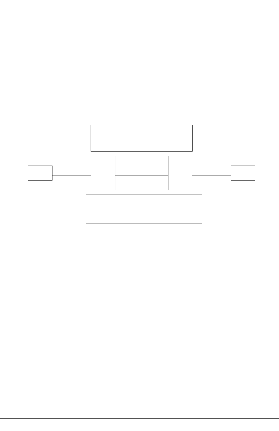
Troubleshooting DVMRP Troubleshooting DVRMP on OmniSwitch 6800/6850/9000 Series
OmniSwitch Troubleshooting Guide July 2008 page 15-21
Troubleshooting DVRMP on OmniSwitch 6800/
6850/9000 Series
Before troubleshooting DVMRP, please be sure the Layer 2 multicast functions correctly. When trouble-
shooting multicast routing, the primary concern is the source address. Multicast has a concept of Reverse
Path Forwarding check (RPF check). When a multicast packet arrives on an interface, the RPF process
checks to ensure that this incoming interface is the outgoing interface used by unicast routing to reach the
source of the multicast packet. This RPF check process prevents loops. Multicast routing does not forward
a packet unless the source of the packet passes a reverse path forwarding (RPF) check. Once a packet
passes this RPF check using the DVMRP route table, multicast routing forwards the packet based only
upon the destination address.
The show ip mroute command displays the multicast routing information for particular IP datagrams sent
by particular sources to the IP multicast groups known in this router. For example:
9700#1-> show ip mroute
Total 1 Mroutes
Group Address Src Address Upstream Nbr Route Address Proto
---------------+------------------+---------------+-------------------+------
225.1.1.1 172.32.0.100/32 172.100.100.1 172.32.0.0/22 DVMRP
9700#2-> show ip mroute
Total 1 Mroutes
Group Address Src Address Upstream Nbr Route Address Proto
---------------+------------------+---------------+-------------------+------
225.1.1.1 172.32.0.100/32 0.0.0.0 172.32.0.0/22 DVMRP
The show ip mroute-nexthop command displays the next-hop multicast routing information for particu-
lar IP multicast datagrams sent by a particular source to the IP multicast group known on 9700#1 and
9700#2. Notice on the 9700#2, there is no upstream neighbor since it is local. For example:
.2 .1
vlan101 – 8/3 8/24 vlan100 4/24
vlan102
–
4/1
9700
9700#1
9700
9700#2
server client
VLAN 100 – 172.100.100.0/24
VLAN 101 – 172.30.0.0/22
VLAN 102 – 172.32.0.0/22
Server – 172.32.0.100 sending 225.1.1.1
Client – 172.30.0.100 requesting 225.1.1.1

Troubleshooting DVRMP on OmniSwitch 6800/6850/9000 Series Troubleshooting DVMRP
page 15-22 OmniSwitch Troubleshooting Guide July 2008
9700#1-> show ip mroute-nexthop
Total 1 Nexthops
Group Address Src Address Interface Name Next Hop Protocol
Address
---------------+----------------+-----------------+-------------+------------
225.1.1.1 172.32.0.100/32 vlan-101 225.1.1.1 DVMRP
9700#2-> show ip mroute-nexthop
Total 1 Nexthops
Group Address Src Address Interface Name Next Hop Protocol
Address
--------------+----------------+------------------+-------------+---------------
225.1.1.1 172.32.0.100/32 vlan-100 225.1.1.1 DVMRP
9700-> show ip dvmrp neighbor
Neighbor Address Intf Name Uptime Expires GenID Vers State
----------------+-------------+-----------+-----------+----------+------+-------
172.100.100.1 vlan-100 00h:22m:18s 00h:00m:31s 1466442929 3.255 active
9700-> show ip dvmrp route
Legends: Flags: L = Local, R = Remote, F = Flash, H = Holddown, I = Invalid
Address/Mask Gateway Metric Age Expires Flags
--------------------+---------------+----------+------------+----------+-----------
172.30.0.0/22 - 1 00h:22m:22s - L
172.32.0.0/22 172.100.100.1 2 00h:22m:22s 01m:58s R
172.100.100.0/24 - 1 00h:22m:22s - L
Check the neighbor uptime/expiration and the route. If this information is missing, then it will affect the
multicast forwarding decision.
9700#1-> show ip dvmrp prune
Group Address Source Address/Mask Expires
-----------------+-----------------------+--------------
225.1.1.2 172.32.0.100/22 :59m:46s
225.1.1.3 172.32.0.100/22 01h:59m:46s
Check the RPF to make sure the multicast data comes in the right VLAN/interface and RPF is valid.
9700#1-> debug ip dvmrp route valid
Address/Mask |Met| Exp|Vlan| IfIndex| Gateway|Flags
1. 172.30.0.0/22| 1| -1| 101| 13600001| 0.0.0.0| L
DF (by default) on all ipInds except vlan-101
Child Intfs: 2
Subordinates :
2
Nbr: 172.100.100.1
2. 172.32.0.0/22| 2| 117| 100| 13600002| 172.100.100.1| R
DF (by default) on all ipInds except vlan-100

Troubleshooting DVMRP Troubleshooting DVRMP on OmniSwitch 6800/6850/9000 Series
OmniSwitch Troubleshooting Guide July 2008 page 15-23
Flow: 172.32.0.100 -> 225.1.1.1
Flow: 172.32.0.100 -> 225.1.1.2 Prunes: Sent
Flow: 172.32.0.100 -> 225.1.1.3 Prunes: Sent
Child Intfs: 1
Subordinates :
3. 172.100.100.0/24| 1| -1| 100| 13600002| 0.0.0.0| L
Route's Intf: 2
Fwder's Intf 2, Router 172.100.100.1, Metric 1
Child Intfs: 1
Subordinates :
Total # valid routes --------------------: 3
Debugging DRC IPMRM/DVRMP on OS-6800/6850/9000
Switches
IPMRM is basically an interface between the IPMS module and the multicast routing protocols (PIM or
DVRMP ) running in the switch. In the 6.1.3 release, we can use the debug drc command to enable high
level debugging messages for IPMRM / DVMRP or PIMSM.
By default all logging is displayed to the console only; however, you can redirect to swlog, buffer file, or
telnet.
9700-> debug drclog output ?
^
TELNET-SESSION SWLOG CONSOLE BUFFER
(Debug Command Set)
To display the current debug level set for the IPMRM option, use the show drclog ipmrm command. For
example:
9700-> show drclog ipmrm
Output = swlog
Show task name = enabled
Show funcs = disabled
Show lines = disabled
Show date = disabled
Show time = disabled
IPMRM debug levels
aging = 0,
error = 0,
fib = 0,
init = 0,
ipms = 0,
mip = 0,
misc = 0,
protos = 0,
tm = 0,

Troubleshooting DVRMP on OmniSwitch 6800/6850/9000 Series Troubleshooting DVMRP
page 15-24 OmniSwitch Troubleshooting Guide July 2008
To enable debug for IPMRM/IPMS to debug level 95 (highest level), use the following command. Note
that the higher the number, the more debug information.
9700-> debug drclog ipmrm ipms 95
9700-> show drclog ipmrm
Output = swlog
Show task name = enabled
Show funcs = disabled
Show lines = disabled
Show date = disabled
Show time = disabled
IPMRM debug levels
aging = 0,
error = 0,
fib = 0,
init = 0,
ipms = 95,
mip = 0,
misc = 0,
protos = 0,
tm = 0,
To display the IPMRM debugging log, use the show log swlog command. For example:
9700-> show log swlog
Displaying file contents for '/flash/swlog2.log'
FILEID: fileName[/flash/swlog2.log], endPtr[60], configSize[500000], mode[2]
Displaying file contents for '/flash/swlog1.log'
FILEID: fileName[/flash/swlog1.log], endPtr[526], configSize[500000], mode[1]
Time Stamp Application Level Log Message
------------------------+--------------+-------+--------------------------------
THU JUN 19 14:18:42 2008 DRC info tDrcIpmrm::Rcvd IPMS Msg:0x11000a,
len:12
THU JUN 19 14:18:42 2008 DRC info tDrcIpmrm::Rcvd IPMS REPORT V:101
THU JUN 19 14:18:42 2008 DRC info tDrcIpmrm::msgId = 0x11000a vs
0x11000a
THU JUN 19 14:18:42 2008 DRC info tDrcIpmrm:: DVMRP Vlan:101 If:1
THU JUN 19 14:18:42 2008 DRC info tDrcIpmrm::
(0.0.0.0,225.1.1.1) forward:1
THU JUN 19 14:18:42 2008 DRC info tDrcIpmrm::Sent IPMS
(172.32.0.100,225.1.1.1) Route V:100
THU JUN 19 14:18:42 2008 DRC info tDrcIpmrm:: Native If:1 V:101
ttl:0
9700->
DRC log debug option for DVRMP:
9700-> debug drclog dvmrp igmp 95
9700-> show drclog dvmrp
Output = swlog
Show task name = enabled
Show funcs = disabled

Troubleshooting DVMRP Troubleshooting DVRMP on OmniSwitch 6800/6850/9000 Series
OmniSwitch Troubleshooting Guide July 2008 page 15-25
Show lines = disabled
Show date = disabled
Show time = disabled
DVMRP debug levels
error = 0,
flash = 0,
grafts = 0,
igmp = 95,
init = 0,
ipmrm = 0,
mip = 0,
misc = 0,
nbr = 0,
probes = 0,
prunes = 0,
routes = 0,
time = 0,
tm = 0,
9700-> show log swlog
Displaying file contents for '/flash/swlog2.log'
FILEID: fileName[/flash/swlog2.log], endPtr[60], configSize[500000], mode[2]
Displaying file contents for '/flash/swlog1.log'
FILEID: fileName[/flash/swlog1.log], endPtr[931], configSize[500000], mode[1]
Time Stamp Application Level Log Message
------------------------+--------------+-------+--------------------------------
THU JUN 19 14:28:00 2008 DRC info tDrcIpmrm::Rcvd IPMS Msg:0x11000a,
len:12
THU JUN 19 14:28:00 2008 DRC info tDrcIpmrm::Rcvd IPMS REPORT V:101
THU JUN 19 14:28:00 2008 DRC info tDrcIpmrm::msgId = 0x11000a vs
0x11000a
THU JUN 19 14:28:00 2008 DRC info tDrcIpmrm:: DVMRP Vlan:101 If:1
THU JUN 19 14:28:00 2008 DRC info tDrcIpmrm::
(0.0.0.0,225.1.1.1) forward:1
THU JUN 19 14:28:00 2008 DRC info tDvmrp::Entry 1 of 1
THU JUN 19 14:28:00 2008 DRC info tDvmrp::Allow (0.0.0.0,225.1.1.1),
vlan 101
THU JUN 19 14:28:00 2008 DRC info tDvmrp::V101 New Group 225.1.1.1
mode ALLOW
THU JUN 19 14:28:00 2008 DRC info tDvmrp::Check forwarding2 for group
225.1.1.1
THU JUN 19 14:28:00 2008 DRC info tDrcIpmrm::Rcvd IPMS Msg:0x110000,
len:20
THU JUN 19 14:28:00 2008 DRC info tDrcIpmrm::Rcvd IPMS
(172.32.0.100,225.1.1.1) Flow V:100 Type:1
THU JUN 19 14:28:00 2008 DRC info tDrcIpmrm::Sent IPMS
(172.32.0.100,225.1.1.1) Route V:100
THU JUN 19 14:28:00 2008 DRC info tDrcIpmrm:: Native If:1 V:101
ttl:0
9700->

Troubleshooting DVRMP on OmniSwitch 6800/6850/9000 Series Troubleshooting DVMRP
page 15-26 OmniSwitch Troubleshooting Guide July 2008

OmniSwitch Troubleshooting Guide July 2008 page 16-1
16 Alcatel-Lucent Trouble-
shooting PIM-SM
In order to troubleshoot issues related to Protocol Independent Multicast-Sparse Mode (PIM-SM), a basic
understanding of the protocol—as well as IP multicast technology—are required. Basic PIM-SM concepts
are explained below; for detailed protocol specifications please refer to RFC 2362 (PIM-SM) as well as
the OmniSwitch 7700/7800/8800 Advanced Routing Configuration Guide, which contains a protocol over-
view and PIM-SM configuration information.
In This Chapter
“Introduction” on page 16-2
“Definition of Terms” on page 16-2
“Protocol Overview” on page 16-3
“BSR Election” on page 16-6
“C-RP Advertisements” on page 16-10
“RP-SET” on page 16-13
“Join/Prune” on page 16-18
“Register” on page 16-21
“Shared Tree” on page 16-23
“Source-Based Tree” on page 16-25
“Troubleshooting Examples: Limitations” on page 16-27
“Troubleshooting PIM on OS-6800/6850/9000 Switches” on page 16-29

Introduction Alcatel-Lucent Troubleshooting PIM-SM
page 16-2 OmniSwitch Troubleshooting Guide July 2008
Introduction
Traditional multicast routing protocols like DVMRP, MOSPF or PIM-DM were implemented to provide
multicast routing in campus network. These traditional dense mode multicast protocol were intended for
use within regions where a group is widely represented or bandwidth is not an issue. However when group
members and senders to these groups are sparsely distributed across a wide area, traditional multicast rout-
ing protocol schemes do not provide an efficient way to establish distribution trees. For instance member-
ship reports or data packets are being eventually forwarded over many links where no receivers or senders
are located.
PIM-SM architecture provides a way for efficiently routing to multicast groups that may span wide area
Internets. PIM-SM, including those with WAN links, scales well to a network of any size. The explicit join
mechanism will prevent unwanted traffic from flooding the WAN links. Data multicast traffic will be
forwarded only to networks segment that have active receivers which have specifically requested the data.
PIM-SM uses a shared tree to distribute the information about active sources. Depending on the configura-
tion options the traffic can remain on the shared tree or switch over to an optimized source distribution tree
called Shortest Path Tree, SPT. The traffic starts to flow down the shared tree and then routers along the
path determine if there is a better path to the source. If a better, more direct path exists the designated
router (router closest to the receiver) will send a “join” message towards the source and then re-route the
traffic along this path.
PIM-SM uses the concept of Rendezvous Point (RP). Sources register with the RP and then data is
forwarded down the shared tree to the receivers. If the shared tree is not an optimal path between the
source and the receiver the routers will dynamically create a source tree and stop traffic from flowing
down the shared tree.
Definition of Terms
Bootstrap Router (BSR). A BSR is dynamically elected between the C-BSR (candidates BSR) within a
PIM-SM domain. Bootstrap messages are sent to discover all C-BSR and associated CBSR priority. The
BSR is the router with the highest CBSR priority. It is responsible for sending bootstrap messages, which
contains RP-Set.
Designated Router (DR). The DR is the highest IP addressed PIM-SM router on a LAN segment. It is
responsible for sending corresponding Join/Prune messages to the RP on behalf of directly connected
receivers and sources.
Rendezvous Point (RP). Each multicast group has a shared-tree via which receivers receives data from
sources. The RP is the root of this per-group shared tree, called RP tree. C-RPs (Candidates RP) are PIM-
SM routers configured to eventually become RP for some or all multicast groups address. Priority can also
be configured for a C-RP and will be used on DR when membership to a multicast group is required.
RP-Set. List of reachable C-RP sent in bootstrap messages distributed by the BSR to all PIM-SM router in
the domain. The BSR compiles the list based on C-RP advertisement. C-RPs periodically unicast C-RP-
Advertisements to the BSR for that domain The RP-Set details each C-RP with their group multicast
address availability. DRs store these bootstrap messages and use it when membership to a specific multi-
cast group is required.
RP Tree (Shared Tree). The set of paths connecting all receivers of a group to the RP.
Shortest Path Tree (SPT). The SPT is the multicast distribution tree that connects, using the shortest
path, receivers of a specific group to the source. The SPT computation is based on unicast routing but is
not depending on any particular unicast routing protocol.
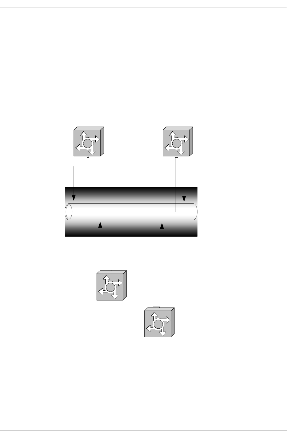
Alcatel-Lucent Troubleshooting PIM-SM Protocol Overview
OmniSwitch Troubleshooting Guide July 2008 page 16-3
Protocol Overview
DR Election
Hello messages are sent periodically between PIM neighbors. This informs routers which interface has
PIM neighbors. Hello messages are multicast packets using address 224.0.0.13, which corresponds to
ALL-PIM-ROUTERS group.
When a router receives a Hello message, it stores the IP address for that neighbor and determines the
Designated Router (DR) for that specific interface. The highest IP address system is elected DR. DR infor-
mation is refreshed on each Hello messages received. Holdtime parameter is the amount of time a receiver
must keep the neighbor reachable, in seconds.
Simplified Hello Message Format
IP: ----- IP Header -----
IP: Protocol = 103 (PIM)
IP: Source address = [192.168.11.1]
IP: Destination address = [224.0.0.13]
Ethernet 192.168.11/24
segment
192.168.11.1/24
192.168.11.2/24
192.168.11.3/24 192.168.11.4/24
Hello pkt
Hello pkt Hello pkt
Hello pkt

Protocol Overview Alcatel-Lucent Troubleshooting PIM-SM
page 16-4 OmniSwitch Troubleshooting Guide July 2008
PIM: ----- PIM Header -----
PIM:
PIM: Version = 2
PIM: Message Type = 0 (Hello)
PIM: Reserved = 0
PIM: Checksum = 4017 (correct)
PIM: Option Type = 1 (PIM-SM)
PIM: Option Length = 2
PIM: Option Value = 0x0069 (Hold time in seconds)
Debugging Hello Messages
To debug DR election and view Hello messages sent and received on PIM router interface, use the follow-
ing commands:
-> ip pimsm debug-type hello
-> ip pimsm debug-level 100
Debug output:
tPimsm-: Sending hello on 2 with IP 192.168.12.1
tPimsm-: Sending hello on 100 with IP 10.1.1.1
tPimsm-: Sending hello on 1 with IP 192.168.11.1
Sending hello on 2 is a Hello message sent on VLAN 2, and the interface with IP 192.168.12.1 is the
router interface sending the Hello message
tPimsm-: Received hello from 192.168.11.2 on 1, len=22
tPimsm-: Recvd. hello from 192.168.11.2 on vlan 1 Holdtime 105
tPimsm-: Recvd. hello from 192.168.11.2 on vlan 1 Priority 1
tPimsm-: Recvd. hello from 192.168.11.2 on vlan 1 Genid 56455
Received hello from 192.168.11.2 is the sender of the Hello message on 1. len=22 is respectively the
VLAN on which the packet is received, and the packet length Holdtime 105 is the holdtime in seconds.
Priority 1 all PIM-SM routers have the same value and are not configurable.
Genid 56455.

Alcatel-Lucent Troubleshooting PIM-SM Protocol Overview
OmniSwitch Troubleshooting Guide July 2008 page 16-5
Related CLI Command
To view if a PIM router interface is the DR for the LAN segment, enter the following command:
-> show ip pimsm neighbor
Neighbor Address Vlan Uptime Expires Mode
-----------------+--------+-----------+-----------+---------
192.168.11.2 2 17h:49m:48s 00h:01m:28s Sparse (DR)
192.168.12.2 2 17h:19m:34s 00h:01m:15s Sparse (DR)
If (DR) is not present it means the interface has not DR role on the segment.
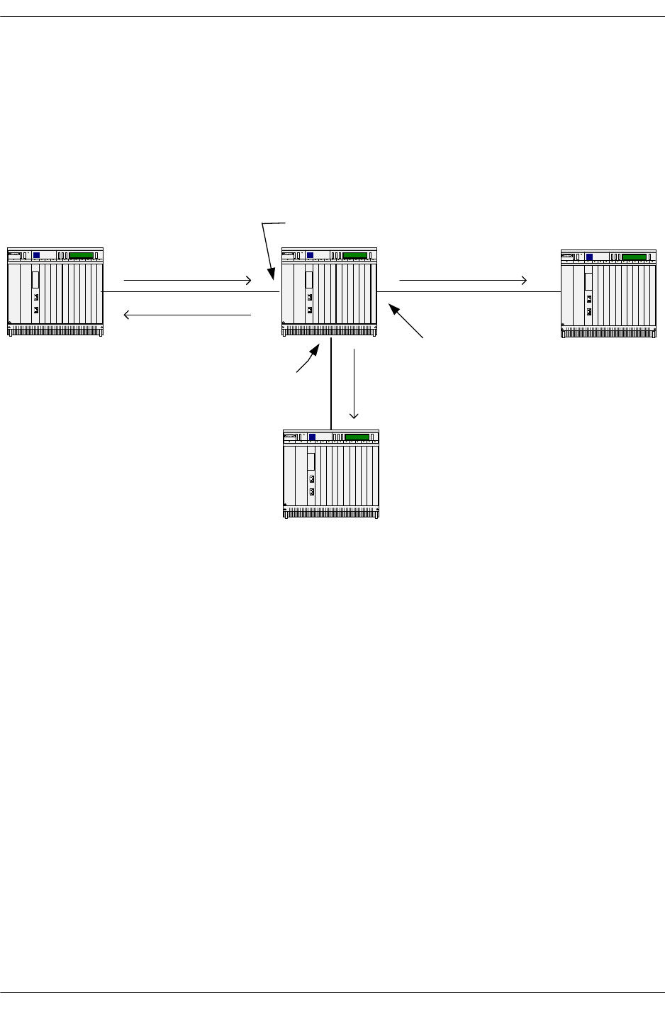
BSR Election Alcatel-Lucent Troubleshooting PIM-SM
page 16-6 OmniSwitch Troubleshooting Guide July 2008
BSR Election
Candidates-BSR sends Bootstrap messages within its PIM-SM domain. Bootstrap messages are multicast
to the ALL-PIM-ROUTERS group. Bootstrap message parameters C-BSR ID, which are equal to the BSR
IP address, and the C-BSR priority, are used for the BSR election. The BSR will be the router with the
highest priority; in case the routers have the same priority, the highest IP address will become the BSR.
After BSR has been elected, intermediate routers forward Bootstrap messages originated at the BSR.
Com3Com3Com3
Com3
192.168.11.2
192.168.10.2
192.168.10.3
192.168.9.4
192.168.9.2
bootstrap message
BSR ID 192.168.11.1
BSR priority 0
bootstrap message
BSR ID 192.168.11.2
BSR priority 0
bootstrap message
source ip 192.168.10.2
BSR ID 192.168.11.1
BSR priority 0
bootstrap message
source ip 192.168.9.2
BSR ID 192.168.11.1
BSR priority 0

Alcatel-Lucent Troubleshooting PIM-SM BSR Election
OmniSwitch Troubleshooting Guide July 2008 page 16-7
Simplified Packet Format
IP: ----- IP Header -----
IP: Protocol = 103 (PIM)
IP: Source address = [192.168.11.2]
IP: Destination address = [224.0.0.13]
PIM: ----- PIM Header -----
PIM:
PIM: Version = 2
PIM: Message Type = 4(Bootstrap)
PIM: Reserved = 0
PIM: Checksum = 71af (correct)
PIM: Fragment tag = 0
PIM: Hash mask length = 30
PIM: BSR-priority = 0
Debugging BSR/Bootstrap
Commands to debug received and forwarded bootstrap, the command will return information on BSR
election as well as Bootstrap messages in general.
-> ip pimsm debug-type bootstrap
-> ip pimsm debug-level 100
Debug output on 192.168.11.2:
tPimsm-: pimsmBSRStateTransition - Entering with Event TMR State : CAND
OperStatus DOWN
tPimsm-: Originate msg.State change to ELCTD
Transitioning from status down to up in order to participate to BSR election.
tPimsm-: BSR Available : 192.168.11.2
C-BSR is the address that will be used in the generated Bootstrap messages.
tPimsm-: pimsmBSRStateTransition - Leaving with Event TMR State : ELCTD
Status UP

BSR Election Alcatel-Lucent Troubleshooting PIM-SM
page 16-8 OmniSwitch Troubleshooting Guide July 2008
The router selects itself as initial BSR.
tPimsm-: Received bootstrap message from 192.168.11.1, bsr
addr:192.168.11.1 on vlan 1
tPimsm-: Ignoring less preferred bsr 192.168.11.1, Pri 0. Bsr
192.168.11.2, Pri 0
Bootstrap message received and action taken, notice BSR ID and BSR priority.
tPimsm-: Received bootstrap message from 192.168.11.1, bsr
addr:192.168.11.1 on vlan 1
tPimsm-: Ignoring less preferred bsr 192.168.11.1, Pri 0. Bsr
192.168.11.2, Pri 0
tPimsm-: Sent BS on vlan 1 ipda = 224.0.0.13
tPimsm-: Sent BS on vlan 1 ipda = 224.0.0.13
Bootstrap messages sent with IP destination and VLAN information.
Debug output on 192.168.11.1:
tPimsm-: pimsmBSRStateTransition - Entering with Event TMR State : CAND
OperStatus DOWN
tPimsm-: Originate msg.State change to ELCTD
tPimsm-: BSR Available : 192.168.11.1
tPimsm-: pimsmBSRStateTransition - Leaving with Event TMR State : ELCTD
Status UP
tPimsm-: Sent BS on vlan 1 ipda = 224.0.0.13
tPimsm-: Sent BS on vlan 2 ipda = 224.0.0.13
tPimsm-: Sent BS on vlan 1 ipda = 224.0.0.13
tPimsm-: Sent BS on vlan 2 ipda = 224.0.0.13
tPimsm-: Received bootstrap message from 192.168.11.2, bsr
addr:192.168.11.2 on vlan 1
tPimsm-: pimsmBSRStateTransition - Entering with Event CHNG State :
ELCTD OperStatus UP
Received bootstrap triggered BSR change.
tPimsm-: BSR Available : 192.168.11.2
Election of a New BSR
tPimsm-: pimsmBSRStateTransition - Leaving with Event CHNG State : CAND
Status UP
........
Forwarding BSR on VLAN 2
Bootstrap message forwarded on the corresponding VLAN.

Alcatel-Lucent Troubleshooting PIM-SM BSR Election
OmniSwitch Troubleshooting Guide July 2008 page 16-9
Related CLI Command
To view which routers are assuming the role of the BSR, expiry time, C-BSR address, and C-BSR prior-
ity, type:
-> show ip pimsm
Status = enabled,
BSR Address = 192.168.13.1,
BSR Expiry Time = 00h:02m:01s,
CBSR Address = 0.0.0.0,
CBSR Mask Length = 30,
CBSR Priority = 0,
.......
IF you don’t want a PIM router to assume BSR role, enter the following syntax:
-> no ip pimsm cbsr-address
This command will result in a C-BSR address of 0.0.0.0
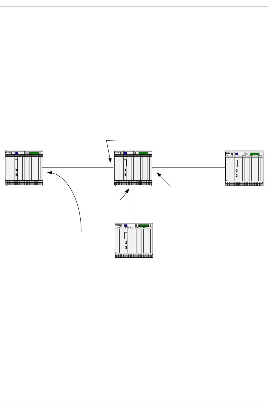
C-RP Advertisements Alcatel-Lucent Troubleshooting PIM-SM
page 16-10 OmniSwitch Troubleshooting Guide July 2008
C-RP Advertisements
Candidate-RPs advertisements are periodically unicast from the C-RP to the BSR. These advertisements
contain group multicast address the router can be responsible for and the priority for the corresponding
group address. C-RP could be configured to participate as RP for specific multicast groups or for all multi-
cast groups. Highest priority will be 0. Other parameters present in the packet are:
•Holdtime timer, which is the amount of time the advertisement, is valid.
•The prefix count, which tells the number of group addresses contained in the advertisement.
•The unicast RP address which is the interface to advertise as RP.
•The mask length.
Simplified RP-Advertisement Packet Format
IP: ----- IP Header -----
IP: Protocol = 103 (PIM)
IP: Header checksum = DF9E (correct)
IP: Source address = [192.168.10.3]
IP: Destination address = [192.168.11.1]
IP: No options
IP:
Com3Co m3Com3
Com3
192.168.11.1 192.168.11.2
192.168.10.2
192.168.10.3
192.168.9.4
192.168.9.2
BSR
C-RP-Adv
RP address 192.168.10.3
Mluticast Group 225.1.1.1

Alcatel-Lucent Troubleshooting PIM-SM C-RP Advertisements
OmniSwitch Troubleshooting Guide July 2008 page 16-11
PIM: ----- PIM Header -----
PIM: Version = 2
PIM: Message Type = 8(Candidate-RP-Advertisement)
PIM: Reserved = 0
PIM: Checksum = 269d (correct)
PIM: Prefix count = 1
PIM: Priority = 0
PIM: Holdtime = 150 (in seconds)
PIM: *** Encoded-Unicast-RP-Address ***
PIM: Address family = 1 (IP (IP version 4))
PIM: Encoding type = 0
PIM: Unicast address = [192.168.11.1]
PIM:
PIM: *** Encoded Group Address-1 ***
PIM: Address family = 1 (IP (IP version 4))
PIM: Encoding type = 0
PIM: Reserved = 0
PIM: Mask length = 32
PIM: Group multicast address = [225.1.1.1]
Debugging C-RP-Adv
The commands below should be issued on the BSR since the packets are directed to it, other possibility is
to use these commands on the originated C-RP in order to identify if the advertisement are really sent.
-> ip pimsm debug-type crp
-> ip pimsm debug-level 100
Debugging output on BSR:
tPimsm-: Recv. CRP-Adv (RP:192.168.10.3,Prefix Cnt:1, Pri:0) from
192.168.10.3:192.168.11.1 on vlan 1
tPimsm-: RP : 192.168.10.3 : Prefix: 225.1.1.1 Mask : 255.255.255.255
Information on the C-RP unicast address, number of count, priority and mcast group as well as on which
PIM interface the advertisement has been received can be seen on with this debug command.

C-RP Advertisements Alcatel-Lucent Troubleshooting PIM-SM
page 16-12 OmniSwitch Troubleshooting Guide July 2008
Another output from a C-RP advertisement, advertises itself for all multicast groups. All group addresses
are represented by the pair 224.0.0.0 240.0.0.0, which covers 224.0.0.0 up to 239.255.255.255.
tPimsm-: Recv. CRP-Adv (RP:192.168.10.3,Prefix Cnt:1, Pri:0) from
192.168.10.3:192.168.11.1 on vlan 2
tPimsm-: RP : 192.168.10.3 : Prefix: 224.0.0.0 Mask : 240.0.0.0
Related CLI Command
To view the set of multicast group address the PIM router wants to participate in issue:
-> show ip pimsm rp-candidate
Group Address RP Address Status
------------------+---------------+--------
225.1.1.1/32 192.168.11.2 enabled
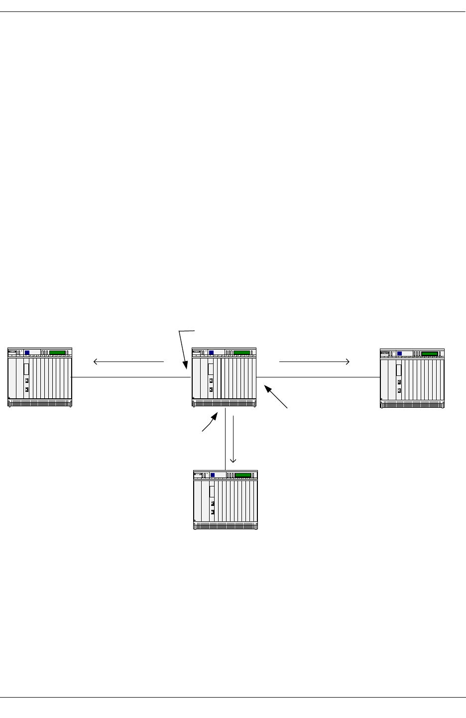
Alcatel-Lucent Troubleshooting PIM-SM RP-SET
OmniSwitch Troubleshooting Guide July 2008 page 16-13
RP-SET
An RP-SET contains a set of Candidates-RP IP addresses that want to participate as RP for multicast
group. The RP-SET is derived from the C RP-Advertisements received by the BSR. RP-SETs are adver-
tised by the BSR in a bootstrap message to all PIM SM routers by using the ALL-PIM-ROUTER address
224.0.0.13. It contains details on the each C-RP IP address, the multicast group routers want to participate
and the corresponding priority.
The DR to determine the RP for each group which it has active members uses the RP-SET. The hash func-
tion algorithm, used to select the RP, takes as input the group address and the addresses of the Candidate
RPs and gives as output one RP address to be used. The protocol requires that all routers hash to the same
RP within a domain for the same multicast group.
Com3Com3Com3
Com3
192.168.13.101 192.168.13.1
192.168.11.1
192.168.11.2
192.168.12.2
192.168.12.1
BSR
C-RP for 225.1.1.1
C-RP for 226.1.1.1
C-RP for 227.1.1.1
BOOTSTRAP message to ALL-PIMSM-ROUTER
BSR ID: 192.168.13.1
Group: 225.1.1.1
RP address: 192.168.11.2
Group: 226.1.1.1
RP address: 192.168.12.2
Group: 227.1.1.1
RP address: 192.168.12.2
Bootstrap
message
Bootstrap
message
Bootstrap
message

RP-SET Alcatel-Lucent Troubleshooting PIM-SM
page 16-14 OmniSwitch Troubleshooting Guide July 2008
Simplified Bootstrap RP-SET Packet Taken on a 192.168.12/24
Network
IP: ----- IP Header -----
IP: Version = 4, header length = 20 bytes
IP: Protocol = 103 (PIM)
IP: Source address = [192.168.12.1]
IP: Destination address = [224.0.0.13]
PIM: ----- PIM Header -----
PIM: Version = 2
PIM: Message Type = 4(Bootstrap)
PIM: Hash mask length = 30
PIM: BSR-priority = 0
PIM: *** Encoded-Unicast BSR Address ***
PIM: Address family = 1 (IP (IP version 4))
PIM: Encoding type = 0
PIM: Unicast address = [192.168.13.1]
PIM:
PIM: *** Encoded-Group Address # 1 ***
PIM: Address family = 1 (IP (IP version 4))
PIM: Encoding type = 0
PIM: Reserved = 0
PIM: Mask length = 32
PIM: Group multicast address = [225.1.1.1]
PIM: RP-count-1 = 1
PIM: Fragment RP-count-1 = 1
PIM: Reserved = 0
PIM:
PIM: *** Encoded-Unicast RP Address # 1 ***
PIM: Address family = 1 (IP (IP version 4))
PIM: Encoding type = 0
PIM: Unicast address = [192.168.11.2]

Alcatel-Lucent Troubleshooting PIM-SM RP-SET
OmniSwitch Troubleshooting Guide July 2008 page 16-15
PIM: RP1-Holdtime = 150 (in seconds)
PIM: RP1-Priority = 0
PIM: Reserved = 0
PIM:
PIM: *** Encoded-Group Address # 2 ***
PIM: Address family = 1 (IP (IP version 4))
PIM: Encoding type = 0
PIM: Reserved = 0
PIM: Mask length = 32
PIM: Group multicast address = [226.1.1.1]
PIM: RP-count-2 = 1
PIM: Fragment RP-count-2 = 1
PIM: Reserved = 0
PIM:
PIM: *** Encoded-Unicast RP Address # 1 ***
PIM: Address family = 1 (IP (IP version 4))
PIM: Encoding type = 0
PIM: Unicast address = [192.168.12.2]
PIM: RP1-Holdtime = 150 (in seconds)
PIM: RP1-Priority = 0
PIM: Reserved = 0
PIM:
PIM: *** Encoded-Group Address # 3 ***
PIM: Address family = 1 (IP (IP version 4))
PIM: Encoding type = 0
PIM: Reserved = 0
PIM: Mask length = 32
PIM: Group multicast address = [227.1.1.1]
PIM: RP-count-3 = 1
PIM: Fragment RP-count-3 = 1
PIM: Reserved = 0
PIM:

RP-SET Alcatel-Lucent Troubleshooting PIM-SM
page 16-16 OmniSwitch Troubleshooting Guide July 2008
PIM: *** Encoded-Unicast RP Address # 1 ***
PIM: Address family = 1 (IP (IP version 4))
PIM: Encoding type = 0
PIM: Unicast address = [192.168.12.2]
PIM: RP1-Holdtime = 150 (in seconds)
PIM: RP1-Priority = 0
PIM: Reserved = 0
The RP-Holdtime parameters is the corresponding time the BSR will hold related RP multicast group
information in its table as valid. This parameter is reset to 150 s when a C-RP Advertisement is received at
BSR and originated by the RP in question.
Debugging RP-SET
As mentioned previously, RP-SET are included in Bootstrap messages. Commands to debug RP-SET:
-> ip pimsm debug-type bootstrap
-> ip pimsm debug-level 100
On Non BSR You Should See
tPimsm-: Received bootstrap message from 192.168.12.1, bsr addr:192.168.13.1
on vlan 2
tPimsm-: AcceptBSMsg: Contents
tPimsm-: AcceptBSMsg: Prefix : 225.1.1.1 Mask : 255.255.255.255
tPimsm-: AcceptBSMsg: RP: 192.168.11.2 Priority : 0
tPimsm-: AcceptBSMsg: current rplist does exist
tPimsm-: AcceptBSMsg: removing timer
tPimsm-: AcceptBSMsg: bit already set for indx:1
tPimsm-: AcceptBSMsg: Prefix : 226.1.1.1 Mask : 255.255.255.255
tPimsm-: AcceptBSMsg: RP: 192.168.12.2 Priority : 0
tPimsm-: AcceptBSMsg: current rplist does exist
tPimsm-: AcceptBSMsg: removing timer
tPimsm-: AcceptBSMsg: bit already set for indx:2
tPimsm-: AcceptBSMsg: Prefix : 227.1.1.1 Mask : 255.255.255.255
tPimsm-: AcceptBSMsg: RP: 192.168.12.2 Priority : 0
tPimsm-: AcceptBSMsg: current rplist does exist
tPimsm-: AcceptBSMsg: removing timer
tPimsm-: AcceptBSMsg: bit already set for indx:2
tPimsm-: AcceptBSMsg: check Rehash
tPimsm-: CheckRehash : SET adding rp:indx:1
tPimsm-: CheckRehash : SET adding rp:indx:2
This output shows the IP address of the routing relaying the bootstrap message, the BSR ID, the VLAN
ID, the various multicast group, RP IP address and priority.
Issuing the same command on the BSR would detail the C-RP Advertisement received, and the bootstrap
messages sent on various interfaces.

Alcatel-Lucent Troubleshooting PIM-SM RP-SET
OmniSwitch Troubleshooting Guide July 2008 page 16-17
Related CLI Command
To View RP-SET on a router, use the show ip pimsm rp-set command. For example:
-> show ip pimsm rp-set
Group Address Address Holdtime Expires
------------------+---------------+--------+-----------
225.1.1.1/32 192.168.11.2 150 00h:00m:00s
226.1.1.1/32 192.168.12.2 150 00h:00m:00s
227.1.1.1/32 192.168.12.2 150 00h:00m:00s
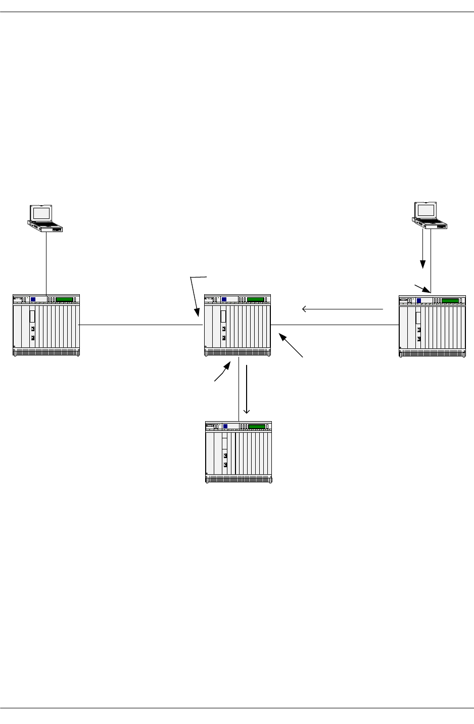
Join/Prune Alcatel-Lucent Troubleshooting PIM-SM
page 16-18 OmniSwitch Troubleshooting Guide July 2008
Join/Prune
Join/Prune messages are sent by the DR to join or prune a branch off the multicast distribution tree in
order to receive multicast group on a specific LAN segment that has active group members. Registration
of the members is achieved with IGMP host membership report. Upon reception of such message each
upstream router between the receiver and the RP creates or updates its multicast route entry for specific
multicast group(s) adding interface where join/prune request have been received. When the RP receives
the join/prune message it sends join request toward the sender(s). Refer to user manual under section-
shared tree for drawing and additional protocol details.
A JOIN/PRUNE message contains, the upstream neighbor message, the multicast group address a router
wishes to join, number of joins and pruned source and the RP address.
Simplified Join Packet
IP: ----- IP Header -----
IP: Protocol = 103 (PIM)
IP: Source address = [192.168.12.2]
IP: Destination address = [224.0.0.13]
Com3Com3Com3
Com3
192.168.13.1
192.168.11.1
192.168.11.2
192.168.12.2
192.168.12.1
BSR
RP for 225.1.1.1
192.168.15.2
IGMP
membership
report 225.1.1.1
DR
DR
JOIN for 225.1.1.1
JOIN for 225.1.1.1
192.168.13.101
SENDER
225.1.1.1
RECEIVER
225.1.1.1

Alcatel-Lucent Troubleshooting PIM-SM Join/Prune
OmniSwitch Troubleshooting Guide July 2008 page 16-19
PIM: ----- PIM Header -----
PIM:
PIM: Version = 2
PIM: Message Type = 3(Join/Prune)
PIM: Reserved = 0
PIM: Checksum = 5794 (correct)
PIM:
PIM: *** Encoded-Unicast-Upstream Neighbor Address ***
PIM: Address family = 1 (IP (IP version 4))
PIM: Encoding type = 0
PIM: Unicast address = [192.168.12.1]
PIM: Reserved = 0
PIM: Number of groups = 1
PIM: Hold time = 210 (in seconds)
PIM:
PIM: *** Group # 1 ***
PIM:
PIM: *** Encoded-Multicast Group Address-1 ***
PIM: Address family = 1 (IP (IP version 4))
PIM: Encoding type = 0
PIM: Reserved = 0
PIM: Mask length = 32
PIM: Group multicast address = [225.1.1.1]
PIM: Number of joined sources = 1
PIM: Number of pruned sources = 0
PIM:
PIM: *** Encoded-Joined Source Address # 1 ***
PIM: Address family = 1 (IP (IP version 4))
PIM: Encoding type = 0
PIM: Reserved = 0
PIM: Flags = 07
PIM: .... .1.. = Sparse bit - PIM-SM

Join/Prune Alcatel-Lucent Troubleshooting PIM-SM
page 16-20 OmniSwitch Troubleshooting Guide July 2008
PIM: .... ..1. = WC bit - join / prune applies to the (*,G) or (*,*,RP) entry
PIM: .... ...1 = RPT-bit - information about (S,G) is sent towards the RP
PIM: Mask length = 32
PIM: Source address = [192.168.11.2]
Simplified PRUNE Packet
The main difference between a JOIN and PRUNE is the number of joined source versus pruned source:
PIM: *** Encoded-Multicast Group Address-1 ***
PIM: Address family = 1 (IP (IP version 4))
PIM: Encoding type = 0
PIM: Reserved = 0
PIM: Mask length = 32
PIM: Group multicast address = [225.1.1.1]
PIM: Number of joined sources = 0
PIM: Number of pruned sources = 1
Debugging JOIN/PRUNE Event
The commands below will allow you to see any JOIN/PRUNE message:
-> ip pimsm debug-type joinprune
-> ip pimsm debug-level 100
That will show if the message is join or prune, the upstream router, outgoing VLAN, the multicast group
and the RP.
tPimsm-: BuildJoinPrune: for nbr:192.168.12.1 on vlan:2
tPimsm-: BuildJoinPrune: next route
tPimsm-: Sending Triggered GJoins Joins 1 Prunes 0
tPimsm-: BuildJoinPrune: for nbr:192.168.12.1 on vlan:2
tPimsm-: BuildJoinPrune: next route
tPimsm-: BuildJoinPrune: (*,225.1.1.1) route
tPimsm-: BuildJoinPrune: next route
tPimsm-: Send Join (192.168.11.2,225.1.1.1) on vlan 2,bits:7 holdtime 210
tPimsm-: BuildJoinPrune: for nbr:192.168.12.1 on vlan:2
tPimsm-: BuildJoinPrune: next route
tPimsm-: BuildJoinPrune: (*,225.1.1.1) route
tPimsm-: BuildJoinPrune: next route
tPimsm-: Send Join (192.168.11.2,225.1.1.1) on vlan 2,bits:7 holdtime 210
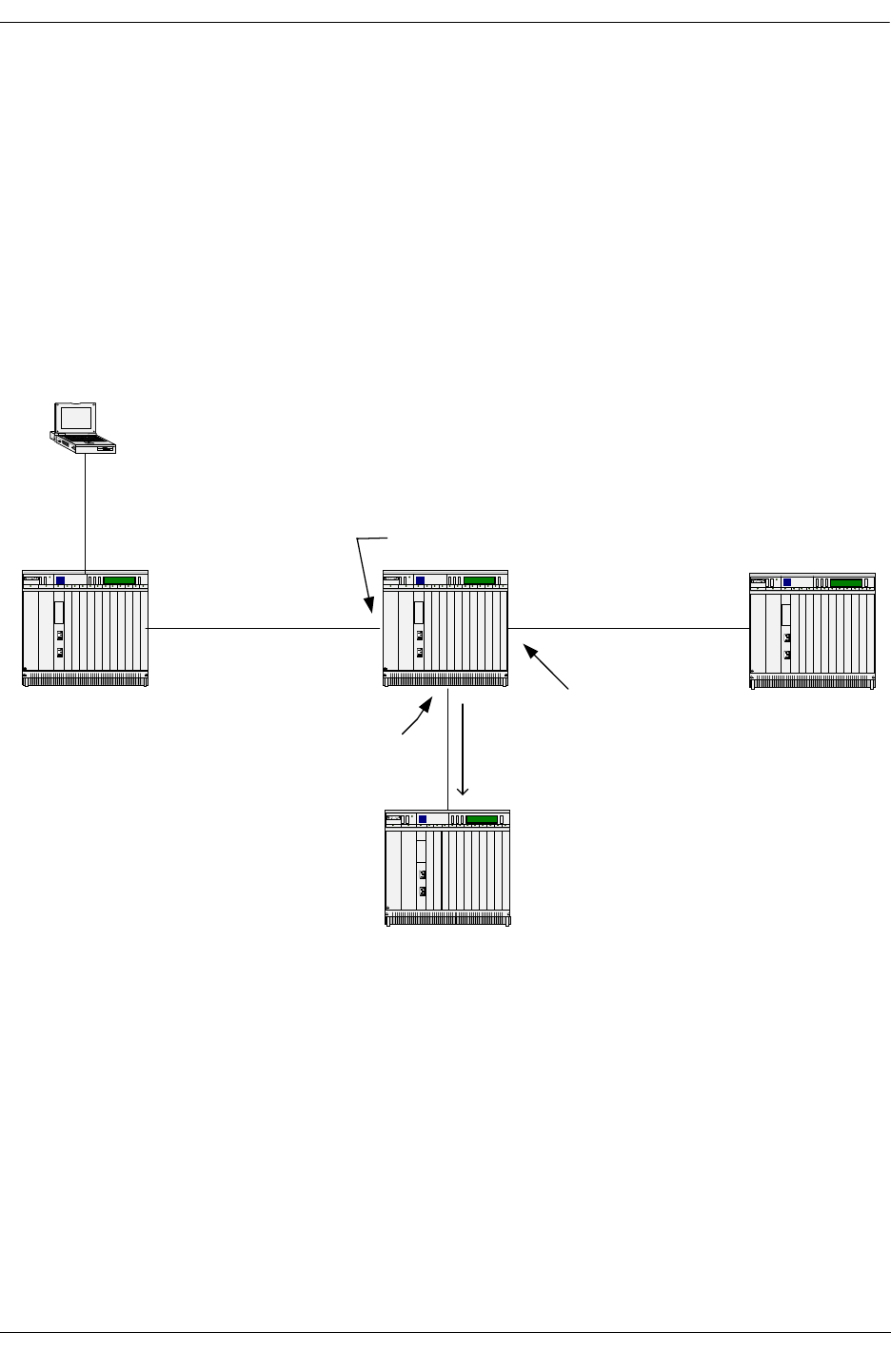
Alcatel-Lucent Troubleshooting PIM-SM Register
OmniSwitch Troubleshooting Guide July 2008 page 16-21
Register
When a source starts transmitting to a multicast group, the DR on the segment encapsulates the data and
sends it as unicast to the RP representing the group. The source IP address will be the DR and the destina-
tion IP address will be the RP. Two behaviors are possible:
1-The RP joins the source tree by sending a PIM join to the DR. Packets will then flow from the source to
the RP unencapsulated.
2-The RP does not join the source tree. The multicast packets will be encapsulated by the DR and send to
the unicast address of the RP.
Upon reception of the multicast stream, the RP forwards the packets unencapsulated to receivers if any. If
there are no receivers the RP issues a REGISTER STOP message to the source.
Com3Com3Com3
Com3
192.168.13.1
192.168.11.1
192.168.11.2
192.168.12.2
192.168.12.1
BSR
RP for 225.1.1.1
192.168.13.101
SOURCE
225.1.1.1
DR
REGISTER for
225.1.1.1

Register Alcatel-Lucent Troubleshooting PIM-SM
page 16-22 OmniSwitch Troubleshooting Guide July 2008
Simplified REGISTER Packet Format
IP: ----- IP Header -----
IP: Source address = [192.168.13.1]
IP: Destination address = [192.168.11.2]
PIM: ----- PIM Header -----
PIM: Version = 2
PIM: Message Type = 1(Register)
PIM: Reserved = 0
PIM: Checksum = deff (should be 45b5)
PIM: Reserved = 0
PIM: Flags = 00
PIM: 0... .... = Border bit - router is a DR for a source that i
PIM: .0.. .... = Null-Register bit - DR not probing the RP
PIM: Multicast data packet
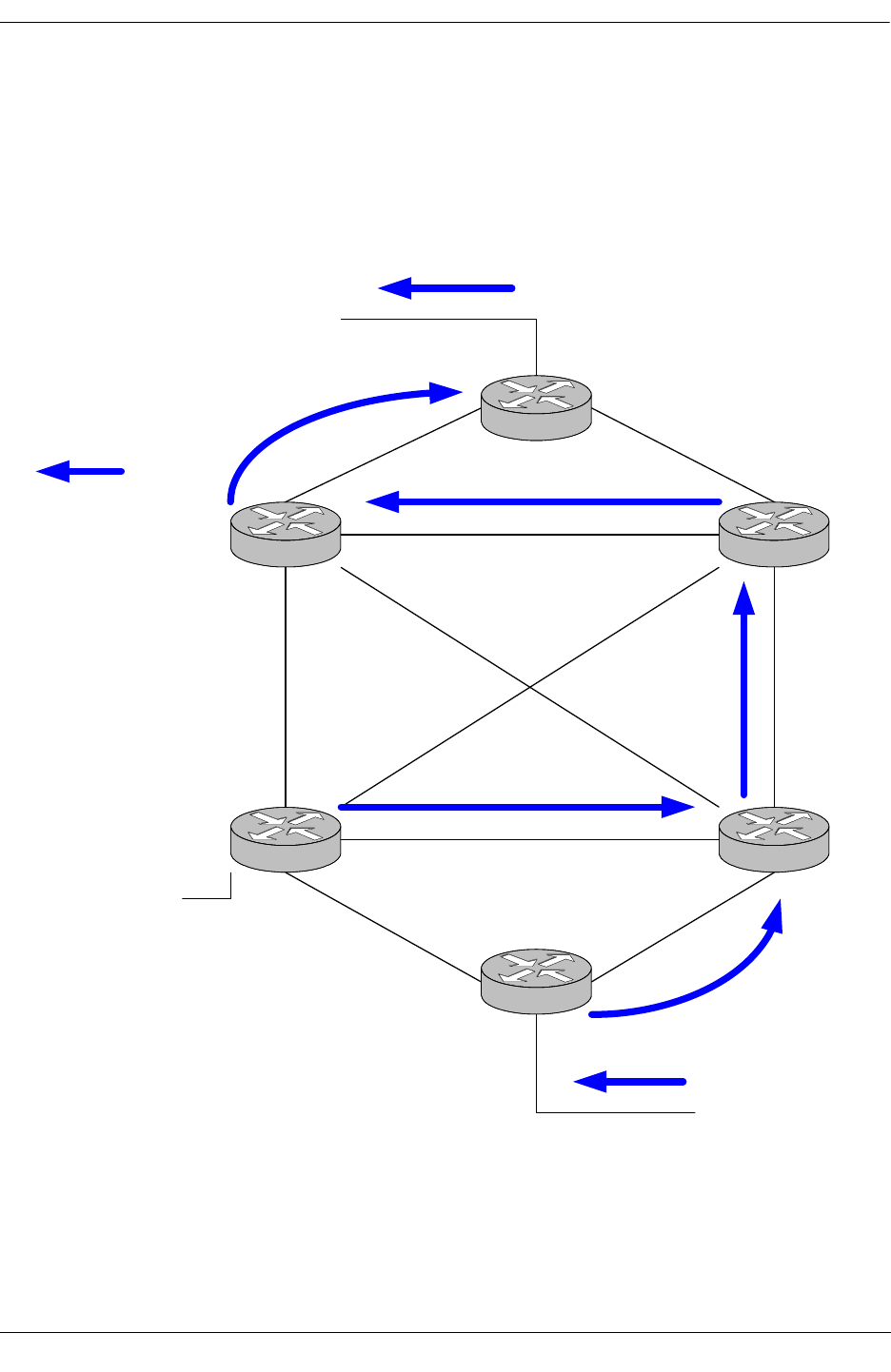
Alcatel-Lucent Troubleshooting PIM-SM Shared Tree
OmniSwitch Troubleshooting Guide July 2008 page 16-23
Shared Tree
A shared distribution tree is formed around the RP, from which all traffic is distributed regardless of the
location of the traffic sources. The advantage of shared distribution trees is simple topology on PIM SM
routers. The DR is sending a JOIN message to the RP, and a graft to the SPT. The disadvantage is that the
path between the source and receivers might not be the shortest one, which could introduce delay. The
rendezvous router may also be a traffic bottleneck if there are many high data rate sources. The Source
Path Tree can be called RP TREE too.
MCAST SOURCE
225.1.1.1
MCAST RECEIVER
for 225.1.1.1
MCAST SOURCE
225.1.1.1

Shared Tree Alcatel-Lucent Troubleshooting PIM-SM
page 16-24 OmniSwitch Troubleshooting Guide July 2008
Related CLI Command
In order to view the IP multicast routing table as well as source and distribution tree type:
-> show ip pimsm mroute
Group Address Src Address Assert Assert Assert Flags
Metric expires Pref
---------------+------------------+------+-----------+------+-----
225.1.1.1 192.168.14.115/32 0 00h:00m:00s 0 rpt
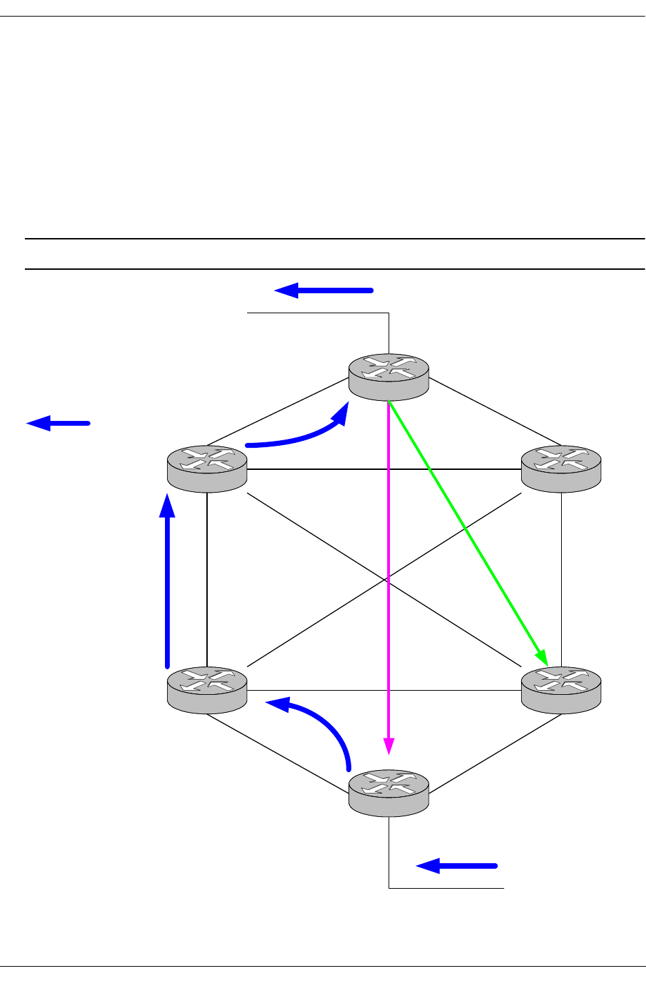
Alcatel-Lucent Troubleshooting PIM-SM Source-Based Tree
OmniSwitch Troubleshooting Guide July 2008 page 16-25
Source-Based Tree
PIM SM protocol allows a DR to build a Shortest Path Tree, which could provide a shortest path toward
the source. It is being referenced as Source Based Tree because the DR closest to the receiver is initiating
the process.
When a PIM SM graft the shared path tree, a counter is initiated for this specific group on the last DR
closest to the receiver that will be incremented every data packet received. Once the data exceeds a config-
ured threshold the router switches over to source based tree mode. A JOIN message is sent directly toward
the source, after the shortest path tree is activated the DR sends a PRUNE message to the RP.
Note. Currently, the threshold cannot be configured from Clips.
MCAST SOURCE
225.1.1.1
MCAST RECEIVER
for 225.1.1.1
JOIN
225.1.1.1
PRUNE
225.1.1.1
DR

Source-Based Tree Alcatel-Lucent Troubleshooting PIM-SM
page 16-26 OmniSwitch Troubleshooting Guide July 2008
Related CLI Command
To view the distribution tree issue:
-> show ip pimsm mroute
Group Address Src Address Assert Assert Assert Flags
Metric expires Pref
---------------+------------------+------+-----------+------+-----
225.1.1.1 192.168.14.115/32 0 00h:00m:00s 0 spt

Alcatel-Lucent Troubleshooting PIM-SM Troubleshooting Examples: Limitations
OmniSwitch Troubleshooting Guide July 2008 page 16-27
Troubleshooting Examples: Limitations
Incorrect BSR ID
Turn on BSR debugging to view bootstrap messages:
-> ip pimsm debug-type bootstrap
-> ip pimsm debug-level 100
tPimsm-: Received bootstrap message from 192.168.11.1, bsr addr:192.168.13.1
on vlan 2
tPimsm-: RPF check failed for bootstrap msg. SA: 192.168.11.1,BSR
:192.168.13.1, vlan 2
tPimsm-: pimsmBSRStateTransition - Entering with Event TMR State : ELCTD
OperStatus UP
tPimsm-: BsrTimer Expired. Orig Message No State change
tPimsm-: pimsmBSRStateTransition - Leaving with Event TMR State : ELCTD
Status UP
tPimsm-: Sent BS on vlan 2 ipda = 224.0.0.13
An IP unicast routing issue causes this; the receiving router does not have a route entry for 192.16811.1.
Multicast Group Status is Shown as Disabled
-> show ip pimsm rp-candidate
Group Address RP Address Status
------------------+---------------+--------
227.1.1.1/32 192.168.12.2 disabled
226.1.1.1/32 192.168.12.2 disabled
This is caused by a missing C-RP address
-> show ip pimsm
Status = enabled,
BSR Address = 192.168.13.1,
BSR Expiry Time = 00h:01m:21s,
CBSR Address = 0.0.0.0,
CBSR Mask Length = 30,
CBSR Priority = 0,
CRP Address = 0.0.0.0,
CRP Hold Time = 150,
CRP Expiry Time = 00h:05m:00s,
CRP Interval = 60,
CRP Priority = 0,
Data Timeout = 210,
Join/Prune Interval = 60,
Max RPs = 32,
Probe Time = 5,
Register Checksum = header,
Register Suppress Timeout = 60
-> ip pimsm crp-address 192.168.12.2

Troubleshooting Examples: Limitations Alcatel-Lucent Troubleshooting PIM-SM
page 16-28 OmniSwitch Troubleshooting Guide July 2008
-> show ip pimsm
Status = enabled,
BSR Address = 192.168.13.1,
BSR Expiry Time = 00h:01m:43s,
CBSR Address = 0.0.0.0,
CBSR Mask Length = 30,
CBSR Priority = 0,
CRP Address = 192.168.12.2,
CRP Hold Time = 150,
CRP Expiry Time = 00h:05m:00s,
CRP Interval = 60,
CRP Priority = 0,
Data Timeout = 210,
Join/Prune Interval = 60,
Max RPs = 32,
Probe Time = 5,
Register Checksum = header,
Register Suppress Timeout = 60
-> show ip pimsm rp-candidate
Group Address RP Address Status
------------------+---------------+--------
227.1.1.1/32 192.168.12.2 enabled
226.1.1.1/32 192.168.12.2 enabled
PIM-SM Limitations
Only one C-RP should be configured per PIM domain. Having multiple C-RPs is not currently supported.
The problem with fragmentation and reassembly of PIM-SM tunneled packets (PIM register-encapsulated
packets fall into this category), is if packets need to be fragmented, it might prevent mcast stream to be
delivered properly. A smaller MTU size would work around this issue.
Upstream Neighbor/Next Hop Debug Commands
Use following debug commands to find an upstream neighbor or to verify next hop.
-> debug ip pimsm rpf 172.100.1.254
Source IP Address = 172.100.1.254,
RPF Vlan = 100,
RPF Neighbor = 172.100.1.254,
RPF Route/Mask = 172.100.1.0/24,
RPF Metric Preference = 1,
RPF Metric = 0
-> debug ip pimsm rp-hash 224.0.0.0
Group Address RP Address
------------------+------------------
224.0.0.0 172.100.1.254
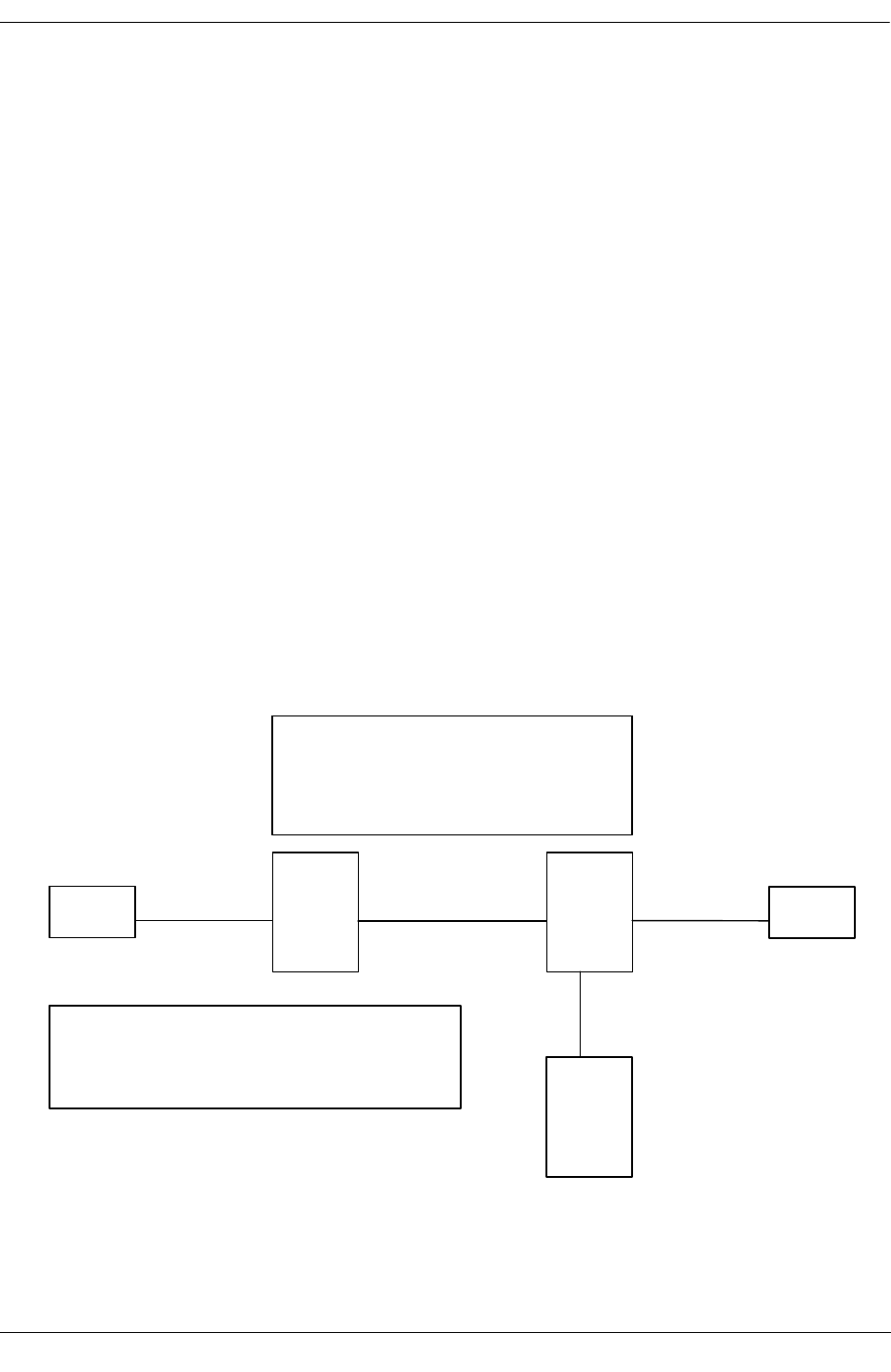
Alcatel-Lucent Troubleshooting PIM-SM Troubleshooting PIM on OS-6800/6850/9000 Switches
OmniSwitch Troubleshooting Guide July 2008 page 16-29
-> debug ip pimsm rp
Group Address RP Address
------------------+------------------
224.0.1.22 172.100.1.254
224.0.1.24 172.100.1.254
239.0.0.90 172.100.1.254
239.1.1.200 172.100.1.254
239.1.1.201 172.100.1.254
239.1.1.202 172.100.1.254
239.255.255.254 172.100.1.254
Troubleshooting PIM on OS-6800/6850/9000
Switches
Before troubleshooting PIM, please be sure that layer 2 multicast layer is functioning correctly. When
troubleshooting multicast routing, the primary concern is the source address. Multicast has a concept of
Reverse Path Forwarding check (RPF check). When a multicast packet arrives on an interface, the RPF
process checks to ensure that this incoming interface is the outgoing interface used by unicast routing to
reach the source of the multicast packet. This RPF check process prevents loops. Multicast routing does
not forward a packet unless the source of the packet passes a reverse path forwarding (RPF) check. Once a
packet passes this RPF check using the unicast route table, multicast routing forwards the packet based
only upon the destination address.
.2 .1
vlan101 – 8/3 8/24 vlan100 4/24
vlan102
–
4/1
9700
Sw#1
9700
Sw#2
server client
VLAN 100 – 172.100.100.0/24
VLAN 101 – 172.30.0.0/22
VLAN 102 – 172.32.0.0/22
VLAN 103 – 172.100.103.0/24
VLAN 104 – 172.100.104.0/24
Server – 172.32.0.100 sending 225.1.1.1
Client – 172.30.0.100 requesting 225.1.1.1
6800
Sw#3
vlan103
vlan104 – RP
225.1.1.0/24

Troubleshooting PIM on OS-6800/6850/9000 Switches Alcatel-Lucent Troubleshooting PIM-SM
page 16-30 OmniSwitch Troubleshooting Guide July 2008
The most important command when troubleshooting PIMSM is the show ip pim group-map command
used to check whether or not the switch has learned the PIM group mapping table. Without this informa-
tion, the client or the server will not be able to send the join message or register its multicast stream to the
RP (172.100.104.1).
Sw#1/> show ip pim group-map
Origin Group Address/Prefix RP Address Mode Precedence
-----------+-----------------------------+--------------------+--------+-----------
BSR 225.0.0.0/24 172.100.104.1 asm 192
BSR 225.1.1.0/24 172.100.104.1 asm 192
In the event the all the PIMSM configuration are correct but the client is not able to receive the stream,
check if the client has sent an IGMP join message and also weather or not the PIM router has also
forwarded the PIM join request toward the RP router. To enable PIM debugging for join/prune message
use "debug drc pim .. ". Use this command on the switch where the client is locate and at the RP switch to
see the join/prune message get there correctly.
Sw#1/> debug drclog pim sm-join-prune 95
tPim::JoinDesired -> True (0.0.0.0,225.1.1.1)
tPim:: (*,G) -> Joined State
tPim::Sent (*,225.1.1.1) Join to 172.100.100.1
tPim:: (S,G,rpt) prune 172.32.0.100 (2)
tPim:: Joins: 1 Prunes: 1
tPim::JoinDesired -> True (172.32.0.100,225.1.1.1)
tPim:: (S,G) -> Joined State
tPim::Sent Join (172.32.0.100,225.1.1.1) to 172.100.100.1 on If:2 (ht:210)
tPim::Sent Join (172.32.0.100,225.1.1.1) to 172.100.100.1 on If:2 (ht:210)
tPim::Sent (*,225.1.1.1) Join to 172.100.100.1
tPim:: Joins: 1 Prunes: 0
tPim::Sent (*,225.1.1.1) Join to 172.100.100.1
tPim:: Joins: 1 Prunes: 0
tPim::Sent Join (172.32.0.100,225.1.1.1) to 172.100.100.1 on If:2 (ht:210)
tPim::Sent Join (172.32.0.100,225.1.1.1) to 172.100.100.1 on If:2 (ht:210)
tPim::Sent (*,225.1.1.1) Join to 172.100.100.1
tPim:: Joins: 1 Prunes: 0
tPim::Sent (*,225.1.1.1) Join to 172.100.100.1
tPim:: Joins: 1 Prunes: 0
tPim::Sent Join (172.32.0.100,225.1.1.1) to 172.100.100.1 on If:2 (ht:210)
In the event that the client is not receiving the multicast but all the information relating to group member-
ship/group mapping is correct and join message is getting to the RP router, the next step is to check
whether the source multicast is sending in the correct VLAN, correct PIM interface, and it is sending the
register packet to the RP.
Sw#2/> show ip multicast source
Total 3 Sources
Group Address Host Address Tunnel Address VLAN Port
---------------+---------------+---------------+-----+-----
225.1.1.1 172.32.0.100 0.0.0.0 102 4/1
225.1.1.2 172.32.0.100 0.0.0.0 102 4/1
225.1.1.3 172.32.0.100 0.0.0.0 102 4/1

Alcatel-Lucent Troubleshooting PIM-SM Troubleshooting PIM on OS-6800/6850/9000 Switches
OmniSwitch Troubleshooting Guide July 2008 page 16-31
Sw#2/> show ip pim groute
Total 1 (*,G)
Group Address RP Address RPF Interface Upstream Neighbor UpTime
---------------+--------------+-------------------+-----------------+-----------
225.1.1.1 172.100.104.1 vlan-103 172.100.103.2 00h:59m:59s
Sw#2/> show ip pim sgroute
Legend: Flags: D = Dense, S = Sparse, s = SSM Group,
L = Local, R = RPT, T = SPT, F = Register,
P = Pruned, O = Originator
Total 3 (S,G)
Source Address Group Address RPF Interface Upstream Neighbor UpTime Flags
---------------+---------------+--------------+--------------------------+--------
172.32.0.100 225.1.1.1 vlan-102 00h:12m:46s STL
172.32.0.100 225.1.1.2 vlan-102 00h:12m:46s STL
172.32.0.100 225.1.1.3 vlan-102 00h:12m:46s STL
The debug ip pim statistics command displays the various updates (BSR,C-BSR,RP,CRP,graft/assert/
register/join-prune,etc) sent and received on interfaces configured as PIM interfaces. For example:
Sw#2/> debug ip pim statistics
vlan-100,
Checksum Errors = 0, Format Errors = 0,
Hello Sent = 129, Hello Rcvd = 127,
Null Register Sent = 0, Null Register Rcvd = 0,
Register Stop Sent = 0, Register Stop Rcvd = 0,
Join/Prune Sent = 0, Join/Prune Rcvd = 122,
Assert Sent = 0, Assert Rcvd = 0,
Graft Sent = 0, Graft Rcvd = 0,
Graft-Ack Sent = 0, Graft-Ack Rcvd = 0,
Bootstrap Sent = 64, Bootstrap Rcvd = 63,
CRP-Advertisement Sent = 0, CRP-Advertisement Rcvd = 0,
State Refresh Sent = 0, State Refresh Rcvd = 0,
Total Sent = 193, Total Rcvd = 312,
The debug ip pim rp command show the RP being used for a particular multicast destination among the
list of RPs. For example:
-> debug ip pim rp
Group Address RP Address
---------------------------+------------------------
225.1.1.1 172.32.0.100
225.1.1.2172.32.0.100
225.1.1.3172.32.0.100
For more detailed debugging, you can use the debug drclog pim command and options to check the
register message to the RP and see if the RP is suppressing the multicast stream. For example:

Troubleshooting PIM on OS-6800/6850/9000 Switches Alcatel-Lucent Troubleshooting PIM-SM
page 16-32 OmniSwitch Troubleshooting Guide July 2008
Sw#2/> debug drclog pim sm-misc 95
Sw#2/>
tPim:: Get Ucast Info for 172.32.0.100
tPim:: Gw=172.32.0.100/255.255.252.0, If:2 proto:0 metric:1
tPim:: Local, We are DR, no Nbr
tPim:: Get Ucast Info for 172.32.0.100
tPim:: Gw=172.32.0.100/255.255.252.0, If:2 proto:0 metric:1
tPim:: Local, We are DR, no Nbr
tPim:: Get Ucast Info for 172.100.104.1
tPim:: Gw=172.100.103.2/255.255.255.0, If:3 proto:2 metric:2
tPim:: Nbr:172.100.103.2
tPim:: Rcvd Reg Stop for (172.32.0.100,225.1.1.2) from 172.100.104.1
tPim:: Get Ucast Info for 172.100.104.1
tPim:: Gw=172.100.103.2/255.255.255.0, If:3 proto:2 metric:2
tPim:: Nbr:172.100.103.2
tPim:: Rcvd Reg Stop for (172.32.0.100,225.1.1.1) from 172.100.104.1
tPim:: Get Ucast Info for 172.100.104.1
tPim:: Gw=172.100.103.2/255.255.255.0, If:3 proto:2 metric:2
tPim:: Nbr:172.100.103.2
tPim:: Rcvd Reg Stop for (172.32.0.100,225.1.1.2) from 172.100.104.1
tPim:: Get Ucast Info for 172.32.0.100
tPim:: Gw=172.32.0.100/255.255.252.0, If:2 proto:0 metric:1
Depending on what the problem is you’re trying to debug, the following PIM debug levels are available
with the debug drclog pim command:
PIM debug levels
boot-strap = 0 bootstrap messages send/recv/expiry and state changes
crp = 0 CRP advertisements send/recv/RP expiry and state changes
error = 1 Critical socket issues
graft = 0 PIM Graft messages recv/send/processing
hello = 0 hello messages send/recv/processing
init = 0 initialization part and socket handling
mip = 0 configuration debugging
spt = 0 switch over from rpt to spt, vice versa
state-refresh = 0 state refresh updates
time = 0 timers for various events(say BSR,RP,join/prune,etc)
sm-assert = 0 Assert processing and events related to it
sm-igmp = 0 IGMP messages processing
sm-ipmrm = 0 interaction with IPMRM for flow/route updates
sm-join-prune = 0 Join prune recv/send/processing
sm-misc = 0 Other misc debugging, includes packet processsing, routing
information database
sm-nbr = 0 Neighbor up/down processing and state changes related to this
sm-route = 0 ((S,G),(*,G)) tree manipulations

Alcatel-Lucent Troubleshooting PIM-SM Troubleshooting PIM on OS-6800/6850/9000 Switches
OmniSwitch Troubleshooting Guide July 2008 page 16-33
Verifying the PIM Configuration with CLI Show Commands
The show ip pim command displays the status of the various global parameters for PIM-Sparse or Dense
Mode. For example:
->show ip pim <sparse> <dense>
Status = enabled,
BSR Address = 172.0.0.20,
BSR Expiry Time = 00h:00m:00s,
CBSR Address = 172.0.0.20,
CBSR Mask Length = 30,
CBSR Priority = 250,
CRP Address = 172.0.0.20,
CRP Hold Time = 150,
CRP Expiry Time = 00h:05m:00s,
CRP Interval = 60,
CRP Priority = 0,
Data Timeout = 210,
Join/Prune Interval = 60,
Max RPs = 32,
Probe Time = 5,
Register Checksum = header,
Register Suppress Timeout = 60,
RP Threshold = 1,
SPT Status = enabled,
Static RP Configuration = disabled
The show ip pim interface command displays the PIM interface configuration. For example:
->show ip pim interface <sparse> <dense>
Total 3 Interfaces
Interface Name Designated Hello Join/Prune CBSR DR Oper
Router Interval Interval Pref Priority Status
---------------+----------------+---------+----------+------+--------+--------
vlan-201 201.0.0.20 30 60 0 1 enabled
vlan-212 212.0.0.20 30 60 0 1 enabled
Loopback0 172.0.0.20 30 60 250 1 enabled
The show ip pim mroute sparse command displays information on the multicast routing table main-
tained by PIM. This can be viewed based on particular route entry. For example:
->show ip pim mroute sparse
Total 1 Mroutes
Group Address Src Address Assert Assert Assert Flags
Metric Expires Pref
-------------+----------------+-------+---------------+-------+--------
225.1.1.1 201.0.0.99/32 0 00h:00m:00s 0 spt

Troubleshooting PIM on OS-6800/6850/9000 Switches Alcatel-Lucent Troubleshooting PIM-SM
page 16-34 OmniSwitch Troubleshooting Guide July 2008
The show ip pim neighbor sparse command displays the active neighbor. For example:
->show ip pim neighbor sparse
Total 2 Neighbors
Neighbor Address Interface Name Uptime Expires Mode
-----------------+--------------+-----------------+------------+-----------
201.0.0.10 vlan-201 00h:24m:26s 00h:01m:22s Sparse
212.0.0.10 vlan-212 00h:23m:38s 00h:01m:23s Sparse
The show ip pim rp-candidate command displays the candidate RPs configured, as shown below. For
static RP, use the show ip pim static-rp command.
->show ip pim rp-candidate
Group Address RP Address Status
--------------+--------------+-------------
225.0.0.0/8 172.0.0.20 enabled
The show ip pim rp-set command displays the information on the complete RP set learned through BSR
Mechanism and also static configurations. For example:
->show ip pim rp-set
Group Address Address Holdtime Expires
------------------+-------------------+- -------------+---------------------
225.0.0.0/8 172.0.0.20 150 00h:01m:46s
225.0.0.0/8 172.0.0.10 150 00h:01m:46s

OmniSwitch Troubleshooting Guide July 2008 page 17-1
17 Troubleshooting Server
Load Balancing
In order to successfully troubleshoot the Alcatel-Lucent Server Load Balancing feature, a brief under-
standing of this services functions are necessary.
Our Basic Definition
The “Server Load Balancing” (SLB) term used in this document refers to the functionality of distributing
client requests across servers logically grouped in “clusters.”
A “cluster” logically aggregates a set of servers that run identical applications with access to the same
content (e.g. a Web server).
Points to Remember
•Each cluster’s Virtual IP address (VIP) is seen by clients
•15 clusters are supported per switch
•Each cluster can have up to 5 servers
Note. The Alcatel-Lucent OmniSwitch supports two different types of SLB distribution algorithms. Read-
ing “Configuring Server Load Balancing” in the appropriate OmniSwitch Network Configuration Guide
for a more detailed explanation of these algorithms is highly recommended.
In This Chapter
“Introduction” on page 17-2
“Server Load Balance Failure” on page 17-2
“What is an SLB Failure?” on page 17-2
“Description of a Complete Failure of Service” on page 17-2
“Description of a Complete Failure of Service” on page 17-2
“Troubleshooting Commands” on page 17-3
“Troubleshooting a Complete Failure” on page 17-4
“Troubleshooting a Partial Failure” on page 17-5
“The Troubleshooting Procedure” on page 17-5

Introduction Troubleshooting Server Load Balancing
page 17-2 OmniSwitch Troubleshooting Guide July 2008
Introduction
The primary function of a Server Load Balance cluster is to provide a method to logically treat a group of
physical servers (known as a server farm) as one large virtual server (known as an SLB cluster).
Note. This document does not discuss the basic operation of Server Load Balancing. To learn about how
SLB works, refer to “Configuring Server Load Balancing” in the appropriate OmniSwitch Network Config-
uration Guide.
This document assumes the reader has knowledge of the Server Load Balance operation.
In the following pages we will discuss:
•How to determine a Server Load Balance failure
•Troubleshooting a Server Load Balance Failure
Server Load Balance Failure
What is an SLB Failure?
A failure in the Alcatel-Lucent Server Load Balance feature will appear in 1 of 2 forms. We will discuss
these two forms in the following paragraphs:
•Complete failure of service
•Partial failure of service
Description of a Complete Failure of Service
A complete failure of service is best described as a loss of connectivity to all servers for all users. This can
be verified by a simple connectivity test (ping) to the SLB cluster Virtual IP (SLB VIP).
Description of a Partial Failure of Service
A partial failure of service is best described as a condition where the traffic distribution rules are not being
adhered to, but cluster connectivity is still present.

Troubleshooting Server Load Balancing Troubleshooting Commands
OmniSwitch Troubleshooting Guide July 2008 page 17-3
Troubleshooting Commands
Below is a list of commands, which will be used and discussed in this chapter.
show ip slb (Displays SLB information)
show ip slb cluster-name
For example:
-> show ip slb cluster Intranet
Cluster Intranet
VIP : 128.241.130.205,
Admin status : Enabled,
Operational status : In Service,
Routed flows success ratio (%) = 100,
Ping period (seconds) = 60,
Ping timeout (milliseconds) = 3000,
Ping retries = 3,
Redirect algorithm : round robin,
Sticky time (seconds) = 600,
Number of flows = 45768,
Number of servers = 2
Server 128.220.40.4
Admin status = Enabled, Operational Status = In Service,
Weight = 10, Number of flows = 2000, Availability (%) = 98
Server 128.220.40.5
Admin status = Enabled, Operational Status = Discovery,
Weight = 10, Number of flows = 0, Availability (%) = 0
ip slb admin {enable | disable} (Enables or disables the SLB service)
ip slb cluster cluster-name admin status {enable | disable}
ip slb cluster cluster-name distribution {round robin | server failover}
[no] ip slb server ip ip-address
For example:
-> show ip slb
Admin status : Enabled,
Operational status : In Service,
Number of clusters = 3
Viewing data of all clusters:
show ip slb clusters
For example:
-> show ip slb clusters
Admin Operational # %
Cluster Name VIP Status Status Srv Avail
----------------+----------------+--------+-------------------+-----+---------
WorldWideWeb 128.241.130.204 Enabled In Service 3 95
Intranet 128.241.130.205 Enabled In Service 2 100
FileTransfer 128.241.130.206 Enabled Out of Service 2 50

Troubleshooting a Complete Failure Troubleshooting Server Load Balancing
page 17-4 OmniSwitch Troubleshooting Guide July 2008
Troubleshooting a Complete Failure
Gathering pertinent information is essential in order to properly characterize the problem. Obtain symp-
tom facts, review all recent network or architecture changes, localize the problem, e.g. does it affect only
certain floors, or departments? Devise an action plan.
The first step in any troubleshooting process is to gather information. The more information you have
about the symptoms and characteristics of a problem, including when it first occurred, the better your
chances of solving the problem quickly and efficiently. Typical questions you might ask at this stage
before beginning to troubleshoot spanning tree include:
•Do the symptoms occur regularly or intermittently?
•Are the symptoms related to certain applications (running simultaneously with), or do they affect all
network operations?
•Are other SLB clusters located on this switch malfunctioning?
•How many users are involved?
•Do the symptoms correlate to other activities in the network?
•When was the first occurrence of the symptom?
•Were there any changes in any hardware or software network components?
•Has anyone connected or disconnected a PC (laptop or desktop), or another component to or from the
network?
•Has anyone installed an interface card in a computer/server?
•Has DHCP possibly provided a lease to a user with the SLB VIP?
•Has anyone stepped on a cable?
•Has any maintenance work been performed in the building recently (by a telephone company or build-
ing maintenance personnel, for example)?
•Has anyone (including cleaning personnel) moved/unplugged any equipment or furniture?
Note. In general, it is advised to restart a device immediately after major changes have been made to it;
you want to make sure that all your changes have been saved. You also want to verify that after a reboot
(equivalent to a power outage or a crash), the device will come up with the correct and complete configu-
ration.

Troubleshooting Server Load Balancing Troubleshooting a Partial Failure
OmniSwitch Troubleshooting Guide July 2008 page 17-5
Troubleshooting a Partial Failure
The number one cause of a partial failure is misconfiguration. In the following area, we will show you
how to determine the SLB configuration.
The Troubleshooting Procedure
If you have reason to believe that the SLB cluster is operational, however inaccessible, Alcatel-Lucent’s
OmniSwitch provides useful commands for narrowing down the problem.
One of the most useful commands used in troubleshooting SLB problems on the OmniSwitch product line
is the show ip slb clusters command.
For example:
-> show ip slb clusters
Admin Operational # %
Cluster Name VIP Status Status Srv Avail
----------------+----------------+--------+-------------------+-----+---------
WorldWideWeb 128.241.130.204 Enabled In Service 3 95
Intranet 128.241.130.205 Enabled In Service 2 100
FileTransfer 128.241.130.206 Enabled Out of Service 2 50
As shown in the example above, this command will provide pertinent information in verifying which
server cluster(s) are inaccessible or malfunctioning.
After you have determined which SLB cluster is not accessible, performing the show ip slb cluster
cluster-name command will provide more detailed information on the configuration and status of the
above named SLB cluster.
The show active policy rule and show policy condition commands are also useful when troubleshooting
SLB problems:
-> show active policy rule
Policy From Prec Enab Act Refl Log Save Matches
SLB-rule-FTP api 65000 Yes Yes No No Yes 7
( L3): SLB-cond-FTP -> SLB-act-FTP
-> show policy condition
Condition Name From Src -> Dest
SLB-cond-FTP api
*IP : Any -> 172.160.1.100

The Troubleshooting Procedure Troubleshooting Server Load Balancing
page 17-6 OmniSwitch Troubleshooting Guide July 2008

OmniSwitch Troubleshooting Guide July 2008 page 18-1
18 Troubleshooting
Authenticated VLANs
In order to troubleshoot Authenticated VLAN (AVLAN), a basic understanding of how authentication
works in the switch is required. Understanding of Radius and DHCP server will be useful in troubleshoot-
ing Authenticated VLAN.
Note. Reading the “Managing Authentication Servers” and the “Configuring Authenticated VLANs”
chapters in the appropriate OmniSwitch Network Configuration Guide is highly recommended.
In This Chapter
“Introduction” on page 18-1
“Troubleshooting AVLAN” on page 18-2
“Useful Notes on Client Issues” on page 18-5
“Troubleshooting Using Debug Systrace” on page 18-5
“Dshell Troubleshooting” on page 18-12
“Troubleshooting AVLAN on OmniSwitch 6850/9000 Series” on page 18-16
Introduction
The main function of Authenticated VLAN is to control user access to network resources based on VLAN
assignment and user login process. This process is sometimes called user authentication or Layer 2
Authentication. The term Authenticated VLANs (AVLANs) and Layer 2 Authenticaion are synonymous.
Note. This document does not discuss the basic operation of the AVLAN. To learn about how AVLAN
works, refer to the “Managing Authentication Servers” and the “Configuring Authenticated VLANs”
chapters in the appropriate OmniSwitch Network Configuration Guide.

Troubleshooting AVLAN Troubleshooting Authenticated VLANs
page 18-2 OmniSwitch Troubleshooting Guide July 2008
Troubleshooting AVLAN
DHCP Request Failure
If the client (PC-1) is configured to get the DHCP IP address and can not get DHCP address during the
first phase of authentication process, it could be because of wrong configuration in the switch, communi-
cation failure or miss configured DHCP server.
Use the command:
-> show ip helper
This command is to verify IP addresses for DHCP servers that will receive BOOTP/DHCP packets
forwarded by this UDP Relay service is set correctly. The example of command output is shown below:
-> show ip helper
Forward Delay(seconds) = 3,
Max number of hops = 4,
Forward option = standard
Forwarding Address:
192.168.10.100
In addition with IP helper address, verify that the Gateway of the DHCP server is correctly specified. The
Gateway is a router port in any of the authenticated VLANs in the switch. It specifies the scope into which
an authentication client receives an IP address.
-> show aaa avlan config
default DHCP relay address = 192.168.10.1,
authentication DNS name = not configured
If the IP address for the DHCP server is set correctly then try to ping the server to verify the connectivity.
You can also verify the MAC-address-table and ARP table entries.
-> show mac-address-table
The mac-address-table CLI command confirms that the switch has learned the MAC address of the DHCP
server has been learned.
-> show mac-address-table
Legend: Mac Address: * = address not valid
Vlan Mac Address Type Protocol Operation Interface
------+-------------------+--------------+-----------+------------+-----------
2 00:c0:4f:0c:3a:e4 learned 0 bridging 1/21
Total number of Valid MAC addresses above = 1
Now verify that the Gateway defined in DHCP server point towards the right IP address. ARP table
confirms that the switch has learned the ARP entry of the DHCP server. Verify that the IP address of the
DHCP server has been learned in the correct VLAN and the port it has been attached.
-> show arp
Total 1 arp entries
Flags (P=Proxy, A=Authentication, V=VRRP)
IP Addr Hardware Addr Type Flags Port Interface
-----------------+-------------------+----------+-------+--------+-----------

Troubleshooting Authenticated VLANs Troubleshooting AVLAN
OmniSwitch Troubleshooting Guide July 2008 page 18-3
192.168.10.100 00:c0:4f:0c:3a:e4 DYNAMIC 1/21 vlan 2
There are couples of other things you can verify is on the DHCP server itself.
•Router IP address is set to the IP address of one of the authenticated VLANs in the switch.
•Address pool must be created in order to assign the DHCP IP address.
Authentication Failure
If the client (PC-1) is cannot successfully completes the authentication, it could be because of wrong
configuration in the switch, communication failure or miss configured RADIUS server.
Use the command:
-> show aaa server
1Verify that the correct IP address of the radius server has been entered. The Authentication port and
Accounting port must match with the Radius server’s port configuration.
To verify the port configuration on the radius server open the radius.ini file in Notepad and check for
below entries.
•[Ports]
•UDPAuthPort = 1812
•UDPAcctPort = 1813
You can also use UDPAuthPort = 1645 and UDPAcctPort = 1646 if you want. It’s ok to use these ports
based on old RFC. Whatever is there it should be same on both Switch and the Server.
The example of the show aaa server CLI command is shown below:
-> show aaa server
Server name = rad-1
Server type = RADIUS,
IP Address 1 = 192.168.10.100,
Retry number = 3,
Time out (sec) = 2,
Authentication port = 1812,
Accounting port = 1813
To modify any of the above fields use the aaa radius-server CLI command. For detail reference of how
to set such parameters, read the “Managing Authentication Servers” and the “Configuring Authenticated
VLANs” chapters in the appropriate OmniSwitch Network Configuration Guide.
2Ping the radius server to verify the good connectivity. If server doesn’t respond, fix the connectivity
issue first and then troubleshoot Authentication configuration.
3You can also verify the MAC address-table and ARP table entries.
-> show mac-address-table
The MAC address table confirms that the switch has learned mac-address of the RADIUS server has been
learned.

Troubleshooting AVLAN Troubleshooting Authenticated VLANs
page 18-4 OmniSwitch Troubleshooting Guide July 2008
-> show mac-address-table
Legend: Mac Address: * = address not valid
Vlan Mac Address Type Protocol Operation Interface
------+-------------------+--------------+-----------+------------+-----------
2 00:c0:4f:0c:3a:e4 learned 0 bridging 1/21
Total number of Valid MAC addresses above = 1
Now verify that the Gateway defined in RADIUS server point towards the right IP address. ARP table
confirms that the switch has learned the ARP entry of the RADIUS server. Verify that the IP address of
the RADIUS server has been learned in the correct VLAN and the port it has been attached.
-> show arp
Total 1 arp entries
Flags (P=Proxy, A=Authentication, V=VRRP)
IP Addr Hardware Addr Type Flags Port Interface
-----------------+-------------------+----------+-------+--------+-----------
192.168.10.100 00:c0:4f:0c:3a:e4 DYNAMIC 1/21 vlan 2
4Verify that the Authentication shared secret on the radius server and the switch (Radius client) is same.
There is no show command to check the Authentication shared secret on the switch for the security
purpose. The only way to verify is reenter the shared secret using the aaa radius-server CLI command
5If so far so good and radius server is rejecting user request, verify the user configuration on the radius
server to make sure he/she is using correct user name and password. Read the “Managing Authentication
Servers” chapter in the appropriate OmniSwitch Network Configuration Guide for detail information about
Radius server attributes and configuration. Check log file on the radius server for more information.
Problem Communicating Using Multiple Protocols
Simultaneously
If client can’t communicate to the remote station in the Authenticated VLAN using multiple protocols
simultaneously then check below possible configuration mistakes.
Let’s take an example of user who is trying to communicate to the target machine using both IP and IPX.
The communication might failure because of one or more of the following steps.
1If client can’t communicate using IP and IPX, troubleshoot the basic authentication issues using the
procedures described in “DHCP Request Failure” on page 18-2 and “Authentication Failure” on page 18-3
explained earlier in this chapter.
2If authentication works fine using IP not IPX then troubleshoot the Radius Server as explained in next
steps.
3Locate Alcatel.dct file under Radius installed folder on the Radius Server. Open this file using Note-
pad and look for the ATTRIBUTE “Alcatel-Auth-Group-Protocol”. If you don’t see this attribute then
contact Alcatel-Lucent Customer Support to get the latest Alcatel.dct (Alcatel Dictionary) file. Replace it
with the new one.
4Once the new file is in place make sure you associate multiple protocol with the Authenticated VLAN
that user moving into. Refer to the “Managing Authentication Servers” chapter in the appropriate
OmniSwitch Network Configuration Guide for Vendor-Specific Attributes for RADIUS.

Troubleshooting Authenticated VLANs Troubleshooting Using Debug Systrace
OmniSwitch Troubleshooting Guide July 2008 page 18-5
Useful Notes on Client Issues
•If using telnet authentication manual IP release and renew required getting the new IP after authentica-
tion.
Troubleshooting Using Debug Systrace
Telnet Authentication and De-authentication
Do not change the aaaDebugFunction flag under Dshell, keep it the default setting.
In addition with that use below commands to capture maximum debug information:
-> debug systrace no appid all
-> debug systrace appid 20 level debug3
-> debug systrace watch enable
After gathering all information disable the systrace using below command.
-> debug systrace watch disable
The best way to troubleshoot is to verify the working and non-working case. Compare the results of both
cases and find the possible point of failure.
Get the IP Address from Default VLAN
-> 2356669885 AAA debug3 entering in aaaProcessPortManager
2356670006 AAA debug3 rec from PM 1, status ad UP, op UP
2356670145 AAA debug2 [ONEX] onex_process_pm LINK_STATUS 1002
2358821890 AAA debug1 begin Authent Evt : Req, St : IDLE, name : admin, Rec
ses : 0/ 1(TRUNCATED)
2358822025 AAA debug3 Entering in aaaAuthentReq
2358822084 AAA debug3 Entering in aaa_ProcessAuthent
2359129753 AAA debug3 Entering in aaa_ReplyHdlMgt
2359130018 AAA debug1 Send auth Success, session 0
2359130099 AAA debug3 Entering in aaa_userReturnST_IDLE
2359130170 AAA debug1 AAA_Serv>> Ctx admin removed from No link, set in No
link
2359130247 AAA debug1 End Authent Evt St : IDLE, name : , ses : 0/ 0,
Ret = OK
2360615756 AAA debug3 AAA_Serv>> sort aaaSortUserCtx
2362006927 AAA debug3 Ip Address not in same Vlan than Default Dhcp Gateway
2362007048 AAA debug1 Send a DHCP Release to DHCP Server 133.2.253.1
2362007107 AAA debug2 op=1, htype=1, hlen=6, hops=0, xid=1
2362007164 AAA debug2 secs=0, flags=0x00000000, ciaddr=172.31.21.161,
yiaddr=0.0.0.0
2362007226 AAA debug2 siaddr=0.0.0.0, giaddr=0.0.0.0,
chaddr=00:90:27:75:dc:a2
2362007271 AAA debug2 sname=<>file=<>
2362007490 AAA debug1 DHCP Release sent successfully
->

Troubleshooting Using Debug Systrace Troubleshooting Authenticated VLANs
page 18-6 OmniSwitch Troubleshooting Guide July 2008
Initiate the Telnet Authentication
-> 2394037098 AAA debug1 Send AAA_HDL_MGT_USER_REQ
2394037225 AAA debug1 Message succefully sent
2394037384 AAA debug3 Entering in aaa_ProcessHdlMsg
2394037565 AAA debug1 AVLAN begin Evt : Req,St : IDLE, name : Avlan ses
0x60008 00.00.00.00.00.00
2394037621 AAA debug3 aaaAvlanUserReq ses rec 0x3ef, Avlan ses 0x60008
2394037675 AAA debug1 Ctx admin removed from No link, set in MAC link
2394037721 AAA debug3 aaaAvlanFormatSendAuthReq
2394037768 AAA debug1 Send Auth. Req. to AAA name : admin, Avlan ses 60008
2394080316 AAA debug12394080448 AVLAAAAN end St : WAIT RESP, name :
admin, Ret = OKdebug1 begin Authent Evt : Req, St : IDLE, name : admin, Rec ses
: 60008/ (TRUNCATED)
2394277037 AAA debug3 Entering in aaaAuthentReq
2394321109 AAA debug3 Entering in aaa_ProcessAuthent
2394385614 AAA debug3 Entering in aaa_FormatSendAuthReq
2394451209 AAA debug1 Send Auth/Log to RADIUS for admin, Refser:0x2 AAA ses
0x1e0020
23945393902394539440 AAAAAA debug1deb ug3AAA_Serv>> Ctx a dmin removed
from N[RAD] radMain : messo link, set in Chal_age received from AARsp linkA
23947124523947125147 AAAAAA debug1info End Authent Evt St : WAIT
RESP1, name :[RAD] Message Authen admin, ses : 60008/tication Request - m 7,
Ret = OKsgID = 140026 - received from(TRUNCATED)
2394930753 AAA info [RAD] radBuildServeurAuth : id = 7
2394997268 AAA info [RAD] radAddAttr : adding attribute type 1
2395083317 AAA info [RAD] radAddAttr : adding attribute type 2
2395148871 AAA info [RAD] radBuildServeurAuth : RADIUS client address =
0x8502fdfc
2395234856 AAA info [RAD] radAddAttr : adding attribute type 4
2395323003 AAA info [RAD] radAddAttr : adding attribute type 5
2395387501 AAA info [RAD] rad_buildauth: port 1 added to access-request
2395474782 AAA info [RAD] radDoSend OK : id=7, addr=0x8502fd01 port=1645
try=1
2395562721 AAA info [RAD] radDoSend OK : id=7, addr=0x8502fd01 port=1645
try=1
2395671413 AAA debug3 [RAD] radProcPkt: Got a reply from Radius server , id =
7, code 2, length 59
2395779908 AAA info [RAD] radProcPkt: Attribute type 25, length 27
2395845441 AAA info [RAD] radProcPkt: classe (_SBR-CL DN="ADMIN" AT="0"_)
rcvd.
2395955105 AAA info [RAD] radProcPkt: Attribute type 26, length 12
2396019598 AAA info [RAD] radProcPkt: Xylan-specific attribute type 1,
length 6
2396106681 AAA info [RAD] radAddAuthGroup :numOfVlans=1, groupeNbr=103,
protobind=0
2396216328 AAA info [RAD] radProcPkt: RADIUS authentication succeeded
(admin)
2396302335 AAA info [RAD] radSendMsgToAaa : message Authentication Reply -
msgID = 140046(TRUNCATED)
2396412150 AAA debug3 in aaa_DispatchClientRsp,msgId=0x140046
2396499091 AAA debug1 begin Authent Evt : Auth Reply Ok, St : WAIT RESP1,
name : admin, Rec(TRUNCATED)
2396607639 AAA debug3 Entering in aaa_AuthRspOK
2396650688 AAA debug3 Entering in aaa_ReplyHdlMgt
2396716214 AAA debug1 Send auth Success, session 60008
23967818172396781906 AAAAAA debug1debug3 AVLAN begin Evt : AEntering in
aaa_useruth Reply Ok,St : WAReturnST_IDLEIT RESP, name : admin Avla2396933365n
se(TRUNC ATED)AAA 2396977 445debug1 AAAAAA_S erv>> Ctx admin r emoved from

Troubleshooting Authenticated VLANs Troubleshooting Using Debug Systrace
OmniSwitch Troubleshooting Guide July 2008 page 18-7
Chal_Rsdebug3p link, set in No linkEntering in aaaAvlanAuthRspOK2
3971075352397129005 AAAAAA debudebug3g1 AAA_Serv>>End Authent Evt St
:entering in aaaAvla IDLE, name : , ses nSendOneCtxToSeconda: 0/ 0, Ret =
OryCmm K
2397304273 AAA debug2 SL 0xa0070 00.90.27.75.dc.a2, VL 103, proto 1 p 1
2397391330 AAA debug3 Entering in aaaAvlanReplyHdlMgt
2397455810 AAA debug1 Send Authent. Success, name : admin, hdl ses 0x3efx
Avlan ses 0x60008
2397544001 AAA debug2 Ask stat user admin ref 0x516bcf0 00.90.27.75.dc.a2
2397630062 AAA debug3 Entering in aaaAvlanFormatSendAcct
2397696619 AAA debug1 Send login Acct Evt to AAA admin, 103
2397761123 AAA debug1 AVLAN end St : CONNECTED, name : admin, Ret = OK
2397847134 AAA debug2 Receiv. stat user admin ref 0x60008 00.90.27.75.dc.a2
Release/Renew IP
ERROR: Invalid entry: "RElease/Renew"
-> 2422393032 AAA debug1 Send a DHCP Release to DHCP Server 133.2.253.1
2422393140 AAA debug2 op=1, htype=1, hlen=6, hops=0, xid=1
2422393204 AAA debug2 secs=0, flags=0x00000000, ciaddr=10.0.1.150,
yiaddr=0.0.0.0
2422393266 AAA debug2 siaddr=0.0.0.0, giaddr=0.0.0.0,
chaddr=00:90:27:75:dc:a2
2422393311 AAA debug2 sname=<>file=<>
2422393554 AAA debug1 DHCP Release sent successfully
De-Authenticating
-> 2450771829 AAA debug1 Send AAA_HDL_MGT_LOGOUT_REQ
2450771954 AAA debug1 Message succefully sent
2450772220 AAA debug3 Entering in aaa_ProcessHdlMsg
2450772284 AAA debug3 Entering in aaaAvlanReplyHdlFailNoCtx
2450772346 AAA debug1 Send authent. Failure session 3f0
2450772540 AAA debug1 AVLAN begin Evt : Logout Usr,St : CONNECTED, name :
admin Avlan ses 0(TRUNCATED)
2450772591 AAA debug3 Entering in aaaAvlanLogHdlPerf1
2450772654 AAA debug2 SL 0xa0071 00.90.27.75.dc.a2, VL 103, proto 1 p 1
2450793571 AAA debug3 AAA_Serv>> entering in aaaAvlanSendOneCtxToSecondaryCmm
2450880635 AAA debug2 Ask stat user admin ref 0x516bcf0 00.90.27.75.dc.a2
2450968891 AAA debug1 Ctx admin removed from MAC link, set in Account. link
2451055841 AAA debug1 AVLAN end St : CONNECTED, name : admin, Ret = OK
2451121440 AAA debug2 Rec Fr SL Del 00.90.27.75.dc.a2, VL 103, p 1, prot = 0
2451230029 AAA debug2 Receiv. stat user admin ref 0x60008 00.90.27.75.dc.a2
2451317046 AAA debug3 Entering in aaaAvlanFormatSendAcct
2451383711 AAA debug1 Send logout Acct Evt to AAA admin, 103
2451449301 AAA debug3 in aaaAvlanReturnST_IDLE
2451492283 AAA debug1 Ctx admin removed from Account. link, set in No link
Release/Renew to Go Back to Default VLAN
ERROR: Invalid entry: "Release/Renew"
-> 2476994772 AAA debug3 Ip Address not in same Vlan than Default Dhcp Gate-
way
2476994902 AAA debug1 Send a DHCP Release to DHCP Server 133.2.253.1
2476994961 AAA debug2 op=1, htype=1, hlen=6, hops=0, xid=1
2476995017 AAA debug2 secs=0, flags=0x00000000, ciaddr=172.31.21.161,
yiaddr=0.0.0.0
2476995079 AAA debug2 siaddr=0.0.0.0, giaddr=0.0.0.0,

Troubleshooting Using Debug Systrace Troubleshooting Authenticated VLANs
page 18-8 OmniSwitch Troubleshooting Guide July 2008
chaddr=00:90:27:75:dc:a2
2476995124 AAA debug2 sname=<>file=<>
2476995365 AAA debug1 DHCP Release sent successfully
2477000684 AAA debug3 AAA_Serv>> sort aaaSortUserCtx
HTTP/S Authentication
Start of Authentication using https://x.x.x.253
-> 2163508216 AAA debug3 Entering in aaa_ProcessHdlMsg
2163508471 AAA debug1 AVLAN begin Evt : Req,St : IDLE, name : Avlan ses
0x9000b 00.00.00.00.00.00
2163508527 AAA debug3 aaaAvlanUserReq ses rec 0x5a22bc0, Avlan ses 0x9000b
2163508584 AAA debug1 Ctx admin removed from No link, set in MAC link
2163508629 AAA debug3 aaaAvlanFormatSendAuthReq
2163508839 AAA debug1 Send Auth. Req. to AAA name : admin, Avlan ses 9000b
2163508921 AAA debug1 AVLAN end St : WAIT RESP, name : admin, Ret = OK
2163509108 AAA debug1 begin Authent Evt : Req, St : IDLE, name : admin, Rec
ses : 9000b/ (TRUNCATED)
2163638516 AAA debug3 Entering in aaaAuthentReq
2163682571 AAA debug3 Entering in aaa_ProcessAuthent
2163747084 AAA debug3 Entering in aaa_FormatSendAuthReq
2163812695 AAA debug1 Send Auth/Log to RADIUS for admin, Refser:0x2 AAA ses
0x2e0030
21639008772163900923 AAAAAA debug1debug3 AAA_Serv>> C[RAD] radMain :
messtx admin removed froage received from AAm No link, set in ChAal_Rsp link
21640721640750534983 AAAA AA debug1 infEnd Authent Evt St :o WAIT
RESP1,name : admin, ses : 9000 b/ 8, Ret = OK[RAD] Message Authentication
Request - msgID = 140026 - received from(TRUNCATED)
2164292241 AAA info [RAD] radBuildServeurAuth : id = 10
2164357668 AAA info [RAD] radAddAttr : adding attribute type 1
2164444794 AAA info [RAD] radAddAttr : adding attribute type 2
2164510338 AAA info [RAD] radBuildServeurAuth : RADIUS client address =
0x8502fdfc
2164617813 AAA info [RAD] radAddAttr : adding attribute type 4
2164681287 AAA info [RAD] radAddAttr : adding attribute type 5
2164768333 AAA info [RAD] rad_buildauth: port 1 added to access-request
2164833038 AAA info [RAD] radDoSend OK : id=10, addr=0x8502fd01 port=1645
try=1
2164942484 AAA info [RAD] radDoSend OK : id=10, addr=0x8502fd01 port=1645
try=1
2165029680 AAA debug3 [RAD] radProcPkt: Got a reply from Radius server , id =
10, code 2, length 59
2165138155 AAA info [RAD] radProcPkt: Attribute type 25, length 27
2165225209 AAA info [RAD] radProcPkt: classe (_SBR-CL DN="ADMIN" AT="0"_)
rcvd.
2165313348 AAA info [RAD] radProcPkt: Attribute type 26, length 12
2165400417 AAA info [RAD] radProcPkt: Xylan-specific attribute type 1,
length 6
2165487500 AAA info [RAD] radAddAuthGroup :numOfVlans=1, groupeNbr=103,
protobind=0
2165573496 AAA info [RAD] radProcPkt: RADIUS authentication succeeded
(admin)
2165682084 AAA info [RAD] radSendMsgToAaa : message Authentication Reply -
msgID = 140046(TRUNCATED)
2165791914 AAA debug3 in aaa_DispatchClientRsp,msgId=0x140046
2165856331 AAA debug1 begin Authent Evt : Auth Reply Ok, St : WAIT RESP1,

Troubleshooting Authenticated VLANs Troubleshooting Using Debug Systrace
OmniSwitch Troubleshooting Guide July 2008 page 18-9
name : admin, Rec(TRUNCATED)
2165965890 AAA debug3 Entering in aaa_AuthRspOK
2166030420 AAA debug3 Entering in aaa_ReplyHdlMgt
2166095975 AAA debug1 Send auth Success, session 9000b
2166161550 AAA debug32166161654 EntAAAering in aaa_user
ReturnST_IDLEde2166227153bug1 AAAA VLAN begin Evt : Auth Reply Ok,St :
debug1WAIT RESP, nam e : admin Avlan se(AAA_Serv>> Ctx adminTRUNCATED) removed
from Chal_Rsp link, 2166400173set in No linkAAA 21664443 23debug3 AAAEnteri
ng in aaaAvlanAut hRspOKdebug1 21665End Authent Evt St :08777 IDLE, name : ,
ses : 0/ 0, RAAAet = OK debug3 AAA_Serv>> entering in aaaAvlanSendOneCtxTo-
SecondaryCmm
2166662500 AAA debug2 SL 0xa0070 00.10.a4.b5.bc.48, VL 103, proto 1 p 1
2166749577 AAA debug3 Entering in aaaAvlanReplyHdlMgt
2166815137 AAA debug1 Send Authent. Success, name : admin, hdl ses 0x5a22bc0x
Avlan ses 0x9000b
2166922686 AAA debug2 Ask stat user admin ref 0x516bfa8 00.10.a4.b5.bc.48
2167010902 AAA debug3 Entering in aaaAvlanFormatSendAcct
2167076367 AAA debug1 Send login Acct Evt to AAA admin, 103
2167146149 AAA debug1 AVLAN end St : CONNECTED, name : admin, Ret = OK
2167234431 AAA debug2 Receiv. stat user admin ref 0x9000b 00.10.a4.b5.bc.48
2202536369 AAA debug1 Send a DHCP Release to DHCP Server 133.2.253.1
2202536483 AAA debug2 op=1, htype=1, hlen=6, hops=0, xid=1
2202536546 AAA debug2 secs=0, flags=0x00000000, ciaddr=10.0.1.151,
yiaddr=0.0.0.0
2202536608 AAA debug2 siaddr=0.0.0.0, giaddr=0.0.0.0,
chaddr=00:10:a4:b5:bc:48
2202536653 AAA debug2 sname=<>file=<>
2202536871 AAA debug1 DHCP Release sent successfully
De-Authenticate using https://x.x.x.253
-> 2243269618 AAA debug3 Entering in aaa_ProcessHdlMsg
2243269736 AAA debug3 Entering in aaaAvlanReplyHdlFailNoCtx
2243269809 AAA debug1 Send authent. Failure session 4a72618
2243270033 AAA debug1 AVLAN begin Evt : Logout Usr,St : CONNECTED, name :
admin Avlan ses 0(TRUNCATED)
2243270260 AAA debug3 Entering in aaaAvlanLogHdlPerf1
2243270330 AAA debug2 SL 0xa0071 00.10.a4.b5.bc.48, VL 103, proto 1 p 1
2243270405 AAA debug3 AAA_Serv>> entering in aaaAvlanSendOneCtxToSecondaryCmm
2243270463 AAA debug2 Ask stat user admin ref 0x516bfa8 00.10.a4.b5.bc.48
2243357036 AAA debug1 Ctx admin removed from MAC link, set in Account. link
2243443989 AAA debug1 AVLAN end St : CONNECTED, name : admin, Ret = OK
2243509583 AAA debug2 Rec Fr SL Del 00.10.a4.b5.bc.48, VL 103, p 1, prot = 0
2243618200 AAA debug2 Receiv. stat user admin ref 0x9000b 00.10.a4.b5.bc.48
2243705189 AAA debug3 Entering in aaaAvlanFormatSendAcct
2243771852 AAA debug1 Send logout Acct Evt to AAA admin, 103
2243837443 AAA debug3 in aaaAvlanReturnST_IDLE
2243880420 AAA debug1 Ctx admin removed from Account. link, set in No link
2252923311 AAA debug3 Ip Address not in same Vlan than Default Dhcp Gateway
2252923436 AAA debug1 Send a DHCP Release to DHCP Server 133.2.253.1
2252923489 AAA debug2 op=1, htype=1, hlen=6, hops=0, xid=1
2252923544 AAA debug2 secs=0, flags=0x00000000, ciaddr=172.31.21.160,
yiaddr=0.0.0.0
2252923604 AAA debug2 siaddr=0.0.0.0, giaddr=0.0.0.0,
chaddr=00:10:a4:b5:bc:48
2252923648 AAA debug2 sname=<>file=<>
2252923886 AAA debug1 DHCP Release sent successfully
2252938688 AAA debug3 AAA_Serv>> sort aaaSortUserCtx

Troubleshooting Using Debug Systrace Troubleshooting Authenticated VLANs
page 18-10 OmniSwitch Troubleshooting Guide July 2008
AVClient
AVClient Authentication Start
-> 1592327563 AAA debug3 XCAP rec. from Auth Dispat 00.90.27.75.dc.a2
1592327668 AAA debug1 XCAP new control block
1592327740 AAA debug3 Memory : allocate space for ccb : 4abbdf0
1592327795 AAA debug3 aaaHdlUtilBufInNormalList, free Id 108784624, typ 8
1592327871 AAA debug1 Send to Authentication dispatcher slice 0 slot 1 port 1
1592327933 AAA debug1 Message succefully sent
1592327979 AAA debug1 aaaHdlXcap_start_timer: Timer:0 CCB:4abbdf0
1592328030 AAA debug1 aaaHdlXcap_start_timer: Time:1071000900 Timeout:
1071000960
1592833650 AAA debug3 XCAP rec. from Auth Dispat 00.90.27.75.dc.a2
1592833721 AAA debug1 XCAP existing control block 0x4abbdf0
1592833765 AAA debug1 XCAP Received AAA_HDL_XCAP_DATA
1592833821 AAA debug3 aaaHdlUtilBufInNormalList, free Id 108783920, typ 8
1592833881 AAA debug1 aaaHdlXcap_send_xvss_quest : No Echo
1592833931 AAA debug1 Send to Authentication dispatcher slice 0 slot 1 port 1
1592833989 AAA debug1 Message succefully sent
1592876009 AAA debug1 aaaHdlXcap_start_timer: Timer:0 CCB:4abbdf0
1592963070 AAA debug1 aaaHdlXcap_clear_timer: Timer:0 CCB:4abbdf0
1593028661 AAA debug1 aaaHdlXcap_start_timer: Time:1071000900 Timeout:
1071000960
1593227043 AAA debug3 XCAP rec. from Auth Dispat 00.90.27.75.dc.a2
1593227107 AAA debug1 XCAP existing control block 0x4abbdf0
1593269448 AAA debug1 XCAP Received AAA_HDL_XCAP_DATA
1593335029 AAA debug1 aaaHdlXcap_clear_timer: Timer:0 CCB:4abbdf0
1593400608 AAA debug3 aaaHdlUtilBufInNormalList, free Id 108785284, typ 8
1593487696 AAA debug1 Send AAA_HDL_MGT_USER_REQ
1593553275 AAA debug11593553350 MeAAAssage succefully sent debug3 Enter-
ing in aaa_ProcessHdlMsg
1593661847 AAA debug1 AVLAN begin Evt : Req,St : IDLE, name : Avlan ses
0x8000a 00.00.00.00.00.00
1593771485 AAA debug3 aaaAvlanUserReq ses rec 0x4abbdf0, Avlan ses 0x8000a
1593858571 AAA debug1 Ctx admin removed from No link, set in MAC link
1593945613 AAA debug3 aaaAvlanFormatSendAuthReq
1593989703 AAA debug1 Send Auth. Req. to AAA name : admin, Avlan ses 8000a
1594076811 1594076926AAA AA Adebug1 AVLAN edebug1nd St : WAIT R ESP, name
: admin, begin Authent Evt : Ret = OKReq, St : IDLE, name : admin, Rec ses :
8000a/ (TRUNCATED)
1594275680 AAA debug3 Entering in aaaAuthentReq
1594318659 AAA debug3 Entering in aaa_ProcessAuthent
1594384252 AAA debug3 Entering in aaa_FormatSendAuthReq
1594449847 AAA debug1 Send Auth/Log to RADIUS for admin, Refser:0x2 AAA ses
0x2b002d
1594559537 AAA debug11594559641 AAAAAA_Serv>> Ctx admi n removed from No
link, set in Chal_debug3Rsp link[RAD1594668089] radMain : message received
AAAfrom AAA 1594debug1732585 End AuAAAthent Evt St : WA IT RESP1, name :
admin, ses : 8000a/info 6, Ret = OK [RAD] Message Authentication Request -
msgID = 140026 - received from(TRUNCATED)
1594951952 AAA info [RAD] radBuildServeurAuth : id = 9
1595017406 AAA info [RAD] radAddAttr : adding attribute type 1
1595081951 AAA info [RAD] radAddAttr : adding attribute type 2
1595147511 AAA info [RAD] radBuildServeurAuth : RADIUS client address =
0x8502fdfc
1595256057 AAA info [RAD] radAddAttr : adding attribute type 4
1595321634 AAA info [RAD] radAddAttr : adding attribute type 5

Troubleshooting Authenticated VLANs Troubleshooting Using Debug Systrace
OmniSwitch Troubleshooting Guide July 2008 page 18-11
1595408715 AAA info [RAD] rad_buildauth: port 1 added to access-request
1595473430 AAA info [RAD] radDoSend OK : id=9, addr=0x8502fd01 port=1645
try=1
1595582865 AAA info [RAD] radDoSend OK : id=9, addr=0x8502fd01 port=1645
try=1
1595670050 AAA debug3 [RAD] radProcPkt: Got a reply from Radius server , id =
9, code 2, length 59
1595778543 AAA info [RAD] radProcPkt: Attribute type 25, length 27
1595865571 AAA info [RAD] radProcPkt: classe (_SBR-CL DN="ADMIN" AT="0"_)
rcvd.
1595953731 AAA info [RAD] radProcPkt: Attribute type 26, length 12
1596040797 AAA info [RAD] radProcPkt: Xylan-specific attribute type 1,
length 6
1596127892 AAA info [RAD] radAddAuthGroup :numOfVlans=1, groupeNbr=103,
protobind=0
1596213884 AAA info [RAD] radProcPkt: RADIUS authentication succeeded
(admin)
1596300968 AAA info [RAD] radSendMsgToAaa : message Authentication Reply -
msgID = 140046(TRUNCATED)
1596435553 AAA debug3 in aaa_DispatchClientRsp,msgId=0x140046
1596500948 AAA debug1 begin Authent Evt : Auth Reply Ok, St : WAIT RESP1,
name : admin, Rec(TRUNCATED)
1596609497 AAA debug3 Entering in aaa_AuthRspOK
1596675141 AAA debug3 Entering in aaa_ReplyHdlMgt
1596718079 AAA debug1 Send auth Success, session 8000a15967836691596783761
AAAAAA debug3deb ug1Entering in aaa_ userReturnST_IDLEAVLAN begin Evt :
Aut1596892230h Reply Ok ,St : WAIT RESP, naAAAme : admin Avlan se(TRUNCATED)
1596979322debug1 AAAA AA_Serv>> Ctx adm in removed from Chadebug3l_Rsp
link,se t in No linkEntering in aaaAvlanAuthRs1597109393pOKAAA15 97130885
debug1A AAEnd Authent Evt S t : IDLE, name : , ses : 0/ 0, debug3Ret =
OKAAA_Serv>> entering in aaaAvlanSendOneCtxToSecondaryCmm
1597306117 AAA debug2 SL 0xa0070 00.90.27.75.dc.a2, VL 103, proto 1 p 1
1597393189 AAA debug3 Entering in aaaAvlanReplyHdlMgt
1597458749 AAA debug1 Send Authent. Success, name : admin, hdl ses 0x4abbdf0x
Avlan ses 0x8000a
1597567346 AAA 1597567404 debugAAA2 Ask stat usdebug3er admin ref 0
x516bec0 00.90.27.7XCAP received a mess5.dc.a2age from AAA1597698585159771994
6AAA AAA debu g3debug1 Entering AAA_HDL_MGT_USER_RSPin aaaAvlanFormatSen
/ AAA_HDL_MGT_CHAL_dAcctREQ received 11597850146597850090 AAAAAA
debugdebug13 Send login aaaHdlUtilBufInNormaAcct Evt to AAA admilList, free Id
10863n, 1030344, typ 611598004946598004880 AAAAAA debugdebug11 AVLAN
end SSend to Authenticat it : CONNECTED, name on dispatcher slice : admin, Ret =
OK0 slot 1 port 115981779431598199405 AAAA AA debug2 debReceiv. stat user
adug1min ref 0x8000a 00.90.27.75.dc.a2Message succefully sent
1598330577 AAA debug1 Send to Authentication dispatcher slice 0 slot 1 port 1
1598418719 AAA debug1 Message succefully sent
1598461700 AAA debug1 aaaHdlXcap_free_ccb: Free ccb 4abbdf0
1598526202 AAA debug3 Memory : free space for CCB : 4abbdf0
1600175529 AAA debug2 aaaReleaseIpRecRequest, Mac address 00.90.27.75.dc.a2
not found
AVClient logout:
-> 1628234237 AAA debug3 XCAP rec. from Auth Dispat 00.90.27.75.dc.a2
1628234342 AAA debug1 XCAP new control block
1628234407 AAA debug3 Memory : allocate space for ccb : 4ad5b10
1628234459 AAA debug1 Removing MAC = 00902775dca2 from all Authenticated
vlans

Dshell Troubleshooting Troubleshooting Authenticated VLANs
page 18-12 OmniSwitch Troubleshooting Guide July 2008
1628234512 AAA debug3 aaaHdlUtilBufInNormalList, free Id 108802664, typ 8
1628234571 AAA debug1 Send AAA_HDL_MGT_LOGOUT_REQ
1628234637 AAA debug1 Message succefully sent
1628234753 AAA debug3 Entering in aaa_ProcessHdlMsg
1628234810 AAA debug3 Entering in aaaAvlanReplyHdlFailNoCtx
1628298934 AAA debug1 Send authent. Failure session 4ad5b10
16283656031628365646 AAAAAA debug1deb ug3AVLAN begin Evt : Logout
Usr,St : CXCAP received a messONNECTED, name : admage from AAAin Avlan ses
0(TRUNCATED)16
285397161628561215 AAAAAA debugdebug31 Entering inAAA_HDL_MGT_LOGOUT_R
aaaAvlanLogHdlPerf1SP received
16286701628670943900 AAAAA A debug3 debuaaaHdlUtilBufInNormag2lList, free
Id 108 636724, typ 6SL 0xa0071 00.90.27.75.dc1628802043.a2, VL 10 3, proto 1 p 1
AAA 1628867630 debuAAAg1 Send to Audebug3thentication d ispatcher slice 0
sAAA_Serv>> entering lot 1 port 1in aaaAvlanSendOneCtxToSeco1628997693ndaryCmm
AAA1629040683 Adebug1AA Message succefully sent debug21629107320 Ask
AAAstat user admin r ef 0x516bec0 00.9 0.27.75.dc.a2debug1
aaaHdlXcap_free_ccb: Free ccb 4ad5b101629193696 16292384AAA76 AAAdebug1
Ctx admin removed from MAC link, setdebug3 in Account. l inkMemory : free space
for CCB : 4ad5b
162936855310AAA debug1 AVLAN end St : CONNECTED, name : admin, Ret = OK
1629456745 AAA debug2 Rec Fr SL Del 00.90.27.75.dc.a2, VL 103, p 1, prot = 0
1629543807 AAA debug2 Receiv. stat user admin ref 0x8000a 00.90.27.75.dc.a2
1629630849 AAA debug3 Entering in aaaAvlanFormatSendAcct
1629696433 AAA debug1 Send logout Acct Evt to AAA admin, 103
1629783513 AAA debug3 in aaaAvlanReturnST_IDLE
1629827577 AAA debug1 Ctx admin removed from Account. link, set in No link
Dshell Troubleshooting
A set of AVLAN Dshell commands is available under adHelp. Following are the Dshell commands under
adHelp for 6600/6800. For 7700/8800 adHelp is available under nidbg.
Note. Dshell commands should only be used by Alcatel-Lucent personnel or under the direction of Alca-
tel-Lucent. Misuse or failure to follow procedures that use Dshell commands in this guide correctly can
cause lengthy network down time and/or permanent damage to hardware.
B05PC1-OS601> dshell
Working: [Kernel]->adHelp
Authentication Dispatcher (AD) Debugging Help
- adDebugResetCounter : Clear debug counters
- adDebugSetDump = X : X=1: Enable additional dump hexa in INFO's trace
X=0: Disable additional dump hexa in INFO's trace
- adDebugSetFilterFrame 0xXXXX: Set frame type filter
Available only for INFO's trace
XXXX = Bit field
XXXX = FFFF = No filter
Bit 1: ARP Bit 2: DHCP
Bit 3: TELNET Bit 4: HTTP
Bit 5: DNS Bit 6: XCAP
Bit 7: 802.1x Bit 8: Spoofing

Troubleshooting Authenticated VLANs Dshell Troubleshooting
OmniSwitch Troubleshooting Guide July 2008 page 18-13
Bit 9: Configuration
- adDebugSetFilterLevel 0xX : Set trace level filter
X = Bit field
Bit 1: ERROR Bit 2: WARNING
Bit 3: INFO
- adDebugSetFilterPort X : Set user port number filter
Available only for INFO's trace
X = 0 = No filter
- adDebugShowAvlanIp : Display Authentication IP addresses configured
- adDebugShowContext : Display AD's context
- adDebugShowCounter : Display debug counters
- adDebugShowPort : Display 802.1x port configured
value = 1424 = 0x590
Working: [Kernel]->
Working: [Kernel]->
Working: [Kernel]->
Working: [Kernel]->
Working: [Kernel]->adDebugSetFilterLevel 0xff
value = 255 = 0xff
Working: [Kernel]->
Working: [Kernel]->adDebugSetFilterFrame 0xffff
value = 65535 = 0xffff
Working: [Kernel]->
AD INFO-> ARP request rcv.on glb.port=0x0,user port=1:Slot=1,Auth.IP
addr.=0x1,Src.MAC known=0x0,Cond.codes=0x16080,Frame=0x63dead8
AD INFO-> TELNET pkt.rcv.from qDispatcher: Slot=1,Glb.port=0x0,User
port=1,Msg.=0x6b01e98,Cond.codes=0x10080,Frame=0x63dead8
Notes.
1. The above is not a complete capture of the successful authentication process. A capture of the entire
process would be several pages.
2. It is recommended that you run this command only in a test environment and with a specific flat set,
rather than all “ffff” shown in the above example.
The Authenticated VLAN adDebugShowContext Function
The adDebugShowContext function displays the following output:
Working: [Kernel]->adDebugShowContext
AD show context
NI Slot = 1
NI Slice = 0
Configuration socket identifier = 286
Packet socket identifier = 287
Authenticated IP addr.configured = Yes
DNS name + 'avlBootpmode' config. = Yes
802.1x node parameters configured = Yes
Default Traffic before authent = No
Port bounding configured = No
avlBootpMode IP address = 172.16.106.5

Dshell Troubleshooting Troubleshooting Authenticated VLANs
page 18-14 OmniSwitch Troubleshooting Guide July 2008
Authenticated MAC address = 00.20.DA.00.00.02
XCAP 802.3 SNAP header = AA.AA.03.00.20DA.0202
Authenticated DNS name = authent.com
802.1x EAPol SNAP header = AA.AA.03.00.0000.888E
802.1x Authentication control = Disable (2)
802.1x Authentication share = Unic (2)
802.1x PAE group MAC address = 01.80.C2.00.00.03
802.1x node MAC address = 00.D0.95.89.9C.D1
Debug level = 0x0
Debug frame type filtered = 0xffffffff
Debug user port filtered = 0
Debug dump = No (0)
value = 1031 = 0x407
Run the adDebugShowCounter command to see any possible errors.
Working: [Kernel]->adDebugShowCounter
AD show debug counters
Mem: 'calloc' failed = 0
IPC: Number of message sending retries = 0
IPC: 'zcSendto' failed = 0
IPC: Unexpected msg.identifier to send = 0
IPC: 'zcSelect' failed = 0
IPC: 'zcRecvFrom' failed = 0
IPC: Unexpected remote application = 0
IPC: Buffer reception failed = 0
IPC: 'zcSocket' failed = 0
IPC: 'zcBind' failed = 0
IPC: Buffer too small for msg. sending = 0
IPC: 'zcBufCreate' failed = 0
IPC: 'zcBufDelete' failed = 0
IPC: Unconsistent msg.and buf.length = 0
AVLAN: Unconsistent IP mask config. = 0
AVLAN: Unexpected message identifier rcv.= 0
AVLAN: DNS request rcv.but DNS not conf. = 0
AVLAN: AvlBootpIp address not config. = 0
8021X: Unexpected message identifier rcv.= 0
8021X: Unexpected node configuration = 0
8021X: Unexpected port configuration = 0
8021X: Erroneous destination MAC address = 0
8021X: Maximum port configured reached = 0
Qdrv: 'qDriverCreateStaticQ' failed = 0
Qdrv: 'qDriverGetDefaultQ' failed = 0
Qdrv: 'qDriverGetFreeHWBuffer' failed = 0
Qdrv: 'qDriverReleaseHWBuffer' failed = 0
Qdrv: 'qDriverGetDefaultQ' failed = 0
Qdrv: 'qEnqueue' failed = 0
Qdrv: 'qEnqueue' (flood) failed = 0
Qdrv: Dato to send too big = 0
Qdsp: Unexpected message identifier rcv.= 0
Qdsp: Unexpected frame type received = 0
DNS: Unconsistent DNS header received = 0
DNS: Unconsistent DNS name format rcv. = 0
DNS: DNS request rcv.but no Auth.IP = 0
IP: Reverse spoofing failed = 0
IP: IP/TCP/UDP header checksum failed = 0
IP: Unexpected IP header received = 0

Troubleshooting Authenticated VLANs Dshell Troubleshooting
OmniSwitch Troubleshooting Guide July 2008 page 18-15
XCAP: Unexpected message identifier rcv.= 0
value = 1866 = 0x74a
To verify the Authentication IP bound to each VLAN with subnet mask please run the adDebugShowAv-
lanIp command.
Working: [Kernel]->adDebugShowAvlanIp
AD show AVLAN IP addresses
VLAN number = 1
IP address = 10.0.0.92
Mask = 255.255.0.0
Authentication IP address = 10.0.0.253
VLAN number = 13
IP address = 10.4.2.18
Mask = 255.255.0.0
Authentication IP address = 10.4.0.253

Troubleshooting AVLAN on OmniSwitch 6850/9000 Series Troubleshooting Authenticated VLANs
page 18-16 OmniSwitch Troubleshooting Guide July 2008
Troubleshooting AVLAN on OmniSwitch 6850/
9000 Series
Here is a simple procedure you can use to troubleshoot AVLAN:
1Make sure the client, DHCP server, our switch and the radius server are configured correctly.
2Make sure communication is established between the client, switch and the servers.
3Make sure the client gets an IP address before and after authentication.
4If HTTPS authentication failed try Telnet and vise versa.
5Run some Sniffer captures to find out where the process is failing.
DHCP Request Failure
-> show ip helper
Ip helper :
Forward Delay(seconds) = 0,
Max number of hops = 4,
Relay Agent Information = Disabled,
DHCP Snooping Status = Disabled
DHCP Snooping Bypass Opt82-Check = Disabled,
DHCP Snooping Opt82 Format = Base MAC,
DHCP Snooping Opt82 String = 00:d0:95:ee:fd:0a,
DHCP Snooping Binding DB Status = Disabled,
PXE support = Disabled,
Forward option = standard
Vlan Number NA
Bootup Option Disable
Forwarding Address :
192.168.10.100
If the client is not able to get an IP address from the DHCP server, check if the correct DHCP server's IP
address has been entered. Also make sure the switch has physical connectivity to the DHCP server. A
sniffer capture can allow you to see if the DHCP discovery message is being sent out or if the DHCP
server is responding.
-> show aaa avlan config
default DHCP relay address = 192.168.1.254,
authentication DNS name = Webview,
default traffic = disabled,
port bounding = disable
Make sure the DHCP relay address is configured on the switch. This is the address the switch will use to
relay the DHCP messages.
You can also verify the MAC-address-table and ARP table entries. The show mac-address-table CLI
command confirms that the switch has learned the MAC address of the DHCP server. For example:
-> show mac-address-table
Legend: Mac Address: * = address not valid
Vlan Mac Address Type Protocol Operation Interface
------+-------------------+--------------+-----------+------------+-------

Troubleshooting Authenticated VLANs Troubleshooting AVLAN on OmniSwitch 6850/9000 Series
OmniSwitch Troubleshooting Guide July 2008 page 18-17
2 00:00:0c:75:b1:4e learned --- bridging 1/49
Total number of Valid MAC addresses above = 1
Now use the show arp command to verify that the IP address of the DHCP server has been learned in the
correct VLAN and the port has been attached. For example:
-> show arp
Total 1 arp entries
Flags (P=Proxy, A=Authentication, V=VRRP)
IP Addr Hardware Addr Type Flags Port Interface
-----------------+-------------------+----------+-------+--------+----------
192.168.10.100 00:00:0c:75:b1:4e DYNAMIC 1/49 vlan 2
There are couple other things you can verify on the DHCP server itself:
•Router IP address is set to the IP address of one of the authenticated VLANs in the switch.
•Address pool must be created in order to assign the DHCP IP address.
If the switch and the DHCP server are configured correctly, but the client still can not get a proper IP
address, you can do some of the following simple troubleshooting steps on the client:
1Force an IP release/renew on the client.
2Run a Sniffer on both the client and the DHCP server to see if proper DHCP traffic has been passing
through.
3Make sure DHCP ports are not blocked.
Authentication Failure
If the client cannot successfully complete the authentication process, it could be because of a wrong
configuration in the switch, communication failure, or a miss-configured RADIUS server.
Verify if the RADIUS server is configured correctly on the switch. Use the following commands to
confirm:
-> show aaa server
Server name = radA
Server type = RADIUS,
IP Address 1 = 192.168.10.100,
Retry number = 3,
Time out (sec) = 2,
Authentication port = 1812
Accounting port = 1813
Make sure the authentication port set on the switch matches the RADIUS server. Make sure a physical
connection is established between the switch and the RADIUS server.
Also, check if the auth-ip is configured on the switch. For example:
-> show aaa avlan auth-ip
Vlan number Authenticated Ip Address
---------------+------------------------

Troubleshooting AVLAN on OmniSwitch 6850/9000 Series Troubleshooting Authenticated VLANs
page 18-18 OmniSwitch Troubleshooting Guide July 2008
1 192.168.1.253
50 192.168.50.253
If the client is able to reach the authentication page but still receives a wrong username or password
message, than check if the RADIUS server is configured with the proper username and password.
Make sure the authentication type is both configured properly on the client and the server. For example, if
MD5 is the authentication type set on the client, then the RADIUS server must allow MD5. If you notice
the client sends out a RADIUS request but is constantly rejected, check the server log to find out the
reason.
A set of AVLAN debug systrace and Dshell commands is also available. These commands are identical to
those available on the 6800, 7000 and 8000 AOS series. For more information on the proper usage, please
refer to “Troubleshooting Using Debug Systrace” on page 18-5 and “Dshell Troubleshooting” on
page 18-12.
Note: that to use the adHelp command on the AOS 9000 Series, you must first telnet to the specific NI
before executing the command. For example:
-> telnet 127.2. [slot number].1
Useful Notes and Guidelines
•Window Vista client must have User Access Control disabled to allow IP release/renew.
•New Window Vista's TCP auto-tuning feature will cause slow authentication process.
•IE 7 client must manually install the AVLAN certificate to get a proper login page to display.
•Disable pop up blocker on Safari 3 to allow the IP release/renew page to come up.
•If using telnet authentication, a manual IP release and renew is required to get the new IP after authen-
tication.

OmniSwitch Troubleshooting Guide September 2005 page 19-1
19 Troubleshooting 802.1X
The 802.1X standard defines port-based network access controls, and provides the structure for authenti-
cating physical devices attached to a LAN. It uses the Extensible Authentication Protocol (EAP).
Note. See the “Configuring 802.1X” chapter in the appropriate OmniSwitch Network Configuration Guide
for a detailed explanation about different 802.1X components.
Understanding and troubleshooting of Radius Server in conjunction with switch level troubleshooting is
very helpful.
In This Chapter
“Troubleshooting with the CLI” on page 19-2
“Troubleshooting Using Debug CLI” on page 19-4
“Dshell Troubleshooting” on page 19-7
“Troubleshooting 802.1x on OmniSwitch 6850/9000 Series” on page 19-10
“Dshell Troubleshooting 802.1x on OmniSwitch 6850/9000 Series” on page 19-14

Troubleshooting with the CLI Troubleshooting 802.1X
page 19-2 OmniSwitch Troubleshooting Guide September 2005
Troubleshooting with the CLI
1Make sure the Radius and Accounting ports are configured the same on both switch and Radius Server.
The default on the Radius Server can be either 1645/1812 for Radius and 1646/1813 for the Accounting.
Layer-2: show aaa server
Server name = rad1
Server type = RADIUS,
IP Address 1 = 133.2.253.1,
Retry number = 3,
Time out (sec) = 2,
Authentication port = 1645,
Accounting port = 1646
2Verify the port is configured for 802.1x authentication.
Layer-2: show vlan port mobile
cfg ignore
port mobile def authent enabled restore bpdu
-------+--------+----+--------+---------+---------+-------
2/1 on 1 on-avlan on on on
2/2 on 1 on-avlan on on on
2/3 on 1 on-8021x on on on
2/4 on 1 on-8021x on on on
3Check the physical status and VLAN assignment of the port.
Layer-2: show vlan port 2/3
vlan type status
--------+---------+--------------
1 default forwarding
101 mobile forwarding
4Check the status of the MAC address table on the 802.1x port.
Layer-2: show mac-address-table 2/3
Legend: Mac Address: * = address not valid
Vlan Mac Address Type Protocol Operation Interface
------+-------------------+--------------+-----------+------------+-----------
101 00:0f:1f:d5:54:95 learned 10800 bridging 2/3
Total number of Valid MAC addresses above = 1
5If a user can not move to VLAN-X after authentication, it could mean that authentication is disabled on
that VLAN, or that the Radius server didn't return a specific VLAN number in the return list attribute.
Please verify that the server is configured properly with the correct return list attribute type as explained in
the user guide. To move a user into a specific VLAN, Radius server has to return the attribute "Alcatel-
Auth-Group" with a valid Authenticated VLAN number.
Layer-2: show vlan 101
Name : bungaku,
Administrative State: enabled,
Operational State : enabled,
Spanning Tree State : disabled,

Troubleshooting 802.1X Troubleshooting with the CLI
OmniSwitch Troubleshooting Guide September 2005 page 19-3
Authentication : enabled,
IP Router Port : none,
IPX Router Port : none,
6Verify the status of the 802.1x port using the show 802.1x command. Read the OmniSwitch CLI Refer-
ence Guide to understand the explanation for each field.
Layer-2: show 802.1x 2/3
802.1x slot/port = 2/3
authenticator PAE state = AUTHENTICATED,
backend authenticator state = IDLE,
direction = both,
operational directions = both,
port-control = auto,
port status = Authorized,
quiet-period (seconds) = 60,
tx-period (seconds) = 30,
supp-timeout (seconds) = 30,
server-timeout (seconds) = 30,
max-req = 2,
re-authperiod (seconds) = 3600,
reauthentication = no
7Check for the 802.1x port statistics. Read the OmniSwitch CLI Reference Guide to understand the
detail of each field.
Layer-2: show 802.1x statistic 2/3
802.1x slot/port = 2/3
EAPOL frames received = 28,
EAPOL frames transmitted = 38,
EAPOL start frames received = 8,
EAPOL logoff frames received = 0,
EAP Resp/Id frames received = 10,
EAP Response frames received = 10,
EAP Req/Id frames transmitted = 13,
EAP Req frames transmitted = 10,
Invalid EAPOL frames received = 0,
EAP length error frames received = 0,
Last EAPOL frame version = 1,
Last EAPOL frame source = 00:0f:1f:d5:54:95

Troubleshooting Using Debug CLI Troubleshooting 802.1X
page 19-4 OmniSwitch Troubleshooting Guide September 2005
Troubleshooting Using Debug CLI
Assuming RADIUS communication takes place on UDP port 1645:
Layer-2: debug ip packet protocol udp port 1645 start
C S 1/1 00d09579640e->00d0956af558 IP 10.1.1.1->133.2.253.1 UDP 1025,1645
C R 1/1 00d0956af558->00d09579640e IP 133.2.253.1->10.1.1.1 UDP 1645,1025
C S 1/1 00d09579640e->00d0956af558 IP 10.1.1.1->133.2.253.1 UDP 1025,1645
C R 1/1 00d0956af558->00d09579640e IP 133.2.253.1->10.1.1.1 UDP 1645,1025
1 R CMM (00d09579640e)->(00d0956af558) IP 10.1.1.1->133.2.253.1 UDP 1025,1645
1 S 1/1 00d09579640e->00d0956af558 IP 10.1.1.1->133.2.253.1 UDP 1025,1645
1 R 1/1 00d0956af558->00d09579640e IP 133.2.253.1->10.1.1.1 UDP 1645,1025
1 S CMM 00d0956af558->00d09579640e IP 133.2.253.1->10.1.1.1 UDP 1645,1025
1 R CMM (00d09579640e)->(00d0956af558) IP 10.1.1.1->133.2.253.1 UDP 1025,1645
1 S 1/1 00d09579640e->00d0956af558 IP 10.1.1.1->133.2.253.1 UDP 1025,1645
1 R 1/1 00d0956af558->00d09579640e IP 133.2.253.1->10.1.1.1 UDP 1645,1025
1 S CMM 00d0956af558->00d09579640e IP 133.2.253.1->10.1.1.1 UDP 1645,1025
2 R 2/3 000f1fd55495->(ffffffffffff) ARP Request 133.2.222.152->133.2.222.152
2 R 2/3 000f1fd55495->(ffffffffffff) ARP Request 133.2.222.152->133.2.222.152
2 R 2/3 000f1fd55495->(ffffffffffff) ARP Request 133.2.222.152->133.2.222.152
Layer-2: debug systrace appid aaa level debug3
Layer-2: debug systrace enable
Layer-2: debug systrace show log
To verify what the Radius server has returned, please look at the following line in bold:
radAddAuthGroup :numOfVlans=1, groupeNbr=101, protobind=0
For example:
431612866 AAA debug3 entering in aaaProcessPortManager
431612997 AAA debug3 rec from PM 34, status ad UP, op DOWN
431613178 AAA debug2 [ONEX] onex_process_pm LINK_STATUS 2003
432450759 TRAP warnin ping NMS 10.2.0.250 : no echo
433243756 AAA debug3 entering in aaaProcessPortManager
433243886 AAA debug3 rec from PM 34, status ad UP, op UP
433244071 AAA debug2 [ONEX] onex_process_pm LINK_STATUS 2003
433244189 AAA debug2 [ONEX] onex_auth_txCannedFail sent to 2003
433244328 AAA debug2 [ONEX] onex_auth_txReqId sent to 2003
440336239 AAA debug2 [ONEX] onex_auth_disp_proc_eapol received from 34
0:f:1f:d5:54:95
440336371 AAA debug2 [ONEX] onex_auth_disp_proc eap resp/ID
440336460 AAA info [ONEX] onex_bauthsm_sendRespToServer user name len 7,
eap msg len 7
440336740 AAA debug1 begin Authent Evt : Req, St : IDLE, name : user101, Rec
ses : 48c4288(TRUNCATED)
440336834 AAA debug3 Entering in aaaAuthentReq
440336915 AAA debug3 Entering in aaa_ProcessAuthent
440337002 AAA debug3 Entering in aaa_FormatSendAuthReq
440356146 AAA debug1 Send Auth/Log to RADIUS for user101, Refser:0x2 AAA ses
0xf0011
440435825 440435891AA AAAA debug1d ebug3AAA_Serv>> Ctx user101 removed
fr[RAD] radMain : messom No link, set in Cage received from AAhal_Rsp linkA
440440595058594997 AAAAAA infodebug 1 [RAD] Message AEnd Authent Evt
St :uthentication Reques WAIT RESP1, name : t - msgID = 140026 -user101, ses :
48c42 received from(TRUNC88/ c, Ret = OKATED)

Troubleshooting 802.1X Troubleshooting Using Debug CLI
OmniSwitch Troubleshooting Guide September 2005 page 19-5
440814250 AAA info [RAD] radBuildServeurAuth : id = 19
440874069 AAA info [RAD] radAddAttr : adding attribute type 1
440933046 AAA info [RAD] radBuildServeurAuth : RADIUS client address =
0xa010101
441012638 AAA info [RAD] radAddAttr : adding attribute type 4
441091272 AAA info [RAD] radAddAttr : adding attribute type 5
441152216 AAA info [RAD] rad_buildauth: port 35 added to access-request
441230837 AAA info [RAD] radAddAttr : adding attribute type 79
441311563 AAA info [RAD] rad_buildauth: EAP msg added to access-request
441391033 AAA info [RAD] radAddAttr : adding attribute type 80
441451000 AAA info [RAD] rad_buildauth: PW_MESSAGE_AUTHENTICATOR added to
access-request
441550316 AAA info [RAD] radBuildReq : Updated MESSAGE_AUTHENTICATOR
441610744 AAA info [RAD] radDoSend OK : id=19, addr=0x8502fd01 port=1645
try=1
441709499 AAA info [RAD] radDoSend OK : id=19, addr=0x8502fd01 port=1645
try=1
441789195 AAA debug3 [RAD] radProcPkt: Got a reply from Radius server , id =
19, code 11, length 77
441889383 AAA info [RAD] radProcPkt: RADIUS challenge for user (user101)
441968957 AAA info [RAD] radProcPkt: Attribute type 24, length 15
442048564 AAA info [RAD] radProcPkt: state rcvd.
442107543 AAA info [RAD] radProcPkt: Attribute type 79, length 24
442167497 AAA info [RAD] radProcPkt: Attribute type 80, length 18
442247130 AAA info [RAD] radProcPkt: RADIUS challenge for user (user101)
442326726 AAA info [RAD] radSendMsgToAaa : message Challenge Request -
msgID = 140048 - (TRUNCATED)
442426339 AAA debug3 in aaa_DispatchClientRsp,msgId=0x140048
442485995 AAA debug1 begin Authent Evt : Chal Req, St : WAIT RESP1, name :
user101, Rec se(TRUNCATED)
442605885 AAA debug3 Entering in aaa_AuthChalReq
442645390 AAA debug3 Entering in aaa_ReplyAuthChalReq
442705166 AAA debug1 Send Challenge Question, name : user101, session
48c4288
442784858 442784996AAA AAA debug1 deAAA_Serv>> Ctx user1bug201 removed
from Chal_Rsp link, set [ONEX] onex_bauthsm_in Client_Rsp linktx
Req sent to 2003 4 42944015442944172 AAAAAA debug1debug2 End Authent
[ONEX] onex_auth_disEvt St : WAIT CHAL, p_proc_eapol receivename : user101, ses
d from 34/ 0:f:1f:d5: 48c4288/ c, Ret :54:95= OK
443142527 AAA debug2 [ONEX] onex_auth_disp_proc eap resp!=id
443202791 AAA debug1 begin Authent Evt : Chal Resp, St : WAIT CHAL, name :
user101, Rec se(TRUNCATED)
443322375 AAA debug3 Entering in aaa_UserChalRsp
443361687 AAA debug3 Entering in aaa_FormatSendChalRsp
443420706 AAA debug1 AAA_Serv>> Send Challenge Response to RADIUS client,
name user101, Re(TRUNCATED)
443540837 AAA debug1 443540929AAA_ Serv>> Ctx user101 AAAremoved from
Client_Rsp link, set in Chal_Rsp linkdebug3 443660523[RAD] radMain : message
AAAreceived from AAA debug144372043 4End Authent Evt St : WAIT RESP2,
nameAAA : user101, ses : 48c4288/ c, Re t = OKinfo [RAD] Message Chal-
lenge Reply - msgID = 14002a - received from AAA f(TRUNCATED)
443899513 AAA info [RAD] radBuildServeurAuth : id = 20
443959256 AAA info [RAD] radAddAttr : adding attribute type 1
444039009 AAA info [RAD] radBuildServeurAuth : RADIUS client address =
0xa010101
444117495 AAA info [RAD] radAddAttr : adding attribute type 4
444177453 AAA info [RAD] radBuildServeurAuth : RADIUS client specData =
SBR-CH 439|1
444276734 AAA info [RAD] radAddAttr : adding attribute type 24

Troubleshooting Using Debug CLI Troubleshooting 802.1X
page 19-6 OmniSwitch Troubleshooting Guide September 2005
444336676 AAA info [RAD] radAddAttr : adding attribute type 5
444417261 AAA info [RAD] rad_buildauth: port 13 added to access-request
444496871 AAA info [RAD] radAddAttr : adding attribute type 79
444556834 AAA info [RAD] rad_buildauth: EAP msg added to access-request
444636441 AAA info [RAD] radAddAttr : adding attribute type 80
444716065 AAA info [RAD] rad_buildauth: PW_MESSAGE_AUTHENTICATOR added to
access-request
444795713 AAA info [RAD] radBuildReq : Updated MESSAGE_AUTHENTICATOR
444875605 AAA info [RAD] radDoSend OK : id=20, addr=0x8502fd01 port=1645
try=1
444954886 AAA info [RAD] radDoSend OK : id=20, addr=0x8502fd01 port=1645
try=1
445054248 AAA debug3 [RAD] radProcPkt: Got a reply from Radius server , id =
20, code 2, length 113
445154438 AAA info [RAD] radProcPkt: Attribute type 25, length 57
445214356 AAA info [RAD] radProcPkt: classe
(_SBR2CLƆ›žÍÛ¨Õ÷À_€$_€_˜€_€_ªÔèÕ'Äà±_€_Æ(TRUNCATED)
445333272 AAA info [RAD] radProcPkt: Attribute type 79, length 6
445393232 AAA info [RAD] radProcPkt: Attribute type 26, length 12
445473011 AAA info [RAD] radProcPkt: Xylan-specific attribute type 1,
length 6
445552466 AAA info [RAD] radAddAuthGroup :numOfVlans=1, groupeNbr=101, proto-
bind=0
445650740 AAA info [RAD] radProcPkt: Attribute type 80, length 18
445710761 AAA info [RAD] radProcPkt: RADIUS authentication succeeded ()
445790313 AAA info [RAD] radSendMsgToAaa : message Authentication Reply -
msgID = 140046(TRUNCATED)
445889783 AAA debug3 in aaa_DispatchClientRsp,msgId=0x140046
445969235 AAA debug1 begin Authent Evt : Auth Reply Ok, St : WAIT RESP2,
name : user101, R(TRUNCATED)
446069472 AAA debug3 Entering in aaa_AuthRspOK
446128451 AAA debug3 8021X Authentication
446168732 AAA debug3 Entering in aaa_ReplyHdlMgt
446228701 AAA debug1 Send auth Success, session 48c4288
446287686 AAA debug3 446287793Ente ring in aaa_userRetAAAurnST_IDLE
446347653 AAA debug2 AAA[ ONEX] onex_proces s_aaa_rsp eap messadebug1ge
@ 48c42a0 l en: 4AAA_Serv>> Ctx user101 removed fr om Chal_Rsp link,
s446467496et in No li nkAAA 44652658info0 AAA[ONEX] o nex_process_aaa_r
sp auth success ifidebug1ndex 2003 En d Authent Evt St : 446606251IDLE, name :
, ses : 0/ 0AAA, Ret = OK debug2 [ONEX] onex_auth_txCannedSuccess sent
to 2003
446746845 AAA debug2 SL 0xa0070 00.0f.1f.d5.54.95, VL 101, proto 1 p 2003,
flush 0
447276940 AAA debug2 SL 0xa0070 00.0f.1f.d5.54.95, VL 101, proto 1 p 2003,
flush 0
447355590 AAA debug2 SL 0xa0070 00.0f.1f.d5.54.95, VL 101, proto 1 p 2003,
flush 0

Troubleshooting 802.1X Dshell Troubleshooting
OmniSwitch Troubleshooting Guide September 2005 page 19-7
Dshell Troubleshooting
Note. Dshell commands should only be used by Alcatel-Lucent personnel or under the direction of Alca-
tel-Lucent. Misuse or failure to follow procedures that use Dshell commands in this guide correctly can
cause lengthy network down time and/or permanent damage to hardware.
Launch the NiDebugger. Go to the NI where user is connected.
2:0 nidbg> adHelp
2:0
2:0
2:0 Authentication Dispatcher (AD) debugging help
2:0
2:0 - adDebugResetCounter : Clear debug counters
2:0 - adDebugSetDump = X : X=1: Enable additional dump hexa in INFO's
trace
2:0 X=0: Disable additional dump hexa in INFO's
trace
2:0 - adDebugSetFilterFrame 0xXXXX: Set frame type filter
2:0 Available only for INFO's trace
2:0 XXXX = Bit field
2:0 XXXX = FFFF = No filter
2:0 Bit 1: ARP Bit 2: DHCP
2:0 Bit 3: TELNET Bit 4: HTTP
2:0 Bit 5: DNS Bit 6: XCAP
2:0 Bit 7: 802.1x Bit 8: Spoofing
2:0 Bit 9: Configuration
2:0 - adDebugSetFilterLevel 0xX : Set trace level filter
2:0 X = Bit field
2:0 Bit 1: ERROR Bit 2: WARNING
2:0 Bit 3: INFO
2:0 - adDebugSetFilterPort X : Set user port number filter
2:0 Available only for INFO's trace
2:0 X = 0 = No filter
2:0 - adDebugShowAvlanIp : Display Authentication IP addresses config-
ured
2:0 - adDebugShowContext : Display AD's context
2:0 - adDebugShowCounter : Display debug counters
2:0 - adDebugShowPort : Display 802.1x port configured
2:0 value = 0 = 0x0
Check the port status using the following command:
2:0 nidbg> adDebugShowPort
2:0
2:0
2:0 AD show port configuration
2:0
2:0 User port = 3
2:0 State = authorized_serv_data (4)
2:0 Direction = In-Out (0)
2:0 Source MAC addr. = 00.0F.1F.D5.54.95
2:0
2:0 User port = 4
2:0 State = unauthorized (3)

Dshell Troubleshooting Troubleshooting 802.1X
page 19-8 OmniSwitch Troubleshooting Guide September 2005
2:0 Direction = In-Out (0)
2:0 Source MAC addr. = 00.00.00.00.00.00
2:0 value = 0 = 0x0
To verify the sequence of the packet flow, set the below Dshell flags to troubleshoot the issue. The best
way to troubleshoot is to compare the failed case with good case.
2:0 nidbg> adDebugSetFilterFrame 0xffff
2:0 nidbg> adDebugSetFilterLevel 0xff
2:0 AD INFO-> 802.1x port config.rcv.: Msg.=0x4370000
2:0
2:0 AD INFO-> 802.1x port config.rcv.:
2:0 Slot=2,Msg.=0x4370000
2:0
2:0 AD INFO-> 802.1x's port broadcast egress traffic blocked:
2:0 Slot=2,Glb.port=0x22,User port=3
2:0 slnFlushPortVlanHandler(1623): count = 1
2:0 qDriverSendReadyToEsmDriver: zcSendto succeeded port 0x22
2:0
2:0 AD INFO-> EAPol pkt.rcv.from AAA's 802.1x:
2:0 Slot=2,Msg.=0x44ff800
2:0
2:0 AD INFO-> EAPol pkt.sent out:
2:0 Slot=2,Glb.port=0x22,User port=3,Frame=0x44fa000
2:0
2:0 AD INFO-> EAPol pkt.rcv.from AAA's 802.1x:
2:0 Slot=2,Msg.=0x4509800
2:0
2:0 AD INFO-> EAPol pkt.sent out:
2:0 Slot=2,Glb.port=0x22,User port=3,Frame=0x4506800
2:0
2:0 AD INFO-> No EAPol pkt., rcv.on 802.1x glb.port=0x22,user port=3: discarded:
2:0 Slot=2,802.1x port's state=3,Auth.Ctrl=1,Auth.Share=2,
2:0 Src.MAC addr.=00.0F.1F.D5.54.95,Cond.codes=0x4180,Frame=0x4662800
2:0
2:0 AD INFO-> No EAPol pkt., rcv.on 802.1x glb.port=0x22,user port=3: discarded:
2:0 Slot=2,802.1x port's state=3,Auth.Ctrl=1,Auth.Share=2,
2:0 Src.MAC addr.=00.0F.1F.D5.54.95,Cond.codes=0x4180,Frame=0x436f000
2:0
2:0 AD INFO-> EAPol pkt., rcv.on 802.1x glb.port=0x22,user port=3: sent to
802.1x CMM:
2:0 Slot=2,802.1x port's state=3,Auth.Ctrl=1,Auth.Share=2,
2:0 Src.MAC addr.=00.0F.1F.D5.54.95,Cond.codes=0x8080,Frame=0x4474800
2:0
2:0 AD INFO-> EAPol pkt.sent to AAA's 802.1x:
2:0 Slot=2,Glb.port=0x22,User port=3,Msg.=0x15cfd70
2:0
2:0 AD INFO-> 802.1x port config.rcv.: Msg.=0x4478000
2:0
2:0 AD INFO-> 802.1x port config.rcv.:
2:0 Slot=2,Msg.=0x4478000
2:0
2:0 AD INFO-> 802.1x's port broadcast egress traffic blocked:
2:0 Slot=2,Glb.port=0x22,User port=3
2:0
2:0 AD INFO-> EAPol pkt.rcv.from AAA's 802.1x:
2:0 Slot=2,Msg.=0x447d800

Troubleshooting 802.1X Dshell Troubleshooting
OmniSwitch Troubleshooting Guide September 2005 page 19-9
2:0
2:0 AD INFO-> EAPol pkt.sent out:
2:0 Slot=2,Glb.port=0x22,User port=3,Frame=0x4479000
2:0
2:0 AD INFO-> EAPol pkt.from supplicant, rcv.on 802.1x glb.port=0x22,user
port=3: sent to 802.1x CMM:
2:0 Slot=2,802.1x port's state=6,Auth.Ctrl=1,Auth.Share=2,
2:0 Src.MAC addr.=00.0F.1F.D5.54.95,Cond.codes=0x8080,Frame=0x447c800
2:0
2:0 AD INFO-> EAPol pkt.sent to AAA's 802.1x:
2:0 Slot=2,Glb.port=0x22,User port=3,Msg.=0x15cfe90
2:0
2:0 AD INFO-> 802.1x port config.rcv.: Msg.=0x4484000
2:0
2:0 AD INFO-> 802.1x port config.rcv.:
2:0 Slot=2,Msg.=0x4484000
2:0
2:0 AD INFO-> 802.1x's port broadcast egress traffic unblocked:
2:0 Slot=2,Glb.port=0x22,User port=3
2:0
2:0 AD INFO-> EAPol pkt.rcv.from AAA's 802.1x:
2:0 Slot=2,Msg.=0x4481800
2:0
2:0 AD INFO-> EAPol pkt.sent out:
2:0 Slot=2,Glb.port=0x22,User port=3,Frame=0x4488000
2:0
2:0 AD INFO-> DHCP pkt.from known src.MAC, rcv.on 802.1x glb.port=0x22,user
port=3: sent to UDP Relay NI:
2:0 Slot=2,802.1x port's state=4,Auth.Ctrl=1,Auth.Share=2,
2:0 Src.MAC addr.=00.0F.1F.D5.54.95,Cond.codes=0x4100,Frame=0x446c800
2:0
2:0 AD INFO-> DHCP pkt.from known src.MAC, rcv.on 802.1x glb.port=0x22,user
port=3: sent to UDP Relay NI:
2:0 Slot=2,802.1x port's state=4,Auth.Ctrl=1,Auth.Share=2,
2:0 Src.MAC addr.=00.0F.1F.D5.54.95,Cond.codes=0x4100,Frame=0x4483800
2:0
2:0 AD INFO-> ARP request, rcv.on 802.1x glb.port=0x22,user port=3:
2:0 Slot=2,802.1x port's state=4,Auth.Ctrl=1,Auth.Share=2,
2:0 Src.MAC known=0x1,Cond.codes=0x6000,Frame=0x44a4000
2:0
2:0 AD INFO-> ARP request, rcv.on 802.1x glb.port=0x22,user port=3:
2:0 Slot=2,802.1x port's state=4,Auth.Ctrl=1,Auth.Share=2,
2:0 Src.MAC known=0x1,Cond.codes=0x6000,Frame=0x4578000
2:0
2:0 AD INFO-> ARP request, rcv.on 802.1x glb.port=0x22,user port=3:
2:0 Slot=2,802.1x port's state=4,Auth.Ctrl=1,Auth.Share=2,
2:0 Src.MAC known=0x1,Cond.codes=0x6000,Frame=0x4678000
A packet capture that is more specific to EAPOL is done by setting bit-7 of the adDebugSetFilterFrame
Dshell command.

Troubleshooting 802.1x on OmniSwitch 6850/9000 Series Troubleshooting 802.1X
page 19-10 OmniSwitch Troubleshooting Guide September 2005
Troubleshooting 802.1x on OmniSwitch 6850/
9000 Series
1Verify that the port is configured for 802.1x authentication.
-> show vlan port mobile
cfg ignore ingress
port mobile def authent enabled restore bpdu filtering
-------+--------+----+--------+---------+---------+-------+----------
2/37 on 1 on-8021x on on off off
2/38 on 1 on-8021x on on off off
2/39 on 1 on-8021x on on off off
2/40 on 1 on-8021x on on off off
2/41 on 1 on-8021x on on off off
2/42 on 1 on-8021x on on off off
2/43 on 1 on-8021x on on off off
2/44 on 1 on-8021x on on off off
2/45 on 1 on-8021x on on off off
2/46 on 1 on-8021x on on off off
2/47 on 1 on-8021x on on off off
2/48 on 1 on-8021x on on off off
2Check the physical status and VLAN assignment of the port.
-> show vlan port 2/37
vlan type status
--------+---------+--------------
1 default forwarding
2 mobile forwarding
3Check the status of the MAC address table on the 802.1x port.
-> show mac-address-table 2/37
Legend: Mac Address: * = address not valid
Vlan Mac Address Type Protocol Operation Interface
------+-------------------+--------------+-----------+------------+-----------
1 00:15:c5:1f:16:0e learned 800 bridging 2/37
Total number of Valid MAC addresses above = 1
4If a user can not move to VLAN-X after authentication, it could mean that authentication is disabled on
that VLAN or that the RADIUS server didn't return a specific VLAN number in the return list attribute.
Please verify that the server is configured properly with the correct return list attribute type as explained in
the user guide. To move a user into a specific VLAN, RADIUS server has to return the attribute "Alcatel-
Auth-Group" with a valid Authenticated VLAN number.
-> show vlan 1
Name : VLAN 1,
Administrative State: enabled,
Operational State : disabled,
1x1 Spanning Tree State : enabled,

Troubleshooting 802.1X Troubleshooting 802.1x on OmniSwitch 6850/9000 Series
OmniSwitch Troubleshooting Guide September 2005 page 19-11
Flat Spanning Tree State : enabled,
Authentication : enabled,
IP Router Port : on,
IPX Router Port : none,
Mobile Tag : off
5 Verify the status of the 802.1x port using the show 802.1x (show 802.1x slot/port can also be used to
verify the status of a specific 802.1x port) command.
-> show 802.1x
802.1x configuration for slot 2 port 37:
direction = both,
operational directions = both,
port-control = auto,
quiet-period (seconds) = 60,
tx-period (seconds) = 30,
supp-timeout (seconds) = 30,
server-timeout (seconds) = 30,
max-req = 2,
re-authperiod (seconds) = 3600,
reauthentication = no,
Supplicant polling retry count = 2
6 Check the 802.1x port statistics. Read the OmniSwitch CLI Reference Guide to understand the detail of
each field.
-> show 802.1x statistic 2/37
802.1x slot/port = 2/37
Last EAPOL frame source = 00:15:c5:1f:16:0e
Last EAPOL frame version = 1,
EAPOL frames received = 3,
EAPOL frames transmitted = 5,
EAPOL start frames received = 0,
EAPOL logoff frames received = 0,
EAP Resp/Id frames received = 2,
EAP Response frames received = 1,
EAP Req/Id frames transmitted = 2,
EAP Req frames transmitted = 1,
EAP length error frames received = 0,
Invalid EAPOL frames received = 0,
7Use the debug systrace show log command to verify the RADIUS server returned the correct attribute
values.
-> debug systrace show log
TStamp(us) AppId Level Task Comment
----------+------+------+----------+---------------------------------------
625943495 AAA debug2 onex SL 0xa0070 00.15.c5.1f.16.0e, VL 2, proto 1 p
2013, flush 1
625943415 AAA debug2 onex [ONEX] onex_auth_txCannedSuccess sent to 2013
625943344 AAA debug1 onex [ONEX] onex_build_send_sec zcSendto error
625943227 AAA info onex [ONEX] onex_process_aaa_rsp auth success ifin-

Troubleshooting 802.1x on OmniSwitch 6850/9000 Series Troubleshooting 802.1X
page 19-12 OmniSwitch Troubleshooting Guide September 2005
dex 2013
625943218 AAA debug1 onex [ONEX] onex_process_aaa_rsp usrname not rcvd
frm aaasrvr or is same
625943196 AAA debug2 onex [ONEX] onex_process_aaa_rsp eap message @
6751374 len: 4
625943080 AAA debug1 AAA End Authent Evt St : IDLE, name : , ses : 0/
0, Ret = OK
625943046 AAA debug1 AAA AAA_Serv>> Ctx radius1 removed from Chal_Rsp
link, set in No link
625943019 AAA debug3 AAA Entering in aaa_userReturnST_IDLE
625942952 AAA debug1 AAA Send auth Success, session 6751270
625942928 AAA debug3 AAA Entering in aaa_ReplyHdlMgt
625942917 AAA debug1 AAA User Name attr not rcvd
625942903 AAA debug3 AAA 8021X Authentication
625942873 AAA debug3 AAA Entering in aaa_AuthRspOK
625942860 AAA debug1 AAA begin Authent Evt : Auth Reply Ok, St : WAIT
RESP2, name : radius1, R(TRUNCATED)
625942821 AAA debug3 AAA in aaa_DispatchClientRsp,msgId=0x140046
625942686 AAA alert RADIUS Cli [RAD] radProcPkt: recvfrom failed
625942570 AAA debug2 RADIUS Cli [RAD] radSendMsgToAaa : message Authentication
Reply - msgID = 140046(TRUNCATED)
625942551 AAA info RADIUS Cli [RAD] radProcPkt: RADIUS authentication
succeeded ()
654924450 AAA debug1 AAA End Authent Evt St : IDLE, name : , ses : 0/
0, Ret = OK
654924421 AAA debug1 AAA AAA_Serv>> Ctx admin removed from No link, set
in No link
654924398 AAA debug3 AAA Entering in aaa_userReturnST_IDLE
654924340 AAA debug1 AAA Send auth Success, session 0
654924321 AAA debug3 AAA Priv. Sent:
Read 0 0, Write ffffffff ffffffff
654924285 AAA debug3 AAA Entering in aaa_ReplyHdlMgt
654924263 AAA debug3 AAA aaa_PerformLocalAuthentication: password expi-
ration hour = -1
654801304 AAA debug3 AAA aaa_PerformLocalAuthentication: MD5_NEW
654801286 AAA debug3 AAA AAA>> Entering aaaFindUserTableInFlash, user
name <admin>
654801264 AAA debug3 AAA Entering in aaa_ProcessAuthent
654801252 AAA debug3 AAA Entering in aaaAuthentReq
654801234 AAA debug1 AAA begin Authent Evt : Req, St : IDLE, name :
admin, Rec ses : 0/ 1(TRUNCATED)
625943495 AAA debug2 onex SL 0xa0070 00.15.c5.1f.16.0e, VL 2, proto 1 p
2013, flush 1
625943415 AAA debug2 onex [ONEX] onex_auth_txCannedSuccess sent to 2013
625943344 AAA debug1 onex [ONEX] onex_build_send_sec zcSendto error
625943227 AAA info onex [ONEX] onex_process_aaa_rsp auth success ifin-
dex 2013
625943218 AAA debug1 onex [ONEX] onex_process_aaa_rsp usrname not rcvd
frm aaasrvr or is same
625943196 AAA debug2 onex [ONEX] onex_process_aaa_rsp eap message @
6751374 len: 4
625943080 AAA debug1 AAA End Authent Evt St : IDLE, name : , ses : 0/
0, Ret = OK
625943046 AAA debug1 AAA AAA_Serv>> Ctx radius1 removed from Chal_Rsp
link, set in No link
625943019 AAA debug3 AAA Entering in aaa_userReturnST_IDLE
625942952 AAA debug1 AAA Send auth Success, session 6751270
625942928 AAA debug3 AAA Entering in aaa_ReplyHdlMgt

Troubleshooting 802.1X Troubleshooting 802.1x on OmniSwitch 6850/9000 Series
OmniSwitch Troubleshooting Guide September 2005 page 19-13
625942917 AAA debug1 AAA User Name attr not rcvd
625942903 AAA debug3 AAA 8021X Authentication
625942873 AAA debug3 AAA Entering in aaa_AuthRspOK
625942860 AAA debug1 AAA begin Authent Evt : Auth Reply Ok, St : WAIT
RESP2, name : radius1, R(TRUNCATED)
625942821 AAA debug3 AAA in aaa_DispatchClientRsp,msgId=0x140046
625942686 AAA alert RADIUS Cli [RAD] radProcPkt: recvfrom failed
625942570 AAA debug2 RADIUS Cli [RAD] radSendMsgToAaa : message Authentication
Reply - msgID = 140046(TRUNCATED)
625942551 AAA info RADIUS Cli [RAD] radProcPkt: RADIUS authentication
succeeded ()
625942544 AAA info RADIUS Cli [RAD] radAddAuthGroup :numOfVlans=1,
groupeNbr=2, protobind=0 -> Check if the Radius server returns the correct values for the
respective attributes.
625942535 AAA info RADIUS Cli [RAD] radProcPkt: Attribute type 80, length 18
625942528 AAA info RADIUS Cli [RAD] radProcPkt: Xylan-specific attribute type
1, length 6
625942520 AAA info RADIUS Cli [RAD] radProcPkt: Attribute type 26, length 12
625942512 AAA info RADIUS Cli [RAD] radProcPkt: Attribute type 79, length 6
625942505 AAA info RADIUS Cli [RAD] radProcPkt: classe
(_SBR2CL‚ª¿ìÁ†úÔ€€$€˜€€_©¨ÄÊÕ¦±€‚(TRUNCATED)
625942492 AAA info RADIUS Cli [RAD] radProcPkt: Attribute type 25, length 57
625942447 AAA debug3 RADIUS Cli [RAD] radProcPkt: Got a reply from Radius
server , id = 6, code 2, length 113
625937677 AAA info RADIUS Cli [RAD] radDoSend OK : id=6, addr=0xaff0d70
port=1812 try=1
625937661 AAA info RADIUS Cli [RAD] radDoSend OK : id=6, addr=0xaff0d70
port=1812 try=1
625937315 AAA info RADIUS Cli [RAD] radBuildReq : Updated
MESSAGE_AUTHENTICATOR
625937265 AAA info RADIUS Cli [RAD] rad_buildauth: …………………….
8Verify the status of the 802.1x users by using the show 802.1x users command.
-> show 802.1x users
Slot MAC Port User
Port Address State Policy Name
-----+-----------------+---------------+--------------+-------------------------
02/37 00:15:c5:1f:16:0e Authenticated Auth Srv radius1
9Verify the Access Guardian 802.1x device classification policies configured for 802.1x ports.
-> show 802.1x device classification policies
Device classification policies on 802.1x port 2/37
Supplicant:
authentication:
pass: group-mobility, default-vlan (default)
fail: block (default)
Non-Supplicant:
block (default)
Captive Portal:
authentication:
pass: default-vlan (default)
fail: block (default)

Dshell Troubleshooting 802.1x on OmniSwitch 6850/9000 Series Troubleshooting 802.1X
page 19-14 OmniSwitch Troubleshooting Guide September 2005
Dshell Troubleshooting 802.1x on OmniSwitch
6850/9000 Series
Note. Dshell commands should only be used by Alcatel-Lucent personnel or under the direction of Alca-
tel-Lucent. Misuse or failure to follow procedures that use Dshell commands in this guide correctly can
cause lengthy network down time and/or permanent damage to hardware.
Verify 802.1x port configuration with the supplicant/non- supplicant port counters by using the following
Dshell command:
-> dshell
Working: [Kernel]->
Working: [Kernel]->onex_port(ifIndex)
"ifIndex" value for a 802.1x can be found from the 802.1x port database dump.
Working: [Kernel]->onex_portdb
Port database= 0x7a3b828
Dumping slot: 2, 0x797dfb8/0x797dfb8
port: 13 0x79179b8, ifindex = 2013, hashkey = 76
port: 14 0x7a41b28, ifindex = 2014, hashkey = 77
port: 15 0x7a277c8, ifindex = 2015, hashkey = 78
port: 16 0x8b16078, ifindex = 2016, hashkey = 79
port: 37 0x6800528, ifindex = 2037, hashkey = 108
port: 38 0x68002f0, ifindex = 2038, hashkey = 109
port: 39 0x68000b8, ifindex = 2039, hashkey = 110
port: 40 0x67ffe80, ifindex = 2040, hashkey = 111
port: 41 0x67ffc48, ifindex = 2041, hashkey = 112
port: 42 0x67ffa10, ifindex = 2042, hashkey = 113
port: 43 0x67ff6d8, ifindex = 2043, hashkey = 114
port: 44 0x6800c48, ifindex = 2044, hashkey = 115
port: 45 0x6800a10, ifindex = 2045, hashkey = 116
port: 46 0x67337b8, ifindex = 2046, hashkey = 117
port: 47 0x6801890, ifindex = 2047, hashkey = 118
port: 48 0x6802798, ifindex = 2048, hashkey = 119
value = 1 = 0x1
-> dshell
Working: [Kernel]->
Working: [Kernel]->onex_port(2037)
slot/Port: 2/37
location: 0x6800528
hashkey: 108
valid: 1
portEnabled: 1
reAuthEnabled: 0
reAuthPeriod: 3600
initialize: 0
reAuthMax: 2
txPeriod: 30
quietPeriod: 60
suppTimeout: 30

Troubleshooting 802.1X Dshell Troubleshooting 802.1x on OmniSwitch 6850/9000 Series
OmniSwitch Troubleshooting Guide September 2005 page 19-15
serverTimeout: 30
maxReq: 2
portControl: 2
Number of Retries for EAPoL frames: 2
Supplicants count: 1
Non Supplicants count: 0
value = 1 = 0x1
Verify the authenticating switch's MAC address using the following command:
Working: [Kernel]->onex_glob
802.1x globals:
Onex_cs_sock: 196
Onex_aaa_sock: 197
Onex_ad_sock: 198
Onex_pm_sock: 199
Onex_gm_sock: 200
Onex_sl_sock: 201
Onex_esm_sock: 202
Onex_mip_sock: 203
Onex_sec_sock: 204
Onex_mip_in: 0x7a422f8
Onex_config: 1
Onex_auth_mac: 00.e0.b1.80.b8.27
Onex_authControl: AAA_8021X_CTRL_ENABLE
Onex_globalUnic: AAA_8021X_SHARE_UNIC
Onex_cmm_status: PRIMARY_CMM
Onex_cmm_sec: 0
Onex_update_sec_running: 0
NI in slot 2 slice 0 is alive: ONEX_DONE
673e718: vlan 1 Description: VLAN 1
value = 1 = 0x1
Working: [Kernel]->onex_retry_list
Retry list... first: 0 last: 0 address: 0x7a3beb0
value = 50 = 0x32 = '2'
To dump the classification of a VLAN to a 802.1x port, use the following command:
Working: [Kernel]->onexDebug=1
onexDebug = 0x7a400c4: value = 1 = 0x1
To dump the flow of packets in the NI and to verify whether or not the user has been classified to suppli-
cant or non-supplicant, use the following command:
Working: [Kernel]->onexNiDebug=1
onexNiDebug = 0xe580cec: value = 1 = 0x1

Dshell Troubleshooting 802.1x on OmniSwitch 6850/9000 Series Troubleshooting 802.1X
page 19-16 OmniSwitch Troubleshooting Guide September 2005
-> [onex_debug]: Evt 0xa0021 from SL for MAC ff.ff.ff.ff.ff.ff, reason 2, ifIndex
0x7dd, vlan 0
Port flush with no vlan specified, clear all non-supp on gport 76
[onex_debug]: Evt 0xa0021 from SL for MAC 00.15.c5.1f.16.0e, reason 1, ifIndex
0xffffffff, vlan 2
Flush is from AAA, no action needed
-> [onex_debug]: new nonSupp gmVlan 65535)
[onex_debug]: nonSupp local auth for 00.15.c5.1f.16.0e, st 1 (1), gv 65535, etype 0
1) policy Type = 5
Add non supp vlan 1, gport 76 (-1, 0)
Add Non Supp 00.15.c5.1f.16.0e, Vl 1, pIdx 0 ifI 2013, flt 1, Policy 5
1x Authentication successful for 00.15.c5.1f.16.0e, nb 1
portStatus = 2SL 0xa0070 00.15.c5.1f.16.0e, 1,VL 2, proto 1 p 2013, flush 1
Protocol Index 0
Request sent to source learning ...
[onex_debug]: Evt 0xa0021 from SL for MAC 00.15.c5.1f.16.0e, reason 1, ifIndex
0xffffffff, vlan 1
Flush is from AAA, no action needed

OmniSwitch Troubleshooting Guide July 2008 page 20-1
20 Troubleshooting SNMP
The Simple Network Management Protocol (SNMP) is an application-layer protocol that allows communi-
cation between SNMP managers and SNMP agents on an IPv4 as well as on an IPv6 network. Network
administrators use SNMP to monitor network performance and to manage network resources.
Note that SNMP functionality in an IPv6 environment can be configured only on an OmniSwitch 6850 and
9000.
In This Chapter
“Troubleshooting SNMP on OmniSwitch 6850/9000 Series” on page 20-2
“SNMP Security” on page 20-5
“SNMP Statistics” on page 20-6
“Dshell Troubleshooting” on page 20-7

Troubleshooting SNMP on OmniSwitch 6850/9000 Series Troubleshooting SNMP
page 20-2 OmniSwitch Troubleshooting Guide July 2008
Troubleshooting SNMP on OmniSwitch 6850/
9000 Series
The User ID and password community string must be configured; make sure that these variables are
correct. SNMP trap forwarding to Webview is enabled by default, but it can be disabled.
To view the SNMP configuration, use the show configuration snapshot snmp command:
-> show configuration snapshot snmp
! SNMP :
snmp security no security
snmp authentication trap enable
snmp community map "public" user "public" on
snmp trap to webview disable
snmp station 10.255.13.112 1024 "public" v2 enable
SNMP Network Management Station (NMS) is a workstation configured to receive SNMP traps from the
switch. The OmniSwitch supports SNMP v1, v2, and v3. The most often mistake is when the wrong
workstation IP address is configured. The workstation can ping the switch, but no traps are being received.
To verify the SNMP Management Station, use the show snmp station command:
-> show snmp station
ipAddress/udpPort status protocol user
----------------------+---------+---------+-----------
10.255.13.193/162 enable v3 snmptest
Verify the user account name and the authentication type for that user by using the show user command
from the CLI:
-> show user
User name = public,
Password expiration = None,
Password allow to be modified date = None,
Account lockout = None,
Password bad attempts = 0,
Read Only for domains = None,
Read/Write for domains = All ,
Snmp allowed = YES,
Snmp authentication = NONE,
Snmp encryption = NONE
Verify whether or not trap filters are configured on the switch. If the switch is configured with SNMP trap
filters, the switch will not pass the specified traps through to the SNMP management station. All other
SNMP traps will be passed through.
To verify the SNMP trap filter configuration, use the show snmp trap filter command:
-> show snmp trap filter
ipAddress trapId list
-----------------------------+--------------------------------------
10.255.13.193 4 5 7 8 9 13 14 18 19 2

Troubleshooting SNMP Troubleshooting SNMP on OmniSwitch 6850/9000 Series
OmniSwitch Troubleshooting Guide July 2008 page 20-3
In the above example, the SNMP management station with the IP address of 10.255.13.193 will not
receive trap numbers that are listed in the trapId list.
To display SNMP trap information, including trap ID numbers, trap names, command families, and
absorption rate, use the show snmp trap config command. This command also displays the enabled/
disabled status of SNMP absorption and the Traps to WebView service. For example:
-> show snmp trap config
Absorption service : enabled
Traps to WebView : enabled
id trap name family absorption
--+------------------------------------+---------------+------------
0 coldStart chassis 15 seconds
1 warmStart chassis 15 seconds
2 linkDown interface 15 seconds
3 linkUp interface 15 seconds
4 authenticationFailure snmp 15 seconds
5 entConfigChange module 15 seconds
6 aipAMAPStatusTrap aip 15 seconds
7 aipGMAPConflictTrap aip 15 seconds
8 policyEventNotification qos 15 seconds
9 chassisTrapsStr chassis 15 seconds
10 chassisTrapsAlert chassis 15 seconds
11 chassisTrapsStateChange chassis 15 seconds
12 chassisTrapsMacOverlap module 15 seconds
13 vrrpTrapNewMaster vrrp 15 seconds
14 vrrpTrapAuthFailure vrrp 15 seconds
15 healthMonDeviceTrap health 15 seconds
16 healthMonModuleTrap health 15 seconds
17 healthMonPortTrap health 15 seconds
18 bgpEstablished bgp 15 seconds
19 bgpBackwardTransition bgp 15 seconds
20 esmDrvTrapDropsLink interface 15 seconds
21 pimNeighborLoss ipmr 15 seconds
22 dvmrpNeighborLoss ipmr 15 seconds
23 dvmrpNeighborNotPruning ipmr 15 seconds
24 risingAlarm rmon 15 seconds
25 fallingAlarm rmon 15 seconds
26 stpNewRoot stp 15 seconds
27 stpRootPortChange stp 15 seconds
28 mirrorConfigError pmm 15 seconds
29 mirrorUnlikeNi pmm 15 seconds
30 slPCAMStatusTrap bridge 15 seconds
31 unused n/a n/a
32 unused n/a n/a
33 slbTrapOperStatus loadbalancing 15 seconds
34 ifMauJabberTrap interface 15 seconds
35 sessionAuthenticationTrap session 15 seconds
36 trapAbsorptionTrap none no
37 alaStackMgrDuplicateSlotTrap chassis 15 seconds
38 alaStackMgrNeighborChangeTrap chassis 15 seconds
39 alaStackMgrRoleChangeTrap chassis 15 seconds
40 lpsViolationTrap bridge 15 seconds
41 alaDoSTrap ip 15 seconds
42 gmBindRuleViolation vlan 15 seconds
43 unused n/a n/a
44 unused n/a n/a

Troubleshooting SNMP on OmniSwitch 6850/9000 Series Troubleshooting SNMP
page 20-4 OmniSwitch Troubleshooting Guide July 2008
45 unused n/a n/a
46 unused n/a n/a
47 pethPsePortOnOff module 15 seconds
48 pethPsePortPowerMaintenanceStatus module 15 seconds
49 pethMainPowerUsageOn module 15 seconds
50 pethMainPowerUsageOff module 15 seconds
51 ospfNbrStateChange ospf 15 seconds
52 ospfVirtNbrStateChange ospf 15 seconds
53 httpServerDoSAttackTrap webmgt 15 seconds
54 alaStackMgrDuplicateRoleTrap chassis 15 seconds
55 alaStackMgrClearedSlotTrap chassis 15 seconds
56 alaStackMgrOutOfSlotsTrap chassis 15 seconds
57 alaStackMgrOutOfTokensTrap chassis 15 seconds
58 alaStackMgrOutOfPassThruSlotsTrap chassis 15 seconds
59 gmHwVlanRuleTableOverloadAlert vlan 15 seconds
60 lnkaggAggUp linkaggregation 15 seconds
61 lnkaggAggDown linkaggregation 15 seconds
62 lnkaggPortJoin linkaggregation 15 seconds
63 lnkaggPortLeave linkaggregation 15 seconds
64 lnkaggPortRemove linkaggregation 15 seconds
65 pktDrop ip 15 seconds
66 monitorFileWritten pmm 15 seconds
67 alaVrrp3TrapProtoError vrrp 15 seconds
68 alaVrrp3TrapNewMaster vrrp 15 seconds
69 gmHwMixModeSubnetRuleTableOverloadAl vlan 15 seconds
70 pethPwrSupplyConflict module 15 seconds
71 pethPwrSupplyNotSupported module 15 seconds
72 lpsPortUpAfterLearningWindowExpiredT bridge 15 seconds
73 vRtrIsisDatabaseOverload isis 15 seconds
74 vRtrIsisManualAddressDrops isis 15 seconds
75 vRtrIsisCorruptedLSPDetected isis 15 seconds
76 vRtrIsisMaxSeqExceedAttempt isis 15 seconds
77 vRtrIsisIDLenMismatch isis 15 seconds
78 vRtrIsisMaxAreaAddrsMismatch isis 15 seconds
79 vRtrIsisOwnLSPPurge isis 15 seconds
80 vRtrIsisSequenceNumberSkip isis 15 seconds
81 vRtrIsisAutTypeFail isis 15 seconds
82 vRtrIsisAuthFail isis 15 seconds
83 vRtrIsisVersionSkew isis 15 seconds
84 vRtrIsisAreaMismatch isis 15 seconds
85 vRtrIsisRejectedAdjacency isis 15 seconds
86 vRtrIsisLSPTooLargeToPropagate isis 15 seconds
87 vRtrIsisOrigLSPBufSizeMismatch isis 15 seconds
88 vRtrIsisProtoSuppMismatch isis 15 seconds
89 vRtrIsisAdjacencyChange isis 15 seconds
90 vRtrIsisCircIdExhausted isis 15 seconds
91 vRtrIsisAdjRestartStatusChange isis 15 seconds
92 dot1agCfmFaultAlarm bridge 15 seconds
93 unused n/a n/a
94 lldpRemTablesChange aip 15 seconds
95 chassisTrapsPossibleDuplicateMac chassis 15 seconds
96 alaPimNeighborLoss ipmr 15 seconds
97 alaPimInvalidRegister ipmr 15 seconds
98 alaPimInvalidJoinPrune ipmr 15 seconds
99 alaPimRPMappingChange ipmr 15 seconds
100 alaPimInterfaceElection ipmr 15 seconds
101 lpsLearnTrap bridge 15 seconds
102 gvrpVlanLimitReachedEvent bridge 15 seconds
103 alaNetSecPortTrapAnomaly netsec 15 seconds

Troubleshooting SNMP Troubleshooting SNMP on OmniSwitch 6850/9000 Series
OmniSwitch Troubleshooting Guide July 2008 page 20-5
104 alaNetSecPortTrapQuarantine netsec 15 seconds
105 udldStateChange interface 15 seconds
The OS6850/9000 supports the SNMPv1 and SNMPv2c community strings security standard. When a
community string is carried over an incoming SNMP request, the community string must match up with a
user account name as listed in the community string database on the switch. Otherwise, the SNMP request
will not be processed by the SNMP agent in the switch.
The show snmp community map command shows the local community strings database, including
status, community string text, and user account name. For example:
-> show snmp community map
Community mode : enabled
status community string user name
--------+--------------------------+--------------------------------
enabled public snmptest
SNMPv3 authentication is accomplished between the switch and the SNMP management station through
the use of a username and password identified via the SNMP station CLI syntax. The username and pass-
word are used by the SNMP management workstation along with an authentication algorithm, either SHA
or MD5, to compute a hash value that is transmitted in the PDU. When the switch receives the PDU, it
will verify the authentication and encryption for validation.
To display the encryption type, use the show user command:
-> show user
User name = snmpv3,
Password expiration = None,
Password allow to be modified date = None,
Account lockout = None,
Password bad attempts = 0,
Read Only for domains = None,
Read/Write for domains = ,
Read/Write for families = snmp ,
Snmp allowed = YES,
Snmp authentication = SHA,
Snmp encryption = DES
SNMP Security
By default, the switch is set to privacy all, which means the switch accepts only authenticated and
encrypted v3 Sets, Gets, and Get-Nexts.
To verify the SNMP security setting, use the show snmp security command:
-> show snmp security
snmp security = no security

Troubleshooting SNMP on OmniSwitch 6850/9000 Series Troubleshooting SNMP
page 20-6 OmniSwitch Troubleshooting Guide July 2008
SNMP Statistics
The show snmp statistics command can be very useful in determining if the switch is sending any traps.
If the switch is sending traps but the workstation is not receiving them, the workstation may have an issue
(for example, Windows firewall) or the IP address is not configured correctly, or user id, etc, on the
swtich.
Each MIB object displayed in the show snmp statistics command output is listed with a counter value.
For example:
snmpOutTraps = 36
-> show snmp statistics
From RFC1907
snmpInPkts = 2645,
snmpOutPkts = 2645,
snmpInBadVersions = 0,
snmpInBadCommunityNames = 0,
snmpInBadCommunityUses = 0,
snmpInASNParseErrs = 0,
snmpEnableAuthenTraps = enabled(1),
snmpSilentDrops = 0,
snmpProxyDrops = 0,
snmpInTooBigs = 0,
snmpOutTooBigs = 0,
snmpInNoSuchNames = 0,
snmpOutNoSuchNames = 31,
snmpInBadValues = 0,
snmpOutBadValues = 0,
snmpInReadOnlys = 0,
snmpOutReadOnlys = 0,
snmpInGenErrs = 0,
snmpOutGenErrs = 0,
snmpInTotalReqVars = 17863,
snmpInTotalSetVars = 0,
snmpInGetRequests = 998,
snmpOutGetRequests = 0,
snmpInGetNexts = 1352,
snmpOutGetNexts = 0,
snmpInSetRequests = 0,
snmpOutSetRequests = 0,
snmpInGetResponses = 0,
snmpOutGetResponses = 2645,
snmpInTraps = 0,
snmpOutTraps = 36
From RFC2572
snmpUnknownSecurityModels = 0,
snmpInvalidMsgs = 0,
snmpUnknownPDUHandlers = 0
From RFC2573
snmpUnavailableContexts = 0,
snmpUnknownContexts = 0
From RFC2574
usmStatsUnsupportedSecLevels = 0,
usmStatsNotInTimeWindows = 0,
usmStatsUnknownUserNames = 0,

Troubleshooting SNMP Dshell Troubleshooting
OmniSwitch Troubleshooting Guide July 2008 page 20-7
usmStatsUnknownEngineIDs = 0,
usmStatsWrongDigests = 0,
usmStatsDecryptionErrors = 0
By default the switch assigns UDP Port 162 for the SNMP traps to be sent to the SNMP Network manage-
ment station, but the NMS station might be listening to some other port for the traps. Make sure that the
switch matches with the NMS's port setup using the show snmp station command. For example:
-> show snmp station
ipAddress/udpPort status protocol user
------------------------------------+---------+----------+-----------
10.255.13.193/162 enable v3 snmptest
Dshell Troubleshooting
Use the showtTraps command to verify the traps received from the Trap Manager:
-> dshell
Certified: [Kernel]->showTraps
DISPLY[00] trapId<15> targets<00000001>
DISPLY[01] trapId<10> targets<00000001>
DISPLY[02] trapId<11> targets<00000001>
DISPLY[03] trapId<01> targets<00000001>
DISPLY[04] trapId<10> targets<00000001>
DISPLY[05] trapId<15> targets<00000001>
DISPLY[06] trapId<15> targets<00000001>
DISPLY[07] trapId<11> targets<00000001>
DISPLY[08] trapId<15> targets<00000001>
DISPLY[09] trapId<26> targets<00000001>
DISPLY[10] trapId<26> targets<00000001>
DISPLY[11] trapId<26> targets<00000001>
DISPLY[12] trapId<26> targets<00000001>
DISPLY[13] trapId<26> targets<00000001>
DISPLY[14] trapId<26> targets<00000001>
DISPLY[15] trapId<26> targets<00000001>
DISPLY[16] trapId<26> targets<00000001>
DISPLY[17] trapId<26> targets<00000001>
DISPLY[18] trapId<26> targets<00000001>
DISPLY[19] trapId<26> targets<00000001>
DISPLY[20] trapId<26> targets<00000001>
DISPLY[21] trapId<26> targets<00000001>
DISPLY[22] trapId<26> targets<00000001>
DISPLY[23] trapId<26> targets<00000001>
DISPLY[24] trapId<11> targets<00000001>
DISPLY[25] trapId<26> targets<00000001>
DISPLY[26] trapId<26> targets<00000001>
DISPLY[27] trapId<27> targets<00000001>
DISPLY[28] trapId<15> targets<00000001>
DISPLY[29] trapId<15> targets<00000001>
DISPLY[30] trapId<94> targets<00000001>
DISPLY[31] trapId<06> targets<00000001>
DISPLY[32] trapId<10> targets<00000001>
DISPLY[33] trapId<10> targets<00000001>
DISPLY[34] trapId<10> targets<00000001>
DISPLY[35] trapId<10> targets<00000001>

Dshell Troubleshooting Troubleshooting SNMP
page 20-8 OmniSwitch Troubleshooting Guide July 2008
DISPLY[36] trapId<10> targets<00000001>
value = 0 = 0x0
To display the number of traps received by the SNMP Agent from Trap Manager, use the trapDbgShow
command:
Certified: [Kernel]->trapDbgShow
+------------------+
| SNMP Agent |
+------------------+
Trap Rcv Fwd Fail
[ 1] 1 1 0
[ 6] 1 1 0
[10] 7 7 0
[11] 3 3 0
[15] 6 6 0
[26] 17 17 0
[27] 1 1 0
[94] 1 1 0
Total 37 37 0
value = 0 = 0x0
To reset the trap counters, use the trapDbgClear command:
Certified: [Kernel]->trapDbgClear
When traps are NOT sent out from the switch, there may be an issue with the system trap task being
'stuck'. If task trap_ping_tid is set to a very large number, this is an indication of the problem. Enter the
following to check this value:
-> dshell
Working: [Kernel]->trap_ping_tid
trap_ping_tid = 0xe1f2cb8: value = 144389968 = 0x89b3750
Working: [Kernel]->trap_ping_tid
If the trap_ping_tid task is stuck to a large value for more than a minute, then it needs to be reset to zero.
-> dshell
Working: [Kernel]->trap_ping_tid = 0

OmniSwitch Troubleshooting Guide July 2008 page 21-1
21 Troubleshooting Power
Over Ethernet
The Power over Ethernet (PoE) feature is supported on OmniSwitch 6850/9000 Series switches. Powered
Devices (PDs) such as IP phones, wireless LAN stations, Ethernet hubs, and other access points can be
plugged directly into the Ethernet. From these RJ-45 the devices receive both electrical power and data
flow.
In This Chapter
“Troubleshooting PoE on OmniSwitch 6850/9000 Series” on page 21-2
“Power Status” on page 21-2
“Power Priority Status” on page 21-3
“Setting the Capacitor Detection Method” on page 21-3
“Dshell Troubleshooting” on page 21-3

Troubleshooting PoE on OmniSwitch 6850/9000 Series Troubleshooting Power Over Ethernet
page 21-2 OmniSwitch Troubleshooting Guide July 2008
Troubleshooting PoE on OmniSwitch 6850/9000
Series
The Chassis in-line Power Supply only provides power to the CMMs and modules and NOT to the POE
devices. Although, the Power voltage is 600 Watts for both chassis and IP-Shelf, PoE and chassis PS are
NOT interchangeable. The length and connector is different. Although it may look the similar, the PoE
cable uses a special type of cable and not the typical RS-232. When connecting the cable to the IP-Shelf
and chassis, the connector ID must match on both ends.
The default PoE operational status is disabled on the switch. This needs to be activated. The command
show lanpower displays the status on a slot-by-slot basis.
-> show lanpower 1
Port Maximum(mW) Actual Used(mW) Status Priority On/Off
----+-----------+---------------+-----------+---------+------
1 15400 0 Powered Off Low ON
2 15400 2700 Powered On Low ON
3 15400 0 Powered Off Low ON
4 15400 0 Powered Off Low ON
5 15400 0 Powered Off Low ON
6 15400 0 Powered Off Low ON
7 15400 0 Powered Off Low ON
Slot 1 Max Watts 230
0 Watts Total Power Budget Remaining
230 Watts Total Power Budget Available
1 Power Supplies Available
Power Status
The status of the lanpower can be verified by using the show lanpower <slot> command. This command
is also used to verify the aggregate slot and chassis management information along with the following
information:
•Maximum watts allocated to the corresponding slot.
•Amount of power budget remaining that can be allocated for PoE modules.
•Total amount of power remaining that can be allocated for additional switch functions.
OS6850 PoE units support either 510W or 360W power supplies. If unlike power supplies are mixed or if
an unsupported power supply (such as a 120W power supply) is used, a console message and traps are
generated.
MON JUN 23 01:17:08 : LANPOWER (108) error message:
+++ Power Supply #1 is NOT SUPPORTED!!!(0xd)
Verify the power supply status and wattage using the show power command:
-> show power
Slot PS Wattage Type Status Location
----+----+---------+------+-----------+----------
1 1 360 AC UP External
1 2 -- -- -- --
1 3 -- -- -- --

Troubleshooting Power Over Ethernet Troubleshooting PoE on OmniSwitch 6850/9000 Series
OmniSwitch Troubleshooting Guide July 2008 page 21-3
Please refer to the OS9000 Hardware Users Guide for OS9000 power supply compatibility.
Power Priority Status
•Low. This default value is used for port(s) that have low-priority devices attached. In the event of a
power management issue, inline power to low-priority is interrupted first (i.e., before critical and high
priority).
•High. This value is used for port(s) that have important, but not mission-critical, devices attached. If
others in the chassis have been configured as critical, inline power to high-priority is given second
priority.
•Critical. This value is used for port(s) that have mission-critical devices attached, and therefore require
top (i.e., critical) priority. In the event of a power management issue, inline power to critical is main-
tained as long as possible.
The default priority level for a port is low.
Setting the Capacitor Detection Method
By default, the power capacitor detection method is disabled on an OmniSwitch. The capacitor detection
method should only be enabled to support legacy IP phones. This feature is not compatible with IEEE
specification 802.3af.
Verify the lanpower capacitor-detection configuration by using the show lanpower capacitor-detection
command. For example:
-> show lanpower capacitor-detection 1
Capacitor Detection disabled on Slot 1
Dshell Troubleshooting
To verify the maximum wattage from the power supply use the following Dshell command:
->dshell
Working: [Kernel]->cs_ps_power_get
value = 360 = 0x168
To start switch logging for lanpower, use the following CLI command:
->swlog appid lanpower level debug3
To start systrace for lanpower, use the following debug CLI command:
->debug systrace appid lanpower level debug3
To display all data for slot(1-8), use the following Dshell command:
Working: [Kernel]->lpDumpData (2)
Primary CMM
Ni State(32) READY

Troubleshooting PoE on OmniSwitch 6850/9000 Series Troubleshooting Power Over Ethernet
page 21-4 OmniSwitch Troubleshooting Guide July 2008
Ni Type 0x52012001
Daughter Module Present No
Comm State 0
Power Attached 0
Main Power Measured 0
Power Consumption 0
Max Watts 210
Max Volts(dV) 570
Min Volts(dV) 440
Power Source 0
System Error 0x0
System Mask 0
PowerDsine Part Number 0(0x0)
PowerDsine SW Version 00..00
PowerDsine HW Version 0(0x0)
Usage Threshold 99
Notification Control Enabled(1)
Change Bit Mask 0x0
Daughter module shutdown threshold 62 degrees C
Slot Power Down Priority Low
Port Max mW Actual mW Priority Status
----+-------+----------+----------+------------------------------------------
1 15400 0 Low Undefined No Initial Port Status
2 15400 0 Low Undefined No Initial Port Status
3 15400 0 Low Undefined No Initial Port Status
4 15400 0 Low Undefined No Initial Port Status
5 15400 0 Low Undefined No Initial Port Status
6 15400 0 Low Undefined No Initial Port Status
7 15400 0 Low Undefined No Initial Port Status
8 15400 0 Low Undefined No Initial Port Status
9 15400 0 Low Undefined No Initial Port Status
10 15400 0 Low Undefined No Initial Port Status
11 15400 0 Low Undefined No Initial Port Status
12 15400 0 Low Undefined No Initial Port Status
13 15400 0 Low Undefined No Initial Port Status
14 15400 0 Low Undefined No Initial Port Status
15 15400 0 Low Undefined No Initial Port Status
16 15400 0 Low Undefined No Initial Port Status
17 15400 0 Low Undefined No Initial Port Status
18 15400 0 Low Undefined No Initial Port Status
19 15400 0 Low Undefined No Initial Port Status
20 15400 0 Low Undefined No Initial Port Status
21 15400 0 Low Undefined No Initial Port Status
22 15400
0 Low Undefined No Initial Port Status TUE O
CT 30 02:18:32 23 : 15400 0 LANPOWERLow ( Undefined No Initial
Port Status 1
08 24 15400 ) 0 Low debug1Undefined No Initial Port Status
message:
+++
Port On/Off Auto/Test Type
lpGetMaxPorts----+-------+----------+----------
: inv alid NI Type 520120 01 Slot 2 returning1 default 24!! OFF
Auto Other
2 OFF Auto Other
3 OFF Auto Other

Troubleshooting Power Over Ethernet Troubleshooting PoE on OmniSwitch 6850/9000 Series
OmniSwitch Troubleshooting Guide July 2008 page 21-5
4 OFF Auto Other
5 OFF Auto Other
6 OFF Auto Other
7 OFF Auto Other
8 OFF Auto Other
9 OFF Auto Other
10 OFF Auto
Other
11 OFF TUE OCT 30 02: 18:33 Auto Other:
12 OFF LANPOWERAuto Other (
13 OFF 108Auto Other
14) OFF Auto debug1Other
15 message:
+++ OFF lpGetMaxPorts: in valid NI Type 520Auto12001 Slot 2 returning default
2Other4!!
16 OFF
Auto Other
17 OFF Auto Other
18 OFF Auto Other
19 OFF Auto Other
20 OFF Auto Other
21 OFF Auto Other
22 OFF Auto Other
23 OFF Auto Other
24 OFF Auto Other
Power Supply Info:
Watts Available 0
Power Supplies Available 0
Total Watts Available 0
Redundancy: Disabled
value = 21 = 0x15

Troubleshooting PoE on OmniSwitch 6850/9000 Series Troubleshooting Power Over Ethernet
page 21-6 OmniSwitch Troubleshooting Guide July 2008

OmniSwitch Troubleshooting Guide July 2008 page -1
A OS6600/OS7700/OS8800
Architecture Overview
The switch benefits from an intelligent, multi-layer switching, fully distributed and passive backplane
architectural design that provides redundancy of critical hardware and software elements for a continuous
(non-stop) traffic processing in any network conditions without a single point of failure. Switch process-
ing scheme includes a non-blocking store-and-forward crossbar design switching fabric with a distributed
processing. The architecture supports a true redundancy of management and the switch fabric. The
OmniSwitch 7000 new and highly intelligent design encompasses advanced distributed architecture
including state-of-the-art ASICs.
The architecture is designed around three major ASICs named the Catalina, the Coronado and the
Nantucket.
In This Chapter
“The MAC ASIC” on page -2
“Queue Driver Interaction” on page -8
“Link Aggregation” on page -11
“Coronado Tables” on page -11
“Source Learning” on page -12
“Hardware Routing Engine (HRE)” on page -13
“QoS/Policy Manager” on page -15
“Coronado Egress Logic” on page -15
“The Fabric Architecture” on page -16
“Nantucket ASIC” on page -17
“Roma” on page -22
“Chassis Management Module (CMM)” on page -26
“Packet Walk” on page -34
“Specific Packet Flows” on page -35
“Unknown Destination” on page -36
“OS6624/6648 Architecture” on page -43
“CMM Functionality for OS6600” on page -54
“OS6600 IPC Communication” on page -58
“OS6600 BOOT Sequence” on page -59
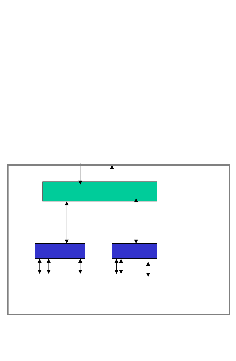
The MAC ASIC
page -2 OmniSwitch Troubleshooting Guide July 2008
The MAC ASIC
There are two different types of MAC layer ASICs:
•Catalina
•Firenze
Catalina
The Catalina basically provides three functions: Media Access Control (MAC) Layer functions, data buff-
ering, and statistics accumulation and storage for each port.
The Catalina provides the interface between Ethernet analog devices (10/100 Mbps and 1000 Mbps) and
the Coronado. The Catalina has a total of thirteen network interfaces, twelve of which support 10/100
Mbps Ethernet through a RMII (Reduced Media Independent Interface) and the thirteenth supports 1000
Mbps. All Catalina ASIC buffer memory is dedicated to providing a smooth stream of data inbound from
the Ethernet ports to the Coronado or outbound from the Coronado to the Ethernet ports.
The Catalina does not contain system-level buffering for storing frames for later transmission. The Coro-
nado Queue Manager provides this function. Catalina packet processing is limited to physical-layer
processing. It does not perform any protocol processing or frame recognition. The Coronado handles these
functions. One or two Catalina ASIC is located on any network interface.
Coronado
Catalina 0
Catalina 1
...
...
12 10/100 ports
12 10/100 ports
XY-BUS
F-BUS
ENI-C-24
OS-7/8XXX
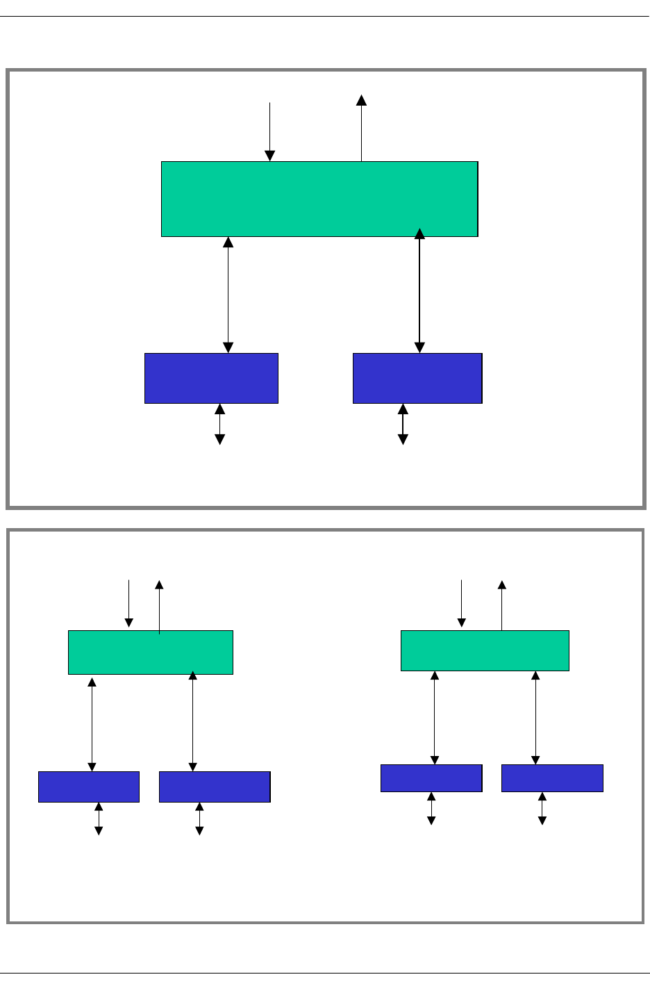
The MAC ASIC
OmniSwitch Troubleshooting Guide July 2008 page -3
Coronado
Catalina 0 Catalina 1
1 Gig Port
1 Gig port
XY-BUS
F-BUS
GNI-U-2
OS-7XXX
Coronado 0
Catalina 0
Catalina 1
Gigabit port 2 Gigabit port 1
XY-BUS
F-BUS
Coronado 3
Catalina 6 Catalina 7
Gigabit port 7 Gigabit port 8
XY-BUS
F-BUS
…
GNI-U/C-8
OS
-
8800
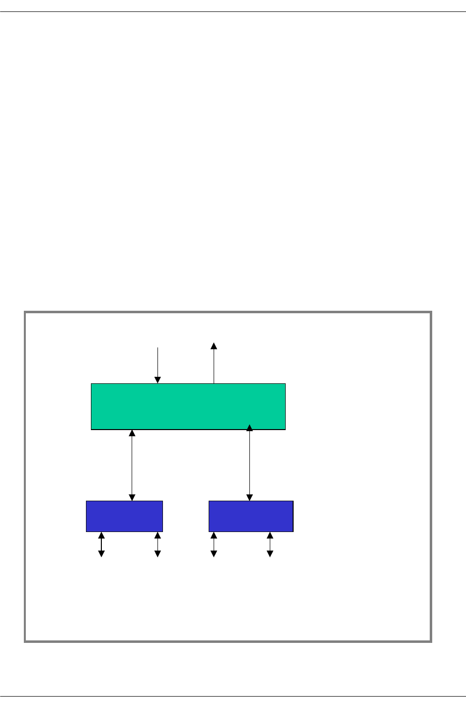
The MAC ASIC
page -4 OmniSwitch Troubleshooting Guide July 2008
Firenze
The Firenze basically provides three functions: Media Access Control (MAC) Layer functions, Data buff-
ering, Flow Control and statistics accumulation and storage for each port.
Firenze handles up to six Ethernet interfaces that can support independently either 10 or 100 or 1000 Mbit/
s throughput using independently either TBI or GMII interfaces.
The Firenze Based GNI is a 1Gbps Ethernet Switching Module for the Falcon system. Two Versions of
the board are configured as below:
•GNI-U12, 12-port fiber Gigabit module equipped with twelve Pluggable SFP Transceivers which can
support short, long and very long haul applications.
•GNI-C12, 12-port copper Gigabit module equipped with twelve RJ45 connector, individually config-
urable as 10/100 or 1000 Base-T.
The Firenze based GNI modules for Eagle OS-8800 are as follows:
•OS8-GNI2-C24, 24-port copper Gigabit module equipped with Twenty four RJ45 connector compati-
ble with cat5 or cat5e minimum cabling specification. Due to the use of Ten-Bit Interface
•TBI between the PHY and Firenze, the ports are limited to 1000BASE-T speed only.
•GNI2-U24, 24-port fiber Gigabit module equipped with Twenty four Pluggable SFP Transceivers.
Coronado
Firenze 0
Firenze 1
...
...
6 Gigabit ports
6 Gigabit ports
XY-BUS
F-BUS
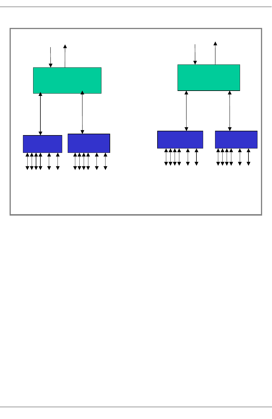
The MAC ASIC
OmniSwitch Troubleshooting Guide July 2008 page -5
The Coronado ASIC
The Coronado ASIC is the centerpiece of this advanced architectural design. While each ASIC performs a
vital function in the overall architecture, the Coronado provides most of the key features like wire-rate L2
and L3 switching and routing.
Coronado features include:
•Classifier and switching ASIC
•Full wire-speed L2/L3
•Provides connectivity for 24x10/100 Mbps ports or 2x1000 Mbps ports
•Up to 64K L3 Table Entries. 64K L2 Entries.
•Four Priority Levels. 2,048 Virtual Queues.
•Flow based QoS with IEEE 802.1Q/p, IP-TOSp or IP-DiffServ
•Up to 4,096 IEEE 802.1Q VLAN support.
•Link Aggregation.
•Port mirroring/monitoring.
6 Gigabit ports 6 Gigabit ports
GNI-U/C-24
OS-8800
Coronado 0
Firenze 0
Firenze 1
XY-BUS
F-BUS
Coronado 3
Firenze 6 Firenze 7
XY-BUS
F-BUS
…
6 Gigabit ports
6 Gigabit ports
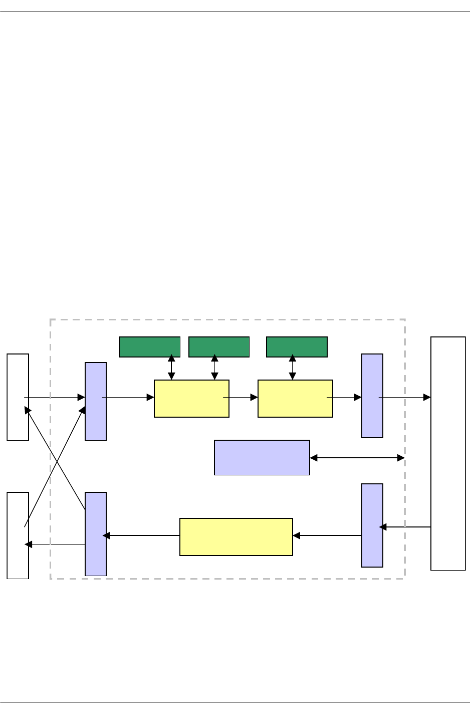
The MAC ASIC
page -6 OmniSwitch Troubleshooting Guide July 2008
The Coronado ASIC contains both Ingress and Egress functions. Ethernet frames flow from the Catalina
through the Ingress Coronado, through the Nantucket switch fabric, then through the Coronado Egress
logic and finally out the Egress Catalina.
Note: Frames always flow through the Nantucket, even if the input and output ports are on the same Coro-
nado ASIC. One or more Coronado ASIC are located on the network interface cards. It is a store and
forward technology meaning that the entire PDU must be received before it is transferred across the fabric
to the egress port. Each Coronado provides 2.4Gbps interface to the backplane.
Coronado has a build-in Hardware Routing Engine known as HRE. This HRE provides the function of
Layer 2 switching as well as Layer 3 routing. Coronado also has classifier logic built-in, which enables the
packet to be classified according to the policies defined.
On the Network Interface cards for OmniSwitch 7XXX, there is one Coronado per NI.
Ethernet switching modules (10/100MB) always have one Coronado for both OmniSwitch 7/8XXX.
OmniSwitch 8800 has four Coronado ASICs (0 t0 3) per NI for all the GNI modules
Coronado is referred to as a Slice. Therefore, the Coronado on a network interface card in a working chas-
sis is referred to by slot and slice number.
Functional Description
HRE
X
Y
B
U
S
_
R
X
Queue
Manager
X
Y
B
U
S
_
T
X
Egress Logic
SPARC
F
B
U
S
_
R
X
F
A
B
R
I
C
SSRAM
S
DRAM0
S
DRAM1
C
a
t
a
l
i
n
a
0
C
A
t
a
l
i
n
a
1
F
B
U
S
_
T
X
BBUS

The MAC ASIC
OmniSwitch Troubleshooting Guide July 2008 page -7
Coronado: The “Brain” of the System
•Provides hardware performance for most features on the OmniSwitch.
•Involved in both the ingress and egress packet processing.
•Provides a high speed connection to Catalina via the XYBUS. XYBUS is two unidirectional busses
between Catalina and Coronado. XYBUS is 1.24 Gbps.
•Provides 2 high speed connections to the fabric via the FBUS. An FBUS is two unidirectional busses.
•Provides connections to all the ASICs via the management BUS known as BBUS. BBUS is a bidirec-
tional bus used for Management purposes for NI/CMM communications.
Coronado Specifications
•On Chip 170 KB memory (for FIFOs, Queue Manager and ingress buffering)
•Off Chip memory
•SSRAM: 2Mbytes for pseudoCAM entries (128k)
•64k Layer 2 entries (32K for SA and 32K for DA)
•64k Layer 3 entries
•SDRAM-0: 32Mbytes (Part of it is allocated to HW for HRE header cache, Priority Description Index
etc; remaining is available to Software)
•SDRAM-1: 16Mbytes used for the buffers
•V7 Sparc Core running at 143 MHz—integrates cache memory:
- 8KB for instruction
- 4KB for data (sending on BBUS)
- 2KB for packet cache (for faster access to the packet being processed)
•Provides software support for distributed features. Executes the Operating System on each NI. The
configuration of the Coronado is updated by the CMM.
•The Coronado ASIC supports 2048 queues and 4096 buffers. Buffers are organized in two lists:
- List 1: 4096-128=3968 buffers of 2048 bytes
- List 2: 128 buffers of 16384 bytes for Jumbo Frames
•Coronado keeps track of the buffer utilization on per port basis. A per port threshold triggers the
802.3x pause frame.
•Each queue can be assigned:
- An egress physical port or can be designated as a multicast queue
- A pay that determines the right to transmit a certain amount of data
- A priority (4 for unicast - 4 for multicast)
- A maximum length, which is the maximum number of packets that can be queued

Queue Driver Interaction
page -8 OmniSwitch Troubleshooting Guide July 2008
•Queues are maintained by the software module known as the Queue Driver runs on each NI. It provides
the interaction to other software modules in the Falcon/Eagle product to create/modify/delete/manage
all the queues in the system. This module provides debugging information required for the queues and
maintains the statistics. This module maintains all the information required about all the queues on the
Coronado.
Software Module Interaction
•Coronado ASIC interacts with the following software modules:
•Ethernet Driver
•Queue Dispatcher
•NI Supervision Task
•L2 Source Learning
•L3 Manager/IPMS
•QoS Manager
•Link Aggregation
Queue Driver Interaction
The interactions of each module with Queue Driver is as follows:
Ethernet Driver
Ethernet driver on the CMM is responsible for initializing the Coronado when the system comes up, when
a board is inserted/removed from the slot and when a link goes up or down. On the initial initialization the
Ethernet driver on the CMM should send the slot configuration information for all the slots in the system.
The initial configuration sent by the Ethernet driver has the following information for each of the slots
present in the system:
•Number of default queues per port (this is user configurable. The default value is 4 queues per port.
The CLI command to change this is provided by the Ethernet driver. The value of this parameter can be
either 2 or 4. This value is configurable per slot).
•Port configuration for each of the ports in the slot.
•Based on the port configuration the Queue Driver will assign ports.
Queue Dispatcher
The interaction between the queue driver and the queue dispatcher is mainly for freeing a default queue
associated with a port when the port goes down and to modify the priority of a queue. When the queue
driver gets the link down event for a port a message is sent to the queue dispatcher task. The Queue
dispatcher performs the appropriate steps to free the queue and updates the status of the request by send-
ing a message back to the queue driver. The queue driver maintains statistics about the number of queues
in an error state. When the priority of a queue needs to be changed, a message is sent to the queue
dispatcher.

Queue Driver Interaction
OmniSwitch Troubleshooting Guide July 2008 page -9
NI Supervision
Queue driver sends the task initialization and task ready messages to the NI Supervision task just before
receiving any configuration information from the CMM Ethernet driver. This indicates to the NI supervi-
sion task that the queue driver task is ready.
Source Learning
L2 Destination Address Manager is a software block of Source Learning. It is responsible for destination
MAC address learning and programming the L2 destination address pseudo cam on the Coronado.
L3 Manager/IPMS
The L3 Manager/IPMS Module interacts with the Queue Driver to get the default queue associated with a
physical port associated with the pseudo cam entry.
QoS Manager
The interaction between the QoS Manager and the Queue Driver can be under following conditions:
Destination MAC Learning
When a L2 destination MAC address is learnt, the source-learning module notifies the QoS Manager of
the MAC learnt. QoS Manager checks to see if any QoS Policy is configured for the MAC address. If a
QoS Policy is present and if it requires that a new queue be created for the flow, then the QoS Manager
requests the Queue Driver for a new queue with the appropriate policy requirements for the queue. The
Queue driver will allocate a new queue if a free queue is available. Depending on the policy, the QoS
Manager can request for multiple consecutive queues. In this case, the QoS Manager can request for
number of consecutive default queues and later modify the parameters of the individual queues
L3 Pseudo CAM Learning
When a L3 address is learned, the L3 manager module notifies the QoS Manager of the L3 address learnt.
QoS Manager checks to see if any QoS Policy is configured for the L3 address. If a QoS Policy is present
and if it requires that a new queue be created for the flow, then the QoS Manager requests the Queue
Driver for a new queue with the appropriate policy requirements for the queue. The Queue driver will allo-
cate a new queue if a free queue is available. Depending on the policy, the QoS Manager can request for
multiple consecutive queues. In this case the QoS Manager can request for number of consecutive default
queues and later modify the parameters of the individual queues
QoS Policy Change
When a QoS Policy changes, the QoS Manager is notified. QoS Manager checks to see if any flows exist
for the policy and if a new queue was allocated for it. If so, it requests the Queue Driver to modify certain
parameters of the queue with the appropriate queue parameters. Only certain parameters of a queue can be
modified on the fly.

Queue Driver Interaction
page -10 OmniSwitch Troubleshooting Guide July 2008
QoS Policy Deleted
When a QoS Policy is deleted, the QoS Manager is notified. It checks to see if there are any flows associ-
ated with the QoS Policy. The queue id for all the pseudo cam entries associated with the policy should be
reprogrammed with a default queue and the existing queue has to be freed. The QoS Manager requests the
Queue Driver to free the queue.
L2 destination MAC Aged/Deleted
When a L2 destination MAC address is aged/deleted from the pseudo cam, the QoS Manager is notified.
QoS Manager checks to see if any QoS Policy was configured for this MAC address. If so it checks to see
if the queue associated with this MAC is used for any other flows. If not the QoS Manager requests the
Queue Driver to free the queue.
L3 PseudoCAM Entry Aged/Deleted
When a L2/L3 pseudo cam entry is aged/deleted, the QoS Manager is notified. QoS Manager checks to see
if any QoS Policy was configured for this L2/L3 flow. If so it checks to see if the queue associated with
this flow is used for any other flows. If not the QoS Manager requests the Queue Driver to free the queue.
Request to Free Queues Sent to QoS Manager
Request for freeing some qos queues, when there are no sufficient queues available for allocating for link
aggregation, is sent to the QoS.
Link Goes Up/Down
When a link goes up or down the qos requests for freeing/adding the QoS queues associated with those
ports if any policies exists on those ports.

Link Aggregation
OmniSwitch Troubleshooting Guide July 2008 page -11
Link Aggregation
Link Aggregation feature allows software to aggregate a set of ports (not necessarily contiguous or on the
same Coronado) into a group. Each port is referred to as a channel that can carry some bandwidth. This
feature requires that all the queues associated with all the ports in the group to be contiguous. Events
resulting in Link Aggregation and Q driver interaction may be for the creation and deletion of link aggre-
gation group.
Coronado Tables
Coronado maintains two different kinds of tables:
•Layer 2 Tables
•Layer 3 Tables
Layer 2 Tables
•64,000 pseudo CAM entries are split in 2 tables:
•L2-Source Address (L2-SA) Table containing
•VLAN membership (GID)
•Value (MAC address)
•2-L2-Destination Address (L2-DA) Table containing
•VLAN Membership (GID)
•Value (MAC address)
•Destination Queues to use (QID/ReQID)
•Priority Description Index (PDI) containing Internal Priority
•Request for additional L3/L4 lookup and use of resultant QID
Layer 3 Tables
•64,000 pseudo CAM entries. A single table is maintained for all the Source and Destination L3
addresses. Entries are based on selected lookup mode.
•Now, the primary functions and the architecture of Source Learning, Hardware Routing Engine (HRE)
and QOS functional blocks will be discussed.

Source Learning
page -12 OmniSwitch Troubleshooting Guide July 2008
Source Learning
Coronado ASIC is a ingress classifier that performs Layer 2 hardware table lookups to the VLAN Id corre-
sponds to the incoming packets.
In principle, Coronado will perform a Layer 2 Source Address (L2 SA) lookup based on whether the
incoming port is a tagging or non-tagging port, a copy of the packet is re-queued to the Source Learning
queue for processing if the lookup fails. Coronado then performs a L2 Destination Address (L2 DA)
pseudoCam lookup to find out the destination Queue Identifier (QID) to queue the packet to the egress
port. Coronado always put the packet in the flood queue if the L2 DA lookup fails until Source Learning
updates DA entry.
Source Learning is responsible for managing (creation, update, deletion) MAC address entry in Layer 2
pseudoCam hardware source and destination address tables and communicating other interested entities
(QOS, Layer 3,...) regarding the new learned mac address.
By taking advantage of the Coronado hardware processing capabilities, Source Learning is distributed on
every Coronado in the switch. The processing load is spread among all the Coronados, thus performance is
increased. On the other hand, Address Learning is independent from the presence of CMM.
Each Coronado sends an event to the CMM to update the filtering database on CMM whenever there is an
operation on its Source Address pseudoCam. As a result, each Coronado has a local view of layer 2
pseudoCam information of its own slot/slice, and the software filtering database on the CMM has global
view of the layer 2 pseudoCam information in the switch.

Hardware Routing Engine (HRE)
OmniSwitch Troubleshooting Guide July 2008 page -13
Hardware Routing Engine (HRE)
This feature is responsible for managing the Coronado HRE resources that perform IP and IPX packet
classification and forwarding.
This functionality employees five principal Coronado resources—header cache entries, pseudo-CAM
entries, hash function registers, modes, and router MACs.
Header Cache Entries
Contain the information necessary to modify and forward a packet, including both modifications to the
packet’s content and Coronado-specific handling information.
Pseudo-CAM Entries
Used for classifying traffic based on its IP or IPX address information and, in the case of IPMS, some
layer 2 information. The HRE does not have Content Addressable Memory (CAMs) for storing address
information. Instead it uses hash tables (called pseudo-CAMs) that can be interpreted by the Coronado.
The entries in these hash tables contain both address information to be matched against the content of the
packet and the resulting action to take when the entry is matched. There are two basic actions:
•Forward the packet using information in a specified header cache entry.
•Perform another refining lookup to match additional, more specific address information.
Hash Function Registers
Used to define the hash algorithms used to lookup pseudo- CAM entries in the hash tables.
Modes are used to govern the classification process:
Mode 0 For IP entries, full IP destination host address. For IPX, destination
network number.
Mode 1 For IP entries, full IP destination and source host addresses. For IPX,
not used.
Mode 2 For IP entries, full IP destination and source host addresses and TCP/
UDP destination port number. For IPX, IPX destination network
number and IPX destination node.
Mode 3 For IP entries, full IP destination and source host addresses and TCP/
UDP destination and source ports. For IPX, not used.
Mode 4 Only used for IP firewalling. Uses same matching criteria as Mode 3.
Mode 5 Only used for IPMS. Matches full IP destination and source host
addresses, source port number, and source VLAN identifier.
Mode 6 Unused.
They identify which hash table is to be used, which hash function is to be used, and what portions of the
address information in the packet are required to match that in the pseudo-CAM entry. There are seven
modes, each represented by a configuration register. Some of these have special meaning. For example,
mode 0 is the initial mode. Each packet classification starts in this mode. Each pseudo-CAM entry that has
as its action to perform another lookup includes a number representing the mode to be used in that subse-
quent lookup.

Hardware Routing Engine (HRE)
page -14 OmniSwitch Troubleshooting Guide July 2008
Router MACs
Helps identify candidate traffic for classification. The HRE only operates on traffic that is identified as
requiring layers 3 and 4 classification. Candidate traffic for such classification must be of the type IP or
IPX and must have its layer 2 destination MAC be a router MAC for this switch or be a bridged MAC that
has been marked for layer 3 and 4 classification or be an IP multicast MAC. This feature only manages
router MACs. Bridged MACs are managed by layer 2 source learning and IP multicast MACs are
managed by the IP multicast routing and switching (IPMS) feature. These resources are used to imple-
ment the forwarding features - IP and IPX unicast routing, IP multicast routing and switching, bridging
based on layers 3 and 4 information, and IP firewall.
IP and IPX Unicast Routing
When an IP or IPX packet is addressed to a router MAC on the switch, the HRE attempts to classify the
packet using data in the pseudoCAMs. If a match is found, the packet is updated and forwarded using
information from header cache entry. If not, the packet is routed using one of two default header cache
entries (one each for IP and IPX). These are configured to route the packet to either the IP or IPX soft-
ware process on the Coronado.
IP Multicast Routing and Switching
When an IP multicast packet is received, the HRE attempts to classify the packet using data in the pseudo-
CAMs. If a match is found, the packet is sent to egress processing which uses the information stored in the
header cache entry as well as other Coronado tables updated by the IPMS feature to forward the packet. If
no match is found, the packet is forwarded to the IPMS software process on the Coronado.
Bridging Based on Layer 3 and 4 Information
When an IP packet is addressed to a MAC with an entry in the layer 2 DA pseudo-CAMs that indicates the
treatment for the bridged packet depends on layer 3 and 4 information, the HRE attempts to classify the
packet using data in the pseudo-CAMs. If a match is found, the packet is not modified but is forwarded
using information from the header cache entry. If a match is not found, the packet is forwarded to the QoS
software task.
IP Firewall
The HRE has the capability to match TCP traffic with particular flag bits set. This capability can be
enabled based on the destination MAC of the packet, the destination host IP address of the packet, or the
final matching pseudo-CAM entry for a flow. When this is enabled and the packet has the appropriate flag
bit set, the packet is forwarded normally and a copy is sent to the IP software process on the Coronado.

QoS/Policy Manager
OmniSwitch Troubleshooting Guide July 2008 page -15
QoS/Policy Manager
Policies describe subsets of traffic, and what to do with that traffic. The Policy Processor determines what
policies are enforceable, and organizes the policies into lists used by the classifier. QoS uses the same
policies for Prioritization/Shaping, IP Filtering (ACLs), NAT, and IPMS Filtering. Using the same poli-
cies for all these functions has several benefits:
•All policies affecting the traffic are centrally located
•All policies share the same expressive power.
•Traffic is only classified once in a single routine.
•A single GUI application (PolicyView) can manage policies, and subsequently manage all these facili-
ties.
QoS determines which policies can possibly be matched on a switch, and constructs lists for each of the
L2 and L3/L4 classifiers. If a policy contains classification criteria that cannot be met by the hardware,
QoS logs a message indicating what parameters could not be matched, and the policy is not used in classi-
fication.
The QoS manager calls the classifiers in response to messages from source learning, routing, and IPMS.
QoS uses lists maintained by the QoS Policy Processor to make it’s decisions.
Coronado Egress Logic
•Coronado receives a packet from the Fabric through FBUS destined for a Queue existing on the same
Coronado. There is not a lot of egress Logic to be performed for Unicast packets.
•If the destination port is untagged, 802.1Q tag is stripped and the packet is forwarded to the destina-
tion port.
•Coronado limits the flood bandwidth or Flood and Multicast Bandwidth per port. Bandwidth limita-
tion is based on dual leaky bucket algorithm. Packets are credited in chunks of 64 bytes every
130.98us.
•IPMS processing is completed by the Coronado on the egress, started by the HRE.
•Updates IPMS routed packets- decrements TTL and rewrite MAC-DA.
•Duplicates the packet whenever needed. Multicast packets are duplicated by the software on a Q-Tag
link.

The Fabric Architecture
page -16 OmniSwitch Troubleshooting Guide July 2008
The Fabric Architecture
ASIC provides the switching fabric functionality for the OmniSwitch Series. The switching fabric does no
frame processing and does not distinguish between L2 switching and L3 routing. The fabric provides only
a limited amount of FIFO buffering for each port, flood and the multicast queue. Most of the system buff-
ering is in the Ingress Coronado’s Queue Manager. The backplane fabric is a bit-sliced ASIC. Each chip
contains a control element and data buffering and queuing logic. All fabrics in the primary fabric operate
in a lock step under control of the “master” fabric. The fabric provides one unicast queue for each physi-
cal port on the OmniSwitch Series plus broadcast and multicast queues and, inter-processor communica-
tion queues. Switching Fabric monitors the depth of its on-chip queues and provides flow control feedback
to the Coronado ASICs. Switching fabric also generates control messages for each of four priorities to
drive the Coronado bandwidth control. The backplane is wired like a wagon wheel where the fabric card is
the “hub” and the point-to-point backplane connections are the spokes. Each network interface card (NI) is
at the end of a spoke. Each NI is connected to the redundant fabric by an identical but separate set of
connections. For redundancy, each NI slot is wired to both fabric cards by separate traces.
OS7XXX and OS8800 use different Fabric ASICs for the backplane connectivity between all the slots:
•OS-7XXX uses Nantucket ASIC
•OS-8800 uses ROMA ASIC

Nantucket ASIC
OmniSwitch Troubleshooting Guide July 2008 page -17
Nantucket ASIC
The Nantucket ASICs have the following:
•Support for 8 and 16 Coronados only.
•No dynamic queue numbering for each NI slot.
•Fixed eight Nantuckets per Fabric board.
•Maximum of one redundant Fabric board.
The Nantucket software is arranged as:
•Nantucket operational software resides on the CMM.
•Nantucket operational software runs on the UltraSPARC IIe on the CMM.
•All accesses to Nantucket registers is through the PCI bridge and over the Bbus bridges.
•Minimum user interface software is provided for configuring and statusing the Nantucket ASICs.
•Minimum SNMP software is provided for configuring and statusing the Nantucket ASICs.
Additional Nantucket Specifications
•Nantucket Fabric consists of eight Nantucket ASICs for the primary Fabric in OS-7800 and four
Nantucket ASICs for the primary Fabric in OS-7700.
•Nantucket Fabric consists of eight/four Nantucket ASICs for the redundant Fabric, when running with
a redundant CMM.
•Nantucket uses six SRAM memories, each SRAM is 32 bits wide by 11264 words deep.
•Nantucket has a point to point interface to all Coronados running at 500MHz.
•No packet processing on Nantucket
•Provides very little buffering
•Supports 512 per-port queues
•Supports 1 per-Coronado broadcast queue and 1 intercommunication queue.
•Supports flow control/pay generation for Coronado bandwidth control
•Supports VLAN spanning tree masks
Nantucket supports the following messages:
•Ingress packets w/header
•Egress packets w/header
•Flow control messages
•Bandwidth management control messages “pay.”

Nantucket ASIC
page -18 OmniSwitch Troubleshooting Guide July 2008
Functional Description:
The Nantucket software resides on Chassis Management Module (CMM) and run on the UltraSPARC IIe
processor within the CMM. The Nantucket software communicates to the Nantucket ASIC via the PCI
Bridge and Bbus Bridges. The Nantucket Software has interfaces to the following:
•Primary CMM SDRAM, EEPROM via the UltraSparc IIe PCI Bridge
•Secondary CMM EEPROM via the UltraSparc IIe PCI Bridge
•2 Primary Fabric Board Burst Bus Bridges via the UltraSparc IIe PCI Bridge
•2 Secondary Fabric Board Burst Bus Bridges via the UltraSparc IIe PCI Bridge
•8 Primary Fabric Board Nantucket ASICs via two Burst Bus Bridges
•8 Secondary Fabric Board Nantucket ASICs via two Burst Bus Bridges
•Primary and Secondary Fabric Board Flash and Backplane EEPROM via the Burst Bus Bridge.
Data Flow
The following describes the data flow of unicast, Multicast and IP packets through the major modules of
the Nantucket ASIC:
•Receives serial input from Coronado at 500MHz
•Outputs 4 bit parallel data at 125MHz to the Data Port Input module
•Separates the 4 bit parallel input from the XyPhy input module into data and control streams.
•Send 192 bit data chunks to the Memory Manager module.
•Send chunk present, start of packet (SOP) and coupons to the Packet Chainer module.
The Packet Chainer Module performs:
•Processes incoming packet chunks from the Data Port Input module.
•Sends SOP, chain ID and packet type (unicast or multicast) to the Queue Manager module.
•For unicast and uP packets, decode the QID and pass the QID to the Queue Manager module upon
EOF.
•For multicast packets, decode the QID and pass to the Queue Manager module upon EOF.
The Queue Manager Module performs:
•Enqueues packets controlled by the Packet Chainer module, links the chain to the unicast queue or
copy the packet head pointer into multiple multicast fifos.
•Dequeues packets controlled by the Calendar Manager module from one of 512 unicast queues or one
of 16 multicast queues.
•Generates four paycheck messages for each physical port every 32.7 us denoting if measured queue
depth is above or below the pay threshold values.
•Generates a per physical port coupon message every 2us to the ingress Coronado denoting if measured
queue depth is above or below the coupon threshold value.

Nantucket ASIC
OmniSwitch Troubleshooting Guide July 2008 page -19
Calendar Manager Module
•Generates dequeue requests to the Queue Manager module with priorities of uP packets highest, multi-
cast packets second highest and unicast packets lowest.
•Request dequeues from 512 unicast queues by sending a QID.
•Request dequeues from uP queue by sending FIFO ID.
•Calendar for a Coronado with 24 10/100 ports would be: 0,1,2,3,4,5,6,7,8,9,...,23.
•Calendar for a Coronado with 12 10/100 ports and 1 Gigabit port would be:0,1,0,2,...9,0,10,11,12.
•Memory Manager Module
•Interfaces between the six SRAMs (32x11264 words) and the data ports.
•Assigns packet chunks to free buffers.
•Queues buffer pointers in per-port queues.
•Returns free buffers to the free buffer list.
Data Port Output Module
•Combines data and control streams into nibble wide output.
•Transmit to the XyPhy Output module (B09) at 125MHz.
•XyPhy Output Module
•Serializes nibble wide input from the Data Port Output module (B08).
•Transmits serial output at 500MHz.
Nantucket Redundancy
•The Redundant/Secondary Fabric Board Nantucket ASICs initialize at startup and initialize prior to
any Primary Fabric Board failures.
•The Nantucket software monitors and detect Primary Fabric failures which includes Fbus link failure,
no frames received, no backpressure/paychecks received, no calendar pointers are updated, etc.
•When a failure condition is detected that requires switchover to the Secondary Fabric, the Nantucket
software writes to a register to cause the primary/secondary signal to the Coronado to transition to’0’.
•This will simulate to the Coronado the Primary Fabric being removed.
•The Coronados detect the primary/secondary deasserted signal and perform the failover procedure.
•The method allows all Coronados to switchover at that same time.
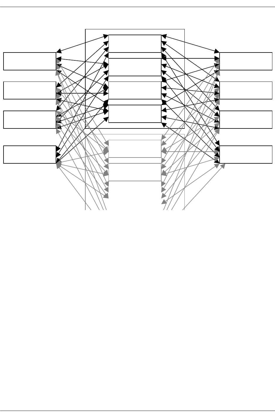
Nantucket ASIC
page -20 OmniSwitch Troubleshooting Guide July 2008
N
antucket 0
N
antucket 1
N
antucket 2
N
antucket 3
N
antucket 0
N
antucket 1
Coronado
Coronado
Coronado
Coronado
Coronado
Coronado
Coronado
Coronado
Primary CMM
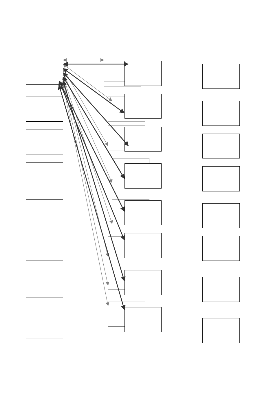
Nantucket ASIC
OmniSwitch Troubleshooting Guide July 2008 page -21
N
antucket 3
Seco
n
da
r
y
C
MM
OS-7700
Backplane
N
antucket 2
N
antucket 3
N
antucket4
N
antucket 5
N
antucket 6
N
antucket7
Coronado
Coronado
Coronado
Coronado
Coronado
Coronado
Coronado
Coronado
N
antucket 0
N
an
tucket 1
N
antucket 0
N
antucket 1
N
antucket 2
N
antucket 3
N
antucket 4
N
antucket 5
N
antucket 6
N
antucket 7
Coronado
Coronado
Coronado
Coronado
Coronado
Coronado
Coronado
Coronado
Every Coronado is connected to Primary CMM and secondary CMM with all the
N
antuckets. Maximum of 16 connections to Coronado can exist
on each Coronado.
OS-7800 Architecture

Roma
page -22 OmniSwitch Troubleshooting Guide July 2008
Roma
Each Fabric Module is based on two Roma ASICs, which provide the store-and-forward switching fabric
function for the OS-8800 product. The Roma ASIC is bit-sliced; a group of eight Roma ASICs operates
together as a single synchronized fabric. A total of four Fabric modules are required to build a complete
Fabric in the OS-8800 system. An optional fifth Fabric Module may be used for fabric redundancy. In a
group of eight Roma ASICs, there is always one master and seven slaves. These ROMA ASICs are located
on Switch Fabric Modules at the rear of the chassis.
The SFM module consists of two identical fabric slices. Each fabric slice consists of one Roma ASIC.
There is also a bridge FPGA that interfaces the on-board ASICs to the CMM modules through the BBUS
management bus. Major SFM elements are the following:
•Two Roma ASICs
•One Bbus FPGA
•One DC-DC Converter
•Reset Circuitry
•Clock Circuitry
•Power Fail Detect/ Uncontrolled Power Failure Circuitry
Following is the fabric hardware environment:
•The Roma-based fabric always operates using a set of eight Roma ASICs
•The eight operational Roma chips must be numbered according to bit slice position
•An additional two hot-standby Roma ASICs can provide for fabric redundancy
•Two Roma ASICs per separately insertable card, five fabric slots per Eagle chassis
•64 fabric ports per Roma ASIC (supports up 64 Coronado ASICs or 16 Calais ASICs)
•Support for any architecturally coherent combination of Coronado and Calais ASICs
•512 logical ports per system corresponding to Roma queues (maximum)
•384 physical ports per system corresponding to Roma unicast queues (maximum)
•64 IPC queues per system (maximum)
•64 multicast FIFOs per system (maximum)
•24 physical ports per NI slot (maximum)
•Calendar mechanism for dequeuing unicast and multicast frames
•Multicast (VLAN) vector table for multicast propagation control
•Greater than 500 MHz raw link rate per fabric port (each direction)
•2.4 Gbps per Coronado
•10 Gbps per Calais (or equivalent replacement hardware)
•Four paycheck levels to support flow prioritization

Roma
OmniSwitch Troubleshooting Guide July 2008 page -23
•Separate paychecks for multicast
•Generates ingress coupons, receives egress coupons for backpressure capability
•Ingress coupon generation period: ~2 microseconds
•Paycheck generation period: 32.125 microseconds
•The BBUS provides access to individual Roma chips based on a chip index number
Functional Description
The Roma Driver’s primary responsibilities are to initialize, monitor, and support the central component
of the Eagle switch/router’s switching fabric system: a set of up to ten Roma ASICs, with exactly eight
operational during fabric operation.
The operational fabric consists of 8 slices for each connected Coronado ASIC (these 8 slices correspond
one-to-one with the 8 operational Roma ASICs). The fundamental logic for packet switching through the
fabric is contained in 5 basic architectural components:
•Link Control
•Calendar
•Multicast Vector Table
•IPC Mapping
•Flow Control
Link Control
This establishes that Roma-Coronado communication is working on each link and is aligned across the 8
fabric bit slices.
Calendar
Each fabric port has a calendar of unicast and multicast egress destinations for the corresponding Coro-
nado. There is a limited ability to designate dequeuing frequency for some destinations, affecting the
egress bandwidth allocated to destinations. During a given cycle of the Primary Cycle, a single calendar
entry for each fabric port is processed (in a specified order). During other cycles, other calendar entries are
processed. IPC packets are given absolute priority, so there are no calendar entries for IPC.
Multicast Vector Table
Indicates multicast domain membership for fabric ports. On fabric ingress, frames are put into a given
fabric port’s multicast FIFO based on this vector.
IPC Mapping
On ingress, Coronado IPC QIDs are identified based on agreed upon values (for Roma the values are
selected from offsets 12 through 15). On egress, an internal Roma table maps IPC QIDs to fabric ports
(one-to-one).

Roma
page -24 OmniSwitch Troubleshooting Guide July 2008
Flow Control
Coupon and paycheck thresholds are set for unicast and IPC queues (multicast is limited by Coronado for
fabric ingress). These thresholds are used to generate ingress backpressure and paycheck messages. Each
Roma ASIC participating as an operational bit slice is responsible for 2 NIs according to the scheme: bit
slice n is responsible for NI slots 2(n+1) and 2(n+1)-1. Bit slices are zero-based (0 - 7); NI slots are one-
based (1 - 16).
In order to support basic system operation, the Roma driver must maintain the correct destination port
mapping on the Roma ASIC chips, including any required multicast and IPC port mapping; appropriate
internal flow control thresholds should be maintained as well. These form a small but significant part of
the initialization process and the Roma driver needs to adapt in case of changes to NI slot configuration.
However, the high level sequencing and selection of Roma Driver activity is mostly a function of a set of
external events, most of which can be termed “hot swap” events. The following 10 scenarios represent
high-level states for the Roma Driver which correspond to its handling of some kind of major.
Initialization
This state is entered when the Roma Driver is first spawned as a task on the primary CMM. Early on, the
fabric slot and NI slot configuration must be completely determined to effectively program the Roma
ASICs. An overview of the ASIC setup follows:
•Bit Slice oriented setup - includes programming chip IDs and master chip selection.
•Fabric Port setup - includes calendar, flow control, and multicast vector setup
•Synchronizing Roma chips - includes starting primary cycle and timer resets
•Manual link acquisition - verify that all links are up, includes retries
•Automatic HW recovery mechanism setup - includes link acquisition and hot swap
•During switch operation, this is the state that the Roma Driver will be in the vast majority of the time.
Remaining in this state implies there are no changes to: physical Fabric slot configuration, NI slot
configuration, the primary CMM slot, or detected framing errors. Processing in this state consists of an
infinite loop where the following tasks are performed:
•Respond to interrupts and use low intensity poll for backup
•Check messages for updates to multicast vector and board changes
•Synchronize the multicast vector shadow table when 2 CMMs are present
•Maintain statistical counts and rates
Fabric Slot Insertion
This state assumes that four operating fabric slots are currently occupied. The state is entered when a fifth
fabric card is inserted into the remaining available slot. This card should not disturb the operational fabric,
and it will assume the role of redundant fabric card.

Roma
OmniSwitch Troubleshooting Guide July 2008 page -25
Fabric Slot Extraction
This state assumes that there are five fabric slots occupied, with one fabric card serving as the redundant
card. Roma Driver will have already set up the operational Roma chip set to use built-in hot swap
handling. Upon extraction of fabric card, most of the hot swap handling is done by Roma ASIC logic. The
performs the following tasks when a fabric card is removed:
•Recover the new fabric slot set state since the operational fabric may change.
•Report fabric slot states to Chassis Supervision.
•Change hot swap settings on the master since a standby slot is no longer present.
•On operational fabric set changes, update flow control settings.
NI Slot Insertion
When a new NI card is inserted, Roma Driver will attempt to disturb existing fabric traffic as little as
possible. The following tasks are performed: Remove perpetual coupons for NI.
Setup Calendars and Flow Control for New NI
•Restart Calendar Manager.
•Enable transmit and take internal blocks out of reset for NI.
•Acquire links to all Coronados on the NI.
NI Slot Extraction
When an NI card is extracted, Roma Driver performs the following tasks:
•Set perpetual coupons to drain traffic for NI.
•Disable transmit and put internal blocks in reset for NI.
•Remove auto link acquisition mechanism for NI.
CMM Takeover and Hot Swap
Following a good takeover or CMM hot swap, the primary objective of the Roma Driver is to disturb the
Roma ASICs as little as possible. If the takeover results in an irrecoverable fabric-related failure, the
driver attempts to detect this condition and execute a “reload all” to the chassis. The following tasks are
performed:
•Recover the new fabric slot set state since it is unknown to the secondary driver.
•Monitor the Roma ASIC registers to detect fatal error condition.
•Send reload all message to chassis supervision if fatal error detected.
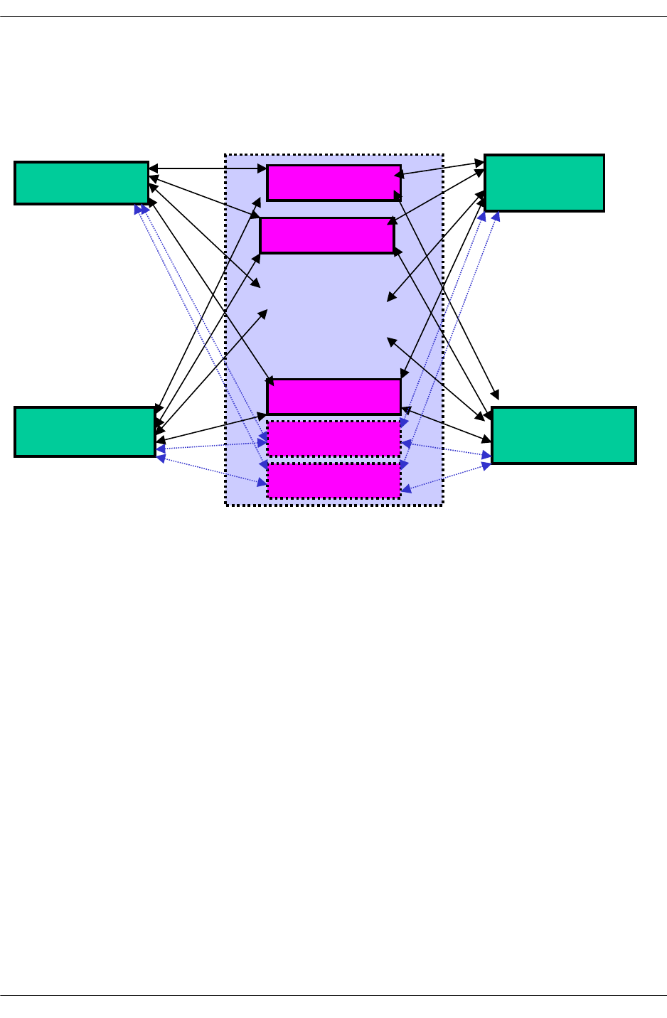
Chassis Management Module (CMM)
page -26 OmniSwitch Troubleshooting Guide July 2008
Framing Error
The Framing Error event represents an event where the Roma ASIC detects an error in a packet header on
ingress. Since this will potentially corrupt the buffer system, a free list rebuild is required when this is
detected.
Chassis Management Module (CMM)
Chassis Management Module (CMM) controls the major functionality and synchronization between two
different components in the distributed architecture. The main responsibilities of the CMM for both
OS7XXX and OS8800 are the same:
•Booting up all the modules in the chassis.
•Downloading the customer specific configurations on the NI.
•Synchronization of the fabric modules
•Power distribution
•Switch diagnostics
•Important availability features, including redundancy (when used in conjunction with another CMM),
software rollback, temperature management, and power management.
•Providing access to the switch through Command Line Interface (CLI), Web management and SNMP
•Provides an out of band Ethernet Management Port (EMP)
ROMA 0
ROMA 1
ROMA 7
ROMA 8
ROMA 9
Coronado
Coronado
Coronado
Coronado
Up to 64
Coronado
ASICs can
Be connected to
ROMA
.
.
.
.
Total of 8
ROMAs are
active at a
time
OS-8800 Switching Fabric

Chassis Management Module (CMM)
OmniSwitch Troubleshooting Guide July 2008 page -27
OS7000 CMM
The CMM for OS7000 contains the following:
•System Processor
•Ultra Space 11e (400MHz)
•64MB SDRAM Memory
•Switching Fabrics
•4 Switching fabrics, Nantucket, in OS-7700
•8 Switching fabrics, Nantucket, in OS-7800
•Management
•DB-9 console/modem Port
•RJ45-Out of Band 10/100 LAN Port
•Reset Switch
•Hot Swappable
•Up to 2 CMMs per chassis
•Management redundancy
•Switching Fabric Redundancy
OS8800 CMM
The CMM for OS8800 contains the following:
•System Processor
•Ultra Space 11e (400MHz)
•64MB SDRAM Memory
•Management
•DB-9 console/modem Port
•RJ45-Out of Band 10/100 LAN Port
•Reset Switch
•Hot Swappable
•Up to 2 CMMs per chassis
•Management redundancy

Chassis Management Module (CMM)
page -28 OmniSwitch Troubleshooting Guide July 2008
Functional Description of CMM
Software and Configuration management is implemented in such a way to provide the operator with:
•Flexibility
•Resiliency
•And to minimize the service interruption during the update of a network.
•2 Software versions are stored into flash:
•1 working version: operational release, used for upgrades.
•1 certified version: operator validated trusted release.
•Automatic rollback from the working version to the certified version in case of failure of the working
version.
•Possibility to certify a version when the operator has considered its behavior acceptable
•All of the files making up the “working” software release must be contained in “/flash/working” direc-
tory.
•All of the files making up the “certified” software release must be contained in “/flash/certified” direc-
tory.
•The “boot.params” file stored in “/flash” is the configuration file that contains the system boot parame-
ters as well as the Image Rollback variables. The two software releases use the same boot parameters
and Image Rollback variables.
•New software version can be activated by loading the images in “/flash/working” and rebooting the
switch in working directory using the command “reload working no roll-back timeout”
•A running “working” version can be certified any time after the “working” version is loaded and veri-
fied.
•The configuration file of a certified software version cannot be modified while working with “certi-
fied” version.
•If the working version is certified and the switch is rebooted or reboots for any other reason, it will
boot up in the new certified version.
•If the working and certified versions of code as well as configurations are completely synchronized the
switch will boot up in certified directory but the running directory will be set to “working”. This flexi-
bility allows to modify configurations and save them. Certification of the new configurations will be
required to save the configurations in certified directory.
CMM Software Startup Process
CMM startup process consists of the following steps:
•Boot ROM
•Vx Works Flash File System
•MiniBoot

Chassis Management Module (CMM)
OmniSwitch Troubleshooting Guide July 2008 page -29
AOS
Boot ROM
•Sparc Processor executes the Sparc Boot ROM code from flash Memory in the protected memory.
•Performs minimum diagnostic tests of the Sparc Processor
•Verifies memory used by Sparc Processor is fine
•If the diagnostic tests find an error, the CMM/Fabric LED will flash to indicate the error and the
processor will retry to boot.
•Boot ROM is not field upgradeable
•Boot ROM image contains:
•Access to Flash File System (FFS)
•Zmodem
•IP stack for EMP Port
•FTP code
Note. Sparc Boot ROM loads the miniboot from the FFS in non protected area of the Flash Memory.

Chassis Management Module (CMM)
page -30 OmniSwitch Troubleshooting Guide July 2008
MiniBoot
MiniBoot contains VX Works Operating system
Performs the following tasks:
•Post Mortem Dump (PMD) Processing to save as much diagnostic as possible in the FFS after a system
crash.
•Hardware diagnostics to determine if all the boards are operational at boot time.
•Image Rollback to select either the current uncommitted (working) software release or the previously-
committed (certified) release.
•Loads the VX Works and passes the control to VX Works
•On error, the miniboot returns to the “Boot ROM” step to allow the user to load new software into the
flash memory.
AOS Start
AOS executes to initialize and start up the system based on the command file which contains:
•Socket Send mechanism: allows sending messages to all CMM and NI processors in the Falcon
•The System services fault management code
•The System services timer facility
•The chassis manager
•Specific services like telnetd, ftpd, cli and snmp
Chassis Manager Component of System Services
•Discover the number of slots, daughter boards, power, temperature and other environmental factors
•Discover the NI boards
•Discover the primary/backup processor status of CMM. If secondary then does not load NI boards and
all processes are started in secondary mode.
•AOS startup code selects the modules to load from the FFS.
•After starting all services System Services Fault Manager acts as a “health monitor” and exchanges
messages with objects in the system to make sure they are working properly.
CMM Reload of NI Module
CMM reloads the NI when:
•CMM Chassis Manger detects a board that does not have the images loaded.
•User enters explicit command to reload the NI.
•CMM fail over happens and the configurations/images were not synchronized between Primary and
Secondary CMM.
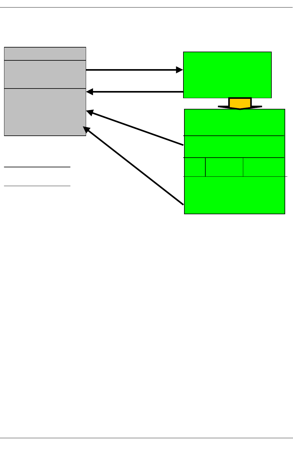
Chassis Management Module (CMM)
OmniSwitch Troubleshooting Guide July 2008 page -31
Miniboot
Load Minimum VX Works
with
File system with PMD
process.
Boot.cfg determination and
Boot ROM
(Hidden & Protected)
MiniBoot
1-Default
2-Backup (Write Protected)
Boot.cfg
………
Contains boot
/workin
g
/certified
/log
/pmd
/flash
/flash/boot
Flash Files
Running Version
Boot
LOAD VXWorks with File System
Chassis Manager
CLI SNMP
HTML
Execute
Read/Write
Read
Read/Write
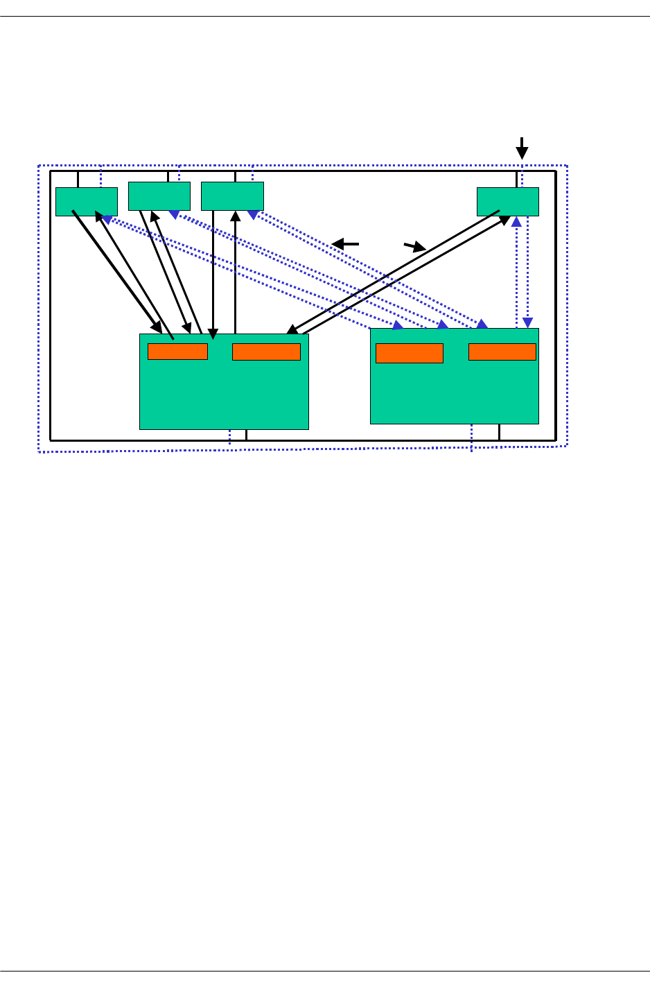
Chassis Management Module (CMM)
page -32 OmniSwitch Troubleshooting Guide July 2008
Overall System Architecture
•Fabric resides on CMM
•Number of Nantuckets can be 4 or 8 depending on the chassis
•Fabric Bus is connected to the CMM as well as to the All NI
•Burst Bus (BBUS) is connected to all the NI from the CMM
•CMM and Switch redundancy fail-over simultaneously
•Up to 16 Coronados can be connected to each Nantucket
Software Management
Command Fos
Configuration Save
Version Activate
Version Restore
Version Certify
Version Query
• Falcon Overall Block Diagram
NI NI NI NI
Primary CMM Board
Nantuck
Secondary CMM Board
………
BBUS
FBUS
…. Secondary
…. Primary
Nantucket
Nantucket
Nantucket
..
..
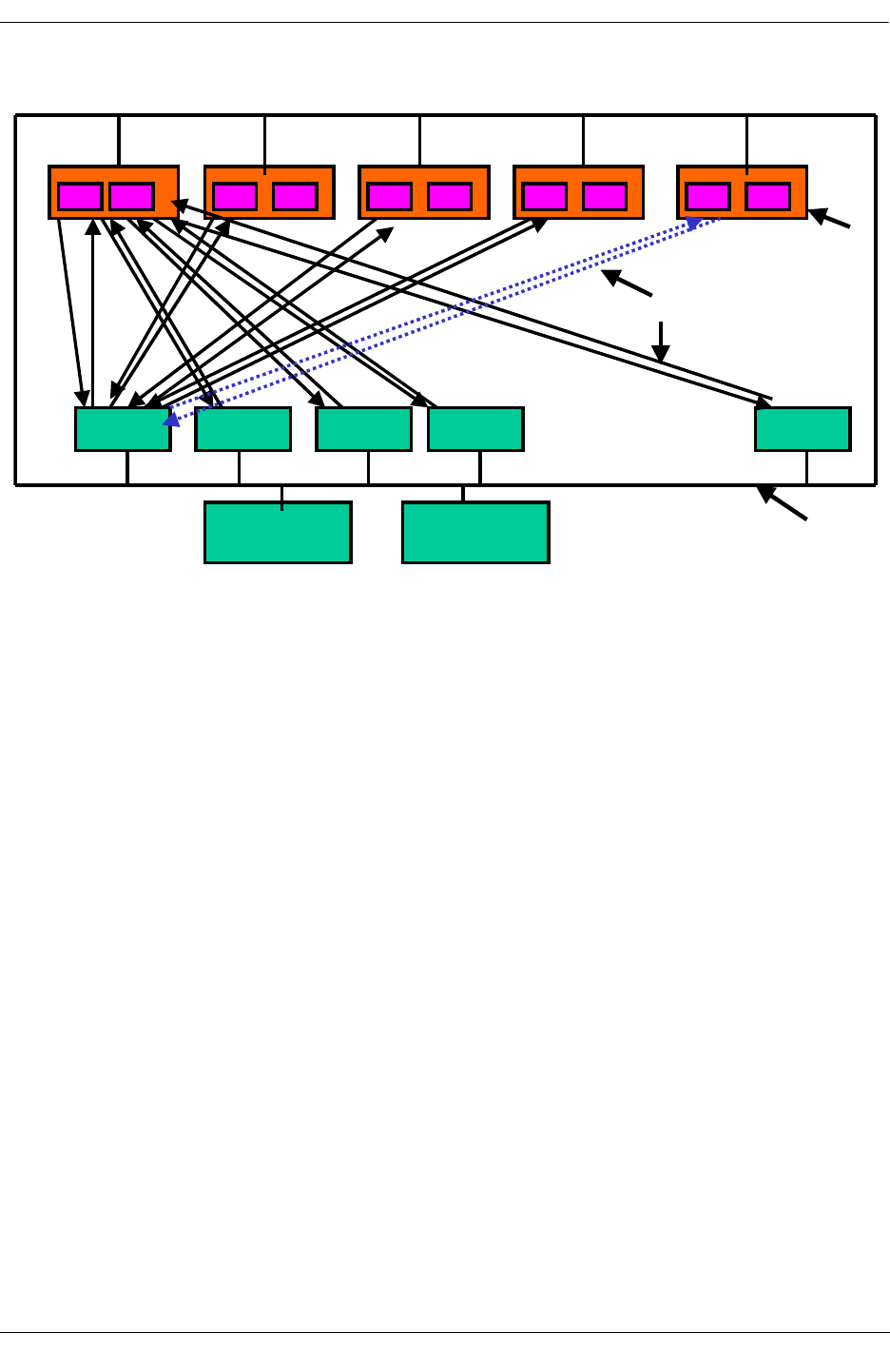
Chassis Management Module (CMM)
OmniSwitch Troubleshooting Guide July 2008 page -33
•Fabric resides independent of the CMM. It resides at the Back of the Chassis. CMM can fail over inde-
pendent of Switching Fabric and vice versa.
•Minimum of 4 Switching Fabric Modules (SFM) with 8 ROMS chips are required to operate. The
additional SFM provides (4+1) redundancy.
•FBUS is not connected to the CMMs
•BBUS is connected to both the CMMs and all the NI in the chassis including the SFMs.
•Up to 64 Coronados can be connected to each ROMA
• Eagle Overall Block Diagram
R
R
R
R
R
R
R
R
R
R
NI
NI
NI
NI
NI
….
CMM CMM BBUS
Fabric Boards
FBUS
…. Secondary
…. Primary
Redundant Fabric Module

Packet Walk
page -34 OmniSwitch Troubleshooting Guide July 2008
Packet Walk
Packet Walk Principles
•All switching and routing is performed on the Ingress side of the switch. There are no address lookups
made on the Egress side.
•The Coronado combines the L2 switching and L3 routing logic into the same ASIC.
•Data always flows through the Nantucket even if the source and destination ports are on the same
Coronado.
•As indicated the “switching fabric” functionality is provided by Nantucket ASICs. The Nantucket
ASICs set also performs part of the broadcast/multicast processing by sending copies of multicast
packets to each Coronado in the system, and participates in the priority de-queuing logic.
Data Flow Overview
•Data flows in a 10/100 Mbps or Gigabit Ethernet port through the Catalina MAC ASIC and into the
Coronado ASIC.
•The Coronado’s HRE-X (Hardware Routing Engine) performs CAM (Content Address Memory) look-
ups on the source and destination addresses and selects a QID (queue ID) to switch the frame. The
queue selection is based upon L2 or L3 switching/routing criteria plus QoS priorities. The Coronado
ASIC can manage up to 2,048 queues. The Coronado could also queue up some frames for software
processing by the on-chip Sparc CPU for some specific unknown packets, which requires a particular
treatment.
•The Coronado’s Queue Manager then de-queues the frame from the appropriate queue based upon
destination and priority. The frame is output from the Coronado into the Nantucket switching fabric.
•The Nantucket provides minimal buffering and delivers the data to the destination Coronado for Egress
processing. Note that the destination Coronado can be the same Coronado or it can be different.
•The Coronado Egress processing sends the frame to the output port via the Catalina Ethernet inter-
faces. Notice that there is no CAM lookup processing or software processing during Egress. The Egress
processing logic also handles multicast processing in cooperation with the Nantucket.

Specific Packet Flows
OmniSwitch Troubleshooting Guide July 2008 page -35
Specific Packet Flows
Unknown L2 Source, Known L2 Destination
The Catalina ASIC
Packet arrives at Catalina. CRC check done. If valid CRC it is put on XYBUS to Coronado
The Coronado ASIC
•The FIFO logic maintains queues of frames from both Xybus interfaces and selects an incoming frame
for HRE processing. This FIFO is done on the on chip memory of the HRE.
•The parser logic selects fields from the frame to identify the protocol and find key values that are used
by the HRE for lookups (DA, SA)
•Coronado does a L2 SA pCAM lookup.
•Coronado determines this is an unknown source due to failed lookup in L2 SA table.
•Since the SA is unknown, there is no pCAM entry, so the default Group ID (VLAN) is used
•If the port is secured then the frame is not forwarded
•The packet is requeued to NI SPARC, for software processing.
•Software creates an entry into the L2 SA table with packet’s mac address and Group ID
•Coronado checks for special L2 DA (ARP, STP, IGMP, IPMS, Router)
•Since the frame is known is present in the L2 DA table for that NI, the L2 entry provides the destina-
tion QID as well as the PDI (internal priority).
•Access the PDI and select internal priority.
•Enqueue the data to the final QID. The QID determines the destination port, priority and bandwidth.
•Coronado’s queue manager dequeues the frame based upon destination and priority. The frame is
output from the Coronado into the Nantucket switching fabric via the FBUS.
Note. The Queue Manager will alternately dequeue the Multicast and Unicast Queues.
The Nantucket ASIC
The Nantucket provides minimal buffering and delivers data to the Coronado for egress processing.
The Coronado ASIC
•The Coronado receives the packet via the FBUS.
•The Coronado then strips the 802.1q header that was added on ingress, if needed.
The Catalina ASIC
•Packet is then put on to the Xybus to be received by the Catalina.
•Catalina Egress will generate the CRC and regulate the packet framing including the interpacket gap.

Unknown Destination
page -36 OmniSwitch Troubleshooting Guide July 2008
Unknown Destination
Known L2 Source, Unknown L2 Destination
The Catalina ASIC
Packet arrives at Catalina. CRC check done. If valid CRC it is put on XYBUS to Coronado
The Coronado ASIC
•The FIFO logic maintains queues of frames from both Xybus interfaces and selects an incoming frame
for HRE processing. This FIFO is done on the on chip memory of the HRE.
•The parser logic selects fields from the frame to identify the protocol and find key values that are used
by the HRE for lookups (DA, SA)
•Coronado does a L2 SA pCAM lookup.
•Coronado determines this is a known source and retrieves Group ID.
•Coronado checks for special L2 DA (ARP,STP,IGMP,IPMS,Router)
•Coronado performs L2 DA pCAM lookup based on Group ID.
•Because the L2 DA is unknown on that NI, the lookup fails.
•Coronado sets the QID to the flood queue, and the PDI to the unknown_DA and ReQId is set to Soft-
ware queue for unknown_DA. 802.1Q header is added.
•Enqueue the data to the final QID. In this case the QID is 511. The QID determines the destination
port, priority and bandwidth.
•Coronado’s queue manager dequeues the frame based upon destination and priority. The frame is
output from the Coronado into the Nantucket switching fabric via the FBUS.
•Note the Queue Manager will alternately dequeue the Multicast and Unicast Queues.
The Nantucket ASIC
•The Nantucket sends the packet to all egress Coronados, that have the bit set in the VLAN flood vector
for this Group ID.
•The Nantucket provides minimal buffering and delivers data to the Coronado for egress processing.

Unknown Destination
OmniSwitch Troubleshooting Guide July 2008 page -37
The Coronado ASIC
•The Coronado receives the packet via the FBUS.
•The Coronado then strips the 802.1q header that was added on ingress, if needed.
The Catalina ASIC
•Packet is then put on to the Xybus to be received by the Catalina.
•Catalina Egress will generate the CRC and regulate the packet framing including the interpacket gap.
•The above delivers the first few packets of a flow that has an unknown destination via the flood queue.
Traffic is Being Passed; the Switch is Attempting to Put a
Correct L2 DA Entry on the NI
The Coronado ASIC
•Ingress Coronado sends IPC messages to all active Coronados on the BBUS inquiring about the desti-
nation address. All the active Coronados look into their L2SA table and if they have a matching entry
then they sends the Group ID, Mac address, QID, PDI, and request for additional L3/L4 lookups to the
Ingress Coronado.
•Once this information is put into the L2 DA table of the ingress Coronado, the packets are processed as
a known DA and are no longer put on the flood queue.

Unknown Destination
page -38 OmniSwitch Troubleshooting Guide July 2008
Unknown L3 DA
The Coronado ASIC
•The FIFO logic maintains queues of frames from both Xybus interfaces and selects an incoming frame
for HRE processing. This FIFO is done on the on chip memory of the HRE.
•The parser logic selects fields from the frame to identify the protocol and find key values that are used
by the HRE for lookups (DA, SA)
•Coronado does a L2 SA pCAM lookup.
•Coronado determines this is a known source and retrieves Group ID.
•Coronado checks for special L2 DA (ARP,STP,IGMP,IPMS,Router)
•This lookup matches a Router, therefore routing is needed.
•Coronado performs L3 DA address lookup.
•This lookup fails and the packet is requeued to the software on the Sparc. (Slow path)
•The L3 DA is compared to the L3 FDB (routing table).
•If this lookup fails, the packet is sent to the default gateway.
•Which ever route the packet matches, the Coronado retrieves the Next Hop Router Cache (NHRC)
Index for this packet.
•The Coronado uses this index, to look up the NHRC and retrieve the QID and PDI.
•The L3 DA table in the pCAM is updated accordingly with this information.
•The frame is output from the Coronado into the Nantucket switching fabric via the FBUS.
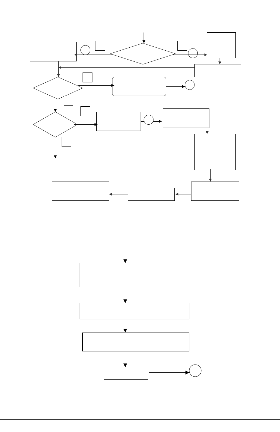
Unknown Destination
OmniSwitch Troubleshooting Guide July 2008 page -39
Packet arrives from Catalina to Coronado
Source Address
known ?
Y
1
Pseudo-CAM (PCAM)
Provides Group ID
(GID)
N
2
Assign
Default GID
and sends to
S/W
De Queue packet and
perform PCAM update
Is DA
Special ?
Is DA Router MAC,
IGMP, STP, Multicast
Switching
Y
5
N
Is DA
Known?
Lookup provides QID
& Priority Description
Index (PDI)
Y
4
Access PDI to assign
internal priority (0…3)
& final QID
En Queue data to
final QID, QID
determines
destination port,
priority &
bandwidth
Queue Manager selects
packet for transmission
to Nantucket, if needed
N
antucket send to other
Coronado, if needed.
Egress Coronado forwards the
packet to destination port,
strips Q-tag, if needed.
Known/Unknown SA and Known DA
N
A
A
DA QID is unknown, QID is set to flood,
PDI is set to unknown DA and ReQID is set
for s/w for unknown DA
S/W De Queue s packet. Includes the learning
of MAC DA via request to all other Coronados
Egress logic sends copy of the packet to all
the ports in that vlan. Strips Q-tag if needed.
Get final QID
4
Unknown DA
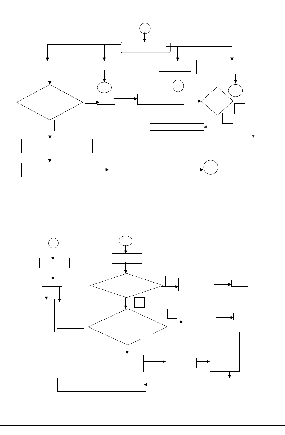
Unknown Destination
page -40 OmniSwitch Troubleshooting Guide July 2008
5
Classify Special DA
DA is router MAC
DA is IGMP DA is IPMS DA is STP multicast
(BPDU)
6
78
DA PCAM
lookup,
known ?
S/W Slow Path Routing L3
FDB?
Send to Destination
Send to Default
Gateway
N
N
Y
Y
Provides a
N
ext_Hop_Header_Cache index
N
HHC index provides QID,
ReQID & PDI Performs NAT, MAC-DA, TTL,
SLB and Fragment modifications
4
L3 Packet Walk
6
DA is IGMP
S/W
QID set
to either
multicast
within
the vlan
or dro
p
ReQID
Sent to
S/W for
p
rocessing
7
DA is IPMS
L3 DA lookup
Pass?
N
ew IPMS
group
S/W
L3-DA, L3-SA,
pport, sGID
lookup, Pass ?
Flow not
known
S/W
Set QID, ReQID, PDI &
header_cache info Access PDI
En Queue the
data to the
final
QID=511
(multicast
Queue on
N
antucket)
N
antucket sends the packet to all egress
Coronado within the same
multicast/vlan id
Egress Coronado sends to all the ports in the
same vlan, strips tag if necessary
N
N
Y
Y
IGMP/IPMS
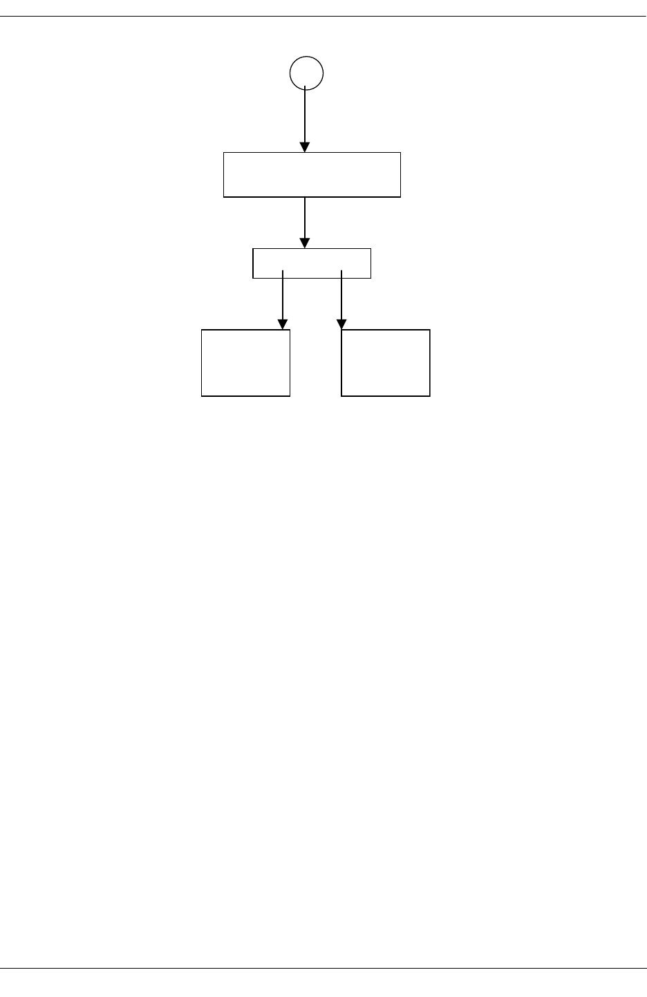
Hardware Buses on OmniSwitch 7700/7800/8800 Switches
OmniSwitch Troubleshooting Guide July 2008 page -41
Hardware Buses on OmniSwitch 7700/7800/
8800 Switches
Xybus
The interface between the MAC to Coronado, which is 0-1
Fbus
The interface between the Coronado to the Fabric ASIC (Nantucket or Roma). For the OmniSwitch 7700
(Falcon half chassis) it is 0-7. For the OmniSwitch 7800 (Falcon full chassis) it is 0-15. For the
OmniSwitch 8800 (Eagle) it is 0-63.
Bbus
This the management bridge bus connecting the CMM sand NIs. It is a single bridge bus.
8
DA is STP multicast
(BPDU)
S/W
QID for
flood or
drop
ReQID for
S/W
processing
BPDU

Bus Mapping on OmniSwitch 7700/7800/8800 Switches
page -42 OmniSwitch Troubleshooting Guide July 2008
Bus Mapping on OmniSwitch 7700/7800/8800
Switches
Xybus Mapping
Each board type has own mapping, described for all existing board type below.
•OS7-ENI-C24 and OS8-ENI-C24: Single slice board, connects two Catalina MAC ASICs through
xybus0 and xybus1.
•OS7-ENI-FM12: Single slice board, connects one Catalina MAC ASICs through xybus0,
•OS7-GNI-U2: Single slice board, connects two Catalina MAC ASICs through xybus0 and xybus1.
•OS8-GNI-U/C8: Four slice board, each slice connects two Catalina MAC ASICs through xybus0 and
xybus1.
•OS7-GNI-U/C12: Single slice board, connects two Firenze MAC ASICs through xybus0 and xybus1.
•OS8-GNI-C24: Two slices board, each slice connecting two Firenze MAC through xybus0 and
xybus1.
•OS8-GNI-U24: Four slice board, Slice 0 and 2 connecting one Firenze MAC through xybus0 and Slice
1 and 3 connecting one Firenze MAC through xybus1.
Fbus Mapping
Note. Dshell commands should only be used by Alcatel-Lucent personnel or under the direction of Alca-
tel-Lucent. Misuse or failure to follow procedures that use Dshell commands in this guide correctly can
cause lengthy network down time and/or permanent damage to hardware.
Falcon (OmniSwitch 7700/7800) Fbus Mapping
-> dshell
Working: [Kernel]->nanListMapping
Full Chassis (OS7800):
Fbus/Nan Port: 0,2,4,6,7,5,3,1,14,12,10, 8, 9,11,13,15
NI Slot: 1,2,3,4,5,6,7,8, 9,10,11,12,13,14,15,16
Half Chassis (OS7700):
Fbus/Nan Port: 0,2,4,6,1,3,5,7
NI Slot: 1,2,3,4,5,6,7,8
Eagle (OmniSwitch 8800) Fbus Mapping
Unlike Falcon, Eagle (OmniSwitch 8800) uses strict fbus number starting from 0 through 63.
Formula: Fbus_number = (slot_number - 1) * 4
For example, a OS8-GNI-U8 in slot 4, (4-1)*4=12. Since the OS8-GNI-U8 is a 4-slice board, Fbus
number starts from 12, up to 15.

OS6624/6648 Architecture
OmniSwitch Troubleshooting Guide July 2008 page -43
OS6624/6648 Architecture
OmniSwitch 6XXX is a stackable version of the OS7/8XXX Switches. It provides pure Ethernet switch-
ing for 10/100 and Gigabit ports, along with stackability.
The key features of OmniSwitch 6XXX are:
•ELEMENT - One Standalone HAWK Unit (1 or 2 Intel Devices)
•Module - Insertable modules (Gigabit copper, fiber, or stackable)
•SLOT - Software numbering of an element
•Virtual Chassis - a stack of Hawk units (max stack =8)
•GARP - Generic Attributes Registration Protocol - A generalized protocol, defined in IEEE802.1p, for
signaling between workstations and the network.
•GMRP - GARP Multicast Registration Protocol - a version of GARP, which allows devices to request
membership in a specific multicast group. Part of the IEEE802.1Q/P, cited by Alcatel-Lucent Enter-
prise QOS requirements.
•GVRP - GARP VLAN Registration Protocol - a version of GARP, which allows devices to request
membership in a specific virtual LAN.
•IGMP - Internet Group Management Protocol, Version 2. The Hawk “snoops” this protocol to deter-
mine which ports should receive copies of multicast packets.
•IP Multicast - data packets sent from an IP host and intended for reception by a number of IP destina-
tion hosts. IP multicast frames have a Class D address in the 224.0.0.0 to 224.255.255.255 range. Each
address refers to an individual “broadcast stream” rather than a destination host. IP multicast was origi-
nally implemented using Ethernet multicast MAC addresses and was received by all hosts on the LAN.
•SFP - Small Form Factor Pluggable - Small form factor Fiber Gigabit connectors.
•Group Mobility - Alcatel-Lucent Proprietary Protocol based VLAN
•Spanning Tree- Both 802.1D and 802.1W
•QOS
•Routing- Local, Static, RIP (2) and OSPF
•Link Aggregation
•802.1Q
•Authenticated VLANs
•UDP/Bootp Relay
•Redundant Management when stacked
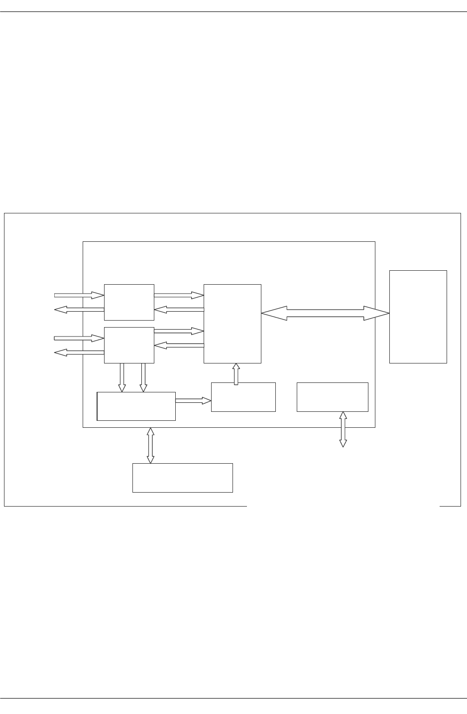
OS6624/6648 Architecture
page -44 OmniSwitch Troubleshooting Guide July 2008
Hardware Architectural Overview
OS6600 uses off the shelf Intel ASIC. Intel IXE2424 Switching ASIC is used to implement the required
functionality.
The key features of Intel IXE2424 are:
•Provides 24 10/100 FE ports and 4 GE ports.
•L2 and L3 switching
•Integrated FE and GE Macs
•L2/L3/L4 Prioritization16K MAC, 16K IP, 8K IPX, 4K VLAN Tables, IEEE 802.1s
•Multiple Spanning Tree IEEE 802.1v VLAN Classification by Protocol
Packet
Data
Path
Switching/Routi
ng Engine
Queuing
Engine CPU
Interface
4 X
Gigabit
MACs
24
10/100
MACs
4 MB
Packet
Storage
External SSRAM for
Address Tables
10/100
PHYs
Gig
PHYs
Intel ASIC IXE 2424 Block Diagram
PCI Complaint CPU
Interface
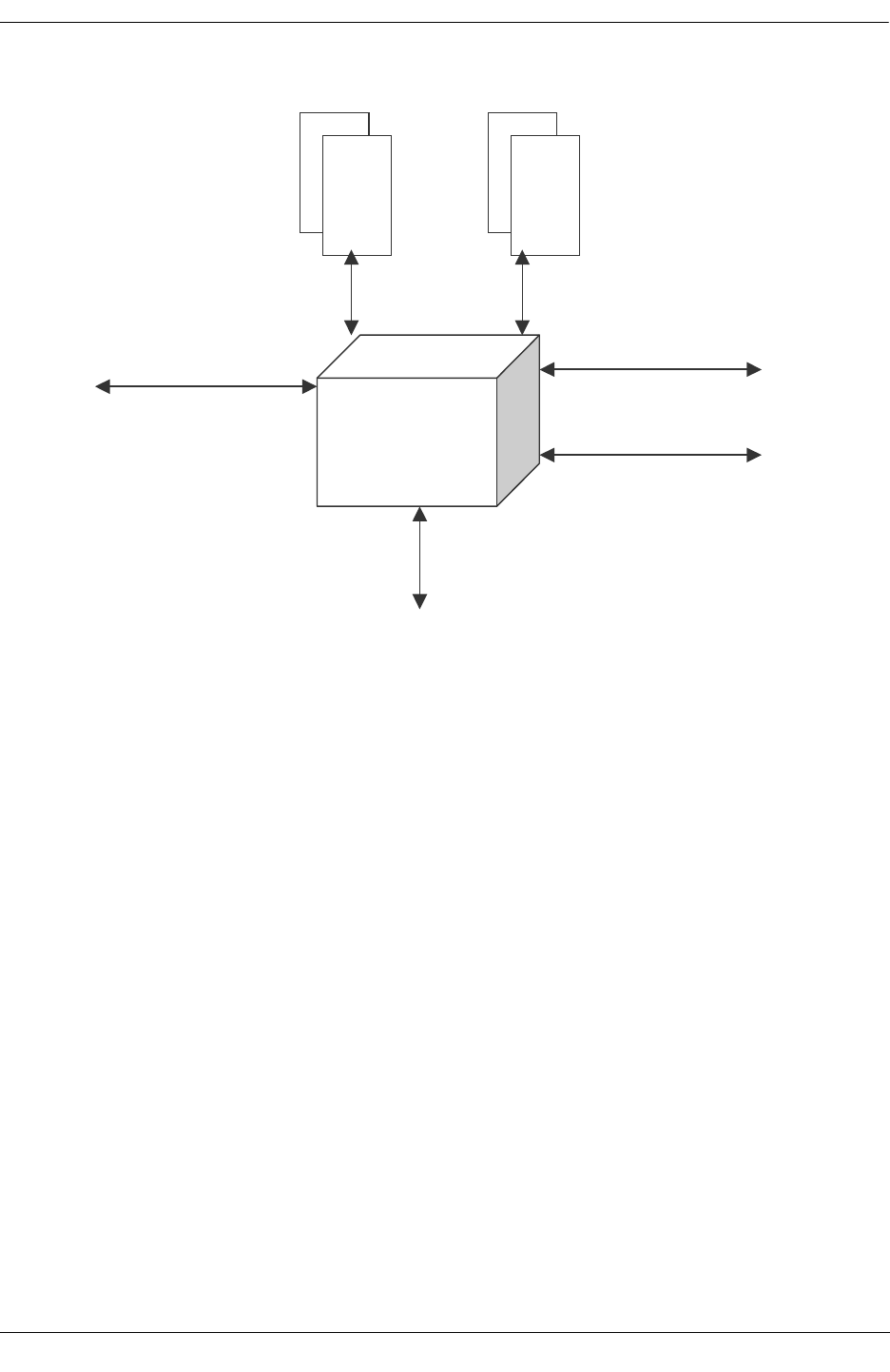
OS6624/6648 Architecture
OmniSwitch Troubleshooting Guide July 2008 page -45
IXE 2424
Packet Memory
Address
Memory
100MH
32 Bit PCI
66 MHz
SMII
125 MHz
MDIO
Interface
GM11/10 Bit
Interface
125MHz
External Interfaces to IXE 2424

OS6624/6648 Architecture
page -46 OmniSwitch Troubleshooting Guide July 2008
Layer 2 Forwarding
•Packets enter the IXE2424 through the SMII & GMII/TBI pins from external PHY devices. First, the
MAC associated with the port the packet was received from processes the packet. The MAC checks the
CRC to see if the packet is valid and also updates appropriate receive packet port statistics.
•In parallel, two things happen next.
•The entire packet is stored in external packet memory and
•The 64 byte packet header is sent to the address resolution logic (ASIC)
•External packet memory contains dedicated memory space for each port. The system processor (via the
Memory Start and Depth Address Registers) configures this address space at power up.
•The packet headers are queued, on a per port basis, before being placed in the processing pipeline. The
headers are examined for errors (i.e. length field, legal MAC address etc). The header is then examined
for
•Presence of prepend word
•Ethernet frame format
•Protocol carried
•Presence of VLAN tag
The Next step is address resolution. Note some packets like BPDU, GARP, LACP etc, bypass address
resolution and are passed to CPU for further processing.
Address Resolution Protocol
The IXE2424 switches packets based on flow. For Layer 2 packets, the IXE2424 identifies the flow using
802.1Q VLAN tag and Source and Destination Ethernet addresses. For IP addresses, the flow can be iden-
tified by the Source and Destination IP addresses, the protocol carried by the packet, and Source and
Destination Socket numbers. The flow entries are created in the software using the Address Resolution
Task provided by Intel’s driver software.
The Address Resolution task registers with the Notification Manager to be notified when an unresolved
entry is received. The Notification Manager function running in the Interrupt Handler context wakes up
this task upon receiving an unresolved entry. The Address Resolution task contains functions for learning
addresses. The Address Resolution task checks the unresolved queues for new entries and uses the CAM
interface to add new addresses to the table. An entry is created for the address with default settings. The
task sends an event through the Event Manager indicating that a new entry has been created. The Configu-
ration Management task waits on this event and with an occurrence, processes the newly added address,
and applies any special properties configured for that address.

OS6624/6648 Architecture
OmniSwitch Troubleshooting Guide July 2008 page -47
Address Learning
Address Learning in the IXE2424 is performed primarily in the software. The hardware provides a CAM
interface to facilitate fast learning of addresses.
On power-up, the switch does not know which addresses are associated with which ports. So, when the
switch receives the first packet, the source address lookup fails. This packet is considered source and
destination address unresolved and is sent to the CPU for address learning. The CPU is interrupted indicat-
ing that an unknown address has been received.
The Address Resolution task that is provided as a part of the driver registers for such an event with the
event manager. This task wakes up, processes the unknown address and creates an entry for the address.
An event is then sent through the Event Manager and wakes up the Configuration Management task. The
configuration task goes through the list of rules and if the address matches any of the configured rules,
those rules are applied to the new learned address.
For destination unresolved packets, the packet is broadcast on all other ports within the VLAN and a desti-
nation unresolved entry is sent to the CPU. The destination (if one exists) receives the packet and responds
back. The driver then learns the destination. All future packets are then forwarded in hardware with no
software intervention.
If the source address was unknown, an unresolved entry is sent to the CPU and depending on whether or
not the destination was resolved or unresolved (or was a broadcast), the packet is sent to the destination
port (if the packet was resolved) or flooded within the VLAN (if the destination was unknown or the
packet was a broadcast packet). The IXE2424 provides the option to turn off such forwarding and the
driver provides an API to do this.
Location of Address Tables
The IXE2424 has two modes of operation - Normal Mode and Low Cost Layer 2 Mode. The locations of
address tables are different for the two modes. In Normal Mode, Layer 4 Record Entries and 12 Last
Address Record Entries are stored on-chip. The rest of the data structures are stored in off-chip address
memory. In Low Cost Layer 2 Mode of operation, there is no external address memory used. All data
structures are contained on-chip.
For the Hawk, we will use the Normal mode with External Address memory.

OS6624/6648 Architecture
page -48 OmniSwitch Troubleshooting Guide July 2008
Address Look-up Methodology
Source and Destination Addresses are searched in parallel and then a sync process occurs to ensure both
are completed. The IXE2424 uses a fast method of organizing and searching the address records to meet
wire speed performance requirements. Record Entries (see Layer 2 Data Structures section below) contain
the addresses. A proprietary binary search algorithm is employed to look for these addresses; no hashing
algorithm is used. Records are organized into 1366 sections of 12 each (supporting a maximum of 16K
records) for L2. A similar organization exists for IP records (64K max records) and IPX (8K max entries).
Note that in Layer 2 only mode, all 40K addresses can be MAC addresses.
For the Hawk platform we will only use the ASIC in mode 4, which is Layer 3 switching with routing and
Layer 4 classification. Phase 1 will be L3 switching with L4 classification.
A binary search (on-chip) is performed among the Last Address (LA) of every section to find section
where the address should belong. A discriminated search is then performed with 10 bits to locate the
Record Entry where the address will fall if it is present. An external search for the record entry is then
performed. If the Record Entry matches with the address for which the search is performed, the rules and
protocol entries are also retrieved from external RAM.
L2 Data Structures
The layer 2 data structures for OS6600 are:
•1-Record Entry
•Contains exact address used for match when searching tables
•MAC Address
•VLAN Tag ID (VID)
•2-Rules Entry
•Contains information on which port the address resides on
•Device Number (IXE2424 number in cascaded systems)
•Port Number (which port this address resides on)
•Pointer to Protocol Specific Information
•Pointer to Destination Swap Information

OS6624/6648 Architecture
OmniSwitch Troubleshooting Guide July 2008 page -49
3-Protocol Entry
•Used to allow different rules to be applied for different protocols associated with same address. Proto-
col Offset Register is used to identify which protocols will be used in the system. Up to 18 Layer 2
protocols are supported. There is a separate protocol entry for each protocol defined in the Protocol
Offset Register
•Priority level of the packet for queuing
•Filter (6 bits), Mirror (5 bits), Priority (5 bits), TOS (6 bits) indices for flow-based rules. Each address
that is to be used in a flow definition is assigned a unique index for the appropriate rule (i.e. Filter,
Mirror, priority or TOS).
•TOS marking rules
•Global destination/source priority rules (i.e. all packets with this destination address get this priority).
•Global destination/source filter rules (i.e. filter all packets with this source address)
•Global destination/source mirror rule (i.e. mirror all packets with this source address)
•Pointer to NetID
•4-NetID Entry
•Contains transmit enables, prepend information and address based VLAN information.
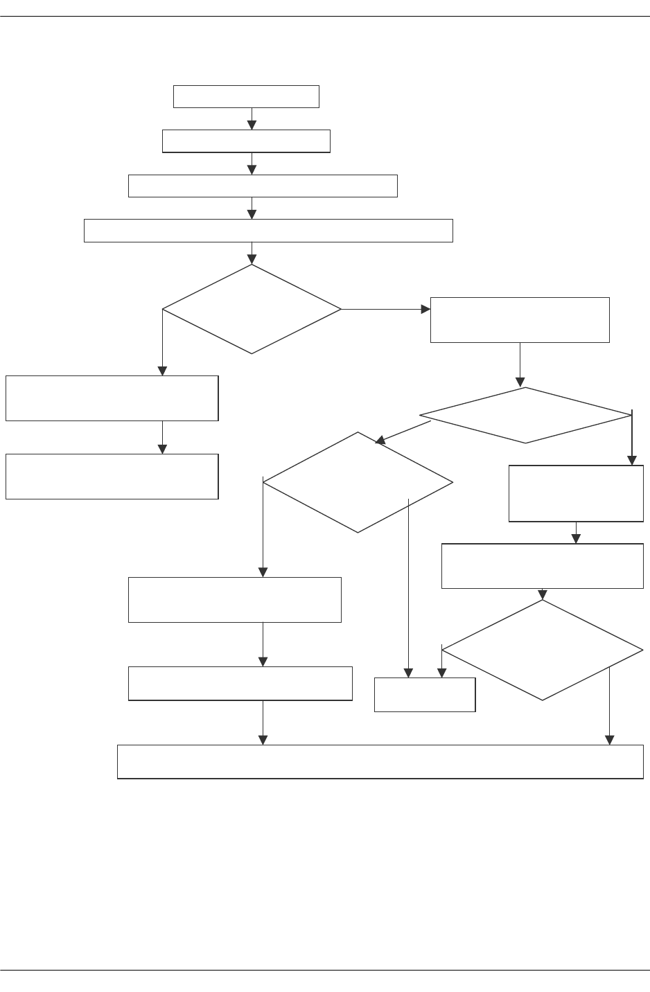
OS6624/6648 Architecture
page -50 OmniSwitch Troubleshooting Guide July 2008
Layer 3 Forwarding
Packets Arrived
Header 64 Bytes
Apply protocol based VLAN on
Search the IP Source and Destination addresses in the
Does the
address exist
idtb ?
Apply address VLAN for
Untagged packet
Is Routed
Pkt?
Send the packet to CPU for
address Learning
Broadcast the packet to all the
ports in the VLAN
Y
es
No
Apply Filter,
Mirror, Priority,
QOS and WRED
Find Outgoing Tag and Port’s
802.1Q status
Apply Filter, Mirror, Priority,
QOS and WRED Rules
Find outgoing Port’s 802.1Q
tt
Drop the
kt
Modify and Send the Packet to the Destination Port
Is the dest Port
member of
egre
ss VLAN
Is the dest
and receive
port in the
Yes
L3
N
o
L3-
N
Y
es
Y
es
N

OS6624/6648 Architecture
OmniSwitch Troubleshooting Guide July 2008 page -51
VLANs
The IXE2424 supports VLANs based on:
•Ports. This is accomplished using Port Net ID Entry described below.
•802.1Q Tags. This tag is included in the packet.
•Protocols. This is accomplished using the Protocol to VID Lookup Table described below.
•Addresses. This is accomplished by using the AVID field in NetId (L2, IP or IPX), if Address-based
VLAN feature is enabled.
The VLAN Tag ID (VID) in the Record entry is determined one of two ways
•For a tagged packet VID is the VLAN ID in the tag.
•For an untagged packet, VID is the default VLAN ID associated with the protocol the packet belongs
to. See Protocol Based VLANs description below.
Port Based VLANs
This is the default means of creating VLANs when no other type VLANs (802.1Q for example) has been
programmed. Port Net ID Entry is fetched based on the receive port number. This entry determines the
ports (including CPU) on which the packet received on that port can be transmitted.
Protocol Based VLANs
Can be configured on the IXE2424 by having different protocols point to different VLAN ID Entries
where a VLAN tag is programmed per protocol per port. The IXE2424 supports 19 different Protocol
Based Entries (IP, IPX, ARP etc) including 9 programmable protocols. Protocol to VID Lookup Table
assigns the VID on a per port, per protocol basis. Protocol-based VLAN control bit has to be set for this
feature to work.
Address Based VLANs
Layer 2, IP & IPX NetID entries has AVID (address based vid) field, which is used for untagged packets
as the 802.1Q VLAN ID for all further tag based processing, when Address-based VLAN feature is
enabled.

OS6624/6648 Architecture
page -52 OmniSwitch Troubleshooting Guide July 2008
Tag Net ID Entry
•Contains related information like tagged set and member set. A 4x32 bit entry is present for every
possible VLAN (4096 supported).
•VLAN Tag Valid. Indicates if this VLAN tag has been configured by the CPU. If not, all packets with
this tag are dropped.
•Ports on which a packet with this Tag can go out on.
•VLAN Statistics Index. IXE2424 can collect statistics on up to 15 VLANs, identified by this index.
•IP Statistics Index. The IXE2424 can collect statistics on up to 256 IP Routed packets, identified by
this index.
•Tagged Set Port indicates which ports have nodes attached that can accept tagged packets on this
VLAN; packets are forwarded untagged to ports that cannot accept the tagged packets.
•Multicast Forward indicates which ports are disabled from transmitting unregistered multicast packets
on this VLAN. If the bit is set for a particular port, unregistered multicast packets are not transmitted
on that port.
•Priority, Bandwidth Management and QOS
Priority
•Each port on the IXE2424 has four output/transmit queues that store pointers to packets to be transmit-
ted. Each queue corresponds to one distinct priority level. Packets in higher priority queues are serviced
before packets in lower priority queues. These transmit queues support weighted fair queuing as well as
strict priority queuing algorithms.
•The IXE2424 supports three methods of assigning device priority to a packet: 802.1p Priority, Rules-
based Priority and QoS flow.
802.1p Priority
The incoming packet may have a priority associated with its 802.1Q Tag. 802.1p priority specifies eight
levels of priority. This priority level is mapped to one of the four device priority levels (per port) using the
Priority Map Register. Note this Priority Map Register applies to all ports on the IXE2424. If the incom-
ing packet is untagged, it is assigned a default 802.1p priority level of zero. However, the priority regener-
ation feature may be used to change this priority level on a per-port basis using the Port Regenerate Tag
Priority Level Entry Register.

OS6624/6648 Architecture
OmniSwitch Troubleshooting Guide July 2008 page -53
Rules-Based Priority
•Several types of priority rules are supported. Each rule is associated with a specific device priority. If a
packet satisfies a certain priority rule, it is assigned the device priority corresponding to that rule.
•Global Priority Rules enable assignment of specific device priority to all packets from a specific source
address (global source priority) or all packets meant for a specific destination address (global destina-
tion priority). This is enabled through the Rules Entry data structure.
•Flow-based Priority Rules enable assignment of priorities by setting up priority flows. A flow refers to
packet transmission between a specific source and a specific destination address. When a packet is
detected to belong to a priority flow, it may be assigned a device priority as a set up for the flow. This
is enabled through the Rules Entry data structure.
•Protocol-based Priority is enabled by Flow-Based and Global Priority. It allows the user to assign
different device priority for packets that satisfy the same flow rules or global priority rules, but corre-
spond to different protocols.
QOS Flow
The QoS-specified device priority may override the device priority already assigned to a packet through
the VLAN tag, or through the global or flow-based priority. The decision to override previously assigned
device priority in favor of QoS-specified device priority is based on the value of bit 30 of SIC Control 0
Register. The user configures this bit.
Bandwidth Management and QoS
•The IXE2424 provides Bandwidth Management at two levels. First, the device manages bandwidth
between different output queues (that store pointers to the packet entries for transmission) at each port
through a priority queuing scheme. Credit based and strict priority are supported. The choice of one of
these two algorithms is configured on a per port basis using the Weighted Fair Queuing Port Address
Control Registers.
•The second level of Bandwidth Management is at the per-output queue level, through QoS rules for
packet flows, setup by the user. This provides bandwidth management on per queue and per flow basis
and is termed QoS bandwidth management. The corresponding flows are termed QoS flows. A QoS
flow essentially specifies a traffic-policing rule and allows users to limit bandwidth assigned for the
specific flow. QoS flows may be specified in terms of flow between two specific addresses, A and B;
flow from a specific address to any destination address; and flow to a specific destination address from
any source address.
•A QoS flow specifies a data limit value, time interval over which the data limit is to be enforced, and a
priority level (which determines the transmit queue number) for the flow. The IXE2424 device keeps
track of the amount of data that has been transmitted within the user-specified time intervals for each
QoS flow. If a packet causes a specific QoS flow to exceed its data allocation, it is dropped. Multiple
QoS flows may be mapped to the same transmit queue and still be guaranteed the required bandwidth
for that flow - the bandwidth management feature takes care of guaranteeing the bandwidth for the
queue (by not allowing other queues to take away unauthorized bandwidth) and the QoS feature guar-
antees bandwidth for all flows mapped to the same queue (by not allowing any of the flows to exceed
their allocated data rate). The device level Bandwidth Management feature is responsible for guaran-
teeing the bandwidth for an output queue (by not allowing other queues to take away unauthorized
bandwidth) and the QoS feature guarantees the bandwidth for all flows mapped to the same queue (by
not allowing other flows to exceed their allocated data rate). By combining these two types of band-
width management, users can efficiently manage bandwidth for different types of traffic with the
IXE2424 device.
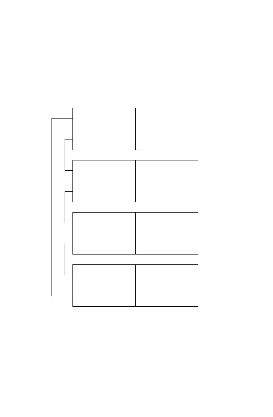
CMM Functionality for OS6600
page -54 OmniSwitch Troubleshooting Guide July 2008
CMM Functionality for OS6600
The overall software architecture of Falcon is retained for Hawk. The user will perceive the system as a
virtual chassis; where one element is elected as the primary CMM, another as the secondary CMM and the
rest of the elements as NI. The two elements that are elected primary CMM and secondary CMM are also
NI. This choice was directed by finding a solution to manage the entire stack with a single IP address.
A Hawk used as standalone switch/router includes the equivalent of the CMM application as well as the
NI applications. When several Hawks are connected together via the stacking link, two of the Hawks
contains CMM and NI applications running on the same processor, and the rest contain a limited Chassis
Supervision and NI applications.
CMM (idle)
CMM (primary)
CMM (idle)
CMM (secondary)
NI (slot 3)
NI (slot 4)
NI (slot 2)
NI (slot 1)

CMM Functionality for OS6600
OmniSwitch Troubleshooting Guide July 2008 page -55
The chassis like, or V-Chassis, strategy allows the system to keep the same management interface. Since
on Falcon/Eagle, the management uses the notion of slot, this notion of slot is retained for Hawk. Since
there is no chassis, we need to provide a means by which a slot number is assigned to an element. The
current strategy is to have the user assigning a slot number, via a push button on the front panel, located
below the LCD display. The default slot number is one. This mechanism provides several advantages. It
removes the risk that from one reboot to another a dynamic allocation protocol might under certain
circumstances assign a different slot number. The second advantage is that even if the user removes an
element (slot) or adds one, the current configuration will still be applicable. There is no need to have
successive numbers in a stack. Eight (8) is the maximum number of slots allowed in a single stack.
The V-Chassis provides to the user the same interface and the same set of commands to configure the
system. The user configures a port; adds a port in a VLAN, etc, by providing both the port number and the
slot number. Chassis Supervision, NI Prober and Supervision and IPC are the main applications that are
impacted by the virtual chassis concept. They will both rely on the first application to have information
allowing them to perform their services correctly (i.e. NI present, NI UP, NI down).
The V-chassis imposes some constraints on Chassis Supervision. Chassis Supervision does not run the
Falcon election protocol, i.e. Hello Protocol, to define the mode (primary or secondary). Chassis Supervi-
sion receives the mode from Stack Manager. This implies that the Hello Protocol is not activated on both
the primary and secondary CMM, because the Stack Manager monitors the two CMMs. In Hawk three
modes are defined for Chassis Supervision. The new mode is idle. In the idle mode allows the system to
have Chassis Supervision available on all elements.
In primary mode, Chassis Supervision behaves as defined in Falcon with the following restrictions:
•CSM (Chassis State Machine) does not activate the Hello Protocol.
•HSM (Hardware Service Manager) does not need to control the available power when a NI is declared
present. On a real chassis (Falcon or Eagle), when Chassis Supervision learns the presence of a new
NI, it first computes whether or not there is enough power to switch on the new NI. This phase must be
bypassed on Hawk since each element has its own power supply.
•HSM needs to communicate to all elements within the stack a new temperature threshold, when it
receives the new configuration.
•Prober does not need to monitor the presence of either the NI or CMM boards. The service is now
available via Stack Manager.
•CVM (Chassis Version Manager) when synchronizing the primary Flash with the secondary Flash
needs to extend the service to all the elements present in the stack, ensuring that all elements have the
same content on the flash.
•When a new element is inserted in the stack, CVM must control that the flash content of this new
element is synchronized with the content of the primary flash.
•There is no need to have a synchronization of the MAC addresses.
•In secondary mode, Chassis Supervision, Chassis Supervision behaves as defined in Falcon with the
following restrictions:
•Prober does not need to monitor the presence of either the NI or CMM boards. The service is now
available via Stack Manager.
•Prober needs to monitor the temperature and report a temperature rising over a defined warning thresh-
old to HSM.
•When HSM receives a message from prober indicating that the temperature has risen over the defined
shutoff threshold, it must send a trap and shutdown the local unit.
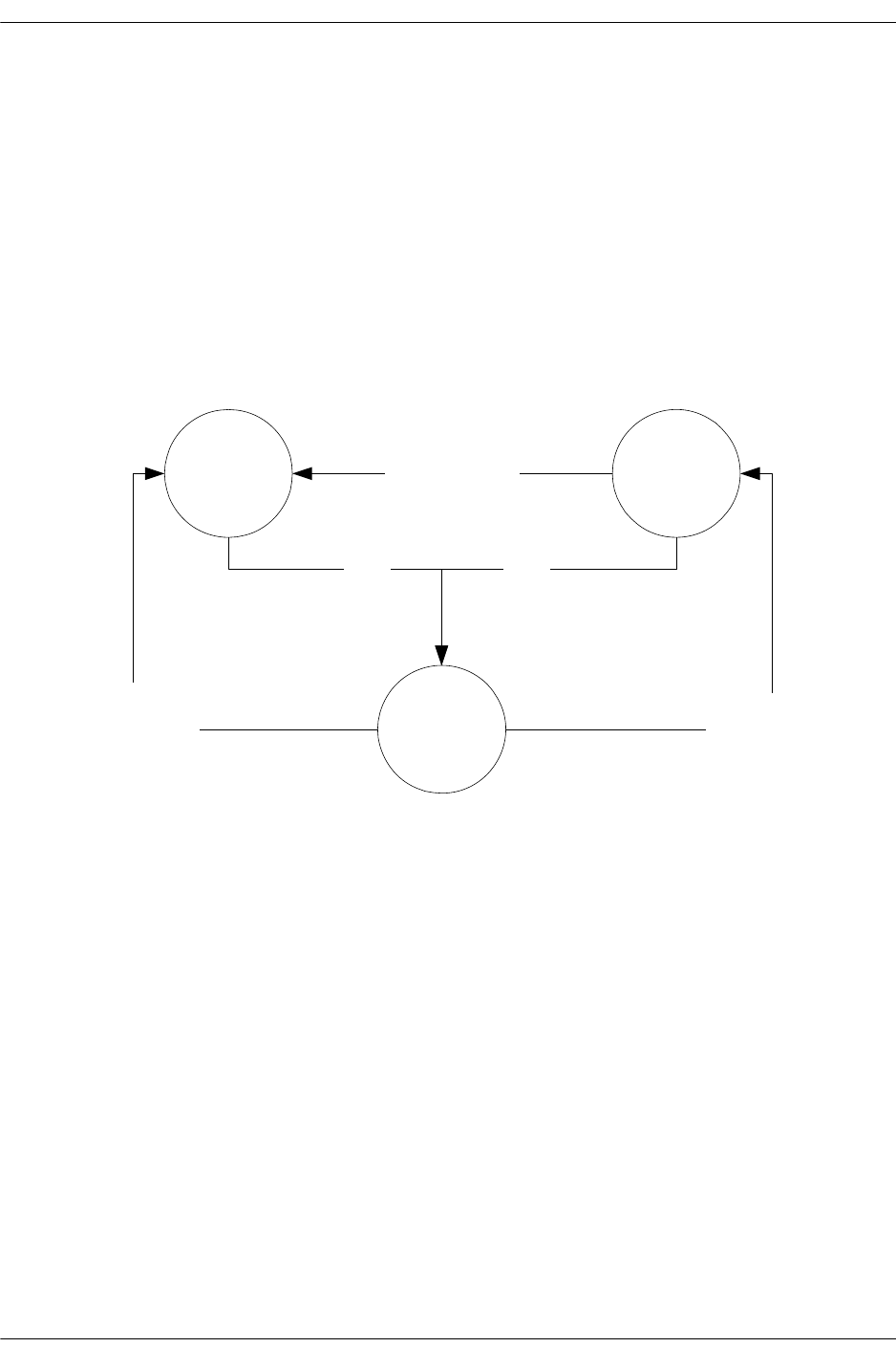
CMM Functionality for OS6600
page -56 OmniSwitch Troubleshooting Guide July 2008
•In idle mode the role of Chassis Supervision is limited to monitoring the temperature, power supply,
fan(s), handling of flash synchronization and takeover. The following services are provided when
running in idle mode:
•Prober needs to monitor the temperature and report a temperature rising over a defined warning thresh-
old to HSM.
•When HSM receives a message from prober indicating that the temperature has risen over the defined
shutoff threshold, it must send a trap and shutdown the local unit.
•CVM must listen to flash synchronization coming from CVM on the primary.
•Chassis Supervision does not implement the Hello Protocol as defined in Falcon/Eagle. It receives noti-
fication from Stack Manager to change to a new mode. The following figure illustrates the different
possible transitions.
•When running in idle mode and upon reception of a notification of Stack Manager indicating the new
state, Chassis Supervision shutdowns the daughter tasks and spawns them according to the new mode.
SecondaryPrimary
Idle
Stack manager
notification Stack manager
notification
Stack manager
notification
or user initiated
reset reset

CMM Functionality for OS6600
OmniSwitch Troubleshooting Guide July 2008 page -57
The process of multiple CMMs is composed of following steps:
•Bootup
•Role election
•Lowest slot number is elected as Primary
•Following number is elected as secondary
•Redundancy
•Failure of primary
•Secondary takeover
•Lowest idle number become secondary
•Failure of secondary
•Lowest idle number become new secondary
•Failure of both
•Election of a new primary and secondary
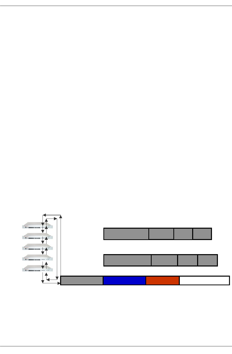
OS6600 IPC Communication
page -58 OmniSwitch Troubleshooting Guide July 2008
OS6600 IPC Communication
IPC software interface is unchanged. IPC provides the following services:
•NI-NI communication
•CMM-NI communication
•CMM is the primary or active
•CMM-CMM communication
•Each element in a stack is addressable from its CMM perspective. Different Types of Sockets are:
•Connection oriented socket
•Connectionless socket
•Multicast socket
•IPC is transported as a layer 2 protocol over Ethernet frame
•Provides Segmentation and Reassembly
•Fragment packet bigger than 1400 bytes
•Provides reliability
•Interface with Stack Manager to obtain MAC address and outgoing port number
•Use special MAC to identify IPC packet
•For all slots a Special MAC is used. Example: slot 7 uses 00:00:77:77:77:77, slot 8 uses
00:00:88:88:88:88
The following diagram can illustrate IPC connection between different slots:
S
l
ot
1
S
l
ot
2
S
l
ot
3
S
l
ot
4
S
l
ot
5
00:00:11:11:11:1
1
CAM Entry on device 5
VID 1
Dev=
0
Port=30
00:00:44:44:44:44 VID 1
Dev=
6
Port=30
00:00:44:44:44: 00:00:11:11:11: 0xABCD
IPC Frame sent from Slot 1 to Slot 4
CAM entry on device 1
OS6600 BOOT Sequence
OmniSwitch Troubleshooting Guide July 2008 page -59
OS6600 BOOT Sequence
•Different from Falcon/Eagle
•No NI code to download
•Each element is independent from the other
•For instance it is possible to have a primary which has not the lowest slot number
The following figures illustrate the bootup process:
•Load the Base Code
•Load the Stack Manager Library
•Start IPC
•Load all the libraries
•Start Chassis Supervision
•Wait for Stack Manager
•Get the topology of the stacks
Load
Base
Stack
Manage
r
IPC
Librari
Librari
Librarie
Chassis
Su
p
ervisio
Wait for Stack
Manager
Topology/role
NI
Supervisio
’
Stack
Manager
Wait for stack port
Configuration
From ESM Driver
OS6600 BOOT Sequence
page -60 OmniSwitch Troubleshooting Guide July 2008
•Get the Role of the Stack-Primary, Secondary or Idle
•Start NI supervision and Prober
•Start Stack Manager
•Get the stack port Configuration from the ESM Driver
•NI Supervision performs the following Tasks:
•Load and Start the IXE2424 driver
•Start the Queue Dispatcher
•Start Stack Manager to compute the stack topology and the role of the chassis from chassis supervision
•Start ESM driver by getting the information from Stack Manager
•Chassis Supervision performs the following tasks:
•Start all the daughter tasks when powered on, which include
•CMM applications
•Start the ESM Driver, which includes:
NI
Supervisio
’
IXE 2424
driver
Queue
Dispatche
Stack
Manager
ESM
Driver
Compute
stack
Stack
p
ort confi
g
uration
Chassis
supervision
Ro
le +
Chassis
Supervisio
OS6600 BOOT Sequence
OmniSwitch Troubleshooting Guide July 2008 page -61
•NI supervision and Prober Task. NI Supervision task in turn starts the NI applications.
Chassis
Supervisio
NI
Supervisio
’
Daughter
Tasks
CMM
applicatio
CMM
applicatio
ESM
Driver
N
I powered on
Start message
NI
applicatio
NI
applicatio
NI
applicatio
NI
applicatio

OS6600 BOOT Sequence
page -62 OmniSwitch Troubleshooting Guide July 2008

OmniSwitch Troubleshooting Guide July 2008 page -1
B Debug Commands
This chapter documents the following Command Line Interface (CLI) debug commands. Blue text indi-
cates that the text is hypertext-linked to additional documentation for that command.
802.1Q Debug Commands debug 802.1q
DVMRP Debug Commands ip dvmrp debug-level
ip dvmrp debug-type
debug ip dvmrp graft
debug ip dvmrp group
debug ip dvmrp nbr vlan
debug ip dvmrp prune recv
debug ip dvmrp rib holdq ageq
debug ip dvmrp route valid hold vlan
show ip dvmrp debug
IP Debug Commands debug ip packet (configures IP debug parameters)
debug ip set
debug ip
debug ip level
debug ip packet default
debug ip packet (displays IP debug configuration parameters)
debug ip mask
DHCP Relay Debug
Commands debug ip helper packet size
Multicast Routing Debug
Commands debug ip mroute debug-level
ip mroute debug-type
OSPF Debug Commands ip ospf debug-level
ip ospf debug-type
show ip ospf debug
PIM-SM Debug Commands ip pimsm debug-level
ip pimsm debug-type
show ip pimsm debug
RIP Debug Commands ip rip debug-type
ip rip debug-level
show ip rip debug
Trap Debug Commands debug trap trace
debug trap reset
debug trap interface
debug trap generate
debug trap data

page -2 OmniSwitch Troubleshooting Guide July 2008
SNMP Debug Commands debug snmp trace
debug snmp reset
debug snmp interface
debug snmp data
Session Debug Commands debug session trace
debug session reset
debug session interface
debug session data
Hardware Slot Debug
Commands debug slot information
Interfaces Debug Commands debug interfaces set backpressure
debug interfaces backpressure
debug interfaces led
debug interfaces mdix
debug interfaces phy
debug interfaces mac
debug interfaces port structure
debug interfaces mac stats
debug interfaces mac port
debug interfaces mac nonport
debug interfaces switching
debug interfaces set mdix
debug interfaces set automdix
debug interfaces set linkled
debug interfaces set linkled activity
IPC Debug Commands debug ipc pools slot
debug ipc pools cmm
debug ipc bbus
debug ipc active sockets
debug ipc active sockets slot
debug ipc active sockets appid
Fabric ASIC Debug
Commands debug fabric threshold
debug fabric status
debug fabric stats
debug fabric output
debug fabric mcvectors
debug fabric input
debug fabric fbus
debug fabric errors
debug fabric calendars

OmniSwitch Troubleshooting Guide July 2008 page -3
Server Load Balancing (SLB)
Debug Commands debug slb help
debug slb
debug slb adminstatus
debug slb createcluster
debug slb deletecluster
debug slb clusteradminstatus
debug slb clusterdistribution
debug slb clusterpingperiod
debug slb clusterpingtimeout
debug slb clusterpingretries
debug slb clusterstickytime
debug slb server
debug slb removeserver
debug slb dumpcluster
debug slb dumpclusters
debug slb dumpserver
debug slb dumpservers
debug slb dumpni
debug slb dumpvlan
debug slb dumpmisc
debug slb discoveryperiod
debug slb discoverytimeout
debug slb discoveryretries
debug slb statperiod
debug slb deadlinewindow
debug slb link
debug slb resetcmm
debug slb resetni
debug slb cmmtrace
debug slb nitrace
debug slb nidebug
debug slb flags
debug slb traps
debug slb simservers
debug slb serverarp
debug slb packetloss
debug slb kill
debug slb ni
debug slb snapshot
debug slb certify
debug slb takeover
HTTP Debug Commands debug http sessiondb

page -4 OmniSwitch Troubleshooting Guide July 2008
HRE Debug Commands debug hre warn
debug hre trace
debug hre pcam
debug hre pcam verbose
debug hre pcam mode range
debug hre ipx flow
debug hre ipms flow
debug hre ip flow
debug hre history
debug hre error
debug hre debug
debug hre cmm warn
debug hre cmm trace
debug hre cmm error
debug hre cmm debug
debug hre clear ipx
debug hre clear ip
debug hre cache verbose
debug hre cache
Health Debug Commands debug health
debug health cpu
debug health temperature cpu
debug health temperature cmm
debug health status
debug health rx
debug health txrx
debug health memory
GMAP Debug Commands debug gmap flags
Console Debug Commands debug console flow control
debug console show flow control
Command Information Debug
Commands debug command-info
CLI Debug Commands debug clishell data
debug cli mip-response
CLI Shell Debug Commands debug clishell data
AMAP Debug Commands debug amap database
Chassis Debug Commands debug chassis show
debug chassis secondary emp
debug chassis show state trace
debug chassis secondary emp
debug chassis hello
debug chassis hello timers
debug chassis auto-reboot
debug chassis auto-reboot ni
Bridging Debug Commands debug bridge hash-bitmask sa
debug bridge hash-bitmask da

OmniSwitch Troubleshooting Guide July 2008 page -5
VLAN Debug Commands debug vlan vpas
debug vlan rule protocol-map
debug vlan rule ports
debug vlan rule memory
debug vlan rule database
debug vlan rule communication
debug vlan communication
debug vlan database
debug vlan communication
Port Manager (PM) Debug
Commands debug pm object
debug pm mibs
debug pm eventlist
debug pm bindings
debug pm index
AAA Debug Commands debug aaa
Port Debug Commands debug port information
QoS Debug Commands debug qos
IPX Debug Commands debug ipx info
debug ipx info rip
debug ipx info host
debug ipx trace
debug ipx vlan
Systrace Debug Commands debug systrace
debug systrace watch
debug systrace show
debug systrace appid level
debug systrace show log
Post Mortem Dump (PMD)
Debug Commands show log pmd
debug remove pmd
debug pmd remove
debug pmd show
debug dump pmd
debug pmd ni
debug show pmd
Memory Monitoring Debug
Commands debug memory monitor
debug memory monitor show status
debug memory monitor show log
debug memory monitor show log global
debug memory monitor show log task
debug memory monitor show log size
Ktrace Debug Commands debug ktrace
debug ktrace show
debug ktrace appid level
debug ktrace show log
Ed Debug Commands debug ed
Set Debug Commands debug set
Debug Show Commands debug show
IPv6 Debug Commands debug ipv6 trace

page -6 OmniSwitch Troubleshooting Guide July 2008
debug 802.1q
Retrieves debugging messages for the tagged port selected.
debug 802.1q {slot/port | aggregate_id}
Syntax Definitions
slot The slot number to configure 802.1Q tagging.
port The port number to configure 802.1Q tagging.
aggregate_id The aggregate link number to configure 802.1Q tagging.
Defaults
N/A
Platforms Supported
OmniSwitch 6624, 6648, 7700, 7800, 8800
Usage Guidelines
Retrieves debugging messages for the tagged port selected.
Examples
-> debug 802.1q 5
Aggregate Status = aggregate up
-> debug 802.1q 3/1
Slot Status = slot up
Port Status = port up
GENERAL INFO ESM: USER PORT 1-12 = CORONADO PORT 0-11
GENERAL INFO ESM: USER PORT 13-24 = CORONADO PORT 16-27
GENERAL INFO GSM: USER PORT 1 = CORONADO PORT 12
GENERAL INFO GSM: USER PORT 2 = CORONADO PORT 28
HARDWARE INFO for slot = 3 and port = 1:
At reg_addr = 660012c, Ingress tag-untag:= 1:
At reg_addr = 6a00010, Eg tag-untag: = 1:
At reg_addr = 6601000,for protocol = 0,ing default vlan: = 1
At reg_addr = 6601080,for protocol = 1,ing default vlan: = 1
At reg_addr = 6601100,for protocol = 2,ing default vlan: = 1
At reg_addr = 6601180,for protocol = 3,ing default vlan: = 1
At reg_addr = 6601200,for protocol = 4,ing default vlan: = 1
At reg_addr = 6601280,for protocol = 5,ing default vlan: = 1
At reg_addr = 6601300,for protocol = 6,ing default vlan: = 1
At reg_addr = 6a70000, egress default vlan: = 1
At reg_addr = 6600118, protocol cam on/off: = 18 :
At reg_addr = 660011c, trusted/untrusted: = fff0fe6
At reg_addr = 6600130, secure/unsecure: = 18
At reg_addr = 6608020, for vlan = 8,spanning tree vector: = 1
At reg_addr = 6a00014, Eg force tag internal: = 0:

OmniSwitch Troubleshooting Guide July 2008 page -7
Release History
Release 5.1; command was introduced.
Related Commands
N/A
MIB Objects
N/A
output definitions
Aggregate/Slot Status Whether the slot or aggregate link is actively running.
Port Status Whether the port is actively running.
General Info Provides general information on the modules in the chassis, including
module type, number of ports, and ASIC.
Hardware Info Lists the various debug messages for the selected slot and port.

page -8 OmniSwitch Troubleshooting Guide July 2008
ip dvmrp debug-level
Defines the level of debugging for DVMRP protocol on the switch.
ip dvmrp debug-level level
Syntax Definitions
level Specifies the DVMRP debug level (0–255). Higher debug-levels will
include all messages that correspond to a lower value. For example, a
debug level of 2 will display all messages for level 1 and level 2. As a
rule of thumb, higher levels will display more detailed messages; lower
levels will display more basic messages.
Defaults
Platforms Supported
OmniSwitch 7700, 7800, 8800
Usage Guidelines
When the debug level is set to 0, DVMRP debug logging is turned off.
Examples
-> ip dvmrp debug-level 2
Release History
Release 5.1; command was introduced.
Related Commands
MIB Objects
ALADVMRPDEBUGCONFIG
alaDvmrpDebugLevel
parameter default
level 1
ip dvmrp debug-type Enables or disables DVMRP debugging for a specified message
type, or for all message types.
show ip dvmrp debug Displays the current level of debugging for DVMRP protocol on the
switch, as well as the current DVMRP debugging status for all mes-
sages types.

OmniSwitch Troubleshooting Guide July 2008 page -9
ip dvmrp debug-type
Enables or disables DVMRP debugging for a specified message type, or for all message types.
Note. Debugging for a specified message type will only be enabled if its debug level is a value greater
than zero (i.e., 1–255). For information on specifying the debug level, refer to the
ip dvmrp debug-level command.
ip dvmrp debug-type message_type
no ip dvmrp debug-type message_type
Syntax Definitions
message_type Enables or disables DVMRP debugging for the specified item. Select
from the list below. You may enter multiple message types in any order.
For example, ip dvmrp debug-type time flash init.
supported message types descriptions
all Enables or disables DVMRP debugging for all items listed below. The
syntax all can be used to easily turn debugging for all message types on
or off.
error Enables or disables debugging for DVMRP Error messages.
flash Enables or disables debugging for DVMRP Flash processing.
graft Enables or disables debugging for DVMRP Graft processing.
igmp Enables or disables debugging for DVMRP Internet Group Management
Protocol (IGMP) packet processing.
ipmrm Enables or disables debugging for DVMRP IP Multicast Routing Man-
ager (IPMRM) interaction.
init Enables or disables debugging related to DVMRP initialization code.
mip Enables or disables debugging for MIP (Management Internal Protocol)
processing. Includes CLI and SNMP.
misc Enables or disables miscellaneous debugging of DVMRP.
nbr Enables or disables debugging for DVMRP Neighbor processing.
probes Enables or disables debugging for DVMRP Probe processing.
prunes Enables or disables debugging for DVMRP Prune processing.
routes Enables or disables debugging for DVMRP Route processing.
time Enables or disables debugging for DVMRP Timer processing.
tm Enables or disables debugging for DVMRP Task Manager interaction.

page -10 OmniSwitch Troubleshooting Guide July 2008
Defaults
Platforms Supported
OmniSwitch 7700, 7800, 8800
Usage Guidelines
•Use the no form of the command to disable debugging for the specified item.
•Reminder: Debugging for a specified message type will only be enabled if its debug level is a value
greater than zero (i.e., 1–255). For information on specifying the debug level, refer to the
ip dvmrp debug-level command.
•The syntax all can be used to easily turn debugging for all message types on or off
(e.g., ip dvmrp debug-type all or no ip dvmrp debug-type all).
Examples
-> ip dvmrp debug-type all
-> ip dvmrp debug-type tm igmp flash
-> no ip dvmrp debug-type misc
-> no ip dvmrp debug-type all
Release History
Release 5.1; command was introduced.
Related Commands
MIB Objects
ALADVMRPDEBUGCONFIG
alaDvmrpDebugAll
alaDvmrpDebugError
alaDvmrpDebugFlash
alaDvmrpDebugGrafts
alaDvmrpDebugIgmp
alaDvmrpDebugInit
alaDvmrpDebugIpmrm
alaDvmrpDebugMip
alaDvmrpDebugNbr
alaDvmrpDebugProbes
alaDvmrpDebugPrunes
alaDvmrpDebugRoutes
alaDvmrpDebugTime
alaDvmrpDebugTm
parameter default
message_type error
ip dvmrp debug-level Defines the level of debugging for DVMRP protocol on the switch.
show ip dvmrp debug Displays the current level of debugging for DVMRP protocol, as
well as the current DVMRP debugging status for all message types.

OmniSwitch Troubleshooting Guide July 2008 page -11
show ip dvmrp debug
Displays the current level of debugging for DVMRP protocol on the switch, as well as the current
DVMRP debugging status for all messages types.
show ip dvmrp debug
Syntax Definitions
N/A
Defaults
N/A
Platforms Supported
OmniSwitch 7700, 7800, 8800
Usage Guidelines
•The administrative debugging status for message types displayed in the table are determined by the
ip dvmrp debug-type command.
•To configure debug levels, refer to the ip dvmrp debug-level command.
Examples
-> show ip dvmrp debug
Debug Level = 1,
Error = on,
Flash = off,
Grafts = off,
IGMP = off,
IPMRM = off,
Init = off,
MIP = off,
Misc = off
Nbr = on,
Probes = off,
Prunes = off,
Routes = on,
Time = off,
TM = off,
output definitions
Debug Level The current debug level value. For information on setting this parame-
ter, see the ip dvmrp debug-level command on page B-8.
error The current debugging status for DVMRP Error messages. Options
include on or off.
Flash The current debugging status for DVMRP Flash processing. Options
include on or off.

page -12 OmniSwitch Troubleshooting Guide July 2008
Release History
Release 5.1; command was introduced.
Related Commands
Grafts The current debugging status for DVMRP Graft processing. Options
include on or off.
IGMP The current debugging status for DVMRP Internet Group Management
Protocol (IGMP) packet processing. Options include on or off.
IPMRM The current debugging status for DVMRP IP Multicast Routing Man-
ager (IPMRM) interaction. Options include on or off.
Init The current debugging status for DVMRP Initialization. Options
include on or off.
MIP The current debugging status for DVMRP MIP (Management Internal
Protocol) processing. Includes CLI and SNMP. Options include
on or off.
Misc The current status of miscellaneous DVMRP debugging. Options
include on or off.
Nbr The current debugging status for DVMRP Neighbor processing.
Options include on or off.
Probes The current debugging status for DVMRP Probe processing. Options
include on or off.
Prunes The current debugging status for DVMRP Prune processing. Options
include on or off.
Routes The current debugging status for DVMRP Route processing. Options
include on or off.
Time The current debugging status for DVMRP Timer processing. Options
include on or off.
TM The current debugging status for DVMRP Task Manager interaction.
Options include on or off.
ip dvmrp debug-level Defines the level of debugging for DVMRP protocol on the switch.
ip dvmrp debug-type Enables or disables DVMRP debugging for a specified message
type, or for all message types.
output definitions (continued)

OmniSwitch Troubleshooting Guide July 2008 page -13
debug ip packet
Enables/disables/configures the IP packet debug feature. This command is generally used only when
working with a field engineer to debug a problem on the switch.
debug ip packet [start] [timeout seconds] [stop] [direction {in | out | all}] [format {header | text | all}]
[output {console | file filename}] [board {cmm | ni [1-16] | all | none} [ether-type {arp | ip | hex
[hex_number] | all}] [ip-address ip_address] [ip-address ip_address] [ip-pair [ip1] [ip2]] [protocol {tcp
| udp | icmp | igmp | num [integer] | all}] [show-broadcast {on | off}] show-multicast {on | off}]
Syntax Definitions
start Starts an IP packet debug session.
timeout Sets the duration of the debug session, in seconds. To specify a dura-
tion for the debug session, enter timeout, then enter the session length.
seconds The debug session length, in seconds.
stop Stops IP packet debug session.
direction Specifies the type of the packets you want to debug. Specify in to debug
incoming packets; specify out to debug outgoing packets; specify all to
debug both incoming and outgoing packets.
format Specifies the area of the packet you want to debug. Specify header to
debug the packets header; specify hex to debug the packet text; specify
all to debug the entire packet.
output Specifies where you want the debug information to go. Specify console
to print the output to the screen; specify file to save the output to a log
file.
filename The filename for the output file.
board Specifies the slot (board) that you want to debug. Specify cmm to
debug CMM packets; specify ni, then enter the slot number of the NI to
debug a network interface card; specify all to debug packets for all
CMMs and NIs on the switch; specify none to clear the previous board
settings.
ether-type Specifies a specific Ethernet packet type to debug. Specify arp to debug
ARP packets; specify ip to debug IP packets; specify hex and enter an
ethernet packet type in hex format (e.g., 800) to debug a specific ether-
net packet type; specify all to debug all Ethernet packet types.
ip-address Specifies an IP address to debug. The debug output will only be for
packets received from this IP address. Enter ip-address, then enter the
IP address that you want to debug.
ip-pair Use this option to match packets exchanged between two network
addresses. Enter ip-pair, then enter each IP address.

page -14 OmniSwitch Troubleshooting Guide July 2008
protocol Specifies a protocol type to debug. Specify tcp to debug TCP packets;
specify udp to debug UPD packets; specify icmp to debug ICMP pack-
ets; specify igmp to debug IGMP packets; specify num to numerically
specify a protocol (e.g., 89); specify all to debug all protocol types.
show-broadcast Specifies whether or not to display broadcast packets. Specify on to
display broadcast packets on the screen or in the log; specify off if you
do not want to display broadcast packets.
show-multicast Specifies whether or not to display multicast packets. Specify on to
display multicast packets on the screen or in the log; specify off if you
do not want to display multicast packets.
Defaults
Platforms Supported
OmniSwitch 6624, 6648, 7700, 7800, 8800
Usage Guidelines
•If you use the basic command to start debug (debug ip packet start) the switch will use default param-
eters for all of the debug options. Once you configure one of the optional parameters, the switch will
use the new parameter(s) until changed.
•If you do not specify a timeout value, the session will continue until it is stopped.
•You must enter the start keyword to begin debugging.
•The command debug ip packet without the start keyword displays IP debug configuration parameters.
Examples
-> debug ip packet start timeout 1
Release History
Release 5.1; command was introduced.
parameter default
timeout -1
in | out | all all
header | text | all header
console | file console
cmm | ni | all | none all
arp | ip | hex | all all
tcp | udp | icmp | igmp | num | all all
on | off on
on | off on


page -16 OmniSwitch Troubleshooting Guide July 2008
debug ip level
Configures the IP debug level. This command allows you to set the level (amount) of information
displayed. The lower the level, the more significant the event. For example, a level of 1 will display only
the most critical problems. A level of 99 would display all of the available information for the specified
debug type. It is best to use the default level of 1 unless instructed to increase the level by a field engineer.
If more information is needed to debug a problem, a higher level can be selected.
debug ip level level
Syntax Definitions
level Debug level. Valid range is 0–255.
Defaults
Platforms Supported
OmniSwitch 6624, 6648, 7700, 7800, 8800
Usage Guidelines
The debug level applies to the debug configuration set with the debug ip packet command. You cannot
set different levels for different configurations.
Examples
-> debug ip level 1
Release History
Release 5.1; command was introduced.
Related Commands
parameter default
level 1
debug ip packet Enables/disables/configures the IP packet debug feature.

OmniSwitch Troubleshooting Guide July 2008 page -17
debug ip packet default
Returns IP packet debug options to default values.
debug ip packet default
Syntax Definitions
N/A
Defaults
N/A
Platforms Supported
OmniSwitch 6624, 6648, 7700, 7800, 8800
Usage Guidelines
See “Defaults” on page B-14 for default values.
Examples
-> debug ip packet default
Release History
Release 5.1; command was introduced.
Related Commands
debug ip packet Configures IP packet debug.

page -18 OmniSwitch Troubleshooting Guide July 2008
debug ip packet
Displays IP debug configuration parameters. This command is generally used only when working with a
field engineer to debug a problem on the switch.
debug ip packet
Syntax Definitions
N/A
Defaults
N/A
Platforms Supported
OmniSwitch 6624, 6648, 7700, 7800, 8800
Usage Guidelines
This command is used to display IP debug configuration parameters. To start IP debugging you must enter
the start keyword.
Examples
-> debug ip packet
packet dump off,
timeout in seconds 0,
output device console,
board all,
ether-type all,
protocol all,
direction in + out,
mcast/bcast on,
format header,
IP address filter
output definitions
packet dump IP debug administrative status (on/off).
timeout in seconds Duration of the debug session, in seconds. (0 = off).
output device Output device for debug information (e.g., file, console).
ether-type Ethernet packet type to debug (e.g., ARP, IP).
protocol Protocol type to debug (e.g., TCP, UDP).
direction Type of traffic to debug incoming (in) or outgoing (out).
mcast/bcast Specifies whether or not to show broadcast/multicast packets.
format Area of the packet to debug (e.g., header, text).
ip address filter Interface to debug.


page -20 OmniSwitch Troubleshooting Guide July 2008
debug ip mroute debug-level
Configures the Mutlicast Routing debug level.
debug ip mroute debug-level level
Syntax Definitions
level Specifies the Mutlicast Routing debug level (0–255).
Defaults
Platforms Supported
OmniSwitch 7700, 7800, 8800
Usage Guidelines
Higher debug-levels will include all messages that correspond to a lower value. For example, a debug
level of 2 will display all messages for level 1 and level 2. As a rule of thumb, higher levels will display
more detailed messages; lower levels will display more basic messages.
Examples
-> debug ip mroute debug-level 10
Release History
Release 5.1; command was introduced.
Related Commands
parameter default
level
ip mroute debug-type Displays the current multicast routing debug levels and types.

OmniSwitch Troubleshooting Guide July 2008 page -21
ip mroute debug-type
Displays the current multicast routing debug levels and types.
ip mroute debug-type [tm | protos {on | off} | misc | mip {on | off} | ipms {on | off} | init | fib {on | off} |
error {on | off} | all | aging {on | off}]
no ip mroute debug-type [tm | protos {on | off} | misc | mip {on | off} | ipms {on | off} | init | fib {on |
off} | error {on | off} | all | aging {on | off}]
Syntax Definitions
debug level The current debug level value.
protos The current state of messages related to multicast routing protocols
(e.g., whether they are enabled or disabled on interfaces, which proto-
cols are going up or down, etc.).
mip The current state of messages related to MIP (Management Internal
Protocol).
ipms The current state of messages related to IPMS interaction.
fib The current state of messages related to IPMRM FIB processing.
error The current state of messages related to all error handling.
aging The current state of messages related to IPMRM FIB aging entries.
Platforms Supported
OmniSwitch 7700, 7800, 8800
Usage Guidelines
Use the no form of the command to turn off a specific type of debug or all debug types.
Examples
-> debug ip mroute debug-type error
Release History
Release 5.1; command was introduced.
Related Commands
debug ip mroute debug-level Configures the Mutlicast Routing debug level.

page -22 OmniSwitch Troubleshooting Guide July 2008
ip ospf debug-level
Configures OSPF debugging level. The level refers to the granularity of the information provided. Gener-
ally, the higher the number, the more specific the information.
ip ospf debug-level level
Syntax Definitions
level The debugging level. The valid range 0–255.
Defaults
Platforms Supported
OmniSwitch 6624, 6648, 7700, 7800, 8800
Usage Guidelines
This command allows you to select the granularity at which you wish to view debugging information.
Currently, in OSPF, there are three levels available:
•10–Only critical errors and warnings.
•50–Most errors, warnings, and events.
•99–All errors, warnings and events.
Examples
-> ip ospf debug-level 10
Release History
Release 5.1; command was introduced.
Related Commands
MIB Objects
ALAOSPFDEBUGCONFIG
alaOspfDebugLevel
parameter default
level 0
ip ospf debug-type Configures type of OSPF functionality to debug.
show ip ospf debug Displays current OSPF debug level and types.

OmniSwitch Troubleshooting Guide July 2008 page -23
ip ospf debug-type
Configures the type of OSPF functionality to debug.
ip ospf debug-type [error] [warning] [state] [recv] [send] [flood] [spf] [lsdb] [rdb] [age] [vlink]
[redist] [summary] [dbexch] [hello] [auth] [area] [intf] [mip] [info] [setup] [time] [tm] [all]
no ip ospf debug-type [error] [warning] [state] [recv] [send] [flood] [spf] [lsdb] [rdb] [age] [vlink]
[redist] [summary] [dbexch] [hello] [auth] [area] [intf] [mip] [info] [setup] [time] [tm] [all]
Syntax Definitions
error Administratively enables/disables debugging error messages. Error
messages provide information of program faults.
warning Administratively enables/disables debugging warning messages.
state Administratively enables/disables debugging OSPF state messages.
State messages show the switch state in relation to its neighbors.
recv Administratively enables/disables debugging messages for packets
received by OSPF.
send Administratively enables/disables debugging messages for packets sent
by OSPF.
flood Administratively enables/disables debugging messages for the flooding
of Link State Advertisements (LSAs) in OSPF.
spf Administratively enables/disables debugging messages for OSPF’s
Shortest Path First (SPF) calculations.
lsdb Administratively enables/disables debugging messages for OSPF’s Link
State Database (LSDB) related operations.
rdb Administratively enables/disables debugging messages for OSPF’s rout-
ing database (RDB) related operations.
age Administratively enables/disables debugging messages for OSPF’s
aging process of LSAs.
vlink Administratively enables/disables debugging messages for OSPF’s
virtual links operations.
redist Administratively enables/disables debugging messages for OSPF’s
route redistribution process.
summary Administratively enables/disables debugging messages for all OSPF’s
summarizations.
dbexch Administratively enables/disables debugging messages for OSPF neigh-
bors’ database exchange.
hello Administratively enables/disables debugging messages for OSPF’s hello
handshaking process.

page -24 OmniSwitch Troubleshooting Guide July 2008
auth Administratively enables/disables debugging messages for OSPF’s
authentication process.
area Administratively enables/disables debugging messages for OSPF’s area
events.
intf Administratively enables/disables debugging messages for OSPF’s
interface operations.
mip Administratively enables/disables debugging messages for MIP process-
ing of OSPF specific commands.
info Administratively enables/disables debugging messages for purpose to
provide OSPF information.
setup Administratively enables/disables debugging messages for OSPF’s
initialization setup.
time Administratively enables/disables debugging messages for OSPF’s time
related events.
tm Administratively enables/disables debugging messages for DRC’s Task
Manager communication events.
all Administratively enables/disables all debugging listed above for OSPF.
Defaults
Platforms Supported
OmniSwitch 6624, 6648, 7700, 7800, 8800
Usage Guidelines
•The debug command allows you to enable debugging on various OSPF functions. These messages can
be highly detailed, or very general, depending upon the debug level set.
•Use the no form of the command to turn off the selected debugging type.
Examples
-> ip ospf debug-type all
Release History
Release 5.1; command was introduced.
parameter default
error | warning | state | recv |
send | flood | spf | lsdb | rdb |
age | vlink | redist | summary |
dbexch | hello| auth | area | intf
| mip | info | setup | time | tm |
all
error

OmniSwitch Troubleshooting Guide July 2008 page -25
Related Commands
MIB Objects
ALAOSPFDEBUGCONFIG
alaOspfDebugError
alaOspfDebugWarning
alaOspfDebugState
alaOspfDebugRecv
alaOspfDebugSend
alaOspfDebugFlood
alaOspfDebugSPF
alaOspfDebugLsdb
alaOspfDebugRdb
alaOspfDebugAge
alaOspfDebugVlink
alaOspfDebugRedist
alaOspfDebugSummary
alaOspfDebugDbexch
alaOspfDebugHello
alaOspfDebugAuth
alaOspfDebugArea
alaOspfDebugIntf
alaOspfDebugMip
alaOspfDebugInfo
alaOspfDebugSetup
alaOspfDebugTime
alaOspfDebugTm
alaOspfDebugAll
ip ospf debug-level Configures OSPF debugging level.
show ip ospf debug Displays current OSPF debug level and types.

page -26 OmniSwitch Troubleshooting Guide July 2008
show ip ospf debug
Displays current OSPF debug level and types.
show ip ospf debug
Syntax Definitions
N/A
Defaults
N/A
Platforms Supported
OmniSwitch 6624, 6648, 7700, 7800, 8800
Usage Guidelines
•This command is used to display the debugging information currently enabled for the OSPF router.
•See the related commands sections below to modify the list.
Examples
-> show ip ospf debug
Debug Level = 0,
Types/Sections
error = on,
warning = on,
state = on,
recv = on,
send = on,
flood = on,
spf = on,
lsdb = on,
rdb = on,
age = on,
vlink = on,
redist = on,
summary = on,
dbexch = on,
hello = on,
auth = on,
area = on,
intf = on,
mip = on,
info = on,
setup = on,
time = on,
tm = on,

OmniSwitch Troubleshooting Guide July 2008 page -27
Release History
Release 5.1; command was introduced.
Related Commands
output definitions
Debug Level The granularity of the debug messages. This number will be 10, 50, or
99, where the lower number is least specific.
error The error debug messages status. Error messages provide information
of program faults.
warning The warning debug messages status. Debugging messages show router
operation calls.
state The state debug messages status. State messages show the router state
in relation to its neighbors.
recv The received OSPF packet debug messages status.
send The status OSPF packet debug messages status.
flood The flood debug messages status.
spf The Shortest Path First (SPF) debug messages status.
lsdb The Link State Database (LSDB) debug messages status.
rdb The Routing Database (RDB) debug messages status.
age The aging debug messages status.
vlink The virtual link debug messages status.
redist The redistribution debug messages status.
summary The summary debug messages status. Summarization of routes can be
set for stubby areas and NSSAs.
dbexch The data base exchange debug messages status.
hello The hello debug messages status.
auth The authorization debug messages status.
area The area related debug messages status.
intf The interface related debug messages status.
mip The MIP operations debug messages status.
info The information debug messages status.
setup The setup debug messages status.
time The time debug messages status.
tm The DRC debug messages status.
ip ospf debug-level Configures OSPF debugging level.
ip ospf debug-type Configures type of OSPF traffic to debug.

page -28 OmniSwitch Troubleshooting Guide July 2008
MIB Objects
alaOspfDebugLevel
alaOspfDebugError
alaOspfDebugWarning
alaOspfDebugState
alaOspfDebugRecv
alaOspfDebugSend
alaOspfDebugFlood
alaOspfDebugSPF
alaOspfDebugLsdb
alaOspfDebugRdb
alaOspfDebugAge
alaOspfDebugVlink
alaOspfDebugRedist
alaOspfDebugSummary
alaOspfDebugDbexch
alaOspfDebugHello
alaOspfDebugAuth
alaOspfDebugArea
alaOspfDebugIntf
alaOspfDebugMip
alaOspfDebugInfo
alaOspfDebugSetup
alaOspfDebugTime
alaOspfDebugTm
alaOspfDebugAll

OmniSwitch Troubleshooting Guide July 2008 page -29
ip pimsm debug-level
Defines the level of PIM-SM debug messages that are generated.
ip pimsm debug-level level
Syntax Definitions
level Specifies the PIM-SM debug level (0–255). Higher debug-levels will
include all messages that correspond to a lower value. For example, a
debug-level of 1 will display only those messages that are defined with
a level of 1; however, a debug level of 2 will display all messages of
level 1 and level 2, etc. Higher levels will display detailed messages;
lower levels will display basic messages.
Defaults
Platforms Supported
OmniSwitch 7700, 7800, 8800
Usage Guidelines
When the debug level is set to 0, PIM-SM debug logging is turned off.
Examples
-> ip pimsm debug-level 2
Release History
Release 5.1; command was introduced.
Related Commands
MIB Objects
ALAPIMSMDEBUGCONFIG
alaPimsmDebugLevel
parameter default
level 1
ip pimsm debug-type Configures the type(s) of PIM-SM debug messages to display.
show ip pimsm debug Displays the current PIM-SM debug levels and types.

page -30 OmniSwitch Troubleshooting Guide July 2008
ip pimsm debug-type
Configures the type(s) of PIM-SM debug messages to display.
ip pimsm debug-type message_list
no ip pimsm debug-type message_list
Syntax Definitions
message_list Specifies the type(s) of PIM-SM messages to be debugged. Select
supported PIM-SM message types from the list below. You may enter
multiple message types in any order. For example, ip pimsm debug-
type time flash init.
Defaults
N/A
supported message types descriptions
all Enables or disables PIM-SM debugging for all items listed below. The
syntax all can be used to easily turn debugging for all message types on
or off.
assert Enables or disables debugging for Assert Metric messages.
bootstrap Enables or disables debugging for Bootstrap Router (BSR) messages.
crp Enables or disables debugging for Candidate Rendezvous Point (C-RP)
messages.
error Enables or disables debugging for PIM-SM Error messages.
hello Enables or disables debugging for PIM-SM Hello messages.
igmp Enables or disables debugging for Internet Group Management Protocol
(IGMP) messages.
ipmrm Enables or disables debugging for messages exchanged with IP Multi-
cast Routing Manager (IPMRM).
init Enables or disables debugging related to PIM-SM initialization code.
joinprune Enables or disables debugging related to Join/Prune.
mip Enables or disables debugging related to MIP (Management Internal
Protocol).
misc Enables or disables miscellaneous debugging of PIM-SM.
nbr Enables or disables debugging for PIM-SM Neighbor processing.
route Enables or disables debugging for PIM-SM Route processing.
spt Enables or disables debugging related to Shortest-Path Tree (SPT).
time Enables or disables debugging for PIM-SM Timer processing.
tm Enables or disables debugging for PIM-SM Task Manager interaction.

OmniSwitch Troubleshooting Guide July 2008 page -31
Platforms Supported
OmniSwitch 7700, 7800, 8800
Usage Guidelines
•The message-types specified in the command line will only be displayed if the debug level has been set
to a number greater than zero (i.e., 1–255). For information on specifying the debug level, refer to the
ip pimsm debug-level command on page B-29.
•The syntax all can be used to easily turn on/off all message types (e.g., ip pimsm debug-type all or
no ip pimsm debug-type all).
Examples
-> ip pimsm debug-type all
-> ip pimsm debug-type bootstrap assert
-> no ip pimsm debug-type all
Release History
Release 5.1; command was introduced.
Related Commands
MIB Objects
ALAPIMSMDEBUGCONFIG
alaPimsmDebugAll
alaPimsmDebugAssert
alaPimsmDebugBootstrap
alaPimsmDebugCRP
alaPimsmDebugError
alaPimsmDebugHello
alaPimsmDebugIgmp
alaPimsmDebugInit
alaPimsmDebugIpmrm
alaPimsmDebugJoinPrune
alaPimsmDebugMip
alaPimsmDebugMisc
alaPimsmDebugNbr
alaPimsmDebugRoute
alaPimsmDebugSpt
alaPimsmDebugTime
alaPimsmDebugTm
ip pimsm debug-level Defines the level of PIM-SM messages that are generated.
show ip pimsm debug Displays the current PIM-SM debug levels and types.

page -32 OmniSwitch Troubleshooting Guide July 2008
show ip pimsm debug
Displays the current PIM-SM debug levels and types.
show ip pimsm debug
Syntax Definitions
N/A
Defaults
N/A
Platforms Supported
OmniSwitch 7700, 7800, 8800
Usage Guidelines
The debug types displayed in the table are determined by the ip pimsm debug-type command on
page B-30. To configure debug levels, refer to the ip pimsm debug-level command on page B-29.
Examples
-> show ip pimsm debug
Debug Level = 1,
assert = off,
bootstrap = off,
crp = off,
error = off,
hello = off,
igmp = off,
init = off,
ipmrm = off,
joinprune = off,
mip = off,
misc = off,
nbr = off,
route = off,
spt = off,
time = off,
tm = off
output definitions
Debug Level The current debug level value. For information on setting this parame-
ter, see the ip pimsm debug-level command on page B-29.
assert The current state of messages related to assert metric.
Options include on or off.
bootstrap The current state of messages related to bootstrap.
Options include on or off.

OmniSwitch Troubleshooting Guide July 2008 page -33
Release History
Release 5.1; command was introduced.
Related Commands
crp The current state of messages related to Candidate Rendezvous Point
(C-RP). Options include on or off.
error The current state of messages related to all error handling.
Options include on or off.
hello The current state of messages related to hello messages.
Options include on or off.
igmp The current state of messages related to Internet Group Management
Protocol (IGMP) packet processing. Options include on or off.
init The current state of messages related to initialization code.
Options include on or off.
ipmrm The current state of messages exchanged with IP Multicast Routing
Manager (IPMRM). Options include on or off.
joinprune The current state of messages related to Join/Prune.
Options include on or off.
mip The current state of messages related to MIP (Management Internal
Protocol). Options include on or off.
misc The current status of miscellaneous message handling.
Options include on or off.
nbr The current state of messages related to the neighbors.
Options include on or off.
route The current state of messages related to routes.
Options include on or off.
spt The current state of messages related to Shortest-Path Tree (SPT).
time The current state of messages related to the time.
Options include on or off.
tm The current state of messages related to the Task Manager.
Options include on or off.
ip pimsm debug-level Defines the level of PIM-SM debug messages that are generated.
ip pimsm debug-type Configures the type(s) of PIM-SM debug messages to display.
output definitions (continued)

page -34 OmniSwitch Troubleshooting Guide July 2008
ip rip debug-type
Configures the type of RIP messages to debug. The debug feature on the switch is generally used only
under the direction of a field engineer. Use this command to configure the type of RIP debug warnings
(e.g., errors, warning) that will be logged.
ip rip debug-type [error] [warning] [recv] [send] [rdb] [age] [redist] [info] [setup] [time] [tm] [all]
no ip rip debug-type [error] [warning] [recv] [send] [rdb] [age] [redist] [info] [setup] [time] [tm] [all]
Syntax Definitions
error Includes error conditions, failures, processing errors, etc.
warning Includes general warnings, non-fatal conditions.
recv Enables debugging in the receive flow path of the code.
send Enables debugging in the send flow path of the code.
rdb Debugs RIP database handling.
age Debugs code handling database entry aging/timeouts.
redist Debugs redistribution code.
info Provides general information.
setup Provides information during initialization.
time Debugs timeout handler.
all Enables all debug options.
Defaults
N/A
Platforms Supported
OmniSwitch 6624, 6648, 7700, 7800, 8800
Usage Guidelines
•Use the no form of the command to delete a debug type.
•RIP must be enabled on the switch with the ip rip status CLI command before you can configure the
debug type.
•To configure more than one debug type, you must repeat the command for each type.
•Use the debug ip level command to set the debug level for the configured type(s).
Examples
-> ip rip debug-type all


page -36 OmniSwitch Troubleshooting Guide July 2008
ip rip debug-level
Configures RIP debug level. You can set the level of information displayed using the ip rip debug level
command. The lower the level, the more significant the event. For example, a level of 1 will display only
the most critical problems. A level of 99 would display all of the available information for the specified
debug type. It is best to use the default level of 1 unless instructed to increase the level by a field engineer.
If more information is needed to debug a problem, a higher level can be selected.
ip rip debug-level level
Syntax Definitions
level Debug level. Valid range is 0–255.
Defaults
Platforms Supported
OmniSwitch 6624, 6648, 7700, 7800, 8800
Usage Guidelines
•RIP must be enabled on the switch with the ip rip status CLI command before you can configure the
debug level.
•The debug level applies to all debug types that are configured. You cannot set different levels for each
debug type.
•When the debug level is set to 0, the log is turned off.
Examples
-> ip rip debug-level 3
Release History
Release 5.1; command was introduced.
Related Commands
MIB Objects
alaRipLogTable
alaRipDebugLevel
parameter default
level 1
ip rip debug-type Configures the type of RIP messages to debug.
show ip rip debug Displays the current RIP debug levels and types.

OmniSwitch Troubleshooting Guide July 2008 page -37
show ip rip debug
Displays the current RIP debug levels and types.
show ip rip debug
Syntax Definitions
N/A
Defaults
N/A
Platforms Supported
OmniSwitch 6624, 6648, 7700, 7800, 8800
Usage Guidelines
N/A
Examples
-> show ip rip debug
Debug Level = 3
Types/Sections
error = on
warning = on
recv = on
send = on
rdb = on
age = on
config = on
redist = on
info = on
setup = on
time = on
Release History
Release 5.1; command was introduced.
output definitions
Debug Level Debug level. The valid range 0–255. The default level is 0.
Types/Selections The status of each debug type is shown here (on/off). See page B-34 for
a description of debug types.


OmniSwitch Troubleshooting Guide July 2008 page -39
debug slot information
Displays all the information about a specific slot. It includes all the details about the ports, statistics,
MDIX, IPC pools, and other phy-related information.
debug slot information slot
Syntax Definitions
slot The slot number of the Network Interface (NI) module.
Defaults
N/A
Platforms Supported
OmniSwitch 6624, 6648, 7700, 7800, 8800
Usage Guidelines
The debug slot information command combines the functions of the debug interfaces backpressure,
show interfaces counters, debug interfaces led, debug interfaces mdix, debug ipc pools slot, debug
interfaces phy, debug interfaces mac, and debug interfaces port structure commands.
Examples
-> debug slot information 1
#########################################
debug interfaces 1 backpressure
#########################################
Slot Backpressure
------+--------------
1 disable
#########################################
show interfaces 1 counters
#########################################
1/16,
InOctets = 258342824, OutOctets = 241185604,
InUcastPkts = 1198288, OutUcastPkts = 628318,
InMcastPkts = 132887, OutMcastPkts = 99632,
InBcastPkts = 639052, OutBcastPkts = 2488,
InPauseFrames = 0, OutPauseFrames = 0
1/18,
InOctets = 24973594, OutOctets = 102309903,
InUcastPkts = 316757, OutUcastPkts = 481006,
InMcastPkts = 354, OutMcastPkts = 134096,
InBcastPkts = 2172, OutBcastPkts = 639437,
InPauseFrames = 0, OutPauseFrames = 0
1/20,
InOctets = 1504323, OutOctets = 77527634,
InUcastPkts = 9547, OutUcastPkts = 172421,
InMcastPkts = 1333, OutMcastPkts = 133117,
InBcastPkts = 196, OutBcastPkts = 641403,

page -40 OmniSwitch Troubleshooting Guide July 2008
InPauseFrames = 0, OutPauseFrames = 0
#########################################
debug interfaces 1 Led
#########################################
Slot/Port Activity LNK
-----------+----------+--------
1/1 normal OFF
1/2 normal OFF
1/3 normal OFF
1/4 normal OFF
1/5 normal OFF
1/6 normal OFF
1/7 normal OFF
1/8 normal OFF
1/9 normal OFF
1/10 normal OFF
1/11 normal OFF
1/12 normal OFF
1/13 normal OFF
1/14 normal OFF
1/15 normal OFF
1/16 normal ON
1/17 normal OFF
1/18 normal ON
1/19 normal OFF
1/20 normal ON
1/21 normal OFF
1/22 normal OFF
1/23 normal OFF
1/24 normal OFF
#########################################
debug interfaces 1 mdix
#########################################
1/1 disable enable
1/2 disable enable
1/3 disable enable
1/4 disable enable
1/5 disable enable
1/6 disable enable
1/7 disable enable
1/8 enable enable
1/9 disable enable
1/10 disable enable
1/11 disable enable
1/12 disable enable
1/13 disable enable
1/14 disable enable
1/15 disable enable
1/16 disable enable
1/17 disable enable
1/18 disable enable
1/19 disable enable
1/20 enable enable
1/21 disable enable
1/22 disable enable
1/23 disable enable
1/24 enable enable

OmniSwitch Troubleshooting Guide July 2008 page -41
#########################################
debug ipc pools slot 1
#########################################
IPC Pools slot 1, slice 0:
UrgentPool: Full size is 256, remaining: 256
In socket queues: 0 Not queued: 0:
In DMA queues: 0
ControlPool: Full size is 1024, remaining: 1023
In socket queues: 0 Not queued: 1:
In DMA queues: 0
NormalPool: Full size is 256, remaining: 255
In socket queues: 0 Not queued: 1:
In DMA queues: 0
JumboPool: Full size is 64, remaining: 64
In socket queues: 0 Not queued: 0:
In DMA queues: 0
LocalPool: Full size is 1024, remaining: 1024
In socket queues: 0 Not queued: 0:
In DMA queues: 0
#########################################
debug interfaces 1 phy
#########################################
slot/port( 1/1 ):
Phy ID : 1e
0 : 3000 7809 13 78f7 de1 0 4 2801
8 : 0 0 0 0 0 0 0 0
10 : 184 100 8000 54 de2 0 0 202
18 : 0 0 40 100 c429 0 0 210
slot/port( 1/2 ):
Phy ID : 1e
0 : 3000 7809 13 78f7 de1 0 4 2801
8 : 0 0 0 0 0 0 0 0
10 : 184 100 8000 54 de2 0 0 202
18 : 0 0 40 100 c42b 0 0 210
slot/port( 1/3 ):
Phy ID : 1e
0 : 3000 7809 13 78f7 de1 0 4 2801
8 : 0 0 0 0 0 0 0 0
10 : 184 100 8000 54 de2 0 0 202
18 : 0 0 40 100 c42b 0 0 210
slot/port( 1/4 ):
Phy ID : 1e
0 : 3000 7809 13 78f7 de1 0 4 2801
8 : 0 0 0 0 0 0 0 0
10 : 184 100 8000 54 de2 0 0 202
18 : 0 0 40 100 c42b 0 0 210

page -42 OmniSwitch Troubleshooting Guide July 2008
slot/port( 1/5 ):
Phy ID : 1e
0 : 3000 7809 13 78f7 de1 0 4 2801
8 : 0 0 0 0 0 0 0 0
10 : 184 100 8000 54 de2 0 0 202
18 : 0 0 40 100 c429 0 0 210
slot/port( 1/6 ):
Phy ID : 1e
0 : 3000 7809 13 78f7 de1 0 4 2801
8 : 0 0 0 0 0 0 0 0
10 : 184 100 8000 54 de2 0 0 202
18 : 0 0 40 100 c42b 0 0 210
slot/port( 1/7 ):
Phy ID : 1e
0 : 3000 7809 13 78f7 de1 0 4 2801
8 : 0 0 0 0 0 0 0 0
10 : 184 100 8000 54 de2 0 0 202
18 : 0 0 40 e100 c42b 0 0 210
slot/port( 1/8 ):
Phy ID : 1e
0 : 3000 7809 13 78f7 de1 0 4 2801
8 : 0 0 0 0 0 0 0 0
10 : 184 100 8000 54 de2 0 0 202
18 : 0 0 40 100 c42b 0 0 210
slot/port( 1/9 ):
Phy ID : 1e
0 : 3000 7809 13 78f7 de1 0 4 2801
8 : 0 0 0 0 0 0 0 0
10 : 184 100 8000 54 de2 0 0 202
18 : 0 0 40 100 c425 0 0 210
slot/port( 1/10):
Phy ID : 1e
0 : 3000 7809 13 78f7 de1 0 4 2801
8 : 0 0 0 0 0 0 0 0
10 : 184 100 8000 54 de2 0 0 202
18 : 0 0 40 100 c421 0 0 210
slot/port( 1/11):
Phy ID : 1e
0 : 3000 7809 13 78f7 de1 0 4 2801
8 : 0 0 0 0 0 0 0 0
10 : 184 100 8000 54 de2 0 0 202
18 : 0 0 40 100 c421 0 0 210
slot/port( 1/12):
Phy ID : 1e
0 : 3000 7809 13 78f7 de1 0 4 2801
8 : 0 0 0 0 0 0 0 0
10 : 184 100 8000 54 de2 0 0 202
18 : 0 0 40 100 c421 0 0 210
slot/port( 1/13):
Phy ID : 1e

OmniSwitch Troubleshooting Guide July 2008 page -43
0 : 3000 7809 13 78f7 de1 0 4 2801
8 : 0 0 0 0 0 0 0 0
10 : 184 100 8000 54 de2 0 0 202
18 : 0 0 40 100 c423 0 0 210
slot/port( 1/14):
Phy ID : 1e
0 : 3000 7809 13 78f7 de1 0 4 2801
8 : 0 0 0 0 0 0 0 0
10 : 184 100 8000 54 de2 0 0 202
18 : 0 0 40 100 c423 0 0 210
slot/port( 1/15):
Phy ID : 1e
0 : 3000 7809 13 78f7 de1 0 4 2801
8 : 0 0 0 0 0 0 0 0
10 : 184 100 8000 54 de2 0 0 202
18 : 0 0 40 e100 c423 0 0 210
slot/port( 1/16):
Phy ID : 1e
0 : 3000 782d 13 78f7 de1 41e1 7 6801
8 : 0 0 0 0 0 0 0 0
10 : 184 7780 8000 f4 de2 0 0 200
18 : 2 0 c8 100 c423 0 0 210
slot/port( 1/17):
Phy ID : 1e
0 : 3000 7809 13 78f7 de1 0 4 2801
8 : 0 0 0 0 0 0 0 0
10 : 184 100 8000 54 de2 0 0 202
18 : 0 0 40 100 c41b 0 0 210
slot/port( 1/18):
Phy ID : 1e
0 : 3000 782d 13 78f7 de1 45e1 7 6801
8 : 0 0 0 0 0 0 0 0
10 : 184 6780 8000 f4 de2 0 0 200
18 : 2 0 c8 100 c41b 0 0 210
slot/port( 1/19):
Phy ID : 1e
0 : 3000 7809 13 78f7 de1 0 4 2801
8 : 0 0 0 0 0 0 0 0
10 : 184 100 8000 54 de2 0 0 202
18 : 0 0 40 100 c41b 0 0 210
slot/port( 1/20):
Phy ID : 1e
0 : 3000 782d 13 78f7 de1 41e1 7 6801
8 : 0 0 0 0 0 0 0 0
10 : 184 6780 8000 f4 de2 0 0 200
18 : 2 0 c8 2100 c419 0 0 210
slot/port( 1/21):
Phy ID : 1e
0 : 3000 7809 13 78f7 de1 0 4 2801
8 : 0 0 0 0 0 0 0 0
10 : 184 100 8000 54 de2 0 0 202

page -44 OmniSwitch Troubleshooting Guide July 2008
18 : 0 0 40 100 c419 0 0 210
slot/port( 1/22):
Phy ID : 1e
0 : 3000 7809 13 78f7 de1 0 4 2801
8 : 0 0 0 0 0 0 0 0
10 : 184 100 8000 54 de2 0 0 202
18 : 0 0 40 100 c41d 0 0 210
slot/port( 1/23):
Phy ID : 1e
0 : 3000 7809 13 78f7 de1 0 4 2801
8 : 0 0 0 0 0 0 0 0
10 : 184 100 8000 54 de2 0 0 202
18 : 0 0 40 100 c41b 0 0 210
slot/port( 1/24):
Phy ID : 1e
0 : 3000 7809 13 78f7 de1 0 4 2801
8 : 0 0 0 0 0 0 0 0
10 : 184 100 8000 d4 de2 31 0 202
18 : 0 0 1c8 100 c41d 0 0 210
#########################################
debug interfaces 1 mac
#########################################
ERROR: Type <0> for Debug_mac is unknown
#########################################
debug interfaces 1 port structure
#########################################
slot/port = ( 1/1 )
slice = 0 mac_chip = 0
index = 0x 3e9 gport = 0x 0
Mac = 0x00:d0:95:6a:5f:28
prevLink = 0 cur_Link = 2 linkUptime= 0
admin = 1 auto = 1 bw = 3 duplex = 3
d_bw = 3 d_duplex = 3
mtu = 1553 flood = 1 flood lmt = 1
ifg = 12 backoff = 0
trap = 0
pause SA = 0x 0:d0:95:6a:5f:28 pause DA = 0x 1:80:c2: 0: 0: 1
long = 1 long sz = 1553
runt = 0 runt sz = 0
flowstate = 0 flowmode = 0 flowwait = 0
slot/port = ( 1/2 )
slice = 0 mac_chip = 0
index = 0x 3ea gport = 0x 1
Mac = 0x00:d0:95:6a:5f:29
prevLink = 0 cur_Link = 2 linkUptime= 0
admin = 1 auto = 1 bw = 3 duplex = 3
d_bw = 3 d_duplex = 3
mtu = 1553 flood = 1 flood lmt = 1
ifg = 12 backoff = 0
trap = 0
pause SA = 0x 0:d0:95:6a:5f:29 pause DA = 0x 1:80:c2: 0: 0: 1
long = 1 long sz = 1553

OmniSwitch Troubleshooting Guide July 2008 page -45
runt = 0 runt sz = 0
flowstate = 0 flowmode = 0 flowwait = 0
slot/port = ( 1/3 )
slice = 0 mac_chip = 0
index = 0x 3eb gport = 0x 2
Mac = 0x00:d0:95:6a:5f:2a
prevLink = 0 cur_Link = 2 linkUptime= 0
admin = 1 auto = 1 bw = 3 duplex = 3
d_bw = 3 d_duplex = 3
mtu = 1553 flood = 1 flood lmt = 1
ifg = 12 backoff = 0
trap = 0
pause SA = 0x 0:d0:95:6a:5f:2a pause DA = 0x 1:80:c2: 0: 0: 1
long = 1 long sz = 1553
runt = 0 runt sz = 0
flowstate = 0 flowmode = 0 flowwait = 0
slot/port = ( 1/4 )
slice = 0 mac_chip = 0
index = 0x 3ec gport = 0x 3
Mac = 0x00:d0:95:6a:5f:2b
prevLink = 0 cur_Link = 2 linkUptime= 0
admin = 1 auto = 1 bw = 3 duplex = 3
d_bw = 3 d_duplex = 3
mtu = 1553 flood = 1 flood lmt = 1
ifg = 12 backoff = 0
trap = 0
pause SA = 0x 0:d0:95:6a:5f:2b pause DA = 0x 1:80:c2: 0: 0: 1
long = 1 long sz = 1553
runt = 0 runt sz = 0
flowstate = 0 flowmode = 0 flowwait = 0
slot/port = ( 1/5 )
slice = 0 mac_chip = 0
index = 0x 3ed gport = 0x 4
Mac = 0x00:d0:95:6a:5f:2c
prevLink = 0 cur_Link = 2 linkUptime= 0
admin = 1 auto = 1 bw = 3 duplex = 3
d_bw = 3 d_duplex = 3
mtu = 1553 flood = 1 flood lmt = 1
ifg = 12 backoff = 0
trap = 0
pause SA = 0x 0:d0:95:6a:5f:2c pause DA = 0x 1:80:c2: 0: 0: 1
long = 1 long sz = 1553
runt = 0 runt sz = 0
flowstate = 0 flowmode = 0 flowwait = 0
slot/port = ( 1/6 )
slice = 0 mac_chip = 0
index = 0x 3ee gport = 0x 5
Mac = 0x00:d0:95:6a:5f:2d
prevLink = 0 cur_Link = 2 linkUptime= 0
admin = 1 auto = 1 bw = 3 duplex = 3
d_bw = 3 d_duplex = 3
mtu = 1553 flood = 1 flood lmt = 1
ifg = 12 backoff = 0
trap = 0
pause SA = 0x 0:d0:95:6a:5f:2d pause DA = 0x 1:80:c2: 0: 0: 1

page -46 OmniSwitch Troubleshooting Guide July 2008
long = 1 long sz = 1553
runt = 0 runt sz = 0
flowstate = 0 flowmode = 0 flowwait = 0
slot/port = ( 1/7 )
slice = 0 mac_chip = 0
index = 0x 3ef gport = 0x 6
Mac = 0x00:d0:95:6a:5f:2e
prevLink = 0 cur_Link = 2 linkUptime= 0
admin = 1 auto = 1 bw = 3 duplex = 3
d_bw = 3 d_duplex = 3
mtu = 1553 flood = 1 flood lmt = 1
ifg = 12 backoff = 0
trap = 0
pause SA = 0x 0:d0:95:6a:5f:2e pause DA = 0x 1:80:c2: 0: 0: 1
long = 1 long sz = 1553
runt = 0 runt sz = 0
flowstate = 0 flowmode = 0 flowwait = 0
slot/port = ( 1/8 )
slice = 0 mac_chip = 0
index = 0x 3f0 gport = 0x 7
Mac = 0x00:d0:95:6a:5f:2f
prevLink = 0 cur_Link = 2 linkUptime= 0
admin = 1 auto = 1 bw = 3 duplex = 3
d_bw = 3 d_duplex = 3
mtu = 1553 flood = 1 flood lmt = 1
ifg = 12 backoff = 0
trap = 0
pause SA = 0x 0:d0:95:6a:5f:2f pause DA = 0x 1:80:c2: 0: 0: 1
long = 1 long sz = 1553
runt = 0 runt sz = 0
flowstate = 0 flowmode = 0 flowwait = 0
slot/port = ( 1/9 )
slice = 0 mac_chip = 0
index = 0x 3f1 gport = 0x 8
Mac = 0x00:d0:95:6a:5f:30
prevLink = 0 cur_Link = 2 linkUptime= 0
admin = 1 auto = 1 bw = 3 duplex = 3
d_bw = 3 d_duplex = 3
mtu = 1553 flood = 1 flood lmt = 1
ifg = 12 backoff = 0
trap = 0
pause SA = 0x 0:d0:95:6a:5f:30 pause DA = 0x 1:80:c2: 0: 0: 1
long = 1 long sz = 1553
runt = 0 runt sz = 0
flowstate = 0 flowmode = 0 flowwait = 0
slot/port = ( 1/10)
slice = 0 mac_chip = 0
index = 0x 3f2 gport = 0x 9
Mac = 0x00:d0:95:6a:5f:31
prevLink = 0 cur_Link = 2 linkUptime= 0
admin = 1 auto = 1 bw = 3 duplex = 3
d_bw = 3 d_duplex = 3
mtu = 1553 flood = 1 flood lmt = 1
ifg = 12 backoff = 0
trap = 0

OmniSwitch Troubleshooting Guide July 2008 page -47
pause SA = 0x 0:d0:95:6a:5f:31 pause DA = 0x 1:80:c2: 0: 0: 1
long = 1 long sz = 1553
runt = 0 runt sz = 0
flowstate = 0 flowmode = 0 flowwait = 0
slot/port = ( 1/11)
slice = 0 mac_chip = 0
index = 0x 3f3 gport = 0x a
Mac = 0x00:d0:95:6a:5f:32
prevLink = 0 cur_Link = 2 linkUptime= 0
admin = 1 auto = 1 bw = 3 duplex = 3
d_bw = 3 d_duplex = 3
mtu = 1553 flood = 1 flood lmt = 1
ifg = 12 backoff = 0
trap = 0
pause SA = 0x 0:d0:95:6a:5f:32 pause DA = 0x 1:80:c2: 0: 0: 1
long = 1 long sz = 1553
runt = 0 runt sz = 0
flowstate = 0 flowmode = 0 flowwait = 0
slot/port = ( 1/12)
slice = 0 mac_chip = 0
index = 0x 3f4 gport = 0x b
Mac = 0x00:d0:95:6a:5f:33
prevLink = 0 cur_Link = 2 linkUptime= 0
admin = 1 auto = 1 bw = 3 duplex = 3
d_bw = 3 d_duplex = 3
mtu = 1553 flood = 1 flood lmt = 1
ifg = 12 backoff = 0
trap = 0
pause SA = 0x 0:d0:95:6a:5f:33 pause DA = 0x 1:80:c2: 0: 0: 1
long = 1 long sz = 1553
runt = 0 runt sz = 0
flowstate = 0 flowmode = 0 flowwait = 0
slot/port = ( 1/13)
slice = 0 mac_chip = 1
index = 0x 3f5 gport = 0x 10
Mac = 0x00:d0:95:6a:5f:34
prevLink = 0 cur_Link = 2 linkUptime= 0
admin = 1 auto = 1 bw = 3 duplex = 3
d_bw = 3 d_duplex = 3
mtu = 1553 flood = 1 flood lmt = 1
ifg = 12 backoff = 0
trap = 0
pause SA = 0x 0:d0:95:6a:5f:34 pause DA = 0x 1:80:c2: 0: 0: 1
long = 1 long sz = 1553
runt = 0 runt sz = 0
flowstate = 0 flowmode = 0 flowwait = 0
slot/port = ( 1/14)
slice = 0 mac_chip = 1
index = 0x 3f6 gport = 0x 11
Mac = 0x00:d0:95:6a:5f:35
prevLink = 0 cur_Link = 2 linkUptime= 0
admin = 1 auto = 1 bw = 3 duplex = 3
d_bw = 3 d_duplex = 3
mtu = 1553 flood = 1 flood lmt = 1
ifg = 12 backoff = 0

page -48 OmniSwitch Troubleshooting Guide July 2008
trap = 0
pause SA = 0x 0:d0:95:6a:5f:35 pause DA = 0x 1:80:c2: 0: 0: 1
long = 1 long sz = 1553
runt = 0 runt sz = 0
flowstate = 0 flowmode = 0 flowwait = 0
slot/port = ( 1/15)
slice = 0 mac_chip = 1
index = 0x 3f7 gport = 0x 12
Mac = 0x00:d0:95:6a:5f:36
prevLink = 0 cur_Link = 2 linkUptime= 0
admin = 1 auto = 1 bw = 3 duplex = 3
d_bw = 3 d_duplex = 3
mtu = 1553 flood = 1 flood lmt = 1
ifg = 12 backoff = 0
trap = 0
pause SA = 0x 0:d0:95:6a:5f:36 pause DA = 0x 1:80:c2: 0: 0: 1
long = 1 long sz = 1553
runt = 0 runt sz = 0
flowstate = 0 flowmode = 0 flowwait = 0
slot/port = ( 1/16)
slice = 0 mac_chip = 1
index = 0x 3f8 gport = 0x 13
Mac = 0x00:d0:95:6a:5f:37
prevLink = 0 cur_Link = 1 linkUptime=3f79780e
admin = 1 auto = 1 bw = 3 duplex = 3
d_bw = 100 d_duplex = 1
mtu = 1553 flood = 1 flood lmt = 1
ifg = 12 backoff = 0
trap = 0
pause SA = 0x 0:d0:95:6a:5f:37 pause DA = 0x 1:80:c2: 0: 0: 1
long = 1 long sz = 1553
runt = 0 runt sz = 0
flowstate = 0 flowmode = 0 flowwait = 0
slot/port = ( 1/17)
slice = 0 mac_chip = 1
index = 0x 3f9 gport = 0x 14
Mac = 0x00:d0:95:6a:5f:38
prevLink = 0 cur_Link = 2 linkUptime= 0
admin = 1 auto = 1 bw = 3 duplex = 3
d_bw = 3 d_duplex = 3
mtu = 1553 flood = 1 flood lmt = 1
ifg = 12 backoff = 0
trap = 0
pause SA = 0x 0:d0:95:6a:5f:38 pause DA = 0x 1:80:c2: 0: 0: 1
long = 1 long sz = 1553
runt = 0 runt sz = 0
flowstate = 0 flowmode = 0 flowwait = 0
slot/port = ( 1/18)
slice = 0 mac_chip = 1
index = 0x 3fa gport = 0x 15
Mac = 0x00:d0:95:6a:5f:39
prevLink = 0 cur_Link = 1 linkUptime=3f79780e
admin = 1 auto = 1 bw = 3 duplex = 3
d_bw = 100 d_duplex = 1
mtu = 1553 flood = 1 flood lmt = 1

OmniSwitch Troubleshooting Guide July 2008 page -49
ifg = 12 backoff = 0
trap = 0
pause SA = 0x 0:d0:95:6a:5f:39 pause DA = 0x 1:80:c2: 0: 0: 1
long = 1 long sz = 1553
runt = 0 runt sz = 0
flowstate = 0 flowmode = 0 flowwait = 0
slot/port = ( 1/19)
slice = 0 mac_chip = 1
index = 0x 3fb gport = 0x 16
Mac = 0x00:d0:95:6a:5f:3a
prevLink = 0 cur_Link = 2 linkUptime= 0
admin = 1 auto = 1 bw = 3 duplex = 3
d_bw = 3 d_duplex = 3
mtu = 1553 flood = 1 flood lmt = 1
ifg = 12 backoff = 0
trap = 0
pause SA = 0x 0:d0:95:6a:5f:3a pause DA = 0x 1:80:c2: 0: 0: 1
long = 1 long sz = 1553
runt = 0 runt sz = 0
flowstate = 0 flowmode = 0 flowwait = 0
slot/port = ( 1/20)
slice = 0 mac_chip = 1
index = 0x 3fc gport = 0x 17
Mac = 0x00:d0:95:6a:5f:3b
prevLink = 0 cur_Link = 1 linkUptime=3f79780e
admin = 1 auto = 1 bw = 3 duplex = 3
d_bw = 100 d_duplex = 1
mtu = 1553 flood = 1 flood lmt = 1
ifg = 12 backoff = 0
trap = 0
pause SA = 0x 0:d0:95:6a:5f:3b pause DA = 0x 1:80:c2: 0: 0: 1
long = 1 long sz = 1553
runt = 0 runt sz = 0
flowstate = 0 flowmode = 0 flowwait = 0
slot/port = ( 1/21)
slice = 0 mac_chip = 1
index = 0x 3fd gport = 0x 18
Mac = 0x00:d0:95:6a:5f:3c
prevLink = 0 cur_Link = 2 linkUptime= 0
admin = 1 auto = 1 bw = 3 duplex = 3
d_bw = 3 d_duplex = 3
mtu = 1553 flood = 1 flood lmt = 1
ifg = 12 backoff = 0
trap = 0
pause SA = 0x 0:d0:95:6a:5f:3c pause DA = 0x 1:80:c2: 0: 0: 1
long = 1 long sz = 1553
runt = 0 runt sz = 0
flowstate = 0 flowmode = 0 flowwait = 0
slot/port = ( 1/22)
slice = 0 mac_chip = 1
index = 0x 3fe gport = 0x 19
Mac = 0x00:d0:95:6a:5f:3d
prevLink = 0 cur_Link = 2 linkUptime= 0
admin = 1 auto = 1 bw = 3 duplex = 3
d_bw = 3 d_duplex = 3

page -50 OmniSwitch Troubleshooting Guide July 2008
mtu = 1553 flood = 1 flood lmt = 1
ifg = 12 backoff = 0
trap = 0
pause SA = 0x 0:d0:95:6a:5f:3d pause DA = 0x 1:80:c2: 0: 0: 1
long = 1 long sz = 1553
runt = 0 runt sz = 0
flowstate = 0 flowmode = 0 flowwait = 0
slot/port = ( 1/23)
slice = 0 mac_chip = 1
index = 0x 3ff gport = 0x 1a
Mac = 0x00:d0:95:6a:5f:3e
prevLink = 0 cur_Link = 2 linkUptime= 0
admin = 1 auto = 1 bw = 3 duplex = 3
d_bw = 3 d_duplex = 3
mtu = 1553 flood = 1 flood lmt = 1
ifg = 12 backoff = 0
trap = 0
pause SA = 0x 0:d0:95:6a:5f:3e pause DA = 0x 1:80:c2: 0: 0: 1
long = 1 long sz = 1553
runt = 0 runt sz = 0
flowstate = 0 flowmode = 0 flowwait = 0
slot/port = ( 1/24)
slice = 0 mac_chip = 1
index = 0x 400 gport = 0x 1b
Mac = 0x00:d0:95:6a:5f:3f
prevLink = 0 cur_Link = 2 linkUptime= 0
admin = 1 auto = 1 bw = 3 duplex = 3
d_bw = 3 d_duplex = 3
mtu = 1553 flood = 1 flood lmt = 1
ifg = 12 backoff = 0
trap = 0
pause SA = 0x 0:d0:95:6a:5f:3f pause DA = 0x 1:80:c2: 0: 0: 1
long = 1 long sz = 1553
runt = 0 runt sz = 0
flowstate = 0 flowmode = 0 flowwait = 0
Release History
Release 5.1; command was introduced.
Related Commands
N/A

OmniSwitch Troubleshooting Guide July 2008 page -51
debug interfaces set backpressure
Enables and disables fabric back pressure on a Network Interface (NI) or an entire chassis.
debug interfaces set [slot] backpressure {enable | disable}
Syntax Definitions
slot The slot number to enable or disable fabric back pressure. The valid
range is 1–8 on an OmniSwitch 7700, 1–16 on an OmniSwitch 7800,
and 1–16 on an OmniSwitch 8800.
enable Enables fabric backpressure.
disable Disables fabric backpressure.
Defaults
Platforms Supported
OmniSwitch 7700, 7800, 8800
Usage Guidelines
If the slot number is not specified then the switch back pressure feature will be enabled or disabled on an
entire chassis.
Examples
-> debug interfaces set backpressure enable
-> debug interfaces set backpressure disable
-> debug interfaces set 3 backpressure enable
-> debug interfaces set 3 backpressure disable
Release History
Release 5.1; command was introduced.
Related Commands
MIB Objects
N/A
parameter default
enable | disable disable
debug interfaces backpressure Displays if fabric back pressure is enabled or disabled on an NI or
an entire chassis.

page -52 OmniSwitch Troubleshooting Guide July 2008
debug interfaces backpressure
Displays if fabric back pressure is enabled or disabled on a Network Interface (NI) or an entire chassis.
debug interfaces [slot] backpressure
Syntax Definitions
slot The slot number to display the fabric back pressure state. The valid
range is 1–8 on an OmniSwitch 7700 and 1–16 on an OmniSwitch 7800,
and 1–16 on an OmniSwitch 8800.
Defaults
N/A
Platforms Supported
OmniSwitch 7700, 7800, 8800
Usage Guidelines
If the slot number is not specified then the switch back pressure state will be displayed for an entire chas-
sis.
Examples
-> debug interfaces backpressure
Slot Backpressure
------+--------------
1 disable
2 disable
3 enable
4 enable
5 disable
6 disable
7 disable
8 enable
-> debug interfaces 3 backpressure
Slot Backpressure
------+--------------
3 enable
Release History
Release 5.1; command was introduced.
output definitions
Slot The slot number of the NI.
Backpressure Displays if the switch fabric back pressure feature is enabled or dis-
abled on this NI. (The default is disabled.)


page -54 OmniSwitch Troubleshooting Guide July 2008
debug interfaces led
Displays LED information.
debug interfaces slot led
Syntax Definitions
slot The slot number of the Network Interface (NI) module.
Defaults
N/A
Platforms Supported
OmniSwitch 6624, 6648, 7700, 7800, 8800
Usage Guidelines
N/A
Examples
-> debug interfaces 1 led
Slot/Port Activity LNK
-----------+----------+--------
1/1 normal OFF
1/2 normal OFF
1/3 normal OFF
1/4 normal OFF
1/5 normal OFF
1/6 normal OFF
1/7 normal OFF
1/8 normal OFF
1/9 normal OFF
1/10 normal OFF
1/11 normal OFF
1/12 normal OFF
1/13 normal OFF
1/14 normal OFF
1/15 normal OFF
1/16 normal ON
1/17 normal OFF
1/18 normal ON
1/19 normal OFF
1/20 normal ON
1/21 normal OFF
1/22 normal OFF
1/23 normal OFF
1/24 normal OFF

OmniSwitch Troubleshooting Guide July 2008 page -55
Release History
Release 5.1; command was introduced.
Related Commands
N/A

page -56 OmniSwitch Troubleshooting Guide July 2008
debug interfaces mdix
Displays Media Dependent Interface with Crossover (MDIX) information.
debug interfaces slot mdix
Syntax Definitions
slot The slot number of the Network Interface (NI) module.
Defaults
N/A
Platforms Supported
OmniSwitch 6624, 6648, 7700, 7800, 8800
Usage Guidelines
N/A
Examples
-> debug interfaces 1 mdix
1/1 disable enable
1/2 disable enable
1/3 disable enable
1/4 disable enable
1/5 enable enable
1/6 disable enable
1/7 disable enable
1/8 disable enable
1/9 disable enable
1/10 disable enable
1/11 disable enable
1/12 disable enable
1/13 enable enable
1/14 disable enable
1/15 disable enable
1/16 disable enable
1/17 disable enable
1/18 disable enable
1/19 disable enable
1/20 enable enable
1/21 enable enable
1/22 disable enable
1/23 disable enable
1/24 disable enable
Release History
Release 5.1; command was introduced.

OmniSwitch Troubleshooting Guide July 2008 page -57
Related Commands
N/A

page -58 OmniSwitch Troubleshooting Guide July 2008
debug interfaces phy
Displays PHY information.
debug interfaces slot phy
Syntax Definitions
slot The slot number of the Network Interface (NI) module.
Defaults
N/A
Platforms Supported
OmniSwitch 6624, 6648, 7700, 7800, 8800
Usage Guidelines
N/A
Examples
-> debug interfaces 1 phy
slot/port( 1/1 ):
Phy ID : 1e
0 : 3000 7809 13 78f7 de1 0 4 2801
8 : 0 0 0 0 0 0 0 0
10 : 184 100 8000 0 de2 0 0 202
18 : 0 0 40 100 c429 0 0 210
slot/port( 1/2 ):
Phy ID : 1e
0 : 3000 7809 13 78f7 de1 0 4 2801
8 : 0 0 0 0 0 0 0 0
10 : 184 100 8000 0 de2 0 0 202
18 : 0 0 40 100 c42b 0 0 210
slot/port( 1/3 ):
Phy ID : 1e
0 : 3000 7809 13 78f7 de1 0 4 2801
8 : 0 0 0 0 0 0 0 0
10 : 184 100 8000 0 de2 0 0 202
18 : 0 0 40 100 c42b 0 0 210
slot/port( 1/4 ):
Phy ID : 1e
0 : 3000 7809 13 78f7 de1 0 4 2801
8 : 0 0 0 0 0 0 0 0
10 : 184 100 8000 0 de2 0 0 202
18 : 0 0 40 100 c42b 0 0 210
slot/port( 1/5 ):
Phy ID : 1e

OmniSwitch Troubleshooting Guide July 2008 page -59
0 : 3000 7809 13 78f7 de1 0 4 2801
8 : 0 0 0 0 0 0 0 0
10 : 184 100 8000 0 de2 0 0 202
18 : 0 0 40 e100 c429 0 0 210
slot/port( 1/6 ):
Phy ID : 1e
0 : 3000 7809 13 78f7 de1 0 4 2801
8 : 0 0 0 0 0 0 0 0
10 : 184 100 8000 0 de2 0 0 202
18 : 0 0 40 100 c42b 0 0 210
slot/port( 1/7 ):
Phy ID : 1e
0 : 3000 7809 13 78f7 de1 0 4 2801
8 : 0 0 0 0 0 0 0 0
10 : 184 100 8000 0 de2 0 0 202
18 : 0 0 40 100 c42b 0 0 210
slot/port( 1/8 ):
Phy ID : 1e
0 : 3000 7809 13 78f7 de1 0 4 2801
8 : 0 0 0 0 0 0 0 0
10 : 184 100 8000 0 de2 0 0 202
18 : 0 0 40 100 c42b 0 0 210
slot/port( 1/9 ):
Phy ID : 1e
0 : 3000 7809 13 78f7 de1 0 4 2801
8 : 0 0 0 0 0 0 0 0
10 : 184 100 8000 0 de2 0 0 202
18 : 0 0 40 100 c425 0 0 210
slot/port( 1/10):
Phy ID : 1e
0 : 3000 7809 13 78f7 de1 0 4 2801
8 : 0 0 0 0 0 0 0 0
10 : 184 100 8000 0 de2 0 0 202
18 : 0 0 40 100 c421 0 0 210
slot/port( 1/11):
Phy ID : 1e
0 : 3000 7809 13 78f7 de1 0 4 2801
8 : 0 0 0 0 0 0 0 0
10 : 184 100 8000 0 de2 0 0 202
18 : 0 0 40 100 c421 0 0 210
slot/port( 1/12):
Phy ID : 1e
0 : 3000 7809 13 78f7 de1 0 4 2801
8 : 0 0 0 0 0 0 0 0
10 : 184 100 8000 0 de2 0 0 202
18 : 0 0 40 100 c421 0 0 210
slot/port( 1/13):
Phy ID : 1e
0 : 3000 7809 13 78f7 de1 0 4 2801
8 : 0 0 0 0 0 0 0 0

page -60 OmniSwitch Troubleshooting Guide July 2008
10 : 184 100 8000 0 de2 0 0 202
18 : 0 0 40 100 c423 0 0 210
slot/port( 1/14):
Phy ID : 1e
0 : 3000 7809 13 78f7 de1 0 4 2801
8 : 0 0 0 0 0 0 0 0
10 : 184 100 8000 0 de2 0 0 202
18 : 0 0 40 100 c423 0 0 210
slot/port( 1/15):
Phy ID : 1e
0 : 3000 7809 13 78f7 de1 0 4 2801
8 : 0 0 0 0 0 0 0 0
10 : 184 100 8000 0 de2 0 0 202
18 : 0 0 40 100 c423 0 0 210
slot/port( 1/16):
Phy ID : 1e
0 : 3000 782d 13 78f7 de1 41e1 5 6801
8 : 0 0 0 0 0 0 0 0
10 : 184 7780 8000 0 de2 0 0 200
18 : 2 0 88 100 c423 0 0 210
slot/port( 1/17):
Phy ID : 1e
0 : 3000 7809 13 78f7 de1 0 4 2801
8 : 0 0 0 0 0 0 0 0
10 : 184 100 8000 0 de2 0 0 202
18 : 0 0 40 100 c41b 0 0 210
slot/port( 1/18):
Phy ID : 1e
0 : 3000 782d 13 78f7 de1 45e1 5 6801
8 : 0 0 0 0 0 0 0 0
10 : 184 4780 8000 0 de2 0 0 200
18 : 2 0 88 100 c41b 0 0 210
slot/port( 1/19):
Phy ID : 1e
0 : 3000 7809 13 78f7 de1 0 4 2801
8 : 0 0 0 0 0 0 0 0
10 : 184 100 8000 0 de2 0 0 202
18 : 0 0 40 100 c41b 0 0 210
slot/port( 1/20):
Phy ID : 1e
0 : 3000 782d 13 78f7 de1 41e1 5 6801
8 : 0 0 0 0 0 0 0 0
10 : 184 4780 8000 0 de2 0 0 200
18 : 2 0 88 2100 c419 0 0 210
slot/port( 1/21):
Phy ID : 1e
0 : 3000 7809 13 78f7 de1 0 4 2801
8 : 0 0 0 0 0 0 0 0
10 : 184 100 8000 0 de2 0 0 202
18 : 0 0 40 100 c419 0 0 210
slot/port( 1/22):

OmniSwitch Troubleshooting Guide July 2008 page -61
Phy ID : 1e
0 : 3000 7809 13 78f7 de1 0 4 2801
8 : 0 0 0 0 0 0 0 0
10 : 184 100 8000 0 de2 0 0 202
18 : 0 0 40 100 c41d 0 0 210
slot/port( 1/23):
Phy ID : 1e
0 : 3000 7809 13 78f7 de1 0 4 2801
8 : 0 0 0 0 0 0 0 0
10 : 184 100 8000 0 de2 0 0 202
18 : 0 0 40 100 c41b 0 0 210
slot/port( 1/24):
Phy ID : 1e
0 : 3000 7809 13 78f7 de1 0 4 2801
8 : 0 0 0 0 0 0 0 0
10 : 184 100 8000 0 de2 0 0 202
18 : 0 0 40 100 c41d 0 0 210
Release History
Release 5.1; command was introduced.
Related Commands
N/A

page -62 OmniSwitch Troubleshooting Guide July 2008
debug interfaces mac
Displays MAC information.
debug interfaces slot mac
Syntax Definitions
slot The slot number of the Network Interface (NI) module.
Defaults
N/A
Platforms Supported
OmniSwitch 6624, 6648, 7700, 7800, 8800
Usage Guidelines
N/A
Examples
-> debug interfaces 1 mac
ERROR: Type <0> for Debug_mac is unknown
Release History
Release 5.1; command was introduced.
Related Commands
N/A

OmniSwitch Troubleshooting Guide July 2008 page -63
debug interfaces port structure
Displays port structure information.
debug interfaces slot port structure
Syntax Definitions
slot The slot number of the Network Interface (NI) module.
Defaults
N/A
Platforms Supported
OmniSwitch 6624, 6648, 7700, 7800, 8800
Usage Guidelines
N/A
Examples
-> debug interfaces 1 port structure
slot/port = ( 1/1 )
slice = 0 mac_chip = 0
index = 0x 3e9 gport = 0x 0
Mac = 0x00:d0:95:6a:5f:28
prevLink = 0 cur_Link = 2 linkUptime= 0
admin = 1 auto = 1 bw = 3 duplex = 3
d_bw = 3 d_duplex = 3
mtu = 1553 flood = 1 flood lmt = 1
ifg = 12 backoff = 0
trap = 0
pause SA = 0x 0:d0:95:6a:5f:28 pause DA = 0x 1:80:c2: 0: 0: 1
long = 1 long sz = 1553
runt = 0 runt sz = 0
flowstate = 0 flowmode = 0 flowwait = 0
slot/port = ( 1/2 )
slice = 0 mac_chip = 0
index = 0x 3ea gport = 0x 1
Mac = 0x00:d0:95:6a:5f:29
prevLink = 0 cur_Link = 2 linkUptime= 0
admin = 1 auto = 1 bw = 3 duplex = 3
d_bw = 3 d_duplex = 3
mtu = 1553 flood = 1 flood lmt = 1
ifg = 12 backoff = 0
trap = 0
pause SA = 0x 0:d0:95:6a:5f:29 pause DA = 0x 1:80:c2: 0: 0: 1
long = 1 long sz = 1553
runt = 0 runt sz = 0
flowstate = 0 flowmode = 0 flowwait = 0

page -64 OmniSwitch Troubleshooting Guide July 2008
slot/port = ( 1/3 )
slice = 0 mac_chip = 0
index = 0x 3eb gport = 0x 2
Mac = 0x00:d0:95:6a:5f:2a
prevLink = 0 cur_Link = 2 linkUptime= 0
admin = 1 auto = 1 bw = 3 duplex = 3
d_bw = 3 d_duplex = 3
mtu = 1553 flood = 1 flood lmt = 1
ifg = 12 backoff = 0
trap = 0
pause SA = 0x 0:d0:95:6a:5f:2a pause DA = 0x 1:80:c2: 0: 0: 1
long = 1 long sz = 1553
runt = 0 runt sz = 0
flowstate = 0 flowmode = 0 flowwait = 0
slot/port = ( 1/4 )
slice = 0 mac_chip = 0
index = 0x 3ec gport = 0x 3
Mac = 0x00:d0:95:6a:5f:2b
prevLink = 0 cur_Link = 2 linkUptime= 0
admin = 1 auto = 1 bw = 3 duplex = 3
d_bw = 3 d_duplex = 3
mtu = 1553 flood = 1 flood lmt = 1
ifg = 12 backoff = 0
trap = 0
pause SA = 0x 0:d0:95:6a:5f:2b pause DA = 0x 1:80:c2: 0: 0: 1
long = 1 long sz = 1553
runt = 0 runt sz = 0
flowstate = 0 flowmode = 0 flowwait = 0
slot/port = ( 1/5 )
slice = 0 mac_chip = 0
index = 0x 3ed gport = 0x 4
Mac = 0x00:d0:95:6a:5f:2c
prevLink = 0 cur_Link = 2 linkUptime= 0
admin = 1 auto = 1 bw = 3 duplex = 3
d_bw = 3 d_duplex = 3
mtu = 1553 flood = 1 flood lmt = 1
ifg = 12 backoff = 0
trap = 0
pause SA = 0x 0:d0:95:6a:5f:2c pause DA = 0x 1:80:c2: 0: 0: 1
long = 1 long sz = 1553
runt = 0 runt sz = 0
flowstate = 0 flowmode = 0 flowwait = 0
slot/port = ( 1/6 )
slice = 0 mac_chip = 0
index = 0x 3ee gport = 0x 5
Mac = 0x00:d0:95:6a:5f:2d
prevLink = 0 cur_Link = 2 linkUptime= 0
admin = 1 auto = 1 bw = 3 duplex = 3
d_bw = 3 d_duplex = 3
mtu = 1553 flood = 1 flood lmt = 1
ifg = 12 backoff = 0
trap = 0
pause SA = 0x 0:d0:95:6a:5f:2d pause DA = 0x 1:80:c2: 0: 0: 1
long = 1 long sz = 1553
runt = 0 runt sz = 0
flowstate = 0 flowmode = 0 flowwait = 0

OmniSwitch Troubleshooting Guide July 2008 page -65
slot/port = ( 1/7 )
slice = 0 mac_chip = 0
index = 0x 3ef gport = 0x 6
Mac = 0x00:d0:95:6a:5f:2e
prevLink = 0 cur_Link = 2 linkUptime= 0
admin = 1 auto = 1 bw = 3 duplex = 3
d_bw = 3 d_duplex = 3
mtu = 1553 flood = 1 flood lmt = 1
ifg = 12 backoff = 0
trap = 0
pause SA = 0x 0:d0:95:6a:5f:2e pause DA = 0x 1:80:c2: 0: 0: 1
long = 1 long sz = 1553
runt = 0 runt sz = 0
flowstate = 0 flowmode = 0 flowwait = 0
slot/port = ( 1/8 )
slice = 0 mac_chip = 0
index = 0x 3f0 gport = 0x 7
Mac = 0x00:d0:95:6a:5f:2f
prevLink = 0 cur_Link = 2 linkUptime= 0
admin = 1 auto = 1 bw = 3 duplex = 3
d_bw = 3 d_duplex = 3
mtu = 1553 flood = 1 flood lmt = 1
ifg = 12 backoff = 0
trap = 0
pause SA = 0x 0:d0:95:6a:5f:2f pause DA = 0x 1:80:c2: 0: 0: 1
long = 1 long sz = 1553
runt = 0 runt sz = 0
flowstate = 0 flowmode = 0 flowwait = 0
slot/port = ( 1/9 )
slice = 0 mac_chip = 0
index = 0x 3f1 gport = 0x 8
Mac = 0x00:d0:95:6a:5f:30
prevLink = 0 cur_Link = 2 linkUptime= 0
admin = 1 auto = 1 bw = 3 duplex = 3
d_bw = 3 d_duplex = 3
mtu = 1553 flood = 1 flood lmt = 1
ifg = 12 backoff = 0
trap = 0
pause SA = 0x 0:d0:95:6a:5f:30 pause DA = 0x 1:80:c2: 0: 0: 1
long = 1 long sz = 1553
runt = 0 runt sz = 0
flowstate = 0 flowmode = 0 flowwait = 0
slot/port = ( 1/10)
slice = 0 mac_chip = 0
index = 0x 3f2 gport = 0x 9
Mac = 0x00:d0:95:6a:5f:31
prevLink = 0 cur_Link = 2 linkUptime= 0
admin = 1 auto = 1 bw = 3 duplex = 3
d_bw = 3 d_duplex = 3
mtu = 1553 flood = 1 flood lmt = 1
ifg = 12 backoff = 0
trap = 0
pause SA = 0x 0:d0:95:6a:5f:31 pause DA = 0x 1:80:c2: 0: 0: 1
long = 1 long sz = 1553
runt = 0 runt sz = 0

page -66 OmniSwitch Troubleshooting Guide July 2008
flowstate = 0 flowmode = 0 flowwait = 0
slot/port = ( 1/11)
slice = 0 mac_chip = 0
index = 0x 3f3 gport = 0x a
Mac = 0x00:d0:95:6a:5f:32
prevLink = 0 cur_Link = 2 linkUptime= 0
admin = 1 auto = 1 bw = 3 duplex = 3
d_bw = 3 d_duplex = 3
mtu = 1553 flood = 1 flood lmt = 1
ifg = 12 backoff = 0
trap = 0
pause SA = 0x 0:d0:95:6a:5f:32 pause DA = 0x 1:80:c2: 0: 0: 1
long = 1 long sz = 1553
runt = 0 runt sz = 0
flowstate = 0 flowmode = 0 flowwait = 0
slot/port = ( 1/12)
slice = 0 mac_chip = 0
index = 0x 3f4 gport = 0x b
Mac = 0x00:d0:95:6a:5f:33
prevLink = 0 cur_Link = 2 linkUptime= 0
admin = 1 auto = 1 bw = 3 duplex = 3
d_bw = 3 d_duplex = 3
mtu = 1553 flood = 1 flood lmt = 1
ifg = 12 backoff = 0
trap = 0
pause SA = 0x 0:d0:95:6a:5f:33 pause DA = 0x 1:80:c2: 0: 0: 1
long = 1 long sz = 1553
runt = 0 runt sz = 0
flowstate = 0 flowmode = 0 flowwait = 0
slot/port = ( 1/13)
slice = 0 mac_chip = 1
index = 0x 3f5 gport = 0x 10
Mac = 0x00:d0:95:6a:5f:34
prevLink = 0 cur_Link = 2 linkUptime= 0
admin = 1 auto = 1 bw = 3 duplex = 3
d_bw = 3 d_duplex = 3
mtu = 1553 flood = 1 flood lmt = 1
ifg = 12 backoff = 0
trap = 0
pause SA = 0x 0:d0:95:6a:5f:34 pause DA = 0x 1:80:c2: 0: 0: 1
long = 1 long sz = 1553
runt = 0 runt sz = 0
flowstate = 0 flowmode = 0 flowwait = 0
slot/port = ( 1/14)
slice = 0 mac_chip = 1
index = 0x 3f6 gport = 0x 11
Mac = 0x00:d0:95:6a:5f:35
prevLink = 0 cur_Link = 2 linkUptime= 0
admin = 1 auto = 1 bw = 3 duplex = 3
d_bw = 3 d_duplex = 3
mtu = 1553 flood = 1 flood lmt = 1
ifg = 12 backoff = 0
trap = 0
pause SA = 0x 0:d0:95:6a:5f:35 pause DA = 0x 1:80:c2: 0: 0: 1
long = 1 long sz = 1553

OmniSwitch Troubleshooting Guide July 2008 page -67
runt = 0 runt sz = 0
flowstate = 0 flowmode = 0 flowwait = 0
slot/port = ( 1/15)
slice = 0 mac_chip = 1
index = 0x 3f7 gport = 0x 12
Mac = 0x00:d0:95:6a:5f:36
prevLink = 0 cur_Link = 2 linkUptime= 0
admin = 1 auto = 1 bw = 3 duplex = 3
d_bw = 3 d_duplex = 3
mtu = 1553 flood = 1 flood lmt = 1
ifg = 12 backoff = 0
trap = 0
pause SA = 0x 0:d0:95:6a:5f:36 pause DA = 0x 1:80:c2: 0: 0: 1
long = 1 long sz = 1553
runt = 0 runt sz = 0
flowstate = 0 flowmode = 0 flowwait = 0
slot/port = ( 1/16)
slice = 0 mac_chip = 1
index = 0x 3f8 gport = 0x 13
Mac = 0x00:d0:95:6a:5f:37
prevLink = 0 cur_Link = 1 linkUptime=3f79780e
admin = 1 auto = 1 bw = 3 duplex = 3
d_bw = 100 d_duplex = 1
mtu = 1553 flood = 1 flood lmt = 1
ifg = 12 backoff = 0
trap = 0
pause SA = 0x 0:d0:95:6a:5f:37 pause DA = 0x 1:80:c2: 0: 0: 1
long = 1 long sz = 1553
runt = 0 runt sz = 0
flowstate = 0 flowmode = 0 flowwait = 0
slot/port = ( 1/17)
slice = 0 mac_chip = 1
index = 0x 3f9 gport = 0x 14
Mac = 0x00:d0:95:6a:5f:38
prevLink = 0 cur_Link = 2 linkUptime= 0
admin = 1 auto = 1 bw = 3 duplex = 3
d_bw = 3 d_duplex = 3
mtu = 1553 flood = 1 flood lmt = 1
ifg = 12 backoff = 0
trap = 0
pause SA = 0x 0:d0:95:6a:5f:38 pause DA = 0x 1:80:c2: 0: 0: 1
long = 1 long sz = 1553
runt = 0 runt sz = 0
flowstate = 0 flowmode = 0 flowwait = 0
slot/port = ( 1/18)
slice = 0 mac_chip = 1
index = 0x 3fa gport = 0x 15
Mac = 0x00:d0:95:6a:5f:39
prevLink = 0 cur_Link = 1 linkUptime=3f79780e
admin = 1 auto = 1 bw = 3 duplex = 3
d_bw = 100 d_duplex = 1
mtu = 1553 flood = 1 flood lmt = 1
ifg = 12 backoff = 0
trap = 0
pause SA = 0x 0:d0:95:6a:5f:39 pause DA = 0x 1:80:c2: 0: 0: 1

page -68 OmniSwitch Troubleshooting Guide July 2008
long = 1 long sz = 1553
runt = 0 runt sz = 0
flowstate = 0 flowmode = 0 flowwait = 0
slot/port = ( 1/19)
slice = 0 mac_chip = 1
index = 0x 3fb gport = 0x 16
Mac = 0x00:d0:95:6a:5f:3a
prevLink = 0 cur_Link = 2 linkUptime= 0
admin = 1 auto = 1 bw = 3 duplex = 3
d_bw = 3 d_duplex = 3
mtu = 1553 flood = 1 flood lmt = 1
ifg = 12 backoff = 0
trap = 0
pause SA = 0x 0:d0:95:6a:5f:3a pause DA = 0x 1:80:c2: 0: 0: 1
long = 1 long sz = 1553
runt = 0 runt sz = 0
flowstate = 0 flowmode = 0 flowwait = 0
slot/port = ( 1/20)
slice = 0 mac_chip = 1
index = 0x 3fc gport = 0x 17
Mac = 0x00:d0:95:6a:5f:3b
prevLink = 0 cur_Link = 1 linkUptime=3f79780e
admin = 1 auto = 1 bw = 3 duplex = 3
d_bw = 100 d_duplex = 1
mtu = 1553 flood = 1 flood lmt = 1
ifg = 12 backoff = 0
trap = 0
pause SA = 0x 0:d0:95:6a:5f:3b pause DA = 0x 1:80:c2: 0: 0: 1
long = 1 long sz = 1553
runt = 0 runt sz = 0
flowstate = 0 flowmode = 0 flowwait = 0
slot/port = ( 1/21)
slice = 0 mac_chip = 1
index = 0x 3fd gport = 0x 18
Mac = 0x00:d0:95:6a:5f:3c
prevLink = 0 cur_Link = 2 linkUptime= 0
admin = 1 auto = 1 bw = 3 duplex = 3
d_bw = 3 d_duplex = 3
mtu = 1553 flood = 1 flood lmt = 1
ifg = 12 backoff = 0
trap = 0
pause SA = 0x 0:d0:95:6a:5f:3c pause DA = 0x 1:80:c2: 0: 0: 1
long = 1 long sz = 1553
runt = 0 runt sz = 0
flowstate = 0 flowmode = 0 flowwait = 0
slot/port = ( 1/22)
slice = 0 mac_chip = 1
index = 0x 3fe gport = 0x 19
Mac = 0x00:d0:95:6a:5f:3d
prevLink = 0 cur_Link = 2 linkUptime= 0
admin = 1 auto = 1 bw = 3 duplex = 3
d_bw = 3 d_duplex = 3
mtu = 1553 flood = 1 flood lmt = 1
ifg = 12 backoff = 0
trap = 0

OmniSwitch Troubleshooting Guide July 2008 page -69
pause SA = 0x 0:d0:95:6a:5f:3d pause DA = 0x 1:80:c2: 0: 0: 1
long = 1 long sz = 1553
runt = 0 runt sz = 0
flowstate = 0 flowmode = 0 flowwait = 0
slot/port = ( 1/23)
slice = 0 mac_chip = 1
index = 0x 3ff gport = 0x 1a
Mac = 0x00:d0:95:6a:5f:3e
prevLink = 0 cur_Link = 2 linkUptime= 0
admin = 1 auto = 1 bw = 3 duplex = 3
d_bw = 3 d_duplex = 3
mtu = 1553 flood = 1 flood lmt = 1
ifg = 12 backoff = 0
trap = 0
pause SA = 0x 0:d0:95:6a:5f:3e pause DA = 0x 1:80:c2: 0: 0: 1
long = 1 long sz = 1553
runt = 0 runt sz = 0
flowstate = 0 flowmode = 0 flowwait = 0
slot/port = ( 1/24)
slice = 0 mac_chip = 1
index = 0x 400 gport = 0x 1b
Mac = 0x00:d0:95:6a:5f:3f
prevLink = 0 cur_Link = 2 linkUptime= 0
admin = 1 auto = 1 bw = 3 duplex = 3
d_bw = 3 d_duplex = 3
mtu = 1553 flood = 1 flood lmt = 1
ifg = 12 backoff = 0
trap = 0
pause SA = 0x 0:d0:95:6a:5f:3f pause DA = 0x 1:80:c2: 0: 0: 1
long = 1 long sz = 1553
runt = 0 runt sz = 0
flowstate = 0 flowmode = 0 flowwait = 0
Release History
Release 5.1; command was introduced.
Related Commands
N/A

page -70 OmniSwitch Troubleshooting Guide July 2008
debug interfaces mac stats
Displays MAC stats for a slot or slot/port.
debug interfaces {slot | slot/port} mac stats
Syntax Definitions
slot The slot number of the Network Interface (NI) module.
port The port number of the interface.
Defaults
N/A
Platforms Supported
OmniSwitch 6624, 6648, 7700, 7800, 8800
Usage Guidelines
N/A
Examples
-> debug interfaces 1 mac stats
ERROR: Type <3> for Debug_mac is unknown
Release History
Release 5.1; command was introduced.
Related Commands
N/A

OmniSwitch Troubleshooting Guide July 2008 page -71
debug interfaces mac port
Displays MAC level register information.
debug interfaces {slot | slot/port} mac port
Syntax Definitions
slot The slot number of the Network Interface (NI) module.
port The port number of the interface.
Defaults
N/A
Platforms Supported
OmniSwitch 6624, 6648, 7700, 7800, 8800
Usage Guidelines
N/A
Examples
-> debug interfaces 1/1 mac port
slot/port(01/01):
100 : 200 a66c 0 956a5f28 d0 c2000001 180
4
120 : 4 0 0 0 0 611 bd4
0
Output fields are described below:
Release History
Release 5.1; command was introduced.
Related Commands
N/A
output definitions
Slot The slot number of the NI.
Port The port number of the interface.

page -72 OmniSwitch Troubleshooting Guide July 2008
debug interfaces mac nonport
Displays MAC level information for nonport from the register values.
debug interfaces {slot | slot/port} mac nonport
Syntax Definitions
slot The slot number of the Network Interface (NI) module.
port The port number of the interface.
Defaults
N/A
Platforms Supported
OmniSwitch 6624, 6648, 7700, 7800, 8800
Usage Guidelines
N/A
Examples
-> debug interfaces 1/1 mac nonport
slot/port(01/01):
Mac Asic Version : 1
0 : b 3 0 0 1ff 1ff 1
0
20 : deadbeef deadbeef 15446 fffff 10101 0 ff
f
40 : 80000000 deadbeef deadbeef deadbeef 3ff577 1ffaff 91
a
60 : a 0 5 96 aa 0 0 d
eadbeef
80 : ff00000f ff00000f 1f000001 0 0 ff ff
43
a0 : 201 0 0 3f3f 1000171 0
Release History
Release 5.1; command was introduced.
Related Commands
N/A

OmniSwitch Troubleshooting Guide July 2008 page -73
debug interfaces switching
Displays the register value specified in hexadecimal for all the slots or displays a specified number of
register values starting from the hexadecimal address for all the slots.
debug interfaces [slot | slot/port] switching 0xhex [num]
Syntax Definitions
slot The slot number of the Network Interface (NI) module.
port The port number of the interface.
0Xhex The register value in hexadecimal (e.g., 0xffff).
num The number of register values to be displayed.
Defaults
N/A
Platforms Supported
OmniSwitch 6624, 6648, 7700, 7800, 8800
Usage Guidelines
N/A
Examples
-> debug interfaces 1 switching 0xffff
ASIC Ver : 1
ffff : d207bff4
Release History
Release 5.1; command was introduced.
Related Commands
N/A

page -74 OmniSwitch Troubleshooting Guide July 2008
debug ipc pools slot
Displays IPC pools on a particular slot.
debug ipc pools slot slot
Syntax Definitions
slot The slot number of the Network Interface (NI) module.
Defaults
N/A
Platforms Supported
OmniSwitch 6624, 6648, 7700, 7800, 8800
Usage Guidelines
N/A
Examples
-> debug ipc pools slot 1
IPC Pools slot 1, slice 0:
UrgentPool: Full size is 256, remaining: 256
In socket queues: 0 Not queued: 0:
In DMA queues: 0
ControlPool: Full size is 1024, remaining: 1023
In socket queues: 0 Not queued: 1:
In DMA queues: 0
NormalPool: Full size is 256, remaining: 255
In socket queues: 0 Not queued: 1:
In DMA queues: 0
JumboPool: Full size is 64, remaining: 64
In socket queues: 0 Not queued: 0:
In DMA queues: 0
LocalPool: Full size is 1024, remaining: 1024
In socket queues: 0 Not queued: 0:
In DMA queues: 0
Release History
Release 5.1; command was introduced.

OmniSwitch Troubleshooting Guide July 2008 page -75
Related Commands
debug ipc pools cmm Displays IPC Pools on Chassis Management Modules (CMMs).
debug ipc bbus Displays IPC pools for the Burst Bus with transmit and received
count, Direct Memory Access errors, and parity errors.
debug ipc active sockets Displays all the active sockets on Chassis Management Modules
(CMMs).
debug ipc active sockets slot Displays all the active sockets on a particular slot.

page -76 OmniSwitch Troubleshooting Guide July 2008
debug ipc pools cmm
Displays IPC Pools on Chassis Management Modules (CMMs).
debug ipc pools CMM
Syntax Definitions
N/A
Defaults
N/A
Platforms Supported
OmniSwitch 6624, 6648, 7700, 7800, 8800
Usage Guidelines
N/A
Examples
-> debug ipc pools cmm
IPC Pools for CMM:
UrgentPool: Full size is 1024, remaining: 1024
In socket queues: 0 Not queued: 0:
In DMA queues: 0
ControlPool: Full size is 5096, remaining: 5096
In socket queues: 0 Not queued: 0:
In DMA queues: 0
NormalPool: Full size is 2024, remaining: 2024
In socket queues: 0 Not queued: 0:
In DMA queues: 0
JumboPool: Full size is 256, remaining: 255
Socket ID = 0x61, dest slot = 65, remote addr = 0x43430041, ipc status = G
Task ID = 0x4553de0, PayLoad Len= 972, ipc priority = 0x1, data ptr = 0x621a9
10
next = 0x0, pFreeQ = 0x6e9be10, data_offset = 0, free_list_num = 2
In socket queues: 0 Not queued: 1:
In DMA queues: 0
LocalPool: Full size is 64, remaining: 64
In socket queues: 0 Not queued: 0:
In DMA queues: 0
Release History
Release 5.1; command was introduced.

OmniSwitch Troubleshooting Guide July 2008 page -77
Related Commands
debug ipc pools slot Displays IPC pools on a particular slot.
debug ipc bbus Displays IPC pools for the Burst Bus with transmit and received
count, Direct Memory Access errors, and parity errors.
debug ipc active sockets Displays all the active sockets on Chassis Management Modules
(CMMs).
debug ipc active sockets slot Displays all the active sockets on a particular slot.

page -78 OmniSwitch Troubleshooting Guide July 2008
debug ipc bbus
Displays IPC pools for the Burst Bus with transmit and received count, Direct Memory Access errors, and
parity errors.
debug ipc bbus
Syntax Definitions
N/A
Defaults
N/A
Platforms Supported
OmniSwitch 6624, 6648, 7700, 7800, 8800
Usage Guidelines
N/A
Examples
-> debug ipc bbus
Slot|Enabled | Tx Cnt | Rx Cnt |DMA Errs |PT Errs |
----|--------|---------|---------|---------|---------|
1| 1| 570044| 271497| 0| 0|
2| 1| 5977| 106238| 0| 0|
3| 0| 0| 316| 0| 0|
4| 1| 9961| 283391| 0| 0|
5| 0| 0| 0| 0| 0|
6| 1| 9061| 237393| 0| 0|
7| 1| 10755| 233827| 0| 0|
8| 1| 5981| 106051| 0| 0|
9| 1| 10913| 234603| 0| 0|
10| 1| 5951| 109021| 0| 0|
11| 1| 6434| 289241| 0| 0|
12| 1| 5929| 110932| 0| 0|

OmniSwitch Troubleshooting Guide July 2008 page -79
13| 1| 5944| 106369| 0| 0|
14| 1| 5946| 108400| 0| 0|
15| 0| 0| 0| 0| 0|
16| 1| 5955| 107128| 0| 0|
Release History
Release 5.1; command was introduced.
Related Commands
debug ipc pools cmm Displays IPC Pools on Chassis Management Modules (CMMs).
debug ipc pools slot Displays IPC pools on a particular slot.
debug ipc active sockets Displays all the active sockets on Chassis Management Modules
(CMMs).
debug ipc active sockets slot Displays all the active sockets on a particular slot.

page -80 OmniSwitch Troubleshooting Guide July 2008
debug ipc active sockets
Displays all the active sockets on Chassis Management Modules (CMMs).
debug ipc active sockets
Syntax Definitions
N/A
Defaults
N/A
Platforms Supported
OmniSwitch 6624, 6648, 7700, 7800, 8800
Usage Guidelines
N/A
Examples
-> debug ipc active sockets
Enter Process CB
328 Falsock control blocks found
CB ADR |S| LocAdr |RemAdr |TasName|
--------|-|--------|--------|--------|
6E9C108|3|10400041|10400042|tCsC-
S M t a
6E9C1D0|2| 6400041| 0|tCsC-
S M t a
6E9C298|2| 9400041| 0|tCsC-
S M t a
6E9C360|2| 8400041| 0|tCsC-
S M t a
6E9C428|2| 7400041| 0|tCsC-
S M t a
6E9C4F0|2| D400041| 0|tCsC-
S M t a
6E9C5B8|2|12400041| 0|tCS_PTB
6E9C680|2| 1400041| 0|tCS_CCM
6E9C748|2| 2400041| 0|tCS_CCM
6E9C810|2| 5400041| 0|tCS_PRB
6E9C8D8|2| B400041| 0|tCS_CMS
6E9C9A0|2| C400041| 0|tCS_CMS
6E9CA68|2| 4400041| 0|tCS_HSM
6E9CB30|2| 3400041| 0|tCS_HSM
6E9CBF8|2| A400041| 0|tCS_CVM
6E9CCC0|2| 1420041| 0|CfgMgr
6E9CD88|2| 2420041|
0|CfgMgr
6E9CE50|2| 3420041| 0|CfgMgr

OmniSwitch Troubleshooting Guide July 2008 page -81
Release History
Release 5.1; command was introduced.
Related Commands
debug ipc pools cmm Displays IPC Pools on Chassis Management Modules (CMMs).
debug ipc bbus Displays IPC pools for the Burst Bus with transmit and received
count, Direct Memory Access errors, and parity errors.
debug ipc pools slot Displays IPC pools on a particular slot.
debug ipc active sockets slot Displays all the active sockets on a particular slot.

page -82 OmniSwitch Troubleshooting Guide July 2008
debug ipc active sockets slot
Displays all the active sockets on a particular slot.
debug ipc active sockets slot slot
Syntax Definitions
slot The slot number of the Network Interface (NI) module.
Defaults
N/A
Platforms Supported
OmniSwitch 6624, 6648, 7700, 7800, 8800
Usage Guidelines
N/A
Examples
-> debug ipc active sockets slot 11
93 Falsock control blocks found slot 11
CB ADR |S| LocAdr |RemAdr | TaskName|
--------|-|--------|--------|--------|
2A5C18|2| 303000B| 0| NI
Task
2A5CE0|2| 5000B| 0| NI
Task
2A5DA8|2| 11A000B| 0| NI
Task
2A5E70|2| 2000B| 0| NI
Task
2A5F38|3| 115000B| 5000B| NI
Task
2A6000|2| 209000B| 0| NI
Task
2A60C8|3| 909000B| 5000B| NI
Task
2A6190|3| 809000B|100B000B| NI
Task
2A6258|3| 309000B| 308000B| NI
Task
2A6320|3| A09000B| 303000B| NI
Task
2A63E8|3| F09000B| 20A000B| NI
Task
2A64B0|3| 609000B| 6000B| NI
Task

OmniSwitch Troubleshooting Guide July 2008 page -83
2A6578|2| 208000B| 0| NI
Task
2A6640|3| A08000B| 5000B| NI
Task
2A6708|3| 908000B|100B000B| NI
Task
2A67D0|3| 308000B| 309000B| NI
Task
2A6898|3| 708000B| 6000B| NI
Task
2A6960|3| F08000B| 20A000B| NI
Task
Release History
Release 5.1; command was introduced.
Related Commands
debug ipc pools cmm Displays IPC Pools on Chassis Management Modules (CMMs).
debug ipc bbus Displays IPC pools for the Burst Bus with transmit and received
count, Direct Memory Access errors, and parity errors.
debug ipc active sockets Displays all the active sockets on Chassis Management Modules
(CMMs).
debug ipc pools slot Displays IPC pools on a particular slot.

page -84 OmniSwitch Troubleshooting Guide July 2008
debug fabric threshold
Displays the threshold number for each fabric ASIC. In addition, it also displays the Unicast pay gener-
ated internally using Pay algorithm and Coupons generated.
debug fabric threshold
Syntax Definitions
N/A
Defaults
N/A
Platforms Supported
OmniSwitch 7700, 7800, 8800
Usage Guidelines
This command is not valid for OS-6600 series of switches.
Examples
-> debug fabric threshold
Nantucket Threshold Ucst Ucst Ucst Ucst Unicast
Number Number Pay3 Pay2 Pay1 Pay0 Coupon
--------- --------- ---- ---- ---- ---- -------
0 1 330 f0 90 60 2d0
0 2 330 f0 90 60 2d0
0 3 330 f0 90 60 2d0
0 4 330 f0 90 60 2d0
0 5 330 f0 90 60 2d0
0 6 330 f0 90 60 2d0
0 7 330 f0 90 60 2d0
0 8 330 f0 90 60 2d0
0 9 330 f0 90 60 2d0
0 10 330 f0 90 60 2d0
0 11 330 f0 90 60 2d0
0 12 330 f0 90 60 2d0
0 13 660 28a 180 c0 5a0
0 14 330 f0 90 60 2d0
0 15 330 f0 90 60 2d0
0 16 330 f0 90 60 2d0
0 17 330 f0 90 60 2d0
0 18 330 f0 90 60 2d0
0 19 330 f0 90 60 2d0
0 20 330 f0 90 60 2d0
0 21 330 f0 90 60 2d0
0 22 330 f0 90 60 2d0
0 23 330 f0 90 60 2d0
0 24 330 f0 90 60 2d0
0 25 330 f0 90 60 2d0
0 26 330 f0 90 60 2d0

OmniSwitch Troubleshooting Guide July 2008 page -85
0 27 330 f0 90 60 2d0
0 28 330 f0 90 60 2d0
0 29 660 28a 180 c0 5a0
0 30 330 f0 90 60 2d0
0 31 20 20 20 20 20
0 32 330 f0 90 60 2d0
0 33 330 f0 90 60 2d0
0 34 330 f0 90 60 2d0
0 35 330 f0 90 60 2d0
0 36 330 f0 90 60 2d0
0 37 330 f0 90 60 2d0
0 38 330 f0 90 60 2d0
0 39 330 f0 90 60 2d0
0 40 330 f0 90 60 2d0
0 41 330 f0 90 60 2d0
0 42 330 f0 90 60 2d0
0 43 330 f0 90 60 2d0
0 44 330 f0 90 60 2d0
0 45 660 28a 180 c0 5a0
0 46 330 f0 90 60 2d0
0 47 330 f0 90 60 2d0
0 48 330 f0 90 60 2d0
0 49 330 f0 90 60 2d0
0 50 330 f0 90 60 2d0
0 51 330 f0 90 60 2d0
0 52 330 f0 90 60 2d0
0 53 330 f0 90 60 2d0
0 54 330 f0 90 60 2d0
0 55 330 f0 90 60 2d0
0 56 330 f0 90 60 2d0
0 57 330 f0 90 60 2d0
0 58 330 f0 90 60 2d0
0 59 330 f0 90 60 2d0
0 60 330 f0 90 60 2d0
0 61 660 28a 180 c0 5a0
0 62 330 f0 90 60 2d0
0 63 20 20 20 20 20
0 64 330 f0 90 60 2d0
------- --------- ---- ---- ---- ---- -------
1 1 330 f0 90 60 2d0
1 2 330 f0 90 60 2d0
1 3 330 f0 90 60 2d0
1 4 330 f0 90 60 2d0
1 5 330 f0 90 60 2d0
1 6 330 f0 90 60 2d0
1 7 330 f0 90 60 2d0
1 8 330 f0 90 60 2d0
1 9 330 f0 90 60 2d0
1 10 330 f0 90 60 2d0
1 11 330 f0 90 60 2d0
1 12 330 f0 90 60 2d0
1 13 660 28a 180 c0 5a0
1 14 330 f0 90 60 2d0
1 15 330 f0 90 60 2d0
1 16 330 f0 90 60 2d0
1 17 330 f0 90 60 2d0
1 18 330 f0 90 60 2d0
1 19 330 f0 90 60 2d0
1 20 330 f0 90 60 2d0

page -86 OmniSwitch Troubleshooting Guide July 2008
1 21 330 f0 90 60 2d0
1 22 330 f0 90 60 2d0
1 23 330 f0 90 60 2d0
1 24 330 f0 90 60 2d0
1 25 330 f0 90 60 2d0
1 26 330 f0 90 60 2d0
1 27 330 f0 90 60 2d0
1 28 330 f0 90 60 2d0
1 29 660 28a 180 c0 5a0
1 30 330 f0 90 60 2d0
1 31 20 20 20 20 20
1 32 330 f0 90 60 2d0
1 33 330 f0 90 60 2d0
1 34 330 f0 90 60 2d0
1 35 330 f0 90 60 2d0
1 36 330 f0 90 60 2d0
1 37 330 f0 90 60 2d0
1 38 330 f0 90 60 2d0
1 39 330 f0 90 60 2d0
1 40 330 f0 90 60 2d0
1 41 330 f0 90 60 2d0
1 42 330 f0 90 60 2d0
1 43 330 f0 90 60 2d0
1 44 330 f0 90 60 2d0
1 45 660 28a 180 c0 5a0
1 46 330 f0 90 60 2d0
1 47 330 f0 90 60 2d0
1 48 330 f0 90 60 2d0
1 49 330 f0 90 60 2d0
1 50 330 f0 90 60 2d0
1 51 330 f0 90 60 2d0
1 52 330 f0 90 60 2d0
1 53 330 f0 90 60 2d0
1 54 330 f0 90 60 2d0
1 55 330 f0 90 60 2d0
1 56 330 f0 90 60 2d0
1 57 330 f0 90 60 2d0
1 58 330 f0 90 60 2d0
1 59 330 f0 90 60 2d0
1 60 330 f0 90 60 2d0
1 61 660 28a 180 c0 5a0
1 62 330 f0 90 60 2d0
1 63 20 20 20 20 20
1 64 330 f0 90 60 2d0
--------- --------- ---- ---- ---- ---- -------
2 1 330 f0 90 60 2d0
2 2 330 f0 90 60 2d0
2 3 330 f0 90 60 2d0
2 4 330 f0 90 60 2d0
2 5 330 f0 90 60 2d0
2 6 330 f0 90 60 2d0
2 7 330 f0 90 60 2d0
2 8 330 f0 90 60 2d0
2 9 330 f0 90 60 2d0
2 10 330 f0 90 60 2d0
2 11 330 f0 90 60 2d0
2 12 330 f0 90 60 2d0
2 13 660 28a 180 c0 5a0
2 14 330 f0 90 60 2d0

OmniSwitch Troubleshooting Guide July 2008 page -87
2 15 330 f0 90 60 2d0
2 16 330 f0 90 60 2d0
2 17 330 f0 90 60 2d0
2 18 330 f0 90 60 2d0
2 19 330 f0 90 60 2d0
2 20 330 f0 90 60 2d0
2 21 330 f0 90 60 2d0
2 22 330 f0 90 60 2d0
2 23 330 f0 90 60 2d0
2 24 330 f0 90 60 2d0
2 25 330 f0 90 60 2d0
2 26 330 f0 90 60 2d0
2 27 330 f0 90 60 2d0
2 28 330 f0 90 60 2d0
2 29 660 28a 180 c0 5a0
2 30 330 f0 90 60 2d0
2 31 20 20 20 20 20
2 32 330 f0 90 60 2d0
2 33 330 f0 90 60 2d0
2 34 330 f0 90 60 2d0
2 35 330 f0 90 60 2d0
2 36 330 f0 90 60 2d0
2 37 330 f0 90 60 2d0
2 38 330 f0 90 60 2d0
2 39 330 f0 90 60 2d0
2 40 330 f0 90 60 2d0
2 41 330 f0 90 60 2d0
2 42 330 f0 90 60 2d0
2 43 330 f0 90 60 2d0
2 44 330 f0 90 60 2d0
2 45 66 28a 180 c0 5a0
2 46 330 f0 90 60 2d0
2 47 330 f0 90 60 2d0
2 48 330 f0 90 60 2d0
2 49 330 f0 90 60 2d0
2 50 330 f0 90 60 2d0
2 51 330 f0 90 60 2d0
2 52 330 f0 90 60 2d0
2 53 330 f0 90 60 2d0
2 54 330 f0 90 60 2d0
2 55 330 f0 90 60 2d0
2 56 330 f0 90 60 2d0
2 57 330 f0 90 60 2d0
2 58 330 f0 90 60 2d0
2 59 330 f0 90 60 2d0
2 60 330 f0 90 60 2d0
2 61 660 28a 180 c0 5a0
2 62 330 f0 90 60 2d0
2 63 20 20 20 20 20
2 64 330 f0 90 60 2d0
--------- --------- ---- ---- ---- ---- -------
3 1 330 f0 90 60 2d0
3 2 330 f0 90 60 2d0
3 3 330 f0 90 60 2d0
3 4 330 f0 90 60 2d0
3 5 330 f0 90 60 2d0
3 6 330 f0 90 60 2d0
3 7 330 f0 90 60 2d0
3 8 330 f0 90 60 2d0

page -88 OmniSwitch Troubleshooting Guide July 2008
3 9 330 f0 90 60 2d0
3 10 330 f0 90 60 2d0
3 11 330 f0 90 60 2d0
3 12 330 f0 90 60 2d0
3 13 660 28a 180 c0 5a0
3 14 330 f0 90 60 2d0
3 15 330 f0 90 60 2d0
3 16 330 f0 90 60 2d0
3 17 330 f0 90 60 2d0
3 18 330 f0 90 60 2d0
3 19 330 f0 90 60 2d0
3 20 330 f0 90 60 2d0
3 21 330 f0 90 60 2d0
3 22 330 f0 90 60 2d0
3 23 330 f0 90 60 2d0
3 24 330 f0 90 60 2d0
3 25 330 f0 90 60 2d0
3 26 330 f0 90 60 2d0
3 27 330 f0 90 60 2d0
3 28 330 f0 90 60 2d0
3 29 660 28a 180 c0 5a0
3 30 330 f0 90 60 2d0
3 31 20 20 20 20 20
3 32 330 f0 90 60 2d0
3 33 330 f0 90 60 2d0
3 34 330 f0 90 60 2d0
3 35 330 f0 90 60 2d0
3 36 330 f0 90 60 2d0
3 37 330 f0 90 60 2d0
3 38 330 f0 90 60 2d0
3 39 330 f0 90 60 2d0
3 40 330 f0 90 60 2d0
3 41 330 f0 90 60 2d0
3 42 330 f0 90 60 2d0
3 43 330 f0 90 60 2d0
3 44 330 f0 90 60 2d0
3 45 660 28a 180 c0 5a0
3 46 330 f0 90 60 2d0
3 47 330 f0 90 60 2d0
3 48 330 f0 90 60 2d0
3 49 330 f0 90 60 2d0
3 50 330 f0 90 60 2d0
3 51 330 f0 90 60 2d0
3 52 330 f0 90 60 2d0
3 53 330 f0 90 60 2d0
3 54 330 f0 90 60 2d0
3 55 330 f0 90 60 2d0
3 56 330 f0 90 60 2d0
3 57 330 f0 90 60 2d0
3 58 330 f0 90 60 2d0
3 59 330 f0 90 60 2d0
3 60 330 f0 90 60 2d0
3 61 660 28a 180 c0 5a0
3 62 330 f0 90 60 2d0
3 63 20 20 20 20 20
3 64 330 f0 90 60 2d0
--------- --------- ---- ---- ---- ---- -------
4 1 330 f0 90 60 2d0
4 2 330 f0 90 60 2d0

OmniSwitch Troubleshooting Guide July 2008 page -89
4 3 330 f0 90 60 2d0
4 4 330 f0 90 60 2d0
4 5 330 f0 90 60 2d0
4 6 330 f0 90 60 2d0
4 7 330 f0 90 60 2d0
4 8 330 f0 90 60 2d0
4 9 330 f0 90 60 2d0
4 10 330 f0 90 60 2d0
4 11 330 f0 90 60 2d0
4 12 330 f0 90 60 2d0
4 13 660 28a 180 c0 5a0
4 14 330 f0 90 60 2d0
4 15 330 f0 90 60 2d0
4 16 330 f0 90 60 2d0
4 17 330 f0 90 60 2d0
4 18 330 f0 90 60 2d0
4 19 330 f0 90 60 2d0
4 20 330 f0 90 60 2d0
4 21 330 f0 90 60 2d0
4 22 330 f0 90 60 2d0
4 23 330 f0 90 60 2d0
4 24 330 f0 90 60 2d0
4 25 330 f0 90 60 2d0
4 26 330 f0 90 60 2d0
4 27 330 f0 90 60 2d0
4 28 330 f0 90 60 2d0
4 29 660 28a 180 c0 5a0
4 30 330 f0 90 60 2d0
4 31 20 20 20 20 20
4 32 330 f0 90 60 2d0
4 33 330 f0 90 60 2d0
4 34 330 f0 90 60 2d0
4 35 330 f0 90 60 2d0
4 36 330 f0 90 60 2d0
4 37 330 f0 90 60 2d0
4 38 330 f0 90 60 2d0
4 39 330 f0 90 60 2d0
4 40 330 f0 90 60 2d0
4 41 330 f0 90 60 2d0
4 42 330 f0 90 60 2d0
4 43 330 f0 90 60 2d0
4 44 330 f0 90 60 2d0
Release History
Release 5.1; command was introduced.
Related Commands
debug fabric status Displays the overall status of all the fabric ASICs.
debug fabric stats Displays the fabric ASIC statistics.

page -90 OmniSwitch Troubleshooting Guide July 2008
debug fabric status
Displays the overall status of all the fabric ASICs. It displays the chip version and netlist version being
used. In addition, it also displays if any internal or external interrupts were received.
debug fabric status
Syntax Definitions
N/A
Defaults
N/A
Platforms Supported
OmniSwitch 7700, 7800, 8800
Usage Guidelines
This command is not valid for OS-6600 series of switches.
Examples
-> debug fabric status
Nantucket Chip Netlist Internal External
Number Version Version Interrupts Interrupts
--------- ------- ------- ---------- ----------
0 1 8 No No
1 1 8 No No
2 1 8 No No
3 1 8 No No
4 1 8 No No
5 1 8 No No
6 1 8 No No
7 1 8 No No
RFL Count RLS Count NBI Count NBE Count FL Count
--------- --------- --------- --------- --------
0 0 0 0 0
Release History
Release 5.1; command was introduced.
Related Commands
debug fabric stats Displays the fabric ASIC statistics.

OmniSwitch Troubleshooting Guide July 2008 page -91
debug fabric stats
Displays the fabric ASIC statistics.
debug fabric stats
Syntax Definitions
N/A
Defaults
N/A
Platforms Supported
OmniSwitch 7700, 7800, 8800
Usage Guidelines
•This command is not valid for OS-6600 series of switches.
•“Unicast In” should be equal to the “Unicast Out”.
•For Multicast, multicast in will be different from multicast out. Iteration of this command should show
the queues moving.
Examples
-> debug fabric stats
Nantucket Unicast Unicast Unicast Dummy
Number In Out Attempt Count
--------- ------- ------- ------- -------
0 884282 884282 884282 140584
1 884282 884282 884282 140584
2 884283 884283 884283 140584
3 884283 884283 884283 140584
4 884283 884283 884283 140584
5 884283 884283 884283 140584
6 884283 884284 884284 140584
7 884284 884284 884284 140584
Nantucket Multicast Multicast Multicast
Number In Out Attempt
--------- --------- --------- ---------
0 269345 631193 269345
1 269345 631193 269345
2 269345 631193 269345
3 269345 631193 269345
4 269345 631193 269345
5 269345 631193 269345
6 269345 631193 269345
7 269345 631193 269345


OmniSwitch Troubleshooting Guide July 2008 page -93
debug fabric output
Displays the fabric ASIC port number and the frame count.
debug fabric output
Syntax Definitions
N/A
Defaults
N/A
Platforms Supported
OmniSwitch 7700, 7800, 8800
Usage Guidelines
•This command is not valid for OS-6600 series of switches.
•Each fabric ASIC has 16 ports in case of 7800 and 8 port in case of 7700.
•The frame count on the similar ports for all the fabric ASICs should be same.
Examples
-> debug fabric output
Nantucket Port Frame
Number Number Count
--------- ------ -------
0 0 55509
0 1 59200
0 2 55029
0 3 55110
0 4 45451
0 5 47993
0 6 31451
0 7 45447
0 8 47328
0 9 47327
0 10 9005
0 11 59975
0 12 59988
0 13 45449
0 14 48030
0 15 62795
--------- ------ -------
1 0 55509
1 1 59200
1 2 55029
1 3 55110
1 4 45451
1 5 47993

page -94 OmniSwitch Troubleshooting Guide July 2008
1 6 31451
1 7 45447
1 8 47328
1 9 47327
1 10 9006
1 11 59975
1 12 59988
1 13 45449
1 14 48030
1 15 62795
--------- ------ -------
2 0 55509
2 1 59200
2 2 55029
2 3 55110
2 4 45451
2 5 47993
2 6 31452
2 7 45447
2 8 47328
2 9 47327
2 10 9006
2 11 59975
2 12 59988
2 13 45449
2 14 48030
2 15 62795
--------- ------ -------
3 0 55509
3 1 59202
3 2 55029
3 3 55110
3 4 45451
3 5 47993
3 6 31452
3 7 45447
3 8 47328
3 9 47327
3 10 9006
3 11 59975
3 12 59988
3 13 45449
3 14 48030
3 15 62795
--------- ------ -------
4 0 55509
4 1 59202
4 2 55029
4 3 55110
4 4 45451
4 5 47993
4 6 31452
4 7 45447
4 8 47328
4 9 47327
4 10 9008
4 11 59975
4 12 59988
4 13 45449

OmniSwitch Troubleshooting Guide July 2008 page -95
4 14 48030
4 15 62795
--------- ------ -------
5 0 55509
5 1 59202
5 2 55029
5 3 55110
5 4 45451
5 5 47993
5 6 31452
5 7 45449
5 8 47328
5 9 47327
5 10 9008
5 11 59975
5 12 59988
5 13 45449
5 14 48031
5 15 62795
--------- ------ -------
6 0 55509
6 1 59202
6 2 55029
6 3 55110
6 4 45451
6 5 47993
6 6 31452
6 7 45450
6 8 47328
6 9 47327
6 10 9008
6 11 59975
6 12 59988
6 13 45449
6 14 48032
6 15 62795
--------- ------ -------
7 0 55509
7 1 59202
7 2 55029
7 3 55110
7 4 45452
7 5 47993
7 6 31452
7 7 45450
7 8 47328
7 9 47327
7 10 9008
7 11 59975
7 12 59988
7 13 45449
7 14 48032
7 15 62795
Release History
Release 5.1; command was introduced.


OmniSwitch Troubleshooting Guide July 2008 page -97
debug fabric mcvectors
Displays the Fabric ASIC port number and the frame count for multicast packets.
debug fabric mcvectors
Syntax Definitions
N/A
Defaults
N/A
Platforms Supported
OmniSwitch 7700, 7800, 8800
Usage Guidelines
•This command is not valid for OS-6600 series of switches.
•Each fabric ASIC has 16 ports in case of 7800 and 8 port in case of 7700.
•The frame count on the similar ports for all the fabric ASICs should be same.
Examples
->debug fabric mcvector
Nantucket Vlan Multicast
Number Number Vector
--------- ------ ---------
0 1 de6d
0 50 404
0 51 404
0 52 404
0 53 404
0 54 404
0 55 404
0 56 404
0 57 404
0 58 404
0 59 404
0 60 404
0 61 404
0 62 404
0 100 5
0 102 4
0 103 4
0 104 44
0 105 44
0 106 4
0 107 4
0 108 24
0 109 24

page -98 OmniSwitch Troubleshooting Guide July 2008
0 110 c
0 111 c
0 112 4004
0 114 1006
0 115 4
0 116 4
0 117 804
0 130 804
0 140 7
0 141 5
0 150 586d
0 211 4004
0 212 1004
0 311 4
0 411 4
0 511 5
0 611 6
0 711 4
--------- ------ ---------
1 1 de6d
1 50 404
1 51 404
1 52 404
1 53 404
1 54 404
1 55 404
1 56 404
1 57 404
1 58 404
1 59 404
1 60 404
1 61 404
1 62 404
1 100 5
1 102 4
1 103 4
1 104 44
1 105 44
1 106 4
1 107 4
1 108 24
1 109 24
1 110 c
1 111 c
1 112 4004
1 114 1006
1 115 4
1 116 4
1 117 804
1 130 804
1 140 7
1 141 5
1 150 586d
1 211 4004
1 212 1004
1 311 4
1 411 4
1 511 5
1 611 6

OmniSwitch Troubleshooting Guide July 2008 page -99
1 711 4
--------- ------ ---------
2 1 de6d
2 50 404
2 51 404
2 52 404
2 53 404
2 54 404
2 55 404
2 56 404
2 57 404
2 58 404
2 59 404
2 60 404
2 61 404
2 62 404
2 100 5
2 102 4
2 103 4
2 104 44
2 105 44
2 106 4
2 107 4
2 108 24
2 109 24
2 110 c
2 111 c
2 112 4004
2 114 1006
2 115 4
2 116 4
2 117 804
2 130 804
2 140 7
2 141 5
2 150 586d
2 211 4004
2 212 1004
2 311 4
2 411 4
2 511 5
2 611 6
2 711 4
--------- ------ ---------
3 1 de6d
3 50 404
3 51 404
3 52 404
3 53 404
3 54 404
3 55 404
3 56 404
3 57 404
3 58 404
3 59 404
3 60 404
3 61 404
3 62 404
3 100 5

page -100 OmniSwitch Troubleshooting Guide July 2008
3 102 4
3 103 4
3 104 44
3 105 44
3 106 4
3 107 4
3 108 24
3 109 24
3 110 c
3 111 c
3 112 4004
3 114 1006
3 115 4
3 116 4
3 117 804
3 130 804
3 140 7
3 141 5
3 150 586d
3 211 4004
3 212 1004
3 311 4
3 411 4
3 511 5
3 611 6
3 711 4
--------- ------ ---------
4 1 de6d
4 50 404
4 51 404
4 52 404
4 53 404
4 54 404
4 55 404
4 56 404
4 57 404
4 58 404
4 59 404
4 60 404
4 61 404
4 62 404
4 100 5
4 102 4
4 103 4
4 104 44
4 105 44
4 106 4
4 107 4
4 108 24
4 109 24
4 110 c
4 111 c
4 112 4004
4 114 1006
4 115 4
4 116 4
4 117 804
4 130 804
4 140 7

OmniSwitch Troubleshooting Guide July 2008 page -101
4 141 5
4 150 586d
4 211 4004
4 212 1004
4 311 4
4 411 4
4 511 5
4 611 6
4 711 4
--------- ------ ---------
5 1 de6d
5 50 404
5 51 404
5 52 404
5 53 404
5 54 404
5 55 404
5 56 404
5 57 404
5 58 404
5 59 404
5 60 404
5 61 404
5 62 404
5 100 5
5 102 4
5 103 4
5 104 44
5 105 44
5 106 4
5 107 4
5 108 24
5 109 24
5 110 c
5 111 c
5 112 4004
5 114 1006
5 115 4
5 116 4
5 117 804
5 130 804
5 140 7
5 141 5
5 150 586d
5 211 4004
5 212 1004
5 311 4
5 411 4
5 511 5
5 611 6
5 711 4
--------- ------ ---------
6 1 de6d
6 50 404
6 51 404
6 52 404
6 53 404
6 54 404
6 55 404

page -102 OmniSwitch Troubleshooting Guide July 2008
6 56 404
6 57 404
6 58 404
6 59 404
6 60 404
6 61 404
6 62 404
6 100 5
6 102 4
6 103 4
6 104 44
6 105 44
6 106 4
6 107 4
6 108 24
6 109 24
6 110 c
6 111 c
6 112 4004
6 114 1006
6 115 4
6 116 4
6 117 804
6 130 804
6 140 7
6 141 5
6 150 586d
6 211 4004
6 212 1004
6 311 4
6 411 4
6 511 5
6 611 6
6 711 4
--------- ------ ---------
7 1 de6d
7 50 404
7 51 404
7 52 404
7 53 404
7 54 404
7 55 404
7 56 404
7 57 404
7 58 404
7 59 404
7 60 404
7 61 404
7 62 404
7 100 5
7 102 4
7 103 4
7 104 44
7 105 44
7 106 4
7 107 4
7 108 24
7 109 24
7 110 c

OmniSwitch Troubleshooting Guide July 2008 page -103
7 111 c
7 112 4004
7 114 1006
7 115 4
7 116 4
7 117 804
7 130 804
7 140 7
7 141 5
7 150 586d
7 211 4004
7 212 1004
7 311 4
7 411 4
7 511 5
7 611 6
7 711 4
Release History
Release 5.1; command was introduced.
Related Commands
debug fabric status Displays the overall status of all the fabric ASICs.
debug fabric stats Displays the fabric ASIC statistics.

page -104 OmniSwitch Troubleshooting Guide July 2008
debug fabric input
Displays the fabric ASIC port number, frame count, and error count.
debug fabric input
Syntax Definitions
N/A
Defaults
N/A
Platforms Supported
OmniSwitch 7700, 7800, 8800
Usage Guidelines
•This command is not valid for OS-6600 series of switches.
•Each fabric ASIC has 16 ports in case of 7800 and 8 port in case of 7700.
•The frame count on the similar ports for all the fabric ASICs should be same.
•There should be no errors on any fabric.
Examples
-> debug fabric input
Nantucket Port Frame Error
Number Number Count Count
--------- ------ ------- -------
0 0 5405287 0
0 1 5129581 0
0 2 5135540 0
0 3 5149705 0
0 4 0 0
0 5 5157878 0
0 6 5170104 0
0 7 0 0
0 8 5125861 0
0 9 5134184 0
0 10 5281984 0
0 11 5134611 0
0 12 5135085 0
0 13 0 0
0 14 5157432 0
0 15 5135397 0
--------- ------ ------- -------
1 0 5405287 0
1 1 5129581 0
1 2 5135540 0
1 3 5149705 0
1 4 0 0

OmniSwitch Troubleshooting Guide July 2008 page -105
1 5 5157878 0
1 6 5170104 0
1 7 0 0
1 8 5125861 0
1 9 5134184 0
1 10 5281984 0
1 11 5134611 0
1 12 5135085 0
1 13 0 0
1 14 5157433 0
1 15 5135397 0
--------- ------ ------- -------
2 0 5405287 0
2 1 5129581 0
2 2 5135540 0
2 3 5149706 0
2 4 0 0
2 5 5157878 0
2 6 5170105 0
2 7 0 0
2 8 5125862 0
2 9 5134184 0
2 10 5281985 0
2 11 5134612 0
2 12 5135085 0
2 13 0 0
2 14 5157433 0
2 15 5135397 0
--------- ------ ------- -------
3 0 5405287 0
3 1 5129582 0
3 2 5135540 0
3 3 5149706 0
3 4 0 0
3 5 5157878 0
3 6 5170105 0
3 7 0 0
3 8 5125862 0
3 9 5134185 0
3 10 5281985 0
3 11 5134612 0
3 12 5135085 0
3 13 0 0
3 14 5157433 0
3 15 5135398 0
--------- ------ ------- -------
4 0 5405287 0
4 1 5129582 0
4 2 5135540 0
4 3 5149706 0
4 4 0 0
4 5 5157878 0
4 6 5170105 0
4 7 0 0
4 8 5125862 0
4 9 5134185 0
4 10 5281985 0
4 11 5134612 0
4 12 5135086 0

page -106 OmniSwitch Troubleshooting Guide July 2008
4 13 0 0
4 14 5157433 0
4 15 5135398 0
--------- ------ ------- -------
5 0 5405287 0
5 1 5129582 0
5 2 5135541 0
5 3 5149706 0
5 4 0 0
5 5 5157879 0
5 6 5170105 0
5 7 0 0
5 8 5125862 0
5 9 5134185 0
5 10 5281985 0
5 11 5134612 0
5 12 5135086 0
5 13 0 0
5 14 5157434 0
5 15 5135398 0
--------- ------ ------- -------
6 0 5405287 0
6 1 5129582 0
6 2 5135541 0
6 3 5149706 0
6 4 0 0
6 5 5157879 0
6 6 5170105 0
6 7 0 0
6 8 5125862 0
6 9 5134185 0
6 10 5281985 0
6 11 5134612 0
6 12 5135086 0
6 13 0 0
6 14 5157434 0
6 15 5135398 0
--------- ------ ------- -------
7 0 5405287 0
7 1 5129582 0
7 2 5135541 0
7 3 5149707 0
7 4 0 0
7 5 5157879 0
7 6 5170106 0
7 7 0 0
7 8 5125863 0
7 9 5134185 0
7 10 5281986 0
7 11 5134613 0
7 12 5135086 0
7 13 0 0
7 14 5157434 0
7 15 5135398 0
Release History
Release 5.1; command was introduced.


page -108 OmniSwitch Troubleshooting Guide July 2008
debug fabric fbus
Displays the fabric ASIC port number and the synchronization status for all the FBUSs.
debug fabric fbus
Syntax Definitions
N/A
Defaults
N/A
Platforms Supported
OmniSwitch 7700, 7800, 8800
Usage Guidelines
•This command is not valid for OS-6600 series of switches.
•Each fabric ASIC has 16 ports in case of 7800 and 8 port in case of 7700.
•The synchronization status on the similar ports for all the fabric ASICs should be same.
Examples
-> debug fabric fbus
Nantucket Port Descrambler 8b9b Link
Number Number Lock Lock In Sync
--------- ------ ----------- ------ -------
0 0 Yes Yes Yes
0 1 Yes Yes Yes
0 2 Yes Yes Yes
0 3 Yes Yes Yes
0 4 No No No
0 5 Yes Yes Yes
0 6 Yes Yes Yes
0 7 No No No
0 8 Yes Yes Yes
0 9 Yes Yes Yes
0 10 Yes Yes Yes
0 11 Yes Yes Yes
0 12 Yes Yes Yes
0 13 No No No
0 14 Yes Yes Yes
0 15 Yes Yes Yes
--------- ------ ----------- ------ -------
1 0 Yes Yes Yes
1 1 Yes Yes Yes
1 2 Yes Yes Yes
1 3 Yes Yes Yes
1 4 No No No
1 5 Yes Yes Yes

OmniSwitch Troubleshooting Guide July 2008 page -109
1 6 Yes Yes Yes
1 7 No No No
1 8 Yes Yes Yes
1 9 Yes Yes Yes
1 10 Yes Yes Yes
1 11 Yes Yes Yes
1 12 Yes Yes Yes
1 13 No No No
1 14 Yes Yes Yes
1 15 Yes Yes Yes
--------- ------ ----------- ------ -------
2 0 Yes Yes Yes
2 1 Yes Yes Yes
2 2 Yes Yes Yes
2 3 Yes Yes Yes
2 4 No No No
2 5 Yes Yes Yes
2 6 Yes Yes Yes
2 7 No No No
2 8 Yes Yes Yes
2 9 Yes Yes Yes
2 10 Yes Yes Yes
2 11 Yes Yes Yes
2 12 Yes Yes Yes
2 13 No No No
2 14 Yes Yes Yes
2 15 Yes Yes Yes
--------- ------ ----------- ------ -------
3 0 Yes Yes Yes
3 1 Yes Yes Yes
3 2 Yes Yes Yes
3 3 Yes Yes Yes
3 4 No No No
3 5 Yes Yes Yes
3 6 Yes Yes Yes
3 7 No No No
3 8 Yes Yes Yes
3 9 Yes Yes Yes
3 10 Yes Yes Yes
3 11 Yes Yes Yes
3 12 Yes Yes Yes
3 13 No No No
3 14 Yes Yes Yes
3 15 Yes Yes Yes
--------- ------ ----------- ------ -------
4 0 Yes Yes Yes
4 1 Yes Yes Yes
4 2 Yes Yes Yes
4 3 Yes Yes Yes
4 4 No No No
4 5 Yes Yes Yes
4 6 Yes Yes Yes
4 7 No No No
4 8 Yes Yes Yes
4 9 Yes Yes Yes
4 10 Yes Yes Yes
4 11 Yes Yes Yes
4 12 Yes Yes Yes
4 13 No No No

page -110 OmniSwitch Troubleshooting Guide July 2008
4 14 Yes Yes Yes
4 15 Yes Yes Yes
--------- ------ ----------- ------ -------
5 0 Yes Yes Yes
5 1 Yes Yes Yes
5 2 Yes Yes Yes
5 3 Yes Yes Yes
5 4 No No No
5 5 Yes Yes Yes
5 6 Yes Yes Yes
5 7 No No No
5 8 Yes Yes Yes
5 9 Yes Yes Yes
5 10 Yes Yes Yes
5 11 Yes Yes Yes
5 12 Yes Yes Yes
5 13 No No No
5 14 Yes Yes Yes
5 15 Yes Yes Yes
--------- ------ ----------- ------ -------
6 0 Yes Yes Yes
6 1 Yes Yes Yes
6 2 Yes Yes Yes
6 3 Yes Yes Yes
6 4 No No No
6 5 Yes Yes Yes
6 6 Yes Yes Yes
6 7 No No No
6 8 Yes Yes Yes
6 9 Yes Yes Yes
6 10 Yes Yes Yes
6 11 Yes Yes Yes
6 12 Yes Yes Yes
6 13 No No No
6 14 Yes Yes Yes
6 15 Yes Yes Yes
--------- ------ ----------- ------ -------
7 0 Yes Yes Yes
7 1 Yes Yes Yes
7 2 Yes Yes Yes
7 3 Yes Yes Yes
7 4 No No No
7 5 Yes Yes Yes
7 6 Yes Yes Yes
7 7 No No No
7 8 Yes Yes Yes
7 9 Yes Yes Yes
7 10 Yes Yes Yes
7 11 Yes Yes Yes
7 12 Yes Yes Yes
7 13 No No No
7 14 Yes Yes Yes
7 15 Yes Yes Yes
Release History
Release 5.1; command was introduced.


page -112 OmniSwitch Troubleshooting Guide July 2008
debug fabric errors
Displays the errors detected for all the fabric ASICs on a switch.
debug fabric errors
Syntax Definitions
N/A
Defaults
N/A
Platforms Supported
OmniSwitch 7700, 7800, 8800
Usage Guidelines
This command is only not for OS-6600 series of switches.
Examples
- >debug fabric errors
Nantucket B04 B08 Framing Parity
Number Error Error Error Error
--------- ----- ----- ------- ------
0 No No No No
1 No No No No
2 No No No No
3 No No No No
4 No No No No
5 No No No No
6 No No No No
7 No No No No
Release History
Release 5.1; command was introduced.
Related Commands
debug fabric status Displays the overall status of all the fabric ASICs.
debug fabric stats Displays the fabric ASIC statistics.

OmniSwitch Troubleshooting Guide July 2008 page -113
debug fabric calendars
Displays the fabric ASIC port number, calendar number, and the calendar length.
debug fabric calendars
Syntax Definitions
N/A
Defaults
N/A
Platforms Supported
OmniSwitch 7700, 7800, 8800
Usage Guidelines
•This command is not valid for OS-6600 series of switches.
•Each fabric ASIC has 16 ports in case of 7800 and 8 port in case of 7700.
•The calendar number and length should be the same for all the similar ports on all the fabric ASICs.
Examples
-> debug fabric calendars
Nantucket Calendar Calendar
Number Number Length
--------- -------- --------
0 1 2
0 2 24
0 3 1
0 4 2
0 5 24
0 6 2
0 7 2
0 8 24
0 9 2
0 10 24
0 11 2
0 12 2
0 13 2
0 14 24
0 15 2
0 16 24
--------- -------- --------
1 1 2
1 2 24
1 3 1
1 4 2
1 5 24
1 6 2

page -114 OmniSwitch Troubleshooting Guide July 2008
1 7 2
1 8 24
1 9 2
1 10 24
1 11 2
1 12 2
1 13 2
1 14 24
1 15 2
1 16 24
--------- -------- --------
2 1 2
2 2 24
2 3 1
2 4 2
2 5 24
2 6 2
2 7 2
2 8 24
2 9 2
2 10 24
2 11 2
2 12 2
2 13 2
2 14 24
2 15 2
2 16 24
--------- -------- --------
3 1 2
3 2 24
3 3 1
3 4 2
3 5 24
3 6 2
3 7 2
3 8 24
3 9 2
3 10 24
3 11 2
3 12 2
3 13 2
3 14 24
3 15 2
3 16 24
--------- -------- --------
4 1 2
4 2 24
4 3 1
4 4 2
4 5 24
4 6 2
4 7 2
4 8 24
4 9 2
4 10 24
4 11 2
4 12 2
4 13 2
4 14 24

OmniSwitch Troubleshooting Guide July 2008 page -115
4 15 2
4 16 24
--------- -------- --------
5 1 2
5 2 24
5 3 1
5 4 2
5 5 24
5 6 2
5 7 2
5 8 24
5 9 2
5 10 24
5 11 2
5 12 2
5 13 2
5 14 24
5 15 2
5 16 24
--------- -------- --------
6 1 2
6 2 24
6 3 1
6 4 2
6 5 24
6 6 2
6 7 2
6 8 24
6 9 2
6 10 24
6 11 2
6 12 2
6 13 2
6 14 24
6 15 2
6 16 24
--------- -------- --------
7 1 2
7 2 24
7 3 1
7 4 2
7 5 24
7 6 2
7 7 2
7 8 24
7 9 2
7 10 24
7 11 2
7 12 2
7 13 2
7 14 24
7 15 2
7 16 24
Nan Cal Cal
Num Num Entry
--- --- ----- --- --- --- --- --- --- --- ---
0 1 1- 8 c 1c 0 0 0 0 0 0
9-16 0 0 0 0 0 0 0 0
17-24 0 0 0 0 0 0 0 0

page -116 OmniSwitch Troubleshooting Guide July 2008
25-32 0 0 0 0 0 0 0 0
0 2 1- 8 20 21 22 23 24 25 26 27
9-16 28 29 2a 2b 30 31 32 33
17-24 34 35 36 37 38 39 3a 3b
25-32 20 20 20 20 20 20 20 20
0 3 1- 8 57 41 42 43 44 45 50 51
9-16 52 53 54 55 40 40 40 40
17-24 40 40 40 40 40 40 40 40
25-32 40 40 40 40 40 40 40 40
0 4 1- 8 6c 7c 60 60 60 60 60 60
9-16 60 60 60 60 60 60 60 60
17-24 60 60 60 60 60 60 60 60
25-32 60 60 60 60 60 60 60 60
0 5 1- 8 80 81 82 83 84 85 86 87
9-16 88 89 8a 8b 90 91 92 93
17-24 94 95 96 97 98 99 9a 9b
25-32 80 80 80 80 80 80 80 80
0 6 1- 8 ac bc a0 a0 a0 a0 a0 a0
9-16 a0 a0 a0 a0 a0 a0 a0 a0
17-24 a0 a0 a0 a0 a0 a0 a0 a0
25-32 a0 a0 a0 a0 a0 a0 a0 a0
0 7 1- 8 cc dc c0 c0 c0 c0 c0 c0
9-16 c0 c0 c0 c0 c0 c0 c0 c0
17-24 c0 c0 c0 c0 c0 c0 c0 c0
25-32 c0 c0 c0 c0 c0 c0 c0 c0
0 8 1- 8 e0 e1 e2 e3 e4 e5 e6 e7
9-16 e8 e9 ea eb f0 f1 f2 f3
17-24 f4 f5 f6 f7 f8 f9 fa fb
25-32 e0 e0 e0 e0 e0 e0 e0 e0
0 9 1- 8 10c 11c 100 100 100 100 100 100
9-16 100 100 100 100 100 100 100 100
17-24 100 100 100 100 100 100 100 100
25-32 100 100 100 100 100 100 100 100
0 10 1- 8 120 121 122 123 124 125 126 127
9-16 128 129 12a 12b 130 131 132 133
17-24 134 135 136 137 138 139 13a 13b
25-32 120 120 120 120 120 120 120 120
0 11 1- 8 14c 15c 140 140 140 140 140 140
9-16 140 140 140 140 140 140 140 140
17-24 140 140 140 140 140 140 140 140
25-32 140 140 140 140 140 140 140 140
0 12 1- 8 16c 17c 160 160 160 160 160 160
9-16 160 160 160 160 160 160 160 160
17-24 160 160 160 160 160 160 160 160
25-32 160 160 160 160 160 160 160 160
0 13 1- 8 18c 19c 180 180 180 180 180 180
9-16 180 180 180 180 180 180 180 180
17-24 180 180 180 180 180 180 180 180
25-32 180 180 180 180 180 180 180 180
0 14 1- 8 1a0 1a1 1a2 1a3 1a4 1a5 1a6 1a7
9-16 1a8 1a9 1aa 1ab 1b0 1b1 1b2 1b3
17-24 1b4 1b5 1b6 1b7 1b8 1b9 1ba 1bb
25-32 1a0 1a0 1a0 1a0 1a0 1a0 1a0 1a0
0 15 1- 8 1cc 1dc 1c0 1c0 1c0 1c0 1c0 1c0
9-16 1c0 1c0 1c0 1c0 1c0 1c0 1c0 1c0
17-24 1c0 1c0 1c0 1c0 1c0 1c0 1c0 1c0
25-32 1c0 1c0 1c0 1c0 1c0 1c0 1c0 1c0
0 16 1- 8 1e0 1e1 1e2 1e3 1e4 1e5 1e6 1e7
9-16 1e8 1e9 1ea 1eb 1f0 1f1 1f2 1f3

OmniSwitch Troubleshooting Guide July 2008 page -117
17-24 1f4 1f5 1f6 1f7 1f8 1f9 1fa 1fb
25-32 1e0 1e0 1e0 1e0 1e0 1e0 1e0 1e0
--- --- ----- --- --- --- --- --- --- --- ---
1 1 1- 8 c 1c 0 0 0 0 0 0
9-16 0 0 0 0 0 0 0 0
17-24 0 0 0 0 0 0 0 0
25-32 0 0 0 0 0 0 0 0
1 2 1- 8 20 21 22 23 24 25 26 27
9-16 28 29 2a 2b 30 31 32 33
17-24 34 35 36 37 38 39 3a 3b
25-32 0 0 0 0 0 0 0 0
1 2 1- 8 20 21 22 23 24 25 26 27
9-16 28 29 2a 2b 30 31 32 33
17-24 34 35 36 37 38 39 3a 3b
25-32 20 20 20 20 20 20 20 20
1 3 1- 8 57 41 42 43 44 45 50 51
9-16 52 53 54 55 40 40 40 40
17-24 40 40 40 40 40 40 40 40
25-32 40 40 40 40 40 40 40 40
1 4 1- 8 6c 7c 60 60 60 60 60 60
9-16 60 60 60 60 60 60 60 60
17-24 60 60 60 60 60 60 60 60
25-32 60 60 60 60 60 60 60 60
1 5 1- 8 80 81 82 83 84 85 86 87
9-16 88 89 8a 8b 90 91 92 93
17-24 94 95 96 97 98 99 9a 9b
25-32 80 80 80 80 80 80 80 80
1 6 1- 8 ac bc a0 a0 a0 a0 a0 a0
9-16 a0 a0 a0 a0 a0 a0 a0 a0
17-24 a0 a0 a0 a0 a0 a0 a0 a0
25-32 a0 a0 a0 a0 a0 a0 a0 a0
1 7 1- 8 cc dc c0 c0 c0 c0 c0 c0
9-16 c0 c0 c0 c0 c0 c0 c0 c0
17-24 c0 c0 c0 c0 c0 c0 c0 c0
25-32 c0 c0 c0 c0 c0 c0 c0 c0
1 8 1- 8 e0 e1 e2 e3 e4 e5 e6 e7
9-16 e8 e9 ea eb f0 f1 f2 f3
17-24 f4 f5 f6 f7 f8 f9 fa fb
25-32 1a0 1a0 1a0 1a0 1a0 1a0 1a0 1a0
1 15 1- 8 1cc 1dc 1c0 1c0 1c0 1c0 1c0 1c0
9-16 1c0 1c0 1c0 1c0 1c0 1c0 1c0 1c0
17-24 1c0 1c0 1c0 1c0 1c0 1c0 1c0 1c0
25-32 1c0 1c0 1c0 1c0 1c0 1c0 1c0 1c0
1 16 1- 8 1e0 1e1 1e2 1e3 1e4 1e5 1e6 1e7
9-16 1e8 1e9 1ea 1eb 1f0 1f1 1f2 1f3
17-24 1f4 1f5 1f6 1f7 1f8 1f9 1fa 1fb
25-32 1e0 1e0 1e0 1e0 1e0 1e0 1e0 1e0
--- --- ----- --- --- --- --- --- --- --- ---
2 1 1- 8 c 1c 0 0 0 0 0 0
9-16 0 0 0 0 0 0 0 0
17-24 0 0 0 0 0 0 0 0
25-32 0 0 0 0 0 0 0 0
2 2 1- 8 20 21 22 23 24 25 26 27
9-16 28 29 2a 2b 30 31 32 33
17-24 34 35 36 37 38 39 3a 3b
25-32 20 20 20 20 20 20 20 20
2 3 1- 8 57 41 42 43 44 45 50 51
9-16 52 53 54 55 40 40 40 40
17-24 40 40 40 40 40 40 40 40

page -118 OmniSwitch Troubleshooting Guide July 2008
25-32 40 40 40 40 40 40 40 40
2 4 1- 8 6c 7c 60 60 60 60 60 60
9-16 60 60 60 60 60 60 60 60
17-24 60 60 60 60 60 60 60 60
25-32 60 60 60 60 60 60 60 60
2 5 1- 8 80 81 82 83 84 85 86 87
9-16 88 89 8a 8b 90 91 92 93
17-24 94 95 96 97 98 99 9a 9b
25-32 80 80 80 80 80 80 80 80
2 6 1- 8 ac bc a0 a0 a0 a0 a0 a0
9-16 a0 a0 a0 a0 a0 a0 a0 a0
17-24 a0 a0 a0 a0 a0 a0 a0 a0
25-32 a0 a0 a0 a0 a0 a0 a0 a0
2 7 1- 8 cc dc c0 c0 c0 c0 c0 c0
9-16 c0 c0 c0 c0 c0 c0 c0 c0
17-24 c0 c0 c0 c0 c0 c0 c0 c0
25-32 c0 c0 c0 c0 c0 c0 c0 c0
2 8 1- 8 e0 e1 e2 e3 e4 e5 e6 e7
9-16 e8 e9 ea eb f0 f1 f2 f3
17-24 f4 f5 f6 f7 f8 f9 fa fb
25-32 e0 e0 e0 e0 e0 e0 e0 e0
2 9 1- 8 10c 11c 100 100 100 100 100 100
9-16 100 100 100 100 100 100 100 100
17-24 100 100 100 100 100 100 100 100
25-32 100 100 100 100 100 100 100 100
2 10 1- 8 120 121 122 123 124 125 126 127
9-16 128 129 12a 12b 130 131 132 133
17-24 134 135 136 137 138 139 13a 13b
25-32 120 120 120 120 120 120 120 120
2 11 1- 8 14c 15c 140 140 140 140 140 140
9-16 140 140 140 140 140 140 140 140
17-24 140 140 140 140 140 140 140 140
25-32 140 140 140 140 140 140 140 140
2 12 1- 8 16c 17c 160 160 160 160 160 160
9-16 160 160 160 160 160 160 160 160
17-24 160 160 160 160 160 160 160 160
25-32 160 160 160 160 160 160 160 160
2 13 1- 8 18c 19c 180 180 180 180 180 180
9-16 180 180 180 180 180 180 180 180
17-24 180 180 180 180 180 180 180 180
25-32 180 180 180 180 180 180 180 180
2 14 1- 8 1a0 1a1 1a2 1a3 1a4 1a5 1a6 1a7
9-16 1a8 1a9 1aa 1ab 1b0 1b1 1b2 1b3
17-24 1b4 1b5 1b6 1b7 1b8 1b9 1ba 1bb
25-32 1a0 1a0 1a0 1a0 1a0 1a0 1a0 1a0
2 15 1- 8 1cc 1dc 1c0 1c0 1c0 1c0 1c0 1c0
9-16 1c0 1c0 1c0 1c0 1c0 1c0 1c0 1c0
17-24 1c0 1c0 1c0 1c0 1c0 1c0 1c0 1c0
25-32 1c0 1c0 1c0 1c0 1c0 1c0 1c0 1c0
2 16 1- 8 1e0 1e1 1e2 1e3 1e4 1e5 1e6 1e7
9-16 1e8 1e9 1ea 1eb 1f0 1f1 1f2 1f3
17-24 1f4 1f5 1f6 1f7 1f8 1f9 1fa 1fb
25-32 1e0 1e0 1e0 1e0 1e0 1e0 1e0 1e0
--- --- ----- --- --- --- --- --- --- --- ---
3 1 1- 8 c 1c 0 0 0 0 0 0
9-16 0 0 0 0 0 0 0 0
17-24 0 0 0 0 0 0 0 0
25-32 0 0 0 0 0 0 0 0
3 2 1- 8 20 21 22 23 24 25 26 27

OmniSwitch Troubleshooting Guide July 2008 page -119
9-16 28 29 2a 2b 30 31 32 33
17-24 34 35 36 37 38 39 3a 3b
25-32 20 20 20 20 20 20 20 20
3 3 1- 8 57 41 42 43 44 45 50 51
9-16 52 53 54 55 40 40 40 40
17-24 40 40 40 40 40 40 40 40
25-32 40 40 40 40 40 40 40 40
3 4 1- 8 6c 7c 60 60 60 60 60 60
9-16 60 60 60 60 60 60 60 60
17-24 60 60 60 60 60 60 60 60
25-32 60 60 60 60 60 60 60 60
3 5 1- 8 80 81 82 83 84 85 86 87
9-16 88 89 8a 8b 90 91 92 93
17-24 94 95 96 97 98 99 9a 9b
25-32 80 80 80 80 80 80 80 80
3 6 1- 8 ac bc a0 a0 a0 a0 a0 a0
9-16 a0 a0 a0 a0 a0 a0 a0 a0
17-24 a0 a0 a0 a0 a0 a0 a0 a0
25-32 a0 a0 a0 a0 a0 a0 a0 a0
3 7 1- 8 cc dc c0 c0 c0 c0 c0 c0
9-16 c0 c0 c0 c0 c0 c0 c0 c0
17-24 c0 c0 c0 c0 c0 c0 c0 c0
Release History
Release 5.1; command was introduced.
Related Commands
debug fabric status Displays the overall status of all the fabric ASICs.
debug fabric stats Displays the fabric ASIC statistics.

page -120 OmniSwitch Troubleshooting Guide July 2008
debug slb help
Prints a list of all debug Server Load Balancing (SLB) options.
debug slb help
Syntax Definitions
N/A
Defaults
N/A
Platforms Supported
OmniSwitch 7700, 7800, 8800
Usage Guidelines
•Server Load Balancing (SLB) is not supported on OS-6600 series of switches.
•Not all the commands by the help option are implemented right now.
Examples
-> debug slb help
Command Name Parameters
--------------------------------------------------------------
AdminStatus <status=0|1>
CreateCluster <name> <ipaddress>
DeleteCluster <name>
ClusterAdminStatus <name> <status=0|1>
ClusterDistribution <name> <distrib=1|2>
ClusterPingPeriod <name> <seconds>
ClusterPingTimeout <name> <milliseconds>
ClusterPingRetries <name> <retries>
ClusterStickytime <name> <seconds>
Server <name> <ipaddr> <status=0|1> <weight>
RemoveServer <name> <ipaddr>
DumpCluster <clusterid>
DumpClusters
DumpServer <clusterid> <serverid>
DumpServers
DumpNI
DumpVlan
DumpMisc
DiscoveryPeriod <milliseconds>
DiscoveryTimeout <milliseconds>
DiscoveryRetries <number>
StatPeriod <milliseconds>
DeadlineWindow <milliseconds>
Link <port number> <adm-0|1> [<lnk-0|1>]
ResetCMM
ResetNI <slot> <slice>

OmniSwitch Troubleshooting Guide July 2008 page -121
CMMTrace <level>
NITrace <level>
NIDebug <slot> <slice>
Flags
Traps <enable=0|1>
SimServers <enable=0|1>
ServerArp <clusterid> <serverid> <macaddr> <port>
PacketLoss <percentage>
Kill
NI <slot> <slice> <status=0|1>
Snapshot
Certify
Takeover <resetni=0|1>
Help
Release History
Release 5.1; command was introduced.
Related Commands
N/A

page -122 OmniSwitch Troubleshooting Guide July 2008
debug http sessiondb
Displays the HTTP session database.
debug http sessiondb
Syntax Definitions
N/A
Defaults
N/A
Platforms Supported
OmniSwitch 6624, 6648, 7700, 7800, 8800
Usage Guidelines
N/A
Examples
-> debug http sessiondb
Sess SessName Name TimeOut Status URL Name--&--StatMsg
---+----+-------------+---------+-------+---------------+--------------------------
-------
Current Active WebView Session: 0
Release History
Release 5.1; command was introduced.
Related Commands
N/A

OmniSwitch Troubleshooting Guide July 2008 page -123
debug hre warn
Enables and disables the Hardware Routing Engine (HRE) warning messages on a specific HRE.
debug hre warn {enable | disable} slot/slice
Syntax Definitions
enable Enables warning messages.
disable Disables warning messages.
slot Specifies an NI slot number.
slice Specifies an NI slice (ASIC) number.
Platforms Supported
OmniSwitch 7700, 7800, 8800
Usage Guidelines
OS-66000 series does not have a HRE so this commands is not supported on these switches.
Examples
-> debug hre warn enable 8/0
Release History
Release 5.1; command was introduced.
Related Commands
debug hre trace Enables and disables Hardware Routing Engine (HRE) trace mes-
sages on a specific HRE.

page -124 OmniSwitch Troubleshooting Guide July 2008
debug hre trace
Enables and disables Hardware Routing Engine (HRE) trace messages on a specific HRE.
debug hre trace {enable | disable} slot/slice
Syntax Definitions
enable Enables trace messages.
disable Disables trace messages.
slot Specifies an NI slot number.
slice Specifies an NI slice (ASIC) number.
Platforms Supported
OmniSwitch 7700, 7800, 8800
Usage Guidelines
OS-66000 series does not have a HRE so this commands is not supported on these switches.
Examples
-> debug hre trace enable 3/0
Release History
Release 5.1; command was introduced.
Related Commands
debug hre warn Enables and disables the Hardware Routing Engine (HRE) warning
messages on a specific HRE.

OmniSwitch Troubleshooting Guide July 2008 page -125
debug hre pcam
Displays all the PCAM entries known on a particular slot and slice.
debug hre pcam slot/slice
There are two possible arguments to this command - <start> and <count>. <start> is the PCAM index to
start with; default is 0. <count> is the number of entries to display; max is 24, default is 12.
Syntax Definitions
slot Specifies an NI slot number.
slice Specifies an NI slice (ASIC) number.
start The PCAM index to start with.
count The number of entries to display. The range is 0–24.
Defaults
Platforms Supported
OmniSwitch 7700, 7800, 8800
Usage Guidelines
OS-66000 series does not have a HRE so this commands is not supported on these switches.
Examples
-> debug hre pcam 11/0
*00005: e0000005 00000000 00000000 4c280000
[ip] dst=224.0.0.5
restart[mode=5], dakey=0000
*00012: e0000012 00000001 00000000 4c280000
[ip] dst=224.0.0.18
restart[mode=5], dakey=0001
0c000: 003d0001 c0a83d02 fff9015c 0c000000
[ipms] src=192.168.61.2, dakey=0001, sgid=03d, svpn=015c
forward[hdr=fff9]
0c001: 003c0001 c0a83c02 fff6015c 0c000000
[ipms] src=192.168.60.2, dakey=0001, sgid=03c, svpn=015c
forward[hdr=fff6]
0c002: 003b0001 c0a83b02 fff5015c 0c000000
[ipms] src=192.168.59.2, dakey=0001, sgid=03b, svpn=015c
parameter default
start 0
count 12

page -126 OmniSwitch Troubleshooting Guide July 2008
forward[hdr=fff5]
0c003: 003a0001 c0a83a02 fff2015c 1c00c008
[ipms] src=192.168.58.2, dakey=0001, sgid=03a, svpn=015c
forward[hdr=fff2], next=0c008
0c004: 00390001 c0a83902 fff1015c 1c00c000
[ipms] src=192.168.57.2, dakey=0001, sgid=039, svpn=015c
forward[hdr=fff1], next=0c000
0c005: 00380001 c0a83802 fff0015c 1c00c001
[ipms] src=192.168.56.2, dakey=0001, sgid=038, svpn=015c
forward[hdr=fff0], next=0c001
0c006: 003e0000 c0a83e02 ffef015c 0c000000
[ipms] src=192.168.62.2, dakey=0000, sgid=03e, svpn=015c
forward[hdr=ffef]
0c007: 003d0000 c0a83d02 ffee015c 0c000000
[ipms] src=192.168.61.2, dakey=0000, sgid=03d, svpn=015c
forward[hdr=ffee]
0c008: 003e0001 c0a83e02 ffe9015c 0c000000
[ipms] src=192.168.62.2, dakey=0001, sgid=03e, svpn=015c
forward[hdr=ffe9]
0c009: 003c0000 c0a83c02 ffec015c 0c000000
[ipms] src=192.168.60.2, dakey=0000, sgid=03c, svpn=015c
forward[hdr=ffec]
Release History
Release 5.1; command was introduced.
Related Commands
debug hre pcam verbose Displays all the PCAM entries known on a particular slot and slice.

OmniSwitch Troubleshooting Guide July 2008 page -127
debug hre pcam verbose
Displays all the PCAM entries known on a particular slot and slice.
debug hre pcam verbose slot/slice [start count]
Syntax Definitions
slot Specifies an NI slot number.
slice Specifies an NI slice (ASIC) number.
start The PCAM index to start with.
count The number of entries to display. The range is 0–24.
Defaults
Platforms Supported
OmniSwitch 7700, 7800, 8800
Usage Guidelines
OS-66000 series does not have a HRE so this commands is not supported on these switches.
Examples
-> debug hre pcam verbose 11/0
*00005: e0000005 00000000 00000000 4c280000
[ip] dst=224.0.0.5
restart[mode=5], dakey=0000
mode=0, alloc=hash, collisions=0001
agetype=branch, child=0c006
*00012: e0000012 00000001 00000000 4c280000
[ip] dst=224.0.0.18
restart[mode=5], dakey=0001
mode=0, alloc=hash, collisions=0001
agetype=branch, child=0c008
0c000: 003d0001 c0a83d02 fff9015c 0c000000
[ipms] src=192.168.61.2, dakey=0001, sgid=03d, svpn=015c
forward[hdr=fff9]
mode=5, alloc=collision, prev=0c004
agetype=leaf, current=4, base=4, initial=2, parent=00012
siblingprev=0c008, siblingnext=0c001
0c001: 003c0001 c0a83c02 fff6015c 0c000000
parameter default
start 0
count 12

page -128 OmniSwitch Troubleshooting Guide July 2008
[ipms] src=192.168.60.2, dakey=0001, sgid=03c, svpn=015c
forward[hdr=fff6]
mode=5, alloc=collision, prev=0c005
agetype=leaf, current=4, base=4, initial=2, parent=00012
siblingprev=0c000, siblingnext=0c002
0c002: 003b0001 c0a83b02 fff5015c 0c000000
[ipms] src=192.168.59.2, dakey=0001, sgid=03b, svpn=015c
forward[hdr=fff5]
mode=5, alloc=collision, prev=0c00d
agetype=leaf, current=4, base=4, initial=2, parent=00012
siblingprev=0c001, siblingnext=0c003
0c003: 003a0001 c0a83a02 fff2015c 1c00c008
[ipms] src=192.168.58.2, dakey=0001, sgid=03a, svpn=015c
forward[hdr=fff2], next=0c008
mode=5, alloc=collision, prev=0c00e
agetype=leaf, current=4, base=4, initial=2, parent=00012
siblingprev=0c002, siblingnext=0c004
Release History
Release 5.1; command was introduced.
Related Commands
debug hre pcam Displays all the PCAM entries known on a particular slot and slice.

OmniSwitch Troubleshooting Guide July 2008 page -129
debug hre pcam mode range
This command displays the range of PCAM indices assigned to each mode.
debug hre pcam mode range slot/slice
Syntax Definitions
slot Specifies an NI slot number.
slice Specifies an NI slice (ASIC) number.
Defaults
N/A
Platforms Supported
OmniSwitch 7700, 7800, 8800
Usage Guidelines
OS-66000 series does not have a HRE so this commands is not supported on these switches.
Examples
-> debug hre pcam mode range 11/0
mode 0: 00000 -> 03fff
mode 1: 04000 -> 07fff
mode 2: 08000 -> 0bfff
mode 3: 0c000 -> 0ffff
Release History
Release 5.1; command was introduced.
Related Commands
N/A

page -130 OmniSwitch Troubleshooting Guide July 2008
debug hre history
Displays the history of the Hardware Routing Engine (HRE).
debug hre history slot/slice
Syntax Definitions
slot Specifies an NI slot number.
slice Specifies an NI slice (ASIC) number.
Defaults
N/A
Platforms Supported
OmniSwitch 7700, 7800, 8800
Usage Guidelines
OS-66000 series does not have a HRE so this commands is not supported on these switches.
Examples
-> debug hre history 11/0
IP flush all count = 0
IP flush net count = 886
last net = 0a286c04, last mask = ffffffff
last time = 140 seconds ago by 15
ARP flush count = 514
last next hop ip address = 0a286c04
last time = 140 seconds ago by 15
IPMS flush all count = 1
last time = 12826 seconds ago by 17
IPX flush all count = 1
last time = 12823 seconds ago by 16
IPX flush net count = 0
Aging period is 30 seconds
0 PCAM entries created, 0 entries aged in last cycle
Release History
Release 5.1; command was introduced.

OmniSwitch Troubleshooting Guide July 2008 page -131
Related Commands
N/A

page -132 OmniSwitch Troubleshooting Guide July 2008
debug hre error
Enables/Disables error messages from Hardware Routing Engine (HRE) support software on a Chassis
Management Module (CMM) for a specific slot/slice.
debug hre error {enable | disable} slot/slice
Syntax Definitions
enable Enables error messages.
disable Disables error messages.
slot Specifies an NI slot number.
slice Specifies an NI slice (ASIC) number.
Platforms Supported
OmniSwitch 7700, 7800, 8800
Usage Guidelines
OS-66000 series does not have a HRE so this commands is not supported on these switches.
Examples
-> debug hre error enable 3/0
Release History
Release 5.1; command was introduced.
Related Commands
N/A

OmniSwitch Troubleshooting Guide July 2008 page -133
debug hre debug
Enables/Disables debug messages from Hardware Routing Engine (HRE) support software on a Chassis
Management Module (CMM) for a specific slot/slice.
debug hre debug {enable | disable} slot/slice
Syntax Definitions
enable Enables debug messages.
disable Disables debug messages.
slot Specifies an NI slot number.
slice Specifies an NI slice (ASIC) number.
Platforms Supported
OmniSwitch 7700, 7800, 8800
Usage Guidelines
OS-66000 series does not have a HRE so this commands is not supported on these switches.
Examples
-> debug hre debug enable 3/0
Release History
Release 5.1; command was introduced.
Related Commands
N/A

page -134 OmniSwitch Troubleshooting Guide July 2008
debug hre cmm warn
Enables/Disables warning messages from Hardware Routing Engine (HRE) support software on a Chassis
Management Module (CMM).
debug hre cmm warn {enable | disable}
Syntax Definitions
enable Enables warning messages.
disable Disables warning messages.
Platforms Supported
OmniSwitch 7700, 7800, 8800
Usage Guidelines
OS-66000 series does not have a HRE so this commands is not supported on these switches.
Examples
-> debug hre cmm warn enable 3/0
Release History
Release 5.1; command was introduced.
Related Commands
N/A

OmniSwitch Troubleshooting Guide July 2008 page -135
debug hre cmm trace
Enables/Disables trace messages from Hardware Routing Engine (HRE) support software on a Chassis
Management Module (CMM).
debug hre cmm trace {enable | disable}
Syntax Definitions
enable Enables warning messages.
disable Disables warning messages.
Platforms Supported
OmniSwitch 7700, 7800, 8800
Usage Guidelines
OS-66000 series does not have a HRE so this commands is not supported on these switches.
Examples
-> debug hre cmm trace enable 3/0
Release History
Release 5.1; command was introduced.
Related Commands
N/A

page -136 OmniSwitch Troubleshooting Guide July 2008
debug hre cmm error
Enables/Disables error messages from Hardware Routing Engine (HRE) support software on a Chassis
Management Module (CMM).
debug hre cmm error {enable | disable}
Syntax Definitions
enable Enables warning messages.
disable Disables warning messages.
Platforms Supported
OmniSwitch 7700, 7800, 8800
Usage Guidelines
OS-66000 series does not have a HRE so this commands is not supported on these switches.
Examples
-> debug hre cmm error enable 3/0
Release History
Release 5.1; command was introduced.
Related Commands
N/A

OmniSwitch Troubleshooting Guide July 2008 page -137
debug hre cmm debug
Enables/Disables debug messages from Hardware Routing Engine (HRE) support software on a Chassis
Management Module (CMM).
debug hre cmm debug {enable | disable}
Syntax Definitions
enable Enables warning messages.
disable Disables warning messages.
Platforms Supported
OmniSwitch 7700, 7800, 8800
Usage Guidelines
OS-66000 series does not have a HRE so this commands is not supported on these switches.
Examples
-> debug hre cmm debug enable 3/0
Release History
Release 5.1; command was introduced.
Related Commands
N/A

page -138 OmniSwitch Troubleshooting Guide July 2008
debug health
Enables and disables health debugging.
debug health {enable | disable}
Syntax Definitions
enable Enables health debugging.
disable Disables health debugging.
Platforms Supported
OmniSwitch 6624, 6648, 7700, 7800, 8800
Usage Guidelines
N/A
Examples
-> debug health enable
Release History
Release 5.1; command was introduced.
Related Commands
debug health cpu Displays the history of CPU utilization on a Chassis Management
Module (CMM) if no parameters are specified and displays the his-
tory of the CPU’s health if parameters are specified.

OmniSwitch Troubleshooting Guide July 2008 page -139
debug health cpu
Displays the history of CPU utilization on a Chassis Management Module (CMM) if no parameters are
specified and displays the history of the CPU’s health if parameters are specified.
debug health cpu [slot]
Syntax Definitions
slot Specifies an interface slot number.
Defaults
N/A
Platforms Supported
OmniSwitch 6624, 6648, 7700, 7800, 8800
Usage Guidelines
N/A
Examples
If no parameters are specified:
-> debug health cpu
Device Level Cpu Utilization
SECONDS: [4]8 [5]15 [6]4 [7]14 [8]4 [9]16 [10]3 [11]15 [0]4 [1]18 [2]5
[3]23
MINUTES: [2]10 [3]10 [4]9 [5]11 [6]10 [7]10 [8]10 [9]10 [10]10 [11]10
[12]11 [13]10 [14]9 [15]10 [16]9 [17]10 [18]10 [19]9 [20]9
[21]10 [22]9 [23]10 [24]9 [25]9 [26]11 [27]10 [28]9 [29]10
[30]10 [31]11 [32]10 [33]9 [34]10 [35]9 [36]10 [37]10 [38]10
[39]11 [40]10 [41]10 [42]12 [43]10 [44]10 [45]10 [46]9 [47]11
[48]11 [49]9 [50]11 [51]9 [52]11 [53]10 [54]10 [55]10 [56]10
[57]10 [58]11 [59]11 [0]10 [1]10
sec<23> min<10> hrAvg<9> hrMax<12>
If a slot number is specified:
-> debug health cpu 11
Slot 11 Cpu Utilization
SECONDS: [11]19 [0]26 [1]17 [2]18 [3]17 [4]15 [5]17 [6]17 [7]19 [8]18
[9]19 [10]21
MINUTES: [59]18 [0]18 [1]19 [2]17 [3]18 [4]19 [5]18 [6]18 [7]17 [8]19
[9]17 [10]18 [11]18 [12]17 [13]18 [14]18 [15]20 [16]18 [17]18
[18]19 [19]19 [20]18 [21]17 [22]19 [23]18 [24]18 [25]19 [26]18
[27]19 [28]17 [29]18 [30]18 [31]19 [32]19 [33]18 [34]19 [35]17
[36]19 [37]18 [38]18 [39]19 [40]19 [41]18 [42]17 [43]18 [44]18
[45]18 [46]18 [47]18 [48]19 [49]18 [50]18 [51]19 [52]17 [53]19
[54]19 [55]19 [56]18 [57]18 [58]19
sec<21> min<18> hrAvg<18> hrMax<20>


OmniSwitch Troubleshooting Guide July 2008 page -141
debug health rx
Displays health of receive utilization on a particular slot or slot/port.
debug health rx [slot[/port]]
Syntax Definitions
slot Specifies an interface slot number.
port Specifies an interface port number.
Defaults
N/A
Platforms Supported
OmniSwitch 6624, 6648, 7700, 7800, 8800
Usage Guidelines
N/A
Examples
A slot number is specified:
-> debug health rx 2
Slot 2 Input Utilization
SECONDS: [1]0 [2]0 [3]0 [4]0 [5]0 [6]0 [7]0 [8]0 [9]0 [10]0 [11]0 [0]0
MINUTES: [36]0 [37]0 [38]0 [39]0 [40]0 [41]0 [42]0 [43]0 [44]0 [45]0
[46]0 [47]0 [48]0 [49]0 [50]0 [51]0 [52]0 [53]0 [54]0 [55]0
[56]0 [57]0 [58]0 [59]0 [0]0 [1]0 [2]0 [3]0 [4]0 [5]0 [6]0 [7]0
[8]0 [9]0 [10]0 [11]0 [12]0 [13]0 [14]0 [15]0 [16]0 [17]0 [18]0
[19]0 [20]0 [21]0 [22]0 [23]0 [24]0 [25]0 [26]0 [27]0 [28]0
[29]0 [30]0 [31]0 [32]0 [33]0 [34]0 [35]0
sec<0> min<0> hrAvg<0> hrMax<0>
A slot and port number is specified:
-> debug health rx 2/1
Port 2/1 Input Utilization
SECONDS:
MINUTES:
sec<0> min<0> hrAvg<0> hrMax<0>
Release History
Release 5.1; command was introduced.

page -142 OmniSwitch Troubleshooting Guide July 2008
Related Commands
N/A

OmniSwitch Troubleshooting Guide July 2008 page -143
debug health memory
Displays history of memory utilization on CMM when no slot number is specified and displays history of
memory utilization on a particular slot if a slot number is specified.
debug health memory [slot]
Syntax Definitions
slot Specifies an interface slot number.
Defaults
N/A
Platforms Supported
OmniSwitch 6624, 6648, 7700, 7800, 8800
Usage Guidelines
N/A
Examples
No slot number is specified:
-> debug health memory
Device Level Memory Utilization
SECONDS: [10]46 [11]46 [0]46 [1]46 [2]46 [3]46 [4]46 [5]46 [6]46 [7]46
[8]46 [9]46
MINUTES: [1]46 [2]46 [3]46 [4]46 [5]46 [6]46 [7]46 [8]46 [9]46 [10]46
[11]46 [12]46 [13]46 [14]46 [15]46 [16]46 [17]46 [18]46 [19]46
[20]46 [21]46 [22]46 [23]46 [24]46 [25]46 [26]46 [27]46 [28]46
[29]46 [30]46 [31]46 [32]46 [33]46 [34]46 [35]46 [36]46 [37]46
[38]46 [39]46 [40]46 [41]46 [42]46 [43]46 [44]46 [45]46 [46]46
[47]46 [48]46 [49]46 [50]46 [51]46 [52]46 [53]46 [54]46 [55]46
[56]46 [57]46 [58]46 [59]46 [0]46
sec<46> min<46> hrAvg<46> hrMax<46>
A slot number is specified:
-> debug health memory 11
Slot 11 Memory Utilization
SECONDS: [2]43 [3]43 [4]43 [5]43 [6]43 [7]43 [8]43 [9]43 [10]43 [11]43
[0]43 [1]43
MINUTES: [2]43 [3]43 [4]43 [5]43 [6]43 [7]43 [8]43 [9]43 [10]43 [11]43
[12]43 [13]43 [14]43 [15]43 [16]43 [17]43 [18]43 [19]43 [20]43
[21]43 [22]43 [23]43 [24]43 [25]43 [26]43 [27]43 [28]43 [29]43
[30]43 [31]43 [32]43 [33]43 [34]43 [35]43 [36]43 [37]43 [38]43
[39]43 [40]43 [41]43 [42]43 [43]43 [44]43 [45]43 [46]43 [47]43
[48]43 [49]43 [50]43 [51]43 [52]43 [53]43 [54]43 [55]43 [56]43
[57]43 [58]43 [59]43 [0]43 [1]43
sec<43> min<43> hrAvg<43> hrMax<43>

page -144 OmniSwitch Troubleshooting Guide July 2008
Release History
Release 5.1; command was introduced.
Related Commands
N/A

OmniSwitch Troubleshooting Guide July 2008 page -145
debug gmap flags
Displays the GMAP flags and information about GMAP entries in GMAP database.
debug gmap flags
Syntax Definitions
N/A
Defaults
N/A
Platforms Supported
OmniSwitch 6624, 6648, 7700, 7800, 8800
Usage Guidelines
N/A
Examples
-> debug gmap flags
GMAP Holdtime Interval (minutes) = 4320,
GMAP Updatetime Interval (seconds) = 300,
GMAP Gaptime Interval (milliseconds) = 133
MAC Address Protocol VLAN Src Switch ID Timeout(sec)
--------------+---------+------+--------------+------------
0010A4:B5B538 10806 111 00D095:7962AA 00:00:00:00 252288
Release History
Release 5.1; command was introduced.
Related Commands
N/A

page -146 OmniSwitch Troubleshooting Guide July 2008
debug console flow control
Enables and disables the flow control for the console.
debug console flow control {enable | disable}
Syntax Definitions
enable Enables flow control.
disable Disables flow control.
Platforms Supported
OmniSwitch 6624, 6648, 7700, 7800, 8800
Usage Guidelines
N/A
Examples
-> debug console flow control enable
Release History
Release 5.1; command was introduced.
Related Commands
N/A

OmniSwitch Troubleshooting Guide July 2008 page -147
debug console show flow control
Displays the current flow control status.
debug console show flow control
Syntax Definitions
N/A
Defaults
N/A
Platforms Supported
OmniSwitch 6624, 6648, 7700, 7800, 8800
Usage Guidelines
N/A
Examples
-> debug console show flow control
Flow Control: Enabled
Output fields are described below:
Release History
Release 5.1; command was introduced.
Related Commands
N/A
output definitions
Flow Control The current flow control status, which can be Enabled or Disabled.

page -148 OmniSwitch Troubleshooting Guide July 2008
debug command-info
Enables and disables the command-info mode.
debug command-info {enable | disable}
Syntax Definitions
enable Enables command-info mode.
disable Disables command-info mode.
Platforms Supported
OmniSwitch 6624, 6648, 7700, 7800, 8800
Usage Guidelines
N/A
Examples
-> debug command-info enable
CLI command info mode on
Release History
Release 5.1; command was introduced.
Related Commands
N/A

OmniSwitch Troubleshooting Guide July 2008 page -149
debug clishell data
Displays the current information about the session.
debug clishell data
Syntax Definitions
N/A
Defaults
N/A
Platforms Supported
OmniSwitch 6624, 6648, 7700, 7800, 8800
Usage Guidelines
N/A
Examples
-> debug clishell data
Session Id : 3
EUPM User : 0
CLI oper mode : 0
Def sub-parser : 12
I/O ctrl option : 14
Command prefix :
MIP appOut : 71578880
Release History
Release 5.1; command was introduced.
Related Commands
N/A

page -150 OmniSwitch Troubleshooting Guide July 2008
debug amap database
Verifies if the AMAP database is fine or not.
debug amap database
Syntax Definitions
N/A
Defaults
N/A
Platforms Supported
OmniSwitch 6624, 6648, 7700, 7800, 8800
Usage Guidelines
N/A
Examples
-> debug amap database
AMAP Debug database ok
Output fields are described below:
Release History
Release 5.1; command was introduced.
Related Commands
N/A
output definitions
AMAP Debug database The current status of the AMAP database.

OmniSwitch Troubleshooting Guide July 2008 page -151
debug chassis show
Displays all the debug configurations.
debug chassis show
Syntax Definitions
N/A
Defaults
N/A
Platforms Supported
OmniSwitch 6624, 6648, 7700, 7800, 8800
Usage Guidelines
N/A
Examples
-> debug chassis show
Release History
Release 5.1; command was introduced.
Related Commands
N/A

page -152 OmniSwitch Troubleshooting Guide July 2008
debug chassis secondary emp
Enables and disables the Ethernet Management Port (EMP) port on a secondary Chassis Management
Module (CMM)
debug chassis secondary emp {enable | disable}
Syntax Definitions
enable Enables the secondary CMM’s EMP port.
disable Disables the secondary CMM’s EMP port.
Platforms Supported
OmniSwitch 7700, 7800, 8800
Usage Guidelines
OS-6600 series does not have an EMP port.
Examples
-> debug chassis secondary emp enable
Release History
Release 5.1; command was introduced.
Related Commands
N/A

OmniSwitch Troubleshooting Guide July 2008 page -153
debug chassis hello
Enables and disables hello messages from the secondary Chassis Management Module (CMM) to the
primary CMM.
debug chassis hello {enable | disable}
Syntax Definitions
enable Enables hello messages.
disable Disables hello messages.
Platforms Supported
OmniSwitch 6624, 6648, 7700, 7800, 8800
Usage Guidelines
N/A
Examples
-> debug chassis hello disable
Release History
Release 5.1; command was introduced.
Related Commands
N/A

page -154 OmniSwitch Troubleshooting Guide July 2008
debug chassis hello timers
Enables and disables hello timers from the primary Chassis Management Module (CMM) to the second-
ary. If the secondary CMM does not respond back in the interval, it is rebooted.
debug chassis hello timers {enable | disable}
Syntax Definitions
enable Enables hello timers.
disable Disables hello timers.
Platforms Supported
OmniSwitch 6624, 6648, 7700, 7800, 8800
Usage Guidelines
N/A
Examples
-> debug chassis hello timers disable
Release History
Release 5.1; command was introduced.
Related Commands
N/A

OmniSwitch Troubleshooting Guide July 2008 page -155
debug chassis auto-reboot
Enables and disables chassis auto-reboots after a fatal error.
debug chassis auto-reboot {enable | disable | on | off}
Syntax Definitions
enable Enables chassis auto-reboots after a fatal error.
disable Disables chassis auto-reboots after a fatal error.
on Same as enable.
off Same as disable.
Platforms Supported
OmniSwitch 6624, 6648, 7700, 7800, 8800
Usage Guidelines
N/A
Examples
-> debug chassis auto-reboot enable
Release History
Release 5.1; command was introduced.
Related Commands
N/A

page -156 OmniSwitch Troubleshooting Guide July 2008
debug chassis auto-reboot ni
Enables and disables Network Interface (NI) module auto-reboots after a fatal error.
debug chassis auto-reboot ni {enable | disable}
Syntax Definitions
enable Enables NI auto-reboots after a fatal error.
disable Disables NI auto-reboots after a fatal error.
Platforms Supported
OmniSwitch 6624, 6648, 7700, 7800, 8800
Usage Guidelines
N/A
Examples
-> debug chassis auto-reboot ni enable
Release History
Release 5.1; command was introduced.
Related Commands
N/A

OmniSwitch Troubleshooting Guide July 2008 page -157
debug vlan vpas
Displays the information about all the ports with their IfIndex and the VLAN membership.
debug vlan vpas
Syntax Definitions
N/A
Defaults
N/A
Platforms Supported
OmniSwitch 6624, 6648, 7700, 7800, 8800
Usage Guidelines
N/A
Examples
-> debug vlan vpas
port vlan type status
------+-------+---------+-------------
1001 1 default forwarding
1001 140 qtagged forwarding
1001 141 qtagged forwarding
1001 150 qtagged forwarding
1001 511 qtagged forwarding
1002 1 default forwarding
1002 100 qtagged forwarding
1002 150 qtagged forwarding
2001 1 default inactive
2001 100 qtagged inactive
2001 102 qtagged inactive
2001 103 qtagged inactive
2001 104 qtagged inactive
2001 114 qtagged inactive
2001 115 qtagged inactive
2001 116 qtagged inactive
2001 130 qtagged inactive
2001 311 qtagged inactive
2001 411 qtagged inactive
2001 611 qtagged inactive
2001 711 qtagged inactive
2002 1 default inactive
2002 111 qtagged inactive
2002 150 qtagged inactive
2003 1 default inactive
2004 1 default inactive
2005 1 default inactive
2006 1 default inactive

page -158 OmniSwitch Troubleshooting Guide July 2008
2006 105 qtagged inactive
2006 108 qtagged inactive
2006 110 qtagged inactive
2006 111 qtagged inactive
2006 112 qtagged inactive
2006 117 qtagged inactive
2006 150 qtagged inactive
2006 211 qtagged inactive
2006 212 qtagged inactive
2007 1 default inactive
2007 62 qtagged inactive
2007 150 qtagged inactive
2007 211 qtagged inactive
2008 1 default inactive
2009 62 default inactive
2010 1 default inactive
2011 1 default inactive
2011 150 qtagged inactive
2011 211 qtagged inactive
2012 1 default inactive
2012 50 qtagged inactive
2012 51 qtagged inactive
2012 52 qtagged inactive
2012 53 qtagged inactive
2012 54 qtagged inactive
2012 55 qtagged inactive
2012 56 qtagged inactive
2012 57 qtagged inactive
2012 58 qtagged inactive
2012 59 qtagged inactive
2012 60 qtagged inactive
2012 61 qtagged inactive
2012 62 qtagged inactive
2012 100 qtagged inactive
2012 102 qtagged inactive
2012 103 qtagged inactive
2012 104 qtagged inactive
2012 105 qtagged inactive
2012 106 qtagged inactive
2012 107 qtagged inactive
2012 108 qtagged inactive
2012 109 qtagged inactive
2012 110 qtagged inactive
2012 111 qtagged inactive
2012 112 qtagged inactive
2012 114 qtagged inactive
2012 115 qtagged inactive
2012 116 qtagged inactive
2012 117 qtagged inactive
2012 130 qtagged inactive
2012 140 qtagged inactive
2012 141 qtagged inactive
2012 150 qtagged inactive
2012 211 qtagged inactive
2012 212 qtagged inactive
2012 311 qtagged inactive
2012 511 qtagged inactive
2012 711 qtagged inactive
4001 1 default inactive

OmniSwitch Troubleshooting Guide July 2008 page -159
4001 104 qtagged inactive
4001 150 qtagged inactive
4002 1 default forwarding
4002 105 qtagged forwarding
4002 150 qtagged forwarding
6001 1 default forwarding
6001 108 qtagged forwarding
6001 150 qtagged forwarding
6002 1 default inactive
6002 109 qtagged inactive
6002 150 qtagged inactive
7001 1 default forwarding
7001 110 qtagged forwarding
7001 150 qtagged forwarding
7002 1 default inactive
7002 111 qtagged inactive
7002 150 qtagged inactive
8001 611 default inactive
8002 140 default inactive
8003 140 default inactive
8004 140 default inactive
8005 140 default inactive
8006 140 default inactive
8007 140 default inactive
8008 140 default inactive
8009 140 default inactive
8010 140 default inactive
8011 140 default inactive
8012 140 default inactive
8013 140 default inactive
8014 140 default inactive
8015 140 default inactive
8016 140 default inactive
8017 140 default inactive
8018 140 default inactive
8019 140 default inactive
8020 140 default inactive
8021 140 default inactive
8022 140 default inactive
8023 114 default inactive
8024 140 default inactive
9001 1 default inactive
9001 150 qtagged inactive
9001 211 qtagged inactive
9002 1 default forwarding
9002 112 qtagged forwarding
9002 150 qtagged forwarding
10001 1 default inactive
10001 150 qtagged inactive
10001 212 qtagged inactive
10002 1 default inactive
10002 114 qtagged inactive
10002 150 qtagged inactive
11001 1 default forwarding
11002 1 default forwarding
12001 1 default inactive
12002 1 default inactive
13001 1 default inactive
13002 1 default inactive

page -160 OmniSwitch Troubleshooting Guide July 2008
13003 1 default inactive
13004 1 default inactive
13005 1 default inactive
13006 1 default inactive
13007 1 default inactive
13008 1 default inactive
13009 1 default inactive
13010 1 default inactive
13011 1 default inactive
13012 1 default inactive
13013 1 default inactive
13014 1 default inactive
13015 1 default inactive
13016 1 default inactive
13017 1 default inactive
13018 1 default inactive
13019 1 default inactive
13020 1 default inactive
13021 1 default inactive
13022 1 default inactive
13023 1 default inactive
13024 1 default inactive
14001 1 default inactive
14001 117 qtagged inactive
14001 150 qtagged inactive
14002 1 default inactive
14002 130 qtagged inactive
14002 150 qtagged inactive
16001 1 default inactive
16002 1 default inactive
16003 1 default inactive
16004 1 default inactive
16005 1 default inactive
16006 1 default inactive
16007 1 default inactive
16008 1 default inactive
16009 1 default inactive
16010 1 default inactive
16011 1 default inactive
16012 1 default inactive
16013 1 default inactive
16014 1 default inactive
16015 1 default inactive
16016 1 default inactive
16017 1 default inactive
16018 1 default inactive
16019 1 default inactive
16020 1 default inactive
16021 1 default inactive
16022 1 default inactive
16023 1 default inactive
16024 1 default inactive
40000001 1 default forwarding
40000001 50 qtagged forwarding
40000001 51 qtagged forwarding
40000001 52 qtagged forwarding
40000001 53 qtagged forwarding
40000001 54 qtagged forwarding
40000001 55 qtagged forwarding

OmniSwitch Troubleshooting Guide July 2008 page -161
40000001 56 qtagged forwarding
40000001 57 qtagged forwarding
40000001 58 qtagged forwarding
40000001 59 qtagged forwarding
40000001 60 qtagged forwarding
40000001 61 qtagged forwarding
40000001 62 qtagged forwarding
40000002 1 default blocking
40000002 50 qtagged blocking
40000002 51 qtagged blocking
40000002 52 qtagged blocking
40000002 53 qtagged blocking
40000002 54 qtagged blocking
40000002 55 qtagged blocking
40000002 56 qtagged blocking
40000002 57 qtagged blocking
40000002 58 qtagged blocking
40000002 59 qtagged blocking
40000002 60 qtagged blocking
40000002 61 qtagged blocking
40000002 62 qtagged blocking
Release History
Release 5.1; command was introduced.
Related Commands
N/A

page -162 OmniSwitch Troubleshooting Guide July 2008
debug vlan rule protocol-map
Displays the protocol map available. If a proprietary protocol type is configured on the switch that will
also display in the output of this command.
debug vlan rule protocol-map
Syntax Definitions
N/A
Defaults
N/A
Platforms Supported
OmniSwitch 6624, 6648, 7700, 7800, 8800
Usage Guidelines
N/A
Examples
-> debug vlan rule protocol-map
*** Protocol Indicator Map ***
proto = Ethernet II IP Frame = E-II PI = 0
proto = Ethernet II ARP Frame = E-II PI = 0
proto = Ethernet II RARP Frame = E-II PI = 0
proto = SNAP IP Frame = 802.3PI = 1
proto = SNAP ARP Frame = 802.3 PI = 1
proto = SNAP RARP Frame = 802.3 PI = 1
proto = IPX Ethernet II Frame = E-II PI = 4
proto = IPX Novell Frame = 802.3 PI = 3
proto = IPX LLC Frame = 802.3 PI = 2
proto = IPX SNAP Frame = 802.3 PI = 5
Release History
Release 5.1; command was introduced.
Related Commands
N/A

OmniSwitch Troubleshooting Guide July 2008 page -163
debug vlan rule ports
Displays all the ports available and can be a candidate for VLAN rules.
debug vlan rule ports
Syntax Definitions
N/A
Defaults
N/A
Platforms Supported
OmniSwitch 6624, 6648, 7700, 7800, 8800
Usage Guidelines
All the ports shown as “+” are in use. If a “+” appears under mobile column then it indicates that the port
has been configured as mobile port.
Examples
-> debug vlan rule ports
port candidate mobile
-----+-----------+---------
1/1 - -
1/2 - -
2/1 - -
2/2 - -
2/3 + -
2/4 + -
2/5 + -
2/6 - -
2/7 - -
2/8 + -
2/9 + -
2/10 + -
2/11 - -
2/12 - -
4/1 - -
4/2 - -
6/1 - -
6/2 - -
7/1 - -
7/2 - -
8/1 + -
8/2 + -
8/3 + -
8/4 + -
8/5 + -
8/6 + -
8/7 + -

page -164 OmniSwitch Troubleshooting Guide July 2008
8/8 + -
8/9 + -
8/10 + -
8/11 + -
8/12 + -
8/13 + -
8/14 + -
8/15 + -
8/16 + -
8/17 + -
8/18 + -
8/19 + -
8/20 + -
8/21 + -
8/22 + -
8/23 + -
8/24 + -
9/1 - -
9/2 - -
10/1 - -
10/2 - -
11/1 - -
11/2 - -
12/1 - -
12/2 - -
13/1 + -
13/2 + -
13/3 + -
13/4 + -
13/5 + -
13/6 + -
13/7 + -
13/8 + -
13/9 + -
13/10 + -
13/11 + -
13/12 + -
13/13 + -
13/14 + -
13/15 + -
13/16 + -
13/17 + -
13/18 + -
13/19 + -
13/20 + -
13/21 + -
13/22 + -
13/23 + -
13/24 + -
14/1 - -
14/2 - -
16/1 + +
16/2 + +
16/3 + +
16/4 + +
16/5 + +
16/6 + +
16/7 + +
16/8 + +

OmniSwitch Troubleshooting Guide July 2008 page -165
16/9 + +
16/10 + +
16/11 + +
16/12 + +
16/13 + +
16/14 + +
16/15 + +
16/16 + +
16/17 + +
16/18 + +
16/19 + +
16/20 + +
16/21 + +
16/22 + +
16/23 + +
16/24 + +
Release History
Release 5.1; command was introduced.
Related Commands
N/A

page -166 OmniSwitch Troubleshooting Guide July 2008
debug vlan rule database
Displays the rules configured on the switch for Group Mobility.
debug vlan rule database
Syntax Definitions
N/A
Defaults
N/A
Platforms Supported
OmniSwitch 6624, 6648, 7700, 7800, 8800
Usage Guidelines
N/A
Examples
-> debug vlan rule database
IP NETWORK RULES
B ssz=2 p=563bf88 l=563bf88 r=46fb4ac v=111
R ssz=1 p=46fb488 l=563bf88 r=563bf88 v=114
PORT RULES
B ssz=1 p=563bf88 l=563bf88 r=563bf88 v=103
Release History
Release 5.1; command was introduced.
Related Commands
N/A

OmniSwitch Troubleshooting Guide July 2008 page -167
debug vlan rule communication
Displays the communication of the Chassis Management Module (CMM) with all the software modules
and all Network Interface (NI) modules for synchronizing the rules configured on the CMM.
debug vlan rule communication
Syntax Definitions
N/A
Defaults
N/A
Platforms Supported
OmniSwitch 6624, 6648, 7700, 7800, 8800
Usage Guidelines
•GlobSlice indicates the slot number.
•If an NI is not present in the chassis then the state will appear as dead.
•The state field should always be RX (received) or CFGD (configured) but should never be dead for
any module that exists in the NI. Dead will indicate that the module is not working properly.
Examples
-> debug vlan rule communication
VlnMgr skt=0x75 rapp=8 rsnp=3 CNXN-OR state:RX
CSping skt=0x73 rapp=64 rsnp=6 CNXNLESS state:RX
CfgMgr skt=0x74 rapp=66 rsnp=3 CNXNLESS state:RX
CLI skt=0x74 rapp=67 rsnp=67 CNXNLESS state:RX
SNMP skt=0x74 rapp=68 rsnp=4 CNXNLESS state:CFGD
WbView skt=0x74 rapp=69 rsnp=2 CNXNLESS state:CFGD
PrtMgr skt=0x76 rapp=65 rsnp=0 CNXNLESS state:RX
CSniev skt=0x73 rapp=64 rsnp=3 CNXNLESS state:RX
GMAP skt=0x77 rapp=19 rsnp=6 CNXN-OR state:RX
PSM skt=0x78 rapp=81 rsnp=1 CNXN-OR state:RX
SrcLrn skt=0x79 rapp=10 rsnp=1 CNXN-OR state:CFGD
MpGate skt=0x74 rapp=70 rsnp=3 CNXNLESS state:RX
AAA_AVLAN skt=0x7a rapp=20 rsnp=1 CNXN-OR state:CFGD
AAA_ONEX skt=0x7b rapp=91 rsnp=3 CNXN-OR state:CFGD
GlobSlice: 0 skt=0x130 rslot=1 rslice=0 rapp=9 rsnp=2 CNXNLESS
state:RX
GlobSlice: 1 skt=0x130 rslot=2 rslice=0 rapp=9 rsnp=2 CNXNLESS
state:RX
GlobSlice: 2 skt=0x0 rslot=0 rslice=0 rapp=0 rsnp=0 CNXN-OR
state:DEAD
GlobSlice: 3 skt=0x130 rslot=4 rslice=0 rapp=9 rsnp=2 CNXNLESS
state:RX
GlobSlice: 4 skt=0x0 rslot=0 rslice=0 rapp=0 rsnp=0 CNXN-OR
state:DEAD

page -168 OmniSwitch Troubleshooting Guide July 2008
GlobSlice: 5 skt=0x130 rslot=6 rslice=0 rapp=9 rsnp=2 CNXNLESS
state:RX
GlobSlice: 6 skt=0x130 rslot=7 rslice=0 rapp=9 rsnp=2 CNXNLESS
state:RX
GlobSlice: 7 skt=0x130 rslot=8 rslice=0 rapp=9 rsnp=2 CNXNLESS
state:RX
GlobSlice: 8 skt=0x130 rslot=9 rslice=0 rapp=9 rsnp=2 CNXNLESS
state:RX
GlobSlice: 9 skt=0x130 rslot=10 rslice=0 rapp=9 rsnp=2 CNXNLESS
state:RX
GlobSlice:10 skt=0x130 rslot=11 rslice=0 rapp=9 rsnp=2 CNXNLESS
state:RX
GlobSlice:11 skt=0x130 rslot=12 rslice=0 rapp=9 rsnp=2 CNXNLESS
state:RX
GlobSlice:12 skt=0x130 rslot=13 rslice=0 rapp=9 rsnp=2 CNXNLESS
state:RX
GlobSlice:13 skt=0x130 rslot=14 rslice=0 rapp=9 rsnp=2 CNXNLESS
state:RX
GlobSlice:14 skt=0x0 rslot=0 rslice=0 rapp=0 rsnp=0 CNXN-OR
state:DEAD
GlobSlice:15 skt=0x130 rslot=16 rslice=0 rapp=9 rsnp=2 CNXNLESS
state:RX
Release History
Release 5.1; command was introduced.
Related Commands
N/A

OmniSwitch Troubleshooting Guide July 2008 page -169
debug vlan communication
Displays the communication of the Chassis management Module (CMM) with all the software modules
and all Network Interface (NI) modules.
debug vlan communication
Syntax Definitions
N/A
Defaults
N/A
Platforms Supported
OmniSwitch 6624, 6648, 7700, 7800, 8800
Usage Guidelines
•GlobSlice indicates the slot number.
•If an NI is not present in the chassis then the state will appear as dead.
Examples
-> debug vlan communication
***CMM Connections***
CS Ping sid= 1c rap= 64 rsp= 6 CNXNLESS NO-RX notify=0
defaults assumed=1
txrty=0 txfail=0 bfrty=0
SL VPA sid= 26 rap= 10 rsp= 7 CNXN-OR NO-RX notify=0
defaults assumed=0
txrty=0 txfail=0 bfrty=0
802.1Q sid= 1e rap= 7 rsp= 3 CNXN-OR ESTABLISHED notify=5
defaults assumed=1
txrty=0 txfail=0 bfrty=0
Port Mgr sid= 1f rap= 65 rsp= 0 CNXNLESS ESTABLISHED notify=0
defaults assumed=1
txrty=0 txfail=0 bfrty=0
SrcLrn sid= 25 rap= 10 rsp= 1 CNXN-OR ESTABLISHED notify=5
defaults assumed=0
txrty=0 txfail=0 bfrty=0
CS Ni Evt sid= 1c rap= 64 rsp= 3 CNXNLESS ESTABLISHED notify=0
defaults assumed=0
txrty=0 txfail=0 bfrty=0
CS Mac sid= 1c rap= 64 rsp= 11 CNXNLESS ESTABLISHED notify=0
defaults assumed=0
txrty=0 txfail=0 bfrty=0
Cfg Mgr sid= 1d rap= 66 rsp= 3 CNXNLESS ESTABLISHED notify=0
defaults assumed=1
txrty=0 txfail=0 bfrty=0
CLI sid= 1d rap= 67 rsp= 67 CNXNLESS ESTABLISHED notify=0

page -170 OmniSwitch Troubleshooting Guide July 2008
defaults assumed=0
txrty=0 txfail=0 bfrty=0
SNMP sid= 1d rap= 68 rsp= 4 CNXNLESS NO-RX notify=0
defaults assumed=0
txrty=0 txfail=0 bfrty=0
Webview sid= 1d rap= 69 rsp= 2 CNXNLESS NO-RX notify=0
defaults assumed=0
txrty=0 txfail=0 bfrty=0
IPMS MC sid= 27 rap= 17 rsp= 23 CNXN-OR ESTABLISHED notify=0
defaults assumed=0
txrty=0 txfail=0 bfrty=0
Regist sid= 36 rap= 68 rsp= 7 CNXNLESS NO-RX notify=0
defaults assumed=1
txrty=0 txfail=0 bfrty=0
GrpMob sid= 2c rap= 9 rsp= 3 CNXN-OR ESTABLISHED notify=5
defaults assumed=0
txrty=0 txfail=0 bfrty=0
IP sid= 20 rap= 15 rsp= 7 CNXN-OR ESTABLISHED notify=80
defaults assumed=0
txrty=0 txfail=0 bfrty=0
DRC sid= 23 rap= 74 rsp= 1 CNXN-OR NO-RX notify=0
defaults assumed=0
txrty=0 txfail=0 bfrty=0
SLB sid= 24 rap= 25 rsp= 1 CNXN-OR ESTABLISHED notify=16
defaults assumed=0
txrty=0 txfail=0 bfrty=0
IPX sid= 21 rap= 16 rsp= 10 CNXN-OR ESTABLISHED notify=32
defaults assumed=0
txrty=0 txfail=0 bfrty=0
UDP Rly sid= 22 rap= 22 rsp= 0 CNXN-OR ESTABLISHED notify=1
defaults assumed=0
txrty=0 txfail=0 bfrty=0
AAA sid= 28 rap= 20 rsp= 1 CNXN-OR ESTABLISHED notify=0
defaults assumed=0
txrty=0 txfail=0 bfrty=0
Nan Drvr sid= 29 rap= 78 rsp= 3 CNXN-OR NO-RX notify=0
defaults assumed=0
txrty=0 txfail=0 bfrty=0
Span Tree sid= 2a rap= 11 rsp= 1 CNXN-OR ESTABLISHED notify=7
defaults assumed=1
txrty=0 txfail=0 bfrty=0
STP SVC sid= 2b rap= 11 rsp= 7 CNXN-OR ESTABLISHED notify=0
defaults assumed=1
txrty=0 txfail=0 bfrty=0
XMAP sid= 2d rap= 18 rsp= 5 CNXN-OR ESTABLISHED notify=0
defaults assumed=1
txrty=0 txfail=0 bfrty=0
GMAP sid= 2e rap= 19 rsp= 5 CNXN-OR ESTABLISHED notify=0
defaults assumed=1
txrty=0 txfail=0 bfrty=0
PSM sid= 2f rap= 81 rsp= 1 CNXN-OR ESTABLISHED notify=0
defaults assumed=1
txrty=0 txfail=0 bfrty=0
Mip Gtwy sid= 1d rap= 70 rsp= 3 CNXNLESS ESTABLISHED notify=0
defaults assumed=0
txrty=0 txfail=0 bfrty=0
VRRP sid= 30 rap= 77 rsp= 1 CNXN-OR ESTABLISHED notify=16
defaults assumed=0
txrty=0 txfail=0 bfrty=0

OmniSwitch Troubleshooting Guide July 2008 page -171
IPMS VL sid= 32 rap= 17 rsp= 34 CNXN-OR ESTABLISHED notify=80
defaults assumed=0
txrty=0 txfail=0 bfrty=0
QOS sid= 31 rap= 13 rsp= 2 CNXN-OR ESTABLISHED notify=82
defaults assumed=0
txrty=0 txfail=0 bfrty=0
Link Agg sid= 33 rap= 12 rsp= 1 CNXN-OR ESTABLISHED notify=4
defaults assumed=1
txrty=0 txfail=0 bfrty=0
Mirror sid= 34 rap= 23 rsp= 1 CNXN-OR NO-RX notify=0
defaults assumed=1
txrty=0 txfail=0 bfrty=0
SNMP Agt sid= 35 rap= 68 rsp= 7 CNXN-OR ESTABLISHED notify=8
defaults assumed=0
txrty=0 txfail=0 bfrty=0
***NI Connections***
GlobSlice: 0 skt=0x131 rslot=1 rslice=0 rapp=8 rsnp=2
CNXNLESS state:RX primary:YES nrCnxns:1 sync:3
GlobSlice: 1 skt=0x131 rslot=2 rslice=0 rapp=8 rsnp=2
CNXNLESS state:RX primary: NO nrCnxns:1 sync:3
GlobSlice: 2 skt=0x0 rslot=0 rslice=0 rapp=0 rsnp=0
CNXN-OR state:DEAD primary: NO nrCnxns:0 sync:0
GlobSlice: 3 skt=0x131 rslot=4 rslice=0 rapp=8 rsnp=2
CNXNLESS state:RX primary: NO nrCnxns:1 sync:3
GlobSlice: 4 skt=0x0 rslot=0 rslice=0 rapp=0 rsnp=0
CNXN-OR state:DEAD primary: NO nrCnxns:0 sync:0
GlobSlice: 5 skt=0x131 rslot=6 rslice=0 rapp=8 rsnp=2
CNXNLESS state:RX primary: NO nrCnxns:1 sync:3
GlobSlice: 6 skt=0x131 rslot=7 rslice=0 rapp=8 rsnp=2
CNXNLESS state:RX primary: NO nrCnxns:1 sync:3
GlobSlice: 7 skt=0x131 rslot=8 rslice=0 rapp=8 rsnp=2
CNXNLESS state:RX primary: NO nrCnxns:1 sync:3
GlobSlice: 8 skt=0x131 rslot=9 rslice=0 rapp=8 rsnp=2
CNXNLESS state:RX primary: NO nrCnxns:1 sync:3
GlobSlice: 9 skt=0x131 rslot=10 rslice=0 rapp=8 rsnp=2
CNXNLESS state:RX primary: NO nrCnxns:1 sync:3
GlobSlice:10 skt=0x131 rslot=11 rslice=0 rapp=8 rsnp=2
CNXNLESS state:RX primary: NO nrCnxns:1 sync:3
GlobSlice:11 skt=0x131 rslot=12 rslice=0 rapp=8 rsnp=2
CNXNLESS state:RX primary: NO nrCnxns:1 sync:3
GlobSlice:12 skt=0x131 rslot=13 rslice=0 rapp=8 rsnp=2
CNXNLESS state:RX primary: NO nrCnxns:1 sync:3
GlobSlice:13 skt=0x131 rslot=14 rslice=0 rapp=8 rsnp=2
CNXNLESS state:RX primary: NO nrCnxns:1 sync:3
GlobSlice:14 skt=0x0 rslot=0 rslice=0 rapp=0 rsnp=0
CNXN-OR state:DEAD primary: NO nrCnxns:0 sync:0
GlobSlice:15 skt=0x131 rslot=16 rslice=0 rapp=8 rsnp=2
CNXNLESS state:RX primary: NO nrCnxns:1 sync:3
Release History
Release 5.1; command was introduced.

page -172 OmniSwitch Troubleshooting Guide July 2008
Related Commands
N/A

OmniSwitch Troubleshooting Guide July 2008 page -173
debug port information
Displays all the information related to an interface. It includes the counters, mobile port configuration, tag,
aggregate, phy, LED, and MAC related information
debug port information slot/port
Syntax Definitions
slot Specifies an interface slot number.
port Specifies an interface port number.
Defaults
N/A
Platforms Supported
OmniSwitch 6624, 6648, 7700, 7800, 8800
Usage Guidelines
N/A
Examples
-> debug port information 11/1
Release History
Release 5.1; command was introduced.
Related Commands
N/A

page -174 OmniSwitch Troubleshooting Guide July 2008
debug qos
Configures the type of QoS events that will be displayed in the QoS log.
debug qos [info] [config] [rule] [main] [route] [hre] [port] [msg] [sl] [ioctl] [mem] [cam] [mapper]
[flows] [queue] [slot] [l2] [l3] [classifier] [nat] [sem] [pm] [ingress] [egress] [rsvp] [balance] [nimsg]
debug no qos
debug no qos [info] [config] [rule] [main] [route] [hre] [port] [msg] [sl] [ioctl] [mem] [cam] [mapper]
[flows] [queue] [slot] [l2] [l3] [classifier] [nat] [sem] [pm] [ingress] [egress] [rsvp] [balance] [nimsg]
Syntax Definitions
flows Logs events for flows on the switch.
queue Logs events for queues created and destroyed on the switch.
rule Logs events for rules configured on the switch.
l2 Logs Layer 2 QoS events on the switch.
l3 Logs Layer 3 QoS events on the switch.
nat Logs events for Network Address Translation policies. Not supported
for the OmniSwitch 6624/6648.
port Logs events related to QoS ports.
msg Logs QoS messages.
classifier Logs information whenever the switch classifies a flow; more details are
provided if the log level is higher.
info Logs basic information about the switch
config Logs information about the global configuration.
main Logs information about basic program interfaces.
route Logs information about routing.
hre Logs information about hardware route programming.
sl Logs information about source learning.
mem Logs information about memory.
cam Logs information about CAM operations.
mapper Logs information about mapping queues.
slot Logs events related to slots.
sem Logs information about semaphore, process locking.
pm Logs events related to the Policy Manager.
ingress Logs information about packets arriving on the switch.

OmniSwitch Troubleshooting Guide July 2008 page -175
egress Logs information about packets leaving the switch.
rsvp Logs information about RSVP flows. Currently not supported.
balance Logs information about flows that are part of a load balancing cluster.
Not supported for the OmniSwitch 6624/6648.
nimsg Logs information about QoS interfaces.
Defaults
By default basic information messages are logged (info). Error messages are always logged.
Platforms Supported
OmniSwitch 6624, 6648, 7700, 7800, 8800
Usage Guidelines
•Use this command to troubleshoot QoS events on the switch.
•Use the no form of the command to change the type of messages that will be logged or to return debug-
ging to its default state.
Examples
-> debug qos flows queue
-> qos debug no flows no queue
-> debug no qos
Release History
Release 5.1; command was introduced.
MIB Objects
alaQoSConfigTable
alaQoSConfigDebug

page -176 OmniSwitch Troubleshooting Guide July 2008
debug systrace
Enables or disables sysTrace logging. The system trace, or sysTrace, facility provides a consistent, high-
level mechanism for capturing event records in a history buffer. Captured sysTrace information can be
referenced for system debugging or following the unlikely event of a system crash. This trace facility will
generally be used by higher level applications.
debug systrace {enable | disable}
Syntax Definitions
enable Enables sysTrace logging.
disable Disables sysTrace logging.
Defaults
Platforms Supported
OmniSwitch 6624, 6648, 7700, 7800, 8800
Usage Guidelines
N/A
Examples
-> debug systrace enable
-> debug systrace disable
Release History
Release 5.1; command was introduced.
parameter default
enable | disable enable

OmniSwitch Troubleshooting Guide July 2008 page -177
Related Commands
MIB Objects
N/A
debug ktrace Enables or disables kTrace logging.
debug ktrace appid level Adds or removes a kTrace capture level for a specified subsystem.
debug ktrace show Displays current kTrace parameters.
debug ktrace show log Displays kTrace log information.
debug systrace watch Enables or disables sysTrace log output to the console.
debug systrace appid level Adds or removes a sysTrace capture level for a specified subsystem.
debug systrace show log Displays sysTrace debug log information.
show log pmd Displays the contents of a stored Post Mortem Dump (PMD) file.

page -178 OmniSwitch Troubleshooting Guide July 2008
debug systrace watch
Enables the sysTrace log on the console, or turns off (disables) the console display.
debug systrace watch {enable | disable}
Syntax Definitions
N/A
Defaults
Platforms Supported
OmniSwitch 6624, 6648, 7700, 7800, 8800
Usage Guidelines
N/A
Examples
-> debug systrace watch enable
-> debug systrace watch disable
Release History
Release 5.1; command was introduced.
Related Commands
MIB Objects
N/A
parameter default
enable | disable
debug ktrace Enables or disables kTrace logging.
debug ktrace appid level Adds or removes a kTrace capture level for a specified subsystem.
debug ktrace show Displays current kTrace parameters.
debug ktrace show log Displays kTrace log information.
debug systrace Enables or disables sysTrace Logging
debug systrace appid level Adds or removes a sysTrace capture level for a specified subsystem.
debug systrace show log Displays sysTrace debug log information.
show log pmd Displays the contents of a stored Post Mortem Dump (PMD) file.

OmniSwitch Troubleshooting Guide July 2008 page -179
debug systrace show
Displays sysTrace debug log information (e.g., sysTrace status, Application IDs with non-default Severity
Level settings).
debug systrace show
Syntax Definitions
N/A
Defaults
N/A
Platforms Supported
OmniSwitch 6624, 6648, 7700, 7800, 8800
Usage Guidelines
N/A
Examples
-> debug systrace show
sysTrace is:
- INITIALIZED
- RUNNING
- configured to TRACE CALLERS
- configured to NOT WATCH on stdout
Only applications not at the level ‘info’ (6) are shown
Application ID Level
--------------------------------------------------------
SNMP (68) debug 1 (7)
MIPGW (70) debug 1 (7)
SYSTEM (75) debug 3 (9)
Output fields are described here:
Release History
Release 5.1; command was introduced.
output definitions
Application ID The Application ID (subsystem) for which the Severity Level is not set
to the info (6) default setting.
Level The Severity Level of the above-referenced Application ID. Levels
include off (1), alarm (2), error (3), alert (4), warning (5), info (6),
debug1 (7), debug2 (8), and debug3 (9).

page -180 OmniSwitch Troubleshooting Guide July 2008
Related Commands
MIB Objects
N/A
debug ktrace Enables or disables kTrace logging.
debug ktrace appid level Adds or removes a kTrace capture level for a specified subsystem.
debug ktrace show Displays current kTrace parameters.
debug ktrace show log Displays kTrace log information.
debug systrace Enables or disables sysTrace logging.
debug systrace watch Enables or disables sysTrace log output to the console.
debug systrace appid level Adds or removes a sysTrace capture level for a specified subsystem.
debug systrace show log Displays the sysTrace log.
show log pmd Displays the contents of a stored Post Mortem Dump (PMD) file.

OmniSwitch Troubleshooting Guide July 2008 page -181
debug systrace appid level
Adds or removes a sysTrace capture level for a specified application ID (i.e., subsystem).
debug systrace appid {app_id | integer} level {level | integer}
debug systrace no appid app_id
Syntax Definitions
app_id An application ID keyword value. Currently supported application IDs
are listed below.
appid integer A numerical equivalent value for the application ID. Currently
supported numeric equivalent values are listed below.
level The severity level keyword for the application ID (shown below). All
sysTrace events of the specified level and lower will be captured.
level integer A numerical equivalent value for the severity level (shown below).
Values may range from 1–9.
Supported Application IDs and Numerical Equivalents
802.1q - 7
aaa - 20
amap - 18
bridge - 10
chassis - 64
cli - 67
config - 66
dbggw - 89
diag - 0
distrib - 84
drc - 74
eipc - 26
epilogue - 85
ftp - 82
gmap - 19
gm - 9
health - 76
idle - 255
interface - 6
ip - 15
ipc-diag - 1
ip-helper - 22
ipc-link - 4
ipc-mon - 21
ipms - 17
ipx - 16
lanpower - 108
ldap - 86
linkagg - 12
mipgw - 70
module - 24
nan-driver - 78
ni-supervision - 5
nosnmp - 87
pmm - 23
policy - 73
port-mgr - 65
psm - 81
qdispatcher - 3
qdriver - 2
qos - 13
rmon - 79
rsvp - 14
session - 71
slb - 25
smni - 83
snmp - 68
ssh - 109
ssl - 88
stp - 11
system - 75
telnet - 80
trap - 72
vlan - 8
vrrp - 77
web - 69
Supported Levels Numeric Equivalents Description
off 1 Off.
alarm 2 Highest severity. The system is about to crash and reboot.
error 3 System functionality is reduced.
alert 4 A violation has occurred.
warning 5 A unexpected, non-critical event has occurred.
info 6 Any other non-debug message (default).
debug1 7 A normal event debug message.
debug2 8 A debug-specific message.
debug3 9 Lowest severity. A maximum verbosity debug message.

page -182 OmniSwitch Troubleshooting Guide July 2008
Defaults
Platforms Supported
OmniSwitch 6624, 6648, 7700, 7800, 8800
Usage Guidelines
•You may enter more than one application ID in the command line. Separate each application ID with a
space.
•Application IDs may be entered in any order.
Examples
-> debug systrace appid 254 level off
-> debug systrace appid policy level info
-> debug systrace appid policy snmp web aaa vlan level alert
-> debug systrace no appid debug2
Release History
Release 5.1; command was introduced.
Related Commands
MIB Objects
N/A
parameter default
level info
debug ktrace Enables or disables kTrace logging.
debug ktrace appid level Adds or removes a kTrace capture level for a specified subsystem.
debug ktrace show Displays current kTrace parameters.
debug ktrace show log Displays kTrace log information.
debug systrace Enables or disables sysTrace logging.
debug systrace watch Enables or disables sysTrace log output to the console.
debug systrace show Displays sysTrace debug log information.
debug systrace show log Displays the sysTrace log.
show log pmd Displays the contents of a stored Post Mortem Dump (PMD) file.

OmniSwitch Troubleshooting Guide July 2008 page -183
debug systrace show log
Displays sysTrace log information.
debug systrace show log [file]
Syntax Definitions
file Specifies a particular file from which sysTrace log information will be
displayed.
Defaults
N/A
Platforms Supported
OmniSwitch 6624, 6648, 7700, 7800, 8800
Usage Guidelines
N/A
Examples
-> debug systrace show log filename
TimeStamp AppID Trace Level Task Caller Session ID Comment
-----------------+----------+--------------------+-----------+--------------+-------------+----------------
0xd3db513d 0x43 CLI 0x6 info 0x00ccd590 CliShell0 0x0305f608 0xffffffff
[CLISHELL2] INIT socket nb : 175, local APP_ID: 67 and SNAP_ID: 66(TRUNCATED)
0xd3db4ff1 0x43 CLI 0x6 info 0x00ccd590 CliShell0 0x0305f608 0xffffffff
[CLISHELL2] INIT socket nb : 174, local APP_ID: 67 and SNAP_ID: 2(TRUNCATED)
0xd3db4f47 0x43 CLI 0x6 info 0x00ccd590 CliShell0 0x030732bc 0xffffffff
[CTRACE] CLI(ccd590) INITIALIZED address=3178b68/size=4096
0xd3db4ed8 0x43 CLI 0x6 info 0x00ccd590 CliShell0 0x0305f914 0xffffffff
[CLISHELL2] Task spawned, inactivity timer: 100000,file descriptor: 61
0xc6d8b3e0 0x43 CLI 0x6 info 0x00cd1890 N/A 0x03073454 0xffffffff
[CTRACE] CLI (cd1890) end by cd1890 address=16d1de0/size=4096
0x0e0641fe 0x4b SYSTEM 0x5 warning 0x03186c10 tMemMon 0x000a7ad4 0xffffffff
Task tShell has a memory leak at address 0x01527d68. Size is 52.
0x0e0641e7 0x4b SYSTEM 0x5 warning 0x03186c10 tMemMon 0x000a7ad4 0xffffffff
Task tShell has a memory leak at address 0x035ff510. Size is 129.
0x0e0641d0 0x4b SYSTEM 0x5 warning 0x03186c10 tMemMon 0x000a7ad4 0xffffffff
Task tShell has a memory leak at address 0x035ff478. Size is 140.
0x0e0641b8 0x4b SYSTEM 0x5 warning 0x03186c10 tMemMon 0x000a7ad4 0xffffffff
Task tShell has a memory leak at address 0x035ff3e0. Size is 140.
0x0e0641a1 0x4b SYSTEM 0x5 warning 0x03186c10 tMemMon 0x000a7ad4 0xffffffff
Task tShell has a memory leak at address 0x01096590. Size is 140.
0x010fb724 0x4b SYSTEM 0x5 warning 0x03186c10 tMemMon 0x000a7ad4 0xffffffff
Task has a memory leak at address 0x031773d0. Size is 32.
0x010a5e85 0x4b SYSTEM 0x6 info0x035ffd60 N/A 0x000b2da4 0xffffffff ====>SYSTEM
BOOT THU DEC 13 02:06:48 2001 <=====
0x010a5e28 0x4b SYSTEM 0x6 info0x035ffd60 N/A 0x00067c9c 0xffffffff initializ-
ing sysTrace, trace buffer at 0x31c0938, size=16384 entries.

page -184 OmniSwitch Troubleshooting Guide July 2008
Output fields are described here:
Release History
Release 5.1; command was introduced.
Related Commands
MIB Objects
N/A
output definitions
Timestamp The timestamp indicating when the sysTrace log entry occurred. Values
can range from 0x00000000 through 0xffffffff.
AppID The Application ID for which the stored sysTrace log information is
displayed. Values can range from 0x00 through 0xff.
Trace Level The Severity Level for which the stored sysTrace log information is
displayed.
Task The Task for which the stored sysTrace log information is displayed.
Caller The function that called the sysTrace log.
Session ID The Session ID for which the stored sysTrace log information is dis-
played. Values can range from 0x00000000 through 0xffffffff.
Comment The condition that resulted in the sysTrace log entry.
debug ktrace Enables or disables kTrace logging.
debug ktrace appid level Adds or removes a kTrace capture level for a specified subsystem.
debug ktrace show Displays current kTrace parameters.
debug ktrace show log Displays kTrace log information.
debug systrace Enables or disables sysTrace logging.
debug systrace watch Enables or disables sysTrace log output to the console.
debug systrace appid level Adds or removes a sysTrace capture level for a specified subsystem.
debug systrace show Displays sysTrace debug log information.
show log pmd Displays the contents of a stored Post Mortem Dump (PMD) file.

OmniSwitch Troubleshooting Guide July 2008 page -185
show log pmd
Displays the contents of a stored Post Mortem Dump (PMD) file. The PMD file is a diagnostic aid that
stores system information following some precipitating event (e.g., a system error).
show log pmd file_name [type type_string | id registrationidentifier_int | subid subidentifier_int |
taskname taskname_string | taskid tasknumber_int | record recordtype_string | address address_int]
Syntax Definitions
file_name Specifies a file containing the PMD dump information.
type_string Specifies a registration type. Valid registration types include
task, application, user-defined.
registrationidentifier_int Specifies a registration identifier. Valid identifiers include task
number, unique value, snap/app id.
subidentifier_int Specifies a value that is unique when used with the registration type and
registration identifier.
taskname_string Specifies the name associated with the desired task.
tasknumber_int Specifies the numeric value corresponding with the desired task.
recordtype_string Specifies a record type. Valid record types include userdefined,
stackinfo, taskinfo, taskname, textstring, rawmemory, stacktrace,
tasknumber.
address_int Specifies the address of the data buffer (specified in the original regis-
tration), to which memory list data will be sent.
Defaults
N/A
Platforms Supported
OmniSwitch 6624, 6648, 7700, 7800, 8800
Usage Guidelines
If no additional filter parameter is entered, all stored PMD file information will be displayed.
Examples
-> show log pmd filename
PMD Version -> 102
File Dump Type -> Mixed
Date Created - Coordinated universal time: Wed Dec 19 09:22:27 2001
----------------------------------------------------------------------------------
Registration Type ->Application Application Id. ->4b

page -186 OmniSwitch Troubleshooting Guide July 2008
Record Type -> MemoryData Address -> 1b2b74 Size -> c4
0 0 0 7 0 6e 31 3d 3 3e df 5 0 0 37 54 0 0 18 b6 0 0 11 87 0 0 7a 88
0 0 2c 4f
0 0 c7 58 0 0 58 40 0 0 53 fc 0 0 b9 f0 0 0 d6 71 0 7 4c 54 0 6 a6 48
0 d c3 20
0 4e 6f 24 0 0 9e c5 0 23 2a 2 0 5 77 c4 0 2 91 f1 0 1 63 8 0 7 d 8
0 4 2c 6
0 9 3e d4 0 e dd 7e 0 24 2d 4 0 2a 43 e0 0 a1 4 89 0 80 1c d7 1 7e c1 dd
0 0 0 0
0 0 0 0 0 0 0 0 0 0 0 0 0 0 0 0 0 0 0 0 0 0 0 0 0 0 0 2f
3 18 42 50
3 43 8 d0 0 0 0 0 3 43 9 18 2 6a 7e 38 0 0 0 0 3 43 8 e8 2 21 42 b0
3 43 7 90
3 18 15 0
-------------------------------------------------------------
Registration Type ->Task Task No. ->3571290
Record Type -> TaskName Task Id -> 3571290
tExcTask
-------------------------------------------------------------
Registration Type ->Task Task No. ->3571290
Record Type -> StackCheck Task Id -> 3571290
NAME ENTRY TID SIZE CUR HIGH MARGIN
------------ ------------ -------- ----- ----- ----- ------
tExcTask excTask 3571290 19984 976 3488 16496
-------------------------------------------------------------
Registration Type ->Task Task No. ->3571290
Record Type -> StackTrace Task Id -> 3571290
e371c vxTaskEntry +c : excTask (0, 0, 0, 0, 0, 0)
fb304 excTask +24 : msgQReceive (1b8c00, 3571120, 1c, ffffffff, 0, 0)
130578 msgQReceive +278: qJobGet (10000003, ffffffff, 7a000400, 1b8c00, 1ed400,
9e)
-------------------------------------------------------------
Registration Type ->Task Task No. ->3571290
Record Type -> TaskInfo Task Id -> 3571290
Address -> 0 Size -> 40
task id= 3571290
task priority= 0
task status= 2
task option bits= 7
original entry point of task= fb2e0
size of stack in bytes= 4e10
current stack usage in bytes= 3d0
maximum stack usage in bytes= da0
current stack margin in bytes = 4070
most recent task error status = 3d0001
delay/timeout ticks = 0
saved stack pointer= 3570ec0
the bottom of the stack= 3571290
the effective end of the stack= 356c480
the actual end of the stack= 356c470
-------------------------------------------------------------

OmniSwitch Troubleshooting Guide July 2008 page -187
Registration Type ->Task Task No. ->3571290
Record Type -> UserDefined Task Id -> 3571290
Address -> 1adcc38 Size -> 10
46 69 72 73 74 20 69 74 65 72 61 74 69 6f 6e a
-------------------------------------------------------------
Registration Type ->Task Task No. ->3571290
Record Type -> UserDefined Task Id -> 3571290
Address -> 1adcc50 Size -> 11
53 65 63 6f 6e 64 20 69 74 65 72 61 74 69 6f 6e a
-------------------------------------------------------------
Registration Type ->Task Task No. ->356b990
Record Type -> TaskName Task Id -> 356b990
tLogTask
-------------------------------------------------------------
Registration Type ->Task Task No. ->356b990
Record Type -> StackCheck Task Id -> 356b990
NAME ENTRY TID SIZE CUR HIGH MARGIN
------------ ------------ -------- ----- ----- ----- ------
tLogTask logTask 356b990 8176 976 1168 7008
-------------------------------------------------------------
Registration Type ->Task Task No. ->356b990
Record Type -> StackTrace Task Id -> 356b990
e371c vxTaskEntry +c : logTask (0, 0, 0, 0, 0, 0)
100cac logTask +2c : msgQReceive (1b8c00, 356b820, 20, ffffffff,
&fppTaskRegsCFmt, 9e)
130578 msgQReceive +278: qJobGet (10000003, ffffffff, 7a000400, 1b8c00, 1ed400,
0)
-------------------------------------------------------------
Registration Type ->Task Task No. ->356b990
Record Type -> TaskInfo Task Id -> 356b990
Address -> 0 Size -> 40
task id= 356b990
task priority= 0
task status= 2
task option bits= 6
original entry point of task= 100c80
size of stack in bytes= 1ff0
current stack usage in bytes= 3d0
maximum stack usage in bytes= 490
current stack margin in bytes = 1b60
most recent task error status = 0
delay/timeout ticks = 0
saved stack pointer= 356b5c0
the bottom of the stack= 356b990
the effective end of the stack= 35699a0
the actual end of the stack= 3569990
-------------------------------------------------------------

page -188 OmniSwitch Troubleshooting Guide July 2008
Output fields are described here:
Release History
Release 5.1; command was introduced.
Related Commands
N/A
MIB Objects
N/A
output definitions
PMD Version The Post Mortem Dump (PMD) version ID.
File Dump Type The file dump type.
Date Created The date when the log was created.
Registration Type The type of data being registered with PMD.
Application ID The ID of the Application registering with PMD.
Record Type The type of data registered with PMD.
Address The address of the data being registered.
Size The size (number of bytes) being registered.
Task Number The number of the task registering with PMD.
Task ID The vxWorks Task ID of the task registering with PMD.
Task Priority The priority of the task registering with PMD.
Task Status The status of the task registering with PMD.
Task Option Bits The option bits of the task registering with PMD.
Original Entry Point of Task The starting function of the task registering with PMD.
Size of Stack (bytes) The size of the stack of the task registering with PMD.
Current Stack Usage (bytes) The amount of the stack currently being used by the task registered
with PMD.
Maximum Stack Usage (bytes) The maximum amount of the stack used by the task registered with
PMD.
Task Error Status The current error status of the task registering with PMD.
Delay/Timeout Ticks The number of ticks that the task will delay before becoming active.
Saved Stack Pointer The stack pointer of the task registered with PMD.
Bottom of Stack The base of the task’s stack of the task registered with PMD.
Effective End of Stack The end of the task’s stack based upon the size shown previously.
Actual End of Stack The actual end of the task’s stack.

OmniSwitch Troubleshooting Guide July 2008 page -189
debug memory monitor
Enables or disables memory monitoring functions.
debug memory monitor {enable | disable}
Syntax Definitions
enable Enables memory monitoring.
disable Disables memory monitoring.
Defaults
Platforms Supported
OmniSwitch 6624, 6648, 7700, 7800, 8800
Usage Guidelines
N/A
Examples
-> debug memory monitor enable
-> debug memory monitor disable
Release History
Release 5.1; command was introduced.
Related Commands
MIB Objects
N/A
parameter default
enable | disable disable
debug memory monitor show
log Displays memory monitoring log information.
debug memory monitor show
log global Displays memory monitoring global statistics.
debug memory monitor show
log task Displays memory monitoring task statistics.
debug memory monitor show
log size Displays memory monitoring size statistics.

page -190 OmniSwitch Troubleshooting Guide July 2008
debug memory monitor show status
The debug memory monitor show status command displays memory monitoring status information.
debug memory monitor show status
Syntax Definitions
N/A
Defaults
N/A
Platforms Supported
OmniSwitch 6624, 6648, 7700, 7800, 8800
Usage Guidelines
N/A
Examples
-> debug pmd ni 3/0
Release History
Release 5.1; command was introduced.
Related Commands
debug memory monitor show
log Displays memory monitoring log information.
debug memory monitor show
log global Displays memory monitoring global statistics.
debug memory monitor show
log task Displays memory monitoring task statistics.
debug memory monitor show
log size Displays memory monitoring size statistics.

OmniSwitch Troubleshooting Guide July 2008 page -191
debug memory monitor show log
Displays memory monitoring log information.
debug memory monitor show log
Syntax Definitions
N/A
Defaults
N/A
Platforms Supported
OmniSwitch 6624, 6648, 7700, 7800, 8800
Usage Guidelines
N/A
Examples
-> debug memory monitor show log
Task Memory Memory Addr of OS func Calling Previous
Name Comments Addr Size OS call Called Function Caller
----------+----------+---------------+-----------+--------+---------+-------------+-------------------------
tssApp_2* TCB Stac 00ca1550 20680 0013a180 objAllocEx taskSpawn ssAppChild
tssApp_2* Vx B Sem 02317ca8 28 001374d0 objAlloc pipe ssAppChild
tssApp_2* Vx B Sem 02317f78 28 001374d0 objAlloc pipe ssAppChild
tssApp_2* 0107be78 5121 0012cfc8 malloc pipe ssAppChild
tssApp_2* 023182b0 16 0012cfa8 malloc pipe ssAppChild
tssApp_2* 024fdc90 9 00105fb0 malloc pipe ssAppChild
tssApp_2* 016d6548 288 000af228 malloc ssAppChild mip_msg_qu
CliShell0 Vx C Sem 035fe590 28 0011f038 semCCreate zcSelect mip_msg_do
SsApp Vx C Sem 035fe4b8 28 0011f038 semCCreate zcSelect tssAppMain
CliShell0 02318250 2 02b33a3c malloc SSLexLexem SSYaccStac
CliShell0 02317538 56 02b33a3c malloc SSLexLexem SSYaccStac
CliShell0 016d6670 272 02b33a3c malloc SSYaccStac SSYaccPars
CliShell0 02318260 1 02b33a3c malloc SSLexLexem SSYaccStac
CliShell0 02317718 56 02b33a3c malloc SSLexLexem SSYaccStac
CliShell0 016d68b0 272 02b33a3c malloc SSYaccStac PropagateP
CliShell0 023182c8 4 02b33a3c malloc SSLexLexem SSYaccStac
CliShell0 027b0060 56 02b33a3c malloc SSLexLexem SSYaccStac
CliShell0 01896b28 272 02b33a3c malloc SSYaccStac SSYaccPars
CliShell0 023182d8 4 02b33a3c malloc SSLexLexem SSYaccStac
CliShell0 035fe4e0 56 02b33a3c malloc SSLexLexem SSYaccStac
CliShell0 01e3d928 272 02b33a3c malloc SSYaccStac SSYaccPars
CliShell0 024fdca8 4 02b33a3c malloc SSLexLexem SSYaccStac
CliShell0 035fe3e0 56 02b33a3c malloc SSLexLexem SSYaccStac
CliShell0 022b3ab0 272 02b33a3c malloc SSYaccStac SSYaccPars
CliShell0 024fdcb8 3 02b33a3c malloc SSLexLexem SSYaccStac
CliShell0 01e37e40 56 02b33a3c malloc SSLexLexem SSYaccStac
CliShell0 022b3bc8 272 02b33a3c malloc SSYaccStac SSYaccPars

page -192 OmniSwitch Troubleshooting Guide July 2008
CliShell0 02314da8 272 02b33a3c malloc SSYaccStac SSYaccInit
CliShell0 023183d8 512 02b33a3c malloc CliParse clishell_m
CliShell0 027b0100 576 02b33a3c malloc CliParse clishell_m
CliShell0 0107a128 2404 02b33a3c malloc CliParse clishell_m
CliShell0 0107aa98 1280 02b33a3c malloc CliParse clishell_m
Stp Vx C Sem024fdcc8 28 0011f038 semCCreate zcSelect stpSock_st
LnkAgg Vx C Sem 023182e8 28 0011f038 semCCreate zcSelect lagg_Sock_
AmapMgr Vx C Sem 02318270 28 0011f038 semCCreate zcSelect xmap_main_
GrpMob Vx C Sem 035fe5b8 28 0011f038 semCCreate zcSelect gmcWaitFor
GmapMgr Vx C Sem 02317fa0 28 0011f038 semCCreate zcRecvfrom gmap_main_
VlanMgr Vx C Sem 02317cd0 28 0011f038 semCCreate zcSelect vmcWaitFor
NanDrvr Vx C Sem 02318158 28 0011f038 semCCreate zcRecvfrom nanDriver
Output fields are described here:
Release History
Release 5.1; command was introduced.
output definitions
Task Name The task that “owns” the memory block.
Comments The type of memory block that has been allocated. Comments include:
•TCB Stack—this block belongs to the task whose name is listed
•PX Msg Q—Posix Message Queue
•Vx Msg Q—vxWorks Message Queue
•P Sem—Posix Semaphore
•Vx B Sem—vxWorks binary semaphore
•Vx C Sem—vxWorks counting semaphore
•Vx M Sem—vxWorks mutual exclusion semaphore
•Leak—Memory leak.
Memory Address The address of the memory block.
Memory Size The size of the memory block.
Address of OS Call The address of the call that allocated the block.
OS Function Called The function that contained the call that allocated the block.
Calling Function The function that called the above-mentioned function.
Previous Caller The function that called the above-mentioned function.

OmniSwitch Troubleshooting Guide July 2008 page -193
Related Commands
MIB Objects
N/A
debug memory monitor Enables or disables memory monitoring functions.
debug memory monitor show
log global Displays memory monitoring global statistics.
debug memory monitor show
log task Displays memory monitoring task statistics.
debug memory monitor show
log size Displays memory monitoring size statistics.

page -194 OmniSwitch Troubleshooting Guide July 2008
debug memory monitor show log global
Displays memory monitoring global statistics.
debug memory monitor show log global
Syntax Definitions
N/A
Defaults
N/A
Platforms Supported
OmniSwitch 6624, 6648, 7700, 7800, 8800
Usage Guidelines
N/A
Examples
-> debug memory monitor show log global
Current = 33741
Cumulative = 687952
Output fields are described here:
Release History
Release 5.1; command was introduced.
output definitions
Current The amount of dynamic memory allocated (currently) since the last
enable.
Cumulative The amount of dynamic memory allocated (cumulative) since the last
enable.

OmniSwitch Troubleshooting Guide July 2008 page -195
Related Commands
MIB Objects
N/A
debug memory monitor Enables or disables memory monitoring functions.
debug memory monitor show
log Displays memory monitoring log information.
debug memory monitor show
log task Displays memory monitoring task statistics.
debug memory monitor show
log size Displays memory monitoring size statistics.

page -196 OmniSwitch Troubleshooting Guide July 2008
debug memory monitor show log task
Displays memory monitoring task statistics.
debug memory monitor show log task
Syntax Definitions
N/A
Defaults
N/A
Platforms Supported
OmniSwitch 6624, 6648, 7700, 7800, 8800
Usage Guidelines
N/A
Examples
-> debug memory monitor show log task
Task Name Current Cumulative
----------------+-------------+-------------
tssApp0_4 26369 52594
cliConsole 16169 20186
tIpxGapper 242 242
tIpxTimer 214 214
tDrcIprm 1801287 1801315
DrcTm 479453 675448
WebView 53690 340083
Rmon 285084 334616
SlbCtrl 578 578
PolMgr 808 15704
Qos 47096 938852
UdpRly 8320 8348
Vrrp 622 1198
Ipx 29634 29634
ipmpm 231152 231152
ipmfm 480422 480450
Ipmem 423686 423686
GmapMgr 9128 263872
AmapMgr 284 891188
LnkAgg 86988 1867592
8021q 128 184
stpTick 1024 1024
Stp 70782 1555454
GrpMob 128 669300
SrcLrn 12516 12572
EsmDrv 356 74752
PsMgr 168 308
L3Hre 528 528

OmniSwitch Troubleshooting Guide July 2008 page -197
Health 249 127649
AAA 221312 222236
Ipedr 31500 105868
NanDrvr 56 74396
Ftpd 56 56
Telnetd 9552 9552
tCS_CVM 28 28
tssApp65535_3 228 228
SsApp 49088 198284
SesMgr 69200 202029
SNMPagt 26347 210129
TrapMgr 4548 63976
EIpc 2336 2392
VlanMgr 208 149672
PortMgr 804 75424
Gateway 84 140
CfgMgr 228 897491
tCS_HSM 1240 2500
tCS_CMS 188 328
tCS_PRB 312 340
tCS_CCM 612 12555
tCsCSMtask 586128 15256874
tSwLogTask 13519+
Output fields are described here:
Release History
Release 5.1; command was introduced.
Related Commands
MIB Objects
N/A
output definitions
Task Name The task that “owns” the memory block.
Current The amount of dynamic memory allocated (currently) since log was
enabled.
Cumulative The amount of dynamic memory allocated (cumulative) since log was
enabled.
debug memory monitor Enables or disables memory monitoring functions.
debug memory monitor show
log Displays memory monitoring log information.
debug memory monitor show
log global Displays memory monitoring global statistics.
debug memory monitor show
log size Displays memory monitoring size statistics.

page -198 OmniSwitch Troubleshooting Guide July 2008
debug memory monitor show log size
Displays memory monitoring size statistics.
debug memory monitor show log size
Syntax Definitions
N/A
Defaults
N/A
Platforms Supported
OmniSwitch 6624, 6648, 7700, 7800, 8800
Usage Guidelines
N/A
Examples
-> debug memory monitor show log size
Lower Upper Currently Cummulatively
Limit Limit Allocated Allocated
-----+-----+-------------+-------------+
0 16 14439 31689
16 32 6299 7704923
32 64 4833 373109
64 128 44248 145775
128 256 12367 122315
256 512 52096 228673
512 1024 26778 365552
1024 2048 24572 358630
2048 4096 49648 274071
4096 8192 50793 1534291
8192 16384 478292 673610
16384 32768 431784 1075783
32768 65536 850216 1588017
65536 5130020 25675316
Output fields are described here:
output definitions
Lower Limit The lower limit of the memory size range being measured.
Upper Limit The upper limit of the memory size range being measured.
Currently Allocated The amount of memory currently allocated (in bytes).
Cummulatively Allocated The amount of memory cumulatively allocated (in bytes).

OmniSwitch Troubleshooting Guide July 2008 page -199
Release History
Release 5.1; command was introduced.
Related Commands
MIB Objects
N/A
debug memory monitor Enables or disables memory monitoring functions.
debug memory monitor show
log Displays memory monitoring log information.
debug memory monitor show
log global Displays memory monitoring global statistics.
debug memory monitor show
log task Displays memory monitoring task statistics.

page -200 OmniSwitch Troubleshooting Guide July 2008
debug ktrace
Enables or disables kTrace logging. The kernel trace, or kTrace, facility provides a consistent, low-level
mechanism for capturing integer-based event records in a history buffer. This trace facility will generally
be used by lower level functions to track information, such as which task is operating.
debug ktrace {enable | disable}
Syntax Definitions
enable Enables kTrace logging.
disable Disables kTrace logging.
Defaults
Platforms Supported
OmniSwitch 6624, 6648, 7700, 7800, 8800
Usage Guidelines
N/A
Examples
-> debug ktrace enable
-> debug ktrace disable
Release History
Release 5.1; command was introduced.
parameter default
enable | disable enable

OmniSwitch Troubleshooting Guide July 2008 page -201
Related Commands
MIB Objects
N/A
debug ktrace appid level Adds or removes a kTrace capture level for a specified subsystem.
debug ktrace show Displays current kTrace parameters.
debug ktrace show log Displays kTrace log information.
debug systrace Enables or disables sysTrace logging.
debug systrace watch Enables or disables sysTrace log output to the console.
debug systrace appid level Adds or removes a sysTrace capture level for a specified subsystem.
debug systrace show Displays sysTrace debug log information.
debug systrace show log Displays the sysTrace log.
show log pmd Displays the contents of a stored Post Mortem Dump (PMD) file.

page -202 OmniSwitch Troubleshooting Guide July 2008
debug ktrace show
Displays current kTrace parameters (e.g., kTrace status, Application IDs with non-default Severity Level
settings).
debug ktrace show
Syntax Definitions
N/A
Defaults
N/A
Platforms Supported
OmniSwitch 6624, 6648, 7700, 7800, 8800
Usage Guidelines
N/A
Examples
-> debug ktrace show
kTrace is:
- INITIALIZED
- RUNNING
- configured to TRACE CALLERS
All applications have their trace level set to the level ‘info’ (6)
Output fields are described here:
Release History
Release 5.1; command was introduced.
output definitions
Application ID If an Application ID (subsystem) keyword is displayed, such as SNMP
(68), its Severity Level is not set to the info (6) default setting.
Level The Severity Level of the above-referenced Application ID. Levels
include off (1), alarm (2), error (3), alert (4), warning (5), info (6),
debug1 (7), debug2 (8), and debug3 (9).

OmniSwitch Troubleshooting Guide July 2008 page -203
Related Commands
MIB Objects
N/A
debug ktrace Enables or disables kTrace logging.
debug ktrace appid level Adds or removes a kTrace capture level for a specified subsystem.
debug ktrace show log Displays kTrace log information.
debug systrace Enables or disables sysTrace logging.
debug systrace watch Enables or disables sysTrace log output to the console.
debug systrace appid level Adds or removes a sysTrace capture level for a specified subsystem.
debug systrace show Displays sysTrace debug log information.
debug systrace show log Displays the sysTrace log.
show log pmd Displays the contents of a stored Post Mortem Dump (PMD) file.

page -204 OmniSwitch Troubleshooting Guide July 2008
debug ktrace appid level
Adds or removes a kTrace capture level for a specified application ID (i.e., subsystem).
debug ktrace appid {app_id | integer} level {level | integer}
debug ktrace no appid app_id
Syntax Definitions
app_id An application ID keyword value. Currently supported application IDs
are listed below.
appid integer A numerical equivalent value for the application ID. Currently
supported numeric equivalent values are listed below.
level The severity level keyword for the application ID (shown below). All
kTrace events of the specified level and lower will be captured.
level integer A numerical equivalent value for the severity level (shown below).
Values may range from 1–9.
Supported Application IDs and Numeric Equivalents
802.1q - 7
aaa - 20
bridge - 10
chassis - 64
cli - 67
config - 66
dbggw - 89
diag - 0
distrib - 84
drc - 74
eipc - 26
epilogue - 85
ftp - 82
health - 76
idle - 255
interface - 6
ip - 15
ipc-diag - 1
ip-helper - 22
ipc-link - 4
ipc-mon - 21
ipms - 17
ipx - 16
lanpower - 108
ldap - 86
linkagg - 12
mipgw - 70
module - 24
nan-driver - 78
ni-supervision - 5
nosnmp - 87
pmm - 23
policy - 73
port-mgr - 65
psm - 81
qdispatcher - 3
qdriver - 2
qos - 13
rmon - 79
rsvp - 14
session - 71
slb - 25
smni - 83
snmp - 68
ssl - 88
stp - 11
system - 75
telnet - 80
trap - 72
vlan - 8
vrrp - 77
web - 69
Supported Levels Numeric Equivalents Description
off 1 Off.
alarm 2 Highest severity. The system is about to crash and reboot.
error 3 System functionality is reduced.
alert 4 A violation has occurred.
warning 5 A unexpected, non-critical event has occurred.
info 6 Any other non-debug message (default).
debug1 7 A normal event debug message.
debug2 8 A debug-specific message.
debug3 9 Lowest severity. A maximum verbosity debug message.

OmniSwitch Troubleshooting Guide July 2008 page -205
Defaults
Platforms Supported
OmniSwitch 6624, 6648, 7700, 7800, 8800
Usage Guidelines
•You may enter more than one application ID in the command line. Separate each application ID with a
space.
•Application IDs may be entered in any order.
Examples
-> debug ktrace appid 254 level off
-> debug ktrace appid policy level info
-> debug ktrace appid policy snmp web aaa vlan level alert
-> debug ktrace no appid debug2
Release History
Release 5.1; command was introduced.
Related Commands
MIB Objects
N/A
parameter default
level info (6)
debug ktrace Enables or disables kTrace logging.
debug ktrace show Displays current kTrace parameters.
debug ktrace show log Displays kTrace log information.
debug systrace Enables or disables sysTrace logging.
debug systrace watch Enables or disables sysTrace log output to the console.
debug systrace appid level Adds or removes a sysTrace capture level for a specified subsystem.
debug systrace show Displays sysTrace debug log information.
debug systrace show log Displays the sysTrace log.
show log pmd Displays the contents of a stored Post Mortem Dump (PMD) file.

page -206 OmniSwitch Troubleshooting Guide July 2008
debug ktrace show log
Displays kTrace log information.
debug ktrace show log [file]
Syntax Definitions
file Specifies a particular file from which kTrace log information will be
displayed.
Defaults
N/A
Platforms Supported
OmniSwitch 6624, 6648, 7700, 7800, 8800
Usage Guidelines
N/A
Examples
-> debug ktrace show log
Event Timestamp AppID Level Task ID Caller (arg1, arg2, arg3, arg4)
-----------+--------------+--------+-------------+--------+---------------------------------------------
TSWITCH 0x4cad9a4 0x4b info (6) SSAppKTL (0x00ca6370) 0x00066578 0x027b23b0
0x00ca6370 0x00000000 0x00000000
TSWITCH 0xd4cad98d 0x4b info (6) ipcInteg (0x027b23b0) 0x00066578 0x00ca6370
0x027b23b0 0x00000000 0x00000000
TSWITCH 0xd4cad8ae 0x4b info (6) SSAppKTL (0x00ca6370) 0x00066578 0x03186c10
0x00ca6370 0x00000000 0x00000000
TCREATE 0xd4cad810 0x4b info (6) tssApp_2 (0x00cab440) 0x000665d0 0x00ca6370
0x00000000 0x00000000 0x00000000
TSWITCH 0xd4cad787 0x4b info (6) tssApp_2 (0x00cab440) 0x00066578 0x03186c10
0x00cab440 0x00000000 0x00000000
TSWITCH 0xd4cad77c 0x4b info (6) tMemMon (0x03186c10) 0x00066578 0x00cab440
0x03186c10 0x00000000 0x00000000
TSWITCH 0xd4cad771 0x4b info (6) tssApp_2 (0x00cab440) 0x00066578 0x00cab440
0x03186c10 0x00000000 0x00000000
TSWITCH 0xd4cad751 0x4b info (6) tMemMon (0x03186c10) 0x00066578 0x03186c10
0x00cab440 0x00000000 0x00000000
KICKDOG 0xd276db09 0x4b info (6) tCsCSMta (0x022fb0d0) 0x00046760 0x0000001e
0x0000001e 0x00000002 0x0000001e
TSWITCH 0xd276d875 0x4b info (6) SSApp (0x01d62350) 0x00066578 0x03186c10
0x01d62350 0x00000000 0x00000000

OmniSwitch Troubleshooting Guide July 2008 page -207
Output fields are described here:
Release History
Release 5.1; command was introduced.
Related Commands
MIB Objects
N/A
output definitions
Event The event for which kTrace log information is displayed.
Timestamp The timestamp for the kTrace log information being displayed. Values
can range from 0x00000000 through 0xffffffff.
AppID The Application ID (subsystem) for which kTrace log information is
displayed. Values can range from 0x00 through 0xff.
Level The Severity Level for which kTrace log information is displayed.Val-
ues include off (1), alarm (2), error (3), alert (4), warning (5), info (6)
(default) debug1 (7), debug2 (8), and debug3 (9).
Task ID The Task for which kTrace log information is displayed.
Caller The address of the function containing the call that logged the event.
debug ktrace Enables or disables kTrace logging.
debug ktrace appid level Adds or removes a kTrace capture level for a specified subsystem.
debug ktrace show Displays current kTrace parameters.
debug systrace Enables or disables sysTrace logging.
debug systrace watch Enables or disables sysTrace log output to the console.
debug systrace appid level Adds or removes a sysTrace capture level for a specified subsystem.
debug systrace show Displays sysTrace debug log information.
debug systrace show log Displays the sysTrace log.
show log pmd Displays the contents of a stored Post Mortem Dump (PMD) file.

page -208 OmniSwitch Troubleshooting Guide July 2008

OmniSwitch Troubleshooting Guide July 2008 page -1
C Technical Support
Commands
This chapter describes Technical Support Command Line Interface (CLI) show commands that create log
files of the output from multiple standard CLI show commands. These log files can be transferred with
FTP to a workstation for off-line analysis and troubleshooting.
Note. See the OmniSwitch CLI Reference Guide for more information on standard CLI show commands.
A summary of available commands is listed here:
show tech-support
show tech-support layer2
show tech-support layer3
show tech-support layer3 rip
show tech-support layer3 pimsm
show tech-support layer3 ospf
show tech-support layer3 mroute
show tech-support layer3 ipx
show tech-support layer3 dvmrp
show tech-support layer3 bgp

page -2 OmniSwitch Troubleshooting Guide July 2008
show tech-support
Creates a log file of the output of several system-wide Command Line Interface (CLI) commands.
show tech-support
Syntax Definitions
N/A
Defaults
N/A
Platforms Supported
OmniSwitch 6624, 6648, 7700, 7800, 8800
Usage Guidelines
•This command creates a file called tech_support.log in the /flash directory of the output produced by
the show hardware info, show chassis, show module long, show fan, show power, show
temperature, show system, show running-directory, show microcode certified, show microcode
working, show microcode loaded, debug ipc pools slot, show aaa authentication, show health,
show vlan, show spantree, show interfaces status, show ip interface, show ip config, and show ip
protocols CLI commands.
•If an existing file called tech_support.log already exists then it will be overwritten when this
command is executed.
•See the OmniSwitch CLI Reference Guide for more information on show commands.
•See Appendix B, “Debug Commands,” for more information on the debug ipc pools slot command.
Examples
-> show tech-support
....................
Release History
Release 5.1; command was introduced.
Related Commands
show tech-support layer2 Creates a log file of the output of several Layer 2 CLI commands.
show tech-support layer3 Creates a log file of the output of several Layer 3 CLI commands.

OmniSwitch Troubleshooting Guide July 2008 page -3
show tech-support layer2
Creates a log file of the output of several Layer 2 Command Line Interface (CLI) commands.
show tech-support layer2
Syntax Definitions
N/A
Defaults
N/A
Platforms Supported
OmniSwitch 6624, 6648, 7700, 7800, 8800
Usage Guidelines
•This command creates a file called tech_support_layer2.log in the /flash directory of the output
produced by the show interfaces, show interfaces accounting, show interfaces collisions, show vlan
port, show vlan port mobile, show linkagg, show linkagg port, show spantree ports,
show mac-address-table count, show mac-address-table aging-time, show mac-address-table,
debug fabric stats, debug fabric fbus, debug fabric errors, debug fabric input, and debug fabric
stats CLI commands.
•If an existing file called tech_support_layer2.log already exists then it will be overwritten when this
command is executed.
•See the OmniSwitch CLI Reference Guide for more information on show commands.
•See Appendix B, “Debug Commands,” for more information on the debug fabric commands.
Examples
-> show tech-support layer2
................
Release History
Release 5.1; command was introduced.
Related Commands
show tech-support Creates a log file of the output of system-wide CLI commands.
show tech-support layer3 Creates a log file of the output of several Layer 3 CLI commands.

page -4 OmniSwitch Troubleshooting Guide July 2008
show tech-support layer3
Creates a log file of the output of several Layer 3 Command Line Interface (CLI) commands.
show tech-support layer3
Syntax Definitions
N/A
Defaults
N/A
Platforms Supported
OmniSwitch 6624, 6648, 7700, 7800, 8800
Usage Guidelines
•This command creates a file called tech_support_layer3.log in the /flash directory of the output
produced by the show vlan router mac status, show ip router database, show ip traffic, show icmp
statistics, show tcp statistics, show tcp ports, show udp statistics, show udp ports, show vrrp,
show vrrp statistics, show ip slb, show ip route, and show arp CLI commands.
•If an existing file called tech_support_layer3.log already exists then it will be overwritten when this
command is executed.
•See the OmniSwitch CLI Reference Guide for more information on show commands.
•Server Load Balancing (SLB) is not supported on OmniSwitch 6624 and 6648 switches and therefore
the show ip slb command output is not relevant for these switches.
Examples
-> show tech-support layer3
.............
Release History
Release 5.1; command was introduced.
Related Commands
show tech-support Creates a log file of the output of system-wide CLI commands.
show tech-support layer2 Creates a log file of the output of several Layer 2 CLI commands.

OmniSwitch Troubleshooting Guide July 2008 page -5
show tech-support layer3 rip
Creates a log file of the output of several Routing Information Protocol (RIP) Command Line Interface
(CLI) commands.
show tech-support layer3 rip
Syntax Definitions
N/A
Defaults
N/A
Platforms Supported
OmniSwitch 6624, 6648, 7700, 7800, 8800
Usage Guidelines
•This command creates a file called tech_support_rip.log in the /flash directory of the output produced
by the show ip rip, show ip rip routes, show ip rip redist-filter, show ip rip redist, show ip rip
interface, show ip rip peer, and show ip rip debug CLI commands.
•If an existing file called tech_support_rip.log already exists then it will be overwritten when this
command is executed.
•See the OmniSwitch CLI Reference Guide for more information on show commands.
•See Appendix B, “Debug Commands,” for more information on debug commands.
Examples
-> show tech-support layer3 rip
.......
Release History
Release 5.1; command was introduced.
Related Commands
show tech-support Creates a log file of the output of system-wide CLI commands.
show tech-support layer2 Creates a log file of the output of several Layer 2 CLI commands.
show tech-support layer3 Creates a log file of the output of several Layer 3 CLI commands.

page -6 OmniSwitch Troubleshooting Guide July 2008
show tech-support layer3 pimsm
Creates a log file of the output of several Protocol-Independent Multicast Sparse Mode (PIM-SM)
Command Line Interface (CLI) commands.
show tech-support layer3 pimsm
Syntax Definitions
N/A
Defaults
N/A
Platforms Supported
OmniSwitch 7700, 7800, 8800
Usage Guidelines
•This command creates a file called tech_support_pimsm.log in the /flash directory of the output
produced by the show ip pimsm, show ip pimsm neighbor, show ip pimsm rp-candidate, show ip
pimsm rp-set, show ip pimsm interface, show ip pimsm nexthop, show ip pimsm mroute, and
show ip pimsm debug CLI commands.
•If an existing file called tech_support_pimsm.log already exists then it will be overwritten when this
command is executed.
•See the OmniSwitch CLI Reference Guide for more information on show commands.
•See Appendix B, “Debug Commands,” for more information on debug commands.
Examples
-> show tech-support layer3 pimsm
........
Release History
Release 5.1; command was introduced.
Related Commands
show tech-support Creates a log file of the output of system-wide CLI commands.
show tech-support layer2 Creates a log file of the output of several Layer 2 CLI commands.
show tech-support layer3 Creates a log file of the output of several Layer 3 CLI commands.

OmniSwitch Troubleshooting Guide July 2008 page -7
show tech-support layer3 ospf
Creates a log file of the output of several Open Shortest Path First routing (OSPF) Command Line Inter-
face (CLI) commands.
show tech-support layer3 ospf
Syntax Definitions
N/A
Defaults
N/A
Platforms Supported
OmniSwitch 6624, 6648, 7700, 7800, 8800
Usage Guidelines
•This command creates a file called tech_support_ospf.log in the /flash directory of the output
produced by the show ip ospf, show ip ospf area, show ip ospf interface, show ip ospf neighbor,
show ip ospf lsdb, show ip ospf host, show ip ospf border-routers, show ip ospf ext-lsdb, show ip
ospf redist, show ip ospf redist-filter, show ip ospf routes, show ip ospf virtual-link, and show ip
ospf debug CLI commands.
•If an existing file called tech_support_ospf.log already exists then it will be overwritten when this
command is executed.
•See the OmniSwitch CLI Reference Guide for more information on show commands.
•See Appendix B, “Debug Commands,” for more information on debug commands.
Examples
-> show tech-support layer3 ospf
.............
Release History
Release 5.1; command was introduced.
Related Commands
show tech-support Creates a log file of the output of system-wide CLI commands.
show tech-support layer2 Creates a log file of the output of several Layer 2 CLI commands.
show tech-support layer3 Creates a log file of the output of several Layer 3 CLI commands.

page -8 OmniSwitch Troubleshooting Guide July 2008
show tech-support layer3 mroute
Creates a log file of the output of several multicast routing Command Line Interface (CLI) commands.
show tech-support layer3 pimsm
Syntax Definitions
N/A
Defaults
N/A
Platforms Supported
OmniSwitch 7700, 7800, 8800
Usage Guidelines
•This command creates a file called tech_support_mroute.log in the /flash directory of the output
produced by the show ip mroute, show ip mroute interface, show ip mroute-nexthop, show ip
mroute-boundary, and show ip mroute debug CLI commands.
•If an existing file called tech_support_mroute.log already exists then it will be overwritten when this
command is executed.
•See the OmniSwitch CLI Reference Guide for more information on show commands.
•See Appendix B, “Debug Commands,” for more information on debug commands.
Examples
-> show tech-support layer3 mroute
.....
Release History
Release 5.1; command was introduced.
Related Commands
show tech-support Creates a log file of the output of system-wide CLI commands.
show tech-support layer2 Creates a log file of the output of several Layer 2 CLI commands.
show tech-support layer3 Creates a log file of the output of several Layer 3 CLI commands.

OmniSwitch Troubleshooting Guide July 2008 page -9
show tech-support layer3 ipx
Creates a log file of the output of several Internet Packet Exchange (IPX) protocol Command Line Inter-
face (CLI) commands.
show tech-support layer3 ipx
Syntax Definitions
N/A
Defaults
N/A
Platforms Supported
OmniSwitch 6624, 6648, 7700, 7800, 8800
Usage Guidelines
•This command creates a file called tech_support_ipx.log in the /flash directory of the output produced
by the show ipx interface, show ipx default-route, show ipx route, show ipx servers, show ipx
filter, show ipx type-20-propagation, show ipx packet-extension, and show ipx timers CLI
commands.
•If an existing file called tech_support_ipx.log already exists then it will be overwritten when this
command is executed.
•See the OmniSwitch CLI Reference Guide for more information on show commands.
Examples
-> show tech-support layer3 ipx
.........
Release History
Release 5.1; command was introduced.
Related Commands
show tech-support Creates a log file of the output of system-wide CLI commands.
show tech-support layer2 Creates a log file of the output of several Layer 2 CLI commands.
show tech-support layer3 Creates a log file of the output of several Layer 3 CLI commands.

page -10 OmniSwitch Troubleshooting Guide July 2008
show tech-support layer3 dvmrp
Creates a log file of the output of several Distance Vector Multicast Routing Protocol (DVMRP)
Command Line Interface (CLI) commands.
show tech-support layer3 dvmrp
Syntax Definitions
N/A
Defaults
N/A
Platforms Supported
OmniSwitch 7700, 7800, 8800
Usage Guidelines
•This command creates a file called tech_support_dvmrp.log in the /flash directory of the output
produced by the show ip dvmrp, show ip dvmrp prune, show ip dvmrp route, show ip dvmrp
neighbor, show ip dvmrp interface, show ip dvmrp nexthop, show ip dvmrp tunnel, and show ip
dvmrp debug CLI commands.
•If an existing file called tech_support_dvmrp.log already exists then it will be overwritten when this
command is executed.
•See the OmniSwitch CLI Reference Guide for more information on show commands.
•See Appendix B, “Debug Commands,” for more information on debug commands.
Examples
-> show tech-support layer3 dvmrp
........
Release History
Release 5.1; command was introduced.
Related Commands
show tech-support Creates a log file of the output of system-wide CLI commands.
show tech-support layer2 Creates a log file of the output of several Layer 2 CLI commands.
show tech-support layer3 Creates a log file of the output of several Layer 3 CLI commands.

OmniSwitch Troubleshooting Guide July 2008 page -11
show tech-support layer3 bgp
Creates a log file of the output of several Border Gateway Protocol (BGP) Command Line Interface (CLI)
commands.
show tech-support layer3 bgp
Syntax Definitions
N/A
Defaults
N/A
Platforms Supported
OmniSwitch 7700, 7800, 8800
Usage Guidelines
•This command creates a file called tech_support_bgp.log in the /flash directory of the output
produced by the show ip bgp, show ip bgp statistics, show ip bgp aggregate-address, show ip bgp
network, show ip bgp path, show ip bgp neighbors, show ip bgp neighbors policy, show ip bgp
neighbors statistics, show ip bgp policy community-list, show ip bgp redist-filter, show ip bgp
routes, and show ip bgp debug CLI commands.
•If an existing file called tech_support_bgp.log already exists then it will be overwritten when this
command is executed.
•See the OmniSwitch CLI Reference Guide for more information on show commands.
•See Appendix B, “Debug Commands,” for more information on debug commands.
Examples
-> show tech-support layer3 bgp
............
Release History
Release 5.1; command was introduced.
Related Commands
show tech-support Creates a log file of the output of system-wide CLI commands.
show tech-support layer2 Creates a log file of the output of several Layer 2 CLI commands.
show tech-support layer3 Creates a log file of the output of several Layer 3 CLI commands.

page -12 OmniSwitch Troubleshooting Guide July 2008

OmniSwitch Troubleshooting Guide July 2008 page -1
D Modifying Files with
VI Editor
The switch has a built in Unix text editor called VI.
This section covers some basic VI commands and how to use VI to modify the IP address of the EMP
(Ethernet Management Port), which is stored in the boot.params file. The boot.params file can also be
modified via MiniBoot.
In This Chapter
“Useful VI Commands” on page -2
“Sample VI Session” on page -3

Useful VI Commands
page -2 OmniSwitch Troubleshooting Guide July 2008
Useful VI Commands
The following are some useful VI commands:
u - undo the last command.
CTL/L -reprint current screen.
CTL/F-pages forward one screen.
CTL/B-pages back one screen.
j -moves cursor down one line.
k -moves cursor up one line.
h - moves cursor back one character.
l - moves cursor forward one character.
Enter key - moves cursor to the beginning of next line.
0 -zero moves cursor to beginning of current line.
$ -- moves cursor to end of current line.
space bar - moves cursor forward one character.
w-moves cursor forward to the next word.
e - moves cursor backward to the end of previous word.
b - moves cursor backward to the beginning of the previous word.
/ pattern - this will search for the entered pattern.
n - this will repeat the last search (/).
s - deletes current character and enters insertion mode.
J - Joins the current line with the next line.
a - append test after cursor. Use Esc key to terminate.
A - Append test at end of line. Use Esc key to terminate.
i - Inserts text before the cursor. Use Esc key to terminate.
I - Inserts text at the beginning of the line. Use Esc key to terminate.
o -Opens new line below current line for text insertion. Use Esc key to terminate.
O - Opens new line above the current line for text insertion. Use Esc key to terminate.
Delete key - Overwrites last character during text insertion.
Esc key -Stops text insertion.
x - Deletes current character.
dd-Deletes the current line.

Sample VI Session
OmniSwitch Troubleshooting Guide July 2008 page -3
Dew - Deletes the current word.
P - Puts back text from previous delete.
yy-Puts the current line in buffer; leaves the current line intact.
p-Places the line in the buffer after the current position of the cursor.
ZZ-Exits VI and saves the changes.
:q-quits VI session and does not save any of the changes.
Sample VI Session
The following is a sample way to use the VI editor to modify the boot.params file.
Note. The commands performed below are executed from the /flash directory (root).
vi boot.params
boot empipaddr 192.168.11.1:ffffff00
boot empgatewayipaddr 192.168.11.254
boot serialbaudrate 9600
boot serialparity none
boot serialwordsize 8
boot serialstopbits 1
boot serialmode modemControlOff
boot reboottimer 0
boot runningversion working
boot nextrunningversion certified
boot numresets 54
The following is one of the ways you could now edit the IP address listed above.
Type the letter l to move one space to the right (h to move to the left) until you are at the front of the IP
address you want to modify, and then issue the letter x to delete the character to the right; repeat until the
address is removed. Issue an i to insert characters, and type in the new address. When you are finished,
type ZZ to exit, and save your changes. If you do not want to save the changes issue the following:
:q!

Sample VI Session
page -4 OmniSwitch Troubleshooting Guide July 2008

OmniSwitch Troubleshooting Guide July 2008 Index-1
Index
Numerics
802.1Q
Debug commands B-6
A
AMAP
Debug commands B-150
ASICs
Catalina A-2
Coronado A-5, A-7
fabric ASICs A-16
Firenze A-4
Layer 2 A-5
Layer 3 A-5
MAC ASICs A-2
Nantucket A-17
Roma A-22
C
Catalina ASIC A-2
chassis
Debug commands B-151
Chassis Management Module (CMM) A-26
CLI Commands
arp time-out command 11-7
clear arp-cache command 11-7
ip dvmrp status command 15-5
ip ospf interface command 12-31
ip pimsm crp-address command 16-27
ip rip interface command 12-13
ip slb admin command 17-3
ip slb cluster admin status command 17-3
ip slb cluster distribution command 17-3
mac-address-table aging-time command 3-4, 11-7
mac-address-table permanent command 3-4, 11-7
ping command 6-1
policy rule command 10-4
qos apply command 10-4
qos enable command 10-3
qos log level command 10-9
qos log lines command 10-9
qos long console command 10-9
qos reset command 10-8
qos revert command 10-8
show 802.1q command 8-3
show aaa avlan config command 18-2
show aaa server command 18-3
show arp command 11-3, 11-8, 13-10, 18-2, 18-4
show configuration snapshot command 2-5
show configuration snapshot qos command 10-5
show dns command 6-2
show health command 1-5, 1-6, 1-21, 2-7, 4-4
show icmp statistics command 12-5
show interfaces command 2-3, 4-3, 12-4
show ip dvmrp command 15-2
show ip dvmrp interface command 15-3
show ip dvmrp neighbor command 15-3
show ip dvmrp nexthop command 15-4
show ip dvmrp route command 15-3
show ip helper command 5-2, 18-2
show ip helper stats command 5-3
show ip interface command 11-4
show ip multicast forwarding command 14-5
show ip multicast groups command 14-2, 14-3
show ip multicast policy-cache command 14-5
show ip multicast queriers command 14-5
show ip multicast switching command 14-4
show ip ospf area command 12-30
show ip ospf command 12-30
show ip ospf ext-lsdb command 12-32
show ip ospf lsdb command 12-31
show ip ospf neighbor command 12-31
show ip ospf routes command 12-33
show ip pimsm command 16-9, 16-27
show ip pimsm meighbor command 16-5
show ip pimsm mroute command 16-24, 16-26
show ip pimsm rp-candidate command 16-12, 16-27,
16-28
show ip pimsm rp-set command 16-17
show ip protocols command 12-5
show ip rip command 12-14
show ip rip interface command 12-13
show ip rip peer command 12-14
show ip rip redist-filter command 12-14
show ip rip routes command 12-14
show ip route command 12-5, 12-33
show ip router database command 12-6
show ip slb cluster command 17-5
show ip slb clusters command 17-3, 17-5
show ip slb command 17-3
show ip traffic command 12-7
show linkagg command 7-3
show linkagg port command 7-4
show log pmd command 1-8
show log swlog command 2-8
show mac-address-table aging-time command 3-4
show mac-address-table command 3-3, 5-4, 8-2, 9-4,
11-2, 18-2, 18-4
show mac-address-table count command 3-6
show mac-address-table slot command 2-6, 3-4
show module status command 1-3
show policy classify command 10-6
show policy rule command 10-5
show power supply command 1-4
show qos config command 10-3
show qos log command 10-10
show qos statistics command 10-11
show running directory command 1-8

page -2 OmniSwitch Troubleshooting Guide July 2008
show show ip rip redist command 12-14
show spantree command 4-2, 7-4
show spantree ports command 4-3
show stack topology command 1-4
show swlog command 1-7
show tech-support command 1-10, C-2
show tech-support layer2 command 1-10, C-3
show tech-support layer3 bgp command C-11
show tech-support layer3 command 1-10, C-4
show tech-support layer3 dvmrp command C-10
show tech-support layer3 ipx command C-9
show tech-support layer3 mroute command C-8
show tech-support layer3 ospf command C-7
show tech-support layer3 pimsm command C-6
show tech-support layer3 rip command C-5
show vlan command 14-3
show vlan port command 4-5, 4-6, 8-2, 9-3, 12-3
show vlan port mobile command 9-2
show vlan router ip command 12-3
show vlan rules command 9-3
show vrrp statistics command 13-6, 13-9
swlog appid vrrp level debug3 command 13-9
traceroute command 12-5
vlan 802.1q frame type all command 8-3
vlan 802.1q frame type tagged command 8-3
CLI shell
Debug commands B-149
command info
Debug commands B-148
console
Debug commands B-146
Coronado ASIC A-5, A-7
HRE A-13
current running configuration 2-5
D
Debug Commands
802.1Q commands B-6
AMAP commands B-150
chassis commands B-151
CLI shell commands B-149
command info commands B-148
console commands B-146
debug 802.1q command 8-5
debug ip packet command 3-5, 12-11, 12-12, 14-7
debug ip packet protocol udp command 5-5
debug qos command 10-11
debug qos internal command 10-12
debug systrace appid command 1-9
debug systrace enable command 1-9
debug systrace show command 1-9
debug vlan rule communication command 9-5
debug vlan rule database command 9-5
debug vlan rule memory command 9-5
debug vlan rule ports command 9-5
debug vlan rule protocol-map command 9-5
DVMRP commands B-8
fabric commands B-84
GMAP commands B-145
health commands B-138
HRE commands B-123
HTTP sessions commands B-122
interfaces commands B-51
IP commands B-13
ip dvmrp debug-level command 15-4
ip dvmrp debug-type command 15-4
ip pimsm debug-level command 16-4, 16-7, 16-11,
16-16, 16-20, 16-27
ip pimsm debug-type command 16-4, 16-7, 16-11,
16-16, 16-20, 16-27
ip rip debug-level command 12-16
ip rip debug-type command 12-16
IPC pools commands B-74
ktrace commands B-200
memory monitor commands B-189
Multicast Routing commands B-20
NI slots commands B-39
OSPF commands B-22
PIM-SM commands B-29
PMD commands B-185
port information commands B-173
QoS commands B-174
RIP commands B-36
show ip dvmrp debug command 15-4, 15-5
show ip ospf debug command 12-34
show ip rip debug command 12-15
systrace commands B-176
VLAN commands B-157
DOS Commands
arp command 11-3
tracert command 12-5
Dshell Commands
bootpSizeCheck command 5-7
debugDisplayRcvDesc command 1-35
dmpAbsPort command 1-36, 1-37
dmpValidPorts command 1-36, 1-37
dumpL2 command 3-10
esmDumpCoronado command 4-5, 4-6
findGlobalPortFromIfIndex command 1-36
findIfIndexFromGlobalPort command 1-36
gmnClassifyDebug command 9-6
gmnIsPortMobile command 9-6
gmnPrintDestination command 9-6
gmnSetPrintDestination command 9-6
gmnShowRules command 9-6
i command 1-13
ipc_control_pools_detail command 1-29
ipc_normal_pools_detail command 1-34
ipc_pools command 1-27, 1-32, 1-34
ipc_socket_info command 1-30, 1-35
ipcSlotPools command 1-31
ipedrArpStateShow command 11-9
ipni_arpShow command 11-8, 11-10
la_cmm_agg_prt command 7-6
la_cmm_agg_stats_prt command 7-7
la_cmm_trace_prt command 7-8
la_ni_info command 7-7

OmniSwitch Troubleshooting Guide July 2008 page -3
la_ni_lacp_stats_prt command 7-8
la_pm_port_prt command 7-6
lagg_Sock_cmm_boardupprint command 7-6
nanListMapping command A-42
pmdi_generate command 1-22
print_configured_list_8021q_ni command 8-7
print_default_vlan_8021q_cmm command 8-7
slcDumpL2DA command 3-8
slcDumpL2SA command 3-7
slcDumpSlotSlice command 3-10
smctx command 1-23
spyReport command 1-11
stack_topo command 1-24
stp_help command 4-10, 4-25
stp_printf_flag command 4-7
stp_traceprint command 4-10
stpCMM_traceprint command 4-25
stpni_debugLport command 4-19
stpni_debugPport command 4-20
stpNISock_boardupprint command 4-7
ti command 1-30
tt command 1-13, 1-30, 1-35
udprelay_do_systrace command 5-6
udprelayDebugLevelCMM command 5-6
Dshell task definitions 1-14, 1-17
DVMRP
Debug commands B-8
F
Firenze ASIC A-4
G
GMAP
Debug commands B-145
H
HRE A-13
Debug commands B-123
HTTP sessions
Debug commands B-122
I
interfaces
Debug commands B-51
IP
Debug commands B-13
IPC pools
Debug commands B-74
K
kTrace
Debug commands B-200
L
log files 2-8
M
memory monitor
Debug commands B-189
Multicast Routing
Debug commands B-20
N
Nantucket ASIC A-17
NI slots
Debug commands B-39
O
OmniSwitch 6624/6648
architecture A-43
Dshell task definitions 1-17
OmniSwitch 7700/7800/8800
Dshell task definitions 1-14
OSPF
Debug commands B-22
P
physical layer connectivity 2-3
PIM-SM
Debug commands B-29
PMD
Debug commands B-185
port information
Debug commands B-173
port numbering
converting 1-36
ports
numbering conversion 1-36
Q
QoS
Debug commands B-174
R
RIP
Debug commands B-36
Roma ASIC A-22
S
software modules A-8
source learning 2-6
Spanning Tree
writing PRs 4-26
switch fabric
Debug commands B-84
switch health 2-7
Debug commands B-138
sysTrace
Debug commands B-176

