Operator's Manual AT, MT, HT Series Allison AT MT Transmission
User Manual: Allison-AT-MT-HT-Transmission M939 Series Trucks
Open the PDF directly: View PDF ![]() .
.
Page Count: 48
- OM1334EN
- TITLE PAGE
- WARNINGS, CAUTIONS, AND NOTES
- TRADEMARK INFORMATION
- TABLE OF CONTENTS
- INTRODUCTION
- SHIFT SELECTORS
- Typical Shift Selector Labeling
- ALLISON AUTOMATICS
- RANGE SELECTION - AT 500 SERIES AND AT 1500 SERIES WITH A SECOND NEUTRAL (PARK)
- RANGE SELECTION - AT 500 SERIES AND AT 1500 SERIES WITHOUT A SECOND NEUTRAL (PARK); MT 640, MT(B) 643, MT 643R, MT(B) 644, MT
- RANGE SELECTION - MT 650; MT(B) 653DR
- RANGE SELECTION - HT 750CR, HT 754CR, MT(B) 654CR
- RANGE SELECTION - HT 750DR, HT 750DR DB
- DRIVING TIPS
- POWER TAKEOFF OPERATION
- CARE AND MAINTENANCE
- PERIODIC INSPECTIONS
- PREVENT MAJOR PROBLEMS
- IMPORTANCE OF PROPER FLUID LEVEL
- TRANSMISSION FLUID CHECK PROCEDURE
- DROPBOX FLUID CHECK PROCEDURE
- KEEPING FLUID CLEAN
- RECOMMENDED AUTOMATIC TRANSMISSION FLUID AND VISCOSITY GRADE — NON-MT 643R TRANSMISSIONS
- RECOMMENDED AUTOMATIC TRANSMISSION FLUID AND VISCOSITY GRADE — MT 643R TRANSMISSIONS
- FLUID AND FILTER CHANGE INTERVALS
- FLUID CONTAMINATION
- AUXILIARY FILTER
- CUSTOMER SERVICE
Operator’s Manual
AT, MT, HT Series
On-Highway Transmissions
OM1334EN

i
OM1334EN
July, 1997
Revision 2 20000501
Operator’s
Manual
Allison Transmission
AT 540
AT 542(N)(R)(NFE)
AT 543
AT 545(N)(R)
AT 1542P
AT 1545P(N)
MT 640, MT(B) 643, MT 643R, 644, 647
MT 650, MT(B) 653, 654CR
HT 740(D)(RS)(FS)
HT 747(D)
HT 750CRD, HT 750DR (DB)(RS)
HT 750DRI, HT 750DRD (DB)
HT 754CRD, HT 754CR (RS)
Printed in U.S.A. Copyright © 2000 General Motors Corp.
Division of General Motors Corporation
P.O. Box 894 Indianapolis, Indiana 46206-0894
ii
WARNINGS, CAUTIONS, AND NOTES
IT IS YOUR RESPONSIBILITY to be completely familiar with the warnings and
cautions described in this handbook. It is, however, important to understand that these
warnings and cautions are not exhaustive. Allison Transmission could not possibly
know, evaluate, and advise the service trade of all conceivable ways in which service
might be done or of the possible hazardous consequences of each way. Consequently,
Allison Transmission has not undertaken any such broad evaluation. Accordingly,
ANYONE WHO USES A SERVICE PROCEDURE OR TOOL WHICH IS NOT
RECOMMENDED BY ALLISON TRANSMISSION MUST first be thoroughly
satisfied that neither personal safety nor equipment safety will be jeopardized by the
service methods selected.
Proper service and repair is important to the safe, reliable operation of the equipment.
The service procedures recommended by Allison Transmission and described in this
handbook are effective methods for performing service operations. Some of these
service operations require the use of tools specially designed for the purpose. The
special tools should be used when and as recommended.
Three types of headings are used in this manual to attract your attention. These
warnings and cautions advise of specific methods or actions that can result in personal
injury, damage to the equipment, or cause the equipment to become unsafe.
NOTE:
A note is used when an operating procedure, practice, etc., is
essential to highlight.
WARNING:
A warning is used when an operating procedure, practice,
etc., if not correctly followed, could result in personal injury or loss of life.
CAUTION:
A caution is used when an operating procedure,
practice, etc., if not strictly observed, could result in damage to or
destruction of equipment.
TRADEMARK INFORMATION
DEXRON
®
is a registered trademark of General Motors Corporation.
iii
TABLE OF CONTENTS
Page
INTRODUCTION
Warnings, Cautions, And Notes . . . . . . . . . . . . . . . . . . . . . . . . . . . . . . . . . . . . . . ii
Keeping That Allison Advantage . . . . . . . . . . . . . . . . . . . . . . . . . . . . . . . . . . . . . 1
Typical AT, MT, And HT Model Transmissions . . . . . . . . . . . . . . . . . . . . . . . . . 2
A Brief Description Of The Allison Automatic . . . . . . . . . . . . . . . . . . . . . . . . . . 3
Torque Converter . . . . . . . . . . . . . . . . . . . . . . . . . . . . . . . . . . . . . . . . . . . . . . . . . 3
Lockup Clutch (AT 1500, MT(B) 600, HT 700) . . . . . . . . . . . . . . . . . . . . . . . . . 3
SHIFT SELECTORS
Allison Automatics . . . . . . . . . . . . . . . . . . . . . . . . . . . . . . . . . . . . . . . . . . . . . . . . 6
Typical AT, MT, HT Shift Selector Positions . . . . . . . . . . . . . . . . . . . . . . . . . . . 6
Range Selection — AT 500 Series And AT 1500 Series With A Second
Neutral (Park) . . . . . . . . . . . . . . . . . . . . . . . . . . . . . . . . . . . . . . . . . . . . . . . . 7
Range Selection — AT 500 Series And AT 1500 Series Without A Second
Neutral (Park); MT 640, MT(B) 643, MT 643R, MT(B) 644, MT 647;
HT 740, HT 747. . . . . . . . . . . . . . . . . . . . . . . . . . . . . . . . . . . . . . . . . . . . . . . 9
Range Selection — MT 650; MT(B) 653DR . . . . . . . . . . . . . . . . . . . . . . . . . . . . 11
Range Selection — HT 750CR, HT 754CR, MT(B) 654CR . . . . . . . . . . . . . . . . 13
Range Selection — HT 750DR, HT 750DR DB . . . . . . . . . . . . . . . . . . . . . . . . . 15
DRIVING TIPS
Throttle Control . . . . . . . . . . . . . . . . . . . . . . . . . . . . . . . . . . . . . . . . . . . . . . . . . . 17
Downshift Inhibit Feature. . . . . . . . . . . . . . . . . . . . . . . . . . . . . . . . . . . . . . . . . . . 17
Operating In Cold Weather. . . . . . . . . . . . . . . . . . . . . . . . . . . . . . . . . . . . . . . . . . 17
Using the Engine For Downhill Braking To Slow The Vehicle
Or Equipment. . . . . . . . . . . . . . . . . . . . . . . . . . . . . . . . . . . . . . . . . . . . . . . . . 18
Using The Hydraulic Retarder . . . . . . . . . . . . . . . . . . . . . . . . . . . . . . . . . . . . . . . 18
Auxiliary Transmission. . . . . . . . . . . . . . . . . . . . . . . . . . . . . . . . . . . . . . . . . . . . . 20
Two-Speed Axle . . . . . . . . . . . . . . . . . . . . . . . . . . . . . . . . . . . . . . . . . . . . . . . . . . 20
Towing Or Pushing. . . . . . . . . . . . . . . . . . . . . . . . . . . . . . . . . . . . . . . . . . . . . . . . 20
Parking Brake . . . . . . . . . . . . . . . . . . . . . . . . . . . . . . . . . . . . . . . . . . . . . . . . . . . . 20
Driving On Ice Or Snow. . . . . . . . . . . . . . . . . . . . . . . . . . . . . . . . . . . . . . . . . . . . 21
Rocking Out . . . . . . . . . . . . . . . . . . . . . . . . . . . . . . . . . . . . . . . . . . . . . . . . . . . . . 21
Temperatures. . . . . . . . . . . . . . . . . . . . . . . . . . . . . . . . . . . . . . . . . . . . . . . . . . . . . 21
iv
Page
POWER TAKEOFF OPERATION
Engine-Driven PTO . . . . . . . . . . . . . . . . . . . . . . . . . . . . . . . . . . . . . . . . . . . . . . . 23
Converter-Driven PTO . . . . . . . . . . . . . . . . . . . . . . . . . . . . . . . . . . . . . . . . . . . . . 23
CARE AND MAINTENANCE
Periodic Inspections . . . . . . . . . . . . . . . . . . . . . . . . . . . . . . . . . . . . . . . . . . . . . . . 25
Prevent Major Problems . . . . . . . . . . . . . . . . . . . . . . . . . . . . . . . . . . . . . . . . . . . . 26
Importance Of Proper Fluid Level . . . . . . . . . . . . . . . . . . . . . . . . . . . . . . . . . . . . 26
Transmission Fluid Check Procedure. . . . . . . . . . . . . . . . . . . . . . . . . . . . . . . . . . 27
Cold Check . . . . . . . . . . . . . . . . . . . . . . . . . . . . . . . . . . . . . . . . . . . . . . . . . . . . . . 28
Hot Check . . . . . . . . . . . . . . . . . . . . . . . . . . . . . . . . . . . . . . . . . . . . . . . . . . . . . . . 29
Dropbox Fluid Check Procedure . . . . . . . . . . . . . . . . . . . . . . . . . . . . . . . . . . . . . 29
Keeping Fluid Clean . . . . . . . . . . . . . . . . . . . . . . . . . . . . . . . . . . . . . . . . . . . . . . . 30
Recommended Automatic Transmission Fluid And Viscosity Grade
Non-MT 643R Transmissions . . . . . . . . . . . . . . . . . . . . . . . . . . . . . . . . . . . . 30
Recommended Automatic Transmission Fluid And Viscosity Grade
MT 643R Transmissions . . . . . . . . . . . . . . . . . . . . . . . . . . . . . . . . . . . . . . . . 31
Fluid And Filter Change Intervals . . . . . . . . . . . . . . . . . . . . . . . . . . . . . . . . . . . . 32
Fluid Contamination . . . . . . . . . . . . . . . . . . . . . . . . . . . . . . . . . . . . . . . . . . . . . . . 33
Auxiliary Filter . . . . . . . . . . . . . . . . . . . . . . . . . . . . . . . . . . . . . . . . . . . . . . . . . . . 35
CUSTOMER SERVICE
Owner Assistance . . . . . . . . . . . . . . . . . . . . . . . . . . . . . . . . . . . . . . . . . . . . . . . . . 36
Service Literature . . . . . . . . . . . . . . . . . . . . . . . . . . . . . . . . . . . . . . . . . . . . . . . . . 38
Allison Transmission Distributors . . . . . . . . . . . . . . . . . . . . . . . . . . . . . . . . . . . . 39
Allison Transmission Regional Offices . . . . . . . . . . . . . . . . . . . . . . . . . . . . . . . . 42
1
KEEPING THAT ALLISON ADVANTAGE
Allison automatics provide many advantages for the driver who must “stop and go” or
change speeds frequently. Driving is easier, safer, and more efficient.
These automatics are rugged and are designed to provide long, trouble-free
service. This handbook will help you gain maximum benefits from your Allison-
equipped vehicle.
HILL
HILL
SPEED
ZONE
RR
STOP
YIELD
YIELD
V01724
INTRODUCTION
2
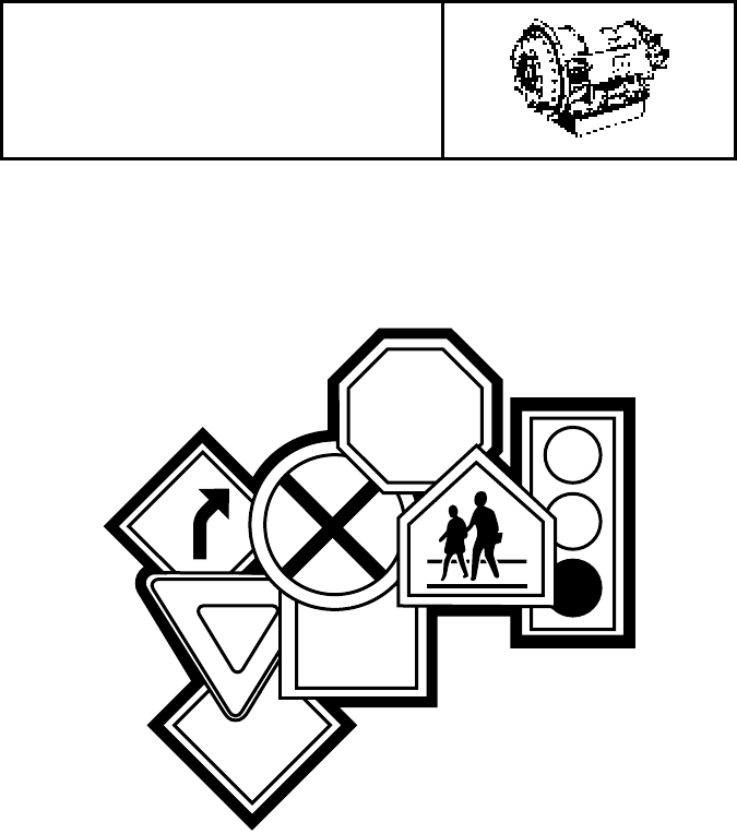
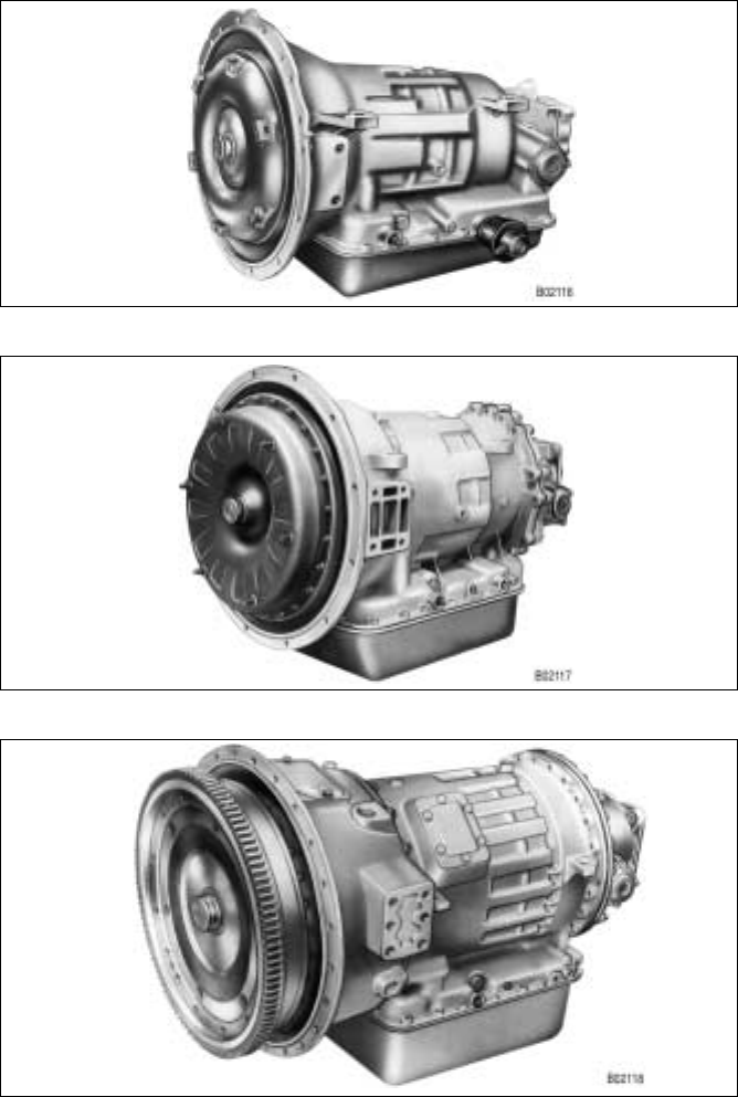
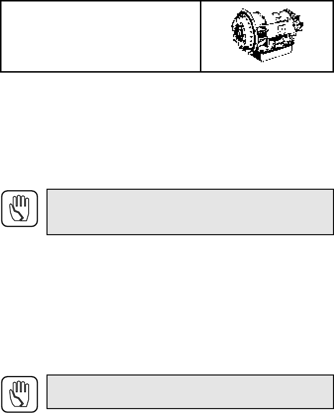
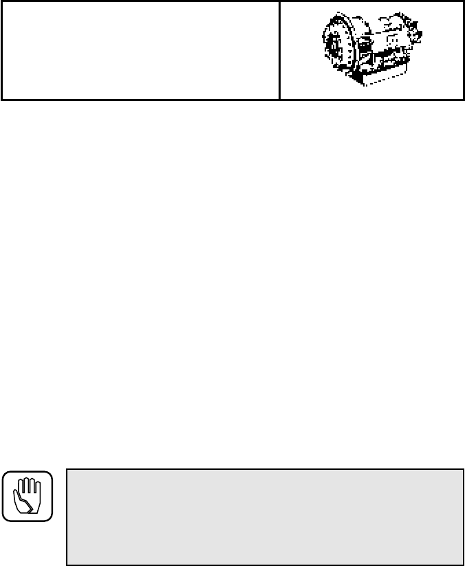
TYPICAL AT, MT, AND HT MODEL TRANSMISSIONS
AT Model Transmission
MT Model Transmission
HT Model Transmission
3
A BRIEF DESCRIPTION OF THE ALLISON AUTOMATIC
Allison automatics described in this manual include a hydraulic torque converter, a
planetary gear train, and a hydraulic control system which supplies fluid under
pressure to apply the clutches and automatically shift ranges.
The torque converter multiplies engine torque during starts and acts as a hydraulic
cushion between the engine and gearing. The clutches and gear sets provide multiple
speeds forward and one speed reverse.
The torque converter lockup clutch, for maximum fuel economy, engages
automatically after the vehicle is moving. All models in this manual, except AT 500,
have a lockup clutch.
TORQUE CONVERTER
The torque converter consists of three elements — pump, turbine, and stator. The
pump is the input element and is driven by the engine. The turbine is the output
element and is driven by fluid from the pump, or directly by the pump when the
lockup clutch is engaged. The stator is the reaction (torque multiplying) element.
The torque converter is continuously filled with fluid. The pump, driven by the engine,
directs the fluid against the turbine vanes, which causes the turbine to rotate. The
turbine returns the fluid through the stator, which redirects the flow so that fluid strikes
the pump vanes in the same direction that the pump is rotating. As the pump turns
faster in relation to the turbine, the velocity of the fluid increases and so does the
torque multiplication.
As the speed of the turbine approaches the speed of the pump, the fluid flow starts
striking the back sides of the stator vanes. This causes the stator to freewheel in the
same direction as the pump and turbine. When this occurs, the torque multiplication
stops and the converter functions as a fluid coupling.
LOCKUP CLUTCH (AT 1500, MT(B) 600, HT 700)
The lockup clutch consists of three elements — piston, clutch plate, and backplate.
The piston and backplate are driven by the engine. The clutch plate, located between
the piston and backplate, is splined to the converter turbine.
The lockup clutch automatically engages after the vehicle is moving and the torque
multiplication demand is low. Engagement of the lockup clutch mechanically
connects the torque converter pump to the turbine and provides a direct drive from the
engine to the transmission. The lockup clutch automatically releases at lower vehicle
speeds. When the lockup clutch is not engaged, drive from the engine is transmitted
hydraulically through the converter to the transmission gearing.
4
Because the converter lockup engagement and release are designed to fit the vehicle’s
vocation, there are many variations among transmission assemblies. Lockup speeds
are determined by many factors. Among these are transmission-engine match,
transmission-vehicle match, model year, throttle position, and calibration of the
hydraulic system. Some models have lockup available in all ranges. Others have
lockup available in the upper ranges. Some models have modulated lockup, which
provides better engine braking by delaying lockup disengagement during closed-
throttle operation. For specific information on the lockup characteristics of your
transmission, contact your dealer or distributor.
Lockup engagement, like range shifts, may be felt under some conditions. The driver
who counts shifts should not confuse lockup with a range change. A little driving
experience with the Allison automatic will enable the driver to distinguish between the
two kinds of shifts.
5
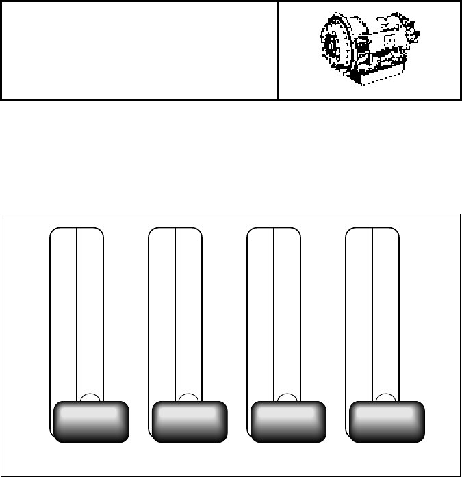
The vehicle manufacturers may choose different types of shift selectors for their
equipment. Different transmission models may also require different designations on
the shift selectors.
Typical Shift Selector Labeling
These are some of the typical shift selectors you may find in Allison-equipped
vehicles. The range selector in your vehicle may vary from these or may have
1
(First Range) at the top and
R
(Reverse) at the bottom. Some models may have
a
P
(Park) position.
The best performance will be obtained by using the correct range for each driving
condition. The following table illustrates shift patterns for the various models and
indicates the page that explains the shift pattern for your vehicle.
R
N
D
4
3
2
1
R
N
D
3
2
1
R
N
D
2-4
2-3
2
1
R
N
D
2-4
2
1
V01958.01
SHIFT SELECTORS
6
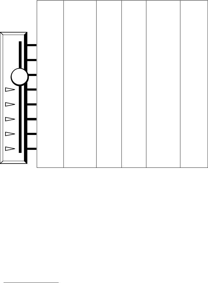
ALLISON AUTOMATICS
Typical AT, MT, HT Shift Selector Positions
When your vehicle is equipped with an Allison automatic, it is not necessary to select
the right moment to upshift or downshift during the changing road and traffic
conditions. The Allison automatic does it for you. A knowledge of the ranges available
at your shift selector will make control of the vehicle and your job even easier.
When the shift selector has no
P
(Park) provision, always put the selector in
N
(Neutral) and apply the parking brake (or service brakes if the vehicle is not
equipped with a parking brake) to hold the vehicle when it is unattended and before
turning off the engine.
* Available on AT 500 Series and AT 1500 Series models
only
(refer to Page 7).
+ This position not present on models with
P
(Park).
** Optional.
◊
Without second gear start.
AT 500
Series And
AT 1500
Series
MT 640,
MT(B) 643,
MT 643R,
MT(B) 644
◊
,
MT(B) 647
MT 650,
MT(B)
653DR
HT 740,
HT 747
HT 750CR,
HT 754CR,
MT(B) 654CR
◊
HT 750DR
(DR DB)
Park — — — — —
Reverse Reverse Reverse Reverse Reverse Reverse
Neutral Neutral Neutral Neutral Neutral Neutral
1–4 1–4 2–5 1–4 1–5 2–5
1–3 1–3 2–4 1–3 1–4 2–4
1–2
+
1–2 2 (2–3**) 1–2 1–3 2–3
1 1 1 1 1–2 2
———— 1 1
(Pages 7-10) (Pages 9-10) (Pages 11-12)(Pages 9-10) (Pages 13-14) (Pages 15-16)
P*
R
N
V01959
7
RAN
GE SELECTION — AT 500 SERIES AND AT 1500 SERIES WITH A
SECOND NEUTRAL (PARK)
P
This activates the vehicle parking brake and at the same time puts the
transmission in neutral. Use this position when you start the engine. If the
engine starts in any other position, except
N
(Neutral), the neutral start
switch is malfunctioning.
R
Use this to back the vehicle. Completely stop the vehicle before shifting
from a forward range to
R
(Reverse) or from
R
(Reverse) to a forward
range. The reverse warning signal is activated when the shift selector is in
this position. Reverse has only one range. Reverse operation also provides
the greatest tractive advantage.
N
Neutral position is used during stationary operation of the power takeoff
(if your vehicle is equipped with a PTO).
D
The transmission will initially attain 1st range and, as vehicle speed
increases, the transmission will upshift to 2nd range, 3rd range, and 4th
range automatically. As the vehicle slows down, the transmission will
downshift to the correct range automatically.
WARNING: If you leave the vehicle and the engine is running, the
vehicle can move suddenly and you or others could be injured. If you
must leave the engine running, do not leave the vehicle until you:
• Put the transmission in N (Neutral)...and
• Apply the parking brake and emergency brakes and make sure they are
properly engaged...and
• Chock the wheels and take any other steps necessary to keep the
vehicle from moving.
WARNING: If you let the vehicle coast in N (Neutral), there is no
engine braking and you could lose control. Coasting can also cause
severe transmission damage. To help avoid injury and property damage,
do not allow the vehicle to coast in N (Neutral).
WARNING: If you just downshift or just use service brakes when going
downhill, you can lose control and cause injury and property damage. To
help avoid loss of control, use a combination of downshifting, braking,
and other retarding devices. Downshifting to a lower transmission range
increases engine braking and helps you to maintain control. The
transmission has a feature to prevent automatic upshifting above the
lower range selected. However, during downhill operation, if engine
governed speed is exceeded in the lower range, the transmission may
upshift to the next higher range. This will reduce braking and could
cause a loss of control. Apply the vehicle brakes or other retarding
device to prevent exceeding engine governed speed in the lower range
selected.

8
RAN
GE SELECTION — AT 500 SERIES AND AT 1500 SERIES WITH A
SECOND NEUTRAL (PARK)
(cont’d)
3
2
Occasionally, the road, load, or traffic conditions will make it desirable to
restrict the automatic shifting to a lower range. (When conditions
improve, return the selector to the normal
D
(Drive) position.) These
positions also provide greater engine braking for going down grades (the
lower the range, the greater the braking effect).
1
Use this range when pulling through mud and snow or driving up or down
steep grades. This range provides the vehicle with maximum driving
power and maximum engine braking power.
9
RANGE SELECTION — AT 500 SERIES AND AT 1500 SERIES
WITHOUT A SECOND NEUTRAL (PARK)
; MT 640, MT(B) 643,
MT 643R, MT(B) 644, MT 647; HT 740, HT 747
R
Use this to back the vehicle. Completely stop the vehicle before shifting
from a forward range to
R
(Reverse) or from
R
(Reverse) to a forward
range. The reverse warning signal is activated when the shift selector is in
this position. Reverse has only one range. Reverse operation also
provides the greatest tractive advantage.
N
Use this position when you start the engine. If the engine starts in any
other position, the neutral start switch is malfunctioning. Neutral position
is also used during stationary operation of the power takeoff (if your
vehicle is equipped with a PTO).
D
The transmission will initially attain 1st range and, as vehicle speed
increases, the transmission will upshift to 2nd range, 3rd range, and 4th
range automatically. As the vehicle slows down, the transmission will
downshift to the correct range automatically.
WARNING: If you leave the vehicle and the engine is running, the
vehicle can move suddenly and you or others could be injured. If you
must leave the engine running, do not leave the vehicle until you:
• Put the transmission in N (Neutral)...and
• Apply the parking brake and emergency brakes and make sure they are
properly engaged...and
• Chock the wheels and take any other steps necessary to keep the
vehicle from moving.
WARNING: If you let the vehicle coast in N (Neutral), there is no
engine braking and you could lose control. Coasting can also cause
severe transmission damage. To help avoid injury and property damage,
do not allow the vehicle to coast in N (Neutral).
WARNING: If you just downshift or just use service brakes when going
downhill, you can lose control and cause injury and property damage. To
help avoid loss of control, use a combination of downshifting, braking,
and other retarding devices. Downshifting to a lower transmission range
increases engine braking and helps you to maintain control. The
transmission has a feature to prevent automatic upshifting above the
lower range selected. However, during downhill operation, if engine
governed speed is exceeded in the lower range, the transmission may
upshift to the next higher range. This will reduce braking and could
cause a loss of control. Apply the vehicle brakes or other retarding
device to prevent exceeding engine governed speed in the lower range
selected.

10
RANGE SELECTION — AT 500 SERIES AND AT 1500 SERIES
WITHOUT A SECOND NEUTRAL (PARK)
; MT 640, MT(B) 643,
MT 643R, MT(B) 644, MT 647; HT 740, HT 747
(cont’d)
3
2
Occasionally, the road, load, or traffic conditions will make it desirable to
restrict the automatic shifting to a lower range. (When conditions
improve, return the selector to the normal
D
(Drive) position.) These
positions also provide greater engine braking for going down grades (the
lower the range, the greater the braking effect).
1
Use this range when pulling through mud and snow or driving up or down
steep grades. This range provides the vehicle with maximum driving
power and maximum engine braking power.
11
RANGE SELECTION — MT 650; MT(B) 653DR
R
Use this to back the vehicle. Completely stop the vehicle before shifting
from a forward range to
R
(Reverse) or from
R
(Reverse) to a forward
range. The reverse warning signal is activated when the shift selector is in
this position. Reverse has only one range.
N
Use this position when you start the engine. If the engine starts in any
other position, the neutral start switch is malfunctioning. Neutral position
is also used during stationary operation of the power takeoff (if your
vehicle is equipped with a PTO).
2–5
D
The transmission will initially attain 2nd range and, as vehicle speed
increases, the transmission will upshift to 3rd range, 4th range, and 5th
range automatically. As the vehicle slows down, the transmission will
downshift to the correct range automatically.
2–4
Occasionally, the road, load, or traffic conditions will make it desirable to
restrict the automatic shifting to a lower range. (When conditions
improve, return the selector to the normal
D
(Drive) position.)
WARNING: If you leave the vehicle and the engine is running, the
vehicle can move suddenly and you or others could be injured. If you
must leave the engine running, do not leave the vehicle until you:
• Put the transmission in N (Neutral)...and
• Apply the parking brake and emergency brakes and make sure they are
properly engaged...and
• Chock the wheels and take any other steps necessary to keep the
vehicle from moving.
WARNING: If you let the vehicle coast in N (Neutral), there is no
engine braking and you could lose control. Coasting can also cause
severe transmission damage. To help avoid injury and property damage,
do not allow the vehicle to coast in N (Neutral).
WARNING: If you just downshift or just use service brakes when going
downhill, you can lose control and cause injury and property damage. To
help avoid loss of control, use a combination of downshifting, braking,
and other retarding devices. Downshifting to a lower transmission range
increases engine braking and helps you to maintain control. The
transmission has a feature to prevent automatic upshifting above the
lower range selected. However, during downhill operation, if engine
governed speed is exceeded in the lower range, the transmission may
upshift to the next higher range. This will reduce braking and could
cause a loss of control. Apply the vehicle brakes or other retarding
device to prevent exceeding engine governed speed in the lower range
selected.

12
RANGE SELECTION — MT 650; MT(B) 653DR
(cont’d)
2
2–3
Use this position for vehicle speed control up or down steep grades or for
other undesirable driving conditions.
1
This is the creeper range — select this for off-highway operation. Use the
creeper for pulling through mud or snow. This range provides the greatest
tractive advantage. It is not recommended that full-power 1–2 or 2–1
shifts be made.
13
RANGE SELECTION — HT 750CR, HT 754CR, MT(B) 654CR
R
Use this to back the vehicle. Completely stop the vehicle before shifting
from a forward range to
R
(Reverse) or from
R
(Reverse) to a forward
range. The reverse warning signal is activated when the shift selector is in
this position. Reverse operation provides the greatest tractive advantage.
Reverse has only one range.
N
Use this position when you start the engine. If the engine starts in any
other position, the neutral start switch is malfunctioning. Neutral position
is also used during stationary operation of the power takeoff (if your
vehicle is equipped with a PTO).
D
The transmission will initially attain 1st range and, as vehicle speed
increases, the transmission will upshift to 2nd range, 3rd range, 4th range,
and 5th range automatically. As the vehicle slows down, the transmission
will downshift to the correct range automatically.
WARNING: If you leave the vehicle and the engine is running, the
vehicle can move suddenly and you or others could be injured. If you
must leave the engine running, do not leave the vehicle until you:
• Put the transmission in N (Neutral)...and
• Apply the parking brake and emergency brakes and make sure they are
properly engaged...and
• Chock the wheels and take any other steps necessary to keep the
vehicle from moving.
WARNING: If you let the vehicle coast in N (Neutral), there is no
engine braking and you could lose control. Coasting can also cause
severe transmission damage. To help avoid injury and property damage,
do not allow the vehicle to coast in N (Neutral).
WARNING: If you just downshift or just use service brakes when going
downhill, you can lose control and cause injury and property damage. To
help avoid loss of control, use a combination of downshifting, braking,
and other retarding devices. Downshifting to a lower transmission range
increases engine braking and helps you to maintain control. The
transmission has a feature to prevent automatic upshifting above the
lower range selected. However, during downhill operation, if engine
governed speed is exceeded in the lower range, the transmission may
upshift to the next higher range. This will reduce braking and could
cause a loss of control. Apply the vehicle brakes or other retarding
device to prevent exceeding engine governed speed in the lower range
selected.

14
RANGE SELECTION — HT 750CR, HT 754CR, MT(B) 654CR
(cont’d)
4
3
2
Occasionally, the road, load, or traffic conditions will make it desirable to
restrict the automatic shifting to a lower range. (When conditions
improve, return the selector to the normal
D
(Drive) position.) The
positions also provide a greater engine braking for going down grades
(the lower the range, the greater the braking effect).
1
Use this range when pulling through mud and snow or driving up or down
steep grades. This range provides the vehicle with maximum driving
power and maximum engine braking power.
15
RANGE SELECTION — HT 750DR, HT 750DR DB
R
Use this to back the vehicle. Completely stop the vehicle before shifting
from a forward range to
R
(Reverse) or from
R
(Reverse) to a forward
range. The reverse warning signal is activated when the shift selector is in
this position. Reverse operation provides the greatest tractive advantage.
Reverse has only one range.
N
Use this position when you start the engine. If the engine starts in any
other position, the neutral start switch is malfunctioning. Neutral position
is also used during stationary operation of the power takeoff (if your
vehicle is equipped with a PTO).
2–5
The transmission will initially attain 2nd range and, as vehicle speed
increases, the transmission will upshift to 3rd range, 4th range, and 5th
range automatically. As the vehicle slows down, the transmission will
downshift to the correct range automatically.
2–4
2–3
Occasionally, the road, load, or traffic conditions will make it desirable to
restrict the automatic shifting to a lower range. (When conditions
improve, return the selector to the normal
D
(Drive) position.) The
positions also provide a greater engine braking for going down grades
(the lower the range, the greater the braking affect).
WARNING: If you leave the vehicle and the engine is running, the
vehicle can move suddenly and you or others could be injured. If you
must leave the engine running, do not leave the vehicle until you:
• Put the transmission in N (Neutral)...and
• Apply the parking brake and emergency brakes and make sure they are
properly engaged...and
• Chock the wheels and take any other steps necessary to keep the
vehicle from moving.
WARNING: If you let the vehicle coast in N (Neutral), there is no
engine braking and you could lose control. Coasting can also cause
severe transmission damage. To help avoid injury and property damage,
do not allow the vehicle to coast in N (Neutral).
WARNING: If you just downshift or just use service brakes when going
downhill, you can lose control and cause injury and property damage. To
help avoid loss of control, use a combination of downshifting, braking,
and other retarding devices. Downshifting to a lower transmission range
increases engine braking and helps you to maintain control. The
transmission has a feature to prevent automatic upshifting above the
lower range selected. However, during downhill operation, if engine
governed speed is exceeded in the lower range, the transmission may
upshift to the next higher range. This will reduce braking and could
cause a loss of control. Apply the vehicle brakes or other retarding
device to prevent exceeding engine governed speed in the lower range
selected.

16
RANGE SELECTION — HT 750DR, HT 750DR DB (cont’d)
2Use this position for vehicle speed control up or down steep grades or for
other undesirable road conditions.
1This is the creeper range — select this for off-highway operation. Use the
creeper for pulling through mud or snow. This range provides the greatest
tractive advantage. It is not recommended that 1–2 or 2–1 shifts be made
while the vehicle is moving.
17
THROTTLE CONTROL
The position of the throttle influences the automatic shifting. At wide open throttle, the
transmission will upshift automatically near the governed speed of the engine. At part
throttle, shifts will occur at a lower engine speed. When modulated lockup is
provided, closed-throttle operation delays the release of the lockup clutch to provide
additional engine braking at lower vehicle speeds.
DOWNSHIFT INHIBIT FEATURE
The transmission hydraulic system will inhibit a shift into any range at a speed that
will cause engine overspeed. Any lower, forward range may be selected at any time,
but the actual engagement will not occur until road speed is reduced; downshifting is
progressive as road speed decreases. The inhibit effect will cause downshifts to occur
at slightly higher speeds than normal automatic downshifts.
OPERATING IN COLD WEATHER
Refer to Table 2 on Page 31 for the minimum fluid temperatures at which the
transmission may be safely operated in a forward or reverse range. When ambient
temperature is below the minimum fluid temperature limit and the transmission is
cold, preheat is required. If auxiliary heating equipment is not available, run the
equipment or vehicle with the transmission in neutral for a minimum of 20 minutes
before attempting range operation.
CAUTION: Never shift from N (Neutral) to D (Drive) or
N (Neutral) to R (Reverse) at engine speeds above idle. The vehicle
will lurch forward or rearward and the transmission can be damaged.
CAUTION: Disregarding minimum fluid temperature limits can
result in transmission malfunction or reduced transmission life.
DRIVING TIPS
18
USING THE ENGINE FOR DOWNHILL BRAKING TO SLOW
THE VEHICLE OR EQUIPMENT
To use the engine as a braking force, select the next lower range. If the vehicle is
exceeding the maximum speed for the lower range, use the service brakes and/or
hydraulic retarder to slow the vehicle so that the lower range is obtained.
USING THE HYDRAULIC RETARDER
WARNING: The transmission incorporates a hold feature to pro-
hibit upshifting above the range selected during normal driving. For
downhill operation, select a lower transmission range. However, if
engine governed speed is exceeded in the held range, the transmis-
sion may upshift to the next higher range and damaging engine
overspeed is a possibility. Use the vehicle brakes or retarder to pre-
vent exceeding engine governed speed in the held range.
NOTE: Transmissions that do not have a lockup clutch (AT 540,
AT 542, AT 545) provide less engine braking than units which have a
lockup clutch. Downhill speed control for non-lockup units without a
retarder must rely on the service brakes.
WARNING: Do not use the retarder during inclement weather or
when road surfaces are slippery. De-energize the retarder at the
master control switch.
CAUTION: Observe the following cautions when driving a vehicle
equipped with an input or output retarder:
• APPLY AND OPERATE THE RETARDER WITH ENGINE AT
CLOSED THROTTLE ONLY.
• OBSERVE TRANSMISSION AND ENGINE TEMPERATURE
LIMITS AT ALL TIMES. Select the lowest possible
transmission range to increase the cooling system capacity and
total retardation available.
• OBSERVE THE RETARDER “ALERT LIGHT” to ensure that
the vehicle control system is functioning properly.
• DO NOT OPERATE THE INPUT OR OUTPUT RETARDER
SIMULTANEOUSLY WITH AN ENGINE EXHAUST BRAKE.
Extreme torque loads can be produced in the range section,
damaging the transmission.
• In the event of OVERHEATING, DECREASE USE OF THE
HYDRAULIC RETARDER; USE THE SERVICE BRAKES.

19
Hydraulic retarders are available on some models of the AT 500, MT 600, and HT 700
Series transmissions. The AT 500 retarder and the MT 643R input retarder are located
between the torque converter and the transmission gearing. The MT 600 output
retarder is installed on the rear of the transmission in place of the output housing. The
HT 700 retarder is installed between the torque converter and the transmission
gearing. The function of the retarder is to provide auxiliary retardation.
The AT 500 Series retarder is available on models without lockup or PTO provision.
The MT 643R retarder is available on models with lockup but without PTO provision.
The retarder is an integral part of the transmission which slows the vehicle by
applying a hydraulic braking force. Retardation and cooling are greatest at high input
(engine) speeds. Maintain high input speed by preselecting a lower range. The
external retarder controls (OEM-furnished) consist of a master switch and typical
options shown in Table 1. External retarder controls apply the retarder at the
50 percent or at the 100 percent level. External controls are also required to
automatically turn off the retarder in first range or when the vehicle anti-lock brake
system is activated. External controls also provide a signal to the modulator control.
The signal causes downshifts to occur at a higher speed when the retarder is operating
than would normally occur during closed throttle operation.
The MT 600 Series output retarder is mounted on the rear of the transmission as an
integral part of the transmission and provides your vehicle with an auxiliary
retardation system to slow the vehicle. The unit combines hydraulic and friction clutch
retardation capabilities. In many applications, the retarder is applied in conjunction
with the service brakes.
Table 1. Typical AT/MT Input Retarder Controls
Type Description Amount Of Application
Manual Manual 3-Position Switch 0%, 50%, Or 100%
Automatic 12V or 24V Signal When Closed Throttle Is Sensed 50% Or 100%
12V or 24V Signal When Brake Pedal Is Applied 50% Or 100%
Combination Manual 2-Position Switch and Closed Throttle
Sensor 50% From One Device,
100% From The Second
Device
Manual 2-Position Switch And Brake Pedal Apply 50% From Switch,
100% From Brake Pedal
Closed Throttle Sensor Plus Brake Apply Sensor 50% From Closed Throttle,
100% When Brake Applied

20
The HT 700 Series retarder, located between the torque converter and the transmission
gearing, provides hydraulic retardation capabilities to slow the vehicle. Maximum
retarder effect in this series occurs at high input speed. Selecting a lower hold range
position when using this type retarder is recommended for maximum effect.
Depending on the vehicle retarder apply system used, partial retarder application is
available when maximum application is not needed.
AUXILIARY TRANSMISSION
Select the desired auxiliary gear ratio while the vehicle is stopped. Do not shift the
auxiliary transmission while the vehicle is moving.
TWO-SPEED AXLE
The two-speed axle may be shifted from low to high or high to low while the
vehicle is moving without damaging the transmission. However, the axle or vehicle
manufacturer’s recommendations should be followed for shifting the axle. It is
recommended that axle shifts be made with the transmission in the highest range to
prevent a transmission range shift from coinciding with an axle shift.
TOWING OR PUSHING
PARKING BRAKE
On a vehicle with no P (Park) position on the transmission shift selector, always put
the selector in N (Neutral) and apply the parking brake (or emergency brake if the
vehicle is not equipped with a parking brake) to hold the vehicle when it is unattended.
CAUTION: Failure to disconnect the driveline or remove the axle
shafts before towing or pushing can cause serious transmission
damage.
The engine cannot be started by towing or pushing. Before towing
or pushing a vehicle, disconnect the driveline or lift the drive
wheels off the road. If the vehicle is a motor coach, remove the axle
shafts from the drive wheels. When the axle shafts are removed, be
sure to cover the wheel openings to prevent loss of lubricant and en-
try of dust and dirt. An auxiliary air supply will usually be required
to actuate the vehicle brake system.
21
DRIVING ON ICE OR SNOW
The ALLISON AUTOMATIC continuously provides proper balance between required
power and good traction. The driver can have better control of his vehicle because of
this smooth, constant flow of power through the drivetrain. When driving on ice or
snow, any acceleration or deceleration should be made gradually.
ROCKING OUT
If the vehicle is stuck in deep sand, snow, or mud, it may be possible to “rock” it out.
Shift to D (Drive) and apply steady, light throttle (never full throttle). When the
vehicle has rocked forward as far as it will go, apply and hold the vehicle service
brakes. Allow the engine to return to idle; then select R (Reverse). Apply a steady,
light throttle and allow the vehicle to rock in R (Reverse) as far as it will go. Again
apply and hold the service brakes and allow the engine to return to idle. This
procedure may be repeated in D (Drive) and R (Reverse) if each directional shift
continues to move the vehicle a greater distance. Never make neutral-to-range or
directional shift changes when the engine rpm is above idle.
TEMPERATURES
The transmission fluid temperature is indicated in some vehicles by a gauge which
usually indicates oil temperature to the cooler (converter out). In some vehicles the
only temperature indication is the engine coolant temperature indicator.
Some important transmission temperatures are shown in the following table.
WARNING: Do not use the retarder during inclement weather or
when road surfaces are slippery. De-energize the retarder at the
master control switch.
CAUTION: DO NOT make neutral-to-range or directional shift
changes when engine rpm is above idle. Failure to return to idle will
subject the transmission to excessive shock loads which could cause
clutch and/or shaft damage. Also, do not allow the transmission to
overheat while rocking out.
Sump Fluid, Minimum Continuous 100°F (40°C)
Sump Fluid, Typical Continuous 200°F (93°C)
Converter Out Fluid, Maximum 300°F (149°C)
Retarder Out Fluid, Maximum 330°F (165°C)
Sump Fluid, Maximum 250°F (121°C)
22
The transmission must never be operated above any of the maximum temperatures
shown in the table.
Extended operations at low vehicle speeds with the engine at full throttle or during
extended use of the hydraulic retarder can cause excessively high fluid temperatures in
the transmission. These temperatures may tend to overheat the engine cooling system
as well as cause possible transmission damage.
• If excessive temperature is indicated by the engine coolant temperature gauge,
stop the vehicle and determine the cause as soon as safely possible. If the
cooling system appears to be functioning properly, the transmission may be
overheated. Shift to N (Neutral) and accelerate the engine to 1200–1500 rpm.
If the transmission is the cause, this should reduce the engine coolant
temperature to operating level within a short time.
• If excessive temperature is indicated by the transmission fluid temperature
gauge, stop the vehicle as soon as safely possible and shift to N (Neutral).
Accelerate the engine to 1200–1500 rpm and allow the temperature to return
to normal (2 or 3 minutes) before resuming operation.
• If the transmission overheats during normal operation, check the fluid level in
the transmission. (Refer to the fluid check procedure found on Page 27 in the
Care and Maintenance section of this handbook.)
• If high temperature in either the engine or transmission persists, stop the
engine and have the overheating condition investigated by maintenance
personnel.
CAUTION: Never operate the engine for more than 30 seconds at
full throttle with the transmission in range and the output stalled.
Prolonged operation of this type will cause the transmission fluid
temperature to become excessively high and will result in severe
overheat damage to the transmission.
NOTE: When overheating occurs during retarder operation, do the
following.
• For output retarders, reduce retarder usage.
• For input retarders, reduce retarder usage and increase the
retarder’s cooling ability. For AT 500(R) or MT 643R input
retarders, overheating can be reduced by using 50 percent apply
instead of 100 percent.
23
ENGINE-DRIVEN PTO
Some models provide PTO mountings on the top and side of the torque converter
housing. The type of PTO installed will determine the operating procedures.
If the PTO driven gear is in constant mesh with the drive gear in the converter housing,
and a friction clutch is used to connect the PTO load, the PTO can be engaged or
disengaged at any time (except at engine speeds that exceed drive speed limits
imposed on the driven equipment). If the PTO is engaged by either a sliding gear or
dog clutch, the vehicle engine must be stopped to engage or disengage the PTO. Do
not exceed the drive speed limits of the driven equipment.
CONVERTER-DRIVEN PTO
A power takeoff may be mounted onto the mounting pad on the side of the
transmission. The PTO drive gear is turbine driven and thus provides infinitely
variable speeds. The power takeoff can be operated when the vehicle is either moving
or stopped. However, on some applications the PTO can be operated only when the
transmission is in neutral.
To operate the power takeoff, follow these instructions:
• Stop the vehicle, set the brakes, and idle the engine.
• Place the shift selector in a drive range.
CAUTION: Always allow the engine to return to idle speed before
shifting to a forward or reverse range after operating the PTO with
the transmission in neutral. Failure to return to idle will subject the
transmission to excessive shock loads which could cause clutch
and/or shaft damage.
POWER TAKEOFF
OPERATION
24
• Engage the PTO.
Typical PTO Drive Gear And Mounting Pad
• If the power takeoff will be operated while the vehicle is stopped, set the
parking brake, shift the transmission to N (Neutral), and depress the
accelerator as required. Disengage the PTO after returning the engine speed to
idle and stopping the PTO-driven equipment.
• If the power takeoff will be operated while the vehicle is moving, simply
select the desired range and depress the accelerator as required. However, the
speed of the power takeoff during this type of operation will be affected by the
ranges selected and the speed of the vehicle.
• To disengage the power takeoff, stop the vehicle, idle the engine, and set the
brake. Place the shift selector in a drive range, stop the PTO-driven
equipment, and disengage the power takeoff. Return the transmission shift
selector to N (Neutral).
CAUTION: Never engage the PTO by clashing the gear teeth. This
may damage the PTO unit and the PTO drive gear teeth. Stop clash-
ing by releasing the vehicle brakes and allowing the vehicle to
move slightly or by moving the shift selector from a drive range to
N (Neutral) and back to a drive range.
CAUTION: Do not exceed the speed limits imposed on the driven
equipment during operation of the PTO.
PTO DRIVE GEAR
PTO MOUNTING PAD
E00874.01
25
PERIODIC INSPECTIONS
The ALLISON AUTOMATIC requires minimum maintenance. Careful attention to
the fluid level, selector linkage, and throttle (modulator) linkage is most important.
For easier inspection, the transmission should be kept clean. Report any abnormal
condition to your maintenance personnel.
Inspect the transmission for the following.
• loose bolts (transmission and mounting components)
• transmission fluid leaks*
• shift linkage freely positioned by transmission detent
• for mechanical modulator valve actuators:
— full (and ease of) movement of mechanical modulator linkage
— vacuum or air line and modulator for leaks
• for electrical modulator valve actuators: proper connections, wire routing and
operation
• damaged or loose hydraulic lines
• damaged or loose electrical harnesses
• worn or frayed electrical connections
• driveline U-joints and slip fittings
• speedometer cable and fittings
• PTO linkage and driveline
Inspect the transmission fluid for the following.
• Check transmission and dropbox fluid levels regularly. Once consistent daily
hot level checks have been established and daily inspection shows no sign of
transmission leakage, less frequent checks could be made.
• Check the engine cooling system occasionally for evidence of transmission
fluid, which would indicate a faulty cooler.
* Transmission fluid leaks require immediate attention.
CARE AND
MAINTENANCE
26
PREVENT MAJOR PROBLEMS
Minor problems can be kept from becoming major problems if you notify
maintenance personnel when any of these conditions occur:
• Overheating
• Shifting feels odd
• Transmission leaks fluid
• Unusual transmission-related sounds (changes in sound level caused by
normal engine thermostatic fan cycling while climbing a long grade with a
heavy load have been mistaken for unusual transmission-related sounds).
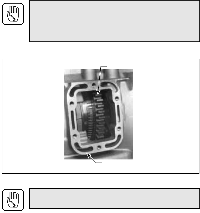
IMPORTANCE OF PROPER FLUID LEVEL
Because the transmission fluid cools, lubricates, and transmits hydraulic power, it is
important that the proper fluid level be maintained at all times. If the fluid level is too
low, the converter and clutches will not receive an adequate supply of fluid. If the level
is too high, the fluid will aerate, the transmission will overheat, and fluid may be
expelled through the breather or dipstick tube.
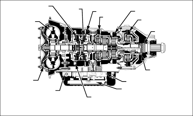
Transmission Cross-Section Showing Internal Components
LOCKUP
CLUTCH
MODULATED LOCKUP VALVE
(OPTIONAL) CONVERTER-DRIVEN POWER
TAKEOFF DRIVE GEAR
MT 653DR
OIL FILTER
CONTROL VALVE BODY
GOVERNOR DRIVEN
GEAR
SPEEDOMETER
DRIVE GEAR
LOW CLUTCH
FIRST CLUTCH
SECOND
CLUTCH
THIRD CLUTCH
FOURTH
CLUTCH
FORWARD
CLUTCH
TORQUE
CONVERTER
V01960
27
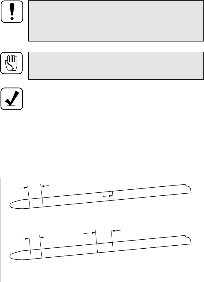
TRANSMISSION FLUID CHECK PROCEDURE
Typical Dipstick Markings
WARNING: Take the following precautions so that unexpected, pos-
sible sudden vehicle movement is avoided. Whenever it becomes nec-
essary to leave the vehicle, even momentarily, while the engine is
running, place the transmission shift selector in N (Neutral) or P (Park),
set the parking brake and/or emergency brakes and chock the wheels.
CAUTION: Dirt and foreign matter must not be permitted to enter
the fluid system. It can cause valves to stick, cause undue wear of
transmission parts, or clog passages.
NOTE:
• Always check the transmission fluid level a minimum of two times.
Consistency is important in maintaining accuracy. If inconsistent
readings persist, check the transmission breather and the vent hole in
the dipstick fill tube to ensure they are clean and free of debris. The
vent hole is located on the underside of the fill tube just below the seal
of the dipstick cap.
• Transmissions equipped with a transfer gear housing (dropbox)
contain two separate hydraulic systems: the transmission system and
the dropbox system. Each system uses different transmission fluid and
must be checked independently.
V01961.01
REF
FILL COLD
RUN
BAND
OR HOT RUN
BAND
CHECK IN NEUTRAL AT
IDLE - USE DEXRON® FLUID
COLD RUN
BAND
HOT OVERFILL CHECK IN NEUTRAL AT
IDLE - USE DEXRON® FLUID
RECOMMENDED DIPSTICK MARKINGS
ALTERNATE DIPSTICK MARKINGS
28
Check the fluid level by the following procedures and record any abnormal fluid level,
milky appearance, or any trace of coolant in the fluid on your maintenance records.
Cold Check
• Park the vehicle on a level surface, set the parking brake and/or emergency
brakes, and chock the vehicle wheels.
• Run the engine at 1000–1500 rpm for 1 minute to purge air from the system.
Return engine to idle, then shift to D (Drive) and then to R (Reverse) to fill the
hydraulic circuits with fluid. Then shift to N (Neutral) or P (Park) and allow
the engine to idle (500–800 rpm). A cold check should be made when the
sump fluid temperature is 60–120˚F (16–49˚C). This temperature typically
occurs within the first ten minutes of operation during initial start-up.
• Clean around the end of the fill tube before removing the dipstick. Wipe the
dipstick clean and check the fluid level. If the fluid on the dipstick is within
the COLD RUN or REF FILL band, the level is satisfactory for operating the
transmission until the fluid is hot enough to perform a HOT RUN check. If the
fluid level is not within the COLD RUN or REF FILL band, add or drain fluid
as necessary to bring the level to the middle of the band.
• Perform a hot check at the first opportunity.
NOTE: The only purpose of the Cold Check is to determine if the
transmission has enough fluid to be safely operated until a Hot Check
can be made.
CAUTION: The fluid level rises as sump temperature increases.
DO NOT fill above the COLD RUN band if the transmission fluid
is below normal operating temperature.
NOTE: To ensure an accurate cold check, operate the transmission
until the sump fluid temperature is 60–120°F (16–49°C). This
temperature is usually reached within the first ten minutes of operation
from initial start-up.

29
Hot Check
• Shift to D (Drive) and then to R (Reverse) to fill the hydraulic circuits with
fluid.
• Park the vehicle on a level surface and shift to N (Neutral) or P (Park). Set the
parking brake and/or emergency brakes and chock the vehicle wheels. Allow
the engine to idle (500–800 rpm).
• After wiping the dipstick clean, check the fluid level. The safe operating range
is anywhere between the FULL and ADD lines, within the HOT RUN band,
or below the HOT OVERFULL mark and above the COLD RUN band.
• If the fluid level is outside of these parameters, raise or lower the fluid level to
bring it within the correct markings on the dipstick. Approximately one quart
(one liter) of fluid is required to raise the level from the bottom to the top of
the band.
DROPBOX FLUID CHECK PROCEDURE
• Bring the dropbox to operating temperature.
• Park the vehicle on level ground, set the parking brake, and turn off the
engine.
• If a level indicator (fill tube) is used, remove the fill tube plug and check the
fluid. Full capacity is indicated when the fluid is at the top of the fill tube.
Maintain a full capacity by adding the required amount of fluid.
• If a dipstick is used, wipe the dipstick clean. Insert the dipstick into the filler
tube, remove the dipstick and check the level. The safe level is any level
between the Full and Add marks on the dipstick. If the fluid level is on or
below the Add mark, add fluid as required.
NOTE: The fluid level rises as the temperature increases. To ensure an
accurate check, operate the transmission until the sump fluid
temperature is 160–200°F (71–93°C); converter-out temperature is
180–220°F (82–104°C). If a transmission temperature gauge is not
present, check fluid level when the engine water temperature gauge has
stabilized and the transmission has been operated under load for at least
one hour.

30
KEEPING FLUID CLEAN
It is absolutely necessary that the fluid put into the transmission be clean. Fluid must
be handled in clean containers, fillers, etc., to prevent foreign material from entering
the transmission. Lay dipstick in a clean place while filling the transmission.
RECOMMENDED AUTOMATIC TRANSMISSION FLUID AND
VISCOSITY GRADE — NON-MT 643R TRANSMISSIONS
Hydraulic fluids (oils) used in the transmission are important influences on
transmission performance, reliability, and durability.
• The following transmission fluid and viscosity grades are recommended.
— DEXRON®-III fluids for standard duty, on-highway applications
— Type C-4 fluids (Allison approved SAE 10W or SAE 30) for severe duty
and off-highway applications
— Type C-4 SAE 30 for all applications where the ambient temperature is
consistently above 95°F (35°C)
— Type C-4 SAE 30 for dropboxes
• Some DEXRON®-III fluids are also qualified as Type C-4 fluids. To ensure the
fluid is qualified for use in Allison transmissions, check for a DEXRON®-III or
C-4 fluid license, or approval numbers on the container, or consult the lubricant
manufacturer. Consult your Allison Transmission dealer or distributor before
using other fluid types; fluid types such as Type F, and universal farm fluids
may or may not be properly qualified for use in your Allison transmission.
• When choosing the optimum viscosity grade of fluid to use, duty cycle,
preheat capabilities, and/or geographical location must be taken into
consideration. Table 2 lists the minimum fluid temperatures at which the
CAUTION: Do not use containers or fillers for transmission fluid
that have been used to handle any antifreeze or engine coolant solu-
tion. Antifreeze and coolant solutions contain ethylene glycol
which, if introduced into the transmission, can cause the clutch
plates to fail.
CAUTION: Disregarding minimum fluid temperature limits can re-
sult in transmission malfunction or reduced transmission life.
31
transmission may be safely operated in a forward or reverse range.
Operation at ambient temperatures lower than those shown will require
preheating with auxiliary heating equipment or by running the vehicle with
the transmission in N (Neutral) for a minimum of 20 minutes before
attempting range operation.
RECOMMENDED AUTOMATIC TRANSMISSION FLUID AND
VISCOSITY GRADE — MT 643R TRANSMISSIONS
• Due to the added heat load from the input retarder, MT 643R transmissions
require special fluid considerations. The approved fluids list is more restrictive
than for non-retarder MT 643R transmissions. Also, the fluid change intervals
are shorter than for non-retarder MT 643R transmissions.
• Only high quality, heavy duty diesel engine oils that are approved Allison C-4
fluids with a viscosity of either SAE 30 or SAE 15W-40 are recommended for
use in MT 643R transmissions. For specific name brands, contact the local
Allison Transmission Regional Office.
• Refer to Table 2 for minimum fluid temperatures at which the transmission
may be safely operated with various fluids. Operation at ambient tempera-
tures lower than those shown will require preheating with auxiliary heating
equipment or by running the vehicle with the transmission in N (Neutral)
for a minimum of 20 minutes before attempting range operation.
CAUTION: Disregarding minimum fluid temperature limits can re-
sult in transmission malfunction or reduced transmission life.
Table 2. Operating Temperature Requirements for Transmission Fluid
Viscosity Grade Ambient Temperature Below Which Preheat
Is Required
Fahrenheit Celsius
SAE 0W-20 –31 –35
DEXRON®-III –22 –30
SAE 10W –4 –20
SAE 15W-40 5 –15
SAE 30 32 0
SAE 40 50 10

32
FLUID AND FILTER CHANGE INTERVALS
Fluid and filter change frequencies are determined as follows.
• Table 3 is a general guide. The fluid must be changed whenever there is
evidence of dirt or high temperature indicated by discoloration or strong odor.
More frequent changes may be required when operations are subject to high
levels of contamination or overheating.
• Fluid change intervals can be optimized by monitoring fluid oxidation
according to the tests and limits in the Fluid Contamination section of this
manual.
Table 3. Fluid and Filter Change Intervals
Transmission
Application Fluid Change Internal Sump
Filter Governor
Filter External
Auxiliary Filter**
AT 500
and 1500 Series
(On-Highway)
(Light-Duty)
(School Bus,
Motorhome, and
One-Way Rental)
Paper Filter:
25,000 miles
(40 000 km)
or 12 months*
Brass Filter:
50,000 miles
(80 000 km)
or 24 months*
Paper Filter in Shallow
Pan (4.0 in.) or
Deep Pan (5.3 in.):
25,000 miles (40 000 km)
or 12 months*
Brass Screen Filter in
Shallow Pan (4.0 in.) or
Deep Pan (5.3 in.):
50,000 miles (80 000 km)
with no time limit
At overhaul After first 5000 miles
(8000 km) and at
25,000 miles
(40 000 km) or
12 months, thereafter
AT 500,
AT 500R,
and 1500 Series
(On-Highway)
(Heavy-Duty)
25,000 miles
(40 000 km)
or 12 months*
Paper Filter in Shallow
Pan (4.0 in.) or Deep Pan
(5.3 in.): 25,000 miles
(40 000 km) or
12 months*
Brass Screen Filter in
Shallow Pan (4.0 in.)
or Deep Pan (5.3 in.):
50,000 miles (80 000 km)
with no time limit
At overhaul After first 5000 miles
(8000 km) and at
normal fluid change
intervals, thereafter
AT 500
and 1500 Series
(Off-Highway)
1000 hours
max
or 12 months*
Paper Filter in Shallow
Pan (4.0 in.), or Deep Pan
(5.3 in.): at each oil
change interval
Brass Screen Filter in
Shallow Pan (4.0 in.) or
Deep Pan (5.3 in.): at each
oil change interval*
At overhaul After first 500 hours
and at normal oil
change intervals,
thereafter
MT 600 Series
(On-Highway,
Non-MT 643R)
25,000 miles
(40 000 km)
or 12 months*
Paper Filter:
25,000 miles (40 000 km)
or 12 months*
Stainless Steel Screen:
At overhaul
25,000 miles
(40 000 km)
or 12 months*
After first 5000 miles
(8000 km) and at
normal oil change
intervals, thereafter
(cont’d on next page)

33
FLUID CONTAMINATION
Examine at Fluid Change
At each fluid change, examine the fluid which is drained for evidence of dirt or engine
coolant (water). A normal amount of condensation will emulsify in the fluid during
operation of the transmission. However, if there is evidence of coolant, check the
cooler (heat exchanger) for leakage between the cooler and fluid areas. Fluid in the
coolant side of the cooler (heat exchanger) is another sign of leakage. This, however,
may indicate leakage from the engine oil system.
Metal Particles
Metal particles in the fluid (except for the minute particles normally trapped in the
filter) indicate damage has occurred in the transmission. When these particles are
Transmission
Application Fluid Change Internal Sump
Filter Governor
Filter External
Auxiliary Filter**
MT 643R After first
5000 miles
(8000 km) then
at 20,000 miles
(32 000 km) or
12 months*
Paper Filter:
At every other fluid
change
Stainless Steel Screen:
At overhaul
20,000 miles
(32 000 km)
or 12 months*
After first 5000 miles
(8000 km) then at
each fluid change
thereafter*
MT 600 Series
(Off-Highway)
1000 hours
maximum
or 12 months*
Paper Filter:
1000 hours maximum or
12 months*
Stainless Steel Screen:
At overhaul
1000 hours
maximum or
12 months*
After first 500 hours
and at normal oil
change intervals,
thereafter
HT 700 Series
(All Applications)
50,000 miles
(80 000 km) or
12 months or
1200 hours*
At overhaul At overhaul After first 5000 miles
(8000 km) and at each
25,000 miles
(40 000 km) or
6 months or
600 hours, thereafter*
* Whichever occurs first.
** An Allison high-efficiency filter may be used until the Change Filter light indicates it is
contaminated or until it has been in use for 3 years, whichever occurs first. No mileage restrictions
apply.
CAUTION: Whenever excessive metal contamination has oc-
curred, replacement of the cooler and replacement of all bearings
within the transmission is recommended.
Table 3. Fluid and Filter Change Intervals (cont’d)
34
found in the sump or on the magnetic plate in the bottom of the pan (if present), the
transmission must be disassembled and closely inspected to find the source. Metal
contamination requires complete disassembly of the transmission and cleaning of all
internal and external circuits, cooler, and all other areas where the particles could
lodge. (Refer to Auxiliary Filter.)
Coolant Leakage
If engine coolant leaks into the transmission hydraulic system, take immediate action
to prevent malfunction and possible serious damage. Completely disassemble, inspect,
and clean the transmission. Remove all traces of the coolant and varnish deposits
resulting from coolant contamination. Replace friction clutch plates contaminated
with ethylene glycol.
Fluid Analysis
Transmission protection and fluid change intervals can be optimized by transmission
fluid analysis. Consult your local telephone directory for fluid analysis firms. Use one
fluid analysis firm as results from various firms cannot be accurately compared. Refer
to the Technicians’ Guide for Automatic Transmission Fluid (SA2055) for additional
information.
To optimize transmission protection, the following is the minimum series of tests
required to properly monitor the condition of the transmission and transmission
fluid/filter system.
• Wear Metals (ppm): Fe, Cu, Pb, Al
• Additive and Contaminant Metals (ppm): Ba, B, Ca, Mg, P, Si, Na, Zn
• Non-metal Contaminants: Fuel (% vol), Soot (% wt), Water (% vol)
• Viscosity (cSt) at 40˚C (ASTM D445)
• Viscosity (cSt) at 100˚C (ASTM D445)
• TAN (Total Acid Number) (ASTM D664)
• Particle Counts (particles/ml) at >5, >10, >20, >30, and >40 microns
ppm = parts per million cSt = centiStokes ml = milliliter
To optimize fluid change intervals, monitor fluid oxidation per the tests and limits
shown in Table 4. A fluid is considered suitable for use if it meets all four limits listed
in the table, regardless of color or odor. If one of the limits is exceeded, however, the

35
fluid in the subject transmission should be sampled again immediately to verify the
exceeded limit. If verified, the fluid should be changed regardless of time or mileage.
AUXILIARY FILTER
If a condition occurs that introduces debris into the transmission hydraulic system, a
complete cleanup of the cooler and lines is recommended.
Repeated cleaning and flushing may not remove all debris. For models with a retarder,
replace the main cooler. For models without a retarder, install an auxiliary filter in the
cooler-out line (between the cooler and transmission) if such a filter does not already
exist. This filter has already been included in many recently built vehicles. This
recommendation applies whether the transmission is overhauled or replaced by a new
or rebuilt unit.
If any doubt exists about the cleanup of the cooler, replace the cooler.
Consult your nearest Allison Transmission dealer/distributor or the chassis OEM for
detailed filter information and availability.
Table 4. Fluid Oxidation Measurement Limits
Condition Limit
Viscosity ± 25% Change From New Fluid
Carbonyl Absorbance
Total Acid Number (TAN)
Solids
+ 30* Change From New Fluid
+ 3.0** Change From New Fluid
2% By Volume Maximum
* Carbonyl absorbance units/cm
** mg of KOH required to neutralize a g of fluid
CAUTION: DO NOT install an auxiliary filter in the AT 500R or
MT 643R primary cooler circuit. This reduces retarder effective-
ness. An auxiliary filter in the secondary cooler circuit is sufficient.

36
OWNER ASSISTANCE
The satisfaction and goodwill of the owners of Allison transmissions are of primary
concern to Allison Transmission Division (ATD), its distributors, and their dealers.
As an owner of an Allison transmission, you have service locations throughout the
world that are eager to meet your parts and service needs with:
• Expert service by trained personnel
• Emergency service 24 hours a day in many areas
• Complete parts support
• Sales teams to help determine your transmission requirements
• Product information and literature
Normally, any situation that arises in connection with the sale, operation, or service of
your transmission will be handled by the distributor or dealer in your area (check the
telephone directory for the Allison Transmission service outlet nearest you).
Reference the Sales and Service Directory (SA2229) for the current listing of Allison
Transmission authorized distributor and service dealers.
We recognize, however, that despite the best intentions of everyone concerned,
misunderstandings may occur. To further assure your complete satisfaction, we have
developed the following three-step procedure to be followed in the event a problem
has not been handled satisfactorily.
Step One — Discuss the problem with a member of management from the
distributorship or dealership. Frequently, complaints are the result of a breakdown
in communication and can quickly be resolved by a member of management. If you
have already discussed the problem with the Sales or Service Manager, contact the
General Manager. All ATD dealers are associated with an ATD distributor. If the
problem originates with a dealer, explain the matter to a management member of the
distributorship with whom the dealer has his service agreement. The dealer will
provide his ATD distributor’s name, address, and telephone number on request.
CUSTOMER SERVICE
37
Step Two — When it appears the problem cannot be resolved readily at the distributor
level without additional assistance, contact the Allison Transmission Regional
Office responsible for the local distributor. You will be assisted by a member of the
Regional Service Manager’s staff, depending on the nature of your problem.
For prompt assistance, please have the following information available.
• Name and location of authorized distributor or dealer
• Type and make of equipment
• Transmission model number, serial number, and assembly number (if
equipped with electronic controls, also provide the ECU assembly number)
• Transmission delivery date and accumulated miles and/or hours of operation
• Nature of problem
• Chronological summary of unit’s history
Step Three — If you contacted a regional office and you are still not satisfied, present
the entire matter to the Home Office by writing to the following address or
calling the phone number below:
Manager, Warranty Administration – PF9
Allison Transmission
P.O. Box 894
Indianapolis, IN 46206-0894
Phone: (317) 242-2052
The inclusion of all pertinent information will assist the Home Office in expediting the
matter. If an additional review by the Home Office of all the facts involved indicates
that some further action can be taken, the Regional Office will be advised.
When contacting the Regional or Home Office, please keep in mind that ultimately the
problem will likely be resolved at the distributorship or dealership utilizing their
facilities, equipment, and personnel. Therefore, it is suggested the above steps be
followed in sequence when experiencing a problem.
Your purchase of an Allison Transmission product is greatly appreciated, and it is our
sincere desire to assure complete satisfaction.

38
SERVICE LITERATURE
Additional service literature is available as shown in Table 5. This service literature
provides fully illustrated instructions for the operation, maintenance, service,
overhaul, and parts support of your transmission. To ensure that you get maximum
performance and service life from your unit, you may order publications from:
SGI, Inc.
Attn: Allison Literature Fulfillment Desk
8350 Allison Avenue
Indianapolis, IN 46268
TOLL FREE: 888-666-5799
INTERNATIONAL: 317-471-4995
Table 5. Service Literature
Transmission Series Mechanic’s
Tips Service
Manual Parts
Catalog Technician’s
Guide
AT 540,
AT 542(N)(R)(NFE),
AT 543,
AT 545(N)(R),
AT 1542P,
AT 1545P(N)
SA1321 SA1241 SA2126
SA1235
SA3048
SA1948
SA2055*
MT 640,
MT(B) 643, MT 643R
MT 650,
MT(B) 653
SA1357 SA1317 SA1316
SA3046 SA2009**
SA2055*
MT, MTB 644,
MT, MTB 647,
MT, MTB 654CR SA1357 SA1546 SA1551 SA2006◊
SA2009**
SA2055*
HT 740(D)(RS)(FS),
HT 747(D),
HT 750CRD,
HT 750DR (DB)(RS),
HT 750DRI,
HT 750DRD (DB),
HT 754CRD,
HT 754CR (RS)
SA1366 SA1270 SA1268
SA3032 SA2033
SA2055*
* Automatic Transmission Fluid
** Output Retarder Inspection/Analysis
◊MT 654CR only
39
ALLISON TRANSMISSION DISTRIBUTORS
EASTERN REGION
Atlantic Detroit Diesel-Allison, LLC
180 Route 17 South
Lodi, NJ 07644
201-489-5800
Penn Detroit Diesel-Allison, Inc.
8330 State Road
Philadelphia, PA 19136-2986
215-335-0500
Covington Detroit Diesel-Allison
8015 Piedmont Triad Parkway
Greensboro, NC 27409
336-292-9240
Western Branch Diesel, Inc.
3504 Shipwright Street
Portsmouth, VA 23703
757-484-6230
Johnson & Towers, Inc.
2021 Briggs Road
Mount Laurel, NJ 08054
856-234-6990
Williams Detroit Diesel-Allison
Southeast, Inc.
2849 Moreland Avenue, S.E.
Atlanta, GA 30315-0037
404-366-1070
New England Detroit Diesel-Allison, Inc.
90 Bay State Road
Wakefield, MA 01880-1095
781-246-1810
40
CENTRAL REGION
Caribe Detroit Diesel-Allison
Division of GT Corporation
Ceramic Ind. Park, Campo Rico Ave.,
Block C
Carolina, Puerto Rico 00982
787-750-5000
Inland Diesel, Inc.
13015 West Custer Avenue
Butler, WI 53007-0916
262-781-7100
Central Detroit Diesel-Allison, Inc.
9200 Liberty Drive
Liberty, MO 64068
816-781-8070
Interstate Detroit Diesel
2501 East 80th Street
Minneapolis, MN 55425
612-854-5511
Clarke Detroit Diesel-Allison, Inc.
3133 East Kemper Road
Cincinnati, OH 45241
513-771-2200
Inland Detroit Diesel-Allison, Inc.
210 Alexandra Way
Carol Stream, IL 60195
630-871-1111
Florida Detroit Diesel-Allison, Inc.
5105 Bowden Road
Jacksonville, FL 32216
904-737-7330
Williams Detroit Diesel-Allison
Midwest, Inc.
1176 Industrial Parkway, North
Brunswick, OH 44212-2342
330-225-7751
SOUTHWESTERN REGION
Detroit Diesel-Allison De Mexico S.A.
De C.V.
Av. Ejercito Nacional #843
Colonia Granada, Mexico D.F.
C.P. 11520
525-901-3057
United Engines, Inc.
5555 West Reno Avenue
Oklahoma City, OK 73127
405-947-3321
Stewart & Stevenson Power, Inc.
5840 Dahlia Street
Commerce City, CO 80022
303-287-7441
Stewart & Stevenson Services, Inc.
2707 North Loop West
Houston, TX 77008
713-868-7700
41
WESTERN REGION
Pacific Detroit Diesel-Allison Company
7215 South 228th Street
Kent, WA 98032
253-854-0505
Valley Detroit Diesel-Allison, Inc.
425 South Hacienda Boulevard
City of Industry, CA 91745-1123
626-333-1243
Sierra Detroit Diesel-Allison, Inc.
1755 Adams Avenue
San Leandro, CA 94577-1001
510-635-8991
Williams Detroit Diesel-Allison
Southwest, Inc.
2602 S. 19th Avenue
Phoenix, AZ 85009
602-257-0561
Smith Detroit Diesel-Allison, Inc.
250 West 3900 South
Salt Lake City, UT 84107
801-262-2631
CANADIAN REGION
Detroit Diesel-Allison
British Columbia Ltd.
9300 - 192nd Street
Surrey, British Columbia V4N 3R8
604-888-1211
Midwest Detroit Diesel-Allison Ltd.
1460 Waverley Street
Winnipeg, Manitoba R3T OP6
204-452-8244
Detroit Diesel-Allison Canada East
(Div. of Integrated Power Systems Corp.)
2997 Rue Watt
Ste. Foy, Quebec G1X 3W1
418-651-5371
Waterous Detroit Diesel-Allison (Div.
of Integrated Power Systems Corp)
10025 - 51 Avenue
Edmonton, Alberta T6E OA8
780-437-3550
Harper Detroit Diesel Ltd.
10 Diesel Drive
Toronto, Ontario M8W 2T8
416-259-3281
42
ALLISON TRANSMISSION REGIONAL OFFICES
EASTERN REGION
19 Oaklynn Drive
P. O. Box 400
Columbus, NJ 08022-0400
609-298-2541
WESTERN REGION
39465 Paseo Padre Parkway
Suite 2400
Fremont, CA 94538
510-498-5208
CENTRAL REGION
P. O. Box 894, Speed Code PF06
Indianapolis, IN 46206
317-242-2327
CANADIAN REGION
P. O. Box 5160, Station A
London, Ontario N6A 4N5
519-452-5256
SOUTHWESTERN REGION
Phone: 936-321-4248
Fax: 936-321-4278
OM1334EN 199907 Printed in U.S.A. 200005
