Alternator Regulator Referance Guide V1.3.0
User Manual:
Open the PDF directly: View PDF ![]() .
.
Page Count: 126 [warning: Documents this large are best viewed by clicking the View PDF Link!]

VSR ALTERNATOR REGULATOR
AN OPEN-SOURCE INTELLIGENT ALTERNATOR REGULATOR
Reference Manual
Copyright 2018 – William A. Thomason
Released Under Creative Commons Attribution-Noncommercial-Share Alike 3.0
http://creativecommons.org/licenses/by-nc-sa/3.0/
v1.3.0 - May 21, 2018
For use with Source Code v1.3.0 and later
Acknowledgments
Special thank you to those who assisted debugging, correcting code, making suggestions for enchantments, documents,
and many other ways of help. The Alternator Regulator is better thanks to their contribution.
Antti-Pekka Virjonen
Ben van Echteld
Ned
Terry Slattery (http://svlux.blogspot.com)
Yachtdynamics
And Many Others. . . .
TABLE OF CONTENTS
The Alternator Regulator................................................................................................................................................. 1
The Alternator Regulator family ...................................................................................................................................... 3
What is a ‘Systems’ approach to battery management? ................................................................................................... 5
Connections ..................................................................................................................................................................... 6
Why do we need a Stator Wire? ..................................................................................................................................10
Why do we need a Current Shunt? ..............................................................................................................................11
Maximum limitations ......................................................................................................................................................12
Accessories – probes, cases, shunts, etc. .........................................................................................................................14
Regulator Installation ......................................................................................................................................................18
Regulator Placement ...................................................................................................................................................18
Battery-Centric vs. Alternator-Centric installations ......................................................................................................18
Cautionary Note: Overstressing small-frame alternators............................................................................................18
Special Considerations for 32v/36v, and 42v systems ..................................................................................................19
Other Considerations: .................................................................................................................................................20
Example 1: Minimal (Voltage Only) Installation ..........................................................................................................24
Example 2: Basic Stand-alone Installation (Most common single engine installation) ................................................25
Example 3: Twin engine Installation ...........................................................................................................................27
Example 4: Basic System Installation (Utilizing remote battery sensor) .....................................................................28
Example 5: System Installation w/Alternator Current Measurement .........................................................................29
Example 6: Dual (or more) Engine System installation ................................................................................................30
Example 7: High Reliability System Installation ...........................................................................................................31
Example 8: Using regulator with a small DC generator (Advanced) .............................................................................32
PCB onboard Voltage Sensing option (Advanced option) ............................................................................................34
Configuring the VSR Alternator Regulator .......................................................................................................................35
Using the DIP Switches ................................................................................................................................................35
Using ASCII commands ................................................................................................................................................37
Altering Source Code ...................................................................................................................................................38
Built in Charge Profiles ....................................................................................................................................................39
Charging LiFePO4 batteries .........................................................................................................................................40
Feature-In .......................................................................................................................................................................42
Feature-Out ....................................................................................................................................................................43
Communicating with the VSR Alternator Regulator .........................................................................................................47
Regulator Name & Password: need to Initialize ...........................................................................................................52
Communications – the CAN (Control Area Network) .......................................................................................................53
CAN wiring ..................................................................................................................................................................54
NMEA-2000TM Support ...............................................................................................................................................55
Native J1939 Support ..................................................................................................................................................56
Operation Overview ........................................................................................................................................................57
Restore to AS-Compiled (default) Status .........................................................................................................................64
Bench testing and diagnostics .........................................................................................................................................65
LED Blink Patterns ...........................................................................................................................................................68
Appendix A: Receiving data FROM the regulator: ...........................................................................................................69
Appendix B: Sending data TO the regulator: ...................................................................................................................81
Appendix C: CAN messages .........................................................................................................................................108
Appendix D: Details of CPE (Charge Profile Entries) ......................................................................................................116
Appendix E: Default System Configuration ...................................................................................................................119
Appendix F: Error codes and meaning ..........................................................................................................................121

1
THE ALTERNATOR REGULATOR
“House Batteries” are common on RVs, boats, remote cabin / houses. These battery banks often represent investments
in the hundreds if not thousands of dollars, so it is well worth the effort to take care of them.
The use of an external alternator regulator is a well-known way to improve over standard ‘auto’ internal regulators.
With accurate measurement of battery voltage, and then control of the alternators field to adjust its output, these often
provide several important features such as soft staring to save belts, multi-stage charging to assure faster and more
complete recharging, even temperature sampling of the battery to adjust target voltages as needed. But with almost
universal exception, all currently available external chargers are lacking one key ability: the ability to monitor current as
well as voltage.
Sampling the specific gravity of the Acid is often the preferred way to determine the true SOC of a battery. Another
approach recommended by many battery manufacturers is to monitor the amount of current a battery is accepting1
while recharging. By continuing to hold a battery in the Acceptance Phase until these manufacturers recommended
thresholds are meet we can assure a battery is indeed fully recharged. Without the ability to measure current, most
common regulators revert to another approach for determining if a battery is fully recharged: they guess.
The Alternator Regulator includes the ability to monitor current in addition to voltage and temperatures. It also
provides the ability to limit alternator output to protect the alternator, battery and/or engine (depending on how it is
configured). And it is able to support batteries and alternators from 12v to 48v, and both P type as well as N type
alternators.
During installation, an Amp Shunt is placed on the house battery to monitor current into and out of the battery. You
may already have such a shunt already installed, for example if you use a battery monitor along the lines of the Link-10.
In this case, simply reuse the same amp shunt, though do make sure the regulator is correctly configured (default is
500A / 50mV) with the shunt proprieties – refer to the $SCA: command for more details.
Another way to utilize the Alternator Regulator is to place the amp Shunt on the Alternator, as opposed to locating it at
the battery. With this configuration, the Amps monitored can more closely focus on the Alternator and one is able to
configure the Regulator to limit the amount of Amps produced, and hence the load the alternator places on the engine.
This can be useful in cases of building a DC generator where the Alternator is much larger than the engine is able to
support. By capping the amount of power the Alternator is allowed to produce, you can match its demands to the
capability of the engine. A downside to this approach is one loses true visibility into the House battery state of charge;
other loads on the system can cause confusion – e.g., if there is a ‘house load’ to power instruments, navigating
equipment, and such, this confuses slightly the true status of the battery’s state of charge. One can compensate for this
by either adjusting the Charge Profiles, slightly raising the Amp Exit Thresholds to account for an expected average
house-amp draw, or the ASCII command $EOA: can be used by an external all-charging source cordoning device to
inform the Alternator Regulator of any adjustments to the measured Amps that are appropriate.
1 Example, see: “Exide Battery Charging & Storage Guidelines 5_9_13” --
www.exide.com/Media/files/Downloads/TransAmer/Battery Care and Maintenance/Battery Charging & Storage Guidelines
05_9_13.pdf

2
The Alternator Regulator may also be used in conventional Voltage Only mode2 by simply not connecting the Amp Shunt
(place a small wire across the Amp Shunt terminals to remove the chance of any electrical noise fooling the regulator).
The Regulator will fall back to time-only charge profiles, though with very accurate measurement of voltages. In
addition, Acceptance Phase will utilize an ‘adaptive’ time based formula; it will remain in Acceptance for 5x the duration
the regulator was in Bulk mode, OR the configured maximum amount of time contained in the CPE – whichever is less.
In this way, the battery gains more protection from over charging when the regulator is unable to measure the amps.
Notable Changes API changes with Source Code v1.1.x vs 1.0.x
With the v1.1.x release of the source code there were a two notable changes to the ASCII status strings and ASCII
command strings.
First and foremost was the migration from Fahrenheit as the units for temperatures to Celsius. This impacts many areas,
from charge profiles to status and other limits. But it was felt moving to a more universal temperature unit was a good
choice, and will allow more common support with other devices as they are introduced to the OSEnergy standard.
The 2nd major change was the redaction of individual request for status strings being replaced by a common $RAS
(Request All Status) which will return all known status strings by the device. This change is made again to better
support figure products and device types, and eliminated the need for any management application from knowing
beforehand what each device is capable of delivering – just ask for it all. With the addition of $RAS, the individual
request strings ($RSS, $RSC, $RCS, $RNP)—have been redacted. Do not however that the ability to request discreet CPE
entries ($RCP n) is retained.
Note also the addition of a Tach Mode override flag to the $SCT: command.
Because of the changes to saved values – specifically temperature units, when upgrading firmware you will
need to reconfigure the regulator, all previously saved values will be overridden with the new defaults.
Notable Changes with Source Code v1.2.x vs 1.1.x
1. DIP Switches 4,5 now define battery capacity in 250Ah steps vs 500Ah steps.
2. SCV and SCA now have ability to change warmup delay
3. Additional check to feature-IN MASTER-RESET capability. DIP switches must be set to select CPE#6 with ALL
other switches set = ON.
Because of the changes to internal saved storage arrays when upgrading firmware you will need to
reconfigure the regulator with any ASCII commands you have preformed. All previously saved values will be
overridden with the new defaults.
2 Voltage Only mode is detected when the Alternator Regulator is unable to measure current in excess of +5A at any point in time.
Under this case the code will ASSUME the Amp Shunt is either not connected, or damaged and will fall back to time-only exit criteria.
(i.e., all the CPE Amp values will be assumed set = 0 (disabled). See source code “#define USE_AMPS_THRESHOLD” to control this
capability.
3
THE ALTERNATOR REGULATOR FAMILY
There are three members in the Alternator Regulator family. All members share common characteristics as noted
above, including: flexible 12v-48v support, ability to use acceptance amps to properly charge a battery, and tight voltage
regulation. But there are some slight differences between each version:
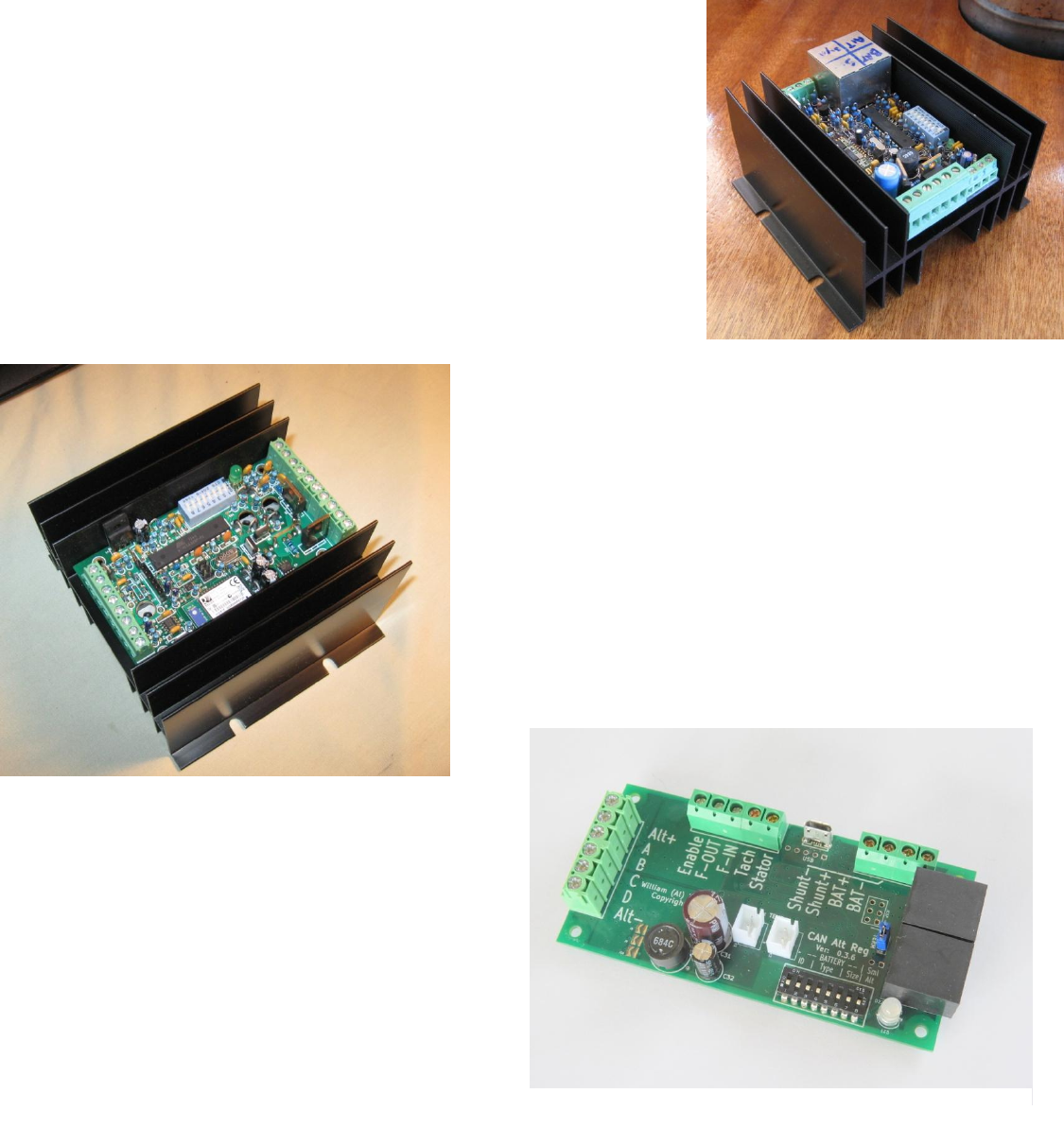
1st Generation: (RETIRED) Original development design. Based on the
ATmega328 CPU, PCB version 0.0.x - this design is retired and not supported.
2nd Generation: (ACTIVE) Through-Hole components.
Continuing to use the ATmega328P CPU, PCB versions 0.1.x.
Features optional Bluetooth. Made available as blank PCB - v0.1.4
being the most common
3rd Generation: (ACTIVE) Newest version - SMT
based design. Utilizes the ATmega64M1 CPU, PCB
version 0.3.x it features CAN subsystem. Available as
both blank PCBs as well as partially/fully assembled
regulator beginning with v0.3.5 of the PCB
Figure 1 - First Generation Design
Figure 2 - Second Generation Design
Figure 3 - Third Generation Design
4
Both the 2nd and 3rd generation design are actively supported. The major difference being the 2nd generation features an
optional Bluetooth module, while the 3rd generation includes CAN (Control Area network) ports to allow for status
updates, as well as forming the basis for coordination and cooperation of multiple charging sources (See: What is a
‘Systems’ approach to battery management? below). Both utilize the same source code – board specific selection is
automatically made during compile time via #IF statements in the source.
5
WHAT IS A ‘SYSTEMS’ APPROACH TO BATTERY MANAGEMENT?
Even the most basic DC battery and an associated battery is a `System’, it is only a question of how well the system
works. Voltage-only regulators have only one channel of communications: voltage. Though very important, it leaves
no ability to communicate any other information, hence the addition of additional sensors: temperature probes, current
shunts, etc. But even with added sensors there is still only one channel of communications: Voltage. And having only
one channel of communication can be restrictive and starts to introduce compromises. Trying to get Solar panel
controllers to cooperate with alternator is one example.
Communications between different nodes in a system is a long know challenge, with many proven and reliable solutions.
Beginning with the 3rd generation of the VSR Alternator Regulator a CAN (Control Area Network) port is added to provide
for a robust proven communications path between devices connected to and surrounding the battery. Built upon truly
open standards, the added communications capability allows for coordination of charging sources. Battery Monitors are
able to determine the true needs of the battery and inform charging sources, twin engine alternators are able to balance
with each other without any extra ‘Balancer’ hardware being added. Solar is able to be used to its fullest capability in
conjunction with other charging sources; while also prioritizing – allowing Solar to finish the final stages of recharging
with the alternator pulling back. Meeting the needs of the battery in ways impossible to obtain with a single (e.g.
voltage-only) communications channel.
CAN (Control Area Network) is a mature communications hardware standard which has been in existence for several
decades. Reliable, fault resistant, it has seen millions and millions of applications ranging from transportation,
industrial, heavy equipment, to agriculture and marine. Just to name a few. The VSR Alternator Regulator builds upon
this robust base again using proven and open standards. SAE’s J1939 (a core part of NMEA-2000) combined with the
open standard RV-C makes up the software protocol which is the basis for OSEnergy (Open Systems Energy). OSEnergy
is an open architectural specification who's aim is to provide a framework for the design, deployment, and operation of
charging sources associated with a DC battery, and whose goals are to protect, optimize, and simplify the installation,
operation and maintenance of DC systems.
Installation can be greatly simplified by utilizing the Remote Instrumentation capability of OSEnergy spec – reducing
cabling from a multitude of wires from each charging device individually to the battery to a single CAT-5 cable. High
Availability installations mesh-type sensing systems are also possible, allowing for one or more component / wiring
failures.
6
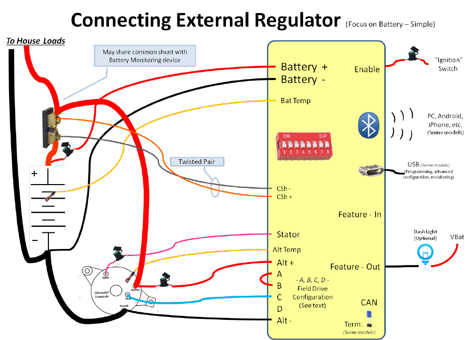
CONNECTIONS
The following illustrates connection terminals on the alternator regulators. See the following table for a description of
each connection, as well as suggested min size. Example deployments follow the table.
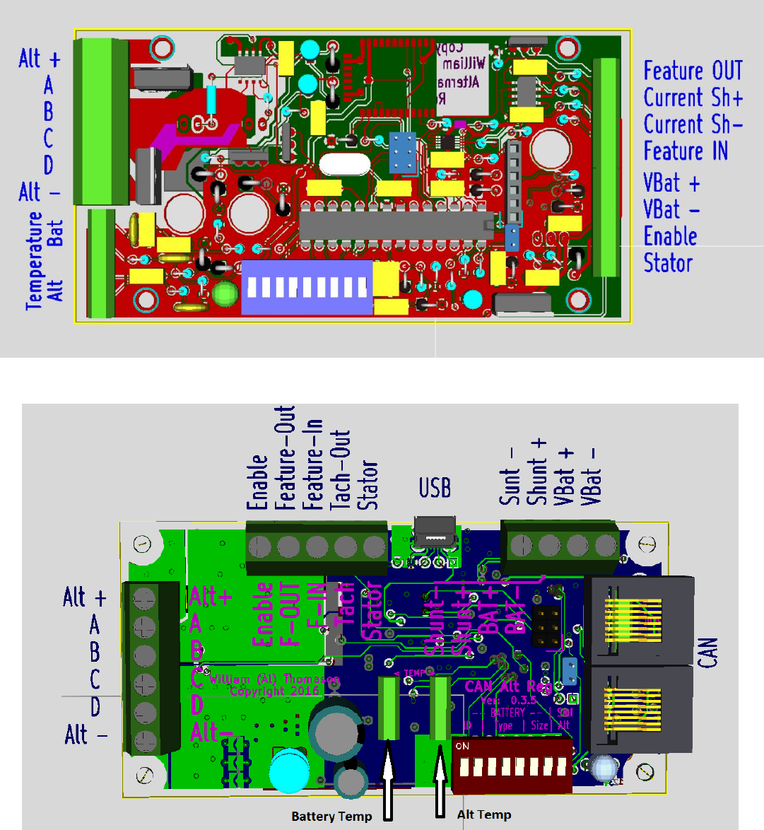
Figure 4: 2nd Generation connection
Figure 5: 3rd Generation connections

7
VBat+, VBat - Connect directly to the battery via 14AWG wire protected with a 2A fuse located at the battery.
(Do not connect after any busses, shunts, etc..)
Alternatively, on Gen 3 regulators, these may be connected locally to the alternator if the regulator
will remotely receive battery voltage via the CAN bus. Refer to “Integrated System Samples” on
page 22
Enable: Connect to VBat+ to ‘turn on’ the regulator. Use min 14AWG wire and a 2A fuse.
Current Shunt + ,
Current Shunt -: (optional) Connect to the Current Shunt using twisted pair 16AWG or larger wire. The Current Shunt
maybe installed in either a ground wire (low shunt), or in the + voltage wire (High Shunt). Do not
exceed 80mV difference between CS+ and CS-, nor exceed connect to a shunt more than 72v above
ground. If the Current Shunt is not being used, it is suggested to place a wire between these two
terminals to avoid any electrical noise confusing the regulator. If the VSR Alternator Regulator is
participating in an Integrated System where battery voltage, current and temperature is being
measured using a remote battery monitor or BMS, the local Current Shunt may optionally be
connected to a shunt located in the ALT+ output to allow direct amperage measurement of the
alternator.
Feature In: (optional) Connect to VBat (6-72v) to enable features (see FEATURE IN section).
Feature Out: (optional) Open Collector driver, connect to external Alternator LAMP at dash. 0.5A max current
sink capability. See Source Code to enable other optional capabilities.
Alternator +: Connect to + (Bat) terminal of Alternator. Use wire sized to match your expected maximum Field
current draw and protected by an appropriate fuse. (typically 4-12A, depending on alternator size)
(Min 14AWG – use 12AWG or 10AWG for large frame alternators)
Alternator -: Connect to the – (gnd) terminal of Alternator using appropriate wire. (Min 14g)
Stator (optional) Connect to an Alternator Stator pole via 2A fuse and 16AWG wire.
Used to increase battery voltage measurement accuracy, as well as enable several battery and
alternator protection features in the regulator.
A, B, C, D: Connect to the field per the following table depending on the configuration of your alternator:
Jumper
Alternator Field
High Drive (P / B-type)
A - B
Field: C
Low Drive (N / A-type)
C - D
Field: B
Use wire of sufficient gauge to carry the expected current, up to 32A (connector limit)
(Min 14AWG).
8
Bat Temp,
Alt Temp: (Optional) Appropriate NTC temperature sender.
Note that Alt Temp may be OPTIONALLY shorted to enable half-power mode.
Service / USB: Used to initialize and debug the regulator. Generation 3 and greater contain a built in USB
connector while Generation 2 requires the use of an external USB TTL adapter.
CAN: (3rd Generation) Allows communication of regulators status via NMEA-2000 and/or OSEnergy
protocols. Provides for remote sensing of battery and charger coordination / prioritization with
other OSEnergy compliant devices. Utilize CAT-5 cables if regulator is populated with RJ-45
connectors, otherwise use 120 Ohm twisted pair wire to the CAN terminal block.
Tach-out: (3rd Generation) A conditioned signal to help drive alternator sourced tachometers – even at low
charging levels.

9
CONNECTION AND FEATURES ENABLED
The VSR Alternator Regulator minimal installation needs only 6 wires to be connected (See “ Example 1: Minimal (Voltage Only) Installation” on page 21) and
will operate as a highly capable multi-step voltage regulator, where charging decisions are based on time. Adding sensing wires unlocks additional features. The
following table highlights a few of these capabilities and connections needed.
Connection
Feature
Minimum Required
Additional Connections
(Connected separately, or in combination)
VBAt+, VBat-
Alt+, Alt-
Field
Enable
Stator
Battery
Temperature
Alternator
Temperature
Current
Shunt
CAN /
CAT-5
High Accuracy voltage regulation
Adaptive Idle
Battery Temperature Compensation
Alternator Overheating protection
Battery measurement based charging
decisions
System charging coordination
Status reporting (NMEA2000TM, etc.)
Table 1: Connections and Features Enabled
.
Table 1 above is not exhaustive, only illustrates some of the main capabilities of the VSR Alternator Regulator.
10
WHY DO WE NEED A STATOR WIRE?
The VSR Alternator Regulator includes a wire to be connected to one of the Status terminals on your alternator. Though
optional, attaching this wire will improve the accuracy of voltage measurements, and enable several protection features.
Improved Voltage Measurement by synchronizing the sampling of battery voltage with the stator. This is a
‘best Practice’ for measuring battery voltage as it allows us to see the true ‘high point’ of the alternators
output each time we measure battery voltage. It also reduces external noise and other issues if the voltage
samples were at random times. Battery voltage to a resolution of 1.25mV (a bit more than 0.001 volt), it is
capable of very accurate sampling. By using the Stator wire we are able to maximize this accuracy.
Connecting the Stator wire is also needed to facilitate Tach Mode. And if you then set the appropriate
calibration values (pulley size, alternator poles, etc), you will be able to measure the engine RPM via the
ASCII status strings (assuming no belt slip).
Stator Sample allows for Adaptive Idle pullback, where the alternator load is reduced as the engine
approaches idle. This can be helpful with small engines to prevent stalling, or sluggish performance near
idle while still allowing for full current output at higher RPMs. (See $SCA: command ‘PFB’ – Pull Back
Factor)
Stator Sample also enables a few protection features. Example, if at some time we see SOME stator pulses,
and then they disappear, we assume the engine has stopped. In this condition we reduce the Field PWM
drive greatly. Without the stator wire we have no idea this has happened (remember, OTHER sources might
be charging the same battery, so looking for a drop in VBat is no use). This prevents the regulator from
continuing to apply field current and heating up the alternator.
Special note: If your existing installation has additional lamps, resistors, diodes etc. connected to the Stator field, or
perhaps a Diode Trio (part of the dash lamp) or ‘exciter’ connection on the alternator, it is advisable to remove these.
You can reconnect the dash lamp to the Feature-out connector. Leaving existing resistors, diodes, or other connections
from the old installation have been known to cause issues with RPM measurements and other features of the VSR
Alternator Regulator.
11
WHY DO WE NEED A CURRENT SHUNT?
The VSR Alternator Regulator is fully capable of operating using only battery voltage sensing, and in fact this is a fail-over
mode in the case of a missing or broken current sensing probe. In Voltage Only mode charging decisions are based on
times values, either pre-determined, or at times calculated based on prior phase changes. However, with very few
exception, battery manufactures preferred charging guidelines call for the monitoring of charge acceptance current as a
critical factor in making charger mode decisions, specifically when to end Acceptance phase. As a battery is held in
Acceptance Phase the amount of current being accepted by the battery has a direct correlation to a batteries SOC (State
of Charge). Monitoring acceptance current allows the regulator to make better decisions and safer charge profiles:
using a lower acceptance voltage set point while still allowing for the complete recharging of a battery. LiFeP04 and
related battery technologies greatly benefit by this ‘lower stress’ charging approach of a proper acceptance phase vs. to
be held long enough to assure a fully charged battery, and no more. Reducing battery stress as a result of overchaging.
Contrast this to time based decision criteria which uses fixed or perhaps a calculated time basis for determining the
batteries needs; perhaps adding a bit of extra time just to make sure. While time based decisions can be estimated in
the lab, they are often confounded by real world imitations. Battery age, temperature, model, and more all impact the
amount of time needed to properly complete an Acceptance Phase. Adding extra time may potential result in a more
complete battery SOC recharge, however care must be taken with this approach as some battery are less forgiving to
over-charging then others. FLA (Flooded Lead-Acid) batteries might just use more water, while some GEL/AGM and any
Li based battery technology could be damaged. The alternative of a short acceptance phase has it owns issues; chronic
under charging has a very detrimental impact on the lifespan of many battery technologies. Not to mentioned the
underutilization of the fill (but paid for) capacity in the battery bank. Another mitigating approach is to monitor the field
drive and use that to help augment charging decisions. However field drive decisions have no idea where the alternator
output is actually being consumed and can be tricked to either over or under charge. One example is by simply running
a concurrent load while charging. If a washer/dryer is being powered via an inverter, field drive decisions will never see
a reduced field drive and can easily overcharge the battery.

12
MAXIMUM LIMITATIONS
The following table documents maximum allowed values during the operation. Exceeding any of these values may cause
unpredictable operation and/or damage. All voltages are referenced to VBat- unless otherwise noted.
Item
Min
Max
Symbol
VBat+
65
Volts
Enable
8.5
65
Volts
CS+
-0.5
65
Volts
CS-
-0.5
65
Volts
CS+ vs. CS-
-80
80
mVolts
Feature-In
-0.5
65
Volts
Feature-out
65
Volts
0.5
Amps
Alt+
65
Volts
Field (B or C) current
32
Amps
Ambient Temperature
-40
100
Celsius
Table 2 – Maximum Limitations
Special care should be noted of the Current Shunt lower voltage limitations. If the current shunt is located in the ground
line and a distance from the battery (example at the alternator), too small of a ground wire between the shunt and the
battery could easily exceed the limits and create a ground-loop. Increasing the size of the ground cable, and/or
relocating the Amp Shunt to the Alternator + wire are potential solutions.
13
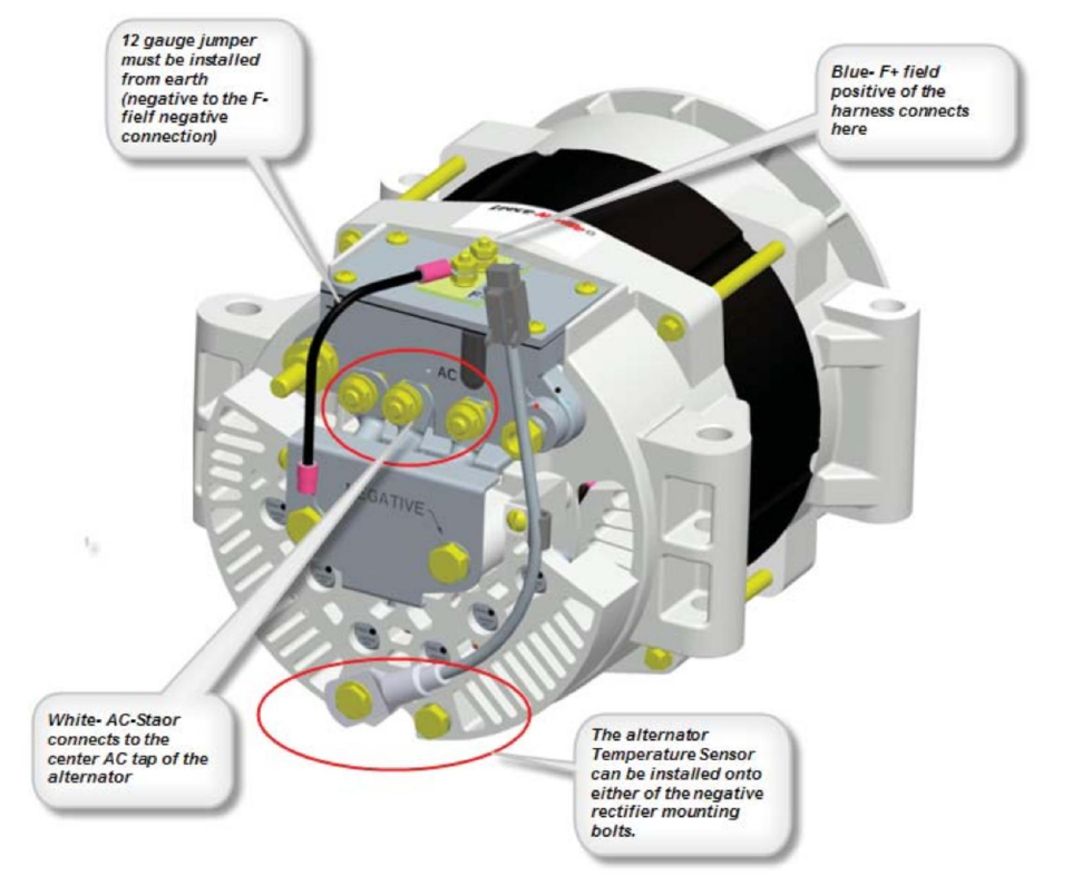
Alternator Temperature Probe Location
In most cases the diode pack is the critical limitation in alternators and the best point of reference for measurement –
however it is best to consult your alternator manufactures for recommended placement - as well as for allowable
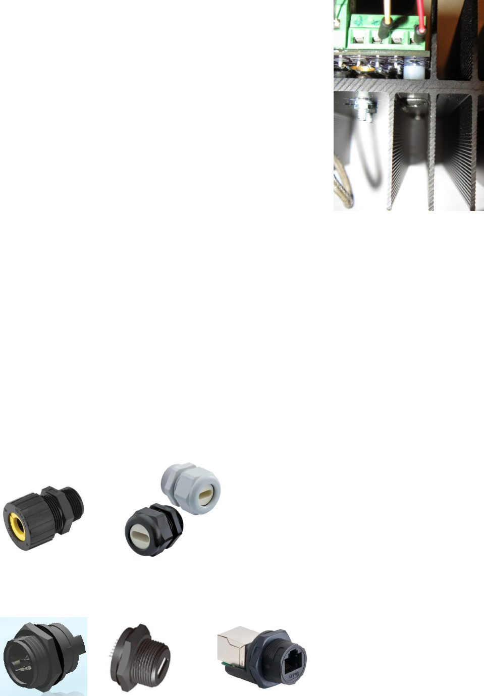
operation limits. Figure 6 below shows the recommended location for the alternator temperature probe from Leece
Neville / Prestotolite -- on the diode pack.
Figure 6 - Example Alt Temperature probe location
14
ACCESSORIES – PROBES, CASES, SHUNTS, ETC.
To install your regulator you may need some or all of the following. There are many ways to purchase these, and the
examples given are only one option.
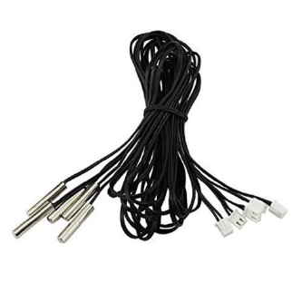
Temperature probes:
The VSR Alternator Regulator uses NTC temperature probes to optionally monitor battery and/or alternator
temperature. There are several sources for NTC probes, do make sure to get ones with these specifications:
Resistance: 10K Ohms
Beta: 3950
(Note: It is possible to alter these values (to some extent) by making changes to the Source Code)
There are positions for two sensors, A and B – typically used for Alternator and Battery respectively. Gen 2
regulators use screw connectors, while Gen 3 uses a common JST XH2.54 2P connector. When sourcing for
sensors you should be able to find many probes which already have the connector installed.
Searching Ebay or Amazon for “NTC 10K waterproof 3950” will quickly bring up a wide range of suppliers, with
cable lengths from 0.5m to 5m. Here is a photo of one bundle of 5x sensors – with attached JST connectors:
Fuse Holders:
It is recommended to install fuses in the locations indicated in the Example Installations. Chose a fuse of appropriate
rating (See `Connections’ above) Use a good quality water resistant fuse holder and fuses which you are able to secure
easily and locally. Remember, Fuses are primarily intended to protect wires, not the device – with one exception: the
Field fuse will also help protect the Alternators Regulators field drive circuit – choose a fuse about 50% higher than you
expected maximum field draw. For smaller alternators, a 10A fuse should be sufficient, while larger units may need a
15A fuse. If you are driving multiple alternators in parallel from one VSR Alternator Regulator, adjust the fuse size
accursedly, but do not exceed 32A as that is the terminal strips maximum rating.
15
Current Shunts:
Many installations already have a battery current shunt installed, often as part of an existing battery meter. If
so, simply attach the Current Shunt leads to that existing shunt. The shunt may be located in the + or the – wire
with no adjustments needed for your regulator. Do pay attention to the + and – connections (refer to example
installation diagrams on page: 17). You can verify the shunt is working correctly by connecting a computer to
the Serial/USB port (see page: 47 ) and monitoring the AST; status strings (page: 70). If you find you have the
shunt installed backwards, correct the wiring or use the $SCA: command (page: 92 ) to indicate the ‘shunt is
reversed’.
By default the regulator is configured for a 500A/50mV shunt (Common on many battery monitors). If you are
using a different shunt, use the $SCA: command to inform the regulator of the shunt value.
CAUTION: Do not use a shunt who’s voltage exceeds 80mV, or inaccurate results will occur as well as a potential
for damage.
Shunts are known for being less then accurate, and if you find the calibration of the VSR Alternator Regulator is
off, you may use the $SCA: command to adjust for any error.
Enclosure:
Gen 2 VSR Alternator Regulator was designed to fit inside its heat-sink, largely for protection – though there is a
little heat which must be dissipated. Aside from protective heat sinks, die-cast aluminum box would be another
suitable choice, just make sure that the driver FETS as well as the voltage regulator (Q1 and U1) are solidly
attached to the case. (Make sure to use appropriate electrical isolation for any heat-sinked component)
Gen 3 dissipates very little heat and no heat-sink is needed – just air flow around the components (PCB standoffs
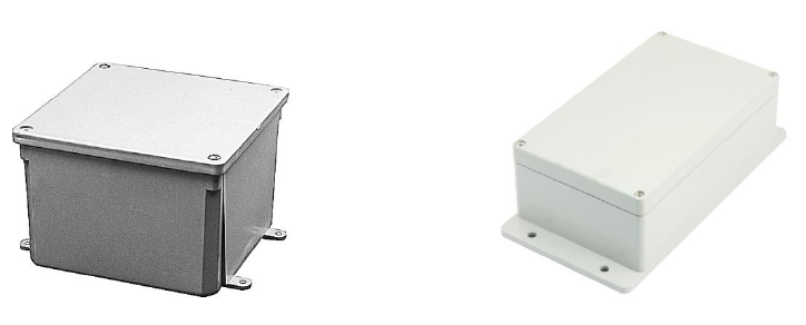
are sufficient). Plastic boxes are suitable for this release of the regulator. NEMA 4x ‘Water-proof’ boxes
available at electrical supplies and/or building supply houses can be an attractive low cost option; especially
when combined with water-tight bulkhead glands around the cables in and out of the box. Some examples:
Figure 7 - E989PPJ 5" X 5" X 2"Junction Box Figure 8 - Uxcell® Waterproof Box 200x120x75mm
Also check the blog / mailing list / github for any updates as well as potentially for custom 3D-printed cases
which others may have designed.
16
Both Gen 2 and Gen 3 regulator PCBs have 3mm mounting holes
in the corners. These holes can be taped using a 6-32 tap,
allowing gentle screwing up from the bottom of the case into the
PCB. Make sure to use nylon spacers to provide air circulation to
the bottom of the PCB.
Here is an example of the gen 2 design so mounted, notice the
screw on the right coming up through the heatsink to the PCB
and the white nylon spacer.
CAT-5 Cable
Used only on the Gen 3 (CAN enabled) regulator, CAT-5 cable is used to connect the VSR Alternator Regulator
with other OSEnergy compliant devices to allow monitoring and coordination of a DC System. Any CAT-5 or
CAT-5e cable will work, as well as CAT-6 cable. Connect the CAT-5 cable from each OSEnergy compliant device
in a daisy-chain fashion, making sure the ‘Terminator’ is enabled on each end of the daily chain (remove the
terminator from any nodes not on the end).
Waterproofing:
There are a verity of options for doing installations in a water resistant way, from simply installing in a protected
area, to using cable glands and/or waterproof bulkhead connectors, to even potting the entire regulator in a
sealed unit. Each of these options comes with a cost. Perhaps the most likely approach is to use a case with
sufficient size to allow for the wires to exit the bottom, providing some level of splash resistance. Another
option is to use sealed box and “Liquid tight / strain relief” cable glands such as these (Often available at home
building centers):
And/or dedicated waterproof bulkhead connectors for the options you wish to bring out, such as:
Combined with matching cable covers.

17
USBasp / USB Serial converters & USB cable:
Generation 2 VSR Alternator Regulators will need access to an ISCP adapters (such as a USBasp device) in order
to burn in the boot-loader into the CPU. A Serial to USB adapter will also be needed if you wish to monitor the
regulators status and/or configure the regulator via ASCII commands. One of these devices will also be needed
in order to load the firmware. Please see the Blog for more details:
http://arduinoalternatorregulator.blogspot.com/2010/06/assembly-and-programming.html
as well as `Communicating with the VSR Alternator Regulator’ on page 47
Neither of these devices is needed for the 3rd generation VSR Alternator Regulator, as it comes pre-assembled
with both the bootloader and the current firmware flashed in. (Unless you purchased a blank PCB). For the
Generation 3 VSR Alternator Regulator a simple Micro USB cable is needed to allow communication and
configuration as well as firmware updates.
Note that when attaching a USB cable, or Serial cable to the service port, the logic portion of the regulator will
be powered via the attached cable. This allows for pre-configuration ‘on the bench’ before physical installing
the regulator. Do keep this feature in mind if you wish to do long-term connection to the USB/service port for
ongoing status monitoring – as the regulator will continue to ‘operate’ even if the ENABLE wire is not powered
on. You may disable this feature on Gen 2 of the regulator by not connecting pin #6 of the Service connector;
and on Gen 3 regulators by either by modifying the USB cable cutting the +5 wire, or by removing D12 from the
PCB. If you do use long-term connections, be aware of a potential for substantial ground-currents, especial with
large alternators. Upwards of 2-300mV ground voltage delta is not uncommon…
18
REGULATOR INSTALLATION
The VSR Alternator Regulator is a very versatile device with several installation options depending on your goals and
objectives. In it s simplest form, the Enable, Alt+, Alt- and Field wires are all that are needed to connect, and in this
mode the regulator will behave as many voltage-only regulators, abet with a high level of precision. Adding additional
sensing capabilities will unlock additional capabilities of the VSR Alternator Regulator, up to and including a fully
integrated Systems deployment.
The following will give an overview of how to connect and configure the regulator in different situations. The first
section will illustrate typical installations, from simple to more involved; while the second section showcases some
alternative installations for unique deployments, such as DC generators or high-reliability integrated systems.
REGULATOR PLACEMENT
Place the near the alternator – keeping the Alt+, Alt- and Field wires as short as reasonably practical. Take into
consideration ambient temperature as well as any potential for water splashing and consider augmenting the case as
needed. The regulator is very efficient and does not need much cooling beyond what is typically found in engine room
compartments, but that is not to say one should test its limits!
BATTERY-CENTRIC VS. ALTERNATOR-CENTRIC INSTALLATIONS
Throughout the examples it is helpful to keep in mind there are two distinct ways the VSR Alternator Regulator may be
configured and installed in a system, depending on where the Amp Shunt is placed. If the shunt is placed at the battery
the installation is known as a ‘Battery Centric’ installation, allowing for accurately monitor the SOC (State of Charge) of
the battery and use that to determine when it should change charging phases. (e.g., from Acceptance to Float). This is
the default deployment model for the regulator.
Alternatively, the amp shunt can be placed at the Alternator in what is referred to as an ‘Alternator Centric’
configuration. This is useful to either further protect a smaller alternator, or perhaps to allow a very large alternator to
be placed on a small engine (for example in a DC Generator). Alternator Centric configurations are also used when
integrating into an OSEnergy compliant ‘system’ where another device is able to monitor battery current (ala, a Battery
Monitor or full BMS) and provide that information remotely.
CAUTIONARY NOTE: OVERSTRESSING SMALL-FRAME ALTERNATORS
The most common alternator found will be a small frame unit, especially if it is the OEM alternator on a motor. These
alternators are good reliable units, but may not be up to the demands of delivering large amounts of current over a long
period of time. Overstressing alternators can result in damage from burnt out diodes and/or internal heat stress related
damage and failures. Such stress conditions are exacerbated by high acceptance battery banks (ala, Lithium, AGM/GEL,
or even large capacity standard wet-cell FLA batteries).
The best way to protect a small-frame alternator is to install an alternator temperature sensor, ideally located near or on
the Diode pack. This will allow the VSR Alternator Regulator to monitor the alternator and reduce output as its safe
temperature limit is approached. . (side note: it is not unknown to see an ‘80A’ alternator restrained to as low as 30A
in order to prevent alternator overheating…). In addition it is recommended to select ‘Small-Alt Mode’ via DIP switch
to provide an overall capping of alternator loading. After some run time experience has been had, you can consider
turning off Small-Alt mode and see if the alternator is able to handle your specific installation.
19
SPECIAL CONSIDERATIONS FOR 32V/36V, AND 42V SYSTEMS
The VSR Alternator Regulator self-adjusts for battery voltage, applying an appropriate multiplier to the CPE entries. For
example, if deployed with a 24v battery all the CPE voltage values will be doubled, ala VBat Target would go from 14.4v
to 28.8v. (The multiplier factor being used is reported out in the $SST ASCII status string.)
In Auto-select mode (default) the battery voltage is sampled at each startup and used decide what the most likely
system battery voltage is. Battery voltages of 12v, 24v, and 48v may be auto selected in this way. If you have a different
system voltage (e.g., 32v) you will need to manually configure the regulator via the $SCO command setting the battery
voltage multiplier to 2.667 – likewise a 42v system can be configured for using a multiplier of 3.5
‘Auto-select’ may be bypassed, forcing the voltage multiplier even for common 12/24/48v systems via the $SCO:
command – this could be considered a high-reliability configuration step to preclude any chance of false auto-detects.
Note: Beginning with release 1.0.3 of firmware, the ‘Favor 32v’ option has been removed as well as auto-select for 32v systems.
Use the $SCO command to set the voltage multiplier as noted above.
20
OTHER CONSIDERATIONS:
Diode based battery isolators: These are often installed when one alternator is asked to charge two or more
batteries. The Isolator prevents any loads on one battery from discharging the other battery when the engine is
turned off. These present a problem for the VSR Alternator Regulator, as it is attempting to decide when the
battery is full – which battery does it look at? If you have a battery Diode battery isolator it is might be better to
replace it with an automatic battery switch/combiner (following). However, if you do install the regulator in a
system with a Diode battery isolator it is suggested you pick the battery you with to focus on – place the Battery
Amp Shunt on that battery, and attach the battery voltage sensing wires to that same battery. The regulator will
then control the Alternator to meet the needs of THAT battery. There is a risk of overcharging the 2nd battery,
but that risk existed well before installing the VSR Alternator Regulator.
Automatic Battery Combiner: Another way to connect a 2nd battery to the main one is to use an Automatic
Battery Switch. These will sense the voltage of both batteries, and when the time is right, connect them
together. If you install in a system with one of these, connect the VSR Alternator Regulator to the primary
battery, placing the Battery Shunt on that main battery and connecting the Battery + and Battery – sensing wires
to that battery. The VSR Alternator Regulator will focus on that main battery and let the Automatic Battery
Combiner deal with the needs of the 2nd battery. A couple of notes:
Make sure to connect the 2nd battery on the Alternator side of the Battery Amp Shunt – it is important
that the Amy Shunt ONLY measure the current needs of the battery we are focusing on.
There is a #define FEATURE_OUT_COMBINER option in the source code that can be enabled to allow
a simple external high current relay to be used for a battery combiner. See the section on Feature-out
options.
21
Standalone Installations
The first set of examples illustrate how the VSR Alternator Regulator may be installed as an independent (not systems
integrated) regulator. In this mode the regulator will make independent decisions for charging and mode transitions,
and is applicable to both Generation 2 and Generation 3 regulators. With each example additional wires and sensors
are connected to the regulator allowing smarter management. Examples shown include:
Example 1: Minimal (Voltage Only) Installation Though simple to install, it is not suggested to use this configuration as
many of the capabilities of the VSR Alternator Regulator will be disabled. If you do select this installation option take
great care with the configuration options (Alternator output capping / limitations, CPE selection of voltages and
transition times among a few) to best match your typical operations and assure limited risks due to battery incomplete
charging and/or alternator over-stress situations.
Even with these risks it is helpful to understand this simplest installation as if any of the regulators sensors fail it will `fall-
back’ to simpler modes of operation, thereby allowing continued operation, though perhaps in a less efferent manner.
22
Example 2: Basic Stand-alone Installation (Most common single engine installation)
Example 3: Twin engine Installation
Integrated System Samples
Following that are examples which feature the benefits of the Generation 3 VSR Alternator Regulator CAN based
communications to help coordinate charging sources as well as potential provide a higher level of reliability / failure
mode recovery.
23
Example 4: Basic System Installation (Utilizing remote battery sensor)
Example 5: System Installation w/Alternator Current Measurement
Example 6: Dual (or more) Engine System installation
Example 7: High Reliability System Installation
Special Examples
The final group of examples shows some special or alternative way to install the VSR Alternator Regulator. For example,
using the regulator in a DC generator in an ‘Alternator Centric’ deployment.
Example 8: Using regulator with a small DC generator (Advanced)
24
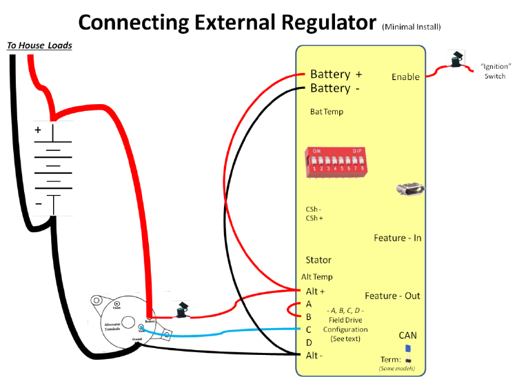
EXAMPLE 1: MINIMAL (VOLTAGE ONLY) INSTALLATION
This example shows the very minimal connections needed when installing the VSR Alternator Regulator; only 4 wires
and a few jumpers. In this very basic installation the VSR Alternator Regulator will function in a like way to most
Voltage-only regulators, relying on battery voltage and timers to make charge decisions; and with that also brings the
same limitations and risks of a voltage/timer regulator.
Figure 9 - Minimal Install
Though simple to install, it is not suggested to use this configuration as many of the capabilities of the VSR Alternator
Regulator will be disabled. If you do select this installation option take great care with the configuration options
(Alternator output capping / limitations, CPE selection of voltages and transition times among a few) to best match your
typical operations and assure limited risks due to battery incomplete charging and/or alternator over-stress situations.
Even with these risks it is helpful to understand this simplest installation as if any of the regulators sensors fail it will `fall-
back’ to simpler modes of operation, thereby allowing continued operation, though perhaps in a less efferent manner.
25
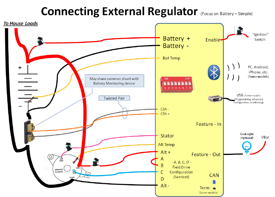
EXAMPLE 2: BASIC STAND-ALONE INSTALLATION (MOST COMMON SINGLE ENGINE INSTALLATION)
This is the recommended basic installation of the VSR Alternator Regulator is in a stand-alone configuration. With this
configuration the regulator monitors a current shunt located at the battery as well as battery temperature and voltage
to allow for accurate and safe charging. By sensing an amp shunt at the battery the VSR Alternator Regulator is able to
account for all other charging sources, as well as potential house loads, when making decisions about charge state
transitions – to give a true indication of the status of the battery’s needs. Alternator temperature sensing protects the
alternator from overheating / overstressing.
Installing the battery voltage sensing wires (Battery+ and Battery -) DIRECTLY to the battery! Do not attach the wires
after a battery switch, dual alternator diode separator, the Battery Amp Shunt, or a common ‘bus bar’. Instead connect
directly to the batteries for best results.
Figure 10 - Basic install, shunt LOW
The shunt may be located on either the ground side of the battery as shown above or positive side of the battery as
shown on the next page. It is suggested to use twisted pairs of wires from the shunt to the regulator. If you already
have a shunt installed (perhaps for an Amp meter, or an existing battery monitor system) there is no need to install a 2nd
shunt, just use the one already in place – the VSR Alternator Regulator is able to share existing shunts. By default, the
regulator is calibrated for a 500A/50mV shunt (commonly used on battery monitors) ; if your shunt has a different rating
adjust the system configuration using the $SCV command. Any shunt may be used as long as the maximum sensing
voltage does not exceed 80mV.
26
Figure 11 - Basic install, shunt HIGH
27
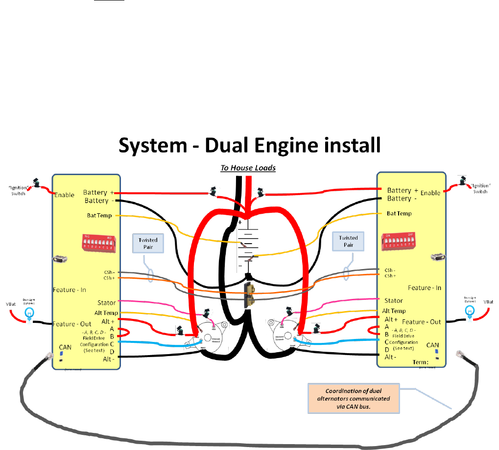
EXAMPLE 3: TWIN ENGINE INSTALLATION
It is common for many marine applications to have two engines, each with an alternator to charge the batteries. In this
case, simply install a regulator on each engine as you would for a single engine installation. Configure the two regulators
the same and connect the Enable wire to each respective engine. You may share the same battery current shunt
between both regulators. It is best if each regulator has its own Battery + and Battery – sensing wires, and the
temperature sensors cannot be shared, each will need its own.
Connect a common CAT-5 cable between the two regulators allowing them to communicate and coordinate their
charging: balancing the loads between the two engines and working towards the same charging goals as opposed to
fighting each other.
If you give each regulator a unique name (e.g., Port and Starboard) it will aid in those models featuring Bluetooth
connectivity or CAN enabled regulators when communicating status. Use the $NPC: command to set each regulators
name.
Figure 12 - Duel engine install with communications
28
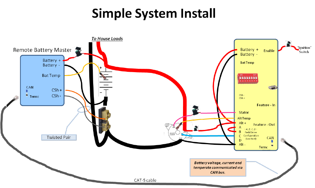
EXAMPLE 4: BASIC SYSTEM INSTALLATION (UTILIZING REMOTE BATTERY SENSOR)
When installing the VSR Alternator Regulator in a ‘system’ one of the benefits is simplified wiring. Rather than routing
individual sensing wires to the battery for voltage, current, and temperature, that information may be delivered over the
CAN bus using a technique of remote-instrumentation.
Remote-instrumentation is a very reliable and long used method for reducing the wiring needs in many industrial and
transportation applications. By having a device located at the battery sensing the voltage/current/temperature of the
battery and sending that information via the CAN bus to the VSR Alternator Regulator, the wiring burden is reduced to
one CAN cable as opposed to several discreet wires. If the installation has more than one charging source (say, twin
engines, or an alternator and solar) this reduced wiring benefit becomes even greater.
To take advantage of remote-instrumentation you will first need an OSEnergy compliant monitoring device at the
battery which senses battery voltage/current/temperature. Then when installing the VSR Alternator Regulator, you only
need to connect sensing wires locally to the alternator saving long wires back to the battery.
At minimum, you need to connect the VBat + and Vbat – wires to the local alternator + and – output. Adding Alternator
Temperature sensing and stator sampling allows the VSR Alternator Regulator to fully protect your alternator.
Figure 13 - Simple System Install
29
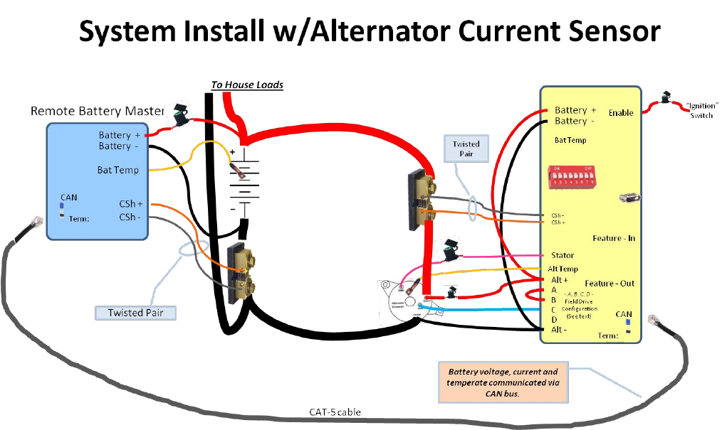
EXAMPLE 5: SYSTEM INSTALLATION W/ALTERNATOR CURRENT MEASUREMENT
By taking advantage of remote instrumentation as shown in the example above, we can then use the remaining VSR
Alternator Regulator ports to monitor the alternator its self, using the wiring as shown in Figure 14.
This will give you the most benefit from your VSR Alternator Regulator as it most closely follows a fundamental concept
of OSEnergy ‘Systems’: Manage and control your local device – in this case we are managing the alternator. Such an
installation is helpful if you wish to fully monitor the output of your alternator, perhaps for display on a NMEA2000
compatible monitor, or as a feed into Signal-K.
Figure 14 - System Install w/alternator current measurement
30
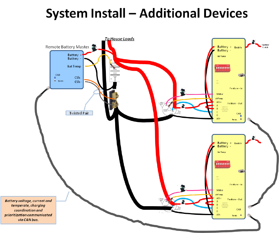
EXAMPLE 6: DUAL (OR MORE) ENGINE SYSTEM INSTALLATION
Extending the examples shown above, as more OSEnergy compliant charging sources are added to your system, you can
simple configure them and extend the CAT-5 cable, connecting them daisy-chain fashion. Make sure the terminator is
installed on the two end devices in the chain, and not on any of the ones in the middle.
Figure 15 - Multiple charging sources in a coordinated system
The integrated system view shown in Figure 15 is extendable to other VSR Alternator Regulators as well as other devices,
such as Solar MPPT controllers, DC Generators, any device which support the OSEnergy protocol. All will work
cooperatively in a well coordinated and prioritized manner.
31
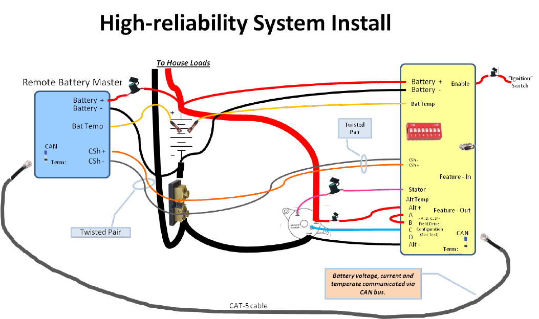
EXAMPLE 7: HIGH RELIABILITY SYSTEM INSTALLATION
In this example the VSR Alternator Regulators sensing wires are routed to the battery in addition to the remote sensing
supplied over the CAT-5 CAN cable. This configuration provides an additional level of reliability in case of a failure
somewhere, and even allows for the VSR Alternator Regulator to assume the role of Remote Battery Sensor if needed.
It does however increase wiring complexity requiring additional wires and sensors back to the battery.
Typically this type of installation is only seen in larger DC designs, where there are multiple charging sources and a desire
to provide a level of redundancy in case of a system failure.
Figure 16 - High-Reliability system deployment with redundant sensing
If this configuration is selected, review carefully the CAN configuration ($CCN:) to assure both the ‘Allow RMB’ and the
‘Shunt-at-battery’ flags are set true. This will allow the VSR Alternator Regulator to offer to assume the role of Remote
Battery Master in case of a system failure.
32
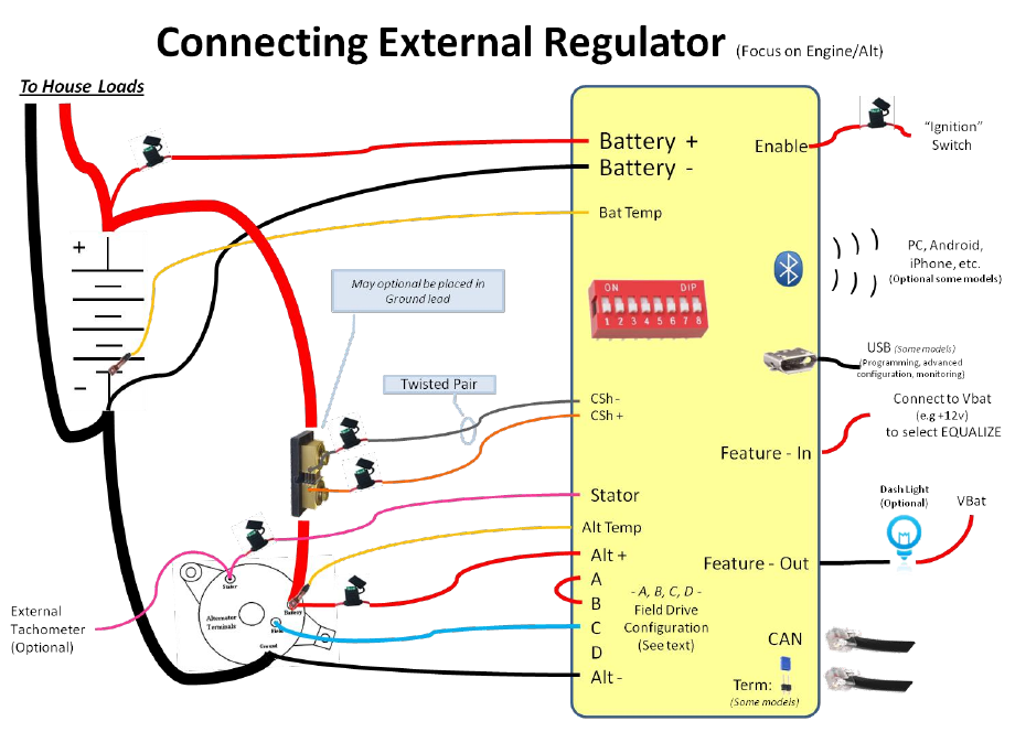
EXAMPLE 8: USING REGULATOR WITH A SMALL DC GENERATOR (ADVANCED)
Another way to deploy the VSR Alternator Regulator is to focus more on the Engine and Alternator (though not totally
ignoring the battery). An example would be a DC generator where the Alternator is so large that it can easily stall the
engine; we need to rein it in some.
Figure 17: Wiring Diagram (Engine/Alt Priority)
By monitoring the number of amps being produced by the alternator, and configuring the regulator (via the $SCV
command) to the maximum number of Watts we wish to be placed on the engine, the max engine load can be
controlled. You may also want to adjust other parameters, such as exit amp criteria, and perhaps even set up Amp
limits for the Alternator.
A feature of the VSR Alternator Regulator when deployed in this way is the ability to protect the Alternator a bit more. It
will limit the amount of Amps produced via the $SCV command. Both an Amp limit and the Watt limit may either be
defined, or you can configure the regulator to automatically determine the capabilities. Then limits can be made via the
DIP Switch #7 (Use Small Alternator Mode) to configure the regulator to ‘take it easy’ on a smaller alternator. The
specific limits can be changed by the derating values in the $SCV command.
There are a couple of new challenges with this deployment when trying to decide if it is time to exit Acceptance Phase:
Other charging sources supplying current to the battery,
Account of house loads that are being served by the Alternator in addition to recharging the battery.
33
In simpler deployments, such as when this is the only charging source, or perhaps when any house load is limited or
relatively consistent, accommodations can be made by increasing the exit Amp criteria for Acceptance Phase. Using the
CAN port (Gen 3 only) allows full participation in an integrated system, regaining not only the ability to remotely monitor
battery voltage, current, and temperature, but also coordinating with other charging sources.
Another option is to change how the FEATURE-OUT port functions, using it to signal to stop the engine when the DC
generator is no longer needed. Uncomment the `#define FEATURE_OUT_ENGINE_STOP ‘ flag in the source code to
enable this capability.
34
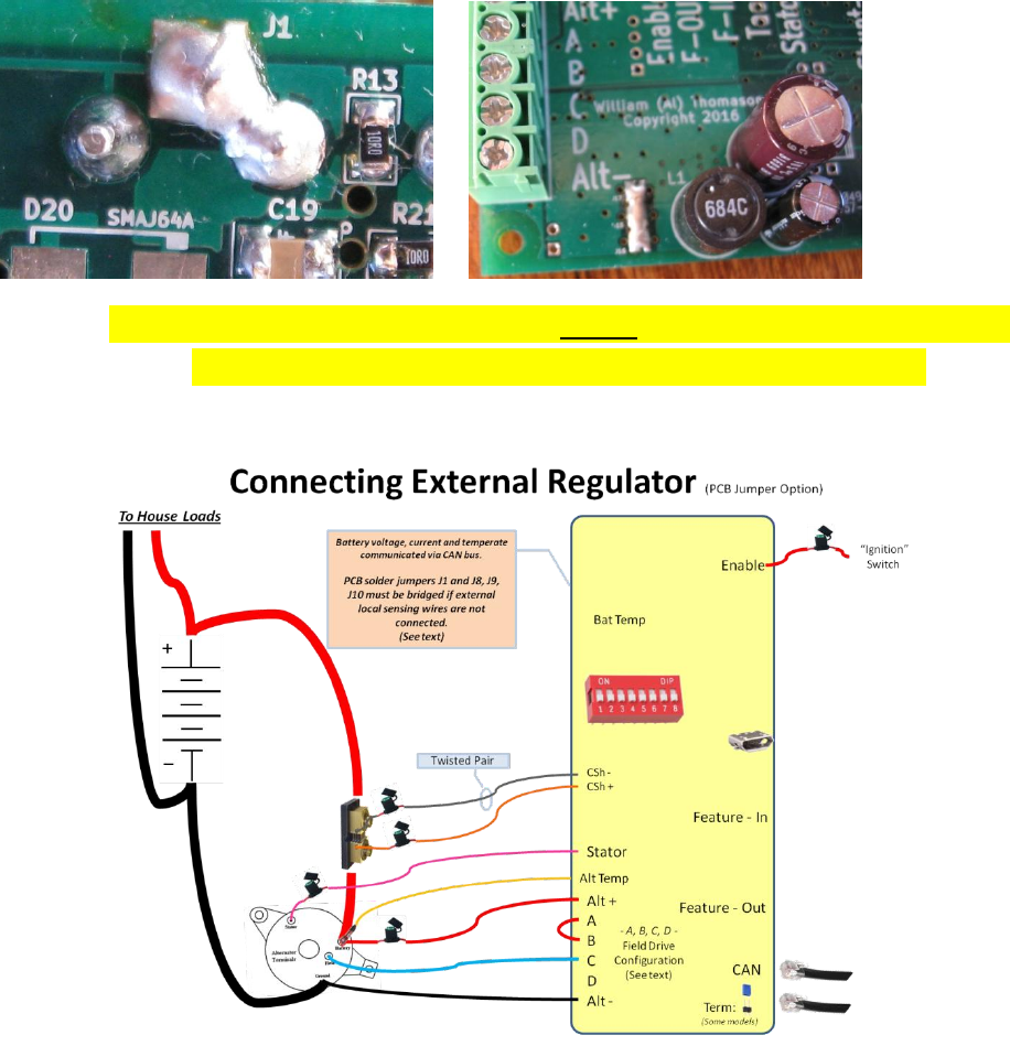
PCB ONBOARD VOLTAGE SENSING OPTION (ADVANCED OPTION)
An option for the VSR Alternator Regulator is to make the connection for VBat+ and VBat- internally, as opposed
to needing external wires as shown in the examples above. ‘Solder Bridging’ PCB jumpers J1 on the back side of
the PCB as well as J8, J9, and J10 on the front as shown in the photos below. Doing so will pick up VBat+ from
the Current Shunt+ connection (J1), and VBat- from the Alt- connection (J8..J10).
--- CAUTION: With this option you MUST connect the Shunt+ wire and
the shunt MUST be located in the Positive power lead. ---
Figure 18 - PCB jumper options, onboard voltage sensing.

35
CONFIGURING THE VSR ALTERNATOR REGULATOR
The simplest way to configure your VSR Alternator Regulator is via the DIP switches. With these you can select one of
the default Charge Profile Entries, as well as tell the regulator the size of the battery you have (needed to more
accurately decide when the battery is full).
USING THE DIP SWITCHES
Many of the basic features of the VSR Alternator Regulator can be configured using the DIP switches. Advanced changes
may be made using the ASCII serial commands (See: Appendix B: Sending data TO the regulator: ). The following table
defines how the DIP switches are used:
Position
Meaning (Regulator Version 2 and earlier)
1
On – Supply power to Bluetooth adapter
Off – Disable Bluetooth
2..4
<4> <3> <2>
Off, Off, Off
Off, Off, On
Off, On, Off
Off, On, On
On, Off, Off
On, Off, On
On, On, Off
On, On, On
Select Charge profile 1..8
1 = Default (Safe) & AGM #1
2 = Flooded Lead Acid #1 (Starter type , etc)
3 = Flooded Lead Acid #2 (HD - Storage type)
4 = AGM #2 (Higher charge voltages)
5 = GEL
6 = Reserved for Future Use
7 = Custom #1 (Changeable – Preconfigured HD Storage with Overcharge)
8 = Custom #2 (Changeable – Preconfigured: LiFeP04)
(See Table 5 for more details)
5,6
<6><5>
Off, Off
Off, On
On, Off
On, On
Define Battery Capacity as: **
1x, – 250Ah
2x, 250Ah – 500Ah
3x, 500Ah – 750Ah
4x. 750Ah and above
7
On – Use Small Alternator Mode
Off – Use Large Alternator Mode
Small Alternator Mode will restrict the maximum alternator output to 75% of its
amperage capability. Large Alt mode limits output to 100%.
See $SCA: command to change these values.
8
On – Tach Mode enabled
Off – Disable Tach mode
Some Diesel engines use the alternator to drive the tachometer. With these if the
Alternator stops charging (say during Float mode), the tachometer can become
sporadic or even stop working. Enabling Tach mode will cause the regulator to
ALWAYS provide some small level of field drive, sufficient to provide a signal to
the tachometer, but low enough to minimize Battery overcharge.
Table 3: DIP switch (2nd Generation Regulator)
** Note: Begin with Firmware 1.2.0, Ah steps are in 250Ah increments. Prior versions were 500Ah steps.

36
Position
Meaning (Regulator Version 3)
1..2
<1> <2>
Off, Off
On, Off
Off, On
On, On
Battery ID
The ‘Battery ID’ this regulator is attached to. Used in CAN connected systems.
Suggested settings:
1 = House Battery
2 = Main starter battery
3 = Secondary house battery
4 = Other
3..5
<3> <4> <5>
Off, Off, Off
On, Off, Off
Off, On, Off
On, On, Off
Off, Off, On
On, Off, On
Off, On, On
On, On, On
Select Charge profile 1..8
1 = Default (Safe) & AGM #1
2 = Flooded Lead Acid #1 (Starter type , etc)
3 = Flooded Lead Acid #2 (HD - Storage type)
4 = AGM #2 (Higher charge voltages)
5 = GEL
6 = Carbon Foam (Firefly)
7 = Custom #1 (Changeable – Preconfigured HD Storage with Overcharge)
8 = Custom #2 (Changeable – Preconfigured: LiFeP04)
(See Table 5 for more details)
6,7
<6> <7>
Off, Off
On, Off
Off, On
On, On
Define Battery Capacity as: **
1x, – 250Ah
2x, 250Ah – 500Ah
3x, 500Ah – 750Ah
4x. 750Ah and above
8
On – Use Small Alternator Mode
Off – Use Large Alternator Mode
Small Alternator Mode will restrict the maximum alternator output to 75% of its
amperage capability. Large Alt mode limits output to 100%.
See $SCA: command to change these values.
Table 4: DIP switch (3rd Generation Regulator)
** Note: Begin with Firmware 1.2.0, Ah steps are in 250Ah increments. Prior versions were 500Ah steps.

37
USING ASCII COMMANDS
In addition to the DIP switches, many parameters of the VSR Alternator Regulator can be customized by sending in a
series of ASCII commands either via a Bluetooth connection (Version 2 board), or by using an attached USB TTL
adapter board attached to the Service Port (Generation 2 board), or via a USB cable (Generation 3 and later board).
Changes sent to the VSR Alternator Regulator are saved in FLASH memory on the CPU for use next time the regulator
starts up. (See Sequence of Operation section below for more details). Because of this you will need to restart the
regulator after you have finished sending it ASCII change commands. There are some exceptions, such as the $FRM
Force Regulator Mode command, $EBA – External Battery Amps, and a few more. See details of each command below.
You can restart the VSR Alternator Regulator either by cycling the power, or sending a $RBT command to the regulator.
Special note for 2nd generation Alternator Regulators and command lockout.
With the ability to support an RF Bluetooth module there is a security risk that someone could remotely
alter the configuration of your Alternator Regulator. In order to increase the level of security, ASCII
commands are disabled by default until you change the regulators name and password/PIN at least once
via the $SCN: command.
This is to protect you from someone inadvertently, or maliciously, altering the configuration of your
regulator. See additional details in section ‘Regulator Name & Password: need to Initialize’ on page# 52

38
ALTERING SOURCE CODE
As a final configuration method, the source code may be directly modified, recompiled and then flashed into the VSR
Alternator Regulator. This gives the ultimate flexibility, as well as the ultimate responsibility.
You will need to download the following:
Arduino IDE: http://Arduino.cc
‘Board Type’ extensions to the Arduino IDE:
o 2nd Generation: https://drive.google.com/drive/folders/0B5GiaoeXCQ3veFNFNWVSOHRUdkU
Select board-type: “Smart Regulator (fixed Optiboot - 3.3V, 8 MHz) w/ ATmega328p”
o 3rd Generation: https://github.com/thomasonw/ATmegaxxM1-C1
Select board-type: “ATmega64M1 (16Mhz - Xtal - Arduino)”
The source code & supporting libraries: https://github.com/AlternatorRegulator/alt-Source
o It is suggested to use these version of supporting libraries, as other versions (including newer) may
introduce errors and/or increase code size exceeding limits
If you purchased a blank PCB for your regulators, you will also need to install the boot-loader. For more details, refer to
the blog: http://arduinoalternatorregulator.blogspot.com/2010/06/assembly-and-programming.html
Install the appropriate board type extensions following the directions in each link. Place the source code in your Arduino
sketch working directory, and the libs in your Arduino working libraries directory, select the Board Type and do a trial
compile of the source. Once you are able to compile without errors, connect your computer to the VSR Alternator
Regulator using the directions in: ‘Communicating with the VSR Alternator Regulator’ on page# 47. Note that you must
use the Service Port on 2nd generation regulators, Bluetooth cannot be used to update firmware. More so, you need to
turn off the Bluetooth module via Dip #1 when attempting to update firmware.
There are several optional compile features in the VSR Alternator Regulators source code. These can enable special
Debug detail outputs, battery combiner code, using Feature-out as an engine-stop signal when the battery is fully
charged. Most of these capabilities are selected via #define statements in the Config.h file.

39
BUILT IN CHARGE PROFILES
Profile
#
Battery
Type
Bulk /
Absorption
Target
Voltage
Exit Absorption
when either:
Overcharge
(Finish Charge)
Float
Equalize
Temperature
Compensation
(mV / 1c from 25c)
Amps
drop to
or Time
exceeds
Target
Amps
Exit
Voltage
Max
Time
Regulated
Voltage
Regulated
Amps
Target
Voltage
Max
Time
#1
Safe /
AGM-1
14.1v
15A
6 Hrs
13.4v
24mV
#2
FLA 1
(Start)
14.8v
5A
3 Hrs
13.5v
30mV
#3
FLA 2
(GC, L16+)
14.6v
5A
4.5 Hrs
13.2v
15.3v
3 Hrs
30mV
#4
AGM-2
14.7v
3A
4.5 Hrs
13.4v
24mv
#5
Gel
14.1v
5A
6 Hrs
13.5v
30mV
#5
Firefly
14.4v
6.5A
6 Hrs
13.4v
14.4v
3 Hrs
24mV
#7**
FLA 3
(GC, L16+)
14.4v
15A
6.0 Hrs
15A
15.3v
3
Hrs
13.1v
15.3v
3 Hrs
30mV
#8**
LiFePO4
13.8v
15A
1.0 Hrs
13.36v
0A
n/a
Table 5: Default Charge Profiles
All values are normalized for 12v / 500Ah battery and assume the Amp shunt is installed at the battery. If the shunt is mounted at the alternator, adjust the
Exit_amp values to account for house loads. (A suggestion is to add 5A to the values shown in the above table.) All Amperage exit values will automatically
scale up by the Battery Capacity Dip switch and likely match larger batteries with larger ‘house loads’.
Blank sections indicate that feature is disabled.
** Profile #7 and 8 may be modified via the Change Profile ASCII commands: $CP_:n
See Appendix D: Details of CPE (Charge Profile Entries) for more details.
40
CHARGING LIFEPO4 BATTERIES
As I write this section during the Summer of 2015, LiFeP04 batteries (and variations) are starting to see deployment in
house-battery applications. There is a lot to be said for them: lighter, smaller, greater acceptance current capability (for
shorter recharging times), and much wider usable discharge range then lead-acid based technology – combined with
lower lifetime costs bring this new technology into a very viable candidate.
However, it is also true that most deployments of LiFeP04 technologies have been in Electric Vehicles – not house
storage battery applications. And as such, what is ‘known’ these days are shaped largely by experience in a vastly
different usage model.
Vehicle usage = High Discharge rates, followed by long recharge cycle with little to no parasite loading.
House usage = Moderate to low discharge rates, over a longer period of time. Recharging often occur
concurrently while moderate to low ’house loads’ are still present.
Vehicle usage focuses on a simple charge profile: Recharge until Vpc reaches a known threshold and then turn off all
charging sources. However, such an approach is suboptimal for house usage. Specifically, it precludes the ability for a
charging source to carry house loads after the battery had been fully recharged. Not allowing for this mode (Float if you
will) can result in arriving at your destination or entering the night, with a less than a fully charged battery.
There is still a lot to learn (and with that, unlearn) as experiences with LiFeP04 technologies advances.
And this presents us with some options when deploying the VSR Alternator Regulator in conjunction with LiFeP04
batteries. Options imagined today may change as more is learned; fortunately, the great flexibility of this regulator
allows for those changes to be easily deployed. The following are some concepts to consider when integrating the VSR
Alternator Regulator into a LiFeP04 (or like chemistry) based system.
One of the first decisions is where the control point will be. Most LiFeP04 batteries are deployed in conjunction with a
BMS, and many of these BMS devices have a signal that is indented to enable or disable charging sources. Other
capabilities often include safety warnings and/or disconnects to prevent over chagrining, or over discharging; health of
the battery, and even active cell balancing. There are perhaps two ways to enable communications between an external
BMS and the VSR Alternator Regulator – both use the Feature-in port and CPE #8 where Feature-in is used to force the
regulator into Float mode when active, and force it back into charging mode (Bulk) upon going inactive.
Consideration 1: BMS is the control point
BMS makes all decisions as to whether the alternator should be charging or not.
Regulator CPE #8 is adjusted to set its voltage points slightly outside the envelope the BMS uses to make charge
/ halt-charging decisions – but at levels less than the BMS disconnect voltage levels. Example, if a BMS has the
following two voltage set points:
o Charging Completed: 13.8v
o Fault charging disconnect voltage 14.4v
One might set the CPE’s Bulk/Acceptance voltage level to 13.9v. In this way during normal operation the BMS
can signal the alternator to go into Float mode at 13.8v, but if something happens to prevent that the regulator
will itself transition at 13.9v before the BMS faults and disconnects charging sources.
Likewise, voltage levels for Float_to_bulk can be set slightly lower than the BMS ‘resume charging’ level, but
again slightly above any BMS disconnect for excessive discharge.

41
Consideration 2: VSR Alternator Regulator is control point:
Much like the above, however in the case the basic roles are swapped, the regulator decides when to begin
charging while the BMS is used as a backup.
Consideration 3: What to do about Float
Much of the knowledge in existence today has been derived from EV (Electric Vehicle) usage profiles.
o In EV usage a discharge cycle is followed by a complete recharge cycle – and once fully charged the
battery’s charging sources are turned off.
o Until the EV is used again, very little current is drawn from the batteries – so this approach works well.
However, in house battery usage there is often a noticeable ‘static’ load to power instruments, refrigeration,
and communications gear. Perhaps pumps, computers, or any number of items.
In this usage model, it would be desirable to allow any charging source to support those house loads while that
charging source is available – preserving the charge in a full battery.
This brings up the question of what to do about Float. Some ideas:
i. Disable Float by setting the float target voltage very low, perhaps just above the BMS excessive discharge
voltage trip point – again as a backup.
ii. Set float to a natural voltage level for idle cells, example 13.4v for a 4-cell (‘12v’) battery
iii. Utilize the Amps regulation capability (this required the Amp Shunt to be installed on the battery) and set
the Float CPE to ‘regulate’ battery current to 0A – neither allowing discharging of the battery, nor allowing
additional energy to enter it.
iv. Perhaps a combination of ii & iii
The default CPE #8 uses approach ii & iii, setting VBat to 13.36v max and regulating current to 0A.
As more is learned about these deployments some of the above may be refined, and/or augmented. You can always
check the Blog to for additional insight and/or join the mailing list.
http://arduinoalternatorregulator.blogspot.com/
https://groups.google.com/forum/#!forum/smart-alt
42
FEATURE-IN
Feature-in is enabled by connecting the Feature In pin to a voltage greater than 6v. Voltages as high as 72v are allowed.
Feature-in serves several purposes. The function of feature-in can be altered using various #define compile options in
the source, by default feature-in will behave as follows:
If CPE #1..7 is selected, Feature-in will:
Master reset: To reset the controller to as-compiled (default) conditions set the DIP switches to select CPE
select CPE#5, and all other switches turned ON. Connect FEATURE-IN pin to VBat before the power is applied.
The regulator will fully reset to factory-configuration upon application of power – even overriding the LOCKOUT
flag.
With the Alternator Running, holding this line to VBat will enable EQUALIZE mode providing the CPE selected
enabled Equalize mode. Once EQUALIZE mode is entered, the regulator will remain in the mode until one of
three conditions are met:
1. FEATURE-IN line is no longer connected to VBat
2. Defined exit Amps have been met.
3. Defined timeout has been met.
A comment on entering EQUALIZE mode: Equalize is considered a high-monitoring mode and there is a potential for
damage to the batteries. As such, the Feature-in port must be in an inactive state (low) and then transition to HIGH in
order for Equalize to be recognized. This is to prevent the possibility of someone acdidently leaving the EQUALIZE switch
turned on. Once equalize mode has been entered, the Feature-in port must remain connected to VBat and the LAMP
light will blink-out the equalize status pattern.
If CPE #8 is selected Feature-in will behave slightly differently:
If CPE #8 is selected (default LiFePO4), holding this line to VBat will prevent the regulator from entering one of
the ‘charging’ modes (Bulk, Acceptance, Over-Charge). Instead only Float will be allowed. This capability is
useful in conjunction with an external Battery management System (BMS), common on LiFePo4 batteries, that
feature a High Voltage Cutout, or Charge Enable signal.
It should be noted that as long as Feature-in is held active, the VSR Alternator Regulator will remain in Float
mode – ignoring any of the normal exit criteria (e.g., timed exit, or accumulated Ah exit). And that when
transitioning from Active to Inactive, the regulator may immediately enter Ramp/Bulk mode. See the section
‘Charging LiFePO4 batteries’ above for more details on using this option.

43
FEATURE-OUT
The Feature Out port is an open-collector driver and can be connected to a dash ‘Alt’ light - operating akin to a
traditional ALT indicator light.
Options for Feature-out: In the source code there are several optional uses of the Feature-out connector. These are
enabled via selecting different #define statements, recompiling the source, and reflashing the firmware. See the source
code for details, but currently the following options are included in the source:
#define FEATURE_OUT_LAMP - Enable LAMP / Fault driver – DEFAULT OPTION
#define FEATURE_OUT_ENGINE_STOP - Active when we enter FLOAT mode.
#define FEATURE_OUT_COMBINER - Allows sharing of charging source(s) between two batteries.
Feature Out is active Low and is limited to 0.5A on the Feature Out connector. This is not only due to the thermal limits
of Q3, but also that the return line (battery -) is shared by the Feature-out and the VBat voltage sensing. Placing too
much return current via the Feature out connector can impact the accuracy of measured battery voltages.
Feature Out Lamp (default option)
In this mode, the Feature Out port is useful for connecting to a dash mounted Alt lamp. The port will be disabled (lamp
out), unless in one of the following conditions:
Indication of no-charging status – lamp will be full on during this time. (e.g., during engine warm-up period)
Fault status – lamp will blink-out the fault code (See status LED section)
Controller resetting – Lamp will blink-out resetting LED pattern (See status LED section)
Regulator is in EQUALIZE mode – Lamp will blink-out EQUALIZE LED pattern (See status LED section)
Feature Out Engine Stop
With this option selected, Feature Out will become active once the alternator enters Float or Post-Float mode. This can
be used to signal an external generator that the battery is fully charged, and it is OK to stop.
Feature Out Battery Combiner Option
(The following description is for Source code v0.1.3 and beyond)
Many situations have more than one battery bank, but only one Alternator. Or they might have two batteries, each with
their own alternator. An example might be a boat that has a large battery bank for the House battery, and a smaller
battery used for the Starter, or a Bow Thruster. Using the Feature Out to drive a high-power relay is an inexpensive way
to get a ‘smart’ battery combiner.
There are perhaps two common reasons for using a battery combiner:
1. Allow a 2nd charging source to ‘help’ recharge the large house battery during its Bulk phase
2. Recharging a 2nd battery which has no charging source of its own.
Because the VSR Alternator Regulator is designed to focus on the attached battery, and not the ‘combined in’, some
assumptions and care must be made. We want to make sure we do not overload a 2nd alternator, or overcharge a 2nd
battery. Some additional considerations which must be taken into account:
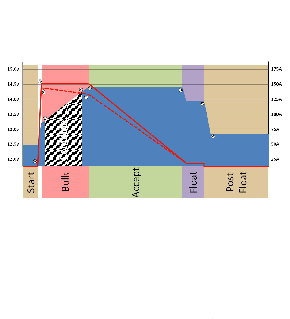
44
Do not exceed the current limit of the Feature Out port (0.5a) with the coil draw of the external large relay.
Use a length of medium size wire (e.g., 10’ of 10g wire) to create a level of resistance between the two batteries.
A minimum resistance of 5-10mΩ (milli-ohm) appears to be common.
Monitor smaller alternators not managed by the VSR Alternator Regulator - watching for signs of overheating.
Situation #1: Using 2nd battery/alternator to ‘help’ the house battery during Bulk.
In this example, there are two fully independent battery and associated charging systems, perhaps the factory alternator
and starter battery, and a house battery with its own alternator using the VSR Alternator Regulator. The starter battery
will likely be quickly recharged after the engine starts, leaving a significant amount of unused capacity in the starter
battery’s alternator.
Figure 19: Receiving Help combiner profile (default)
In this mode, Figure 19 above illustrates when we want to combine the two systems (between points ‘X’ and ‘Y’).
Specifically during Bulk, we want to:
Wait until the house battery reaches 13.2v before enabling the combiner. If we combined sooner there is a risk
of pulling energy from the 2nd battery, as opposed to only asking the 2nd alternator to share its capacity. 13.2v
will also reduce the voltage difference between the two batteries thereby minimizing initial surge current.
Break the connection of the two batteries after 14.2v. With the assumption the 2nd battery has its own charging
source that will handle all the recharging needs of that battery, we do not want to ‘override’ those decisions.
14.2v was selected under the assumption that many ‘starter’ batteries are connected to a default internally
regulator fixed voltage alternator; those are often in the 13.8 to 14.2v range.
Situation #2: Recharging a 2nd battery which has no charging source of its own.
In this example, there are still two independent batteries, but only one charging source. A representative example
would be a house battery / alternator being controlled by the VSR Alternator Regulator, and a 2nd battery used for
engine starting or to power a bow-thruster. Unlike the case above where we are looking to gain assistance from the
other battery/alternator, in this case the one alternator is being asked to be the charging source for the 2nd battery.
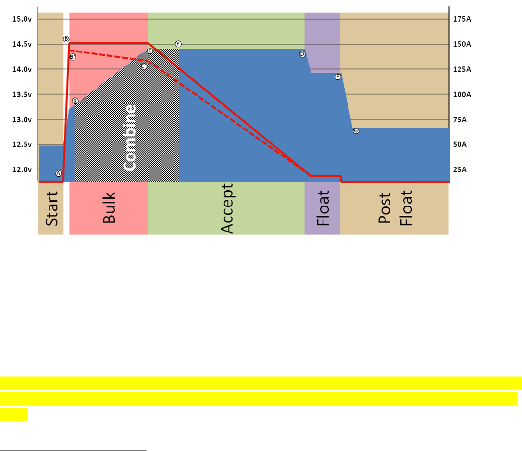
45
Figure 20: Charging 2nd battery combiner profile
Figure 20 illustrates the conditions when we want the combiner enabled. The idea is the 2nd battery parallels the charge
profile of the main battery, and because we are not actively managing the 2nd battery we cut off the Acceptance phase
after a relatively short time (Points ‘C’ to ‘Y’ above) to reduce the risk of overcharging the 2nd battery, in effect boiling it
off.
Care must be taken in each of these situations to protect the 2nd battery and charging system; remember the VSR
Alternator Regulator will focus on its battery and adjust things to its needs with NO regard to the other batteries
needs - outside of the limited combiner configuration options.
Combiner Configuration Options
All options for configuring the Feature-out port as a combiner are made in the source code, there are no ASCII
commands to modify these. The following variables in the source code:
#define COMBINE_CUTIN_VOLTS 13.2
#define COMBINE_HOLD_VOLTS 13.0
#define COMBINE_DROPOUT_VOLTS 14.2
#define COMBINE_ACCEPT_CARRYOVER 0.75*3600000UL // ¾ an hour, 45 minutes.
COMBINE_CUTIN_VOLTS when the combiner is enabled (point ‘X’ below), along with COMBINE_HOLD_VOLTS. Once
voltage raises to the CUTIN level (13.2 by default) the combiner will be enabled (via Feature-out), and will stay so even if
the battery voltage temporarily dips – as long as it remains above the HOLD level (13.0v by default). However, if it drops
too much and goes below the HOLD level, the combiner will be disabled.
46
As battery voltage rises, the combiner will be disabled by either rising above the DROPOUT level – point ‘Y’ shown in
Figure 19 (14.2v by default), or after being in the accept phase for CARRYOVER duration – point ‘Y’ shown in Figure 20.
Either point (along with low voltage) will cause the combiner to open.
Note that as with all Charge Profile Entries, voltages shown above are ‘normalized’ to a 12v battery and will
automatically scale by the system voltage multiplier. (e.g., in a 48v system, the multiplier is 4, so the combine voltage
becomes 4 * 13.2v, or 52.8v).
,

47
COMMUNICATING WITH THE VSR ALTERNATOR REGULATOR
The VSR Alternator Regulator supports external communication of status and more advanced configuration changes
than the DIP switched allow for. Communications is primarily via Serial ASCII strings, the formats of which are
documented in Appendix A: Receiving data FROM the regulator: and Appendix B: Sending data TO the regulator: The
3rd generation regulator adds support for Control Area Network (CAN) communications. Refer to Appendix C: CAN
messages for additional details of the CAN communications protocol.
Serial Port Connections:
Making the physical connection for a serial terminal to your regulator depends on which generation you have.
3rd Generation Regulator: The 3rd generation regulator features a built-in USB connector. Simply connect a micro USB
cable to the connector and use a serial terminal program of your choice. The default communications rate is 115,200
Baud, 8-bit, no parity, 1 stop bit.
Serial commands may also be carried over the CAN bus using the J1939 CAN ‘Terminal’ communications protocol DGN
(17E00h).
2nd Generation communications: Physical connection is made either via the SERVICE port located on the regulator, or
wirelessly via the included Bluetooth module using SPP (Serial Port Protocol). Remember, changes will be blocked until
the NAME and PIN code have been updated; see ‘Need to Initialize’ in the Bluetooth section on page 52 and the $SCN:
command in Appendix B.
The Service port is a 6-pin female header located in line with a 2-pin expansion connector. Pin 1 of the service port is on
the end of the female socket located next to the two male expansion pins. The Service port is defined as:
Pin #
Purpose
6
+3.3v
5
GROUND
4
n/c
3
RX: Regulator Serial Receiving pin (Overrides Bluetooth module)
2
TX: Regulator Serial Transmission pin
1
~RESET: Resets regulator on falling edge
●
SLC
I2C Expansion (male pin - 3.3v)
●
SDA
I2C Expansion (male pin - 3.3v)
Figure 21: Service Port pin-out (Generation 2 regulator)
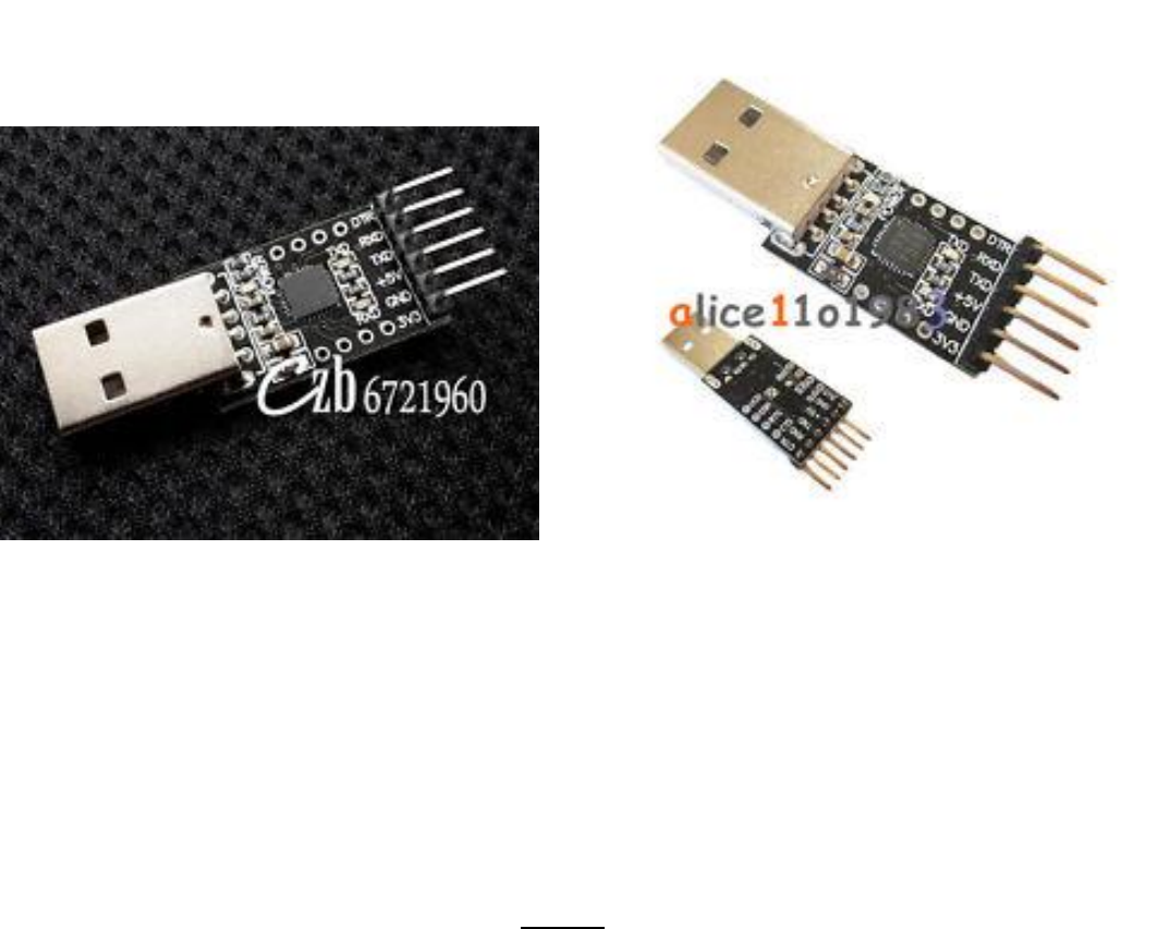
48
Service Port pin outs as used on the 2nd Gen regulator match a very select USB TTL adapter, and example of which
is shown here:
Take careful note of the pinouts, there are a wide variety of 6-pin adapters. One that is known to work was found on
EBay using the search: “CP2102 USB 2.0 to TTL UART Module 6Pin Serial Converter STC Replace FT232”. When verifying
the pinouts, look closely at the 3.3v supply and the DTR signal in position 1 (used to drive ~RESET).
Serial communication is at 9600 Baud, 8-bit, no parity, 1 stop bit. When the Serial port is attached it will have
hardware priority – preventing any communications received via the Bluetooth from reaching the regulator. You will
still be able to monitor the VSR Alternator Regulator status via Bluetooth – just not send any commands via Bluetooth.
The 3.3v pin can be used to supply limited power to an external expansion device, or optionally to power the VSR
Alternator Regulator when it is not installed.
Remember that the 2nd generation regulator will lockout all ASCII commands until the NAME and PASSWORD has been
updated from its default. See section ‘Regulator Name & Password: need to Initialize’ on page# 52.

49
Bluetooth Operation
Optional to the 2nd generation regulator, serial communications may be initiated with the VSR Alternator Regulator
using Bluetooth. Attach an external computer, tablet, or smart-phone using the SPP (Serial Port Protocol). Then use a
serial terminal to see the ASCII strings, or send commands to the regulator. The default NAME and PASSWORD for the
Bluetooth connection is:
NAME: “ALTREG”
PASSWORD: “1234”
Terminal Programs
Many OSes have built in terminal programs, as does the Arduino IDE. After connecting the regulator to the computer
you can use one of these to open a communications window to the VSR Alternator Regulator. Gen 2 regulators requires
an external a USB to Serial adapter, while Gen 3 regulators already have a USB port built in device. If your Gen 2 board is
equipped with the Bluetooth option, that can also be used to access the serial port on the VSR Alternator Regulator. A
special note, some terminal programs do not send a complete end-of-line terminator (CR+LF - specifically, Arduino’s
Serial Monitor). To support these environments, the VSR Alternator Regulator will recognize the character ‘@’ as an
alternative EOL.
Remember that any configuration changes you make to the regulator via ASCII commands may not take effect until the
regulator is rebooted. When you have finished, make sure to issue the $RBT: command to not only assure changes are
saved to the regulators’ non-volatile memory, but that the changes are then utilized by the regulator. (refer to $RBT:
- ReBooT system on page 106) After rebooting the VSR Alternator Regulator verify the changes you sent were
indeed recognized by the regulator by inspecting the various status strings.
Putty: Another versatile option is the free ‘Putty’ program (www.putty.org ). It supports a wide range of OSes and
includes a very nice logging function. To use connect up the USB cable as directed above and start Putty. Configure as
shown here – selecting the Serial Line which your USB serial port is associated with, and setting the speed to 115200 and
clicking the Serial Connection Type redial button.
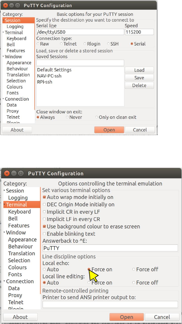
50
Next click on the Terminal category and click the Forced-on button for local echo, this will assure you can see what you
are typing.
51
Finally, if you wish to keep a logfile of the session clock on the Logging category, enter a file name and select the
‘Printable Output’ button as shown here:
Logging sessions is very helpful for debugging your installations, the files are comma separated and easily import into
Excel using the import wizard specifying commas (,) as the separator. Refer to Appendix A: Receiving data FROM the
regulator: for details on the output.
Once you have done your configuration press the Open button to start the terminal session.
Bench-top Configuration: When a USB cable is to connect the either the 2nd or 3rd generation of the VSR Alternator
Regulator power is supplied to the logic portion of the hardware. This allows you to do bench-top configuration before
completing the installation to the actual alternator. Make sure to do a $RBT: command as your last step, to assure
changes are recorded. After the regulator reboots make sure to verify your changes before installing the regulator in a
live installation.

52
REGULATOR NAME & PASSWORD: NEED TO INITIALIZE
Each VSR Alternator Regulator has a name associated with it. This name is used to help identify the regulator when
communicating and is used for the Bluetooth ID, as well as the CAN identifier. Each regulator also contains a password
which is primary used by the optional Bluetooth module. Both the NAME and PASSWORD may be any combination of
alpha numeric character - with the exception of the comma (,), space ( ), or the ‘@’ - up to 18 characters long.
After a master reset (or when 1st using the regulator) you will be able to view the VSR Alternator Regulator status via
ASCII strings. However, due to the wireless nature of Bluetooth, and because the an incorrect change the configuration
could potential harm your battery the ability to SAVE any configuration changes is disabled in the 2nd generation
regulators until the Name & Password has been updated via $SCN: command. For additional security – the 1st time the
Alternator’s Name / Password is changed on the 2nd generation regulator you MUST use the Service Port, set the DIP
Switch 1 = OFF (Bluetooth disabled) and DIP switch 2..8 = ON. The alternator must also not be charging (e.g., bench top
configuration, or the engine is stopped) . Once the name/password has initially been updated you can then restore the
DIP switches to the configuration needed for your system; and the name/password may be changed again without
having to set the DIP switches as above. (Unless you do a master reset on the regulator – see Restore to AS-Compiled
(default) Status on page 64)
Caution: The regulator will NOT check the validity of the strings, specifically that they do NOT contain a comma (,) space
( ) or ‘@’ character. Be careful not to send these as the results might be unpredictable. If needed, perform a master
reset to the regulator and start over.
On 2nd generation regulators, it is STRONGLY suggested you change BOTH the NAME and PASSWORD to something
unique OR disable the Bluetooth via DIP-switch #1. And remember: no ASCII changes will be accepted until you do.
Else you run the risk of someone near you accidentally, or maliciously, adjusting your Alternators configuration and
potential damaging your system / batteries. (And this is why the ability to save configuration changes is disabled until
the 1st $SCN: command has been received, and that can only happen if you set all the DIP switches as directed above.)

53
COMMUNICATIONS – THE CAN (CONTROL AREA NETWORK)
The CAN (Control Area Network) ports allow Generation 3 and beyond VSR Alternator Regulators to communicate with
other devices. Developed in the 1980’s by Bosch and targeted towards the transportation sector, CAN is now one of the
most widely deployed communications standards covering not only the Transportation sector but also widely used in
Industrial, Heavy Industry, Farming, Medical, Consumer, and more. Over a billonCAN nodes have been deployed, with
modern automobiles contained upwards of over 100 individual nodes each! It is a proven reliable and robust
communications standard with many feature to assure deterministic and prioritized communication to form the
backbone of the VSR Alternator Regulator.
Leveraging this backbone devices are able to integrate into a ‘System’ where each works in cooperation with the others.
Further, the CAN allow simple and reliable way to connect computers or displays for ongoing monitoring and easy
configuration. The VSR Alternator Regulator leverages several standards covering physical wiring, message content and
other communications standards. These include:
CAN Specification 2.0b / ISO-IS 11898
CiA 303
SAE J1939
OSEnergy (Open Systems Energy - derived from the RV-C standard)
NMEA2000TM (Limited support)
OSEnergy (Open Systems Energy) is an architectural specification who's aim is to provide a framework for the design,
deployment, and operation of charging sources associated with a DC battery. Allowing them to work together in a
'systems' approach while meeting the full requirements of an associated battery as well as concurrently supplying house
power needs in a consistent and efficient way. You can learn more here: https://github.com/OSEnergy/OSEnergy
Through the application of these standards the VSR Alternator Regulator is able deliver several key benefits, including:
Coordination of charging goals and objectives; all devices work towards the SAME goal vs. fighting each other.
Prioritization of charging sources. e.g.: Utilization of Solar to its maximum capability while filling in the
remaining energy needs from an engine driven alternator. Thereby saving fuel.
Remote sensing / Port Expander: The VSR Alternator Regulator is able to take advantage of the CAN
communications capability to transfer real-time battery status: Voltage, Amperage, and Temperature as well as
operational status (e.g., off-line in the case of a LiFeP04). By using this capability wiring and installations may be
simplified without reduction in reliability. (Refer to: `Example 4: Basic System Installation (Utilizing remote
battery sensor)’ on page 28 for one example)
Self healing / fail over: Ability to self-recover from a failed, removed, or turned off device. The system
continuously monitors all devices and adjusts as needed.
‘Get-Home’ total system failure mode: In the event of a catastrophic total system communications failures, the
VSR Alternator Regulator will fail-to-safe and operate in a stand-alone mode. Allowing for continued charging,
but perhaps with less optimization and longer times needed.
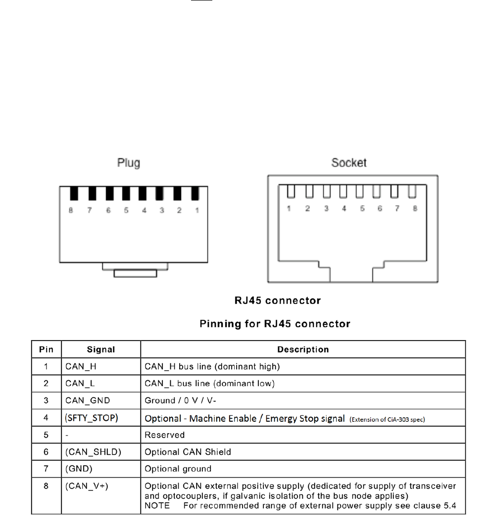
54
CAN WIRING
Use good quality CAT-5, CAT-5e, or CAT-6 cable to connect between devices in a daisy-chained fashion plugging into one
of the two RJ45 connectors on the regulator. At each end of the daisy-chain leave one connector open and place a
jumper on the TERM block – removing the TERM jumper on any devices in-between. It is important that the CAN bus be
a single end-to-end chain with termination at each end. Do NOT connect an extra CAT-5 cable between the end devices
making a loop – instead make sure each end point has one open RJ45 connector.
The total length of the CAT-5 daisy-chain should be kept under 100M (300’) with no more than 100x nodes total for best
reliability.
The RJ45 connectors follow the CiA-303 standard, as shown here:
Figure 22 – CiA 303 CAN RJ45 connector specification
Connect the CAN_H and CAN_L signals. If supported, CAN_SHLD may also be optional connected as needed. It is
generally NOT recommended to connect the CAN_GND to anything, as this may create a ground loop between it and
ALT-
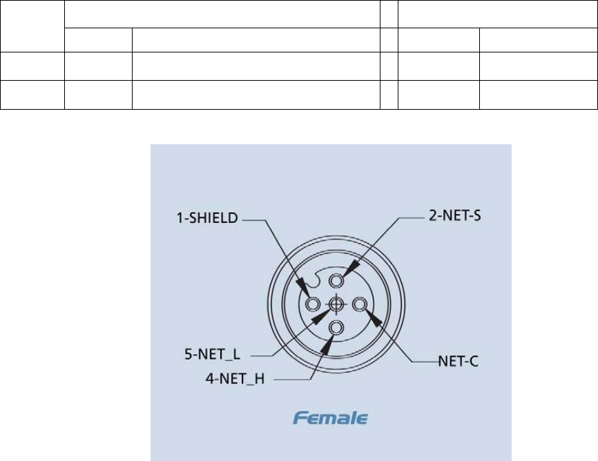
55
NMEA-2000TM SUPPORT
VSR Alternator Regulator CAN protocol shares the same foundation and electrical specifications and NEMA2000, and is
able to produce messages which may often be displayed on a NMEA2000 device. It needs to be noted, the VSR
Alternator Regulator is NOT a certified NMEA2000 compliant device, and its support is a byproduct of the J1939 library
used. But in many cases connecting to a NMEA2000 network is successful. If you have issues with either the
NMEA2000 or OSEnergy communications capabilities disconnect the regulator and use a stand-alone CAT-5 based
network. Future product developments may result in a proper OSEnergy to NMEA2000 bridge, thereby eliminating any
issues with potential conflicts.
Wiring:
To connect into an existing NMEA-2000 network you will need to make up a patch cable. The simplest way to do this is
to cut one end off a common CAT-5 cable and attach a Micro connector. If you have ordered the option of a terminal
strip instead of the RJ45 connectors, you may use a NMEA2000 drop cable and connect the CAN_H and CAN-_L wires to
the appropriate positions. Referring to Figure 22 above as well as Figure 23 below only the CAN_H and CAN-_L wires
need to be connected. With either approach take care not to exceed the maximum Drop-cable length of 6 meters,
remove the TERM jumper and use the following as a wiring guide:
Signal
CAT-5 Cable
NMEA2000 Cable
POSITION
COLOR
POSITION
COLOR
CAN_H
1
White/Green --OR-- White/Orange
4
White
CAN_L
2
Green --OR-- Orange
5
Blue
Figure 23 - NMEA2000 connector pinout
There is no need to connect the CAN-GND, and in fact doing so may cause reliability issues due to ground-loops.
56
A limited number of NMEA2000TM like status output messages are supported. These messages may be useful when the
VSR Alternator Regulator is connected to a NMEA2000 network and will allow the operational status of the alternator
and battery to be displayed. Be sure to properly configure the regulator when using these messages, specifically the
`Engine ID’ using the $CCN: command.
NMEA2000-DC Detailed Status - PGN127506
NMEA2000-Battery Configuration Status -- PGN127513
NMEA2000-Battery Status - PGN127508
NMEA2000-Engine parameters rapid - 127488L: (Provides Engine RPMs)
The VSR Alternator Regulator is also able to receive a limited number of non OSEnergy CAN messages for special
purposes:
NMEA2000-DC Detailed Status - PGN127506
o If `Enable_NMEA2000-RAT’ is enabled (See $CCN: command), the regulator will look for DC Detailed
Status to receive the battery current and temperature.
o Eliminating the need for dedicated probes in systems which have a battery monitor already installed.
o If the VSR Alternator Regulator receives a DC Detailed Status message, it will cease sending out one of its
own.
NATIVE J1939 SUPPORT
The VSR Alternator Regulator is able to support some CAN messages beyond the OSEnergy / NMEA2000 standard.
Specifically support for J1939 protocol based messages have been added for additional features and capabilities. These
capabilities are often selected via compile-time switches (#defines) and require custom compiling of the source code to
enable.
J1939 Engine Speed - PGN 61444
o A compile-option #define DISABLE_ON_J1939_RPMs in SmartRegulator.h when enabled will
cause the regulator to go into a disabled / low power mode if Engine Speed is reported to be below 400
RPMs (indicating the engine has stopped). By enabling this compile option the ENABLE pin may be
continuously powered and the regulator will look for the J1939 engine speed messages to determine if
it should begin a charge cycle with the alternator or not.
o J1939 derived RPMs will take precedence over any locally measured RPMs using the Stator wire.

57
OPERATION OVERVIEW
The VSR Alternator Regulator has a wide range of flexibility and can be configured in three ways, ranging from Simple to
Any-thing goes.
Select among built-in (default) parameters via the DIP switches
Modify many of the built-in parameters via sending ASCII commands over the Service port and/or the Bluetooth
serial connection
Modifying any or all built in parameters in the source code, recompile and re-flash to regulators firmware.
(requires use of Service port and Arduino IDE, see http://arduino.cc/ )
Startup Sequence:
When the VSR Alternator Regulator is first powered up it loads in the default Firmware and then looks to the DIP
switches to see what the user has selected. It will then sample the system voltage to decide if it is installed in a 12v, 24v
or 48v environment (and thereby setting the SysVolt multiplier, see SST: / System Status below for more details about
this and how it is used). Finally, it will look at the saved FLASH memory in the CPU to see if any of the parameters have
been modified or any of the DIP switches have been overridden by the user using ASCII commands.
Note that parameters saved to Flash are ONLY checked during startup; this is why after changing any parameters via an
ASCII string command you need to reset the regulator (via the $RBT – ReBooT command) in order for any of those
parameters to take effect. This is done this way so that the regulator does not start acting on changes part way through
you making configuration changes. For example, if you are updating the CPE entry, you want to update and verify ALL
parts of it before the regulator starts using the new values.
Ramp-up Sequence:
Next, the regulator will enter the Ramp-up phase. It first waits 30 seconds before doing anything (configurable) to give
the engine time to start. Finally it will begin to slowly ramp up the alternator field over a period of about a minute
before entering Bulk phase.
Charging the Battery:
Once the regulator has completed its startup and ramping sequence it enters the ‘charging’ phases. Each phase has
limits (e.g., voltage, amps, etc.) as well as ‘exit’ criteria based on voltage, amps and/or time. A high degree of
configurability allows each phase to be used, or bypassed as needed to meet the battery manufacturer’s recommended
charging profile. While in each of these phases the regulator will also monitor battery and alternator temperature,
making adjustments as required. It will also look to see if the regulator has been configured with System limits and
make sure none of those are exceeded.

58
Figure 24: Example 3-stage Charge profile
Figure 24 above shows a typical 3-phase charge profile, consisting of the Bulk, Acceptance, and Float state. This is one of the simplest charge profiles, and very
commonly seen in external regulators. The following table details each phase as well as the parameters in the source which can impact them.
Phase
Ref
Limiting
Factor
Exit Criteria
Discussion
Key Source Variables
Start
-A
Time
30 second delay or
Stator Signal.
Allows time for the engine to start and get up to speed before
we apply a load to it.
If Tach Mode is enabled, and the regulator has been configured
with a fixed minimum PWM value via the $SCT: ASCII command
(see: Tach Min Field), Start Phase will be extended past the 30
second initial delay until a value Stator signal is detected.
ENGINE_WARMUP_DURATION

59
Phase
Ref
Limiting
Factor
Exit Criteria
Discussion
Key Source Variables
Ramp
A-B
Time
30 seconds
Reaching target Voltage
Soft ramp of applied load. Normally this will exit via the Time
variable, but if the battery is already well charged it will very
quickly reach the target voltage set point, forcing an earlier exit
of the Ramp(A-B) phase
PWM_RAMP_RATE
ACPT_BAT_V_SETPOINT
Bulk
B-C
Alternator
Capacity
Battery Voltage
Time(optional)
Using default configuration (Battery Focused). During this
phase, the majority of energy is returned to the battery, often
touted as up to the 80% SOC point. The Alternator is run full out
producing as much power is it is capable of producing. As the
battery recharges voltage will raise until the set point is reached,
which will trigger the exiting of Bulk.
If Small-Alt mode is selected via the DIP switches, then the
output of the Alternator will be managed to a lower level, to
prevent overheating of small alternators that are unable to
sustain continuous max amp output.
Likewise, if Half-power mode is selected (via shorting the Alt
Temp probes together), a more aggressive scale back will occur.
This can be useful in installations where extra engine power is
needed, perhaps to drive an additional pump, or perhaps allow
for high speed / power mode (passing).
ACPT_BAT_V_SETPOINT
ALT_AMP_DERATE_NORMAL
ALT_AMP_DERATE_SMALL_MODE
ALT_AMP_DERATE_HALF_POWER
Bulk’
B’-
C’
System
Capacity
Battery Voltage
Time(optional)
An alternative configuration (Alternator Focused) to manage
the system load at a lower level than the full capability of the
Alternator. This is useful when powering a large alternator with
a small engine, such as in a DC generator.
All items discussed in Bulk above are still applicable in this
configuration, with the additional system limit added. Notice in
Figure 24 above: as the battery voltage increases – amps
delivered are reduced, resulting in a constant wattage. Which
translates to a constant load placed on the driving engine.
ALT_WATTS_LIMIT
ALT_AMPS_LIMIT

60
Phase
Ref
Limiting
Factor
Exit Criteria
Discussion
Key Source Variables
Accept
C-D
Battery
Acceptanc
e Rate
Battery Acceptance
Current
Time – Fixed
Time - Adaptive
Acceptance carries recharging from 80% to 100% of the
battery’s capability. The preferred way to exit this phase is via
measuring the current the battery is accepting; indicating its
state of charge.
Other ways to exiting include a fixed Max time, as well as a time
ratio based on a multiplier of how long the battery was in the
Bulk phase. Both of these can be useful for installations where
the Amp shunt has not been installed, or it has failed.
ACPT_BAT_V_SETPOINT
EXIT_ACPT_AMPS
EXIT_ACPT_DURATION
ADPT_ACPT_TIME_FACTOR
Float
Forced
Float
D-F
--
Pull back to Bulk
Time(optional)
Float is a ‘parking place’ intended to maintain a fully charged
battery. A slightly higher than rest voltage is maintained to
overcome the batteries internal self-discharge. Further, the
Alternator is maintained in a ready mode to supply current to
any external load that might be requested.
If the Alternator is unable to support this load and current is
requested from the battery, we are pulled out of Float and back
into a recharge cycle (back to Bulk). Another indication of this is
if the battery volts start to drop. This can be helpful in
situations where the Amp shunt is not installed, or has failed.
Finally, the accumulated Amp Hours may be monitored and
once a given amount has been removed from the battery – the
regulator will revert to Bulk mode.
Note: If CPE #8 is enabled, the FEATURE_IN pin may be used to
force the regulator into Float mode. As such, none of the above
exit criteria will be checked while FEATURE_IN is active.
FLOAT_BAT_V_SETPOINT
EXIT_FLOAT_DURATION
FLOAT_TO_BULK_AMPS
FLOAT_TO_BULK_VOLTS
FLOAT_TO_BULK_AHS
<NONE – All exits bypassed>

61
Phase
Ref
Limiting
Factor
Exit Criteria
Discussion
Key Source Variables
Post
Float
F-G
--
Pull back to Bulk
Time(optional)
Post Float is much like Float, except the alternator is turned off
allowing the battery to sit on its own.
Post Float will return to Float mode based on a timed exit value.
Once this has been exceeded, the regulator will revert to FLOAT
mode.
Another way to exit Post Float is through the appearance of a
large load which has been placed on the system. This can either
be determined by battery voltage, or by monitoring the
accumulated Amp Hours removed from the battery – much like
Float above. Note however that when exiting via these
conditions these two methods will cause the regulator to move
back into Bulk mode - just like Float above.
EXIT_PF_DURATION
PF_TO_BULK_VOLTS
PF_TO_BULK_AHS
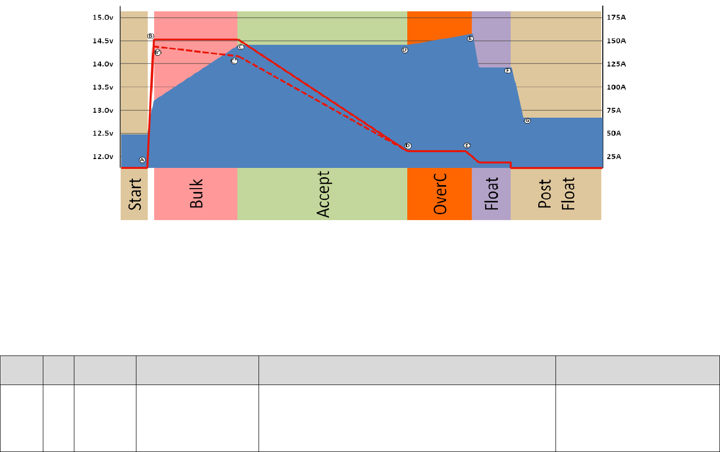
62
Figure 25: 4-stage Charge Profile
Some batteries ask for an additional charging phase after the Acceptance phase, one that provides a small constant current and allowed the voltage to raise.
Referred to as a Finish Charge or an Over Charge, the purpose is to assure even chemical actions has occurred throughout the entire battery. For batteries which
specify this 4th charge step, the above charge profile is used. Refer to the above table for stages other than Over Charge.
Phase
Ref
Limiting
Factor
Exit Criteria
Discussion
Source Variables
Over
Charge
D - E
Defined
Amps
Battery Voltage
Time(optional)
In this phase the alternator will be managed to maintain a
consistent current into the battery, allowing battery voltage to
raise (much like Bulk phase). Once battery voltage has reached
the exit volts (Point E), or a max time has been exceeded, the
regulator will move to the Float mode.
LIMIT_OC_AMPS
EXIT_OC_VOLTS
EXIT_OC_DURATION
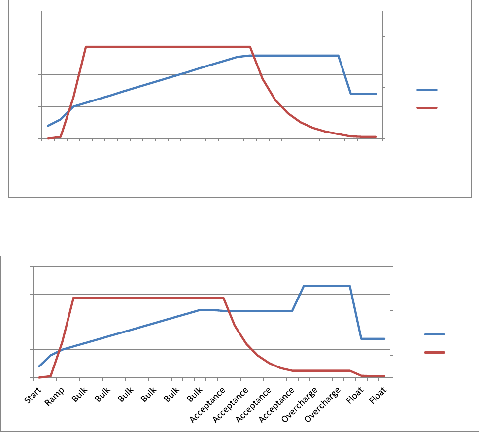
63
Note how the VSR Alternator Regulator will move directly to Acceptance Phase if the battery voltage quickly rises.
This, combined with the measurement of the Acceptance Current to determine if a battery is fully charged, handles the
all too common situation of being plugged into shore-power and subsequently getting under way with the battery
already fully charged. Traditional time-only based regulators might be stuck in the Acceptance phase for several hours
until the fixed time limit is reached, overcharging the battery. With the VSR Alternator Regulator, the regulator will
recognize quickly the battery is fully charged and move into float mode within seconds of starting the engine. This
eliminates one of the major ways a less intelligent regulator can damage your batteries.
Each of the charge steps are fully configurable, and many can be bypassed (e.g., most charge profiles do not use the
Overcharge step). As way of an example, the following two diagrams show two different approaches for charging a
heavy duty 12v / 500Ah battery (e.g., two L-16 batteries). Both profiles are included in the default VSR Alternator
Regulator as profile #3 and #6. Figure 26 shows the traditional 3-step charge profile (Bulk, Accept, and Float), while
Figure 27 illustrates the flexibility to accommodate a 4-step charge profile (Bulk, Accept, Over-charge, then float). The
diagrams provide an overview of each phase and represent a 180A alternator charging a 12v 500Ah battery.
Figure 26 – Example Charge Profile #3 (HD FLA Storage battery)
Figure 27 – Example Charge profile #6 (HD FLA - Alternative Charge Profile)
0
50
100
150
200
250
12.0
13.0
14.0
15.0
16.0
Start
Ramp
Ramp
Bulk
Bulk
Bulk
Bulk
Bulk
Bulk
Bulk
Bulk
Bulk
Bulk
Bulk
Bulk
Bulk
Acceptance
Acceptance
Acceptance
Acceptance
Acceptance
Acceptance
Acceptance
Acceptance
Float
Float
Float
Volts
Amps
0
50
100
150
200
250
12.0
13.0
14.0
15.0
16.0
Volts
Amps
64
RESTORE TO AS-COMPILED (DEFAULT) STATUS
Configurations (system and Charge parameters) which have been changed from the as-compiled default values may be
restore in one of three ways:
Individually by the $CPR:n , $SCR: and $CCR: commands.
Collectively via the $MSR: command.
Total system restore by connecting the FEATURE-IN to VBat before applying power to the regulator, and then
applying power. This will restore ALL configurations to the default condition.
o DIP switches must be set to select CPE #5 with ALL other DIP switches set = ON
If the regulator has been Locked Out via the $SCO command the only way to restore to the default configuration is via
using the FEATURE-IN reset procedure, because none of the ASCII change commands will function once the regulator
has been locked. You may also clear the locked flag by recompiling the firmware and reloading it. If you do this, you will
need to make a change to the following defines in the source code to some other random value:
#define SCS_ID1_K 0xFC3A
#define SCS_ID2_K 0x69D3
These provide a validation token at the beginning of each saved block of data in the FLASH. If you do not change these
values the CPU will read the existing FLASH and finding a match to the above keys will assume the saved parameters are
valid. (Including the locked-out bit). So, in order to ‘clear’ the FLASH, you must change the tokens.
65
BENCH TESTING AND DIAGNOSTICS
Limited testing can be performed on the VSR Alternator Regulator using a simple test mockup, a voltage meter, power
supply and a computer to monitor status out. If you suspect the regulator has been damaged, these steps can help you
confirm basic functionality.
Simple Go / No-Go testing
The 1st test is to simply confirm the regulator is able to wake up and begin processing. This may be done with the
regulator installed or removed on the bench. Connect a PC to the regulator via the Serial/USB port and open a terminal
program. (See section: Communicating with the VSR Alternator Regulator on page: 47). You should see ASCII strings
being sent out, much along the lines of this:
AST;,0.00, ,12.30,-39.3,0.0,-484, ,14.40,1000,15000,4, ,-99,18, ,0, ,12.30,15,-99,0
AST;,0.00, ,12.30,-39.3,0.0,-484, ,14.40,1000,15000,4, ,-99,18, ,0, ,12.30,15,-99,0
AST;,0.00, ,12.30,-39.2,0.0,-483, ,14.40,1000,15000,4, ,-99,18, ,0, ,12.30,15,-99,0
AST;,0.00, ,12.30,-39.3,0.0,-483, ,14.40,1000,15000,4, ,-99,18, ,0, ,12.30,15,-99,0
AST;,0.00, ,12.30,-39.3,0.0,-484, ,14.40,1000,15000,4, ,-99,18, ,0, ,12.30,15,-99,0
AST;,0.00, ,12.30,-39.3,0.0,-483, ,14.40,1000,15000,4, ,-99,62, ,0, ,12.30,15,-99,0
AST;,0.00, ,12.30,-39.3,0.0,-483, ,14.40,1000,15000,4, ,-99,18, ,0, ,12.30,15,-99,0
AST;,0.00, ,12.30,-39.3,0.0,-483, ,14.40,1000,15000,4, ,-99,18, ,0, ,12.30,15,-99,0
AST;,0.00, ,12.30,-39.2,0.0,-483, ,14.40,1000,15000,4, ,-99,18, ,0, ,12.30,15,-99,0
This means the basic CPU is operational. Please note that for bench testing the VSR Alternator Regulator is able to self-
power from the Serial/USB port, so no other connection is needed – though this simple Go / No-Go test may also be
performed with the regulator installed.
At the same time the LED should start flashing, about once a second. Both the flashing and the ASCII strings will
continue for approximately 30 seconds at which time if the regulator is not installed (specifically, the Vbat sensing wires
are not connected) it will fault-out with a low-voltage error. This is normal, as if the regulator cannot see a battery
voltage that is reasonable it assumes something is wrong.
If you do not see strings such as above but the LED flashes, it means there may be a problem with your serial
communications hardware/software. If you cannot see neither the flashing nor the strings it implies the regulator CPU is
not functioning.
Good next steps would be to test the regulator using the Arduino IDE, making sure the firmware is flashed in.
Bench testing mockup
A simple test setup will allow you to verify major portions of the VSR Alternator Regulator are operational. Specifically
testing the battery Voltage and Amperage sensing circuit and field driver FETs.
You will need the following test gear:
Remove the regulator from the installation (do NOT attempt to do this test while the regulator is installed)
A power supply of some type. To see complete operation a variable voltage supply is needed.
Three resistors: 1M ohm, 10K ohm, and 1K ohm. Common 1/4W 5% or better resistors are ok.
A DVM or VOM.
A computer connected to the serial/USB port is helpful.
2x - 10k NTC temperature probes (optional)
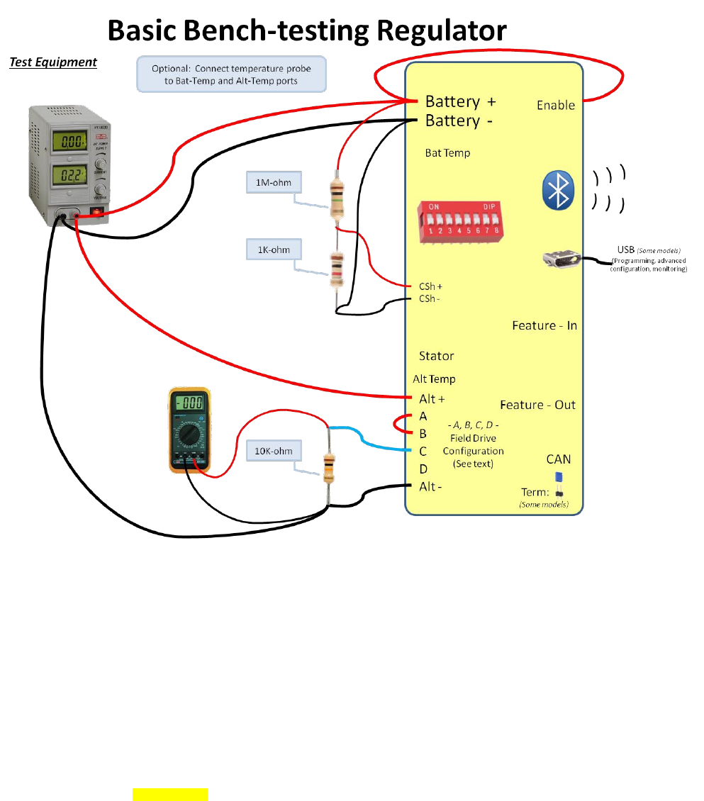
66
Connect the power-supply, resistors and field as shown:
Verifying Voltage and Current sensing:
Turn on the power-supply and adjust it for approx 12.6v. Connect your terminal observe the AST; strings and you should
see something along the lines of the example here. Note the reported Battery Voltage and Current (Marked in Yellow in
the example below). It may take a few seconds for these values to be produced and your values may be slightly
different (notable the current ones) if your regulator is configured with a different shunt ratio.
AST;,0.00, ,12.60,126.0,0.0,-483, ,14.40,1000,15000,4, ,-99,18, ,0, ,12.30,15,-99,0
Using your DVM/VOM, measure the actual voltage at the VBat+ and VBat- terminals on the regulator. They should be
close to what the regulator reports. Depending on tolerances of regulator and meter, expect the results to be within 1%
of each other. If not, there is a problem with the INA226 voltage sensing circuit.

67
Next measure the voltage across the Current_shunt+ and Current_shunt- terminals. Also take note of the
configured shunt value as reported by the $SCV; status string. Using the following formula, calculate the ‘battery
current’:
Battery-current = (Measured-mV) * (SCV-Shunt-ratio)
Battery-current = (Measured-mV) * 10,000 If you are using the default shunt ratio
The resulting value should be close to what is reported by the $AST strings, if not there is something wrong with the
INA226 and/or INA282 level shifter. Some areas to investigate include the 13v power supply (TP1 on the Gen3 regulator,
pin #1 of U3 are accessible test points) – there should be around 11-14v at these points.
Verifying Field drive:
With the regulator still connected per above, connect your DVM/VOM to the Field terminal and monitor its voltage.
While watching the AST; strings - looking at the field-drive% value (Highlighted in Yellow here)
AST;,0.01, ,12.49,124.9,48.2,602, ,14.40,1000,15000,5, ,-99,18, ,731, ,12.49,15,-99,58
AST;,0.01, ,12.50,125.0,46.1,577, ,14.40,1000,15000,5, ,-99,18, ,731, ,12.50,15,-99,60
AST;,0.01, ,12.51,125.1,48.3,604, ,14.40,1000,15000,5, ,-99,18, ,731, ,12.51,15,-99,62
As the regulator ramps up, and the field drive % increases, you should see a like increase in voltage indicated on your
DVM/VOM, with the value being around the voltage of your power supply times the % field drive shown via the AST;
string. Do note the field drive is a low PWM frequency (around 140hz), and many DVMs will be confused by this. If the
DC setting does not work, try AC, or better – if you are able to locate an old-style VOM meter use it.
Failure to see increasing field drive voltage indices an issue with your power supply, the Enable source, the regulators
13v power supply (noted above), the FETs and/or the field drive. Depending on your meter you may try touching the
input pun to the FET driver chip (marked FIELD-PWM in the schematics), and you should see a DC voltage increasing
from 0 to 3.3v (for Gen 2) or 5.0v (Gen 3) regulator.
Once you have confirmed the field drive is working you can try varying the power-supply to voltage above and below the
set point (14.40 in the above examples) and observe the field drive % ratio change.
Verifying Temperature probes:
If you connect temperature probes you should see values close to room temperature. Note the FET temperature as
well; it also should be close to room temperature. You can hold one of the probes in your fingers to observe a rise. Or
place it on top of an ice-cube.
Other portions of the VSR Alternator Regulator will need to be tested using custom programs and more advanced
diagnostic equipment. But the above will verify the core functionality.
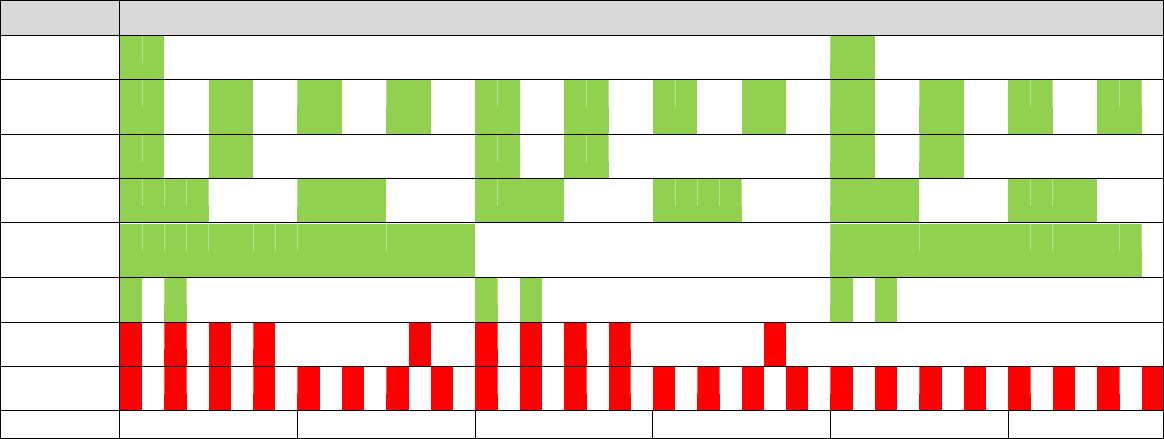
68
LED BLINK PATTERNS
The on-board LED will blink out patterns to inform the user of its current status, errors, and pending actions (e.g., about
to restart). Patterns are made up by a combination of blink patterns, and the speed at which they blink. The following
table describes the patterns.
Status
Blink Pattern
Idle
Ramp
Bulk
Accept
Over Charge
Float
Post-float
Equalize
Error
Pattern repeated twice then followed by
flashing out of error # ( 2 or 3 digits.)
Restarting
< 1 Second >
< 1 Second >
< 1 Second >
< 1 Second >
< 1 Second >
< 1 Second >
Note: Generation 2 board only blinks GREEN.
If using the CAN enabled Systems Regulator (Version 3 or later), the LED will blink GREEN during normal operation. If the
regulator is linked into a ‘system’ and being coordinated by a remote battery manager, the LED will blink YELLOW
instead of Green. These colors can be used to quickly identify which device is currently acting as the battery master and
that the system is configured correctly. It also allows quick visualization of which node has taken over in the case of a
failed battery master. The LED will blink RED if there is a fault condition. Note also that if a Required Sensor is
identified as not present (See the $SCA: command), the LED will blink out the normal mode patterns (Idle, Ramp, bulk,
etc) except it will do so in RED indicating an issue.
69
APPENDIX A: RECEIVING DATA FROM THE REGULATOR:
Appendix A: Receiving data FROM the regulator: ...........................................................................................................69
ALTERNATOR STATUS -- AST; .............................................................................................................................70
SYSTEM STATUS -- SST; ......................................................................................................................................72
CAN STATUS -- CST; ...........................................................................................................................................73
CHARGE PROFILE ENTRY – CPE; ...........................................................................................................................75
SYSTEM CONFIG – SCV;........................................................................................................................................77
NAME & PASSWORD CONFIG – NPC; ...................................................................................................................79
FAULTED -- FLT; .................................................................................................................................................80
ACKNOWLEDGE – AOK; .......................................................................................................................................80
DEBUG – DBG; .....................................................................................................................................................80
RESET – RST; ........................................................................................................................................................80
AST; Alternator STatus- sent every 1 second
SST; System STatus -
CST; CAN STatus – 3rd generation regulator only
CPE:n Charge Profile Entry – line ‘n’ from the Charge Profile Table
SCV; System Configuration Variables –
NPC; Name / Password Configuration (was BTC: BlueTooth Configuration)
FLT; System is FAULTED, Fault number will follow.
AOK; Acknowledge – Regulator has received a valid change command.
DBG; DeBuG – Additional internal information sent if the #define DEBUG is present.
RST; ReSeTing – Regulator is resetting in response to a command or resettable fault.
All status outputs are suspended during the receiving and processing of a command string. In this way, a command
which expects a response (ala $RSC:) can be assured the next string sent back by the regulator is the response to the
request command (though one should still do error checking and validation, as the simple regulator will often just ignore
commands that have a syntax error in them)
Formats are all in clear ASCII using comma separated fields. Note the presence of double commas (separated by a
space) between major ‘sections’, this is to simplify manual reading of the strings. Each string is delivered as one
continuous line with a CR/LF termination.
Additional details of each status may be discovered by examine the command string for changing those parameters.

70
ALTERNATOR STATUS -- AST;
AST: “AST;, Hours, , BatVolts, AltAmps, BatAmps, SystemWatts, ,TargetVolts, TargetAmps, TargetWatts, AltState,
,BTemp, ATemp, ,RPMs, , AltVolts, FTemp, FAmps, FLD%”
Hours: Time regulator has been powered up, in hours and fraction (to 2 digits) of hours.
BatVolts: Derived Battery Volts, in volts and fractions of volts (to 1mV resolution). Used to decide change
mode changes.
AltAmps: Measured Alternator Amps, in Amps and fraction of Amps (to 1/10th of an Amp)
BatAmps: Derived Battery Amps being used to decide charge modes.
Voltage and current readings made by the VSR Alternator Regulator are directly reported as
AltVolts and AltAmps. Unless overridden by an external source (example via a Remote Battery
Sensor) those same values will be assumed to be BatVolts and BatAmps and used b the
regulator to make charge state decisions.
SystemWatts: Current measured System Watts being delivered.
TargetVolts: Volts the regulator is attempting to bring the battery to. This value is the ACTUAL voltage value
being driven to, and reflected the adjusted Charge profile entry and the sysVolts index value.
TargetAmps*: Amps the regulator will limit the alternator to. This value is the ACTUAL amperage being driven
to, and reflecting the derating and half power mode adjustments.
TargetWatts*: Watts the regulator is actually working to limit the system to.
AltState: Current state of the Alternator, per the following table:
1.2.x
and
below
1.3.x
and
above
0,1
0,1,4
– Alternator Off
2, 3
2,3
- Alternator FAULTED (See Fault Code)
4
10
- Alternator in delay mode while engine warms up
5
11,15
- Ramping towards BULK mode.
6,7
12,20
- In BULK mode
8
21
- In ACCEPTANCE mode
9
22
- In OVER CHARGE mode
10
30
- In FLOAT mode
11
31
- In FORCED_FLOAT mode (via Feature_in pin and CPE = #8)
12
36
- In OFF (Post Float) mode
13
38
- In EQUALIZE mode
14
39
- In CVCC mode (only available in system under direction of CAN master)
71
BTemp: Measured temperature of NTC sensor attached to B-port in degrees C or battery temperature
received via external CAN sensor. -99 indicates temperature has not been measured, NTC
sender has failed, not attached, and there is no remote temperature information available via
the CAN connection.
ATemp: Measured temperature of NTC sensor attached to A-port in degrees C. -99 indicate
temperature has not been measured, or NTC sender has failed. -100 indicates the Alternator
temp NTC probe is shorted (to select ½ power mode)
RPMs: Measured RPMs of engine (Derived from Alternator RPMs and the Engine/Alternator drive ratio)
(The following additions are available with Firmware version 1.0.0 and above)
AltVolts: Measured Alternator Volts, in volts and fractions of volts (to 1mV resolution)
FTemp: If equipped, this is the temperate of the FETs in degrees C.
-99 indicated FET temperate cannot be measured.
FAmps: If equipped, this is a measurement of the current (amperage) being delivered to the field.
-99 indicated field current is not being measured.
FLD %: % (0..100%) field is being driven.
Note: * If the VSR Alternator Regulator is configured with no limits for Alternator Amps and/or System Watts a self-
impose limits of 1,000A / 15,000W as max values. AST; will report these working values. To use on larger systems, you
will need to modify the source code and proceed at your own risk.

72
SYSTEM STATUS -- SST;
“SST;, Version , ,Small Alt Mode?, Tach Mode?, , CP index, BC Mult, SysVolts, ,AltCap, CapRPMs, , Ahs, Whs,
,ForcedTM?”
Version: Firmware revision identifier. Will have format of “AREG” followed w/o a space by the version
number. E.g., “AREG1.0.1”
Small Alt?: 0 or 1, has the user selected Small Alternator Mode? (1 = yes)
Tach Mode? 0 or 1, has user selected Tach Mode? (1 = yes)
CP Index: Which Charge profile (1..8) is currently being used?
BC Mult: What adjustment factor for Battery Amp Hour Capacity (1-10x) is currently being used?
Fractional values may also be used to fine tune the system to a given battery size. This needs to
be entered via the $SCO: command.
SysVolt: Detected system voltage. Adjusts target Charge Profile Volts per the following table:
SysVolt
Detected System
Voltage
Charge Profile VOLTAGE Adjustment
Factor
1
12v
1x
2
24v
2x
2.67
32v
2.667x
4
48v
4x
Fractional values may also be used to support battery voltages such as 8v, 32v, 42v. Those
values will need to be selected manually via the $SCO: command.
Alt Cap: If regulator is configured to auto-determine the capacity of the alternator, this will be the
current high-water mark noted.
CapRPMs: And this will be the RPMs at which that capacity was noted at.
AHs: The number of Amp-Hours that have been produced in the current charge cycle.
WHs: The number of Watt-Hours produced in the current charge cycle.
ForcedTM?: 0 or 1, has user forced Tach-Mode on via the $SCT: command.

73
CAN STATUS -- CST;
“CST;, BatteryID, IDOverride, Instance, Priority, ,Enable NMEA2000?, Enable OSE?, ,AllowRBM?,IsRBM, ShuntAtBat?,
,RBM ID, IgnoringRBM?,Enable_NMEA2000-RAT?, ,CAN_ID, ,EngineID”
(This string is only sent out by the CAN enabled regulators)
BatteryID: Battery number (or Instance) the regulator is associated with. 1..100
The following ‘convention’ is suggested – but not required:
1. Main House Battery
2. Primary Engine Starter battery (port engine)
3. Secondary House Battery
4. Secondary Engine Starter battery (starboard engine)
5. Generator Starter Battery
6. Forward Thruster battery
7. Aft Thruster Battery
IDOverride: Battery number (or Instance) is set via the DIP switches, however it is possible to ‘override’ the
DIP switches using the $CCN: command. (0= no override)
Instance: Charger Instance (1..13). Set with $CCN: command (Default = 1)
Priority: Device priority, used to decide which devices should provide charging current, as well as who
will be potential ‘master’ device. Set with $CCN: command (Default = 70)
Enable NMEA2000?: 0 or 1, Is regulator configured to send NMEA-2000 type messages? (1 = Yes)
Enable OSE?: 0 or 1, Is regulator configured to send OSEnergy type messages? (1 = Yes)
By using the $CCN: command, the user may disable portions of the CAN message stack. One
would do this in cases where conflicts exist with existing devices on a shared CAN bus. An
example might be the Regulator is installed into an existing NMEA-2000 system, and it is desired
to have NMEA-2000-like status be sent out; however some of the OSE messages cause issues
with existing NMEA-2000 instruments. In this case the user may choose to disable OSE
messages.
CAUTION: If OSE messages are disabled, all CAN-based value-add capabilities of the Regulator
will also be disabled. Including Remote instrumentation, common charging goal, and charging
device prioritization. DISABLE OSEnergy MESSAGING WITH CAREFUL CONSIDERATION
and perhaps consider setting up isolated networks instead with a CAN bridge to forward
the NEMA2000 messages to the proper NMEA2000 bus.

74
AllowRBM?: 0 or 1, Is regulator configured to attempt to act as the Remote Battery Master? (1 = Yes)
IsRBM?: 0 or 1, Does regulator currently think it is the Remote Battery Master? (1 = Yes)
ShuntAtBat?: 0 or 1, Does regulator currently think its shunt is directly connected to the battery? (1 = Yes,
default = 0)
The VSR Alternator Regulator is able to assume the role of the Remote Battery Master, thereby
acting as the central coordinator for all charging sources. In practice, using the regulator as the
RBM typically would occur only with small installations, twin engines installations are a common
example. However, one is also able to configure a more extensive system where the VSR
Alternator Regulator is configured as a backup device. Set this via the $CCN: command
RBM ID: Remote Battery Master ID: ID number of remote device which is currently recognized as the
Remote Battery Master. 0 = VSR Alternator Regulator has not associated itself with RBM.
IgnoringRBM?: 0 or 1, Is the regulator ignoring the Remote Battery Master? (1 = Yes)
If the Remote Battery Master sends information which seems unbelievable, this flag will be set
and the regulator will ignore it. Such a condition indicates something is wrong in the overall
system and that should be investigated and resolved. Conditions which will cause this fault
include:
Indicated Battery Voltage too high, or too low. (8..18v for normalized 12v battery)
Indicated Battery Current too high (> +/- 2,000A)
Voltage difference between battery and alternators > 1.5v (indicating issue with
alternator wiring)
Enable_NMEA2000-RAT?: 0 or 1, Allow NMEA-2000 device to Remotely supply battery Amperage and
Temperature information via the Battery Status PGN: 127506. If enable_NMEA2000-RAT is set =
yes, the regulator will not send out its own copy of PGN: 127506 (1 = Yes, default = 0)
CAN_ID: This is the current CAN Node ID, or node address which the VSR Alternator Regulator has been
assigned.
EngineID: Engine ID (or number) the VSR Alternator Regulator with the engine it is mounted on. Used for
monitoring J1939 RPMs messages as well as sending NMEA2000 RPMs back out.
(New in V1.1.1 firmware)
75
CHARGE PROFILE ENTRY – CPE;
In response to RCP: command, this displays the current values of a Charge Profile Entry. Special note on Charge Profile
Entries: All Voltage and Current values in Charge Profile tables are displayed in their normalized ‘12v’ vales. See
Defining Charging Voltages and Amps for additional information.
“CPE;, n, acptVBAT, acptTIME, acptEXIT, res1, , ocAMPS, ocTIME, ocVBAT, res2, , floatVBAT, floatAMPS, floatTIME,
floatRESUMEA, floatRESUMEAH , floatRESUMEV, ,pfTIME, pfRESUME, pfRESUMEAH, , equalVBAT,
equalAMPS, equalTIME, equalEXIT, , BatComp, CompMin, MinCharge, MaxCharge”
n: Charge Profile ‘n’ is being displayed/returned (1..8)
acptVBAT: Target battery voltage during BULK and ACCEPT phase
acptTIME: Time limit to stay in ACCEPT mode – in Minutes.
acptEXIT: Amp limit to trigger exiting ACCEPT mode
res1: Reserved for future use (dV/dT exit criteria, currently = 0, disabled)
ocAMPS: Max Amps which will be supplied by during OVERCHARGE mode.
ocTIME: Time limit to stay in OVERCHARGE mode – in Minutes.
ocVBAT: Target battery voltage during OVERCHARGE phase
res2: Reserved for future use (dV/dT exit criteria, currently = 0, disabled)
floatVBAT: Target battery voltage during FLOAT phase
floatAMPS: Max Amps which will be supplied by during FLOAT mode.
floatTIME: Time limit to stay in FLOAT mode – in Minutes.
floatRESUMEA: Amp limit to trigger resumption of BULK charge mode
floatRESUMEAH: Amp Hours withdrawn after entering Float to trigger resumption of BULK charge mode
floatRESUMEV: Volt limit to trigger resumption of BULK charge mode
Note: If the regulator is in FORCED_FLOAT mode via the FEATURE-IN pin, then none of the
above checks to exit float mode (e.g., floatTIME) will be performed. However, regulation will
still occur to floatVBAT and floatAMPS.
76
pfTIME: Time limit to stay in POSTFLOAT mode – in Minutes, before resuming FLOAT charge mode.
pfRESUME: Battery Voltage that will trigger resumption of FLOAT charge mode
pfRESUMEAH: Amp Hours withdrawn after entering Post Float to trigger resumption directly to BULK charge
mode
equalVBAT: Target battery voltage during EQUALIZE phase
equalAMPS: Current limit of Alternator while in EQUALIZE mode
equalTIME: Time limit to stay in EQUALIZE mode – in Minutes.
equalEXIT: Amp limit to trigger exiting EQUALIZE mode
BatComp: Temperature Compensations value per 1-degree C (normalized to ‘12v’ battery)
CompMin: Minimum temperate to apply compensation at. In degrees C
MinCharge: Minimum temperate to charge the battery at, below this will force into FLOAT mode.
MaxCharge: Maximum temperate to charge the battery at, above this will force into FLOAT mode.
77
SYSTEM CONFIG – SCV;
"SCV;, Lockout, reserved, RevAmp, SvOvr, BcOvr, CpOvr, ,AltTempSet, drtNORM, drtSMALL, drtHALF, PBF, ,Amp
Limit, Watt Limit, , Alt Poles, Drive Ratio, Shunt Ratio, ,IdleRPM, TachMinField, Warmup Delay, Required Sensor”
Lockout: Current lockout level. (0..2), see $SCO: command.
Reserved: Always = 0; (Was Favor 32v system detection over 24/48v?)
RevAmp: 0 or 1: Reverse polarity of Amp Shunt readings? (1 = yes)
SvOvr: System Voltage auto-detect (=0), or force (1.0x .. 4.0x 12v .. 48v)
BcOvr: Override Battery Capacity DIP switches (Dip 5/6). ( 0.00 = No)
CpOvr: Override Charge Profile DIP Switches (Dip 2..4) (0 = No)
AltTempSet: Target max running setpoint for Alternator, in degrees C
drtNORM: Normal Amp reduction (de-rating) fraction
drtSMALL: Amp reduction (de-rating) fraction when in SMALL - MODE
drtHALF: Amp reduction (de-rating) fraction when in half-power mode.
PBF: Pull-back factor, for reducing Field Drive at lower RPMs.
Amp Limit: Defined Alternator size, or -1 to enable auto-sizing. Set this = 0 for installations where
Alternator Sizing is not to be regulated (ala, battery focused installations).
Note: During startup, and unless defined, this value will present: 1,000
Watt Limit: Defined System size, or -1 to enable auto-sizing. Set this = 0 for installations where Watts
loading is not to be regulated (ala, battery focused installations).
Note: During startup, and unless defined, this value will present: 15,000
Alt Poles: Number of poles on Alternator
Drive Ratio: Ratio of engine and alternator drive pulley
Shunt Ratio: Amp Shunt ratio in Amps / mV
IdleRPM: Idle RPM value used as basis for Field Drive Reduction at lower RPMs.
TachMinField: Minimum % of field drive that will be applied if TACH MODE is enabled.
Warmup Delay: Number of seconds after power on before entering RAMP mode.
(Firmware 1.2.0 and above)
78
Required Sensor: Key indicaing critical sensors which have been configured via the $SCA: command
(Firmware 1.3.0 and above)
79
NAME & PASSWORD CONFIG – NPC;
"NPC;, Use BT?, Name, Password, , SerialNum”
use BT? 0 or 1: Enable Bluetooth? (1 = yes)
Name: Name of Regulator (Used for Bluetooth and CAN device ID) (ASCII up to 18 characters)
Password: Password (Used for Bluetooth PIN) (ASCII up to 18 characters)
SerialNum Serial number of VSR Alternator Regulator (Not supported in all generations)
Note: This status string was called BTC; in versions of firmware before v1.0.0
80
FAULTED -- FLT;
FLT: “FLT;, FaultCode, RequriedSensorStatus ”
System has Faulted, fault code number (See Source code for details.)
RequiredSensorStatus is a combined number following the pattern as defiend by the $SCA command and detailed in
`Table 6 - Required Sensor Encoding ‘ on page number 95
Following this, the AST, SST and SCV will be printed, as well as the currently active CPE.
ACKNOWLEDGE – AOK;
Sent after a successfully received change command ($CPx, or $SCx), $MSW, or $EDB
DEBUG – DBG;
Special string with extra internal parameters. See Source code for details of Debug String
RESET – RST;
Regulator has been requested to reset. This can take up to 10 seconds to complete.
81
APPENDIX B: SENDING DATA TO THE REGULATOR:
All commands begin with the character `$’, contain 3 letters(CAPS) followed by a `:’ and then parameters as requested
by the command. All must end with a CR (or CR/LF) or may optional be terminated with the character `@’ (this is to
accommodate a bug in the Arduino IDE that does not send CR nor LF at the end of entered strings). A complete ‘string’
must be received within 60 seconds from the `$’ to the ending `@’/CR/LF, else the regulator will abort the capture of
that string command and begin looking for a new `$’ starting character. (See #define IB_BUFF_FILL_TIMEOUT 60 in
source code).
Sending communications TO the regulator:
Appendix B: Sending data TO the regulator: ...................................................................................................................81
$RCP:n -Request to send back CPE entry #N (n=1..8) ** ..................................................................................83
$RCP:0 - Request to send back current selected CPE**.................................................................................83
$RAS: - Request All Status back ...................................................................................................................84
$CPA:n - Change ACCEPT parameters in CPE user entry n (n = 7 or 8)...........................................................84
$CPO:n - Change OVERCHARGE parameters in CPE user entry n (n = 7 or 8) .................................................86
$CPF:n - Change FLOAT parameters in CPE user entry n (n = 7 or 8).............................................................87
$CPP:n - Change POST-FLOAT parameters in CPE user entry n (n = 7 or 8) ....................................................89
$CPE:n - Change EQUALIZE parameters in CPE user entry n (n = 7 or 8) .......................................................90
$CPB:n - Change BATTERY parameters in CPE user entry n (n = 7 or 8)..........................................................91
$CPR:n - RESTORES Charge Profile ‘n’ to default (as defined at program compile time). ...................................91
$SCA: - Changes ALTERNATOR parameters in System Configuration table .....................................................92
$SCT: - Changes TACHOMETER parameters in System Configuration table ....................................................98
$SCO: - Override features ............................................................................................................................100
$SCN: - Changes NAME (and PASSWORD) parameters in System Configuration table ..................................102
$SCR: - RESTORES System Configuration table (+ Bluetooth) to default .......................................................103
$CCN: - Change parameters in the CAN Configuration table ........................................................................104
$CCR: - RESTORES CAN Configuration table to default .................................................................................105
$MSR: - RESTORE all parameters (to as defined at program compile time). ...................................................106
$EDB: - Enable DeBug serial strings ..............................................................................................................106
$RBT: - ReBooT system ...............................................................................................................................106
$FRM: - Force Regulator Mode ......................................................................................................................107
82
Remember: On Version 2 (Bluetooth capable) until you initially the regulator’s NAME and PASSWORD from their
default values via the $SCN command, no ASCII other change command will be processed. See ‘Regulator Name &
Password: need to Initialize’ on page# 52
Defining Charging Voltages and Amps – All volts and Amps are represented for a normalized 12v 500Ah battery and are
automatically scaled depending on the sampled battery voltage at startup and the setting of the Battery Capacity DIP
switches.
Take care that the MAXIMUM length of a string is fixed at 70 characters, including the line termination character(s).
When assembling a command to send make sure not to exceed this length, remove any extra spaces if present to assure
total length is under 70 characters.
**Note on Requesting Status commands. All ‘Request’ commands will reply via the Serial port (and Bluetooth if
enabled). In addition, IF the request arrived via the J1939 CAN ‘Terminal’ DGN (17E00h), a copy of the reply will also be
returned to the requesting CAN node. This is useful to gain access to advanced setup parameters of the VSR Alternator
Regulator which are not supported via standard RV-C DGNs. See AltReg_CAN.ccp for more details.

83
$RCP:n -Request to send back CPE entry #N (n=1..8) **
This command will instruct the VSR Alternator Regulator to send out via the Serial port the SAVED contents of the CPE
entry N, where N is a number from 1 to 8. See “CPE: Charge Profile Entry” for description of resulting transmission.
$RCP:n
$RCP:0 - Request to send back current selected CPE**
Special version of Request for CPE, this will send back the currently selected (via the DIP switched) CPE.
$RCP:0
Note, the CPE entry sent back in response to a $RCP: command will reflect the current values contained in FLASH
memory which may not match what the regulator is currently working with. If a CPE has been modified and saved to
FLASH, those modifications will be reflected. However, until the VSR Alternator Regulator is rebooted it will not utilize
those values. For current active targets being used, look at AST; and SCV; status strings.
Note on Change Requests to Charge Profiles: The source code currently will allow ONLY Charge Profile 7 or 8 (the two
customizable entries) to be modified via an ASCII command. This is to reduce the potential for major errors in the
regulator. If you wish to modify other Charge Profiles, the Source code will need to be revised to either change the
default tables, or alter the trap to allow changes via ASCII beyond entry 7 or 8.
Also, take great care in setting these values, esp the exiting time and amp thresholds. Some of these thresholds can be
disabled by setting to 0, disabling that threshold test. If both Amps & time values are disabled, it is possible for the
regulator to stay in a full charge state indefinitely, likely causing damage to the battery. As the VSR Alternator
Regulator may be deployed with the Amp Shunt wither on the Alternator, or the battery, there some of the CPE entries
will behave differently depending on which deployment model is used. And some entries might have no meaning.
Great Flexibility results in Great Responsibility…
All Change Profile commands will reply with “AOK;” if the command was processed successfully. However, to assure the
changes are STORED and used the regulator must be reset using the $RBT: command after all changes have been made.

84
$RAS: - Request All Status back
This command will instruct the VSR Alternator Regulator to send out via the Serial port a copy of the all known status
strings. It is useful for external applications to capture the current status w/o needing to await the arrival of each string
(which could take several minutes or more, depending on how status strings are paced out).
$RAS:
After all status strings have been sent, “AOK” will be sent to indicate the end.
$CPA:n - Change ACCEPT parameters in CPE user entry n (n = 7 or 8)
This command (with its parameters) will cause the ACCEPT (and BULK) portion of a Charge Profile Entry to be updated.
Parameters must be in the following order and include comma “,” separators where indicated. Extra spaces before
and/or after the parameters are allowed.
$CPA:n <VBat Set Point>, <Exit Duration>, <Exit Amps>,<Reserved>
n: (7 8) ‘n’ is the Charge Profile Table Entry that will be modified. Use range 7 to 8.
VBat Set Point: <FLOATING POINT NUMBER (0.0 20.0) > Voltage the Regulator will use during
ACCEPT phase. When this voltage has been reached, the regulator will transition from BULK to ACCEPT phase.
This value is a floating-point number and entered for a normalized 12v system (See note: Defining Charging
Voltages and Amps)
Exit Duration: <WHOLE NUMBER (0 600 (10 hours)) > After entering ACCEPT phase, a timer will be started.
After ‘ExitDuration’ minutes have expired ACCEPT mode will exit and the regulator will move to OVER-CHARGE
mode. Setting ‘ExitDuration’ = 0 will disable time based exiting of ACCEPT mode and only AMP based
monitoring will be used.
Exit Amps: <WHOLE NUMBER (-1 200)> After entering ACCEPT phase, delivered Amps will be monitored
and if they fall to (or below) ‘ExitAmps’ ACCEPT mode will exit and the regulator will move to OVER-CHARGE
mode. This is providing that the battery voltage is at the target VBat Set Point above (to prevent early exiting
from low amps being delivered as a result of the engine slowing down to say very slow idle).
85
Setting ‘ExitAmps’ = 0 will disable Amp based exiting of ACCEPT mode and only Time monitoring to
‘ExitDuration’ will be used.
Setting ‘ExitAmps’ = -1 will disable Amp based exiting of ACCEPT mode and time monitoring of ‘ExitDuration’
will be used as above. In addition, when the time spend in Acceptance mode has exceed 5x the duration spent
in Bulk mode, the regulator will also trigger an exit. (Adaptive Acceptance).
Note: If you set BOTH ‘ExitDuration’ & ‘ExitAmps’ = 0, the regulator will bypass ACCEPT mode.
Reserved: <0> Place holder for future t.b.d. dV/dT exit criteria. Must be 0.
Example:
$CPA:7 14.5, 200, 40, 0 @ #7: 14.5VOLTS, EXIT AFTER 200 MINUTES OR UNDER 40AMPS
$CPA:8 12.4, 0, 20, 0@ #8: 12.4 VOLTS, EXIT ONLY ON AMPS UNDER 20
$CPA:810.4,0,20,0@ #8: 10.4 VOLTS, EXIT ONLY ON AMPS UNDER 20
(SHOWN WITH OPTIONAL ‘@’ FOR ARDUINO IDE TERMINAL SUPPORT)

86
$CPO:n - Change OVERCHARGE parameters in CPE user entry n (n = 7 or 8)
This command (with its parameters) will cause the OVERCHARGE portion of a Charge Profile Entry to be updated.
Parameters must be in the following order and include comma “,” separators where indicated. Extra spaces before
and/or after the parameters are allowed.
$CPO:n <Limit Amps>, <Exit Duration>, <Exit VBat>, <Reserved>
n: (7 8) ‘n’ is the Charge Profile Table Entry that will be modified. Use range 7 to 8.
Limit Amps: <WHOLE NUMBER (0 50)> After entering OVERCHAGE phase, delivered Amps will be
monitored and regulated to ‘LimitAmps’ . Setting ‘LimitAmps’ = 0 will disable OVERCHAGE mode.
Exit Duration: <WHOLE NUMBER (0 600 (10 hours)) > After entering OVERCHAGE phase, a timer will be
started. After ‘ExitDuration’ minutes have expired OVERCHAGE mode will exit and the regulator will move to
FLOAT mode. Setting ‘ExitDuration’ = 0 will disable OVERCHAGE mode.
Exit VBat: <FLOATING POINT NUMBER (0.0 20.0) > Once battery voltage reached ‘ExitVBat’,
OVERCHAGE phase will be exited. This value is a floating-point number and entered for a normalized 12v
system (See: Defining Charging Voltages and Amps). Setting ‘ExitVBat’ = 0 will disable OVERCHAGE mode.
Reserved: <0> Place holder for future t.b.d. dV/dt exit criteria. Must be 0.

87
$CPF:n - Change FLOAT parameters in CPE user entry n (n = 7 or 8)
This command (with its parameters) will cause the FLOAT portion of a Charge Profile Entry to be updated. Parameters
must be in the following order and include comma “,” separators where indicated. Extra spaces before and/or after the
parameters are allowed.
$CPF:n <VBat Set Point>, <Limit Amps>, <Exit Duration>, <Revert Amps>, <Revert Amp-
hours>, <Revert Volts>
n: (7 8) ‘n’ is the Charge Profile Table Entry that will be modified. Use range 7 to 8.
VBat Set Point: <FLOATING POINT NUMBER (0.0 20.0) > Voltage the Regulator will use during FLOAT
phase. This value is a floating-point number and entered for a normalized 12v system (See note: Defining
Charging Voltages and Amps)
Limit Amps: <WHOLE NUMBER (-1 50)> While in FLOAT phase delivered Amps will be monitored and
regulated to ‘LimitAmps’ . Setting ‘LimitAmps’ = -1 will disable this feature and only ‘VBatSetPoint’ will be
regulated.
Exit Duration: <WHOLE NUMBER (0 30000 (500 hours)) > After entering FLOAT phase, a timer will be
started. After ‘ExitDuration’ minutes have expired FLOAT mode will exit and the regulator will move to POST-
FLOAT mode. Setting ‘ExitDuration’ = 0 will cause the regulator to remain in FLOAT mode unless triggered by
another exit criteria.
Revert Amps: <WHOLE NUMBER (-300 0)> While in FLOAT mode, if ‘RevertAmps’ are exceeded it is an
indication that a large load has been placed on the battery and current is being withdrawn, the regulator will re-
start a charge cycle, looping back to BULK mode. Setting ‘RevertAmps’ = 0 will disable this feature.
RevertAmps is most useful in the case where the Amp shunt is placed on the battery, as when the amp draw
from the battery exceeds RevertAmps , it is a clear indication energy is being drawn from the battery. In this
case, set RevertAmps equal to the number of amps being drawn from the Battery that should be used to trigger
a revert to Bulk.
In cases where the Amp shunt is installed on the Alternator, this can also be of use by sizing RevertAmps to a
value slightly above expected house load values. However, perhaps a better indication is to set this to =0, and
use RevertVolts.
Revert Amps-hours: <WHOLE NUMBER (-250 0)> After entering FLOAT mode if the accumulated number
of Amp Hours removed from the battery exceeded ‘RevertAmp-hours’ the regulator will re-start a charge
cycle, looping back to BULK mode. Setting ‘RevertAmp-hours’ = 0 will disable this feature
This is another way to indicate the need to restart charging of the battery, and perhaps a better approach than
raw RevertAmps, but it is only usable if the amp shunt is placed on the battery.
88
Revert Volts: <WHOLE NUMBER (0.0 20.0)> While in FLOAT mode, if battery voltage drops below
‘RevertVolts’ we assume this indicates a large load has been placed on the system and the regulator will re-
start a charge cycle, looping back to BULK mode. Setting ‘RevertVolts’ = 0 will disable this feature.
In determining to exit Float Mode, a rolling average value for measured Amps and Volts is used. This way short
term events (e.g., a surge of a refrigerator starting up and before the Alternator can respond) will not pull the
regulator out of Float mode. Note also that the revert Amp –hours are a negative value, and measure the
number of AHs removed from the battery after entering Float mode.

89
$CPP:n - Change POST-FLOAT parameters in CPE user entry n (n = 7 or 8)
This command (with its parameters) will cause the POST- FLOAT portion of a Charge Profile Entry to be updated.
Parameters must be in the following order and include comma “,” separators where indicated. Extra spaces before
and/or after the parameters are allowed.
$CPP:n <Exit Duration>, <Revert VBat>, <Revert Amp-hours>
n: (7 8) ‘n’ is the Charge Profile Table Entry that will be modified. Use range 7 to 8.
Exit Duration: <WHOLE NUMBER (0 30000 (500 hours)) > After entering POST-FLOAT phase, a timer will be
started. After ‘ExitDuration’ minutes have expired POST-FLOAT mode will exit and the regulator will revert to
FLOAT phase. Setting ‘ExitDuration’ = 0 will disable POST-FLOW mode revering to FLOAT charge
immediately.
Revert VBat: <<FLOATING POINT NUMBER (0.0 20.0)> While in POST-FLOAT mode, if the system battery
voltage drops below ‘RevertVBat’’ it is an indication that a large load has been placed on the system and the
regulator will re-start a charge cycle, looping back to BULK mode. Setting ‘RevertVBat’ = 0 will disable this
feature.
Revert Amps-hours: <WHOLE NUMBER (-250 0)> After entering POST-FLOAT mode if the accumulated
number of Amp Hours removed from the battery exceeded ‘RevertAmp-hours’ the regulator will re-start a
charge cycle, looping back to BULK mode. Note that this trigger goes directly to Bulk, as opposed to back to
Float mode. Setting ‘RevertAmp-hours’ = 0 will disable this feature

90
$CPE:n - Change EQUALIZE parameters in CPE user entry n (n = 7 or 8)
This command (with its parameters) will cause the EQUALIZATION portion of a Charge Profile Entry to be updated.
Parameters must be in the following order and include comma “,” separators where indicated. Extra spaces before
and/or after the parameters are allowed.
$CPE:n <VBat Set Point>, < Max Amps >, <Exit Duration>, <Exit Amps>
n: (7 8) ‘n’ is the Charge Profile Table Entry that will be modified. Use range 7 to 8.
VBat Set Point: <FLOATING POINT NUMBER (0.0 25.0) > Voltage the Regulator will use during
EQUALIZE mode. This value is a floating-point number and entered for a normalized 12v system (See note:
Defining Charging Voltages and Amps). Setting ‘VBat’ = 0 will disable EQUALIZE mode.
MaxAmps: <WHOLE NUMBER (0 50)> Optional additional current limit while in EQUALIZE phase; the
regulator will cap delivered AMPS to ‘MaxAmps’ . Setting ‘MaxAmps’ = 0 will disable this amperage capping.
Exit Duration: <WHOLE NUMBER (0 240 (4 hours)) > After starting an EQUALIZE phase, a timer will be
started. After ‘ExitDuration’ minutes have expired EQUALIZE will emanate and the regulator will enter FLOAT
mode. Setting ‘ExitDuration’ = 0 will disable EQUALIZE mode.
Exit Amps: <WHOLE NUMBER (0 50)> During EQUALIZE mode delivered Amps will be monitored and if it
falls to (or below) ‘ExitAmps’ equalization will be terminated and the regulator will move to FLOAT mode. Note
that as a precaution, Battery Voltage is not checked when sampling Equalization Exit Amps (as it is in Acceptance
and Overcharge). It is up to the operator to keep the engine speed up and allow for a full equalization session to
occur. Setting ‘ExitAmps’ = 0 will disable Amp based exiting of EQUALIZE mode and only Time monitoring will
be used.

91
$CPB:n - Change BATTERY parameters in CPE user entry n (n = 7 or 8)
This command (with its parameters) will cause the remaining portion of a Charge Profile Entry to be updated.
Parameters must be in the following order and include comma “,” separators where indicated. Extra spaces before
and/or after the parameters are allowed.
$CPB:n <VBat Comp per 1OC>, < Min Comp Temp >, <Min Charge Temp>, <Max Charge
Temp>
n: (7 8) ‘n’ is the Charge Profile Table Entry that will be modified. Use range 7 to 8.
VBat Comp: <FLOATING POINT NUMBER (0.0 0.1)> This is used to adjust all target VBat voltages based
on the current Battery Temperature in 1 degree C increments. This value is a floating-point number and entered
for a normalized 12v system at 25c. (See note: Defining Charging Voltages and Amps). Set = 0.0 to disable
temperature based voltage compensation.
Min Com Temp: <WHOLE NUMBER (-30 40)> Additional compensation to battery target voltages will be
stopped when the battery is at or below this temperature in degree C.
Min Charge Temp: <WHOLE NUMBER (-50 10) > If the battery drops below this temperature, the system
will be forced into FLOAT mode to protect it.
Max Charge Temp: <WHOLE NUMBER (20 95) > If the battery reaches this temperature, the system will be
forced into FLOAT mode to protect it. If the battery temperature continues to raise, the system may eventually
FAULT based on the value of #define FAULT_BAT_TEMP in the source code. 60c (140f) by default.
$CPR:n - RESTORES Charge Profile ‘n’ to default (as defined at program compile time).
Restores to default (values at compile time) Charge Profile Entry ‘n’. After entry ‘n’ is restore, the regulator will be
restarted automatically.
$CPR:n
n: (7 8) ‘n’ is the Charge Profile Table Entry that will be restored. Use range 7 to 8.

92
$SCA: - Changes ALTERNATOR parameters in System Configuration table
Used to update the system configuration table entries associated with the Alternator.
$SCA: <reserved>, < Alt Target Temp >, <Alt Derate (norm) >,<Alt Derate (small) >,<Alt Derate
(half) >, <PBF>, <Alt Amp Cap >, <System Watt Cap. >, <Amp Shunt Ratio>, <Shunt
Reversed?>,<Idle RPMs>,<Warmup Delay>,<RequiredSensors>
Reserved: <WHOLE NUMBER = 0> Was ‘Favor 32v?’, a feature which was been removed due to potential
risk for false auto-selection. Send ‘0’ for this now reserved parameter.
Alt Target Temp: <WHOLE NUMBER (15 120)> Operating temperature the regulator should attempt to
keep the Alternator under. If the Alternator temperature exceeds this value, the regulator will reduce field
current to allow the alternator to cool off. if the Alternator temperature continues to raise and exceeds this
temperature by 10% (as defined by #define FAULT_ALT_TEMP) the regulator will fault out and stop all power
production.
Alt Derate(norm),
Alt Derate(small),
Alt Derate(half): <FLOATING POINT NUMBER (0.10 1.00) > These derating values are used to limit the
alternator’s maximum current output to some % (10% to 100%) of its demonstrated capability (see Alt Amp
Cap). The three values correspond to the mode the Alternator:
Normal - Condition when either of the other modes are not selected.
Small Alternator Mode – selected via DIP switch 8 (or the override via $SCO command)
Half Power Mode – Selected by shorting the Alternator NTC temperature sensor wires.
In operation, De-rating values are applied to BOTH the Alt Amp Cap as well as the internal maximum field PWM
drive. In this way, a smaller alternator is protected, even if the Amp Shunt is not connected.

93
PBF: < INTEGER (-1 10)> Pull-back factor for reducing Field Drive at lower RPMs. If the VSR Alternator
Regulator is able to determine RPMs (via the Stator wire), the Alternator Field Drive will be reduced when the
regulator detects the engine is at Idle. At idle the max PWM will be capped at around 1/4 of full field, which
should result in some current bring produced. As RPMs are increased, this ‘Field Drive Capping’ will slowly be
removed. PBF determines how quickly this pull-back is scaled off.
Set = 0 to disable this feature.
Set = -1 (DEFAULT) to cause Field Drive to be reduced to a maximum of 70% drive in the case where the VSR
Alternator Regulator is no longer able to measure RPMs via the Stator-in signal. This might be for example
where an engine is operating at extremely low RPMs, below the cut-in point for the alternator. Or where the
engine is no longer running. The 70% limit will only be enabled if at one time during operation the regulator
was able to measure RPMs successfully.
For many engine / alternator combinations the default value of 1 should result in good operations. However, if
you have installed a large alternator on a rather modest sized engine, you might notice the engine struggles
when trying to increase RPMs from idle. In that case, increase the PBF value. A factor of 8x or so might be
needed in the case of a small sail-boat engine with a large 150A or greater alternator (consider also using the Alt
Amp Cap and/or System Watts Cap capabilities as well to restrict maximum engine loading at higher RPMs).
If the engine has a large capacity relative to the alternator size, consider reducing the PBF to 1. Doing so will
allow a greater production of amps while at idle, while at the same time preventing the alternator from being
driven at Full Field during low RPMs (and hence low cooling)
Finally, if your system matches an engine with great capability, and the alternator has good cooling / heat
management – you can set the PBF factor = 0 to disable any capping of field drive while the engine is at idle.
This will allow for maximum alternator output at idle, however if the regulator is enabled but the engine is not
actually running, field drive will increase to Full Field until a fault check causes the regulator to reset. Do not
leave the ‘ignition’ in the ON position, without the engine actually running to prevent this situation. It would be
advisable to assure there is a temperate sensor attached to the alternator in this case – to prevent unintended
overheating during prolonged idle periods.
Note: Field Pull back is dependent upon the Stator sensing wire being connected to the alternator. If the
regulator is unable to reliability sense RPMs, all idle pull-back features will be disabled. Note also that one
should make sure to configure the tachometer via the $SCT: command.
Alt Amp Cap: <WHOLE NUMBER ( -1 500 ) > This regulator will limit the Amperage output of the
alternator to this value, after applying the ‘Alt Derate xxx’ factors. There is no adjustment made to this value
based on system voltage or selection of system battery size – the values declared will be used directly. A special
feature is enabled by setting this = -1: the regulator will drive the alternator as hard as it can for a short period
of time when 1st entering Bulk phase and in this way will auto-sample the alternator size based on its
capabilities.
Note: Alt Amp Cap is a feature intended to be used in Alternator-Centric deployments (see section ‘Example
Installations’ above) and should ONLY be defined if the current shunt is located at the alternator. During
94
operation the regulator will limit measured Amps to Alt Amp Cap value. During reduced power modes (i.e., –
Half Power mode) the Amperage allowed will be further limited by the appropriate scaling factor.
For Battery-Centric deployments this value should be set = 0, thereby disabling measured amperage limits of the
alternator. With Amperage limits disabled, reduced power modes will apply the scaling factor to the PWM duty
cycle. It should be noted that there may not be a direct relation between reductions in PWM duty cycles and
delivered Amperages – care should be used when setting up the system. (Default = 0, disabled)
System Watts Cap: <WHOLE NUMBER ( -1 20000 )> This regulator will limit the system wattage to this
value. Its primary use is to protect the driving engine and/or belts – by limiting the maximum amount of Work
the engine is asked to do in behalf of the alternator. (Work being a function of BOTH Volts and Amps, hence
Watts). It may also be used to limit the total amount of power being delivered into the battery by all charging
sources. There is no derating or adjustment made to this value based on system voltage or selection of system
battery size. System Watts Capacity is used to after applying the ‘Alt Derate xxx’ factors. It is used to protect
the alternator from over current usage. A special feature is enabled by setting this = -1, the regulator will drive
the alternator as hard as it can for a short period of time when 1st entering Bulk phase. This will then be used to
define the Amp Limit of the Alternator.
Note on Alt Amps and System Watts: You may set either of these parameters =-1 to allow the regulator
to automatically calculate limits based on the sampled capability of the alternator, or set them = 0 to
disable that feature. Though these two are interlaced, they are indeed separately monitored and
adjustments to the Field PWM are made independently for each.
.(Default = 0, disabled)
Amp Shunt Ratio: <WHOLE NUMBER 500 20000)> Enter the ratio of your Amp measurement shunt in
terms of AMPS / mVolts. e.g., if you have a 250A / 75mV shunt, you would enter 3333 (250/0.075). And you
may adjust the number to allow for fine tuning of the Amp Shunt. e.g., if your shunt has a 3% error, you could
enter 3433
Caution: Shunt Voltage is limited to +/-80mV. Do NOT exceed this value!
Shunt reversed?: <WHOLE NUMBER (0, or 1) > Allows software correction if the Amp Shunt was wired
backwards. Set = 1 and Amp readings will have their polarity changed.
Idle RPMs: < INTEGER (0 1500)> Used in conjunction with PBF to manage Field Drive at lower RPMs. As
RPMs rise above Idle RPMs, field drive will be increased at a rate determined by PBF. During normal operation,
Idle RPMs can be detected automatically by the VSR Alternator Regulator. However, in more sensitive
installations where the management of the alternator Field Drive at low RPMs is critical, additional system
reliability can be achieved by defining the IDLE RPMs value to be used in all calculations. In extreme installations
(very small engine with large efficient alternator), Idle RPMs may be defined artificially high; doing so will cause
the regulator to increases its pull back of Field Drive during low RPM operations.
Set = 0 (DEFAULT) to enable ‘auto’ determination of Idle RPM.

95
Warmup Delay: <WHOLE NUMBER ( 15 600 ) > Hold-off period when regulator is 1st powered on before
it will begin to apply a load to the engine. This is the number in seconds of delay the regulator will remain in
PRE-RAMP mode before moving into RAMP mode. Default = 60 seconds.
(Available with Firmware 1.2.0 and above)
Required Sensors: <WHOLE NUMBER ( 0 255 ) > Many capabilities depend on the presence of sensors.
Battery compensation requires the presence of a battery temperature sensor; Alternator Temperature
regulation requires the presence of an alternator temperature sensor. If one or more of these sensors are not
installed, or fail during operation, results could be less then desired. As a precaution against this, Required
Sensors allows the identification of critical sensors, and if any of them are missing or fail the regulator will take
action to reduce demands placed on the system.
Required Sensors allows the identification of critical sensors. It is a number created by summing up the value
associated with each potential critical sensor. For example: if you wished to indicate the Alternator and Battery
temperature sensors are critical, you would enter 3 (1+2). The value of 0 disables critical Required Sensor
checks and the regulator will utilize other existing fall-back modes.
Sensor
Value
Default Action of missing sensor
Alternator Temperature Sensor
1
Enable Half-Power mode
Battery Temperature Sensor
2
Force to FLOAT mode
Current Shunt
4
FAULT regulator (See note**)
Engine Temperature Sensor
8
Go into Falf Power Mode, stop Watermaker
EGT Temperature Sensor
16
Go into Half Power mode, Stop Watermaker, Full
throttle.
Sea-water(cooling) Temperature Sensor
32
Fault if missing
Watermaker PSI (pre / post) Sensors
64
Disable Watermaker
Force FAULT override
128
Overrides ‘Default’ action and forces regulator
into FAULT mode.
Table 6 - Required Sensor Encoding
If at any time one of the Required Sensors are identified as failed or missing the LED will flash its normal
patterns, but in RED. In addition if the Feature_out port is configured to drive a dash-lamp (compile time default
mode) it will turn on the lamp full time indicating a fault.
The VSR Alternator Regulator may also be configured to cause a non-recoverable FAULT condition, overriding
the default actions listed in Table 6 by adding 128 to the summed number. In the prior example of Bat and Alt
sensors being critical, sending 131 instead of 3 will cause the regulator to FAULT if either is noted as missing or
fails.
96
Note** It is difficult to determine if an Amp Shunt has failed vs. if are truly reading 0A of current. Because of
this, the VSR Alternator Regulator will delay check for the presence of a working Current Shunt until after Bulk
has been completed. If at any time during BULK a current of greater than 5A was noted it will be flagged as the
shunt is present and working. Once this determination is made no additional checks will be made – as a valid
operation condition for the regulator is a true 0A of current (example, when actively regulating current to 0A in
FLOAT mode).
(Available with Firmware 1.3.0 and above)
$SCA: will reply with “AOK;” if the command was processed successfully. However, to assure the changes are STORED
and used the regulator must be reset using the $RBT: command after all changes have been made.
Example - Large alternator powered by large main engine:
If not already done, set regulator’s name
o Be sure to unlock 2nd gen regulators first, see “Regulator Name & Password: need to Initialize” on page
52
Disable Idle adaptive pullback (alternator has massive cooling capability, and engine has sufficient reserve)
Adjust amp shunt to 250A/75mV
Define engine idle @ 550 RPMs
Must have Alternator Temperature sensor present, else cause regulator to FAULT
Leave other values as default (See Appendix D: )
$SCN:0,MainsAlt,5555@
$SCA:0,95,1.0,0.75,0.50,0,0,0,3333,0,550,60,129@
$RBT:@
Notes: Some versions of the Arduino IDE do not send the correct cr/lf termination – in these cases the ‘@’
symbol (as shown above) may be placed at the end of a line to communicate end-of-command.
Example - Detailed configuration. Large alternator powered by large main engine, 1500AH industrial FLA battery:
Set name to MainsAlt
Acceptance @ 14.4v until acceptance current is less than 1% of capacity, 8hr max.
o 8hr Time limit is set as fall-back in case of battery current sensing failure.
13.2v float - revert back if 2% of capacity is removed
15.3v Equalize, 3Hr duration.
No overcharge nor post-float phases.
Allow Alternator to operate up to 105c
30mV temp comp
$SCN:0,MainsAlt,4449@
$SCA:0,105,1.0,0.75,0.50,0,0,0,3333,0,550,30,0@
$CPA:7 14.4,480,5,0@
$CPO:7 0,0,0,0@
$CPF:7 13.2,-1,0,0,-10,12.7@
$CPP:7 0,0,0@
$CPE:7 15.3,0,180,0@
$CPB:7 0.030,15,-50,125@
$SCO:7,3,1,0@
$RBT:@
97
Example: Shorted warm-up delay to 15 seconds, leaving the rest of the configuration at the default
values:
$SCA:0,90,1.0,0.75,0.50,-1,0,0, 10000,0,0,15@

98
$SCT: - Changes TACHOMETER parameters in System Configuration table
Update calibration ratios and parameters associated with alternator driven tachometers. It should be noted the
regulator will function correctly without changing any of these parameters; you need only change them if you wish to
estimate the RPMs of your engine to be reported by the VSR Alternator Regulator.
$SCT: <Alt Poles>, < Eng/Alt drive ratio >, <Tach Min Field>, <ForceTM>
Alt Poles: <WHOLE NUMBER ( 2 25 )> Number of poles in the alternator.
Eng/Alt Drive Ratio: <FLOATING POINT NUMBER ( 0. 5 50 )> Enter the ratio your engine drive pulley
diameter vs. the alternator drive diameter. Example, if your engine has a 7” drive pulley, and the Alternator has
a 2.6” drive pulley, then enter: 2.6923 ( 7.0 / 2.3 )
Tach Min Field: <WHOLE NUMBER ( -1 30 )> This is the % value the PWM will be kept at as the
minimum drive when the DIP switch has selected TACH MODE. BE VERY CAREFUL with this value as it will set
the floor in which the alternator is driven. If that floor is too high, it will prevent the regulator from ‘regulating’,
burning out the battery. This is the actual PWM value sent to the field drive; though it is capped at 30% the full
hardware PWM.
Set Tach Min Field = -1 to enable auto-determination. The VSR Alternator Regulator will monitor the Stator
signal and when it becomes stable will use that PWM drive value as the floor. Alternatively, set this = 0 to
disable any tach field drive even if the DIP switch is turned on.
If a Tach Min Field value is set (any value greater then 0), and TACH-MODE is enabled, the Regulator will use this
value as a minimal field drive %. Even during the warm-up period. You may have to experiment wit this value to
get one which matches your system, taking care not to make it too great as that could cause issues with
overcharging of you battery.
If a fixed Tech Min Field value is set, the regulator will also hold in the warmup / idle phase until it is able to
stably see RPMs, indicating the engine is running. This will prevent the field from being driven any harder in the
case of the regulator is powered on via ENABLED, but the actual engine is not running. Do take note though: if
the stator wire is not connected (or has failed), and/or the Tach Min Field % drive value is too low, the regulator
will remain in warm-up mode, ‘appearing’ to have failed when in fact it was been instructed to wait until it can
see a stator signal…
Note: Effective with Firmware version 1.0.0 and above Tech Min Field has been changed from a` RAW PWM’
value to a % of full field ratio. Take note of this change and make adjustment during future use.
99
ForceTM: <0, or 1> Setting the value to 1 will force on Tach-mode, independent of the Tach-mode DIP
switch (if equipped). 0 will or cause the regulator follow the DIP-Switch, or disable Tach-Mode if no dip-Switch is
present. (0 = DEFAULT)
$SCT: will reply with “AOK;” if the command was processed successfully. However, to assure the changes are STORED
and used the regulator must be reset using the $RBT: command after all changes have been made.
$SCT: will not be recognized if system has been locked-out via the $SCO: command.
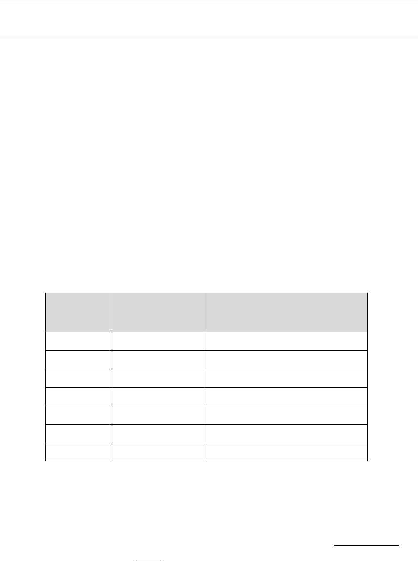
100
$SCO: - Override features
Overrides the DIP Switches for Charge Profile (2..4) and Battery Capacity (5..6) selection. This command also
allows the selection of auto detect for system voltage (12v, 24v, 48v), or forcing a fixed defined target system
voltage.
$SCO: <CP_Index>, <BC_Index >, <SV_Override>, <Lockout>
CP Index: <WHOLE NUMBER ( 0 8 )> Which Charge profile entry should be used? (1..8). Set = 0 to use
DIP switches for selection.
BC Index: < FLOATING POINT NUMBER ( 0.0 10.0 )> Which Battery Capacity Multiplier entry should be
used against normalized 500Ah battery? (1..4). Set = 0.00 to restore selection to DIP Switch value.
SV Override: < FLOATING POINT NUMBER ( 0.0 4.0 )> Enable (by setting = 0.0) or override the auto system
voltage detection feature by defining the SV multiplier to be used. (If auto SV feature is overridden the favor32v
flag will have no impact.) Though Auto detect is a nice feature, being able to fix the system voltage can improve
reliability and allow support for battery voltages which are not a whole number multiple of the ‘12v’ normalized
battery used in the CPE tables. The following table shows some common values which may be used:
SV_Override
value
Forced System
Voltage
Charge Profile VOLTAGE
Adjustment Factor
0
Auto
Auto
1
12v
1x
2
24v
2x
2.67
32v
2.67x
3
36v
3x
3.5
42v
3.5x
4
48v
4x
(Set SV Over-ride = 0 to restore auto-selection of 12v, 24v, or 48v system voltages)
Lockout: <WHOLE NUMBER ( 0 2 )> Security feature: Restricts ability to perform changes and/or provide
input to the regulator which can impact how the Alternator charges the battery. BE CAREFUL: Once lockout is
enabled (value other then 0), it can ONLY be cleared by doing a hardware based master reset (See Feature-In,
mode 1 above), or re-flashing the firmware. No other command, not even $MSR: will be able to clear a non-
zero lockout.
101
0 = No locking out.
1 = Prevent any configuration changes
2 = Prevent any configuration changes.
$SCO: will reply with “AOK;” if the command was processed successfully. However, to assure the changes are STORED
and used the regulator must be reset using the $RBT: command after all changes have been made.
$SCO: will no longer be recognized once it has been locked-out. See section “Restore to AS-Compiled (default) Status”
Example - Configure to override DIP switches and positively define system voltage and battery capacity:
If not already done, set regulators name (Needed to unlock regulator, see “Regulator Name & Password: need to
Initialize” on page 52)
Use CPE#3 (FLA#2 – large batteries)
1500AH battery (BC Index = 3)
12v system (SV Override = 1)
Lockout NOT enabled (Allows continued changes)
$SCN:0,MainsAlt,5555@
$SCO:3,3,1,0@
$RBT:@

102
$SCN: - Changes NAME (and PASSWORD) parameters in System Configuration table
Update Name and Password configuration, and allows forced disable of Bluetooth (if equipped). The name is used by
the optional Bluetooth module as well as the CAN controller to identify this regulator. To protect the user and reduce
the possibility of hacking the alternator, the 1st time this command is used the alternator must not be actively charging,
AND all the DIP switches must be in the ON state. Once the Regulators Name & Password has been initial changed they
may be updated at a later time independent of the alternator state and/or DIP switch state. Resetting the regulator to
Factory default configuration, or clearing the System Configuration will require you to again change the regulators
name/password before any other commands will be recognized.
This command will also clear any prior Bluetooth associations saved in the Bluetooth module – you will need to re-
connect.
$SCN: <Enable BT?>, < Reg Name >, <Reg Password>
Enable BT?: <WHOLE NUMBER (0, or 1)> Should the Bluetooth be enabled (in conjunction with DIP-Switch 1,
Bluetooth power)? Use this to turn off Bluetooth via software.
0 = Disable Bluetooth until master reset or enabled via Service port. ,
1 = RE-enable Bluetooth adapter (providing DIP Switch is turned on).
Caution: If you disable the Bluetooth via software, the only way you will be able to re-enable it is
via attaching a physical TTL serial cable to the Service / USB Port, or by doing a master
restore on the regulator.
Reg Name: <STRING (up to 18 characters, no spaces, comma, or ‘@’) > Name used for Bluetooth broadcast
as well as CAN ID. If you have twin engines, you might wish to set these to descriptive names.
Reg Password: <STRING (up to 18 characters, no spaces, comma, or ‘@’) > Password that should be asked
for when an external device is attempting to attach to the Bluetooth.
Comment on Bluetooth Security: Bluetooth was design to simplify communications between personal devices in
close proximity to each other. Part of this capability is easy visibility and connection. This however has a
downside of the risk of someone coming close to your alternator and ‘hi-jacking’ the alternator via Bluetooth;
even opening up the potential for malicious activity that can damage your system. The Regulator has several
security features to help prevent this:
1. The ability to change Charge Parameters or System Configuration is disabled until the factory default
Bluetooth name and password are changed.
2. The Bluetooth name and password can only be initially changed if the Alternator is not charging, and all
the DIP switch#1 is OFF, and DIP switched 2..8 are ON.
3. When attaching and external computer or tablet, you must enter the password in your host.
103
4. The password can be long (up to 18 character), and alphanumeric.
5. Once you are happy with the configuration, there is the ability to lock-out future changes using the $SCO
command.
The password is your primary line of defense, please choose it carefully, make it random, and long. Do not use
1234 or 0000 (Common ones). If you have great concern, utilize the $SCO lockout feature, or even power off the
Bluetooth module using DIP switch position #1.
$SCN: will reply with “AOK;” if the command was processed successfully. However, to assure the changes are STORED
and used the regulator must be reset using the $RBT: command after all changes have been made.
$SCN: will not be recognized if system has been locked-out via the $SCO: command.
$SCR: - RESTORES System Configuration table (+ Bluetooth) to default
Restores System Configuration AND Bluetooth values to original as-compiled (default).
$SCR: will reply with “AOK;” if the command was processed successfully. However, to assure the changes are
STORED and used the regulator must be reset using the $RBT: command after all changes have been made.
$SCR: will not be recognized if system has been locked-out via the $SCO: command.

104
$CCN: - Change parameters in the CAN Configuration table
(This command is only recognized by the 3rd generation CAN enabled regulator)
Configure the CAN Configuration Table for this regulator
$CCN: <Battery Instance Override>, <Device Instance >, <Device Priority>, <AllowRMB?>,
<ShuntAtBat?>, <Enable-OSE?>, <Enable-NMEA2000?>, <Enable_NMEA2000_RAT?>,
<Engine ID>
Battery Instance Override: <WHOLE NUMBER ( 0 100 )> What battery instance is this device associated
with? (1..100). Set = 0 to use DIP switches for selection.
Device Instance: <WHOLE NUMBER ( 1 13 )> Which instance of charging devices is this? Allows unique
identification of charging sources. (Default = 1)
Device Priority: <WHOLE NUMBER (1 250)> What is the relative priority of this charging device?
A key value of the OSEnergy protocol is the ability to prioritize charging sources. This value is what is
used to decide a given charging sources priority. If the needs of the associated battery (and any
additional loads) can be met by higher priority charging sources the regulator will reduce its output to
0A. However, if the battery/load needs cannot be meet the regulator will deliver current to its limits as
needed. If there are two or more charging sources with the same priority, battery /load needs will be
split between them. (Useful in dual engine installations to balance loads between both engines).
(Default=70)
Device priority is also used to decide who should act as the Remote Battery Master, or the overall
coordinator in the system to assure all charging devices are working towards the same goal. If
AllowRBM? Is enabled, the VSR Alternator Regulator will assume the RBM role if no other higher device
exists. This can be useful in simple installations where no Battery Monitor is installed or as a fall-back
for a failed battery monitor.
Allow RBM?: <WHOLE NUMBER (0, or 1)> Should the VSR Alternator Regulator attempt to act as the Remote
Battery master?
0 = Do not allow the regulator to assume the RBM role.
1 = Allow the regulator to potentially assume the RBM role. (Default)
Shunt At Bat?: <WHOLE NUMBER (0, or 1)> Is the shunt connected to the Battery? Used during RBM mode
to know if we are seeing alternator or battery current. 0=no(default), 1=yes
Enable OSE?: <WHOLE NUMBER (0, or 1)> Should the VSR Alternator Regulator send and receive OSEnergy
(RC-V) status and coordination messaged via the CAN bus? 0=no, 1=yes(default)
There may be some simple installations where one wishes to use the VSR Alternator Regulator to only broadcast
status to NMEA2000 devices, and the OSEnergy messaging (RV-C standard) causes issues with some existing
105
NMEA2000 devices. Do note that disabling OSEnergy mode will remove many of the systems benefits such as
coordinated / prioritized charging, simplified remote instrumentation, and more.
Enable NMEA2000?: <WHOLE NUMBER (0, or 1)> Should the VSR Alternator Regulator send out NMEA-2000
like status messages via the CAN bus? 0=no, 1=yes(default)
Enable NMEA2000_RAT?: <WHOLE NUMBER (0, or 1)> Should the VSR Alternator Regulator look for a
NMEA2000 device to supply remotely sensing battery Amperage and Temperature via PGN: 127506? To reduce
confusion in the NMEA2000 network, if Enable_NMEA2000_RAT is set = yes, and the regulator notices any other
device supplying this information it will stop sending out its own versions of PGN: 127506. 0=no,
1=yes(default)
Engine ID: <WHOLE NUMBER ( 0 250 )> :Used to associate the regulator with the engine it is mounted
on. Specifically with regards to RPMs. The regulator monitors for a matching J1939 engine RPM (PGN: 61444)
and will use it instead of measured stator RPMs. Also, if NMEA2000 messages are enabled and the regulator is
able to measure RPMs – NMEA2000 PGN: Engine parameters rapid (#127488) will be sent with the RPMs
indicated as being associated with this Engine ID. Default ID = 0.
(New in v1.1.1 firmware)
$CCN: will reply with “AOK;” if the command was processed successfully. However, to assure the changes are STORED
and used the regulator must be reset using the $RBT: command after all changes have been made.
$CCR: - RESTORES CAN Configuration table to default
(This command is only recognized by the 3rd generation CAN enabled regulator)
Restores CAN Configuration values to original as-compiled (default).
$CCR: will reply with “AOK;” if the command was processed successfully. However, to assure the changes are
STORED and used the regulator must be reset using the $RBT: command after all changes have been made.
$CCR: will not be recognized if system has been locked-out via the $SCO: command.

106
$MSR: - RESTORE all parameters (to as defined at program compile time).
Restores all configurable parameters to the as-compiled (default) values. This is a combination of the $SCR: , $CCR
commands, the $CPR:n commands for all Charge Profile Entry tables, and $RBT; command. Plus, any calibrations done
are cleared. It performs the same function as holding FEATURE-IN high during initial power-on (See “RESTORE TO AS-
COMPILED (DEFAULT) STATUS” ) ). Alternator will RESET after this command is completed.
$MSR:
Note $MSR is disabled if the Regulator has been locked out via the $SCO command. In this case, you will need to do to
do a full system reset via the Feature In connector. If successful, the regulator will reply with “AOK;” and then reboot.
$MSR: will not be recognized if system has been locked-out via the $SCO: command.
$EDB: - Enable DeBug serial strings
Will cause regulator to start sending $DBG; strings via ASCII communication ports. (Serial + Bluetooth). This has the like
effect to adding “#define DEBUG” to the source code, except $EDB: will ONLY enable the serial strings. Other debug
features (ala, overriding Bluetooth lock outs, etc) will not be changed. This command is also only effective for the time
the Regulator is running. If it is powered down, or reset (ala a Fault, or by receiving a command string that causes a
reset), the regulator will restore to its default handling of $DBG: strings.
$EDB:
$RBT: - ReBooT system
Will cause regulator to reset. This is useful to load any changes from saved Flash memory into the regulator for its use.
$RBT:
$RBT: will not be recognized if system has been locked-out via the $SCO: command.
It is stronigly suggested that you use the $RBT command after you have finished making changes to the Alternators
configuration via other ASCII commands. This will restart the regulators’, allowing those changes to be recognized – but
more important some hardware needs the $RBT: command as a signal to actually save requested changes in non-volatile
memory. If your device using what is known as EEPROM-Emulation, any changes you make will not be saved until you
issue the $RBT: command.

107
$FRM: - Force Regulator Mode
This command (with its parameters) will force the regulator to change its current mode to the one indicated. Once
forced into a mode the regulator will continue to manage the system accordingly, even if this means the regulator
immediately exits the forced mode. For example, if you force the regulator into Float mode, but the Amps being taken
from the battery exceed the exit_float criteria, the regulator will return to the Bulk phase.
$FRM:<Mode>
Mode: <Character> The ASCII character immediately following the ‘:’ will be used to force the alternator mode.
Character must match EXACTLY the following (including case), must be IMMEDIATELY after the ‘:’, but may be
followed by any number of additional characters.
B = Force into BULK mode.
A = Force into ACCEPTANCE mode.
O = Force into OVER-CHARGE mode.
F = Force into FLOAT mode.
P = Force into POST-FLOAT mode.
E = Force into EQUALIZE mode.
Any other character will be ignored and no change will be made. If the active Charge Profile has ‘disabled’ a given
phase, the regulator will immediately exit that phase – even if it is ‘forced’ into it, and switch to the next appropriate
phase. Also note that if the exit criteria of a forced-mode phase is meet, the regulator will again exit that phase quickly.
In such cases the mode may be chanced before the next $AST string is sent.
Examples:
$FRM:B Forces regulator into BULK mode
$FRM:Bulk Forces regulator into BULK mode
$FRM:Bob@ Forces regulator into BULK mode (Note use of ‘@’ as needed with Arduino IDE terminal)
$FRM:b Ignored (lower case ‘b’)
No pre-existing condition check is made when receiving these mode change commands. For example, normally you
would be able to enter Equalize mode only if the regulator was already in Float or Post-float mode. However, the $FRM:
command can force the regulator into Equalize mode directly from any state, including Bulk or Ramping. (Do remember:
as noted above - if conditions are such, it may not stay in Equalize very long.)

108
APPENDIX C: CAN MESSAGES
Beginning with the 3rd generation of the VSR Alternator Regulator a built-in Control Area Network (CAN) is included. The
purpose of this network is to allow communications of status, configuration, and coordination of charging in a systems
view.
The VSR Alternator Regulator utilizes a mixture of open source standards, and reverse engineered standards including:
OSEnergy – (https://github.com/OSEnergy/OSEnergy) Open Systems Energy initiative: Overriding specification
defining communication hardware and protocols allowing for coordination of charging devices.
J1939 – SAE standard providing basic coordination of nodes and communications of messages
NMEA-2000 – Marina orientated status messages. Closes specification built upon J1939 which has been reverse
engineered.
RV-C -- (RV-C.com) True open source speciation targeting primary Recreation Vehicle industry, but extended to
include many needed communications to support the OSEnergy initiative.
109
CAN messages summary
The following summarizes the pgns sent out vie the VSR Alternator Regulator over the CAN bus. This list may change; refer to the source code for more details.
‘NMEA-2000 type’ messages
/*****************************************************************************
// NMEA2000-DC Detailed Status - PGN127506
// Input:
// - SID Sequence ID. If your device is e.g. boat speed and heading at same time, you can set
// same SID for different messages to indicate that they are measured at same time.
// - DCInstance DC instance.
// - DCType Defines type of DC source. See definition of tN2kDCType
// - StateOfCharge % of charge
// - StateOfHealth % of heath
// - TimeRemaining Time remaining in minutes
// - RippleVoltage DC output voltage ripple in V
*/
/*****************************************************************************
// NMEA2000-Battery Configuration Status -- PGN127513
// Note this has not yet confirmed to be right. Specifically Peukert Exponent can have in
// this configuration values from 1 to 1.504. And I expect on code that I have to send
// value PeukertExponent-1 to the bus.
// Input:
// - BatteryInstance BatteryInstance.
// - BatType Type of battery. See definition of tN2kBatType
// - SupportsEqual Supports equalization. See definition of tN2kBatEqSupport
// - BatNominalVoltage Battery nominal voltage. See definition of tN2kBatNomVolt
// - BatChemistry Battery See definition of tN2kBatChem
// - BatCapacity Battery capacity in Coulombs. Use AhToCoulombs, if you have your value in Ah.
// - BatTemperatureCoeff Battery temperature coefficient in %
// - PeukertExponent Peukert Exponent
// - ChargeEfficiencyFactor Charge efficiency factor
*/
/****************************************************************************
// NMEA2000-Battery Status - PGN127508
// This PGN will not be sent if ENABLE_NMEA2000_RAT is set = YES.
// Input:
// - BatteryInstance BatteryInstance.
// - BatteryVoltage Battery voltage in V
// - BatteryCurrent Current in A
// - BatteryTemperature Battery temperature in °K. Use function CToKelvin, if you want to use °C.
110
// - SID Sequence ID.
*/
/****************************************************************************
// Engine parameters rapid - 127488L
// Input:
// - EngineInstance Engine instance.
// - EngineSpeed RPM (Revolutions Per Minute)
// - EngineBoostPressure in Pascal
// - EngineTiltTrim
*/
RV-C messages (in support of OSEnergy standard)
/*****************************************************************************
// DC Source Status 1
// Input:
// - Instance DC Instance (bus) ID.
// - Device Priority Relative ranking of DC Source
// - DC Voltage 0..3212.5v, in 50mV steps
// - DC Current -2M..+2MA, in 1mA steps (0x77359400 = 0A)
*/
/*****************************************************************************
// DC Source Status 2
// Input:
// - Instance DC Instance (bus) ID.
// - Device Priority Relative ranking of DC Source
// - Source Tempeature -273 to 1735 Deg-C in 0.03125c steps
// - State of Charge Batteries: % SOC; DC Charging sources: Current % output.
// - Time Remaining Estimated number of minutes until SOC reaches 0%
*/
/*****************************************************************************
// DC Source Status 4
// Input:
// - Instance DC Instance (bus) ID.
// - Device Priority Relative ranking of DC Source
// - Desired Charge Mode Charging mode / state being requested.
111
// - Desired DC Voltage Target voltage for chargers to deliver 0..3212.5v, in 50mV steps
// - Desired DC Current Target current for all chargers to deliver combined -1600A..1612.5A, in 50mA steps (0x7D00 = 0A)
// - Battery Type
*/
/*****************************************************************************
// DC Source Status 5
// Input:
// - Instance DC Instance (bus) ID.
// - Device Priority Relative ranking of DC Source
// - DC Voltage High precision value in 1mV. Useful for remote instrumentation
// - VDC ROC Rate-of-change (dV/dT) in mV/s -- 32000 = 0 mV/s
*/
/*****************************************************************************
// Charger Status - 1FFC7h
// Input:
// - Instance
// - Charge Voltage 0..3212.5v, in 50mV steps
// - Charge Current -1600..+1512.5 in 50mA steps (0x7D00 = 0A)
// - % max current
// - Operating State (Bulk, float, etc)
// - Default PO state
// - Auto Recharge
// - Force Charged
*/
//////////////// THIS IS A PROPOSED ONE!!!!!! ???????????????????????????????
/*****************************************************************************
// Charger Status2 - 1FF9Dh (PROPOSED, TEMP USING OLD BRIDGE_DGN_LIST DGN #)
// Input:
- Instance Instance of charger
// - DC Source Instance DC Instance (bus) ID associated with
// - Device Priority Relative ranking of DC charging Source
// - DC Voltage 0..3212.5v, in 50mV steps
// - DC Current -2M..+2MA, in 1mA steps (0x77359400 = 0A)
// - Temperature -40..210 in deg-C, in 1C steps
*/
/*****************************************************************************
// Charger Configuration Status - 1FFC6h
// Input:
112
// - Instance
// - Charging Algorithum
// - Controller Mode
// - Battery Sensor Present
// - Charger AC Line Line 1 or 2 (AC Chargers only)
// - Linkage Mode
// - Battery Type
// - Battery Bank Size 0..65,530 Ah, 1Ah increments
// - Maximum charging current 0..250, 1A increments
*/
/*****************************************************************************
// Charger Configuration Status2 - 1FF96h
// Input:
// - Instance
// - Max Charge Current %
// - Max AC current % Of attached line (AC Chargers only)
// - Shore Breaker Size 0..250, 1A increments (AC Chargers only)
// - Default Batt Temp
// - Recharge Voltage 0..3212.5v, in 50mV steps
*/
/*****************************************************************************
// Charger Configuration Status3 - 1FECCh
// Input:
// - Instance
// - Bulk Voltage 0..3212.5v, in 50mV steps
// - Absorption Voltage 0..3212.5v, in 50mV steps
// - Float Voltage 0..3212.5v, in 50mV steps
// - Temp Comp mV/K
*/
/*****************************************************************************
// Charger Configuration Status4 - 1FEBFh
// Input:
// - Instance
// - Bulk Time 0..65,530min in 1min steps
// - Absorption Time 0..65,530min in 1min steps
113
// - Float Time 0..65,530min in 1min steps
*/
/*****************************************************************************
// Charger Equalization Status - 1FF99h
// Input:
// - Instance
// - Time Remaining 0..65,530min in 1min steps
// - Pre-Charging
*/
/*****************************************************************************
// Charger Equalization Configuration Status - 1FF98h
// Input:
// - Instance
// - Equalization Voltage 0..3212.5v, in 50mV steps
// - Equalization Time 0..65,530min in 1min steps
*/
/*****************************************************************************
// Terminal - 17E00h
// Input:
// - Source / Destination
// - Count 0..8
// - Characters Buffer with up to 8 characters
*/
/*****************************************************************************
// ISO Diagnostics message - 1FECAh
// Input:
// - On / Off
// - Active / Standby
// - DSA Default Source Address (Standard fault codes)
// - SPN Service Point Number (Device Specific)
// - FMI Failure Mode Identifier
// - Occurrence Count
// - DSA Extension
// - Bank Select
*/
114
The following table indicates how often CAN messages are sent. As an example pgn: 127506 (NMEA-2000 DC Status message) is sent every 667mS, while pgn:
127513 (NMEA-2000 Battery Configuration Message) is not automatically sent out, but will only be sent when a request is made (via the J1939 ISO-Request message
pgn: 59904). One is also able to see which PGNs are utilized by the VSR Alternator Regulator via the _handler entries.
This table may change as features are added, refer to the source code for the most recent update.
tCANHandlers CANHandlers[]={
#ifdef SUPPORT_NMEA2000 // Sent | N2K| RVC | RBM <<-- Characterization flags, when are these messages
allowed, have they been sent recently, etc..
{127506L,NULL, &N2kDCStatus_message, 667,{false,true,false,false}}, // 0x1F212
{127508L,&N2kDCBatStatus_handler,&N2kDCBatStatus_message, 667,{false,true,false,false}}, // 0x1F214
{127513L,NULL, &N2kBatConf_message, 0,{false,true,false,false}}, // 0x1F219
{127488L,NULL, &N2KEngineParamRapid, 500,{false,true,false,false}}, // 0x1F200 // Note I am using 500ms vs. 100mS per N2K
Spec. (Why SOO fast?)
#endif
#ifdef SUPPORT_RVC
{0x1FFFD,&RVCDCStatus1_handler, &RVCDCStatus1_message, 500,{false,false,true,true}},
{0x1FFFD, NULL, &RVCDCStatus1OA_message, 100,{false,false,true,true}},
{0x1FFFC,&RVCDCStatus2_handler, &RVCDCStatus2_message, 500,{false,false,true,true}},
{0x1FEC9,&RVCDCStatus4_handler, &RVCDCStatus4_message, 5000,{false,false,true,true}},
{0x1FEC8,&RVCDCStatus5_handler, &RVCDCStatus5_message, 500,{false,false,true,true}},
{0x1FEC8, NULL, &RVCDCStatus5OV_message, 100,{false,false,true,true}}, // Special instance, called every 100mS when
over voltage.
{0x1FEC7,&RVCDCStatus6_handler, NULL, 0,{false,false,true,false}},
{0x1FED0,&RVCDCDisconnectStatus_handler, NULL, 0,{false,false,true,false}},
{0x1FECF,&RVCDCDisconnectCommand_handler, NULL, 0,{false,false,true,false}},
{0x1FFC7,&RVCChrgStat_handler, &RVCChrgStat_message, 5000,{false,false,true,false}},
{0x1FF9D,&RVCChrgStat2_handler, &RVCChrgStat2_message, 500,{false,false,true,false}}, /* PROPOSED!!! USING TEMP PGN# */
{0x1FFC6,&sendNAK_handler, &RVCChrgConfig_message, 0,{false,false,true,false}}, // For now we do not allow CPE configuration
via the RVC protocol.
{0x1FF96,&sendNAK_handler, &RVCChrgConfig2_message, 0,{false,false,true,false}},
{0x1FECC,&sendNAK_handler, &RVCChrgConfig3_message, 0,{false,false,true,false}},
{0x1FEBF,&sendNAK_handler, &RVCChrgConfig4_message, 0,{false,false,true,false}},
{0x1FF99, NULL, &RVCChrgEqualStat_message,5000,{false,false,true,false}},
{0x1FF98,&sendNAK_handler, &RVCChrgEqualConfig_message, 0,{false,false,true,false}},
{0xFEEB, NULL, &RVCProdId_message, 0,{false,false,true,false}},
{0x17E00,&RVCTerminal_handler, &RVCTerminal_message, 50,{false,false,true,false}}, // Terminal handler called every 50mS to send
out 'Next portion' of string.
#endif
#ifdef SUPPORT_J1939
{0xF004,&J1939EngineSpeed_handler, NULL, 0,{false,false,true,false}},
#endif
// Common J1939 type messages we need to handle.
{0x1FECA, NULL, &ISODiagnostics_message, 5000,{false,false,true,false}},
{0x1FECA, NULL, &ISODiagnosticsER_message,1000,{false,false,true,false}}, // Special instance, sent out more often
during fault condition.
115
{0,NULL,NULL,0,false} // ----PGN of 0 indicates end of table----
}; // Note: send_CAN() scans this table from the beginning each time looking for the next message who has timed out and is ready to be
sent.
// As such, this table becomes a priority order for CAN messages. be careful placing a very low time period message early in the table
// as that may cause that one message to dominate transmissions - preventing later entries from being serviced.
Table 7: CAN messages sent and received
116
APPENDIX D: DETAILS OF CPE (CHARGE PROFILE ENTRIES)
The following are excerpt from the CPE.H source code file to give more details on how each parameter impacts battery charging.
//----- This structure defines a 'profile' for battery charging. Each stage consist of 'modes', primarily: Bulk, Acceptance,
// Overcharge, and Float. Each mode has a max voltage set point, and criteria for exiting that phase (Exceeding a time limit,
// or Amps dropping below a given value). Of special note is the entry Float and Post Float, which have additional criteria
// resuming charging.
//
#define MAX_CPES 8 // There are 8 different Charge profile Entries
#define CUSTOM_CPES 2 // The last two of which are set aside as 'customizable' and are changeable via the ASCII
string commands.
typedef struct { // Charging Profile Structure
float ACPT_BAT_V_SETPOINT; // Set point for Ramp, Bulk and Acceptance battery voltage.
// Alternator will transition from BULK mode into Accept Mode when this voltage is
reached, and then start the Accept Duration counter.
unsigned long EXIT_ACPT_DURATION; // Stay in Accept mode no longer then duration in mS (Set = 0 to disable Acceptance phase
and move directly to OC or Float mode)
int EXIT_ACPT_AMPS; // If Amps being delivered falls to this level or below, exit Accept mode and go to next
// Set ExitAcptAmps = 0 to disable Amps based transition and only rely on
EXIT_ACPT_DURATION timeout.
// Set ExitAcptAmps = -1 to disable Amps based transition and rely on
EXIT_ACPT_DURATION timeout
// or ADPT_ACPT_TIME_FACTOR adaptive duration.
// Set ExitAcptAmps = Same value used for LIMIT_OC_AMPS if Overcharge mode is to be used.
//
// FUTURE: EXIT_ACPT_DVDT Add dV/dt exit criteria for Acceptance mode, need to decide
what it is :-)
// Overcharge mode is sometimes used with AGM batteries and occurs between Acceptance and
Float phase.
int LIMIT_OC_AMPS; // During Overcharge phase, Amps are capped at this low value. (Set this = 0 to disable
OC mode.)
float EXIT_OC_VOLTS; // Overcharge will continue until the battery voltage reaches this level.
unsigned long EXIT_OC_DURATION; // Over Charge mode duration in mS.
// ( as a safety step, setting OC_VOLTS or DURATION = 0 will also disable OC mode..)
// FUTURE: EXIT_OC_DVDT Add dV/dt exit criteria for Overcharge mode, need to decide what
it is :-)
float FLOAT_BAT_V_SETPOINT; // Set point for Float battery voltage, do not exceed this voltage.
117
int LIMIT_FLOAT_AMPS; // During Float, manage system to keep Amps into Battery at or under this value. Maybe =
0, set = -1 to disable limit.
unsigned long EXIT_FLOAT_DURATION; // Alternator will stay in Float mode this long (in mS) before entering Post-Float (no
charging) mode. Set = 0UL disable transition to Post-float mode.
int FLOAT_TO_BULK_AMPS; // If Amps being delivered exceeds this value, we will assume a LARGE load has been placed
on the battery and we need to re-enter
// BULK phase. Set this = 0 to disable re-entering BULK phase feature
int FLOAT_TO_BULK_AHS; // If the number of Ahs removed from the battery after 1st entering Float mode exceed this
value, revert back to BULK.
// Note this will ONLY be usable if the Amp shunt is at the battery. Set = 0 to disable
this feature.
float FLOAT_TO_BULK_VOLTS; // As with Amps, if the voltage drops below this threshold we will revert to Bulk. Set =
0 to disable.
unsigned long EXIT_PF_DURATION; // Only stay in Post_float mode (no charging) this amount of time. Set = 0UL to disable
times based Post-float exiting and exit only on Voltage.
float PF_TO_BULK_VOLTS; // If during Post-Float mode VBat drops below this voltage, re-enter FLOAT mode.
// Set = 0.0 to disable exiting of post-float mode based on voltage.
// Config note: IF you configure the system to enter post-float mode from float-mode (by
setting a time value EXIT_FLOAT_DURATION), AND you
// set both EXIT_PT_DURATION and PF_TO_BULK_VOLTS = 0, the regulator will in
effect turn off the alternator once charging is completed
// and not restart a charge cycle until powered down and up again. This can
be useful if you truly want a one-time only charge.
// You could also config the FEATURE-OUT port to indicate the complete
charge cycle has finished, to say power-off the driving engine?
int PF_TO_BULK_AHS; // If the number of Ahs removed from the battery after 1st entering Post Float mode exceed
this value, revert back to BULK.
// Note this will ONLY be usable if the Amp shunt is at the battery. Set = 0 to disable
this feature.
float EQUAL_BAT_V_SETPOINT; // If Equalize mode is selected, this is the target voltage. Set = 0 to prevent user from
entering Equalization mode.
int LIMIT_EQUAL_AMPS; // During equalization, system will limit Amps to this value. Set = 0 to disable amp
limits during Equalization Mode.
unsigned long EXIT_EQUAL_DURATION; // Regulator will not stay in Equalization any longer then this (in mS). If set = 0, then
Equalization mode will be disabled.
int EXIT_EQUAL_AMPS; // If Amps fall below this value during Equalization, then exit equalization. Set = 0 to
disable exit by Amps and use only time.
float BAT_TEMP_1C_COMP; // Battery Temperature is compensated by this factor for every 1C temp change. Note this
is based off of BAT_TEMP_NOMINAL (25c)
int MIN_TEMP_COMP_LIMIT; // If battery temperature falls below this value (in deg-c), limit temp compensation
voltage rise to prevent overvoltage in very very cold places.
118
int BAT_MIN_CHARGE_TEMP; // If Battery is below this temp (in deg-c), stop charging and force into Float Mode to
protect it from under-temperature damage.
int BAT_MAX_CHARGE_TEMP; // If Battery exceeds this temp (in deg-c), stop charging and force into Float Mode to
protect it from over-temperature damage.
} CPS;
Actual content of the CPE tables. Remember, all references are against a ‘normalized’ 12v / 500Ah battery.
const tCPS PROGMEM defaultCPS[MAX_CPES] = {
// Bulk/Accpt Overcharge Float Post Float Equalization Temp Comp
{14.1, 6.0*3600000UL, 15, 0, 0.0, 0*3600000UL, 13.4, -1, 0*3600000UL, -10, 0, 12.8, 0*3600000UL, 0.0, 0, 0.0, 0, 0*3600000UL, 0, 0.004*6, -9, -45, 45},
{14.8, 3.0*3600000UL, 5, 0, 0.0, 0*3600000UL, 13.5, -1, 0*3600000UL, -10, 0, 12.8, 0*3600000UL, 0.0, 0, 0.0, 0, 0*3600000UL, 0, 0.005*6, -9, -45, 45},
{14.6, 4.5*3600000UL, 5, 0, 0.0, 0*3600000UL, 13.2, -1, 0*3600000UL, -10, 0, 12.8, 0*3600000UL, 0.0, 0, 15.3, 25, 3.0*3600000UL, 0, 0.005*6, -9, -45, 45},
{14.7, 4.5*3600000UL, 3, 0, 0.0, 0*3600000UL, 13.4, -1, 0*3600000UL, -10, 0, 12.8, 0*3600000UL, 0.0, 0, 0.0, 0, 0*3600000UL, 0, 0.004*6, -9, -45, 45},
{14.1, 6.0*3600000UL, 5, 0, 0.0, 0*3600000UL, 13.5, -1, 0*3600000UL, -10, 0, 12.8, 0*3600000UL, 0.0, 0, 0.0, 0, 0*3600000UL, 0, 0.005*6, -9, -45, 45},
{14.4, 6.0*3600000UL, 7, 0, 0.0, 0*3600000UL, 13.4, -1, 0*3600000UL, -20, 0, 12.0, 0*3600000UL, 0.0, 0, 14.4, 0, 3.0*3600000UL, 3, 0.024, -20, -20, 50},},
{14.4, 6.0*3600000UL, 15, 15, 15.3, 3.0*3600000UL, 13.1, -1, 0*3600000UL, -10, 0, 12.8, 0*3600000UL, 0.0, 0, 15.3, 25, 3.0*3600000UL, 0, 0.005*6, -9, -45, 45},
{13.8, 1.0*3600000UL, 15, 0, 0.0, 0*3600000UL, 13.36, 0, 0*3600000UL, 0,-50, 12.9, 0*3600000UL, 0.0, 0, 0.0, 0, 0*3600000UL, 0, 0.000*6, 0, 0, 40}
};
const CPS PROGMEM defaultCPS[MAX_CPES] = {
// #1 Default (safe) profile & AGM #1 (Low VOltage AGM).
// #2 Standard FLA (e.g. Starter Battery, small storage)
// #3 HD FLA (GC, L16, larger)
// #4 AGM #2 (Higher Voltage AGM)
// #5 GEL
// #6 Firefly (Carbon Foam)
// #7 4-stage HD LFA (+ Custom #1 changeable profile)
// #8 LiFeP04 (+ Custom #2 changeable profile)
};
119
APPENDIX E: DEFAULT SYSTEM CONFIGURATION
The following documents default values (As Compiled) for the VSR Alternator Regulator’s system configuration. It is configured assuming the Amp Shunt will be
placed at the battery and that a 500A / 50mV shunt is being used. (This is the shunt used in the Link-10 battery meter as well as others).
SCS systemConfig = {
false, // .REVERSED_SHUNT --> Assume shunt is not reversed.
90, // .ALT_TEMP_SETPOINTc --> Default Alternator temp - 90c (Approx 195f)
1.00, // .ALT_AMP_DERATE_NORMAL --> Normal cap Alternator at 100% of demonstrated max Amp capability,
0.75, // .ALT_AMP_DERATE_SMALL_MODE --> Unless user has selected Small Alt Mode via DIP switch, then do 75% of its capability
0.50, // .ALT_AMP_DERATE_HALF_POWER --> User has shorted out the Alternator Temp NTC probe, indicating want 1/2 power mode.
-1, // .ALT_PULLBACK_FACTOR --> Used to pull-back Field Drive as we move towards Idle.
0, // .ALT_IDLE_RPM --> Used to pull-back Field Drive as we move towards idle.
Set = 0 causes RPMs to be determined automatically during operation.
0, // .ALT_AMPS_LIMIT --> The regulator may OPTIONALLY be configured to limit the size of the alternator output
// Set = 0 to disable Amps capping. Set = -1 to auto-size Alternator during Ramp.
(required Shunt on Alt, not Bat)
0, // .ALT_WATTS_LIMIT --> The regulator may OPTIONALLY be configured to limit the load placed on the engine via
// the Alternator.
// Set = 0 to disable, -1 to use auto-calc based on Alternator size.
(Required Shunt on Alt, not Bat)
12, // .ALTERNATOR_POLES --> # of poles on alternator (Leece Neville 4800/4900 series are 12 pole alts)
((6.7 / 2.8) * 1.00), // .ENGINE_ALT_DRIVE_RATIO --> Engine pulley diameter / alternator diameter & fine tuning calibration ratio
(int) ((500/0.050) * 1.00), // .AMP_SHUNT_RATIO --> Spec of amp shunt, 500A / 50mV shunt (Link10 default) and % calibrating error
// CAUTION: Do NOT exceed 80mV on the AMP Shunt input
-1, // .FIELD_TACH_PWM --> If user has selected Tach Mode, use this for MIN Field PWM.
// Set = -1 to 'auto determine' the this value during RAMP phase
// Set = 0 to in effect 'disable' tach mode, independent of the DIP switch.
true, // .USE_BT --> Should we try to use the Bluetooth?
"ALTREG", // .BT_NAME --> Name of Bluetooth module. MAX 18 CHARS LONG! (see BT_NAME_LEN)
"1234", // .BT_PSWD --> Password to use for Bluetooth module. MAX 18 CHARS LONG! (see BT_PIN_LEN)
DEFAULT_BT_CONFIG_CHANGED, // .BT_CONFIG_CHANGED --> BT name and password are still the default. Updates to configuration data is
prevented until the name & password is changed.
0, // .CP_INDEX_OVERRIDE --> Use the DIP switch selected indexes
0.0, // .BC_MULT_OVERRIDE --> Use the DIP switch selected multiplier
0.0, // .SV_OVERRIDE --> Enable Auto System voltage detection
0 }; // .CONFIG_LOCKOUT; --> No lockouts at this time.
120
CCS canConfig = {
0, // .BI_OVERRIDE --> Battery Instance attached to. 0=use DIP switches, override with $CCN command
1, // .DEVICE_INSTANCE --> Default 'Charger' instance. Override with $CCN
70, // .DEVICE_PRIORITY --> Default 'Device Ranking' - 70, Below AC powered chargers. Override with $CCN command
true, // .CONSIDER_MASTER --> Default, is no one else steps up to the plate - shall we try to be master? Override with $CCN
false, // .SHUNT_AT_BAT --> Until user explicitly tells us otherwise, we need to assume the shunt is NOT connected to the
battery when we are the RBM.
RVCDCbt_Unknown, // .BATTERY_TYPE --> Default, we do not know unless the user tells us.
true, // .ENABLE_OSE --> Default, push out OSEnergy (RV-C) messages (This is NEEDED to support remote instrumentation,
prioritization, etc.) Override with $CCN
true, // .ENABLE_NMEA2000 --> Default, push out NMEA-2000 messages. Override with $CCN
false // .ENABLE_NMEA2000_RAT --> Default, do not look for a NMEA2000 device to remotely supply battery amperage and
temperature - and we will send out PGN: 127506
};
Note: not all struct entries shown here, see Source code for more details.
121
APPENDIX F: ERROR CODES AND MEANING
The following is a description of error codes as reported via the ASCII status and/or the LED blinking pattern. Most errors are hard-faults, indicating a condition which
the VSR Alternator Regulator is unable to decipher and as such will shut down until corrected, in order to prevent any potential systems or battery damage. A few
errors will attempt to auto-restart to see if the failing condition clears (example, error low battery voltage).
These error codes may change and be expanded, refer to source code for latest list. Many error codes are related to internal logic checks, if those are received look
for a firmware upgrade. However, some errors codes occur during installation errors and / or system issues. A prime example is the Alternator overheating errors –
which typically indicate a need to either increase cooling and/or enable SMALL-ALT-MODE or increase its pullback. These alternator overheating issues are very
common when using small frame alternators (anything under 30lbs) combined with large battery banks or any Li based battery bank.
Other error codes are related to the overall system operation. Prime examples are the Battery Disconnected faults, where the regulator received notification that the
BMS has (or will soon) disconnect the battery from charging sources to protect it. Any overvoltage or disconnect error must be investigated carefully to determine
the cause of the overvoltage condition and corrected. (Likely miss-configuration, though perhaps incorrect auto-detect of system voltage)
FET over temperature (error #40) is an indication of a hardware issue with the regulator its self, or perhaps a short in the alternator field.
//---- Error codes. If there is a FAULTED status, the variable errorCode will contain one of these...
// Note at this time, only one error code is retained. Multi-faults will only show the last one in the checking tree.
// Errors with + 0x8000 on them will cause the regulator to re-start, others will freeze the regulator.
// (Note combinations like 10, and 11 are not used. Because one cannot flash out 0's, and kind of hard to
// tell if 11 is a 1+1, or a real slow 2+0)
#define FC_LOOP_BAT_TEMP 12 // Battery temp exceeded limit
#define FC_LOOP_BAT_VOLTS 13 // Battery Volts exceeded upper limit (measured via INA226)
#define FC_LOOP_BAT_LOWV 14 + 0x8000U // Battery Volts exceeded lower limit, either damaged or sensing wire missing.
(or engine not started!)
#define FC_LOOP_ALT_TEMP 21 // Alternator temp exceeded limit
#define FC_LOOP_ALT_RPMs 22 // Alternator seems to be spinning way to fast!
#define FC_LOOP_ALT2_TEMP 23 // Alternator #2 temp exceeded limit
#define FC_LOOP_ALT_TEMP_RAMP 24 // Alternator temp reached / exceeded while ramping - this can NOT be right, to
reach target while ramping means way too risky.
122
#define FC_LOG_ALT_STATE 31 // Global Variable chargingState has some unsupported value in check_for_faults()
#define FC_LOG_ALT_STATE1 32 // Global Variable chargingState has some unsupported value in manage_ALT()
#define FC_LOG_CPI_STATE 33 // Global Variable cpIndex has some unsupported value in caculate_ALT_Targets()
#define FC_LOG_CPINDEX 34 // Global Variable cpIndex has some unsupported value in check_for_faults()
#define FC_LOG_SYSAMPMULT 35 // Global Variable systemAmpMult has some unsupported value in check_for_faults()
#define FC_SYS_FET_TEMP 41 // Internal Field FET temperature exceed limit.
#define FC_SYS_REQIRED_SENSOR 42 // A 'Required' sensor is missing, and we are configured to FAULT out.
#define FC_CAN_BATTERY_DISCONNECTED 51 // We have received a CAN message that the battery charging bus has been
disconnected.;
#define FC_CAN_BATTERY_HVL_DISCONNECTED 52 // We have noted that a command has been sent asking for the battery bus to be
disconnected!
#define FC_LOG_BATTINST 53 // Battery Instance number is out of range (needs to be from 1..100)
#define FC_ENGINE_UNSUPPORTED_INTERFACE 61 // Attempted to start and/or stop engine with unsupported 'interface'
configuration
#define FC_INA226_READ_ERROR 100 + 0x8000U // Returned I2C error code is added to this, see I2C lib for error codes.
