Contact Manager Alti Contactô Administration Manual Contact
AltiContact%99 Manager Administration Manual manual pdf -FilePursuit
User Manual: AltiContactô Manager Administration Manual
Open the PDF directly: View PDF ![]() .
.
Page Count: 576 [warning: Documents this large are best viewed by clicking the View PDF Link!]
- Preface: About This Manual
- Overview
- Key AltiContact Manager Characteristics
- Call Center/IP PBX Features
- Automatic Call Distribution Features
- IVR Features
- AltiGen Voice Mail Features
- Internet Integration Features
- System Administration Features
- T1/PRI/E1 Features
- Voice over IP Features
- Voice over IP Session Support AltiContact Manager Features
- AltiWare Tools
- Optional Add-On Software
- Optional Add-On Products
- Optional Kits
- Key AltiContact Manager Characteristics
- System Requirements
- Hardware Requirements
- System Key Requirement
- Selecting the AltiContact Manager Platform
- Minimum System Requirements
- Proper Grounding and Loop Current
- Uninterruptible Power Supply (UPS)
- Operating Environment
- AltiGen Telephony Boards
- Functional Specifications
- AltiGen Board Installation
- AltiGen Board Options
- System Limitations
- Power Requirements
- Heat Factor
- Installing a Cooling Fan
- Proper Board Handling Procedures
- Electrostatic Discharge (ESD) Warning
- Operating Environment
- Packaging for Shipment and Storage
- AltiContact Manager Conference Resource Limits
- Software Installation
- Software License Activation and Registration
- New Installation
- Upgrading AltiWare OE
- License Activation and Registration Process
- Online License Registration Procedures
- Manual Online License Registration Procedure
- Offline Registration Procedures
- Windows Emergency Repair Disk
- Installing ACM Administrator on Remote Systems
- Running ACM Administrator
- Shutting Down AltiContact Manager when Changing or Adding Hardware
- Transferring the AltiContact Manager to Another Server Chassis
- AltiContact Manager Uninstall
- Software Installation Troubleshooting
- Getting Around ACM Administrator
- System Configuration
- Setting General Parameters
- Setting a System Number Plan
- Setting Business Hours
- Routing Calls on Holidays
- Configuring System Speed Dialing
- Defining System Call Restrictions
- Creating Account Codes
- Setting up Call Reports
- Using a Tenant Table
- Country Relevant
- CT-Bus Clock Configuration
- Audio Peripheral Configuration
- Board Configuration
- Trunk Configuration
- Voice Mail Configuration
- VoIP Configuration
- Defining an IP Dialing Table
- Setting VoIP Codecs
- Network Configuration Guidelines for VoIP
- Network Configuration Guidelines for the Alti-IP 600
- Configuration Guidelines for NAT
- Firewall Considerations
- Setting up H.323 Traffic Forwarding for H.323 NAT
- Setting Up an AltiContact Manager-to- AltiContact Manager IP Network
- Out Call Routing Configuration
- IVR Configuration
- CallCenter Configuration
- Agent Configuration
- Huntgroup Configuration
- Workgroup Configuration
- Setting Up IP Extensions
- Alti-IP 600 Phone Configuration
- Application Extension Configuration
- System Data Management
- System Report Management
- Data and Internet Integration
- AltiWeb
- Using TAPI
- Tools
- Basic Call Router & Call Router Advanced
- Call Accounting Report Formats
- E1 R2 CAS Installation
- Product Repair Services & Technical Support
- Glossary
- Index
- Readers Comment Form

AltiContact ManagerãÂ
Version 4.6
Administration Manual
Revised 06/2003 4413-0001-4.6
WARNING!
Toll fraud is committed when individuals unlawfully gain access to
customer telecommunication systems. This is a criminal offense.
Currently, we do not know of any telecommunications system that is
immune to this type of criminal activity. AltiGen Communications, Inc.
will not accept liability for any damages, including long distance charges,
which result from unauthorized and/or unlawful use. Although AltiGen
Communications, Inc. has designed security features into its products, it is
your sole responsibility to use the security features and to establish security
practices within your company, including training, security awareness, and
call auditing.
NOTICE
While every effort has been made to ensure accuracy, AltiGen
Communications, Inc. will not be liable for technical or editorial errors or
omissions contained within the documentation. The information contained
in this documentation is subject to change without notice.
This documentation may be used only in accordance with the terms of the
AltiGen Communications, Inc. License Agreement.
AltiGen Communications, Inc.
47427 Fremont Blvd.
Fremont, CA 94538
Telephone: 510-252-9712
Fax: 510-252-9738
E-mail: info@altigen.com
Web site: www.altigen.com
TRADEMARKS
AltiContact Manager, AltiGen, AltiServ, AltiWare, AltiReach, AltiLink,
AltiConsole, AltiAdmin, Zoomerang, and Dynamic Messaging are
trademarks or registered trademarks of AltiGen Communications, Inc.
All other brand names mentioned are trademarks or registered trademarks
of their respective manufacturers.
Copyright ôˋ AltiGen Communications, Inc. 1998-2003. All rights
reserved.
Printed in U.S.A. 06/2003 4413-0001-4.6
AltiContact Manager Administration Manual i
Contents
Preface:AboutThisManual........................1-xxix
Chapter 1
Overview ........................................1-1
KeyAltiContactManagerCharacteristics............... 1-3
CallCenter/IPPBXFeatures........................ 1-6
AutomaticCallDistributionFeatures ................ 1-12
IVRFeatures ................................... 1-15
AltiGen Voice Mail Features. . . . . . . . . . . . . . . . . . . . . . . 1-16
InternetIntegrationFeatures....................... 1-18
SystemAdministrationFeatures.................... 1-19
T1/PRI/E1Features.............................. 1-21
VoiceoverIPFeatures............................ 1-22
Voice over IP Session Support AltiContact Manager Features 1-24
AltiWare Tools. . . . . . . . . . . . . . . . . . . . . . . . . . . . . . . . . . 1-25
OptionalAdd-OnSoftware ........................ 1-25
OptionalAdd-OnProducts ........................ 1-26
OptionalKits................................... 1-26
Chapter 2
SystemRequirements..............................2-1
HardwareRequirements............................ 2-1
SystemKeyRequirement .......................... 2-1
Selecting the AltiContact Manager Platform. . . . . . . . . . . . 2-1
MinimumSystemRequirements..................... 2-1
ProperGroundingandLoopCurrent.................. 2-3
UninterruptiblePowerSupply(UPS) ................. 2-3
OperatingEnvironment............................ 2-3
AltiGen Telephony Boards 4
FunctionalSpecifications........................... 2-4
AltiGen Board Installation. . . . . . . . . . . . . . . . . . . . . . . . . . 2-8
AltiGen Board Options . . . . . . . . . . . . . . . . . . . . . . . . . . . . 2-9
SystemLimitations .............................. 2-11
PowerRequirements ............................. 2-12
HeatFactor..................................... 2-13
ii AltiContact Manager Administration Manual
Installing a Cooling Fan . . . . . . . . . . . . . . . . . . . . . . . . . . . 2-13
ProperBoardHandlingProcedures .................. 2-14
ElectrostaticDischarge(ESD)Warning............... 2-14
OperatingEnvironment............................ 2-15
PackagingforShipmentandStorage................. 2-17
AltiContact Manager Conference Resource Limits . . . . . . 2-18
Chapter 3
SoftwareInstallation...............................3-1
AltiContactManagerasanNTService ................. 3-2
PreparingtoInstallAltiContactManager ............... 3-2
FirewallConsiderations............................ 3-3
Licensing ........................................ 3-5
Registration ...................................... 3-7
DealerInstallationID.............................. 3-8
RegistrationMethods.............................. 3-8
Upgrades......................................... 3-9
BeforeNewInstallation ............................ 3-11
ToBeginNewInstallation .......................... 3-11
BeforeUpgrade .................................. 3-18
BackupDatabase................................. 3-18
Shutting Down the AltiGen Switching Service . . . . . . . . . 3-18
ToBeginUpgrade ................................ 3-19
OnlineLicenseRegistrationProcedures............... 3-29
Manual Online License Registration Procedure . . . . . . . . . 3-38
OfflineRegistrationProcedures..................... 3-45
WindowsEmergencyRepairDisk .................... 3-45
Installing ACM Administrator on Remote Systems . . . . . . 3-45
RunningACMAdministrator........................ 3-46
Shutting Down AltiContact Manager when Changing or Adding Hard-
ware.............................................. 3-47
Transferring the AltiContact Manager to Another Server Chassis 3-47
AltiContactManagerUninstall ...................... 3-48
SoftwareInstallationTroubleshooting................. 3-49
Chapter 4
GettingAroundACMAdministrator .................4-1
AltiContactManagerAdministrator.................... 4-1
LogginginfortheFirstTime........................ 4-1
AltiContact Manager Administration Manual iii
The AltiContact Manager Main Window 2
TheMainMenu .................................. 4-3
QuickAccessToolbar ............................. 4-3
TheViewWindows ................................ 4-5
BoardsViewWindow ............................. 4-5
AgentExtensionViewWindow...................... 4-6
TrunkViewWindow.............................. 4-7
WorkgroupViewWindow.......................... 4-8
CallLogViewWindow............................ 4-9
IPTrunkCurrentTrafficStatisticsWindow ............ 4-9
StatusBar...................................... 4-10
LoggingIn ...................................... 4-10
ChangingthePassword ............................ 4-11
StoppingtheAltiGenSwitchingService ............... 4-11
Chapter 5
SystemConfiguration ..............................5-1
SettingGeneralParameters .......................... 5-2
SettingaSystemNumberPlan ....................... 5-4
Assigning Trunk, Feature, IP Trunk, & Route Access. . . . . 5-6
SettingBusinessHours ............................. 5-8
RoutingCallsonHolidays........................... 5-9
ConfiguringSystemSpeedDialing ................... 5-11
AddingNamesandComments...................... 5-12
DefiningSystemCallRestrictions ................... 5-12
Blocking Calls to Area Codes from All Extensions. . . . . . 5-13
LockingAttackedExtensions....................... 5-14
BlockingAllOutgoingCalls....................... 5-14
EnablingHopOffforTieTrunks.................... 5-14
CreatingAccountCodes ........................... 5-15
AddingandDeletingAccountCodes................. 5-15
SettingupCallReports ............................ 5-16
Internal(Local)LoggingofCallDataData............ 5-17
External(Remote)LoggingofCallData.............. 5-19
ExportingThroughaLocalPort..................... 5-21
UsingaTenantTable .............................. 5-22
ConfiguringtheTenantTable....................... 5-23
ModifyingtheTenantTable........................ 5-24
CountryRelevant ................................. 5-25
SettingTollCallPrefixes.......................... 5-25
iv AltiContact Manager Administration Manual
SettingEmergencyNumbers....................... 5-26
SettingtheTDMBusMode........................ 5-26
CT-BusClockConfiguration........................ 5-26
AudioPeripheralConfiguration...................... 5-27
Configuring Music On Hold and Recorded Announcements 5-28
SettingGreetingandUpdatePrompts ................ 5-30
ConfiguringOverheadPaging...................... 5-30
Chapter 6
BoardConfiguration...............................6-1
UsingtheTritonResourceBoard ..................... 6-2
ConfiguringtheQuantumBoard ...................... 6-2
ConfiguringtheTritonAnalogStationBoard ............ 6-4
Configuring the Triton Analog Trunk LS/GS and LS Boards 6-6
ConfiguringtheTritonVoIPBoard.................... 6-7
Voice over IP for AltiWare OE . . . . . . . . . . . . . . . . . . . . . . 6-8
TritonVoIPBoard................................ 6-8
BoardInstallation................................. 6-9
TroubleshootingãCommon Symptoms and Solutions . . . 6-10
ConfiguringtheTritonT1/PRIBoard ................. 6-11
ServiceParametersforT1 ......................... 6-12
ServiceParametersforPRI......................... 6-14
BoardConfiguration.............................. 6-15
Triton T1 Configuration - Triton T1/PRI Dialog Box . . . . 6-17
Setting up T1 or PRI Channels on the Triton T1/PRI Board 6-22
Installing a Channel Service Unit (CSU) to the Triton T1 or T1/E1/PRI
Board....................................... 6-27
TroubleshootingãCommon Symptoms. . . . . . . . . . . . . . . 6-27
Chapter 7
TrunkConfiguration ..............................7-1
SelectingTrunkstoSetAttributes.................... 7-2
SettingGeneralTrunkAttributes...................... 7-3
QuantumTrunkProperties.......................... 7-6
TritonAnalogTrunkProperties...................... 7-9
TritonAnalogTrunkGS/LSProperties............... 7-11
TritonVoIPTrunkConfiguration.................... 7-13
TritonT1/PRITrunkProperties..................... 7-15
IncomingCallRouting............................. 7-20
AltiContact Manager Administration Manual v
OutgoingCallBlocking............................ 7-21
Chapter 8
VoiceMailConfiguration ..........................8-1
ManagingMessages................................ 8-1
Setting Message Notification Retries. . . . . . . . . . . . . . . . . . 8-2
Setting Message Management Options . . . . . . . . . . . . . . . . 8-3
Setting Message Recording Options . . . . . . . . . . . . . . . . . . 8-3
Setting E-mail Messaging Options . . . . . . . . . . . . . . . . . . . 8-4
SynchronizingE-mailwithExchange................. 8-5
CreatingDistributionLists .......................... 8-5
DefiningaDistributionList......................... 8-6
Chapter 9
VoIPConfiguration ...............................9-1
DefininganIPDialingTable......................... 9-1
AbouttheLocationIDDigitLength.................. 9-1
DefiningtheIPDialingTable ....................... 9-2
Setting the Location ID Digit Length. . . . . . . . . . . . . . . . . . 9-3
DefiningRemoteLocations......................... 9-3
Setting VoIP Codecs . . . . . . . . . . . . . . . . . . . . . . . . . . . . . . . 9-5
NetworkConfigurationGuidelinesforVoIP ............ 9-8
Network Configuration Guidelines for the Alti-IP 600 . . . . 9-10
ConfigurationGuidelinesforNAT ................... 9-11
IPPhoneConfiguration........................... 9-12
H.323NAT..................................... 9-12
FirewallConsiderations............................ 9-23
Setting up H.323 Traffic Forwarding for H.323 NAT . . . . . 9-24
Setting Up an AltiContact Manager-to-AltiContact Manager IP Net-
work ............................................. 9-25
Chapter 10
OutCallRoutingConfiguration ....................10-1
Working with Route Definitions . . . . . . . . . . . . . . . . . . . . . 10-2
Setting Default Routes . . . . . . . . . . . . . . . . . . . . . . . . . . . . . 10-4
AboutCallRoutingand911Calls................... 10-5
Setting Dialing Pattern Routing . . . . . . . . . . . . . . . . . . . . . . 10-6
vi AltiContact Manager Administration Manual
Chapter 11
IVRConfiguration................................11-1
PlanningisEssential..............................11-1
Example: IVR Planning 2
AddingIVRs.....................................11-4
EditingIVRs.....................................11-5
ConfiguringMenuItems...........................11-6
MakingIVRAssignments.........................11-10
PhraseManagement ..............................11-10
UsingPre-RecordedPrompts......................11-10
RecordingCustomPhrases........................11-11
UsingProfessionallyRecordedPhrases..............11-12
Chapter 12
CallCenterConfiguration..........................12-1
CallerIDRouting .................................12-1
Adding and Deleting Caller ID Route Entries . . . . . . . . . . 12-2
DefiningtheRouting..............................12-3
DNISRouting....................................12-3
AddingandDeletingDNISRouteEntries.............12-4
DefiningtheRouting..............................12-5
AgentLogoutReasonCodes ........................12-5
CallRecording ...................................12-6
Chapter 13
AgentConfiguration ..............................13-1
Setting up Extensions . . . . . . . . . . . . . . . . . . . . . . . . . . . . . . 13-3
AddingNewExtensions...........................13-4
EstablishingBasicExtensionAttributes...............13-4
ForcedAccountCode.............................13-6
ChangingtheExtensionLocationorType.............13-8
Setting an IP Extension . . . . . . . . . . . . . . . . . . . . . . . . . . . . 13-8
Setting the Line Properties . . . . . . . . . . . . . . . . . . . . . . . . 13-10
PhoneDisplayOptions...........................13-14
Setting Up Groups . . . . . . . . . . . . . . . . . . . . . . . . . . . . . . . 13-15
Setting up Station Speed Dialing . . . . . . . . . . . . . . . . . . . . 13-17
Setting the Mailbox Options . . . . . . . . . . . . . . . . . . . . . . . . 13-19
Setting an Information-Only Mailbox. . . . . . . . . . . . . . . . 13-20
AltiContact Manager Administration Manual vii
DisablingaMailbox............................. 13-20
SynchronizingwithExchangeServer ............... 13-20
SMTP/POP3 Setting. . . . . . . . . . . . . . . . . . . . . . . . . . . . . 13-20
MailForwardingOptions......................... 13-20
Setting Message Playback Options . . . . . . . . . . . . . . . . . 13-21
Setting Mailbox Capacities . . . . . . . . . . . . . . . . . . . . . . . 13-22
Setting Message Notification Options . . . . . . . . . . . . . . . . 13-22
Setting the Message Types for Notification. . . . . . . . . . . 13-23
Setting the Type of Notification. . . . . . . . . . . . . . . . . . . . 13-24
Setting Notification Timing . . . . . . . . . . . . . . . . . . . . . . . 13-25
Setting Notification Business Hours . . . . . . . . . . . . . . . . 13-25
EnablingMessageNotification .................... 13-25
Configuring Calling Restrictions . . . . . . . . . . . . . . . . . . . . 13-26
Setting Call Restriction Options. . . . . . . . . . . . . . . . . . . . 13-26
Setting Other Call Restrictions. . . . . . . . . . . . . . . . . . . . . 13-27
Setting Answering Options . . . . . . . . . . . . . . . . . . . . . . . . 13-28
ForwardingAllCalls............................ 13-29
EnablingãDoNotDisturbã....................... 13-30
HandlingBusyCalls............................. 13-30
Setting Call Waiting Options . . . . . . . . . . . . . . . . . . . . . . 13-31
HandlingUnansweredCalls....................... 13-31
Configuring One Number Access . . . . . . . . . . . . . . . . . . . 13-32
Enabling One Number Access . . . . . . . . . . . . . . . . . . . . . 13-33
Setting Caller ID Verification . . . . . . . . . . . . . . . . . . . . . 13-34
SpecifyingForwardingNumbers................... 13-35
Setting Up Monitor Lists . . . . . . . . . . . . . . . . . . . . . . . . . . 13-35
ConfiguringaMonitorList ....................... 13-36
FeatureTips .................................... 13-38
Chapter 14
HuntgroupConfiguration .........................14-1
Setting Up Huntgroups . . . . . . . . . . . . . . . . . . . . . . . . . . . . 14-3
AddingaHuntgroup.............................. 14-4
EstablishingBasicHuntgroupAttributes.............. 14-4
EstablishingHuntgroupMembership ................. 14-6
AddingExtensionstoHuntgroups................... 14-7
Assigning Huntgroups to Agent Extensions . . . . . . . . . . . 14-8
AutomaticLogIn/Out ........................... 14-10
Setting Huntgroup Mail Management . . . . . . . . . . . . . . . . 14-11
DisablingaMailbox............................. 14-12
viii AltiContact Manager Administration Manual
SynchronizingwithExchangeServer................ 14-12
SettingEmailOptions............................ 14-12
SettingMailboxPlaybackOptions.................. 14-13
Setting Mailbox Capacities. . . . . . . . . . . . . . . . . . . . . . . . 14-13
SettingMessageNotificationOptions ................ 14-14
Setting the Message Types for Notification . . . . . . . . . . . 14-15
SettingtheTypeofNotification.................... 14-15
SettingNotificationTiming....................... 14-16
SettingNotificationBusinessHours................. 14-16
EnablingMessageNotification..................... 14-17
SettingCallHandlingOptions ...................... 14-17
HandlingBusyCalls............................. 14-18
ForwardingAllCalls ............................ 14-19
HandlingUnansweredCalls....................... 14-20
SettingHuntgroupHandling....................... 14-21
GroupRNAHandling............................ 14-21
SettingQueueManagementOptions ................. 14-23
Chapter 15
WorkgroupConfiguration .........................15-1
CreatingaWorkgroup ............................ 15-2
Establishing Basic Workgroup Attributes . . . . . . . . . . . . . 15-2
ServiceLevelThreshold........................... 15-4
CentralizedWorkgroupRecordingOptions............ 15-4
EstablishingWorkgroupMembership ................. 15-5
AutomaticLogIn/Out............................. 15-7
SkillSettingAssignment ........................... 15-8
SettingtheMailboxOptions ........................ 15-9
DisablingaMailbox............................. 15-10
SynchronizingwithExchangeServer................ 15-10
SMTP/POP3 Setting . . . . . . . . . . . . . . . . . . . . . . . . . . . . . 15-11
MailForwardingOptions......................... 15-11
SettingMessagePlaybackOptions.................. 15-11
Setting Mailbox Capacities. . . . . . . . . . . . . . . . . . . . . . . . 15-12
SettingMessageNotificationOptions ................ 15-13
Setting the Message Types for Notification . . . . . . . . . . . 15-13
SettingtheTypeofNotification.................... 15-14
SettingNotificationTiming....................... 15-15
SettingNotificationBusinessHours................. 15-15
EnablingMessageNotification..................... 15-15
AltiContact Manager Administration Manual ix
SettingCallHandlingOptions ......................15-16
HandlingBusyCalls.............................15-16
ForwardingAllCalls.............................15-17
HandlingUnansweredCalls.......................15-18
SettingWorkgroupHandling ......................15-19
GroupRNA(RingNoAnswer)Handling.............15-20
QueueManagement ..............................15-22
SettingQueuePhraseOptions......................15-22
QueueAnnouncement............................15-23
QueueOverflowRouting .........................15-23
QueueQuitOption ..............................15-24
OperationNotes.................................15-25
Chapter 16
SettingUpIPExtensions.......................... 16-1
AltiGenIPPhoneService..........................16-1
IntercomwithIPPhones...........................16-1
IP Connections and Voice Quality . . . . . . . . . . . . . . . . . . . 16-2
SystemRequirements ..............................16-2
Configuration ....................................16-2
AltiAdmin......................................16-3
Clients.........................................16-4
Chapter 17
Alti-IP600PhoneConfiguration ................... 17-1
Chapter 18
ApplicationExtensionConfiguration ............... 18-1
ApplicationExtensionSetup ........................18-2
ApplicationFailoverPlan..........................18-3
ApplicationInformation...........................18-4
Chapter 19
SystemDataManagement......................... 19-1
UsingBackupandRestore ..........................19-1
BackingupFiles ..................................19-2
SchedulingBackups ...............................19-3
xAltiContact Manager Administration Manual
RestoringBackedupFiles .......................... 19-4
Chapter 20
SystemReportManagement .......................20-1
SystemSummaryReport ........................... 20-1
SystemLog ..................................... 20-2
IPCumulativeTrafficStatistics...................... 20-3
Chapter 21
DataandInternetIntegration ......................21-1
NetworkProtocolandAddressing................... 21-1
SettingUpEmailService.......................... 21-4
SettingupanExchangeServer..................... 21-10
ExchangeonWindows2000...................... 21-34
About AltiReach Configuration . . . . . . . . . . . . . . . . . . . . 21-36
Chapter 22
AltiWeb ........................................22-1
SystemRequirements............................. 22-1
AltiWebComponents............................. 22-1
Installing AltiWeb . . . . . . . . . . . . . . . . . . . . . . . . . . . . . . . . 22-2
ConfiguringIVR................................ 22-16
Troubleshooting................................ 22-19
Uninstalling AltiWeb . . . . . . . . . . . . . . . . . . . . . . . . . . . . . 22-20
AltiWebSecurity ................................ 22-20
Symantec Norton AntiVirus Corporate Edition 7.5 . . . . . 22-20
Chapter 23
UsingTAPI .....................................23-1
SystemRequirements.............................. 23-1
Installing TAPI Services . . . . . . . . . . . . . . . . . . . . . . . . . . . 23-2
ChangingTAPIConfigurationParameters ............. 23-3
Chapter 24
Tools ...........................................24-1
AltiContact Manager Administration Manual xi
Work/HuntGroupConverter........................ 24-1
ConfigurationReader.............................. 24-3
ExtensionChecker................................ 24-4
MVIPTestTool.................................. 24-6
AltiDBReader ................................... 24-7
DINAManager ................................. 24-11
Chapter 25
BasicCallRouter&CallRouterAdvanced ..........25-1
BasicCallRouter................................. 25-1
CallRouterAdvanced ............................. 25-9
Additional Call Router Advanced Features . . . . . . . . . . . 25-20
TestingCallRouter .............................. 25-28
TestingSQLServerDatabase ..................... 25-30
APPENDIX A
CallAccountingReportFormats ....................A-1
RTMDataSchema ................................A-9
SMDRReportingFormat ..........................A-15
TrunkCallsInFormat:............................A-15
ExtensionCallsOutFormat:.......................A-16
FromExtensionA ...............................A-16
FromTrunkB...................................A-17
APPENDIX B
E1R2CASInstallation ............................B-1
APPENDIX C
ProductRepairServices&TechnicalSupport .........C-1
TechnicalSupport ................................. C-1
Repair and Replacement . . . . . . . . . . . . . . . . . . . . . . . . . . . . C-2
StandardProductWarranty .........................C-4
RMAForm....................................... C-8
Glossary...........................................G-1

AltiContact Manager Administration Manual xv
Liabilitiy & Warranty
Liability & Warranty
Limitation of Liability
Except for personal injury, direct damages to tangible personal property proximately caused
by AltiGen products and liability otherwise expressly assumed in a written agreement signed
by AltiGen, the liability of AltiGen, its affiliates, suppliers, and authorized resellers for any
claims, losses, damages, or expenses from any cause whatsoever (including acts of omission
of third parties), regardless of the form of action, whether in contract, tort or otherwise, shall
not exceed an amount equal to the lesser of the direct damages proven or the purchase price
of the product. In no event shall AltiGen or its affiliates, suppliers, or authorized resellers be
liable for incidental, consequential, or any other indirect loss or damage (including lost profits
or revenues) incurred in connection with the product. This limitation of liability shall survive
failure of the exclusive remedy set forth in the limited warranty referred to in this book under
ãWarranty.ã
FCC and Industry Canada Compliance
This section describes the requirements for compliance with Federal Communications (FCC)
Rules and Industry Canada CS-03 standard.
Statement
This equipment has been tested and found to be in compliance with the limits for a Class B
digital device pursuant to Part 15 and Part 68 of the FCC Rules. These limits are designed to
provide reasonable protection against harmful interference when the equipment is operated in
a commercial or residential environment. This equipment generates and can radiate radio
frequency energy and, if not installed and used in accordance with the instruction manual, may
cause harmful interference to radio communications.
This Class B digital apparatus meets all requirements of the Canadian interference-causing
Equipment Regulations. Cet apparell numûˋrique de la Classe B respecte toutes les exigences
du Reglement sur le materiel brouilleur du Canada.
FCC Requirements
1. The Federal Communications Commission (FCC) has established Rules which permit
this device to be directly connected to the telephone network. Standardized jacks are used
for these connections. This equipment should not be used on party lines or coin phones.
2. If this device is malfunctioning, it may also be causing harm to the telephone network;
this device should be disconnected until the source of the problem can be determined and
until repair has been made. If this is not done, the telephone company may temporarily
disconnect service.
3. The telephone company may make changes in its technical operations and procedures; if
such changes affect the compatibility or use of this device, the telephone company is
required to give adequate notice of the changes. You will be advised of your rights to file
a complaint with the FCC.
4. If the telephone company requests information on what equipment is connected to their
lines, inform them of:
xvi AltiContact Manager Administration Manual
a. The telephone number to which this unit is connected.
b. The ringer equivalence number. [0.0B]
c. The USOC jack required. [RJ11C]
d. The FCC Registration Number. [see label on board]
e. Industry Canada (Industrie Canada) Certification Number.
[see label on board]
Items (b) and (d) are indicated on the label. The Ringer Equivalence Number (REN) is used
to determine how many devices can be connected to your telephone line. In most areas, the
sum of the RENs of all devices on any one line should not exceed five (5.0). If too many
devices are attached, they may not ring properly.
Service Requirements
In the event of equipment malfunction, all repairs should be performed by our Company or an
authorized agent. It is the responsibility of users requiring service to report the need for service
to AltiGen or to one of our authorized agents. Service can be obtained at your Authorized
AltiGen Dealer.
Equipment Attachment Limitations - Industry Canada
NOTICE: The Canadian Industry Canada label identifies certified equipment. This
certification means that the equipment meets certain telecommunications network protective,
operational, and safety requirements. The Department does not guarantee the equipment will
operate to the userãs satisfaction.
Before installing this equipment, users should ensure that it is permissible to be connected to
the facilities of the local telecommunications company. The equipment must also be installed
using an acceptable method of connection. In some cases, the companyãs inside wiring
associated with the single line individual service may be extended by means of a certified
connector assembly (telephone extension cord). The customer should be aware that
compliance with the above conditions may not prevent degradation of service in some
situations.
Repairs to the certified equipment should be made by an authorized Canadian maintenance
facility designated by the supplier. Any repairs or alterations made by the user to this
equipment, or equipment malfunctions, may give the telecommunications company cause to
request the user to disconnect the equipment.
Users should ensure for their own protection that the electrical ground connections of the
power utility, telephone lines, and internal metallic water pipe system, if present, are
connected together. This precaution may be particularly important in rural areas.
Caution: Users should not attempt to make such connections themselves, but should
contact the appropriate electrical inspection authority, or electrician, as
appropriate.
The Load Number (LN) assigned to each terminal device denotes the percentage of the total
load to be connected to a telephone loop that is used by the device, to prevent overloading.
The termination on a loop may consist of any combination of devices subject only to the
requirement that the total of the Load Number of all the devices does not exceed 100.
WARNING: Changes or modifications to this unit not expressly approved in writing
by AltiGen Communications, Inc. could void the userãs authority to
operate this equipment.

AltiContact Manager Administration Manual xvii
Port Identification, Facility Interface, and Service Order Codes
The following tables list the manufacturerãs network interface port designations, Facility
Interface Codes (FIC), Ringer Equivalence Number (REN), or Service Codes and the network
jacks for the required facilities. The facility interface and service order codes are with
reference to the codes specified in Table 5 of Appendix D of FCC Form 730 Application
Guide of January 1998.
Table 1. Quantum Network Trunk Interfaces for Loop Start, Ground Start and DID Services
Table 2. Network Digital Trunk Interfaces for Digital Services
Triton T1/E1 PRI FCC Registration No., Part 68 55MUSA-25184-PF-E
*The Triton T1/PRI interface connects to the Public Switched Telephone Network through an
FCC registered NCTE which specifies the type of network jack to be used.
Table 3. Triton Analog Trunk Interfaces for Loop Start/Ground Start and Loop
Start Services
Disruption of Network
If any Quantum or Triton boards disrupt the telephone network, the telephone company can
discontinue your service temporarily. If possible, the telephone company will notify you in
advance. If advance notice is not practical, they will notify you as soon as possible. You are
also informed of your right to file a complaint with the FCC.
Manufacturer Port
Identifier Facility Interface Code
(FIC) REN Network Jack
(USOC)
ALTI-CD0408UD 02LS2 0.0B RJ-11C
ALTI-CD0804UD 02LS2 0.0B RJ-11C
ALTI-CD0408UD 02GS2 0.0B RJ-11C
ALTI-CD0804UD 02GS2 0.0B RJ-11C
ALTI-DID0408UD 02RV2-T 0.0B RJ-11C
Manufacturer Port
Identifier Facility Interface Code
(FIC) Service Order
Code (SOC) Network Jack
(USOC)
ALTI-T1E1-1 04DU9-BN 6.0P/AS.2 RJ-48C*
ALTI-TTT1-1 04DU9-DN 6.0P/AS.2 RJ-48C*
ALTI-TTT1-1 04DU9-1KN 6.0P/AS.2 RJ-48C*
ALTI-TTT1-1 04DU9-1SN 6.0P/AS.2 RJ-48C*
Manufacturer Port Identifier Facility Interface Code
(FIC) REN Network Jack
(USOC)
ALTI-TTAT-12GS O2GS2 0.5B RJ21X, RJ11
ALTI-TTAT-12 O2LS2 0.5B RJ21X, RJ11
xviii AltiContact Manager Administration Manual
Direct Inward Dialing (DID) Answering Supervision
Customers allowing Triton T1/PRI, Quantum, or Triton Analog Station Analog DID to be
operated in such a manner as to not provide for proper answer supervision is a violation of Part
68 of the FCC rules.
Proper answer supervision occurs when:
1. The AltiWare system returns answer supervision to the PSTN when DID calls are:
ãÂAnswered by the called station.
ãÂAnswered by the attendant.
ãÂRouted to a recorded announcement that can be administered by the customer.
2. The AltiServ system returns answering supervision on all DID calls forwarded to the
PSTN.
Class A Equipment
This is a Class A product. In a domestic environment, this product may cause radio
interference, in which case, the user may be required to take adequate measures.
Safety
(Seguridad/Sicherheit)
The following information is included in this publication for the use and safety of installation
and maintenance personnel.
Important Safety Instructions
ãÂRead all of the instructions before attempting to operate the equipment and before
connecting the power supply.
ãÂAlways follow basic safety precautions to reduce the risk of fire, electrical shock, and
injury to persons.
ãÂTo prevent fire or shock hazard, do not expose the unit to rain, moisture, or install this
product near water. Never spill liquid of any kind on this product.
ãÂNever push objects of any kind into this product through module openings or expansion
slots, as they may touch dangerous voltage points or short out parts, which could result
in the risk of fire or electrical shock.
ãÂRefrain from opening the cabinet as there are high voltage components inside. Refer
servicing to qualified service personnel. If you are a qualified service personnel, power
down everything before opening.
ãÂDo not attach the power supply cord to building surfaces. Do not allow anything to rest
on the power cord or allow the cord to be abused by persons walking on it.
ãÂTo protect this equipment from overheating, do not block the slots and openings in the
module housings that are provided for ventilation.
Seguridad
La siguiente informaciû°n se incluye en la presente publicaciû°n para la utilizaciû°n y seguridad
del personal instalador y de mantenimiento.
AltiContact Manager Administration Manual xix
Informaciû°n de Seguridad de Importancia
ãÂLea todas las instrucciones antes de que intente operar el equipo y antes de conectar la
fuente de alimentaciû°n.
ãÂObserve siempre las precauciones bûÀsicas de seguridad, a fin de reducir el riesgo de
incendio, electrochoque y de lesiones al personal.
ãÂCon objeto de evitar incendios o el riesgo de electrochoque, no exponga la unidad a la
lluvia, humedad, ni tampoco instale este producto cerca del agua. JamûÀs derrame
ninguna clase de lûÙquido sobre el producto.
ãÂJamûÀs inserte objeto alguno, de ninguna clase, a travûˋs de las aberturas del mû°dulo o de
las ranuras de expansiû°n de este producto, ya que podrûÙan establecer contacto con puntos
de voltaje peligrosos, o provocar cortos circuitos en los componentes del producto, y
esto a su vez podrûÙa originar el riesgo de incendio o de electrochoque.
ãÂAbstûˋngase de abrir el gabinete ya que ûˋste contiene componentes de alto voltaje.
AsûÙgnele el mantenimiento û¤nicamente a personal capacitado. Si usted forma parte de
dicho personal capacitado, corte absolutamente toda la energûÙa elûˋctrica antes de que
abra el gabinete.
ãÂNo sujete el cordû°n del suministro elûˋctrico a las superficies del edificio. No permita
que objeto alguno descanse sobre el cordû°n del suministro elûˋctrico, ni que la gente lo
maltrate al caminar sobre ûˋl.
ãÂA fin de evitar el sobrecalentamiento del equipo, no obstruya las ranuras y aberturas que
se encuentran sobre las cubiertas del mû°dulo, ya que ûˋstas se suministran para su
ventilaciû°n.Read all of the instructions before attempting to operate the equipment and
before connecting the power supply.
Sicherheit
Die in dieser VerûÑffentlichung enthaltene Information befaût sich mit der Sicherheit von
Personal sowohl beim Einbau als auch bei der Wartung des GerûÊts.
Wichtige Sicherheitsbestimmungen
ãÂVor Einschaltung der Stromversorgung und der Inbetriebnahme des GerûÊts mit allen
Bestimmungen sorgfûÊltig vertraut machen.
ãÂUm die Gefahr von Feuer, elektrischem Schlag und anderen persûÑnlichen Verletzungen
zu verhû¥ten, sind grundsûÊtzliche Vorsichtsmaûnahmen zu beachten.
ãÂZur Vermeidung von Feuer oder elektrischem Schlag muû verhû¥tet werden, das GerûÊt
Regen oder Feuchtigkeit auszusetzen, oder aber es in WassernûÊhe zu installieren. Es darf
auf keinen Fall Flû¥ssigkeit auf das GerûÊt verschû¥ttet werden.
ãÂUm die Gefahr von Feuer oder elektrischem Schlag auszuschalten, die durch Berû¥hrung
mit Spannungsteilen oder einem elektrischen Kurzschluû entstehen kann, dû¥rfen auf
keinen Fall Objekte irgendeiner Art durch ModulûÑffnungen oder Erweiterungsschlitze
in das GerûÊt eingefû¥hrt werden.
ãÂDas GehûÊuse enthûÊlt Hochspannungsteile und sollte deshalb nicht geûÑffnet werden.
Wartung ist von qualifiziertem Wartungspersonal durchzufû¥hren.. Im Wartungsfalle ist
vor der ûffnung des GehûÊuses sûÊmtliche Stromzufuhr abzuschalten.

xx AltiContact Manager Administration Manual
ãÂStromversorgungskabel nicht an GebûÊudeteilen befestigen. Keine GegenstûÊnde auf das
Stromversorgungskabel legen oder auf das Kabel treten.
ãÂZur Verhû¥tung der ûberhitzung des GerûÊtes ist die Verschlieûung von
Ventilationsschlitzen und -ûÑffnungen im ModulgehûÊuse zu vermeiden.
Safety with Electricity
High Voltages
ãÂObserve all safety regulations and read the warnings, cautions, and notes posted on the
equipment.
ãÂFind the switch to power off the cabinet. Read the posted instructions.
ãÂEnsure that equipment can not be powered from another source or controlled from a
different circuit breaker or disconnecting switch.
ãÂWhen a procedure requires that you power off the system:
ãLock the wall box-switch in the off position.
ãAttach a DO NOT OPERATE tag to the wall box-switch.
ãÂNever assume that the power is turned off. Always check to ensure that a circuit does
not have power.
Note: Unit must have ground wire attached if trunks are attached and system is
unplugged.
ãÂDo not work alone. Work with another person who knows the locations of the power-off
switches, especially if you are working with exposed electrical circuits. (See note
above.)
ãÂFollow the instructions in the manual carefully, especially when working with circuits
that are powered. Disconnect power when instructed to do so in the procedures.
ãÂDisconnect all power before working near power supplies unless otherwise instructed by
a maintenance procedure.
ãÂDisconnect all power before installing changes in machine circuits unless otherwise
instructed by a maintenance procedure.
ãÂHigh voltages capable of causing shock are used in this equipment. Be extremely careful
when measuring high voltages and when servicing cards, panels, and boards while the
system is powered on.
ãÂDo not wear jewelry or other metal objects when working on the equipment.
ãÂWhen possible, work with one hand so that a circuit is not created.
ãÂUse caution when installing or modifying telephone lines. Never install telephone wiring
during an electrical storm.
ãÂNever install a telephone jack where it can get wet unless the jack is specifically
designed for wet conditions.
DANGER
Do not take chances with your life. Follow these safety guidelines carefully.

AltiContact Manager Administration Manual xxi
ãÂNever touch uninsulated telephone wires or terminals unless the telephone line has been
disconnected at the network interface.
Seguridad en El Manejo de La Electricidad
Alto Voltaje
ãÂObserve todas las normas de seguridad y lea las advertencias, avisos de precauciû°n y
notas que se encuentran adheridos al equipo.
ãÂEncuentre el interruptor que corta la corriente elûˋctrica del gabinete. Lea las
instrucciones que se encuentran adheridas.
ãÂCerciû°rese de que la corriente elûˋctrica del equipo no pueda encenderse desde otra
fuente, ni controlares desde ningû¤n otro interruptor de circuitos o interruptor de
desconexiû°n.
ãÂCuando alguno de los procedimientos requiera que corte usted la corriente elûˋctrica del
sistema:
ãFije el interruptor del centro de carga que se encuentra empotrado en la pared, en la
posiciû°n de apagado (off).
ãPegue una etiqueta de NO OPERAR sobre el interruptor del centro de carga.
ãÂJamûÀs presuponga que la energûÙa elûˋctrica se encuentra apagada. Cerciû°rese siempre
de que el circuito no tiene energûÙa elûˋctrica.
Nota: Cuando existan troncales conectadas a la unidad y el sistema se encuentre
desenchufado, la unidad deberûÀ tener instalado el cable de conexiû°n a tierra.
ãÂNo trabaje sû°lo. Trabaje con alguna otra persona que conozca las ubicaciones de los
interruptores de apagado de la corriente elûˋctrica, particularmente, si estûÀ usted
trabajando con circuitos elûˋctricos descubiertos. (Lea la nota anterior).
ãÂSiga al piûˋ de la letra las instrucciones contenidas en el manual, particularmente, cuando
trabaje con circuitos que tengan energûÙa elûˋctrica. Desconecte la energûÙa cuando las
instrucciones del procedimiento se lo indiquen.
ãÂDesconecte toda la energûÙa elûˋctrica antes de trabajar cerca de cualquier fuente de
alimentaciû°n, salvo que el procedimiento de mantenimiento le instruya lo contrario.
ãÂDesconecte toda la energûÙa elûˋctrica antes de efectuar cualquier cambio en los circuitos
de la mûÀquina, salvo que el procedimiento de mantenimiento le instruya lo contrario.
ãÂEl alto voltaje que utiliza este equipo puede ocasionar electrochoques. Tenga sumo
cuidado al medir los altos voltajes y al darle mantenimiento a las tarjetas, paneles y
placas cuando la energûÙa elûˋctrica del equipo se encuentre encendida.
ãÂNo use alhajas u otros objetos de metal cuando trabaje en el equipo.
ãÂCuando le sea posible, trabaje con una sola mano, a fin de no producir un circuito.
ãÂTenga cuidado cuando instale o modifique lûÙneas telefû°nicas. JamûÀs instale cableado
telefû°nico durante una tormenta elûˋctrica.
DANGER/PELIGRO
Do No ponga en riesgo su vida. Sigua estos lineamientos de seguridad al pie de
la letra.

xxii AltiContact Manager Administration Manual
ãÂNunca instale un conector telefû°nico en donde pueda mojarse, salvo cuando el conector
se encuentre especialmente diseûÝado para funcionar en condiciones de humedad.
ãÂJamûÀs toque cables o terminales telefû°nicas que no tengan aislante, a menos que haya
desconectado la lûÙnea telefû°nica desde la interfase de la red.
Elektrosicherheit
Hochspannung
ãÂAlle Sicherheitsregeln beachten und am GerûÊt angebrachte Warnungen und Hinweise
lesen.
ãÂStellen Sie fest, wo sich der GehûÊuseschalter befindet. Anleitung lesen.
ãÂStellen Sie sicher, daû das GerûÊt weder durch eine andere Stromquelle versorgt noch
durch eine andere Sicherung oder Trennschalter kontrolliert werden kann.
ãÂSollte ein Verfahren die Abschaltung der Anlage erfordern:
ãWandschalter in der "AUS" - Position sperren
ãKennzeichen "NICHT BETûTIGEN" am Wandschalter anbringen
ãÂGehen Sie NIE davon aus, daû der Strom abgeschaltet ist, sondern û¥berprû¥fen Sie es.
Note: Anmerkung: GerûÊt muû geerdet sein, wenn Kabel angeschlossen und die Anlage
abgeschaltet ist.
ãÂNicht alleine arbeiten. Arbeiten Sie mit jemandem, der weiû, wo sich der AUS-Schalter
befindet, besonders dann, wenn an freiliegenden Schaltkreisen gearbeitet wird. (Siehe
obige Anmerkung).
ãÂBeachten Sie die Anleitungen im Handbuch sorgfûÊltig, besonders dann, wenn an
eingeschalteten Schaltkreisen gearbeitet wird. Strom abschalten, wenn ein Verfahren
das vorsieht.
ãÂFalls nicht anderweitig durch ein Wartungsverfahren bestimmt, ist der Strom bei
Arbeiten nahe der Stromversorgung abzuschalten.
ãÂFalls nicht anderweitig durch ein Wartungsverfahren bestimmt, ist der Strom bei
ûnderungen am Maschinenstromkreis abzuschalten.
ãÂDieses GerûÊt enthûÊlt Hochspannungen, die elektrischen Schlag verursachen kûÑnnen.
ûuûerste Vorsicht ist geboten beim Messen von Hochspannung und beim Warten von
Schalttafeln und Steckkarten solange der Strom eingeschaltet ist.
ãÂBei Arbeiten am GerûÊt keinen Schmuck oder metallische GegenstûÊnde tragen.
ãÂMûÑglichst mit einer Hand arbeiten, um keinen Stromkreislauf entstehen zu lassen.
ãÂVorsicht bei der Installation oder Modifizierung von Telefonleitungen. Keine
Telefonleitungen bei Gewittern legen.
ãÂKeine Telefonbuchse installieren, wo die Gefahr besteht, daû sie angefeuchtet wird, es
sei denn die Buchse ist fû¥r Feuchtigkeit besonders ausgelegt.
DANGER/GEFAHR
Nicht mit dem Leben spielen. Sicherheitsrichtlinien sorgfûÊltig beachten.
AltiContact Manager Administration Manual xxiii
ãÂVermeiden Sie das Berû¥hren von nichtisolierten Telefonkabeln oder Terminals, wenn
die Telefonleitung an den Netzschnittstellen nicht abgeschaltet ist.
UL Regulatory Safety Requirements
(Requisitos Reglamentarios de Seguridad de La Asociaciû°n de
Aseguradores (UL)/Sicherheitserfordernisse gemûÊû UL (Underwriter's
Laboratories, Inc.))
Host Computer
1. Model AltiGen/AltiWare apparatus is approved for connection to Telecommunications
Systems specified in these instructions for use subject to the conditions set out in them.
Any other usage will INVALIDATE this approval.
2. The host machine shall be ãCEã marked, with the internal ISA and PCI slots operating
at SELV in accordance with EN60950, 1992, issue 2, +A4.
3. This apparatus MUST be professionally installed.
4. The host machine MUST be hardwired earthed in accordance with EN60950, 1992,
issue 2, +A4, 1997, cl. 6.2.1.2 with an earth wire from the host machine earthing
terminal to the building earth.
5. The host machine SELV circuit is connected to the protective earthing terminal in
accordance with EN60950 cl. 2.5.
6. The host machine ISA bus pins B1, B10, or B31 (edge connectors on CPU mother-
board/backplane) MUST be less than 0.1 Ohms to host machine earthing terminal.
7. AltiGen complies with PCI Board specifications Rev. 2.1 (5V 32-bit).
8. The power required by the host machine and the total of all adapter cards installed within
the host environment, together with any ancillary apparatus, shall not exceed the power
specification of the host machine.
9. It is essential that, when other option cards are introduced that use or generate a
hazardous voltage, the minimum creepages and clearances specified in the following
table are maintained. A hazardous voltage is one that exceeds 42.4V peak AC or 60V
DC. If you have any doubt, seek advice from a competent engineer before installing
other adapters into the host machine.
Clearance (mm) Creepage (mm) Voltage used or generated by
host or other cards
2.0 2.4 (3.8) Up to 50 Vrms or Vdc
ISA bus ISA bus
B1 B10 B31

xxiv AltiContact Manager Administration Manual
For a host or other expansion card fitted in the host, using or generating voltages greater than
300V (rms or dc), advice from a competent safety engineer must be obtained before
installation of the relevant equipment.
Any other usage will INVALIDATE the approval of the apparatus, ifas a result, it then ceases
to conform to the standards against which approval was granted.
Requisitos Reglamentarios de Seguridad de La Asociaciû°n de
Aseguradores (UL)
Computadora Principal
1. El aparato modelo AltiGen/AltiWare se encuentra aprobado para conectarse a los
Sistemas de Telecomunicaciones que se especifican en estas instrucciones y para
emplearse bajo las condiciones que se indican en las mismas. Cualquier utilizaciû°n
distinta INVALIDA esta aprobaciû°n.
2. La computadora principal deberûÀ encontrarse marcada con "CE", y sus ranuras internas
ISA y PCI deberûÀn estar operando en SELV, conforme lo indica el EN60950, 1992,
ediciû°n 2, +A4.
3. La instalaciû°n de este aparato la DEBEN ejecutar profesionales.
4. La mûÀquina principal DEBE conectarse a tierra conforme lo dispone el EN60950, 1992,
ediciû°n 2, +A4, 1997, cl. 6.2.1.2, utilizando cable de conexiû°n a tierra desde la terminal
amasadelamûÀquinaprincipalalaconexiû°natierradeledificio.
5. El circuito SELV de la mûÀquina principal debe conectarse a la terminal protectora de
aterrizada de conformidad con el EN60950 cl. 2.5.
6. Las clavijas de los canales de distribuciû°n ISA B1, B10, o B31 de la mûÀquina principal
(conectores planos de entrada lateral de la placa matriz/panel de fondo (motherboard/
back plane)) de la unidad central de proceso (CPU), DEBEN tener menos de 0.1 ohmios
en la conexiû°n a tierra de la mûÀquina principal.
7. El AltiGen debe cumplir con las especificaciones de las Placas PCI, Rev. 2.1 (5V 32-
bit).
2.6 3.0 (4.8) Up to 125 Vrms or Vdc
4.0 5.0 (8.0) Up to 250 Vrms or Vdc
4.0 6.4 (10.0) Up to 300 Vrms or Vdc
Clearance (mm) Creepage (mm) Voltage used or generated by
host or other cards
ISA bus ISA bus
B1 B10 B31

AltiContact Manager Administration Manual xxv
8. La energûÙa elûˋctrica que requiere la mûÀquina principal y el total del conjunto de tarjetas
de los adaptadores instalados dentro del ûÀmbito de la mûÀquina principal, junto con
cualquier aparato auxiliar adicional, no deberûÀ exceder las especificaciones de energûÙa
elûˋctrica de la mûÀquina principal.
9. Es esencial que, cuando se introduzcan tarjetas opcionales que utilicen o generen
voltajes peligrosos, tambiûˋn se mantengan las distancias y longitudes de frotamiento
mûÙnimas y mûÀximas que se especifican en la tabla que aparece a continuaciû°n. Voltaje
peligroso es aquel que excede de 42.4 voltios, en su valor mûÀximo de cresta en la
corriente alterna o, de 60 voltios, en su valor mûÀximo de cresta en la corriente directa.
Si tiene usted alguna duda, obtenga asesorûÙa de un ingeniero competente, antes de
instalar otros adaptadores en la mûÀquina principal.
Para la tarjeta de la computadora principal o para las demûÀs tarjetas de ampliaciû°n que se
inserten en la principal y que utilicen o generen voltajes superiores a los 300 voltios (rms o
dc), deberûÀ obtener asesorûÙa de un ingeniero competente en materia de seguridad, antes de
proceder a instalar el equipo en cuestiû°n.
Cualquier uso distinto INVALIDARû la aprobaciû°n otorgada al aparato, si como resultado de
dicho uso, ûˋste deja de cumplir con los estûÀndares para los cuales se otorgû° la aprobaciû°n.
Sicherheitserfordernisse gemûÊû UL (Underwriter's Laboratories, Inc.)
Host Computer/Wirtsrechner
1. Das GerûÊt Model AltiGen/AltiWare ist nur in Verbindung mit
Telekommunikationssystemen zugelassen, die den gegebenen Anleitungen gemûÊû den
darin geforderten Bedingungen entsprechen. Anderweitige Verwendung setzt diese
Zulassung auûer Kraft.
2. Das HauptgerûÊt ist mit "CE" zu bezeichnen, wobei die internen ISA und PSI SteckplûÊtze
bei SELV gemûÊû EN60950, 1992, Ausgabe 2, +A4, fungieren.
3. Das GerûÊt darf nur von ausgebildetem Personal installiert werden.
4. Das HauptgerûÊt ist festzuverdrahten und gemûÊû EN60950, 1992, Ausgabe 2, +A4, 1997,
cl. 6.2.1.2 mit einem Erdleiter vom HauptgerûÊterdanschluû zum GebûÊude zu erden.
5. Der HauptgerûÊtschaltkreis SELVist mit dem Sicherungserdanschluû gemûÊû EN60950
cl. 2.5. verbunden
6. Die HauptgerûÊt ISA Bus Kontaktanschlû¥sse B1, B10, oder B31 (Randstecker auf CPU
Grundplatine/Hauptplatine) MûSSEN weniger als 0.1 Ohm zum
HauptgerûÊterdanschluû haben.
Distancia (mm) Longitud de Frotamiento
(mm) Voltaje empleado o generado por la
tarjeta madre u otras tarjetas
2.0 2.4 (3.8) Hasta 50 Vrms o Vdc
2.6 3.0 (4.8) Hasta 125 Vrms o Vdc
4.0 5.0 (8.0) Hasta 250 Vrms o Vdc
4.0 6.4 (10.0) Hasta 300 Vrms o Vdc

xxvi AltiContact Manager Administration Manual
7. AltiGen entspricht den PCI Board Anforderungen Rev. 2.1 (5V 32-bit).
8. Der Energiebedarf fû¥r das HauptgerûÊt sowie aller Anschluûkarten im Hauptrechner,
einschlieûlich von ZusatzgerûÊt, darf die fû¥r das HauptgerûÊt spezifizierte Leistung nicht
û¥berschreiten.
9. Die in der folgenden Tabelle vorgesehenen Minimalwerte mû¥ssen fû¥r den Fall beachtet
werden, daû mit der Einfû¥hrung von zusûÊtzlichen Karten riskante Stromspannungen
entweder benûÑtigt oder verursacht werden. Dabei gilt als riskant eine Spannung, die
Spitzenwerte von 42.4V AC (Wechselstrom) oder 60V DC (Gleichstrom) û¥berschreitet.
Im Zweifelsfalle ist ein zustûÊndiger Ingenieur zu Rate zu ziehen.
Vor dem Einbau einer Haupt- oder Erweiterungskarte in den Hauptrechner , die Werte von
300V (rms or dc) û¥berschreiten, ist der zustûÊndige Sicherhaitsingenieur zu Rate zu ziehen.
Anderweitige Benutzung des GerûÊts, deren Ergebnis die Auûerkraftsetzung der erteilten
Genehmigung zum Betrieb des GerûÊts zur Folge hat, macht diese Genehmigung ungû¥ltig.
Power Failure
(Fallas en La EnergûÙa Elûˋctrica/Netzausfall)
In the event of a power failure, the first telephone extension on each card (except for the
CD0012UD) is connected directly to the first exchange line, thus permitting access to dial the
emergency services. This telephone must be powered from the PSTN or have local battery
backup capable of calling the emergency services four hours after the power failure event
occurs.
En caso de ocurrir una falla en la energûÙa elûˋctrica, la primera extensiû°n telefû°nica de cada
tarjeta (salvo en lo que respecta a la CD0012UD), se conecta directamente a la primera lûÙnea
de la central, para asûÙ permitir el acceso a la marcaciû°n de los servicios de emergencia. Este
equipo debe alimentarse a partir del PSTN, o contar con un respaldo de baterûÙa local con
capacidad suficiente para llamar a los servicios de emergencia, durante cuatro horas despuûˋs
de que ocurra la falla en la energûÙa elûˋctrica.
Abstand (mm) Schlupf (mm) Spannungseinheit
fû¥r GerûÊt oder Zusatzkarten
2.0 2.4 (3.8) Bis zu 50 Vrms oder Vdc
2.6 3.0 (4.8) Bis zu 125 Vrms oder Vdc
4.0 5.0 (8.0) Bis zu 250 Vrms oder Vdc
4.0 6.4 (10.0) Bis zu 300 Vrms oder Vdc
ISA bus ISA bus
B1 B10 B31
AltiContact Manager Administration Manual xxvii
Bei Netzausfall wird der erste Telefonanschluû jeder Karte (mit der Ausnahme von
CD0012UD) direkt mit der Vermittlung verbunden und garantiert dadurch Zugang zu
Notdiensten. Der Anschluû muû von PSTN, betrieben werden oder aber eine ûÑrtliche
Notstromversorgung haben, die es ermûÑglicht, Notdienste bis zu vier Stunden nach dem
Netzausfall anzurufen.
Wiring
(Cableado/Schaltung)
All wiring must conform to National Telecommunications Wiring Regulations and the
National Electrical Wiring Regulations.
Todo el cableado deberûÀ cumplir con las Normas Nacionales del Cableado para
Telecomunicaciones y con las Normas Nacionales del Cableado Elûˋctrico.
Alle Schaltungen mû¥ssen den Nationalen Vorschriften fû¥r Fernmeldeschaltungen ("National
Telecommunications Wiring Regulations") und den Nationalen Vorschriften fû¥r
Elektroschaltungen ("National Electrical Wiring Regulations") entsprechen.
Additional Requirements for Australia
(Requisitos Adicionales para Australia/ZusûÊtzliche Bestimmungen fû¥r
Australien)
1. Warning: For safety reasons, connect only ACA or AUSTEL permitted or certified
equipment to the telephone ports (RJ11) of the patch panel or the audio in/out jacks on
the AltiServ card.
2. Warning: THIS EQUIPMENT MUST ONLY BE INSTALLED AND MAINTAINED
BY SERVICE PERSONNEL
1. Advertencia: Por razones de seguridad, conecte solamente equipo permitido o
certificado de ACA o AUSTEL a los puertos telefû°nicos (RJ11) del tablero de
conexiones o a los conectores de entrada y salida de la tarjeta de sonido AltiServ.
2. Advertencia: ûNICAMENTE EL PERSONAL DE MANTENIMIENTO DEBERû
INSTALAR Y SUMINISTRAR MANTENIMIENTO A ESTE EQUIPO.
1. Warnung: Aus Sicherheitsgrû¥nden darf nur von ACA oder AUSTEL genehmigtes oder
beglaubigtes GerûÊt an Telefonanschlû¥sse (RJ11) des Schaltplans oder die Audio EIN/
AUS Buchsen der AltiServ Karte geschaltet werden.
2. Warnung: DIESES GERûT DARF NUR VON WARTUNGSPERSONAL
EINGEBAUT UND GEWARTET WERDEN.
Additional Requirements for USA and Canada
(Requisitos Adicionales para Los Estados Unidos y CanadûÀ/
ZusûÊtzliche Bestimmungen fû¥r USA und Kanada)
1. The interconnecting trunk line cord should be at least size 26AWG.
2. This trunk card must be fitted in host equipment with fire enclosures complying with the
flammability requirements of sub-clause UL1950/CSA C22: 1995 4.4.3. In addition, the
card must be separated from internal materials of flammability class or lower by at least
xxviii AltiContact Manager Administration Manual
25 mm of air Class V-1 or better. Also, the card must be separated from openings in the
top or sides of the enclosure by at least 25 mm of air or by a barrier of flammability Class
V-1 or better unless the openings comply with one of the following:
ãÂnot exceed 5 mm in any direction, or
ãÂnot exceed 1 mm in width, regardless of length
3. Any holes in the chassis not conforming to the above should be covered with a metal
perforated screen, with holes not exceeding 5 mm diameter, fixed internally.
1. El cordû°n de la lûÙnea troncal de interconexiû°n debe ser, por lo menos, calibre 26 AWG.
2. El armazû°n del equipo principal en el que se instale esta tarjeta troncal debe estar
diseûÝado a prueba de incendios y cumplir con los requisitos de inflamabilidad que
dispone el PûÀrrafo 4.4.3 del ArtûÙculo 1995 del Cû°digo 22 de la UL1950/CSA5. AdemûÀs,
la tarjeta debe encontrarse alejada de materiales internos de clase inflamable, o por
debajo, de por lo menos 25 mm de aire de la Clase V-1 o superior. Tambiûˋn, la tarjeta
debe encontrarse alejada de cualquier abertura superior o lateral de la cubierta, por lo
menos mediante 25 mm de aire o a travûˋs de una barrera de inflamabilidad Clase V-1 o
superior, salvo cuando las aberturas se apeguen a cualesquiera de los siguientes criterios:
ãÂNo excedan de 5 mm en cualquier direcciû°n, o
ãÂNo excedan de 1 mm de ancho sin importar su longitud.
3. Cualquier orificio del chasis que no cumpla con las especificaciones anteriores deberûÀ
cubrirse con una malla metûÀlica perforada, fija por dentro, cuyas perforaciones no
deberûÀn exceder de 5 mm de diûÀmetro.
1. Das Kabel fû¥r die Hauptverbindungsleitung muû mindestens 26AWG entsprechen.
2. Der Einbau der Hauptkarte im HauptgerûÊt muû feuerfest sein und den
Entflammbarkeitserfordernissen des Untertitels UL1950/CSA C22: 1995 4.4.3
entsprechen. ZusûÊtzlich muû ein Abstand von mindestens 25 mm und der Luftklasse V-
1 zwischen der Karte und internen Materialien mit mindestens Entflammbarkeitsklasse
bestehen. Weiterhin muû zwischen der Karte und ûffnungen auf der Oberseite und an
den Seiten des GehûÊuses ein Luftabstand von mindestens 25 mm oder aber eine Sperre
von mindestens der Entflammbarkeitsklasse V-1 bestehen, es sei denn, die ûffnungen
entsprechen folgenden Ansprû¥chen:
ãÂin allen Richtungen nicht grûÑûer als 5 mm, oder
ãÂnicht breiter als 1 mm, ungeachtet der LûÊnge.
3. Alle ûffnungen im GehûÊuse, die nicht den obigen Anforderungen entsprechen, sind mit
einem perforierten Deckel zu schlieûen, dessen LûÑcher nicht grûÑûer sind als 5 mm im
Durchmesser. Der Deckel muû von innen am GehûÊuse angebracht werden.The
interconnecting trunk line cord should be at least size 26AWG.
Instructions for Hardwired Earth Connection
(Instrucciones para El Cableado de La Conexiû°n a Tierra/Anleitungen
fû¥r festverdrahtete Erdanschlû¥sse)
AltiContact Manager Administration Manual xxix
1. A supplementary equipment earthing conductor is to be installed between the product or
system and earth, that is, in addition to the equipment earthing conductor in the power
supply cord.
2. The supplementary equipment earthing conductor may not be smaller in size (8 AWG
minimum, recommend 6 AWG) than the unearthed branch-circuit supply conductors.
The supplementary equipment earthing conductor is to be connected to the product at
the terminal provided, and connected to earth in a manner that will retain the earth
connection when the power supply cord is unplugged. The connection to earth of the
supplementary earthing conductor shall be in compliance with the appropriate rules for
terminating bonding jumpers in Park K of Article 250 the National Electrical Code,
ANSI/NFPA 70, and Article 10 of Part I of the Canadian Electrical Code, Part I, C22.1.
Termination of the supplementary equipment earthing conductor is permitted to be made
to building steel, to a metal electrical raceway system or to any earthed item that is
permanently and reliably connected to the electrical service equipment earthed.
3. Bare, covered or insulating earthing conductors are acceptable. A covered or insulating
earth conductor must have a continuous outer finish that is either green, or green with
one or more yellow stripes.
4. Earthing conductor shall not run through steel conduit.
1. DeberûÀ instalarse equipo complementario de conducciû°n a tierra entre el producto o
sistema y la tierra misma, esto es, ademûÀs del conductor a tierra que el equipo tiene en
el cordû°n de la fuente de alimentaciû°n.
2. El conductor de conexiû°n a tierra del equipo complementario no podrûÀ ser de
dimensiones inferiores (mûÙnimo calibre 8 AWG, se recomienda el calibre 6 AWG) a la
dimensiû°n de los conductores de alimentaciû°n sin conexiû°n a tierra del circuito de la
derivaciû°n. El conductor de conexiû°n a tierra del equipo complementario deberûÀ
conectarse a los productos en la terminal que se proporciona y, conectarse a tierra, de tal
manera en que la conexiû°n a tierra se mantenga cuando el cordû°n de la fuente de
alimentaciû°n se encuentre desconectada. La aterrizada del conductor a tierra
complementario deberûÀ cumplir con las reglas conducentes para la terminaciû°n de los
conductores de empalme de conexiû°n a tierra que seûÝalan el Apartado K del ArtûÙculo 250
del Cû°digo Nacional Elûˋctrico; el ArtûÙculo 70 del ANSI/NFPA, y ArtûÙculo 10, apartado
I del Cû°digo Elûˋctrico Canadiense, Apartado I, C22.1. EstûÀ permitido que la terminaciû°n
del conductor a tierra del equipo complementario se realice al acero del edificio, a un
sistema de conductos elûˋctricos o a cualquier artûÙculo con tierra que se encuentre
conectado en forma permanente y confiable al equipo de servicio elûˋctrico que se
aterriza.
3. Se consideran aceptables los conductores sin aislante, recubiertos o con aislante. Los
conductores revestidos o con material aislante deberûÀn contar con un acabado exterior
continuo de color verde, o verde con una o mûÀs franjas amarillas.
4. Los conductores de conexiû°n a tierra no deberûÀn tenderse a travûˋs de conductos de acero.
1. Sowohl Stromversorgungskabel als auch GerûÊt oder Anlage mû¥ssen geerdet sein.
2. Das Zusatz-GerûÊteerdungskabel darf nicht dû¥nner sein als die ungeerdete
Verzweigungsleitung (8 AWG minimum, empfohlen 6 AWG). Es ist mit dem dafû¥r
vorgesehenen Anschluû derartig zu verbinden, daû eine Erdung auch dann weiter
xxx AltiContact Manager Administration Manual
besteht, wenn das Stromversorgungskabel aus dem Stecker gezogen ist. Die Erdung des
Zusatzkabels muû den geltenden Bestimmungen fû¥r den Endanschluû von
Metallbrû¥cken im Teil K, Artikel 250 des Nationalen Elektrokodex, [in Park (?) K of
Article 250 the National Electric Code], ANSI/NFPA 70, und Artikel 10, Teil I des
Kanadischen Elektrokodex, Tei I, [and Article 10, Part I of the Canadian Electrical
Code, Part I] C22.1entsprechen. Der Endanschluû des Zusatz-GerûÊteerdungskabels ist
erlaubt sowohl an Baustahl, an Zufû¥hrungsbahnen oder an jedem Gegenstand, der auf
Dauer und verlûÊûlich mit geerdetem elektrischem GerûÊt verbunden ist.
3. Blanke, umhû¥llte oder isolierte Erdungskabel sind zulûÊssig. Ein umhû¥lltes oder isoliertes
Erdungskabel muû eine durchgehend grû¥ne OberflûÊche, oder eine grû¥ne mit einem oder
mehreren gelben Streifen,
4. Erdleitungen dû¥rfen nicht durch Stahlrohre fû¥hren.
UL Hardware Preparation
(Preparaciû°n del Equipo UL/GerûÊtevorbereitung gemûÊû UL
(Underwriter's Laboratories, Inc.))
Prepare the hardware as follows ensuring that the relevant manufacturerãs installation
instructions are complied with. If you have doubts about any of these, call your supplier.
1. This apparatus must be professionally installed.
2. Select a ãCEã computer chassis according to the Safety Requirements above, ensuring
that it has an external marked earth point.
3. The host machine ISA bus pins B1, B10 or B13 MUST be tested to ensure that there is
less than 0.1 Ohms to the earthing terminal.
4. The host machine PCI bus pins complies with PCI Board specifications Rev. 2.1 (5V 32-
bit).
5. Prepare the chassis, in accordance with the PC manufacturers instructions, to receive the
necessary PC cards, ensuring the installation of extension cards does not result in non-
conformance to the Safety Requirements above.
6. When installing a system using AltiGenãs cards, note that the continued compliance to
the LVD and EMC EU Directives at the system level is the responsibility of the system
supplier.
7. Prepare above cards ensuring all jumpers are set according to the manufacturerãs
instructions.
8. Attach suitable grounded ESD wrist strap between wrist and earth.
9. Follow the manufacturerãs instruction and install above cards into PC.
Note: If more than three cards are using the MVIP, ensure that the Quantum or Triton
board set as board zero is installed at one end of the MVIP cable and the board at the far
end of the MVIP cable has its switch set to terminated (switch closed).
10. Replace PC outer case.
11. Connect a fixed earth from the PC to a suitable premises fixed earthing point. Note that
the earth cable must be at least the same gauge as the live wire of the main cord and fixed
to the earth terminal and the rear of the PC. (6 AWG recommended, 8 AWG minimum.)
12. Connect cable supplied with AltiServ to the ãD-type sub-miniatureã (25 pin) connector
on the AltiServ card and the connector to the Modular RJ-11 Patch Panel.
AltiContact Manager Administration Manual xxxi
13. Connect the building telecommunication wiring to the RJ-11 sockets.
14. Building telecommunication wiring shouldbe installed accordingto the National Wiring
Regulations for Telecommunications.
UL File No. E179719
Preparaciû°n del Equipo UL
Prepare el equipo de la manera que se indica a continuaciû°n. Cerciû°rese de antemano de que
se observan todas las instrucciones aplicables del fabricante. Si tiene usted alguna duda
acerca de cualesquiera de ellas, llame a su proveedor.
1. La instalaciû°n de este aparato la deben realizar profesionales.
2. Seleccione el chasis "CE" de la computadora tomando en consideraciû°n los Requisitos
de Seguridad que se indican anteriormente, ademûÀs, cerciû°rese de que cuenta con un
punto de conexiû°n a tierra marcado en el exterior.
3. Las clavijas ISA de los canales de distribuciû°n B1, B10 o B13 DEBEN someterse a
prueba, a fin de verificar que la corriente sea inferior de 0.1 ohmios hacia la terminal de
la conexiû°n a tierra.
4. Cerciû°rese de que las clavijas PCI de los canales de distribuciû°n cumplen con las
especificaciones de los tableros PCI, Rev. 2.1 (5 voltios 32-bit).
5. Prepare el chasis de acuerdo con las instrucciones del fabricante de la computadora
personal, para efectos de que reciba las tarjetas de PC que necesita, y se cerciore asûÙ de
que la instalaciû°n de las tarjetas de extensiû°n no redundarûÀ en la infracciû°n de los
Requisitos de Seguridad que se indican con anterioridad.
6. Observe que cuando instala un sistema que utiliza tarjetas AltiGen, el acatamiento
continuo de las Directivas LD y EMC EU a nivel sistema, son responsabilidad del
proveedor del sistema.
7. Prepare las tarjetas mencionadas con anterioridad y cerciû°rese de que todos los puentes
de salto se encuentran posicionados conforme a las instrucciones del fabricante.
8. Coloque una pulsera antiestûÀtica ESD adecuadamente aterrizada entre la muûÝeca y la
tierra.
9. Siga las instrucciones del fabricante e instale las tarjetas que se mencionan con
anterioridad en la computadora.
Nota: Cuando mûÀs de tres tarjetas utilicen el MVIP, cerciû°rese de que la placa de Cuanto o de
Tritû°n establecida como placa cero se encuentre instalada en uno de los extremos del cable
MVIP, y de que la placa en el otro extremo del cable MVIP tiene su interruptor en la posiciû°n
de terminado (interruptor cerrado).
10. Reemplace la cubierta externa de la computadora.
11. Instale una conexiû°n a tierra fija desde la computadora hasta un punto apropiado de
conexiû°n a tierra dentro de las instalaciones. Observe que el cable de puesta a tierra debe
de ser, por lo menos, del mismo calibre que el cable con corriente viva del cordû°n
principal y, que el mismo debe de encontrarse conectado a la terminal de aterrizada y a
la parte posterior de la computadora. (Se recomienda el cable calibre 6 AWG, u 8 AWG,
como mûÙnimo).
xxxii AltiContact Manager Administration Manual
12. Conecte el cable que se le suministra con la tarjeta AltiServ al conector sub-miniatura
tipo D (25 clavijas) de la tarjeta AltiServ y el conector al Tablero de Conexiones del
Modular RJ-11.
13. Conecte el cableado de telecomunicaciû°n del edificio a los enchufes del RJ-11.
14. El cableado de telecomunicaciû°n del edificio debe instalarse de conformidad con las
Normas Nacionales de Cableado para Telecomunicaciones.
Archivo de la Asociaciû°n de Aseguradores No. E179719
GerûÊtevorbereitung gemûÊû UL (Underwriter's Laboratories, Inc.)
Entsprechend den gegebenen Anleitungen des Herstellers ist das GerûÊt wie folgt
vorzubereiten. Im Zweifelsfalle ist der Lieferant zu benachrichtigen.
1. GerûÊt darf nur von qualifiziertem Personal eingebaut werden.
2. WûÊhlen Sie ein "CE" (communication electronics) KomputergehûÊuse entsprechend den
oben angefû¥hrten Sicherheitsanforderungen mit einem an der Auûenseite markiertem
"Erd" Punkt.
3. Die ISA (International Standard Atmosphere) Kontaktanschlû¥sse B1, B10 oder B13 auf
der Sammelschiene des HauptgerûÊtes sind zu testen um sicherszustellen, daû weniger als
0.1 Ohms zum Erdanschluû fû¥hren.
4. Die PCI (Program Controlled Interrupt) Kontaktanschlû¥sse auf der Sammelschiene des
HauptgerûÊtes entsprechen den PCI Steckkartenanforderungen (PCI Board
specifications) Rev. 2.1 (5V 32-bit).
5. Vor dem Einbau der entsprechenden PC (Personal Computer) Karten in das GehûÊuse
gemûÊû den PC Herstelleranweisungen ist sicherszustellen, daû durch den Einbau
zusûÊtzlicher Karten die oben genannten Sicherheitsansprû¥che nicht verletzt werden.
6. Beim Einbau einer Anlage mit AltiGen's Karten ist zu beachten, daû die stûÊndige
ûbereinstimmung mit den LVD (Low Voltage -DC) und EMC (Electromagnetic
Compatibility) EU Regeln auf Anlagenebene in den Verantwortungsbereich des
Anlagenherstellers fûÊllt.
7. Alle Drahtbrû¥cken auf oben erwûÊhnten Karten mû¥ssen den Anforderungen des
Herstellers entsprechen.
8. Geeignetes geerdetes ESD (Electrostatic Device) Gelenkband zwischen Handgelenk
und Erde verwenden.
9. Beim Einbau oben erwûÊhnter Karten in den PC (Personal Computer) sind die
Anordnungen des Herstellers zu beachten.
10. Anmerkung: Benutzen drei oder mehr Karten den MVIP (?- manual volume...?), ist
sicher zu stellen, daû die als 0-Karte bezeichnete Quantum oder Triton Karte an einem
Ende des MVIP Kabels eingebaut ist, und daû der Schalter der Karte am anderen Ende
des MVIP Kabel auf "geschlossen" (terminated-closed) steht
11. PC GehûÊuse austauschen..
12. Anschluû zwischen einer festen Erdung am PC und einer geeigneten festen Erdung in
der RûÊumlichkeit erstellen. Zu beachten ist, daû das Erdkabel zumindest die gleiche
StûÊrke wie der unter Spannung stehende Draht des Hauptkabels hat und an den
Erdanschluû und an den PC angeschlossen ist. (6 AWG empfohlen, 8 AWG minimum.)
AltiContact Manager Administration Manual xxxiii
13. Anschluû zwischen dem mit dem AltiServ gelieferten Kabel, dem "D-type sub-
miniature" (25 pin-Kontaktanschlû¥sse) Stecker auf der AltiServ Karte und dem Stecker
des modularen RJ-11 Steckfeldes erstellen
14. Anschluû zwischen der GebûÊudefernmeldeschaltung und den RJ-11 Buchsen erstellen.
15. GebûÊudefernmeldeschaltung gemûÊû National Wiring Regulations for
Telecommunications ("Nationale Vorschriften fû¥r Fernmeldeschaltungen").
UL Kartei No. E179719
Warranty
What The Warranty Covers
AltiGen Communications warrants its hardware products to be free from defects in material
and workmanship during the warranty period. If a product proves to be defective in material
or workmanship during the warranty period, AltiGen Communications will, at its sole option,
repair, refund or replace the product with a like product.
How Long the Warranty Is Effective
All AltiGen Communications products are warranted for one (1) year for all parts from the
date of the first end user purchase.
Whom the Warranty Protects
This warranty is valid only for the first end user purchaser.
What the Warranty Does Not Cover
1. Any product on which the serial number has been defaced, modified or removed.
2. Damage, deterioration or malfunction resulting from:
a) Accident, misuse, neglect, fire, water, lightning, or other acts of nature,
unauthorized product modification, or failure to follow instructions supplied with
the product.
b) Repair or attempted repair by anyone not authorized by AltiGen Communications.
c) Any damage of the product due to shipment.
d) Removal or installation of the product.
e) Causes external to the product, such as electric power fluctuations or failure.
f) Use of supplies or parts not meeting AltiGen Communicationsã specifications.
g) Normal wear and tear.
h) Any other cause which does not relate to a product defect.
i) At AltiGenãs sole discretion, if the product(s) is determined to be repairable, the
then current Out of Warranty charge shall apply.
3. Shipping, installation, set-up and removal service charges.
How to Obtain Service
End user customers should contact your Authorized AltiGen Dealer for service.
Authorized AltiGen Dealers must follow the steps below for service:

xxxiv AltiContact Manager Administration Manual
1. Take or ship the product (shipment prepaid) to your AltiGen distributor or to AltiGen
Communications, Inc.
All materials being returned to AltiGen must have an associated RMA number. RMA
numbers are issued by AltiGen Customer Service and can be obtained by calling 1-510
252-9712. AltiGen reserves the right to refuse return of any material that does not have
an RMA number. The RMA number should be clearly marked on the outside of the
box in which the material is being returned. Please see the example below:
Attn.: RMA # 123
AltiGen Communications, Inc.
47427 Fremont Blvd.
Fremont, CA 94538
Upon authorization of return, AltiGen will decide whether the malfunctioning product
will be repaired or replaced.
2. To obtain warranty service, you must provide 1) date/proof of purchase, 2) serial number
of product, 3) your name and company name, 4) your shipping address and 5) description
of the problem.
3. For additional information, contact AltiGen via e-mail at support@altigen.com.
Effect of State Law
This warranty gives you specific legal rights, and you may also have other rights which vary
from state to state. Some states do not allow limitations on implied warranties and/or do not
allow the exclusion of incidental or consequential damages, so the above limitations and
exclusions may not apply to you.
Sales Outside the U.S.A.
For AltiGen Communications products sold outside of the U.S.A., contact your AltiGen
Communications dealer for warranty information and services.
Internet and Security Disclaimer
AltiGen Communications assumes no liability for the security of customer computer systems,
web sites and networks. Any computer connected to the Internet is at risk to the system being
compromised. While there are many ways to configure an effective, secure firewall platform,
customer implementations will vary, and as such, AltiGen Communications cannot specify
firewall settings. You may refer to the section on firewalls in this document for a list of
recommended ports used by various AltiGen applications.

AltiContact Manager Administration Manual xxix
Preface
Preface: About This Manual
This guide is designed for dealers, administrators, and technicians who are
responsible for installation, configuration, and administration of an
AltiContact Manager system.
Another manual, the AltiServ User Guide, covers the AltiContact Manager
end user features and functions such as call handling, voice mail, and web
interface.
This guide contains the following chapters and appendices:
Chapter 1, Overview, describes the AltiContact Manager functions,
features, benefits, and new features with AltiContact Manager 4.6.
Chapter 2, System Requirements, describes the system and hardware
specifications needed, based on the number of trunks and extensions
required.
Chapter 3, Software Installation, describes software specifications of the
AltiContact Manager system.
Chapter 4, Getting Around ACM Administrator, describes how to
navigate the AltiContact Manager Administrator application, which
is used to configure and maintain the AltiContact Manager system.
Chapter5, System Configuration, describes AltiContact Manager system
basic configuration, phone numbers, number plans, out-call and in-
call settings.
Chapter 6, Board Configuration, describes the Quantum and Triton
boards.
Chapter 7, Trunk Configuration, describes trunk attributes, including
channels.
Chapter 8, Voice Mail Configuration, describes configuration for voice
mail.
Chapter 9, VoIP Configuration, describes configuration for voice over IP
and codecs.
Chapter 10, Out Call Routing Configuration, describes cdefault
outgoing call routes and restrictions.
Chapter 11, IVR Configuration, describes IVR pre-recorded prompts
and menus.
xxx AltiContact Manager Administration Manual
Chapter 12, CallCenter Configuration, describes configuration for call
centers.
Chapter 13, Agent Configuration, describes configuration for agent
extensions.
Chapter 14, Huntgroup Configuration, describes configuration for
huntgroup functions and features.
Chapter 15, Workgroup Configuration, describes configuration for
workgroups.
Chapter 16, Setting Up IP Extensions, outlines procedures for setting up
IP extensions using AltiGen-certified clients.
Chapter 17, Alti-IP 600 Phone Configuration, describes configuration
steps for the Alti-IP 600 phone.
Chapter 18, Application Extension Configuration, describes
configuration for application extensions.
Chapter 19, System Data Management, describes backup and restore
procedures.
Chapter 20, System Report Management, describes system management
reports on summary, traffic, system log and call detail summary.
Chapter 21, Data and Internet Integration, describes setting up email,
AltiReach, Exchange integration.
Chapter 22, AltiWeb, gives procedures for installing and configuring the
AltiWeb feature, which allows internet users to talk to an extension
via VoIP and share web pages.
Chapter 23, Using TAPI, describes how to configure AltiGenãs TAPI
gateway to use off-the-shelf applications for calling contacts.
Chapter 24, Tools, gives a brief overview and general instructions for
using AltiContact Manager tools.
Chapter 25, Basic Call Router & Call Router Advanced, gives general
instructions for using Basic & Advanced CallRouter tools.
Appendix A, Call Accounting Report Formats, describes keys to the
data in CDR reports.
AppendixB,E1R2CASInstallation,describes configuration for E1-R2
CAS installation.

AltiContact Manager Administration Manual xxxi
Preface
Appendix C, Product Repair Services & Technical Support, describes
technical support, customer service, repair and replacement policies
and forms.
Glossary, Index, and Readersã Comment Form
Related Publications
Related publications include:
ã AltiView Manual
ã AltiConsole Manual
ã AltiClient Manual
ãÂCDRManual
xxxii AltiContact Manager Administration Manual

AltiContact Manager Administration Manual 1-1
1. Overview
C
HAPTER
1
Overview
AltiContact ManagerãÂis AltiGenãs new powerful turnkey, hardware/
software multi-channel IP Contact Center platform targeted at the formal
small to midsize contact center market of 10-500 agents. The product is
designed to provide contact centers with the essentials to service, respond
and track performance of contact professionals. Since AltiContact
Manager, or ACM, is IP-enabled and modular, call-centric businesses are
protected against growing out of their investment. A single platform with
an easy to use graphical user interface for business and contact center
professionals designed to increase overall productivity.
With AltiContact Manager, AltiGen has combined several separate
compelling contact center productivity applications into one integrated
system to handle daily voice, Internet, and email interactions. AltiContact
Manager is designed with an intuitive easy to use graphical user interface
for your current IT staff to easily manage the system and reduce
administrative costs. There is no need to learn complicated command line
interfaces or manage disparate systems. Companies now can deploy a VoIP
enabled contact center solution in days versus months.
AltiContact Manager is comprised of:
ã AltiContact Manager Platform for five 99999ãs uptime
ãÂACMSoftware
ã 12 Agent seats
ã 12 AltiAgent Client sessions
ã Industrial Chassis Intel 2.0 GHz Pentium IV
ã Windows 2000 Server
ãÂ512MBRAM
ã 3X18GBSCSIRAID5harddiskdrives
ã 2 x 400 watt redundant hot swap power supplies
ãÂ3hotswapfans
ã Centralized administration with easy-to-use GUI
ã Skills-based routing among 8 different call distribution choices
1-2 AltiContact Manager Administration Manual
ã An integrated IP or traditional PBX with voicemail for both extensions
and voicemail
ã Unified Messaging integrating voice with E-Mail and third party fax,
e-mail server
ã Easy to use IVR with capability to answer PSTN and Web calls
ã Enhanced ACD
ã Built-in CRM screen-pop with popular applications like Goldmine,
ACT, Microsoft Outlook and Microsoft CRM
ã TAPI (Telephony API) Service Provider
ã Real-time status monitoring and reporting
ã Call Record to Voice Mail or to external server
ã Data synchronization with agent and supervisor desktop applications
ã Local and Remote IP agent and supervisor capability
ã Monitor and Barge in capable of advanced historical group and agent
performance reporting options
ã Seamless integration with CRM, Advanced IVR, databases with easy
to use SDK
ã Easy to plug in optional module to turn on web interactions for VoIP,
chat, and Web page push.
ã Virtual Contact Center via VoIP
ã Callback Interview
ã Caller ID Routing
ã Configurable Emergency Number
ã Directory Name Announcement
ã Enhanced Call Forwarding
ã Group Call Distribution
ã Enhanced call routing by several categories
ã Huntgroups/Workgroups
ã Queue announcement
ã Queue quit option

Overview
AltiContact Manager Administration Manual 1-3
1. Overview
AltiContact Manager also includes the following IP PBX features:
ãÂVoiceMail
ãÂIVR
ãÂEmailServer
ã Configurable Emergency Number
ã Call Detail Reports (CDR)
ã Internet Integration
ã TAPI (Telephony API) Service Provider
ã Voice over IP
ã Digital T1/PRI/E1 Integration
ã Tie Trunks with Caller ID
ãÂOutCallRouting
ã Data Directed Routing
ã IP Extensions
The AltiContact Manager computer telephony platform is built by
installing one or more AltiGen boards into full-size ISA/PCI slots of a
Windows 2000/Windows NT Server and then installing the associated
AltiWare software. ACM Platform chassis and AltiGen Quantum and
Triton boards may also be added and must be installed into PCI slots. See
ãSystem Limitationsã on page 2-11 for details on the number of boards you
can install on one system.
Key AltiContact Manager Characteristics
ãÂQuantum Board - a telephony card that uses DSP technology to
provide trunks, lines, and voice processing resources.
Quantum is an ISA compatible telephony card, which is designed
around open software standards to facilitate implementation of third-
party-provided applications in addition to the AltiContact Manager-
provided applications.
The Quantum telephony board has 12 analog ports. The Quantum
board has eight (8) voice channels, so eight ports can listen to
voicemail simultaneously.
Key AltiContact Manager Characteristics
1-4 AltiContact Manager Administration Manual
Additional Quantum boards can be added to meet larger system
requirements. The maximum number of Quantum boards in one
system is up to 16 boards and depends on the number of ISA slots
available and the selected computer platform performance
characteristics.
Note: AltiContact Manager does not support Quantum Rev. C/C+
boards. Upgrade Quantum boards to Rev. D prior to installation.
ãÂTriton Boards:
ãTriton VoIP Board - a PCI bus telephony board that provides
voice processing resources. DSP engines reside on the VoIP board
to perform voice processing functions needed for H.323 devices.
The Triton VoIP board supports 12 or 30 IP trunk ports. See
ãSystem Limitationsã on page 2-11 for details on the number of
Triton VoIP boards and ports you can install on one system.
ãTriton VoIP 12- and 30-port boards - Triton 8-port boards
running on previous AltiWare releases are automatically upgraded
to 12-port boards with AltiContact Manager. With a 30-port
upgrade license, the 12-port board can be upgraded to a 30-port
board (one board upgrade per license) in AltiContact Manager.
ã 5V PCI slot is required for each Triton board.
ã Additional VoIP boards, up to a maximum of ten (10) per
system, can be added to meet larger system requirements.
ã The VoIP board can also be used individually as a third-party
developer application platform.
ãTriton T1/E1/PRI Trunk Board - a PCI telephony card that
supports either T1, E1 or PRI digital trunks through software
configuration.
ã 5V PCI slot is required for each Triton board.
ã Additional T1/PRI boards can be added to meet larger system
requirements. The maximum number of T1/PRI boards in one
system is up to eight (8) T1/PRI lines (192 digital trunks).
ã Tone detection (fax, modem, voice) available.
ãTriton Analog Extension Board - a PCI bus telephony board that
supports 12 analog extensions per board.
ã Provides adaptive balance and selectable impedance
ã Analog and digital loop back test modes

Overview
AltiContact Manager Administration Manual 1-5
1. Overview
ã Tip and ring reversal
ã FSK message lamp
ã 5V PCI slot is required for each Triton Analog Station Board.
ã Recording capability
ãTriton Analog Trunk Board - a long form factor PCI telephony
card that supports 12 trunks, available in two models: loop start/
ground start (LS/GS) and loop start (LS). Both models have the
same features regarding LS. The LS/GS board is required when
ground start trunks may be required. You can install up to 16 Triton
Analog Trunk boards per system.
ã Tone detection (fax, modem, voice) available.
ãTriton Resource Board - a PCI bus telephony board that provides
monitoring and Barge In system support functions. You can install
up to two (2) Resource Boards per system.
ãÂAltiContact Manager System Software - the system telephony
application software that provides an easy-to-use graphical user
interface. It lets you configure, administer, and maintain the
AltiContact Manager system, and can be used as a platform for third-
party enhanced application development. AltiWare software
components such as Switching Service, Messaging Agent, SMTP
Server, POP3 Server, AltiBackup and Exchange integration are NT
services that are automatically launched when the AltiContact
Manager system starts. You do not have to login and start these
applications manually. This provides better security and reliability for
these services.
ãÂTAPI Gateway Support - AltiContact Manager is an open platform
that allows third party telephony developers to develop applications
for the AltiContact Manager system. The system supports Telephony
Applications Programming Interface (TAPI) 3.0.
AltiContact Manager supports a complete TAPI service provider that
accepts first party call control (such as AltiView, AltiAgent, and
AltiSupervisor) and the third party client-server call control (such as
call routing applications).
Key AltiContact Manager Characteristics
1-6 AltiContact Manager Administration Manual
Call Center/IP PBX Features
The Call Center/IP PBX features include telephone switching for making
calls, answering calls, and transferring calls. For more sophisticated
business applications, AltiContact Manager provides advanced features
such as group call routing, multiple trunk and route access codes, scheduled
call routing, and flexible call restrictions. For effective system
management, AltiContact Manager provides information about system
traffic and statistics to help the system administrator understand the
dynamics of business communications and adjust resources such as the
number of outside lines, accordingly.
For more information on using PBX features, see the AltiServ User Guide
or AltiView User Guide.
In addition to station-to-station dialing, the PBX features include:
ãÂAccount Codes - allows the user to input an account code on each call
to track telephone usage in order to bill back to clients or create a
record of calls specific to a project and to budget and forecast
expenses. Forced Account Codes force the user to input an account
code on each call to track telephone usage. The administrator can
configure which extensions are required to enter an account code.
ãÂApplication Extension - a new type of extension that provides the
interface to a third party product, such as IVR.
ãÂBusiness Hours - allows for setting morning and afternoon business
hours for each day of the week.
ãÂBusy or Ring-No-Answer Call Handling - sends calls to voice mail,
another extension, or IVR if the called extension or group is busy or
does not answer.
ãÂCallback Interview - caller will be prompted to enter a callback
number and record a message.
ãÂCall Forwarding and Remote Call Forwarding - sends all calls to
another extension, to a workgroup/huntgroup, to an application
extension, or to an external telephone number. This allows users to
redirect their calls to another location such as home or a branch office.
Call Forwarding can be set up either at the source extension or at the
destination extension on the system (Remote Call Forwarding). There
is 10 hop limit on forwarded calls.

Overview
AltiContact Manager Administration Manual 1-7
1. Overview
ãÂCall Park and Pick Up - users can park calls at one station to be
picked up at another station. Up to 50 calls may be parked at one
station simultaneously. Calls parked to a group are protected. Only
group agents or the person who parked the call can pick it up.
Call Park Ring Back Identification to Operator -when
parked calls are not picked up, the operator will be rung.
ãÂCall Restrictions - restricts users from dialing specific long distance
area codes and phone numbers. Reduces the risk of toll fraud. Up to 20
digits are allowed to specify area codes and/or phone numbers that are
restricted system-wide; up to 10 digits are allowed to specify area
codes and/or phone numbers that are restricted on an extension by
extension basis. Or, you may block ALL outgoing calls.
ãÂCaller ID - fully supports the Bellcore Caller ID standard and displays
alpha and numeric caller ID and name on a standard analog telephone
with a display. Up to 64 characters are transmitted and displayed. If
your local exchange carrier provides enhanced caller ID, such as caller
name, this information will also be displayed.
ãÂCaller ID Routing - the system administrator can define Caller IDs in
a routing table and set different routing options.
ãÂCentrex Transfer - allows user to transfer or forward calls to an
external telephone number. Once the transfer is complete, the trunk
lines are released. AltiView and AltiAgent also support Centrex
Transfer.
ãÂConference Calling - the system supports conference calls with up to
6 parties. You can speak privately to each person before adding the
person to the conference.
ãÂConfigurable Caller Name/DNIS Display - the system administrator
can configure the Caller Name or DNIS displayed on a phone set.
ãÂDial Last Caller - allows user to dial the last caller.
ãÂHands Free Mode - allows user to leave handset off-hook without
having to hear the dial tone.
ãÂDirect Inward Dial (DID) - allows an incoming trunk call to directly
access an extension without IVR intervention.
Note: If your local exchange carrier provides DID service, DID calls
will automatically be steered to the appropriate destination.
NEW
Key AltiContact Manager Characteristics
1-8 AltiContact Manager Administration Manual
ãÂDirectory Name Announcement - the huntgroup/workgroup agentãs
directory name will be announced to the caller before the call rings to
an agent.
ãÂDistinctive Call Waiting Tone - allows three different call waiting
tone cadences to distinguish between internal, external, and operator
calls.
ãÂDistinctive Ringing - allows three different ringing cadences to
distinguish between internal, external, and operator calls.
ãÂDo Not Disturb - blocks all calls coming into a specific extension and
sends them to preprogrammed destinations such as voice mail or the
operator.
ãÂAltiSpanTM -(orExtended Caller ID) inexpensive caller ID display
phones can be used to deliver functionality previously requiring the
use of proprietary telephones.
ãÂFeature Tips - plays helpful tips and reminders for optimal use of
AltiContact Manager.
ãÂFSK-based Message Waiting - allows message waiting that is based
on FSK (Frequency Shift Keying), a modulation technique for data
transmission. Tone or voltage-based message waiting options can also
be selected. Phones with FSK-based message waiting indicator are
highly recommended.
ãÂHands Free Intercom Mode -bypressing#81 on their speaker
phone, users can receive calls without having to pickup the handset to
answer. Hands Free Manual Answer Mode,#82, allows another
version of this function.
ãÂHop Off Calls over T1/PRI Tie Trunks - multiple AltiContact
Manager systems at the same or remote locations can be linked
through a T1/PRI network. Also, this feature provides toll savings on
long distance calls by allowing users to dial a remote AltiContact
Manager system via a T1/PRI trunk and then the destination phone
number through PSTN.
ãÂHuntgroup - a group of related phones that can be set up to share
particular lines, so that if the first line is busy, the next line is hunted
until a free line is found.
ãÂHoliday Routing - routes inbound DNIS and trunk calls on designated
holidays to specified destinations. You can create separate routes for
business and non-business hours on half-day holidays.

Overview
AltiContact Manager Administration Manual 1-9
1. Overview
ãÂIndividual and System Call Pick Up - allows users to answer a
ringing telephone from another station.
ãÂIntercom Call - by pressing #93 on any phone connected to an
AltiWare system, users can make an intercom call to an AltiTouch
Plus or Alti-IP 600 phone. If the phone is in idle state, the phone
speaker will be turned on, and the voice path is connected. If the IP
phone is busy, the call will follow the busy call handling feature of the
IP phoneãs configuration. This feature can be enabled or disabled per
extension by the administrator.
Note: Alti-IP 600 phones or 390 Analog phones that are configured
on a Triton Analog Extension board can be intercommed.
ãÂIP Extensions - the IP extension feature allows an H.323-compliant
terminal device to connect to AltiContact Manager. With a few
exceptions (described in Chapter 16, Setting Up IP Extensions), IP
extensions have the same functionality as an analog station.
ãÂLive Call Handlingãallows an extension user to play a ringback tone
when the called party is in voice mail, paging, transfer, or conference
state. The call is shown as ãringingã in AltiConsole.
ãÂMultiple Call Waiting with Personalized Greetings - a personal
queue that allows users to handle multiple incoming calls by letting
callers wait in queue until the user answers the call. This allows users
to transfer or park calls before answering the next call in queue. Users
may also record and use personalized Initial and Subsequent
greetings to be played for callers in queue.
ãÂMusic or Message on Hold - when the system is connected to an
external audio source, this allows callers to hear music or pre-recorded
messages while waiting on hold.
ãÂOne Number Access - a feature that eliminates ãtelephone tagã by
forwarding important callers to predetermined numbers, according to
a designated schedule. Setup is available through the One Number
Access page of Extension Configuration and/or web-based AltiReach
and AltiView management. ONA passwording is optional. The user
can press any key to pick up an ONA call.
ãÂOperator Off-line - when this feature is enabled, all calls are directed
to the IVR. When the caller dials 0 and the operator is not available,
the call is routed to the operator mailbox.
Key AltiContact Manager Characteristics
1-10 AltiContact Manager Administration Manual
ãÂOut Call Routing Configuration - allows outgoing calls to be
directed to particular trunk routes, based on parameters assigned in
AltiAdmin, and supporting the new tenant tables.
ãÂOutside Call Blocking - when this feature is enabled, access to
outside lines is temporarily disallowed.
ãÂOverhead Paging - allows the use of voice paging over an internal
public address system.
ãÂOverhead Paging by Trunk - allows the use of voice paging or
broadcasting through a trunk without checking call progress.
ãÂPersonal Call Park and Pick Up - users can park calls at one station
to be picked up at another station. Up to 50 calls may be parked at one
station simultaneously. Calls parked to a group are protected. Only
group agents or the person who parked the call can pick it up. If the
user does not answer the call when it rings after the two-minute hold
time, the call will be put on hold again. If the call is still on hold after
two minutes, the system will ring the user again.
ãÂPower Failure Transfer - upon loss of power, this feature allows the
first trunk and first extension on each Quantum board to be
automatically connected. Ensures emergency outside line access in
case of power failure.
ãÂQueue Announcement - before a call is send to a group queue,
expected wait time and call position will be announced.
ãÂQueue Quit - a caller can press # to leave a workgroup queue to
transfer to group voice mail, IVR, extension, another group,
application extension, an outside number, an operator or callback
interview.
ãÂRecord Conversation to File - an extension user (on Triton Analog
Extension boards only) can record a conversation and save as a file.
Requires a voice recording license.
ãÂReturn to IVR - after leaving a voicemail message and pressing # to
send it, incoming trunk callers are prompted with the option to return
to IVR to try another path or person.
ãÂSingle Call Waiting - allows users to put an existing call on soft hold
and take a second call upon hearing a Call Waiting tone. The user can
then alternate between the two calls.

Overview
AltiContact Manager Administration Manual 1-11
1. Overview
ãÂStation Log In/Log Out - enables system users to move an extension
number from one station to another, or deactivate an extension on a
long-term basis.
ãÂSystem and Station Speed Dial - allows programming of frequently
used telephone numbers for speed dialing. Up to 60 system speed
numbers can be programmed. Up to 20 station speed numbers can be
programmed for each extension. For easy programming, AltiWare
uses friendly voice prompts to guide extension users to program their
station speed dial numbers.
ãÂSystem Callback from IVR - allows the user to instruct AltiContact
Manager to call the user at a remote location after the user logs in with
extension and password. This is useful for traveling users who donãt
want to accrue expensive toll charges while traveling, especially from
international locations where there is no access to toll-free numbers.
See ãPlanning is Essentialã on page 11-1 for more information.
ãÂTransfer to AltiGen Voice Mail System - allows anyone in the office
to send an outside user into the AltiGen Voice Mail System by pressing
FLASH # 40 while connected to the user.
ãÂTransfer to IVR - allows a user to transfer a call to an IVR by pressing
FLASH #15 and then the 2- or 3-digit IVR number.
ãÂTrunk Digits Pushed to AltiLink Plus - Digit event will be sent
through AltiLink Plus (SDK) when the caller presses any key during
IVR.
ãÂTrunk Interface:
ãAnalog - loop start, ground start, and wink start (DID).
ãDigital - PRI-ISDN, T1 E & M, loop start, and ground start.
ãÂVirtual Extensions - an extension that is not associated with a
physical port, but allows access to the AltiGen Voice Mail System
features and telephone sharing. Up to 2,000 total (physical + virtual)
extensions can be created on a system. Access to virtual extensions is
through voicemail use, a physical extension, a trunk, or via AltiView
or AltiAgent.
ãÂWorkgroup Call Pickup - allows pickup of calls to a specific group.
Key AltiContact Manager Characteristics
1-12 AltiContact Manager Administration Manual
ã Flexible Wrapup Times and Inter Call Delays - can be used to set
delays before the system sends the next call to an extension. Further,
the user can manually set the extension state to Ready or Not Ready
to receive calls.
Automatic Call Distribution Features
Automatic Call Distribution (ACD) features include:
ãÂAuto Logout - a group member can be automatically logged out if a
call is not answered.
ãÂLogin/Logout/Keep Login Status on system startup or reboot -all
group members can be set to the ãLoginã or ãLogoutã state at system
startup or reboot. By default, group members are set to ãKeep Login
Status.ã
ãÂCDR Search - allows workgroup supervisors to search CDR files and
workgroup CDR statistics for records that match selected criteria.
CDR Search provides workgroup statistics from the real-time
monitoring function used in the AltiSupervisor client application.
Settings in ACM Administrator let you specify time intervals for
saving RTM data.
ãÂCall Queuing - places caller in a queue to wait until an ACD group
member becomes available.
ãÂCall Queue Announcement - before a call enters a workgroup queue,
the system announces the expected wait time or call queue length to the
caller.
ãÂConfigurable Call Wrapup Time - allows a group member some
time in between calls to wrap up on notes, prepare for the next call, or
logout of the group. This wrapuptime is configurable on a per-member
basis.
ãÂMultiple Queue Announcements - allows each group to have its own
set of unique audio announcements. Up to five announcements can be
configured for each group. The intervals between announcements can
also be configured.
ãÂMultiple Workgroup Membership - allows each extension to belong
to multiple groups. The system can be configured with a maximum of
32 groups.

Overview
AltiContact Manager Administration Manual 1-13
1. Overview
ãÂMultiple Workgroup Log In and Log Out - lets group members
quickly log in and out of multiple groups.
ãÂReady/Not Ready - members can also enable a ãreadyã (#90) or ãnot
readyã (#91) status to inform the system whether or not the agent is
able to receive the next call.
ãÂSkill-Based Call Distribution - the system administrator can define
different skill workgroups and then assign different skill levels for
agents for incoming calls, which will ring the lowest member agent
first, from 1 to 9. Levels 1 to 9 can also be described as proficiency for
a skill group for an agent.
ãÂService Level Threshold - a time value for callers waiting in queues.
The performance statistics show when workgroup calls are queued for
longer than a prescribed value.
ãÂWorkgroup Membership - groups can have up to 128 members.
ãÂWorkgroup Monitoring - allows real-time monitoring of workgroup
informationãtrunk state, group status, call queue status, details of
group queue entries and agent status. Limited monitoring is available
through a group view window in ACM Admin or remotely through
AltiReach. Caller ID identifies agent calls as inbound or outbound,
internal or external.
ãÂWorkgroup Call Routing - for special call handling applications,
incoming calls can be routed to a group. For automatic distribution,
calls can be distributed to the first available group member, or among
group members according to the following options:
ãRing First Available Member
ãRing Next Available Member
ãRing All Available Members
ãRing Longest Idle Member
ãRing Average Longest Idle Member
ãRing Fewest Answered Calls
ãRing Shortest Average Talk Time
ãSkill-Based Routing
When all the members in a workgroup are busy, calls can be
overflowed to another workgroup or extension, directed to the
workgroup voice mail, to workgroup members voice mail, or placed in
Key AltiContact Manager Characteristics
1-14 AltiContact Manager Administration Manual
the call queue for the next available member. When the first called
member fails to answer the call within the number of rings configured,
the system can direct the call to the next available workgroup member.
The system can also ring the longest idle member or ring all available
members. Calls encountering RNA among all agents can be
automatically directed to an alternate destination.
ãÂWorkgroup Member (Agent) Login/Logout - allows huntgroup/
workgroup members to log in and out of a group so that incoming calls
bypass the workgroup member (agent) who has logged out and the call
is automatically routed to other active group members or ACD agents.
This feature is available only to group members and is disabled
through group configuration. Logout does not block direct calls to the
group memberãs extension.
ãÂWorkgroup Logout Reason Codes - allows a workgroup member to
enter a reason code when signing off. Up to 20 reason codes may be
defined.
ãÂWorkgroup Silent Monitoring - with the Triton Resource Board,
allows a workgroup supervisor to silently monitor calls between
workgroup agents and callers. Personal calls also also be silently
monitoredbyaworkgroupsupervisor.
ãÂWorkgroup Barge In - with the Triton Resource Board, allows a
workgroup supervisor to barge into calls between workgroup agents
and callers. The supervisor can barge in on a specific agent by entering
the agentãs extension via the telephone. Calls can be monitored
regardless of login status. Personal calls also also be barged in on by a
workgroup supervisor.
ãÂOutbound Workgroup Call Monitoring - Workgroup supervisor
can monitor agentãs inbound and outbound calls. If an agent wants to
make a personal call that is not monitored, the agent must either log out
or set the Outbound Workgroup to N/A (if enabled in AltiAdmin).
Calls can be barged-in on regardless of login status.
ãÂWorkgroup Queue Overflow Handling - routes incoming calls to an
alternate destination when the queue is already full, or when incoming
calls will have an unacceptably long wait time.
ãÂCall to Queue Alert - agents can be alerted via a beep and a screenpop
when a call enters the workgroup queue.

Overview
AltiContact Manager Administration Manual 1-15
1. Overview
IVR Features
The IVR features provide quick and courteous processing of all incoming
calls. An IVR can be configured to serve as a primary Attendant or as a
backup to a receptionist.
IVR features include:
ãÂDial By Name - allows a caller who does not know your extension
number to spell your name using the telephone key pad. The system
will search the Directory and make a match on the name to connect the
caller to the intended partyãs extension. The caller can match first OR
last name when dialing by name.
ãÂData-Directed Routing - allows the routing of calls directed by the
callerãs input (digit or text). Third party applications can be used to
route incoming calls based on caller information.
ãÂDigit Collection - caller can be prompted to enter numbers, which are
then collected and used for routing the call.
ãÂDirect Station Transfer - allows the IVR to handle all incoming calls
instead of being answered by an operator. Callers can dial an extension
number to reach a specific station or use the name directory to find an
extension number.
ãÂFailover Routing - allows the IVR to provide a new menu path as a
failover action if the Collect Digits action fails.
ãÂMultiple IVR Support - allows up to 255 editable IVR attendants.
ãÂName Directory Service - allows callers to hear a list of employees
and their extension numbers.
ãÂNine-level Programmable Menus - allows multiple levels of
recorded menu options for specific routing of calls.
ãÂProgrammable Time-Out Handling - allows the administrator to
select the action the system should take if there is no digit detected by
the caller within specified seconds.
ãÂSchedule-Based Call Processing - routes calls differently for
different times of the day.
ãÂWeb-based Call Processing - allows the IVR to accept calls placed
over the World Wide Web.
Key AltiContact Manager Characteristics
1-16 AltiContact Manager Administration Manual
AltiGen Voice Mail Features
The AltiGen Voice Mail System is a sophisticated message management
system that provides the calling and the called parties with enhanced
communication features. It allows greater accessibility, faster reply time
between parties, and reduces the frustration of telephone tag.
The AltiGen Voice Mail System is described in the AltiServ User Guide.A
summary of voice messaging features include the following:
ãÂAltiGen Voice Mail Access from Voice Mail Greeting - users can
log into the AltiGen Voice Mail System by pressing * during the voice
mail greeting of any extension.
ãÂAltiGen Voice Mail Quick Features - allows direct access to a
specific AltiGen Voice Mail menu without having to login to AltiGen
Voice Mail System.
ãÂCall Forwarding from Voice Mail - users can set up Call Forwarding
from within the AltiGen Voice Mail System. This allows users to set
up Call Forwarding away from the office and without having to access
AltiReach or AltiView.
ãÂDisable a Mailbox - voice mailboxes can be disabled so that callers
cannot leave messages. This can be useful for maximizing system
capacity or controlling access to phone services.
ãÂConfigurable voicemail playing order - Administrators can
configure usersã voice mailboxes to play the oldest or the newest
message first.
ãÂFuture Delivery - allows users to record a message to be delivered at
a specific time and date in the future, up to one year in advance.
ãÂInformation Only Mailbox - a mailbox can be configured to
announce customized pre-recorded information when accessed. This
mailbox does not allow callers to leave a message, but only to listen to
the message announcement (personal greeting) from the mailbox. To
repeat the message, callers are instructed to press the # key.
ãÂMaking a Call from the AltiGen Voice Mail System - allows users
to make a call from within the AltiGen Voice Mail System by pressing
#at the Main Menu and entering the external phone number. This is
especially useful while traveling where users can respond to all

Overview
AltiContact Manager Administration Manual 1-17
1. Overview
messages and make other calls not associated with a message, all with
one call into the AltiGen Voice Mail System. This can result in
significant savings. The use of this privilege is configurable on a per-
user basis.
ãÂMessage Management - receives, sends, forwards, deletes, and
replies to messages.
ãÂMessage Notification of E-mail Messages -designedtoalertyouof
new voice and/or email messages in your mail box. (At this time,
notification of email messages can only be configured by the system
administrator.) The AltiGen Voice Mail System will notify you by
calling an extension, phone or pager number. A notification schedule
can be set for business hours, after business hours, at any time or at a
specified time. For voice messages, you have an option of being
notified of all messages or only urgent messages. You may enter up to
80 digits for the destination (notification) phone number. Operator-
assisted paging is also supported.
ãÂPersonal Greeting - allows users to record greetings in their own
voice to be played when callers reach their voice mail.
ãÂPriority Delivery - allows users to determine the priority of message
delivery such as normal or urgent.
ãÂPrivate Messaging - allows users to leave a private message in their
voice mail for the expected caller.
ãÂRecord Conversation to Voice Mail - an extension user (on Triton
Analog Extension boards only) can record a conversation and save as
a voice mail. Requires a voice recording license.
ãÂReminder Calls - are used to remind you of important meetings,
things to do or people to call.
ãÂRemote Access - allows users to access the AltiGen Voice Mail
System from any telephone by dialing into the main system number
and pressing #to login.
ãÂVoice Mail Distribution List - allows the user to use system
distribution lists, or create and use personal distribution lists for
forwarding voice mail. Up to 100 distribution lists can be created. Each
distribution list can have up to 64 entries, and any entry can be another
distribution list.
Key AltiContact Manager Characteristics
1-18 AltiContact Manager Administration Manual
ãÂZoomerang - allows users to listen to messages in the AltiGen Voice
Mail System,prompt the system to automatically call the party who
left the message, and then return to the AltiGen Voice Mail System to
continue checking messages, all in a single call into the AltiGen Voice
Mail System. If the caller ID information is not captured, the user may
enter the ãcall backã number manually.
Internet Integration Features
Internet integration features include:
ãÂAltiReachãÂ- a Web-based management tool that provides a way for
users to visually manage their call handling options such as One-
Number-Access, CallView, Message Notification, Speed Dial
Numbers and other personal phone settings using a standard Web
browser. Groups can also be monitored and configured over
AltiReach. AltiReach is further described in the AltiServ User Guide.
ãÂBuilt-in E-mail Server - a complete SMTP/POP3 email server is built
into the AltiContact Manager system so that all you need is an SMTP/
POP3 email client to send and retrieve Internet email. The system
allows use of alpha character-based passwords.
ãÂCallViewTM - a Web-based Java application that allows for call control
using a standard Web browser to manage multiple incoming calls and
view information including Caller ID, calls in queue and extension
status.
ãÂExchange Integration - provides unified messaging between
AltiContact Manager and a Microsoft Exchange server on the LAN.
The state of both servers will be synchronized. This feature allows for
dynamic synchronization of mail between the two servers so that
deleted messages from one server get automatically deleted in the
other server. Similarly, a new message sent to one server is transmitted
to the other server. This way, the message can be accessed or deleted
from either server. For example, when a voice mail is deleted from
AltiContact Manager, it is automatically deleted from the Exchange
server too. The address of the Exchange server must be the name of the
machine or the fully qualified domain name.

Overview
AltiContact Manager Administration Manual 1-19
1. Overview
ãÂMail Forwarding - allows you to forward mail (email and voice mail)
to an SMTP-based mail server. The destination server address should
be the address of the SMTP server to which all mails should be
forwarded. This address can be an IP address such as 100.200.101.201,
a domain name such as altigen.com, a fully qualified domain name
such as symphony.altigen.com or a machine name such as symphony.
ãÂMixed-Media Messaging - allows users to combine multiple forms of
communication (such as voice mail, email, data file, etc.) into a single
e-mail message. The user can record a voice message using a
telephone handset or microphone on a multi-media PC and attach it to
the AltiGen Voice Mail System for delivery to an internal user (LAN)
or an external user (internet) who can listen to it from the PC. The
recipients of the AltiContact Manager system also have the option of
listening to annotated messages from the handset.
ãÂRemote Download of Messages via Internet - allows users who are
traveling and/or working at home to download all new voice and email
messages in their the AltiGen Voice Mail System Post Office Box via
a local internet access line.
ãÂSupport of Internet E-mail Standards - allows the user to send and
retrieve email using any SMTP/POP3 e-mail client.
System Administration Features
System Administration features include:
ãÂAccess Restriction - allows administrators control over system user
access to features and trunks.
ãÂACM Remote Administration - a version of the AltiContact Manager
Administrator application that can be installed on a Windows 2000 or
Windows NT 4.0 client computer with Service Pack 6a (or higher)
installed and used on the LAN to remotely administer one or more
AltiContact Manager systems. If there is no firewall on the LAN where
AltiContact Manager resides, ACM Administrator can be installed and
used to manage AltiContact Manager over the Internet from a remote
site as well. This also allows the ACM Administrator on the
AltiContact Manager to be closed without affecting the telephony
functions that continue to run in the background on the server.
ãÂApplyToFeature- applies changes (only the field that was changed)
to multiple extensions, trunks or channels instead of having to change
them one at a time.
Key AltiContact Manager Characteristics
1-20 AltiContact Manager Administration Manual
ãÂCall Detail Reporting (CDR) - the system collects and records
information on outgoing and incoming phone calls, such as length of
call, time of call, number of calls. This data can be written to an
internal database or to an external SQL database. CDR Search
provides an interface that captures workgroup statistics from the real-
time monitoring function used in the AltiSupervisor client application.
Settings in ACM Administrator let you specify time intervals for
saving RTM data.
ãÂConfigurable Emergency Number - For international use, allows the
system administrator to set up country-specific emergency numbers.
ãÂConfiguration Reader - a tool that summarizes details of your
AltiContact Manager configuration, so you can send a single file to
AltiGen Tech Support if needed.
ãÂDNIS Routing Tables - incoming trunk calls can be routed to trunks
to IVR, extensions, huntgroups, etc., based on DNIS digit information
configured in system administration routing tables.
ãÂEmail and Voice Mail Storage - can be placed on drives other than
the AltiContact Manager server.
ãÂExtension Checker - a tool that checks the security status of every
extension in your AltiContact Manager system.
ãÂMonitor List - lets you select the Physical or IP extensions you wish
to monitor. Monitoring is available within AltiView and
AltiSupervisor.
ãÂOut Call Routing Configuration - allows outgoing calls to be
directed to particular trunk routes, based on parameters assigned in
ACM Administrator, and supporting the new tenant tables.
ãÂEnhanced Password Security - allows administrators to lock
extensions that have been ãattackedã with false password attempts and
to set default system passwords for newly created or newly assigned
extensions (more secure than the default of an exact extension/
password match). Password requirements are also stricter.
ãÂIVR Configuration File - lets you export your complete IVR
configuration to an html file.
ãÂRTM External Logger -withtheExternal Logger license, RTM
data is sent to the External Logger.

Overview
AltiContact Manager Administration Manual 1-21
1. Overview
ãÂSplit Area Code Support - allows you to identify area codes and
prefixes that are exceptions to the standards of how area codes and
long distance prefixes are normally used. For example, this
configuration allows the system to treat calls to certain areas as local
calls.
ãÂTenant Service - allows certain trunks to be shared among multiple
groups. In this manner, for example, an AltiContact Manager system
in a large building can be shared among smaller offices, or tenants. A
tenant table can be created to list the tenants who share an AltiContact
Manager system usage. Each extension can be assigned a tenant entry
to which it belongs. Each trunk can be associated with a tenant entry.
ãÂVoice Mail Distribution List - allows you to create a group of
extensions for forwarding voice mail. Up to 100 distribution lists can
be created. Each distribution list can have up to 64 entries, and each
entry can be another distribution list.
ãÂVoice Mail Alert - An announcement can be sent to Voice Mail when
the email server disk is full.
ãÂWork/Hunt Group Converter - used when upgrading from AltiWare
OE 4.6, this tool that converts agents to non-agents, non-agents to
agents, workgroups to huntgroups and huntgroups to workgroups.
T1/PRI/E1 Features
T1/PRI features include:
ãÂANI/DNIS Transport over T1/PRI Tie Trunks - ANI (Automatic
Number Identification) and DNIS (Dialed Number Identification
Service) digits for calls can be forwarded and transmitted between
extensions at remote AltiContact Manager systems.
ãÂCollecting Caller ID/DID Digits for T1 - allows you to configure the
format and sequence of caller ID and DID digits using DTMF for a T1
connection.
ãÂCollecting Caller Name for PRI - PRI Caller Name feature is
incorporated, compliant to NI-2 standard.
ãÂSupport for E1/PRI.
Key AltiContact Manager Characteristics
1-22 AltiContact Manager Administration Manual
Voice over IP Features
Voice over IP features include:
ãÂACM Administrator Remote Administration - remote AltiContact
Manager locations can be managed using ACM Administrator.
ãÂAltiContact Manager-to-AltiContact Manager Networking
Capability - multiple AltiContact Manager systems at the same or
remote locations can be linked through an IP network. Also, this
feature provides toll savings on long distance calls by allowing users
to dial a remote AltiContact Manager system via an IP trunk and then
the destination phone number through PSTN.
ãÂAltiContact Manager Feature Support - many of the AltiContact
Manager features are also available when using IP trunks. See ãVoice
over IP Session Support AltiContact Manager Featuresã on page 1-24
ãÂBoard ID Support - The board ID of the Triton IP board is displayed
in the ACM Administrator board window. This can be used to relate a
Triton VoIP board to a hardware board.
ãÂDTMF Remote Carriage - DTMF tones and/or digits are detected and
sent out-of-band, over a reliable TCP/IP channel to the remote
AltiContact Manager, to guarantee the delivery.
ãÂDialing Prefix Filter - users may select a PSTN or IP trunk when
making outgoing calls by dialing a configurable access code.
ãÂEcho Cancellation - due to bandwidth limitations and device loading,
long delays may occur during packet delivery process, which worsens
the echo effect of recorded and live voice speech. Echo cancellation is
provided to maintain reasonable voice quality.
ãÂG.711 Codec - toll quality (64K) digital voice encoding, which
guarantees interoperability for better voice quality.
ãÂG.723.1 Codec - a dual rate audio encoding standard, which provides
near toll quality performance under clean channel conditions. VAD
(Voice Activity Detection) capability is also included to suppress
silence packets.
ãÂH.323 Standard Support - AltiWare IP is based on the H.323
protocol, which is an emerging ITU standard for multimedia
communications over IP.

Overview
AltiContact Manager Administration Manual 1-23
1. Overview
ãÂIP Extensions - the IP Extension feature allows an H.323 compliant
terminal device to connect to AltiContact Manager. IP extensions have
the same functionality as an analog station. Group agents can log in
from a remote location using IP extensions.
ãÂIP Phone Service - a service that runs on the same system as
AltiContact Manager, is installed together with AltiContact Manager,
and connects to AltiContact Manager through enhanced AltiLink Plus
protocol on behalf of AltiGen IP Phones.
ãÂIP Port Support - AltiContact Manager IP port density is increased to
120 ports. The system supports up to ten (10) Triton IP boards (120
ports) or, two (2) G.723 and two (2) G.711 (84 ports).
ãÂIntegrated Administration - calls through both PSTN and IP
networks can be managed using a single point of administration.
ãÂIntegrated VoIP Gateway - because the VoIP gateway is built-in to
the system, translation of PSTN calls to IP calls and IP to PSTN calls
are smoother and more successful. Also, the Overlap dialing is enabled
and the dialing sequence is smoother for end users. Without the need
for cable configuration and the purchase of additional analog ports,
there can be significant time and cost savings.
ãÂJitter Removals - due to various delays in the IP network, audio
packet streams may be delivered late or out of order. AltiContact
Manager is able to buffer incoming packets and re-sequence them by
maintaining a queue. This queue is adjustable to accommodate
different network environment characteristics.
ãÂRelease Link Tie - when transferring between two systems through IP
tie trunks, the trunks can be released by pressing FLASH *.
ãÂRing-Back Tone Generation - ring back tones can be generated to
other analog trunk or extension lines on behalf of the IP trunk.
ãÂSilence Detection and Suppression - A silence detection feature
enables the following:
ã Silence Suppression - when silence suppression is enabled and
silence is detected, AltiContact Manager stops sending packets to
the other side. The other side does not receive any packets and plays
silence.
ã AltiContact Manager disconnects the voice mail session when a
silence period exceeds 7 seconds during voice mail recording over
VoIP.
Key AltiContact Manager Characteristics
1-24 AltiContact Manager Administration Manual
ãÂVoIP Hop Off Call Support - allows an extension to access a T1 or
COtrunkontheremotesystemandãhopoffãtodialanoutside
telephone number. This ãhop offã feature can be enabled or disabled
on the remote system. Outcall restrictions for hop off calls are
configurable.
Voice over IP Session Support AltiContact Manager
Features
The following trunk-related AltiContact Manager features are supported
during IP trunk call sessions. Refer to the AltiServ User Guide for more
details on how these features work over IP trunks.
ã Incoming and Outgoing Trunk Calls
ã Call Transfer To and From IP Trunk (Blind & Supervised)
ã One Number Access
ã Message Notification
ã Reminder Calls
ã Multi-Location Conferencing
ã Call Park
ã Call Waiting
ãÂCallForwarding
ã Automatic Call Distribution
ãÂIVR
ã System Call Back
ã Calling Out from Voice Mail
ã Zoomerang
ã DialLastCaller
ã Speed Dialing
ã Call Accounting
ã Caller ID
ãÂVoiceMail
ã MS Exchange Integration
ã AltiConsole Client Support
ã AltiReach Support
ã AltiView/AltiView IP Extensions

Overview
AltiContact Manager Administration Manual 1-25
1. Overview
ã Intercom
ã IP Extension Log In/Log Out
AltiWare Tools
AltiWare comes with useful tools for testing, diagnosing and operating
your AltiContact Manager configuration.
ãÂAltiDBReader - allows you to view historical data from a database,
which can be saved to a file.
ãÂDINA (Distributed Intelligence Network Architecture) Manager -
an application that allows a system administrator to configure several
distributed systems from a single system. The tool can be run on any
server (local or remote) to an AltiContact Manager system that has a
connection for access to all the servers to be managed. DINA Manager
can support multiple versions of AltiWare and AltiContact Manager.
Also, extensions across multiple systems can be deleted.
ãÂCT-bus Test Tool - detects one-way connection, cross talk, bad MVIP
cable, and static noise problems.
Optional Add-On Software
ãÂAltiConsoleãÂ- a personal, computer-based Attendant console
connected to AltiContact Manager over a network; emulates a
standard, hardware-based Attendant console through software; has the
flexibility of adding new features through software without changing
the hardware.
ãÂAltiView/AltiView IP Extension - a Windows-based desktop call
control and window popup application that interacts with AltiContact
Manager through AltiLink Plus and provides easy-to-use call control,
monitoring and logging capability.
ãÂAltiAgentãÂ- a workgroup user version of AltiView; in addition to
AltiView features, also provides call statistics, call wrap up with data
entries, logon/logoff with reason codes and agent ready/not ready
status.
ãÂAltiSupervisorãÂ- provides workgroup statistics, silent monitoring
and barge-in features.
Key AltiContact Manager Characteristics
1-26 AltiContact Manager Administration Manual
ãÂBasic CallRouter - a call handling application that uses ACM
Administrator Auto IVR and AltiAPI Data Directed Routing features
to match incoming trunk call data against customer records built using
the Call Router GUI. The Call Router Advanced license gives
additional features including dynamic searching of DNS data to match
against incoming call data, and workgroup call queue announcements.
ãÂCDR Search - allows administrators to search CDR files for records
that meet selected criteria, and allows workgroup supervisors to search
both CDR files and workgroup CDR statistics.
Optional Add-On Products
ãÂAlti-IP 600 - AltiGenãs H.323-compliant, business telephone that
provides voice communication over an IP network.
Optional Kits
ãÂSDK2.7ToolKit-offers a complete set of tools including APIs,
documentation and sample programs, to enable a developer to begin
programming rapidly and efficiently. It includes a self-installing CD-
ROM containing AltiGen SDK software. Session-based licensing is
required for both Basic API and APC API interfaces.

AltiContact Manager Administration Manual 2-1
2. System
Requirements
C
HAPTER
2
System Requirements
Hardware Requirements
AltiContact Manager hardware requirements depend on the number of
extensions (lines) and trunks your site requires. Refer to Table 4 on page 2-
12 for AltiContact Manager platform selection.
System Key Requirement
AltiContact Manager is integrated with a system key, a hardware security
device that allows the software to run ONLY when that system key is
attached to the parallel or USB port of the server that AltiContact Manager
is running on. The system key is required for initial installation, software
upgrade process, and upon system reboot.
One pre-assigned, DB-25 parallel port system key is included with every
copy of AltiContact Manager (upgrade or original). Each system key has a
unique key designated for a particular AltiGen software package - system
keys cannot be shared among systems. System keys are also available in
USB form factor. USB system keys must be special ordered.
Selecting the AltiContact Manager Platform
In order to maintain your AltiContact Manager system integrity and plan
for future site expansion, you should take into consideration the following
points before selecting the AltiContact Manager platform:
ã Reliability
ã Expandability
ã System performance
Minimum System Requirements
The following operating systems are supported in AltiContact Manager:
ãÂFor AltiContact Manager 4.6 Server: Microsoft NT 4.0 Server with
SP6, and Windows 2000 Server with SP2 and above
2-2 AltiContact Manager Administration Manual
Note: If installing AltiContact Manager for the first time and you
wish to use the software with Windows 2000, you must already
be running Windows 2000 prior to the AltiContact Manager
software installation.
Note: If migrating to AltiContact Manager, a turnkey ACM or
migration from AltiServ will be available.
ãÂFor 4.6 Administrator: NT 4.0 Workstation/Server with SP6,
Windows 2000 Server/Professional with SP2 and above.
ãÂFor 4.6 Client Applications: Windows 98 2nd Edition, Windows ME,
NT 4.0 Workstation/Server with SP6, Windows 2000 Server/
Professional with SP2, and Windows XP Professional.
ãÂFor Online Help: Internet Explorer 5.0 or higher browser.
To accommodate Quantum and Triton telephony boards with AltiContact
Manager software, AltiContact Manager requires the following minimum
system configuration:
ã IBM/PC compatible system with adequate number of full-size ISA and
PCI slots.
ã Microsoft Windows NT Server 4.0 with Service Pack 6a (or higher)
installed or Microsoft Windows 2000 Server.
ã Microsoft Internet Information Services (version 5 or higher for NT,
version 3 or higher for Windows 2000 [web server software that is
supplied with Windows]) must be installed prior to installing
AltiContact Manager. This is necessary if you want AltiReach, the
web-based call handling application, to run.
ã Channel Service Unit for T1/E1/PRI.
Hardware selection may have to be adjusted based on the following
variables:
ã The number of AltiGen telephony boards required
ã The maximum AltiContact Manager extension and trunk traffic
anticipated
ã The number of simultaneous client software connections
Table 5, ãIndividual Board Power Requirements,ã on page 2-13 shows the
AltiContact Manager system requirements guidelines depending on the
number of AltiGen boards that will be installed.

System Requirements
AltiContact Manager Administration Manual 2-3
2. System
Requirements
Proper Grounding and Loop Current
Proper grounding is essential for any PBX system. This is a simple but
very important step and is highly recommended.Runawirefromthe
server chassis to earth ground. Donãt wait for a problem to arise before
taking this step. Make sure this is one of the first things you do before
turning the AltiGen system on.
Also, check the loop current on incoming trunks before connecting to any
AltiGen boards. The desired loop current measurement is 25mAã28mA.
This is another essential step to ensure proper operation of AltiGen
systems. For more information on loop current issues, please refer to the
toolbox in the tech support section of AltiGenãs web site at
http://support.altigen.com.
Uninterruptible Power Supply (UPS)
Using a UPS prevents power fluctuations and surges on power sources
from utilities. Windows NT files can be corrupted as a result of power
failure or improper system shutdown.
Caution: Corrupted files may not be repairable and may require re-
installation of Windows NT and AltiContact Manager. To
protect your system from surges and power outages, it is
strongly recommended that an adequate UPS (providing
between 600VA and 1000VA) and power surge protector is
used with the system.
Operating Environment
Before you set up and use the system, consider the environment in which
the system will reside:
ã Choose a work surface large enough to accommodate the entire
system.
ã Use a flat, stable work surface with enough space around it for proper
air circulation. For proper heat dissipation, a fan is recommended in
front of the AltiGen telephony boards to ensure sufficient airflow. Be
sure the fan filter is clean and does not block the airflow.
The following table contains the operating specifications for the AltiGen
telephony board.

2-4 AltiContact Manager Administration Manual
Table 1. AltiGen Board Operating Environmentals/Condiciones Ambientales
para La Operaciû°n de La Tarjeta AltiGen/Betriebsbedingungen fû¥r die AltiGen
Karte
AltiGen Telephony Boards
AltiGen telephony boards are installed into the AltiContact Manager
motherboard expansion slots or can be used individually as a third-party
developer application platform. To obtain maximum performance
reliability and long-term, fault-free operation, you must maintain power
and environmental conditions specified at the end of this section.
Note: When installing VoIP boards, the recommended installation
procedure is to install the VoIP boards first, then set up the IP
extensions. If there are no VoIP boards in the system and no IP
extensions are loaded, then no IP extensions can be set up.
Functional Specifications
Quantum Board
Each Quantum telephony board has eight voice channels, so eight ports can
listen to voicemail simultaneously. One port will remain active even if the
system has a power failure.
Description/
Descripcion/
Beschreibung Specification/Especificacion/Spezifizierung
Operating Temperature/
Temperatura de
Operacion/
Betriebstemperatur/
0ô¯ to + 50ô¯ C/
0ô¯a+50ô¯C/
0ô¯ bis + 50ô¯ C
Storage Temperature/
Temperatura de
Almacenamiento/
Lagerungstemperatur
-20ô¯ to +70ô¯ C/
-20ô¯ a +70ô¯ C/
-20ô¯ bis +70ô¯ C
Relative Humidity/
Humedad Relativa/
Relative
Luftfeuchtigkeit
10% to 80% non-condensing/
10% to 80% sin condensacion/
10% bis to 80% nicht-verdichtend
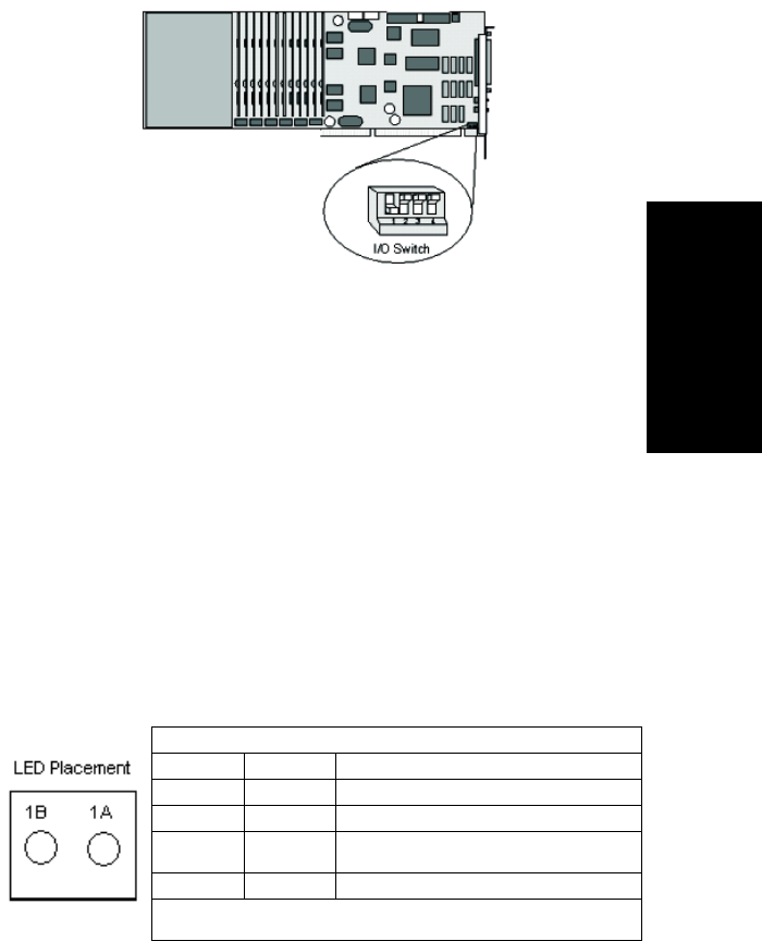
System Requirements
AltiContact Manager Administration Manual 2-5
2. System
Requirements
The I/O switch is factory preset as shown below. Change this setting only
if there is a hardware conflict.
The Quantum telephony board has the following functional characteristics:
ã MVIP compatible
ã 256 Port Non-Blocking Switch Matrix
ã Audio Peripheral Input & Output
ã Jumper-Free Configuration
ã On-Board Telephony Power Supply for Quantum D Board
ã Automatic Power Failure Transfer
ãÂISABus
Triton Analog Extension Board
The Triton Analog Extension telephony board has a dedicated voice
channel for every extension port and FSK-only message waiting.
The Triton Analog Extension telephony board has the following functional
characteristics:
LED Indicators
LED 1B LED 1A Status
ON ON 5V is OK; 12V is OK ã normal operation
OFF OFF Power cable not plugged in
ON OFF 5V less than 4.5V but more than 3V ã bad PC 5V
power
OFF ON 12V less than 9V ã bad PC 12V power
LED 2, located near the 12V connector, is a red LED for diagnostic purposes. If
it is ON, the fuse is blown.
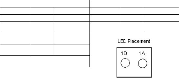
2-6 AltiContact Manager Administration Manual
ã MVIP Compatible
ã 256 Port Non-Blocking Switch Matrix
ã Jumper-Free Configuration
ã PCI Bus
ã Compliant with EIA464
ã Recording capability
Note: When the board is configured for audio input, the first port cannot
be used for an extension.
Triton Analog Trunk Board
The Triton Analog Trunk board comes in two models: Loop Start/Ground
Start (LS/GS) and Loop Start only (LS). It supports 12 analog trunks and
offers FSK Caller ID receiving, Centrex flash, and voice/silence activated
answer supervision. This board is also compatible with major PCI chassis
vendors.
The Triton Analog Trunk board has the following functional
characteristics:
ã MVIP-compatible
ã 256 Port Non-Blocking Switch Matrix
ã Jumper-Free Configuration
ã 32-bit, 5v PCI Bus
ã Compliant with EIA464
LS/GS LED Indicators*LS LED Indicators
LED 1B LED 1A Status LED 1B LED 1A Status
ON ON Normal ON ON Normal
OFF OFF No power to board OFF OFF No +5V or less than
4.1V
ON OFF No +5V or less than
4.1V
OFF ON No +12V or less than
9.2V
*
LED 2, located on the board, is a red LED for
diagnostic purposes. If it is ON, the fuse is blown.

System Requirements
AltiContact Manager Administration Manual 2-7
2. System
Requirements
ã Tone detection for fax tone, modem tone and voice.
Triton VoIP Board
The Triton VoIP telephony board has the following functional
characteristics:
ã MVIP-compatible
ã 256 Port Full-Duplex Switch Matrix
ã Jumper Free Configuration
ãÂPCIBus
Triton T1/PRI Board
The Triton T1/PRI telephony board, which supports either T1, E1 or PRI
through software configuration, has the following functional
characteristics:
ã MVIP Compatible
ã 256 Port Non-Blocking Switch Matrix
ã Jumper-Free Configuration
ãÂPCIBus
ã Tone detection for fax tone, modem tone and voice.
LED Indicators
Green LED Red LED Status
OFF OFF No power
ON OFF Normal operation
OFF ON No signal
ON Flashing Faulty signal with frame
synchronization*
OFF Flashing Faulty signal without frame
synchronization
Alternating Alternating Frame slips in normal operation
*Faulty signals include the following: yellow alarm, bipolar violation, or frame error.
2-8 AltiContact Manager Administration Manual
Triton Resource Board
The Triton Resource board enables call center supervisors to barge in or
silently monitor conversations. Up to two Resource Boards can be installed
in one system. Up to 12 simultaneous supervisor silent monitoring or
barge-in sessions are supported for each board.
The Triton Resource board has the following functional characteristics:
ã MVIP Compatible
ã Jumper-Free Configuration
ã 12 ports for silent monitoring and barge-in
ã PCI Bus
AltiGen Board Installation
Always install Triton and Quantum boards and attach MVIP and power
cables prior to powering server on. Failure to do so may result in damage
to the board. When removing or connecting the MVIP cable, do so with a
slow, vertical motion. Do not use a side-to-side rocking motion to remove
the connector or by pulling the cable. Be careful to make sure pins in the
MVIP connector on the board line up with the sockets on the MVIP cable.
Failure to do so may result in pins being pushed down toward the bottom
of the MVIP connector on the board. The MVIP test will detect these errors.
For complete instructions on how to install Triton and Quantum boards,
please refer to the Quick Installation Guide, which is provided with every
AltiGen board package.
TritonDef.inf
When a new PCI board is installed in a Windows 2000 system, the OS will
detect the board and ask for a driver. The driver file for the boards
(TritonDef.inf) can be found in the following locations:
ãÂBefore installing AltiContact Manager: on the root directory of the
AltiContact Manager CD-ROM; this file will be installed when you
install the software.
ãÂAfter installing AltiContact Manager: in the \AltiServ\SP directory on
your hard drive.

System Requirements
AltiContact Manager Administration Manual 2-9
2. System
Requirements
AltiGen Board Options
(Opciones de La Tarjeta AltiGen /AltiGen Kartenoptionen)
Table 2 lists the AltiGen telephony board modules. This selection allows
you to optimize your system based on the trunk/extension mix required at
your site.
La Tabla No. 2 lista los mû°dulos de la tarjeta de telefonûÙa AltiGen. Esta
selecciû°n le permite optimizar su sistema con base en la mezcla de
troncales y extensiones que requiere su sitio.
In Tabelle 2 sind AltiGen Kartenmodule fû¥r das Fernsprechwesen
aufgelistet. Diese Auswahl erlaubt eine Optimierung ihrer Standortanlage
mit der gewû¥nschten Kombination von Haupt- und Nebenanschlû¥ssen.

2-10 AltiContact Manager Administration Manual
Table 2. AltiGen Telephony Board Options
* When you upgrade to AltiWare OE 4.6, all 8-port boards are automatically upgraded to 12-
port boards. With a 30-port upgrade license, the 12-port board can be upgraded to a 30-port
board (one board upgrade per license). The original ports retain their configurations, but
you must configure the new ports if you want to use them.
* Cuando sustituye usted el producto por el AltiWare OE 4.6, todas las tarjetas de 8 puertos
automûÀticamente pasan a convertirse en tarjetas de 12 puertos. Con la licencia para 30
puertos, la tarjeta de 12 puertos puede convertirse en una de 30 puertos (un incremento en
la tarjeta por cada licencia). Los puertos originales conservan su configuraciû°n.
* Bei der Aufrû¥stung zur AltiWare OE 4.6 werden alle 8 Anschluû-Karten automatisch zu
12 Anschluû-Karten aufgerû¥stet. Mit der Lizenz zur Aufrû¥stung fû¥r 30 Anschlû¥sse kann
Board/Tarjeta/
Karte
Model Number/No. de
Modelo/Modell
Nummer Description/Descripcion/
Beschreibung
Quantum1ALTI-CD0408UD-
SPH001
4 trunks/troncales/Haupt and 8
extensions/extensiones/
Nebenanschlû¥sse
Quantum1ALTI-CD0804UD-
SPH001
8 trunks/troncales/Haupt and 4
extensions/extensiones/
Nebenanschlû¥sse
Quantum1ALTI-CD0012UD-
SPH001
12 extensions/extensiones/
Nebenanschlû¥sse
Triton ALTI-TTAS-12 12 extensions (stations)/
extensiones (estaciones)/
Nebenanschlû¥sse (Stationen)
Triton ALTI-TTIP-8 12 or 30 VoIP trunks/troncales/
Haupt or extensions/extensiones/
Nebenanschlû¥sse*
Triton ALTI-T1E1-1 1 T1, 1 E1 or 1 PRI
Triton ALTI-TTRS-12 12 ports for supervisor
monitoring/12 puertos para
monitoreo del supervisor/12
Stechanschlusse fur Monitor-
Dienst
Triton ALTI-TTAT-12GS 12 trunks/troncales/Haupt, ground
start/loop start
Triton ALTI-TTAT-12 12 trunks/troncales/Haupt, loop
start only

System Requirements
AltiContact Manager Administration Manual 2-11
2. System
Requirements
die 12 Anschluû-Karte zu einer 30 Anschluû-Karte aufgerû¥stet werden. (Eine Kartenau-
frû¥stung pro Lizenz). Die ursprû¥nglichen Anschlû¥sse behalten ihre Konfiguration, die
neuen Anschlû¥sse jedoch mû¥ssen bei Gebrauch neu konfiguriert werden.
1Available in the Americas and Caribbean only./Disponible en las Amûˋricas y en el Caribe
û¤nicamente./Nur in Nord-und Sû¥damerika und der Karibik erhûÊltlich.
System Limitations
Note the following limitations for board installation and Triton VoIP board
and port combinations.
Table 3. Board Installation
Board Type Maximum in a
System Board ID
Range Total Ports
Triton VoIP 12-
port
10 0-9 120
Triton VoIP 30-
port
20-960
TOTALTriton
VoIP boards
10 120 max in one
system, via any
combination of
boards that com-
plies with the sys-
tem limitations
shown here
Triton Analog
Trunk
16 0-15
Triton Analog
Extension
16 0-15
Quantum 16 0-15
Triton T1/E1/PRI 8 0-7
Triton Resource 2 0-1
TOTAL T1/
PRI, VoIP, and
Resource
Combined
10

2-12 AltiContact Manager Administration Manual
Recommended ACM System Configurations*
Table 4. System Selection Guidelines
*Individual requirements may vary depending on particular applications. Please contact
AltiGen Sales Engineering or Technical Support for assistance on selecting the most
appropriate system configuration for your installation.
Power Requirements
(Requisitos de EnergûÙa Elûˋctrica/Energiebedarf)
The power requirements are as follows for each individual board/Los
requisitos de energûÙa elûˋctrica son los que se indican a continuaciû°n para
cada tarjeta individual/Die folgende Tabelle zeigt den Energiebedarf jeder
einzelnen Karte an:
Number of
Quantum or Triton
Boards per System
CPU Type
Available
Memory
Hard Disk
Controller
Power Supply
5V Requirement
12V Requirement
1ã3 333 MHz 128
MB
IDE/
SCSI
Single 300W 15A 6A or
better
4ã6 700 MHz 256
MB
IDE
ATA-
100/
SCSI
Single 400W
or Dual
400W load
sharing rec-
ommended
20A 16A
7ã16 850+
MHz
512
MB
IDE
ATA-
100/
SCSI
Dual 400W
with load
sharing
required
40A 20A

System Requirements
AltiContact Manager Administration Manual 2-13
2. System
Requirements
Table 5. Individual Board Power Requirements
*1A@12V is provided by power connector.
Heat Factor
(Factor Tûˋrmico/Hitzefaktor)
Internal system temperature must not exceed the specified operating
temperature. If more than two AltiGen telephony boards are installed in the
system, then additional cooling fans are suggested. These fans need to
effectively reduce heat and increase airflow to the AltiGen telephony
boards to ensure system reliability.
La temperatura interna del sistema no debe exceder la temperatura de
operaciû°n que se especifica. Cuando en un mismo sistema se encuentren
instaladas mûÀs de dos tarjetas de telefonûÙa AltiGen, se sugiere que tambiûˋn
se instalen ventiladores adicionales de enfriamiento. Es menester que estos
abanicos reduzcan efectivamente el calor e incrementen el flujo de aire que
ingresa a las tarjetas de telefonûÙa AltiGen, a fin de garantizar la
confiabilidad del sistema.
Die interne Anlagentemperatur darf die vorgeschriebene
Betriebstemperatur nicht û¥berschreiten. Befinden sich mehr als zwei
AltiGen Fernmeldekarten in der Anlage empfiehlt sich der Einbau
zusûÊtzlicher Ventilatoren. Ihre Aufgabe ist es, effektiv Hitze zu reduzieren
und gleichzeitig den Luftstrom zu den Fernmeldekarten zu erhûÑhen, um die
ZuverlûÊssigkeit der Anlage zu gewûÊhrleisten. iabilidad del sistema.
Installing a Cooling Fan
(Instalaciû°n del Ventilador de Enfriamiento/Ventilatoreinbau)
Board/Tarjeta/Karte 5V 12V Slot Type/Tipo
Ranura/Steckplatz
Quantum 1.6 1.4A ISA
Triton Analog Extension 1.6 1A* PCI
Triton Analog Trunk LS/GS 1.6 0.25A PCI
Triton Analog Trunk LS 1.6A 0 PCI
Triton VoIP 1.6 0 PCI
Triton T1/PRI 1.6 0 PCI
Triton T1/E1 PRI 1.6 0 PCI
Triton Resource 1.6 0 PCI
2-14 AltiContact Manager Administration Manual
If more than two AltiGen telephony boards are installed in the AltiWare
system, then an additional cooling fan will be required. This fan needs to
effectively reduce heat and increase airflow to the AltiGen telephony
boards to ensure system dependability and reliability. To install a cooling
fan into the system, read the instructions included with the fan unit.
Cuando en un mismo sistema se encuentren instaladas mûÀs de dos tarjetas
de telefonûÙa AltiGen, tambiûˋn se requerirûÀ de la instalaciû°n de un ventilador
adicional de enfriamiento. Es menester que este abanico reduzca
efectivamente el calor e incremente el flujo de aire que ingresa a las tarjetas
de telefonûÙa AltiGen, a fin de garantizar la fiabilidad y la seguridad
funcional del sistema. Para instalar el ventilador de enfriamiento en el
sistema , lea las instrucciones que se incluyen con la unidad de ventilaciû°n.
Befinden sich mehr als zwei AltiGen Fernmeldekarten in der AltiWare
Anlage, muû ein zusûÊtzlicher Ventilator eingebaut werden. Dieser
Ventilator hat die Aufgabe, effektiv Hitze zu reduzieren und gleichzeitig
den Luftstrom zu den Fernmeldekarten zu erhûÑhen, um die ZuverlûÊssigkeit
der Anlage zu gewûÊhrleisten. Beim Einbau eines Ventilators in die Anlage
sind die dem Ventilator beigefû¥gten Anleitungen zu beachten.
Proper Board Handling Procedures
Handle boards by the edges only. Always hold the boards individually by
the face plate (with the components facing you) and pinching the edge on
the right side of the board. Do not make contact with the solder or
component sides of the boards. Do not slide the boards over any surface,
including an electrostatic discharge mat. Some boards have very sensitive
ceramics that contain embedded traces. These traces are very close to the
edge of the component and are easily chipped if they are hit against a hard
object or surface.
Electrostatic Discharge (ESD) Warning
Electrostatic discharge is caused by static electricity. It can damage boards
and may result in hard failures, early life failures, or cause a system to
experience intermittent, erratic behavior. Always use an ESD kit when
working on the telephony boards. The use of a special wrist strap or foot
strap (to ground the wearer to the computer's case) reduces the risk of ESD
damage.

System Requirements
AltiContact Manager Administration Manual 2-15
2. System
Requirements
Operating Environment
(Condiciones Ambientales de Operaciû°n/Betriebsbedingungen)
Before you set up and use the system, consider the environment in which
the system will reside:
ã Choose a work surface large enough to accommodate the entire
system.
ã Use a flat, stable work surface with enough space around it for proper
air circulation. For proper heat dissipation, a fan is recommended in
front of the AltiGen telephony boards to ensure sufficient airflow. Be
sure the fan filter is clean and does not block the airflow.
ã Always work with grounded equipment and fixtures. The use of an
ESD mat (to dissipate static) and grounding wrist/foot straps is
necessary.
ã In the manual assembly process, boards must be removed from the
anti-static bag and placed gently on a dissipative workstation mat, so
that they become discharged safely before being touched. The
dissipative mat should have a rubber upper layer and conductive
bottom layer. Regular cleaning of the mat should be done using an
anti-static mat cleaner.
The following table contains the operating specifications for the AltiGen
telephony board.
Condiciones Ambientales de Operaciû°n
Antes de Montar y utilizar el sistema, considere el medio ambiente en el
que dicho sistema residirûÀ:
ã Selecciones un espacio de trabajo lo suficientemente amplio para dar
cabida a la totalidad del sistema.
Description Specification
Operating Temperature 0ô¯ to + 50ô¯ C
Storage Temperature -20ô¯ to +70ô¯ C
Relative Humidity 10% to 80% non-condensing

2-16 AltiContact Manager Administration Manual
ã Utilice una superficie de trabajo plana y estable, con suficiente espacio
alrededor para que pueda darse una adecuada circulaciû°n del aire. Se
sugiere la colocaciû°n de un ventilador frente a las tarjetas de telefonûÙa
AltiGen, con objeto de disipar el calor adecuadamente y garantizar un
flujo de aire suficiente. Cerciû°rese de que el filtro del ventilador se
encuentra limpio y de que no obstruye el flujo del aire.
ã Trabaje siempre con equipo y aditamentos con conexiû°n a tierra. Es
necesario utilizar un tapete ESD (para disipar la estûÀtica) y pulseras/
tobilleras de aterrizada.
ã Durante el proceso de ensamble manual, las tarjetas deben retirarse de
la bolsa antiestûÀtica y colocarse suavemente sobre el tapete dispersivo
de la estaciû°n de trabajo, de tal manera en que ûˋstas se descarguen en
forma segura, antes de que las toquen. El tapete dispersor debe contar
con una capa superior de caucho y una capa inferior c. El tapete debe
limpiarse en forma regular utilizando un limpiador para tapetes
antiestûÀtica.
La tabla siguiente contiene las especificaciones de funcionamiento para el
tablero de la telefonûÙa de AltiGen:
Betriebsbedingungen
Vor Aufbau und Inbetriebnahme der Anlage mû¥ssen folgende
Betriebsbedingungen berû¥cksichtigt werden:
ã Es ist eine ArbeitsflûÊche zu wûÊhlen, die der gesamten Anlage
genû¥gend Platz bietet.
ã Die ArbeitsflûÊche muû flach und stabil sein und genû¥gend Raum fû¥r
eine entsprechend ausreichende Ventilation bieten. Zum
angemessenen Hitzeverlust und ausreichender Luftzufuhr wird der
Einbau eines Ventilators vor den AltiGen Fernmeldekarten
empfohlen. Der Filter des Ventilators muû sauber sein und darf die
Luftzufuhr nicht blockieren.
Descripcion Specification
Temperatura de Operacion 0ô¯ a + 50ô¯ C
Temperatura de
Almacenamiento
-20ô¯ a +70ô¯ C
Humedad Relativa 10% a 80% sin condensacion

System Requirements
AltiContact Manager Administration Manual 2-17
2. System
Requirements
ã Es darf nur mit geerdetem GerûÊt gearbeitet werden. ESD Matten (zur
Vermeidung von Statik) sowie geerdete Handgelenk- und FuûbûÊnder
sind dabei erforderlich.
ã Beim Zusammenbau von Hand ist zu beachten, daû mit Karten nach
der Entnahme aus einem anti-statischen BehûÊlter vorsichtig
umyugehen ist. Karten mû¥ssen dann zur elektrischen Entladung auf
eine Dissipationsmatte am Arbeitsplatz gelegt werden, bevor sie
berû¥hrt werden dû¥rfen. Die Dissipationsmatte muû eine gummierte
Oberseite und eine konduktive Unterseite haben. Beim regelmûÊûigen
Reinigen der Matte muû ein antistatisches Reinigungsmittel
verwendet werden.
Die folgende Tabelle enthûÊlt die funktionierenden Spezifikationen fû¥r das
AltiGen Telephoniebret:
Packaging for Shipment and Storage
ã AltiGen telephony boards are packaged and shipped individually in
fully closed, static-shielding bags. The pink anti-static foam should be
used only as cushioning material ã it is not static-dissipative and
cannot discharge the boards.
ã Always save and use the original packaging materials (foam, static-
shielding bag, and cardboard box) to transport the boards.
ã AltiGen telephony boards are protected by their anti-static bags and
should be removed from their packaging for installation by a properly
grounded technician.
Beschreibung Spezifizierung
Betriebstemperatur/ 0ô¯ to + 50ô¯ C
Lagerungstemperatur -20ô¯ to +70ô¯ C
Relative Luftfeuchtigkeit 10% bis to 80% nicht-verdichtend

2-18 AltiContact Manager Administration Manual
AltiContact Manager Conference Resource Limits
The following table defines conference resource limits for boards used in
an AltiContact Manager system.
Table 6. Conference Call Resource Limits
1The Quantum board can support up to 3 conference bridges with up to 6 members each. However, this
does not imply that you can have a total of 18 conferenced members (external + internal) per board, as it
only has 12 conference resources.
2The Quantum board can only support up to 4 members located on different boards on a conference call
initiated by a local extension, even is there are (12-1=11) resources available. For example, if Ext 101
(located on the Quantum board) wants to host a conference call with Ext 200, Ext 201, Ext 202, Ext 203
and Ext 204 (located on different boards), the last extension to be brought into the conference will not be
conferenced, even if there are no other ongoing conferences on this Quantum board. Therefore, a total of
5 (1+4) conference resources have been used. However, it is possible for Ext 101 to bring in Ext 102 into
the conference, if Ext 102 is located on the same Quantum board as Ext 101. Once Ext 102 joins the
conference, no other members can join this conference call, as the 6 conference member limit has been
reached.
3The Triton Resource board can support up to 12 conference bridges with up to 6 members each. However,
this does not imply that you can have a total of 72 conferenced members (external + internal) per board,
as it only has 36 conference resources.
Board
Maximum
Number of
Conferences
Supported
(Conference
Bridge)
Maximum
Number of
Members
per
Conference
(Internal
Extensions
and External
Parties)
Total
Number of
Conference
Resources
Available
Support of Conference
Members on Other Boards
Quantum 3up to 6112 Yes, limited to 4members.
Triton Analog
Extension 3618
Yes, limited by maximum num-
ber of conference resources and
maximum number of members
per conference
Triton Analog
Trunk 000 0
Triton VoIP
12 Port 000 0
Triton VoIP
30 Port 2612
Yes, limited by maximum num-
ber of conference resources and
maximum number of members
per conference
Triton T1/PRI 000
Triton Resource 12 up to 6 36 Yes, limited by maximum num-
ber of conference resources and
maximum number of members
per conference

AltiContact Manager Administration Manual 3-1
3.Software
Installation
C
HAPTER
3
Software Installation
The AltiContact Manager software is provided on a CD-ROM and contains
the following components or folders:
ãÂAltiContact Manager. Contains the AltiContact Manager
Administrator as well as the switching service, SMTP/POP3 server,
messaging agent, Exchange Integration, AltiBackup, AltiGatekeeper,
AltiWeb that can be installed on any Windows NT Server with Service
Pack 6a (or higher) or on Window 2000 Server.
ãÂACM Admin. Contains the AltiContact Manager Administrator that
can be installed on any Windows NT with Service Pack 6a (or higher)
or Windows 2000 on the LAN to control the system(s).
ãÂAltiWeb. Contains the AltiWeb installation files.
ãÂCallRouter. Contains the CallRouter installation program.
ãÂCDR. Contains the CDR Search Client that allows you to search a Call
Data Reporting database, along with documentation and external
logger service.
ãÂDINA Manager. Contains the DINA Manager installation program.
ãÂDocumentation. Contains the AltiContact Manager System
Installation and Administration Manual and the AltiView and AltiServ
User Guide in the Adobe Acrobat PDF format.
ãÂGatekeeper. Contains the Gate Keeper for IP Phones.
ãÂReader. Contains the AdobeôÛ AcrobatôÛ Reader executable.
ãÂReadme.txt. Contains late breaking information about AltiContact
Manager. Please be sure to take a moment to read this brief file,
which contains very important information you need to be aware
of before you install AltiContact Manager.
ãÂTAPI Gateway. Contains the TAPI Proxy Server and TAPI Service
Provider that allow you to use AltiGenãs AltiLinkPlus to create TAPI
applications for your AltiContact Manager configuration.
AltiContact Manager as an NT Service
3-2 AltiContact Manager Administration Manual
AltiContact Manager as an NT Service
AltiContact Manager components such as the switching, messaging agent,
and AltiBackup are NT services that are automatically launched when
AltiContact Manager is installed and the system is restarted. Benefits of
AltiContact Manager as an NT service:
ã The AltiContact Manager Administrator user interface does not have
to be tied to the switching service so that if there is a problem with the
user interface, the switching service is not affected.
ãÂRemote administration is possible through ACM Admin.
Important: Do not tamper with the startup settings of AltiGen services in
the Services applet of the Control Panel. Only the AltiGen
Switching Service should be set to Automatic; all other
AltiGen services should be set to Manual.
Preparing to Install AltiContact Manager
The following is a step-by-step procedure for installing or upgrading the
AltiContact Manager software from the AltiContact Manager 4.6 CD-
ROM.
It should take about 15 to 20 minutes to install the AltiContact Manager
software program. Before you begin installation, however, please note the
following:
ãÂBackup prior to install. Before upgrading your system from
AltiWare Release 4.6, you should back up all the configuration
information to adifferent location, such as the network drive. (You can
do this by using the backup utility OR by copying the contents of the
\altiserv\db\,\altiserv\Phrases\LangCustom, and \postoffice\
folders to a backup location.) This backup information is also required
when rolling back to prior AltiWare versions.
ãÂNT Service Pack 6a, Windows 2000 Server (or higher) is required
and must be installed before AltiContact Manager can be installed or
upgraded.

Software Installation
AltiContact Manager Administration Manual 3-3
3.Software
Installation
ãÂUser Account. During installation, a user account with local
administrator right is created automatically to run AltiContact
Manager services. Do not delete or modify this account. You may
change its password through installation. The account name is in the
form:
(user name: AltiGen_<servername>)
ãÂThird party applications. AltiContact Manager must be installed
before any third party applications on a Windows NT with Service
Pack 6a (or higher) or Windows 2000 system. Contact your third party
application vendor(s) to find out if an upgrade is required for their
product to work with the release you are about to install.
ãÂInstalling over old versions. If AltiWare 4.6 is installed, there is no
need to uninstall it before installing AltiContact Manager.
If AltiWare 4.0/4.5 is installed, first upgrade to 4.6, then upgrade to
AltiContact Manager.
Firewall Considerations
If you are using a firewall in the AltiContact Manager environment, the
following are the network ports used:
Client Server TCP UDP
ACM AdminaAltiWare DCOM 135 135
AltiConsole AltiLink + 10025
AltiControl AltiLink+ 10025
AltiReach AltiLink 10015
AltiView/AltiAgent AltiLink+
VM Service
10025
10028
Supervisor AltiLink+
Internal/External CDR
Logger
10025
10027
CDRSearch AltiLink+
Internal/External CDR
Logger
10025
10027
TAPI Client TAPI Gateway 10026
VoIP H.323/H.225
Gatekeeper
VoIP H.323/H.225 1720
1718, 1719

Preparing to Install AltiContact Manager
3-4 AltiContact Manager Administration Manual
VoIP Message
Waiting
VoIP Message Waiting 49151
(Quicknet IP
ext only)
VoIP H.245 VoIP H.245 From 49152
to Nb
VoIP RTP VoIP RTP From 49152
to Nb
Web Client AltiLink+
NetMeeting Chat
plus VoIP ports
described above
10025
1720
AltiGen IP Phone 10032
Polycom Between
2222-2242
and 1718/
1719
a. It is recommended that this be run only in an intranet.
b. N=49152+ (62*number of boards)ã1
Client Server TCP UDP

Software Installation
AltiContact Manager Administration Manual 3-5
3.Software
Installation
Software License Activation
and Registration
Licensing
The licensing has two components ã a system key which is a physical
device shipped with every copy of AltiContact Manager. This hardware
key is equipped with a DB -25 connector that is designed to be connected
to the parallel printer port on the system running AltiContact Manager.
Optionally, a USB port version of the system key is available for use on
systems ONLY equipped with a USB port. The USB system key is a special
order item.
The second component is the license key. The following table lists all
licenses used in Release 4.6.
Table 4. Release 4.6 License Summary
License Type Description/Notes
AltiContact Man-
ager
Site ãÂRequired for ACM Product.
ãÂUser can run ACM and ACM Administrator but only 8
business users are available and all ACM-related
licenses will not be able to register if this license is not
installed.
AltiView Site ãÂThis license enables the AltiView client.
ãÂAltiView cannot connect to AltiWare without this
license.
ãÂAltiView does not require session license.
AltiWeb Site ãÂThis license enables AltiWeb function.
ãÂDesktop Connect/SDK Client session license is
required to connect AltiWeb sessions.
External Logger Site ãÂThis license enables External Logger.
ãÂAltiWare will not send CDR/RTM data to External
Logger if this license is not installed.
Call Router
Advanced
Site ãÂThis license enables Call Router Advanced service.
30 Port IP Site ãÂThis license enables the Triton 30-port VoIP option.
ãÂA maximum of two 30-port licenses per system.
ãÂLicense is the same for OE 4.5/4.5A/4.6/ACM 4.6.

Licensing
3-6 AltiContact Manager Administration Manual
Business User Seat ãÂThis license counts the total number of physical and IP
phones configured in the system.
ãÂIncluded in Agent Seat license.
Agent Seat Session ãÂThis license counts the number of concurrent, logged
in agents to one or multiple workgroups. When a single
agent logs in to one or more workgroups, one agent
seat license is be used.
ãÂWhen the system does not have enough agent session
licenses, it will reject any new workgroup login that
requires a new agent seat license.
Recording Seat Session ãÂThis license counts the number of concurrent recording
seats for agent/extension to record a conversation to a
centralized folder without additional hardware.
ãÂWhen recording to a central location, a recording
session license is required. If there are not enough
licenses, the recording request will be rejected.
ãÂOnly available with ACM product.
ãÂOnly applies to Triton Analog extensions.
ãÂRecorded file can be in any network drive for backup.
AltiAgent Client
Session
Session ãÂThis license enables a per concurrent connection of
AltiAgent.
AltiSupervisor
Client Session
Session ãÂThis license enables a per concurrent connection of
AltiSupervisor.
SDK Connection
Session
Session ãÂThis license enables TCP/IP connection to 3rd party
client applications with the following abilities:
ãReceive call information
ãReceive real-time statistics
ãGet system configuration data
ãGet/Set extension configurations
ãRecord voice/conversations
ãScreen pop ability
ãphysical extension call control
ãÂEnables AltiWeb concurrent connection.
ãÂSupports all SDK functions (Basic SDK, APC SDK
and recording SDK) for client application.
License Type Description/Notes

Software Installation
AltiContact Manager Administration Manual 3-7
3.Software
Installation
For step-by-step instructions on the licensing process, refer to page 3-29.
Registration
Licenses must be registered with AltiGen for the system to function at full,
licensed capacity. This registration includes both AltiContact Manager
systems information, as well as registering dealer, installer, and end user
(customer) data for each AltiGen system installed or upgraded to
AltiContact Manager.
All software must be registered, including AltiWare Office products. No
AltiGen software comes out of the factory pre-registered. All license keys
must be registered to the system key and without proper registration,
the system will function with only 8 extension ports enabled. To support
the new licensing and registration requirement, all copies of AltiContact
Manager software (new) are shipped with a system key.
Once registered, system keys have license keys associated with them. All
license keys are individually tracked and can only be registered to one
system key. Individual license keys cannot be reactivated or installed on a
different system once it has been registered the first time. The same license
key cannot be associated with multiple systems even on the same customer
site. Through registration, AltiGen tracks all licenses shipped, which
licenses have been installed and registered, and which license keys are
associated with each system key.
SDK Application
Session
Session ãÂThis license enables trunk and extension ports to enter
APC state. In APC state, 3rd party applications can
control the port to perform the following functions:
ãPlay phrase/tone
ãPlay DTMF tone
ãReceive DTMF digit
ãRecord voice (not conversation)
ãSwitch to music
ãÂRequires SDK Connection Session license.
ãÂThis license is mainly designed for IVR applications.
License Type Description/Notes
Registration
3-8 AltiContact Manager Administration Manual
Dealer Installation ID
As part of the installation and registration process, the Dealer is associated
with the customer and the system installed. To facilitate this, a Dealer
Installation ID will be provided to all dealers. This Dealer Installation ID
will provide safe access to the registration system in the case where Dealers
send their software and license keys direct to the customers to install. This
Dealer Installation ID is a dealer-specific registration password and can be
given to customers without compromising the secure access to our
Authorized Dealer website and Tech Support site. The password ensures
the dealer information is tracked along with customer information as part
of the total system installation record. You cannot progress through
registration without this number. Current passwords, such as the dealer
website password, will not work for registration
Registration Methods
There are two ways a system can be registered. These are based on the
ability of the AltiContact Manager system being installed and registered to
have Internet access.
Manual Online Registration
If there is no access to the Internet from the server being installed, the
Installer must go to a PC with Internet access and manually register the
software. A registration tool allows the Installer to manually enter three
pieces of information as part of the registration process:
1. Dealer Installation ID
2. Customer information
3. System key and associated license keys
The registration tool will validate the information and assign the license
keys to the system key as a part of this online registration process.
Completion of the final step of this process generates an activation file that
will be used to populate the actual system with valid registration
information.
WARNING! Once a license key is associated with a system key, it
cannot be reassigned to another system.
Remember that some licenses for AltiContact Manager are specific for that
release. For upgrades, some 4.5 licenses must be converted to 4.6 in order
to work with AltiContact Manager.

Software Installation
AltiContact Manager Administration Manual 3-9
3.Software
Installation
For step-by-step instructions on the manual online registration process,
refer to page 3-38.
AltiContact Manager Online Registration
The second method for registering AltiContact Manager, Seat licenses and
optional software features can be accomplished during installation of the
system. To accomplish this, an online connection is needed to the
AltiContact Manager system at the time of registration. This online
registration tool automatically populates the license keys and system keys
in the proper fields of installed software on the AltiContact Manager
systems. This tool also requires the Installer to register the three pieces of
information tracked on all system:
1. Dealer Installation ID
2. Customer information
3. System key and associated license keys
Completion of the final step of this process generates an activation file that
will be used to populate the actual system with valid registration
information.
WARNING! Once a license key is associated with a system key, it
cannot be reassigned to another system.
Remember that some licenses for AltiContact Manager are specific for that
release. For upgrades, some 4.5 licenses must be converted to 4.6 in order
to work with AltiContact Manager.
For step-by-step instructions on the AltiContact Manager online
registration process, refer to page 3-29.
Note: Internet Explorer 5.0 (or higher) is required for online registration.
Upgrades
ã Upgrade to ACM 4.6 is only supported when upgrading from OE 4.6.
ã OE 4.6 licenses are not supported except for AltiView software,
AltiConsole software, IP Extension seat and 30-Port IP board licenses.
ã Upgrade to ACM 4.6 from OE 4.0/4.0A is not supported.
ã Upgrade to ACM 4.6 from OE 4.5/4.5A (with or without Contact
Advantage) is not supported.
Upgrades
3-10 AltiContact Manager Administration Manual
For all the above cases, the customer must go to a registered 4.6 version to
transfer compatible licenses.
The AltiGen upgrade process is designed to ensure that the proper
compatible seat licenses are provided with upgrade software ordered. Other
optional software, such as AltiAgent and AltiSupervisor, must also be
upgraded to be compatible with 4.6 (4.6 compatible licenses).
Lost Licenses
AltiGen views a registered license key as the right for the system registered
under to have access to the feature. If a license key or system key is lost, it
is the responsibility of the party who purchased the item. The policy for
replacing any lost software licenses or system keys is to repurchase the
software.

Software Installation
AltiContact Manager Administration Manual 3-11
3.Software
Installation
New Installation
Before New Installation
Note: TritonT1RevA1/A2orVoIPRevA1/A2boardsarenotsupported
in AltiContact Manager. These boards must be replaced with Rev
A3 or later boards.
Before you begin, have the following at hand:
ãÂSystemKey
ã The 20-digit software license key (located on the End User License
Agreement)
ã The system home area code
ã The extension length
Note: The extension length, which is from 3ã6 digits, is the number
of digits for all extension numbers. All extensions in the
AltiContact Manager configuration must be the same length.
You cannot change the extension length once the first
extension is configured, which is something you do later
running the AltiContact Manager Setup. To change the
extension after extensions are configured requires
reconfiguring the entire system or deleting all the extensions
and groups already configured.
ã Internet Explorer 5.0 or higher (for online registration)
To Begin New Installation
To install AltiContact Manager:
1. Make sure you have prepared for installation as described beginning
on page 3-2.
2. Install the System Key on the parallel or USB port.
Caution: Do not connect the system key to any AltiGen board as
damage may occur to the board or the system key.

To Begin New Installation
3-12 AltiContact Manager Administration Manual
3. Login to Windows NT or Windows 2000 as a domain or local user
account that has local administrator privileges.
If your machine is a stand-alone server, you need to login as a local
administrator account.
Note: If you plan to run Exchange Integration, you must have domain
administrator rights.
4. Insert the AltiContact Manager CD-ROM into the CD-ROM drive.
5. Select and read the Readme.txt file.
6. After reading the Readme.txt file, click on SETUP.EXE in the
AltiContact Manager folder.
7. At the Welcome page window, exit all Windows programs before
continuing with the setup, then click Next.
8. Setup will retrieve logon information to determine if the user has
corresponding privilege.
9. Setup will retrieve system key and install its driver, if applicable. If the
system key is not available, you may still continue with setup.
However, you cannot perform the license registration process (to
activate your licenses) without the system key.
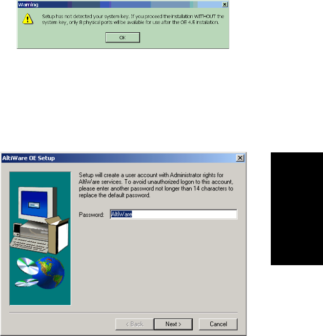
Software Installation
AltiContact Manager Administration Manual 3-13
3.Software
Installation
10. Setup will check AltiGen boards on your system.
Note: Setup will terminate if T1 Rev. A1/A2 or VoIP Rev. A1/A2
boards are found. These boards are not supported.
11. Setup will create a user account for AltiWare services. AltiGen
recommends that you do not change the default password. If you still
wish to change this, you may enter a password (no longer than 14
characters) for this account and click Next.
12. Setup is creating the user account.
13. Setup will install AltiContact Manager into a destination folder. Click
Next to install to the folder, or click Browse to install to a different
folder.

To Begin New Installation
3-14 AltiContact Manager Administration Manual
14. Setup will use the following disk drives as noted for PostOffice,
AltiDB and AltiDB Backup or you may select another local drive.
Note: It is recommended that the local drive used should have at least
2GB of free space for PostOffice and 500MB each for AltiDB and
AltiDB Backup.
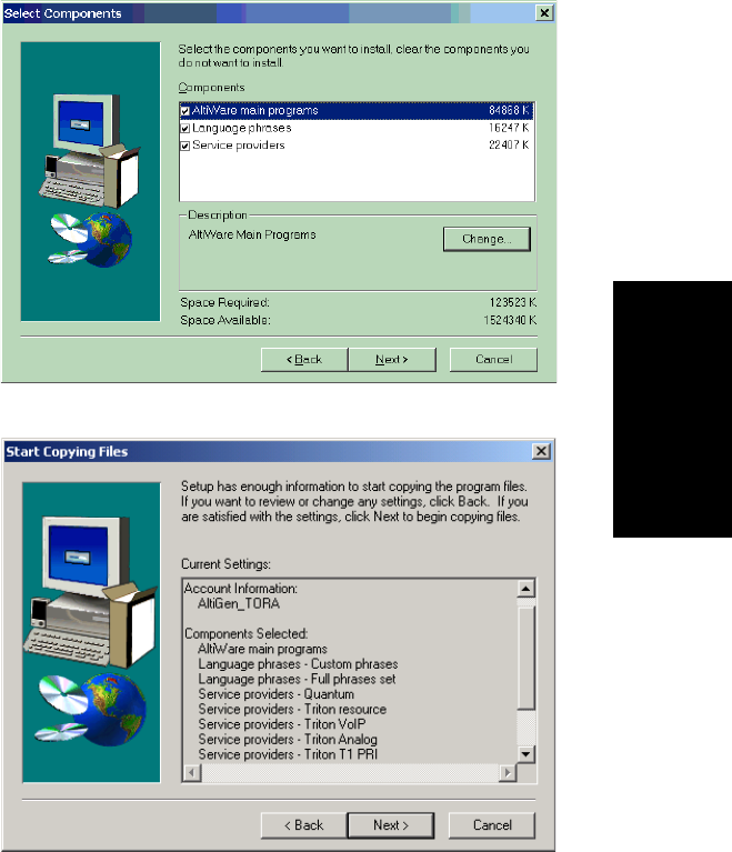
Software Installation
AltiContact Manager Administration Manual 3-15
3.Software
Installation
15. Setup allows you to select the components you wish to install. By
default, all components are checked, and it is recommended that you
do not uncheck any items.
16. Click Next to have Setup begin copying the program files.
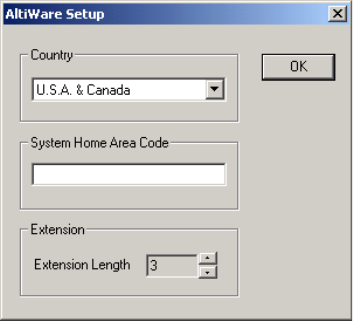
To Begin New Installation
3-16 AltiContact Manager Administration Manual
17. Setup will perform the following:
ã Install Microsoft Data Access Components
ã Install AltiWare Services
ã Register AltiWare COM components
ã Create program folder and icons
ã Upgrade AltiWare databases
18. Setup Window will prompt for the Country,System Home Area
Code and Extension Length. When finished, click OK.
Note: Once the Extension Length is set and you click OK,you
cannot change the extension length after this setup unless you
re-configure the entire system or delete all the extensions
already configured.
19. Setup is almost complete. Make sure the MVIP cable connections and
terminator setting are correct, then click Finish.
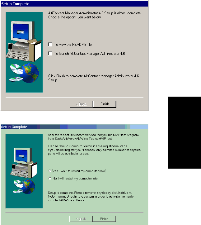
Software Installation
AltiContact Manager Administration Manual 3-17
3.Software
Installation
20. Setup is complete. Reboot the system to finish the installation process
21. (Recommended) After rebooting, run the MVIP test program from
Start>AltiWare>AltiWare Tools>MVIP test.
22. Use AltiAdmin to register your licenses. Follow the steps for ãOnline
License Registration Proceduresã on page 29. If you do not register
and activate your licenses, only eight (8) physical ports will be
available for use.

Before Upgrade
3-18 AltiContact Manager Administration Manual
Upgrading AltiWare OE
Note: Triton T1 Rev A1/A2 or VoIP Rev A1/A2 boards are notsupported
in AltiContact Manager. These boards must be replaced with Rev
A3 or later boards.
Before Upgrade
Before you begin, youãll need to have the 20-digit software license key
located on the back of the End User License Agreement and a System Key.
Backup Database
AltiContact Manager supports direct upgrade from OE 4.6 only.Ifyour
system is running an earlier release, you first upgrade to OE 4.6 or later.
If AltiWare 4.6 is installed, there is no need to uninstall it before installing
AltiContact Manager 4.6. If AltiWare 4.0/4.5 is installed, first upgrade to
4.6, then upgrade to AltiContact Manager.
Back up all the configuration information to a different location, such as the
network drive. (You can do this by using the backup utility OR by copying
the contents of the \altiserv\db\,\altiserv\Phrases\LangCustom, and
\postoffice\ folders to a backup location.). To uninstall an earlier version of
AltiWare, click the Uninstall icon in the AltiWare program group. The
uninstall does not remove the AltiWare configuration and messages.
For addressing firewall considerations, refer to ãFirewall Considerationsã
on page 3-3.
Shutting Down the AltiGen Switching Service
Before installing this upgrade on the AltiContact Manager system, please
make sure that the ACM Admin application and the AltiGen Switching
Service are not running.
You can shutdown the AltiGen Switching Service Com Server and the ACM
Admin application at the same time by running ACM Admin, logging in
and selecting Services Shutdown Switching.
Note: Stopping the AltiGen Switching Service COM Server will
automatically stop all the auxiliary services.

Software Installation
AltiContact Manager Administration Manual 3-19
3.Software
Installation
These are the Windows 2000 / NT services distributed with AltiContact
Manager:
ã AltiGen Switching Service COM Server
ã AltiGen Messaging Service COM Server
ã AltiGen SMTP Service COM Server
ã AltiGen POP3 Service COM Server
ã AltiGen Exchange Integration Service COM Server
ã AltiGen Backup/Restore Service
ã AltiGen Keep Up Service
ã AltiGen Internal Logger Server
Shutting Down Switching as a Windows 2000 / NT Service
Optionally, if youãre not running ACM Admin, you can shut down the
services using Windows 2000 / NT Services.
1. Do one of the following:
ãÂOntheWindows 2000 desktop, select Start Programs
Administrative Tools Services.
ãÂOntheNT desktop, Open the Control Panel and double-click
Services.
2. Highlight AltiGen Switching Service COM Server.
3. Stop the service.
If the status column is empty, proceed to the next step. If the status
column says Started, double-click the listing to open the Properties
dialog box, then click the Stop button followed by the OK button to
close the dialog.
To Begin Upgrade
To complete the upgrade:
1. Make sure you have prepared for installation as described beginning
on page 3-2.
2. Install the System Key on the parallel or USB port.
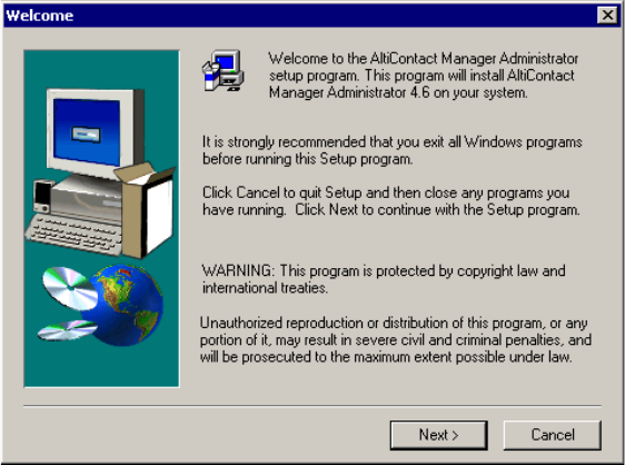
To Begin Upgrade
3-20 AltiContact Manager Administration Manual
Caution: Do not connect the system key to any AltiGen board as
damage may occur to the board or the system key.
3. Login to Windows NT or Windows 2000 as a domain or local user
account that has local administrator privileges.
If your machine is a stand-alone server, you need to login as a local
administrator account.
Note: If you plan to run Exchange Integration, you must have domain
administrator rights.
4. Insert the AltiContact Manager CD-ROM into the CD-ROM drive.
5. Select and read the Readme.txt file.
6. After reading the Readme.txt file, click on SETUP.EXE in the
AltiContact Manager folder.
7. At the Welcome page window, exit all Windows programs before
continuing with the setup, then click Next.
8. Setup will retrieve logon information to determine if the user has
corresponding privilege.
9. Setup will retrieve system key and install its driver, if applicable.
Software Installation
AltiContact Manager Administration Manual 3-21
3.Software
Installation
WARNING! If the system key is not available, Setup will terminate.
10. Setup will check AltiGen boards on your system.
Note: Setup will terminate if T1 Rev. A1/A2 or VoIP Rev. A1/A2 boards
are found. These boards are not supported.
11. Setup will check existing licenses to see if they are registered or
partially registered. Depending on these conditions, Setup will proceed
to either Sub-step 1A. ã No registered Licenses or Sub-step 1B. ã
Partially Activated Licenses.
Note: OE 4.6 license keys are not compatible with AltiContact Manager.
You need to register all AltiContact Manager 4.6 license keys
through the registration process.
Sub-step 1A:
No Registered Licenses - If no licenses are registered, you will see
the following Installation Options window.
You may choose the following options:
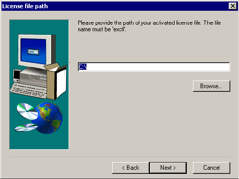
To Begin Upgrade
3-22 AltiContact Manager Administration Manual
a) Provide the activated license file - if you select this option and
click Next, enter the path of the ãexctlã file in the License Path
page, then click Next to proceed to Step 12.
b) Register license now - if you select this option and click Next,
you will automatically launch AltiContact Managerãs License
Information window. Click Online Register to activate your
license(s) and follow the steps for online registration on page 3-
32.
Sub-Step 1B:
Partial Registered Licenses -Ifsomeofyourexistinglicensesare
registered, you will see the following Installation Options window.
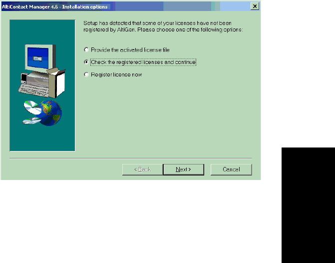
Software Installation
AltiContact Manager Administration Manual 3-23
3.Software
Installation
You may choose the following options:
a) Provide the activated license file - If you select this option and
click Next, enter the path of the ãexctlã file in the License Path
page, then click Next to proceed to Step 12.
b) Look at partially activated licenses and continue -ifyouselect
this option and click Next, you can view your existing licenses
and their activation status in the Information page, then continue
upgrading with activating these licenses by following the steps for
online registration on page 3-32.
Caution: If you do not register all your licenses and continue the
upgrade, some features may not function after the upgrade is
complete.
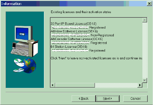
To Begin Upgrade
3-24 AltiContact Manager Administration Manual
.
c) Activate license now - if you select this option and click Next,
you will automatically launch AltiContact Managerãs License
Information window. Click Online Register to activate your
license(s) and follow the steps for online registration on page 3-
32.
12. Setup will check service status.
13. Setup will create a user account for AltiContact Manager services.
AltiGen recommends that you do not change the default password. If
you still wish to change this, you may enter a password (no longer than
14 characters) for this account and click Next.
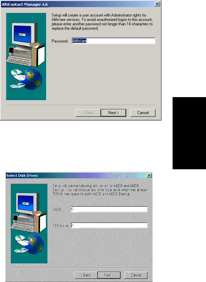
Software Installation
AltiContact Manager Administration Manual 3-25
3.Software
Installation
14. Setup is creating the user account.
15. Setup will use the following disk drives as noted for AltiDB and
AltiDB Backup or you may select another local drive.
Note: It is recommended that the local drive used should have at least
500MB of free space each for AltiDB and AltiDB Backup.
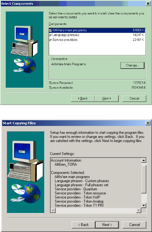
To Begin Upgrade
3-26 AltiContact Manager Administration Manual
16. Setup allows you to select the components you wish to install. By
default, all components are checked, and it is recommended that you
do not uncheck any items.
17. Setup will begin copying the program files.
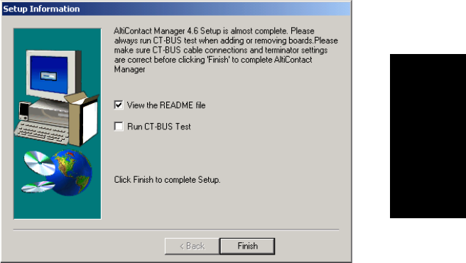
Software Installation
AltiContact Manager Administration Manual 3-27
3.Software
Installation
18. Setup will perform the following:
ã Install Microsoft Data Access Components
ã Install AltiContact Manager Services
ã Register AltiContact Manager COM components
ã Create program folder and icons
ã Upgrade AltiContact Manager databases
19. Setup is almost complete. Setup will suggest running CT bus test
before rebooting.
If the CT bus test option is checked, the test will begin when you click
Finish. You can see the pass or fail information in the CT Bus Test Tool
test log box.
20. Setup will complete, whether or not the CT Bus test passes, if Setup
cannot get the results of the CT bus test, or if the CT bus test is skipped.
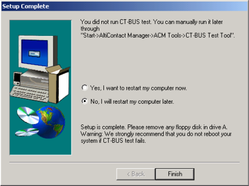
To Begin Upgrade
3-28 AltiContact Manager Administration Manual
You can restart your computer now or later, then click Finish to end
Setup.
21. If the CT Bus test fails, it is recommended that you address the CT Bus
failure before you reboot the system. You can manually run the CT
Bus test program through Start>AltiWare>AltiWare Tools>CT Bus
test.
22. Reboot the system to finish the upgrade process.

Software Installation
AltiContact Manager Administration Manual 3-29
3.Software
Installation
License Activation and
Registration Process
In AltiContact Manager, a software license allows you to increase the
capacity for the following:
ãÂPhysical and IP extensions. A Quantum board can provide 4, 8, or 12
extensions (depending on the type of Quantum board) and the Triton
Analog Station board provides 12 extensions. You may increase the
number of software-supported extensions up to the maximum
available by adding station licenses. Each license you enter adds to the
previous total.
ãÂSessions. AltiContact Manager includes a single session license. You
may increase the number of concurrent client sessions by purchasing
additional session licenses packages. Each license you enter adds to
the previous total.
Online License Registration Procedures
To activate any license through online registration, follow these steps:
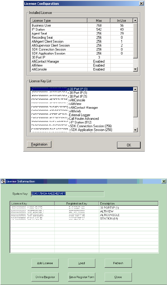
To Begin Upgrade
3-30 AltiContact Manager Administration Manual
1. From the About AltiContact Manager window in ACM Admin, click
on the License Information button.
2. Click the Registration button to open a new License Information
window.
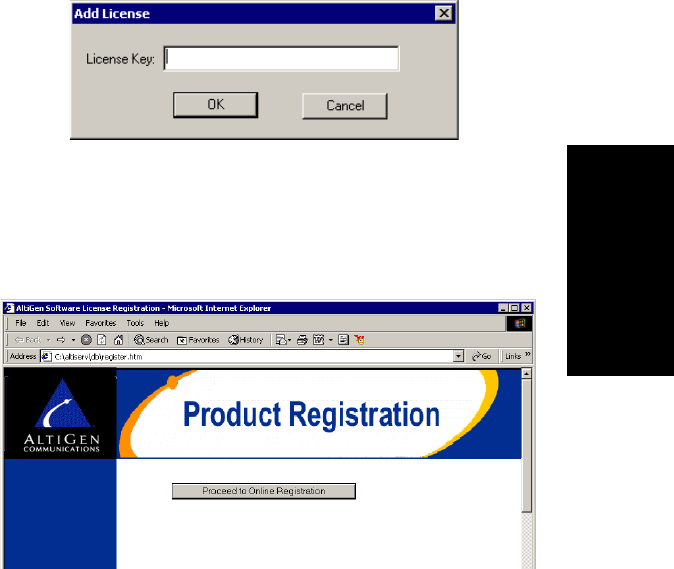
Software Installation
AltiContact Manager Administration Manual 3-31
3.Software
Installation
3. <Optional - you may add licenses here OR during online registration.
Skip to Step 5 if you wish to add licenses later.>
Click Add License to add the license keys that you wish to add and
activate. (License keys are located on the End User License Agreement
sent with every License purchase.)
4. In the License Key field of the Add License pop-up window, enter the
license key and click OK.
Continue adding licenses with the Add License button until all
licenses are entered.
5. Select the Online Register button. This automatically launches the
following web page to start online registration.
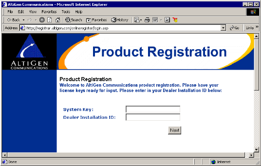
To Begin Upgrade
3-32 AltiContact Manager Administration Manual
6. Click the Proceed to Online Registration button.
7. The next web page allows for inputting System and Dealer Installation
ID. The System Key field is automatically loaded. (This information
is located on the End User License Agreement). In the Dealer
Installation ID field, enter the ID number assigned to your Dealer.
This information can be obtained by contacting either your local
authorized AltiGen Dealer or AltiGen Technical Support.
Click Next when finished.
8. The next web page allows for inputting of Customer and Installer
information.
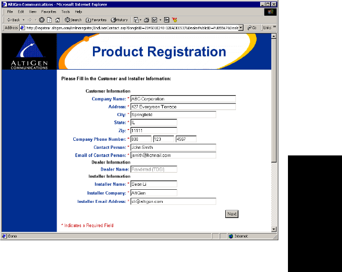
Software Installation
AltiContact Manager Administration Manual 3-33
3.Software
Installation
For the Customer Information and Installer Information sections, fill in
all fields (required) and click Next when finished.
9. The next web page allows for entering of new License Keys or for
adding any additional licenses.
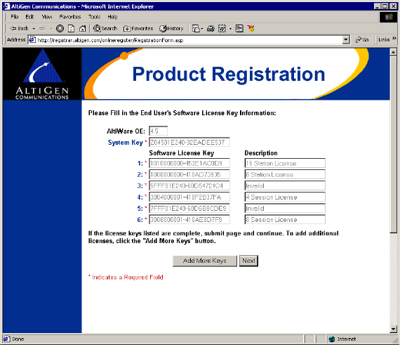
To Begin Upgrade
3-34 AltiContact Manager Administration Manual
Click Add More Keys to add more licenses, or click Next to register
these licenses.
Note: All keys are case sensitive.
10. The next web page displays the licenses that have been activated and
are about to be registered.
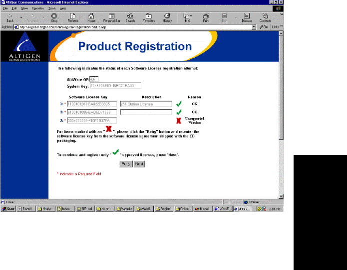
Software Installation
AltiContact Manager Administration Manual 3-35
3.Software
Installation
ã Approved licenses are indicated by a green check mark and will
display a description next to the approved license.
ã Invalid licenses are indicated by a red X mark.
Possible reasons for ãinvalidã licenses include:
a) obsolete licenses (such as unsupported OE 4.X licenses)
b) not enough digits in license number
c) wrong license number
d) license number registered to another system key
You may attempt up to three retries to validate licenses. If you click
Retry on the fourth attempt, the Web Registration will not continue
and you must begin the Web Registration process again from Step 5.
Click Next to continue.
11. The next web page displays the final results of the license activation to
show which licenses have been validated. Click Submit to continue.
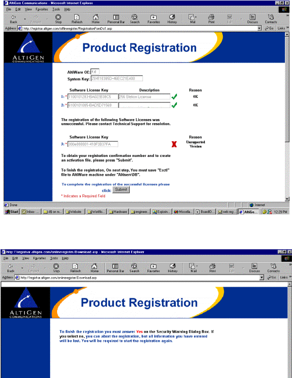
To Begin Upgrade
3-36 AltiContact Manager Administration Manual
12. The next web page continues the registration by initiating a product
registry program.
At the Security Warning prompt, click Yes to install and run the
program. If you click No or close this box, the Web Registration will
not continue and you must begin the Web Registration process again
from Step 5.
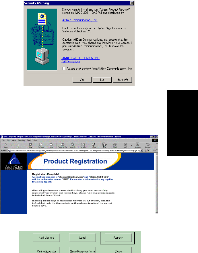
Software Installation
AltiContact Manager Administration Manual 3-37
3.Software
Installation
Setup will create or update an ãexctlã file in \altiserv\db\.
13. The final web page displays a verification notice and number,
confirming that an email of the registration process results has been
sent to the customer and installer. Save the email for future reference.
You may close this web page.
14. Return to the AltiContact Manager system. In the License
Information window, click the Refresh button.
The licenses that have just been validated will appear in the license
field, along with an accompanying Registration Key number and
Description of the license.
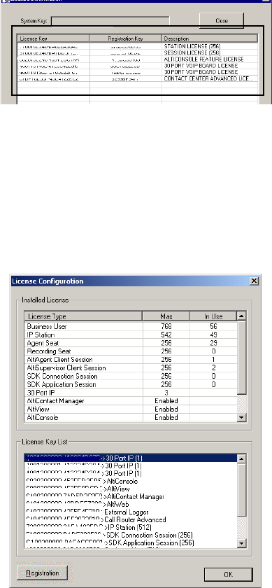
To Begin Upgrade
3-38 AltiContact Manager Administration Manual
15. Close the License Info window to finish the license registration.
Manual Online License Registration Procedure
To manually register any license through online registration,(wherethe
local AltiContact Manager system has no Internet connection), follow these
steps:
1. From the About AltiContact Manager window in the local ACM
Admin,clickontheLicense Information button.
2. Click the Registration button to open a new License Information
window.
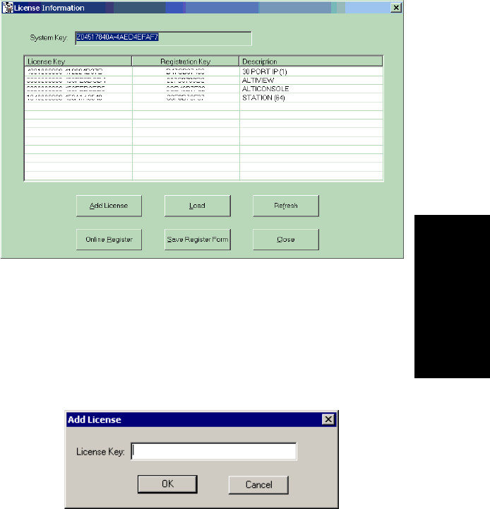
Software Installation
AltiContact Manager Administration Manual 3-39
3.Software
Installation
3. <Optional - you may add licenses here OR during online registration.
Skip to Step 5 if you wish to add licenses later.>
Click Add License to add the license keys that you wish to add and
activate. (License keys are located on the End User License Agreement
sent with every License purchase.)
4. In the License Key field of the Add License pop-up window, enter the
license key and click OK.
Continue adding licenses with the Add License button until all
licenses are entered.
5. Click Save Register Form to save registration information as a
Register.htm file and copy to a floppy disk, or a shared file location
that can be accessed by the destination system.
6. From any PC with an Internet connection, open the Register.htm file.
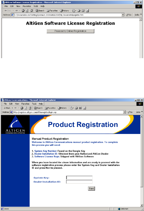
To Begin Upgrade
3-40 AltiContact Manager Administration Manual
7. On the AltiGen Software License Registration web page, click the
Proceed to Online Registration.
8. The next web page allows for inputting System and Dealer Installation
ID. In the System Key field, enter your System Key (located on the
End User License Agreement). In the Dealer Installation ID field,
enter the ID number assigned to your Dealer. This information can be
obtained by contacting either your local authorized AltiGen Dealer or
AltiGen Technical Support.
Click Next when finished.
9. The next web page allows for inputting of Customer and Installer
information.
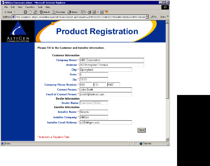
Software Installation
AltiContact Manager Administration Manual 3-41
3.Software
Installation
For the Customer Information and Installer Information sections, fill in
all fields (required) and click Next when finished.
10. The next web page allows for entering of new License Keys or for
adding any additional licenses.
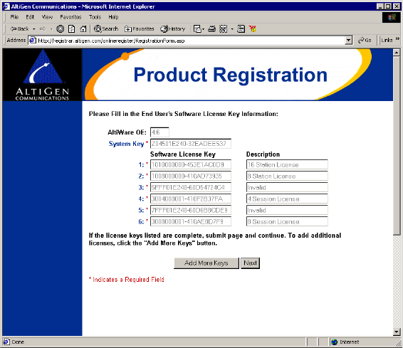
To Begin Upgrade
3-42 AltiContact Manager Administration Manual
Click Add More Keys to add more licenses, or click Next to register
these licenses.
11. The next web page displays the licenses that have been activated and
are about to be registered.
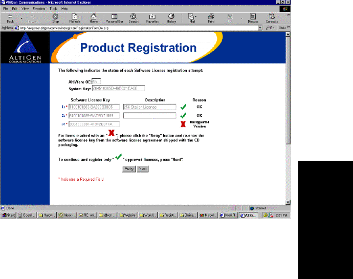
Software Installation
AltiContact Manager Administration Manual 3-43
3.Software
Installation
ã Approved licenses are indicated by a green check mark and will
display a description next to the approved license.
ã Invalid licenses are indicated by a red X mark.
Possible reasons for ãinvalidã licenses include
a) obsolete licenses (such as unsupported OE 4.X licenses)
b) not enough digits in license number
c) wrong license number
d) license number registered to another system key
You may attempt up to three retries to validate licenses. If you click
Retry on the fourth attempt, the Web Registration will not continue
and you must begin the Web Registration process again from Step 5.
Click Next to continue.
12. The next web page displays the final results of the license activation to
show which licenses have been validated. Click Submit to continue.
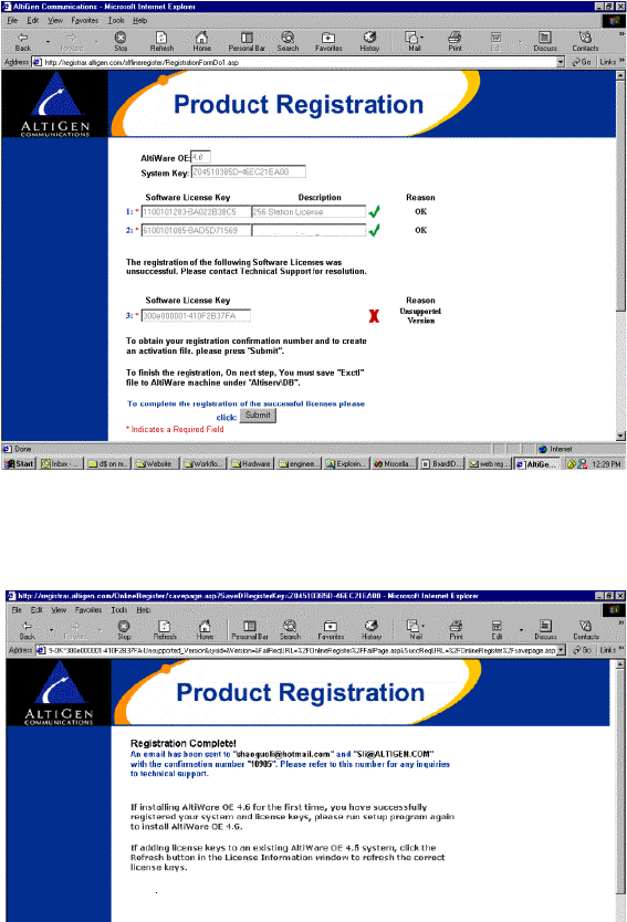
To Begin Upgrade
3-44 AltiContact Manager Administration Manual
13. The next web page continues the registration by initiating a product
registry program.
14. At the end of the Web Registration, save the exctl file to a floppy disk.
15. Return to the AltiContact Manager machine. In the License
Information window, click the Load button and to load the exctl file
from floppy into the AltiContact Manager system.

Software Installation
AltiContact Manager Administration Manual 3-45
3.Software
Installation
16. Click Refresh to update the License Information window. Any
newly activated licenses through web registration will appear in the
license field.
Offline Registration Procedures
To register licenses through the Web (without ACM Admin), go to the
following web URL: http://registrar.altigen.com/offlineregister/
login.asp. Then follow the online registration process (page 3-39)
beginning with Step 6.
Windows Emergency Repair Disk
After installing AltiContact Manager, you should create the Windows
Emergency Repair Disk, even if you have previously created a repair disk.
This repair disk is needed to repair any corrupted Windows files.
ã To create the disk on NT, choose Run from the Windows NT Start
button and type rdisk at the prompt.
ã For Windows 2000, use the Accessories System
Tools Backup utility program and select Create an Emergency
Repair Disk from the Tools menu.
Installing ACM Administrator on Remote
Systems
ACM Administrator contains the AltiContact Manager Administrator
application that can be installed on any Windows NT Server or
Workstation 4.0 system with Service Pack 6a (or higher), or Windows
2000 and a network connection. ACM Administrator does not support
Windows 95/98.
When you install ACM Administrator on a machine that is not an
AltiContact Manager server, it does not contain the switching, SMTP/
POP3 server, messaging agent, AltiBackup, Exchange integration services
that are included in the full AltiContact Manager installation described
above. Remote ACM Administrator does not utilize the System Data
Management or Shutdown Switching Service functions on the AltiContact
Manager system.

Running ACM Administrator
3-46 AltiContact Manager Administration Manual
ACM Administrator provides the ability to manage the AltiContact
Manager system from a remote client system on the LAN. If there is no
firewall on the LAN where AltiContact Manager resides, ACM
Administrator can be installed and used to manage AltiContact Manager
over the Internet from a remote site as well.
To install ACM Administrator on a non-AltiServ PC for the first time:
1. Insert the AltiContact Manager CD-ROM into the appropriate drive.
2. Run SETUP.EXE from the ACM Admin folder.
3. Follow the instructions on the window.
4. To open ACM Administrator, refer to ãRunning ACM Administratorã
on page 3-46.
Running ACM Administrator
To run AltiContact Manager Administrator:
1. Choose Programs from the Windows NT Start button and click on
ACM Administrator in the AltiContact Manager or ACM Admin
folder.
2. If you are opening ACM Administrator, enter the server name when
prompted. If you are logging into ACM Administrator at a remote site
to administer AltiContact Manager over the Internet, enter the IP
address (e.g. 100.100.100.100) of the AltiContact Manager system
when prompted for the server name. Multiple AltiContact Manager
systems can be managed at a single location with an ACM
Administrator open for each AltiContact Manager system.
3. LoginbySelectingtheServices Login or clicking the
Login iconãthe left-most icon in the Toolbar. The Login
Password window prompts you to enter the password and
click OK. The system default password is ã22222.ã You should
change the system password as soon as possible to ensure system
security. For more information, refer to ãLogging in for the First
Timeã on page 4-1.
Once you are logged in, you can configure the AltiContact Manager
system.

Software Installation
AltiContact Manager Administration Manual 3-47
3.Software
Installation
Shutting Down AltiContact Manager when
Changing or Adding Hardware
When you add or change hardware, follow these procedures to back up and
shut down the AltiContact Manager system. The best time to do this is
during off hoursãthe system should be idle.
1. Using the ACM Administrator application System Data Management
function, backup the AltiContact Manager data, messages, and custom
files using the procedures in the chapter on ãSystem Data
Management.ã
2. In ACM Administrator, shutdown the AltiGen Switching Service and
exit ACM Administrator, as described in ãShutting Down Switching
as a Windows 2000 / NT Serviceã on page 3-19.
3. Shut down and power down the Windows 2000 / NT system using the
standard Windows shutdown procedure.
4. After adding or removed hardware, it is recommended to run MVIP
test from Start>AltiContact Manager>ACM Tools>MVIP test.
Transferring the AltiContact Manager to
Another Server Chassis
If you transfer the AltiContact Manager system to another platformãfor
example, to upgrade or expand your system or for other reasonsãyou need
to backup the database, move the telephony boards, install the AltiContact
Manager software, and restore the database to the new platform.
The new platform should have accessvia a LAN to the system to which you
backed up the files from the old platform.
To transfer the system to another platform:
1. Back up the system files, then shut down and unplug the AltiContact
Manager system computer, following the steps listed in ãShutting
Down AltiContact Manager when Changing or Adding Hardwareã on
page 3-47.
2. Remove the computer cover, following the computer manual
instructions.
3. Disconnect the MVIP internal data cable.

AltiContact Manager Uninstall
3-48 AltiContact Manager Administration Manual
4. Label and disconnect the DB-25 to 50 pin Telco cable(s) from the
board I/O connectors.
5. Remove the telephony board(s) from the original system.
6. Install the board(s) into the new system.
7. Install the system key to the parallel or USB port.
8. Install the AltiContact Manager software as described, beginning with
ãPreparing to Install AltiContact Managerã on page 3-2.
9. Restore the AltiContact Manager system database as follows:
a. Run AltiAdmin and select Services System Data
Management to run the data management utility.
b. Click the Restore icon to open a dialog that allows you to choose
files to restore.
c. Make sure all the Component check boxes are selected.
d. In the Restore From drop-down list, select the drive and directory
to which you backed up the files in Step 1.
e. Click OK to start the restore.
f. Once the restore is complete, click the Exit icon to exit the data
manager.
g. Shut down and exit the system by selecting Shutdown Switching
from the Services menu.
10. Reboot the system, then run the MVIP test.
11. Reboot the system.
AltiContact Manager Uninstall
To back out the upgrade, be sure to stop all AltiContact Manager-related
services before uninstallation. To do this, run AltiAdmin, log in, and select
Shutdown Switching from the Services menu.
In the event that the auxiliary services were not stopped, stop them one at
a time using the Start Programs Administrative Tools
Services applet.
Then launch the Uninstall program by clicking the Uninstall AltiContact
Manager icon in the AltiContact Manager program folder. (Do not use the
Add/Remove program in Windows to remove AltiContact Manager; this
will not completely delete all necessary folders.)

Software Installation
AltiContact Manager Administration Manual 3-49
3.Software
Installation
Software Installation Troubleshooting
Use this table for troubleshooting error messages encountered during
software installation.
Error Message Solution
This version of AltiContact Manager
does not support Triton T1 Rev A2 or
VoIPRevA2boards.Pleaseunplug
these boards, then run setup again.
Unplug Triton T1 Rev A2 or VoIP Rev A2
boards, then run setup again.
Copy activation file failed. Activation file (exctl) is not in the specified
folder, is missing, or is corrupted. Make sure
you select the correct file folder where the
activation file is located and try again. If
problem persists, you can manually copy the
activation file to c:\AltiServ\db directory (if
AltiServ is installed on the c: drive) and run the
installation program again.
An error occurred during the move data
process.
Make sure all AltiGen applications and services
are stopped/closed before installing AltiContact
Manager.
Setup cannot detect your system key.
You must plug your system key into
either a parallel or USB port for
upgrading to AltiContact Manager.
Make sure your system key is fully inserted into
your parallel or USB port prior to installing
AltiContact Manager. If error persists, reboot
the system, then run setup again.
Setup has not detected your system key.
If you proceed the installation
WITHOUT the system key, only 8
physical ports will be available for use
after the AltiContact Manager
installation.
Make sure your system key is fully inserted into
your parallel or USB port prior to installing
AltiContact Manager.
Setup cannot append the AltiContact
Manager path because your existing
system environment is too long. You
must manually append the AltiContact
Manager path to your system
environment path after finishing
AltiContact Managerãs installation but
before restarting your system. You can
find the system environment path
through Control Panel>System
>Environment>path.
Manually append c:\AltiContact Manager\exe
(if AltiContact Manager is installed on c: drive)
to your system environment path (through
Control Panel>System >Environment>path)
after finishing AltiContact Managerãs
installation but before restarting your system.

Software Installation Troubleshooting
3-50 AltiContact Manager Administration Manual
Unable to add AltiContact Manager path
to the system.
Manually append c:\AltiContact Manager \exe
(if AltiContact Manager is installed on c: drive)
to your system environment path (through
Control Panel>System >Environment>path)
after finishing AltiContact Managerãs
installation but before restarting your system
Failed to upgrade AltiContact Manager
databases.
The previous database may be corrupted.
Restore the last, known working database and
try again. If error persists, contact your
Authorized AltiGen Dealer.
Error Message Solution

AltiContact Manager Administration Manual 4-1
4. Getting Around
ACM Administrator
C
HAPTER
4
Getting Around ACM
Administrator
AltiContact Manager Administrator
This section describes how to configure and administer the AltiWare
system using the AltiContact Manager application software.
The AltiContact Manager, or ACM, Administrator allows you to configure
sophisticated switching and messaging functions using windows that guide
you through the configuration steps for each feature.
ACM Administrator can be used at the AltiContact Manager system or on
any other system on the LAN for remote maintenance. On a remote
Windows NT or Windows 2000 client system on the LAN, ACM
Administrator allows control of one or more AltiContact Manager systems.
System Data Management, and Stop Switching Service cannot be
performed over the LAN.
Instructions for installing ACM Administrator are described in ãInstalling
ACM Administrator on Remote Systemsã on page 3-45.
Logging in for the First Time
To access AltiContact Manager functions to configure and administer the
AltiContact Manager system, you must first log in as an administrator. The
first time you log in, use the system default password, ã22222.ã
Important: To ensure system security, change the system password as
soon as possible. See ãChanging the Passwordã on page 4-11.
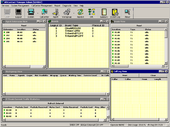
AltiContact Manager Administrator
4-2 AltiContact Manager Administration Manual
The AltiContact Manager Main Window
Once you run the Administrator, the first window you see is the AltiContact
Manager main window.
Figure 1. AltiContact Manager Administrator main window
At the top you see the Main Menu bar and below that, the Quick Access
Toolbar. At the bottom is a status bar that contains information on the
current runtime status.
The main window contains separate child windows, or different views of
the system. There are five default views: the boards, agent extensions,
trunks, workgroups and call log.
Additionally, if appropriate, you can also run a view of IP Trunk Traffic,
which is the 6th window, at the bottom in the above example.
Note: If using Windows XP for AltiContact Manager Administrator or
client applications, please note that for ACM Admin, the font that
appears in the title of the View Windows (Extension, Trunk, etc.)
is in the Windows 2000 style font and will appear small. To adjust,
change the Active Title font in Windows XP to Tahoma (or other
font).
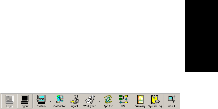
Getting Around ACM Administrator
AltiContact Manager Administration Manual 4-3
4. Getting Around
ACM Administrator
The Main Menu
The Main Menu functions are as follows:
ã Services
Login and logout, change password, utilities (System Data
Management and Convert Work/Hunt Group), and shutdown the
switching service.
ã System Management
Opens configuration windows to work with the system, huntgroups,
trunks, voice mail, VoIP, out call routing, and AltiGen IP Phone
configuration.
ã CallCenter Management
Opens configuration windows to work with Call Center, agent
extensions, workgroups, application extensions and IVR.
ãÂReport
System Summary, System Log, and IP Traffic Statistics.
ã Diagnostic
Reserved for use by authorized technical personnel.
ãÂView
Show, hide, or set default alignment of the windows, the toolbar, and
the status bar.
ãÂHelp
Online help and AltiContact Manager version and license information
Quick Access Toolbar
Figure 2. AltiContact Manager Quick Access Toolbar
The toolbar contains icons representing shortcuts to frequently accessed
functions. From left to right, the toolbar icons are as follows:

AltiContact Manager Administrator
4-4 AltiContact Manager Administration Manual
Logout and login. Click the light blue monitor at the left
to login. When you do, themonitor grays out and the logout
monitor at the right turns black. The monitors provide a
clear indication of login status. While youãre logged in,
anyone at the keyboard can modify system settings.
System. Opens the General Configuration window to set system-
wide options and parameters, the same function as System
Management General ConfigurationãÎ.
CallCenter. Opens the CallCenter Configuration window, the
same function as CallCenter Management CallCenter
ConfigurationãÎ.
Agent. Opens the Agent Configuration window, the same function
as CallCenter Management Agent ConfigurationãÎ.
Workgroup. Opens the Workgroup Configuration window, the
same function as CallCenter Management Workgroup
ConfigurationãÎ.
App Ext. Opens the Application Extension Configuration
window, the same function as CallCenter Management
Application Ext ConfigurationãÎ.
IVR. Opens the IVR Configuration window, the same function as
CallCenter Management IVR ConfigurationãÎ.
Summary. Opens the System Summary window, the same
function as Report System SummaryãÎ.
System Log. Opens the System Log window, the same function as
Report System LogãÎ.
About. Opens the About AltiContact Manager window, which
displays version, license and file information, the same function as
Help About AltiContact ManagerãÎ. Also, administrators
can add, activate and register licenses from this information window.
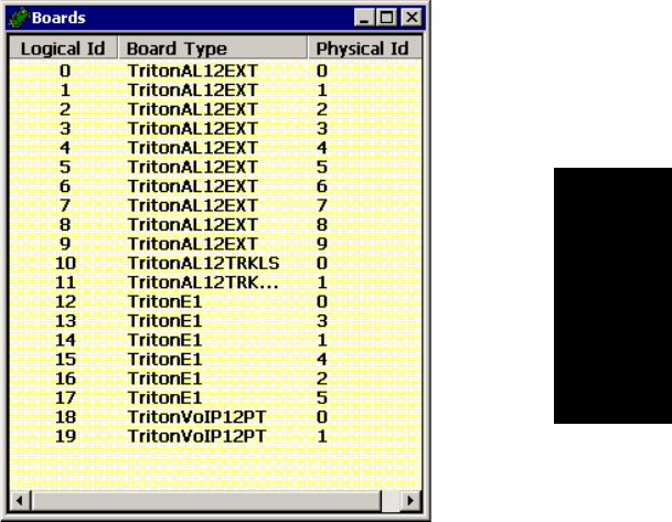
Getting Around ACM Administrator
AltiContact Manager Administration Manual 4-5
4. Getting Around
ACM Administrator
The View Windows
As noted in ãThe AltiContact Manager Main Windowã on page 4-2, the
AltiContact Manager main window hosts a number of child windows,
which are called view windows in AltiContact Manager because they
provide various views into the internal system setup and active status.
Boards View Window
The Boards window displays the AltiContact Manager Quantum or Triton
boards hardware status. It displays the card location in the ISA or PCI slots
and board model numbers.
Figure 3. Boards window
Each board is represented by the logical ID ([0], the sequential location of
the board), card model number (name of the board) and physical ID (the ID
set using the dial on the faceplate of the board). For example,
TritonVoIP12PT is a Triton board with 12 trunk ports.
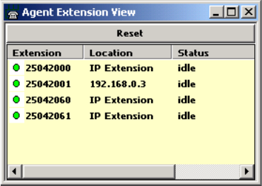
The View Windows
4-6 AltiContact Manager Administration Manual
Agent Extension View Window
The Agent Extension View window, which displays the status of all
assigned extensions.
Figure 4. Agent Extension View window
The radio button to the left of each extension number is green when the
extension is idle, and red when the extension is not ready or in use. The
Location number (i.e. 01:04) identifies the card ID and port (channel)
number on the board. For example, in location 01:04, the card ID is 1 and
the port number is 4. If an extension user with IP Extension enabled has
logged onto an IP extension, the location will show the static IP address you
have assigned. If you use dynamic IP addressing, this location will change
every time the user logs off and back onto an IP extension.
You can double-click any extension number to open the Extension
Configuration window for the selected extension.
The Reset button resets the selected extension to the idle status. When you
click the Reset button, a small dialog box opens, asking if you want to
continue with the reset and displays the selected extension number and the
name of the person assigned to the extension.
You can click the Reset button without selecting an extension, and then
type in the extension number for the extension to reset.

Getting Around ACM Administrator
AltiContact Manager Administration Manual 4-7
4. Getting Around
ACM Administrator
Trunk View Window
The Trunk View window displays the status of all assigned trunks.
Figure 5. Trunk View window
The radio button to the left of each trunk location is green when the trunk
is idle, and red when the extension is not ready or in use. The location
format is slot:channelãfor example, channel 3 on the board in slot 9 is
location 09:03.
You can double click any trunk location to open the Trunk Configuration
window for the selected trunk.
The Reset button resets the selected trunk(s) to the idle status. Youãll be
asked to confirm the reset and a status message will tell you if the reset was
successful. You can select and reset multiple trunks.
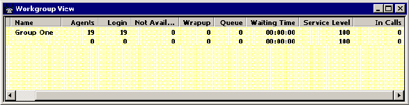
The View Windows
4-8 AltiContact Manager Administration Manual
Workgroup View Window
The Workgroup View window displays data and statistics for
workgroups:
Figure 6. Workgroup View window
This window displays the following data:
ãÂExtensionãthe workgroup pilot extension number
ãÂNameãthe workgroup name
ãÂAgentsãthe number of agents assigned to the workgroup
ãÂLoginãthe number of agents logged into the workgroup
ãÂNot Availableãthe number of agents who are currently on the phone,
or who are unavailable with the Do Not Disturb or other status
ãÂWrapupãthe number of agents who are in wrapup mode
ãÂQueueãthe number of calls waiting to be answered
ãÂWaiting Timeãthe average waiting period before incoming calls are
answered
ãÂService Levelãdisplays the percentage of calls being answered
within an acceptable period of time
ãÂIn Callsãdisplays the number of incoming calls to each workgroup
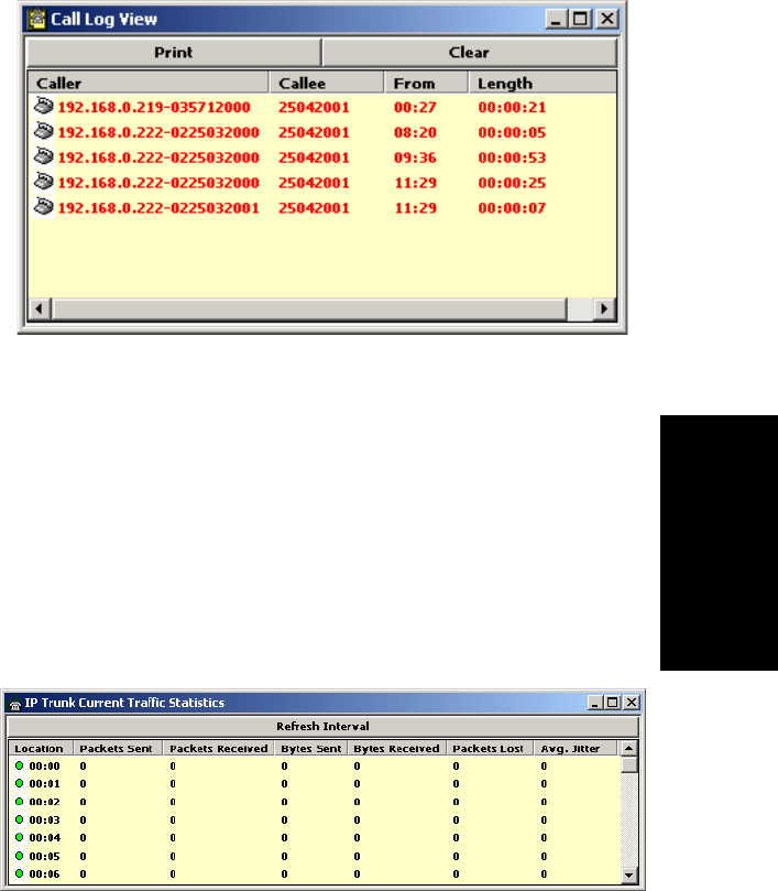
Getting Around ACM Administrator
AltiContact Manager Administration Manual 4-9
4. Getting Around
ACM Administrator
Call Log View Window
The Call Log View window displays the line and trunk traffic history.
Figure 7. Call Log View window
The window displays, for the last 30 calls, the caller line or number, the
callee, the starting time in 24-hour format and the length of the call.
You can select calls and click the Print button to print the selected log
entries for the call.
YoucanclicktheClear button to clear the window of all data.
IP Trunk Current Traffic Statistics Window
the IP Trunk Current Traffic Statistics window displays currently active
calls for IP trunks.
Figure 8. IP Trunk Current Traffic Statistics window
The packet and byte data that follows is for data sent or received from other
systems over the public or private IP network.
Logging In
4-10 AltiContact Manager Administration Manual
ãÂLocationãthe Triton VoIP board ID:channel ID
ãÂPackets Sentãthe number of voice packets sent
ãÂPackets Receivedãthe number of voice packets received
ãÂBytes Sentãthe total size (in bytes) of all voice packets sent
ãÂBytes Receivedãthe total size (in bytes) of all voice packets received
ãÂPackets Lostãthe number of voice packets that have been lost due to
prolonged delays, network congestion or routing failure
ãÂAverage Jitterãdisplays the average length of delay per voice packet
in milliseconds. This number can be used to measure the quality of
service on the network that connects the source and destination sites.
Under 100 milliseconds is good, while a higher figure indicates a
longer than average delay.
Status Bar
The information at the bottom of the window in the Status Bar displays
informational and status messages such as name of the operator, disk usage
status, status of external logging, current time, and other data.
Setting the Refresh Interval
The IP Trunk Current Traffic Statistics window is updated according to
the Refresh Interval configuration. By default, the Refresh Interval is set
to refresh the data in the window every 5 seconds. To change the refresh
interval, click the Refresh Interval button and use the slide rule to set the
time to an interval to a number of seconds up to one minute. Each tick on
the rule represents 5 seconds. To set the time to 0 is to turn off refreshing
the data.
Logging In
To log in and use the AltiContact Manager functions, click the Login icon
(the left-most icon in the toolbar) or select LoginãÎ on the Services menu.
Youãll be prompted to enter the password and click OK.
To log out, click the Logout icon (second icon from the left of the toolbar),
or select Logout from the Services menu.

Getting Around ACM Administrator
AltiContact Manager Administration Manual 4-11
4. Getting Around
ACM Administrator
The logout option in the Services menu allows the system administrator to
logout of the system. You should always log out after you have completed
the administrative or configuration tasks. This will prevent unauthorized
persons from accessing the AltiContact Manager configuration functions.
AltiContact Manager telephony functions continue to run in the
background on the ACM Administrator.
Changing the Password
Change the password frequently to prevent unauthorized access to the
system. You can change the password only if youãre already logged in.
Select Change Password from the Services menu to open a Change
Password dialog box. Youãll be prompted type in and verify the new
password and then click OK.
Stopping the AltiGen Switching Service
Normally, when you exit AltiContact Manager, the AltiGen services that
provide the various telephony and data services remain activeãthey are
needed to run the system, of course. If you need to shut the entire system
down, select the Stop Switching Service option from the Services menu.
This stops the AltiContact Manager system services, including the
AltiContact Manager application itself. When you re-open AltiContact
Manager, the switching services are reactivated.
This option is available when you are logged in at the AltiContact Manager
system computer; it is not available from a remote AltiContact Manager
client.
Stopping the AltiGen Switching Service
4-12 AltiContact Manager Administration Manual

AltiContact Manager Administration Manual 5-1
5. System
Configuration
C
HAPTER
5
System Configuration
The System Configuration functions provide for configuring the
AltiContact Manager system-wide settings.
Access System Configuration by selecting System Configuration... on the
System Management menu, by clicking the System icon, or using the
dropdown list next to the icon and going to System Configuration.
You can then work with the following settings, each of which is accessed
by a tab in the System Configuration window.
ãÂGeneral setupãsystem ID, area code and number, operator and
manager extensions, country, extension and DID number lengths,
distinctive ring, conference call, and system park options.
ãÂNumber Planãhow the system responds to each first digit dialed.
ãÂBusiness Hoursãused by system functions.
ãÂHolidayãhow calls are routed on designated holidays.
ãÂSystem Speed dial numbers.
ãÂCall Restrictionãprefixes to block, toll call prefixes and call control.
ãÂAccount Codeãtables for creating and removing account codes.
ãÂCall ReportsãCDR logging and data export.
ãÂTenantsãsharing an AltiContact Manager system among multiple
companies.
ãÂCountry Relevantãsettings for toll call prefixes, emergency
numbers and the TDM bus mode.
ãÂCT-BUS Clock ãsettings for the CT Bus Clock.
ãÂAudio Peripheral ãsettings for music on hold, system default
prompts and overhead paging.
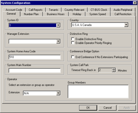
Setting General Parameters
5-2 AltiContact Manager Administration Manual
Setting General Parameters
The General tab is the default window you see when you open the System
Configuration window. You use this window to set the system area code
and number, operator extension, country, distinctive ring, conference call,
and system park options.
To access the General settings, select System Management... on the
Management menu, or click the System icon. If the System Configuration
window is already open, click the General tab.
Figure 1. General window, System Configuration
You can set the following parameters and options:
Parameter Description
System ID Assign a number (1-100) to the system.

System Configuration
AltiContact Manager Administration Manual 5-3
5.System
Configuration
Country Select a location for the system.
Note: When selecting a country code, other than
USA & Canada, there will be a 7 second
dialing delay for en-bloc trunks. (Refer to
ãReducing Dialing Delay For En-Bloc
Trunks For Non-US/Canada Countriesã on
page 10-9 for more detail.)
Manager Extension Type the system managerãs extension number.
The system manager has access to system
administrator functions.
For information on setting up extensions, see
Chapter 13, Agent Configuration.
Distinctive Ring Enables users to distinguish between internal,
external, and operator calls by the way the phone
rings:
ãÂEnable Distinctive Ringãestablishes a short
double ring cadence for internal calls and a
normal, single ring for external calls.
Unselected, both rings are normal.
ãÂEnable Operator Priority Ringingã
produces a long single ring between short
pauses on calls to the operator.
System Home Area Code Area code for the system location.
Conference Bridge
Option Selected, conference calls will end when all
internal lines have disconnected from the
conference bridge.
Not selected, the conference connection can
continue between outside parties, even after all
internal parties have disconnected.
System Main Number The main system telephone number, which is sent
to the pagerãs display when a userãs messaging
options are configured to call a pager. This is also
the number subscribers call to access the AltiGen
Voice Mail System.
Parameter Description
Setting a System Number Plan
5-4 AltiContact Manager Administration Manual
Setting a System Number Plan
The System Number Plan defines the extension digit length. You can use
from 3ã6 digits for extensions. You also use the System Number plan to set
a DID number length to use, and to define the system response to the first
digit dialedãfor example, pressing 9to get a trunk line.
The numbering scheme requires some thoughtful planning. You cannot edit
the extension length after the first extension is assigned. Further, if a first
digit dialed is assigned to extensions and you have set up extensions
beginning with that digit, you cannot change the digit assignment without
first deleting all affected extensions. For example, if 7is assigned to
Extension and youãre using extensions 7010, 7113, etc., you cannot
reassign 7to IP trunk access, without first deleting all the 7nnn extensions.
System Call Park
Timeout Ring Back in Allows the user to park a call, then pick up the call
from another extension, forward the call, or take
some other action. If the call is forgotten or the
forward not picked up, the Ring Back time sets the
number of minutes a call remains parked before
the userãs extension is rung again. To the caller,
the call park sounds like being put on hold.
Operator Extension and
Group Members Select the extension to be used by the system
operator. For the extension you select, the group
members show up in the Group Members box. For
further information on extensions, see Chapter 13,
Agent Configuration.
Parameter Description
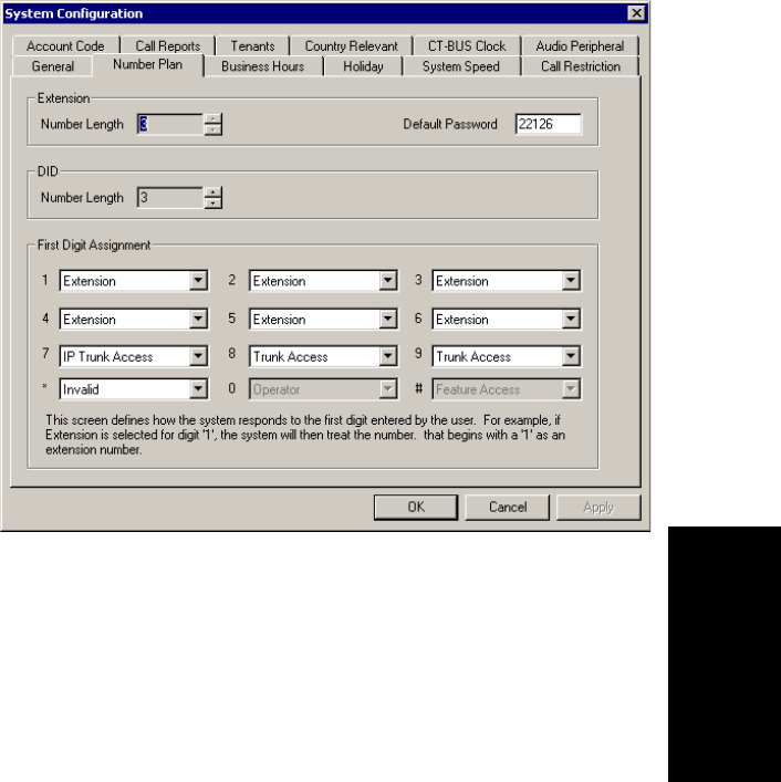
System Configuration
AltiContact Manager Administration Manual 5-5
5.System
Configuration
Accessing the Number Plan
To access the Numbering plan settings, select System Management... on
the Management menu, then click the Number Plan tab.
Figure 2. Number Plan window, System Configuration
Use the Number Plan window to specify the following parameters:
Parameter Description
Extension
Length The number of digits for your extension numbering system.
Valid entries are from 3ã6. For example, extension 2001
and 4020 are 4-digit extension numbers.
Note: The extension length is not adjustable once the first
extension is configured. To be more precise, the
length cannot be changed without totally
reconfiguring the system or deleting all the
extensions already configured.
Default
Password The default password for newly created extensions will be
randomly set; when changing the password, it must be four
to eight digits in length.
Setting a System Number Plan
5-6 AltiContact Manager Administration Manual
Assigning Trunk, Feature, IP Trunk, & Route Access
You can use trunk,feature,IP trunk,androute access outgoing call options
alone or in combination when making the number plan assignments.
DID Number
Length The number of digits needed to match a DID (Direct Inward
Dialing) number, with a range of 2 - 16.
Each extension can be assigned a DID number. A DID
number does not have a fixed length. For example, the DID
number length is 4; the extension DID number - 2529299.
Depending on the service contract with the Central Office
(CO), the DID trunk can send all 7 digits (2522999) or just
the last 4 digits (2999). If this DID Number Length option
is set to 4, the system always tries to match the last 4 digits
received to the last 4 digits of a DID number, regardless of
what is received.
Note: To accommodate future growth and minimize
disturbance, it is recommended that the length of the DID
numbers assigned to an extension be greater than or equal to
this DID Number Length. However, it is not necessary to
use the DID Number Length when routing via tie trunks.
First Digit
Assignment These define how the system responds to the first digit
dialed by the user. If a particular digit is grayed outãnot
availableãthat means it cannot be used in the country
location selected in the General window.
The drop-down list options for each digit are as follows:
ãExtension
ãTrunk Access
ãFeature Access
ãOperator
ãInvalid (no action)
ãIP Trunk Access
ãRoute Access
Parameter Description

System Configuration
AltiContact Manager Administration Manual 5-7
5.System
Configuration
Trunk Access
Usually, 9is used as the analog or PSTN trunk access code, and AltiContact
Manager uses 9 as the default for trunk access. You can keep that
configuration and assign other digits such as 7or 8to Route Access and IP
trunk access, or you can change it. There are no defaults for IP trunk or
Route Access.
Feature Access
By default, the first digit assignment for #is set to Feature Access, which
is used as part of feature access codes. In addition, you may also set 1-9or
*to Feature Access. For example, if 7is set to Feature Access, Station
Login (#27) can also be accessed using 727.
IP Trunk Access
Only one IP trunk access option is allowed per AltiContact Manager
system. It is highly recommended that the same IP trunk access code (e.g.
8) be used for all AltiContact Manager systems in the network. To use
Voice over IP, you must set up this access and, in addition, configure the
IP Dialing Table as discussed in ãDefining the IP Dialing Tableã on page
9-2 and set the VoIP codecs as discussed in ãSetting VoIP Codecsã on page
9-5.
Note: After setting the IP Trunk Access code here, you should set the
Trunk Access Codes of any 30-port VoIP boards to ãNoneã on the
General tab of the Trunk Configuration window (see ãSetting
General Trunk Attributesã on page 7-3). This will prevent users
from directly accessing the 30-port boardsãwhich use the G.711
codec onlyãfor calls to AltiContact Manager servers or other IP
gateways that may require the G.723 codec. If you still want users
to have access to this trunk for outgoing calls, you can set it up
through Outcall Routing (see Chapter 10, Out Call Routing
Configuration).
Route Access
The Route Access option can be assigned to one or more digits, to route the
call per the out call routing table. Out call routing, which is sometimes
called ARS (Automatic Route Selection) or LCR (Least Cost Routing
without carrier rate table), is described in Chapter 10, Out Call Routing
Configuration.
Out call routing is designed to help 10-digit dialing, zoomerang dialing,
digit manipulation, and tie trunk hop-off dialing.
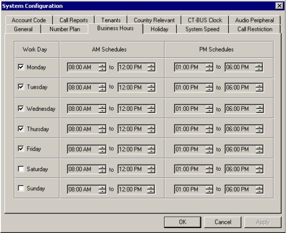
Setting Business Hours
5-8 AltiContact Manager Administration Manual
Note:
When making or editing these or other number plan assignments,
refer to the considerations on setting and editing discussed in
ãSetting a System Number Planã on page 5-4
.
Setting Business Hours
The Business Hours tab contains group boxes for setting the business hours
and days of the week for which the business or organization is in operation.
The business hours schedules are used to set other AltiContact Manager
settings such as trunk usage or routing DNIS calls to different extensions
depending on the time and day.
Note: Because the business hours are used throughout the system, you or
the appropriate administrator must make sure the system time
has been set correctly. The system time can be changed using the
Date/Time utility in the Windows or NT Control Panel.
To access the Business Hour settings, select System Configuration... on
the Management menu, then click the Business Hours tab.
Figure 3. Business Hours window, System Configuration

System Configuration
AltiContact Manager Administration Manual 5-9
5.System
Configuration
Set the business schedule parameters as follows:
Routing Calls on Holidays
You can create special routes for incoming DNIS and trunk calls that come
in on designated holidays. For holidays that your organization treats as
half-days, you can create separate routes for business and non-business
hours.
Note: Incoming DID and tie trunk calls will not follow holiday routes,
but go to the dialed extensions directly.
Parameter Description
Work Day Select the days of the week on which the company
does business. For example, if the company does
business Monday ã Friday, the check boxes for those
days should show check marks.
AM and PM
Schedules For each day of the week, select the time periods
during which the company is available for business.
The time between the AM and PM times can be used
to indicate a lunch break or time between shifts.
If you donãt want to set a break between AM and PM
schedules, set the PM starting time to be the same as
the AM ending time.
Or if you wish to specify 24 hours as standard
business hours, select the following hours:
AM Schedules:
From 08:00 AM
To 12:00PM
PM Schedules:
From 12:00 PM
To 08:00 AM
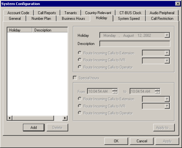
Routing Calls on Holidays
5-10 AltiContact Manager Administration Manual
To access Holiday routing settings, select System Management... on the
Management menu, then click the Holiday tab.
Figure 4. Holiday window, System Configuration
Set holiday routing as follows:
1. Click Add to create a new holiday. In the popup that displays, select a
date from the dropdown and enter a description to identify the holiday.
2. Set call routing for ãnormalã holiday hours using the field group in the
upperhalfoftheHolidaywindow.
This is the default route for calls coming in on the holiday.
3. Optionally, select Special hours and set call routing for special hours
using the field group in the lower half of the Holiday window.
This route will override the route for normal holiday hours, for the
hours you specify. Use this option, for instance, to route calls for the
working portion of a holiday that your organization treats as a half-
day.
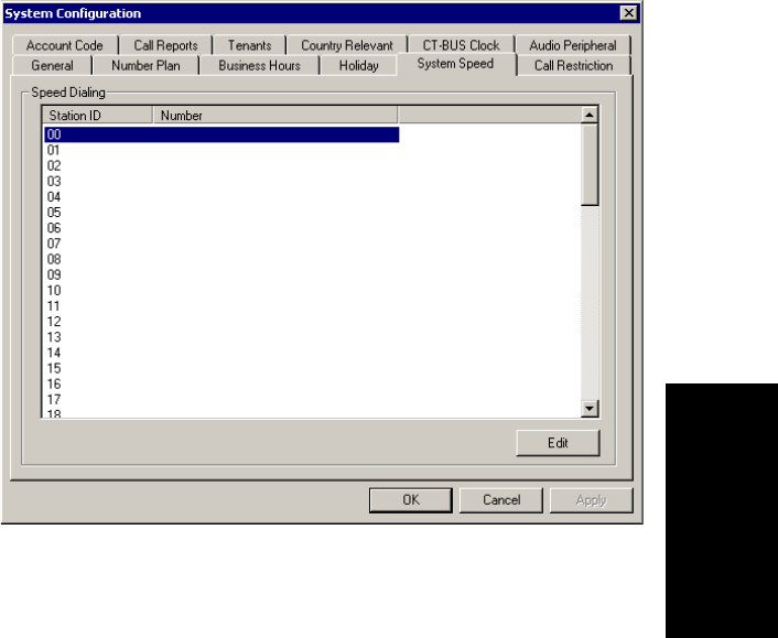
System Configuration
AltiContact Manager Administration Manual 5-11
5.System
Configuration
Configuring System Speed Dialing
You can set up to 60 system speed dial numbers. The numbers available are
from 00 ã 59, used following the system speed dial access code, #88.
Speed dial settings for individual extensions are set in Extension
Configuration. (See ãSetting up Station Speed Dialingã on page 13-17.)
To access the Speed Dialing settings, select System Management... on the
Management menu, then click the System Speed tab.
Figure 5. System Speed window, System Configuration
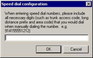
Defining System Call Restrictions
5-12 AltiContact Manager Administration Manual
Editing Speed Dial Entries
To add or edit an entry, double-click the Station ID number you want to
work with, or select the number and click Edit. A dialog box appears:
Type in the full number as you would dial it, with a maximum of 20 digits
per entry. For example, the phone number 914085551212 comprises of 9
(trunk access code), 1(long distance prefix), followed by 408 (area code),
and finally the seven digit telephone number.
Valid digits include 0through 9,#,*,and(,) comma. The comma
represents a one (1) second pause.
Adding Names and Comments
If you want to add names and comments for the usersã convenience, use the
following steps:
1. Configure the system speed dialing numbers as described in the
preceding procedure.
2. Open an AltiView user desktop and define the names and comments
for the speed dialing numbers.
3. Save the speed dial setup and Exit AltiView.
4. From the C:\Program Files\AltiGen\AltiView\<ext#>\, copy
sysspeedlist.dat directory to the same directory for every AltiView
user desktop.
Defining System Call Restrictions
Call Restriction allows you to block outgoing calls for up to 20 prefixes.
This window also provides for blocking all outgoing calls and for enabling
hop off to other trunks when that function has been set up.
The restrictions you set up here are global restrictions.
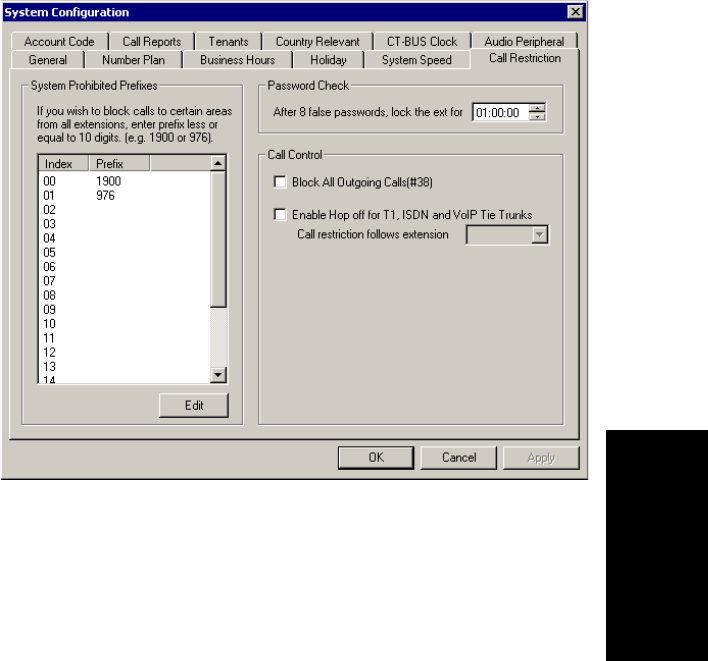
System Configuration
AltiContact Manager Administration Manual 5-13
5.System
Configuration
Note: The dialing restrictions set here are one of three ways of blocking
calls. See ãAbout Restricting Outgoing Callsã on page 10-1 for a
discussion of the uses of the different functions.
To access call restriction setup, select System Management... on the
Management menu, then click the Call Restriction tab.
Figure 6. Call Restriction window, System Configuration
Blocking Calls to Area Codes from All Extensions
To add or edit system prohibited area codes:
1. Double-click an index entry in System Prohibited Prefixes list, or
select the index entry and click Edit. This opens a dialog box that
allowsyoutoenteraprefixnumber.
2. Enter a 1and the dialing prefix to block (e.g. 900, 976). You can enter
up to 20 digits maximum for each prefix. For example, to block calls
from all extensions to 976 numbers, type 1976.
3. Click Apply.

Defining System Call Restrictions
5-14 AltiContact Manager Administration Manual
Locking Attacked Extensions
If a user enters eight consecutive invalid passwords when logging on,
AltiContact Manager considers this an attack. To protect your company
from theft of services, you can lock an attacked extension for the period of
time you specify (1-24 hours) in the Password Check field group.
To unlock an extension, use the Extension Checker tool that is installed
with AltiContact Manager. See ãExtension Checkerã on page 24-4.
Blocking All Outgoing Calls
To block all outgoing callsãfor example, when testing or modifying the
systemãselect the Block All Outgoing Calls check box.
Enabling Hop Off for Tie Trunks
When selected, this function allows calls over T1 tie trunks to use PSTN
trunks or other servers, when those trunks have been configured to accept
tie-trunk calls. For Hop Off to work, it must be enabled on all AltiContact
Manager systems on which trunk calls are able to be used as a transit
switch.
Figure 7. Hop Off for Tie Trunks
The trunk configuration to allow this function is discussed under ãSetting
General Trunk Attributesã on page 7-3.
The board must be configured to allow for tie trunks, as discussed in
ãConfiguring the Triton T1/PRI Boardã on page 6-30.
System BSystem A
Tie Trunk:
T1/PRI or VoIP
Outgoing
call on
PSTN Trunk
The call originating on System B hops off over the T1/PRI or VoIP trunk to use the PSTN
trunk in System A. Both System A and System B must be set up and configured to use
hop-off for tie-trunks.
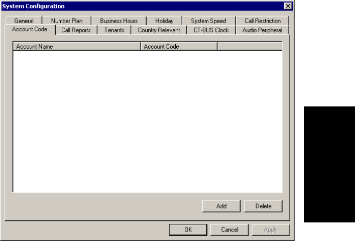
System Configuration
AltiContact Manager Administration Manual 5-15
5.System
Configuration
Restricting Tie Trunk Calls
You can set call restrictions on tie trunk calls by telling the system to use
the same restrictions as the ones set up for an extension. Using the Call
restriction follows extension drop-down list, you can select the extension
with the restrictions to use for the tie trunk calls.
Creating Account Codes
Account Codes let you enable or force users to assign incoming and
outgoing calls to particular account codes for billing, tracking, or
forecasting purposes.
To access the Account Code window, select System Management... on the
Management menu, then click the Account Code tab.
Figure 8. Account Code window, System Configuration
Adding and Deleting Account Codes
To create an account/code association, click Add. Enter an Account Name
and Account Code in the dialog box that appears.
Setting up Call Reports
5-16 AltiContact Manager Administration Manual
ã The Account Code may contain 1-10 digits.
ã You can assign the same Account Code to different Account Names.
To delete an account and its code, select it and click Delete. You can select
multiple items for deletion by using Ctrl-click or Shift-click. Click Apply
to save your changes and OK to save and close the window.
You can now set options for each extension that determine whether account
codes can be forced or bypassed. See ãEstablishing Basic Extension
Attributesã on page 13-4.
Setting up Call Reports
You can set up call reporting if AltiContact Manager and ACM
Administrator are installed on the same server.
In AltiContact Manager, call reporting distinguishes between call detail
data, which records every call made to, out of, and within the AltiContact
Manager system, and RTM data, which is workgroup-related statistical data
captured from the real-time monitoring function used in the AltiSupervisor
client application. Both types of data can be set up for call reporting, or
logging, although their storage systems are different.
ãÂCall detail data canbeloggedtoyourlocaldrive,toaremoteserver,
and/or exported via a COMM port.
ãÂRTM data is always logged to your local drive.
Data logged to your local drive is stored in a directory called AltiDB,which
is located by default on the root of the drive where Contact Manager is
installed. Files are stored in .mdb format.
Backups, if you choose to make them, are created in a subdirectory called
DBBackup, which in turn contains three subdirectories: MCDR for
Advanced Call Data, RTMCALL for Call Data, and RTMDATA for
RTM data. These three types of data have separate report screens in the
CDR Search client, and are described in the CDR documentation.
The CDR formats are described in ãCall Accounting Report Formatsã on
page A-1.
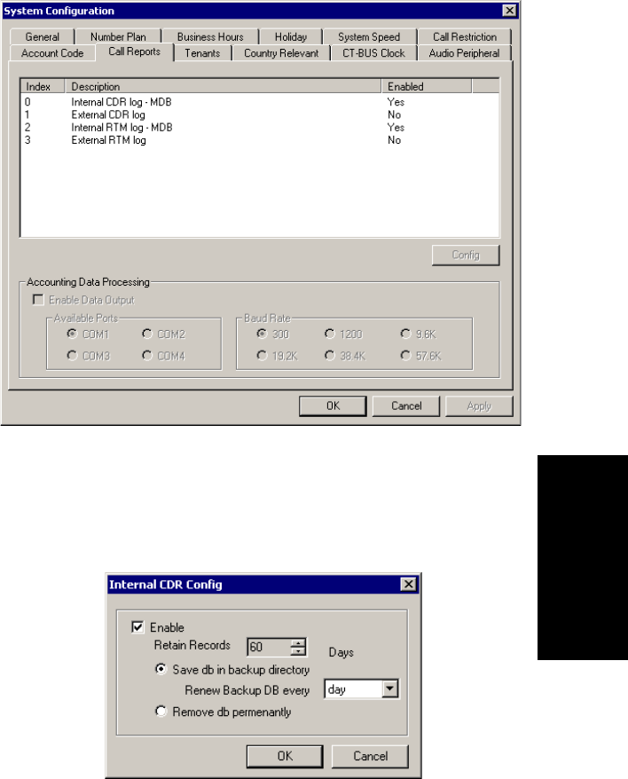
System Configuration
AltiContact Manager Administration Manual 5-17
5.System
Configuration
To set up Call Reports, select System Management... on the Management
menu, then click the Call Reports tab.
Figure 9. Call Reports window, System Configuration
Internal (Local) Logging of Call Data Data
To enable CDR collection to the local drive, select Internal CDR log -
MDB and click the Config button. A dialog box appears.
Figure 10. Enable local call data logging
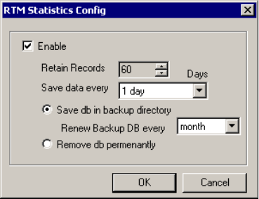
Setting up Call Reports
5-18 AltiContact Manager Administration Manual
To enable RTM data collection to the local drive, select Internal RTM
data - MDB and click the Config button. A dialog box appears.
Figure 11. Enable local RTM data logging
:
Parameter Description
Enable Check to enable internal (local) logging of call data.
Retain Records Select the number of days to retain records. This can
be any number of days from 1ã365.
Save data every
(RTM Statistics only) Specifies how often to save workgroup call data from
the real-time monitor. This setting, with intervals
ranging from 15 minutes to 1 day (24 hours),
provides the minimum level of granularity at which
RTM data (ãWorkgroup Statisticsã) will be reported
from the CDR Search client.
Save db in backup
directory Select to save backup files into the AltiDB
>DBBackup folder. Select a Renew option to specify
how often to save the backup files. AltiContact
Manager will save all data that overflows the Retain
Records limit each day at midnight, into a file of
format <yyyymmdd>.mdb.
Remove db
permanently Select to remove data after the Retain Records limit
is passed instead of backing it up. When the Retain
Records limit is reached, the oldest dayãs data is
removed permanently.

System Configuration
AltiContact Manager Administration Manual 5-19
5.System
Configuration
Example:
ãÂRetain Records is set to 60 days
ãÂSave db is selected
ãÂRenew Backup is set to every month
With these settings, on day 61 a backup file is started in the DBBackup
folder. Each dayãs call or RTM data is added to this file for one month. At
the end of a month, a new file is started in DBBackup, which is likewise
appended with each dayãs call or RTM data every day at midnight.
Backup files are dated and renewed according to the following schedule,
regardless of when you actually make the Renew selection.
External (Remote) Logging of Call Data
AltiContact Manager allows you to output call accounting to a Microsoft
SQL 7 or SQL 2000 database or to a third party external application.
In either case, the database cannot be on the same server as the AltiContact
Manager system. A system integrator or database developer will need to
write a custom query to extract data from the SQL database.
You can send reports from a number of different systems to the same
database.
Renew setting Renewal Dates
day daily, at midnight
week every Sunday
2 weeks the 1st and 15th of every month
month the first of every month
3 months December, March, June, September
6 months December and June
year January

Setting up Call Reports
5-20 AltiContact Manager Administration Manual
Note: Before you enable external logging using this window, you need to
set up and configure the database. It should be ready to receive the
reports before you enable the export here.
To enable CDR collection to the local drive, select External CDR log, and
click the Config button. A dialog box appears.
Figure 12. Enable external call data logging
:
Note: AltiGen does not provide any SQL backup and restore utility. We
strongly recommend that you use SQL Backup and Maintenance
utility to perform daily backup and maintenance jobs, and use a
restore utility to restore the database. If you need to reconstruct the
SQL server, run the External Logger Setup to create an empty
calldb database before restore.
Parameter Description
Enable Check to enable external (remote) logging of call
data.
Server Address Enter serverãs IP address.
Altigen External
Server Select to use AltiGenãs implementation of the
Microsoft SQL database.
Third Party External
Server Select to export the data to a third party application.
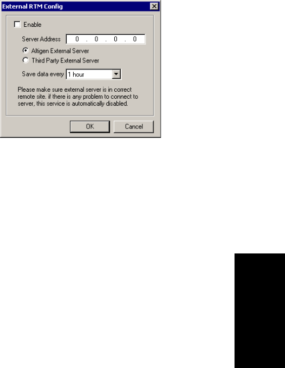
System Configuration
AltiContact Manager Administration Manual 5-21
5.System
Configuration
To enable RTM data collection to the local drive, select External RTM
log, and click the Config button. A dialog box appears.
Figure 13. Enable external RTM data logging
:
Exporting Through a Local Port
You can send the CDR to a COMM Port to export to, for example, an
accounting data processing system.
To do this, select the Enable Data Output box in the Accounting Data
Processing field group. Then select an Available Port and the Baud Rate.
Parameter Description
Enable Check to enable external (remote) logging of call
data.
Server Address Enter serverãs IP address.
Altigen External
Server Select to use AltiGenãs implementation of the
Microsoft SQL database.
Third Party External
Server Select to export the data to a third party application.
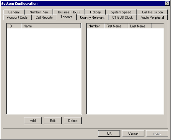
Using a Tenant Table
5-22 AltiContact Manager Administration Manual
Using a Tenant Table
If several small businesses or groups want to share an AltiContact Manager
system, specific trunks can be assigned so that each company or group has
its own set of extensions for outbound calling. Each business or group can
be set up as a tenant in AltiContact Manager, where you use the Tenants
window to define the tenants, their call restrictions and call tracking.
The tenant IDs are matched on the one hand to extensions and on the other
hand to trunks, so that extensions are matched to trunks, or, more precisely,
extension tenant IDs are linked to trunk tenant IDs. This configuration
eliminates the need to set up separate access codes for each tenant. Instead,
all extensions can dial the Route Access code for outbound calls.
For information on Route Access, see ãAssigning Trunk, Feature, IP
Trunk, & Route Accessã on page 5-6.
To access the Tenants window, select System Configuration... on the
Management menu, then click the Tenants tab.
Figure 14. Tenants window, System Configuration

System Configuration
AltiContact Manager Administration Manual 5-23
5.System
Configuration
Configuring the Tenant Table
Configuring the tenant table involves first adding entries to the tenant list,
then using Agent Extension Configuration and Trunk Configuration to
assign extensions and trunks, respectively, to tenant IDs.
To create tenant entries:
1. In the Tenant window, click the Add button to open a small Tenant
Configuration dialog box.
2. In the dialog box, type in the Tenant Name and click OK. Then click
the Apply button in the Tenant window. The tenant ID is assigned
automatically and sequentially.
3. Repeat the above steps for all the tenants you want to add, then click
OK to close the System Configuration window.
To assign extensions to tenant IDs:
1. Select Agent... on the Call Center Management menu to open the
Agent Extension Configuration General window.
2. For each extension you want to assign to a tenant ID:
a. In the Extension list, select and highlight the extension you want to
assign to a tenant ID. Each extension can be assigned to only one
tenant ID.
b. Select a tenant ID in the Tenant drop-down list under Personal
Information, then click Apply.
3. Repeat the previous step for each extension you want to assign. When
youãre done, click OK to close the Agent Extension Configuration
window.
To assign trunks to tenant IDs:
1. Select Trunk Configuration... on the System Management menu to
open the Trunk Configuration General window.
2. For each trunk you want to assign to a tenant ID:
a. In the trunk list, select and highlight the trunk you want to assign to
a tenant ID.
b. Select a tenant ID in the Tenant Selection drop-down list, then
click Apply.
Using a Tenant Table
5-24 AltiContact Manager Administration Manual
3. Repeat the previous step for each trunk you want to assign. When
youãre done, click OK to close the Trunk Configuration window.
Important: When creating Tenant entries for IP extensions, the IP trunk
must have the same Tenant Name assigned as the IP extension.
Modifying the Tenant Table
To delete a tenant from the tenant window:
Highlight the ID number and click Delete.
If you delete a tenant ID that has been assigned to an extension or to a
trunk, the extension and trunk assignments are reset to N/A (no
assignment).
To edit the tenant name:
Double-click the name in the Tenant window (or select the name and
click Edit), then change the name in the dialog box that appears.
To change the extension-to-tenant ID assignment:
Open the Agent Extension Configuration General window, as
discussed in the steps on the previous section under ãTo assign
extensions to tenant IDs:,ã and use the Tenant drop-down list to
change the tenant ID assigned to any extension.
If a tenant ID is already assigned, you must change or remove the
assignment from the old extension before you can assign it to a new
one.
Note: If an extension is assigned to N/A in the Tenant drop-down
list, the extension is able to access all trunks, even though the
trunks have been assigned to tenants.
To change the trunk-to-tenant ID assignment:
Open the Trunk Configuration General window and use the Tenant
Selection drop-down list to change the tenant ID assigned to any trunk.
Note: If a trunk is assigned to N/A in the Tenant Selection drop-
down list, the trunk is accessible to all extensions, even though
there are tenant assignments.
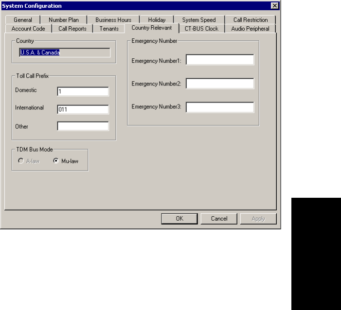
System Configuration
AltiContact Manager Administration Manual 5-25
5.System
Configuration
Country Relevant
The Country Relevant tab contains group boxes for setting toll call
prefixes, emergency numbers and the TDM bus mode.
The Country field displays the country selected in the General Page of
System Configuration.
:
Figure 15. Country Relevance window, System Configuration
Setting Toll Call Prefixes
AltiContact Manager uses the Toll Call Prefixes to determine the type of
outside call and imposes restrictions when necessary. For example, if the
international toll call prefix is 011 and a user attempts to make an
international call from an extension without international call privileges,
the call will be terminated as soon as the user dials 011 after the trunk or
route access number. The caller hears an error tone.
The toll prefixes set here should match the dialing plan prefixes for the
country set in the General window (see ãSetting General Parametersã on
page 5-2). You can set the following toll call prefixes.
CT-Bus Clock Configuration
5-26 AltiContact Manager Administration Manual
ãÂDomestic. The dialing plan for your country or region. For example,
type in a 1for 1-plus dialing within the U.S. dialing plan (also known
as the North American Numbering Plan).
ãÂInternational. The prefix used for international calls. For example,
this is 011 for international calls made in the USA.
ãÂOther. Flexible and variable uses, such as a string of digits to be
considered non-local.
Setting Emergency Numbers
In the event that a person dialing a number in an emergency (911, for
example) forgets to press the trunk access code to dial out, entering the
number in the Emergency Number field will have the system
automatically find the trunk access code to seize the call. You may enter up
to three (3) emergency numbers in the appropriate fields.
Note: When using this option, make sure your systemãs trunk access code
is available.
Setting the TDM Bus Mode
The TDM (Time Division Multiplexed) bus allows for routing data to be
carried at a steady rate. Depending on your T1/E1 trunk configuration, the
system will automatically select one of the following companding schemes
to optimize your systemãs TDM bus mode:
ãÂA-law - typical standard used in Europe
ãÂu-law - typical standard used in the U.S. and Japan.
CT-Bus Clock Configuration
The CT bus is a bit-serial, byte-oriented, synchronous TDM bus that uses a
bit clock for bit registration and a common frame sync pulse for frame
alignment. This ensures signal quality between the systemãs CT bus and the
boardsã signal processing resources.
Through the CT-Bus Clock Configuration window, you can set the CT
Bus clock.
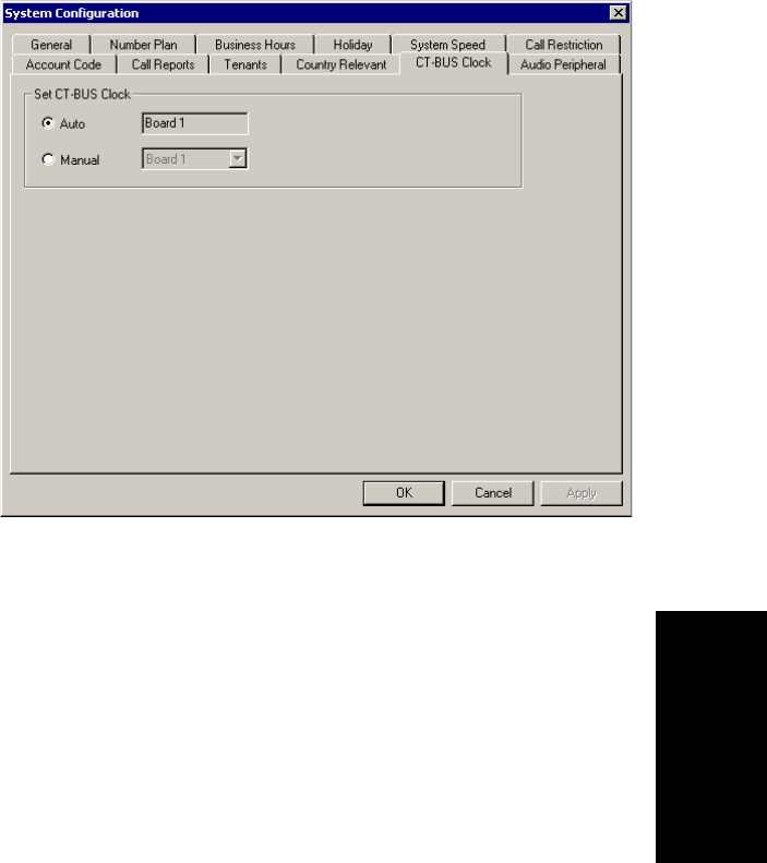
System Configuration
AltiContact Manager Administration Manual 5-27
5.System
Configuration
Figure 16. CT-BUS Clock Configuration window, System Configuration
ãÂSet CT-BUS Clock - select Auto or Manual to identify the
appropriate board that will serve as the CT-Bus Clock master.
Audio Peripheral Configuration
The Audio Peripheral configuration window is used to set up:
ã Music-On-Hold
ã System Default Beginning and Update Prompts for Callers in Queue
ã Overhead Paging
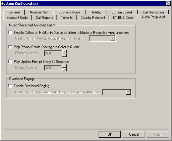
Audio Peripheral Configuration
5-28 AltiContact Manager Administration Manual
To access Audio Peripheral configuration, select System
Configuration... on the Management menu, then click the Audio
Peripheral tab.
Figure 17. Audio Peripheral Configuration window, System Administration
Configuring Music On Hold and Recorded
Announcements
Callers will hear the music or recorded announcement configured in Audio
Peripheral configuration only if the user places the caller on hold by
pressing FLASH or LINK. If the user presses HOLD (except on the Alti-
IP 600), the caller hears nothing.
To configure music on hold:
1. Open the Audio Peripheral configuration window as discussed in the
previous section.
2. Select the check box, Enable Callers on Hold or in Queue to Listen
to Music or Recorded Announcement.
3. Select the Quantum or Triton Analog Station board number to which
the audio equipment is attached.
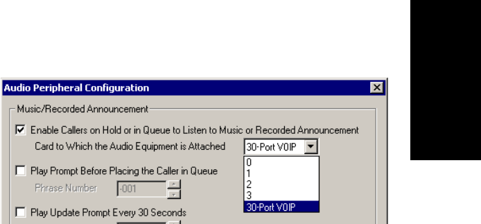
System Configuration
AltiContact Manager Administration Manual 5-29
5.System
Configuration
Playing Music from a File for Music On Hold
The system can be set up to play music on hold from a custom file (and
replaces the systemãs default music on hold file). This file is located at
\altiserv\phrases\Music\MusicOnWaiting.
Notes:
ã A 30-port IP Board is required
ã There can only be ONE system default Music On Waiting file, which
must be in 32K AltiGen ADPCM format.
ã The default music on hold file can be replaced with AltiGenãs ADPCM
format. To convert a .wav file to AltiGen ADPCM format, run
wav2alt.exe (available at AltiGenãs web site). Once the .wav file is
converted, rename the file to ãMusicOnWaitingã and replace the
default music file with this one.
To play music from a file:
1. Make sure a 30-Port IP board is installed in the system.
2. Stop AltiGen Switching Service.
3. Replace the MusicOnWaiting file located at
c:\altiserv\Phrases\Music with the desired file.
4. In the Audio Peripheral Configuration window, select the Enable
Callers on Hold or In Queue to Listen to Music or Recorded
Announcement check box and use the drop-down list to select the 30-
Port IP board.
5. Restart AltiGen Switching Service.
Audio Peripheral Configuration
5-30 AltiContact Manager Administration Manual
Setting Greeting and Update Prompts
To play a prompt before placing the caller into a hold queue:
1. Select the Play Prompt BeforeãÎ checkbox.
2. Use the drop-down list to select the prompt number you want to use for
the greeting message. (Creating prompts is discussed in previous
sections.)
To play an update prompt every thirty seconds:
1. Select the Play Update Prompt ãÎ checkbox.
2. Use the drop-down list to select the prompt number you want to use for
the greeting message.
Configuring Overhead Paging
To configure overhead paging:
1. Connect overhead paging equipment to a Quantum board audio out
jack or Triton Analog Station board audio in jack.
2. Access the Audio Peripheral configuration window and select Enable
Overhead Paging.
Use the drop-down list to select the Quantum or Triton Analog Station
board to which the overhead paging is attached.
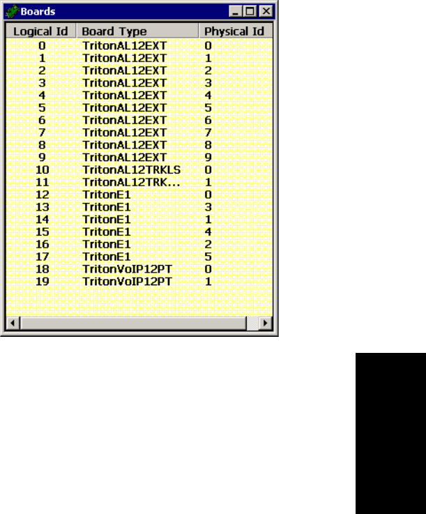
AltiContact Manager Administration Manual 6-1
6. Board
Configuration
C
HAPTER
6
Board Configuration
Board attributes and functions are accessible in the Boards window in the
AltiContact Manager desktop.
Figure 1. Board window
For the board you want to configure, double click the boardãs icon in the
Boards windowtoopentheBoard Configuration window.
Important: To implement some board configuration changes, you must
shutdown and restart AltiGen Switching Services by first
choosing Shutdown Switching on the Services menu, which
also closes AltiContact Manager, and then restarting
AltiContact Manager.
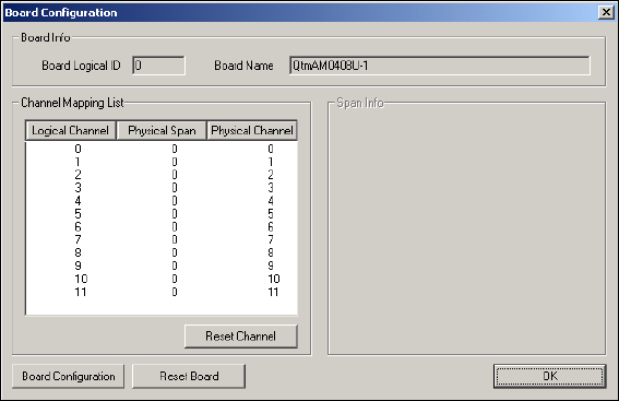
Using the Triton Resource Board
6-2 AltiContact Manager Administration Manual
Using the Triton Resource Board
The Triton Resource Board is a PCI bus telephony board that provides the
ability for one extension to monitor other extensions (as set up in the
Extension Configuration Monitor List, discussed in ãSetting Up Monitor
Listsã on page 13-35), and the barge-in ability. The Resource Board
requires no complex configuration; you install it and run it. The Board ID
must be the range of 0 to 15, and each AltiContact Manager system
supports a maximum of 2 boards.
Once installed and the system powered up, the board is displayed in the
Board View window on the AltiContact Manager desktop, and you can use
the barge-in and silent monitoring features without further board
configuration.
Without the Resource Board installed, supervisors will hear an error tone if
they try to perform a monitoring or barge-in operation.
Configuring the Quantum Board
Double click the boardãs icon in the Boards windowtoopentheBoard
Configuration window.
Figure 2. Board Configuration window (Quantum Board)

Board Configuration
AltiContact Manager Administration Manual 6-3
6. Board
Configuration
Use the Board Configuration window for the Quantum board to view the
following attributes:
Parameter Description
Board Info Board Logical ID: assigned by AltiContact
Manager.
Board Name: the type of board installed in the
system and board ID.
Note: For Quantum boards in a Windows 2000
system:
ãÂthe physical board ID 0 is not supported
ãÂthe valid physical board IDs are 1ã15
Channel Mapping
List Logical Channel,Physical Span,andPhysical
Channel for the entire board.
To reset the channel, select the channel to reset and
click the Reset Channel button, then click OK.
Note: Depending on whether the channel is a line or
a trunk line, double clicking a channel in this
window invokes either a Line Properties
window (see ãQuantum Line Propertiesã on
page 13-10, or a Trunk Line Properties
window (see ãQuantum Trunk Propertiesã on
page 7-6).
Span Info Not available for Quantum boards.
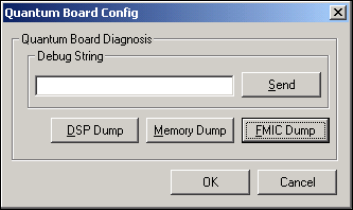
Configuring the Triton Analog Station Board
6-4 AltiContact Manager Administration Manual
Configuring the Triton Analog Station Board
Double click the boardãs icon in the Boards windowtoopentheBoard
Configuration window.
Board Configuration Opens a diagnostic dialog box.
Figure 3. Quantum Board Debug
You can send a debug string to the board, or you can
do a DSP Dump, Memory Dump, or FMIC Dump.
Reset Board Resets the board, after you confirm by accepting a
warning that resetting a board will disconnect all
calls in progress on that board.
Important: Be sure to inform all users before
resetting a board.
Parameter Description
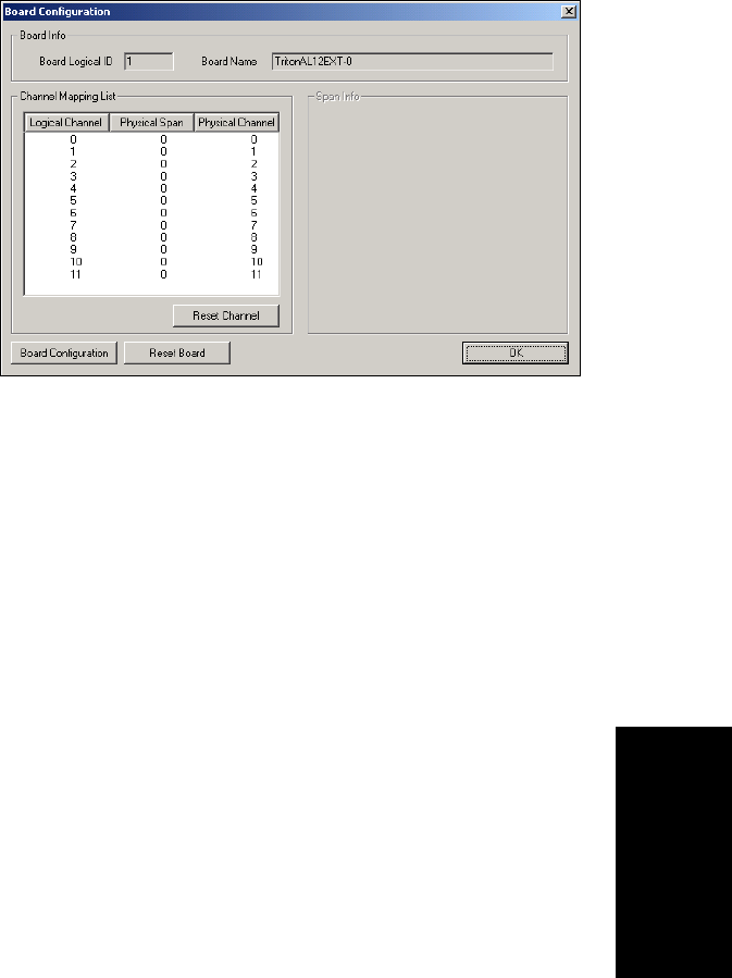
Board Configuration
AltiContact Manager Administration Manual 6-5
6. Board
Configuration
Figure 4. Board Configuration window (Triton Analog)
Use the Board Configuration window to view the following attributes:
Parameter Description
Board Info Board Logical ID: assigned by AltiContact
Manager.
Board Name: the type of board installed in the
system and board ID.
Note: This is informational only and cannot be
edited.
Channel Mapping
List Shows the board Logical Channel,Physical Span,
and Physical Channel.
To reinitialize channels, select the channel to reset
and click the Reset Channel button, then click OK.
Note: This is informational only and cannot be
edited.
Note: Double clicking a channel in this window
invokes a channel configuration window.
Refer to the Line Properties button in
Extension Configuration.See ãTriton Analog
Station Line Propertiesã on page 13-11.
Span Info Not available for Triton Analog Station boards.

Configuring the Triton Analog Trunk LS/GS and LS Boards
6-6 AltiContact Manager Administration Manual
Configuring the Triton Analog Trunk LS/GS and
LS Boards
The Triton Analog Trunk board is a long form factor PCI telephony card
that supports 12 trunks, and is available in two models; loop start/ground
start (LS/GS) and loop start (LS). Both models have the same features
regarding LS. The LS/GS board is required when ground start trunks may
be required.
Double click the boardãs icon in the Boards window (see Figure 1) to open
the Board Configuration window.
Figure 5. Board Configuration window (Triton Analog Trunk)
Board Configuration Displays the boardãs serial number.
Reset Board Resets the board, after you confirm by accepting a
warning that resetting a board will disconnect all
calls in progress on that board.
Important: Be sure to inform all users before
resetting a board.
Parameter Description

Board Configuration
AltiContact Manager Administration Manual 6-7
6. Board
Configuration
The Board Configuration window contains the following attributes:
Configuring the Triton VoIP Board
Important: It is strongly recommended that system administrators review
the ãNetwork Configuration Guidelines for VoIPã on page 9-8
before setting up VoIP features.
Parameter Description
Board Info Group Board Logical ID: assigned by AltiContact
Manager.
Board Name: the type of board installed in the
system and board ID.
Note: This is informational only and cannot be
edited.
Channel Mapping
List Group Shows the board Logical Channel,Physical Span,
and Physical Channel.
To reinitialize channels, select the channel to reset
andclicktheReset Channel button, then click OK.
Note: This is informational only and cannot be
edited.
Note: Double clicking a channel in this window
invokes a channel configuration window. See
ãTriton Analog Trunk Propertiesã on page 7-
9.
Span Info Not available for Triton Analog Trunk LS/GS and
LS boards.
Board Configuration Displays the boardãs serial number.
Reset Board Resets the board, after you confirm resetting by
accepting a warning.
Important: Resetting a board will disconnect all
calls in progress on that board! Be sure
to inform all users before resetting a
board.
Configuring the Triton VoIP Board
6-8 AltiContact Manager Administration Manual
Voice over IP for AltiWare OE
VoIP for AltiContact Manager runs on an H.323 platform that allows voice
calls to be made through an IP network. It includes an integrated VoIP
gateway to convert voice calls into IP packets and transmit them through
the IP network. It also has the capability of networking multiple
AltiContact Managers into a virtual PBX network. This enables calls to be
made through the IP network, which allows for significant savings in toll
charges.
Triton VoIP Board
The Triton VoIP board is used to provide voice processing resources for
AltiContact Manager, similar to the way Quantum telephony boards are
used for analog trunks and extension lines. Unlike the Quantum telephony
boards, however, only IP trunks are provided on the Triton VoIP board.
AltiContact Manager VoIP uses DSP engines residing on the Triton VoIP
board to perform the voice processing functions needed for H.323 devices.
Quantum and Triton boards are connected via MVIP connectors.
The Triton VoIP board is available as a 12-port and 30-port board.
Important: Triton 30-port VoIP boards are recommended for use with IP
extensions only or for tie-trunk configurations to other 30-port
VoIP boards. Additionally, to prevent users from directly
accessing the 30-port boardsãwhich use the G.711 codec
onlyãfor calls to AltiWare servers or other IP gateways that
may require the G.723 codec, it is recommended that the trunk
access code is set to ãNoneã for trunks on 30-port IP boards.
(See ãSetting General Trunk Attributesã on page 7-3for more
detail on setting access codes.) If you still want users to have
access to this trunk for outgoing calls, you can set it up through
Outcall Routing (see Chapter 10, Out Call Routing
Configuration).
Features
The following features are automatically enabled during AltiContact
Manager installation.
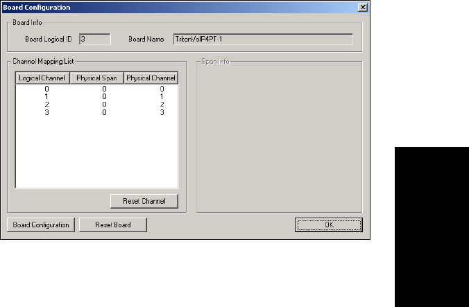
Board Configuration
AltiContact Manager Administration Manual 6-9
6. Board
Configuration
PCI Plug and Play
Triton VoIP boards fit into standard PCI slots. Once installed, it is
recognized by AltiContact Manager and appears on the Boards window of
ACM Administrator.
Device Driver
A kernel mode device driver is implemented for the Triton VoIP board. The
device driver provides access to resources on the Triton VoIP board to
applications.
Port Specifications
See Chapter 2, System Requirements, for limitations on configuring Triton
VoIP boards and ports.
Board Installation
Double click the boardãs icon in the Boards window (see Figure 1) to open
the Board Configuration window.
Figure 6. Board Configuration window (VoIP Board)
The Board Configuration window for the Triton VoIP board displays the
same options as the Quantum board, which are discussed in ãConfiguring
the Quantum Boardã on page 6-2.
Configuring the Triton VoIP Board
6-10 AltiContact Manager Administration Manual
The Board Configuration button invokes the Triton VoIP Trunk
Properties window, which displays the board serial number and displays
line settings. Refer to ãTriton VoIP Trunk Configurationã on page 7-13 for
more detail.
TroubleshootingãCommon Symptoms and Solutions
The following are some of the most common problems you may encounter
and a list of steps to troubleshoot and resolve these problems.
Poor Voice Quality
When voice quality is poor, try the following:
1. Perform a Loop-Back Test. Call yourself by dialing out and dialing
back into yourself. If you donãt have any problems performing this
test, the problem is most likely in the network or at the remote site.
2. Check Traffic Between AltiContact Manager IP Stations.Openthe
IP Trunk Current Traffic Statistics window and the AltiWare IP
Cumulative Traffic Statistics window in Contact Manager to view
network traffic.
3. Check the RTP and RTCP Settings. Make sure UDP port numbers
49152-49199 are not assigned to other applications. RTP/RTCP is the
acronym for Real-Time Transport (Control) Protocol, a transport
protocol for real-time applications used to transport packetized voice
packets over the IP network.
4. Check Network Configurations. Follow all network configuration
guidelines provided under ãNetwork Configuration Guidelines for
VoIPã on page 9-8. Make sure the router, WAN bandwidth, and Jitter
Buffer are configured properly.
Cannot Make a Connection
1. Check Network Connectivity using ãping.ã
2. Check Network Firewall Settings. See ãNetwork Configuration
Guidelines for VoIPã on page 9-8 for more details.
3. Check IP Address of Destination System
4. Check the RTP and RTCP Settings. Make sure UDP port numbers
49152-49199 are not assigned to other applications. RTP/RTCP is the
acronym for Real-Time Transport (Control) Protocol, a transport

Board Configuration
AltiContact Manager Administration Manual 6-11
6. Board
Configuration
protocol for real-time applications used to transport packetized voice
packets over the IP network.
5. Check the AltiContact Manager IP Dialing Table for Dialed Digits
Length. Refer to ãDefining the IP Dialing Tableã on page 9-2.
6. Check if Called Extension is a Workgroup or has Multiple Call
Waiting Enabled. When the called party is a workgroup pilot number
or has Multiple Call Waiting enabled, the caller is placed on hold and
hears ringback or music.
IP Trunk Does Not Appear in Trunk View
When an IP trunk doesnãt appear in the Trunk View, there are two possible
causes:
1. Device Driver is Not Running - check the device driver. Make sure
itãs installed and working properly.
Windows NT 4.0 does not support Plug and Play. Therefore, the PnP
ISA Enable Driver (PNPISA.SYS) must be installed if it is not
installed already. Refer to the Microsoft Web site for installation
instructions.
2. Triton VoIP Board is Not Installed Properly - Refer to the Quick
Installation Guide for more details on proper installation of the Triton
VoIP board.
Configuring the Triton T1/PRI Board
Through AltiContact Manager, the Triton T1/PRI board can be configured
for either digital T1 or PRI (Primary Rate Interface).
Both T1 and PRI carry 24 pulse code modulation (PCM) signals using
time-division multiplexing (TDM) at an overall rate of 1.544 Mbps. Voice
T1 provides twenty-four 64K channels with robbed bit signaling. PRI
provides twenty-three 64K channels, using one 64K channel for D channel
messaging.
The Triton T1/PRI board is used to provide voice processing resources for
AltiContact Manager, similar to the way Quantum telephony boards are
used for analog trunks and extension lines. AltiContact Manager uses DSP
engines residing on the Triton T1/PRI board to perform the voice
processing functions needed for either T1 or PRI service. Quantum and
Triton boards are connected via MVIP connectors.
Configuring the Triton T1/PRI Board
6-12 AltiContact Manager Administration Manual
For information on how to install Triton T1/PRI boards, refer to the Quick
Installation Guide provided with every board package.
Important: Configuration for Triton T1/E1/PRI boards can only be done at
the local system. These boards cannot be configured by a
remote ACM Admin.
Service Parameters for T1
To subscribe to T1 service, certain parameters are required to establish
service. The information provided below identifies the recommended and
supported parameters for T1 service.
T1 Service Request Information
When ordering T1 service, provide the following service request
information:
Equipment Information
Product Manufacturer - AltiGen Communications, Inc.
Product Name - AltiContact Manager Phone System
CSU/DSU - ADTRAN T1 ACE (recommended) or other CSU/DSU
Technical Information for T1 with Voice
Signaling Protocol:
ã E&M Wink Start (recommended)
ã E&M Immediate Start
ã Ground Start
ã Loop Start (not recommended)
Trunk Type:
ãÂDID
ã 2-Way DID (recommended)
ãÂDOD
Framing:
ã Super Frame (SF)/D4
ã Extended Super Frame (ESF) (recommended)

Board Configuration
AltiContact Manager Administration Manual 6-13
6. Board
Configuration
Line Coding:
ã Alternate Mark Inversion (AMI)
ã B8ZS (recommended)
DNIS, Caller ID - DTMF (Dual Tone Multi-Frequency)
Physical Termination -RJ-48XorRJ-48C
Wire:4wires
800 Service: you decide
Termination Impedance - 100 ohms
Type of Registered Services Provided
BN 1.544 Mbps SF without power
DN 1.544 Mbps SF B8ZS without power
1KN 1.544 Mbps ANSI ESF without power
1SN 1.544 Mbps ANSI ESF, B8ZS without power (recommended)
Service Order Code
SOC 6.0P AS.2
T1 Channel Assignment
Trunk Type: In, Out, or 2-Way (recommended)
Channels Assigned: 24 (Enter partial channels if you wish to subscribe to
both voice and data service.)
Hunting: Most Idle, Least Idle, Ascend, Descend
DNIS Digits/Signal: 3/DTMF (can be 3 to 10 digits)
Caller ID Signal: DTMF, if available (Not every service provider provides
Caller ID over T1 lines.)
CSU/DSU Requirements
The CSU (channel service unit) is a device used to connect a digital trunk
line coming in from the phone company to the PBX. A CSU can terminate
signals, repeat signals and respond to loopback commands sent from the
central office.
Configuring the Triton T1/PRI Board
6-14 AltiContact Manager Administration Manual
Service Parameters for PRI
To subscribe to PRI service, certain parameters are required to establish
service. The information provided below identifies the recommended and
supported parameters for PRI service.
PRI Service Request Information
When ordering PRI service, provide the following service request
information:
Equipment Information
Product Manufacturer - AltiGen Communications, Inc.
Product Name - AltiContact Manager Phone System
CSU/DSU - ADTRAN T1 ACE (recommended) or other CSU/DSU
Technical Information for PRI with Voice
Switch Type:
ã 5ESS (recommended)
ã DMS (recommended)
ã NI-2 (recommended)
ãÂ4ESS
ã MEGACOMM
Framing:
ã Super Frame (SF)/D4
ã Extended Super Frame (ESF) (recommended)
Line Coding:
ã Alternate Mark Inversion (AMI)
ã B8ZS (recommended)
Physical Termination: RJ-48X or RJ-48C
Wire:4wires
PRI Channel Assignment
D Channels Assignment: 24th channel (channel ID 23)
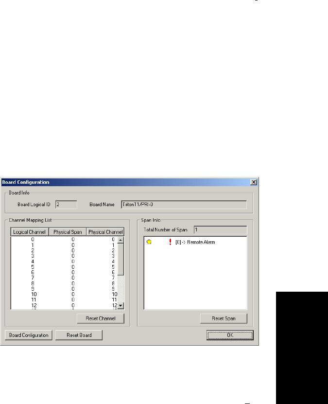
Board Configuration
AltiContact Manager Administration Manual 6-15
6. Board
Configuration
Note: AltiContact Manager can configure any channel in a PRI span
to be the D channel. The default setting is the last channel.
Every span should select a D channel within the span. Shared
D channel (NFAS) or back up D channel is not supported.
Hunting: Most Idle, Least Idle, Ascend, Descend
DNIS Digits:canbe3to10digits
CSU/DSU Requirements
The CSU (channel service unit) is a device used to connect a digital trunk
line coming in from the phone company to the PBX. A CSU can terminate
signals, repeat signals, and respond to loopback commands sent from the
central office.
Board Configuration
Double click the boardãs icon in the Boards window (see Figure 1) to open
the Board Configuration window.
Figure 7. Board Configuration window (Triton T1/PRI Board)
The Board Configuration window for the Triton T1/PRI board displays
the same options as the Triton Analog Station board, which is discussed in
ãConfiguring the Triton Analog Station Boardã on page 6-4, but there are
additional options available. The Board ID must be in the range 0ã7.
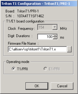
Configuring the Triton T1/PRI Board
6-16 AltiContact Manager Administration Manual
ã Clicking on a trunk in the Channel Mapping List invokes the T1
Trunk Properties dialog box (refer to ãTriton T1/PRI Trunk
Propertiesã on page 7-15).
ãÂTheBoard Configuration button invokes a configuration dialog box.
Figure 8. Triton T1 Configuration dialog box
This dialog box displays the board serial number and allows you to
reconfigure the Clock Frequency,Digit Duration,andtheFirmware
File Name.TheOperating mode is automatically displayed as T1/
PRIorE1/PRI.
ãÂTheSpan Info window displays the Total Number of Spans on the
board and the status of the span in the Span Info window. To reset the
span, click the Reset Span button. Double clicking a span in this
window will invoke a configuration window, as discussed in the
following section.
See ãT1 Clockingã on page 6-21 and the Status Messages table beginning
in the next section.
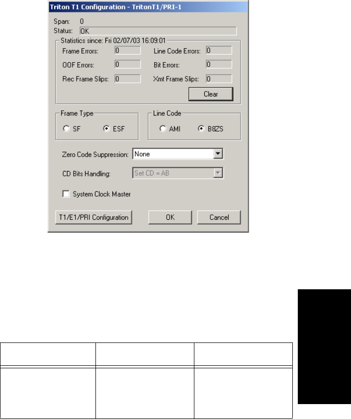
Board Configuration
AltiContact Manager Administration Manual 6-17
6. Board
Configuration
Triton T1 Configuration - Triton T1/PRI Dialog Box
Double clicking the span line for a Triton T1 board in the Span Info
window invokes a T1/PRI Configuration dialog box.
Figure 9. Triton T1/PRI Configuration dialog box
Reading the Status Messages
If the span is working, the Status line displays OK. This status line is
updated every 3 seconds. If there is an error, a message is displayed. The
following table lists the types of error messages and the appropriate actions.
Table 1: Span Status Error Messages
Error Message Meaning Action
Hardware Failure - NO
ANSWER
Major hardware prob-
lem. Board is not
responding to com-
mands.
Set board as MVIP
master. Reset Board.

Configuring the Triton T1/PRI Board
6-18 AltiContact Manager Administration Manual
Hardware Failure - NO
CLOCKS
No clock signal is
detected on T1 interface
drop.
Reset Board. If this
does not work, board
must be replaced.
HDLC Failure - NO
HDLC FRAMES
HDLC = High level
Data Link Control. No
HDLC framing is
detected on the selected
D Channel. This is a
PRI-specific issue.
Check with CO on D
Channel usage for pos-
sible mismatch between
your selection of D
channel and COãs selec-
tion.
OR
COmayhavelockedD
Channel. Contact CO to
unlock.
Line Failure - NO SIG-
NAL (ALOS)
ALOS = Analog Loss
of Signal
Check T1/PRI cable
and change if neces-
sary. If cable is okay,
CO is not sending any
signal. Contact CO.
Line Failure - BLUE
ALARM (AIS)
AIS = Alarm Indicator
Signal
CO is sending Blue
Alarm. Contact CO.
Line Failure - YEL-
LOW ALARM (RAI)
RAI = Remote Alarm
Indicator
Cable is broken. If there
are no frame slips, con-
tact CO. If frame slips
exist, set this board as
the master.
Setup Failure - NO
VALID FRAME
No valid framing is
detected.
Possible span mis-con-
figuration (i.e., ESF is
selected but the actual
framing is SF, or vice
versa). Check span con-
figuration.
Setup Failure - RED
ALARM (BPV)
BPV = Bi-Polar Viola-
tion
Location condition,
equipment problem. For
excessive BPV, check
AMI/B8ZS setting.
Table 1: Span Status Error Messages
Error Message Meaning Action

Board Configuration
AltiContact Manager Administration Manual 6-19
6. Board
Configuration
Reading the Statistics
The Statistics is an informational display of accumulated statistics
(counters) for the errors that have occurred since the last system reboot or
statistics clearing. There may be non-zero values when configuring the T1
span for the first time. You can clear these fields with the Clear button.
ãÂFrame Errors -numberofframingbiterrors.InT1mode,aframing
bit error is defined as an incorrect FS-bit value. The counter is
suppressed when framer loses frame alignment.
ãÂOOF Errors - the Out Of Frame counter registers every time the T1
chip is forced to re-frame when receiving a frame with severe errors.
ãÂRec Frame Slips - the Receiver Frame Slips counter shows the
number of frame slips for the receiver.
ãÂLine Code Errors - Line Code Error is defined as an occurrence of a
bi-polar variation or excessive zeroes.
ãÂBit Errors - Bit Errors are defined as a CRC-6 error in ESF, FT-bit
error in SLC-96 and F-bit or sync bit error in SF.
Setup Failure - RED
ALARM (LCV)
LCV = Line Code Vio-
lation
Check the MVIP bus
master setting.
OR
Have CO perform a line
test to check for a faulty
cable or line.
Setup Failure - RED
ALARM (OOF)
OOF = Out of Frame.
Excessive frame errors.
Check the MVIP bus
master setting.
OR
Have CO perform a line
test to check for a faulty
cable or line.
Clock Sync Failure -
FRAME SLIPSã
Conflict between trans-
mit and receive clocks.
The MVIP bus master-
ship is set improperly.
Check MVIP bus mas-
ter setting.
Table 1: Span Status Error Messages
Error Message Meaning Action
Configuring the Triton T1/PRI Board
6-20 AltiContact Manager Administration Manual
ãÂXmt Frame Slips - Transmit Frame Slips counter shows the number
of frame slips for the transmitter.
ãÂClear button - use the Clear button to reset the statistics counters.
Note: For ideally synchronized systems, Transmit and Receive
Frame Slips counters should be ã0.ã Continuous update of the
frame slips counters means that transmit and receive
frequencies are not equal. In this case, you should check the
system and MVIP clock setup.
Setting the Configurable Options
ã You can set the Frame Type to either SF or ESF.
SF (Superframe Format) consists of twelve (12) consecutive frames.
ESF (Extended Superframe Format) consists of twenty-four (24)
consecutive frames.
ã You can set the Line Code to either AMI or B8ZS.
AMI (Alternate Mark Inversion) is the line coding format in T1
transmission systems whereby successive ones (marks) are alternately
inverted and sent with opposite polarity of the preceding mark. B8ZS
(Binary 8 Zero Substitution) sends two violations of the bipolar line
encoding technique, rather than inserting a one for every seven
consecutive zeros.
ã You can set the Zero Code Suppression to None (default setting),
Jam Bit 8,GTE or Bell.
Zero Code Suppression inserts a ãoneã bit to prevent the transmission
of eight or more consecutive ãzeroã bits; Jam Bit 8 forces every bit 8
to a one; GTE Zero Code Suppression replaces bit 8 of an all zero
channel byte to a one, except in signaling frames where bit 7 is forced
to a one. Bell Zero Code Suppression replaces bit 7 of an all zero
channel byte with a one.
ãÂCD Bits Handling is for display only.
ã If you click the T1/E1/PRI Configuration button you can set
channels to either T1 or PRI, as discussed in ãSetting up T1 or PRI
Channels on the Triton T1/PRI Boardã on page 6-22.
ã You can set the System Clock Master if you have a back-to-back
configuration and you want this span to be the master clock to the
system. (Only one clock master should be selected in a back-to-back
system.) See the following discussion.

Board Configuration
AltiContact Manager Administration Manual 6-21
6. Board
Configuration
T1 Clocking
Depending on the configuration of the T1 boards and span for your
AltiContact Manager system(s), the System Clock Master setupshouldbe
set according to the follow conditions:
ã If all of the T1 boards are connected to an FXO (Foreign Exchange
Office) or CO, the System Clock Master check box must NOT be
checked for any of the T1 boards.
ã If two AltiContact Manager systems are connected back-to-back with
aT1span,theSystem Clock Master check box must be checked for
only one of the T1 boards.
ã If two T1 boards in the same AltiContact Manager system are
connected back-to-back with a T1 span, the System Clock Master
check box must be checked for the T1 board that has not been
designated by the MVIP setting as the systemãs master clock to drive
the MVIP bus.
ã If four T1 boards are in the same AltiContact Manager system, where
each pair is connected back-to-back with a T1 span:
ãTheSystem Clock Master check box must be checked for one of
the T1 boards from the first pair, that has not been designated by the
MVIP setting as the systemãs master clock to drive the MVIP bus.
ã The other two T1 boards of the second pair must have its System
Clock Master check box unchecked
Important: In all back-to-back cases, the MVIP Clock Configuration
should be set to ãManual,ã and the board connected to the
board configured as the back-to-back clock master must be
designated at the MVIP bus master.

Configuring the Triton T1/PRI Board
6-22 AltiContact Manager Administration Manual
Setting up T1 or PRI Channels on the Triton T1/PRI
Board
Use the T1/PRI Configuration button (see Figure 9) to invoke the T1/PRI
Configuration window. The Triton T1/PRI Board can be configured to
either T1 or ISDN PRI through the configuration options within the
window.
Note: In a tie-trunk configuration, set the trunks to ãOut of Serviceã
before changing the trunk type from T1 to PRI or vice versa.
Otherwise, the system will generate garbage call records to your
internal or external logger service. See ãSetting General Trunk
Attributesã on page 7-3 for details.
Figure 10. T1/PRI Configuration window
The CH -> Type list displays the channel types.
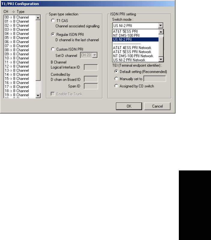
Board Configuration
AltiContact Manager Administration Manual 6-23
6. Board
Configuration
Setting the ISDN PRI Switch Mode
If you select a Span Type of Regular ISDN PRI or Custom ISDN PRI in the
T1/PRI Configuration Window, use the following guidelines to set the
ISDN PRI Switch mode.
Figure 11. ISDN PRI Switch Mode
The top four settings are used for a connection to a CO switch:
ã AT&T 4ESS PRI
ã AT&T 5ESS PRI
ãÂNTDMS-100PRI
ã NI-2 PRI (default)
The bottom four settings are used for a PRI tie trunk configuration where
two AltiContact Manager systems are connected back to back. In such a
configuration, one AltiContact Manager system must be configured as
Network and the other as User. For example, set one to US NI-2 PRI
Network and the other to US NI-2 PRI.
ã AT&T 4ESS PRI Network
ã AT&T 5ESS PRI Network
ãÂNTDMS-100PRINetwork
ãÂNI-2PRINetwork
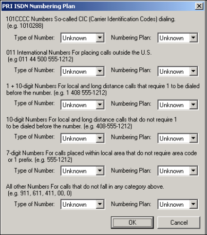
Configuring the Triton T1/PRI Board
6-24 AltiContact Manager Administration Manual
Selecting Span Types
ãÂT1CAS - select this option to associate all channels on the span to
T1channel associated signaling.
ãÂRegular ISDN PRI - select this option to indicate 23B+D ISDN PRI
span and to designate the last channel as the D channel.
ãÂCustom ISDN PRI - this option is not available.
ãÂEnable Tie Trunk - check this box to enable a tie trunk. Note that tie
trunks must terminate to a system also configured as a tie trunk.
Configuring an ISDN Numbering Plan
The ISDN Numbering Plan button invokes the PRI ISDN Numbering
Plan dialog box. This function allows you to select how the system will
identify and code the Called Number for six different types of calls. This
coding instructs the CO on how to interpret the number being sent to it.
.
Figure 12. PRI ISDN Numbering Plan dialog box
The PRI ISDN Numbering Plan dialog box displays the six classes of
numbers (call type) that can be sent to a CO:

Board Configuration
AltiContact Manager Administration Manual 6-25
6. Board
Configuration
ã 101CCCC Numbers - CIC (Carrier Identification Codes) dialing.
ã 011 International Numbers - for placing calls outside the U.S.
ã 1+10-digit Numbers - for local and long distance calls that require
dialing 1 before the number.
ã 10-digit Numbers - for local and long distance calls that do not
require 1 before dialing.
ã 7-digit Numbers - for calls placed within the local area that do not
requireanareacodeora1prefix.
ã All Other Numbers - for calls that do not fall into any category
above, i.e. 911, 311.
For each class, select the type of number/numbering plan from the drop-
down list:
ãÂType of Number:
ã Unknown
ã International
ã National
ã Network Specific
ã Subscriber Number
ãÂNumbering Plan:
ã Unknown
ãISDN
ã National
ãPrivate
The setting ãUnknownã is used when the user or network has no knowledge
of the numbering plan. In this case, the number digits field is organized
according to the network dialing plan.
Setting the NSF
The NSF (Network-Specific Facilities) is used with PRI to instruct the CO
to route a call to a specific carrier or long distance service. Use the drop-
down list to identify the type of carrier service you wish to use for your
ISDN PRI lines.
The choices in the list depend on the specific switch and your long distance
service provider. An example of such service includes AT&T Megacom.

Configuring the Triton T1/PRI Board
6-26 AltiContact Manager Administration Manual
Note: If your CO requires specific NSF features to be present in the call
setup packet, please contact AltiGenãs Technical Support
department with such information from the CO and they will help
you configure it.
Setting a TEI
The TEI (Terminal Endpoint Identifier) defines which terminal device
is communicating with the CO switch for a given message. PRI messages
involve point-to-point configuration in which each side already knows the
source of any message received. ISDN messages involve point to multi-
point locations in which the source can only be identified by the TEI.
Select one of the following TEI settings:
ãÂDefault setting - this is the recommended setting.
ãÂManually set to - should always be set to 0. Typically, a zero (0) is
used for TEI on a PRI connection. In some cases where a shared D
channel is used, other TEI values might be required to identify
which span will be used for a call.
ãÂAssigned by CO switch - do not use this setting unless advised by
your CO.
Installing a Channel Service Unit (CSU) to the Triton T1
or T1/E1/PRI Board
1. Connect the CSU (Adtran model T1 CSU ACE used as an example) to
the T1/PRI or T1/E1PRI board using an RJ-48C or RJ-48X cable.
2. Connect the CSU to the network termination box using an RJ-48C or RJ-
48X cable.
AltiGen T1Socket (RJ-48) Refer to your CSU manufacturerãs manual for the proper pinout.
Pin1=ReceiveRing(INPUT)

Board Configuration
AltiContact Manager Administration Manual 6-27
6. Board
Configuration
TroubleshootingãCommon Symptoms
The most common problems when installing T1 or PRI services:
1. The service provider misconfigures your T1/PRI service or terminates
your service improperly.
2. T1 is installed but not turned on because there is no termination device
for a period of time.
3. T1 is turned on but channel is not in service.
AltiContact Manager provides basic troubleshooting information in the T1
Span Configuration window, described in ãTriton T1 Configuration -
Triton T1/PRI Dialog Boxã on page 6-17.
Several diagnostic tools are available that can help troubleshoot these
situations, such as a T1 watcher (ãT-Berdã) or a multimeter. For more
information, check the Communication Technology Corp. web site at
www.commtech.com.
Pin 2=Receive Tip (INPUT)
Pin 4=Transmit Ring (OUTPUT)
Pin 5=Transmit Tip (OUTPUT)
Configuring the Triton T1/PRI Board
6-28 AltiContact Manager Administration Manual

AltiContact Manager Administration Manual 7-1
7.Trunk
Configuration
C
HAPTER
7
Trunk Configuration
Trunk attributes and parameters are set using the Trunk Configuration
window. The attributes and options available depend on the type of board
and trunk.
Trunks that are out of service are automatically tested by the system every
15 seconds. Once the situation is corrected, the trunk will be brought back
to service automatically. If none of the trunks are available when an outside
call is placed, the caller will hear the system prompt: ãAll outside lines are
busy, please try again later.ã
To access the Trunk Configuration window:
ã Select the System Management menu, then select Trunk
ConfigurationãÎ
ã Use the drop-down list next to the System icon and select Trunk
Configuration,or,
ã Double-click a trunk listing in the Trunk View window.
Figure 1. Trunk View window
However you open the Trunk Configuration window, the General window
appears.

7-2 AltiContact Manager Administration Manual
Figure 2. General window, Trunk Configuration
Selecting Trunks to Set Attributes
The title bar of the Trunk Configuration window displays the card and the
channel of the selected trunk.
The list on the left shows all the configured trunks. The location format is
the same as in the Trunk View window, that is, slot:channelãfor example,
channel15ontheboardinslot1islocation01:15.
When you select a trunk in this list, the options and parameters for the trunk
appear in the settings in the right of the window.
Configuring One or Multiple Trunks
To customize trunk characteristics, you work on one trunk at a time. To
apply the same configuration to multiple trunks, use the Apply ToãÎ
button. This pops up a list of all trunks, with all of the trunks selected by
default. Deselect the trunks you donãt want to apply changes to, then click
OK. (Note that you cannot use the mouse to drag over and select multiple
items; you must use the Shift and Ctrl keys.) This applies changes to
multiple trunks for only the attribute or option that you changed.

Trunk Configuration
AltiContact Manager Administration Manual 7-3
7.Trunk
Configuration
Setting General Trunk Attributes
Select the channel to view its current attributes, as discussed in the previous
section. You can then set or change the following attributes. If an option is
grayed out, it is not available for that type of trunk:
Attribute Description
Access Code Access code to the selected trunk. If you need to use
access codes other than 9, you must first set this up on
the Number Planwindow of System Configuration
(ãSetting a System Number Planã on page 5-4). This
option is not available for a DID trunk.
Note: It is recommended that you set this value to
ãNoneã for trunks on 30-port VoIP boards.
This will prevent users from directly
accessing the 30-port boardsãwhich use the
G.711 codec onlyãfor calls to AltiContact
Manager servers or other IP gateways that
may require the G.723 codec. If you still want
users to have access to this trunk for outgoing
calls, you can set it up through Outcall
Routing (see Chapter 10, Out Call Routing
Configuration).
Area Code The local area code for each trunk. Enter a three-digit
area code. If left blank, the trunk assumes the home
area code defined in the General window of the
System Configuration window. This configuration is
for each trunk in the system and will negatively affect
features such as Zoomerang if the area code is not
configured properly. This is not available for a DID
trunk.
Setting General Trunk Attributes
7-4 AltiContact Manager Administration Manual
Direction The trunk direction can be Outgoing only, Incoming
only, Both Outgoing and Incoming, or for Paging.
Outgoing and Both are not available on an analog
Quantum DID trunk, which is an Incoming trunk.
The Both option is the system default.
Note: When incoming calls are received on an
Outgoing only trunk, they are immediately
disconnected.
Paging is only available for analog (CO) trunks and
is used for paging or broadcasting purposes. This
option enables a third party paging device directly to
the trunk port.
When this option is selected, the system assigns a
default unused paging ID. You can assign a different
ID in the drop-down list. The range of paging IDs are
from 00 to 99, which allows AltiContact Manager to
be connected to up to 100 paging systems through
trunks for multi-zone paging applications. If the
manually selected paging ID is used by another trunk,
the current paging ID is not changed.
The trunk paging is accessed using the Overhead
Paging by Trunk (# 45 Feature Code). For example,
a user dials ã#4508ã to connect to a paging system
through the trunk with paging ID of 08.
The Overhead paging feature requires paging
equipment to provide loop start CO trunk
characteristics. This option is not supported on
ground start trunks.
The Paging option and the Overhead Paging option
(in ãAudio Peripheral Configurationã on page 5-27)
are different and independent of one another. The
Overhead Paging option is to set up the audio out port
of the Quantum board for use with the #44 overhead
option built into the system.
Phone Number The phone number, without the area code, assigned to
the location. If the wiring changes and a new phone
number is assigned to the location, you must update
the information in this field.
Attribute Description

Trunk Configuration
AltiContact Manager Administration Manual 7-5
7.Trunk
Configuration
Description Descriptive information such as the company name
for the assigned Phone Number, or appropriate
agency if this trunk provides 911 access.
Trunk Dialing
Scheme Overlap or En-bloc dialing.
ãÂOverlap allowstheterminaltoomitpartofthe
digits required to complete a call, while the
remaining digits are buffered. Use Overlap
Dialing for analog trunks and for T1 (robbed bit)
for best results.
ãÂEn-bloc allows the terminal to include all of the
digits required to complete a call. Use En-bloc
Dialing for digital (PRI-ISDN) trunks.
Centrex Transfer Applies to analog and T1 trunks if the trunk is
supported by Centrex. This option must be selected to
forward calls to an outside number through a Centrex
switch. If the Centrex provider requires a particular
string to be sent before the dialed number, enter the
string in the Transfer Predial String box. If no
string is set as a predial string, FLASH is used.
Attribute In Service makes the trunk available for use. Out of
Service prevents the trunk from being used (for
example, while performing maintenance).
Enable Tie Trunk Allows hop-on and hop-off dialing for an ISDN/PRI,
or T1 trunk. When this box is checked, any incoming
call to the selected trunk can be sent with ANI/DNIS
information. To use this feature, Hop-off must also be
enabled under System Configuration Call
Restrictions, as discussed in ãDefining System Call
Restrictionsã on page 5-12. Also, the board must be
configured to allow for tie trunks. See ãSetting up T1
or PRI Channels on the Triton T1/PRI Boardã on
page 6-41.
Trunk Properties Opens a dialog box that allows you to configure low-
level, hardware-specific properties for each trunk.
The options vary depending on the type of board and
trunk; this is discussed in subsequent sections.
Attribute Description
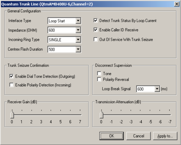
Setting General Trunk Attributes
7-6 AltiContact Manager Administration Manual
Quantum Trunk Properties
To configure a Quantum channel, select a Quantum channel from the trunk
channels list in the Trunk Configuration window, then click the Trunk
Properties button or double-click the list entry to view the Quantum
Trunk Line Properties dialog box.
Figure 3. Quantum Trunk Line Properties window
Note that you can use Apply to... on this dialog box to apply changes to
other trunks of the same type. See ãConfiguring One or Multiple Trunksã
on page 7-2.
Tenant Selection The Tenant group assignment for the trunk,
configured from the Tenant Table window in
System Configuration, discussed in ãUsing a
Tenant Tableã on page 5-22. If no tenant is selected,
any extension can use this trunk to make an out call.
Attribute Description

Trunk Configuration
AltiContact Manager Administration Manual 7-7
7.Trunk
Configuration
Quantum Trunk General Configuration
Parameter Description
Interface Type Select from:
ãÂLoop Start
ãÂGround Start
ãÂDID (Wink Start)ãavailable only if the selected
trunk is a DID trunk
Impedance The resistance of electrical current to alternating current,
measured in OHMs. Impedance occurs when power or
signal is transferred from one circuit to another. The
setting options are:
ãÂ600 OHMs (domestic setting)
ãÂ900 OHMs (international setting, depending on the
country)
ãÂExternal
Incoming Ring
Type Select single or double.
Centrex Flash
Duration (ms) Specifies the Flash Duration time in milliseconds, with a
range from 50 ms to 1000 ms. This setting complements
the Centrex Flash Support option in the General window
for the trunk.
Detect Trunk
Status By Loop
Current
When selected, causes detection of the Quantum trunk
status using a loop current.
Enable Caller ID
Receive Select for user to receive caller ID digits.
OutofService
With Trunk
Seizure
When selected, if the trunk is set to OutofService,the
Quantum service provider will busy out (seize) the trunk.
The CO will treat this trunk as a busy line and WILL
NOT place a call to this trunk. (By default, this option is
unchecked.)
Setting General Trunk Attributes
7-8 AltiContact Manager Administration Manual
Trunk Seizure
Confirmation Select from:
ãÂEnable Dial Tone Detection (Outgoing)ã
detection of outgoing dial tone.
ãÂEnable Polarity Detection (Incoming)ãdetection
of incoming polarity. Polarity detection is used
when the CO or the connected PBX provides
polarity reversal on the tip and ring.
Disconnect
Supervision Select from:
ãÂToneãbusy tone (reorder tone, fast busy tone, error
tone, etc.) or dial tone (continuous tone, etc.). This
should be used in conjunction with drop in loop
current. For COs who cannot guarantee loop break,
this may be the only option.
ãÂPolarity Reversalãa reversed battery signal. You
can set the Loop Break Signal to either 200 or 600
ms.
Receive Gain Slide setting adjusts the incoming volume from
-6dBto6dBforeveryTritonAnalogTrunkchannel.
The default setting is 0dB, and it is highly recommended
not to change this setting.
Caution: Setting the volume too high will cause
distortion in voice quality and/or missed
DTMF digits.
Transmit Gain Slide setting adjusts the outgoing volume from
-6dBto6dBforeveryTritonAnalogTrunkchannel.
The default setting is 0dB, and it is highly recommended
not to change this setting.
Caution: Setting the volume too high will cause
distortion in voice quality and/or missed
DTMF digits.
Parameter Description
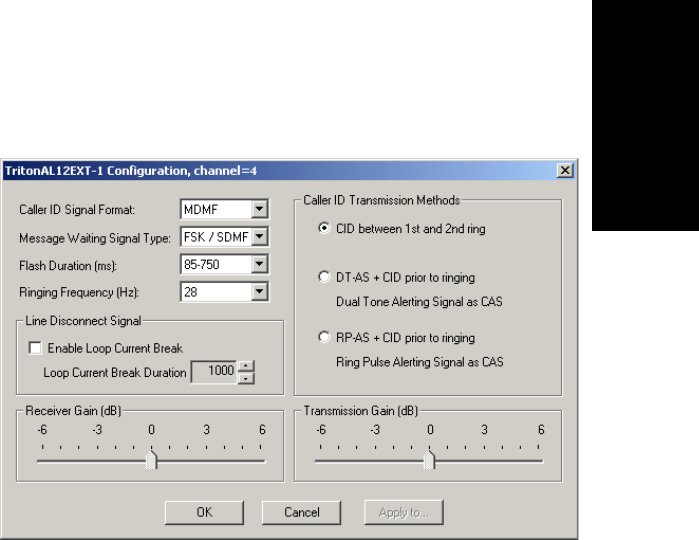
Trunk Configuration
AltiContact Manager Administration Manual 7-9
7.Trunk
Configuration
Triton Analog Trunk Properties
To configure a Triton Analog Trunk channel, select a Triton Analog Trunk
channel from the trunk channels list in the Trunk Configuration window,
then click the Trunk Properties button or double-click the list entry to
view the Configuration dialog box.
Figure 4. Triton Analog Trunk Properties window
Note that you can use Apply toãÎ on this dialog box to apply changes to
other trunks of the same type.
Parameter Description
Caller ID Signal
Format MessageformatwithwhichtosendCallerID
information:
ãÂNone
ãÂSDMFãSingleDataMessageFormatfor
supporting and sending a single data type, such as
phone numbers.
ãÂMDMFãMultiple Data Message Format for
supporting and sending multiple data types, such
as name and number information.
ãÂDTMFãDual Tone Multi-Frequency for push
button or touch tone dialing.
Setting General Trunk Attributes
7-10 AltiContact Manager Administration Manual
Message Waiting
Signal Type Type of Message Waiting indicator for the phone set:
ã None
ãÂFSK/SDMFãFrequency Shift Keying with and
Single Data Message Format.
ãÂFSK/MDMFãFrequency Shift Keying with
Multiple Data Message Format.
Flash Duration (ms) Specifies the Flash Duration time in milliseconds,
with the following set ranges: 85-750, 50-600, 100-
700, 150-800, 200-900, 300-1000.
Ringing Frequency
(Hz) Select the frequency in Hertz that is necessary for the
equipment attached to this line, set to either 28 or 20.
Line Disconnect
Signal The loop break desired for answering supervision.
Select the Enable Loop Current Break check box
and select the Loop Current Break Duration in
milliseconds.
Caller ID
Transmission
Methods
Select the type of caller ID transmission method:
ãÂCID between 1st and 2nd ringãcaller ID
transmitted between first and second ring.
ãÂDT-AS + CID prior to ringingãdual tone
alerting signal sent prior to ringing.
ãÂRP-AS + CID prior to ringingãring pulse
alerting signal sent prior to ringing.
Receiver/
Transmission Gain Slide setting adjusts the incoming volume from
-6dBto6dBforeveryTritonAnalogTrunk
channel.
The default setting is 0dB, and it is highly
recommended not to change this setting.
Caution: Setting the volume too high will cause
distortion in voice quality and/or
missed DTMF digits.
Parameter Description
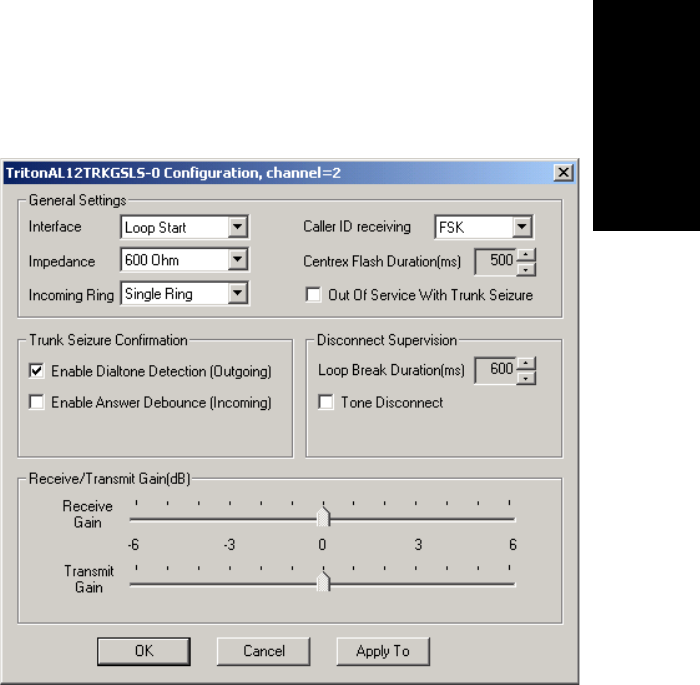
Trunk Configuration
AltiContact Manager Administration Manual 7-11
7.Trunk
Configuration
Triton Analog Trunk GS/LS Properties
To configure a Triton Analog Trunk GS/LS channel, select a Triton Analog
Trunk channel from the trunk channels list in the Trunk Configuration
window, then click the Trunk Properties button or double-click the list
entry to view the Configuration dialog box.
Figure 5. Triton Analog Trunk GS/LS Properties window
Note that you can use Apply toãÎ on this dialog box to apply changes to
other trunks of the same type.
Parameter Description
Interface Type For the LS/GS model, can be one of the following:
ãÂLoop Start Trunk
ãÂGround Start Trunk
Setting General Trunk Attributes
7-12 AltiContact Manager Administration Manual
Impedance The resistance of electrical current to alternating
current, measured in OHMs. Impedance occurs when
power or signal is transferred from one circuit to
another. The setting options are:
ãÂ600 OHMs (domestic setting)
ãÂ900 OHMs (international setting, depending on
the country)
ãÂComplex (for handling multi-component AC
circuits used by the CO)
Incoming Ring Type Can be single or double.
Caller ID Receiving Select as None,FSK or DTMF for when receiving
caller ID digits.
Centrex Flash
Duration (ms) Specifies the Flash Duration time in milliseconds,
with a range from 150 ms to 1000 ms.
OutofServiceWith
Trunk Seizure When enabled, the system automatically takes the
trunk out of service whenever the trunk is seized.
Enable Dial Tone
Detection (Outgoing) Detects outgoing dial tone.
Enable Answer
Debounce (Incoming) Enables a timeout period of 2 seconds (for ignoring
false CO disconnect signal), after answering an
incoming call.
Loop Break Duration
(ms) Disconnects signal if CO breaks loop current. You
can set the duration from 200 to 1000 ms.
Tone Disconnect Busy tone (reorder tone, fast busy tone, error tone,
etc.) or dial tone (continuous tone, etc.). This should
beusedinconjunctionwithdropinloopcurrent.For
COs who cannot guarantee loop break, this may be
the only option.
Parameter Description

Trunk Configuration
AltiContact Manager Administration Manual 7-13
7.Trunk
Configuration
Triton VoIP Trunk Configuration
To configure a Triton VoIP channel, select a Triton VoIP channel from the
trunk channels list in the Trunk Configuration window, then click the
Trunk Properties button or double-click the list entry to view the Triton
VoIP Trunk Line Configuration dialog box.
Figure 6. VoIP Trunk Configuration window
Receiver/
Transmission Gain Slide setting adjusts the incoming volume from 6 dB
to 6 dB for every Triton Analog Trunk channel.
The default setting is 0dB, and it is highly
recommended not to change this setting.
Caution: Setting the volume too high will cause
distortion in voice quality and/or
missed DTMF digits.
Parameter Description
Setting General Trunk Attributes
7-14 AltiContact Manager Administration Manual
The primary configuration for the Triton VoIP is the H.323 Configuration,
with the following settings:
Parameter Description
G.711 Enable Provides toll qualitydigital voice encoding and is not
configurableãthat is, you cannot deselect it. It
guarantees interoperability when other voice
compression (e.g. G.723.1) is not available or when
better voice quality is desired.
G.723.1 Enable Uses low rate audio encoding to provide near toll
quality performance under clean channel conditions.
This option is also not configurable. On the 30-port
board, it cannot be selected; on the 12-port board, it
cannot be deselected.
FastStart Enable Fast connect feature allowing endpoints to establish
channels without waiting for an H.245 connection to
be opened.
MWI Enable Message Waiting Indication (MWI) feature which
activates a message waiting light on an IP phone to
inform a user of unheard voicemail messages.
Silence Suppression Suppresses silence packets during VoIP sessions.
When silence is detected during a call, AltiWare
stops sending packets to the other side. When silence
is detected during voice mail, the silence period is
not recorded.
AltiWare disconnects the voice mail session when a
silence period exceeds 7 seconds during voice mail
recording over VoIP.
G711 Jitter Buffer
Range (ms) Indicates the delay, in milliseconds, used to buffer
G.711 voice packets received from the IP network.
Voice packets sent over the IP network may incur
different delays due to network load or congestion.
The jitter buffer helps to smooth out the delay
variation in the arriving voice packets and maintain
voice quality at the receiving end. The initial values
for the jitter buffer is 10 min. to 20 max milliseconds.
The jitter buffer should be adjusted according to the
WAN bandwidth allocated to data traffic.

Trunk Configuration
AltiContact Manager Administration Manual 7-15
7.Trunk
Configuration
Debugging the Triton VoIP Configuration
Click the Debug button in the Triton VoIP Configuration dialog box (see
Figure 6) to open a small dialog box for typing and sending a debug string.
Triton T1/PRI Trunk Properties
To configure a Triton T1/PRI channel, select a Triton T1/PRI channel from
the trunk channels list in the Trunk Configuration window, then click the
Trunk Properties button or double-click the list entry to view the Triton
T1 Properties dialog box.
G723 Jitter Buffer
Range (ms) Indicates the delay, in milliseconds, used to buffer
G.723 voice packets received from the IP network.
Voice packets sent over the IP network may incur
different delays due to network load or congestion.
The jitter buffer helps to smooth out the delay
variation in the arriving voice packets and maintain
voice quality at the receiving end. The initial value
for the jitter buffer is 10 min. to 20 max milliseconds.
The jitter buffer should be adjusted according to the
WAN bandwidth allocated to data traffic.
G711 RTP Packet
Length (ms) Lets you configure the length of the RTP packets for
G.711 in milliseconds. The RTP packet length can be
set to 10,20 or 30 milliseconds.
Note: A maximum range of 30 ms is not supported
for the Cisco router.
Type Lets you select between a 12-port G.723.1
configuration and a 30-port G.711 configuration.
This is available only with the 12-port board and 30-
port upgrade license.
Parameter Description
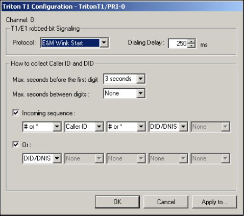
Setting General Trunk Attributes
7-16 AltiContact Manager Administration Manual
Figure 7. Triton T1 Configuration dialog box
The following are the parameters for the Triton T1 Configuration dialog
box:
Parameter Description
T1 robbed-bit signaling
Protocol You can set Protocol to one of the following:
ãÂE&M Wink Start (default)
ãÂE&M Immediate Start
ãÂGround Start
ãÂLoop Start
For signaling from one board to another, only FXS
(Foreign Exchange Subscriber) is supported. Loop Start
and Ground Start protocols cannot be used for interfacing
between two boards.
Dialing Delay Specifies the delay, in milliseconds, after trunk seizure and
before digit dialing. Do not change this value unless
advised.
Caller ID and DID Collection

Trunk Configuration
AltiContact Manager Administration Manual 7-17
7.Trunk
Configuration
You can select the maximum time-out delays, in seconds and the appropriate
sequence of symbols to be collected for Caller ID and DID.
Max. seconds
before the first
digit
Maximum wait time before time-out for the system to
identify this digit after either the first ring in ground start or
loop start or the wink in wink start. The range is from 1-6
seconds, or None, with a default value of 3 seconds.Donot
change this value unless advised.
ãNoneãmeansno Caller ID or DID information will be
collected. All other options will be grayed out. Use this
option to disable Caller ID and DID collection.
Max. seconds
between digits Maximum wait time before time-out between two digits.
Default value is ãNone.ã Do not change this value unless
advised.
Selecting ãNoneã means the system will only wait for the
sequence of digits that are collected within the length of
time specified in the Max. seconds before the first digit
field.
Incoming
sequence Select up to five incoming symbols to collect from the
Caller ID or DID digits:
ãÂNone
ãÂ#
ãÂ*
ãÂ#or*
ã Caller ID
ã DID/DNIS
Selecting ãNoneã in any field of the sequence will terminate
the sequence and automatically disable subsequent entries
in the sequence.
The default sequence is:
ã# or *ã (and then) ãCaller IDã (and then) ã#or*ã(and
then) ãDID/DNISã
Parameter Description
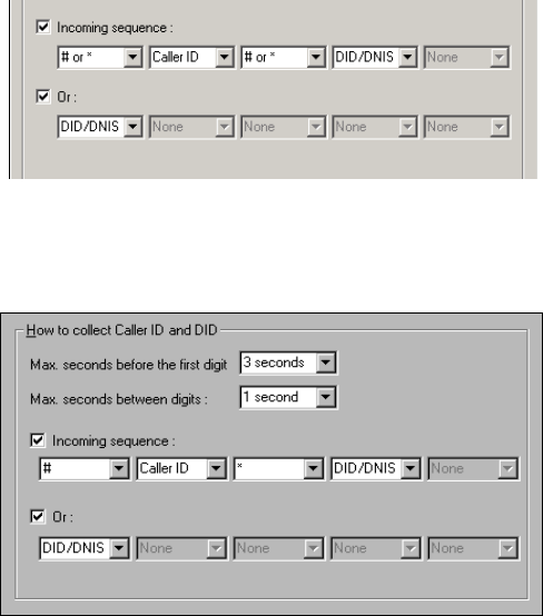
Setting General Trunk Attributes
7-18 AltiContact Manager Administration Manual
Note: In order for back-to-back T1 and tie trunk T1 configurations to
perform properly, it is recommended that you use the systemãs
default incoming call sequences:
Caller ID and DID Incoming Sequence Example
The following is an example of a Caller ID and DID/DNIS incoming
sequence window.
Figure 8. Incoming Sequence window
Or Sets up an additional, alternative sequence. You can select
another set of up to five incoming symbols to collect.
NotcheckinganyboxisequivalenttocheckingãNoneãin
the first field.
The default sequence is:
ãDID/DNISã
Apply toãÎ If appropriate, you can use this button, as described in
ãConfiguring One or Multiple Trunksã on page 7-2, to
apply the Caller ID Collection to multiple T1 trunks.
Parameter Description

Trunk Configuration
AltiContact Manager Administration Manual 7-19
7.Trunk
Configuration
When a call comes in, the system tries to match the incoming sequence to
either the first or second Incoming Sequence Digit String sequence. If no
match is found, no Caller ID or DID digits will be collected.
ã The system waits 3 seconds for the first digit to arrive. If the symbol is
a#, it continues with the first sequence. Otherwise, it looks for a match
to the first (and only) symbol in the second sequence, the DID/DNIS
number.
ã For the example, letãs say the system receives the #. It then waits 1
second between each digit forthe next digit until all digits arereceived.
The *symbol is a delimiter between Caller ID and DID digits.
In this example, the AltiContact Manager system is expecting either the
sequence #CID*DID or only DID digits for incoming calls. If no match is
found for either sequence, no Caller ID or DID digits are collected.
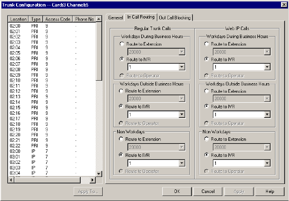
Incoming Call Routing
7-20 AltiContact Manager Administration Manual
Incoming Call Routing
To set incoming call routing for a trunk, select the trunk in the General
window, then click the In Call Routing tab in the Trunk Configuration
window to display the In Call Routing window. The trunk location
appears in the title bar.
Figure 9. In Call Routing window, Trunk Configuration
For each trunkãor using Apply toãÎ to apply the settings to multiple
trunksãyou can set routing for the three time periods defined in the System
Configuration Business Hours window (ãSetting Business Hoursã on page
5-8):
ã During Business Hours
ã Outside Business Hours
ã Non Workdays
Within each of these three time slots, you have the following routing
options for incoming calls:
ã Route to an extension selected in the drop-down list
ã Route to an auto-Attendant number selected in the drop-down list
ã Route to the operator
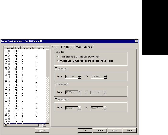
Trunk Configuration
AltiContact Manager Administration Manual 7-21
7.Trunk
Configuration
Outgoing Call Blocking
To set outgoing call blocking for a trunk, select the trunk in the General
window, then click the Out Call Blocking tabintheTrunk Configuration
window to display the Out Call Blocking window with the selected trunk
location in the title bar.
Figure 10. Out Call Blocking window, Trunk Configuration
If you select Trunk allowed for Outside Calls at Any Time, call
restrictions set in System Configuration, Outcall Routing, and Extension
Configuration still apply to calls made on the trunk.
If you select Outside Calls Allowed According to The Following
Schedules, you can then use the Schedule 1, 2, and 3 options to set up to
three different time periods during which calls are allowed.
You can use Apply toãÎ to apply the settings to multiple trunks.
Outgoing Call Blocking
7-22 AltiContact Manager Administration Manual

AltiContact Manager Administration Manual 8-1
8.VoiceMail
Configuration
C
HAPTER
8
Voice Mail Configuration
Voice mail messaging attributes and voice mail distribution list parameters
are set using the Voice Mail Configuration window.
To access the Voice Mail Configuration window:
ã Select the System Management menu, then select Voice Mail
ConfigurationãÎ,or,
ã Use the drop-down list next to the System icon, and select Voice Mail
Configuration.
Managing Messages
The Messaging tab is the default view for the Voice Mail Configuration
window.
The Messaging function provides for setting basic parameters and options
for messaging, including message notification retry attempts, deletion
confirmation options, the length of time for message storage, message
recording length, and email activation and usage.

Managing Messages
8-2 AltiContact Manager Administration Manual
:
Figure 1. Messaging window, Voice Mail Configuration
Setting Message Notification Retries
When a message is sent to a userãs email in-box or voice mailbox and
outcall notification is configured, notification is sent to the user. You can
set the retry setting for the notification as follows:
Parameter Description
Maximum Retry
Count Can be between 0and 16. This is the number of times
the system will try to deliver a voice message
notification after the original attempt. For example, 5
retries means five tries after the original, or 6 total
attempts.
Retry Interval in
Minutes The number of minutes between retry attempts. Five
minutes is the minimum and 60 minutes is the
maximum interval allowed. The default is 5 minutes.

Voice Mail Configuration
AltiContact Manager Administration Manual 8-3
8.VoiceMail
Configuration
Setting Message Management Options
Set message confirmation and warning parameters:
Setting Message Recording Options
Set message recording parameters:
Parameter Description
Confirm Message
Deletion If checked, the system plays a voice message
instructing the user to confirm request for deletion by
pressing the # key. This prevents users from
accidentally deleting messages with a single key
entry.
Warn Expiration of
Saved Messages If checked, the system warns the user that saved
messages will be deleted due to their retention time
expiring. The message is given the day before the
messages are automatically deleted, and the user then
has the option to either keep or delete the message.
By default, this feature is enabled.
Note: If this feature is disabled, saved messages are
deleted automatically without warning when
they expire.
Parameter Description
Minimum Recording
Length Sets the minimum length in seconds for any
recording (i.e., incoming voice mail message,
personal greeting, system prompts). This can be from
1ã5 seconds, or 0, which means no minimum.
All recordings that are shorter than the designated
Minimum Recording length are deleted. This feature
is recommended when users receive many empty
voice mail messages on a regular basis and would
like them automatically deleted.
Pause Detect Length Selected, this feature causes the deletion of pauses in
messages. The default pause detect length is 500 ms.
The pause detect can be disabled by deselecting the
check box, or the length can be set to a value between
200ã2000 ms (.2ã2 seconds).
Managing Messages
8-4 AltiContact Manager Administration Manual
Setting E-mail Messaging Options
To use the AltiContact Manager email services, configure the following
settings.
Parameter Description
Enable SMTP/POP3
E-Mail Service Selected, this enables incoming and outgoing mail
services on AltiContact ManagerãSimple Mail
Transfer Protocol (SMTP) and Post Office Protocol
(POP).
Postmaster Ext This field defines the extension that will be assigned
as a Postmaster Extension. When the e-mail system
receives an e-mail with an invalid e-mail account, the
automatic reply (informing of the invalid e-mail
account used) to the sender is sent from the defined
extension.
Note: The system always requires an extension to
selected as the Postmaster Extension. By
default, the first extension in the system is
used. If an extension is selected as the
Postmaster Extension, it cannot be deleted
until the Postmaster Extension is re-assigned
to another extension.
Allow Inbound
Internet Mail This check box option is activated and selected by
default if you enable the SMTP/POP E-Mail Service.
You can deselect this option if you donãt want to use
the AltiContact Manager E-Mail service for inbound
mail; for example when youãre using another email
server on the AltiContact Manager system.

Voice Mail Configuration
AltiContact Manager Administration Manual 8-5
8.VoiceMail
Configuration
Synchronizing E-mail with Exchange
Creating Distribution Lists
The System Distribution Lists provide for forwarding voice mail messages
to multiple recipients defined as list members. To forward a voice mail to
all list members, a user need only enter the two-digit ID instead of entering
numerous individual extensions.
You can create up to 100 distribution lists, each composed of up to 64
extensions. The extension list member can represent another distribution
list.
Note: The system distribution lists discussed here are different from the
extension distribution lists, which are configured through the
phone sets or the AltiView or AltiAgent user applications.
To access the Distribution List window, select Voice Mail
Configuration... on the System Management menu, then click the Voice
Mail Distribution List tab.
Parameter Description
Synchronize with
Exchange Server Before selecting this option to use an Exchange
Server, you should make sure the Exchange Server
and Windows / NT configuration is established. See
the AltiGen document, Exchange Server Integration
in AltiWare OE.
Select this option if you are using an Exchange
Server and want to synchronize it and the AltiWare
serversãthat is, when emails or voice mails are
deleted from one service, they are automatically
deleted from the other server as well.
If you choose this option, you must type in the
Exchange ServerAddress. The name must be just the
name of the machine or the fully qualified domain
name.
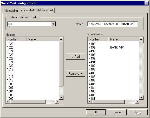
Creating Distribution Lists
8-6 AltiContact Manager Administration Manual
Figure 2. Voice Mail Distribution List window, Voice Mail Configuration
Defining a Distribution List
1. In the Distribution List window, select an ID (0 ã 99) in the System
Distribution List ID drop-down list.
The list name, if any, now appears in the Name box; the members of
the list are now displayed in the Member box, and other available
extensions are displayed in the Non-Member box.
2. To give the list a name or change the existing name, type a descriptive
name into the Name box.
3. To add a member, select the name(s) in the Non-Member list and
click the Add button to move it to the Member list.
To remove a member, select the name(s) in the Member list and click
the Remove buttontomoveittotheNon-Member list.
You can select multiple names by using Ctrl-Click.
4. Click Apply to save your changes, or click OK to save and close the
System Configuration window.

AltiContact Manager Administration Manual 9-1
9.VoIP
Configuration
C
HAPTER
9
VoIP Configuration
An IP Dialing table and VoIP Codec attributes are set using the VoIP
Configuration configuration window.
To access the VoIP Configuration window:
ã Select the System Management menu, then select VoIP
ConfigurationãÎ,or,
ã Use the drop-down list next to the System icon, and select VoIP
Configuration.
Defining an IP Dialing Table
To use a AltiContact Manager-to-AltiContact Manager connection for
voice over IP, you need to configure the routing in the IP Dialing Table for
each AltiContact Manager system.
Note: To enable VoIP, you must have at least one Triton VoIP board
installed and configured. (The IP Dialing Table is disabled unless
there is at least one VoIP board installed.) You also must have
assigned an IP Trunk Access code, as discussed in ãAssigning
Trunk, Feature, IP Trunk, & Route Accessã on page 5-6, and you
must set the VoIP codecs as discussed in ãSetting VoIP Codecsã
on page 13-9.
About the Location ID Digit Length
In the IP dialing table, you define the addresses of the remote locations and
set a Location ID Digit Length. The dialing length sets the length of the
Location ID, the number you define in the dialing table to identify each
remote location.
The Location ID is used in dialing: the user dials the IP trunk access,
followed by the location ID to identify the remote location, followed by the
remote extension. For example, if the IP trunk access is 8,thelocation ID
is 27,andtheextension to reach is 837, the user dials 827837.
Defining an IP Dialing Table
9-2 AltiContact Manager Administration Manual
The Location ID Digit Length can be set to None, 1, 2, or 3ãa seemingly
simple choice. However simple it seems, though, it needs to be given some
thought before it is set. Location IDs are used system wide, and a
coordinated configuration is recommended. It is highly recommended to
use the same length for the location ID for all networked AltiContact
Manager systems. It may also be advantageous to use the same location IDs
at all locations. For example, if the location ID for the Chicago office is 12
when dialed from both San Francisco and New York, users who travel will
find it easier to work at multiple locations.
Use Caution Before Changing the Dialing Length
The dialing length can be changed without having to re-install or re-start
AltiContact Manager. However, if this number is changed, the location IDs
are all alteredãso that it is advisable to keep the original length if it works
well.
If you increase the location ID length, the number 0 is added to the front of
the location IDs. For example, if you change the length from 2 to 3, location
IDs 02 and 27 will become 002 and 027 respectively.
If you decrease the number of digits in the location ID, the last digit is
dropped from location IDs. For example, Location ID 240 becomes 24.
There is an exception to this truncation method: if the leading digit is 0, it
is dropped. For example, 048 becomes 48.
Defining the IP Dialing Table
The IP Dialing Table tab is the default view for the VoIP Configuration
window.
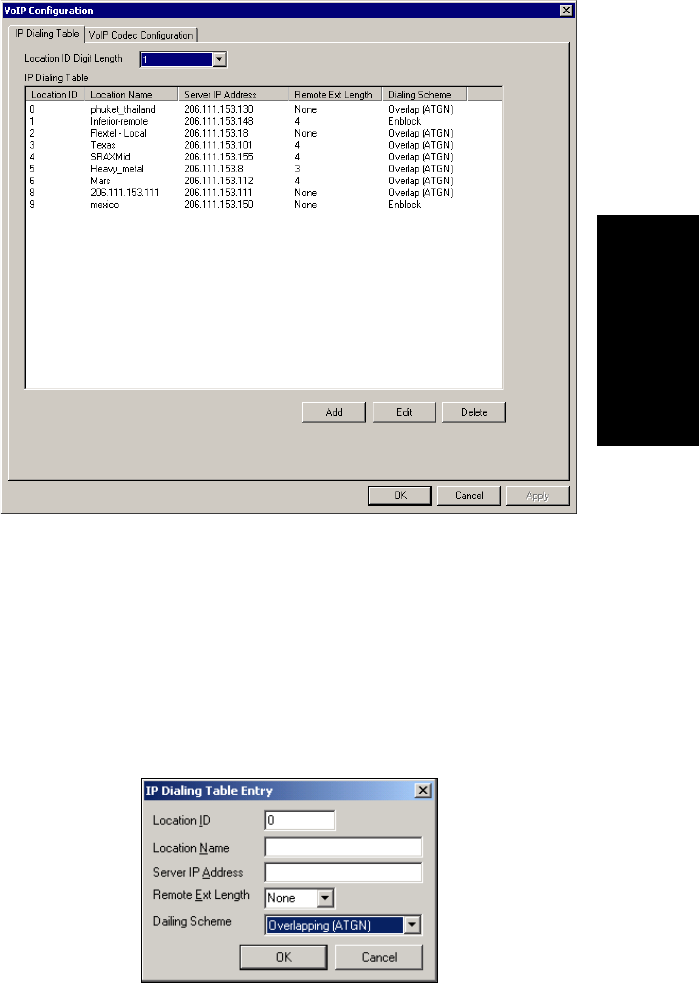
VoIP Configuration
AltiContact Manager Administration Manual 9-3
9.VoIP
Configuration
Figure 1. IP Dialing Table window, VoIP Configuration
Setting the Location ID Digit Length
Set the length in the Location ID Digit Length drop-down list, noting the
discussion about the length in the previous section.
Defining Remote Locations
To add a location, click the Add button to open an entry dialog box:
Defining an IP Dialing Table
9-4 AltiContact Manager Administration Manual
Define the attributes for the entry:
Parameter Description
Location ID A unique dialing number to connect to the remote
location. The length of the number is of course the
Location ID Digit Length described in ãAbout the
Location ID Digit Lengthã on page 9-1.
Location Name A descriptive name of up to 15 characters to identify
the location. This name may be used by Caller ID.
Server IP Address The remote serverãs address in one of the following
formats:
ã RFC assigned IP address (e.g. 100.100.100.100).
IP addresses with prefixes of 10.0.0.0/8,
172.16.0.0/12 or 192.168.0.0/16 can only be used
within private networks (Intranets).
ã Fully qualified DNS name (e.g.,
newyork.altigen.com), of up to 64 characters.
This IP address format is recommended over DNS
names, since with the IP address, the application does
not need to resolve the name.
Remote Ext. Length The length of extension digits at the remote location.
Valid entries are None - 7, with ãNoneã meaning not
specified. Specifying the remote extension length is
optional but highly recommended, since this
information tells the system how long to wait for
another entry before outpulsing (sending the digits).
Dialing Scheme Overlapping (ATGN) is best used with analog
trunks to allow the terminal to omit part of the digits
required to complete a call while buffering the
remaining digits.
Enbloc, used with digital (ISDN) trunks, allows the
terminal to include all of the digits required to
complete a call.

VoIP Configuration
AltiContact Manager Administration Manual 9-5
9.VoIP
Configuration
Setting VoIP Codecs
The default codec for static IP extensions is G.711, which gives a
bandwidth of approximately 64 kbps. This is appropriate for lease lines or
high-speed connections. The default codec for dynamic IP extensions is
G.723, which gives a bandwidth of approximately 6.4 kbps. This is
appropriate for internet connections.
ã G.711/G.723 compression and bandwidth requirements:
(for example, a Multilink Point-to-Point Protocol (MLPPP) or Frame
Relay Forum (FRF), with no Voice Activity Detection (VAD)
running)
ã G711 10ms packet frame = 100.8 kbps
ã G711 20ms packet frame = 82.4 kbps
ã G711 30ms packet frame = 76.3 kbps
ã G723 30ms packet frame 6.4k rate = 18.7 kbps
If you are running G.723.1 compression, you should reserve 17 kbps
WAN link bandwidth for each channel.
You can change these defaults and set dynamic IP addressing ranges and
codecs for AltiContact Manager-to-AltiContact Manager connections
using the VoIP Codec Configuration window.
To open the VoIP Codec Configuration window:
ã Select the VoIP Configuration... from the System Management
menu and select the VoIP Codec Configuration tab. Or,
ã Use the drop-down list next to the System icon, select VoIP
Configuration... and select the VoIP Codec Configuration tab.
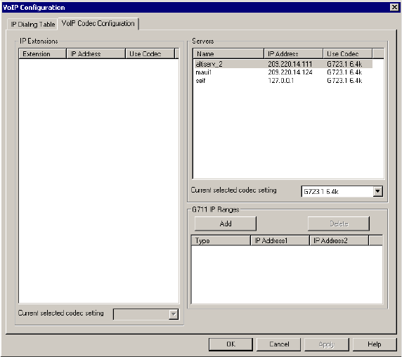
Setting VoIP Codecs
9-6 AltiContact Manager Administration Manual
Figure 2. VoIP Codec Configuration window, VoIP Configuration
To set the codec of an IP extension with static IP addressing:
1. Select the extension in the Static IP Extensions list.
2. In the drop-down below the list, select the codec to use for this
extension.
Parameter Description
Static IP Extensions Lists IP extensions with static IP addressing you
have created in the Extension Configuration window
Servers Lists other Contact Manager servers you have
entered in the IP Dialing Table window, which have
AltiContact Manager-to-AltiContact Manager
connections to your server
G711 IP Ranges Lists the G.711 dynamic IP address ranges you have
created in the Add IP Codec Setting dialog box,
described below
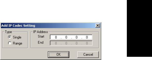
VoIP Configuration
AltiContact Manager Administration Manual 9-7
9.VoIP
Configuration
To set the codec for a connection to another AltiContact Manager
server:
1. Select the server in the Servers list.
2. In the drop-down below the list, select the codec to use for a
connection to this server.
Note: AltiContact Manager-to-AltiContact Manager IP connections
between systems must use the same codec.
To set ranges and values for dynamic IP addressing:
1. In the G711 IP Ranges list, click the Add button. The Add IP Codec
Setting dialog appears.
Figure 3. Add IP Codec Setting
2. In the Add IP Codec Setting dialog, specify Single or Range to set a
single dynamic IP address or a range of addresses.
3. Enter a Start value and, for a Range, an End value for the dynamic IP
addresses your IP extension users can access.
You cannot use the minimum and maximum values (0.0.0.0. and
255.255.255.255).
4. Click OK.
5. Repeat these steps for every range or value you wish to make available
for users of IP extensions with dynamic addressing.
Setting Ranges and Values with the 30-Port IP Board
If you do not have 12-Port IP boards in your system, and only have a 30-
Port IP board, you must configure the system to use G.711 only.
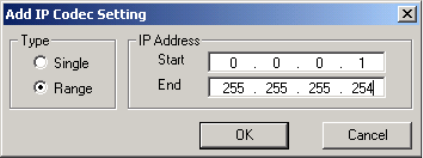
Network Configuration Guidelines for VoIP
9-8 AltiContact Manager Administration Manual
To set ranges and values for dynamic IP addressing when only using
a 30-Port IP Board:
1. In the G711 IP Ranges list, click the Add button. The Add IP Codec
Setting dialog appears.
Figure 4. Add IP Codec Setting
2. In the Add IP Codec Setting dialog, specify Range to set a range of
dynamic IP address.
3. Enter the Start value as 0.0.0.1;fortheEnd value, enter
255.255.255.254.
You cannot use the minimum and maximum values (0.0.0.0. and
255.255.255.255).
4. Click OK.
5. From the main menu, go to the VoIP Codec Configuration window
and change the codec setting of current selection of all servers and
codecs to G.711 uLaw, then click OK. (By default, server codec is set
to G.723.1.)
This will force all connections to be G.711 and allow remote users
access to a range of IP addresses, instead of the users having to contact
the administrator for the specific IP address.
Network Configuration Guidelines for VoIP
Real-time applications such as voice communications require a networking
environment that meets certain requirements to deliver and maintain good
voice quality. The following network configuration guidelines are highly
recommended when using AltiWareãs VoIP features. ISP/Intranet Quality
of Service (QoS)
ã If you subscribe to the public IP network or use your own Intranet,
make sure the maximum network delay is less than 150 milliseconds.
ã Also, the typical packet loss rate should be less than 5 percent.

VoIP Configuration
AltiContact Manager Administration Manual 9-9
9.VoIP
Configuration
WAN Bandwidth
ã G.711/G.723 compression and bandwidth requirements:
(for example, a Multilink Point-to-Point Protocol (MLPPP) or Frame
Relay Forum (FRF), with no Voice Activity Detection (VAD)
running)
ã G711 10ms packet frame = 100.8 kbps
ã G711 20ms packet frame = 82.4 kbps
ã G711 30ms packet frame = 76.3 kbps
ã G723 30ms packet frame 6.4k rate = 18.7 kbps
If you are running G.723.1 compression, you should reserve 17 kbps
WAN link bandwidth for each channel.
ã When a small data application (e.g. one FTP transfer session) is
running across the same WAN as AltiWare IP, make sure bandwidth
is reserved for data traffic. An example would be, if you have 64 kbps
WAN link, you can run one G.723.1 session concurrently with one
FTP file transfer session, provided that the router fragments each TCP
packet to 500 bytes.
ã The Jitter Buffer should be adjusted according to the bandwidth
allocated to data traffic. For example, a long Ethernet packet
(approximately 1500 bytes) traversing through a WAN which is
allocated with 256 kbps of data traffic bandwidth will take about 50
milliseconds. The Jitter Buffer value should be set to this WAN link
transmission delay plus the typical network jitter delay. Refer to
ãTriton VoIP Trunk Configurationã on page 7-13 for more information
on how to configure the Jitter Buffer.
ã If you have heavier data applications running concurrently, the
bandwidth reserved for data traffic should be increased.
ã If your router supports multilink or TCP fragmentation, configure your
WAN router to user smaller packet sizes, e.g. 500 bytes.
WAN Router Configuration
ã The router which connects your LAN and the WAN should support
priority queuing.
Network Configuration Guidelines for VoIP
9-10 AltiContact Manager Administration Manual
ã Configure the router so that the IP/UDP packets being sent to and from
an IP station have higher priority than the packets generated by other
stations on the same network. Please consult your router manufacturer
for more information on setting up this configuration.
Firewall Configuration
Pleasenotethefollowingveryimportant guidelines when working with a
firewall on your network:
ã If a firewall is used to protect your network access security,
reconfigure the firewall (as described in ãFirewall Considerationsã on
page 9-23) to open up TCP and UDP ports to the IP systemãs IP
address. This allows IPãs voice and H.323 packets to pass through the
firewall freely. If the firewall supports H.323 protocol, configure the
firewall using H.323 instead of opening up the specific ports.
ã Ensure that the rules to permit IPãs H.323 traffic are at the beginning
of your access filter list. This will minimize the delay of latency-
sensitive voice packets. This is ESPECIALLY important with long
access lists and/or slow routers.
Network Using NAT
If you plan to connect to your AltiContact Manager system via the
Internet and your router or Internet access provider is using Network
Address Translation (NAT), please note that most NAT
implementations DO NOT support H.323.
ã You are probably using NAT if both of the following conditions
apply:
ã Your AltiContact Manager server's IP address matches any of
the following numbers (where x is any number from 0-255):
ã 10.x.x.x
ã 172.16.x.x to 172.32.x.x
ã 192.168.x.x
ã You are able to connect to the Internet directly WITHOUT
using a proxy server.

VoIP Configuration
AltiContact Manager Administration Manual 9-11
9.VoIP
Configuration
ã Contact your router/firewall vendor to obtain a software update for
your networking equipment, or obtain routable address space from
your Internet provider. If you are unsure whether or not you are
using NAT, contact your router/firewall vendor or Internet
provider.
Network Configuration Guidelines for the Alti-IP
600
The following guidelines (specific to the Alti-IP 600 phone) should be
taken into consideration as a precursor to configuring your network for use
with NAT (see Network Configuration Guidelines below).
ã DHCP is recommended to reduce the risks for duplicating IP
addresses. AltiContact Manager provides seamless support for
AltiGen IP Phones using dynamic IP addresses. Select Dynamic IP
address for IP Extensions in ACM Admin.
ã A switch is recommended at the corporate network, rather than a hub,
for IP phone connection. This can reduce packet loss ratio.
ã If there are not enough IP addresses in the corporate network, refer to
ãPrivate and Public Network Configuration (AltiWare with Both
Private and Public IP Addresses)ã on page 9-18. If DHCP is used in
this configuration, the administrator will need to perform the following
for the Alti-IP 600:
1. Configure the DHCP server to assign a private network IP address
for each phone based on the phoneãs MAC address (printed on the
label on the bottom of the IP Phone.
2. Private IP address needs to be added to AltiServ and TFTP server
as well.
3. Launch an AltiGatekeeper with private IP address and point to
AltiWareãs private IP address.
Configuration Guidelines for NAT
Note: This section only applies to Alti-IP 600 phones or NetMeeting
integrated with AltiView. For third party IP Phones, refer to
AltiGenãs NAT Application Note.
Configuration Guidelines for NAT
9-12 AltiContact Manager Administration Manual
The following section discusses the use of NAT (Network Address
Translation) with AltiContact Managerãs IP functionality. Configurations
and limitations for using NAT are addressed, and network diagrams
explain the topology of these configurations. The first 3 examples involve
AltiContact Manager configurations for remote IP phones with a public IP
address, with a private IP address behind NAT, and with both private and
public IP addresses, respectively. The last example involves configuration
for a remote branch office environment where multiple IP phones require
connection to AltiContact Manager.
Notes:
ã When AltiContact Manager and the local IP phone both use a public
IP address and a remote IP phone is behind NAT, it is recommended
that you use the NAT configurations as described in ãPublic Network
Configuration (AltiWare with Public IP Address)ã on page 9-14.
ã When AltiContact Manager and local IP phones use private IP address
behind NAT, it is recommended that you use the NAT configurations
as described in ãPrivate Network Configuration (AltiWare with
private IP address and behind NAT)ã on page 9-16.
ã When a public IP address is used in the corporate network and there is
insufficient public IP address space for the IP phones, it is
recommended that you use the NAT configurations as described in
ãPrivate and Public Network Configuration (AltiWare with Both
Private and Public IP Addresses)ã on page 9-18.
ã When the remote offices have more than 1 (one) IP phone behind
NAT, it is recommended that you use the VPN configurations as
described in ãVPN Network Configuration (Connecting to AltiWare
with VPN)ã on page 9-20. You may also apply this configuration in
conjunction with the first 3 examples.
ã For single remote IP phones, it is recommended that you use the NAT
configurations as described in the first 3 examples.

VoIP Configuration
AltiContact Manager Administration Manual 9-13
9.VoIP
Configuration
IP Phone Configuration
When configuring the IP phone, you should specify the serverãs IP address,
referred to as AWIP ãAltiWareãs IP address.ã To configure AWIP for
AltiGen IP phone, please refer to ãAltiGen IP Phone Quick Referenceã and
edit the AW Server setting at the SYSTEM menu. For NetMeeting
integrated with AltiView, the AWIP is the AltiViewãs login server IP
address.
H.323 NAT
The NAT router must support H.323. The router should know the H.323
protocol and be able to translate the private IP address into a public IP
address in H.323 packets. Normally, you should configure the router to
forward all the H.323 traffic to a specified IP address of H.323 endpoint
behind the NAT. This H.323 endpoint can be one of AltiWare's or the IP
phone. (The IP address of this H.323 endpoint is referred to as H323FWIP
- "H.323 Forward IP address.")
Private IP address
Only the private IP address is used in private network - the public router
will not route the packet that has a private IP address as its destination. (All
IP addresses beginning with 192.168.x.x are referred to as private IP
addresses.)

Configuration Guidelines for NAT
9-14 AltiContact Manager Administration Manual
Remote IP Phone Connecting Through DSL or Cable Modem
Figure 5. Home Network with DSL/Cable Modem
Figure 1 shows a typical home network layout with DSL/cable modem with
an IP phone and PCs. A router that supports H.323 over NAT is required
between the DSL/Cable Modem and IP phone and PCs, if the DSL/Cable
Modem does not support H.323 over NAT. If this router provides multiple
10/100 BaseT ports for devices behind NAT, the IP phone and PCs plug
into these ports. Otherwise, a hub or switch is necessary to connect this
router, IP phone and PCs.
In the case where the DSL/Cable Modem supports H.323 over NAT, the
router and the DSL/Cable Modem can be converged into a single system.
Please refer to ãSetupã on page 9-14 for detailed configuration ofIP phones
and routers.
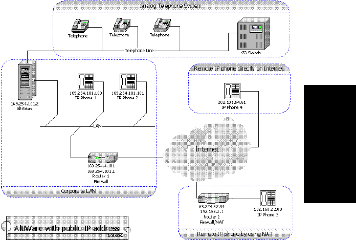
VoIP Configuration
AltiContact Manager Administration Manual 9-15
9.VoIP
Configuration
Public Network Configuration (AltiWare with Public IP
Address)
Figure 6. AltiWare with Public IP Address
Figure 2 shows a network layout in which AltiWare is installed and running
on a host with public IP address 169.254.101.2. The local IP phones, IP
Phone 1 and IP Phone 2, use public IP addresses 169.254.101.100 and
169.254.101.101, respectively. There are two remote IP phones. IP Phone
3 with private IP address 192.168.2.100 connects to the Internet via the
Router 2, which must also support H.323 NAT. Router 2 can also sit behind
a DSL/Cable Modem. Another remote IP phone, IP Phone 4, with public IP
address 202.101.54.61, connects to the Internet directly.
Setup
The following components should be configured:
For the corporate LAN:
ãÂAltiWare
The public IP address of Router 2 should be configured as the IP
address of this IP extension in AltiWare for IP Phone 3. If it is
Configuration Guidelines for NAT
9-16 AltiContact Manager Administration Manual
changed dynamically, then assign dynamic IP address
configuration for that extension.
ãÂIP Phone 1 and IP Phone 2
When configuring the local IP phones, IP Phone 1 and IP Phone 2,
you should set up the AWIP to AltiWare's IP address, which is
169.254.101.2.
ãÂRouter 1
Router 1 is a normal router and the firewall is optional. It is
recommended that the user install a firewall for security reasons.
However, you should configure the firewall to allow the H.323
traffic to reach AltiWare. For firewall considerations, refer to
ãFirewall Considerationsã on page 9-23.
For the Remote IP phone by using NAT:
ãÂIP Phone 3
When configuring remote IP Phone 3, you should set up the AWIP
to AltiWare's IP address, which is 169.254.101.2. Note that only
one (1) IP phone can be behind the NAT and connect to the
AltiWare through the H.323 NAT.
ãÂRouter 2
Router 2 is a router supporting H.323 NAT with the remote IP
phone connected. You need to set up the H.323FWIP for this H.323
NAT to the private IP address of IP Phone 3, which is
192.168.2.100. For information on how to set up the H.323 traffic
forwarding for H.323 NAT, please refer to ãSetting up H.323
Traffic Forwarding for H.323 NATã on page 9-24.
For the Remote IP Phone Directly on Internet:
ãÂIP Phone 4
When remotely configuring IP Phone 4, you should set up the
AWIP to AltiWare's IP address, which is 169.254.101.2.
For an H.323 IP Call from Another AltiWare on Internet:
Another AltiWare can make a H.323 IP call to this AltiWare by calling the
IP address 169.254.101.2.
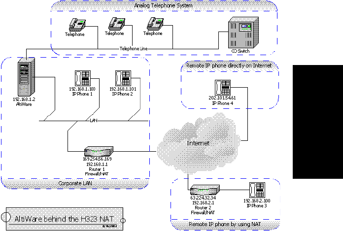
VoIP Configuration
AltiContact Manager Administration Manual 9-17
9.VoIP
Configuration
Private Network Configuration (AltiWare with private IP
address and behind NAT)
Figure 7. AltiWare behind NAT
Figure 3 shows a private network - 192.168.1.0, where the AltiWare is
installed and running on a host with a private IP address 192.168.1.2.
Router 1 is a H.323 NAT router. The local IP phones, IP Phone 1 and IP
Phone 2, use the private IP addresses 192.168.1.100 and 192.168.1.101,
respectively. There are two remote IP phones; IP Phone 3 with a private IP
address 192.168.2.100 connects to the Internet via Router 2, which must
also support H.323 NAT. Router 2 can also sit behind a DSL/Cable
Modem. Another remote IP phone, IP Phone 4, with a public IP address
202.101.54.61, connects to the Internet directly.
Setup
For the Corporate LAN:
ãÂAltiWare
The public IP address of Router 2 should be configured as the IP
address of this IP extension in AltiWare for IP Phone 3. If it is
Configuration Guidelines for NAT
9-18 AltiContact Manager Administration Manual
changed dynamically, then assign dynamic IP address
configuration for that extension.
ãÂIP Phone 1 and IP Phone 2
When configuring local IP Phone 1 and IP Phone 2, you should set
up the AWIP to AltiWare's IP address 192.168.1.2.
ãÂRouter 1
Router 1 is also a H.323 NAT. You need to set up the H.323FWIP
for this H.323 NAT to the private IP address of AltiWare
192.168.1.2. For information on how to set up the H.323 traffic
forwarding for H.323 NAT, please refer to ãSetting up H.323
Traffic Forwarding for H.323 NATã on page 9-24.
For the Remote IP Phone Using NAT
ãÂIP Phone 3
When configuring remote IP Phone 3, you should set up the AWIP
to Router 1's public IP address, which is 169.254.56.169. Note that
only ONE (1) IP phone can be behind the NAT and connect to the
AltiWare through the H.323 NAT.
ãÂRouter 2
Router 2 is a router supporting H.323 NAT with the remote IP
phone connected. You need to set up the H.323FWIP for this H.323
NAT to the private IP address of IP Phone 3, which is
192.168.2.100. For information on how to set up the H.323 traffic
forwarding for H.323 NAT, please refer to ãSetting up H.323
Traffic Forwarding for H.323 NATã on page 9-24
For the Remote IP Phone Directly on Internet:
ãÂIP Phone 4
When configuring remote IP Phone 4, you should set up the AWIP
to Router 1's public IP address, which is 169.254.56.169.
For an H323 IP Call from Another AltiWare on Internet:
Another AltiWare can make an H.323 IP call to this AltiWare by calling
Router 1's public IP address, which is 169.254.56.169.
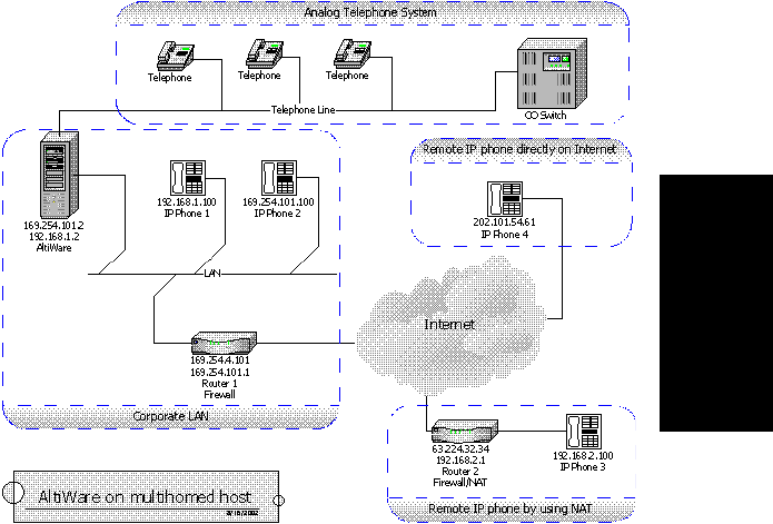
VoIP Configuration
AltiContact Manager Administration Manual 9-19
9.VoIP
Configuration
Private and Public Network Configuration (AltiWare with Both
Private and Public IP Addresses)
Figure 8. AltiWare on Multi-Homed Host
In the case of insufficient public IP addresses for local IP phones, IP phones
can be located in a private network. With private IP addresses assigned,
when assigning two IP addresses (one public and one private) to AltiWare,
H.323 NAT is not required in the local network.
Figure 4 shows this network layout, where the AltiWare is installed and
running on a multi-homed host with private IP address 192.168.1.2 and
public IP address 169.254.101.2.
IP Phone 1 uses the private IP address 192.168.1.100 and IP Phone 2 uses
the public IP address 169.254.101.100. There are two remote IP phones. IP
Phone 3 with private IP address 192.168.2.100 connects to the Internet via
the Router 2, which must also support H.323 NAT. Router 2 can also sit
behind a DSL/Cable Modem. Another remote IP phone one, IP Phone 4,
with a public IP address 202.101.54.61, connects to the Internet directly.
Setup
For the Corporate LAN:
Configuration Guidelines for NAT
9-20 AltiContact Manager Administration Manual
ãÂAltiWare
The public IP address of Router 2 should be configured as the IP
address of this IP extension in AltiWare for IP Phone 3. If it is
changed dynamically, then assign dynamic IP address
configuration for that extension.
Important: If there are two network cards on this multi-homed host, when
configuring the network cards, you should only set the default
gateway for the public interface network card. PLEASE
LEAVE THE DEFAULT GATEWAY FOR PRIVATE
INTERFACE NETWORK CARD EMPTY.
ãÂIP Phone 1
When configuring the local IP phone with private IP address, IP
Phone 1, you should set up the AWIP to AltiWare's private IP
address, which is 192.168.1.2.
ãÂIP Phone 2
When configuring the local IP phone with public IP address, IP
Phone 2, you should set up AWIP to AltiWare's public IP address,
which is 169.254.101.2.
ãÂRouter 1
Router 1 is a normal router and the firewall is optional. It is
recommended that the user install a firewall for security reasons.
However, you should configure the firewall to allow the H.323
traffic to reach AltiWare. For firewall considerations, refer to
ãFirewall Considerationsã on page 9-23.
For the Remote IP Phone Using NAT:
ãÂIP Phone 3
When configuring remote IP phone 3, you should set up the AWIP
to AltiWare's public IP address, which is 169.254.101.2. Note that
only one (1) IP phone can be behind the NAT and connect to the
AltiWare through the H.323 NAT.
ãÂRouter 2
Router 2 is a router supporting H.323 NAT with the remote IP
phone connected. You need to set up the H.323FWIP for this H.323
NAT to the private IP address of IP Phone 3 192.168.2.100. For
information on how to set up the H.323 traffic forwarding for H323
NAT, please refer to ãSetting up H.323 Traffic Forwarding for
H.323 NATã on page 9-24.
For the Remote IP Phone Directly on Internet:

VoIP Configuration
AltiContact Manager Administration Manual 9-21
9.VoIP
Configuration
ãÂIP Phone 4
When configuring remote IP Phone 4, you should set up the AWIP
to AltiWare's public IP address, which is 169.254.101.2.
For an H.323 IP Call from Another AltiWare on Internet:
Another AltiWare can make an H.323 IP call to this AltiWare by calling the
AltiWare's public IP address, which is 169.254.101.2.
VPN Network Configuration (Connecting to AltiWare with
VPN)
Figure 9. AltiWare with VPN
In a small branch office, there are more than one IP phones with private IP
addresses that require connection to AltiWare. Due to fact that H.323 NAT
only allows one IP phone behind it, a VPN solution can be used to meet this
requirement.
Figure 5 shows a network layout in which there are two private networks,
the corporate LAN and branch office LAN. The VPN tunnel connects the
two private networks such that the two networks access each other with a
private IP address.
Configuration Guidelines for NAT
9-22 AltiContact Manager Administration Manual
In the corporate network, AltiWare and AltiGatekeeper are installed and
running on a host with private IP address 192.168.1.2. This gatekeeper
redirects requests from local IP phones and from remote IP phones through
VPN.
Both Router 1 and Router 2 are VPN-capable and compatible with each
other. (It is recommended that the routers come from same vendor.) A VPN
tunnel exists between these two routers. The local IP phones, IP Phone 1
and IP Phone 2, directly connect to the corporate network with private IP
address 192.168.1.100and 192.168.1.101. And the three remote IP phones,
IP Phone 3, IP Phone 4 and IP Phone 5, connect to the branch office
network with private IP addresses 192.168.2.100, 192.168.2.101 and
192.168.2.102, respectively.
Setup
For the Corporate LAN:
ãÂAltiWare
AltiWare is installed and running at same host with private IP
address 192.168.1.2.
ãÂIP Phone 1 and IP Phone 2
When configuring the local IP Phone 1 and IP Phone 2, you should
set up the AWIP to AltiWare's IP address, which is 192.168.1.2.
For the Branch office LAN:
ãÂIP Phone 3,IP Phone 4 and IP Phone 5
When configuring the remote IP phones, IP Phone 3, IP Phone 4
and IP Phone 5, you should set up the AWIP to AltiWare's IP
address, which is 192.168.1.2.
For the VPN Tunnel between the Two Private Networks:
You must set up a VPN tunnel to connect the two private networks. The
VPN setup procedure may be complicated and is generally performed by a
professional IT technician.
The following minimum guidelines need to be considered for setting up the
VPN tunnel:
ãÂWAN Bandwidth - should be greater than the aggregate of
maximum VoIP session bandwidth usage. Each G.711 codec
requires 17 Kbps and each G.723.1 codec requires 85 Kbps.
ãÂQoS - if the IP WAN network provides QoS (Quality of Service), it
should be configured to honor VoIP RTP packet transmission.

VoIP Configuration
AltiContact Manager Administration Manual 9-23
9.VoIP
Configuration
An easy example for a VPN resolution is with the Linksys EtherFast VPN
router1. Router 1 and Route 2 are routers supporting VPN. When
configuring these VPN routers, the following information is needed. (Also,
please refer to the Router's User Guide for more detailed information.)
Router 1's Setting
Router 2's Setting
Router 2's public IP address should be a fixed IP address.
1Linksys is for reference only. AltiGen has not certified this product or any other
router at this time.
Local Secure Group:
(specifies the local network
which can access the VPN tun-
nel at the corporate network)
Subnet IP:
192.168.1.0
(Corporate Network)
Subnet Mask:
255.255.255.0
Remote Secure Group:
(specifies the remote network
which can access the VPN tun-
nel at the branch office net-
work)
Subnet IP:
192.168.2.0
(Branch Office Net-
work)
Subnet Mask:
255.255.255.0
Remote Security Gateway:
(specifies the public IP address
of the remote gateway which
can access the VPN tunnel at
the branch office)
63.224.32.34
(Router 2ãs public IP
Address
Local Secure Group:
(specifies the local private network in
the branch office, which can access
the corporate network through VPN)
Subnet IP:
192.168.2.0
(Branch Office Net-
work)
Subnet Mask:
255.255.255.0
Remote Secure Group:
(specifies the corporate network,
which can be accessed by stations in
this local private network through the
VPN tunnel)
Subnet IP:
192.168.1.0
(Corporate Network)
Subnet Mask:
255.255.255.0
Remote Security Gateway:
(specifies the public IP address of the
corporate VPN-enabled gateway)
169.254.56.159
(Router 1ãs public IP
Address

Firewall Considerations
9-24 AltiContact Manager Administration Manual
Firewall Considerations
If you are using a firewall in the AltiWare environment, the following are
the network ports used:
Client Server TCP UDP
ACM AdminaAltiWare DCOM 135 135
AltiConsole AltiLink + 10025
AltiControl AltiLink+ 10025
AltiReach AltiLink 10015
AltiView/AltiAgent AltiLink+
VM Service
10025
10028
Supervisor AltiLink+
Internal/External CDR
Logger
10025
10027
CDRSearch AltiLink+
Internal/External CDR
Logger
10025
10027
TAPI Client TAPI Gateway 10026
AltiGen IP Phone AltiGen IP Phone Service 10032
VoIP H.323/H.225
Gatekeeper
VoIP H.323/H.225 1720
1718, 1719
VoIP Message
Waiting
VoIP Message Waiting 49151
(Quicknet IP
ext only)
VoIP H.245 VoIP H.245 From 49152
to Nb
VoIP RTP VoIP RTP
VoIP ATPS VoIP ATPS 10032
Web Client AltiLink+
NetMeeting Chat
plusVoIPportsdescribed
above
10025
1720
Polycom Between
2222-2242
and 1718/
1719

VoIP Configuration
AltiContact Manager Administration Manual 9-25
9.VoIP
Configuration
Setting up H.323 Traffic Forwarding for H.323
NAT
When you configure the H.323 NAT router, it can forward the IP traffic to
a specified private IP address based on the destination port in the TCP/IP
or UDP packets. When an H.323 endpoint is behind the H.323 NAT, you
should set up the forwarding to a private IP address of this H323 endpoint.
If this H.323 endpoint is AltiWare, the NAT router must be configured to
forward the following ports to the H.323 endpoint's private IP address:
If this H.323 endpoint is an AltiGen IP Phone, the NAT router must be
configured to forward the following ports to the H.323 endpoint's private
IP address:
If this H.323 endpoint is NetMeeting integrated with AltiView, you need to
set all unknown TCP/UDP ports to be forwarded to the IP phone's private
IP address. This is usually referred to as DMZ port forwarding in most
NAT routers.
a. It is recommended that this be run only in an intranet.
b. N=49152+ (62*number of boards)ã1
TCP UDP Description
10032 1718 for phone service
1720 for H.225
49152~Na
a. N=49152 + (62 * number of VoIP boards) - 1
for H.245 and RTP/RTCP
TCP UDP Description
1720 for H.225
30040 ~ 30042 for H.245
30000 ~ 30001 for RTP/RTCP

Setting Up an AltiContact Manager-to-AltiContact Manager IP Network
9-26 AltiContact Manager Administration Manual
Setting Up an AltiContact Manager-to-
AltiContact Manager IP Network
Two or more AltiContact Manager systems can be networked together to
provide extension-to-extension connections via IP trunk calls. Users may
dial a remote AltiContact Managerãs auto attendant or direct dial to an
extension, without having to dial out through the PSTN. A diagram
illustrating a multiple AltiContact Manager-to-AltiContact Manager
connection is provided below and is referred to as an example throughout
the configuration instructions below.
Figure 10. AltiContact Manager-to-AltiContact Manager Connection
Follow the steps below to configure IP trunks for an AltiContact Manager-
to-AltiContact Manager tie-trunk line connection:
1. Confirm that the correct number of Triton VoIP boards are installed
and connected by checking the Boards window on the Main Window
of ACM Administrator. Refer to ãBoards View Windowã on page 4-5
for more details about this window.
2. Assign the IP trunk access code on the Number Plan tab window of
System Configuration. See ãIP Trunk Accessã on page 5-7.
3. Configure general trunk parameters on the General tab window of
Trunk Configuration. See ãSetting General Trunk Attributesã on
page 7-3.

VoIP Configuration
AltiContact Manager Administration Manual 9-27
9.VoIP
Configuration
4. Configure the dialing plan for connection to remote AltiContact
Manager systems on the IP Dialing Table tab window of System
Configuration.SettheNumber of Dialed Digits to ãNone.ã Refer to
ãDefining the IP Dialing Tableã on page 9-2.
5. Set the VoIP codecs so that servers use the same codec. See ãSetting
VoIPCodecsãonpage9-5.
6. Repeat steps 1 through 5 for all local and remote AltiContact Manager
systems that are to be networked via tie-trunk line connection.
This completes the AltiContact Manager-to-AltiContact Manager network
connection. Your organization is now ready to make and receive IP trunk
calls through public or private IP networks.
Note: Extension users should refer to the AltiView and AltiServ User
Guide for instructions on how to dial a remote AltiContact
Manager. Also, be sure to distribute the Remote Locations Dialing
Chart with your organizationãs unique dialing plan. This chart is
available in the AltiView and AltiServ User Guide.
Setting Up an AltiContact Manager-to-AltiContact Manager IP Network
9-28 AltiContact Manager Administration Manual

AltiContact Manager Administration Manual 10-1
10. Out Call Routing
Configuration
C
HAPTER
10
Out Call Routing Configuration
Out Call Routing Configuration allows you to define default routes for
outgoing calls as well as special routing for specific prefixes.
Aroute definition consists essentially of a name and a group of trunks,
listed in the order accessed for outgoing calls. You can assign different
routing configurationsãlists of route definitionsãto local, national,
international, and 911 outgoing calls. Access to the call routing trunks is set
up through the System Configuration Numbering Plan, discussed in
ãSetting a System Number Planã on page 5-4.
If you intend to use Out Call Routing for 911 calls, see the note, ãAbout
Call Routing and 911 Callsã on page 10-5.
Further, you can use the Out Call Routing Configuration window to create
and assign exceptions to the normal routes for particular dialing patterns.
That is, you can assign or restrict routing to specified dialing patterns.
About Restricting Outgoing Calls
Before using Out Call Routing to restrict outgoing calls, note that there are
three AltiContact Manager functions dealing with restricting outgoing
calls.
ãÂTheDialing Pattern function, discussed in this section in ãSetting
Dialing Pattern Routingã on page 10-6, is used to set up blocks with
specific exceptions. It also provides the ability to easily turn
restrictions on or off.
ãÂTheCall Restriction function of System Configuration, described in
ãDefining System Call Restrictionsã on page 5-12, provides for setting
up global blocks to outgoing calls and global parameters, such as toll
call prefixes, used for other restrictions.
ãÂOutcall restriction by extension is discussed in ãConfiguring Calling
Restrictionsãonpage13-26.
The global restrictions established in the Call Restriction window take
precedence over Dialing Pattern settings. You canãt set allow calling a
number in the Dialing Pattern window if it is blocked in the Call Restriction
window of System Configuration.
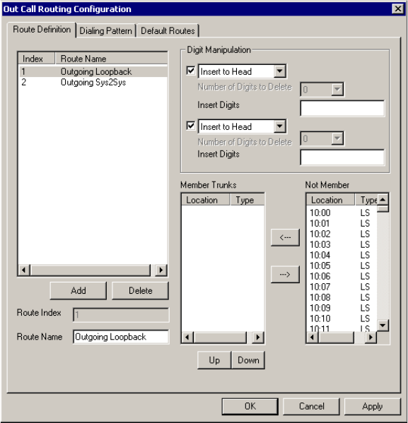
Working with Route Definitions
10-2 AltiContact Manager Administration Manual
Accessing Out Call Routing Configuration
To access Out Call Routing Configuration, select Out Call Routing
Configuration... on the System Management Menu.
Working with Route Definitions
The Route Definition tab is the default view on the Out Call Routing
Configuration window.
Figure 1. Route Definition window, Out Call Routing Configuration
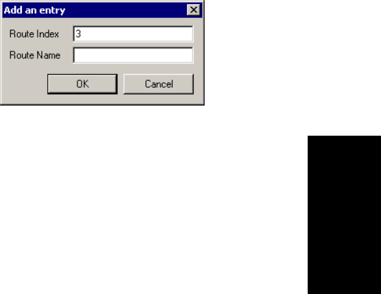
Out Call Routing Configuration
AltiContact Manager Administration Manual 10-3
10. Out Call Routing
Configuration
Adding Route Definitions
To add a route definition:
1. Click Add under the route definition list. The Addanentrydialog box
appears:
Figure 2. The Add an entry dialog box
2. Type in a name and index number:
ãÂTheRoute Index determines the position of the definition in the
index list of the Route Definition window.
ãÂTheRoute Name can be descriptive.
After adding the route, you then define it as described in the discussion
that follows.
Editing a Route Definition
To define a route definition:
1. Select and highlight the route in the definition list.
2. Make changes to the definition attributes. You can change the
following attributes:
ãÂRoute Name
You can change the name but not the index number.
ãÂDigit Manipulation
For each route, you can insert extra digits or remove prefix digits
from the number dialed by the user. The number sent to the trunk
will then have these digits added or removed.
ãInsert to Head inserts a string of digits to the number before it
is sent to the trunk. Type the digits into the String to Insert box.
Setting Default Routes
10-4 AltiContact Manager Administration Manual
ãDelete from Head removes prefix digits from the number
before it is sent to the trunk. Select the number of digits to
remove in the Number of Digits to Delete box.
ã Member and Non Member Trunks
Use this to define the trunks and trunk order for the route.
Member Trunksãdisplays the trunks assigned to the selected
route. The order in which member trunks are added determines the
order in which the trunks are accessed. (i.e. the first trunk listed is
used first, the second trunk is used next, and so forth).
Not Memberãdisplays the trunks, along with trunk location and
type, which are not assigned to the selected route.
To add trunks to a route definition group, highlight the trunks you
wish to add in the Non Member list, then click the left arrow to
move the trunks to the Member Trunks list. Similarly, you can
move trunks to the Non Member list to remove them from the
definition.
Use the Up and Down buttons to set the order in which the trunks
are accessed. Highlight the member trunk you wish to move, then
click Up or Down to place the trunk in the desired position.
3. Click Apply.
Deleting a Definition
To delete a route definition:
1. Highlight the definition you want to delete in the route definition list.
2. Click the Delete button beneath the list.
Setting Default Routes
The Default Routes function allows you to create default routes for four
types of outgoing calls: local, long distance, international, and 911.The
default routes are used for all Out Call Routing dialing except for special
routing defined on the Dialing Pattern window described later.
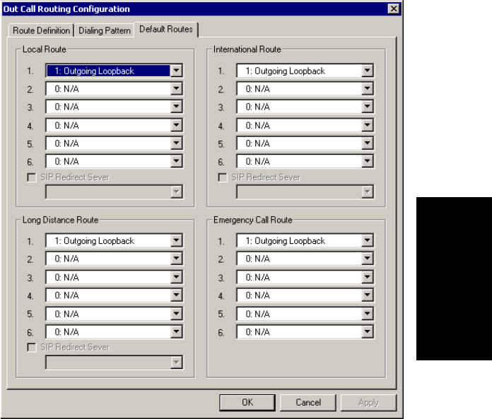
Out Call Routing Configuration
AltiContact Manager Administration Manual 10-5
10. Out Call Routing
Configuration
Click the Default Routes tabintheOut Call Routing Configuration
window to display the Default Routes window.
Figure 3. Default Routes window, Out Call Routing Configuration
For each of the four types of calls, you can use the drop-down lists to select
up to six route definitions. The order you set, from 1 to 6, is the order used
by the system when placing the call.
Note: The SIP Redirect Server fields are reserved for future use.
About Call Routing and 911 Calls
Important: If you use Call Routing for 911, make sure that the default 911
route is configured to the route that can accept 911 calling
capability. Failing to do so may cause 911 direct dialing
failure. You can leave the 911 default, in which case you need
Setting Dialing Pattern Routing
10-6 AltiContact Manager Administration Manual
to let all extension users know that they need to dial 9+911 to
call 911. It might be a good idea to have them sign a 911 dialing
disclaimer stating that they understand and accept the 9+911
configuration.
Setting Dialing Pattern Routing
You can use the Dialing Pattern window to create or disallow routing for
specific dialing patterns.
As noted in ãAbout Restricting Outgoing Callsã on page 10-1, there are
three AltiContact Manager functions to restrict outcalls, of which the Call
Restriction setup of System Configuration takes precedence.
The Dialing Pattern window provides for setting up blocks with specific
exceptions. For example, you could use this window to block calls that
begin with 767, but to accept and route calls to 767-2676, by disallowing a
ã767ã entry while setting up and providing routing for a separate
ã767-2676ã entry.
Click the Dialing Pattern tab on the Out Call Routing Configuration
window to display a Dialing Pattern window.
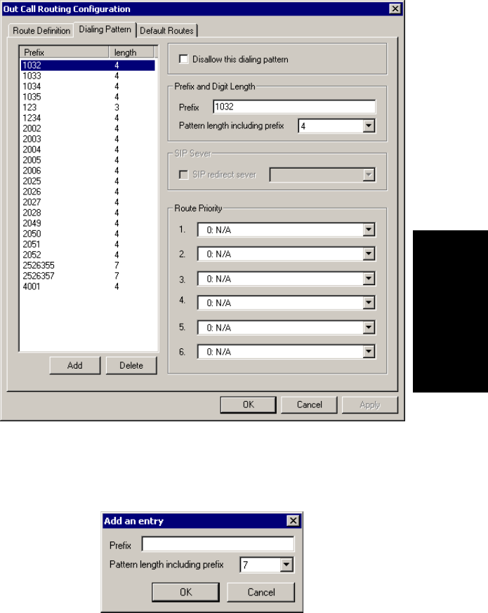
Out Call Routing Configuration
AltiContact Manager Administration Manual 10-7
10. Out Call Routing
Configuration
Figure 4. Dialing Pattern window, Out Call Routing Configuration
Adding a Dialing Pattern Definition
1. Click Add to open the Add an entry dialog box.
2. Type in a Prefix number, select the pattern length,thenclickOK.
Setting Dialing Pattern Routing
10-8 AltiContact Manager Administration Manual
Note: The pattern length tells the system to wait for nnumber of digits to
be dialed before executing the route or disallowing the call.
Selecting N/A creates a ã?ã symbol in place of number of the digits,
and this indicates an unspecified number of digits.
After a route is added, you can edit to further define it as described in the
following discussion.
Editing a Dialing Pattern
To edit, or define, a pattern, select and highlight the route in the prefix list,
make changes to the attributes, then click Apply.
You can change the following attributes:
ãÂPrefix and Pattern length. If desired, you can change the prefix
number and pattern length for a prefix.
ãÂDisallow this dialing pattern check box. Select this to block calls that
match the dialing pattern.
ãÂRoute Priority boxes. These specify the trunk route(s) and the order
of routes assigned to the prefix. Use the drop-down list to select the
desired route used when the selected dialing pattern is found. Up to six
routes can be assigned, and they are accessed in order from 1ã6.
Note: The SIP Redirect Server fields are reserved for future use.
Deleting a Pattern
To delete a pattern, highlight the one you want to delete in the prefix list,
then click Delete.
Example: 10-Digit Dialing
A sample use of dialing patterns is enabling 10-digit dialing, which some
geographical areas require. Normally, AltiContact Manager prepends a ã1ã
to 10-digit numbers when users use single-click calling features such as
zoomerang or calling from a Contacts list in AltiView or a TAPI-enabled
application. This could cause some calls to fail. Here is how you would
enable 10-digit dialing.
1. On the Route Definition tab, define a route that deletes one digit from
the head.
2. On the Dialing Pattern tab, create a dialing pattern with Prefix set to
<1+area code>, such as ã1408,ã and Pattern length set to ã11,ã where

Out Call Routing Configuration
AltiContact Manager Administration Manual 10-9
10. Out Call Routing
Configuration
area code is different from the AltiContact Manager system but
requires 10-digit dialing.
3. Assign the Route Priority for this dialing pattern to the Index of the
route definition you created above.
4. Repeat steps 2 and 3 above for other area codes requiring 10-digit
dialing as necessary.
Reducing Dialing Delay For En-Bloc Trunks For Non-US/
Canada Countries
When using a country code other than USA & Canada in System
Configuration, there will be a 7 second dialing delay for en-bloc trunks. To
reduce this delay, Out Call Routing Configuration can be used as a
workaround.
To reduce dialing delay:
1. In the Number Plan page of System Configuration, select a digit for
route access.
2. In the Route Definition page of Out Call Routing Configuration,
add a route definition entry for en-bloc and assign the member en-bloc
trunk(s).
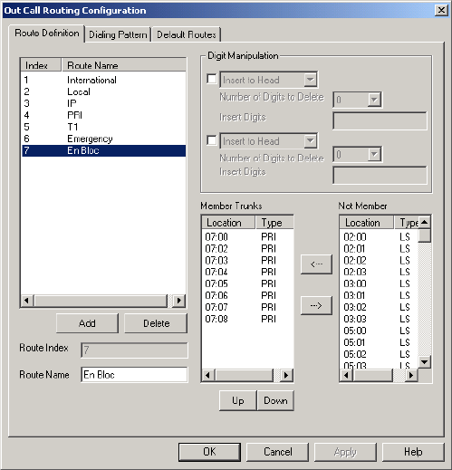
Setting Dialing Pattern Routing
10-10 AltiContact Manager Administration Manual
3. In the Dialing Pattern page of Out Call Routing Configuration,add
dialing pattern definition entries for the following prefixes:
ã prefix = 0, length = 11
ã prefix = 00, length = 14
ã prefixes = 1-9, each length = 7
In the Route Priority field, use the drop-down list to select the En-
Bloc route definition (assigned in Step 2).

Out Call Routing Configuration
AltiContact Manager Administration Manual 10-11
10. Out Call Routing
Configuration
The Dialing Pattern page should look as follows:
With this configuration, the system will see that all digits have been
collected and will send digits to the CO, instead of waiting 7 seconds for
the dialing to finish.
Setting Dialing Pattern Routing
10-12 AltiContact Manager Administration Manual

AltiContact Manager Administration Manual 11-1
11. IVR
Configuration
C
HAPTER
11
IVR Configuration
IVR performs simple call processing tasks such as transferring calls to
extensions to the AltiGen Voice Mail System or the operator, or giving
information and secondary options. It can also provide general information
that is frequently asked, such as company address. IVR allows multiple
incoming calls to be answered simultaneously. In a call-heavy environment
the IVR can greatly reduce the number of calls that need to be handled by
the operator. Calls that do not require an operatorãs assistance can be
handled effectively and appropriately.
IVR can handle more complex call processing tasks such as handling web-
based calls (in addition to PSTN calls).
It can also accept text or digits input by the user. For example, if the IVR
prompts the caller to enter an account number, the call and associated data
can be quickly forwarded to an agentãs desktop using a third party
application.
You can set up to 255 different IVRs, each using all the number keys as
well as the * and # key and a timeout option. Each IVR provides for
expanding and nestingãa menu choice leading to another menuãup to
any number of levels.
Planning is Essential
Follow the steps below before you set up an IVR.
1. Before you configure tasks for one or more IVRs, you should plan the
entire setup. Decide how many options you will provide at each menu
and how many menu levels you will use. Based on the action choices in
each menu, write down the appropriate prompts or phrases that are to
be played at each menu level.
2. Record phrases for each menu level or use the pre-recorded phrases that
are available to you. See ãPhrase Managementã on page 11-10 for more
details on how to record custom phrases, use pre-recorded phrases and
use professionally recorded phrases.
11-2 AltiContact Manager Administration Manual
Example: IVR Planning
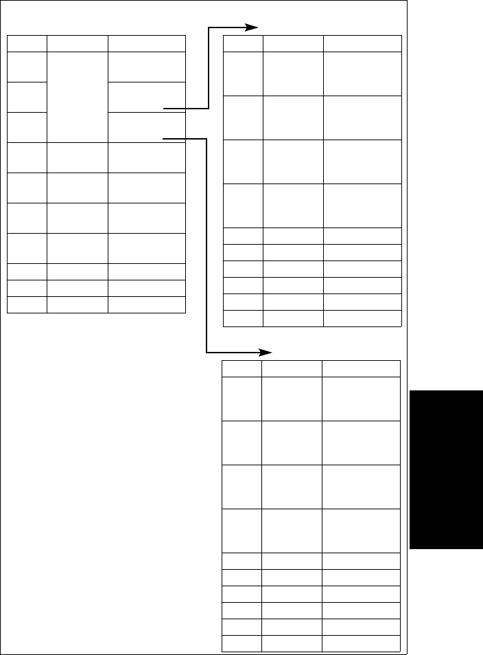
IVR Configuration
AltiContact Manager Administration Manual 11-3
Auto Attendant
Configuration
11. IVR
Configuration
Auto Attendant ID: 100, Phrase 10
Main Menu for XYZ Office
Digit Meaning Action
1Reserved
for
Extensions
(no
prompts)
Collect
Extension
2Collect
Extension
3Collect
Extension
4Express
Support
Expand Tree
(No. 110)
5Sales Expand Tree
(No. 120)
6Technical
Support
Expand Tree
(No. 130)
7Phone
FAQs
Expand Tree
(No. 140)
8
9
0Operator To Operator
Auto Attendant ID: 110, Phrase 20
Express Support
Digit Meaning Action
1Installation Call Extension
(Workgroup
350)
2Board
Support
Call Extension
(Workgroup
360)
3Version 5
Support
Call Extension
(Workgroup
370)
4Version 6
Support
Call Extension
(Workgroup
380)
5
6
7
8
9
0Operator To Operator
Auto Attendant ID: 120, Phrase 30
Sales
Digit Meaning Action
1Hardware Call Extension
(Workgroup
310)
2Application
s
Call Extension
(Workgroup
320)
3Check
Order
Status
GoTo Item 127
(Collect Order
#)
4Other:
Ques-tions,
etc.
Call Extension
(Workgroup
311)
5
6
7
8
9
0
Planning is essential in organizing
an IVR menu structure that makes
sense. Planning also helps you to
identify needs for custom prompts.
This simple example, using sample
work forms for each menu, shows a
beginning structure: a main menu
and two of the four expansions.
When callers are routed to
workgroup extensions, the
workgroups have their own call
handling settings for greetings,
update phrases, rules for sending to
voice mail, etc.
Timeout (not shown on forms):
after 7 seconds on first level, call
the operator; on any other level, go
to top level by default.
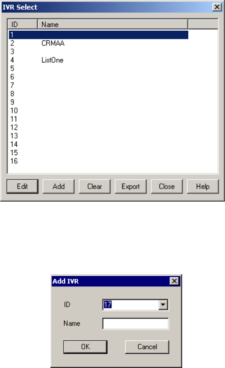
Adding IVRs
11-4 AltiContact Manager Administration Manual
Adding IVRs
The first 16 IVRs are provided by default with the menus blank. You can
edit these as described in ãEditing IVRsã on page 11-5. You donãt need to
add a new IVR if youãre going to use 16 or fewer.
To add an IVR beyond the first 16:
ã Select IVR ConfigurationãÎ from the CallCenter Management
menu, or
ã select the IVR icon.
Figure 1. IVR Select window
ãÂEditãopens the IVR window, where you can edit the IVR as
described in ãEditing IVRsã on page 11-5
ãÂAddãopens the IVR dialog box.
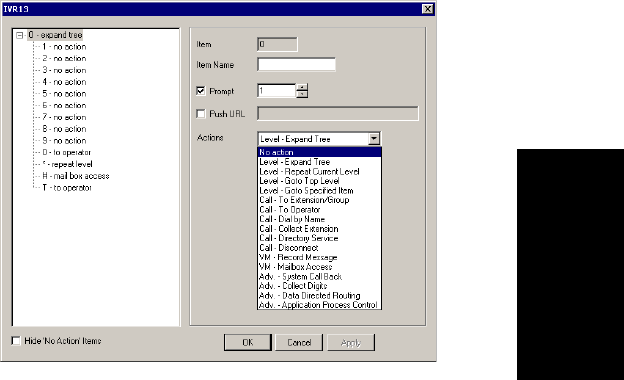
IVR Configuration
AltiContact Manager Administration Manual 11-5
Auto Attendant
Configuration
11. IVR
Configuration
Select an ID in the drop-down list and type in a descriptive Name for
IVR, then click OK.
ãÂClearãclears all edits to the selected IVR, restoring system defaults
ãÂExportãexports all IVR settings to an html file
ãÂCloseãcloses the IVR Select dialog box
ãÂHelpãopens the help file for IVR.
Editing IVRs
To edit an IVR, select IVR ConfigurationãÎ from the CallCenter
Management menu, or select IVR icon.
When the IVR Select window appears, select an IVR in the list and click
the Edit button.
This opens the IVR window with the IVR you selected in the title bar.
Figure 2. IVR window
Tip: You can use the Hide ãNo Actionã Items check box to hide items
that are set to ãno action.ã This will give you a cleaner view of your
various action items.
Editing IVRs
11-6 AltiContact Manager Administration Manual
Configuring Menu Items
For any menu item you want to use, you make an action assignment. If you
want the assignment to expand the menu to the next level, choose the
assignment, LevelãExpand Tree.
To make an assignment, select a menu item in the menu tree at the left, then
configure it using the entries at the right.
ãÂItemãan informational display of the level and item youãre working
with. The number gives the following information:
This key is easier to read when youãre also viewing the expanding
menu tree in the display at the left. To use a longer example: 09375
would mean that at the root level (0), menu item 9 is expanded, and on
the expanded menu, item 3 is selected. In turn, item 3 is expanded and
on that expanded menu, item 7 is selected. Item 7 is selected and on
that expansion, item 5 is selected.
ãÂItem Nameãthe name you wish to assign to the menu item.
Digit
Position Meaning Example
First Root level,
always 0 0nãrootlevel.ItIsfollowedbyadigit
if a menu item on the menu is selected.
If it is not followed by a digit, there is
no expanded menu tree, only a single
prompt and a single action such as rout-
ingtotheoperator.
Last Currently
Selected menu
item
06ã Menu item 6 is selected at the root
level
Inside Item & Level 058 ã Menu Item 5 at the root level is
expanded, and Menu Item 8 is selected
on the expanded menu.

IVR Configuration
AltiContact Manager Administration Manual 11-7
Auto Attendant
Configuration
11. IVR
Configuration
ãÂPromptãselect the prompt number that is to be played for incoming
calls. Prompts are numbered in the range of 0ã300. The default prompt
is 1, a generic greeting. See ãUsing Pre-Recorded Promptsã on page
11-10 to see the script of this prompt and other AltiGen supplied pre-
recorded prompts. Discussions on using customized and
professionally recorded prompts follow the section on using the
AltiGen supplied greetings.
ãÂPush URLãa URL associated with the menu item. When this entry is
selected, the web page and data is pushed to the web client and the web
client browser displays the page. Type a web address in the Push URL
text box if you wish to prompt a URL to the user.
ãÂActionsãthe event triggered by the caller pressing the digit for the
menu item. This drop-down list contains the available actions, which
are as follows:
Table 12. IVR Actions
Action Description
No Action An ãinvalidã message plays and the menu is
repeated.
Level - Expand Tree Plays the prompt for the next menu level down.
Level - Repeat Cur-
rent Level
Repeats the current prompt.
Level - Go to Top
Level
Repeats the first prompt at the root level and returns
the options to the root level options.
Level - Go to
Specified Item
Goes to selected menu item at any level. A drop-
down appears from which you select the item.
Call - To Ext./Work-
group
Goes to the extension or workgroup number you
select in the drop-down list that appears.
Call - To Operator Routes the call to the operator.
Call - Dial By Name Prompts the caller to enter the name (first, or last, or
both in any order) of the person they wish to speak
with and dials the extension that matches the name.
Callers may enter just the first letter of the last name
to hear a list of all users with last names that begin
with the letters entered.

Editing IVRs
11-8 AltiContact Manager Administration Manual
Collecting Digits
When you select the Adv. - Collect Digits action, the caller is prompted to
enter more digits. Once a minimum number of digits are entered, the
system proceeds to open a single item expansion of the Adv. - Collect
Digits action. In the item tree at the left, you can see a ã&-ã appear as an
expanded item action.
Call - Collect Exten-
sion
Call the extension entered by the user.
Call - Directory Ser-
vice
Lists the system users and their extensions to the
caller. For this to work properly, users need to record
their directory names.
Call - Disconnect Disconnects the call.
VM - Record Mes-
sage
Records the callerãs message. A drop-down list
appears from which you select the extension to which
to route the voice message.
VM - Mailbox Access Routes the call to the AltiGen Voice Mail System
voice mailbox after successful login. This is nor-
mally assigned to the #digit.
Adv. - System Call
Back
Calls the user at a remote location, only after the
caller logs in with extension and password.The
caller should enter a 1 and the area code if it is a long
distance number, or 011 and the country code if it is
an international number. You must be using a Cen-
trex system to use this feature.
Adv. - Collect Digits See the discussion below on ãCollecting Digitsã.
Adv. - Data Directed
Routing
Prompts the caller to input digits or text and use the
data entry to route the call. This allows third party
applications to route incoming calls based on caller
information.
Adv. - Application
Process Control
For 3rd party application integration.
Table 12. IVR Actions
Action Description
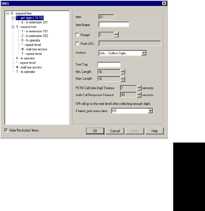
IVR Configuration
AltiContact Manager Administration Manual 11-9
Auto Attendant
Configuration
11. IVR
Configuration
To use the Collect Digits action:
1. Selecting the Adv. - Collect Digit action, first set the following
additional parameters:
Figure 3. Collect digits
ãÂText Tagãa name for this set of options.
ãÂMin. Lengthãthe minimum length of digits to be collected.
ãÂMax. Lengthãthe maximum length of digits to be collected.
ãÂPSTN Call Inter-Digit Timeoutãthe length of time the system
will wait between collecting of digits before timing out.
ãÂWeb Call Response Timeoutãthe length of time the system will
wait for digits after responding to a web-based call before timeout.
2. Click the expanded &-menu item in the item tree and treat it as a
normal itemãthat is, give it a name, a prompt, a push URL if
appropriate, and an action to take.
3. If the Collect Digits action fails (due to time out or not enough digits
are collected), you can set the IVR to take a failover routing, or back
up action. Use the dropdown list (If failed, go to menu item:) to select
a menu path that will serve as the failover action.
Phrase Management
11-10 AltiContact Manager Administration Manual
Making IVR Assignments
Once the IVRs are set up, you can use them in various in-call routing
situationsãtrunk configuration, answering for extensions or groups, and
so forth.
For example, for trunk /IVR assignments, see ãIncoming Call Routingã on
page 7-20. For extension or group assignments, see ãSetting Answering
Optionsãonpage13-28.
Phrase Management
You might want to record unique phrases to customize an IVR or a group.
When the system is configured to answer incoming calls by the IVR, callers
hear a customized greeting. For example:
ãThank you for calling ABC Company.
Enter the extension number of the person you wish to speak with.
Press 1 for sales,
Press 2 for technical support,
Press 3 for accounts payable,
Press 0 to reach the operator,
To repeat this menu, press star (*).ã
An example of a group greeting phrase:
ãPlease hold; someone will be with you shortly.ã
This section covers information using pre-recorded phrases, recording
custom phrases, and using professionally recorded phrases.
Using Pre-Recorded Prompts
AltiWare provides ready-to-use pre-recorded phrases. Phrase 0001 is the
default IVR greeting at the root menu level. Phrases 0291 through 0297 are
phrases used for group queue prompts.
Phrase # Phrase
0001
(default)
Thank you for calling. If you know the extension of the person
youwishtospeakwith,pleaseenteritnow.Toreachthe
operator, press 0or simply stay on the line.

IVR Configuration
AltiContact Manager Administration Manual 11-11
Auto Attendant
Configuration
11. IVR
Configuration
Recording Custom Phrases
When you create custom phrases, you should keep a record of phrase
numbers and the corresponding phrases so that if a phrase needs to be
changed, the correct phrase number is readily available.
To record a custom phrase:
1. Log in from any telephone on the system with the system managerãs
extension and password.
This brings you to the AltiGen Voice Mail System Main Menu.
2. Press 6for the Phrase Management option.
3. Press 2to record a phrase.
4. Enter a four-digit phrase number between 0001 and 0999.
5. Record the phrase after the tone. Press #at the end of the recording.
0291
(default)
Please hold; someone will be with you shortly. For your
convenience, you may leave a message if you wish by pressing
the # key on your telephone and we will get right back to you.
0292 Please hold; someone will be with you shortly.
0293 We appreciate your call and will be with you as quickly as
possible.
0294 Thank you for your patience. We should be with you soon.
0295 Thank you for your patience. We should be with you soon. For
your convenience, you may leave a message if you wish by
pressing the # key on your telephone and we will get right back
to you.
0296 We apologize for the extended delay, but our current call load is
abnormally high. Remember, you may leave a message by
pressing the # key on your telephone and we will get right back
to you.
0297 You may still wait if you prefer, but we suggest you leave a
message by pressing the # key on your telephone and we will get
right back to you.
Phrase # Phrase
Phrase Management
11-12 AltiContact Manager Administration Manual
6. The system will replay the recorded phrase. Press # if the recording is
acceptable.
7. At the Phrase Management menu, press 2to record additional prompts
or star (*) to exit Phrase Management.
Using Professionally Recorded Phrases
Recording studios such as Worldly Voices (see AltiGenãs Support Page at
http://support.altigen.com for more information) provide professionally
recorded prompts as electronic files that can be installed and used on
AltiWare.
AltiGen provides a utility to convert these files into the proper AltiWare
format. Some recording studios provide the conversion service for an
additional fee. The converted file can then be used for IVR or group setup.
To install professionally recorded phrases or prompts:
1. Assign a prompt number (between 0001 to 0999) to each prompt you
would like recorded.
2. Submit your prompt script and prompt number to the recording studio.
3. Instruct the recording studio to record prompts in either 8KHz or
11.025KHz mono in the WAVE format.
4. Ask the studio to convert the WAVE file(s) into the proper AltiWare
format.
ã If using Worldly Voices, this conversion is done for you.
ã If you are using a studio other than Worldly Voices, the conversion
utility is available from AltiGenãs Support Web site at http://
support.altigen.com. This utility allows you to convert an audio file
recorded at either 8KHz or 11.025KHz in the WAVE format to an
AltiWare playable audio file.
5. The prompt should be saved in the following file name format:
ãÂ0001.wav for phrase #0001
ãÂ0002.wav for phrase #0002, etc.
6. Once you receive the prompts in the AltiWare format, place them in
the altiserv\phrases\LangCustom directory on the AltiWare.
Your prompts are now ready to be used in IVR or group setup.

AltiContact Manager Administration Manual 12-1
12. CallCenter
Configuration
C
HAPTER
12
CallCenter Configuration
The CallCenter Configuration functions provide for configuring the call
center settings for AltiContact Manager.
Access CallCenter Configuration by selecting CallCenter
Configuration... on the Management Menu, or by clicking the CallCenter
Configuration icon.
You can then work with the following settings, each of which is access by
a tab in the CallCenter Configuration window.
ãÂCaller ID RoutingãCaller ID-based call routing for incoming trunk
calls.
ãÂDNIS RoutingãDNIS-based call routing for incoming trunk calls.
ãÂAgent Logout Reasonãdefines reason codes to allow agents to
specify why they are signing off from a workgroup.
ãÂCall Recordingãenables a voice recording option to record an
agentãs incoming workgroup calls.
Caller ID Routing
When an incoming call comes through a trunk with Caller ID (numbers or
digits), the system can route the call to the proper extension, IVR or
operator based on the Caller ID number collected.
Note: Caller ID supports only incoming trunks, and in the case of T1 and
PRI, Caller ID works with incoming trunks that are not set up as tie
trunks.
In order to locate an entry in the Caller ID table for an incoming call, a full
match is required. If there is no match in the Caller ID routing table set up
in this window, the system tries to match the number based on the DID
number entered in the General page of Extension Configuration (see
ãSetting up Extensionsã on page 13-3). If there is still no match, the system
routes the call according to the In Call Routing page defined in Trunk
Configuration.
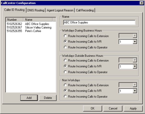
Caller ID Routing
12-2 AltiContact Manager Administration Manual
To access Caller ID routing, select CallCenter Configuration... on the
Management menu, then click the Caller ID Routing tab (the default
view).
Figure 1. Caller ID Routing window, CallCenter Configuration
Adding and Deleting Caller ID Route Entries
To add entries to the Caller ID routing table, click the Add button. In the
dialog box that appears, type in a Caller ID Number and a descriptive
Caller ID Name, then click OK.
The number and name entries have the following requirements:
ãÂTheCaller ID Number must be devoid of all characters EXCEPT ã-ã
(hyphen), ã*ã (asterisk), and the numbers 0ã9. For example, 2529876
is an acceptable entry.
ãÂTheCaller ID Name is descriptive and optional; it can be used to
remind you about the nature of the number and routing. For example,
you might give the 2529876 number the name, ãTech Support.ã
To delete an entry, select it in the Caller ID number list, then click Delete.

CallCenter Configuration
AltiContact Manager Administration Manual 12-3
12. CallCenter
Configuration
Defining the Routing
After adding an entry, you define it by first selecting it in the list. When you
select an entry, its name and other defined attributes, if any, appear in the
options at the right of the window. You can edit any of these attributes.
For each number, you can set routing for three distinct time periods defined
in the Business Hours window (see ãSetting Business Hoursã on page 5-8):
ã During Business Hours
ã Outside Business Hours
ã Non Workdays
Within each of these three time slots, you have the following routing
options for incoming calls:
ã Route to a particular extension selected in the drop-down list
ã Route to a particular IVR number selected in the drop-down list
ã Route to the operator
DNIS Routing
When an incoming call comes through a trunk with DNIS or DID numbers,
the system can route the call to the proper extension, IVR or operator based
on the DNIS or DID number collected.
Note: DNIS supports only incoming T1, PRI, and analog DID trunks, and
in the case of T1 and PRI, DNIS works with incoming trunks that
are not set up as tie trunks.
In order to locate an entry in the DNIS table for an incoming call, a full
match is required. If there is no match in the DNIS routing table set up in
this window, the system tries to match the number based on the DID
number entered in the General page of Extension Configuration (see
ãSetting up Extensionsã on page 13-3). If there is still no match, the system
routes the call according to the In Call Routing page defined in Trunk
Configuration.
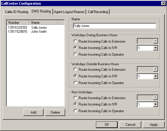
DNIS Routing
12-4 AltiContact Manager Administration Manual
To access DNIS routing, select CallCenter Configuration... on the
Management menu, then click the DNIS Routing tab.
Figure 2. DNIS Routing window, CallCenter Configuration
Adding and Deleting DNIS Route Entries
To add entries to the DNIS routing table, click the Add button. In the dialog
box that appears, type in a DNIS Number and a descriptive DNIS Name,
then click OK.
The number and name entries have the following requirements:
ãÂTheDNIS Number must be devoid of all characters except the
numbers 0ã9 (the hyphen is not accepted in this dialog box). For
example, 2529876 is a good entry, but 252-9876 is not.
ãÂTheDNIS Name is descriptive and optional; it can be used to remind
you about the nature of the number and routing. For example, you
might give the 2529876 number the name, ãTech Support.ã
To delete an entry, select it in the DNIS number list, then click Delete.

CallCenter Configuration
AltiContact Manager Administration Manual 12-5
12. CallCenter
Configuration
Defining the Routing
After adding an entry, you define it by first selecting it in the list. When you
select an entry, its name and other defined attributes, if any, appear in the
options at the right of the window. You can edit any of these attributes.
For each number, you can set routing for three distinct time periods defined
in the Business Hours window (see ãSetting Business Hoursã on page 5-8):
ã During Business Hours
ã Outside Business Hours
ã Non Workdays
Within each of these three time slots, you have the following routing
options for incoming calls:
ã Route to a particular extension selected in the drop-down list
ã Route to a particular IVR number selected in the drop-down list
ã Route to the operator
Agent Logout Reason Codes
In a workgroup environment, logout reason codes allow agents to specify
why they are signing off from the workgroup, and the manager can view
that information. If logout reasons are required, the system requests a
reason at logout from the phone set and from the Agent application.
The Logout Reason window allows you to enable or disable the required
entry of a logout reason, and it provides for defining up to 20 reason codes.
A logout history can be tracked and stored for future analysis.
To access the Logout Reason window, select CallCenter Configuration...
on the System Management menu,thenclicktheAgent Logout Reason
tab.
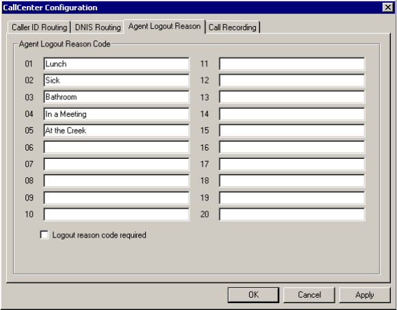
Call Recording
12-6 AltiContact Manager Administration Manual
.
Figure 3. Agent Logout Reason window, CallCenter Configuration
To require logoff reasons, check the Logout reason code required check
box. If you donãt want to require reason codes, deselect the check box.
To define reason codes, type the associated reason into the text box next to
the code you want to associate with the reason.
Call Recording
AltiContact Manager provides a system-wide, voice call recording feature
in the CallCenter Configuration.
Note: Call recording options for specific agents/workgroups can be set
up in General Configuration window of Agent Configuration
and Workgroup Configuration, respectively.
To access this option, select CallCenter Configuration... on the System
Management menu, then click the Call Recording tab.
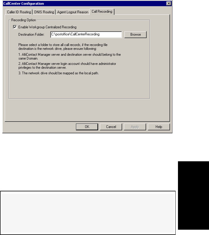
CallCenter Configuration
AltiContact Manager Administration Manual 12-7
12. CallCenter
Configuration
Figure 4. Call Recording window, CallCenter Configuration
To activate the recording option:
1. Select the Enable Workgroup Centralized Recording checkbox.
2. Set the destination folder and path for saving the call recording in the
Saving Folder field. The recording is saved in 64k PCM format only.
Notes:
ã This feature applies to inbound and outbound workgroup calls on PCI
analog extensions to a centralized location if configured in
Workgroup Configuration.
ã Calls can be silently monitored or barged-in on, regardless of agent
login status.
WARNING!
Listening in to or recording a conversation without the consent of one or
both parties may be a violation of local, state and federal privacy laws. It
is the responsibility of the users of this feature to assure they are in
compliance with all applicable laws.
Call Recording
12-8 AltiContact Manager Administration Manual

AltiContact Manager Administration Manual 13-1
13. Agent
Configuration
C
HAPTER
13
Agent Configuration
There are two types of Agent extensions:
ãÂPhysical Extensions are associated with a physical port and device,
usually a telephone set. This is what most users think of as an
extension.
ãÂVirtual Extensions are not associated with a physical port. Virtual
extensions can be used as message mailboxes and in telephone sharing
environments. Users of a virtual extension can log in on any available
station to access physical extension features using Feature Codes.
You can create up to 2,000 total (physical + virtual) extensions.
IP extensions can be configured either as physical or virtual extensions.
After creating the extensions, you then work with the following settings,
each of which is accessed by a tab in the Agent Configuration window.
ãÂGeneral setupãcreating the extension numbers and assigning people
to the extensions, creating workgroup pilot numbers, and setting other
basic parameters.
ãÂGroupãadd or remove huntgroup members.
ãÂSpeed Dialingãextension speed dial numbers.
ãÂMail Managementãcapacity and features options for extension
mailboxes.
ãÂNotificationãpreferences and options for voice mail notifications.
ãÂRestrictionãextension out-call restrictions.
ãÂAnsweringãcall forwarding, call waiting, and call handling
preferences and options.
ãÂOne Number Accessãspecial handling for designated VIP calls.
ãÂMonitor Listãextension rights to monitor other extension calls.
13-2 AltiContact Manager Administration Manual
Two Configuration Windows in One
Certain configuration functions apply only to physical extensionsãfor
example, configuring the physical line. And some functions, or the lack of
function, apply only to virtual extensionsãfor example, call waiting
options do not apply to virtual extensions.
Generally, you work on agentconfiguration by selecting an extension in the
General window, then clicking another tab to work on the settings in
another other window. The features and functions available in the Agent
Configuration windows vary depending on the type of extension selected.
When you select an extension in the General windowãthe first window
you see when you first launch Agent Configurationãand work on it under
other tabs, the extension number appears in the window title bar.
The entire group of extensions is shown as a Agent/Supervisor/Extension
side window list on the left side of the configuration window.
You can print the data in any of the windows by clicking the Print button.
Apply To Button
The agent configuration windows often allow you to apply changes to a
particular extension or to select many extensions to which to apply the
changes.
Clicking the Apply To button pops up a list of all extensions to which the
change can apply. All extensions are selected by default. You then de-
select the ones you donãt want, or de-select all and then select the ones you
want. Note that you cannot use the mouse to drag over and select multiple
items; you must use the Shift and Ctrl keys.
The Apply To button is disabled unless there is a change that can be
applied to multiple extensions, and when you use it to apply changes to
multiple extensions, it works on only those changed attributes that can be
applied. For example, if you use Apply To on the General window after
you changed the personãs name, you do not re-assign the same name to
others, because the name is not an attribute that uses Apply to.
Accessing Extension Configuration
To access Agent Configuration, either select Agent ConfigurationãÎ from
the CallCenter Management menu,or click the Agent Configuration
icon on the Quick Access Toolbar.
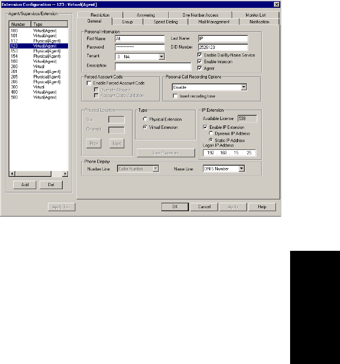
Agent Configuration
AltiContact Manager Administration Manual 13-3
13. Agent
Configuration
Setting up Extensions
The Agent Configuration General window provides for creating agent
extensions and establishing their basic attributes.
The General window is the default tab displayed when you open the Agent
Configuration window. If youãre viewing another Agent Configuration
window, you can click the General tab to open the General window.
Figure 1. General window, Agent Extension Configuration
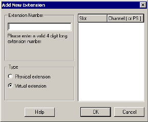
Setting up Extensions
13-4 AltiContact Manager Administration Manual
Adding New Extensions
To add a new extension:
1. Click the Add button in the General window. The Add New
Extension dialog box opens.
Figure2. AddNewExtensiondialogbox
2. Type in an Extension Number.
The number must begin with a number assigned to be used for exten-
sion, and it must be the length assigned to extensions, both of which
are set in the Number Plan in System Configuration as described in
ãSetting a System Number Planã on page 5-4.
3. Select the Type of extension from the two options, Physical or
Virtual.
4. Depending on the type of extension youãre creating, take one of the
following actions:
ã If youãre setting a virtual number, youãre done. Click OK.
ã If youãre setting up a physical extension, select an available
physical locationãslot and channel for the lineãthen click OK.
The slots (logical board ID) and the channels (the ports) are dis-
played and available if they have not yet been assigned to an exten-
sion.
Establishing Basic Extension Attributes
After you create an extension, you can set other basic attributes in the
Agent Configuration General window:

Agent Configuration
AltiContact Manager Administration Manual 13-5
13. Agent
Configuration
To set the Personal Information:
Type in the User Name, Password, DID, Tenant Group, and optional
Description:
ãÂFirst Name and Last Name of the extension user, each with a
maximum of 32 characters.
ãÂPassword for the extension user. The default is the system default
password set on the Number Plan tab of the System Configuration
window.
A valid password must be 4 to 8 digits (numbers or letters A-Z) in length
and cannot be the same as its extension number. Basic password patterns,
such as repeated digits (1111), consecutive digits strings (1234), or digits
that match the extension (Ext. 101 using 1012, 9101,10101, etc.) are not
allowed. The letters map to numbers as follows:
ãÂDID Numberãeach extension can be assigned a DID number. This
number does not have a fixed length, but the length must be long
enough (range 2ã16) for the system to match the DID incoming call.
It is HIGHLY recommended to use the full 10 digit DID number, not
just the last few digits. This full number guarantees the system can
send the correct number as the Caller ID on PRI lines. With fewer
digits, the system sends the trunkãs configured phone number as the
Caller ID. If the trunk number is not configured, the system main
number is sent.
Also, if more than 12 digits are assigned for the DID number, when
the extension makes an outbound call through PRI trunks, all the dig-
its will be sent to the target number. If the target number is not able to
display all the digits, it may show ãUnknown Numberã in the Caller
ID display.
Note: Please note the following information regarding Caller ID
when using particular phones.
ã Some phones (such as Nortel) can only display up to 12
digits for the Caller ID.
Numbers Letters Numbers Letters
2 A,B,C,a,b,c 6 M,N,O,m,n,o
3 D,E,F,d,e,f 7 P,Q,R,S,p,q,r,s
4 G,H,I,g,h,i 8 T,U,V,t,u,v
5 J,K,L,j,k,l 9 W,X,Y,Z,w,x,y,z
Setting up Extensions
13-6 AltiContact Manager Administration Manual
ã The Alti-IP 600 Phone can support up to 16 digits in the
Caller ID display.
ã AltiTouch/AltiTouch Plus phones support up to 12
digits in the Caller ID display. If the phone receives a
Caller ID length longer than 12 digits, it will display
ãUnknown Number.ã
ãÂTenantãa drop-down list of Tenant IDs (groups) to which the
extension can be assigned. See ãUsing a Tenant Tableã on page 5-22
for more information on Tenants.
Note: If an extension is assigned to N/A in the Tenant drop-down
list, the extension is able to access all trunks, even though the
trunks may have been assigned to tenants.
ãÂEnable Dial-By-Name Serviceãselect this box to allow callers to
search the extension list by employee name for this extension.
Note: The Tenant and Enable Dial-by-Name Service settings can
be applied to multiple extensions by using Apply To,as
described in ãApply To Buttonã on page 13-2.
ãÂDescriptionãOptional descriptive information such as cubicle
number or job title.
ãÂEnable Intercomãselect this box to enable the intercom call feature
for this extension. Pressing #93 allows the user to make an intercom
call to another intercom-enabled extension.
Note: Intercom is only available for extensions on Triton Analog
Extension Boards and AltiGen IP Phone Extensions. The option is
grayed out for extensions on Quantum boards.
ãÂAgent Check Box - allows the extension to be added as a member of
one or multiple huntgroups or workgroups. ã(Agent)ã will displayed
in the extensionãs Type field, next to the extension type.
Note: For an extension being added to one or more workgroups,an Agent
License is required per extension.
Forced Account Code
These settings determine how callers use any account codes you have
established when making outgoing trunk calls. For information on creating
account/code associations, see ãCreating Account Codesã on page 5-15.

Agent Configuration
AltiContact Manager Administration Manual 13-7
13. Agent
Configuration
ãÂEnable Forced Account Codeãselected, forces the user to enter an
account code.
ãÂOverride Allowedãselected, prompts the user to enter an account
code, or the user can press # to bypass the account code.
ãÂAccount Code Validationãselected, forces the user to enter a valid
account code.
Personal Call Recording Options
The system administrator can specify the following personal call recording
options for an agent extension:
ãÂDisableãno call recording.
ãÂRecord all calls to central locationãrecords all calls which are saved
to a centralized location (defined in the Call Recording page of
CallCenter Configuration, see page 12-6); this option requires a
Recording Seat license to be available.
ãÂRecord on demand to central locationãrecords calls on demand
which are saved to a centralized location (defined in the Call
Recording page of CallCenter Configuration, see page 12-6); this
option requires a Recording Seat license to be available.
ãÂRecord on demand to agent VMãrecords calls on demand which
are saved to the extension agentãs voicemail box.
ãÂInsert Recording Toneãplays a recording beep to alert the parties
that the conversation is being recorded.
Notes:
ã The recording session starts when the call enters the connected state
and ends when hang up or flash is pressed, or when the call is
transferred.
WARNING!
Listening in to or recording a conversation without the consent of one or
both parties may be a violation of local, state and federal privacy laws. It
is the responsibility of the users of this feature to assure they are in
compliance with all applicable laws.
Setting up Extensions
13-8 AltiContact Manager Administration Manual
ã The recording setting at Extension Configuration only applies to
personal calls. The recording setting at Workgroup Configuration only
applies to workgroup calls. To allow an agent to record all calls
(personal and workgroup), both recording settings must be enabled.
Changing the Extension Location or Type
Changing the Type
The type of extension is set when you create the extension: physical or
virtual, described on page 13-2. After you create the extension, the
extension is displayed in brackets within a tree list on the left side of the
General window.
You can change a Virtual extension to a Physical one, and vice versa.
If you change the type to physical, you can also set the location and
configure the line as discussed in the subsequent paragraphs.
Changing the Location
When you create a physical extension, you assign it a location or you accept
an automatically assigned location. If you have available extensions, you
can change the location in the General window.
To change the location, select the extension number in the list of
extensions, then click the Previous or Next buttons to change the slot and
channel settings until the location you want is displayed. Like other
changes, this change isnãt finalized until you click Apply.
Setting an IP Extension
The IP Extension option allows an H.323 compliant terminal device (IP
phone) to connect to AltiContact Manager. IP extensions have the same
features as analog stations. For system requirements and limitations on
setting up IP extensions, see Chapter 16, Setting Up IP Extensions.
To use the IP Extension option, check the Enable IP Extension,thenset
the IP addressing by choosing either Dynamic or Static IP Addressing.If
you choose Static addressing, you need to type in a Logon IP Address.
The type of addressing you use affects users:

Agent Configuration
AltiContact Manager Administration Manual 13-9
13. Agent
Configuration
ãÂUsing dynamic IP addressing, the IP extension can log in from any
IP address. However, the IP extensions must always log in via the IVR
and log into voice mail to activate the IP extension. Users who travel
may well prefer dynamic addressing.
Note: AltiGen IP Phone extension users should not activate their IP
Phone by logging into voicemail ã instead, #27 should be
used to log in.
Important: When you enable dynamic IP addressing, a physical extension
on one AltiContact Manager system can effectively disable the
IVR for system-to-system IP calls to the second system. This
happens if a physical extension on one system calls a second
system via an IP trunk, logs into an extension, and enables an
IP connection. As long as the connection is active, all IP trunk
calls from the first to the second system will receive a dial tone
rather than the IVR. From the dial tone, callers can dial
extension numbers on the second system.
ãÂUsing static IP addressing, the extension user logs in from the station
having the IP address. An advantage for virtual extensions is that the
user doesnãt have to log in at all; when the user connects to the system,
the extension is immediately recognized as an IP extension. When
physical extensions connect, on the other hand, the system prompts the
user to log in. Static addressing is more convenient for users and may
be preferred by users who work primarily at a specific location.
Important: If you enter the serverãs IP address as the Logon, IP trunk calls
from another AltiContact Manager system will receive a dial
tone rather than the IVR. From the dial tone, callers can dial
extension numbers on this system.
Setting VoIP Codecs
The default codec for static IP extensions is G.711, which gives a
bandwidth of approximately 64 kbps. This is appropriate for lease lines or
high-speed connections. The default codec for dynamic IP extensions is
G.723, which gives a bandwidth of approximately 6.4 kbps. This is
appropriate for internet connections.
You can change these defaults and set dynamic IP addressing ranges and
codecs for AltiContact Manager-to-AltiContact Manager connections
using the VoIP Codec Configuration window.
To set up the VoIP codec and configure IP extensions, refer to the VoIP
Codec Configuration section on page 9-5.
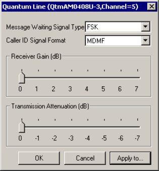
Setting up Extensions
13-10 AltiContact Manager Administration Manual
Setting the Line Properties
For a physical extension, you can configure hardware options on the board
port used for the extensions. To do so, select the extension number in the
list of extensions, then click the Line Properties button to open a dialog
box that is specific to the board using for the extension.
The Line Properties are somewhat different for Quantum Board than for
Triton Analog Station Boards. The subsequent sections deal first with
Quantum, then with Triton Analog Station.
Quantum Line Properties
If you select a Quantum board extension and click Line Properties, youãll
see the Quantum Line Properties dialog box. Note that you can use the
Apply toãÎ button to apply these hardware settings to one, some, or all
ports on the board. Using Apply toãÎ is discussed in ãApply To Buttonã on
page 13-2.
Figure 3. Quantum Line Properties dialog box for extensions

Agent Configuration
AltiContact Manager Administration Manual 13-11
13. Agent
Configuration
Configure the following hardware extension-specific features:
Caution: Use caution in setting the Receiver Gain or the
Transmission Attenuation. If either setting is too high, the
result will be distortion in voice quality.
Triton Analog Station Line Properties
If you select a Triton Analog Station Board extension and click the Line
Properties button, youãll see the Triton Analog Station Line Properties
dialog box. Note that you can use the Apply toãÎ button to apply these
hardware settings to one, some, or all ports on the board. Using Apply toãÎ
is discussed ãApply To Buttonã on page 13-2.
You can also access this window by double-clicking a span in Channel
Mapping List of the Triton Analog Station Board configuration window.
Parameter Description
Message Waiting
Signal Type Type of Message Waiting indicator for the phone set:
ãÂNone
ã Voltageãvoltage-based indicator.
ã FSKãFrequency Shift Keying indicator.
ã Toneãtone-based indicator.
Caller ID Signal
Format MessageformatwithwhichtosendCallerID
information:
ãÂNone
ãÂSDMFãSingleDataMessageFormatfor
supporting and sending a single data type, such as
phone numbers.
ãÂMDMFãMultiple Data Message Format for
supporting and sending multiple data types, such
as name and number information.
Receiver Gain/
Transmission
Attenuation
Incoming and outgoing volume for every extension.
Unlike the Quantum board, these slide settings have
positive and negative values. Both defaults are 0
decibels.

Setting up Extensions
13-12 AltiContact Manager Administration Manual
Figure 4. Triton Analog Station Line Properties dialog box
Configure the following hardware extension-specific features:
Parameter Description
Caller ID Signal
Format
Message format with which to send Caller ID
information:
ãÂNone
ãÂSDMFãSingleDataMessageFormatfor
supporting and sending a single data type, such
as phone numbers.
ãÂMDMFãMultiple Data Message Format for
supporting and sending multiple data types,
such as name and number information.
ãÂDTMFãDual Tone Multi-Frequency,
composed of high and low frequencies, for
touch tone dialing.
Message Waiting
Signal Type
Type of Message Waiting indicator for the phone set:
ãÂNone
ãÂFSK/SDMFãFrequency Shift Keying/Single
Data Message Format indicator.
ãÂFSK/MDMFãFrequency Shift Keying/
Multiple Data Message Format indicator.

Agent Configuration
AltiContact Manager Administration Manual 13-13
13. Agent
Configuration
Caution: If the Receiver Gain or the Transmission Attenuation
setting is too high, the result will be distortion in voice
quality.
Flash Duration Specifies the Flash Duration time in milliseconds:
ãÂ50-600
ãÂ100-700
ãÂ150-800
ãÂ200-900
ãÂ300-1000
Ringing Frequency Specifies the number of rings: 28 or 20
Line Disconnect
Signal
The loop break desired for answering supervision,
either 200 or 600 ms.
Note: If the extension uses a 390 phone with
Intercom service, set this to 750 ms.
Ringing Frequency Select the frequency in Hz that is necessary for the
equipment attached to this line.
Caller ID
Transmission
Methods
Specifies how Caller ID will be detected:
ãÂCID between 1st and 2nd ring - Caller ID is
received between first and second ring.
ãÂDT-AS+CID prior to ringing - Dual Tone
Alerting Signal Caller ID is received prior to
ringing.
ãÂRP-AS+CID prior to ringing -RingPulse
Alerting Signal Caller ID is received prior to
ringing.
Receiver Gain/
Transmission
Attenuation
Incoming and outgoing volume for every extension.
Unlike the Quantum board, these slide settings have
positive and negative values. Both defaults are 0
decibels.
Parameter Description
Setting up Extensions
13-14 AltiContact Manager Administration Manual
Phone Display Options
For analog and IP phones, the administrator can select what information is
to be displayed. Depending on the number of display lines on the LCD, the
phone can be set up to show two lines of specific caller information on the
display.
In the Phone Display field, use the Number Line and Name Line drop-
down lists to select the caller information to display:
ãÂCaller Number
ãÂCaller Name
ãÂDNIS Number
ãÂDNIS Name
ãÂIVR Data
ãÂUser Data
Note: For most phones, the number line can only display a number. If the
Number Line is set to Caller Name,DNIS Name,User Data or
IVR Data, the phone may display ãUnknownã on the number line.
Alti-IP 600 Phone Display Notes
For the Alti-IP 600, the Name Line displays caller information under the
following conditions:
ãIfName Line is set to Caller Name, it will display caller name. If
there is no name information, the number will be displayed.
ãIfName Line is set to Caller Number, it will display the caller
number. If there is no number information, ãUnknownã will be
displayed.
ãIfName Line is set to DNIS Name, it will display DNIS name. If
there is no name information, the DNIS number will be displayed.
ãIfName Line is set to DNIS Number, it will display the DNIS
number. If there is no number information, ãUnknownã will be
displayed.
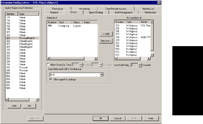
Agent Configuration
AltiContact Manager Administration Manual 13-15
13. Agent
Configuration
Setting Up Groups
The primary use of a huntgroup is similar to that of workgroups ã when
the huntgroup extension is dialed, the system hunts for an available
member extension to which to route the call. You can use huntgroups for
various purposes, for example, in selecting a huntgroup as a System
Operator.
Note: This is the second of the two ways (see ãEstablishing Huntgroup
Membershipã on page 14-6) to assign agent extensions as members
of huntgroups.
This methodãselecting a physical or virtual extension from the Agent
Extension General page, and then clicking the Group tabãprovides an
agent extension view of huntgroups. You can see all the huntgroups to
which the agent extension belongs, and you can change those assignments.
To open the Agent Extension view of the Group window:
1. Select the Virtual or Physical extension number from the Agent/
Supervisor/Extension side window list in the Agent Extension
General window.
2. Click the Group tab. The Extension view of the group window opens,
with the agent extension number appearing in the window title bar.
Figure 5. Physical Agent Extension view of Group window, Agent Extension
Configuration
Setting Up Groups
13-16 AltiContact Manager Administration Manual
Adding or Removing Huntgroup Assignments
To assign huntgroups to the selected physical or virtual extension:
1. In the Agent Extension view of the Group window, click the huntgroup
pilot number(s) in the Not Member list.
2. Click the Add button to move them to the Member list.
Note: If the huntgroup pilot extension is configured to Ring All
Available Members, the maximum number of members is 20.
See ãSetting Call Handling Optionsã on page 14-17 for details.
To remove huntgroups assigned to a physical or virtual extension:
1. Click the huntgroup pilot number(s) in the Member list.
2. Click the Remove button to move them to the Not Member list.
Setting Wrapup Time
In the Extension view, you can set the Wrapup Time for the selected
physical agent extension. This option doesnãt appear for a virtual extension
or a non-agent extension. Wrapup time is a system delay before routing the
next call to the extension, and it gives the agent time to finish up with notes,
prepare for the next call, log out of the huntgroup, or hit the ãWaitã button
in AltiView after putting a call on hold and going back onhook. You can
set a wrapup time of up to 29 minutes, 59 seconds.
To set the extension wrapup time:
1. Check the Allow Wrap Up Time box.
2. Using the drop-down lists, select the minutes and seconds for the
delay. Be sure to set at least enough time (e.g. 5 seconds) to allow an
agent to hit the ãWaitã button in AltiView after putting the caller on
hold and going onhook.
Setting Inter Call Delay
Like Wrapup time, Inter Call Delay can create time before the next call
comes in. It can be set for any extension.
If the system is delaying the next call to a user extension based on the
Wrapup Time setting, the Inter Call Delay setting is ignored.
However, if Wrapup Time does not applyãfor example, if it is de-
selectedãthen Inter Call Delay acts as follows:

Agent Configuration
AltiContact Manager Administration Manual 13-17
13. Agent
Configuration
ã If the extension user hangs up and there are callers waiting in an
extension or huntgroup queue, the ring is delayed for the number of
seconds specified in the Inter Call Delay setting.
ã If the extension user hangs up, there is no one waiting in a queue and
a call comes in within the Inter Call Delay period, the call is put
through immediately; the Inter Call Delay period is ignored.
To set the extension Inter Call Delay time:
1. Check the Inter Call Delay box.
2. Using the drop-down lists, select the seconds for the delay. The default
is 15 seconds.
Logging Outbound Workgroup Calls
In the Extension view, you can assign an agent to an outgoing workgroup,
which is useful for call detail reporting and workgroup statistics. All calls
made by the agent while logged into the workgroup will be tracked as calls
from the workgroup. The agentãs outgoing workgroup can be assigned to
any workgroup to which he is a member of.
To set an agentãs outgoing workgroup:
In the Log Outbound Call to Workgroup field, use the drop-down list to
choose a workgroup from among the workgroups the agent belongs to. If
the ãAllow agent to changeã checkbox is selected, the agent can change the
outgoing workgroup from the phone set or from AltiAgent.
When a user is first assigned to a workgroup, it is set as their default
outgoing workgroup and remains so no matter how many workgroups the
user is subsequently assigned to. If an agent is unassigned from their
outgoing workgroup, the outgoing workgroup is automatically set to N/A.
Setting up Station Speed Dialing
For each extension, you can set up to 20 station speed dial numbers. The
numbers available are from 00ã19, used following the extension speed dial
access code, #77.
To work with Speed Dialing settings, select the extension number you want
to work with from the Agent/Supervisor/Extension side window list, then
click the Speed Dialing tab.
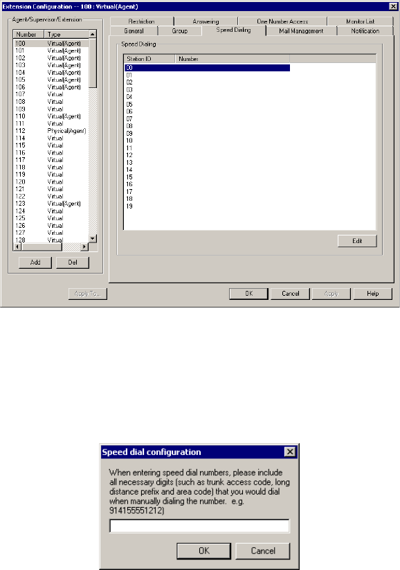
Setting up Station Speed Dialing
13-18 AltiContact Manager Administration Manual
Figure 6. Speed Dialing window, Agent Extension Configuration
Editing Speed Dial Entries
To add or edit an entry:
1. Double-click the Station ID number you want to work with, or select
the number and click Edit. A dialog box appears:
2. Type in the full number as you would dial it, with a maximum of 20
digits per entry. For example, the phone number 914085551212
comprises of 9(trunk access code), 1(long distance prefix), followed
by 408 (area code), and finally the seven digit telephone number.
Valid digits include 0through 9,#,*,and(,) comma. The comma
represents a one (1) second pause.
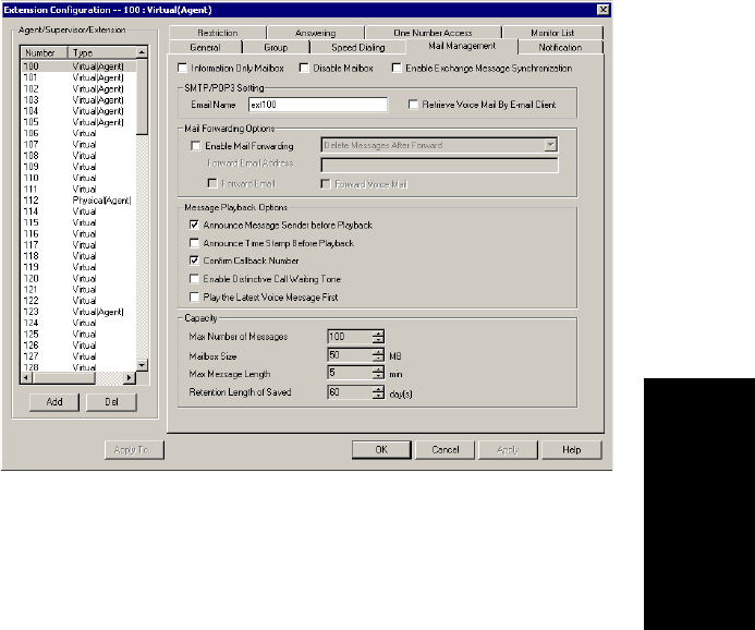
Agent Configuration
AltiContact Manager Administration Manual 13-19
13. Agent
Configuration
Note: You can use Apply to to apply speed dialing numbers to one,
some, or all physical extensions. See ãApply To Buttonã on
page 13-2 for more information on using Apply to.
Setting the Mailbox Options
The Mail Management settings define how voice messages are handled
for an extension: whether the mailbox is information only or is full-
featured, how messages are announced and processed, and how much
capacity is allotted to message storage.
To work with mailbox settings, select the extension number you want to
work with from the Agent/Supervisor/Extension side window list, then
click the Mail Management tab to open the Mail Management window.
Figure 7. Mail Management window, Agent Extension Configuration
Note: You can use Apply to to apply mailbox settings to one, some, or
all extensions. See ãApply To Buttonã on page 13-2 for more
information on using Apply to.
Setting the Mailbox Options
13-20 AltiContact Manager Administration Manual
Setting an Information-Only Mailbox
You can select the Information Only Mailbox check box to set virtual or
physical extension mailboxes to Information Only, then click Apply to to
set one or more extension mailboxes.
An Information Only mailbox allows callers to listen to customized
recorded announcements but does not provide taking messages from the
caller. To repeat the message, callers are instructed to press the # key.
You cannot set a group number mailbox to Information Only.
Disabling a Mailbox
When you disable a mailbox, the normal greeting is played but callers
cannot leave messages.
Synchronizing with Exchange Server
If your system is set up to synchronize with an Exchange Server, you can
select this check box to enable synchronization for voice mails. See
ãSetting E-mail Messaging Optionsã on page 8-4, and ãSetting up an
Exchange Serverã on page 21-10.
SMTP/POP3 Setting
ãÂEmail Nameãthe userãs email name without the @domain. The
default email name is ext[extension number], that is, the letters ãextã
followed by the extension number. For example, the default email
name for extension 2497 would be ext2497.
ãÂRetrieve Voice Mail by Email Clientãselected, this sends voice
mail to the user extension as an email attachment. Deselected, voice
mail is retrieved as voice mail.
Mail Forwarding Options
ãÂEnable Mail Forwardingãselected, the userãs email will be
forwarded to the email address you specify in the Forward Email
Address box. The address should be a full address, including the
domain (for example, jsmith@thecompany.com.).
If you enable mail forwarding, you also specify what you want done
with the original messages after they have been forwarded. In the
drop down list you can choose to:

Agent Configuration
AltiContact Manager Administration Manual 13-21
13. Agent
Configuration
ãDelete Messages after Forward
ãKeep the Messages as New
ãKeep Messages as Saved
Further, if you enable mail forwarding, you can use the check boxes
whether you want to Forward Email,Forward Voice Mail, or both.
Setting Message Playback Options
You can use the following checkboxes to turn on or off options for listening
to playback of recorded messages. These options apply to both new
messages and saved messages, and they can be applied to multiple
extensions using Apply to.
Parameter Description
Announce Message
Sender Before
Playback
Selected, the user hears the name of the
message sender (internal sender only) before
listening to recorded AltiGen Voice Mail
System messages.
Announce Time
Stamp Before
Playback
Selected, the user hears the timestamp (time
and date) of each message before playback.
Confirm Callback
Number Selected, system confirms the accuracy of the
callerãs number.
Enable Distinctive
Call Waiting Tone Selected, the user hears three different call
waiting tone cadences to distinguish between
internal, external, and operator calls (see
ãDistinctive Ringã on page 5-3).
Play the Newest
Voice Message First Selected, voicemails are played in reverse order
of their delivery when the user retrieves them.
Setting Message Notification Options
13-22 AltiContact Manager Administration Manual
Setting Mailbox Capacities
You can set various mailbox capacities with the following options:
These options can be applied to multiple extensions using Apply to.
Setting Message Notification Options
The Notification tab of Agent Extension Configuration providesfor setting
notification options on new incoming email as well as voice messages.
To work with notification settings, select the extension number from the
Agent/Supervisor/Extension side window list, then click the Notification
tab to open the Notification window.
Parameter Description
Max Number of
Messages Maximum number of messages stored in the
userãs mailbox. The range is 1ã999, defaulting
to 100.
Mailbox Size Mailbox size in MBs of stored messages. The
range is 1ã500 MB, with a default of 50.
Max Message
Length Maximum length of voice messages in minutes.
The range is 1ã30 minutes, with a default of 5
minutes.
RetentionLengthof
Saved Messages Number of days saved messages are archived
by the system. The range is 1ã90 days, with a
default of 60.
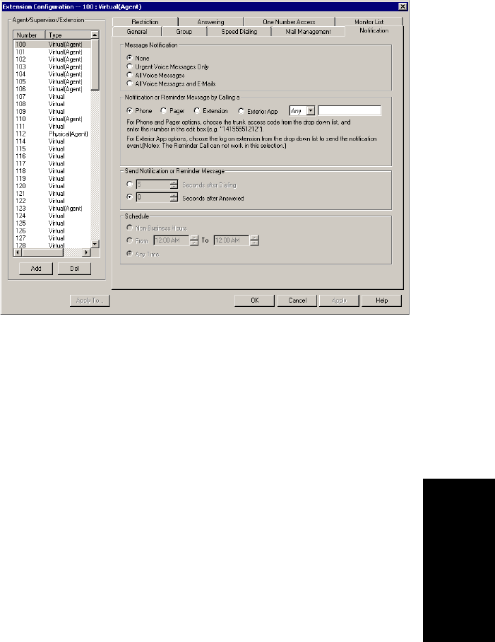
Agent Configuration
AltiContact Manager Administration Manual 13-23
13. Agent
Configuration
Figure 8. Notification window, Agent Extension Configuration
Individual users can also configure Message Notification within the
AltiGen Voice Mail System.
Note: You can use Apply to to apply notification settings to one, some,
or all extensions. See ãApply To Buttonã on page 13-2 for more
information on using Apply to.
Setting the Message Types for Notification
Select the types of messages for which the extension user is notified:
ãÂNoneãselected, the user is not notified with a call regarding newly
received messages. Selecting this option does not prevent the user
from getting message waiting indicators or stutter dial tone when new
messages are received.
ãÂUrgent Voice Messages Only
ãÂAll Voice Messages
ãÂAll Voice Messages and E-mails
Setting Message Notification Options
13-24 AltiContact Manager Administration Manual
Setting the Type of Notification
There are four options for sending the notification or reminder message:
phone,pager,extension or custom application (Custom App).
ãÂExtension -tousetheExtension option, select the Extension radio
button, then type the extension number into the text box.
ãÂPhone/Pager -forthePhone and Pager options, first specify the trunk
or route access code using the drop-down list next to the Extension
radio button. The Any option means to locate any available trunk.
Then type in the number with all relevant dialing prefixes other than
the trunk code, using a maximum of 80 digits.
ãÂCustom App - when used in conjunction with a third party notification
application, the Custom App feature enables an extension to connect
to an application that can receive the notification event; use the drop-
down list to choose the log on extension to which the third party
application is connected. Contact your local AltiGen dealer for more
information on using this feature.
Note: The Reminder Call will not work with this selection.
Note also the following considerations:
ãÂUsingthePhone option, see ãOutcall to Cellular or PCS Phone
Numbersã on page 13-25.
ãÂForthePager option, the system calls the specified pager number and
then dials the system main number (as set in the System Configuration
General window), which is then displayed on the userãs pager.
For the operator-assisted paging function, the operator phone number
and the pager number must be entered in the <phone
number>*<pager number> format. For example, if the phone
number to call the pager operator is 7654321 and the pager number to
page the user is 12345678, the notification outcall number that needs
to be entered is 7654321*12345678. When the pager operator answers
the Message Notification call, AltiContact Manager announces the
pager number and the System Main Number (as configured on the
General window of System Configuration), which will be displayed
on the userãs pager. The operator is also given the option to repeat
these numbers by pressing ã#ã.

Agent Configuration
AltiContact Manager Administration Manual 13-25
13. Agent
Configuration
Outcall to Cellular or PCS Phone Numbers
When an outcall is made by the system (for One-Number-Access, Mes-
sage Notification, Zoomerang, Call Forwarding, etc.) to a cellular or PCS
phone, it may ring the phone once but not necessarily present the call and
make a connection. This will happen if the ringback tone played by the
cellular service provider does not confirm to standard ringback tones. To
work around this problem, instruct users to append a few commas (,)tothe
outcall (cellular) number when entering it. Each comma provides a one
second pause.
Setting Notification Timing
You can set the type of delay detection and the duration (from 5 to 30
seconds) before the system sends the return phone number (the System
Main Number as set in the System Configuration General window) after
the system detects an answer when sending a notification:
ãÂSeconds after Dialingãthe delay (from 5 to 30 seconds) after dialing
before the system sends the return phone number.
ãÂSeconds after Answeredãthe delay (from 5 to 30 seconds) after a
call is answered before the system sends the return phone number.
Setting Notification Business Hours
You can choose one of three options for when the extension user is to be
notified of new messages:
ãÂNon-Business Hoursãnotification only during non-business hours.
Business hours are set in the System Configuration Business Hours
window (ãSetting Business Hoursã on page 5-8)
ãÂFrom/Toãnotification during a specified time of day.Select the
hours in the From and To time scroll boxes
ãÂAny Timeãnotification at all times (every day)
Enabling Message Notification
After configuring your message notification settings, to enable message
notification, check the ãAllow Calls to be Transferred/Conferenced/
ForwardedtoanOutsideNumberã field in the Restriction page of
Extension Configuration.
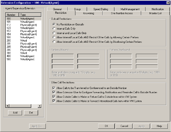
Configuring Calling Restrictions
13-26 AltiContact Manager Administration Manual
Configuring Calling Restrictions
Available restrictions on outgoing calls from extensions range from no
restrictions to allowing internal calls only.
System calling restrictions, discussed under ãDefining System Call
Restrictionsã on page 5-12, specify global restrictions for all extensions,
and you cannot override the system settings when you configure
extensions. Further, restrictions can be placed on out call routing calls, as
discussed in Chapter 10, Out Call Routing Configuration.
To work with extension call restrictions, select the extension number you
want to work with from the Agent/Supervisor/Extension side window list,
then click the Restriction tabtoopentheRestriction window.
Figure 9. Restriction window, Agent Extension Configuration
Note: You can use Apply to to apply call restriction settings to one,
some, or all extensions. See ãApply To Buttonã on page 13-2 for
more information on using Apply to.
Setting Call Restriction Options
You can use one of the following options in setting restrictions on an
extension or on multiple extensions using Apply to.

Agent Configuration
AltiContact Manager Administration Manual 13-27
13. Agent
Configuration
ãÂNo Restrictions on Outcalls.
ãÂInternal Calls Onlyãextension-to-extension.
ãÂInternal and Local Calls Onlyãextension-to-extension and local
calls only.
ãÂAllow Internal/Local Calls AND Restrict Other Calls by Allowing
Certain Prefixesãinternal calls, local calls and prefixes you specify
in the Prefixes Allowed boxes. Includeall relevant prefix numbers, for
example, starting with 1+ prefix.
ãÂAllow Internal/Local Calls AND Restrict Other Calls by
Disallowing Certain Prefixesãdisallows calls to outside numbers
with prefixes you specify in the Prefixes Disallowed boxes. Include
all relevant prefix numbers, for example, starting with 1+prefix.
Setting Other Call Restrictions
You can allow or restrict two other types of calls by using the following
check boxes. You may choose to enable or disable these optionsãthe
default is set to Allow Calls to be Transferred or Conferenced to an
Outside Number and Allow Off-Premise Mailbox User to Make or
Return Call From Voice Mail. These default settings reduce the risk of
international toll fraud.
Caution: Allowing these options may increase the potential for toll
fraud if they are not properly administered.
ãÂAllow Calls to be Transferred or Conferenced to an Outside
Numberãselected, the extension user can transfer or conference calls
to an outside telephone number.
ãÂAllow Extension User Configure Forwarding, Notification and
Remind Call to an Outside Numberãselected, the extension user
can set these features to an outside telephone number. Checking this
box will enable Message Notification.
ãÂAllow Outside Caller to Make or Return Call From Voice Mailã
selected, the extension user can make or return calls from within voice
mail (i.e. Zoomerang).
ãÂAllow Outside Caller to Make International Call From Voice
Mailãselected, the extension user can make international outgoing
calls from within voice mail (i.e. Zoomerang).
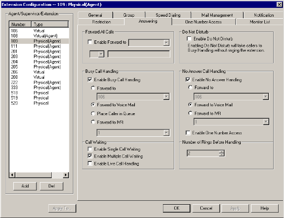
Setting Answering Options
13-28 AltiContact Manager Administration Manual
Setting Answering Options
Answering options include forwarding, handling busy calls, handling no-
answers and other options. Which options are available depends on the type
of extension. Virtual and physical extensions each use somewhat different
answering options.
You can use Apply to to apply call restriction settings to one, some, or all
extensions. See ãApply To Buttonã on page 13-2 for more information on
using Apply to. However, since the available options vary with the type of
extension, you can only apply the choices to the same type of extension.
For example, If you are working with the settings for a virtual extension,
you can use Apply to to apply changes to one, some, or all virtual
extensions, but not to physical numbers.
To work with extension answering options, select the extension number
from the Agent/Supervisor/Extension side window list, then click the
Answering tabtoopentheAnsweringwindow.
Figure 10. Answering window, Agent Extension Configuration

Agent Configuration
AltiContact Manager Administration Manual 13-29
13. Agent
Configuration
Forwarding All Calls
Call Forwarding is available to all types of extensions.
This is the Call Forwarding feature that is also accessible by the extension
user by dialing #36.
A One Hop Limit to Call Forwarding for a Transferred Call
There is a one hop limit to call forwarding when the call that is being passed
is a transferred call. For example, extension 100 receives a transferred call
and forwards this call to extension 101; extension 101 is set to forward all
calls to extension 102; extension 102 receives the call but CANNOT
forward this call to another extension.
A 10-Hop Limit to Call Forwarding for Direct Calls
For direct calls, there is a ã10-hopã limit to call forwarding. For example,
extension 100 forwards to extension 101, 101 forwards to 102, 102
forwards to 103, and etc. through extension 120. A call to extension 100
will be forwarded to 101, which will forward to 102, which will forward to
103, and etc. until the call has been forwarded 10 times. At this point, the
call will not be forwarded again; if the last extension in the forwarding
chain does not answer, the call is sent to extension 100ãs voice mail.
If there is a loop condition in the forwarding chain (for example, 100
forwards to 101, 101 to 102, and 102 back to 100), the call is sent to the first
destinationãs voice mail.
To enable call forwarding, select the Enable Call Forward to check box,
then, using the drop-down list, indicate the forwarding destination. You can
use Apply to to act on multiple extensions, with the restrictions discussed
in the previous section. The forwarding options are as follows:
ãÂToVoice Mail
ãÂToIVRãselect the IVR number to use in the drop-down list under the
option. IVR settings are established in IVRãÎ on the Management
menu.
ãÂToanExtensionãselect an extension from the drop-down list.
ãÂToaWorkgroupãselect a workgroup from the drop-down list.
Setting Answering Options
13-30 AltiContact Manager Administration Manual
ãÂToaCustom Appãwhen used in conjunction with a third party
notification application, the Custom App feature enables an extension
to connect to an application that can receive the notification event; use
the drop-down list to choose the log on extension to which the third
party application is connected. Contact your local AltiGen dealer for
more information on using this feature.
ãÂToanOutside Numberãthis option is available if it is allowed in the
Other Call Restrictions option in the Restriction window,as
discussed in ãSetting Other Call Restrictionsã on page 13-27. Also, see
ãOutcall to Cellular or PCS Phone Numbersã on page 13-25.
If you choose Outside Number, select a trunk or route access code to
use in the small drop-down list on the left, and type in the full prefix
and phone number.
ãÂTotheOperator
Note: Forwarding calls to a pager is possible but not recommended
since callers will only hear what is heard when calling a pager and
will not know to enter a return phone number unless instructed.
Enabling ãDo Not Disturbã
This is not available for group numbers. Select the Do Not Disturb
checkbox option to send all calls for the selected extension(s) to the
extensionãs voice mail. This feature is also accessible by the user at the
userãs station by dialing #33. Note that this overrides any One Number
Access settings for the extension.
Handling Busy Calls
You have several options for handling calls while the extension is busy, and
again, the options vary depending on the extension type. If you do not
enable busy call handling, the caller simply hears a busy signal.
To enable the options, select the Enable Busy Call Handling check box,
then select from the following options:
ãÂForward to ExtensionãSelect an extension number in the
drop-down list. See ãA 10-Hop Limit to Call Forwarding for Direct
Callsã on page 13-29.
ãÂForward to Voice Mail

Agent Configuration
AltiContact Manager Administration Manual 13-31
13. Agent
Configuration
ãÂForward to IVRãuse the drop-down list to select an IVR to which to
route the call. IVR settings are established in IVR ãÎ on the
Management menu.
Setting Call Waiting Options
Call waiting options are available only if the Enable Busy Call Handling
check box has been selected, and this option is not available to group
numbers.
ãÂEnable Single Call Waitingãsets up single call waiting. This feature
gives an alert tone (audio beep) to indicate that a call is waiting.
ãÂEnable Multiple Call Waitingãenables a ãpersonal queueã of
multiple calls waiting. You must also select the PlaceCallerIn
Queue option under Busy Call Handling to enable this option. This
allows the user to transfer or park the current call before picking up the
next call in queue.
ãÂEnable Live Call Handlingãwhen enabled, allows an extension user
to play a ringback tone when the called party is in voice mail, paging,
transfer, or conference state.
Note: The call will be shown as ãringingã in AltiConsole.
Handling Unanswered Calls
The No Answer Call Handling function provide options for handling calls
when no one answers the extension within a specified number of rings.
Except for Enabling One Number Access, these options are not available
to virtual extensions.
To enable these options, select Enable No Answer Handling box.
Use the Number of Rings Before Handling scroll box to select a number
between 2 and 20 for the times the telephone rings before the call is handled
by the system.
Select one of the following options for no answer call handling:
ãÂForward to ExtensionãSelect an extension number in the
drop-down list. See ãA 10-Hop Limit to Call Forwarding for Direct
Callsã on page 13-29.
ãÂForward to Voice Mail (physical extensions only)
Configuring One Number Access
13-32 AltiContact Manager Administration Manual
ãÂForward to IVRãuse the drop-down list to select an IVR to which to
route the call. IVR settings are established in IVRãÎ on the
Management menu.
Enabling One Number Access
This check box option is available to all extension types, but with
qualifications:
ã It is available to physical extensions only when the Forward to Voice
Mail option is selected.
ãÂItisnot available when Forward to IVR or Forward to Extension is
selected.
Configuring One Number Access
One Number Access (ONA) allows you to identify specified callers to be
connected to the user without having to dial more than one number. The
system searches for the caller and, if a match is found, searches for the user
through specified forwarding numbers and connects the call if possible. If
the system is unable to connect the call, it is sent to the extension userãs
voice mail.
Note: Options in the window are disabled unless One Number Access
has been enabled as a No Answer option in the Answering window
as discussed in ãEnabling One Number Accessã on page 13-32.
Furthermore, if the Enable Do Not Disturb option is selected in
the Answering window, the call is forwarded to voice mail
regardless of ONA settings.
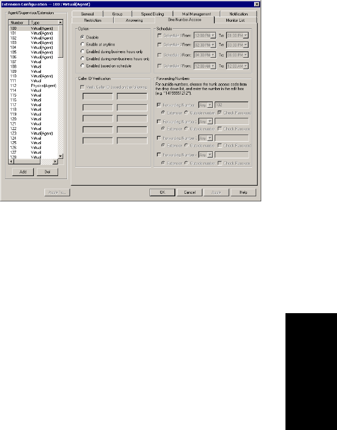
Agent Configuration
AltiContact Manager Administration Manual 13-33
13. Agent
Configuration
To configure ONA, select the extension number from the Agent/
Supervisor/Extension side window list, then click the One Number
Access tab.
Figure 11. One Number Access window, Agent Extension Configuration
Note: You can use Apply to to apply some ONA settings to one, some,
or all extensions of the same typeãphysical to physical, etc., but
only if the extensions are ONA enabled in the Answering window.
See ãApply To Buttonã on page 13-2 for more information on
using Apply to.
Enabling One Number Access
In the One Number Access window, you enable the function by selecting
one of the following options:
ãÂEnabled at any time
ãÂEnabled during business hours only
ãÂEnabled during non-business hours only
ãÂEnabled based on the following schedules
If you select this last option, Enabled based on the following schedules,
you can then select and set up to four different time periodsãSchedules 1
through 4ãusing the From and To time drop-down lists.
Configuring One Number Access
13-34 AltiContact Manager Administration Manual
After choosing any of the enabling options, you set the Verify Caller ID
and Forwarding choices, and these are discussed below.
Note: You can also enable and set up One Number Access remotely
through AltiReach.
Disabling One Number Access
You can disable ONA for the extension by clicking the Disable option.
Disabling access in this window does not destroy the data you might have
entered. For example, if you entered a group of Caller IDs to use to identify
the caller, these will be available if you enable access at a future time.
Setting Caller ID Verification
You can select the Verify Caller ID based on the following checkbox and
then type in up to 10 phone numbers in the text boxes. Whenever the system
detects a call from one of the numbers entered here during the selected
schedule, the system searches for you by dialing the numbers configured in
the Forwarding Number fields.
Caution: If ONA is enabled and no numbers are entered for Caller ID
Verification, ONA is available to all callers.
Caller ID verification entries should be complete phone numbers.
ãÂDomestic long distance should be the area code + a seven digit
number.
ãÂLocal numbers should be the seven digit number alone.
Using a Password Verification
You can also enter a random ãpasswordã number such as ã5555ã so that
any caller who knows this password can use ONA to find you, regardless
of where they are calling from. Once youãve set this up, you need to instruct
the caller to dial 1 during your personal greeting then enter the ãpasswordã
to use ONA.

Agent Configuration
AltiContact Manager Administration Manual 13-35
13. Agent
Configuration
Specifying Forwarding Numbers
The Forwarding Numbers are used by the system to find the user when
ONA is active. You can set up to four different numbers. When ONA is
active, the system dials the forwarding number(s) in the order from
Forwarding Number 1 through Forwarding Number 4. The Forwarding
Number order does not correspond to the Schedule orderãForward
Number 4 is not used first during Schedule Number 4.
You can forward to another extension, or to an outside number. You can
use an outside number only if the extension is set to allow for Transferred/
Conferenced/Forwarded calls, an Other Call Restrictions optioninthe
Extension Configuration Restriction window.
When you use the outside number option, select a trunk or route access
code in the drop-down list and type in the phone number as it would be
dialed after keying the access code.
Enable the Check Password option to force users to enter their extension
password when a call is forwarded to them via ONA. This ensures that only
the owner of the forwarding extension can answer the call.
Note: If you disable this option, a call forwarded via ONA that is picked
up by a voicemail box or answering machine will connect, and will
not try any subsequent Forwarding Numbers.
Setting Up Monitor Lists
The Monitoring List window provides for setting up lists of extensions for
which call processing events can be monitored by the user of a selected
extension. Once this monitoring list is established, the application logging
into the extension can receive AltiLink Plus events for the monitored
extensions. The monitored list is available in the AltiView and AltiAgent
Change Monitor windows.
WARNING!
Listeningintoorrecordingaconversationwithouttheconsentofoneor
both parties may be a violation of local, state and federal privacy laws. It
is the responsibility of the users of this feature to assure they are in
compliance with all applicable laws
Setting Up Monitor Lists
13-36 AltiContact Manager Administration Manual
Restrictions and Defaults
ã Monitoring is effective for physical extensions only; only physical
extensions can have monitoring rights, and only physical extensions
can be monitored. If you place a virtual extension in a Monitor List,
that extension will not show in the client userãs Change Monitor
window.
ã If you add an extension (1001, for example) that belongs to
Workgroup A to the Monitor List for a member of Workgroup B, the
Workgroup B member will only be able to pick up personal calls to
1001, not workgroup calls.
ã In AltiSupervisor, the user can monitor only the workgroup(s) he or
she logs in to, regardless of the monitoring rights assigned to his or her
extension in AltiAdmin.
Note: These restrictions can be overridden by third-party applications
that make calls through AltiLink Plus.
Configuring a Monitor List
To set up a monitoring list, select the extension number to receive the
monitoring rights from the Agent/Supervisor/Extension side window list,
then click the Monitor List tab.
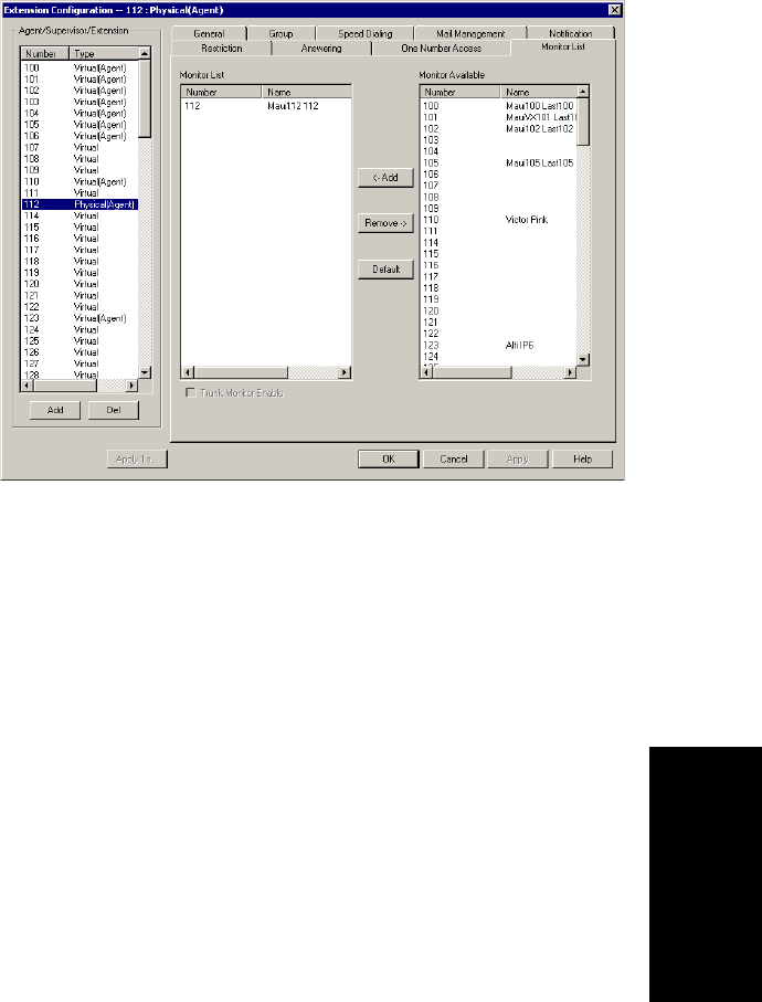
Agent Configuration
AltiContact Manager Administration Manual 13-37
13. Agent
Configuration
Figure 12. Monitor List window, Agent Extension Configuration
To add members to the list:
1. From the Monitor Available list, select the extensions to add to the
extension userãs AltiView Change Monitor window.
2. Click Add to move the extensions to the Monitor List.
To remove members:
1. Select the extensions in the Monitor List.
2. Click Remove.
Select the Trunk Monitor Enable check box to allow monitoring of the
AltiLink Plus trunk events at the selected extension.
Click the Default button to return the settings to the defaultãthe extension
can monitor its own calls.
Feature Tips
13-38 AltiContact Manager Administration Manual
Feature Tips
Each time a user logs into the AltiGen Voice Mail System, the user will
hear a Feature Tip, helpful tips and reminders of the most useful features
for optimal use of AltiContact Manager. There are a total of eleven tips and
a different tip is played each time the AltiGen Voice Mail System is
accessed. Another way to listen to Feature Tips is by pressing #55 on the
telephone. You can listen to just one tip at a time or listen to all the tips at
once.
Individual users may turn this feature off (stop AltiContact Manager from
playing Feature Tips at the beginning of the AltiGen Voice Mail System
login) by pressing 6at the Personal Options menu. This is a toggle feature,
so pressing 6at the Personal Options menu will turn it back on if it is off.
You may, however, want to completely disable this feature for all users.
To disable Feature Tips system-wide:
1. Select Run from the Start menu and enter regedit to open the
Registry Editor.
Caution: Changing the registry can affect the configuration of your
system! We recommend making a backup copy of the
registry before making any changes.
2. Go to the following location:
\HKEY_LOCAL_MACHINE\SOFTWARE\AltiGen
Communications, Inc.\AltiWare\
3. Create a new DWORD Value (select DWORD Value from the New
option under the Edit menu) called FeatureTipEnabled.
4. Set the Value data to 0to disable Features Tips. (Set the Value data
back to 1to enable Feature Tips again.)
5. Open the System Configuration window of AltiContact Manager and
click OK without making any changes in the data fields. It is not
necessary to restart AltiContact Manager.

AltiContact Manager Administration Manual 14-1
14. Huntgroup
Configuration
C
HAPTER
14
Huntgroup Configuration
What is a Huntgroup?
The primary use of a huntgroup is similar to that of workgroups ã when
the huntgroup extension is dialed, the system hunts for an available
member extension to which to route the call. You can use huntgroups for
various purposes, for example, in selecting a huntgroup as a System
Operator.
Huntgroups vs. Workgroups
As of Release 4.6 and higher, huntgroups differ from workgroups in that
they do not require special licensing (whereas workgroups require Seat
Licenses). Also, both agents and non-agents, can be assigned to huntgroups
(whereas workgroups require licensed agents).
AltiContact Manager allows up to 32 huntgroups to be configured. Each
huntgroup can have up to 128 members or extensions, and an extension can
be members of multiple huntgroups.
There are three sets of Agent Configuration steps to set up huntgroups:
ã The first step is creating a huntgroup pilot number, a type of logical
extension, as described in ãSetting Up Huntgroupsã on page 14-3.
ã Once the huntgroup pilot number is created, you can use the
Huntgroup Configuration windows to set up parameters for the
huntgroup.
ã Once the huntgroup pilot number is created, you can use the General
window of Huntgroup Configuration to assign physical extensions as
members of the huntgroup.
The Huntgroup Configuration functions provide for configuring
huntgroups in AltiContact Manager.
Note: A feature of huntgroup membership is that all members are set to
the ãKeep Login Statusã state at system startup or reboot. To
change this setting, refer to ãAutomatic Log In/Outã on page 14-
10.
14-2 AltiContact Manager Administration Manual
Apply to Button
The huntgroup configuration windows often allow you to apply changes to
a particular huntgroup or to select many huntgroups to which to apply the
changes.
Clicking the Apply to button pops up a list of all huntgroups to which the
change can apply. All huntgroups are selected by default. You then de-
select the ones you donãt want, or de-select all and then select the ones you
want. Note that you cannot use the mouse to drag over and select multiple
items; you must use the Shift and Ctrl keys.
The Apply to button is disabled unless there is a change that can be applied
to multiple huntgroups, and when you use it to apply changes to multiple
huntgroups, it works on only those changed attributes that can be applied.
Accessing Extension Configuration
Access Huntgroup Configuration from Huntgroup Configuration... on
the System Management menu, or using the drop-down list next to the
System icon) and going to Huntgroup Configuration.
You can then work with the following settings, each of which is accessed
by a tab in the Huntgroup Configuration window.
ãÂGeneralãadd or delete a huntgroup, assign a group name, password,
DID number and tenant assignment (if applicable).
ãÂGroup Memberãadd or remove members from huntgroups.
ãÂMail Managementãcapacity and feature options for huntgroup
mailboxes.
ãÂNotificationãpreferences and options for voice mail notification.
ãÂCall Handlingãcall forwarding, call waiting, and call handling
preferences and options.
ãÂQueue Managementãoptions for setting default or custom phrases
used as queue announcements.

Huntgroup Configuration
AltiContact Manager Administration Manual 14-3
14. Huntgroup
Configuration
Setting Up Huntgroups
The Huntgroup Configuration General window provides for creating
huntgroups and establishing their basic attributes.
The General window is the default tab displayed when the Huntgroup
Configuration window is opened. If you are viewing another Huntgroup
Configuration window, click the General tab to open the General window.
Figure 1. General window, Huntgroup Configuration
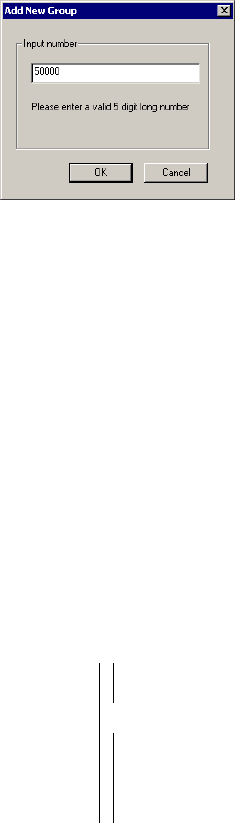
Setting Up Huntgroups
14-4 AltiContact Manager Administration Manual
Adding a Huntgroup
1. To add a huntgroup, click the Add button in the General window. The
Add New Group dialog box opens.
2. Type in a group number for the huntgroup and click OK.
Establishing Basic Huntgroup Attributes
After you create a huntgroup, you can set other basic attributes in the
Huntgroup Configuration General window:
To set up Group Information, type in the following:
ãÂFirst Name and Last Nameãeach with a maximum of 32 characters.
ãÂPasswordãthe default is the system default password set on the
Number Plan tab of the System Configuration window.
A valid password cannot be the same as its extension number and must
be 4ã8 digits (numbers or letters AãZ) in length. Basic password
patterns, such as repeated digits (1111), consecutive digit strings
(1234), or digits that match the extension (Ext. 101 using 1012, 9101,
10101, etc.) are not allowed. The letters map to numbers (on a phone,
for example) as follows:
ãÂDID Numberãeach huntgroup can be assigned a DID number. This
number does not have a fixed length, but the length must be long
enough (range 2ã16) for the system to match the DID incoming call.
Numbers Letters Numbers Letters
2 A,B,C,a,b,c 6 M,N,O,m,n,o
3 D,E,F,d,e,f 7 P,Q,R,S,p,q,r,s
4 G,H,I,g,h,i 8 T,U,V,t,u,v
5 J,K,L,j,k,l 9 W,X,Y,Z,w,x,y,z

Huntgroup Configuration
AltiContact Manager Administration Manual 14-5
14. Huntgroup
Configuration
It is recommended to use the full 10 digit DID number, not just the
last few digits. This full number guarantees the system can send the
correct number as the Caller ID on PRI lines. With fewer digits, the
system sends the trunkãs configured phone number as the Caller ID. If
the trunk number is not configured, the system main number is sent.
ãÂTenantãa drop-down list of Tenant IDs (groups) to which the
huntgroup can be assigned. See ãUsing a Tenant Tableã on page 5-22
for more information on Tenants.
Note: If a huntgroup is assigned to N/A in the Tenant drop-down list,
the huntgroup is able to access all trunks, even though the
trunks have been assigned to tenants.
ãÂDescriptionãeach huntgroup can be assigned a description.
Setting Call Restrictions
You can allow or restrict other types of calls by using the following check
boxes. You may choose to enable or disable these optionsãthe default is
set to enable the first two options. These default settings reduce the risk of
international toll fraud.
Caution: Allowing these options may increase the potential for toll
fraud if they are not properly administered.
ãÂAllow Calls to be Transferred or Conferenced to an Outside
Numberãselected, the group user can transfer or conference calls to
an outside telephone number. Checking this box will enable Message
Notification.
ãÂAllow User to set Forward, Notification and Remind Call to
Outside from within Groupãs VM Systemãselected, the group user
can set these features to an outside telephone number when accessing
the groupãs voice mail. Checking this box will enable Message
Notification.
ãÂAllowUsertoMakeorReturnCalltoOutsidefromwithin
Groupãs VM Systemãselected, the group user can make or return
calls from within the groupãs voice mail (i.e. Zoomerang).
ãÂAllow User to Make or Forward International Calls from within
Groupãs VM Systemãselected, the group user can make
international outgoing calls from within the groupãs voice mail (i.e.
Zoomerang).
Establishing Huntgroup Membership
14-6 AltiContact Manager Administration Manual
Establishing Huntgroup Membership
There are two different ways to attach extensions to huntgroups.
1. If you select a huntgroup in the Huntgroup Configuration window,
then click the Group Member tab; you open the group view of the
Huntgroup window, which provides for adding extensions to the
selected huntgroup.
2. If you select an extension from the Agent/Supervisor/Extension side
window list in the Agent Extension Configuration General window,
then click the Group tab, you open the Extension view of the
Workgroup window, which provides for assigning workgroups to the
selected extension and for setting wrap-up times.
This section discusses the first way first.
Important: Regardless of which way you add extensions to huntgroups,the
order in which you add extensions can have consequences. For
example, one way of handling incoming huntgroup calls is to
always send the call to the first extension, if available, the
second if the first is not available, and so forth.
When you add an extension to a huntgroup, the extension is in
the ãLogoutã state. The huntgroup member must manually log
in.
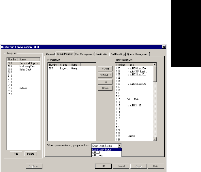
Huntgroup Configuration
AltiContact Manager Administration Manual 14-7
14. Huntgroup
Configuration
Adding Extensions to Huntgroups
To add extensions to a huntgroup, select the huntgroup pilot number in the
list of huntgroups in the General window of Huntgroup Configuration, then
click the Group Member tab. The huntgroup pilot number appears in the
window title bar.
Figure 2. Huntgroup view of Group Member window, Huntgroup Configuration
Adding or Removing Members
To add extension(s) to the selected huntgroup:
1. In the huntgroup view of the Group Member window, click the agent
extension number(s) in the Not Member list.
2. Click Add to move them to the Member list.
Note: If the huntgroup pilot extension is configured to Ring All
Available Members, the maximum number of members is 20.
See ãSetting Call Handling Optionsã for details.
To remove extension(s) from a huntgroup:
1. Click the agent extension number(s) in the Member list.
2. Click Remove to move them to the Not Member list.

Establishing Huntgroup Membership
14-8 AltiContact Manager Administration Manual
Assigning Huntgroups to Agent Extensions
This is the second of the two ways (see ãEstablishing Huntgroup
Membershipã on page 14-6) to assign agent extensions as members of
huntgroups.
This methodãselecting a physical or virtual extension from the Agent
Extension General page, and then clicking the Group tabãprovides an
agent extension view of huntgroups. You can see all the huntgroups to
which the agent extension belongs, and you can change those assignments.
To open the Agent Extension view of the Group window:
1. Select the Virtual or Physical extension number from the Agent/
Supervisor/Extension side window list in the Agent Extension
General window.
2. Click the Group tab. The Extension view of the huntgroup window
opens, with the agent extension number appearing in the window title
bar.
Figure 3. Agent Extension view of Group window, Agent Extension Configuration

Huntgroup Configuration
AltiContact Manager Administration Manual 14-9
14. Huntgroup
Configuration
Adding or Removing Huntgroup Assignments
To assign huntgroups to the selected physical or virtual extension:
1. In the Agent Extension view of the Group window, click the huntgroup
pilot number(s) in the Not Member list.
2. Click the Add buttontomovethemtotheMember list.
Note: If the huntgroup pilot extension is configured to Ring All
Available Members, the maximum number of members is 20.
See ãSetting Call Handling Optionsã for details.
To remove huntgroups assigned to a physical or virtual extension:
1. Click the huntgroup pilot number(s) in the Member list.
2. Click the Remove button to move them to the Not Member list.
Setting Wrapup Time
In the Extension view, you can set the Wrapup Time for the selected
physical agent extension. This option doesnãt appear for a virtual extension
or a non-agent extension. Wrapup time is a system delay before routing the
next call to the extension, and it gives the agent time to finish up with notes,
prepare for the next call, log out of the huntgroup, or hit the ãWaitã button
in AltiView after putting a call on hold and going back onhook. You can
set a wrapup time of up to 29 minutes, 59 seconds.
To set the extension wrapup time:
1. Check the Allow Wrap Up Time box.
2. Using the drop-down lists, select the minutes and seconds for the
delay. Be sure to set at least enough time (e.g. 5 seconds) to allow an
agent to hit the ãWaitã button in AltiView after putting the caller on
hold and going onhook.
Setting Inter Call Delay
Like Wrapup time, Inter Call Delay can create time before the next call
comes in. It can be set for any extension.
If the system is delaying the next call to a user extension based on the
Wrapup Time setting, the Inter Call Delay setting is ignored.
However, if Wrapup Time does not applyãfor example, if it is de-
selectedãthen Inter Call Delay acts as follows:
Establishing Huntgroup Membership
14-10 AltiContact Manager Administration Manual
ã If the extension user hangs up and there are callers waiting in an
extension or huntgroup queue, the ring is delayed for the number of
seconds specified in the Inter Call Delay setting.
ã If the extension user hangs up, there is no one waiting in a queue and
a call comes in within the Inter Call Delay period, the call is put
through immediately; the Inter Call Delay period is ignored.
To set the extension Inter Call Delay time:
1. Check the Inter Call Delay box.
2. Using the drop-down lists, select the seconds for the delay. The default
is 15 seconds.
Logging Outbound Workgroup Calls
In the Extension view, you can assign an agent to an outgoing workgroup,
which is useful for call detail reporting and workgroup statistics. All calls
made by the agent while logged into the workgroup will be tracked as calls
from the workgroup. The agentãs outgoing workgroup can be assigned to
any workgroup to which he is a member of.
To set an agentãs outgoing workgroup:
In the Log Outbound Call to Workgroup field, use the drop-down list to
choose a workgroup from among the workgroups the agent belongs to. If
the ãAllow agent to changeã checkbox is selected, the agent can change the
outgoing workgroup from the phone set or from AltiAgent.
When a user is first assigned to a workgroup, it is set as their default
outgoing workgroup and remains so no matter how many workgroups the
user is subsequently assigned to. If an agent is unassigned from their
outgoing workgroup, the outgoing workgroup is automatically set to N/A.
Automatic Log In/Out
Whenever the system is restarted, the administrator can use the drop down
list at the bottom of the Group Member window to:
ãÂKeep Login Statusãdefault setting; all group members retain their
original login status for that group prior to restart.
ãÂAll Loginãall group members are automatically logged into the
assigned group after the system is restarted.
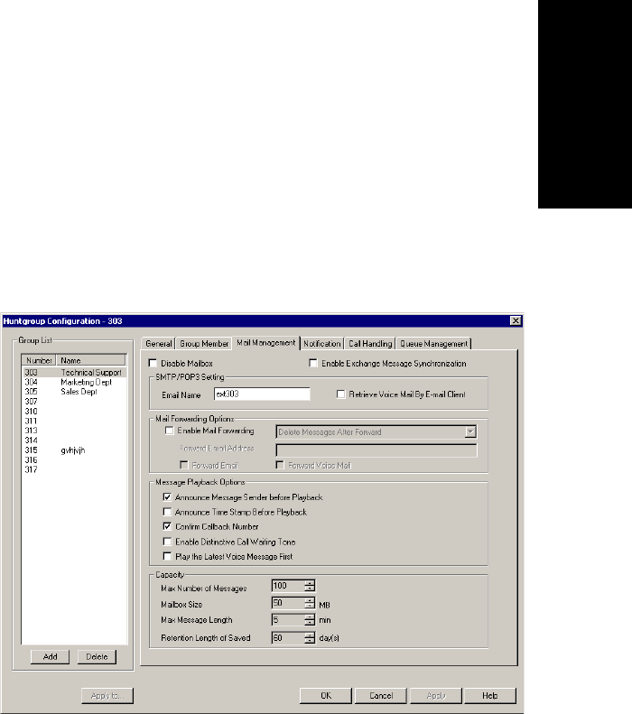
Huntgroup Configuration
AltiContact Manager Administration Manual 14-11
14. Huntgroup
Configuration
ãÂAll Logoutãall group members are not logged back into the group
when the system is restarted; members must re-log back into the
assigned group.
Setting Huntgroup Mail Management
The Mail Management settings define how voice messages are handled for
a huntgroup, including how messages are announced and processed, and
how much capacity is allotted to message storage.
To work with mail management settings, select the huntgroup number you
want to work with from the list in the Huntgroup Configuration General
window, then click the Mail Management tabtoopentheMail
Management window.
Figure 4. Mail Management window, Huntgroup Configuration
Note: You can use Apply to to apply mailbox settings to one, some, or
all huntgroups. See ãApply to Buttonã on page 14-2 for more
information on using Apply to.
Setting Huntgroup Mail Management
14-12 AltiContact Manager Administration Manual
Disabling a Mailbox
When you disable a mailbox, the normal greeting is played but callers
cannot leave messages.
Synchronizing with Exchange Server
If your system is set up to synchronize with an Exchange Server, you can
select this check box to enable synchronization for voice mails. See
ãSetting E-mail Messaging Optionsã on page 8-4, and ãSetting up an
Exchange Serverã on page 21-10.
Setting Email Options
In the General window, you can set the email options for the huntgroup:
ãÂEmail Nameãthe huntgroupãs email name without the @domain.
The default email name is ext[huntgroup number], that is, the letters
ãextã followed by the huntgroup number. For example, the default
email name for huntgroup 50000 would be ext50000.
ãÂRetrieve Voice Mail by Email Clientãselected, this sends voice
mail to the user extension as an email attachment. Deselected, voice
mail is retrieved as voice mail.
ãÂEnable Mail Forwardingãselected, the userãs email will be
forwarded to the email address you specify in the Forward Email
Address box. The address should be a full address, including the
domain (for example, jsmith@thecompany.com.).
If you enable mail forwarding, you also specify what you want done
with the original messages after they have been forwarded. In the
drop down list you can choose to:
ãDelete Messages after Forward
ãKeep the Messages as New
ãKeep Messages as Saved
Further, if you enable mail forwarding, you can use the check boxes
whether you want to Forward Email,Forward Voice Mail, or both.

Huntgroup Configuration
AltiContact Manager Administration Manual 14-13
14. Huntgroup
Configuration
Setting Mailbox Playback Options
You can use the following checkboxes to turn on or offoptions for listening
to playback of recorded messages. These options apply to both new
messages and saved messages, and they can be applied to multiple
huntgroups using Apply to:
Setting Mailbox Capacities
You can set various mailbox capacities with the following options, and can
be applied to multiple huntgroups using Apply to:
Parameter Description
Announce Message
Sender Before
Playback
Selected, the user hears the name of the
message sender (internal sender only) before
listening to recorded AltiGen Voice Mail
System messages.
Announce Time
Stamp Before
Playback
Selected, the user hears the timestamp (time
and date) of each message before playback.
Confirm Callback
Number Selected, system confirms the accuracy of the
callerãs number.
Enable Distinctive
Call Waiting Tone Selected, the user hears three different call
waiting tone cadences to distinguish between
internal, external, and operator calls (see
ãDistinctive Ringã on page 5-3).
Play the Latest
Voice Message First Selected, voicemails are played in reverse order
of their delivery when the user retrieves them.
Parameter Description
Max Number of
Messages Maximum number of messages stored in the
userãs mailbox. The range is 1ã999, defaulting
to 100.
Mailbox Size Mailbox size in MBs of stored messages. The
range is 1ã500 MB, with a default of 50.
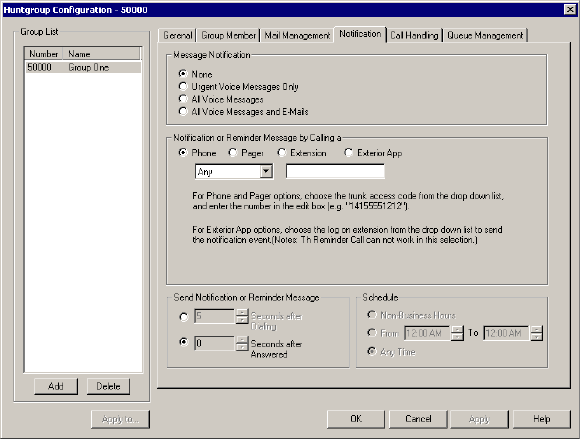
Setting Message Notification Options
14-14 AltiContact Manager Administration Manual
Setting Message Notification Options
The Notification tab of Huntgroup Configuration provides for setting
notification options on new incoming email as well as voice messages.
To work with notification settings, select the huntgroup number from the
list in the Huntgroup Configuration General window, then click the
Notification tab to open the Notification window.
Figure 5. Notification window, Huntgroup Configuration
Individual users can also configure Message Notification within the
AltiGen Voice Mail System.
Max Message
Length Maximum length of voice messages in minutes.
The range is 1ã30 minutes, with a default of 5
minutes.
RetentionLengthof
Saved Messages Number of days saved messages are archived
by the system. The range is 1ã90 days, with a
default of 60.
Parameter Description

Huntgroup Configuration
AltiContact Manager Administration Manual 14-15
14. Huntgroup
Configuration
Note: You can use Apply to to apply mailbox settings to one, some, or
all huntgroups. See ãApply to Buttonã on page 14-2 for more
information on using Apply to.
Setting the Message Types for Notification
Select the types of messages for which the huntgroup user is notified:
ãÂNoneãselected, the user is not notified with a call regarding newly
received messages. Selecting this option does not prevent the user
from getting message waiting indicators or stutter dial tone when new
messages are received.
ãÂUrgent Voice Messages Only
ãÂAll Voice Messages
ãÂAll Voice Messages and E-mails
Setting the Type of Notification
There are four options for sending the notification or reminder message:
phone,pager,extension, or exterior application.
To use the Extension option, select the Extension radio button, then type
the extension number into the text box. For the Phone and Pager options,
first specify the trunk or route access code using the drop-down list next to
the Extension radio button. The Any option means to locate any available
trunk. Then type in the number with all relevant dialing prefixes other than
the trunk code, using a maximum of 80 digits.
Note also the following considerations:
ãÂUsingthePhone option, see ãOutcall to Cellular or PCS Phone
Numbersã on page 14-16.
ãÂForthePager option, the system calls the specified pager number and
then dials the system main number (as set in the System Configuration
General window), which is then displayed on the userãs pager.
For the operator-assisted paging function, the operator phone number
and the pager number must be entered in the <phone
number>*<pager number> format. For example, if the phone
number to call the pager operator is 7654321 and the pager number to
page the user is 12345678, the notification outcall number that needs
to be entered is 7654321*12345678. When the pager operator answers
Setting Message Notification Options
14-16 AltiContact Manager Administration Manual
the Message Notification call, the system announces the pager
number and the System Main Number (as configured on the
General window of System Configuration), which will be displayed
on the userãs pager. The operator is also given the option to repeat
these numbers by pressing ã#ã.
ãÂFortheCustom App, when used in conjunction with a third party
notification application, this feature enables an extension to connect to
an application that can receive the notification event; use the drop-
down list to choose the log on extension to which the third party
application is connected. Contact your local AltiGen dealer for more
information on using this feature.
Note: The Reminder Call feature cannot work with this function
selected.
Outcall to Cellular or PCS Phone Numbers
When an outcall is made by the system (for One-Number-Access, Mes-
sage Notification, Zoomerang, Call Forwarding, etc.) to a cellular or PCS
phone, it may ring the phone once but not necessarily present the call and
make a connection. This will happen if the ringback tone played by the
cellular service provider does not confirm to standard ringback tones. To
work around this problem, instruct users to append a few commas (,)tothe
outcall (cellular) number when entering it. Each comma provides a one
second pause.
Setting Notification Timing
You can set the type of delay detection and the duration (from 5 to 30
seconds) before the system sends the return phone number (the System
Main Number as set in the System Configuration General window) after
the system detects an answer when sending a notification:
ãÂSeconds after Dialingãthedelay(from5to30seconds)afterdialing
before the system sends the return phone number.
ãÂSeconds after Answeredãthe delay (from 5 to 30 seconds) after a
call is answered before the system sends the return phone number.
Setting Notification Business Hours
You can choose one of three options for when the extension user is to be
notified of new messages:

Huntgroup Configuration
AltiContact Manager Administration Manual 14-17
14. Huntgroup
Configuration
ãÂNon-Business Hoursãnotification only during non-business hours.
Business hours are set in the System Configuration Business Hours
window (ãSetting Business Hoursã on page 5-8).
ãÂFrom/Toãnotification during a specified time of day.Select the
hours in the From and To time scroll boxes
ãÂAny Timeãnotification at all times (every day)
Enabling Message Notification
After configuring your message notification settings, to enable message
notification, check the ãAllow Calls to be Transferred/Conferenced/
ForwardedtoanOutsideNumberã field in the Restrictions page of
Agent Extension Configuration.
Setting Call Handling Options
Call Handling options include handling busy calls, forwarding, handling
no-answers, call distribution, and other options.
You can use Apply to to apply call handling settings to one, some, or all
huntgroups. See ãApply to Buttonã on page 14-2 for more information on
using Apply to.
To work with huntgroup call handling options, select the huntgroup
number from the list in the Huntgroup Configuration General window, then
click the Call Handling tab to open the Call Handling window.
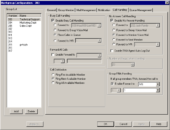
Setting Call Handling Options
14-18 AltiContact Manager Administration Manual
Figure 6. Call Handling window, Huntgroup Configuration
Handling Busy Calls
You have several options for handling calls while the agent extension in a
huntgroup is busy. If you do not enable busy call handling, the caller simply
hears a busy signal.
To enable the options, select the Enable Busy Call Handling check box,
then select from the following options:
ãÂForward toãSelect an extension number in the drop-down list. See
ãA 10-Hop Limit to Call Forwarding for Direct Callsã on page 14-19.
ãÂForward to Group Voice Mail
ãÂPlaceCallerinQueueãfor workgroup numbers and extensions with
Multiple Call Waiting, discussed in the next subsection.
ãÂForward to IVRãuse the drop-down list to select an IVR to which to
route the call. IVR settings are established in IVRãÎ in the Call
Center Management menu.

Huntgroup Configuration
AltiContact Manager Administration Manual 14-19
14. Huntgroup
Configuration
Forwarding All Calls
Call Forwarding is available to huntgroups.
This is the Call Forwarding feature that is also accessible by the agent
extension user by dialing #36.
A One Hop Limit to Call Forwarding for a Transferred Call
There is a one hop limit to call forwarding when the call that is being passed
is a transferred call. For example, agent extension 100 receives a
transferred call and forwards this call to agent extension 101; agent
extension 101 is set to forward all calls to agent extension 102; agent
extension 102 receives the call but CANNOT forward this call to another
agent extension.
A 10-Hop Limit to Call Forwarding for Direct Calls
For direct calls, there is a ã10-hopã limit to call forwarding. For example,
agent extension 100 forwards to agent extension 101, 101 forwards to 102,
102 forwards to 103, and etc. through agent extension 120. A call to agent
extension 100 will be forwarded to 101, which will forward to 102, which
will forward to 103, and etc. until the call has been forwarded 10 times. At
this point, the call will not be forwarded again; if the last agent extension
in the forwarding chain does not answer, the call is sent to agent extension
100ãs voice mail.
If there is a loop condition in the forwarding chain (for example, 100
forwards to 101, 101 to 102, and 102 back to 100), the call is sent to the first
destinationãs voice mail.
To enable call forwarding, select the Enable Forward to check box, then,
using the drop-down list, indicate the forwarding destination. You can use
Apply toãÎ to act on multiple extensions, with the restrictions discussed in
the previous section. The forwarding options are as follows:
ãÂToVoice Mail
ãÂToIVRãselect the IVR number to use in the drop-down list under the
option. IVR settings are established in IVRãÎ in the Call Center
Management menu.
ãÂToanExtensionãselect an extension from the drop-down list.
ãÂToaGroupãselect a group from the drop-down list.
Setting Call Handling Options
14-20 AltiContact Manager Administration Manual
ãÂToaCustom Appãwhen used in conjunction with a third party
notification application, the Custom App feature enables an extension
to connect to an application that can receive the notification event; use
the drop-down list to choose the log on extension to which the third
party application is connected. Contact your local AltiGen dealer for
more information on using this feature.
ãÂToanOutside Numberãthis option is available if it is allowed in the
Other Call Restrictions option in the Restriction window,as
discussed in ãSetting Other Call Restrictionsã on page 13-27. Also, see
ãOutcall to Cellular or PCS Phone Numbersã on page 14-16.
If you choose Outside Number, select a trunk or route access code to
use in the small drop-down list on the left, and type in the full prefix
and phone number.
ãÂTotheOperator
Handling Unanswered Calls
The No Answer Call Handling function provide options for handling calls
when no one answers the huntgroup agent extension within a specified
number of rings.
To enable these options, select Enable No Answer Handling box.
Use the Number of Rings Before Handling scroll box to select a number
between 2 and 20 for the times the telephone rings before the call is handled
by the system.
Select one of the following options for no answer call handling:
ãÂForward toãSelect an agent extension number in the drop-down list.
See ãA 10-Hop Limit to Call Forwarding for Direct Callsã on page 14-
19.
ãÂForward to Group Voice Mail (huntgroup extensions only)
ãÂForward to Member Voice Mail (huntgroup extensions only)ã
forwards the call to the voice mail for the extension that didnãt answer
the call.
ãÂForward to Next Member (huntgroup extensions only)
ãÂForward to IVRãuse the drop-down list to select an IVR to which to
route the call. IVR settings are established in IVR in the Call Center
Management menu.

Huntgroup Configuration
AltiContact Manager Administration Manual 14-21
14. Huntgroup
Configuration
Enabling RNA Agent Auto Log Out
This ãRing No Answerã check box option is available only when Enable
No Answer Handling is selected. When a huntgroup agent's extension is
rung and there is no answer, that agentãs extension is automatically logged
out of the huntgroup.
Setting Huntgroup Handling
For huntgroup numbers, the Huntgroup Configuration Call Handling
window lets you set the handling of normal inbound calls: how to route the
incoming call to an extension, using one of the following options:
ãÂRing First Available Memberãfirst available extension in a
huntgroup. For example, if there are three member extensions in a
huntgroup, the call is always sent to the first member configured in the
huntgroup. If this member is busy, the call goes to the second member
configured and so forth.
ãÂRing Next Available Memberãa round-robin method that attempts
to evenly distribute calls among the group members. This method
sends the call to the next member configured in a huntgroup
(regardless of whether the previous member is busy or not).
ãÂRing All Available Membersãall extensions in a huntgroup.
Note: When this option is enabled, a single huntgroup can have no
more than 20 members set to Ring All. If members are using IP
extensions, the system will require an equal or greater number
of available IP ports than the number of IP extensions. For
example, with 15 IP extensions set to Ring All in a single
huntgroup, the system needs to have at least 15 IP ports
available at any given time.
In addition, calls to huntgroups that have this option enabled
have higher priority than other huntgroup calls. Therefore, if an
agent belongs to multiple huntgroups, one of which has this
option enabled, a call to that huntgroup will be picked up
before others, regardless of its Wait Time in the queue.
Group RNA Handling
You have several options for handling calls when a huntgroup agent's
extension is rung and there is no answer.
Setting Call Handling Options
14-22 AltiContact Manager Administration Manual
To enable call forwarding, select the Enable Forward to check box, then,
using the drop-down list, indicate the forwarding destination. You can use
Apply toãÎ to act on multiple extensions, with the restrictions discussed in
the previous section. The forwarding options are as follows:
ãÂToVoice Mail
ãÂToIVRãselect the IVR number to use in the drop-down list under the
option. IVR settings are established in IVRãÎ in the Call Center
Management menu.
ãÂToanExtensionãselect an extension from the drop-down list.
ãÂToaGroupãselect a group from the drop-down list.
ãÂToanApplication Extensionãselect an application extension from
the drop-down list.
ãÂToanOutside Numberãthis option is available if it is allowed in the
Other Call Restrictions option in the Restriction window,as
discussed in ãSetting Other Call Restrictionsã on page 13-27. Also, see
ãOutcall to Cellular or PCS Phone Numbersã on page 14-16.
If you choose Outside Number, select a trunk or route access code to
use in the small drop-down list on the left, and type in the full prefix
and phone number.
ãÂTotheOperator
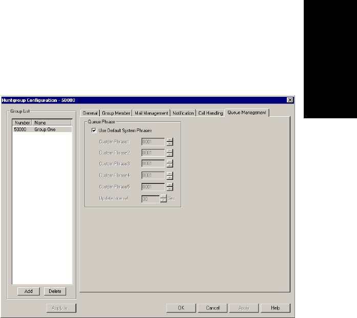
Huntgroup Configuration
AltiContact Manager Administration Manual 14-23
14. Huntgroup
Configuration
Setting Queue Management Options
In the Queue Management window of Huntgroup Configuration, you can
set audio peripheral optionsãwhich greetings and updates to use as well as
the update interval. For each huntgroup you can either use the system
default audio peripheral configuration or you can set up a custom
configuration.
Figure 7. Queue Management window, Huntgroup Configuration
The default audio peripheral setup is discussed in ãAudio Peripheral
Configurationã on page 5-27. Custom configuration involves choosing
other phrasesãa function set with the IVR as discussed in Chapter 11, IVR
Configuration.
You can also use Apply toãÎ as discussed in ãApply to Buttonã on page
14-2 to apply the configuration to one, some, or all huntgroups.
Setting Queue Management Options
14-24 AltiContact Manager Administration Manual

AltiContact Manager Administration Manual 15-1
15.Workgroup
Configuration
C
HAPTER
15
Workgroup Configuration
The primary use of a workgroup is to have specific calls answered by a
designated group of extension usersãwhen the workgroup extension is
dialed, the system hunts for an available member extension to which to
route the call. You can use workgroups for various purposes, for example,
in selecting a workgroup as a System Operator.
AltiContact Manager allows up to 32 workgroups to be configured. Each
workgroup can have up to 128 members or extensions, and an extension
can be a member of multiple workgroups.
Note: If the workgroup pilot extension is configured to Ring All
Available Members, the maximum number of members is 20. See
ãSetting Call Handling Optionsã for details.
There are two main configuration steps to setting up a workgroup:
The first step is use Workgroup Configuration setup windows to create a
workgroup and configure the following workgroup settings, each of which
is accessed by a tab in the Agent Configuration window:
ãÂGeneral Configurationãcreating workgroup pilot numbers, group
descriptions, service level threshold and call recording options.
ãÂSkill Settingsãdefining workgroup skills.
ãÂMail Managementãcapacity and features options for extension
mailboxes.
ãÂNotificationãpreferences and options for voice mail notifications.
ãÂCall Handlingãcall forwarding, call waiting, and call handling
preferences and options.
ãÂQueue Managementãqueue phrases, overflow routing, queue
announcements and queue quit option.
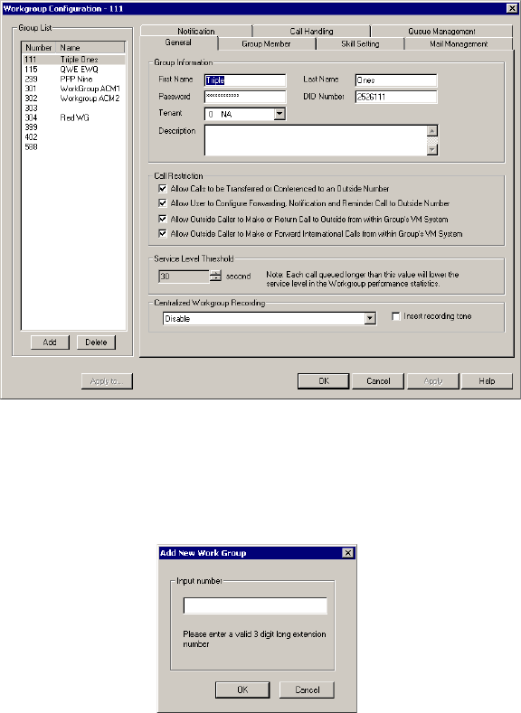
15-2 AltiContact Manager Administration Manual
The second step is, after you have created a workgroup, use the Group
Member window to assign agents to the workgroup(s).
Figure 1. General Configuration window, Workgroup Configuration
Creating a Workgroup
1. To add a new workgroup, click the Add button in the General window.
The Add New Group dialog box opens.
2. Type in a workgroup number in the Input Number field and click OK.
Establishing Basic Workgroup Attributes
After you create a workgroup, you can set other basic attributes in the
Workgroup Configuration General window:

Workgroup Configuration
AltiContact Manager Administration Manual 15-3
15.Workgroup
Configuration
To set the Personal Information:
Type in the User Name, Password, DID, Tenant Group, and optional
Description:
ãÂFirst Name and Last Name of the workgroup, each with a maximum
of 32 characters.
ãÂPassword for the workgroup. The default is the system default
password set on the Number Plan tab of the System Configuration
window.
A valid password must be 4 to 8 digits (numbers or letters A-Z) in length
and cannot be the same as its workgroup pilot number. Basic password
patterns, such as repeated digits (1111), consecutive digits strings (1234),
or digits that match the workgroup pilot number (Ext. 101 using 1012,
9101,10101, etc.) are not allowed. The letters map to numbers as follows:
ãÂDID Numberãeach workgroup can be assigned a DID number. This
number does not have a fixed length, but the length must be long
enough (range 2ã16) for the system to match the DID incoming call.
It is recommended to use the full 10 digit DID number, not just the
last few digits. This full number guarantees the system can send the
correct number as the Caller ID on PRI lines. With fewer digits, the
system sends the trunkãs configured phone number as the Caller ID. If
the trunk number is not configured, the system main number is sent.
ãÂTenantãa drop-down list of Tenant IDs (groups) to which the
workgroup can be assigned. See ãUsing a Tenant Tableã on page 5-22
for more information on Tenants.
Note: If a workgroup is assigned to N/A in the Tenant drop-down
list, the workgroup is able to access all trunks, even though the
trunks may have been assigned to tenants.
ãÂDescriptionãOptional descriptive information such as department
name or workgroup office location.
Numbers Letters Numbers Letters
2 A,B,C,a,b,c 6 M,N,O,m,n,o
3 D,E,F,d,e,f 7 P,Q,R,S,p,q,r,s
4 G,H,I,g,h,i 8 T,U,V,t,u,v
5 J,K,L,j,k,l 9 W,X,Y,Z,w,x,y,z
15-4 AltiContact Manager Administration Manual
Setting Call Restrictions
You can allow or restrict other types of calls by using the following check
boxes. You may choose to enable or disable these optionsãthe default is
set to enable the first three options. These default settings reduce the risk of
international toll fraud.
Caution: Allowing these options may increase the potential for toll
fraud if they are not properly administered.
ãÂAllow Calls to be Transferred or Conferenced to an Outside
Numberãselected, the group user can transfer or conference calls to
an outside telephone number. Checking this box will enable Message
Notification.
ãÂAllow User to set Forward, Notification and Reminder Call to
Outside Numberãselected, the group user can set these features to an
outside telephone number when accessing the groupãs voice mail.
Checking this box will enable Message Notification.
ãÂAllow Outside Caller to Make or Return Calls from within
Groupãs VM Systemãselected, the group user can make or return
calls from within the groupãs voice mail (i.e. Zoomerang).
ãÂAllow Outside Caller to Make or Forward International Calls
from within Groupãs VM Systemãselected, the group user can
make international outgoing calls from within the groupãs voice mail
(i.e. Zoomerang).
Service Level Threshold
The Service Level Threshold scroll box allows you to select the length of
time in seconds that a call can be in queue before the call is logged in
workgroup performance statistics as having exceeded the allowable service
level limits. You can set the value to any number between 1ã1200 seconds.
Centralized Workgroup Recording Options
The system administrator can specify the following workgroup call
recording options for a workgroup:

Workgroup Configuration
AltiContact Manager Administration Manual 15-5
15.Workgroup
Configuration
ãÂDisableãno call recording.
ãÂRecord all calls to central locationãrecords all calls which are saved
to a centralized location (defined in the Call Recording page of
CallCenter Configuration, see page 12-6); this option requires a
Recording Seat license to be available.
ãÂRecord on demand to central locationãrecords calls on demand
which are saved to a centralized location (defined in the Call
Recording page of CallCenter Configuration, see page 12-6); this
option requires a Recording Seat license to be available.
ãÂRecord on demand to agent VMãrecords calls on demand which
are saved to the extension agentãs voicemail box.
ãÂInsert Recording Toneãplays a recording beep to alert the parties
that the conversation is being recorded.
Notes:
ã The recording session starts when the call enters the connected state
and ends when hang up or flash is pressed, or when the call is
transferred.
ã The recording setting at Extension Configuration only applies to
personal calls. The recording setting at Workgroup Configuration
only applies to workgroup calls. To allow an agent to record all calls
(personal and workgroup), both recording settings must be enabled.
Establishing Workgroup Membership
To add agent extensions to a workgroup, select the workgroup pilot number
from the Group List side window list in the General window of
Workgroup Configuration, then click the Group Member tab. The
workgroup pilot number appears in the window title bar.
WARNING!
Listening in to or recording a conversation without the consent of one or
both parties may be a violation of local, state and federal privacy laws. It
is the responsibility of the users of this feature to assure they are in
compliance with all applicable laws.
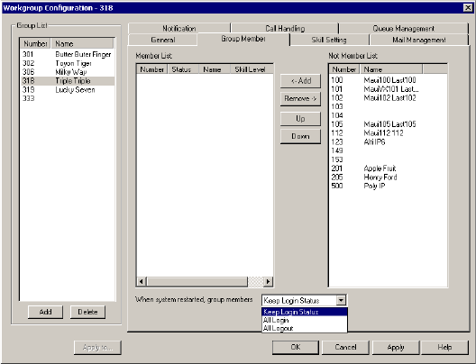
Establishing Workgroup Membership
15-6 AltiContact Manager Administration Manual
Figure 2. Group Member window, Workgroup Configuration
Adding or Removing Members
To add extension(s) to the selected workgroup:
1. In the Group Member window, click the extension number(s) in the
Not Member list.
2. Click Add to move them to the Member list.
Note: If the workgroup pilot extension is configured to Ring All
Available Members, the maximum number of members is 20.
See ãSetting Call Handling Optionsã for details.
3. By default, the newly added member will have the Skill Level set to 1.
To change the Skill Level, double-click on the member in the Member
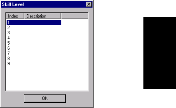
Workgroup Configuration
AltiContact Manager Administration Manual 15-7
15.Workgroup
Configuration
List to open the Skill Level dialog box. (Skill Levels are defined in
ãSkill Setting Assignmentã on page 15-8.)
Figure 3. Skill Level dialog box
Click on the desired Skill Level Index, then click OK.
To remove extension(s) from a workgroup:
1. Click the extension number(s) in the Member list.
2. Click Remove to move them to the Not Member list.
Automatic Log In/Out
Whenever the system is restarted, the administrator can use the drop down
list at the bottom of the Group Member window to:
ãÂKeep Login Statusãdefault setting; all group members retain their
original login status for that group prior to restart.
ãÂAll Loginãall group members are automatically logged into the
assigned group after the system is restarted.
ãÂAll Logoutãall group members are not logged back into the group
when the system is restarted; members must re-log back into the
assigned group.

Skill Setting Assignment
15-8 AltiContact Manager Administration Manual
Skill Setting Assignment
The Skill Setting window in Workgroup Configuration allows the system
administrator to define different skill workgroups and then assign different
skill levels for agents for incoming calls, which will ring the lowest
member agent first, from 1 to 9. Levels 1 to 9 can also be described as
proficiency for a skill group for an agent.
The system administrator can create skill set categories, such as ãSpanish-
speakingã which can be assigned to an agent or a group. Calls can then be
queued according to the agentãs call handling knowledgeãproviding for
faster service and more informed answers.
The settings configured here correspond tothe Skill-Based Routing option
in the Call Handling page of Workgroup Configuration (see ãSetting
Workgroup Handlingã on page 15-19).
Figure 4. Skill Setting window, Workgroup Configuration
To set up a skill set:
1. Select a workgroup in the Group List window.
2. Double-click an index number in the Skill Set box or highlight an
index number and click the Edit button.
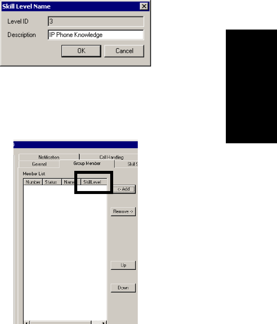
Workgroup Configuration
AltiContact Manager Administration Manual 15-9
15.Workgroup
Configuration
3. In the Skill Level Name dialog box, enter the skill name in the
Description field, then click OK.
Figure 5. Skill Level Name dialog box
4. The Skill Set appears in the main window for that index number.
5. In the Group Member page or Workgroup Configuration, the Skill
Level for the workgroup will appear in the last column of the Member
List.
Figure 6. Skill Level Column, Group Member window
6. In the Call Handling page of Workgroup Configuration for the
specified workgroup, go to the Call Distribution field and select Skill-
Based Routing. When a call comes into this workgroup, the call will
be routed according to the agent assigned with the lowest skill number.
Setting the Mailbox Options
The Mail Management settings define how voice messages are handled
for a workgroup: how messages are announced and processed, and how
much capacity is allotted to message storage.

Setting the Mailbox Options
15-10 AltiContact Manager Administration Manual
To work with mailbox settings, select the workgroup number you want to
work with from the Group List, then click the Mail Management tab to
open the Mail Management window.
Figure 7. Mail Management window, Workgroup Configuration
Note: You can use Apply to to apply mailbox settings to one, some, or
all workgroup.
Disabling a Mailbox
When you disable a mailbox, the normal greeting is played but callers
cannot leave messages.
Synchronizing with Exchange Server
If your system is set up to synchronize with an Exchange Server, you can
select this check box to enable synchronization for voice mails. See
ãSetting E-mail Messaging Optionsã on page 8-4, and ãSetting up an
Exchange Serverã on page 21-10.

Workgroup Configuration
AltiContact Manager Administration Manual 15-11
15.Workgroup
Configuration
SMTP/POP3 Setting
ãÂEmail Nameãthe workgroupãs email name without the @domain.
The default email name is ext[extension number], that is, the letters
ãextã followed by the workgroup extension number. For example, the
default email name for extension 2497 would be ext2497.
ãÂRetrieve Voice Mail by Email Clientãselected, this sends voice
mail to the workgroup extension as an email attachment. Deselected,
voice mail is retrieved as voice mail.
Mail Forwarding Options
ãÂEnable Mail Forwardingãselected, the workgroupãs email will be
forwarded to the email address you specify in the Forward Email
Address box. The address should be a full address, including the
domain (for example, jsmith@thecompany.com.).
If you enable mail forwarding, you also specify what you want done
with the original messages after they have been forwarded. In the
drop down list you can choose to:
ãDelete Messages after Forward
ãKeep the Messages as New
ãKeep Messages as Saved
Further, if you enable mail forwarding, you can use the check boxes
whether you want to Forward Email,Forward Voice Mail, or both.
Setting Message Playback Options
You can use the following checkboxes to turn on or off options for listening
to playback of recorded messages. These options apply to both new
messages and saved messages, and they can be applied to multiple
workgroups using Apply to.
Parameter Description
Announce Message
Sender Before
Playback
Selected, the user hears the name of the
message sender (internal sender only) before
listening to recorded AltiGen Voice Mail
System messages.
Setting the Mailbox Options
15-12 AltiContact Manager Administration Manual
Setting Mailbox Capacities
You can set various mailbox capacities with the following options:
These options can be applied to multiple extensions using Apply to.
Announce Time
Stamp Before
Playback
Selected, the user hears the timestamp (time
and date) of each message before playback.
Confirm Callback
Number Selected, system confirms the accuracy of the
callerãs number.
Enable Distinctive
Call Waiting Tone Selected, the user hears three different call
waiting tone cadences to distinguish between
internal, external, and operator calls (see
ãDistinctive Ringã on page 5-3).
Play the Newest
Voice Message First Selected, voicemails are played in reverse order
of their delivery when the user retrieves them.
Parameter Description
Max Number of
Messages Maximum number of messages stored in the
userãs mailbox. The range is 1ã999, defaulting
to 100.
Mailbox Size Mailbox size in MBs of stored messages. The
range is 1ã500 MB, with a default of 50.
Max Message
Length Maximum length of voice messages in minutes.
The range is 1ã30 minutes, with a default of 5
minutes.
RetentionLengthof
Saved Messages Number of days saved messages are archived
by the system. The range is 1ã90 days, with a
default of 60.
Parameter Description
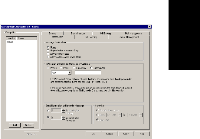
Workgroup Configuration
AltiContact Manager Administration Manual 15-13
15.Workgroup
Configuration
Setting Message Notification Options
The Notification tab of Workgroup Configuration provides for setting
notification options on new incoming email as well as voice messages.
To work with notification settings, select the workgroup number from the
Group List, then click the Notification tab to open the Notification
window.
Figure 8. Notification window, Agent Extension Configuration
Individual users can also configure Message Notification within the
AltiGen Voice Mail System.
Note: You can use Apply to to apply notification settings to one, some,
or all extensions.
Setting the Message Types for Notification
Select the types of messages for which the workgroup extension user is
notified:
ãÂNoneãselected, the user is not notified with a call regarding newly
received messages. Selecting this option does not prevent the user
from getting message waiting indicators or stutter dial tone when new
messages are received.
ãÂUrgent Voice Messages Only
Setting Message Notification Options
15-14 AltiContact Manager Administration Manual
ãÂAll Voice Messages
ãÂAll Voice Messages and E-mails
Setting the Type of Notification
There are four options for sending the notification or reminder message:
phone,pager,extension or custom application (Custom App).
ãÂExtension -tousetheExtension option, select the Extension radio
button, then type the extension number into the text box.
ãÂPhone/Pager -forthePhone and Pager options, first specify the trunk
or route access code using the drop-down list next to the Extension
radio button. The Any option means to locate any available trunk.
Then type in the number with all relevant dialing prefixes other than
the trunk code, using a maximum of 80 digits.
ãÂCustom App - when used in conjunction with a third party notification
application, the Custom App feature enables an extension to connect
to an application that can receive the notification event; use the drop-
down list to choose the log on extension to which the third party
application is connected. Contact your local AltiGen dealer for more
information on using this feature.
Note also the following considerations:
ãÂUsingthePhone option, see ãOutcall to Cellular or PCS Phone
Numbersã on page 15-15.
ãÂForthePager option, the system calls the specified pager number and
then dials the system main number (as set in the System Configuration
General window), which is then displayed on the userãs pager.
For the operator-assisted paging function, the operator phone number
and the pager number must be entered in the <phone
number>*<pager number> format. For example, if the phone
number to call the pager operator is 7654321 and the pager number to
page the user is 12345678, the notification outcall number that needs
to be entered is 7654321*12345678. When the pager operator answers
the Message Notification call, AltiContact Manager announces the
pager number and the System Main Number (asconfiguredonthe
General window of System Configuration), which will be displayed
on the userãs pager. The operator is also given the option to repeat
these numbers by pressing ã#ã.

Workgroup Configuration
AltiContact Manager Administration Manual 15-15
15.Workgroup
Configuration
Outcall to Cellular or PCS Phone Numbers
When an outcall is made by the system (for One-Number-Access, Mes-
sage Notification, Zoomerang, Call Forwarding, etc.) to a cellular or PCS
phone, it may ring the phone once but not necessarily present the call and
make a connection. This will happen if the ringback tone played by the
cellular service provider does not confirm to standard ringback tones. To
work around this problem, instruct users to append a few commas (,)tothe
outcall (cellular) number when entering it. Each comma provides a one
second pause.
Setting Notification Timing
You can set the type of delay detection and the duration (from 5 to 30
seconds) before the system sends the return phone number (the System
Main Number as set in the System Configuration General window) after
the system detects an answer when sending a notification:
ãÂSeconds after Dialingãthe delay (from 5 to 30 seconds) after dialing
before the system sends the return phone number.
ãÂSeconds after Answeredãthe delay (from 5 to 30 seconds) after a
call is answered before the system sends the return phone number.
Setting Notification Business Hours
You can choose one of three options for when the extension user is to be
notified of new messages:
ãÂNon-Business Hoursãnotification only during non-business hours.
Business hours are set in the System Configuration Business Hours
window (ãSetting Business Hoursã on page 5-8)
ãÂFrom/Toãnotification during a specified time of day.Select the
hours in the From and To time scroll boxes
ãÂAny Timeãnotification at all times (every day)
Enabling Message Notification
After configuring your message notification settings, to enable message
notification, check the ãAllow Calls to be Transferred or Conferenced
to an Outside Numberã field in the Restriction page of Extension
Configuration.
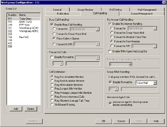
Setting Call Handling Options
15-16 AltiContact Manager Administration Manual
Setting Call Handling Options
Call Handling options include forwarding, handling busy calls, handling
no-answers and other options.
You can use Apply to to apply call restriction settings to one, some, or all
workgroups.
To work with workgroup call handling options, select the workgroup
number from the Group List,thenclicktheCall Handling tabtoopenthe
Call Handling window.
Figure 9. Call Handling window, Workgroup Configuration
Handling Busy Calls
You have several options for handling calls while the workgroup extension.
If you do not enable busy call handling, the caller simply hears a busy
signal.
To enable the options, select the Enable Busy Call Handling check box,
then select from the following options:
ãÂForward to ExtensionãSelect an extension number in the
drop-down list. See ãA 10-Hop Limit to Call Forwarding for Direct
Callsãonpage15-17.

Workgroup Configuration
AltiContact Manager Administration Manual 15-17
15.Workgroup
Configuration
ãÂForward to Group Voice Mail
ãÂForward to IVRãuse the drop-down list to select an IVR to which to
route the call. IVR settings are established in IVR ãÎ on the
Management menu.
Forwarding All Calls
Call Forwarding is available for workgroups.
This is the Call Forwarding feature that is also accessible by the workgroup
extension user by dialing #36.
A One Hop Limit to Call Forwarding for a Transferred Call
There is a one hop limit to call forwarding when the call that is being passed
is a transferred call. For example, extension 100 receives a transferred call
and forwards this call to extension 101; extension 101 is set to forward all
calls to extension 102; extension 102 receives the call but CANNOT
forward this call to another extension.
A 10-Hop Limit to Call Forwarding for Direct Calls
For direct calls, there is a ã10-hopã limit to call forwarding. For example,
extension 100 forwards to extension 101, 101 forwards to 102, 102
forwards to 103, and etc. through extension 120. A call to extension 100
will be forwarded to 101, which will forward to 102, which will forward to
103, and etc. until the call has been forwarded 10 times. At this point, the
call will not be forwarded again; if the last extension in the forwarding
chain does not answer, the call is sent to extension 100ãs voice mail.
If there is a loop condition in the forwarding chain (for example, 100
forwards to 101, 101 to 102, and 102 back to 100), the call is sent to the first
destinationãs voice mail.
To enable call forwarding, select the Enable Forward to check box, then,
using the drop-down list, indicate the forwarding destination. You can use
Apply to to act on multiple workgroups, with the restrictions discussed in
the previous section. The forwarding options are as follows:
ãÂToVoice Mail
ãÂToIVRãselect the IVR number to use in the drop-down list under the
option. IVR settings are established in IVRãÎ on the Management
menu.
ãÂToanExtensionãselect an extension from the drop-down list.
Setting Call Handling Options
15-18 AltiContact Manager Administration Manual
ãÂToaWorkgroupãselect a workgroup from the drop-down list.
ãÂToaCustom Appãwhen used in conjunction with a third party
notification application, this feature enables an extension to connect to
an application that can receive the notification event; use the drop-
down list to choose the log on extension to which the third party
application is connected. Contact your local AltiGen dealer for more
information on using this feature.
ãÂToanOutside Numberãthis option is available if it is allowed in the
Other Call Restrictions option in the Restriction window,as
discussed in ãSetting Other Call Restrictionsã on page 13-27. Also, see
ãOutcall to Cellular or PCS Phone Numbersã on page 15-15.
If you choose Outside Number, select a trunk or route access code to
use in the small drop-down list on the left, and type in the full prefix
and phone number.
ãÂTotheOperator
Note: Forwarding calls to a pager is possible but not recommended
since callers will only hear what is heard when calling a pager and
will not know to enter a return phone number unless instructed.
Handling Unanswered Calls
The No Answer Call Handling function provide options for handling calls
when no one answers the extension within a specified number of rings.
Except for Enabling One Number Access, these options are not available
to virtual extensions.
To enable these options, select Enable No Answer Handling box.
Use the Number of Rings Before Handling scroll box to select a number
between 2 and 20 for the times the telephone rings before the call is handled
by the system.
Select one of the following options for no answer call handling:
ãÂForward to ExtensionãSelect an extension number in the
drop-down list. See ãA 10-Hop Limit to Call Forwarding for Direct
Callsãonpage15-17.
ãÂForward to Group Voice Mail (physical extensions only)
ãÂForward to New Member

Workgroup Configuration
AltiContact Manager Administration Manual 15-19
15.Workgroup
Configuration
ãÂForward to IVRãuse the drop-down list to select an IVR to which to
route the call. IVR settings are established in IVRãÎ on the
Management menu.
Enable RNA Agent Auto Logout Checkbox
Select this option to have the system automatically log out an agent
extension from a workgroup if RNA is encountered.
Setting Workgroup Handling
The Call Distribution field options let you set the handling of normal
inbound calls: how to route the incoming call to an workgroup agent, using
one of the following options:
ãÂRing First Available Memberãfirst available extension in a
workgroup. For example, if there are three member extensions in a
workgroup, the call is always sent to the first member configured in the
workgroup. If this member is busy, the call goes to the second member
configured and so forth.
ãÂRing Next Available Memberãan automatic call distribution
method that attempts to evenly distribute calls among the workgroup
members. This method sends the call to the next member configured in
the workgroup (regardless of whether the previous member is busy or
not).
ãÂRing All Available Membersãall extensions in a workgroup.
Note: When this option is enabled, a single workgroup can have no
more than 20 members set to Ring All. If members are using IP
extensions, the system will require an equal or greater number
of available IP ports than the number of IP extensions. For
example, with 15 IP extensions set to Ring All in a single
workgroup, the system needs to have at least 15 IP ports
available at any given time.
In addition, calls to workgroups that have this option enabled
have higher priority than other workgroup calls. Therefore, if
an agent belongs to multiple workgroups, one of which has this
option enabled, a call to that workgroup will be picked up
before others, regardless of its Wait Time in the queue.
ãÂRing Longest Idle Memberãthe agent who has been off the phone
the longest.
Setting Call Handling Options
15-20 AltiContact Manager Administration Manual
ãÂRing Average Longest Idle Memberãthe agent who averages being
off the phone the longest.
Note: Average Longest Idle is calculated as follows:
idle time = login duration - incoming call duration - outgoing call
duration
login time = total length of time of agent login for the day, reset by
midnight task
Important: Please note the following issue that may arise from using this
option.
When an agent is added to a workgroup and logs in, the agentãs login time
starts from 0, while other agents (already logged in) have a login time
starting many hours earlier. With Ring Average Longest Idle Member
enabled, the new agent will not receive a call for a long time.
ãÂRing Fewest Answered Callsãthe agent who has answered the
fewest number of calls.
ãÂRing Shortest Average Talk Timeãthe agent who averages the
shortest talk time.
Note: Average talk time is calculated as follows:
avg. talk time (ATT) = total incoming call duration / # of incoming
calls
The agent calculated with the lowest value for ATT is rung first.
ãÂSkill-Based Routingãthe agent who has the lowest skill number
assigned (defined in ãSkill Setting Assignmentã on page 15-8). By
default, the newly added member will have the Skill Level set to 1.
Group RNA (Ring No Answer) Handling
You have several options for handling calls when a workgroup agent's
extension is rung and there is no answer.
Note: If an incoming call encounters RNA for every agent in the
workgroup AND No Answer Call Handling is set to ãForward to
Next Memberã, the call will be forwarded according to these
settings. If you do not set options here, the call will go to the
workgroupãs voice mail after ringing all agents.

Workgroup Configuration
AltiContact Manager Administration Manual 15-21
15.Workgroup
Configuration
To set options for workgroup RNA handling, select the Enable Forward
to check box, then, using the drop-down list, indicate the forwarding
destination. You can use Apply to to act on multiple workgroups, with the
restrictions discussed in the previous section. The forwarding options are
as follows:
ãÂToVoice Mail
ãÂToIVRãselect the IVR number to use in the drop-down list under the
option. IVR settings are established in IVRãÎ on the Management
menu.
ãÂToanExtensionãselect an extension from the drop-down list.
ãÂToaGroupãselect a workgroup from the drop-down list.
ãÂToaCustom Appãwhen used in conjunction with a third party
notification application, this feature enables an extension to connect to
an application that can receive the notification event; use the drop-
down list to choose the log on extension to which the third party
application is connected. Contact your local AltiGen dealer for more
information on using this feature.
ãÂToanOutside Numberãthis option is available if it is allowed in the
Other Call Restrictions option in the Restriction window,as
discussed in ãSetting Other Call Restrictionsã on page 13-27. Also, see
ãOutcall to Cellular or PCS Phone Numbersã on page 15-15.
If you choose Outside Number, select a trunk or route access code to
use in the small drop-down list on the left, and type in the full prefix
and phone number.
ãÂTotheOperator
Note: Forwarding calls to a pager is possible but not recommended
since callers will only hear what is heard when calling a pager and
will not know to enter a return phone number unless instructed.
Announce Agent Info
Enable this checkbox to have the system announce the agentãs directory
name before an incoming workgroup call is transferred to an agent from the
queue.
Note: When an extension (A) calls another extension (B), and is then
transferred to a workgroup with Announce Agent Info enabled,
only Ext. B will hear the agent announcement information.
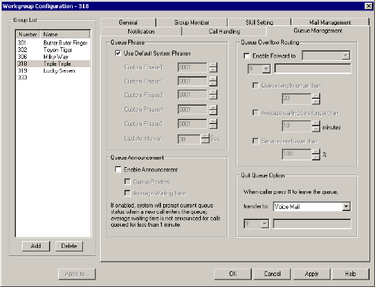
Queue Management
15-22 AltiContact Manager Administration Manual
Queue Management
The Queue Management tab in Workgroup Configuration allows you to
set options for queue phrases and announcments, queue overflow routing
and queue quit options.
Figure 10. Queue Management window, Workgroup Configuration
Setting Queue Phrase Options
For each workgroup, you can either use the system default phrases or you
can set up a custom configuration.
The default audio phrases are discussed in ãAudio Peripheral
Configurationã on page 5-27. Custom configuration involves choosing
other phrasesãa function set with the IVR as discussed in Chapter 11, IVR
Configuration.
You can also use Apply to to apply the configuration to one, some, or all
workgroups.

Workgroup Configuration
AltiContact Manager Administration Manual 15-23
15.Workgroup
Configuration
Queue Announcement
You can set up the system to announce a callerãs queue statusãqueue
position and average waiting timeãwhen an incoming call enters a
workgroup queue. To enable this option, select Enable Announcement,
then select Queue Position and/or Average Waiting Time.
Note: If enabled, the system will prompt the current queue status when a
a new call enters the queue; also, average waiting time is not
announced for calls queued for less than 1 minute.
Queue Overflow Routing
The Queue Overflow Routing options are for handling long queues or long
wait times for callers. When a queue exceeds a set number of calls, or
callers are waiting beyond a set length of time, calls are automatically
forwarded to an IVR, voicemail box, extension, group, application
extension, or operator.
To set options for handling call overflow:
1. In the Queue Overflow Handling field group, set options for:
ãÂQueue call not to exceed Xcalls -(setnumberofcalls)
IMPORTANT!
If queue call is set to zero (0), queue overflow routing will always
be in effect.
ãÂExpected waiting time longer than Xminutes -(setminutes)
ãÂService level lower than X%- (set percent level)
You can set one, some or all of these.
Note: The expected waiting time is calculated by
(AverageCallHandleTime x PositioninQ + 59) / 60
AverageCallHandleTime = TotalWorkgroupCallDuration x
1.05 / (TotalCall x TotalLoginAgent)
DefaultAverageCallHandleTime is configurable from 1 to 600
seconds.
StartCalculationCallCount is configurable from 1 to 100 calls.
2. Set a call forwarding destination if the queue length, wait time or
service level settings are exceeded. If this option is not enabled, calls
will go to the workgroupãs voicemail.

Queue Management
15-24 AltiContact Manager Administration Manual
Note: If you choose an extension, this can be the same workgroup
extension or another workgroup.
You can use Apply to to apply the configuration to one, some, or all
workgroups.
Queue Quit Option
The queue quit feature gives a caller the option of leaving a workgroup
queue at any time by pressing #. Use the transfer to drop-down list to
select the option the caller will have:
ãÂVoice Mail
ãÂIVRãselect the IVR number to use in the drop-down list under the
option. IVR settings are established in IVRãÎ on the Management
menu.
ãÂExtensionãselect an extension from the drop-down list.
Note: If the forwarding extension is busy when a caller quits a queue,
the call will go to this extensionãs voice mail.
ãÂGroupãselect a workgroup from the drop-down list.
ãÂCustom Appãwhen used in conjunction with a third party
notification application, this feature enables an extension to connect to
an application that can receive the notification event; use the drop-
down list to choose the log on extension to which the third party
application is connected. Contact your local AltiGen dealer for more
information on using this feature.
ãÂOutside Numberãthis option is available if it is allowed in the Other
Call Restrictions option in the Restriction window, as discussed in
ãSetting Other Call Restrictionsã on page 13-27. Also, see ãOutcall to
Cellular or PCS Phone Numbersã on page 15-15.
If you choose Outside Number, select a trunk or route access code to
use in the small drop-down list on the left, and type in the full prefix
and phone number.
ãÂOperator
Note: Forwarding calls to a pager is possible but not recommended
since callers will only hear what is heard when calling a pager and
will not know to enter a return phone number unless instructed.

Workgroup Configuration
AltiContact Manager Administration Manual 15-25
15.Workgroup
Configuration
ãÂCallback Interviewãthe System will record the callerãs Caller ID
and will prompt the caller to record a message into the voicemail box
of the workgroup. With a third party application, the system can notify
workgroup agents of the waiting voicemail. (For more detail on this
option, refer to the Callback Interview section below.)
Note: This option is only available to external callers.
Callback Interview Option
Under heavy call traffic conditions, the Callback Interview feature (a queue
quit option) is useful in helping improve service quality for customers
calling into the call center.
Typically, when a customer calls into a workgroup, if no agents are
available, the caller usually waits in queue until an agent is able to take the
call. If the caller hangs up while waiting in queue, the agent is unaware of
this.
When Callback Interview is enabled as a queue quit option, the caller can
press #when waiting in queue. The system will then 1) prompt the caller to
enter a callback number (if caller ID is unavailable); then 2) prompt the
caller to record a message.
The system saves the message as a voicemail, which is delivered to the
workgroup voice mail box. With a third party application, the system can
also notify workgroup agents of the waiting voicemail.
Operation Notes
ã Conference calling may not work properly when an internal call is
made to workgroup that has Ring All Available Members setting. If
the internal extension is connect to anagent of this workgroup and then
initiates a conference call to another agent in this workgroup, the first
agent does not connect to the conference call.
ã The system does not follow Busy Call Handling for a workgroup if no
IP trunks are available for IP extension agent. Instead, the system will
send the call to the workgroupãs voice mail.
Queue Management
15-26 AltiContact Manager Administration Manual

AltiContact Manager Administration Manual 16-1
16. IP Extensions
C
HAPTER
16
Setting Up IP Extensions
IP extensions communicate with the AltiContact Manager system using IP-
based protocols to carry voice and signaling data. Instead of PSTN, they
use a data networking connection such as an Ethernet 100-Base-T (RJ-45).
AltiContact Manager supports only those devices that are based on H.323
protocol.
From the end-user's perspective, an IP extension works exactly the same as
an analog extension with the added advantage of being able to work
remotely and without any cabling requirements. There is also no functional
difference in AltiContact Manager features and client applications such as
real-time monitoring, AltiView, and AltiConsole, with the following
exceptions which are unavailable on an IP extension:
ã #81 Hands freeãIntercom mode
ã #82 (Hands freeãManual answer mode)
ã Distinctive ringing (double ring for internal calls, single rings for
external calls).
Note: For Alti-IP 600 Phones, #81 and #82 are supported.
In addition, the Location column in the Extension View in ACM
Administrator will show the IP address used by any extension currently
logged onto an IP extension.
AltiGen IP Phone Service
AltiGen IP Phone Service runs on the same system as AltiContact
Manager, is installed together with AltiContact Manager, and connects to
AltiContact Manager through enhanced AltiLink+ protocol on behalf of
AltiGen IP Phones.
Intercom with IP Phones
Intercom (#93) is supported on the Triton Analog extension with
AltiTouch+ phones. Intercom is supported on IP extensions as well,
provided AltiGen IP Phones are used. An extension user can use the feature
code #93 to intercom an IP extension associated with an AltiGen IP Phone.
If this phone is in idle state, an H.323 session will be established, the phone
System Requirements
16-2 AltiContact Manager Administration Manual
speaker will be turned on automatically, a short ring tone is generated, the
Speaker is turned on, and the voice path is connected. If the IP phone is
busy, the caller will follow the call busy handling of the AltIGen IP Phonesã
configuration.
IP Connections and Voice Quality
Voice quality can degrade when multiple IP connections use DSL; the
exact numbers will depend on your bandwidth and the number of IP
connections active at one time. If you encounter this problem, you may
need to reduce the number of IP extensions.
System Requirements
Server
ã AltiContact Manager 4.6 or higher
ã Triton VoIP board(s)ãone VoIP port per simultaneous IP extension
user is required.
ã High-speed WAN connectivity to support remote users (minimum
64kbps per remote user)
ã Static IP address assigned to each extension configured for an IP
connection (recommended, but not required)
Client
ã An AltiGen-certified IP phone device (see ãClientsã on page 16-4 for
details)
ã High-speed data connection to the AltiContact Manager system
(minimum 64kbps)
Configuration
You must configure AltiContact Manager and, in some cases, your client
hardware or software for using IP extensions.
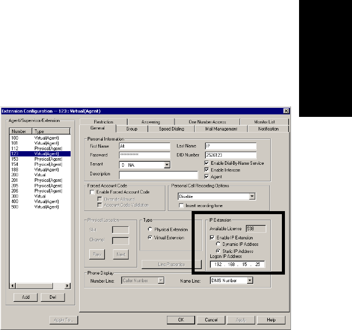
Setting Up IP Extensions
AltiContact Manager Administration Manual 16-3
16. IP Extensions
AltiAdmin
1. Ensure that the VoIP settings are configured properly and work.
For details on configuring the Triton VoIP board and the IP trunks,
refer to ãConfiguring the Triton VoIP Boardã on page 6-7 and ãSetting
General Trunk Attributesã on page 7-3.
2. Ensure that you can make calls over IP by creating an entry (at least an
entry with the IP address of the system) in the IP dialing table and then
dialing <IP Trunk access code> +<IP dialing table entry code> +
<extension number>. Make sure you can have a two-way conversation
on this VoIP call.
For details on using the IP dialing table, see ãDefining the IP Dialing
Tableã on page 9-2. Also see ãSetting VoIP Codecsã on page 9-5.
3. For each extension for which you are enabling IP extensions, check
Enable IP Extension on the General tab of the Agent Configuration
window.
Figure 1. General Window, Extension Configuration
a. If you have static IP addressing (recommended), choose Static and
then enter the IP address of the IP phone in the Logon field.
b. If you do not have static IP addressing available, choose Dynamic.
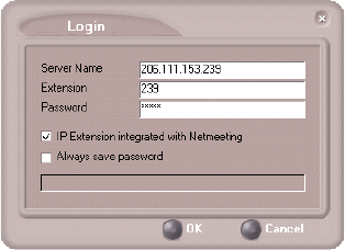
Configuration
16-4 AltiContact Manager Administration Manual
Note that dynamic IP addressing will show a different IP address in
the Location column of the Extension View every time the
extension user enables an IP extension.
Clients
Currently, AltiGen certifies the following IP phone/adapter devices:
ã AltiGen IP Phone
ã QuicknetãPhoneJackã PCI adapter and PhoneCardã PCMCIA
adapter with Internet SwitchBoardã software
ã Siemens HiNet LP5100 IP Phone
ã PolycomôÛ SoundPointôÛ 500 IP Phone
ã AltiView integrated with NetMeeting
For details on configuring these devices, see the documentation that
AltiGen provides with each.
AltiView Integrated with NetMeeting
AltiView provides an option called IP Extension Integrated with
NetMeeting that allows it to use NetMeeting as the IP extension.
In addition to the AltiView software, the client requirements are as follows:
ãÂA sound card
ãÂA headset connected to the sound card (Plantronics LS1
recommended, available from retail outlets or from the Plantronics
website at http://www.plantronics.com/computer/ls1.html).
A microphone and speakers should not be used, since the speaker's
output would be fed back to the microphone and cause severe echoes.

Setting Up IP Extensions
AltiContact Manager Administration Manual 16-5
16. IP Extensions
ãÂNetMeeting 3.01, which is automatically installed with Windows
2000. Users can check to see if NetMeeting is installed by looking
under Programs>Accessories>Communication from the Windows
Start button. If not, it is available for download from the Microsoft
website at http://www.microsoft.com/windows/netmeeting/download/
default.asp.
ãÂAdditional system requirements as listed on the Microsoft website at
http://www.microsoft.com/windows/NetMeeting/
SystemRequirements/default.ASP.
Note also that processor-intensive applications will affect voice quality.
Instructions on using this option are also provided in the AltiView and ACM
User Guide.
Configuration
16-6 AltiContact Manager Administration Manual
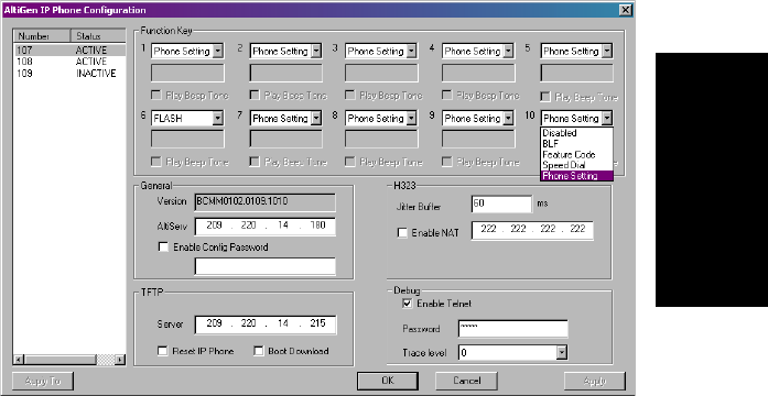
AltiContact Manager Administration Manual 17-1
17.Alti-IP 600 Phone
Configuration
C
HAPTER
17
Alti-IP 600 Phone Configuration
AltiContactManager supports the Alti-IP 600, AltiGenãs H.323-compliant,
business telephone that provides voice communication over an IP network.
To configure the Alti-IP 600 phone, select AltiGen IP Phone
Configuration on the Management menu.
This opens the IP Phone Properties Window where, after setting up an IP
extension, you can set the following parameters for the IP extension:
Figure 1. IP Phone Properties window, AltiGen IP Phone Configuration
17-2 AltiContact Manager Administration Manual
The left side of the IP Phone Configuration window displays all the Alti-IP
phone extensions that have been set up in the system. After creating the IP
extensions, you can set the following parameters:
Parameter Description
SoftKey1-10 Corresponds to the 10 soft keys on the Alti-IP 600. Use the
drop down list to assign one of the following functions to the
desired keys:
ã Disabled - when selected, the corresponding soft key
cannot be used.
ã BLF (Busy Lamp Field) - when selected, enter an
extension number in the field below; this will be
associated with the corresponding soft key to
automatically dial this extension number ; the button light
next to this soft key indicates that the extension number
is busy. You can select the Play Beep Tone check box to
also have the IP phone play an audible beep when the
extension number is ringing.
Note:TheBLF feature can only be assigned to
internal extension numbers, not outside numbers.
ã Feature Code - when selected, enter an AltiContact
Manager feature code in the field below; this will be
associated with the corresponding soft key to dial this
feature code.
ã Speed Dial - when selected, enter the speed dial code in
the field below; this will be associated with the
corresponding soft key to dial this speed dial code.
ã Phone Setting - when selected, the IP phone user will be
able to program the corresponding soft key, as a speed
dial or feature code key, directly from the IP phone (using
**6,thenENTER).
Note: The lower left soft key is set up as FLASH by default.
This key can be re-assigned in ACM Admin, using
the AltiGen IP Phone Configuration window. No
other soft keys can be configured to FLASH.

Alti-IP 600 Phone Configuration
AltiContact Manager Administration Manual 17-3
17.Alti-IP 600 Phone
Configuration
Important: Please note that the configuration in ACM Admin will override
the Alti-IP 600 phoneãs local configuration after the IP Phone
is registered. If the IP phoneãs local configuration is changed
while in Basic mode, these changes will be overwritten by
ACM Admin settings. Also, after the IP Phone is successfully
registered with AltiContact Manager, the IP phone will
overwrite the AltiContact Manager IP address and network-
related settings on the server.
Important: When updating the Alti-IP 600 phoneãs firmware, it is
recommended that administrators perform any updates after
normal business hours or when the IP phone is not in use. If the
Alti-IP 600 phone is in use during an update, the call will be
disconnected.
General Allows you to specify the IP address of the AltiContact
Manager system the Alti-IP 600 phone is connected to. The
version of software associated with AltiContact Manager is
automatically displayed in the Version field.
To allow the extension user to have password-protected
configuration functionality from the phone itself, check the
Enable Config Password checkbox and assign a numerical
password. When the extension user attempts to configure
features, the user will need to enter the assigned password to
proceed.
H.323 Allows you to set the Jitter Buffer in milliseconds, the delay
used to buffer voice packets received from the IP network.
The Jitter Buffer should be adjusted according to the WAN
bandwidth allocated to data traffic.
To allow NAT support for the IP extension, check the
Enable NAT button and enter the public IP address of the
NAT router.
TFTP Allows you to assign the TFTP Server to which the IP phone
can connect to for updating firmware when necessary. Enter
the IP address of the TFTP Server in the Server field. Check
the Reset IP Phone and Boot Download checkbox options
to reset or reboot the phone, respectively.
Debug When enabled, allows the Alti-IP 600 phone to connect to
Telnet for debugging.
Parameter Description
17-4 AltiContact Manager Administration Manual
Apply To Button
The Apply To button works with the following parameters: General,
H.323,TFTP (Server field only; Reset IP Phone and Boot Download
options cannot be applied to multiple extensions), and Debug.
IP Extension Log In/Log Out
The feature codes #26 (Extension Log Out) and #27 (Extension Log In) are
available on the Alti-IP 600. When the Alti-IP 600 is logged in using #27
+ENTER, the LCD will display the extension number. The Alti-IP 600
must be onhook for #26 and #27 to work.
Dialing an IP Number Directly from the Alti-IP 600
To dial an IP number directly from the Alti-IP 600 phone set, enter the IP
address using the *key to enter periods followed by the #key.
Notes:
ã This only works when the Alti-IP 600 is operating in basic mode.
ã If the Alti-IP 600 is configured for a public IP address, you can call
other public IP address devices.
ã If the Alti-IP 600 is configured for a private IP address, you can call
other private IP address devices that you can ãseeã or that are on your
subnet.

AltiContact Manager Administration Manual 18-1
18.Application
Extension Config.
C
HAPTER
18
Application Extension
Configuration
The application extension is an extension intended for use with IVR or
outbound applications and requires an SDK Application Session License
per concurrent connection.
The application extension can be logged in/out with a password by the
application but only one application can login at a time. A user can login as
an administrator, and will get the administrative privilege of having the
application send any command to the server; the administrator can also
receive trunk event, line event and RTM event details.
An application extension differs from a physical or virtual extension as
follows:
ã The following feature codes are not available:
ã #27 Station Log In
ã #34 Dial By Name
ã #35 Station Privilege Override
ã #37 Remote Call Forwarding
ã The following features are not available:
ãVoicemail
ãDialbyName
ã Call Restriction
ã ONA
ã Workgroup membership
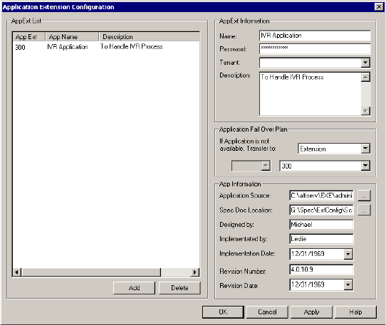
Application Extension Setup
18-2 AltiContact Manager Administration Manual
Application Extension Setup
You can access Application Extension Configuration by clicking the
App Ext icon or by selecting Application Ext Configuration... from the
Call Center Management menu.
Figure 1. Application Extension Configuration window
To set up an Application Extension:
Note: Before you begin, make sure to have an SDK Application Session
License registered and activated for your system.

Application Extension Configuration
AltiContact Manager Administration Manual 18-3
18.Application
Extension Config.
1. Open the Application Extension Configuration window.
2. Click the Add button and enter the extension number in the Add
Application Extension dialog box. and click OK.
Figure 2. Add Application Extension dialog box
3. The Application Extension appears in the Application Extension List.
Continue adding application extensions as needed. Otherwise, refer to
the following sections for further configuration.
4. For the third party application connecting to this extension, make sure
the application is properly set to log into the application extension.
Application Failover Plan
The Application Failover Plan ensures that a call made to the extension
will be automatically transferred if the application is not available. Use the
transfer to drop-down list to select the forwarding destination. The options
are as follows:
ãÂIVRãselect the IVR number to use in the drop-down list under the
option. IVR settings are established in IVRãÎ on the Management
menu.
ãÂExtensionãselect an extension from the drop-down list.
ãÂOperatorãselect an operator from the drop-down list.
Important: If the failover setting for the Application Extension is set to an
extension, and the extension is RNA or busy, the system will
announce to the caller that the extension is not available and the
call will be dropped.
Application Extension Setup
18-4 AltiContact Manager Administration Manual
Application Information
Additional information can be described in the App Information fields. If
desired, enter the appropriate information in the fields for Application
Source,Spec Doc Location,Design Party,Implementation Party,
Implementation Date,Revision Number and Revision Date.
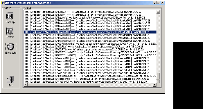
AltiContact Manager Administration Manual 19-1
19. System Data
Management
C
HAPTER
19
System Data Management
System Data Management provides for backing up data to, and restoring
files from, a system hard disk drive or a network drive. This option can only
be accessed at the AltiContact Manager system; it is not available from a
remote ACM Administrator client.
Using Backup and Restore
You can also access this feature by selecting the Backup and Restore
Utility program from the AltiWare folder accessible from the Start menu.
To access the feature, select System Data Management in Utilities from
the Service menu.
Figure 1. System Data Management window

BackingupFiles
19-2 AltiContact Manager Administration Manual
Backing up Files
To backup files immediately:
1. Open the System Data Management window as described in the
preceding section, then select the Backup icon to view the Backup
Configuration dialog box.
Figure 2. Backup Configuration dialog box
2. In the Components box, select the files you want to back up.
3. In the Backup To drop-down list, select the day of the week you want
to use as the starting date for back up files, or select Advanced.
Advanced means that you select the folder or drive to back up.
Selecting Advanced displays a folder icon. Click the folder icon to
pop up a browse dialog box that lets you select the folder to backup.
When you click OK to close the dialog box, the selected drive or
directory is displayed in the box below the Backup To drop-down list.
Note: You cannot select Advanced to choose a directory and at the
same time select a starting day. You need to use one or the
other for a particular backup operation.
4. Once you are satisfied with the selection of files to back up, and with
the date and target location, click OK to start the backup. This closes
the dialog box.
In the System Data Management window, the progress and status of
the file backup is displayed.
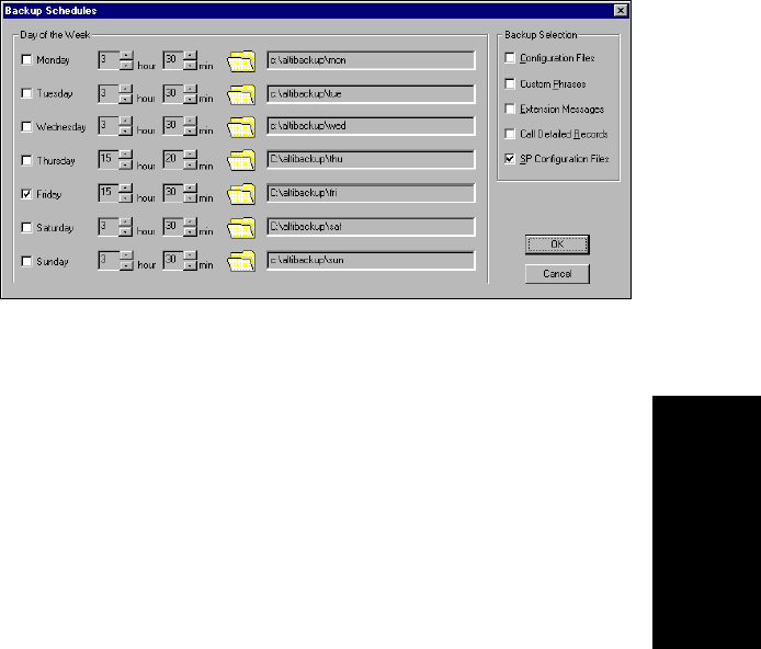
System Data Management
AltiContact Manager Administration Manual 19-3
19. System Data
Management
Scheduling Backups
You can set up automated backup on a schedule, and you can select the
days, the times, and the target drives and folders for the backup.
To set backup schedules:
1. Open the System Data Management window as described above, then
select the Schedule icon to view the Backup Schedules dialog box.
Figure 3. Backup Schedules window
2. Set the options:
ã Select the checkbox for each day of the week you want run the
backup.
ã For each day, use the drop-down lists to specify the time. These
time settings use a 24-hour clock.
ã You can accept the default target directories, or you can click the
Folder to open the Browse for Folder to select the destination or
the backup files.
ãÂUnderBackup Selection, select the file components you want to
back up: Configuration files, Custom Phrases, Extension Messages,
Call Detail Records, and/or SP Configuration files.
3. Click OK.
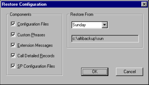
Restoring Backed up Files
19-4 AltiContact Manager Administration Manual
Restoring Backed up Files
To restore the backed up files:
1. Open the System Data Management window as described in ãUsing
Backup and Restoreã on page 19-1, then select the Restore icon to
view the Restore Configuration dialog box.
Figure 4. Restore Configuration window
2. Under Components, select the file groups you want to restore.
3. Using the Restore From drop-down list, select the day you want to
restore from, or select Advance to choose the restore folder.
Clicking Advance displays a folder icon that you can click to open a
dialog box that allows you to select the directory you want to restore
from.
Selecting a day of the week or manually choosing the restore directory,
the directory specification appears in the text box below the drop-
down list.
Note: The components you select for restore must have been backed
up into the directory you selected. For example, if you didnãt
back up configuration files on Thursday, you wonãt be able to
restore them from the Thursday directory.
4. Click OK to start the restore process.
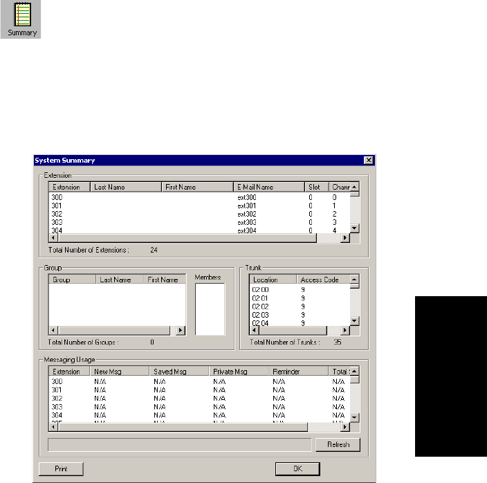
AltiContact Manager Administration Manual 20-1
20.SystemReport
Management
C
HAPTER
20
System Report Management
AltiContact Manager provides system management reports that contain
information on system configuration summary, traffic, system log, call
detail summary, and IP cumulative traffic statistics.
System Summary Report
The System Summary report provides summary information on extensions,
trunks, and workgroups configured in the system.
To open the System Summary report window, select the Report menu from
the Main Menu Bar and then select System Summary from the drop-down
list, or select the Summary icon.
.
Figure 1. System Summary window
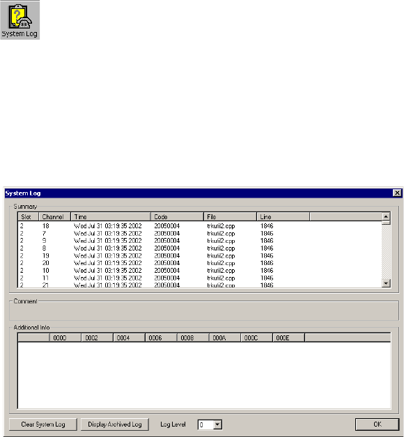
System Log
20-2 AltiContact Manager Administration Manual
The system configuration summary data includes basic attributes on
extensions, groups and group members (click a group to display the groupãs
members), trunk location and access, and messaging usage by extension.
You can Print this report using the Print button.
System Log
The System Log window displays information on system operating status.
This window is designed for use by system engineers and certified
personnel only.
To view the System Log, select the Report menu from the Main Menu bar,
then select System Log from the drop-down list, or select the System Log
icon. You can also view the system log by running the LogViewer.exe
program in the \altiserv\exe folder.
Figure 2. System Log window
The Summary box displays information on each channel for each card.
Select a channel in the Summary box to see data about the channel in the
Comment area and additional technical data in the Additional
Information box.
Click Clear System Log to clear the information in all the windows.
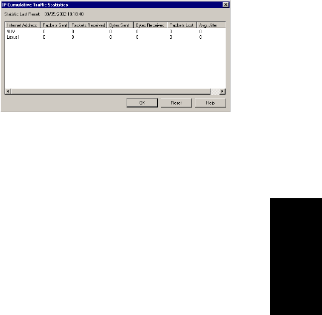
System Report Management
AltiContact Manager Administration Manual 20-3
20.SystemReport
Management
Click Display Archived Log /Display Current Log to toggle the view
between the current and the most recently cleared system log.
Use the Log Level dropdown list to view the level of severity for system
errors. Level 0displays the most obvious system errors, Level 5displays
all system errors in specific detail.
IP Cumulative Traffic Statistics
To view a report of all cumulative IP traffic, click IP Traffic Statistics
from the Reports menu. The IP Cumulative Traffic Statistics window
displays the following IP trunk traffic information for all calls.
Figure 3. IP Cumulative Traffic Statistics window
This window displays the following data:
Parameter Description
Internet Address Displays the IP address or fully qualified DNS name
of the remote location.
Packets Sent Displays the number of voice packets sent to other
AltiContact Manager systems over the public or
private IP network.
Packets Received Displays the number of voice packets received from
other AltiContact Manager systems over the public
or private IP network.
Bytes Sent Displays the total size (in bytes) of all voice packets
sent to other AltiContact Manager systems over the
public or private IP network.
IP Cumulative Traffic Statistics
20-4 AltiContact Manager Administration Manual
The difference between the IP Trunk Current Traffic Statistics window
and the IP Cumulative Traffic Statistics window is that the former shows
figures only for the active call (Current Traffic) on a particular IP trunk of
the local AltiContact Manager system while the other window shows
figures for all calls combined (Cumulative Traffic) to and from remote
AltiContact Manager locations.
Resetting Cumulative Statistics
You can reset the IP Cumulative Traffic Statistics by clicking the Reset
button. Also, this window automatically resets all fields to 0when the
AltiContact Manager system is shut down and restarted. Statistics gathered
before the reset are not saved.
Bytes Received Displays the total size (in bytes) of all voice packets
received from other AltiContact Manager systems
over the public or private IP network.
Packets Lost Displays the number of voice packets that have been
lost due to prolonged delays, network congestion, or
routing failure.
Average Jitter displays the average length of delay per voice packet
in milliseconds. This figure should stay under 100
milliseconds. A higher figure indicates a longer
average delay. This number can be used to measure
the quality of service on the network that connects
the source and destination sites.
Parameter Description

AltiContact Manager Administration Manual 21-1
21. Data and Internet
Integration
C
HAPTER
21
Data and Internet Integration
This section describes how to integrate the system with the Internet and
data communications. It will cover the following areas:
ãÂEmail
ãÂMailforwarding
ã Exchange integration
ã AltiReach Setup
Network Protocol and Addressing
The system integrates telephony functions with the LAN and Internet to
provide a state-of-the art communication facility with local and remote
access to email mixed-media messaging.
Before you begin, you should be familiar with the following LAN and
Internet protocol and addressing information.
Network
A network is a distributed interconnection of multiple voice and data
communication devices utilizing network protocol software to
communicate and exchange information.
Protocol
A protocol is a set of rules and methods by which telephone equipment and
computers exchange information across a network. Networking software
generally implements multiple levels of protocols in the process of
interconnecting two or more devices on the network and enabling them to
exchange information.
Transport Protocols
Among the various transport protocols available, AltiContact Manager
uses the TCP/IP transport protocol.
TCP/IP - Transmission Control Protocol/Internet Protocol (TCP/IP) is the
protocol used on the Internet.
21-2 AltiContact Manager Administration Manual
Aprotocol stack is a collection of actual protocol layers used to establish a
connection across the network that allows dissimilar network devices to
exchange information.
SMTP/POP3
SMTPãSimple Mail Transfer Protocol. As seen by the client side of the
network, is an Internet email sending protocol software format.
POP3ãPost Office Protocol Version 3. As seen by the client side of the
network, POP3 is an Internet email retrieving protocol software format that
allows users to retrieve mail from its stored location.
IMAP4ãInternet Message Protocol Version 4. An enhanced version of
POP3 that, among other things, allows the user to view message headers of
each message before retrieving the complete message.
Network Address
A network address is an identifier for a node, station, or unit of equipment
in a network. There are many methods of accessing the network, such as
email or Hyper Text Transport Protocol (HTTP), Gopher, etc.
AltiContact Manager uses the email client/server access method.
A sample email client/server network address might look something like
the following example:
jsmith@earth.science.berkeley.edu
This address tells the routers and the Internet Service Provider (ISP) where
to deliver this message. This is an extended address. The address is read
from the right to the left:
edu = first level domain
berkeley = second level domain
science = third level domain
earth = fourth level domain
@=at
jsmith =username
Or it might be as simple (and short) as:
altigen.com
com = first level domain name
altigen = second level domain name

Data and Internet Integration
AltiContact Manager Administration Manual 21-3
21. Data and Internet
Integration
Local Address
When you are sending messages among users in a LAN, the local address
is used in place of the extended network address. Local addressing is used
in a peripheral node or station and is transformed to or from an extended
address for delivery purposes. Often within a LAN, the domain is assumed
to be the local domain if no @domain is added to the address.
Mixed-Media Messaging
Messaging includes many options other than just text. Messages might
include all of the following types of information or any combination
thereof:
ã Text - (includes word processing files, spreadsheets, database listing)
ãÂVoice
ãÂFax
ãÂVideo
If you include more than one attachment or media type in your email
messages (such as graphics, video, or sound), you must employ a method
called MIME (Multipurpose Internet/Mail Extensions). MIME is a
technique designed to bundle attachments within individual email
messages.
When a MIME file with attachments arrives at your workstation,
additional processing begins immediately. As the various attachments
arrive, the client or browser identifies these attachments by file type or by
description information in the attachment tag (as specified by the MIME
format). After the client or browser identifies a file, it can handle the file
playback or display. Sometimes the client or browser itself handles
playback or display (including .GIF and .JPG files).
When other kinds of files show up and need special handling capabilities
(beyond the scope of most client/browsers), the client hands off the files to
other Helper Applications for playback or display. Helper Applications
are designed to read and process the files and to present the file contents on
demand.
AltiWare provides users with the ability to record a voice annotation and
attach it to an email mixed-media message. This voice recording must be
done before the user sends the email in order to send the voice annotation
as an attachment to the email. After the voice recording is complete, the
21-4 AltiContact Manager Administration Manual
user can send the email. AltiWare then combines the voice message and the
email into a single MIME message and sends it to the recipient. The ability
to send and receive MIME messages is included as part of AltiWare email
capabilities.
Setting Up Email Service
There are some basic requirements that must be met in order to access
Mixed-Media Messaging using email over the AltiContact Manager
system.
Before You Begin
To set up email for the AltiContact Manager system, you need to have the
following installed on AltiContact Manager:
ã Windows NT network interface card installed and Windows NT
network capability enabled
ã Network TCP/IP installed and configured
ã Internet connection (if sending and receiving emails over the
internet)
ã Multi-media stations/PCs as clients
Setting Up LAN and Internet Email on the Server
To set up the server side of the network, follow the steps below:
Step 1: Selecting Your ISP and IP Addresses
You will need to obtain the following to setup Internet email:
1. Select your Internet Service Provider (ISP). There are numerous
ISPs to choose from. There is a fee associated with these services. For
details, please contact an ISP that serves your area.
2. From your ISP:
ãÂObtainaDomain Name Server (DNS) Address. AltiWare address
should be added to the DNS database by your ISP.
ã Select and give your ISP a unique Domain Name. Each domain
must have a unique name associated with it, such as the address for
AltiGen, which is ãaltigen.comã.
ãÂObtainaBlock of IP Addresses and assign a unique IP address to
each client on the LAN.
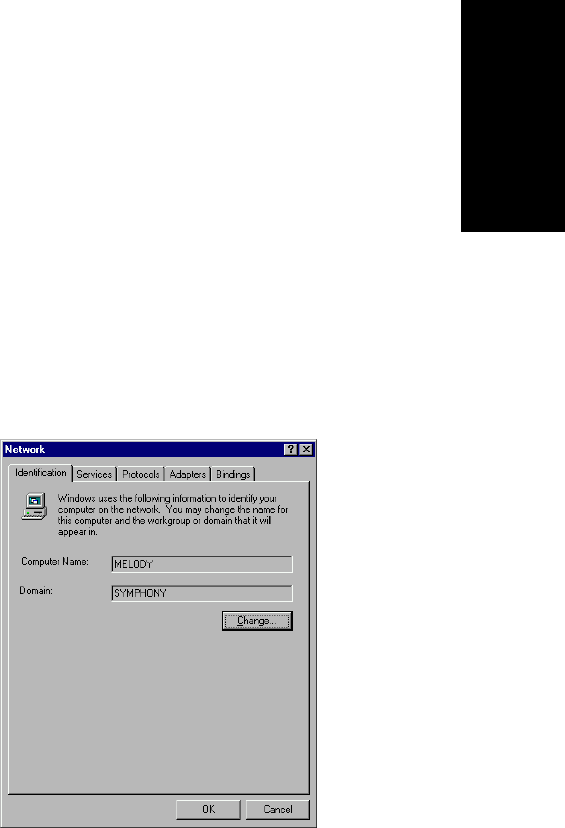
Data and Internet Integration
AltiContact Manager Administration Manual 21-5
21. Data and Internet
Integration
ãÂObtaintheSubnet Mask. You will need to enter this address later
in the TCP/IP configuration setup for both the server and client
stations.
Step 2: Setup the Router
Install the router on the LAN. The router is the gateway to another LAN or
to the Internet.
1. Specify a router that is on the same LAN as the AltiWare server, such
as ISDN or T1.
2. Assign an IP address (one of the block of IP addresses obtained from
the ISP to the router). This becomes the gateway router address.
Step 3: Configure TCP/IP Properties
Configure the TCP/IP protocol parameters.
1. Open the Control Panel and select the Network icon. The Network
Setting window is displayed.
Figure 1. Network Setting window
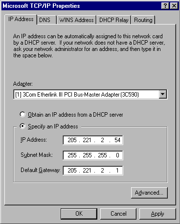
21-6 AltiContact Manager Administration Manual
2. Click the Protocols tab, then double click on TCP/IP Protocol from
the drop-down list box. The TCP/IP Protocol window appears (see
Figure 2), where you configure the IP Address, Subnet Mask, and
Default Gateway (router).
Figure 2. TCP/IP Configuration
ãÂIP addressãenter the assigned IP address (from the block of IP
addresses obtained from your ISP) to the AltWare.
ãÂSubnet Maskãenter the Subnet Mask obtained from your ISP.
ãÂDefault Gatewayãenter the email Gateway (the router address).
3. Select the DNS tab at the top of the TCP/IP Properties window (see
Figure 3) to configure Domain Name System.
Note: You must configure the DNS tab if you want to exchange
email through the Internet.
Configure the following:
ãÂHost Nameãenter the name of the server (for example: melody)
ãÂDomainãenter the domain name (for example: altigen.com)
ãÂDNS Service Search Orderãenter the IP address of either your
own or your ISPãs Domain Name Server.
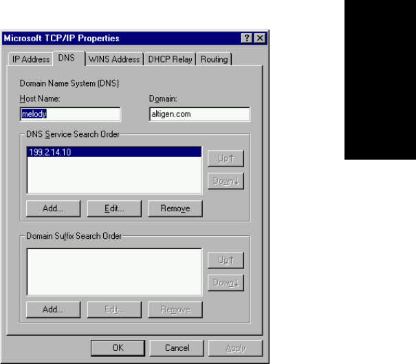
Data and Internet Integration
AltiContact Manager Administration Manual 21-7
21. Data and Internet
Integration
4. Click OK.
Figure 3. DNS Configuration window
5. Refer to Microsoft Windows NT configuration documentation to
complete the TCP/IP network setup.
Step 4: Notify Your ISP of the Following:
1. Your AltiContact Manager Host Name (host name of the server or
server name)ãyour AltiContact Manager Server is the server that
actually receives the mail or messages. For example, AltiGen has
named its server ãglobal_cti.ã This tells the DNS to route all mail or
messages for altigen.com to the global_cti server.
2. Your AltiContact Managerãs IP address (e.g., 200.133.204.2).
Step 5: Configure Email in ACM Administrator
Important: If you have a Windows NT or Windows 2000 server, you must
stop the Default SMTP Site server, or it will conflict with
AltiContact Managerãs SMTP server. Do the following:
1. In AltiContact Manager, go to the System Management menu, select
Voice Mail ConfigurationãÎ and click the Messaging tabtoopenthe
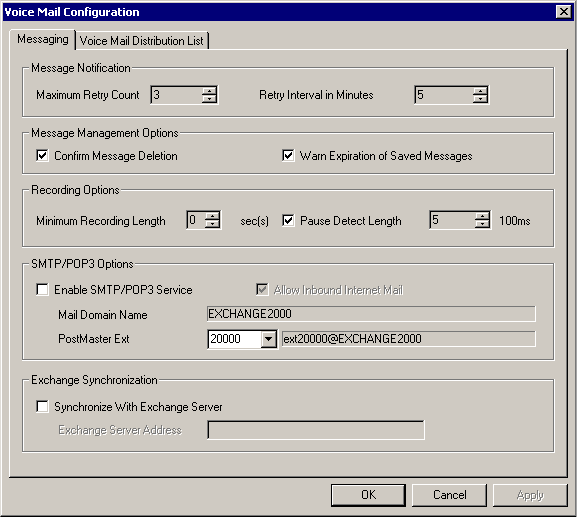
21-8 AltiContact Manager Administration Manual
Messaging window. Be sure that Enable SMTP/POP3 Service (in the
E-Mail Messaging Options field group) is deselected.
2. Open the Windows Internet Information Services window by right-
clicking the My Computer icon and choosing Manage from the
popup. Expand Services and Applications in the tree to view Internet
Information Services.
3. Select Default SMTP Site in the tree.
4. On the toolbar, click the Stop button.
You can now proceed with the steps given below.
To configure the AltiContact Manager for email service:
1. On the System Management menu, select Voice Mail
ConfigurationãÎ and click the Messaging tabtoopentheMessaging
window:
2. Configure the E-Mail Messaging Options group as follows:
ã Select Enable SMTP/POP3 Service to enable email and Mixed-
Media Messaging on the AltiWare system.

Data and Internet Integration
AltiContact Manager Administration Manual 21-9
21. Data and Internet
Integration
ã Select Allow Inbound Internet Mail if AltiWare is the only mail
server running on the system. If you are running another SMTP
server on the same system (such as Exchange) and you do not want
AltiContact Manager to receive inbound Internet mail, you should
leave this box unchecked.
3. Assign a unique Email Name to extension users in the General
window of Extension Configuration.
ã Select the extension number (or select Add Extension and then
enter the extension number in the field provided if this is a new
extension).
ã Enter the email name in the E-mail Name data entry field.
4. Allocate the system storage capacity for extensions in the Mailbox
Setting window of Extension Configuration.
Each userãs needs might be different. The default is 50 MB of storage,
which on the average, will give each user room for 100 messages.
Refer to ãSetting E-mail Messaging Optionsã on page 8-4 for more
details.
Setting Up LAN and Internet Email on the Client
To set up the client side of the LAN:
1. Configure the following client TCP/IP Properties (see Figure 2):
ã IP Address
ã Subnet Mask
ã Default Gateway
2. On the DNS tab of TCP/IP Properties, enter the following (see
Figure 3):
ãÂHostName
ãÂDomain
ã DNS Service Search Order
3. Configure the following mail server parameters of the email client
application:
ãÂEntertheMail Server (POP3) User Name. (This is the same name
entered as the email name on the AltiWare General page of
Extension Configuration).
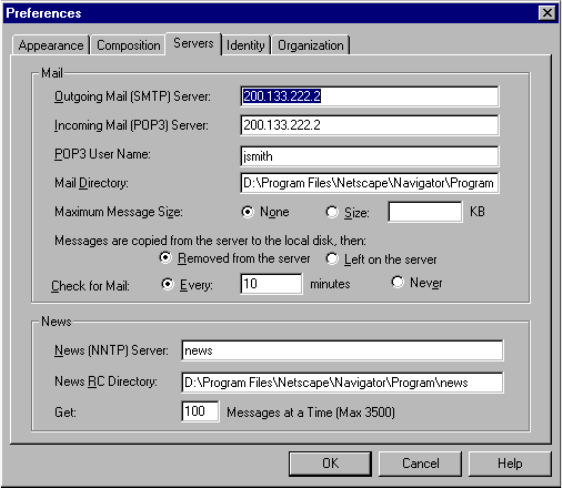
21-10 AltiContact Manager Administration Manual
ãÂEntertheIncoming Mail (POP3) Server address.
ãÂEntertheOutgoing Mail (SMTP) Server address.
Figure 4. Netscape Mail Server Setup
4. Set up helper applications and general preferences for the email client
application (i.e., associates the .WAV files with sound recorder
application).
Setting up an Exchange Server
This section provides you with step-by-step instructions to configure the
Exchange Integration feature in AltiContact Manager, for the Microsoft NT
4.0 server and the Microsoft NT 2000 server.
Exchange Server Windows NT 4.0 Integration
In the example that follows, the AltiContact Manager system is called
TELESYSTEM, and the Exchange Server is called MAILSERVER,and
both systems belong to the NT domain called ALTICHINA.

Data and Internet Integration
AltiContact Manager Administration Manual 21-11
21. Data and Internet
Integration
Prerequisites
Two NT servers:
ã One NT server with the AltiContact Manager software
ã One NT server with Exchange Server software
AltiWare System Prerequisites
ã Windows NT 4.0 with Service Pack 6a or higher
ã AltiContact Manager software
ã The AltiContact Manager system and the Exchange server system
must belong to the same NT domain.
ã AltiGen Services should be started with the user account
<Domainname>\AltiGen_<AltiContactManagerSystemName>.
For example, ALTICHINA\AltiGen_TELESYSTEM.
To check the Windows NT version:
Click the Start button, select Run,andtypewinver in the Run dialog
box.
This opens an About Windows NT dialog box that displays the version
of NT running on your system. It should say:
Version 4.0 (Build 1381: Service Pack 6)ãÎ.Revised
Service Pack 6a
If you have an older version of NT, upgrade to the latest version.
Check http://www.microsoft.com/ntserver to get the latest service
pack for Windows NT.
To check the AltiWare version:
Select About from the Help menu of ACM Administrator. The version
displayed should be AltiContact Manager 4.6 or higher.
To check the domain:
On the AltiContact Manager system, go to
Start!Settings!Control Panel!Network. In the Identification
tab of the Network dialog box, verify that you see two text boxes,
Computer Name and Domain. Note down the value in the Domain
field.
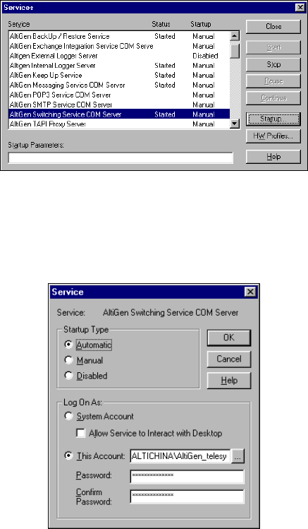
21-12 AltiContact Manager Administration Manual
Repeat the same steps on the Exchange server system and make sure
the domain names are the same.
To verify AltiGen Services:
1. Select Start!Control Panel!Services. A Windows Services
dialog box will be shown, as in this example.
Figure 5. Windows Service window
2. Select AltiGen Switching Service COM Server from the control
panel of AltiContact Manager.
3. Highlight the AltiGen Switching Service Com Server and click the
Startup button. A Service startup options dialog box will popup:
Figure 6. Service Startup options dialog box
4. Complete the entries in this dialog box as follows:

Data and Internet Integration
AltiContact Manager Administration Manual 21-13
21. Data and Internet
Integration
ãÂIntheLog On As group, select This Account and set
<DomainName>\AltiGen_<ServerName>as the account. In this
example, it is ALTICHINA\AltiGen_telesystem.
If this is not the case, you need to re-install AltiContact Manager
while logged in as a domain administrator with local administrator
privileges.
ã Repeat the previous step, but this time, check the Log On As
account for AltiGen Exchange Integration Service COM Server.
Exchange Server Prerequisites
ã Exchange Server 5.5 with Service Pack 3
ã Successful ping to the AltiContact Manager and vice versa
ã Exchange Server Services must be started
To check the NT version:
Click the Start button, select Run,andtypewinver in the Run dialog
box.
To check the Exchange Server version:
Click About in the Exchange Administrator.
To ping the Exchange Server from AltiWare and vice versa:
From the AltiContact Manager system, open a MS-DOS window, and
type ping <exchange server name>,thenpressenter.
For example, type ping mailserver. You should see Reply
from... as the response. If you see Request timed out,thereis
something wrong with your network settings or connectivity.
Similarly, ping the AltiContact Manager system from the Exchange
server. For example, from the command prompt in Exchange Server,
type ping telesystem, then press enter. You should get proper
reply.
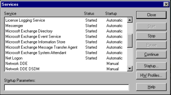
21-14 AltiContact Manager Administration Manual
To check that all Exchange Server Services Have Started:
1. Open the Control Panel and click the Services icon to view the
Services window.
Figure 7. Exchange Server Services Window
2. Check the status of the following services to see if they are started:
ã Microsoft Exchange Directory
ã Microsoft Exchange Event Service
ã Microsoft Exchange Information Store
ã Microsoft Exchange Message Transfer Agent
ã Microsoft Exchange System Attendant
If any of these services are not started, select the service and click
Start in the Services window to start it.
If a service cannot be started, please contact Microsoft technical
support.
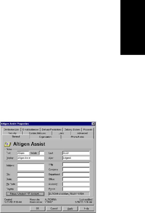
Data and Internet Integration
AltiContact Manager Administration Manual 21-15
21. Data and Internet
Integration
Exchange Server Configuration
Now that you have verified that the AltiContact Manager and the Exchange
Server systems are properly installed, you can start configuring the two
systems to enable the Exchange Integration feature. In this section, we
describe the configurations to be performed in the Exchange Server.
For testing purposes, create an Exchange mailbox for NT account
<Domain>\AltiGen_<AltiContactManagerSystemName>(e.g.
ALTICHINA\AltiGen_TELESYSTEM).
Open the Exchange Administrator on the Exchange Server and do the
following:
1. Select New Mailbox from the File menu.
2. Input a mailbox name, for example, first name AltiGen, last name
Assist,displaynameAltiGen Assist and alias name AltiGenA.
3. Click Primary Windows NT Account and in the dialog box, select
<Domain>\AltiGen_<AltiContactManagerSystemName>(e.g.
AltiGen_telesystem). After setting the primary NT account, your
dialog box should look the example that follows (see Figure 8). Click
Apply to create the mailbox.
Figure 8. Adding a mailbox to Exchange Server
4. Click the primary NT account and select Use Existing Account.This
account can then be added from the user manager window. Remember
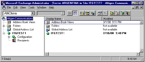
21-16 AltiContact Manager Administration Manual
that this can only be achieved if AltiGen has an account in the same
domain as the Exchange Server or a trusted domain.
5. Give Service Account Admin rights to AltiContact Manager service
account in the Exchange server. (See Note 3 on page 21-26.)
Microsoft Exchange Administrator Configuration
1. In Microsoft Exchange Administrator, highlight the Organization
container. (Organization is the top item in the hierarchy on the left of
the Exchange Admin window.)
Figure 9. Microsoft Exchange Administrator
2. Select Properties on the File menu, then click Permissions to get a
window such as the following:
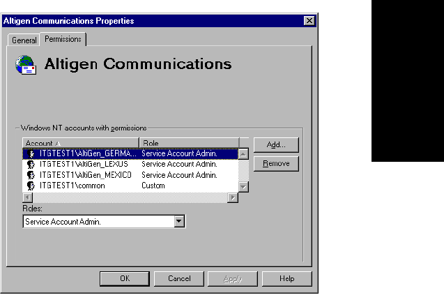
Data and Internet Integration
AltiContact Manager Administration Manual 21-17
21. Data and Internet
Integration
Figure 10. Properties window, Exchange Object
3. Add <Domain>\AltiGen_<AltiServSystemName>(e.g.
AltiGen_telesystem) account to the account list.
4. Change the accounts role to Service Account Admin from the Roles
combo box (see Figure 10).
5. Repeat the above two steps for the Domain and Configuration
containers. The name of Site is ITGTEST1. The name of
Configuration is Configuration.
6. Stop and restart all the services of Exchange Server, or reboot the
Exchange server.
Installing Outlook 2000 Client on the AltiContact Manager
System
Outlook 2000 has two modes: Internet Only mode and Corporate or
Workgroup mode. To enable the Exchange Integration feature, you
MUST configure it to use Corporate or Workgroup mode.
If you have already installed Outlook 2000 in the AltiContact Manager
system, make sure that you have installed it in the Corporate or
Workgroup mode. This is discussed on page 21-19.
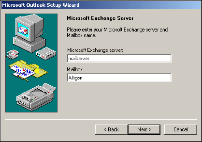
21-18 AltiContact Manager Administration Manual
To install Outlook 2000 to Corporate or Workgroup mode:
1. Install Outlook 2000 from the Outlook 2000 or Office 2000 CD.
During installation, you will be prompted to choose a mode (Internet
Only vs. Corporate or Workgroup). Make sure you choose the
CorporateorWorkgroupmode.
2. After installation is complete, start Outlook 2000 from Start!
Programs. In the Microsoft Installer wizard, select Microsoft
Exchange Server to install, then click Next to move to the next
window.
Figure 11. Outlook setup, Exchange Server Name and Mailbox
3. In the above dialog box, type in values for the Microsoft Exchange
Server and Mailbox. Enter the name of the Exchange server, and enter
the test mailbox we created (AltiGen Assist) in the Mailbox field.
4. Click the Next button to bring up the next dialog box, which asks a
Travel question, to which you should answer No, then click Next.
5. Once you have completed the Setup Wizard, a final dialog box
appears, indicating that the information services that have been added
to your profile. Then a Done! dialog box appears; click Finish to end
this part of configuration.
6. If the values you entered for Microsoft Exchange Server and
Mailbox are correct, you will be able to use Outlook 2000 now. If they
are not correct, youãll be asked to re-enter the Microsoft Exchange
Server and Mailbox names. Make sure you enter the correct values.
You can verify your input by clicking the Check name button.
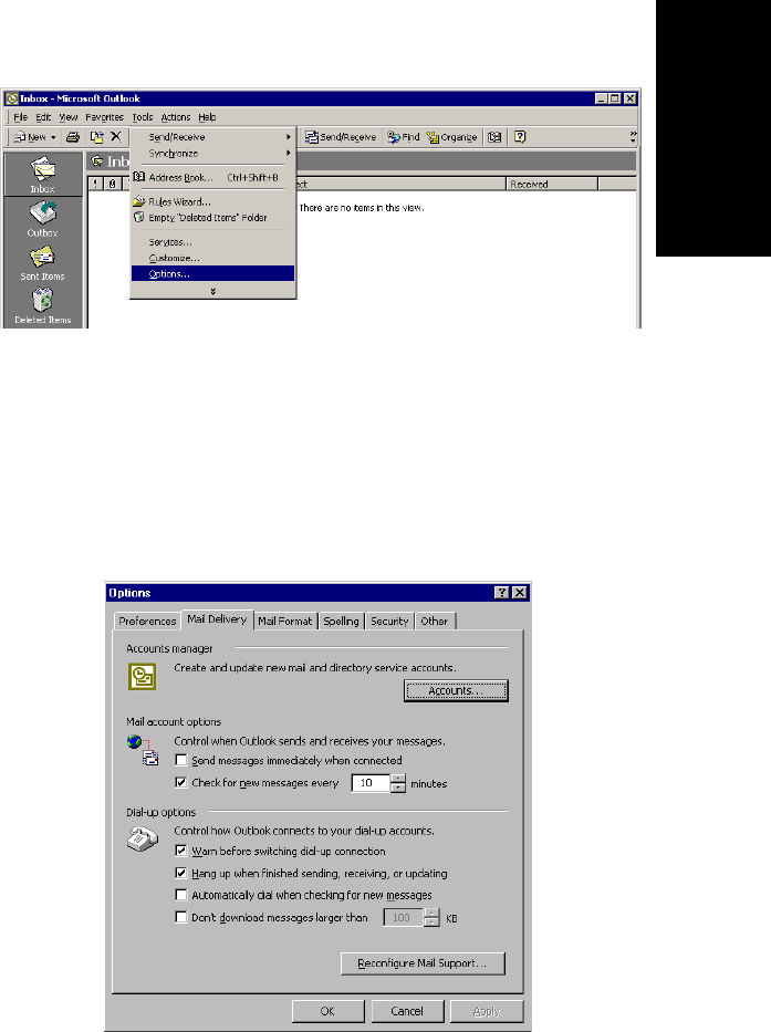
Data and Internet Integration
AltiContact Manager Administration Manual 21-19
21. Data and Internet
Integration
To check the Outlook 2000 mode:
1. Start Outlook 2000. Select Tools from the menu options.
Figure 12. Outlook Tools menu
2. If there is a menu item Service, it means Outlook 2000 is in the mode
of Corporate or Workgroup. You can move on to the next set of
steps. If there is a menu item Accounts, it means Outlook 2000 is in
themodeofInternet Only. Perform the following steps to change
Outlook 2000 to the mode of CorporateorWorkgroup.
3. Click OptionsãÎ to open the Options dialog box, and select Mail
Delivery.
Figure 13. Outlook Options

21-20 AltiContact Manager Administration Manual
4. Click Reconfigure Mail SupportãÎ to open the E-mail Service
Options dialog box.
Figure 14. Email Service Options
5. Select CorporateorWorkgroupand click Next. When a dialog box
pops up, click Yes.
To configure an Outlook 2000 profile:
1. Start Outlook 2000. Select ServicesãÎ on the Tools menu to open the
Services dialog box.
Figure 15. Outlook Services
If Microsoft Exchange Server is in the list of services in this profile,
proceed to ãEnabling the Exchange Serverã on page 21-22.
If Microsoft Exchange Server is not in the list of services, proceed as
follows.
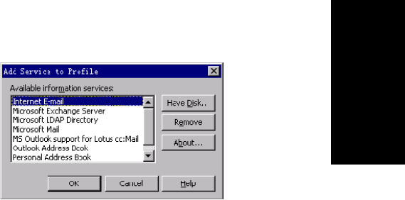
Data and Internet Integration
AltiContact Manager Administration Manual 21-21
21. Data and Internet
Integration
2. Click Add to open the Add Service to Profile dialog box. Add
Microsoft Exchange Server,Outlook Address book and Personal
Folders to profile.
Figure 16. Add Services to Profile
3. In the Microsoft Exchange Server dialog box that opens, type the
Exchange Server name in the Microsoft Exchange Server field and
the test mailbox name (e.g. AltiGen Assist)intheMailbox field.
4. Click Check Name. If you entered valid values, the names will be
underlined and the Check Name button will be grayed out. Click
Apply and then OK.
You will see Microsoft Exchange Server in the list in the Services
window.
5. Optional: Select Microsoft Exchange Server in the list box, and click
Properties to see its configurations. The Microsoft Exchange Server
dialog box appears. If you need to, you can use this Properties dialog
box to change the name of Microsoft Exchange Server and Mailbox.
To Test the configuration:
1. Restart Outlook 2000 at least once. Test the configuration by sending
an email, then check if you receive it.
2. When the reboot is complete, log on using the AltiGen service account.
3. Open Outlook, and from the Tools menu, select Services.
4. Click Add and select Exchange Server. The Mailbox field should
already be populated with the Name entered above.
5. Enter the Exchange Servers hostname and click the Check Name
button. Both the Mailbox and Exchange Server should now be
underlined.
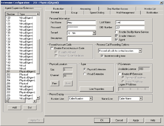
21-22 AltiContact Manager Administration Manual
This completes setting up AltiContact Manager and Exchange server
systems properly, and you are ready to enable the Exchange Integration
feature. Please remember you MUST have completed the previous steps
before moving ahead.
Enabling the Exchange Server
1. Delete obsolete files from \altiserv\exe directory.
a. From Windows NT Explorer, go to the \altiserv\exe folder. If
mapi32.dll and gapi32.dll remain in this folder, delete them.
2. In ACM Administrator (AltiContact Manager Administrator),
configure the extensions that are to be synchronized with their
corresponding mailboxes in Exchange server.
a. From the Extension Configuration General window (example
below), select an extension that needs to be synchronized with
Exchange.
b. Type the First Name and Last Name exactly as they appear in the
corresponding Exchange mailbox in the Global Address List of
the Exchange Server.
Figure 17. General window, Agent Extension Configuration
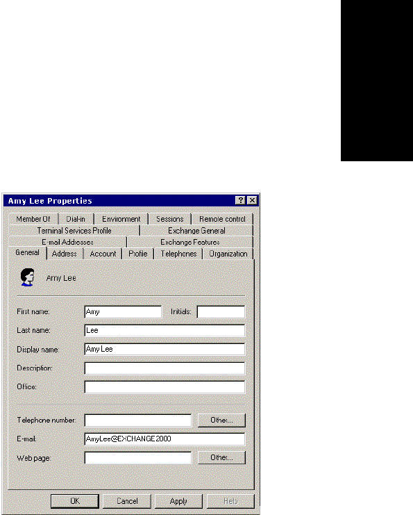
Data and Internet Integration
AltiContact Manager Administration Manual 21-23
21. Data and Internet
Integration
Make sure that the E-mail Name field contains alphanumeric
characters only and does not contain other characters such as spaces
( ) or periods ( . ).
3. In Exchange Administrator, ensure that for each mailbox in Microsoft
Exchange Server to be synchronized, the First Name and Last Name
are exactly as they appear in their corresponding extensions in ACM
Administrator.
Important:The Middle Initial field should be empty for Exchange
Server mail accounts in order for Exchange Integration to
work properly.
Figure 18. Mail account configuration in Exchange Administrator
4. Use these preceding steps to double check the synchronization of all
mailbox names used jointly by AltiContact Manager and Exchange
Server.
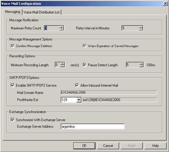
21-24 AltiContact Manager Administration Manual
Enable the Exchange Integration feature in ACM
Administrator
1. In ACM Administrator, select Voice Mail Configuration from the
System Management menu.
2. Select the Messaging tab, and under the E-mail Messaging Options,
check the Synchronize with Exchange Server box only.
Figure 19. Messaging window, Voice Mail Configuration
3. Enter the name of the Exchange Server (e.g. MAILSERVER)inthe
space provided and click Apply.
This completes the configuration for the Exchange Integration feature.

Data and Internet Integration
AltiContact Manager Administration Manual 21-25
21. Data and Internet
Integration
Testing the Exchange Server Setup
You can use some simple procedures to make sure that the Exchange
Integration feature is working correctly.
To test the integration, set up an extension in AltiContact Manager (e.g.,
100) and its corresponding mailbox in Exchange server. Also, set up a PC
with Outlook 2000 configured for this user.
To Test Message Delivery to Exchange:
1. Leave a voice mail for extension 100. The message light illuminates.
2. Log on to the Exchange Mailbox from Outlook and check for the
message in the inbox. The message should be titled VoiceMail from
xxx and include the voice mail as a .WAV attachment.
To check Message State Change Notification:
1. Log in to extension 100ãs voice mail from a phone. The message you
left in the preceding step should be there as a new message.
2. Save the message by pressing 3. Within approximately a minute, the
message in Outlook will become a saved message as wellãit will no
longer appear in bold.
To Listen to VM in Outlook:
Open the message in Outlook, and open the .WAV attachment. It
should be the same message.
To check Deletion Notification:
1. Delete this message from Outlook.
2. Wait for a couple of minutes, and then log on to extension 100ãs voice
mail from a phone. The voice mail should no longer be there.
If any of these tests fail, consult the ãTroubleshooting Tipsã section.
Troubleshooting Tips
To check profiles:
1. Log on to the AltiContact Manager system as the AltiGen service
account (e.g. AltiGen_telesystem).
2. Select the Mail Icon from the Control Panel.
21-26 AltiContact Manager Administration Manual
3. Click Show Profiles. For the test mailbox there should be profiles
named such as AltiExch<ServerName><FirstName><LastName>
(e.g. AltiExchMAILSERVERAmyLee).
If you donãt see any such profile, make sure that \altiserv\exe folder
does not contain the files mapi32.dll or gapi32.dll. If these files exist,
delete them, then stop and start the Exchange Integration Service.
To delete old profiles:
If an error occurred while AltiContact Manager was creating mail profiles,
the damaged profiles would remain there until removed manually. After the
re-configuration, the new profiles can't be created since the old ones still
exist.
You can remedy this as follows:
1. Logon as AltiGen Service Account
2. Shutdown Altigen Exchange Integration Service from Control Panel \
Services, then open the Control Panel\Mail (or Mail and Fax) and
click Show Profiles. Remove all the profiles such as
AltiExch<ServerName><FirstName><LastName>(e.g.
AltiExchMAILSERVERAmyLee).
3. Delete all the files under \Altiserv\db\SynchStorage*(e.g.
SynchStorageExt100).
4. Start the AltiGen Exchange Integration Service from Control Panel
\ Services.
If this doesnãt work, contact AltiGen Technical Support.
Notes
ã Email client confirmed to work on the AltiContact Manager system is
Outlook 2000 (using Corporate or Workgroup mode). Note that this
is the client installed on AltiWare host. The client running on the end
user computer is irrelevant.
ã Prevent attempts by the Exchange Administrator to use the existing
service account for the AltiGen Exchange Integration Service. Using
the AltiGen service account will provide you an audit trail that is
invaluable while troubleshooting.
ã Depending on the number of voice mails you have on the AltiGen
server, the initial mailbox synchronization may take a long time.

Data and Internet Integration
AltiContact Manager Administration Manual 21-27
21. Data and Internet
Integration
For example, if you have 10GB voice mails on the AltiGen server and
are enabling Exchange Integration for all the mailboxes, it may take up
to 24 hours to initialize the Exchange Integration service.
On the other hand, if you have less than 100MB of voice mails on the
AltiGen server, the initialization will take less than 5 minutes.
ã When checking the profiles using the mail icon in the control panel of
AltiContact Manager, you should see one account for each mailbox.
You will see these profiles only if you are logged on as the AltiGen
service account (e.g. AltiGen_telesystem).
Exchange Server 2000 Integration
In the example that follows, the AltiContact Manager system is called
ALTIWARE4_1 and the Exchange Server is called GOLDMINE. Both
systems belong to the NT domain called HAPPINESS.
Important: The Windows 2000 server must be the Primary Domain
Controller.
Prerequisites
Two Windows servers:
ã One Windows NT server with the AltiContact Manager software
ã One Windows 2000 server with Exchange Server 2000 software
Important: When you install the Exchange Server, you must log in as the
Domain Administrator, NOT the Local Administrator.
Also note that the Windows 2000 server must be the Primary
Domain Controller.
AltiContact Manager System Prerequisites
ã Windows NT 4.0
ã AltiContact Manager software version 4.6 or higher
ã The AltiContact Manager system and the Exchange server system
must belong to the same NT domain.
ã AltiGen Services should be started with the user account
<Domainname>\AltiGen_<AltiContactManagerSystemName>.
For example, HAPPINESS\AltiGen_ALTIWARE4_1.
21-28 AltiContact Manager Administration Manual
To check the Windows NT version:
Click the Start button, select Run, and type winver in the Run dialog
box.
This opens an About Windows dialog box that displays the version of
Windows 2000 running on your system. It should say:
Version 4.0 (Build 1381: Service Pack 6)ãÎ.Revised
Service Pack 6a
If you have an older version of NT, upgrade to the latest version.
Check http://www.microsoft.com/ntserver to get the latest service
pack for Windows NT.
To check the AltiWare version:
Select About from the Help menu of ACM Administrator. The version
displayed should be AltiContact Manager 4.6or higher.
To check the domain:
On the AltiContact Manager system, go to
Start!Settings!Network and Dial-up Connections. In the left
panel of the Network and Dial-up Connections window, click the
Network Identification link. Verify that you see two text entries, Full
Computer Name and Domain. Note the value in the Domain field.
Repeat the same steps on the Exchange server system and make sure
the domain names are the same.
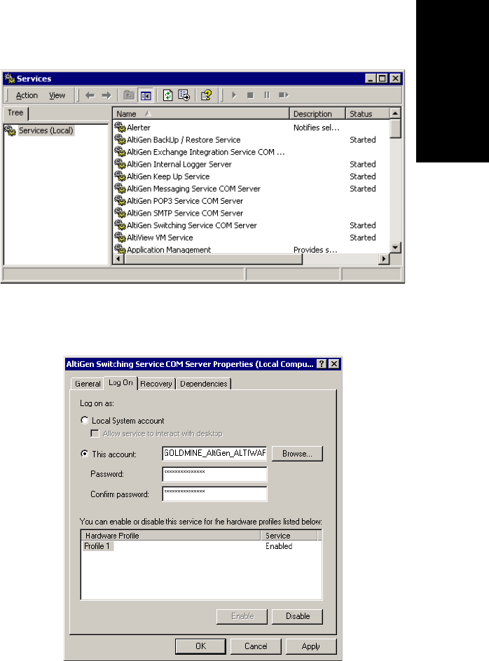
Data and Internet Integration
AltiContact Manager Administration Manual 21-29
21. Data and Internet
Integration
To verify AltiGen Services:
1. Select Start!Programs!Administrative Tools!Services.A
Windows Services dialog box will be shown, as in this example.
Figure 20. Windows Services window
2. Double-click AltiGen Switching Service COM Server to launch its
Properties dialog.
Figure 21. Service Properties dialog box
21-30 AltiContact Manager Administration Manual
3. In the Log On tab, set <DomainName>\AltiGen_<ServerName>as
the account. In this example, it is
GOLDMINE\AltiGen_ALTIWARE4_1.
If this account is not available, you must reinstall AltiContact Manager
while logged in as a domain administrator with local administrator
privileges.
Exchange Server Prerequisites
ã Exchange Server 2000 software
Important: When you install the Exchange Server, you must log in as the
Domain Administrator, NOT the Local Administrator.
Also note that the Windows 2000 server must be the Primary
Domain Controller.
ã Successful ping to the AltiContact Manager and vice versa
ã Exchange Server Services must be started
To check the Windows 2000 Server version:
Click the Start button, select Run, and type winver in the Run dialog
box. It should say:
Windows 2000 Server Version 5 (Build 2195: Service
Pack 1)
Service Pack 1 is the minimum required.
To check the Exchange Server version:
Click About in the Exchange Administrator.
To ping the Exchange Server from AltiContact Manager and vice
versa:
From the AltiContact Manager system, open a MS-DOS window, and
type ping <exchange server name>,thenpressenter.
For example, type ping mailserver. You should see Reply
from... as the response. If you see Request timed out,thereis
something wrong with your network settings or connectivity.
Similarly, ping the AltiContact Manager system from the Exchange
server. For example, from the command prompt in Exchange Server,
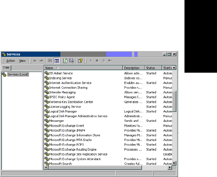
Data and Internet Integration
AltiContact Manager Administration Manual 21-31
21. Data and Internet
Integration
type ping ALTIWARE4_1, then press Enter. You should get the proper
reply.
To check that all Exchange Server Services Have Started:
1. Open the Control Panel and click the Services icon to view the
Services window.
Figure 22. Exchange Server Services Window
2. Check the status of the following services to see if they are started:
ã Microsoft Exchange Event
ã Microsoft Exchange IMAP4
ã Microsoft Exchange Information Store
ã Microsoft Exchange MTA Stacks
ã Microsoft Exchange POP3
ã Microsoft Exchange Routing Engine
ã Microsoft Exchange Site Replication Service
ã Microsoft Exchange System Attendant
If any of these services are not started, select the service and click the
Start arrow in the Services window to start it.
If a service cannot be started, contact Microsoft technical support.
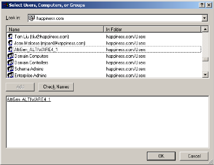
21-32 AltiContact Manager Administration Manual
Microsoft Exchange Administrator Configuration
1. From the Windows Start menu, launch Programs!Microsoft
Exchange!System Manager to open the Exchange System
Manager window.
2. In the Exchange System Manager window, expand the Servers to
locate the Exchange 2000 server. Right-click its name to pop up a
menu; select the Properties command to open the Properties dialog.
3. In the Properties dialog, select the Security tab and click the Add
button to open a Select dialog.
4. In the Select dialog, highlight the AltiContact Manager server name
andclicktheAdd button below.
Figure 23. Adding the AltiContact Manager server
5. Click OK to close this dialog and return to the Security tab of the
Properties dialog. Select the AltiContact Manager server and assign
Full Control in the Permissions. Select the Allow inheritable
permissions... option.
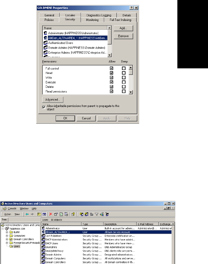
Data and Internet Integration
AltiContact Manager Administration Manual 21-33
21. Data and Internet
Integration
Figure 24. Assigning permissions to the AltiWare server
Checking the AltiGen Service Account
Check to see that the AltiGen Service account has been added properly.
1. From the Windows Start button, launch Programs!Microsoft
Exchange!Active Directory User and Computers.
2. In the left panel of the Active Directory User and Computers window,
expand the domain name, then open the Users folder. Locate the server
name as the AltiGen Service account in the list of Users.
Figure 25. The AltiGen Service Account
21-34 AltiContact Manager Administration Manual
Installing Outlook 2000 Client on the AltiWare System
(Same as settings for Exchange Server for Windows NT 4.0 Integration,
follow steps under ãInstalling Outlook 2000 Client on the AltiContact
Manager Systemã on page 21-17.)
Enabling the Exchange Server
(Same as settings for Exchange Server for Windows NT 4.0 Integration;
follow steps under ãEnabling the Exchange Serverã on page 21-22.)
Testing the Exchange Server Setup
(Same as settings for Exchange Server for Windows NT 4.0 Integration;
follow steps under ãTesting the Exchange Server Setupã on page 21-25.)
Troubleshooting Tips
(Same as Exchange Server for Windows NT 4.0 Integration; refer to
ãTroubleshooting Tipsã on page 21-25.)
Notes
(Same as Exchange Server for Windows NT 4.0 Integration; refer to
ãNotesã on page 21-26.)
Exchange on Windows 2000
To set up Exchange Server integration with Windows 2000:
First, on the machine running Exchange server:

Data and Internet Integration
AltiContact Manager Administration Manual 21-35
21. Data and Internet
Integration
1. Run Program> Exchange> System Manager>Server
2. Right-click on the name of Exchange Server to integrate.
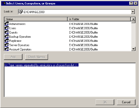
21-36 AltiContact Manager Administration Manual
3. Go to Properties >Security >Add > name of AltiGen Server
linked up.
In AltiContact Manager, enable the ãExchange Message
Synchronizationã check box in the Mailbox Setting of the user in
Extension Configuration. Then, enable the ãSynchronize With Exchange
Serverã checkbox and add the name of the Exchange server in the
Messaging window of Voice Mail Configuration.
To troubleshoot this integration, you may 1) run an Exchange Server Trace
or 2) login to AltiContact Manager as Domain Administrator. Open
Outlook and right-click to Properties, and look for show profiles.
About AltiReach Configuration
The AltiReach Call Management system allows AltiContact Manager to
provide remote and local desktop call management to users using the
Intranet or Internet via a standard Web browser.
AltiReach is installed and configured automatically when you install
AltiContact Manager. The configuration settings differ depending on the
version of the Microsoft Internet Services Manager you are running and
whether AltiContact Manager is running on Windows NT or Windows
2000.

Data and Internet Integration
AltiContact Manager Administration Manual 21-37
21. Data and Internet
Integration
To troubleshoot or double-check the server configuration:
ãÂInternet Services Manager (IIS) 2.0 and 3.0: In the Microsoft
Internet Services Manager!WWW (Running) settings, the Home
directory is set to c:\altiserv\webmgmnt (where c:\ is the local drive on
which AltiContact Manager is installed). In the Properties for this
directory, the access privileges allow Read and Execute.
ãÂInternet Services Manager (IIS) 4.0 and higher: In Internet
Services Manager!Default Web Site!PropertiesWeb Site tab,
the IP Address is set to the address of the AltiContact Manager server.
Under the Properties!Home Directory tab, the following configu-
ration is established:
ãTheLocal Path shows c:\altiserv\webmgmt (where c:\ is the local
drive where AltiContact Manager is installed). On this local path,
Read and Directory Browsing (NT) or Directory Browsing
Allowed (Windows 2000) are both selected.
ãIntheApplication Settings group:
ãÂInWindows NT, under Permissions,theExecute (including
script) radio button is selected. On the Execute is selected.
ãÂInWindows 2000,Scripts and Executables is selected in the
Execute Permissions drop-down list.
Using AltiReach
For instructions on how to use AltiReach and descriptions of all the
functions within AltiReach, please refer to the AltiServ User Guide.
21-38 AltiContact Manager Administration Manual

AltiContact Manager Administration Manual 22-1
22. AltiWeb
C
HAPTER
22
AltiWeb
AltiContact Manager integrates VoIP, IVR, and Microsoft Internet
Information Services (IIS) to provide the AltiWeb feature, which allows
internet users to talk to an extension via VoIP and share web pages.
System Requirements
ãÂClient/Server System only: AltiContact Manager 4.6 or higher
running on Windows 2000 or Windows NT
ãÂClient System: Microsoft Internet Explorer 5.5 or better, or Netscape
4.7 or better, NetMeeting 3.01, and Sound Card
ãÂWeb Server: Microsoft Internet Information Services (IIS) 4.0/5.0
AltiWeb Components
Figure 1. AltiWeb Component Overview
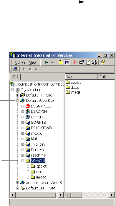
Installing AltiWeb
22-2 AltiContact Manager Administration Manual
Installing AltiWeb
Make sure AltiContact Manager has been installed on the AltiContact
Manager system and the link to TCP/IP is enabled before continuing with
CDR Search setup.
1. Log in to the client machine using a domain account and make sure it
is connected to the network on which AltiContact Manager is running.
2. Exit all Windows applications.
3. Insert the AltiWeb CD into the CD ROM drive of the IIS web server.
4. Run the Setup.exe program by selecting Start Run and typing D:/
Setup.exe, where D is the letter of your CD ROM drive. Follow the
step-by-step installation instructions as they appear on the screen.
5. AltiWeb installs into the Home directory of the IIS server. To verify
installation, start IIS, and select Default Web Site. The WebCall
directory appears at the bottom of the directory, as shown below.
Figure 2. Logical AltiWeb installation in IIS
Default Web Site
WebCall
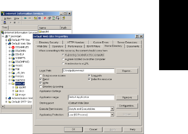
AltiWeb
AltiContact Manager Administration Manual 22-3
22. AltiWeb
6. Verify the physical location of the AltiWeb directory by right-clicking
the Default Web Site, and selecting Properties. On the Home Directory
tab of the Properties dialog, the Local Path field shows AltiWebãs
physical location on the drive (in this case
C:\Inetpub\wwwroot\altiweb).
AltiWeb Directory Structure
The AltiWeb directory contains the following subdirectories:
ãÂAppletãSample files you can use to set up AltiWeb. Refer to the
following sections for details.
ãÂDocsãDocumentation on AltiWeb.
ãÂImagesãGraphics used in the html files residing in the Applet
directory.
Applet Subdirectory Files
The Applet subdirectory contains sample pages you can use to set up Web
Call, as well as files necessary for proper AltiWeb functioning.
ãÂContact.htmãCustomer Information page for use with IVR
Figure 3. Local Path in IIS Properties dialog
Installing AltiWeb
22-4 AltiContact Manager Administration Manual
ãÂcontactaltigen.htmãCustomer Information page for use without
IVR
ãÂcustomerid.htmãPage where caller enters customer ID
ãÂdirectory.htmãTemplate for creating an in-house AltiWeb directory
(for internal use only)
ãÂIVR_top.htmãFrameset for top.htm and IVRApplet.htm
ãÂIVRApplet.htmãSends connected information to the main AltiWeb
applet
ãÂNetMeeting.htmãError message indicating NetMeeting not found
and providing opportunity to download
ãÂNsapplet.zipãContains files necessary for the proper functioning of
AltiWeb (Do not modify this file.)
ãÂNsplugin.zipãContains files necessary for the proper functioning of
AltiWeb (Do not modify this file.)
ãÂproductid.htmãPage where caller enters product ID
ãÂsales_cid.htmãFrameset for customerid.htm
ãÂsales_pid.htmãFrameset for productid.htm
ãÂTop.htmãCollects caller input and sends the result to the next
IVRApplet.htm
ãÂAltiWeb.cabãContains files necessary for the proper functioning of
AltiWeb (Do not modify this file.)
ãÂAltiWeb.htmãPage displaying AltiWeb window
ãÂAltiWeb.jsãJavaScript file necessary for the proper functioning of
AltiWeb
ãÂWizard.htmãError message advising caller to run the initial
configuration for NetMeeting
Collecting Form Data, IVR Data, and URL History
You can configure AltiWeb to display Form Data, IVR Data, and URL
HistorywhenawebcallisansweredbyanextensionwiththeAltiAgent
application.
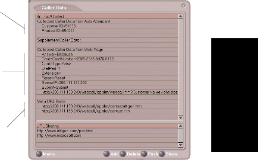
AltiWeb
AltiContact Manager Administration Manual 22-5
22. AltiWeb
Tagging Pages for URL History
To appear in the URL history, the pages the caller visits prior to the call
must be tagged, as shown below:
<head>
<script language="JavaScript"src="altiweb.js"></script>
<script language="JavaScript">
tagURL(location.href)
</script>
</head>
For more information on configuring:
ã IVR Data: Refer to ãConfiguring IVR for Scenario 2ã on page 22-15.
ã Form Data: ãCustomizing Contactaltigen.htmã on page 22-8 or
ãCustomizing Contact.htmã on page 22-13.
Scenario 1ãCaller Data from Web Page
The following scenario, based on contactaltigen.htm, exemplifies the
simplest implementation of AltiWeb.
Figure 4. Caller Data window in AltiAgent
The URLHistory shows
all URLpaths to tagged
html pages the caller
visited prior to the call.
The Form Data come
from the <form
name=infoForm>
fields in the source
code of Contact.htm
or Contactaltigen.htm
The IVR data comes
from the IVR/Collect
Digit action.
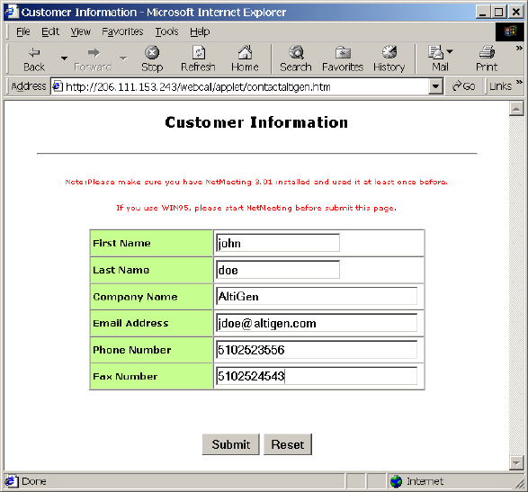
Installing AltiWeb
22-6 AltiContact Manager Administration Manual
1. A web caller browses the company web site and has a question
regarding some product information.
2. The web caller clicks the "contact us" link on the web page. The
Customer Information page (contactaltigen.htm) opens.
Figure 5. Contactaltigen.htm page
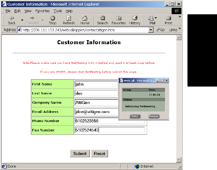
AltiWeb
AltiContact Manager Administration Manual 22-7
22. AltiWeb
3. The web caller enters the required information, then clicks the Submit
button. The AltiWeb window (altiweb.htm) appears.
Note: If NetMeeting is not installed on the callerãs computer (or itãs
not configured correctly), an error message displays.
Note: This scenario directly dials a preset extension. You can also set
the AltiWeb window to display a DialPad the caller can use to
dial any extension. For details, refer to ãCustomizing
Contactaltigen.htmã on page 22-8.
4. Once NetMeeting successfully connects to an AltiGen VoIP port, the
web caller is routed to the proper extension.
Figure 6. The AltiWeb window
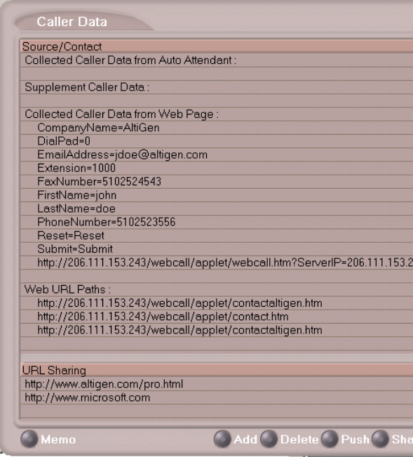
Installing AltiWeb
22-8 AltiContact Manager Administration Manual
5. If the call goes to an AltiAgent user, the Caller Data window shows the
Form Data and URL history.
6. From this point, in addition to voice communication, the agent can
push and share web pages with the caller. For procedures, refer to the
section on ãViewing, Sharing, or Pushing Dataã in the AltiClient
Manual.
Customizing Contactaltigen.htm
You can use the Contactaltigen.htm page to collect caller information, and
automatically direct the call to a specific extension. This collected
information is then displayed on the agentãs screen.
Figure 7. Caller Data window in AltiAgent

AltiWeb
AltiContact Manager Administration Manual 22-9
22. AltiWeb
To alter form data:
Using Notepad or another html editor, modify Contactaltigen.htm source
code as follows:
1. Change the ServerIP.
Set the value of the ServerIP to the IP address of the server on which
AltiContact Manager resides.
<input type="hidden"name="ServerIP"value="206.111.153.203">
2. Set DialPad visibility.
By default, the code is set to hide the Dial Pad (value = "0")andtodial
a specific number (value = "300"). To show the Dial pad, change the
values as shown below:
Show DialPad, Let Caller Dial Extension
<input type="hidden"name="Extension"value=""><input
type="hidden"name="DialPad"value="1">
Hide DialPad, Autoconnect to Extension 300
<input type="hidden"name="Extension"value="300"><input
type="hidden"name="DialPad"value="0">
3. Alter the data collection fields.
Shown below is the form row that collects the callerãs first name.
Copy, modify, or delete variables to your companyãs specifications.
<tr>
<td width="240"bgcolor="#CCFF99"><font size="2"
face="Verdana"><b>First Name </b></font></td>
<td width="282"><font face="Verdana"><input
type="text"size="20"maxlength="40"name="FirstName"
tabindex="1"> </font></td>
</tr>
Scenario 2ãCaller Data from IVR
The following scenario, based on contact.htm, exemplifies a customized
implementation of AltiWeb.
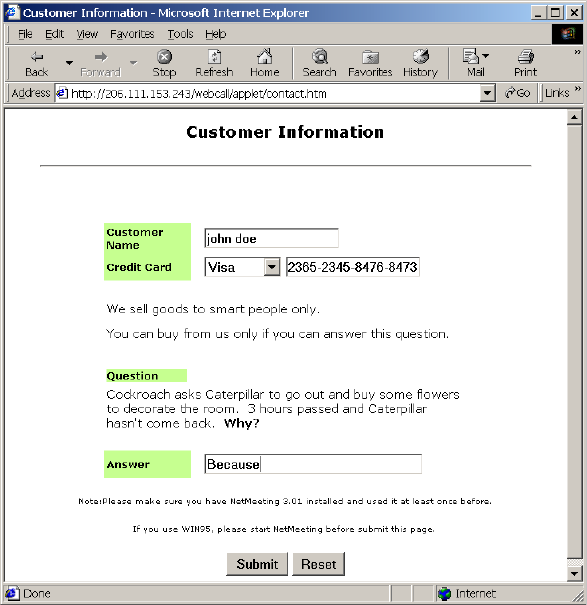
Installing AltiWeb
22-10 AltiContact Manager Administration Manual
1. A web caller browses the company web site and has a question
regarding some product information.
2. The web caller clicks the "contact us" link on the web page. The
Customer Information page (contact.htm) opens.
Figure 8. Contact.htm page
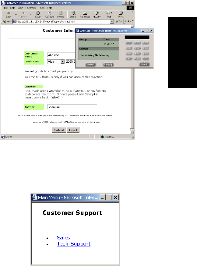
AltiWeb
AltiContact Manager Administration Manual 22-11
22. AltiWeb
3. The web caller enters the required information, then clicks the Submit
button. The AltiWeb window (altiweb.htm) appears.
Figure 9. AltiWeb window with DialPad visible
Note: If NetMeeting is not installed on the callerãs computer (or itãs
not configured correctly), an error message displays.
4. Once NetMeeting successfully connects to an AltiGen VoIP port, the
web caller sees the Customer Support page, and hears a prompt
requesting the selection of Sales or Tech support.
Note: The DialPad is visible to allow the web caller to close the IVR
windows and dial a number directly, if so desired.
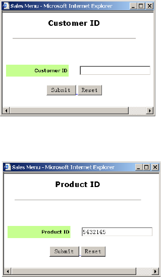
Installing AltiWeb
22-12 AltiContact Manager Administration Manual
5. The caller selects Sales, and the Customer ID window
(customerid.htm) appears.
Figure 10. Customer ID window
6. Once the caller enters the customer ID and clicks Submit, the Product
ID window (productid.htm) appears.
Figure 11. Product ID window
7. After the caller enters the product ID and clicks Submit, the web caller
is routed to the proper extension.
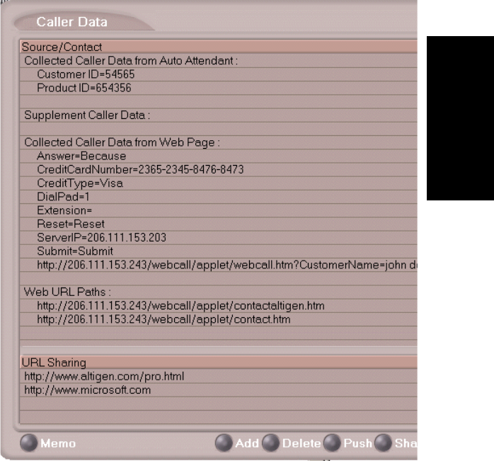
AltiWeb
AltiContact Manager Administration Manual 22-13
22. AltiWeb
8. If the call goes to an AltiAgent user, the Caller Data window shows
Form data, IVR data, and URL history.
Figure 12. Caller Data window in AltiAgent
9. From this point, in addition to voice communication, the agent and
caller can share web pages. For procedures, refer to the section on
ãViewing, Sharing, or Pushing Dataã in the AltiClient Manual.
Customizing Contact.htm
You can use the Contact.htm page to collect caller information, and then
automatically direct the call to a specific extension. This caller information
is then displayed on the agentãs screen.
Installing AltiWeb
22-14 AltiContact Manager Administration Manual
To alter form data:
Using Notepad or another html editor, modify Contact.htm source code as
follows:
1. Change the ServerIP.
Set the value of the ServerIP to the IP address of the server on which
AltiWare resides.
<input type="hidden"name="ServerIP"value="206.111.153.203">
2. Set DialPad visibility.
By default, the code in contact.htm is set to show the Dial Pad (value
="1") and not to dial a specific number (value = ""). To hide the Dial-
Pad, change the values as shown below:
Hide DialPad, Autoconnect to Extension 300
<input type="hidden"name="Extension"value="300"><input
type="hidden"name="DialPad"value="0">
Show DialPad, Let Caller Dial Extension
<input type="hidden"name="Extension"value=""><input
type="hidden"name="DialPad"value="1">
3. Alter the data collection fields.
Shown below is the form row that collects the callerãs full name.
Copy, modify, or delete variables to your companyãs specifications.
<tr>
<td align="left"width="128" bgcolor="#CCFF99">
<b><small><font face="Verdana">Customer Name </font></
small></b></td>
<td width=22 align=left></td>
<td align=left width=282>
<font face=Verdana>
<input type="text"name="CustomerName"maxlength=40 size=20
tabindex=1> </font></td>
</tr>
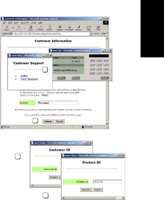
AltiWeb
AltiContact Manager Administration Manual 22-15
22. AltiWeb
Configuring IVR for Scenario 2
Scenario 2 demonstrates how to use IVR in conjunction with AltiWeb. For
example, when the web caller clicks the Submit button (1), Web Call
connects and the Customer Support page appears. When the customer
clicks Sales (2), the Customer ID (3) and Product ID (4) pages follow
before the caller is put through.
Figure 13. Using IVR to push pages to the caller
sales_cid.htm
sales_pid.htm
IVR_top.htm
1
2
3
4
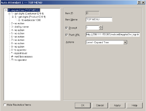
Installing AltiWeb
22-16 AltiContact Manager Administration Manual
Configuring IVR
Note: For detailed instructions, refer to ãIVR Configurationã on page 11-
1.
1. Run IVR.
2. Select 0-expand tree.
3. Make the following entries, then click Apply.
ã Type an Item Name, if desired.
ã To assign a voice message, check Prompt and select the number of
the appropriate message.
ã Check Push URL, and type the path of the page you want to display.
ã Select Level-Expand Tree in the Actions dropdown.
Figure 14. "0 - expand tree" window
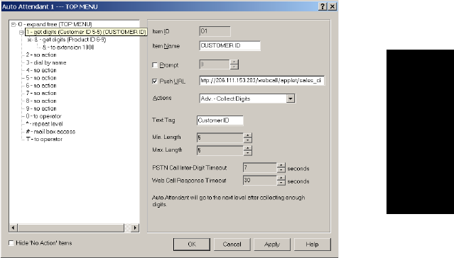
AltiWeb
AltiContact Manager Administration Manual 22-17
22. AltiWeb
4. Select 1-get digits.
5. Make the following entries, and click Apply.
ã Type an Item Name, if desired.
ã Check Push URL, and type the path of the page you want to display
(e.g., sales_cid.htm).
ã Select Adv.- Collect Digits from the Actions dropdown.
ã Set the Min. and Max. Lengths that the caller must enter.
ã Adjust the Web Call Response Timeout to give the web caller
enough time to provide all meaningful information.
Figure 15. "1-get digits" window
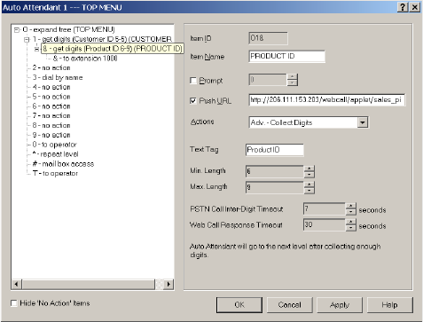
Installing AltiWeb
22-18 AltiContact Manager Administration Manual
6. Select &-get digits.
7. Make the following entries, then click Apply.
ã Type an Item Name, if desired.
ã Check Push URL, and type the path of the page you want to display
(e.g., sales_pid.htm).
ã Select Adv. - Collect Digits from the Actions dropdown.
ã Set the Min. and Max. Lengths that the caller must enter.
ã Adjust the Web Call Response Timeout to give the web caller
enough time to provide all meaningful information.
Figure 16. "& - get digits" window
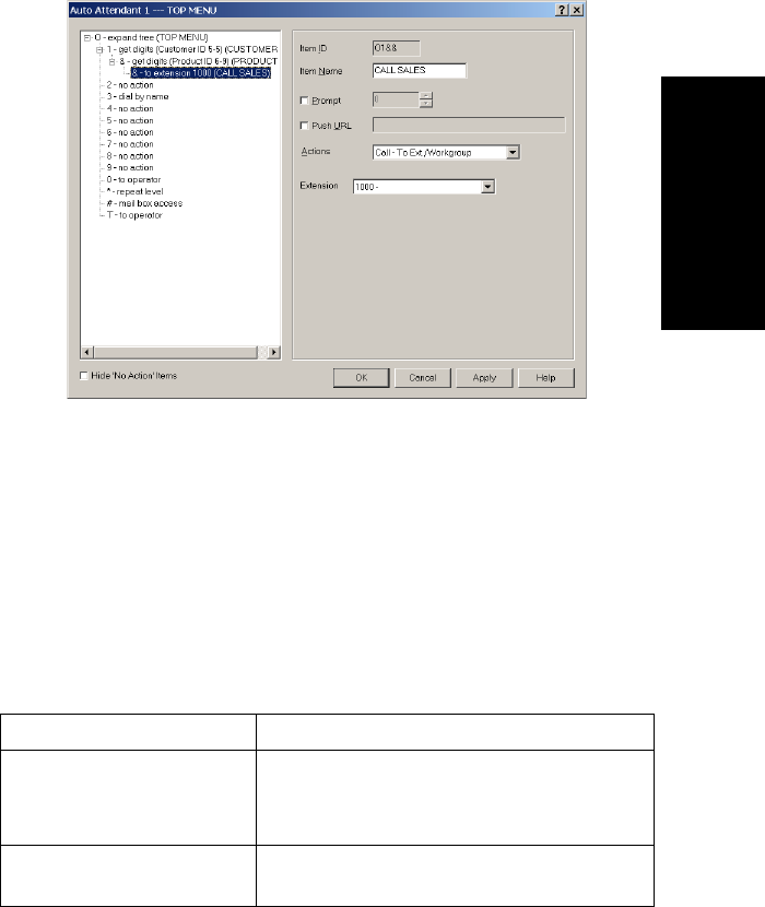
AltiWeb
AltiContact Manager Administration Manual 22-19
22. AltiWeb
8. Select &-to extension.
9. Make the following entries, then click OK.
ã Type an Item Name, if desired.
ã Select Call - To Ext/Workgroup from the Actions dropdown.
ã Select the Extension.
Troubleshooting
If a web caller cannot connect and an error message displays, the cause may
be one of the following:
Figure 17. "& - to extension" window
Error Message Cause
Server connection failed.
Please try again later.
ã AltiServ IP address is not correct
ã AltiServ is not running
ã Firewall is not open
No more available sessions.
Please try again later. ã All session licenses are used or there are no
session licenses at all.

Uninstalling AltiWeb
22-20 AltiContact Manager Administration Manual
Uninstalling AltiWeb
1. From the Windows Start menu, select Programs AltiWeb 4.6
Uninstall AltiWeb 4.6.
2. Click OK when the dialog box asks if you want to uninstall the
program, and respond to any additional prompts.
Alternatively
1. In the Control Panel, select Add/Remove Programs.
2. Choose AltiWeb 4.6 and click the Add/Remove or Change/Remove
button, depending on which version of Windows youãre running.
3. Click OK in the dialog box to confirm you want to remove the service,
and respond to any additional prompts.
AltiWeb Security
AltiWeb (and AltiReach) uses Microsoft IIS as a web server, which poses
web server security issues common to all Microsoft users. AltiGen
recommends the following basics steps to protecting AltiWare from
antiviruses and worms:
ã Update your virus definition every day
ã Enable real-time scan and exclude AltiServ and PostOffice folders
ã Schedule Daily Full Scan
Computer viruses can penetrate a PC in many ways, network shares,
emails, OS security holes, and more. Here are some common practices to
follow. If necessary, open shares for READ ONLY. Monitor Microsoft
security bulletins for updates. Open only the necessary ports on your
firewall.
Symantec Norton AntiVirus Corporate Edition 7.5
Update your virus definition every day
For a Corporate Edition version, administrators can receive updates from
either a dedicated local server or the Symantec LiveUpdate web site. Please
refer to Norton Administration menu on how to set up a dedicated local
server.
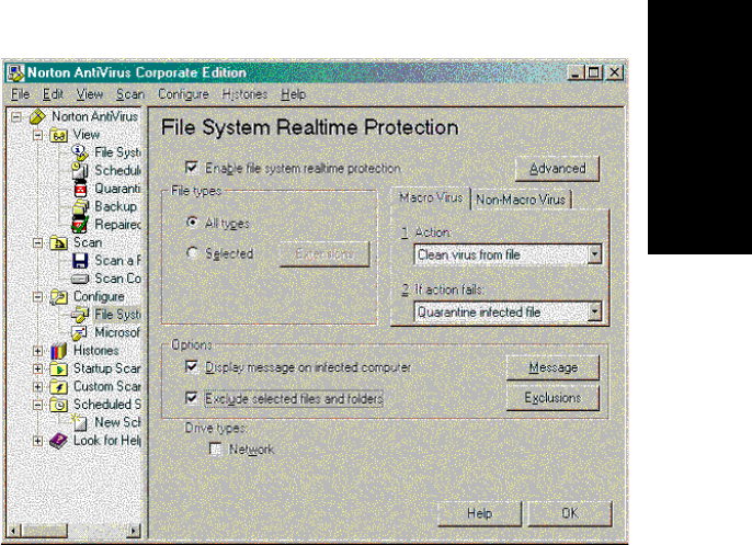
AltiWeb
AltiContact Manager Administration Manual 22-21
22. AltiWeb
To receive updates from the Symantec LiveUpdate web site
1. Click on File menu and choose schedule updates
2. Check enable scheduled automatic updates and click Schedule button
3. Set it for Daily at 8:00 PM
To receive updates on the fly, Click on File menu and choose LiveUpdate
and get the latest virus definition.
Enable Real-Time Scan
1. Click on Configuration menu and choose File System Realtime
Protection
2. Check Enable File System Realtime Protection
3. Choose All Files for File Types
4. Check Display message on infected computer
5. (optional) Click Advanced button and bring up advanced options
6. (optional) Uncheck backup files before attempting repair if your
system disk space is small.
AltiWeb Security
22-22 AltiContact Manager Administration Manual
7. Check Exclude selected files and folders and click Exclusions button
8. Enable Check file for exclusion before scanning and click Files/
Folders button
9. Find and check Altiserv and Postoffice folders and click OK
Schedule Daily Full Scan on all drives
1. Choose Edit menu and New Scheduled Scan
2. Edit the job name, ex, Daily Full Scan. Click Next
3. Set the frequency as Daily 9:00 PM and click Next
4. Check all the local hard drives and click Options
5. Choose All Files for File Types and set the CPU utilization for 50%
6. Click OK and Save
Now you have set it for daily scan for all files on your hard drives.

AltiContact Manager Administration Manual 23-1
23.Using TAPI
C
HAPTER
23
Using TAPI
If your office has an off-the-shelf application for calling contacts without
manually dialing the telephone's keypad that supports the Telephony
Application Programming Interface (TAPI), you can install AltiGenãs
TAPI gateway to use this functionality through your AltiContact Manager
installation. An example of such an application would be Microsoft
Outlook.
AltiContact Manager implements its service provider based on TAPI 2.1,
so applications written to TAPI 3.0 can make full use of all the telephony
functions implemented by AltiContact Manager.
AltiGen's TAPI implementation has two components:
ãÂTAPI Proxy Server - installed on the AltiContact Manager server
system.
ãÂTAPI Service Provider - installed on each client system.
Note: Only outbound dialing functions are supported in the TAPI
gateway. Users can make outbound calls from their extensions, but
call control functions such as transfer, hold, and park, are not
supported.
Also, users cannot make calls through TAPI with an IP phone as the
source phone.
System Requirements
Server
ã Windows NT Server 4.0 with Service Pack 6a or Windows 2000
Server
Note: For Windows 2000 Server, the TAPI client must be installed on
a separate PC. Otherwise, it wonãt be able to detect your
devices.
ã Network connection with TCP/IP enabled
Client
ã Windows 98, Windows NT 4.0 with Service Pack 6a or Windows 2000
Installing TAPI Services
23-2 AltiContact Manager Administration Manual
ã Network connection with TCP/IP enabled
ã A TAPI application (Phone Dialer, Outlook, etc.)
Installing TAPI Services
Note: Install the TAPI services (TAPI Proxy Server and TAPI Service
Provider) after physically configuring your AltiContact Manager
system. The TAPI Service Provider will automatically load the
AltiContact Manager configuration. If you change the AltiContact
Manager configuration after installing TAPI, by physically adding,
removing, or moving extensions, you will have to uninstall and
reinstall the TAPI Service Provider to reload the AltiContact
Manager configuration.
Note: For Windows 2000 Server, the TAPI client must be installed on a
separate PC. Otherwise, it wonãt be able to detect your devices.
To install TAPI Proxy Server on the server:
1. Locate the TAPI Gateway folder on your AltiContact Manager CD-
ROM.
2. In the Tapi_Server subfolder, run SETUP.EXE.
The service is started automatically. No configuration parameters need be
set on the server.
To install TAPI Service Provider on the client system:
1. Locate the TAPI Gateway folder on your AltiContact Manager CD-
ROM.
2. In the Tapi_Client subfolder, run SETUP.EXE.
3. When prompted, enter the Server IP address, the clientãs Extension
Number, and clientãs Password.
To test TAPI Service Provider on the client system:
1. Launch Phone Dialer from Start >Programs > Accessories >
Communication.
2. Enter a number to call in the Number to Dial box and then click on
Dial.
Your extension should ring. When you pick up the phone, the system
will dial the number you entered and connect you. If this does not
work, see ãChanging TAPI Configuration Parametersã.

Using TAPI
AltiContact Manager Administration Manual 23-3
23.Using TAPI
Changing TAPI Configuration Parameters
To change TAPI Configuration Parameters:
1. On Windows NT, select Start > Settings > Control Panel >
Telephony.
On Windows 2000, select to Start > Settings > Control Panel >
Phone and Modem Options.
2. On Windows NT, clickontheTelephony Drivers tab.
On Windows 2000, clickontheAdvanced tab.
3. Choose AltiGen (TM) Communications Service Provider and click
Configure.
4. In the AltiGen TAPI Device Detect dialog box, click Configure.
5. In the AltiGen TAPI Configuration dialog box, click Extension.
6. Enter the extension number and password of the entry you want to
change and click Remove.
7. Enter the extension number and password of an entry to add with new
values and click Add.
Changing TAPI Configuration Parameters
23-4 AltiContact Manager Administration Manual

Tools
AltiContact Manager Administration Manual 24-1
24. Tools
C
HAPTER
24
Tools
AltiContact Manager comes with the following tools for testing,
diagnosing and configuring your system:
ã Work/Hunt Group Converter
ã Configuration Reader
ã Extension Checker
ãÂMVIPTestTool
ã AltiDBReader
ã DINA Manager
Work/Hunt Group Converter
AltiContact Managerãs Work/Hunt Group Converter allows customers to
convert workgroups to huntgroups or huntgroups to workgroups.
To launch the Work/Hunt Group Converter, from the Services drop-down
list, go to Utilities>Work/Hunt Group Converter. This opens the Work/
Hunt Group Converter window.
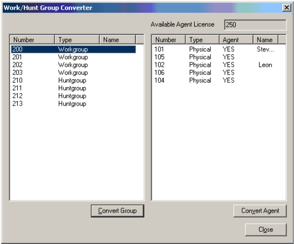
Work/Hunt Group Converter
24-2 AltiContact Manager Administration Manual
Figure 1. Work/Hunt Group Converter
The number of available agent licenses are displayed in the top right
window. Workgroups and huntgroups are listed in the left window,
member agents and non-agents are listed in the right window.
The Work/Hunt Group Converter can be used to convert:
ãÂAgent to Non-Agent - if an agent belongs to any workgroup, it cannot
be converted to non-agent. When an agent is converted to non-agent,
all workgroup-related parameters will be cleared, including wrap-up
time, inter-call delay, and outgoing workgroup number.
To convert, select the agent (indicated by YES in the Agent field) and
click the Convert Agent button or double-click the agent.
ãÂNon-Agent to Agent
To convert, select the non-agent (indicated by NO in the Agent field)
and click the Convert Agent button or double-click the non-agent.
ãÂConvert Workgroup to Huntgroup - when a workgroup is converted
to a huntgroup, its members are not changed, but the following
parameters are cleared, including:

Tools
AltiContact Manager Administration Manual 24-3
24. Tools
ã voice recording setting
ã queue time threshold
ã queue overflow settings
ã queue announcement
ã agent announcement
ã queue quit forward (returns to default value - to voice mail)
ã call distribution (if previously configured to Ring First Available
Member,Ring Next Member or Ring All, the setting is not changed.
If configured to any other settings, the setting is configured to Ring
First Available Member.)
To convert, select the workgroup (indicated in the Type field) and click
the Convert Group button or double-click the workgroup.
ãÂConvert Huntgroup to Workgroup - a huntgroup cannot be
converted if it contains at least one non-agent. You must first change
the extension from non-agent to agent (by selecting the Agent check
box) before converting.
To convert, select the huntgroup (indicated in the Type field) and click
the Convert Group button or double-click the huntgroup.
Configuration Reader
Configuration Reader is a tool that creates a subdirectory in
\altiserv\EXE\AltiWareHtml\ of html files showing details of your
AltiContact Manager configuration. Another file, altigen_ rc.dat,
summarizes all this information and can be sent to your dealer or to AltiGen
Tech Support if you have problems.
To use Configuration Reader:
1. Launch Configuration Reader from AltiWare>AltiWare Tools on the
Windows Start button.
A DOS window opens, indicating the progress of Configuration
Reader.
2. When the status window is complete, you can press Yto view the html
files showing your configuration.
Columns across the top of the opening page let you view statistics on
different components of your configuration.
Extension Checker
24-4 AltiContact Manager Administration Manual
Extension Checker
Extension Checker is a tool checks the security status of every extension in
your AltiContact Manager system.
Generally, an extension is considered secure if its password meets the
following conditions:
ã contains 4-8 digits
ã different from extension
ã different from default system password
ã does not consist of consecutive numbers
ã does not consist of a repetition of the same digit
Security characteristics of each extension are detailed in the application
window itself.
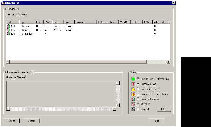
Tools
AltiContact Manager Administration Manual 24-5
24. Tools
To use Extension Checker:
1. Launch Extension Checker from AltiWare>AltiWare Tools on the
Windows Start button.
2. Select the security characteristics you want to check in the Show field
group, described below.
Figure 2. Extension Checker
Status Description
Secure Pwd + Internal
Only Has secure password and cannot make outbound
trunk calls
Unsecure Pwd Password has unsecure elements described in
Unsecure Elements window
Outbound-capable Can make outbound trunk calls
Unsecure Pwd +
Outbound Password has unsecure elements described in
Unsecure Elements window AND can make
outbound trunk calls
Password Expired Password is expired
MVIP Test Tool
24-6 AltiContact Manager Administration Manual
3. Click Refresh. Extensions with the selected insecure characteristics
will appear in the Extension List.
4. Make changes or advise extension user(s) to make changes.
ãÂRight-click commands for each extension in the Extension List let
you send the following changes to AltiContact Manager:
ã lock the extension
ã unlock the extension
ã force the user to change the password
ã clear an attack record
5. After changes have been made (for example in ACM Administrator,
AltiView, or with right-click commands described above), click
Reload to fetch the new settings from AltiContact Manager.
Security characteristics for extensions you select in the Extension List
display in the Unsecure Elements window.
6. (Optional) Click Export to export the data in the Extension List to a
text file.
MVIP Test Tool
The MVIP Test Tool is a tool that detects one-way connection, cross talk,
bad MVIP cable and static noise problems.
To run MVIP Test Tool:
1. Stop AltiGen Switching Services before running this utility.
2. Launch MVIP Test Tool from AltiWare>AltiWare Tools on the
Windows Start button.
3. Click Start to begin test.
Attacked 8 consecutive false password attempts have
been made
Locked Extension has been locked by system due to
attack or by System Administrator
Status Description
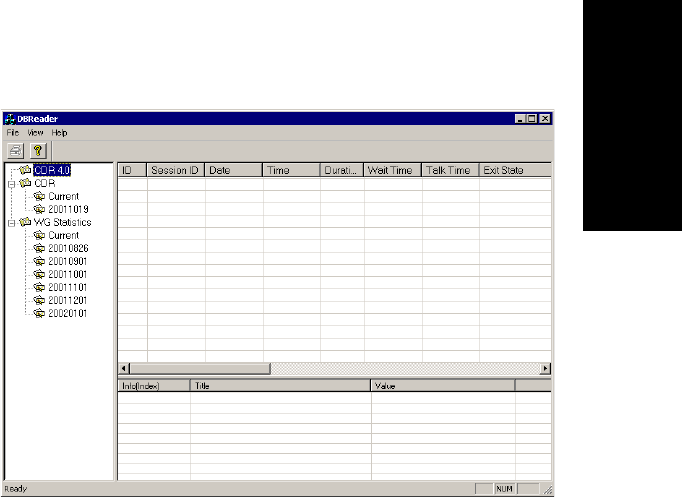
Tools
AltiContact Manager Administration Manual 24-7
24. Tools
4. If the MVIP Test encounters an error, click Yes or Noto view the error
report.
5. At the end of the test, the utility will provide pass or fail results.
AltiDBReader
AltiDBReader is a tool that allows you to view and export historical CDR
data and Workgroup Statistics. You can also convert 4.0/4.0a CDR files
(icc_cdr.dbf) for viewing in AltiDBReader.
To use AltiDBReader:
1. Launch AltiDBReader from AltiWare>AltiWare Tools from the
Windows Start button.
2. When launched, AltiDBReader automatically finds and displays DB
files from the AltiDB folder into three folder directories (CDR 4.0,
CDR and WG Statistics) on the left side of the window.
3. Search a particular DB folder by clicking the mouse cursor on the
folder, then right-click to open a Search window to perform the search
on the DB folder.
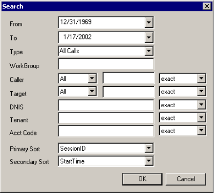
AltiDBReader
24-8 AltiContact Manager Administration Manual
For CDR DB searches, the Search window allows the following search
parameters:
ãÂFrom - sets the desired start date to begin the search
ãÂTo - sets the desired end date to end the search
ãÂType - specifies the call type to search: All Calls, Answered Calls
& Messages, Answered Calls, Messages, Unanswered Calls,
Messages, Unanswered Calls, All Trunks Busy, Agent Login/out
ãÂWorkgroup - allows user to specify workgroup number to search
ãÂCaller - specifies the caller as All, Extension or Trunk; to further
specify this search field, you may add matching digits in the empty
fieldandsettoanexact,like or pat (pattern) match.
ãÂTarget - specifies the caller as All, Extension or Trunk; to further
specify the search this search field, you may add matching digits in
the empty field and set to an exact,like or pat (pattern) match.
ãÂDNIS - to further specify the search this search field, you may add
matching digits in the empty field and set to an exact,like or pat
(pattern) match.
ãÂTenant - to further specify the search this search field, you may add
matching digits in the empty field and set to an exact,like or pat
(pattern) match.

Tools
AltiContact Manager Administration Manual 24-9
24. Tools
ãÂAcct Code - to further specify the search this search field, you may
add matching digits in the empty field and set to an exact,like or pat
(pattern) match.
ãÂPrimary Sort - specifies the first sorting category the search results
will be put into; select: Session ID, StartTime, CallerNum,
CallerName, TargetNum, TargetName, AccountCode, DNIS or
ExitState.
ãÂSecondary Sort - specifies the second sorting category the search
results will be put into; select: Session ID, StartTime, CallerNum,
CallerName, TargetNum, TargetName, AccountCode, DNIS or
ExitState.
For Workgroup DB searches, the Search window allows the
following search parameters:
ãÂFrom - sets the desired start date to begin the search
ãÂTo - sets the desired end date to end the search
ãÂInterval - specifies the search interval; select 15 minutes, 1 hour,or
1 day.
ãÂSearch by - specifies the type of workgroup search; select
Workgroup Statistics, Agent Statistics per Workgroup, or Agent
Statistics.
ãÂWorkgroup -specifies the workgroup number
ãÂAgent - specifies the agent number
4. Select the desired search parameters and click OK.

AltiDBReader
24-10 AltiContact Manager Administration Manual
5. The search results appear in the fields on the right side of the main
window.
6. To delete a DB folder, right-click on any DB folder (except ãCurrentã)
and select Delete DB.
To Show/Export/Print Search Results Data:
ãÂToprintthe search results data, select the desired DB folder and click
the Print button.
ãÂToshow
Advanced Call Info or Call Info, right click on any data field
and scroll to the desired option.
ã To export the search results data as a .CSV file, right-click on any data
field and select Export.
To Convert 4.0 or 4.0a DB files:
1. Select and highlight a DB folder from the CDR 4.0 directory.
2. Go to File>Convert Old DB.
3. The converted 4.0/4.0a file appears in the DBReader window fields.

Tools
AltiContact Manager Administration Manual 24-11
24. Tools
DINA Manager
DINA Manager is GUI-based tool designed to help a customer configure
several distributed AltiContact systems synchronously to work as just one
AltiContact Manager system. The tool can be run on any server, local or
remote to an AltiContact Manager system, which has a connection for
access to all the servers that are desired to be managed. The tool respects
the individual password protection by checking password access to each of
the servers that are desired to be managed before connecting to them. The
tool will synchronize extensions and workgroup pilot numbers. It can
complete the functions below for multiple systems from a single location
and session:
ã Create virtual extensions with the correct forwarding parameters for
multiple servers for specific extensions desired to be managed.
ã Synchronize the extensions with same number in all systems so that all
calls to the extension will be presented to the appropriate AltiContact
Manager system.
ã Synchronize the extensions with same number in all systems so that all
voice mails to the extension will be presented to the appropriate
AltiContact Manager system.
ã Delete extensions from multiple systems.
ã Requires 4.5/4.6 software
Note: DINA Manager can only launch the same AltiWare versions of the
server that DINA Manager is located. For example, if AltiWare OE
4.6 is located same server as DINA Manager, only systems running
OE 4.6 can be launched by DINA Manager.
Refer to DINA Manager Help file for usage instructions.
DINA Manager
24-12 AltiContact Manager Administration Manual

Basic Call Router & Call Router Advanced
AltiContact Manager Administration Manual 25-1
25.CallRouter
C
HAPTER
25
Basic Call Router & Call Router
Advanced
Basic Call Router
Basic Call Router is a call-handling tool included with AltiContact
Manager software. Basic Call Router uses the ACM Administrator IVR
and the AltiAPI Data Directed Routing (DDR) features to match incoming
trunk call data against existing customer records that you build using the
Basic Call Router GUI. Calls can be intelligently routed before they are
answered, based on Basic Call Routerãs routing ãrules.ã
Note: The workgroup to which incoming trunk calls will be routed via
Call Router must be assigned to the IVR whose Action is set to
ãAvd - Data Directed Routing, with Application set to the virtual
extension you use to start Call Router. For further information on
configuring IVR, refer to ãIVR Configurationã on page 11-1l and
the AltiAPI Programmer Guide.
To Install Basic Call Router:
Run Call Router, select the Basic Call Router and click Next. Setup will
confirm the destination for the Call Router application (default is
C:\Program Files\AltiGen\Call Router). Click Next to proceed. To select a
different location, use the Browse button to choose the new destination.
Note: Call Router Advanced Service requires the purchase and
activation of the Call Router Advanced license.
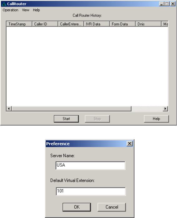
Basic Call Router
25-2 AltiContact Manager Administration Manual
To Configure/Run Basic Call Router:
1. Launch Call Router from Start>Programs.
2. Select Operation>Preference.
3. In the Preference window, enter the Server Name and Default
Virtual Extension that Call Router will connect to, then click OK.
4. Click Start to run Basic Call Router. Then, enter the default virtual
extension password. When Basic Call Router is stopped, you can
create customer records and configure the server and login
information.
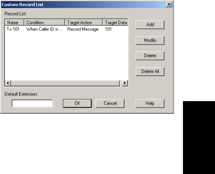
Basic Call Router & Call Router Advanced
AltiContact Manager Administration Manual 25-3
25.CallRouter
Basic Call Router Customer Records
To create customer records that will be used to route calls, select
Operation>Customer Record to open the Custom Record List window.
This window also allows you to view existing customer records, and
modify/delete customer records.
ãÂAdd - opens a Custom Record dialog box, where you can create a
new record and build the conditions for the record.
ãÂModify - opens the Customer Record dialog box to modify the
record selected in the Record List.
ãÂDelete - deletes the record selected in the Record List.
ãÂDelete All - deletes all records in the Record List.
ãÂTheDefault Extension field allows you to specify an extension that
Call Router will send a call to, if no match is found in the records
or in the database.
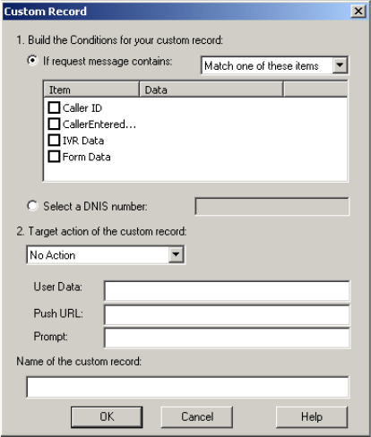
Basic Call Router
25-4 AltiContact Manager Administration Manual
Creating Customer Records
To create a customer record:
1. Select Customer Record from the Operation menu. (If Customer
Record fieldisgrayedout,stopCallRouter.)
2. Click the Add button to open a new customer record or Modify to
modify an existing record in the Record List window.
3. Select the data to match against customer records.
ãÂIf the request message contains - lets you select Call Router
Request data to match against the customer record.
a) Select ãMatch oneãorãMatch allã from the dropdown list.
b) Select the items you want.
c) Click in the Data column and type to specify the data.
Note: Caller Entered Digits must be numeric only.
ãÂSelect a DNIS number - lets you enter a callee number to check
against customer records.

Basic Call Router & Call Router Advanced
AltiContact Manager Administration Manual 25-5
25.CallRouter
4. Select a Target action for Call Router to perform when Call Router
Request data matches this record.
Target action options: Goto Top Level, Goto Menu Item, Repeat
Current Level, Call to Extension/Workgroup, Call to Operator, Dial by
Name, Collect Extension, Directory Service, Record Message (specify
target data in accompanying text box), Mailbox Access, Disconnect,
System Callback, Collect Digits (specify fields in accompanying
Collect Digit dialog box, see note below), Other DDR Application
(specify target data in accompanying text box).
Note: Collect Digit Dialog Box
ãÂTag name - for example, ãpasswordã (gathered from a response
to an IVR prompt or another AltiLink Plus application)
ãÂMinimum Digits and Maximum Digits to collect
ãÂPSTN and Web Timeout values
ãÂIVR Data - for example, ãusername=Michaelã (gathered from
a response to an IVR prompt or another AltiLink Plus
application)
5. (future release) Enter optional data to match against customer record:

Basic Call Router
25-6 AltiContact Manager Administration Manual
ã User Data (gathered from a response to an IVR prompt or another
AltiLink Plus application)
ã Push URL (AltiWeb only)
ã the number of prompt to play to the callee
6. Enter a name for this record.
7. Click OK.
Viewing Call Router History
The Basic Call Router window gives a history of all incoming trunk calls
to Basic Call Router.
To specify Call Router History window content:
1. Choose Select Column from the View Menu.
2. In the Select Columns dialog box, select the following columns to
display in the Call Router history window:
ãÂCallerID
ã Entered Digit
ã IVR Data
ãÂFormData
ã DNIS
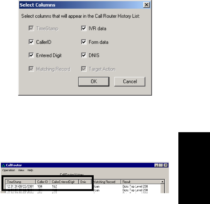
Basic Call Router & Call Router Advanced
AltiContact Manager Administration Manual 25-7
25.CallRouter
Call Route Request Data
The ãCall Router Requestã message sent by AltiContact Manager to Call
Router contains data about the incoming call, which Call Router attempts
to match against your routing rules. Call Route Request data consists of
Caller ID, (Caller) Entered Digits, IVR data, Form data and DNIS, all
collected via real-time monitoring.
Note: Caller Entered Digits shows the IVR assignment for the workgroup
that receives the call. If the workgroupãs IVR assignment is 5, this
item shows ã0 & 5ã; is the IVR assignment is 3, the item shows ã0
& 3,ã and so on. The ã0ã indicates transfer to an IVR.
Call Route Response Data
The ãCall Route Responseã message, sent from Call Router to AltiContact
Manager, contains the search results of the Call Route Request Message. In
the Call Router History window, this data shows how Call Router handled
each call. Call Route Response data includes Matching Record (routing
rule Call Router referred to for call routing) and Result (how and where the
call was routed), all collected via real-time monitoring.
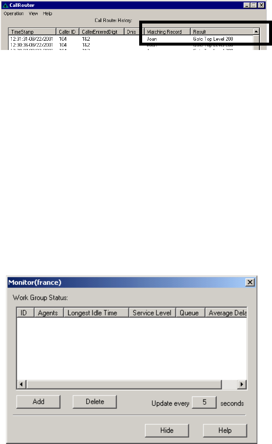
Basic Call Router
25-8 AltiContact Manager Administration Manual
Note: If no match is found between the Call Route Request Data and the
routing rules, the call is routed according to the business rules that
check monitored workgroups for the longest available agent,
maximum service level, and minimum expected delay.
Clearing Basic Call Router History Data
To clear data from the Call Router History window:
1. In the directory where Call Router.exe resides, locate the Call
Router.csv file.
2. Open Call Router.csv and delete all contents.
3. Save and close Call Router.csv.
Show Monitor
To view real-time data on incoming trunks to workgroups, select Show
Monitor from the View menu. (If the option is grayed out, stop Call
Router.)
ã The main window box displays the following workgroup fields: ID,
Agents,Longest Idle Time,Service Level,Queue and Average
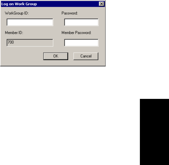
Basic Call Router & Call Router Advanced
AltiContact Manager Administration Manual 25-9
25.CallRouter
Delay.
ãÂAdd button - Click Add to log on to a workgroup whose incoming
trunk call data you want to monitor. This opens a Log on Work Group
dialog box.
Enter the workgroup extension as the WorkGroup ID and Password,
and enter the virtual extensionãs password.(Bydefault,theExtension
ID field is grayed out.)
ãÂDelete button - click Delete to remove the selected workgroup from
the display.
Note: The workgroup to which incoming trunk calls will be routed via
Call Router must be assigned to the IVR whose Action is set to
ãAvd - Data Directed Routing,ã with Application set to the virtual
extension you use to start Call Router. For further information on
configuring IVR, refer to ãIVR Configurationã on page 11-1 and
the AltiAPI Programmer Guide.
To log on to multiple workgroups:
ã Click Add again and enter the next Workgroup ID and Password and
Virtual Extension password.
Call Router Advanced
Call Router Advanced is the standard Call Router application plus call
router service. Call Router Advanced requires the purchase and activation
of a Call Router Advanced license.
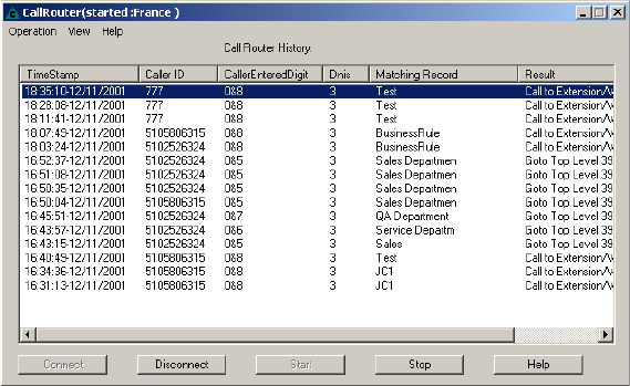
Call Router Advanced
25-10 AltiContact Manager Administration Manual
Note: The workgroup to which incoming trunk calls will be routed via
Call Router must be assigned to the IVR whose Action is set to
ãAvd - Data Directed Routing, with Application set to the virtual
extension you use to start Call Router. For further information on
configuring IVR, refer to ãIVR Configurationã on page 11-1 and
the AltiAPI Programmer Guide.
To Install Call Router Advanced:
Run Call Router, select the Call Router Advanced and click Next.When
prompted, enter the 20 digit license key for Call Router Advanced in the
field and click Next. Setup will confirm the destination for the Call Router
application (default is C:\Program Files\AltiGen\Call Router). Click Next
to proceed. To select a different location, use the Browse button to choose
the new destination.
Note: Call Router Advanced Service requires the purchase and
activation of the Advance Call Router license.
To Configure/Run Call Router Advanced:
1. Launch Call Router from Start>Programs.
2. Click the Connect button to enter the Call Router Server Name or IP
address to connect to, then click OK.
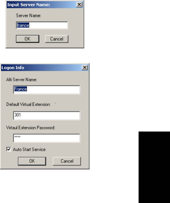
Basic Call Router & Call Router Advanced
AltiContact Manager Administration Manual 25-11
25.CallRouter
To disconnect from this server, click the Disconnect button.
3. Select Operation>Logon Info.
4. In the Logon Info window, enter the Server Name and Default
Virtual Extension and Password, that Call Router Advanced will
connect to, then click OK.
(Optional) Check Auto Start Service to have Call Router start routing
calls automatically, after the system restarts or after Call Router
service has been stopped and restarted.
5. Click Start to run Call Router Advanced. When Call Router Advanced
is stopped, you can configure the server and login information.
6. Route Rules and Show Monitor can be configured while Call Router
Advanced is started.
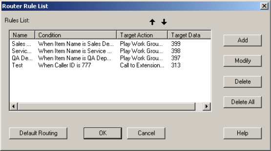
Call Router Advanced
25-12 AltiContact Manager Administration Manual
Call Router Advanced Route Rules
To create route rules that will be used to route calls, select
Operation>Route Rule to open the Route Rule List window. This
window also allows you to view existing route rules, and modify/delete
route rules.
ãÂAdd - opens a Custom Record dialog box, where you can create a
new record and build the conditions for the record.
ãÂModify - opens the Customer Record dialog box to modify the
record selected in the Record List.
ãÂDelete - deletes the record selected in the Record List.
ãÂDelete All - deletes all records in the Record List.
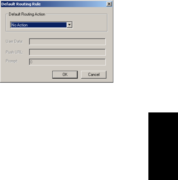
Basic Call Router & Call Router Advanced
AltiContact Manager Administration Manual 25-13
25.CallRouter
ãÂTheDefault Routing button opens a Default Routing Rule dialog
box, where you can specify the action for Call Router to take if no
match is found in the rules or in the database.
Default Routing Action options: No Action, Goto Top Level, Goto
Menu Item, Repeat Current Level, Call to Extension/Workgroup,
Call to Operator, Dial by Name, Collect Extension, Directory
Service, Record Message (specify target data in accompanying text
box), Mailbox Access, Disconnect, System Callback, Collect Digits
(specify fields in accompanying Collect Digit dialog box), Other
DDR Application (specify target data in accompanying text box),
Play WG Queue Status (specify target data in accompanying text
box).
Creating Route Rules
To create a route rule:
1. Select Route Rule from the Operation menu.
2. Click the Add button to open a new Route Rule or Modify to modify
an existing rule in the Rules List window.
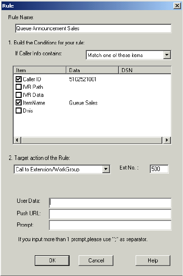
Call Router Advanced
25-14 AltiContact Manager Administration Manual
3. Enter or modify the Rule Name in this field.
4. Select the data to match against routing rules.
ãÂIf Callee Info contains - lets you select Call Route Request data to
match against the customer record.
a) Select ãMatch oneãorãMatch allã from the dropdown list.
b) Select the items you want.
c) Click in the Data column and type to specify the data.
To manually specify data for an item, right-click the item, select
Input data and enter information in the column.
Notes:
ã Caller Entered Digits must be numeric only.
ã You can enter ã*ã as a wildcard character for any length of digits,
or ã?ã for a single digit.
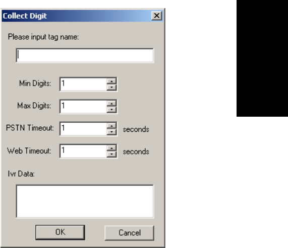
Basic Call Router & Call Router Advanced
AltiContact Manager Administration Manual 25-15
25.CallRouter
For example, if you specify Call ID Data ã510252*,ã this will
match all Caller IDs 510-252-xxxx. If you specify Call ID Data
ã510252????,ã this will match all Caller IDs 510 252-xxxx.
To specify data from an existing database, right-click the item,
select From user database, and enter information in the
DataSource dialog box.
5. Select a Target action for Call Router to perform when Call Route
Request data matches this record.
Target action options: No Action, Goto Top Level, Goto Menu Item,
Repeat Current Level, Call to Extension/Workgroup, Call to Operator,
Dial by Name, Collect Extension, Directory Service, Record Message
(specify target data in accompanying text box), Mailbox Access,
Disconnect, System Callback, Collect Digits (specify fields in
accompanying Collect Digit dialog box, see Note below), Other DDR
Application (specify target data in accompanying text box), Play WG
Queue Status (specify target data in accompanying text box, see Note
below).
Note: Collect Digit Dialog Box
Call Router Advanced
25-16 AltiContact Manager Administration Manual
ãÂTag name - for example, ãpasswordã (gathered from a response
to an IVR prompt or another AltiLink Plus application)
ãÂMinimum Digits and Maximum Digits to collect
ãÂPSTN and Web Timeout values
ãÂIVR Data - for example, ãusername=Michaelã (gathered from
a response to an IVR prompt or another AltiLink Plus
application)
Note: Play WG Queue Status - if you select ãPlay WG Queue
Status,ã Call Router Advanced must log on as a workgroup
extension with password and Call Routerãs virtual extension
and password. Specify this workgroup extension in the textbox
that appears when you select Play WG Queue Status.(See
ãQueue Announcementsã on page 25-21.)
If you want to apply the ãPlay WG Queue StatusãTarget
action to several different workgroups, you must create separate
rules for each.
6. (future release) Enter optional data to match against the routing rule:
ã User Data (gathered from a response to an IVR prompt or another
AltiLink Plus application)
ã Push URL (AltiWeb only)
ã the number of prompt to play to the callee
7. Click OK.
Viewing Call Router History Menu
The Call Router Advanced window gives a history of all incoming trunk
calls to Call Router Advanced.
To specify Call Router History window content:
1. Choose Select Column from the View Menu.
2. In the Select Columns dialog box, select the columns to display in the
Call Router history window the following:
ãÂCallerID
ã Entered Digit
ãÂIVRdata
ã DNIS

Basic Call Router & Call Router Advanced
AltiContact Manager Administration Manual 25-17
25.CallRouter
Call Route Request Data
The ãCall Router Requestã message sent by AltiContact Manager to Call
Router contains data about the incoming call, which Call Router attempts
to match against your routing rules. Call Route Request data consists of
Caller ID, (Caller) Entered Digits, IVR data and DNIS, all collected via
real-time monitoring.
Note: Caller Entered Digits shows the IVR assignment for the workgroup
that receives the call. If the workgroupãs IVR assignment is 5, this
item shows ã0 & 5ã; is the IVR assignment is 3, the item shows ã0
& 3,ã and so on. The ã0ã indicates transfer to an IVR.
Call Route Response Data
The ãCall Route Responseã message, sent from Call Router to AltiContact
Manager, contains the search results of the Call Route Request Message. In
the Call Router History window, this data shows how Call Router handled
each call. Call Route Response data includes Matching Record (routing
rule Call Router referred to for call routing) and Result (how and where the
call was routed), all collected via real-time monitoring.
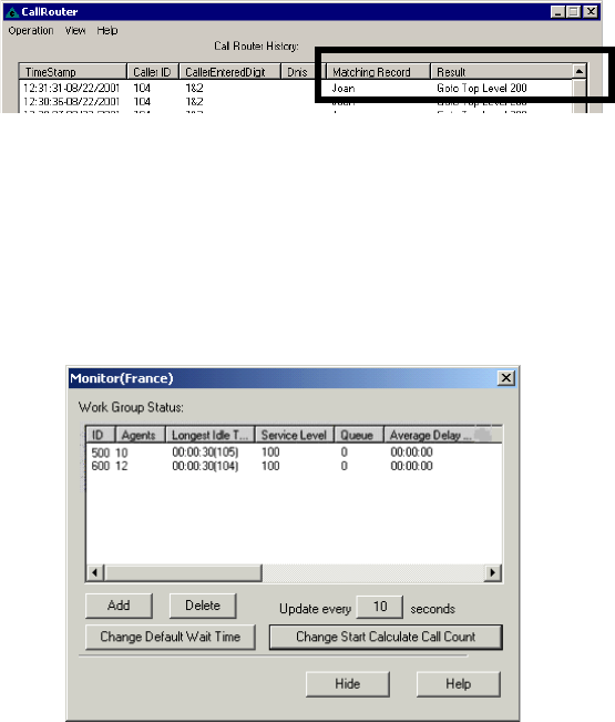
Call Router Advanced
25-18 AltiContact Manager Administration Manual
Note: If no match is found between the Call Route Request Data and the
routing rules, the call is routed according to the business rules that
check monitored workgroups for the longest available agent,
maximum service level, and minimum expected delay.
Show Workgroup Status
To view real-time data on incoming trunks to workgroup, select Show
Workgroup Status from the View menu.
ã The main window box displays the following workgroup fields: ID,
Agents,Longest Idle Time,Service Level,Queue,Average Delay
and Default Wait Time.
ãÂAdd button - Click Add to log on to a workgroup whose incoming
trunk call data you want to monitor. This opens a Log on Work Group
dialog box.

Basic Call Router & Call Router Advanced
AltiContact Manager Administration Manual 25-19
25.CallRouter
Enter the workgroup extension as the WorkGroup ID and password,
and enter the virtual extensionãs password.InthefieldforDefault
Wait Time in Queue, type in the desired minutes. (By default, the
Extension ID field is grayed out.)
ãÂDelete button - click Delete to remove the selected workgroup from
the display.
ãÂChange Default Wait Time (in Call Router Advanced only) - click
this button to change the default wait time associated with the work-
group queue.
Note: The workgroup to which incoming trunk calls will be routed via
Call Router must be assigned to the IVR whose Action is set to
ãAvd - Data Directed Routing,ã with Application set to the virtual
extension you use to start Call Router. For further information on
configuring IVR, refer to ãIVR Configurationã on page 11-1 and
the AltiAPI Programmer Guide.
If you want to announce queue status to callers (Target action of
any routing rule is ãPlay WG Queue Status,ã) complete the Virtual
Extension ID and Virtual Extension password fields using the
workgroup agent extension (and its password) specified in the rule.
To log on to multiple workgroups:
ã Click Add again and enter the next Workgroup ID and Password.
ãÂChange Start Calculate Call Count - click this button to change the
starting point for the number of calls to be reached for Call Router to
start calculating call data.
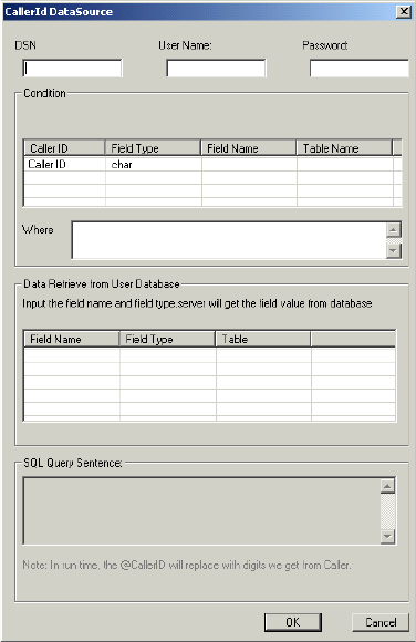
Call Router Advanced
25-20 AltiContact Manager Administration Manual
Clearing Call Router Advanced History Data
To clear data from the Call Router History window:
1. Go to the directory ãProgram Files/AltiGen/Call Routerã where Call
Router.exe resides, locate the Call Router.csv file.
2. Open Call Router.csv and delete all contents.
3. Save and close Call Router.csv.
Additional Call Router Advanced Features
Building SQL Queries
To build an SQL query that Call Router will send to your database, use the
CallerId Datasource dialog box. The customer information retrieved from
your database will be used in the routing rule.

Basic Call Router & Call Router Advanced
AltiContact Manager Administration Manual 25-21
25.CallRouter
To open the Datasource dialog box, right-click on a data Item you want to
specify using information from an existing database. Select From user
database:
To build and SQL query:
1. Enter User Name and Password information for the database.
2. Enter information for the database you are querying against. For
example:
DSN - BankAccount
Table Name - AccountBalance
Matched Field Name - CustomerPhoneNumber
Matched Field Data Type - char
Note: as you build the query, the SQL query sentence will appear in
the window at the bottom.
3. Specify the condition for this query.
a. Select the Caller Match Item data for this query - Caller ID,
CallerEnteredDigits,Dnis,Item name or IVR data.
b. Add any additional condition. For example Where - &&
Balance>1000
4. Click OK. You will be returned to the Rule dialog box, where the SQL
query will be shown in the Data column and the database will be shown
in the DSN column.
Queue Announcements
You can use Call Router Advanced to inform callers of their position in a
workgroup queue. There are two requirements:
1. In Call Router, you must create a rule with Target action ãPlay WG
Queue Status.ã In addition, enter an Item Name that matches the name
of the IVRãs ãData Directed Routingã name. The workgroup extension
information you specify in the rule must also be entered when Call
Router logs on in the Monitor window. Thus, it is a requirement to use
the same virtual agent extension if you are writing several different
queue announcement rules.
2. In AltiAdmin, you must configure one of the IVR numbers to which
Call Router is assigned to ãData Directed Routing.ã 1) Enter the same
ãItem Nameã you use in the rule discussed immediately above. 2)
Call Router Advanced
25-22 AltiContact Manager Administration Manual
Replace the ãNo Actionã level with ãCall ã to Ext./Workgroup,ã and
enter the workgroup extension number. For further information on
configuring IVR, see ãIVR Configurationã on page 11-1 and the
AltiAPI Programmer Guide.
If your organization has multiple workgroups and you want queue
announcement for several or all of them, you must create separate rules for
each, with workgroup extension information pertinent to each workgroup.
Example:
You use virtual extension 700 to log in to Call Router. You have two
workgroups, Sales and Support, with the following agent and workgroup
extensions:
Sales Support
Workgroup extension number 500 600
Call Router virtual extension number 700 700
For both workgroups, you want Call Router to check incoming calls for
Caller ID and Caller Entered Digits, and to play the WG queue status if a
match is found and all agents are busy.
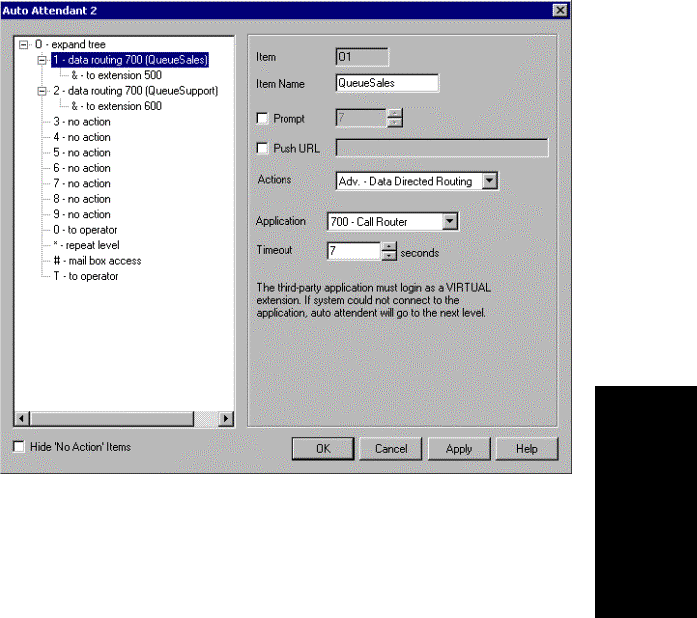
Basic Call Router & Call Router Advanced
AltiContact Manager Administration Manual 25-23
25.CallRouter
In ACM Administrator, you configure the IVR to which Call Router is
assigned as shown below. (The example uses IVR 2.) Note that you must
enter a different Item Name for each level.
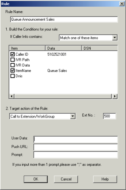
Call Router Advanced
25-24 AltiContact Manager Administration Manual
For Sales, you create a rule as shown below.
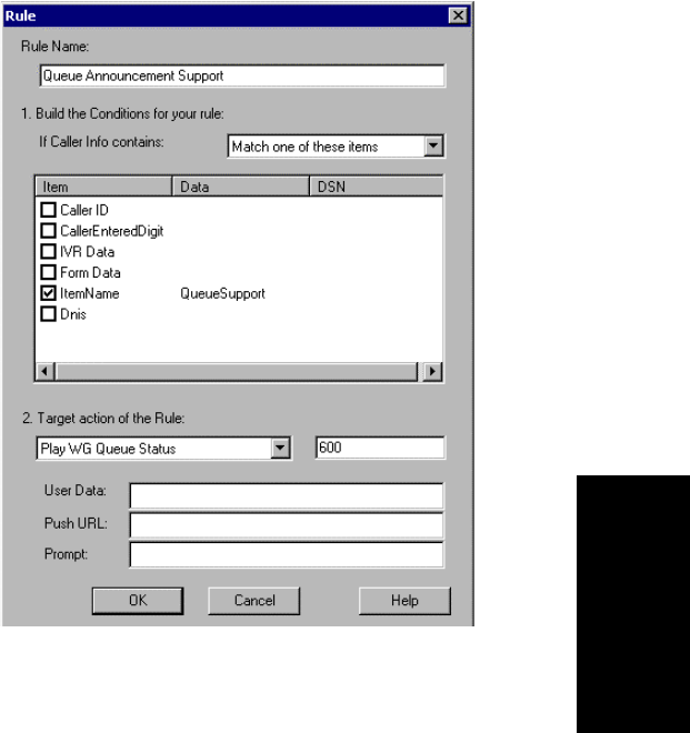
Basic Call Router & Call Router Advanced
AltiContact Manager Administration Manual 25-25
25.CallRouter
Similarly, for Support, you create a rule as shown below.
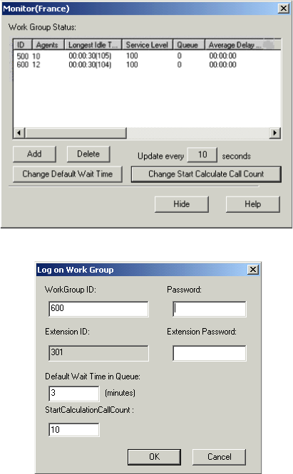
Call Router Advanced
25-26 AltiContact Manager Administration Manual
In the Monitor window, click Add to log on to Sales, entering both the
workgroup extension & password and the virtual extension & password
you specified in the ãIVR Sales Queue Announcementã rule:
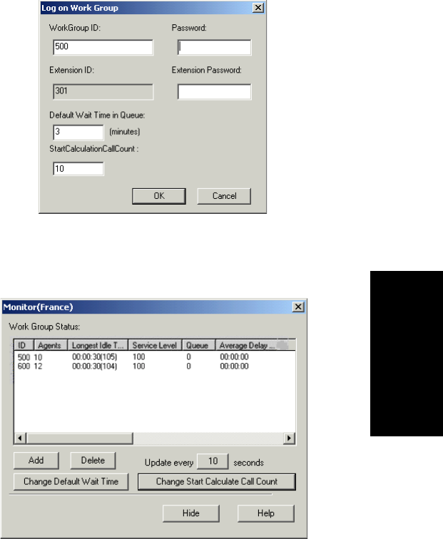
Basic Call Router & Call Router Advanced
AltiContact Manager Administration Manual 25-27
25.CallRouter
In the Monitor window, click Add to log on to Support, entering both the
workgroup extension & password and the virtual extension & password
you specified in the ãIVR Sales Queue Announcementã rule:
The Monitor window shows that Call Router is logged on to both
workgroups. Calls to each workgroup will be checked against the rules and
will trigger queue announcement if a match is found and all agents are
busy.

Testing Call Router
25-28 AltiContact Manager Administration Manual
Testing Call Router
To test the performance of Call Router, you can access a test tool from the
Call Router main menu. Call Router must be stopped in order to run the
test.
To test Call Router:
1. With Call Router function stopped, go to Test in the Tool drop-down
list of the Call Router main menu for the Test dialog box.
2. In the Configuration fields, the user can input the following test
parameters:
ãÂNumber of concurrent calls
ãÂInterval between calls
ãÂNumber of test cycles
For example, inputting 5for concurrent calls,3for interval between
calls,and4for test cycles means that every 3 seconds, there will be 5
concurrent call requests to Call Router. Total cycles of concurrent
requests will be 4 times.
3. After inputting the test parameters, click Start. During the test, the
user can click Stop to stop the test. The title of the Test dialog box will
be shown as ãTest(Started)ã while running.
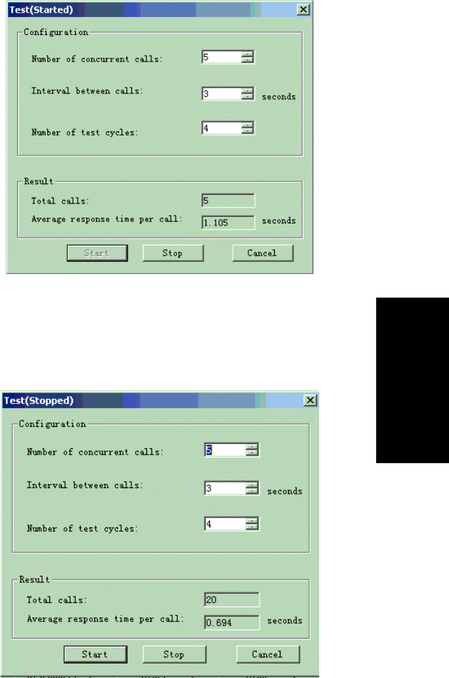
Basic Call Router & Call Router Advanced
AltiContact Manager Administration Manual 25-29
25.CallRouter
The total calls processed and average time per call will be updated in
real-time during the test. The user will know how many calls were
processed and the average response time per call at that time.
4. After the test has finished, the title of the Test dialog box will be
shown as ãTest(Stopped).ã
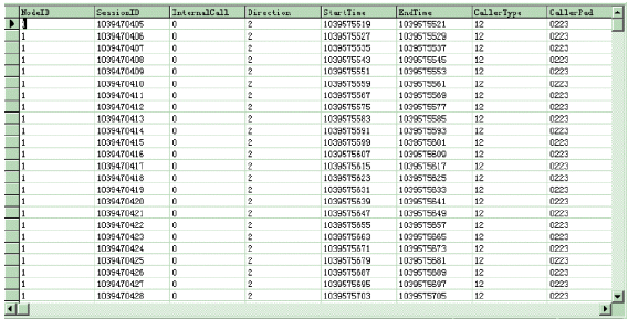
Testing Call Router
25-30 AltiContact Manager Administration Manual
5. The Total calls that Call Router processed and Average response
time per call of this test will be shown in the Result fields.
Testing SQL Server Database
To test SQL server database access performance of Call Router:
1. Add a database for the SQL server.
For example, for a database ãcalldbã and table name ãRTMCALLã,
10,000 records are added to the table.
Note: Because the data of DDR request has hard coded. If the user
wants a rule match, the user needs to add the record to the table.
The caller ID of test request will be ã1039470405.ã IVR Path
of test request will be ã0&9.ã
To use the ãSessionIdã field in the table to match caller ID of the
request, the user must add a record to the table and set the SessionId
value to ã1039470405ã. Then during match process, the matched
result will be true.
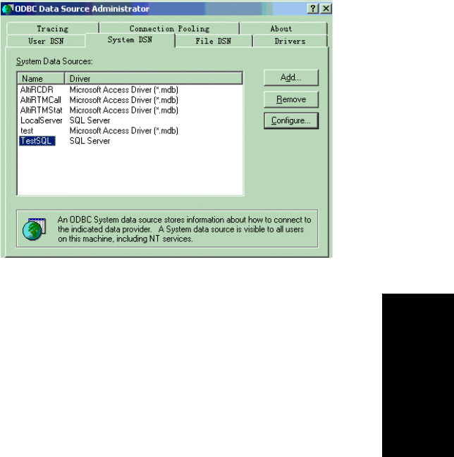
Basic Call Router & Call Router Advanced
AltiContact Manager Administration Manual 25-31
25.CallRouter
2. Add a data source to ãODBCã configuration in Windows.
The ãTestSQLã is the newly added data source. This data source is
connect to the SQL serverãs ãcalldbã database.
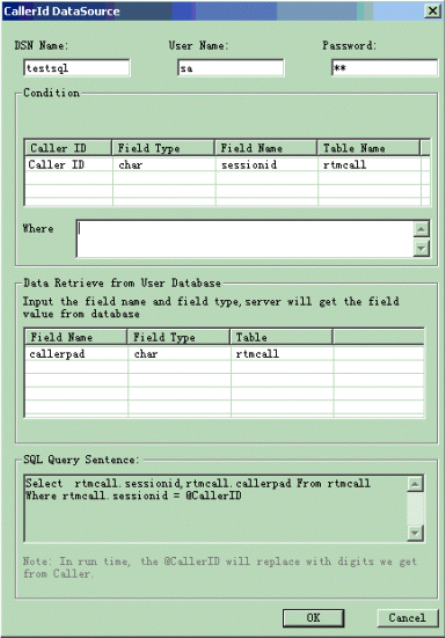
Testing Call Router
25-32 AltiContact Manager Administration Manual
3. In Call Router, add a rule to access database.
The user can change the rule configuration to fit his own conditions.
During the test, Call Router will use this rule to match the DDR
request. When using this rule, Call Router will access the SQL server
to execute the SQL query.

AltiContact Manager Administration Manual A-1
A. Call Accounting
Report Formats
A
PPENDIX
A
Call Accounting Report Formats
This appendix identifies the field codes for AltiGenãs CDR (Call Detail
Reporting) records and the formats for the Station Message Detail
Reporting (SMDR) specification support by AltiGen.
The first tables describe CDR and RTM database elements, while the
remainder of the section describes the SMDR format.

A-2 AltiContact Manager Administration Manual
CDR Data Schema
Table 1: CDR Call Format
Database
Element Definition Type Specification
NodeID Server ID (System ID)
assigned to an AltiServ system
in AltiAdmin
ULONG value: 1ã100
SessionID Session ID: a unique number,
usually 9 digits or larger,
assigned by AltiWare to a call
ULONG
InternalCall Internal or external call UBYTE 0=External
1=Internal
Direction Direction of the call (incoming
or outgoing)
UBYTE 1=None (logon/off)
2=Incoming
4=Outgoing (includes
silent monitor, barge-
in)
StartTime Outgoing call: Time when
caller receives ringback, busy,
or connect signal
Incoming call: Time when AA
picks up
ULONG
EndTime Timestampwhencallis
disconnected
ULONG
CallerType Type of line for an incoming
call
UBYTE 0=Unknown
1=Ext analog
2=Ext IP
3=Ext PHS (not used)
4=Ext virtual
5=Ext WG
11=trk analog
12=trk T1
13=trk IP
14=trk PRI
15=trk PHS (not used)

Call Accounting Report Formats
AltiContact Manager Administration Manual A-3
A. Call Accounting
Report Formats
CallerPad Lineãs physical address for an
incoming call
UCHAR
(5)
E.g. ã0004ã, where
ã00ã=slot,
ã04ã=channel
Always ã-1-1ã for WG
or virtual extension
CallerNum Caller phone number of an
incoming call (extension
number or off-net PSTN)
UCHAR
(41)
CallerName Caller name for an incoming
call (provided by CO for trunk
calls; as entered in AltiAdmin
for extension calls)
UCHAR
(65)
TargetType Type of line for an outgoing
call
UBYTE 0=None
1=Ext analog
2=Ext IP
3=Ext PHS (not used)
4=Ext virtual
5=Ext WG
11=trk analog
12=trk T1
13=trk IP
14=trk PRI
15=trk PHS (not used)
TargetPad Physical address of line for an
outgoing call
UCHAR
(5)
E.g. ã0004,ã where
ã00ã=slot and
ã04ã=channel
TargetNum Target phone number of an
outgoing call (extension
number or off-net PSTN)
UCHAR
(41)
TargetName Target name for an outgoing
call (as entered in AltiAdmin
for extension calls)
UCHAR
(65)
WGNum Workgroup number for an
incoming call
UCHAR
(8)
Table 1: CDR Call Format
Database
Element Definition Type Specification

A-4 AltiContact Manager Administration Manual
OutGoingW
G
Workgroup number for an
outgoing call, as set in
AltiAdminorbyagentat
logon
UCHAR
(8)
DNIS DNIS number for incoming
call
UCHAR
(33)
Tenant Tenant name for trunk UCHAR
(31)
AccountCod
e
Account code UCHAR
(11)
1ã10 digits in length
AADuration Duration in seconds an
incoming call is connected to
the Auto Attendant; multiple
connections to AA in a single
session produces multiple
records
ULONG
RingDuratio
n
Duration in seconds a call is
ringing and in workgroup
queue
ULONG
QueueDurati
on
Duration in seconds when a
call stays in a queue..
ULONG
VMDuration Duration in seconds after a call
goes into a voicemail box;
includes greeting, false
attempts at messages,
successful message, and
review of message
ULONG
VMRecDura
tion
Duration in seconds of
recording time for a VM
message that was completed
ULONG
HoldDuratio
n
Duration in seconds while a
call is on hold
ULONG
TalkDuratio
n
Duration in seconds of talk
time
ULONG
RecordDura
tion
Duration in seconds of NOVO
recording
ULONG
Table 1: CDR Call Format
Database
Element Definition Type Specification

Call Accounting Report Formats
AltiContact Manager Administration Manual A-5
A. Call Accounting
Report Formats
ExitState State when call is terminated ULONG (see boxed inset)
LogoffReaso
n
Logoff reason code UBYTE
URL URL when ãcallã is initiated
by AltiWeb user clicking the
make-call button
UCHAR
(255)
Table 1: CDR Call Format
Database
Element Definition Type Specification
Specification
[documented (HEX)] - [data output (Decimal)] - [exit state definition]
ã0x0001ã - 1 - Auto Attendant
ã0x0002ã - 2 - Ring No Answer
ã0x0003ã - 3 - Queue
ã0x0004ã - 4 - Voice Mail (no VM recorded)
ã0x0005ã - 5 - VM (VM recorded)
ã0x0006ã - 6 - Connect
ã0x0007ã - 7 - Logon
ã0x0008ã - 8 - Logoff
ã0x0009ã - 9 - All Trunks Busy
ã0x000Aã - 10 - No session
ã0x000Bã - 11 - VM Access
ã0x000Cã - 12 - Forward
ã0x000Dã - 13 - Transfer
ã0x000Eã - 14 - VM Notify
ã0x000Fã - 15 - WG Abandoned
ã0x0010ã - 16 - Park
ã0x0011ã - 17 - System Park
ã0x0012ã - 18 - Conference
ã0x0013ã - 19 - Call Monitor
ã0x0014ã - 20 - Transfer Cancel
ã0x0015ã - 21 - Call Redirect
ã0x0016ã - 22 - Call Pick Up
ã0x0017ã - 23 - Dial Cancel

A-6 AltiContact Manager Administration Manual
Table 2: CDR Logon-Off Format
UserData Agent input UCHAR
(255)
CallEnd For indication of the last
record of a call
UCHAR
LocalStartTi
me
Outgoing call: Timestamp
when caller receives ringback,
busy or connect signal
Incoming call: Timestamp
when AA picks up
String yyyymmddhhmmss
LocalEndTi
me
Timestampwhencallis
disconnected
String yyyymmddhhmmss
Database
Element Definition Type Specification
NodeID Server ID (System ID)
assignedtoanAltiServ
system in AltiAdmin
ULONG value: 1ã100
SessionID Session ID: a unique number,
usually 9 digits or larger,
assigned by AltiWare to a call
ULONG
StartTime Timestamp when workgroup
logs on, logs off, is ready or
not ready
ULONG value
EndTime Timestamp when call is
disconnected
ULONG
AgentNum Agent extension number UCHAR
(8)
WGNum Workgroup Number UCHAR
(8)
LogoffReaso
n
Logoff reason code UBYTE
Table 1: CDR Call Format
Database
Element Definition Type Specification
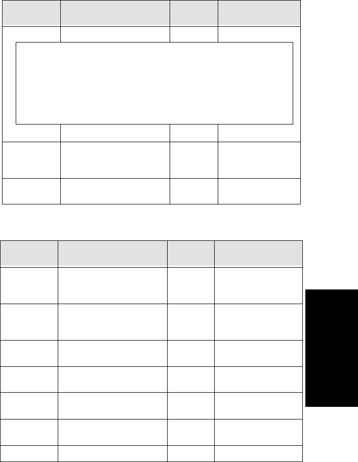
Call Accounting Report Formats
AltiContact Manager Administration Manual A-7
A. Call Accounting
Report Formats
Table 3: CDR Wrap-Up Format
ExitState State when call is terminated ULONG (see boxed inset)
LocalStartTi
me
Timestamp when workgroup
logs in, logs out, is ready or
not ready
String yyyymmddhhmmss
LocalEndTi
me
Timestamp when call is
disconnected
String yyyymmddhhmmss
Database
Element Definition Type Specification
NodeID Server ID (System ID)
assigned to an AltiServ
system in AltiAdmin
ULONG value: 1ã100
SessionID Session ID: a unique number,
usually 9 digits or larger,
assigned by AltiWare to a call
ULONG
StartTime Timestampwhenwrapup
starts
ULONG
EndTime Timestampwhenwrapup
stops
ULONG
AgentNum Agent extension number UCHAR
(8)
WGNum Workgroup Number UCHAR
(8)
Duration Wrap up duration time ULONG
Database
Element Definition Type Specification
Specification
[documented (HEX)] - [data output (Decimal)] - [exit state definition]
ã0x0007ã - 7 - Logon
ã0x0008ã - 8- Logoff
ã0x0018ã - 24 - Ready
ã0x0019ã - 25 - Not Ready

A-8 AltiContact Manager Administration Manual
ExitState State when call is terminated ULONG (see boxed inset)
LocalStartTi
me
Timestampwhenwrapup
starts
String yyyymmddhhmmss
LocalEndTi
me
Timestampwhenwrapup
stops
String yyyymmddhhmmss
Database
Element Definition Type Specification
Specification
[documented (HEX)] - [data output (Decimal)] - [exit state definition]
ã0x0020ã - 1 - Wrap up

Call Accounting Report Formats
AltiContact Manager Administration Manual A-9
A. Call Accounting
Report Formats
RTM Data Schema
Table 4: RTM Data Format
Database
Element Definition Type Specification/
*CDRClientField
Workgroup Data
NodeID Server ID (System ID) assigned
to an AltiServ system in
AltiAdmin
ULONG value: 1ã100
Date Day information ULONG *Timevalue
Time Time interval short minutes
* Period value
WGNum Workgroup Number UCHAR
(8)
MaxWaitTim
eInQ
Longest waiting time in queue
during searched time interval
short *Queue is not an
accumulated value; it
is recorded at a
specific point in time.
PeakQLength Maximum queue length since
midnight
short
PeakWaitTim
eInQ
Maximum queued time since
midnight
ULONG
QLength Number of calls routed into the
queue; if a call is recycled into
the queue after RNA, the count
is increased
short * Calls in Queue
DurationInQ Time calls waited in queue
during searched time interval
before being abandoned or
answered
ULONG *It is not an
accumulated value, it
is recorded at a
specific point in time.
NumInCall Callsansweredbyanagent;ifa
call is forwarded to and
answered by multiple agents,
the count is increased
short * Calls Answered

RTM Data Schema
A-10 AltiContact Manager Administration Manual
InCallDurati
on
Duration of incoming calls
(NumInCall), starting from the
time an agent answers a call
until the call is disconnected or
transferred out of the WG
ULONG * Calls Answered
Duration
NumOutCall All outgoing trunk and station-
to-station calls that entered
ãConnectedã state
short * Outgoing Calls
OutCallDurat
ion
Duration of outgoing calls
(NumOutCall); from the time
the call enters ãConnectedã
state until disconnect
ULONG * Outgoing Calls
Duration
NumCallToV
M
Count of voicemail messages
(calls transferred to VM from
queue by caller pressing #, and
calls automatically transferred
to WG VM after RNA for every
agent)
short * Calls Transferred
to Voice Mail
NumCallAba
ndoneDuring
Ring
Count of calls abandoned while
ringinganagent
short A
* Calls Abandoned
During Ring
NumCallAba
ndonedInQ
Count of calls abandoned while
waiting in queue
short B
* Calls Abandoned
in Queue
NumCallAba
ndoneBefore
Answer
Total abandoned calls (during
VM, queue, and RNA)
short C
CãAãB=
* Calls Abandoned
during VM
NumQueueO
verflow
Calls routed to the WG but not
queued due to AltiAdmin
settings that specify acceptable
queue length and/or wait time
short *QueueOverflow
BeforeAnswe
rDuration
Time calls waited in queue
before being answered
ULONG *WaitTimefor
Answered Calls
DurationInQ
OfCallAband
one
Total wait time of all calls
abandoned in queue
(NumCallAbandonedInQ)
ULONG *WaitTimefor
Abandoned Calls
Table 4: RTM Data Format
Database
Element Definition Type Specification/
*CDRClientField

Call Accounting Report Formats
AltiContact Manager Administration Manual A-11
A. Call Accounting
Report Formats
ServiceLevel Service Level number of calls in
queue - X / # of calls
in queue
X = number of calls
in queue exceeding
threshold
*ServiceLevel is not
an accumulated
value, it is recorded
at a specific point in
time.
LocalDate Day information String yyyymmdd
Agent Data
NodeID Server ID (System ID) assigned
to an AltiServ system in
AltiAdmin
ULONG value: 1ã100
Date Day information ULONG *Timevalue
Time Time interval short minutes
* Period value
AGNum Agent extension number UCHAR
(8)
NumInCall Calls answered; if a call is
rerouted to and answered by the
same agent, the count is
incremented
short * Calls Answered
InCallDurati
on
Duration of incoming calls
(NumInCall), starting from the
time the agent answers a call
until the call is disconnected or
transferred out of the WG
ULONG * Calls Answered
Duration
NumOutCall All outgoing trunk and station-
to-station calls that entered
ãConnectedã state
short * Outgoing Calls
Table 4: RTM Data Format
Database
Element Definition Type Specification/
*CDRClientField

RTM Data Schema
A-12 AltiContact Manager Administration Manual
OutCallDurat
ion
Duration of outgoing calls
(NumOutCall); from the time
the call enters ãConnectedã
state until disconnect
ULONG * Outgoing Calls
Duration
NumWrapUp Number of times agent entered
Wrapup, where Wrapup lasts
from agent-set ãNot Readyã to
ãReadyã status
short * Wrapup
WrapUpDura
tion
Theamountoftimefor
Wrapup, where Wrapup lasts
from agent-set ãNot Readyã to
ãReadyã status
ULONG * Wrapup
Duration
NumCallToV
M
Count of voicemail messages short *VoiceMail
VMDuration Total duration of voicemail
messages
ULONG *VoiceMail
Duration
nGroups Count of workgroups agent is
logged in to
short
NumHold The number of call put on hold
in this workgroup
short
HoldDuration Total duration of workgroup
hold calls
ULONG
extNumInCal
l
Personal (non-workgroup)
incoming call
short * Calls Answered
extInCallDur
ation
Total duration of personal (non-
workgroup) incoming calls
ULONG * Calls Answered
Duration
extNumOutC
all
Number of personal (non-
workgroup) outgoing calls
short * Outgoing Calls
extOutCallDu
ration
Total duration of personal (non-
workgroup) outgoing calls
ULONG * Outgoing Calls
Duration
extNumCallto
VM
Count of non-workgroup
voicemail messages
short *VoiceMail
extVMDurati
on
Total duration of voicemail
messages
ULONG *VoiceMail
Duration
extNumHold Count of non-workgroup calls
holding
short
Table 4: RTM Data Format
Database
Element Definition Type Specification/
*CDRClientField

Call Accounting Report Formats
AltiContact Manager Administration Manual A-13
A. Call Accounting
Report Formats
extHoldDurat
ion
Total duration of non-
workgroup hold count
ULONG
NumNotRead
y
Number of not ready, not
including wrap up
short
NotReadyDur
ation
Total duration of the not ready
period
ULONG
LocalDate Date String yyyymmdd
DND Times Number of times agent entered
DND
ULONG
DND
Duration
Total duration of the DND
period
ULONG
Agent Per Workgroup
NodeID Server ID (System ID) assigned
to an AltiServ system in
AltiAdmin
ULONG value: 1ã100
Date Day information ULONG *Timevalue
Time Time interval short minuutes
* Period value
AGNum Agent extension number UCHAR
(8)
WGNum Workgroup number UCHAR
(8)
Login Log state UBYTE 0=Logout
1=Login
LogTimeSta
mp
Login/logout time stamp ULONG
ReasonCode Logout reason code UBYTE
NumInCall Calls answered; if a call is
rerouted to and answered by the
same agent, the count is
incremented
short * Calls Answered
Table 4: RTM Data Format
Database
Element Definition Type Specification/
*CDRClientField

RTM Data Schema
A-14 AltiContact Manager Administration Manual
InCallDurati
on
Duration of incoming calls
(NumInCall), starting from the
time the agent answers a call
until the call is disconnected or
transferred out of the WG
ULONG * Calls Answered
Duration
NumOutCall All outgoing trunk and station-
to-station calls that entered
ãConnectedã state
short * Outgoing Calls
OutCallDurat
ion
Duration of outgoing calls
(NumOutCall); from the time
the call enters ãConnectedã
state until disconnect
ULONG * Outgoing Calls
Duration
NumWrapUp Number of times agent entered
Wrapup, where Wrapup lasts
from agent-set ãNot Readyã to
ãReadyã status
short * Wrapup
WrapUpDura
tion
Theamountoftimefor
Wrapup, where Wrapup lasts
from agent-set ãNot Readyã to
ãReadyã status
ULONG * Wrapup
Duration
NumCallToV
M
Count of voicemail messages short *VoiceMail
VMDuration Total duration of voicemail
messages
ULONG *VoiceMail
Duration
NumHold Count of calls holding short
HoldDuration Total duration of workgroup
hold calls
ULONG
LoginDuratio
n
The total time agent was logged
in since midnight
ULONG
LogoutDurati
on
The total time agent was logged
out since midnight
ULONG
LocalDate Date String yyyymmdd
Table 4: RTM Data Format
Database
Element Definition Type Specification/
*CDRClientField

Call Accounting Report Formats
AltiContact Manager Administration Manual A-15
A. Call Accounting
Report Formats
SMDR Reporting Format
Besides the CDR format, AltiServ reports telephone information in the
Station Message Detail Reporting (SMDR) format to an application
through the COM port. The SMDR format and sample entries for the
specification are described below.
In AltiWareãs reports, internal extension-to-extension calls are not logged;
neither are outbound calls of less than 15 seconds duration.
Trunk Calls In Format:
09/01 07:04P 00:00:25 0200 5102526354 109 12345678:
(Start, Length) Field Format Notes
(0, 1) space
(1, 5) date mm/dd
(6, 1) space
(7, 6) start time hh:mmP P = pm, A = am
(13, 1) space
(14, 8) duration hh:mm:ss
(22, 1) space
(23, 4) trunk PAD number xxyy x = board numb.
y = channel numb.
(27, 34) calling party
(61, 4) called party
(65, 7) space
(72,8) accountcode 1to10digits
(80, 1) delimiter line feed

SMDR Reporting Format
A-16 AltiContact Manager Administration Manual
Extension Calls Out Format:
09/01 08:12P 00:00:33 109 2526352 0411 12345678:
From Extension A
Extension A: 100
Extension B: 111
Outside #: 3210002:
(Start, Length) Field Format Notes
(0, 1) space
(1, 5) date mm/dd
(6, 1) space
(7, 6) start time hh:mmP P = pm, A = am
(13, 1) space
(14, 8) duration hh:mm:ss
(22, 1) space
(23, 4) calling party
(27, 6) space
(33, 26) called number
(59, 2) space
(61, 4) trunk PAD number xxyy x = board numb.
y = channel numb.
(72,8) accountcode 1to10digits
(80, 1) delimiter line feed
Calls Initiated by Extension A (Column A)
1 Dial out 11/18 05:53P 00:00:28 100 3210002 0100
2 Ext B fwd to Trk Y 11/18 05:55P 00:00:21 100 3210002 0001
3 Ext B ONA to Trk Y 11/18 05:57P 00:00:17 100 3210002 0100

Call Accounting Report Formats
AltiContact Manager Administration Manual A-17
A. Call Accounting
Report Formats
From Trunk B
Extension B: 100
Trunk X: 3210001
Trunk Y: 3210002:
4 VM make call to Trk Y 1/18 05:58P 00:00:15 100 3210002 0001
5 ### to Ext B (WG B,
Virtual B) and VM make
call
11/18 05:59P 00:00:23 111 3210002 0100
6 Ext B S-transfer to Trk
Y* (see examples)
11/18 06:00P 00:00:22 111 3210002 0001
7 Ext B B-transfer to Trk
Y* (see examples)
11/18 06:01P 00:00:18 100 3210002 0100
11/18 06:01P 00:00:05 0001100 100
8 ToTrkYthentransferto
Ext B
11/18 06:02P 00:00:27 100 3210002 0001
9 Outcall Log time only, no lines logged
10 Zoomerang 11/18 06:06P 00:00:27 100 3210002 0100
11 System Speed Dial 11/18 06:07P 00:00:18 100 3210002 0001
12 Ext Speed Dial 11/18 06:08P 00:00:25 100 3210002 0100
13 #35 privilege overwrite
to Ext B (WG B, virtual
B)
11/18 06:09P 00:00:31 100 3210002 0001
14 B is WG B N/A
15 Ext B transfer to WG C N/A
16 Conference with Trunk 11/18 06:10P 00:00:25 100 3210002 0100
Calls Initiated by Trunk X to Extension B (Column B)
1 Dial in 11/18 06:11P 00:00:07 0100 3210001 100
2 Ext B fwd to Trk Y 11/18 06:13P 00:00:35 0100 3210001 100
11/18 06:13P 00:00:25 TRK0 3210002 0001
Calls Initiated by Extension A (Column A)

SMDR Reporting Format
A-18 AltiContact Manager Administration Manual
3 Ext B ONA to Trk Y 11/18 06:15P 00:00:12 0100 3210001 100
11/18 06:16P 00:00:00 0100 3210001
4VM make call to Trk Y 11/18 06:18P 00:00:29 100 3210001 100
11/18 06:18P 00:00:58 0100 3210001 100
5### to Ext B (WG B, Vir-
tual B) and VM make call
N/A
6 Ext B S-transfer to Trk
Y* (see examples)
11/18 06:19P 00:00:21 0100 3210001 100
11/18 06:20P 00:00:41 0100 3210001 TRK0
11/18 06:20P 00:00:23 3210 3210002 0001
7 Ext B B-transfer to Trk
Y* (see examples)
11/18 06:22P 00:00:24 3210 3210002 0001
11/18 06:22P 00:00:40 0100 3210001 3210
8 To Trk Y then transfer to
Ext B
N/A
9 Outcall Log time only, no lines logged
10 Zoomerang 11/18 06:24P 00:00:38 100 3210002 0100
11/18 06:24P 00:01:08 0001 3210001 100
11 System Speed Dial N/A
12 Ext Speed Dial N/A
13 #35 privilege overwrite to
Ext B (WG B, virtual B)
N/A
14 B is WG B 11/18 06:25P 00:00:09 0100 3210001 100
15 Ext B transfer to WG C 1/18 06:26P 00:00:17 100 100 0100
11/18 06:26P 00:00:24 0100 3210001 111
16 Conference with Trunk 11/18 06:27P 00:00:15 0001 3210001 100
Calls Initiated by Trunk X to Extension B (Column B)
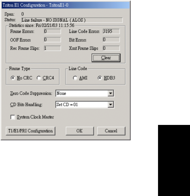
AltiContact Manager Administration Manual B-1
B. E1 R2 CAS
Installation
A
PPENDIX
B
E1 R2 CAS Installation
This appendix describes the configuration procedures necessary to
implement E1 R2 digital signaling for European, Pacific Rim, and other
emerging markets. Please carefully follow the procudures step by step
Step 1: Physical Layer
In the Triton E1Configuration window, check the properties of the E1
trunk and consult your CO for the proper settings for the following fields:
ãÂFrame Type -No CRC or CRC4 (a 4-bit cyclic redundancy check)
ãÂLine Code -AMI or HDB3 (high-density bipolar 3)
ãÂZero Code Suppression - None,Jam Bit 8,GTE or Bell
DO NOT select the System Clock Master check box because CO is a clock
provider, our system is synchronized to CO.
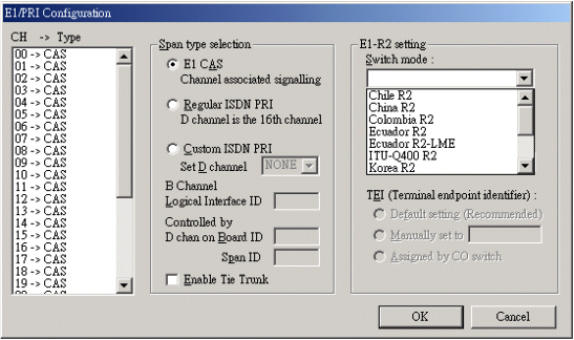
B-2 AltiContact Manager Administration Manual
CD Bits Handling is selected to "CD = 01". If all configurations are
correct, the status of trunk line should be shown as ãOK.ã
Step 2: Data Link Layer
In the T1/E1 Configuration window, the Span type selection should be
E1 CAS.IntheE1 R2 setting field, select the switch mode according to
your country.
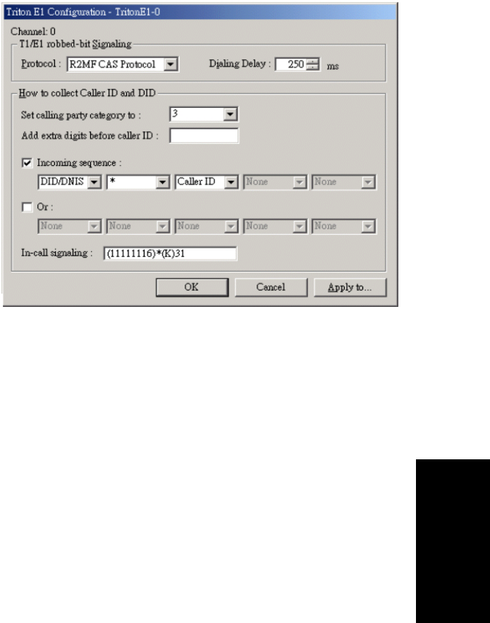
E1 R2 CAS Installation
AltiContact Manager Administration Manual B-3
B. E1 R2 CAS
Installation
Step 3: Signaling Layer
Depending on your country and itãs corresponding trunk property, in the
Triton E1 Trunk Configuration dialog box, configure the following
fields:
ãÂSet Calling Party Category to - the Calling Party Category
indicates the type of calling party, (e.g. operator, pay phone,
priority, ordinary subscriber). Select 1,2or 3(for ordinary
subscribers, refer to Table 1). If the suscribed line is intended for
other purposes, contact your CO for the proper value.
ãÂAdd extra digits before caller ID - consult your CO to find out if
any extra digits are needed.
ãÂIncoming sequences - select check box and configure the sequence
according to Table 1.
ãÂIn-call signaling - configure the in-call signaling value according
to Table 1.
Note: Consult your CO to find out if caller ID digits are provided in the
lines.

B-4 AltiContact Manager Administration Manual
Table 1: Foreign Countries/Signaling Values
Country Signaling Values
Chile/Nacional MFC-
R2 Set calling part category:1
[Assume no caller ID provided]:
Incoming sequence: DID/DNIS
In-call signaling (depend on how many DID digits):
For 3-digit DID, set to (113)6
For 4-digit DID, set to (1113)6
For 5-digit DID, set to (11113)6
For 6-digit DID, set to (111113)6
For 7-digit DID, set to (1111113)6
For 8-digit DID, set to (11111113)6
[Assume caller ID provided]:
Incoming sequence (same as above shown): DID/DNIS *
Caller ID
In-call signaling (depend on how many DID digits):
For 3-digit DID, set to (115)*(K)36
For 4-digit DID, set to (1115)*(K)36
For 5-digit DID, set to (11115)*(K)36
For 6-digit DID, set to (111115)*(K)36
For 7-digit DID, set to (1111115)*(K)36
For 8-digit DID, set to (11111115)*(K)36

E1 R2 CAS Installation
AltiContact Manager Administration Manual B-5
B. E1 R2 CAS
Installation
China MFC-R2 Set calling part category:3
[Assume no caller ID provided]:
Incoming sequence:DID/DNIS
In-call signaling (depend on how many DID digits):
For 3-digit DID, set to (113)1
For 4-digit DID, set to (1113)1
For 5-digit DID, set to (11113)1
For 6-digit DID, set to (111113)1
For 7-digit DID, set to (1111113)1
For 8-digit DID, set to (11111113)1
[Assume caller ID provided]:
Incoming sequence (same as above shown):
DID/DNIS * Caller ID
In-call signaling (depend on how many DID digits):
For 3-digit DID, set to (116)*(K)31
For 4-digit DID, set to (1116)*(K)31
For 5-digit DID, set to (11116)*(K)31
For 6-digit DID, set to (111116)*(K)31
For 7-digit DID, set to (1111116)*(K)31
For 8-digit DID, set to (11111116)*(K)31
Colombia MFC-R2 Set calling part category:2
[Assume no caller ID provided] :
Incoming sequence: DID/DNIS
In-call signaling (depend on how many DID digits):
For 3-digit DID, set to (113)6
For 4-digit DID, set to (1113)6
For 5-digit DID, set to (11113)6
For 6-digit DID, set to (111113)6
For 7-digit DID, set to (1111113)6
For 8-digit DID, set to (11111113)6
[Assume caller ID provided]:
Incoming sequence (same as above shown):
DID/DNIS * Caller ID
In-call signaling (depend on how many DID digits):
For 3-digit DID, set to (115)*(K)36
For 4-digit DID, set to (1115)*(K)36
For 5-digit DID, set to (11115)*(K)36
For 6-digit DID, set to (111115)*(K)36
For 7-digit DID, set to (1111115)*(K)36
For 8-digit DID, set to (11111115)*(K)36
Table 1: Foreign Countries/Signaling Values
Country Signaling Values

B-6 AltiContact Manager Administration Manual
Ecuador MFC-R2 Set calling part category:1
[Assume no caller ID provided]:
Incoming sequence: DID/DNIS
In-call signaling (depend on how many DID digits):
For 3-digit DID, set to (113)6
For 4-digit DID, set to (1113)6
For 5-digit DID, set to (11113)6
For 6-digit DID, set to (111113)6
For 7-digit DID, set to (1111113)6
For 8-digit DID, set to (11111113)6
[Assume caller ID provided] :
Incoming sequence (same as above shown):
DID/DNIS * Caller ID
In-call signaling (depend on how many DID digits):
For 3-digit DID, set to (115)*(K)36
For 4-digit DID, set to (1115)*(K)36
For 5-digit DID, set to (11115)*(K)36
For 6-digit DID, set to (111115)*(K)36
For 7-digit DID, set to (1111115)*(K)36
For 8-digit DID, set to (11111115)*(K)36
Ecuador MFC-LME Set calling part category:2
[The switch doesn't support caller ID transmission]:
Incoming sequence: DID/DNIS
In-call signaling (depend on how many DID digits):
For 3-digit DID, set to (113)1
For 4-digit DID, set to (1113)1
For 5-digit DID, set to (11113)1
For 6-digit DID, set to (111113)1
For 7-digit DID, set to (1111113)1
For 8-digit DID, set to (11111113)1
Korea MFC-R2 Set calling part category:1
[The switch doesn't support caller ID transmission]:
Incoming sequence: DID/DNIS
In-call signaling (depend on how many DID digits):
For 3-digit DID, set to (113)6
For 4-digit DID, set to (1113)6
For 5-digit DID, set to (11113)6
For 6-digit DID, set to (111113)6
For 7-digit DID, set to (1111113)6
For 8-digit DID, set to (11111113)6
Table 1: Foreign Countries/Signaling Values
Country Signaling Values

E1 R2 CAS Installation
AltiContact Manager Administration Manual B-7
B. E1 R2 CAS
Installation
Mexico / Telûˋfonos de
Mexico Set calling part category:2
[Assume no caller ID provided] :
Incoming sequence: DID/DNIS
In-call signaling (depend on how many DID digits):
For 3-digit DID, set to (113)1
For 4-digit DID, set to (1113)1
For 5-digit DID, set to (11113)1
For 6-digit DID, set to (111113)1
For 7-digit DID, set to (1111113)1
For 8-digit DID, set to (11111113)1
[Assume caller ID provided]:
Incoming sequence (same as above shown):
DID/DNIS * Caller ID
In-call signaling (depend on how many DID digits):
For 3-digit DID, set to (116)*(K)31
For 4-digit DID, set to (1116)*(K)31
For 5-digit DID, set to (11116)*(K)31
For 6-digit DID, set to (111116)*(K)31
For 7-digit DID, set to (1111116)*(K)31
For 8-digit DID, set to (11111116)*(K)31
PanamûÀ / Nacional
MFC-R2
Set calling part category:1
[Assume no caller ID provided]:
Incoming sequence:DID/DNIS
In-call signaling (depend on how many DID digits) :
For 3-digit DID, set to (113)6
For 4-digit DID, set to (1113)6
For 5-digit DID, set to (11113)6
For 6-digit DID, set to (111113)6
For 7-digit DID, set to (1111113)6
For 8-digit DID, set to (11111113)6
[Assume caller ID provided]:
Incoming sequence (same as above shown):
DID/DNIS * Caller ID
In-call signaling (depend on how many DID digits):
For 3-digit DID, set to (115)*(K)36
For 4-digit DID, set to (1115)*(K)36
For 5-digit DID, set to (11115)*(K)36
For 6-digit DID, set to (111115)*(K)36
For 7-digit DID, set to (1111115)*(K)36
For 8-digit DID, set to (11111115)*(K)36
Table 1: Foreign Countries/Signaling Values
Country Signaling Values

B-8 AltiContact Manager Administration Manual
Venezuela / Nacional
MFC-R2 Set calling part category:1
[Assume no caller ID provided]:
Incoming sequence: DID/DNIS
In-call signaling (depend on how many DID digits):
For 3-digit DID, set to (113)6
For 4-digit DID, set to (1113)6
For 5-digit DID, set to (11113)6
For 6-digit DID, set to (111113)6
For 7-digit DID, set to (1111113)6
For 8-digit DID, set to (11111113)6
[Assume caller ID provided]:
Incoming sequence (same as above shown):
DID/DNIS * Caller ID
In-call signaling (depend on how many DID digits) :
For 3-digit DID, set to (115)*(K)36
For 4-digit DID, set to (1115)*(K)36
For 5-digit DID, set to (11115)*(K)36
For 6-digit DID, set to (111115)*(K)36
For 7-digit DID, set to (1111115)*(K)36
For 8-digit DID, set to (11111115)*(K)36
Table 1: Foreign Countries/Signaling Values
Country Signaling Values

AltiContact Manager Administration Manual C-1
C. Product Repair &
Technical Support
A
PPENDIX
C
Product Repair Services &
Technical Support
This appendix describes AltiGen technical support policy and procedures. It also covers repair
and replacement procedures that the user should follow when returning or replacing defective
equipment.
Technical Support
Before contacting Technical Support, always have the following information on hand:
ãÂYour name
ãÂCompany name
ãÂProduct serial number
ãÂAltiWare version number
ãÂNumber of boards in the system
ãÂServer brand and model
ãÂThe telephone number where you can be reached
ãÂA brief description of the problem and the procedure to reproduce the problem
Having this information ready will allow us to better assist you.
Eligibility
AltiGen provides technical support to Authorized AltiGen Dealers and Distributors only.
End User customers, please contact your Authorized AltiGen Dealer for technical support.
Direct AltiGen support is available to End User customers through E-mail only, when
addressing problems that cannot be resolved by referring to the instruction manuals or
by your Authorized AltiGen Dealer.
Technical Support Hours
During AltiGenãs business hours (7:00 A.M. to 5:30 P.M., Pacific Standard Time, Monday
through Friday except holidays), your call will be returned in the order it was received (on a
first come, first serve basis), within two (2) hours under normal circumstances. Outside
AltiGen business hours, only emergency calls will be returned within eight (8) hours. All other
calls are returned on the next business day.
Repair and Replacement
B-2 AltiContact Manager Administration Manual
How To Reach AltiGen Technical Support
Contact AltiGen technical support by any of the following methods:
ãÂCALL 510-252-9712 and follow the prompts. This is available to Authorized AltiGen
Dealers and Distributors only. Your call will be answered by one of AltiGenãs
Technical Support Representatives or routed to the Technical Support Message Center
if no one is available to answer your call. Your call will be returned promptly, within
two (2) hours under normal circumstances. Please see ãTech Support on AltiGenãs Web
site.ã
ãÂSEND EMAIL TO: support@altigen.com. Messages are checked on a daily basis.
ãÂSEND A FAX TO 510-252-9738, ATTENTION: Technical Support.
Tech Support on AltiGenãs Web Site
AltiGen offers tech support on the web at http://support.altigen.com.
Unresolved Problems Escalation Procedure
The following escalation steps should be followed to report unresolved problems. Please
contact the following parties in the order listed:
1. Local Authorized Dealers Service Department.
2. AltiGenãs Technical Support Manager at support@altigen.com.
For remaining unresolved problems or complaints, send an email to AltiGenãs CEO at
ceo@altigen.com, or call 510-252-9712 x 120.
Repair and Replacement
This policy addresses the procedure for return of any materials to AltiGen from Authorized
AltiGen Dealers only. It covers materials returned for any and all reasons.
AltiGen Communicationãs Repair Program provides registered customers with replacement
parts in a timely and professional manner. The AltiGen Repair Program allows you to send
defective AltiGen manufactured hardware products (in or out of Warranty) to our factory for
prompt authorized repairs.
Hardware Warranty Period
AltiGen Communications hardware products are warranted for one (1) year for all parts and
manufacturing labor, from the date of the first end user purchase or 14 months from the date
of shipment from AltiGen. Product proof of purchase or equivalent is required.
Products Returned Before Warranty Expiration
All repaired units remain under the Warranty period of the original product. Advance
Replacement products are provided on an exchange basis; the products sent to AltiGen
become the property of AltiGen, and AltiGen provides the sender with a new product OR a
repaired product that is functionally equivalent to new.

Product Repair Services & Technical Support
AltiContact Manager Administration Manual C-3
C. Product Repair &
Technical Support
For products found to be in a non-repairable condition, at AltiGenãs sole discretion, the sender
will be notified for further directions and disposition. If there is no response and or, no
directions are provided to AltiGen within 5 days, the credit card will be charged 100% of the
productãs then current list price, if applicable.
For Depot Repairs, the product(s) will be returned to the sender.
Products Returned After Warranty Expiration
Products returned after the Warranty Period will be repaired or replaced, at AltiGen discretion,
under the, then current, price schedule. Out of warranty repairs are warranted for 90 days from
date of return shipment to the customer. For products found to be in a non-repairable
condition, at AltiGen sole discretion, the sender will be notified for further directions and
disposition. If there is no response and or, no directions are provided to AltiGen within 5 days,
the credit card will be charged 100% of the product(s) then current list price, if applicable.
For Depot Repairs, the product(s) will be returned to the sender.
Repair Service Offerings
Standard Warranty (Depot Repair)
AltiGen will use its best efforts to repair and return AltiGen manufactured products within
thirty (30) working days of receipt. Standard Repair price for out of Warranty products, shall
be in accordance with the then current price list and/or schedule.
AltiGen will apply a No Trouble Found (NTF) service charge of $300.00 if the returned
product(s), after being tested by Manufacturing and Quality Assurance (QA) evaluation, was
found trouble free.
There is no charge for covered In-Warranty product repair services.
Advance Replacement
All Advance Replacement RMAs MUST be secured with a company or personal credit card.
Advance Replacements are not available or provided for the Alti-IP 600 phone sets.
AltiGen will, at the callerãs request, provide an Advance Replacement product for, In or Out
of Warranty inoperable units, excluding the Alti-IP 600 phone. Upon receiving the Advance
Replacement product, the caller will return the defective product to AltiGen via the RMA
number provided for the return.
DOA (Dead on Arrival) Provisions
AltiGen will replace products under Warranty that fail at the initial power up or within the first
24 hours of service (DOA) with a new product on an expedited basis, at no charge, including
shipping and freight charges.
AltiGen will apply a No Trouble Found (NTF) service charge of $300.00 if the returned
product(s), after being tested by Manufacturing and Quality Assurance (QA) evaluation, was
found trouble free.
Repair and Replacement
B-4 AltiContact Manager Administration Manual
Standard Product Warranty
Failures beyond the first 24 hours of initial power up, including Early Life Failures, shall not
be considered under the DOA provisions.
ãÂAll products provided under the Standard Product provision will be new or,
reconditioned to adhere to the same, form, fit and function as the product being replaced.
ãÂAdvance Replacement services are available for Out of Warranty products. A $300.00
service fee shall apply for this service, plus the standard applicable Repair Service
charges for Out of Warranty product.
ãÂAll shipping is 2nd day Air. If other shipping arrangements are requested any additional
cost will be charged to the caller.
ãÂAltiGen will apply a NTF service charge of $300.00 if the returned product(s), after
being tested by Manufacturing and Quality Assurance (QA) evaluation, was found
trouble free; No Trouble Found (NTF).
Product Returns
You are provided 30 days, from AltiGen ship date, to return the inoperable product. If the
product is not returned within 30 days, the credit card provided, will be charged 100% of the
product(s) current list price. No discounts will be applied.
If the product returned is different ã Product type, Serial Number, etc. ãthan the one
requested and shipped, AltiGen Communications, at its discretion, may elect to return the non-
conforming product back to the sender and charge the sender, 100% of the then current list
price.
The appropriate invoice will be cancelled and/or credited if the proper unit is returned within
the 30 day period.
For products found to be in a non-repairable condition, at AltiGenãs sole discretion, the sender
will be notified for further directions and disposition. If there is no response and/or no
directions are provided to AltiGen within 5 days, the credit card provided will be charged
100% of the product(s) then current list price.
If the returned unit is In-Warranty and the reason for failure is covered by the Product
Warranty, no charge(s) will apply.
Restocking
Where as, if AltiGen receives the return of the Advance Replacement product and the product
is the ãsame product as shippedã ã Product type, Serial Number, etc. ã a 20% Restocking
fee shall apply at the then current price and/or schedule.
Repair Procedures - For Initiating Any Repair Level Service
(Standard or Advanced)
To initiate a Repair Order, either Standard or Advanced, contact the AltiGen Technical
Support Department at (510) 252-9712 between 8:00 AM and 5:00 PM (PT).
The following information must be provided at the time of your request:
ãÂRMA Form (See ãRMA Formã on page C-8)

Product Repair Services & Technical Support
AltiContact Manager Administration Manual C-5
C. Product Repair &
Technical Support
ãÂProof of Purchase
Advanced Replacement Orders
To initiate an Advance Replacement order: Contact AltiGen Communicationãs Repair
Technical Support Department at (510) 252-9712 between 8:00 AM and 5:00 PM (PT). If the
call arrives outside of the normal working hours and a message is left, an AltiGen
Communicationãs representative will return the calls during the next normal business day.
For same day shipments during the normal workweek, the request must be received and
accepted by 3 PM PST. Requests out side of this will be shipped the next business day.
The following information must be provided to initiate an Advanced Replacement order:
ãÂRMA Form (See ãRMA Formã on page C-8)
ãÂProof of Purchase
What You Must Do
Once the replacement unit is received, adequately pack the defective equipment in the same
packing materials and return it and ALL the component parts and documentation to the
address noted in the RMA form.
Component parts, literature and documentation(s) missing from the Advance Replacement
return will be charged to the credit card provided. You are provided 30 days form Altigen ship
date to return the inoperable unit. If not returned in 30 days, you will be charged 100% of the
unitãs current list price. No discounts will be applied. See description of Advanced
Replacement above.
Shipping cartons not marked with the return RMA number on the outside of the packaging
will be returned to the sender.
What You Will Receive
With verification of a product defect, the AltiGen representative will issue a Return Material
Authorization (RMA) number.
How to Ship Units for Repair
All materials being returned to AltiGen must have an associated RMA number. RMA numbers
are issued by AltiGen Customer Service and can be obtained by calling 510-252-9738.
AltiGen reserves the right to refuse return of any material that does not have an RMA number.
The RMA number should be clearly marked on the outside of the box in which the material is
being returned. For example:
Attn.: RMA # 123
AltiGen Communications, Inc.
47427 Fremont Blvd.
Fremont, CA 94538
Repair and Replacement
B-6 AltiContact Manager Administration Manual
Terms and Conditions
1. Exceptions and Notice of Non-Repairable Equipment
Equipment returned for repair (whether in or out of Warranty), which is found to be damaged,
or at AltiGenãs sole discretion are, beyond economical repair, will either be returned to the
user or scrapped by AltiGen at the userãs option. AltiGen will notify the sender and request
instruction for disposition. Test and freight charges may apply. Any unit returned for repair
without a valid AltiGen serial number will be considered as Out of Warranty.
This Repair Service does not cover PROMS, Tapes, Disks, or software items.
2. Shipping Methods, Payment and Insurance
AltiGen ships all equipment FOB (Freight on Board) from Fremont, California. AltiGen does
not arrange shipment insurance or special packing, unless requested to do so by the customer.
Please specify any special shipping requirements on the RMA form.
Proper care and packaging is the responsibility of the sender.
AltiGen Communications pays outbound freight on all repaired items if shipped by our
standard method, which is UPS Ground, which takes from 5 to 7 days. The customer will be
responsible for any special handling, overnight-NFO, and/or insurance requests beyond
AltiGenãs standard method of shipment. Any additional shipping charges will be applied to
the provided credit card.
All shipments to AltiGen must have the freight charges pre-paid by the sender. AltiGen does
not accept inbound shipments that are COD, collect, or any shipment that does not have an
authorized RMA number clearly marked on the outside of the package.
All applicable charges and payments for services will be by way of, credit card (Visa,
MasterCard).
3. Equipment Damaged During Shipment
PLEASE CHECK FOR SHIPPING DAMAGE WHEN YOUR EQUIPMENT IS
RECEIVED.
Inspect all cartons at the time of delivery. Visible damage should be brought to the attention
of the carrier at once. In the event of concealed damage, keep the shipping container, packing
material and equipment intact. It is your responsibility to file any claims for damage or loss
with the carrier or your insurance carrier.
4. Accounts Not Current
Customers with outstanding accounts, over sixty (60) days will be refused Repair Services
until their account is in good standing.
5. Repair and or Technical Support Exclusions
Any equipment not manufactured by AltiGen Communications and/or provided by AltiGen,
or software owned and/or provided by a third party, which is integrated with AltiGen
Communicationãs products/ system, in a package for an end-user, is excluded from AltiGenãs
Support Services.

Product Repair Services & Technical Support
AltiContact Manager Administration Manual C-7
C. Product Repair &
Technical Support
6. Hardware Limitations
Products, which are not manufactured by AltiGen, may not be returned to AltiGen, and should
be returned directly to the original manufacturer for repair. AltiGen will not be responsible or
guarantee the safekeeping of any third party equipment deliveries. Altigen will not coordinate
the repairs or the forwarding of any such equipment to other vendors.

RMA Form
B-8 AltiContact Manager Administration Manual
RMA Form
One article per RMA Issued initiating any repair level service.
To initiate a repair order, contact AltiGen Communicationsãs Technical Support
Department at (510) 252-9712 between 8:00 AM and 5:00 PM (PST) or e-mail
support@altigen.com.
The following information must be provided at the time of your request.
In/Out of Warranty Repair Request Form
Date:________________________________________________________________________________
End User Name:_______________________________________________________________________
Dealer Company Name:_________________________________________________________________
Dealer Phone Number:______________________________AltiGen Case Number:__________________
Credit Card Number ã VISA/MC:
___ ___ ___ ___ ã ___ ___ ___ ___ã___ ___ ___ ___ ã ___ ___ ___ ___
Expiration: ___ ___ /___ ___ Card Holder Name:_____________________________________________
SHIP TO INFORMATION
Company Name:_______________________________________________________________________
Attn:________________________________________________________________________________
Address:_____________________________________________________________________________
City/State/ZIP Code:_________________________________________________________________
Phone Number:________________________________________________________________________
FOR ALTIGEN USE ONLY
RMA # Tech Support Rep:
Adv. Replacement: YES ! NO !
A.R. Fee Required: YES ! NO !
ProofofPurchaseRequired:
YES ! NO !
Under Warranty: YES ! NO !Depot Repair: YES ! NO !

Product Repair Services & Technical Support
AltiContact Manager Administration Manual C-9
C. Product Repair &
Technical Support
BILL TO INFORMATION
Company Name:_______________________________________________________________________
Attn:________________________________________________________________________________
Address:_____________________________________________________________________________
City/State/ZIP Code:____________________________________________________________________
Phone Number:________________________________________________________________________
SHIPMENT METHOD: STANDARD ! EXPRESS !
WARRANY STATUS: UNDER WARRANTY ! WARRANTY EXPIRED !
PRODUCT INFORMATION:
Product Part Number:___________________________________________________________________
Serial Number:________________________________________________________________________
Chassis Model/Mfg:____________________________________________________________________
AltiOffice BTOS #:__________________________Operating System:____________________________
Number of Boards in System:_____________________________________________________________
Complete Description of Problem:
(including steps taken to isolate the problem to the particular product, MVIP test results, affected port
number(s), etc. RMA will not be processed without this information.)
RMA Form
B-10 AltiContact Manager Administration Manual

AltiContact Manager Administration Manual G-1
Glossary
Glossary
A
AC - Alternating Current.
ADPCM - Adaptive Differential Pulse Code Modulation. A sophisticated
compression algorithm for digitizing audio that stores the differences between
successive samples rather than the absolute value of each sample. This method of
digitization also reduces storage requirements from 64K bits/second to as low as
24K bits/second.
AltiConsole - a personal computer-based Attendant console connected to the
AltiServ over the network that emulates a standard hardware-based Attendant
console through software and has the flexibility of adding new features through
software without changing the hardware.
AltiSpan - link from the AltiServ base to the system extension that allows for
passing Caller ID.
AltiWare - the system software that is used by AltiGenãs Quantum products.
AltiServ - an advanced, highly integrated business and computer telephony
platform that consists of a Quantum card and AltiWare software working in a
PC/Server running under Windows NT.
analog - a method of telephony transmission in which the information from the
source (for example, speech in a human conversation) is converted into an electrical
signal that varies continuously over a range of amplitude values.
API - Applications Programming Interface. A set of routines that an application
program uses to request and carry out lower-level services performed by an
operating system.
ASCII - American Standard Code for Information Interchange.
B
blocked calls - calls that cannot be immediately connected to the number dialed. A
call is defined as blocked when access paths to the called station are unavailable.
This is not applicable to AltiServ.
BPS - Bits Per Second. The number of bits transmitted per second.
C
card - printed circuit assembly.
CCIS - Common Channel Interoffice Signaling. A method of carrying telephone
signaling information along a path different to the path used to carry voice.
G-2 AltiContact Manager Administration Manual
Central Office (CO) - a switching system that connects lines to lines, lines to
trunks, and trunks to trunks. These systems are operated by local telephone
companies. The term sometimes refers to a telephone company building in which a
switching system is located and sometimes includes other equipment (such as
transmission system terminals).
Centrex (CTX) - a business telephone service offered by a local telephone
company from a local central office. Centrex is a single line telephone service,
delivered to individual desks or telephones with added features such as intercom,
call forwarding, call transfer, toll restriction, out call routing, and hold on single line
telephones. These features are provided by the local phone companyãs central
office. Centrex is a leased business service serving as an option to owning a PBX
or key telephone system.
channel - the smallest subdivision of a circuit capable of carrying communication
service.
circuit - the physical connection of channels, conductors and equipment between
two given points. Includes both transmitting and receiving capabilities.
client - a process whose threads call services provided by either a local or remote
server process. In Windows NT, communication between a client and server occurs
through the local procedure call (LPC) or remote procedure call (RPC) facilities.
CO - Central Office.
conference call - a call in which two or more persons speak together. Stations may
be internal or external.
configure - to determine and assign the equipment cabinet or chassis contents and
location of each card, as well as software parameters.
configuration databases - those databases that represent unique customer
specifications relating to system and station features.
console phone - emulates a standard Attendant Console through software. It
provides all the call handling features provided by a standard hardware-based
console and has the flexibility of adding new features through software without
changing the hardware (i.e. AltiConsole).
conversation path - the route from originating port to terminating port of a two-
way communication. A conversation requires two such port-to-port paths. Transmit
and receive.
CTI - Computer Telephone Integration. Or in the case of an AltiServ, Computer
Telephony Internet.
D
database - a collection of related data that can be immediately accessed and
operated upon by a data processing system for a specific purpose.

AltiContact Manager Administration Manual G-3
Glossary
DC - direct current. The flow of free electrons in one direction with an electrical
conductor, such as wire.
Default - the preset value from the factory or the software writer that the program
or equipment comes with. In the absence of any other command from the user, it
will work with default values.
DID - Direct Inward Dialing.
digit - a single whole number between 0 and 9.
disk duplexing - the procedure of copying data onto two hard drives, each using its
own hard drive controller. If any component (hard drive controller card, cable, boot
hard drive) on the first channel fails, then the second channel will boot and operate
normally.
disk mirroring - the procedure of duplicating data written to two identical hard
drives, where both hard drives are connected to one disk controller card. If one hard
drive fails, then the data can be retrieved from the second hard drive.
DNIS (Dialed Number Identification Service) - is a telephone service that
identifies for the receiver of a call the number that the caller dialed. It's a common
feature of 800 and 900 lines. If you have multiple 800 or 900 numbers to the same
destination, DNIS tells which number was called. DNIS works by passing the touch
tone digits (DTMF or MF digits) to the destination where a special facility can read
and display them or make them available for call center programming.
Do Not Disturb (DND) - when this feature is selected, all incoming calls to the
userãs extension are denied. If the station has system forwarding instructions, the
calls will be automatically redirected to another extension, Attendant, or operator.
DTMF - Dual Tone Multi Frequency are the low and high frequency tones that
comprise touch tone signals.
drop-down menu - a list of options that display below a menu option.
DSP - Digital Signal Processor. A microprocessor with an architecture that is
particularly optimized to perform mathematical algorithms that manipulate digital
signals.
Dual Tone Multi Frequency -seeDTMF.
E
en-bloc dialing - dialing scheme that allows the terminal to include all the digits
required to complete a call.
environmental subsystem - A protected subsystem (server) that provides an
application programming interface (API) and environment - such as Win32,
MS-DOS, POSIX, or OS/2 - on Windows NT.
escalation - to expand step-by-step from a limited or local issue to higher level.
G-4 AltiContact Manager Administration Manual
Ethernet - a communications protocol used in local area networks to connect
computers, terminals, printers, etc., typically located within the same building.
Ethernet operates over twisted wire and over coaxial cable at speeds up to 10
megabits per second. Ethernet is a physical link and data link protocol reflecting the
two lowest layers of the DNA/OSI model.
Exchange Server Integration - provides unified messaging by synchronizing the
mailboxes in an AltiServ and Exchange Server, so that a user can access messages
in either server. If a message is added to one server, it is automatically sent to the
other server, similarly, if a message is deleted in one server it is automatically
deleted from the other server.
extension number - an arbitrary number of two to five digits that matches a station
to a particular user.
F
FCC - Federal Communications Commission.
feature - a special or specific capability.
field - a unit of data in a record or message and designated for a particular purpose.
file - an organized collection of related information treated as a unit.
file server - an integral part of a multi-user computer network such as a local area
network (LAN). It typically is a combination of a computer, data management
software, and large capacity hard disk drive. A file server directs all movement of
files and data on a multi-user communications network and gives each user on the
network access to files stored on the file server. It allows the user to store
information, leave electronic mail messages for other users on the system and
access application software on the file server such as word processors or
spreadsheets.
FLASH - a sudden brief signal. Activated by depressing the flash key on the
telephone pad if one has been configured, or by a quick press and release of the
receiver button (switch hook).
FSK - Frequency Shift Keying. A modulation technique for data transmission.
function - a specific purpose of an entity, or its characteristic action. In computer
programming, a synonym for procedure.
FXS - Foreign Exchange Subscriber. An analog interface for direct connection of a
telephone set to a digital multiplexer.
G
GMT - Greenwich Mean Time. Mean solar time of the meridian at Greenwich,
England, used as the basis for standard time throughout the world.

AltiContact Manager Administration Manual G-5
Glossary
ground start - a type of start signaling on a subscriberãs trunks in which the ring
(minus side) is grounded (ground start) to get dial tone.
GUI - Graphical User Interface.
H
hard disk - a sealed mass storage unit used for storing large amounts of data.
hardware - a term used to describe the physical components of a machine,
particularly computer equipment, and devices containing logic elements used in
data processing or communication equipment.
Hertz - cycles per second. Abbreviated as Hz.
http or HTTP - Hypertext Transfer Protocol. The Internet protocol used to manage
communications between Web clients (browsers) and servers.
Hunt group - see Workgroups.
Hz - see definition for Hertz.
I
Impedance - occurs when power or signal is transferred from one circuit to another.
This is known as the resistance of electrical current to alternating current and it is
measured in OHMs.
IMAP4 - Internet Message Access Protocol - Version 4.
interface - the interconnections between two separate systems or pieces of
equipment.
ISA - Industry Standard Architecture.
ISO - International Standards Organization.
ISP - Internet Service Provider.
J
jack - the mate for a plug. Used to connect two pieces of equipment together.
K
keyboard - system interface for communication. A group of numeric keys,
alphabetic keys, or function keys used for entering information into a terminal and
into the system. Usually patterned after the QWERTY keyboard layout. This term
is derived from the sequence of the first six keys in the first row of alphabetic keys.
G-6 AltiContact Manager Administration Manual
L
Language Server - allows the ability to record and play phrases in different foreign
languages without requiring any software changes.
Local address - an address used in a peripheral node or station in place of a network
address and transformed to or from a network address for delivery purposes.
Logoff - the procedure by which a user disconnects from a program or session.
Logon - the procedure by which a user begins a program or terminal session and
gains access to the AltiServ or Quantum system.
Loop Start - a type of start signaling. A closed path or circuit over which a signal
can circulate. When used on a telephone line, it tests the line, the circuit is closed
and reflects received signals to the sender.
M
maintenance - any activity intended to retain a functional unit in, or to restore it to,
a state in which it can perform its required function. Maintenance includes keeping
a functional unit in a specified state by performing activities such as test,
measurements, replacements, adjustments, and repairs.
MAPI (Messaging API) - a Component Object Model (COM)-based API that
supports message-related components such as message stores, address book, and
message transport.
MDMF - Multiple Data Message Format.
menu - a display of a list of available machine functions for selection by the user.
MHz - Megahertz.
MIME - Multipurpose Internet Mail Extension. A technique designed to bundle
attachments within individual email files. Microsoft email protocol software
format.
module - a compact assembly that is a component of a larger unit in electronics. A
detachable section, compartment or unit with a specific purpose or function.
mounting panel - the panel used to mount the connection panels to a wall.
ms - millisecond.
MVIP - Multi-Vendor Integration Protocol.
N
network - A configuration of data processing and/or telecommunication devices
and software connected for information exchange.

AltiContact Manager Administration Manual G-7
Glossary
network address - An identifier for a node, station, or unit of equipment in a
network.
network domain - a set of workstations and servers that share a security account
manager database and can be administered as a group. A user with an account in a
particular network domain can log onto and access his or her account from any
system in the domain.
network server - networking software that responds to I/O or computes requests
from a client machine. Windows NT network servers can be implemented either as
server processes or as drivers.
numbering plan - the method of assigning NNX codes to provide a unique
telephone address for each subscriber, special line, or trunk destination. In
AltiWare, the method of assigning extension numbers and trunk designations to
local premises.
North American Numbering Plan -alsoknownasNPA. Refers to the assignment
and management of the area code system for North America. Administered by
Bellcore, presently being expanded due to high demand for new numbers and
services, requiring new area codes. Numbering sequence being changed from
traditional N 1/0 X area code (center digit a 1 or a 0) to NNX, where N = numbers
1to9andX=anynumber.
O
offhook - refers to a telephone set when the receiver is not resting in the base. This
usually initiates a dial tone from the receiver.
OneNumberAccess- a feature of AltiWare that allows users to create a list of
phone numbers that the system can use to track users and connect them with an
incoming call if they are not at their extension desk.
onhook - the term used to describe a telephone in the idle state or with the receiver
still resting in the base.
option - a selection from several possibilities.
OSI - Open Systems Interconnection. A software model defined by the
International Standards Organization that standardizes levels of service and types
of interaction for networked computers. The OSI reference model defines seven
layers of computer communication and what each layer is responsible for.
overlap dialing - dialing scheme that allows the terminal to omit part of the digits
required to complete a call, while the remaining digits are buffered.
G-8 AltiContact Manager Administration Manual
P
PABX - Private Automatic Branch Exchange. A private branch exchange (PBX)
that provides access to and from the public telephone network without operator
intervention.
PBX - Private Branch Exchange. A switching system providing telephone
communications between internal stations and external networks.
PCM - Pulse Code Modulation.
physical extension - is associated with a physical port and device. An extension is
created, by default, as a physical extension (as opposed to a virtual or workgroup
extension) unless there are no more physical ports available.
pilot number - the extension number that identifies a workgroup or distribution
group.
POP3 - Post Office Protocol version 3. Protocol for retrieving email by remote
client.
port - a communication channel through which a client process communicates with
a protected subsystem.
POSIX - an acronym defined as ãa portable operating system interface based on
UNIX,ã refers to a collection of international standards for UNIX-style operating
system interfaces. In the mid-to-late 1980ãs, government agencies began specifying
POSIX as a procurement standard for government computing contracts.
Power Failure Backup - If your AC power fails, your telephone system can still
operate by switching to a backup battery power supply, often called an
(Uninterrupted Power Supply) UPS.
Power Failure Transfer - A telephone system feature. When the commercial AC
power fails and there is no backup power source such as a battery or a generator,
this feature switches some of the trunks connected to the telephone system to
several single line phones that do not need external power and can draw their power
from the telephone lines.
Power Supply - the part of the telephone system or a computer that converts the
normal 120 or 240 volts AC power to AC and DC at the various voltages and
frequencies as needed by various components and circuits of the system.
Private Network - A series of offices connected together by leased and non-leased
telephone lines, with switching facilities and transmission equipment owned and
operated by the user or by the carrier and leased to the user.
process - a logical division of labor in an operating system. In Windows NT, it
comprises a virtual address space, an executable program, one or more threads of
execution, some portion of the userãs resource quotas, and the systems resources
that the operating system has allocated to the process threads. It is implemented as
an object.

AltiContact Manager Administration Manual G-9
Glossary
Protected subsystems - integral subsystems that perform important operating
system functions, such as security subsystems among others.
protocol - A set of rules and conventions by which two computers pass messages
across a network medium. Networking software generally implements multiple
levels of protocols layered one on top of the other.
Q
Quantum - an ISA standard computer telephony board of AltiGenãs AltiServ
product line. It is an all-in-one platform designed with open software standards to
facilitate use of enhanced applications.
queue - a collection of calls waiting to be served. Queued calls in AltiWare are
handled on a first-in, first-out basis.
R
RAM - Random Access Memory. The primary memory in a computer that can be
written over with new information. The contents of RAM memory are lost when the
electrical power to the PC is switched off.
RAS - Remote Access Service.
retry - to resend data a prescribed number of times or until the data is finally
delivered.
RJ-11 - The ãcommonã telephone jack. Usually wired with four wires, the red and
green signify the tip and ring circuits.
RJ-45 - The ãcommonã telephone jack. Usually wired with eight wires, the red and
green signify the tip and ring circuits.
ROM - Read Only Memory.
root directory - in an IBM or compatible PC, the directory that is created when the
user formats a diskette that may contain subdirectories. Synonymous with system
directory.
S
save - to retain data by placing it in memory or by copying it from one storage
device to another.
SDMF - Single Data Message Format.
server - a process with one or more threads that accepts requests from client
processes. It implements a set of services that it makes available to clients running
either on the same computer or possibly on various computers in a distributed
network.
slot - a numbered division of a computer in which a printed circuit card is located.
G-10 AltiContact Manager Administration Manual
SMTP - Simple Mail Transfer Protocol. Protocol for sending Internet email.
station - any location wired to accept a telephone, sometimes referred to as an
extension. Also another name for a place where a call can be answered. It may be a
telephone, an Attendant console, a PC, or any other device.
subscriber - a user or connection. The line from a telephone to a switch.
System Speed Dialing - this feature allows the user to access a system wide
directory of commonly called numbers that have been ãcondensedã into a two- or
three-digit code on the telephone dial pad.
T
TAPI - Telephone Application Programming Interface. A call-processing software
that allows developers to implement telephony applications that control switches
from different vendors.
TCP/IP - Transfer Control Protocol/Internet Protocol. A full set of protocols used
on the Internet.
TDM - Time Division Multiplexing.
telecommunications - any transmission, emission, or reception of signals, writing,
images, or other information by wire, radio, or any other electromagnetic system.
Tip and Ring - the traditional telephony indication of plus and minus in electrical
circuits. (See Ground start and Loop start.)
toll call - a call to a point outside of the local service calling area. Identified by
greater distance and increased rates or by 1 plus dialing requirements.
toll restriction - a feature that allows the user to restrict certain station users from
placing toll calls, or other non-business related locations.
traffic - a measure of the demand or use of facilities, circuits, or trunks. Measured
by converting seconds and minutes into CCSs (Centum Call Seconds) and Erlangs
(hours of use per hour).
transfer - this feature redirects a call to another extension, the AltiGen Voice
Mail System, or operator.
trunk - one of the cables that contain numerous shared telephone circuits used to
interconnect telephone switching centers.
trunk access code - the prefix digit (i.e. 9) dialed to access a trunk line and dial an
external phone number.
trunk group -trunksofacommontype,givenanidentitytodistinguishbetween
different types of connecting facilities.

AltiContact Manager Administration Manual G-11
Glossary
U
UCA - Universal Communication Architecture.
UPS - Uninterrupted Power Supply. A backup battery module attached to a
computer that allows memory contents to remain intact long enough for the
operating system to perform an orderly system shutdown if a power outage occurs.
USB - Universal Serial Bus.
user(s) - the person or persons accessing the features and functions of the AltiWare
product.
V
virtual extension - an extension not associated with a physical port that allows for
guest access to the AltiGen Voice Mail System features and telephone sharing
environments. Users of a virtual extension have to log in before accessing the
system features assigned to it.
W
WATS - Wide Area Telephone Service. A leased service for direct long distance
dialing.
Wink - a single supervisory pulse.
Windows NT (New Technology) - the high-end Windows operating system in a
family of Windows operating systems.
workgroup - telephones arranged in groups within a particular organizational
function (for example, marketing, sales, service, etc.). Each workgroup is assigned
a pilot number. When the pilot number is dialed, the system scans the list of
extensions comprising the workgroup and connects the call to the first available idle
extension number. If no extensions are available, the call is placed in that
workgroupãs queue.
workgroup pilot number - an extension designated to a workgroup that is not
associated with a physical port and may consist of up to 64 members. When the pilot
number is dialed, the call is distributed to the workgroup members.
World Wide Web - A network of Internet servers that can provide browser
information in the form of ãweb pagesã to web clients such as Netscape Navigator.
G-12 AltiContact Manager Administration Manual

Index
AltiContact Manager Administration Manual I-1
Index
Index
A
About icon 4-4
access
restriction 1-19
system 4-10
access code 7-3
account code 1-6
ACD 1-24
call handling 15-19
ACM Administrator 1-22
installation 3-45
login 3-46
adding a huntgroup 14-4
adding or changing hardware 3-47
address
AltiGen Communications,
Inc. 1-ii
IP 21-6
network 21-2
administration
AltiContact Manager 5-1
remote 1-22
Adobe Acrobat PDF 3-1
Advanced CallRouter 25-10
queue announcements 25-21
SQL queries 25-20
agent
logout reason codes 12-5
agent check box 13-6
agent configuration 13-1
Agent Extension view window 4-6
Agent icon 4-4
A-law 5-26
AlCM Administrator
login 3-46
alternate mark inversion (AMI) 6-20
AltiAdmin 3-1
menus & windows 4-1,4-11
AltiBackup 3-1
AltiConsole 1-24,1-25,G-1
AltiContact Manager
administration 5-1
call center features 1-6
characteristics 1-3
NT service 3-2
online registration 3-9
PBX features 1-6
platform selection 2-1
AltiDB Reader 1-25
AltiGen Communications
phone numbers 1-ii
AltiGen Communications, Inc.
address 1-ii
Altigen External CDR 5-20,5-21
AltiGen Switching Service 3-18
Alti-IP 600 1-26
phone configuation 17-1
AltiMail
making a call from 1-16
AltiReach 1-24
call management 21-36
call view 1-18
AltiServ
hardware requirements 2-1
AltiServ features 1-22,1-24
AltiServ-to-AltiServ network 9-25
AltiSpan
caller ID 1-8
AltiView 1-25
AltiWare
definition G-1
developer support 1-5
installation 3-1
Internet integration features 1-18
IVR features 1-12,1-15
main window
hardware status 4-5
system administration
features 1-19
T1/E1/PRI features 1-21
tools 1-25
voice messaging features 1-16
voice over IP features 1-22
AltiWare Administrator 4-1,4-11
AltiWare OE
new installations 3-11

Index
I-2 AltiContact Manager Administration Manual
AltiWeb.cab 22-4
AltiWeb.htm 22-4,22-7,22-11
AltiWeb.js 22-4
AM schedule 5-9
AMI (Alternate Mark
Inversion) 6-20
analog G-1
Analog board 6-4
announce agent 15-20
announcement
time stamp 13-21,14-13,15-12
answer options 13-31
answering
huntgroup call handling 14-21
workgroup call handling 15-19
applet subdirectory 22-3
applet subdirectory files 22-3
application extension 1-6
failover plan 18-3
application extension
configuration 18-1
Application Extension icon 4-4
application failover plan 18-3
Application Session License 18-1
apply to 1-19
Apply to, and trunks 7-3
Apply To, multiple extensions 13-2,
14-2
area code, on trunk 7-3
area codes 1-21
system home 5-3
attributes
trunk 7-3,7-5
audio peripheral 5-27
audio peripheral options
for huntgroups 14-23
automatic call distribution 1-24,
15-19
Average Jitter 4-10
B
B Channel 6-24
B8ZS (Binary 8 Zero
Substitution) 6-20
backing up
files 19-2
backup 3-2
database 3-47
system data 19-1
bandwidth
WAN 9-8
Basic CallRouter 1-26,25-1
Bell 6-20
binary 8 zero substitution
(B8Z8) 6-20
blocking all outgoing calls 5-14
blocking calls 5-13
board
Boards window 9-25
options 2-9
Quantum 6-2
Triton Analog Station 6-4
Triton Resource 6-2
Triton T1/PRI 6-11
Triton VoIP 6-7
board configuration 6-1
boards
Triton 1-4
Boards view window 4-5
bridge
conference 5-3
business hours 1-6,5-8
24-hour business hour setup 5-9
busy call handling 13-28,13-30,
14-17,15-16
huntgroups 14-18
Bytes Received 4-10
Bytes Sent 4-10
C
call
accounting report 5-21
call management setup in
AltiReach 21-36
from AltiMail 1-16
call accounting
codes A-17
tables A-1
call center features 1-6
call control 5-14

Index
AltiContact Manager Administration Manual I-3
Index
call detail reporting 1-20,A-1ãA-17
call forwarding 1-6
from voice mail 1-16
call handling 13-28,13-30,14-17,
15-16
for workgroups 15-16
huntgroup 14-17
incoming 13-28
Call Log view window 4-9
call log window 4-9
call park 1-7,1-10,1-24
call parking 5-4
call pickup 1-9
workgroup 1-11
call recording 12-6
call reports 5-16
call reports, external 5-19
call restrictions 5-12,13-26
call restrictions, extension 13-26
call route request data 25-7,25-17
call route response data 25-7,25-17
Call Router
testing 25-28
Call Router Advanced 25-9
call routing 1-13,7-20
call view 1-18
call waiting 1-10,1-24
distinctive 1-8,13-21,14-13,
15-12
multiple 1-9,13-31
callback interview 1-6,15-25
callback number 13-21,14-13,
15-12
CallCenter configuration
configuration
CallCenter 12-1
callcenter configuration
agent logout reason 12-5
call recording 12-6
caller ID routing 12-5
DNIS routing 12-3
CallCenter icon 4-4
CallCenter Management menu 4-3
caller ID 1-7
AltiSpan 1-8
collecting 7-17
routing 12-5
signal format 13-11
T1 1-21
caller ID receive, on trunk 7-7
caller ID routing 1-7,12-1,12-5
CallRouter
Advanced 25-1
Basic 1-26,25-1
calls, blocking all outgoing 5-14
card ID 4-6
CDR 1-20,5-16,A-1ãA-17
session A-17
CDR Search 1-14
CenterAdmin
main window 4-2
central office G-2
Centrex G-2
Centrex transfer 7-5
change hardware 3-47
change password 4-11
changing hardware 3-47
changing password 4-11
channel 4-7
channel service unit 6-13,6-15
child windows 4-5,4-10
circuit G-2
client setup 21-9
CO switch 6-27
code
access 7-3
area 7-3
codec
G.711 1-22
G.723.1 1-22
codecs 9-5
collecting caller ID and DID
digits 1-21,7-17
COM Server 3-19
conference
bridge option 5-3
conference call 1-7,G-2
limits 2-18
configurable caller name/DNIS
display 1-7
configurable emergency
number 1-20

Index
I-4 AltiContact Manager Administration Manual
configuration 13-26
agent 13-1
apply to feature 1-19
audio peripheral 5-27
firewall 9-9
huntgroup 14-1
IP dialing table 9-1
IP extension 13-8
music on hold & recorded
announcements 5-28
network 6-10
out call routing 10-1
overhead paging 5-30
Quantum board 6-2
system
business hours 5-8
call restrictions 5-12
extension length 5-5
numbering plan 5-4
work days 5-9
system speed dialing 5-11
TCP/IP 21-5
Triton Analog Station Board 6-4
Triton T1/PRI Board 6-11
Triton VoIP Board 6-7
voice mail 8-1
configure
firewall 9-9
network for VoIP 9-8
WAN router 9-9
configuring
Alti-IP 600 17-1
distribution lists 8-5
confirm callback number 13-21,
14-13,15-12
connection difficulty 6-10
contact.htm 22-3,22-9,22-13
contactaltigen.htm 22-4,22-5,22-8
cooling fan
installation 2-13
Country 5-3
creating
NT Emergency Repair Disk 3-45
creating workgroups 15-2
CSU 6-13,6-15
CSU installation 6-27
CSU/DSU Requirements 6-13,6-15
CT-Bus Clock Configuration 5-26
CT-bus Test Tool 1-25
cumulative IP traffic statistics 20-3
current traffic statistics
refresh interval 4-10
custom app 13-24,13-30,14-16,
14-20,15-14,15-18,15-21,15-24
customerid.htm 22-4,22-12
D
D channel 6-24
data collection fields, altering 22-9,
22-14
data service unit 6-13,6-15
database
backup 3-47
dealer installation ID 3-8
dealer registration ID 3-8
default
gateway 21-6
default routes 10-4
desktop 4-2
developer support 1-5
device driver 6-11
Diagnostic menu 4-3
dial last caller 1-7
dialed digits 6-11
dialing an IP number from the Alti-IP
600 17-4
dialing delay
T1 signaling 7-16
dialing pattern routing 10-6
dialing scheme
trunk 7-5
DialPad, displaying 22-9,22-14
DID 7-7
collecting 7-17
T1 1-21
DID number
extension 13-5,14-4,15-3
Digit Manipulation 10-3
DINA Manager 1-25,24-11
directory
dial by name 1-15

Index
AltiContact Manager Administration Manual I-5
Index
name directory 1-15
directory name announcement 1-8
directory structure 22-3
directory, verifying location 22-3
directory.htm 22-4
distinctive call waiting 1-8,13-21,
14-13,15-12
distinctive ringing 1-8,5-3
distribution lists 8-5
DNIS
routing 12-3
DNIS routing 12-3
Do Not Disturb 13-30,G-3
docs subdirectory 22-3
documents 3-1
domain name 21-4
downgrade AltiWare 3-48
DSU 6-13,6-15
DTMF
remote carriage 1-22
E
E&M 6-12
echo cancellation 1-22
echo suppression 1-22
email 8-4,21-9
client setup 21-9
forwarding 1-19
integration with Exchange
server 8-5
Internet 21-4
name 13-20,14-12,15-11
setup 21-4
email messaging options 8-4
email services 8-4
emergency numbers 5-26
Emergency Repair Disk for Windows
NT 3-45
enable
multiple call waiting 13-31
One Number Access 13-32
enable distinctive ring 5-3
enable intercom 13-6
enable live call handling 1-9,13-31
enbloc dialing 7-5,9-4
en-bloc trunks
reducing dialing delay for 10-9
error messages 22-7,22-11,22-19
ESF (Extended Superframe
Format) 6-20
establishing basic huntgroup
attributes 14-4
Exchange
email synchronization 8-5
integration 1-18
Exchange Server 21-10ã21-27
Exchange Server, synchronizing an
extension 13-20,14-12,15-10
Exchange synchronization 8-5
Extended Superframe Format
(ESF) 6-20
extension
calling options 13-26
configuration
applytomultiple
extensions 1-19
definition G-4
DID number 13-5,14-4,15-3
email name 13-20,14-12,15-11
general settings 13-3
incoming call handling 13-28
information only mailbox 13-20
length 5-5
message notification 13-23,
14-15,15-13
monitor list 13-35
One Number Access 13-35
outgoing call restrictions 13-26
physical extension 13-1,G-8
send notification 13-25,14-16,
15-15
speed dial 13-17
types defined 13-1
virtual 1-11,13-1
definition G-11
extensions
mail management 13-19
external logging 5-19

Index
I-6 AltiContact Manager Administration Manual
F
failover routing 1-15,11-9
faststart enable 7-14
FCC statement 3-xv
feature access 5-6
feature tips 1-8
enabling/disabling 13-38
features
AltiServ 1-22,1-24
file
server G-4
files
backup 19-2
firewall 6-10
configuration 9-9
first digit 5-4
first time login 4-10
flash G-4
forced account code 13-6
foreign exchange subscriber
(FXS) 7-16
form data 22-4
form data, altering 22-9,22-14
formats
CDR A-1ãA-17
forwarding
mail 1-19
FSK 7-10,13-11
FSK-based message waiting 1-8
functional specification 2-4
FXS G-4
FXS (Foreign Exchange
Subscriber) 7-16
G
G.711 1-22,7-14
G.711 channel 9-8
G.723.1 1-22,7-14,9-8
G711 jitter buffer range 7-14
G711 RTP packet length 7-15
G723 jitter buffer range 7-15
gateway 21-6
glossary G-1ãG-11
greeting
personal 1-17
greeting prompts 5-30
ground start 7-7,G-5
grounding 2-3
group
setup 13-15
group RNA handling 14-21
GTE 6-20
H
H.323 1-22,9-9
configuration 7-14
hands free intercom mode 1-8
hands free manual answer mode 1-8
hardware
adding or changing 3-47
basic requirements 2-1
hardware status 4-5
installation 2-1
cooling fan 2-13
heat factor 2-13
operatingenvironment 2-3,2-15,
2-16,2-17
system requirements 2-1
uninterrupted power supply 2-3
Help menu 4-3
helper applications 21-3
hold
music on hold 1-9
Holiday Routine 5-1
Holiday Routing 1-8,1-12
home area code 5-3
hop off
enabling 5-14
huntgroup 1-8
adding a 14-4
answer handling 14-21
busy call handling 14-18
call handling 14-17
configuration 14-1
establishing basic attibutes 14-4
mail management 14-11
queue management 14-23
setting up membership 14-6
setup 14-3

Index
AltiContact Manager Administration Manual I-7
Index
I
icons, toolbar 4-4,4-10
images subdirectory 22-3
impedance 7-7,G-5
incoming call handling 7-20
incoming ring type 7-7
information only mailbox 1-16,
13-20
install
previous version 3-48
installation
ACM Administrator 3-45
cooling fan 2-13
hardware 2-1
heat factor 2-13
operating environment 2-3,
2-15,2-16,2-17
Windows NT Emergency Repair
Disk 3-45
installation requirements 22-1
installation, AltiWare 3-1
installing a Channel Service Unit
(CSU) 6-27
installing AltiWeb 22-2
integrating Exchange Server 21-10ã
21-27
integration
administration 1-23
Exchange 1-18
VoIP gateway 1-23
intercom
distinctive call waiting 1-8
hands free mode 1-8
intercom call 1-9
Internet 21-4
domain name 21-4
email 21-4
MIME G-6
service provider 21-4
Internet integration
features 1-18
Intranet 9-8
IP address 21-6
IP Cumulative Traffic Statistics
window 20-3
IP dialing table 9-1,9-26
IP extension 13-8
IP extensions 1-23,13-1
IP Phone Service 1-23
IP trunk
access code 9-25
appearance 6-11
configuration 9-25
number code 5-6
IP Trunk Access 5-7
IP trunk current traffic statistics
screen 4-9
IP trunk traffic window 4-9
IP trunk, number plan 5-6
ISDN setting
TEI 6-26
ISP 9-8
Item Name 11-6
IVR
actions 11-7
beginning prompt 11-7
configuring 22-16
features 1-12,1-15
9-level menu 1-15
dial by name 1-15
direct station transfer 1-15
multiple attendant
support 1-15
name directory 1-15
menu items, nesting 11-6
prompts, phrase
management 11-10
push web URL 11-7
system callback 1-11
IVR configuration 11-1
IVR data 22-4
IVR icon 4-4
IVR Select 11-5
IVR_top.htm 22-4
IVRApplet.htm 22-4
J
Jam Bit 8 6-20
jitter
average 4-10

Index
I-8 AltiContact Manager Administration Manual
average statistic 20-4
buffer 1-23
Jitter Buffer 9-8
jitter buffer 7-14,7-15
K
keys, CDR data elements A-1ãA-17
L
liability 3-xv
limitations 2-11
line properties
Quantum 13-10
link session ID number A-2
live call handling 1-9,13-31
location format 4-7
log entries 4-9
log level 20-3
logging outbound workgroup
calls 13-17,14-10
login
first time 4-10
workgroup 1-14
Login and Logout icons 4-4
login, logout 4-1
logout
workgroup 1-14
logout reason codes 12-5
loop current 2-3
loop start 7-7,G-6
M
mail forwarding 1-19
mail management
for extensions 13-19
for workgroups 15-9
mailbox 13-19
information only 1-16,13-20
size 13-22,14-13,15-12
mailbox capacities 13-22,14-13,
15-12
main menu 4-2,4-3
main number 5-3
making a connection
difficulty 6-10
making calls
from AltiMail 1-16
from voice mail 13-27,14-5,
15-4
management menu
audio peripheral
configuration 5-27
Manager Extension 5-3
managing
messages 8-3
manual online registration 3-8
MDMF (Multiple Data Message
Format) 7-9,13-11,13-12
menu, AltiAdmin main 4-3
message
length 13-22,14-14,15-12
maximum number of 13-22,
14-13,15-12
notification 1-17,13-23,14-15,
15-13
for email messages 13-23,
14-15,15-14
schedule 13-25,14-17,15-15
notification type 13-24,14-15,
15-14
playback 13-21,14-13,15-11
retention 13-22,14-14,15-12
message notification 1-24
for workgroups 15-13
message waiting
FSK-based 7-10,13-11
tone-based 13-11
voltage-based 13-11
messaging 8-1
management 8-3
mixed-media 21-3
Microsoft Exchange Server
integration 21-10ã21-27
Microsoft SQL 5-19
MIME 21-3,G-6
mixed-media messaging 21-3
helper applications 21-3
MIME 21-3
Monitor Available 13-37
monitor list 1-20,13-35

Index
AltiContact Manager Administration Manual I-9
Index
mounting panel G-6
moving system 3-47
multilink 9-9
multiple call waiting 1-9,13-31
multiple data message format
(MDMF) 7-9,13-11,13-12
multiple workgroup
membership 1-12
music on hold 1-9
configuration 5-28
MVIP G-6
MVIP clock master, and T1
Clocking 6-21
MWI enable, message waiting indica-
tor enable 7-14
N
NAT 9-9
navigating AltiAdmin 4-1,4-11
NetMeeting.htm 22-4
network
address 21-2
client setup 21-9
configuration 6-10
definition 21-1,G-6
domain name 21-4
email 21-4
Internet
service provider 21-4
local address 21-3
mixed-media messaging 21-3
helper applications 21-3
multiple AltiServ systems 1-22
multiple AltiServs 9-25
protocol 21-1
IMAP4 21-2
TCP/IP 21-1,21-5
transport 21-1
quality of service 9-8
server side setup 21-4
Network Address Translation
(NAT) 9-9
network configuration for VoIP 9-8
networking
MIME 21-3
protocol
POP3 21-2
SMTP 21-2
new installations
AltiWare OE 3-11
no answer handling 13-31,14-20,
15-18
node ID A-2,A-9,A-11,A-13
North American Numbering
Plan G-7
notification
message 13-23,14-15,15-13
email 13-23,14-15,15-14
schedule 13-25,14-17,15-15
notification type and timing 13-25,
14-16,15-15
Nsapplet.zip 22-4
Nsplugin.zip 22-4
NT service
AltiContact Manager 3-2
number plan 9-25
numbering plan 5-4
O
offline registration 3-45
old versions 3-3
One Number Access 1-9,1-24,
13-32,13-35,G-7
online help 4-3
online license registration
procedures 3-29,3-38
Operator Extension 5-4
operator group 5-4
optional add-on software 1-25
options
boards 2-9
outcallrouting
configuration 10-1
dialing pattern 10-6
out call routing configuration
default routes 10-4
outgoing calls, blocking all 5-14
overhead paging 1-10,5-30
by trunk 7-4
overlap dialing 7-5,9-4

Index
I-10 AltiContact Manager Administration Manual
P
Packets Lost 4-10
Packets Received 4-10
Packets Sent 4-10
pager notification 13-24,14-15,
15-14
paging 1-10,5-30,7-4
Party1PAD A-9
password 3-46,4-1
changing 4-11
extension 13-5
workgroup 15-3
password, change 4-11
PBX
features
account code 1-6
business hours 1-6
call forwarding 1-6
call park 1-7,1-10
call pickup 1-9
call waiting 1-10
caller ID 1-7
conference call 1-7
distinctive ringing 1-8
do not disturb 1-8
FSK-based message
waiting 1-8
music on hold 1-9
One Number Access 1-9
overhead paging 1-10
power failure transfer 1-10
remote call forwarding 1-6
system and station speed
dial 1-11
toll restrictions 1-7
virtual extension 1-11
workgroup call routing 1-13
PBX features 1-6
PCI Plug and Play 6-9
personal call recording options 13-7
phone display options 13-14
phone number
trunk 7-4
phrase
for IVR 11-10
phrases recorded 11-11
physical and IP extensions
licenses 3-29
physical extension 13-1,G-8
pilot number G-8
ping 6-10
platform
selection 2-1
selection guidelines 2-12
playback message 13-21,14-13,
15-11
playing music from a file 5-29
PM schedule 5-9
poor voice quality 6-10
POP3 8-4,21-2,G-8
POP3 service 8-4
port 4-6
port specifications 6-9
Postmaster Extension 8-4
power
backup G-8
on-board telephony power
supply 2-5
power failure transfer 1-10,G-8
uninterrupted power supply 2-3
prefix
system prohibited 5-13
toll call 5-25
pre-recorded prompts 11-11
PRI 6-14
channel assignment 6-14
equipment information 6-14
service request information 6-14
service requirements 6-14
with Voice 6-14
PRI ISDN Numbering Plan 6-25
productid.htm 22-4,22-12
prompt
IVR 11-7
prompts 11-10
greeting and update 5-30
multiple workgroup
prompts 1-12
protocol 21-1
definition 21-1
IMAP4 21-2

Index
AltiContact Manager Administration Manual I-11
Index
POP3 21-2,G-8
SMTP 21-2
TCP/IP 21-1,21-5
TCP/IP configuration 21-5
transport protocol 21-1
PSTN 9-25
push web URL 11-7
Q
quality of service (QoS) 9-8
Quantum
line properties 13-10
trunk properties 7-6
Quantum Board
configuration 6-2
Quantum board
specifications 2-4
trunk seizure 7-7
queue
multiple announcements 1-12
queue announcement 1-10
queue announcements 25-21
queue management
for huntgroups 14-23
for workgroups 15-22
queue overflow routing 15-23
queue phrase options 15-22
queue quit 1-10,15-24
Quick Access toolbar 4-4,4-10
R
readme.txt 3-1
Realtime Transport Control Protocol
(RTP/RTCP)
definition 6-10
reason codes 12-5
recorded announcements 5-28
recorded phrases 11-11
recording options 8-3
Recording Seat license 13-7,15-5
recording tone 13-7,15-5
reducing dialing delay for en-bloc
trunks 10-9
refresh interval 4-10
registration
manual online 3-8
registration methods 3-8
reminder calls 1-17
remote
call forwarding 1-6
remote locations 9-4
remote systems 3-45
report
cumulative IP traffic
statistics 20-3
system summary 20-1
Reports menu 4-3
reports, call logs 5-16
reports, system 20-1ã20-4
requirements
basic AltiServ platform 2-1
requirements, system hardware 2-1
Reset button 4-6,4-7
resetting cumulative statistics 20-4
Resource Board 6-2
restore files 3-48
Restoring files 19-4
restricting tie trunk calls 5-14
restrictions
call 13-26
outgoing call 13-26
return policy C-5
ring all available members 14-21,
15-19
ring back 5-4
ring fewest answered calls 15-20
ring first available member 14-21,
15-19
ring longest idle member 14-21,
15-19,15-20
ring no answer (RNA) 14-21
ring shortest average talk time 15-20
ring-back tone generation 1-23
ringing
distinctive 5-3
RMA C-5
RNA Agent Auto Log Out 14-21
RNA handling
for workgroups 15-20
route access 5-7

Index
I-12 AltiContact Manager Administration Manual
route access, number plan 5-6
route definition 10-1
router 9-9
routing
caller ID 12-5
DNIS 12-3
RTM External Logger 1-20
RTP & RTCP 6-10
RTP/RTCP
definition 6-10
run ACM Administrator 3-46
S
safety 3-xviii
electricity 3-xx
sales_cid.htm 22-4
sales_pid.htm 22-4
scenarios 22-5,22-9
scheduling backup 19-3
SDK 1-26
send notification 13-25,14-16,
15-15
server
Exchange 8-5
Exchange integration 1-18
file G-4
server IP address 9-4
ServerIP, changing 22-9,22-14
service level 4-8
service level threshold 15-4
service parameters 6-14
service provider
Internet 21-4
services
NT 3-2
SMTP/POP3 8-4
Services menu 4-3
services menu
system data management 19-1
session
CDR records A-17
session ID number A-2,A-9
sessions
licenses 3-29
setting up 13-17
business hours 5-8
email 21-4
groups 13-15
huntgroup mail
management 14-11
huntgroup membership 14-6
huntgroups 14-3
LAN email 21-4
server side 21-4
system numbering plan 5-4
trunk attributes 7-3
setting up extensions 13-3
setting VoIP codecs 9-5
SF (Superframe Format) 6-20
Shutdown Switching 3-18
shutting down AltiServ 3-47
signaling protocol
T1 7-16
silence detection 1-23
silence suppression 1-23,7-14
single data message format
(SDMF) 7-9,13-11
skill definition 1-13
skill setting
workgroups 15-8
skill-based routing 15-20
slot 4-7
SMDR Report Format A-15
SMTP 8-4,21-2
SMTP service 8-4
SMTP/POP3 3-1
software license
activation 3-5
registration 3-5
Span Types 6-24
specifications
functional 2-4
Quantum board 2-4
Triton Analog Extension
board 2-5
Triton Resource board 2-8
TritonT1/PRI board 2-7
speed dial 1-11
station 13-17
speed dialing 1-24
configuration 5-11

Index
AltiContact Manager Administration Manual I-13
Index
split area codes 1-21
SQL 5-19
SQL queries 25-20
station speed dialing 13-17
statistics 6-10
IP traffic 4-9
status bar 4-10
Stop Switching Service 4-11
stop/start
AltiWare services 4-11
Summary icon 4-4
Superframe Format (SF) 6-20
switching service 3-2,3-18
switching, shutting down 3-47
synchronization
email servers 8-5
system
area codes 1-21
business hours 5-8
call restrictions 5-12
callback from IVR 1-11
country relevant 5-25
data management 19-1
distinctive ringing 5-3
email 8-4
extension length 5-5
home area code 5-3
main number 5-3
messaging 8-1
numbering plan 5-4
summary report 20-1
work days 5-9
system administration
features 1-19
system call park 5-4
system callback 1-24
system clock master 6-20
System icon 4-4
System ID 5-2
system key 2-1
system limitations 2-11
System Log icon 4-4
System Management menu 4-3
system numbering 5-4
system password 3-46
system reports 20-1ã20-4
system requirements 2-1,22-1
T
T1
caller ID 1-21
channel assignment 6-13
DID 1-21
equipment information 6-12
service parameters 6-12
service request information 6-12
signaling protocol 7-16
types of services 6-13
with Voice 6-12
T1 clock 6-21
T1 service 6-12
T1 signaling
dialing delay 7-16
T1/E1/PRI
features 1-21
T1/PRI
troubleshooting 6-27
T1/PRI configuration button 6-20
T1/PRI features
ANI/DNIS Transport over Tie
Trunks 1-21
hop off calls over Tie Trunks 1-8
TAPI
definition G-10
support 1-5
TCP fragmentation 9-9
TCP/IP 21-1,21-5
TDM bus mode 5-25
A-law 5-26
u-law 5-26
technical support
escalation procedures C-2
TEI (terminal endpoint
identifier) 6-26
tenant selection
trunk 7-6
tenant service 1-21
tenant table 5-22
terminal endpoint identifier
(TEI) 6-26
testing

Index
I-14 AltiContact Manager Administration Manual
Call Router 25-28
Third party applications 3-3
tie trunk 7-5
tie trunks 5-14
toll call prefix 5-25
toll call prefixes 5-25
toll prefix 5-26
toll restrictions 1-7,5-12
toolbar 4-4,4-10
tools 24-1
Top.htm 22-4
traffic statistics 4-9,6-10
Transfer Predial String 7-5
transfer system 3-47
transport protocol 21-1
Triton
T1 board 1-4
T1/PRI trunk properties 7-15
Triton Analog Extension board
specifications 2-5
Triton Analog GS/LS trunk
properties 7-11
Triton Analog Station Board
configuration 6-4
Triton Analog Station Line Properties
dialog box 13-11
Triton Analog trunk properties 7-9
Triton Resource Board 6-2
Triton Resource board
specifications 2-8
Triton T1/PRI (see also T1/PRI)
Triton T1/PRI Board
configuration 6-11
Triton T1/PRI board
specifications 2-7
Triton VoIP
trunk properties 7-13
Triton VoIP Board
configuration 6-7
Triton VoIP board (see also VoIP)
troubleshooting 22-19
cannot make connection 6-10
loop-back test 6-10
poor voice quality 6-10
VoIP board 6-10ã6-11
troubleshooting T1/PRI 6-27
trunk
access code 7-3
attributes 7-5
Centrex 7-5
configuration
apply to multiple trunks 1-19
dialing scheme 7-5
direction of transmission 7-4
ground start G-5
impedance G-5
incoming call routing 7-20
loop start G-6
phone number 7-4
tenant selection 7-6
type A-3
trunk access 5-7
trunk access code 1-22
trunk configuration 7-1
Trunk Configuration window 4-7
trunk interface
loop/ground/wink start 1-11
Trunk Monitor Enable 13-37
trunk properties
Quantum 7-6
Triton T1/PRI 7-15
Triton VoIP 7-13
VoIP 7-13
trunk seizure
Quantum 7-7
trunk traffic, IP statistics 4-9
trunk view 6-11
Trunk View window 7-1
Trunk view window 4-7
trunk, number plan 5-6
trunks
setting up attributes 7-3
trunks, tie 5-14
U
UDP 9-9
u-law 5-26
unanswered calls 13-31,14-20,
15-18
uninstall AltiWare 3-48
uninstalling AtliWeb 22-20

Index
AltiContact Manager Administration Manual I-15
Index
uninterrupted power supply
(UPS) 2-3
update prompts 5-30
upgrading
AltiWare OE 3-18
UPS 2-3
URL history 22-4
User Account 3-3
user interface 4-1,4-11
V
View menu 4-3
view window
call log 4-9
View windows 4-5,4-10
virtual extension 13-1
definition G-11
voice
compression 1-22
encoding 1-22
quality 1-22,6-10
voice mail
call forwarding from 1-16
configuration 8-1
distribution list 1-17,1-21
distribution lists 8-5
forwarding 1-19
making calls from 13-27,14-5,
15-4
messaging 8-1
voice messaging
features 1-16
message notification 1-17
reminder calls 1-17
zoomerang 1-18
voice over IP
features 1-22
voicemail playing order 13-21,
14-13,15-12
VoIP 7-13
codeds 9-5
integrated gateway 1-23
trunk properties 7-13
VoIP configuration 9-1
VoIP troubleshooting 6-10ã6-11
voltage based call indicator 7-10,
13-11
W
waiting time 4-8
WAN
bandwidth 9-8
router configuration 9-9
warranty 3-xxxiii
extended warranty 3-xxxiii
how to get service 3-xxxiii
windows
view (boards, trunks, etc.) 4-5,
4-10
Wink Start 7-7
Wizard.htm 22-4
work days 5-9
Work/Hunt Group Converter 1-21,
24-1
workgroup
agent login/logout 1-14
answer handling 15-19
barge in 1-14
call pickup 1-11
call routing 1-13
CDR Search 1-14
incoming call handling 15-16
log off reason codes 1-14
mail management 15-9
message notification
options 15-13
multiple membership of 1-12
multiple queue
announcements 1-12
operation notes when
upgrading 3-10
pilot number G-8
queue management 15-22
RNA handling 15-20
silent monitoring 1-14
upgrade change 3-18
workgroup configuration 15-1
Workgroup icon 4-4
Workgroup view window 4-8
workgroups


Index
AltiContact Manager Administration Manual I-17
Index

Index
I-18 AltiContact Manager Administration Manual

AltiContact Manager Administration Manual R-1
Readers Comment Form
AltiWare OE Release 4.6
AltiContact Manager Administration Manual
Please use this form to provide comments about this publication, its
organization, or the subject matter. Suggestions for improvement or
enhancements to our documentation are always welcome.
Onascaleof1to5,1isthelowestscore and 5isthehighestscore. Please
complete the following questionnaire.
Question Rating Scale
1-5
Did you find the information to be:
Well-organized by subject matter?
Organized for convenient use?
Accurate?
Well illustrated?
Written for your technical level?
Complete? (If not, whatãs missing?)
Your occupation or job title:
Do you use this publication as: Place an ãXã
in the column.
A reference for hardware information?
A reference for software information?
Mixed-media messaging or network
information?
Other

R-2 AltiContact Manager Administration Manual
COMMENTS:
Mail to:
AltiGen Communications, Inc.
47427 Fremont Blvd.
Fremont, CA 94538
Or
Call us at: (510) 252 - 9712
Fax us at: (510) 252 - 9738
E-Mail us at: docs@altigen.com
