SuperGlaze Aluminum MIG Welding Guide (pdf) Metallurgy And
User Manual: Aluminum-Metallurgy-And-Welding Igor's of metalworking and electrical manuals
Open the PDF directly: View PDF ![]() .
.
Page Count: 32
Gas Metal Arc Welding for Aluminum
Aluminum GMAW Welding Guide
2
www.lincolnelectric.com
Aluminum
For superior welding performance, turn to Super Glaze®aluminum
MIG wire from Lincoln Electric®. Super Glaze®prevents the problems
usually associated with aluminum wire feeding such as birdnesting,
tangling and burnback to provide a stable arc, great feedability and
exceptional control –– every time you weld! The keys are Super
Glaze’s smooth surface finish and consistent chemical composition.
What this means for you is quality wire that produces a quality weld.
Let Us Put Our Experience to Work for You
As a major supplier of welding wire, Lincoln Electric®is the leader in
MIG wire manufacturing technology. We carry that same technology
and expertise to our aluminum MIG wire manufacturing. Our fully
integrated aluminum MIG wire facility uses state-of-the-art equipment
to produce a complete range of aluminum alloys including 1100, 4043
4047, 5183, 5356, 5554 and 5556.
What Makes Our Super Glaze®Stand Out From the Rest?
Three unique features:
1. A proprietary process which gives Super Glaze®a superior surface
finish for optimum surface integrity.
2. A manufacturing process that precisely controls the alloy chemical
composition to produce consistent physical
characteristics.
3. State-of-the-art testing equipment to evaluate the
surface condition and feedability of the wire to ensure
problem-free welding.
What all this means to you is outstanding welding characteristics, spool
to spool, time after time. Lincoln’s aluminum MIG wire coupled with our
advanced MIG welding equipment makes aluminum as easy to weld as
any other material... and makes Lincoln®the one source for all your
aluminum welding needs.
Lincoln Electric
®
is the world’s leading
manufacturer of welding equipment and
consumables. Our focus is on helping
companies make their welding
operations more effective, more
efficient, more profitable.
We are dedicated to two equally
important goals: exceptional quality and
exceptional service. Our field support
team –– with hundreds of field sales
engineers and thousands of
knowledgeable and responsive Lincoln
®
distributors in countries all over the
world –– is the largest in the industry.
Innovative thinking.
A quality, service-first attitude.
Fresh approaches to design,
manufacturing, and packaging.
Worldwide strength.
That’s Lincoln Electric
®
.
LLiinnccoollnn’’ss SSuuppeerr GGllaazzee®®TTeecchhnnoollooggyy
AAbboouutt TThhee LLiinnccoollnn
EElleeccttrriicc CCoommppaannyy®®
Important Information on our Website
Consumable AWS Certificates:
www.lincolnelectric.com/products/certificates/
Material Safety Data Sheets (MSDS):
www.lincolnelectric.com/products/msds/
ANSI Z49.1 Safety in Welding and Cutting and Arc Welding
Safety Checklist:
www.lincolnelectric.com/community/safely/
Request E205 Safety Booklet:
www.lincolnelectric.com/pdfs/products/literature/e205.pdf
3
Aluminum
www.lincolnelectric.com
Here’s How Our Process Works:
Controlling Alloys
The process of making aluminum MIG wires is a complex one,
but one in which Lincoln®has a clear and distinct advantage.
First, we utilize automated titling furnaces to efficiently produce
the proper aluminum alloys. With this equipment, we are able to
hold tight tolerances in the composition. The alloy is carefully
refined prior to casting to minimize hydrogen, alkaline metals,
and inclusions.
Continuous Casting
Second, we use a continuous casting process specially
configured to high alloy materials. This process keeps the
surface free from imperfections and impurities.
Drawing the Wire
In the last manufacturing step of the process, we use advanced
wire drawing technology to preserve both surface integrity and
internal soundness.
Testing the Wire
To ensure superior quality of welding wire, continuous finished
product inspection is done. Surface quality is evaluated along
with feedability and welding performance. This guarantees every
spool of wire is problem-free.
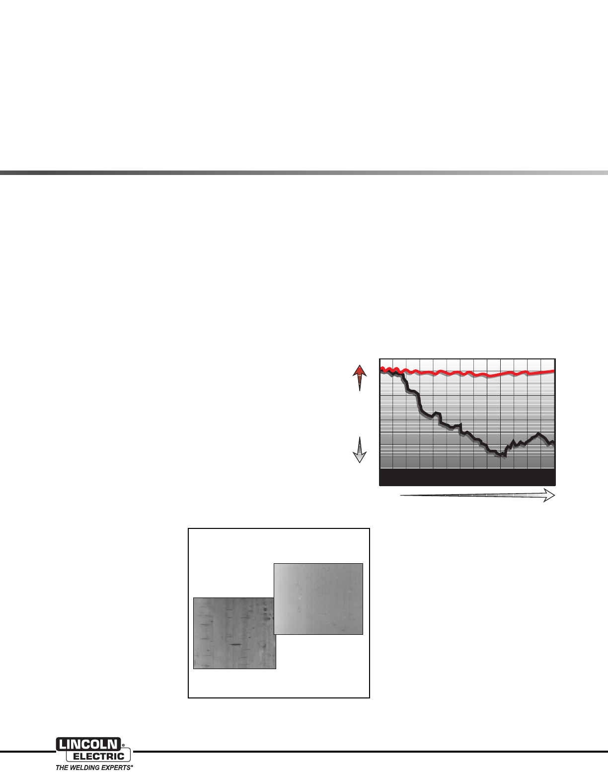
Welding Performance
Most aluminum MIG welding problems are caused by poor
feeding. Since aluminum is relatively soft, it is important that the
wire surface be as smooth as
possible for best feedability.
Super Glaze®products provide
easier feeding than competitive
products because they have
fewer surface imperfections as
shown at the right.
Super Glaze®wire also feeds
with less force than typical
competitive products as the
feedability test graph shows.
What this means is better
control of the weld puddle for
the operator. t also means longer
gun liner and contact tip life as
burnbacks do not occur.
With our MIG welding process knowledge, we understand that
welding performance is one of the most important criteria used
when selecting a wire. Aluminum MIG wire tends to produce a
welding arc that is less stable than other materials because
aluminum conducts electricity better. Small changes in wire
diameter, wire feed speed, and current produce dramatic
changes in weld bead profile, arc length and can even cause
equipment downtime due to wire burnback and fusing to tip.
Our continuous evaluation of finished product ensures
consistency in manufacturing. You can count on Lincoln®
aluminum MIG wire for superior arc stability, weld appearance,
integrity and productivity.
The SuperGlaze Advantage
5356 Wire Surfaces Magnified 60x
Typical Competitive
Product
SuperGlaze
“Best in Class”
Excellent
Time
Poor
Wire Jams and Stops Feeding
Feedability
Lincoln
SuperGlaze™
Product
Typical
Competitive
Product
Typical
Competitive
Product

4
www.lincolnelectric.com
Aluminum
Contents Page
Effects of Alloying Elements . . . . . . . . . . . . . . . . . . . . . . . . . . . . . . . . . . . . . . . . . . . . . . . . . . . . . . . . . . . . . . . . . 5-9
Introduction . . . . . . . . . . . . . . . . . . . . . . . . . . . . . . . . . . . . . . . . . . . . . . . . . . . . . . . . . . . . . . . . . . . . . . . . . . . 5
Welding Aluminum vs. Welding Steel . . . . . . . . . . . . . . . . . . . . . . . . . . . . . . . . . . . . . . . . . . . . . . . . . . . . . . . 5
Metallurgy . . . . . . . . . . . . . . . . . . . . . . . . . . . . . . . . . . . . . . . . . . . . . . . . . . . . . . . . . . . . . . . . . . . . . . . . . . 5-7
Aluminum Alloys . . . . . . . . . . . . . . . . . . . . . . . . . . . . . . . . . . . . . . . . . . . . . . . . . . . . . . . . . . . . . . . . . . . 6
Wrought Alloys . . . . . . . . . . . . . . . . . . . . . . . . . . . . . . . . . . . . . . . . . . . . . . . . . . . . . . . . . . . . . . . 6
Cast Alloys . . . . . . . . . . . . . . . . . . . . . . . . . . . . . . . . . . . . . . . . . . . . . . . . . . . . . . . . . . . . . . . . . . . 6
Alloying Elements . . . . . . . . . . . . . . . . . . . . . . . . . . . . . . . . . . . . . . . . . . . . . . . . . . . . . . . . . . . . . . . . . . . . . 6-7
Temper Designations . . . . . . . . . . . . . . . . . . . . . . . . . . . . . . . . . . . . . . . . . . . . . . . . . . . . . . . . . . . . . . . . . . 7-8
Effects of Welding on Aluminum Alloys . . . . . . . . . . . . . . . . . . . . . . . . . . . . . . . . . . . . . . . . . . . . . . . . . . . . . . . . . . 9
Nonheat-treatable Alloys . . . . . . . . . . . . . . . . . . . . . . . . . . . . . . . . . . . . . . . . . . . . . . . . . . . . . . . . . . . . . . . . . 9
Heat-treatable Alloys . . . . . . . . . . . . . . . . . . . . . . . . . . . . . . . . . . . . . . . . . . . . . . . . . . . . . . . . . . . . . . . . . . . . 9
Filler Metal Selection . . . . . . . . . . . . . . . . . . . . . . . . . . . . . . . . . . . . . . . . . . . . . . . . . . . . . . . . . . . . . . . . . . . . . 10-12
Aluminum Filler Alloys . . . . . . . . . . . . . . . . . . . . . . . . . . . . . . . . . . . . . . . . . . . . . . . . . . . . . . . . . . . . . . . 10-11
Aluminum Filler Metal Guide . . . . . . . . . . . . . . . . . . . . . . . . . . . . . . . . . . . . . . . . . . . . . . . . . . . . . . . . . . . . . 12
Welding Preparation . . . . . . . . . . . . . . . . . . . . . . . . . . . . . . . . . . . . . . . . . . . . . . . . . . . . . . . . . . . . . . . . . . . . . 13-14
Storage and Handling of Aluminum Prior to Welding . . . . . . . . . . . . . . . . . . . . . . . . . . . . . . . . . . . . . . . . . 13
Forming the Weld Preparation . . . . . . . . . . . . . . . . . . . . . . . . . . . . . . . . . . . . . . . . . . . . . . . . . . . . . . . . . . . 13
Pre-weld Cleaning . . . . . . . . . . . . . . . . . . . . . . . . . . . . . . . . . . . . . . . . . . . . . . . . . . . . . . . . . . . . . . . . . . 13-14
GMAW of Aluminum Alloys . . . . . . . . . . . . . . . . . . . . . . . . . . . . . . . . . . . . . . . . . . . . . . . . . . . . . . . . . . . . . . . . 15-18
Properties of Aluminum . . . . . . . . . . . . . . . . . . . . . . . . . . . . . . . . . . . . . . . . . . . . . . . . . . . . . . . . . . . . . . . . . 15
Modes of Metal Transfer . . . . . . . . . . . . . . . . . . . . . . . . . . . . . . . . . . . . . . . . . . . . . . . . . . . . . . . . . . . . . . . . 15
GMAW Power Supplies . . . . . . . . . . . . . . . . . . . . . . . . . . . . . . . . . . . . . . . . . . . . . . . . . . . . . . . . . . . . . . 15-16
GMAW-P Power Supplies . . . . . . . . . . . . . . . . . . . . . . . . . . . . . . . . . . . . . . . . . . . . . . . . . . . . . . . . . . . . . . . 16
Wire Drives and Controls . . . . . . . . . . . . . . . . . . . . . . . . . . . . . . . . . . . . . . . . . . . . . . . . . . . . . . . . . . . . . 16-17
Push and Push-Pull Type Feeders . . . . . . . . . . . . . . . . . . . . . . . . . . . . . . . . . . . . . . . . . . . . . . . . . 16-17
Push-Pull GMAW Torches and Spool Guns . . . . . . . . . . . . . . . . . . . . . . . . . . . . . . . . . . . . . . . . . . . . 17
Aluminum Feeding Enhancement . . . . . . . . . . . . . . . . . . . . . . . . . . . . . . . . . . . . . . . . . . . . . . . . . . . . . . . . . 17
Shielding Gas . . . . . . . . . . . . . . . . . . . . . . . . . . . . . . . . . . . . . . . . . . . . . . . . . . . . . . . . . . . . . . . . . . . . . . . . . 18
Welding Techniques . . . . . . . . . . . . . . . . . . . . . . . . . . . . . . . . . . . . . . . . . . . . . . . . . . . . . . . . . . . . . . . . . . . 18
Welding Defects — Causes and Cures . . . . . . . . . . . . . . . . . . . . . . . . . . . . . . . . . . . . . . . . . . . . . . . . . . 19-20
Solving Problems in Qualifying Weld Procedures . . . . . . . . . . . . . . . . . . . . . . . . . . . . . . . . . . . . . . . . . . . . 21
Meeting Tensile Test Requirements . . . . . . . . . . . . . . . . . . . . . . . . . . . . . . . . . . . . . . . . . . . . . . . . 21-22
Meeting Bend Test Requirements . . . . . . . . . . . . . . . . . . . . . . . . . . . . . . . . . . . . . . . . . . . . . . . . . 21-22
General Welding Guidelines . . . . . . . . . . . . . . . . . . . . . . . . . . . . . . . . . . . . . . . . . . . . . . . . . . . . . . . . . . . . . . . 23-26
Typical Melting Rates . . . . . . . . . . . . . . . . . . . . . . . . . . . . . . . . . . . . . . . . . . . . . . . . . . . . . . . . . . . . . . . . . . 23
Current vs. Wire Feed Speed . . . . . . . . . . . . . . . . . . . . . . . . . . . . . . . . . . . . . . . . . . . . . . . . . . . . . . . . . . . . 23
Welding Joint Design for Groove Welding . . . . . . . . . . . . . . . . . . . . . . . . . . . . . . . . . . . . . . . . . . . . . . . 24-25
Welding Guidelines for Fillet and Lap Welding . . . . . . . . . . . . . . . . . . . . . . . . . . . . . . . . . . . . . . . . . . . . . . . 26
Safety Practices . . . . . . . . . . . . . . . . . . . . . . . . . . . . . . . . . . . . . . . . . . . . . . . . . . . . . . . . . . . . . . . . . . . . . . . . 27-30

5
Aluminum
www.lincolnelectric.com
Effects of Alloying Elements
Introduction
The use of aluminum as a structural material is fairly recent. In
fact, when the Washington Monument was completed in
December, 1884, it was capped with a 100-ounce pyramid of
pure aluminum, because aluminum was considered to be a
precious metal at that time. The problem that impeded the use
of aluminum is that it is a reactive metal. It is never found in its
elemental state in nature, but is always tightly bound with
oxygen as aluminum oxide, Al2O3. Although aluminum oxide,
found as bauxite ore, is plentiful, no direct reduction method,
such as they used to make steel, has ever been found to produce
aluminum from bauxite.
It was only after the American Charles M. Hall and the
Frenchman Paul Heroult almost simultaneously, but indepen-
dently, discovered electrolytic processes for obtaining pure
aluminum from aluminum oxide (in 1886) that aluminum became
available in commercial quantities. These processes, with some
modifications, are still used today. In large part, it is the extremely
large amount of electrical power required to produce aluminum
that accounts for its higher cost relative to steel.
Since that time, aluminum has found wide use in numerous
applications:
• It conducts electricity and heat almost as well as copper.
• It is widely used in electrical bus bars and other conductors,
heat exchangers of all kinds, and cookware.
• It does not become brittle with decreasing temperature, but
does become stronger, so it has found wide application in
cryogenic equipment at temperatures as low as –452°F
(-269°C).
• It is very corrosion resistant in most environments, so it has
found wide applications in marine and chemical environments.
The characteristics of aluminum alloys which make them
attractive as structural materials are their light weight (one third
the weight of steel for equal volumes) and their relatively high
strength (equal in many cases to that of construction steel
grades). This combination has resulted in increased use of
aluminum alloys in applications such as passenger automobiles,
trucks, over-the-road trailers, and railroad cars. Additionally, the
structure of most aircraft is fabricated mainly from aluminum
alloys, although in these applications, pieces are most often
joined by riveting.
Welding Aluminum vs. Welding Steel
Most welders start out by learning how to weld steel. Some later
move over to welding aluminum. Most welding equipment is
designed to weld steel, with welding of aluminum alloys often
being an afterthought, although this is changing. Very often we
approach welding of aluminum as if it was just shiny steel.
However, there are differences between steel and aluminum that
usually make this approach doomed to failure.
The balance of this guide will discuss these differences and how
to overcome them. They can all be summed up in three
statements:
I. If you take enough care almost all steels are weldable.
There are some aluminum alloys that just are not arc weldable.
Fabricators fall into this trap regularly. We’ll discuss the
weldability of the various alloy families in detail. At this point, let’s
just say that many aluminum alloys, and especially the stronger
ones, are not weldable.
2. All steels are heat-treatable. Some aluminum alloys are
heat-treatable, but some are not.
Even for the heat-treatable aluminum alloys, the heat treatments
are totally different from those used for steel. In fact, if you heat
up some alloys and quench them, they will become softer, not
harder. Be aware of the differences and act accordingly.
3. When welding steels, you can almost always make a weld
that is as strong as the parent material. In aluminum alloys,
the weld will rarely be as strong as the parent material.
This is usually true for welds in both heat treatable and nonheat-
treatable alloys. The strength difference between the weld or
heat affected zone (HAZ) and the parent material is often
significant, often 30% or more.
Metallurgy
To understand aluminum, we must first understand some basics
about aluminum metallurgy. Aluminum can be alloyed with a
number of different elements, both primary and secondary, to
provide improved strength, corrosion resistance, and general
weldability.
The primary elements that alloy with aluminum are copper, silicon,
manganese, magnesium and zinc. It is important to note that
aluminum alloys fall into two classes: heat-treatable or
nonheat-treatable.
Heat-treatable alloys are those that are heat-treated to increase
their mechanical properties. To heat treat an alloy means heating
it at a high temperature, putting the alloying elements into solid
solution and then cooling it at a rate which will produce a super
saturated solution. The next step in the process is to maintain it
at a lower temperature long enough to allow a controlled
amount of precipitation of the alloying elements.
With the nonheat-treatable alloys it is possible to increase
strength only through cold working or strain hardening. To do
this, a mechanical deformation must occur in the metal
structure, resulting in increased resistance to strain, producing
higher strength and lower ductility.
6
www.lincolnelectric.com
Aluminum
Alloying Elements
Pure Aluminum (1XXX series) Contains no alloying elements,
and is not heat-treatable. It is used primarily in chemical tanks
and pipe because of its superior corrosion resistance. This series
is also used in electrical bus conductors because of its excellent
electrical conductivity. It is welded easily with 1100 and 4043 filler
wires.
Copper (2XXX series) Provides high strength to aluminum. This
series is heat-treatable and mainly used in aircraft parts, rivets
and screw products. Most 2XXX series alloys are considered
poor for arc welding because of their sensitivity to hot cracking.
Most of these alloys should not be welded, however, alloys
2014, 2219 and 2519 are easily welded with 4043 or 2319 filler
wire. These three alloys are widely used in welded fabrication.
Manganese (3XXX series) Yields a nonheat-treatable series
used for general-purpose fabrication and build-up. Moderate in
strength, the 3XXX series is used for forming applications
including utility and van trailer sheet. It is improved through strain
hardening to provide good ductility and improved corrosion
properties. Typically welded with 4043 or 5356 filler wire, the
3XXX series is excellent for welding and not prone to hot cracking.
Its moderate strengths prevent this series from being used in
structural applications.
Silicon (4XXX series) Silicon reduces the melting point of the
aluminum and improves fluidity. Its principle use is as filler metal.
The 4XXX series has good weldability and is considered a
nonheat-treatable alloy. Alloy 4047 is often used in the
automotive industry as it is very fluid and good for brazing and
welding.
Magnesium (5XXX series) When added to aluminum,
magnesium has excellent weldability, good structural strength
and is not prone to hot cracking. In fact, the 5XXX series has the
highest strength of the nonheat-treatable aluminum alloys. It is
used for chemical storage tanks and pressure vessels as well as
structural applications, railway cars, dump trucks and bridges
because of its corrosion resistance.
Aluminum Alloys
Much in the same manner that the American Iron and Steel
Institute (AISI) registers steel chemistries and grades, the
Aluminum Association (AA) registers alloy designations,
chemistries, and mechanical properties for aluminum alloys.
However, the alloy designation system is totally different than
that used for steels. Additionally, different designation systems
are used for wwrroouugghhttand ccaassttalloys.
Wrought Alloys
Wrought alloy designations use a four digit number, plus a
temper designation, discussed later. Aluminum alloys are
broken up into eight "families" depending on the main alloying
elements. The aluminum alloy families are shown in Table 1,
along with their heat treatability.
For example, if you have a piece of 6061, it’s clear that it is a
wrought alloy (4 digits), it’s heat treatable, and it contains
magnesium and silicon. The second digit of the four shows
whether the alloy is the first such alloy registered, in which case
the second digit will be "0", as in 5054. Digits other than "0"
indicate that the alloy is a modification of a registered alloy. 5154
would be the first modification of 5054. Alloy 5754 is the
seventh modification. The last two digits are assigned arbitrarily
by the Aluminum Association when the alloy is registered. Note
there is no indication of alloy or weld strength given by the
material designation.
Alloy Heat
Family Main Alloying Elements Treatable
1XXX Pure Aluminum No
2XXX Copper (sometimes with magnesium) Yes
3XXX Manganese (sometimes with magnesium) No
4XXX Silicon No
5XXX Magnesium No
6XXX Magnesium plus silicon Yes
7XXX Zinc (sometimes with magnesium and copper) Yes
8XXX All others Normally
Yes
NOTE: The designation 2XXX, etc. is an industry standard abbreviation
used to mean “all the alloys in the 2000 series”.
Table 1: Wrought Alloy Destinations
Alloy Heat
Family Main Alloying Elements Treatable
1XX.X Pure Aluminum No
2XX.X Copper Yes
3XX.X Silicon plus magnesium Yes
4XX.X Silicon Yes
5XX.X Magnesium No
6XX.X Not Used NA
7XX.X Zinc Yes
8XX.X Tin No
9XX.X Other
Table 2 — Cast Alloy Destinations
Cast Alloys
The designation system for cast alloys are classified into families
as shown in Table 2. The specific families are somewhat
different from the designations for wrought alloys and the
designations have only three digits followed by a decimal point
and one more digit. For these alloys, the first digit shows the
alloy family. The next two digits are arbitrarily assigned. Alloy
modifications are shown by a letter prefix, so 356 is the original
version of an alloy and A356 is the first modification, B356 is the
second modification, etc. The number following the decimal
point designates whether the alloy is produced as a casting of
final form or is produced as an ingot for re-melting.
7
Aluminum
www.lincolnelectric.com
Silicon and Magnesium (6XXX series) This medium strength,
heat-treatable series, is primarily used in automotive, pipe,
railings, and structural extrusion applications. The 6XXX series is
prone to hot cracking, but this problem can be overcome by the
correct choice of joint and filler metal. Can be welded with either
5XXX or 4XXX series without cracking — adequate dilution of the
base alloys with selected filler wire is essential. A 4043 filler wire
is the most common for use with this series. 6XXX alloys should
never be welded autogenously, they will crack.
Zinc (7XXX series) Zinc added to aluminum with magnesium
and copper produces the highest strength heat-treatable
aluminum alloy. It is primarily used in the aircraft industry. The
weldability of the 7XXX series is compromised in higher copper
grades, as many of these grades are crack sensitive (due to
wide melting ranges and low solidus melting temperatures).
Grades 7005 and 7039 are weldable with 5XXX filler wires. They
are widely used for bicycle frames and other extruded
applications.
Other (8XXX series) Other elements that are alloyed with alu-
minum (i.e. lithium) all fall under this series. Most of these alloys
are not commonly welded, though they offer very good rigidity
and are principally used in the aerospace industry. Filler wire
selection for these heat-treatable alloys include the 4XXX series.
In addition to the primary aluminum alloying elements, there are
a number of secondary elements, which include chromium, iron,
zirconium, vanadium, bismuth, nickel and titanium. These ele-
ments combine with aluminum to provide improved corrosion
resistance, increased strength and better heat treatability.
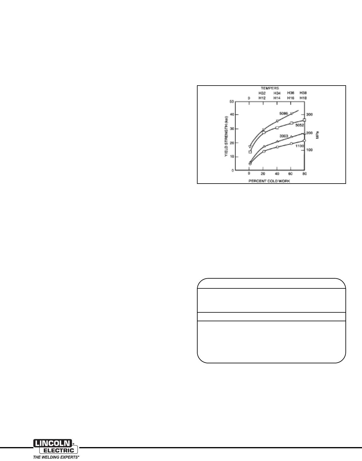
Figure 1: Relationship of Yield Strength, Amount of Cold
Work and Alloy Content
Temper Designations
The information above allows an aluminum alloy to be recognized
by its chemistry, but not by the heat treatment or mechanical
properties. To show these properties, temper designations are
assigned. The complete designation of an alloy might be 6061-T6
or 5083–H114. Most of these designations are different for heat-
treatable and nonheat-treatable alloys; however, two common
designations apply to all alloys:
• "O" Temper (not zero). When an alloy is given this designation,
the supplier has annealed the alloy, typically at 650-750°F
(343-300°C), and it is as soft as possible.
• "F" Temper. When an alloy is supplied in this temper it is
supplied "as fabricated". This means the supplier is guaran-
teeing that the chemistry of the material meets the chemical
requirements for the specified alloy, but there are no claims
regarding the mechanical properties of the alloy. This temper
is often specified by fabricators who subsequently forge or
form the supplied material and establish mechanical
properties by heat treatment after forming.
To discuss the remainder of the temper designations, we need
to discuss the heat-treatable and nonheat-treatable alloys.
Nonheat-Treatable Alloys — Strain-Hardened Designations
These alloys cannot be strengthened by heat treatment.
However, they can be strengthened by ccoolldd wwoorrkkiinngg,,also called
ssttrraaiinn hhaarrddeenniinngg. If an aluminum alloy is deformed at elevated
temperatures, [600°F (315°C) or higher], little or no strengthening
takes place. However, if the alloy is deformed at lower
temperatures, it will gain strength. In general:
• The more the alloy is deformed, the stronger it gets. Finally, at
some point, the alloy will have no ductility and will fracture.
• The higher the alloy content, the more it will gain strength by
being deformed.
Both of these phenomena are shown in Figure 1.
The temper designation for strain hardened alloys is usually
made up of two digits as shown in Table 3.
The first digit shows whether the alloy is only strained or whether
it has been partially annealed and/or stabilized. The second digit
shows how much strain hardening has been put into the alloy.
Higher numerical values mean higher strain levels, which means
higher yield and tensile strengths.
First Digit Indicates Basic Operations
H1 — Strain Hardened Only
H2 — Strain Hardened and Partially Annealed
H3 — Strain Hardened and Stabilized
Second Digit Indicates Degree of Strain Hardening
HX2 — Quarter Hard
HX4 — Half Hard
HX6 — Three-Quarters Hard
HX8 — Full Hard
HX9 — Extra Hard
Table 3: “H” Temper Designations
Heat Treatable Alloys
Strain hardened “H” tempers are not used for heat-treatable
alloys. Instead a series of “T” tempers indicating the heat
treatment state are used. A total of (10) tempers exist; “T1”
through “T10”. The commonly seen designations are “T4”
and “T6”. All 10 designations are listed in Table 4 on the
following page.
T1 Cooled from an elevated temperature shaping process
and naturally aged to a substantially stable condition.
Applies to products that are not cold worked after cooling
from an elevated temperature shaping process, or in which
the effect of cold work in flattening or straightening may not
be recognized in mechanical property limits.
T2 Cooled from an elevated temperature shaping process,
cold worked and naturally aged to a substantially stable
condition. Applies to products that are cold worked to
improve strength after cooling from an elevated temperature
shaping process, or in which the effect of cold work in flatten-
ing or straightening is recognized in mechanical property limits.
T3 Solution heat-treated(1),cold worked and naturally aged
to a substantially stable condition. Applies to products that
are not cold worked to improve strength after solution heat
treatment, or in which the effect of cold work in flattening or
straightening is recognized in mechanical property limit.
T4 Solution heat-treated(1) and naturally aged to a
substantially stable condition. Applies to products that are
cold worked after solution heat-treatment, or in which the
effect of cold work in flattening or straightening may not be
recognized in mechanical property limits.
T5 Cooled from an elevated temperature shaping process
and then artificially aged. Applies to products that are not
cold worked after cooling from an elevated temperature
shaping process, or in which the effect of cold work in
flattening or straightening may not be recognized in mechanical
property limits.
T6 Solution heat-treated(1) and then artificially aged. Applies
to products that are not cold worked after solution heat-
treatment, or in which the effect of cold work in flattening or
straightening may not be recognized in mechanical property
limits.
8
www.lincolnelectric.com
Aluminum
Aluminum alloys are heat treatable because of a phenomenon
called precipitation hardening. They do not harden by a
martensitic transformation as steel does. In precipitation
hardening, one metal can be dissolved in another in a "solid
solution" and solubility generally increases with temperature. For
example, just as sugar will dissolve in a glass of iced tea when
heated — copper, zinc or combinations of magnesium and
silicon will dissolve in aluminum as it is heated.
When the heat-treatable alloys are heated to approximately
950°F (510°C), and held for a few minutes, all the alloying
elements are taken into a solution in the solid aluminum. This is
termed a "solution heat treatment". Normally, the alloy is
quenched in water from this point to arrive at the T4 temper.
Although the T4 temper is substantially stronger than the
annealed “O” temper, the primary purpose of quenching is not
strengthening. Instead, the quenching serves to keep the alloy
additions in solution at room temperature — if the aluminum
were cooled slowly from the solution treatment, the alloying
additions would re–precipitate and no strengthening would
occur.
Table 4 — T1 through T10 Temper Designations
T7 Solution heat-treated(1) and overaged/stabilized. Applies
to wrought products that are artificially aged after solution heat
treatment to carry them beyond a point of maximum strength to
provide control of some significant characteristic(2). Applies to
cast products that are artificially aged after solution heat
treatment, to provide dimensional and strength stability.
T8 Solution heat-treated(1), cold worked, and then artificially
aged. Applies to products that are cold worked to improve
strength, or in which the effect of cold work in flattening or
straightening is recognized in mechanical property limits.
T9 Solution heat-treated(1), artificially aged, and then cold
worked. Applies to products that are cold worked to
improve strength.
T10 Cooled from an elevated temperature shaping process,
cold worked, and then artificially aged. Applies to
products that are cold worked to improve strength, or in
which the effect of cold work in flattening or straightening is
recognized in mechanical property limits.
(1) Solution heat treatment is achieved by heating cast or wrought products
to a suitable temperature, holding at that temperature long enough to
allow constituents to enter into solid solution and cooling rapidly enough
to hold the constituents in solution. Some 6XXX series alloys attain the
same specified mechanical properties whether furnace solution heat
treated or cooled from an elevated temperature shaping process at a rate
rapid enough to hold constituents in solution. In such cases, the temper
designations T3, T4, T6, T7, T8 and T9 are used to apply to either
process and are appropriate designations.
(2) For this purpose,
characteristic
is something other than mechanical
properties. The test method and limit used to evaluate material for this
characteristic are specified at the time of the temper registration.
The tensile and yield strengths of the material will increase for
several weeks after the heat treatment and, in some alloys, can
increase significantly. However, once past this initial period, the
alloy is stable indefinitely. The user normally is unaware of this
initial strength increase because the aluminum producer doesn’t
ship the alloy until the strength has stabilized.
The T4 temper, while stable, does not give maximum strength to
the alloy. Most alloys are sold in a maximum strength T6 temper.
To get from T4 to T6 temper, the material is put in a furnace at a
temperature of 325°F to 400°F (163°C to 204°C) and allowed to
age 1 to 5 hours. The dissolved alloying elements will form
submicroscopic pre-precipitates in the material and produce
maximum strength. If this aging heat treatment is carried out at
too high a temperature or for too long, the precipitates will get
too large and a lower strength "overaged" condition will result.
Note: This final aging heat treatment is carried out at 400°F (204°C)
maximum. The welding heat, which can heat the surrounding material to
well over this temperature, can significantly degrade the strength of the
weld heat affected zone (HAZ), which is discussed in more detail on the
following page.
9
Aluminum
www.lincolnelectric.com
As before, it is easiest to discuss the effects of welding on the
mechanical properties of aluminum weldments if we discuss
nonheat-treatable alloys and heat-treatable alloys separately.
Nonheat-Treatable Alloys
As was discussed earlier, these alloys can be, and often are,
strengthened by cold working. Cold worked alloys can have
yield and tensile strengths twice those of the annealed "O"
temper alloy. These cold worked alloys can be softened back to
the "O" temper by annealing at 650-700°F (343-371°C). Since
the heat of welding produces temperatures considerably higher
than this at the weld fusion line, the result of welding is that the
heat affected zone (HAZ) of welds in nonheat-treatable alloys (ie,
1XXX, 3XXX, 4XXX, and 5XXX alloys) becomes annealed.
Therefore, the strength of the weld joint is always equal to the
strength of the "O" temper annealed base material, regardless of
what the starting temper of the parent material was. If you weld
"O" temper material, the weld will be as strong as the starting
parent material. If you weld any material that is strain hardened
(ie, cold worked), the weld will be weaker than the starting
material, perhaps significantly weaker.
The HAZ can never become softer then the "O" temper, so that
excess welding heat input will not make the HAZ softer. It can,
however, make the HAZ wider. Normally, this will not further
reduce the strength of the welded joint, although other problems
can arise due to excessive heat input.
From a practical standpoint, there is no way to regain the
strength lost during welding. If the weld is cold worked, it will
begin to work harden again. However, this is not usually a
practical industrial solution, because, in most cases, the weld
will not be as strong as the starting cold worked material.
Heat-Treatable Alloys
There is no blanket statement that can be made about the
welded strength of heat-treatable alloys. As previously stated,
the weld will generally be weaker than the parent material.
However, the welded properties will strongly depend on the
temper of the material before welding and also on heat
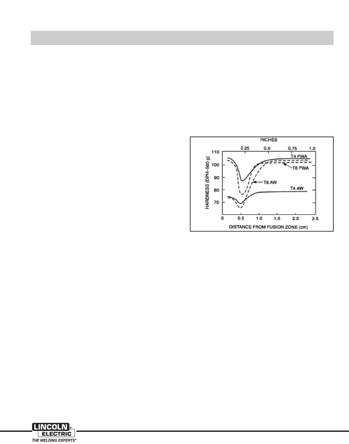
treatments performed after welding. Figure 2 shows a
micro-hardness trace across a weld, starting at the center of the
weld. The graph actually shows four curves representing what
happens to material in the T4 and T6 tempers in the as-welded
(AW) and postweld heat-treated (PWA) conditions. The following
can be noted:
1) The HAZ is about 1/2” (12.7 mm) wide. The actual width of
the HAZ will depend on a number of things, including the
welding process used and the thickness of the material.
HAZ widths of 1” (25.4 mm) are not uncommon in thin materials.
2) The hardness and strength of the weldment is typically lowest
in the HAZ. Because of this, strength of the welding filler alloy is
not a primary concern when making butt welds. A weld will most
often fail in the HAZ.
3) Unlike nonheat-treatable alloys, the hardness (and therefore
strength) in the HAZ is not always the same. It depends on the
material temper prior to welding and whether the weld is
post-weld aged.
a) The weakest HAZ occurs when the material is welded in the
T6 temper and used as–welded.
b) The HAZ, and therefore the weldment, will actually be slightly
stronger if the material is used in the T4 temper and used
as–welded.
c) If the weldment in either T4 or T6 material is post-weld aged,
the strength of the HAZ can increase significantly. The exact
postweld heat treatment varies with the alloy, but is usually an
aging at around 400°F (204°C) for about one hour.
The fabricator has some options that he doesn’t have when
fabricating the nonheat-treatable alloys in terms of recovering
some of the strength lost during welding. For instance, since the
6XXX alloys also bend easier and around a smaller radius in the
T4 temper than in the T6 temper, these alloys can be bought in
the T4 temper, formed easily, welded, and then aged. The
resulting mechanical properties will be significantly higher than if
the material was purchased in the T6 temper.
Finally, if the right filler alloy is chosen, the finished weldment can
be completely heat-treated and the T6 properties restored. This
requires a re-solution heat treatment, quench, and re-aging. This
is often practical for small structures, but not for large ones. For
example, aluminum bicycle frames are often fabricated in this
way.
The HAZ of welds in heat-treatable alloys is significantly different
than those in nonheat-treatable alloys. The strength of the HAZ
in heat-treatable alloys can be made considerably wider and
weaker if excessive heat input is used. Therefore, it is very
important not to use excessive preheats [200°F (93°C)
maximum is recommended], to carefully monitor interpass
temperatures [250°F (121°C) maximum is recommended], and
to avoid practices such as wide weave passes which will result
in excessive heat input.
Figure 2: Hardness vs. Distance for 6061-T4 and -T6 in the
as-welded and post-weld aged conditions.
Effects of Welding on Mechanical Properties of Aluminum Alloys
AWS A5.10-99
ASME SFA-5.10
Classification
%Mn %Si %Fe %Mg %Cr %Cu %Ti %Zn %Be %Others(1) %Al
ER1100 & 0.05 — —— — 0.05-0.20 — 0.10 0.05 99.0
Alloy 1050
ER2319 0.20-0.40 0.20 0.30 0.02 — 5.8-6.8 0.10-0.20 0.10 (2) 0.05(3) Balance
ER4043 0.05 4.5-6.0 0.8 0.05 — 0.30 0.20 0.10 (2) 0.05 Balance
ER4047 0.15 11.0-13.0 0.8 0.10 — 0.30 — 0.20 (2) 0.05 Balance
Alloy 5052 0.10 0.25 0.40 2.2-2.8 0.15-0.35 0.10 — 0.10 (2) 0.05 Balance
Alloy 5056 0.05-0.20 0.30 0.40 4.5-5.6 0.05-0.20 0.10 — 0.10 (2) 0.05 Balance
Alloy 5154 0.10 0.25 0.40 3.1-3.9 0.15-0.35 0.10 0.20 0.20 (2) 0.05 Balance
ER5183 0.50-1.0 0.40 0.40 4.3-5.2 0.05-0.25 0.10 0.15 0.25 (2) 0.05 Balance
ER5356 0.05-0.20 0.25 0.40 4.5-5.5 0.05-0.20 0.10 0.06-0.20 0.10 (2) 0.05 Balance
ER5554 0.50-1.0 0.25 0.40 2.4-3.0 0.05-0.20 0.10 0.05-0.20 0.25 (2) 0.05 Balance
ER5556 0.50-1.0 0.25 0.40 4.7-5.5 0.05-0.20 0.10 0.05-0.20 0.25 (2) 0.05 Balance
ER5654 0.01 — — 3.1-3.9 0.15-0.35 0.05 0.05-0.15 0.20 (2) 0.05 Balance
10
www.lincolnelectric.com
Aluminum
Filler Metal Selection
Aluminum Filler Alloys
Most common aluminum filler alloys fall into the 4XXX and 5XXX
families, with a few coming from the 1XXX, 2XXX, and the
casting alloys. The chemical composition of the common
aluminum filler alloys is shown in Table 5, below.
There are a number of characteristics which determine the best
filler metal choice for a given base material, or combination of
base materials. Among these are:
• Freedom from hot cracking.
• Weld metal ductility.
• Weld metal corrosion resistance.
• Weld metal shear strength in fillet and lap joints.
• Ease of welding (i.e., weldability).
• Filler wire feedability.
• Weld color match with parent metal for applications requiring
postweld anodizing.
There are a number of filler metal selection charts which have
taken these factors into account and give good overall
recommendations for filler metal selection. A composite of these
charts covering most alloy combinations are shown in Table 7
on page 12.
In general, filler alloy recommendations for the various alloy
families can be summarized as follows:
1XXX alloys — These alloys are usually used for their electrical
conductivity and/or corrosion resistance. Their sensitivity to hot
cracking is very low. They are usually welded using 1100 or
1188 fillers, but matching filler metals are also available for
specialized alloys such as 1350. If electrical conductivity of the
joint is not of primary importance, 4043 may be used.
2XXX alloys — Many alloys in this series are not arc weldable.
Those that are include 2219, 2014, 2519, 2008, and 2036. Alloy
2319 is a matching filler alloy for 2219 and 2519 and can also
be used on the other weldable alloys. Alloys 4043 and 4145,
which contain copper, can also be used. Alloy 5XXX fillers
should not be used to weld 2XXX parent materials, because
cracking will result.
3XXX alloys — These moderate strength aluminum–manganese
alloys are relatively crack resistant and can be welded easily
using either 4043 or 5356.
4XXX alloys — These alloys are usually found as welding or
brazing fillers. In the rare event they are encountered as parent
materials, 4047 is usually the best choice as a filler metal.
Table 5
(1) Total of “others” shall not exceed 0.15%.
(2) Beryllium shall not exceed 0.0003%.
(3) Vanadium content shall be 0.05 - 0.15% and Zirconium content shall be 0.10 - 0.25%.
NOTE: Single values are maximum, except aluminum.
WIRE CHEMICAL COMPOSITION FOR COMMON ALUMINUM WIRES
Aluminum
AWS Lincoln
Classification Product Name
ER1100 Super Glaze®1100
ER4043 Super Glaze 4043
ER4047 Super Glaze 4047
ER5183 Super Glaze 5183
ER5356 Super Glaze 5356
ER5554 Super Glaze 5554
ER5556 Super Glaze 5556
11
Aluminum
www.lincolnelectric.com
Super Glaze®Aluminum GMAW Wire
5XXX alloys — These higher strength aluminum–magnesium
alloys are the most common structural aluminum sheet and
plate alloys. The general rule, except for the alloy 5052, is to
choose a 5XXX filler metal with slightly higher magnesium
content than the parent material being welded. For all alloys
except 5052, 5XXX alloys should not be welded using 4XXX filler
alloys. The high Mg content of the parent material, when
combined with the high Si content of the 4XXX fillers, will result
in a high level of Mg2Si — a brittle intermetallic compound which
will cause the weld to have poor ductility and toughness. In
choosing filler alloys for 5XXX alloys, there are several specific
recommendations as follows:
5052 — This alloy has just the right amount of Mg content to
exhibit a relatively high crack sensitivity. If it is welded with
5052 filler alloy, it will often crack. To avoid the tendency to
crack, 5052 is usually welded with a filler alloy of much higher
Mg content, such as 5356. The resulting weld metal, which is
an alloy of the 5356 and 5052, has a Mg content high
enough to be crack resistant. Additionally, the Mg content of
5052 is low enough so that it can be successfully welded
using 4043.
High temperature applications — Al-Mg alloys with Mg
content over 3% are unsuitable for service temperatures over
150°F (65°C) because they are susceptible to stress
corrosion cracking at higher temperatures. This is true for
filler alloys as well and should be taken into account in
selecting filler alloys
5454 — This alloy is a lower Mg alloy specifically developed
to be immune to the stress corrosion cracking noted above.
Filler alloy 5554 is designed as a matching filler alloy for 5454
and should be used whenever possible.
5083 and 5456 — These high Mg, high strength alloys can
be successfully welded using 5356. However, most structural
Codes require that welds in these alloys have a minimum
ultimate tensile strength of 40 ksi (276 MPa). When welded
using 5356, welds in these alloys often will not meet this
requirement. For this reason, 5183 or 5556 are recommend-
ed for these alloys.
6XXX alloys— These Al-Mg-Si alloys are primarily used for
extrusion alloys, although they can also often be found as sheet
and plate. The chemistry of these alloys makes them very sensi-
tive to hot short cracking. Autogenous welds (i.e., welds made
without adding filler metal) will almost always crack. This is why
6061 filler metal does not exist. If it did, welds made using it
would crack. Yet, these alloys are readily weldable using either
4043 or 5356 filler metal. Since the chemistry of 4043, Al with
5% Si, or 5356, Al with 5% Mg, is so different than that of 6061,
when either is mixed with 6061, the result is a weld with a crack
resistant chemistry.
The decision whether to use 4043 or 5356 depends on a
number of factors summarized in Table 6. This table compares
these two common filler metals and shows the advantages and
disadvantages of each.
As shown in Table 6, 4043 is easier for the welder to use, it
flows better, and is more crack resistant. Filler metal 5356 feeds
better and gives welds that are stronger, especially in lap welds
and fillet welds, and are more ductile. While 5356 should be
used to weld the 6XXX alloys to any of the 5XXX alloys, 4043
should be used to weld the 6XXX alloys to the common 3XX.X
casting alloys.
ER4043 ER5356
Smooth Bead, Good Wetting Black Smut, Distinct Ripples
Low Column Strength Best Feedability
Higher Penetration Lower Penetration
Lower Ductility Higher Ductility
Lower Tensile Higher Tensile
Less Prone to Porosity More Prone to Porosity
Anodizes a Dark Grey Anodizes with Good Color Match
Much Lower Shear Strength Higher Shear Strength
Lower Cracking Sensitivity Higher Cracking Sensitivity
Lower Melting Point Higher Melting Point
Narrower Melting Range Wider Melting Range
Table 6 — Comparison of Filler Metals 4043 and 5356
Note: 5356 should be used for applications that will be subsequently
anodized. 5356 will anodize to a color very similar to the parent material.
4043 will turn dark grey on anodizing. Since the 6XXX parent materials
anodize to a clear color, a 4043 weld is very visible and not desirable.
7XXX alloys – Although most of these alloys are not
arc-weldable, 7005, 7003, and 7039, display good weldability.
These alloys should be welded using 5356.
ALUMINUM PRODUCT SELECTION GUIDE
Request publication C8.05 for more information on Lincoln’s
Super Glaze®premium aluminum GMAW wires.
12
www.lincolnelectric.com
Aluminum
1060, 1100, 5086, 6005, 6061 356.0, A356.0, 357.0,
3003, 2219, 3004, 5005, 5052, 5083, 514.0, 5154, Alclad 6061, 354.0 A357.0, 359.0,
Base Metal to Base Metal Alclad 3003 A201.0 Alclad 3004 5050 5652 5456 535.0 5254 5454 6063, 6351 7005 C355.0 443.0 A444.0
356.0, A356.0, 357.0,
A357.0, 359.0, 443.0, 4043 4145 4043 4043 4043 5356 5356 4043 4043 4043 4043 4145 4043
A444.0
354.0, C355.0 4145 4145 4145 4145 4043 NR NR NR 4043 4145 4145 4145
7005 5356 4145 5356 5356 5356 5556 5356 5356 5356 5356 5356
6005, 6061, Alclad 6061, 4043 4145 5356 4043, 5356, 5356 5356 5356 5356 4043,
6063, 6351 5356 4043 5356
5454 4043 4043 5356 5356 5356 5356 5356 5356 5554
5154, 5254 4043 NR 5356 5356 5356 5356 5356 5356
5086, 514.0, 535.0 5356 NR 5356 5356 5356 5356 5356
5083, 5456 5356 NR 5356 5356 5356 5556,
5183
5052, 5653 4043 4043 4043 4043, 5356
5356
5005, 5050 4043 4145 4043 4043,
5356
3004, Alclad 3004 4043 4145 4043
2219, A201.0 4145 2319
1060, 1100, 3003, 1100
Alclad 3003
Notes:
1) The filler alloy shown is the best choice for most structural applications. Where two filler alloys are shown, either are acceptable.
2) Whenever 4043 filler alloy is shown, 4047 is an acceptable alternate.
3) Whenever 5356 filler alloy is shown, 5556 or 5183 are acceptable alternates.
4) Al-Mg alloys containing more than 3% Mg should not be used in applications where long term exposures above 150°F (65°C) are encountered.
5) There are applications where specific requirements make the selection of filler alloys other than those shown above necessary.
Table 7: Aluminum Alloy Filler Metals for Structural Welding of Various Base Aluminum Alloys

13
Aluminum
www.lincolnelectric.com
Welding Preparation
Preparation for welding includes storage and handling of
aluminum prior to welding, methods for making the weld
preparation, and methods for cleaning prior to welding. While
not strictly "welding preparation", methods for backgouging
and interpass cleaning will be included in this section.
Storage of Aluminum and Aluminum Wire
Prior to Welding
Improper storage of aluminum and aluminum wire prior to welding
makes preparation for welding much more costly at best. At
worst, it can result in welds of inadequate quality.
It is well known that all aluminum alloys form a thin oxide coating
immediately upon exposure to air. This coating is extremely thin,
approximately 100–150 Angstroms (one millionth of a centimeter)
thick. Because it is so thin, it is transparent and not visible to the
naked eye. When stored at ambient temperatures and relative
humidity levels of 70% or below, the oxide thickness increases
extremely slowly. It is safe to say that aluminum and aluminum
wires stored under these conditions will be usable for a couple
of years. Plus, the reverse polarity arc tends to strip off the
oxides. Therefore, if aluminum is stored in a dry area, oxide
removal prior to welding will be very easy or unnecessary.
However, if aluminum is subjected to temperatures above 200°F
(93°C) and/or very high humidity levels, the oxide layer thickness
can grow rapidly. Because of this, the following guidelines are
suggested:
• Aluminum plate which has ever become wet should be
scrapped. Boxes of wire where the cardboard box has
become wet on the inside should be discarded.
• Aluminum should never be stored outside.
• Wire should be stored in the original box and any plastic
interior bag it came in.
• It is helpful to store wire in a closed cabinet which is heated to
approximately 20°F (-6°C) above the ambient temperature to
reduce relative humidity. This can be done simply by mounting
an electrical fixture with a low wattage bulb inside the cabinet
and letting the bulb burn continuously.
• Wire which will not be used for 2 days or more should be
dismounted from the wire feeder, returned to its original
packaging, and stored properly.
Aluminum wire which is stored in accordance with the above
recommendations will be usable with no deterioration in
performance for at least 2 years. Wire older than this should
be discarded.
Oxides on aluminum plate can be removed by power wire
brushing, sanding, grinding, or chemical etching, however,
proper storage will prevent the formation of oxides. Aluminum
should be stored indoors in a dry environment. If stored outside,
it should be securely covered to keep it dry. Under no circum-
stances should it be stored uncovered with one plate laying flat
on top of another. This will allow water to “wick” in between the
plates from the edges. If this happens, thick hydrated oxide will
form very quickly on the plate surfaces, making it very difficult to
pry the two plates apart.
Welding Preparation
Even the hardest aluminum alloy is much softer than a high
speed steel or carbide cutting tool. While specialized tools are
available to cut aluminum, aluminum is easily cut using circular
saws, radial arm saws, etc. End preparations can be put on pipe
or tube using woodworking routers. The general rule is "if it will
cut wood, it will cut aluminum".
While aluminum can’t be cut using oxyfuel cutting equipment, it
can be easily cut using plasma cutting equipment. Thin aluminum,
less than 3/16" (4.8 mm) thick, can also be cut by high powered
lasers. However, care must be taken in plasma or laser cutting
of heat-treatable alloys. These alloys are prone to form micro-
cracks which can extend back from the cut edge as far as 1/8"
(3.2 mm). Therefore, laser or plasma cut edges in heat-treatable
alloys are usually machined to remove the edge before welding.
Methods of weld preparation are as follows:
Machining
Machining of weld preparations can be performed using a variety
of tools. Milling machines, bed planers, and shapers are
commonly used with carbide cutting tools. It is recommended
that any machining be performed dry, i.e., without any cutting
lubricants. Lubricants are either oil (hydrocarbon) or water-based.
If lubricants are used, the residue must be removed before
welding. If not removed, excessive porosity will result.
Sawing
Both band and circular saws are commonly used to make weld
preparations. Higher blade speeds and coarser teeth are
required than when cutting steel. Recommended blade surface
speeds are 8000 sfpm for circular saws and 5000 sfpm for band
saws. Band saw blades should have no more than 4 teeth per
inch. If circular saws are used, the cut quality can be good
enough so that no further preparation is necessary. Band saws
usually leave a coarse surface which must be sanded or grinded.
Grinding and Sanding
The use of grinding and/or sanding to form weld preparations
has been discouraged in the past, because organic binders in
the disc often left behind organic residues which then caused
weld porosity. However, there are a number of grinding and
sanding discs available today which are specifically formulated
for aluminum. These can give excellent results for forming weld
preparations on aluminum.
Shearing
Shearing is very useful to cut sheets or plates to size. However,
the edge quality is rarely acceptable for welding. It is relatively
rough and has a lot of crevices which can trap oils, greases, etc.
It is recommended that the edge be smoothed by machining,
grinding, or sanding after shearing.
14
www.lincolnelectric.com
Aluminum
Preweld Cleaning
Once the weld preparation is formed, it must be cleaned before
the weld joint is fit together. Cleaning consists of removing any
contaminants. These contaminants are as follows:
(1) Oils and Greases
Removal of oils and greases can be performed in one of several
ways. First, wiping with a clean rag saturated with a degreasing
solvent. This method is very effective. However, the use of many
solvents has been severely curtailed in recent times because of
environmental concerns. Second, mild alkaline solutions make
good degreasers. The part to be degreased can be sprayed
with these solutions or dipped into a tank containing them.
Since such cleaners are usually water based, it is important to
thoroughly dry the part after degreasing. Third, many suppliers
sell acid based cleaning solutions for cleaning aluminum. These
are usually effective. However, all are acidic and some contain
hydrofluoric acid, so caution in their use and disposal is
required. Again, since they contain water, the piece must be
thoroughly dried before welding.
Whichever method is used, it is important to degrease the part
to be welded before performing any of the oxide removal
procedures outlined below. Otherwise the oils and greases will
be spread by the oxide removal and will be difficult to remove.
(2) Excess Oxides
Once the oils and greases are removed, oxide removal can be
performed in several ways. The most common is to use a
stainless steel wire brush. The brush should be clean and not
previously used on materials other than aluminum. The brush
should be relatively flexible and should be used with only light
pressure in order to avoid unnecessarily roughening the surface
of the aluminum.
Oxide removal can also be performed by immersing the part in a
strong alkaline solution. However, these solutions are very
corrosive, and can etch the surface of the aluminum, therefore,
extreme care must be used.
In some industries, especially the aerospace industry, final oxide
removal is performed just before the joint is fit together by
mechanically removing the oxide using a steel scraper (identical
to those used in woodworking) or by draw filing. Once the
cleaning is performed, the joint is fit together as soon as possible.
These are very effective methods for oxide removal. However,
they are time consuming, costly, and are primarily used in
industries where the demand for extremely high quality overrides
the additional cost.
Interpass Cleaning
The surface of a weld usually has areas of oxides and weld
"smut" on it. This gray to black colored smut is composed of
aluminum oxide and magnesium oxide. Before depositing
another weld pass, it is recommended that the smut and oxides
be removed, because they can cause lack of fusion defects.
The easiest way to remove these oxides is to use a wire brush,
either manual or power driven. The wire brush should be clean
and used only on aluminum. It should be flexible and used with
light pressure.
Backgouging
When making a double-sided weld, it is necessary to remove the
metal on the back side to sound metal before depositing the
back side weld. If this isn’t done and the backside weld is made
with no preparation, lack of fusion will often result.
The usual geometry for the backgouged seam is a V preparation
with a 60° included angle and a 1/8" (3.2 mm) radius at the
base. There are a number of ways to perform this backgouging:
(1) Air Arc or Plasma Arc Gouging
Either of these processes can be used successfully. However,
they rely on the skill and steadiness of the operator to obtain a
uniform backgouge. In addition, they usually require cleaning up
with a grinding disk before welding. This is especially true of air
arc gouging, which leaves carbon deposits in the gouged
groove. If the carbon isn’t removed, porosity on the backside
weld can result.
(2) Grinding
A thin [1/8" (3.2 mm)] grinding disk on edge can be used for
backgouging. Again, the operator must be skilled in order to
produce a uniform gouge.
(3) Machining
Ideally, the best way to get a uniform backgouge is to mount the
weld in a milling machine and machine the backgouge.
Unfortunately, this usually isn’t practical. However, a number of
manufacturers supply a pneumatically powered circular saw
mounting a 4" (102 mm) diameter milling cutter. This milling
cutter is ground to have a tooth form with a 60° V with a 1/8"
(3.2 mm) tip radius. The depth of the backgouge is set by
setting the cutting depth of the saw. It is relatively easy to set up
a straightedge to guide the saw along to get a straight back-
gouge.
(4) Chipping
Although not used very often, the use of a pneumatic chipping
hammer with the appropriate chisel can be a very effective way
to backgouge. The problem with this method is the extremely
high noise level produced. It is very easy to regulate the cutting
depth to get down to sound metal because it is obvious to the
operator when sound metal is reached. The effectiveness of this
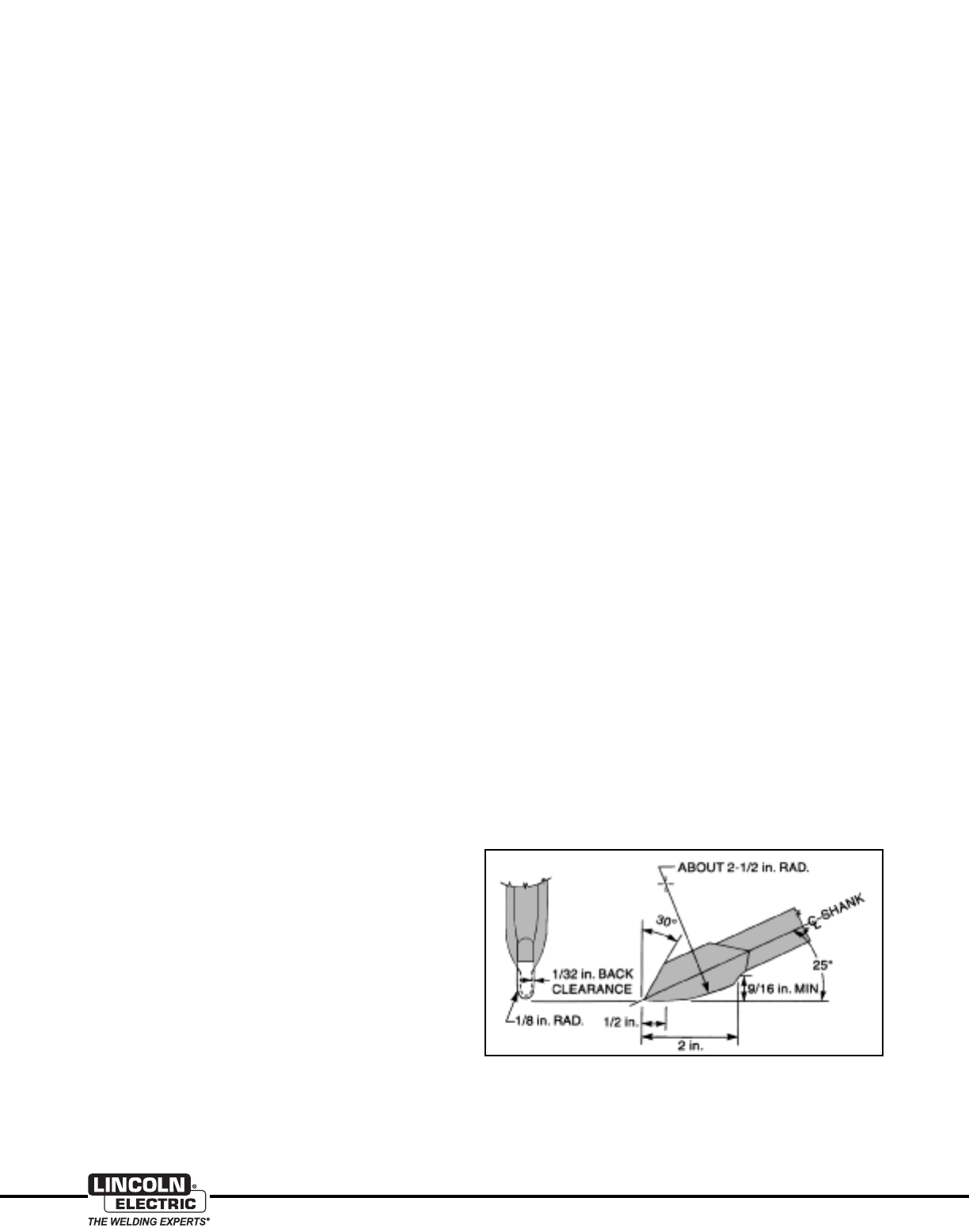
method is very dependent on the geometry of the chisel. The
correct geometry is shown in Figure 3.
Figure 3: Correct Pneumatic Chisel Geometry for
Backgouging Aluminum.

15
Aluminum
www.lincolnelectric.com
If available, GMAW-P is able to join thin and thick sections of
aluminum. For those materials that are less than or equal to
0.125" (3.2 mm), pulsed spray transfer is the preferred choice.
Pulsed spray transfer is more easily able to join materials less
than 0.125" (3.2 mm), and this is due to the fact that the
average current is lower in magnitude for GMAW-P than axial
spray transfer welding current. When compared to axial spray
transfer GMAW-P has the following advantages when used for
welding aluminum:
• Lower heat input – less distortion.
• Ability to handle poor fit-up.
• Ability to handle thinner materials.
• The lower heat input of GMAW-P reduces the size of the
heat affected zone.
• Out-of-position welding is greatly enhanced.
Power Supplies and Wire Drives
The history of the development of power sources for aluminum
GMAW welding relates to the development of constant current
(CC), or constant voltage (CV) output characteristics. Prior to the
development of CV power sources the use of CC or "drooper"
type power sources were used exclusively for welding aluminum.
Special techniques were required for arc striking and special
variable speed wire drives were developed as a solution for the
unstable arc length associated with constant current.
Constant current power sources provided excellent penetration
uniformity, and they reacted slowly to changing conditions. The
slower dynamic response to changes in arc length were desirable
for welding thicker sections of aluminum with electrode diameters
3/32" (2.4 mm) and larger. The primary disadvantage of CC
power sources is arc starting and the ability to regulate arc
length.
In the late 1950s, when selenium rectifiers were employed to
provide the CV output characteristics, many aluminum fabrica-
tors soon realized there was a problem. The output of the early
CV power sources produced wide welding current fluctuations
due to changes in arc length, and this was compounded by
changes in output due to fluctuations in input power. Because of
the higher thermal conductivity of aluminum the current changes
that occurred produced variations in weld penetration.
Properties of Aluminum
The engineering use of wrought and cast aluminum base materials
continues to increase, and it does so because of the basic
properties of this unique material. The more prominent features
of aluminum and its alloys are:
• Aluminum is lightweight. It weighs about one third that of
steel. A cubic inch of aluminum weighs 0.098 lbs./in.3com-
pared to steel, which weighs 0.283 lbs/in3.
• Aluminum has a wide range of strength properties that vary
from 13,000 tensile for pure aluminum up to 90,000 tensile for
the heat treatable aluminum alloys.
• Aluminum provides excellent corrosion resistance in many
environments. The thin refractory oxide that forms on the
surface of aluminum provides a protective barrier.
• Aluminum is an excellent conductor of heat. It is up to five
times more thermally conductive than steel.
• Aluminum is reflective of radiant heat, and the surface finish of
aluminum is frequently used to take advantage of this feature.
• Aluminum is widely available in either extruded shapes or
wrought sheet in an equally wide range of alloy compositions.
• Aluminum is widely available as a die cast base material.
For welding purposes, an important consideration for welding
aluminum is its thermal conductivity. This property has an
important facet:
• To compensate for the high rate of thermal conductivity,
aluminum requires the use of higher energy modes of metal
transfer. Axial spray and pulsed spray are the two recom-
mended GMAW modes of metal transfer for aluminum. The
use of the lower energy forms of metal transfer will usually
result in incomplete fusion defects.
Modes of Metal Transfer
What is important to note when welding aluminum base material
is that the thermal conductivity of the aluminum base material is
higher than it is for carbon steel, and because of this the lower
energy modes of metal transfer are unable to provide sufficient
melting of the base material to ensure good fusion.
Axial spray and pulsed spray metal transfers are the preferred
metal transfer modes for aluminum, each of these are capable
of providing the required energy levels for base metal melting to
assure good fusion.
Table 8 supplies the typical axial spray transfer transition
currents related to specific aluminum electrode diameters (note
that argon gas is the shielding gas associated with the transition
currents). In those cases where helium additions are made to
the argon, the required watt energy level (current x voltage) to
achieve the transition to axial spray will have to increase. Axial
spray is the higher energy transfer mode for GMAW, and
aluminum requires the use of higher energy modes of transfer to
compensate for the higher thermal conductivity. Because of
these two central facts, axial spray is generally applied to
aluminum base materials 0.125" (3.2 mm) or greater in material
thickness.
Table 8
Aluminum Electrode
Diameter Shielding Transition
(mm) Inches Gas Current
(0.8) 0.030 100% Argon 90 ± 5 Amps
(0.9) 0.035 100% Argon 110 ± 5 Amps
(1.2) 0.047 100% Argon 135 ± 5 Amps
(1.6) 0.062 100% Argon 180 ± 5 Amps
AXIAL SPRAY TRANSITION CURRENT
GMAW of Aluminum Alloys
16
www.lincolnelectric.com
Aluminum
Incomplete fusion defects often accompanied the penetration
problems. Because of this, many aluminum fabricators went
back to CC power supplies for consistent penetration. As a
result of these early difficulties, much of the available aluminum
welding literature continues to advocate the use of CC supplies.
Constant voltage power supplies produced since the 1990’s
demonstrate more consistent output. These newer CV power
sources are line voltage compensated, which assures consistent
delivery of output. CV enjoys widespread use, and is highly
recommended for aluminum gas metal arc welding.
GMAW-P Power Supplies
Pulsed arc power supplies have become much more sophisti-
cated than those of only a few years ago. Early pulsed power
supplies had a fixed pulsing frequency based upon multiples of
input frequencies, and they usually were 60 and 120Hz. These
systems were non-synergic, and they were difficult to set up.
The 1990’s introduced newer pulsed power sources that provided
synergic control (one knob control) with a high speed amplifier
used to control output. In the newer pulsed arc power sources,
either an inverter transformer or related Chopper Technology®
provide power for the arc, and software is used to direct the
output of the power source.
The software developed specifically for these newer power
sources provides a wide selection for a range of filler types,
diameters, and shielding gas compositions. In most cases the
newer power sources provide a wide selection of pulsed spray
transfer, synergic CV, and special Pulse on Pulse™ programs
for use with aluminum electrodes.
Wire Drives and Controls
Reliable feeding of the softer aluminum solid wire electrodes
through a welding torch presents more of a challenge than
feeding carbon steel electrodes. Aluminum wire is much less
rigid than steel wire and it is harder to push through a GMAW
torch. Special wire drives and GMAW guns are available to
enhance the feedability of aluminum electrode. They fall into four
main categories:
1. Push Type Feeders
Standard wire feeders, employed for carbon steel solid wire
electrodes, can also be referred to as "push type feeders." In
this type of equipment, a spool of wire is mounted on a spindle
located to the rear of the drive. A shielding gas pre-flow and
post-flow timer/control should be available. There is a set of
drive rolls (two-roll or four-roll), on the feeder which pushes the
wire through from the spool mounting device through the torch
cable and then through the contact tip.
For aluminum electrode, the use of highly polished "U"
groove drive rolls, is recommended. In all of the ensuing
scenarios the use of hard shell nylon or Teflon type liners is
strongly recommended. This type of system, with some modifi-
cations described below, can also be used to feed softer
aluminum wire under the following circumstances:
• The gun cable must be kept short, 10-12 ft. (3.0-3.6 m) is the
practical maximum length. The shorter the GMAW gun cable,
the better the overall performance. Teflon or hard shelled
nylon electrode liners must also be employed.
• If 1/16" (1.6 mm) diameter wire is used, either 4043 or 5356
filler alloys can be pushed. The thicker electrodes have higher
column strength. Again, Teflon or hard shell nylon electrode
liners must be employed.
• 3/64" (1.2 mm) 5356 filler metal can generally be pushed, but
3/64" (1.2 mm) 4043 filler metal will usually result in wire
feeding problems if pushed.
• Plastic or aluminum specific inlet and outlet guides and
special aluminum contact tips are also recommended.
• U-grooved type drive rolls should be used.
2. Push–Pull Type Feeders
A solution to the problem of feeding either small diameter or
softer aluminum wire is to use a "push–pull" feeder. In most
push-pull feeders, the pull motor in the welding torch is the
“master” motor and the push motor in the cabinet is the “slave”
motor.
Wire feed speed is controlled by the motor on the torch handle,
and the cabinet contains a motor system designed to provide a
slack wire reducing effect on the electrode. This push-pull type
of aluminum wire drive system provides the most consistent
daily performance when compared to the other type systems.
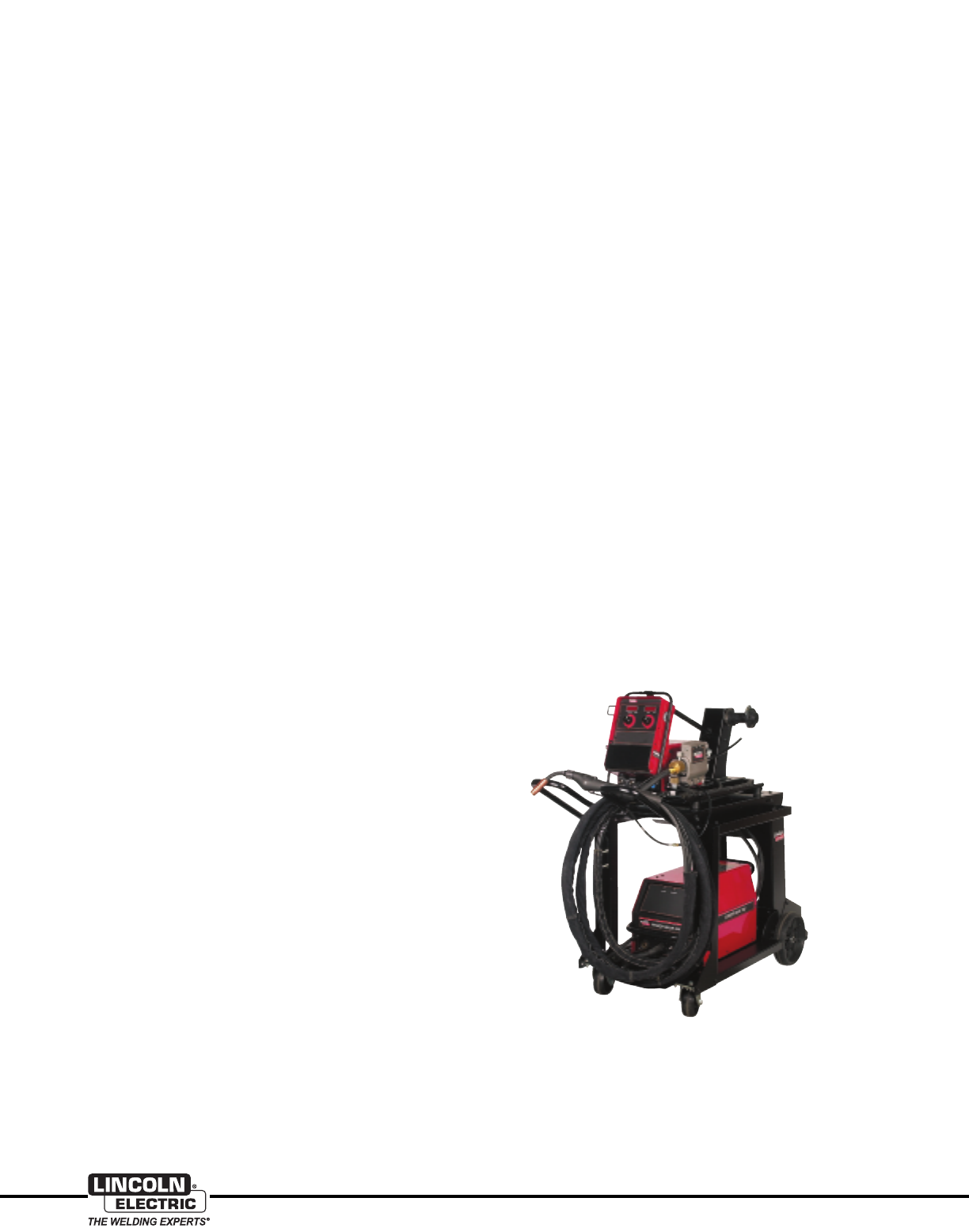
Figure 4 shows a complete push-pull system. Figure 5, on the
following page, shows the welding torch up close.
The push-pull systems handle aluminum diameters from 0.030"
to 1/16" (0.8 - 1.6 mm). They reliably feed aluminum wire up to
50 ft. (15.2 m) from the control cabinet.
Figure 4: Complete Push-Pull Drive System:
Power Wave® 355M power source, combined with the
Power Feed™ 10M wire feeder and push-pull aluminum torch.
For more information on this system, request
publications E5.146 and E8.267.
17
Aluminum
www.lincolnelectric.com
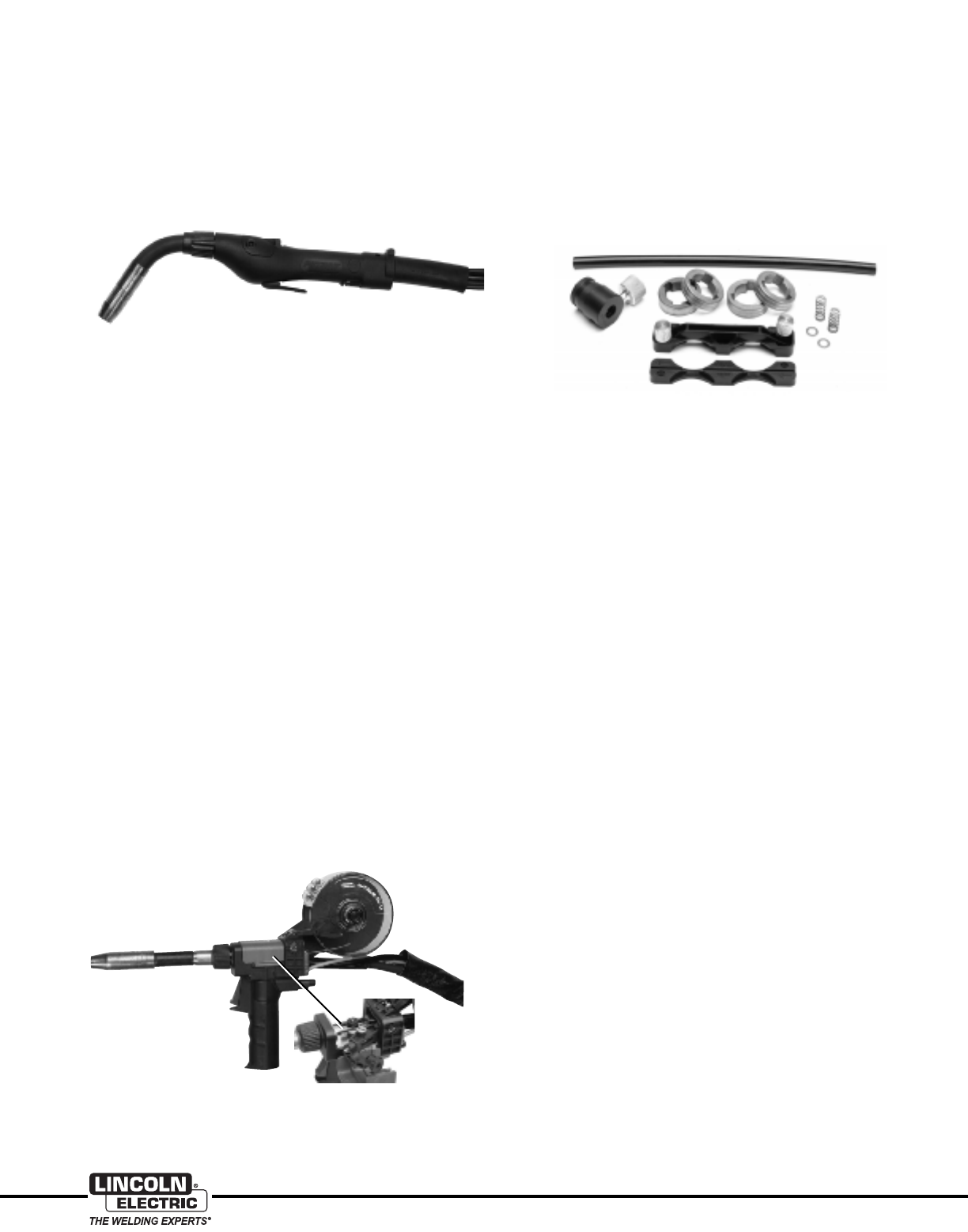
3. Push–Pull GMAW Torches
Figure 5 shows a closeup of a push-pull aluminum torch. The
bulged area of the gun handle houses the pull drive motor. This
permits the use of a more integrated approach for feeding
aluminum. The motor in the torch handle is variable torque —
constant speed, which permits the use of the wire feed speed
control at the wire feeder.
There are several “after market” add–on welding torches
available that can convert most wire feeders to push-pull. These
add-on welding torches usually function such that the pull torch
in the gun is the “slave” and the push motor in the wire feeder is
the “master”.
There is evidence that the more commonly used gun (master)
and feeder (slave) arrangement gives more consistent results,
but these add–on pull torches have also been shown to be
effective.
Both push and push-pull welding torches are available in air-
cooled and water-cooled versions. Even the largest air-cooled
torches are typically rated at 200 amps maximum at 60% duty
cycle for aluminum. It is recommended that water-cooled
torches be used for high-volume production or whenever
currents over 150 amps will be used.
Welding torches are available in straight barrel pistol grip, curved
barrel pistol grip or gooseneck styles. All are acceptable for
welding aluminum, however, if curved barrels are used, avoid
sharply bent barrels — they will add to wire feeding difficulties.
4. Spool Guns
Another solution for light duty aluminum welding is the spool gun
shown in Figure 6. In this system, a 1 lb. (0.5 kg) spool of filler
wire is mounted directly on the rear of the GMAW gun, so that it
is only pushed a few inches past the drive rolls, show in inset.
These spool guns are usually air-cooled and rated for 200 Amps
maximum at 60% duty cycle, so they are not recommended for
high current or high duty cycle welding.
Aluminum Feeding Enhancements
• Drive Rolls should always be highly polished "U" groove type
for aluminum. The “U" groove is designed to cradle the softer
electrode without altering its shape and the high polish prevents
the accumulation of aluminum oxide in the drive roll groove.
Steel electrodes use either knurled rolls or a "V" groove
configuration. Drive rolls designed for carbon steel electrodes
should not be used for feeding aluminum.
• Inlet and outlet wire guides for feeding aluminum should be
made from teflon, nylon, or other suitable plastic which will not
scrape the wire. A typical wire guide for aluminum is shown in
Figure 7. Wire guides for steel wire are usually made from
steel and should not be used to feed aluminum.
• Torch liners for aluminum welding should be either teflon,
nylon or other plastic liner material. Some of these types of
aluminum liners will have a short coiled brass liner section
located at the front of the plastic liner. Liners for torches made
to feed steel are usually made from spirally wound small
diameter steel wire. These types of liners should not be used
for feeding aluminum. They will shave the aluminum wire and
then quickly clog the path.
• Most manufacturers make contact tips specifically for
aluminum wire. Aluminum readily expands as it absorbs the
heat of the arc. Aluminum contact tips for a given size
aluminum wire are designed to accommodate the thermal
expansion of the wire — the inside diameter of the contact tip
is slightly larger than those for the same size steel wire.
Contact tips for welding steel are not suitable for welding
aluminum.
Some welders, after encountering aluminum feeding problems,
opt to use oversize contact tips, ie., 1/16” (1.6 mm) tips on
3/64” (1.2 mm) wire. This is usually unacceptable. The contact
tip must transfer current to the wire. An oversized tip will not
allow consistent current transfer. Arcing in the tip will occur
which will produce sharp burrs on the bore of the tip.
Another unacceptable practice is to use a wire straightener
and tighten it down hard so that all of the cast is removed
from the wire. Because the wire needs cast to make proper
contact in the tip, removing all of the cast usually results in
burnback.
• The contact tip should be flush with the end of the gas nozzle
or slightly recessed [approximately 1/8” (3.2 mm)]. The tip
should not extend past the gas nozzle.
Figure 5: Push-Pull GMAW Aluminum Torch
Figure 7: Drive Rolls and Wire Guide for Feeding Aluminum
Figure 6: Magnum® 250LX Spool Gun
For more information, request publication E12.25.
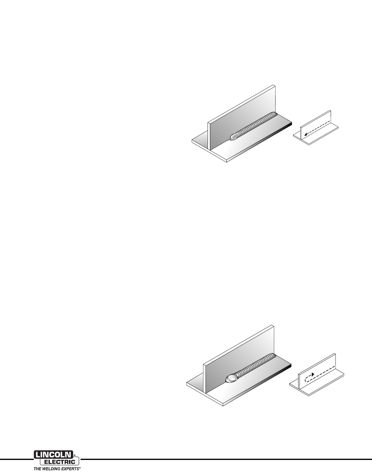
18
www.lincolnelectric.com
Aluminum
Shielding Gas
The recommended shielding gas for welding aluminum up to
approximately 1/2" (12.7 mm) in thickness is 100% argon.
Above this thickness, where additional energy is needed to melt
the material, it is common to use gas mixtures of 75% argon +
25% helium or 75% helium + 25% argon. The use of helium in
the arc provides additional energy used to accommodate heavier
section thickness welding. It also expands the cross sectional
shape of the finished weld giving it a more rounded appearance.
Shielding gas flow rates range from 30 to 100 cubic feet/hour
(cfh), (14 to 47 L/min). Higher flow rates are employed for wider
diameter gas nozzles and when using higher helium two-part
blends.
Shielding gas components such as oxygen, hydrogen, or CO2
should never be employed for aluminum GMAW. Even in trace
amounts these gases will adversely affect the weld.
Welding Techniques
The formation of black soot on the surface, or the adjacent
areas of a weld, is referred to as smut. It is made up of finely
divided oxides of aluminum and magnesium. They usually
indicate that adjustments in technique are necessary.
At the onset of learning to weld using aluminum GMAW, the
most common mistake made is to hold too long a contact tip to
work distance (CTWD). Shorter CTWD’s, 1/2" to 5/8"
(12.7 - 15.8 mm), are required when welding aluminum. If the
CTWD is too long, then the gas shielding will be insufficient. In
the absence of adequate shielding gas the weld will become
gray, and in the most severe case, the arc may bore into the
work piece.
At the start of an aluminum weld, it is not uncommon to get a
cold looking weld bead for the first 1/2" (12.7 mm). This is due
to the high thermal conductivity of aluminum. This condition can
be minimized by using a power supply with a hot start. A common
alternative used in the absence of a hot start control is to strike
the arc about 1" (25.4 mm) ahead of the nominal weld starting
point, and quickly maneuver the arc back to the desired starting
point. This action has the effect of providing preheat to the
aluminum base material, and it provides improved fusion at the
beginning of the weld.
While welding, the torch must be held with a push angle of 5° to
10° (also known as a leading torch angle). If the torch is applied
using a drag angle (also known as a lagging torch angle), then
the gas shielding will be absent from the molten puddle and the
finished weld will appear gray or black.
Care must be taken in extinguishing the arc. Terminating the arc
abruptly will result in a deep weld crater that may contain a
shrinkage crack in the crater. There are a number of ways to
minimize the size and depth of the crater.
• Weld tabs can be used and the weld may be started and
terminated on them.
• A power supply with an arc decay control allows the electrode
and current to tail off for a predetermined wire feed speed per
unit of time. This permits a controlled fill of the aluminum weld
crater.
• Near the end of the weld, progressively increase the travel
speed. The effect here is to reduce the size of the weld bead
and diminish the overall size of the crater. This is known as a
"feathering” or “back step” technique.
• At the end of the weld, reverse the direction of the torch to
place the crater within the body of the weld bead.
Some welders learn aluminum GMAW by keeping a very steady,
constant motion in the travel direction to make a very smooth
weld with a minimum of weld ripples. This is known as a straight
progression type weld bead, see Figure 8. Other welders learn
to weld by using the back step technique, see Figure 9. Each of
these techniques produce a weld with distinct, evenly spaced
ripples. Each technique produces acceptable finished welds.
The finished weld should be bright and free from oxides and
smut. A "frost line" or cleaning stripe approximately 1/16" to 1/8"
(1.6 to 3.2 mm) wide should be visible along each edge of the
weld. These stripes show the area where the reverse polarity arc
has removed the oxide from the aluminum surface. If the weld
metal is black or gray, or if the cleaning stripes are not present,
something is wrong. The most likely causes are either the arc
length is too long or the torch angle is wrong. If some weld smut
is present outside these areas - this is expected. There will also
be some weld smut present at weld starts, stops and at internal
and external corners. More smut will be present when using
5XXX filler than with 4XXX filler.
Figure 9: A Back Step Technique Weld
Figure 8: Straight Progession Weld
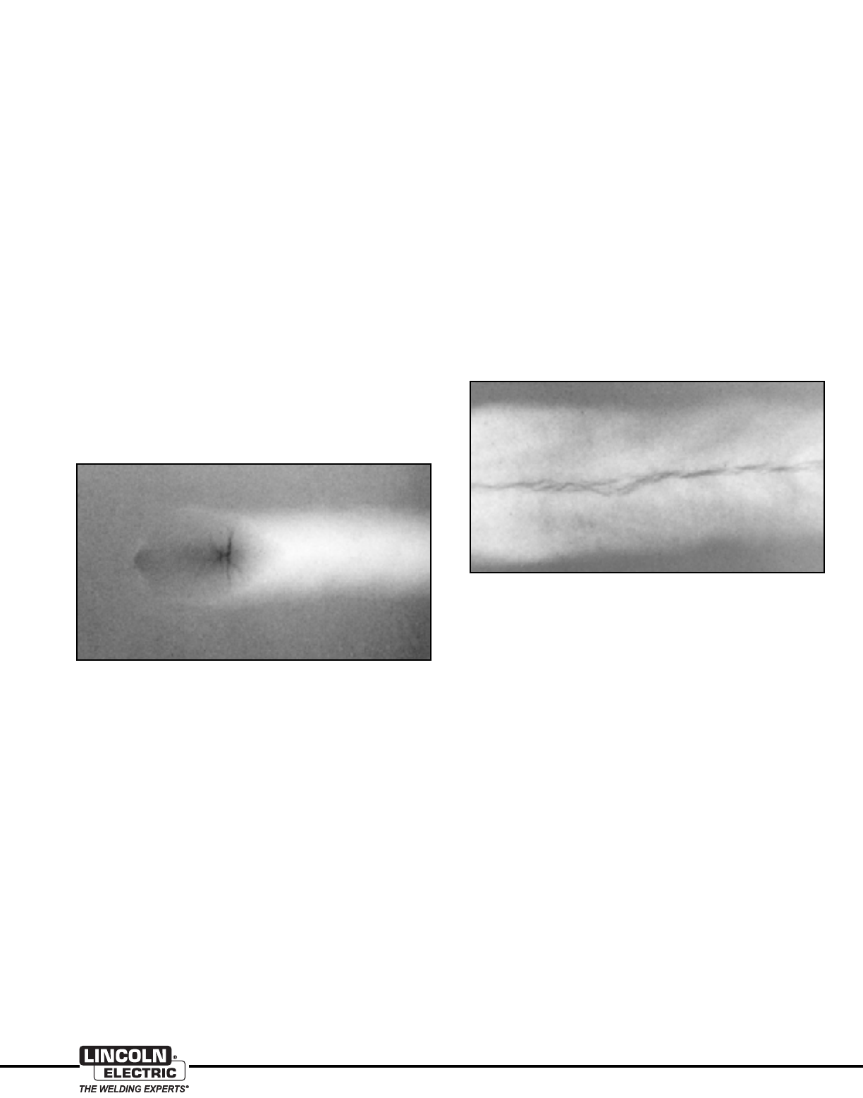
19
Aluminum
www.lincolnelectric.com
Figure 10: Radiograph Showing a Crater Crack
Weld Defects — Causes and Cures
Some weld defects — or discontinuities — may be small enough
that they don’t seriously impair the mechanical properties of the
weld joint. Other discontinuities may cause immediate joint failure.
The effects of other discontinuities may be more insidious. It is
not the purpose of this section to assess the acceptability or
rejectability of specific discontinuities. Instead, the appearance
of the various types of weld defects will be illustrated and
methods to eliminate or minimize these defects.
Cracking
Cracking occurs when a combination of a susceptible
microstructure or chemistry and a sufficiently high solidification
stress are present. If you reduce the stress or change the
microstructure or chemistry, the cracking can be eliminated.
All weld cracking in aluminum is caused by hot cracking.
That is, it takes place during weld solidification.
Crater Cracking
If the arc is extinguished rapidly, there isn’t enough filler metal
present to avoid forming a deep "crater". The geometry of the
crater locally intensifies the solidification stresses. If they are high
enough, a crack forms in and around the crater.
In order to eliminate crater cracking, the geometric discontinuity
of the crater must be minimized, i.e., the crater must be filled in
as much as possible. There are several methods to prevent
crater cracking:
• Use a power supply with a crater fill option.
• Rapidly restrike and extinguish the arc a few times while
keeping the wire tip in the crater. This will build up the crater.
• Run the weld bead to the end of the workpiece, then reverse
direction and increase travel speed in the new travel direction.
Figure 11: Radiograph Showing Longitudinal Weld Cracking
Longitudinal Cracking
Longitudinal cracking occurs relatively frequently. A radiograph
of a longitudinal weld crack is shown in Figure 11.
Weld cracking can usually be eliminated by taking following
precautions:
• Heat treatable alloys are crack sensitive and will crack if
welded autogenously. Make sure you add filler metal.
• Make sure you add enough filler metal in welding any alloy. Do
not deposit thin, concave groove welds or small or concave
fillets. They may crack. Weld passes in both groove welds and
fillet welds should be convex.
• If cracking is encountered in making a square butt weld, try
a V-weld preparation. It will allow the addition of more filler
metal. Similarly, if you’re using a bevel prep, go to a V-prep.
• Reduce the clamping pressure to allow the material to move
slightly during solidification. Occasionally high stress is caused
by the joint geometry, which may need to be changed.
Liquation Cracking
Liquation cracking is common in lap and fillet welds in thin heat-
treatable alloys. It usually is not seen in the nonheat-treatable
alloys or in butt joints. It manifests itself as a short longitudinal
crack in the parent material on the back side of a weld. It is
caused by the melting of low melting point compounds which
tend to segregate to the grain boundaries in heat-treatable
alloys. In order to minimize it, weld penetration into the parent
metal needs to be controlled in lap and fillet welds. Welds having
30 or 40% penetration into the parent metal will almost never
cause a crack, while welds penetrating 70 – 80% into the parent
metal will often cause a small crack on the back side of a weld.
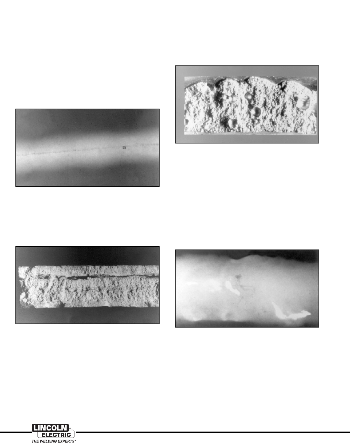
20
www.lincolnelectric.com
Aluminum
Incomplete Penetration
A radiograph of a weld showing incomplete penetration is
shown in Figure 12. Incomplete penetration is often caused by
insufficient weld current at a welding travel speed that is too
high. However the use of an arc voltage that is too high can also
result in the arc bridging the weld root and not penetrating
completely.
Care must also be taken in backgouging a two–sided weld.
Insufficient backgouging can sometimes result in incomplete
penetration. It is sometimes surprising how deep the backgouge
must be to get to sound metal.
Figure 12: Radiograph Showing Incomplete Penetration
Figure 13: Fracture Surface of a Weld with Incomplete Fusion
Figure 14: Fracture Surface of a Weld with Excessive Porosity
Figure 15: Radiograph Showing Copper Contamination
(Copper contamination shows up as lighter and irregularly shaped areas.)
Incomplete Fusion
Incomplete fusion, Figure 13, is usually caused by welding over
heavy oxides, insufficient interpass cleaning, or poor bead place-
ment. Heavy oxides must be removed before welding. The weld
smut and/or oxides must be removed before making another
weld pass.
Porosity
Figure 14 shows excessive porosity in a fracture surface of a
weld. Porosity in aluminum welds is caused by bubbles of
hydrogen gas which are trapped in the welds as it cools. It has
already been discussed that the source of this hydrogen is oils,
greases, or water vapor that is dissociated by the welding arc.
In order to control weld porosity, the sources of these
contaminates must be eliminated. It is also helpful when welding
in the vertical position, to use an upward progression, rather
than the downward progression usually used to weld steel, to
minimize weld porosity.
Copper Contamination
Copper contamination will also appear white on a radiograph, as
seen in Figure 15. Copper contamination is usually larger and
"fuzzier" than tungsten, which appears as individual small
particles.
Copper contamination is often encountered in GMAW and is
caused when the wire burns back and fuses to the copper
contact tip. The copper and aluminum quickly alloy and deposit
copper in the aluminum weld. If this occurs, the copper
contamination must be ground out and repaired because the
aluminum/copper alloy that is deposited is very brittle.
Copper contamination can also be caused by copper backing
bars or copper tooling. While the use of copper backing bars is
acceptable, the joint preparation must be such that the arc is
not allowed to impinge directly on the copper bar. If it does, the
copper bar will melt and alloy with the aluminum. While copper
backing bars are acceptable, wide root openings must be
avoided.

21
Aluminum
www.lincolnelectric.com
Solving Problems in Qualifying Weld Procedures
Many fabricators encounter difficulties in qualifying welding
procedures or welders for aluminum. Most codes require the
use of reduced section tensile tests and guided bend tests for
procedure qualification. Therefore, we will discuss these two
requirements:
Difficulties in Meeting Tensile Test Requirements
All codes have minimum tensile test values. Samples removed
from procedure qualification test plates must meet these values.
However, the weld does not have to meet the same minimum
requirements as the parent material. For example, all codes
require that 6061–T6 material have a minimum tensile strength
of 40 ksi (276 MPa). Welds in 6061–T6 only have to meet 24 ksi
(165 MPa) minimum. It is important to understand what is
required for the specific alloy being used.
There are several reasons why samples fail tensile testing. For
heat-treatable alloys, usually it is because excessive heat input
has been used. Common reasons for excessive heat input are:
• Use of excessive preheat. Preheat should be no more than
200°F (93°C) and isn’t needed unless the ambient
temperature is below 32°F (0°C).
• Interpass temperature that is too high. Maximum interpass
temperature should be 250°F (121°C).
• Technique issues, such as the use of very wide weave
passes, which can cause heat input to be excessive.
Generally stringer passes should be used, although weaving
is acceptable as long as the weave width is no wider than
four times the wire diameter.
Weld defects can also cause premature tensile failures. Observe
the fracture face of the failed tensile sample. The presence of
weld defects should be fairly obvious. Lack of fusion or lack of
penetration defects are especially prone to cause tensile failure.
Where the code requires the tensile sample to meet 40 ksi
(276 MPa) minimum tensile strength, the use of 5356 is not
recommended. Higher strength filler alloys, such as 5183 or
5556, are recommended for these applications.
Difficulties in Meeting Bend Test Requirements
Most bend test failures are caused by the welder’s lack of
familiarity with the bend test requirements for aluminum welds.
Some points to remember are as follows:
1. The ductility of aluminum welds is lower than that of steel
welds. Ensure the test radius is correct for the alloy under
test. Figure 16, on the following page, shows the bend test
requirements of AWS D1.2.
2. If the bend sample fails with little or no distortion before
breaking, the most likely cause is a defect in the weld. Any
lack of fusion or insufficient penetration in the weld will
quickly open up on bending and cause the sample to break
in half. A visual examination of the fracture surface will reveal
these defects.
3. Ensure that the bend test sample preparation is correct.
a. Make sure grinding or machining marks go along the
length of the sample, not across it. Marks going across
the sample can act as crack initiation sites.
b. Don’t leave square-machined corners on the sample. All
codes allow a radius at the corners of 1/2 the sample
thickness or 1/4” (6.4 mm) , whichever is less. Adhering to
this radius reduces the probability of initiating a crack in the
corners.
4. Special precautions are necessary when testing welds in
6061 or other M23 (per AWS) or P23 (per ASME Section IX)
materials because of their limited ductility. In recognition of
this, both AWS D1.2 and ASME Section IX require bend test
samples in 6061 and other M23 materials to be machined to
1/8" (3.2 mm) thickness, instead of the normal 3/8" (9.5 mm)
thickness. If 6061 samples are machined to 3/8" (9.5 mm)
thickness and tested around a standard radius mandrel,
they often fail. AWS D1.2 alternatively allows samples in M23
materials to be machined to 3/8" (9.5 mm) thick and
annealed before testing, but ASME Section IX has no such
provision.
5. The use of the standard plunger-type bend tester is respon-
sible for most bend test failures. This test fixture works well
for steel because the mechanical properties of the weld,
HAZ, and parent material are all similar. However, in aluminum,
the HAZs are usually much weaker than the remainder of the
sample. If the sample is tested in a plunger–type tester, the
bend strain is concentrated in the HAZ. Instead of bending
smoothly around the mandrel, the sample often forms a
sharp kink at the HAZ and the sample fails at the kink.
A much better test for welded aluminum bend samples is the
Wraparound Guided Bend Test, shown in Figure 17, on the
following page. In this test, the sample is pulled around the
mandrel and forced to stay in contact with it. These test jigs
are often made from rotary tubing benders. Both AWS D1.2
and ASME Section IX encourage the use of these testers for
aluminum.
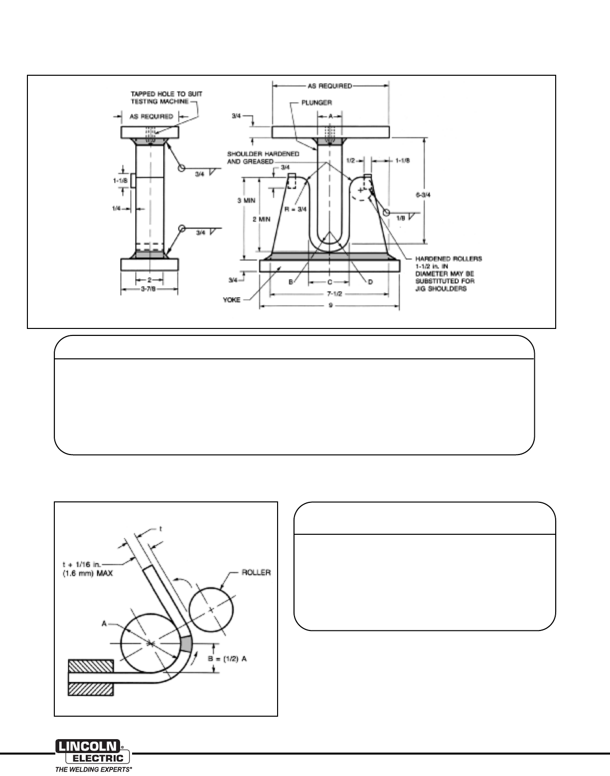
22
www.lincolnelectric.com
Aluminum
Figure 16: Bend Test Requirements from AWS D1.2 using Plunger Type Tester
Figure 17: Bend Test Requirements for Wraparound Bend Test Fixture
Thickness of
Specimen (Inches) A (Inches) B (Inches) C (Inches) D (Inches) Materials
3/8 1-1/2 3/4 2-3/8 1-3/16 M21 and M22
t 4t 2t 6t + 1/8 3t + 1/16
1/8 2-1/16 1-1/32 2-3/8 1-3/16 M23 and F23
t (<1/8) 16-1/2t 8-1/4t 18-1/2t + 1/16 9-1/4t + 1/32 Welds
3/8 2-1/2 1-1/4 3-3/8 1-11/16 M25 and
t 6-2/3t 3-1/3t 8-2/3t + 1/8 4-1/3t + 1/16 Annealed M23
3/8 3 1-1/2 3-7/8 1-15/16 M27 and
t 8t 4t 10t + 1/8 5t + 1/16 Annealed M24
Thickness of
Specimen
Inches A (Inches) B (Inches) Materials
3/8 1-1/2 3/4 M21 and M22
t4t 2t
1/8 2-1/16 1-1/32 M23 and F23
t (<1/8) 16-1/2t 8-1/4t Welds
3/8 2-1/2 1-1/4 M25 and
t 6-2/3t 3-1/3t Annealed M23
3/8 3 1-1/2 M27 and
t 8t 4t Annealed M24
Notes:
1. Dimensions not shown are the option of the designer. The essential consideration
is to have adequate rigidity so that the jig parts will not springs.
2. The specimen shall be firmly clamped on one end so that there is no sliding of the
specimen during the bending operation.
3. Test specimens shall be removed from the jig when the outer roll has been
removed 180° from the starting point.
NOTE: All dimensions in Inches
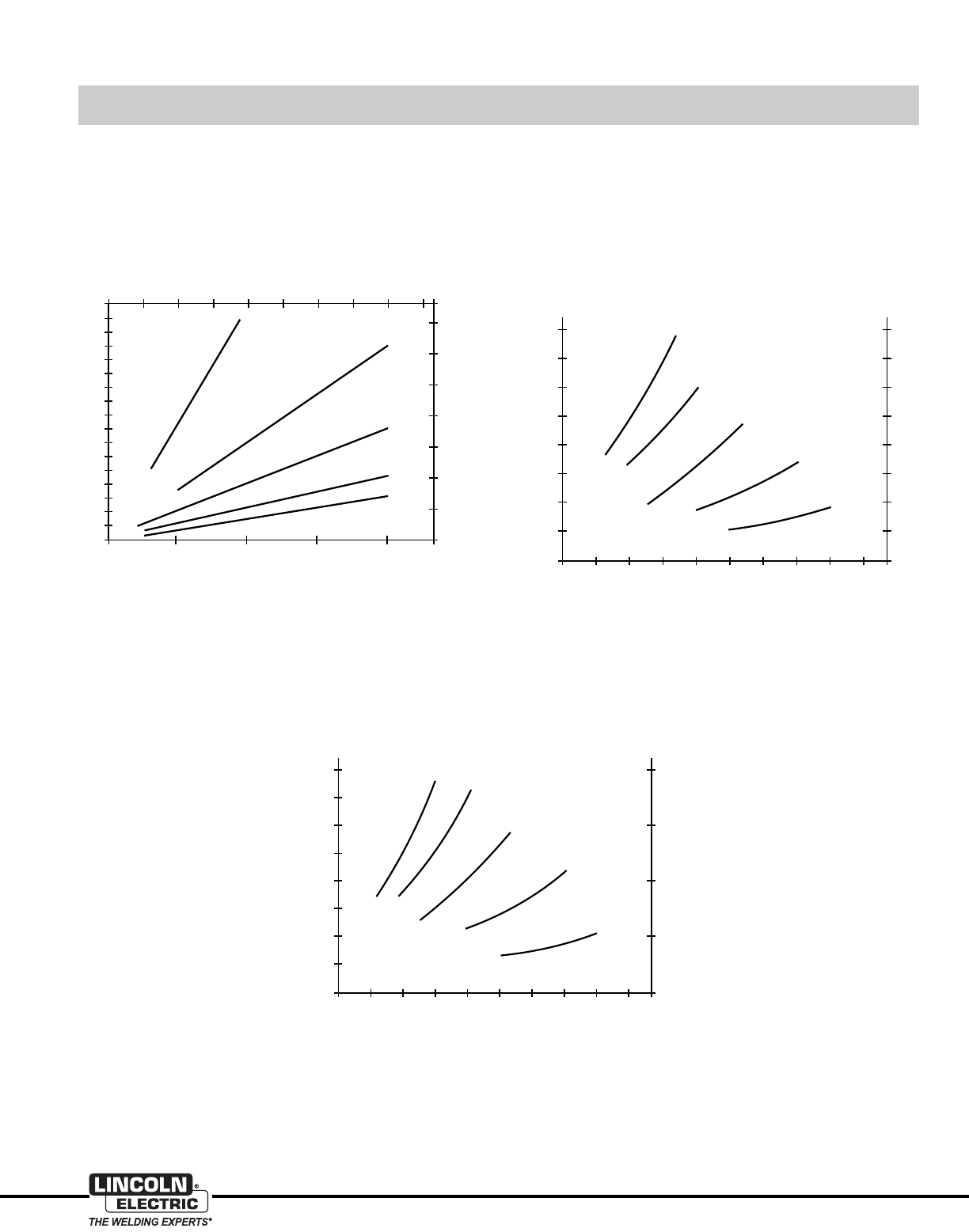
23
Aluminum
www.lincolnelectric.com
16
14
12
10
8
6
4
2
00
1
2
3
4
5
7
6
0 5 10 15 20
0 100 200 300 400 500 600 700 800 900
0.030 in. (0.8 mm)
0.035 in. (0.9 mm)
0.045 in. (1.2 mm)
0.062 in. (1.6 mm)
0.093 in. (2.4 mm)
Wire feed speed, inches per minute
Wire feed speed, meters per minute
Melting rate, lb/h
Melting rate, kg/h
800
700
600
500
400
300
200
100
00
5
20
15
10
0 50 100 150 200 250 300 350 400
Welding current A (DCEP)
Wire feed speed, inches per minute
Wire feed s
p
eed, meters
p
er minute
0.030 in. (0.8 mm)
0.035 in. (0.9 mm)
0.045 in. (1.2 mm)
0.062 in. (1.6 mm)
0.093 in. (2.4 mm)
450
Welding Current vs WFS for ER4043 Aluminum Electrodes
at a Fixed Stickout
Typical Melting Rates for Aluminum Electrodes
General Welding Guidelines
Welding Current vs WFS for ER5356 Aluminum Electrodes
at a Fixed Stickout
800
700
600
500
400
300
200
100
00
5
20
15
10
0 50 100 150 200 250 300 350 400
Welding current A (DCEP)
Wire feed speed, inches per minute
Wire feed speed, meters per minute
0.030 in. (0.8 mm)
0.035 in. (0.9 mm)
0.045 in. (1.2 mm)
0.062 in. (1.6 mm)
0.093 in. (2.4 mm)
450
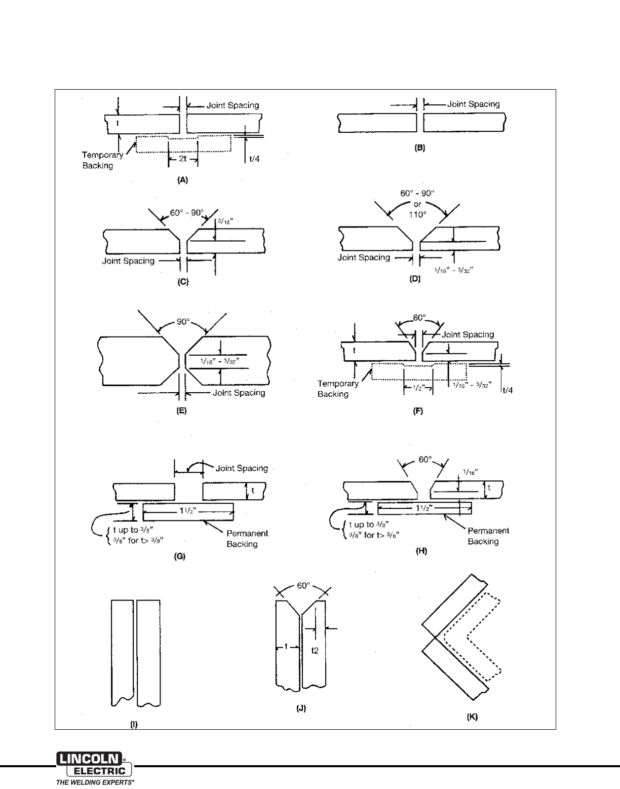
24
www.lincolnelectric.com
Aluminum
Welding Joint Designs for Aluminum GMAW
Groove Welding — Flat, Horizontal, Vertical and Overhead
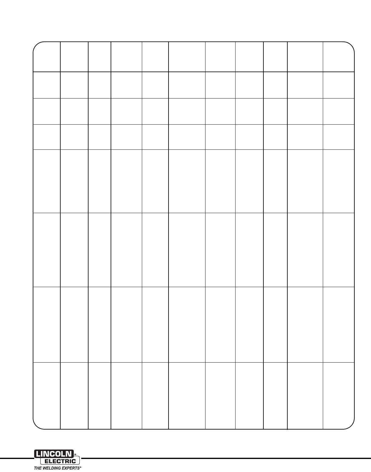
25
Aluminum
www.lincolnelectric.com
Welding Guidelines for Aluminum GMAW
Groove Welding — Flat, Horizontal, Vertical and Overhead
Welding Argon Travel Approx.
Joint Electrode Current(3) Arc Gas Flow Speed Electrode
Plate Weld Edge Spacing Weld Diameter (Amps) Voltage(3) CFH ipm Consump.
Thickness Position(1) Prep (2) In. (mm) Passes In. (mm) (DC+) (Volts) (L/min.) (M/min.) (lbs/100 ft)
1/16” F A None 1 0.030 (0.8) 70-110 15-20 25 25 - 45 1.5
(2 mm) (12) (0.64 - 1.14)
F G 3/32 (2.4) 1 0.030 (0.8) 70-110 15-20 25 25 - 45 2
(12) (0.64 - 1.14)
3/32” F A None 1 0.030-3/64 90-150 18-22 30 25 - 45 1.8
(2 mm) (0.8 - 1.2) (14) (0.64 - 1.14)
F, V, H, O G 1/8 (3.2) 1 0.030 (0.8) 110-130 18-23 30 25 - 30 2
(14) (0.64 - 0.76)
1/8” F, V, H A 0 - 3/32 10.030 - 3/64 120-150 20-24 30 24 - 30 2
(3 mm) (0 - 2.4) (0.8 - 1.2) (14) (0.60 - 0.76)
F, V, H, O G 3/16 (4.8) 1 0.030 - 3/64 110-135 19-23 30 18 - 28 3
(0.8 - 1.2) (14) (0.45 - 0.71)
3/16” F, V, H B 0 - 1/16 1F, 1R 0.030 - 3/64 130-175 22-26 35 24 - 30 4
(5 mm) (0 - 1.6) (0.8 - 1.2) (16) (0.60 - 0.76)
F, V, H F 0-1/16 13/64 140-180 23-27 35 24 - 30 5
(0 - 1.6) (1.2) (16) (0.60 - 0.76)
OF0-1/16 2F 3/64 140-175 23-27 60 24 - 30 5
(0 - 1.6) (1.2) (28) (0.60 - 0.76)
F, V H 3/32 - 3/16 23/64 - 1/16 140-185 23-27 35 24 - 30 8
(2.4 - 4.8) (1.2 - 1.6) (16) (0.60 - 0.76)
H, O H 3/16 33/64 130-175 23-27 60 25 - 35 10
(4.8) (1.2) (28) (0.63 - 0.89)
1/4” FB
0 - 3/32 1F, 1R 3/64-1/16 175-200 24-28 40 24 - 30 6
(6 mm) (0 - 2.4) (1.2 - 1.6) (19) (0.60 - 0.76)
FF
0 - 3/32 23/64-1/16 185-225 24-29 40 24 - 30 8
(0 - 2.4) (1.2 - 1.6) (19) (0.60 - 0.76)
V, H F 0 - 3/32 3F, 1R 3/64 165-190 25-29 45 25 - 35 10
(0 - 2.4) (1.2) (21) (0.63 - 0.89)
OF
0 - 3/32 3F, 1R 3/64, 1/16 180-200 25-29 60 25 - 35 10
(0 - 2.4) (1.2 - 1.6) (28) (0.63 - 0.89)
F, V H 1/8 - 1/4 2 - 3 3/64-1/16 175-225 25-29 40 24 - 30 12
(3.2 - 6.4) (1.2 - 1.6) (19) (0.60 - 0.76)
O, H H 1/4 4 - 6 3/64-1/16 170-200 25-29 60 25 - 40 12
(6.4) (1.2 - 1.6) (28) (0.63 - 1.02)
3/8” F C - 90° 0 - 3/32 1F, 1R 1/16 225-290 26-29 50 20 - 30 16
(10 mm) (0 - 2.4) (1.6) (24) (0.51 - 0.76)
FF
0 - 3/32 2F, 1R 1/16 210-275 26-29 50 24 - 35 18
(0 - 2.4) (1.6) (24) (0.60 -0.89)
V, H F 0 - 3/32 3F, 1R 1/16 190-220 26-29 55 24 - 30 20
(0 - 2.4) (1.6) (26) (0.60 - 0.76)
OF
0 - 3/32 5F, 1R 1/16 200-250 26-29 80 25 - 40 20
(0 - 2.4) (1.6) (38) (0.63 - 1.02)
F, V H 1/4 - 3/8 41/16 210-290 26-29 50 24 - 30 35
(6.4 - 9.5) (1.6) (24) (0.60 - 0.76)
O, H H 3/8 8 - 10 1/16 190-260 26-29 80 25-40 50
(9.5) (1.6) (38) (0.63 - 1.02)
3/4” F C-60° 0 - 3/32 3F, 1R 3/32 340-400 26-31 60 14 - 20 50
(19 mm) (0 - 2.4) (2.4) (28) (0.36 - 0.51)
FF
0 - 1/8 4F, 1R 3/32 325-375 26-31 60 16 - 20 70
(0 - 3.2) (2.4) (28) (0.41 - 0.76)
V, H, O F 0 - 1/16 8F, 1R 1/16 240-300 26-30 80 24 - 30 75
(0 - 1.6) (1.6) (38) (0.60 - 0.76)
FE
0 - 1/16 3F, 3R 1/16 270-330 26-30 60 16 - 24 70
(0 - 1.6) (1.6) (28) (0.41 - 0.61)
V, H, O E 0 - 1/16 6F, 6R 1/16 230-280 26-30 80 16 - 24 75
(0 - 1.6) (1.6) (38) (0.41 - 0.61)
(1) F = Flat; V = Vertical; H = Horizontal; O = Overhead. (2) See joint designs on page 24. (3) For 5xxx series electrodes, use a welding current in the high side of the range
and an arc voltage in the lower portion of the range. 1XXX, 2XXX and 4XXX series electrodes would use the lower currents and higher arc voltages.
26
www.lincolnelectric.com
Aluminum
Welding Guidelines for Aluminum GMAW
Fillet and Lap Welding — Flat, Horizontal, Vertical and Overhead
Welding Argon Approx.
Electrode Current(4) Arc Gas Flow Travel Speed Electrode
Plate Weld Weld Diameter (Amps) Voltage(4) CFH ipm Consump.
Thickness(1) Position(2) Passes(3) In. (mm) (DC+) (Volts) (L/min.) (M/min.) (lbs/100 ft)
3/32” F, V, H, O 1 0.030 100-130 18-22 30 24 - 30 1.8
(2 mm) (0.8) (14) (0.60 - 0.76)
1/8” F1
0.030 - 3/64 125-150 20-24 30 24 - 30 2
(3 mm) (0.8 - 1.2) (14) (0.60 - 0.76)
V, H 1 0.030 110-130 19-23 30 24 - 30 2
(0.8) (14) (0.60 - 0.76)
O1
0.030 - 3/64 115-140 20-24 40 24 - 30 2
(0.8 - 1.2) (19) (0.60 - 0.76)
3/16” F1
3/64 180-210 22-26 30 24 - 30 4.5
(5 mm) (1.2) (14) (0.60 - 0.76)
V, H 1 0.030 - 3/64 130-175 21-25 35 24 - 30 4.5
(0.8 - 1.2) (16) (0.60 - 0.76)
O1
0.030 - 3/64 130-190 22-26 45 24 - 30 4.5
(0.8 - 1.2) (21) (0.60 - 0.76)
1/4” F1
3/64 - 1/16 170-240 24-28 40 24 - 30 7
(6 mm) (1.2 - 1.6) (19) (0.60 - 0.76)
V, H 1 3/64 170-210 23-27 45 24 - 30 7
(1.2) (21) (0.60 - 0.76)
O1
3/64 - 1/16 190-220 24-28 60 24 - 30 7
(1.2 - 1.6) (28) (0.60 - 0.76)
3/8 F1
1/16 240-300 26-29 50 18 - 25 17
(10 mm) (1.6) (24) (0.46 - 0.64)
H, V 3 1/16 190-240 24-27 60 24 - 30 17
(1.6) (28) (0.60 - 0.76)
O3
1/16 200-240 25-28 85 24 - 30 17
(1.6) (40) (0.60 - 0.76)
3/4 F4
3/32 360-380 26-30 60 18 - 25 66
(19 mm) (2.4) (28) (0.46 - 0.64)
H, V 4-6 1/16 260-310 25-29 70 24 - 30 66
(1.6) (33) (0.60 - 0.76)
O10
1/16 275-310 25-29 85 24 - 30 66
(1.6) (40) (0.60 - 0.76)
(1) Metal thickness of 3/4” or greater for fillet welds sometimes employ a double vee bevel of 50° or greater included vee with 3/32” to 1/8” land thickness on the abutting
member. (2) F = Flat; V = Vertical; H = Horizontal; O = Overhead. (3) Number of weld passes and electrode consumption given for weld on one side only. (4) For 5xxx
series electrodes, use a welding current in the high side of the range and an arc voltage in the lower portion of the range. 1xxx, 2xxx and 4xxx series electrodes would use
the lower currents and higher arc voltages.

27
Aluminum
www.lincolnelectric.com
Introduction. The general subject of safety and safety practices in
welding, cutting, and allied processes is covered in ANSI Z49.18,
“Safety in Welding and Cutting,” and ANSI Z49.29. “Fire Prevention
in the Use of Welding and Cutting Processes.” The handling of
compressed gases is covered in CGA P-110.
Personnel should be familiar with the safe practices discussed in
these documents, equipment operating manuals, and Material Safety
Data Sheets (MSDS) for consumables.
In addition to the hazards discussed in the Arc Welding Safety
Precautions following this section, be familiar with the safety con-
cerns discussed below.
Safe Handling of Shielding Gas Cylinders and Regulators.
Compressed gas cylinders should be handled carefully and should be
adequately secured when in use. Knocks, falls, or rough handling
may damage cylinders, valves, or fuse plugs and cause leakage or
accident. Valve protecting caps, when supplied, should be kept in
place (handtight) until the connecting of container equipment.
Cylinder Use. The following should be observed when setting up
and using cylinders of shielding gas:
1. Properly secure the cylinder.
2. Before connecting a regulator to the cylinder valve, the valve
should momentarily be slightly opened and closed immediately
(opening) to clear the valve of dust or dirt that otherwise might
enter the regulator. The valve operator should stand to one side of
the regulator gauges, never in front of them.
3. After the regulator is attached, the adjusting screw should be
released by turning it counter-clockwise. The cylinder valve
should then be opened slowly to prevent a too-rapid surge of high
pressure gas into the regulator.
4. The source of the gas supply (i.e., the cylinder valve) should be
shut off if it is to be left unattended.
Gases. The major toxic gases associated with GMAW welding are
ozone, nitrogen dioxide, and carbon monoxide. Phosgene gas could
also be present as a result of thermal or ultraviolet decomposition of
chlorinated hydrocarbon cleaning agents located in the vicinity of
welding operations, such as trichlorethylene and perchlorethylene.
DEGREASING OR OTHER CLEANING OPERATIONS
INVOLVING CHLORINATED HYDROCARBONS SHOULD BE
SO LOCATED THAT VAPORS FROM THESE OPERATIONS
CANNOT BE REACHED BY RADIATION FROM THE WELD-
ING ARC.
Ozone. The ultraviolet light emitted by the GMAW arc acts on the
oxygen in the surrounding atmosphere to produce ozone, the amount
of which will depend upon the intensity and the wave length of the
ultraviolet energy, the humidity, the amount of screening afforded by
any welding fumes, and other factors. The ozone concentration will
generally be increased with an increase in welding current, with the
use of argon as the shielding gas, and when welding highly reflective
metals. If the ozone cannot be reduced to a safe level by ventilation
or process variations, it will be necessary to supply fresh air to the
welder either with an air supplied respirator or by other means.
Nitrogen Dioxide. Some test results show that high concentra-tions
of nitrogen dioxide are found only within 6 in. (152 mm) of the arc.
With normal natural ventilation, these concentrations are quickly
reduced to safe levels in the welder’s breathing zone, so long as the
welder keeps his head out of the plume of fumes (and thus out of the
plume of welding-generated gases). Nitrogen dioxide is not thought
to be a hazard in GMAW.
Carbon Monoxide. CO shielding used with the GMAW process will
be dissociated by the heat of the arc to form carbon monoxide. Only
a small amount of carbon monoxide is created by the welding process,
although relatively high concentrations are formed temporarily in the
plume of fumes. However, the hot carbon monoxide oxidizes to CO
so that the concentrations of carbon monoxide become insignificant
at distances of more than 3 or 4 in. (76 or 102 mm) from the welding
plume.
Under normal welding conditions there should be no hazard from
this source. When the welder must work with his head over the weld-
ing arc, or with the natural ventilation moving the plume of fumes
towards his breathing zone, or where welding is performed in a con-
fined space, ventilation adequate to deflect the plume or remove the
fumes and gases must be provided. Because shielding gases can dis-
place air, use special care to insure that breathing air is safe when
welding in a confined space. (See ANSI Z49.1.)
Metal Fumes. The welding fumes generated by GMAW can be con-
trolled by general ventilation, local exhaust ventilation, or by respira-
tory protective equipment as described in ANSI Z49.1. The method
of ventilation required to keep the level of toxic substances within
the welder’s breathing zone below acceptable concentrations is
directly dependent upon a number of factors. Among these are the
material being welded, the size of the work area, and the degree of the
confinement or obstruction to normal air movement where the welding
is being done. Each operation should be evaluated on an individual
basis in order to determine what will be required. Exposure limits for
toxic substances associated with welding, and designated as time-
weighted average threshold limit values (TLV) and ceiling values,
have been established by the American Conference of Governmental
Industrial Hygienists (ACGIH) and Permissable Exposure Limits
(PEL) by the Occupational Safety and Health Administration
(OSHA). Compliance with these acceptable levels can be checked by
sampling the atmosphere under the welder’s helmet or in the imme-
diate vicinity of the helper’s breathing zone. The principle composi-
tion or particulate matter (welding fume) which may be present
within the welder’s breathing zone are listed on the MSDS for the
consumable being used. Sampling should be in accordance with ANSI/
AWS F1.1, Method for Sampling Airborne Particulates Generated by
Welding and Allied Processes.
8ANSI Z49.1 is available from the American Welding Society, 550
N.W. LeJeune Road, Miami, Florida 33126. It may also be down-
loaded at no charge from the www.aws.org website.
9ANSI Z49.2 is available from the American National Standards
Institute, 11 West 42nd Street, New York, NY 10036.
10 CGA P-1 is available from the Compressed Gas Association, Inc.,
1235 Jefferson Davis Highway, Suite 501, Arlington, VA 22202.
SAFE PRACTICES
28
www.lincolnelectric.com
Aluminum
FOR ENGINE
powered equipment.
1.a. Turn the engine off before troubleshooting and maintenance
work unless the maintenance work requires it to be running.
____________________________________________________
1.b.Operate engines in open, well-ventilated
areas or vent the engine exhaust fumes
outdoors.
____________________________________________________
1.c. Do not add the fuel near an open flame
welding arc or when the engine is running.
Stop the engine and allow it to cool before
refueling to prevent spilled fuel from vaporiz-
ing on contact with hot engine parts and
igniting. Do not spill fuel when filling tank. If
fuel is spilled, wipe it up and do not start
engine until fumes have been eliminated.
____________________________________________________
1.d. Keep all equipment safety guards, covers and devices in
position and in good repair.Keep hands, hair, clothing and
tools away from V-belts, gears, fans and all other moving
parts when starting, operating or repairing equipment.
____________________________________________________
1.e. In some cases it may be necessary to remove safety
guards to perform required maintenance. Remove
guards only when necessary and replace them when the
maintenance requiring their removal is complete.
Always use the greatest care when working near moving
parts.
___________________________________________________
1.f. Do not put your hands near the engine fan.
Do not attempt to override the governor or
idler by pushing on the throttle control rods
while the engine is running.
___________________________________________________
1.g. To prevent accidentally starting gasoline engines while
turning the engine or welding generator during maintenance
work, disconnect the spark plug wires, distributor cap or
magneto wire as appropriate.
i
SAFETY
i
ARC WELDING CAN BE HAZARDOUS. PROTECT YOURSELF AND OTHERS FROM POSSIBLE SERIOUS INJURY OR DEATH.
KEEP CHILDREN AWAY. PACEMAKER WEARERS SHOULD CONSULT WITH THEIR DOCTOR BEFORE OPERATING.
Read and understand the following safety highlights. For additional safety information, it is strongly recommended that you
purchase a copy of “Safety in Welding & Cutting - ANSI Standard Z49.1” from the American Welding Society, P.O. Box
351040, Miami, Florida 33135 or CSA Standard W117.2-1974. A Free copy of “Arc Welding Safety” booklet E205 is available
from the Lincoln Electric Company, 22801 St. Clair Avenue, Cleveland, Ohio 44117-1199.
BE SURE THAT ALL INSTALLATION, OPERATION, MAINTENANCE AND REPAIR PROCEDURES ARE
PERFORMED ONLY BY QUALIFIED INDIVIDUALS.
WARNING
Mar ‘95
ELECTRIC AND
MAGNETIC FIELDS
may be dangerous
2.a. Electric current flowing through any conductor causes
localized Electric and Magnetic Fields (EMF). Welding
current creates EMF fields around welding cables and
welding machines
2.b. EMF fields may interfere with some pacemakers, and
welders having a pacemaker should consult their physician
before welding.
2.c. Exposure to EMF fields in welding may have other health
effects which are now not known.
2.d. All welders should use the following procedures in order to
minimize exposure to EMF fields from the welding circuit:
2.d.1.
Route the electrode and work cables together - Secure
them with tape when possible.
2.d.2. Never coil the electrode lead around your body.
2.d.3. Do not place your body between the electrode and
work cables. If the electrode cable is on your right
side, the work cable should also be on your right side.
2.d.4. Connect the work cable to the workpiece as close as
possible to the area being welded.
2.d.5. Do not work next to welding power source.
1.h. To avoid scalding, do not remove the
radiator pressure cap when the engine is
hot.
CALIFORNIA PROPOSITION 65 WARNINGS
Diesel engine exhaust and some of its constituents
are known to the State of California to cause
cancer, birth defects, and other reproductive harm.
The engine exhaust from this product contains
chemicals known to the State of California to cause
cancer, birth defects, or other reproductive harm.
The Above For Diesel Engines The Above For Gasoline Engines
29
Aluminum
www.lincolnelectric.com
ii
SAFETY
ii
ARC RAYS can burn.
4.a. Use a shield with the proper filter and cover
plates to protect your eyes from sparks and
the rays of the arc when welding or observing
open arc welding. Headshield and filter lens
should conform to ANSI Z87. I standards.
4.b. Use suitable clothing made from durable flame-resistant
material to protect your skin and that of your helpers from
the arc rays.
4.c. Protect other nearby personnel with suitable, non-flammable
screening and/or warn them not to watch the arc nor expose
themselves to the arc rays or to hot spatter or metal.
ELECTRIC SHOCK can
kill.
3.a. The electrode and work (or ground) circuits
are electrically “hot” when the welder is on.
Do not touch these “hot” parts with your bare
skin or wet clothing. Wear dry, hole-free
gloves to insulate hands.
3.b. Insulate yourself from work and ground using dry insulation.
Make certain the insulation is large enough to cover your full
area of physical contact with work and ground.
In addition to the normal safety precautions, if welding
must be performed under electrically hazardous
conditions (in damp locations or while wearing wet
clothing; on metal structures such as floors, gratings or
scaffolds; when in cramped positions such as sitting,
kneeling or lying, if there is a high risk of unavoidable or
accidental contact with the workpiece or ground) use
the following equipment:
• Semiautomatic DC Constant Voltage (Wire) Welder.
• DC Manual (Stick) Welder.
• AC Welder with Reduced Voltage Control.
3.c. In semiautomatic or automatic wire welding, the electrode,
electrode reel, welding head, nozzle or semiautomatic
welding gun are also electrically “hot”.
3.d. Always be sure the work cable makes a good electrical
connection with the metal being welded. The connection
should be as close as possible to the area being welded.
3.e. Ground the work or metal to be welded to a good electrical
(earth) ground.
3.f.
Maintain the electrode holder, work clamp, welding cable and
welding machine in good, safe operating condition. Replace
damaged insulation.
3.g. Never dip the electrode in water for cooling.
3.h. Never simultaneously touch electrically “hot” parts of
electrode holders connected to two welders because voltage
between the two can be the total of the open circuit voltage
of both welders.
3.i. When working above floor level, use a safety belt to protect
yourself from a fall should you get a shock.
3.j. Also see Items 6.c. and 8.
FUMES AND GASES
can be dangerous.
5.a. Welding may produce fumes and gases
hazardous to health. Avoid breathing these
fumes and gases.When welding, keep
your head out of the fume. Use enough
ventilation and/or exhaust at the arc to keep
fumes and gases away from the breathing zone. When
welding with electrodes which require special
ventilation such as stainless or hard facing (see
instructions on container or MSDS) or on lead or
cadmium plated steel and other metals or coatings
which produce highly toxic fumes, keep exposure as
low as possible and below Threshold Limit Values (TLV)
using local exhaust or mechanical ventilation. In
confined spaces or in some circumstances, outdoors, a
respirator may be required. Additional precautions are
also required when welding on galvanized steel.
5.b.
Do not weld in locations near chlorinated hydrocarbon
vapors
coming from degreasing, cleaning or spraying operations.
The heat and rays of the arc can react with solvent vapors
to f
orm phosgene, a highly toxic gas, and other irritating
products.
5.c. Shielding gases used for arc welding can displace air and
cause injury or death. Always use enough ventilation,
especially in confined areas, to insure breathing air is safe.
5.d. Read and understand the manufacturer’s instructions for this
equipment and the consumables to be used, including the
material safety data sheet (MSDS) and follow your
employer’s safety practices. MSDS forms are available from
your welding distributor or from the manufacturer.
5.e. Also see item 1.b. Mar ‘95
30
www.lincolnelectric.com
Aluminum
FOR ELECTRICALLY
powered equipment.
8.a. Turn off input power using the disconnect
switch at the fuse box before working on
the equipment.
8.b. Install equipment in accordance with the U.S. National
Electrical Code, all local codes and the manufacturer’s
recommendations.
8.c. Ground the equipment in accordance with the U.S. National
Electrical Code and the manufacturer’s recommendations.
CYLINDER may explode
if damaged.
7.a. Use only compressed gas cylinders
containing the correct shielding gas for the
process used and properly operating
regulators designed for the gas and
pressure used. All hoses, fittings, etc. should be suitable for
the application and maintained in good condition.
7.b. Always keep cylinders in an upright position securely
chained to an undercarriage or fixed support.
7.c. Cylinders should be located:
•Away from areas where they may be struck or subjected to
physical damage.
•A safe distance from arc welding or cutting operations and
any other source of heat, sparks, or flame.
7.d. Never allow the electrode, electrode holder or any other
electrically “hot” parts to touch a cylinder.
7.e. Keep your head and face away from the cylinder valve outlet
when opening the cylinder valve.
7.f. Valve protection caps should always be in place and hand
tight except when the cylinder is in use or connected for
use.
7.g. Read and follow the instructions on compressed gas
cylinders, associated equipment, and CGA publication P-l,
“Precautions for Safe Handling of Compressed Gases in
Cylinders,” available from the Compressed Gas Association
1235 Jefferson Davis Highway, Arlington, VA 22202.
iii
SAFETY
iii
Mar ‘95
WELDING SPARKS can
cause fire or explosion.
6.a.
Remove fire hazards from the welding area.
If this is not possible, cover them to prevent
the welding sparks from starting a fire.
Remember that welding sparks and hot
materials from welding can easily go through small cracks
and openings to adjacent areas. Avoid welding near
hydraulic lines. Have a fire extinguisher readily available.
6.b. Where compressed gases are to be used at the job site,
special precautions should be used to prevent hazardous
situations. Refer to “Safety in Welding and Cutting” (ANSI
Standard Z49.1) and the operating information for the
equipment being used.
6.c. When not welding, make certain no part of the electrode
circuit is touching the work or ground. Accidental contact
can cause overheating and create a fire hazard.
6.d. Do not heat, cut or weld tanks, drums or containers until the
proper steps have been taken to insure that such procedures
will not cause flammable or toxic vapors from substances
inside. They can cause an explosion even
though
they have
been “cleaned”. For information, purchase “Recommended
Safe Practices for the
Preparation
for Welding and Cutting of
Containers and Piping That Have Held Hazardous
Substances”, AWS F4.1 from the American Welding Society
(see address above 1.a. [Safety]).
6.e. Vent hollow castings or containers before heating, cutting or
welding. They may explode.
6.f.
Sparks and spatter are thrown from the welding arc. Wear oil
free protective garments such as leather gloves, heavy shirt,
cuffless trousers, high shoes and a cap over your hair. Wear
ear plugs when welding out-of-position or in confined places.
Always wear safety glasses with side shields when in a
welding area.
6.g. Connect the work cable to the work as close to the welding
area as practical. Work cables connected to the building
framework or other locations away from the welding area
increase the possibility of the welding current passing
through lifting chains, crane cables or other alternate
circuits. This can create fire hazards or overheat lifting
chains or cables until they fail.
6.h. Also see item 1.c.

31
www.lincolnelectric.com
Aluminum
Notes
CUSTOMER ASSISTANCE POLICY
The business of The Lincoln Electric Company is manufacturing and selling high quality welding equipment, consumables, and cutting equipment. Our challenge is to meet the
needs of our customers and to exceed their expectations. On occasion, purchasers may ask Lincoln Electric for advice or information about their use of our products. We respond
to our customers based on the best information in our possession at that time. Lincoln Electric is not in a position to warrant or guarantee such advice, and assumes no liability,
with respect to such information or advice. We expressly disclaim any warranty of any kind, including any warranty of fitness for any customer’s particular purpose, with respect to
such information or advice. As a matter of practical consideration, we also cannot assume any responsibility for updating or correcting any such information or advice once it has
been given, nor does the provision of information or advice create, expand or alter any warranty with respect to the sale of our products.
Lincoln Electric is a responsive manufacturer, but the selection and use of specific products sold by Lincoln Electric is solely within the control of, and remains the sole responsibility
of the customer. Many variables beyond the control of Lincoln Electric affect the results obtained in applying these types of fabrication methods and service requirements.
Subject to Change – This information is accurate to the best of our knowledge at the time of printing. Please refer to www.lincolnelectric.com for any updated information.

Aluminum Welding Guide
C8.100 9/06
LINCOLN NORTH AMERICA
DISTRICT SALES OFFICES
U.S.A.
ALABAMA
BIRMINGHAM 35124-1156
(205) 988-8232
MOBILE 36582-5209
(251) 443-6524
ALASKA
Contact VANCOUVER, WA
(360) 693-4712
ARIZONA
PHOENIX 85260-1745
(480) 348-2004
ARKANSAS
LITTLE ROCK 72032-4371
(501) 764-0480
CALIFORNIA
FRESNO 93722-3949
(559) 276-0110
LOS ANGELES 90670-2936
(562) 906-7700
SAN DIEGO 92065-4165
(760) 787-1970
NORTHERN CALIFORNIA
95762-5706
(916) 939-8788
COLORADO
DENVER 80112-5115
(303) 792-2418
CONNECTICUT
NORTH HAVEN 06238-1090
(860) 742-8887
FLORIDA
JACKSONVILLE 32216-4634
(904) 642-3177
MIAMI 33178-1175
(305) 888-3203
ORLANDO 32714-1974
(407) 788-8557
TAMPA 33594
(813) 477-5817
GEORGIA
ATLANTA 30076-4914
(770) 475-0955
SAVANNAH 31324-5180
(912) 727-4286
HAWAII
Contact LOS ANGELES, CA
(562) 906-7700
IDAHO
BOISE 83616-6646
(208) 938-2302
ILLINOIS
CHICAGO 60527-5629
(630) 920-1500
PEORIA 60527-5629
(630) 920-1500
INDIANA
EVANSVILLE 47630
(812) 454-3428
FT. WAYNE 46825-5547
(260) 484-4422
SOUTH BEND 46561-9160
(219) 674-5523
INDIANAPOLIS 46250-5536
(317) 845-8445
IOWA
CEDAR RAPIDS 52402-3160
(319) 362-6804
DAVENPORT 52806-1344
(563) 386-6522
DES MOINES 50265-6218
(515) 963-1778
KANSAS
KANSAS CITY 66214-1625
(913) 894-0888
WICHITA 67037-9614
(316) 788-7367
KENTUCKY
LOUISVILLE 47112-7025
(502) 727-7335
LOUISIANA
BATON ROUGE 70808-3150
(225) 922-5151
LAFAYETTE 70507-3126
(337) 886-1090
SHREVEPORT 75692-9313
(318) 518-4099
MARYLAND
BALTIMORE 21050-3067
(443) 831-0416
MASSACHUSETTS
BOSTON 01701-7726
(508) 788-9353
MICHIGAN
DETROIT 48034-4005
(248) 353-9680
FLINT 48439-8728
(810) 695-2627
GRAND RAPIDS 49512-3924
(616) 942-8780
MINNESOTA
MINNEAPOLIS 55447-4743
(763) 551-1990
MISSISSIPPI
JACKSON 39212-9635
(601) 372-7679
MISSOURI
KANSAS CITY (KS) 66214-1625
(913) 894-0888
ST. LOUIS 63045
(314) 291-5877
SPRINGFIELD 65804
(417) 841-2779
MONTANA
Contact VANCOUVER, WA
(360) 693-4712
NEBRASKA
OMAHA 68046-2826
(402) 339-1809
NEW JERSEY
EDISON 08837-3939
(732) 225-2000
NEW MEXICO
ALBUQUERQUE 87008
(505) 890-6347
NEW YORK
ALBANY 12304-4320
(518) 469-8222
BUFFALO 14075-2520
(716) 646-8414
NEW YORK CITY
(888) 269-6755
SYRACUSE 13057-9313
(315) 432-0281
NORTH CAROLINA
CHARLOTTE 28273-6200
(704) 588-3251
RALEIGH 27604-8456
(919) 303-1972
OHIO
AKRON 44236-4680
(330) 342-8009
CINCINNATI 45242-3706
(513) 554-4440
CLEVELAND 44117-2525
(216) 383-2662
COLUMBUS 43221-4073
(614) 488-7913
DAYTON 45458
(937) 885-6964
TOLEDO 43528-9483
(419) 867-7284
OKLAHOMA
OKLAHOMA CITY 73139-2432
(405) 616-1751
TULSA 74146-1622
(918) 622-9353
PENNSYLVANIA
PHILADELPHIA 19008-4310
(610) 543-9462
PITTSBURGH 15001-4800
(724) 857-2750
HARRISBURG
17104-1422
(717) 213-9163
SOUTH CAROLINA
GREENVILLE 29681-4724
(864) 967-4157
COLUMBIA 29209
(803) 783-2851
SOUTH DAKOTA
SIOUX FALLS 57108-2609
(605) 339-6522
TENNESSEE
KNOXVILLE 37922-1736
(423) 612-1204
MEMPHIS 38119
(901) 683-6260
NASHVILLE 37228-1708
(615) 291-9926
TRI-CITIES 37659-5693
(423) 612-1204
TEXAS
DALLAS 76051-7602
(817) 329-9353
HOUSTON 77060-3143
(281) 847-9444
SAN ANTONIO 78258-4009
(210) 393-9337
UTAH
MIDVALE 84047-3759
(801) 233-9353
VIRGINIA
LEESBURG, VA 20175-3911
Washington, D.C.
(703) 904-7735
DANVILLE
(434) 489-3222
HAMPTON ROADS 23693-4171
(757) 870-5508
WASHINGTON
VANCOUVER 98661-8023
(360) 693-4712
SPOKANE 99005-9637
(509) 468-2770
WASHINGTON DC
LEESBURG, VA 20175-3911
(703) 904-7735
WEST VIRGINIA
CHARLESTON 25526-8864
(304) 757-9862
WISCONSIN
GREEN BAY 54302-1829
(920) 435-1012
MILWAUKEE 53186-0403
(262) 650-9364
CANADA
ALBERTA
CALGARY
(403) 253-9600/(877) 600-WELD
EDMONTON
(780) 436-7385
WINNIPEG
(204) 488-6398
BRITISH COLUMBIA
VANCOUVER
(604) 945-7524
MARITIMES
NEW BRUNSWICK
(506) 849-4474
MANITOBA
WINNIPEG
(204) 488-6398
ONTARIO
MISSISSAUGA
(905) 565-5600
TORONTO
(416) 421-2600/(800) 268-0812
QUEBEC
MONTREAL
(450) 654-3121
LINCOLN INTERNATIONAL HEADQUARTERS
HARRIS CALORIFIC DIVISION
2345 Murphy Blvd., Gainesville, Georgia 30504 U.S.A.
Phone: 1-800-241-0804 • Fax: (770) 535-0544 • Web Site: www.harriscal.com
LATIN AMERICA
Miami, Florida U.S.A.
Phone: (305) 888-3203
EUROPE
Barcelona, Spain
Phone: 34 91 816 4266
RUSSIA, AFRICA & MIDDLE EAST
Cleveland, Ohio U.S.A.
Phone: (216) 481-8100
ASIA PACIFIC
Singapore
Phone: 65 6773 6689
Australia
Phone: 61 2 9772 7222
