Welding Innovation Vol XVI, No 2, 1999 Aluminum
User Manual: Aluminum-Welding Igor's of metalworking and electrical manuals
Open the PDF directly: View PDF ![]() .
.
Page Count: 28
Volume XVI, Number 2, 1999
We, at Lincoln Electric, certainly have a fine tradition
of rewarding our employees’ accomplishments.
However, it is especially gratifying when one of our
own is singled out for recognition by a very respected
representative of the industry. Such was the case
recently, when
Engineering News Record
named
Lincoln’s Senior Design Consultant Omer W. Blodgett
one of the “Top People of the Past 125 Years,” in cele-
bration of the magazine’s own 125th anniversary. In
the issue dated August 30, 1999, Omer was named
as a “Technology & Materials Innovator” with the fol-
lowing citation:
“Before becoming the nation’s preeminent author
of weld-design handbooks, Blodgett beseeched
highway officials to allow welded connections and
plate girders in place of riveted ones. With
Design of Welded Structures
(1966), he provided
necessary analytical tools. A mechanical engi-
neer by training, and a Lincoln Electric Co. design
consultant since 1945, he devised the first
method for analyzing three-dimensional weld
groups. In the 1980s, he rationalized the need to
enlarge weld access holes to reduce cracking of
welded steel jumbo sections.”
Participants in our Lincoln Design Seminar Series
have known for decades that as a teacher of design
theory, Omer Blodgett has no peer. His observations
are relevant, factual, and down-to-earth. Now, thanks
to
Engineering News Record
, his achievements have
been recognized as belonging in a league with those
of John Roebling (1843-1903), designer of the
Brooklyn Bridge; Buckminster Fuller (1895-1983),
inventor of the geodesic dome; Thomas A. Edison
(1847-1931); and the world-renowned architect Frank
Lloyd Wright (1869-1959). In a nice bit of symmetry,
In Good Company
ENR
also included among its “Top 125 People” R.G.
LeTourneau (1888-1964), inventor of large earthmov-
ing equipment and founder of LeTourneau University,
where the Omer W. Blodgett Endowed Chair of
Welding and Materials Joining Engineering was
established in 1990. All in all, pretty good company
for a boy from Duluth, Minnesota, who learned to weld
at the age of ten using a 200 amp Lincoln welder.
For 54 years, Lincoln Electric and thousands of our
customers have had the benefit of Omer’s insight,
wisdom and practical know-how. While quietly going
about his work of solving the most challenging design
problems, he has managed to make us all look good.
And now, he has made us all very proud, as well!
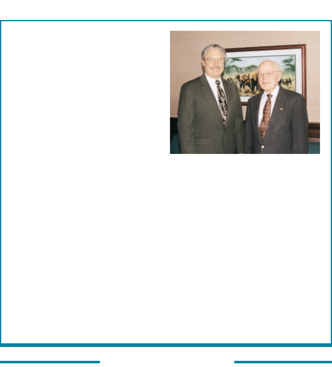
Tony Massaro
Chairman & CEO
The Lincoln Electric Company
Tony Massaro and Omer Blodgett
Australia and
New Zealand
Raymond K. Ryan
Phone: 61-29-772-7222
Fax: 61-29-792-1387
Croatia
Prof. Dr. Slobodan Kralj
Phone: 385-1-6168306
Fax: 385-1-6157124
Hungary
Dr. Géza Gremsperger
Phone: 361-156-3306
India
Dr. V.R. Krishnan
Phone: 91-11-247-5139
Fax: 91-124-321985
Japan
Dr. Motoomi Ogata
Phone: 81-565-48-8121
Fax: 81-565-48-0030
People’s Republic
of China
Dai Shu Hua
Phone: 022-831-4170
Fax: 022-831-4179
Russia
Dr. Vladimir P. Yatsenko
Phone: 07-095-238-5543
Fax: 07-095-238-6934
United Kingdom
Dr. Ralph B.G. Yeo
Phone & Fax:
44-1709-379905
INTERNATIONAL ASSISTANT SECRETARIES
1
Welding Innovation Vol. XVI, No. 2, 1999
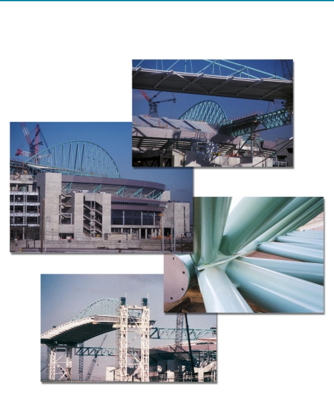
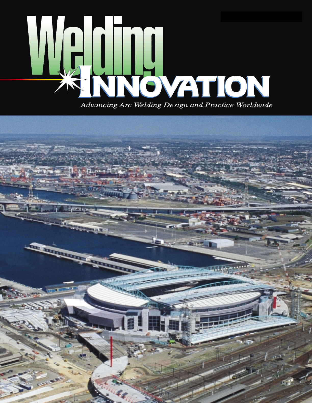
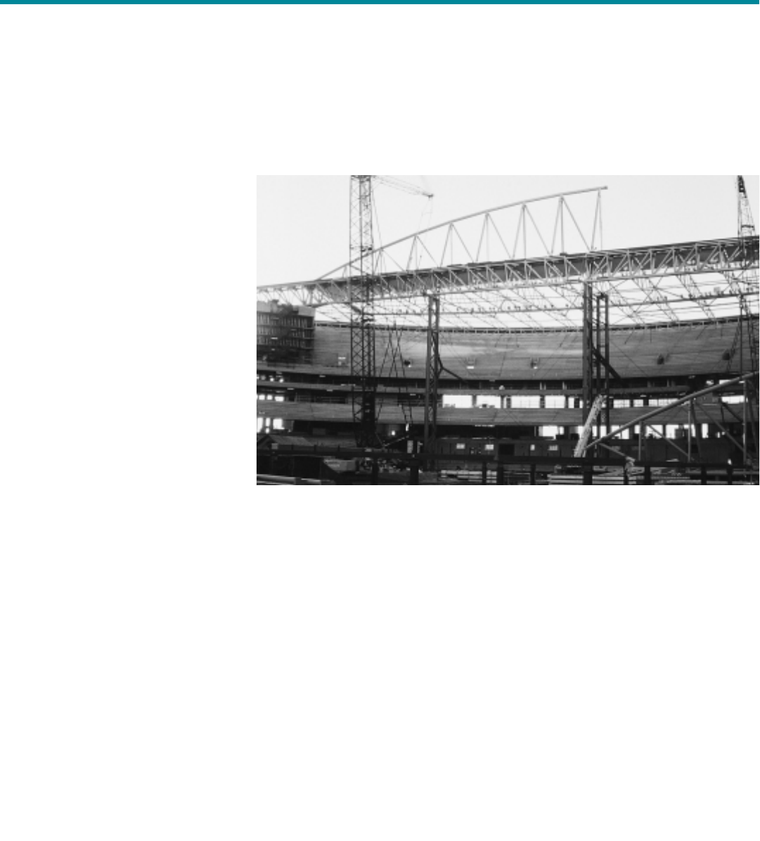
Cover: Melbourne’s Colonial Stadium
features state-of-the-art technology and
a retractable roof that will open and close
in just 20 minutes. See story on page 22.
2Common Mistakes Made in the Design
of Aluminum Weldments
When designing with aluminum, the engineer must not rely
on prior experiences with steel or any other material.
7Framed in Steel: Dwellings for the New Millennium
A small Ohio company is capitalizing on the advantages of using
light gauge steel in residential construction.
22 Challenging Stadium Project Headed
for On-Time Completion
Weld fabrication of the Colonial Stadium being built in Melbourne, Australia,
required special treatment to ensure that the high strength of the steel
would be fully utilized.
The serviceability of a prod-
uct or structure utilizing the
type of information present-
ed herein is, and must be,
the sole responsibility of the
builder/user. Many vari-
ables beyond the control of
The James F. Lincoln Arc
Welding Foundation or The
Lincoln Electric Company
affect the results obtained
in applying this type of infor-
mation. These variables
include, but are not limited
to, welding procedure, plate
chemistry and temperature,
weldment design, fabrica-
tion methods, and service
requirements.
Volume XVI
Number 2, 1999
Editor
Duane K. Miller,
Sc.D., P.E.
Assistant Editor
R. Scott Funderburk
The James F. Lincoln
Arc Welding Foundation
Omer W. Blodgett, Sc.D., P.E.
Design Consultant
Features
Award Programs
Departments
10 Key Concepts:
Selecting Filler Metals: Matching Strength Criteria
17 Design File:
Use Caution When Specifying Seal Welds
21 Opportunities:
Year 2000 Professional Programs
Visit
Welding Innovation
online at http://www.lincolnelectric.com/services/educate/innovate.asp
13 1999 Awards for Engineering
and Technology Students
THE JAMES F. LINCOLN ARC WELDING FOUNDATION TRUSTEES & OFFICERS
Dr. Donald N. Zwiep,
Chairman
Worcester, Massachusetts
John T. Frieg,
Trustee
Cleveland, Ohio
Leslie L. Knowlton,
Trustee
Cleveland, Ohio
Roy L. Morrow
Executive Director
Duane K. Miller, Sc.D., P.E.
Secretary
2 Welding Innovation Vol. XVI, No. 2, 1999
Common Mistakes Made
in the Design of
By Frank G. Armao
Senior Application Engineer
The Lincoln Electric Company
Cleveland, Ohio
Background
As a rule, designers of metallic struc-
tures have learned to design using
steel. When designing with alu-
minum, however, the engineer must
not base the design on prior experi-
ences with steel or any other material.
The alloy selection, proper joint design
and the choice of an optimal welding
process may all be a function of the
base material. While aluminum obvi-
ously obeys the same laws of
mechanics as all other materials, it
must be approached differently than
steel when welded. Aluminum struc-
tures are not necessarily more difficult
to design or weld than steel structures,
they are just different.
Don’t Just Choose
the Strongest Alloy
Aluminum is often chosen as a struc-
tural material for applications in which
weight savings are important. Very
often, the designer will choose the
very strongest alloy available. This is
a poor design practice for several rea-
sons. First, the critical design limita-
tion for many structures often is
deflection, not strength. In such
cases, the modulus of elasticity, not
the tensile properties, will govern the
design. The modulus of most alu-
minum alloys, weak and strong alike,
is approximately the same (one-third
the modulus of elasticity of steel), so
no benefit accrues from using the
strongest alloy. Second, and most
importantly, many of the strongest alu-
minum alloys are not weldable using
conventional techniques.
When we speak about aluminum
alloys being “weldable” or “non-weld-
able,” we are usually referring to the
alloy’s ability to be welded without hot
cracking. Alloys that are extremely
susceptible to hot cracking are not
considered appropriate for structural
(load-carrying) applications, and are
generally put in the non-weldable cate-
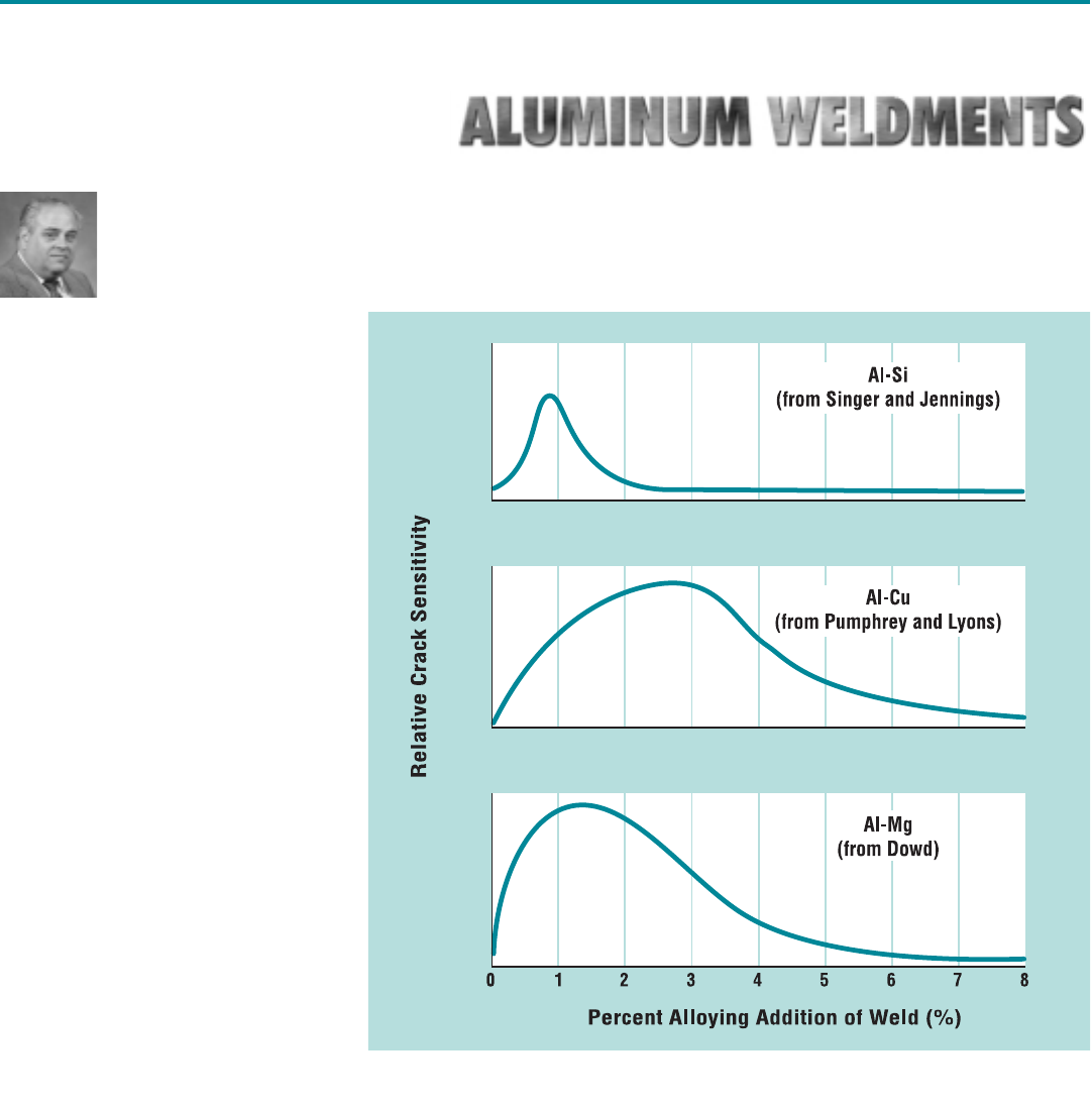
gory. Hot cracking in aluminum alloys
is primarily due to the chemistry of the
alloy and the weld bead. For virtually
every alloying addition, the cracking
sensitivity varies as alloy content
increases as shown in Figure 1.
Weldable alloys have a composition
that falls either well above or well
below the maximum cracking sensitivi-
ty. In some cases, such as that of
6061, which is very crack-sensitive if
welded without filler material, the weld
cracking sensitivity can be reduced to
Figure 1. Relative crack sensitivity versus weld composition for various binary
aluminum systems.
Return to TOC
Welding Innovation Vol. XVI, No. 2, 1999 3
acceptable levels with the addition of
a high silicon or high magnesium filler
metal. The additional silicon or mag-
nesium pushes the solidifying weld
metal below the cracking sensitivity
level. In other alloys, such as 7075, it
is not possible to design a weld filler
alloy that results in a crack-resistant
chemistry. These are considered to be
non-weldable.
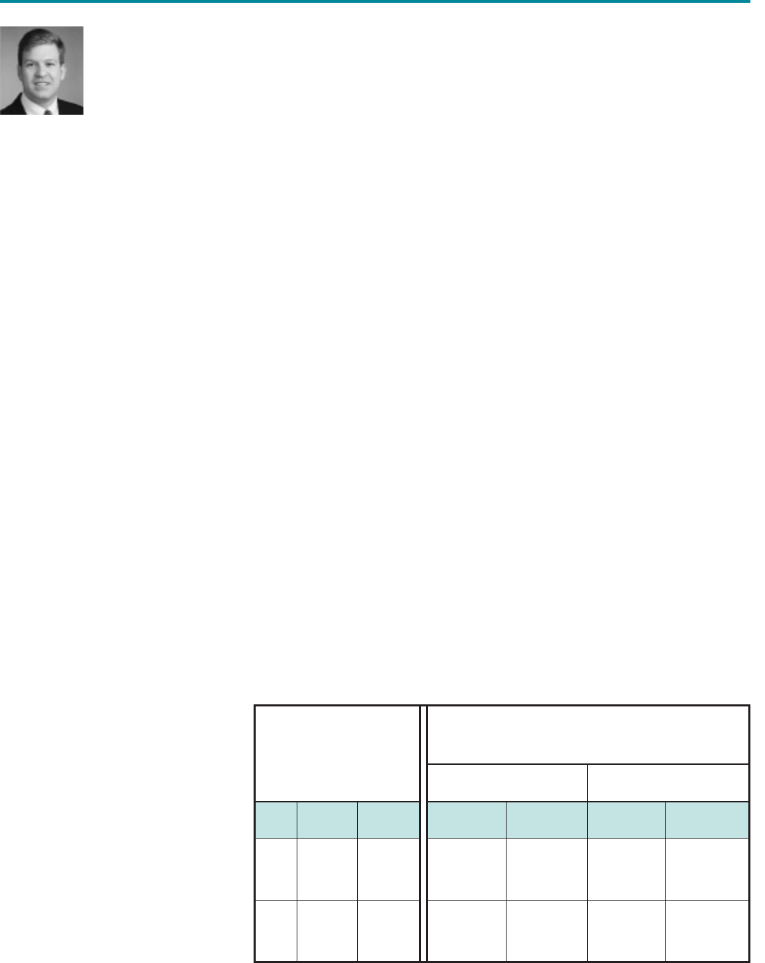
A number of common aluminum alloys
are shown in Figure 2, along with typi-
cal ultimate tensile strength values.
These alloys have been broken into
two groups: heat-treatable alloys and
non-heat-treatable alloys. A relative
assessment of weldability is also given
for each of these.
The non-heat-treatable alloys are
composed of the 1XXX, 3XXX, 4XXX,
and 5XXX series. It is not possible to
strengthen these alloys by heat treat-
ment. They can only be strengthened
by cold working (also called strain
hardening). The 1XXX alloys, such as
1100, 1188, or 1350, are essentially
pure aluminum (99+% purity). They
are relatively soft and weak, with good
corrosion resistance, and are usually
used where high electrical conductivity
is required, such as for bus bars or as
electrical conductors. They are also
used in certain applications that
require a high degree of resistance to
corrosion. All of these alloys are read-
ily weldable.
The 3XXX series of alloys have vari-
ous levels of manganese (Mn) added
to strengthen them and improve their
response to cold work. They are of
moderate strength, have good corro-
sion resistance, and are readily weld-
able. They are used for air conditioning
and refrigeration systems, non-structur-
al building trim, and other applications.
The 4XXX series of alloys have silicon
(Si) added as an alloying element to
reduce the melting point and increase
their fluidity in the molten state. These
alloys are used for welding and braz-
ing filler materials and for sand and
die castings. They are the least crack-
sensitive of all the aluminum alloys.
The 5XXX series of alloys have mag-
nesium (Mg) added in order to
increase their strength and ability to
work-harden. They are generally very
corrosion resistant and have the high-
est strengths of any of the non-heat-
treatable alloys. Increasing
magnesium content in these alloys
results in increasing strength levels.
These alloys are commonly available
in the form of sheet, plate and strip,
and are the most common structural
aluminum alloys. They are generally
not available as extruded sections,
because they are expensive to
extrude. They are readily weldable, in
most cases, with or without filler metal.
However, there is an Al-Mg cracking
peak at approximately 2.5% Mg, so
care must be used in welding alloys
such as 5052. It should not be welded
autogenously (i.e., without adding filler
metal). Weld filler metal with a high
Mg content, such as 5356, should be
used to reduce the crack sensitivity.
The heat-treatable alloys are con-
tained in the 2XXX, 6XXX, and 7XXX
alloy families. The 2XXX family of
alloys are high strength Al-Cu alloys
used mainly for aerospace applica-
tions. In some environments, they can
exhibit poor corrosion resistance. In
general, most alloys in this series are
considered non-weldable. A prime
example of a non-weldable alloy in this
series, which is attractive to designers
because of its high strength, is alloy
2024. This alloy is commonly used in
airframes, where it is almost always
riveted. It is extremely crack-sensitive
and almost impossible to weld suc-
cessfully using standard techniques.
Only two common structural alloys in
the 2XXX series are weldable: 2219
and 2519. Alloy 2219 is very easily
weldable and has been extensively
welded in fabricating the external
tanks for the U.S. space shuttle. This
alloy gets its good weldability because
of its higher copper content, approxi-
mately 6%. A closely related alloy,
which is also very weldable, is 2519.
It was developed for fabrication of
armored vehicles. Although there are
detailed exceptions to this rule, the
designer should probably consider all
other alloys in the 2XXX series to be
non-weldable.
The 6XXX series of alloys are the
alloys probably most often encoun-
tered in structural work. They are rela-
tively strong (although not as strong as
the 2XXX or 7XXX series) and have
good corrosion resistance. They are
most often supplied as extrusions. In
fact, if the designer specifies an extru-
sion, it will almost certainly be sup-
plied as a 6XXX alloy. 6XXX alloys
may also be supplied as sheet, plate
The critical
design limitation
for many structures
often is deflection,
not strength…
Figure 2. Various aluminum alloys and
their relative strengths.
Alloy Typical Ultimate
Tensile Stress
1XXX Alloys
1100-0
1350-0
1350-H18
2XXX Alloys
2219-T62
2024-T62
3XXX Alloys
3003-0
3003-H18
4XXX Alloys
4143-0
5XXX Alloys
5083-0
5052-0
6XXX Alloys
6061-0
6061-T4
6061-T6
7XXX Alloys
7075-T6
7178-T6
ksi
13
11
18
54
64
16
27
17
40
25
20
30
40
78
84
MPa
90
75
125
370
440
110
185
115
275
170
140
210
275
540
580
Return to TOC
4 Welding Innovation Vol. XVI, No. 2, 1999
and bar, and are the most common
heat treatable structural alloys.
Although all alloys in this series tend
to be crack-sensitive, they are all con-
sidered weldable and are, in fact,
welded every day. However, the cor-
rect weld filler metal must be used to
eliminate cracking. Additionally, these
alloys will usually crack if they are
welded either without, or with insuffi-
cient, filler metal additions.
The 7XXX alloys are the ones that
usually trip designers up. They are the
very high strength Al-Zn or Al-Zn-Mg-
Cu alloys that are often used in aero-
space fabrication, and are supplied in
the form of sheet, plate, forgings, and
bar, as well as extrusions. With the
few exceptions noted below, the
designer should assume that the
7XXX alloys are non-weldable. The
most common of these alloys is 7075,
which should never be welded for
structural applications. In addition,
these alloys often suffer from poor corro-
sion performance in many environments.
A few of the 7XXX series defy the
general rule and are weldable. These
are alloys 7003 and 7005, which are
often seen as extrusions, and 7039,
which is most often seen as sheet or
plate. Some common uses of these
alloys today are bicycle frames and
baseball bats, both of which are weld-
ed. These alloys are easily welded
and can sometimes offer strength
advantages in the as-welded condition
over the 6XXX and 5XXX alloys.
There is one other exception to the
general rule that 2XXX and 7XXX
alloys are unweldable. There are a
number of thick cast and/or wrought
plate alloys designed as mold plate
material for the injection molding
industry. These alloys, which include
Alca Plus, Alca Max, and QC-7, are all
very close in chemistry to 7075 or
2618. The designer should absolutely
avoid structural welds on these alloys.
However, welding is often performed
on these alloys to correct machining
mistakes, die erosion, etc. This is
acceptable because there are only low
stresses on such welds and, in fact,
the weld is often in compression.
This discussion has tried to make
a few points:
• First, when designing a structure of
any kind, don’t scroll through the
nearest list of aluminum alloys and
pick the strongest.
• Realize that some alloys, often the
stronger ones, are non-weldable.
Make sure the selected alloy is
readily weldable.
• Recognize that some alloys or alloy
families are more suitable for some
applications than others.
One more caveat: when welding alu-
minum, the designer must not assume
that the properties of the starting mate-
rial and the properties of the weld are
equivalent.
Why Isn’t the Weld as
Strong as the Original
Base Metal?
A designer of steel structures general-
ly assumes that a weld is as strong as
the parent material, and the welding
engineer who is responsible for fabri-
cating the structure expects to make a
weld which is as strong as the steel
being used. It would be tempting to
assume that the situation is the same
when designing and fabricating alu-
minum structures, but it isn’t. In most
cases, a weld in an aluminum alloy is
weaker, often to a significant degree,
than the alloy being welded.
In order to understand why this is so,
we must discuss the heat-treatable
and non-heat-treatable alloys sepa-
rately and define the temper designa-
tions used for aluminum alloys.
Non-Heat-Treatable
Alloys
Alloys in this category (i.e., 1XXX,
3XXX, 4XXX, and 5XXX families) are
produced by a cold working process:
rolling, drawing, etc. After the cold
working process, the alloy is given the
designation of an F temper (as-fabri-
cated). Alloys are then often given a
subsequent annealing heat treatment,
after which they are classified as an O
temper (annealed). Many alloys are
sold in this condition. Thus the correct
designation for a plate of 5083 which
was annealed after rolling is 5083 – O.
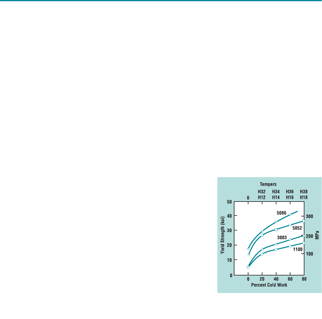
One of the attractive properties of
these alloys is that they can be signifi-
cantly increased in strength if they are
cold worked after annealing. Figure 3
shows what happens to several alloys
with varying amounts of cold work.
For example, alloy 5086 rises in yield
strength from approximately 18 ksi
(125 MPa) to 40 ksi (275 MPa) and is
now said to be strain-hardened. A
complete designation for this alloy
would be 5056-H36. The H temper
designation can be somewhat compli-
cated, since it is used to designate a
number of processing variables.
However, the last digit, which ranges
from 1 to 8, designates the level of
cold working in the alloy, with 8 denot-
ing the highest.
…some alloys, often
the stronger ones,
are non-weldable…
Figure 3. Effect of cold work on yield
strength of several work-hardening
alloys.
Return to TOC
Welding Innovation Vol. XVI, No. 2, 1999 5
A common mistake in designing weld-
ed structures using non-heat-treatable
alloys is to look down a list of proper-
ties, disregard the O temper material,
and choose an alloy of the highest
temper because it is significantly
stronger. This would seem to make
sense, but it often doesn’t, because
the heat of welding acts as a local
annealing operation, significantly
weakening the heat affected zone
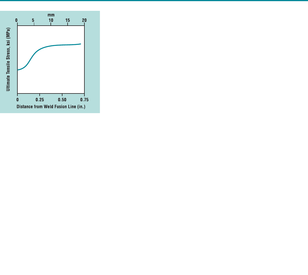
(HAZ) of the weld. If one plots the
yield or tensile stress versus distance
from the weld, a curve such as that
seen in Figure 4 is obtained. If the
design is based on the strain hard-
ened properties, the allowable design
stress will usually be above the actual
yield point of the HAZ. Although it
may seem counter-intuitive, the fact is
this: No matter what temper one starts
with, the properties in the HAZ will be
those of the O temper annealed mate-
rial due to the welding operation.
Therefore, the design must be based
on the annealed properties, not on the
strain-hardened properties. Because
of this, it usually doesn’t make sense
to buy the more expensive strain hard-
ened tempers for welded fabrications.
One should design with and specify
the alloy in the O temper and up-
gauge as necessary.
An obvious question is whether any-
thing can be done to restore material
properties after welding a strain-hard-
ened material. Unfortunately, the
answer is almost always no. The only
way to harden these materials is
through mechanical deformation, and
this is almost never practical for weld-
ed structures.
Heat-Treatable Alloys
The situation is somewhat different
when welding the heat-treatable alloys.
Alloys are heat-treated by initially heat-
ing the material to approximately
1000°F (540°C), holding the tempera-
ture for a short time, and then quench-
ing it in water. This operation is
intended to dissolve all the alloying
additions in solution and hold them
there at room temperature. Alloys in
this condition are said to be in the T4
temper and have significantly higher
strengths than the same alloy in the O
temper. Depending on the alloy, “natu-
ral aging” at room temperature can
lead to further strength increases over
time. This takes place over a matter of
days or, at most, a few weeks. After
that, the properties will remain stable
over decades. If one buys T4 material,
it is stable and the properties will not
change over the course of a lifetime.
However, most alloys are given an
additional heat treatment to obtain the
highest mechanical properties. This
heat treatment consists of holding the
material at approximately 400°F
(205°C) for a few hours. During this
time, the alloying additions that were
dissolved in the prior heat treatment
precipitate in a controlled manner,
which strengthens the alloy. Material
in this condition is designated as T6
(artificially aged) temper, the most
common heat-treated alloy temper.
Again, the complete temper designa-
tion system is actually much more
complex than this, but understanding
the T4 and T6 tempers will help to
overcome some of the most common
mistakes made when designing alu-
minum weldments. It is important to
note that heat treatable alloys can also
be strain-hardened after heat treat-
ment, and this can further complicate
the temper designation.
Remember that the aging treatment is
performed at approximately 400°F
(205°C). Any arc welding process gets
the HAZ much hotter than this.
Therefore, welding constitutes an addi-
tional heat treatment for the HAZ.
Some alloys experience an additional
solution heat treatment, while other
alloys become overaged in the HAZ.
This results in degradation of material
properties, especially if the as-welded
properties are compared to T6 proper-
ties. For example, the minimum speci-
fied tensile strength in ASTM B209 for
6061 – T6 is 40 ksi (275 MPa). Most
fabrication codes require a minimum as-
welded tensile strength of 24 ksi (165
MPa), which is a significant degradation.
As when designing for the non-heat-
treatable alloys, the designer must not
use the parent material properties in
design. Realistic as-welded properties
must be used. It is difficult to general-
ize what these properties are. They
change from alloy to alloy and depend
strongly on the starting temper of the
alloy. Most design codes contain as-
welded properties for aluminum alloys
and these should be used.
Understanding the T4
and T6 tempers will
help to overcome some
of the most common
mistakes…
Figure 4. Tensile stress vs. distance
from weld fusion line.
Return to TOC
6 Welding Innovation Vol. XVI, No. 2, 1999
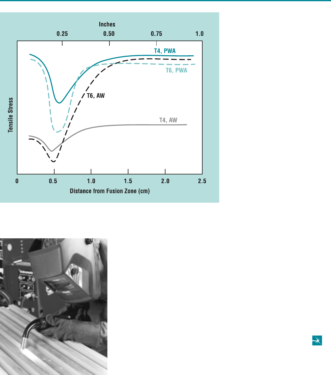
With heat-treatable alloys, however,
there are some ways to recover some
of the material properties of the par-
ent. Figure 5 shows a plot of tensile
stress versus distance from the weld
for 6061, revealing curves for both T4
and T6 material in both the as-welded
(AW) and post-weld-aged (PWA) con-
ditions. The PWA condition represents
a weld that is subsequently aged for
one hour at approximately 400°F
(205°C). Post weld aging improves
the mechanical properties for both T4
and T6 starting materials. In fact,
often times it is better to weld in the T4
condition and post weld age after the
welding process.
There is one final alternative to dis-
cuss. If after welding, the structure is
given a complete heat treatment (i.e.,
solution treat at 1000°F [540°C],
quench, age at 400°F [205°C]), all of
the material properties (even in the
weld) will be recovered and T6 proper-
ties will be obtained. This practice is
frequently followed on small structures
such as bicycle frames, but it is
impractical for larger structures.
Furthermore, the quenching usually
causes enough distortion of the struc-
ture that a straightening operation is
necessary before aging.
Conclusions
In the design of welded aluminum
structures, too often the differences
between steel and aluminum are not
taken into account. To recap, common
mistakes include:
• Not all aluminum alloys are weld-
able. In general, the least weldable
alloys are also the strongest alloys.
• The weld will rarely be as strong as
the parent material.
• The HAZ will have O temper
annealed properties for non-heat-
treatable alloys regardless of the ini-
tial material temper.
• For the heat treatable alloys, the as-
welded properties will be significant-
ly lower than the properties of the
T6 alloy temper.
• Post-weld heat treatment can help to
restore the mechanical properties of
welds in heat treatable alloys.
Figure 5. Tensile stress profiles of the heat affected zone for 6061-T4 and T6
starting material in the As-Welded (AW) and Post-Weld Aged (PWA) conditions.
Return to TOC
Welding Innovation Vol. XVI, No. 2, 1999 7
At Enertech Systems, Inc., in
Cleveland, Ohio, Michael Whitticar and
his two partners are preaching a
gospel new to the midwestern United
States: the advantages of using light
gauge steel in residential construction.
Despite the fact that most American-
produced steel comes from this
region, area builders have so far been
slow to embrace this alternative to
wood. In the U.S., the popularity of
steel-framed housing continues to be
greatest in Hawaii and California,
where steel’s ability to withstand high
winds and earthquakes has been a
significant selling point, according to
Geoffrey C. Stone, director of corpo-
rate programs for the North American
Steel Framing Alliance (NASFA).
Whitticar notes that Enertech Systems
was formed in 1994, when lumber
prices had hit a peak, sparking a sud-
den interest in steel. Investors William
Tuttle and Nicholas Russo had already
identified residential construction as a
huge potential market for light gauge
steel. When they discovered Whitticar,
a third generation carpenter who had
learned how to frame houses with
steel while living in Canada, they knew
they had found the technical expertise
needed to round out their team. For
the first year of its existence, the fledg-
ling company simply offered its servic-
es on a consulting basis. In 1995,
Enertech began to get involved in the
fabrication of steel trusses.
Workshop Case Study
In the mid-1990s, LTV Steel
approached Greater Cleveland Habitat
for Humanity with an offer to donate
light gauge steel, detailed drawings,
some tools, and design assistance if
Habitat would consent to use steel
frames to construct some of its afford-
able homes. Agreeing with alacrity,
Habitat soon secured a building in
inner city Cleveland where it could
panelize its own trusses. When the
project reaches completion, more than
30 steel-framed Habitat houses will
have been constructed in the
Cleveland area.
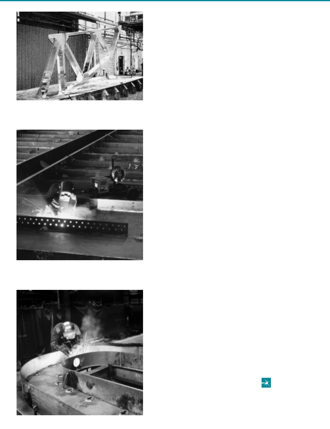
In August, 1999, Enertech joined
forces with NASFA (an affiliate of the
American Iron and Steel Institute), the
Lincoln Electric Company, and LTV
Steel to co-sponsor a four-day
“Workshop on Applications and
Practices for Cold-Formed Steel
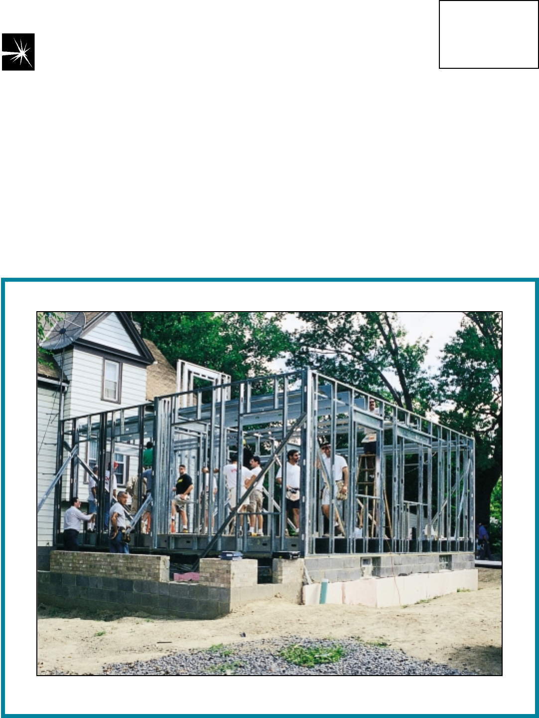
Framing.” The practical case for the
workshop was a 1,300 sq ft steel-
framed Habitat for Humanity house
under construction at 2205 East 100th
St. in Cleveland (Figure 1). LTV and
Rysar Homes donated the time and
materials to build the house, with
Enertech donating some time, and
also being reimbursed by LTV Steel for
some of its participation.
Framed in Steel:
Dwellings for the New Millennium
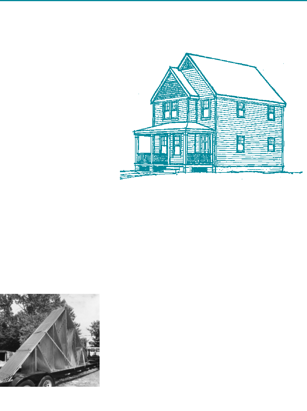
Figure 2. Prefabricated light gauge steel
frame trusses were towed to the site.
Light gauge steel is
used in 3-4 percent
of homes currently
being built
By Carla Rautenberg
Welding Innovation
Contributing Writer
James F. Lincoln Arc Welding Foundation
Cleveland, Ohio
Figure 1. This rendering of a modest traditional Habitat for Humanity house
betrays no hint of the actual structure’s steel frame.
Return to TOC

8 Welding Innovation Vol. XVI, No. 2, 1999
An introductory seminar featured three
presentations:
• Geoff Stone presented the mission
and goals of NASFA.
• Hank Mailand, general manager of
cost reduction for NASFA, described
the organization’s cost reduction
program.
• Mike Whitticar lectured on “Cold-
Formed Steel Framing –
Applications and Practices.”
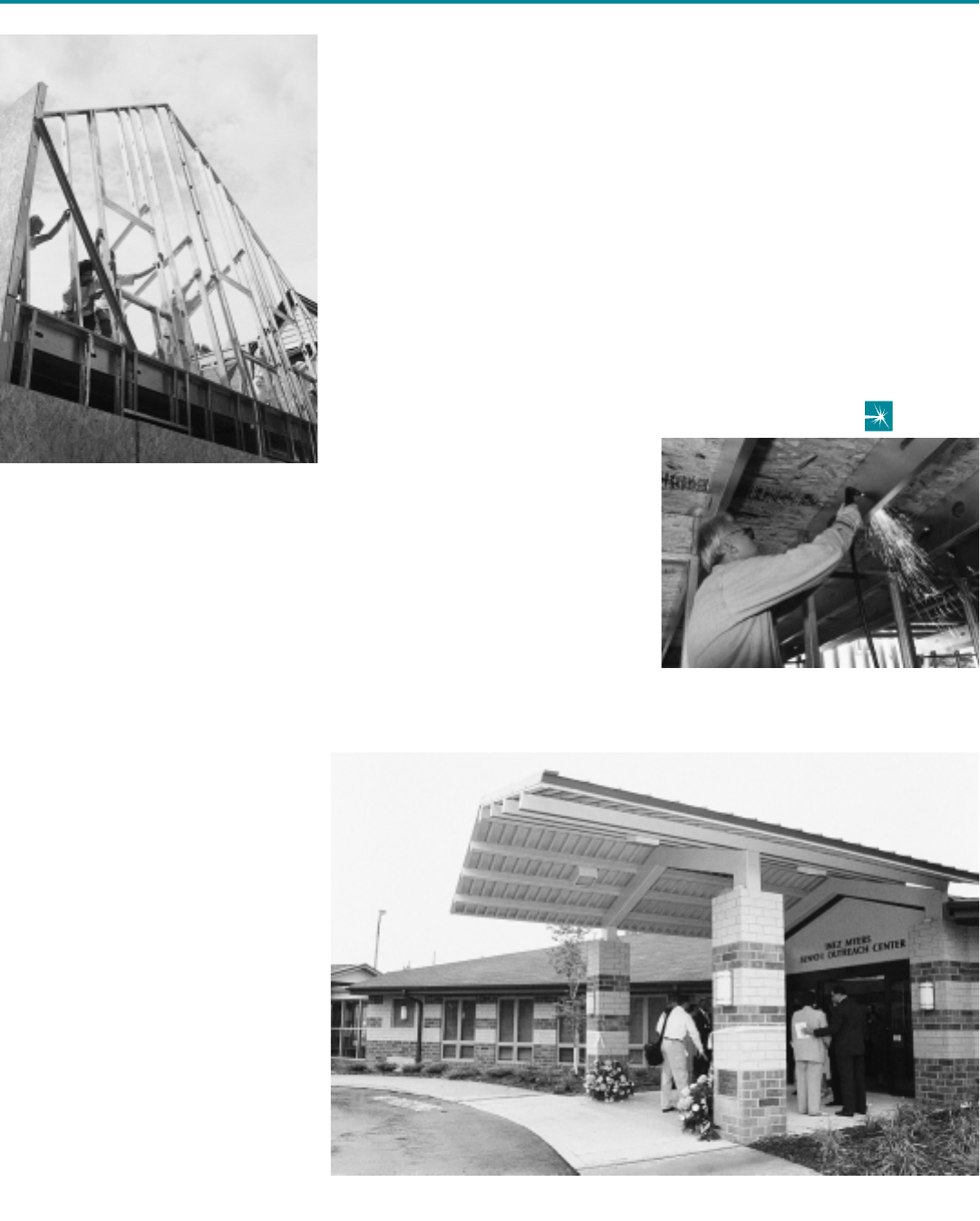
Following the formal program, work-
shop attendees traveled to the con-
struction site, where, after watching
demonstrations by Enertech personnel,
they assisted in the construction of
floor joists and sheathing, exterior and
interior wall framing, and the erection
of roof/truss framing (Figures 2 and 3).
In addition, Lincoln Electric personnel
demonstrated the use of a Lincoln
SP175 Plus welder and a Pro-Cut 25
plasma cutter (Figure 4).
“Fastening productivity is a critical issue
for steel at this stage of its market
development,” says Don Moody, NASFA
president. “NASFA has dedicated a
great amount of effort and resources to
help develop a fastening system that
will connect steel members as quickly
and cost-effectively as wood members
are connected. Spot welding is one
method we are reviewing.”
Currently, Enertech uses screws to
fasten light gauge steel members
together. Whitticar readily admits,
“We’re new to the welding industry, but
we certainly see the technology’s
potential to create a superior connec-
tion as far as providing shear value
goes.” He and his employees have
experimented with Lincoln’s new
equipment for one-sided spot welding,
and found it to be quick and efficient
while offering a better shear value
than a screwed connection.
Ultimately, however, Whitticar expects
welding will be fastest and therefore
most cost effective for shop paneliza-
tion of walls and roof trusses.
The American Society for Testing
and Materials (ASTM) has
announced that its Subcommittee
A05.11 on Sheet Specifications is
currently developing two draft stan-
dards to govern the use of steel
sheet to make cold-formed framing
members for studs, joists, purlins,
girts and track in residential con-
struction. According to Don Moody,
president of the North American
Steel Framing Alliance, “The fact that
ASTM is currently developing these
two important standards for cold-
formed steel in residential construc-
tion is a testament to the
fast-growing interest in steel for this
market. NASFA strongly supports
their efforts.”
The draft standards now under
development are:
• “Standard Specification for Steel
Sheet, Carbon, Metallic and Non-
Metallic Coated For Cold-Formed
Framing Members”—covers coated
steel sheet used in the manufac-
ture of cold-formed framing mem-
bers. Sections include
terminology, classification, materi-
als and manufacture, mechanical
and coating properties, certifica-
tion, chemical composition tables,
and more.
• “Standard Practice for Establishing
Conformance to the Minimum
Cold Formed Steel Framing Standards
Under Development
Expected Corrosion Characteristics
of Metallic, Painted-Metallic, and
Non-Metallic Coated Steel Sheet
Intended for Use as Cold Formed
Framing Members”—covers proce-
dures used to establish the accept-
ability of metallic coated steel
sheet, and painted metallic or non-
metallic-coated steel sheet for use
as cold-formed framing members.
This practice assesses whether
materials used for cold-formed
framing members satisfy the
required minimum expected corro-
sion characteristics. In-depth sec-
tions on teminology, summary of
practice, use, procedure, and relat-
ed topics are included.
Donald Mongeon, chairman of
Subcommittee A05.11, reports:
“There were people involved in the
task group who use, specify, and
manufacture the cold-formed framing
members—specifiers, architects,
engineers, steel producers. We’re
trying to reach compromise among
those disparate interests who have
their own set of priorities and we’re
using the ASTM balloting method to
get there.”
Editor’s Note: Committee A-5 is one of 129
ASTM technical standards-writing committees.
Organized in 1898, ASTM has more than
34,000 members from around the globe and is
one of the largest voluntary standards devel-
opment organizations in the world.
Participation in ASTM is open to any interest-
ed party. Web Site: www.astm.org.
Potential—and Barriers
Whitticar sees the most potential for
steel to penetrate the residential mar-
ket with applications that are essential-
ly a hybrid of steel and wood
construction. For example, he sug-
gests that home builders consider the
use of steel floor joists for elevated
floor framing because:
• Steel floor joists are dimensionally
stable, which eliminates the need to
cull and crown each member.
• Steel joists are lighter and will out-
span traditional dimensional wood
joists of equal size.
• Steel is cost-competitive with engi-
neered wood.
Return to TOC
Welding Innovation Vol. XVI, No. 2, 1999 9
According to NASFA, barriers to
greater use of steel in residential con-
struction include:
• The higher cost of construction.
• Thermal performance—steel alone
conducts heat through the walls
more than wood, but with appropri-
ate insulation, steel can exhibit
equivalent or better performance.
• Lack of infrastructure—the fact that
carpenters and lumberyards are
accustomed to working with wood,
not steel.
• Lack of standards—although this is
now being addressed by ASTM (see
sidebar).
Geoff Stone notes, “At NASFA, we are
systematically addressing these barri-
ers, and our goal is to fully enable the
home-building market for the wide-
spread and economic use of steel
framing, in any application that makes
sense.” NASFA estimates that light
gauge steel is used in one or all fram-
ing applications (floors, walls, ceilings
and roofs) in approximately 3-4 per-
cent of homes currently being built.
Commercial Use
of Cold-Formed Steel
Another area that interests the princi-
pals of Enertech is the use of cold-
formed steel for low-rise commercial
construction, which typically includes
applications such as schools, assisted
care living facilities, hotels and motels,
multiple occupancy residences,
churches and certain types of retail
structures. As an example of this mar-
ket, Mike Whitticar cited his company’s
work on the recently completed Eliza
Bryant Center in Cleveland, which is
the first HUD-financed assisted living
facility to be framed in steel (Figure 5).
HUD officials jumped on the light
gauge steel frame bandwagon when
they became convinced of the materi-
al’s benefits:
• Non-combustible framing at a lower
price than comparable fire-treated
wood framing components.
• Commercial sub-trades are familiar
with using steel framing.
• With the highest strength-to-weight
ratio of any building material, steel is
conducive to long spans.
• Attic sprinklers could be eliminated.
On September 13, 1999, the Eliza
Bryant Center was officially opened.
Whitticar notes that the three-story,
52,000 sq ft structure was built by
combining panelization and traditional
stick framing. The framing portion of
the job, which consumed 212 tons of
cold-formed steel, was completed in
approximately 3-1/2 months, and no
site crane was required.
Fastening productivity
is a critical issue
for steel
Figure 3. Volunteers installed the site-
fabricated steel frame.
Figure 4. The Habitat for Humanity
house was used to demonstrate
plasma cutting of light gauge steel.
Figure 5. Cleveland’s Eliza Bryant Center was framed in cold-formed steel.
Return to TOC
10 Welding Innovation Vol. XVI, No. 2, 1999
Key Concepts in Welding Engineering
by R. Scott Funderburk
Introduction
This column is the first of a series that
will address topics related to filler metal
selection. The focus will be on the con-
cerns of design engineers, beginning
with filler metal strength. The strength
of weld metal vs. base metals may be
defined as matching, overmatching or
undermatching. This column will
address “matching” filler metal.
What is
“Matching” Strength?
What is “matching strength” filler
metal? The
AWS A3.0 Standard
Welding Terms and Definitions
does
not contain such a term, although it
has been used for years. “Matching
strength,” on the surface, would seem
to imply that the filler metal will deposit
weld metal of the exact strength as (or
“matching”) the base metal. Codes
have tables with lists of matching filler
metals, such as the
AWS D1.1
Structural Welding Code – Steel
, Table
3.1, as do various filler metal suppli-
ers. A careful review of AWS D1.1,
Table 3.1, shows that the matching
electrodes do not deposit welds with
exactly the same strength as the base
metal, and in reality, this is not what is
meant by “matching.”
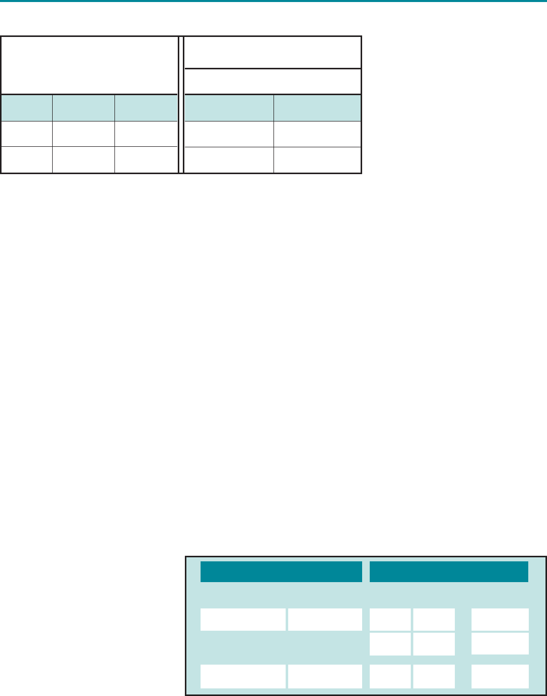
In Table 3.1, A36 and A570 Gr. 50 are
both listed in the Group I category.
“Matching” filler metal is shown as
both E60 and E70 electrode and
flux/electrode classifications. A36 and
A570 Gr. 50 have different minimum
specified yield and tensile strengths,
as do E60 and E70 filler metals.
Obviously, matching cannot be as sim-
ple as “matching” the base metal
strength (see Table 1).
While AWS D1.1 calls the preceding
combinations “matching,” clearly the
minimum specified weld metal proper-
ties are not the same as the minimum
specified base metal properties. The
matching combinations for AWS D1.1,
Table 3.1, Group III materials provide
some additional insight, where the min-
imum specified filler metal properties
are more closely matched to the base
metal, and the tensile strength values
are very similar (see Table 2).
All of the preceding examples are
considered “matching,” although the
degree of match is different. The
common element is that the minimum
specified tensile strength of the filler
metal is always the same as or greater
than the minimum specified tensile
Selecting Filler Metals:
Matching Strength Criteria
Table 1. Filler/Base Metal Strength Comparison in AWS D1.1, Table 3.1, Group I.
Base Metal
AWS D1.1, Table 3.1,
Group I
“Matching” Filler Metal
E60, Fy = 48 ksi (330 MPa)
Fu = 60 ksi (415 MPa)
Yield,
ksi (MPa)
Tensile,
ksi (MPa)
A36 36 min.
(250)
58-80
(400-550)
50 min.
(345)
65 min.
(450)
Weld is 12 ksi
(80 MPa)
greater
Weld is 2 ksi
(15 MPa) less
Weld is 5 ksi
(35 MPa) less
Weld is 8 ksi
(55 MPa)
greater
Weld is 5 ksi
(30 MPa)
greater
Weld is between
2 ksi (15 MPa)
greater to 20 ksi
(135 MPa) less
Weld is 22 ksi
(150 MPa)
greater
Weld is between
12 ksi (80 MPa)
greater to 10 ksi
(70 MPa) less
A572
Gr. 50
Yield Tensile Yield Tensile
E70, Fy = 58 ksi (400 MPa)
Fu = 70 ksi (480 MPa)
Matching tensile
strengths often do not
result in matching
yield strengths
Return to TOC
11
Welding Innovation Vol. XVI, No. 2, 1999
strength of the base metal. The com-
parison is of the “minimum specified
properties,” not the actual properties of
the delivered steel, or of the deposited
weld metal. Since these are minimum
properties, actual deposited welds on
the actual steel will routinely exceed
those values.
Matching tensile strengths often do not
result in matching yield strengths
because the yield-to-tensile ratio for
most hot rolled steels is lower than that
of most as-deposited welds. Therefore,
a match of both yield and tensile
strength is improbable. However, for
higher strength steels, the yield-to-ten-
sile ratio typically approaches the val-
ues for welds and provides for a closer
match of both the yield and tensile
strengths. Table 3 shows the average
yield-to-tensile ratio for all the base
metals contained in Groups I and III
and the corresponding matching filler
metals of the AWS D1.1-98 Code,
Table 3.1. The difference between the
filler metal and base metal yield-to-ten-
sile ratio is much less of the higher
strength combination (Group III) than
that of the mild steel combination
(Group I) as shown by the percent dif-
ference (% Diff.).
Ultimately, matching compares weld
and base metal properties. However,
welds are not specified per se; filler
metals are. Thus, tables of matching
products typically are called “matching
filler metals,” not “matching weld metals.”
Joints Requiring
Matching Filler Metal
The need for matching filler metals is
dependent upon joint type and loading
condition. AWS D1.1, Table 2.3
“Allowable Stresses in Nontubular
Connection Welds” shows that match-
ing filler metal is required for only one
combination of loading and joint type –
tension loading of CJP groove welds,
but is permitted for all other welds and
loading conditions. Thus, a simple
conclusion could be to always use
matching filler metal. However, this
may preclude better options such as
undermatching combinations where
cracking tendencies may be mini-
mized. A common misuse of tables
of matching filler metals occurs when
other options are never considered.
Particularly for high strength materials
(>70 ksi [480 MPa] yield), under-
matching filler metals may significantly
reduce cracking tendencies.
Actual vs. Minimum
Specified Properties
The traditional definition of “matching”
compares minimum specified proper-
ties, not actual properties. For most
applications, this has proven to be
adequate, even though, based on
actual properties of either the base
metal or the weld, the weld may be the
lower strength element. For example,
A572 Gr. 50 with matching strength
E70 filler metal may have matching,
undermatching or overmatching rela-
tionships, based on actual properties.
In theory, specified service loads
would be limited to some percentage
of the minimum specified yield or ten-
Table 2. Filler/Base Metal Strength Comparison in AWS D1.1, Table 3.1, Group III.
Table 3. Varying yield-to-tensile ratios prevent matching both the yield and
tensile strengths (data from AWS D1.1-98, Table 3.1).
*Based on minimum specified values
Base Metal
AWS D1.1, Table 3.1,
Group III
Base Metals
Avg. Fy/Fu*
Group I
(mild steel)
Group III
(higher strength)
.62
.80
E60
E70
E80 .85 6%
.83 25%
.80 22%
Weld Fy/Fu* % Diff
Matching Filler Metals
“Matching” Filler Metal
E80, Fy = 68 ksi (470 MPa)
Fu = 80 ksi (550 MPa)
Yield,
ksi (MPa)
A572 Gr. 65
A913 Gr. 60
65 min. (450) 80 min. (550)
60 min. (415) 75 min. (520)
Tensile,
ksi (MPa) Yield Strength
Weld is 3 ksi
(20 MPa) greater Weld is equivalent
Weld is 8 ksi
(55 MPa) greater
Weld is 5 ksi
(30 MPa) greater
Tensile Strength
A common misuse of
tables of matching
filler metals occurs
when other options are
never considered
Return to TOC
12 Welding Innovation Vol. XVI, No. 2, 1999
sile strength. If this were the case, the
weaker component in the system
would not limit the design even at the
maximum design load.
This is not necessarily the case for
welded components that are expected
to be loaded into the inelastic range.
Examples would include components
in buildings subject to inelastic (plastic)
deformations in large earthquakes, and
roll-over protection devices on con-
struction equipment. Under these
severe loading conditions where yield-
ing is expected, it is preferred that such
deformations be distributed throughout
the base metal, and therefore, the
undermatching combination shown in
Table 4 may be unacceptable. Further
definition of matching properties as a
function of the actual materials may be
necessary.
It is sometimes desirable to evaluate
actual, or typical, properties of base
metals and filler metals. For example,
an electrode classified as an E70
(such as E71T-1) may also meet E80
requirements. For an application
where E80 is required, the E70 prod-
uct could be used, providing there is
adequate assurance that the deposit-
ed weld metal will still deliver E80
properties given variability in the pro-
duction of the filler metal, as well as
differences in procedures.
The yield and tensile strength proper-
ties for the base and weld metal are all
determined by standard tensile test
coupons, uniaxially loaded, slowly
strained, smooth specimens. Under
different conditions of loading, and
with different geometries, these
mechanical properties will vary, gener-
ally resulting in higher yield and tensile
strengths and reduced ductility.
Conclusion
Matching strength is not formally
defined by AWS. However, the
accepted interpretation is that the filler
metal tensile strength will be equal to
or greater than that of the base metal.
The need for matching filler metal is
dependent upon the joint type and
loading condition, and it is generally
required for CJP groove welds in ten-
sion applications. Matching can be
used for most applications, but in
some cases, it may not be the most
economical or conservative choice.
For high strength
materials…under-
matching filler metals
may reduce cracking
tendencies
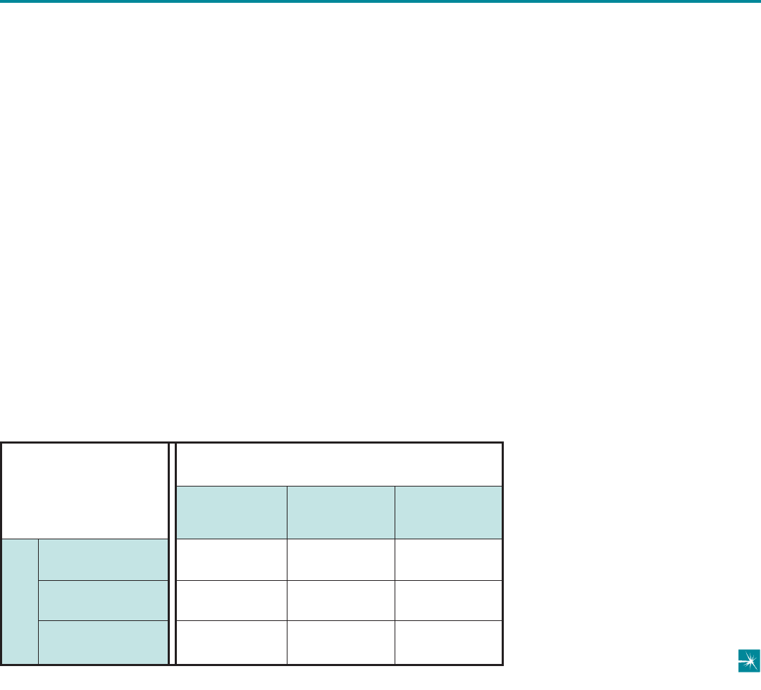
Table 4. Matching (M), Undermatching (U) and Overmatching (O) tensile strength
combinations for A572 Gr. 50 with E70 filler metal.
Base Metal - A572 Gr. 50
E70 Filler Metal - Strength Levels
Min. - 65 ksi (450 MPa)
Med. - 80 ksi (550 MPa)
High - 90 ksi (620 MPa)
M
U
U
O
M
U
O
O
M
Strength
Minimum
70 ksi (480 MPa)
Medium
80 ksi (550 MPa)
High
90 ksi (620 MPa)
Return to TOC
Welding Innovation Vol. XVI, No. 2, 1999 13
In addition to the following awards to undergraduate and graduate students,
The James F. Lincoln Arc Welding Foundation also provided grants of $250
to the following universities in recognition of each Best of Program, Gold,
Silver, or Bronze Award received by students of that university:
Prof. Thomas Conry
University of Illinois at
Urbana-Champaign
Prof. James D. McBrayer
University of Central Florida
Prof. James Ricles
Lehigh University
Donald N. Zwiep
Chairman of the Jury
Chairman, The James F. Lincoln
Arc Welding Foundation
Charles J. Bersback
Erich M. McCoy
Ken Schmidt
Roark Wolfe
Jacob J. Loverich
College of Engineering & Technology
Northern Arizona University
Faculty: David Hartman
JURY OF AWARDS
Golf Swing Tracking System
Algis Baliunas
David Leder
Michael Lee
General Engineering Dept.
University of Illinois
Faculty: James Carnahan
Design of a Picosatellite
Theresa Kuhlman
Dina Hadi
Mechanical Engineering
Santa Clara University
Faculty: Tim Hight
WPI Parking Structure Design
Brendan FitzPatrick
Michael Pockoski
Civil Engineering Dept.
Worcester Polytechnic Institute
Faculty: Leonard Albano & Robert D’Andrea
$2,000
UNDERGRADUATE DIVISION
$1,000
$750 Each
Santa Clara University
Stanford University
University of Connecticut
University of Illinois
University of Northern Arizona
Worcester Polytechnic Institute
Off-Road Mobility Vehicle for the Disabled
Return to TOC
14 Welding Innovation Vol. XVI, No. 2, 1999
AC-R Servicing Manifold Design
Gautam Baksi
Everett Hafenrichter
Nathan Searcy
Mechanical & Industrial Engineering Dept.
University of Illinois
Faculty: J.W. Nowak
Economic Insulation Choice
for a Warehouse
Shane Cisco
Gina Woloszyn
Joseph Woolums
General Engineering Dept.
University of Illinois
Faculty: Ramavarapu S. Sreenivas
The Burnt Bagel Conundrum
Jeffrey Chow
Michael Gredlics
Andrew McGrath
Mechanical & Industrial Engineering Dept.
University of Wyoming
Faculty: David Walrath
PMI System for Characterization of Load
Resisting Structures
Emily J. Pryputniewicz
Mechanical Engineering Dept.
Worcester Polytechnic Institute
Faculty: Ryszard J. Pryputniewicz
1999 Mini Baja
Shaun Fought
Benjamin C. Rubenson
Mark L. Anderson
Ryan Wellman
Mechanical Engineering Dept.
Santa Clara University
Faculty: Tim Hight
Design of an Underwater Remotely
Operated Vehicle
Aaron B. Weast
Tevor D. Wigle
William B. Perkins
Jason F. Cook
Mechanical Engineering Dept.
Santa Clara University
Faculty: Jeff Ota
Design of a Mini-Baja Vehcile: A
Customer-Driven Approach
Brent D. Zollinger
Mechanical Engineering Dept.
Brigham Young University
Faculty: Robert Todd
Thermal Redesign of a Low Voltage
Outdoor Halogen Floodlamp
Paul Dynowski
Paul Kawka
James Nonnenmann
Mechanical & Industrial Engineering Dept.
University of Illinois
Faculty: J.W. Nowak
Ball Mountain Dam Access Bridge
Jacob Argiro
Jennifer Copponi
Christina Watson
General Engineering Dept.
Worcester Polytechnic Institute
Faculty: Leonard D. Albano
A Rotational Molding Machine
Benjamin S. Sheen
Mechanical Engineering Dept.
University of Wyoming
Faculty: David Walrath
Point-to-Point Wireless Network Link
Antenna Positioner
Sothy Chhe
Alexander Jasso
Patrick Kim
Matthew Lee Schwall
Mechanical Engineering Dept.
Stanford University
Faculty: Drew Nelson
Failure Analysis of Cracks in Small
Diameter Taps
Melody Langeneckert
Dave Lash
Jason Pelch
Mechanical & Industrial Engineering Dept.
University of Illinois
Faculty: J.W. Nowak
Machine Design for the Treatment &
Prevention of Shin Splints
David A. Brady
Thomas A. Toye
Kenneth J. Tardif
Mechanical & Industrial Engineering Dept.
University of Massachusetts - Amherst
Faculty: David Kazmer
Overload Clutch Mechanism for
AC-Powered Drills
Simon Beland
Dante Cantieri
Cezar Velasco
Lorena Solorzano
Dennis Odulio
Mechanical Engineering Dept.
University of Illinois-Chicago
Faculty: Foster
Redesign of Spray Profile Test Operation
Mae Lee Chung
Christy Claus
Kevin Keller
Michael Stock
General Engineering Dept.
University of Illinois
Faculty: Henrique Reis
Redesign of a Compressed Air Loop
David Grover
Jason Oliva
Chris Ras
Mechanical & Industrial Engineering Dept.
University of Illinois
Faculty: J.W. Nowak
Design of a Piano Maintenance Timer
Jeff Ernst
John Whittenhall
Robert Zeller
Mechanical & Industrial Engineering Dept.
University of Illinois
Faculty: J.W. Nowak
Gearmotor Noise Test & Evaluation
Kevin Bollman
David Hinkle
Leo Wrigley
General Engineering Dept.
University of Illinois
Faculty: Henrique Reis
$250 Each
$500 Each
UNDERGRADUATE DIVISION
Return to TOC
Welding Innovation Vol. XVI, No. 2, 1999 15
Innovative Composite Crutch
Dorota Shortell
Jeff Kucer
W. Lawrence Neeley
Mechanical Engineering Dept.
Stanford University
Faculty: Mark Cutkosky
Parallel Parking Assistive System
Casey P. Hare
Jeremy T. Dabrowiak
Kendra J. Cermak
Mechanical Engineering Dept.
Stanford University
Faculty: Mark Cutkosky
An Implement Hitching System for the
Controlled Traffic Farming System
Andrew J. Holtz
Bioresource & Agricultural Engineering Dept.
California Polytechnic State University
Faculty: Andrew Holtz
Mercury-Free Oven Control System
Tim Jager
Yi Tang
Jayson Valluzzi
Mechanical & Industrial Engineering Dept.
University of Illinois
Faculty: J.W. Nowak
Warehouse Layout Optimization
Nathan Kennedy
Joseph Lambert
James Lutgen
General Engineering Dept.
University of Illinois
Faculty: R.S. Sreenivas
Mensical Repair Device-Delivery System
Todd W. Jenkins
Scott D. Kennedy
Carlos Marron
Mechanical Engineering Dept.
Santa Clara University
Faculty: Tim Hight
Failure Analysis of Bus Leaf Springs
David Hopp
Colin Horn
John Frana
Mechanical & Industrial Engineering Dept.
University of Illinois
Faculty: J.W. Nowak
$250 Each
$2,000
$1,000
GRADUATE DIVISION
UNDERGRADUATE DIVISION
Return to TOC
16 Welding Innovation Vol. XVI, No. 2, 1999
Shift Simulator Design Document
Christopher R. Carlson
Wendy Cheng
Juli Satoh
Neeta Verma
Mechanical Engineering Dept.
Stanford University
Faculty: Mark Cutkosky
Laser Methodologies for
Characterizing Behavior
of MEMS
Gordon C. Brown
Mechanical Engineering Dept.
Worcester Polytechnic Institute
Faculty: Ryszard J. Pryputniewicz
Relaxation in High-Strength
Bolted Connections Using
Galvanized Steel
Jun Yang
Civil Engineering Dept.
University of Connecticut
Faculty: John T. DeWolf
Inspection Device for Detecting
Contaminated Blades
David Cavazos
Sekou Crawford
Mike Eodice
Mechanical Engineering Dept.
Stanford University
Faculty: Mark Cutkosky
Automatic Door Project
Kevin R. Kopczynski
Huck B. Dorn
Derek S. Pai
Mechanical Engineering Dept.
Stanford University
Faculty: Mark Cutkosky
$750 Each
$500 Each
$250 Each
GRADUATE DIVISION
FlexRim Low Impact Wheelchair Pushrim
W. Mark Richter
Mechanical Engineering Dept.
Stanford University
Faculty: Larry Leifer
Seismic Rehabilitation of Pre-Northridge
Steel Moment Connection with Welded
Haunch
Qi-Song Yu
Structural Engineering Dept.
University of California, San Diego
Faculty: Chia-Ming Uang
Valve Timing by Means of a
Rotary Actuator
Pete Fitsos
Mechanical Engineering Dept.
California State University, Sacramento
Faculty: Joe Harralson
Power Extendable Towing Motors
Adam C. Gold
Eric C. Olson
Christopher Van Wert
Michael A. Prados
Mechanical Engineering Dept.
Stanford University
Faculty: Mark Cutkosky
Master Stress-Strain Curves for Adhesives
Jianmin You
Mechanical Engineering Dept.
University of Maryland
Faculty: Pedro Albrecht
Return to TOC
Welding Innovation Vol. XVI, No. 2, 1999 17
Use Caution When Specifying
“Seal Welds”
Practical Ideas for the Design Professional by Duane K. Miller, Sc.D., P.E.
Design File
Introduction
What is a “seal weld?”
AWS A3.0, Standard Welding
Terms and Definitions
, defines a seal weld as: “Any weld
designed primarily to provide a specific degree of tight-
ness against leakage.” The purpose of a seal weld may
be to contain a fluid – either gaseous or liquid. In the
mechanical and structural fields, seal welds are used most
often not to prevent leakage out of a container, but to pre-
vent entry of a fluid into a space where some type of
harmful behavior, often corrosion, is expected to occur. In
these fields, seal welds are frequently used to preclude
moisture and oxygen-laden air and water from entering
that cavity.
Seal welds may be specified on parts to be galvanized to
prohibit pickling acids and/or liquid zinc from entering into a
specific region. For architecturally exposed steel that is to
be painted, seal welds may be specified to prevent unsight-
ly rust bleeding. Seal welds may be required for some
applications where the sealed joint is more conducive to
cleanup than an exposed joint would be. Food processing
facilities are one such example.
The characteristic common to all of the aforementioned
examples of seal welds is as follows: none of them are
placed for traditional strength-related reasons, and for this
reason, caution should be exhibited when seal welds are
specified. In some cases, the application of a seal weld
may result in a conflict of code requirements. In others,
the seal weld may perform structural functions that were
unintended, resulting in undesirable load paths. Seal
welds may affect inspection practices, in particular, the
interpretation of ultrasonic inspection results. Finally, seal
welds may be treated in a casual manner by those
responsible for making them, resulting in weld quality
problems. Each of these examples will be examined, as
will be some issues related to galvanizing that need to be
considered as well.
Code Conflicts
A common inquiry is as follows:
“The drawings call for seal weld, but in order for me to
comply with that requirement, I need to violate
AWS
D1.1-98
, Section 2.4.7.5. What should I do?”
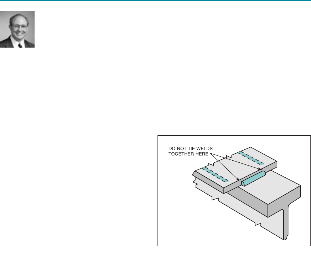
The specific code provision cited is the one that calls for
the interruption of welds which occur on opposite sides of
a common plane, and under these conditions, the welds
are required to be interrupted at the corner (Figure 1).
This provision has a practical foundation: it is difficult to
make a continuous weld in these conditions, and the prob-
ability of undercutting the corners is great when the welds
are made continuous. This is one problem associated with
seal welds when applied to these situations.
Figure 1.
Return to TOC
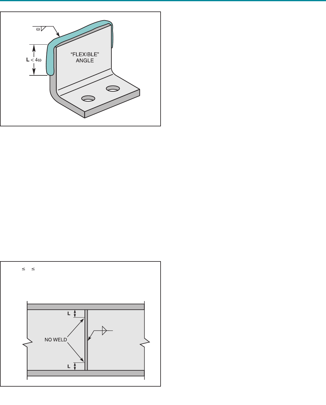
Other code provisions can be violated, including
AWS
D1.1
, Section 2.4.7.3, which addresses “flexible connec-
tions” that rely on the flexibility of the outstanding leg of
angles (Figure 2). Examples would include framing angles,
top angles of seated beam connections, and simple end
plate connections. A seal weld around a flexible connec-
tion reduces such flexibility and may change the overall
behavior that is expected.
AWS D1.1
, Section 2.4.7.4, calls for welds on stiffeners to
be cut short not less than 4 times, nor more than 6 times,
the thickness of the web from the weld toe of the web-to-
flange welds (Figure 3). This provision was incorporated to
provide for a degree of flexibility in this region. Previous
experience in shipping had shown this to be an area that
was prone to cracking when the weld extended too far.
Seal welds applied to this area effectively preclude such
flexibility.
The designer who calls for a seal weld should review these
code provisions if the project is governed by the D1.1
code, and in the situations where the code is not applica-
ble, examine these principles and determine their relative
suitability to the components where seal welding has been
utilized. To handle the issue of consistency between job
specifications and code requirements, the engineer can
address how these issues are to be resolved in the project
specifications. The preceding list of code examples is illus-
trative only, and may not be comprehensive in its coverage
of issues where seal welding requirements may violate
code provisions.
Alternate Load Paths
The second major series of problems associated with seal
welds involves those applications where unintended load
paths are created. For example, a lapped connection may
be joined by bolts with no welds expected at all. However,
a seal weld is specified around the connection.
AWS D1.1
,
Section 2.6.3, may be applicable in this situation. In bear-
ing connections, the code does not allow bolts and welds
to share the load. Of course, in this particular situation, the
designer would probably not consider the seal welds as
members that would share loads with welds, but in fact,
they will. The seal welds would be small in size and proba-
bly incapable of transmitting the applied loads by them-
selves. In actual service, the first thing that would happen
would be for the welds to fracture, violating the purpose of
the seal weld, before the bolts would load up and carry the
transferred forces.
The welding adage, “There are no secondary members in
welded design,” is applicable when considering seal welds.
An example arose several years ago where a tub-type rock
crusher had been designed with a series of stiffeners. The
detailing had been carefully thought through so as to avoid
stress risers. A stainless steel nameplate was to be
applied to the unit, and a seal weld was called for to attach
this nameplate. The entire unit received a special, multi-
coat paint system to preclude corrosion, and the seal weld
ensured that the material under the stainless steel name-
plate would not be exposed to the elements. The name-
plate was put into a high stress region, and whether
Figure 2.
Figure 3.
4twL 6tw
where,
L = length of unwelded stiffener
tw= weld thickness
18 Welding Innovation Vol. XVI, No. 2, 1999
Return to TOC
19
Welding Innovation Vol. XVI, No. 2, 1999
intended or not by the designer, the nameplate became
part of the load bearing system, and the weld introduced
residual stresses as well.
The seal weld around the nameplate became the design-
limiting fatigue detail that resulted in crack initiation in serv-
ice. The intention of the designer was circumvented by an
ill-conceived plan for a seal weld around a nameplate. In
this particular example, any weld (including an intermittent
weld) may have created a poor fatigue detail.
Casual Treatment of Seal Welds
The minimum heat input requirements imposed by
AWS
D1.1
may be violated when the seal weld is made. Table
5.8 of that code prescribes certain minimum sizes of welds
that must be maintained, regardless of the level of loading,
in order to ensure that adequate heat input is achieved
when the weld is made. The size of the seal weld may not
be specified, resulting in a weld that would otherwise be
disallowed by Table 5.8. It is still important that good weld-
ing practices be followed when seal welds are made,
including adherence to the minimum fillet weld size.
Failure to do so may result in weld cracking or incomplete
fusion defects.
The welder who is charged with the responsibility of mak-
ing a seal weld may approach it in a very casual manner,
as might the welder’s supervisor. The welder should have
the same qualifications as the welder charged with the
responsibility for making a similar weld that would have a
structural purpose. The welding procedures, including the
selection of the electrode and the required preheat level,
are deserving of the same attention as a weld that trans-
fers calculated loads. The claim “It is only a seal weld” is
often a prescription for problems.
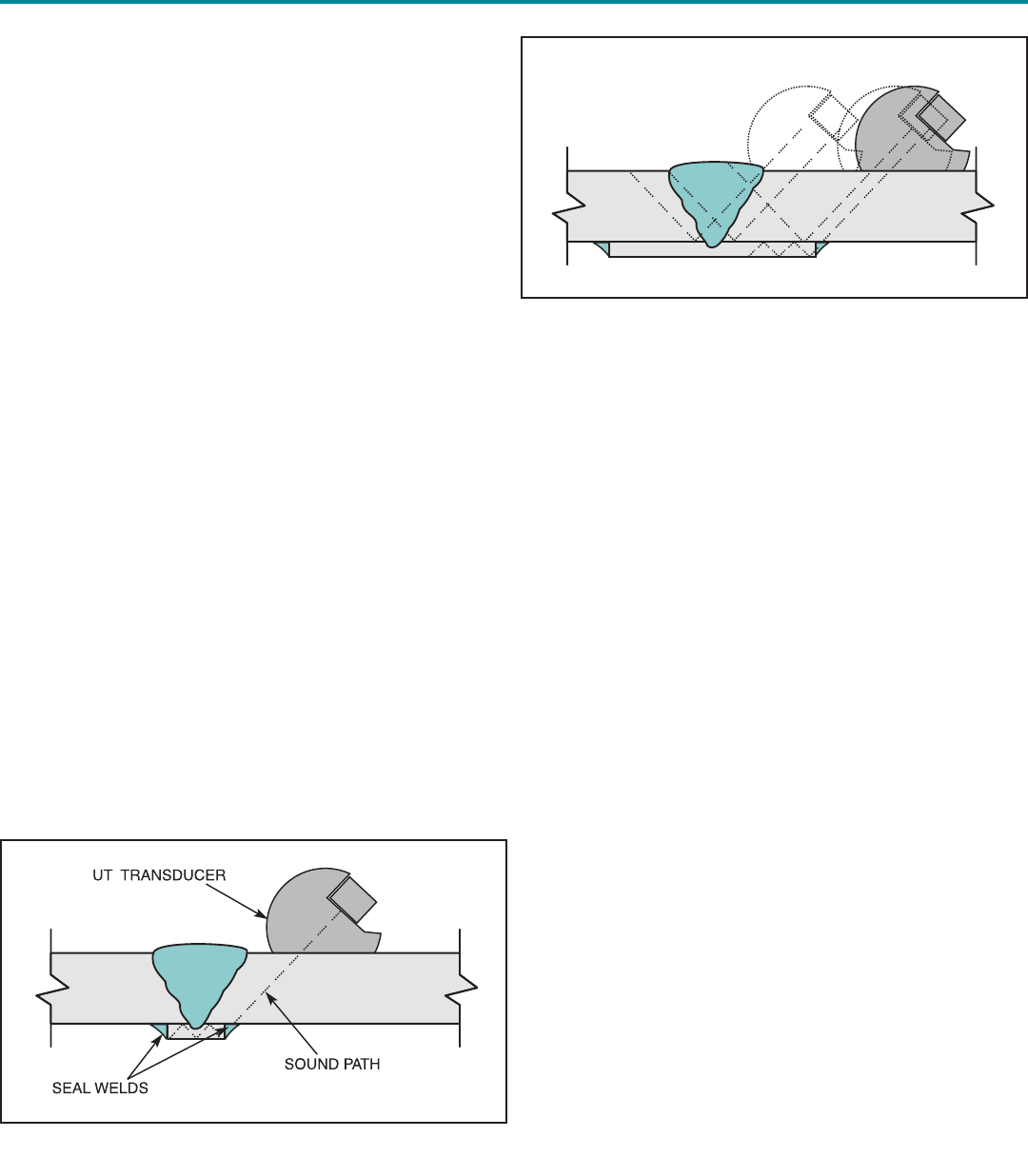
Inspection Issues
The presence of seal welds around steel backing that is
left in place after welding may have implications for the
ultrasonic testing (UT) of such connections. Consider
Figure 4 in which a CJP groove weld with steel backing is
inspected with UT. An alternate sound path is created
when the seal welds are placed around the left-in-place
backing. Such implications should be understood before
inspection begins.
If backing is to be seal welded to the base material, then
one may consider making the backing a little wider (Figure 5).
With the seal welds further from welded joint, the UT sound
waves will have a better opportunity to “see” the root without
secondary reflections through the seal welds.
Galvanizing Issues
One of the more common applications for seal welds is in
assemblies that are required to be hot dip galvanized
(Figure 6). The American Galvanizers Association (AGA)
defines three classes for welded assemblies that will be
galvanized. Class 1 Joints are held together by a full seal
weld. Class 2 Joints are held together by seal welds, but
the overlapped area is large enough to require venting, i.e.,
provision of an escape hole for the release of expanding
trapped gases. Class 3 Joint details do not contain seal
welds.
Figure 4.
Figure 5.
Return to TOC
20 Welding Innovation Vol. XVI, No. 2, 1999
AGA documents require a vent to be provided whenever
the overlapping area exceeds 16 in2(100 cm2). Specific
diameters of the holes and locations are also spelled out.
Thus, a Class 1 detail is only applicable for an overlapped
area of 16 in2(100 cm2) or less. Class 1 represents “the
highest degree of corrosion protection that is attainable,”
and while Class 2 is “not quite equal to Class 1,” it is possi-
ble to plug the vent hole after galvanizing to upgrade a
Class 2 to Class 1.
Class 3 details provide “a degree of corrosion protection
that meets or exceeds the protection provided by most
industrial coatings.” It is noted that the unsealed overlaps
from Class 2 and 3 details may stain the surface of the
coating, or steaming from unsealed overlaps may result in
slight bare spots along the line of the exhaust.
Special caution is noted for Class 1 seal applications
because porosity may result in an explosion as trapped
liquid-acid vaporizes and expands when the part is dipped
into the hot zinc. Venting minimizes that concern.
This edition of Design File is not intended to be a treatise
on galvanizing and preferred details for corrosion resist-
ance. However, it does identify concerns that are associat-
ed with seal welding and the galvanizing practice. The user
is encouraged to review AGA documents in this regard.
The American Galvanizers Association can be contacted
through their website at www.galvanizeit.org, or by phone at
(800) 468-7732.
Conclusions
Seal welds can perform an important function both in con-
taining fluids, and in precluding the entry of fluids into
regions where harmful effects can result. However, seal
welds also can unintentionally cause differences in the struc-
tural behavior of the attached members, and the designer
should be aware of these potential interactions. The welding
practices employed when seal welds are made should not
be any different than those associated with welds that are
designed to carry loads. When seal welds are applied to
galvanized assemblies, caution should be taken to make
sure that venting is appropriate, and for Class 1 Joints where
vents are not required, that the weld is “porosity-free” so that
no seepage is experienced. Once seal welds have been
carefully thought through, the designer needs to clearly com-
municate in the job specifications how the fabricator is to
deal with code restrictions which may specify practices that
are inconsistent with seal welding.
Figure 6.
Figure 7.
Figure 8.
Return to TOC
Lincoln Electric Professional Programs
Welding Innovation Vol. XVI, No. 2, 1999 21
Opportunities
Fracture & Fatigue Control in Structures:
Applications of Fracture Mechanics
October 31 – November 2, 2000
Fracture mechanics has become the primary approach to analyzing and controlling brittle
fractures and fatigue failures in structures. This course will focus on engineering applications
using actual case studies. Guest seminar leaders: Dr. John Barsom and Dr. Stan Rolfe. 2.0
CEUs. Fee: $595.
Space is limited, so register early to avoid disappointment. For full details, visit our website
at www.lincolnelectric.com/services/educate/educate.asp, call 216/383-2240, or write to
Registrar, Professional Programs, The Lincoln Electric Company, 22801 Saint Clair Avenue,
Cleveland, OH 44117-1199.
Production Welding
Basic May 9-11, 2000
Advanced September 19-21, 2000
Each section of Production Welding is a 3-day program conducted by
Lincoln Electric’s staff of expert welding engineers. The Basic course
includes: arc welding processes and procedures; arc blow and proper
grounding; wire feeding techniques; distortion; destructive testing;
safety; and more. The Advanced curriculum includes: pulse GMAW;
tandem GMAW; twin and tandem SAW; aluminum welding; stainless
steel welding; surface tension transfer (STT); robotic welding; wave-
form development; nondestructive testing; and more. 2.0 CEUs.
Fee: $395.
Blodgett’s Design of Steel Structures
March 7-9, 2000
October 24-26, 2000
Blodgett’s Design of Steel Structures is an intensive 3-day program that addresses methods
of reducing costs, improving appearance and function, and conserving material through the
efficient use of welded steel in a broad range of structural applications. Seminar leaders:
Omer W. Blodgett, Duane K. Miller, and R. Scott Funderburk. 2.0 CEUs. Fee: $595.
Blodgett’s Design of Steel Weldments
April 11-13, 2000
September 12-14, 2000
Blodgett’s Design of Steel Weldments is an intensive 3-day program for those concerned
with manufacturing machine tools, construction, transportation, material handling, and agri-
cultural equipment, as well as manufactured metal products of all types. Seminar leaders:
Omer W. Blodgett, Duane K. Miller, and R. Scott Funderburk. 2.0 CEUs. Fee: $595.
Return to TOC
22 Welding Innovation Vol. XVI, No. 2, 1999
It was evident from the project’s incep-
tion that the Colonial Stadium, current-
ly under construction in Melbourne,
Australia, would be a challenging fabri-
cation project due to the structure’s
design. The stadium will feature a
retractable roof that will fully open and
close in just twenty minutes. Alfasi
Construction was awarded the job in
January 1998 by Baulderstone
Hornibrook for the fabrication of the
stadium’s steel structure. This incorpo-
rated more than 5,000 tonnes of steel-
work, including major tubular trusses
with lengths up to 220 m (722 ft).
As the project progressed, several
common construction issues were
addressed. From this experience, the
following lessons were learned:
• Materials with higher strength and
alloy content are weldable, but atten-
tion to details such as hydrogen and
preheat control are essential.
• Tubular construction requires
extremely close fit-up and tolerance
control.
• Pre-production planning and training
pays big dividends.
Main Roof Chords
The steel (European EN1021O) sup-
plied for the construction of the main
roof chords is a newly developed 460
MPa (65 ksi) micro-alloyed high-
strength steel for structural use. The
weld fabrication required special treat-
ment to ensure that the high strength
characteristics of the steel would be
fully utilized.
As Terry Phelan, general manager of
Alfasi Construction explained, “I was
confident of our ability to handle the
fabrication of the project’s steelwork.
We fabricated the complex compo-
nents used in Sydney’s Olympic rail
station and Melbourne’s new Museum,
so we knew what we were in for.”
The higher alloy content and thicker
sections of the main support beams
(up to 58 mm [2.3 in]) required that
close attention be paid to three main
elements: the selection of the correct
welding consumable; the development
of realistic and reproducible welding
procedures; and a focus on welder
skills to ensure quality throughout. It
was clear that the project schedule
would not allow time for delays or re-
work. “In effect, we had to get it right
from the very first joint,” said Phelan.
Aware that accurate fabrication is
dependent on good preparation, Alfasi
purchased a Maruhide CNC controlled
tube profiler. Since some of the most
costly and time critical elements of
tubular construction are the prepara-
Challenging Stadium Project
Headed for On-time Completion
By Peter Lawlor
Southern Regional Manager
Lincoln Electric Australia
Victoria, Australia
Figure 1. Installation of a section of the retractable roof.
Welding the main
beams involved careful
control of preheat
and heat input…
Return to TOC
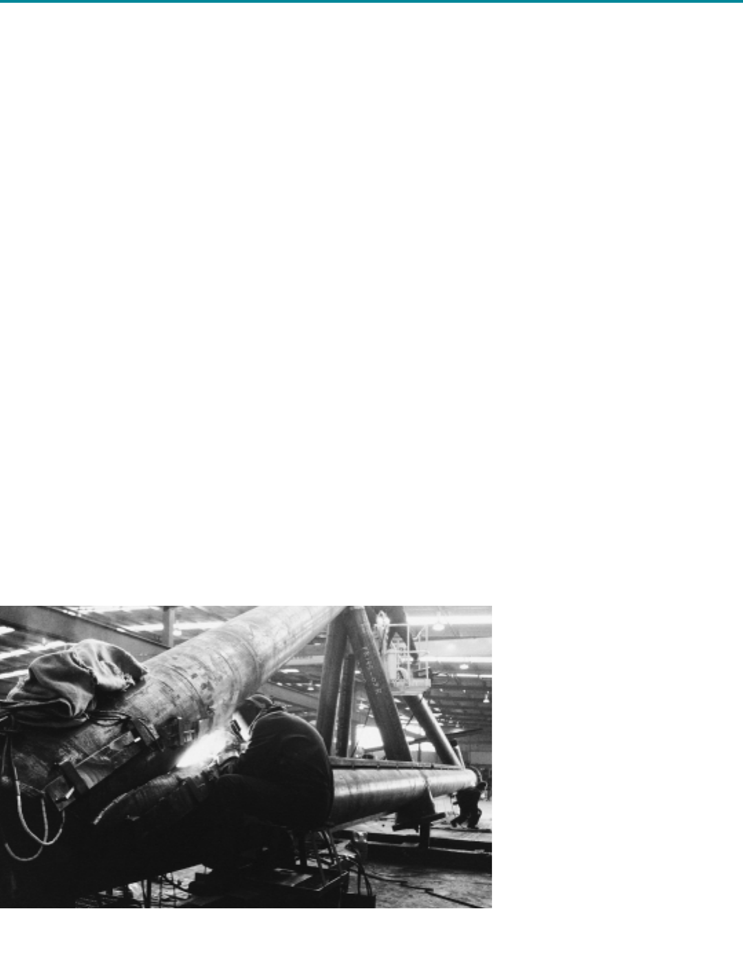
Welding Innovation Vol. XVI, No. 2, 1999 23
tion, fit-up and tolerances of the tubu-
lar members, this step was essential.
This machine is capable of plasma
cutting complex profiles in tubular
members up to 12 m (39 ft) in length
and with a 60 mm (2 1/2 in) wall thick-
ness, and is the only one of its kind in
South Eastern Australia. Throughout
the project, this unit was used to cut
and prepare complex weld profiles on
most of the tubular sections.
Although there was an assortment of
welded joint configurations, there were
three main types of joints to be consid-
ered:
• Grade 460 MPa (65 ksi) steel
to 460 MPa (65 ksi), for the main
chords;
• Grade 460 MPa (65 ksi) steel to
Grade 350 MPa (50 ksi) steel, for
connections to the main support
frame; and
• Grade 350 MPa (50 ksi) to Grade
350 MPa (50 ksi) steel, for general
connections and supports.
Matching the Weld
Metal Properties
The governing code for the construc-
tion of the beams was AS1554 Part 1.
However, the higher alloy content of
the steel (carbon equivalent of 0.63-
0.68) meant the construction specifica-
tion required further clarification to
ensure optimum strength and quality
were achieved. For instance, care was
taken to ensure weld metal properties
closely matched the parent plate and
weldments returned heat affected
zone hardness of less than 300HV.
In order to meet the high strength prop-
erties of the tubular steel (minimum
specified yield strength of 460 MPa [65
ksi] and minimum ultimate tensile
strength of 560 MPa [80 ksi]), as well
as meet the minimum specified Charpy
V-Notch impact properties, while main-
taining low hydrogen values, an E81T1-
Ni1 (Outershield 81Ni1-H) gas shielded
flux cored electrode was used to join
the main chords. Straight lengths were
joined by a submerged arc combination
of F7A6-EM14K-H8 (LA71 electrode
with 880M flux).
Initial weld tests indicated that the 460
MPa (65 ksi) steel was prone to high
heat-affected zone hardness if preheat
and welding heat input requirements
were not followed. To ensure that oper-
ators were aware of the importance of
these factors, additional training was
provided to the construction crew to
explain the correct handling of the
steel and the importance of following
the proper welding protocol. The mini-
mum preheat temperature for each
joint (varied between 125°C [250°F]
and 225°C [440°F] depending on the
specific joint details) was maintained
and monitored using electric heat
blankets. It was this pre-production
planning and training that enabled the
construction to move along at such an
efficient pace.
Achieving Desired
Mechanical Properties
Welding the main beams involved
careful control of preheat and heat
input to achieve good mechanical
properties. The welding of the high
strength 460 MPa (65 ksi) steel to
350 MPa (50 ksi) steel created a few
problems.
As Merril Degee, workshop foreman of
Alfasi’s Dandenong facility explained,
“The welding of the 460 to 460 joints
was relatively straight-forward once we
determined the effect of preheat and
heat input on joint strength and hard-
ness values.” However, providing for
elasticity and a smooth transition of
strengths between the 460 MPa and
350 grade material wasn’t so easy.
“When I first went to do a procedure
for a ‘T’ type joint made up of a Grade
Figure 2. Shop fabrication of some of the large tubular trusses used in the
Colonial Stadium.
The governing code
recommended that HAZ
hardness values be
kept below 350 HV
Return to TOC
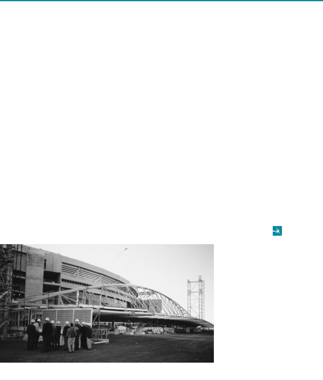
24 Welding Innovation Vol. XVI, No. 2, 1999
“The end result was a joint with good
flexibility, strength and low hydrogen
contents. The welders liked using the
electrode. For joining the Grade 350
steel we used a GMAW ER70S-4
electrode (L54) and an FCAW-g E71T-
1 electrode (Outershield 71M).
Currently, (the project is 85% com-
plete) we’re a little ahead of schedule.
It’s obvious now that without the early
focus on welding processes, proce-
dures and electrode selection we
wouldn’t be in this position,” said
Degee.
Over 5,000 tonnes of steel have been
processed so far, using more than 6
tonnes of electrode with very few weld
defects.
Construction Logistics
Given the considerable size of some
of the weldments, distortion was a
potential problem. However, with care-
ful fixture building and continuous
monitoring of dimensions during fabri-
cation, distortion was kept to a mini-
mum. The main chords were
fabricated in Alfasi’s Dandenong work-
shop in lengths up to 40 m (130 ft),
then transported to the site where they
were joined using field welding proce-
dures.
Engine driven welders and portable
wire feeders were used to complete
the final field welds on the main truss-
es. Small site tents were erected to
ensure that preheat and gas shielding
would not be affected by the elements.
For joining the Grade 350 steel to
itself, an all-position E71T-8J self-
shielding electrode (Innershield
NR203MP) was used.
Conclusion
Terry Phelan summed up the current
status of the Colonial Stadium as fol-
lows: “We’ve just passed a landmark
project date on schedule. Most of the
steelwork has been fabricated and it’s
now a matter of lifting and fixing sec-
tions into place. It’s a tight schedule, but
we’re meeting it thanks to dedicated
staff and the support of major suppliers.
You need that type of partnership when
the pressure is on.”
Editor’s Note: The A$460 million (US$293 mil-
lion) stadium is scheduled to be completed by
February 2000. It will have 52,000 fixed seats,
plus retractable seating on the lower tier that will
allow the stadium to be reconfigured to suit a
wide variety of needs. It will be primarily a
venue for Australian Football League (soccer)
games and other sporting events. However, an
advanced acoustic design and audio system will
make it suitable for music concerts as well.
Selected seats will be equipped with individual
touchscreen video units. More information on
the stadium can be obtained online at
www.docklandstadium.com.au.
350 vertical plate with a 460 cap, I
used a standard E71T-1 electrode,
which did not meet the bend test
acceptance criteria. Therefore, it was
determined that a different electrode
was required.”
An electrode with a controlled hydro-
gen content was selected for these
joints (Outershield 71C-H) to meet the
testing criteria. The electrode, which
meets the E71T-1 classification, was
designed to meet 5 ml (max) of hydro-
gen per 100 grams of weld metal.
The new welding procedure with
OS71C-H and careful bead placement
gave excellent results. The moderate
yield and tensile strength of the weld
metal gave a smooth transition
between the Grade 350 steel and the
high strength Grade 460 steel.
Figure 3. After field welding, a tubular truss awaits installation as part of the
retractable roof assembly.
The new welding
procedure with
Outershield 71C-H and
careful bead placement
gave excellent results
Return to TOC