Ampex 400 Manual Grayscale
Ampex-400_manual_grayscale Ampex-400_manual_grayscale
User Manual: Ampex-400 manual grayscale
Open the PDF directly: View PDF  .
.
Page Count: 79

AMPEx
SERIES
4b0
OPERATION
AND
MAINTENANCE
MANUAL
SERIES
400
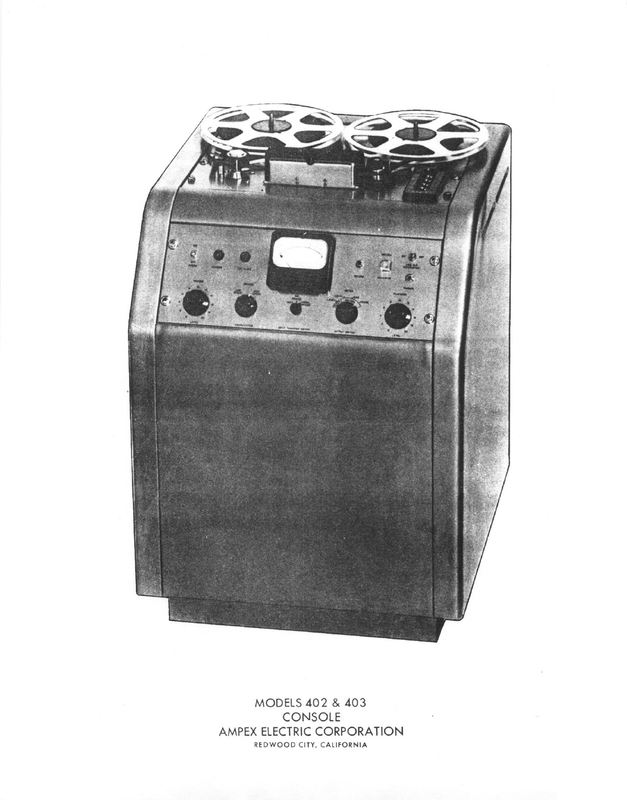
MODELS
402
&
403
COP4SOIE
AMPEX
ELECTRIC
CORPORATION
REOW000
CITY
CALIFORNIA
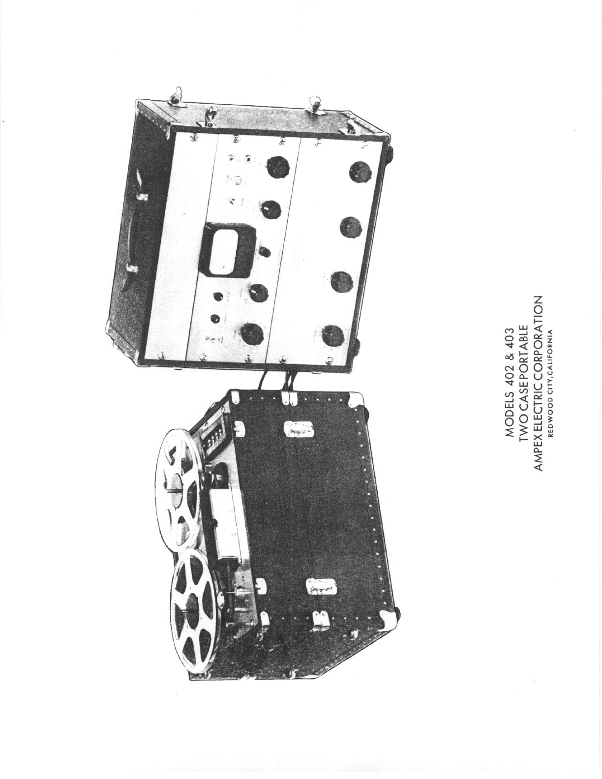
MODELS
402
&
403
TWO
CASE
pORTABLE
AMPEX
ELECTRiC
CORPORATION
REDWOO0
CITV,CALIFORNIA
INSTRUCTION
MANUAL
FOR
AMPEX
MAGNETIC
TAcbE
RECORDER
MODELS
400A,401,
402,403,404
and
405
TABLE
CF
CONTENTS
SECTION
I
Specifications
SECTION
II
Installation
SECTION
111
Operating
Procedure
SECTION
IV
Operating
Theory
SECTION
V
Routine
Maintenance
SECTION
VI
Electronics
Alignment
SECTION
VII
Mechanical
Service
Guide
SECTION
VIII
Mechanical
Adjustments
SECTION
IX
Parts
List
FIGURE
0
Reel
Hold
Down
Knob
FIGURE
1
Single
Case
Portable
Electronic
Assembly
Schematic
FIGURE
2
Rack,
Console,
Two
Case
Portable
Electronic
Assembly
Schematic
FIGURE
3
Single
Case
Portable
Power
Supply
Schematic
FIGURE
4
Rack,
Console,
Two
Case
Portable
Power
Supply
Schematic
FIGURE
5
Control
Circuit
Schematic
FIGURE
6
Input
Transformer
Connections
FIGURE
7
Remote
Control
and
60
Cycle
Amplifier
Connections
FIGURE
8
Playback
Amplifier
Equalization
FiGURE
9
Record
AmplifierEqualization
FIGURE
10
Single
Case
PortableElectronic
P
ssembly-Front
View
FIGURE
11
Single
Case
Portable
Electronic
Pssembly
-Top
View
FIGURE
12
Single
Case
Portable
Electronic
ssemnbly
-Bottom
View
FIGURE
13
Rack,
Console,
Two
Case
PortableElectronic
Assembly-Front
View
FIGURE
14
Rack,
Console,
Two
Case
‘ortable
Elec.Ass’y.-Top
&
Rear
View
FIGURE
15
Rack,
Console,
Two
Case
Portable
Elec.Ass’y.-Bottom
View
FIGURE
16
Mechanical
Assembly-Top
View
FIGURE
17
Mechanical
Assembly-Bottom
View
FIGURE
18
Mechanical
Assembly-Rear
View
FIGURE
19
MechanicalAssembly-Side
View
FIGURE
20
Reel
Idler
and
Flywheel
FIGURE
21
Console
Cabinet
FIGURE
22
Mechanical
Assembly
Case
SERIES
400
INDEX
SECTION
1
SPECIFICATIONS-MODELS
400A,401A,
402
&
403
The
Ampex
Models
400A,
401A,
402
and
403
magnetic
tape
recorders
are
audio
recorders
utilizing
the
standard
1/4
inch
wide
tape.
Models
400A
and
401P
are
identical
in
every
respect
cept
for
the
head
assembly.
Similarly,
the
Models
401
and
403
are
alike
except
for
head
assemblies.
The
main
difference
between
these
two
groups
is
the
former
incorporates
an
Electronic
Assembly
designed
for
single
case
portable
mounting.
The
400A
and
402
incorporate
half
track
erase,
record
and
playback
heads.
The
401A
and
403
incorporate
full
track
erase
record
and
playback
heads.
Half
track
heads
are
effective
over
onlyone
half
of
the
tape
width.
Thus,
a
machine
having
a
half
track
record
head
can
record
two
separate
audio
tracks
on
a
standard
reel
of
tape.
Machines
havinghalf
track
playback
heads
can
reproduce
either
full
or
half
track
recordings.
Machines
having
full
track
playbackheads
can
only
reproduce
tapes
on
which
a
single
track
has
been
recorded.
Head
assemblies
incorporating
full
track
record
and
erase
heads
and
half
track
playback
heads
are
available
on
special
order.
This
allows
recording
full
track
tapes
and
playingback
either
full
track
or
half
track
tapes.
All
of
the
modelsproduce
a
tape
frequency
characteristic
which
has
been
accepted
as
standard
for
the
exchange
of
programs
by
the
National
Association
of
Radio
and
Television
Broadcasters.
TAPE
SPEELt
15
inchesper
second
and
7-1/2
inchesper
second,
with
motor
ipiea
&hThjuindequalization
switchesconveniently
located.
FREC’UENCY
RESPONSE.
Pt
15
inches
/
2db
30-15,
000
cycles
At
7-1/a
inches
/
2db
40-10,
000
cycles
/4db
30-15,
000
cycles
SIGNAL-TO-NOISE
RATIO
.
Over
65 db
unweighted
noise
to
maximum
recording
levelT.
Over
55
db,
asmaffied
by
NARTB
standards.
By
NARTB
definition,
the
signal-to-noise
ratio
is
the
ratio
of
peak
recording
level
to
the
total
unweighted
playback
noise
when
erasing
a
signal
of
peak
recording
level
and
in
the
absence
of
a
new
signal.
Thus, bias
and
erase
noise
are
included,
as
well
as
playback
ampli
fier
noise.
P.11
frequencies
between
50
and
15,
000
cycles
aremeasured.
The
peak
recording
level
is defined
as
that
level
at
which
the
overall
input
to
output
total
RMS
harmonic
distortion
does
not
exceed
3%
when
measured
on
a
400
cycle
tone.
STARTING
TIME.
Instantaneous.
When
starting,
the
tape
accelerates
to
full speed
in
less
than
1710
second
because
the
capstan
motor
operates
whenever
the
power
is
on.
STOPPING
TIME.
When
playing
at
15
inchesper
second,
the
tape
moves
less
than
two
inches
after
the
stop
button
is
operated.
MODEL
400A,401A,
402
&
403,
SECTION
1,
Page
1
11/1/52
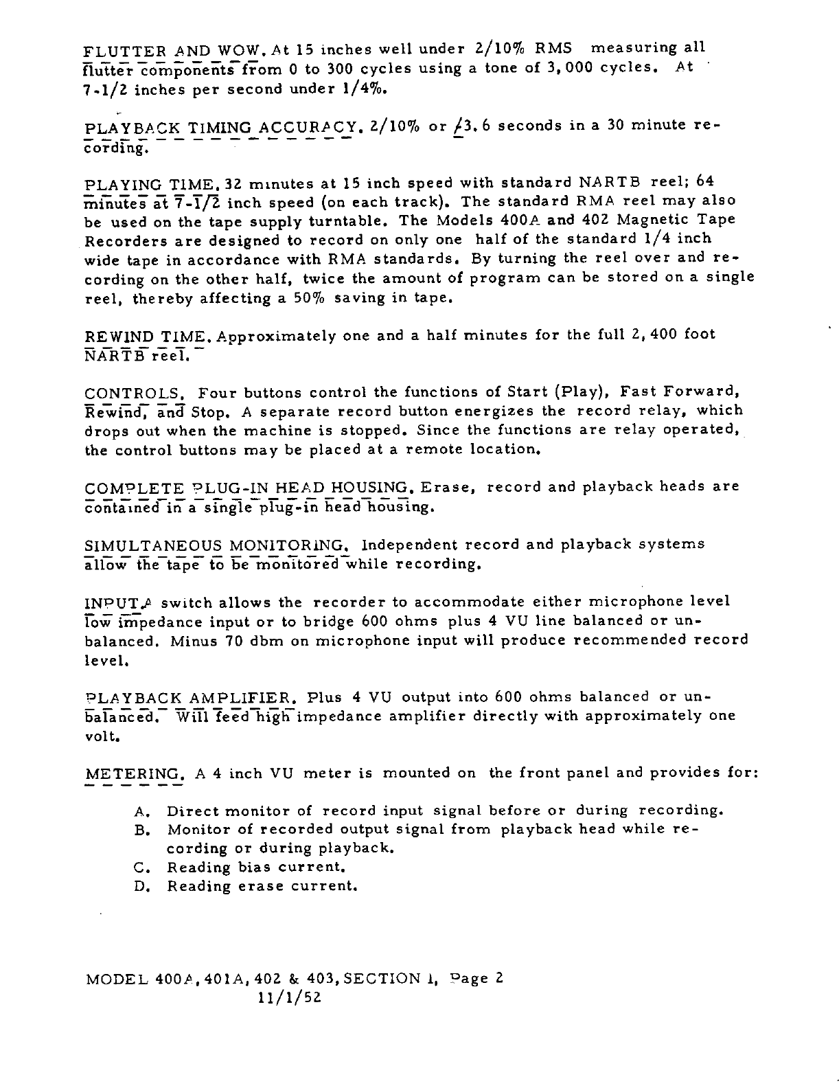
FLUTTER
AND
WOW.At
15
inches
wellunder
2/10%
RMS
measuring
all
fluTtooeitflThm
0
to
300
cyclesusing
a
tone
of
3,000
cycles.
At
7-1/a
inches
per
second
under
1/4%.
PLAYBACKTIMING
ACCURACY.
2/10% or
/3.6seconds
in a
30
minute
re
cording.
PLAYING
T1ME.
32
minutes
at
15
inch
speed with
standard
NARTB
reel;
64
minutes
at
7-TR
inch
speed
on
each
track.
The
standard
RMA
reel
may
also
be
used
on
the
tape
supply
turntable.
The
Models
400A
and
402
Magnetic
Tape
Recorders
are
designed
to
record
on
onlyone
half
of
the
standard
1/4
inch
wide
tape
in
accordance
with
RMA
standards.
By
turning
the
reel
over
and
re
cording
on
the
otherhalf,
twice
the
amount
of
program
can
be
stored
on
a
single
reel, thereby
affecting
a
50%
saving
in
tape.
REW1ND
TIME.
Approximately
one and
a
half
minutes
for
the
full
2,
400
foot
NARTB
reel.
CONTROLS.
Four
buttons
control
the
functions
of
Start
Play,
Fast
Forward,
ewi5d
inZ
Stop.
A
separate
record
button
energizes
the
record
relay,
which
drops
out
when
the
machine
is
stopped.
Since
the
functions
are relay
operated,
the
control
buttons
may
be
placed
at
a
remote
location.
COMPLETE
LUG-IN
HEADHOUSING.
Erase,
record
and
playback
heads
are
contained
in a
single
plug-in
head
housing.
SIMULTANEOUS
MONITORING.
Independent
record
and
playback
systems
allow
thetape
to
be
monitored
while
recording.
INUTJ
switchallows
the
recorder
to
accommodate
either
microphonelevel
Fo’
{Iiipedance
input
or
to
bridge
600
ohms
plus
4 VU
line balanced
or
un
balanced.
Minus
70
dbm
on
microphone
input
will
producerecommended
record
level.
PLAYBACK
AMPLIFIER.
Plus
4 VU
output
into
600
ohms
balanced
or
un
balanced.
Will
feed
higlflmpedance
amplifier
directly
with
approximately
one
volt.
METERING.
A 4
inch
VU
meter
is
mounted
on
the
front
panel
and
provides
for:
A.
Direct
monitor
of
record
input
signal
before
or
during
recording.
B.
Monitor
of
recorded
output
signal
from
playback
head
while
re
cording
or
during
playback.
C.
Reading
bias
current.
D.
Reading
erase
current.
MODEL
400A,4OlA,
402
&
403,
SECTION
1,
Page
2
11/1/52
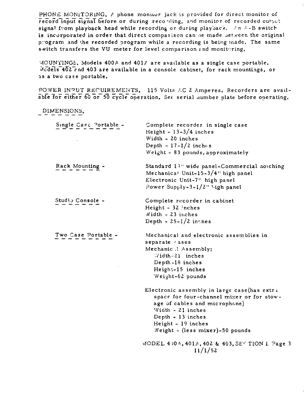
PHONEMONITORING.
A
phone
moniwr
jack
is
provided
for
direct
monitor
of
eod1riuT
iijhaT
£fore
or
during
reco.ding,
and
monitor
of
recorded
outut
signal
ftom
playback
head
while
recording
or
during
playback,
.tn
4-B
switch
is
incorporated
in
order
that
direct
compat
son
can
oe
made
aetneen
the
original
p1ogram
and
the
recorded
program
while
a
recording
is
being
u-4ade.
The
same
switch
transfers
the
VU
meter
for levelcomparison
2nd
monit’ring.
‘AOUNTINGS.
Models
400A
and
401P
are
available
as
a
single
caseportable.
c4sdels
40l’nd
403
are
available
in
a
console
cabinet,
for rack
mountings,
or
as a
two
case
portable.
POWER
INUT
REC’UIREMENTS.
115
Volts
AC
2
Amperes.
Recorders
are
avail
able
Io
iither
60
or
50
cycle
operation.
Sec
serial
dumber
plate
before
operating.
DIMENSIONS.
Stngle
Ca5ctortable_
Complete
recorder
in
single
case
Height
-
13-3/4
inches
Width
-
20
inches
Depth
-
17-1/2
inches
Weight
-
83
pounds,
approximately
Rack
Mounting
-
Standard
1"
wide
panel-Commercial
aoLching
Mechanica’
Unit-15-3/4"
high
panel
Electronic
Unit-7"
high
panel
Power
Supply-3-l/2"
3’igh
panel
Studtj
Console
-
Complete
recorder
in
cabinet
Height
-
32
nches
Width
-
23
inches
Depth
-
zs-i/z
iri’hes
Two
Case
Portable
-
Mechanical
and
electronic
assemblies
in
separate
cases
Mechanic.l
Assembly:
7/idth-21
inches
Depth-iSinches
Height-iS
inches
Weight-62
pounds
Electronic
assembly
in
large
casehas
extrs
space
forfour-channel
mb:er
or for
stow
age
of
cables
and
microphone
Width
-
21
inches
Depth
-
13
inches
Height
-
19
inches
Weight
-
less
mixer-50
pounds
VIODEL
404,
401A,
402
&
403,
SEC
TION
I,
?age
3
11/1/52
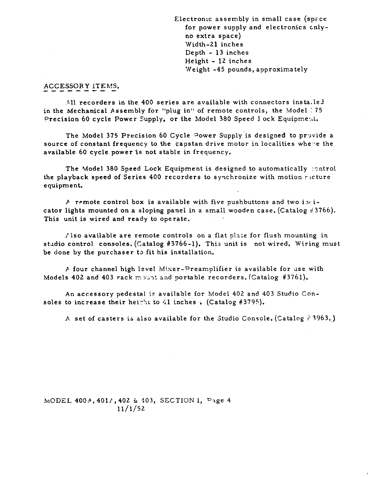
Electronicassembly
in
small
case
spzce
for
power
supply
and
electronics
cnly
no
extra
space
Width-21
inches
Depth
-
13
inches
Height
-
12
inches
Weight-45
pounds,
approximately
ACCESSORY
ITEMS.
All
recorders
in
the
400
series
are
available
with
connectors
ins
ta.lei
in
the
Mechanical
Assembly
for
"plug
in"
of
remotecontrols,
the
Model
:75
Precision
60
cycle
Power
Supply,
or
the
Model
80
Speed
I
ock
Equipme:.t.
The Model
375
Precision
60
Cycle
power
Supply
is
designed
to
pr’vide
a
source
of
constant
frequency
to
the
capstan
drivemotor
in
localities
whee
the
available
60
cyclepower
Is
not
stable
in
frequency.
The Model
380
Speed
Lock
Equipment
is
designed
to
automatically
:ontrol
the
playback
speed
of
Series
400
recorders
to
synchronize
with
motion
r
cture
equipment.
P
remote
control
box
is
available
with
five
pushbuttons
and
two
i.it
i
cator
lights
mounted
on
a sloping
panel
in
a
small
wooden
case.Catalog
ii
3766.
This
unit
is
wired
and
ready
to
ope.rate.
.
-
Piso
available
are
remote
controls
on a
flat
plate
for
flush
mounting
in
st4dio
control
consoles.
Catalog#3766-1.
This
unit
is
not
wired.
Wiring
must
be
done
by
the
purchaser
ta
fit his
installation.
A
four
channel
high
level
Miser-Preamplifier
is.
available
for
use
with
Models
402
and
403
rack
m--it
aiid
portable
recorders.
Catalog
#3761,
An
accessory
pedestal
is
available
for
Model
402
and
403
Studio
Con
soles
to
increase
theirheir’c
to
41
inches
Catalog
#3795.
A
set
of
casters
is
also
availablefor
the
Studio
Console.
Catalog
3963,
MODEL
400ft,
4011,
401
&
‘103,
SECTION
I,
rage
4
11/1/52
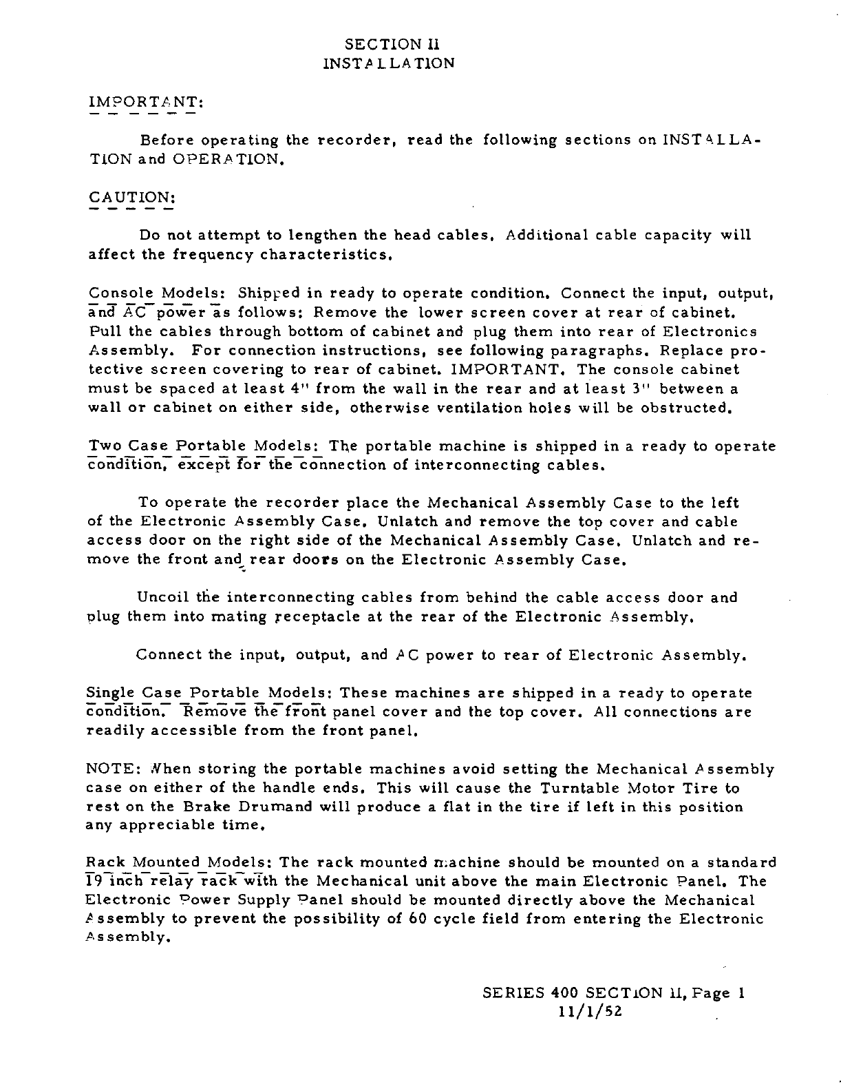
SECTION
Il
INSTALLATiON
IMPORT
A
NT:
Before
operating
the
recorder,
read
the
following
sections
on
INSTLLA
TION
and
OPERATION.
CAUTION:
Do
not
attempt
to
lengthen
the
head
cables.
Additional
cable
capacity
will
affect
the
frequency
characteristics.
Console
Models:
Shipped
in
ready
to
operate
condition.
Connect
the
input,
output,
inJ
ACpr
is
follows: Remove
the
lower
screen
cover
at
rear
of
cabinet.
Pull
the
cables
through
bottom
of
cabinet
and plug
them into
rear
of
Electronics
Assembly.
For
connection
instructions,
see
following
paragraphs.
Replace
pro
tective
screen
covering
to
rear
of
cabinet.
IMPORTANT.
The
console
cabinet
must
be
spaced
at
least
4"
from
the
wall
in
the
rear
and
at
least
3"
between
a
wall
or
cabinet
on
either
side,
otherwise
ventilation
holes
will
be
obstructed.
Two
Case
Portable
Models:
The
portable
machine
is
shipped
in
a
ready
to
operate
condition,
except
for
the
connection
of
interconnecting
cables.
To
operate
the
recorder
place
the
Mechanical
Assembly
Case
to
the
left
of
the
Electronic
Assembly
Case.
Unlatch
and
remove
the
top
cover
and
cable
access
door
on
the
right
side
of
the
Mechanical
AssemblyCase.
Unlatch
and
re
move
the
front
and
rear
doors
on
the
Electronic
AssemblyCase.
Uncoilthe
interconnecting
cables
from
behind
the
cable
access
door and
plug
them into
mating
receptacle
at
the
rear
of
the
Electronic
Assembly.
Connect
the input,
output,
and
AC
power
to
rear
of
Electronic
Assembly.
Single
Case
Portable
Models:
These
machines
are
shipped
in a
ready
to
operate
condition.
Remove
the
front
panelcover
and
the
top
cover.
All
connections
are
readilyaccessible
from
the
front
panel.
NOTE:
Nhen
storing
the
portablemachines
avoid
setting
the
Mechanical
Assembly
case
on
either
of
the
handle
ends.
This
will
cause
the
Turntable
Motor
Tire
to
rest
on
the
Brake Drumand
will
produce
a
flat
in
the
tire
if
left
in
this
position
any
appreciable
time.
Rack
Mounted
Models:
The
rack
mounted
machine
should
be
mounted
on a
standard
T91nhrliiakw1th
the
Mechanical
unit
above
the
main
Electronic
Panel.
The
Electronic
Power
Supply
Panel
should
be
mounted
directly
above
the
Mechanical
/
ssembly
to
prevent
the
possibility
of 60
cycle
field
from
entering
the
Electronic
Assembly.
SERIES
400
SECTiON
11,
Page
1
ii/i/sz
-
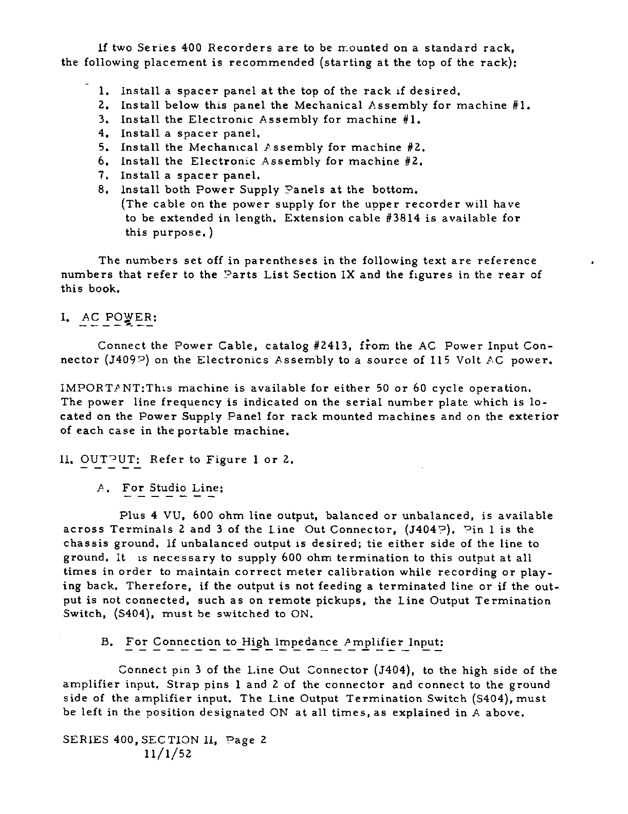
If
two
Series
400
Recordersare
to
be
irounted
on
a
standard
rack,
the
following
placement
is
recommended
starting
at
the
top
of
the
rack;
1.
Install
a
spacer
panel
at
the
top
of
the
rack
if
desired.
2.
Install
below
this
panel
the
Mechanical
Assembly
for
machine
#1.
3.
Install
the
Electronic
Assembly
for
machine
#1.
4.
Install
a
spacer
panel.
5.
Install
the
Mechanical
P
ssembly
for
machine
#2.
6.
Install
the
Electronic
Assembly
for
machine
#2.
7.
Install
a
spacer
panel.
8.
Install
both
Power
Supply
Panels
at
the
bottom.
The
cable
on
the
power
supply
for
the
upper
recorder
will
have
to
be
extended
in
length. Extensioncable
#3814
is
availablefor
this
purpose,
The
numbers
set
off
in
parentheses
in
the
following
text
are
reference
numbers
that
refer
to
the
Parts
List
Section
IX
and
the
figures
in
the
rear
of
this
book.
I.
Connect
the
PowerCable,
catalog
#2413,
fom
the
AC
Power
Input
Con
nector
J4092
on
the
Electronics
Assembly
to
a
source
of
115
Volt
PC
power.
IMPORTPNT:Thtsmachine
is
availablefor
either
50
or
60
cycle
operation.
The
power
line
frequency
is
indicated
on
the
serial
number
plate
which
is
lo
cated
on
the
Power
Supply
Panelfor rack
mounted
machines
and
on
the
exterior
of
each
case
in
the
portable
machine.
Ii.
OlTT:
Refer
to
Figure
1
or
2.
A.
For
Studio
Line:
Plus
4
VU,
600
ohm
line
output,
balanced
or
unbalanced,
is
available
across
Terminals
2
and
3
of
the
Line
Out
Connector,
.7404°,
Pin
1
is
the
chassis
ground,
if
unbalanced
output
is
desired;
tie
either
side
of
the
line
to
ground.
It
is
necessary
to
supply
600
ohm
termination
to
this
output
at
all
times
in
order
to
maintain
correct
meter
calibration
while
recording
or
play
ing
back.
Therefore,
if
the
output
is
not
feedinga
terminated
line
or
if
the
out
put is not
connected,
such
as
on
remote
pickups,
the
Line
Output
Termination
Switch,
5404,
must
he
switched
to
ON.
B.
For
Connection
to
High
impedance
Amplifier
Input:
Connect
pin
3
of
the
Line
Out
Connector
J404,
to
the
high
side
of
the
amplifier
input.
Strap
pins
1
and
2
of
the
connector
and
connect
to
the
ground
side
of
the
amplifier
input.
The
Line Output
Termination
Switch
S404,
must
be
left
in
the
position
designated
ON
at
all
times,
as
explained
in
A
above.
SERIES
400,
SECTION
ii,
Page
2
11/1/52
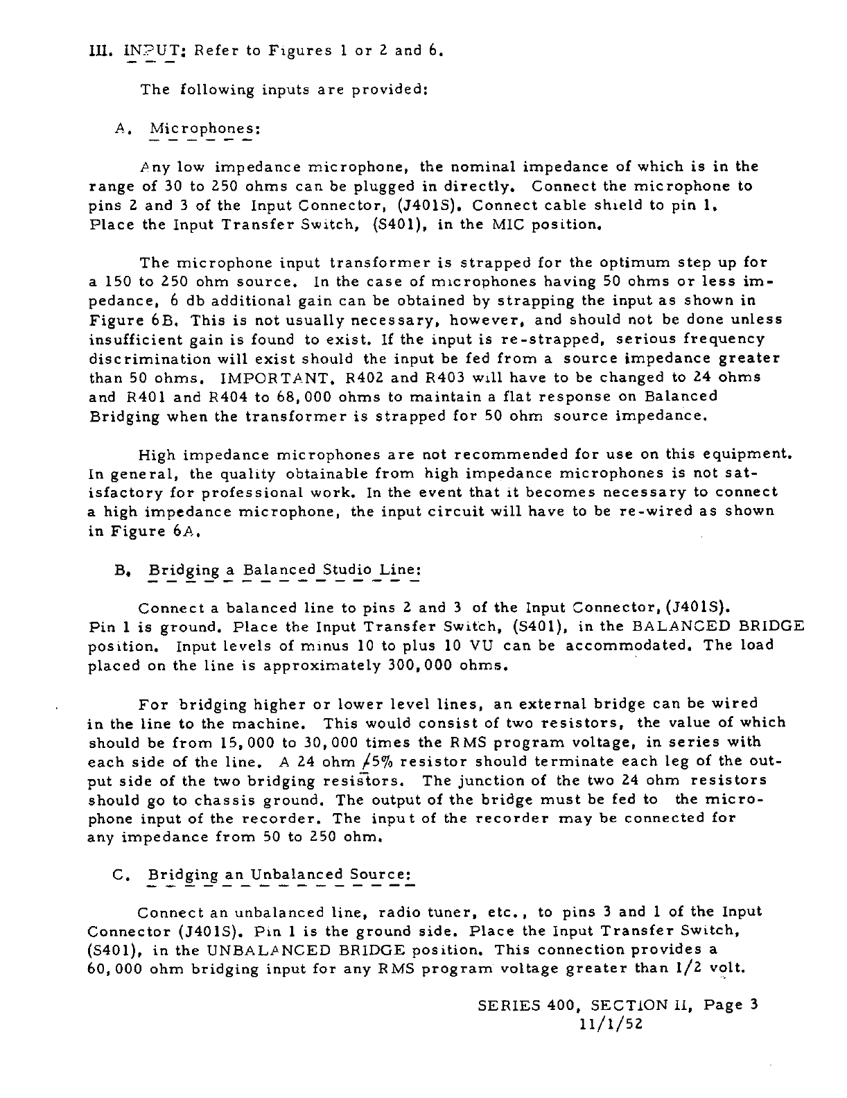
ill.
iNPUT:
Refer
to
Figures
1
or
2
and
6.
The
followinginputs
are
provided:
A.
Microphones:
Any
low
impedance
microphone,
the
nominal
impedance
of
which
is
in
the
range
of
30
to
250
ohms
can
be
plugged
in
directly.
Connect
the
microphone
to
pins
2
and
3
of
the
Input
Connector,
3401S.
Connect
cable
shield
to
pin
1.
Place
the
Input
Transfer
Switch,
S40l,
in
the
MIC
position.
The
microphone
input
transformer
is
strapped
for
the
optimum
step
up
for
a
150
to 250
ohm
source.
In
the
case
of
microphones
having
50
ohms or
less
im
pedance,
6
db
additional
gain
can
be
obtained
by
strapping
the
input
as shown
in
Figure
6B.
This
is not
usually
necessary,
however,
and should
not
be
done
unless
insufficient
gain
is
found
to
exist.
If
the
input
is
re-strapped,
serious
frequency
discrimination
will
exist
should
the
input
be
fed
from
a
source
impedance
greater
than
50
ohms.
IMPORTANT.
R402
and
R403 will
have
to
be
changed
to
24
ohms
and
P401
and
P404
to
68,
000
ohms
to
maintain
a
flat
response
on
Balanced
Bridging
when
the
transformer
is
strapped
for
50
ohm
source
impedance.
High
impedance
microphones
are
not
recommended
for
use
on
this
equipment.
In
general,
the
qualityobtainable
from
high
impedance
microphones
is not
sat
isfactory
for
professional
work.
In
the
event
that
it
becomes
necessary
to
connect
a
high
impedancemicrophone,
the
input
circuit
will
have
to
be
re-wired
as shown
in
Figure
6A.
B,
Bridginga Balanced
Studio
Line:
Connect
a
balanced
line
to
pins
2
and
3
of
the
Input
Connector,
J4O1S.
Pin
1
is
ground.
Place
the
Input
Transfer
Switch,
S401,
in
the
BALANCED
BRIDGE
position.
Input
levels
of
minus
10
to
plus
10
VU
can
be
accommodated.
The
load
placed
on
the
line
is
approximately
300,
000
ohms.
For
bridging
higher
or
lower
level
lines,
an
external
bridge
can
be
wired
in
the
line to
the
machine.
This
would
consist
of
two
resistors,
the
value
of
which
should
be
from
15,
000 to
30,
000
times
the
RMS
program
voltage,
in
series
with
each
side
of
the
line.
A
24
ohm
/5%
resistor
should
terminate
each
leg
of
the
out
put
side
of
the
two
bridging
resiiiors.
The
junction
of
the
two
24
ohm
resistors
should
go
to
chassis
ground.
The
output
of
the
bridge
must
be
fed
to
the
micro
phone
input
of
the
recorder.
The
input
of
the
recorder
may
be
connected
for
any
impedance
from
50
to
250
ohm.
C.
Bridging
an
Unbalanced
Source:
Connect
an
unbalancedline,
radiotuner,
etc.
,
to
pins
3
and
1
of
the
Input
Connector
340
iS.
Pin
1
is
the
ground
side.
Place
the
Input
Transfer
Switch,
5401,
in
the
UNBALANCED
BRiDGE
position.
Thisconnection
provides
a
60,
000
ohm
bridging
input
for
any
RMS
program
voltage
greater
than
1/2
volt.
SERIES
400,
SECTION
II,
Page
3
11/1/52
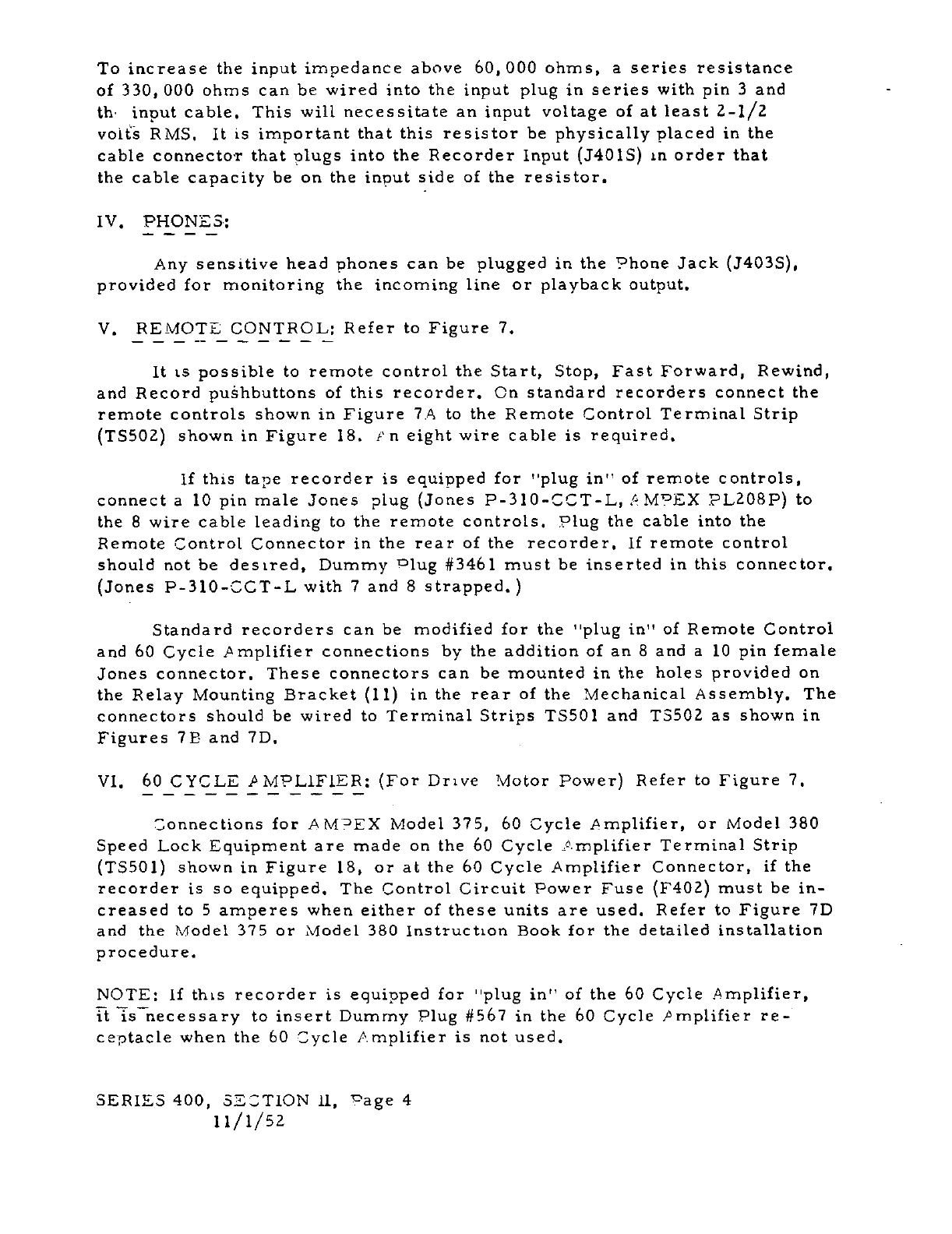
To
increase
the
input
impedance
above
60,
000
ohms,
a
series
resistance
of 330,
000
ohms
can
be
wired
into
the
input
plug
in
series
with
pin
3
and
th-
input
cable.
This
will
necessitate
an
input
voltage
of
at
least
2-1/2
voiè
RMS.
It
is
important
that
this
resistor
be
physically
placed
in
the
cable
connector
that
plugs
into
the
Recorder
Input
J4O1S
in
order
that
the
cable
capacity
be
on
the
input
side
of
the
resistor.
IV,
PHONES:
Any
sensitive
head
phones
can
be
plugged
in
the
Phone
Jack
J403S,
provided
for monitoring
the
incoming
line
or
playback
output.
V.
REMOTECONTROL:
Refer
to
Figure
7.
It
is
possible
to
remote
control
the
Start,
Stop,
Fast
Forward,
Rewind,
and
Record
pushbuttons
of
this
recorder,
On
standard
recorders
connect
the
remote
controls
shown
in
Figure
7A
to
the
Remote
Control
Terminal
Strip
T5502
shown
in
Figure
18.
i’
n
eight
wire cable
is
required.
if
this
tape
recorder
is
equipped
for
"plug
in"
of
remote
controls,
connect
a
10
pin
male
Jones
plug
Jones
P-310-CCT-L,
MPEX
PL2O8P
to
the
8
wire cable
leading
to
the
remote
controls.
Plug
the
cable
into
the
Remote
Control
Connector
in
the
rear
of
the
recorder.
If
remote
control
should
not
be
desired,
Dummy
lug
#346
1
must
be
inserted
in
this
connector.
Jones
P-3l0-CCT-L
with
7
and
8
strapped.
Standard
recorders
can
be
modified
for
the
"plug
in"
of
Remote
Control
and
60
Cycle
Amplifier
connections
by
the
addition
of
an
8
and
a
10
pin
female
Jones
connector.
These
connectors
can
be
mounted
in
the
holes
provided
on
the
Relay
Mounting
Bracket
Ii
in
the
rear
of
the
Mechanical
Assembly.
The
connectors
should
be
wired
to
Terminal
Strips
TSSO1
and
T5502
as
shown
in
Figures
lB
and
7D.
VI.
60
CYCLE
MPL1FIER:
For
Drive
Motor
Power
Refer
to
Figure
7.
Connections
for
AM?EX
Model
375,
60
Cycle
Amplifier,
or
Model
380
Speed
Lock
Equipment
are
made
on
the
60
Cycle
Amplifier
Terminal
Strip
TSSO1
shown
in
Figure
18,
or
at
the
60
Cycle
Amplifier
Connector,
if
the
recorder
is
so
equipped.
The
Control
Circuit
Power
Fuse
F402
must
be
in
creased
to
5
amperes
when
either
of
these
units
are
used.
Refer
to
Figure
7D
and
the
Model
375
or
Model
380
instruction
Book
for
the
detailed
installation
procedure.
NOTE:
If
this
recorder
is
equippedfor
"plug
in"
of the
60
Cycle
Amplifier,
U
TsThecessary
to
insert
Dummy
Plug
#567
in
the
60
Cycle
Amplifier
re
ceptacle
when
the
60
Cycle
Amplifier
is
not
used.
SERIES
400,
SECTION
ii,
°age
4
1
i/i/sz

Vu.
CONVERSiON
FRO
T
.
B:
V
12
kICUNT:
if
a
portable
or
console
c1er
is
convei
ce!
‘o
a
rack
mount
machine,
the
TakeunTension rm
:ounterbalanc
ring
6S
r
ii:jt
re
affded.
This
spring
is
supplied
with
th
recorder
and
is
hT&:
to
the
eeL
T
rust
2racket
85.
See
Figure
17.
To
instad,
let
ove
trcn
.r.E
bra
cet
;r
Jetween
th
lug
provided
on
Safety
w’t
li
501
ard
the
.
.
:
c’tdecoi
the
Takeup
Ten
sion
rrn
Collar
.
The
‘1
‘e
ro
Tensior
cm
.
rxterbalanc
£pring
65
is
sho
n
instaLd
c
rack
mounted
-eration
on
H.
tien
shipped
as
a
rack
mount
machine,
the
spring
w.ii
oe
instaile.
f
tce
conversion
is
to
be
perm
anerit,
the
oiling
cups
ci
the
Turritabie
toter
6,
if
..i
ped
ith
sI.eve
bearings,
shoLid
he
rotat3
tc
be
a
.ie
for
otii
‘
.
ccs ‘JNSrL..
Ni’
r:
PNlNG:
$efore
01
en,.r;
the
‘:csole
or
cci
tae
case:;,disconnect
‘C
oower.
Complete
accessibility
for
inspection
or
service
ii
provided
to
the
to
nd
bottom
of
the
Electronic
Assembly
and
bottom
of
the
viechanical
Assemby.
Fig
ie
21
for
illustration
of
Cabinet
opened
for
full
accessibility.
Coening
rocelLire
1.
Remove
the
four
frontparel
screws
X,
Figure
21,
securing
:lectronic
Assembly
to
cabinet.
2.
°uII
Electronics
P
sserrbly
forward
in
the
position
illus
trated
in Figure
21.
3.
For
access
to
undersic
ofr
lectronic
ssencbly,
pivct
it
back
on
the
hinge
protided
at
rear.
4.
Hinge
at
rear
will
separate
for.
torpiete
removal
of
chassis
from
the
cabinet,
if
desired.
5.
Toe
Mechanical
Assembly
can
bF
raised
to
a
450
positron
removing
t’.o
!ont
.1cc
anical
A
sserv
st-czs,
Y
,
Figire
21.
6.
Use
siport
red
k’
to
support
Mechanical
Assembly.
7.
The
Hechanical
sse
tbli
may
also
be
raised
to
a
vertical
position
and
wilt
be
s
upDuc’e:
oy
e
chain
stop.
IX.
Cca:C
1IlvDR’iiDJ
Cr
*HANIC,"L
AS3K3L?
s?
TO
CASL
ORT
S’;d
jechanical
AssembLy
Case
on
erd
as
shown
in Figure
22.
Release
latches
hal.
I
‘
center
dirisions
of
case.
Inen
La
aporoximately
900.
Care
must
be
taker
t:j
insure
that
cabJes
*:an
pass
throughcable
compar.ment
into
main
rabr’ce
ft
eely.
X.
P
OChC;
TO
UND.R
SIDE
CF
i’4
CH
NIC
_
PSSEMBLY
iN
SINGLE
C!
SE
PORTA
LE,
SiLde
the
Electronics
Chassis
out
of the
case.
Remove
the
headcable
SrIP1ES
400,
SECTION
II,
Page
5
11/1/52
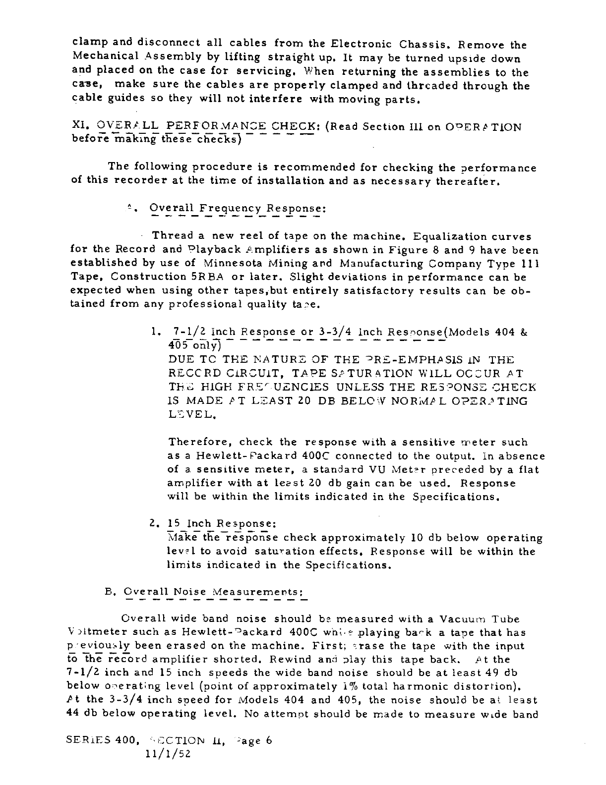
clamp
and
disconnect
all
cables
from
the
Electronic
Chassis.
Remove
the
Mechanical
Assembly
by
lifting
straight
up.
It
may
be
turnedupside
down
and
placed
on
the
casefor
servicing.
When
returning
the
assemblies
to
the
ca-se,
make
sure
the
cables
are
properly
clamped
and
threaded
through
the
cable
guides
so
they
will
not
interfere
with
moving
parts.
Xl,
OVER/LL
PERFORMANCE
CHECK:
Bead
Section
111.
on
OEBfrTiON
before
making
these
checks
-
The
following
procedure
is recommended
for checking
the
performance
of
this
recorder
at
the
time
of
installation
and
as
necessary
thereafter.
.
Overall
Frequency
Response:
Thread
a
new
reel
of
tape
on
the
machine.
Equalization
curves
for
the
Record
and
Playback
Amplifiers
as shown
in
Figure
8
and
9
havebeen
established
by
use
of
Minnesota
Mining
and
Manufacturing
CompanyType
lii
Tape,
Construction
BREA
or
later.
Slightdeviations
in
performance
can
be
expected
when
using
other
tapes,but
entirely
satisfactory
results
can
be
ob
tained
from
any
professional
quality
tane.
1.
7-1/2
Inch
Response
or
3-3/4
inch
ResnonseModels
404
&
405
only
DUE
TC
THE
NATURE
-OF
THE
RE-EMPHPSlS
IN
THE
RECCRD
CIRCUIT,
TAPE
SATURATION
WILL
OCCUR
AT
TH.
HIGH
FRECUENCJES
UNLESS
THE
RES2ONSE
CHECK
15
MADE
PT LEAST
20
DB
BELOW
NOR1vIAL
OPEASPTING
LLVEL.
Therefore,
check
the
response
with
a
sensitive
meter
such
as
a
Hewlett-Packard
400C
connected
to
the
output.
in
absence
of
a
sensitive
meter,
a
standard
VU
Metr
preceded
by
a
flat
amplifier
with
at
least
20 db
gain
can
be
used.
Response
will
be
within
the
limits
indicated
in
the
Specifications.
a.
is
Inch
Response:
check
approximately
10
db
below
operating
level
to
avoid
saturation
effects.
Response
will
be
within
the
limits
indicated
in
the
Specifications.
B.
Overall
Noise
Measurements:
Overall
wide band
noise
should
be
measured
with
a
Vacuum
Tube
V
ltmeter
such
as
Hewlett-°ackard
400C
wh
eplaying
bark
a
tape
that
has
p:eviously
been
erased
on
the
machine.
First;
trase
the
tape
with
the
input
f
Th
E’rd
amplifiershorted.
Rewind and
play
this
tape
back.
Pt
the
7-1/2
inch
and
15
inch speeds
the
wide
band
noise
should
be
at
least
49
db
belowonerat;.ng
level
point
of
approximately
1%
total
harmonic
distortion.
Pt
the
3-3/4
inch
speed
for
Models
404
and
405,
the
noise
should
be
at
least
44
db
below
operating
level.
No
attempt
should
be
made
to
measure
wide
band
SERiES
400,
OCTION II,
age
6
11/1/52
noise
‘vhdt
stxz,ulLwus1y
recording
and
1aying
back
as
-
-
;
of
Ye
flO
1C
ias
irto
he
play-ack
head
may
interL
with
t
:C3S2
‘c
-
C.
Listortion;
Dverall
distortion
can
be
treasured
by
connecting
any
standard
distcrtion
rreasurenent
appatatus
across
the
outpuL
The
readings
from
a
wave
ana’yzer
or
selectivefrequencydistortion
rr’eter
will
be
moreaccurate
than
those
from
a
null
type
instrument
at
lower
distortion
levels.
Distortion
read
ings
are
some-,vhat
dependent
on
tape.
reading
of
l
is
normal
at
ooerating
level
whi1
a
reading
of
3%
is
normalat
6
db
above
ooerating
level.
D.
Flutter_and
Vow:
Flutter
and
i1ow
are
the
change
of
soeed
over
a
short
time
interval
in
a
Der1dicmanner.
They
can
be
measured
by
means
of
a
sta3dard
flutter
bridge
such
as
.
F.
Tatum
Beverly
Hills,
California
Model
2--
Flutter
"1eter.
Variations
in
amplitude
as
indicated
on
level
measurements
do
not
constitute
flutter
and
are entirely
due to
taoe
coating
variations.
Readings
will
be
well
‘1nder
.
2%’c.
at
15
inch,
.
25
at 7-1/2
inch
and
.
3
at
3-3/4
inch
speed.
For
moreinformation
on
alignment
or
performance
checking,
refer
to STCTION
VI
-
c
ltgnment.
SERII3
400,
SECT1ON
11,
7-age
7
ii/i/sz
SLCTIOIr
III
OPLR4TING
IROCEDUR
I,
REEL
SIZE:
The
turntable
on
the
left
side
tape
supply
is
equipped
to
handle
either
the
NP-RTB
io-i/z"reel
of
tape or
the
smaller
R.
M.
A. 5"
and
7"
sizes.
On
console
or
portable
machinesposition
the
small
reels
on
the
turntable
engaging
the
turntable-keys.For
the
large
ia-i/a"
reel,
use
the
black
plastic
Centering
Guide
Catalog
#976
that
has
been
provided.
On
rack
mount
machines,
use
the
Hold-Down
Knob
Catalog
#4402
wth
both
small
and
large
reels.
The
#4402
reel
Lold-down
knob
works
in
the
following
manner.
A
re
movable
pin
in
the
bottom
surface
of
the
knob
engages
a
corresponding
hole
in
the
turntable.
A
coliet
grips
the
turntable
shaft
when
the
top
of
the
knob is
ro
tated.
Two
spring
loaded
balls
hold
the
reel
to
the
turntable.
A
pin
in
the side
of
the
knob
drives
the
reel.
The
knob
should
be
positioned
on
the
NPRTB
reels
so
that
the
removable
pin
engages
one
of
the
turntable
holes
and
approximately
two
thirds
of
the
ball
is
exposed
above
the
reel.
The
knob
should
not
be
pushed
down
all
the
way,
but
should
stick
up
above
the
turntable.
Once
the
knob
is
po
sitioned
correctly,
the
NARTB
reels
may
be
removed
without
removing
the
knobs.
When
using
the
knob
with
the
small
RMA
reels,
unscrew
the
removable
pin.
The
knob is
used
only
t9
prevent
the
reel
from
falling
off
the
turntable,
since
three
keys
in
the
turntabledrive
and
center
the
reel.
Lock
the
knob
to
the
shaft,
avoid:
ing
excess
pressure
on
the
reel
which
could
distort
the
reel
flanges.
The
turntable
on
the
right
side
Takeup
Reel
is
designed
to
handle
only
the
NtRTB
10-1/2"
reel.
No
attempt
should
be
made
to
use
the
small
reel
sizes
on
this
turntable
as
the
performance
of
the
recorder
will
be
seriously
impaired.
U.
TA?E
THREADING:
Thread
the
tape as
indicated
in
Figure
16.
All
new
factory
wound
reels
should
be
unwound
and
inspected
by
runningthrough
at
Fast
Forward
before
using
them
in
the
?lay
mode
of
operation.
New
tapes
are
usually
looped
to
the
hub
in
sucha
manner
that
the
tape
will
not
come
free
of
the
reel
at
the
end
of
the
reel.
This
will
prevent
the
Safety
Switch
5501
from disengaging
the
Capstan
Idler
50
from
the
Capstan
A
which
results
in
a
flat
being
worn
on
the
Rubber
:Capstan
-
Idler
Wheel.
Any
adhesive
material
accumulation
on
the
reel
hub
must
be
removed
with
solvent
for
the
same
reason.
Ill.
HALF-TRACK
OPERATION:
The
handling
of
half-track
tape
on
this machine
i
accomplished
in
the
following
manner.
The
tape
is
threaded
and
operated
as
described
under
T
Jii
THRLADING
and
TAF-
MOTION.
However,
only
the
upper
half
of
the
tape
will
be
used
on
the
half-track
machine.
To
utilize
the
lowerhalf
of
the
tape,
the
full
reel
on
the
Takeup
Turntable
should
be
removed,
turned
over
and
placed
on
the
SERIF
5
400
SECTION
III
Fage
1
1
i/i/sz
Tape
Supply
Turntable
upside
dow..
Place
an
empty
reel
on
the
Takeup
Turn
table.
Repeat
the
operation
as
performed
on
the
first
track.
IV. POWER:
Power
is
supplied
through
Power
Switch
S406, which
must
be
turned
on
to
operate
the
Electronic
and
Mechanical
Assemblies.
The
Mechanical
Assembly
and
Electronic
Assembly
are
individually
fused
by
the
2
ampere
Con
trol
Circuit
Fuse
F402
and
the
1
ampere
Electronics
Fuse
F401,
V.
SEED
SWITCHES:
There
are
two
switches
associated
with
operating
speed.
SpeedSwitch
5502
governs
the
motor,
and
the
Equalization
Speed
Switch
5402
corrects
the
equalization
in
the
amplifiers.
VI.
TAPE
MOTION:
-
The
tape motion
is
controlled
by
means
of
four
pushbuttons
labeled
Stop,
Start,
Fast
Forward,
and
Rewind.
1.
Play
or
Record:
The
tape
is
set
into
Play
motion
at
the
speed
selected
-by
the
Speed
Switch
when
the
Start
Button
5507
is
depressed.
The
tape
must
be
completely
stopped
before
starting
in
this
mode.
To
change
from
Play
mode
to
the
Record
modewith
the
tape
in
motion,
press
the
Record
Button
5403.
2.
Stop:
To
stop
the
tape
motion
vhile
it
is
moving
in
any mode
press
the
-
t&Button
5506.
This
will
occurautomatically
if
the
tape
should
break
or
run
off
either
reel.
3.
Fast
Forward:
If
the
tape
isin
the
Dlay
or
Record
mode,
press
the
Fast
Forward
Button
S504.
If
the
tape
is
stopped,
first
press
the
Start
Button,
then
the
Fast
Forward
Button
or
press
both
at
the
same
time.
This
provides
a
Fast
Forward
speed
which
is
used
to
arrive
rapidly
at
a
point
within
a
reel.
4.
Rewind:
If
the
tape
is
in
the
Play
or
Record
mode,
press
the
Rewind
Button
S505.
If
the
tape
is
stopped,
press
the
Start
Button
then
the
Rewind
Button
or
press
both
at
the
same time. This
provides
a
fast
reverse
to
rewind
a
tape
completely
or
to
return
to
an
earlier
section.
In
using
either
the
Fast
Forward
or
Rewind
n-ode,
it
is
desirable
to
remove
the
tape
from
direct
contact
with
the
heads
by
opening
the
gate
of
the
Head
&ssembly.
This
will
reducewear
on
the
heads
and
prevent
the
oxide
coating
on
the
tape
fromdepositing
on
the
heads
and
impairing
their
performance.
it
is
not
possible
to
switchfrom
Rewind
to
Fast
Forward
or vice
versa
unless
the
machine
is
re
turned
to
Stop.
Interlocking
the
‘machine
in
this
manner
provides
the
least
nossible
wear
on
the
Tape
Transport
system.
SERIES
400
SECTION
AU
-
rage
2
i
1/1/52
Indexing
the
tape
as
in
editing
or
cueing
or when
anproaching
the
end
of
the
reel
is
simplified
by
holding
down
a
combination
of
buttons.
Hold
down
the Stop
and
Fast
Forward
or
the Stop
and
Rewind
Buttons.
Now
press
the
Start
Button
and
control
the
tape
speed
with
this
button.
CAUTION:
Avoid
thisoperation
at
high
speeds,
as
it
will
result
in
tape
breakage
if
the
wrong
combination
of
buttons
should
be
pushed.
When the
tape
is
traveling
at
high speed
in
the
Rewind
or
Fast
Forward
mode,
the
tane
will
break
if
the
Stop
and
Start
Buttons
are
pressed
in
rapid
sequence.
This
is
caused
be
cause
sufficient
time
is
not
allowed
for
the
brakes
to
-stop
the
tape
before
the
Capstan
Idler
locks
the
tape
to
the
Capstan.
VII.
PLAYBACK:
To
play
back
a
previously
recorded
tape,
turn
the
Meter
and Output
Switch,
5405,
to
the
extreme
left
position
designated
PLAYBACK.
Then
start
the
tape
in
motion
as
indicatedunder
T?LAY.
For
Single
Case
Portable
Models.
If
the
recording
was
made
at
the
correct
level,
the
VU
Meter
will
peak
on
0
iiio.
No
attempt
should
be
made
to
alter
the
gain
of
the
Playback
Amplifier
if
the
meter
does
not
peak
on
0
zero.
Other
wise,
the
calibration
of
this
meter
as
a
record
level
indicator
will
be
destroyed.
The
playbackgain
will
be
clcse
when
playing
any
tape
recorded
to
NARTB
specifi
cation
s
For
Rack,
Console
or
Two
Case
‘ortable
Models
*
P
Playback
Level
Con
trol
has
been
provided
on
the
front
panel
to
adjust
the
tape
level
to
plus
4 VU
output.
V1II.
RECORD:
To
record
a
new
program
on
prevtouslyrecorded
tape,
or
on
blank
tape,
turn
the
Meter
and
Output
Switch
5405
to
the
second
positionfrom
the
left
which
is designated
RECORD-LEVEL.
Turn
the
Record
Level
Control
R409
clockwise
until
the
level
reads
0
zero
on
the
VU
Meter
on
the
most
intense
program
peaks.
The
program
can
be
audibly
monitored
through
either
the
Phone
Jack
J403S,
or
the
Line
Out
Connector
J404’°
before
the
tape
is
in
motion.
For
correct
meter
calibration
it
is
important
that
the
Line
Out
be
properly
term
inatedeither
external
to
the
machine
or
by
use
of
the
Line
Out
Termination
Switch
S404.
This
direct
monitor
feature
allows
the
program
to
be
set
up
through
the
machinewithout
actually
recording
during
the
set
up
period.
When
the
program
levelis
properlyset,
start
the
tape
in
motion
as
indicated
under
PLAY.
Then
push
the
Record
Button,
5403.
It
is
desirable
that
a
delay
of
at
least
i/i
second
occur
before
the
Recc$rd
Button
is
depressed,
as
the
surge
from
operating
the
Start
Button
maymagnetize
the
record
head,
thereby
increasng
the
noise
level
on
the
tape.
The
Record
Indicator,
NE4O1,
next
to
the
Record
Button
will
now
glow
and
the
machine
is
recording.
It
is
desirable
to
check
the
record
bias
and
erasecurrents
occasionally.
In
order
to
do
this,
re-position
the
Meter
and
OutputSwitch
S405,
to
the
po
SERIES
400
SECTION
LU,
‘°age
3
11/1/52
-

sitions
designated
BIAS
and
ERASE,
respectively.
The
erase
is
not
critical
and
should
read
approximately
zero
on
the
meter
scale.
The
bias
should
read
between
-i/a
and
/
1/2
on
the
VU
scale.
The
bias
is
somewhat
critical
and
must
be
kept
within
the
indicated
range
in
order
to
record
the
higher
fre
quencies
at
the
low
tape
speed.
The
bias
is
adjusted
by
means
of
the
Bias
Control,
R449
located
on
the
electronic
chassis.
The
meter
calibrationfor
bias
measurement
can
be
checked
as
indicated
in
SECTION
VI.
SERIES
400
SECTION
III,
Page
4
11/1/52
SEC
LION
IV
OPERATING
THEOR
Y
The
purpose
of
this
section
is
to
explain
the
electrical
and
mechanical
functioning
of
the
Recorder
as
the
machine
is
operated.
An
understanding
of
this
functional
operation
will
enable
the
operator
to
utilize
fully
the
capa
bilities
of
the
machine,
I.
MECHANICALASSEMBLY:
Refer
to
figures
in
rear
of book
for
circuits
and
location
of
parts.
To
understand
the
operation
of
the
Tape
Transport
Mechanism
it
is
necessary
to
examine
the
following
assemblies
in
the
various
modes
of
operation:
1.
Capstan
Drive
Motor
24,
Figure
18.
The
Capstan
Motor
is
a
synchronous
motor
whose
extended
shaft
forms
the
TapeDrive
Capstan
A
Figure
16.
It
has
two
sets
of
windings
to
provide
the
two
tape
speeds.
2.
Turntable
Motor
6
Figure
19.
The
Turntable
Motor
is
an
induction
motor
which
drives
either
the
Tape
Supply
or
Takeup
Turntable
by
means
of
a
Rubber-tired
Pulley
7
on
its shaft.
The
motor
is positioned
to
contact
either
of
the
turntable
Brake
Drums
34
and
35,
Figure
18,
by
the
Tilt
Solenoids
K503
and
1504.
3.
Capstan
Idler
50,
Figure
16.
The
Capstan
Idler
is
positioned
by
the
Capstan
Solenoid
1501.
In
the
Play
mode
of
operation
the
Idler
is
positionedagainst
the
Capstan
A
and
drives
the
tape
at
a
constant
speed.
4.
Stopping
Brakes
36
and
39
Figure
17.
The
Stopping
Brakes
are
solenoid
operated
to
stop
the
turntables
whenever
the
machine
is
stopped.
5.
Reel
Idler
69,
Figure
20.
The
Reel
Idler
is
provided
to
smooth
out
any
takeup speed
variations
in
the
tape
system.
6.
TakeupTension
Arm
62,
Figure
16,
The
TakeupTension
Arm
provides
automatic
stop
at
the
end
of
the
reel
of
tape or
if
the
tape
should
br
eak*
7.
Constant
Tension
Brake
47,
Figure
17.
The
Constant
Tension
Brake
is
mechanically
operated
by
the
Constant
Tension
Arm
44,
Figure
16.
It
SERIES
400,
SECTION
IV,
Page
1
11/1/52
providesconstant
hold-back
tension
to
the
Tape
Supply
Turntable
27,
regardless
of
the
amount
of
tape
on
the
reel
or
its
size.
When
the
Power"On-Off’
Switch
5406
is
thrown,
AC
voltageis
applied
to
the
Electronics
Assembly
and
to
the
Capstan
Motor.
Therefore,
the
Capstan
is turningwhenever
the
recorder
is
turned
on,
which
makes
possible
the
fast
start
feature.
When
the
tape
is
threaded
the
Safety
Switch
S501
is
actuated
by
the
Takeup
Tension
Arm
62.
This
energizes
the
DC
Power
Supply
which
in
turn
provides
power
to
operate
the
solenoids
and
relays.
START:
When
the
Start
Button
S507
is
pressed
the
Start
Relay
1505
will
be
energized.
It
is held
energized
through
its
own
contacts
and
the
normally
closed
Stop
Button
5506.
The
Start
Relay,
through
appropriate
inter
locks,
performs
the
following
functions:
1.
Energizes
the
Brake
Solenoid
1502
thus
releasing
the
Stopping
Brakes
36
and
39.
2.
Energizes
the
Forward
Tilt
Solenoid
1504
thus
positioning
the
Turn
table
Motor
in
the
takeup
position.
3.
Applies
AC
powerthrough
the
Takeup
Torque
Switch
S503
to
the
Turn
table Motor.
4.
Energizes
the
Capstan
Solenoid
1501.
which
positions
the
Capstan
Idler
50
to
contact
the
tape
and
the
Capstan.
The
Capstan
Solenoid
when
energizedmechanically
opens
the
Takeup
Torque
Switchwhich
inserts
a
resistor
P503
in
series
with
the
Turntable
Motor.
This
allows
the
high
starting
torque
to
be
reduced
to
a
more
suitable
value
for
operating
conditions.
Full
power
is
utilized
in
Fast
Forward
or
Rewind.
The
recorder
is
now
operating
in
the
Play
mode
of
operation
with
the
tape
moving
at
the
speed
selected
by
the
Speed
Switch
S502.
FAST
FORWARD:
If
the
Fast
Forward
Button
5504
is
pressed
and
the
machine
is
in
the
Play
mode
of
operation,
the
Fast
Forward
Relay
1506
will
be
energized.
The
relayperforms
the
following
functions:
1.
It
interlocks
the
Rewind
Relay
1507
so
it
can
not
be
energized.
2.
It
breaks
the
circuit
to
the
Capstan
Solenoid.
When
the
Capstan
Solenoid
is
de-energized
the
Takeup
Torque
Switch
closes,
thus
applying
fullpower
to
the
Turntable
Motor.
Since
the
Forward
Solenoid
is
still
energized
the
machine
is
now
operating
in
the
Fast
Forward
mode
of
opera
tion.
If
the Rewind
Button
is
pressed
nothing
will
happen
and
it
is
necessary
to
re
SERIES
400,
SECTION
IV
?age
a
11/1/52
turn
to
Stop
before
the
mode
of
operation
can
again
be
changed.
This
interlocking
prevents
scuffing
the
Turntable
Motor
Tire
on
the
Brake
Drums.
REWIND:
If
the Rewind
Button
5505
is
pressed
and
the
machine
is
in
the
Play
mode,
the Rewind
Relay
1507
will
be
energized.
The
relay
performs
the
following
functions:
1.
It
interlocks
the
Fast
Forward
Relay
1506
so
it
can
not
be
energized.
2.
It
breaks
the
circuit
to
the
Capstan
Solenoid
1501
and
the
Forward
Tilt
Solenoid
1504.
3.
It
energizes
the
Rewind
Tilt
Solenoid
1503
thus
positioning
the
Turn
table
Motor
in
the
Rewind
position.
4.
It
reverses
the
polarity
on
one
winding
of
the
Turntable
Motorthus
re
versing
its
direction.
When the
Capstan
Solenoid
is
de-energized
the
Takeup
Torque
Switch
closes
applying
full
power
to
the
Turntable
Motor.
The
machine
is
now
operating
in
the
Rewind
mode
of
operation.
If
the
Fast
Forward
Button
is
pressed
nothing
will
happen
and
it
is
necessary
to
return
to
Stop
before
the
mode
of
operation
can
again
be
changed.
STOP:
Nhen
the Stop
Button
is
pressed
during
any
mode
of
operation,
the
Start
Relay
will
be
de-energized.
This
in
turnbreaks
the
circuits
to
the
Rewind
and
Fast
Forward
Relays
and
to
the
circuits
described
in
the
paragraph
on
START.
The
Stopping
Brakes
will
be
applied
to
both
turntables.
In
addition
it
applies
DC
power
through
a
series
resistor
R502
to
the
condenser
winding
of
the
Turntable
Motor. This
brakes
the
motor
and
prevents
throwing
a
tape
loop
when
the
tape
direction
is
changed.
SERIES
400,
SECTION
IV
Eage
3
11/1/52
Ii.
HEAD ASSEMBLYY
The Head
Housing
is
a
die
cast
assembly
which
contains
the
three
heads
used
in
the
recording
process.
The
heads
are
respectively
Erase,
Record
and
Playback
as
viewed
from
left
to
right
when
facing
the
machine.
The
gate
on
the
housingholds
the
Playback
and
Record
Shield
Covers
and
the
Tape-lifting
Fingers.
The
function
of
the
Tape-lifting
Fingers
is
to
re
move
the
tape
from
the
heads
when
the
gate
is
open
during
Rewind
or
Fast
Forwardposition.
This
reduces
head
wear
considerably.
The
tapemay
leave
a
deposit
on
the heads
if
allowed
to
contact
them
at
high
speeds.
Such
a
deposit
will
seriously
impair
the
performance
of
the
machine
and
should
be
guarded
against
by
always
openingthe
gate
on
Fast
Forward
or
Rewind.
lf
a
deposit
is
left,
it
may
be
easily
removed
with
carbon
tetrachloride
on
a
soft
rag.
Never
use
metal
of
any
kind
to
touch
the
head
surfaces.
The
gate
should
never
be
allowed
to
spring
shut
but
should
be
closed
gently.
The
Model
400A,
402,
and
404
Recorders
incorporate
half-track
Erase,
Record,
and
Playback
Heads. These
heads
function
on
the
upper
half
of
the
tape
only.
In
order
to
use
the
remaining
half
of
the
tape
the
reels
must
be
turned
over
as
explained
in Section
Ill-UI.
The Head
Assembly
of
the
Model
4OlA,
403
and
405
Recorders
incorporate
full
track
Erase,
Record,
and
Playback
Heads. This
affords
maximum
performance
from
the
full
width
of
the
tape
and
permits
complete
interchangeability
of
tapes
re
corded
on
the
Models
300,
201
and
other
full
track
recorders.
SERIES
400
SECTION
IV,
Page
4
11/1/52
in.
£LCfRONlC54sSEhrBLY:
The
OlecTr.;nc
..sembiy
of
the
Series
400
sccrder3
consists
of
a
Record
mtslifier,
a
layback
mnlifier
and
an
En
e
4td
Bias
Oscillator
on
one
chassis
and
a
ower
Supply
on
a
separate
chas.
is.
The
Record
-
mçlifier
is
a
four
stage,
highgain
annrlifier
that
feeds
ëhe
Record
Head
through
the
Noi0e
Balance
Circuit
and
Record
Relay
F401.
The
Record
Belay
is
ener2ized
by
the
Record
Button
:403
through
contacts
of the
Start
Relay
V.505
in
the
energizedçosition
and
contacts
of
the
Fast
Fcrwa-cd
Relay
L506
and
the
flewind
P.elay
1<537
in dc-energized
*.ositions.
TherefDre,tte
taecord
mode
of
operation
can
cnly
be
realized
when
the
tare
is
traveling
at
the
t:iy
‘,‘eeds.
henever
the
Fast
Forward,
Rewind
or
Aol.
Euttons
are
&e
ressed,
the
Record
Relay
will
be
de-energized.
Three
in ut
irnf.edctnca
cn
be
elected
by
the
Input
Transfer
Switch
5401;
low
itt
edance
microphone,
balanced
brid;’e
and
unbaianced
bridge.
Ehe
Pecorci
mp
lifier
also
.irovides
se:arate
high
ft
quency
pre-emphasis
for
each
seed.
This
change
in
ecualization
is made
by
he
qualization
5’sead
Switch
340?
iccated
on
the
ft
rt
2aneI.
Ti-e
Record
C,sin
:ontrol
p409
is
located
on
the
front
‘anel.
The
layback
mç.lifier
Is a
threestaze
amplifier
which
,srovides
a
plus
4
TTJ
60.
ohm
output
at
the
Line
C’u
:onnec
tot
J404:
.
The
Flayback
equalization
is
the
5aoe
mr
the
7-
/a
and
13
inch
:.eeds
arsd
is
adjusted
to
the
.tandatd
curve
Fig.
--
Lv
R43Z,
located
on
too
cf
the
Electronic
chassis.
The
3-3/4
inch
tayhack
eoualiation
conforms
to
the
curve
in
‘i*.
butis
not
adjustable.
ih’
ia
hack
gain
on
single
case
portaUe
models
is
ccntrolled
by
a
fiice
d
screw
driver
adjustment
P437
which
should
nc
be
varied
in
the
normal
opera
Lion
of the
n-’achine,
On
all other
models
the
gainrosy
be
adjusted
by
the
-layback
Level
Control
P437
located
on
the
front
panel.
An
output
term
ination
is
prvjdr
by
thi
line
C-at
Termination
Switch
S404.
3ionitoring
ts
provided
by
a
VU
Meter
and
a
hone
Jack
whichis
connected
to
the
layback
I
mplifier
output.
The
Meter
and
Outlut
Switch
S405
provides
fourmonitoring
checks:
Playback
Level,
Record
Level,
Bias
Current,
Erase
Current.
In
the
Erase
position
the
VU
meter
is
con
nected
across
the
7
ohm
resistor
P448
to
read
erase
current,
in
the
Bias
osition
the
meter
is
connected
across
the
adjustable
500
ohm
resistor
R450
to
read
bias
current.
ic
both
the
Record
and
Playback
Levelpositions
the
meter
is
connected
across
the
Elayback
mlifier
o
ttout.
In
the
Playback
position
the
Playback
t
mpiifier
functions
normally
and
the
output
of
the
tape
is
monitored.
In the
Record
position
the
last
two
stages
of the
playback
P
mplifier
are
disconnected
from
the
first
stage
and
bridged
across
the
Record
Amplifier
before
9re-emphasis
through
the
Record
Level
Meter
Calibration
Control
R413.
The
Calibration
Control
is
factory
adjusted
so
that
the
de
sired
recordlevel
will
be
effected
on
the
tape.
The
rase
and
Bias
oscillator
provides
the
100
KC
erase
and
bias
SERIES
400
SECTION
IV,
Page
5
11/1/52

frequency.It
feeds
the
erase
head
through
the
Erase
Trimmer
C435
and
the
record
head
through
the
Record
Bias
Control
R449.
The
Power
Supply
provides
the
6.3
Volt
AC
heater
power,
the
12.
6
Volt
DC
heater
powerthrough
a
full
wave
selenium
rectifier
SR6OJ
and
the
plate
supply
through
the
5Y3G
Full
Wave
Rectifier
V60l.
SERIES
400
SECTION
IV,
Page
6
1
i/i/sz
SECTION
V
ROUTINE
MAINTENANCE
I.
CLEANING:
The
Tape
Transport
Mechanism
should
at
all
timec
be
kept
clears
and
dry.
The
following
parts
should
be
inspected
daily
before
the
use
of
the
recorder
arid
cleaned
with
a soft
rag
and
carbon
tetrachloride
or
alcohol,
if
necessary
Refer
to
Figure
16.
1.
Head
surfaces
contacted
by
tape.
2.
Capstan
A.
3.
Capstan
Idler
so.
Cleaning
is
required
only
if
fregn
matter
should
adhere
to
the
rubber.
4.
CapstanTape
Guide
89.
5.
ConstantTension
Arm
TapeGuide
45.
6.
Reel
Idler
Pulley
71.
7.
TakeupTension
Arm
TapeGuide
J.
II,
HEAD
DEMAGNETIZATION:
Occasionally
the
heads
may
become
magnetized
through
an
electrical
fault
in
the
amplifiers,
improper
use
of
the
machine,
or
by
the
heads
coming
in
contact
with
a
magnetizedobject.
This
will
result
in
an
increase
of
noise
level
frorr
5
to
10
db.
It
is
especially
important
that
the
heads
be
free
of
magnetization
if
you
are
to
realize
the
dynamic
range
of
the
machine.
It
should
be
remembered
that
any
phenomena
that
tends
to
put
an
unbalanced
pulse
through
the
Record
Head
will
inag
netize
it,
Such
pulses
can
appear
in
the
form
of
signal
or
power
line
pulses.
If
the
following
precautions
are
observed,
no
difficulty
should
be
experienced:
1.
Do
not
remove
any
tube
from
the
Record
Amplifier
while
the
machine
is
recording.
2,
Do
not
connect
or
disconnect
input
leads
or
head
leads
while
recording.
3.
Do
not
depress
the
Record
Button
until
after
depressing
the
Start
Button,
In
other
words,
allow
the
transient
caused
by
switching
the
motors
and
solenoids
to
die
out
before
the
record
head
is connected.
A
one-half
secondpause
is
sufficient.
SERIES
400,
SECTION
Vt
Page
1
l1/1/5
4.
Do
not
saturate
the
RecordAmplifier
with
an
abnormally
high
input
signal,
Such
a
signal
would
he
10
db
greater
than
tape
sat
uration
or
approximately
30
db
greattr
than
normal
operating
level,
5.
Do
not
test
continuity
in
the
heads
with
an
ohm
meter.
Should
the
heads
become
magnetized,
they
can
be
demagneized
with
an
AMPEXHead
IJernagnetizer
Catalog
#704.
The
following
Demagneti
zation
Procedure
should
be
performed:
Bring
the
tip
of
the
Derragneizer
in
direct
contact
or
close
proximity
to
the
head
core
stack,
Run
the
tip
of
the
Demagnetizer
up
and
down
the
entire
height
of
the
core
stack
three
or
four
times,
Remove
the
demagnetizer
very
slowly, allowing
the
AC
field
to
die
off
gradually.
Repeat
this
operation
on
Record
and
Playback
Heads
only,
as
the
Erase
Head
will
demagnetize
itself.
In
the
event
demagnetization
is not
effected,
repeat
the
process
several
times.
IV,
LUBRICATION:
Thefollowing
places
require
lubrication
once
or
twice
a
year
depend
ing upon the
amount
of
usage
of
the
machine:
I.
Capstan
Drive
Motor
24
and
Turntable
Motor
6.
The
motor
manufacturers
recommend
the
followin
lubr1cantsfor
theirrespective
motors;
Eastern
Air
Devices-Saccny
VacuumOil Company.
S,A.E,20
Bodine
Zlectric
Comoany
‘Gulf
Oil
&
Refining
Comany-Gulfcrest
P
Standard
Oil
Co,of
Indiari-Stanoil
#l8oi
Sacony
VacuumOil
Co.
-
argoyle
D,
I,
E.
Light
If
equivalent
oils
are
to
be
used,
ar
epresentative
of
the
oil
corrpany
thould
be
contacted
to
ascertain
that
the
equivalent
is
miscible
with
the
lul
ricants
listed
above.
Otherwise,
sludging
may
result.
A.
Capstan
Drive
Motor,
The
Uop-’
SleeveBearing
on
this
muto
requirer
lubrication.
Pry
off
the
Capste.i
Dust
Cap
26
shown
in
Figur
16.
T:e
oil
hole
on
the
motor
is
located
near
the
outside
edge
of
the
cutout
arid
in
some
cases
tray
be
partially
cbscured.
Lubricate
with
10
drops
of
the
recommended
lubricant,
preferahiy
using
an
oil
can
with
flexible
spout.
3,
Turntable
4otcr,
The
rec
ord
r
may
be
equipped
with
different
tyiI5
of
turntable
motors,
If
the
tir
tahle
rrctor
has
oil
cups
o
oiling
heR
requires
10
drops
of
the
recor.rznded
lubricant.
Raise
c
r
rencve
Tape
Transport
Top
Plate
to
Cpose
the
oil
holes.
Refer
o
Section
J
for
access
into
the
console
ca
net
or
portable
case.
If
U
e
motor
is
supplied
with
ball
bearings
frio
oil
cups
or
oiling
holes,
ubricatior
i
not
required.
SERIES400,SECTICN
V,
Page
2
11/1/52
2.
Reel
Idler
Upper
Bearing
72.
Refer
to
Figure
20.
Remove
the
Plug
Button
74
and
lubricate
withone
drop
of
SAE
20
motor
oil.
The
following
places
have
been
lubricated
at
the
factory
with
Dow-Corning
DC-44
Silicone
Grease
light
consistency.
No
further
lubrication
should
be
necessary
unless
the
grease
becomescontaminated
with
dirt
in
which
case
the
part
should
be
cleaned
and
re-lubricated.
1.
Capstan
Idler
Arm
Bushing
4,
Figure
19.
2.
Constant
TensionArm Bushing
5,
Figure
19,
3.
Capstan
SolenoidEye
Bolt
54,
Figure
17.
4.
Reel
Idler
Thrust
Bearing
86,
Figure
20.
5.
Safety
Switch
Level
Ssoi,
Figure
17.
The
Takeup
Tension
Arm
Bushing
3,
Figure
17,
has
been
lubricated
at
the
factory
with
Dow-Corning
DC-ZOO
oil.
No
furtherlubrication
should
be
neces
saryunless
the
oil
becomes
contaminated
with
dirt
in
which
case
the
part
should
be
cleaned
and
re-lubricated.
If
DC-ZOO
oil
is not
available,
SAE
20
motor
oil
can
be
used,
The
following
places
require
no
lubricationand
should
be
left
dry:
1.
Brake
Shoe
pivot
on
the
ConstantTension
Brake
47,
Figure
17.
2.
The
armatures
of
all
solenoids,
3.
Brake
SolenoidLink
13,
Figure
18.
4.
Tilt
Solenoid
Spade
Bolts
14,
Figure
18.
V.
BRAKE
LINING:
Periodic
inspection
should
be
made
of
the
BrakeLinings
on
the
Stopping
Brakes,
36
and
39,
Constant
Tension
Brake
47
and
the
Hold
Pack
Brake
22,
as
worn
linings
will
result
in
damage
to
the
surface
of
the
Brake
Drums.
These
linings
are
made
of
high
grade
felt
but
theymay
requirereplacementafter
long
service.
The
linings
are
supplied
by
the
factory
cut
to
size.
For
ordering
in
formation,
see
Parts
List,
Section
IX.
The
recommended
method
of
applyingBrake
Lining
is
described
below:
1.
Remove
both
Brake
Drums
34
and
35
as
described
in
Section
VIII
-4.
2.
Remove
old
liningand
scrape
the
shoe
clean.
It
is
not
necessary
to
remove
the
brakes
to
do
this.
3.
Spread
a
liberal
amount
of
DuPontHousehold
Cement
or
equivalent
on
the
brake
shoe;
excessivecement
should
be
avoided
as
it
will
soak
through
the
Brake
Lining.
SERIES
400,
SECTION
V,
Page
3
11/1/52
4.
Position
the
felt
carefully
so
it
lines
up
with
the
outside
edges
of
the
shoe
and
allow
at
least
30
minutes
for
cement
to
dry.
CAUTION:
Be
sure
that cement
is
not
allowed
to
remain
on
working
surfaces.
5.
Replace
the
Brake
Drums
and
adjust
the
turntable
and
Brake
Drum
height
as
described
in Section
VIII-4.
A
number
of
stops
may
be
neces
sary
to
bring
the
stopping
energy
of
the
brakes
up
to
normal,
Sanding
the
Brake
Drums
as
described
in Section
VIII-Z
will
hasten
this
pro
cess.
Do
not
touch
the
surface
of
the
Brake
Drum
after
sanding.
In
an
emergency
any
good
quality
ioO%
wool
felt
may
be
cut
to
size
and
used
as
linings.
They
should,
however,
be
replaced
as
soon
as
poss
ible
with
factorylinings.
If
a
felt
containing
nylonshould
be
used,
a
brown
residue
will
be
deposited
on
the
drums.
This
should
be
removed
with
sand
paper
as
explained
in Section
VIII-Z
when
factory
linings
are
applied.
SERIES
400, SECTION
V,
Page
4
11/1/52
SECTiON
VI
ELECTRONIC
ALiGNMENT
Alignmentis
the
necessary
adjustments
required
to
have
the
Electric
Assembly
of
the
tape
recorder
perform
properly.
A
machine
"out
of
alignment"
may
be
characterized
by
poor
frequency
response,
high
noise,
low
output,
or
high
distortion.
It
should
not
be
necessary
to
align
the
recorder
when
it
comes
to you
from
the
factory.
The
proceduresdescribed
on
the
followingpages
have
been
performed
at
the
factor
prior
to
shipment.
Further
adjustments
are
not
required
except
as
found
necessary
in
routine
maintenance.
Alignment
consists
of
the
following
steps:
I
Head
Alignment
ii
Playback
Circuit
Alignment
ILl
Record
Circuit
Alignment
1.
Bias
Adjustment
2.
Record
Level
Meter
Calibration
3.
Record
Equalization
A.
15
inch
per
second
B.
7-1/2
inchper
second
4.
Noise
Balance
IV
Erase
Adjustment
StandardAlignment
Tape
#4494
is
availablefor
alignment
purposes.
lt
is
recorded
at
15
inchesper
second,
10
db
below
15
inch
operating
level.
It
contains
a
15
XC
tone
for
head
azimuth
check,
a
reference
tone
for
level
adjust
ment,
and
a
series
of
tones
for
a playback
response
check.
IMPORTANT:
Before
playing
the
standard
tape,
demagnetize
the
heads
with
the
AMPEX
Head
Demag
netizer,
Catalog
#704.
Magnetized
heads
will
cause
a
partial
erasure
of
the
high
frequencies
on
the
standard
tape.
MODEL400A, 401A,
402
&
403,SECTION
Vi,
Page
1
11/1/52
I.
HEAD
ALIGNMENT:
The
high
frequencyresponse
of
the
recorder
depends
on
the
correct
head
alignment.
If
tapes
are
to
be
interchangeable
from
one
machine
to
another
the
heads
of
all
machines
must
have
the
sameazimuthsetting,
This
is
accom
plished
by
using
a
Stad
Tape
Ca
talo’g
#94
,
for
aligning
the
heads
of
all
machines.
Head
alignment
is independent
of
tape
speed;
however,
it
is
rec
ommendedthat
the
heads
be
aligned
at
15
inches
per
second
since
the
standard
tape
is
recorded
at
this
speed.
Remove
the
top
coverfrom
the
Head
Housing
by
removing
the
two
screws
from
the
top
and
pulling
cover
gently
back
and
up.
Looking
at
the
Head
Housing
from
the
front
the
three
heads
from
left
to
right
are:
Erase,
Record,
and
Playback.
The
azimuth
angle
of
the
erase
head
is
not
adjustable.
The
Record
and
Playback
Heads
should
be
aligned
only
after reading
and
fully
understanding
the
procedure
under
PLAYBACK
AND
RECORDCIRCUIT
Al
IGNMENT.
The
actual
physicalalignment
of
the
Record
and
Playback
Heads
con
sists
of
placing
a
1/4"
spintitesocket
wrench
on
the
left
hand
elastic
stop
nut
in
eachhead
and
adjusting
back
and
forth
until
the
proper
azimuth
angle
is
arrived
at.
First
adjust
the
Playback
Head
azimuth
by
playing
the
standard
tape
at
15
inches
per
second
and
adjusting
the
stop
nut
for
the
maximum
output
of
the
15
kc
tone
first
tone
that
appears
on
the
standard
tape.
The
Record
Head
azimuthis then
aligned
with
the
Playback
Head
by
recording
a
15,
000
cycle
signal
from
an
audio
oscillator
on
a blank
tape
and
ad
justing
the
record
stop
nut
for
maximum
playback
output.
MODELS
400A,
4014,402
&
403,
SECTION
Vi,
°age
2
i
i/i/sz
II.
ALIGNMENT
OF
PLAYBACK
CIRCUiT:
Refer
to
Figure
1
or
2.
1.
Position
the
Electronic
Assembly
so
that
adjustments
can
be
made
on
the
controls
located
on
the
top
of the
chassis.
2.
Set
the
Tape
Speed
Switch
S502
and
Equalization
Speed
Switch
S402
to
15
inches
per
second.
3.
Set
the
meter
and
Output
switch
S405
to
the
PLAYBACK-LEVEL
p0-
S
ition.
4.
Terminate
the
line
output
either
by
means
of
the
Line
Out
Termination
Switch
5404
or
by
externaltermination
of
600
ohms.
5.
Connect
an
amplifier
and
loudspeaker
to
the
outputor
plug
in a
pair
of
high
impedance
head
phones so
that
voice
announcements
on
the
standard
tape
can
be
heard.
6.
Thread
the
standard
tape
on
the
machine
and
set
the
tape
in
motion
in
the
Play
mode
of
operation.
7.
Adjust
the
playback
head
azimuth
as
discussed
under
HEAD
ALIGNMENT.
8. The
second
tone
on
the
standard
tape
is
used
to
adjust
the
playback
gain.
Adjust
the
PlaybackLevel
Control
R437
for
a
reading
of
-10
on
the
VU
meter.
On
the
Model
400A
and
401A,
R437
is
a
screw
driver
control,
whichshould
be
locked
after
this adjustment.
On
the
Model
402
and
403,
R437
is
a
front
panel
control.
IMPORTANT:
Retain
this
setting
until
the
Record
Level
Meter
Calibration
has
been
adjusted.
9.
PLAYBACK
EQUALIZATiON:
The
Playback
Amplifier
is
factory
equal
ized
by
means
of
the
High
Frequency
Playback
Equalizer
R432
Figure
11
or
14,
in
accordance
with
the
standard
voltage
curve
shown
in
Figure
8.
The
recommended
method
for
adjusting
the
PlaybackAmplifier
re
sponse
is
to
connect
an audio
oscillator
and
vacuum
tube
voltmeter
to
the
Playback
Amplifier
as shown
in
Figure
8.
Adjust
the
Playback
Equal
izer
R432
to
give
the
frequencyresponse
of
the
standard
50
micro
second
curve.
Deviation
from
this
curve
is
not
recommended.
Check
the
playback
level
setting
with
a
standard
tape
if
any
change
is
made
in
the
Equalizer.
The
above
will
properly
align
the
playback
circuit
for
operation
at
both
speeds.
The
15
inch
standard
tape
will
play
backwithin/
2
db
to
15,
000
cycles
when
the
PlaybackAmplifier
is
adjusted
to
the
standard
curvi.
Failure
for
the
standard
tape
to
play
back
vithin
these
tolerances
after
the
PlaybackAmplifier
has
beenaligned
indicates
one
of
the
following:
a.
Trouble
in
the
Head
Assembly
such
as
worn
heads.
b.
A
faulty
Standard
Tape
which
has
been
partially
erased
af
high
frequencies
by
passing
over
magnetized
heads,etc.
MODEL400A,
401A,
402
&
403,
SECTION
Vi,
Page
3
ii/i/sz
An
overall
frequency
response
check
will
isolate
the
trouble.
Good
overall
response
indicates
a
faulty
StandardTape.
PoorOverall
response
indicates
one
of
the
following:
a. Faulty
Heads
b.
Tape
deficiency
c. Record
or
Playback
Amplifier
improperly
equalized.
d.
incorrect
bias
Alignment
of
the
Record
Circuits
as
described
in
the
next
sub-section
will
further
aid
in
isolating
trouble.
Iii,
ALIGNMENT
OF THE
RECORDCIRCUITS:
Refer
to
Figure
1
or
2.
The
7-i/a
inch
and
15
inchper
second
record
alingment
should
not
be
attempted
until
the
playbackis
properly
aligned.
Perform
the
following
in
order
indicated:
1.
Bias
Adjustment:
The
record
bias
current
is
factory
adjusted
for
opti
mum
overallresponse
and
low
frequency
distortion.
However,
the
optimum
value
of
bias
current
will
vary
with
different
types
of
tape.
The
recordequalization
characteristics
on
this
equipment
havebeen
determinedfor
peak
bias
at
1000
cycles
at
15
inchper
second
tape
speed,
Peak
bias
means
that
the
bias
current
is
adjusted
so
that
the
1000
cyclesignal
is
recorded
at
its
maximum
level.
Adjust
the
bias
in
the
following
manner:
a. Thread
ablank
tape
on
the
machine.
Terminate
the
playback
am
plifier
as
in
Playback
Alignment.
Set
the
Speed
Switches
S402
and
S502
to
15"
per
second.Set
the
meter
and
OutputSwitch
S405
to
the
Playback
Level
position.
b.
Connect
an
audio
oscillator
to
the
Input
Connector
J4OIS,
set
the
input
Transfer
Switch
S401
for
unbalanced
bridging
input
and
adjust
the
frequency
to
1000
cycles
per
second.
c.
Start
the
machinein
the
record
mode
of
operation.
d.
Adjust
the
Record
LevelControl
R409
so the
meter
reads
approx
imately
0
zero.
e.
Adjust
Bias
Control
R449
for
maximumplayback
level
of
1000
cycle
tone
while
recording
the
playing
back
simultaneously.
it
is
de
sirable
to
be
within
1/2
db
of
the
maximum
efficiency
point
in
order
to
achieve
wide
frequency
range
recording
at
7-1/2"
per
second,
f.
The
Bias
Meter
Calibration
is
adjusted
as
follows:
After
the
bias
is
adjusted,
meter
the
bias
in
the
normal
fashion
and
adjust
the
Meter
Shunt
R450
for
0
zero
reading
on
the
VU
scale
of the
meter.
MODEL
400A, 401A,
402
&
403,
SECTION
Vi,
Page
4
ii/i/sz
2,
Record
Level
Meter
Calibration:
The
Record
Level Meter
Calibration
Control
R41
3,
Figure
11
or
14,
is
adjusted
so
that
the
program
level
as
read
on
the
VU
meter
is
the
same
as
monitoredfrom
the
Dlayback
Head
or
the
incomingline. This
is
accomplished
by
recording
a
250
cycle tone
or
program
in
the
absence
of
an
audio
oscillator
at
0
zero
on
the
VU
meter
with
the
Meter
and
Output
Switch
in
the
PLAY
BACK-LEVEL
position.
Then
switch
the
Meter
and
Output
Switch
to
the
RECORD-LEVEL
position
and
adjust
the
Record
Level
Meter
Cal
ibration
Control
for
0
zero
on
the
VU
meter.
IMPORTANT:
The
Playback
Level
Control
R437
must
be
set
as
described
in
Playback
Alignment
before
making
this adjustment.
3.
Record
Equalization:
The
7-1/2
inch
and
15
inch
record
equalization
circuits
have been
factory
adjusted
to
the
curves
shown
in
Figure
9.
These
curves
have been
found
to
produce
flat
overall
response,
when
recording
on
Minnesota
Mining
and
Manufacturing
Company
type
ill
tape,
construction
SR
BA,
or
later.
Othertapes
may
requireresetting
or
equalization
and
Bias
Control.
Badly
worn
tapes
may
produceloss
in
high
frequency
response
at
the
i-i/a
inch
speed
and
should
not
be
used.
The
adjustment
procedure
for
flatoverall
response
on
any
tape
is
as
follows:
A.
15
inch
Record
Equalization
Adjustment
1.
Set
up
the
machine
as
described
under
Bias
Adjustment.
2.
Start
the
machine
in
the
record
mode
of
operation
at
the
15
inch
tape
speed.
3.
Reset
the
audio
oscillator
to
15,000
cycles
and
adjust
the
record
head
azimuth
as
described
under
Head
Alignment.
NOTE:
All
frequency
checks
at
the
15
inch
tape
speed should
be
made
10
db
below
operating
level
-10
on
the
VU
meter
monitoring
record
to
avoid
saturation
effects
caused
by
the
high
frequency
preemphasis.
On
the
Model
402
and
403
the
front
panel
Playback
Level
Control
may
be
set for increased
gain
so
the
following
adjustments
can
be
made
in
a
more
sensitive
meter
range.
4.
Reset
oscillator
to
250
cycles
and
adjust
the
Record
Level
Control
R409
so
the
VU
Meter
monitoring
playback
reads
-10.
5.
Reset
oscillator
to
8,000cycles
and
adjust
the
15
inchRecord
Equal
izer
so
the
VU
meter
monitoring
playback
reads
-10.
6.
Frequency
response
should
be
/
2
db
30
to
15,
000
cycles.
MODEL
400P,
4OlA,
402
&
403,
SECTION
Vi,
Page
5
11/1/52
B.
7-1/a
Inch
Record
Equalization
Adjustment
1.
With
the
machine
set
up
as
above,
change
the
Speed
Switches
5402
and
5502
to
the
7-l/z
inch
position.
2.
Reset
oscillator
to 250
cycles
and
adjust
the
Record
Level
Control
so
the
VU
meter
monitoringplayback
reads
-10.
3.
Reset
oscillator
to
8,000cycles
and
adjust
the
7-1/2
inch
Record
Equalizer
so
the
VU
meter
monitoring
playback
reads
-10.
4.
Frequencyresponse
should
be
p1
2
db
from
40
to
8,000
cycles.
Due
to
tape
saturation,
frequency
checks
can
not
be
made
at
thislevel
beyond
8,000
cycles.
To
run
response
checks
beyond
8,000
cycles
refer
to
Overall
Performance
Check,Section
Ii-Xi.
4.
Noise
Balance:
A
noise
balance
control
is provided
to
eliminateexcessive
low
frequency
noise
and
null
second
harmonic
distortion.
The
noise
bal
ance
should
not
be
touched
unless
all
heads
havebeen
thoroughly
demag
netized
withan
AMPEX
Head
Demagnetizer
or
equivalent
See
Section
V.
If
noise
of
a
crackling
nature
is
still
found
to
exist
in
the
output
of
the
machine,
connect
a
1
MFD
condenser
across
the
output
of
the
machine
and
adjust
the NoiseBalance
Control
R424,
Figure
11
or
14,
for
mini
mum
record
noise
as
read
on
a
sensitive
meter
or
heard
in a
loudspeaker
connected
to
the
machine
output
through
a
power
amplifier.
IV.
ERASEADJUSTMENT:
The
erase
current
is
factory
adjusted
and
no
further
adjustment
should
be
necessary
unless
the
Erase
Head
is
replaced.
Should
this
happen,
the
following
procedure
must
be
followed:
a.
Set
the
Meter
and
OutputSwitch
S405
in
the
Erase
position
and
press
the
Record
Button
S403.
b.
Back
off
the
Erase
Trimmer
C435,
Figure
11
or
14,
to
a
minimum
capacity
clockwise
direction.
c.
Increase
the
capacity
until
the
meter
reads
0
zero.
d.
Check
the bias
current
after
making
this
adjustment
since
a
ch ange
in
erase
current
will
produce
a
change
in
bias
current.
MODEL
400A,
401A,
402
&
403,
SECTION
Vi,
Page
6
11/1/52
SECTION
VII
MECHNICP
I
SERVICE
GUIDE
This
section
is
a
guide
to
locating
irregularities
in
the
operation
of
the
Tape
Transport
Mechanism
of
this
r e
cc
r
d
c
r.
Sources
of
irregularities
in
the
Electronic
Assembly
have
not
been
included
in
this
book
since
standard
elec
tronic
maintenance
techniques
apply.
This
section
is
divided
into
the
following
four
parts:
I.
Failure
to
Start.
II.
Irregularities
in
Play
Mode.
III.
Irregularities
in
Rewind
or
Fast
Forward
Mode.
IV.
Miscellaneous.
To
use
this
section
first
decide
into
which
of
the
above
groups
the
trouble
lies.
Check
the
list
of
symptoms
in
the
group
to
further
localize
the
trouble.
Investigate
each
of
the
partslisted
under
the
appropriate
symptoms
to
detect
incorrect
adjustments
or
possible
defects.
Refer
to
Section
VIII
for
the
correct
mechanical
adjustment
procedures.
The
numbers
in
parentheses
are
reference
numbers
which
refer
to
the
figures
in
the
rear
of
the
book.
I.
FAILURE
TO
START.
A.
Capstan
Drive
Motor
inoperative
at
one
or
both
speeds.
Check
the
following:
1.
AC
Power
to
the
recorder.
a.
Control
Circuit
Fuse
F402.
b.
Power
Cable
fromMechanical
Assembly
to
Elec
tronic
Assembly.
c.
Capstan
Drive
Motor
Connector
J502P.
d.
Speed
Change
Switch
S502.
e.
Jumpersfrom
1
to
2
and
3
to
4
on
60
Cycle
Ampli
fier
Terminal
Strip
TSSO1.
NOTE:
Machines
equipped
for
Trplug
in"
of
60
Cycle
Amplifier
must
have
properly
jumpered
Dummy
Plug
catalog
#567
inserted
in
the
60
Cycle
Amplifier
Connector
J703S
in
absence
of
the
60
Cycle
Amplifier.
2.
Head
cables
interfering
with
Drive
Motor
Flywheel.
SERIES
4C0,
SECTION
VII
Page
1
11-1-
52
3.
Capstan
Drive
Motor
24
for
binding
of
shaft,
open
or
shorted
winding.
4.
Drive
Motor
Capacitor
0508.
B.
Machine
does
not
operate
or
tripsitself
off
when
St?rt
Button
is
depressed.
NOTE:
Before
making
thesechecks
read
Sec
tion
Ill-Il
on
Tape
Threading.
Check
the
following:
1.
Switches
a.
Safety
Switch
5501.
For
adjustment,
See
Section
VIII-
10.
b.
Stop
Button
3506.
c. Start
Button
5507.
d.
Takeup
Torque
Switch
S503.
For
adjustment,
see
SectionVIIl-7.
2.
DC
Relay
and
Solenoid
Power
Supply.
a.
Selenium
Rectifier
SR5Ol.
b.
Resistor
RSOl.
c.
Electrolytic
Condenser
C50Z.
3.
Relays.
a. Start
Relay
1505.
b.
Rewind
Relay
1507.
c.
Fast
Forward
Relay
1506.
4.
Solenoids.
a.
Capstan
Solenoid
1501.
For
adjustment,
see
Section
VIII-l.
b.
Forward
Tilt
Solenoid
1504.
For
adjustment,
see
Section
VIII-8.
c.
Brake
Solenoid
K50Z.
For
adjustment,
see
Section
VIII-2.
5.
Play
Resistor
R503
for
an
open
circuit.
6.
Jumper
from
Terminal
7
to
8
on
the
Remote
Control
Ter
minal
Strip
T3502.
NOTE:
Machines
equipped
for
plug
in"
of
Remote
Control
must
have
the
properly
jumpe
red
Dummy
Plug
catalog
#3461
inserted
in
the
Remote
Con
trol
Connector
J7OIS
in
absence
of
a
Remote
Control
System.
SERIES400,
SECTION
VII
Page
2
11/1/52
7.
Binding
of
Turntable
Iotorivots
18
and
19.
8.
Cables
interfering
with
the
Brake
Drums
34
and
35.
9.
Counterbalance
Spring
65
in
rack
mount
position
on
‘-‘ortable
machines.
See
Section
lI-Vu.
II.
IRRYGUT
ARITIES
IN
LAY
MODE.
P.
Unsatisfactorystarting
in
lay
Mode.
Check
the
followng:
I.
Takeup
Torque
Switch
S303 for
adjustment.
May
be
opening
too
early.
See
Section
VIII-7.
2.
Binding
of
Turntable
Motor
I
ivots
18
and
19
may
cause
late
engagement
of
Turntable
Motor.
3.
Tilt
Solenoids
1533
and
1504
if
misadjusted
can
cause
sliipage
or
late
engagement
of
Turntable
Motor
B50a.
See
Section
VIII-8.
4.
Insufficient
takeup
torque
in
the
P’ay
mode.
a.
Play
Resistor
R503
set
too
high.
See
Section
VIII-9.
-b.
Cable
interfering
with
Takeup
Brake
Drum
35.
5. Stopping
Brakes
36
and
39.
a.
Dragging
brakes.
b.
Brake
Clearanceadjustment
too
great
so
thatbrakes
are
slowin
releasing.
See
Section
VIII-2.
6.
Capstan
Idler
pressure
adjustment.
See
Section
VIII-1.
7.
Takeup
Tension
Arm
62
sluggish.
8.
Constant
Tension
Brake
47
adjustment.
See
Section
VIII-3.
9.
Low
relay
and
solenoidsupply
voltage
which
would
slow
down
the
relay
and
solenoid
operation
time.
B.
High
flutter.
The low
flutter
specifications
on
this equipment
are
rigidly
met.
Any
noticeable
flutter
can
probably
be
traced
to
one
of
the
following:
*
SERIES
400
,
SECTION
VII
?age
3
11/1/52
1.
Cable
dragging
on
a.
Takeup
Brake
Drum
35.
b.
Reel
Idler Flywheel
78.
c.
Capstan
Drive
iv4otor
Flywheel.
2.
Foreign
material
such
as
deposit
left
by
the
tape
on
a. Capstan
A,
Figure
16.
-
b.
Reel
Idler
Pulley
71,
Figure
ZO.
c. Capstan
Idler
50,
Figure
16.
.d.
Turntable
Motor
Tire
7,
Figure
19.
e.
Takeup
Brake
Drum
35,
Figure
18.
f.
Head
Surfaces.
g.
-
Tape
Guides
45, 89,
and
j,
Figure
16.
3.
Excessive
drag
in
Reel
Idler
69.
If
Reel
Idler
is
quiet
and
turns
freely,
it
is
not
likely
to
contribute
to
the
flutter
and
should
not
be
disassembled.
If
the
Reel
Idler
will
not
turn
freely
or
is
noisy,
check
the
following.
Refer
tp
Figure
20.
a.
Reel
Idler
Adjustment.
See
SectionVIII-6.
b. Top
Bearing
72
insufficiently
lubricated.
See
Section
V-IV.
c.
Thrust
Bearing
86
worn.
-
d.
Foreign
material
in
Lower
Bearing
75.
4.
Capstan
Drive
Motor
24.
a.
Top
Bearing
insufficiently
lubricated.
Do
not
over-lubricate.
See
Section
V-IV.
-
b.
Bent
Capstan
A.
-
c.
Motor
windings
partiaUy
open
or
shorted.
5.
Capstan
Idler
50
defective.
.
6.
T.akeup
Torque
Switch
5503
not
opening.
See
Section
VIII-7
for
adjustment.
7.
Bad
Tape
worn,
ragged,
or
of
poor
quality.
8..
Recorder
subjected
to
excessive
external
vibration.
C.
Recorder
fails
to
shut
off
when
tape
runs
out.
Check
the
following:
SERIES400,
SECTION
VII,
Page
4
11/1/52

1.
TakeupTension
Arm
62
sluggish
due
to:
a.
Dirt
betweenTakeup
Tension
Arm
62
and
Bushing
3.
b.
TakeupTensionArm
Return
Spring
-64
‘diiconne-c-ted
or
broken.
c.
Safety
Switch
S501
inoperative
or out
of
adjustment.
See
Section
VUI-lO.
-
d.
Safety
Switch
Condenser
C501
shorted.
D.
Instability
of
Tape
on
Capstan.
Check
the
following:
1.
Oil
on
Capstan
A
or
Capstan
Idler
50.
2.
Takeup
Torque
Switch
S503
not
opening
causing
excessive
takeup
tension.
See
Section
VIII-7
for
adjustment.
3.
Capstan
Idler
Pressure
Adjustment.
See
Section
VuIl-l.
4.
Capstan
Solenoid
1501
notseating.
5.
ConstantTension
Brake
Spring
49
disconnected
or
broken.
6.
ConstantTension
Arm
44
binding
in
Bushing
5.
7. Bad
Tape
stretched
edges
or
bad
splices.
E.
Recorder
goes
into
Fast
Forward
Mode
when
Start
Button
is
depressed.
Check
the
following:
1.
Capstan
Idler
Pressure
Adjustment.
See
Section
VIII-1.
2.
Capstan
Solenoid
1501
for
defect.
III.
IRREGULARITIES
IN
FAST
FORWARD
OR
REWIND
MODE.
A.
Recorder
stops
when
Fast
Forward
or
Rewind
Buttons
are
depressed.
Check
the
following:
1.
Fast
Forward
Button
S504.
2.
Rewind
Button
S505.
3.
Fast
Forward
Relay
1506.
4.
Rewind
Relay
1507.
5.
Rewind
Tilt
Solenoid
1503.
For
adjustment,
see
Section
VIII-8.
SERIES
400,
SECTION
VII
Page
5
11-1
-52
B.
Recorder
sluggish
in
Fast
Forward
or
Rewind.
Check
the
following:
--
________
1.
Takeup
Torque
Switch
S503 stays
open.
See
-
Section
VIII-7
for adjustment.
2.
Cable
Dragging
on
either
Brake
Drum
34
or
35.
3.
Stopping
Brakes
3o
and
39.
-
-
a.
Dragging
Brakes.
b.
Brake
Solenoid
1502
lone
or
inoperative.
Se
Section
VIII-2,
4.
Turntable
Motor
6
for
insufficient
lub’ication.
3cc
Section
V-IV.
5.
Slippage
between
Turntable
Motor
Tire
7
and
Brace
Drums
34
or
35.
a.
Tilt
Solenoid
1503
and
K504.For
Ec’ustrflent
ee
*
Section
VIII-8.
b.
Oil
on
Brake
Drums
34
or
35
or
Tur
table
AoL.
Tire
7.
c.
Binding
of
Turntable
Motor
Pivots
13
and
19;.
IV,
MISCELLANEOUSIRUEGULARITIES
A.
Braking
too
severe
causing
breaking
or
delorrnatior
tape.
*
1.
Binding
of
Brake
P
rm
Pivot,
Figure
17
r
oint
G
See
Section
V1II-2A
for adjustment.
2,
Brake
Solenoid
Stop
67
deformed.
See
Si-
-tion
ILl.
-.
B.
Braking
insufficient
causing
tape
slack
to
be
throwi
w
en
the
machine
is
stopped.
1.
Brake
Drum
contaminated
with
oil
or
gr
a
e.
Se
Section
VIIIZF,
for
cleaning
procedure
C.
Braking
rotationally
uneven.
1.
BrakeDrum
contaminated
with
oil
or
gr-ea:
.
See
Section
VIll-2F
for
cleaning
procedure.
3LRIES400,
SZCTION
V1I,
Page
6
I
1/1/52

SECTION
VIII
MECHANICAL
ADJUSTMENTS
The
mechanical
adjustments
described
below
havebeen
made
at
the
factory
prior
to
shipment
of
the
machine.
No
further
adjustments
should
be
necessary
ex
cept
as
required
by
routine
maintenance
if
irregularities
should
occur
in
the
oper
ation
of
the
machine.
CAUTION:
When
returning
the
Mechanical
Assembly
to
the
portablecase
after
making
adjustments,
make
sure
the
cables
do
not
interfere
with
moving
parts.
-
The
following
mechanical
adjustments
are
described:
1.
Capstan
Idler
Pressure
Adjustment
2.
Adjustment
of
Braking
System.
3.
Constant
Tension
Brake
Adjustment.
4.
Turntable
and
Brake
DrumHeight.
5.
Rewind
Holdback
Brake
Adjustment.
6.
Reel
Idler
Adjustment.
7.
Takeup
Torque
Switch
Adjustment.
8.
Forward
and
Rewind
Tilt
Solenoids
Adjustment
9.
Play
Takeup
Torque
Adjustment.
10.
Safety
Switch
Adjustment.
The
numbers
in
the
parentheses
are
reference
numbers
and
refer
to
the
figures
in
the
rear
of
the
book.
1.
Capstan
Idler
Pressure
Adjustment.
The
Capstan
Idler
50
is
positioned
to
contact
the
Capstan
A
by
the
Capstan
Solenoid
1501.
The
pressure
is
adjusted
by
a
lock
nut
on
the
Capstan
Solenoid
Eye
Bolt
54.
See
Point
B,
Figure
17.
Tightening
this
nut
causes
greater
pressure
until a
point
is
reached
where
the
Capstan
Solenoidwill
not
seat
or
bottom.
At
this
point
the
pressure
is
very
low
and
the
nut
must
be
backed
off.
Excessive
pressure
should
also
be
avoided
as
it
throws
unnecessary
load
on
the
Upper
Drive
Motor
Bearing.
SERIES
400,
SECTION
VIII,
Page
1
11/1/52
The
recommended
method
for
adjusting
this
solenoid
is
to
take
up on
the
adjusting
nut
B
until
the
Capstan
Idler
50
just
touches
the
Capstan
A
when
the
Capstan
Solenoid
1501
isbottomed.
Then
turn
the
nut
an
additional
z-i/z
turns.
CAUTION:
Make
sure
the
solenoid
will
bottom
after
this
adjustment.
If
not,
the
solenoid
or
linkage
is
defective.
When
adjusted
as
above,
sufficient
driveforceexists
under
all
operating
con
ditions
to
prevent
tape
slippage
unless
the
Capstan
Idler
should
become
contaminated
with
oil
or
foreign
matter.
2.
Adjustment
of
Braking
System.
The
braking
system
in
this
machine
is
designed
to
retain
its
adjust
ments
over
extremely
long
periods
of
time.
The
following
explanation
and
adjustment
information
will
be
of
value
if it
becomes
necessary
to
replace
parts
in
the
braking
system
or
to
clean
the
Brake
Drums.
It
is
necessary
that
each
reel
have
considerably
more
braking
force
in
one
direction
than
the
other.
This
is
often
referred
to
as
"Brake
Differential".
The
braking
force
can
be
easily
measured
by
attaching
a
piece
of
string
about
30
inches
long
to
the
hub
of
the
NARTB
reel,
the
other
end being
attached
to
a
spring
scale
0
to
64
oz.
preferred
Wind
the
string
around
the
hub
and
pull
the
scale
evenly.
Take
the
read
ing
onlywhile
the
turntable
shaft
is
in
steady
motion
as
the
force
re
quired
to
overcome
the
staticfriction
of
the
system
will
be
considerably
higherthan
that
of
the
actual
braking
force.
Most
scales
when
operated
in
the
horizontal
plane
will
show
a
zero
setting
different
from
the
norm
al
scale
zero.
The
scale
readings
should
be
corrected
accordingly.
In
measuring
forces
on
the Tape
Supply
Reel,
hold
the
Constant
Tension
Arm
44
firmly
in
the
direction
of
the
Capstan
A
as
this
is
also
a
brake
and should
not
be
included
in
the
reading
of
Tape
Supply
braking
force.
The
following
braking
forcesare
optimum:
Tape
Supply
Reel
with
Constant
Tension
Arm
held
"off"
Clockwise
3
oz.
p1
1
oz.
Counterclockwise
18
oz.
7
2
oz.
TakeupReel
-
Clockwise
28
oz.
/
3
oz.
Counterclockwise
8
oz.
7
1
oz.
The
following
adjustments
should
be
performed
in
the
sequence
indicated
if
a
part
in
the
braking
system
is
replaced.
SERIES
400,
SECTION
VIII,
Page
2
11/1/52
A,
Rrake
A
rm
°ivoL
I
he
if
rake
Arm
Pivots
art
adjusted
by
a
lork
nut,
.U
-
-
-
-.
so
the
Brake
Arms
3c
and
39
will
siide
freely
n
t
*tr
s:cs.
Jonsiderable
vertical
play
can
be
tolerated
at
the
end
of
‘-e
Brake
"rm.
Tighten
the
lock
nut
down
until
it
bottoms
on
the
Arm,
Then
back
off
i/s
turn
or
more
as
required
to
eliminate
any
drag
or
bind
in
the
Brake
Arm.
An
excessivley
high
brake
differential
can
us-4aliy
be
traced
to
this
adjustment.
T..-e
Su’nlyBrake
Shoe
Clearance.
ane
or
fasten
the
[akeup
TensionArm
62
in
the
onerating
pa
siUo,.
ae
the
"fechanical
Assembly
in
a
position
so
that
the
Brake
..oes
-anbe
observed
and
start
the
recorder.
2,
Loosen
ftc
--c
sc
-ews
that
secure
the
Brake
Solenoid
1502
to
ftc
ioienoid
--ounting
Bracket.
See
Figure
18,
Point
C.
Slide
L-e
Sclenod
tn
the
required
direction
to
establish
a
cle
arance
of
i/o4
to
1/
32
inch
between
the
P-rake
Lining
and
the
Brake
Drum.
Tighten
the
Solenoid
screws
securely
when
the
adjustment
is
correct.
As
Erake
Lirnngs
wear
the
clearance
will
increase
slightly,
but
this
will
not
affect
the
performance
of
the
machine.
C.
TakeuD
Brake
Shoe
Clearance,
The
Takeup
Brake
Clearance
is
adjusted
by
the
Brake
Roe’
Adjust
ing
Clamo
43
to
provide
a
clearance
f
1/64
to
1/32
inch
between
the
Brake
Lining
and
the
Brake
Drum
when
the
Brakes
are
released
Brake
Solenoid
energized.
Tighten
the
set
screw
43
securely.
Ihe
btake
Rod
Retaining
Ring
100
is
placed
on
the
Brake
Rod
to
prevent
the
Rod
being
detached
from
the
Brake.
Be
sure
there
is
at
least
5/32
inch
clearance
between
this
Ring
and
the
Brake
Arm.
D.
F
rake
Pivot
Spring
Position.
Three
holes
are
located
in
each
Brake
Arm
to
anchor
the
Brake Pivot
Spring
98.
Anchoring
this
spring
in
the
middle
hole
will
normally
provide
the
optimum
braking
forces
previously
listed.
If
this
is not
the
case,
move
the
spring
to
the
hole
required
to
produce
the
correct
braking
forces.
If
the
forces
should
be
considerably
lowerthan
the
optimumvalues
and
do
not
changewhen
the
Pivot
Spring
is
moved,
contamination
,of
the Brake
Drums
or
Brake Linings
is
indicated.
Clean
the
Drums
as
described
on
the
next
page
under
F.
SERIES
400,
SECTION
VIII,
Pae
3
1
i/i/sz

E.
Brake
Solenoid
Stop
67.
The
clearance
between
the
end
of
the
Brake
Solenoid
plunger
and
the Stop
shouii
be
3/16
inch
when
the
plunger
is
bottomed.
Adjustment
is
accomplished
by
beraif.g
the
Stop
Bracket
67
to
provide
the
aforementioned
clearance.
Be
sure
that
the Stop
catches
the
plunger
of
theSolenoid
but
does
not
drag
on
the
linkage.
Improper
adjustment
will
result
in
excess
braking
differential.
F.
Prake
Drum
Cleaning
Procedure.
In
servicing
the
recorder
the
:rake
Drums
34
and
35
may
become
contaminated
by
handling,
or
by
oil
or
grease
getting
on
them.
evlild
cases
of
contamination
will
soon
dis
appear
through
the
normal
operation
of
the
machine,
The
Brake
Shoe
may
chatter
until
the
contamination
wears
off.
In
such
cases
cleaning
is not
necessary
if
the
recorder
handles
the
tape
satis
factorily.
If
operation
is
unsatisfarory,
clean
both
brake
drums
as follows:
1.
Hold
a
piece
of
#320
wet-or-dry
sandpaper
firmly
against
the
braking
surf-ace
of
the
Brake
Drum.
2.
Rotate
the
Brake
Drum
four or
five
revolutions
by
turning
the
turntable.
It
is not
necessary
to
release
the
brakes
for
this
operation.
Shift
the
sandpaper
to
a
clean
spot
frequently
to
avoid
contamination
of
the
paper.
3.
If
this
does
not
cure
the
condition,
the
Brake
Linings
have
become
contaminated
and
should
be
replaced.
See
Section
V-V.
3.
ConstantTension
Brake
Adjustment:
The
ConstantTension
Brake
47
is
adjusted
for
minimum
clearance
be
tween
the
ConstantTension
Brake
Lining
48
and
the
Tape
Supply
Brake
Drum
34
when
the
Brake
is
released.
T-.e
adjustment
is
made
by
the
P-rake
Stop,
a
set
screw
and
lock
nut
shown
in
Figure
17,
Point
D.
As
the
Brake
Lining
wears,
readjustment
of
the Stop
is
desirable.
a. Loosen
the
lock
nut.
-Vith
both
the
Stopping
Brakes
and
Constant
-
Tension
Brakes
released,
screw
in
the
set
screw
untila
slight
drag
is
noticed
on
the
Brake
Drum.
b.
Back
off
the
set
screw
until
the
drag
just
disappears.
c.
Tighten
the
lock
nut
and
re-check
for
drag.
The
drum
should
spin
freely
withboth
Brakes
reeased,
The
Constant
Tension
Arm
44
shouldhave
a
veryshorttravel
-
approximately
1/8
inch
at
the
end
of
the
arm.
SERIiS
400,
SECTION
VIII,
Page
4
ll/1/5?
NOTE:
It
is
important
that
the
force
applied
to
the
Constant
1
ensio;
Brake
47
by
the
Constant
Tension
Brake Soring
4
be in
the
corr.ct
direction;otherwise
the
Brake
I
wing
maywear
anevenly
and
tEe
Brake
may
oscillate
or
chatter
causing
high
flutter,
This
should
not
be
con
fused
with
the
normal
motion
of
the
arm
to
compensate
for
dtscontinui
ties
in
the
reels.
If
the
Spring
is
attached
to
the
Takeup
Torque
Switch
5503
with
a
solder
lug,
this
lug
should
be
positioned
at
right
angles
to
the
edge
of
the
Switch. See
Figure
17,
4.
Turntable
and
BrakeDrum
Height.
The
height
of
both
the
Turntables
27
or
28
and
their
respective
Brake
Drums
34
and
35
must
be
carefully
adjusted
whenever
they
are
removed.
Theirremoval
should
be
avoided
unless
absolutely
necessary.
When
removing
Brake
Drums,
first
loosen
the
Turntable
Set
Screws,
Figure
17,
Point
E.
Loosen
the
Brake
Drum
set
screws,
Figure
13,
Point
F,
backing
them
off
far
enough
to
prevent
galling
of
the
Turntable
Shaft.
Lift
the
Turntable
from
the
Brake
Drum,
Carefully
mark
the
Brake
Drums
so
they
will
be
returned
to
the
same
shafts.
If
it
is
neces
sary
to
replace
either
a
Brake Drum
or
a
Turntable,
they
must
be
re
placed
as
a
pair.
Hhen
replacing
Brake
Drums,
place
a
little
oil
on
the
Turntable
Shaft
and
work
the
Drum
on
the
shaft,
Adjust
the
Turntable
Height
so
that
the
top
surface
of
the
Turntable
Pad
30
Figure
19,
is
0. 635
inches
from
the
surface
of
the
Mechanical
top
plate.
Be
sure
to
tighten
the
set
screws.
After
the
correct
Turntable
Heightis
set,
adjust
the
Brake
Drum
height
so
that
the
lower
spoke
side
of
the
Brake
Drum
lines
up
with
the
Turntable
Motor
Tire.
Approximately
1/32
inch
of
the
Drum
should
show
below
the
tire.
Tighten
the
set
screws,
being
sure
that
they
line
u-
with
the
flats
on
the
Turntable
Shaft. Clean
the
braking
surface
of
the
Brake
Drum
thoroughly
as
explained
in
Section
VIII-ZF
as
it
will
become
contaminated
by
handling.
5.
Rewind
HoldbackBrake
Adjustment.
The
Rewindl-loldback
Brake
22
is
adjusted
to
give
a
slight
tension
during
rewind.
It
should
only
require
adjustment
if it
is
accidentally
bent,
With
the
Takeup
Brake
Drum
35
removed,
the
lining
of
the
Hold-
back
Brake
should
assume
a
position
2-5/8
inches
from
the
edge
of
the
Takeup
Turntable
Shaft.
6.
Reel
Idler
Adjustment.
Should
the
Reel
Idler
69
be
removed,
it
must
be
reassembled
as
shown
in
Figure
20.
Vertical
play
in
the
Reel
Idler
Pulley
and
Shaft
Assembly
71
is provided
by
the
ReelIdlerThrust
Bearing
86.
SERIES
400,
SECTION
VIII,
Page
5
11/1/52
-
a.
Assemble
the
Re
el
Idler
Housing
70
to
the
Mechanical
Top
Plate
as shown
in
Figure
20.
b.
Place
a
spacer
1/16
inch
thick
between
the
top
of
the
Reel
Idler
Pulley
71
and
the
Reel
Idler
Housing
-
c.
Make
sure
that
the
Reel
Idler
-aIi
Bea
-
--g
is
in
place.
Si
e
the
Peel
Idler
Spacer
84
on
the
shaft.
HoL3rg
the
Reel
Idler
Ely
heel
78
by
the
Sauare
Hub,
oottom
it
against
the
Spacer
and
fall
Bearing.
Then
tighten
the
set
scre
,
-<emove
the
1/16
in--h
snarer
between
tha
Reel
Idler
Pulley
and
iusing
Ir,ert
me
Peel
Idli
II-
r
‘st
FaA
7;,
using
a
little
light
grease
c
hold
t
in
pa’
e
in
ft.e
center
of
the
Peel
Idler
Shaft.
-Attach
-
--e
-eel
Idler
Th-ust
Bracket
C
5;.
f.
Screw
‘n
the
Thrust
fearing
86
until
the
vertical
play
in
the
Re--I
idler
shaft
a-I
Dulley
71
is
between
.010
and
.020
inches.
I
ignten
the
Lock
Nut
88.
In
the
case
of
rack
mounted
machines,
i-;
is
desirable
to
reduce
the
play
to
*
003
to
.005
inches.
g.
F
e-bheck
to
see
that
the
play
still exists
after
the
Lock
Nut
tightened.Insufficient
clearance
will
prevent
the
proper
oneratior
of
the
idler.
It
should
soin
without
drag.
7.
rake
Tor,e
Snitch
Adjstrrent.
The
Takeup
Torque
SwiLh
SY’3
plays
an
Ln-’portant
role
in
startin;
the
recorder
in
the
Play
i-node.
It
allows
full
voltage
to
be
applied
to
the
lurntable
Motor
until
the
Capstan
Idler
engages
the
tape,
facilitating
fast
sta
--
ng
without
throwing
tape
slack.
The
adjustn
e
-
is
made
by
bending
the
tongue
ofthe
micro
switch.
To
check
for
correct
adjustment,
act:ate
the
armature
of
the
Capstan
Solenoid
xi1
by
hand,
The
Takeup
Torque
Switch
should
-
click
or
open
after
the
L:pstan
Idler
-0
has
made
firm
contact
with
the
Capstan
A
but
slightly
before
the
armature
of
the
Solenoid
seats.
Allow
approximately
1/32
ich
over
travel
for
safety.
Che
k
the
7lay
Takeu-
Torqueas
expiatned
tn
Part
9
of
this Sectior
If
the
torque
Is
co-isiderablymore
than
7
onces,
e
-
akeup
Ir
‘;
S-k
ccb
is
not
o
ening.
Severe
deformation
ot
tape
w
resflt
and
the
f-n
rj2’-le
Motor
may
overheat
to
he
point
of
destruction.
8.
Forwar’3
and
Rewnd
Tilt
Solenoid
A
-i
S
Lit
ent.
-
The
Forward
Tilt
Solenc
id
S04
anc
the
i’ow
Lnd
Tilt
Solenoid
I
cQ
-
positicn
the
Turntable
Nlotor
6
to
engage
the
proper
Exake
Dru;-
de
pendirg
upon
the
n-ode
t-f
operation.
Adjustment
is
wade
by
e
U
k
nuts
shown
in
Figure
V
,
Coinc
H.
Ti cc
should
be
ad:
-sted
s
‘-i
tly
tight
to
prevent
any
si
wage
bet.een
the
Turntable
oc
r
I
r
a-
d
the
Brake
Draws,
Si;BLj
400,
SECTION
VIII,
rage
6
11/1/52
-
-
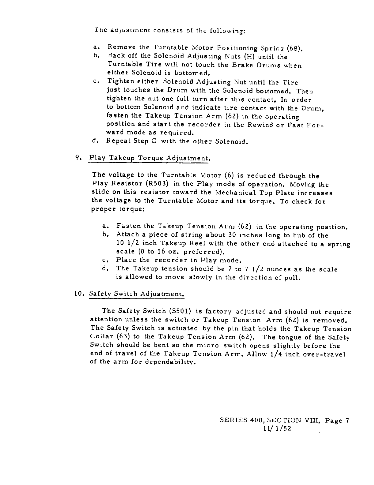
It-ie
adjustment
consists
of
the
following:
a.
Remove
the
Turntable
Motor
Positioning
Spring
68.
b.
Back
off
the
Solenoid
Adjusting
Nuts
H
until
the
Turntable
Tire
will
not
touch
the
Brake
Drun-is
when
either
Solenoid
is
bottomed.
c.
Tighten
either
Solenoid
Adjusting
Nut
until
the
Tire
just
touches
the
Drum
with
the
Solenoid
bottomed.
Then
tighten
the
nut
onefull
turnafter
this
contact,
In
order
to
bottom
Solenoidand
indicate
tire
contact
with
the
Drum,
fasten
the
Takeup
Tension
Arm
62
in
the
operating
position
and
start
the
recorder
in
the
Rewind
or
Fast
For
ward
mode
as
required.
d.
Repeat
Step
C
with
the
other
Solenoid.
9.
Play
Takeup
Torque
Adjustment.
The
voltage
to
the
Turntable
Motor
6
is
reduced
through
the
Play
Resistor
R503
in
the
Play
mode
of
operation,
Moving
the
slide
on
this
resistor
toward
the
Mechanical
Top
Plate
increases
the
voltage
to
the
Turntable
Motor
and its
torque.
To
check
for
proper
torque:
a.
Fasten
the
Takeup
Tension
Arm
62
in
the
operating
position.
b.
Attach
a
piece
of
string
about
30
inches
long
to
hub
of
the
10
1/2 inch
TakeupReel
with
the
other
end
attached
to
a
spring
scale
0
to
16
oz.
preferred.
c.
Place
the
recorder
in
Play
mode.
d. The
Takeup
tension
should
be
7
to
7
1/2
ounces
as
the
scale
is
allowed
to
move
slowly
in
the
direction
of
pull.
10.
Safety
Switch
Adjustment.
The
Safety
Switch
S501
is
factory
adjusted
and should
not
require
attentionunless
the
switch
or
Takeup
Tension
Arm
62
is
removed.
The
Safety
Switch
is
actuated
by
the
pin
that
holds
the
Takeup
Tension
Collar
63
to
the
Takeup
Tension
Arm
62.
The
tongue
of
the
Safety
Switch
should
be
bent
so
the
micro
switch
opens
slightly
before
the
end
of
travel
of
the
TakeupTension
Arm.
Allow
1/4
inch
over-travel
of
the
arm
for
dependability.
SERIES400,
SECTION
VIII,
Page
7
11/
i/sz
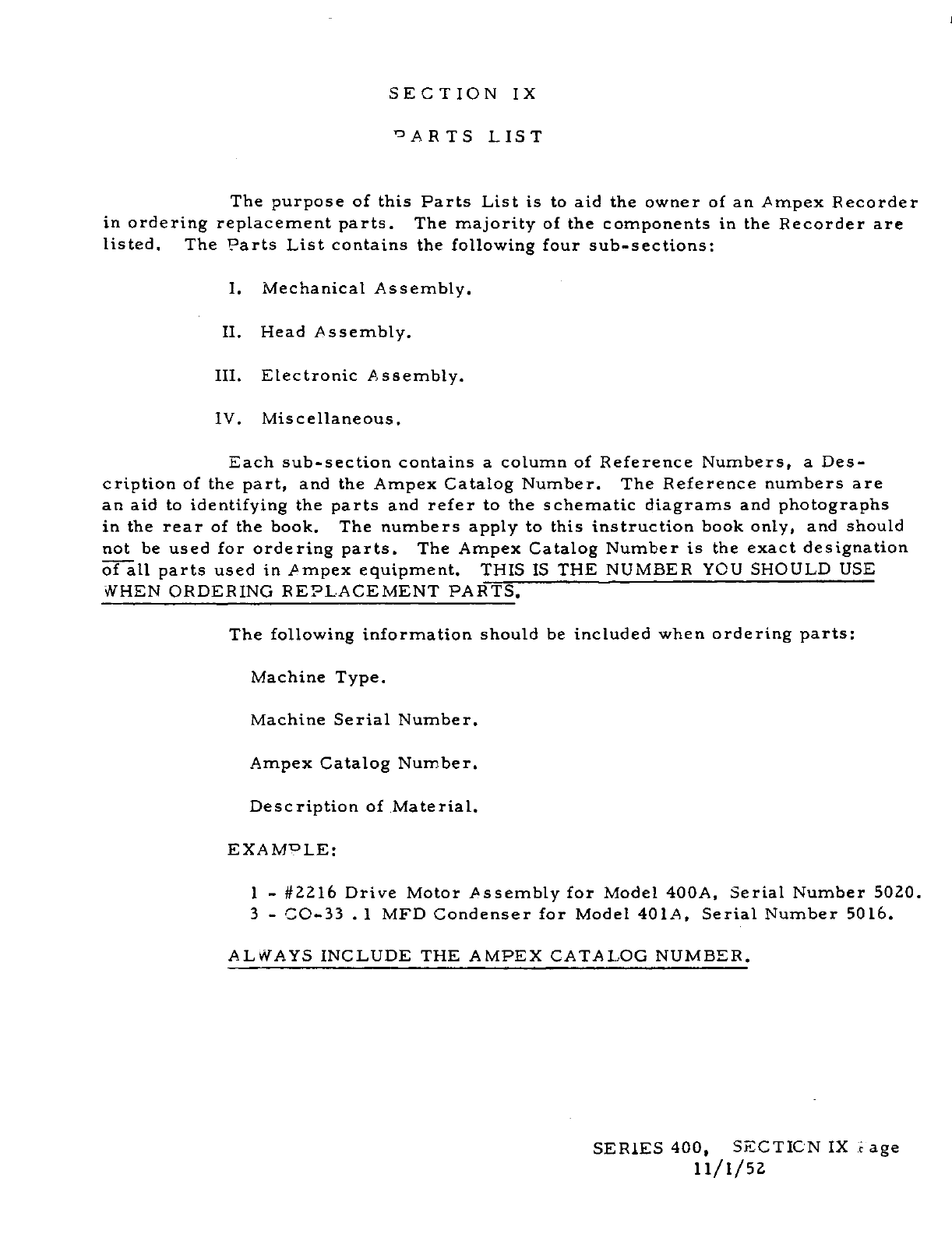
SECTION
IX
‘DARTS
LIST
The
purpose
of
this
Parts
List
is
to
aid
the
owner
of
an
Ampex
Recorder
in
orderingreplacement
parts.
The
majority
of
the
components
in
the
Recorder
are
listed.
The
Parts
List
contains
the
following
four
sub-sections:
I.
Mechanical
Assembly.
II.
Head
Assembly.
III.
Electronic
Assembly.
IV.
Miscellaneous.
Each
sub-section
contains
a column
of
Reference
Numbers,
a
Des
cription
of
the
part,
and
the
Ampex
Catalog
Number.
The
Reference
numbers
are
an
aid
to
identifying
the
parts
and
refer
to
the
schematic
diagrams
and
photographs
in
the
rear
of
the
book.
The
numbers
apply
to
this
instruction
book
only,
and should
not
be
used
for
ordering
parts.
The
Ampex
Catalog
Number
is
the
exact
designation
6Till
parts
usedin
Ampex
equipment.
THIS
IS
THE
NUMBER
YOU
SHOULD
USE
WHEN
ORDERING
REPLACEMENTPARTS.
The
following
information
should
be
included
when
ordering
parts:
Machine
Type.
Machine
Serial
Number.
Ampex
Catalog
Number.
Description
of
Material.
EXAMPLE:
1
-
#2216
Drive
Motor
Assembly
for
Model
400A,
Serial
Number
5020.
3
-
CO-33
-
1
MFD
Condenser
for
Model
4OIA,
Serial
Number
5016.
ALWAYS
INCLUDE
THE
AMPEX
CATALOG
NUMBER.
SERIES
400,
SEC
TIC-N IX :
age
11/1/52
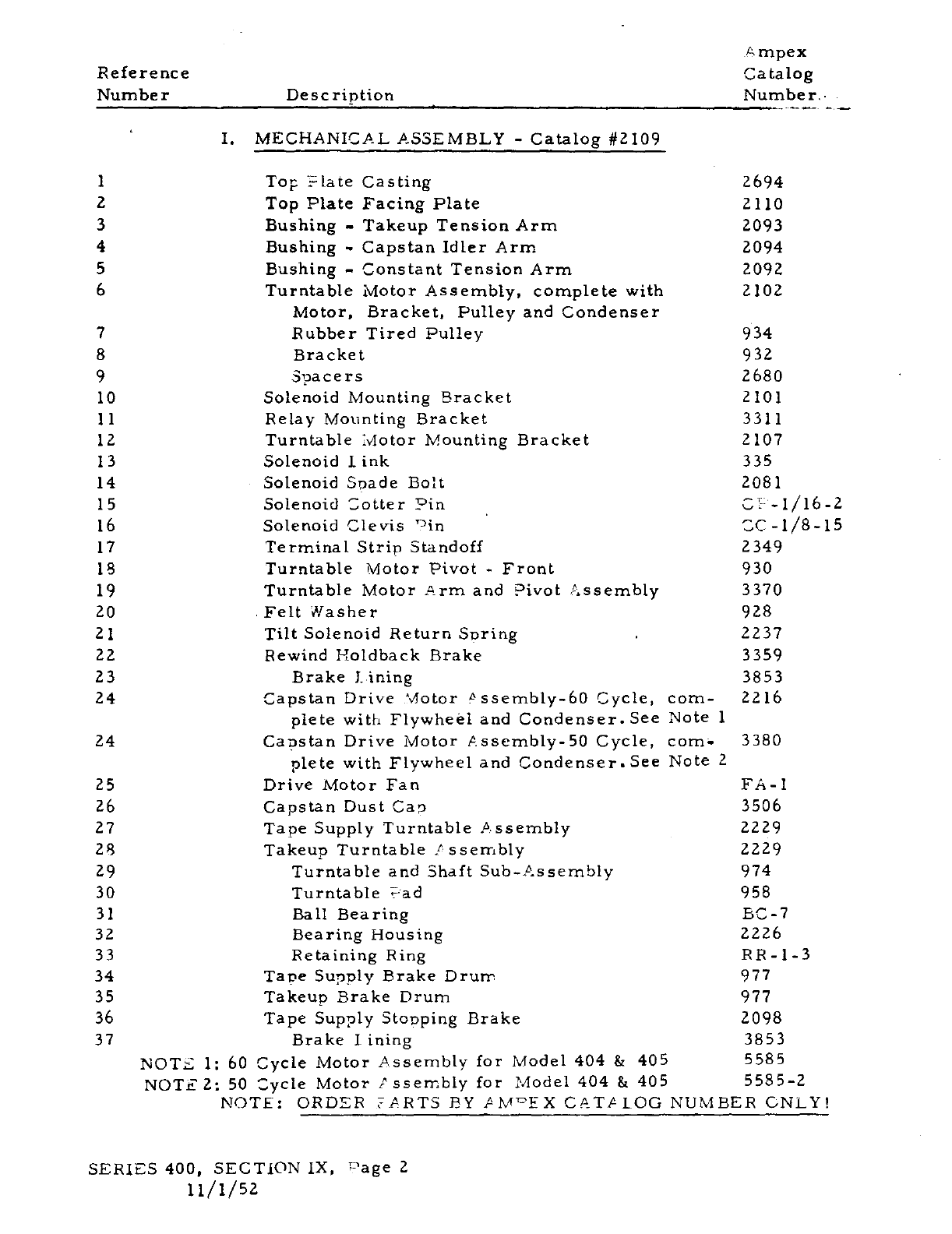
A
mpex
Reference
Catalog
Number
Description
-
Number,
-
I. MECHANICAL
ASSEMBLY
-
Catalog
#2109
1
2694
2
2110
3
2093
4
2094
5
2092
6
2102
7
934
8
932
9
2680
10
2101
11
3311
12
2107
13
335
14
2081
15
OP-
1/16-2
16
cc-I/B-is
17
2349
18
930
19
3370
20
928
21
2237
22
3359
23
3853
24
2216
24
3380
25
FA-1
26
3506
27
2229
28
2229
29
974
30
958
,
I
-J1
32
2226
33
RR-1-3
34
977
35
977
36
2098
37
3853
5585
558
5-2
MBER
ONLY!
SERIES400,
SECTION
IX,
Page
2
11/1/52
Top
?late
Casting
Top
Plate
Facing
Plate
Bushing
-
Takeup
Tension
Arm
Bushing
-
Capstan
Idler
Arm
Bushing
-
ConstantTension
Arm
Turntable
Motor
Assembly,complete
with
Motor,
Bracket,
Pulley
and
Condenser
Rubber
Tired
Pulley
Bracket
Spacers
Solenoid
Mounting
Bracket
Relay
Mounting
Bracket
Turntable
Motor
Mounting
Bracket
Solenoid
link
-
Solenoid
Spade
Bolt
Solenoid
Cotter
Pin
-
Solenoid
Clevis
‘Din
Terminal
Strip
Standoff
Turntable
Motor
Pivot
-
Front
Turntable
Motor
Arm
and
Pivot
Assembly
-Felt
Washer
Tilt
Solenoid
Return
Spring
-
Rewind
HoldbackBrake
Brake
lining
Capstan
Drive
Motor
ssembly-60
Cycle,
com
plete
with
Flywheel
and
Condenser.
See
Note
1
Capstan
Drive
Motor
Assembly-SO
Cycle,
corn’
plete
with
Flywheel
and
Condenser.-See
Note
2
Drive
Motor
Fan
Capstan
Dust
Cap
Tape
Supply
Turntable
Assembly
Takeup
Turntable
P
ssembly
Turntable
and
Shaft
Sub-Assembly
Turntable
?ad
Ball
Bearing
Bearing
Housing
Retaining
Ring
Tape
Supply
Brake
Drum
Takeup
Brake
Drum
Tape
Supply
Stopping
Brake
Brake
lining
NOfl
1:
60
Cycle
Motor
Assembly
for
Model
404
&
405
NOTE
2:
so
cycle
Motor
P
ssembly
for
Model
404
&
405
NOTE:
ORDER
TARTS
BYPM1rEXCATALOCNU
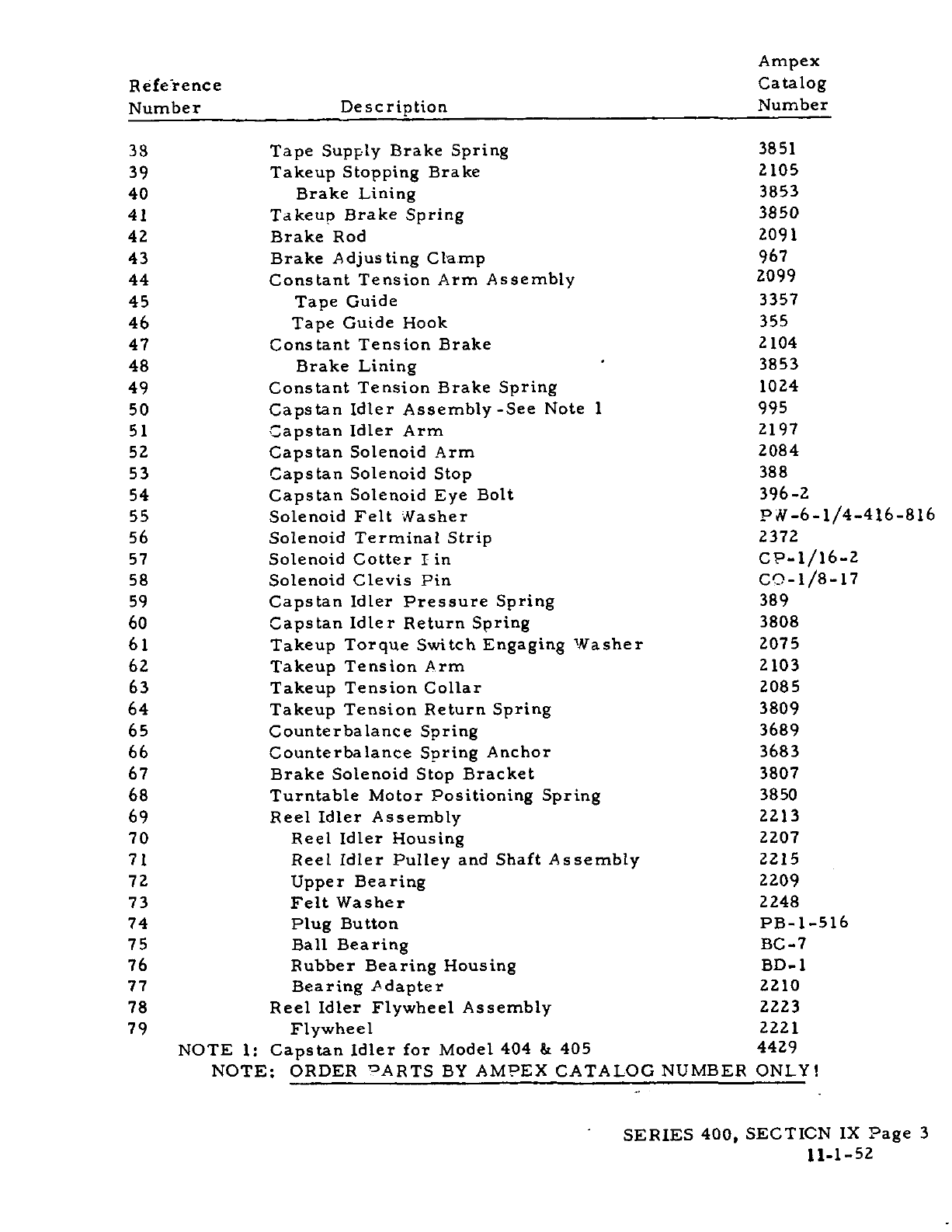
Ampex
Refeience
Catalog
Number
Description
Number
33
Tape
Supply
Brake
Spring
3851
39
Takeup
Stopping
Brake
2105
40
Brake Lining
3853
41
Takeup
Brake Spring
3850
42
Brake
Rod
1091
43
Brake
Adjusting
Clamp
967
44
Constant
Tension
Arm
Assembly
2099
45
Tape
Guide
3357
46
Tape
Guide
Hook
355
47
ConstantTension
Brake
2104
48
Brake
Lining
.
3853
49
ConstantTension
Brake
Spring
1024
50
Capstan
Idler
Assembly
-See
Note
1
995
51
Capstan
Idler
Arm
2197
52
Capstan
SolenoidArm
2084
53
Capstan
Solenoid
Stop
388
54
Capstan
Solenoid
Eye
Bolt
396-2
55
Solenoid
Felt
Masher
P11-6-1/4-416-816
56
Solenoid
Terminal
Strip
2372
57
Solenoid
Cotter
tin
CP-l/16-2
58
Solenoid
ClevisPin
CO-1/8-l7
59
Capstan
Idler
Pressure
Spring
389
60
Capstan
Idler
Return
Spring
3808
61
Takeup
Torque
SwitchEngaging
Washer
2075
62
Takeup
Tension
Arm
2103
63
TakeupTension
Collar
2085
64
Takeup
TensionReturn
Spring
3809
65
Counterbalance
Spring
3689
66
Counterbalance
Spring
Anchor
3683
67
Brake
Solenoid
Stop
Bracket
3807
68
Turntable
Motor
Positioning
Spring
3850
69
Reel
Idler
Assembly
2213
70
Reel
Idler
Housing
2207
71
Reel
Idler
Pulley
and
Shaft
Assembly
2215
72
Upper
Bearing
2209
73
Felt
Washer
2248
74
Plug
Button
PB-1-516
75
Ball
Bearing
BC-?
76
Rubber
Bearing
Housing
BD-1
77
Bearing
Adapter
2210
78
Reel
IdlerFlywheel
Assembly
2223
79
Flywheel
2221
NOTE
1:
Capstan
Idler
for
Model
404
&
405
4429
NOTE:
ORDER ARTS
BY
AMPEXCATALOG
NUMBER ONLY!
-
SERIES
400,
SECTICN
IX
Page
3
11-1-52
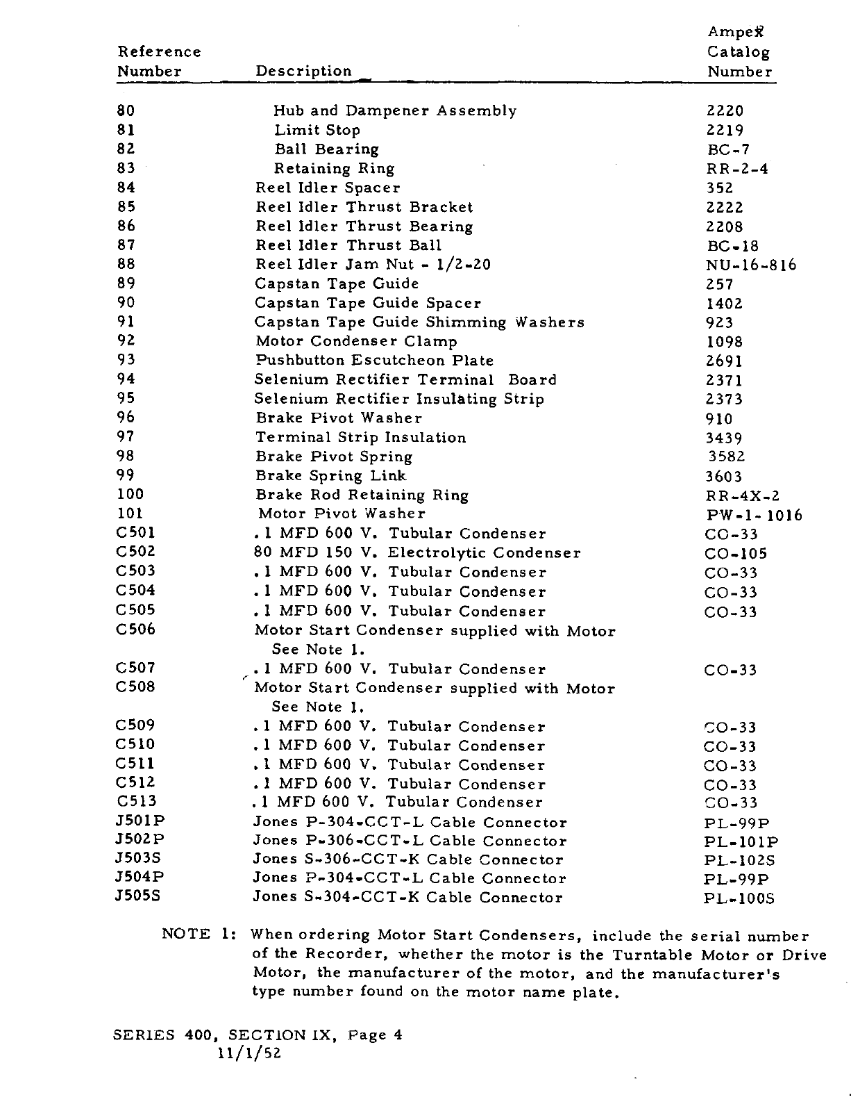
-
Ampef
Reference
Catalog
Number
Description
-
Number
80
Hub
and
Dampener
Assembly
2220
81
Limit
Stop
2219
82
Ball
Bearing
BC-7
83
Retaining
Ring
-
RR-2-4
84
Reel
Idler
Spacer
352
85
Reel
IdlerThrust
Bracket
2222
86
Reel
IdlerThrust
Bearing
2208
87
Reel
IdlerThrust
Ball
BC-iS
88
Reel
IdlerJam
Nut
-
i/z-zo
NU-16-816
89
Capstan
TapeGuide
257
90
CapstanTape
Guide
Spacer
1402
91
CapstanTape
Guide
Shimming
Washers
923
92
Motor
Condenser
Clamp
1098
93
Pushbutton
Escutcheon
Plate
2691
94
Selenium
Rectifier
Terminal
Board
2371
95
Selenium
Rectifier
Insulating
Strip
2373
96
Brake
PivotWasher
910
97
Terminal
Strip
Insulation
3439
98
Brake
Pivot
Spring
3582
99
BrakeSpring
Link
3603
100
Brake
Rod
Retaining
Ring
RR-4X-2
101
Motor
PivotWasher
PW-1-
1016
C501
I
MFD
600
V.
TubularCondenser
CO-33
C502
80
MFD
150
V.
Electrolytic
Condenser
CO-lOS
C503
*
1
MFD
600
V.
TubularCondenser
CO-33
C504
.
1
MFD
600
V.
Tubular
Condenser
CO-33
C505
.
1
MFD
600
V.
TubularCondenser
CO-33
C506
Motor
Start
Condenser
supplied
with
Motor
See
Note
1.
C507
*
1
MFD
600
V.
TubularCondenser
CO-33
C508
r
Motor
Start
Condenser
supplied
with
Motor
See
Note
1.
C509
.
1
MFD
600
V.
Tubular
Condenser
00-33
CSlO
.
1
MFD
600
V.
TubularCondenser
CO-33
C511
*
I
MFD
600
V.
TubularCondenser
CO-33
C512
.
1
MFD
600
V.
Tubular
Condenser
CO-33
C513
.
1
MFD
600
V.
Tubular
Condenser
CO-33
JSOIP
Jones
P-3O4-CCT-L
Cable
Connector
PL-99P
J502p
Jones
P-306-CCT-J..
Cable
Connector
PL-lOlP
J503S
Jones
S-306-CCT-K
Cable
Connector
PL-1O2S
J504P
Jones
P-304-CCT-L
Cable
Connector
PL-99P
J5055
Jones
S-304-CCT-K
Cable
Connector
PL-IOOS
NOTE
1:
When
ordering
Motor
Start
Condensers,
include
the
serial
number
of
the
Recorder,
whether
the
motor
is
the
Turntable
Motoror
Drive
Motor,
the
manufacturer
of
the
motor,
and
the
manufacturer’s
type
number
found
on
the
motor
name
plate.
SERIES
400,
SECTION
IX,
Page
4
11/1/52
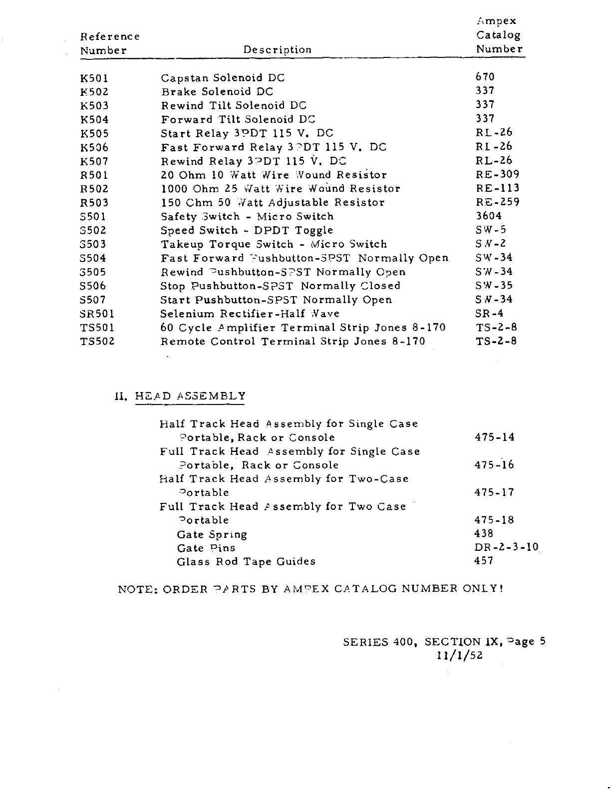
Ampex
Reference
Catalog
Number
Description
Number
K501
Capstan
Solenoid
DC
670
K502
Brake
Solenoid
DC 337
K503
Rewind
Tilt
Solenoid
DC
337
K504
Forward
Tilt
Solenoid
DC 337
K505
Start
Relay
3PDT
115 V. DC
RL-26
K506
Fast
Forward
Relay
3TDT
115
V. DC
RI
-26
K507
Rewind
Relay
3?DT
115 V. DC
RL-26
R501
20
Ohm
10
Watt
Wire
Wound
Resitor
RE-309
R502
1000 Ohm
25
#att
Wire
Wound
Resistor
RE-113
R503
150
Ohm
50
Watt
Adjustable
Resistor
RE-259
5501
Safety
Switch
-
Micro
Switch
3604
3502
SpeedSwitch
-
DPDT
Toggle
SW-S
3503
TakeupTorque
Switch
-
Micro
Switch
SM-2
3504
Fast
Forward
ushbutton-SPST
Normally
Open
SW-34
3505
Rewind
Dushbutton_S?ST
Normally
Open
5W-34
S506
Stop
Pushbutton-SPST
NormallyClosed
SW-35
5507
Start
Pushbutton-SPST
Normally
Open
S
11-34
SRSO1
Selenium
Rectifier-Half
Na’,e
SR-4
T3501
60
Cycle
Pmplifier
Terminal
Strip
Jones
8-170
TS-2-8
TSSO2
Remote
Control
Terminal
Strip
Jones
8-170
TS-2-8
11.
HEJAD
ASSEMBLY
Half
Track
Head
Assembly
for
Single
Case
°ortable,
Rack
or Console 475-14
FullTrack
Head
Assembly
for
Single
Case
-
Portable,
Rack
or
Console
475-16
Half
Track
Head
Assemblyfor
Two-Case
°ortable
475-17
Full Track
Head
P
ssembly
for
Two
Case
°ortable
475-18
Gate
Sprtng
438
Gate
Pins
DR-2-3-1O
Glass
Rod
Tape
Guides
457
NOTE:
ORDER
°PRTS
BY
AM?EX
CATALOGNUMBER
ONLY!
SERIES
400,
SECTION
IX.
age
5
11/1/52
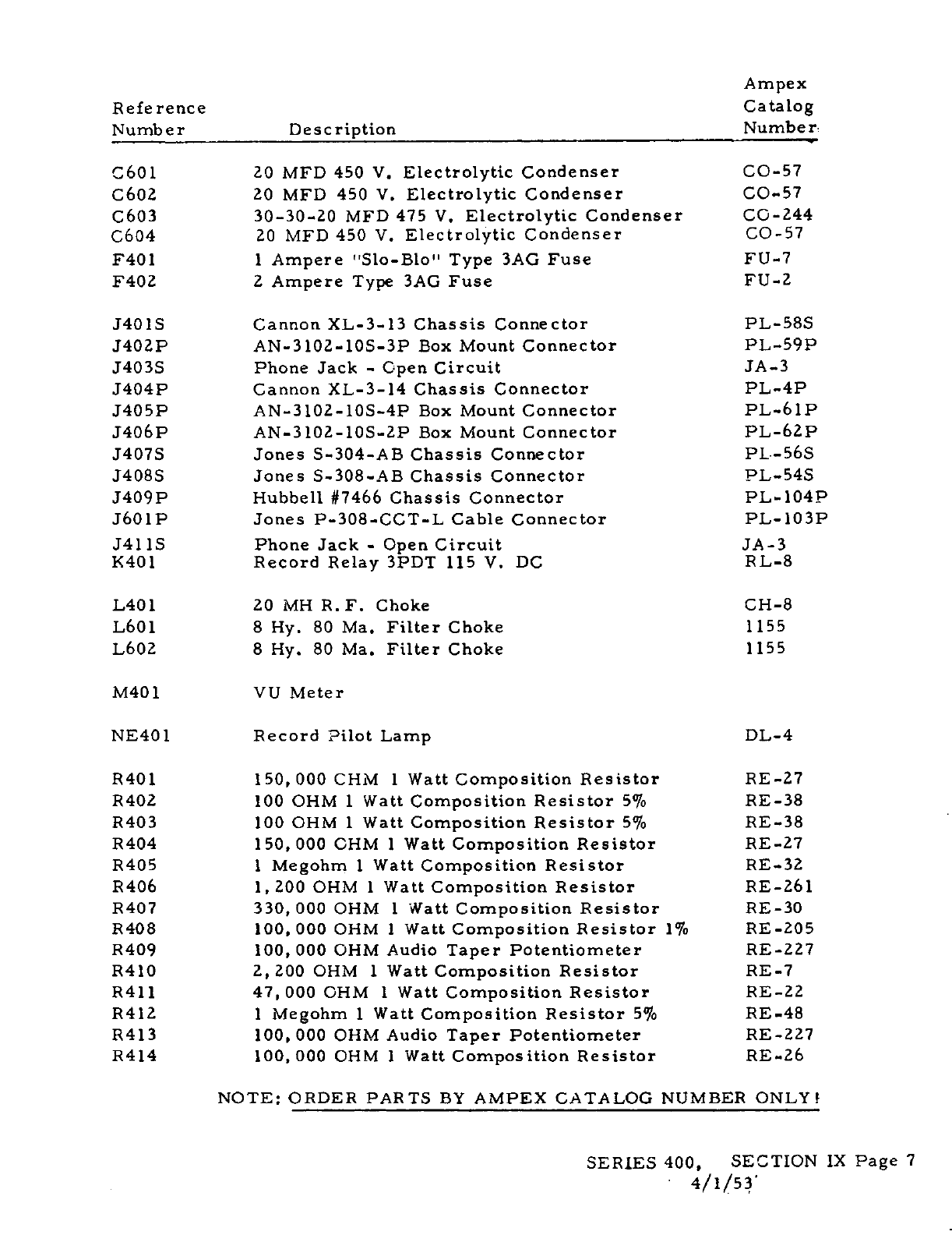
Ampex
Reference
Catalog
Number
Description
Number
C601
20
MFD
450
V
Electrolytic
Condenser
CO-57
C602
20
MFD
450
V.
Electrolytic
Condenser
CO-57
C603
30-30-20
MFD
475
V.
Electrolytic
Condenser
CO-244
C604
20
MFD
450
V.
Electrolytic
Condenser
CO-57
F401
1
Ampere
"Slo-Blo"
Type
3AG
Fuse
FU-7
F402
2
Ampere
Type
3AG
Fuse
FU-2
J4O1S
Cannon
XL-3-l3Chassis
Connector
PL-585
J402P
AN-3l02-1OS-3P
Box
Mount
Connector
PL-59P
J403S
Phone
Jack
-
Open
Circuit
JA-3
J4O4P
Cannon
XL-3-l4Chassis
Connector
PL-4P
J405P
AN-3102-1OS-4P
Box
Mount
Connector
PL-61P
J406P
AN-3l02-1OS-2P
Box
Mount
Connector
PL-62P
J407S
Jones
S-304-AB
Chassis
Connector
PL.-56S
J408S
Jones
S-308-AB
Chassis
Connector
PL-54S
J409P
Hubbell
#7466
Chassis
Connector
PL-104P
J6O1P
Jones
P-308-CCT-L
Cable
Connector
PL-1O3P
J411S
Phone
Jack
-
Open
Circuit
JA-3
1401
Record
Relay
3PDT
115
V.
DC
RL-8
L40l
20
MN
R.F.
Choke
CH-8
L601
8
Hy.
80
Ma.
Filter
Choke
1155
L602
8
Hy.
80
Ma.
Filter
Choke
1155
M401
VU
Meter
NE4O1
Record
Pilot
Lamp
DL-4
R401
150,
000
CHM
1
Watt
Composition
Resistor
RE-27
R402
100
OHM
1
Watt
Composition
Resistor
5%
RE-38
R403
100
OHM
1
Watt
Composition
Resistor
5°lo
RE-38
R404
150,
000
OHM
1
Watt
Composition
Resistor
RE-27
R405
1
Megohm
1
Watt
Composition
Resistor
RE-32
R406
1,200
OHM
1
Watt
Composition
Resistor
RE-26l
R407
330,
000
OHM
1
Watt
Composition
Resistor
RE-30
R408
100,
000
OHM
1
Watt
Composition
Resistor
1%
RE-205
R409
100,
000 OHM
Audio
Taper
Potentiometer
RE-227
R410
2,
200
OHM
1
Watt
Composition
Resistor
RE-7
R411
47,
000 OHM
1
Watt
Composition
Resistor
RE-22
R4l2
1
Megohm
1
Watt
Composition
Resistor
5%
RE-48
R4l3
100,
000
OHM
Audio
Taper
Potentiometer
RE-227
R414
100,
000
OHM
1
Watt
Composition
Resistor
RE-26
NOTE:
ORDER
PARTS
BY
AMPEX
CATALOG
NUMBER
ONLY!
SERIES
400,
SECTION
IX
Page
7
4/1/53
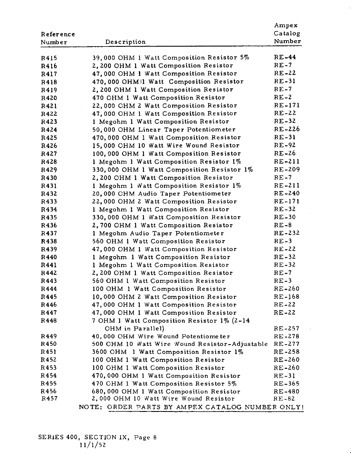
Ampex
Reference Catalog
Number
Description
Number
R415
39.
000
OHM
1
Watt
Composition
Resistor
5%
RE-44
R416
2,200
OHM
1
Watt
Composition
Resistor
RE-7
R417
47,
000 OHM
1
Watt
Composition
Resistor
RE-22
R4l8
470,
000
OHMU
Watt
Composition
Resistor
RE-31
P419
2,
200
OHM
1
Watt
Composition
Resistor
RE-i
R420
470
OHM
1
Watt
Composition
Resistor
RE-2
R421
22,
000 OHM
2
Watt
Composition
Resistor
RE-ill
P422
47,
000 OHM
1
Watt
Composition
Resistor
RE-22
P423
1
Megohm
1
Watt
Composition
Resistor
RE-32
R424
50,
000 OHM
LinearTaper
Potentiometer
RE-226
R425
470,
000
OHM
1
Watt
Composition
Resistor
RE-31
R426
15,000
OHM
10
Watt
Wire
Wound
Resistor
RE-92
P427
100,
000 OHM
1
Watt
Composition
Resistor
RE-26
P428
1
Megohm
1
Watt
Composition
Resistor
1%
RE-211
P429
330,
000 OHM
1
Watt
Composition
Resistor
1%
RE-209
P430
2,200
OHM
1
Watt
Composition
Resistor
RE-7
R431
1
Megohm
1
Watt
Composition
Resistor
1%
RE-21
I
R432
20,
000 OHM
Audio
Taper
Potentiometer
RE
-240
P433
22,
000 OHM
2
Watt
Composition
Resistor
RE-i71
R434
1
Megohm
1
Watt
Composition
Resistor
RE-32
R435
330,
000 OHM
1
Watt
Composition
Resistor
RE-30
R436
2, 700 OHM
1
Watt
Composition
Resistor
RE-8
P437
1
Megohm
Audio
Taper
Potentiometer
RE-232
R438
560
OHM
1
Watt
Composition
Resistor
RE-3
P439
47,
000 OHM
1
Watt
Composition
Resistor
RE-22
R440
1
Megohm
1
Watt
Composition
Resistor
RE-32
P441
1
Megohm
1
Watt
Composition
Resistor
RE-32
P442
2,200
OHM
1
Watt
Composition
Resistor
RE-7
P443
560 OHM
1
Watt
Composition
Resistor
RE-3
P444
100
OHM
1
Watt
Composition
Resistor
RE-260
P445
10,
000
OHM
2
Watt
Composition
Resistor
RE-168
P446
47,
000 OHM
1
Watt
Composition
Resistor
RE-22
R447
47,
000 OHM
1
Watt
Composition
Resistor
RE-22
P448
7
OHM
1
Watt
Composition
Resistor
1%
2-14
OHM
in
Parallel
RE-257
R449
40,
000
OHM
Wire
Wound
Potentiometer
RE-us
P450
500
OHM
10
Watt
Wire
Wound
Resistor-Adjustable
RE-277
R451 3600
OHM
1
Watt
Composition
Resistor
1%
RE-258
R452
100
OHM
1
Watt
Composition
Resistor
RE-260
R453
100
OHM
I
Watt
Composition
Resistor
RE-260
R454
470,
000
OHM
1
Watt
Composition
Resistor
RE-31
P455
470
OHM
I
Watt
Composition
Resistor
5%
RE-365
R456
680,
000 OHM
1
Watt
Composition
Resistor
RE-480
R457
2,000
OHM
10
Watt
Wire
Wound
Resistor
RE-82
NOTE:
ORDER
PARTS
BY
AMPEX
CATALOG
NUMBERONLY!
SERIES400,
SECTION
IX,
Page
8
1
i/i/sz
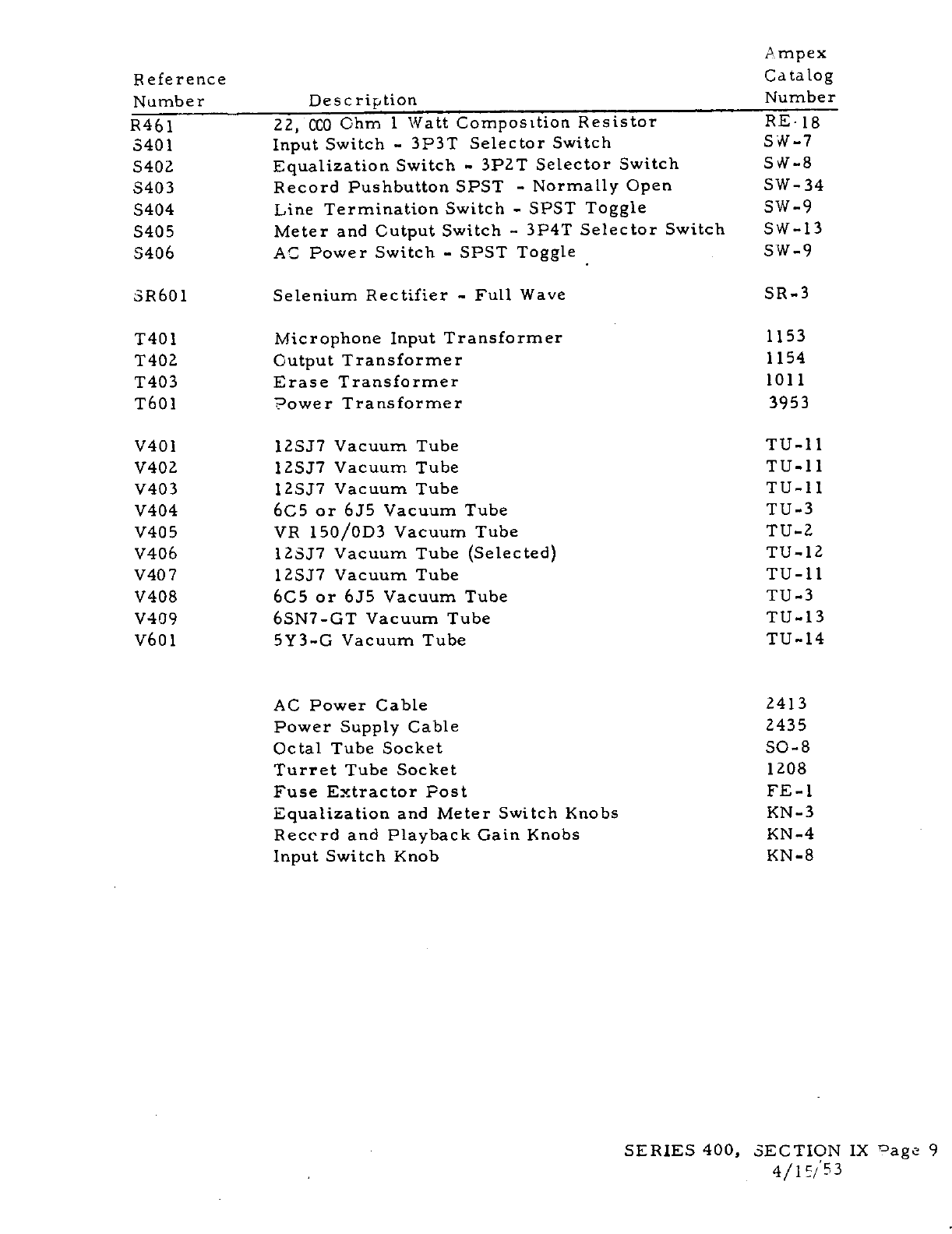
Ampex
Reference
Catalog
Number
Description
Number
R461
22,
CCO
Ohm
1
Watt
Composttion
Resistor
RE*
18
3401
Input
Switch
-
3P3T
Selector
Switch
SW-i
S402
Equalization
Switch
-
3P2T
Selector
Switch
SW-S
S403
RecordPushbutton
SPST
-
Normally
Open
SW-34
5404
Line
Termination
Switch
-
SPST
Toggle
SW-9
S405
Meter
and
Output
Switch
-
3P4T
Selector
Switch
SW-13
5406
AC
Power
Switch
-
SPST Toggle SW-9
SR6O1
Selenium
Rectifier
-
Full
Wave
SR-3
T401
Microphone
Input
Transformer
1153
T402
Output
Transformer
1154
T403
EraseTransformer
1011
T601
Power
Transformer
3953
V40l
l2SJ7
Vacuum
Tube
TU-il
V402
12SJ7
Vacuum
Tube
TU-li
V403
12SJ7
Vacuum
Tube
TU-li
V404
6C5
or
6J5
Vacuum
Tube
TU-3
V405
VP
150/0D3
Vacuum
Tube
TU-2
V406
l23J7
Vacuum
Tube
Selected
TU-l2
V407
12SJ7
Vacuum
Tube
TU-ll
V408
6C5
or
6J5
Vacuum
Tube
TU-3
V409
6SN7-GT
Vacuum
Tube
TU-13
V601
5Y3-G
Vacuum
Tube
TU-l4
AC
Power
Cable
2413
Power
Supply
Cable
2435
Octal
Tube
Socket
SO-s
Turret
Tube
Socket
1208
Fuse
Extractor
Post
FE-i
Equalization
and
Meter
Switch
Knobs
KN-3
Recc’rd
and
Playback
Gain
Knobs
KN-4
Input
Switch
Knob KN-8
SERIES
400,
SECTION
IX
°agc
9
4/1/
53
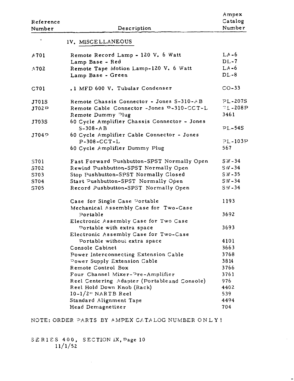
Ampex
Reference
Catalog
Number
Description
Number
1V.
MISCELLANEOUS
A701
Remote
RecordLamp
-
120
V.
6
Watt
LA-6
LampBase
-
Red
DL-7
A702
Remote
Tape
Motion
Lamp-120
V.
6
Watt
LA-6
Lamp Base
-
Green
DL-8
C701
.
1
MFD
600
V.
TubularCondenser
CO-33
J7O1S
Remote
Chassis
Connector
-
Jones
S_310-i#B
PL-2OiS
J702°
RemoteCable
Connector-Jones
W_310.CCT..L
L-208P
Remote
Dummy
°lug
3461
J703S
60
Cycle
Amplifier
Chassis
Connector
-
Jones
S-308-AB
PL-54S
J7049
60
Cycle
Amplifier
Cable
Connector
-
Jones
P-308-CCT-L
PL-lO3P
60
Cycle
Amplifier
Dummy
Plug
567
S701
Fast
Forward
Pushbutton-SPST
Normally
Open
571-34
3702
Rewind
Pushbutton-SPST
Normally
Open
SW-34
5703
Stop
Pushbutton-SPST
Normally
Closed
SW-35
5704
Start
Pushbutton-SPST
Normally
O5en
571-34
5705
Record
?ushbutton-SPSTNormally
Open
571-34
Case
for
Single
Case
°ortable
1193
Mechanical
Assembly
Case
for
Two-Case
Portable
3692
Electronic
Assembly
Case
for
Two
Case
ortable
with
extra
space
3693
Electronic
Assembly
Case
for
Two-Case
Portable
without
extra
space
4101
Console
Cabinet
3663
Power
InterconnectingExtension
Cable
3768
ower
Supply
Extension
Cable
3814
Remote
Control
Box
3766
Four
Channel
Mixer_Dre_Amplifier
3761
Reel
Centering
Adapter
Portableand
Console
976
Reel
Hold
Down
Knob
Rack
4402
io-i/z"
NARTB
Peel
539
StandardAlignment
Tape
4494
Head
Demagnetizer
704
NOTE:
ORDER
PARTS
BY
AMPEX
CATALOGNUMBER
ONLY!
SERiES
400,
SECTIONIX,Pagelo
u/i/si
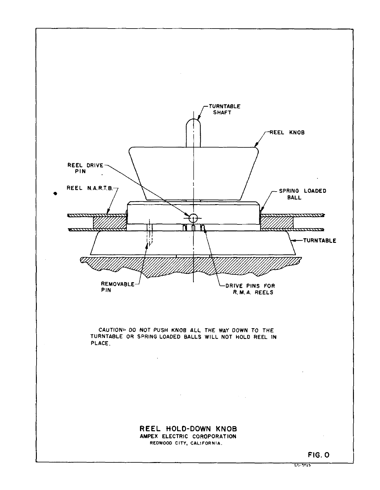
cAuTIoN-
DO
NOT
PUSH KNOB
ALL
THE
WAY
DOWN
TO
THE
TURNTABLE
OR
SPRING
LOADED
BALLS
WILL
NOT
HOLD REEL
IN
PLACE.
TABLE
REEL
HOLD-DOWN
KNOB
AMPEX
ELECTRIC
COROPORATION
REDWOOD
CITY,
CALIFORNIA.
TURNTABLE
SHAFT
REEL
DRIVE
PIN
REEL
KNOB
SPRING
LOADED
BALL
REMOVABLE
PIN
NS
FOR
ft
M.
A.
REELS
FIG.
0
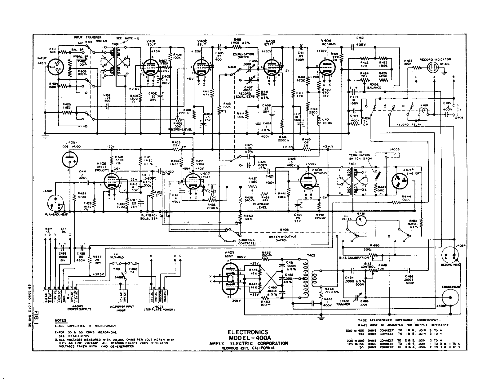
*406
‘0’
LL
A
POWEl
JT
"ReaP
TES:
hALL
CAPACITiES
IN
M1CROPAPACS
*440.
22
00
CL
1*
IMEG S5%
I2SJ 7
t
I
H
EQUALiZATION
.25
SWITCH
S;y
_
4001
CR0
27
Hf
P415
4711
EQOALIZEPS
*5%
P4’S
I
lOOK
I
25
"‘CRO
I
p41k"
V_j
125
II00P
-cr:l"
4
25W
1
-T
-
-
400W
C423
r
55%
o-j
.0025
-
C4
.5
+
330
V
400W
i___
U
SCS6JS
‘S
444:
I
ItO
p
x
C
427
25
25W
J4035
LINE
TERMINATION
54,1CM
5404
T402
.4404.
--
I.INE
OUT
40Cr,
11UT
TRM41IER
SEE
NOTE
‘-2
V401
SIC
SCO
5*37CM
T4
125J7
flfl
ISV
-
IW
I
33011
+70W
cs
2
‘C4Q
T
2
J
42.5W
150111
:
25
I
.25
200.
zsv
400
I’I
*405
40011
-
t5
V
-K--
C4I2
V404
SC5J5
jg
400W,
V403
12547
‘I
C
411
.05
‘COW
*444,
‘I
470E
1%
-
4422 P423
4711
1525
475
Nd
5
tIC:
I
7
Xx
*420
-
470
ISV
P449
2200
A
L
401
20
Mh
.40
lOOK
C0ROL
EL
*424 *425
50111
47011
NOISE
11+
IM,AIICE
- fl
V405-
*433
003
VPITO
150+
-
‘
py
PECOPO
*
P417
‘4711
:41
10
4
:i.
P431
P.
AeAa
sCt
*4.9
2200n
2104
It
-
C
413
__________________
IS
I-i
‘sow
I
-*4
C414
I
.1
C1426
P9-
liSA
‘OW
______________
*425
111.-I
33011
Pe4
*435
V406
15
IMEC
330"
C.
.
*425 *430
25
p
IME2
2200,
25g
I
27OOs
IS.
-
P445
ION
2W
+
340W
rf1’
C
425
MEG
P433 *439
"on-
47P
PLAY0AN
LEVEL
IV
SAC
EQ UA
L
IlL
1
I-
-an
*440
11116.
P442
22001
ISV
2..
‘C.
CC
‘Xv
2
Itt
______________________
-H
24
I
C
j
I
IA
A
S
C
2000
I
to
-
I
5t031.O
I
4
I
fP_r0..0.1___
-11
+355W
____
____
.1
1123
L’f01x18
I+I&I
IIIJj
IIkItI-I>’>’
H>’
lollilTItiol
P1=1
=
j.0OS
.44075
I
TOW
PLATE
POWER
I$HORTNG
METER
SOUTPUT
SWITCH
400V
-
‘t
t*A
StAG

S
S
0
.9
a
11401
I
*450
‘1
0
5000
I
‘AlA
r
V409
P452
IOO
7403
SIAS CALISPATION
CONTROL
*444
*5%
______
45117
3,5v
-zsv
Ca
4711
4711
C430
-25w
*5%
C433
ERASE
CIS.
395W
TRIMMER
.001
IO0-
.1
2-F015 50 S
SO
014115.
IACPOPHONE
SEE
IHS?ILL
AVON
hALL
VOLTAGES
MEAMIO
WITH
20,000
OHMS
PER
VOLT
"ICIER
WITH
II?
V
AC
UNC
VOLTAIC
ALL PlACING
EXCEPT
V409
OSCILATOP
VOLTAGES
TAKEN
WITH
P404
0E-EHERGIZEO.
I’
C
439
.0002
500W
ELECTRONICS
MODEL
-
400A
AMPEW
ELECTRIC
cORPORATION
RED*000
CITY,
CALIPNIA
7402
TRANSFC*MEP
SMPEOAIICE
CONNECTiONS-
*445
MUST
54
JUSTEO
‘OUTPUT
IMPIDAN:E
--
500
‘*400
OHMS
CONNECT
TO
I
S
4,
JOIN
3 10 4
335
OhMS
CONNECT
TO
I
5 5*
JOIN
S
TO
4
20045250
01111$
CONNECT
TO
255,
JOIN
3
TO
4
1251.150
OHMS
CONNECT
TO
44,
R
I
TO354’TO6
50
OHMS
CONNECT
TO
2*4.
JOIlI 2
TOSS
4305
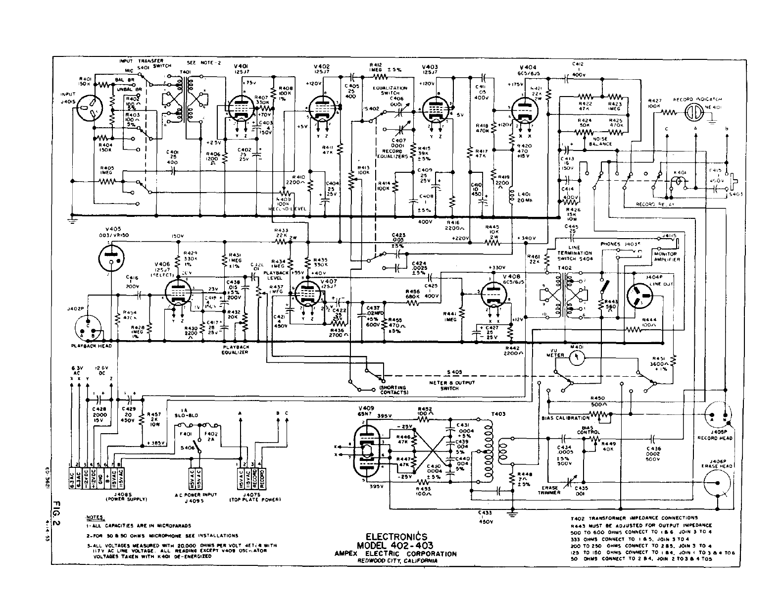
IIUT
TPANSFEP
SEE
NOTE
-1
v4OI
6401
SWITCH
125.4?
MIC
TSOI
________
___________
-
I75’,
p407
-
INPUT
*40
I
330N
t70v
4O3
I
*401
P404
SAL
OR
400
*
£40
£401
4
‘Ti,o+
‘ISV
T
I
C
*406.
‘25
-
=
I
25 1200
*
256
-
400
A
*405
V405
003/
V*IS0
1503
c
63W
263
AC DC
Xxv
‘I
*
44
_______________
±4
HHf
I
C429
I
20001
20
_i.P457
IA
SLO’SLO
A S C
2K
92iL1::,
I23!
LU
U00
J4045
.44075
ITOP
PLATE
POWERI
*442
V402
1526
±5%
125.47
+I203j
25
I
SWIICH
I
00I?1p
+:
‘olt:
TI
I
£40?
000I
*411
EOUALI2EPS
I
4711
P413
lOOK
I
1C404
4444
+
25V
I’s"

f
T41
I
005
V4O4
£412
f
400+
6C5/6J5
2211
+421
7W
-
N427400G
lOON
AflAAAU
:t1201
27
S
XX
401SF
*420
B4.ANCE
470
-
;:
t153
470+
_
40I
IAn
_____
#4,9
ISO’,
2200
20Mh
400V
A
__-
OW
04SF’7
S
I4
__
L401
________
P426
-
__________
ISlE
£445
25
4340V
.....V
I
Soon
C
436
0002
500+
P400
lOOK
1%
N
410
2200-’>.
ECL30Lf
I
V403
25.47
‘P415
‘39K
±5%
C409
25
25+
4
C400"F
ts-I
t
-If-
C
411
OS
400+
#419
-
4/OR
*41?
47111
£410
ID
I
In
H
*433
400W
*416
2200’>
4220+
PLAYBACK
HEAO
4445
ION
2*
33011
*
P434
L
P435
V4061
1%
*IMEG -
-
11%
C4JL
MEG
0
fl,?
-
________I
PLAyBACK
4553 44
£414
I’ELFCII
I, V
C4SBI,
]
LEVEL
*
V407
200+
____
235
-013
P437
2
3j7
t5%T
Mb
s
0416
4
200W
-
L
6454
I
"
7
iv
I"J,
-
P432
I
___
L
I’"l
£41
C
421
4
450W
*434
P428
*430

25
MEG
I
2200
25i
4%
I
-‘-F’
I
1.
2700’>
PL
At
S
AC
N
tOO
AL
I?
E
C424
.0025
IF
4330+
I’
£423
*456
I
630K 4003’
C437
L_02
rn-A
*455
600W
470’>
.5%
P444
I
MEO
,T
+406
6C5/6J5
,
412W
+
C427
25
1*-
LINE
PHONES
403’
TERMINATION
-
_,,,j
AMPLIFIER
P461
SWITCH
5404
2211
LINE OJTI
-$t
,I
_____-
__-
3600’>
-
+
1%
Li
A
M
40’
P442
Vu
2200’>
S3
-.
METEP S
OUTPUT
IS
WITCH
C
OP
TAC
T
SI
P430
V
40W::_
-
-
1403
BIALIBRATI0N
400’>
63N7
BIAS
,±cr-
r+
II
CON
TPOL
I
...tff
3
4711
*449
‘-f-fl
I
-3--%-4
004
I
:
:
t
I
P444
47
£450
Vt’
L_’
004
I
0004
-
-25W
E5%
ERASE
A’ CA35
395+
r
!5%
TPIMMER
-
0Oh
-n
p
FsI
.4
405P
PECOPO
HEAD
J406P
ERASE
HEAL
AC
P0*63
INPUt
.44095
-NOTES
‘ALL
CAPACITIES APE
IN
MICROFAPADS
2-FOP
so 5 50
OHMS
MICROPHONE
SEE
INSTALLATIONS
S-ALL
VOLTAGES
*IEAS4J*EO
WITH
20,000
OHMS
PEP
VOLT
*ETJ*
WITH
Ills
AC
LINE
WOLTASE
-
ALL
READING
EXCEPT
+405
O$C-LATON
VOLTAGES
TANEN
WITN 1401 D4-ENEPGIZEO
£435
450W
ELECTRONIt
S
MODEL
402-403
AMPEX
ELECTRIC CORPORATION
REDWOOD
CITY
CALIFORNIA
T402
TPAPSFORMEP
IMPEOANCE
CONNECTIONS
P443
MUST
SE
ADJUSTED
FOP
OUTPUT
IMPEDANCE
500
TO
400
OHMS
CONNECT
TO
I
5 4
-
JOIN
3TO 4
333
OHMS
CONNECT
TO
I
6 3. JOIN 3 TO 4
200
TO
250
OHMS
CONNECT
TO
255.
JOIN
3
TO
4
125
TO
ISO
OHMS
CONNECT
TO
64,
JOIN
I
TO
364
TOG
I
50
01111$
CONNECT
TO
264,
JOIN
2T036
4105
J
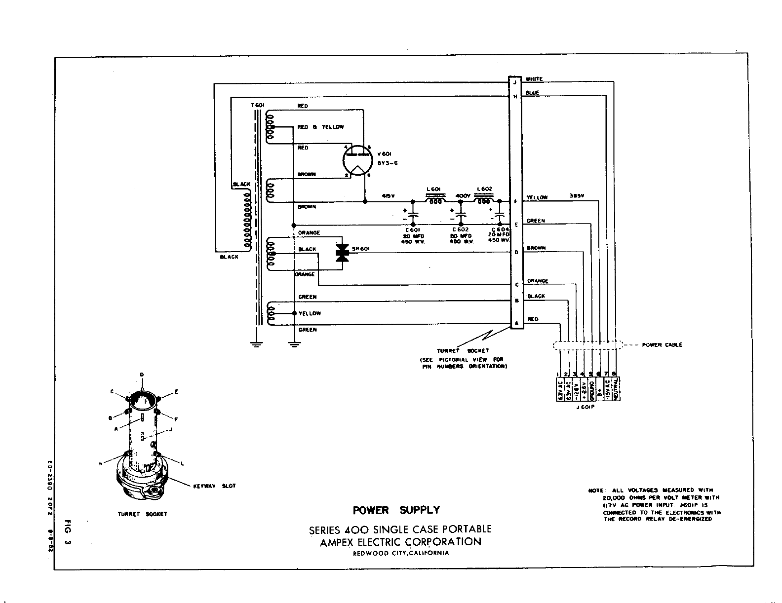
POWER
SUPPLY
SERIES
400
SINGLE
CASE
PORTABLE
AMPEX
ELECTRIC
CORPORATION
REDWOOD
CITY.CALIFORNIA
p0
.E
IIOTE1
ALL
VOLTAGES
MEASURED
WITH
20,000
OHMS
PER
VOLT
METER
WITH
lIly
AC
POWER
INPUT
JGOIP
IS
C0I**CTEO
TO
THE
ELECTRIICS
WITH
THE
RECORD
PELAY
01-ENERGIZED
0
C
TURRET
KET
SEE
PICTORIAL
VIEW
F
PIN
IIUMBEPS
OPIENTATIGII
N-
J
604
P
IX
C
N
Ii
C
0
N
0
‘P
Eli
C
a
U
N
NETWAY
SLOT
-I.
C
‘I
TURRET
SCOUT
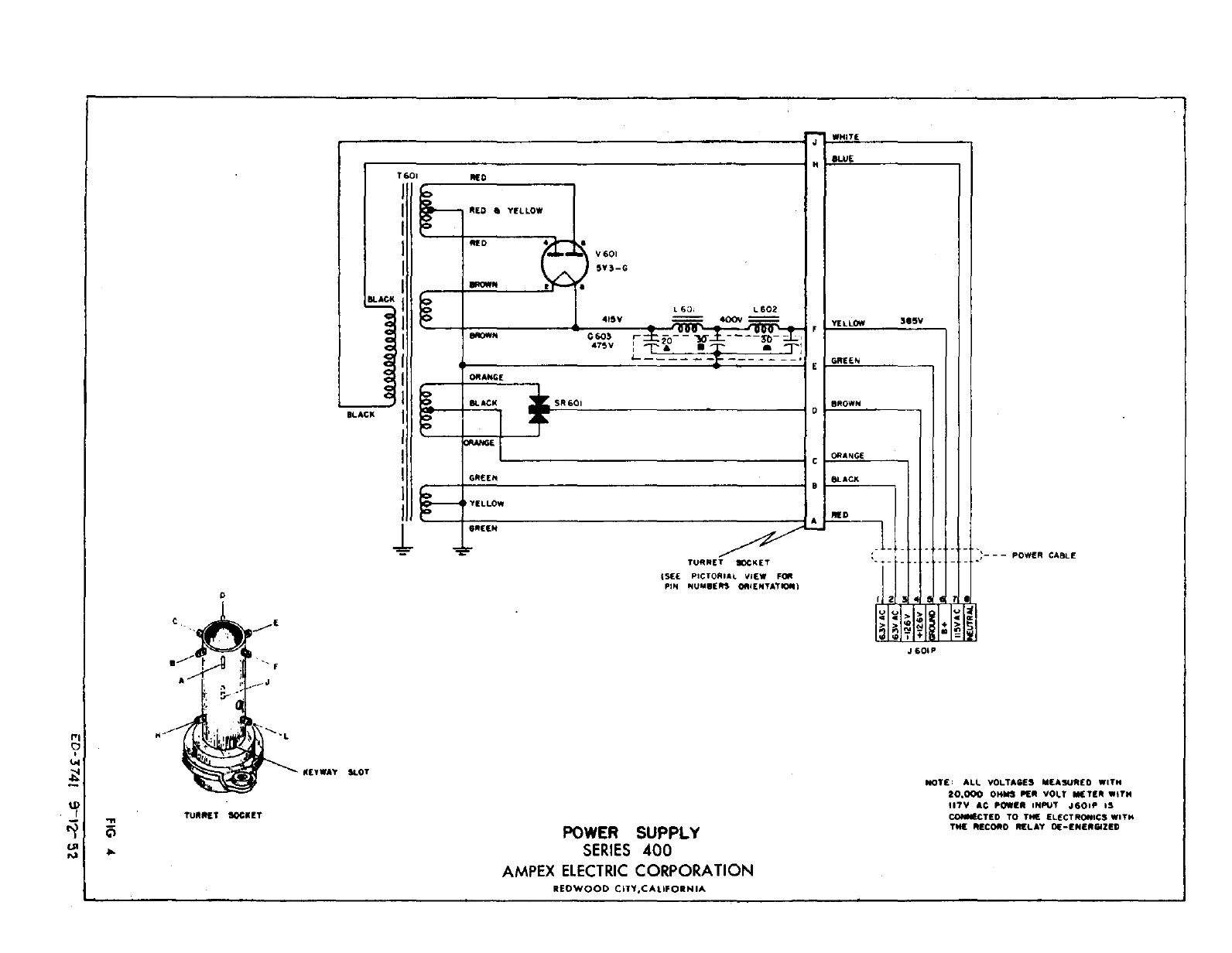
POWER
SUPPLY
SERIES
400
AMPEX
ELECTRIC
CORPORATION
REDWOOD
CITY.CALIFORNIA
--
POWER
CABLE
NOTE
1
ALL
VOLTAGES
MEASURED
WITH
20.000
OHMS
PER
VOLT
METER
WITH
lIlY
AC
POWER
INPUT
J6OIP
IS
COIMIECTED
TO
THE
ELECTRONICS
WITH
THE
RECORD
RELAY
01-ENERGIZED
C
It
IS
PICTORIAL
VIEW
FOR
PIN
NUMBERS
ORIENTATI
H
‘I"
tI
.1
111?
L
J
6OIP
TI
C
ICEYWAY SLOT
TURRET
SOCNET
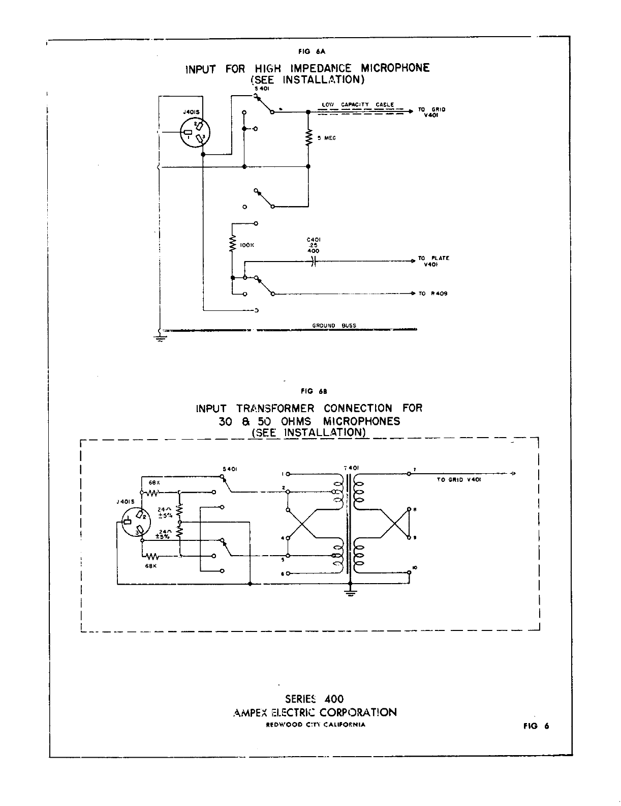
FIG
6A
INPUT
FOR
HIGH
IMPEDANCE
MICROPHONE
SEE
INSTALLITION
$
401
FIG
62
TO
GRIO
V4OI
TO
PLATE
V40’
TO
P409
INPUT
TRJNSFORMER
CONNECTION
FOR
30
&
50
OHMS
MICROPHONES
SEE INSTALLATION
SERIE
400
AMPEX
ELECTRIC
CORPORAT!ON
REDWOOD
CT%
CALIFOVNIA
LOW
CAPACITY
CACLE
S
MEG
D
GROUND
BUSS
-‘1
-J
FIG
6
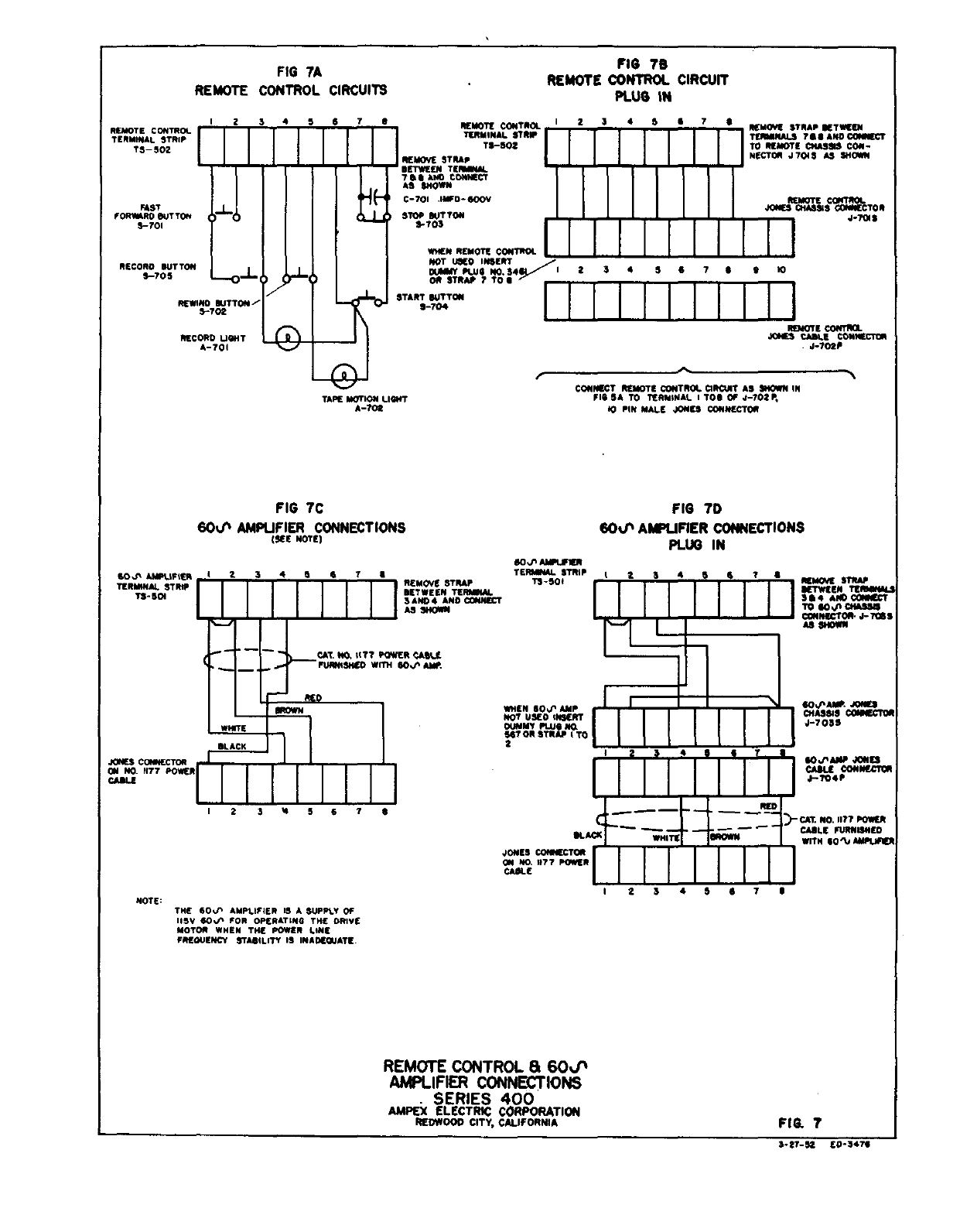
REMOTE
CONTROL
TERMINAL
STRIP
TS-
502
RUT
FORYRO
SUTTON
S-TO’
RECORD
SUTTON
5-705
FIG
lA
REMOTE
CONTROL
CIRCUITS
TAPE
MOTION
LIQ’T
A-tOt
FIG
76
REMOTE CONTROL
CIRCUIT
PLUG
IN
REMOTE
CONTROL
I
2
$
REMOVE
STRAP
RETWEEJI
TERMINALSTRWI
IIIII I I
ITEIWSNAI.S7$$AIIDCOISIECT
TI-SOt
I
I
I
I
I
I
I
ITOREMOTE1CI4ASSISCON-
I
NECTOR
J70I5
AS
SHORN
REMOVESTRAP
I I
I
I
I
I
I I
7SSANOCOINT*CT
IIIiI
II
SETWEENTEMRNM.
IIIIII I
0-701
IIWO-SOOV
I
I
I
I
I
REMOTE
CONTROL
ASSIOWM
I
I
I
I
I
JONES
0+05545 COWECTOR
STOP
SUTTON
I
I
I
i
I
S-lOS
REMnCONTROLI
IIIIIIIII!
NOT
iato
INSERT
*SYFtUSNO.S4
I
23
4
5
4
7
4 9
40
OR
STRAP
7
TO
S
START
SUTTON
1-704
CONNECT
REMOTE
CONTROL
CIROAT
AS
SHOWN
IN
FIG
5A
TO
TERMINAL
I
TOS
OF
J-702P,
0
PIN
MALE
JONES
CONNECTOR
IQTE
CONTRa.
JOltS
CABLE
CONNECTOR
-
J702P
FIG
70
60*/’
AP*UFIER
CONNECTIONS
FIG
7C
60i/’
AMPLiFIER
CONNECTIONS
SEE
NOTE
PLUG
IN
60,1’
AItSER
SO.PAIIUF%E%
I2
3
4
5
4
1
TERAV4ALSTRIP
I234
5
4
7
4
REMOVE
STRAP
TERMPNAI.
STRIP
1SETWEENTEM
I
II
I*
*
REMOVE STRAP
T3’SOI
4
I I
I J
*
ETWEEN
TEIWSIIIJ
LII
1111
______
*sAND4ANDflIECT
I
I
I
I I
I344C06tn
___________________________________
J
TO
SOIlS
CIaSS.
I
AS
SHOWN
I
I
I I I I
-
WINECTOAJ-TOWS
AS
SeWN
*
LCAt
II??
R
CALL
-
SI-
-f’
FUflIIsHED
WITh
SOI1’
Alt
If
MD
*1411
SLACK
JONES
Ca*4ECTOR
I
ON
NO,
77
POWER
flaIR
I
I
2 3
*4
S
S
74
WHEN
6OP
AMP
I
__________
NOTUSEDIMERT[
II
I
I
ONJNMYPLUSIIO
II I
I
SITORSTEAP
ITO -
III
2
_________________________
______________
40.1’
At
JONES
0+03515
CONIECTOW
4-703S
I
2
S
44T
-
__________
U
sorsp
an
I
I I I
CABLE
CONNECTOR
I I I
_____
d----
‘-
WHITE
RED
nfl
JONES
COllECTOR
044
Na
1177
PORER
CAStE
CAt
NO.
IIfl
POWER
CABLE
FURNISHED
-
WITH
SO’1A1L$ER
THE
SOIlS
AMPLIFIER
IS
A
SUPPLY
OF
IISY
10.1’
FOR
OPERATING
THE
ORIVE
MOTOR
WHEN THE
POWER
LINE
FREGUENCY
STASILITY
IS
INADECJATE.
REMOTE
CONTROL
&
6OJ’
AMPLIFIER
CONNECTIONS
-
SERIES
400
AMPEX
ELECTRIC
CORPORATION
REDWOOD
CITY,
CALIFORNIA
I
2
3
4
S
4
7
S
FIG. 7
NOTE:
3’tT-SZ
EPS4TS
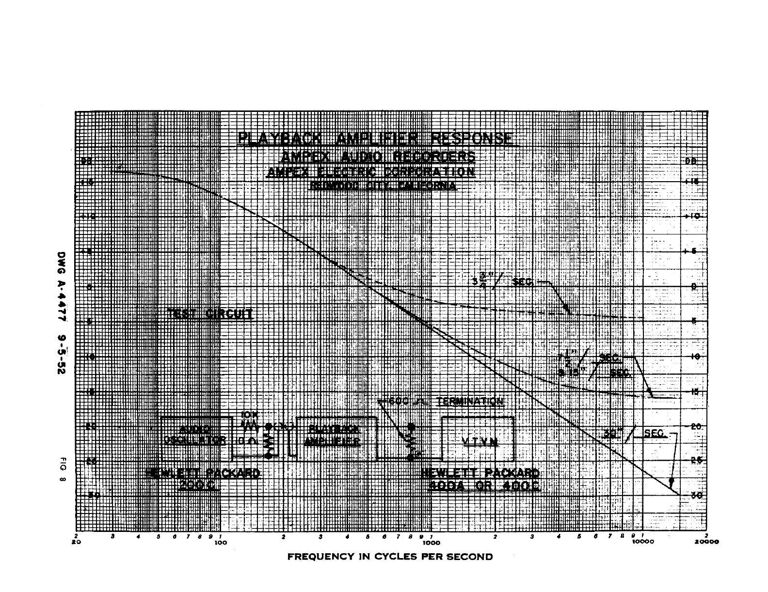
a
a
-4
-4-
to
C,
N
FREQUENCY
IN
CYCLES
PER
SECOND
C
0
-H
I
Li
:
:1:1
t
-
-
rut
.
ru;
m
rrT-r
-It
j-
t-l-
-‘--‘
1-1-f
m
tj4±t
,T
4FH
at
Eli
iv::
-
--
-
-
viit
-r’
-l-r-r--r-rrrrn-r.
*1
I
-I,,,,.,:,,I,,,TrrrrI-rrr-tT-ttrTttI,f
‘iF--
j,:f
£I
E-
fi
:?
-
-
.
-
Lf
Th
S
U]
I,
-[
--
-T
-
-
H
p144
I
ItL1I-i’
1!!
14II
1I
I:
F-
I-----
-s
----P-
-1-’
-
4
-LJHCI
4-HH
4i-
4flflwIfl
H
14_
-r
4-44-
LI4
14i1WJWll444T
t
-
H
a---,
TI
r
ti;
fl
-
-
-
Vr4
-I.
C
CO
r
.
:4li:l.
--
A
F-
I--
[1-1
6
7
8 I
20
zOO
I--
-r
I
114
-t
--F
tjitjfh
I.
-t
&!
Pt
I.
:1
I
--l’i
---4-
--
345
67891
3000
:1]
414
4567
89 I
10000
3
-
2
20000
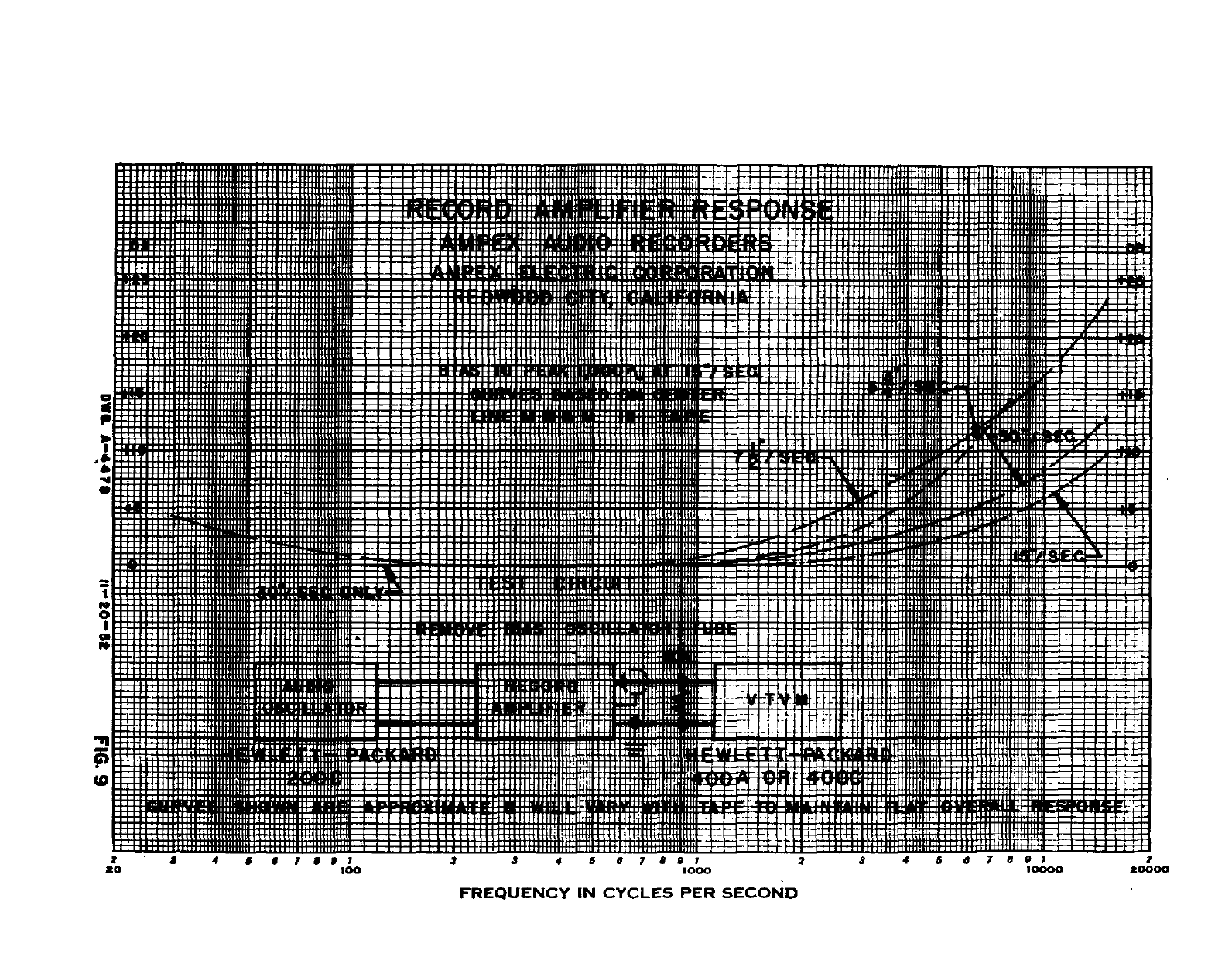
111
II!
I]
4
I
!
as
::::-
c:::fl:.
-0
-
-
- - -
-
-4
Sil!
I
I
I.
-
-
- -
-
-
-
-
:
- - -
-
- -
- -
-
-
-
- - - -
o
-
It
E
SRI
III
-
EE
-
:
:::::j.It1
_i
0
,
ElI
2
-
3 4 5
67991
2 3 4 5
67891
2345
67897
2
20
100
1000
10000
*0000
FREQUENCY
IN
CYCLES
PER
SECOND
-
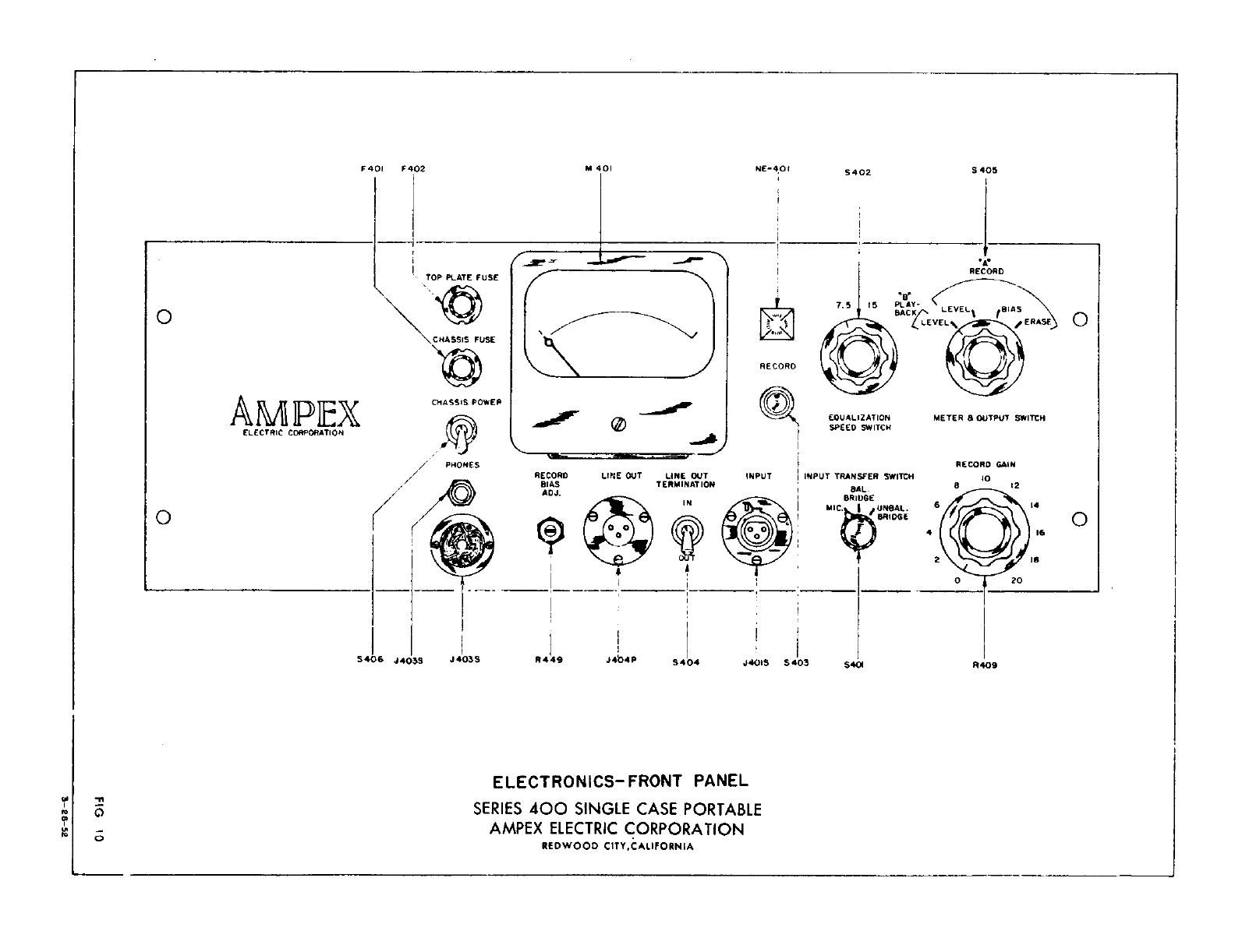
AMPIEX
ELECTRIC
CORPORATION
P401
P402
5406
CHASSIS
POWER
0
/
PHONES
J4O3S
ELECTRONICS-FRONT
PANEL
SERIES
400
SINGLE
CASE PORTABLE
AMPEX
ELECTRIC
coRPORATION
REDWOOD
CITY,CALIFORNIA
14401
NE4OI
S4O5
5402
-
TOP
PLATE FUSE
CHASSIS
FUSE
b
0
0
C
7-5
‘5
‘S
PLAY
-
ncr
RECORD
LEVELS
,BIAS
LEVEL
0
RECORD
-a
RECORD
BIAS
AOJ.
LINE
OUT
EQUALIZATION
SPEED
SWITCH
LINE
OUT
TERMINATION
METER
& OUTPUT
SWITCH
RECORD
GAIN
INPUT
I
INPUT TRANSFER
SWITCH
SAL.
BRIDGE
MIC
I
,UNSAL,
BI1IDCE
J
405S
R449
J4b4P
S404
44015 $403
tC
0
S4
P409
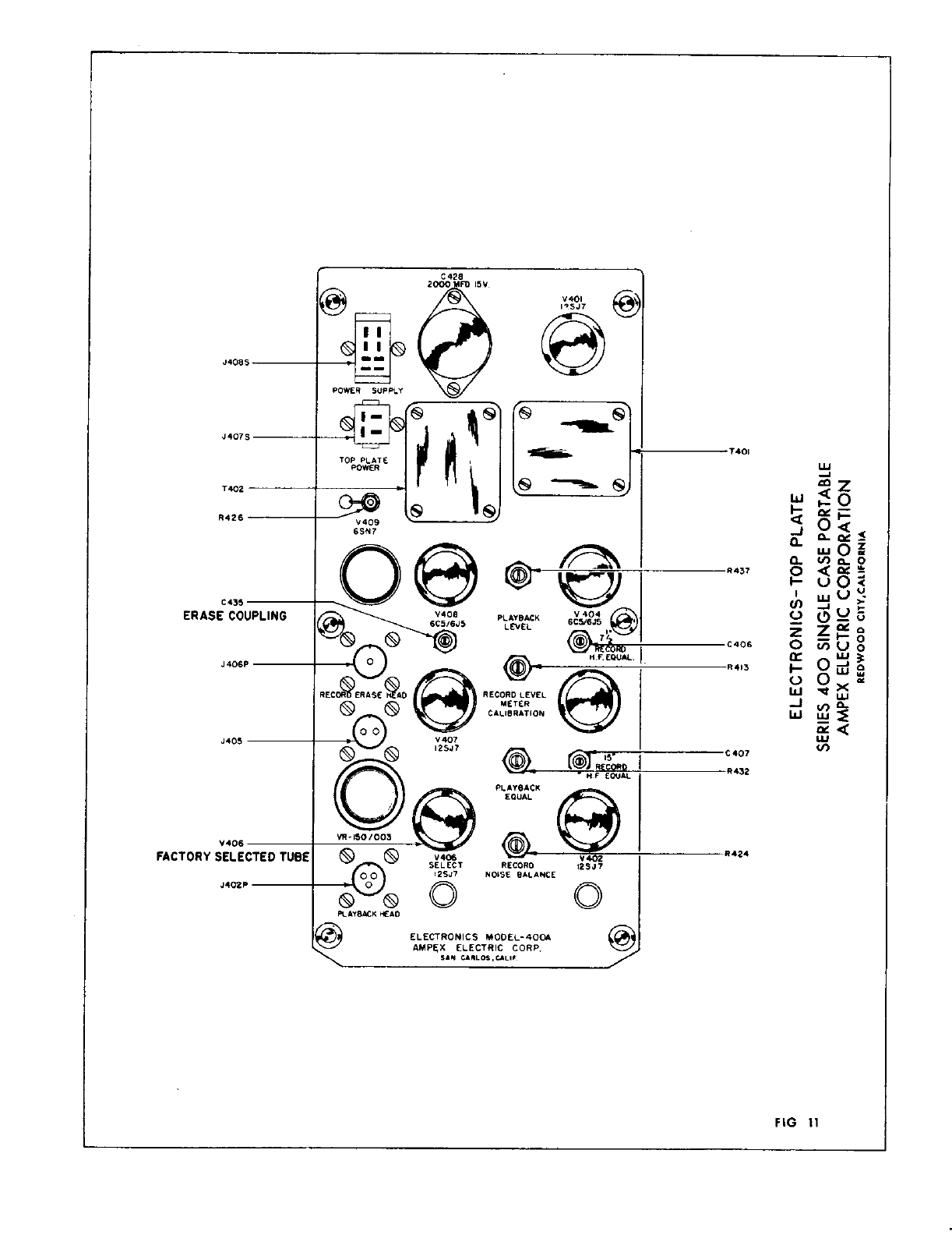
C
435
ERASE
FACTORY
LU
-I
wO
-
z
wQ.g
Q
VoO
o
I-uO
‘-I
u-I
‘
Cn_J
-
2oo
zzfl
o
cflUo
ir
I-0ui2
oO
-
WuJ
-Jv-,O
I
FIG
11
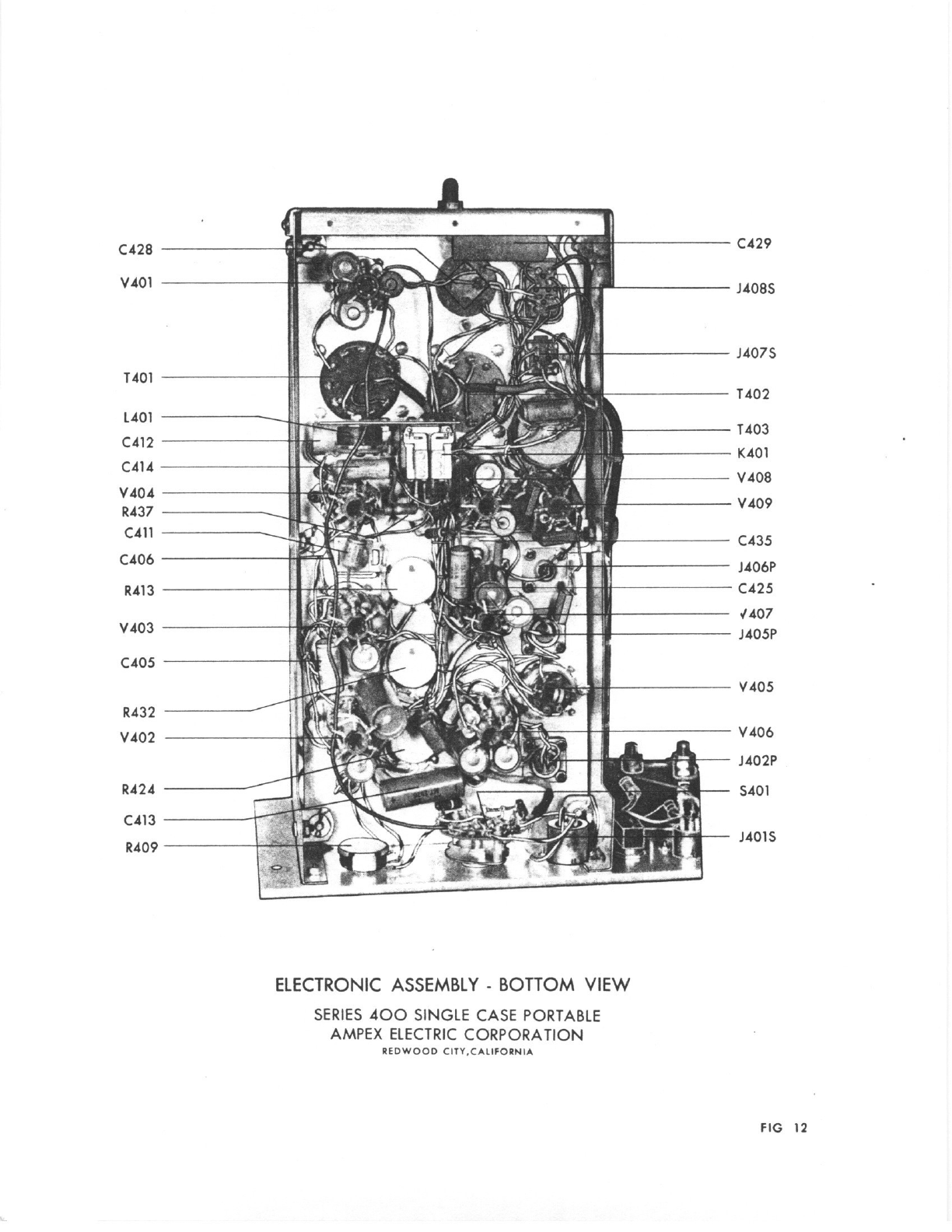
C428
C429
1401
V401
--
C413
-t
R409
1401
C41
2
C414
V40
4
R437
C41
1
C406
R41
3
V403
C4O5
R432
V402
R424
ELECTRONIC
ASSEMBLY
-
BOTTOM
VIEW
SERIES
400
SINGLE
CASE
PORTABLE
AMPEX
ELECTRIC
CORPORATION
REDWOOD
CITY,CALIFORNIA
J408S
J407S
1402
T403
K401
V
408
V409
C435
J406P
C425
.1407
J405P
V405
V406
J402P
5401
J4015
FIG
12
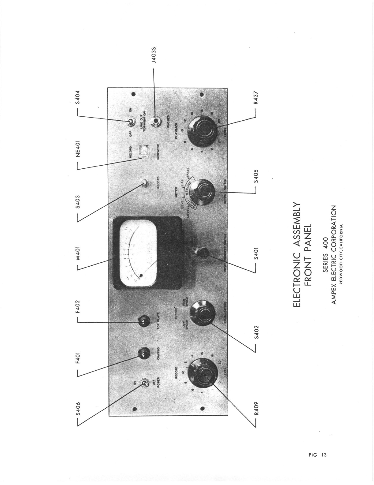
-
ELECTRONIC
ASSEMBLY
FRONT
PANEL
SERIES
400
AMPEX
ELECTRIC
CORPORATION
REDWOOD
CITYCALIFORNIA
‘1
C
‘I,
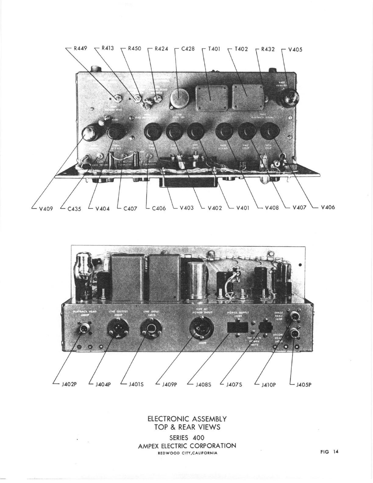
ELECTRONIC ASSEMBLY
TOP
&
REAR
VIEWS
SERIES
400
AMPEX
ELECTRIC
CORPORATION
V406
REDWOOD
CITY.CALIFORNIA
PIG 14
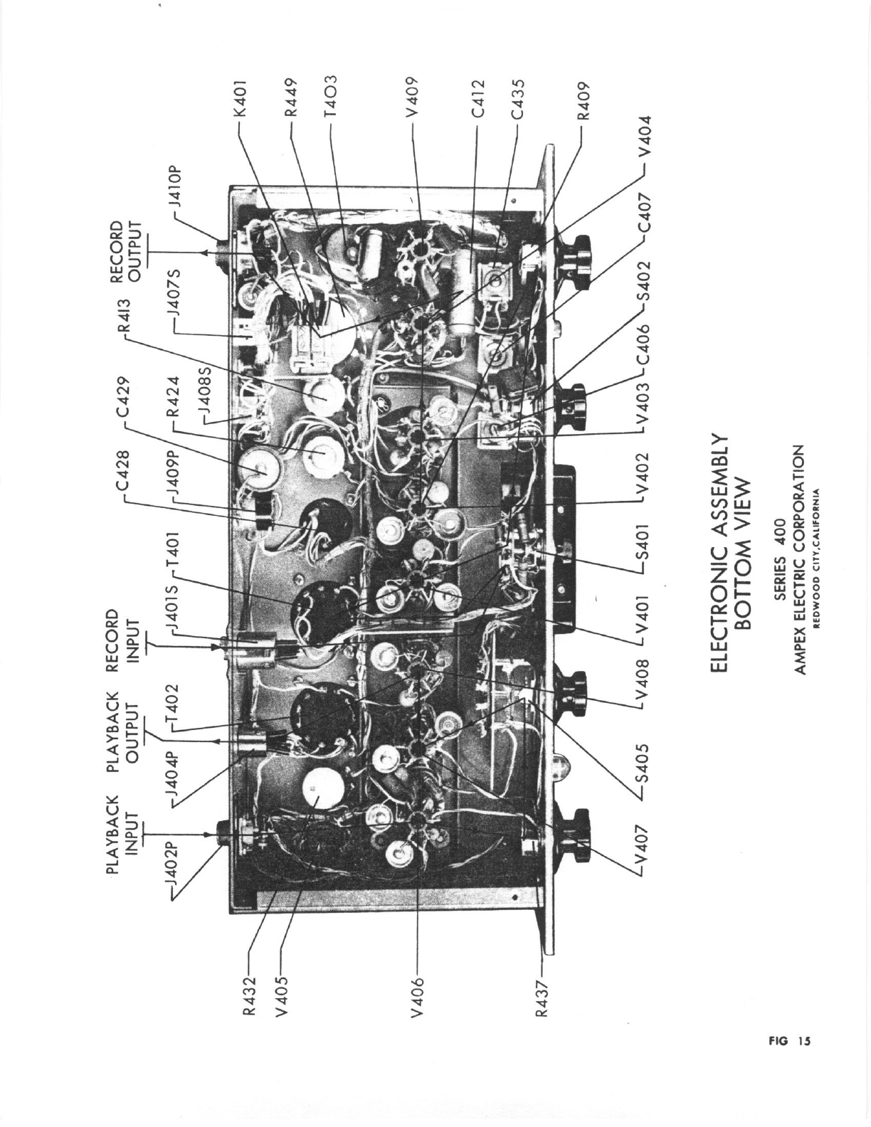
R
432
V
405-
V406
R437
-s
K401
_-
V409
-
C412
C435
R409
ELECTRONIC
ASSEMBLY
BOTTOM
VIEW
SERIES
400
AMPEX
ELECTRIC
CORPORATION
PLAYBACK
PLAYBACK
RECORD
INPUT
OUTPUT
INPUT
R4I3
RECORD
f
OUTPUT
R449
-
T403
‘I
C
LA
tC40
V404
REDWOOD
CITYICALIFORNIA
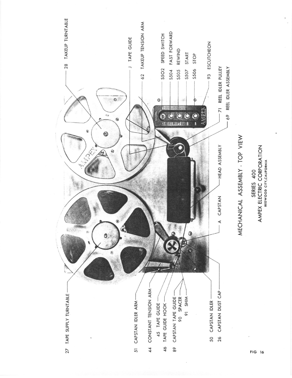
27
TAPE
SUPPLY
TURNTABLE
51
CAPSTAN
IDLER
ARM-
44
CONSTANT TENSION
ARM
-
45
TAPE
GUIDE
46
TAPE
GUIDE
HOOK
89
CAPSTAN
TAPE
GUIDE
90
SPACER
91
SHIM
50 CAPSTAN
IDLER
26
CAPSTAN
DUST
CAP
MECHANICAL
ASSEMBLY
-
TOP
VIEW
28
TAKEUP
TURNTABLE
J
TAPE
GUIDE
TAKEUP
TENSION
ARM
SPEED
SWITCH
FAST
FORWARD
REWIND
START
STOP
93
ESCUTCHEON
SERIES
400
AMPEX
ELECTRIC
CORPORATION
REDWOOD
CITY,CALIFORNIA
0
S502
S504
S505
S507
S506
-II
0
0-
--
______
71
REEL
IDLER
PULLEY
69
REEL
IDLER
ASSEMBLY
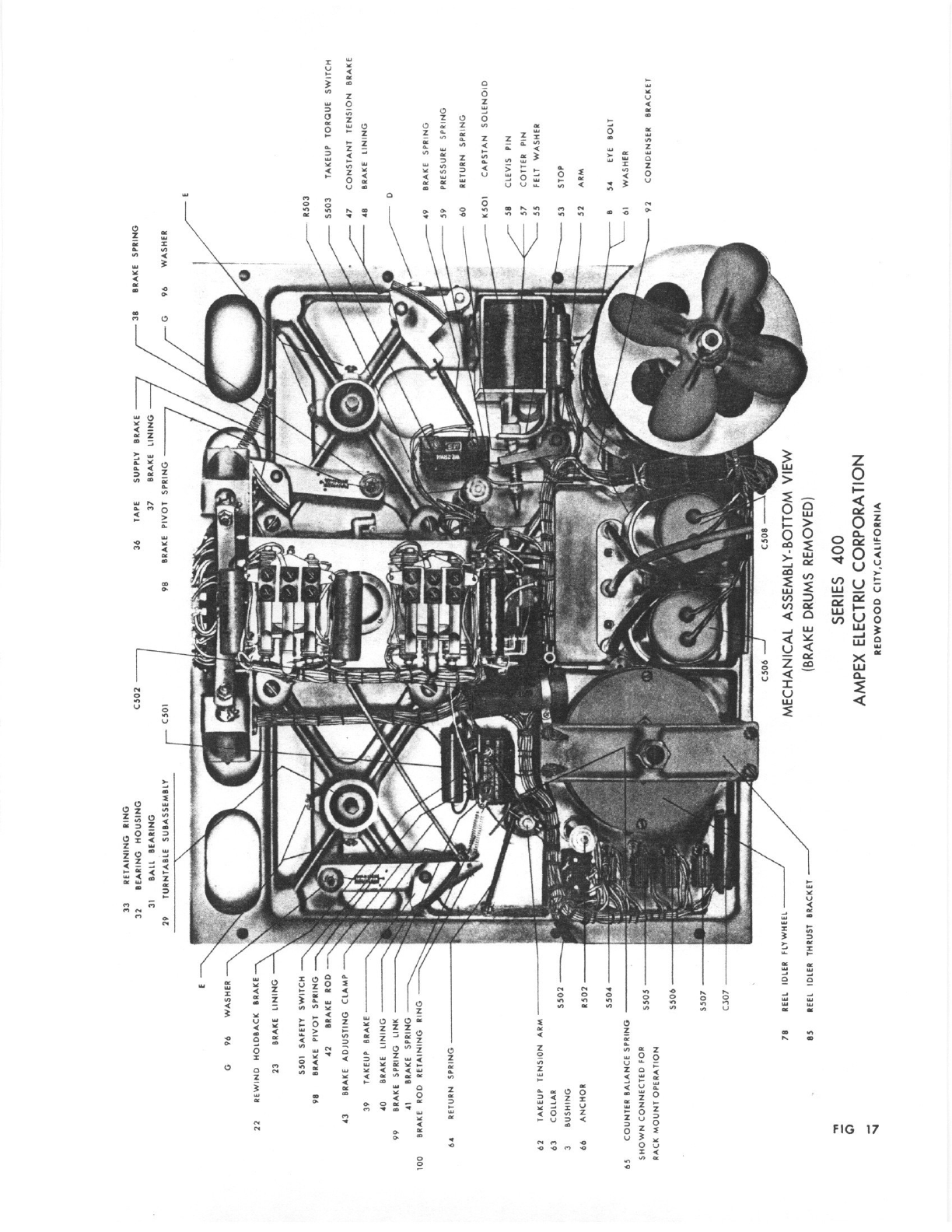
22
REWIND
HOLDEACIC
BRAKE
23
BRAKE
LINING
-
SSOT
SAFETY
SWITCH
98
BRAKE
PIVOT
SPRING
-S
42
BRAKE
ROD
43
BRAKE
ADJUSTING
CLAMP
39 TAKEUP
BRAKE
40
BRAKE
LINING
99
BRAKE
SPRING LINK
4!
BRAKE
SPRING
lOG
BRAKE
ROD
RETAINING
BIB
64 RETURN SPRING
62 TAKEUP
TENSION
ARM
62
COLLAR
5502
2
RUSHING
66
ANCHOR
R302
S504
65
COUNTER
BALANCE SPRING
SHOWN
CONNECTED
POR
________
RACK
MOUNT
OPERATION
SSDb
C
N
R303
5503
TAKEUP
TORQUE
SWITCH
-K---
‘?
CONSTANT
TENSION
BRAKE
48
BRAKE
LINING
D
49
BRAKE
SPRI
NO
59
PRESSURE
SPRING
60 RETURN SPRING
KSOI
CAPSTAN
SOLENOID
SB
CLEVIS PIN
57 COTTER
PIN
55
PELT
WASHER
53
STOP
52 ARM
54
EVE
BOLT
WASHER
CONDENSER
BRACKET
23
ERTAINING
SING
32
BEARING
HOUSING
3!
BALL
BEARING
29
TURNTABLE
SUBASSEMBLY
G
96
WASHER
BRAKE
SPRING
96
WASHER
70
REEL
IDLER
FLY
WHEEL
Es
BEEt
IDLER
THRUST
IRACK
ET
-
92
C508
-
MECHANICAL
ASSEMBLY-BOTTOM
VIEW
BRAKE
DRUMS
REMOVED
SERIES
400
AMPEX
ELECTRIC
CORPORATION
REDWOOD
CITYICALIFORNIA
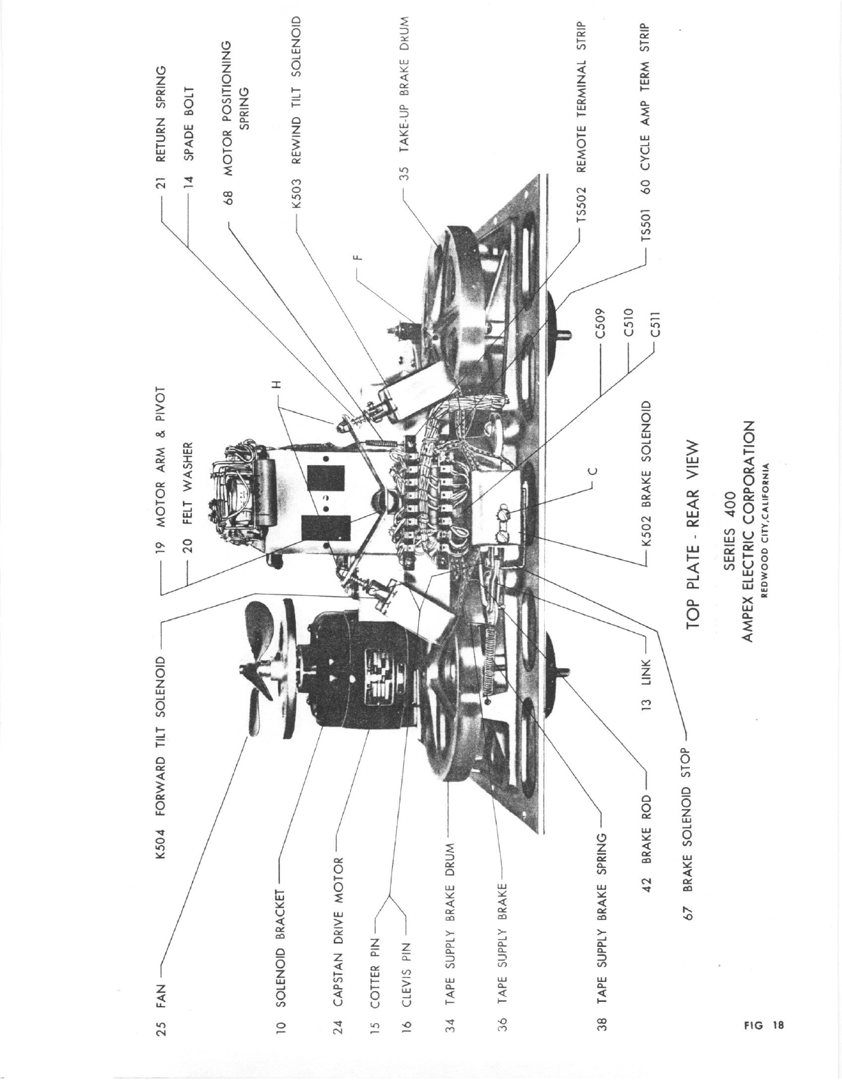
25
FAN
10
SOLENOID
BRACKET
24
CAPSTAN
DRIVE
MOTOR
VIS
NN
34
TAPE
SUPPLY
BRAKE DRUM
36
TAPE
SUPPLY
BRAKE
-
38
TAPE
SUPPLY
BRAKE
SPRING
42
BRAKE
ROD
TOP
PLATE
-
REAR
VIEW
CS
10
21
RETURN
SPRING
14
SPADE
BOLT
68
MOTOR POSITIONING
SPRING
K503
REWIND
TILT
SOLENOID
TAKE-UP
BRAKE
DKUM
TSSO2
REMOTE
TERMINAL
STRIP
T5501
60
CYCLE
AMP
TERM
STRIP
SERIES
400
AMPEX
ELECTRIC
CORPORATION
19
MOTOR
ARM
&
PIVOT
20
K504
FORWARD
TILT
SOLENOID
FELT
WASHER
F
7735
LINK’
13
/K5
02
67
BRAKE
SOLENOID
STOP
I,
a
a
C509
BRAKE
SOLENOID
C51
I
REDWOOD
CITY,CALIFORNIA
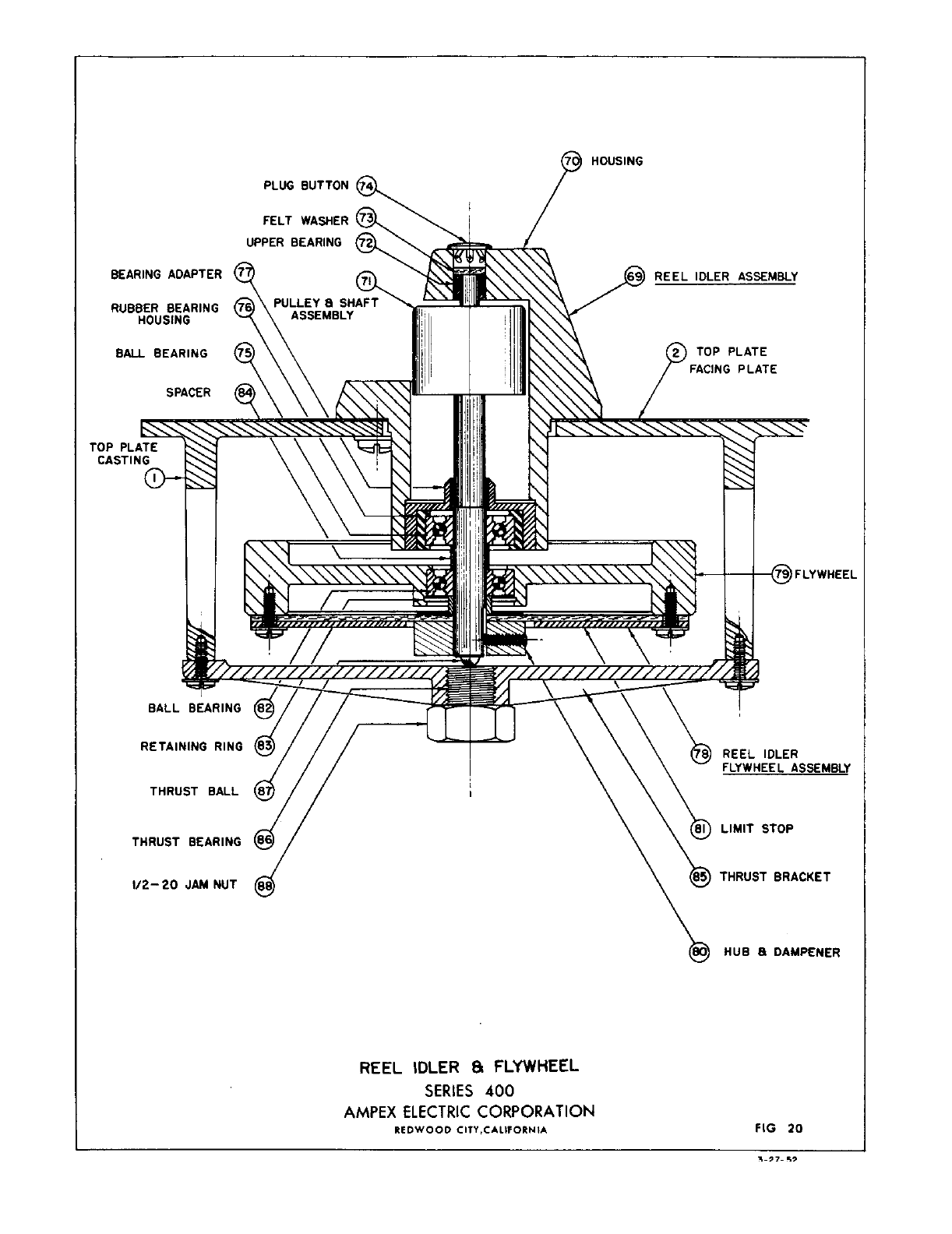
HOUSING
BEARING
ADAPTER
RUBBER
BEARING
HOUSING
BALL
BEARING
SPACER
BALL
BEARING
RETAINING
RING
THRUST
BALL
REEL
IDLER
FLYWHEEL
ASSEMBLY
THRUST
BEARING
REEL
IDLER
8FLYWHEEL
SERIES
400
AMPEX
ELECTRIC
CORPORATION
PLUG
BUTTON
FELT
WASHER
UPPER
BEARING
REEL
IDLER
ASSEMBLY
FACING
PLATE
1/2-20
JAM NUT
LIMIT
STOP
THRUST
BRACKET
HUB
&
DAMPENER
FIG
20
REDWOOD
CITY,CALIFORNIA
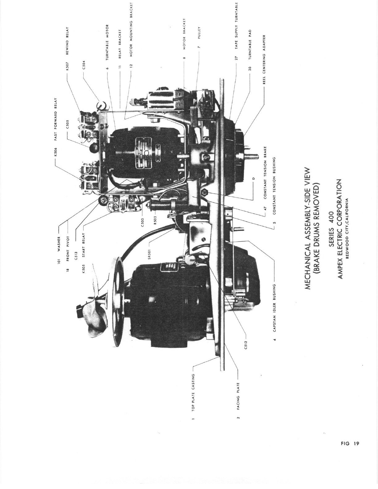
KSO6
I
TOP
PLATE
CASTING
2
PACING
PLATE
MECHANICAL
ASSEMBLY-SIDE
VIEW
BRAKE
DRUMS
REMOVED
SERIES
400
AMPEX
ELECTRIC
CORPORATION
REDWOOD
CITLCALIFORNIA
KSO7
REWIND
BELAY
C504
TURNTABLE
MOTOR
BELAY BRACKET
MOTOR
MOUNJING
ERACKEI
--
8
NOT
OR
BRACKET
7
PULLEY
27
TAPE
SUPPLY
TURNTABLE
30
TURNTABLE
PAD
REEL
CENTERING
ADAPTER
II
6
I
/
‘I
0
‘0
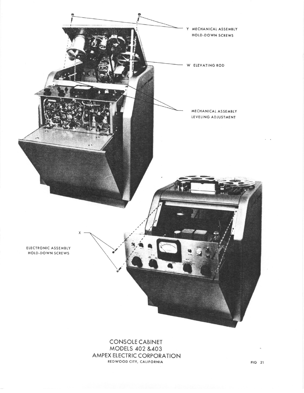
Y
MECHAN1
AS5EMSLY
-
II
HOLDDOWN
SCREWS
-_----____
W
ELEVAfl
qØO
MECHANICAL
ASSEMBLY
LEVELING
AWIJSTMENT
ELECTRONIC ASSEMBLY
HOLD-DO’
SCREWS
CONSOLE
CABINET
MODELS
402
&403
AMPEX
ELECTRIC
CORPORATION
REDWOOD
CITY,
CALIFORNSA
x
fIG
21
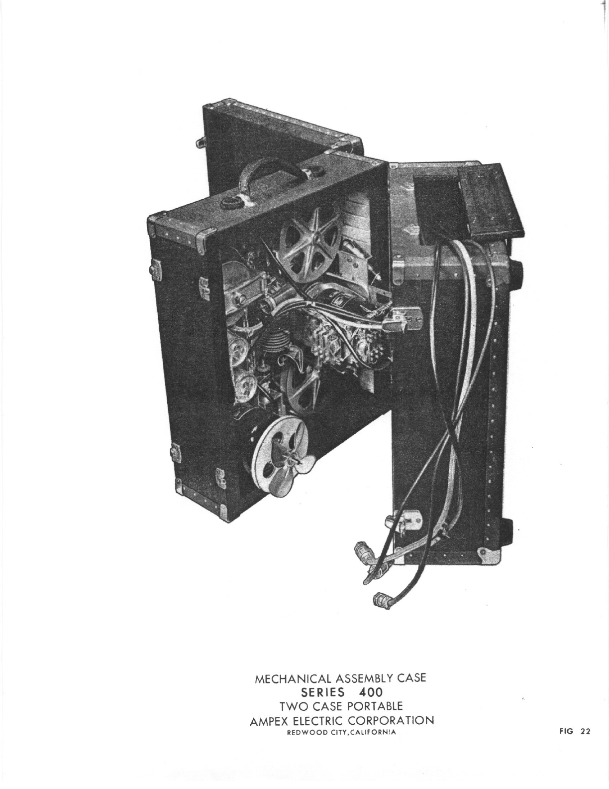
MECHANICAL
ASSEMBLY CASE
SERIES
400
-
TWO
CASE
PORTABLE
AMPEX
ELECTRIC
CORPORATION
REDWOOD CITY.CALIFORNIA
FIG
22
