ARM® Mali™ Display Processor Android DDK Integration Manual SW Guide
User Manual:
Open the PDF directly: View PDF ![]() .
.
Page Count: 70
- ARM® Mali™ Display Processor Android DDK Integration Manual
- Contents
- Preface
- 1 : Introduction
- 2 : Build Tools and Installation
- 3 : Integrating the Driver in a New Platform
- 3.1 : Prerequisites
- 3.2 : Integrating the display processor driver
- 3.2.1 : Flattened device tree description
- Flattened Device Tree description
- Flattened Device Tree description for the dummy video transmitter
- Example: Display processor connected to an I2C video transmitter
- Example: Display processor connected to a simple panel
- Example: Display processor connected to test transmitters
- Example: Display processor connected to I2C HDMI transmitter
- 3.2.1 : Flattened device tree description
- 3.3 : Update and configure the kernel
- 3.4 : Add updated kernel headers into Android 4.4 source tree
- 3.5 : Modify init.rc
- 3.6 : Modify Android makefile
- 3.7 : The Gralloc module
- 3.8 : Setting the main clock and the pixel clock rate ratio
- 4 : Integrating a System MMU
- 5 : Integrating a Video Transmitter
- 5.1 : Integrating a video transmitter
- 6 : Integrating a Custom Gralloc
- 7 : Integrating Runtime Power Management
- 8 : Integrating System Power Management
- 9 : Building the DDK
- 10 : Testing the Driver
- A : Revisions

ARM® Mali™ Display Processor Android
DDK
Revision: r1p0
Integration Manual
Confidential - Beta
Copyright © 2014, 2015 ARM. All rights reserved.
ARM 100144_0100_01_en

ARM® Mali™ Display Processor Android DDK
Integration Manual
Copyright © 2014, 2015 ARM. All rights reserved.
Release Information
Document History
Issue Date Confidentiality Change
0000-00 20 November 2014 Confidential First release for r0p0
0100-00 17 July 2015 Confidential First release for r1p0
0100-01 07 August 2015 Confidential Second release for r1p0
Confidential Proprietary Notice
This document is CONFIDENTIAL and any use by you is subject to the terms of the agreement between you and ARM or the
terms of the agreement between you and the party authorised by ARM to disclose this document to you.
This document is protected by copyright and other related rights and the practice or implementation of the information contained in
this document may be protected by one or more patents or pending patent applications. No part of this document may be
reproduced in any form by any means without the express prior written permission of ARM. No license, express or implied, by
estoppel or otherwise to any intellectual property rights is granted by this document unless specifically stated.
Your access to the information in this document is conditional upon your acceptance that you will not use or permit others to use
the information: (i) for the purposes of determining whether implementations infringe any third party patents; (ii) for developing
technology or products which avoid any of ARM’s intellectual property; or (iii) as a reference for modifying existing patents or
patent applications or creating any continuation, continuation in part, or extension of existing patents or patent applications; or (iv)
for generating data for publication or disclosure to third parties, which compares the performance or functionality of the ARM
technology described in this document with any other products created by you or a third party, without obtaining ARM’s prior
written consent.
THIS DOCUMENT IS PROVIDED “AS IS”. ARM PROVIDES NO REPRESENTATIONS AND NO WARRANTIES,
EXPRESS, IMPLIED OR STATUTORY, INCLUDING, WITHOUT LIMITATION, THE IMPLIED WARRANTIES OF
MERCHANTABILITY, SATISFACTORY QUALITY, NON-INFRINGEMENT OR FITNESS FOR A PARTICULAR PURPOSE
WITH RESPECT TO THE DOCUMENT. For the avoidance of doubt, ARM makes no representation with respect to, and has
undertaken no analysis to identify or understand the scope and content of, third party patents, copyrights, trade secrets, or other
rights.
This document may include technical inaccuracies or typographical errors.
TO THE EXTENT NOT PROHIBITED BY LAW, IN NO EVENT WILL ARM BE LIABLE FOR ANY DAMAGES,
INCLUDING WITHOUT LIMITATION ANY DIRECT, INDIRECT, SPECIAL, INCIDENTAL, PUNITIVE, OR
CONSEQUENTIAL DAMAGES, HOWEVER CAUSED AND REGARDLESS OF THE THEORY OF LIABILITY, ARISING
OUT OF ANY USE OF THIS DOCUMENT, EVEN IF ARM HAS BEEN ADVISED OF THE POSSIBILITY OF SUCH
DAMAGES.
This document consists solely of commercial items. You shall be responsible for ensuring that any use, duplication or disclosure of
this document complies fully with any relevant export laws and regulations to assure that this document or any portion thereof is
not exported, directly or indirectly, in violation of such export laws. Use of the word “partner” in reference to ARM’s customers is
not intended to create or refer to any partnership relationship with any other company. ARM may make changes to this document at
any time and without notice.
If any of the provisions contained in these terms conflict with any of the provisions of any signed written agreement covering this
document with ARM, then the signed written agreement prevails over and supersedes the conflicting provisions of these terms.
This document may be translated into other languages for convenience, and you agree that if there is any conflict between the
English version of this document and any translation, the terms of the English version of the Agreement shall prevail.
Words and logos marked with ® or ™ are registered trademarks or trademarks of ARM Limited or its affiliates in the EU and/or
elsewhere. All rights reserved. Other brands and names mentioned in this document may be the trademarks of their respective
owners. Please follow ARM’s trademark usage guidelines at http://www.arm.com/about/trademarks/guidelines/index.php
ARM® Mali™ Display Processor Android DDK
ARM 100144_0100_01_en Copyright © 2014, 2015 ARM. All rights reserved. 2
Confidential - Beta

Copyright © [2014, 2015], ARM Limited or its affiliates. All rights reserved.
ARM Limited. Company 02557590 registered in England.
110 Fulbourn Road, Cambridge, England CB1 9NJ.
LES-PRE-20348
Confidentiality Status
This document is Confidential. This document may only be used and distributed in accordance with the terms of the agreement
entered into by ARM and the party that ARM delivered this document to.
Product Status
The information in this document is for a Beta product, that is a product under development.
Web Address
http://www.arm.com
ARM® Mali™ Display Processor Android DDK
ARM 100144_0100_01_en Copyright © 2014, 2015 ARM. All rights reserved. 3
Confidential - Beta

Contents
ARM® Mali™ Display Processor Android DDK
Integration Manual
Preface
About this book ...................................................... ...................................................... 7
Feedback ...................................................................................................................... 9
Chapter 1 Introduction
1.1 About the DDK .................................................... .................................................... 1-11
1.2 Linux kernel device driver ........................................................................................ 1-12
1.3 User space driver .................................................................................................... 1-14
Chapter 2 Build Tools and Installation
2.1 Tools ........................................................................................................................ 2-16
2.2 Linux kernel source ................................................ ................................................ 2-17
2.3 Android platform ...................................................................................................... 2-18
2.4 Unpacking the deliverable ........................................... ........................................... 2-19
Chapter 3 Integrating the Driver in a New Platform
3.1 Prerequisites ............................................................................................................ 3-21
3.2 Integrating the display processor driver ................................. ................................. 3-22
3.3 Update and configure the kernel ...................................... ...................................... 3-30
3.4 Add updated kernel headers into Android 4.4 source tree ...................................... 3-32
3.5 Modify init.rc ............................................................................................................ 3-33
3.6 Modify Android makefile .......................................................................................... 3-34
ARM 100144_0100_01_en Copyright © 2014, 2015 ARM. All rights reserved. 4
Confidential - Beta

3.7 The Gralloc module ................................................ ................................................ 3-35
3.8 Setting the main clock and the pixel clock rate ratio ................................................ 3-39
Chapter 4 Integrating a System MMU
4.1 Integrating a system MMU ........................................... ........................................... 4-41
Chapter 5 Integrating a Video Transmitter
5.1 Integrating a video transmitter ........................................ ........................................ 5-44
Chapter 6 Integrating a Custom Gralloc
6.1 Purpose ......................................................... ......................................................... 6-50
6.2 Interface definition ................................................. ................................................. 6-51
6.3 Build and link ..................................................... ..................................................... 6-53
Chapter 7 Integrating Runtime Power Management
7.1 Runtime power management callbacks ................................. ................................. 7-55
7.2 Integrating the runtime power management ............................................................ 7-56
Chapter 8 Integrating System Power Management
8.1 System power management callbacks .................................................................... 8-58
8.2 Integrating system power management ................................. ................................. 8-59
Chapter 9 Building the DDK
9.1 Building the kernel driver ............................................ ............................................ 9-61
9.2 Building the user space driver ........................................ ........................................ 9-63
9.3 Building the tests .................................................. .................................................. 9-64
Chapter 10 Testing the Driver
10.1 Executing the test suites ........................................................................................ 10-66
Appendix A Revisions
A.1 Revisions ................................................... ................................................... Appx-A-70
ARM 100144_0100_01_en Copyright © 2014, 2015 ARM. All rights reserved. 5
Confidential - Beta


About this book
The ARM® Mali™ Display Processor Android DDK produces drivers for the ARM Mali display
processor.
Product revision status
The rmpn identifier indicates the revision status of the product described in this book, for example, r1p2,
where:
rmIdentifies the major revision of the product, for example, r1.
pnIdentifies the minor revision or modification status of the product, for example, p2.
Intended audience
This book is for developers who need to know how to configure and use the ARM® Mali™ Display
Processor Android DDK.
Using this book
This book is organized into the following chapters:
Chapter 1 Introduction
This chapter introduces the ARM Mali Display Processor Android DDK.
Chapter 2 Build Tools and Installation
This chapter lists the build tools. It also describes how to install the DDK.
Chapter 3 Integrating the Driver in a New Platform
The chapter gives the information that is needed to integrate the display processor driver.
Chapter 4 Integrating a System MMU
This chapter describes how to integrate a system MMU and provides an example integration using
the ARM MMU-500.
Chapter 5 Integrating a Video Transmitter
This chapter describes how connect the display processor to a video display.
Chapter 6 Integrating a Custom Gralloc
This chapter describes how to integrate a the display processor DDK with a Gralloc library that is
not provided by ARM.
Chapter 7 Integrating Runtime Power Management
This chapter describes how to integrate the driver with the Linux Runtime Power Management
framework.
Chapter 8 Integrating System Power Management
This chapter describes how to integrate with the Linux System Power Management framework.
Chapter 9 Building the DDK
This chapter contains instructions on how to build the user and kernel driver components.
Chapter 10 Testing the Driver
The display processor DDK is provided with facilities to test and verify system integration.
Appendix A Revisions
This appendix describes the changes between released issues of this book.
Glossary
The ARM Glossary is a list of terms used in ARM documentation, together with definitions for those
terms. The ARM Glossary does not contain terms that are industry standard unless the ARM meaning
differs from the generally accepted meaning.
Preface
About this book
ARM 100144_0100_01_en Copyright © 2014, 2015 ARM. All rights reserved. 7
Confidential - Beta

See the ARM Glossary for more information.
Typographic conventions
italic
Introduces special terminology, denotes cross-references, and citations.
bold
Highlights interface elements, such as menu names. Denotes signal names. Also used for terms
in descriptive lists, where appropriate.
monospace
Denotes text that you can enter at the keyboard, such as commands, file and program names,
and source code.
monospace
Denotes a permitted abbreviation for a command or option. You can enter the underlined text
instead of the full command or option name.
monospace italic
Denotes arguments to monospace text where the argument is to be replaced by a specific value.
monospace bold
Denotes language keywords when used outside example code.
<and>
Encloses replaceable terms for assembler syntax where they appear in code or code fragments.
For example:
MRC p15, 0, <Rd>, <CRn>, <CRm>, <Opcode_2>
SMALL CAPITALS
Used in body text for a few terms that have specific technical meanings, that are defined in the
ARM glossary. For example, IMPLEMENTATION DEFINED, IMPLEMENTATION SPECIFIC, UNKNOWN, and
UNPREDICTABLE.
Additional reading
Information published by ARM and by third parties.
See http://infocenter.arm.com for access to ARM documentation.
ARM publications
This book contains information that is specific to this product. See the following documents for
other relevant information:
ARM® AMBA® Specification (Rev 2.0) (ARM IHI 0011).
ARM® AMBA® AXI and ACE Protocol Specification (ARM IHI 0022).
ARM® AMBA® APB Protocol Specification v2.0 (ARM IHI 0024).
ARM® Mali™-DP500 Display Processor Technical Overview (ARM 100040).
ARM® Mali™-DP500 Display Processor Technical Reference Manual (ARM 100039).
ARM® Mali™-DP500 Display Processor Configuration and Sign-off Guide (ARM 100041).
ARM® Mali™-DP500 Display Processor Integration Manual (ARM 100042).
ARM® Mali™-DP550 Display Processor Technical Overview (ARM 100135).
ARM® Mali™-DP550 Display Processor Technical Reference Manual (ARM 100136).
ARM® Mali™-DP550 Display Processor Configuration and Sign-off Guide (ARM 100137).
ARM® Mali™-DP550 Display Processor Integration Manual (ARM 100138).
Developer resources:
http://malideveloper.arm.com
Other publications
Relevant documents published by third parties:
None.
Preface
About this book
ARM 100144_0100_01_en Copyright © 2014, 2015 ARM. All rights reserved. 8
Confidential - Beta

Feedback
Feedback on this product
If you have any comments or suggestions about this product, contact your supplier and give:
• The product name.
• The product revision or version.
• An explanation with as much information as you can provide. Include symptoms and diagnostic
procedures if appropriate.
Feedback on content
If you have comments on content then send an e-mail to errata@arm.com. Give:
• The title ARM® Mali™ Display Processor Android DDK Integration Manual.
• The number ARM 100144_0100_01_en.
• If applicable, the page number(s) to which your comments refer.
• A concise explanation of your comments.
ARM also welcomes general suggestions for additions and improvements.
Note
ARM tests the PDF only in Adobe Acrobat and Acrobat Reader, and cannot guarantee the quality of the
represented document when used with any other PDF reader.
Preface
Feedback
ARM 100144_0100_01_en Copyright © 2014, 2015 ARM. All rights reserved. 9
Confidential - Beta

Chapter 1
Introduction
This chapter introduces the ARM Mali Display Processor Android DDK.
It contains the following sections:
•1.1 About the DDK on page 1-11.
•1.2 Linux kernel device driver on page 1-12.
•1.3 User space driver on page 1-14.
ARM 100144_0100_01_en Copyright © 2014, 2015 ARM. All rights reserved. 1-10
Confidential - Beta

1.1 About the DDK
The display processor contains the Linux kernel device driver and user space components necessary to
support the HWComposer Hardware Abstraction Layer (HAL) on Android.
The DDK also includes integration tests to verify correct integration.
1 Introduction
1.1 About the DDK
ARM 100144_0100_01_en Copyright © 2014, 2015 ARM. All rights reserved. 1-11
Confidential - Beta

1.2 Linux kernel device driver
The supplied device driver can be integrated with a new Linux kernel or Android platform if the
differences between your platform and the supplied implementation are restricted to the items listed here.
If the differences are restricted to any of the items on the following list, then integration is simple:
• The interrupt line assigned to the display processor hardware.
• The physical addresses assigned to the display processor hardware.
• The clock sources feeding the clock inputs of display processor in the system.
• The video transmitter or panel attached to the digital video output of the display processor.
• The IOMMU model where display processor is connected.
To integrate the software driver with a platform, you must perform these tasks:
1. Configure a device tree entry for the display processor hardware in your device and the Linux kernel
you are using.
2. Implement the integration layer for your device's one or more video transmitters.
3. Build and test the device driver and video transmitter integration on your platform.
If your platform is different from the reference implementation in ways that are not listed above, it might
be necessary to modify the device driver, the Linux kernel, or provide your own full port of the driver.
The process for porting a new device driver is hardware and OS-specific.
This section contains the following subsections:
•1.2.1 Device driver architecture on page 1-12.
1.2.1 Device driver architecture
The device driver consists of the two kernel objects, mali-dp and video-tx.
mali-dp is the main kernel driver and is responsible for all access and control of the display processor
hardware in your device. It should not be necessary to make any modifications to the mali-dp kernel
driver in order to integrate into your device.
The video-tx kernel object is an integration layer that gives the mali-dp kernel object access and
control of the transmitter in your device to provide:
• Status of connected display panel/monitor.
• Hotplug notifications.
• List of supported modes/resolutions.
• Control of Display power state.
You will need to develop an implementation of the video-tx framework for your device to integrate
with the mali-dp kernel object.
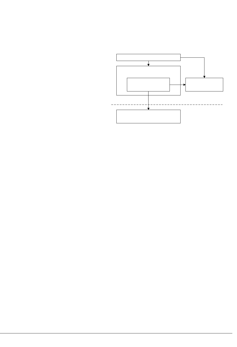
The following diagram shows how these two different components interact with each other and with
other blocks available in the Linux kernel.
The HWComposer driver in user space mostly communicates with the mali-dp driver through the ADF
Framework and in some cases directly. In turn the mali-dp driver communicates with the MMU Driver,
to control the 3rd party system MMU using the IOMMU Framework, and the video-tx Driver, to
control the 3rd party transmitter using the transmitter framework. The mali-dp driver is also responsible
for communicating directly with the display processor hardware.
1 Introduction
1.2 Linux kernel device driver
ARM 100144_0100_01_en Copyright © 2014, 2015 ARM. All rights reserved. 1-12
Confidential - Beta

MMU Driver
Linux IOMMU
Framework
3rd Party MMU
Integration
mali-dp Driver
Display Processor
ADF Frontend
Display Processor
Hardware Abstraction
video-tx Driver
Transmitter Framework
3rd Party Transmitter
Integration
ADF Framework
System MMU Display Processor
Hardware
3rd Party Transmitter
Display Processor
HWComposer Driver
Display
User Space
Kernel Space
Figure 1-1 Kernel driver block diagram
The driver does not support specific memory allocators for graphics buffers but instead supports the
Linux Kernel's memory sharing framework, dma_buf. Therefore any memory allocator that supports
sharing through dma_buf, for example ION, can be used with the driver.
The driver has been tested with the Gralloc implementation that can be obtained from ARM.
The IOMMU driver provides an interface to register memory buffers with the system MMU where the
display processor is attached using the Linux kernel IOMMU framework. You will need to develop and
implement the driver for your system MMU unless it is already available in the Linux kernel.
1 Introduction
1.2 Linux kernel device driver
ARM 100144_0100_01_en Copyright © 2014, 2015 ARM. All rights reserved. 1-13
Confidential - Beta
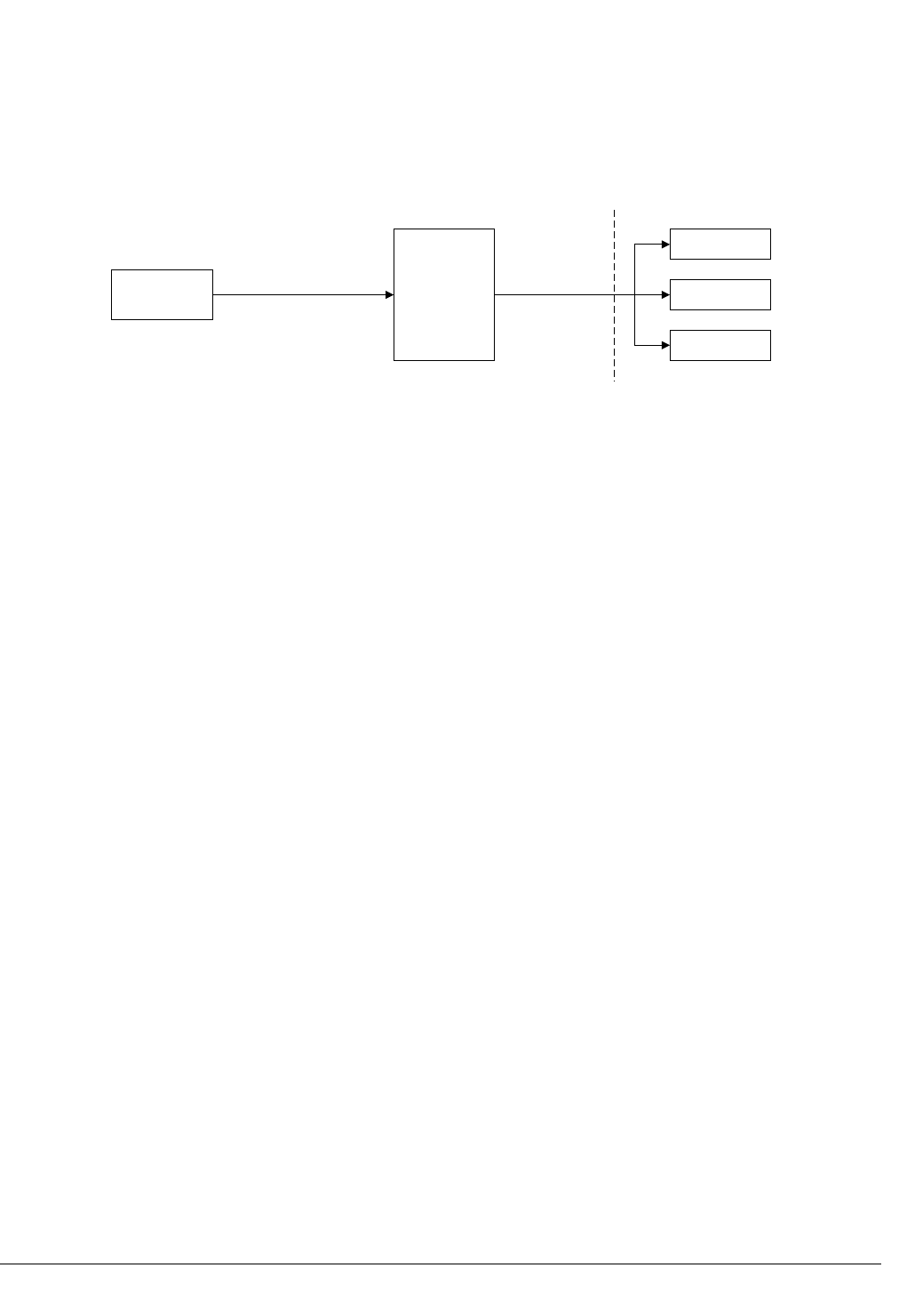
1.3 User space driver
The user space driver consists of an implementation of the Android HWComposer HAL and a buffer
importing component. These components act as a layer between the Android window composition
framework, SurfaceFlinger, and the kernel driver.
Display Processor
HWComposer Driver
Core Layer Gralloc Library
Display Processor Kernel Driver
User Space
Kernel Space
SurfaceFlinger
Figure 1-2 User space driver block diagram
1 Introduction
1.3 User space driver
ARM 100144_0100_01_en Copyright © 2014, 2015 ARM. All rights reserved. 1-14
Confidential - Beta

Chapter 2
Build Tools and Installation
This chapter lists the build tools. It also describes how to install the DDK.
It contains the following sections:
•2.1 Tools on page 2-16.
•2.2 Linux kernel source on page 2-17.
•2.3 Android platform on page 2-18.
•2.4 Unpacking the deliverable on page 2-19.
ARM 100144_0100_01_en Copyright © 2014, 2015 ARM. All rights reserved. 2-15
Confidential - Beta

2.1 Tools
ARM recommends that you use the following tools and versions to build the DDK:
GNU tar
GNU tar version 1.14 or later is required to unpack the deliverables.
GNU Make
GNU Make version 3.81 is required to build the Linux kernel objects.
2 Build Tools and Installation
2.1 Tools
ARM 100144_0100_01_en Copyright © 2014, 2015 ARM. All rights reserved. 2-16
Confidential - Beta

2.2 Linux kernel source
Android requires a Linux kernel source tree to build the kernel objects.
The Linux kernel device driver requires a kernel which supports the Atomic Display Framework (ADF).
Kernels with ADF and all Android patches applied can be downloaded from https://
android.googlesource.com.
Alternatively, the mainline kernel source can be downloaded from http://kernel.org. However, at a
minimum, ADF will need to be ported from the Android kernel in order to use the mainline kernel.
ARM has tested the software with the Linux kernel source tree version 3.10, from https://git.linaro.org/
landing-teams/working/arm/kernel.git, branch arm-juno-mali-fpga.
2 Build Tools and Installation
2.2 Linux kernel source
ARM 100144_0100_01_en Copyright © 2014, 2015 ARM. All rights reserved. 2-17
Confidential - Beta

2.3 Android platform
The display processor DDK supports both Android 4.4 and 5.0.
Android 4.4
The reference platform is Versatile Express. Versatile Express is 32 bit.
Android 5.0
The reference platform is Juno Versatile Express. Juno is 64 bit.
The platform source can be downloaded from http://source.android.com.
2 Build Tools and Installation
2.3 Android platform
ARM 100144_0100_01_en Copyright © 2014, 2015 ARM. All rights reserved. 2-18
Confidential - Beta

2.4 Unpacking the deliverable
1. Extract the downloaded archive into the directory vendor/arm/malidp of the Android source code
tree.
tar –xzvf <download_name>.tgz
2. When you unpack the tarball it unpacks into <display processor>/driver. The following figure
shows an example for the Mali-DP500 display processor:
mali_dp500/
documentation/
kernel/
driver/
tests/
user/
Figure 2-1 Unpacked directory structure
3. You must copy or move the driver directory into the Android tree as vendor/arm/malidp. The
following diagram shows the modified directory structure:
arm/
malidp/
documentation/
vendor/
aosp root/
<various Android folders>/
driver/
kernel/
tests/
user/
Figure 2-2 Modified directory structure
2 Build Tools and Installation
2.4 Unpacking the deliverable
ARM 100144_0100_01_en Copyright © 2014, 2015 ARM. All rights reserved. 2-19
Confidential - Beta

Chapter 3
Integrating the Driver in a New Platform
The chapter gives the information that is needed to integrate the display processor driver.
It contains the following sections:
•3.1 Prerequisites on page 3-21.
•3.2 Integrating the display processor driver on page 3-22.
•3.3 Update and configure the kernel on page 3-30.
•3.4 Add updated kernel headers into Android 4.4 source tree on page 3-32.
•3.5 Modify init.rc on page 3-33.
•3.6 Modify Android makefile on page 3-34.
•3.7 The Gralloc module on page 3-35.
•3.8 Setting the main clock and the pixel clock rate ratio on page 3-39.
ARM 100144_0100_01_en Copyright © 2014, 2015 ARM. All rights reserved. 3-20
Confidential - Beta

3.1 Prerequisites
You must have the following information available before you configure and build the device driver:
• The display processor interrupt line number.
• The display processor physical address region.
• The display processor power regulation.
• The display processor clock supply.
• AXI bus access settings.
3 Integrating the Driver in a New Platform
3.1 Prerequisites
ARM 100144_0100_01_en Copyright © 2014, 2015 ARM. All rights reserved. 3-21
Confidential - Beta

3.2 Integrating the display processor driver
To integrate the display processor in a Linux kernel, you need:
• A Flattened Device Tree (FDT) description for the SoC including clock tree, interrupt controller, and
buses.
• An FDT description for the board including a device tree description for the video transmitter or
panel attached to the digital video output of the display processor.
• The physical address of the registers in the system.
• Interrupt numbers for the Scaling Engine (SE) and the Display Engine (DE) in the system
• Clock sources for all the clock inputs:
— mclk
— aclk
— pclk
— pxclk
This section contains the following subsections:
•3.2.1 Flattened device tree description on page 3-22.
3.2.1 Flattened device tree description
The preferred way to describe a new platform within the Linux kernel is using an FDT description of the
system.
The FDT is is a .dts file that describes the system, including the system application processors, and all
the buses and devices that are attached to the application processors.
For more information on device trees, see http://elinux.org/Device_Tree.
Flattened Device Tree description
As part of this FDT description, you must define a special node for the display processor. This is located
in the node for the bus where the device is attached.
The format of this node is defined in the binding documentation in the DDK in:
kernel/Documentation/devicetree/bindings/video/mali-dp.txt
The following properties must be provided to enable the Linux kernel to correctly identify and register
the display processor driver in your system:
compatible
This property is used to identify the hardware you want to instantiate, for example "arm,mali-
dp550"
reg
This property contains the physical base address and length of registers in the system.
The physical address is dependent on the hardware configuration. The length is 4kB for Mali-
DP500, and 128kB for the Mali-DP550. The Mali-DP550 includes a 64kB secure page in the
128kB.
interrupts
This property contains two interrupt cells, one each for the SE and the DE.
The information is dependent on the Device Tree description for the interrupt controller used in
your system, and typically includes the interrupt number and whether the interrupt is activated
by a rising or falling edge.
interrupt-names
This property contains two strings, SE and DE, which are used as names for the interrupts.
These must be in the same as the order as defined by the interrupts property.
3 Integrating the Driver in a New Platform
3.2 Integrating the display processor driver
ARM 100144_0100_01_en Copyright © 2014, 2015 ARM. All rights reserved. 3-22
Confidential - Beta

clocks
This property contains four cells, one for each clock that the display processor requires, as
defined by the clock-names property.
Each of these cells contains a phandle and a clock specifier.
clock-names
This property contains four strings, one for each clock input of the display processor:
•mclk
•pclk
•aclk
•pxclk
These must be in the same order as defined by the clocks property.
The following optional properties enable you to optimize the behavior of the display processor in your
system:
de-axi-burst-length
This property controls the burst length, in bytes, the DE uses to read data from the AXI
interface.
Allowed parameters are:
Table 3-1 de-axi-burst-length
Mali-DP500 Mali-DP550
<1> <8>
<2> <16>
<4> <32> - default
<8> <64>
<16> - default -
<32> -
<64> -
<128> -
<256> -
de-axi-outstanding-transactions
This property controls the number of outstanding transactions the DE can use in the AXI
interface during active region.
Allowed parameters are <1> to <32>.
If this property is not specified, the driver uses the default of <16>.
de-axi-poutstdcab
This property is for Mali-DP550 only.
This property controls the number of outstanding transactions the DE can use in the AXI
interface during prefetch region.
Allowed parameters are <1> to <32>.
3 Integrating the Driver in a New Platform
3.2 Integrating the display processor driver
ARM 100144_0100_01_en Copyright © 2014, 2015 ARM. All rights reserved. 3-23
Confidential - Beta

se-axi-burst-length
This property controls the burst length, in bytes, the SE uses to write data to the AXI interface.
Allowed parameters are:
Table 3-2 se-axi-burst-length
Mali-DP500 Mali-DP550
<1> <8>
<2> <16>
<4> <32> - default
<8> <64>
<16> - default -
<32> -
<64> -
<128> -
<256> -
se-axi-outstanding-transactions
This property controls the number of outstanding transactions the SE can use in the AXI
interface.
Allowed parameters are <1> to <32>.
If this property is not specified, the driver uses the default of <16>.
se-axi-awqos
This property defines the identifier used by the SE to perform the AXI transactions as specified
by the AXI4 interface described in the AMBA AXI and ACE Protocol Specification.
It can be used to establish a QoS mechanism in the bus.
Allowed parameters are <0> to <15>.
se-axi-awcache
This property defines the memory type for the SE AXI transaction as specified by the AXI4
interface described in the AMBA AXI and ACE Protocol Specification.
Allowed parameters are <0> to <15>.
rotmem
This property specifies the size, in KB, of the internal rotation memory in the DE.
If the property is not provided, the driver will make a best effort to guess the size by reading the
DE registers.
The device node should contain one port child node with one child endpoint node, according to the
bindings defined in <KDIR>/Documentation/devicetree/bindings/media/video-interfaces.txt,
where <KDIR> is the root folder of the Linux kernel source code.
The endpoint has the following required properties:
remote-endpoint
The phandle of the input endpoint of the attached video transmitter device.
An alias, in the form malidpX, must be provided where X is the device node number in the system. If an
alias is not provided, the device nodes that are created are assigned a number that looks random but is
actually related to the position of the kernel virtual address assigned to the register mapping of the
device.
3 Integrating the Driver in a New Platform
3.2 Integrating the display processor driver
ARM 100144_0100_01_en Copyright © 2014, 2015 ARM. All rights reserved. 3-24
Confidential - Beta

Flattened Device Tree description for the dummy video transmitter
The dummy video transmitter driver is actually a virtual device and is not connected to any bus in the
system.
ARM recommends that all the test video transmitters instantiated in a system are defined inside a
simple-bus node so that they can be assigned a unique address in that virtual bus.
There are only two properties and one node that need to be defined for this component:
compatible
This property contains the string generic,video_transmitter.
reg
This property contains the test video transmitter index in the generic, virtual bus.
The device node should contain one port child node with one child endpoint node, according to the
bindings defined in <KDIR>/Documentation/devicetree/bindings/media/video-interfaces.txt.
The endpoint has the following required properties:
remote-endpoint
The phandle of the input endpoint of the attached video transmitter device.
Example: Display processor connected to an I2C video transmitter
This example assumes the display processor has the following:
• The digital video output of the DE is attached to an I2C DVI video transmitter, that is also connected
to a DVI connector.
• The physical base address of the display processor in the system is 0xf0040000.
• The interrupt numbers for the DE and the SE in the system are 39 and 40, active high level-sensitive
and the interrupt controller is an ARM Generic Interrupt Controller (GIC).
• The clocks are connected as follows:
— pxclk to oscclk0
— mclk to oscclk1
— aclk to oscclk2
— pclk to oscclk3
The following code provides the device tree description for the system described above.
It also defines a value for the optional properties.
Note
An example of a device tree description for a video transmitter is also provided but, as it is a third party
device, it might vary among different vendors.
aliases {
malidp0 = &dp0;
};
dp0: display@f0040000 {
compatible = "arm,mali-dp550";
reg = <0xf0040000 0x20000>;
interrupts = <0 39 4>, <0 40 4>;
interrupt-names = "SE", "DE";
clocks = <&oscclk0>, <&oscclk1>, <&oscclk2>, <&oscclk3>;
clock-names = "pxclk", "mclk", "aclk", "pclk";
de-axi-burst-length = <32>;
de-axi-outstanding-transactions = <15>;
se-axi-burst-length = <32>;
se-axi-outstanding-transactions = <15>;
se-axi-awqos = <15>;
se-axi-awcache = <0>;
rotmem = <64>;
port {
dp0_output: endpoint {
remote-endpoint = <&tx0_in>;
};
};
3 Integrating the Driver in a New Platform
3.2 Integrating the display processor driver
ARM 100144_0100_01_en Copyright © 2014, 2015 ARM. All rights reserved. 3-25
Confidential - Beta

};
v2m_i2c_dvi: i2c@16000 {
compatible = "arm,versatile-i2c";
reg = <0x16000 0x1000>;
#address-cells = <1>;
#size-cells = <0>;
dvi-transmitter@39 {
compatible = "sil,sii9022-tpi", "sil,sii9022";
reg = <0x39>;
ports {
#address-cells = <1>;
#size-cells = <0>;
port@0 {
reg = <0>;
tx0_in: endpoint {
remote-endpoint = <&dp0_output>;
};
};
port@1 {
reg = <1>;
tx0_out: endpoint {
remote-endpoint = <&dvi_out>;
};
};
};
};
};
connector {
compatible = "dvi-connector";
label = "dvi";
port {
dvi_out: endpoint {
remote-endpoint = <&tx0_out>;
};
};
};
Example: Display processor connected to a simple panel
This example assumes the display processor has the following:
• The digital video output of the DE is attached to a panel.
• The physical base address of display processor in the system is 0xf0040000.
• The interrupt numbers for the DE and the SE in the system are 39 and 40, active high level-sensitive
and the interrupt controller is an ARM GIC.
• The clocks are connected as follows:
— pxclk to socclka
— mclk to socclkb
— aclk to socclkc
— pclk to socclkd
The following code provides the device tree description for the system described above, with optional
properties omitted.
Note
An example of a device tree description for a panel is also provided but, as it is a third party device, it
might vary among different vendors.
aliases {
malidp0 = &dp0;
};
dp0: display@f0040000 {
compatible = "arm,mali-dp550";
reg = <0xf0040000 0x1000>;
interrupts = <0 39 4>, <0 40 4>;
interrupt-names = "SE", "DE";
clocks = <&socclka>, <&socclkb>, <&socclkc>, <&socclkd>;
clock-names = "pxclk", "mclk", "aclk", "pclk";
port {
3 Integrating the Driver in a New Platform
3.2 Integrating the display processor driver
ARM 100144_0100_01_en Copyright © 2014, 2015 ARM. All rights reserved. 3-26
Confidential - Beta

dp0_output: endpoint {
remote-endpoint = <&v2m_clcd_panel>;
};
};
};
panel {
compatible = “vendor,simple-panel”;
port {
v2m_clcd_panel: endpoint {
remote-endpoint = <&de_video_output>;
};
};
panel-timing {
clock-frequency = <63500127>;
hactive = <1024>;
hback-porch = <152>;
hfront-porch = <48>;
hsync-len = <104>;
vactive = <768>;
vback-porch = <23>;
vfront-porch = <3>;
vsync-len = <4>;
};
};
Example: Display processor connected to test transmitters
This example describes a case with two display processors that are both attached to a test video
transmitter.
Note
In this example, a simple-bus is defined to assign an address to each transmitter.
aliases {
malidp0 = &dp0;
malidp1 = &dp1;
};
dp0: display@f0040000 {
compatible = "arm,mali-dp500";
reg = <0xf0040000 0x1000>;
interrupts = <0 39 4>, <0 40 4>;
interrupt-names = "SE", "DE";
clocks = <&oscclk0>, <&oscclk1>, <&oscclk2>, <&oscclk3>;
clock-names = "pxclk", "mclk", "aclk", "pclk";
port {
dp0_output: endpoint {
remote-endpoint = <&tx0_in>;
};
};
};
dp1: display@f0041000 {
compatible = "arm,mali-dp500";
reg = <0xf0041000 0x1000>;
interrupts = <0 41 4>, <0 42 4>;
interrupt-names = "SE", "DE";
clocks = <&oscclk4>, <&oscclk5>, <&oscclk6>, <&oscclk7>;
clock-names = "pxclk", "mclk", "aclk", "pclk";
port {
dp1_output: endpoint {
remote-endpoint = <&tx1_in>;
};
};
};
test-transmitters {
compatible = “simple-bus”;
#address-cells = <1>;
#size-cells = <0>;
test-transmitter@0 {
compatible = “generic,video_transmitter”;
reg = <0>;
port {
tx0_in: endpoint {
remote-endpoint = <&dp0_output>;
};
};
};
test-transmitter@1 {
3 Integrating the Driver in a New Platform
3.2 Integrating the display processor driver
ARM 100144_0100_01_en Copyright © 2014, 2015 ARM. All rights reserved. 3-27
Confidential - Beta

compatible = “generic,video_transmitter”;
reg = <1>;
port {
tx1_in: endpoint {
remote-endpoint = <&dp1_output>;
};
};
};
};
Example: Display processor connected to I2C HDMI transmitter
This example describes a case with two display processors that are both attached to an I2C video
transmitter.
This example assumes the display processor has the following:
• The digital video output of the DE is attached to an I2C HDMI video transmitter, that is also
connected to a HDMI connector.
• The physical base address of display processor in the system is 0x6f200000.
• The interrupt numbers for the DE and the SE in the system are both 168, active high level-sensitive
and the interrupt controller is an ARM GIC.
• The clocks are connected as follows:
— pxclk to socclk0
— mclk to socclk1
— aclk to socclk2
— pclk to socclk3
The following code provides the device tree description for the system described above. It also defines a
value for the optional properties:
dp0: display@6f200000 {
compatible = "arm,mali-dp550";
reg = <0 0x6f200000 0 0x20000>;
interrupts = <0 168 4>, <0 168 4>;
interrupt-names = "DE", "SE";
clocks = <&socclk0>, <&socclk1>, <&socclk2>, <&socclk3>;
clock-names = "pxclk", "mclk", "aclk", "pclk";
de-axi-burst-length = <32>;
de-axi-outstanding-transactions = <15>;
se-axi-burst-length = <32>;
se-axi-outstanding-transactions = <15>;
se-axi-awqos = <0>;
se-axi-awcache = <0>;
#stream-id-cells = <1>;
port {
dp0_out: endpoint {
remote-endpoint = <&tx0_in>;
};
};
};
dp1: display@6f220000 {
compatible = "arm,mali-dp550";
reg = <0 0x6f220000 0 0x20000>;
interrupts = <0 168 4>, <0 168 4>;
interrupt-names = "DE", "SE";
clocks = <&socclk0>, <&socclk1>, <&socclk2>, <&socclk3>;
clock-names = "pxclk", "mclk", "aclk", "pclk";
de-axi-burst-length = <32>;
de-axi-outstanding-transactions = <15>;
se-axi-burst-length = <32>;
se-axi-outstanding-transactions = <15>;
se-axi-awqos = <0>;
se-axi-awcache = <0>;
#stream-id-cells = <1>;
port {
dp1_out: endpoint {
remote-endpoint = <&tx1_in>;
};
};
};
test-transmitters {
compatible = "simple-bus";
#address-cells = <1>;
#size-cells = <0>;
3 Integrating the Driver in a New Platform
3.2 Integrating the display processor driver
ARM 100144_0100_01_en Copyright © 2014, 2015 ARM. All rights reserved. 3-28
Confidential - Beta

tx0: video_tx@0 {
compatible = "generic,slave_enc_video_tx";
reg = <0>;
i2c-slave = <&dvi2>;
type = "HDMI";
type-idx = <0>;
port {
tx0_in: endpoint {
remote-endpoint = <&dp0_out>;
};
};
};
tx1: video_tx@1 {
compatible = "generic,slave_enc_video_tx";
reg = <1>;
i2c-slave = <&dvi3>;
type = "HDMI";
type-idx = <1>;
port {
tx1_in: endpoint {
remote-endpoint = <&dp1_out>;
};
};
};
};
3 Integrating the Driver in a New Platform
3.2 Integrating the display processor driver
ARM 100144_0100_01_en Copyright © 2014, 2015 ARM. All rights reserved. 3-29
Confidential - Beta

3.3 Update and configure the kernel
You must update the kernel and set up the configuration for your display processor.
This section contains the following subsections:
•3.3.1 Configure the kernel for Juno platform on page 3-30.
•3.3.2 Configure the kernel for the ARM V2C-HDMI-0336A daughterboard on page 3-30.
•3.3.3 Configure the kernel for runtime power management on page 3-30.
•3.3.4 Configure the kernel for system power management on page 3-30.
3.3.1 Configure the kernel for Juno platform
You must change the configuration if you are using a Juno platform.
You must perform the following configuration before make:
./scripts/kconfig/merge_config.sh linaro/configs/linaro-base.conf linaro/configs/
android.conf linaro/configs/vexpress64.conf
3.3.2 Configure the kernel for the ARM V2C-HDMI-0336A daughterboard
If you are using the ARM V2C-HDMI-0336A daughterboard, you must change the configuration and
apply a patch before make.
First, enable the driver for the Versatile I2C bus used by the daughterboard.
enable I2C
Symbol: I2C_VERSATILE [=y]
Type : tristate
Prompt: ARM Versatile/Realview I2C bus support
Location:
-> Device Drivers
-> I2C support (I2C [=y])
-> I2C Hardware Bus support
If you are using the recommended Linaro kernel then it already includes the changes needed to support
the HDMI daughterboard. If not, you must apply the necessary patches:
drm/i2c
Add DT support.
https://git.linaro.org/landing-teams/working/arm/kernel.git/commit/
363bc040759efc90944419feb46477df09f607c3
drm encoder slave
Do not unregister DT-probed i2c clients.
https://git.linaro.org/landing-teams/working/arm/kernel.git/commit/
b67e25176fb75611a3855123f7560a6f011b0c4e
The necessary changes to the device tree can also be found in the Linaro kernel on the arm-juno-mali-
fpga branch.
3.3.3 Configure the kernel for runtime power management
You can enable runtime power management in the kernel by updating the configuration using
menuconfig or any other kernel configuration utility.
To enable runtime power management, you must add the following configuration.
CONFIG_PM_RUNTIME=y
3.3.4 Configure the kernel for system power management
You can enable system power management in the kernel by updating a configuration file.
3 Integrating the Driver in a New Platform
3.3 Update and configure the kernel
ARM 100144_0100_01_en Copyright © 2014, 2015 ARM. All rights reserved. 3-30
Confidential - Beta

To enable runtime power management, you must add the following configuration:
CONFIG_PM_SLEEP=y
And then run:
./scripts/kconfig/merge_config.sh linaro/configs/linaro-base.conf linaro/configs/
android.conf linaro/configs/vexpress64.conf
To run the integration test, you also need to enable the following configuration:
CONFIG_PM_DEBUG=y
CONFIG_PM_ADVANCED_DEBUG=y
3 Integrating the Driver in a New Platform
3.3 Update and configure the kernel
ARM 100144_0100_01_en Copyright © 2014, 2015 ARM. All rights reserved. 3-31
Confidential - Beta

3.4 Add updated kernel headers into Android 4.4 source tree
The display processor uses Android interfaces that are not part of the Android Open Source Project
(AOSP) 4.4 release. If you are using AOSP 4.4 you must add updated kernel drivers. If you are using
AOSP 5.0 then it includes the updated kernel drivers and you do not have to add them.
You must add or replace header files in the Android source tree. You must take these files from the kernel
source tree.
Modify bionic/libc/kernel/tools/defaults.py by adding a drm to the list of entries in the
kernel_dir variable:
kernel_dirs = [ "linux", "asm", "asm-generic", "mtd", "video", "drm"]
You can run the following commands in a shell environment that is set up to build the kernel tree. In
these commands, the following variables must be set appropriately for your build environment:
export KDIR = /path/to/kernel/tree
export MYDROID = /path/to/android/tree
Perform the following commands to update the appropriate header files:
pushd $KDIR
make headers_install
chmod +x scripts/headers_install.sh
./scripts/headers_install.sh ./usr/include/video/ include/uapi/video/adf.h
./scripts/headers_install.sh ./usr/include/linux/ drivers/staging/android/uapi/ion.h
popd
mkdir $MYDROID/external/kernel-headers/original/drm
cp $KDIR/usr/include/video/adf*.h $MYDROID/external/kernel-headers/original/video/
cp $KDIR/usr/include/linux/ion.h $MYDROID/external/kernel-headers/original/linux/
cp $KDIR/usr/include/linux/types.h $MYDROID/external/kernel-headers/original/linux/
cp $KDIR/usr/include/drm/drm_mode.h $MYDROID/external/kernel-headers/original/drm/
cp $KDIR/usr/include/drm/drm_fourcc.h $MYDROID/external/kernel-headers/original/drm/
pushd $MYDROID/bionic/libc/kernel/tools/
./update_all.py
popd
You must update and rebuild the libion system library in Android to cope with these changes to header
files. The updates can be cleanly made by cherry-picking two commits from a future version of Android
with the following commands: pushd $MYDROID/system/core.
git cherry-pick 969eac8161ba3c08bac4278451c91f3307f3f565
git cherry-pick 03c932dffa2f72ee63de24c221d07d249a6eafd3
popd
3 Integrating the Driver in a New Platform
3.4 Add updated kernel headers into Android 4.4 source tree
ARM 100144_0100_01_en Copyright © 2014, 2015 ARM. All rights reserved. 3-32
Confidential - Beta

3.5 Modify init.rc
You must make a number of edits to the init.rc file for the platform being integrated, in order to ensure
that the display processor DDK is correctly loaded and configured. The exact edits required depend on
the exact system configuration as well as the build configuration and are detailed below.
The additions described below should be made, in order, to the on init section of init.rc
1. If you are building the display processor kernel driver in an out of tree configuration, as described in
9.1.1 Building an out-of-tree driver on page 9-61, then add the following commands to init.rc:
insmod /video-tx.ko
insmod /test-video-tx.ko
insmod /mali-dp.ko
test-video-tx should be replaced with the name of the platform specific video transmitter kernel
object once it has been developed, see Chapter 5 Integrating a Video Transmitter on page 5-43.
2. Add the following commands to the init.rc file, for Android 4.4:
chmod 777 /dev/mali0
chmod 777 /dev/malidp0
chmod 777 /dev/malidp0-interface0
chmod 777 /dev/malidp0-interface1
chmod 777 /dev/malidp0-overlay-engine0
chmod 777 /dev/malidp0-overlay-engine1
chmod 777 /dev/malidp0-overlay-engine2
Add the following commands to the init.rc file, for Android 5.0:
chmod 777 /dev/adf0
chmod 777 /dev/adf-interface0.0
chmod 777 /dev/adf-interface0.1
chmod 777 /dev/adf-overlay-engine0.0
chmod 777 /dev/adf-overlay-engine0.1
chmod 777 /dev/adf-overlay-engine0.2
And for Mali-DP550 add the following:
chmod 777 /dev/adf-overlay-engine0.3
3. If the system contains a second instance of the display processor hardware, for a secondary or
external display, then add the following commands to the init.rc file for Android 4.4:
chmod 777 /dev/malidp1
chmod 777 /dev/malidp1
chmod 777 /dev/malidp1-interface0
chmod 777 /dev/malidp1-interface1
chmod 777 /dev/malidp1-overlay-engine0
chmod 777 /dev/malidp1-overlay-engine1
chmod 777 /dev/malidp1-overlay-engine2
Add the following commands to the init.rc file, for Android 5.0:
chmod 777 /dev/adf1
chmod 777 /dev/adf-interface1.0
chmod 777 /dev/adf-interface1.1
chmod 777 /dev/adf-overlay-engine1.0
chmod 777 /dev/adf-overlay-engine1.1
chmod 777 /dev/adf-overlay-engine1.2
And for Mali-DP550 add the following:
chmod 777 /dev/adf-overlay-engine1.3
3 Integrating the Driver in a New Platform
3.5 Modify init.rc
ARM 100144_0100_01_en Copyright © 2014, 2015 ARM. All rights reserved. 3-33
Confidential - Beta

3.6 Modify Android makefile
To add the display processor DDK to the Android build system you must add some components of the
DDK to the PRODUCT_PACKAGES of your platform's device.mk.
device.mk is typically located in device/<vendor>/<platform>/device.mk of the Android source
code tree.
PRODUCT_PACKAGES += \
Libxml2 \
hwcomposer.juno \
malidp_integration_tests \
malidp_cv_unit
The exact name of the HWcomposer component to add depends on the value of the build variable
TARGET_BOARD_PLATFORM in your platform's BoardConfig.mk.
In the case of the reference platform above this value is Juno.
3 Integrating the Driver in a New Platform
3.6 Modify Android makefile
ARM 100144_0100_01_en Copyright © 2014, 2015 ARM. All rights reserved. 3-34
Confidential - Beta

3.7 The Gralloc module
The Android composition engine uses the Gralloc module to allocate and manage memory suitable for
2D and 3D graphics. It is closely connected and integrated with the Hardware Composer (HAL)
module.The display processor DDK can use ION memory directly, and therefore compositing can be
performed with direct access to physical memory without the need for any copy operations.
This section contains the following subsections:
•3.7.1 The ARM Gralloc module on page 3-35.
•3.7.2 Vendor pixel format selection and configuration on page 3-35.
•3.7.3 Vendor Gralloc module customizing on page 3-37.
3.7.1 The ARM Gralloc module
The ARM Gralloc module can allocate memory from either the UMP or the ION device driver. To
integrate with the display processor DDK, the Gralloc module must be configured to use the ION device
driver.
The ARM Gralloc module is available from http://malideveloper.arm.com/develop-for-mali/drivers/
open-source-mali-gpus-android-gralloc-module/.
This should be installed in your Android filesystem in <aosp>/hardware/arm/gralloc/src.
You must modify the Android.mk makefile for the ARM Gralloc module to support the display
processor DDK by enabling the following configuration options:
MALI_ION
Enables memory allocation using the ION device driver.
MALI_DISPLAY_VERSION
Set MALI_DISPLAY_VERSION?=500 for if you are using the Mali-DP500. Set
MALI_DISPLAY_VERSION?=550 for if you are using the Mali-DP550.
MALI_AFBC_GRALLOC
Enables the AFBC support in the ARM Gralloc module. See 3.7.2 Vendor pixel format selection
and configuration on page 3-35.
DISABLE_FRAMEBUFFER_HAL
Disables the deprecated framebuffer HAL as this is not required.
A LOCAL_CFLAGS option is supplied by the driver:
GRALLOC_ARM_FORMAT_SELECTION_DISABLE
By default, the ARM Gralloc module uses a heuristic algorithm to select pixel formats based on
the hardware-specific block configuration. When disabled, by specifying this option, the pixel
format selected is the same as the one requested at allocation. See 3.7.2 Vendor pixel format
selection and configuration on page 3-35.
3.7.2 Vendor pixel format selection and configuration
There are several GPU internal pixel formats that are not represented by pre-defined Android HAL
formats. Many of the GPU specific formats contain compatible number of channels and channel depth as
the HAL formats but can be laid out differently or use compression. Often application processor access
to graphic buffers is not needed or is handled through specific APIs such as glReadPixels, so the need
for an application to be able to interpret the raw format is rare.
The ARM Gralloc module maps Android HAL formats and the intended usage to internal formats. For
example, if the Android framework or application code tries to allocate HAL_PIXEL_FORMAT_RGBA_8888
and application processor access is not required, an internal format known only to other hardware blocks
and drivers could be allocated internally.
3 Integrating the Driver in a New Platform
3.7 The Gralloc module
ARM 100144_0100_01_en Copyright © 2014, 2015 ARM. All rights reserved. 3-35
Confidential - Beta

Format selection heuristics
To understand how the pixel format configuration works and how it can be controlled, this section
describes the implementation.
The mappings between Android HAL formats and internal formats are stored in matrices, one for each
hardware block that requires access to graphic buffers. The matrix values are weights specifying how
much you prefer a format compared to another. The higher the weight the more preferred the format. The
weights for each internal format are added together across the hardware configurations. For example, the
internal format RGBA_8888 weight for a GPU configuration is added to the weight for the display
configuration. In the end, each internal format’s total weight is compared with the other internal formats
and the one with the largest total weight gets selected.
Formats that are not supported are initialized with a negative weight. If a hardware block needs to use a
format for specific usage flags, it must define a weight of 0 or above otherwise the format is not
supported.
Example: HAL_PIXEL_FORMAT_RGBA_8888
gpu.weights[FORMAT_INDEXED_RGBA_8888][INTERNAL_INDEXED_RGBA_8888] = 10
gpu.weights[FORMAT_INDEXED_RGBA_8888][INTERNAL_INDEXED_BGRA_8888] = 20
If the GPU is the only hardware block in the system with a defined configuration, a requested format of
HAL_PIXEL_FORMAT_RGBA_8888 actually uses a BGRA format.
Example: Multiple hardware block configurations
gpu.weights[FORMAT_INDEXED_RGBA_8888][INTERNAL_INDEXED_RGBA_8888] = 10
gpu.weights[FORMAT_INDEXED_RGBA_8888][INTERNAL_INDEXED_BGRA_8888] = 20
display.weights[FORMAT_INDEXED_RGBA_8888][INTERNAL_INDEXED_RGBA_8888] = 100
display.weights[FORMAT_INDEXED_RGBA_8888][INTERNAL_INDEXED_BGRA_8888] = 10
In this case, two hardware block configurations exist. The GPU configuration is the same as the previous
example but the display configuration prefers RGBA when RGBA is requested. The format selection in
this case results in a weight of 110 for internal RGBA and 30 for internal BGRA when the format of
HAL_PIXEL_FORMAT_RGBA_8888 is requested. The selected format is the internal RGBA because of its
higher total weight.
Format members of Gralloc private data type private_handle_t
The pixel format that a Gralloc buffer uses is stored in the internal_format member of the
private_handle_t type. It is defined as a 64-bit integer.
See gralloc_priv.h for the definition.
The member contains two parts:
• The least significant 32-bits define an Android HAL pixel format.
• The most significant word defines private formats bits.
These are defined in format_chooser.h.
A second member, req_format, is defined as a 32-bit member. It is the original format parameter passed
into the Gralloc allocation API.
To understand what pixel format a Gralloc buffer uses, you must check the internal_format bits for
both the HAL format and the extension bits.
Hardware block configuration for format selection
Each hardware block defines a matrix with HAL formats on one axis and internal formats on the other.
The definitions for these types are in the file format_chooser.h.
To add format selection configuration for a new hardware block you must add an entry to the blklist
array in format_chooser_blockinit.cpp. The entry specifies a block initialization callback routine that
you need to write that is called whenever gralloc is loaded into a process.
3 Integrating the Driver in a New Platform
3.7 The Gralloc module
ARM 100144_0100_01_en Copyright © 2014, 2015 ARM. All rights reserved. 3-36
Confidential - Beta

Writing a format selection callback routine
You must write a block initialization callback routine that is called whenever gralloc is loaded into a
process.
1. Selecting usage for your block.
The mappings between Android HAL format and internal format are dependent on usage.
Specifically, usage is Gralloc usage identified in a bit mask of different GRALLOC_USAGE_ types.
Your callback routine must specify what usage the configuration is intended to work for. The GPU
configuration is defined as two hardware blocks, one for read and one for write where the
configuration uses GRALLOC_USAGE_HW_RENDER for write and GRALLOC_USAGE_HW_TEXTURE for read.
An example usage could be set like this:
blk->usage = GRALLOC_USAGE_HW_TEXTURE;
If the standard Android Gralloc usage flags do not work for you, private ones can be defined too.
Usage flags that indicate application processor access to buffers such as GRALLOC_USAGE_SW_ prefix,
immediately return the requested format and do not run the format selection algorithm.
During an allocation the format selection routine checks your hardware block usage against the
incoming usage and sees if there is a match. If there is, your weight matrix is evaluated like the
others.
2. Initializing the format matrix.
The format matrix is defined in such a way that every internal format can be used for every Android
HAL format. In practice this may not make sense for some format combinations but it enables you to
override any format with something else.
There are two ways to initialize your hardware block format matrix. The first one is to fill in all the
formats your hardware block support yourself. The format matrix is pre-initialized to negative values
which mean none of the formats are supported.
For example, if you are integrating a video decoder and you only support YV12, then you simply
initialize the YV12 internal format, as shown in the following code, in your callback routine. The
actual weight value used is not important, but how it relates to other weight values is important. The
current GPU configuration uses weights between 10 and 100.
blk->weights[FORMAT_INDEXED_YV12][INTERNAL_INDEXED_YV12] = DEFAULT_WEIGHT_MOST_PREFERRED
The second approach is to fill in the compatible format array, that is, the second parameter to the
callback routine. It is a double pointer intended to take an array of internal format weights. Instead of
you filling in the entire matrix you fill in the internal formats you care about and the matrix is
automatically populated for you. It does this by defining compatible formats for each internal format.
These are assumed compatible formats for generic hardware blocks. It is possible that your hardware
block does not handle swizzling as seamlessly as the GPU in that case do not use this form of
initialization.
Example with compatible format array:
int16_t pref_formats[INTERNAL_INDEXED_LAST] = {-1};
pref_formats[INTERNAL_INDEXED_RGBA_8888] = 10
*array = pref_formats;
This automatically initializes the following matrix entries. The implementation gives a slight
preference to the HAL format that matches the internal format. In format_chooser_blockinit.cpp
an array of internal formats define:
blk->weights[FORMAT_INDEXED_RGBA_8888][INTERNAL_INDEXED_RGBA_8888] = 10+1
blk->weights[FORMAT_INDEXED_BGRA_8888][INTERNAL_INDEXED_RGBA_8888] = 10
3.7.3 Vendor Gralloc module customizing
You can customize the Gralloc module as follows:
3 Integrating the Driver in a New Platform
3.7 The Gralloc module
ARM 100144_0100_01_en Copyright © 2014, 2015 ARM. All rights reserved. 3-37
Confidential - Beta

Vendor pixel formats
A vendor might want to support pixel formats outside those defined by default in Android. To
support this, the ARM Gralloc module private handle structure contains a format element. The
value for this element is selected in the alloc_device_alloc function in the file
alloc_device.cpp in the Gralloc module directory. Comments have been added to the relevant
switch statements to indicate where the custom formats can be added.
ION heap customizing
By default the ARM Gralloc module uses the ION_HEAP_SYSTEM_MASK heap mask when
allocating memory using ION. You can customize this using the switch statement in the function
gralloc_alloc_buffer in the file alloc_ion.cpp in the Gralloc module directory.
3 Integrating the Driver in a New Platform
3.7 The Gralloc module
ARM 100144_0100_01_en Copyright © 2014, 2015 ARM. All rights reserved. 3-38
Confidential - Beta

3.8 Setting the main clock and the pixel clock rate ratio
The ratio between the main clock rate and the pixel clock rate places constraints on the downscaling
capability of the display processor.
This is described in the ARM® Mali™-DP500 Display Processor Technical Reference Manual and the
ARM® Mali™-DP550 Display Processor Technical Reference Manual.
If the platform uses different clocks for mclk and pxclk, then it may be desirable to set the ratio between
mclk and pxclk to allow downscaling.
This ratio can be set via the clock_ratio file in the display device's sysfs directory.
As the pixel clock depends on the display mode in use, the setting in this file is applied and updated at
mode-set time.
During system integration, a ratio should be determined, which can then be set by the init.rc script at
system boot.
3 Integrating the Driver in a New Platform
3.8 Setting the main clock and the pixel clock rate ratio
ARM 100144_0100_01_en Copyright © 2014, 2015 ARM. All rights reserved. 3-39
Confidential - Beta

Chapter 4
Integrating a System MMU
This chapter describes how to integrate a system MMU and provides an example integration using the
ARM MMU-500.
It contains the following sections:
•4.1 Integrating a system MMU on page 4-41.
ARM 100144_0100_01_en Copyright © 2014, 2015 ARM. All rights reserved. 4-40
Confidential - Beta
4.1 Integrating a system MMU
The display processor kernel ADF driver has been tested using the ARM MMU-500 but it has been
designed in such a way that it should be able to work with any model of system MMU.
The figure below shows the standard IOMMU framework included in the Linux kernel.
Mali display
processor
driver
IOMMU
Framework foo-smmu.c
arm-smmu.c
bar-iommu.c
iommu_map
iommu_unmap
iommu_domain_alloc
iommu_attach_device
...
map
unmap
domain_init
domain_destroy
...
MMU driver
Figure 4-1 MMU software integration
This framework exposes a standard, generic API to the display processor ADF driver (host) that enables
it to perform basic operations in the MMU, such as creating a new address domain or registering buffers,
regardless of the MMU model attached in the system.
The client MMU driver also has to implement a set of callbacks in order to be compliant with the
framework. Every MMU model will potentially have a different MMU client driver, although some
drivers such as the arm-smmu can support several MMU models using the same driver.
The display processor driver uses the following functions from the Linux IOMMU framework:
iommu_domain_alloc
This function allocates a new iommu domain in the bus where the device is attached. An iommu
domain is effectively an independent address space in the MMU.
iommu_domain_free
This function frees a previously allocated iommu domain.
iommu_attach_device
This property enables a device to use a previously allocated iommu domain.
iommu_detach_device
This function declares that a device will no longer be able to use an iommu domain.
iommu_map
This function registers a physically contiguous memory buffer with the iommu and assign it a
particular virtual address. By assigning contiguous virtual addresses to non physically
contiguous buffers we can make the display processor access non physically contiguous
memory in the system.
iommu_unmap
This function unregisters a buffer that was previously registered using iommu_map.
iommu_set_fault_handler
This registers a function that will be called if there is an iommu context fault. This will happen if
the hardware tries to access a virtual address that hasn’t previously been mapped using
iommu_map.
For more information about the Linux IOMMU framework API, see http://lxr.free-electrons.com/source/
drivers/iommu/iommu.c.
4 Integrating a System MMU
4.1 Integrating a system MMU
ARM 100144_0100_01_en Copyright © 2014, 2015 ARM. All rights reserved. 4-41
Confidential - Beta

To integrate an MMU with the display processor you must:
1. Develop or use an existing Linux kernel driver that is compliant with the Linux IOMMU framework.
This is usually be provided by the MMU vendor and there are plenty of MMU drivers already
available in the Linux mainline kernel.
2. Provide the device tree description for your MMU. This is specific to the MMU model that is being
used in the system and requires a good knowledge of the hardware platform. You could be required to
know parameters such as the base register address for the MMU or the interrupt number.
3. Build the MMU driver in the Linux kernel image or as a separate module. If the latter is chosen then
the MMU driver module must be loaded in the system before loading the display processor driver.
This section contains the following subsections:
•4.1.1 Example: Integrating the ARM MMU-500 on page 4-42.
4.1.1 Example: Integrating the ARM MMU-500
The ARM MMU-500 uses the arm-smmu driver that is already available in recent versions of the
mainline Linux kernel.
The arm-smmu driver can be found in the file drivers/iommu/arm-smmu.c in the kernel tree.
If the kernel version you are using does not include this driver, you can backport from a more recent
kernel version, provided that it supports the Linux iommu framework.
The following example backports the arm-smmu driver from a mainline 3.16 kernel to an Android 3.10
kernel:
1. Build the arm-smmu driver, using the following options:
CONFIG_ARM_LPAE=y
CONFIG_OF=y
CONFIG_IOMMU_API=y
CONFIG_ARM_SMMU=y
2. Provide the device tree description to notify the system that the display processor is attached to the
MMU-500. The following shows an example device tree description:
dp: display@70060000 {
compatible = "arm,mali-dp550";
reg = <0 0x70060000 0 0x1000>;
interrupts = <0 39 4>, <0 39 4>;
interrupt-names = "DE", "SE";
clocks = <&db2oscclk2>, <&fpgaosc0>, <&db2oscclk0>, <&db2oscclk0>;
clock-names = "pxclk", "mclk", "aclk", "pclk";
#stream-id-cells = <1>;
port {
de_video_output: endpoint {
remote-endpoint = <&tx0_in>;
};
};
};
smmu@7c070000 {
compatible = "arm,mmu-500";
reg = <0 0x7c070000 0 0x10000>;
#global-interrupts = <1>;
interrupts = <0 39 4>, <0 39 4>; /* Only 1 context bank -> 1 context IRQ */
mmu-masters = <&dp0 0>;
};
The device tree description adds a new property, #stream-id-cells, to the display processor. This is
used to notify the system how many stream-id values the display processor uses to access the SMMU
and is specified by the arm-smmu device tree bindings described in http://lxr.free-electrons.com/source/
Documentation/devicetree/bindings/iommu/arm,smmu.txt.
The stream-id is an ARM SMMU-specific identifier shared using hardware signals between the MMU
and attached devices that decides which address context the MMU uses to perform memory access
requests. Each stream-id represents one address context in the IOMMU.
In the example above, the display processor uses only one stream-id value that the mmu-masters
property, defined in the smmu node, sets to 0.
4 Integrating a System MMU
4.1 Integrating a system MMU
ARM 100144_0100_01_en Copyright © 2014, 2015 ARM. All rights reserved. 4-42
Confidential - Beta


5.1 Integrating a video transmitter
To connect the display processor to a video display, you must use a video transmitter to convert the
parallel RGB output of the display processor into a format suitable for the display. The design and
operation of transmitters varies greatly, however it is necessary to integrate the connected transmitter
with the display processor.
To enable this, a video transmitter framework is used that provides a consistent interface between the
display processor driver and the video transmitter.
To use a video transmitter with the display processor DDK, it must have a Linux kernel driver which
implements the video transmitter framework described in 5.1.1 Video transmitter framework
on page 5-44.
The video transmitter framework acts as an intermediary, allowing communication between a host driver
and a client. All clients must register themselves with the video transmitter framework, and the host must
know which client it is connected to. This client identification is communicated to the display processor
driver via device-tree, see Flattened Device Tree description on page 3-22.
The main functions of the video transmitter framework are:
• Handling hotplug events.
• Reporting hardware details.
• Determining and reporting supported video modes.
• Control of video modes.
• Control of display power state.
This section contains the following subsections:
•5.1.1 Video transmitter framework on page 5-44.
•5.1.2 Defining the client driver on page 5-44.
•5.1.3 Extended display identification data on page 5-47.
•5.1.4 Example implementation of a simple video transmitter on page 5-47.
•5.1.5 Example implementation of a video transmitter using a DRM encoder slave on page 5-48.
•5.1.6 Integration testing on page 5-48.
5.1.1 Video transmitter framework
The video transmitter framework must be present in the kernel for any host or client drivers to work.
The framework can be built with the kernel configuration option CONFIG_VIDEO_TX.
A single parameter, polling_period_ms, sets the approximate time in milliseconds between subsequent
hotplug polling calls as described in Handling hotplug events on page 5-45.
Note
All of the clients are polled from the same thread, so the time between polling calls may not be exactly
equal to the value set.
Having too small a polling period could have an impact on system performance.
5.1.2 Defining the client driver
The video transmitter client driver is responsible for interfacing with the video transmitter hardware, and
communicating with the video transmitter framework via the client API.
The client API consists of two parts:
• A collection of functions implemented by the framework which are called by the client.
• A video_tx_driver consisting of callbacks implemented by the client but called by the framework.
5 Integrating a Video Transmitter
5.1 Integrating a video transmitter
ARM 100144_0100_01_en Copyright © 2014, 2015 ARM. All rights reserved. 5-44
Confidential - Beta

Client framework functions
The framework implements a number of functions which a client must use to inform the framework of
certain events.
Register and unregister
Before any interaction with the video transmitter framework can occur, the client driver must register
with the framework.
This is enabled by calling video_tx_register_device with a populated video_tx_driver as described
in Client driver callbacks on page 5-45.
The register function also requires a struct device corresponding to the client driver. This device should
either belong to a Linux platform_device or i2c_client, depending on which bus the transmitter
hardware is connected to. If successful, the registration function will return a pointer to a
video_tx_device structure which is used to identify the client in all further interactions. When the client
driver is removed, it should unregister with the framework using video_tx_unregsiter_device.
Private driver data
The client driver may ask the framework to associate a private data structure with the video_tx_device
returned by the registration call.
This is done via video_tx_set_drvdata, and the structure can be later retrieved with a call to
video_tx_get_drvdata. This can be used in the client callbacks for example, to obtain some context
information about the video_tx_device being acted upon.
Handling hotplug events
In some cases the video transmitter hardware is capable of asserting an IRQ when a display is connected
or disconnected to a video connector, however in other cases it is not.
The video transmitter framework provides facilities for both cases. If the display cannot be disconnected,
for example if it is a permanently attached display panel, then there is no need to implement hotplug
handling.
Polling
When IRQ support does not exist, it is necessary for the video transmitter client driver to
periodically poll the hardware to determine the connection status. The framework implements a
polling timer which can be used to poll a client so that the client driver doesn’t have to
implement this functionality. The frequency of polling is determined by the framework
parameter polling_period_ms as described in 5.1.1 Video transmitter framework on page 5-44.
If required a client can call video_tx_request_polling to enable polling, after which the
framework will call detect in the client driver callbacks whenever the polling period expires.
The client should call video_tx_cancel_polling when polling is no longer required.
In this case, the video transmitter framework will notify any host drivers if the connection status
reported changes between two calls to detect.
IRQ Handling
If the client driver can use an IRQ to determine that a hotplug event has occurred, the IRQ
handler must call video_tx_report_hotplug_event to notify the framework that the
connection status has changed. The framework will subsequently call the client’s detect callback
to determine what the new connection status is, and notify any interested hosts of the change.
Client driver callbacks
The client callbacks are contained in struct video_tx_driver defined in kernel/include/video/
video_tx.h.
A client must provide a populated instance of this structure when it registers with the framework. The
client callbacks are called by the framework, normally in response to a request from a host.
5 Integrating a Video Transmitter
5.1 Integrating a video transmitter
ARM 100144_0100_01_en Copyright © 2014, 2015 ARM. All rights reserved. 5-45
Confidential - Beta

Retrieving display modes
The get_modes callback is used to report the supported display modes of the connected display to the
framework, and in turn, a host.
The supported modes depend on the connected display and can be determined via the EDID data or via
timing information from device-tree. If no display is connected, then no modes should be reported.
In normal operation, the get_modes function is called twice – once to determine how much memory the
caller should allocate, and the second time to copy the mode list into the allocated memory. The
semantics of this function match the host API function video_tx_get_modes defined in kernel/
drivers/video/video-tx/video_tx.c.
The return value of get_modes is either the number of modes supported on the first call or the number of
modes copied on the second. The caller will set the third argument to the number of modes which can fit
in the allocation, so that the client driver does not copy more mode descriptions than can fit. The mode
descriptions are instances of struct drm_mode_modeinfo defined in <KDIR>/include/uapi/drm/
drm_mode.h.
Setting a display mode
The display mode of the transmitter is set via the set_mode callback.
This should configure the transmitter hardware appropriately for the given mode.
Note
If the given mode is not compatible with the attached display, that is not in the list of supported modes
returned by get_modes, or no display is connected, then the callback should return an error.
Setting display power state
The power state of the transmitter and display is controlled by the dpms callback.
The power states correspond to those defined by the VESA DPMS standard, and use the
DRM_MODE_DPMS_XXX values defined in <KDIR>/include/uapi/drm/drm_mode.h. The client driver
should preserve the display settings such as the display mode between DPMS transitions, for instance
when being turned off and back on again.
Reporting fixed hardware configuration
Certain information about the transmitter client driver should not change during the operation of the
system; for example the number of bits per color component or the type of video connector.
This information is reported via the get_tx_info callback, in which the client should populate a struct
video_tx_info defined in kernel/include/video/video_tx.h with this static information.
Reporting display information
Some video output properties are different from display to display, for instance the white-point and
gamma value.
This information is retrieved by the framework via the get_display_info callback, which populates a
struct video_tx_display_info defined in kernel/include/video/video_tx.h. The client driver must
determine these properties for the attached display, either via Extended Display Identification Data
(EDID) or from device-tree in the case of displays which don’t support EDID.
Reporting connection status
The detect callback is called by the host to determine whether the transmitter has a connected display or
not.
The return value is one of the enum drm_connector_status values defined in <KDIR>/include/drm/
drm_crtc.h. In the case of a permanently connected display such as a hard-wired panel, this function
5 Integrating a Video Transmitter
5.1 Integrating a video transmitter
ARM 100144_0100_01_en Copyright © 2014, 2015 ARM. All rights reserved. 5-46
Confidential - Beta

can always return connector_status_connected. Otherwise the client driver must determine the
connection status by querying the hardware.
5.1.3 Extended display identification data
Video displays differ in properties and capabilities, for instance physical size, supported video mode
timings and white-point vary from one screen to another.
This information is normally stored in an EDID structure in a memory in the display device, which can
be queried by a connected video source such as a video transmitter.
It is the client driver’s responsibility to retrieve this information from the attached display, as the
methods for reading the EDID “blob” vary from one transmitter to another. The client driver must also
parse this information to provide the contained information to the framework in the formats described
Client driver callbacks on page 5-45.
5.1.4 Example implementation of a simple video transmitter
An example video transmitter client implementation is provided in kernel/drivers/video/video-tx/
test_video_tx.c. This is a simple client that does not interact with a real hardware video transmitter.
This serves as an example of how the video transmitter framework should be used, and can be used in aid
of integration testing. As the test transmitter does not correspond to a real hardware device, it is
controlled entirely through a sysfs interface.
When using the test-video-tx module, the location of the sysfs interface will vary depending on the
provided device-tree description. In the sysfs entry for the device, there are several files of interest:
•disp_connect
•gamma
•polling
•red_coords
•green_coords
•blue_coords
•white_coords
Providing XY CIE coordinates
The XY CIE color-space coordinates of the virtual display provided by the test_video_tx can be set via
sysfs.
There are 4 files, each containing a value for the x coordinate and the y coordinate for that particular
primary. The values are 10-bit integers, separated by a single comma: <x coord>,<y coord>
The values follow the same format as those provided by an EDID blob, that is they are integers
representing the range 0-0.999. The integer value can be converted to its floating point equivalent using
the equation :
float = value / 1024;
Setting connection status
The disp_connect file can be used to set the connection status of the virtual transmitter.
The possible values are connected and disconnected, which can be read from or written to this file.
If polling is disabled, as described in Hotplug polling on page 5-47, then changing the connection
status via this file will generate a hotplug event immediately.
If polling is enabled, then the change will be registered the next time the status is polled.
Hotplug polling
The polling file sets whether the virtual transmitter should act as though it has a hotplug IRQ or
whether polling should be used.
5 Integrating a Video Transmitter
5.1 Integrating a video transmitter
ARM 100144_0100_01_en Copyright © 2014, 2015 ARM. All rights reserved. 5-47
Confidential - Beta

The possible values are enabled to enable polling and disabled to disable it. These values can be read
from or written to the polling file.
When polling is enabled, the polling interface of the video transmitter framework will be used to monitor
the connection status set in the disp_connect file.
Gamma value
The gamma file contains the value which the virtual transmitter should report as the gamma value of its
display.
This is an unsigned int value as used by the EDID standard. It can be converted into the actual gamma
using the equation gamma = (value + 100)/100.
For example, 0 represents a gamma value of 1.0, whereas 254 represents a decimal value of 3.54. Valid
values are in the range 1.0-3.54, or 0-254 in hexadecimal.
5.1.5 Example implementation of a video transmitter using a DRM encoder slave
An example video transmitter client implementation is provided in kernel/drivers/video/video-tx/
senc_tx.c. This is a wrapper of the drm_i2c_encoder_driver, it has been tested against the TDA998x
driver in the Linaro kernel.
Note
This transmitter driver is for the ARM V2C-HDMI-0336A daughterboard. The V2C-HDMI-0336A
provides dual HDMI output connectors for use on the Juno development boards.
5.1.6 Integration testing
A test suite for video transmitter integration testing is included in the malidp_integration_tests test
application.
This can be used to verify correct interaction between the Mali-DP driver and a video transmitter client
driver.
Further testing of transmitter integration can be achieved via the malidp_cv_unit test application,
described in 10.1.1 Testing Video Transmitter Integration on page 10-66
Valid modes testing
This test will attempt to set each mode reported as supported by the transmitter client.
In each case the vsync rate will be compared to the expected vsync rate. This test requires a connected
display.
A failure in this test may mean that the transmitter client driver is not correctly querying or reporting
supported modes for the connected display.
Invalid modes testing
This test attempts to set modes which are not reported by the video transmitter client, by modifying the
reported modes.
This test requires a connected display.
A failure of this test probably means that the client driver doesn’t correctly reject unsupported video
modes.
5 Integrating a Video Transmitter
5.1 Integrating a video transmitter
ARM 100144_0100_01_en Copyright © 2014, 2015 ARM. All rights reserved. 5-48
Confidential - Beta

Chapter 6
Integrating a Custom Gralloc
This chapter describes how to integrate a the display processor DDK with a Gralloc library that is not
provided by ARM.
It contains the following sections:
•6.1 Purpose on page 6-50.
•6.2 Interface definition on page 6-51.
•6.3 Build and link on page 6-53.
ARM 100144_0100_01_en Copyright © 2014, 2015 ARM. All rights reserved. 6-49
Confidential - Beta

6.1 Purpose
The display processor DDK includes a buffer import interface.
This interface, described in 1.2 Linux kernel device driver on page 1-12, is used by the HWComposer
Core component and is responsible for taking Gralloc buffer handles and extracting the required
information, for example the dma_buf file descriptor, pixel format, or AFBC flags, from them.
The purpose of this interface is to avoid making the HWComposer Core component dependent on any
particular Gralloc library implementation allowing customers to plug in whatever Gralloc
implementation they need to.
6 Integrating a Custom Gralloc
6.1 Purpose
ARM 100144_0100_01_en Copyright © 2014, 2015 ARM. All rights reserved. 6-50
Confidential - Beta

6.2 Interface definition
The interface is defined in ($DDK)/user/include/malidp_hwc_buffer.h.
It consists of the interface malidp_bi_get_buffer_info() and the data structure
malidp_hwc_buffer_info. To integrate a custom Gralloc with the display processor you must
implement the interface malidp_bi_get_buffer_info() to extract the buffer information from the
Gralloc handle and fill the malidp_hwc_buffer_info data structure with the extracted information.
This section contains the following subsections:
•6.2.1 malidp_hwc_buffer_info data structure on page 6-51.
•6.2.2 malidp_bi_buffer_info() interface on page 6-52.
6.2.1 malidp_hwc_buffer_info data structure
This data structure is used to retrieve the buffer information that is needed by the HWComposer driver.
The data structure is shown below. For the exact version, please refer to the definition in the interface
header file.
typedef struct malidp_hwc_buffer_info
{
uint num_of_planes; /**< the number of the planes in the buffer */
int fd[MALIDP_MAX_PLANES]; /**< the file descriptors of the planes */
int stride[MALIDP_MAX_PLANES]; /**< the byte stride */
int offset[MALIDP_MAX_PLANES]; /**< the offset to the plane */
int size; /**< the buffer size */
int format; /**< the HAL pixel format */
int width;
int height;
uint32_t flags; /**< the AFBC related flags */
int afbc_crop_bottom;
int afbc_crop_left;
int afbc_crop_top;
int afbc_crop_right;
int reserved[3];
} malidp_hwc_buffer_info_t;
Table 6-1 malidp_hwc_buffer_info data structure
Field
num_of_planes Number of planes in the buffer. This can be greater than one when importing multi-planar YUV formats.
fd Array of dma_buf file descriptors of the planes.
stride Array of row strides of the planes. The stride is in bytes.
offset Array of offset of the planes. The offset is in bytes.
size Size of the buffer in bytes.
format HAL pixel format of the buffer.
width Width of the buffer in pixels.
height Height of the buffer in pixels.
flags AFBC flags of the buffer, for example AFBC enable and YUV transform.
afbc_crop_bottom Cropping of AFBC content. Pixels are cropped at the bottom.
afbc_crop_left Cropping of AFBC content. Pixels are cropped at the left.
afbc_crop_top Cropping of AFBC content. Pixels are cropped at the top.
afbc_crop_right Cropping of AFBC content. Pixels are cropped at the right.
reserved Reserved fields for future expansion.
6 Integrating a Custom Gralloc
6.2 Interface definition
ARM 100144_0100_01_en Copyright © 2014, 2015 ARM. All rights reserved. 6-51
Confidential - Beta

6.2.2 malidp_bi_buffer_info() interface
You must implement a function to extract the buffer information, given a buffer handle.
You must implement the following prototype to extract the buffer info from the buffer handle and to fill
the malidp_hwc_buffer_info data structure. The interface returns 0 on success. On failure it returns a
negative error number.
/**
* Get buffer info
*
* @param buf_handle[in] a buffer handle from HWC runtime
* @param buf_info[out] the received private buffer info
*
* @return int 0 on success
*/
int malidp_bi_get_buffer_info(const buffer_handle_t buf_handle,
malidp_hwc_buffer_info_t* buf_info);
6 Integrating a Custom Gralloc
6.2 Interface definition
ARM 100144_0100_01_en Copyright © 2014, 2015 ARM. All rights reserved. 6-52
Confidential - Beta

6.3 Build and link
The buffer import library is built as a static library named libbufimport.
The source code can be found at <aosp_root>/vendor/arm/malidp/user/libbufimport.
This directory contains two files:
Android.mk
The makefile used to build the library.
malidp_buffer_import.cpp
A reference library implementation pre-integrated with the ARM Gralloc library.
When using a custom Gralloc library ARM recommends that a copy of the malidp_buffer_import.cpp
file is created and edited so that it is specific to the Gralloc library being used, and that the Android.mk
file is updated appropriately to compile this new file instead. Provided that the library is still named
libbufimport then it is used by the rest of the display processor DDK.
6 Integrating a Custom Gralloc
6.3 Build and link
ARM 100144_0100_01_en Copyright © 2014, 2015 ARM. All rights reserved. 6-53
Confidential - Beta

Chapter 7
Integrating Runtime Power Management
This chapter describes how to integrate the driver with the Linux Runtime Power Management
framework.
It contains the following sections:
•7.1 Runtime power management callbacks on page 7-55.
•7.2 Integrating the runtime power management on page 7-56.
ARM 100144_0100_01_en Copyright © 2014, 2015 ARM. All rights reserved. 7-54
Confidential - Beta

7.1 Runtime power management callbacks
The power management (PM) core of the kernel controls runtime power management. Runtime power
management tries to turn devices off when they are not in use.
runtime_pm_idle()
A device enters a quiescent state, to be ready to be suspended by power management. If the
driver returns 0 from this call, it confirms to the PM core that the device is idle and that the
power management can suspend this device.
runtime_pm_suspend()
Power management is controlled by the subsystem that has that device. The subsystem can be
platform bus or the power domain of the PPU. The subsystem is implementation-defined. The
PM asks the subsystem to suspend the device - the subsystem selects how to achieve this.
runtime_pm_resume()
Resuming is a similar but opposite process. When userspace asks the display processor to do
something, for example, unblank the display, it asks for the PM core to take a reference and
wake the display processor up. The PM core then requessthe subsystem to wake up the display
processor.
7 Integrating Runtime Power Management
7.1 Runtime power management callbacks
ARM 100144_0100_01_en Copyright © 2014, 2015 ARM. All rights reserved. 7-55
Confidential - Beta

7.2 Integrating the runtime power management
To implement the power management subsystem, you must ensure that the Linux bus code for the bus
that the display processor is logically attached to, calls the appropriate functions,
runtime_pm_suspend() and runtime_pm_resume() callbacks.
This is described in the kernel documentation Documentation/power/runtime_pm.txt. The Mali-DP
driver fully implements runtime power management for the Mali-DP device. No modifications to the
Mali-DP driver are required to enable runtime PM.
7 Integrating Runtime Power Management
7.2 Integrating the runtime power management
ARM 100144_0100_01_en Copyright © 2014, 2015 ARM. All rights reserved. 7-56
Confidential - Beta

Chapter 8
Integrating System Power Management
This chapter describes how to integrate with the Linux System Power Management framework.
It contains the following sections:
•8.1 System power management callbacks on page 8-58.
•8.2 Integrating system power management on page 8-59.
ARM 100144_0100_01_en Copyright © 2014, 2015 ARM. All rights reserved. 8-57
Confidential - Beta

8.1 System power management callbacks
System power management (PM) is distinct from runtime PM, in that it changes the power state of the
whole system instead of individual devices. System PM is the process of suspend-to-RAM or suspend-
to-disk, commonly called sleep or hibernate.
The system PM functions are:
prepare()
Prepare the device for the upcoming transition, but do not change the hardware state.
suspend()
Executed before putting the system into a sleep state that preserves the contents of main
memory.
suspend_late()
Power off the device in much the same manner that runtime_suspend() does, and possibly in
the same routine as runtime_suspend().
resume()
Executed after waking the system up from a sleep state in which the contents of main memory
were preserved. Put the device into the appropriate state, according to the information saved in
memory by the preceding @suspend().
resume_early()
Prepare to execute @resume().
pm_notifier()
System PM callback notifier, called before or after the system PM callbacks.
8 Integrating System Power Management
8.1 System power management callbacks
ARM 100144_0100_01_en Copyright © 2014, 2015 ARM. All rights reserved. 8-58
Confidential - Beta

8.2 Integrating system power management
No action is required to integrate system power management. The Mali-DP driver fully implements the
necessary functionality.
In order to utilize the system power management functionality, the platform code must implement the
appropriate platform_suspend_ops in the kernel.
8 Integrating System Power Management
8.2 Integrating system power management
ARM 100144_0100_01_en Copyright © 2014, 2015 ARM. All rights reserved. 8-59
Confidential - Beta

Chapter 9
Building the DDK
This chapter contains instructions on how to build the user and kernel driver components.
It contains the following sections:
•9.1 Building the kernel driver on page 9-61.
•9.2 Building the user space driver on page 9-63.
•9.3 Building the tests on page 9-64.
ARM 100144_0100_01_en Copyright © 2014, 2015 ARM. All rights reserved. 9-60
Confidential - Beta

9.1 Building the kernel driver
There are two different ways of building the kernel driver that is provided in the display processor DDK:
• Independently of the Linux kernel source. Also called out-of-tree, this method only allows building
the kernel driver as an external module at runtime.
• Integrating the kernel driver into an existing tree. This allows you to decide whether to build the
driver as a module or built into the kernel image.
Note
Regardless of which method is used, a Linux kernel source must always be available that meets the
requirements of 1.2 Linux kernel device driver on page 1-12
Furthermore, if the user decides to build the kernel as a module the option CONFIG_MODULES needs to be
enabled in the kernel .config file.
This section contains the following subsections:
•9.1.1 Building an out-of-tree driver on page 9-61.
•9.1.2 Building the driver in an existing kernel tree on page 9-62.
9.1.1 Building an out-of-tree driver
As previously described, this method only enables the driver to be built as a separate module, and
requires a built, external Linux kernel source containing the correct configuration and header files.
To build a video transmitter framework and the test video transmitter driver for the DDK:
cd /<path to ddk>/kernel/drivers/video/video-tx
make ARCH=arm CROSS_COMPILE=<path to your toolchain> KDIR=/<path to your kernel>
This produces two kernel modules:
video-tx.ko
This contains the video transmitter framework.
test-video-tx.ko
This is a test video transmitter test driver. It is not meant for production but can help testing. It
can also be used to start an initial integration when a real video transmitter driver is not
available.
To build the example HDMI transmitter driver for the ARM V2C-HDMI-0336A daughterboard:
cd /<path to ddk>/kernel/drivers/video/video-tx
make ARCH=arm CROSS_COMPILE=<path to your toolchain> KDIR=/<path to your kernel>
make senc_tx ARCH=arm CROSS_COMPILE=<path to your toolchain> KDIR=/<path to your kernel>
The next step is building the Mali display processor driver inside the kernel/drivers/video/adf/arm
folder in the DDK:
cd /<path to ddk>/kernel/drivers/video/adf/arm
make ARCH=arm CROSS_COMPILE=<path to your toolchain> KDIR=/<path to your kernel>
This builds the mali-dp.ko kernel module.
All build commands in this section can target either 32-bit or 64-bit systems, depending on the setting of
the ARCH= parameter.
ARCH=arm
Use this parameter value when targeting 32-bit systems.
ARCH=arm64
Use this parameter value when targeting 64-bit systems.
9 Building the DDK
9.1 Building the kernel driver
ARM 100144_0100_01_en Copyright © 2014, 2015 ARM. All rights reserved. 9-61
Confidential - Beta

9.1.2 Building the driver in an existing kernel tree
A more flexible method enables the driver to be built in the kernel or as separate loadable modules.
To build the driver in an existing kernel tree:
1. Copy the contents of vendor/arm/malidp/driver/kernel/:
cp –r vendor/arm/malidp/driver/kernel/* /<path to kernel directory>/
2. Make the following changes to files in the source tree to ensure the display processor driver is
properly hooked into the kernel build system.
• Add the following line to drivers/video/adf/Kconfig:
source “drivers/video/adf/arm/Kconfig”
• Add the following line to drivers/video/adf/Makefile:
obj-$(CONFIG_MALI_DP) += arm/
• Add the following line to drivers/video/Kconfig:
source “drivers/video/video-tx/Kconfig”
• Add the following line to drivers/video/Makefile:
obj-$(CONFIG_VIDEO_TX) += video-tx/
The display processor driver is now hooked into the kernel build system and can be configured like any
other available driver.
You must enable the following kernel configuration options to build the driver provided by the display
processor DDK.
In the example below all the drivers are being built in the kernel image, but you could also provide the m
option instead for CONFIG_MALI_DP, CONFIG_VIDEO_TX and CONFIG_TEST_VIDEO_TX to enable you to
build them as modules.
Note
The CONFIG_ADF=y option is required as ADF is the framework being used by the kernel driver.
CONFIG_ADF=y
CONFIG_MALI_DP=y
CONFIG_VIDEO_TX=y
CONFIG_TEST_VIDEO_TX=y
9 Building the DDK
9.1 Building the kernel driver
ARM 100144_0100_01_en Copyright © 2014, 2015 ARM. All rights reserved. 9-62
Confidential - Beta

9.2 Building the user space driver
If the integration steps have been followed then the user space components of the display processor
should already be integrated into the Android build system.
Building the user space component can then be achieved by invoking the full Android build from the top
of the build tree:
cd <AOSP>
source build/envsetup.sh
lunch
m
If the Gralloc DDK does not enable MALI_AFBC_GRALLOC, then you must add the following to the
environment variable:
export GRALLOC_AFBC_DISABLE=1
9 Building the DDK
9.2 Building the user space driver
ARM 100144_0100_01_en Copyright © 2014, 2015 ARM. All rights reserved. 9-63
Confidential - Beta

9.3 Building the tests
Invoking a build of the user space components will also build the test applications.
For the tests to run successfully, an ion heap must be selected to be used for buffer allocations in some of
the test suites. For this, the environment variable MALIDP_DEFAULT_HEAP_MASK can be set to an
appropriate ION heap mask, for example:
export MALIDP_DEFAULT_HEAP_MASK=ION_HEAP_SYSTEM_MASK
Alternatively, it can be set in the Android.mk file in the DDK directory. If this variable is not set, then
the default value of ION_HEAP_TYPE_DMA_MASK will be used.
This heap type must be compatible with the system architecture, providing allocations which can be read
and written by the display processor's DMA engines.
Note
If the Gralloc DDK does not enable MALI_AFBC_GRALLOC, then you must add the following to the
environment variable:
export GRALLOC_AFBC_DISABLE=1
9 Building the DDK
9.3 Building the tests
ARM 100144_0100_01_en Copyright © 2014, 2015 ARM. All rights reserved. 9-64
Confidential - Beta


10.1 Executing the test suites
The tests include testing platform, device-tree integration, verifying IOMMU operation and testing the
video transmitter interface. Additionally, tests are provided to verify that Android-level integration works
correctly, and that the platform can meet the necessary performance requirements of the display
processor.
The integration test suites can be executed from anywhere in the target file system by running a single
command:
malidp_integration_tests
When the tests are complete a result summary is provided, listing the number of tests which passed or
failed. If all tests pass then system integration has been completed successfully. Refer to the Test Report
for the release you are using to see the expected test results.
Detailed information on the usage of the test binary can be found by using the command:
malidp_integration_tests --help
More detailed information on each of the tests can be obtained with the command:
malidp_integration_tests -v
It is recommended that the integration tests are run with the test_video_tx video transmitter driver
initially, so that integration of the display processor DDK can be tested decoupled from integration of a
video transmitter.
The test application also includes a test suite for checking video transmitter integration, see
10.1.1 Testing Video Transmitter Integration on page 10-66.
Note
All tests must be run as the root user.
This section contains the following subsections:
•10.1.1 Testing Video Transmitter Integration on page 10-66.
10.1.1 Testing Video Transmitter Integration
In general, the above test application should pass in its entirety using the test_video_tx transmitter
before attempting integration of a custom video transmitter.
The video transmitter test suite is a part of the integration test binary. It can also be executed separately
from the other integration tests, using the command:
malidp_integration_tests --suite="video_tx_integration"
The tests in this application should pass for a correctly implemented video transmitter driver with a
connected display.
Furthermore, a generic test application is provided which can be used for manual testing of features
which cannot be tested automatically.
This includes hotplug detection, gamma correction and color adjustment. This application is executed
using the command:
malidp_cv_unit
Testing color and gamma correction
Test content is provided to verify correct operation of the color and gamma correction features of the
display processor DDK.
10 Testing the Driver
10.1 Executing the test suites
ARM 100144_0100_01_en Copyright © 2014, 2015 ARM. All rights reserved. 10-66
Confidential - Beta

This ensures that the color space and gamma curve of the connected display is correctly reported and
interpreted by the DDK.
The data necessary for testing the color and gamma correction can be found in:
driver/tests/integration/cv_unit
You must copy check_color_gamma.tga and check_color_gamma.xml from this location to the target
file system for use with malidp_cv_unit.
The following command produces a display output which matches the check_color_gamma.tga
reference image when viewed on a well-adjusted PC monitor:
malidp_cv_unit -w 640 -h 480 -c check_color_gamma.xml
The -w and -h arguments specify a width and height for the display mode to be used. This must be
supported by the display, and reported by the transmitter driver. If the mode is larger than 640x480 then
the reference image will not fill the whole screen.
The image can be scaled by modifying the display rectangle in the configuration XML file. Details on
the syntax of malidp_cv_unit configuration files can be found in example_config.xml in the
documentation directory in the malidp_cv_unit source directory.
Figure 10-1 Color and gamma correction reference image
Important points to note about the displayed reference image are:
10 Testing the Driver
10.1 Executing the test suites
ARM 100144_0100_01_en Copyright © 2014, 2015 ARM. All rights reserved. 10-67
Confidential - Beta

• The top-most portion of the image consists of dark-grey blocks in a repeating pattern. There should
be 4 distinct shades, repeating across the whole width of the display.
• There are four rows of color blocks, each consisting of 9 regions of varying brightness. In each case,
only the leftmost block should appear completely black and the rightmost block completely white.
— The rows of colored blocks should appear, from top-to-bottom, as grey, pure red, pure green, and
pure blue.
— Each colored block should be clearly discernible from its neighbors.
• The color gradients below each row of colored blocks should appear to extend all the way to both
edges of the display, with color visible in each of the 9 vertical block regions.
• In the bottom section, Mali-DP should be clearly readable on both the light and dark backgrounds.
If any of these are not seen, there could be a problem with the transmitter driver's interpretation of the
display's properties, or incorrect integration with the DDK.
For example:
• If the grey regions appear to in any way colored, then the XY CIE color coordinates are likely to be
wrong.
• If the dark or light regions of the screen appear too dark or too light, then the gamma value is likely
to be wrong.
Testing hotplug support
The correct operation of hotplug detection and reporting can be tested using the list option of
malidp_cv_unit.
With a display connected, running:
malidp_cv_unit --list
Should produce a list of all supported display modes for the connected display. This should be checked
against the expected display modes.
After unplugging the display, running:
malidp_cv_unit --list
Should report that the display is DISCONNECTED and list no modes.
Testing multiple displays
In a system with multiple display processor devices, the display number used by the display processor
test applications can be selected using the --display command line option.
For example, to get the information for display zero:
malidp_cv_unit --list --display 0
For malidp_integration_tests, the --display option only affects the kernel_integration and
video_tx_integration test suites.
For example, to run the kernel_integration and video_tx_integration test suites on display one:
malidp_integration_tests --suite-list="kernel_integration|video_tx_integration" --display 1
10 Testing the Driver
10.1 Executing the test suites
ARM 100144_0100_01_en Copyright © 2014, 2015 ARM. All rights reserved. 10-68
Confidential - Beta


A.1 Revisions
This appendix describes the technical changes between released issues of this book.
Table A-1 Issue 0000_00
Change Location Affects
First release - -
Table A-2 Issue 0100_00
Change Location Affects
First release - -
A Revisions
A.1 Revisions
ARM 100144_0100_01_en Copyright © 2014, 2015 ARM. All rights reserved. Appx-A-70
Confidential - Beta
