Any Portrait User Guide
AnyPortrait%20User%20Guide
AnyPortrait%20User%20Guide
User Manual:
Open the PDF directly: View PDF ![]() .
.
Page Count: 125 [warning: Documents this large are best viewed by clicking the View PDF Link!]
AnyPortrait User Guide
(Ver.1.0.0)
Team.RainyRizzle
Contents
1. Overview 3
1.1. Working with AnyPortrait 3
1.2. AnyPortrait Key Features 3
1.3. Contact and More Guides 3
2. Getting Started 1 : The process of making a slime 4
2.1. Starting AnyPortrait and creating apPortrait 5
2.2. Adding Images 9
2.3. Creating Meshes 10
2.4. Creating Mesh Groups 17
2.5. Adding Control Parameters 26
2.6. Changing the face with Transform Modifier 30
2.7. Using Morph Modifier 38
2.8. Editing Vertices using various tools 44
2.9. Adding Physical Effects 51
2.10. Creating a Thumbnail 60
3. Getting Started 2 : The process of making a character 63
3.1. Import the PSD file 64
3.2. Edit meshes for Bone Animation 69
3.3. Clipping Layer 73
3.4. Adding Bones 75
3.5. Using the Rigging Modifier 86
3.6. Creating an Animation Clip 101
3.7. Adding the Timeline 106
3.8. Animation Curves 110
3.9. Creating Bone Animation 117

1. Overview
1.1. Working with AnyPortrait
AnyPortrait is a Unity Extension Editor for 2D character animation production developed by the “Team.RainyRizzle”.
It provides many features that allow you to work from start to finish within Unity.
This User's Guide contains an overview of AnyPortrait.
1.2. AnyPortrait Key Features
- User-created mesh
- Creating character automatically by parsing PSD
- Vertex morphing animation
- Color and Transform Animation
- Combined state control using control parameters
- Bone Rigging Animation
- Tension-based vertex physics effect
- Keyframe Animation
- Various functions for users such as backup, data export / import and capturing.
- Support for 8 languages (English, Korean, French, German, Spanish, Danish, Japanese, and Chinese)
- Script functions that are easy to use in practice
1.3. Contact and More Guides
Most of the documents related to AnyPortrait are made as web pages.
You can find more information on the homepage below.
If you contact us by email, we will process it as soon as possible.
Homepage : https://www.rainyrizzle.com (English, Korean)
Support email : contactrainyrizzle@gmail.com
Team email : rainyrizzle@gmail.com
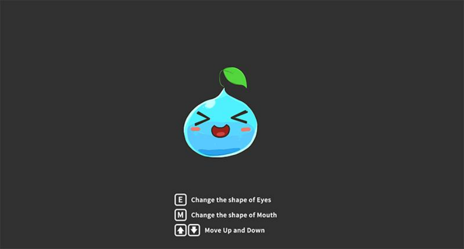
2. Getting Started 1 : The process of making a slime
This tutorial is based on slime image assets included in the package.
Learn the basics of creating meshes by loading images.
You can learn how to use Control Parameters that are the core of AnyPortrait.
You can create interesting results by giving physical effects.
2.1. Starting AnyPortrait and creating apPortrait
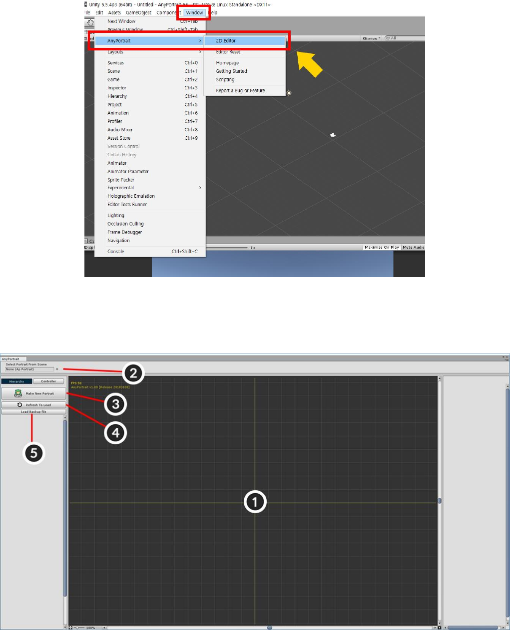
If you installed the package, you can see Window > AnyPortrait in the top menu.
Window> AnyPortrait > 2D Editor to launch the editor.
It is the first screen where AnyPortrait is executed.
1. Workspace : This is where the main tasks are processed in the editor. You can move and zoom the focus by
Scrolling the Mouse Wheel or Clicking the Wheel Button.
2. apPortrait Object : The apPortrait object currently edited. Here you can replace and select apPortrait.
3. Make New Portrait : Create apPortrait.
4. Refresh to Load : Refresh the list of apPortrait present in the scene. After refreshing, the objects that can be
opened at the bottom of the button appear.
5. Load Backup File : Open a backup file and create a new apPortrait.
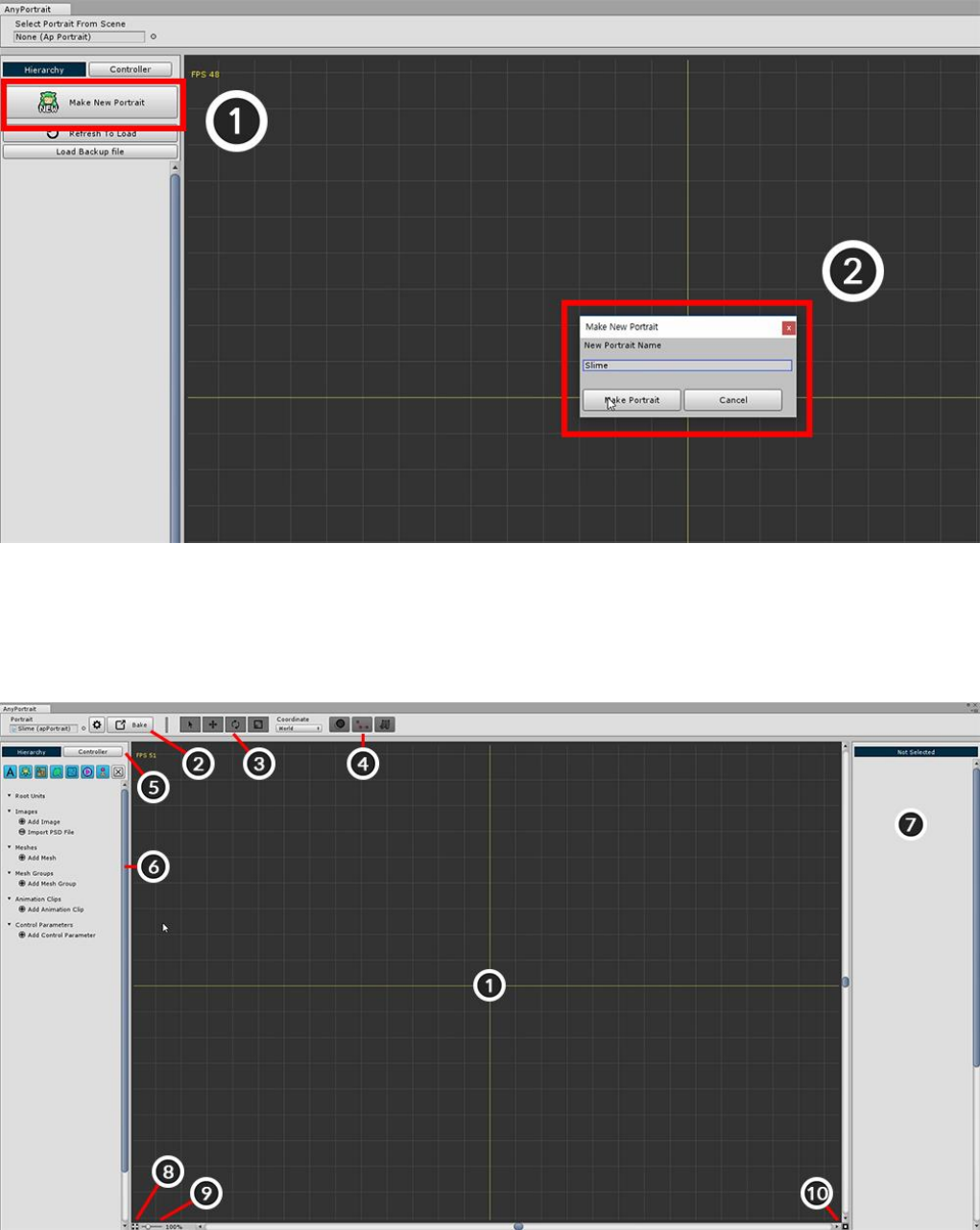
Press the "Make New Portrait" button to create a new apPortrait object. Enter a name in the dialog box.
When you create apPortrait, the UI at the top and left of the screen changes. Each function is as follows.
1. Workspace : This is where major work takes place. You can Zoom (Scroll the mouse wheel) and Move (Drag
the mouse wheel button).
2. Setting, Bake button : Opens a dialog for changing apPortrait and editor settings, or for exporting.
3. Select, Move, Rotate, and Scale tools : These tools are used to modify shapes. The shortcut keys are Q, W, E,
and R.
4. Onion Skin, Bone, and Physics Show / Hide buttons : Determines whether the Onion Skin, Bones, and
Physical Effects are displayed on the screen. The Onion Skin's shortcut is O, and Bone's shortcut is B
5. Hierarchy, Controller tab : Tabs on the left UI. Press "Hierarchy" to see the objects you are working on. Press
"Controller" to see the registered Control Parameters.
6. Hierarchy : This is the UI that appears when "Hierarchy" is selected. Objects are shown by type, and the filter
button at the top allows you to see only certain types of objects.
7. Details UI : Right UI is the area where information of selected object is output. Depending on the selected
object, it may be divided into up to 3 zones.
8. Maximize workspace : Hide the top and left and right UIs and greatly increases the workspace. The shortcut is
Alt+W.
9. Zoom : Specify the zoom of the screen. You can also control using the Mouse Wheel.
10. GUI Reset : Reset screen scrolling and zooming.
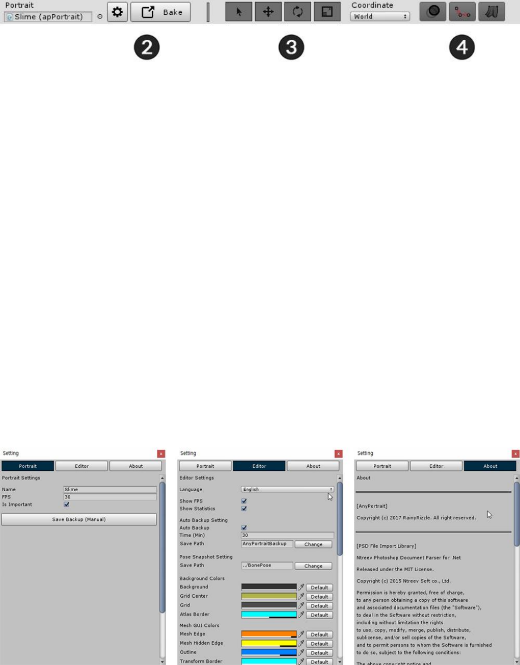
When you press the Setting button, the above dialog box appears.
Here you can rename apPortrait or change the language and color of the editor.
1. Portrait tab : Settings of apPortrait currently being edited.
- Name : Edit the name of the selected apPortrait.
- Important / FPS : If "Important" is on, it will be updated every frame. (FPS is ignored.) Conversely, if
"Important" is off, it will be updated to the specified "FPS" for better performance. It is recommended to turn off
Important if the object is not important in the game.
2. Editor tab : Settings of the editor.
- Language : Languages of the editor are supported. Supports English, Korean, French, German, Spanish,
Danish, Japanese, and Chinese (Traditional / Simplified) based on the release version.
- Show FPS / Statistics : Display the editor's FPS and current Workspace data.
- Auto Backup Setting : Setting of automatic backup. You can specify the save time and path.
- Pose Snapshot Setting : When editing the animation, you can save the posture of the bone. It is the path of
the save file.
- Editor Colors : Setting of GUI colors of the editor. You can return to each default value by pressing the Default
button.
3. About tab : Licenses for AnyPortrait and the external libraries used in the editor are specified.
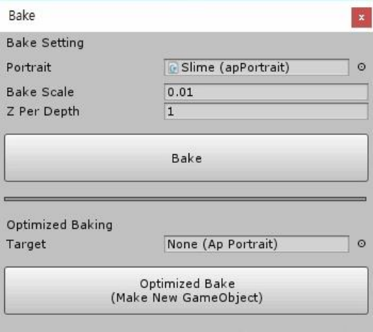
When you press the Bake button, the above dialog box appears.
This function is used to export the results from the AnyPortrait editor to the scene.
1. Portrait : This is the apPortrait to be baked.
2. Bake Scale : The ratio of the size applied to the scene. Because the scene and AnyPortrait's coordinate system
are different, you have to scale them appropriately.
3. Z Per Depth : Set Z distance of each meshes. (A value that is too low can cause a Depth Fighting problem.)
4. Bake button : Export to scene and apply.
5. Optimized Baking Target : This is the target of optimized Bake.
6. Optimized Bake : Bake only the execution data and copy and export optimized objects. Creates a new target if
it does not exist.
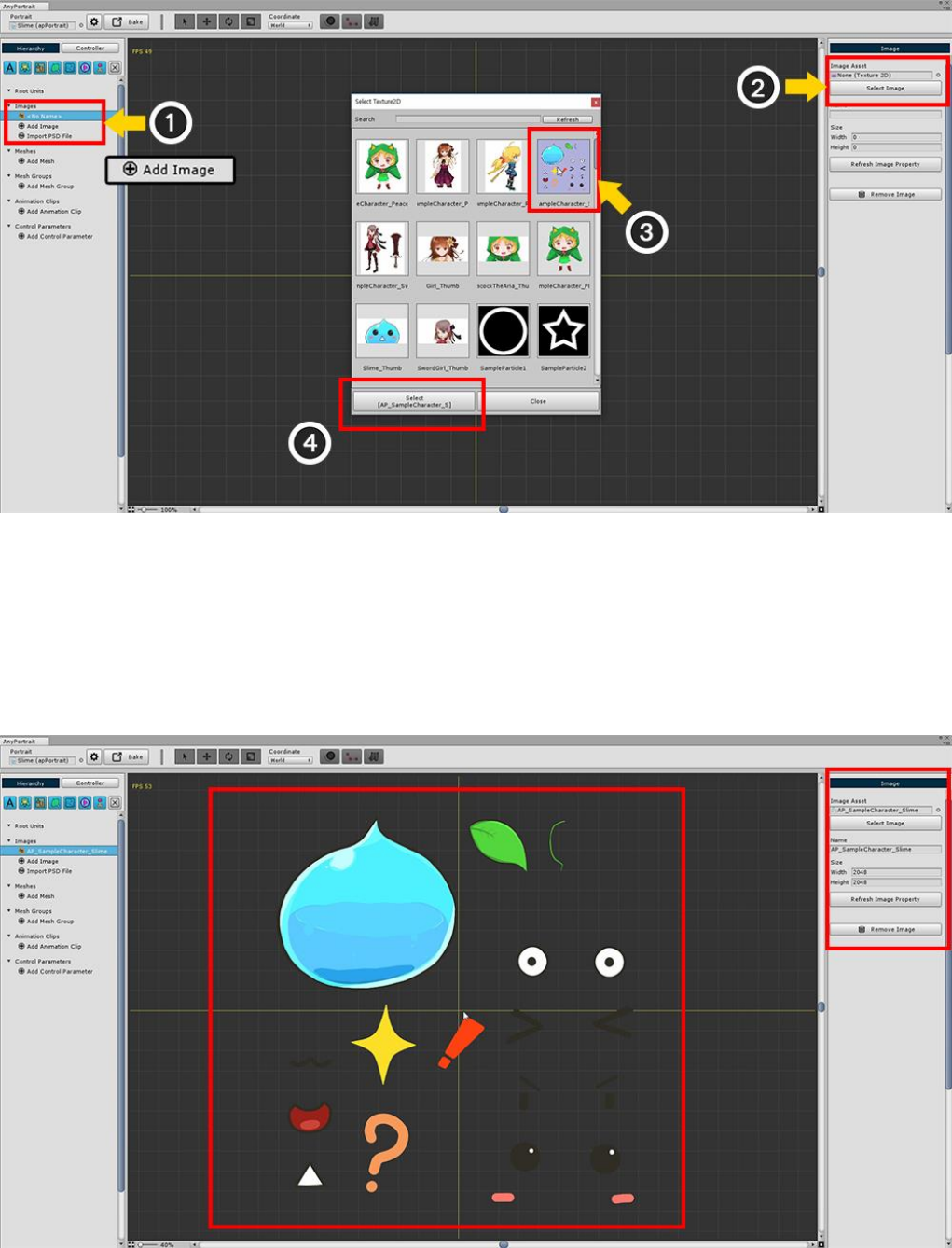
2.2. Adding Images.
In the Hierarchy UI (1) Click the "Add Image" button and select the created image.
If you select an image, nothing is displayed at this time.
You must open and specify an image resource (Texture) from among the assets.
(2) Click the Select Image button to call the image selection dialog.
(3) Select the Slime image included in the AnyPortrait package, and (4) Click the Set Texture button.
When you load an image asset, each item in the details UI on the right is automatically updated.
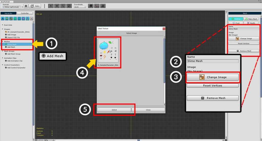
2.3. Creating Meshes
In the Hierarchy UI, (1) Click the "Add Mesh" button and select the generated Mesh.
When you select Mesh, "Setting", "Mesh Edit", "Pivot", "Modify" menu appears on the right screen.
(2) Set the Mesh Name with the Setting menu selected.
(3) Press the "Change Image" button to (4) Select the pre-created image and (5) Press the "Select" button.
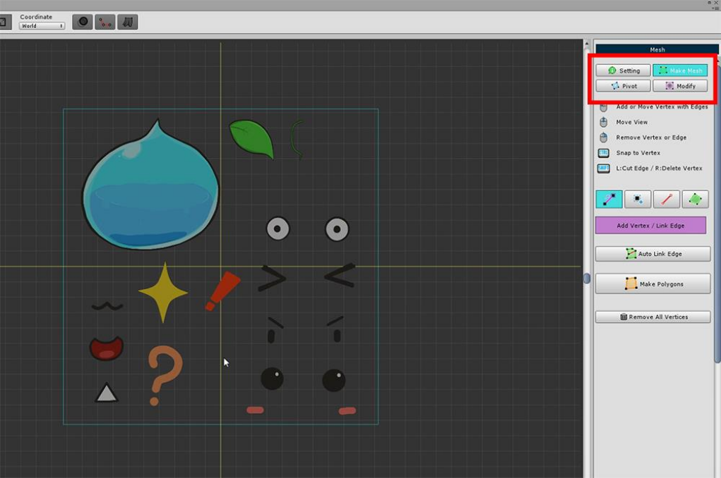
Select the "Mesh Edit" menu in the right side UI.
Mesh can be created using the tools in the "Mesh Edit" menu.
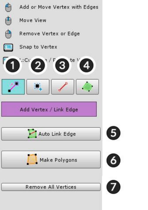
Tools for editing meshes.
Left click to Add or Connect.
Drag to Move a selected object
Right click to delete.
1. Vertex+Edge Tool : Automatically connect segments as you add vertices.
2. Vertex Tool : Add vertices.
3. Edge Tool : Connect or turn edges.
4. Polygon Tool : Select a polygon. You can delete it with the Delete key.
5. Auto Link Edge : Automatically connect edges.
6. Make Polygons : Automatically generate polygons after all the work is done.
7. Remove All Vertices : Delete all vertices.
A detailed explanation of the above functions is as follows.
(In Mac OSX, use the Command key as a shortcut instead of the Control key.)
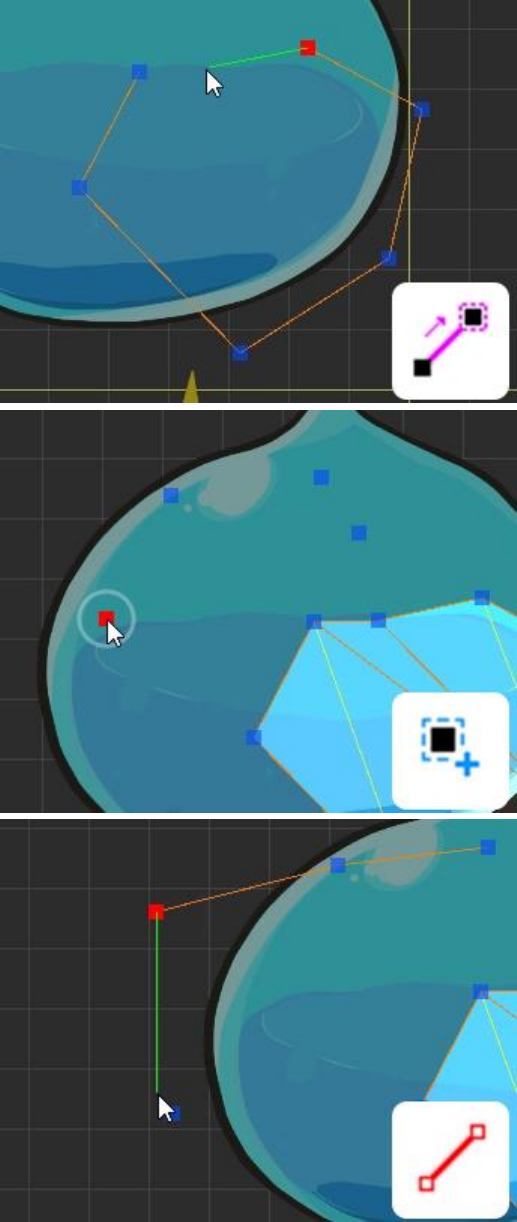
1. Vertex+Edge Tool
Left Click : Add a vertex and connect an edge
Drag : Move a vertex
Right Click : Delete a vertex or an edge
Ctrl + Left Click : Snap to nearest vertex
Shift + Left Click : Create a vertex at intersection
Shift + Right Click : An edge is not deleted when
vertex is deleted
2. Vertex Tool
Left Click : Add a vertex
Drag : Move a vertex
Right Click : Delete a vertex
3. Edge Tool
Left Click : Connect or Turn an edge
Right Click : Delete an edge
Ctrl + Left Click : Snap to nearest vertex
Shift + Left Click : Create a vertex at intersection
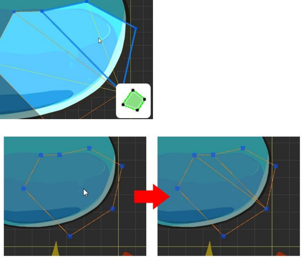
4. Polygon Tool
Left Click : Select a polygon
Delete Key : Delete a selected polygon
5. Auto Link Edge
When you press the button, edges are automatically created and connected.
It does not connect all vertices, it is a feature that makes it easy to make polygons.
Depending on the shape, the connection may be strange. You should check the execution result.
6. Make Polygons
When you press the button, polygon are automatically created according to vertices and edges.
This function must be executed because polygons must be created before rendering.
You can modify vertices even after polygons are created.
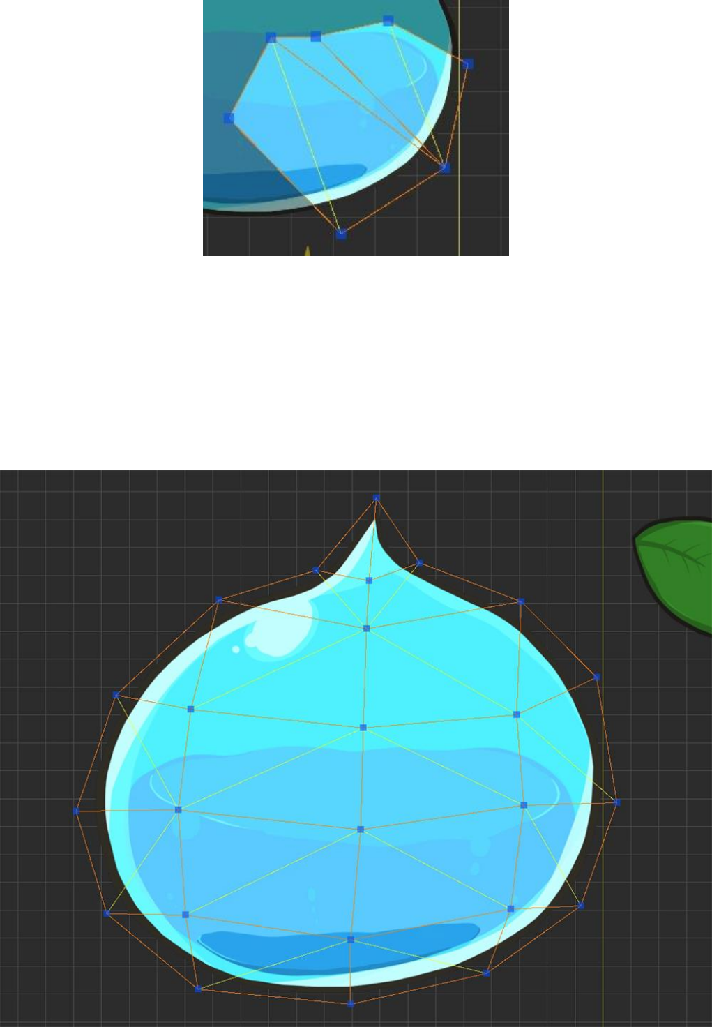
The calculated triangular meshes are represented by yellow lines.
After selecting the Edge tool, click this yellow edge line, then the selected edge will be Turned.
If a problem polygon occurs, you can delete the polygon or delete the vertex and work again.
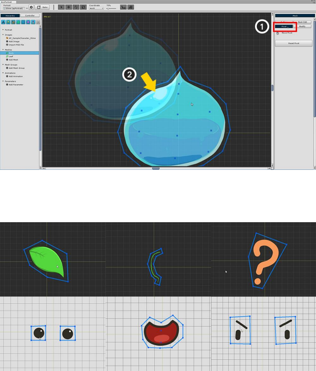
Now you need to modify the Pivot.
In the current state, you can see that the position of the mesh is not the origin.
The Center Point of the mesh is very important, since it becomes the axis when "Rotate" or "Zoom".
Select (1) "Pivot" from the right menu. (If the polygon is not created at this time, nothing will be output.)
(2) Drag the mesh to the center of the grid.
The origin of the grid immediately becomes the center point of the mesh.
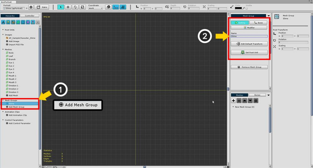
Create meshes for all images in the same way as above.
(If you can not distinguish between background and image, press Setting button to change background color.)
2.4. Creating Mesh Groups
The most central of the various elements of AnyPortrait is Mesh Group.
If you look at the name, it's easy to see "Meshes are together", but adding various functions to the mesh group
can give various effects.
At this time, the added functions are called Modifier.
Depending on what modifier you are adding to the mesh group, bone animation may be added, or morphing
animation may be added.
This section covers the steps before creating a mesh group and adding a modifier.
In the Hierarchy UI (1) Click on the "Add Mesh Group" button and select the mesh group created.
When you select the mesh group, "Setting", "Bone", "Modifier" menu appears on the right screen.
With the Setting menu selected, (2) Write down the name of the Mesh Group (Slime).
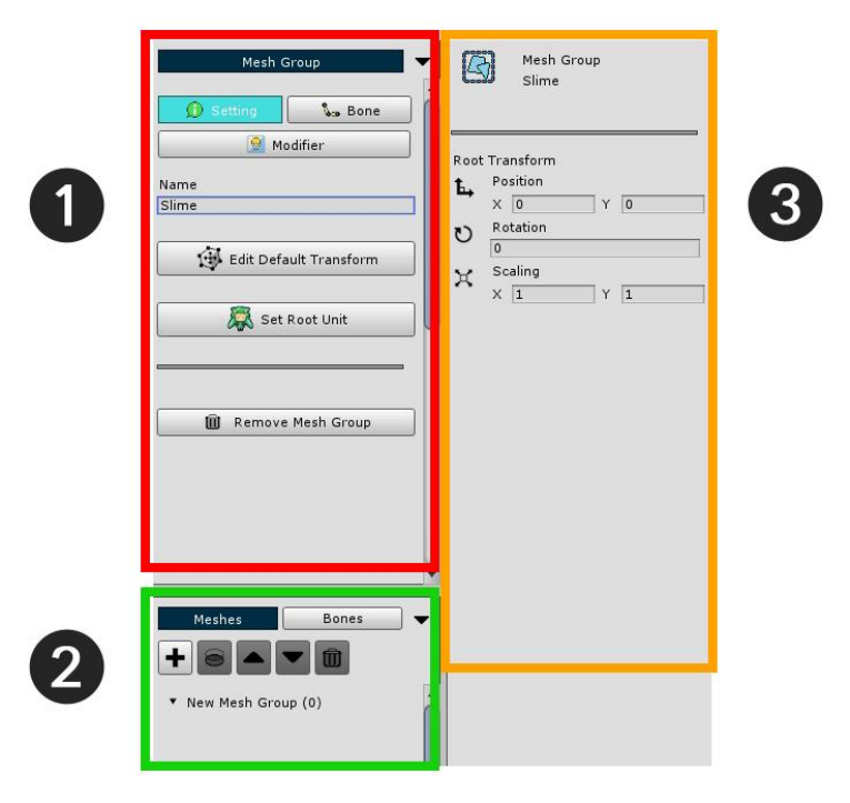
The mesh group detail screen is divided into 3 areas.
1. Main Menu : There are "Setting", "Bone", "Modifier" menus. Displays the default settings or sub menus of each
menu.
2. Sub Mesh / Mesh Group Hierarchy, Bone Hierarchy : Display meshes, mesh groups, or bones of the mesh
group.
3. Object information : The information of the object selected such as an mesh, modifier, bone is displayed.
Now you need to do the basic work of the mesh group.
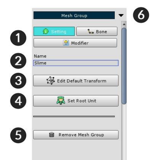
1. Menu tab : There are "Setting", "Bone" and "Modifier" menus.
2. Name : You can edit the name.
3. Edit Default Transform : You can move meshes while this function is enabled. This is a function that specifies
the "default position" of meshes.
4. Set Root Unit : When the button is pressed, the current mesh group is registered as the root unit. Only mesh
groups registered as root units are moved to the scene.
5. Remove Mesh Group : Delete this mesh group.
6. Fold the menu : This minimizes the fold zone.
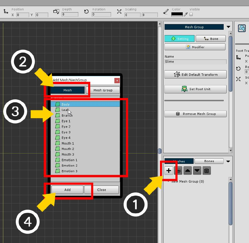
Add meshes to the mesh group.
(1) Press the "+" button to open the dialog to select the target to add.
In this dialog you can add a mesh by selecting them or selecting another mesh group. (2) Click the Mesh tab.
(3) Select a mesh, and Add it by (4) clicking Add button.
One mesh has been added as above. Repeat the above procedure for all meshes.
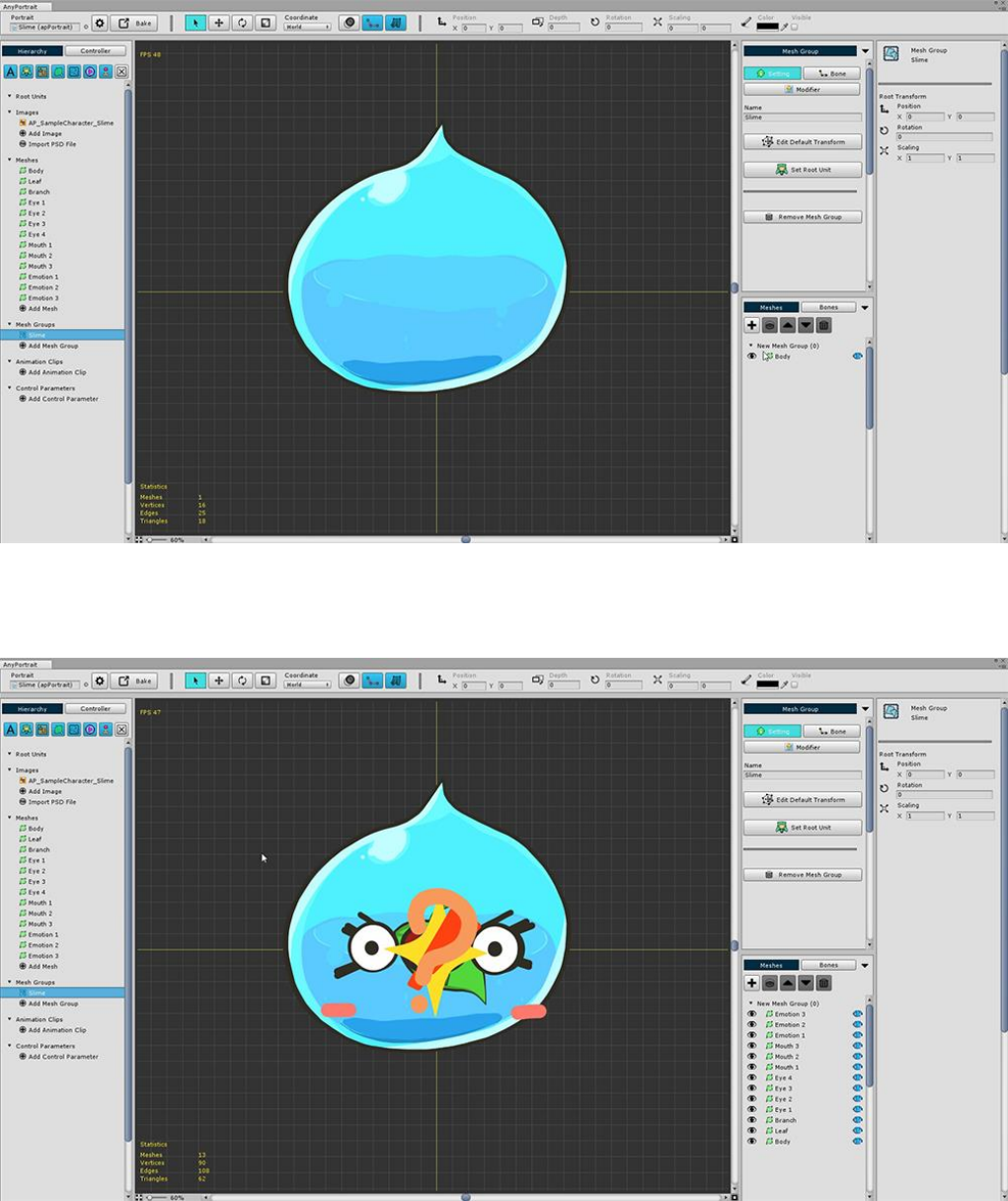
If you add all the meshes, they look like the above.
The shape is not pretty because all the positions are gathered at the origin.
Moreover, it is difficult to distinguish all eyes and mouth shapes because they are printed at once.
You have to modify the default positions of each mesh and try to set Show / Hide as default.
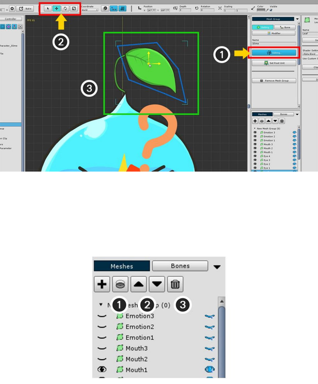
(1) Press the Edit Default Transform button. When the button is pressed, the button turns blue and is activated.
In this state, you can move the mesh / mesh group to get the default shape.
Using the (2) "Select", "Move", "Rotate", and "Scale" tools (shortcut keys Q, W, E, R), (3) Arrange the meshes
in the appropriate positions,
If you need to change the rendering order of registered meshes or need to delete them, you can use the top
menu of Sub Mesh Hierarchy.
1. Clipping to the lower layer : Use the lower layer of the selected layer as a clipping mask.
2. Rendering order Up / Down : Change the rendering order. The rendering order is rendered in front of the
mesh above.
3. Remove selected objects : Remove the added mesh or mesh group.
As you work, the meshes may overlap and may not be visible.
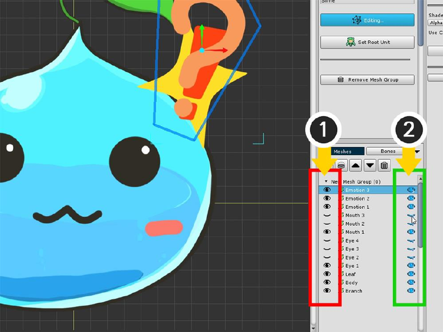
Each item in the Sub Mesh Hierarchy has an eye icon on the left and right of each item.
It is a function that shows or hides each object. (Show / Hide)
However, there is a difference.
(1) The eye-shaped button on the left determines the "Momentary visibility" for the task. It is not a value that
is actually stored.
(2) The eye-shaped button on the right is the "Stored visibility".
The current state in which you are working with the Default Edit Transform determines the "Initial visibility
when there is no modifier".
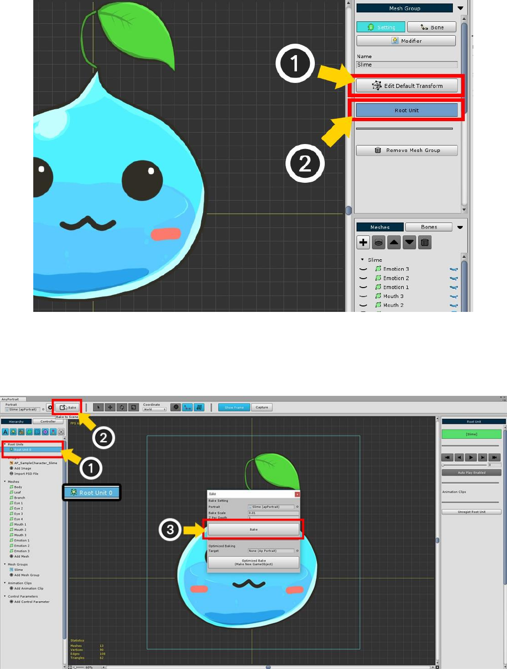
If you have set both the default position of meshes and the default visibility (1) Turn off Edit Default Transform
mode.
Now, set this slime as (2) Root Unit to move to the scene.
If you set it as root unit, you can see that "Root Unit 0" is added to the left UI.
(1) Select "Root Unit 0" and check if the mesh group you just worked on is rendered.
(2) Press the "Bake" button to open the dialog to export to scene.
(3) Press the "Bake" button on the dialog and exit the editor.
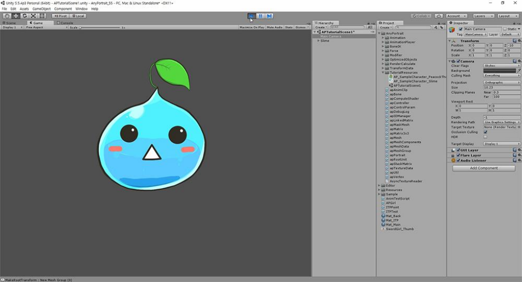
Note :
Bake will export all Root Units to the scene.
Root Unit 0 is shown first and the rest is hidden.
You can replace it with another Root Unit by using script or animation.
You can see the slime applied to the scene.
When you run the game, you will see that the "Show / Hide specified by default" works.
2.5. Adding Control Parameters
There are two ways to control the modifier of a mesh group.
One is to use Control Parameters, and the other is to use Animation Keyframes.
(You can also control the control parameters in the animation.)
Here we learn to add control parameters and use them in the following "modifier step".
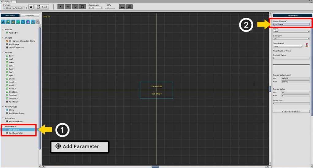
(1) Press the Add Control Parameter to create the control parameter.
After selecting the generated parameter, (2) Specify the name of the parameter.
Now create three parameters: "Eye Shape", "Mouth Shape", and "Vertical Position".
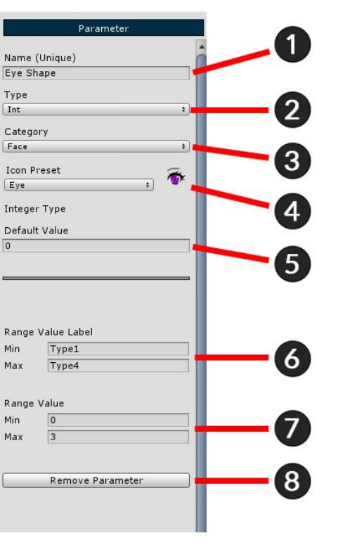
The configuration of the control parameter setting screen is shown on the left.
1. Name : Set the parameter name. Because it serves as an ID that can be controlled by a script, you must enter
a unique value.
2. Type : Set the input type. You can determine either an integer (Int), a floating-point type (Float), or a two-
dimensional vector (Vector2).
3. Category : You can organize the parameters in the UI in the filter. This is the value used at this time.
4. Icon Preset : Set icon to display parameter in UI.
5. Default Value : Specify the default value.
6. Range Value Label : Name corresponding to Min and Max displayed in UI.
7. Range Value : The input range value.
8. Presets : Use pre-created parameter presets or save them as new presets.
9. Remove Control Parameter : Remove this parameter.
Enter values in the Eye Shape parameter as shown in the image above.
- The shape of the eyes has 4 images. Set the Integer type (Int) as the Type value, and enter 0 and 3 so that 4
values are included in the Range Value.
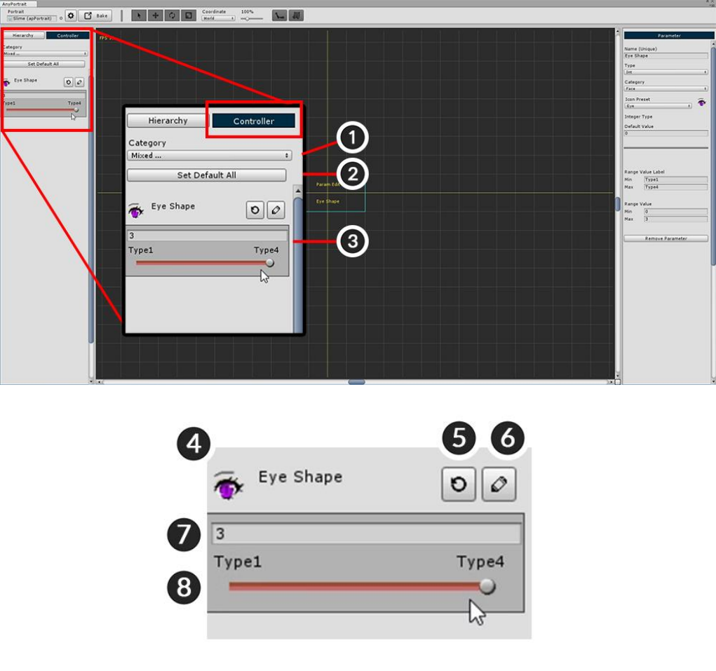
The created control parameters can be checked on the Controller tab in the left-hand UI.
Click the Controller tab to register the Eye Shape parameter you just created.
The configuration on the controller screen is as follows.
1. Category : If you have too many control parameters, you can specify a filter to show only the required
parameters.
2. Set Default All : Restore the values of all parameters to the default. (Settings are not reset.)
3. Control parameters : Area of registered control parameters.
4. Icon and Name : The name and icon specified in Name, Icon Preset are displayed in the above settings.
5. Set Default : Returns the current value of the parameter to the default value. In the above setting, it changes
to the value corresponding to the Default Value.
6. Edit : You can go to the setting screen of the control parameter and edit it immediately.
7. Current value : Current value of the control parameter.
8. Slider : A slider that can be controlled by the mouse. For a two-dimensional vector (Vector2) type, a grid
appears instead of a slider.
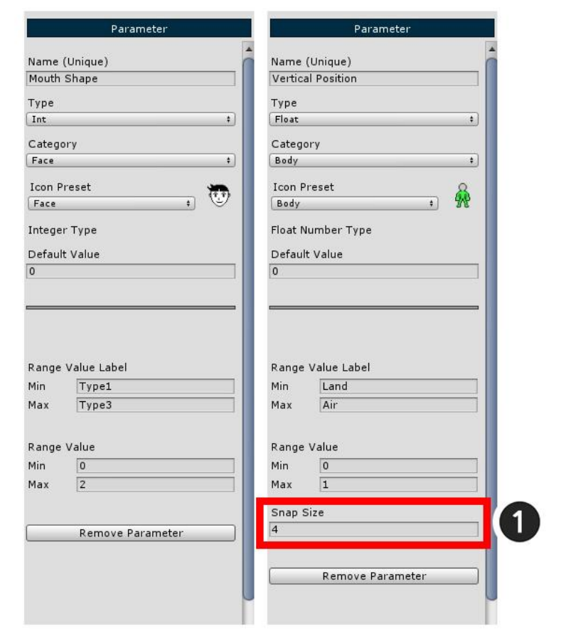
It now also creates control parameters for Mouth Shape and Vertical Position.
Set the two parameters as shown above.
When the type of Vertical Position is specified as Float, (1) Snap Size appears at the bottom of the setting.
Snap Size is a value that determines the number of minutes between Min and Max. Enter 4 here.
2.6. Changing the face with Transform Modifier
Adding the Modifier of the Mesh Group is the most important process of AnyPortrait.
The modifier's working principle is complex, so we will only cover how to add and use it.
Please check the relevant page for the type, characteristics and cautions of the modifier.
On this page, the "Transform (Controller)" modifier is used among the various modifiers.
With the "Transform" modifier, you can change the position, size, etc., or change the color or visibility to
match the control parameters.
Therefore, it is suitable to give effect to change images by replacing images.
It is easy to use as the most basic modifier.
(Note that you can also control the color in the "Morph" modifier.)
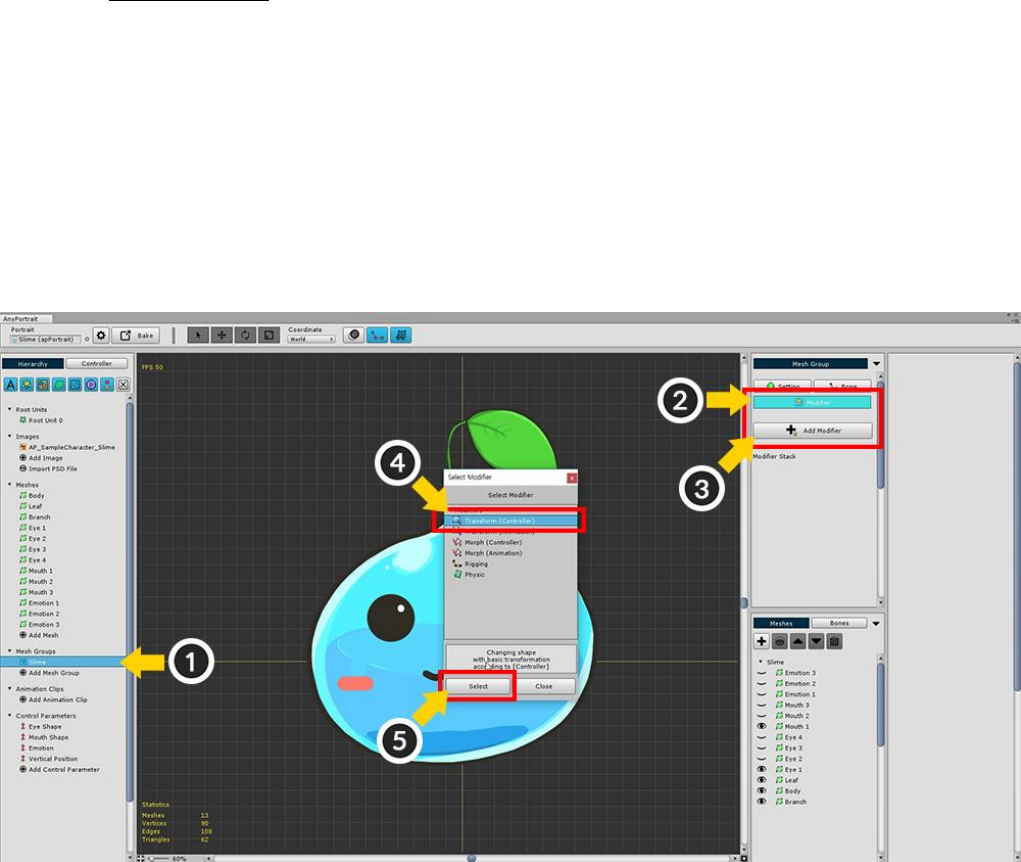
Select the (1) Slime mesh group created on the previous page.
If you (2) Select Modifier menu, you can confirm that no modifier is registered yet.
(3) Press the Add Modifier button to open a dialog that adds a modifier.
(4) Select the "Transform (Controller)" modifier among the various modifiers (5) Press the Select button.
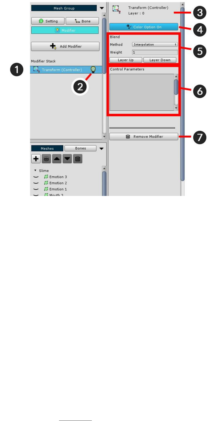
This is the screen you can see after adding a modifier.
(It varies slightly depending on the modifier.)
1. Modifier Stack : Modifiers are calculated sequentially. (The following modifiers are counted first.)
2. Modifier On / Off : You can temporarily disable the modifier during the operation. Click the light bulb icon to
turn On / Off.
3. Selected Modifier : The name, icon, and layer position of the currently selected modifier.
4. Color Option On / Off : The Transform / Morph modifier can control the color value. This button determines
whether or not to control the color value.
5. Modifier Blend : Determines how the modifier blends with other modifiers.
- Method : The method of merging values. Interpolation and Additive are available.
- Weight : The weight when merging values. It has a value between 0 and 1.
- Layer Up / Down : Changes the modifier calculation order.
6. Control Parameters : Display the registered control parameters as input values.
7. Remove Modifier : Removes the selected modifier.
The modifier consists of a combination of "Input key" and "Modified value".
At this time, corresponding to the "Input key" in the current sample is the Control Parameter, and the
"Modified value" is "whether the mesh is colored / rendered".
Therefore, the next task is to select a "Control Parameter as input value" and a "Mesh to be applied modifier"
and register together.
Detailed explanation can be found on related page.
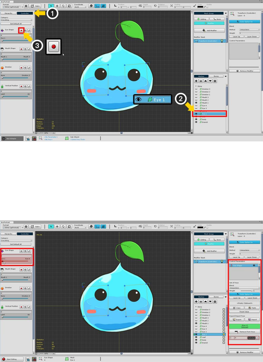
(1) Select the Controller tab.
(2) Select a mesh (Eye1).
With the Controller tab selected, check the Eye Shape parameter you created earlier.
You can see that the Red Recording button appears while selecting the modifier that receives the control
parameter as input value.
(3) Press the Record button of the Eye Shape parameter to register it in the modifier.
This will change the screen as follows.
The background of the Control Parameter changes to red, and the new settings appear in the right-hand UI.
This state is that "Control Parameter + Mesh" is registered in the modifier.
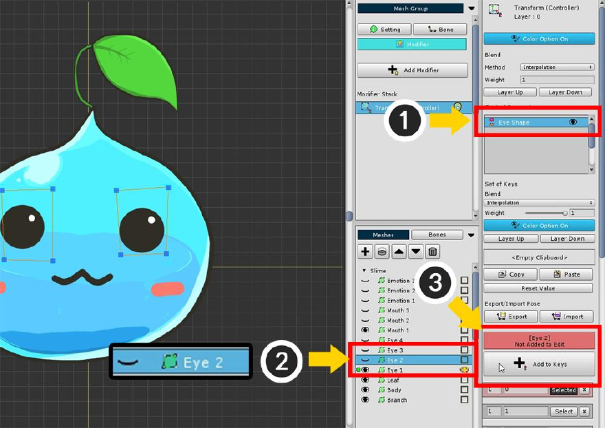
Let's register other "eye-shaped meshes" with the modifier.
(1) Since the "Eye Shape" control parameter is already registered,
(2) Select another eye-shaped mesh (Eye2)
(3) Click the Start Editing button to register.
In the same way, you register all 4 eye-shaped meshes (Eye1, Eye2, Eye3, Eye4).
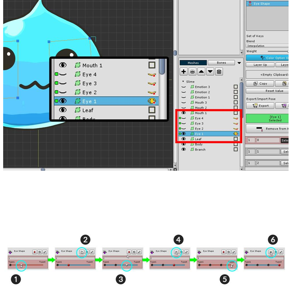
If you have registered all 4 meshes, Green icons will appear as shown above.
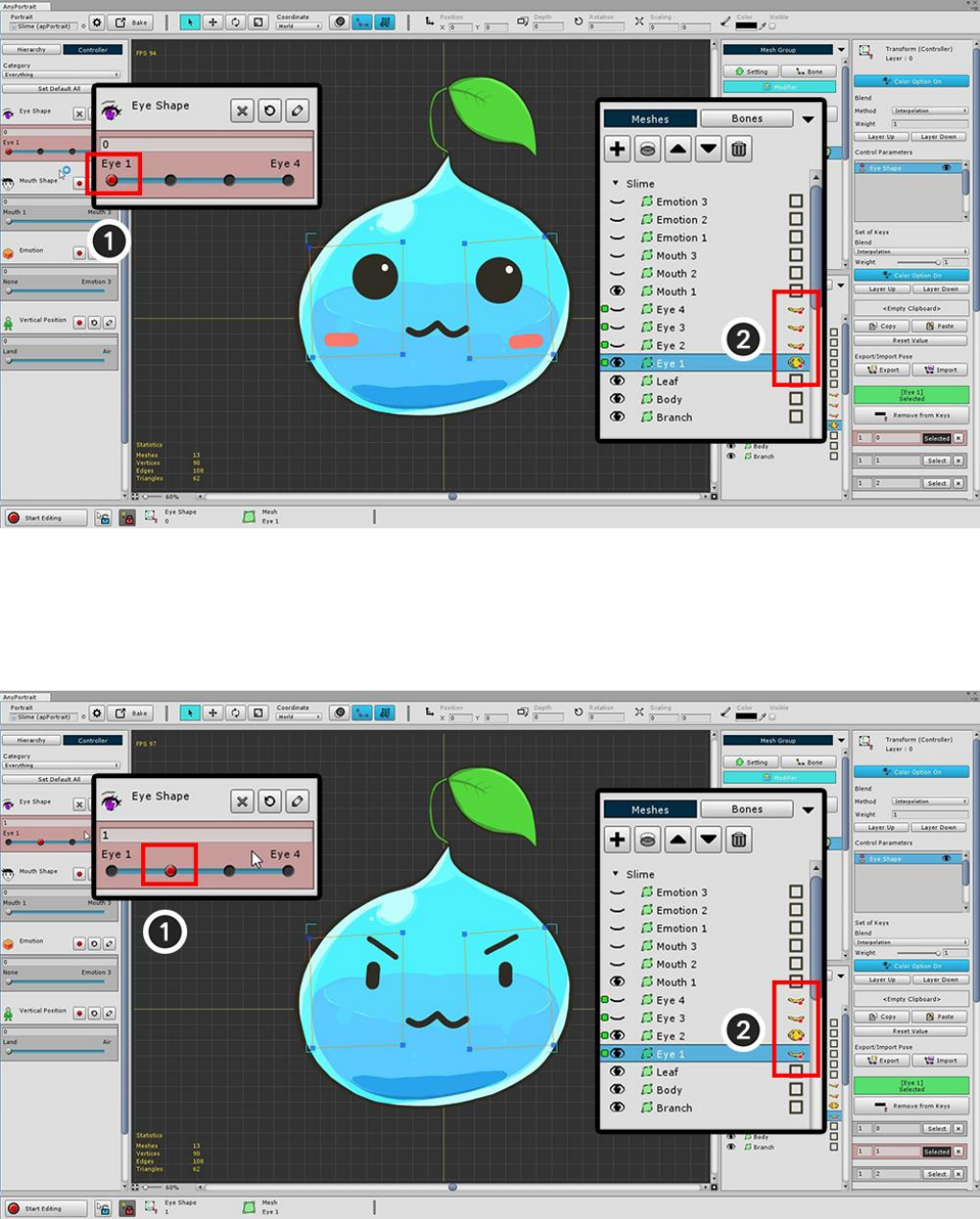
The next task is to actually assign the expression to each value of the control parameter.
When the value of the eye shape parameter is 0, only the Eye1 mesh is displayed,
When the value is 1, only the Eye2 meshes are displayed.
(1) Move the parameter value to 1. The Red Recording button is activated because there is no key at that
position.
(2) Press the Record button to generate the key when "Parameter value = 1".
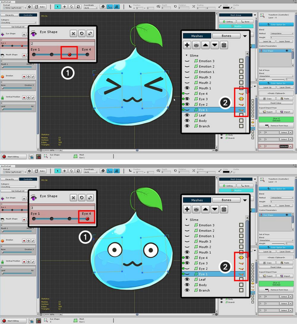
Likewise, (3) move the parameter to 2 and (4) press the record button to generate the key.
(5) and (6), so that a total of four keys are generated.
Visibility of the eye meshes is determined by the four keys of the control parameter.
First, (1) move the Control Parameter back to the first position (key value = 0)
(2) Turn On the yellow eye button of Eye1 mesh and turn off the rest.
Then we work on the second key.
After (1) moving the Control Parameter to the second position (key value = 1)
(2) Turn On the yellow eye button of the Eye2 mesh and turn off the rest.
Work with the remaining two keys in the same way to complete the settings for the four facial expressions.
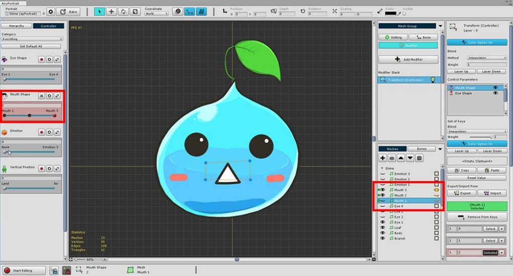
You can also work on the Mouth Shape in the same way as above.
If you have created both eye and mouth expressions, you can test right from the game.
You can run the Bake function, move it to the scene, and test it right in Unity Editor.
2.7. Using Morph Modifier
The Morph Modifier provides the ability to directly deform vertices.
You can do more precise work than the Transform Modifier.
It is mainly used to adjust the appearance of illustrations to make them feel bulky or lively.
This page contains a basic transformation process by adding a Morph Modifier.
To see the tools for editing vertices, go to the next page.
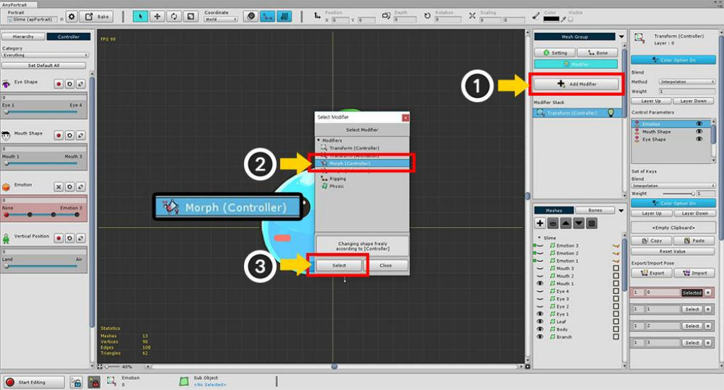
(1) Press the Add Modifier button and (2) select and add the "Morph (Controller)" modifier.
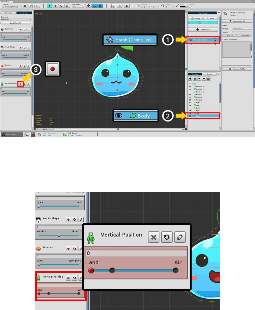
The Morph modifier's working screen is not much different from the Transform modifier's working screen.
(1) Select the Morph (Controller) modifier, and then (2) select "Body" Mesh.
And (3) press the Record button of the Vertical Position parameter.
Add the key to the Control Parameter as you learned earlier.
The right side of the Vertical Position parameter means "slime floating in the air", and the left side will represent
"the slime in the ground".
Add a key to the "0", "0.25", "1" position of each parameter.
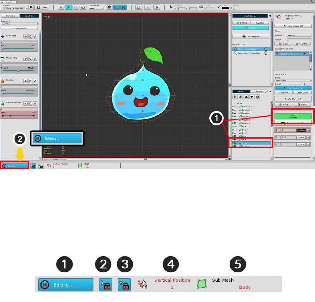
To apply Morph, you need to select the vertex and prepare it for editing.
Currently, you can not select vertices or edit vertices.
This is because editing is possible only in "Editing status".
To edit, (1) Make sure that the target body mesh is registered,
(2) Press "Start Editing" button to make "Editing status".
(If you press the button again, "Editing status" is released.)
At the bottom of the screen there is a UI associated with the "Editing status".
1. Editing button : It is a button to turn on / off the Editing status. If editing is not possible, it will be
automatically turned off. The shortcut is the A key.
2. Selection Lock : You can not select other meshes or bones on the workspace. The shortcut is the S key.
3. Modifier Lock : In the On state, only the modifier in operation is calculated and the rest is turned off. In the
Off state, the calculation is done only for the "non-colliding modifier". The shortcut is the D key.
4. Selected Input Value : The control parameter and key value selected as the current input value. The target
may change depending on the modifier.
5. Selected object : Objects to be processed. This is the "Body" mesh.
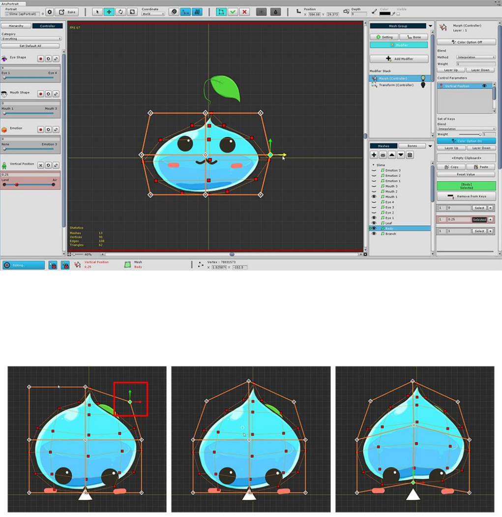
Now let's modify the vertex and use the "Morph" function.
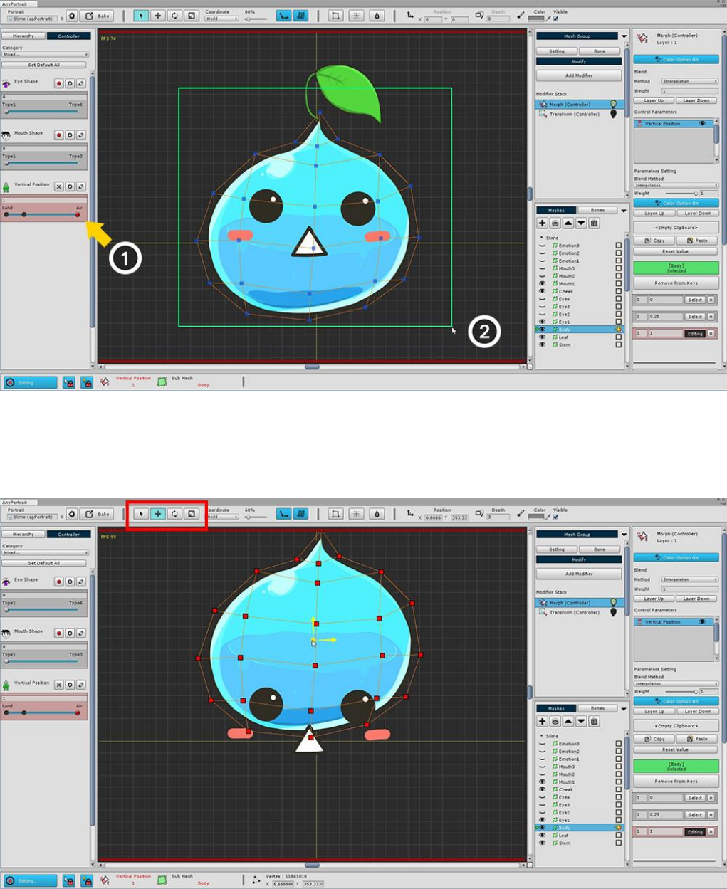
After (1) moving the slider to the key that corresponds to "floating in the air", drag the mouse to (2) select all
the vertices.
Use the Move tool (shortcut W key) to move vertices upward.
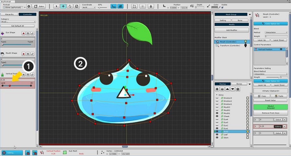
(1) Move the slider to a key with a value of 0.25 and (2) create a "flat slime".
It is easy to create using the Move and Scale tools.
If you have finished all the above steps, you can see the slime going up and down every time you move the
slider
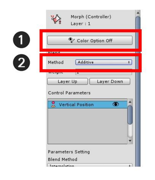
In this sample, the Morph modifier does not control color.
If you do not control the color, turn off the Color Option in Settings to avoid conflict with other modifiers.
(1) Press the Color Option button to turn it off as shown in the above image.
Change the Blend Method from Interpolation to (2) Additive.
If you are merging multiple modifiers, you typically use the Additive method.
If you choose the interpolation method, the value will be overwritten, so use it only for special cases.
2.8. Editing Vertices using various tools
When you use the modifier to edit vertices, you will see some tools to help you work.
You can learn how to use these tools to make things easier.
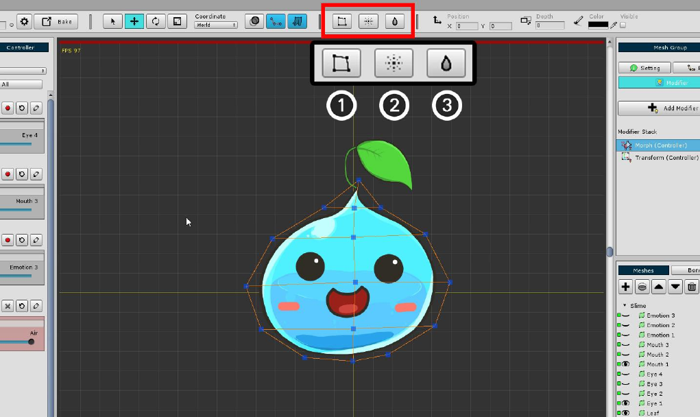
When working with vertices with the Morph modifier, three buttons appear at the top of the screen.
1. FFD : This tool controls the vertex by Free-Form Deformation method. Control points appear to allow you to
edit the shape.
2. Soft Selection : When selecting and editing a vertex, the surrounding vertices are selected and moved
smoothly.
3. Blur : Smoothly interpolates the shape of selected vertices.
< FFD >
When FFD is executed, 9 control points are displayed by default.
This control point can be moved, rotated, and resized as you would with vertex editing.
You can change the shape by moving the control point.
With FFD, it is possible to smoothly deform while keeping a rough shape.
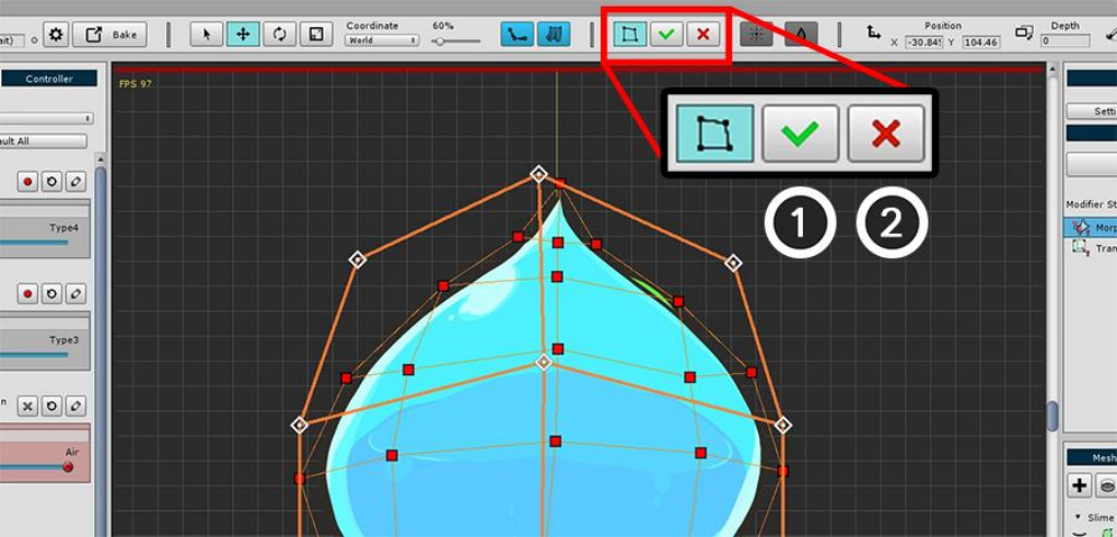
After you have finished working with FFD, you must decide whether to apply or cancel it.
1. Apply : Apply your work.
2. Revert : Ignores the work and reverts.
If you do not complete the FFD and move the control parameters or perform another operation, the FFD
operation history disappears. Please be careful.
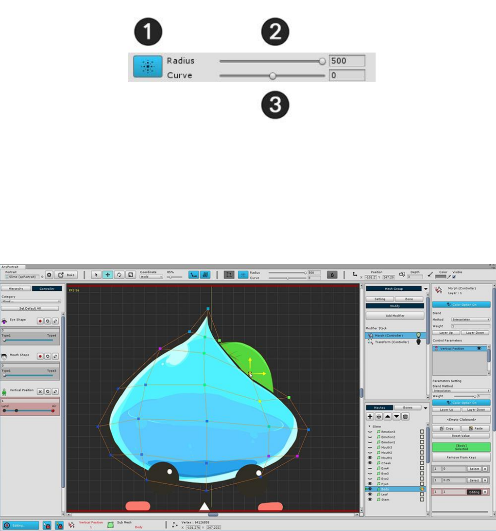
< Soft Selection >
When Soft Selection is executed, the above UI appears.
1. Exit Soft Selection : Exit the active Soft Selection. (Shortcut: Right Click)
2. Radius : Adjusts the selected range. (Shortcut: [, ] key)
3. Curve : The degree to which the surrounding vertices move smoothly.
Soft Selection lets you see which vertices are selected together through the vertex color.
It is also applied to Move, Rotate, and Scale tools so it can be useful when you want to keep smooth shape.
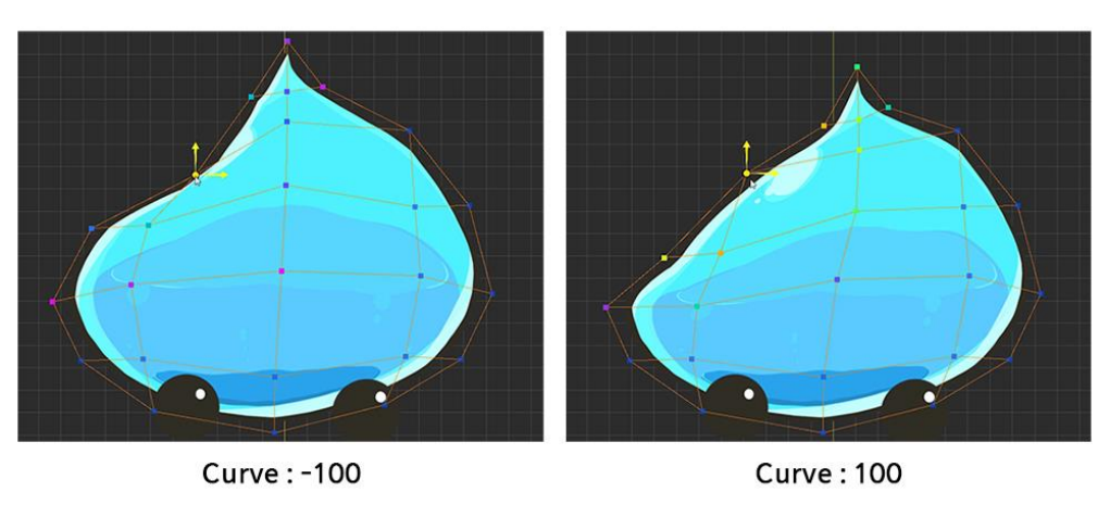
The lower the Curve value, the more intensively the weight near the selected vertex, the higher the Curve value,
the higher the weight is applied to the farther away.
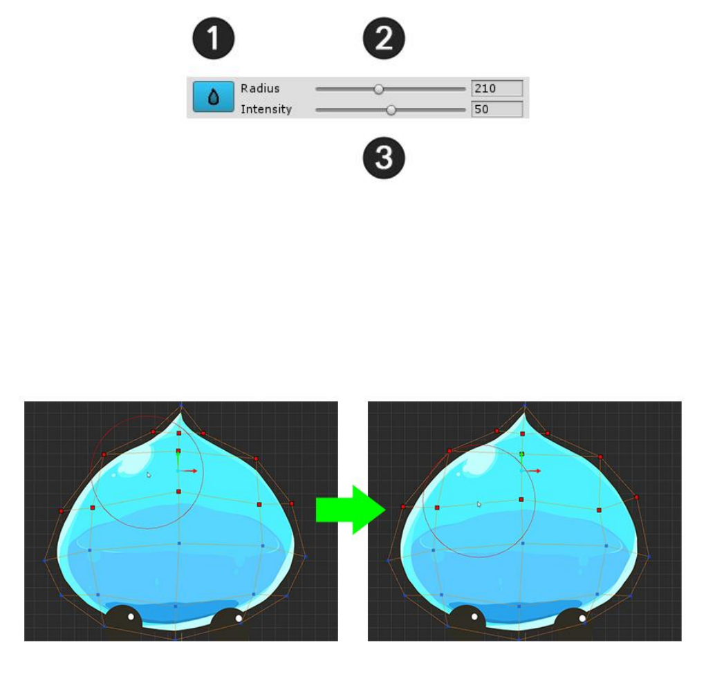
< Blur >
When you run Blur, the above UI appears.
1. Exit Blur : Exit the activated Blur. (Shortcut: Right Click)
2. Radius : Adjusts the selected range. (Shortcut: [, ] key)
3. Intensity : Sets the intensity at which the vertices will change smoothly.
When you run Blur, the Blur area appears around the mouse in a circle.
If you rub it with the mouse, you can see that the deformed values are crumpled similar to the surrounding
values.
The Blur tool is mainly useful when you want to work with the vertex after selecting it.
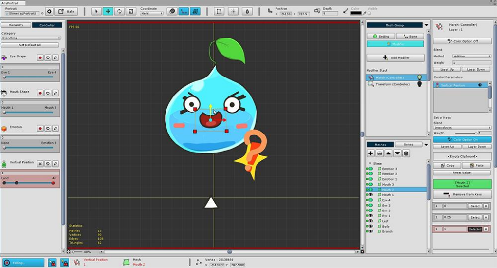
Other meshes can now be modified to accommodate the Vertical Position Control Parameter.
This can be a lot of hands-on work. Please do not burden one by one.
2.9. Adding Physical Effects
There is a modifier that gives a physical effect.
You can add interesting effects by expressing tension and inertia.
To set the physical effects, you need to know the theory and make various settings,
On this page, you will learn how to apply prebuilt physical materials to make them easier to apply.
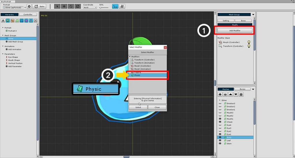
Add a Physic modifier.
Before you set up a physical effect, make sure that no physical effects are applied in the workspace.
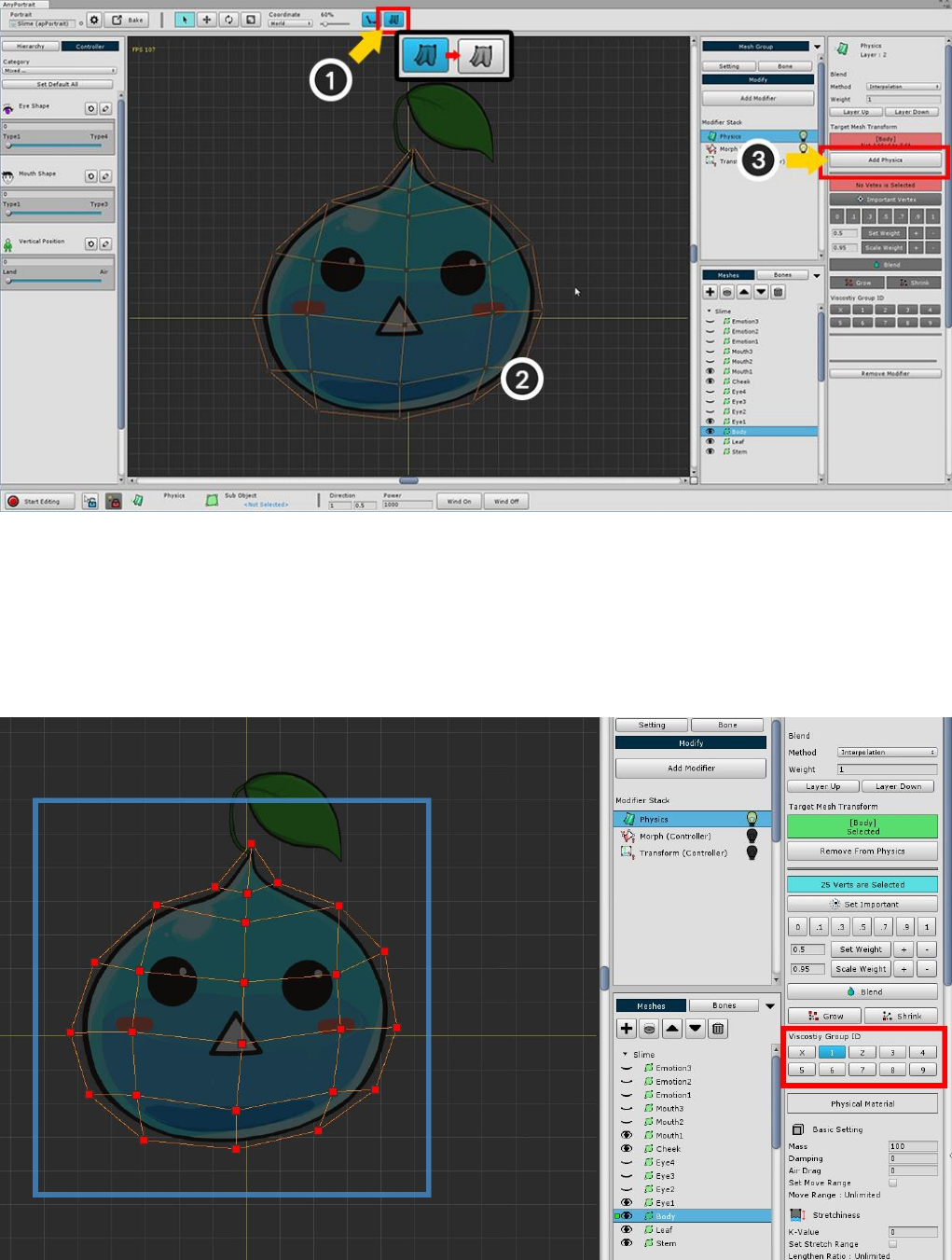
You can (1) turn on / off the physics effect setting at the top of the screen.
(2) Select the slime body mesh (3) Press the Add to Physics button.
Before setting the physical material, Select all vertices and set the ID of the Viscosity Group to 1.
This is because viscous forces are applied between the vertices sharing the viscous group ID.
Setting physical materials is a difficult task.
At this stage, we will select a pre-created preset.
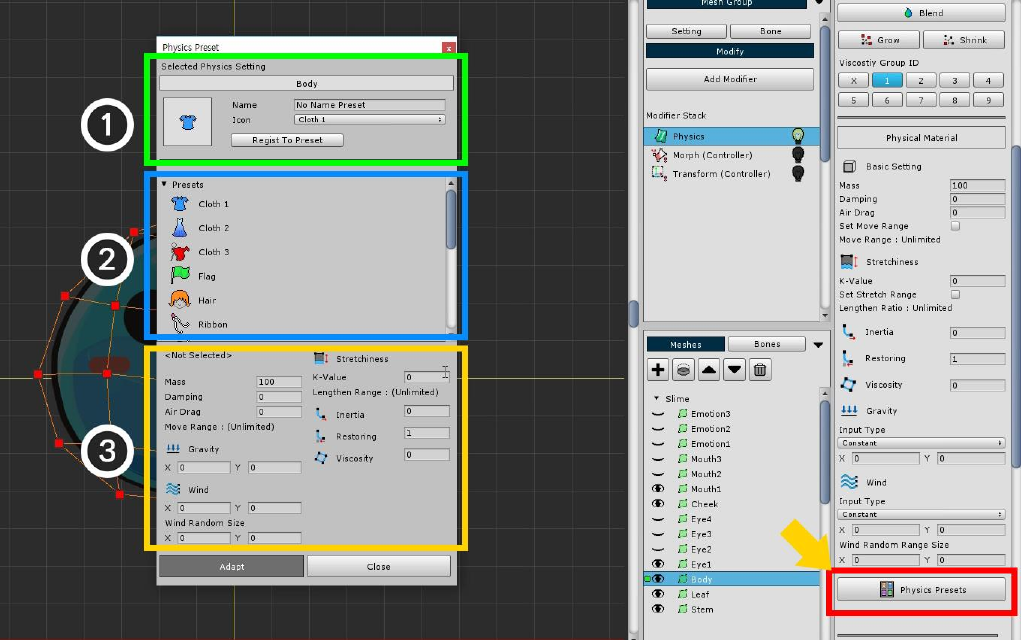
The Physics Presets button is on the right side of the UI. Click it to open the Physical Preset dialog.
The screen configuration of the physical preset dialog box is as follows.
1. Save current physical setting as preset : Save the physical setting value of the selected mesh as a preset. You
can specify and save names and icons.
2. Physical Presets : These are the physical presets created by default or added by the user.
3. Selected Physical Preset Values : Detailed setting of the selected physical preset. It can not be modified here,
and any user-added presets can be deleted.
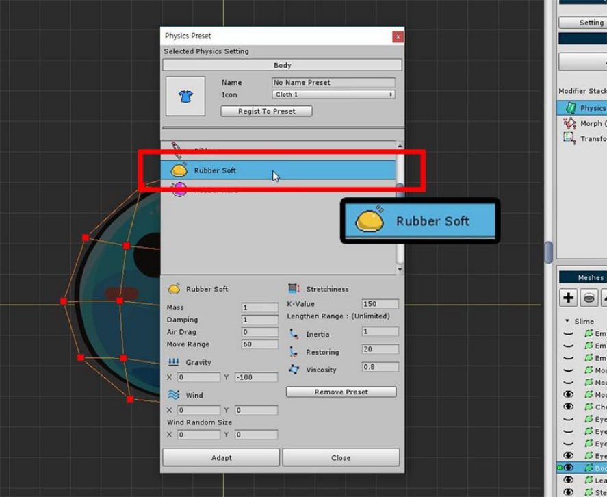
Apply the "Rubber Soft" material, which is similar to the slime material.
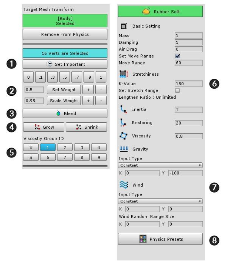
When physical material is applied, it is set as the above screen.
This page briefly describes the screen configuration only.
1. Set Important : The physics effect is applied around the vertex to which the setting is applied.
2. Weighting tools : These are the tools that specify how much you want to receive the physical effects. It has a
value between 0 and 1.
3. Blend : This is a function that smoothes the weight based on the weight of the vertex.
4. Grow / Shrink : Select or exclude more vertices.
5. Viscosity group ID : Specify the viscosity ID for viscosity calculation. It has a value from 1 to 9 and can have
multiple values.
6. Physical material settings : Value of physical material. Mass, air resistance, tension, inertia, resilience, and
viscosity.
7. Gravity and Wind : Gravity and wind can be set. You can specify a fixed value or use the value of a control
parameter.
8. Physics Presets : Presets can be opened or saved by opening preset physical preset dialogs.
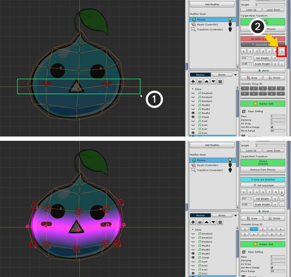
(1) Select the vertices in the center, (2) Set the weight to 1.
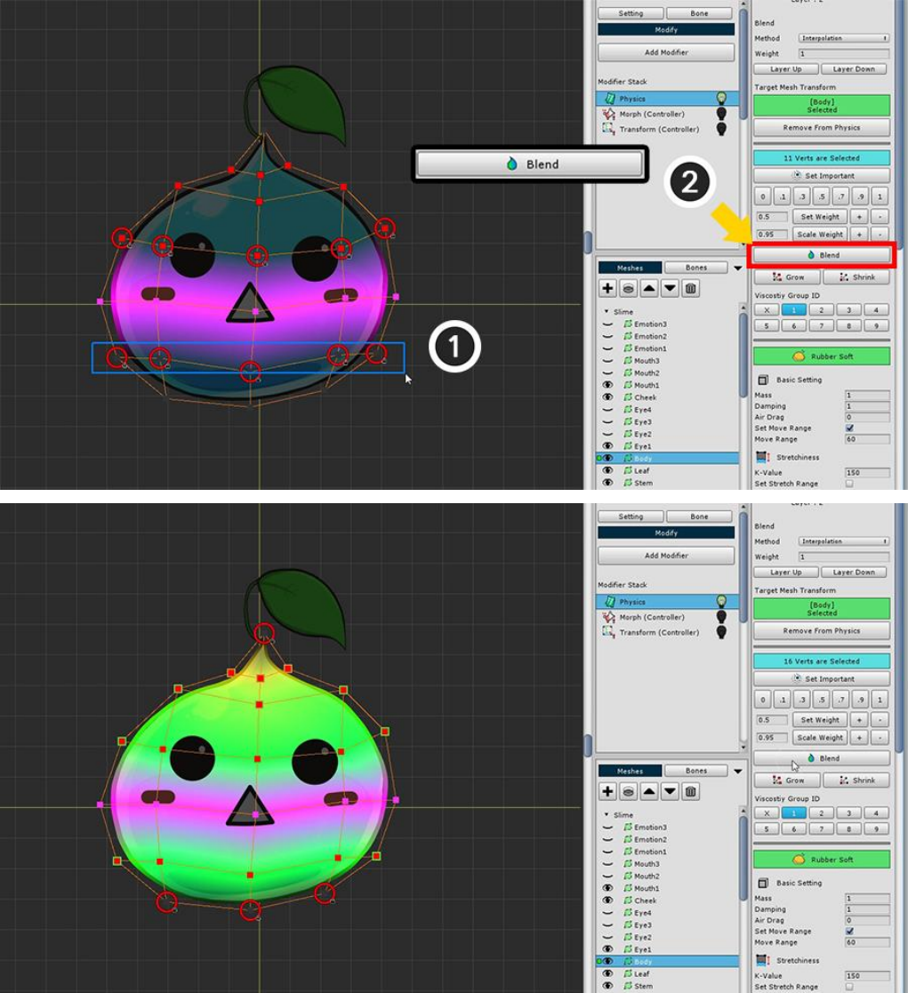
(1) Select the remaining vertices except the upper and lower endpoints.
(2) Press the Blend button several times to set the weight appropriately.
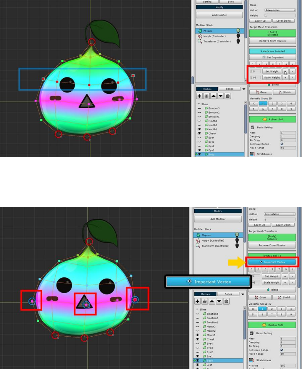
If the weight is too small or too large, you can increase or decrease it using the weighting tool.
Select some vertices in the middle and press the Set Important button.
Physical effects occur around vertices with the "Important" setting.
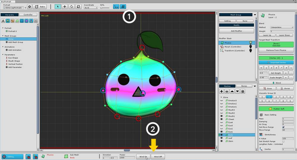
Let's see if the set physical effect works properly.
(1) Turn on the physical effects again and see if they work properly.
(2) There is a Wind On / Off buttons for the physical test at the bottom of the screen. Let's test it by pressing
it.
2.10. Creating a Thumbnail
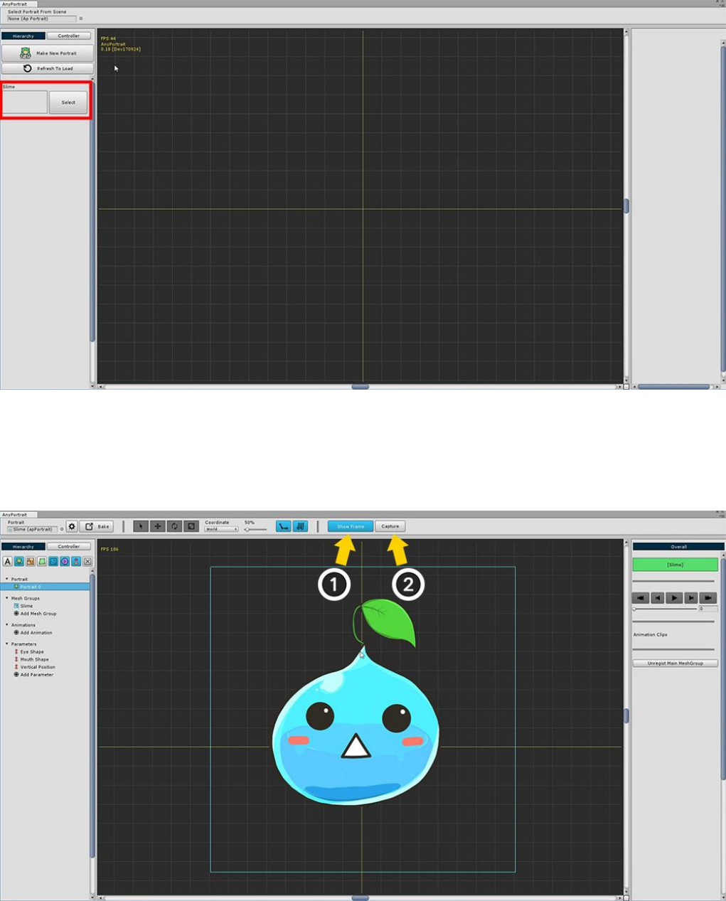
When you launch AnyPortrait, you will see the selectable apPortrait objects on the left side of the screen.
However, the name alone is inconvenient to distinguish.
If the thumbnails are displayed together, it will be convenient to distinguish them.
When Root Unit 0 is selected, there are Show Frame button and Capture button at the top of the screen.
(1) Press Show Frame to show the capture area, and then the screen will come into the capture area.
(2) Press the Capture button to open the dialog box.
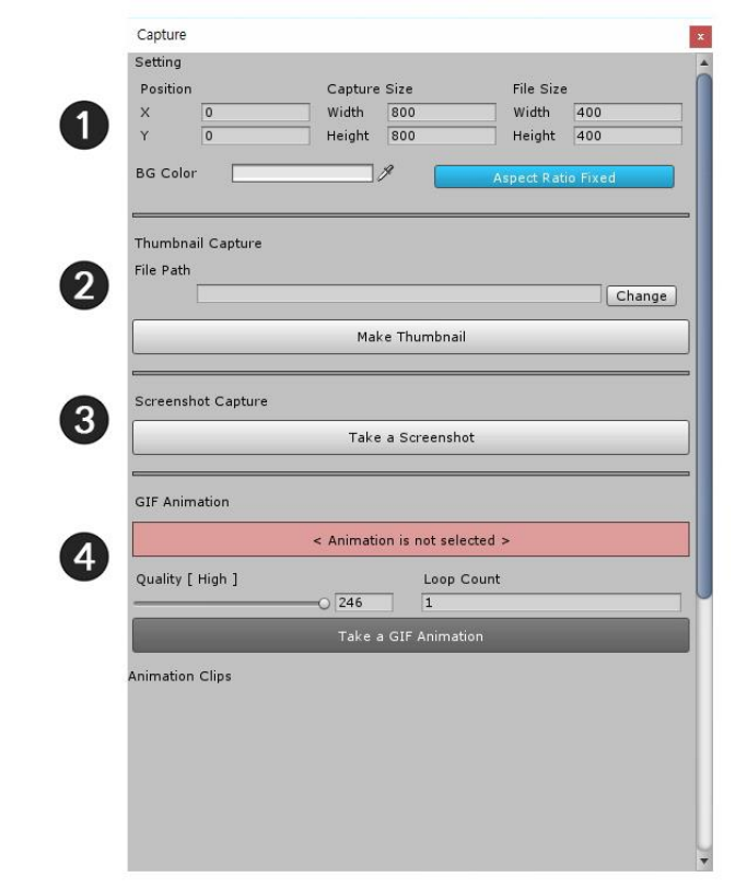
It is the Capture dialog.
This page only covers thumbnails, but there are many more.
1. Frame setting : This area is used to set the capture area. Set the area to be captured, the size actually saved
as a file, and the background color. (Thumbnails are not affected by frame size.)
2. Thumbnail capture : This area is used to create a thumbnail.
3. Capture Screenshot : Take a screenshot right from the capture area and export it to an image file.
4. Save Animated GIF : Select the animation and save it as "Animated GIF file". Specify quality and number of
repetitions and save.
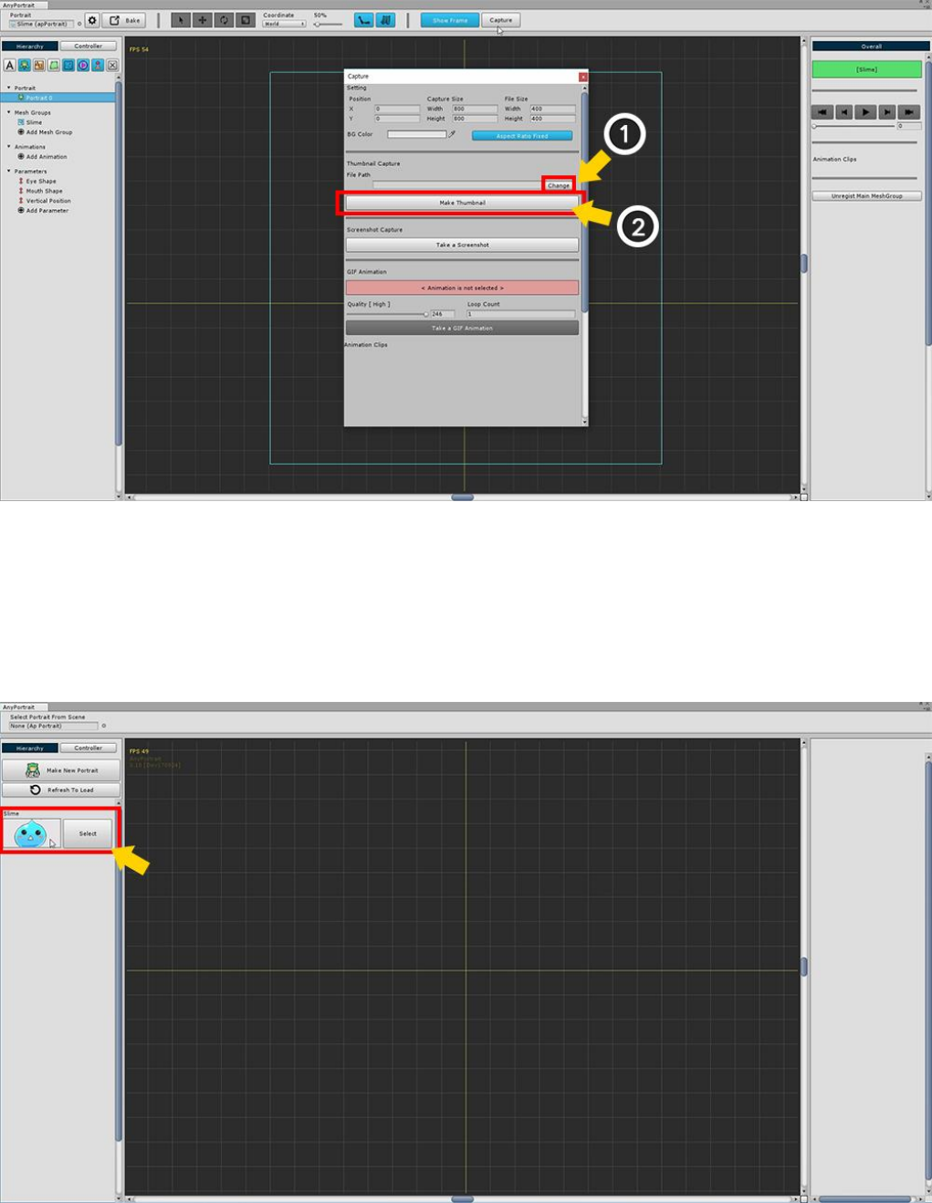
(1) Press the Change button to set the path to save the thumbnail image.
Since the image file is managed as an asset, it must be stored within "Assets/" folder.
(2) Press the Make a Thumbnail button to save the thumbnail.
When you open the editor again, you can see that the created thumbnail has been applied.
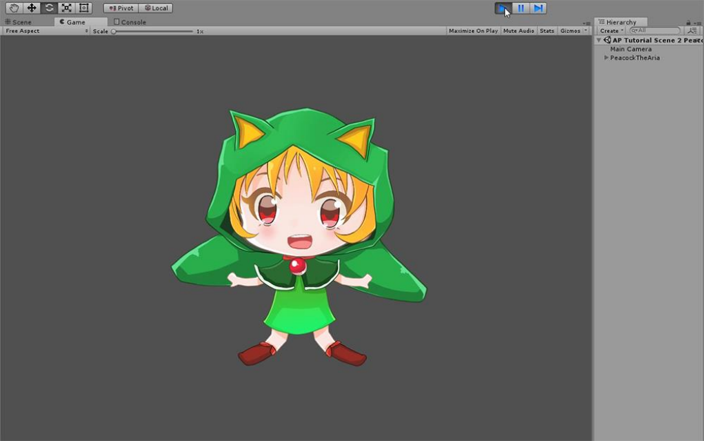
3. Getting Started 2 : The process of making a character
This tutorial is based on the SD character image included in the package.
You will learn how to easily create mesh groups by opening the PSD file.
Learn how to add bones and create an animation.
3.1. Import the PSD file
Most of the illustrations exist as files with layer information.
AnyPortrait provides the ability to create mesh groups at once using layer information.
With the images included in the tutorial package, Let's open the PSD file and start working on it.
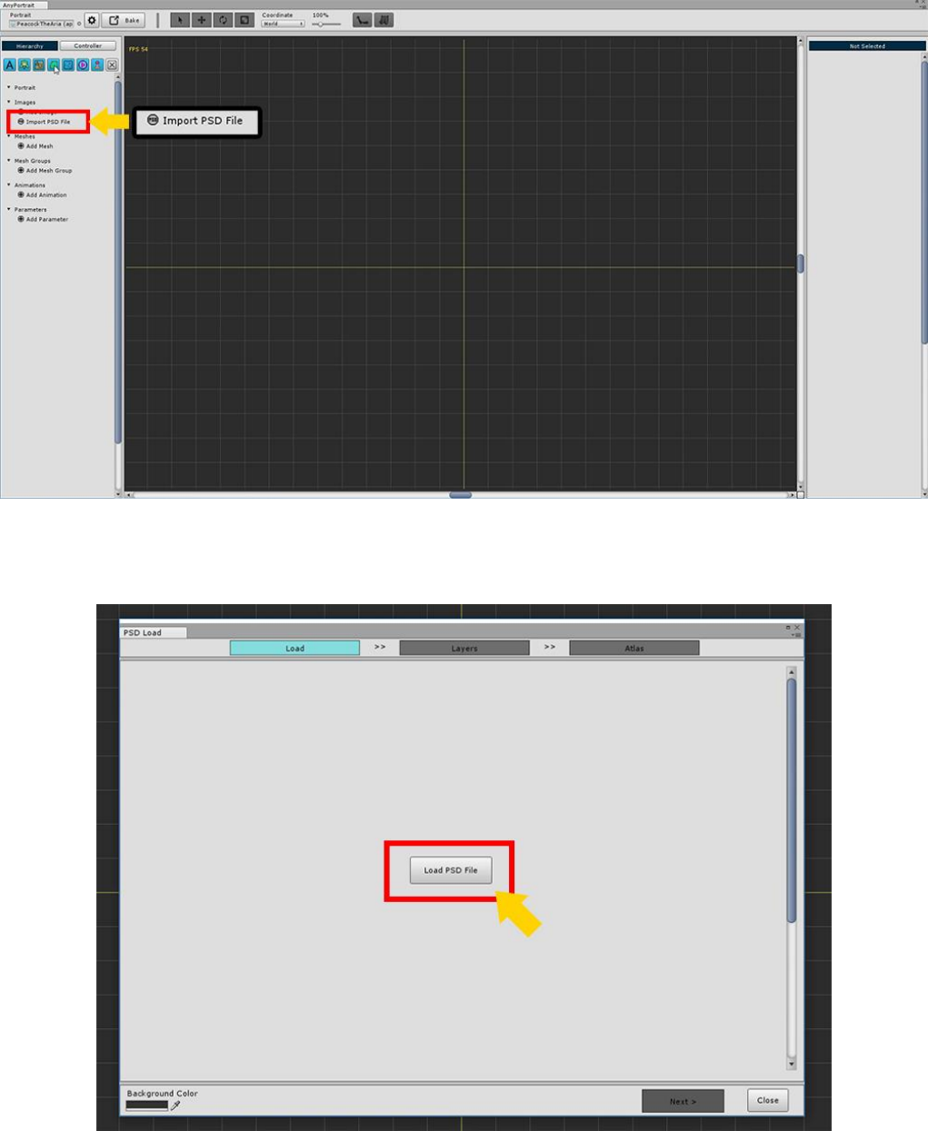
Create a new apPortrait and press the Import PSD File button.
Press the Load PSD File button on the first page.
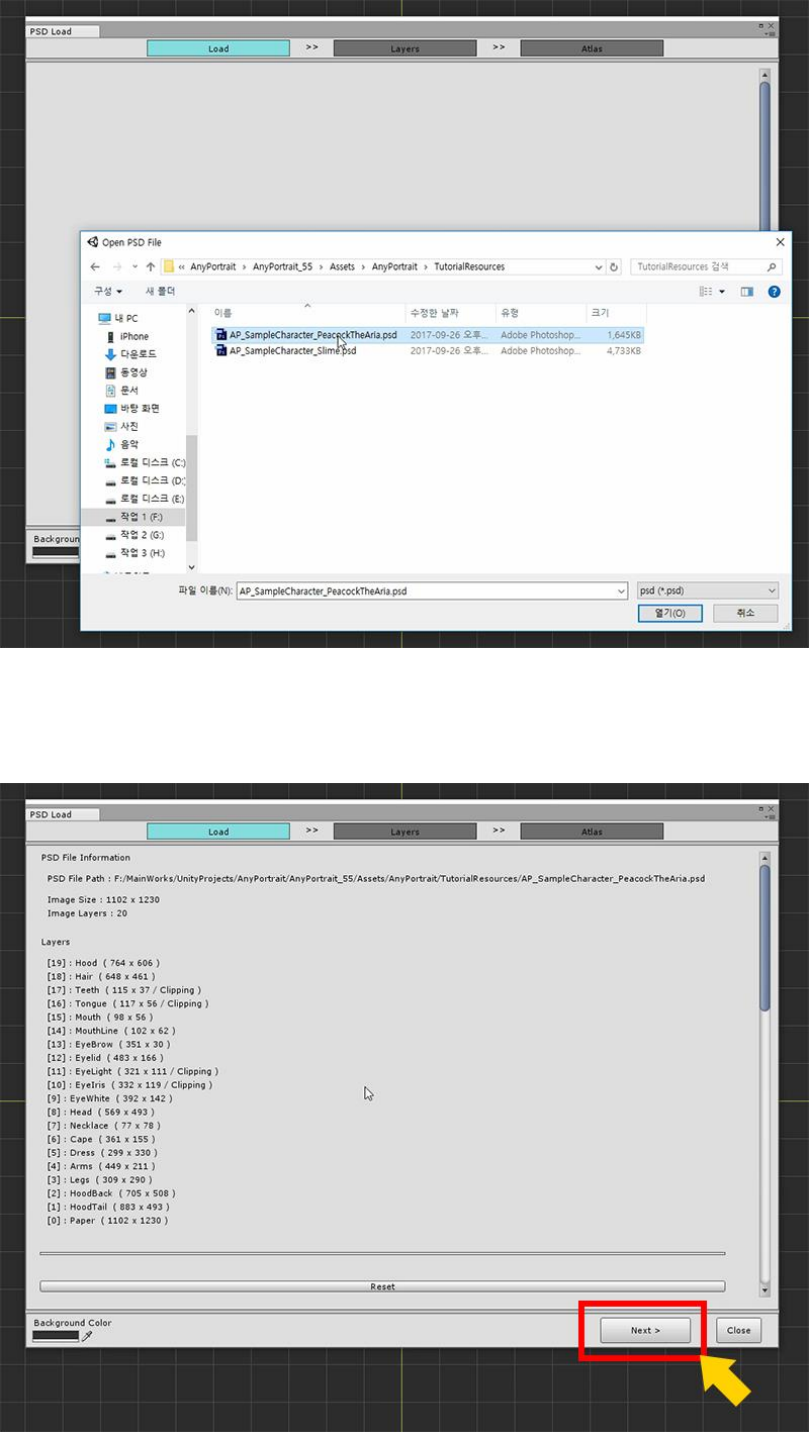
Select and open the AP_SampleCharacter_PeacockTheArea.psd file provided by the package.
(The PSD file path does not have to be in the Assets folder.)
Make sure the file is open normally and click the Next button.
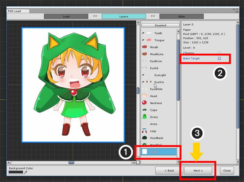
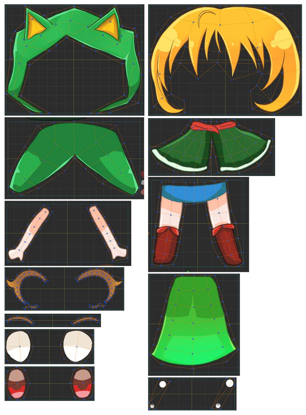
Go to the second page, "Layers" page, and the loaded layer images will appear.
You should exclude layers that are not needed here.
(1) Select the Paper layer, and (2) Release Bake Target.
When all settings are completed (3) Press the Next button to proceed to the next page.
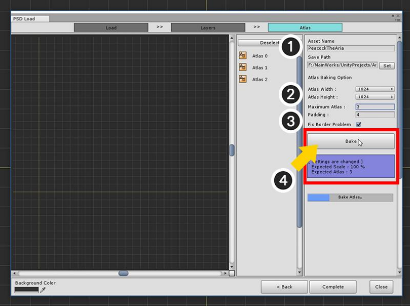
Now it is the process of making PSD files into several images and making them into assets. We call it Bake here.
(1) Specify the name of the image file and set the path to save as an asset. (Set the path to the Set button.)
(2) Set the size of the image Atlas. 1024 or 2048 is recommended.
(3) Determine the maximum number of Atlas to be bake. If you specify a small number, the whole will be shrunk
to become Bake.
Set Padding and set Fix Border Problem. (Checking the Fix Border Problem solves the problem with translucent
colors that appear at the edges.)
(4) Press the Bake button to create Atlas.
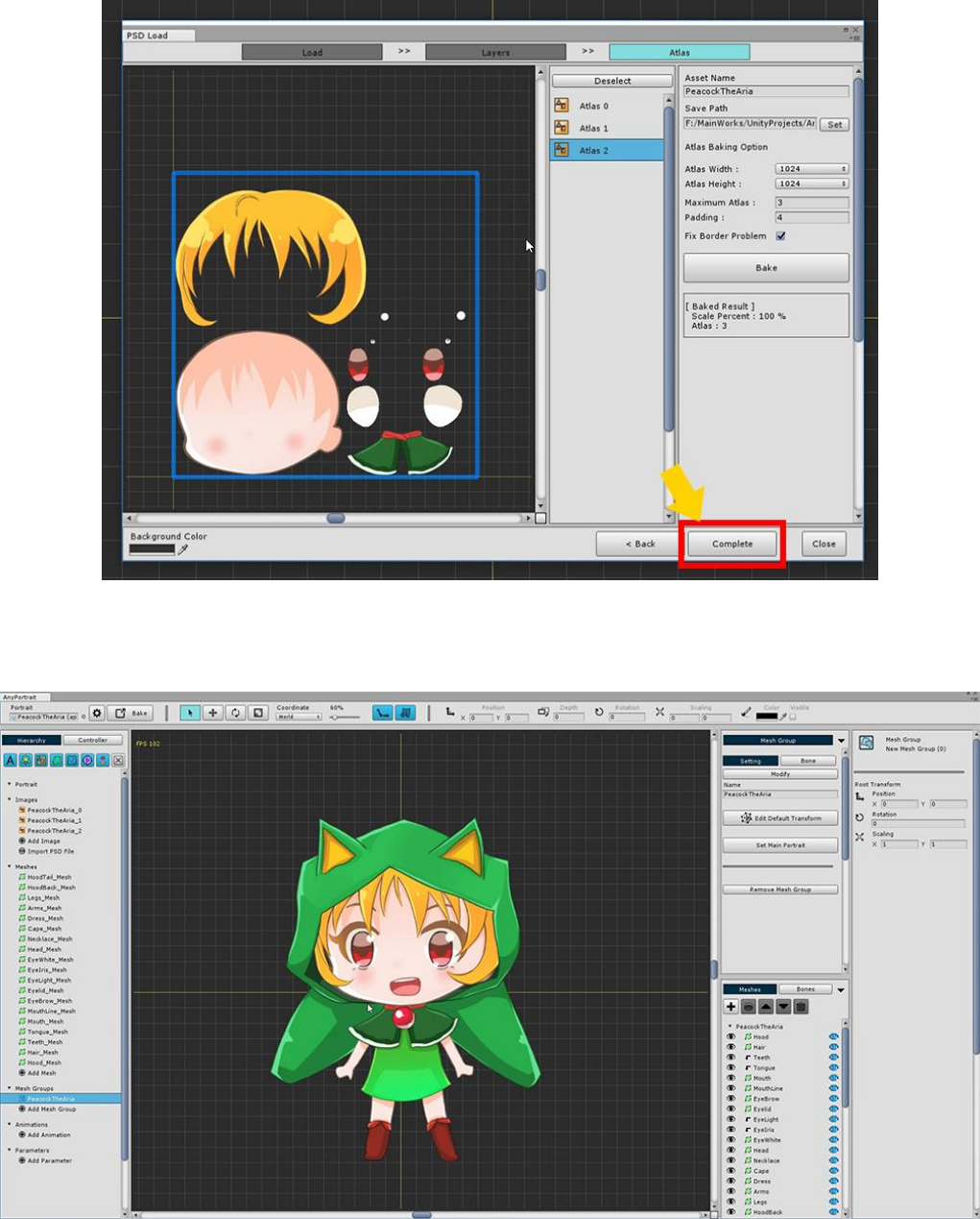
When the Atlas is created, press the Complete button.
You can see that all images, meshes, and mesh groups are created automatically.
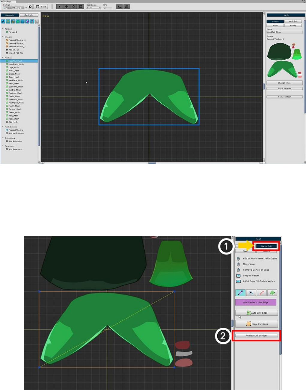
3.2. Edit meshes for Bone Animation
It is very convenient to automatically create mesh and mesh groups when you open a PSD file to create a mesh
group,
When you open the mesh, you can see it consists of a simple square mesh.
This is all it takes to simply move the image fragment like a "puppet",
In this tutorial, you need to refine the mesh for this animation.
To delete the square mesh and add vertices (1) Enter the "Mesh Edit" menu.
(2) Click the Remove All Vertices button to delete all vertices.
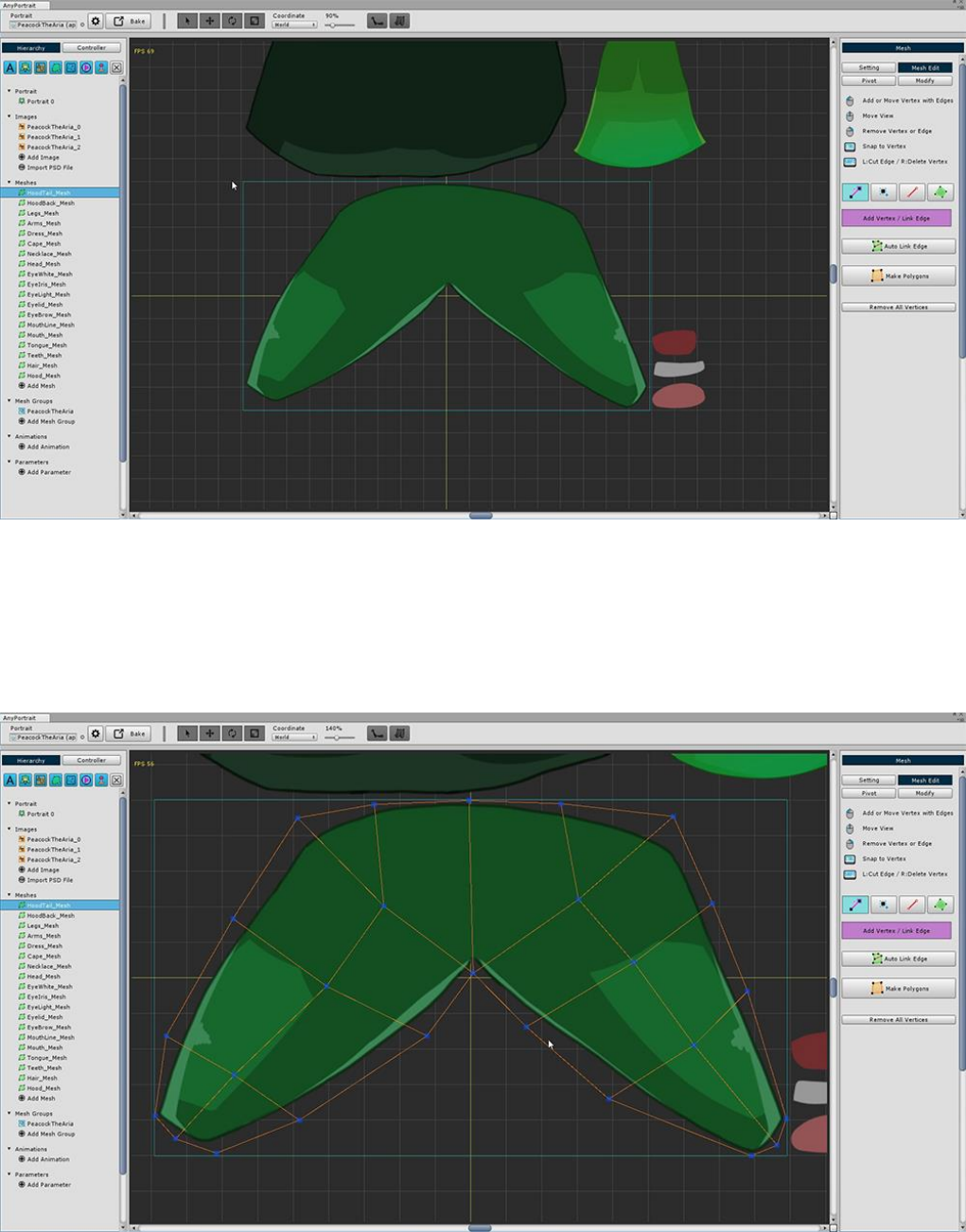
Once you remove the vertex, you will see a light blue square that was not seen before.
This rectangle represents the size of the layer image.
If you create a vertex within this area, you can create it without affecting the image area of another layer.
(It does not matter if you need to go a little longer, but be careful.)
Generate vertices more densely at the part animated by the bones.
The more vertices are placed on the folded part by the bone, the smoother the animation appears.
In this tutorial, the meshes to which the Bone animation is applied.
Let's make it by referring to the features of the upper mesh.
- Eye-shaped meshes are not animated in this tutorial, so you can skip them.
- Make meshes taking into account the appearance of joints such as arms, legs, and body.
3.3. Clipping Layer
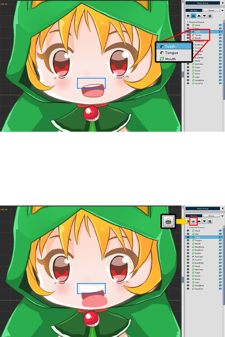
When you open the mesh group, you can see that there is an arrow-shaped icon that is folded before the
"Teeth" and "Tongue" meshes.
If you select the "Teeth" or "Tongue" mesh, you can see that the mesh is only partially rendered.
This is because the "Teeth" and "Tongue" meshes have Clipping Layer properties.
The Mask of the two meshes is the "Mouth" mesh just below.
As a test, let's turn off the clipping layer properties applied to the two meshes.
You will see that the image is rendered without any hidden parts.
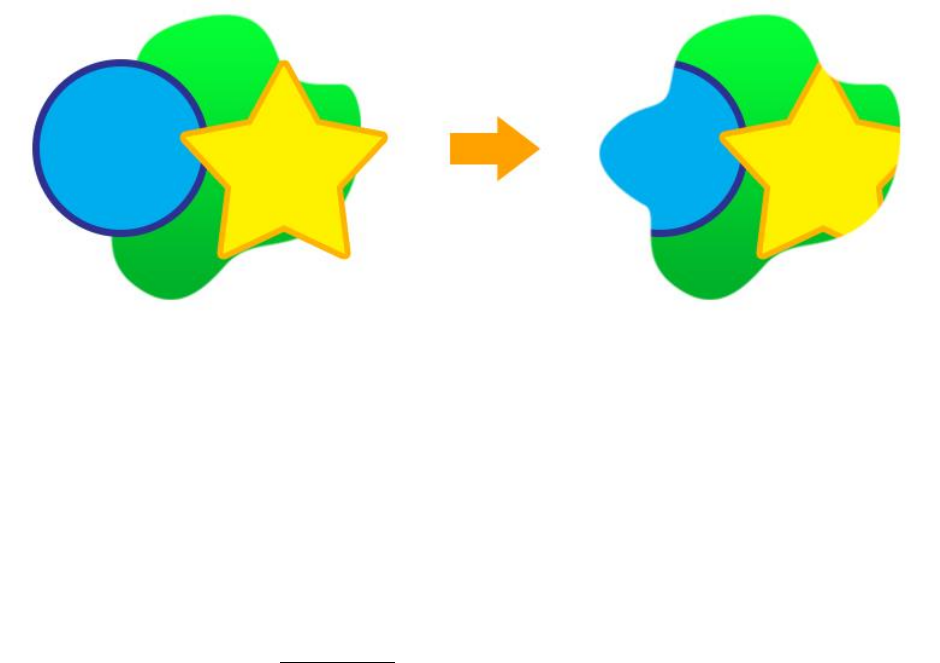
The clipping function is to render only a portion of the mesh by specifying another mesh as the mask.
It is mainly used in eyes, mouth, etc.
However, please note the following.
1. The clipping function causes the process to be slow, so it slows down the game. Please use only necessary
parts.
2. If you create and use a Custom Shader, you must also write code related to the clipping function.
To create a clipping shader, see the related page.
3.4. Adding Bones
It covers how to add a bone for a bone animation.
AnyPortrait supports Bone IK (Inverse Kinematics) and supports Bone Socket.
Details can be found on the relevant page (IK Guide, Socket Guide).
This page tells you how to add basic bones and how to set up for the next tutorial.
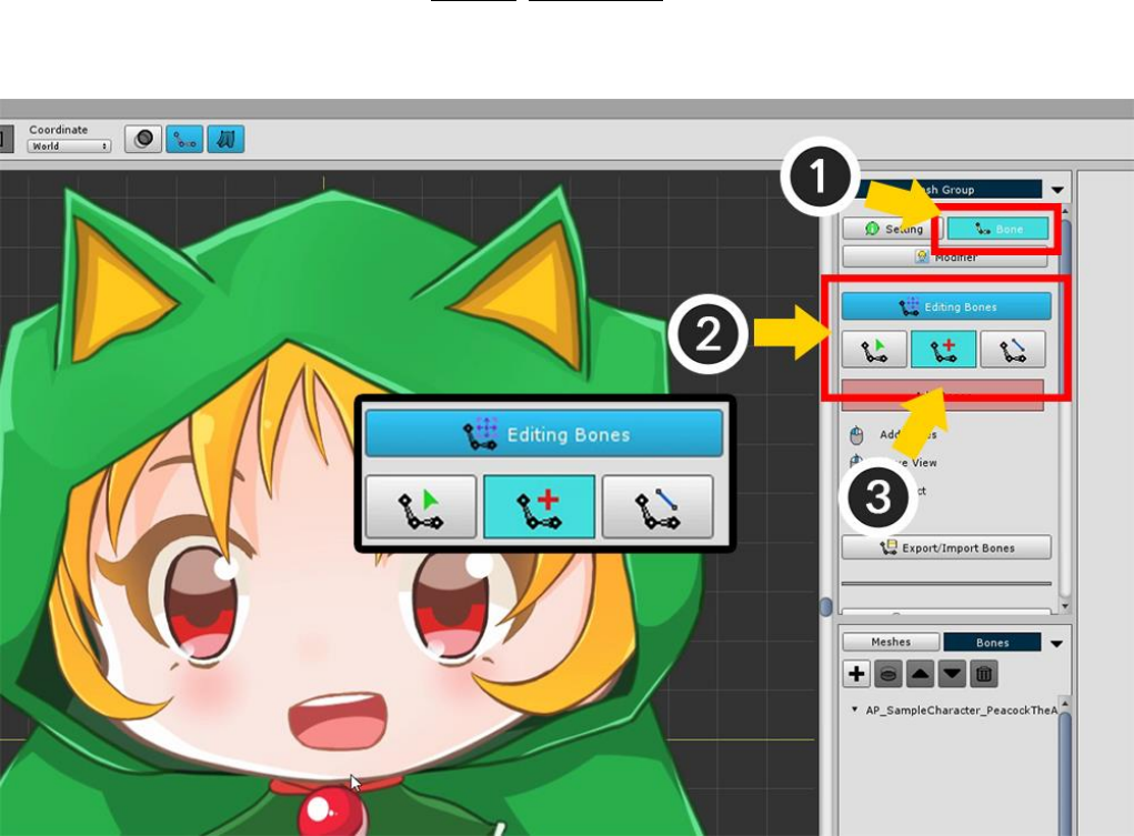
(1) Select the Bone menu.
(2) Press the Start Editing Bones button to activate the Bone editing mode.
(3) Select the Adding tool from the three Bone editing tools.
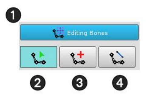
The above screen is the UI for the Bone edit mode.
1. Bone Editing Enable/Disable Button : Turns Bone Edit Mode on or off. You can only edit it while it is on.
2. Selection tool : Bone can be selected.
3. Adding tool : You can add bones. If there is a selected Bone, it is automatically registered as a Child Bone. If
you uncheck it with the Right Click, and Right Click again, it switches to this selection tool.
4. Connecting tool : Connect two bones and connect them in Parent-Child relationship. The second selected
bone becomes the Parent Bone. If you uncheck it with the Right Click, and Right Click again, it switches to
this selection tool.
We will learn how to add bones and we will proceed with the next step.
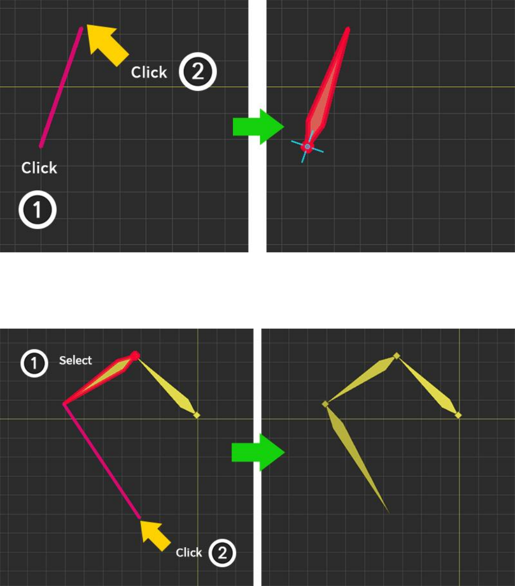
With Bone not selected, create a bone with (1) the first clicked position as the start point, and (2) the second
clicked position as the end point.
When Bone is selected, create a bone with (1) the end point of the selected bone as the start point and (2)
the end point that is clicked.
At this time, the Name and Color of the newly created Bone will be set similar to the previously selected Bone,
and the Shape will be the same.
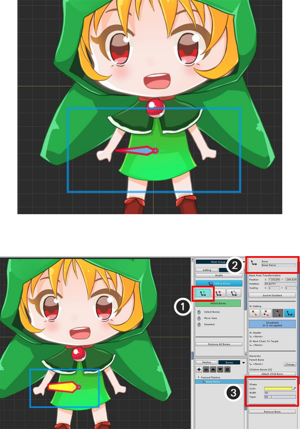
Add a bone to the pelvis, which is the center of your body.
The direction of the pelvic bone is not so important, so we made it easy to choose later in the future.
(1) Change to the Selection tool and select the bone you just created.
(2) Set the name of the selected Bone to "Bone Pelvis".
(3) Modify the color and shape of the bone.
For large bones, it is easy to select larger ones, so we recommend setting the size to make it easier to work on
later.
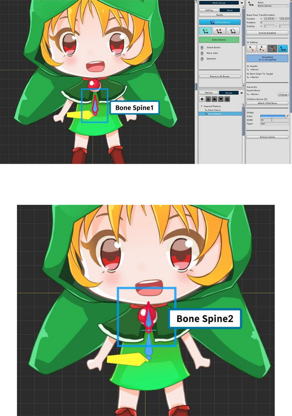
Now we make our body bones.
First create a new bone and name it "Bone Spine1".
Create a second bone with "Bone Spine1" selected.
The name of the second bone is automatically named "Bone Spine2" and its size or color is set similar to the
previous bone.
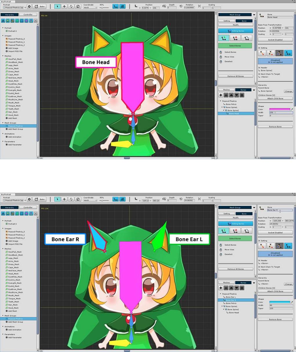
Add a head bone ("Bone Head").
Also add a bone to the ear decor of the character hoodie.
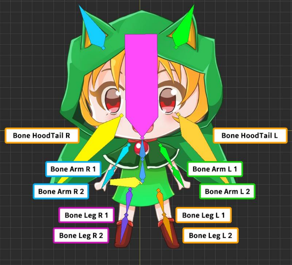
Set the bones as above.
Set various bones depending on which animation you are creating and which image you are targeting.
Now the next task is to connect the finished bones together.
If you connect the bone properly, you can move naturally like a real person.
It is common to first set the Pelvis to the parent bone (Root Parent Bone), and connect the head, hands, and feet
to the ends.
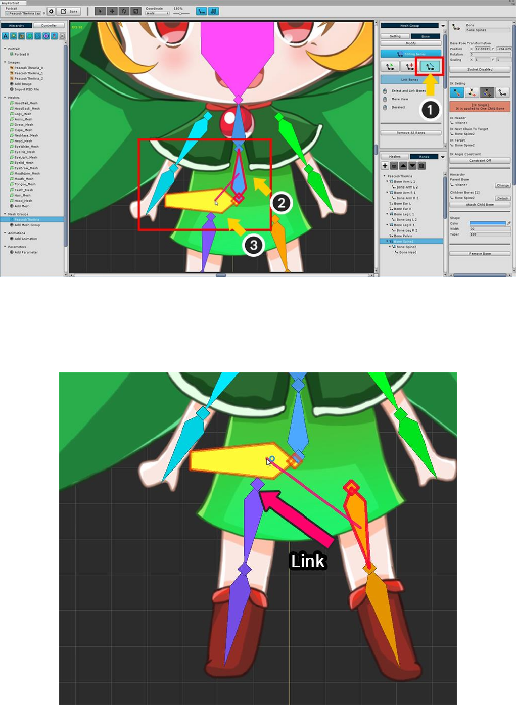
To connect the bones (1) Select the Connecting tool.
(2) Select body's starting bone ("Bone Spine 1"), and (3) select the pelvis ("Bone Pelvis").
In this way, the pelvis becomes the parent and the body becomes the child.
Right Click to deselect the next selection.
In the same way, Select legs and connect them to pelvis.
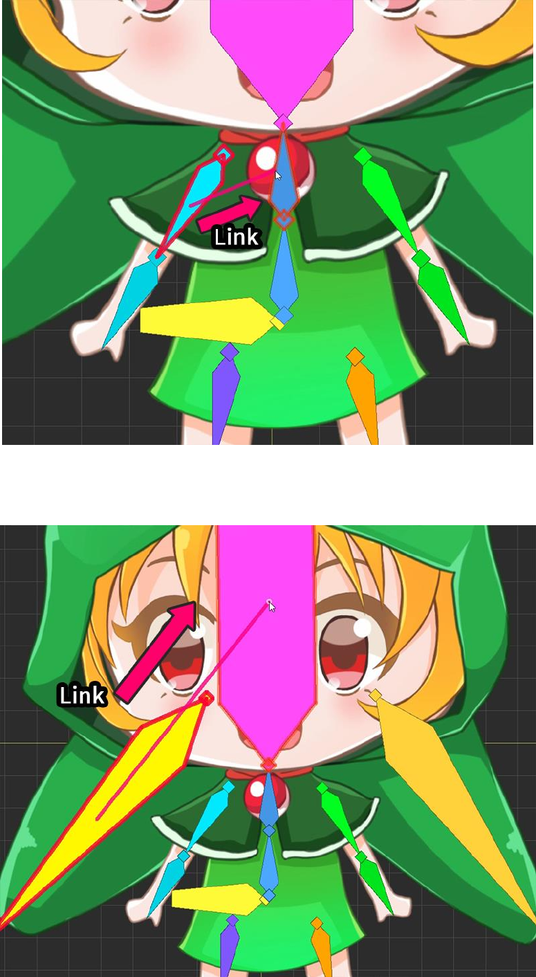
The head and both arms are connected to the uppermost bone ("Bone Spine2") of the body.
Attach the bones (hood ears and hood tails) of your head to the head ("Bone Head").

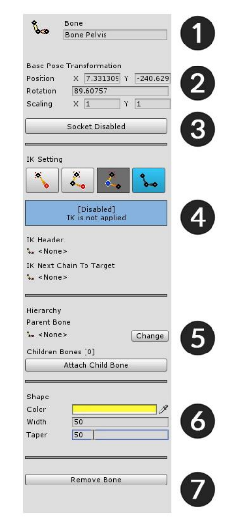
1. Name : Sets the name of the bone.
2. Base Pose Transformation : Position, rotation, size value of bone.
3. Socket : To refer to the bone after bake, turn on the socket.
4. IK Setting : This is the area to set the IK function of the bone.
5. Hierarchy : You can select parent bone, child bone here.
6. Shape : Set color and shape. The larger the taper, the tapered tip.
7. Remove Remove Bone : Delete the bone. You can also delete all children by selecting the dialog box.
3.5. Using the Rigging Modifier
For bone animation, a process called Rigging is essential.
Rigging can be defined as "Connecting vertices to bones".
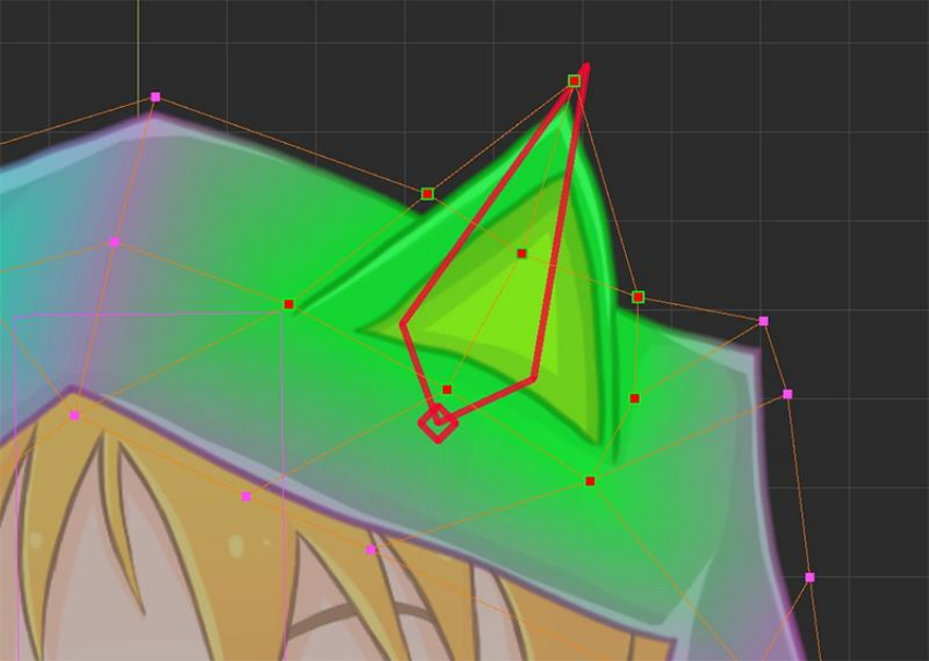
It is important to enter the "Weight attached to the bone" in the vertex so that the vertex follows the
movement of the bone.
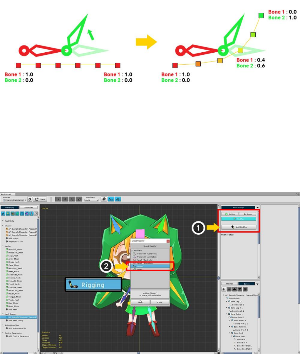
In the left figure, all vertices have a weight of "Bone 1: 1.0".
Therefore, it does not depend on the movement of the green bone (Bone 2).
On the right, the weights of the vertices are gradually increasing to "Bone 2".
So you can see the smooth movement of the green bone.
That is, Rigging is the process of setting the connection weights of "vertex + bone".
Add Rigging modifier.
(1) Press the Add Modifier button to select (2) Rigging modifier and add it.
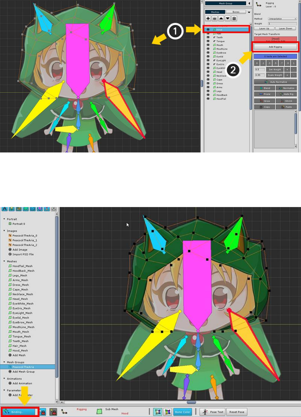
First, modify the head hood.
(1) Select the Hood mesh, and (2) press the Add to Rigging button to register the mesh in the modifier.
Press the Binding button in the lower left of the screen to start rigging.
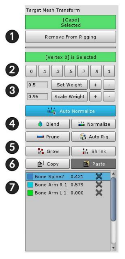
1. Add / Remove : Registers or unregisters the mesh with the rigging modifier.
2. Set Weight Manually : Weight is assigned by the value of the button.
3. Weight tools : These are tools that set weights.
Set Weight : Assigns a weight to the number on the left.
Set Weight +/- : Weight is added or subtracted in units of 0.05.
Scale Weight : Multiply the weight by the number created on the left.
Scale Weight +/- : Weight is multiplied by 1.05 (+ button) or multiplied by 0.95. (-button)
4. Assistant tools : This tool helps you to specify the weights of selected vertices.
Auto Normalize : When this is active, the weighted sum is corrected to 1.
Blend : Makes the weight of the vertex smooth by mixing it appropriately with the surrounding vertex values.
Normalize : Calibrate the weighted sum to 1.
Prune : Delete this information with a very low weight value.
Auto Rig : Rigging automatically based on registered bone information.
5. Grow / Shrink : Adjusts the range by further selecting or excluding vertices.
6. Copy / Paste : Copy or Paste the rigging information of the selected vertex.
7. Bone Rigging Information : Bones and rigging values registered for rigging. You can exclude the bone by
pressing the X button. You can also select bone from this screen.
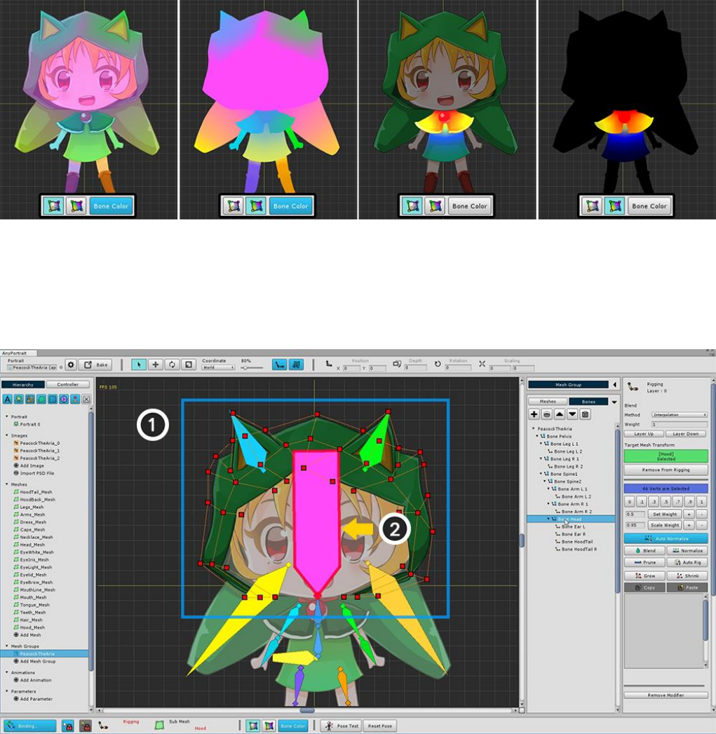
In the UI at the bottom of the screen, you can select 4 modes to visually display the rigging weights.
You can decide whether to use the bone color, or whether to display the texture together.
(1) Select all vertices, and then (2) select "Bone Head".
If the bone is not selected, turn off Selection Lock or choose from the menu on the right.
Set the weight of all vertices to 1 for Bone Head.
You can see that the color of the mesh changes like the color of the head bone.
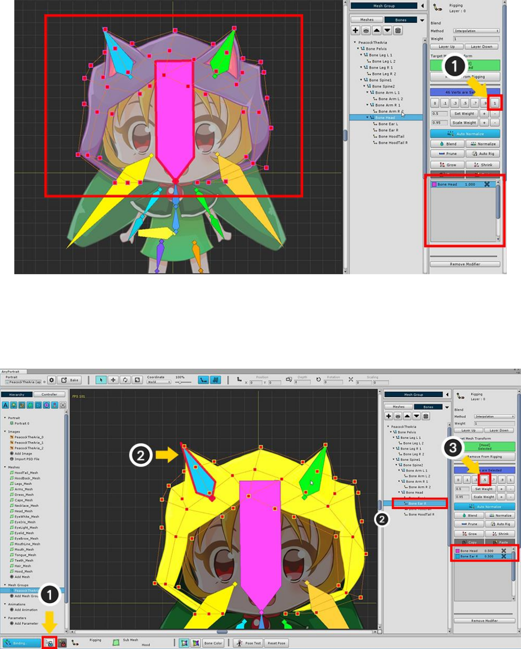
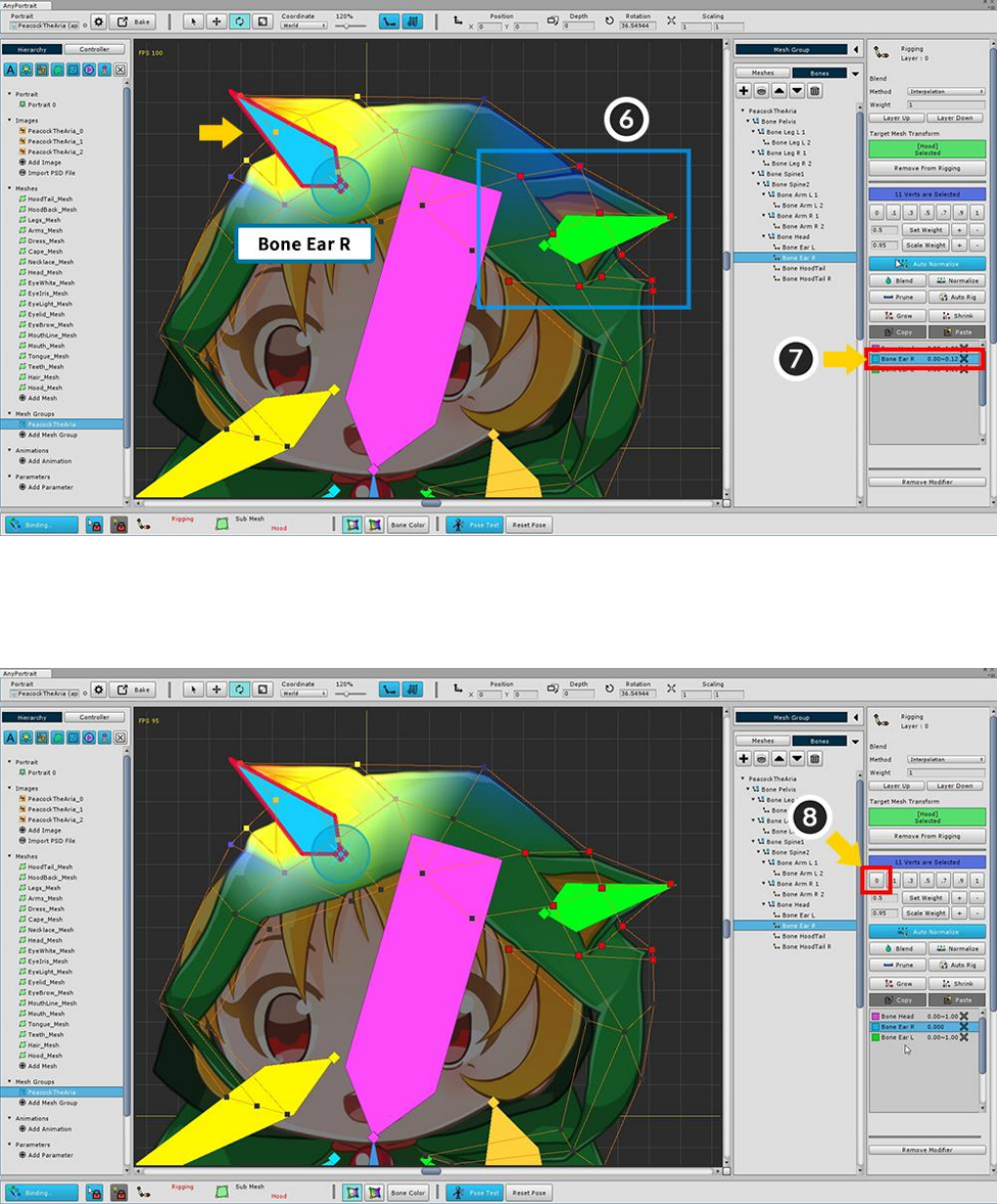
Briefly (1) release the Selection Lock and (2) select "Bone Ear R".
If you do not release the selection lock, please select it from the right menu.
With vertices selected , (3) set weights to 0.5.
You can see that the rigging information of "Bone Ear R" is registered.
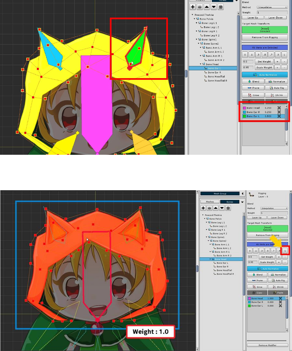
Weights are assigned to the opposite ear as well.
Select "Bone Head" again. Select all vertices and assign a weight of 1.
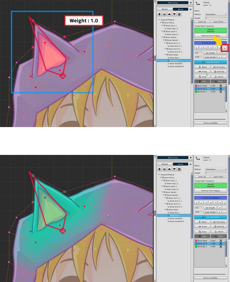
Select "Bone Ear R", select its surrounding vertices, and assign a weight of 1.
Weights are applied only around the ears to change the color.
In the same way, we assign weights for the opposite ear.
Rigging is a task that is difficult to complete at once.
Even if weights are specified, it is easy to see awkward points when actually moving the bone.
Therefore, the Rigging modifier provides a "Pose Test" function that allows you to temporarily move bones.
Use the Pose Test function to see if the weights are applied properly and try to fix them.
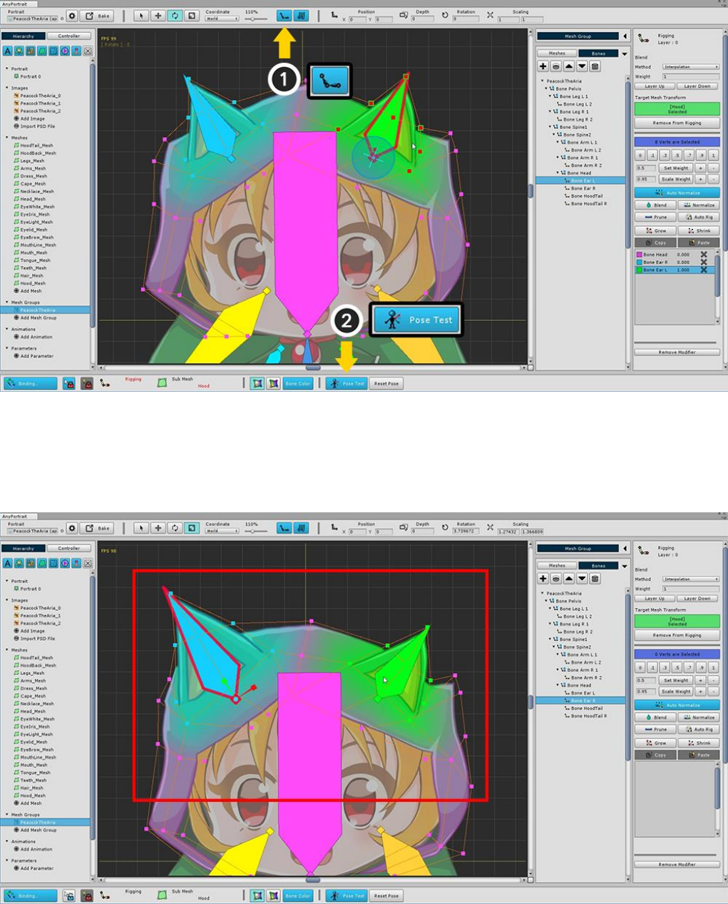
First, make sure the bones appear on the screen.
(1) Make the bone appear as "filled".
(2) Press the Pose Test button.
You can select a bone to move freely.
Please check that you are properly rigged.
Rigging in the current state is not smooth.
You need to make it smoother and fix the problem areas.
Press the Pose Test button to disable it, and then modify the rigging again.
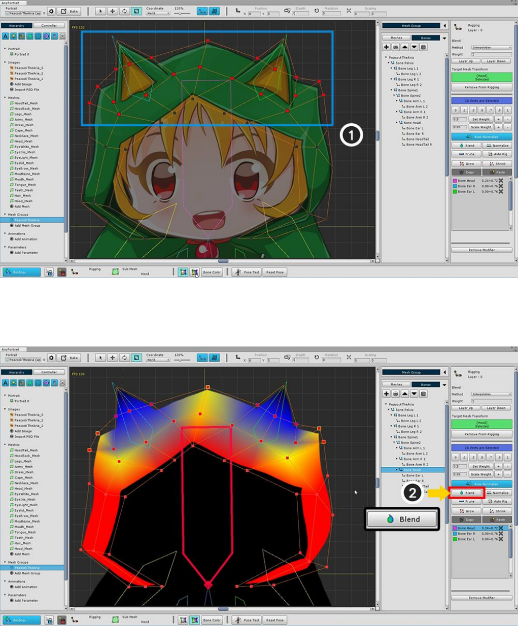
(1) Select all the vertices around the ears.
(2) Press the Blend button several times to soften the weight value.
(We changed the weight value to <Bone Color Off + Texture Off>.)
You can see that the weights are distributed more smoothly than before.
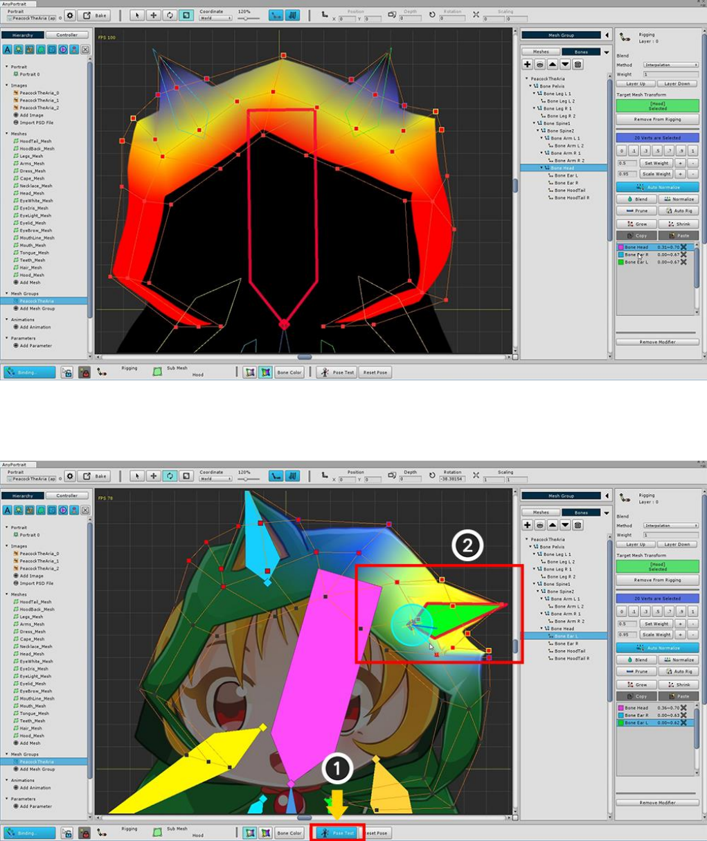
Now let's test again.
(1) Turn on Pose Test mode.
(2) Tilt ears to see if the rigged rigging is applied properly.
In this sample, you can see that one side of the character is tilted and the opposite side moves as well.
Let's suppose that the vertex on the other side should not move.
(Rigging is done differently depending on the intention of the designer.)

(3) Select vertices of the center of the head.
(4) Select "Bone Head", and (5) press the Set Weight + button several times to add weights.
(6) Select one of the vertices on the ear, and then (7) select Ear (Bone Ear R or L).
You can see that the weights are applied beyond the center.
(8) Set weight 0.
Make the same for the opposite ear and vertices.
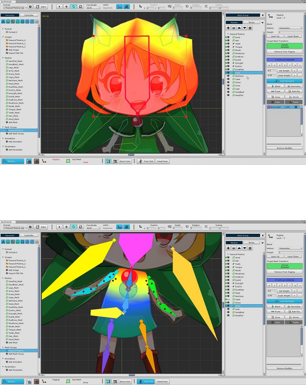
Now add other meshes to the Rigging Modifier.
Face meshes should be registered only on the head (Bone Head).
Other meshes are rigged while properly using the Pose Test.

The screenshot below shows the rigging results for each bone.
Please refer to these for rigging.
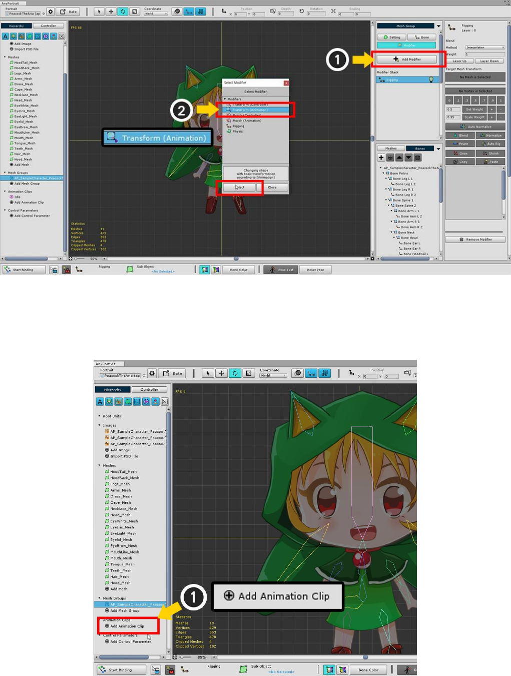
3.6. Creating an Animation Clip
Adds a modifier to be associated with the animation.
Transform (Animation) Modifiers and Morph (Animation) Modifiers are modifiers for animation.
In this case, select the Transform (Animation) modifier for bone animation.
Add an animation clip.
Click the Add Animation Clip button to create and select an animation clip.
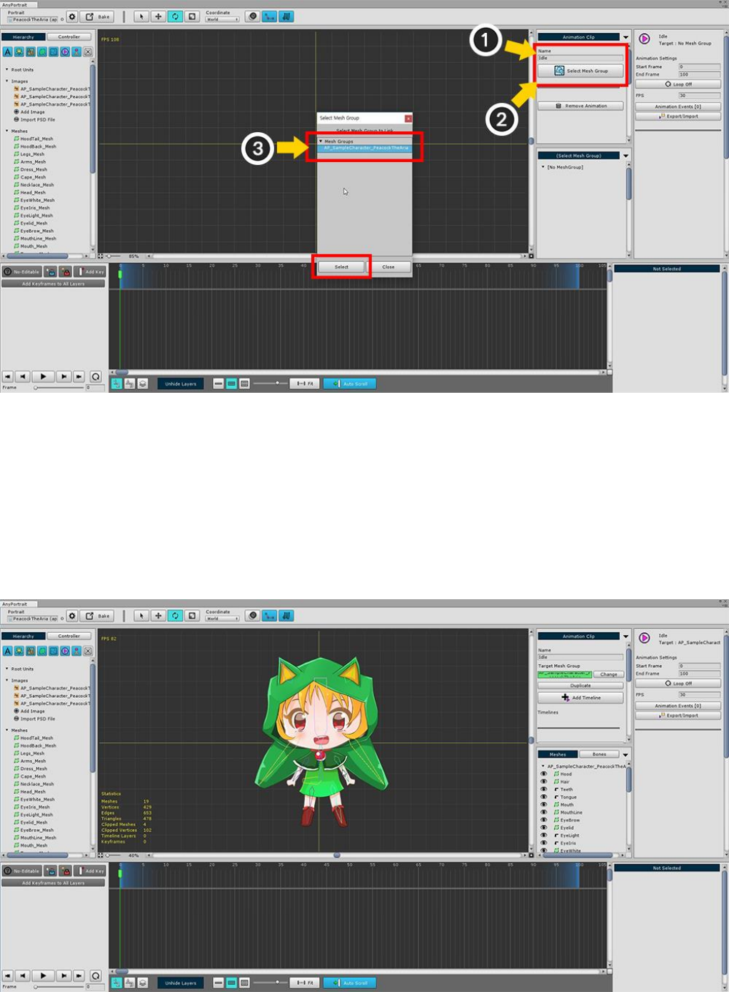
(1) Specify the name of the animation clip. I set it to "Idle" here.
(2) Press the Set Mesh Group button and (3) Select the mesh group you were working with.
Note : The animation name is used to play the animation during the game. If the name is duplicated or entered
incorrectly, playback will not be possible.
Animation clip work screen associated with mesh group.
You will create an animation on this screen.
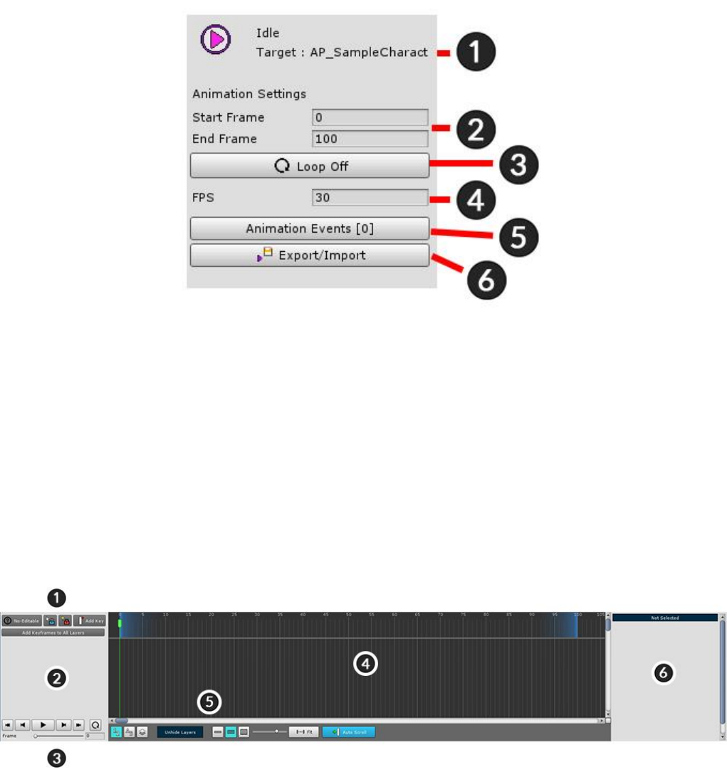
Animation clip setting UI.
1. The name of the animation clip and mesh group
2. Start and End frames of animation clip
3. Whether Loop
4. Frames per second (FPS)
5. Animation Events
6. Export / Import animation to file
Timeline UI in which the keyframe animation is registered.
Add animated data here called Timeline.
1. Edit mode UI : Turn on / off edit mode, add key frame, and lock.
2. Timeline header : The names of the registered Timeline and Timeline Layer are displayed.
3. Playback UI : UI that controls animation, play, stop, or move frame.
4. Keyframe workspace : Keyframes appear. (Left and Right scrolling : Mouse Wheel Button Drag, Up and
Down scrolling : Mouse Wheel Scrolling)
5. View Settings UI : Contains functions related to viewing settings related to the timeline UI.
6. Details UI : Information and functions of the selected timeline, timeline layer, and key frame are displayed.
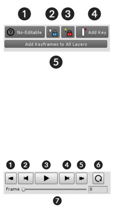
Edit mode UI
1. Start / End animation editing (A key)
2. Selection Lock On / Off (S key)
3. Modifier Lock On / Off (D key)
4. Add Keyframe at the current frame (F key)
5. Create keyframes on all layers in the current frame
Playback UI
1. Move to First frame (Shift + < Key)
2. Move to Previous frame (< Key)
3. Play or Pause (Space Bar)
4. Move to Next frame (> Key)
5. Move to Last frame (Shift + > Key)
6. Loop On / Off
7. Currently playng frame
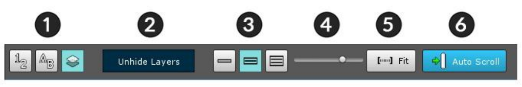
View Settings UI of timelines
1. Timeline Layers Order : Determines in which order the timeline layers are shown. (Registration order, name
order, and rendering order)
2. Unhide Layers : If any timeline layer is hidden, you can press this button to make it appear.
3. Timeline UI Size : Adjusts the size of the timeline UI at the bottom of the entire editor area.
4. UI Zoom Ratio : Zoom ratio of the main timeline workspace where the keyframe is displayed.
5. Fit : Automatically adjusts the zoom ratio of the main workspace to fit the entire playback range.
6. Auto Scroll : If this function is on, scrolling automatically moves to the frame when playing.
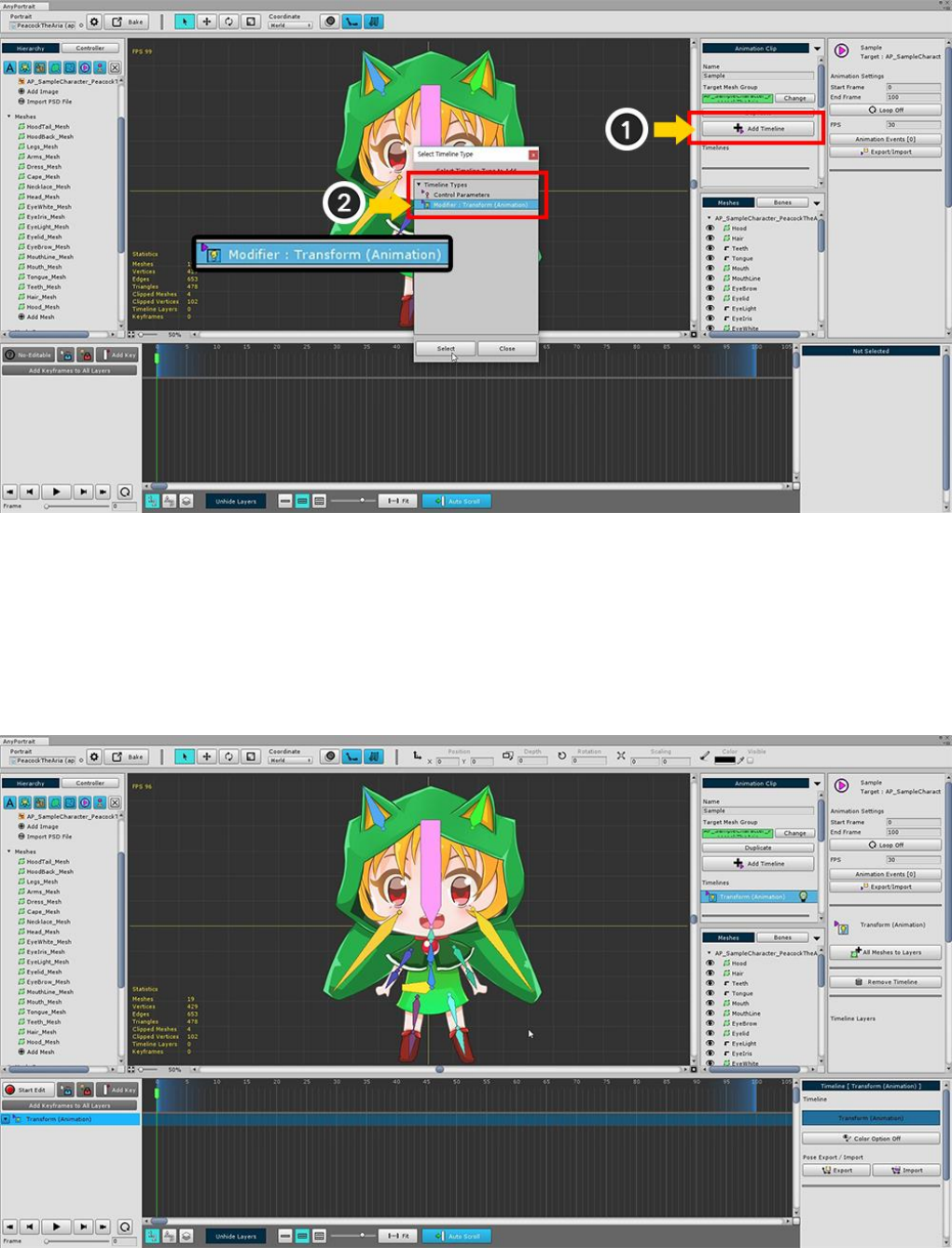
3.7. Adding the Timeline
To create a keyframe animation, you must add a timeline to the animation clip.
(1) Click the Add Timeline button to display the types of timeline that you can add.
By default, there is a "Control Parameters" timeline, and the "Animation Modifier" you added from the mesh
group appears.
Select the (2) Transform (Animation) modifier you created earlier and add it.
Transform (Animation) Timeline is added.
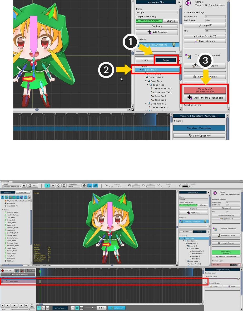
Add a bone to the timeline.
After changing to (1) Bone tab, (2) Select one bone.
Click the (3) Add Timeline Layer to Edit button in the bone property UI.
Timeline (Animation) Timeline layer for "Bone Pelvis" is added to the timeline.
To create animations, create animated clips, timelines, and timeline layers in order.
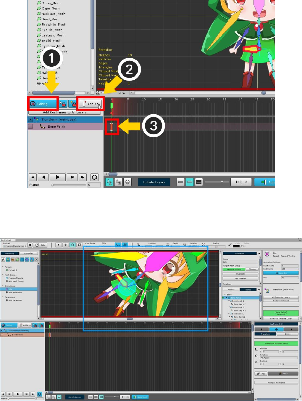
(1) Press the Start Edit button (A key) to turn on the Edit mode.
(2) Press the Add Key button (F key).
You can see that the keyframe is created where (3) the current time slider is located.
When Edit mode is on and the Keyframe is selected, you can transform the object. This status is recorded in the
keyframe.
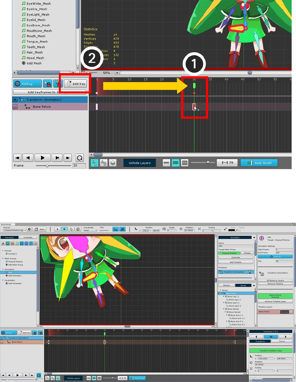
If you create another keyframe, the animation will work.
(1) Move the time slider to another frame, and (2) press the Add Key button to create a keyframe.
Move the selected bone in the generated keyframe and record it.
Animation will now run when you play.
3.8. Animation Curves
Interpolation is the most important principle when understanding keyframe animation.
Interpolation is the process of calculating what form to take between a keyframe and a keyframe.
Depending on the interpolation method, even if you have the same keyframe, the result of the animation might
be different.
This page covers Animation curves that deal with interpolation methods.
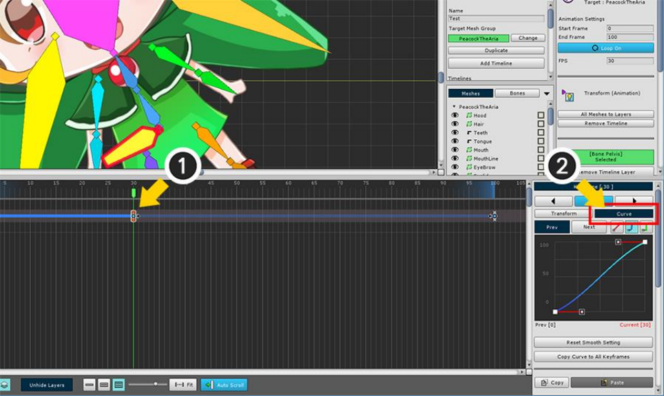
(1) Select one keyframe, (2) Select the Curve tab.
When you modify an animation curve, the type of curve appears in the timeline workspace as a bold line.
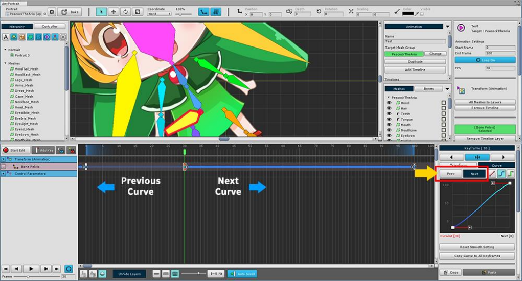
You can select a Previous Curve with the previous keyframe and a Next Curve with the next keyframe based
on the currently selected keyframe.
The selected curve appears bright in the timeline workspace.
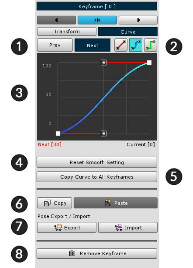
Animation curve detail property UI
1. Prev/Next : Select previous curve or next curve.
2. Curve type : Determines the interpolation method of the curve. They are Linear, Smooth, and Constant.
3. Edit curve : You can edit or view the curve. In the case of the Smooth method, the control points can be
edited.
4. Reset Smooth Setting : In the case of the Smooth method, the control point is returned to the initial value.
5. Copy Curve to All Keyframes : Applies the current curve settings to all keyframes in the timeline layer.
6. Copy / Paste keyframe : Temporarily copy or paste keyframe information.
7. Export / Import posture : If it is a keyframe in the bone animation, you can save or open the posture.
8. Delete the keyframe
1. Linear
Movement, size, etc. are changed uniformly.
2. Smooth
Movement, size changes smoothly.
The user can edit the shape of the curve.
It is appropriate when giving acceleration or smoothly switching from keyframe.
3. Constant
The value changes at the end point between the keyframes.
It can give effect like sprite animation.
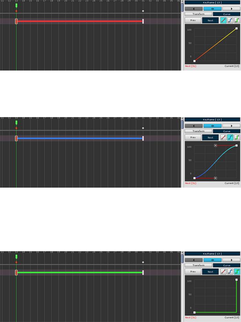
Let's see how it actually varies depending on the curve type.
1. Linear
The color of the curve is red.
You can see that it changes at regular intervals from start to finish.
2. Smooth
The color of the curve is blue.
The default state is similar to linear but there are some acceleration and deceleration at the beginning and end.
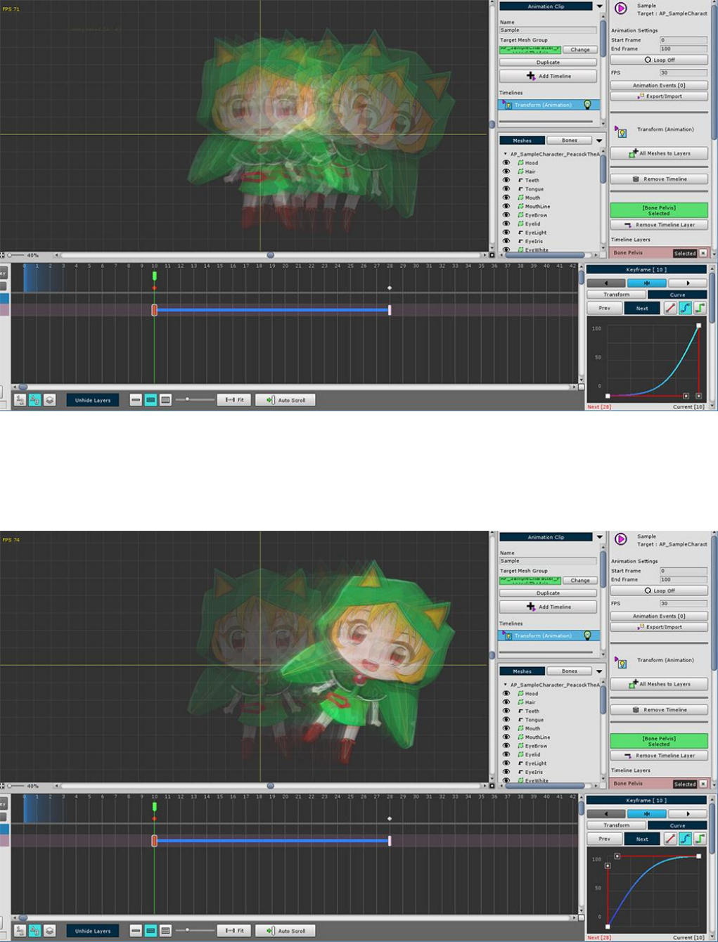
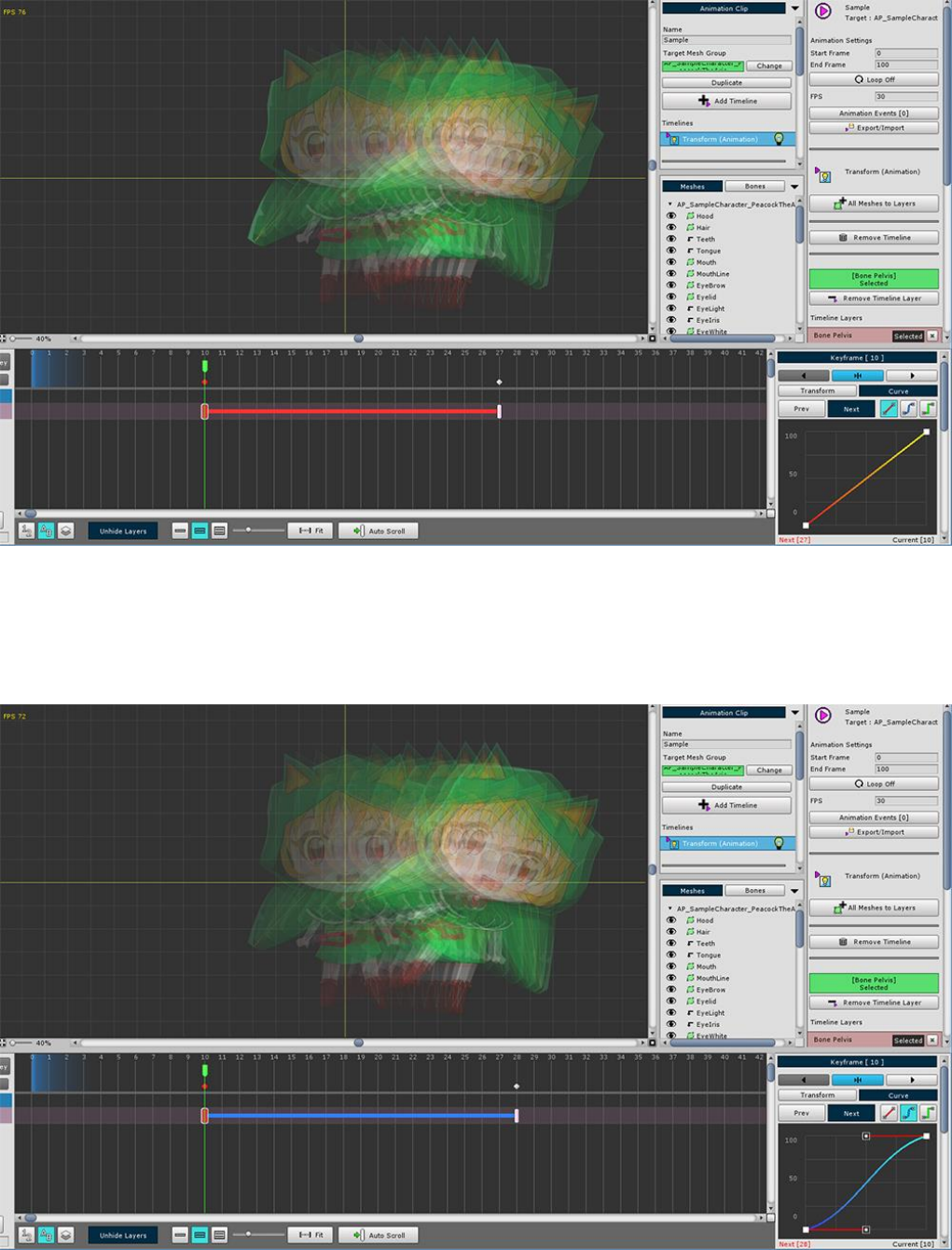
2-1. Accelerated Smooth
A variation example of a Smooth curve.
It keeps close to the starting keyframe value and then accelerates and changes quickly.
2-2. Decelerating Smooth
A variation example of a Smooth curve.
You can see the speed change in the start key frame and then decelerate.
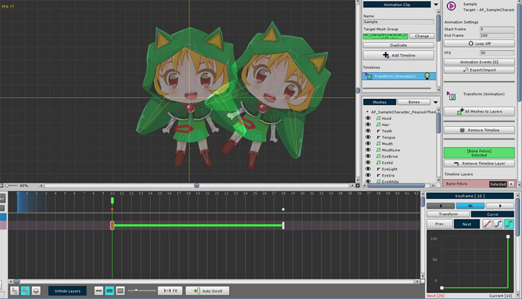
3. Constant
The color of the curve is green.
There are only two interpolation states: start and end.
It is transformed based on the end point.
3.9. Creating Bone Animation
On this page, let's create a simple animation.
Learn the entire process while creating a repeating animation in which the character bounces lightly.
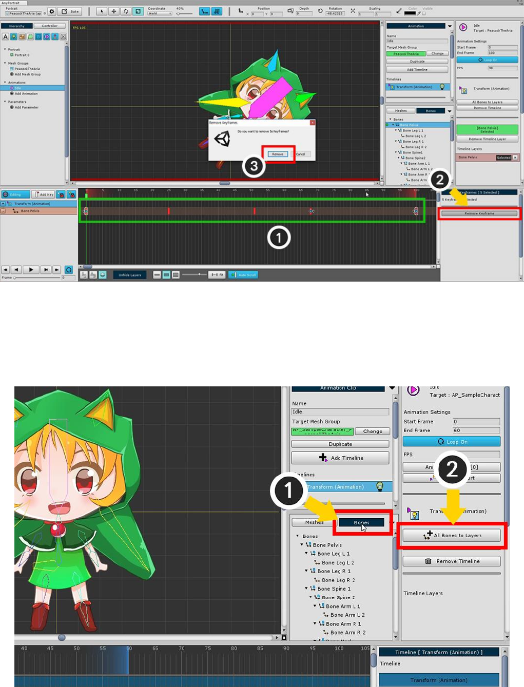
Creates a new animation clip or deletes animation keyframes that were created before.
If you delete keyframes,
(1) Select all keyframes (2) Press the Remove Keframes button to remove.
Selecting all the bones and adding them to the timeline is cumbersome and time-consuming.
(1) With the Bones tab selected
(2) Press the All Bones to Layers button to create a timeline layer for all bones at once.
Skips work for already added bones.
(With the Meshes tab selected, add all meshes as timeline layers.)
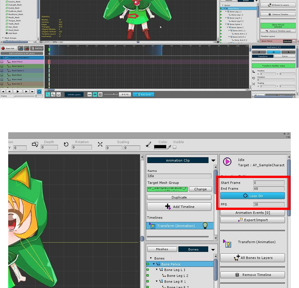
All bones are registered on the timeline.
Turn on Loop of animation to create loop animation.
You need to create a second frame, which can be cumbersome if you have multiple timeline layers.
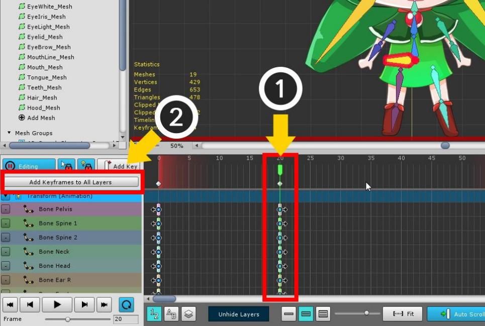
In this case, it is convenient to use Add Keyframes to All Layers function.
(1) Move the time slider, and (2) press the Add Keyframes to All Layers button to create keyframes in
batches.
(Note: Edit mode must be activated to create keyframes.)
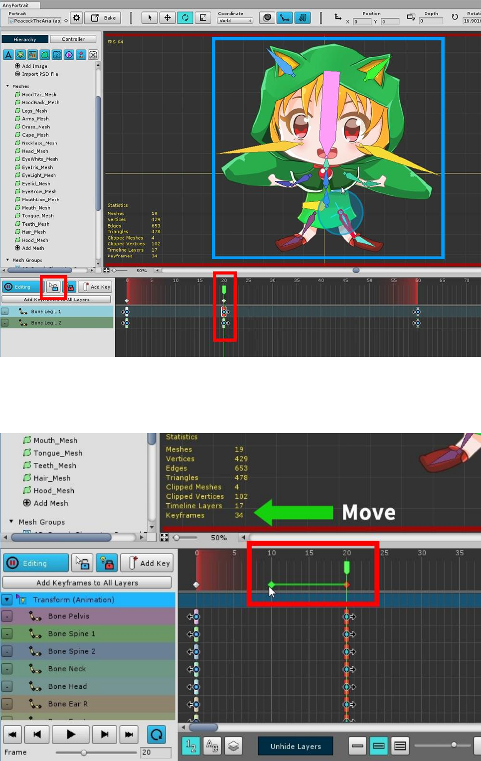
Move the time slider to where the generated keyframe is located and turn on edit mode.
In this state, it will hold a pose that makes you jump.
It may be convenient to turn off the Selection Lock and work on it. (S key)
When moving keyframes, it can be cumbersome if there are many timeline layers.
Selecting a Common Keyframe located below the time slider allows you to select and control all the keyframes
at that location at once.
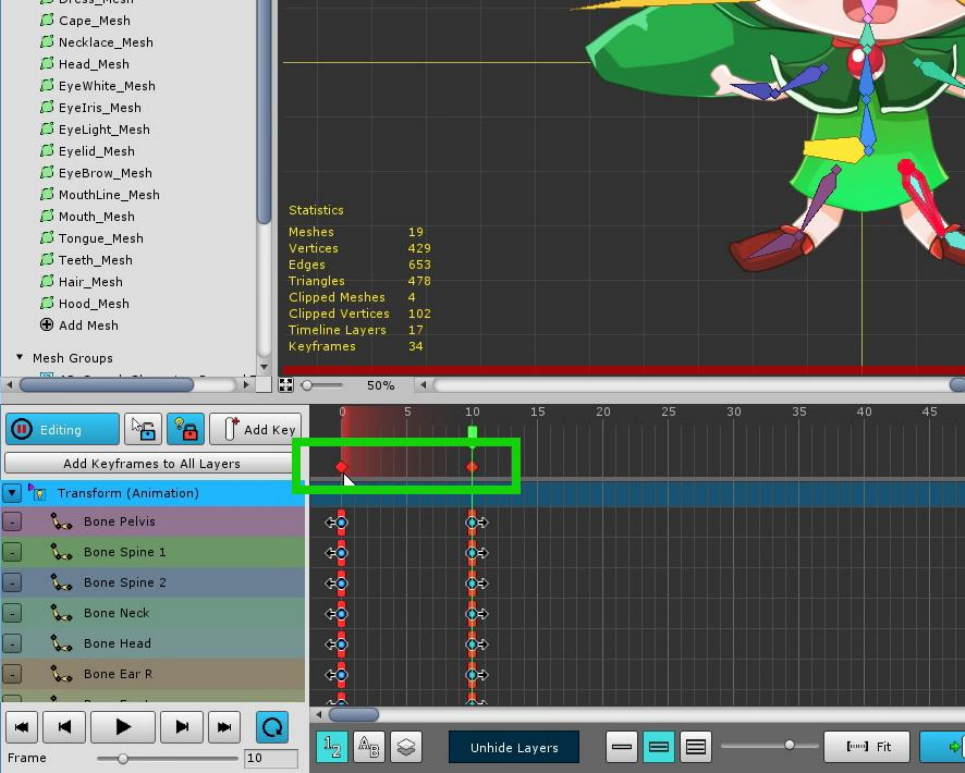
Create animations by moving or copying keyframes.
Let's make a few more repetitions of pose 1 and 2.
Select all keyframes.
You can select a common keyframe by dragging the mouse.
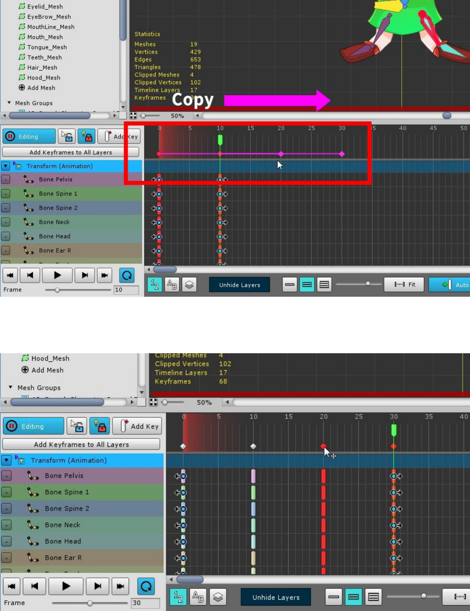
Copy keyframes in this step. (Hold down the Shift or Ctrl (Command) key and Drag Mouse)
The pattern of the animation repeating pose 1, 2 is copied.
This sample will no longer be modified, but you can create an animated pattern and then make some variations
to create interesting results.
Copy the pattern one more time to complete the animation.
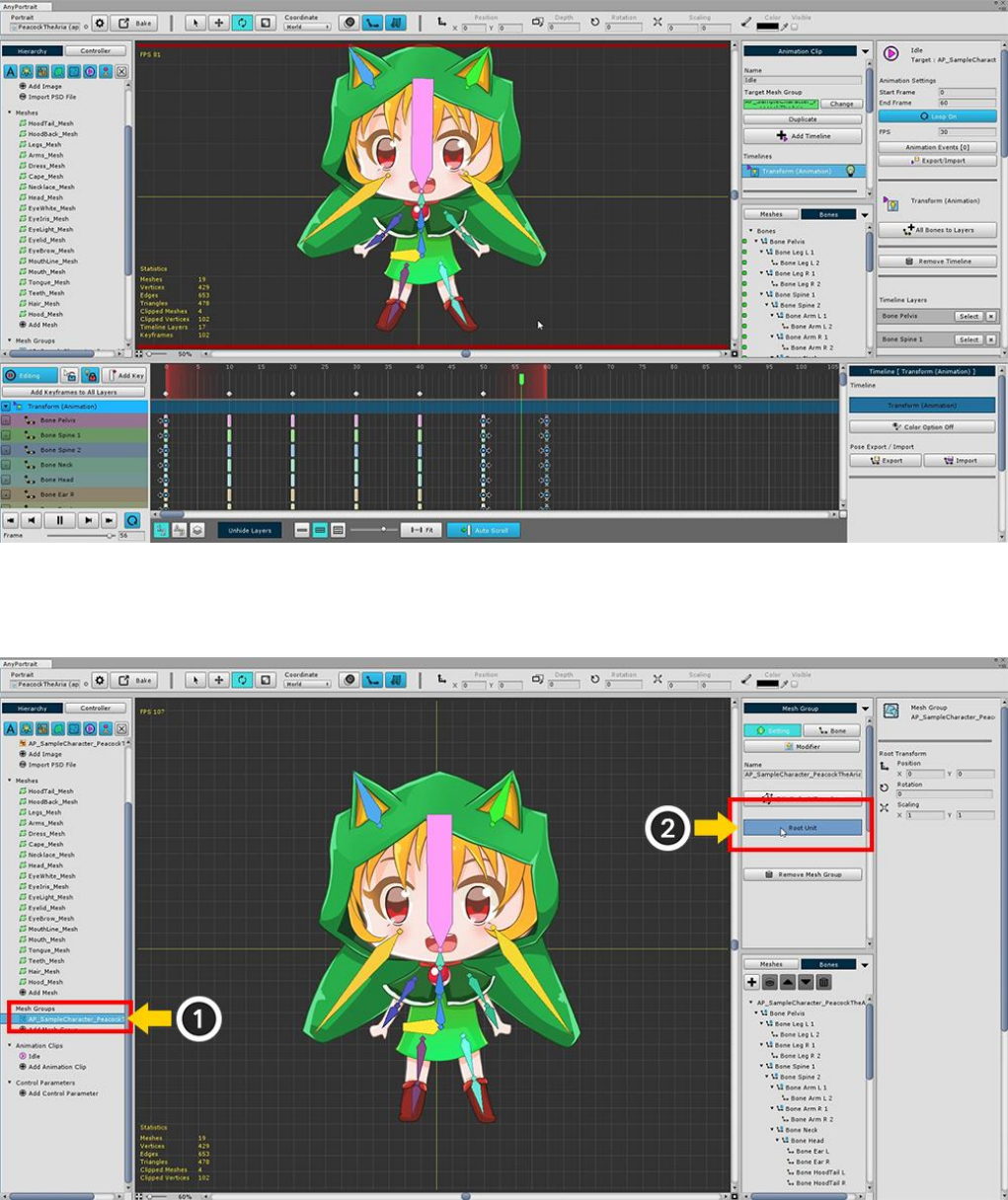
Now we move the finished animation to the scene.
(1) Select mesh group again, and (2) Confirm that it is registered as Root Unit.
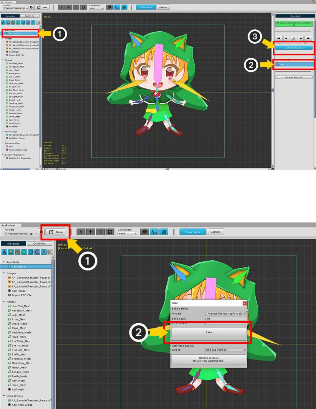
If you (1) select Root Unit 0 in the Hierarchy menu, the completed animation is automatically registered.
You can test by (2) selecting animation and executing it.
(3) Press the Auto Play button to set the animation to play automatically in the scene.
Bake to move the character you created so far to the scene