2005_Focal_Point_Book Surfside Appendix
User Manual: Surfside
Open the PDF directly: View PDF ![]() .
.
Page Count: 73
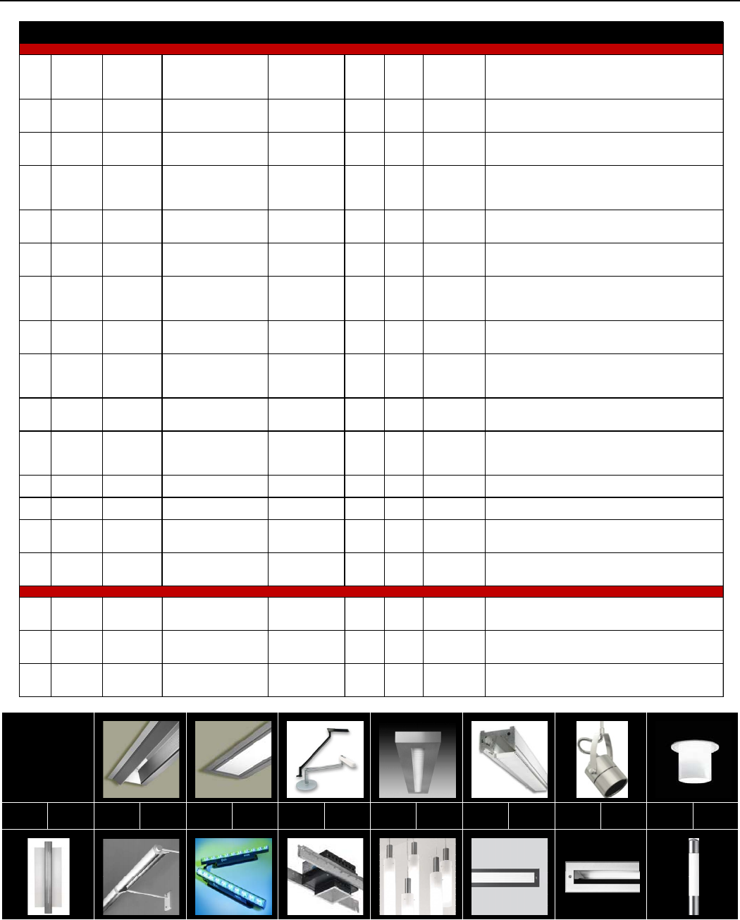
LIGHTING EQUIPMENT SCHEDULE
TYPE MANUF. CATALOG # LAMP(S) BALLAST INPUT
WATTS VOLTS MOUNTING DESCRIPTION
F01 FOCAL
POINT
FAVA-NS-1T5-
1C-277-S-F-
WH-4'
(1) 28W T5, 4100K,
CRI=85, FP28/841/ECO
ADVANCE ICN-
2S28-N
30 (PER
FX) 277 CEILING SEMI-
RECESSED
"AVENUE A" - NARROW APERTURE ASYMMETRIC WALL
WASHER. SINGLE CIRCUIT, DRYWALL FLANGE, MATTE WHITE
HOUSING, 4' NOMINAL LENGTH. STEEL CONSTRUCTION.
F02 FOCAL
POINT
FAVB-FL-1T5-
1C-277-D-F-
WH-4'
(1) 28W T5, 4100K,
CRI=85, FP28/841/ECO
DIMMING: LUTRON
ECO-T528-277-2
30 (PER
FX) 277 CEILING
RECESSED
"AVENUE B" - RECESSED SLOT FIXTURE. DIFFUSE FLUSH LENS,
SINGLE CIRCUIT, MATTE WHITE HOUSING. STEEL
CONSTRUCTION.
F03 LIGHTOLIER SU-F-L-S-T-SL (1) 13W CFL, 4-PIN/2G7
BASE, 3500K, INCLUDED
IN-LINE
ELECTRONIC 13 120 TABLE "SURFSIDE" CFL PERSONAL TASK LIGHT. 20" ARM, SILVER
FINISH, TABLE BASE
F04 FOCAL
POINT
FTWS-PB-1-1-
277-D-J12-TS-
20'
(1) 28 W T5, 4100K,
CRI=85, FP28/841/ECO
DIMMING: LUTRON
ECO-T528-277-2
30 (PER
FX) 277 CEILING
SUSPENDED
"TWELVE" - SUSPENDED INDIRECT/DIRECT LUMINIRE. PARALLEL
BLADE LOUVER, 24" CABLE SUSPENSION, INTEGRAL
WATTSTOPPER OCCUPANCY SENSOR, TITANIUM SILVER FINISH,
FACTORY 20' RUN
F05 LIGHTOLIER PTS5-1-S-S-2-
4
(1) 28W T5, 4100K,
CRI=85, FP28/841/ECO
DIMMING: LUTRON
ECO-T528-277-2
30 (PER
FX) 277 CEILING
RECESSED
"PTS5-1" - RECESSED PERIMETER WALL WASH. STRAIGHT BLADE
ALUMINUM LOUVER, DIE-FORMED STEEL CONSTRUCTION.
F06 TECH
LIGHTING
700-MO-SPT6-
04-S
(1) 35W SOLUX MR16,
4100K, 17 DEGREE SPREAD N/A 35 12 TRACK-
MOUNTED
"SPOT" TRACK HEAD. COMPATIBLE WITH MONORAIL SYSTEM.
4.5" LENGTH. SATIN NICKEL FINISH. DESIGNER APPROVAL
REQUIRED FOR LAMP SUBSTITUTION.
F06-A TECH
LIGHTING
700MOA-
48+24-S N/A N/A N/A 12 CEILING
SURFACE
"MONORAIL" LOW-VOLTAGE STRAIGHT RAIL TRACK. 48" + 24"
FOR TOTAL 72" OVERALL RUN. SATIN NICKEL FINISH WITH
CLEAR INSULATOR. SEE CUTSHEETS FOR ADDITIONAL
EQUIPMENT.
F07 LOUIS
POULSEN
BAL-1/18W CF
GX24q-2 -
277V - WHT
(1) 18W CFL, 4100K,
CRI=82, PL-T
18W/841/4P/ ALTO
OSRAM QTP
1x18CF/UNV 20 277 CEILING SEMI-
RECESSED "BALLERUP" SEMI RECESSED DECORATIVE CFL DOWNLIGHT.
F08 LIGHTOLIER 48023ALU (1) 28W T5, 4100K,
CRI=85, FP28/841/ECO
ADVANCE ICN-
2S28-N
30 (PER
FX) 277 WALL
MOUNTED
"SOLI" WALL-MOUNTED DECORATIVE T5 FIXTURE. METALLIC
ALUMINUM FINISH, SEE DIFFUSER SPECIFICATION BELOW
(ORDER SEPERATELY). ADA COMPLIANT
F09 ELLIPTIPAR F101-T335-X-
01-2-000
(1) 35W T5, 4100K,
CRI=85, F35T5/841/ ALTO
ADVANCE ICN-
2S28-N
38 (PER
FX) 277
WALL
CANTILEVER
MOUNTED
"STYLE 102" WALL CANTILEVER-MOUNTED WALL WASH
LUMINAIRE. BRIGHT ALUMINUM FLUTED HOUSING WITH SILVER
END PLATES, 18" CANTILEVEL ARM. 5' LENGTH.
F10 COLOR
KINETICS
101-000066-
00
45 LEDs (15 RED, 15
GREEN, 15 BLUE) N/A 3W 24V DC COVE
MOUNTED
"iCOLOR COVE QLX" COVE-MOUNTED RGB COLOR-
CHANGING COVE FIXTURE. 120 DEGREE CANDLEPOWER
DISTRIBUTION, ADJUSTABLE POSITION MOUNTING BRACKET.
F10-A COLOR
KINETICS PDS-60ca 24V N/A N/A N/A 277 REMOTE 277V AC - 24V DC LED POWER SUPPLY.
F10-B COLOR
KINETICS 101-000008 N/A N/A N/A N/A REMOTE "COLORDIAL" DMX LED CONTROLLER.
F11 PHILIPS
OM4-1H-32
PLT-SQ-CS-
120/277
(1) 32W CFL, 4100K,
CRI=82, PL-T
32W/841/4P/ ALTO
OSRAM QTP
2X32CF/UNV BM
35 (PER
FX) 277 CEILING
RECESSED
"OMEGA REVELATION" 4-INCH SQUARE CFL DOWNLIGHT.
CLEAR SPECULAR REFLECTOR.
F12 SCHMITZ 26237.06 (2) 28W T5, 4100K,
CRI=85, FP28/841/ECO
ADVANCE ICN-
2S28-N BF
60 (PER
FX) 277 PENDANT "TOOL" PENDANT FIXTURE. NO DOWNLIGHT. RIBBED ACRYLIC
TUBE, SATIN NICKEL FINISH. ADJUSTABLE SUSPENSION CABLE.
S01 BEGA 2007 P (1) 35W T5, 3000K,
CRI=85, F35T5/830/ALTO
ADVANCEICN‐
2S28,BF
38.5 (PER
FX) 277 WALL
RECESSED
RECESSED LINEAR WALL FIXTURE. STAINLESS STEEL FINISH.
RATED FOR WET LOCATION.
S02 BEGA 8642 P
(1) 24W T5HO, 3000K,
CRI=85,
F24T5/830/HO/ALTO
ADVANCE ICN-
2S24, BF
26 (PER
FX) 277 IN-GRADE
RECESSED
IN-GRADE RECESSED FLODLIGHT. LINEAR FLUORESCENT. DRIVE
OVER. RATED FOR WET LOCATION. STAINLESS STEEL FINISH.
S03 BEGA 8989 P (1) 36W CFL, 3000K,
CRI=82, PL-L 36W/830/4P
ADVANCE ICN-
2S54, BF 46 277 POLE LINEAR STAINLESS STEEL POLE-MOUNTED SITE FIXTURE. RATED
FOR WET LOCATION.
INDOOR FIXTURES
OUTDOOR / SITE FIXTURES
VISUAL
INDEX
F08 ➡ F01 F09 ➡ F02 F10 ➡ F03
F11 ➡
F04
F12 ➡
F05
S01 ➡ F06 S02 ➡
F07
S03 ➡
A0
2.20"
55.88mm
3.20"
81.28mm
4.3"
109.22mm
.54"
13.72mm
4.00"
101.60mm
4.3"
109.22mm
6.5"
165.1mm
24-30" Recommended
Distance from Wall
Grid Mount
Drywall Flange
frame width
4.75" max–4.625" min
Mounting yoke must be
installed before drywall.
(see Instruction Sheet
#ISO214 for details)
3.50"
88.9mm
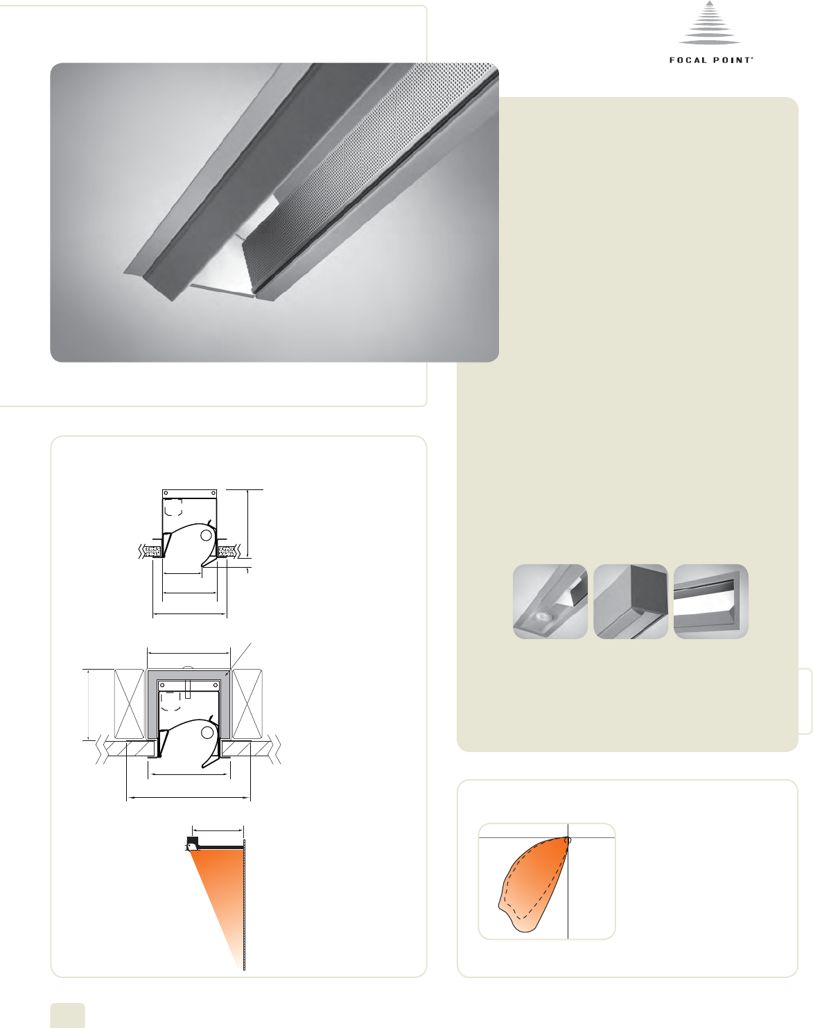
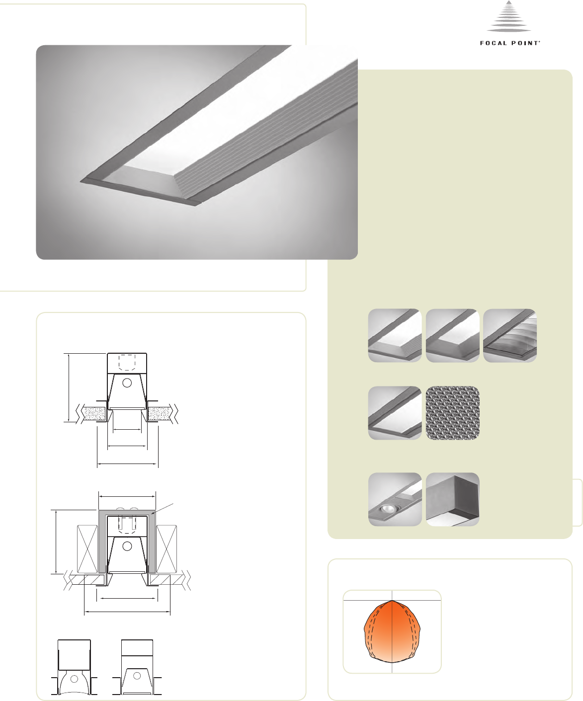
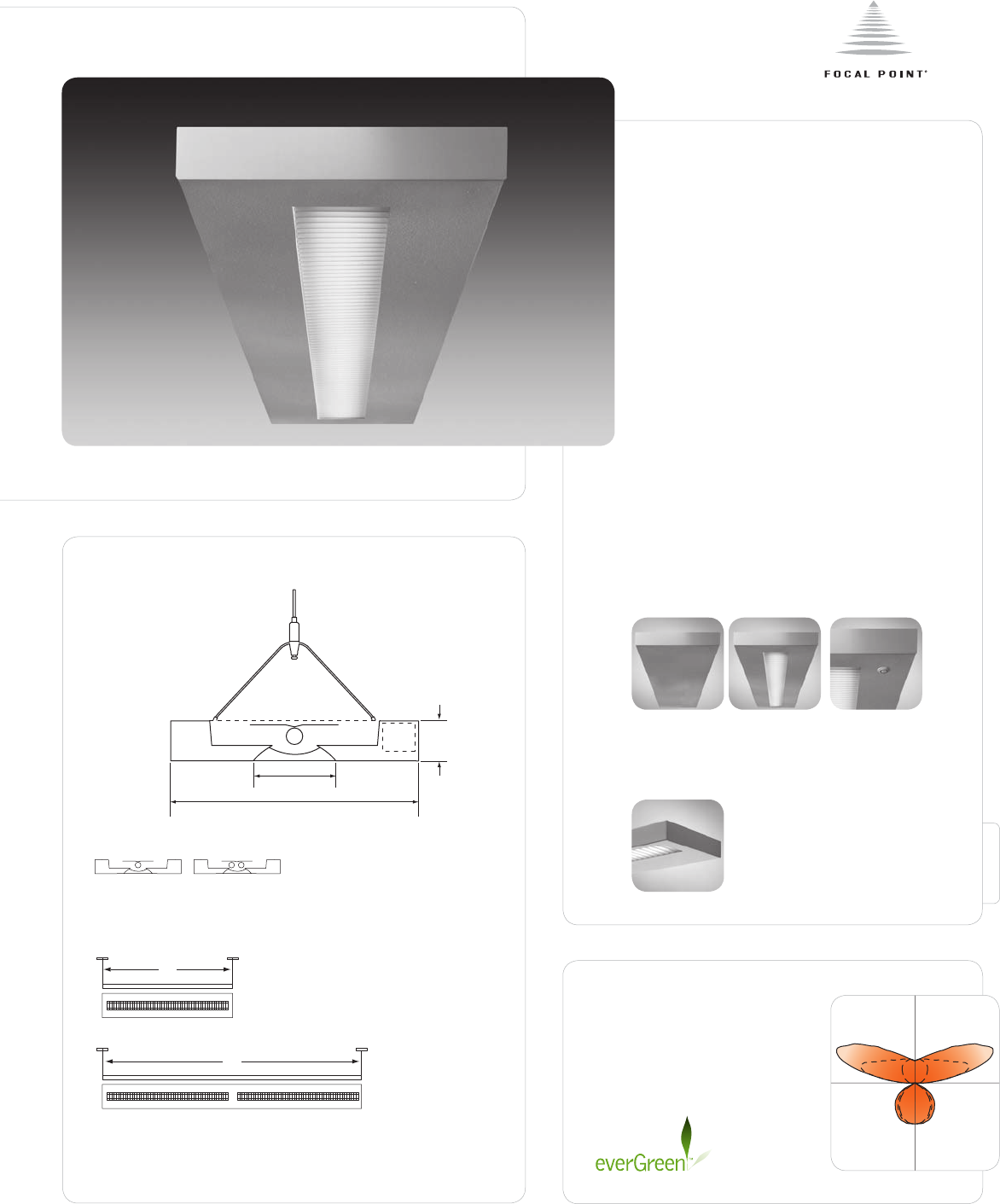
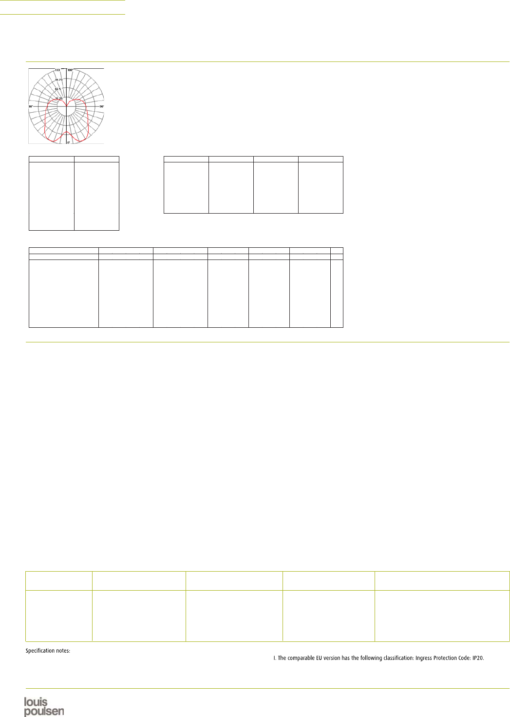
FEATURES
Narrow aperture high performance T5/T5HO
asymmetric wall wash.
Precision micro-optic delivers shadow free
illumination from the ceiling to the floor.
Features 2" narrow aperture for clean
unobtrusive aesthetic.
Drywall installation is available, which
allows for both individual or continuous row
mount capability.
Great solution for conference rooms,
highlighting artwork, corridors, white board
or any application that requires high levels
of vertical illumination.
companion luminaire
November 2007
avenue
® a
1–Lamp T5HO
57% Efficiency
1933 cd @ 25°
See Photometric section for
additional performance data.
PERFORMANCE
DIMENSIONAL DATA
86
recessed
wall mount
linearmr16
A1
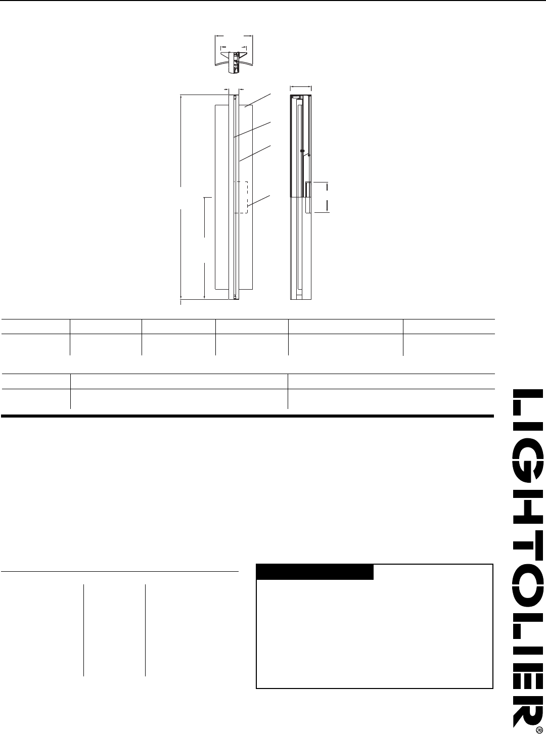
F01
fixture type:
project name:
SPECIFICATIONS
construction
One-piece 20 Ga. steel housing.
Grid luminaires include 20 Ga. steel, .5" wide universal flange rail.
Drywall flange option is provided with 20 Ga. steel, .5" wide flange kit and 20 Ga.
galvanized steel mounting yoke.
2' unit weight: 5 lbs.
3' unit weight: 6 lbs.
4' unit weight: 7 lbs.
5' unit weight: 8 lbs.
optic
.020" specular aluminum upper reflector and .020" semi-specular lower reflector.
24 Ga. perforated matte black diffuser with 24% opening.
please note:
radial cut-off louver FAVA-RL or the clear lens FAVA-CL cannot be field installed
on the non-shielded profile FAVA-NS.
electrical
Luminaires are individually wired for specified circuits.
Thru-wiring not available.
Electronic ballasts are thermally protected and have a Class “P” rating.
Optional DALI and other dimming ballasts available.
Consult factory for dimming specifications and availability.
UL and cUL listed.
emergency
Emergency battery packs provide 90 minutes of illumination.
Initial lumen output for lamp types are as follows:
T5 Lamp: Up to 550 lumens
T5HO Lamps: Up to 825 lumens
Battery pack requires unswitched hot from same branch circuit as AC ballast.
finish
Polyester powder coat applied over a 5-stage pre-treatment.
Standard luminaire housing finished in Matte Satin White or Matte Black.
Perforated diffuser always finished in Matte Black.
ORDERING
luminaire series
Avenue A FAVA
shielding
No Shielding, Open Optic NS
(Radial cut-off louver FAVA-RL
or the clear lens FAVA-CL
cannot be field installed on the
non-shielded profile FAVA-NS)
lamping
One Lamp T5 1T5
One Lamp T5HO 1T5HO
circuits
Single Circuit 1C
voltage
120 Volt 120
277 Volt 277
347 Volt 347
(Consult factory for availability)
ballast
Electronic Program Start <10% THD S
Electronic Dimming Ballast D
ceiling configurations
(For mounting configurations, see
Reference section)
Drywall Flange F
(Consult factory for custom variations)
Std. 15/16" Lay-in G1
Std. 15/16" Tegular T1
Std. 15/16" Tegular, against Tee T1T
Std. 9/16" Lay-in G2
Std. 9/16" Tegular T2
Std. 9/16" Tegular, against Tee T2T
9/16" Slot-tee Tegular G3
Tall 15/16" Lay-in G4
Tall 15/16" Tegular T4
Tall 15/16" Tegular, against Tee T4T
Tall 9/16" Lay-in G5
Tall 9/16" Tegular T5
Tall 9/16" Tegular, against Tee T5T
Node 9/16" Tegular T6
Node 9/16" Tegular, against Tee T6T
factory options
Chicago Plenum CP
Emergency Circuit EC
Emergency Battery Pack EM
(3' & 4' Luminaires Only)
Seismic Brackets EQ
HLR/GLR Fuse FU
Include 3000K Lamp L830
Include 3500K Lamp L835
Include 4100K Lamp L841
finish
Matte White Housing WH
Titanium Silver TS
Matte Black Housing BK
(Perforated diffuser always painted black)
luminaire length
2' Nominal Housing 2'
3' Nominal Housing 3'
4' Nominal Housing 4'
5' Nominal Housing 5'
(Dimming not available with 5' lamps)
(For continuous row mount in drywall
ceiling, specify luminaire run length, ie 24')
FAVA
1C
Focal Point L.L.C. 4201 South Pulaski Rd, Chicago, Illinois 60632 | T: 773.247.9494 | F: 773.247.8484 | info@focalpointlights.com | www.focalpointlights.com
Focal Point L.L.C. reserves the right to change specifications for product improvement without notification.
DETAILS
Drywall flange version provided with mounting yoke.
5' unit (cutout dimension: 3.5" x 59.6")
3' unit (cutout dimension: 3.5" x 35.6")
2' unit (cutout dimension: 3.5" x 23.6")
4' unit (cutout dimension: 3.5" x 47.6")
grid
drywall
Standard
G2, T2, T2T
1 1
/
2
"
Standard
G1, T1, T1T
1 1
/
2
"
15
/
16
"
1 1
/
2
"
Slot tee
G3
Tall
G4, T4, T4T
1 11
/
16
"
Tall
G5, T5, T5T
1 11
/
16
"
Node
T6, T6T
1 1
/
2
"
15
/
16
"
9
/
16
"
9
/
16
"
9
/
16
"
9
/
16
"
lay-in tile tegular tile
row mount
detail
RECESSED
87
1 1
/
2
"
1 1
/
2
"
1 1
/
2
"
1 1
/
2
"
1 11
/
16
"
1 11
/
16
"
A2
4'
NS
1T5
277
S
G1
-
WH
F01
avenue
® a
0
390
780
1170
1560
1950
0
°
10
°
20
°
30
°
40
°
0°
45°
90°
90°
45°
0°
90
°
80
°
70
°
60
°
50
°
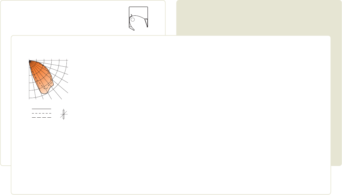
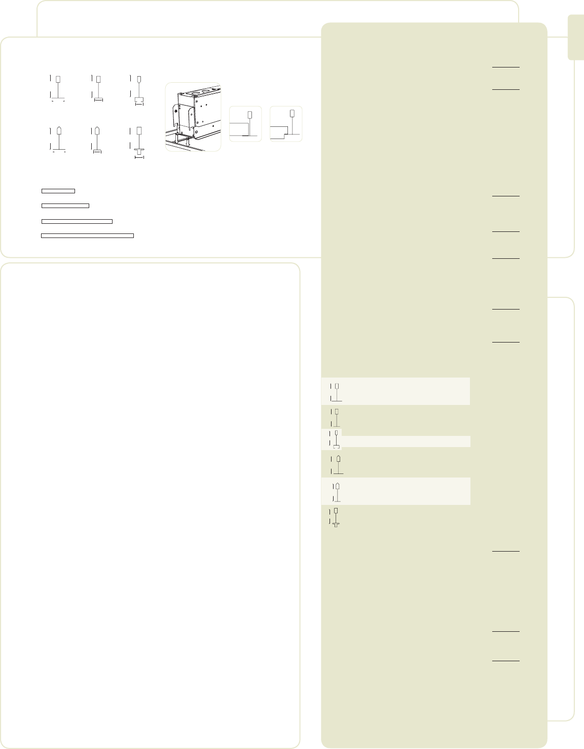
CANDLEPOWER DISTRIBUTION LUMEN SUMMARY
Filename: FAVANS1T5H.IES
Catalog #: FAVA-NS-1T5HO-1C-120-S-G-WH-4'
Efficiency: 57%
Test #: 12355.0
0°
5°
15°
45°
55°
105°
115°
125°
135°
145°
155°
165°
175°
180°
276 256 214 154 101 13
919 771 499 291 102 85
1806 1775 1647 1296 88 610
To t al
25°
35°
65°
75°
85°
90°
95°
108108108108108
1933 1873 1300 415 101 279
1832 1799 1695 707 96 408
1434 1416 1329 110874 580
1072 1052 962 811 56 473
655 631 56845839 294
317 294 224 129 14 119
183 165 112 40 2
0 0 0 0 0 0
0 0 0 0 0 0
0 0 0 0 0 0
0 0 0 0 0 0
0 0 0 0 0 0
0 0 0 0 0 0
0 0 0 0 0 0
0 0 0 0 0 0
0 0 0 0 0 0
0 0 0 0 0
Vertical Horizontal Angle Zonal
Angle 0° 22.5° 45° 67.5° 90° Lumens
376 7.5 13.2
784 15.7 27.4
1975 39.5 69.0
2861 57.2 100.0
2861 57.2 100.0
Luminaire
% %
Zone Lumens Lamp Fixt
0°-30°
0°-40°
0°-60°
0°-90°
0°-180°
Go to www.focalpointlights.com for additional photometric data.
A3
F01
Louver
Grid Mount (Regress Trim Shown)
Drywall Flange (Regress Trim Shown)
Flush Lens
2.88"
73.15mm
2.02"
51.31mm
frame width
4.75" max–4.625" min
Mounting yoke must be
installed before drywall.
(see Instruction Sheet
#ISO217 for details)
4.80"
121.92mm
5.00"
127mm
4.0"
101.6mm
4.0"
101.6mm
6.5"
165.1mm
FEATURES
Narrow 3" slot T5 fluorescent with opaque
satin lens.
Shielding options include corrugated, solid
regressed trim, concave louver as well as
flush lens.
Drywall installation is available, which
allows for both individual or continuous row
mount capability.
Avenue® B is a great solution for general
illumination in a narrow aperture.
shielding options
companion luminaire
january 2008
avenue® b
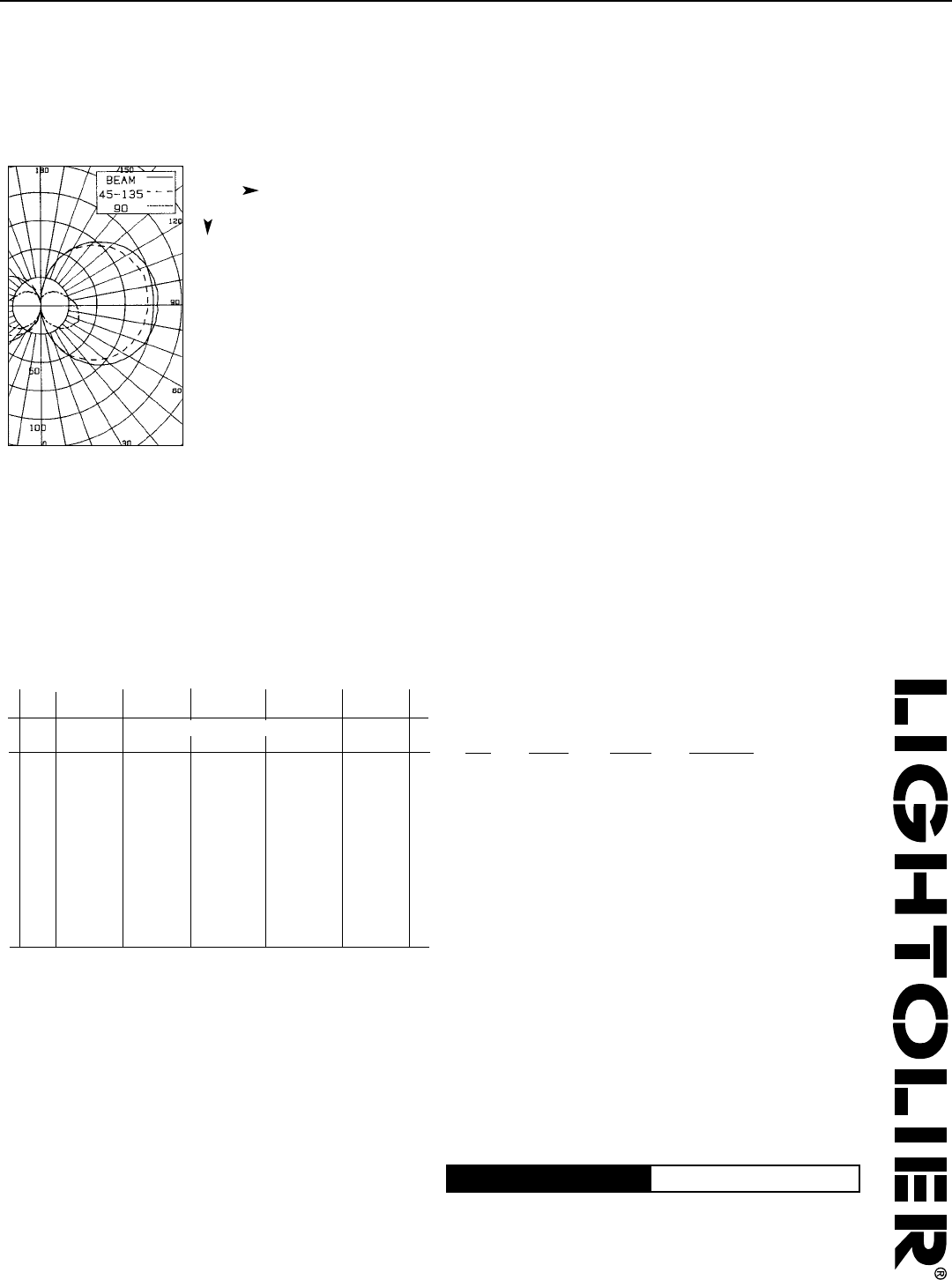
1–Lamp T5
62% Efficiency
1466 cd @ 0°
See Photometric section for
additional performance data.
PERFORMANCE
DIMENSIONAL DATA
corrugated
regress trim
flush lens microglowTM\ lens
solid regress
trim concave louver
mr16 linear
A4
F02
fixture type:
project name:
SPECIFICATIONS
construction
One-piece 20 Ga. steel housing.
Corrugated and solid regress trim constructed of 6063-T5 extruded aluminum
finished in Matte Satin White.
Grid luminaires include 20 Ga. steel, .5" wide flange rail finished in Matte
Satin White.
Drywall flange option is provided with 20 Ga. steel, .5" wide flange kit and 20 Ga.
galvanized steel mounting yoke.
2' unit weight: 5 lbs.
3' unit weight: 6 lbs.
4' unit weight: 7 lbs.
5' unit weight: 8 lbs.
optic
22 Ga. steel reflectors finished in High Reflectance White powder coat.
Frosted Acrylic lens diffuser .118" thick.
Clear Acrylic MicroGlowTM diffuser .125" thick with miniature prismatic pattern.
Concave parabolic louver: 1"H x 1" frequency fabricated of low iridescent,
semi-specular premium grade aluminum.
Louver can be specified with matte white finish.
electrical
Luminaires are individually wired for specified circuits.
Thru-wiring not available.
Electronic ballasts are thermally protected and have a Class “P” rating.
Optional DALI and other dimming ballasts available.
Consult factory for dimming specifications and availability.
UL and cUL listed.
emergency
Emergency battery packs provide 90 minutes of illumination.
Initial lumen output for lamp types are as follows:
T5 Lamp: Up to 550 lumens
T5HO Lamps: Up to 825 lumens
Battery pack requires unswitched hot from same branch circuit as AC ballast.
finish
Polyester powder coat applied over a 5-stage pre–treatment.
Standard luminaire housing finished in Matte Satin White.
FAVB
Focal Point L.L.C. 4201 South Pulaski Rd, Chicago, Illinois 60632 | T: 773.247.9494 | F: 773.247.8484 | info@focalpointlights.com | www.focalpointlights.com
Focal Point L.L.C. reserves the right to change specifications for product improvement without notification.
DETAILS
Drywall flange version provided with mounting yoke.
5' unit (cutout dimension: 3.5" x 59.6")
3' unit (cutout dimension: 3.5" x 35.6")
2' unit (cutout dimension: 3.5" x 23.6")
4' unit (cutout dimension: 3.5" x 47.6")
grid
drywall
Standard
G2,T2,T2T
1 1
/
2
"
Standard
G1,T1,T1T
lay-in tile tegular tile
1 1
/
2
"
15
/
16
"
1 1
/
2
"
Slot tee
G3
Tall
G4,T4,T4T
1 11
/
16
"
Tall
G5,T5,T5T
1 11
/
16
"
Node
T6,T6T
1 1
/
2
"
15
/
16
"
9
/
16
"
9
/
16
"
9
/
16
"
9
/
16
"
RECESSED
1C
WH
ORDERING
luminaire series
Avenue B FAVB
shielding
Corrugated Regressed Trim Frst.Lns CR
Solid Regressed Trim Frosted Lens SR
Concave Parabolic Louver PL
Flush Frosted Lens FL
Corrugated Regressed Trim CRM
with MicroGlowTM Lens
Solid Regressed Trim SRM
MicroGlowTM Lens
Flush MicroGlowTM Lens FLM
White Concave Parabolic Louver PW
lamping
One Lamp T5 1T5
One Lamp T5HO 1T5HO
circuits
Single Circuit 1C
voltage
120 Volt 120
277 Volt 277
347 Volt 347
(Consult factory for availability)
ballast
Electronic Program Start <10% THD S
Electronic Dimming Ballast D
ceiling configurations
(For mounting configurations, see
Reference section)
Drywall Flange F
(Consult factory for custom variations)
Std. 15/16" Lay-in G1
Std. 15/16" Tegular T1
Std. 15/16" Tegular, against Tee T1T
Std. 9/16" Lay-in G2
Std. 9/16" Tegular T2
Std. 9/16" Tegular, against Tee T2T
9/16" Slot-tee Tegular G3
Tall 15/16" Lay-in G4
Tall 15/16" Tegular T4
Tall 15/16" Tegular, against Tee T4T
Tall 9/16" Lay-in G5
Tall 9/16" Tegular T5
Tall 9/16" Tegular, against Tee T5T
Node 9/16" Tegular T6
Node 9/16" Tegular, against Tee T6T
factory options
Chicago Plenum CP
Emergency Circuit EC
Emergency Battery Pack EM
(3' & 4' Luminaires Only)
Seismic Brackets EQ
HLR/GLR Fuse FU
Include 3000K Lamp L830
Include 3500K Lamp L835
Include 4100K Lamp L841
finish
Matte White Housing WH
luminaire length
2' Nominal Housing 2'
3' Nominal Housing 3'
4' Nominal Housing 4'
5' Nominal Housing 5'
(Dimming not available with 5' lamps)
(For continuous row mount in drywall
ceiling, specify luminaire run length, ie 24')
1 1
/
2
"
1 1
/
2
"
1 1
/
2
"
1 1
/
2
"
1 11
/
16
"
1 11
/
16
"
A5
WH
NS
1T5
277
S
G1
-
F02
regress with lens
avenue® b
Numbers indicate percentage values of reflectivity.
Floor
Ceiling
Wall
RCR 0
1
2
3
4
5
6
7
8
9
10
20
80 70 50 30 10 00
70 50 30 10 70 50 10 50 10 50 10 50 10 00
73 73 73 73 72 72 72 68 68 65 65 63 63 62
68 66 64 62 67 65 61 62 59 60 57 58 56 54
63 59 56 53 62 58 52 56 51 54 50 52 49 48
59 53 49 46 57 52 45 51 45 49 44 48 43 42
54 48 43 40 59 47 40 46 39 45 39 43 38 37
50 43 38 35 49 42 34 41 34 40 34 39 33 32
46 39 34 31 45 39 30 37 30 36 30 36 30 29
43 35 31 27 42 35 27 34 27 33 27 32 26 25
40 32 27 24 39 32 24 31 24 30 23 29 23 22
37 29 24 21 36 29 21 28 21 27 21 27 20 19
34 26 22 19 33 26 19 25 18 25 18 24 18 17
1466
1172
879
586
293
0
293
586
879
1172
1466
180
°
170
°
160
°
150
°
140
°
0
°
10
°
20
°
30
°
40
°
0°
45°
90°
0°45°
90°
130
°
120
°
110
°
100
°
90
°
80
°
70
°
60
°
50
°
Spacing 1.2
Criterion: 1.1
CANDLEPOWER DISTRIBUTION
CO–EFFICIENTS OF UTILIZATION
LUMINANCE DATA (CD/M2)
LUMEN SUMMARY
Filename: FAVBSR1T5HO.IES
Catalog #: FAVB-SR-1T5HO-1C-120-S-G1-WH-4’
Efficiency: 62%
Test #: 12914.0
0°
5°
15°
25°
35°
45°
55°
65°
75°
85°
90°
95°
105°
115°
125°
135°
145°
155°
165°
175°
180°
1466 1466 1466 1466 1466
1457 1457 1456 1456 1456 139
1432 1428 1417 1399 1393 401
1311 1299 1254 1187 1150 575
1102 1073 958 837 793 599
934 866 701 586 553 565
649 578 426 357 335 416
404 328 232 187 174 257
184 133 77 60 58 103
39 21 19 18 17 24
0 0 0 0 0
0 0 0 0 0 0
0 0 0 0 0 0
0 0 0 0 0 0
0 0 0 0 0 0
0 0 0 0 0 0
0 0 0 0 0 0
0 0 0 0 0 0
0 0 0 0 0 0
0 0 0 0 0 0
0 0 0 0 0
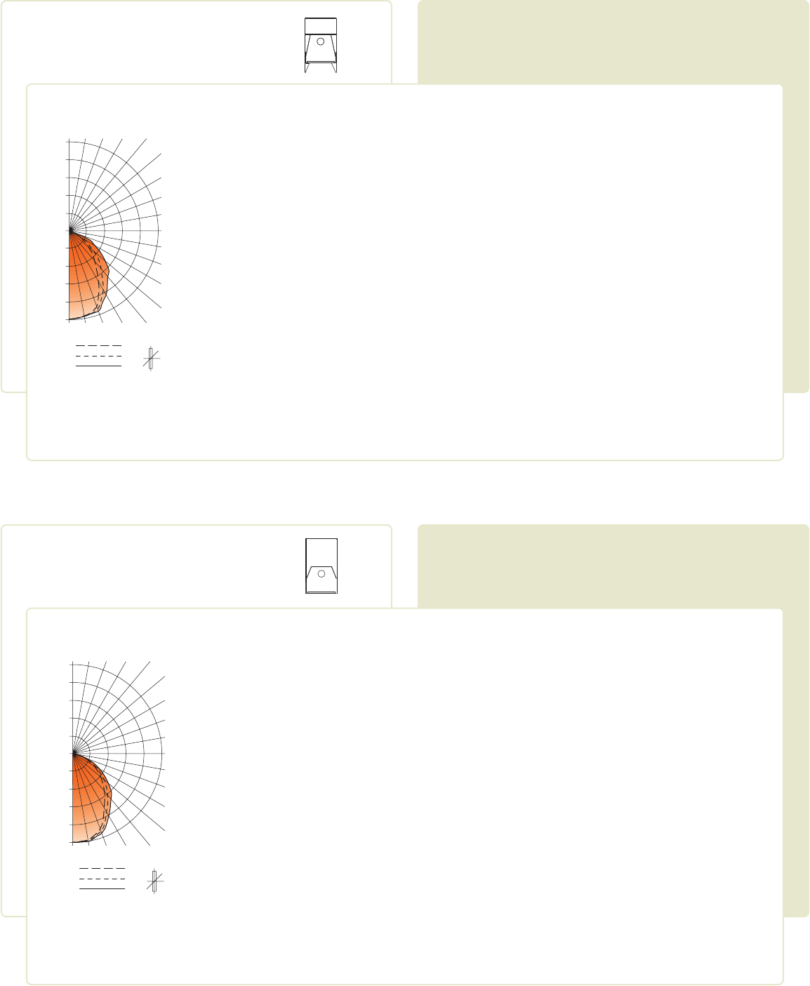
Vertical Horizontal Angle Zonal
Angle 0° 22.5° 45° 67.5° 90° Lumens
1115 22.3 36.2
1714 34.3 55.7
2695 53.9 87.5
3078 61.6 100.0
3078 62 100.0
Total
Luminaire
% %
Zone Lumens Lamp Fixt
0°-30°
0°-40°
0°-60°
0°-90°
0°-180°
16467 12359 9750
14106 9259 7281
11918 6844 5133
8863 3709 2794
5579 2718 2432
Vertical
Angle 0° 45° 90°
45°
55°
65°
75°
85°
Go to www.focalpointlights.com for additional photometric data.
flush lens
avenue® b
Numbers indicate percentage values of reflectivity.
Floor
Ceiling
Wall
RCR 0
1
2
3
4
5
6
7
8
9
10
20
80 70 50 30 10 00
70 50 30 10 70 50 10 50 10 50 10 50 10 00
77 77 77 77 75 75 75 72 72 69 69 66 66 65
71 69 66 64 70 67 63 64 61 62 59 60 57 56
66 61 57 54 64 60 53 58 52 56 51 54 50 49
61 55 50 46 59 54 46 52 45 50 44 49 44 42
56 49 44 40 55 48 40 47 39 45 39 44 38 37
51 44 38 34 50 43 34 42 34 41 34 39 33 32
48 40 34 30 46 39 30 38 30 37 30 36 29 28
44 36 30 27 43 35 27 34 26 33 26 32 26 25
43 32 27 23 40 32 23 31 23 30 23 29 23 22
37 29 24 20 37 29 20 28 20 27 20 26 20 19
35 26 21 18 34 26 18 25 18 25 18 24 18 17
1405
1124
843
562
281
0
281
562
843
1124
1405
180° 170° 160° 150° 140°
0° 10° 20° 30° 40°
0°
45°
90°
0° 45°
90°
130°
120°
110°
100°
90°
80°
70°
60°
50°
Spacing 1.2
Criterion: 1.0
CANDLEPOWER DISTRIBUTION
CO–EFFICIENTS OF UTILIZATION
LUMINANCE DATA (CD/M2)
LUMEN SUMMARY
Filename: FAVBFL1T5.IES
Catalog #: FAVB-FL-1T5HO-1C-120-S-G1-WH-4’
Efficiency: 65%
Test #: 13734.0
0°
5°
15°
25°
35°
45°
55°
65°
75°
85°
90°
95°
105°
115°
125°
135°
145°
155°
165°
175°
180°
1397 1397 1397 197 1397
1395 1395 1394 1391 1392 133
1361 1357 1342 1329 1324 381
1242 1228 1192 1159 1145 552
1029 1005 950 903 885 599
8446 812 747 700 684 586
580 550 501 471 464 458
356 338 310 297 293 315
165 158 150 144 142 160
35 37 38 38 40 41
0 0 0 0 0
0 0 0 0 0 0
0 0 0 0 0 0
0 0 0 0 0 0
0 0 0 0 0 0
0 0 0 0 0 0
0 0 0 0 0 0
0 0 0 0 0 0
0 0 0 0 0 0
0 0 0 0 0 0
0 0 0 0 0
Vertical Horizontal Angle Zonal
Angle 0° 22.5° 45° 67.5° 90° Lumens
1066 21.3 33.0
1665 33.3 51.6
2709 54.2 84.0
3225 64.5 100.0
3225 64.5 100.0
Total
Luminaire
% %
Zone Lumens Lamp Fixt
0°-30°
0°-40°
0°-60°
0°-90°
0°-180°
19577 17286 15828
16546 14293 13237
13784 12003 11344
10432 9483 8977
6571 7134 7510
Vertical
Angle 0° 45° 90°
45°
55°
65°
75°
85°
Go to www.focalpointlights.com for additional photometric data.
A6
F02
-
- -
-
16
P e r s o n a l L i g h t i n g 17
Solid Color Shade Color Options
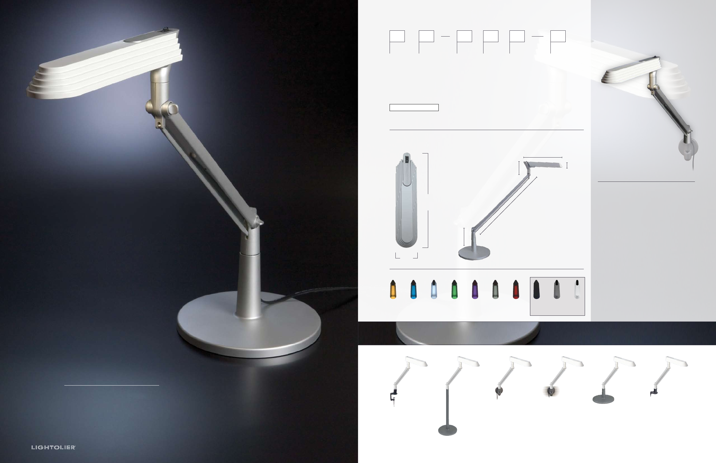
SURFSIDE
F l u o r e s c e n t / L E D T a s k L i g h t
Lamp: 13w compact
uorescent 4-pin /2G7 base
(3500k). Lamps included. Or 8x1w
LEDs (6500k). LEDs included.
Electrical: Wired for 120V
60Hz operation.
Ballast: In-line
hybrid electronic ballast
with quick connect cord.
Transformer (LED):
In-line transformer with
quick connect cord.
Primary input: 120V.
Secondary output: 12V.
Power Cord: Quick connect.
Minimum 6ft (182mm) long.
Arm: Extruded aluminum,
spring-balanced arm with
adjustable tension joints.
Available in 14" or 20" lengths.
Shade: Hi-impact
polycarbonate with a
perforated reector and
prismatic lens. Solid or
transparent colors. See color
options in options block.
Finish: Matte black or silver
Listing: UL/cUL listed.
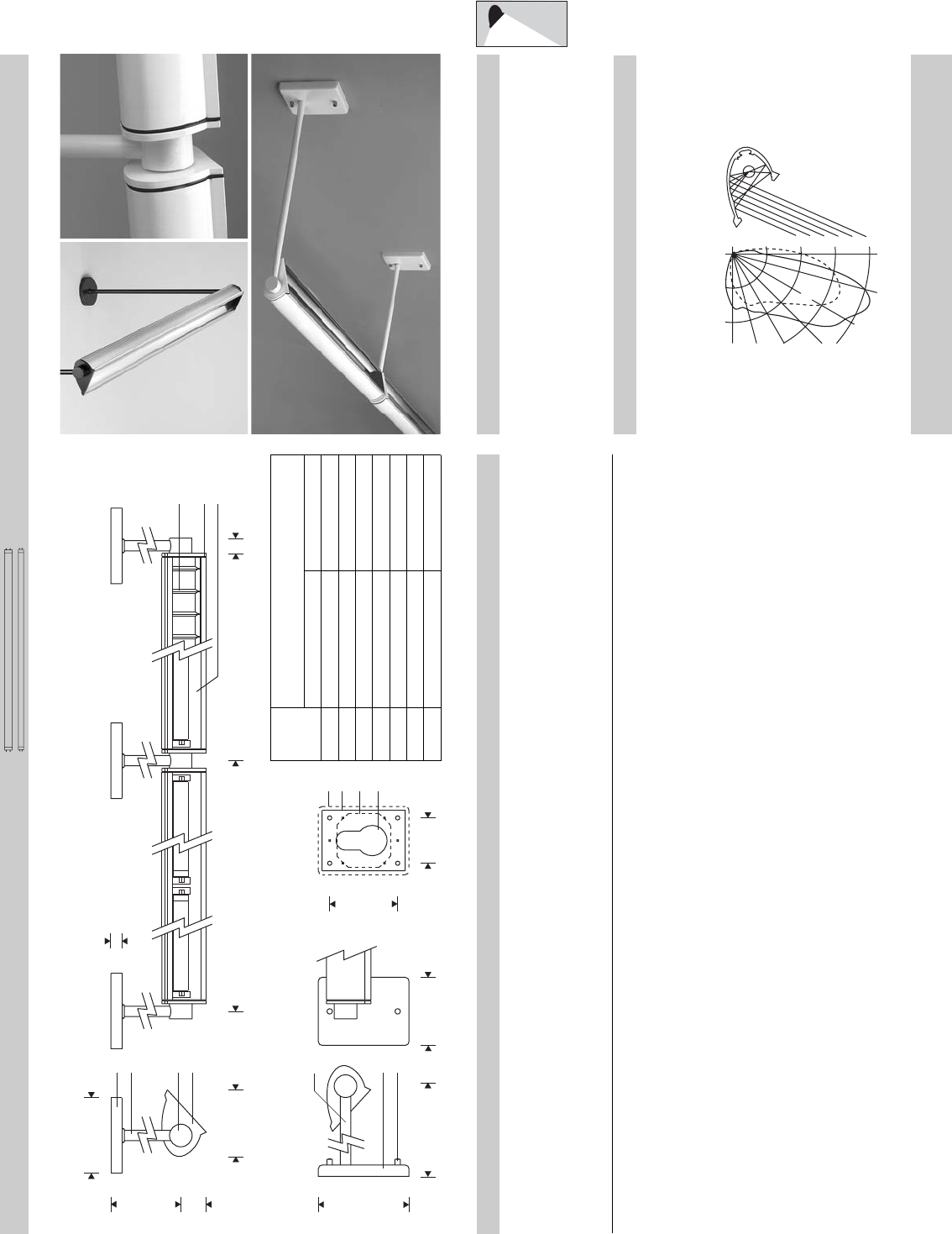
Features
Zero Clearance
Bracket (Z):
Two-piece edge clamp for
tight spaces. Clamps onto
edge of desk or table.
Edge Clamp (E):
Clamps onto edge
of desk or table.
Floor Stand (F):
Weighted oor base.
Table Base (T):
9" diameter weighted
base for desktop use.
Panel Bracket (P):
Attaches to 1" slotted
panel standard.
Consult factory for
furniture compatibility.
Slat Wall
Bracket (S):
Attaches to many
furniture slat
wall systems.
Consult factory
for furniture
compatibility.
Series Lamps Arm Color Mounting Options
SU = Surfside F = 13W Compact S = 14" B = Black E = Edge Clamp Shade Color Options
Fluorescent L = 20" S = Silver F = Floor Stand AM = Amber
L = LED 8x1w P = Panel Bracket BK = Black (solid)
S = Slat Wall Bracket BL = Blue
T = Table Base BW = Blue White
Z = Zero Clearance GN = Green
Bracket PL = Purple
SM = Smoke
SI = Silver (solid)
WN = Wine
WT = White (solid)
S U
Example = SUF–SSP–WT
Note: Colors not designated as solid are transparent.
Dimensions
M o u n t i n g O p t i o n s
Ordering Information
Shade Entire Fixture
SURFSIDE
Surfside is a sleek, contemporary adjustable arm task light
with two arm sizes and two distinctively different light sources.
Available in either 13 watt compact fluorescent or state of
the art LED versions, Surfside will provide the right amount
of light where needed in the task area. Surfside is available
in black or silver with 10 solid or transparent colored shade
options. The shade assemblies are easily interchangeable to suit
user preference.
Shade Color Options
AM BL BW GN PL SM WN WTBK SI
10 ⁄"
260mm
2 ⁄"
57mm
4 ⁄"
121mm
3 ⁄"
89mm
1 ⁄"
29mm
10 ⁄"
260mm
20" (L - Arm)
508mm
14" (S - Arm)
356mm
A7
F
L
S
T
SL
F03
dimensional data
Visit focalpointlights.com for
complete photometric data.
louver/indirect
twelve™
features
Suspended direct/indirect ideal for low
ceiling applications.
Twelve™ delivers 70% indirect/30% direct
illumination.
The CU Filter precisely controls lamp
brightness above the fixture to allow for 12"
suspension lengths.
Sleek rectilinear design adds clean style to
any space.
Parallel blade louver with acrylic lens diffuser
provides comfortable downlight shielding.
Excellent choice for lower ceiling
applications and areas where ceiling
uniformity is important.
shielding options sensor options
companion luminaire
performance
1–Lamp T5HO
90% Efficiency
1264 cd @ 115°
70%
30%
Covered by the following U.S. Patents: 5,733,028; 5,914,487; 5,967,652;
6,043,873; 6,064,061; 6,088,091; 6,238,077; 6,266,136; 6,334,700.
july 2008
3.00"
76.2mm
9.00"
228.6mm
1.43"
36.32mm
T5/T5HO LAMPS
lamping options
fixture information
4'
8'
48"
96"
solid indirect louver
wall mount
daylight /
occupancy sensor
www.focalpointlights.com | 1.773.247.9494
A8
F04
suspension information
Consult factory for additional row length information.
16' 8' start 8' end
96" 96"
24' 8' start 8' end
8' intermediate
96" 96" 96"
20' 4' intermediate 8' end
8' start
96" 96"48"
12' 4' end
8' start
96" 48"
fixture:
project:
Focal Point LLC | 4141 S. Pulaski Rd, Chicago, IL 60632 | T: 773.247.9494 | F: 773.247.8484 | info@focalpointlights.com | www.focalpointlights.com.
Focal Point LLC reserves the right to change specifications for product improvement without notification.
ordering
fixture series FTWS
twelve FTWS
shielding
Parallel Blade Louver with CU Filter PB
Solid, no lens, 100% indirect SD
lamping
1 Lamp T5 1T5
1 Lamp T5HO 1T5HO
2 Lamp T5 2T5
2 Lamp T5HO 2T5HO
circuit
Single Circuit 1C
Dual Circuit 2C
(Multiple lamp luminaires only)
voltage
120 Volt 120
277 Volt 277
347 Volt 347
ballast
Electronic Program Start <10% THD S
Electronic Dimming Ballast* D
mounting
12" Cable Suspension J12
(5" canopy at feed locations and 2" canopy
non–feed locations)
(specify “C" in place of “J" for 5" dia. canopies
both at power feed and non–feed locations)
(suspension may be adjusted up to 24". Consult
factory for lengths longer than 24")
Stem Mount S__
(specify stem length in inches Standard stem
lengths 6, 12, 18, 24, 36, 48". Stem painted
white unless otherwise specified)
factory options
Emergency Circuit* EC
Emergency Battery Pack* EM
HLR/GLR Fuse FU
Include 3000K Lamp L830
Include 3500K Lamp L835
Include 4100K Lamp L841
(factory installed lamps recommended)
Lutron™ Daylight Sensor* LY1
(EcoSystem ballast required)
Lutron™ IR Receiver* LIR
(EcoSystem ballast required)
Lutron™ Sensor Feed* SF
(EcoSystem ballast required)
WattStopper™ Daylight Sensor* WY1
(0–10V dimming ballast required)
WattStopper™ Occupancy Sensor* WO1
finish
Matte Satin White WH
Titanium Silver TS
(louver painted to match housing)
fixture run length
4' 4'
8' 8'
12' (8'+4') 12'
16' (8'+8') 16'
20' (8'+4'+8') 20'
24' (8'+8'+8') 24'
(individual units may not be field modified for
continuous row mount)
remotes
(specify quantity)
WattStopper™ Daylight Setup Remote* WYSR
(required for daylight programming,
one included per order)
WattStopper™ Occupant Controller* WOR
* for more information see Reference section.
linear
specifications
construction
One-piece 20 Ga. steel housing.
14 Ga. steel end caps mechanically attach flush to housing with concealed fasteners.
For row installation, internal brackets form hairline joint.
Standard lengths are available in 4' and 8'.
All luminaires are provided with Y-cable suspension mounted on 48" or 96" centers.
4' unit weight: 20 lbs.
8' unit weight: 38 lbs.
optic
Reflector fabricated of low iridescent, semi specular premium grade aluminum.
Parallel Blade Louver: 24 Ga. steel, .5"H x 2.8"W x .56" frequency.
Louver blade finished to match housing and backed with an acrylic lens diffuser.
24 Ga. steel Ceiling Uniformity Filter (CU Filter) finished in high reflectance
white powder coat.
electrical
Luminaires are pre–wired with factory installed branch circuit wiring and
over-molded quick connects.
Factory installed SJT power cord at feed location is included.
Electronic ballasts are thermally protected and have a Class “P" rating.
Optional dimming ballasts available.
UL and cUL listed.
sensors
Lutron Daylight sensor is a directional sensor that operates with a Lutron
EcoSystem ballast. The sensor has an integrated IR receiver for EcoSystem
programming. One sensor controls multiple fixtures or groups of fixtures differently.
Sensor should be mounted 1 to 2 times the effective window height (from 3' AFF,
or bottom of window to top of window).
Lutron IR sensor controls individual or grouped EcoSystem ballasts or BMFs.
Sensor provides a flashing LED response to indicate signal reception and received
IR signals from up to 8' away when mounted on a 10' ceiling. Order Lutron IR
remote accessory (LOR).
Wattstopper Daylight sensor is a closed loop system that measures total light
level from daylight and electric light. A 0-10V dimming ballast is required, one
sensor controls multiple fixtures. Sensor should be mounted 6-12' from window.
Wattstopper daylight setup remote required for programming; one included per
order. Order additional setup remote accessory (WYSR) or occupant controller
remote accessory (WOR) for increased control.
Wattstopper Occupancy sensor is a passive infrared sensor designed for cubicles and
small offices. It has built-in daylight sensing that will hold lights off when adequate
ambient light exists. One sensor controls multiple fixtures.
finish
Polyester powder coat applied over a 5-stage pre–treatment.
Canopy finished in Matte Satin White.
A9
NS
1T5
277
S
G1
-
WH
4'
W01
TS
20'
F04
louver
twelveTM
Numbers indicate percentage values of
Floor
Ceiling
Wall
RCR 0
1
2
3
4
5
6
7
8
9
10
20
80 70 50 30 10 00
70 50 30 10 70 50 10 50 10 50 10 50 10 00
92 92 92 92 83 83 83 65 65 49 49 35 35 28
85 81 78 75 76 73 68 58 54 44 42 31 30 24
77 71 66 62 69 64 56 51 46 39 36 28 26 21
71 63 57 52 64 57 47 46 39 35 31 25 23 19
65 56 49 44 58 51 40 41 33 31 27 23 20 16
59 50 43 38 53 45 35 36 29 28 23 21 17 14
55 45 38 33 49 40 30 33 25 25 20 19 15 12
51 40 33 29 45 36 26 30 22 23 18 17 13 11
47 36 30 25 42 33 23 27 19 21 16 15 12 09
43 33 27 22 39 30 20 24 17 19 14 14 10 08
40 30 24 20 36 27 18 22 15 17 12 13 09 07
1260
1008
756
504
252
0
252
504
756
1008
1260
180
°
170
°
160
°
150
°
140
°
0
°
10
°
20
°
30
°
40
°
0°
45°
90°
0°
45°
90°
130
°
120
°
110
°
100
°
90
°
80
°
70
°
60
°
50
°
Spacing 1.1
Criterion: 1.3
CANDLEPOWER DISTRIBUTION
CO–EFFICIENTS OF UTILIZATION
LUMINANCE DATA (CD/M2)
LUMEN SUMMARY
Filename: FTWSPB1T5H.IES
Catalog #: FTWS-PB-1T5HO-1C-120-S-C12-WH-4’
Efficiency: 90%
Test #: 12096.0
0°
5°
15°
25°
35°
45°
55°
65°
75°
85°
90°
95°
105°
115°
125°
135°
145°
155°
165°
175°
180°
590 590 590 590 590
587 589 590 593 593 56
551 553 562 575 582 160
486 492 510 537 553 238
394 404 429 464 486 273
290 301 333 376 407 263
178 193 226 269 301 208
86 99 126 157 177 127
29 41 52 60 59 52
0 7 11 11 7 9
0 0 1 1 1
17 171 105 74 69 107
75 364 788 952 937 690
136 315 772 1151 1264 729
202 312 609 928 1051 555
255 330 516 722 806 406
321 355 449 550 302 285
357 373 415 462 490 194
373 377 385 399 410 110
365 365 365 364 364 35
352 352 352 352 352
Vertical Horizontal Angle Zonal
Angle 0° 22.5° 45° 67.5° 90° Lumens
454 9.1 10.1
1387 27.7 30.8
2082 41.6 46.3
3112 62.2 69.2
4498 90.0 100.0
Total
Luminaire
% %
Zone Lumens Lamp Fixt
0°-30°
0°-90°
90°-130°
90°-180°
0°-180°
2147 2466 3014
1625 2063 2748
1066 1531 2193
587 1052 1194
Vertical
Angle 0° 45° 90°
45°
55°
65°
75°
85°
Go to www.focalpointlights.com for additional photometric data.
A10
F04
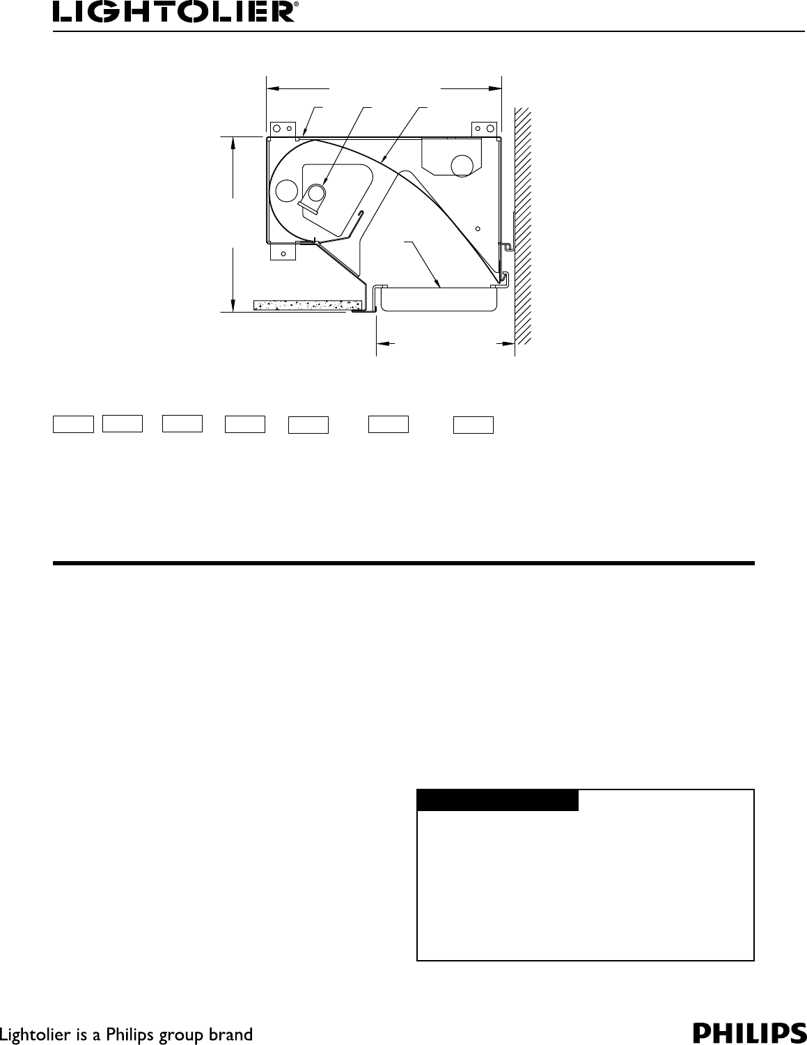
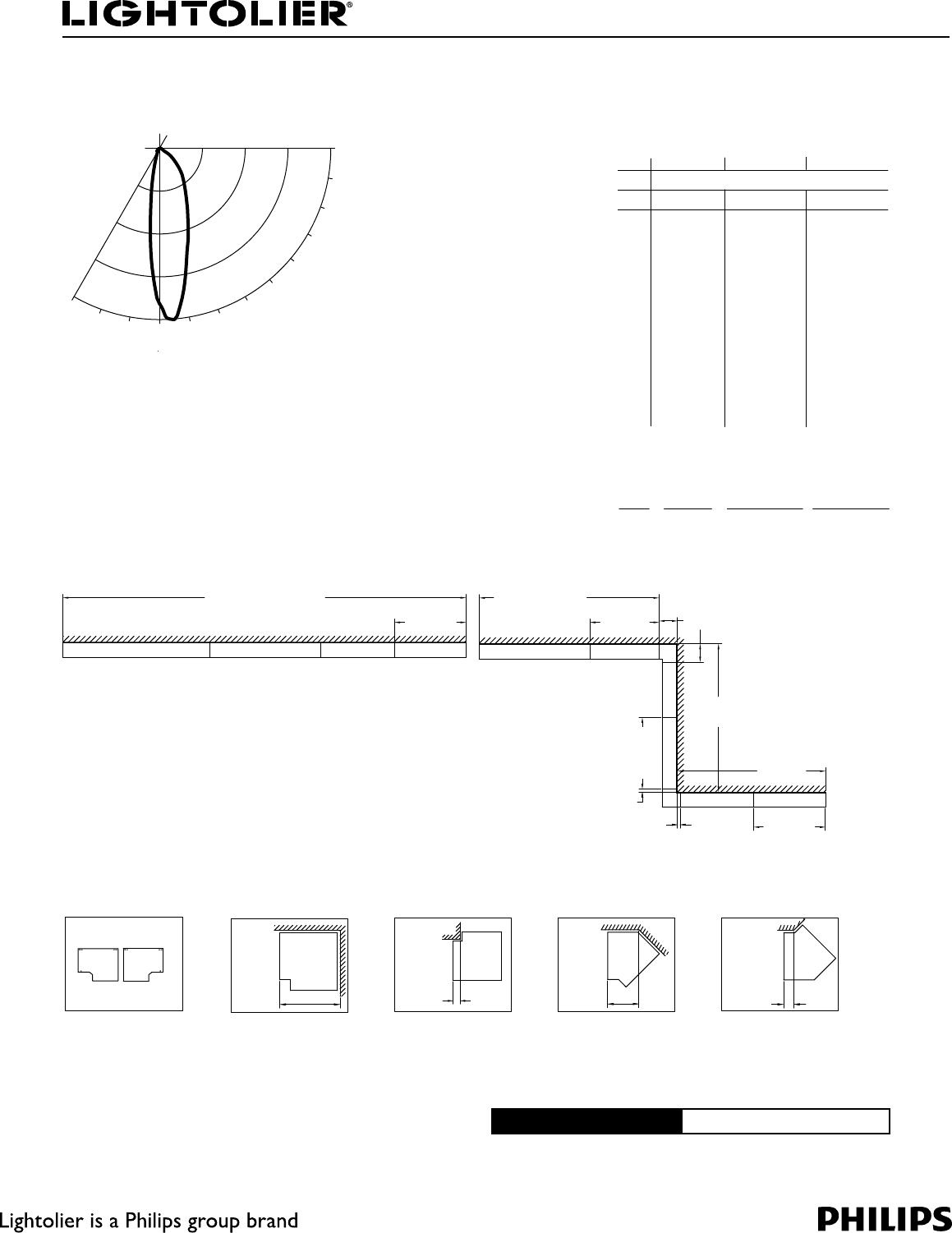
Lighting Systems PTS5-1
1BHFPG 1FSJNFUFS5SPVHI3FDFTTFE-JHIU51FS/PNJOBM4FDUJPO
7"
(17.78cm)
9 3/8" (23.81cm)
5 1/2" (13.97cm)
1 3
4
2
Quarter Scale
Module Ordering Information
Family Lamps Lamp Type Shielding Voltage Length Options
PTS5 1
1 = 1 Lamp S = Standard O = Open 1 = 120V 2 = Two-Foot Blank = No Options
H = HO L = Lens 2 = 277V 3 = Three-Foot A = Adjustable*
S = Straight 3 = 347V 4 = Four-Foot X4 = 4 thru wires
Blade Louver D1 = 120V Dim. 6 = Six-Foot X5 = 5 thru wires
D2 = 277V Dim. 8 = Eight-Foot A4 = Adjustable 4 thru wires*
E1 = 120V Emerg. A5 = Adjustable 5 thru wires*
E2 = 277V Emerg.
* only available on Two-Foot, Three-Foot and Four-Foot versions. See length variations of adjustable fixtures on page 2.
Features
1. Housing: Die-formed 20 gauge pre-painted steel. Integral heavy gauge bulk-
heads support housing and trim, permitting modules to be bolted together in
continuous runs and facilitate suspension.
2. Lamping: Cross-sectional one linear T5 fluorescent lamp. Provided by others.
3. Reflector: Precision parabolic roll-formed semi-specular aluminum.
4. Louver: Lift and shift straight blade louver constructed from die-formed alu-
minum and painted to match housing. Louver blades are 1” (2.54cm) high on
1-1/8” (2.86cm) centers. (Optional)
Mounting
“J” Rail is first mounted to the wall and the modules connect to the rail for 1/4”
(0.64cm) wall adjustment. Modules are hung from suspension wires attached to the
fixture bulkheads and the structure above.
Electrical
Electronic Ballast: Programmed start, 3 conductor, 12 gauge wire. Color-coded
quick connectors allow easy connection for modular fixutres. Factory installed
ballast disconnect allows the ballast to be disconnected from and reconnected to
incoming power under load without turning the entire circuit off.
Dimming: T5 lamp uses PowerSpec® HDF. Use PowerSpec® HDF compatible
three-wire control (extra control lead required).
T5 HO lamp uses Advance Mark X. Use Advance compatible two-wire control (no
extra control lead required).
Emergency Battery Pack: 450 Lumens @ 90 minimum.
Ordering Instructions
Individual Fixtures:
1. Order number of MODULES required.
2. Order one END SET per MODULE.
Continuous Rows:
1. Determine run length.
2. Order the appropriate number of MODULES for the complete ROW.
3. Stagger rows must be completed with an adjustable module. (2-light only)
4. Non-stagger rows must be completed with an adjustable module unless row
lengths are in precise 1 foot (30.48cm) intervals.
5. Order one END SET per ROW.
Labels
UL, cUL and IBEW
Job Information Type:
Job Name:
Cat. No.:
Lamp(s):
Notes:
"JSQPSU3PBE'BMM3JWFS."tt'BY
We reserve the right to change details of design, materials and finish.
XXXMJHIUPMJFSDPN½1IJMJQT(SPVQt $
A11
S
2
4
S
F05
Lighting Systems PTS5-1
1BHFPG 1FSJNFUFS5SPVHI3FDFTTFE-JHIU51FS/PNJOBM4FDUJPO
Performance & Quick Calculators CANDLEPOWER COEFFICIENTS OF UTILIZATION
ZONE 0 45 90 135 180 % EFFECTIVE CEILING CAVITY REFLECTANCE
2700
2025
1350
675
-30
-20
-10
30
40
50
60
70
80
90
10
20
DEG.
180
175
165
155
145
135
125
115
105
95
90
80 70 50
% WALL REFLECTANCE
70 50 30 70 50 30 50 30 10
0
1
2
3
4
5
6
7
8
9
10
44
41
39
36
34
32
30
28
27
25
24
44
40
36
33
30
28
26
24
23
21
20
44
39
34
31
28
25
23
22
20
19
18
43 43 43
40 39 38
38 36 34
35 33 30
33 30 28
31 28 25
29 26 23
28 24 22
26 23 20
25 21 19
24 20 18
41
28
34
32
29
27
25
24
22
21
20
41
37
33
30
27
25
23
21
20
19
17
41
36
32
28
25
23
21
20
18
17
16
0
0
0
0
0
0
0
0
0
0
21
0
0
0
0
0
0
0
0
0
0
28
0
0
0
0
0
0
0
0
0
0
0
0
0
0
0
0
0
0
0
0
0
0
0
0
0
0
0
0
0
0
0
0
0
85 27 39 12 10 0
75 34 78 53 45 9
ROOM CAVITY RATIO
0
Report No: ITL53559
Cat No: PTS51HS14
Lamps: 1 F54T5
Lumens: 5000
Efficiency: 37.2%
65 66 190 106 89 20
55 224 262 176 128 34
45 428 408 433 130 60
35 673 686 997 123 55
25 1036 1163 1558 203 83
15 1674 1943 2044 611 343 Floor cavity reflectance = 20%
5
0
2708
2450
2681
2450
2376
2450
1811
2450
1594
2450
ZONE
ZONAL LUMEN SUMMARY
LUMENS % BARELAMP % LUMINAIRE
0-90
90-180
0-180
1861
0.0
1861
37.2
0.0
37.2
100.0
0.0
100.0
Sample Run
For Fixture Using Staggered Lamps
The Four-Foot Adjustable Staggered Fixture has a range of 51”(129.54cm) - 60”(152.40cm).
The Three-Foot Adjustable Staggered Fixture has a range of 39”(99.06cm) - 48”(121.92cm).
The Two-Foot Adjustable Staggered Fixture has a range of 27”(68.58cm) - 36”(91.44cm).
For Fixture Using non-Staggered Lamps
The Four-Foot Adjustable Fixture has a range of 48.75”(123.83cm) - 60”(152.40cm).
The Three-Foot Adjustable Fixture has a range of 36.75”(93.35cm) - 48”(121.92cm).
The Two-Foot Adjustable Fixture has a range of 24.75”(62.87cm) - 36”(91.44cm).
6' (182.88cm) 4' (121.92cm) Three-Foot A¹
8' (243.84cm) Three-Foot A¹
6' (182.88cm)
Three-Foot A¹ 3' (91.44cm)
Three-Foot A¹4' (121.92cm)
1 3/4"
(4.45cm) 1 3/4"
(4.45cm)
¹ A = Adjustable Fixture or Adjustable Staggered Fixture
21' - 10 3/4" (667.39cm) 9' - 3 1/4" (282.58cm)
7' - 10 1/2"
(240.03cm)
7' - 10 1/2"
(240.03cm)
1’ (30.48cm)
Fixture used at
3’ - 10 3/4”
(118.75cm)
Fixture used at
3’ - 3 1/4”
(99.70cm)
Fixture used at
3’ - 10 1/2”
(118.11cm)
Fixture used at
3’ - 10 1/2”
(118.11cm)
End Plate and Corner Block Accessories
12”
(30.48cm)
1 3/4"
(4.45cm) 6 1/4"
(15.88cm)
2"
(5.08cm)
End Cap Set: 90° Inside Corner: 90° Outside Corner: 135° Inside Corner: 135° Outside Corner:
PTSEP PTS9ØINCO - Open PTS9ØOTCO - Open PTS135INCO - Open PTS135OTCO - Open
PTS9ØINCL - Lens PTS9ØOTCL - Lens PTS135INCL - Lens PTS135OTCL - Lens
PTS9ØINCS - Straight PTS9ØOTCS -Straight PTS135INCS - Straight PTS135OTCS - Straight
Blade Louver Blade Louver Blade Louver Blade Louver
Job Information Type:
"JSQPSU3PBE'BMM3JWFS."tt'BY
We reserve the right to change details of design, materials and finish.
XXXMJHIUPMJFSDPN½1IJMJQT(SPVQt $
A12
F05
F05
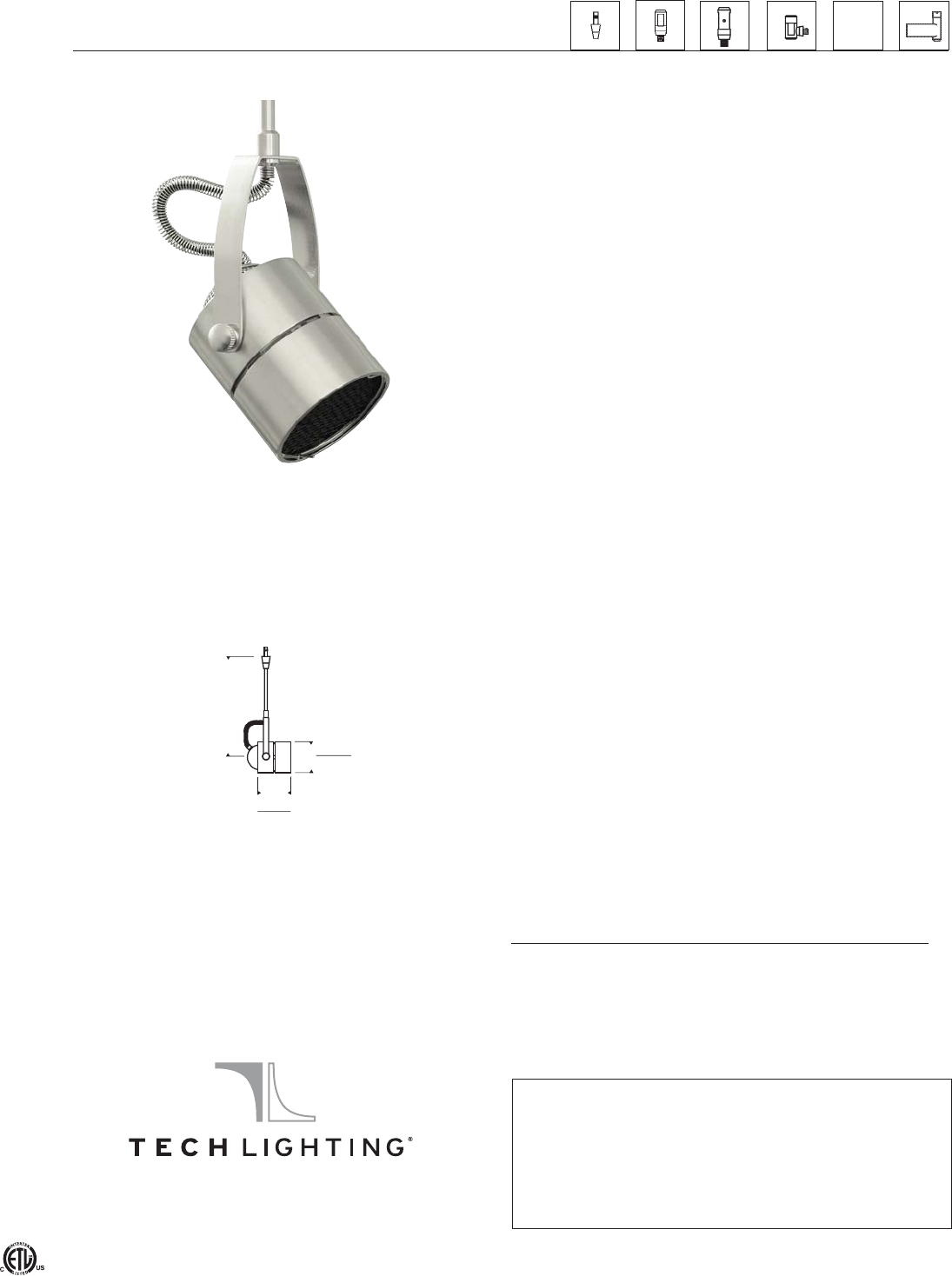
LOW-VOLTAGE ELEMENTS Two-Circuit Wall
FreeJack MonoRail MonoRail MonoRail Kable Lite T~trak™
N/A
Spot
hds_spot_spec.pdf
ARCHITECTURAL HEAD
DESCRIPTION
Classic head rotates 360˚ around stem, pivots 290˚. Can hold
one lens or louver (sold separately). Low-voltage, MR16 lamp
of up to 50 watts (not included).
SYSTEM
Available for FreeJack, MonoRail, Two-Circuit MonoRail, and
Wall MonoRail. For use on T~trak, order FreeJack version and
T~trak FreeJack Connector (sold
separately).
COLOR
None.
FINISH
Chrome, satin nickel.
LAMP
SPOT WITH EGGCRATE LOUVER Low-voltage halogen MR16 lamp up to 50 watts (not included).
Shown approximately 50% actual size.
ACCESSORIES AND OPTICAL CONTROLS
Compatible optical controls (sold separately): Eggcrate Louver,
Glass Lens.
WEIGHT
0.84 lb./0.38 kg. ±
A
2.1”
53 mm
2.4”
61 mm
Socket terminates with FreeJack male connector, which
may be installed into a system connector. Elements ordered
with a system prefix include a connector for that system.
7400 Linder Avenue T 847.410.4400
Skokie, Illinois 60077 F 847.410.4500
www.techlighting.com
ORDERING INFORMATION
700 SYSTEM SPT6 LENGTH (A) FINISH
FJ
MO
MO2
WMO
FREEJACK
MONORAIL
TWO-CIRCUIT
MONORAIL
WALL MONORAIL
04
06
12
18
4.5"
6"
12"
18"
C CHROME
S SATIN NICKEL
700 _______ S P T6 _______ ______
FIXTURE TYPE: _________________________________________
JOB NAME: _____________________________________________
© 2009 Tech Lighting, L.L.C. All rights reserved. The "Tech Lighting" graphic is a registered trademark of Tech Lighting, L.L.C.
Tech Lighting reserves the right to change specifications for product improvements without notification.
A13
MO 04 S
F06
UCI NAT. SCI. II
F06
MONORAIL
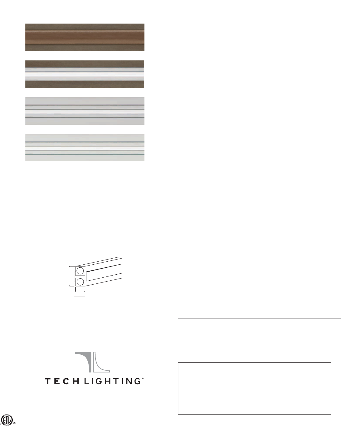
Straight Rail
ANTIQUE BRONZE - BROWN INSULATOR DESCRIPTION
Low-voltage conductor of two individual conductive metal
pieces fused together by a plastic separator. Hand-bendable,
field-cuttable MonoRail is rated for 300 watts at 12 volts,
600 watts at 24 volts. Each piece of rail is shipped with
ANTIQUE BRONZE - CLEAR INSULATOR conductive connectors to join rail pieces end to end. Order
additional connectors if cutting and rejoining rails. Standard
MonoRail bends horizontally to a radius as small as 6" and
vertically to a radius as small as 24".
CHROME - CLEAR INSULATOR COLOR
Insulator is available in clear and brown.
FINISH
Antique bronze, chrome, satin nickel.
SATIN NICKEL - CLEAR INSULATOR WEIGHT
24": 0.27 lb./0.12 kg. ±
48": 0.55 lb./0.25 kg. ±
96": 1.10 lb./0.50 kg. ±
SHOWN ACTUAL SIZE
(0.60" height x 0.30" width)
.6”
14 mm
.3”
6 mm
ORDERING INFORMATION
700MOA LENGTH FINISH/INSULATOR
24 24" (0.6 m)
48 48" (1.2 m)
96 96" (2.4 m)
BRZ ANTIQUE BRONZE W/ BROWN INSULATOR
Z ANTIQUE BRONZE W/ CLEAR INSULATOR
C CHROME W/ CLEAR INSULATOR
S SATIN NICKEL W/ CLEAR INSULATOR
700MOA _______ _______
FIXTURE TYPE: _________________________________________
JOB NAME: _____________________________________________
mo_straight_rail_spec.pdf
7400 Linder Avenue T 847.410.4400
Skokie, Illinois 60077 F 847.410.4500
www.techlighting.com
© 2009 Tech Lighting, L.L.C. All rights reserved. The "Tech Lighting" graphic is a registered trademark of Tech Lighting, L.L.C.
Tech Lighting reserves the right to change specifications for product improvements without notification.
A14
48+24 S
T01
UCI NAT. SCI II
F06-A
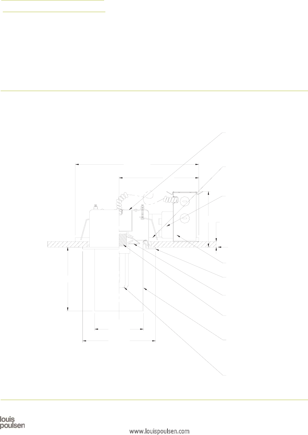
Ballerup
compact fluorescent
Design: C. J. Nørgaard Pedersen
and P. Hougaard Nielsen
Type:
Project:
Catalog Number:
NOTES:
1. SUITABLE FOR ACCESSIBLE NON-ACCESSIBLE CEILING TYPES
2. CEILING CUTOUT = 5.5" DIAMETER
5.7"
4.4" DIA.
6.5" DIA.
11.0" x 8.0"
7.1"
5.0"
SPUN STEEL SOCKET HOUSING
WITH WHITE POWDER COATED
FINISH
UNIVERSAL MOUNTING BRACKETS
WITH SLOTS 1 1/2" VERTICAL
ADJUSTABILITY (SUPPLIED) FOR
C-CHANNEL, 1/2" NPT CONDUIT OR
FLAT BAR MOUNTING (BY OTHERS)
ELECTRONIC BALLAST FOR
120-277V OPERATION
0.75" MAX. CEILING
THICKNESS
CEILING LINE
GALVANIZED STEEL JUNCTION
BOX FOR THROUGH WIRING
WHITE CEILING RING
SPUN ALUMINUM REFLECTOR
WITH HIGH REFLECTANCE
WHITE FINISH
LAMPHOLDER: GX24q-2
HANDBLOWN THREE-LAYER
WHITE OPAL GLASS CYLINDER
BAYONET-TYPE, WITH OPAL CENTER
LAYER LAMINATED BETWEEN TWO
CLEAR GLASS OUTER LAYERS
(REMOVABLE FOR RELAMPING)
MAXIMUM LAMP:
1/18W/CF
COMPACT FLUORESCENT
(BY OTHERS)
Louis Poulsen Lighting, Inc., 3260 Meridian Parkway, Fort Lauderdale, FL 33331 Telephone: (954) 349-2525 Fax: (954) 349-2550
www.louispoulsen.com
A15
F07
F07
1SPEVDUDPEF
-JHIUTPVSDF 7PMUBHF 'JOJTI 0QUJPOT
#"-
8$'(9R
8"$-NFEJVN
7
7
7
7
8)5
&.1,
-6530/%*..*/(
#BMMFSVQ
DPNQBDUGMVPSFTDFOU
TFNJSFDFTTFETVSGBDF
3KRWRPHWULF5HSRUW %$/:*;4,(6
5HSRUW1R /
3RXOVHQ5HSRUW1R %$/:*;4,(6
/XPLQDLUH %DOOHUXS&HLOLQJ2SDO &RPSDFW)OXRUHVFHQW
/DPS :*;4
(IILFLHQF\
'HVFULSWLRQ $OOGDWDVKRZQDUHSHUOXPHQV7KLVUHSRUW
FDQEHXVHGIRUFDOFXODWLRQRQDOOYHUVLRQVOLVWHG
EHORZ8VHRQO\DFWXDOOXPHQGDWDZKHQ
FDOFXODWLQJ
#ANDLEPOWER$ISTRIBUTION :ONAL,UMEN3UMMARY
9HUWLFDO$QJOH &DQGHOD
#OEFFICIENTSOF5TILIZATION =RQDO&DYLW\0HWKRG
(IIHFWLYH)ORRU&DYLW\5HIOHFWDQFH
=RQH /XPHQV /DPS )L[WXUH
&HLOLQJ5HIOHFWDQFH
:DOO5HIOHFWDQFH
5RRP&DYLW\5DWLR
%FTJHO
$+/SHBBSE1FEFSTFO1)PVHBBSE/JFMTFO
$PODFQU
#BMMFSVQDSFBUFTTZNNFUSJDBMEPXOMJHIUJMMVNJOBUJPO5IFWFSUJDBMUISFFMBZFSPQBMHMBTTDZMJOEFSQSPWJEFT
CPUIUIFDFJMJOHBOEUIFSFTUPGUIFTQBDFXJUITPGUEJGGVTFJMMVNJOBUJPOXJUIUIFNBKPSJUZPGMJHIUEJSFDUFE
EPXOXBSE
'JOJTI
8IJUFQPXEFSDPBUFE8IJUFPQBMHMBTT
.BUFSJBM
%JGGVTFS)BOECMPXOXIJUFPQBMHMBTT)PVTJOH4QVOTUFFM
.PVOUJOH
4FNJSFDFTTFE.PVOUJOHGSBNFXJUIUXPWFSUJDBMMZBEKVTUBCMFCSBDLFUTTQBDFEFRVBMMZ BUUPCF
JOTUBMMFEQSJPSUPDMPTJOHUIFDFJMJOH$FJMJOHUZQFT"DDFTTJCMFBOEOPOBDDFTTJCMFDFJMJOHT$FJMJOHDVUPVU
±EJBNFUFS
8FJHIU
.BYMCT
-BCFM
D6-%BNQMPDBUJPO*#&8
*OGPOPUFT
B$'WBSJBOUTQSPWJEFEXJUIPOF7FMFDUSPOJDCBMMBTU
C*ODBOEFTDFOUWBSJBOUTPOMZBWBJMBCMFJO7
D&.1,FNFSHFODZQPXFSQBDLJTBWBJMBCMFJOEVBMUBQ7XJUISFNPUFNPVOUFEUFTUTXJUDI
E-6530/EJNNJOH7PS7JTEJHJUBMEJNNJOH
-PVJT1PVMTFO-JHIUJOH*OD.FSJEJBO1BSLXBZ'PSU-BVEFSEBMF'-5FMFQIPOF'BY
XXXMPVJTQPVMTFODPN
A16
F07
Architectural Decorative Soli™ 48023ALU
Page 1 of 2 Wall/Ceiling Mounted T-5 Fluorescent ADA Compliant
6-1/2"
3-5/8"
Extension
1-3/4"
Width
23-1/4"
To Outlet
Box Center
46-7/16"
Height
4-1/2"
2
1
4
3
5-1/2"
Note:
Luminaire can be ordered with or without
diffuser shield. Order each separately.
Can be mounted vertically or horizontally.
Fixture Ordering Information
Catalog No. Finish Wattage Voltage Lamping Options
48023ALU
48023AL54U
Powder Coated
Metallic Aluminum
28W
54W
120/277V
120/277V
T-5 Miniature Bi-Pin Fluorescent
T-5 Miniature Bi-Pin Fluorescent HO
See Below
Diffuser Ordering Information
Catalog No. Description Dimensions
40876
40916
Translucent Etched Soda Lime Glass w/ Pencil Polished Edges
Extruded Opal Virgin Acrylic w/ Pencil Polished Edges
43” L x 6.5” W x 5 mm Thick
43” L x 6.5” W x 5 mm Thick
Features
1. Housing: Extruded and die-cast aluminum ballast and lamp chamber.
2. Optional Diffuser/Reflector: Curved etched glass or extruded opal virgin
acrylic.
3. Optics: Internal white acrylic diffuser covers slit on front cover.
4. J-Box Covers: Die-cast split covers to enclose 4” octagonal J-Box (J-Box
by others).
Mounting
Mounts directly to switch box or 4” octagonal J-Box. Octagonal box mounting
requires use of “J-Box Covers” and “Support Plate” supplied standard.
Electrical
Ballast: Electronic
120/277V 28W 54W
Total Input Watts:
Max. Line Current:
Power Factor:
Ballast Factor:
THD:
Starting Temp:
Finish
33W
120V = 0.28
277V = 0.12
.98
1.00
120V = <10%
277V = <10%
0°F / -18°C
62W
120V=.51
277V=.21
.98
1.00
120V = <10%
277V = <10%
0°F / -18°C
Options
Dimming: (Voltage Specific/54W HO lamps only)
Add MX1 suffix code (for 120V) to Cat. No.
Add MX2 suffix code (for 277V) to Cat. No.
for example: 48023AL4MX1
Emergency: Integral Bodine LP550 emergency battery pack, test switch and
light, add E suffix code.
DALI: Digital Dimming System ballast 120/277V. For 28W lamps add 28DA
suffix code to Cat. No. For 54W lamps add 54DA suffix code to Cat. No.
for example: 48023AL54DA
Labels
cULus Listed. Suitable for Damp Locations.
Job Information Type:
Job Name:
Cat. No.:
Lamp(s):
Notes:
Lightolier a Genlyte company www.lightolier.com
631 Airport Road, Fall River, MA 02720 • (508) 679-8131 • Fax (508) 674-4710
We reserve the right to change details of design, materials and finish.
© 2005 Genlyte Group LLC • C0305
All painted parts utilized the powder coat process. Lightolier Metallic Aluminum
Powder Coat Enamel.
A17
F08
Architectural Decorative Soli™ 48023ALU
Page 2 of 2 Wall/Ceiling Mounted T-5 Fluorescent ADA Compliant
CERTIFIED TEST REPORT NO. 2221FR
COMPUTED BY LSI PROGRAM **TEST-LITE**
LIGHTOLIER ARCHITECTURAL DECORATIVE LUMINAIRE SOLI
CAT. NO. 48023ALU / 40876, ETCHED GLASS SHIELD
1-28W SYLVANIA T-5 LAMP. LUMEN RATING = 2610 LMS.
UNIVERSAL BALLAST #B228PUNVC
CANDLEPOWER
ZONE 90 67.5 45 22.5 Beam
DEG.
CANDELAS
0 2 2 2 2 2
5 5 4 5 6 6
15 10 13 24 27 25
25 16 30 42 45 43
35 22 41 56 59 59
45 28 52 68 70 74
55 32 60 78 80 85
65 35 67 85 87 94
75 35 72 91 92 100
85 33 75 94 95 103
95 30 77 95 97 104
105 26 77 95 96 102
115 22 74 90 92 97
Prepared For: 125 20 68 84 85 90
Lightolier 135 17 61 74 76 79
Fall River, MA 145 14 50 63 66 66
Date: May 11, 2003 155 12 41 50 53 50
165 9 25 33 35 33
175 7 11 14 15 15
180 6 6 6 6 6
Tested according to IES procedures.
Test distance exceeds five times the greatest luminous opening of luminaire.
COEFFICIENTS OF UTILIZATION
% EFFECTIVE CEILING CAVITY REFLECTANCE
80 70 50 30 10 0
% WALL REFLECTION DISTRIBUTION
50 30 10 50 30 10 50 30 10 50 30 10 50 30 10 0 Zone Lumens % Lamp % Luminaire
0-30 18 0.7 2.87
0 2727 27 2525 25 21 2121 17 17 17 14 1414 12 0-40 43 1.6 6.61
1 2120 19 2018 17 16 1514 13 12 12 1010 9 8 0-60 128 4.9 19.69
2 1816 14 1615 13 13 1211 1110 9 8 7 7 5 0-90 323 12.4 49.44
3 1513 11 1412 10 1110 8 9 8 7 7 6 6 4 40-90 279 10.7 42.83
4 13 11 9 12 10 8 10 8 7 8 6 5 6 5 4 3 60-90 194 7.4 29.75
5 129 7 118 7 9 7 6 7 5 4 5 4 3 2 90-180 330 12.7 50.56
610 8 6 97 6 865 654 533 2 0-180 653 25.0 100.00
7 975 86 5 754 543 432 2
8 865 86 4 653 543 432 1 ** EFFICIENCY = 25.0% **
9 754 75 4 643 432 322 1
10 7 5 3 6 4 3 5 4 3 4 3 2 3 2 1 1
Note:
For 54 watt lamp, multiply calculated
DETERMINED IN ACCORDANCE WITH CURRENT IES PUBLISHED PROCEDURES footcandle values by 1.7
20% FLOOR CAVITY REFLECTANCE
ROOM CAVITY RATIO
Job Information Type:
Lightolier a Genlyte company www.lightolier.com
631 Airport Road, Fall River, MA 02720 • (508) 679-8131 • Fax (508) 674-4710
We reserve the right to change details of design, materials and finish.
© 2005 Genlyte Group LLC • C0305
A18
F08
Nominal Length
Lamp (center to center of hangers)
Length T8 T5
1 x 2' 26-7/16" (672mm) 24-7/16" (621mm)
1 x 3' 38-7/16" (976mm) 36-1/4" (921mm)
1 x 4' 50-7/16" (1281mm) 48" (1219mm)
1 x 5' 62-5/16" (1583mm) 60" (1524mm)
2 x 3' 74-15/16" (1903mm) 72" (1829mm)
2 x 4' 98-15/16" (2513mm) 96" (2438mm)
2 x 5' 122-15/16" (3123mm) 120" (3048mm)
E
F
G
3"
6"
3/4"
Style 101 / 102
T8 Fluorescent
T5 Fluorescent
Lighting the Wall Small fluted or smooth
Pendant Mount 1:8 Scale
(127mm)
5" Dia. (19mm)
Pendant
length
(6" min.)
1-3/4"
(44mm)
(152mm)
J
K
D
C
B
A
M
L
J
4-1/2"
(114mm) Length (see chart)
4-1/2"
(114mm)
1" (25mm)
N
H
Cantilever Mount 1:8 scale Mounting Plate
4-1/2"
18" (457mm) (76mm)
(114mm)
Specifications Features
W
4.0
ARound aluminum
canopy (pendant mount)
B11/16" O.D. aluminum
pendant stem
CMachined aluminum
mounting hub
DDie-cast aluminum
end plates
EAluminum reveal
plates (black)
FSpecular extruded
aluminum reflector
Finish:
Style 101
fluted - bright clear anodized aluminum housing.
Painted end plates in choice of silver or semi-gloss black.
Style 102
smooth - semi-gloss white housing and end plates.
Painted surfaces - 6 stage pretreatment and electrostatically
applied thermoset powder coat for stable, long lasting and
corrosion resistant finish.
Reflector - extruded high purity aluminum with clear anodized
specular finish. All luminaire hardware - stainless steel.
All mounting hardware - zinc or cadmium plated.
Mounting:
Pendant or cantilever mounting hangers (ordered separately);
specify end and intermediate hangers.
Pendant assembly furnished with canopy for mounting on
recessed outlet box. Optional hang-straight allows mounting
on slopes up to 45° (in the plane perpendicular to wall).
Cantilever wall plate mounts over recessed outlet box
(suitable backing structure required). Adjustable interface
plate (concealed under canopy) allows for leveling of arms.
Cantilever limited to single lamp reflectors (up to 5' long).
REV. 7/07
G Optional snap-in specular K Chrome cap nuts
parabolic cross baffle L Cantilever
H 11/16" O.D. cantilever arm mounting plate
J Rectangular aluminum M Outlet box (by others)
canopy (cantilever mount) N Splice access opening
Electrical:
Use 90°C wire for supply connections.
Remote electronic HPF thermally protected class P ballast
(with end-of-life protection for T5 lamps). Aluminum ballast
enclosure includes four 7/8" diameter entries and a knockout
for an accessory fuse.
Maximum wire length between electronic ballast and
fixture is 7' for two-lamp reflectors and 12' for one-lamp
reflectors, less length of stem or arm.
For dimming, see Styles 105/106 with integral dimming
ballast.
For complete ballast specifications, see Accessories Section.
Standard:
UL listed or CSA certified for damp locations. (Style 124
painted model with lens recommended for damp locations.)
■
Unequaled low energy wall lighting with T5 or T8 lamps
■
Machined aluminum mounting hub attaches to pendant
stem or cantilever arm without exposed threads
■
Die-cast end plate joins at articulated black reveal - no
exposed fasteners
■
Optional snap-in specular parabolic cross baffle
Performance
Two parabolic reflector sections drive light to the bottom of the
wall. An elliptical section shields the lamp from normal viewing
angles and redirects its light to a parabola. Glare is minimized
and asymmetry of the beam is maximized resulting in high
beam efficiency and superior surface uniformity.
28W
T5 Cd
32W
T8
1200
For complete photometrics, see www.elliptipar.com.
elliptipar
A19
F09
F09
1
2
To Order Style 101 / 102
- -- X
To form a Catalog Number
- -
F
1 2 3 4 5 6 7 8
Source
F = Linear fluorescent
Style
101 = Small fluted surface, remote ballast
102 = Small smooth surface, remote ballast
= Lamp Code
3 Lamp
Lamp Wattage (see chart below)
Reflector Configuration, specify 1, 2 or 3
(see chart below)
A = T8 Fluorescent
T = T5 Fluorescent
Example: A325 = two nominal 3' reflectors, each for use with
one 25W T8 lamp; one 2-lamp ballast
Reflector Configuration
W
4.1
1
3
1-Lamp Reflector
1-Lamp Ballast
2-Lamp Ballast
1-Lamp Reflector 1-Lamp Reflector
2-Lamp Ballast
2-Lamp Reflector
2
Lamp Wattage
Lamp Length Lamp Wattage (Lamp Number)
(nominal) T8 T5 T5 HO
2' 17 (F17T8) 14 (F14T5) 24 (F24T5/HO)
3' 25 (F25T8) 21 (F21T5) 39 (F39T5/HO)
4' 32 (F32T8) 28 (F28T5) 55 (F54T5/HO)
5' 40 (F40T8) 35 (F35T5) 80 (F80T5/HO)
For complete lamp and ballast information, see Accessories Section.
Standard T5 lamp color is 3000K / 80+ CRI. T8 lamps by others.
Project:
4 Mounting
X = For use with end and intermediate hangers. Available
in pendant or cantilever (order separately).
Note: Cantilevers are limited to use with single lamp
reflectors (Configuration 1 or 3) up to 5' long.
5 Finish
Style 101 Fluted
01 = Bright aluminum
housing with silver
end plates
81 = Bright aluminum
housing with
semi-gloss black
end plates
Style 102 Smooth
02 = Semi-gloss white
reflector and end
plates
99 = Custom RAL or
computer matched
color to be specified,
consult sales
representative
6 Voltage/Ballast
Electronic Dimming
*
1 = 120V
2 = 277V
3 = 347V (Canada)
* For dimming, see Styles 105/106 with integral dimming ballast.
7
00
0B
0E
XX
Option (See Accessories Section for specifications)
= No options
= Snap-in parabolic cross baffle, specular finish,
provides 35° lengthwise shielding
= Remote emergency battery pack
= For modification not listed, include detailed description.
Consult factory prior to specification.
8 Standard
0 = UL, Underwriters Laboratories
J = CSA, Canadian Standards Association
Example
F102 - A132 - X - 02 - 1 - 000
Small smooth surface model for use with one 32W T8 lamp in
nominal 4 foot reflector. Semi-gloss white. Remote 1-lamp
120V electronic ballast. UL. (Order pendant or cantilever
mounting hangers separately.)
Type:
Mounting Hangers
For individually mounted luminaires, order two end hangers
for each reflector.
For a continuous row, order two end hangers. To determine
the quantity of intermediate hangers, total the number of
reflectors in the row and subtract one. Example: a row of five
reflectors requires 2 end hangers and 4 intermediate hangers.
Note: In determining hanger quantities, treat Reflector
Configuration 3 as
two
reflectors.
HS
HS
18 = Cantilever hanger with wall plate,
18" (457mm) setback
(Limited to single lamp
reflectors up to 5' long)
0 = UL
J = CSA
02 = Semi-gloss white
07 = silver
08 = Semi-gloss black
C = Intermediate
= Pendant hanger with canopy
0 = UL
J = CSA
D = End
Length in inches,
up to 60" (1.5m),
6" minimum
02 = semi-gloss white
07 = silver
08 = semi-gloss black
F = Intermediate, straight
G = End, straight
J = Intermediate, swivel (up to 45°)
K = End, swivel (up to 45°)
Accessories
Order separately. See Accessories Section for specifications.
AFK000X = Ballast fuse kit
0 =UL
J = CSA
The external shapes of the asymmetric reflectors are trademarks of
elliptipar.
elliptipar
Certain products illustrated may be covered by applicable patents and patents pending.
REV. 7/07 114 Boston Post Road, West Haven, Connecticut 06516, USA
For a list of patents, see Contents pages. These specifications supersede all prior
Voice 203.931.4455 ■ Fax 203.931.4464 ■ www.elliptipar.com
publications and are subject to change without notice.
© 2007 elliptipar.
elliptipar
A20
UCI NATURAL SCIENCES UNIT 2
F09
T
3
35
F09
F09
iColor Cove QLX
CK INTELLIGENT SERIES Preliminary
iColor Cove® QLX is a compact linear fixture that generates saturated color and dynamic effects
in alcoves, accent areas, and other interior spaces. The fixture is available with a wide (120º x
120º) or medium (100º x 40º) beam. An integrated rotating mount and optional mounting track
provide precise positioning, and end-to-end connections ensure a simple installation.
• Integral mounting bracket with 180º rotation • Optibin® technology ensures uniform light quality
• 24 VDC input power •Chromasic
® technology provides precise and
• End-to-end connectors cost-efficient digital control
• Two standard lengths: 6 in (152 mm) and
12 in (305 mm)
A21
F10
2 Preliminary iColor Cove QLX Data Sheet
iColor Cove QLX Dimensions
.4 in
(36 mm)
.2 in
(30 mm)
in
(25 mm)
8. in
(206 mm)
2 in
(305 mm)
7.2 in
(83 mm)
5.6 in
(42 mm)
6 in
(52 mm)
3.2 in
(355 mm)
Typical Installation Cut-Away
iColor Cove QLX fixtures can be used effectively in numerous applications. A typical ceiling
cove construction cut-away is shown below. (See “Installation Details” on page 9.)
Philips Solid-State Lighting Solutions, Inc. • 3 Burlington Woods Drive • Burlington, MA 01803 • USA
Tel: 617.423.9999 • Toll Free: 888.385.5742 • Fax: 617.423.9998 • www.colorkinetics.com
A22
F10

3 iColor Cove QLX Specifications Preliminary
iColor Cove QLX Specifications
Specifications are subject to change without notice.
6-Inch Fixture 12-Inch Fixture
Length 6 in (152 mm) 12 in (305 mm)
Width 1.25 in (32 mm) (tube diameter)
Height 1.37 in (35 mm)
Weight 3 oz. (85 g) 5 oz. (142 g)
LEDs Per Fixture 5 each: red, green, and blue 10 each: red, green, and blue
Total Output
(Lumens)
26: Wide (120º x 120º) beam angle:
20.8: Medium (100º x 40º) beam angle
49.8: Wide (120º x 120º) beam angle
46.1: Medium (100º x 40º) beam angle
Efficacy (Lm/W)a 13: Wide (120º x 120º) beam angle
10.4: Medium (100º x 40º) beam angle
16.6: Wide (120º x 120º) beam angle
15.4: Medium (100º x 40º) beam angle
Source High-brightness LEDs.
Color Range 16.7 million (8-bit) additive RGB colors; continuously variable intensity
Beam Angle 120º x 120º or 100º x 40º
Mixing Distance 2 in (51 mm) to uniform light
Housing Charcoal gray, UL-recognized, injection-molded plastic
Lens Clear polycarbonate. V-0 flame rating. F1 UV rating.
Medium-Beam Optics Polycarbonate.
Environment UL Dry; IP20
Fixture Connectors IEC 15 A (max) with C13 plug
Configuration See “Maximum Number of Fixtures and Cables” below.
Listings CE, PSE, RoHS, UL/CUL, WEEE, C-Tick
Control Chromasic input data
Operating Voltage 24 VDC from a Philips or Color Kinetics DMX In / Chromasic Out power supply
Power Consumption 2 W maximum at full output steady state. 3 W maximum at full output steady state.
Temperature Range -4°F – 122°F (-20°C – 50°C) operating temperature
Humidity Range 0 – 95% non-condensing
LED Source Life 50,000 hours, based on LED manufacturers’ test data
a. Measurements made at full RGB.
Maximum Number of Fixtures and Cables
If no jumper cables are used, you may interconnect as many as either 30 6 in (152 mm)
fixtures (on a single 60W power supply) or 20 12 in (305 mm) fixtures (on a single 60W
power supply).
If you plan to use jumper cables:
• The maximum number of 1 ft (305 mm) jumper cables is nine; the maximim number of
5 ft (1524 mm) jumper cables is five.
• If you plan to combine jumper cables of different lengths, please contact
support@colorkinetics.com for help with planning your configuration.
Philips Solid-State Lighting Solutions, Inc. • 3 Burlington Woods Drive • Burlington, MA 01803 • USA
Tel: 617.423.9999 • Toll Free: 888.385.5742 • Fax: 617.423.9998 • www.colorkinetics.com
A23
F10

4 Preliminary iColor Cove QLX Data Sheet
Ordering Information
iColor Cove QLX Item Numbers
Fixture Length Beam Angle Item Number Part Number
12 in (305 mm) Wide 120º x 120º 101-000066-00 910503700217
Medium 100º x 40º 101-000066-01 910503700219
6 in (152 mm) Wide 120º x 120º 101-000066-02 910503700218
Medium 100º x 40º 101-000066-03 910503700220
Accessories for iColor Cove QLX Fixtures
iColor Cove QLX fixtures are part of a low-voltage system made up of the fixtures and:
• One or more compatible power supplies from the list below.
• One leader cable used to connect each power supply output port to a series of
fixtures.
• A Philips, Color Kinetics, or other DMX512-based controller that works with iColor
Cove QLX fixtures. The number of fixtures that can be addressed varies with each
controller and jumper cable length. For information on Philips or Color Kinetics
controllers, see http://www.colorkinetics.com/support/systemguide/SysMatrix.pdf.
Compatible Philips and
Color Kinetics Power Supplies Item Number Part Number
sPDS-60ca 24V — provides 60W output
that can be split between two ports.
109-000021-02
(DMX / Ethernet)
910503700106
PDS-60ca — provides 60W output that
can be split between two ports.
109-000016-00
(preprogrammed) or
109-000016-01
(DMX)
910503700095
sPDS-480ca 24V — provides eight 60W
output ports
109-000026-00 910503700110
Leader Cable Item Number Part Number
30 ft (9144 mm) leader cable 108-000015-00 910503700072
Depending on the installation’s design, you may need optional jumper cables to add space
between fixtures. Optional mounting tracks ensure straight runs of fixtures.
Jumper Cables Item Number Part Number
1 ft (305 mm) jumper cable 108-000020-00 910503700079
5 ft (1524 mm) jumper cable 108-000020-01 910503700080
Mounting Track Item Number Part Number
Box of 25 mounting tracks — 4 ft (1219
mm) in length — for straight runs
523-000006-00 910403326201
Philips Solid-State Lighting Solutions, Inc. • 3 Burlington Woods Drive • Burlington, MA 01803 • USA
Tel: 617.423.9999 • Toll Free: 888.385.5742 • Fax: 617.423.9998 • www.colorkinetics.com
A24
F10
6
0
Preliminary iColor Cove QLX Data Sheet
12 Inch iColor Cove QLX — Medium Beam Photometrics
This photometric data is based on test results from an Candle Power Distribution
independent testing lab. IES files are available at http://
www.colorkinetics.com/support/ies. Data to come later: The dashed line indicates that x candela is
x% of peak.
0º
7 4 20 27
90º-90º
Illuminance Distribution Illuminance Beam Angle
This illustration shows the plane x ft (x mm) from the fixture. Data is in This illustration shows measurement of the
footcandles and (lux). center beam and the fixture’s angle. Data is in
footcandles and (lux).
2 ft ft 0 ft 2 ft
2 ft 60 mm
Illustration to come later
ft 305 mm
0
ft 305 mm
2 ft 60 mm
A
F
B
C
D
E
60 mm 305 mm 0 305 mm 60 mm
A 1.5 fc (16 lux) B 3 fc (32 lux) C 5 fc (54 lux)
D 8 fc (86 lux) E 10 fc (108 lux) F 5 fc (61 lux)
Philips Solid-State Lighting Solutions, Inc. • 3 Burlington Woods Drive • Burlington, MA 01803 • USA
Tel: 617.423.9999 • Toll Free: 888.385.5742 • Fax: 617.423.9998 • www.colorkinetics.com
A25
F10
8
0
Preliminary iColor Cove QLX Data Sheet
12 Inch iColor Cove QLX — Wide Beam Photometrics
This photometric data is based on test results from an Candle Power Distribution
independent testing lab. IES files are available at http:// Data to come later: The dashed line indicates that x candela is
www.colorkinetics.com/support/ies. x% of peak.
Illustration to come later
Illuminance Distribution Illuminance Beam Angle
This illustration shows the plane x ft (x mm) from the fixture. Data is in This illustration shows measurement of the
footcandles and (lux). center beam and the fixture’s angle. Data is in
2 ft ft 0 ft 2 ft
footcandles and (lux).
2 ft
ft
ft
2 ft
B
A
F
D
E
C
60 mm
305 mm
Illustration to come later
0
305 mm
60 mm
60 mm 305 mm 0 305 mm 60 mm
A 1.5 fc (16 lux) B 3 fc (32 lux) C 5 fc (54 lux)
D 8 fc (86 lux) E 10 fc (108 lux) F 3 fc (40 lux)
Philips Solid-State Lighting Solutions, Inc. • 3 Burlington Woods Drive • Burlington, MA 01803 • USA
Tel: 617.423.9999 • Toll Free: 888.385.5742 • Fax: 617.423.9998 • www.colorkinetics.com
A26
F10
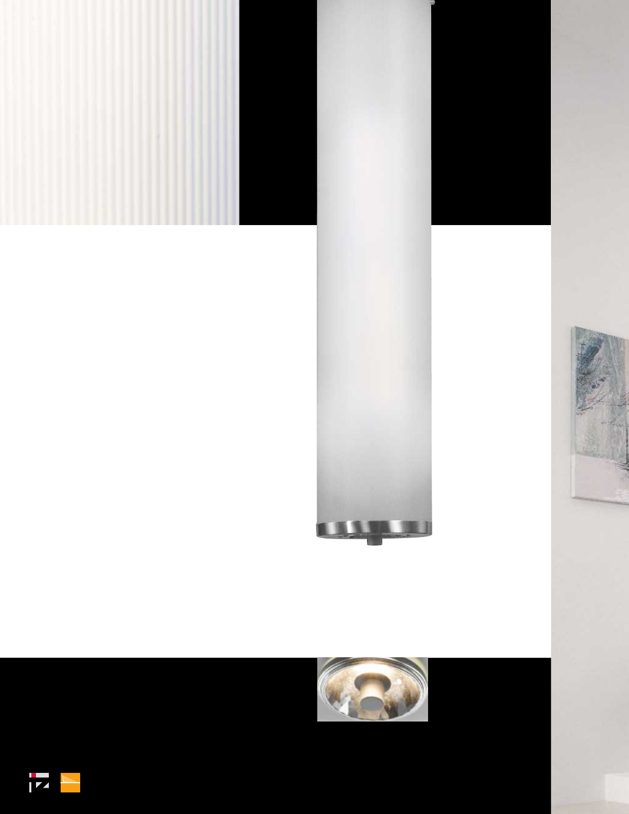
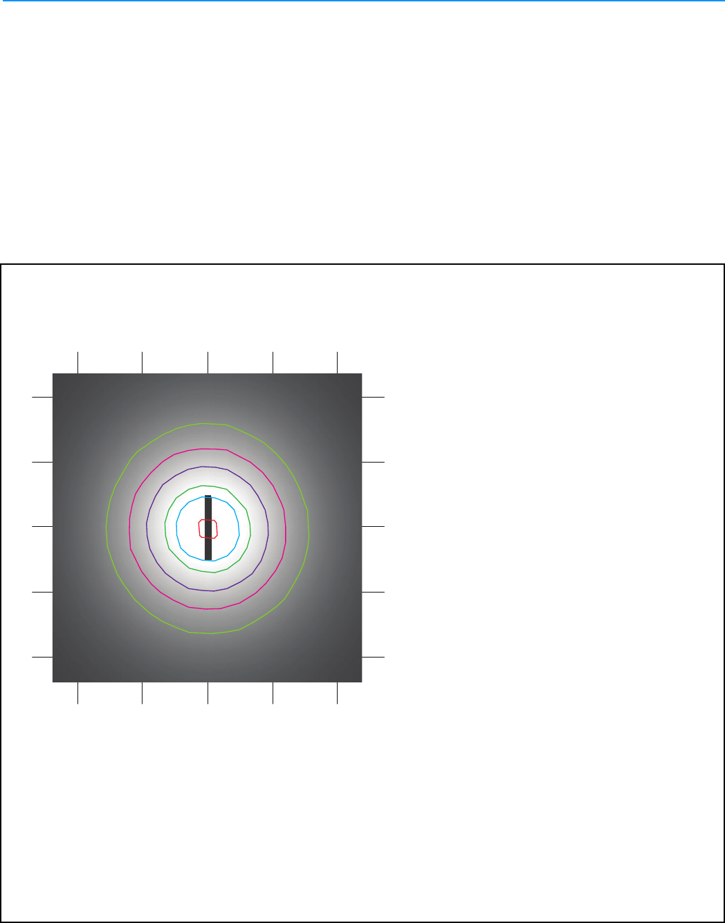
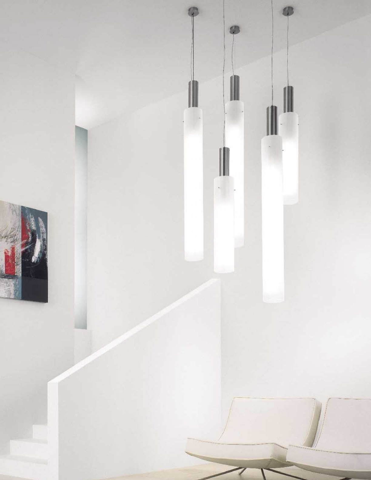
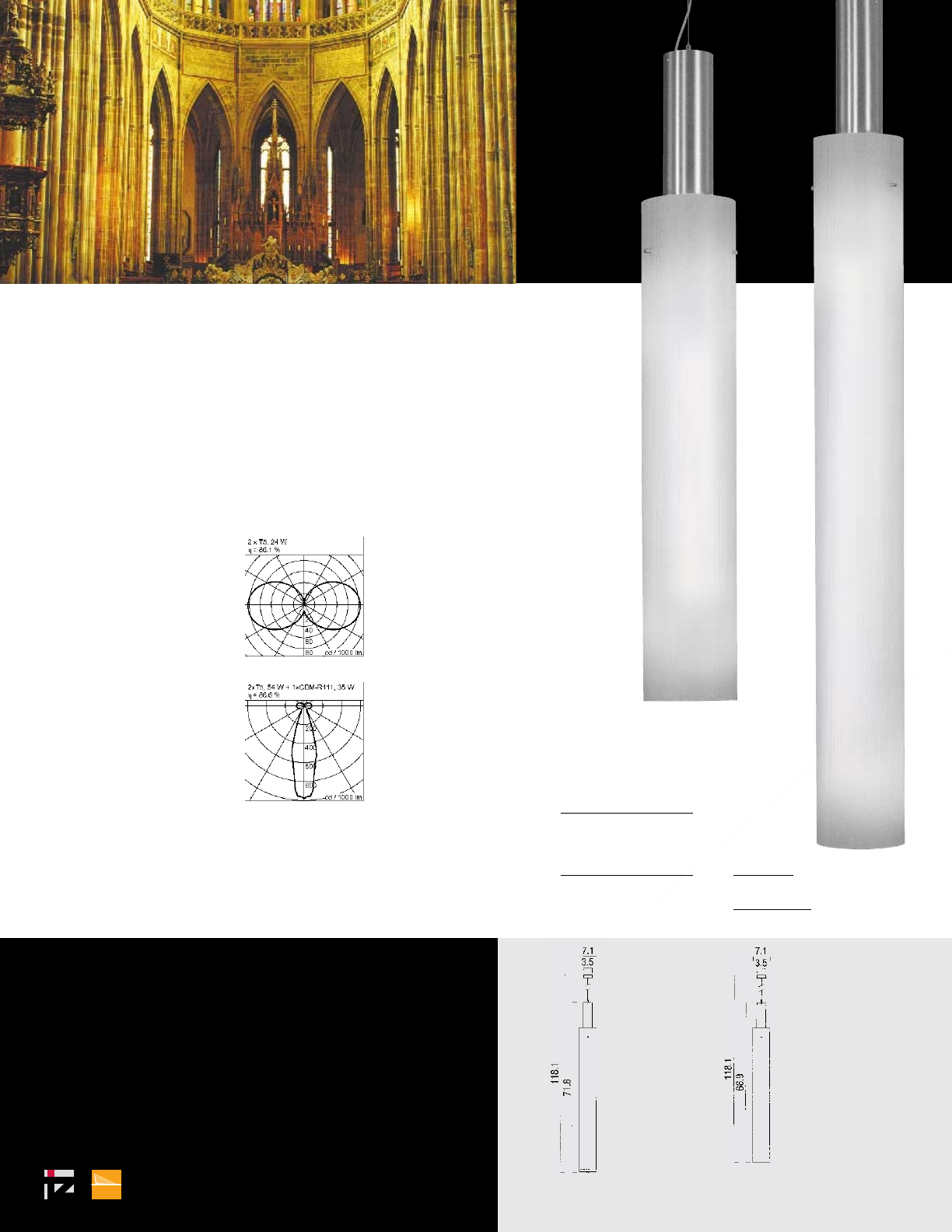
PENDANT LIGHTS
138_139
TOOL
inter-lux www.inter-lux.com
A27
F11
F11
PENDANT LIGHTS
138_139
TOOL
inter-lux www.inter-lux.com
A28
F11
TOOL
satin nickel
ribbed acrylic tube satin
with electronic ballast
120 / 277 VAC
contact factory for
dimming options
add HO for high output
T5 lamp
mounting note:
canopy to fit
standard junction box
1 x GX24q-3, 32 W
16207.06
1 x GX24q-4, 42 W
16208.06
2 x 2G11, 18 W
26209.06
2 x 2G11, 24 W
26210.06
2 x T5, 14 W
26238.06
2 x T5 HO, 24 W
26211.06
2 x T5, 14 W
and
1 x CDM-R111, 35 W, GX8.5
36238.06
2 x T5 HO, 24 W
and
1 x CDM-R111, 35 W, GX8.5
36212.06
please specify
120 or 277 VAC
PENDANT LIGHTS
2 x T5, 28 W
26237.06
2 x T5 HO, 54 W
26213.06
2 x T5, 28 W
and
1 x CDM-R111, 35 W, GX8.5
36237.06
2 x T5 HO, 54 W
and
1 x CDM-R111, 35 W, GX8.5
36214.06
please specify
120 or 277 VAC
TOOL
see chapter
wall lights
see chapter
ceiling lights
GX24q-3/4 2G11CDM-R111T5
140_141
inter-lux www.inter-lux.com
A29
F11
F11
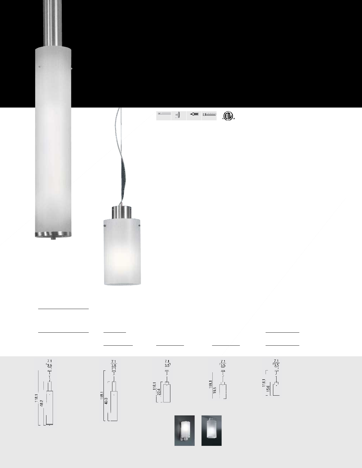
TOOL
satin nickel
ribbed acrylic tube satin
with electronic ballast
120 / 277 VAC
contact factory for
dimming options
add HO for high output
T5 lamp
mounting note:
canopy to fit
standard junction box
1 x GX24q-3, 32 W
16207.06
1 x GX24q-4, 42 W
16208.06
2 x 2G11, 18 W
26209.06
2 x 2G11, 24 W
26210.06
2 x T5, 14 W
26238.06
2 x T5 HO, 24 W
26211.06
2 x T5, 14 W
and
1 x CDM-R111, 35 W, GX8.5
36238.06
2 x T5 HO, 24 W
and
1 x CDM-R111, 35 W, GX8.5
36212.06
please specify
120 or 277 VAC
PENDANT LIGHTS
2 x T5, 28 W
26237.06
2 x T5 HO, 54 W
26213.06
2 x T5, 28 W
and
1 x CDM-R111, 35 W, GX8.5
36237.06
2 x T5 HO, 54 W
and
1 x CDM-R111, 35 W, GX8.5
36214.06
please specify
120 or 277 VAC
TOOL
see chapter
wall lights
see chapter
ceiling lights
GX24q-3/4 2G11CDM-R111T5
140_141
inter-lux www.inter-lux.com
A30
F11
2007.indd 49 4/2/08 2:24:26 PM
Recessed wall luminaires · faceplate stainless steel
Housing: Aluminum outer rough-in housing provided. The outer housing
is provided with (2) ½" conduit openings suitable for through wiring. Inner
housing made from die-cast aluminum end caps welded to an aluminum
extrusion. The welds are continuous and ground flat to provide a watertight
inner lamp housing module. All aluminum used in the construction is marine
grade and copper free.
Enclosure: Faceplate is constructed of machined stainless steel, secured
to the inner housing with captive stainless steel fasteners. Tempered white
glass, 3⁄8" thick, machined to be flush with the faceplate. Fully gasketed with a
molded silicone ”U“ channel gasket. The inner lamp module is fully sealed and
independent of the outer housing installation.
Electrical: Lampholders; Fluorescent T5 HO, G5 miniature bi-pin. Ballasts;
integral electronic, universal voltage 120 V through 277 V, class P, HPF,
program start, minimum start temperature of 0 °F. Ballasts have circuitry to
reliably shut down the system at the end of lamp life. Standard T5 lamping
available on request.
Finish: #4 brushed stainless steel. Custom colors are not available.
Stainless steel requires regular cleaning and maintenance, much like household
appliances, to maintain its luster and to prevent tarnishing or the appearance
of rust like stains.
U.L. listed, suitable for wet locations. Protection class: IP 65. Not suitable for
installation inside of a spa, sauna, or in the wall of a shower/bath stall. BEGA
does not recommend luminaires with non-isolated metal parts be used in
these applications.
B
A C
Type:
BEGA Product:
Project:
Voltage:
Color:
Options:
Modified:
Unshielded light · white safety glass
Lamp* Lumen A B C
2007 P 80 W FL T5 HO 7000 607⁄8 5 5
* Standard T5 lamping available
BEGA- US 1000 BEGA Way, Carpinteria, CA 93013 (805)684-0533 FAX (805)566-9474 www.bega-us .com
©copyright BEGA-US 2008 Updated 2/08
A31
S01
2007P
UCI NAT SCI II
277
S01
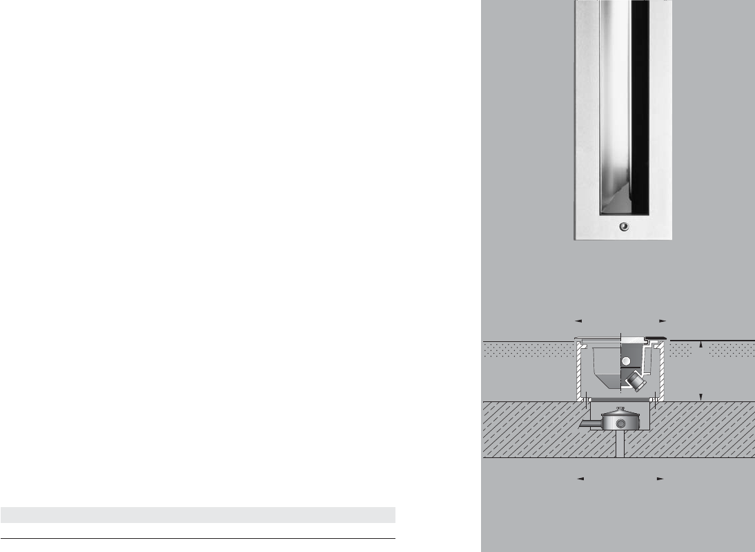
8642P.indd 225 5/23/08 10:06:09 AM
Drive-over in-grade floodlights
for linear fluorescent lamps
Enclosure: Outer housing: Constructed of high tensile strength, copper free die-cast
aluminum alloy.
Inner housing: One piece copper free die-cast aluminum housing with welded end
caps. Trim /Faceplate is heavy gauge, machined stainless steel secured to the inner
housing by stainless steel threaded welded studs. Relamping requires removal of
inner housing /trim /faceplate assembly from outer housing by means of two flush,
socket head stainless steel screws. 1⁄2" thick tempered glass machined flush to
faceplate. Reflector of pure anodized aluminum. One piece molded U-channel, high
temperature silicone gasket.
Electrical: Lampholders: Fluorescent T5 HO, rated 660 W, 600 V. Ballasts are
electronic, universal voltage 120 V through 277 V. Inner housing pre-wired with three
(3) feet of 18/3 waterproof cable, cable clamp, and waterproof cable gland entry into
housing. A separate weatherproof single gang wiring box for power supply must be
provided (by contractor).
Finish: Machined #4 stainless steel. Custom colors are not available.
U.L. Listed, suitable for wet locations and vehicle drive over. Protection class: IP 67.
Note: A foundation and proper drainage must be supplied by the contractor.
These luminaires are designed to bear pressure loads up to 11,000 lbs. from
vehicles with pneumatic tires. The luminaires must not be used for traffic lanes
where they are subject to horizontal pressure from vehicles braking, accelerating
and changing direction.
Type:
BEGA Product:
Project:
Voltage:
Color:
Options:
Modified:
A
C
B
Asymmetrical floodlights · clear safety glass
Lamp β Lumen T A B C
415
8642 P 1 24 W FL T5 HO 65 x 92° 2000 40° 4 5⁄8 x 25 43⁄16 x 24 5⁄8 ⁄16
β = Beam angle
BEGA- US 1000 BEGA Way, Carpinteria, CA 93013 (805)684-0533 FAX (805)566-9474 www.bega-us .com
©copyright BEGA-US 2008 Updated 2/08
A32
S02
8642P
UCI NAT SCI II
277
S02
8989P.indd 289 3/25/08 9:18:05 AM
C
Light building elements · STAINLESS STEEL
Post construction: Seamless stainless steel tubing with a machined
top insert and a machined base internally welded into an assembly.
Lamp enclosure: Seamless stainless steel tubing with machined diffuser
opening, louvers or slot. The lamp enclosure is secured to the post with
two captive stainless steel set screws. One piece, handblown three-ply opal
glass. Fully gasketed using high temperature silicone rubber O-ring gaskets.
Free space of at least dimension ‘B’ is required above the luminaires for
relamping.
Electrical: Lampholders; 2G11 rated 75 W, 250 V. Ballasts are electronic,
universal voltage 120 V through 277 V.
Anchor base: Heavy gauge stainless steel with four (4) threaded
stainless steel studs which accept BEGA #896 A anchorage kit (supplied).
Finish: #4 brushed stainless steel. Stainless steel requires regular
cleaning and maintenance, much like household appliances, to maintain
its luster and to prevent tarnishing or the appearance of rust like stains.
U.L. listed, suitable for wet locations. Protection class IP 65.
A
B
D
Light building elements · unshielded Light sector 140°/140°
Lamp Lumen A B C D
Anchorage
8989 P 1 39 W CF twin-4p 2900 4 3⁄8 311⁄2 981⁄2 87⁄8 896 A
Type:
BEGA Product:
Project:
Voltage:
Color:
Options:
Modified:
BEGA- US 1000 BEGA Way, Carpinteria, CA 93013 (805)684-0533 FAX (805)566-9474 www.bega-us . com
©copyright BEGA-US 2008 Updated 2/08
A33
S02
8989P
UCI NAT SCI II
277V
STEEL
S03
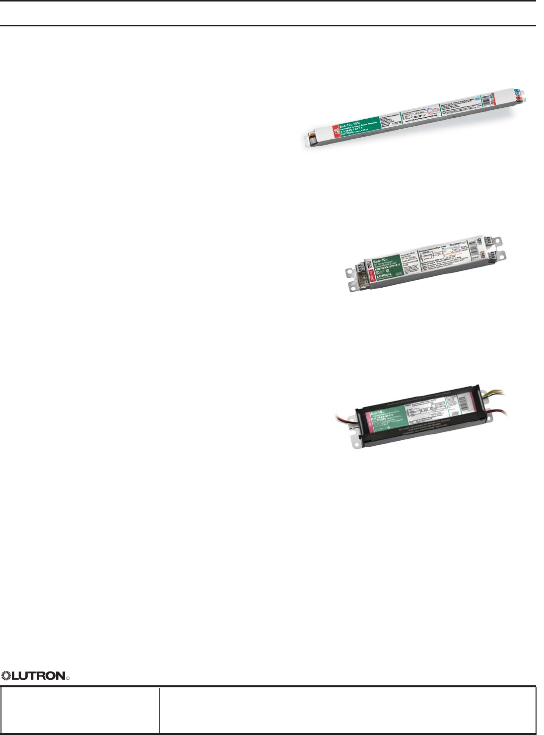
Fluorescent Dimming Ballasts Eco-10® 10% Lighting Management Dimming
Eco-10 Overview
Eco-10 lighting management electronic dimming
ballasts are designed to maximize the benefits of a
lighting management system. Eco-10 offers 100% to
10% dimming, and is ideal for use in any space where
saving energy is the primary goal of the design.
Features
• Continuous, flicker-free dimming from 100% to 10%
• Standard 3-wire line-voltage phase-control
technology for consistent fixture-to-fixture dimming
performance
• Models available for T5 and T5-HO linear, T8 linear
and U-bent, and T5 twin-tube lamps
• Programmed rapid start design preheats lamp
cathodes before applying full arc voltage
• Lamps turn on to any dimmed level without flashing
to full brightness
• Low harmonic distortion throughout the entire
dimming range maintains power quality
• Frequency of operation ensures that ballast does
not interfere with infrared devices operating
between 38 and 42 kHz
• Inrush current limiting circuitry eliminates circuit
breaker tripping, switch arcing, and relay failure
• End-of-lamp-life protection circuitry (for T5 and
T5-HO linear models) ensures safe operation
throughout entire lamp life cycle
• For linear lamps, ballasts maintain consistent light
output for different lamp lengths, ensuring uniformity
• Ultra-quiet operation
• Protected from miswires of any input power to
control lead
• 100% compatible with all Lutron 3-wire fluorescent
controls
• 100% performance tested at factory
• Designed and assembled in the USA
• 5-year limited warranty with Lutron field service
commissioning (3-year standard warranty) from
date of purchase
R
SPECIFICATION SUBMITTAL
Eco-10 1 08.08.08
Eco-10, case type C
1.18 in. w (30 mm) x 1.00 in. h (25 mm) x
18.00 in. l (457 mm)
Eco-10, case type D
1.58 in. w (40 mm) x 1.00 in. h (25 mm) x
9.50 in. l (241 mm)
Eco-10, case type F
2.38 in. w (60 mm) x 1.50 in. h (38 mm) x
9.50 in. l (241 mm)
Page
Job Name: Model Numbers:
Job Number:
A34
UCI NAT SCI II
T528-277-2
1

Fluorescent Dimming Ballasts Eco-10® 10% Lighting Management Dimming
Specifications
Performance
• Dimming Range: 100% to 10% measured
relative light output
• Lamp Starting: programmed rapid start
• Minimum Lamp Starting Temperature: 10 °C (50 °F)
• Ambient Temperature Operating Range: 10 °C (50 °F)
to 60 °C (140 °F)
• Relative Humidity: maximum 90% non-
condensing
• Operating Voltage: 120 V or 277 V at 60Hz
• Lamp Current Crest Factor: less than 1.7
• Lamp Flicker: none visible
• Light Output Variation: constant ±2% light output
for line voltage variations of ±10%
• Lamp Life: average lamp life meets or exceeds
rating of lamp manufacturer
• Ballast Factor: greater than .85 for T8 and T5 twin-
tube lamps, equal to 1.0 for T5 lamps
• Power Factor: greater than .95
• Total Harmonic Distortion (THD): less than 20%
• Maximum Inrush Current: 7 amps per ballast at
120 V, 3 amps per ballast at 277 V
• Sound Rating: Inaudible in a 27 dBa ambient
• Maximum Ballast Case Temperature: 75 °C (167 °F)
Eco-10 2 08.08.08
Standards
• UL Listed (evaluated to the requirements
of UL935)
• CSA certified (evaluated to the requirements
of C22.2 No. 74) – specific model numbers only
• Class P thermally protected
• Meets ANSI C82.11 High Frequency Ballast
Standard
• Meets FCC Part 18 Non-Consumer requirements
for EMI/RFI emissions
• Meets ANSI C62.41 Category A surge
protection standards up to and including 4 kV
• Manufacturing facilities employ ESD reduction
practices that comply with the requirements
of ANSI/ESD S20.20
• Lutron Quality Systems registered to ISO
9001.2000
R
SPECIFICATION SUBMITTAL Page
Job Name: Model Numbers:
Job Number:
A35
UCI NAT SCI II
T528-277-2
2
Fluorescent Dimming Ballasts Eco-10® 10% Lighting Management Dimming
Eco-10 3 08.08.08
Eco-10 Ballast Models
Lamp
Type
120 VOLTS 277 VOLTS
Lamp
Watts
(length)
Lamps
per
ballast
Case
Type
Ballast
Current
(amps)
Eco-10
Model Number
Ballast
Current
(amps)
Eco-10
Model Number
T5 linear 14 W 1 C .17 E 3 T514 C 120 1 .08 E 3 T514 C 277 1
(22 in.) 2 C .32 E 3 T514 C 120 2 .14 E 3 T514 C 277 2
5/8 in. diameter 21 W
(34 in.)
1
2
C
C
.25
.43
E 3 T521 C 120 1
E 3 T521 C 120 2
.11
.19
E 3 T521 C 277 1
E 3 T521 C 277 2
28 W 1 C .30 ECO-T528-120-1 .14 ECO-T528-277-1
(45.3 in.) 2 C .55 ECO-T528-120-2 .25 ECO-T528-277-2
T5-HO linear
high output
24 W
(21.5 in.)
1
2
C
C
.26
.45
ECO-T524-120-1
ECO-T524-120-2
.13
.20
ECO-T524-277-1
ECO-T524-277-2
39 W 1 C .38 ECO-T5H39-120-1 .17 ECO-T5H39-277-1
5/8 in. diameter
(33.4 in.) 2 C .76 ECO-T5H39-120-2 .31 ECO-T5H39-277-2
54 W 1 C .58 ECO-T554-120-1 .25 ECO-T554-277-1
(45.3 in.) 2 C 1.1 ECO-T554-120-2 .45 ECO-T554-277-2
T5 Twin-Tube 36/39 W 1 F .33 ECO-T539-120-1* .14 ECO-T539-277-1*
(16 in.) 2 F .58 ECO-T539-120-2* .25 ECO-T539-277-2*
3 F .85 ECO-T539-120-3* .35 ECO-T539-277-3*
5/8 in. diameter
40 W
(22 in.)
1
2
3
F
F
F
.33
.61
.88
ECO-T540-120-1*
ECO-T540-120-2*
ECO-T540-120-3*
.14
.25
.38
ECO-T540-277-1*
ECO-T540-277-2*
ECO-T540-277-3*
50 W 1 F .38 ECO-T550-120-1* .17 ECO-T550-277-1*
(22 in.) 2 F .69 ECO-T550-120-2* .32 ECO-T550-277-2*
*UL certified only
R
SPECIFICATION SUBMITTAL Page
Job Name: Model Numbers:
Job Number:
A36
UCI NAT SCI II
T528-277-2
3
R
Job Name:
Job Number:
Model Numbers:
Page
SPECIFICATION SUBMITTAL
Eco-10 4 08.08.08
Lighting Management Dimming
Eco-10®10%
Fluorescent Dimming Ballasts
Lamp
Type
120 VOLTS 277 VOLTS
Lamp
Watts
(length)
Lamps
per
ballast
Case
Type
Ballast
Current
(amps)
Eco-10
Model Number
Ballast
Current
(amps)
Eco-10
Model Number
T8 linear
and U-bent
17 W
(24 in.)
1
2
3
F
F
F
.19
.31
.43
ECO-T817-120-1
ECO-T817-120-2
ECO-T817-120-3
.08
.15
.20
ECO-T817-277-1
ECO-T817-277-2
ECO-T817-277-3
25 W
(36 in.)
1
2
F
F
.24
.43
ECO-T825-120-1
ECO-T825-120-2
.12
.19
ECO-T825-277-1
ECO-T825-277-2
32 W
(48 in.)
1
1
1
1
2
2
2
2
3
C
D
D
F
C
D
D
F
F
- -
.34
.34
- -
- -
.53
.53
- -
.82
- -
ECO-T832-120-1-L
ECO-T832-120-1-T
- -
- -
ECO-T832-120-2-L
ECO-T832-120-2-T
- -
ECO-T832-120-3
- -
.14
.14
.15
- -
.23
.23
.22
.35
- -
ECO-T832-277-1-L
ECO-T832-277-1-T
ECO-T832-277-1
- -
ECO-T832-277-2-L
ECO-T832-277-2-T
ECO-T832-277-2
ECO-T832-277-3
Eco-10 Ballast Models continued ...
1 in. diameter
A37
UCI NAT SCI II
T528-277-2
4
C
A
E
D
B
R
Job Name:
Job Number:
Model Numbers:
Page
SPECIFICATION SUBMITTAL
Eco-10 5 08.08.08
Lighting Management Dimming
Eco-10®10%
Fluorescent Dimming Ballasts
Eco-10 Case Dimensions
C
A
E
B
C
D
A 16.12 in. (409 mm)
B 1.00 in. (25 mm)
C 1.18 in. (30 mm)
D 18.00 in. (457 mm)
E 17.70 in. (450 mm)
(mounting centers)
DA 7.13 in. (181 mm)
B 1.00 in. (25 mm)
C 1.58 in. (40 mm)
D 9.50 in. (241 mm)
E 8.91 in. (226 mm)
(slot mounting centers)
If using four hole mount,
mounting centers are 9.00”
(229 mm) x 1.06 in. (27 mm).
F
CE
D
B
A
A 8.30 in. (211 mm)
B 1.50 in. (38 mm)
C 2.38 in. (60 mm)
D 9.50 in. (241 mm)
E 8.91 in. (226 mm)
(slot mounting centers)
If using four hole mount,
mounting centers are 9.21 in.
(234 mm) x 1.70 in. (43 mm).
Power and control
wires are 18 in. (0.45 m)
Lamp wires are
36 in. (0.90 m)
Optional lamp wires
are 36 in. (0.90m)
Optional power
and control wires
are 18 in. (0.45 m)
A38
UCI NAT SCI II
T528-277-2
5

R
Job Name:
Job Number:
Model Numbers:
Page
SPECIFICATION SUBMITTAL
Eco-10 6 08.08.08
Lighting Management Dimming
Eco-10®10%
Fluorescent Dimming Ballasts
Eco-10 Wiring Diagrams
One T5 or T8 lamp
Two T5 or T8 lamps
Three T8 lamps
Eco-10 Dimming
Ballast
1Dimming control wire colors do not necessarily match ballast wire colors (e.g. control ‘dimmed hot’ may be yellow, and
ballast ‘dimmed hot’ may be orange. Wire colors shown are for Lutron ballasts and controls only.
2Ballast and lighting fixture must be effectively grounded.
3 Includes 31 W T8 U-bent lamps
Note: For T5 and T8 lamps, maximum lamp-to-ballast wire length is 7 feet (2 m).
Eco-10 Dimming
Ballast
Eco-10 Dimming
Ballast
1
3
2
Black (Switched Hot)
Neutral
Red
Red Blue
Blue
Ground
To
Dimming
Control
1
Orange (Dimmed Hot)
Fluorescent Lamp
1
3
2
Black (Switched Hot)
Neutral
Red
Red
Red
Red
Blue
Blue
Blue
Blue
Blue/White
Blue/White
Yellow
Yellow
Yellow
Yellow
Ground
To
Dimming
Control
1
Orange (Dimmed Hot)
Fluorescent Lamp
3
Fluorescent Lamp
3
Fluorescent Lamp
Fluorescent Lamp
3
Fluorescent Lamp
1
2
Black (Switched Hot)
Neutral
Ground
To
Dimming
Control
1
Orange (Dimmed Hot)
A39
UCI NAT SCI II
T528-277-2
6
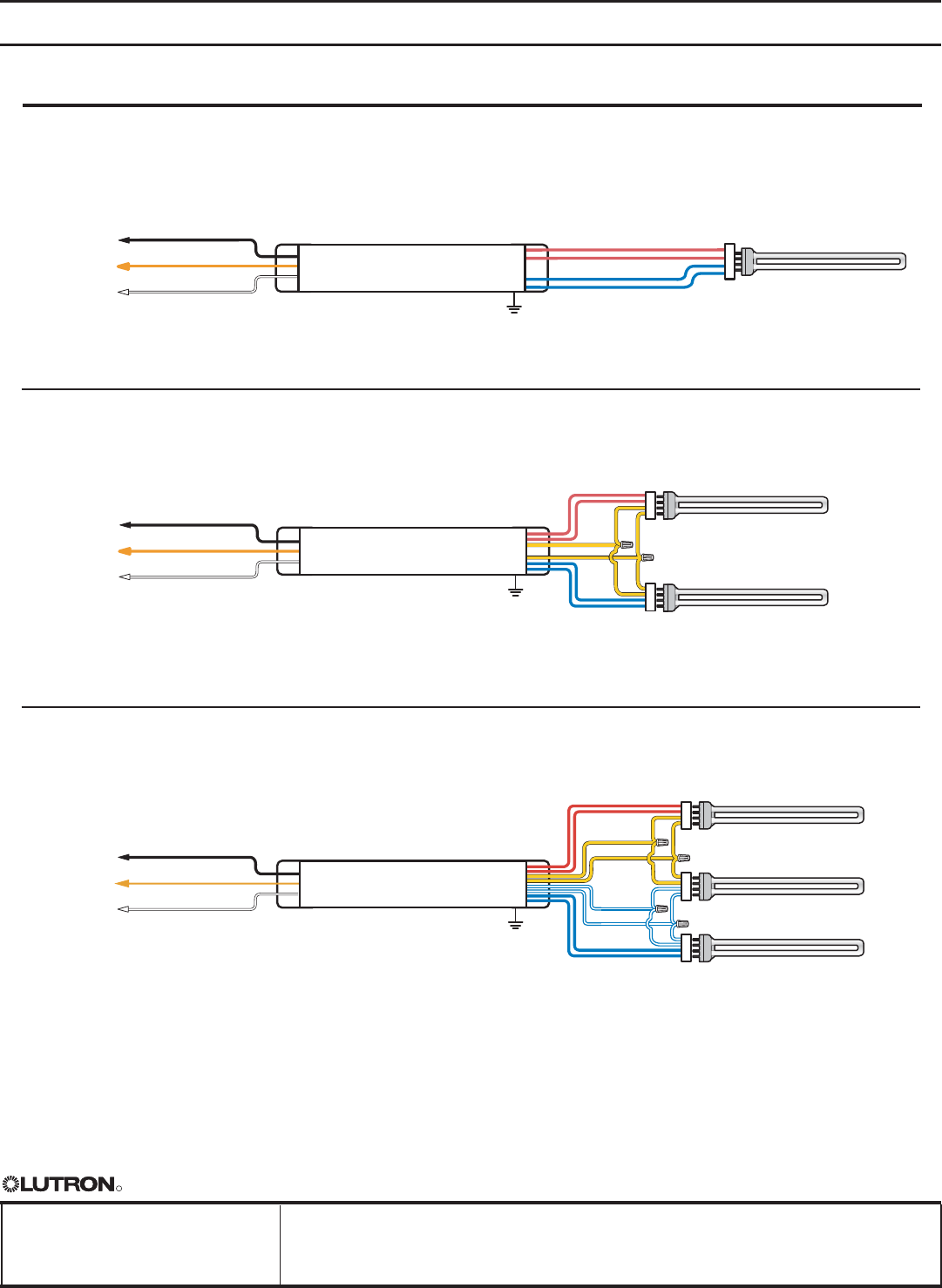
R
Job Name:
Job Number:
Model Numbers:
Page
SPECIFICATION SUBMITTAL
Eco-10 7 08.08.08
Lighting Management Dimming
Eco-10®10%
Fluorescent Dimming Ballasts
Eco-10 Wiring Diagrams continued
Two T5 twin-tube lamps
Three T5 twin-tube lamps
1Dimming control wire colors do not necessarily match ballast wire colors (e.g. control ‘dimmed hot’ may be yellow,
and ballast ‘dimmed hot’ may be orange). Wire colors shown are for Lutron ballasts and controls only.
2Ballast and lighting fixture must be effectively grounded.
Note: For T5 twin-tube lamps, maximum lamp-to-ballast wire length is 3 feet (1 m).
One T5 twin-tube lamp
Eco-10 Dimming Ballast
Eco-10 Dimming Ballast
Eco-10 Dimming Ballast
1
1
Black (Switched Hot)
Orange (Dimmed Hot)
Neutral
Red
Red Blue
Blue
Red
Red
Blue
Blue
Yellow
Yellow
To
Dimming
Control
1
Black (Switched Hot)
Orange (Dimmed Hot)
Neutral
To
Dimming
Control
Black (Switched Hot)
Orange (Dimmed Hot)
Neutral
To
Dimming
Control
Fluorescent Lamp
Fluorescent Lamp
Fluorescent Lamp
Fluorescent Lamp
Fluorescent Lamp
Fluorescent Lamp
2
Ground
2
Ground
Red
Red
Blue
Blue/White
Blue/White
Blue
Yellow
Yellow
2
Ground
1
1
1
UCI NAT SCI II
T528-277-2
7
A40
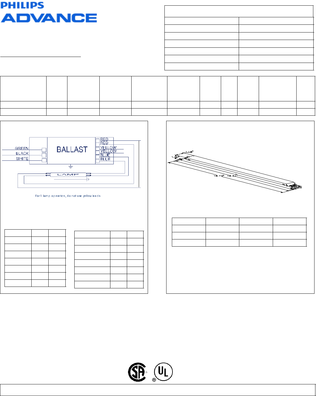
Revised 03/11/2009
Data is based upon tests performed by Philips Lighting Electronics N.A. in a controlled environment and is representative of relative performance. Actual
performance can vary depending on operating conditions. Specifications are subject to change without notice. All specifications are nominal unless otherwise noted.
PHILIPS LIGHTING ELECTRONICS N.A.
10275 WEST HIGGINS ROAD · ROSEMONT, IL 60018
Tel: 800-322-2086 · Fax: 888-423-1882 · www.philips.com/advance
Customer Support/Technical Service: 800-372-3331 · OEM Support: 866-915-5886
ICN-2S54@277V
Brand Name CENTIUM T5
Ballast Type Electronic
Starting Method Programmed Start
Lamp Connection Series/Parallel
Input Voltage 120-277
Input Frequency 50/60 HZ
Status Active
Electrical Specifications
Lamp Type Num.
of
Lamp
s
Rated
Lamp
Watts
Min. Start
Temp
(°F/C)
Input
Current
(Amps)
Input
Power
(ANSI
Watts)
Ballast
Factor MAX
THD
%
Power
Factor MAX Lamp
Current
Crest Factor
B.E.F.
* FT36W/2G11 1 36 -20/-29 0.18 46 1.22 20 0.96 1.7 2.65
FT36W/2G11 2 36 -20/-29 0.32 86 1.20 10 0.98 1.7 1.40
Wiring Diagram
The wiring diagram that appears above is
for the lamp type denoted by the asterisk (*)
Standard Lead Length (inches)
in. cm.
Black 31 78.7
White 31 78.7
Blue 28 71.1
Red 28 71.1
Yellow 48 121.9
Gray 0
Violet 0
in. cm.
Yellow/Blue 0
Blue/White 0
Brown 0
Orange 0
Orange/Black 0
Black/White 0
Red/White 0
Enclosure
Enclosure Dimensions
OverAll (L) Width (W) Height (H) Mounting (M)
16.70 " 1.18 " 1.00 " 16.34 "
16 7/10 1 9/50 1 16 17/50
42.4 cm 3 cm 2.5 cm 41.5 cm
A41
ICN-2S54@277V
Brand Name CENTIUM T5
Ballast Type Electronic
Starting Method Programmed Start
Lamp Connection Series/Parallel
Input Voltage 120-277
Input Frequency 50/60 HZ
Status Active
Electrical Specifications
Notes:
Section I - Physical Characteristics
1.1 Ballast shall be physically interchangeable with standard electromagnetic or standard electronic ballasts, where applicable.
1.2 Ballast shall be provided with integral leads or poke-in wire trap connectors color-coded per ANSI C82.11.
Section II - Performance Requirements
2.1 Ballast shall be Programmed Start.
2.2 Ballast shall contain auto restart circuitry in order to restart lamps without resetting power.
2.3 Ballast shall operate from 50/60 Hz input source of ___________________ (120V through 277V or 347V through 480V) with sustained
variations of +/- 10% (voltage and frequency) with no damage to the ballast.
2.4 Ballast shall be high frequency electronic type and operate lamps at a frequency above 42 kHz to avoid interference with infrared devices
and eliminate visible flicker.
2.5 Ballast shall have a Power Factor greater than 0.98 for primary lamp.
2.6 Ballast shall have a minimum ballast factor of 1.00 for primary lamp application.
2.7 Ballast shall provide for a Lamp Current Crest Factor of 1.7 or less in accordance with lamp manufacturer recommendations.
2.8 Ballast input current shall have Total Harmonic Distortion (THD) of less than 20% for Standard models and THD of less than 10% for
Centium models when operated at nominal line voltage with primary lamp.
2.9 Ballast shall have a Class A sound rating.
2.10 Ballast shall have a minimum starting temperature of _______ {-18C (0F) or -29C (-20F)} for primary lamp. Consult lamp manufacturer for
temperature versus light output characteristics.
2.11 Ballast shall provide Lamp EOL Protection Circuit.
2.12 Ballast shall tolerate sustained open circuit and short circuit output conditions without damage.
2.13 Ballast shall have a hi-low switching option when operating (4) F54T5/HO lamps to allow switching from 4-2 lamps, 3-2 lamps or 3-1 lamp.
2.14 Four-lamp ballast shall have semi-independent lamp operation.
Section III - Regulatory Requirements
3.1 Ballast shall not contain any Polychlorinated Biphenyl (PCB).
3.2 Ballast shall be Underwriters Laboratories (UL) listed, Class P and Type 1 Outdoor; and Canadian Standards Association (CSA) certified
where applicable.
3.3 Ballast shall comply with ANSI C62.41 Category A for Transient protection.
3.4 Ballast shall comply with ANSI C82.11 where applicable.
3.5 Ballast shall comply with the requirements of the Federal Communications Commission (FCC) rules and regulations, Title 47 CFR part 18,
Non-Consumer (Class A) for EMI/RFI (conducted and radiated).
3.6 Ballast shall comply with UL Type CC rating.
Section IV - Other
4.1 Ballast shall be manufactured in a factory certified to ISO 9002 Quality System Standards.
4.2 Ballast shall carry a five-year warranty from date of manufacture against defects in material or workmanship, including replacement, for
operation at a maximum case temperature of 70C. Ballasts with a "90C" designation in their catalog number shall also carry a three-year
warranty at a maximum case temperature of 90C.
4.3 Manufacturer shall have a fifteen-year history of producing electronic ballasts for the North American market.
Revised 03/11/2009
Data is based upon tests performed by Philips Lighting Electronics N.A. in a controlled environment and is representative of relative performance. Actual
performance can vary depending on operating conditions. Specifications are subject to change without notice. All specifications are nominal unless otherwise noted.
PHILIPS LIGHTING ELECTRONICS N.A.
10275 WEST HIGGINS ROAD · ROSEMONT, IL 60018
Tel: 800-322-2086 · Fax: 888-423-1882 · www.philips.com/advance
Customer Support/Technical Service: 800-372-3331 · OEM Support: 866-915-5886
A42
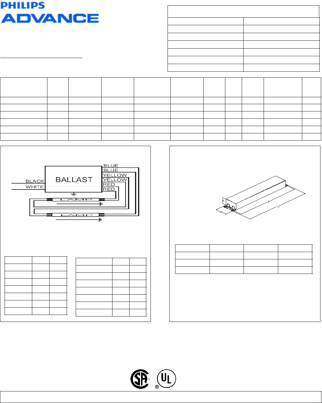
Revised 03/03/2009
Data is based upon tests performed by Philips Lighting Electronics N.A. in a controlled environment and is representative of relative performance. Actual performance
can vary depending on operating conditions. Specifications are subject to change without notice. All specifications are nominal unless otherwise noted.
PHILIPS LIGHTING ELECTRONICS N.A.
10275 WEST HIGGINS ROAD · ROSEMONT, IL 60018
Tel: 800-322-2086 · Fax: 888-423-1882 · www.philips.com/advance
Customer Support/Technical Service: 800-372-3331 · OEM Support: 866-915-5886
ICN-2S28-N@277
Brand Name CENTIUM T5
Ballast Type Electronic
Starting Method Programmed Start
Lamp Connection Series
Input Voltage 120-277
Input Frequency 50/60 HZ
Status Active
Electrical Specifications
Lamp Type Num.
of
Lamps
Rated
Lamp Watts Min. Start
Temp (°F/C) Input
Current
(Amps)
Input
Power
(ANSI Watts)
Ballast
Factor MAX
THD
%
Power
Factor MAX Lamp
Current
Crest Factor
B.E.F.
F14T5 1 14 0/-18 0.07 17 1.07 10 0.98 1.7 6.29
F14T5 2 14 0/-18 0.12 33 1.04 10 0.98 1.7 3.15
F21T5 1 21 0/-18 0.10 25 1.06 10 0.98 1.7 4.24
F21T5 2 21 0/-18 0.18 49 1.02 10 0.98 1.7 2.08
F28T5 1 28 0/-18 0.12 31 1.05 10 0.98 1.7 3.39
* F28T5 2 28 0/-18 0.22 60 1.00 10 0.98 1.7 1.67
Wiring Diagram
The wiring diagram that appears above is for
the lamp type denoted by the asterisk (*)
Standard Lead Length (inches)
in. cm.
Black 23 58.4
White 23 58.4
Blue 27 68.6
Red 27 68.6
Yellow 42 106.7
Gray 0
Violet 0
in. cm.
Yellow/Blue 0
Blue/White 0
Brown 0
Orange 0
Orange/Black 0
Black/White 0
Red/White 0
Enclosure
Enclosure Dimensions
OverAll (L) Width (W) Height (H) Mounting (M)
9.5 " 1.3 " 1.0 " 8.9 "
9 1/2 1 3/10 1 8 9/10
24.1 cm 3.3 cm 2.5 cm 22.6 cm
A43

ICN-2S28-N@277
Brand Name CENTIUM T5
Ballast Type Electronic
Starting Method Programmed Start
Lamp Connection Series
Input Voltage 120-277
Input Frequency 50/60 HZ
Status Active
Electrical Specifications
Notes:
Section I - Physical Characteristics
1.1 Ballast shall be physically interchangeable with standard electromagnetic or standard electronic ballasts, where applicable.
1.2 Ballast shall be provided with integral leads or poke-in wire trap connectors color-coded per ANSI C82.11.
Section II - Performance Requirements
2.1 Ballast shall be Programmed Start.
2.2 Ballast shall contain auto restart circuitry in order to restart lamps without resetting power.
2.3 Ballast shall operate from 50/60 Hz input source of ___________________ (120V through 277V or 347V through 480V) with sustained
variations of +/- 10% (voltage and frequency) with no damage to the ballast.
2.4 Ballast shall be high frequency electronic type and operate lamps at a frequency above 42 kHz to avoid interference with infrared
devices and eliminate visible flicker.
2.5 Ballast shall have a Power Factor greater than 0.98 for primary lamp.
2.6 Ballast shall have a minimum ballast factor of 1.00 for primary lamp application.
2.7 Ballast shall provide for a Lamp Current Crest Factor of 1.7 or less in accordance with lamp manufacturer recommendations.
2.8 Ballast input current shall have Total Harmonic Distortion (THD) of less than 20% for Standard models and THD of less than 10% for
Centium models when operated at nominal line voltage with primary lamp.
2.9 Ballast shall have a Class A sound rating.
2.10 Ballast shall have a minimum starting temperature of _______ {-18C (0F) or -29C (-20F)} for primary lamp. Consult lamp manufacturer
for temperature versus light output characteristics.
2.11 Ballast shall provide Lamp EOL Protection Circuit.
2.12 Ballast shall tolerate sustained open circuit and short circuit output conditions without damage.
2.13 Ballast shall have a hi-low switching option when operating (4) F54T5/HO lamps to allow switching from 4-2 lamps, 3-2 lamps or 3-1
lamp.
2.14 Four-lamp ballast shall have semi-independent lamp operation.
Section III - Regulatory Requirements
3.1 Ballast shall not contain any Polychlorinated Biphenyl (PCB).
3.2 Ballast shall be Underwriters Laboratories (UL) listed, Class P and Type 1 Outdoor; and Canadian Standards Association (CSA) certified
where applicable.
3.3 Ballast shall comply with ANSI C62.41 Category A for Transient protection.
3.4 Ballast shall comply with ANSI C82.11 where applicable.
3.5 Ballast shall comply with the requirements of the Federal Communications Commission (FCC) rules and regulations, Title 47 CFR part 18,
Non-Consumer (Class A) for EMI/RFI (conducted and radiated).
3.6 Ballast shall comply with UL Type CC rating.
Section IV - Other
4.1 Ballast shall be manufactured in a factory certified to ISO 9002 Quality System Standards.
4.2 Ballast shall carry a five-year warranty from date of manufacture against defects in material or workmanship, including replacement, for
operation at a maximum case temperature of 70C. Ballasts with a "90C" designation in their catalog number shall also carry a three-year
warranty at a maximum case temperature of 90C.
4.3 Manufacturer shall have a fifteen-year history of producing electronic ballasts for the North American market.
Revised 03/03/2009
Data is based upon tests performed by Philips Lighting Electronics N.A. in a controlled environment and is representative of relative performance. Actual performance
can vary depending on operating conditions. Specifications are subject to change without notice. All specifications are nominal unless otherwise noted.
PHILIPS LIGHTING ELECTRONICS N.A.
10275 WEST HIGGINS ROAD · ROSEMONT, IL 60018
Tel: 800-322-2086 · Fax: 888-423-1882 · www.philips.com/advance
Customer Support/Technical Service: 800-372-3331 · OEM Support: 866-915-5886
A44
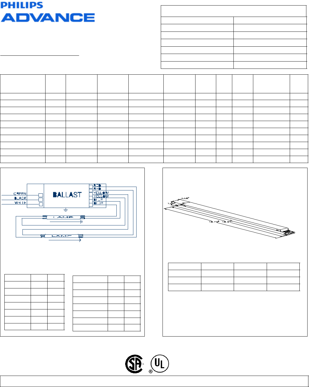
Revised 09/01/2004
Data is based upon tests performed by Philips Lighting Electronics N.A. in a controlled environment and is representative of relative performance. Actual performance
can vary depending on operating conditions. Specifications are subject to change without notice. All specifications are nominal unless otherwise noted.
PHILIPS LIGHTING ELECTRONICS N.A.
10275 WEST HIGGINS ROAD · ROSEMONT, IL 60018
Tel: 800-322-2086 · Fax: 888-423-1882 · www.philips.com/advance
Customer Support/Technical Service: 800-372-3331 · OEM Support: 866-915-5886
ICN-2S24@277V
Brand Name CENTIUM T5
Ballast Type Electronic
Starting Method Programmed Start
Lamp Connection Series
Input Voltage 277
Input Frequency 50/60 HZ
Status Active
Electrical Specifications
Lamp Type Num.
of
Lamps
Rated
Lamp Watts Min. Start
Temp (°F/C) Input
Current
(Amps)
Input
Power
(ANSI Watts)
Ballast
Factor MAX
THD
%
Power
Factor MAX Lamp
Current
Crest Factor
B.E.F.
F24T5/HO 1 24 0/-18 0.10 27 1.02 10 0.98 1.7 3.78
* F24T5/HO 2 24 0/-18 0.19 52 1.00 10 0.98 1.7 1.92
F39T5/HO 1 39 0/-18 0.15 40 0.90 10 0.98 1.7 2.25
FC12T5 1 40 0/-18 0.15 40 0.84 10 0.98 1.7 2.10
FC9T5 1 22 0/-18 0.10 27 1.02 10 0.98 1.7 3.78
FC9T5 2 22 0/-18 0.19 52 1.00 10 0.98 1.7 1.92
FT24W/2G11 1 24 0/-18 0.10 27 1.02 10 0.98 1.7 3.78
FT24W/2G11 2 24 0/-18 0.19 52 1.00 10 0.98 1.7 1.92
FT36W/2G11 1 36 0/-18 0.13 34 0.90 10 0.98 1.7 2.65
FT40W/2G11/RS 1 40 0/-18 0.17 47 1.00 10 0.98 1.7 2.13
Wiring Diagram
The wiring diagram that appears above is for
the lamp type denoted by the asterisk (*)
Standard Lead Length (inches)
in. cm.
Black 0 0
White 0 0
Blue 0 0
Red 0 0
Yellow 0 0
Gray 0 0
Violet 0 0
in. cm.
Yellow/Blue 0 0
Blue/White 0 0
Brown 0 0
Orange 0 0
Orange/Black 0 0
Black/White 0 0
Red/White 0 0
Enclosure
Enclosure Dimensions
OverAll (L) Width (W) Height (H) Mounting (M)
16.70 " 1.18 " 1.00 " 16.34 "
16 7/10 1 9/50 1 16 17/50
42.4 cm 3 cm 2.5 cm 41.5 cm
A45

ICN-2S24@277V
Brand Name CENTIUM T5
Ballast Type Electronic
Starting Method Programmed Start
Lamp Connection Series
Input Voltage 277
Input Frequency 50/60 HZ
Status Active
Electrical Specifications
Notes:
Section I - Physical Characteristics
1.1 Ballast shall be physically interchangeable with standard electromagnetic or standard electronic ballasts, where applicable.
1.2 Ballast shall be provided with integral leads or poke-in wire trap connectors color-coded per ANSI C82.11.
Section II - Performance Requirements
2.1 Ballast shall be Programmed Start.
2.2 Ballast shall contain auto restart circuitry in order to restart lamps without resetting power.
2.3 Ballast shall operate from 50/60 Hz input source of ___________________ (120V through 277V or 347V through 480V) with sustained
variations of +/- 10% (voltage and frequency) with no damage to the ballast.
2.4 Ballast shall be high frequency electronic type and operate lamps at a frequency above 42 kHz to avoid interference with infrared
devices and eliminate visible flicker.
2.5 Ballast shall have a Power Factor greater than 0.98 for primary lamp.
2.6 Ballast shall have a minimum ballast factor of 1.00 for primary lamp application.
2.7 Ballast shall provide for a Lamp Current Crest Factor of 1.7 or less in accordance with lamp manufacturer recommendations.
2.8 Ballast input current shall have Total Harmonic Distortion (THD) of less than 20% for Standard models and THD of less than 10% for
Centium models when operated at nominal line voltage with primary lamp.
2.9 Ballast shall have a Class A sound rating.
2.10 Ballast shall have a minimum starting temperature of _______ {-18C (0F) or -29C (-20F)} for primary lamp. Consult lamp manufacturer
for temperature versus light output characteristics.
2.11 Ballast shall provide Lamp EOL Protection Circuit.
2.12 Ballast shall tolerate sustained open circuit and short circuit output conditions without damage.
2.13 Ballast shall have a hi-low switching option when operating (4) F54T5/HO lamps to allow switching from 4-2 lamps, 3-2 lamps or 3-1
lamp.
2.14 Four-lamp ballast shall have semi-independent lamp operation.
Section III - Regulatory Requirements
3.1 Ballast shall not contain any Polychlorinated Biphenyl (PCB).
3.2 Ballast shall be Underwriters Laboratories (UL) listed, Class P and Type 1 Outdoor; and Canadian Standards Association (CSA) certified
where applicable.
3.3 Ballast shall comply with ANSI C62.41 Category A for Transient protection.
3.4 Ballast shall comply with ANSI C82.11 where applicable.
3.5 Ballast shall comply with the requirements of the Federal Communications Commission (FCC) rules and regulations, Title 47 CFR part 18,
Non-Consumer (Class A) for EMI/RFI (conducted and radiated).
3.6 Ballast shall comply with UL Type CC rating.
Section IV - Other
4.1 Ballast shall be manufactured in a factory certified to ISO 9002 Quality System Standards.
4.2 Ballast shall carry a five-year warranty from date of manufacture against defects in material or workmanship, including replacement, for
operation at a maximum case temperature of 70C. Ballasts with a "90C" designation in their catalog number shall also carry a three-year
warranty at a maximum case temperature of 90C.
4.3 Manufacturer shall have a fifteen-year history of producing electronic ballasts for the North American market.
Revised 09/01/2004
Data is based upon tests performed by Philips Lighting Electronics N.A. in a controlled environment and is representative of relative performance. Actual performance
can vary depending on operating conditions. Specifications are subject to change without notice. All specifications are nominal unless otherwise noted.
PHILIPS LIGHTING ELECTRONICS N.A.
10275 WEST HIGGINS ROAD · ROSEMONT, IL 60018
Tel: 800-322-2086 · Fax: 888-423-1882 · www.philips.com/advance
Customer Support/Technical Service: 800-372-3331 · OEM Support: 866-915-5886
A46

F28T5/841 ALTO TG
1LP
Product family description
Product data
Product Number 166744
Full product name F28T5/841 ALTO TG 1LP
Ordering Code F28T5/841 TG
Pack type 1 Lamp
Pieces per Sku 1
Skus/Case 40
Pack UPC 046677166748
EAN2US
Case Bar Code 50046677166743
Successor Product number
System Description High Efficiency
Base Miniature Bipin
Base Information Green [Green Base]
Bulb T5 [16mm]
Packing Type 1LP [1 Lamp]
Packing Configuration 40
Rated Avg. Life 24000 hr
Type F28T5
Feature ALTO®
Ordering Code F28T5/841 TG
Pack UPC 046677166748
Case Bar Code 50046677166743
Watts 28W
Lamp Wattage EL 28.0 W
Dimmable Yes
Color Code 841 [CCT of 4100K]
Color Rendering Index 85 Ra8
1
9/4/2009
A47
F01, F02, F04, F05, F08, F12
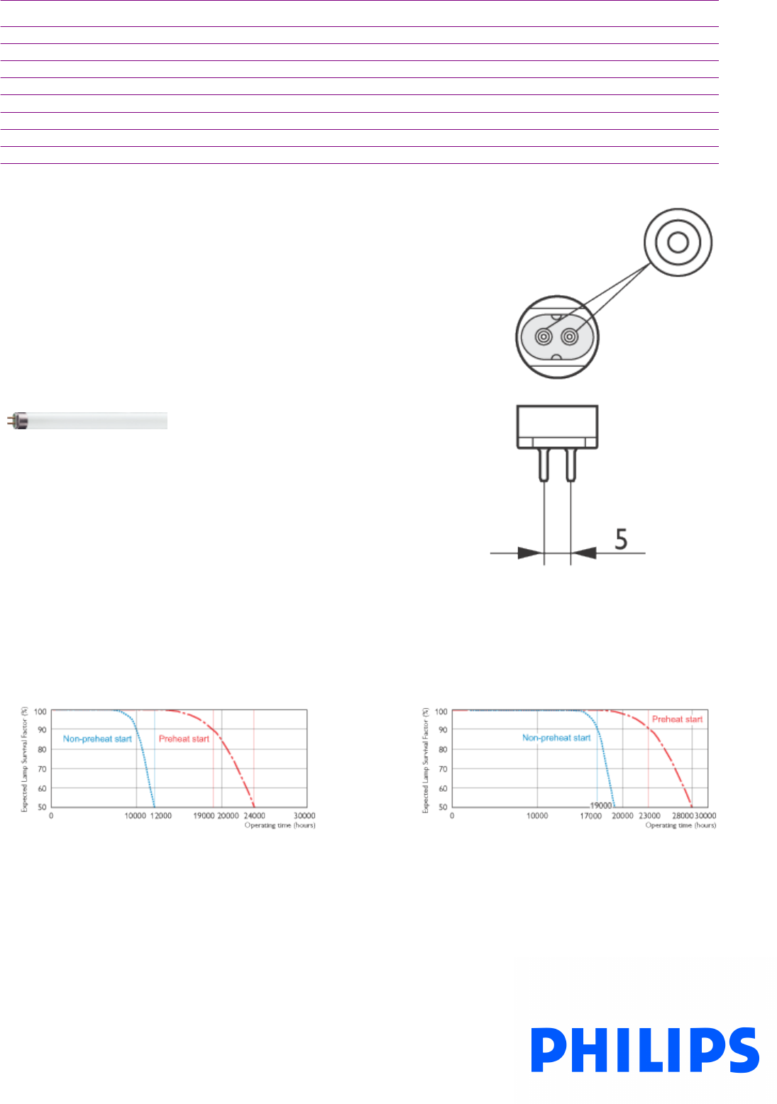
Product data
Color Designation 841
Color Description na [-]
Color Temperature 4000 K
Initial Lumens - Lm
Overall Length C 1163.2 mm
Diameter D 17 mm
Special Note TuffGuard™ [TuffGuard Coated]
Product Number 166744
TL5 HE
Base Miniature Bipin
Life Expectancy 3h cycle
TL5 HE
Life Expectancy 12h cycle
TL5 HE
2
9/4/2009
A48
F01, F02, F04, F05, F08, F12

Service Life 3h cycle
TL5 HE
Service Life 12h cycle
TL5 HE
TL5 HE
3
9/4/2009
A49
F01, F02, F04, F05, F08, F12
PL-C ALTO 13W/841
G24q-1 /4P 1CT
Product family description
Product data
Product Number 383281
Full product name PL-C ALTO 13W/841 G24q-1 /4P 1CT
Ordering Code PL-C 13W/841/4P/ALTO
Pack type 1 Lamp in a Folding Carton
Pieces per Sku 1
Skus/Case 50
Pack UPC 046677240004
EAN2US
Case Bar Code 60046677240006
Successor Product number
Base G24q-1
Base Information 4P
Execution /4P [4 Pins]
Packing Type 1CT [1 Lamp in a Folding Carton]
Packing Configuration 5X10BOX
Avg. Life 10000 hr
Rated Avg. Life 12000 hr
Ordering Code PL-C 13W/841/4P/ALTO
Pack UPC 046677240004
Case Bar Code 60046677240006
Watts 13W
Lamp Wattage EL 12.5 W
Dimmable Yes
Mercury (Hg) Content - mg
Color Code 840 [CCT of 4000K]
Color Rendering Index 82 Ra8
Color Designation Cool White
1
9/4/2009
A50
F03
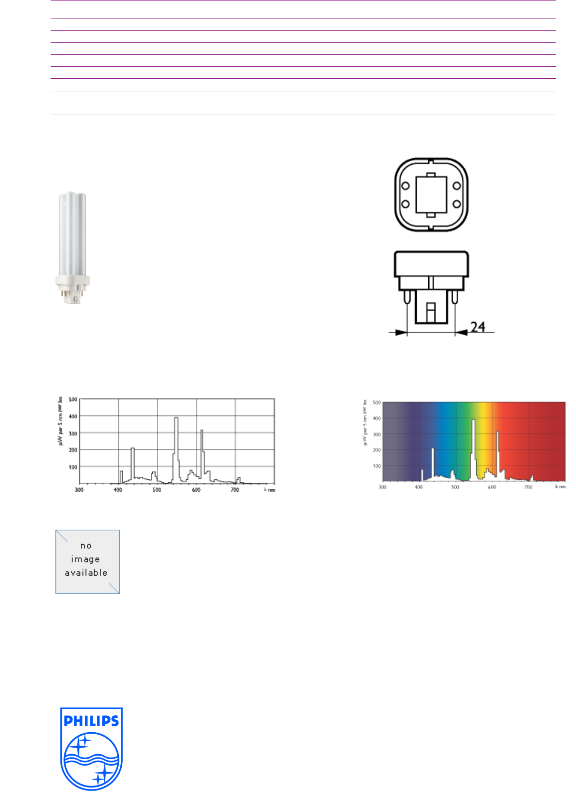
Product data
Color Description 840 Cool White
Color Temperature 4000 K
Initial Lumens 900 Lm
Initial Lumens 900 Lm
Overall Length C 142.9 mm
Diameter D 27.1 mm
Diameter D1 27.1 mm
Product Number 383281
PL-C 13W
Base G24q-1
PL-C/840 PL-C/840
PL-C
2
9/4/2009
A51
F03
SoLux 4100K 35W Specs.
Technical Data SoLux 4100 Kelvin
PHYSICAL
ELECTRICAL
LIGHT
Bulb Type:
MR 16
Watts:
35
Life:
4000 Hrs.
Cover Glass:
Yes
Volts:
12
Color Temperature:
4100 Kelvin
Bulb Diameter:
2" (50mm)
Filament.
C-8
Color Rendition Index.
98+ C.R.I.
Maximum Overall Length:
1 3/4 " (45 mm
Burning Position:
Any
Base
2 pin / GX5.3
CANDLEPOWER
IR EMISSION
UV VALUES
#35011 (10°) =
7897
56 % Less Than
UV :
9.75 Microwatt / Lumen
#35012 (17°) =
2782
Standard MR16 50W
UVA:
9.39 Microwatt / Lumen (380-315 nm)
# 35014 (24°) =
1701
UVB:
0.36 Microwatts / Lumen (315-280nm)
# 35013 (36°) =
1048
Part Number
35011
35012
35014
35013
10° 17° 24° 36°
Distance Beam Diameter Illuminance Beam Diameter Illuminance Beam Diamter Illuminance Beam Diameter Illuminance
Feet Meters Feet Meters fc Lux Feet Meters fc Lux Feet Meters fc Lux Feet Meters fc Lux
20.6 0.35 0.11 2038.7 21936.1 0.60 0.20 718.2 7727.8 0.90 0.26 439.1 4725.0 1.30 0.40 270.5 2911.1
41.2 0.70 0.21 509.7 5484.0 1.20 0.40 179.5 1931.9 1.70 0.52 109.8 1181.3 2.60 0.80 67.6 727.8
61.8 1.05 0.32 226.5 2437.3 1.80 0.55 79.8 858.6 2.60 0.78 48.8 525.0 3.90 1.20 30.1 323.5
82.4 1.40 0.43 127.4 1371.0 2.40 0.73 44.9 483.0 3.40 1.04 27.4 295.3 5.20 1.60 16.9 181.9
10 3.0 1.75 0.53 81.5 877.4 3.00 0.91 28.7 309.1 4.30 1.30 17.6 189.0 6.50 2.00 10.8 116.4
Tailored Lighting Inc.
1-800-254-4487
A52
F06

PL-T 18W/841/4P 1CT
Product family description
PL-T Triple 4pin Fluorescent Lamp with Amalgam.
Features/Benefits
•ALTO® Lamp Technology - Passes EPA's TCLP test for non-hazardous waste.
•Utilizes amalgam technology to provide > 90% of rated lumens in ambient temperatures from 23F to 130F.
•Triple tube design available in 18, 26, 32, and 42W.
•Excellent Color Rendering - 82 Color Rendering Index (CRI).
•Broad Range of Color Temperature - Available in 2700, 3000, 3500 and 4100K.
•Dimmable - PL-T 4-pin lamps may be used with electronic dimming ballasts.
•Long Life - 12,000 hours.
•Energy Saving - Designed for use with electronic ballasts for lower operating costs and flicker-free starting.
Applications
•Ideal for downlights and medium bay multi-lamp fixtures for general lighting.
Notes
•Rated average life under specified test conditions with lamps turned off and restarted no more frequently than once every 3 operating hours.
Lamp life is appreciably longer if lamps are started less frequently. (202)
•Approximate Initial Lumens. The lamp lumen output is based upon lamp performance after 100 hours of operating life, when the output is
measured during operation on a reference ballast under standard laboratory conditions. (203)
•Design Lumens are the approximate lamp lumen output at 40% of the lamp's Rated Average Life. This output is based upon measurements
obtained during lamp operation on a reference ballast under standard laboratory conditions. (208)
Product data
Product Number 268227
Full product name PL-T 18W/841/4P 1CT
Ordering Code 268227
Pack type 1 Lamp in a Folding Carton
Pieces per Sku 1
Skus/Case 12
Pack UPC 046677268220
EAN2US
1
9/4/2009
A53
F07

Product data
Case Bar Code 50046677268225
Successor Product number
Base GX24q-2
Base Information 4P
Execution /4P [4 Pins]
Packing Type 1CT [1 Lamp in a Folding Carton]
Packing Configuration 12
Avg. Hrs. Life 16000 hr
Ordering Code PL-T 18W/841/4P/ALTO
Pack UPC 046677268220
Case Bar Code 50046677268225
Watts 18W
Lamp Wattage EL 16.5 W
Lamp Voltage 100 V
Dimmable Yes
Color Code 840 [CCT of 4000K]
Color Rendering Index 82 Ra8
Color Designation Cool White
Color Description 840 Cool White
Color Temperature 4000 K
Initial Lumens 1200 Lm
Initial Lumens 1200 Lm
Overall Length C 116.4 mm
Diameter D 39.85 mm
Diameter D1 39.65 mm
Product Number 268227
2
9/4/2009
A54
F07

PL-T 18W
Base GX24q-2
PL-T/840 PL-T/840
3
9/4/2009
A55
F07

F35T5/841 TG
Product family description
Product data
Product Number 167338
Full product name F35T5/841 TG
Ordering Code F35T5/841 TG
Pack type 1 Lamp
Pieces per Sku 1
Skus/Case 40
Pack UPC 046677167332
EAN2US
Case Bar Code 50046677167337
Successor Product number
System Description High Efficiency
Base Miniature Bipin
Base Information Green Plate
Bulb T5 [16mm]
Packing Type 1LP [1 Lamp]
Packing Configuration 40
Rated Avg. Life 24000 hr
Type F35T5
Feature na [Not Applicable]
Ordering Code F35T5/841 TG
Pack UPC 046677167332
Case Bar Code 50046677167337
Watts 35W
Lamp Wattage EL 35 W
Dimmable Yes
Color Code 841 [CCT of 4100K]
Color Rendering Index 85 Ra8
1
9/4/2009
A56
F09

Product data
Color Designation 841
Color Description na [-]
Color Temperature 4000 K
Initial Lumens - Lm
Overall Length C 1463.2 mm
Diameter D 17 mm
Product Number 167338
TL5 HE
Base Miniature Bipin
Life Expectancy 3h cycle
TL5 HE
Life Expectancy 12h cycle
TL5 HE
2
9/4/2009
A57
F09
Service Life 3h cycle
TL5 HE
Service Life 12h cycle
TL5 HE
TL5 HE
3
9/4/2009
A58
F09
PL-T 32W/841/4P 1CT
Product family description
PL-T Triple 4pin Fluorescent Lamp with Amalgam.
Features/Benefits
•ALTO® Lamp Technology - Passes EPA's TCLP test for non-hazardous waste.
•Utilizes amalgam technology to provide > 90% of rated lumens in ambient temperatures from 23F to 130F.
•Triple tube design available in 18, 26, 32, and 42W.
•Excellent Color Rendering - 82 Color Rendering Index (CRI).
•Broad Range of Color Temperature - Available in 2700, 3000, 3500 and 4100K.
•Dimmable - PL-T 4-pin lamps may be used with electronic dimming ballasts.
•Long Life - 12,000 hours.
•Energy Saving - Designed for use with electronic ballasts for lower operating costs and flicker-free starting.
Applications
•Ideal for downlights and medium bay multi-lamp fixtures for general lighting.
Notes
•Rated average life under specified test conditions with lamps turned off and restarted no more frequently than once every 3 operating hours.
Lamp life is appreciably longer if lamps are started less frequently. (202)
•Approximate Initial Lumens. The lamp lumen output is based upon lamp performance after 100 hours of operating life, when the output is
measured during operation on a reference ballast under standard laboratory conditions. (203)
•Design Lumens are the approximate lamp lumen output at 40% of the lamp's Rated Average Life. This output is based upon measurements
obtained during lamp operation on a reference ballast under standard laboratory conditions. (208)
Product data
Product Number 268722
Full product name PL-T 32W/841/4P 1CT
Ordering Code 268722
Pack type 1 Lamp in a Folding Carton
Pieces per Sku 1
Skus/Case 12
Pack UPC 046677268725
EAN2US
1
9/4/2009
A59
F11

Product data
Case Bar Code 50046677268720
Successor Product number
Base GX24q-3
Base Information 4P
Execution /4P [4 Pins]
Packing Type 1CT [1 Lamp in a Folding Carton]
Packing Configuration 12
Avg. Hrs. Life 16000 hr
Ordering Code PL-T 32W/841/4P/ALTO
Pack UPC 046677268725
Case Bar Code 50046677268720
Watts 32W
Lamp Wattage EL 32.0 W
Lamp Voltage - V
Dimmable Yes
Color Code 840 [CCT of 4000K]
Color Rendering Index 82 Ra8
Color Designation Cool White
Color Description 840 Cool White
Color Temperature 4000 K
Initial Lumens - Lm
Initial Lumens 2400 Lm
Overall Length C 141.4 mm
Diameter D 39.85 mm
Diameter D1 39.65 mm
Product Number 268722
2
9/4/2009
A60
F11
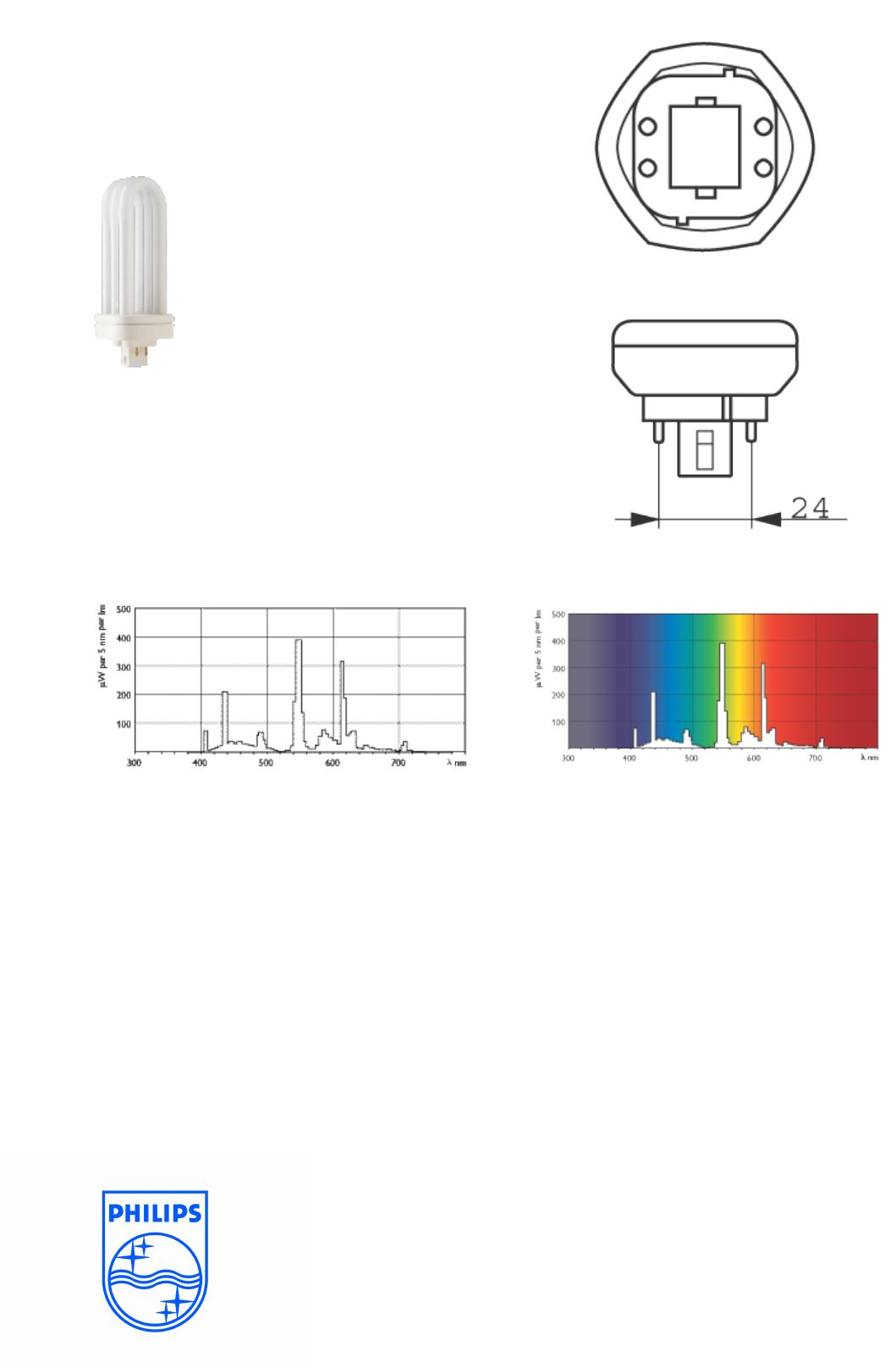
PL-T 32W
Base GX24q-3
PL-T/840 PL-T/840
3
9/4/2009
A61
F11

24W/841 Min Bipin T5
HO ALTO UNP
Product family description
Product data
Product Number 290213
Full product name 24W/841 Min Bipin T5 HO ALTO UNP
Ordering Code F24T5/841/HO/ALTO
Pack type Unpacked
Pieces per Sku 1
Skus/Case 40
Pack UPC 046677290214
EAN2US
Case Bar Code 50046677290219
Successor Product number
System Description High Output
Base Miniature Bipin
Base Information Green [Green Base]
Bulb T5 [16mm]
Packing Type UNP [Unpacked]
Packing Configuration 40
Rated Avg. Life 24000 hr
Type na
Feature na [Not Applicable]
Ordering Code F24T5/841/HO/ALTO
Pack UPC 046677290214
Case Bar Code 50046677290219
Watts 24W
Lamp Wattage EL 22.5 W
Dimmable Yes
Color Code 840 [CCT of 4000K]
Color Rendering Index 85 Ra8
1
9/4/2009
A62
S02
Product data
Color Designation Cool White
Color Description 840 Cool White
Color Temperature 4000 K
Initial Lumens - Lm
Overall Length C 563.2 mm
Diameter D 17 mm
Special packing ALTO
Product Number 290213
TL5 HO
Base Miniature Bipin
Life Expectancy 3h cycle
TL5 HO
Life Expectancy 12h cycle
TL5 HO
2
9/4/2009
A63
S02
Service Life 3h cycle
TL5 HO
Service Life 12h cycle
TL5 HO
TL5 HO/840 TL5 HO/840
TL5 HO
3
9/4/2009
A64
S02
PL-L 36W/830
2G11/4P 1CT
Product family description
PL-L Long 4pin Fluorescent Lamp.
Features/Benefits
•High lumen Output in a slim, compact size.
•Broad range of available wattages: 18, 24, 36, 40, 50, 55, and 80W.
•Excellent Color Rendering - 82 Color Rendering Index (CRI); 55W available with 91 CRI.
•Available in 3000, 3500 and 4100K; 55W available as 5000K only.
•Dimmable - PL-L 4-pin lamps may be used with electronic dimming ballasts.
•Long life: 15,000 to 20,000 hours average life depending on wattage.
Applications
•Ideal for commercial interior lighting applications in 2'x2' fixtures,1'x2' fixtures, and indirect lighting.
Notes
•Rated average life under specified test conditions with lamps turned off and restarted no more frequently than once every 3 operating hours.
Lamp life is appreciably longer if lamps are started less frequently. (202)
•Approximate Initial Lumens. The lamp lumen output is based upon lamp performance after 100 hours of operating life, when the output is
measured during operation on a reference ballast under standard laboratory conditions. (203)
•Design Lumens are the approximate lamp lumen output at 40% of the lamp's Rated Average Life. This output is based upon measurements
obtained during lamp operation on a reference ballast under standard laboratory conditions. (208)
Product data
Product Number 345116
Full product name PL-L 36W/830 2G11/4P 1CT
Ordering Code 345116
Pack type 1 Lamp in a Folding Carton
Pieces per Sku 1
Skus/Case 25
Pack UPC 046677345112
EAN2US
Case Bar Code 50046677345117
Successor Product number
1
9/4/2009
A65
S03
Product data
Base 2G11
Base Information 4P
Bulb Finish Silicon
Execution /4P [4 Pins]
Packing Type 1CT [1 Lamp in a Folding Carton]
Packing Configuration 25
Avg. Life 15000 hr
Rated Avg. Life 20000 hr
Ordering Code PL-L 36W/830/4P
Pack UPC 046677345112
Case Bar Code 50046677345117
Watts 36W
Lamp Wattage EL 32.0 W
Dimmable Yes
Color Code 830 [CCT of 3000K]
Color Rendering Index 82 Ra8
Color Designation Warm White
Color Description 830 Warm White
Color Temperature 3000 K
Initial Lumens 2900 Lm
Initial Lumens 2900 Lm
Overall Length C 416.6 mm
Diameter D 38 mm
Diameter D1 18 mm
Product Number 345116
PL-L 36W
Base 2G11
2
9/4/2009
A66
S03
PL-L/830 PL-L/830
3
9/4/2009
A67
S03
A68
2500 kVA
THESIS SUMMARY REPORT
APRIL 7, 2009

FEEDERSCHEDULE
TagFromToNo.of
Sets
Conduit(PerSet)Conductors(PerSet)
SizeofOvercurrentProtectionPhaseConductors NeutralConductors GroundConductors
SizeTypeNo.SizeType No. Size Type No.SizeType
1 UTILITY
XFMR25"EM
T
2500KCMIL CUTHWN 1500KCMIL CUTHWN 14/0CUTHWN ‐
2 XFMR
US1114"EM
T
3500KCMIL CUTHWN 1500KCMIL CUTHWN 1500KCMILCUTHWN 4000A
3 US1
MCC123"EM
T
2350KCMIL CUTHWN ‐‐ CUTHWN 1#1CUTHWN 600A
3 US1
T223"EM
T
2350KCMIL CUTHWN ‐‐ CUTHWN 1#1CUTHWN 600A
3 US1
T323"EM
T
2350KCMIL CUTHWN ‐‐ CUTHWN 1#1CUTHWN 600A
4 US1
HLP112.5"EM
T
34/0CUTHWN 14/0 CUTHWN 1#4CUTHWN 225A
4 US1
HLP212.5"EM
T
34/0CUTHWN 14/0 CUTHWN 1#4CUTHWN 225A
4 US1
HLP312.5"EM
T
34/0CUTHWN 14/0 CUTHWN 1#4CUTHWN 225A
4 US1
HLP412.5"EM
T
34/0CUTHWN 14/0 CUTHWN 1#4CUTHWN 225A
4 US1
HLP512.5"EM
T
34/0CUTHWN 14/0 CUTHWN 1#4CUTHWN 225A
4 US1
HPHELa12.5"EM
T
34/0CUTHWN 14/0 CUTHWN 1#4CUTHWN 225A
4 EHDP1-C
EHLPHEL‐C12.5"EM
T
34/0CUTHWN 14/0 CUTHWN 1#4CUTHWN 225A
4 EHDP1-C
EHLP4‐C12.5"EM
T
34/0CUTHWN 14/0 CUTHWN 1#4CUTHWN 225A
4 EHDP1-C
EHLP3‐C12.5"EM
T
34/0CUTHWN 14/0 CUTHWN 1#4CUTHWN 225A
4 EHDP1-C
EHLP2‐C12.5"EM
T
34/0CUTHWN 14/0 CUTHWN 1#4CUTHWN 225A
4 EHDP1-C
EHLP1‐C12.5"EM
T
34/0CUTHWN 14/0 CUTHWN 1#4CUTHWN 225A
4 EHDP1-S
EHLPHEL‐S12.5"EM
T
34/0CUTHWN 14/0 CUTHWN 1#4CUTHWN 225A
4 EHDP1-S
EHLP1‐S12.5"EM
T
34/0CUTHWN 14/0 CUTHWN 1#4CUTHWN 225A
4 EHDP1-S
EHLP2‐S12.5"EM
T
34/0CUTHWN 14/0 CUTHWN 1#4CUTHWN 225A
4 EHDP1-S
EHLP3‐S12.5"EM
T
34/0CUTHWN 14/0 CUTHWN 1#4CUTHWN 225A
4 EHDP1-S
EHLP4‐S12.5"EM
T
34/0CUTHWN 14/0 CUTHWN 1#4CUTHWN 225A
5 US1
HDP113"EM
T
2500KCMIL CUTHWN ‐‐ CUTHWN 1#3CUTHWN 400A
5 US1
HDP213"EM
T
2500KCMIL CUTHWN ‐‐ CUTHWN 1#3CUTHWN 400A
5 US1
HDP313"EM
T
2500KCMIL CUTHWN ‐‐ CUTHWN 1#3CUTHWN 400A
6 US1
HDP412.5"EM
T
24/0CUTHWN ‐‐ CUTHWN 1#4CUTHWN 225A
7 US1
T122.5"EM
T
2300KCMIL CUTHWN ‐‐ CUTHWN 1#1CUTHWN 500A
8 T1
DP134"EM
T
3350KCMIL CUTHWN 1350KCMIL CUTHWN 12/0CUTHWN 1000A
9 DP1
LP1a12.5"EM
T
34/0CUTHWN 24/0 CUTHWN 1#4CUTHWN 225A
9 DP1
LP1b12.5"EM
T
34/0CUTHWN 24/0 CUTHWN 1#4CUTHWN 225A
9 DP1
LP1c12.5"EM
T
34/0CUTHWN 24/0 CUTHWN 1#4CUTHWN 225A
9 DP1
LP1d12.5"EM
T
34/0CUTHWN 24/0 CUTHWN 1#4CUTHWN 225A
9 DP1
LP1e12.5"EM
T
34/0CUTHWN 24/0 CUTHWN 1#4CUTHWN 225A
9 DP1
LP1f12.5"EM
T
34/0CUTHWN 24/0 CUTHWN 1#4CUTHWN 225A
9 DP1
LP1g12.5"EM
T
34/0CUTHWN 24/0 CUTHWN 1#4CUTHWN 225A
9 DP1
LP1h12.5"EM
T
34/0CUTHWN 24/0 CUTHWN 1#4CUTHWN 225A
9 DP1
LP1i12.5"EM
T
34/0CUTHWN 24/0 CUTHWN 1#4CUTHWN 225A
9 DP1
LP1j12.5"EM
T
34/0CUTHWN 24/0 CUTHWN 1#4CUTHWN 225A
9 DP2
LP2a12.5"EM
T
34/0CUTHWN 24/0 CUTHWN 1#4CUTHWN 225A
9 DP2
LP2b12.5"EM
T
34/0CUTHWN 24/0 CUTHWN 1#4CUTHWN 225A
9 DP2
LP2c12.5"EM
T
34/0CUTHWN 24/0 CUTHWN 1#4CUTHWN 225A
9 DP2
LP2d12.5"EM
T
34/0CUTHWN 24/0 CUTHWN 1#4CUTHWN 225A
9 DP2
LP2e12.5"EM
T
34/0CUTHWN 24/0 CUTHWN 1#4CUTHWN 225A
9 DP2
LP2f12.5"EM
T
34/0CUTHWN 24/0 CUTHWN 1#4CUTHWN 225A
9 DP2
LP2g12.5"EM
T
34/0CUTHWN 24/0 CUTHWN 1#4CUTHWN 225A
9 DP2
LP2h12.5"EM
T
34/0CUTHWN 24/0 CUTHWN 1#4CUTHWN 225A
9 DP2
LP2i12.5"EM
T
34/0CU THWN 24/0 CUTHWN 1#4CUTHWN 225A
A69

FEEDERSCHEDULE(CONTINUED)
TagFromToNo.of
Sets
Conduit(PerSet)Conductors(PerSet)
SizeofOvercurrentProtectionPhaseConductors NeutralConductors GroundConductors
SizeTypeNo.SizeType No. Size Type No.SizeType
9 DP2
LP2j12.5"EM
T
34/0CUTHWN 24/0 CUTHWN 1#4CUTHWN 225A
9 DP2
LP2k12.5"EM
T
34/0CUTHWN 24/0 CUTHWN 1#4CUTHWN 225A
9 DP2
LP2l12.5"EM
T
34/0CUTHWN 24/0 CUTHWN 1#4CUTHWN 225A
9 DP2
LP2m12.5"EM
T
34/0CUTHWN 24/0 CUTHWN 1#4CUTHWN 225A
9 DP2
LP2n12.5"EM
T
34/0CUTHWN 24/0 CUTHWN 1#4CUTHWN 225A
9 DP2
LP2o12.5"EM
T
34/0CUTHWN 24/0 CUTHWN 1#4CUTHWN 225A
9 DP2
LP2p12.5"EM
T
34/0CUTHWN 24/0 CUTHWN 1#4CUTHWN 225A
9 DP2
LP2q12.5"EM
T
34/0CUTHWN 24/0 CUTHWN 1#4CUTHWN 225A
9 DP2
LP2r12.5"EM
T
34/0CUTHWN 24/0 CUTHWN 1#4CUTHWN 225A
9 DP3
LP3a12.5"EM
T
34/0CUTHWN 24/0 CUTHWN 1#4CUTHWN 225A
9 DP3
LP3b12.5"EM
T
34/0CUTHWN 24/0 CUTHWN 1#4CUTHWN 225A
9 DP3
LP3c12.5"EM
T
34/0CUTHWN 24/0 CUTHWN 1#4CUTHWN 225A
9 DP3
LP3d12.5"EM
T
34/0CUTHWN 24/0 CUTHWN 1#4CUTHWN 225A
9 DP3
LP3e12.5"EM
T
34/0CUTHWN 24/0 CUTHWN 1#4CUTHWN 225A
9 DP3
LP3f12.5"EM
T
34/0CUTHWN 24/0 CUTHWN 1#4CUTHWN 225A
9 DP3
LP3g12.5"EM
T
34/0CUTHWN 24/0 CUTHWN 1#4CUTHWN 225A
9 DP3
LP3h12.5"EM
T
34/0CUTHWN 24/0 CUTHWN 1#4CUTHWN 225A
9 DP3
LP3i12.5"EM
T
34/0CUTHWN 24/0 CUTHWN 1#4CUTHWN 225A
9 DP3
LP3j12.5"EM
T
34/0CUTHWN 24/0 CUTHWN 1#4CUTHWN 225A
9 DP3
LP3k12.5"EM
T
34/0CUTHWN 24/0 CUTHWN 1#4CUTHWN 225A
9 DP3
LP3l12.5"EM
T
34/0CUTHWN 24/0 CUTHWN 1#4CUTHWN 225A
9 DP3
LP3o12.5"EM
T
34/0CUTHWN 24/0 CUTHWN 1#4CUTHWN 225A
9 DP3
LP3p12.5"EM
T
34/0CUTHWN 24/0 CUTHWN 1#4CUTHWN 225A
9 DP3
LP3q12.5"EM
T
34/0CUTHWN 24/0 CUTHWN 1#4CUTHWN 225A
9 DP4
LP4a12.5"EM
T
34/0CUTHWN 24/0 CUTHWN 1#4CUTHWN 225A
9 DP4
LP4b12.5"EM
T
34/0CUTHWN 24/0 CUTHWN 1#4CUTHWN 225A
9 DP4
LP4c12.5"EM
T
34/0CUTHWN 24/0 CUTHWN 1#4CUTHWN 225A
9 DP4
LP4d12.5"EM
T
34/0CUTHWN 24/0 CUTHWN 1#4CUTHWN 225A
9 DP4
LP4e12.5"EM
T
34/0CUTHWN 24/0 CUTHWN 1#4CUTHWN 225A
9 DP4
LP4f12.5"EM
T
34/0CUTHWN 24/0 CUTHWN 1#4CUTHWN 225A
9 DP4
LP4g12.5"EM
T
34/0CUTHWN 24/0 CUTHWN 1#4CUTHWN 225A
9 DP4
LP4h12.5"EM
T
34/0CUTHWN 24/0 CUTHWN 1#4CUTHWN 225A
9 DP4
LP4i12.5"EM
T
34/0CUTHWN 24/0 CUTHWN 1#4CUTHWN 225A
9 DP4
LP4j12.5"EM
T
34/0CUTHWN 24/0 CUTHWN 1#4CUTHWN 225A
9 DP4
LP4k12.5"EM
T
34/0CUTHWN 24/0 CUTHWN 1#4CUTHWN 225A
9 DP4
LP4l12.5"EM
T
34/0CUTHWN 24/0 CUTHWN 1#4CUTHWN 225A
9 DP4
LP4m12.5"EM
T
34/0CUTHWN 24/0 CUTHWN 1#4CUTHWN 225A
9 DP4
LP4n12.5"EM
T
34/0CUTHWN 24/0 CUTHWN 1#4CUTHWN 225A
9 DP4
LP4p12.5"EM
T
34/0CUTHWN 24/0 CUTHWN 1#4CUTHWN 225A
9 DP4
LP4q12.5"EM
T
34/0CUTHWN 24/0 CUTHWN 1#4CUTHWN 225A
9 DP4
LP5a12.5"EM
T
34/0CUTHWN 24/0 CUTHWN 1#4CUTHWN 225A
9 DP4
LP5b12.5"EM
T
34/0CUTHWN 24/0 CUTHWN 1#4CUTHWN 225A
9 ELP1-C ELP1a-C 1 2.5" EMT 3 4/0 CU THWN 2 4/0 CU THWN 1 #4 CU THWN 225A
9 ELP1-C ELP1b-C 1 2.5" EMT 3 4/0 CU THWN 2 4/0 CU THWN 1 #4 CU THWN 225A
9 ELP2-C ELP2a-C 1 2.5" EMT 3 4/0 CU THWN 2 4/0 CU THWN 1 #4 CU THWN 225A
9 ELP2-C ELP2b-C 1 2.5" EMT 3 4/0 CU THWN 2 4/0 CU THWN 1 #4 CU THWN 225A
9 ELP2-C ELP2c-C 1 2.5" EMT 3 4/0 CU THWN 2 4/0 CU THWN 1 #4 CU THWN 225A
A70

FEEDERSCHEDULE(CONTINUED)
TagFromToNo.of
Sets
Conduit(PerSet)Conductors(PerSet)
SizeofOvercurrentProtectionPhaseConductors NeutralConductors GroundConductors
SizeTypeNo.SizeType No. Size Type No.SizeType
9 ELP2-C ELP2d-C 1 2.5" EMT 3 4/0 CU THWN 2 4/0 CU THWN 1 #4 CU THWN 225A
9 ELP3-C ELP3a-C 1 2.5" EMT 3 4/0 CU THWN 2 4/0 CU THWN 1 #4 CU THWN 225A
9 ELP3-C ELP3b-C 1 2.5" EMT 3 4/0 CU THWN 2 4/0 CU THWN 1 #4 CU THWN 225A
9 ELP3-C ELP3c-C 1 2.5" EMT 3 4/0 CU THWN 2 4/0 CU THWN 1 #4 CU THWN 225A
9 ELP3-C ELP3d-C 1 2.5" EMT 3 4/0 CU THWN 2 4/0 CU THWN 1 #4 CU THWN 225A
9 ELP4-C ELP4a-C 1 2.5" EMT 3 4/0 CU THWN 2 4/0 CU THWN 1 #4 CU THWN 225A
9 ELP4-C ELP4b-C 1 2.5" EMT 3 4/0 CU THWN 2 4/0 CU THWN 1 #4 CU THWN 225A
9 ELP4-C ELP4c-C 1 2.5" EMT 3 4/0 CU THWN 2 4/0 CU THWN 1 #4 CU THWN 225A
9 ELP4-C ELP4d-C 1 2.5" EMT 3 4/0 CU THWN 2 4/0 CU THWN 1 #4 CU THWN 225A
9 THEL LPHELa 1 2.5" EMT 3 4/0 CU THWN 2 4/0 CU THWN 1 #4 CU THWN 225A
10 T2 DP2 4 3" EMT 3 350KCMIL CU THWN 2 350KCMIL CU THWN 1 3/0 CU THWN 1200A
10 T3 DP3 4 3" EMT 3 350KCMIL CU THWN 2 350KCMIL CU THWN 1 3/0 CU THWN 1200A
10 T4 DP4 4 3" EMT 3 350KCMIL CU THWN 2 350KCMIL CU THWN 1 3/0 CU THWN 1200A
11 US1 T4 2 3.5" EMT 3 500KCMIL CU THWN - - CU THWN 1 1/0 CU THWN 700A
12 US1 ELEV-1 1 2.5" EMT 3 250KCMIL CU THWN - - CU THWN 1 #4 CU THWN 250A
13 HLPHELb THEL 1 1.5" EMT 3 #1 CU THWN - - CU THWN 1 #6 CU THWN 125A
14 US1 HLP SITE 1 1.25" EMT 3 #2 CU THWN 1 #2 CU THWN 1 #8 CU THWN 100A
15 US1 ATS #2 2 3" EMT 3 #2 CU THWN 1 #2 CU THWN 1 #8 CU THWN 600A
15 EDB NS2 ATS #2 2 3" EMT 3 #2 CU THWN 1 #2 CU THWN 1 #8 CU THWN 600A
15 ATS #2 EHDP1-C 2 3" EMT 3 #2 CU THWN 1 #2 CU THWN 1 #8 CU THWN 600A
16 US1 ATS #1 2 4" EMT 3 500KCMIL CU THWN 1 500KCMIL CU THWN 1 1/0 CU THWN 800A
16 EDB NS2 ATS #1 2 4" EMT 3 500KCMIL CU THWN 1 500KCMIL CU THWN 1 1/0 CU THWN 800A
16 ATS #1 EHDP1-S 2 4" EMT 3 500KCMIL CU THWN 1 500KCMIL CU THWN 1 1/0 CU THWN 800A
17 GENERATOR EDB NS2 6 4" EMT 3 500KCMIL CU THWN 1 500KCMIL CU THWN 1 250KCMIL CU THWN 2000A
18 EHDP1-S AH-1 1 3" EMT 3 500KCMIL CU THWN - - CU THWN 1 #3 CU THWN 350A
18 EHDP1-S AH-2 1 3" EMT 3 500KCMIL CU THWN - - CU THWN 1 #3 CU THWN 350A
19 EHDP1-S EMCCR-S 2 3" EMT 3 500KCMIL CU THWN - - CU THWN 1 1/0 CU THWN 800A
20 EHDP1-S ELEV-2 1 1.5" EMT 3 2/0 CU THWN - - CU THWN 1 #6 CU THWN 175A
20 EMCCR-S EF-1 1 1.5" EMT 3 2/0 CU THWN - - CU THWN 1 #6 CU THWN 175A
20 EMCCR-S EF-2 1 1.5" EMT 3 2/0 CU THWN - - CU THWN 1 #6 CU THWN 175A
20 EMCCR-S EF-3 1 1.5" EMT 3 2/0 CU THWN - - CU THWN 1 #6 CU THWN 175A
21 EHLPHEL-S ETHEL-S 1 3/4" EMT 3 #10 CU THWN - - CU THWN 1 #10 CU THWN 25A
22 ETHEL-S ELP-g 1 1" EMT 3 #4 CU THWN 1 #4 CU THWN 1 #10 CU THWN 60A
23 EHLPHEL-C ETHEL-C 1 1" EMT 3 #4 CU THWN - - CU THWN 1 #8 CU THWN 70A
23 EHLP1-S ET1-S 1 1" EMT 3 #4 CU THWN - - CU THWN 1 #8 CU THWN 70A
23 EHLP2-S ET2-S 1 1" EMT 3 #4 CU THWN - - CU THWN 1 #8 CU THWN 70A
23 EHLP3-S ET3-S 1 1" EMT 3 #4 CU THWN - - CU THWN 1 #8 CU THWN 70A
23 EHLP4-S ET4-S 1 1" EMT 3 #4 CU THWN - - CU THWN 1 #8 CU THWN 70A
24 ETHEL-C ELPHEL-C 1 2" EMT 3 1/0 CU THWN 1 1/0 CU THWN 1 #6 CU THWN 150A
24 ET1-S ELP1-S 1 2" EMT 3 1/0 CU THWN 1 1/0 CU THWN 1 #6 CU THWN 150A
24 ET2-S ELP2-S 1 2" EMT 3 1/0 CU THWN 1 1/0 CU THWN 1 #6 CU THWN 150A
24 ET3-S ELP3-S 1 2" EMT 3 1/0 CU THWN 1 1/0 CU THWN 1 #6 CU THWN 150A
24 ET4-S ELP4-S 1 2" EMT 3 1/0 CU THWN 1 1/0 CU THWN 1 #6 CU THWN 150A
25 EHLP4-C EHDPR-C 1 1" EMT 3 #6 CU THWN 1 #6 CU THWN 1 #10 CU THWN 50A
26 EHLP2-C ET2-C 1 1.5" EMT 3 1/0 CU THWN - - CU THWN 1 #6 CU THWN 150A
26 EHLP3-C ET3-C 1 1.5" EMT 3 1/0 CU THWN - - CU THWN 1 #6 CU THWN 150A
26 EHLP4-C ET4-C 1 1.5" EMT 3 1/0 CU THWN - - CU THWN 1 #6 CU THWN 150A
26 EHLP1-C ET1-C 1 1.5" EMT 3 1/0 CU THWN - - CU THWN 1 #6 CU THWN 150A
27 ET1-C ELP1-C 1 4" EMT 3 500KCMIL CU THWN 2 500KCMIL CU THWN 1 #3 CU THWN 400A
A71
FEEDERSCHEDULE(CONTINUED)
TagFromToNo.of
Sets
Conduit(PerSet)Conductors(PerSet)
SizeofOvercurrentProtectionPhaseConductors NeutralConductors GroundConductors
SizeTypeNo.SizeType No. Size Type No.SizeType
27 ET2-C ELP2-C 1 4" EMT 3 500KCMIL CU THWN 2 500KCMIL CU THWN 1 #3 CU THWN 400A
27 ET3-C ELP3-C 1 4" EMT 3 500KCMIL CU THWN 2 500KCMIL CU THWN 1 #3 CU THWN 400A
27 ET4-C ELP4-C 1 4" EMT 3 500KCMIL CU THWN 2 500KCMIL CU THWN 1 #3 CU THWN 400A
28 EHDP1-C PCWP 1 1 1" EMT 3 #6 CU THWN - - CU THWN 1 #10 CU THWN 50A
28 EHDP1-C PCWP 2 1 1" EMT 3 #6 CU THWN - - CU THWN 1 #10 CU THWN 50A
NOTES:
1. REFER TO SINGLE-LINE DIAGRAM FOR FEEDER TAGS
CU = COPPER
A72
