POS MV V5 Installation And Operation Guide Applanix Manual
Applanix_POS_MV_-_Manual
User Manual:
Open the PDF directly: View PDF ![]() .
.
Page Count: 273 [warning: Documents this large are best viewed by clicking the View PDF Link!]
- General Notice
- For Our European Union Customers
- A New Recycling Program
- About This Document
- Table of Contents
- List of Figures
- List of Tables
- List of Abbreviations, Synonyms and Symbols
- 1.0 Introduction
- 2.0 Installation
- Handling Precautions
- Unpacking and Storage
- Site Preparation
- Installation
- Installation Parameters
- Installation Checklist
- 3.0 Interfaces and Data Formats
- LAN (Ethernet) Data
- COM Ports
- NMEA Data Formats
- NMEA Sentence Formats
- $xxGGA: Global Positioning Fix Data
- $xxGGK: Time, Position, Position Type and DOP Values
- $xxHDT: Heading - True Data
- $xxVTG: Course Over Ground and Ground Speed Data
- $xxGST: GNSS Pseudorange Noise Statistics
- NMEA Port RMC Message Format
- $PASHR ($PASHR-TSS): Attitude Data
- $PRDID ($PRDID-TSS): Attitude Data
- $xxZDA: Time and Date
- $UTC: Time and Date
- $xxPPS: Time and Offset
- UTC: Date and Time (Trimble format)
- Binary Data Formats
- Output String Formats
- GNSS Ports
- 4.0 System Configuration
- 5.0 System Operation
- 6.0 TrueHeave Operation
- 7.0 Specifications
- 8.0 Tools and Diagnostics
- 9.0 Fault Identification
- Component Description
- Fault Identification
- Remove and Replace Procedures
- Troubleshooting
- Total System Failure
- Initialization Failure
- GNSS Not Available
- GAMS Not Ready
- Serial Communications Problem
- Ethernet Communications Problem
- Contact Applanix
- How to Reach Customer Support
- Returns
- Inertial Navigation
- Heave Filter
- GNSS Azimuth Measurement Subsystem
- Heading Measurements
- Baselines
- Baseline Measurement
- Carrier Phase Differential Position
- Alignment
- Error Sources
- Aided Inertial Navigation
- Supplied Software
- Hardware and Software Requirements
- MV-POSView Controller Program
- Firmware Upgrade
- Survey Area
- Survey Procedure
- Handling Instructions
- Background
- GNSS Timing Basics
- POS System Timing
Copyright © Applanix Corporation, 2011
I
POS MV V5 Installation and Operation
Guide
PUBS-MAN-004291
Revision 4

Copyright © Applanix Corporation, 2011
III
General Notice
Although every care has been taken to ensure that this manual is reliable and accurate, Applanix
Corporation (here after referred to as Applanix) provides it “as is” and without express, implied, or limited
warranty of any kind. In no event shall Applanix be liable for any loss or damage caused by the use of this
manual.
This manual describes the POS MV™ V5 and V5-1 in detail and contains full installation and operating
instructions. This manual is an important part of the system and should remain with the installation.
It is the customer’s responsibility to ensure that there are adequate mounting facilities, and to carefully
plan the component layout. Applanix will not be responsible for damage caused by improper installation
or inadequate environmental conditions.
Applanix reserves the right to change the specifications and information in this document without notice.
The information contained herein is proprietary to Applanix. Release to third parties of this publication or
of information contained herein is prohibited without the prior written consent of Applanix.
Pentium® is a registered trademark of Intel Corporation. Microsoft, Windows XP, Windows Vista, and
Windows 7 are trademarks of Microsoft group of companies.
All rights reserved. No part of this publication may be reproduced, stored in a retrieval system or
transmitted in any form or by any means without the prior written consent of Applanix.
Copyright© Applanix Corporation, 2011.
Printed in Canada.
Copyright © Applanix Corporation, 2011
IV
Liability and Safety Information
Important: All cables connected to the POS MV V5 and
POS MV V5-1 equipment shall be constructed of (in order of
preference): a) halogen free, b) low smoke and c) high
temperature materials.
CAUTION
DOUBLE POLE/NEUTRAL FUSING
Ethernet Cable - Applanix supplies a suitable Ethernet cable. However, if supplied by the customer the
cable shall incorporate a braid shield, having at least 90% coverage that has a 360 degree termination at
both connectors, and be rated as CAT5 or better. The RJ45 connectors used in the cable shall also be
shielded.
Serial Cables - Applanix supplies suitable COM port serial cables, each are about 3.6 m (12.0 ft) in
length. If the cables are supplied by the customer each cable shall incorporate a braid shield, having at
least 90% coverage that has a 360 degree termination at the backshells of both connectors.
Power Cord - Applanix ships a specially constructed power cord with its POS MV V5 ac products and is
detailed in Appendix E . Otherwise, the customer is responsible for supplying and using a compliant
power cord. Ensure that the destination country electrical codes are adhered to. Applanix recommends an
ac power cord not exceeding 2 m (6 ½ ft) in length and that can safely handle a maximum of 10 A.
Regulatory Information
Caution: Do not make mechanical or electrical modifications to the
POS MV system or any of their components. Changes or
modifications not expressly approved by Applanix could void the
compliance and negate your authority to operate the product.
Certification was achieved using the following original or
replacement equipment supplied by Applanix: Power Cord, GNSS
antennas, GNSS antenna cables, Ethernet cable, IMU, IMU cable
and RS-232 serial cables.
Notice: POS MV V5 and POS MV V5-1 are not certified to EN
60945 standard and therefore cannot be used for maritime
navigation as defined by EN 60945. POS MV cannot be installed
near bridge-mounted equipment, in close proximity to receiving
antennas, or anywhere it could be capable of interfering with safe
navigation of the ship and with radio-communications.

Copyright © Applanix Corporation, 2011
V
DECLARATION OF CONFORMITY
Manufacturer's Name:
Manufacturer's Address: 85 Leek Crescent
Richmond Hill, Ontario, Canada L4B 3B3
EC Representative's Name: Applanix Corporation, A Trimble Company
EC Representative's Address: 85 Leek Crescent
Richmond Hill, Ontario, Canada L4B 3B3
Equipment Model Designation: POS MV V5, POS MV V5-1
Equipment Description: POS MV is a fully integrated, turnkey
position and orientation system for Marine
vessels.
Application of Council Directive: 2006/95/EC on the harmonization of the
laws related to Member States relating to electrical equipment designed
for use within certain voltage limits and Council Directive 2004/108/EC
on the approximation of the laws related to Member States relating to
electromagnetic compatibility.
Referenced Safety Standards: Referenced EMC Standards:
EN 60950-1 : 2006 EN 55022 : 2006
EN 55024 : 98 with Amendments
A1:2001 and A2:2003
FCC Section 15.21 Information to the user.
Changes or modifications not expressly approved by Applanix could void the user's authority to operate
the equipment.
FCC Section 15.105 Information to the user.
NOTE: This equipment has been tested and found to comply with the limits for a Class B digital device,
pursuant to Part 15 of the FCC Rules. These limits are designed to provide reasonable protection against
harmful interference when the equipment is operated in a commercial environment. This equipment
generates, uses, and can radiate radio frequency energy and, if not installed and used in accordance with
the instruction manual, may cause harmful interference to radio communications.
Copyright © Applanix Corporation, 2011
VI
Industry Canada
This Class B digital apparatus complies with Canadian ICES-003.
Cet appareil numérique de la classe B est conforme à la norme NMB-003 du Canada.
VCCI
English Translation: This is a Class B product based on the standard of the Voluntary Control
Council for Interference from Information Technology Equipment (VCCI). If this is used near a
radio or television receiver in a domestic environment, it may cause radio interference. Install
and use the equipment according to the instruction manual.

Copyright © Applanix Corporation, 2011
VII
For Our European Union Customers
A New Recycling Program
Applanix recognizes the importance of minimizing the environmental impacts of our products. We
endeavour to meet your needs, not only when you purchase and use our products, but also when you are
ready to dispose of them. Applanix is actively pursuing, and will continue to pursue, the expanded use of
environmentally friendly materials in all its products. In addition, we have established a convenient and
environmentally friendly recycling program.
As Applanix makes additional recycling facilities available for your use, we will
post their locations and contact information on our recycling instructions Web
page. In the meanwhile see Appendix A, page A-1, for Applanix contact
information.
WEEE is Waste Electrical and Electronic Equipment, products that operate on
electrical power.

Copyright © Applanix Corporation, 2011
IX
About This Document
Text Conventions
The following text conventions are used in this manual:
• Emphasize a term - italic font or bold italic font (e.g. ‘An Inertial Frame is’ or ‘An Inertial Frame
is’); a mixture is acceptable but, consistency is preferable
• Referring to another manual or to a file name - italic font (e.g. ‘read the Power Requirements
manual’ or ‘locate the start.exe file’)
• Referring to a placard label - regular font (e.g. ‘the COM (2) connector’)
• Referring to a screen label - bold font (e.g. ‘press the OK button’)
• Path statement - bold font (e.g. ‘select C:\My Computer\ Working Files\.Fields’)
• Menu statement - bold font (e.g. ‘select Insert, AutoText, Closing window menu’ or ‘select
Insert | AutoText | Closing window menu’); a mixture is acceptable but, consistency is
preferable
• Web address statement - bold font (e.g. ‘select http://www.applanix.com from’)
Copyright © Applanix Corporation, 2011
X
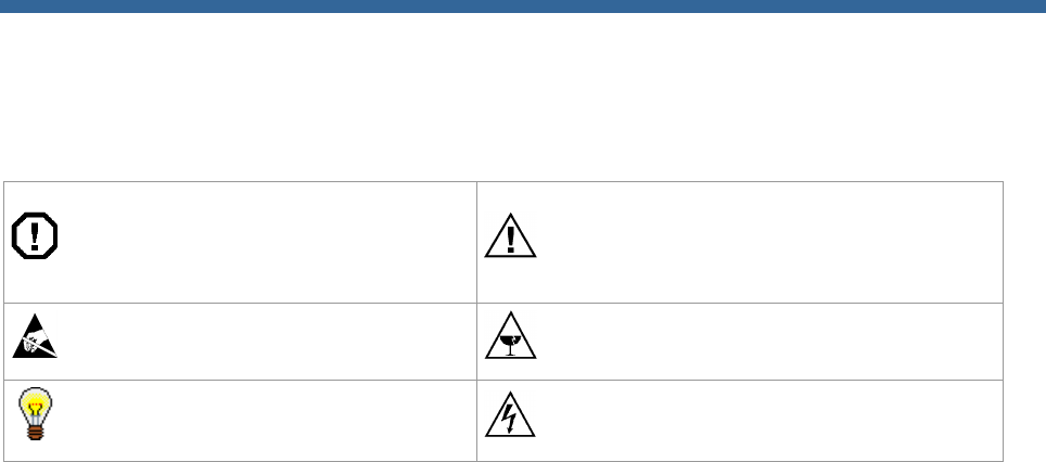
Symbols
The following symbols appear in this manual:
Warning - operating procedures,
practices, etc., which, if not correctly
followed, could result in personal
injury or loss of life
Caution - procedures, practices, etc.,
which, if not correctly followed, could
result in damage or destruction of
equipment, or loss of data
Electrostatic Discharge (ESD)
sensitive material
Fragile/Breakable
Hint - provides a suggested method
or approach
Electrocution Hazard
Document Number
PUBS-MAN-004291, Revision 4, dated 22-August-2012

Copyright © Applanix Corporation, 2011
XI
Table of Contents
1.0 INTRODUCTION ............................................................................................................................. 1-1
SYSTEM DESCRIPTION AND OVERVIEW ............................................................................................................................ 1-1
MV-POSVIEW CONTROLLER SOFTWARE ...................................................................................................................... 1-13
2.0 INSTALLATION .............................................................................................................................. 2-1
HANDLING PRECAUTIONS ............................................................................................................................................. 2-1
UNPACKING AND STORAGE ........................................................................................................................................... 2-2
SITE PREPARATION ...................................................................................................................................................... 2-2
INSTALLATION ............................................................................................................................................................ 2-4
INSTALLATION PARAMETERS ....................................................................................................................................... 2-24
INSTALLATION CHECKLIST ........................................................................................................................................... 2-32
3.0 INTERFACES AND DATA FORMATS ........................................................................................... 3-1
LAN (ETHERNET) DATA ............................................................................................................................................... 3-1
COM PORTS ............................................................................................................................................................. 3-1
GNSS PORTS ........................................................................................................................................................... 3-23
4.0 SYSTEM CONFIGURATION .......................................................................................................... 4-1
POWER-ON ............................................................................................................................................................... 4-1
FRONT PANEL STATUS LEDS ......................................................................................................................................... 4-2
MV-POSVIEW CONTROLLER PROGRAM ......................................................................................................................... 4-3
POS MV CONFIGURATION ........................................................................................................................................... 4-7
INPUT/OUTPUT PORTS SET-UP .................................................................................................................................... 4-13
POWER-OFF ............................................................................................................................................................ 4-24
SAVE SETTINGS ........................................................................................................................................................ 4-26
MAKING CHANGES .................................................................................................................................................... 4-27
MANAGE MULTIPLE CONFIGURATIONS ......................................................................................................................... 4-27
PASSWORD PROTECTION ............................................................................................................................................ 4-27
5.0 SYSTEM OPERATION ................................................................................................................... 5-1
MV-POSVIEW CONTROLLER PROGRAM ......................................................................................................................... 5-1
MONITORING POS MV ............................................................................................................................................... 5-2
DATA LOGGING ........................................................................................................................................................ 5-10
DATA LOGGING – REMOVABLE MEDIA .......................................................................................................................... 5-12
DATA LOGGING - ETHERNET ....................................................................................................................................... 5-15
DATA OUTPUT – ETHERNET ........................................................................................................................................ 5-16
OPERATION WITH GAMS........................................................................................................................................... 5-17

Copyright © Applanix Corporation, 2011
XII
STAND-ALONE OPERATION ......................................................................................................................................... 5-24
6.0 TRUEHEAVE OPERATION ............................................................................................................ 6-1
OVERVIEW ................................................................................................................................................................ 6-1
CONFIGURATION REQUIREMENTS .................................................................................................................................. 6-1
INITIALIZATION REQUIREMENTS ..................................................................................................................................... 6-1
DATA OUTPUT ........................................................................................................................................................... 6-1
TRUEHEAVE PROCEDURE ............................................................................................................................................. 6-2
7.0 SPECIFICATIONS .......................................................................................................................... 7-1
8.0 TOOLS AND DIAGNOSTICS ......................................................................................................... 8-1
GNSS CONFIGURATION ............................................................................................................................................... 8-1
GNSS RESET ............................................................................................................................................................. 8-1
GNSS DATA .............................................................................................................................................................. 8-1
DIAGNOSTICS ............................................................................................................................................................. 8-2
REGULAR MAINTENANCE ............................................................................................................................................. 8-4
TECHNICAL SUPPORT ................................................................................................................................................... 8-5
9.0 FAULT IDENTIFICATION ............................................................................................................... 9-1
COMPONENT DESCRIPTION ........................................................................................................................................... 9-1
FAULT IDENTIFICATION................................................................................................................................................. 9-3
REMOVE AND REPLACE PROCEDURES............................................................................................................................ 9-19
TROUBLESHOOTING ................................................................................................................................................... 9-25
APPENDIX A TECHNICAL SUPPORT AND SERVICE .................................................................... A-1
APPENDIX B THEORY OF OPERATION .......................................................................................... B-1
APPENDIX C TRAINING .................................................................................................................... C-1
APPENDIX D SOFTWARE INSTALLATION ..................................................................................... D-1
APPENDIX E DRAWINGS ................................................................................................................. E-1
APPENDIX F PATCH TEST ................................................................................................................ F-1
APPENDIX G IP68 CONNECTOR HANDLING ................................................................................. G-1
APPENDIX H POS-GPS TIMING ....................................................................................................... H-1

Copyright © Applanix Corporation, 2011
XIII
List of Figures
Figure 1: Typical POS MV Components ....................................................... 1-2
Figure 2: Heading Measurement without GAMS .......................................... 1-7
Figure 3: Heading Measurement with GAMS ............................................... 1-9
Figure 4: GNSS Antenna .............................................................................. 2-6
Figure 5: Typical IMU Mounting Features ..................................................... 2-8
Figure 6: PCS Rear Panel - POS MV V5 .................................................... 2-10
Figure 7: PCS Rear Panel – POS MV V5-1 ................................................ 2-14
Figure 8: PWR Connector Pin Arrangement ............................................... 2-16
Figure 9: COM Connector Pin Arrangement ............................................... 2-17
Figure 10: PPS Port Signal Sources - Functional Diagram ........................ 2-18
Figure 11: I/O Connector Pin Arrangement ................................................ 2-20
Figure 12: Right-Hand Orthogonal System ................................................. 2-31
Figure 13: $xxGST Sentence Nomenclature ................................................ 3-9
Figure 14: PCS Front and Rear Panels - POS MV V5 ................................. 4-2
Figure 15: POS MV PCS V5-1 PCS Front Panel .......................................... 4-2
Figure 16: POSView POS Internet Address ................................................. 4-6
Figure 17: Configuration Data Refinement ................................................... 4-7
Figure 18: POSView Lever Arms & Mounting Angles Tab ........................... 4-8
Figure 19: POSView Sensor Mounting Tab .................................................. 4-9
Figure 20: Calibration Control Screen ......................................................... 4-10
Figure 21: Controller Tags, Multipath & AutoStart Tab ............................... 4-12
Figure 22: User Time Data Screen ............................................................. 4-12
Figure 23: Input/Output Ports Set-up – COM1............................................ 4-14
Figure 24: Input/Output Ports Set-up – COM3............................................ 4-14
Figure 25: POSView Heave Filter ............................................................... 4-15
Figure 26: Input/Output Ports Set-up – GNSS 1 Interface .......................... 4-16
Figure 27: Input/Output Ports Set-up – GNSS 2 Interface .......................... 4-17
Figure 28: GAMS Solution Status ............................................................... 4-18
Figure 29: POSView GAMS Parameters Setup .......................................... 4-19
Figure 30: POSView GAMS Installation Wizard ......................................... 4-20
Figure 31: POSView Settings Menu, Status and Attitude Panes ................ 4-22
Figure 32: PCS Front and Rear Panels - POS MV V5 ............................... 4-25

Copyright © Applanix Corporation, 2011
XIV
Figure 33: PCS Front Panel – POS MV V5-1 ............................................. 4-26
Figure 34: POSView Controller Password Protection ................................. 4-29
Figure 35: POSView Controller Main Window .............................................. 5-3
Figure 36: POSView User Parameter Accuracy ........................................... 5-6
Figure 37: POSView Navigation Data at Sensors......................................... 5-7
Figure 38: POSView Fault Detection ............................................................ 5-9
Figure 39: POSView Message Log ............................................................. 5-10
Figure 40: Ethernet Logging Control ........................................................... 5-11
Figure 41: USB Logging Control ................................................................. 5-12
Figure 42: Removable Media Bay – POS MV V5 ....................................... 5-12
Figure 43: Removable Media Bay – POS MV V5-1 .................................... 5-13
Figure 44: Ethernet Realtime Output Control.............................................. 5-16
Figure 45: POSView GAMS Solution and Status Pane .............................. 5-17
Figure 46: POSView GAMS Parameters Setup .......................................... 5-23
Figure 47: TrueHeave Functional Block Diagram ......................................... 6-1
Figure 48: POSView Heave Data ................................................................. 6-2
Figure 49: POSView Status and Accuracy Panes ........................................ 6-3
Figure 50: POSView GNSS Data .................................................................. 8-2
Figure 51: POSView Binary Diagnostics ....................................................... 8-3
Figure 52: POS MV V5 Front Panel .............................................................. 9-3
Figure 53: POS MV V5-1 Front Panel ........................................................... 9-4
Figure 54: POSView Fault Detection ............................................................ 9-6
Figure 55: POSView Fault Detection - IMU and GNSS Corr. Tabs .............. 9-8
Figure 56: POSView Message Log ............................................................... 9-9
Figure 57: PCS Front Panel - POS MV V5 ................................................. 9-19
Figure 58: PCS Rear Panel - POS MV V5 .................................................. 9-20
Figure 59: PCS Front Panel – POS MV V5-1 ............................................. 9-20
Figure 60: PCS Rear Panel – POS MV V5-1 .............................................. 9-20
Figure 61: POSView Other Diagnostic ........................................................ 9-26
Figure 62: POSView GNSS Data - Receiver Status Pane ......................... 9-27
Figure 63: POSView Primary GNSS Diagnostics ....................................... 9-28
Figure 64 GAMS Solution Status Window .................................................. 9-28
Figure 65: POSView Input/Output Port Setup............................................. 9-30
Figure 66: POSView NMEA & Binary Output Diagnostic ............................ 9-31

Copyright © Applanix Corporation, 2011
XV
Figure 67: POSView Base 1 Diagnostic ..................................................... 9-32
Figure 68: (1 of 2) Ethernet Communications Failure ................................. 9-33
Figure 69: (2 of 2) Ethernet Communications Failure ................................. 9-34
Figure 70: Example of INS Navigation on a Spherical Earth ....................... B-5
Figure 71: Gimballed INS Platform Structure............................................... B-7
Figure 72: Strap-Down INS Generic Architecture ........................................ B-9
Figure 73: Heave Filter Architecture .......................................................... B-10
Figure 74: Percentage Steady State Error with Heave Bandwidth ............ B-14
Figure 75: Percentage Steady State Error with Damping Ratio ................ B-15
Figure 76: Heave Filter Transient Behaviour with Heave Bandwidth ........ B-16
Figure 77: Heave Filter Transient Behaviour with Damping Ratio ............. B-17
Figure 78: Geographic Antenna Baseline Vector ...................................... B-19
Figure 79: Baseline Comparison ................................................................ B-20
Figure 80: IMU and GNSS Antenna Geometry .......................................... B-22
Figure 81: Carrier Phase Cycle Measurement........................................... B-24
Figure 82: Feasible Position Solutions from One Satellite ......................... B-24
Figure 83: Feasible Position Solutions from Two Satellites ....................... B-25
Figure 84: Feasible Position Solutions from Three Satellites .................... B-25
Figure 85: Horizontal Acceleration Error in a Tilted Platform ..................... B-27
Figure 86: Example of Complementary Navigation Sensor Blending ........ B-31
Figure 87 IMU Types 36, 37 and 42 Mechanical Interface .......................... E-1
Figure 88 IMU Type 26 Mechanical Interface .............................................. E-2
Figure 89 IMU Type 31 and 40 Mechanical Interface .................................. E-3
Figure 90: IMU Type 38 or 39 Mechanical Interface .................................... E-4
Figure 91: IMU Type 21 Mechanical Interface ............................................. E-5
Figure 92: IMU Type 21 Mounting Tray ....................................................... E-6
Figure 93: IMU Type 33 Mechanical Interface ............................................. E-7
Figure 94: Trimble Zephyr II GNSS Antenna Footprint ................................ E-8
Figure 95: Trimble 382AP GNSS Antenna Footprint ................................... E-8
Figure 96: PCS Footprint – POS MV V5-1 ................................................... E-9
Figure 97: PCS Footprint - POS MV V5 ..................................................... E-10
Figure 98: IMU Mounting Plate .................................................................. E-11
Figure 99: Ideal Survey Calibration Area ..................................................... F-2
Figure 100: Correct Roll Calibration ............................................................. F-3

Copyright © Applanix Corporation, 2011
XVI
Figure 101: Incorrect Roll Calibration .......................................................... F-3
Figure 102: IP68 Connector ......................................................................... G-1
Figure 103: GPS. TAI and UTC Time .......................................................... H-2
Figure 104: 1PPS Signal Characteristics ..................................................... H-4

Copyright © Applanix Corporation, 2011
XVII
List of Tables
Table 1: System Performance....................................................................... 1-6
Table 2: Connector/Cable Summary - POS MV V5 .................................... 2-10
Table 3: COM Connectors Pin Assignment - POS MV V5 ......................... 2-11
Table 4: COM Port Configuration ................................................................ 2-12
Table 5: Connector and Port Summary ...................................................... 2-14
Table 6: PWR Connector Pin Assignment .................................................. 2-16
Table 7: COM Connector Pin Assignment .................................................. 2-17
Table 8: COM Connector COM Port Configuration .................................... 2-18
Table 9: I/O Connector Pin Assignment ...................................................... 2-19
Table 10: I/O Connector COM Port Configuration ...................................... 2-20
Table 11: Ethernet Connector Pin Assignment ............................................ 2-21
Table 12: Default COM Port Settings ............................................................ 3-2
Table 13: $xxGGA Sentence Format ............................................................ 3-3
Table 14: $xxGGK Sentence Format ............................................................ 3-5
Table 15: $xxHDT Sentence Format ............................................................ 3-6
Table 16: $xxVTG Sentence Format ............................................................ 3-7
Table 17: $xxGST Sentence Format ............................................................ 3-8
Table 18: NMEA RMC Message Format ...................................................... 3-9
Table 19: RMC Mode Indicator Values ....................................................... 3-10
Table 20: $PASHR Sentence Format ......................................................... 3-11
Table 21: $PRDID Sentence Format .......................................................... 3-12
Table 22: $xxZDA Sentence Format ........................................................... 3-12
Table 23: $UTC Sentence Format .............................................................. 3-13
Table 24: $xxPPS Sentence Format ........................................................... 3-14
Table 25: UTC Sentence Format ................................................................ 3-14
Table 25: TSS1 Output Format ................................................................... 3-17
Table 26: Simrad 1000 Digital Output Format ............................................ 3-18
Table 27: Simrad 3000 Digital Output Format ............................................ 3-19
Table 28: TSM 5265 Digital Output Format ................................................ 3-20
Table 29: Atlas Output Format .................................................................... 3-21
Table 30: PPS Digital Output Format .......................................................... 3-22
Table 31: Time of PPS Digital Output Format............................................. 3-22

Copyright © Applanix Corporation, 2011
XVIII
Table 32: COM 3 and 4 Port Settings ......................................................... 3-23
Table 33: PCS Front Panel Lights ................................................................ 4-2
Table 34: PCS Front Panel Indicators - Fault Identification .......................... 9-4
Table 35: Message Log Entries .................................................................... 9-9
Table 36: Status Warning Messages .......................................................... 9-14
Table 37: Effects of Modifying Heave Filter Parameters ........................... B-13
Table 38: Controlling PC Requirements ...................................................... D-2
Table 39: Message 55 - User Time Recovery ............................................. H-5
Table 40: Common ICD Group Structure ..................................................... H-6

Copyright © Applanix Corporation, 20
XIX
List of Abbreviations, Synonyms and Symbols
°C Degree Celsius
°F Degree Fahrenheit
μs Microsecond
A Ampere
ac Alternating Current
ASCII American Standard Code for Information Interchange
BNC Bayonet Neil-Concelman (British Naval Connector)
bps Bits Per Second
C/A Coarse Acquisition
CD Compact Disk
cm Centimetre
CTS Clear to Send
dB Decibel
dc Direct Current
DCM Direction Cosine Matrix
deg Degree (plane angle)
DGNSS Differential Global Navigation Satellite System
dia Diameter
DOP Dilution of Position
EMI Electromagnetic Interference
ESD Electrostatic Discharge
FDIR Fault Detection, Isolation and Reconfiguration
ft Foot
g Gravity (acceleration due to gravity)
GAMS GNSS Azimuth Measurement Subsystem
GB Gigabyte
GMT Greenwich Mean Time
GND Ground
gnd Ground
GNSS Global Navigation Satellite System

Copyright © Applanix Corporation, 2011
XX
GUI Graphical User Interface
HDOP Horizontal Dilution Of Precision
hex Hexadecimal
hr Hour
Hz Hertz
I/O Input/Output
IEC International Electrotechnical Commission
IEEE Institute of Electrical and Electronics Engineers
IMU Inertial Measurement Unit
in Inch
INS Inertial Navigation System
I/P Input
IP Ingress Protection
IP Internet Protocol
kb Kilobit
kB Kilobyte
kbps Kilobits Per Second
kHz Kilohertz
LAN Local Area Network
lb Pound (weight)
LWH Length, Width, Height
m Metre
mA Milliampere
Mb Megabit
MB Megabyte
MHz Megahertz
mm Millimetre
mPOS Mini-Position and Orientation System
N/A Not Applicable
N/C No Connection
NED North, East and Down
NMEA National Marine Electronics Association

Copyright © Applanix Corporation, 20
XXI
NRG No Range Given
NVM Non-Volatile Memory
O/P Output
OTF On-the-Fly
PC Personal Computer
PCS POS Computer system
PDOP Positional Dilution of Precision
POS Position and Orientation system
POS MV Position and Orientation System for Marine Vessels
POSPac Position and Orientation Post Processing Package
PPS Pulse Per Second
pwr Power
QC Quality Control
qty Quantity
RAM Random Access Memory
RD Receive Data
RFI Radio Frequency Interference
RH Relative Humidity
RMS Root Mean Square
RTCM Radio Technical Commission for Maritime Services
RTK Real-Time Kinematic
RTS Ready to Sent
RX Receive Data
s Second (time interval)
SAE Society of Automotive Engineers
SI System of Units
SNR Signal-To-Noise Ratio
SV Space Vehicle
sync Synchronous
TCP Transmission Control Protocol
TCP/IP Transmission Control Protocol/Internet Protocol
TNC Threaded-Neill-Concelman (Threaded Navy Connector)

Copyright © Applanix Corporation, 2011
XXII
TOV Time of Validity
TR Terminal Ready
TTL Transistor-Transistor Logic
UDP Universal Datagram Protocol
UNC Unified National Coarse (Screw Thread)
UPS Uninterrupted Power Supply
UTC Universal Time Coordinated (or Coordinated Universal Time)
TX Transmit Data
Vac Volt Alternating Current
Vdc Volt Direct Current
VDOP Vertical Dilution of Precision
W Watt

POS MV V5 Installation and Operation Guide
Introduction
Copyright © Applanix Corporation, 2012
1-1
1.0 Introduction
The Applanix POS MV is a Position and Orientation System for Marine Vessels using a system that
provides accurate navigation and attitude data for use by equipment on board the vessel, such as
multibeam sonar, to correct for the effects of vessel motion during survey operations.
This manual contains full installation and operating instructions for the V5 generation of POS MV and is
an important part of the system. The manual should remain easily available for use by those who will
install, operate and maintain the system.
Installation and operation of POS MV are not complex tasks. However, you should spend time to
familiarize yourself with the contents of this manual before you start to install or use the system.
Provided you follow the installation, operation and maintenance instructions included throughout this
manual, POS MV will operate reliably and supply measurements to its specified accuracy.
Unless otherwise stated, the units used throughout this manual conform to the SI International system of
units.
Operators who intend to write their own Ethernet software or data extraction software should contact
Applanix for additional information on the POS MV V5 Ethernet interface. Refer to Technical Support and
Service on page A-1 for contact procedures.
System Description and Overview
Each POS MV system consists of a POS Computer System (PCS) with two embedded Global Navigation
Satellite System (GNSS) receivers, two GNSS antennas and an Inertial Measurement Unit (IMU).
The PCS has two versions:
POS MV V5 - a 19-inch rack mount chassis, 1U high, ac powered.
POS MV V5-1 - a stand alone micro-POS (µPOS) chassis, dc powered.
The POS MV product family consists of four models:
POS MV 320 - consists of a POS MV V5 PCS and a type 35, type 37, type 26 or type 40 IMU.
POS MV WaveMaster - consists of a POS MV V5-1 PCS and a type 36 or type 38 IMU.
POS MV WaveMaster RM - consists of a POS MV V5 PCS and a type 36 or type 38 IMU.
POS MV Elite – consists of a POS MV V5 PCS and a type 33 IMU
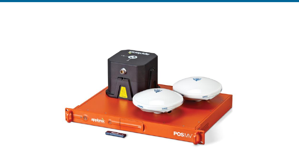
Shown in Figure 1 and detailed in Appendix E are the typical components of a POS MV system.
POS MV V5 Installation and Operation Guide
Introduction
1-2
Figure 1: Typical POS MV Components
The POS MV delivers an accurate and comprehensive data set, including:
• Geographic position (latitude, longitude and altitude)
• Heading
• Attitude (roll and pitch)
• Vertical displacement (heave)
• Velocity
• Acceleration
• Angular rate of turn
• Performance metrics
• Fault detection and reporting
POS MV combines the IMU and GNSS sensor data into an integrated navigation solution. There are two
navigation algorithm designs incorporated into the system, namely tightly coupled and loosely coupled
inertial/GNSS integration. Tightly coupled inertial/GNSS integration involves the processing of GNSS
pseudorange, phase and Doppler observables. In this case, the GNSS receiver is strictly a sensor of the
GNSS observables and the navigation functions in the GNSS receiver are not used. With loosely coupled
inertial/GNSS integration, the GNSS position and velocity solution are processed to aid the inertial
navigator.
POS MV employs tightly coupled integration to enhance performance, especially rapid Real-Time
Kinematic (RTK) recovery after a loss of GNSS signal reception. Depending on the availability and
relative quality of sensor inputs such as the primary GNSS, auxiliary GNSS and base station GNSS

POS MV V5 Installation and Operation Guide
Introduction
Copyright © Applanix Corporation, 2012
1-3
corrections, POS MV will automatically switch between tightly coupled and loosely coupled algorithms to
ensure maximum performance.
With its use of leading-edge technology, POS MV marks a significant breakthrough in the field of aided
inertial navigation and precision motion measurement for use in marine applications. The accuracy and
stability of measurements delivered by the system remain unaffected by vessel turns, changes of speed,
wave-induced motion, or other dynamic manoeuvres.
Therefore, by using POS MV, you can continue survey operations during poor weather and throughout
deteriorating sea conditions. This allows a more efficient use of survey time and a reduction in the overall
cost of the operation.
POS MV generates attitude data in three axis. Measurements of roll, pitch and heading are all accurate to
±0.02° (±0.03° for WaveMaster) or better, regardless of the vessel latitude. Heave measurements
supplied by POS MV maintain an accuracy of 5% of the measured vertical displacement or ±5 cm
(whichever is the larger) for movements that have a period of up to 20 seconds.
The system includes a compact disk containing the MV-POSView Controller program, which runs on a PC
under Microsoft Windows®. After you install the POS MV, you can use this program to configure the
system and monitor its status during operation.
After you have configured the POS MV successfully, you can operate the system in two start-up modes:
• You can use the controller program to enable navigation mode and to monitor the status and
performance of the system, or
• You can operate the POS MV in stand-alone mode. In this mode, after power-on, the system will
enable navigation mode and deliver measurements automatically through whichever ports you
have selected.
Communication between POS MV and the controller program is through a 10/100/1000BaseT Ethernet
link:
• Data output by POS MV may use the Universal Datagram Protocol (UDP) so that other
computers attached to the same Ethernet Local Area Network (LAN) can receive the data or
Transmission Control Protocol (TCP) so that only a single computer can receive the data.
• The controller program uses Transmission Control Protocol (TCP) to issue commands to POS
MV. This blocks other computers on the LAN from receiving the controlling messages, and
prevents POS MV from responding to any other source of controlling message.
Fault Detection, Isolation and Reconfiguration (FDIR) enhances the operating reliability of POS MV. This
feature allows the system to monitor the health of its various sensors so that it can reconfigure itself to
isolate any that show degraded performance. POS MV also estimates and corrects sensor errors on an
ongoing basis using a Kalman Filter that allows it to produce consistent and accurate results.

POS MV V5 Installation and Operation Guide
Introduction
1-4
Operating Modes
POS MV has two operating modes:
Standby Mode:
Following power-on, the IMU, GNSS receivers and the
processor perform self-test sequences after which POS
MV enters standby mode. Typically, this process takes 30
to 40 seconds to complete.
The system will remain in standby mode until you
command a change to another mode, or unless you have
enabled ‘AutoStart’. With AutoStart enabled, the system
will transition automatically into navigate mode.
Applanix ships the POS MV with AutoStart enabled.
Navigate Mode:
Navigate Mode is the normal operating mode of POS MV.
Once you have selected this mode, the system will go
through several stages of navigate mode until it reaches
the final stage, which indicates that POS MV has reached
its full user-defined operating accuracy.
Subsystems
POS MV includes three subsystems: the PCS, IMU and two GNSS receiver cards. The following
paragraphs describe each subsystem individually and Figure 1, page 1-2, shows these major
components.
POS Computer System
The POS Computer System (PCS) comprises the processor, GNSS receivers and interface cards
necessary to communicate with and process the IMU and GNSS data.
Inertial Measurement Unit
The IMU comprises three solid-state linear accelerometers and three solid-state gyros arranged in a
triaxial orthogonal array. These sensitive components, together with the electronics to convert their
analog outputs into the digital information required by the PCS, are all contained in a sealed unit that
requires no maintenance.
IMPORTANT
Do not open the IMU housing for any reason. Opening the IMU
housing will void the warranty.

POS MV V5 Installation and Operation Guide
Introduction
Copyright © Applanix Corporation, 2012
1-5
While the array of linear accelerometers sense acceleration in all three directions, the array of gyros
sense angular motion around all three axis centred on the IMU. The PCS receives these measurements
from the IMU and uses them to compute the measurements of motion. Refer to the Theory of Operation
description starting on page B-1 for a more detailed explanation of the POS MV operating theory.
GNSS Receivers
POS MV includes two GNSS receiver cards:
• A primary receiver card that provides the position, velocity and raw observation information to the
POS MV. It also provides a one Pulse Per Second (PPS) strobe together with a time message
that the POS MV uses to accurately time-stamp data output with Universal Time Coordinated
(UTC) or GPS Time.
• A secondary receiver card, in conjunction with the primary receiver card, which allows the POS
MV to compute GNSS heading aiding by performing carrier phase differential measurements
between the two GNSS receivers.
The system includes two identical antennas with 15 metre (~50 feet) long cables. You must connect each
receiver to a GNSS antenna to receive GNSS signals from the orbiting constellation of satellites.
The antennas supplied with the system have excellent phase centre stability. If you use alternative
antennas with the POS MV, Applanix cannot guarantee the heading or position performance of the
system.
GNSS Azimuth Measurement Subsystem
GNSS Azimuth Measurement Subsystem (GAMS) is a unique feature of POS MV that allows the system
to achieve exceptional accuracy in the measurement of heading. The GAMS subsystem uses two GNSS
receivers and antennas to determine a GNSS-based heading that is accurate to ±0.02° (±0.03° for
WaveMaster) or better (using a two-metre [~6 ½ feet] antenna baseline) when blended with the inertial
navigation solution. POS MV uses this heading information as aiding data together with the position,
velocity and raw observations information supplied by the primary GNSS receiver.
GAMS provides heading aiding to the POS MV. To understand the effect that GAMS has on the system it
is useful to compare system performance with and without GAMS, see Table 1.
Note: Operation without GAMS will occur when POS MV has insufficient data to compute a heading
solution.
Before POS MV can deliver valid measurements for use in your application, you must configure the
system with the relative mounting angles between the IMU and vessel reference frame. You do this by

POS MV V5 Installation and Operation Guide
Introduction
1-6
selecting a convenient and fixed reference point on the vessel, and by defining a reference frame
orientation centred on that point.
Table 1: System Performance
Parameter
Without GAMS
With GAMS
Heading
accuracy:
0.2° to 2.0° RMS after POS
MV achieves full alignment
(depending on the nature of
vessel manoeuvres).
Heading accuracy degrades
at latitudes above 50°.
0.02° (0.03° for the
WaveMaster), or better,
independent of vessel
manoeuvres and latitude.
POS MV tolerates GAMS
outages lasting several tens
of minutes with no significant
degradation of heading
accuracy.
Alignment
time:
Heading alignment can take
as long as 30 minutes.
Alignment occurs within two
to five minutes.
Vessel
manoeuvres:
More frequent vessel
manoeuvres will improve the
accuracy of heading
measurements. To obtain a
faster alignment and better
accuracy the vessel must
perform a calibration
manoeuvre at intervals of ten
minutes or less.
Accuracy is independent of
vessel manoeuvres.
Follow the instructions in the Installation Parameters description on page 2-24 to measure the mounting
angles of the IMU, vessel and multibeam transducer relative to the reference frame that you have
defined. Refer to the POS MV Configuration description on page 4-7 for instructions to configure POS MV
with these important parameters.
When correctly configured with this information, POS MV delivers measurements for use by the
multibeam transducer, compensated for any difference in mounting angles between the transducer, the
IMU, the vessel and your chosen reference frame.
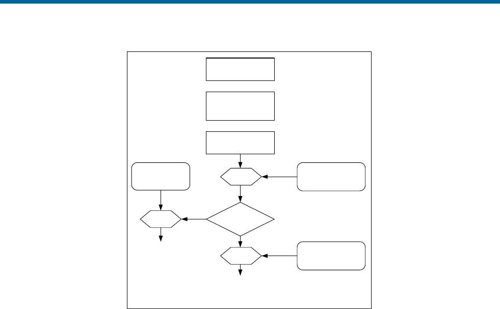
Operation without GAMS
Figure 2 and the following paragraphs describe how POS MV computes heading without GAMS.
After power-on, and the initialization and self-test routines have finished, the IMU performs a levelling
routine to establish a locally level reference frame. This occurs rapidly and usually finishes within 30
seconds.
POS MV V5 Installation and Operation Guide
Introduction
Copyright © Applanix Corporation, 2012
1-7
POS MV without
GAMS heading aiding
Up to 30 minutes
to complete
POS MV power-on
Rotation IMU wrt reference
frame mounting
angles
IMU begins levelling
and heading
alignment
Heading
information
Rotation
Rotation
Ship frame wrt
reference frame
mounting angles
Sensor 1 (Sonar) wrt
reference frame
mounting angles
Vessel heading
accuracy = 0.2 to 2
degrees
Sonar heading
accuracy = 0.2 to 2
degrees
Figure 2: Heading Measurement without GAMS
Following its levelling routine, the IMU begins to align itself to true north. This process, called
gyrocompassing, occurs much more slowly and can take from 5 to 30 minutes to complete. The time
taken to complete this process will depend on the latitude and on the manoeuvres that the vessel
performs during the operation.
A more accurate and rapid alignment will occur if the vessel performs a number of calibration manoeuvres
during the alignment process. These manoeuvres consist of full turns, starts and stops, S-curves and
figure-of-eight turns.
After alignment, the IMU delivers measurements of its heading with respect to true north. These are
accurate to between 0.2° and 2.0°, depending on the manoeuvres made by the vessel and its latitude.
Manoeuvres that are more frequent will yield a more accurate heading result, while operation in higher
latitudes will degrade the unaided heading accuracy.
POS MV rotates the IMU heading measurement, using the relative mounting angles between the IMU, the
vessel, the transducer and your chosen reference frame, and delivers heading measurements valid for
the multibeam transducer and the vessel.

POS MV V5 Installation and Operation Guide
Introduction
1-8
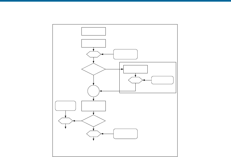
Operation with GAMS
Figure 3 and the following paragraphs describe how POS MV computes heading with GAMS heading
aiding.
After power-on, and the Initialization and self-test routines have finished, the IMU performs a levelling
routine to establish a locally level reference frame. This occurs rapidly and usually finishes within 30
seconds.
Following its levelling routine, the IMU begins to align itself to true north. This gyrocompassing process is
aided by the heading input from GAMS and is completed within two to five minutes, depending on how
long it takes GAMS to come online.
GAMS heading error is largely due to GNSS receiver noise and multipath errors. By blending this
information with the IMU data in the Kalman Filter, POS MV can average the GAMS heading error down
to a blended heading accuracy of typically 0.02° RMS (0.03° for WaveMaster) or better.
The Kalman Filter uses information in the IMU coordinate frame. POS MV must therefore rotate GNSS
heading information into this frame.
After alignment, the IMU delivers measurements of vessel heading relative to true north. These possess
an accuracy of ±0.02° RMS (±0.03° for WaveMaster) or better, independent of vessel manoeuvres or
latitude.
POS MV V5 Installation and Operation Guide
Introduction
Copyright © Applanix Corporation, 2012
1-9
GPS derived heading
information
Rotation Surveyed antenna
baseline vector
POS MV with GAMS
heading aiding
IMU begins levelling
and alignment
Rotation IMU wrt reference
frame mounting
angles
Levelling
& alignment data
POS MV power-on After levelling
& alignment
Kalman
Filter
GAMS
Heading aiding information in
IMU coordinate frame
Heading alignment
complete within
2 to 5 minutes
Heading
information
Rotation
Rotation
Ship frame wrt
reference frame
mounting angles
Sensor 1 (Sonar) wrt
reference frame
mounting angles
Vessel heading
accuracy = 0.02
degree
(0.03° for
WaveMaster) Sonar heading
accuracy = 0.02
degree
(0.03° for
WaveMaster)
Figure 3: Heading Measurement with GAMS
After alignment, the IMU delivers measurements of multibeam transducer heading relative to true north.
These measurements possess the same accuracy as those of vessel heading defined in the paragraph
above.
Refer to the Theory of Operation description on page B-1 for a more complete description of GAMS,
together with an explanation of GNSS carrier phase differential position measurement, levelling,
gyrocompassing and the Kalman Filter.
Refer to the Lever Arm Distances, page 2-26, and the Antenna Separation, page 2-29, descriptions for
instructions to measure the mounting angles of the IMU, multibeam transducer and ship frames with
respect to your chosen reference frame.
Functions
The Applanix POS MV offers many advanced functions including:
• Motion measurement
• TrueHeave (software option)
• Position and velocity measurement
• AutoRecovery and fault detection, isolation and reconfiguration

POS MV V5 Installation and Operation Guide
Introduction
1-10
• AutoStart
• Ethernet Data logging
• Event tagging
The following paragraphs describe each of these functions.
Motion Measurement
The principal function of POS MV is to deliver dynamically integrated position and orientation data. It
delivers motion measurements (roll and pitch angle, true heading and real-time heave) for use by external
equipment such as multibeam sonar. The system also estimates and displays the accuracy of its attitude
and heading measurements.
TrueHeave
TrueHeave (different than real-time heave) is based on an advanced two sided filter, making use of both
past and present vertical motion data to compute a significantly improved heave estimate. POS MV has
sufficient computational speed such that a secondary estimate of heave can be accomplished shortly
after the sonar acquisition event.
Delayed time heave output not only removes many of the compromises that must be made in real-time,
but provides near real-time Quality Control (QC) of heave performance. The MV-POSView graphical
interface includes a time series plot of both real-time and TrueHeave estimates, which allows the operator
to react if a divergence between the two heave estimates is observed.
Refer to the TrueHeave Operation description on page 6-1 for a full description of the data formats used
by POS MV to output these parameters.
Position and Velocity Measurement
POS MV supplies parameters such as the position, velocity, speed, acceleration and angular rate of the
vessel. The system also estimates and displays the accuracy of some of these output parameters.
Refer to Interfaces and Data Formats on page 3-1 for description of the data formats used by POS MV to
output these parameters.
AutoRecover and Fault Detection, Isolation and Reconfiguration
Because the IMU is the most important sensing subsystem in POS MV, errors in communication between
the PCS and the IMU can cause significant problems. AutoRecovery is a feature that allows POS MV to
recover from such a communication error.

POS MV V5 Installation and Operation Guide
Introduction
Copyright © Applanix Corporation, 2012
1-11
POS MV is tolerant of data corruption caused by noise or power problems on board the vessel. However,
the MV-POSView Controller program will alert you if either of these problems becomes insurmountable,
so that you can take appropriate corrective action.
Fault Detection, Isolation and Reconfiguration (FDIR) allow POS MV to combine data from the GNSS and
the IMU sensor subsystems to offer the best possible navigation solution for the current data quality.
The system monitors its sensor subsystems and determines which of them, if any, shows a degraded
performance. If it finds any sensor subsystem operating with reduced performance, the system re-
combines the available data to retain the highest possible quality in the navigation solution.
AutoStart
You must first configure the system with the following parameters before it can operate properly when you
transition POS MV to its navigate mode:
• The lever arm distances including those from the IMU, multibeam transducer and the primary
GNSS antenna, to your chosen reference point
• The sensor mounting angles of the IMU and the multibeam transducer relative to your chosen
reference frame
These details are generally fixed at the time of installation. You can save them to non-volatile memory so
that POS MV initializes itself correctly during each power-on sequence. If necessary, you can use the MV-
POSView Controller program at any time to alter and save any of the installation parameters.
You can configure POS MV to enter navigate mode (the normal operating mode) automatically after
power-on. Alternatively, you can configure the system to wait until it receives your command to enter
navigate mode.
The ability to automatically enter navigate mode is called AutoStart. You can use the MV-POSView
Controller program to enable or disable AutoStart.
Refer to the System Configuration section on page 4-1 for instructions to configure the system using the
MV-POSView Controller program. Refer to Software Installation on page D-1 for instructions to install the
MV-POSView Controller program on a Personal Computer (PC).
Removable Media Data Logging
Data logging allows the POS MV to store both raw sensor data and real-time processed navigation data
to a removable USB flash drive for post-processing using the Applanix POSPac MMS software; post-
processing enhances navigation solution accuracy. The USB flash drive is transferable between the PCS
and any Microsoft Windows® based computer with a USB port.

POS MV V5 Installation and Operation Guide
Introduction
1-12
Back-up Data Logging
When the removable media logging is active, the same data are written to an internal storage device
within the PCS. In the event that removable media logging fails or the USB flash drive gets lost or
corrupted, anonymous File Transfer Protocol (FTP) may be used to recover the mission data from the
PCS.
Ethernet Data Logging
You can log processed navigation or raw sensor data through the Ethernet to a controlling PC. Data
gathered by the POS MV during a mission may be post-processed using POSPac to further enhance the
quality of seafloor maps generated by multibeam sonar systems. Contact Applanix for more information
on POSPac.
Ethernet Real-Time Output
High rate data are available from the PCS data port using Universal Datagram Protocol (UDP)
broadcasts. The emphasis here is outputting timely data, even though there may be some data loss.
Event Tagging
POS MV provides the facility to ‘time tag’ events using either UTC or GPS Time.
Note: UTC and GPS Times are not identical. Due to the occasional need for a ‘leap second’ to be applied
to UTC, there is an integer number of seconds time difference between UTC and GPS Time. Transitions
between seconds are precisely coincident for both UTC and GPS Time.
Time tagging of events occurs through the EVENT port on the PCS rear panel. To tag an event using
UTC or GPS Time you must provide POS MV with a digital pulse in the range of 3 to 50 V. You can
configure POS MV for a positive edge trigger or a negative edge trigger with respect to the ground
associated with that event input.
Event time tagging occurs when POS MV detects a TTL pulse on the Event 1 or Event 2 line, it captures
the exact time that corresponds to the trigger edge (within a window 1 μs wide). Event records are
available for output on the Ethernet data ports. Contact Applanix for advice if you need additional
information about the Ethernet group structure.
Output Summary
There are several types of communication interfaces that POS MV can use to supply its data. You must
select whichever type will be most suitable for the specific multibeam sonar in use.

POS MV V5 Installation and Operation Guide
Introduction
Copyright © Applanix Corporation, 2012
1-13
In some cases, a multibeam sonar and / or related acquisition system can accept data in more than one
format. However, for specific installations, one type of communications interface usually provides for a
more accurate data exchange than the other.
Electrical noise or sonar timing can have a significant effect on the images produced by the multibeam
sonar. You must consider this when you select the communications interface used to supply position,
attitude and motion data from POS MV. Because each installation will be different, this manual cannot
include explicit instructions in this area.
POS MV can use a variety of interface protocols to output information:
• RS-232
• RS-422
• Ethernet
Each interface protocol is unique. Refer to the Interfaces and Data Formats description starting on page
3-1 for information on each of these interface protocols.
MV-POSView Controller Software
You can use the MV-POSView Controller program to configure POS MV; the controller ships with the
POS MV system. For subsequent operation of the POS MV you can use the controller program or you
can configure the system to start operating automatically with no further need for operator control. A brief
description of the AutoStart feature is located on page 1-11.
Refer to the Software Installation description on page D-1 for instructions to install the MV-POSView
Controller program on your PC. Refer to the System Configuration description on page 4-1 and the
System Operation description on page 5-1 for instructions on how to use the controller program.

POS MV V5 Installation and Operation Guide
Installation
Copyright © Applanix Corporation, 2012
2-1
2.0 Installation
Installation of the Position and Orientation system for Marine Vessels (POS MV) is reasonably simple,
provided the installation instructions in this manual are carefully followed. Installation and connection of
the POS Computer System (PCS), the Inertial Measurement Unit (IMU) and the Global Navigation
Satellite System (GNSS) antennas should only take a few hours.
This section of the POS MV V5 manual explains each stage of the installation. By following these
instructions, you can unpack, install and configure the system so that it is ready to operate with minimal
delay.
Handling Precautions
To prevent damage to the system components handle all POS MV assemblies with care. The following
paragraphs explain the special handling precautions that apply to the IMU, PCS and GNSS antennas.
Inertial Measurement Unit
The IMU contains sensitive and expensive solid-state
accelerometer and gyro components. Permanent damage to
these components will result if handled roughly.
Exercise care when handling this unit; in particular, be careful when placing the IMU on or mounting it to
any surface. Field repair of the IMU is not possible. If this unit develops a fault or becomes damaged it
must be returned to Applanix for repair. Refer to Technical Support and Service on page A-1 for
procedures.
POS Computer System
Field repair of the PCS is not recommended. If this unit develops a fault or becomes damaged it must be
returned to Applanix for repair. Refer to Technical Support and Service on page A-1 for procedures.
Consider the following when handling the PCS:
• Handle with care.
• Do not drop from any height
• Observe standard Electrostatic Discharge (ESD) procedures.
• Refer to Circular Connectors for a guide on handling the connectors.
GNSS Antennas
Applanix supplies the POS MV with two identical GNSS antennas - handle these with care. Avoid
scratching or damaging the antenna housings in any way.

POS MV V5 Installation and Operation Guide
Installation
2-2
Any damage to the housings could impair the ability of the antenna to receive satellite signals and
therefore degrade the performance of the associated GNSS receiver.
Unpacking and Storage
The supplied POS MV components and cables are listed on the packing list shipped with the system.
Physically verify that each item is present.
Applanix tests the POS MV system electrically and mechanically prior to delivery. The protective transit
case prevents damage during shipment and ensures the operating integrity of the system.
Important
Retain the original POS MV equipment packing case. Transport or
return POS MV equipment in the original packing case. Improper or
inadequate POS MV equipment packing for storage or transport will
void the warranty.
Upon receipt of the system, check all items carefully against the shipping documents and inspect them for
any damage that may have occurred during transit. If any damage has occurred, file a claim with the
carrier and notify Applanix immediately. Refer to Technical Support and Service on page A-1 for postal
address, contact telephone and fax numbers, and e-mail and Web address for Applanix.
Storage
When storing the POS MV system for an extended period, ensure the following conditions are
maintained:
• Protect the PCS from moisture, excessive humidity and temperature extremes (see Specifications
starting on page 7-1 for details).
• Protect the PCS and IMU from accidental damage by storing in their original shipping cases.
• Store all remaining components in their original shipping cases.
Site Preparation
You can install the system more efficiently if you give early and careful consideration to the location and
layout of the POS MV components.
You should read and understand the instructions in the Installation and Installation Parameters topics on
pages 2-4 and 5-23 before you commence to install the POS MV. By taking this precaution, you will
become more familiar with the requirements of the system and will be less likely to encounter unexpected
problems during this important operation.

POS MV V5 Installation and Operation Guide
Installation
Copyright © Applanix Corporation, 2012
2-3
Note: Before installing the POS MV, make certain that adequate mounting provisions exist for all
components of the system.
Power Requirements
Applanix strongly recommends that you arrange to supply electrical power to the POS MV from an
Uninterrupted Power Supply (UPS). This is for two reasons:
• Usually, the electrical supply on board the vessel will be noisy. Although the POS MV includes
power supply conditioning circuitry, it is a sensible precaution to make certain the power supply is
‘clean’ before it enters the system.
• The electrical supply on board the vessel may be unreliable and may drop out or fall to an
unacceptable level unexpectedly.
A suitable UPS will ‘clean’ the electrical supply before it enters the PCS and will continue to supply power
for a short period if the electrical supply fails for any reason. The UPS should be able to supply the total
power requirements of POS MV.
PCS
POS MV V5
POS MV V5-1
Max.Current:
1.1 A Max
5.5 A Max
Voltage range:
90 Vac to 264 Vac
10 Vdc to 34 Vdc
GNSS Antennas
Both Models
Voltage:
Supplied by the GNSS receiver via the
antenna coaxial cable
IMU
Both Models
Voltage:
Supplied by the PCS via the IMU cable.
Note that for POS MV V5-1 the minimum
usable PCS input voltage depends on a
combination of IMU type and IMU cable
length. Contact customer support for
assistance.
Environmental Requirements
GNSS Antennas
To receive GNSS satellite signals without interruption, the GNSS antennas require a clear view of the sky
from horizon to horizon in all directions. You must mount them outside in an elevated position on the
vessel. Follow the instructions in the GNSS System paragraphs on page 2-4 to install the GNSS
antennas.
POS MV V5 Installation and Operation Guide
Installation
2-4
Although the antennas are tolerant of an exposed mounting position, please observe the environmental
limits starting on page 7-4 when installing these components.
Inertial Measurement Unit
The IMU has anodized aluminium housing. If you intend to mount the IMU against a steel hull, use
stainless steel spacers of 5 mm (3/16 in) thickness between the IMU and the hull to prevent galvanic
corrosion of the housing. Applanix recommends the use of an IMU mounting plate to aid in aligning the
IMU with the vessel reference frame in which lever arms and misalignments are measured. Refer to
Applanix for details.
Follow the installation instructions listed on page 2-7, Inertial Measurement Unit, to select a suitable
mounting location for the IMU. Observe the environmental limits starting on page 7-4 when selecting a
mounting location for the IMU. Although the IMU is sealed in a housing it is not depth-rated; do not mount
the IMU where it can become immersed in water. An IP68 rated (submersible) option is available, details
of which are available from Applanix Customer Support (see page Appendix A for contact details).
POS Computer System
Applanix ships the PCS in a protective transit case that must be removed prior to operation. Please retain
this packing case for reuse should the system need to be shipped for any reason. Follow the instructions
in the installation paragraphs, starting on page 2-9 for V5 and page 2-12 for V5-1, to install the PCS.
Observe the environmental limits starting on page 7-4 when installing the PCS.
Installation
Important:
1. Equipment shall be installed by qualified personnel.
2. The PCS (POS MV V5 and POS MV V5-1) shall be grounded via the safety ground screw or stud.
3. Power to the POS system should be protected by a user-supplied, resettable circuit breaker.
4. Upstream breaker used to protect POS system shall be limited to 20Amp rating
5. Antenna connection shall be provided only after making the permanent safety earth connection.
GNSS System
Do not connect any input to the PPS (POS MV V5) or PPS OUT
(POS MV V5-1) port. Connecting a signal input to this port will
damage the PCS interface circuitry.
The PCS includes a dual antenna GNSS receiver for operation with the POS MV.

POS MV V5 Installation and Operation Guide
Installation
Copyright © Applanix Corporation, 2012
2-5
Multipath reflections of the received GNSS signals are the dominant source of measurement errors in the
heading aiding information computed by the GNSS Azimuth Measurement Subsystem (GAMS).
Reflectors can include flat surfaces on the vessel and the surface of the sea.
The POS MV GNSS antennas may be installed anywhere on the vessel, provided their locations meet the
following criteria:
• Observe the environmental limitations specified on page 2-3, GNSS Antennas.
• Avoid GNSS antenna locations that may experience multipath satellite signals caused by
reflections off nearby structures.
• Avoid mounting the GNSS antennas where salt deposits can accumulate and degrade the
received signal quality. Remove salt deposits by washing the antenna with fresh water.
• Do not mount the GNSS antennas closer than 0.5 m (~20 in) to any radar, UHF, satellite
communications or other communications antennas or transmitters.
• Avoid mounting the GNSS antennas in areas that may experience high levels of vibration, shock
or electrical noise.
• Both antennas must have the clearest possible view of the sky from horizon to horizon in all
directions. This means mounting them outside and as high as possible on the vessel.
• Mount the GNSS antennas rigidly with respect to each other and with respect to the IMU within
the vessel. This requirement may be difficult to achieve if the antennas are mounted on separate
masts or on a single mast that can flex with respect to the vessel. Relative movement of one
antenna with respect to the other of more than 0.5 cm (~¼ in), or of both antennas with respect to
the vessel, will introduce an extra source of heading error to degrade the POS MV heading
accuracy.
• Do not mount the antennas near any large flat surface. Large flat surfaces are a source of
multipath reflections that may degrade the accuracy of POS MV heading measurements.
• The system includes two GNSS antennas. Install these so that they have less than 5 m (~16 ½ ft)
separation distance between them. The antenna separation distance must be more than 1 m
(~3 ¼ ft) in the horizontal vector, but it is recommended that the antennas be at least 2 m
(~6 ½ ft) apart.
• Mount both antennas so that the labels on their top surfaces point in approximately the same
direction. This precaution means that both antennas have the same orientation relative to the
vessel.

POS MV V5 Installation and Operation Guide
Installation
2-6
The phase centres of the GNSS antennas may move by several millimetres as the vessel turns or as
satellites move across the sky. When both antennas have the same orientation, their phase centres will
move approximately together. This will allow a better heading resolution by GAMS.
Install GNSS Antennas
The following instructions refer to the GNSS antennas as the primary and
the secondary units, although both antennas are physically and electrically
identical. Identify, label and connect the antennas in the following manner:
• Primary antenna to ANT1 port on the PCS
• Secondary antenna to ANT2 port on the PCS
Note: POS MV includes two low-loss antenna cables with connectors at each end. These cables are
standard length of 15 m (~50 ft). Applanix can supply longer GNSS antenna cables on request, up to a
maximum allowable length of 50 m (~165 ft) with a maximum signal loss of eight Decibels (dB). It is not
necessary for both cables to be the same length.
1. Install the primary and secondary antennas at the positions you have chosen and prepared.
Note: Orient the label on the top surface of the secondary antenna so that it points in
approximately the same direction as the label on the primary antenna.
2. Connect the TNC cable connector to the GNSS antenna and tighten the connection. Use
waterproof tape and a suitable silicone sealant to protect the connection against the ingress of
water or dirt.
3. Route the antenna cable from the primary antenna to the PCS mounting location. Avoid
subjecting the cable to sharp bends or other mechanical stresses; minimum bend radius of LMR
400 cable is one inch (~ 25 mm). Use cable clips to secure the cable at regular intervals along its
length. At the PCS mounting location, identify the cable clearly as the primary antenna.
4. Connect the primary antenna cable to the ANT1 port on the PCS rear panel.
5. Route the antenna cable from the secondary antenna to the PCS mounting location. Avoid
subjecting the cable to sharp bends or other mechanical stresses. Use cable clips to secure the
cable at regular intervals along its length. At the PCS mounting location, identify the cable clearly
as the secondary antenna.
6. Connect the secondary antenna cable to the ANT2 port on the PCS rear panel.
Note: You must identify the primary and the secondary antennas clearly. POS MV uses the lever
arms distances between your chosen reference point and the primary GNSS antenna to generate
a navigation solution.
Figure 4: GNSS Antenna

POS MV V5 Installation and Operation Guide
Installation
Copyright © Applanix Corporation, 2012
2-7
Once the GNSS antennas are installed, measure the antenna separation distance. POS MV can calculate
this distance automatically during the installation calibration routine, although it will mean the routine will
take longer to complete. If you make a manual measurement instead, record the distance between the
antenna phase centres to an accuracy of ±5 mm (±¼ in). The GNSS antenna footprint is shown on page
E-8.
Inertial Measurement Unit
The IMU contains sensitive and expensive solid-state
accelerometer and gyro components. Permanent damage to
these components will result if handled roughly. To prevent
irreversible damage, handle the IMU with care while installing
the system.
Mechanical Interface Information for POS MV IMU options can be found in Appendix E (beginning on
page E-1).
Locate the IMU
The IMU is a self-contained unit that must be connected to the PCS using the supplied shielded cable.
Consider the following guidelines when selecting a location to install the IMU:
• Observe the environmental limitations specified on page 2-4, Inertial Measurement Unit.
• Avoid mounting the IMU where it may experience high levels of vibration, shock or electrical
noise.
• The standard IMU connection cable is 8 m (~26 ft) long. Plan the system layout carefully so that
the cable will fit between the IMU and the PCS. Do not subject the cable to sharp bends or other
mechanical stresses. Applanix can supply a longer cable of up to 50 m (~165 ft) in length if
necessary. Use suitable clips to support the cable at intervals along its length.
• Ensure the mounting location permits easy access to attach the cable to the IMU.
• Mount the IMU with its base plate nominally level.
• Ideally, install the IMU at a location for which you require roll, pitch, heading and heave
measurements. Usually this implies mounting the IMU close to, or even on, the multibeam
transducer. The chosen location must provide rigid support so that the IMU does not move
relative to the GNSS antennas; see GNSS System on page 2-4.
• It is not necessary to install the IMU at the vessel’s centre of rotation. There is no degradation of
POS MV performance if the IMU is mounted away from the vessel’s centre of rotation, although
this offset should be measured and applied during configuration of the system; see the POS MV
Configuration topic starting on page 4-7.
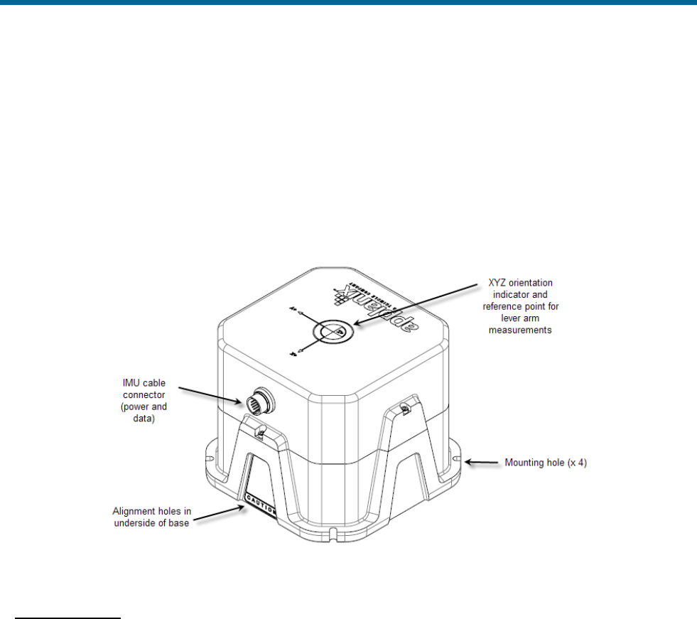
POS MV V5 Installation and Operation Guide
Installation
2-8
• There is a label on the top plate of the IMU to identify its sensing axis. It is not required to align
these marks closely with the vessel or the multibeam transducer. Instead, measure the mounting
angles, save them in the PCS when you first power-on and configure the system.
• Two offset holes are predrilled in the base to accept 5 mm (0.197 in) diameter alignment pins.
These holes maintain IMU orientation and alignment when the unit is replaced, see Figure 5. Two
colinear slots are machined in the base to mate with corresponding rails on the IMU mounting
plate. These slots maintain IMU alignment on the mounting plate when the unit is replaced but
allow the orientation to be reversed in case of cable interference during installation.
Figure 5: Typical IMU Mounting Features
Install the IMU
Once a suitable mounting location is selected, perform the following steps to install the IMU:
1. Apply a thin film of anti-seize grease from the supplied packet all around the alignment pins or
rails, whichever is used, to prevent the IMU housing from becoming stuck on the mounting plate.
2. Attach the IMU to the mounting location using four M5 ( #10 ) pan head bolts inserted through the
fixing holes in the base plate, isolating the IMU from the hull by way of an electrically non-
conductive material if possible. Use flat and shake proof washers under the IMU mounting
screws. Ensure that the flat washers (not shake proof washers) are placed in direct contact with
the IMU base plate.
3. Tighten the mounting bolts in a uniform manner, exercising care not to over torque. Avoid warping
the IMU base plate.
POS MV V5 Installation and Operation Guide
Installation
Copyright © Applanix Corporation, 2012
2-9
4. Attach the IMU connection cable to the IMU connector. Route the cable from the IMU to the PCS
mounting location. Avoid subjecting the cable to sharp bends or other mechanical stresses. Use
cable clips to secure the cable at regular intervals along its length.
5. Connect the IMU cable to the IMU port on the rear panel of the PCS.
6. After IMU installation, measure the lever arm distances and the mounting angles that POS MV
requires to generate its navigation solutions. Refer to page 2-24, Installation Parameters for
details of these parameters.
POS Computer System - POS MV V5
The PCS is the heart of the POS MV V5 systems. The PCS footprint is shown in Appendix E .
Install the PCS
Remove the PCS from its transit case to allow connection and operation. With the PCS removed from the
transit case, you can install, connect and use the unit in a 19 inch instrument rack where it occupies one
rack unit of space. Use an instrument rack that provides isolation against shock and vibration.
Observe the following installation constraints:
Do not hang the PCS from the loose panel mounting hardware.
Support the PCS weight from underneath while tightening the
panel mounting hardware.
• Observe the environmental limitations starting on page 7-4.
• Do not install the PCS where it may come into direct contact with water or high concentrations of
dust.
• The PCS may be mounted in a shock isolating 19-inch instrument rack if one is available. The
PCS occupies one rack unit of space in a 19 inch instrument rack.
• Do not mount the PCS to a vibrating surface or one that may experience severe shocks.
• A minimum of 15 cm (~6 in) clearance is required behind the PCS cabinet for cable connection
and ventilation. Do not restrict the airflow intakes located on each side of the cabinet. If
necessary, provide additional fan ventilation inside the instrument rack to prevent overheating.
• Provide sufficient cable lengths to allow easy connection to the ports on the PCS rear panel.
Rear Panel Electrical Connections
The rear panel of the PCS provides connections for power and communications with sensors and other
devices, see Figure 6.
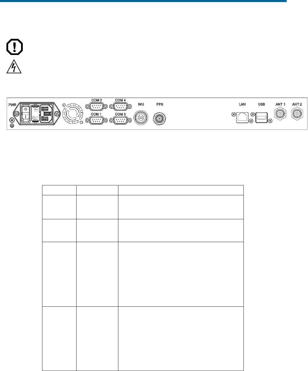
POS MV V5 Installation and Operation Guide
Installation
2-10
ELECTRICAL HAZARD
The PCS employs double pole / neutral fusing on the power
receptacle. Each of the two RoHS compliant fuses are rated at:
• Rating = 250 V
• Current = 4 A
• Type = fast acting
• Case = 5.2 mm x 20 mm
Figure 6: PCS Rear Panel - POS MV V5
Use Table 2 as a guide when making cable connections to the PCS rear panel.
Table 2: Connector/Cable Summary - POS MV V5
Connector
Cable
Description
PWR, 3-pin
male
Standard 3-
conductor IEC
cable
The internal power supply is auto-switching;
see page 2-3 for details
IMU, 19-pin
female
Shielded
cable
• RS-422 serial data
• Supplies dc power to and receives data
from IMU
LAN, RJ-45
female
Straight
through or
Cross over
cable (meets
Cat5)
• Ethernet interface communicates with a
controlling PC through this 10/100/1000
Base-T port
• Port used to complete initial POS MV
configuration
Note: The POS MV system may be configured in
the ‘AutoStart’ mode, so that subsequent operations
uses a standalone mode without the further need
for an Ethernet connection.
PPS, BNC
female
75 ohm
coaxial cable
(RG59/U)
• A TTL strobe at one pulse per second.
• Output pulse polarity and pulse width is
configurable from POSView controller.
• Leading edge of pulse is coincident with
exact GNSS second.
• Provides synchronization with GPS Time.
Note: Do not connect an input signal to the PPS
OUT port; otherwise, damage to the PCS interface
circuitry may result.

POS MV V5 Installation and Operation Guide
Installation
Copyright © Applanix Corporation, 2012
2-11
Table 2: Connector/Cable Summary - POS MV V5
Connector
Cable
Description
COM(1),
DE-9P
Single-
shielded cable
RS-232 Serial I/O port (digital)
COM(2),
DE-9P
Single-
shielded cable
RS-232 Serial I/O port (digital)
COM(3),
DE-9P
Single-
shielded cable
RS-232 / RS-422 (software switchable) Serial
I/O port (digital)
COM(4),
DE-9P
Single-
shielded cable
RS-232 / RS-422 (software switchable) Serial
I/O port (digital)
ANT1, TNC
female
50 ohm
coaxial cable
(RG303/U)
Supplies dc power to and receives signals
from primary GNSS antenna
ANT2, TNC
female
50 ohm
coaxial cable
(RG303/U)
supplies dc power to and receives signals
from secondary GNSS antenna
If the POS MV V5 receives power from an Uninterruptible Power Supply (UPS), make certain that it is
operating at the correct voltage; refer to the Power Requirements description on page 2-3 for details.
Good grounding practices are essential for proper operation of the POS MV V5 systems.
COM (1) through COM (4) Interface
PHYSICAL INTERFACE
Serial cables should not exceed 15 m [~49 ft] in length. To ensure data integrity, use high quality RS-232
cable with its shielding connected through the back shell to ground at both cable ends. Table 7, page 2-
17 and Table 9, page 2-19 provide COM port connector assignments and mapping for the POS MV V5-1
PCS. Table 3 provides the same information for the POS MV V5 PCS.
Table 3: COM Connectors Pin Assignment - POS MV V5
Pin
Pin Description
Signal Type
Signal
Direction
1
N/C (port 1 & 2)
N/A
N/A
RXa (port 3 & 4)
RS-422
Input
2
RX (port 1 & 2)
RS-232
Input
RXb (port 3 & 4)
RS-422
Input
3
TX (port 1 & 2)
RS-232
Output
TXb (port 3 & 4)
RS-422
Output
4
N/C (port 1 & 2)
N/A
N/A
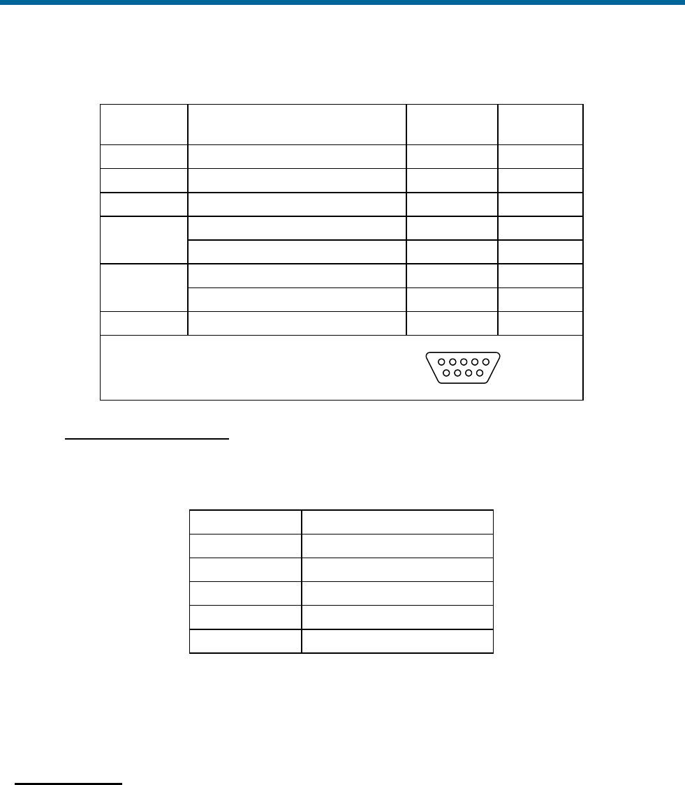
POS MV V5 Installation and Operation Guide
Installation
2-12
Table 3: COM Connectors Pin Assignment - POS MV V5
Pin
Pin Description
Signal Type
Signal
Direction
TXa (port 3 & 4)
RS-422
Output
5
GND (port 1 through 4)
N/A
N/A
6
N/C (port 1 through 4)
N/A
N/A
7
RTS (port 1 & 2)
RS-232
Output
N/C (port 3 & 4)
N/A
N/A
8
CTS (port 1 & 2)
RS-232
Input
N/C (port 3 & 4)
N/A
N/A
9
N/C (port 1 through 4)
N/A
N/A
POS MV V5 Rear Panel
DE-9P Male Connector
15
69
INTERFACE CONFIGURATION
Table 4 identifies the configuration for the COM ports.
Table 4: COM Port Configuration
Setting
Value
Baud Rate
2400 to 115200
Parity
None, Even, Odd
Data Bits
7, 8
Stop Bits
1, 2
Flow Control
Hardware, Software, None
POS Computer System - POS MV V5-1
The PCS is the heart of the POS MV V5 systems. The PCS footprint is shown in Appendix E .
Install the PCS
Remove the PCS from its transit case to allow connection and operation. The MV V5-1 PCS is a sealed
unit and may be installed in almost any location that is convenient.
Observe the following installation constraints:
• Observe the environmental limitations starting on page 7-4.

POS MV V5 Installation and Operation Guide
Installation
Copyright © Applanix Corporation, 2012
2-13
• The PCS is sealed so the only way for it to shed heat is via conduction, either to the air or another
metal surface. Allow for air circulation around the PCS or remove the rubber feet and bolt the
PCS to another metal surface that can conduct the heat away. If necessary, provide additional
fan ventilation to prevent overheating.
• Do not mount the PCS to a vibrating surface or one that may experience severe shocks.
• A minimum of 15 cm (~6 in) clearance is required behind the PCS for cable connection.
• Provide sufficient cable lengths to allow easy connection to the connectors on the PCS rear panel
or cable stubs supplied with the PCS.
Rear Panel Electrical Connections
The rear panel of the PCS provides connections for power and communications with sensors and other
devices, see Figure 7.
The POS MV V5-1 PCS footprint is shown in Appendix E . There are ten connectors located on the rear
panel of the PCS, see Figure 7. Each rear panel connector supports a single cable except for the I/O and
COM connectors, which support a multi-connector breakout cable. Table 5 provides a summary of the
connectors used in the POS MV configuration.
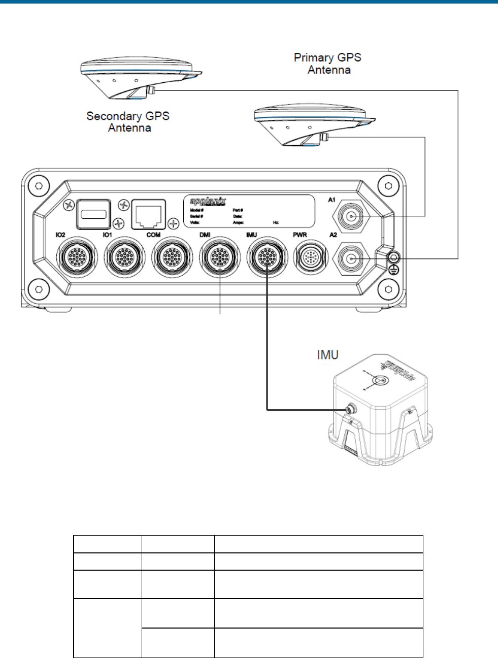
POS MV V5 Installation and Operation Guide
Installation
2-14
Figure 7: PCS Rear Panel – POS MV V5-1
Table 5: Connector and Port Summary
Connector
Port
Description
PWR
Connects to a customer source
IMU
• RS-422 serial I/O data port
• Supplies dc power to IMU
COM
COM (1)
RS-232 Serial I/O port (digital) with
Tx/Rx/CTS/RTS
COM (2)
RS-232 Serial I/O port (digital) with
Tx/Rx/CTS/RTS

POS MV V5 Installation and Operation Guide
Installation
Copyright © Applanix Corporation, 2012
2-15
Table 5: Connector and Port Summary
Connector
Port
Description
PPS In
• Optically isolated digital input, 3 to 50 Vdc
signal level, 1 mA maximum input current
requirement
• Only effective if external GNSS option is
enabled through POSConfig
I/O 1
COM (3)
• RS-232/422 Serial I/O port (digital) with
Tx/Rx only
• Software control of 232 / 422 switch
• Software switch to connect with Primary
GNSS receiver COM 1 for software
upgrade - contact Applanix Customer
Support for details
DIO - Event 1
• Optically isolated digital input, 3 to 50 Vdc
signal level, 1 mA maximum input current
requirement
• Event 1 time tagging
DIO - Event 2
• Optically isolated digital input, 3 to 50 Vdc
signal level, 1 mA maximum input current
requirement
• Event 2 time tagging
PPS Out
• One pulse per second for synchronization
with GPS time
• TTL signal level
I/O 2
COM (4)
• RS-232/422 Serial I/O port (digital) with
Tx/Rx only
• Software control of 232 / 422 switch
• Software switch to connect with
Secondary GNSS receiver COM 1 for
software upgrade - contact Applanix
Customer Support for details
DIO - Event 3
• Optically isolated digital input, 3 to 50 Vdc
signal level, 1 mA maximum input current
requirement
• Event 3 time tagging
DIO - Event 4
• Optically isolated digital input, 3 to 50 Vdc
signal level, 1 mA maximum input current
requirement
• Event 4 time tagging
PPS Out
• One pulse per second for synchronization
with GPS time
• TTL signal level
DMI
• Not Implemented
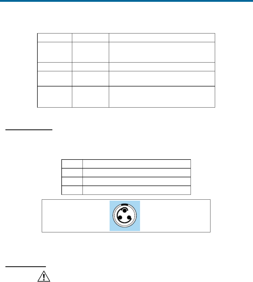
POS MV V5 Installation and Operation Guide
Installation
2-16
Table 5: Connector and Port Summary
Connector
Port
Description
Ethernet
• 10/100/1000 Base-T
• Communication between POS MV and
MV-POSView
USB
• USB 2.0 Host
ANT1
I/O TNC connector - supplies dc power and
receives signal from primary GNSS antenna
ANT2
I/O TNC connector - supplies dc power and
receives signal from secondary GNSS
antenna
Power Connector
Table 6 and Figure 8 identify the pin assignments for the power connector.
Table 6: PWR Connector Pin Assignment
PIN
Pin Description
1
+10 to +34 V dc input
2
N/C
3
Return
POS MV Receptacle:
Lemo HES-1F-303-CLDP
3 pin male (shown)
Cable Plug:
Lemo FGS.1F.303.CLM
Figure 8: PWR Connector Pin Arrangement
IMU Connector
Do not disconnect the IMU cable while the PCS is powered-on.
Damage to the IMU or the PCS hardware may result.
The IMU data/power interface is a multi-pin female circular connector.
A proprietary shielded cable, supplied with the system, connects the IMU to the PCS. Ensure the cable is
secure by locking the connector shell to the base.
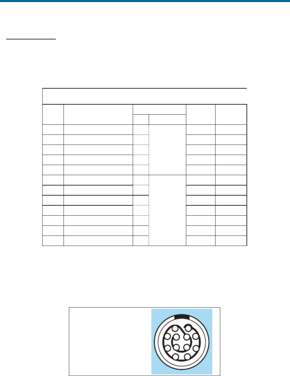
POS MV V5 Installation and Operation Guide
Installation
Copyright © Applanix Corporation, 2012
2-17
COM Connector
There is one COM connector which supports a multi-connector breakout cable (COM cable) that provides
access to two independent, 4 wire RS232 serial communication ports.
Table 7 and Figure 9 provide the pin assignment for the COM connector and pin mapping of the COM
cable.
Table 7: COM Connector Pin Assignment
I/O Pin
Pin Description
I/O Cable Mapping
Signal
Type
Signal
Direction
PIN
Connector
1
COM 1 Rx
2
DE-9
(Male)
RS232
Input
3
COM 1 Tx
3
RS232
Output
4
COM 1 RTS
7
RS232
Output
2
COM 1 CTS
8
RS232
Input
10
Signal Ground
5
Common
Common
8
COM 2 Rx
2
DE-9
(Male)
RS232
Input
6
COM 2 Tx
3
RS232
Output
5
COM 2 RTS
7
RS232
Output
7
COM 2 CTS
8
RS232
Input
11
Signal Ground
5
Common
Common
9
PPS In
4
**see notes
Input
12
PPS In Return
12
Return
Input
** PPS In is an optically isolated digital input.
** The input (and return line) is not referenced and is independent of internal µPOS power supplies and
GND.
** PPS input can be triggered from an external 3 – 50 Vdc source capable of supplying a minimum of 1
mA of sourcing or sinking current.
POS MV Receptacle:
Lemo HEN.2F.312.CLNP
12 pin female (shown)
Cable Plug:
Lemo FGN.2F.312.CLC
Figure 9: COM Connector Pin Arrangement

POS MV V5 Installation and Operation Guide
Installation
2-18
Physical Interface
To ensure data integrity, use high quality RS-232 cable with its shielding connected through the back
shell to ground at both cable ends.
Interface Configuration
Table 12 identifies the possible configurations for the COM connector COM ports (default in bold).
Table 8: COM Connector COM Port Configuration
Setting
Value
Baud Rate
2400 to 115200 (9600)
Parity
None, Even, Odd
Data Bits
7, 8
Stop Bits
1, 2
Flow Control
Hardware, Software, None
PPS Input
The PCS requires the one Pulse Per Second (PPS) signal for internal timing requirements. This signal is
normally obtained from the primary GNSS receiver but may be from an external GNSS receiver. The PPS
input signal is only effective if the external GNSS option is enabled through the POSConfig menu
selection in MV-POSView (refer to the Manage Multiple Configurations description on page 4-27).
Figure 10 provides a functional diagram.
Figure 10: PPS Port Signal Sources - Functional Diagram
I/O Connector
There are two identical I/O connectors which support a multi-connector breakout cable (I/O cable) that
permits access to the following signals:
• One 2-wire RS232/RS422 multi-function COM port
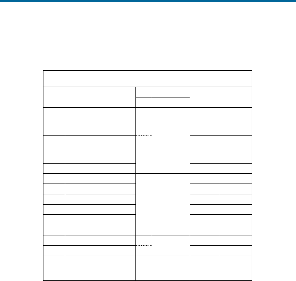
POS MV V5 Installation and Operation Guide
Installation
Copyright © Applanix Corporation, 2012
2-19
• One output for the One Pulse Per Second (PPS) signal
Table 9 and Figure 11 provide the pin assignment for the I/O connector and pin mapping of the I/O cable.
Table 9: I/O Connector Pin Assignment
I/O Pin
Pin Description
I/O Cable Mapping
Signal
Type
Signal
Direction
PIN
Connector
3
COM 3(4) Rx+
1
DE-9
(Male)
RS422
Input
4
COM 3(4) Rx
2
RS232 /
RS422
Input
2
COM 3(4) Tx
3
RS232 /
RS422
Output
1
COM 3(4) Tx+
4
RS422
Output
15
Signal Ground
5
Common
Common
7
Strobe 1(2) Out
No connection
5V TTL
Output
16
Strobe 1(2) Out Return
5V TTL
Output
13
Event 1(3) In
**see notes
Input
11
Event 1(3) In Return
**see notes
Input
10
Event 2(4) In
**see notes
Input
9
Event 2(4) In Return
**see notes
Input
12
PPS Out
centre
BNC
5V TTL
Output
14
PPS Return
shell
5V TTL
Output
5, 6, 8,
17, 18,
19
Reserved
No connection
N/A
N/A
** All Event Inputs are optically isolated digital inputs.
** Inputs (and their return lines) are not referenced and are independent of internal µPOS power
supplies and GND.
** Event inputs can be triggered from an external 3 – 50 Vdc source capable of supplying a minimum of
1 mA of sourcing or sinking current.

POS MV V5 Installation and Operation Guide
Installation
2-20
POS MV Receptacle:
Lemo HEP.2F.319.CLNP
19 pin female (shown)
Cable Plug:
Lemo FGP.2F.319.CLC
Figure 11: I/O Connector Pin Arrangement
COM Port Configuration
Table 10 identifies the possible configurations for the I/O connector COM ports (default in bold).
Table 10: I/O Connector COM Port Configuration
Setting
Value
Interface
RS232, RS422
Baud Rate
2400 to 115200 (9600)
Parity
None
Data Bits
8
Stop Bits
1
Flow Control
None
GNSS Access
The serial digital port for each GNSS receiver is accessible for upgrading the receiver through the I/O
COM ports. Access to the GNSS serial port is under software control in the same way that other functions
are assigned to COM ports.
PPS Output
The PCS uses the one Pulse Per Second (PPS) signal from a GNSS receiver for internal timing
requirements. A user customizable version of this signal is provided on the connector to allow external
equipment to be synchronized with POS MV. A dialog in MV-POSView allows control of the polarity and
pulse width of the PPS output signal.
The PPS output port is an active circuit. Ensure that an ‘input
signal’ is NOT connected to the PPS output port, otherwise
damage may result.

POS MV V5 Installation and Operation Guide
Installation
Copyright © Applanix Corporation, 2012
2-21
The 1PPS signal is a TTL level strobe that occurs at a 1 Hz rate. The leading edge of the strobe is
coincident with the exact GPS second. The corresponding time message that specifies the UTC time of
the 1PPS is available in multiple formats from any COM port by selecting the desired configuration
through MV POSView. Refer to the GNSS Timing Basics description starting on page H-2.
Ethernet Connector
A 10/100/1000 Base-T Ethernet interface provides communication between the PCS and other PCs for
monitoring or controlling the system. The Ethernet port can also be used to transmit POS MV data to a
host PC for real-time processing or for data logging and subsequent post-processing with POSPac MMS.
The Ethernet port supports both Transmission Control Protocol/Internet Protocol (TCP/IP) and Universal
Datagram Protocol (UDP).
Physical Interface
An Ethernet cable is supplied with the POS MV system: a shielded straight through cable. The Ethernet
interface on the PCS is auto detecting so a cross-over cable is not required. The cable is terminated with
shielded RJ-45 connectors. Ensure that replacement cables meet the RJ-45 Cat5 standard, or better (i.e.
Cat6, Cat6e), to avoid an impedance mismatch. In addition, the maximum cable length is determined by
the Ethernet specification. Table 11 provides connector pin assignments and mapping.
Table 11: Ethernet Connector Pin Assignment
Pin
Pin Description
Signal
Type
Signal
Direction
1
BI_DA+
Analog
Bidirectional
2
BI_DA-
Analog
Bidirectional
3
BI_DB+
Analog
Bidirectional
4
BI_DC+
Analog
Bidirectional
5
BI_DC-
Analog
Bidirectional
6
BI_DB-
Analog
Bidirectional
7
BI_DD+
Analog
Bidirectional
8
BI_DD-
Analog
Bidirectional
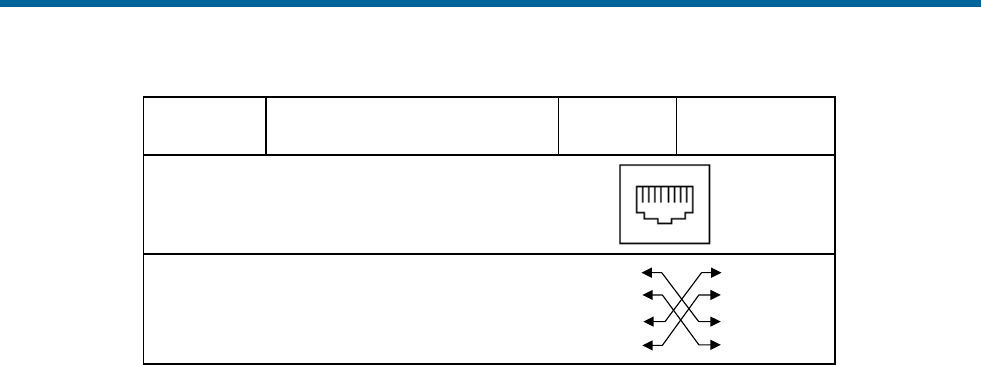
POS MV V5 Installation and Operation Guide
Installation
2-22
Pin
Pin Description
Signal
Type
Signal
Direction
POS MV Rear Panel
RJ-45 Female Connector
81
Pin out for a 100 BaseT crossover cable
TD+
TD-
RD+
RD-
TD-
TD+
RD+
RD-
3
2
1
6
3
2
1
6
The Ethernet interface provides a means for configuring and monitoring the POS MV and conforms to the
Institute of Electrical and Electronics Engineers (IEEE) standard 802.3 that comprise the following types
of ports:
• One control port - TCP/IP transmits configuration information to POS MV and operates in
conjunction with the Display port described below
• One display port - UDP provides data at a 1 Hz rate for use by MV-POSView software
• One real-time data port – user configurable data output, at rates up to 200 Hz - (asynchronous
events at higher rates), broadcast using UDP protocol to minimize latency.
• One logging data port - user configurable data output, at rates up to 200 Hz - (asynchronous
events at higher rates), using TCP/IP protocol to ensure data integrity.
Note: Data output from the display port (above) is broadcast using UDP protocol and may be
captured by any host on the physical Ethernet network (regardless of the IP address of the host).
Note: Network routers typically block UDP protocol data transmissions. In addition, other couplers
can only receive UDP data if they are in the same subnet (i.e. class B or class C). The subnet class
(B or C) is determined by the choice of Ethernet address.
Output Data Format
The data available on the Ethernet connection (for both Display and Data ports) is organized into a group
and message structure. Each port is configured independently in terms of the groups that are output and
only those groups selected for a port are output on that port.
Refer to the Data Logging - Ethernet description on page 5-15 for information on selecting data groups for
output. Please refer to Applanix document PUBS-ICD-004089 (supplied on CD with POS MV or available

POS MV V5 Installation and Operation Guide
Installation
Copyright © Applanix Corporation, 2012
2-23
from Applanix Customer support on request) if the data are used with software other than MV-POSView
or POSPac MMS.
Input Data Format
The data input to the POS MV on the control port is organized into a message structure. Refer to
Applanix document PUBS-ICD-004089 (supplied on CD with POS MV or available from Applanix
Customer support on request) if control commands will be generated by software other than MV-
POSView.
USB Connector
A USB A type connector is located on the rear of the PCS. This Host port supports the USB 2.0 standard
and is intended for external sensor connections.
ANT1 and ANT2 Interfaces
Signals from the GNSS antennas are coupled to the GNSS receivers using the ANT1 (primary GNSS)
and ANT2 (secondary GNSS) ports located on the rear panel of the PCS.
The operating dc voltage for each antenna is coupled through the centre conductor of each cable and is
supplied by the PCS; GNSS signals are routed through the same conductor to the respective receiver. If it
is necessary to replace an antenna cable and RG-303 (50 ohm) coaxial cable is not available, RG-400
(50 ohm) may be used as an alternate. Both the GNSS antennas and the PCS ANT1 and ANT2 ports are
female TNC connectors.
Ancillary Equipment Interfaces
Auxiliary GNSS Receiver
Any of the four COM ports may be used for connecting one or two auxiliary GNSS receivers to the PCS.
The output of the auxiliary GNSS receiver must be manually configured before it can be used by POS
MV. The PCS will only use an auxiliary GNSS receiver if its quality is better than the primary GNSS
receiver. The state of the auxiliary GNSS receiver input is displayed in the GNSS Data window, see
Figure 50 on page 8-2.
Obtain a cable and connector to suit the particular requirements of the GNSS receiver in use. Refer to
Table 3 on page 2-11 for the connector pin assignments of the COM ports.
Sonar Hardware and Acquisition Software
Any of the four COM ports may be used for connecting the sonar to the PCS. Note that Applanix strongly
recommend the use of an Ethernet interface in preference to serial for interfacing to sonar acquisition

POS MV V5 Installation and Operation Guide
Installation
2-24
systems. Unlike asynchronous serial messages, the Applanix defined Ethernet messaging (see PUBS-
ICD-004089 for details) includes a microsecond accurate time of validity.
Installation Parameters
Once the POS MV components are installed, the installation parameters must be measured. These
measurements allow the POS MV to deliver the best possible performance.
After you have configured the system with these parameters, save the data to non-volatile memory for
immediate use each time the POS MV is powered-on.
The POS MV configuration information defines the layout of the system and its associated peripheral
equipment relative to a reference point. The reference point is defined as any convenient location on the
survey vessel, and it may be assigned any orientation that you choose. Once you have decided on a
reference point, make the following measurements as carefully and accurately as possible.
Lever Arm Distances
Note: Measure distances in metres, resolved into their longitudinal, lateral and vertical components in
the reference frame.
NB POS MV uses a right-hand Cartesian co-ordinate system. Hence the lever arm offsets
should be entered using the following rules:
+X=to Bow, +Y=to Starboard, +Z=Down
NB When using DGPS, lever arms should be measured to 0.05m. When using RTK or
POSPac MMS IAPPK, lever arms should be measured to 0.005m.
• Reference to IMU
• Reference to primary GNSS antenna:
• Reference to vessel
• Reference to sensor 1 and sensor 2
• Reference to auxiliary GNSS antenna:
• Reference to centre of rotation measurement location - measure to an accuracy of ±0.10 m
When measuring the lever arm distances, you must resolve them into their longitudinal, lateral and
vertical components using the reference frame. Refer to the Theory of Operation description on page B-1
for an explanation of the various frames of reference used by POS MV.

POS MV V5 Installation and Operation Guide
Installation
Copyright © Applanix Corporation, 2012
2-25
Additionally, the scalar antenna separation distance may be measured to an accuracy of 5 mm (~¼ in),
although this is not necessary as this value will be computed by POS MV as part of the GAMS calibration
process.
Record the measurements carefully so that you can use the MV-POSView Controller program to
configure the system. These measurements inform POS MV of the relative positions of the IMU, the
GNSS antenna, the multibeam transducer (sensor 1) and the vessel by relating them all to a common
reference point that you have defined. It may be convenient for you to define the reference point to be
coincident with the IMU for example, in which case the lever arm distances for this relationship will be
zero.
Measurements of position, attitude, velocity and dynamics displayed by the main window of the MV-
POSView Controller program (
Figure 35, page 5-3) are valid for the vessel location. You define their precise point of validity by
configuring the system with the lever arm distances between the reference point and your chosen vessel
location.
Mounting Angles
Note: Measure angles in degrees, resolved into the longitudinal, lateral and vertical axis in the reference
frame:
• IMU with respect to the reference frame
• Sensor with respect to the reference frame
When measuring the mounting angles you must resolve them into rotations, in a strict sequence, about
the longitudinal, lateral and vertical axis using the reference frame.
Record the measurements carefully so that you can use the MV-POSView Controller program to
configure the system. These measurements inform POS MV of the relative orientations of the IMU and
the multibeam transducer (sensor 1) by relating them all to a common reference frame that has been
defined. It may be convenient to define the reference frame to be coincident with the multibeam
transducer for example, in which case the mounting angles for this relationship will be zero. Note that, by
definition, the vessel frame and the reference frame co-align.
The accuracy with which you measure the mounting angles will affect the accuracy of measurements
made by the multibeam sonar:
• Measure the mounting angles to the same degree of accuracy that you require of POS MV. For
example, if you require POS MV to deliver roll measurements for multibeam sonar compensation
to an accuracy of 0.02°, then you must measure the mounting angles to an accuracy of 0.02°.

POS MV V5 Installation and Operation Guide
Installation
2-26
• Not measuring the mounting angles to the required accuracy will cause a constant offset in all the
images from the multibeam sonar. Additionally, some multibeam sonar may calculate the beam
forming parameters incorrectly.
• Perform a ‘patch test’ to determine whether there is any uncorrected misalignment between the
multibeam sonar and the POS MV. Many operators have a defined procedure to complete a
patch test to refine the accuracy of the POS MV and multibeam sonar interface. The Patch Test
topic on page F-1 describes a suitable patch test procedure that can be used.
The following subsections of this manual explain how to measure the lever arm distances and mounting
angles in readiness to configure POS MV.
Note: After you have made all the required physical measurements on the POS MV installation, refer to
the System Configuration description on page 4-1 for instructions on configuring the system and saving
all the information to non-volatile memory.
Lever Arm Distances
Before starting to measure the lever arm distances, you must define a reference starting point. Choose an
easily identifiable point at some convenient location on the vessel that allows you to measure offset
distances in three axes. The reference point must be fixed and rigid relative to the IMU, the GNSS
antennas and the multibeam transducer.
Measure and resolve the lever arm distances using the reference frame:
• X lever arm - the distance measured along the surveyed horizontal fore-aft axis of the vessel (X is
positive towards the bow of the vessel)
• Y lever arm - the distance measured along the surveyed horizontal port-starboard axis of the
vessel (Y is positive towards starboard)
• Z lever arm - the distance measured along the surveyed vertical axis of the vessel (Z is positive
down)
Reference to IMU Lever Arm
Measure and record the distance from your reference point to the centre of the circular black and white
label on top of the IMU.
• A positive value for the X lever arm means the IMU is forward of your reference point
• A positive value for the Y lever arm means the IMU is to starboard of your reference point
• A positive value for the Z lever arm means the IMU is below your reference point

POS MV V5 Installation and Operation Guide
Installation
Copyright © Applanix Corporation, 2012
2-27
Reference to Primary GNSS Lever Arm
Measure and record the distance from your reference point to the centre of the primary GNSS antenna.
• A positive value for the X lever arm means the primary GNSS antenna is forward of your
reference point
• A positive value for the Y lever arm means the primary GNSS antenna is to starboard of your
reference point
• A negative value for the Z lever arm means the primary GNSS antenna is above your reference
point
Reference to Vessel Lever Arm
POS MV uses the main window of the controller program to display its navigation solution, valid for the
point you have defined as the vessel datum. Measure and record the distance from your reference point
to the vessel datum.
• A positive value for the X lever arm means the vessel datum is forward of your reference point
• A positive value for the Y lever arm means the vessel datum is to starboard of your reference
point
• A positive value for the Z lever arm means the vessel datum is below your reference point
Reference to Sensor 1 Lever Arm
Sensor 1 is typically a multibeam transducer. Measure and record the distance from your reference point
to the sensing centre of the multibeam transducer array.
• A positive value for the X lever arm means the multibeam transducer is forward of your reference
point
• A positive value for the Y lever arm means the multibeam transducer is to starboard of your
reference point
• A positive value for the Z lever arm means the multibeam transducer is below your reference
point
Reference to Sensor 2 Lever Arm
Measure and record the distance from your reference point to the second sensor.
• A positive value for the X lever arm means the second sensor is forward of your reference point
• A positive value for the Y lever arm means the second sensor is to starboard of your reference
point
• A positive value for the Z lever arm means the second sensor is below your reference point

POS MV V5 Installation and Operation Guide
Installation
2-28
Note: If your application does not use a second sensor, record these lever arm distances as zero.
Reference to Auxiliary GNSS Lever Arm
The auxiliary GNSS supplies DGNSS, P-Code or RTK measurements to POS MV. Measure and record
the distance from your reference point to the auxiliary GNSS antenna.
• A positive value for the X lever arm means the auxiliary GNSS antenna is forward of your
reference point
• A positive value for the Y lever arm means the auxiliary GNSS antenna is to starboard of your
reference point
• A negative value for the Z lever arm means the auxiliary GNSS antenna is above your reference
point
Note: If your application does not include an auxiliary GNSS receiver, record these lever arm distances
as zero.
Reference to Centre of Rotation
Normal dynamics in a marine environment apply a complex combination of forces to a survey vessel,
causing the vessel to experience a continuously varying pattern of heave, roll and pitch.
Under the influence of these, vertical movements experienced by the multibeam transducer include two
components:
• Heave movements as the vessel moves vertically in the water - in the absence of any changes in
vessel attitude, these will be the same throughout the vessel.
• Apparent heave movements under the influence of roll and pitch - the amplitude of these will vary
directly with distance from the vessel centre of rotation.
The vessel centre of rotation is a point of the vessel that experiences only rotations with changes in
attitude. Any heave measured at this point arises entirely from vertical movements that affect the whole
vessel equally.
The multibeam transducer will be some distance from the vessel centre of rotation. The transducer will
therefore experience a small component of heave as the vessel moves vertically in the water and a much
larger component of apparent heave with changes in vessel attitude.
To separate these effects, POS MV translates the IMU measurements to the vessel centre of rotation.
Having done so, it applies filtering to the measurements of pure heave as explained in the Theory of
Operation on page B-1 and then translates the filtered measurements back to the positions of sensors 1
and 2.

POS MV V5 Installation and Operation Guide
Installation
Copyright © Applanix Corporation, 2012
2-29
This method for measuring heave avoids the errors that can occur if you filter direct heave measurements
made from a point remote from the vessel centre of rotation.
Measure and record the distance from your reference point to the vessel centre of rotation.
• A positive value for the X lever arm means the vessel centre of rotation is forward of your
reference point
• A positive value for the Y lever arm means the vessel centre of rotation is to starboard of your
reference point
• A positive value for the Z lever arm means the vessel centre of rotation is below your reference
point
Antenna Separation
The scalar antenna separation distance may be measured to an accuracy of 5 mm (~¼ in), although this
is not necessary as this value will be computed by POS MV as part of the GAMS calibration process.To
measure the antenna separation distance manually, use one of the following methods:
• Use a tape measure to measure the separation distance between the geometric centres of the
antennas; that is between the centres of both antenna domes.
• Stretch a non-elastic string or wire between the GNSS antennas. Mark the string or wire where it
crosses the centres of the antenna domes. Remove the string or wire and measure the distance
between the marks.
Note: Both methods assume there is a straight unobstructed vector between both antennas.
Mounting Angles
General
Measure and record the mounting angles relative to the reference frame that you have chosen. Resolve
these angles into three rotations that you must apply, in a strictly defined sequence, to align the mounting
angles with your chosen reference frame. The Tate-Bryant sequence of rotations is used.
Tate-Bryant Rotation Sequence
Apply the rotation in the following order to bring the two frames of
reference into complete alignment:
• Heading rotation - apply a right-hand screw rotation θz about
the z-axis to align one frame with the other
• Pitch rotation - apply a right-hand screw rotation θy about the
once-rotated y-axis to align one frame with the other

POS MV V5 Installation and Operation Guide
Installation
2-30
• Roll rotation - apply a right-hand screw rotation θx about the
twice-rotated x-axis to align one frame with the other
Frames of Reference
The IMU frame of reference includes the vertical and the horizontal
axis of the IMU with which the orthogonal array of sensing
elements aligns. These are fixed relative to the IMU and are
identified by a label on the IMU housing.
By convention, POS MV uses the right-hand orthogonal co-
ordinate system, with its origin centred on the black and yellow
circle on the top of the IMU.
The sensor 1 reference frame includes the vertical and the
horizontal axis of the multibeam transducer. These axis are fixed
relative to the multibeam transducer.
By convention, POS MV uses the right-hand orthogonal coordinate
system, with its origin at the sensing centre of the multibeam
transducer.
The vessel reference frame co-aligns with your chosen reference
frame.
Right-Hand Orthogonal System
The right-hand orthogonal system defines the following:
• The x-axis is in the fore-aft direction in the appropriate
reference frame
• The y-axis is perpendicular to the x-axis and points towards
the right (starboard) side in the appropriate reference frame
• The z-axis points downwards in the appropriate reference
frame
Figure 12 shows an example of a frame centred on the vessel and
aligned with its surveyed fore-aft, port-starboard and vertical axis.
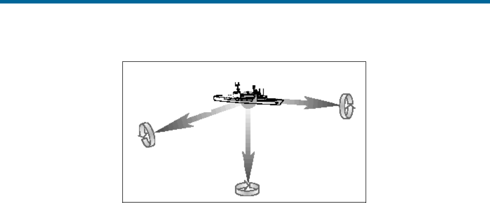
POS MV V5 Installation and Operation Guide
Installation
Copyright © Applanix Corporation, 2012
2-31
y = Horizonral
(port-stbd line) x = Horizonral
(fore-aft line)
z = Vertical
Centre of
vessel
y
z
x
Figure 12: Right-Hand Orthogonal System
The mounting angles describe the relative angles between one frame and another, for example between
your reference frame and the IMU frame. The following examples use the mounting angles between your
chosen reference frame and the IMU frame to illustrate how to measure and apply these parameters.
The examples use the following assumptions:
• The IMU is installed so that it has a permanent roll angle of -5° relative to your reference frame.
That is, if you consider your reference frame as level, then the port edge of the IMU is lower than
the starboard edge.
• The IMU is installed so that it has a permanent pitch angle of +2° relative to your reference frame.
That is, if you consider your reference frame as level, then the bow edge of the IMU is higher than
the stern edge.
The circular label on the top of the IMU identifies the directions of the IMU x and y-axis.
Example 1 - The IMU x-axis nominally points towards the x-axis of the chosen reference frame, but with a
small yaw offset so that the IMU has a 3° clockwise rotation relative to your reference frame. Record the
following:
• +3° for the IMU with respect to reference frame z mounting angle
• +2° for the IMU with respect to reference frame y mounting angle
• -5° for the IMU with respect to reference frame x mounting angle
Example 2 - The IMU x-axis nominally points towards the starboard side of the chosen reference frame,
but with a small yaw offset so that the IMU has a 3° clockwise rotation relative to the y-axis of your
reference frame. Record the following:
• +93° for the IMU with respect to reference frame z mounting angle
• +2° for the IMU with respect to reference frame y mounting angle

POS MV V5 Installation and Operation Guide
Installation
2-32
• -5° for the IMU with respect to reference frame x mounting angle
IMU with respect to Reference Frame
Measure and record the rotations that you must apply, using the Tate-Bryant sequence explained above,
to align your chosen reference frame with the IMU reference frame.
Sensor 1 with respect to Reference Frame
Sensor 1 is typically a multibeam transducer. Measure and record the rotations that you must apply, using
the Tate-Bryant sequence explained above, to align your chosen reference frame with the sensor 1
frame.
Sensor 2 with respect to Reference Frame
Measure and record the rotations that you must apply, using the Tate-Bryant sequence explained above,
to align your chosen reference frame with the sensor 2 frame.
Note: If your application does not use a second sensor, record these mounting angles as zero.
Installation Checklist
This checklist is included to help you install the POS MV efficiently and with minimal disruption to the
vessel, its crew or any ongoing operations.
After installing the system correctly and all items have been checked against this list, refer to the
Interfaces and Data Formats description starting on page 3-1 to configure and start using the POS MV.
1. Mechanical Interface
a) IMU Positioning:
Mount the IMU as close as possible to the multibeam transducer.
Mount the IMU rigidly so that it cannot move or rotate
independently of the vessel.
Install the IMU where the data and power cable will reach easily
between the IMU and the PCS.
Ensure there is sufficient clearance for the connectors at both
ends of the data and power cable. Tighten the connectors by
hand only.
Mount the IMU so that it is approximately level.
Do not immerse the IMU in water or any liquid.
Respect the environmental limits listed for the Inertial
Measurement Unit on page 2-4 for storage and operation.
Refer to the Drawings section on page E-1 for dimensional
details to help when you install the IMU.

POS MV V5 Installation and Operation Guide
Installation
Copyright © Applanix Corporation, 2012
2-33
Connect the IMU housing to a good ground connection.
b) PCS Positioning:
Protect the PCS from shock, vibration and moisture.
Allow easy access to the front and the rear panels of the PCS.
Refer to the Drawings section on page E-1 for dimensional
details to help when you install the PCS.
Connect the primary GNSS antenna to the ANT1 port.
Connect the secondary GNSS antenna to the ANT2 port
If necessary, connect the Differential GNSS corrections to a
COM port.
Connect the IMU data and power cable to the IMU port.
(POS MV V5) Connect an electrical supply of nominal voltage
110/220V (voltage range - 90 Vac to 264 Vac) to the 3-pin IEC
mains inlet connector on the PCS. The PCS uses an auto-
switching power supply that configures itself to the applied ac
electrical supply.
(POS MV V5-1) Connect an electrical supply of nominal voltage
Error! Reference source not found. (voltage range - 10 Vdc to
34 Vdc) to the 3-pin power inlet connector on the PCS.
c) GNSS Antenna Positioning:
Ensure there is a horizontal separation distance of between 1.0
and 5.0 m (~3 ¼ and ~16 ½ ft) between the primary and the
secondary GNSS antennas.
Mount the antennas as high as possible on the vessel.
Do not mount the antennas close to MF, HF, VHF or UHF
transmitters or antennas. Do not mount the GNSS antennas
within 0.5 m (~±19 ¾ in) of radar or satellite communications
equipment.
Avoid mounting the antennas near large flat surfaces.
Avoid mounting the antennas in a location where they may move,
twist or vibrate significantly relative to the vessel or the IMU.
2. Offset Measurements
Measure the lever arm distances and mounting angles, as
instructed in Lever Arm Distances on page 2-26 and Mounting
Angles on page 2-29. Be as careful and accurate as possible.
Measure the GNSS antenna separation distance, as instructed in
Antenna Separation on page 2-29. Be as careful and accurate as
possible.
3. Power Supply

POS MV V5 Installation and Operation Guide
Installation
2-34
The application of incorrect electrical power to the PCS may
result in damage to POS MV system.
(POS MV V5) Arrange a clean, stable electrical supply at a
nominal voltage 110/220V (voltage range - 90 Vac to 264 Vac)
for the PCS. If possible, supply electrical power to the PCS from
an uninterruptible power supply.
(POS MV V5-1) Arrange a clean, stable electrical supply at a
nominal voltage Error! Reference source not found. (voltage
range 10 Vdc to 34 Vdc) for the PCS. If possible, supply electrical
power to the PCS from an uninterruptible power supply.
4. Cable Runs
Install all cables carefully so that they do not present a hazard.
Avoid applying sharp bends or other mechanical stresses to the
cables when you install them. Do not run cables where they may
bend or twist after installation. Use cable clips to secure the
cables at regular intervals along their length.
If you need to extend any cables, use approved cables and
connectors of the highest quality. Refer to Applanix for advice,
see Technical Support and Service on page A-1 for procedures.

POS MV V5 Installation and Operation Guide
Interfaces and Data Formats
Copyright © Applanix Corporation, 2012
3-1
3.0 Interfaces and Data Formats
This section of the manual describes the data formats for each of the following interface ports on the POS
Computer System (PCS) rear panel.
Note: Each port has a different format. To avoid operating problems, give careful attention to the
structure of each interface.
LAN (Ethernet) Data
The POS MV 10/100/1000BaseT Ethernet interface conforms to the Institute of Electrical and Electronics
Engineers (IEEE) 802.3i standard. It allows you to configure the system and to monitor its status during
operation.
The interface comprises four ports:
• Control port - used to transmit configuration information to POS MV
• Display port - provides navigation and attitude information at a low update rate for use by the MV-
POSView Controller program running on a separate PC
• Real-time data port - provides the same information as the display port, but at a higher update
rate for use by other computers on a shared Ethernet LAN
• Logging data port - provides the same information as the display port, but is buffered for robust
logging by other computers on a shared Ethernet LAN
POS MV broadcasts information from the display and real-time data port using the Universal Datagram
Protocol (UDP) protocol, and the logging data port using the Transmission Control Protocol (TCP)
protocol. Information is organised into a data group structure and each port may be configured
independently to permit the output of selected data groups.
The MV-POSView Controller program configures the groups transmitted through the display port
automatically according to the specific windows that the program has open at any one time. The group
structure is therefore user transparent. POS MV enables groups automatically to support the demands
that you make by opening windows within the controller program.
COM Ports
The four RS-232 serial ports, COM(1) through COM(4), allow communication between the PCS and
external equipment. Two of the four COM ports are software switchable between the RS-232 and RS-422
protocols. Two of the four COM ports are software switchable to connect with the internal GNSS receiver
COM ports. All COM ports are assignable for input and/or output. The following identifies the available
port assignments:
• NMEA sentence types
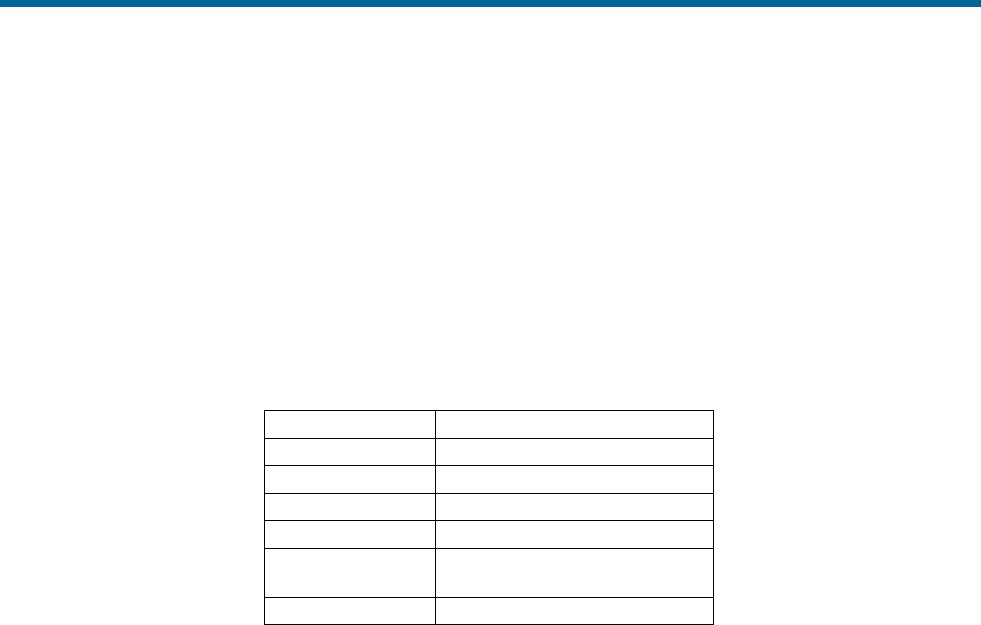
POS MV V5 Installation and Operation Guide
Interfaces and Data Formats
3-2
• Binary data formats
• Base 1 and 2 GNSS outputs
• Base 1 and 2 GNSS inputs
• Auxiliary 1 and 2 GNSS inputs
• GNSS 1 and 2 COM port access
Table 12 identifies the default COM port settings.
Table 12: Default COM Port Settings
Baud Rate
9600
Parity
None
Data Bits
8 Bits
Stop Bits
1 Bit
Flow Control
None
Output Select
None
Input Select
None
Note: Baud rates may require different settings, other than the default settings, for the transmission of various
sentence formats.
NMEA Data Formats
The PCS can be configured to use any number of the four COM ports to output data using the National
Marine Electronics Association (NMEA) 0183 format at rates up to 50 Hz. POS MV makes twelve
sentence formats available.
1. $xxGGA: global system position fix data
2. $xxGGK: time, position, position type and DOP values
3. $xxHDT: heading - true data
4. $xxVTG: course over ground and ground speed data
5. $xxGST: GNSS pseudorange noise statistics
6. $xxRMC:
7. a) $PASHR: attitude data
b) $PASHR-TSS: attitude data (TSS indicates the use of the TSS standard instead of the Tate-
Bryant standard, see page 2-29 for a description)
8. a) $PRDID: attitude data

POS MV V5 Installation and Operation Guide
Interfaces and Data Formats
Copyright © Applanix Corporation, 2012
3-3
b) $PRDID-TSS: attitude data (TSS indicates the use of the TSS standard instead of the Tate-
Bryant standard, see page 2-29 for a description)
9. $xxZDA: time and date
10. $UTC: time and date
11. $xxPPS: time and offset
12. UTC: date and time (Trimble UTC format)
Note: The initial two characters following the $ (noted as “xx” above) may be configured to either “IN”
or “GP”. Although “IN” is more correct in the context of a GNSS aided inertial navigation system,
some third party software applications may accept only “GP”.
Use the MV-POSView Controller program to set the system to output one or more of these sentences, as
well as to set the output frequency of these sentences.
Note: System performance may degrade if multiple ports are configured for high rate output
simultaneously.
Note: $PASHR and $PASHR-TSS are mutually exclusive; as are $PRDID and $PRDID-TSS.
Information supplied through the COM port is valid for the point described by the vessel lever arms and
mounting angles, as selected by the user.
NMEA Sentence Formats
$xxGGA: Global Positioning Fix Data
Time and position fix related data. POS MV supplies information using the following American
Standard Code for Information Interchange (ASCII) NMEA 0183 sentence format.
$xxGGA,hhmmss.sss,llll.lllll,a,yyyyy.yyyyy,b,t,nn,v.v,xxxxx.xx,M,,,ccc,rrrr*hh<CRLF>
Table 13: $xxGGA Sentence Format
Item
Definition
Value
Units (If Applicable)
$xxGGA
Header
$xxGGA
hhmmss.sss
UTC time of
position
N/A
hours|minutes|seconds|decimal seconds
2 fixed digits for hours
2 fixed digits for minutes
2 fixed digits for seconds
3 digits for decimal seconds
llll.lllll
Latitude
0 to 90
degrees|minutes|decimal minutes
2 fixed digits for degrees
2 fixed digits for minutes
5 digits for decimal minutes

POS MV V5 Installation and Operation Guide
Interfaces and Data Formats
3-4
$xxGGA,hhmmss.sss,llll.lllll,a,yyyyy.yyyyy,b,t,nn,v.v,xxxxx.xx,M,,,ccc,rrrr*hh<CRLF>
Table 13: $xxGGA Sentence Format
Item
Definition
Value
Units (If Applicable)
A
N (North) or S
(South)
N or S
yyyyy.yyyyy
Longitude
0 to 180
degrees|minutes|decimal minutes
3 fixed digits for degrees
2 fixed digits for minutes
5 digits for decimal minutes
B
E (East) or W
(West)
E or W
T
GNSS quality
indicator
0 = fix not available or invalid
1 = C/A standard GNSS; fix valid
2 = DGNSS mode; fix valid
3 = GNSS PPS mode; fix valid
4 = RTK fixed
5 = RTK float
6 = free inertial
nn
Number of
satellites used
in the fix
0 to 32
v.v
Horizontal
dilution of
precision
xxxxx.xx
Altitude above
or below mean
sea level; a
negative value
indicates below
sea level
N/A
metres
M
Units of
measure =
metres
M
Null
Null
Null
Null
ccc
Age of
differential
corrections in
seconds since
last RTCM-104
message
0 to 999
seconds

POS MV V5 Installation and Operation Guide
Interfaces and Data Formats
Copyright © Applanix Corporation, 2012
3-5
$xxGGA,hhmmss.sss,llll.lllll,a,yyyyy.yyyyy,b,t,nn,v.v,xxxxx.xx,M,,,ccc,rrrr*hh<CRLF>
Table 13: $xxGGA Sentence Format
Item
Definition
Value
Units (If Applicable)
rrrr
DGNSS
reference
station identity
0000 to
1023
*hh
Checksum
<CRLF>
Carriage return
and line feed
<CRLF>
Note: Commas separate all items, including null fields. The information is valid at the location of the vessel frame.
$xxGGK: Time, Position, Position Type and DOP Values
The message string is shown below.
$xxGGK,hhmmss.ss,mmddyy,llll.llllllll,a,yyyyy.yyyyyyyy,b,t,nn,v.v,x.xxx,M*hh<CRLF>
Table 14: $xxGGK Sentence Format
Item
Definition
Value
Units (If Applicable)
$xxGGK
Header
$xxGGK
hhmmss.ss
UTC of
position fix
N/A
hours|minutes|seconds|decimal seconds
2 fixed digits for hours
2 fixed digits for minutes
2 fixed digits for seconds
2 digits for decimal seconds
mmddyy
UTC date of
position
N/A
month|day|year
2 fixed digits for month
2 fixed digits for day
2 fixed digits for year
llll.llllllll
Latitude
0 to 90
degrees|minutes|decimal minutes
2 fixed digits for degrees
2 fixed digits for minutes
8 digits for decimal minutes
A
Direction of
latitude
N or S
yyyyy.yyyyyyyy
Longitude
0 to 180
degrees|minutes|decimal minutes
3 fixed digits for degrees
2 fixed digits for minutes
8 digits for decimal minutes
B
Direction of
longitude
E or W

POS MV V5 Installation and Operation Guide
Interfaces and Data Formats
3-6
$xxGGK,hhmmss.ss,mmddyy,llll.llllllll,a,yyyyy.yyyyyyyy,b,t,nn,v.v,x.xxx,M*hh<CRLF>
Table 14: $xxGGK Sentence Format
Item
Definition
Value
Units (If Applicable)
T
GNSS quality
indicator
0 = fix not available or invalid
1 = C/A standard GNSS; fix valid
2 = RTK float
3 = RTK fixed
4 = DGNSS mode; fix valid
5 = free inertial
nn
Number of
satellites used
in GNSS
solution
0 to 32
v.v
DOP of fix
x.xxx
Ellipsoid
height of fix
(vessel height
above WGS84
ellipsoid)
N/A
metres|decimal metres
1 fixed digit for metres
3 fixed digits for decimal metres
M
Ellipsoid
height
N/A
metres
*hh
Checksum
<CRLF>
Carriage
return and line
feed
<CRLF>
$xxHDT: Heading - True Data
True vessel heading is in degrees. POS MV supplies information in the following ASCII NMEA
0183 sentence format.
$xxHDT,xxx.x,T*hh<CRLF>
Table 15: $xxHDT Sentence Format
Item
Definition
Value
Units (If Applicable)
$xxHDT
Header
$xxHDT
xxx.x
True vessel
heading in the
vessel frame
000.0 to 359.9
degrees|decimal degrees
3 fixed digits for degrees
1 digit for decimal degrees
T
True
T
*hh
Checksum
N/A
<CRLF>
Carriage return
and line feed
<CRLF>

POS MV V5 Installation and Operation Guide
Interfaces and Data Formats
Copyright © Applanix Corporation, 2012
3-7
$xxVTG: Course Over Ground and Ground Speed Data
Actual course and speed relative to the ground. POS MV supplies information in the following
ASCII NMEA 0183 sentence format.
$xxVTG,xxx.x,T,,M,n.n,N,k.k,K*hh<CRLF>
Table 16: $xxVTG Sentence Format
Item
Definition
Value
Units (If Applicable)
$xxVTG
Header
$xxVTG
xxx.x
True vessel
track in the
vessel frame
000.0 to 359.9
degrees|decimal degrees
3 fixed digits for degrees
1 digit for decimal degrees
T
True
T
Null
Not supported
null
M
M
n.n
Speed in the
vessel frame
N/A
knots
N
Knots
N
k.k
Speed in the
vessel frame
N/A
km/h
K
Kilometres per
hour
K
*hh
Checksum
N/A
<CRLF>
Carriage return
and line feed
<CRLF>
Note: Commas separate all items, including null fields.
$xxGST: GNSS Pseudorange Noise Statistics
GNSS pseudorange noise statistics indicate the quality of the position solution delivered by the
integrated navigation solution. POS MV supplies information in the following ASCII NMEA 0183
sentence format.

POS MV V5 Installation and Operation Guide
Interfaces and Data Formats
3-8
$xxGST,hhmmss.sss,,smjr.smjr,smnr.smnr,ooo.o,l.l,y.y,a.a
*hh<CRLF>
Table 17: $xxGST Sentence Format
Item
Definition
Value
Units (If Applicable)
$xxGST
Header
$xxGST
hhmmss.sss
UTC time of
position
N/A
hours|minutes|seconds|decimal
seconds
2 fixed digits for hours
2 fixed digits for minutes
2 fixed digits for seconds
3 digits for decimal seconds
Null
Not supported
null
smjr.smjr
Standard
deviation of
semi-major axis
of error ellipse
N/A
metres
smnr.smnr
Standard
deviation of
semi-minor axis
of error ellipse
N/A
metres
ooo.o
Orientation of
semi major axis
of error ellipse
000.0 to
359.9
degrees from true north
l.l
Standard
deviation of
latitude
N/A
metres
y.y
Standard
deviation of
longitude
N/A
metres
a.a
Standard
deviation of
altitude
N/A
metres
*hh
Checksum
N/A
<CRLF>
Carriage return
and line feed
<CRLF>
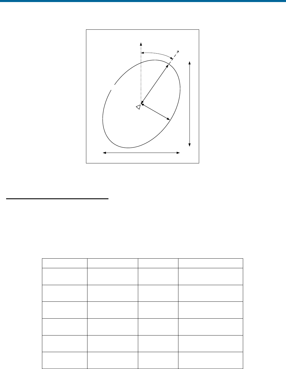
POS MV V5 Installation and Operation Guide
Interfaces and Data Formats
Copyright © Applanix Corporation, 2012
3-9
Indicated
position
0.0
True
North
Error ellipse
smnr.smnr
smjr.smjr
y.y
l.l
Figure 13: $xxGST Sentence Nomenclature
NMEA Port RMC Message Format
The RMC navigation data are output in the following ASCII NMEA format. Note the 2 fields describing
magnetic variation are not included and are therefore left null.
Table 18: NMEA RMC Message Format
$xxRMC,hhmmss.ssss,v,llll.lllll,a,yyyyy.yyyyy,b,sssss.s,
hhh.h,ddmmyy,,,c*hh<CR><LF>
Items
Definition
Values
Units
$xxRMC
Header with
talker ID
$ttRMC
tt = IN or GP
hhmmss.ssss
UTC time of
navigation data
NRG
hours / minutes /
seconds. decimal sec
V
A (Valid) or V
(Not valid)
A or V
N/A
llll.lllll
Latitude
0o to 90o
degrees / minutes.
decimal min
A
N (North) or S
(South)
N or S
N/A
yyyyy.yyyyy
Longitude
0o to 180o
degrees / minutes.
decimal min

POS MV V5 Installation and Operation Guide
Interfaces and Data Formats
3-10
Table 18: NMEA RMC Message Format
$xxRMC,hhmmss.ssss,v,llll.lllll,a,yyyyy.yyyyy,b,sssss.s,
hhh.h,ddmmyy,,,c*hh<CR><LF>
Items
Definition
Values
Units
B
E (East) or W
(West)
E or W
N/A
sssss.s
Speed in knots
NRG
knots
hhh.h
Heading
0o to 359.9o
degrees
ddmmyy
Date of
navigation data
NRG
days/
months/
year
C
Mode indicator
See Table 43
N/A
*hh
Checksum
Hexadecimal
value
N/A
<CR><LF>
Carriage return &
Line feed
<CR><LF>
N/A
NRG stands for No Range Given.
Table 19: RMC Mode Indicator Values
Value
RMC Mode
A
Autonomous
D
Differential
E
Dead reckoning
N
Not valid

POS MV V5 Installation and Operation Guide
Interfaces and Data Formats
Copyright © Applanix Corporation, 2012
3-11
$PASHR ($PASHR-TSS): Attitude Data
POS MV supplies attitude data information in the following ASCII NMEA sentence format.
$PASHR,hhmmss.sss,xxx.xx,T,RRR.RR,PPP.PP,HHH.HH,
a.aaa,b.bbb,c.ccc,d,e*hh<CRLF>
Table 20: $PASHR Sentence Format
Item
Definition
Value
Units (If Applicable)
$PASHR
Header
$PASHR
hhmmss.sss
UTC time of
data string
N/A
hours|minutes|seconds|decimal
seconds
• 2 fixed digits for hours
• 2 fixed digits for minutes
• 2 fixed digits for seconds
• 3 digits for decimal seconds
xxx.xx
True vessel
heading
0 to
359.99
degrees
T
True
T
RRR.RR
Roll
-90.00 to
+90.00
degrees
PPP.PP
Pitch
-90.00 to
+90.00
degrees
HHH.HH
Heave
-99.00 to
+99.00
metres
a.aaa
Accuracy roll
0 to
9.999
degrees
b.bbb
Accuracy pitch
0 to
9.999
degrees
c.ccc
Accuracy
heading
0 to
9.999
degrees
D
Flag -
accuracy
heading
0, 1, 2
0 = no aiding
1 = GNSS aiding
2 = GNSS & GAMS aiding
E
Flag - IMU
0, 1
0 = IMU out
1 = satisfactory
*hh
Checksum
N/A
<CRLF>
Carriage return
and line feed
<CRLF>
Note: Commas separate all items. Two attitude data strings are available. The strings are identical except for the
definition of roll and pitch angles. One string uses Tate-Bryant angles and the other uses TSS angles. Use the MV-
POSView Controller program to set the required angle convention. Refer to COM Port Set-up on page 4-13 for
instructions and Mounting Angles on page 2-29 for a definition of the Tate-Bryant angles. The information is valid in
the vessel frame, except for heave, which is valid in the sensor 1 frame.

POS MV V5 Installation and Operation Guide
Interfaces and Data Formats
3-12
$PRDID ($PRDID-TSS): Attitude Data
POS MV supplies attitude data information in the following ASCII NMEA sentence format.
$PRDID,PPP.PP,RRR.RR,xxx.xx*hh <CRLF>
Table 21: $PRDID Sentence Format
Item
Definition
Value
Units (If Applicable)
$PRDID
Header
$PRDID
PPP.PP
Pitch
-90.00 to +90.00
degrees
RRR.RR
Roll
-90.00 to +90.00
degrees
xxx.xx
Sensor heading
0 to 359.99
degrees
*hh
Checksum
N/A
<CRLF>
Carriage return
and line feed
<CRLF>
Note: Commas separate all items. Two attitude data strings are available. The strings are identical except for the
definition of roll and pitch angles. One string uses Tate-Bryant angles and the other uses TSS angles. Use the MV-
POSView Controller program to set the required angle convention. Refer to COM Port Set-up on page 4-13 for
instructions and Mounting Angles on page 2-29 for a definition of the Tate-Bryant angles. The information is valid in
the vessel frame, except for heave, which is valid in the sensor 1 frame.
$xxZDA: Time and Date
POS MV supplies time and date information in the following ASCII NMEA sentence format.
$xxZDA,hhmmss.ssss,DD,MM,YYYY,,*hh<CRLF>
Table 22: $xxZDA Sentence Format
Item
Definition
Value
Units (If Applicable)
$xxZDA
Header
$xxZDA
hhmmss.ssss
UTC time
N/A
hours|minutes|seconds|decimal
seconds
• 2 fixed digits for hours
• 2 fixed digits for minutes
• 2 fixed digits for seconds
• 4 digits for decimal seconds
DD
Day of month
01 to 31
MM
Month of year
01 to 12
YYYY
Year
Null
Null
Null
Null
*hh
Checksum
N/A
POS MV V5 Installation and Operation Guide
Interfaces and Data Formats
Copyright © Applanix Corporation, 2012
3-13
$xxZDA,hhmmss.ssss,DD,MM,YYYY,,*hh<CRLF>
Table 22: $xxZDA Sentence Format
Item
Definition
Value
Units (If Applicable)
<CRLF>
Carriage return
and line feed
<CRLF>
Note: Commas separate all items.
$UTC: Time and Date
POS MV supplies UTC time and date information in the following ASCII NMEA sentence format.
$UTC,YYYYMMDD,hhmmss.ssss,*hh<CRLF>
Table 23: $UTC Sentence Format
Item
Definition
Value
Units (If Applicable)
$UTC
Header
$UTC
YYYY
Year
MM
Month
01 to 12
DD
Day
01 to 31
hhmmss.ssss
UTC time
000000.0000
to
235959.9999
hours|minutes|seconds|
decimal seconds
• 2 fixed digits for hours
• 2 fixed digits for minutes
• 2 fixed digits for seconds
• 4 digits for decimal seconds
*hh
Checksum
N/A
<CRLF>
Carriage
return and
line feed
<CRLF>
Note: Commas separate all items.
$xxPPS: Time and Offset
POS MV supplies UTC time and GPS Time offset information in the following ASCII NMEA
sentence format.

POS MV V5 Installation and Operation Guide
Interfaces and Data Formats
3-14
$xxPPS,hhmmss.ssss,d,wwww,uu.uu,pppp,*hh<CRLF>
Table 24: $xxPPS Sentence Format
Item
Definition
Value
Units (If Applicable)
$xxPPS
Header
$xxPPS
hhmmss.ssss
UTC time
000000.0000
to
235959.9999
hours|minutes|seconds|
decimal seconds
• 2 fixed digits for hours
• 2 fixed digits for minutes
• 2 fixed digits for seconds
• 4 digits for decimal seconds
D
Offset
dayN1
0 to 6
wwww
GNSS
week
number
0000 to 9999
uu.uu
Offset of
GPS Time
from UTC
timeN2
00.00 to
99.99
seconds|decimal seconds
• 2 fixed digits for seconds
• 2 digits for decimal seconds
pppp
PPS
countN3
1 to n
*hh
Checksum
N/A
<CRLF>
Carriage
return and
line feed
<CRLF>
N1 First day of week (Sunday) = 0.
N2 GPS Time = UTC time + UTC offset.
N3 Variable length.
Note: Commas separate all items.
UTC: Date and Time (Trimble format)
POS MV supplies UTC date and time information in the following Trimble ASCII sentence
format.
UTC YY.MM.DD hh:mm:ss ab<CRLF>
Table 25: UTC Sentence Format
Item
Definition
Value
Units (If Applicable)
UTC
Header
UTC
YY
Year
00 to 99
MM
Month
01 to 12
DD
Day
01 to 31

POS MV V5 Installation and Operation Guide
Interfaces and Data Formats
Copyright © Applanix Corporation, 2012
3-15
UTC YY.MM.DD hh:mm:ss ab<CRLF>
Table 25: UTC Sentence Format
Item
Definition
Value
Units (If Applicable)
hh:mm:ss
UTC time
00:00:00 to
23:59:59
hours:minutes:seconds
• 2 fixed digits for hours
• 2 fixed digits for minutes
• 2 fixed digits for seconds
a
Position fix
type
1 to 5 or ?
1 – time only
2 – 1D & time
3 – unused
4 – 2D & time
5 – 3D & time
? – no SV tracked, time based
on receiver clock
b
# of SV
tracked
≥ 1 or ?
? – no SV tracked, time based
on receiver clock
<CRLF>
Carriage
return and
line feed
<CRLF>

POS MV V5 Installation and Operation Guide
Interfaces and Data Formats
3-16
Binary Data Formats
The PCS outputs attitude data using any of the following output string formats (any number of COM ports
can be independently configured for Binary output):
1. TSS1 format
2. Simrad 1000 format using Tate-Bryant or TSS angles
3. Simrad 3000 format using Tate-Bryant or TSS angles
4. TSM 5265 format using Tate-Bryant or TSS angles
5. Atlas format
6. PPS format
7. Time of PPS format (copy of Novatel TM1B)
Output String Formats
The following descriptions include the update rate for each output format. To achieve these update rates,
you must set an appropriate communication speed for the COM port.
Note: System performance may degrade if multiple ports are configured for high rate output
simultaneously.
Information supplied through the COM port is valid for the point described by the sensor 1 or sensor 2
lever arms and mounting angles, as selected by the user.
TSS1 Format
Format TSS1 consists of five fields and contains 27 ASCII characters. Each record begins with a
start character and ends with the two-character carriage-return line-feed sequence. All fields
contain measurements in real-world units; POS MV supplies acceleration measurements in
ASCII coded hexadecimal values and heave, roll and pitch as ASCII coded decimal values. You
can use the MV-POSView Controller program to change the sense of the roll, pitch and heave
outputs. POS MV supplies information in the following format.

POS MV V5 Installation and Operation Guide
Interfaces and Data Formats
Copyright © Applanix Corporation, 2012
3-17
:XXAAAASMHHHHQMRRRRSMPPPP<CRLF>
Table 26: TSS1 Output Format
Field
Definition
Value
Units (If Applicable)
:
Start of packet
character
3A hex
ASCII
XX
Horizontal
acceleration
0 to +9.81 cm/s2
3.83 cm/s2
AAAA
Vertical
acceleration
0 to +40.96 cm/s2
0.0625 cm/s2
S
Space character
20 hex
ASCII
MHHHH
Heave
-99 to +99 m
1 cm
Q
Status flag
U = unaided mode - settled condition
u = unaided mode - settling
G = GNSS aided mode - settled condition
g = GNSS aided mode - settling
H = heading aided mode - settled condition
h = heading aided mode - settling
F = full aided mode - settled condition
f = full aided mode - settling
MRRRR
Roll
-90 to +90°
0.01°
S
Space character
20 hex
ASCII
MPPPP
Pitch
-90 to +90°
0.01°
<CRLF>
Carriage return
& line feed
0D hex and 0A
hex
ASCII
Note 1: M = space if positive or minus if negative. You can use the MV-POSView Controller program to change the
sense of the roll, pitch and heave outputs.
Note 2: POS MV sends records using the TSS1 format at an update rate from one to 200 Hz. It updates the TOV at
the same rate. The recommended minimum baud rate for use with this format is 9600 baud at 25 Hz.
Simrad 1000 Format
You can use this format with the Simrad 1000 multibeam sonar. The MV-POSView Controller
program is used to select the TSS or the Tate-Bryant convention of rotations for the attitude
measurement. Refer to page 2-29 for an explanation of these conventions.
The Simrad attitude data are a 10-byte message with the following format.
• Sync format: 90 hex
• Roll format: 2’s complement, LSB = 0.01°, roll sense is user selectable from the MV-
POSView Controller program

POS MV V5 Installation and Operation Guide
Interfaces and Data Formats
3-18
• Pitch format: 2’s complement, LSB = 0.01°, pitch sense is user selectable from the
MV-POSView Controller program
• Heave format: 2’s complement, LSB = 1 cm, heave sense is user selectable from the
MV-POSView Controller program
• Heading format: LSB = 0.01°, 0 to 359.99°, positive = clockwise
A frame of Simrad digital attitude data, as supplied by the POS MV, has the format shown in
Table 27.
Table 27: Simrad 1000 Digital Output Format
Item
Byte
Value
Units (If Applicable)
Header LSB
Header MSB
0
1
0x00
0x99
N/A
Roll LSB
Roll MSB
2
3
±180°
0.01°
Pitch LSB
Pitch MSB
4
5
±180°
0.01°
Heave LSB
Heave MSB
6
7
±327 m
1 cm
Heading LSB
Heading MSB
8
9
0 to 359.99°
0.01°
Note: POS MV sends records using the Simrad 1000 format at an update rate from one to 200 Hz; TOV is updated
at the same rate. The recommended minimum baud rate for use with this format is 19200 baud at 100 Hz.
Simrad 3000 Format
You can use this format with the Simrad 3000 multibeam sonar. The MV-POSView Controller
program is used to select the TSS or the Tate-Bryant convention of rotations for the attitude
measurement. Refer to page 2-29 for an explanation of these conventions.
The Simrad attitude data are a 12-byte message with the following format.
• Status format: 99 hex
• Sync format: 90 hex
• Roll format: 2’s complement, LSB = 0.01°, roll sense is user selectable from the MV-
POSView Controller program
• Pitch format: 2’s complement, LSB = 0.01°, pitch sense is user selectable from the
MV-POSView Controller program
• Heave format: 2’s complement, LSB = 1 cm, heave sense is user selectable from the
MV-POSView Controller program
• Heading format: LSB = 0.01°, 0 to 359.99°, positive = clockwise

POS MV V5 Installation and Operation Guide
Interfaces and Data Formats
Copyright © Applanix Corporation, 2012
3-19
A frame of Simrad digital attitude data, as supplied by the POS MV, has the format shown in
Table 28.
Table 28: Simrad 3000 Digital Output Format
Item
Byte
Value
Units (If Applicable)
Header LSB
Header MSB
0
1
0x00
0x90
N/A
Roll LSB
Roll MSB
2
3
±180°
0.01°
Pitch LSB
Pitch MSB
4
5
±180°
0.01°
Heave LSB
Heave MSB
6
7
±327 m
1 cm
Heading LSB
Heading MSB
8
9
0 to 359.99°
0.01°
Note: POS MV sends records using the Simrad 3000 format at an update rate from one to 200 Hz; TOV is updated
at the same rate. The recommended minimum baud rate for use with this format is 19200 baud at 100 Hz.
TSM 5265 Format
You can use this format with the Thompson TSM 5265 multibeam sonar. The output message
supplies the sonar with a time tag (roll, pitch and heave), heading and sonar velocity. POS MV
updates the message and the TOV from one to 200 times per second.
The message is a 24-byte data string with the following format.
• Header: 90 hex
• Time tag: double precision float, UTC time in seconds of the week
• Roll format: 2’s complement, LSB = 0.01°, roll sense is user selectable from the MV-
POSView Controller program
• Pitch format: 2’s complement, LSB = 0.01°, pitch sense is user selectable from the
MV-POSView Controller program
• Heave format: 2’s complement, LSB = 1 cm, heave sense is user selectable from the
MV-POSView Controller program
• Heading format: LSB = 0.01°, 0 to 359.99°, positive = clockwise
• Longitudinal velocity format: 2’s complement, LSB = 0.1 cm/s, positive = forward
• Transverse velocity format: 2’s complement, LSB = 0.1 cm/s, positive = starboard
• Down velocity format: 2’s complement, LSB = 0.1 cm/s, positive = down
The recommended minimum baud rate for use with this format is 38400 baud at 100 Hz.

POS MV V5 Installation and Operation Guide
Interfaces and Data Formats
3-20
You can use the MV-POSView Controller program to change the sense of the roll, pitch and
heave outputs. You can also select the TSS or the Tate-Bryant convention of rotations for the
attitude measurement. Refer to page 2-29 for instructions to do this and for an explanation of the
TSS and Tate-Bryant conventions.
The time tag attached to the data is Universal Time Coordinated (UTC) time in seconds of the
week. For the purposes of this feature, a week begins on Sunday morning so that the first
second occurs at 00:00:01 UTC.
A frame of TSM 5265 digital attitude data, as supplied by the POS MV, has the format shown in
Table 29.
Table 29: TSM 5265 Digital Output Format
Item
Byte
Value
Units (If Applicable)
Header LBS
Header MSB
0
1
0x00
0x90
N/A
Time tag
2 to 9
seconds
Roll LSB
Roll MSB
10
11
±180°
0.01°
Pitch LSB
Pitch MSB
12
13
±180°
0.01°
Heave LSB
Heave MSB
14
15
±327 m
1 cm
Heading LSB
Heading MSB
16
17
0 to
359.99°
0.01°
Longitudinal velocity LSB
18
±32.8
m/s
0.1 cm/s
Longitudinal velocity MSB
19
Transverse velocity LSB
20
±32.8
m/s
0.1 cm/s
Transverse velocity MSB
21
Down velocity LSB
22
±32.8
m/s
0.1 cm/s
Down velocity MSB
23
Atlas Format
The Atlas format consists of a series of fields of 16-bit 2’s complement numbers expressed as
two binary-coded digits.
POS MV supplies attitude measurements in units of 0.0054931641° (=360°/65536).

POS MV V5 Installation and Operation Guide
Interfaces and Data Formats
Copyright © Applanix Corporation, 2012
3-21
The system uses millimetres for measurements of heave. You can use the MV-POSView
Controller program to change the roll, pitch and heave sense outputs. POS MV supplies
information in the following format.
DLERrPpHhQDLE
Table 30: Atlas Output Format
Field
Definition
Value
Units (If Applicable)
DLE
Start of packet
character
10 hex
ASCII
R
R
Roll MSB
Roll LSB
+90 to -90°
0.00549°
P
P
Pitch MSB
Pitch LSB
+90 to -90°
0.00549°
H
H
Heave MSB
Heave LSB
+9999 to -9999
mm
Q
Status flag
0 = unaided mode - settled condition
1 = unaided mode - settling
2 = GNSS aided mode - settled condition
3 = GNSS aided mode - settling
4 = heading aided mode - settled condition
5 = heading aided mode - settling
6 = full aided mode - settled condition
7 = full aided mode - settling
DLE
Stop character
10 hex
ASCII
Note: POS MV sends records using the Atlas format at an update rate from one to 200 Hz. The recommended
minimum baud rate for use with this format is from 9600 to 19200 baud at 50 Hz.

POS MV V5 Installation and Operation Guide
Interfaces and Data Formats
3-22
PPS Format
Table 31: PPS Digital Output Format
Item
Byte
Value
Units (If Applicable)
Header LBS
Header MSB
0
1
0x00
0x99
N/A
PPS time (GNSS seconds
into the week, coincident with
PPS strobe [GPS Time])
2 to 9
seconds
Week (GNSS week number)
10 to 13
N/A
UTC offset (offset of GPS
Time from UTC time where
UTC time = GPS Time - UTC
offset)
14 to 17
seconds
PPS count
18 to 21
N/A
Checksum
22 to 23
N/A
Time of PPS Format (copy of Novatel TM1B)
Table 32: Time of PPS Digital Output Format
Item
Byte
Value
Units (If Applicable)
Sync
0
1
2
0xAA
0x44
0x11
N/A
Checksum
3
N/A
Msg ID
4 to 7
3
N/A
Bytes
8 to 11
52
N/A
Week (GNSS week number)
12 to 15
N/A
PPS time (GNSS seconds
into the week, coincident with
PPS strobe [PCS time])
16 to 23
seconds
Clock offset (PCS clock
offset where GPS Time =
PPS time - clock offset)
24 to 31
seconds
Clock offset standard
deviation (standard
deviation of PCS clock offset)
32 to 39
seconds
UTC offset (offset of UTC
time from GPS Time where
UTC time = GPS Time +
UTC offset)
40 to 47
seconds

POS MV V5 Installation and Operation Guide
Interfaces and Data Formats
Copyright © Applanix Corporation, 2012
3-23
Table 32: Time of PPS Digital Output Format
Item
Byte
Value
Units (If Applicable)
Clock model status (PCS
clock model status where 0 is
valid and values -20 to -1
implies that clock is in
process of stabilization)
48 to 51
N/A
GNSS Ports
The PCS configures the primary and secondary GNSS receiver cards automatically for its own use.
Physical Interface
COM ports 3 and 4 may be configured using the MV-POSView software to allow direct access to the
primary and secondary GNSS receiver cards. Table 33 lists the factory port settings.
Table 33: COM 3 and 4 Port Settings
Setting
Default Value
GNSS Output Rate
1 Hz
Auto Configuration
Enabled
Baud Rate
115200
Parity
None
Data Bits
8
Stop Bits
1

POS MV V5 Installation and Operation Guide
System Configuration
Copyright © Applanix Corporation, 2012
4-1
4.0 System Configuration
This section of the manual includes instructions on how to power-on, power-off and configure the Position
and Orientation System for Marine Vessels (POS MV) after installation.
The installation specific parameters described in this section are very important. The accuracy with which
you measure them contributes significantly to the overall accuracy and performance of the system.
Refer to the Installation Parameters topic on page 2-24 for instructions on how to measure the installation
parameters.
Once POS MV is configured using the installation parameters, save the data to Non-Volatile Memory
(NVM) so that the system takes the same configuration each time the POS Computer system (PCS) is
powered-on. The MV-POSView Controller program that provides these functions is contained on the
compact disk supplied with the system. Refer to the Software Installation description on page D-1 for
instructions on how to install the MV-POSView Controller program on your Personal Computer (PC).
Power-On
Once the system is installed and configured, POS MV is ready for operation in a stand-alone mode. This
feature allows POS MV to start processing information after power-on without further need for the
controller program or a controlling PC.
The initial power-on for the POS MV system occurs in two stages:
a) Power-on the POS MV system
b) Power-on the controlling PC and start the MV-POSView Controller program
POS MV Power-On
Power for the POS MV V5 system is applied to the PCS rear panel PWR connector, refer to Figure 14.
Two power switches are available on the PCS; a rear panel PWR switch and a front panel POWER
switch. Enabling the rear panel PWR switch applies operating power to an internal power supply, which in
turn supplies power to the internal electronics stack and to the external Inertial Measurement Unit (IMU)
once the front panel POWER switch is enabled. On the MV V5-1, energizing the power cable connected
to the rear of the PCS applies power to the internal electronics.
The internal electronics stack is the heart of the PCS and interfaces directly with the front panel switches
and indicators. The front panel POWER switch is an alternate action push-and-hold switch; press once for
power-on, press again for power-off. Press and hold the POWER switch until the light illuminates
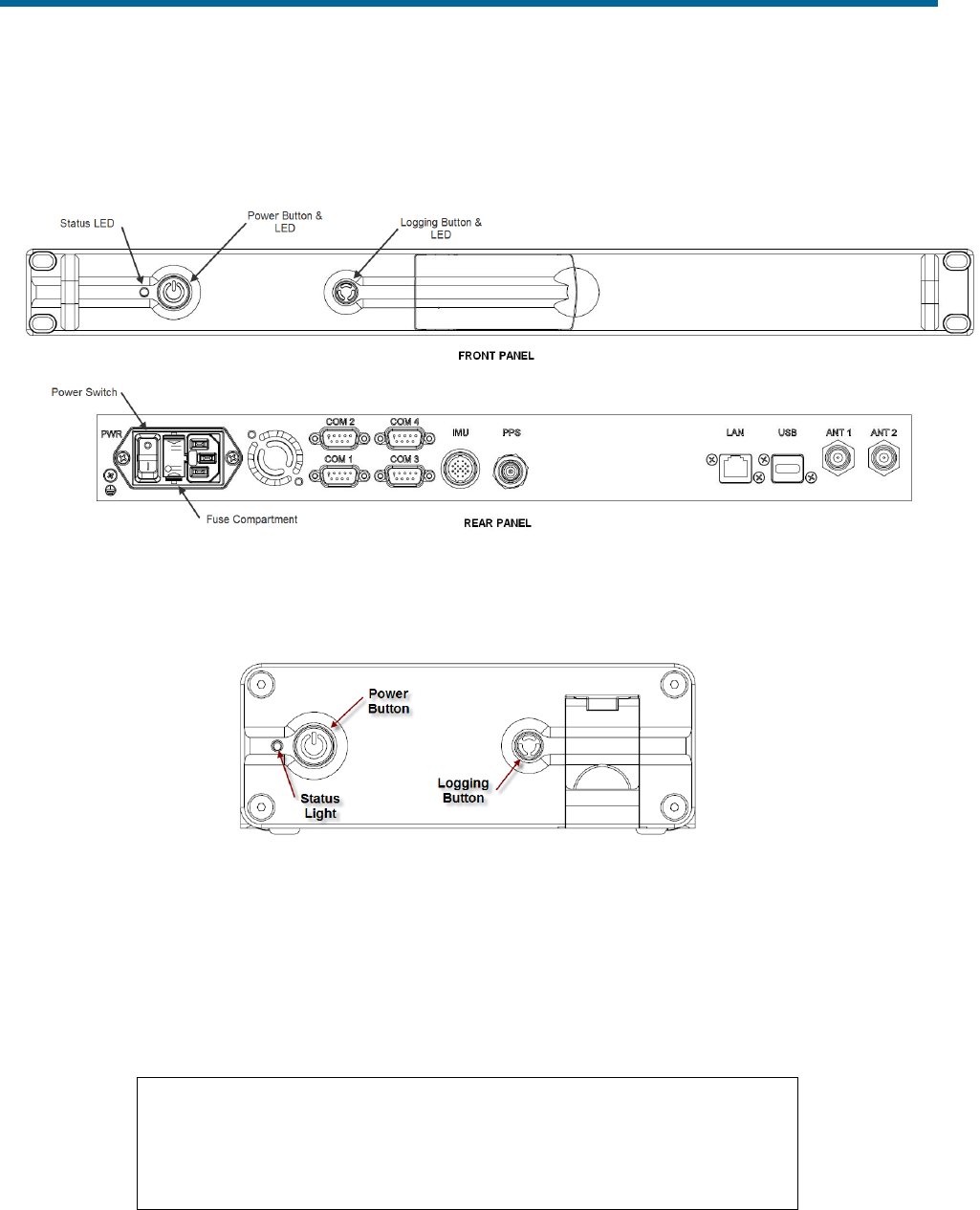
POS MV V5 Installation and Operation Guide
System Configuration
4-2
indicating that the PCS is powered-on. To power-off, press and hold the POWER switch until the light
starts blinking, then release the switch.
Figure 14: PCS Front and Rear Panels - POS MV V5
Figure 15: POS MV PCS V5-1 PCS Front Panel
Front Panel Status LEDs
Table 34 identifies the functions and status of the various PCS front panel lights.
Table 34: PCS Front Panel Lights
Status light - indicates current status of POS MV:
Steady red:
POS MV failure - shows red when PCS is first
powered-on. Changes to a valid condition when PCS
internal program begins to run, but will turn red again
if there is a fault in PCS.

POS MV V5 Installation and Operation Guide
System Configuration
Copyright © Applanix Corporation, 2012
4-3
If a fault occurs, do not power-off PCS. Refer to
Fault Detection window of controller program, see
Fault Identification topic starting on page 9-3.
Steady amber:
Standby mode - POS MV is waiting for instructions.
Flashing amber:
Navigate mode - initialising and aligning attitude
(coarse levelling).
Flashing green:
Navigate mode - degraded attitude performance.
Attitude measurements are acceptable but do not
meet user-set accuracy limits.
Steady green:
Navigate mode - normal system operation. System
meets accuracy limits set by user for position,
velocity, attitude and heading.
Logging light - indicates status of removable logging device.
Steady green:
Removable logging device is active and recording
data.
Steady amber:
Logging media is > 80% full.
Steady red:
Logging has failed – check that there is a USB flash
drive in the logging bay and that the device is not
full.
Power light - illuminates when the PCS is operating.
Initial Power-On Considerations
The POS MV AutoStart feature is enabled prior to shipment from Applanix. The system will transition to
navigate mode automatically after start-up.
Before the system can successfully navigate for first time, the installation parameters measured during
the installation procedures need to be entered; refer to Installation Parameters on page 2-24.
Use the MV-POSView Controller program to enter this information. Save these parameters to NVM if you
require the system to use the same configuration after each power-on sequence. POS MV retrieves these
details from memory after a power-up or after a reset command. Refer to the POS MV Configuration
description on page 4-7 for instructions on configuring the system with installation parameters using the
MV-POSView Controller program.
MV-POSView Controller Program
Refer to the Software Installation appendix, page D-1, for instructions on installing the MV-POSView
Controller program on a PC.
The following assumes that the controlling PC has a suitable version of windows installed and that you
are familiar with its operation. If necessary, refer to the manuals supplied with the controlling PC for
instructions on how to use your version of windows.

POS MV V5 Installation and Operation Guide
System Configuration
4-4
• Connect the PCS and the controlling PC to the 10/100/1000 BaseT Ethernet LAN
• Power-on the PCS and the controlling PC, and start Microsoft Windows®; from windows, launch
the MV-POSView Controller program
MV-POSView connects automatically and starts to display information broadcast by the PCS over the
Ethernet if you have installed and configured the PCS, the controlling PC and the MV-POSView
Controller correctly.
The controller program can operate in either of two modes:
• Monitor mode - the MV-POSView Controller program displays all PCS data that is broadcast over
the Ethernet, however, changes to any of the PCS settings cannot be made. This mode allows
several users to monitor the PCS data simultaneously.
• Control mode - the MV-POSView Controller program displays all PCS data that is broadcast over
the Ethernet, and allows changes to the system configuration and the saving of new
configurations to NVM. Only one MV-POSView Controller program can control a given POS at
any time.
MV-POSView Controller - Initial Use
Note: Certain MV-POSView windows have an icon in the lower left corner. They are either all
locked (password protected) or all unlocked (no password). Refer to the Password Protection
description on page 4-27 for more details.
When you install and operate the POS MV for the first time, perform the procedures described in the
following paragraphs.
PCS IP Address
Applanix sets the IP address of the PCS to 192.168.53.100 and the subnet mask to 255.255.255.0.
Initially, to communicate with the PCS, you must give the controlling PC a unique address within the
same subnet. Applanix recommends using address 192.168.53.101.
IP Addresses
IP addresses consist of four sets of numbers separated by full
stops (e.g. 192.168.53.100). The first three sets of numbers are
the network part of the address and the last set of numbers is the
host part. For example, 192.168.53 are the default value for the
PCS network IP address and 100 is the default value for the PCS
host.

POS MV V5 Installation and Operation Guide
System Configuration
Copyright © Applanix Corporation, 2012
4-5
To be compatible with a network the first two sets of numbers in
the IP addresses of all items attached to the network must be the
same.
Once communication with the PCS is established you can change the IP address of the PCS to any
suitable address within your subnet. The IP address of the controlling PC may also be reset back to the
original setting. The following paragraphs provide instructions on doing this.
Running the MV-POSView Controller Program
Check the MV-POSView Controller program main window (illustrated in
Figure 35 on page 5-3) for update activity; the window should update at one-second intervals. If not,
check that the LAN light, located on the front panel of the PCS, is flashing green.
Changing Address
It is unlikely that the default IP address of the PCS will be compatible with your local area network.
Therefore, you must change the system IP address before you can exercise control over the POS MV.
Follow the instructions below carefully, noting that you must begin all menu selections from the main
window of the controller.
a) Power-on the PCS, open Windows® and start MV-POSView.
b) On the MV-POSView menu bar, select Tools, Connect.
c) The tool bar shows the current IP address of the PCS Ethernet connection (this address may not
be compatible with your network). Make a written note of this address so that you can change the
address of the controlling PC temporarily to a compatible one. This must be done before you can
communicate with the PCS through the LAN.
d) In MV-POSView, select File, Exit (or press the Alt, F4 keys) to exit MV-POSView.
e) Select the configure option from the Ethernet driver software included with your Windows®
environment.
f) Note the original IP address of the controlling PC so that you can change it back once you have
changed the PCS address.
g) Change the IP address of the controlling PC to one that has the same network identity as the
PCS. Set a new and unique address for the controlling PC (e.g. set the PC to IP address
129.100.1.230).
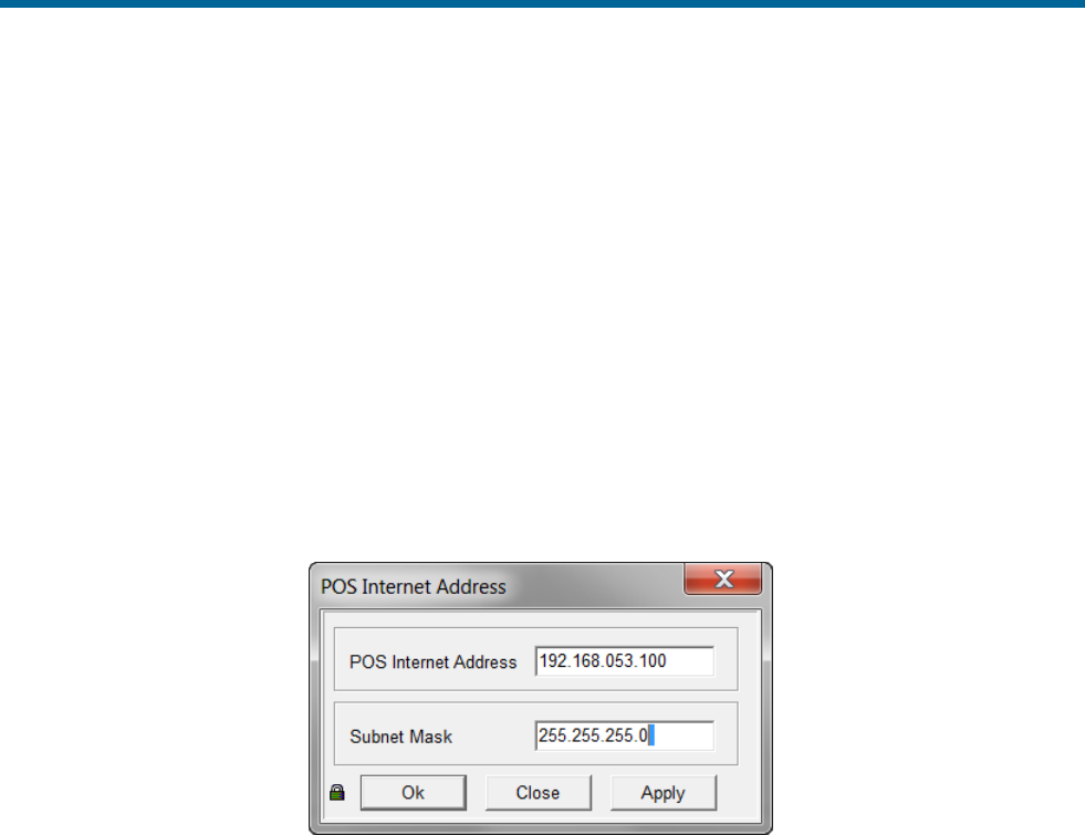
POS MV V5 Installation and Operation Guide
System Configuration
4-6
h) For some versions of Windows®, the new IP address does not become active until you have
rebooted the PC - Exit Windows® and power-off the controlling PC; wait thirty seconds and
power-on the PC again.
i) Run Windows® and start MV-POSView. In MV-POSView, select Tools, Connect.
j) On MV-POSView menu bar, select Settings, Installation, POS IP Address and insert a new IP
address and/or subnet mask, see Figure 16. The new address must be valid for the network on
which you will operate the PCS. Press the OK button.
k) The new IP address for the PCS will take effect immediately and a ‘Lost connection with POS’
message is displayed at the controlling PC.
l) At the controlling PC, select File, Exit (or press the Alt, F4 keys) to exit the MV-POSView
Controller program.
Figure 16: POSView POS Internet Address
m) Follow the instructions in steps e) and g) above and reset the controlling PC to its original IP
address.
n) Exit Windows® and power-off the controlling PC. Wait thirty seconds and power-on the PC. The
new IP addresses become active during the PC reboot sequence.
o) At completion of the reboot sequence:
• The IP address of the PCS is set to be compatible with your network
• The original IP address to the controlling PC is restored

POS MV V5 Installation and Operation Guide
System Configuration
Copyright © Applanix Corporation, 2012
4-7
POS MV Configuration
Once the POS MV components are installed and the physical installation parameters measured, these
measurements are then entered in to the MV-POSView Controller program. The PCS stores this data in
non-volatile memory for use on subsequent start-ups of POS MV.
The POS MV has a built-in feature that permits automatic fine-tuning of the configuration data. However,
the more accurate the initial physical measurements are the quicker the automatic fine-tuning process.
Figure 17 outlines the configuration data refinement process.
Measure
Installation
Parameters
& Record
Configuration
Data
(Section 2)
Enter Initial
Configuration
Data into
MV-POSView
(Section 4)
Automatic
Fine-tuning of
Configuration
Data
(Section 4)
Auto
Calibration
Vessel
Prescribes a
Figure Eight
Figure 17: Configuration Data Refinement
Automatic fine-tuning permits the accurate measurement of the longitudinal, lateral and vertical distances
between the installed components. Accurate manual measurements are often difficult to obtain and are
subject to errors caused by accessibility. If it is not possible to measure the installation parameters to
within Real-Time Kinematic (RTK) level accuracy (about 2 cm) then the automatic lever arm calibration
feature should be used to improve accuracy. Although only the Reference to Primary GNSS
measurement is presently available, other automatic measurements will be available in the future.
Set the initial configuration of POS MV by performing the following.
a) Connect the PCS and the controlling PC to the 10/100BaseT Ethernet LAN. Both must have
compatible IP addresses; if necessary refer to the Changing Address description on page 4-5 for
instructions on IP addressing.
b) Power-on the PCS and the controlling PC, and start Microsoft Windows®; from windows, launch
the MV-POSView Controller program.
c) Select Tools, Connect on the MV-POSView main window menu bar.
Configuration Data
To configure the POS MV consult the list of installation parameters that was created as you progressed
through the physical installation. Refer to the Installation Parameters description starting on page 2-24 for
detailed instructions.
Configuration - Initial
Note: Select the standby mode prior to changing lever arm or mounting angle values.
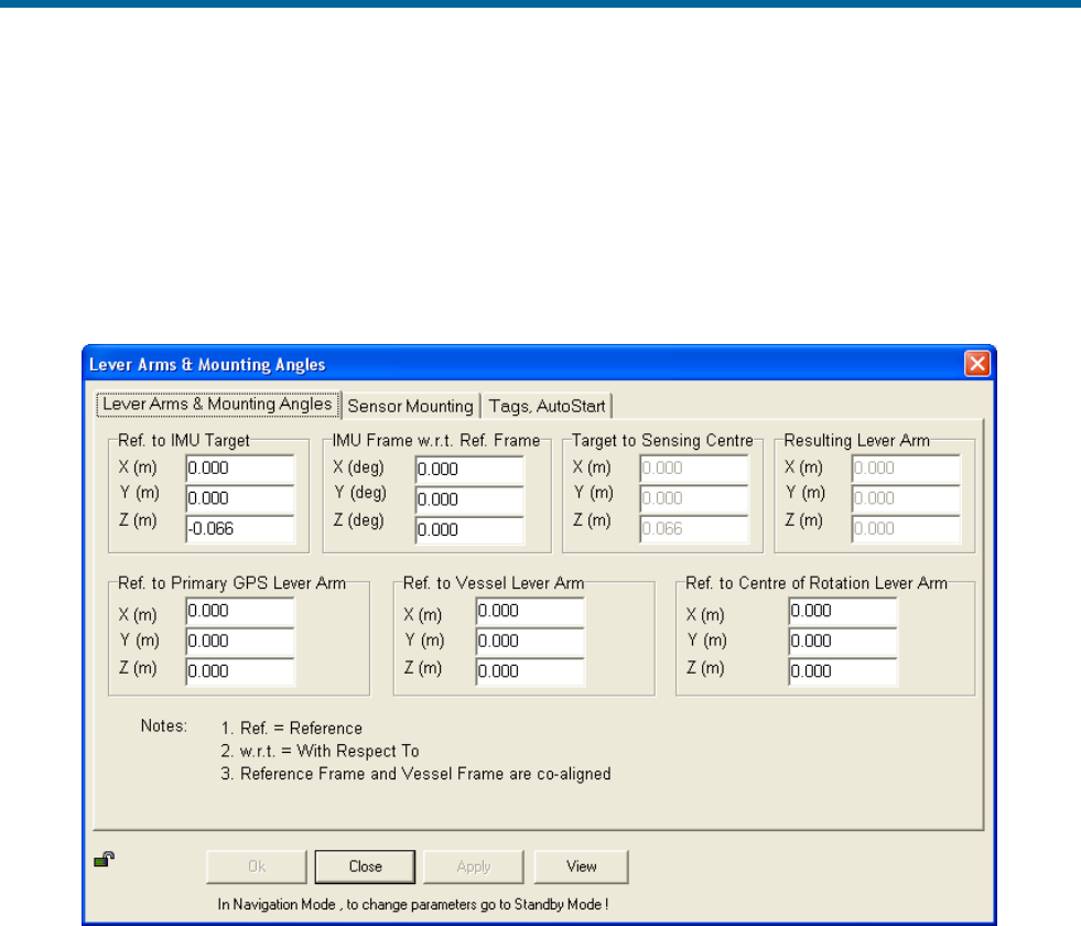
POS MV V5 Installation and Operation Guide
System Configuration
4-8
From the menu bar of the MV-POSView Controller program, select Settings, Installation, Lever Arms &
Mounting; the Lever Arms & Mounting Angles tab is displayed (see Figure 18). Use metres for lever
arm distances and degrees for misalignment angles.
In circumstances where you do not have the complete set of installation parameters, you must at least
enter values in the Ref. to IMU Lever Arm and the Ref. to primary GNSS Lever Arm panes. This basic
information allows the system to supply useful data to the multibeam sonar.
Figure 18: POSView Lever Arms & Mounting Angles Tab
Next, select the Sensor Mounting tab (Figure 19) and enter the values for the lever arm distances and
mounting angles. Once these values are entered, select the OK button.
Note: These settings become active immediately. To save the settings to non-volatile memory, select
Settings, Save Settings. This permits the system to initialize using these installation parameters
whenever the PCS is powered-on.
Note: Any changes made to the IMU or the Global Navigation Satellite System (GNSS) lever arm
parameters will cause the fields to reset and begin again automatically.
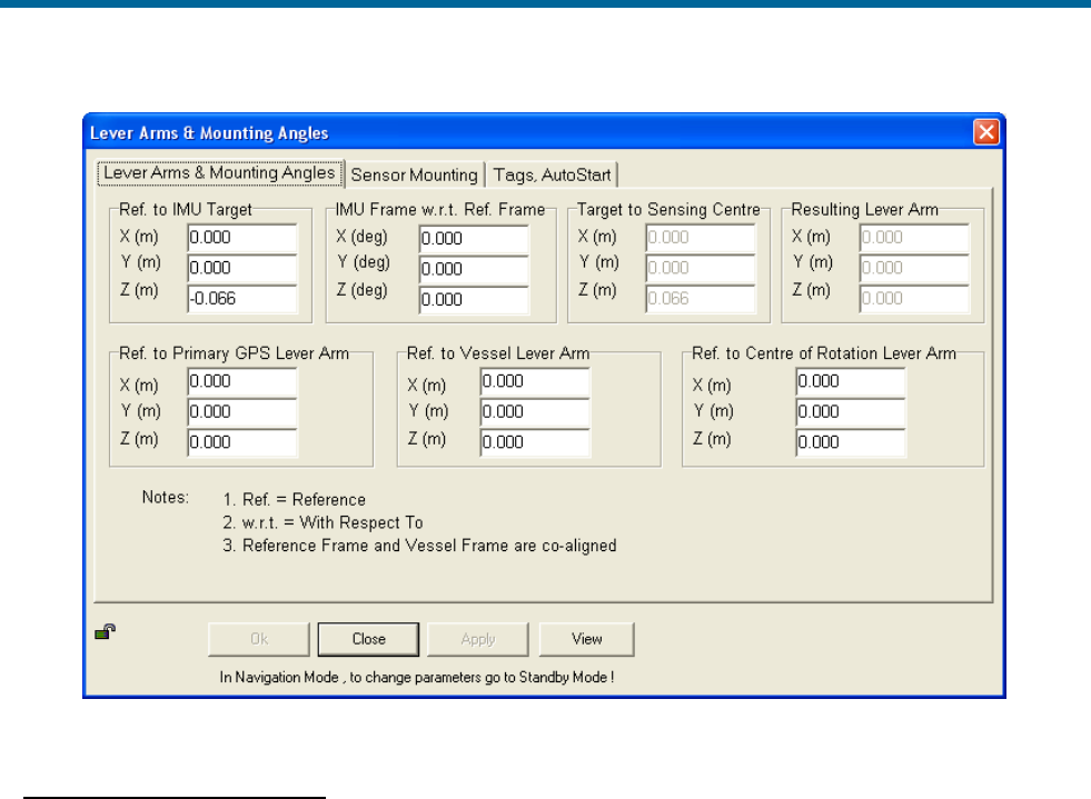
POS MV V5 Installation and Operation Guide
System Configuration
Copyright © Applanix Corporation, 2012
4-9
Figure 19: POSView Sensor Mounting Tab
Configuration - Automatic
Note: Perform a GNSS Azimuth Measurement Subsystem (GAMS) calibration prior to running this
procedure, see Antenna Installation Calibration on page 4-18.
Note: The integrated navigation solution should be delivering a RTK solution; may be tightly coupled or
using an auxiliary RTK GNSS receiver. The Nav Status (MV-POSView Status pane) indicates FLOAT
RTK or FIXED RTK.
Ensure that GAMS is on-line then select Settings, Installation, Installation Calibration Control from
the menu bar of the MV-POSView Controller program. The Calibration Control window is displayed
(Figure 20).
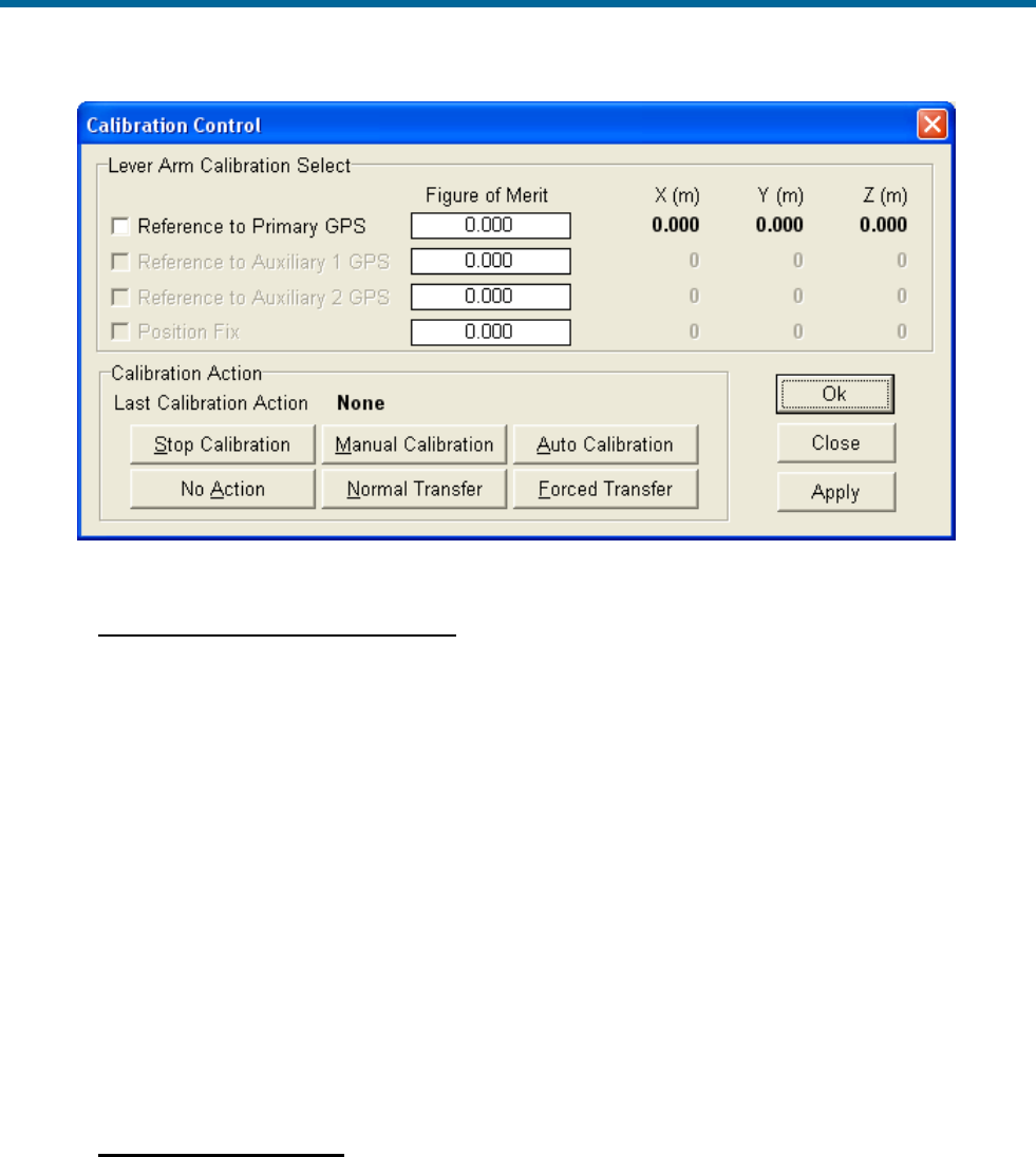
POS MV V5 Installation and Operation Guide
System Configuration
4-10
Figure 20: Calibration Control Screen
LEVER ARM CALIBRATION SELECT PANE
Note: The Figure of Merit (FOM) may not reach 100 if the vessel dynamics (speed and rate of
turn) are not great enough, the GNSS coverage is not good or the base corrections are not
reliably received.
Figure of Merit field - indicates the completeness of the correction level of the selected
parameter; the calibration (X, Y and Z) are complete when FOM reaches 100
X, Y, Z fields - computed values are complete when the Figure of Merit reaches 100 and the
field values stop changing; the field values may not correspond with the measured values
Reference to Primary GNSS check box - select to compute corrected values
Reference to Auxiliary 1 GNSS check box - not enabled
Reference to Auxiliary 2 GNSS check box - not enabled
Position Fix check box - not enabled
CALIBRATION ACTION PANE
Last Calibration Action field - indicates the last action performed
Stop Calibration button - select to stop the selected calibration action
Manual Calibration button - (only use for special situations) select to start the manual
calibration procedure; vessel must prescribe a loose figure eight pattern; the FOM reaches

POS MV V5 Installation and Operation Guide
System Configuration
Copyright © Applanix Corporation, 2012
4-11
100 and continues to update the X, Y, Z fields; next command would be Normal Transfer of
calibrated parameters
Auto Calibration button - (preferred) select to start the auto calibration procedure; vessel
must prescribe a loose figure eight pattern; once the corrections are complete they become
active, the Kalman filter is reset and POS restarts in the Navigate mode
No Action button - select to cancel all calibration actions
Normal Transfer button - select to make the Manual Calibration corrections active; the
Kalman filter is reset and POS restarts in the Navigate mode
Forced Transfer button - select to make the corrections active (FOM must be >0 and <100);
the Kalman filter is reset and POS restarts in the Navigate mode
COMMAND BUTTONS
OK button - enables all window parameter settings and closes the window, calibration does
not start
Close button - closes the window without saving or enabling any changes
Apply button - enables all window parameter settings, but does not close the window,
calibration does not start
Time Tags
POS attaches time tags to all of its outputs to permit synchronization with data from other sensors or
systems. The time tag is based on Universal Time Coordinated (UTC), GNSS, POS or User time; has a
resolution of 1 µs; and has an accuracy of less than 10 µs.
Select Settings, Installation, Tags & AutoStart on the MV-POSView Controller menu bar to display
(Figure 21) the settings.
Note: UTC and GPS Times are not identical. Due to the occasional need for the addition of a leap
second to UTC, there is an integer difference between UTC and GPS Time. Transitions between the
seconds are precisely coincident between the two times.
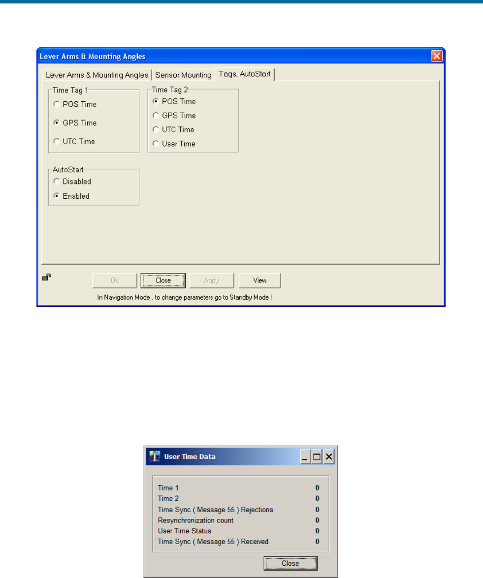
POS MV V5 Installation and Operation Guide
System Configuration
4-12
Figure 21: Controller Tags, Multipath & AutoStart Tab
The User Time Data screen (Figure 22) on the controller shows the status of the user time
synchronization; select View, User Time Data. The user's equipment can send message 55 (see
POS MV V5 User Interface Control Document [Applanix document control number - PUBS-ICD-004089])
with their own time recovery time and POS will create an internal offset. Also, the user can then select the
User Time (Figure 21) to be output in the time ‘2’ field of ICD groups. This feature allows the user to
synchronize with a time base other than POS, GNSS or UTC. If more information is required, please
contact Applanix customer support, see page A-1 for contact details.
Figure 22: User Time Data Screen

POS MV V5 Installation and Operation Guide
System Configuration
Copyright © Applanix Corporation, 2012
4-13
AutoStart
AutoStart is a feature of POS MV that allows operation in a stand-alone configuration. With AutoStart
enabled, POS MV will transition to navigate mode after power-on, without operator intervention.
• With AutoStart enabled, POS MV will transition to navigate mode each time the PCS is powered-
on. In this configuration, the PCS can operate independently without the need for a controlling
PC.
• With AutoStart disabled, the system will remain in standby mode after power-on. The operator
must issue a command from the controlling PC, via the controller program, to make the system
transition to navigate mode.
To enable AutoStart, select Settings, Installation, Lever Arms & Mounting from the MV-POSView
menu bar, then select the Tags, Multipath and AutoStart tab and click the Enabled option button in the
AutoStart pane, see Figure 21. Select the OK button to accept the change.
Note: The AutoStart configuration change must be saved to NVM to retain its new setting when POS MV
is powered-on again; refer to the 4-17
description on page 4-16 for instructions.
Input/Output Ports Set-up
The Input/Output Ports Set-up screen shown in Figure 23 is accessed from the MV-POSView menu bar
by selecting Settings, Input/Output Ports. Configuration of each of the four serial COM ports is
performed on the screen tabs. The following lists the configuration choices:
• Selecting the input and output functionality for each port
• Setting the update rate for selected output data formats
• Setting the baud rate for the ports
• Setting the protocol and flow control for COM 1 and 2
• Selecting RS232 or RS422 interface for COM 3 and 4
COM Port Set-up
Select a tab for the COM port to be configured. All COM ports allow selection of Baud Rate. COM 1 and
2 allow selection of Parity, Data Bits, Stop Bits and Flow Control (Figure 23). COM 3 and 4 allow
selection of the physical Interface (Figure 24). Settings that are not available on a particular COM port
tab will be hidden or dim and not selectable.
Any input or output can be selected from the drop down menus for a given COM port (click on the down
arrow). A context sensitive pane will appear once an input or output selection has been made, as
described in the following sections.
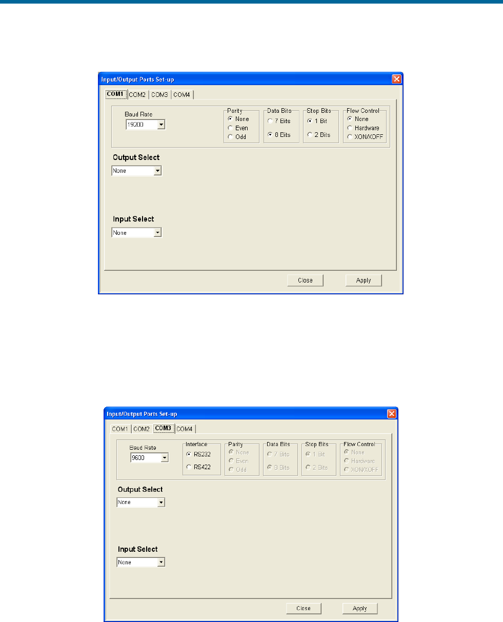
POS MV V5 Installation and Operation Guide
System Configuration
4-14
Figure 23: Input/Output Ports Set-up – COM1
Some interfaces require bi-directional communications, in which case a selection in either the Input or
Output menu will result in the automatic assignment of the corresponding Output or Input for that COM
port. For interfaces that require only uni-directional communications it is possible to assign an input and
an output simultaneously on a COM port, but a ‘Y’ cable is required to split the transmit (Tx) and receive
(Rx) lines to the two separate devices. A ‘Y’ cable is not included as part of the system.
Figure 24: Input/Output Ports Set-up – COM3
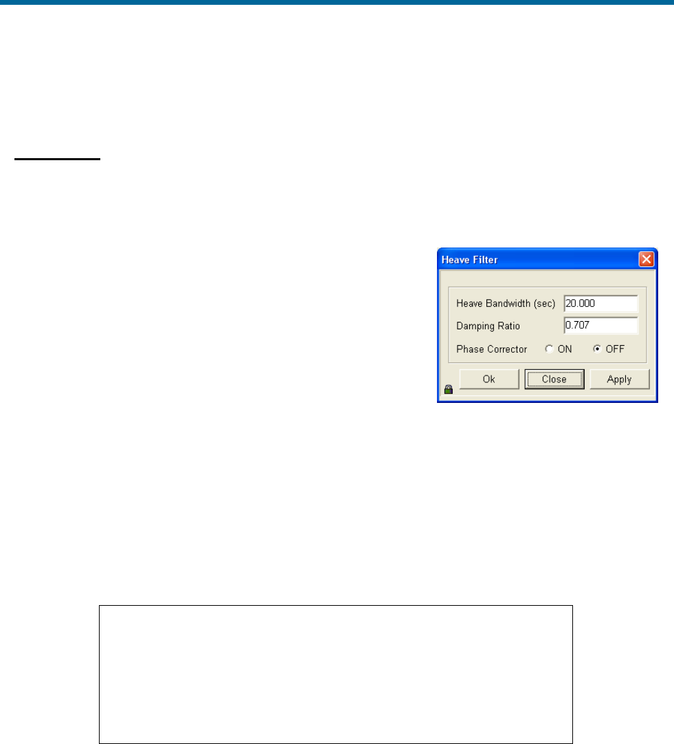
POS MV V5 Installation and Operation Guide
System Configuration
Copyright © Applanix Corporation, 2012
4-15
To accept the screen parameters, click the Apply button. To abort
any changes or to close the screen, click the Close button.
Heave Filter
Certain characteristics of the POS MV heave filter can be adjusted to obtain the best compromise
between steady-state heave error and the time that the filter takes to settle after abrupt changes in
vertical displacement; refer to Figure 25. You may have to modify the characteristics of the heave filter,
for example, to allow for the dynamic characteristics of different
vessels, variations of sea state or to meet the particular
requirements of a survey.
Optimum settings for the heave filter can depend upon a number of
factors, including the size and weight of the vessel, the weather
conditions in the survey area and the direction of travel into the sea.
Refer to the Theory of Operation description starting on page B-1
for a more detailed explanation of heave filter settings.
The default settings for the heave filter have proved to be satisfactory for use with a wide range of vessel
characteristics and across a broad spectrum of sea states:
• Heave bandwidth = 20.00 seconds. You can set the heave bandwidth to any positive number
greater than 1.0.
• Damping ratio = 0.707. You can set the damping ratio to any positive number less than 1.0.
Important
Although you cannot harm any part of the POS MV by changing the
heave filter characteristics, inappropriate values for heave bandwidth
and damping factor can severely degrade the measurement
performance.
Do not alter the characteristics of the heave filter unless you are
entirely confident that your changes will improve the performance of
the system for a given set of survey conditions.
Note: Save the settings to NVM so that they are effective next time POS MV is powered-up. Refer to the
Save Settings topic on page 4-17 for instructions. Settings become active once the OK or the Apply
button is pressed.
To modify the characteristics of the heave filter select Settings, Heave from the menu bar of the MV-
POSView Controller program. Enter appropriate values into the Heave Bandwidth and Damping Ratio
fields of the Heave Filter pane. Select the OK button to activate the settings and close the dialogue box.
Figure 25: POSView Heave Filter
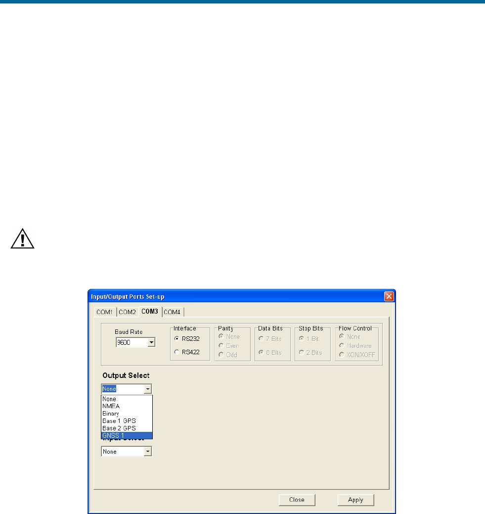
POS MV V5 Installation and Operation Guide
System Configuration
4-16
Refer to the Reference to Centre of Rotation instructions on page 2-28 for an explanation of the method
that POS MV uses to measure and filter heave values.
The Z Altitude option allows the user to replace the heave filter with an inertial smoothed RTK height in
the chosen output string.
GNSS 1/2 Interface
The PCS provides a mechanism to connect directly to the internal GNSS receivers’ COM ports through
the external COM 3 and COM 4 ports. This is a bi-directional RS232 link so both input and output are
automatically assigned when either one is selected. GNSS 1 is accessible through COM 3 (Figure 26)
and GNSS 2 is accessible through COM 4 (Figure 27).
The purpose of this link is to allow field upgrades of the GNSS receiver firmware if necessary. This
connection could also be used to output data directly from the GNSS if configured to do so.
Applying a configuration to the internal GNSS via the COM port must be done with extreme care so as
not to interfere with the PCS configuration. Contact Applanix customer support for assistance.
Figure 26: Input/Output Ports Set-up – GNSS 1 Interface
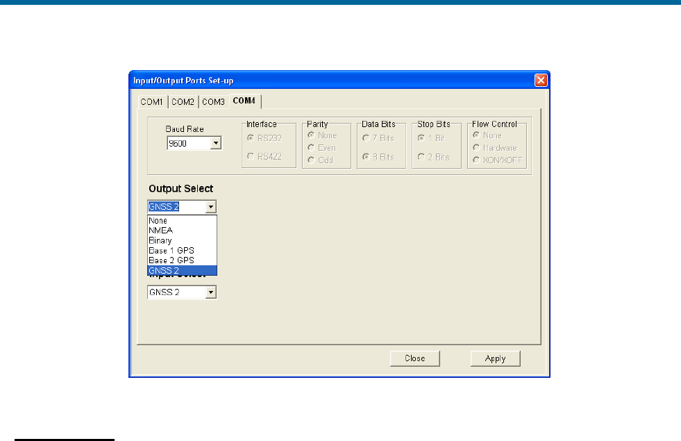
POS MV V5 Installation and Operation Guide
System Configuration
Copyright © Applanix Corporation, 2012
4-17
Figure 27: Input/Output Ports Set-up – GNSS 2 Interface
Save Settings
Changes made to the POS MV parameters will have an immediate effect on system operation. However,
if you require the changes to apply to all future occasions when you power-on the POS MV, you must
save them to NVM.
The non-volatile memory is resident in the PCS so that all stored operating parameters will be available to
the system during the start-up sequence, even when it operates in a stand-alone configuration.
To save the system parameters to NVM, select Settings, Save Settings from the MV-POSView menu
bar.
Note: If you do not save any new settings for the installation parameters to NVM, POS MV will apply the
values stored previously (or the factory default values) when you next power-on the system.
Initial GNSS Configuration
Applanix supplies POS MV with two GNSS receiver cards installed in the PCS and optimally configured
for use with the system.
If either of the GNSS receivers loses its configuration for any reason, the PCS will reconfigure the
receiver cards automatically for its own use. The messages supplied by the GNSS receivers are only
those required by POS MV.
If you ever need to configure the installed GNSS receivers manually, you must select Tools, Configure
GNSS from the menu bar window of the MV-POSView Controller program.
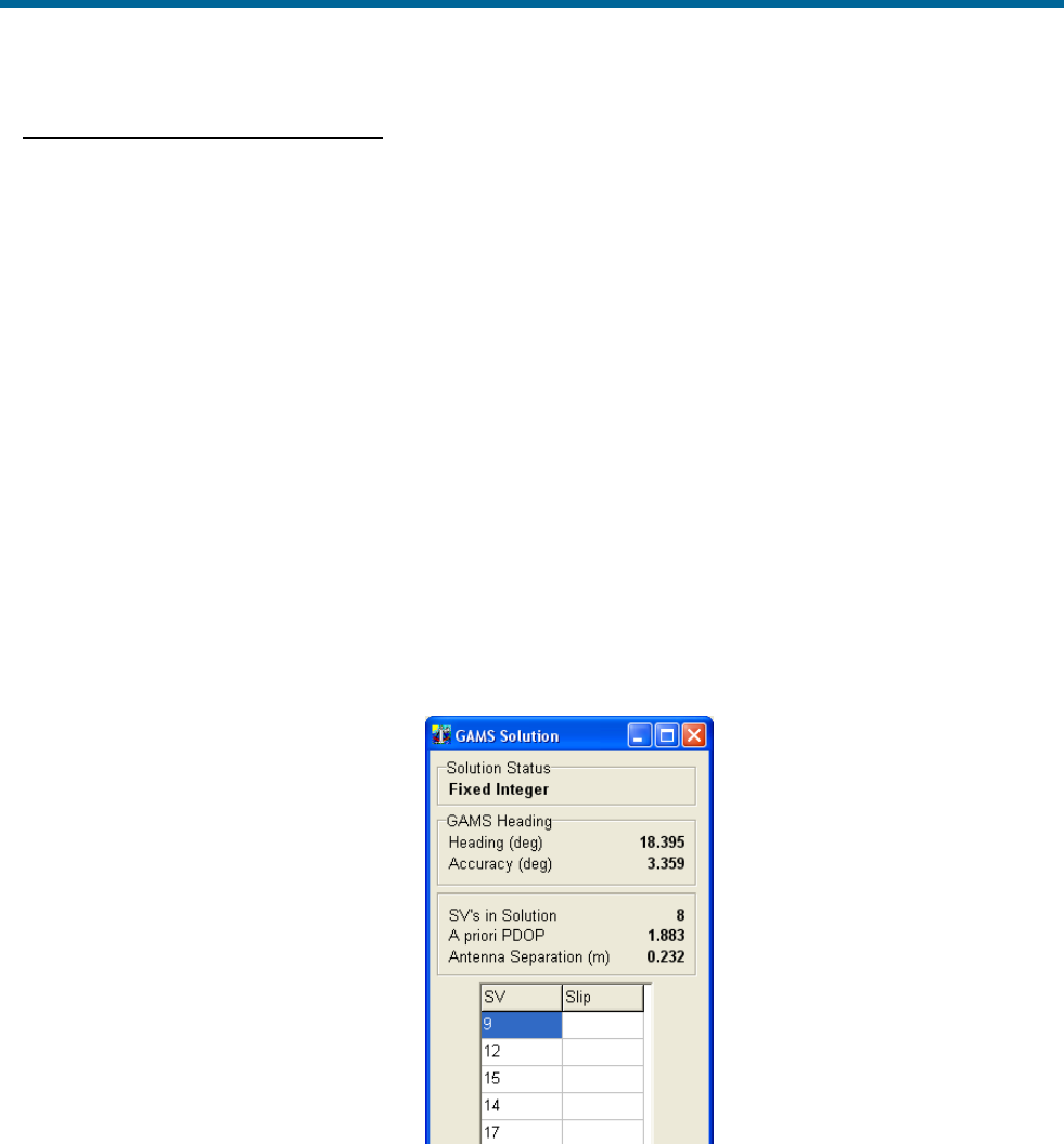
POS MV V5 Installation and Operation Guide
System Configuration
4-18
Antenna Installation Calibration
A successful antenna installation calibration depends upon the GNSS Azimuth Measurement Subsystem
(GAMS) being able to use data from five or more satellites with a Positional Dilution of Precision (PDOP)
equal to or less than three. Perform the antenna installation calibration at a time when there is good
satellite geometry.
Note: Applanix recommends that the user make use of the GNSS mission planning software to identify
an optimal time of day during which the PDOP is at a minimum in order to achieve a good GAMS
calibration.
Perform the following steps with the vessel under way in an area where unrestricted manoeuvring is
possible. You have the option of allowing POS MV to start the calibration automatically (this is called a
calibration auto-start) or to start the calibration manually.
1. Ensure that MV-POSView is Connected as indicated in the status bar, refer to
2. Figure 35 on page 5-3.
3. Select View, GAMS Solution from the menu bar to open POS MV GAMS Solution window
shown in Figure 28.
Figure 28: GAMS Solution Status
4. Transition the system to standby mode by selecting the Standby icon from the MV-POSView tool
bar.
5. Select Settings, Installation, GAMS Parameter Setup from the menu bar to open the GAMS
Parameter Setup window shown in Figure 29.
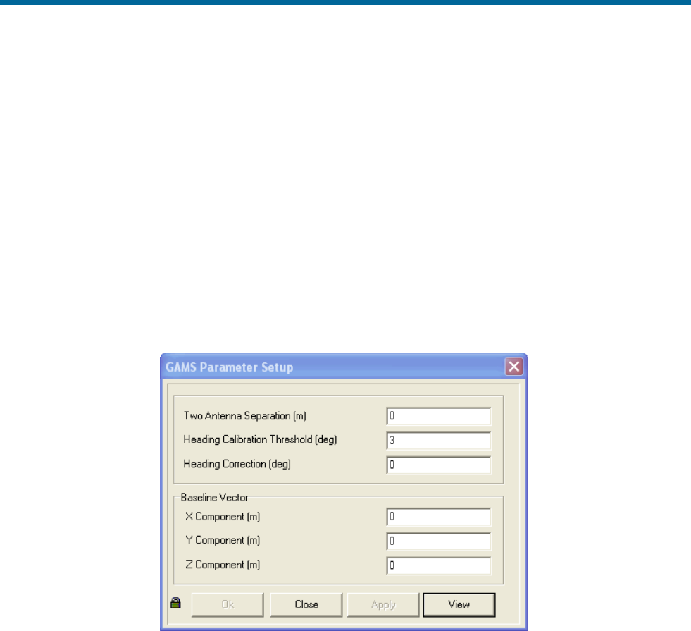
POS MV V5 Installation and Operation Guide
System Configuration
Copyright © Applanix Corporation, 2012
4-19
6. In the GAMS Parameter Setup window, enter a value in the Heading Calibration Threshold
field that represents the best achievable with the vessel, ideally 0.5° or less. Select the OK
button.
When the indicated Heading Accuracy (Attitude pane on the controller main window) falls
below the setting in the Heading Calibration Threshold field and the GAMS status (main
window Status pane) reads Ready Offline, POS MV will start the antenna installation calibration
routine. Choose an easy value for POS MV to achieve as you perform a series of calibration
manoeuvres with the vessel:
• Set a lower value (approximately 0.2°) if you can manoeuvre the vessel aggressively.
• Conversely, set a higher value (approximately 1°) if the most aggressive manoeuvres you
can perform are 180° turns followed by a straight run.
Figure 29: POSView GAMS Parameters Setup
7. Perform the following in the GAMS Parameter Setup window:
a) In most cases, this value is entered as ‘0’. Only if you are able to measure the antenna
separation to 1 mm accuracy should you enter a value here.
Refer to the Installation Checklist on page 2-32 for instructions on how to measure the
antenna separation distance.
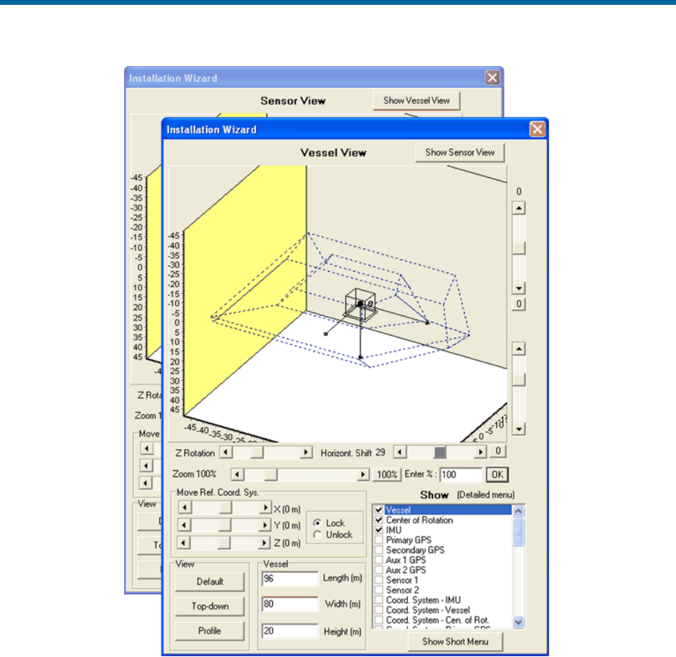
POS MV V5 Installation and Operation Guide
System Configuration
4-20
Figure 30: POSView GAMS Installation Wizard
b) In each of the component fields in the Baseline Vector pane, enter ‘0’. Select the Apply and
OK buttons.
8. Manually transition POS MV to the navigate mode. This also commands GAMS to begin
execution of its on-the-fly (OTF) ambiguity resolution algorithm.
9. Next, perform either the auto-start calibration (steps 10 and 11)or the manual calibration
procedure (steps 12 and 13).

POS MV V5 Installation and Operation Guide
System Configuration
Copyright © Applanix Corporation, 2012
4-21
AUTO-START CALIBRATION PROCEDURE
10. Select Settings, GAMS Calibration Control, Start from the MV-POSView menu bar (Figure 31,
page 4-22). The Status pane for GAMS indicates CAL Requested (Figure 31, page 4-22).
The Start command prepares the system for an automatic start to the calibration process, but
does not actually start it. Instead, the calibration process will start automatically when the POS
MV RMS heading error falls below the value that you set for the Heading Calibration Threshold
field in step 6 above.
11. If possible, when GAMS has resolved the carrier phase ambiguities (GAMS on the main window
Status pane reads Ready Offline), perform a series of full turns, ‘S-turns’ or ‘Figure-8’
manoeuvres, each lasting approximately one minute.
During these manoeuvres, monitor the POS MV Heading Accuracy field on the MV-POSView
main window Attitude pane (Figure 31, page 4-22). When the value displayed falls below the
setting for the Heading Calibration Threshold field (Figure 29), finish the turns and manoeuvres
and hold the vessel steady on a course and at a fixed speed.
The Status pane for GAMS now indicates CAL in Progress and this condition lasts for
approximately 60 seconds. When POS MV has completed the calibration, the displayed GAMS
status becomes CAL Completed. This condition lasts for approximately five seconds and then
changes to Online.
See Options starting with step 14.
MANUAL CALIBRATION PROCEDURE
Note: Before proceeding ensure the GAMS Parameters Setup window displays the values that you
entered in step 6 above.
12. When GAMS has resolved the carrier phase ambiguities, the Status pane for GAMS indicates
Ready Offline (Figure 31, page 4-22). You can start the calibration manually at any time.
If possible, perform a series of full turns, ‘S-turns’ or ‘Figure-8’ manoeuvres, each lasting
approximately one minute. During these manoeuvres, monitor the POS MV Heading Accuracy
on the MV-POSView main window Attitude pane (Figure 31, page 4-22). Ideally, the heading
accuracy displayed should be as small as possible.
Wait until the heading error becomes as small as possible before starting the calibration. Simple
manoeuvres of the vessel, such as a change of course, will cause the heading accuracy to
improve.
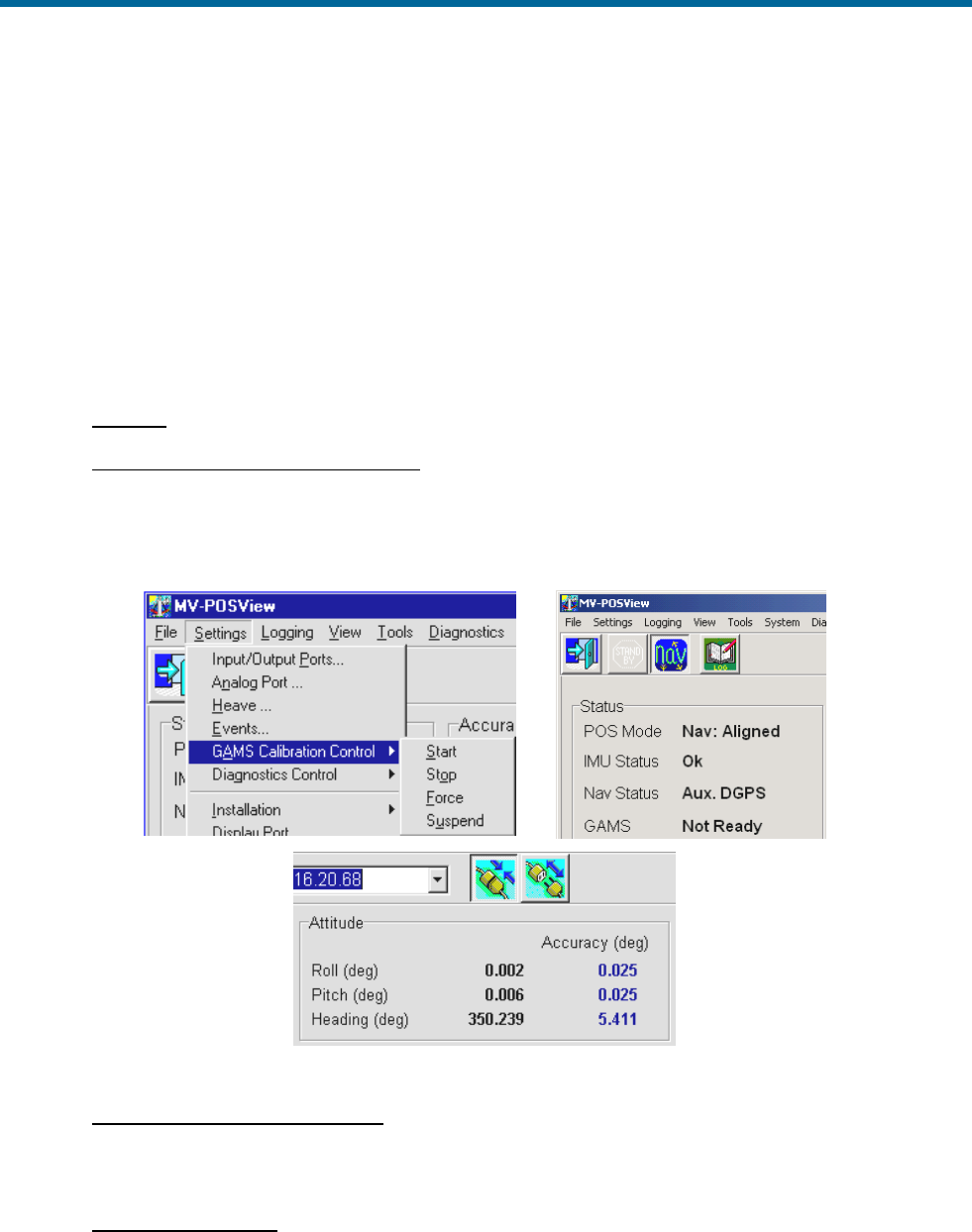
POS MV V5 Installation and Operation Guide
System Configuration
4-22
13. To start the manual calibration, select Settings, GAMS Calibration Control, Force from the MV-
POSView menu bar (Figure 31, page 4-22). This commands an immediate start of the calibration
process.
The Status pane for GAMS indicates CAL in Progress and this condition lasts for approximately
60 seconds. When POS MV has completed the calibration, the displayed GAMS status becomes
CAL Completed. This condition lasts for approximately five seconds and then changes to
Online.
See Options starting with step 14.
OPTIONS
14. Suspend calibration while in progress: Select Settings, GAMS Calibration Control, Suspend.
The displayed GAMS status then becomes CAL Suspended.
The system suspends the partially completed calibration process until you resume it. To resume
the calibration process select Settings, GAMS Calibration Control, Start.
Figure 31: POSView Settings Menu, Status and Attitude Panes
15. Stop calibration while in progress: Select Settings, GAMS Calibration Control, Stop. The
displayed GAMS status then becomes Ready Offline. The system cancels the partially
completed calibration process.
16. Save calibration data: Select Settings, Save Settings. Wait until the MV-POSView Controller
program displays the Settings Saved message panel. Select the OK button to close the message
panel.

POS MV V5 Installation and Operation Guide
System Configuration
Copyright © Applanix Corporation, 2012
4-23
17. Monitor system operation: Indications of a successful calibration appear in the main window of
the MV-POSView Controller program:
• The Status pane for GAMS indicates Online.
• The Altitude pane Heading Accuracy field drops slowly to less than 0.15° and
eventually settles to a value of 0.03° in a low multipath environment. The actual value
that it settles to depends on the current setting for the multipath environment.
If the calibration was successful and no GNSS dropouts occurred, POS MV should settle into a
steady-state operation using the GAMS heading aiding, as indicated by the Online status.
If the calibration was not successful, GAMS will reject the carrier phase ambiguities repeatedly
and will eventually reject the installation parameters. If this occurs, repeat the calibration process.
18. Record data: If the installation parameters appear to be correct, select Settings, Installation,
GAMS Parameter Setup from the menu bar (Figure 29, page 4-19) and write down the displayed
parameters. Keep the written record in a safe place for future reference.
Refer to the Operation with GAMS topic on page 1-8 for a description of how GAMS uses the GAMS
installation parameters to aid the On-the-Fly (OTF) ambiguity search.
Installation Parameter Correction
The surveyed antenna baseline vector may include the following errors:
• The length of the vector may not be correct if there were large multipath errors during the
calibration process. This may affect the reliability of the GAMS ambiguity resolution during future
POS MV Initialization sequences.
• There may be an azimuth error similar in size to the displayed heading accuracy that existed
during the calibration process. This results in a constant offset in the displayed heading during
normal operation of the POS MV with GAMS heading aiding.
Correct these errors by:
1. If the displayed antenna separation differs by more than 5 mm (~¼ in) from the value that you
measured after you installed the antennas, clear the installation parameters and then re-enter the
measured separation distance in the GAMS Parameter Setup window, see Figure 29 on page 4-
19. Select the OK button to install the new antenna separation distance.
Begin a new calibration procedure, see Antenna Installation Calibration on page 4-18.
The 5 mm (~¼ in) allowance accounts for differences that may exist between the antenna phase
centres and their geometric centres.
POS MV V5 Installation and Operation Guide
System Configuration
4-24
2. If you can identify a heading offset then enter this value in the Heading Correction field of the
GAMS Parameter Setup window, see Figure 29 on page 4-19. Select the OK button to install the
new correction value.
POS MV will then compute new components of the surveyed antenna baseline vector having a
corrected azimuth.
3. Select Settings, Save Settings from the MV-POSView menu bar to save the new values to the
PCS Non-Volatile Memory (NVM).
Note: The Heading Correction field in the GAMS Parameter Setup window allows you to correct an
inaccurately surveyed baseline vector. You can use this method to obtain a more accurate vector.
Note: You should not use this facility to implement the installation angles of the IMU body frame with
respect to the echo-sonar frame. Refer to the Installation Parameters and the Configuration Data
descriptions on pages 2-24 and 4-7 respectively, for instructions on how to measure and enter these
installation parameters.
Power-Off
The initial power-off sequence for the POS MV system occurs in three stages:
a) Save parameter and configuration changes
b) Exit the MV-POSView Controller program and power-off the controlling PC
c) Power-off the POS MV system
Save Changes
Powering-off the PCS before the MV-POSView displays the
confirmation message panel may corrupt the settings held in
NVM.
Whenever changes are made to the POS MV installation parameters or its configuration, they must be
saved to NVM in order to retain them for the next power-on sequence.
The MV-POSView Controller program displays a message panel to confirm that it has saved the settings
successfully to NVM. Wait for this message to appear prior to powering-off the PCS or the POS MV
system.
Save Parameter Values
Select Settings, Save Settings from the MV-POSView menu bar to save all parameter settings to NVM.
Refer to the Save Settings description on page 4-26 for more information.
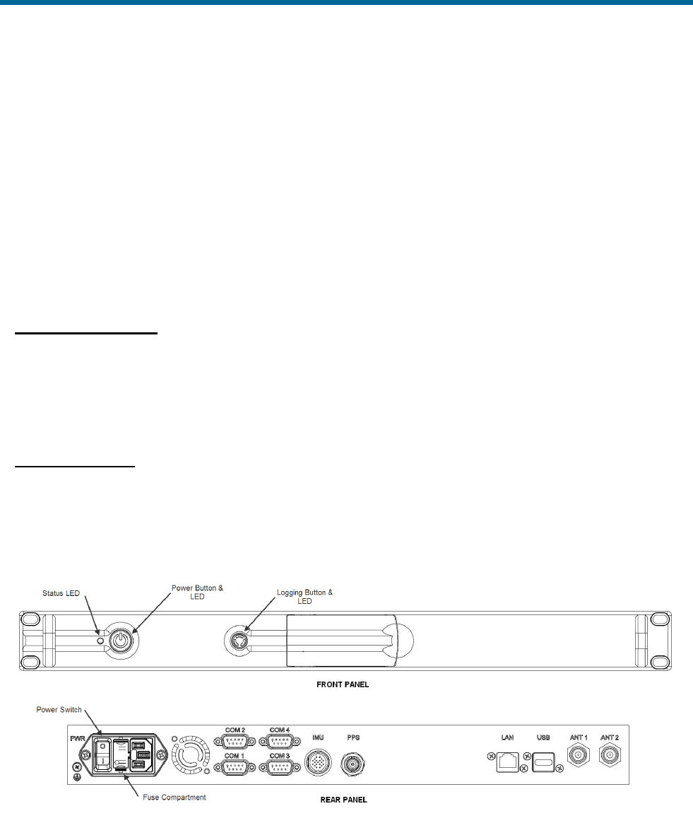
POS MV V5 Installation and Operation Guide
System Configuration
Copyright © Applanix Corporation, 2012
4-25
Perform the following to check that the PCS has stored the parameters correctly:
1. Select File, Exit (or press Alt, F4) to close the MV-POSView Controller program.
2. Press and hold the POWER switch on the PCS front panel until the POWER light starts flashing.
3. Wait thirty seconds and then press and hold the POWER switch to power-on the PCS and
illuminate the POWER light.
4. Start the MV-POSView Controller program.
5. Select Settings, GAMS Calibration Control and check that the PCS has saved all the GAMS
installation parameters correctly. Select the Cancel button.
Save Configuration
Select File, Save POS Config from the MV-POSView menu bar to save the new configuration settings to
the PC. Refer to the Manage Multiple Configurations description on page 4-27 for more information.
POS MV Power-Off
POS MV V5 PCS
Power for the POS MV V5 system is applied to the PCS rear panel PWR connector, refer to Figure 32.
Two power switches are available on the PCS; a rear panel PWR switch and a front panel POWER
switch. Refer to the POS MV Power-On description on page 4-1 for more information.
Figure 32: PCS Front and Rear Panels - POS MV V5

POS MV V5 Installation and Operation Guide
System Configuration
4-26
POS MV V5-1 PCS
Power for the POS MV V5-1 system is applied to the PCS rear panel PWR connector, refer to Figure 7.
The front panel POWER switch (Figure 33) is an alternate action push-and-hold switch; press once for
power-on, press again for power-off.
Figure 33: PCS Front Panel – POS MV V5-1
Both Systems (POS MV V5 and POS MV V5-1)
To power-off the POS MV system, perform the following steps:
1. Select File, Exit from MV-POSView menu bar to close MV-POSView Controller program.
2. Press and hold the PCS front panel POWER switch until front panel POWER light starts flashing.
3. Set PCS rear panel PWR switch to off (POS MV V5).
Leave the POS MV powered-on to reduce the electrical and
thermal stresses that occur when the system is powered-off and
powered-on.
Save Settings
Cycling power while saving may result in lost settings.
Save the POS MV parameters after any modification, otherwise changes will be lost when the POS MV
power is cycled (powered-down and up). Each time POS MV is powered up, the settings default to the
last saved values. To save these settings, select Settings, Save Settings from the MV-POSView
Controller menu bar. The MV-POSView Controller indicates when the settings are successfully saved
(may take up to 30 seconds to save the settings).

POS MV V5 Installation and Operation Guide
System Configuration
Copyright © Applanix Corporation, 2012
4-27
Making Changes
If you need to change any of the POS MV operating parameters, you must use the MV-POSView
Controller program as described throughout this section of the manual.
Any changes that you make will take effect immediately, although you must save them to NVM if you
require the changes to apply each time you power-on the system.
Note: To make any parameter changes permanent you must save them to NVM. Do this by selecting
Settings, Save Settings from the main window of the controller program.
Manage Multiple Configurations
The controlling PC’s hard drive may be used to store multiple configurations. Select File, Save POS
Config on the controller menu bar, specify a file name and save location, then click the OK button.
Repeat this for each configuration.
To load a particular POS MV configuration from the PC’s hard disk, choose File, Load POS Config,
highlight the file to load and click the OK button. POS MV is automatically configured with the settings
contained in the configuration file.
Note: By default, POS MV boots to the last saved configuration located in the PCS NVM.
Note: Occasionally a change is made in the Ethernet interface that affects the format of configuration
data. The effects of the change are described in the release notes accompanying the firmware upgrade or
contact an Applanix Customer Support representative for additional information; refer to page A-1 for
contact details.
Password Protection
The password protection feature protects the controller’s critical settings from unauthorized personnel. An
authorized user must login from the MV-POSView Controller program when attempting to change settings
in the following menu selected windows:
• File, Load POS Config menu selection
• Settings, Heave menu selection - Heave Filter window
• Settings, Installation menu selection - Lever Arms & Mounting Angles, Sensor Mounting and
Tags, Multipath & AutoStart windows
• Settings, Installation, GAMS Parameter Setup menu selection - GAMS Parameter Setup window
• Settings, Installation, User Accuracy menu selection - User Parameter Accuracy window
• Settings, Installation, POS IP Address menu selection - POS Internet Address window

POS MV V5 Installation and Operation Guide
System Configuration
4-28
• Settings, Save Settings menu selection
Each of the above windows has an icon in the lower left corner. They are either all locked
(password protected) or all unlocked (not protected or the user has logged in).
Note: The password protection feature can be disabled using the POS Config utility.
The following outlines the password protection operation:
• Default password is pcsPasswd
• User is prompted to log in when one of the above windows are selected (a change is made and
the OK button is selected), see Figure 34 left
• User is logged in until one of the following occurs:
o A period of 10 minutes elapses
o User disconnects via the MV-POSView Controller monitor
icon (disconnect) located on the tool bar
o User terminates the TCP connection
• Change the password by selecting Settings, Installation, Set Password, see Figure 34 right
side
• Reset the password to the default setting (pcsPasswd) by:
o Acquire an authorization code, from Applanix Customer Support, for Option 10 of the POS
Config utility (contained on the installation CD); refer to page A-1 for details
o Start the POS Config utility and select the left box (10 DPW Disable Password Protection)
o Reset POS MV
o Start the POS Config utility again, select the POS chassis IP address (appears
automatically), then de-select Option 10
o Reset POS MV again, the password protection is enabled and the password is reset to its
default value (pcsPasswd)
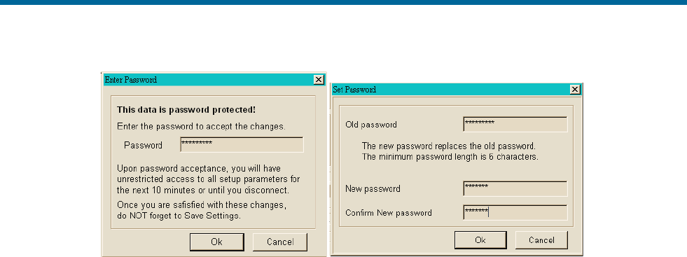
POS MV V5 Installation and Operation Guide
System Configuration
Copyright © Applanix Corporation, 2012
4-29
Figure 34: POSView Controller Password Protection

POS MV V5 Installation and Operation Guide
System Operation
Copyright © Applanix Corporation, 2012
5-1
5.0 System Operation
This section describes how to use the MV-POSView Controller program to operate the POS MV. To
perform the instructions in this section:
• The Position and Orientation System for Marine Vessels (POS MV) controller program (MV-
POSView) must be installed on the controlling Personal Computer (PC).
• The controlling PC and the POS Computer System (PCS) must both be connected to the same
Ethernet Local Area Network (LAN).
• The controlling PC and the PCS must both have network compatible Internet Protocol (IP)
addresses and subnet masks.
• The POS MV must be configured with the correct installation parameters, which are saved to
Non-Volatile Memory (NVM).
POS MV may be configured to transition directly to navigate mode after power-on and deliver integrated
navigation solutions through the enabled ports. This is performed by enabling AutoStart, refer to page 4-
13 for instructions.
If necessary, refer to the following instructions for assistance:
• Installation starting on page 2-1.
• System Configuration starting on page 4-1
• Power-On starting on page 4-1
• PCS IP Address starting on page 4-4
• AutoStart starting on page 4-13
• Power-Off starting on page 4-24
• Password Protection starting on page 4-27
• Software Installation starting on page D-1
MV-POSView Controller Program
Modes of Operation
The controller program operates in one of two modes:
• Monitor mode - the controller program displays all the PCS data broadcast over the Ethernet
display port but cannot change any of the PCS settings. This mode allows several users to
monitor the PCS data simultaneously.

POS MV V5 Installation and Operation Guide
System Operation
5-2
• Control mode - the controller program displays all the PCS data broadcast over the Ethernet
display port and has an established Transmission Control Protocol (TCP) connection to the PCS
control port. This allows you to change the system configuration and save any new configurations
to NVM. Only one MV-POSView Controller program can connect to a given PCS at any one time.
In control mode, when a controller window is opened, the controller automatically requests the
appropriate group(s) to be output from the display port.
PCS Ethernet Connection
Refer to
Figure 35 on page 5-3 for this discussion. The MV-POSView Controller constantly receives broadcast
display data and records the originating PCS IP address. This list of IP addresses is displayed in the tool
bar drop-down field. The user selects the IP address for the PCS of interest from the drop-down field. The
controller monitors or connects to the IP address displayed on the controller tool bar.
Monitoring POS MV
Main Window Regions
Figure 35 shows the main window of the MV-POSView Controller. The window can be divided into five
regions:
Title bar (top):
Identifies the controller type; in this case MV-POSView.
Menu bar (top):
Select any of these items to display its pull-down menu
tree.
Tool bar (top):
Contains icons or action buttons (hot buttons) of
frequently used functions; the IP address of the Ethernet
connection is displayed.
POS MV status
(centre):
Contains sensor and processing data; cannot be
changed.
Status bar
(bottom):
This shows from left to right:
• Current date in mm/dd/yyyy format
• Universal Time Coordinated (UTC) or Global
Navigation Satellite System (GNSS) time in
hh:mm:ss format (user selectable)
• POS MV time in hh:mm:ss format since the POS MV
was powered-on (not the time since the controller
program was started)
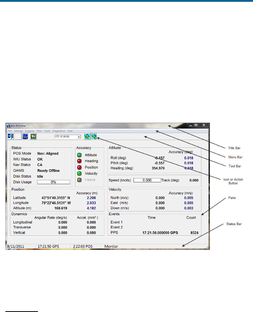
POS MV V5 Installation and Operation Guide
System Operation
Copyright © Applanix Corporation, 2012
5-3
• Connection status of the MV-POSView Controller
program:
Connected - the controller is communicating with the
specified IP address in control mode
Disconnecting - the controller is terminating
communication with the specified IP address
Connecting - the controller is attempting to connect to
the control port of the specified IP address
Monitor - the controller is receiving broadcast data
from the specified IP address
Waiting - the controller cannot communicate with the
specified IP address
Figure 35: POSView Controller Main Window
POS MV Status Region
POS MV status is displayed in the centre area of the MV-POSView Controller window. The following
describes these areas.
Status Pane
Displays the status of POS MV.

POS MV V5 Installation and Operation Guide
System Operation
5-4
POS Mode - POS MV may be in standby mode or in one of its
navigation modes.
Levelling Active
Basic levelling and heading determination; no
navigation output
Nav: Degraded
Navigation active but with loose error model
Nav: Aligned
Navigation with full error model correction
Nav: Full
All user specified accuracies are met
The normal operating condition for POS MV is navigate mode.
IMU Status - this field may display OK, Warning or Failure.
If the Inertial Measurement Unit (IMU) status field shows anything except OK, check the
Fault Detection window described in Faults and Messages on page 5-8. Contact Applanix
for advice if necessary.
Nav Status - displays the source and quality of the GNSS sensors
and the resulting mode of the navigation solution.
DR (Dead
Reckoning )
No GNSS input is available; navigation is using
only the IMU data
RTCM DGNSS
Navigator is tightly coupled using the primary
GNSS raw observables plus base GNSS
corrections (RTCM 1 or 9)
CODE DGNSS
Navigator is tightly coupled using the primary
GNSS raw observables plus base GNSS
corrections (RTCM 18 and 19, CMR, CMR+)
FLOAT RTK
Navigator is tightly coupled using the primary
GNSS raw observables plus base GNSS
corrections (RTCM 18 and 19, CMR, CMR+)
FIXED RTK
Same as Float RTK but better accuracy
Pri. C/A
Navigator is loosely coupled using the primary
GNSS position data in C/A mode
Pri. DGNSS
Navigator is loosely coupled using the primary
GNSS position data in DGNSS mode
Pri. P Code
Navigator is loosely coupled using the primary
GNSS position data in P-CODE mode
Pri. RTK
Navigator is loosely coupled using the primary
GNSS position data in RTK mode
Aux. DGNSS
Navigator is loosely coupled using the auxiliary
GNSS position data in DGNSS mode
Aux. P Code
Navigator is loosely coupled using the auxiliary
GNSS position data in P-CODE mode
Aux. Float RTK
Navigator is loosely coupled using the auxiliary
GNSS position data in Float RTK mode

POS MV V5 Installation and Operation Guide
System Operation
Copyright © Applanix Corporation, 2012
5-5
Aux. WL RTK
Navigator is loosely coupled using the auxiliary
GNSS position data in Wide Lane RTK mode
Aux. NL RTK
Navigator is loosely coupled using the auxiliary
GNSS position data in Narrow Lane RTK mode
GAMS - this field can display Online, Ready Online, Ready Offline, Cal in Progress, Cal
Requested, Cal Complete or Not Ready.
Note: Measurement of attitude, position, velocity and dynamics described below are valid for the
vessel location as determined by the Reference to vessel lever arm distances. Accuracy indications
are described in the Accuracy Pane heading on page 5-5.
Attitude Pane
Displays angles of roll, pitch and heading using degrees in the vessel frame of reference.
Position Pane
Displays latitude and longitude solutions in degrees from the equator and the Prime Meridian
respectively, and WGS84 ellipsoid altitude solutions in metres.
Velocity Pane
Displays velocities in their longitudinal, lateral and downward components in metres per second.
Dynamics Pane
Displays vessel dynamics (angular rates in degrees per second, and accelerations in m/s2) in their
longitudinal, lateral and downward components.
Accuracy Pane
There are five coloured lights, one adjacent to the Attitude, Heading, Position, Velocity and real-
time Heave labels. The lights show whether the associated measurement is within a user-defined
accuracy threshold (green) or outside it (red).
These lights provide a visual indication of an acceptable user defined performance level. The
threshold settings do not affect POS MV performance.
Note: POS MV will not transition to full navigation mode until it has met all of the user-defined
accuracy requirements and the entire Accuracy pane indicators show green.
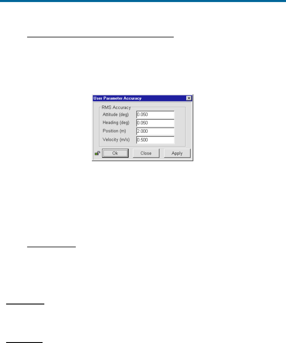
POS MV V5 Installation and Operation Guide
System Operation
5-6
ATTITUDE, HEADING, POSITION AND VELOCITY PARAMETERS
To set the thresholds for each measurement, select Settings, Installation, User Accuracy from the
MV-POSView menu bar. Enter the preferred accuracy threshold for each of the four fields; see
Figure 36. Click the OK button to accept.
The threshold settings do not affect the operation of POS MV, however, POS MV will not transition to
full navigation mode until it achieves the RMS accuracy setting boundaries.
Figure 36: POSView User Parameter Accuracy
In addition, POS MV estimates the accuracy of the data contained in the Attitude, Position and
Velocity panes. These estimations reflect the confidence boundaries on the displayed parameters;
they vary according to the current performance level of the GNSS receiver, the number of satellites
tracked and whether DGNSS corrections are available to the navigation algorithm. It also depends on
the level of motion that POS MV is experiencing; more dynamics will tend to improve the accuracy of
the solution (reducing the displayed confidence boundaries).
HEAVE PARAMETER
The real-time heave accuracy parameter is not adjustable by the user. The fixed setting is based on
the industry standard performance ratings of 5 cm or 5% (whichever is greater). For heave
amplitudes (peak-to-peak) of 1 m or less, a 5 cm threshold is used, while for heave amplitudes which
exceed 1 m, 5% of the peak-to-peak amplitude is used.
Events Pane
Displays the identification count number and the time of occurrence for the most recent recorded
events.
Speed Pane
Displays the current speed in nautical miles per hour (knots) and the direction of the velocity vector
(Track) in degrees. When the vessel is travelling in the forward direction, the direction should be
similar to the Heading displayed in the Attitude pane.
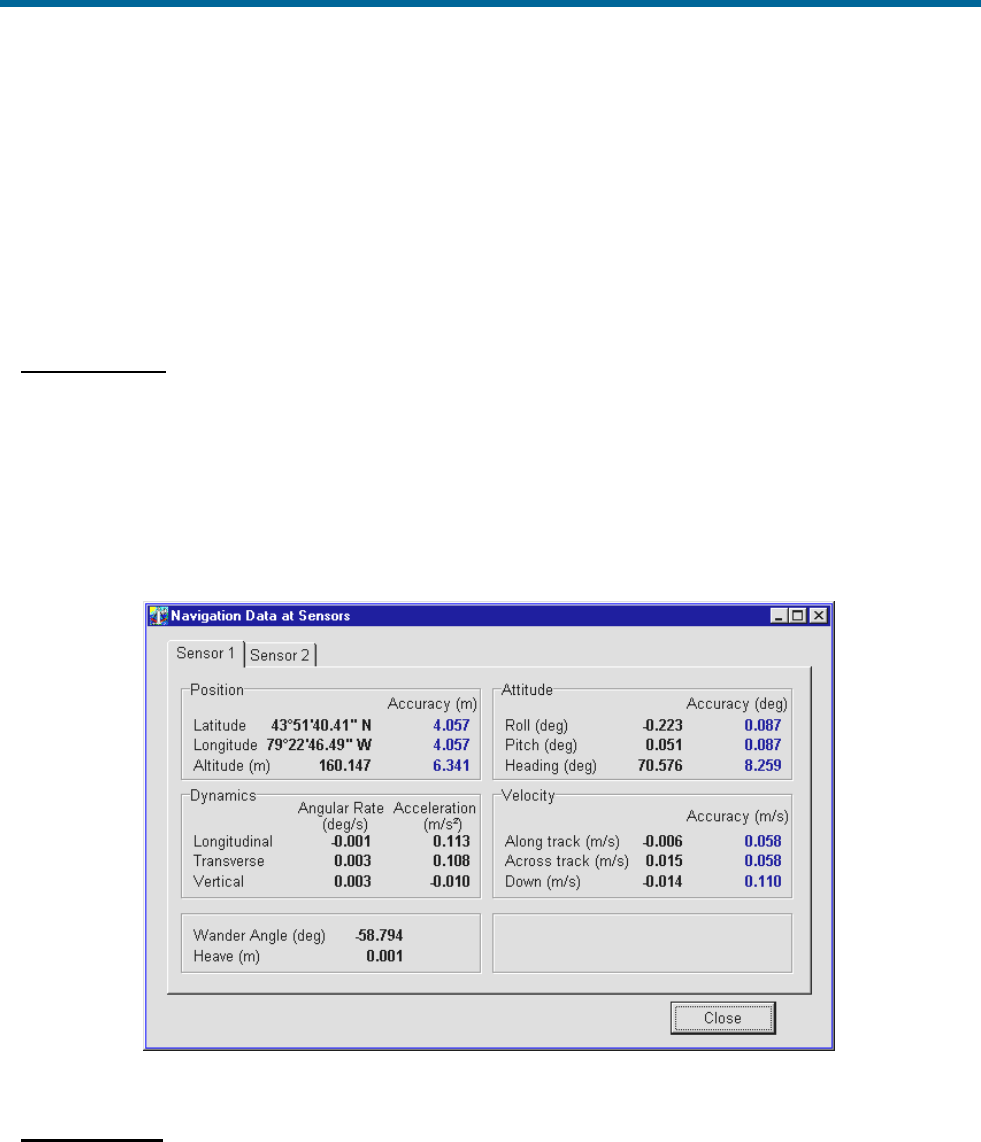
POS MV V5 Installation and Operation Guide
System Operation
Copyright © Applanix Corporation, 2012
5-7
Sensor Navigation Data
The Navigation Data at Sensors window, shown in Figure 37, displays the navigation data for sensor 1
and sensor 2. Access this window selecting View, Sensor Navigation; a tab is available for each sensor.
Sensor 1 and sensor 2 may be used to define the location of a multibeam transducer or other equipment.
Refer to the Installation Parameters description starting on page 2-24 when assigning lever arms and
mounting angles.
Position Pane
The sensor position appears as latitude and longitude in degrees, minutes and seconds. The altitude
of the sensor position is shown in metres above the WGS84 ellipsoid. POS MV defines latitude,
longitude and altitude with respect to the World Geodetic System 1984 (WGS-84) referenced
ellipsoid.
Latitude is reference to the equator and is either North or South. Longitude is reference to the Prime
Meridian and is either East or West. Estimations of accuracy are in metres.
Figure 37: POSView Navigation Data at Sensors
Attitude Pane
Displays the angles of roll, pitch and heading of the sensor using the sensor frame of reference. POS
MV uses degrees to display the attitude measurements and their estimated boundaries of accuracy.

POS MV V5 Installation and Operation Guide
System Operation
5-8
Velocity Pane
Velocities of the sensor are given in the longitudinal and down directions. POS MV uses metres per
second to display the velocities and their estimated boundaries of accuracy.
Dynamics Pane
Displays the angular rates and linear accelerations of the sensor in the longitudinal and vertical
directions. POS MV uses degrees per second or m/s2 to display the dynamics and their estimated
boundaries of accuracy.
Wander Angle Field
The navigation frame is derived from the North, East and Down (NED) frame by a rotation of “
”
(wander angle) about the down axis. This provides a locally level coordinate frame that is well-defined
at the earth’s poles.
Heave Field
Heave is the filtered vertical motion (acceleration data) plus roll and pitch derived heave at the sensor
location. Heave is in a positive down direction in a ‘local level’ or ‘platform’ frame, so the heave is in
the gravity direction.
Faults and Messages
The Fault Detection window displays the status of POS MV system and reports any fault conditions that
may occur during operation, see Figure 38. Two other tabs on the window show IMU and GNSS
Correction fault status. Three light conditions may occur where; green indicates an acceptable condition,
red indicates an unacceptable condition and greyed is not applicable. Access to the Fault Detection
window is from the MV-POSView menu bar, select View, Faults.
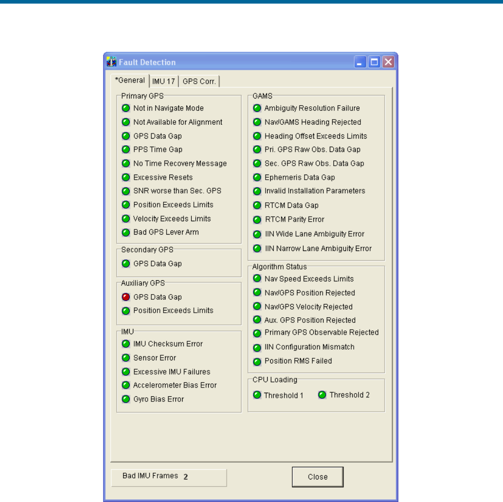
POS MV V5 Installation and Operation Guide
System Operation
Copyright © Applanix Corporation, 2012
5-9
Figure 38: POSView Fault Detection
Note: Some fields may display a red indicator (intermittently) during initialization and operation.
The Fault Identification description starting on page 9-1 includes a list of the messages that may appear
in the message log. If you suspect that a fault condition has occurred, but the Faults Detection window
does not show it, check the message log. To access the Message Log (Figure 39) select View, Message
Log from the MV-POSView menu bar.
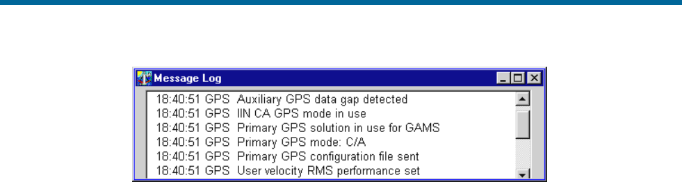
POS MV V5 Installation and Operation Guide
System Operation
5-10
Figure 39: POSView Message Log
POS MV uses AutoRecovery and Fault Detection, Isolation and Reconfiguration (FDIR) to assist in its
recovery from fault conditions. AutoRecovery helps POS MV to recover from a communications failure
between the PCS and the IMU, and provides alerts for any problems in this area. Investigate persistent
communication failures with the IMU, the most likely cause being a faulty data cable or connector. Never
open the IMU; if you suspect the IMU is faulty, contact Applanix for return instructions. Refer to Technical
Support and Service on page A-1 for procedures.
POS MV monitors its sensing subsystems continuously and determines which of them, if any, shows
degraded performance. FDIR allows POS MV to combine data from the GNSS and IMU to offer the best
navigation solution for the current data quality.
For more information on AutoRecovery and FDIR refer to page 1-10.
Data Logging
POS MV real-time and raw data may be recorded on storage media for post-processing. Typically, the
data are recorded on removable media, a USB flash drive using the USB connector installed in the front
of the POS Computer System (PCS). Alternately, the data may be transferred across the Ethernet Data
Port to a disk file on an external PC. The USB flash drive is useable for post-processing in any PC with a
USB connector.
Back-up logging is initiated when data are logged to the removable media and remains active, regardless
of the removable media data logging activity, until the PCS is reset or powered-off.
Note: Use of the removable media interface is preferred due to the bandwidth limitations associated with
some Ethernet installations.
The PCS contains a USB connector and an internal memory device, both dedicated to data logging. The
system includes a 4GB industrial grade USB flash drive which is inserted into a USB connector behind a
door on the front of the PCS; see Figure 42, page 5-12 for MV V5 and Figure 43, page 5-13 for MV V5-1.
A 4 GB internal memory device functions as a circular buffer and is used to back-up the last data logging
file. Back-up logging is automatic and does not require any user maintenance. Once the user begins
removable media logging, back-up logging will log the same data and continues to back-up the data until
the system is reset or powered-off.
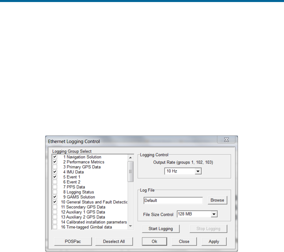
POS MV V5 Installation and Operation Guide
System Operation
Copyright © Applanix Corporation, 2012
5-11
To access the logging configuration and control menus, select one of the following from the MV-POSView
menu: Logging, Ethernet Logging... or Logging, USB Logging....
The logging screens (Figures 40 and 41) permit the selection of data groups to be recorded and define
the logging rate for those data groups.
The Ethernet logging port is intended for data logging for a delayed processing application where data
loss cannot be tolerated. This port implements a very large storage buffer to minimize the risk of data
loss.
The logging method, Ethernet or Removable media, is changeable at any time, even if logging is in
progress. To accept the screen parameters and not close the screen, click the Apply button. To accept
the screen parameters and close the screen, click the OK button.
Figure 40: Ethernet Logging Control
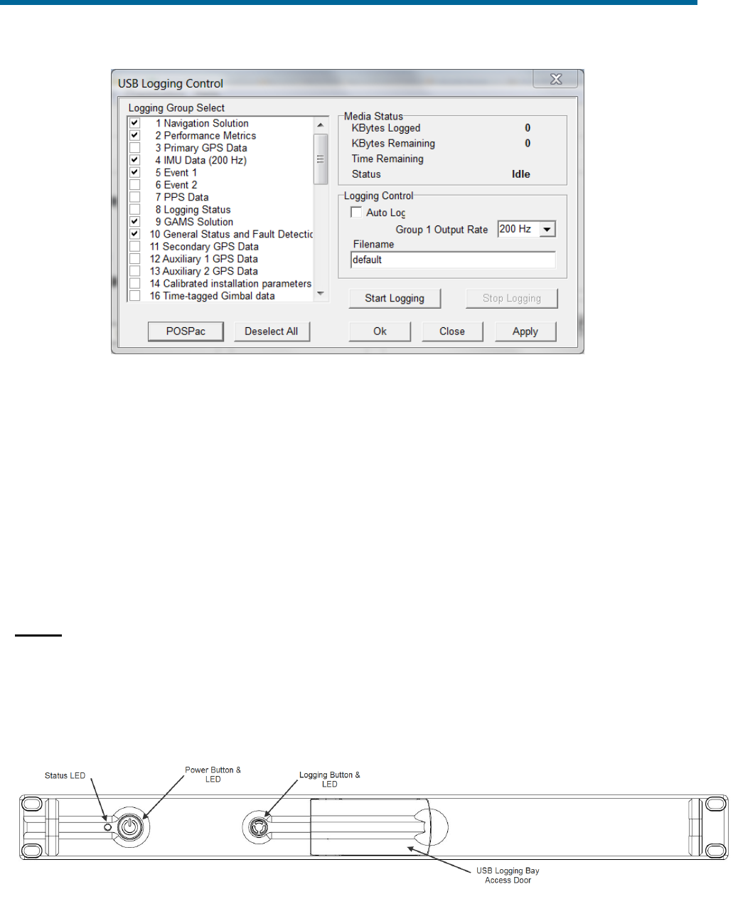
POS MV V5 Installation and Operation Guide
System Operation
5-12
Figure 41: USB Logging Control
Note: If the logged data are to be used with POSPac, click the POSPac button to select all the groups
required for post-processing.
Data Logging – Removable Media
Insert a USB flash drive
The USB flash drive can be inserted into the PCS at any time (i.e. with PCS power on or off). Both V5 and
V5-1 versions have the removable USB connector behind a door on the front of the PCS but the internal
mechanism is different.
MV V5
Open the spring loaded USB access door on the front of the PCS all the way and it will stay open on its
own. Insert the USB flash drive into the bay (Figure 43) ensuring that the card is facing up, Applanix logo
showing. The logging bay door should close without hitting the USB flash drive if it is properly seated in
the connector.
Figure 42: Removable Media Bay – POS MV V5
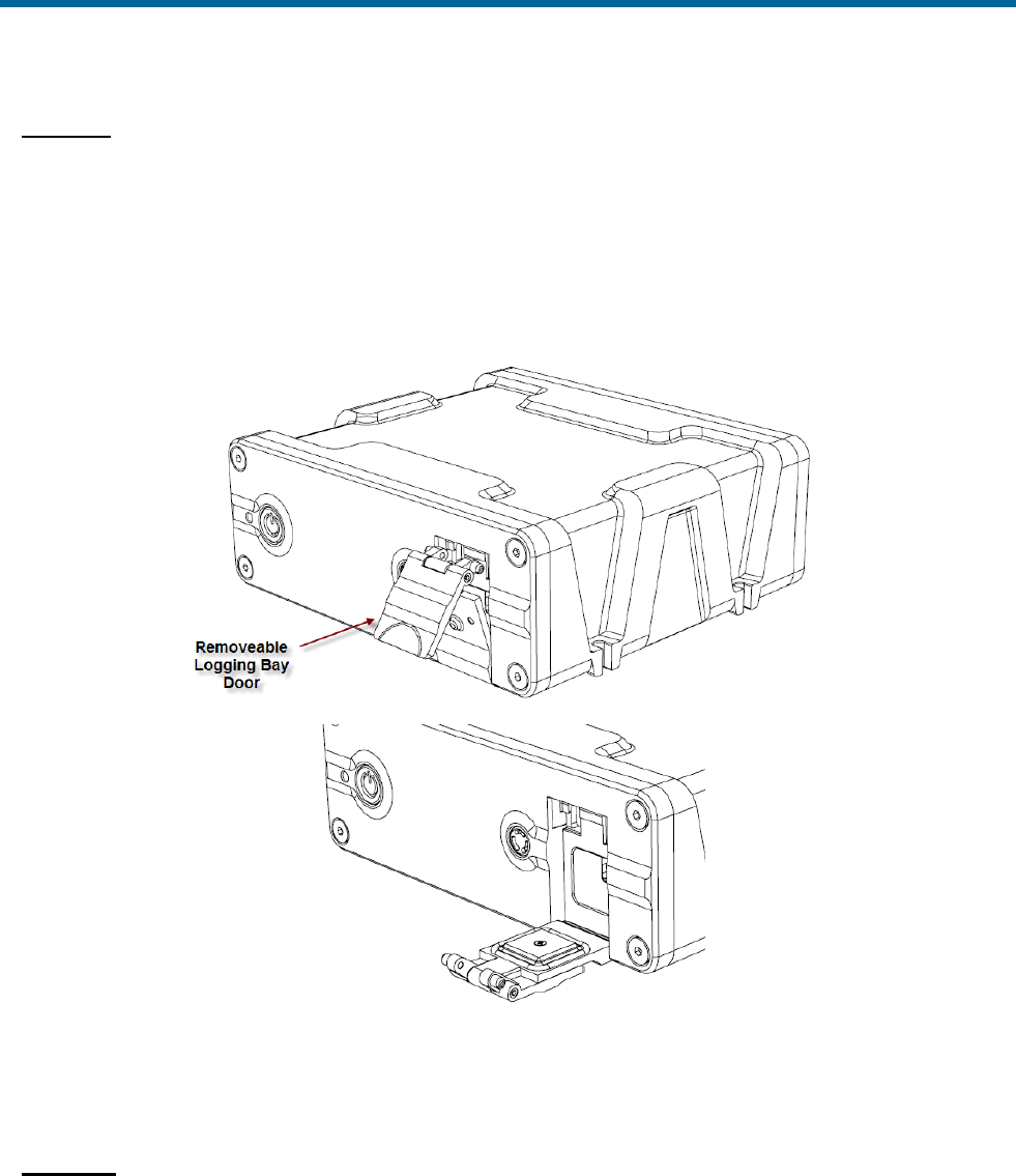
POS MV V5 Installation and Operation Guide
System Operation
Copyright © Applanix Corporation, 2012
5-13
MV V5-1
The USB connector is attached to a moving shuttle that allows the USB flash drive to be entirely enclosed
by the PCS housing. Insert the USB flash drive into the bay (Figure 43) ensuring that the card is facing
up, Applanix logo showing. The shuttle mechanism will move back to its innermost position, at which point
the USB flash drive must be pressed into the connector. The logging bay door should close without hitting
the USB flash drive if it is properly seated in the connector.
Figure 43: Removable Media Bay – POS MV V5-1
Start Logging – Removable Media
AutoLog
If AutoLog is enabled (refer to Figure 41 on page 5-12), logging starts automatically on PCS power-up. If
AutoLog is enabled and there is no USB flash drive in the logging bay, the Logging light will turn red. If
this occurs, insert a USB flash drive and start manually as described in the following paragraphs.

POS MV V5 Installation and Operation Guide
System Operation
5-14
Manual Start
Press the Logging button on the PCS front panel and hold for at least 2 seconds to begin.
An alternate method to start logging is to click the MV-POSView Start Logging button on the PC Card
Logging Control screen (Figure 41, page 5-12).
For a description of the logging status lights, refer to Table 34.
Stop Logging – Removable Media
Logging is stopped manually by pressing the Logging button on the PCS front panel and holding for at
least 2 seconds. Logging stops after about six seconds.
An alternate method to stop logging is to click the MV-POSView Stop Logging button on the PC Card
Logging Control (Figure 41, page 5-12) screen.
Logging data to the removable media may be stopped and restarted repeatedly. Restarting the logging
process causes a new file to be opened with the same kernel name. If a new kernel name is assigned,
the new file is viewed as a new mission.
Note: A data gap is treated as a new mission. The system can tolerate a 0.015 ms (maximum) IMU data
gap.
Logged Data
Data are logged to the removable media in approximately 12-Megabyte (MB) files. If POS MV loses
power while logging data to the USB flash drive, the amount of mission time lost will depend on how
many groups were selected for output. The fewer the groups the less information recorded per minute, a
longer time to fill a 12 MB file and the more mission time that may be lost.
Remove the USB flash drive
Do not remove a USB flash drive from the logging bay when the
logging light is on; the PCS may still be writing to the device. If
the USB flash drive is removed when the logging light is on,
there is a chance that all mission data will be lost.
Stop logging before attempting to remove the USB flash drive from the logging bay.
Note: It may take several seconds after a request to stop logging for the PCS to stop recording to the
USB flash drive and the logging light to extinguish.
MV V5
When the logging light is off, open the logging bay door, grasp the USB flash drive and remove it from
the connector (Figure 42, page 5-12).

POS MV V5 Installation and Operation Guide
System Operation
Copyright © Applanix Corporation, 2012
5-15
MV V5-1
When the logging light is off, open the logging bay door, press in on the USB flash drive and then release.
The shuttle mechanism will partly eject the USB flash drive to a point where it is possible to remove it
from the connector (Figure 43, page 5-13).
Data Logging - Ethernet
Ethernet logging is intended to capture data for a delayed processing application where data loss cannot
be tolerated. Data are output for Ethernet logging on the LAN data logging port. This port implements a
very large storage buffer to minimize the risk of data loss due to delays in the Ethernet link.
Ethernet logging is performed using the MV-POSView software or other user supplied software. Any
custom designed logging software’s interface must conform to the POS MV Ethernet ICD specifications.
Please refer to Applanix document PUBS-ICD-004089 for a description of the Ethernet data output
format.
Note the following points regarding the Ethernet circuit:
• Requires at least a 100 Base T connection.
• Applanix recommends the use of the shielded Ethernet cables shipped with the POS MV system.
• Use of shielded Ethernet cables is a requirement of the European Union CE standard.
Note: Ethernet data logging cannot be started or stopped using the Logging button on the PCS front
panel.
Ethernet data logging performed by MV-POSView will be written to a single file and could be
subject to loss or corruption depending on the stability of the PC on which it is being recorded.
Start logging - Ethernet Data Port
To start Ethernet data logging to a local PC, select Logging on the MV-POSView menu bar and
Ethernet Logging on the drop-down menu. Next, select a file location and name using the Browse
button, and finally, click the Start Logging button; refer to Figure 40 on page 5-11.
Stop logging - Ethernet Data Port
To stop Ethernet data logging, click the Stop Logging button on the Ethernet Logging Control screen
(Figure 40, page 5-11).
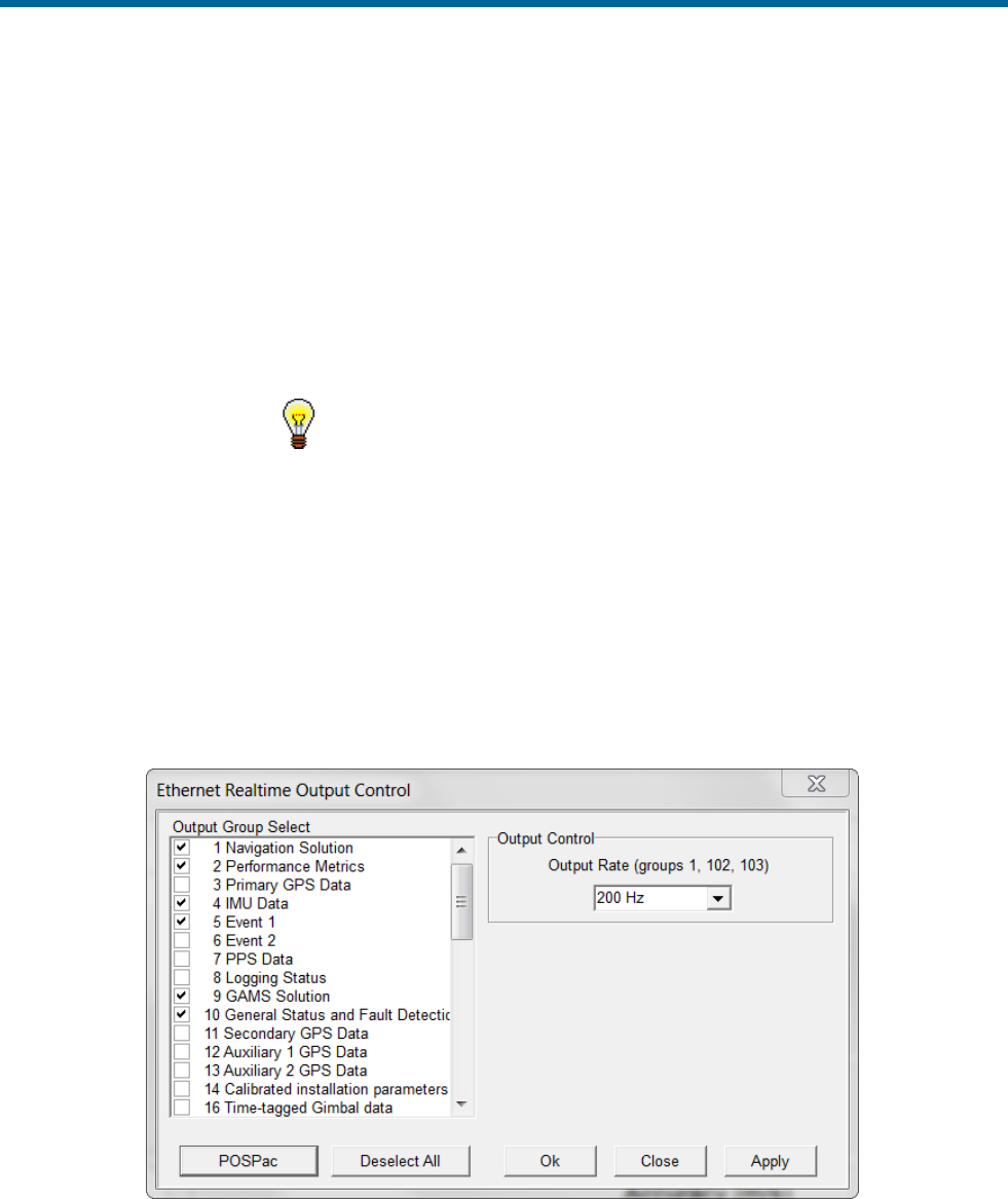
POS MV V5 Installation and Operation Guide
System Operation
5-16
Data Output – Ethernet
The Ethernet real-time data output port is intended for real-time control applications where the most
current position and orientation data are required. Real time data output on an Ethernet port is intended to
provide data for a third-party application that is capable of decoding the POS MV Ethernet ICD format.
Please refer to Applanix document PUBS-ICD-004089 for a description of the Ethernet data output
format. These ports implement small storage buffers which are flushed frequently to ensure timely
delivery of the data.
Ethernet Real-Time is used for real-time control applications,
whereas, Ethernet Logging has a large data buffer.
Start Output - Ethernet Realtime Data Port
To start Ethernet real-time data output, select Settings on the MV-POSView menu bar and Ethernet
Real-time Port on the drop-down menu. The window shown in Figure 44 appears.
Click on the tab for the port to be configured and then select the group or groups to be output by clicking
on the check box next to the group in the Logging Group Select pane. Select an output rate for group 1
(navigation solution) and finally, click the Start Logging button.
Figure 44: Ethernet Realtime Output Control.
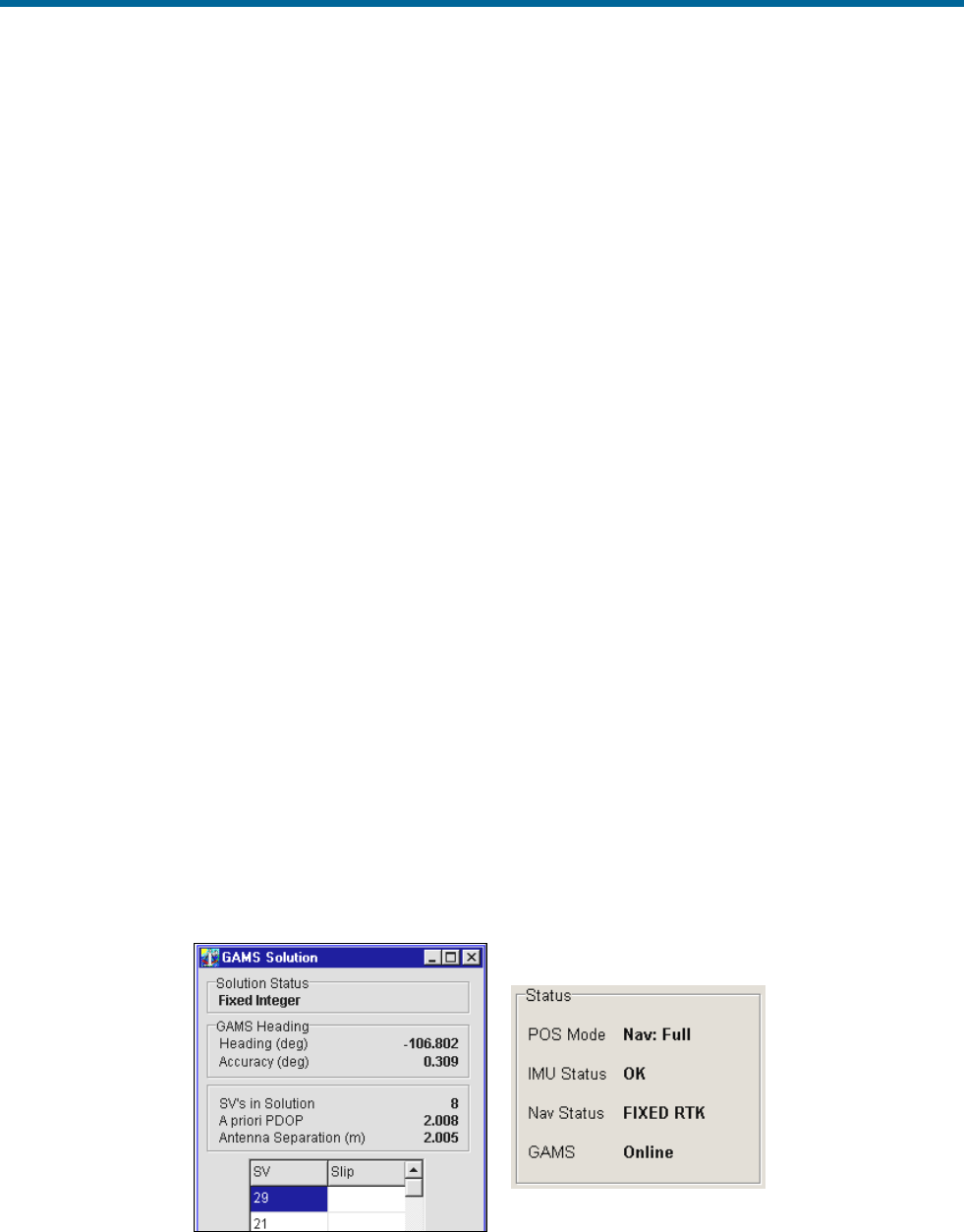
POS MV V5 Installation and Operation Guide
System Operation
Copyright © Applanix Corporation, 2012
5-17
Operation with GAMS
Normal Operation
If POS MV has valid installation parameters stored in NVM then it is ready to operate with GAMS heading
aiding.
a) Follow the instructions in the Power-On topic on page 4-1 to power-on the PCS.
b) If you have not enabled AutoStart, transition POS MV to the navigate mode by selecting the Nav
icon on the MV-POSView tool bar.
View both the GAMS Solution and the Status pane windows (Figure 45) to follow the GAMS Initialization
sequence.
1. Once the POS MV has completed its levelling routine GAMS will start-up. The controller program
will show the following indicators:
• The Status pane will show GAMS as Not Ready. This indicates that GAMS has not
resolved the carrier phase ambiguities.
• The GAMS Solution window shows SVs in solution, A priori PDOP and Antenna
Separation.
• In addition, the GAMS Solution window shows a list of satellites (SVs or space vehicles)
that are being tracked by POS MV. The order in which they appear in the window is not
important.
2. If POS MV is tracking fewer than five satellites, or if the indicated Position Dilution of Precision
(PDOP) is greater than 4.5, then GAMS becomes dormant. In this dormant state, GAMS
continues to monitor tracked satellites but does not process the observables from the GNSS
receivers. GAMS status displays Not Ready.
Figure 45: POSView GAMS Solution and Status Pane

POS MV V5 Installation and Operation Guide
System Operation
5-18
3. Following the successful completion of coarse levelling, the POS Mode transitions to Degraded
Navigation status. During this time, errors in the reported roll and pitch angles will be larger than
0.05°. If five or more satellites are being tracked and the indicated PDOP is less than 4.5 then
GAMS begins the On-the-Fly (OTF) ambiguity search, using only the antenna separation distance
to aid the search process. GAMS status displays Not Ready.
4. When the POS Mode transitions to Nav Aligned status, the errors in the reported angles of roll
and pitch will be less than 0.075° RMS. The heading error remains large - in the order 10° to 15°
RMS - unless the vessel performs dynamic manoeuvres, in which case errors may fall to below
5°.
The computed angles of roll and pitch are now sufficiently accurate to be used by GAMS,
together with the antenna separation distance, in the OTF ambiguity search process. Additional
aiding data shortens the time that it takes to fix ambiguities from as long as 20 minutes to as short
as two minutes, depending on the satellite geometry.
5. Once GAMS has resolved the carrier phase ambiguities, the GAMS status displays Ready
Online to indicate that GAMS is ready to provide heading aiding data to the POS MV Kalman
Filter.
This status may exist for up to ten seconds. If it exists beyond 20 seconds then this indicates that,
for some reason, the Kalman Filter may have rejected the GAMS heading aiding data.
6. When the POS MV Kalman Filter begins to process the GAMS heading aiding data GAMS status
displays Online. Within 30 seconds the heading errors should fall to 0.25° RMS and to between
0.02° and 0.15° RMS within two minutes.
7. The GAMS status display will transition from Online to Ready Online to indicate that the POS
MV Kalman Filter has stopped processing GAMS heading aiding data. This can occur if one of
the following conditions arise:
• A one or two-second GNSS data dropout occurs in either/both GNSS receivers. A data
dropout comprises either/both of the following:
o Valid phase observables are available from fewer than four satellites
o The indicated PDOP is greater than 4.5
• The tracking Signal-to-Noise Ratio (SNR) for one or more satellites in either or both
GNSS receivers drops to below 32 Decibels (dB). GAMS processes the observables for a
satellite if the corresponding tracking SNR ratio in both receivers is greater than 30 dB.
The POS MV Kalman Filter rejects GAMS heading aiding data computed from any
marginal observables.

POS MV V5 Installation and Operation Guide
System Operation
Copyright © Applanix Corporation, 2012
5-19
• The POS MV Kalman Filter rejects the GAMS heading aiding data as being inconsistent
with the inertial navigator heading. This can occur if a large multipath error causes GAMS
to temporarily exhibit an unusually large heading error.
Once the cause of the heading aiding data rejection has been cleared, GAMS status displays
Online.
8. The GAMS status display will transition from Online to Not Ready to indicate that GAMS has
reset (i.e. it has abandoned the current fixed phase ambiguities and has restarted the OTF
ambiguity search).
This can occur for two reasons:
• A GNSS data gap occurs and lasts for longer than two seconds. This can be caused by a
blockage of the GNSS signal, for example, as the vessel passes under a bridge.
• GAMS has rejected the current fixed phase ambiguities. This can occur if the carrier
phase ambiguity for a recently acquired satellite is fixed to the wrong integer due to
multipath errors or excessive phase noise.
If the cause of the GAMS reset has been cleared then GAMS will quickly resolve the carrier
phase ambiguities and return to Online status.
Abnormal Behaviour
Abnormal behaviour that occurs after a period of normal operation is symptomatic of environmental
anomalies such as multipath errors, GNSS signal masking, or unexpected changes in IMU or GNSS
antenna geometry.
The following are symptoms of abnormal behaviour together with their possible causes and some
suggested remedies.
Repeated Ambiguity Rejection
Symptom
GAMS repeatedly resolves the carrier phase ambiguities and then rejects
them. This cycle can continue indefinitely or, eventually, POS MV flags the
installation parameters as invalid.
Possible Causes and Remedies
1. Cause - Installation Parameters - The installation parameters are
incorrect or have become incorrect. This can occur if either/both GNSS
antennas move with respect to the IMU by more than a few centimetres or

POS MV V5 Installation and Operation Guide
System Operation
5-20
if the IMU has moved with respect to the GNSS antennas by more than a
few centimetres.
Remedy - Ensure that you have mounted the antennas and the IMU rigidly
with respect to each other. Measure the correct installation parameters
(Installation Parameters on page 2-24) and re-configure the POS MV
installation parameters (POS MV Configuration on page 4-7).
2. Cause - Multipath Environment - A temporarily high multipath
environment may occur if the vessel passes near a large reflecting surface
such as a large ship or a building. SNR degradation for low elevation
satellites may occur in either/both GNSS receivers if trees, buildings or a
bridge partially masks the satellite signal paths. If, for example, the vessel
has sailed into a harbour where large ships are moored then their hulls
may generate multipath reflections.
Remedy - Move the vessel away from the source of the high multipath
environment.
GAMS Status Remains ‘Ready Online’ Indefinitely
Symptom
The GAMS status display remains Ready Online for several minutes,
although the Navigator Configuration window commands POS MV to use
GAMS. Select Tools, Configuration to see the Navigator Configuration
window.
Possible Causes and Remedies
1. Cause - Incorrect Ambiguity Resolution - GAMS has identified the
wrong carrier phase ambiguities and has computed the wrong heading.
The POS MV Kalman Filter continuously rejects the GAMS heading aiding
data because it is inconsistent with the heading solution computed by the
system without GAMS aiding.
Remedy - Click on the Standby icon on the MV-POSView tool bar to
transition POS MV to standby mode. Then click on the Nav icon to return
to navigate mode. This action will re-initialize POS MV and GAMS.

POS MV V5 Installation and Operation Guide
System Operation
Copyright © Applanix Corporation, 2012
5-21
2. Cause - Incorrect Heading Resolution - POS MV has computed a
heading that is incorrect in spite of the displayed heading accuracy. This
may occur if the POS MV Kalman Filter processes highly inaccurate
GNSS data during the heading alignment.
Remedy - Click on the Standby icon on the tool bar to transition POS MV
to standby mode. Then click on the Nav icon to return to navigate mode.
This action will re-initialize POS MV and GAMS.
3. Cause - Low SNR - GAMS uses one or more satellite observables with a
tracking SNR that is consistently below 32 dB from either/both GNSS
receivers. This can arise from:
• Partial masking of a GNSS signal from a low elevation
satellite; masking of this type may be caused by a bridge,
trees, cliffs or hills along a nearby shore
• Interference from nearby high voltage power lines
• Very long antenna cables or the use of coaxial antenna cables
that have excessive losses at the L1 frequency (1575 MHz)
• GNSS receiver failure
Remedy - The problem of partial masking or interference will go away
when the vessel moves away from the suspected shore-based source of
signal degradation. You can identify a problem with antenna cables by
substituting shorter low-loss cables.
Refer to Figure 38 on page 5-9, Fault Detection window (by selecting
View, Faults), to check the GNSS receiver status and to determine
whether either receiver has reported a fault.
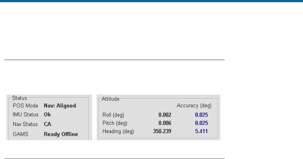
POS MV V5 Installation and Operation Guide
System Operation
5-22
Obvious Incorrect Heading
Symptom
The displayed GAMS status is Online and the displayed POS MV Heading
accuracy is less than 0.15°. However, the displayed POS MV heading is
clearly in error by several degrees.
Possible Causes and Remedies
1. Cause - GAMS has resolved the wrong carrier phase ambiguities and
computes the wrong heading. The heading computed by POS MV has
aligned to the incorrect heading reported by GAMS.
Remedy - Click on the Standby icon on the MV-POSView tool bar to
transition POS MV to the standby mode. Then click on the Nav icon to
return to the navigate mode. This action will re-initialize POS MV and
GAMS.
There may be a problem with the IMU being out of specification. Contact
Applanix for advice.
Repeatedly Rejected Carrier Phase Ambiguities
If GAMS is operating in a high multipath environment there may be repeated ambiguity rejections or an
inability to resolve the carrier phase ambiguities. This may also occur if you experience degraded signal
reception in either/both GNSS receivers due, possibly, to satellites being at a low elevation.
POS MV will continue indefinitely to try to resolve these carrier phase ambiguities. However, if either
GNSS antenna has moved by more than a few centimetres with respect to the IMU, GAMS will never be
able to resolve ambiguities until you have completed another calibration.
Provided there has been no change to the relative mounting positions of the antennas or the IMU, the
displayed GAMS status will become Ready Online when GAMS resolves the carrier phase ambiguities.
GAMS status will show Not Ready if GAMS has started a new OTF search.
Without GAMS heading aiding, the POS MV heading accuracy will degrade slowly at an approximate rate
of one arc-minute per minute of operation. This slow rate of deterioration allows sufficient time to remove
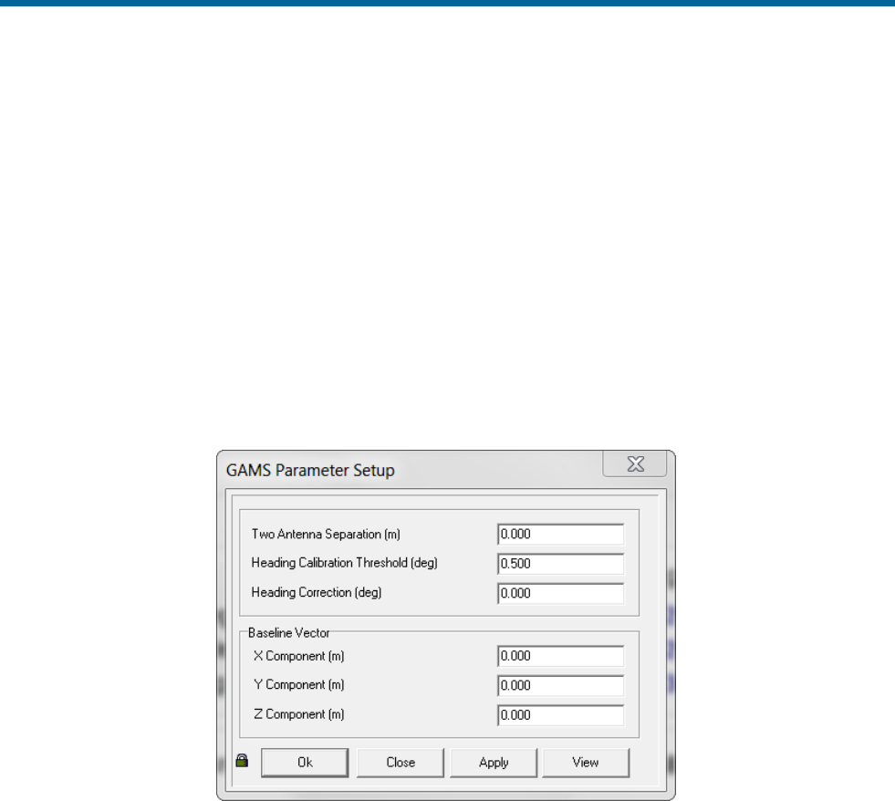
POS MV V5 Installation and Operation Guide
System Operation
Copyright © Applanix Corporation, 2012
5-23
the vessel from the source of GNSS signal degradation while it continues to maintain an acceptable
heading accuracy.
Once you have removed the vessel from the source of GNSS signal degradation, GAMS status should
become Online.
Installation Parameters
Figure 46 shows the GAMS Parameter Setup window. Refer to Antenna Installation Calibration on page
4-18 for instructions on how to configure this window with the GAMS installation parameters.
Once you have identified the GAMS installation parameters correctly, save them to Non-Volatile Memory
(NVM). It is unlikely you will ever need to modify these parameters again unless you move either/both
GNSS antennas or the IMU.
Figure 46: POSView GAMS Parameters Setup
GAMS uses the installation parameters to aid the OTF search algorithm. Please note the following:
• If the antenna separation and the surveyed antenna baseline vector installation parameters are
zero, then the GAMS OTF search algorithm runs completely unaided. GAMS can be forced to
operate in this mode by clearing the GAMS installation parameters.
• If the surveyed antenna baseline vector components are zero, and:
o The antenna separations are non-zero, or
o If the non-zero surveyed antenna baseline vector components are flagged as invalid, then
o The GAMS OTF algorithm assumes the non-zero antenna separation to be correct, and
o Uses the antenna separation to aid the OTF carrier phase ambiguity search.

POS MV V5 Installation and Operation Guide
System Operation
5-24
You can force GAMS to operate in this mode by clearing the GAMS installation parameters and
then entering an antenna separation distance.
• If the surveyed antenna baseline vector components and the antenna separation are non-zero
and flagged as valid, then the GAMS OTF algorithm uses the complete set of parameters to aid
the OTF search process.
If the POS MV roll and pitch errors are less than 0.25° RMS, GAMS constrains the ambiguity
search space to a circle centred on the primary GNSS antenna (ANT 1). Ambiguity resolution in
these circumstances takes less than five minutes.
Additionally, if the POS MV heading error is of the order of 1.0° to 2.0°, then the ambiguity is a small arc
of the circle containing one or two candidate sets of ambiguities. In these circumstances, ambiguity
resolution is nearly instantaneous and occurs in less than 10 seconds.
Stand-Alone Operation
Note: Prior to power-on and POS MV operation in stand-alone mode, the AutoStart feature must be
enabled. Refer AutoStart on page 4-13 for instructions on how to enable AutoStart. The following
instructions assume that you have enabled the AutoStart feature.
Follow the Power-On instructions on page 4-1 to power-on the POS MV. The system will initialize using
the configuration parameters that it holds in NVM. These include the IP address, the installation
parameters, the output configuration, the heave filter parameters and the data groups that you selected
for output on the display, and real-time and logging data ports. Once the system is initialized, it will begin
to output data across the enabled ports.
Refer to the Data Logging instructions page 5-10 for a full description of the data logging facilities
available for the POS MV.
When the system operates in stand-alone mode, the front panel status LED on the PCS continues to
provide an indication of the system status as described in the Power-On instructions on page 4-1.
In stand-alone mode, whichever outputs you enabled and saved to the NVM will be available from the
PCS. Data output will begin when the status LED, on the PCS front panel, begins to flash green.
The PCS will begin to broadcast Ethernet data as soon as the POS MV is powered-on. The Ethernet
messages contain only POS MV status and time until the status LED begins to flash green, at which time
the PCS will start to broadcast all the selected output groups.
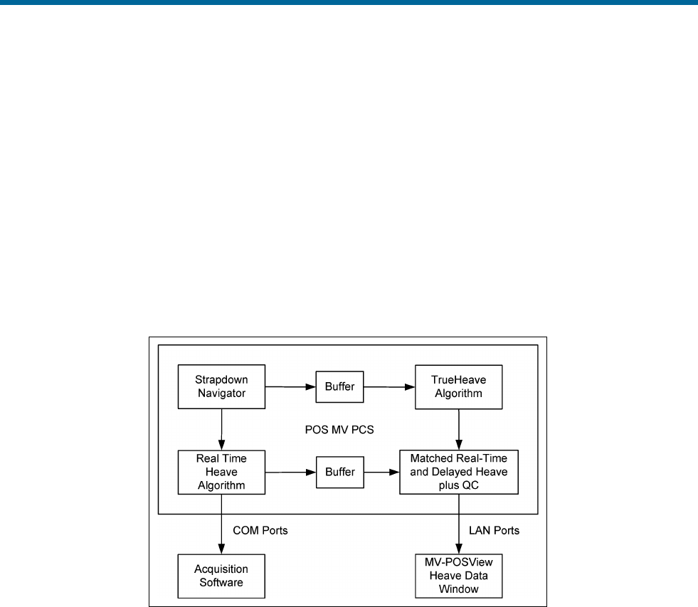
POS MV V5 Installation and Operation Guide
TrueHeave Operation
Copyright © Applanix Corporation, 2012
6-1
6.0 TrueHeave Operation
Overview
TrueHeaveTM provides an estimate of vessel heave during conditions that often defeat traditional real-time
heave filters. The POS MV TrueHeave solution uses algorithms that provide a zero phase response
across the range of 0.03 to 0.2 Hz (30 to 5 s). Traditional real-time heave solutions tend to exhibit their
most notable artefacts in long (>16 s) period swell conditions, often encountered with vessels in following
seas. The frequency range of the TrueHeave solution dramatically reduces such low frequency artefacts.
Figure 47 illustrates the relationship of the TrueHeave solution to the current real-time approach and
shows how it is computed and applied.
Figure 47: TrueHeave Functional Block Diagram
Configuration Requirements
TrueHeave is a turnkey solution and requires none of the tuning of standard real-time heave solutions.
Initialization Requirements
TrueHeave requires a period of up to five minutes after the commencement of navigation in order to
initialize. After this initial period, no further initialization or settling time is required.
Data Output
The TrueHeave solution is provided at the Ethernet interface, LAN port. Details of the output message
format are provided in the POS MV V5 User Interface Control Document (Applanix document control
number - PUBS-ICD-004089). This delayed output is provided by the Group 111 heave data message
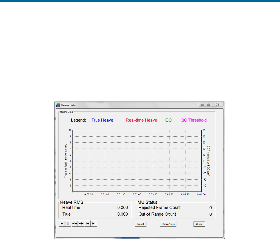
POS MV V5 Installation and Operation Guide
TrueHeave Operation
6-2
which provides the TrueHeave output, the equivalent of the real-time heave solution and the applicable
Time of Validity (TOV) signal. Group 113 contains the associated performance metrics.
Groups 111 and 113 data are output on the real-time Ethernet data port at a rate of 25 Hz to provide
sufficient resolution on the Heave Data display, see Figure 48. It may be selected for internal or Ethernet
logging.
Note: The heave data output, in real-time, is in no way affected by the addition of TrueHeave; it can and
should continue to be used as normal.
Figure 48: POSView Heave Data
TrueHeave Procedure
Use the following procedure to enable the TrueHeave feature prior to its first use.
1. Initialize POS MV ensuring that all pre-set user accuracy values are acceptable. This is indicated
by green light buttons adjacent to the Attitude, Heading, Position, Velocity and Heading labels in
the Accuracy pane on the MV-POSView Controller, see Figure 49.
2. View real-time heave and TrueHeave data by selecting View, Heave Plot, see Figure 48. Due to
the delay inherent in creating the TrueHeave solution, the heave data plot remains blank for the
first three minutes after initialization.

POS MV V5 Installation and Operation Guide
TrueHeave Operation
Copyright © Applanix Corporation, 2012
6-3
Figure 49: POSView Status and Accuracy Panes
3. TrueHeave data may be used two ways:
a) To adjust the real-time heave parameters to improve the real-time data available on the COM
ports
b) To log the TrueHeave data for post-mission processing
4. Refer to the Data Logging procedures on page 5-10, noting the following points:
a) Select the 111 Heave data and 113 Heave data quality control check boxes in the Ethernet
Logging Control window
b) Since there is a three-minute delay between real-time and the calculation of the equivalent
TrueHeave solution, logging must continue for at least three minutes past the end of the
survey session or line
Following the survey, the TrueHeave data may be analysed offline by third party post-processing
software. Contact Applanix for a list of software packages which currently provide support for TrueHeave,
refer to page A-1.

POS MV V5 Installation and Operation Guide
Specifications
Copyright © Applanix Corporation, 2012
7-1
7.0 Specifications
POS MV 320
Main Specifications (with Differential Corrections)
Roll, Pitch accuracy:
0.02 (1 sigma with GNSS or DGNSS)
0.01 (1 sigma with RTK)
Heave Accuracy:
5 cm or 5% (whichever is greater) for periods of 20 s
or less
Heading Accuracy:
0.02 (1 sigma) with 2 m antenna baseline, 0.01 (1
sigma) with 4 m baseline
RTK Positioning
Accuracy
Horizontal: ±(10 mm + 1 ppm x baseline length)
Vertical: ±(20 mm + 1 ppm x baseline length)
Note: RTK accuracies assume 1 m IMU-GNSS
antenna offset
DGPS Positioning
Accuracy
0.5 - 2 m (1 sigma) depending on quality of differential
corrections
Velocity Accuracy:
0.03 m/s horizontal
During GNSS Outages
Roll, Pitch accuracy:
0.02 (1 sigma)
Heave accuracy:
5 cm or 5% (whichever is greater) for wave periods of
18s or less
Heading accuracy:
Drift less than 1° per hour (negligible for outages <
60 s)
Position accuracy
degradation:
2.5 m (1 sigma) for 30 s outages
<6 m (1 sigma) for 60 s outages

POS MV V5 Installation and Operation Guide
Specifications
7-2
POS MV WaveMaster & WaveMaster RM
Main Specifications (with Differential Corrections)
Roll, Pitch accuracy:
0.03 (1 sigma with GNSS or DGNSS)
0.02 (1 sigma with RTK)
Heave Accuracy:
5 cm or 5% (whichever is greater) for periods of 20 s
or less
Heading Accuracy:
0.03 (1 sigma) with 2 m antenna baseline, 0.015 (1
sigma) with 4 m baseline
RTK Positioning
Accuracy
Horizontal: ±(10 mm + 1 ppm x baseline length)
Vertical: ±(20 mm + 1 ppm x baseline length)
Note: RTK accuracies assume 1 m IMU-GNSS
antenna offset
DGPS Positioning
Accuracy
0.5 - 2 m (1 sigma) depending on quality of differential
corrections
Velocity Accuracy:
0.05 m/s horizontal
During GNSS Outages
Roll, Pitch accuracy:
0.04 (1 sigma)
Heave accuracy:
5 cm or 5% (whichever is greater) for wave periods of
18 s or less
Heading accuracy:
Drift less than 2° per hour
Position accuracy
degradation:
3 m (1 sigma) for 30 s outages
<10 m (1 sigma) for 60 s outages

POS MV V5 Installation and Operation Guide
Specifications
Copyright © Applanix Corporation, 2012
7-3
Physical Characteristics
Size and Weight
Size
Weight
MV 320
IMU type 26
203 mm X 203 mm X 116 mm
2.1 kg
IMU type 36
158 mm X 158 mm X 124 mm
2.5 kg
IMU type 38
208 mm X 196 mm
5.5 kg Al, 8.4 kg Ti,
13 kg SS
IMU type 40
131 mm X 163 mm X 124 mm
1.8 kg
WaveMaster & WaveMaster RM
IMU type 26
203 mm X 203 mm X 116 mm
2.1 kg
IMU type 37
158 mm X 158 mm X 124 mm
2.5 kg
IMU type 39
208 mm X 196 mm
5.5 kg Al, 8.4 kg Ti,
13 kg SS
Elite
IMU type 21
200 mm X 197 mm X 176 mm
4.8 kg 1
IMU type 33
229 mm X 315 mm X 196 mm
3.5 kg
PCS (POS MV V5):
483 mm X 44 mm X 334 mm
3.9 kg
PCS (POS MV V5-1):
167 mm X 185 mm X 68 mm
2.5 kg
Zephyr GNSS Antenna:
165 mm X 76 mm
0.64 kg
382AP GNSS Antenna:
146 mm X 63 mm
0.5 kg
Power
IMU:
Power provided by PCS
PCS POS MV V5:
Voltage:
90 Vac to 264 Vac, 47 to 63 Hz, auto-switching
Current:
1.1 A Max (@ 90 V)
PCS POS MV V5-1:
Voltage:
10 Vdc to 34 Vdc 1
Current:
5.5 A Max (@ 10 Vdc)
GNSS Antennas:
Power provided by PCS
Notes:
1 – minimum acceptable input voltage supplied to the MV V5-1 PCS depends on the IMU type and length of
IMU cable. Contact Applanix for details.

POS MV V5 Installation and Operation Guide
Specifications
7-4
Environmental
Temperature Range (Operating)
IMU:
-40 C to +60 C
-40 F to +140 F
PCS POS MV V5:
POS MV V5-1:
-20 C to +55 C
-20 C to +55 C
-4 F to +131 F
-4 F to +131 F
GNSS Antenna:
-40 C to +70 C
-40 F to +158 F
Temperature Range (Storage)
IMU:
-40 C to +60 C
-40 F to +140 F
PCS:
-40 C to +70 C
-40 F to +158 F
GNSS Antenna:
-50 C to +70 C
-58 F to +158 F
Humidity
IMU (320)
10 - 80% RH, Ingress Protection of 65
IMU (WaveMaster &
WaveMaster RM):
0 - 100% RH, Ingress Protection of 66
PCS (POS MV V5):
10 - 80% RH, non-condensing
PCS (POS MV V5-1):
0 - 100% RH, Ingress Protection of 66
GNSS Antenna:
0 - 100% RH
Shock & Vibration (IMU)
320
Operating:
90 g, 6 ms terminal saw tooth
Non-Operating:
220 g, 5 ms half-sine
WaveMaster & WaveMaster RM
Operating:
35 g, 6 ms terminal saw tooth
Non-Operating:
40 g, 5 ms half-sine

POS MV V5 Installation and Operation Guide
Tools and Diagnostics
Copyright © Applanix Corporation, 2012
8-1
8.0 Tools and Diagnostics
The Position and Orientation System for Marine Vessels (POS MV) provides a diagnostics function to
help solve some of the problems that may arise when connecting the system within an integrated suite of
survey equipment.
GNSS Configuration
Upon installation, the POS MV configures the GNSS receivers so that they output only those messages
used by the system. When necessary, the POS Computer System (PCS) will reconfigure the receivers
automatically if either one ever loses its configuration for any reason.
Additionally, you can send the GNSS configuration message to the GNSS receivers manually by
selecting Tools, Configure GNSS from the MV-POSView menu bar.
GNSS Reset
The MV-POSView Controller program allows you to send a reset command to the GNSS receivers. To do
this, select Tools, Reset GNSS from the MV-POSView menu bar.
Once the reset command is initiated, the GNSS receivers will take approximately two minutes before they
return to the navigation mode and POS MV can use their data.
Use the GNSS reset feature only as a final option if the receivers exhibit inexplicable, uncharacteristic
behaviour. Examples of such behaviour include a failure to track satellites, a failure to compute or a
failure to output a valid navigation solution for an extended period. Before using the GNSS reset feature,
verify that you cannot attribute the cause to faults in cables or connectors.
GNSS Data
Select View, GNSS Data from the MV-POSView menu bar to view the GNSS Data window shown in
Figure 50.
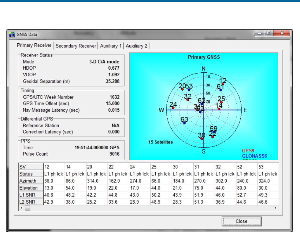
POS MV V5 Installation and Operation Guide
Tools and Diagnostics
8-2
Figure 50: POSView GNSS Data
The GNSS Data window shows the GNSS navigation status in a polar style display. POSMV generates
an identification number for each satellite in use and indicates its location in the sky, with the centre of the
display directly overhead. From this display, a person can deduce if a satellite signal is being blocked.
The bottom of the window displays a list of the satellites in solution and includes details of their Signal-to-
Noise Ratios (SNR) at the important L1 frequency (L1 SNR). Low SNR values for all satellites could
indicate deterioration in the quality of the GNSS antenna cable. The window will show the L2 SNR for
L1/L2 GNSS, if fitted.
Diagnostics
POS MV provides both control and display diagnostic functions. The control functions permit the selection
and setting of various binary outputs to specific values. The display functions allow the viewing of real-
time parameters. This provides POS MV with a debugging function that can be used to establish a
successful integration of the system into an extended suite of survey equipment.
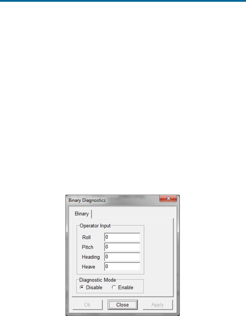
POS MV V5 Installation and Operation Guide
Tools and Diagnostics
Copyright © Applanix Corporation, 2012
8-3
Control Diagnostics
Diagnostic values that are entered and enabled for the digital ports will replace any real-time attitude
information on those channels. To resume normal operation, disable the diagnostic output for the relevant
channel.
Enter and enable diagnostic values by following the steps below. The diagnostic values that are entered
have no effect on the configuration of affected ports; refer to Figure 51.
1. On the MV-POSView menu bar, select Settings, Diagnostics Control, Binary to open the
Diagnostics window.
2. Select the appropriate tab and enter the diagnostic values for the displayed parameters in the
Operator Input pane.
3. Select the Enable option in the Output pane.
4. Select the OK or Apply button. The diagnostic values then appear on the appropriate output port,
using the current configuration for that port.
5. Return to normal operation by performing the following steps:
a) Set all values in the Operator Input pane to zero (optional)
b) Select the Disable option in the Output pane
c) Finally, select the OK or Apply button
Figure 51: POSView Binary Diagnostics
POS MV V5 Installation and Operation Guide
Tools and Diagnostics
8-4
Display Diagnostics
Display diagnostics permit the operator to view selected POS MV real-time internal data as an aid to
debugging system problems. Select Diagnostics on the MV-POSView menu bar to display the following
selections:
• Primary GNSS
• Display, Data & NVM
• Secondary GNSS
• Time & Pulses
• Base GNSS (Base 1 and Base 2)
• IMU
• Aux GNSS
• NMEA & Binary Output
• Control Port
• Other
Contact Applanix Customer Support for assistance, see page A-1
Regular Maintenance
Important:
1. Equipment shall be serviced only by qualified personnel.
2. The PCS (POS MV V5 and POS MV V5-1) shall be grounded via the safety ground screw or stud.
3. Power to the POS system should be protected by a user-supplied, resettable circuit breaker.
POS MV has a minimal requirement for scheduled maintenance on its subassemblies and components.
Performing these procedures at the recommended intervals enables the POS MV to maintain the highest
standard of service and performance throughout its lifetime.
Inertial Measurement Unit
The IMU contains sensitive and expensive solid-state
accelerometer and gyro components. Permanent damage to
these components will result if handled roughly.
IMPORTANT
Unauthorised opening of the IMU housing will void the warranty. The
IMU is a sealed unit that contains no user serviceable parts and does
not require internal maintenance.
Maintenance Procedures:
• Wipe the IMU housing with a damp cloth every six months, or more often if necessary, to protect
the finish and to remove oil and salt deposits.
• Check the cables and connectors for signs of damage, degradation or contamination. Repair or
renew them as necessary.

POS MV V5 Installation and Operation Guide
Tools and Diagnostics
Copyright © Applanix Corporation, 2012
8-5
• Ensure that cables are securely connected.
GNSS Antennas
Do not place metallized labels on the radome. Signal
attenuation will result.
Maintenance Procedures:
• Use fresh water to wash any deposits of salt or other contamination from the antennas.
• Inspect the antennas, cables and connectors every six months, or more often if necessary, for
signs of damage, degradation or contamination. Repair or renew them as necessary.
• Ensure that cables are securely connected.
• When operating in very cold conditions, use an appropriate method to remove any ice
accumulation from the antennas.
POS Computer System
If you protect the PCS from moisture and dust in its mounting location, the unit will require very little
regular maintenance.
Maintenance Procedures:
• Wipe the PCS housing with a damp cloth every six months, or more often if necessary, to protect
the finish and to remove oil and dust deposits.
• Check all cables and connectors for signs of damage, degradation or contamination. Repair or
renew them as necessary.
• Ensure that cables are securely connected.
Technical Support
Refer to the Technical Support and Service information and procedures on page A-1.

POS MV V5 Installation and Operation Guide
Fault Identification
Copyright © Applanix Corporation, 2012
9-1
9.0 Fault Identification
Important:
1. Equipment shall be serviced only by qualified personnel.
2. The PCS (POS MV V5 and POS MV V5-1) shall be grounded via the safety ground screw or stud.
3. Power to the POS system should be protected by a user-supplied, resettable circuit breaker.
Position and Orientation System for Marine Vessels (POS MV) development efforts are centred on the
need for the system to operate for long periods in rigorous marine environments with minimal
maintenance requirements.
POS MV incorporates self-diagnostics in the form of a Fault Detection Isolation and Reconfiguration
(FDIR) algorithm. FDIR monitors the health of the various system components and, in the case of sensor
degradation or failure, automatically reconfigures the system to minimise the effect of the degradation.
The POS MV uses two methods simultaneously, to inform you that the system has experienced a failure
or performance degradation:
• Lights on the POS Computer System (PCS) front panel will show a fault condition
• The MV-POSView Controller program will provide a more detailed description of the problem
By planning and conducting regular maintenance procedures, described in the Regular Maintenance
description starting on page 8-4, the POS MV will continue to provide a high standard of service and
performance.
If you suspect a fault condition on the POS MV, follow the instructions in this section of the manual to
identify the cause. Field maintenance procedures allow the following operations only:
• Identifying problems associated with system integration
• Identifying the cause of system failures
• Repairing the system by replacement of the PCS, cables, or sensing subsystems
Component Description
POS MV comprises the following subsystem components:
• One Inertial Measurement Unit (IMU)
• One POS Computer System (PCS)
• Two Global Navigation Satellite System (GNSS) antennas

POS MV V5 Installation and Operation Guide
Fault Identification
9-2
In addition to the above hardware, the POS MV includes all cables to interconnect the components of the
system and certain additional cables that can be used to connect to external equipment.
Previous sections of this manual describe the cables, the connection ports and the data formats; refer to
the Table of Contents at the beginning of the manual or the Index at the end of the manual for specific
items. The Handling Precautions on page 2-1 describes the precautions that should be exercised when
unpacking and installing the POS MV subsystems.
Inertial Measurement Unit
The IMU contains sensitive and expensive solid-state
accelerometer and gyro components. Permanent damage to
these components will result if handled roughly.
The IMU includes an orthogonal array comprising three accelerometers and three gyros. The
accelerometers sense translational acceleration along one of three axis (x, y, and z) and the gyros sense
angular rate around each axis. Incremental velocities and angles are output across a digital interface to
the PCS.
The IMU is a sensitive device and must be handled carefully to prevent damage to the sensing elements.
Refer to the Inertial Measurement Unit description on page 2-1 for instructions pertaining to IMU handling
and care.
GNSS Antennas
Do not place metallized labels on the radome. Signal
attenuation will result.
The GNSS antennas are solid state devices with no moving parts. They are rugged and reliable and, with
a little care, will provide long-term trouble free operation. Follow the steps outlined in the GNSS Antennas
topic on page 8-5 to maintain their operating efficiency.
To prevent damage caused by moisture ingress, ensure that the TNC connection between the GNSS
antenna receptacle and its mating cable plug is waterproof. Use a good waterproof tape and sealant.
POS Computer System
Note: An optional field support kit includes a replacement PCS.
The PCS contains a computer module, an interface module, two GNSS receivers, and power supplies for
the internal electronics and the remote IMU. Constructed of rugged, industrial grade components, the
PCS should be handled with care to minimize risk of damage.
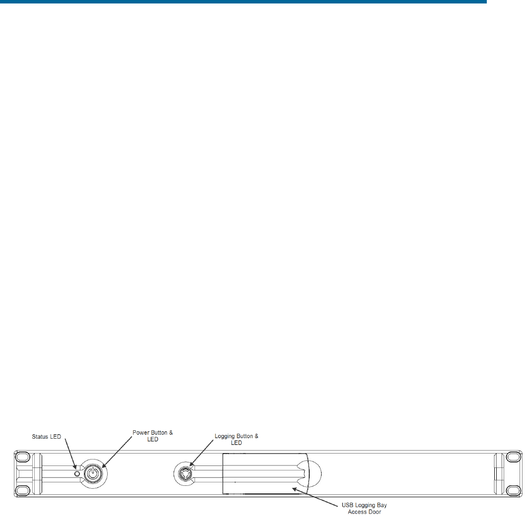
POS MV V5 Installation and Operation Guide
Fault Identification
Copyright © Applanix Corporation, 2012
9-3
Fault Identification
Field maintenance for the POS MV involves the following actions:
• Identification of a fault condition
• Repair of the fault by substitution or product return
POS MV has self-diagnostics to assist with isolating a fault to the following subsystems:
• IMU subsystem, including the IMU and the IMU cable
• PCS subsystem
• GNSS subsystem, including the GNSS antennas, GNSS antenna cables and GNSS receivers
If POS MV detects a failure condition in either the GNSS or IMU subsystems, it will use two methods to
alert you:
• Indicates a fault condition through status lights on the PCS front panel
• Outputs appropriate status warning messages to the various MV-POSView Controller windows
(Fault Detection and Message Log)
The following paragraphs describe both types of failure indications.
Front Panel Indicators
The lights on the PCS front panel display status information about the PCS system. To isolate faults
follow the advice and instructions provided in Table 35.
Figure 52: POS MV V5 Front Panel
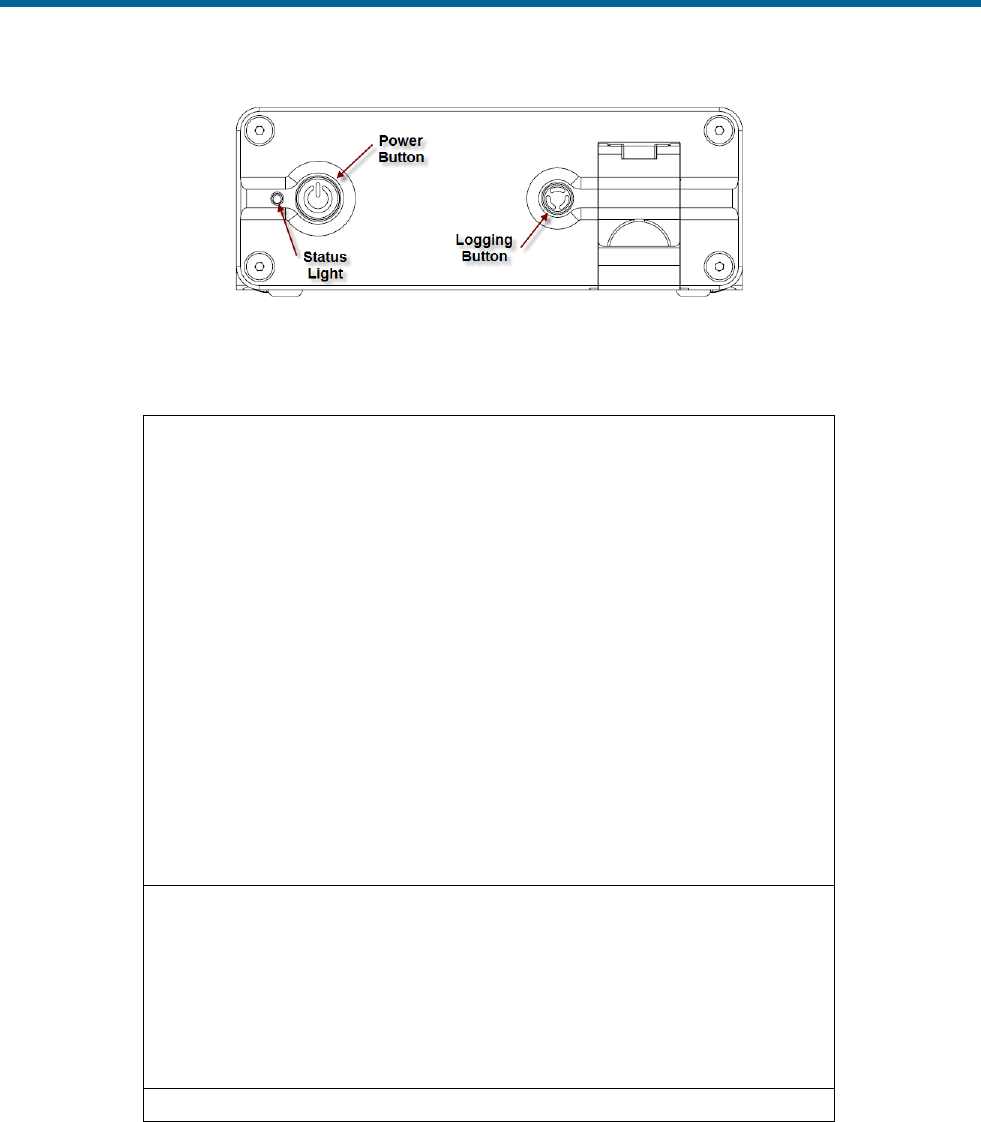
POS MV V5 Installation and Operation Guide
Fault Identification
9-4
Figure 53: POS MV V5-1 Front Panel
Table 35: PCS Front Panel Indicators - Fault Identification
Status light - indicates current status of POS MV:
Steady red:
POS LV failure - shows red when PCS is first
powered-on. Changes to a valid condition when PCS
internal program begins to run, but will turn red again
if there is a fault in PCS.
If a fault occurs, do not power-off PCS. Refer to
Fault Detection window of controller program, see
Fault Detection starting on page 9-4.
Steady amber:
Standby mode - POS MV is waiting for instructions.
Flashing amber:
Navigate mode - initialising and aligning attitude
(coarse levelling).
Flashing green:
Navigate mode - degraded attitude performance.
Attitude measurements are acceptable but do not
meet user-set accuracy limits.
Steady green:
Navigate mode - normal system operation. System
meets accuracy limits set by user for position,
velocity, attitude and heading.
Logging light - indicates status of removable logging device.
Steady green:
Removable logging device is active and recording
data.
Steady amber:
Logging media is > 80% full.
Steady red:
Logging has failed – check that there is a USB flash
drive in the logging bay and that the device is not
full.
Power light - illuminates when the PCS is operating.
Fault Detection
To access the Fault Detection window select View, Faults from the MV-POSView menu bar. This
window, shown in Figure 54, shows the faults detected by the POS MV during operation. A fault is

POS MV V5 Installation and Operation Guide
Fault Identification
Copyright © Applanix Corporation, 2012
9-5
present if an indicator shows red against any item in the list. Three tabs provide a list of the system health
monitoring items: General, IMU and GNSS Corrections.
If you suspect that a fault condition has occurred, but the Fault Detection window does not show it,
check the Message Log. The Message Log description starting on page 9-9 lists the possible messages
that may appear in the message log. Of interest, at this point, are the items in Figure 54. The monitored
items are organized by category and each fault has a brief description.
If you suspect that the system has developed a fault, note the condition of the indicators on the Fault
Detection window. If necessary, contact Applanix for advice, refer to Technical Support and Service on
page A-1 for procedures.
General Tab
The Primary GNSS pane, Figure 54, shows the status of the primary GNSS receiver and any faults
reported by it. If this pane reports any persistent faults, they could be caused by a faulty GNSS antenna
or its cable.
The Secondary GNSS pane monitors the data gaps from the secondary GNSS receiver. A persistent
loss of secondary GNSS information will prevent GNSS Azimuth Measurement Subsystem (GAMS) from
performing carrier phase differential measurements to determine the heading. Investigate the secondary
GNSS antenna and its cable as a possible cause of persistent data gaps.
Data gaps experienced by both GNSS receivers simultaneously are likely to occur if nearby buildings or
structures block the satellite signals (this is not a system fault). During such data gaps, the POS MV will
continue to navigate inertially with only a gradual degradation in position and heading accuracy.
The Auxiliary GNSS pane reports the status of navigation solutions supplied from any auxiliary GNSS
receiver connected to the PCS.
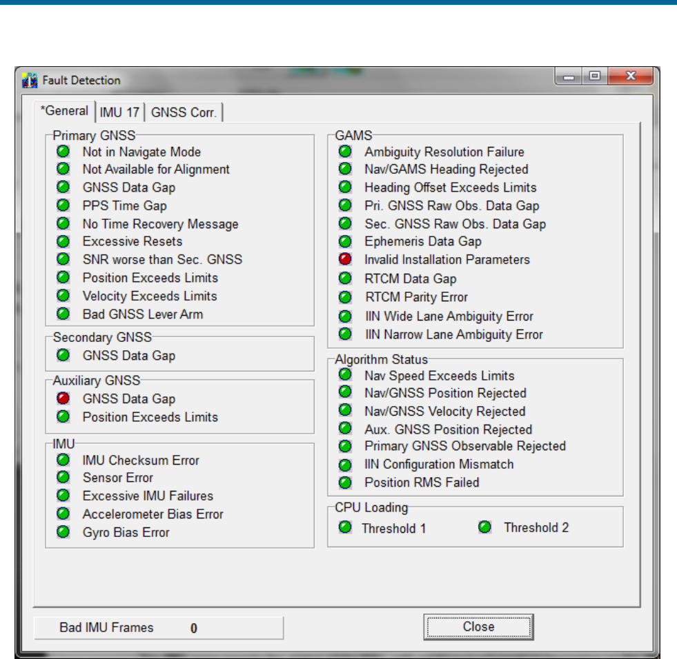
POS MV V5 Installation and Operation Guide
Fault Identification
9-6
Figure 54: POSView Fault Detection
The IMU pane reports the status of the IMU, with additional information appearing on the IMU tab shown
in Figure 55. There is also an additional field that appears at the bottom left-hand side of each Fault
Detection tab to show the number of bad data frames received from the IMU. An occurrence of several
consecutive bad IMU frames will cause the POS MV to reinitialize and start coarse levelling.
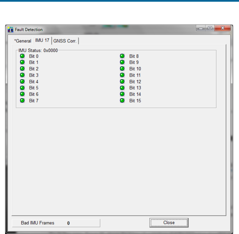
POS MV V5 Installation and Operation Guide
Fault Identification
Copyright © Applanix Corporation, 2012
9-7
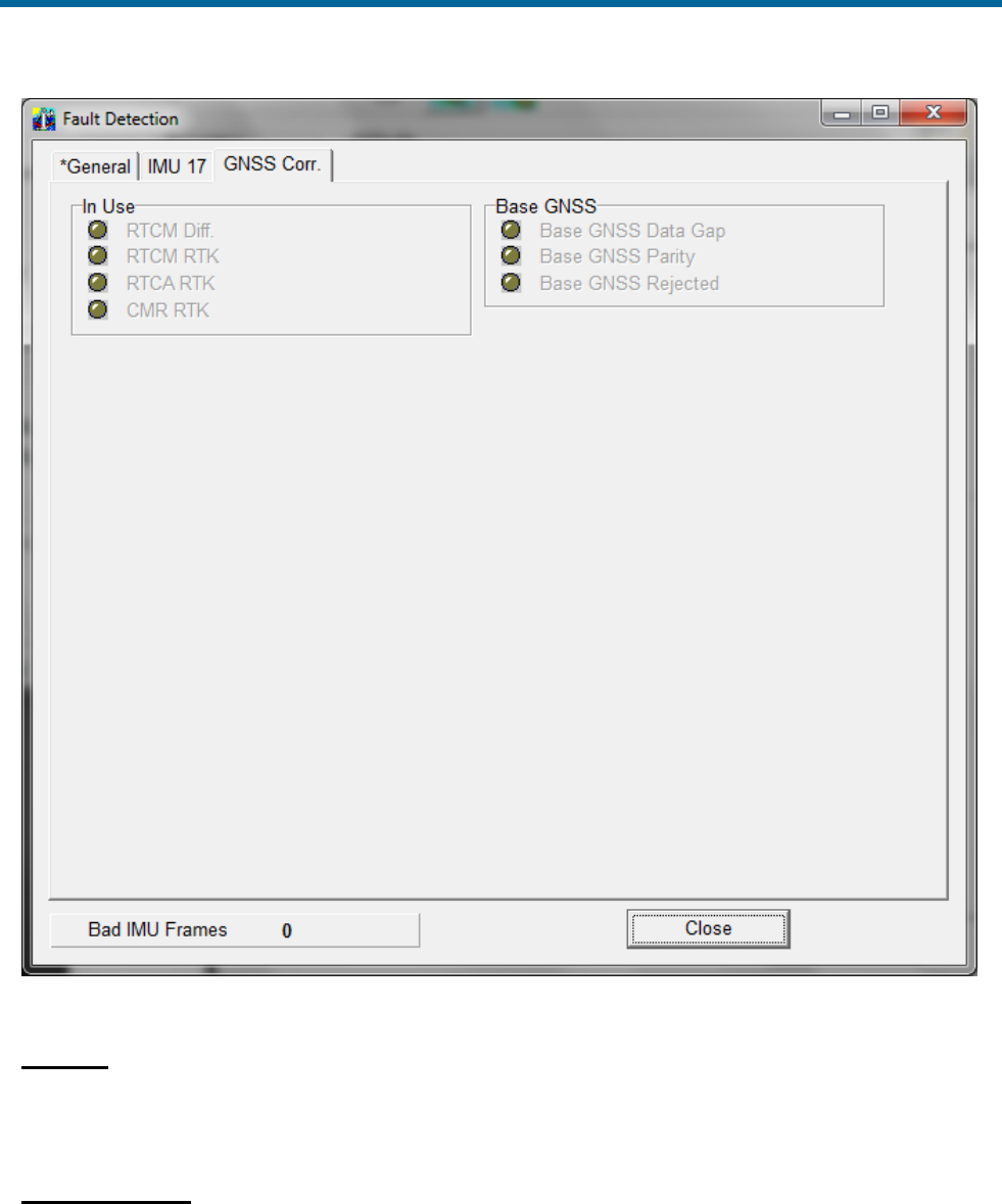
POS MV V5 Installation and Operation Guide
Fault Identification
9-8
Figure 55: POSView Fault Detection - IMU and GNSS Corr. Tabs
IMU Tab
The IMU Status pane, Figure 55, identifies the raw status bits from the IMU. If any of these bits have a
red light please contact Applanix Customer Support representative for assistance, refer to page A-1.
GNSS Corr. Tab
The In Use pane, Figure 55, shows the types of corrections that the navigation algorithm may use. A
green light indicates the item that is currently being used.

POS MV V5 Installation and Operation Guide
Fault Identification
Copyright © Applanix Corporation, 2012
9-9
The Base GNSS pane indicates the status of received data on the base GNSS COM port. A green light
indicated no problems; a red light indicates a problem.
Message Log
Access the Message Log by selecting View, Message Log from the MV-POSView menu bar, see
Figure 56.
Figure 56: POSView Message Log
Table 36 contains messages that can appear in the message log. Messages marked with an asterisk (*)
relate to indicators on the Fault Detection window.
Note: Some cases of incorrect GNSS configuration is handled automatically if the GNSS automatic
reconfiguration feature is enabled (select Enabled in the Auto Configuration pane on the GNSS
Receiver Configuration window). The automatic reconfiguration logic checks for expected messages
from the GNSS receiver, and will send a configuration command to the receiver if the expected messages
are not present. The contents of messages are not checked.
Table 36: Message Log Entries
Message Text
Description
*PPS data not received
Time recovery data not received
PPS data received
Flag reset
HDOP data not received
Dilution of precision data not
received; receiver not configured
properly; send configuration file
HDOP data received
Flag reset
*Ephemeris data gap detected
There is a gap in GNSS data; Short
periods when this occurs are normal
Ephemeris data gap cleared
Flag reset

POS MV V5 Installation and Operation Guide
Fault Identification
9-10
Message Text
Description
*Primary GNSS raw observable data
gap detected
There is a gap in GNSS data; short
periods when this occurs are normal
Primary GNSS raw observable data
gap cleared
Flag reset
*Secondary GNSS raw observable
data gap detected
There is a gap in GNSS data; short
periods when this occurs are normal
Secondary GNSS raw observable
data gap cleared
Flag reset
*Auxiliary GNSS data gap detected
There is a gap in auxiliary GNSS
data
Auxiliary GNSS data gap cleared
Flag reset
Horizontal acceleration out of range
Receiver not configured properly
Horizontal acceleration out of range
cleared
Flag reset
*GNSS not available for alignment
POS MV failed to receive GNSS data
for > 60 s
GNSS available for alignment
Flag reset
*GNSS data gap detected
Gap in GNSS data; short periods
when this occurs are normal
GNSS data gap cleared
Gap discontinued
*PPS time gap
Gap in PPS signal; short periods
when this occurs are normal
PPS time gap cleared
Gap discontinued
Time recovery message not
received
The GNSS receiver is not configured
properly
Time recovery message received
Flag reset
*GNSS not in navigate mode
GNSS receiver has not entered
navigate mode; still searching for
satellites
GNSS in navigate mode
Receiver in navigation mode
*GNSS tracking elevation limit
incorrect
GNSS receiver is not configured
GNSS tracking elevation limit
corrected
Flag reset
HDOP/VDOP less than 10
GNSS receiver is not configured
HDOP/VDOP less than 10 cleared
Flag reset
GPS Time output mode is not UTC
GNSS receiver is not configured
GPS Time output mode is UTC
Flag reset
Incorrect time parameters
GNSS receiver is not configured

POS MV V5 Installation and Operation Guide
Fault Identification
Copyright © Applanix Corporation, 2012
9-11
Message Text
Description
Incorrect time parameters cleared
Flag reset
Incorrect GNSS datum parameters
The GNSS receiver is not configured
properly
Incorrect GNSS datum parameters
cleared
Flag reset
Position/velocity fix error
Positions and velocities reported by
the IMU and the GNSS are
inconsistent; likely cause is an
incorrect entry of GNSS lever arms in
the installation data
Position/velocity fix error cleared
Flag reset
Incorrect differential GNSS
configuration cleared
Flag reset
Incorrect SV selection parameters
The GNSS receiver is not configured
properly
Incorrect SV selection parameters
cleared
Flag reset
GAMS ambiguity resolution failure
The GNSS receiver is not configured
properly
GAMS ambiguity resolution failure
cleared
Flag reset
GNSS failure
GNSS velocity or position failure
GNSS failure cleared
Flag reset
*Speed out of range fault
Navigation algorithm speed is out of
range (speed > 35 m/s); algorithm
will reset itself
Speed out of range fault cleared
Flag reset
*GNSS velocity failure
GNSS reports speed > 35 m/s;
problem will probably correct itself
GNSS velocity failure cleared
Flag reset
*GNSS position failure
GNSS reports horizontal position
error > 1000 m; problem will
eventually correct itself
GNSS position failure cleared
Flag reset
Auxiliary GNSS position failure
The GNSS receiver is not configured
properly
Auxiliary GNSS position failure
cleared
Flag reset

POS MV V5 Installation and Operation Guide
Fault Identification
9-12
Message Text
Description
*GNSS position measurement
rejected
Position reported between IMU and
GNSS are inconsistent; likely GNSS
Lever Arms are incorrect in
installation data
GNSS position measurement reject
cleared
Flag reset
*GNSS velocity measurement
rejected
Velocity reported between IMU and
GNSS are inconsistent; likely GNSS
Lever Arms are incorrect in
installation data
GNSS velocity measurement reject
cleared
Flag reset
GAMS heading failure
The GNSS receiver is not configured
properly
GAMS heading failure cleared
Flag reset
Aux GNSS position measurement
rejection
The GNSS receiver is not configured
properly
Aux GNSS position rejection cleared
Flag reset
IMU Messages - Message Log
*Multiple consecutive IMU failures
Communications problem between
IMU and PCS; check cable
Multiple consecutive IMU failures
cleared
Flag reset
IMU X accelerometer failure
IMU diagnostics indicate failure of X
accelerometer channel
IMU X accelerometer failure cleared
Flag reset
IMU Y accelerometer failure
IMU diagnostics indicate failure of Y
accelerometer channel
IMU Y accelerometer failure cleared
Flag reset
IMU Z accelerometer failure
IMU diagnostics indicate failure of Z
accelerometer channel
IMU Z accelerometer failure cleared
Flag reset
IMU X gyro failure
IMU diagnostics indicate failure of X
gyro channel
IMU X gyro failure cleared
Flag reset
IMU Y gyro failure
IMU diagnostics indicate failure of Y
gyro channel
IMU Y gyro failure cleared
Flag reset
IMU Z gyro failure
IMU diagnostics indicate failure of Z
gyro channel

POS MV V5 Installation and Operation Guide
Fault Identification
Copyright © Applanix Corporation, 2012
9-13
IMU Messages - Message Log
IMU Z gyro failure cleared
Flag reset
IMU A/D converter failure
IMU diagnostics indicate failure of
A/D converter
IMU A/D converter failure cleared
Flag reset
IMU pickoff test failure
IMU diagnostics indicate failure of
voltage pickoff
IMU pickoff test failure cleared
Flag reset
IMU power supply failure
IMU diagnostics indicate problems in
external power delivered to IMU
IMU power supply failure cleared
Flag reset
*IMU/POS checksum error
Error in data checksum between
POS MV and IMU
IMU/POS checksum error cleared
Flag reset
IMU failure
IMU status test failure set by IMU
sensor
IMU failure cleared
Flag reset
IMU warning
One of the IMU bias estimates is out
of range
IMU warning cleared
Flag reset
X accelerometer bias estimate out of
range
The Kalman Filter’s estimate of the X
accelerometer bias is outside the
allowable range of 4000 micro-g
X accelerometer bias estimate error
cleared
Flag reset
Y accelerometer bias estimate out of
range
The Kalman Filter’s estimate of the Y
accelerometer bias is outside the
allowable range of 4000 micro-g
Y accelerometer bias estimate error
cleared
Flag reset
Z accelerometer bias estimate out of
range
The Kalman Filter’s estimate of the Z
accelerometer bias is outside the
allowable range of 4000 micro-g
Z accelerometer bias estimate error
cleared
Flag reset
X gyro bias estimate out of range
The Kalman Filter’s estimate of the X
gyro bias is outside the allowable
range of 20 deg/hr
X gyro bias estimate error cleared
Flag reset

POS MV V5 Installation and Operation Guide
Fault Identification
9-14
IMU Messages - Message Log
Y gyro bias estimate out of range
The Kalman Filter’s estimate of the Y
gyro bias is outside the allowable
range of 20 deg/hr
Y gyro bias estimate error cleared
Flag reset
Z gyro bias estimate out of range
The Kalman Filter’s estimate of the Z
gyro bias is outside the allowable
range of 20 deg/hr
Z gyro bias estimate error cleared
Flag reset
*These messages correspond to faults reported by the Fault Detection
window.
Status Warning Messages
POS MV provides status information on the complete system and each individual subsystem. The MV-
POSView Controller program decodes some of the bits automatically and displays the relevant status
information. Some examples of the faults represented by the status bits appear in Table 37.
Table 37: Status Warning Messages
IMU
The IMU can experience a communication failure between the IMU
and the PCS, or a loss of calibration.
Communication Failure
The IMU can experience a permanent or intermittent communication
failure. If the IMU develops a fault that causes permanent loss of
communication, you will see the following symptoms:
• The IMU front panel light will show clear (off).
• The IMU tab on the Fault Detection window will show intermittent
failures in IMU communications.
• The IMU transmits a checksum in each data frame. POS MV uses
the checksum to validate the data received from the IMU. If the
validation fails, then POS MV sets a bit to declare that it has
detected a bad IMU frame.
Simultaneously, it increments a counter that keeps track of the
number of bad IMU frames. The Fault Detection window shows
the count of Bad IMU Frames in its bottom left-hand corner.
• An occurrence of several consecutive bad IMU frames will cause
POS MV to reinitialize and start coarse levelling. However, due to
the communications handshaking used by the IMU, bad IMU
frames are highly unlikely.

POS MV V5 Installation and Operation Guide
Fault Identification
Copyright © Applanix Corporation, 2012
9-15
IMU
If bad IMU frames do occur, their likely cause is one of the following:
• Problems in the data cable that connects the IMU to the PCS
• Problems with the IMU or the power supplied to the IMU
• Problems within the PCS
Loss of Calibration
If IMU performance falls below specification (as may happen if the
IMU experiences excessive shock or vibration), the IMU Status field
on the controller main window will indicate an IMU failure.
Refer to the Fault Detection and the Message log windows
(described in Fault Identification on page 9-3 and Message Log on
page 9-9) for a more detailed identification of the fault.
Note: If POS MV detects that the IMU performance is outside
specification, it will alert you and continue navigation.
If POS MV detects a hardware failure in the IMU, the controller main
window will display the warning message IMU Failure. Note any
indications on the Fault Detection or the Message Log windows, and
contact Applanix for advice.
GNSS
The GNSS subsystem can experience a permanent loss of satellites,
or a breakdown of communication between the GNSS receiver and
the PCS.
Permanent Loss of Satellites
POS MV provides continuous information on the status of the GNSS
receivers. The status of the GNSS receivers may be monitored on the
GNSS Data window; select View, GNSS Data from the MV-POSView
menu bar. Additionally, the GNSS Data window includes detailed
information on the satellites that the receiver is tracking and on the
receiver mode (i.e. tracking, navigate, etc).
The GNSS subsystem may experience periodic GNSS dropouts
caused, for example, by antenna obstruction. The controller program
indicates a GNSS dropout by displaying GNSS Not Available or
GNSS Data Gap in the GNSS Status field on the main window.
However, if a GNSS dropout occurs and persists without any
apparent antenna obstruction, then one of the following problems may
exist:
• A loss of GNSS receiver configuration

POS MV V5 Installation and Operation Guide
Fault Identification
9-16
GNSS
• A failure in the GNSS antenna
• A failure in the GNSS antenna cable
• A failure in the GNSS receiver
The above diagnoses assume that the PCS continues to receive
messages from the primary GNSS receiver. If this is true, the front
panel GNSS light will behave normally for the GNSS service in use.
If the front panel GNSS light shows red, then there are no GNSS
navigation solutions available to the PCS. The most likely cause of
this is a loss of communication with the receiver. If this occurs, refer to
the following Loss of Communications heading.
Correct a loss of configuration by selecting Tools, Configure GNSS
from the MV-POSView menu bar.
The GNSS antenna is a solid-state device with a low failure rate.
Faults in the GNSS subsystem are more likely to arise from damaged
antenna cabling or a receiver failure. If examination of the GNSS
antenna installation reveals damage to a cable, replace the cable.
If none of the above actions resolves the problem, contact Applanix
for advice.
Loss of Communications
If the front panel GNSS light shows red, then there is a
communications failure between the PCS and the primary GNSS
receiver. Typical causes for this fault are:
• A loss of GNSS receiver configuration
• There is a failure in the internal PCS wiring harness
• There is a failure in the GNSS receiver
If Auto Configuration is enabled (select Enabled in the Auto
Configuration pane on the GNSS Receiver Configuration window),
then during the power-on sequence the PCS will establish a proper
configuration for the GNSS receiver. Therefore, incorrect settings for
baud rate should not be possible unless the Auto Configuration
feature is disabled.
The GNSS receiver may be configured manually be sending a
configuration command by selecting Tools, Configure GNSS from
the controller menu bar.

POS MV V5 Installation and Operation Guide
Fault Identification
Copyright © Applanix Corporation, 2012
9-17
GNSS
If proper operation is not restored within a minute, select Tools,
Reset GNSS from the controller menu bar. The GNSS receiver is
reset to the factory defaults. This action takes a couple of minutes.
Also. if the auto configuration feature is enabled, the receiver will
assume an appropriate POS configuration.
Finally, if all else fails, cycle the PCS power (off and on) to provide a
hard reset of the GNSS receiver. Refer to the Power-On and Power-
Off procedures on pages 4-1 and 4-24 respectively.
GAMS
The GAMS subsystem can experience a permanent loss of satellites,
or a communication failure between the GNSS receiver and the PCS.
Permanent Loss of Satellites
The GAMS Solution window provides information on satellites being
tracked and the status of GAMS; select View, GAMS Solution to
view this window.
GAMS may experience periodic GNSS dropouts caused, for example,
by an antenna obstruction. During these dropouts, GAMS is unable to
compute a heading solution and the controller Status pane indicates
Not ready in the GAMS field.
However, if a GAMS dropout occurs and persists without any
apparent antenna obstruction, one of the following problems may
exist:
• A loss of GNSS receiver configuration
• A failure in the GNSS antenna
• A failure in the GNSS antenna cable
• A failure in the GNSS receiver
The above diagnosis assumes that the PCS continues to receive
messages from the secondary GNSS receiver. Select View, GAMS
Solution to see the GAMS status.
GAMS Ambiguity Resolution Failures
If there is a GAMS ambiguity resolution failure, the controller Status
pane indicates Not ready in the GAMS field. The same status is
indicated when there is satellite signal loss due to an antenna
obstruction.
The POS MV Message Log window specifically indicates GAMS
ambiguity resolution failures; see Figure 56 on page 9-9.

POS MV V5 Installation and Operation Guide
Fault Identification
9-18
GAMS
Occasional failures of ambiguity resolution, for example at intervals of
10 to 20 minutes, are quite common and may be the result of changes
to the satellite constellation.
Repeated or continuous failures in ambiguity resolution may be the
result of a poor GAMS calibration or excessive vibration at the
antennas. These failures may also indicate weak signal reception
from the satellites, requiring changes to the installation.
Use the following steps to further diagnose the problem:
1. Select View, GNSS Data and examine the L1 Signal-To-Noise
Ratios (SNR) for the available satellites, see Figure 50 on page 8-
2. If the L1 SNR is below 38 dB for more than one satellite, the
GNSS antenna cables are introducing too much signal
attenuation. To correct this fault, shorten the cables or substitute
them with new low-loss cables.
2. Examine the antenna mountings; they must be rigid with respect
to each other and with respect to the IMU. Make any necessary
modifications to secure the antenna mounting positions so that
they experience no significant twisting or movement relative to the
IMU.
3. Repeat the GAMS calibration and ensure that:
• The Positional Dilution of Precision (PDOP) is below 2.5
(preferable below 2.0)
• The GAMS Solution window shows at least six Space
Vehicles (SVs) in the solution
Prior to the calibration, perform a series of calibration manoeuvres
and ensure the heading accuracy is better than 2.0°. Refer to the
Initial GNSS Configuration description on page 4-17 for the
instructions to complete this calibration procedure. Try to achieve
a heading accuracy better than 1.0°.
Within the first ten minutes after calibration, GAMS uses dynamic
inputs to verify the calibration. Therefore, once the calibration is
completed, perform a series of dynamic and vigorous
manoeuvres with the vessel for ten minutes to support this
process.
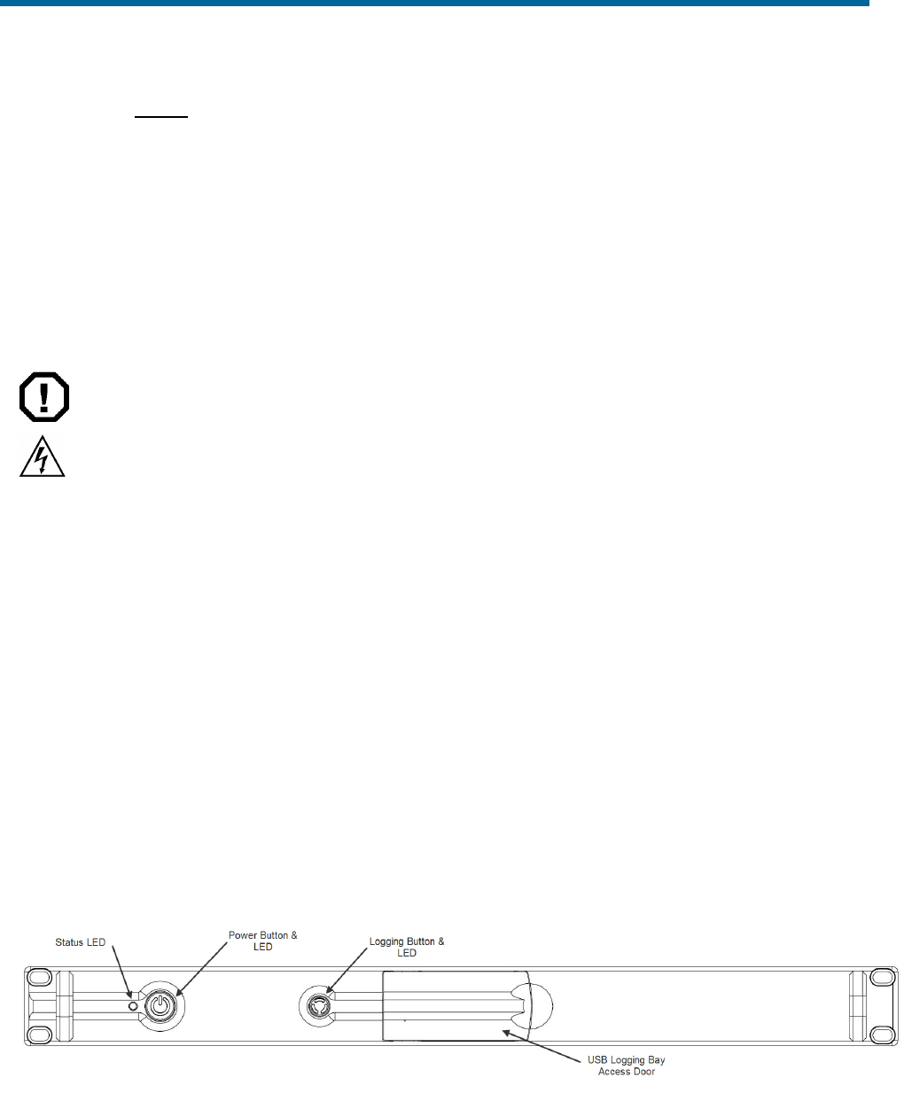
POS MV V5 Installation and Operation Guide
Fault Identification
Copyright © Applanix Corporation, 2012
9-19
GAMS
4. If the ambiguity resolution problem persists, contact Applanix for
further instructions. Refer to Technical Support and Service on
page A-1 for procedures.
Remove and Replace Procedures
The following paragraphs explain how to remove and replace the various components and subassemblies
of the POS MV system.
ELECTRICAL HAZARD
Note: these warnings apply only to POS MV V5 PCS.
Mains electrical voltages can cause death or serious injury by
electric shock.
Only a competent person who has received the relevant training
and experience should perform maintenance work on electrical
equipment.
Power-off and isolate the equipment from the electrical supply
before you work on any equipment that uses mains voltage.
Arrange to safely discharge any power supply storage
capacitors.
Observe all relevant local and national safety regulations while
performing any maintenance work on electrically powered
equipment.
After completing maintenance, refit all safety covers and ground
connections to the equipment.
The PCS employs double pole / neutral fusing on the power
receptacle. Each of the two RoHS compliant fuses are rated at:
• Rating = 250 V
• Current = 4 A
• Type = fast acting
• Case = 5.2 mm x 20 mm
Figure 57: PCS Front Panel - POS MV V5
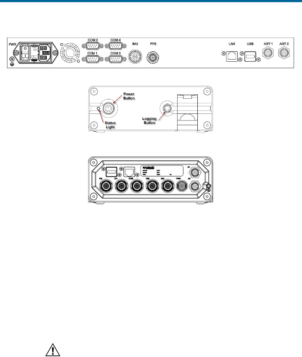
POS MV V5 Installation and Operation Guide
Fault Identification
9-20
Figure 58: PCS Rear Panel - POS MV V5
Figure 59: PCS Front Panel – POS MV V5-1
Figure 60: PCS Rear Panel – POS MV V5-1
Circular Connectors
The IMU connector on POS MV V5 and the majority of connectors on POS MV V5-1 are high quality,
IP67 Lemo ® connectors. These connectors use spring loaded latches that engage when the connector is
pushed fully into the socket. Once engaged the connector is very secure against shock, vibration and
pulling on the cable, ensuring a reliable connection. To disengage the connector you must pull back on
the outer release sleave. Since pulling back on the release sleave often results in some force on the
entire connector body the latches can experience some friction and not retract smoothly. If possible it is
better to hold the cable forward while pulling back on the release sleave and then sliding the connector
out of the socket. Applying excess force could damage the latch mechanism.
Inertial Measurement Unit
The IMU contains sensitive and expensive solid-state
accelerometer and gyro components. Permanent damage to
these components will result if handled roughly. To prevent
irreversible damage, handle the IMU with care.
If you suspect a fault condition with the IMU please return it to Applanix for service and repair. To remove
or replace the IMU complete this procedure.

POS MV V5 Installation and Operation Guide
Fault Identification
Copyright © Applanix Corporation, 2012
9-21
Tools
• Set of metric open-end or combination wrenches appropriate to remove or secure IMU to its
mounting location
Remove
1. Observe PCS front panel power-off procedures (starting on page 4-24).
2. Remove power cable from PCS rear panel (starting page 9-20).
3. Release and disconnect power and data cable from IMU. Protect free end of power and data
cable from damage or contamination.
4. If fault suspected on power and data cable, disconnect and install a new one. Refer to IMU Cable
procedure on page 9-23 for details.
5. Release IMU from installed position noting orientation. Retain fixing screws or bolts.
6. Handle IMU with care and pack into original transit case.
Note: It is imperative that proper packing is used to transport IMU.
7. Contact Applanix Customer Support for shipping instructions; refer to page A-1.
Replace
Note: Each IMU is designed with alignment holes to ensure consistency in the physical mounting of
the IMU (within certain tolerances); refer to Figure 5 on page 2-8. The internal accelometers and
gyros have tolerances that affect the overall alignment. Any time a repaired or new IMU is installed
the calibration procedure, starting on page 2-24, should be followed. Contact Applanix Customer
Support for additional information, refer to page A-1 for instructions.
1. Same location:
a) Place IMU in installed position noting orientation. Secure fixing screws or bolts.
b) Connect power and data cable to IMU. Protect free end of power and data cable from
damage or contamination.
c) Replace power cable to PCS rear panel (starting page 9-20).
d) Observe PCS front panel power-on procedures (starting on page 4-1).
2. New location - Follow installation instructions for Inertial Measurement Unit starting on page 2-7.

POS MV V5 Installation and Operation Guide
Fault Identification
9-22
GNSS Antenna
Do not place metallized labels on the radome. Signal
attenuation will result.
If you suspect a fault condition on the GNSS antenna, replace it with the same type and ensure its
serviceability. To remove or replace the GNSS antenna complete this procedure.
Tools
• Self-amalgamating tape
• Waterproof spray
• Sharp knife or scalpel
• Set of SAE open-end or combination wrenches appropriate to remove or secure GNSS antenna
Remove
1. Observe PCS front panel power-off procedures (starting on page 4-24).
2. Remove power cable from PCS rear panel (starting page 9-20).
3. Remove waterproof sealing tape or silicone sealant protecting TNC antenna connector.
4. Disconnect TNC antenna connector. Protect free end of cable from damage or contamination.
5. Note direction of arrow on top of antenna dome.
6. Remove antenna by turning in a counter-clockwise direction.
Replace
1. Same location:
a) Install antenna by turning in a clockwise direction.
b) Note direction of arrow on top of antenna dome and align with previous installation.
c) Connect TNC antenna connector. Protect free end of cable from damage or contamination.
d) Apply waterproof sealing tape or silicone sealant to protect TNC antenna connector.
e) Replace power cable to PCS rear panel (starting page 9-20).
f) Observe PCS front panel power-on procedures (starting on page 4-1).
2. New location - Follow installation instructions for GNSS System on page 2-4.

POS MV V5 Installation and Operation Guide
Fault Identification
Copyright © Applanix Corporation, 2012
9-23
IMU Cable
If you suspect a fault condition on the IMU power and data cable, install a new cable. To remove or
replace the IMU power and data cable, complete this procedure.
Tools
No tools are required.
Remove
1. Observe PCS front panel power-off procedures (starting on page 4-24).
2. Remove power cable from PCS rear panel (starting page 9-20).
3. Disconnect IMU power and data cable at both IMU and PCS (Figure 96 on page E-9).
4. Inspect cable and connectors for signs of damage or contamination. Perform repairs to cable as
necessary. Protect free ends of cable from damage or contamination.
5. Replace cable if not repairable.
Replace
1. Connect IMU power and data cable at both IMU and PCS (Figure 96 on page E-9). Protect free
ends of cable from damage or contamination.
2. Replace power cable to PCS rear panel (starting page 9-20).
3. Observe PCS front panel power-on procedures (starting on page 4-1).
GNSS Antenna Cable
If you suspect a fault condition on the GNSS antenna power and data cable, install a new cable. To
remove or replace the GNSS antenna power and data cable complete this procedure.
Tools
• Self-amalgamating tape
• Waterproof spray
• Sharp knife or scalpel
• Slip joint pliers appropriate to remove or secure the GNSS antenna connector
Remove
1. Observe PCS front panel power-off procedures (starting on page 4-24).
POS MV V5 Installation and Operation Guide
Fault Identification
9-24
2. Remove power cable from PCS rear panel (starting page 9-20).
3. Remove waterproof sealing tape or silicone sealant protecting TNC antenna connector.
4. Disconnect GNSS antenna power and data cable at both GNSS and PCS (Figure 96 on page E-
9).
5. Inspect cable and connectors for signs of damage or contamination. Perform repairs to cable as
necessary. Protect free ends of cable from damage or contamination.
6. Replace cable if not repairable.
Replace
1. Connect GNSS antenna power and data cable at both GNSS and PCS (Figure 96 on page E-9).
Do not over tighten. Protect free ends of cable from damage or contamination.
2. Apply waterproof sealing tape or silicone sealant to protect TNC antenna connector.
3. Replace power cable to PCS rear panel (starting page 9-20).
4. Observe PCS front panel power-on procedures (starting on page 4-1).
POS Computer System
There are no user replaceable parts inside. Service shall be
performed by trained and qualified personnel. If you suspect a
fault condition with the PCS contact Applanix Customer
Support, refer to page A-1 for instructions.
To remove or replace the PCS complete this procedure.
Tools
• Cross tipped screwdrivers
• Straight tipped screwdriver
• Set of SAE or metric open-end or combination wrenches appropriate to remove or secure the
PCS to its mounting location
Remove
1. Observe PCS front panel power-off procedures (starting on page 4-24).
2. Remove power cable from PCS rear panel (starting page 9-20).
3. Remove PCS from mounting location.
4. Tag and remove PCS rear panel connectors.

POS MV V5 Installation and Operation Guide
Fault Identification
Copyright © Applanix Corporation, 2012
9-25
Replace
1. Same location:
a) Install PCS rear panel connectors.
b) Install PCS in mounting location.
c) Replace power cable to PCS rear panel (starting page 9-20).
d) Observe PCS front panel power-on procedures (starting on page 4-1).
2. New location - Follow installation instructions for POS MV V5-1 on page 2-12 and POS MV V5 on
page 2-9.
Troubleshooting
Note: If the POS MV system fails to operate when you first try to use it after installation, check that you
have installed and configured the system correctly. Contact Applanix for advice if necessary, refer to
Technical Support and Service on page A-1 for procedures.
Refer to this subsection if the system develops a fault after a period of normal and successful operation,
or if you experience some problems during the initial integration of POS MV into the survey suite.
The following subsections cover six categories of system failure:
• Total system failure
• Initialization failure
• GNSS Not Available
• GAMS Not Ready
• Serial communications problem
• Ethernet communications problem
Total System Failure
A total system failure is indicated by the following symptoms:
• Real-time and NMEA data communication stops
• Ethernet LAN communication stops
Use the following procedure to diagnose and isolate a total system failure:
1. Power-off PCS. Wait for thirty seconds and then power-on PCS again to reboot the system. If
failure symptoms persist, continue with procedure.
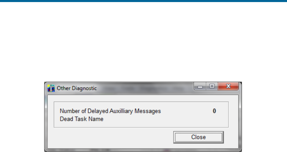
POS MV V5 Installation and Operation Guide
Fault Identification
9-26
2. Check IMU light, it should be solid green. If not, there is problem with IMU subsystem. Refer to
Fault Identification subsection on page 9-3 for further IMU diagnostic advice.
3. Check SYS light, if red there may be a software problem. If Ethernet is functioning, select
Diagnostics, Other from the controller menu bar, see Figure 61. Record any dead tasks and
inform Applanix.
Figure 61: POSView Other Diagnostic
4. Check quality of electrical power supplied to PCS.
5. Check PCS connection to ground through ground strap to grounding screw or stud on PCS rear
panel.
6. If failure still exists, system may have experienced a board failure. Substitute working PCS for
failed unit.
Return the failed PCS to Applanix for repair. Provide a report of your findings with the returned PCS,
refer to Technical Support and Service on page A-1.
Initialization Failure
The system Initialization procedure requires POS MV to compute the approximate tilt of the IMU relative
to a locally level reference, taking into account the present position. This is called coarse levelling. If POS
MV fails to complete its coarse levelling procedure, the most likely cause is the lack of GNSS aiding data.
If the system fails to complete coarse levelling, follow the instructions below to isolate the problem:
1. Check Nav Status on controller main window.
2. If Nav Status shows DR (Dead Reckoning), select View, GNSS Data from the controller menu
bar, see Figure 62. If Receiver Status Mode indicates No Nav Data follow GNSS Not Available
procedure starting on page 9-27.
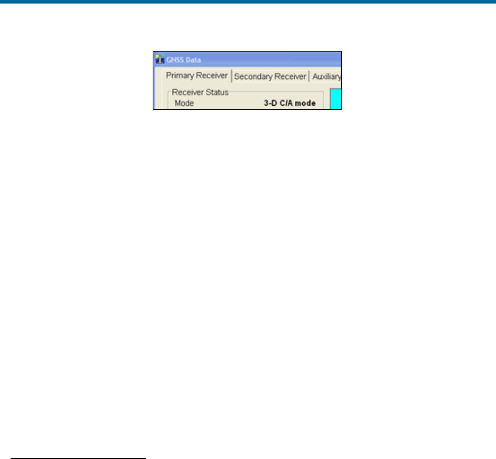
POS MV V5 Installation and Operation Guide
Fault Identification
Copyright © Applanix Corporation, 2012
9-27
Figure 62: POSView GNSS Data - Receiver Status Pane
3. Check IMU Status on controller main window. If IMU Status shows Failure or Warning, power-
off system and contact Applanix for instructions to return IMU for repair.
4. If IMU Status shows OK, check IMU base plate is mounted in nominal horizontal orientation. If
necessary, adjust installation to make base plate of IMU as close to horizontal as possible.
5. If problem still exists, contact Applanix for instructions to return POS MV system for evaluation
and repair.
GNSS Not Available
When the POS MV system is powered-on, the GNSS receivers require approximately two minutes to
acquire satellites and to begin computing a navigation solution. During this time, the Nav Status display
on the controller main window shows DR.
If this status does not change after several minutes, or if the status changes from a valid mode to DR and
remains unavailable, there is likely a problem with the GNSS subsystem.
There are two classes of GNSS problems associated with the POS MV:
a) A communication fault between the receiver and the PCS
b) The receivers are not tracking a sufficient number of satellites
Improper Communication
Note: The GNSS lights are controlled by the navigation software; the system must be in the navigate
mode for the proper indication of the GNSS lights.
Follow the instructions below to identify a communications fault:
1. Examine GNSS light on PCS front panel:
• If light shows red, there is no communication between PCS and GNSS receiver. Follow
instructions relating to loss of GNSS communications in Status Warning Messages on
page 9-14 and the following step below.
• If light shows amber or green, select View, GNSS Data from controller menu bar; see
Figure 50 on page 8-2.
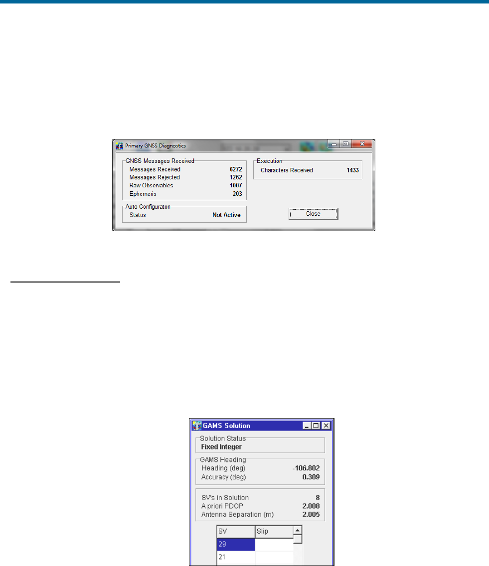
POS MV V5 Installation and Operation Guide
Fault Identification
9-28
• If GNSS Data window shows system is tracking fewer than four satellites, go to
Insufficient Satellites on page 9-28.
2. Select Diagnostics, Primary GNSS from controller menu bar and check that messages are
being received, see Figure 63. If no, fault may be in GNSS receiver or in communications
between GNSS and PCS. Please contact Applanix Customer Support, see page A-1.
Figure 63: POSView Primary GNSS Diagnostics
Insufficient Satellites
Follow the instructions below to identify a problem caused by insufficient satellite signals:
1. From controller main window select View, GAMS Solution and note how many satellites appear
in SVs in Solution field, see Figure 64.
2. If SVs in Solution field has fewer than four satellites, mounting
location for GNSS antennas may be cause. Ensure mounting position of antennas provides
unobstructed view of sky in all directions. If either antenna is moved, refer to Installation section
starting on page 2-1 and System Configuration description starting on page 4-1 for instructions.
Figure 64 GAMS Solution Status Window
3. If mounting locations for both GNSS antennas are optimal and DR status persists, move vessel to
area that has better satellite visibility.

POS MV V5 Installation and Operation Guide
Fault Identification
Copyright © Applanix Corporation, 2012
9-29
4. If the problem persists after moving the vessel, a problem may exist with the GNSS receiver card,
antenna cable or connections. Examine cable and connections for damage, degradation or
contamination, e.g. moisture ingress. Use low-loss cable to replace defective cables. Ensure
cable connectors are waterproofed.
5. If problem persists, contact Applanix for advice.
GAMS Not Ready
After the POS MV system is installed, the GNSS Azimuth Measurement Subsystem (GAMS) requires
calibration. Refer to the Initial GNSS Configuration description starting on page 4-17 for instructions.
Once GAMS is calibrated, it will initialize itself and deliver heading measurements automatically each time
the system is powered-on and enters the navigate mode. Depending on the availability of satellites, the
GAMS Initialization process may take up to five minutes.
If there is a temporary loss of satellites, e.g. caused by a signal obstruction, the GAMS Status may show
Not Ready for brief periods. However, if GAMS Status shows Not Ready for an extended period after
power-on, or if it transitions from Online to Not Ready and remains there, take the following steps to
determine the cause.
1. Select View, GAMS Solution from controller menu bar. In GAMS Solution window, check
number of SVs tracked and value displayed for PDOP. GAMS must track five SVs minimum and
have PDOP value <3 before it can solve ambiguities. Wait for satellite constellation to improve or
move to a location that has better satellite visibility.
2. If number of SVs tracked does not increase or if PDOP remains too high, problem may be GNSS
antenna installation. Examine GNSS antennas, cables and connectors for damage or
degradation.
3. GAMS may experience problems caused by invalid calibration or excessive vibration in the
antennas. Check antenna installation and ensure antennas are rigid relative to each other and
relative to IMU.
Serial Communications Problem
A serial communications problem may occur on any of the user configurable COM ports. Use the
following steps to determine the nature of the problem.
1. Select Settings, Input/Output Ports from controller menu bar. Verify parameter settings; see
Figure 65 and the COM Ports description starting on page 3-1.
2. Verify serial port connection.
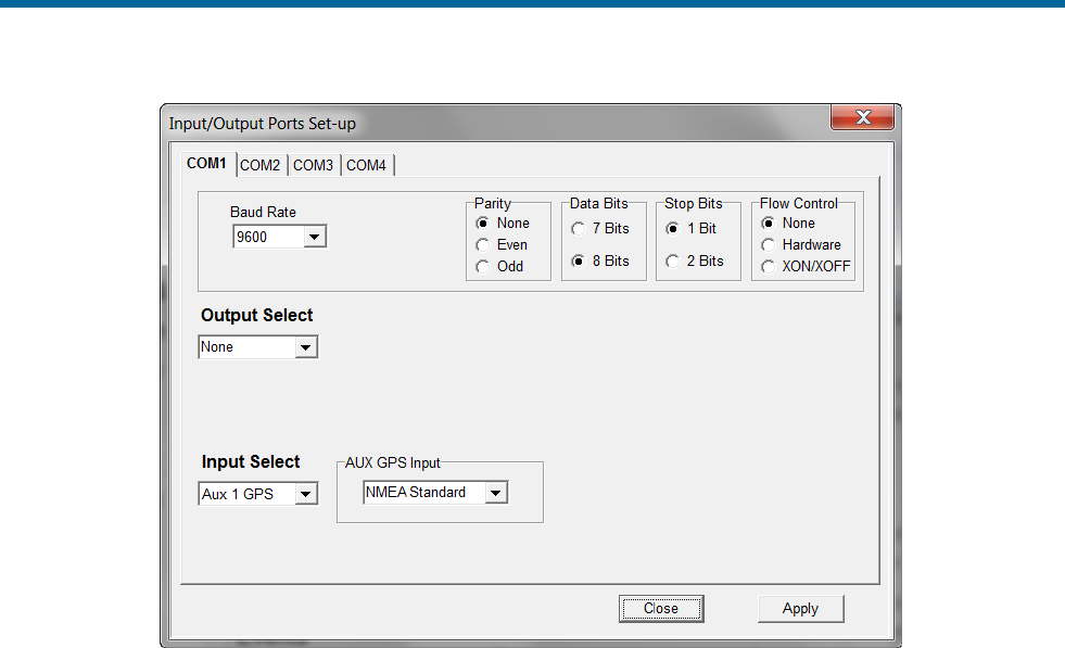
POS MV V5 Installation and Operation Guide
Fault Identification
9-30
Figure 65: POSView Input/Output Port Setup
Note: Dynamically configurable COM ports add great flexibility, but can also cause problems if
inadvertently reassigned.
To check the output functions (NMEA and Binary) perform the following steps:
1. Ensure that POS is navigating and is in Degraded Nav mode or better. Binary data is not output
until this mode is reached.
2. Select Diagnostics, NMEA & Binary Output from controller menu bar. Verify displayed Port#
matches selected COM port (e.g. Port# 1 = COM 1), see Figure 66.
3. Check Write Failure field. If value increases, indicates PCS hardware interface problem; try
another COM port. Reassign NMEA or Binary output to unused COM port. If communications
restored, note defective COM port for future reference.
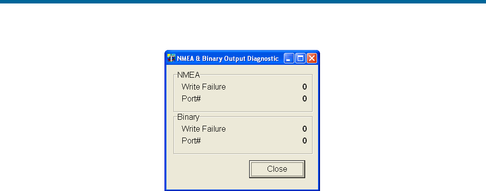
POS MV V5 Installation and Operation Guide
Fault Identification
Copyright © Applanix Corporation, 2012
9-31
Figure 66: POSView NMEA & Binary Output Diagnostic
4. Check that baud rate is sufficient to transmit data selected.
5. Check serial cable integrity.
6. Disconnect remote end of cable from sonar or other receiving equipment and connect cable to
PC running serial program (e.g. ProComm or Hyper Terminal). Adjust baud and protocol to match
PCS output settings. If data received from POS, problem is receiving equipment.
To check the input functions (Base GNSS and Auxiliary GNSS) perform the following steps:
1. Select Diagnostics, Base GNSS, Base 1 or 2, or Diagnostics, Aux GNSS from controller menu
bar, see Figure 67.
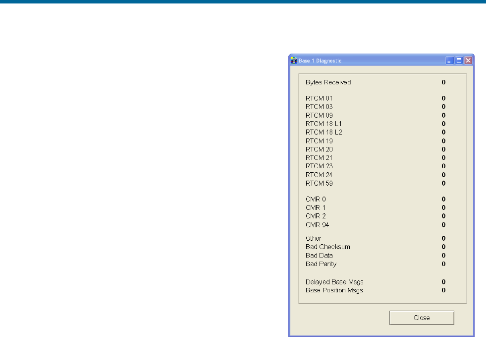
POS MV V5 Installation and Operation Guide
Fault Identification
9-32
2. Check Bytes Received field. If no bytes received,
may indicate PCS hardware interface problem; try
another COM port. Reassign Base or Aux GNSS
input to unused COM port. If communications
restored, note defective COM port for future
reference.
3. Check serial cable integrity.
4. Disconnect PCS end of serial cable and connect to
PC running a serial program (e.g. ProComm or Hyper
Terminal). Adjust baud and protocol to match Base
GNSS or Aux GNSS output settings. If data received
from GNSS, problem is PCS.
Ethernet Communications Problem
Loss of Ethernet communications will result in the loss of
communications between the PCS and the controlling PC.
The MV-POSView Controller program indicates this by
displaying an appropriate error message. Figures 68 and 69
provide troubleshooting procedures to identify the causes of
Ethernet communications failures.
Figure 67: POSView Base 1 Diagnostic
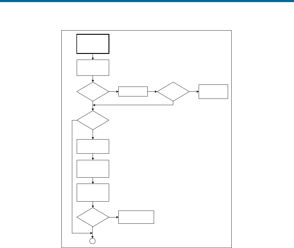
POS MV V5 Installation and Operation Guide
Fault Identification
Copyright © Applanix Corporation, 2012
9-33
Ethernet
Communications
Failure
(Broadcast)
Check SYSTEM
LED on PCS front
panel
SYSTEM LED
red? Reboot the PCS
YSYSTEM LED
red?
Refer to Total
System Failure
procedure
Y
NN
PCS on
multinode
network?
Y
Disconnect PCS
and PC from
network
PC to PCS
comms OK?
Check network cables
and integrity
N
Y
Establish stand
alone connection
between PC and
PCS
Check
communication
between PC and
PCS
A
N
Figure 68: (1 of 2) Ethernet Communications Failure
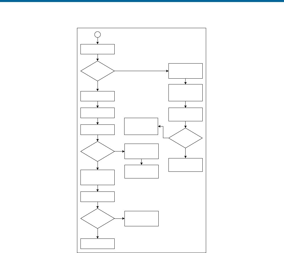
POS MV V5 Installation and Operation Guide
Fault Identification
9-34
Check LAN Tx LED
LAN Tx LED
flashes?
Reboot PC and
restart Controller
program
Y
N
A
Check
communication
between PC and
PCS
Check Ethernet
cable and
connectors
Cable OK?
Problem with TCP
drivers or Ethernet
adapter in PC
Y
Replace Ethernet
cable
N
Reboot the PCS
Check LAN Tx LED
PC to PCS
comms OK?
Y
N
Intermittent failure,
log for future
reference
LAN Tx LED flashes
Reconnect PCS and
PC to network
Swap GPS
receivers and
change PCS
Reboot the PCS
PC to PCS
comms OK?
System working, re-
install and initialize
parameters
Contact Applanix
Y
N
Figure 69: (2 of 2) Ethernet Communications Failure

POS MV V5 Installation and Operation Guide
Technical Support and Service
Copyright © Applanix Corporation, 2011
A-1
Appendix A Technical Support and Service
Contact Applanix
Applanix Corporation
85 Leek Crescent
Richmond Hill, ON
L4B 3B3
Canada
Applanix LLC
17461 Village Green Drive
Houston, TX 77040
USA
Applanix Corporation
Forester’s House
Old Racecourse
Oswestry, SY10 7PW
UK
Tel: +1 (289) 695-6000
Fax: +1 (905) 709-6027
Appendix A Tel:
+1 (713) 896-9900
Fax: +1 (713) 896-9919
Tel: +44 (1691) 659359
Fax: +44 (1691) 659299
Web site: http://www.applanix.com
How to Reach Customer Support
For technical support on POS regarding installation or operation, contact Applanix customer support at
the numbers listed on our website. On the home page, select Support. If voice communication is
required, select the Contact Support link. For general inquiries, please visit our website or call +1 (289)
695-6000.

POS MV V5 Installation and Operation Guide
Technical Support and Service
Copyright © Applanix Corporation, 2011
A-2
Returns
In the event that it becomes necessary to return any component of the POS MV system for repair, please
follow the procedure below.
1. Call your Applanix Customer Support Representative and request a Return Material Authorization
(RMA) number and shipping instructions or obtain an RMA number via our website.
2. Carefully disconnect and remove the part(s) to be returned.
3. Pack the part(s) to be returned in their original packing containers. Applanix will not be
responsible for damage to parts during shipment, if returned in any container other than the
original shipping cases. New cases are available - please contact your Customer Support
Representative for details.
4. Address shipping cartons to the address listed on the packing list shipped with the system.
Please DO NOT ship any POS components to Applanix without an RMA number.

POS MV V5 Installation and Operation Guide
Theory of Operation
Copyright © Applanix Corporation, 2011
B-1
Appendix B Theory of Operation
This appendix provides a simplified explanation of the POS MV theory of operation. The explanation
includes some details on each of the main techniques that the system uses to compute an integrated
navigation solution.
Inertial Navigation:
An introduction to the theory of inertial navigation.
Heave Filter:
You can tune the characteristics of the heave filter
to provide optimal performance of POS MV
through a wide range of dynamic conditions.
GNSS Azimuth
Measurement Subsystem:
GAMS uses information from two GNSS receivers
to improve the accuracy of heading measurement.
Heading Measurements:
The unaided system can deliver heading
measurements with reduced accuracy.
Baselines:
An explanation of the baseline definitions used
throughout this appendix.
Baseline Measurement:
How the system measures the baseline vectors of
the GNSS antennas and the IMU.
Carrier Phase Differential
Position:
A simplified description of the process by which
POS MV measures the difference in position
between the two GNSS antennas.
Alignment:
How POS MV levels itself and aligns with true
north in an unaided condition.
Error Sources:
How the position measurements of a free inertial
navigation system would degrade with time
caused by unavoidable errors in the sensing
subsystems.
Aided Inertial Navigation:
POS MV uses a Kalman Filter to compensate for
the effects of errors to deliver a blended navigation
solution that maintains a high degree of accuracy.
Inertial Navigation
An Inertial Navigation System (INS) computes its position on the Earth by a sophisticated form of dead
reckoning. In its simplest form, dead reckoning estimates the current position by measuring the speed,

POS MV V5 Installation and Operation Guide
Theory of Operation
Copyright © Applanix Corporation, 2011
B-2
direction and time of travel from a known starting point. The errors inherent in this form of navigation arise
from two sources:
• Uncertainty in determining the position of the starting point. This contributes a fixed error in the
dead reckoning position. The magnitude of this error is the same as the error in determining the
position of the starting point.
• Inevitable inaccuracies in the measurement of speed and heading. Errors in the dead reckoning
position will increase with time as the effects of these inaccuracies accumulate.
Dead reckoning requires no external support from radio navigation aids. It can be reasonably accurate if
the system compensates for errors in the measurement of speed and heading, and for the effects of wind,
tide and current.
To implement dead reckoning an INS contains sensitive components that include:
• Accelerometers to sense the specific forces of gravity, plus the forces that accelerate the INS with
respect to the Earth.
• Gyros to sense all angular rates of rotation experienced by the INS with respect to an inertial
frame of reference.
From the inertial measurements delivered by these components the INS solves Newton’s equations of
angular and translational motion on the approximately spherical surface of the Earth, and computes a full
range of motion parameters:
• The orientation of the IMU (roll and pitch) with respect to a locally level reference plane.
• The heading of the IMU with respect to geographical north.
• The latitude, longitude and altitude of the IMU on the surface of the Earth.
In addition to these, appropriate calculations will also deliver measurements of velocity and track over the
ground.
How INS Navigates
The accelerometers and gyros sense specific forces and angular rates relative to an inertial frame of
reference. An inertial frame of reference is one that experiences no accelerations or angular rates of its
own. Therefore, in such a reference frame, Newton’s laws of motion apply without requiring corrections
for accelerations or rotations of the frame.
Navigation on the Earth introduces forces and angular rates due to gravity and the rotation of the Earth.
The accelerometers and gyros will sense these forces and movements, even when the INS is stationary
relative to the Earth: Any object on the surface of the Earth experiences the force due to gravity. It also

POS MV V5 Installation and Operation Guide
Theory of Operation
Copyright © Applanix Corporation, 2011
B-3
has an angular rate with respect to the inertial frame of reference frame because the Earth rotates about
is north-south axis at 15°/hour.
An INS that is designed to operate on the surface of the Earth must first subtract the gravitational force
and Coriolis acceleration from the sensed specific forces, to obtain the acceleration of the INS with
respect to the Earth.
• Gravitational acceleration - Essentially a constant over the surface of the Earth (although small
variations exist from one place to another). The standard acceleration of gravity
2
80665.9 msg
. The convention used throughout this manual defines gravitational acceleration
81.9g
.
• Coriolis acceleration - The apparent tendency of a freely moving body to swing to one side when
its motion is referred to a set of axis that is itself rotating in space. The magnitude of Coriolis
acceleration measured by an INS moving horizontally on the surface of the Earth is:
sin2c
Where:
=
is the angular magnitude of the angular
velocity of rotation of the Earth
=
is the speed of the INS
=
is the latitude
The acceleration is perpendicular to the direction of
and is towards the right in the Northern
Hemisphere.
The INS must also subtract the 15°/hour Earth rotation rate from the sensed angular rates to obtain the
angular rate of the INS relative to the Earth.
After it has performed these functions, the INS integrates the corrected accelerations and angular rates to
compute changes in velocity, position, attitude and heading relative to the Earth.
Figure 70 on page B-5 is a simplified view of inertial navigation on a spherical non-rotating Earth. The
vessel is moving north at an initial velocity
n
.
The INS housing and its internal accelerometers are fixed to the vessel, forming a ‘strap-down’
arrangement. One accelerometer aligns with the fore-aft line of the vessel, another aligns with the vertical
and a third accelerometer aligns with the port-starboard axis of the vessel. For convenience, this
explanation considers only the fore-aft and the vertical accelerometers (although the INS uses all three to
compute the solution).
With the vessel on a northerly course as shown, the fore-aft accelerometer also aligns with true north and
therefore senses any change in the northerly velocity.

POS MV V5 Installation and Operation Guide
Theory of Operation
Copyright © Applanix Corporation, 2011
B-4
Similarly, as the vessel heaves, the vertical accelerometer senses the specific force:
down down g
Where:
down
=
is the vertical motion
g
=
is the steady state acceleration due to
gravity
This is the varying vertical acceleration experienced by the vessel caused by vertical motion, added to the
steady state acceleration due to gravity.
As the vessel moves northwards, the gyro aligned with the lateral axis senses two rotations:
1. The varying short-term rotations about the pitch axis as the bow pitches up and down with the
dynamic action of the vessel.
2. A slow rotation about the pitch axis as the vessel translates towards latitudes that are more
northerly. This slow rotation is called the transport rate and can be determined by:
r
north
east
Where:
east
=
the transport rate about the eastward
axis of the INS platform
north
=
the northerly velocity of the vessel
r
=
the radius of the Earth
This is the negative of the rate at which latitude changes. Consequently, if the INS knows the starting
latitude, it can compute the current latitude of the vessel as follows:
t
eaststart
0
--
Where:
east
=
the transport rate about the eastward
axis of the INS platform
start
-
=
the starting latitude
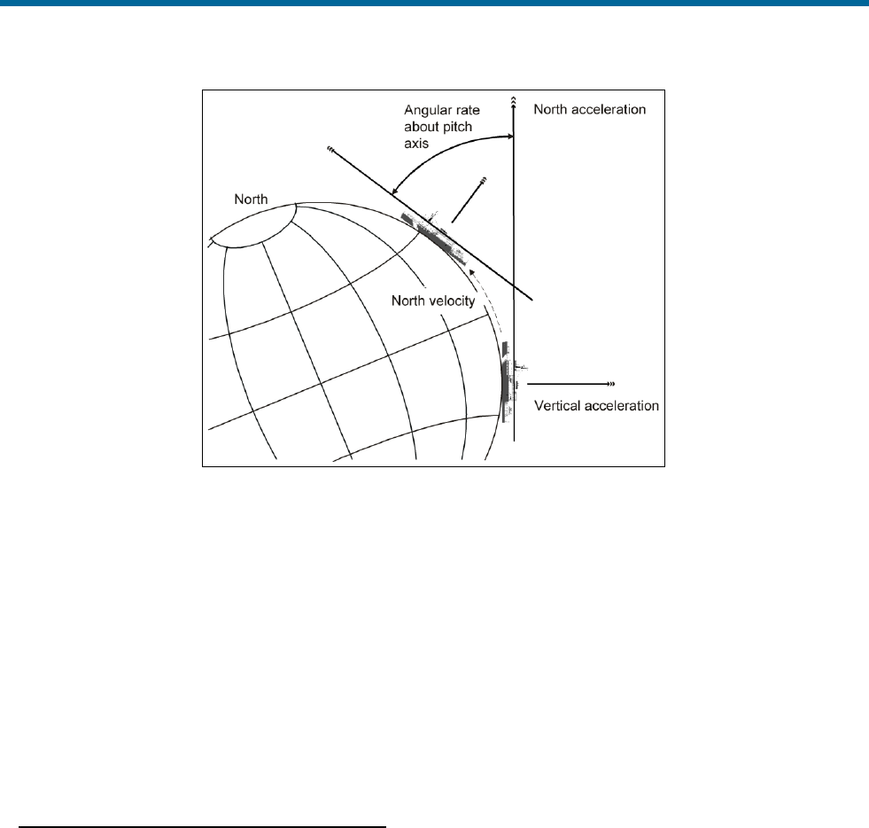
POS MV V5 Installation and Operation Guide
Theory of Operation
Copyright © Applanix Corporation, 2011
B-5
Figure 70: Example of INS Navigation on a Spherical Earth
In Figure 70, the vessel that supports the INS has no applied angles of roll or pitch, and moves along a
fixed northerly heading.
Ideally, the INS platform defines a navigation frame that is both locally stable and locally level:
• A locally stable reference frame always maintains a constant orientation relative to the surface of
the Earth at its current position.
• A locally level reference frame is always level relative to the surface of the Earth at its current
position.
In Figure 70, the navigation frame of the vessel coincides with the geographic frame of reference.
Inertial Navigation Frames of Reference
This appendix refers to a number of different frames of reference:
• Inertial frame
• Earth frame
• Geographic navigation frame
• Body frame
• IMU body frame
For clarity, the following subsections define each of these reference frames as they apply throughout this
appendix.

POS MV V5 Installation and Operation Guide
Theory of Operation
Copyright © Applanix Corporation, 2011
B-6
Inertial Frame
The inertial frame of reference is a Newtonian reference frame that experiences zero specific force
and angular rate of its own. It is an absolute frame of reference and has a fixed, convenient
orientation in space.
Earth Frame
The Earth co-ordinate frame is fixed to the Earth with its axis arranged as follows:
• The x-axis coincides with the axis of Earth rotation.
• The z-axis is in the equatorial plane at zero longitude (on the Greenwich meridian).
• The y-axis completes the right-handed orthogonal frame.
Note: This definition of the Earth frame differs from the WGS-84 definition in which the z-axis
coincides with the Earth rotation axis and the x-axis coincides with the intersection of the Greenwich
meridian and the equator.
The Earth frame rotates relative to the inertial frame at a nominal 15°/hr (or, more accurately,
15.04107°/hr).
Geographic Navigation Frame
The geographic navigation frame is a locally level frame of reference. The north and east axis are
tangential to the Earth surface at the current latitude and longitude, and are defined by the north and
east directions respectively.
The third axis of the geographic navigation frame is the down axis and is a local vertical that passes
through the centre of the Earth.
Body Frame
The body frame is a co-ordinate frame fixed to the vessel with its axis arranged as follows:
• The x-axis coincides with the surveyed fore-aft line of the vessel.
• The y-axis is perpendicular to the x-axis and coincides with the port-starboard line of the
vessel.
• The z-axis is perpendicular to both the x- and the y-axis and coincides with the surveyed
vertical of the vessel.
IMU Body Frame
The IMU body frame uses the right-handed orthogonal co-ordinate system with its origin at the
sensing centre of the IMU. These axis are fixed relative to the IMU and are marked by a label on the
IMU housing.
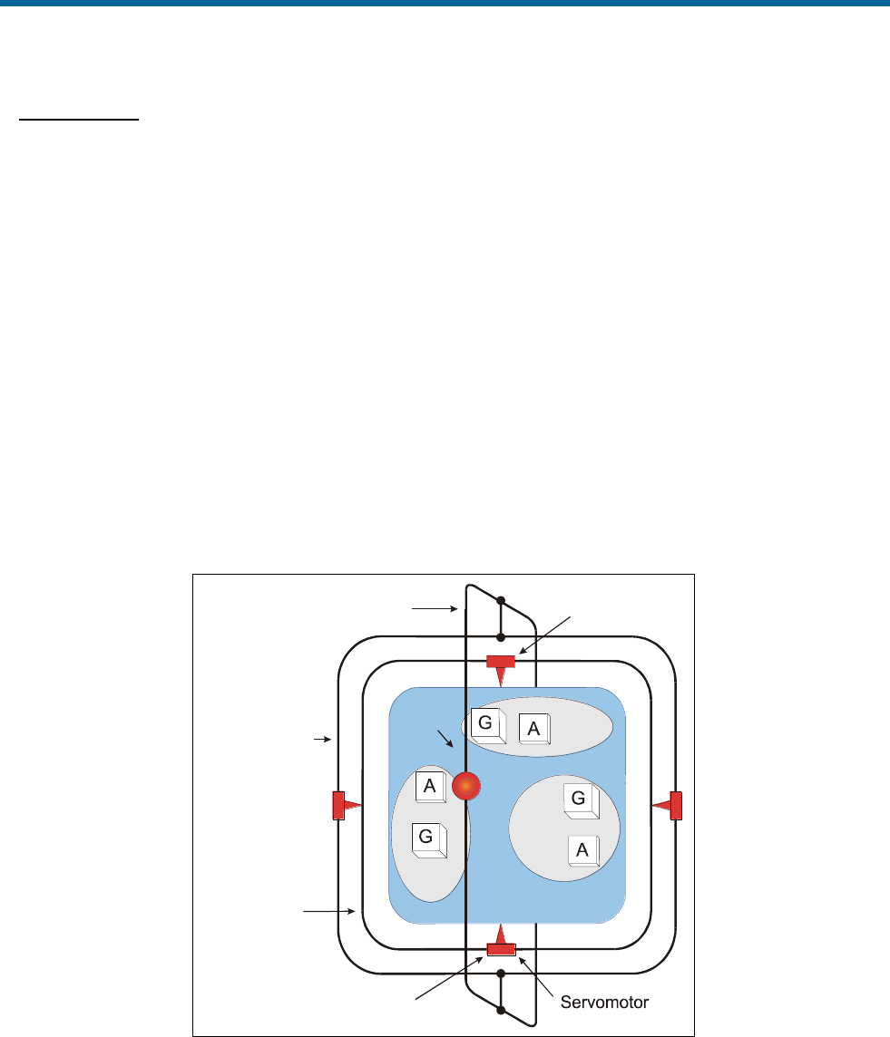
POS MV V5 Installation and Operation Guide
Theory of Operation
Copyright © Applanix Corporation, 2011
B-7
INS Platform
An INS platform is one that has its accelerometers mounted on a mechanically gimballed platform. The
platform is stabilized so that it always remains level relative to the local geographic navigation frame.
Note: POS MV does not use a mechanically stabilized platform of the type described in this subsection.
This explanation is included because it may be easier to visualise an inertial navigation system based on
a mechanical platform than one based on a strap-down INS arrangement.
Note: POS MV uses a strap-down INS of the type described in Strap-Down INS on page B-8.
Figure 71 on page B-7 represents a simplified INS platform suspended by three gimbals. The platform
defines a locally level navigation frame as long as it maintains a level orientation with respect to the
surface of the Earth, in spite of any motion applied externally.
Feedback systems and a servomechanism maintain platform stability in each axis of suspension:
• An arrangement of three gyros senses any angular rate of motion of the platform about each axis.
The arrangement places each of the gyros orthogonally so that each responds to rotations in one
axis only.
G=Gyro
A=Accelerometer
X-axis
Y-axis
Z-axis Z-axis
Y-axis
X-axis
Outer gimbal
Middle gimbal
Inner gimbal
Angular resolver
Figure 71: Gimballed INS Platform Structure
• A servomotor in each axis receives the amplified signals from its complementary gyro and rotates
the gimbals axis to correct for the measured rate of rotation. In an ideally configured and
compensated INS platform, the net angular rotation of the platform is almost entirely removed.

POS MV V5 Installation and Operation Guide
Theory of Operation
Copyright © Applanix Corporation, 2011
B-8
This action gives the platform stability in the inertial reference frame. In this condition, to an
observer on the surface of the Earth the platform would appear to rotate at the Earth rate of
15°/hour relative to a locally level navigation frame.
To remove this apparent rotation, the control system makes the platform locally level by adding to
the respective feedback signals, reference signals that cause the three gimbals axis to rotate at
the Earth rate plus the transport rate.
• With the INS housing fixed to the vessel and the platform north aligned and locally level, the INS
can measure the roll, pitch and heading of the vessel directly from the gimbals angles of the INS
platform. It takes these measurements from angular resolvers in each gimbals axis.
The accelerometers are also mounted orthogonally on the platform to sense accelerations in the
x, y and z directions relative to the surface of the Earth. When the platform is aligned and level
with respect to the Earth surface, its x-axis points in a known direction, usually towards true north.
With the platform aligned and maintained locally both stable and level, the accelerometers align
to a geographic navigation frame. In this orientation, the accelerometer array measures specific
forces that the INS experiences relative to the inertial reference frame, and resolves them in the
geographic navigation frame.
From these measurements, the INS computes its accelerations with respect to the surface of the
Earth, also resolved in the geographic navigation frame. The INS integrates these accelerations
in the navigation frame to obtain velocity and changes in position.
Strap-Down INS
A strap-down INS has its rate gyros and accelerometers fixed to the INS or IMU housing. This housing is
fixed to the vessel. The inertial sensor array therefore moves and rotates with the vessel. This is the
inertial navigator mechanization used by POS MV.
The accelerometers sense specific forces with respect to the inertial frame. These are resolved in the IMU
body frame defined by the orthogonal accelerometer and gyro arrangement.
Similarly, the gyros sense all angular rates with respect to the inertial frame. These too are resolved in the
inertial sensor frame.
The INS uses the sensed angular rates, the computed Earth rate and transport rates to update a
Direction Cosine Matrix (DCM), which describes the mathematical transformation from the IMU body
frame to a mathematically defined geographic navigation frame.
Following transformation of the measured specific forces into the geographic navigation frame, the
navigation computations are the same as those for the INS platform.
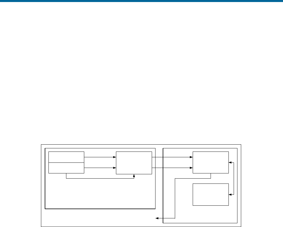
POS MV V5 Installation and Operation Guide
Theory of Operation
Copyright © Applanix Corporation, 2011
B-9
The navigation platform, though not a physical entity as was the gimballed platform, exists in the
navigation computer as an IMU-to-navigation frame DCM. For this reason, the geographic navigation
frame is sometimes called the mathematical platform.
Figure 72 shows the functional architecture of a strap-down INS. The arrangement contains an inertial
sensor assembly comprising a triad of accelerometers and a triad of gyros. Each of the three orthogonal
axis of the IMU body frame includes one accelerometer and one gyro.
The inertial sensor processor collects the digitised accelerations and angular rates from the inertial
sensor assembly and compensates these for temperature-dependent sensor errors.
Together, the inertial sensor assembly and the inertial sensor processor comprise the Inertial
Measurement Unit (IMU). In POS MV, the IMU is a separate self-contained unit that interfaces to the PCS
through a data interface cable.
Inertial Sensor
Assembly Inertial Sensor
Temperatures
Inertial Measurement Unit (IMU)
Navigation Solution
Gyros
Accelerometers
Inertial Sensor
Processor
Navigation and Alignment
Processor
Alignment
Algorithm
Strapdown
Navigator
zyx ,,
zyx ,,
zyVx ,,
zyVx ,,
Figure 72: Strap-Down INS Generic Architecture
The compensated inertial measurements pass to the navigation and alignment processor, which
implements the alignment algorithm and computes the INS navigation solution.
The alignment algorithm initializes the navigation equations, implements levelling and gyrocompassing,
and obtains a mathematical platform alignment.
In POS MV, the navigation and alignment processor is located inside the PCS.
The strap-down INS ‘navigates’ the inertial sensors and computes the roll, pitch and heading angles of
the inertial sensor assembly relative to the geographic navigation frame.
Generally, the housing of the INS (the IMU in POS MV) is assumed to be aligned with the inertial sensor
frame. With the inertial sensor installed so that its x, y and z axis coincide with the forward, starboard and
down directions of the vessel hull respectively, the INS will measure the vessel roll, pitch and heading
directly. Otherwise, the INS must apply a constant installation offset transformation to the computed roll,
pitch and heading to transform the inertial sensor assembly attitude to the hull attitude.
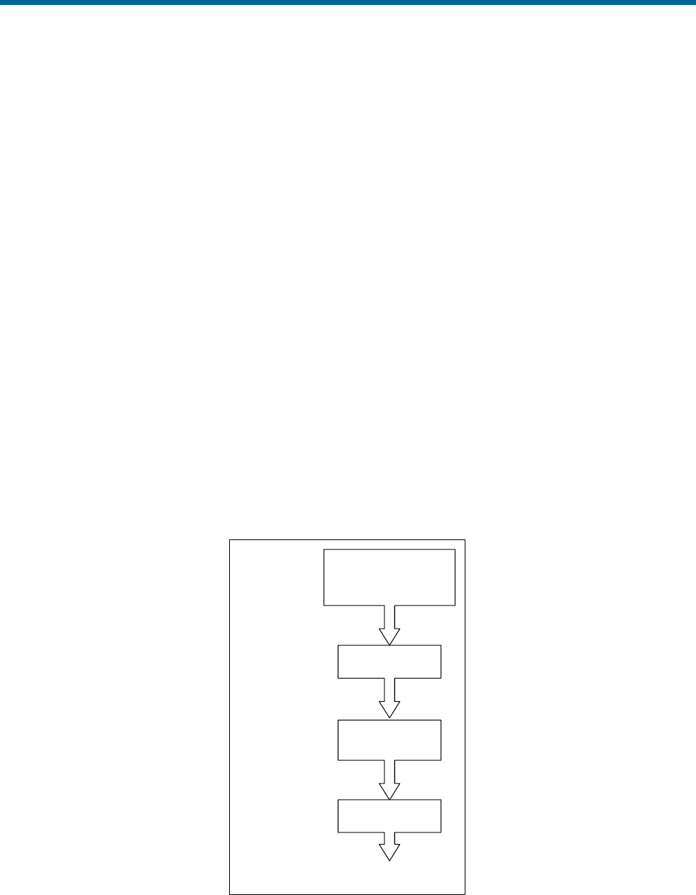
POS MV V5 Installation and Operation Guide
Theory of Operation
Copyright © Applanix Corporation, 2011
B-10
POS MV includes a user orientation input capability. This makes it possible to correct the orientation of
the IMU so that it delivers measurements valid for an alternative reference frame, such as that of a
multibeam transducer or of the vessel.
The small size and lightweight of the IMU allow it to be mounted directly on the multibeam transducer.
From here, it can measure the transducer position and orientation directly.
Heave Filter
POS MV measures heave by performing a double integration on the measurements of vertical
acceleration computed by the strap-down navigator, see Figure 73.
The high pass filter limits the appearance of noise in the vertical measurement channel caused by the
strap-down navigator. Sources of such noise could include Schuler oscillations, GNSS noise, etc.
The performance characteristics of the heave filter are:
• Filter settling time
• Steady state heave error
Filter settling time describes the time required for a transient in the heave filter to settle to a negligible
level. The filter has a transient behaviour that is stimulated by sudden changes in the filter input. This
occurs when you power-on POS MV and when the vessel experiences abrupt changes in vertical
displacement.
Information from
POS MV Strapdown
Navigator
Heave Estimate
First Integration
Second
Integration
High Pass Filter
Vertical Acceleration
Vertical Velocity
Vertical Displacement
Figure 73: Heave Filter Architecture
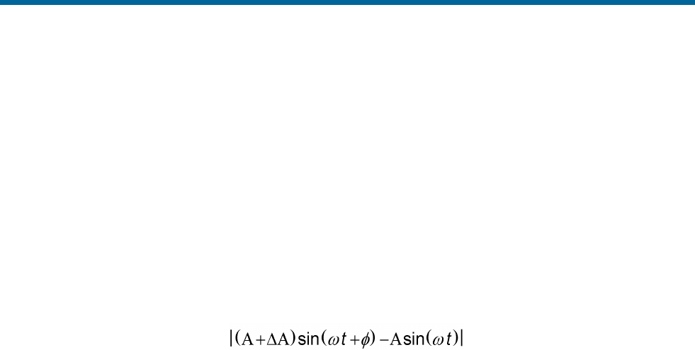
POS MV V5 Installation and Operation Guide
Theory of Operation
Copyright © Applanix Corporation, 2011
B-11
Abrupt changes of this type can occur if the vessel experiences induced heave because of speed
changes. Lighter vessels respond rapidly to changes in engine throttle settings and are therefore more
likely to experience abrupt induced heave. Conversely, larger vessels that have a heavier displacement
are not so responsive to changes in engine throttle settings and tend to exhibit a reduced tendency
towards induced heave.
If the IMU is located close to the bow of the vessel then a significant induced heave can occur as the
vessel climbs its own bow wave and pitches upwards.
Steady state heave error describes the error in measured heave after the filter transients have decayed.
This error can be characterized as follows for an approximately sinusoidal heave motion with magnitude
A and frequency ω:
Steady state heave error =
Where:
=
the gain error introduced by the heave
filter
=
the phase error introduced by the heave
filter
Steady state heave error becomes greater at lower heave frequencies in the frequency band of interest.
The high pass component of the heave filter is characterized by the following parameters, both of which
are configurable through the MV-POSView Controller program:
• Heave bandwidth
• Damping ratio
The corner frequency is the lower (band reject) cut-off frequency of the high pass filter. Its setting should
be at least one decade below the lowest heave frequency of interest. For example, if you require a heave
measurement bandwidth of 0.05 Hz (for heave periods up to 20 seconds), then you should set the heave
bandwidth to 20 seconds, and thus the corner frequency will be 0.005 Hz or lower (a heave period of 200
seconds or longer).
The damping ratio defines the transient characteristics of the heave filter and affects the steady state
heave error. The largest recommended value for the damping ratio is 0.707, which causes the heave filter
to be ‘critically damped’. In general, this setting provides the shortest settling time among the available
damping ratios for a fixed corner frequency. A smaller damping ratio causes the filter transient response
to exhibit a decaying sinusoidal behaviour whose settling time is longer than the critically damped settling
time.

POS MV V5 Installation and Operation Guide
Theory of Operation
Copyright © Applanix Corporation, 2011
B-12
Default Heave Filter Parameters
The default heave filter parameters are:
• Heave bandwidth = 20 seconds
• Heave damping ratio = 0.707 (critically damped)
These default values give the best compromise between settling time and steady state heave error for a
vessel performing multibeam surveys in sea conditions up to sea state five.
On a different class of vessel in a different sea state, a different combination of heave filter parameters
may provide better results. The following guidelines assist in selecting appropriate heave filter
parameters.
Guidelines for Setting Heave Filter Parameters
The best combination of heave filter parameters will depend on the following factors:
• Survey conditions - how often does the survey vessel change speed or direction?
• The dynamic characteristics of the survey vessel, in particular the induced heave following
changes to engine throttle settings.
• Significant heave amplitudes caused by the response of the survey vessel to the sea state.
You can determine empirically the correct combination of parameters for a particular survey vessel during
trials. The following are guidelines for selecting appropriate values:
1. Select heave filter parameters according to the following criteria:
• Heave bandwidth - equal to or greater than the longest heave period
• Heave damping ratio - in the range 0.45 to 0.71
2. Calculate the maximum allowable steady state percentage error as follows:
Maximum percentage error =
Maximum heave error
Significant heave amplitude
Choose a heave bandwidth and damping ratio to achieve the required maximum percentage error
with the shortest settling time.
Usually, the maximum heave error is comparable with the resolution of the bathymetric sonar that
requires heave compensation. The significant amplitude will change from one day to the next with
sea state and, therefore, so will the maximum percentage error.
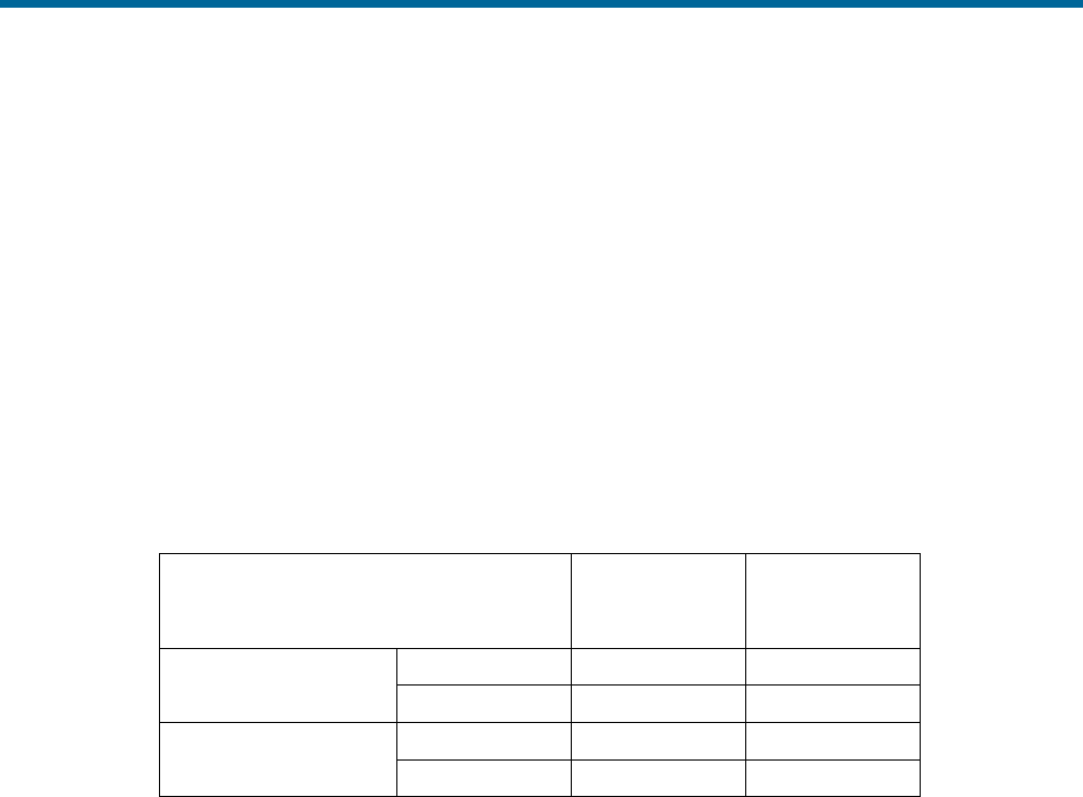
POS MV V5 Installation and Operation Guide
Theory of Operation
Copyright © Applanix Corporation, 2011
B-13
For example, if the heave error should be no more than 10 cm (comparable with the bathymetric
sonar resolution), and the significant heave amplitude is 0.5 metres on a given day, then the
maximum percentage error for that day is 20%.
3. A vessel that has a large displacement will usually exhibit more gradual changes of speed than
one that has a small displacement. Since the dynamics of a large vessel will not significantly
excite the transient behaviour of the filter, configure the heave filter to achieve a small percentage
steady state error at the expense of a long settling time.
Table 38 describes the variations of steady state heave error and settling time with changes in damping
ratio and bandwidth. Figure 74 through Figure 77 on pages B-14 through B-17 respectively show plots of
steady state heave error and transient behaviour for different combinations of heave filter parameters.
Table 38: Effects of Modifying Heave Filter Parameters
Heave Filter Tuning
Steady State
Error
Settling Time
Damping ratio
Increase
Increase
Decrease
Decrease
Decrease
Increase
Heave bandwidth
Increase
Decrease
Increase
Decrease
Increase
Decrease
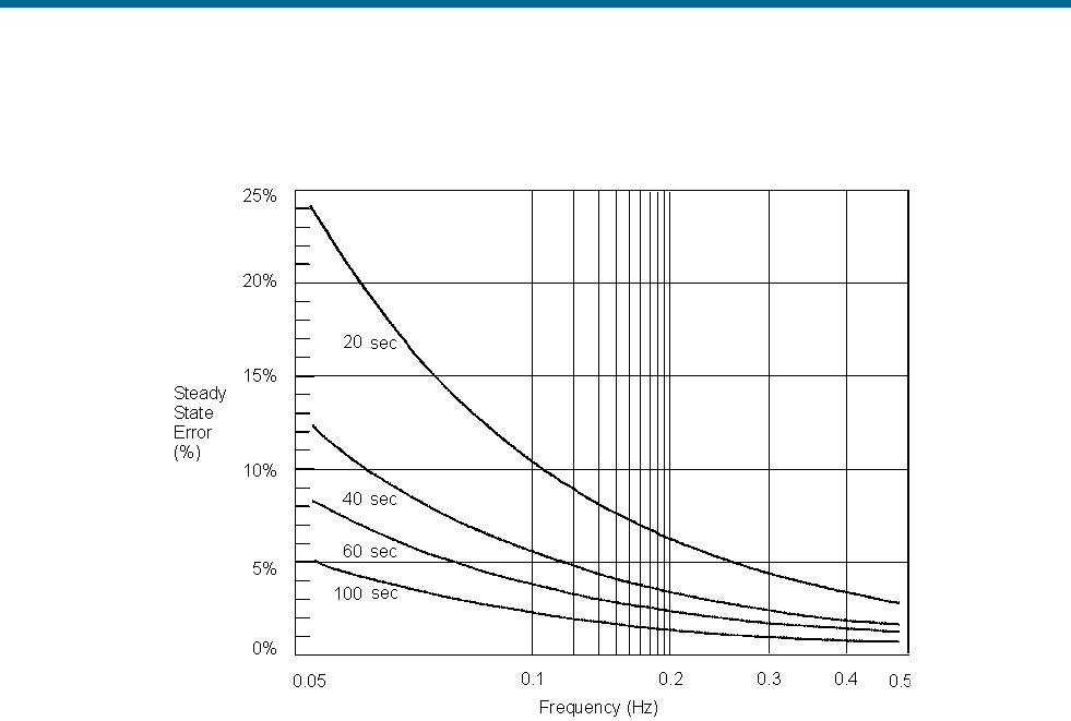
POS MV V5 Installation and Operation Guide
Theory of Operation
Copyright © Applanix Corporation, 2011
B-14
Figure 74 shows a plot of the steady state heave error as a percentage of heave amplitude against heave
frequency for four heave bandwidths at the default damping ratio of 0.707.
Figure 74: Percentage Steady State Error with Heave Bandwidth
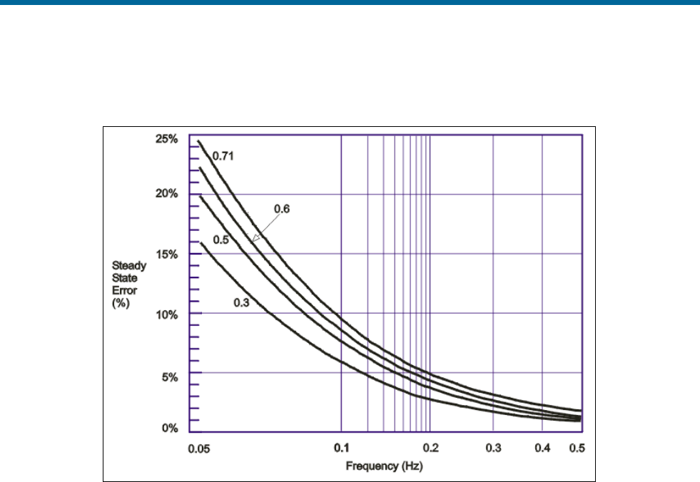
POS MV V5 Installation and Operation Guide
Theory of Operation
Copyright © Applanix Corporation, 2011
B-15
Figure 75 shows a plot of steady state heave error as a percentage of heave amplitude against heave
frequency for four damping ratios at the default corner heave bandwidth of 20 seconds.
Figure 75: Percentage Steady State Error with Damping Ratio
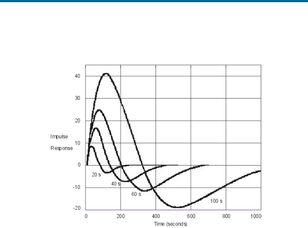
POS MV V5 Installation and Operation Guide
Theory of Operation
Copyright © Applanix Corporation, 2011
B-16
Figure 76 shows a plot of the heave filter response against time for four heave bandwidths at the default
damping ratio 0.707. The filter settling time is for the impulse response to settle to 20% of the impulse
magnitude.
Figure 76: Heave Filter Transient Behaviour with Heave Bandwidth
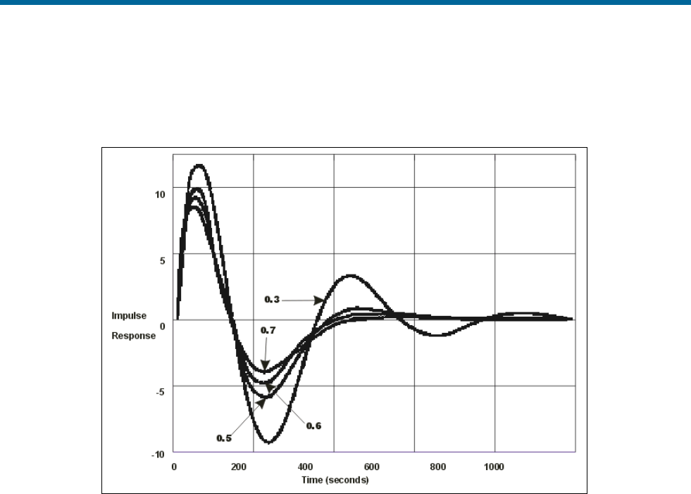
POS MV V5 Installation and Operation Guide
Theory of Operation
Copyright © Applanix Corporation, 2011
B-17
Figure 77 shows a plot of the heave filter response against time for four damping ratios at the default
heave bandwidth of 20 seconds. The filter settling time is for the impulse response to settle to 20% of the
impulse magnitude.
Figure 77: Heave Filter Transient Behaviour with Damping Ratio
GNSS Azimuth Measurement Subsystem
POS MV delivers heading measurements with an optimal accuracy of ±0.02°. It does this by using two
distinct and independent methods:
1. Dynamic Heading Alignment - A method that uses data supplied by the IMU and GNSS receivers
to achieve a heading that is, at best, accurate to within 0.35°.
Dynamic heading alignment delivers its best performance when the measurement unit
experiences rapid changes of direction and varying forces of acceleration. Drift will begin to
appear in the heading measurements when these dynamic manoeuvres cease and the vessel
follows a steady course and speed.
2. GNSS Azimuth Measurement Subsystem (GAMS) - A system that determines the geographic
vector between two GNSS antennas fixed to the vessel. It does this by comparing the phase of
satellite signals arriving at each antenna.
You can expect carrier phase differential measurements to deliver differential range
measurements with an accuracy of between two and 10 millimetres, and heading measurements
with an accuracy of between 0.1° to 0.5° RMS. These specifications are typical of multi-antenna

POS MV V5 Installation and Operation Guide
Theory of Operation
Copyright © Applanix Corporation, 2011
B-18
GNSS attitude sensors that have antenna separations of between one and three metres. They
will vary according to the multipath signal environment affecting the antennas.
Each of the above heading measurement methods have advantages and disadvantages:
• An inertial navigator that undergoes dynamic heading alignment delivers heading measurements
that suffer from drift but are relatively unaffected by noise.
• GAMS heading error is largely due to noise but exhibits no drift.
POS MV uses the advantages of each method to compensate for the disadvantages of the other. By
blending the measurements delivered by GAMS with those delivered by the inertial navigator, POS MV
averages the heading error over time and delivers blended measurements to an accuracy of between
0.02° and 0.1° RMS.
Heading Measurements
Heading measurements calculated by GAMS provide aiding data to the Kalman Filter to improve the
heading estimate made by the strap-down navigator.
Baselines
Heading measurements used by POS MV are:
• The true heading of the vessel in a geographic navigation frame of reference
• The ‘heading’ of the IMU in a geographic frame of reference - that is, the geographic heading of
the x-axis of the IMU body frame
To deliver heading measurements of the required accuracy, POS MV blends measurements made by
GAMS and measurements made by the inertial navigator. A Kalman Filter performs this blending
operation.
POS MV includes a primary and a secondary GNSS receiver, each with its own antenna. The GNSS
System topic on page 2-4 of this manual includes instructions to install both GNSS antennas so that they
are rigid relative to each other and relative to the IMU, and are separated by a distance of between one
and five metres.
By using a carrier phase differential GNSS algorithm, POS MV can measure the vector between the two
antennas in a geographic frame of reference. Figure 78 illustrates this situation. The Carrier Phase
Differential Position topic on page B-22 explains the process of carrier phase differential GNSS
measurement.
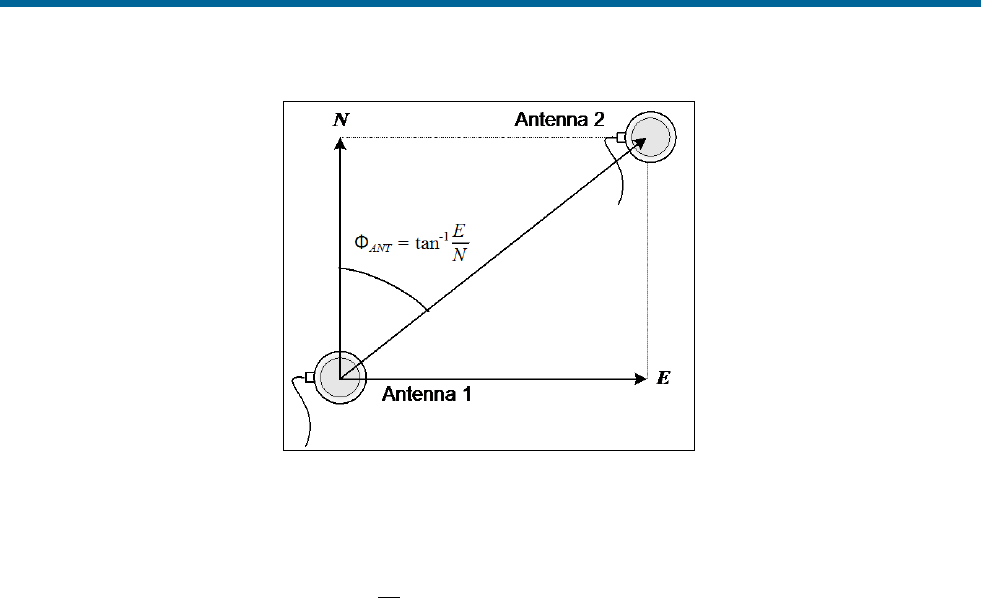
POS MV V5 Installation and Operation Guide
Theory of Operation
Copyright © Applanix Corporation, 2011
B-19
Figure 78: Geographic Antenna Baseline Vector
POS MV computes a carrier phase differential position solution in geographic co-ordinates of Antenna 2
with respect to Antenna 1. This is the geographical antenna baseline vector:
ФANT = tan-1
E
N
Where:
ФANT =
the geographical antenna baseline vector
E =
the easterly component of the position
difference between Antenna 1 and Antenna 2
N =
the northerly component of the position
difference between Antenna 1 and Antenna 2
Because the geographical antenna baseline vector is referenced to true north, it varies as the vessel
changes course. However, the heading aiding data required by POS MV is the heading of the antenna
baseline referenced to the x-axis of the IMU.
POS MV transforms the geographic antenna baseline vector ФANT to the geographic IMU heading ФIMU
using the surveyed antenna baseline vector
12
rΔ
, which is the antenna baseline vector resolved in the
IMU co-ordinate frame. Figure 79 illustrates these headings and angles.
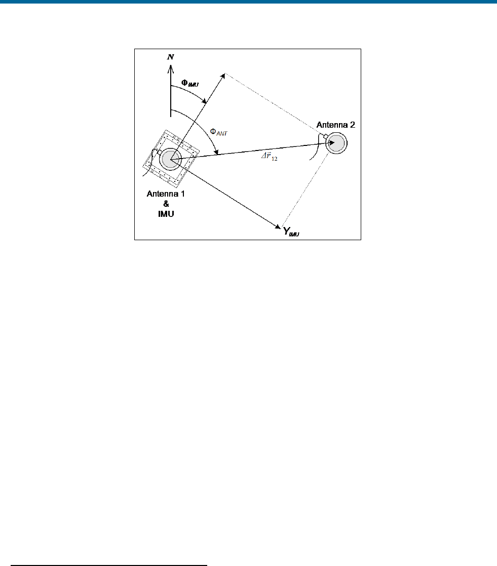
POS MV V5 Installation and Operation Guide
Theory of Operation
Copyright © Applanix Corporation, 2011
B-20
Figure 79: Baseline Comparison
Where:
ФANT =
geographic antenna baseline vector - the
geographic vector of the line that joins the two
GNSS antennas; this vector varies as the
heading of the vessel changes
ФIMU =
geographic IMU vector - the geographic
heading of the IMU x-axis; this vector varies
as the heading of the vessel changes
12
rΔ
=
surveyed antenna baseline vector - the vector
that joins the two GNSS antennas; because
the IMU and the GNSS antennas are mounted
rigidly on the vessel, this vector remains fixed
Note: The example shown in Figure 79 is greatly simplified. It shows only the relative yaw angles made
by the baseline vectors. In practice, the transformation of one baseline vector to another may possibly
involve rotations in all three axis - roll, pitch and yaw.
Baseline Measurement
Geographic Antenna Baseline Vector
To compute a highly accurate value for ФANT based on carrier phase differential GNSS, GAMS must first
resolve the phase ambiguities in the differential carrier phase observables.
The GNSS receivers in POS MV use the L1 GNSS signal, which has a carrier frequency of 1575.42 MHz
and a wavelength of 19 cm. You can consider the range between each GNSS satellite and a GNSS
antenna as an integer number of L1 wavelengths plus a fraction of a wavelength.

POS MV V5 Installation and Operation Guide
Theory of Operation
Copyright © Applanix Corporation, 2011
B-21
Each receiver can measure the fraction of a wavelength from each tracked satellite but cannot determine
the integer number of wavelengths between the transmitting satellite and the antenna.
By using satellite pseudo-range, the receiver can reduce the uncertainty in knowing the integer number of
wavelengths to less than 100. The remaining unknown integer number of wavelengths is the carrier
phase ambiguity.
GAMS uses an On-the-Fly (OTF) ambiguity resolution algorithm to resolve the carrier phase ambiguities.
On-the-fly implies that the algorithm resolves the phase ambiguities while the antennas are moving.
The OTF algorithm uses carrier phase measurements from five or more satellites to estimate and,
eventually, to identify a set of integer phase ambiguities for each satellite being tracked by both receivers.
The Carrier Phase Differential Position topic on page B-22 explains this process simply.
For the OTF algorithm to work, both receivers must track at least five common satellites to resolve the
ambiguities. Preferably, they should track six or more to resolve the ambiguities within a reasonable
length of time.
The GAMS OTF algorithm uses the roll, pitch and initial heading computed by POS MV (without GAMS
heading aiding) to accelerate the ambiguity resolution process. Practically, if POS MV uses the IMU
heading alignment process to compute the heading with an RMS accuracy of 1° or better, then ambiguity
resolution is almost instantaneous and can be completed in less than ten seconds. You can achieve this
degree of heading measurement accuracy without GAMS heading aiding by executing a few vessel turns
after you power-on POS MV.
This facility also allows GAMS to recover very quickly following a GNSS dropout caused by a signal
blockage when passing under a bridge for example.
Surveyed Antenna Baseline Vector
Figure 80 shows the geometry of the two GNSS antennas and the IMU. The antenna baseline vector is
shown as ∆RAB.
During normal operation, GAMS measures this vector resolved in the geographic or North-East-Down
frame (the geographic antenna baseline vector) by using a carrier phase differential GNSS algorithm.
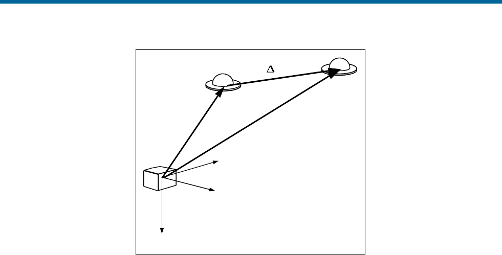
POS MV V5 Installation and Operation Guide
Theory of Operation
Copyright © Applanix Corporation, 2011
B-22
IMU body
frame
RARB
RAB
Antenna A
zb
zb
yb
yb
xb
xb
Antenna B
Figure 80: IMU and GNSS Antenna Geometry
To compute the heading of the IMU (that is the heading of the x-axis of the IMU body frame) GAMS must
have the components of ∆RAB resolved in the IMU body frame (the surveyed antenna baseline vector).
These components and the length of the vector are the GAMS installation parameters.
You can measure the GAMS installation parameters using a direct survey method, or POS MV can
calibrate them automatically as part of an antenna installation calibration.
Both methods have advantages and disadvantages:
• Direct measurement of the parameters using precision survey techniques provides the best
heading accuracy and allows POS MV to deliver full operational performance immediately.
However, it also involves a laborious and complicated survey exercise using qualified survey
personnel, special equipment and detailed engineering drawings of the vessel.
• Conversely, a POS MV installation calibration provides calibration parameters that are initially
less accurate. However, the system can perform the procedure during normal survey operations
without the need for any special additional equipment or personnel. You can improve the
accuracy of this type of calibration by empirical methods, or by making a direct comparison with
another heading instrument such as a gyrocompass.
Refer to Initial GNSS Configuration on page 4-17 for instructions to complete an installation calibration.
Carrier Phase Differential Position
GNSS measurements possess long-term stability and an accuracy that, with DGNSS, can be within a few
metres. However, the measurements do not possess sufficient accuracy to allow a precise determination
of the geographic antenna baseline vector.

POS MV V5 Installation and Operation Guide
Theory of Operation
Copyright © Applanix Corporation, 2011
B-23
Instead, POS MV uses carrier phase differential position measurements to determine the relative position
of one GNSS antenna with respect to the other.
Using this method, the differential position computed by GAMS for the two antennas has an accuracy of
between two and 10 millimetres, depending on the local multipath environment. The heading data
supplied can therefore exhibit accuracy of the order 0.1° to 0.5° RMS, depending on the multipath
environment and on the horizontal separation distance between the two antennas. Errors of this
magnitude are typical of installations where the antenna separation distance is between one and three
metres.
Figure 81 represents the signal from one satellite in the GNSS constellation received by the GNSS
receiver. The drawing shows the true position of the receiver, although the receiver knows this position
only to a finite limit of accuracy.
Pseudorange is the distance measured between the transmitting satellite and the receiver, based on the
correlation between the transmitted code and the local reference code in the receiver. This measurement
includes no correction for errors in synchronization between the satellite and the receiver clocks.
In the example in Figure 81, the predicted position is shown as calculated from the satellite pseudo-
range.
GNSS signals at the L1 frequency (1575.42 MHz) have a wavelength of 0.19 metres. A GNSS receiver
could compute its precise distance from a transmitting satellite if it knew two facts:
• The exact number of integer wavelengths between the transmitter and the receiving antenna
• The phase of the received signal
Although the GNSS receiver can measure the phase of the received signal, it cannot determine exactly
how many integer wavelengths exist between the transmitter and the receiving antenna. It knows this
value to within approximately one hundred cycles by knowing the satellite pseudo-range, but there
remains some uncertainty in its precise determination.
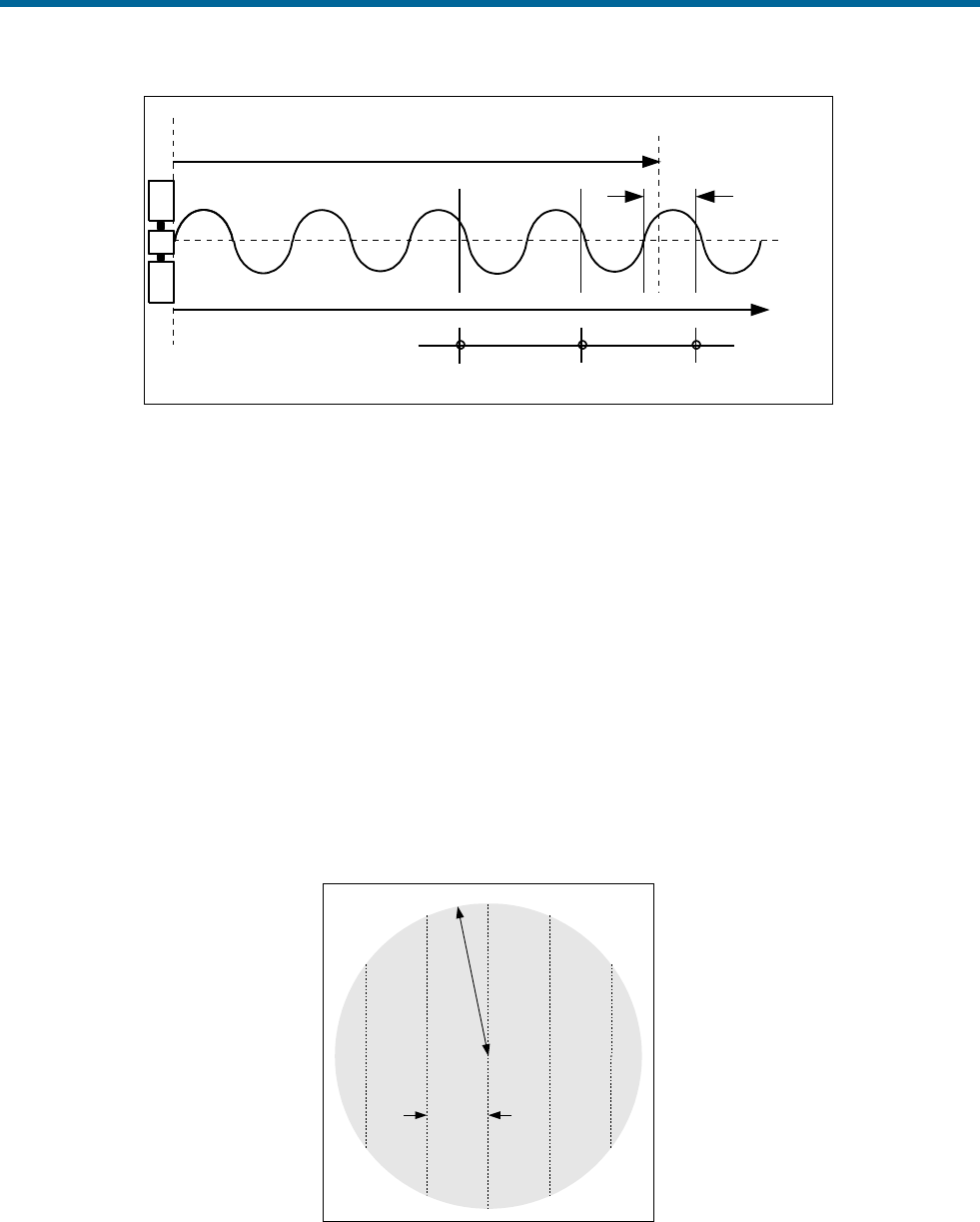
POS MV V5 Installation and Operation Guide
Theory of Operation
Copyright © Applanix Corporation, 2011
B-24
Predicted position from
satellite pseudo-range
Feasible positionsFeasible positions
Measured
phase
Number of cycles in
transmission path
Figure 81: Carrier Phase Cycle Measurement
Because of the uncertainty in its knowledge of the number of integer wavelengths in the transmission
path, the receiver has a number of feasible true positions. These all lie along the circumferences of
circles, centred on the satellite and varying in radius by the signal wavelength.
The range to any satellite is very large and so, for the purposes of this explanation, the feasible positions
lie along parallel straight lines. These lines are 19 cm apart and are within a circle of radius ‘R’ equal to
the uncertainty in the GNSS position solution. This is represented by the shaded circle in Figure 82.
The uncertainty in determining which line is the one on which the actual position lies is the carrier phase
ambiguity. It can be resolved by performing the same operation using multiple satellites.
Figure 83 shows that, by performing the same operation using signals from two satellites, the range of
feasible position solutions is reduced to a number of points where the lines intersect. For this to be
effective, the satellites must be spaced with respect to each other so that the lines intersect at a
reasonably wide angle.
R
19 cm
True position lies
along one of
these lines
Figure 82: Feasible Position Solutions from One Satellite
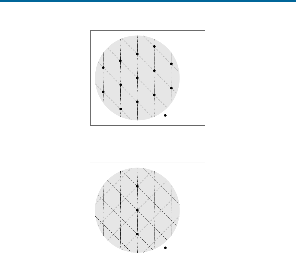
POS MV V5 Installation and Operation Guide
Theory of Operation
Copyright © Applanix Corporation, 2011
B-25
Feasible positions
Figure 83: Feasible Position Solutions from Two Satellites
Figure 84 shows how the range of feasible position solutions reduces still further when three satellites are
used to resolve the carrier phase ambiguities.
Feasible positions
Figure 84: Feasible Position Solutions from Three Satellites
In practice, the operation is more complex than the simple explanation above. This is for the following
reasons:
• The radius of the circle of uncertainty in knowing the position of the GNSS antenna is usually
much larger than the simple examples shown above. There are therefore many more points
within the circle that could be feasible true positions.
• Although the illustrations above show the situation in two dimensions, the actual computation
performed by POS MV involves the resolution of carrier phase ambiguities in three dimensions.

POS MV V5 Installation and Operation Guide
Theory of Operation
Copyright © Applanix Corporation, 2011
B-26
In POS MV, resolution of the carrier phase ambiguities is one of the functions performed by the GNSS
Azimuth Measurement Subsystem (GAMS). The process uses an aided OTF algorithm to resolve the
carrier phase ambiguities while the antennas are moving and uses the following information to reach a
resolution more rapidly:
• Antenna baseline length - the distance between the two GNSS antennas. You can measure this
distance with a tape measure to the required accuracy of 5 mm (3/16 in). The measurement allows
GAMS to achieve ambiguity resolution within two to five minutes.
• Antenna baseline vector - the vector of the line joining the two GNSS antennas measured in the
vessel frame of reference. You can use direct survey techniques to measure this, or POS MV can
make the measurement automatically during the installation calibration (refer to the Surveyed
Antenna Baseline Vector topic on page B-21). The measurement allows GAMS to achieve
ambiguity resolution within 10 to 30 seconds.
• Roll, pitch and heading - information supplied by the strap-down navigator allows GAMS to
achieve ambiguity resolution in one to five seconds.
GAMS uses these three sources of information to reduce the space within which the OTF algorithm
searches for the correct ambiguity resolution.
The desired result of the carrier phase cycle measurement is the determination of the geographic antenna
baseline vector.
Alignment
Alignment is the process by which an INS determines the down and the north directions. It does this by
sensing the gravity and Earth angular rate vectors to obtain a levelled and aligned platform.
• A gimballed INS platform (refer to the INS Platform topic on page B-7) undergoes alignment when
its servomotors physically rotate the platform to make it level and oriented in a known direction,
called the wander angle, with respect to north.
• A strap-down INS undergoes alignment when the navigation processor continuously updates the
computed sensor-to-navigation Direction Cosine Matrix (DCM) until the DCM describes a
transformation to a mathematical platform that is level and has a known wander angle with
respect to true north.
Both these alignment mechanisms are conceptually equivalent. The explanations below therefore refer to
the gimballed platform arrangement because it is easier to visualise than the strap-down arrangement.
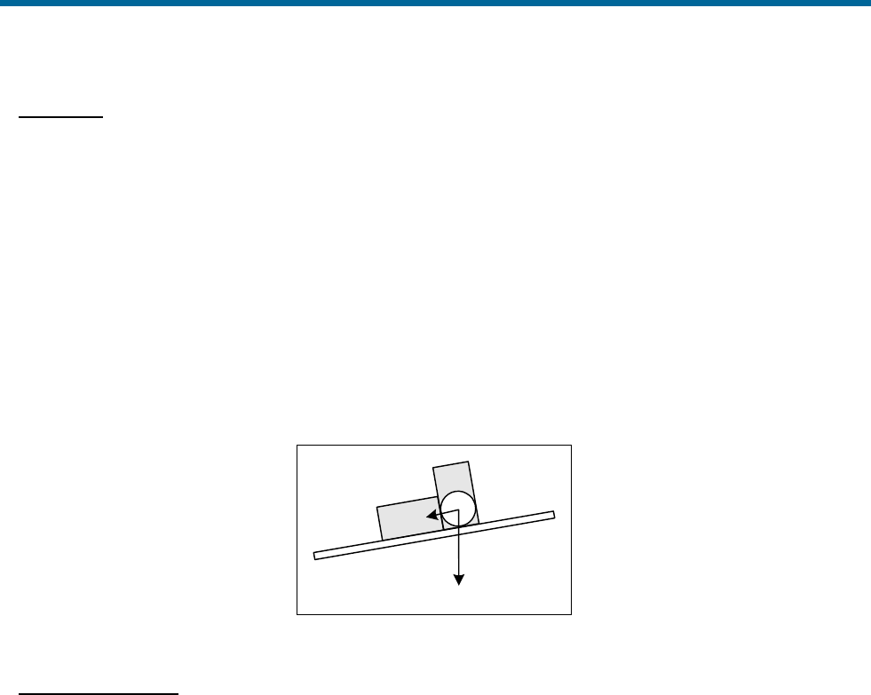
POS MV V5 Installation and Operation Guide
Theory of Operation
Copyright © Applanix Corporation, 2011
B-27
Levelling
A horizontally unaligned INS will have a tilted platform with respect to the true horizontal of a navigation
frame of reference. This tilt causes the horizontally pointing accelerometers to sense some component of
gravity coupled by the angle of tilt, as shown in Figure 85. From this component of horizontal
acceleration, the INS computes an erroneous horizontal velocity.
A platform-levelling algorithm matches the INS-computed velocity with an independent velocity reference
and attributes the resulting velocity differences to platform tilt errors.
During a stationary alignment, the velocity reference is zero. Tilt estimates are then computed and
applied as feedback signals to the gimbal servomotors in a INS platform, or as corrections to the sensor-
to-navigation DCM in a strap-down INS. Because of these corrections, the velocity errors are nulled. The
platform (whether real or mathematical) is then considered horizontally levelled.
ax
z
a
Figure 85: Horizontal Acceleration Error in a Tilted Platform
Gyrocompassing
Full alignment is complete when the platform is level and its x-axis points in a known direction with
respect to true north. The method by which an INS seeks north during an alignment is called
gyrocompassing.
A properly aligned platform will rotate about its north axis at Ω cos λ and about its azimuth (yaw) axis at -
Ω sin λ, where Ω is the Earth’s rotation rate (15°/hour) and λ is the latitude. This combined motion about
two axis will compensate for the rotation of the Earth so that the platform remains locally level.
If a heading error exists (i.e. the platform x-axis points away from north) then there will be a small
component of the Earth rate appearing in the east axis that remains uncompensated by the INS. The
platform will rotate slowly at the Earth rate about the east axis causing the platform to tilt away from the
level at a constant rate.
This slowly increasing platform tilt causes a sensed horizontal acceleration in the north direction due to
gravity coupling as shown in Figure 85. This northward acceleration error has the distinct characteristic of
growing linearly with time and it is therefore clearly recognisable if there are no other large sources of
acceleration error present.

POS MV V5 Installation and Operation Guide
Theory of Operation
Copyright © Applanix Corporation, 2011
B-28
In a gimballed INS platform, the ramping northward acceleration can be used as a feedback signal to a
proportional-integral feedback servomechanism. This servomechanism rotates the platform about its
azimuth axis and drives the heading error towards zero. The levelling mechanism already described
continuously returns the platform to the level.
In a strap-down INS, the alignment algorithm separates the ramping northward acceleration due to
heading error from other constant acceleration errors due to platform tilts. It then computes the correction
needed by the sensor-to-navigator DCM to null the acceleration error and therefore remove the heading
error.
INS operation is similar to the mechanization of a gyrocompass.
Because gravity is an observable quantity through the accelerometers, levelling occurs rapidly, usually
within 30 seconds. The actual time that it takes to achieve levelling depends on the slewing rate of the
gimbal motors of a INS platform, or the iteration rate of a strap-down INS algorithm.
Once levelling is complete, the ramping northward acceleration error caused by heading error becomes
weakly observable against a background of acceleration transients due to vessel motion and
accelerometer noise.
The alignment algorithm must filter these random disturbances in the acceleration signal. Therefore, a
heading alignment will take longer to complete, typically from 10 to 30 minutes depending on latitude.
Error Sources
Once the heading alignment is complete, the INS can begin to navigate free Inertially. Free inertial
navigation allows an INS to reach a navigation solution without input from any independent form of
navigation aid.
The problem with this form of navigation is that it relies totally on the accuracy and stability of the inertial
sensor assembly. In practice, there are a number of errors to consider, each of which contributes in some
way to a deterioration in the accuracy of the navigation solution supplied by an INS:
• Alignment errors - these are errors in roll, pitch and heading measurements following the
completion of an alignment. They arise from errors in the inertial sensing assembly and from
motion disturbances during alignment.
• Accelerometer bias - this is a constant offset in the accelerometer output. It changes randomly
each time you power-on the INS. Typical values for high quality accelerometers, as used in POS
MV, are between 50 and 500 μg.
• Accelerometer scale factor -This is an error in the assumed scale factor on the accelerometer
output. It results in an acceleration error proportional to the sensed acceleration. Typical values
for high quality accelerometers, as used in POS MV, are 0.01 to 0.02%.

POS MV V5 Installation and Operation Guide
Theory of Operation
Copyright © Applanix Corporation, 2011
B-29
• Gyro drift -This appears as a constant output from a gyro when there is no angular rate of rotation
present. The gyros used in POS MV exhibit drift rates of between 1° and 5° per hour.
• Gyro random noise -This is an uncorrelated error caused by the internal noise characteristics of
the gyro. The high quality gyros used in POS MV exhibit a spectral noise density of (0.07°)2 per
hour.
The above component-specific errors cause the following navigational errors to occur:
• Schuler oscillations having a period of 84.4 minutes (see the information on the Schuler
Oscillations on page B-30)
• Space rate oscillations having a nominal period of 24 hours
• Linear position error rate
Over short navigation periods of several hours, the space rate and the linear position error rate are not
separately observable and are therefore viewed together.
Because of the above sources of error, POS MV cannot perform free inertial navigation for extended
periods without the introduction of an increasingly significant error.
Instead, POS MV implements an aided inertial navigator that controls the navigation errors and calibrates
the inertial sensor errors using GNSS data as a reference.
Aided Inertial Navigation
The primary purpose of an aided inertial navigation system, also called an integrated inertial navigation
system, is to compute a blended navigation solution. It does this by using a complementary blending
algorithm to combine inertial navigation data with aiding data from another source.
In POS MV, the aiding data comes from the integral GNSS receivers. The IMU and the GNSS navigation
sensors are complementary because they meet the following conditions:
• The set of navigation sensors together generate all the information required to compute a
complete navigation solution.
• The navigation sensors have complementary error dynamics because all their error dynamics are
observable. Each complementary sensor can calibrate the errors of the other because their
respective errors are separately observable in any linear combination of their outputs.
The important characteristics of the two navigation sensors used by POS MV can be summarised:
• The INS position error grows by several nautical miles per hour in the long term (over several
hours) but is smooth and dynamically accurate in the short term (over a few minutes). The output

POS MV V5 Installation and Operation Guide
Theory of Operation
Copyright © Applanix Corporation, 2011
B-30
also exhibits a strongly recognisable Schuler oscillation superimposed on the growing position
error.
• The GNSS position error is noisy in the short term but exhibits a constant long-term error of only
a few metres (with DGNSS).
Schuler Oscillations
Schuler oscillations appear as regular oscillations about a mean
position in the output of a free inertial navigator. You can also see
them on the output from a gyrocompass. These oscillations have a
period of 84.4 minutes, which is the theoretical period of a
pendulum having a length equal to the radius of the Earth.
In a free inertial navigation system, the oscillations occur as the
platform (whether mechanical or mathematical) over-corrects for
small residual errors in platform levelling and alignment. These
residual errors may arise because of uncorrected bias in the
accelerometers or the gyros.
You can expect the best performance from the aided inertial navigation system when the advantages of
one navigation sensor compensate for the disadvantages of the other.
The following is a simplified example of how navigation data from an INS and a GNSS receiver can be
blended or integrated in a complementary fashion (refer to Figure 86). Note that POS MV uses a
significantly more complex process involving a Kalman Filter.
1. The position solution determined by the INS includes an error that varies with time. This error
comprises a drift, which increases at a linear rate with time, and the Schuler oscillations having a
period of 84.4 minutes. Depending on the quality of components used in the INS, the overall
combined effect of these two error sources can be considerable.
2. The DGNSS receiver delivers a position solution that is stable in the long term and includes an
error of only a few metres (depending on the quality of differential correction information
supplied). However, the DGNSS position solution includes short-term errors of several metres
amplitude that appear as ‘noise’ on the position solution.
3. Calculating the difference between the INS position and the DGNSS position, and then passing
this difference through a low-pass filter can determine a good estimate of the INS position error.
The filter smoothes the random noise from the DGNSS solution and passes the INS position error
and the small steady-state DGNSS position offset.
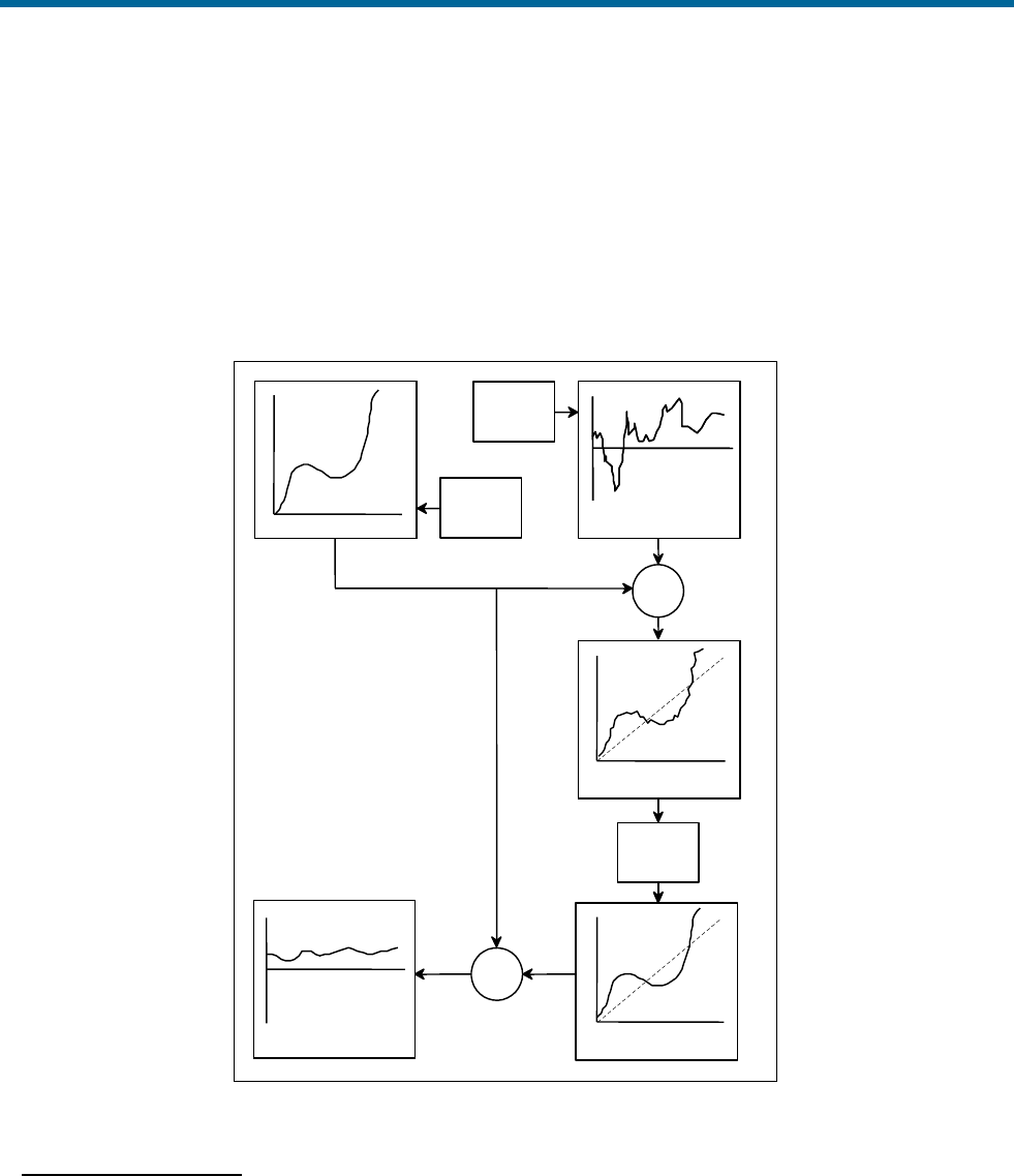
POS MV V5 Installation and Operation Guide
Theory of Operation
Copyright © Applanix Corporation, 2011
B-31
4. Having obtained this estimate of the INS position error, the system then subtracts it from the INS
computed position. This delivers a blended solution with the long-term INS position error and the
DGNSS short-term noise removed. The only remaining error is the constant position offset from
the DGNSS that has passed through the filter.
The blended position solution now has the best characteristics of both the INS and the DGNSS; the
position solution is smoothed like the INS solution, and has a bounded error that is less than or equal to
the DGNSS solution.
INS position error
INS-
Filtered INS
-
Blended North position error
nmi
1 nmi
1 nmi
20 m
+-
+-
INS position error GPS position error
INS - GPS position
difference
Filtered INS - GPS
position difference
Blended North position
error
1 M
1 M
1 M
2 m
2 m
Low - pass
filter
INS
DGPS
Figure 86: Example of Complementary Navigation Sensor Blending
In-Motion Alignment
The paragraphs contained under the Alignment topic on page B-26 describe how an inertial navigation
platform achieves alignment under static conditions. An important feature that the integration of inertial
navigation and GNSS offers is in-motion alignment of the inertial navigator.

POS MV V5 Installation and Operation Guide
Theory of Operation
Copyright © Applanix Corporation, 2011
B-32
The magnitude of Schuler oscillations in the inertial navigator depends on the quality of platform
alignment. Similarly, the rate at which the position error grows depends partly on the quality of alignment
and partly on the magnitude of gyro bias.
To accomplish in-motion alignment the simple low-pass filter shown in Figure 86 on page B-31 is a more
sophisticated filter that has built into it a mathematical model. This mathematical model includes details of
the relationship between the quality of INS alignment, the gyro and accelerometer errors, and the
respective magnitudes of the Schuler oscillations and position error growth.
Such a filter is an algorithm that combines the operations of filtering and estimation. Its main function is to
estimate the internal dynamics of a system using measurements of the system outputs.
POS MV uses this ‘Kalman’ filter with the INS-GNSS position difference to estimate the position error, and
the cause of the INS position error (i.e. the alignment errors and the inertial sensor errors).
• The INS uses the estimated alignment error to correct and therefore improve the alignment of the
INS.
• The INS uses the estimated errors in the inertial sensors to correct and calibrate the outputs from
the inertial sensors.
This process does not require the INS platform (and therefore the vessel) to be stationary. In fact,
movements of the vessel actually assist the calibration process and provide a faster and more accurate
inertial sensor calibration.

POS MV V5 Installation and Operation Guide
Training
Copyright © Applanix Corporation, 2011
C-1
Appendix C Training
The POS MV Aided Inertial Navigation System is a complex assembly of interactive subsystems that
delivers position and attitude measurements for use in a variety of survey applications. Those who will
install, operate and maintain the system will do so more effectively after they receive training in all
aspects of its operation.
In support of this philosophy, Applanix has developed a comprehensive training program for all personnel
who may be involved with POS MV.
Items covered by the course include:
• POS MV Overview
• Principles of Operation - Inertial Navigation Systems, GAMS, GNSS
• Hardware Installation and Configuration
• MV-POSView Controller Program Overview
• Simple Maintenance
The course includes simplified explanations for each subject. There is no requirement for participants to
be entirely familiar with electronics or computers, although it may prove easier to grasp some of the
concepts if attendees possess some basic knowledge in these areas.

POS MV V5 Installation and Operation Guide
Software Installation
Copyright © Applanix Corporation, 2011
D-1
Appendix D Software Installation
Applanix supplies a copy of the MV-POSView Controller software, for use with a PC based Microsoft
Windows® environment, with each POS MV system. This program is used to configure the POS MV once
the system components have been installed and connected.
Subsequently, you can use the program to control POS MV and to view and log its data. Alternatively, for
installations where the use of a controlling PC is not convenient, you can configure POS MV to run in a
stand-alone mode without the need for a controlling PC.
Refer to the System Configuration and the System Operation descriptions on pages 4-1 and 5-1
respectively for instructions on how to configure and control the POS MV using the controller program.
Supplied Software
A compact disk containing POS MV
software is included with each system.
Hardware and Software
Requirements:
The minimum requirements of a Personal
Computer (PC) running the POS MV
software are listed.
MV-POSView Controller
Program:
The MV-POSView Controller program must
be run from the hard disk of the controlling
PC. You cannot run the program from the
installation Compact Disk (CD).
Firmware Upgrade:
Upgrading the POS MV embedded
firmware from a PC connected through the
Ethernet port.
Supplied Software
A compact disk containing POS MV software is included with each system. The following provides a brief
description of the software contained on the CD.
• MV-POSView Controller - required to configure the various POS MV components, operate the
system, access and display information, and to monitor system health.
• POSLoader - windows based Graphical User Interface (GUI) application that is required when
upgrading the POS MV firmware; it automates firmware upgrades through an Ethernet port. The
software checks the current version of POS firmware and updates the requested new firmware.
POSLoader requests a password prior to operation.

POS MV V5 Installation and Operation Guide
Software Installation
Copyright © Applanix Corporation, 2011
D-2
• POSConfig - windows based GUI application that is required for enhancements or automating
changes to the POS MV system setup (e.g. enabling software options). Pricing and enabling
passwords are available from Applanix Customer Support.
Hardware and Software Requirements
Make certain the controlling PC meets or exceeds the requirements outlined in Table 39.
Table 39: Controlling PC Requirements
Item
Minimum Requirements
Processor
Intel Pentium® III or equivalent
Memory
128 MB RAM
Operating System
Microsoft Windows® XP or Windows Vista® or
Windows7®
Free Disk Space
8 MB
Ethernet Card
10/100/1000 Base-T Ethernet; IEEE 802.3 Standard
MV-POSView Controller Program
You must install the MV-POSView Controller program on the hard disk of the controlling PC. You cannot
run the program directly from the installation compact disk.
This program communicates with POS MV through an Ethernet LAN port. You must have Microsoft
Windows® XP, Windows Vista® or Windows7® installed on your PC before you can install and use the
controller program.
Note: Applanix recommends the removal of previous versions of the POS Controller. Keeping previous
versions may result in user confusion and program instability.
To install the MV-POSView Controller program:
1. Open Windows® on controlling PC.
2. Insert Compact Disk (CD) containing POS MV software into controlling PC’s CD drive.
3. Select Start, Run from Windows® Desktop.
4. Enter a:setup.exe.
5. Select OK to start software installation.
6. PC should display setup window with MV-POSView Controller Setup dialogue. This includes a
default installation directory that can be changed to another location.

POS MV V5 Installation and Operation Guide
Software Installation
Copyright © Applanix Corporation, 2011
D-3
7. Select Continue. If controller directory does not exist, installation software will create it. During
installation, program copies a number of files from compact disk to controller directory. These
files include posmv.exe executable file; posmv.hlp file, a read.me file and a set of dynamically
linked library files (*.dll).
8. Installation software prompts for creation of icons. Skip this step if default icons are preferred.
Otherwise, select default program group or a new program group (either of which are created by
installation software through Windows®). Also, icons may be installed into an existing program
group.
This completes the installation of the MV-POSView Controller program.
Firmware Upgrade
You can upgrade the embedded software inside the PCS by connecting to the PCS through its Ethernet
interface and using the POS Loader program to upload the new files.
1. Contact Applanix for an authorization code. Also, S/N of PCS is required.
2. Copy upgrade file to PC. Upgrade file is available from Applanix or may be downloaded from
Internet site. Upgrade file is larger than two MB and may take a considerable time to download.
3. Once file saved to PC hard disk, run POS Loader program. Program locates PCS on your
network and displays its network address. Select PCS and then continue with upgrade procedure.
4. A dialogue panel appears and lists product identification and serial number. Write these details
down carefully and contact Applanix.
5. In Loader program, type authorization code into its text field and continue with upgrade.
6. Observe progress of file transfer and wait for software prompts. During reboot sequence, PCS
decodes and error-checks upgrade software prior to beginning normal operation. These
additional steps mean that first Initialization sequence, after installing an upgrade, will take
considerably longer to complete than normal. Resulting total boot time will be approximately three
to four minutes. Subsequent Initializations will proceed normally.
7. Run MV-POSView Controller program and select View, Statistics to verify that system is
successfully upgraded. Note software revision level.
This completes the upgrade procedure.
Note: The error checking routine performed by the PCS prevents the system from overwriting the current
version of firmware until it has error-checked the new version. If the PCS finds a corruption in the new file,
it will abort the upgrade procedure and retain the previous version of software.
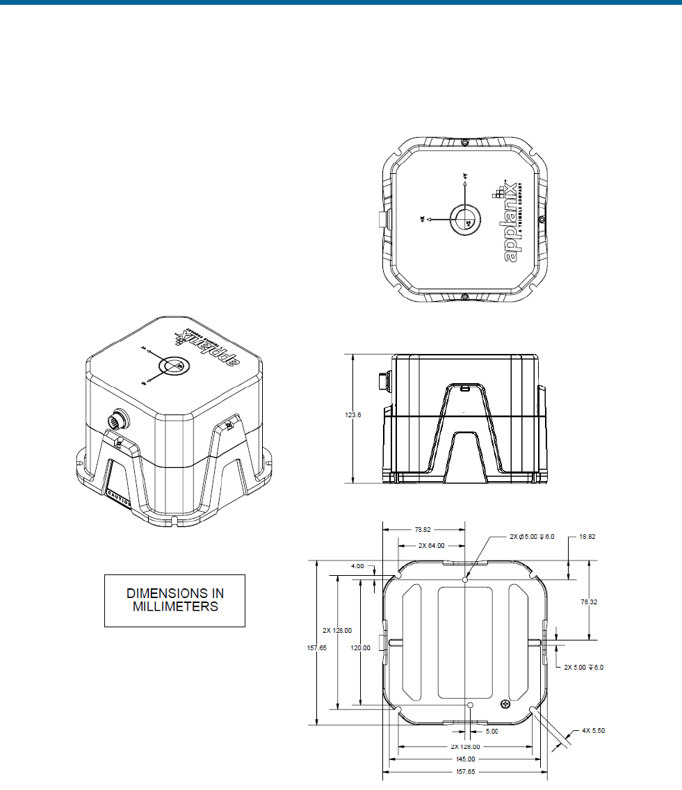
POS MV V5 Installation and Operation Guide
Drawings
Copyright © Applanix Corporation, 2011
E-1
Appendix E Drawings
Figure 87 IMU Types 36, 37 and 42 Mechanical Interface
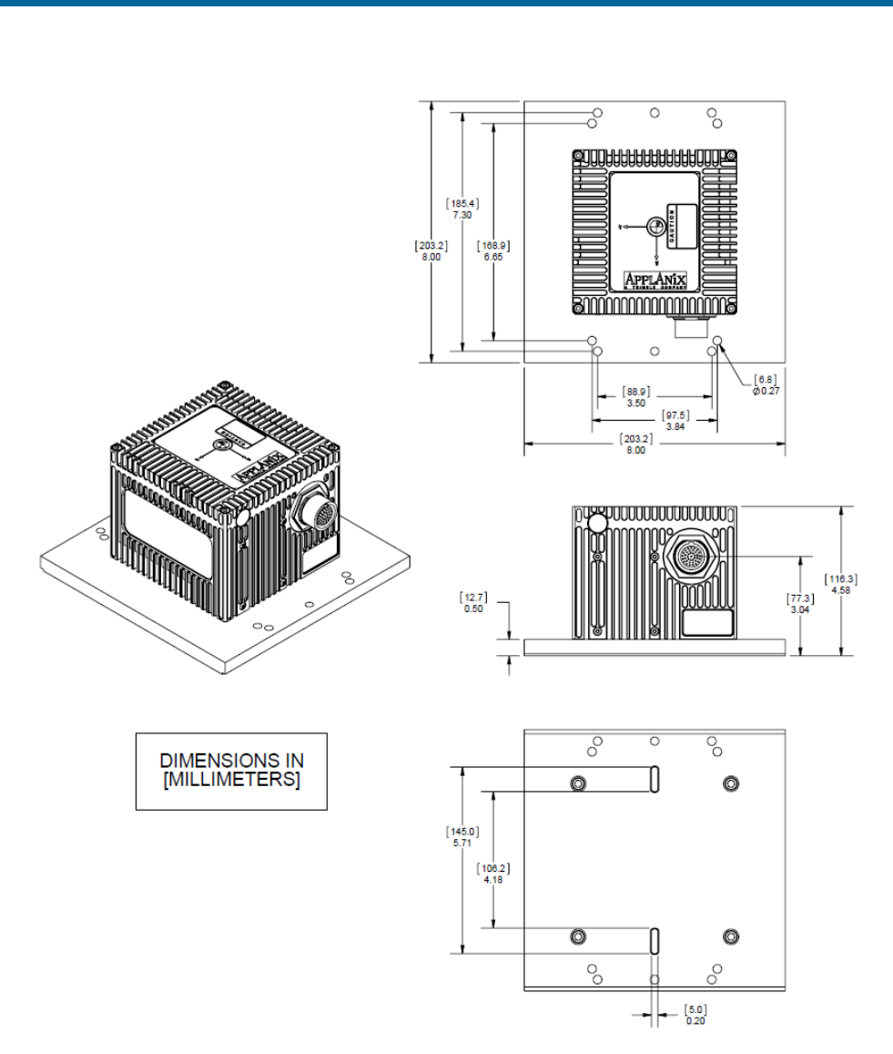
POS MV V5 Installation and Operation Guide
Drawings
Copyright © Applanix Corporation, 2011
E-2
Figure 88 IMU Type 26 Mechanical Interface
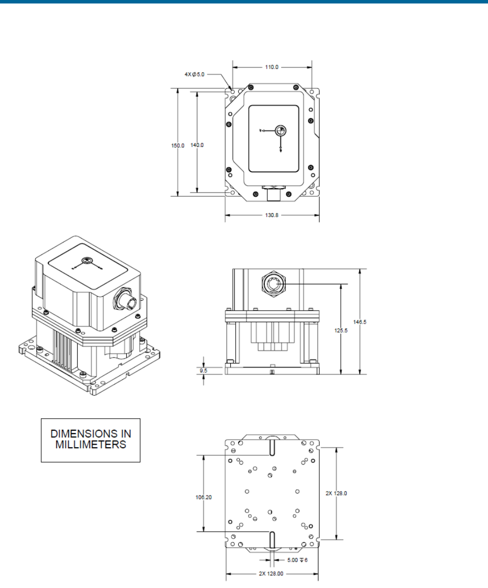
POS MV V5 Installation and Operation Guide
Drawings
Copyright © Applanix Corporation, 2011
E-3
IMU shown with adaptor plate 10004691. Contact Applanix for additional information.
Figure 89 IMU Type 31 and 40 Mechanical Interface
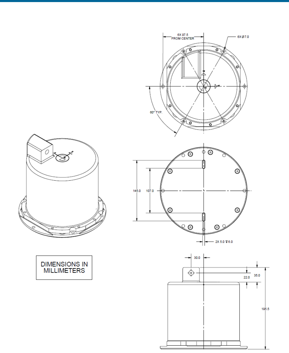
POS MV V5 Installation and Operation Guide
Drawings
Copyright © Applanix Corporation, 2011
E-4
NOTE: IMU type 38 overall height is 195.5mm as shown, IMU type 39 overall height is 205.5mm.
Figure 90: IMU Type 38 or 39 Mechanical Interface
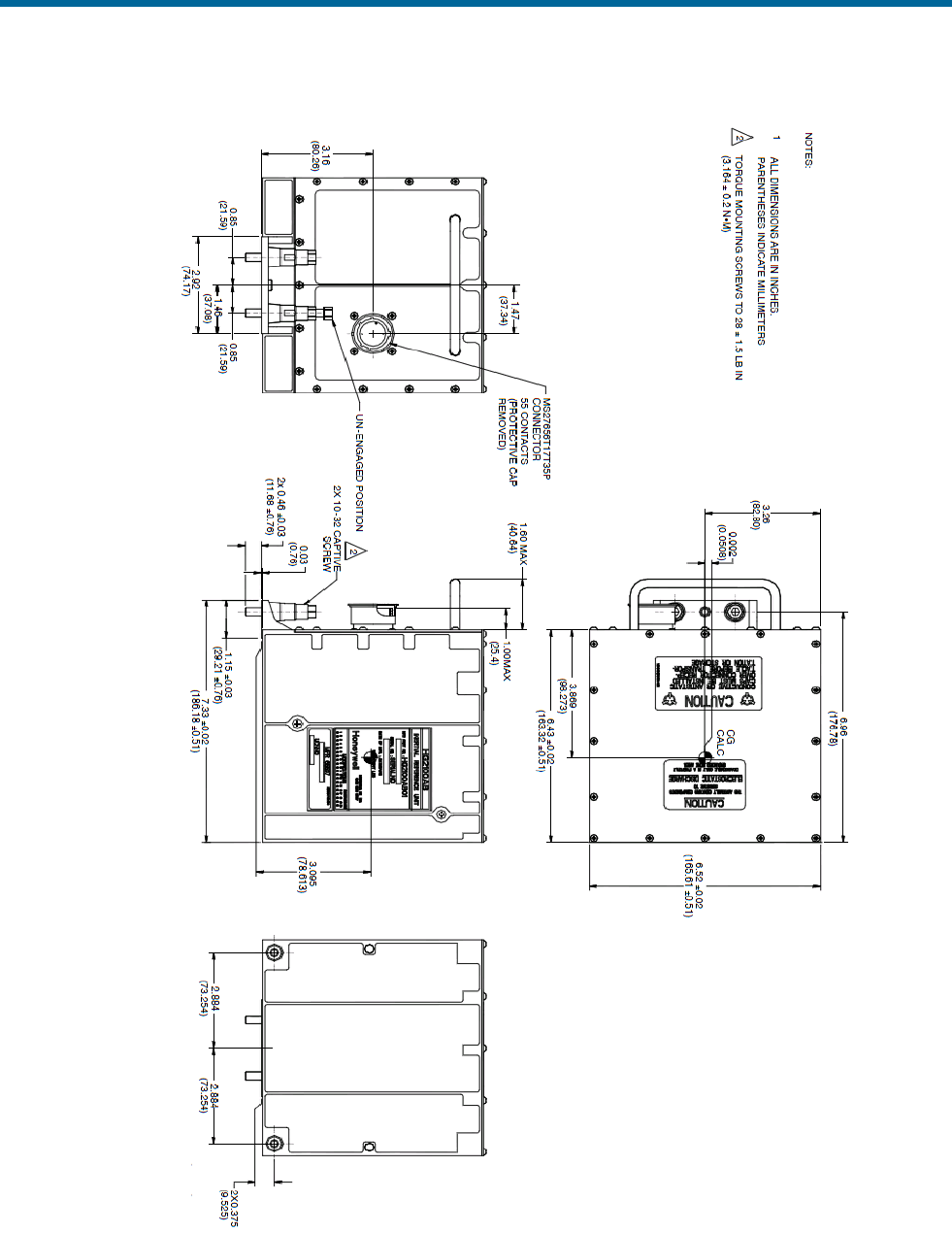
POS MV V5 Installation and Operation Guide
Drawings
Copyright © Applanix Corporation, 2011
E-5
Figure 91: IMU Type 21 Mechanical Interface
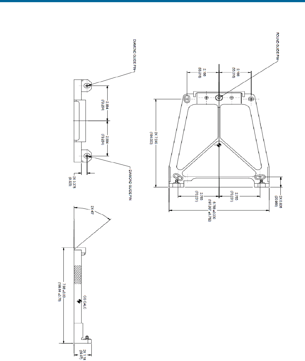
POS MV V5 Installation and Operation Guide
Drawings
Copyright © Applanix Corporation, 2011
E-6
Figure 92: IMU Type 21 Mounting Tray
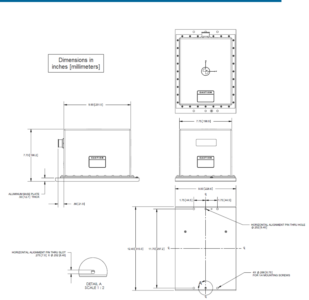
POS MV V5 Installation and Operation Guide
Drawings
Copyright © Applanix Corporation, 2011
E-7
Figure 93: IMU Type 33 Mechanical Interface
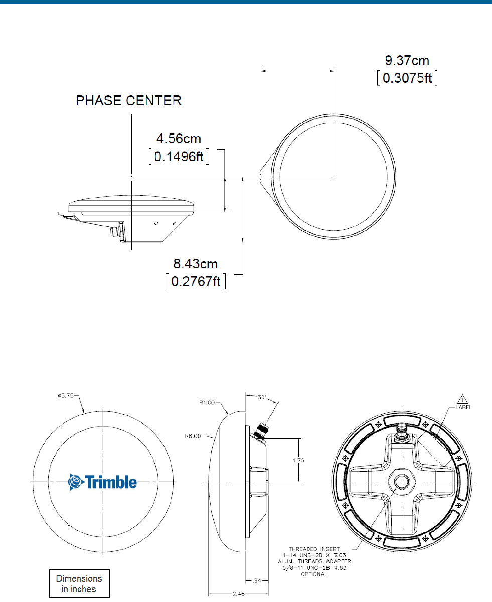
POS MV V5 Installation and Operation Guide
Drawings
Copyright © Applanix Corporation, 2011
E-8
Figure 94: Trimble Zephyr II GNSS Antenna Footprint
Phase centre is 66 mm above bottom of mounting thread.
Figure 95: Trimble 382AP GNSS Antenna Footprint
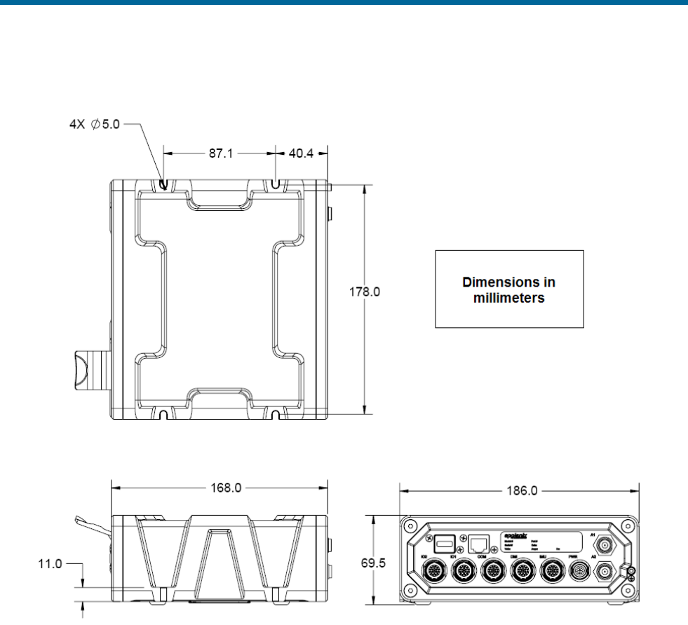
POS MV V5 Installation and Operation Guide
Drawings
Copyright © Applanix Corporation, 2011
E-9
Figure 96: PCS Footprint – POS MV V5-1
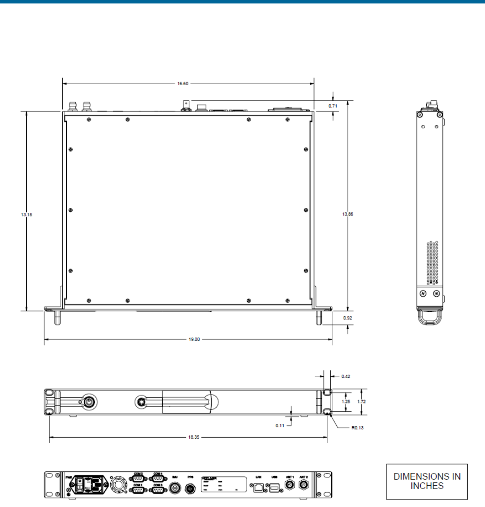
POS MV V5 Installation and Operation Guide
Drawings
Copyright © Applanix Corporation, 2011
E-10
Figure 97: PCS Footprint - POS MV V5
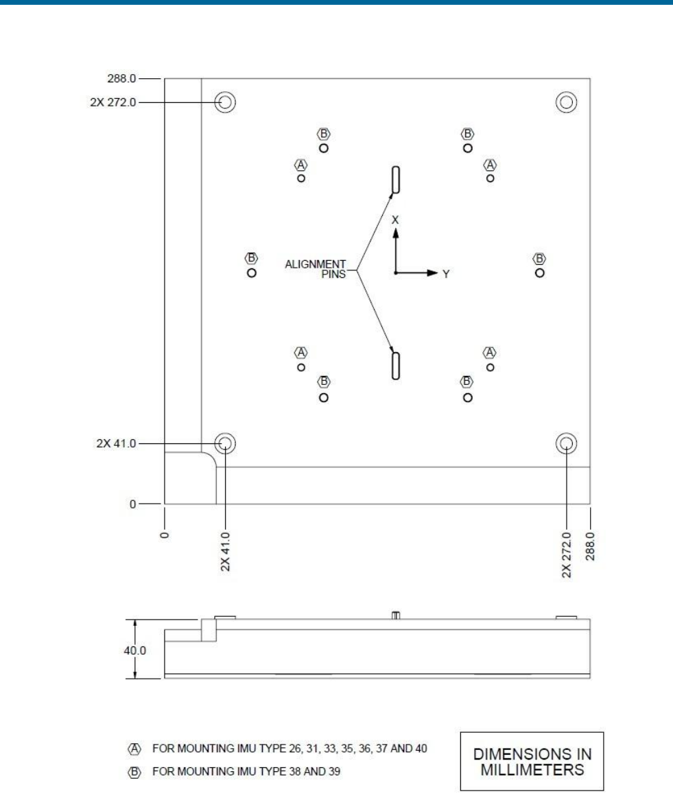
POS MV V5 Installation and Operation Guide
Drawings
Copyright © Applanix Corporation, 2011
E-11
Figure 98: IMU Mounting Plate

POS MV V5 Installation and Operation Guide
Patch Test
Copyright © Applanix Corporation, 2011
F-1
Appendix F Patch Test
This appendix suggests a simple procedure for performing a patch test to remove any residual errors in
the POS MV mount angle configuration. You should perform a patch test before you use POS MV data
for survey purposes.
Note: The calibration procedures explained in this appendix provide generic guidance only.
Note: Specific survey sonar may require different procedures, or individual survey companies may set
their own patch test procedures. You should follow the instructions in this appendix only if there are no
preferred procedures already in force.
Survey Area
To complete the calibration operations detailed in this appendix successfully, the vessel should perform a
series of survey lines and manoeuvres over an area of seabed that conforms closely to the following
requirements:
1. There should be two distinct regions:
• A region where the seabed is flat and level
• A region immediately adjacent where the seabed slopes at a relatively steep angle
(greater than 10°)
Figure 99 shows an ideal survey calibration area.
2. Ideally, the survey calibration area should also include a readily identifiable target object at a fixed
position on the seabed. This could be a rock, a wreck or any other relatively small structure.
3. The survey calibration area should be sufficiently large so that the survey vessel can manoeuvre
freely within its boundaries and can perform a series of straight survey lines approximately 300 to
500 metres long.
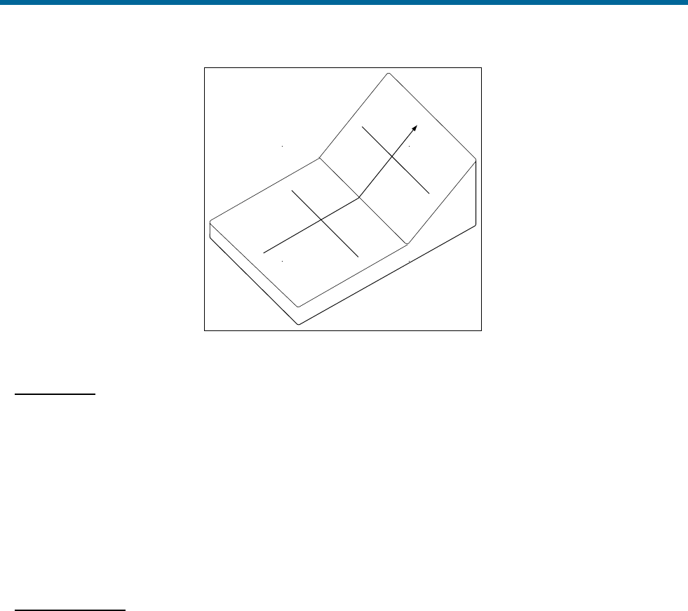
POS MV V5 Installation and Operation Guide
Patch Test
Copyright © Applanix Corporation, 2011
F-2
C
A
B
D
E
X
X
O
Figure 99: Ideal Survey Calibration Area
Calibration
The procedure outlined in this appendix includes a calibration check on the following parameters. Perform
the following:
• Roll measurement
• Position time delay
• Gyrocompass heading
• Pitch measurement
Roll Calibration
Complete the gyrocompass calibration routine and remove any offset that may exist.
1. Sail a line to survey the flat region of the test area (A to B of Figure 99 on page F-2).
2. Turn through 180° and sail a reciprocal course along the same line. Log this line separately from
the first survey line.
3. Use the multibeam software and select a single point along both survey lines (point O of
Figure 99 on page F-2). Examine the profile of the seabed perpendicular to the course of the
vessel at this point (the line X–X of Figure 99 on page F-2) and confirm that both survey lines
show the same seabed profile. They should be substantially coincident as shown in Figure 100
on page F-3. If they are not (as shown in Figure 101 on page F-3), this indicates that there is a
constant steady state roll offset in the mounting angles. Use the multibeam software to
compensate for this offset.
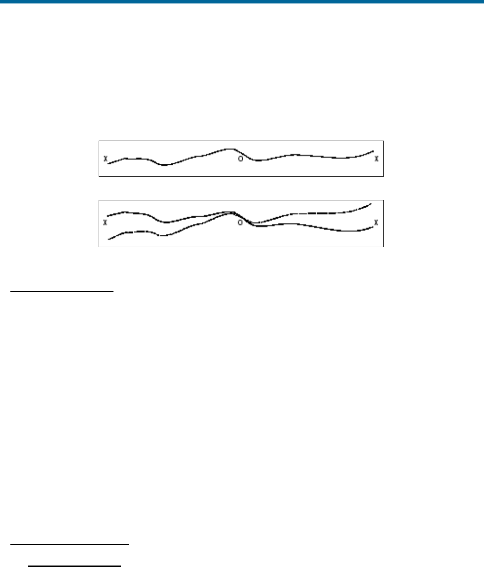
POS MV V5 Installation and Operation Guide
Patch Test
Copyright © Applanix Corporation, 2011
F-3
4. Repeat the above survey tests to confirm that any adjustments you make to the multibeam
software have removed the roll offset.
5. As a final check, perform a similar survey following the line D–E in Figure 99 on page F-2. At the
end of the survey line, turn through 180° and repeat the survey line E–D, logging both lines
separately. Check that the profiles from both survey lines coincide where they cross the line B–C.
Figure 100: Correct Roll Calibration
Figure 101: Incorrect Roll Calibration
Position Time Delay
1. Complete a sound velocity profile for the multibeam sonar and correct any errors that may exist.
2. Set a vessel speed of 4 knots and sail a straight line that crosses the flat and the sloping regions
of the test area (line A-C in Figure 99 on page F-2). Repeat the line on a reciprocal heading and
at the same speed. Log both lines separately.
3. Increase the vessel speed to 8 knots and repeat both lines. Log both lines separately.
4. Compare the two lines surveyed in the same direction but at different speeds. Any offset that
appears on the seabed chart between the two runs arises from a position time delay. Use the
multibeam software to correct any such error.
5. Now compare the two lines that run in opposite directions but at the same speed. Any offset that
appears on the seabed chart between these two runs arises from a pitch offset in the mounting
angles. Use the multibeam software to correct any such error.
6. Finally, repeat the survey lines to verify that you have removed all offsets successfully.
Gyrocompass Heading
Harbour Calibration
Ideally, you should perform the gyrocompass calibration while the vessel is in a harbour:
1. Power-on the POS MV and allow it to settle in accordance with instructions supplied by the
manufacturer.

POS MV V5 Installation and Operation Guide
Patch Test
Copyright © Applanix Corporation, 2011
F-4
2. With the vessel tied alongside use survey techniques to determine the precise heading
against a known landmark. Record this value together with the heading displayed by the
gyrocompass.
3. Turn the vessel through 180° and again measure the precise heading of the vessel. Record
this value together with the heading displayed by the POS MV.
4. Note any offsets that may exist between the two values for surveyed heading and the
corresponding values for gyrocompass heading. Follow the instructions supplied by the sonar
manufacturer to configure the system with these gyrocompass offset values.
Sea Calibration
You can use the following procedure to calibrate the gyrocompass at sea. However, this method is
inherently less accurate than the preferred method detailed above and you should use it only where
there are no alternatives.
1. Sail a straight course while making a calibration survey chart of the seabed. Observe the
position of a target object on the chart which, ideally, should occur at about the halfway point
of the survey line.
2. At the end of the first survey line, turn the vessel through 180° and repeat the survey line in
the opposite direction. Again, note the position of the target object.
3. Any gyrocompass offset will appear as an apparent shift in the position of the target on the
seabed.
Survey Procedure
Each operator is likely to have a standard procedure that you should follow when performing a multibeam
survey. Similarly, the manufacturer of the multibeam system is likely to have a set of specific instructions
detailing how to configure and use their system within such a survey. You should give precedence to any
existing instructions and operating procedures over the procedures outlined in this appendix.
Generally, the following procedures should be included as part of any multibeam survey:
1. Verify the sound velocity profile.
2. Even if the system was previously calibrated, the first and the last survey lines should be sailed in
both directions to enable a post-processing calibration check.
3. Finally, an extra line should be sailed perpendicular to the other survey lines. This allows
detection of any changes in sound velocity or tidal action during post-processing.
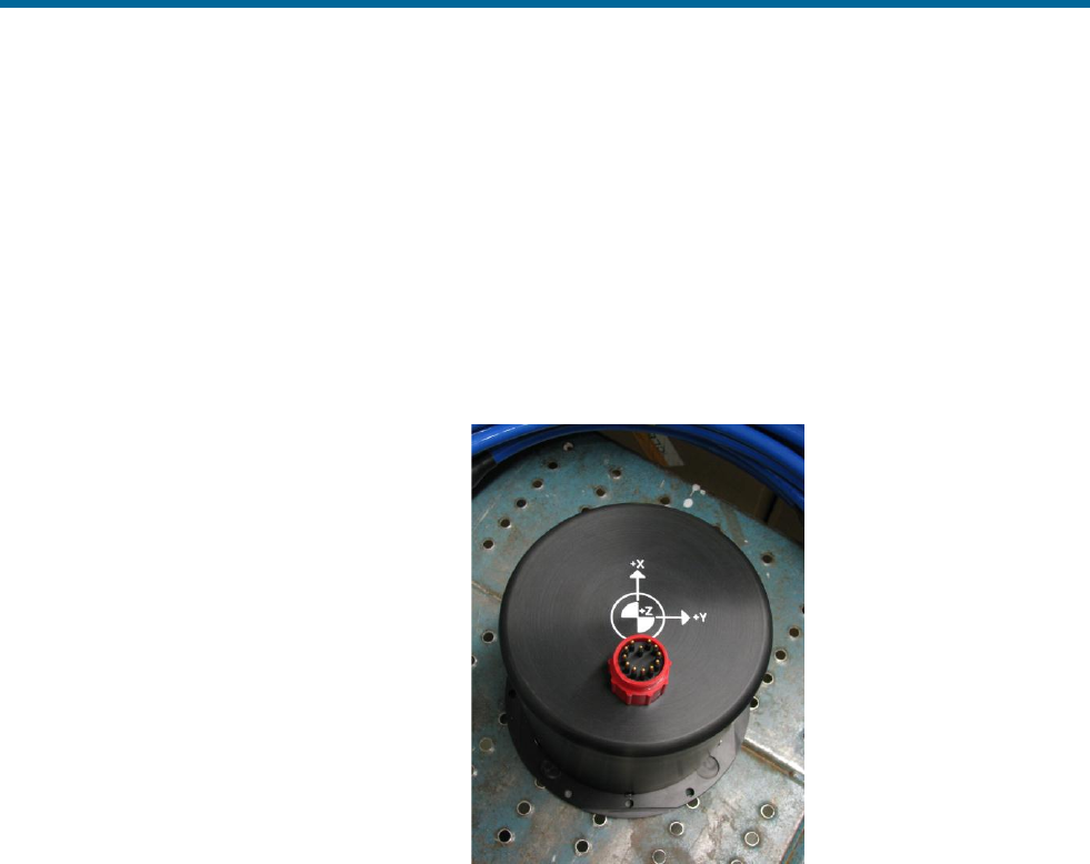
POS MV V5 Installation and Operation Guide
IP68 Connector Handling
Copyright © Applanix Corporation, 2011
G-1
Appendix G IP68 Connector Handling
Handling Instructions
• The connector should not be exposed to long term heat or sunshine.
• If this occurs, and the connectors are very dry, soak in fresh water before use.
• Ensure the connectors are lubricated - the recommended lubricant is Loctite 8021 as a spray or
Molykote 44 Medium as a paste - use either sparingly.
• Any accumulation of sand or mud in the female contact should be removed with fresh water. Spraying
or the application of grease could dammage the the female seals; see Figure 102.
• Do not over tighten the bulkhead nuts
• Do not disconnect by pulling on the
cable and avoid sharp bends at cable
entry.
• When disconnecting, pull straight, not
at an angle.
Ensure the above points are fulfilled to get
the best out of your connectors. If in doubt,
please contact Applanix.
Figure 102: IP68 Connector

POS MV V5 Installation and Operation Guide
POS-GPS Timing
Copyright © Applanix Corporation, 2011
H-1
Appendix H POS-GPS Timing
Background
Global Positioning System (GPS) time is a continuous measurement of time from an epoch started on
January 6, 1980 at midnight (0 hours 0 minutes 0 seconds) Universal Time Coordinated (UTC). GPS
Time is often stated in a number of weeks and seconds from this GPS Time epoch. GPS Time does not
introduce leap seconds and therefore, is ahead of UTC by a number of seconds.
The GPS Master Control Station, located at Schriever AFB in Colorado, steers GPS Time to within one
microsecond (less leap seconds) of UTC. Navigation messages transmitted by the Space Vehicles (SVs)
contains parameters that permit users to compute an estimate of the current GPS/UTC sub-microsecond
difference as well as the number of leap seconds introduced into UTC since the GPS epoch. GPS Time is
derived from the GPS Composite Clock (CC), consisting of the atomic clocks at each Monitor Station and
all of the GPS SV frequency standards.
The following identify a few of the many time standards:
• Local time is the date/time reported by your PC. Local time differs from UTC by the number of
hours for your time zone (plus local PC clock errors).
• UTC, popularly known as GMT (Greenwich Mean Time), or Zulu time.
• GPS, Global Positioning System time, is the atomic time scale implemented by the atomic clocks
in the GPS ground control stations and the GPS satellites.
• TAI, Temps Atomique International, is the international atomic time scale based on a continuous
counting of the International System of Units (SI) second.
Because GPS and TAI time do not have leap seconds, they will change by one second with respect to
UTC whenever a leap second is inserted. GPS and UTC time scales were aligned when GPS Time
began on January 6, 1980. TAI and UTC time scales were aligned when TAI time began on January 1,
1958.
Date
GPS to UTC
Offset (sec)
Date
TAI to UTC
Offset (sec)
Jan 6, 1980
0
Jan 1, 1980
19
Jul 1, 1981
1
Jul 1, 1981
20
Jul 1, 1982
2
Jul 1, 1982
21
Jul 1, 1983
3
Jul 1, 1983
22
Jul 1, 1985
4
Jul 1, 1985
23
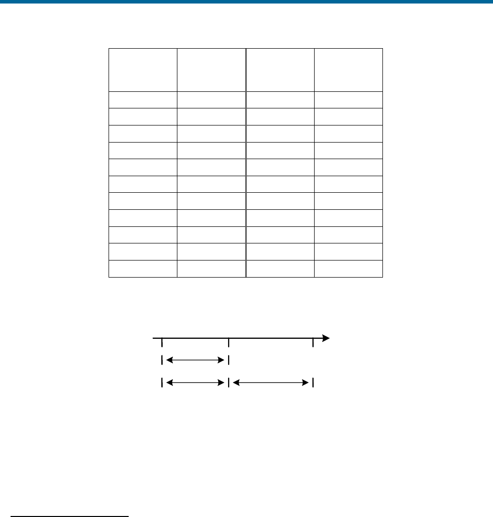
POS MV V5 Installation and Operation Guide
POS-GPS Timing
Copyright © Applanix Corporation, 2011
H-2
Date
GPS to UTC
Offset (sec)
Date
TAI to UTC
Offset (sec)
Jan 1, 1988
5
Jan 1, 1988
24
Jan 1, 1990
6
Jan 1, 1990
25
Jan 1, 1991
7
Jan 1, 1991
26
Jul 1, 1992
8
Jul 1, 1992
27
Jul 1, 1993
9
Jul 1, 1993
28
Jul 1, 1994
10
Jul 1, 1994
29
Jan 1, 1996
11
Jan 1, 1996
30
Jul 1, 1997
12
Jul 1, 1997
31
Jan 1, 1999
13
Jan 1, 1999
32
Jan 1, 2006
14
Jan 1, 2006
33
Jan 1, 2009
15
Jan 1, 2009
34
Notes:
1. GPS and TAI are ahead of UTC time, see Figure 103.
Figure 103: GPS. TAI and UTC Time
2. Consult the International Earth Rotation Service (IERS) web pages for more quantitative
information.
GNSS Timing Basics
One Pulse Per Second
The basis for all time and frequency functions is the One Pulse Per Second (1PPS) signal supplied by the
GNSS receiver. This signal is typically a short logic pulse, one edge of which is adjusted by the receiver
to be ‘on time’ with respect to the one second epoch of UTC. In order to do this, the GNSS receiver needs
to know its position.
If the position is unknown, the receiver can find its own position and solve for time by tracking four or
more GNSS satellites. This is called the dynamic mode, and is the mode used in moving platform
applications.
UTC
GPS
TAI
t
15 Leap
Seconds
15 Leap
Seconds
19 Seconds
Fixed

POS MV V5 Installation and Operation Guide
POS-GPS Timing
Copyright © Applanix Corporation, 2011
H-3
Alternatively, timing receivers can be told to use a known fixed position, in which case the receiver can
solve for time by tracking a minimum of one satellite. This is called the static mode, and it is used in
applications where the position is fixed.
Timing Accuracy
Errors in the time of occurrence of the 1PPS pulses from the GNSS receiver consist of three parts:
• Bias - a fixed offset due to uncompensated delay errors in the receiver/antenna system
• Drift - variations in timing over long periods due primarily to differences in satellites tracked over
time
• Jitter - short-term variations in timing from pulse to pulse
These error sources are inherent in the both the GNSS system and the GNSS receiver. The sum of these
errors can be as low as a few tenths of a microsecond or up to a few microseconds. This high level of
accuracy is possible because the timekeeping maintained within the GNSS system is continuously
adjusted to null out timing errors.
Output Characteristics
The 1PPS signal (from the GNSS) is usually in the form of a pulse of whose duration varies between
microseconds and milliseconds, at Transistor-Transistor Logic (TTL) or RS-232 signal levels.
Time Message
The 1PPS signal provides an accurate time mark, but is ambiguous unless coupled with a time stamp.
Most timing systems specify a time message that is transmitted (usually over a serial data port) that gives
the date and time of day for each occurrence of the 1PPS signal. This time message is sent in between
the 1PPS signals and may be specified to time-tag either the 1PPS that has just occurred, or the one that
is just about to happen.
POS System Timing
There are a number of aspects to POS system timing; there is the internal timing of sensor data and the
navigation solution, there is the ability to synchronize external equipment to POS, or POS can be
synchronized to external equipment time, all ICD data output from POS includes time tags, and the user
can generate event pulses which are time tagged by POS and then made available for output or logging.
Each of these items are described in the following sections.
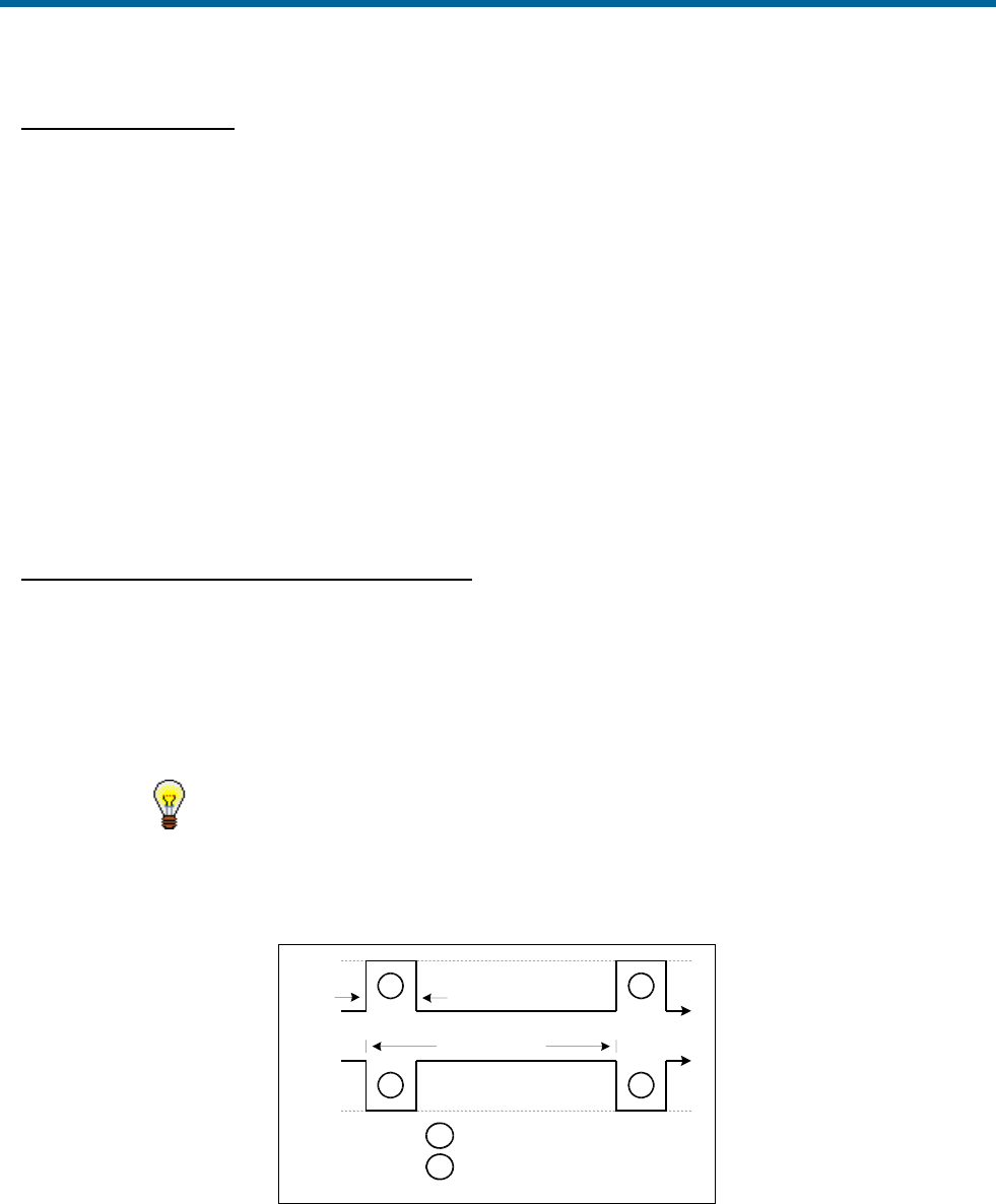
POS MV V5 Installation and Operation Guide
POS-GPS Timing
Copyright © Applanix Corporation, 2011
H-4
Internal POS Timing
POS uses its internal clock to keep track of POS time, which starts from 0 when the system is powered up
and continually increases. POS time never resets the way GPS and UTC seconds of the week do. POS
uses the 1PPS pulse and the corresponding time message from the Primary GNSS receiver to 1) set an
internal GPS and UTC offset with respect to POS time and 2) correct the drift in the internal clock.
The Primary GNSS receiver must has sufficient satellites visible when POS is started so that it will
generate the 1PPS and time message. Without this data POS will not be able to synchronize its internal
clock and navigation will not proceed. Once the internal clock is synchronized there can be gaps in the
Primary GNSS output of 1PPS and time message without adversely affecting POS performance.
The Events pane on the main POSView window, see page 5-6, displays the Universal Time, Coordinated
(UTC) time of the most recent PPS pulse transmitted by the primary GNSS receiver. The Count field for
PPS indicates the total number of signals recorded from the GNSS receiver.
Synchronizing External Equipment to POS
To synchronize external equipment time with POS, the external equipment must read and record the
1PPS signal and one of the corresponding time messages from POS. With this information the external
device can adjust its internal timing to match POS timing using either GPS or UTC as the time base. Any
data recorded by the external device can then be time stamped with a time synchronized to POS so that
the data can later be merged with POS data using a common time base.
Processing the time differential for each new 1PPS pulse and time
message allows the user to compensate for drift in the external device
clock.
The PPS pulse is present at the rear panel IO connectors and is configurable for pulse width and polarity
from the POSView Settings – Events window. Figure 104 shows the parameters of the 1PPS signal.
Figure 104: 1PPS Signal Characteristics
The time messages corresponding to PPS can be configured to be output on any COM port. The various
1PPS time message outputs provide the time of the previous 1PPS signal. PPS time is available from
+ Vdc
2
2
1
1
0 Vdc
0 Vdc
Configurable
1000 us (1 s)
t
t
1
= Positive pulse
2
= Negative pulse
+ Vdc

POS MV V5 Installation and Operation Guide
POS-GPS Timing
Copyright © Applanix Corporation, 2011
H-5
POS in either a NMEA message (ZDA or PPS) or Binary output message (PPS or TM1B). Refer to COM
Ports starting on page 3-1 for message format details.
Synchronizing POS to External Equipment
POS maintains a User time offset in addition to the GPS and UTC offsets with respect to its internal POS
time. This provides the user with the option of supplying POS with an external time message that will be
used to set the User time offset. Once set, the User time can be used as a time tag for ICD output data
groups.
To synchronize POS with external equipment time (User Time), the external equipment must read and
record the 1PPS signal from POS and transmit its User Time to POS on the Ethernet port. Refer to the
description of the Ethernet Connector on page 2-21.
‘Message 55 - User Time Recovery’ (Table 40) is extracted from Applanix document PUBS-ICD-003759.
This message specifies the time of the last PPS in User Time to the POS. It directs POS to synchronize
its User Time with the time specified in the User PPS Time field. POS accepts this message at anytime at
a maximum rate of once per second.
To establish User Time synchronization, the user must send the User Time of last PPS to POS with this
message after the PPS has occurred. The resolution of time synchronization is one microsecond.
Table 40: Message 55 - User Time Recovery
Item
Bytes
Format
Value
Units
Message start
4
Char
$MSG
N/A
Message ID
2
Ushort
55
N/A
Byte count
2
Ushort
24
N/A
Transaction
number
2
Ushort
Input: Transaction
number
Output: [65533, 65535]
N/A
User PPS time
8
Double
[0, ) default = 0.0
seconds
User Time
conversion
factor
8
Double
[0, ) default = 1.0
/seconds
Pad
2
Short
0
N/A
Checksum
2
Ushort
N/A
N/A
Message end
2
Char
$#
N/A
This message must be sent by a user application that connects to the POS TCP/IP socket interface
(Control Port) to accommodate both the User Timing input and the substitute controller communication.

POS MV V5 Installation and Operation Guide
POS-GPS Timing
Copyright © Applanix Corporation, 2011
H-6
Time Tagging of Output Data
POS formats data into ICD groups as described in PUBS-MAN-003759. The ICD groups are output in
real-time on the Display Port and Data Port, are logged on the removable media and internal flash drive
and are output on the Ethernet logging port. Which groups are output on which port are under user
control.
All ICD groups have the same basic structure as shown in Table 41 (extracted from Applanix document
PUBS-ICD-003759). The selections of the time and distance types are made from the POSView Settings
– Installation – Tags, Multipath & Autostart window. To ensure the POS data are useful for post-
processing using POSPac, set Time Tag 1 to GPS time.
Table 41: Common ICD Group Structure
Item
Bytes
Format
Value
Units
Group start
4
Char
$GRP
N/A
Group ID
2
Ushort
Group specific
N/A
Byte count
2
Ushort
Group specific
bytes
Time 1
8
Double
N/A
sec
Time 2
8
Double
N/A
sec
Distance tag
8
Double
N/A
m
Time types
1
Byte
Time 1 Select Value: bits 0-3
Time 1: POS time 0
Time 1: GPS time 1 (default)
Time 1: UTC time 2
Time 2 Select Value: bits 4-7
Time 2: POS time 0 (default)
Time 2: GPS time 1
Time 2: UTC time 2
Time 2: User Time 3
Distance type
1
Byte
Distance select Value
N/A 0
POS distance 1 (default)
DMI distance 2
Group specific data fields
Pad
0-3
Byte
0
N/A
Checksum
2
Ushort
N/A
N/A
Group end
2
Char
$#
N/A
The navigation solution, sensor data and user event groups are time tagged with the Time of Validity of
the data. Other low rate (1 Hz) status type groups are time tagged with the time when the group was
processed.

POS MV V5 Installation and Operation Guide
POS-GPS Timing
Copyright © Applanix Corporation, 2011
H-7
POS outputs data in NMEA and Binary formats in addition to the ICD format described. Not all formats
have a time field, the assumption being that they are output with minimal latency with respect to their
Time of Validity. For those formats that do incorporate a time field, POS will insert the Time of Validity of
the data in the appropriate time base.
Event Time Tagging
Event inputs can be used to capture any external event whose time or distance when the event occurred
is important for processing the mission data. The user must arrange for the external equipment to
generate a digital pulse. POS is configured to detect the event pulse from the POSView Settings –
Events window. Upon detecting an event input pulse, POS will record the time and distance into an ICD
Event group, within 1 µs of the pulse edge. The time and distance types will be the same as configured
for all other ICD groups. These Event ICD groups can be output or logged in the same manner as other
ICD groups.
The Events pane of the POSView main window displays the last times and counts for events 1 and 2. To
view all the events, open the POSView View – Event Data window.
ICD groups 5, 6, 30 and 31 correspond to Events 1, 2, 3 and 4.

POS MV V5 Installation and Operation Guide
POS-GPS Timing
Copyright © Applanix Corporation, 2011
GLOSSARY
Acceleration of Gravity
Acceleration of Gravity (g), not to be confused with the force of gravity (Fgrav), is the acceleration
experienced by an object when the only force acting upon it is the force of gravity. On and near the
Earth's surface, the value for the acceleration of gravity is approximately 9.8 m/s/s. It is the same
acceleration value for all objects, regardless of their mass (and assuming that the only significant force
is gravity).
Angular Rate
Defines how quickly an angle is changing. The faster the angle changes, the higher the angular rate.
Can be expressed as:
changeangleofduration
angleinchange
.
ASCII
American Standard Code for Information Interchange. A code in which each alphanumeric character is
represented as a number from 0 to 127, translated into a 7-bit binary code for the computer.
Attitude
Attitude determination is the process of estimating the orientation of a vehicle (space, air, marine or
land) by using known reference points and vehicle attitude. Vehicle attitude sensors supply roll, pitch,
and yaw data to a computer for processing with navigational data (reference points).
Baseline Vector
X, Y and Z components of the displacement from the Primary to secondary GNSS antenna phase
centre. The baseline vector is resolved in the Vehicle body frame.
Baud Rate
Baud Rate, in computer science, is commonly a reference to the speed at which a modem can
transmit data. Often incorrectly assumed to indicate the number of bits per second (bps) transmitted,
baud rate actually measures the number of events, or signal changes, that occur in one second.
Because one event can actually encode more than one bit in high-speed digital communications, baud
rate and bits per second are not always synonymous, and the latter is the more accurate term to apply
to modems. For example, a so-called 9600-baud modem that encodes four bits per event actually
operates at 2400 baud but transmits 9600 bits per second (2400 events times 4 bits per event) and
thus should be called a 9600 bps modem.
Bit
The smallest element of computer storage, the bit is a single digit in a binary number (0 or 1). Groups
of bits make up storage units in the computer, called "characters," "bytes," or "words," which are

POS MV V5 Installation and Operation Guide
POS-GPS Timing
Copyright © Applanix Corporation, 2011
2
manipulated as a group. The most common is the byte, made up of eight bits and equivalent to one
alphanumeric character.
Bits are widely used as a measurement for transmission. Ten megabits (Mb) per second means that
ten million pulses are transmitted every second. Measurements for storage devices such as disks, files
and databases are given in bytes rather than bits.
Byte
The common unit of computer storage from micro to mainframe, the byte is made up of eight binary
digits (bits). A ninth bit may be used in the memory circuits as a parity bit for error checking. The term
was originally coined to mean the smallest addressable group of bits in a computer (has not always
been eight).
C/A
The coarse/acquisition or clear/acquisition code modulated onto the GNSS L1 signal. This code is a
sequence of 1023 pseudorandom binary bi-phase modulations on the GNSS carrier at a chipping rate
of 1.023 MHz, thus having a code repetition period of one millisecond. The code was selected to
provide good acquisition properties. Also known as the "civilian code".
Control Port
Accessed via the LAN connector, the Control Port is designed to receive and acknowledge setup and
control commands from MV-POSView Controller. The Control port is not a physical port. Rather, it is a
subset of the Ethernet Interface.
Data Port
Accessed via the LAN connector, the Data Port is designed to broadcast high rate navigation and raw
sensor data. The Data port is not a physical port. Rather, it is a subset of the Ethernet Interface.
DGNSS
Differential GNSS. A technique used to improve positioning or navigation accuracy by determining the
positioning error at a known location and subsequently incorporating a corrective factor (by real-time
transmission of corrections or by post-processing) into the position calculations of another receiver
operating in the same area and simultaneously tracking the same satellites.
Dilution of Precision
Dilution of Precision (DOP) is a dimensionless number that accounts for the purely geometric
contribution of the position of the satellites to the uncertainty in a position fix. Standard terms for the
GNSS application are: GDOP-Geometric Dilution of Precision (three position coordinates plus clock
offset in the solution); PDOP-Position Dilution of Precision (three coordinates); HDOP-Horizontal
Dilution of Precision (two horizontal coordinates); VDOP-Vertical Dilution of Precision (height only);
TDOP-Time Dilution of Precision (clock offset only); RDOP-Relative Dilution of Precision (normalized
to 60 seconds).

POS MV V5 Installation and Operation Guide
POS-GPS Timing
Copyright © Applanix Corporation, 2011
Display Port
Accessed via the LAN connector, the display port is designed to broadcast low rate (once per second)
data and status information for display by MV-POSView Controller. The display port is not a physical
port; it is a subset of the Ethernet Interface.
Dropout
Loss of signal.
Ephemeris
The predictions of current satellite positions transmitted to the user in the data message. A list of
accurate positions or locations of a celestial object as a function of time. Available as "broadcast
ephemeris" or as post-processed "precise ephemeris."
Force of Gravity
Gravity is a force that exists between the Earth and objects which near it. All objects on Earth
experience this force and is represented it by the symbol Fgrav.
GNSS
Global Navigation Satellite System. A constellation of satellites that allows precise determination of
position by analysis of satellite signals.
GPS Time
Highly accurate time system with units of Weeks and Seconds. GPS Time is offset from UTC time by
an integer number of seconds.
IP Address
An Internet Protocol Address is a series of numbers that identifies a specific computer.
Kalman Filter
A Kalman Filter is an algorithm that refines imprecise data to provide a more accurate estimate of a
system’s current state.
NMEA
National Marine Electronics Association. NMEA is a standard for interfacing electronic devices. This
standard includes the definition of specific message formats.
Point of Validity
The Point of Validity defines the geographical location to which a particular set of data applies.
Post-Processing
Non real-time navigation solution computation from previously collected and recorded raw sensor
data.

POS MV V5 Installation and Operation Guide
POS-GPS Timing
Copyright © Applanix Corporation, 2011
4
Pound
The pound (avoirdupois) or international pound is the mass unit defined as exactly 0.45359237
kilograms (or 453.59237 grams). It is part of the avoirdupois system of mass units. There are 16
ounces in a pound (avoirdupois). The pound is equal to exactly 7000 grains, where a grain is officially
defined as exactly 0.06479891 gram. The legal definition of the pound in the United Kingdom and
Canada are the same as in the United States, and were unified to their current value in 1960.
PPS Mode
Precise Positioning Service capable GNSS receivers have higher accuracy than C/A code receivers,
but are currently only available for military use.
PPS Strobe
The Pulse per Second Strobe is a TTL-level signal; generated once per second, whose falling edge is
coincident with the GNSS second.
Pseudo-range
A GNSS distance measurement that has not been corrected for differences in synchronization
between the satellite and receiver clocks.
TCP/IP
TCP/IP is a routable protocol, and the TCP part provides transport functions, which ensures that the
total amount of bytes sent is received correctly at the other end.
The IP part of TCP/IP provides the routing capability. In a routable protocol, all messages contain not
only the address of the destination station, but the address of a destination network. This allows
TCP/IP messages to be sent to multiple networks within an organization or around the world, hence its
use in the worldwide Internet. Every client and server in a TCP/IP network requires an IP address that
is either permanently assigned or dynamically assigned at start-up.
Time of Validity
Time of Validity defines the exact time at which a particular set of data are current.
TTL Level Signal
TTL Level Signals are DC signals interpreted in a discrete fashion. A signal below 0.8V is interpreted
as a LOW, and a signal above 3.3V is interpreted as a HIGH. TTL signals can be likened to a binary
system, where LOW is equivalent to 0, and HIGH is equivalent to 1.
UDP
UDP is a collection of protocols similar to TCP/IP. Most notable among the differences is that data
broadcast in UDP can be read by any computer on the network. In contrast, TCP/IP messages are
directed at particular computer.

POS MV V5 Installation and Operation Guide
POS-GPS Timing
Copyright © Applanix Corporation, 2011
UTC
Coordinated Universal Time is a precise atomic time system, offset from GPS Time by an integer
number of seconds. Also known as Greenwich Mean Time (GMT).

POS MV V5 Installation and Operation Guide
Copyright © Applanix Corporation, 2011
INDEX
1PPS
message, H-3
Assembly Procedures, 9-19
GNSS antenna, 9-22
GNSS antenna cable, 9-23
IMU, 9-20, 9-24
IMU cable, 9-23
AutoLog, 5-13
AutoRecovery, 1-10, 5-10
AutoStart, 1-4, 1-11, 4-3, 4-13, 5-17, 5-24
enable, 4-13
Auxiliary GNSS Receiver, 2-23
Binary Formats, 3-16
Binary String Formats
Atlas, 3-20
Simrad 1000, 3-17
Simrad 3000, 3-18
TSM 5265, 3-19
TSS1, 3-16
Cables
ANT, 2-23
COM ports, 2-11, 2-18
digital, 2-18
Ethernet port, 2-21
GPS ports, 2-20
IMU, 2-16
LAN port, 2-21
PCS, 2-13
power, 2-16
Change Parameters, 4-27
COM Port Settings, 3-1
COM Ports, 2-18
default configuration, 2-12, 2-18, 2-20
Component Descriptions, 9-1
GNSS antennas, 9-2
IMU, 9-2
PSC, 9-2
Configuration, 4-7
automatic, 4-9
GNSS, 4-17, 8-1
antenna calibration, 4-18
parameter correction, 4-23
GNSS reset, 8-1
initial, 4-7
AutoStart, 4-13
heave filter, 4-15
parameters, 4-8
save settings, 4-17
Connector Summary
rack mount, 2-10
Control Port, 2-22
Controller, 4-3
accuracy pane, 5-5
heave, 5-6
attitude pane, 5-5
dynamics pane, 5-5
events pane, 5-6
faults window, 5-8
GAMS, 5-17
hardware requirements, D-2
installation, D-1
IP address, 4-4

Copyright © Applanix Corporation,2011
Index-2
load configurations, 4-27
main window, 5-2
position pane, 5-5
save configurations, 4-27
save settings, 4-26
sensor data window, 5-7
attitude pane, 5-7
dynamics pane, 5-8
heave field, 5-8
position pane, 5-7
velocity pane, 5-8
wander angle field, 5-8
software requirements, D-2
speed pane, 5-6
status pane
GAMS, 5-5
IMU status, 5-4
nav status, 5-4
POS mode, 5-4
velocity pane, 5-5
Data Logging, 5-10
AutoLog, 5-13
Ethernet, 1-12, 5-15
USB flash drive, 5-12
Data Ouput
start, Ethernet, 5-16
Data Port, 2-22
Diagnostics, 8-2
control, 8-3
display, 8-4
Display Port, 2-22
Environmental
GNSS antenna, 2-3
IMU, 2-4
PCS, 2-4
Ethernet
control port, 3-1
display port, 3-1
logging data port, 3-1
real-time data port, 3-1
Ethernet Port, 2-21
cables, 2-21
signal format, 2-22
Fault Finding, 9-3
fault detection window, 9-4
fault warning messages, 9-14
indicators, 9-3
message log, 9-9
Fault Identification, 9-1
FDIR, 1-10, 5-10
Functions
POS MV V4, 1-9
Galvanic Corrosion, 2-4
GAMS, 4-18
abnormal behaviour, 5-19
normal operation, 5-17
operation with, 1-8
operation without, 1-6
overview, 1-5
parameter setup, 5-23
stand-alone operation, 5-24
GNSS
configuration, 4-17, 8-1
reset, 8-1

POS MV V5 Installation and Operation Guide
Copyright © Applanix Corporation, 2011
GNSS Antenna
Applanix, 2-6
GNSS Antennas
cables, 2-23
GNSS Receiver Subsystem, 1-5
GPS Ports, 2-20
Grounding
19-Inch Rack Mount, 2-4, 8-4, 9-1
mPOS, 2-4, 8-4, 9-1
Handling, 2-1
GNSS antenna, 2-1
IMU, 2-1
PCS, 2-1
Heave
trueheave, 1-10
trueheave operation, 6-1
IMU
cable, 2-16
IMU Subsystem, 1-4
Inertial/GNSS Integration
loosely coupled, 1-2
tightly coupled, 1-2
Install
GNSS antenna, 2-6
GNSS system, 2-4
IMU, 2-7
mPOS
PCS, 2-13
rack mount
PCS, 2-9
PCS cables, 2-9
Installation Checklist, 2-32
Installation Parameters, 2-24
checklist, 2-32
lever arm distance, 2-24, 2-26
mounting angle, 2-25
mounting angles, 2-29
reference to -
aux GNSS lever arm, 2-28
GNSS lever arm, 2-27
heave lever arm, 2-28
IMU lever arm, 2-26
sensor 1 lever arm, 2-27
sensor 2 lever arm, 2-27
vessel lever arm, 2-27
Interface
ANT, 2-23
COM ports, 2-11
Interfaces
POS MV V4, 1-12
IP Address
changing, 4-5
LAN Port, 2-21
cables, 2-21
signal format, 2-22
Lever Arms, 2-24
Light
Logging, 4-3, 9-4
Power, 4-3, 9-4
SYS, 4-2, 9-4
Logging
start, Ethernet, 5-15
stop, Ethernet, 5-15
Logging Status Light, 4-3, 9-4
LV-POSView
logging, 5-11

Copyright © Applanix Corporation,2011
Index-4
ethernet, 5-15
Removable Media, 5-13
settings menu
I/O ports, 4-13
Maintenance, 8-4
GNSS antenna, 8-5
IMU, 8-4
PCS, 8-5
Mounting Angles, 2-25, 2-29
frames of reference, 2-30
right-hand orthogonal, 2-30
Tate-Bryant rotation, 2-29
wrt to reference frame -
IMU, 2-32
sensor 1, 2-32
sensor 2, 2-32
Navigate Mode, 1-11, 4-3, 4-13, 4-20, 5-4, 5-17,
9-4, 9-29
NMEA Formats, 3-2
NMEA Sentence Formats
$INGGA, 3-3
$INGGK, 3-5
$INGST, 3-7
$INHDT, 3-6
$INVTG, 3-7
$INZDA, 3-12
$PASHR, 3-10
$PRDID, 3-11
$UTC, 3-12, 3-13
UTC, 3-14
Operating Modes, 1-4
Password Protection, 4-27
PCS Subsystem, 1-4
Port Formats, 3-1
Ethernet, 3-1
LAN, 3-1
Port Settings, 3-1
COM, 3-1
GNSS, 3-23
POS Config Utility, 4-28
POS Timing, H-4
Power, 2-3
both systems
power-off, 4-26
GNSS antenna, 2-3
IMU, 2-3
mPOS
power-off, 4-26
PCS, 2-3
power-off, 4-24
power-on, 4-1
rack mount
power-off, 4-25
power-on, 4-1
Power Status Light, 4-3, 9-4
PPS, 2-18, 2-20
PPS Ports
signal format, 2-21
RTK, 2-28
Sensors, 1-2
Software
MV-POSView Controller, D-1
POSConfig, D-2
POSLoader, D-1

POS MV V5 Installation and Operation Guide
Copyright © Applanix Corporation, 2011
requirements, 1-13
Sonar, 2-23
Specifications, 7-1
Standby Mode, 1-4, 4-3, 4-13
Storage, 2-2
Support, A-1
SYS Status Light, 4-2, 9-4
System Overview, 1-1
Tags
time, 4-11
Time
1PPS, H-2
accuracy, H-3
atomic, H-1
GNSS, H-1
leap second, H-1
local, H-1
tags, 4-11
user, H-5
user time data, 4-12
UTC, H-1
Troubleshoot, 9-25
Ethernet communications, 9-32
GAMS not ready, 9-29
GNSS not available, 9-27
initialization failure, 9-26
serial communications, 9-29
total system failure, 9-25
TrueHeave, 1-10
Unpacking, 2-2
Upgrade
primary GPS software, 2-15
UPS, 2-11
USB Port, 2-23
User Time Data, 4-12
