Apple 1 32K And 20K Memory Upgrade
User Manual:
Open the PDF directly: View PDF ![]() .
.
Page Count: 4
Apple 1 32K and 20K Memory Upgrade
Wendell Sander February 16, 2010
The memory upgrades to the Apple 1 Board described here require a significant
modification to the Apple 1 PC Board. This design was used on my board in about
1980 and represents the type of modification that was common for hobbyists of that
era. Many Apple 1 boards were modified because they were intended for hardware
and software tinkerers. These modifications are not likely to affect the value of an
Apple 1 board so long as the parts and design are as they would have been done
during the time of the hobbyists use of the board.
32K Board Mod
This design supports the installation of 16 16K DRAMS in the memory positions on
the Apple 1 board. The memory chips must be the 3 power supply variety, not the
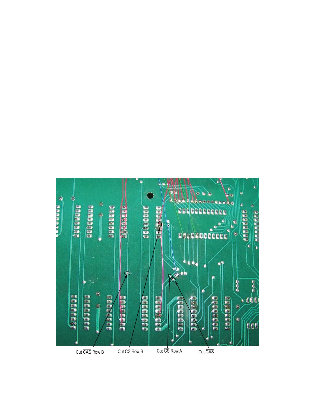
single 5 volt parts. Figure 1 shows the cuts that were made on the board for this
modification.
Figure 1
If you don’t have the nerve to make cuts on a $50,000 collectable board the same
result can be accomplished by lifting pins 13 and 15 on all 16 DRAMS then connect
all pin 13’s together and then connect all pin 15’s on each row together. This is not
very esthetically pleasing when looking at the top of the Board but no cuts are
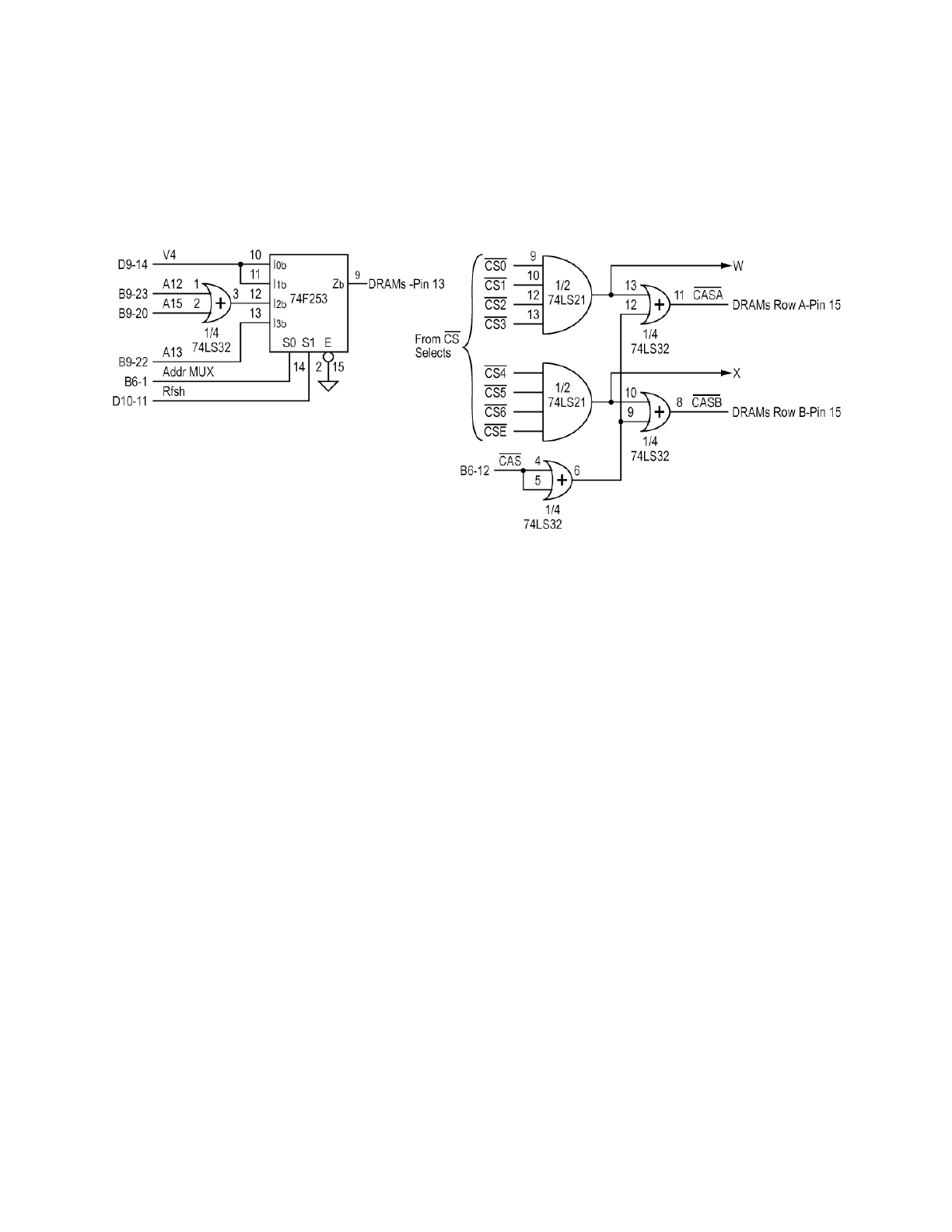
needed. Figure 2 illustrates the Schematic of the modification.
Figure 2
Three IC’s need to be added, a 74LS32, 74LS21, and a 74S253 or 74F253. The 253
multiplexer needs to be a fast part to assure Address set-up time to /CAS. The
extra LS32 gate is used to add delay to the /CAS signal for added margin but is not
required. This design maps the DRAM memory from $0000 to $6FFF with no
breaks and $E000 to $EFFF.
This design provides the maximum flexibility for address remapping for peripherals
using the /CS connections. The bottom view of the board is shown in Figure 3, no
sign of the modification is seen on the top of the board except for the added parts in
the BB space. The interconnection style using wire wrap wire stretched tight is
very similar to Woz’s assembly style.
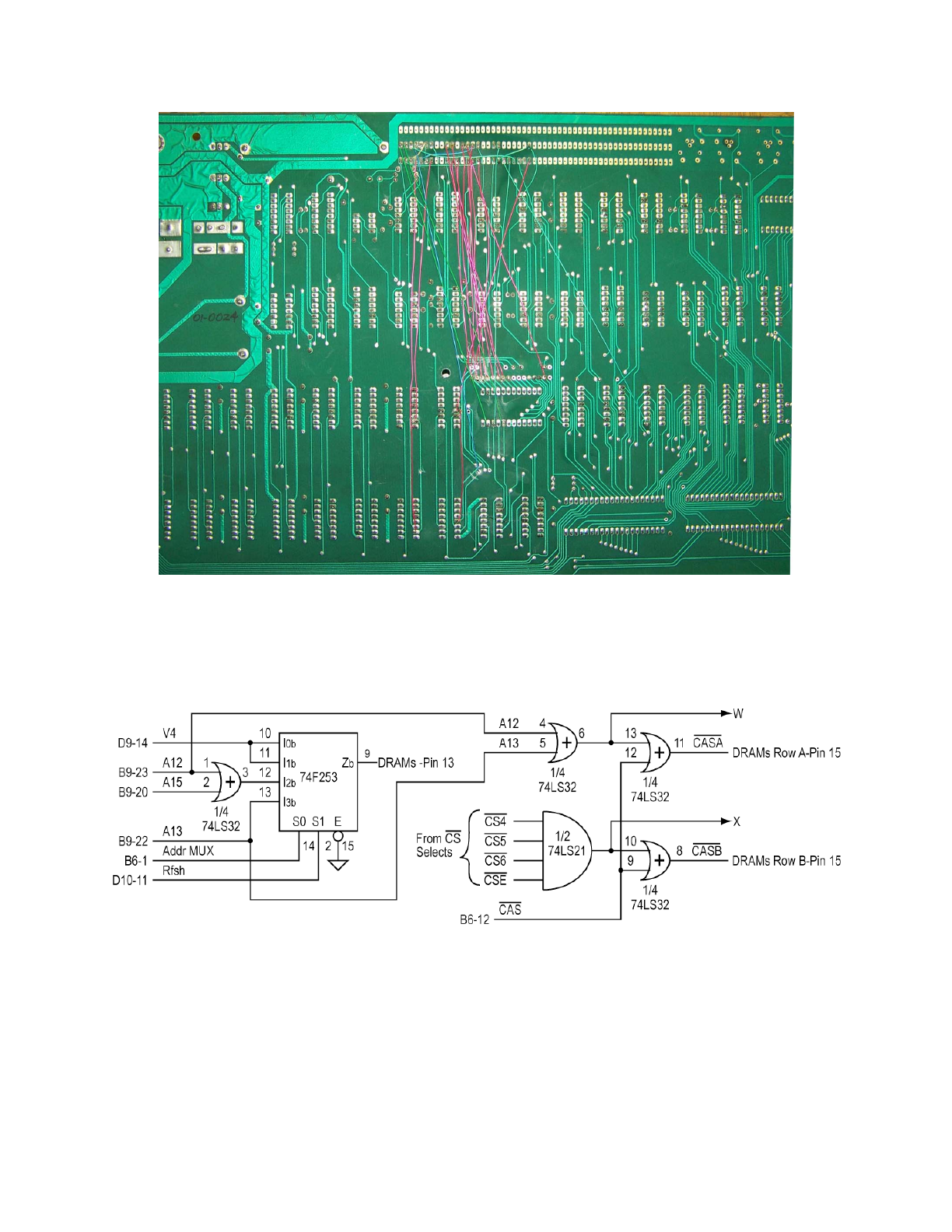
Figure 3
A simpler wiring version that uses the same parts but is not quite as peripheral
friendly is shown in Figure 4
Figure 4
20K Board Mod
The 20K version of the circuit of Figure 4 requires only the 74x253 and 74LS32.
Only the DRAMs in Row B are 16K in this case. Figure 5 shows the schematic for
this implementation.
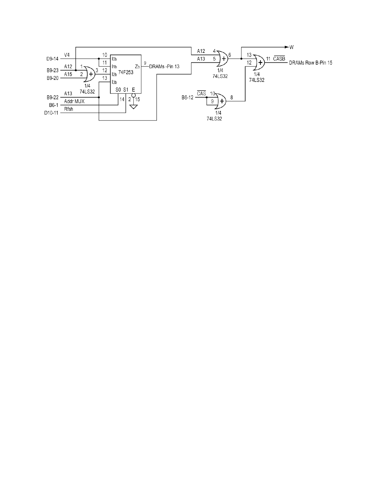
Figure 5
This 16K of added memory is mapped from $0000 to $3FFF with no breaks. The 4K
bank of DRAMS in Row A would normally be mapped to $E000 to $EFFF.
