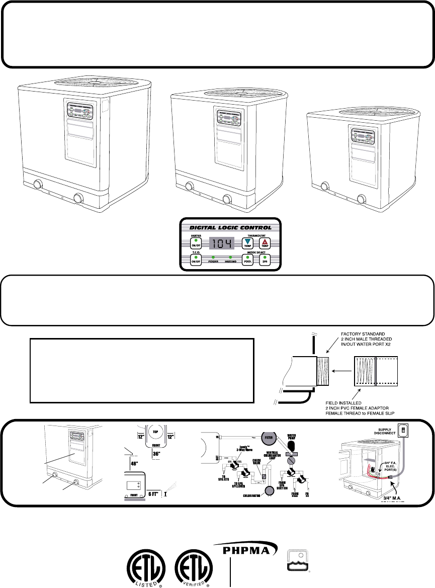
Aquatherm AT Digital Series Install Manual V3.2 Swimming Pool Heater Solar Heating System IMAT400 600 800D
User Manual: Aquatherm Swimming Pool Heater Swimming Pool Solar Heating System
Open the PDF directly: View PDF ![]() .
.
Page Count: 22
V3.2-AT-D © 2001 Aquatherm Heat Pumps a division of Calorex USA L.L.C.
MEMBER
Pool
Heat
Pump
Manufacturers
Association
MEMBER
INSTALLATION MANUAL
SWIMMING POOL & SPA
HEAT PUMPS
WARNING: Specifications may change without notice.
NATIONAL
POOL & SPA
INSTITUTE
SWIMMING POOL & SPA
HEAT PUMPS
OFF
OFF
OFF
OFF
POOL
SPA
WATER
IN
WATER
OUT
ELEC.
PANEL
WARNING: Specifications may change without notice. Intended for licensed factory
authorized installers only! Users should review separate owners operational manual.
INFORMATION
PLACEMENT
PLUMBING
ELECTRICAL
Model AT800 AT600 & AT400
“BLACK CABINET” with DIGITAL CONTROLDIGITAL CONTROL
DIGITAL CONTROLDIGITAL CONTROL
DIGITAL CONTROLSS
SS
S ONLY ONLY
ONLY ONLY
ONLY
DIGITAL LOGIC™DIGITAL LOGIC™
DIGITAL LOGIC™DIGITAL LOGIC™
DIGITAL LOGIC™
NOTICE: UNIT REQUIRES TWO,
2 INCH FEMALE ADAPTORS
FOR PLUMBING CONNECTIONS !

Written & Illustrated by Michael Glore
Table of Contents
A. Unit Placement .........................................................................................
1. Placement Requirements
2. Air Flow Clearances & Service Access
3. Gutters, Overhangs & Sprinklers
B. Plumbing- Water Connections ................................................................
1. Basic Plumbing
2. Chlorinator & Chemical Feeder Requirements
3. Freezing Condition Plumbing Requirements
4. External Bypass Requirements Over 70 G.P.M.
5. Pool/Spa Combination Plumbing
6. Plumbing with Solar
7. Plumbing Above or Below Water Level
8. Optional External Flow Switch Installation
C. Electrical Connections .............................................................................
1. Supply Wiring 220V
2. Wire & Breaker Size Requirements
3. Bonding Requirements
4. Unit Wiring Diagram
5. Optional Time Clock Override Wiring
6. Optional Remote Key Pad & Jandy™ & Motor Valve Connections
7. Interfacing with External Controls, Jandy & Compool
D. Control Panel Information & Operation & Description ...........................
1. Heater Controls
2. Optional Time Clock Override Explanation
3. LED Display Code Explanations
4. Operation Sequence & Troubleshooting Flow Chart
5. Time Delay Explanations
E. Factory Specification Listings .................................................................
F. How Does A Heat Pump Warms A Pool ? ...............................................
1. Explanation of Heat Pump Heat Transfer
2. Efficiency Comparisons
Page 4
Pages 5 - 7
Pages 8 -17
Page 18 - 19
Page 20
Page 21
a Division of Calorex USA L.L.C.
2213 Andrea Lane Ft. Myers FL 33912
888-297-3826 941-482-0606
www.aquathermheatpumps.com
www.calorexusa.com
HEAT PUMPS
WARNING
Unit Description
AIR DISCHARGE FAN
WARNING: ROTATING BLADE
KEEP HANDS & HAIR CLEAR!
THERMOSTAT
CONTROLS
POOL/SPA
LED TEMPERATURE
& STATUS READOUT
WATER OUT
2” MALE THREADED
PIPE
REFRIGERANT
SERVICE VALVES
DO NOT OPEN !
WATER IN
2” MALE THREADED
PIPE
SERIAL
NUMBER
PLATE
“OPTIONAL”
TIME CLOCK
OVERRIDE
BUTTON
DANGER FROM ELECTRICAL
SHOCK & ROTATING FAN !
SHUT OFF ALL POWER
BEFORE SERVICING !
CAUTION: MORE THAN ONE
DISCONNECTION MAY BE
REQUIRED TO ELIMINATE ALL
POWER TO THIS UNIT INCLUDING
POWER TO THE OPTIONAL TIME
CLOCK OVERRIDE !
ELECTRICAL
SUPPLY WIRING
ACCESS PANEL
Page 3
HIGH VOLTAGE
ELECTRICAL
INSTALLATION
PORT(S)
POOL/SPA
SELECT
BUTTONS
LOW
VOLTAGE
ACCESSORY
PORT
NOTICE: UNIT REQUIRES TWO, 2 INCH
FEMALE ADAPTORS FOR PLUMBING
CONNECTIONS
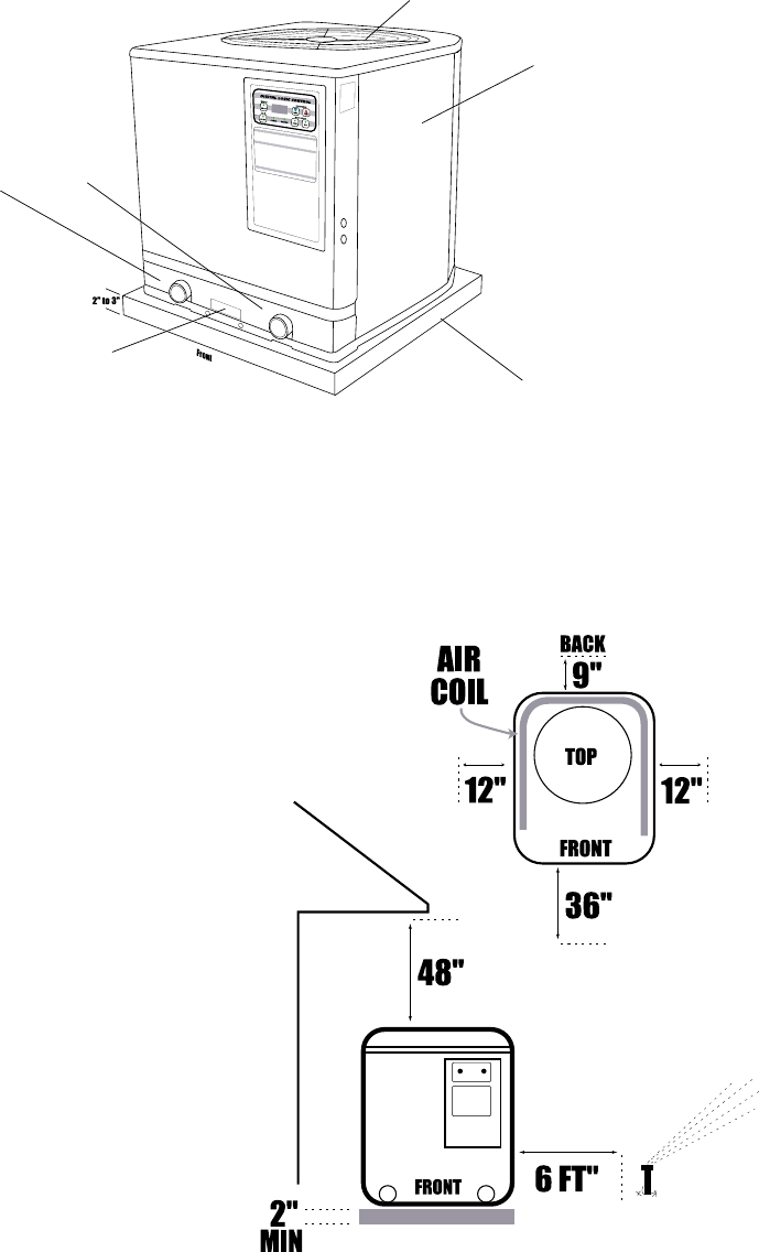
1. To allow for proper condensation drain-
age, use a level slab to elevate the heat pump
to at least the same height as the pool filter
system slab or 2 to 3 inches “minimum” above
grade.
2. Allow the minimum air flow clearances
on top and the sides as shown here. Make
sure the unit can “breathe” well. Do not in-
stall indoors or where the discharge air can
accumulate and be drawn back through the
heater. Make sure the front is accessible
for future service.
3. Keep sprinkler heads at least 6 feet away
from the heat pump. Do not allow the sprin-
kler to spray the unit in any way to prevent
damage.
4. If the unit is installed under a sharp roof
pitch or under a roof valley without a gutter,
a gutter or diverter should be fitted to pre-
vent excessive water from rushing through the
unit.
5. Keep all plants and shrubs trimmed away
from the heater to the minimum clearances
shown here to prevent air coil damage.
6. If the heater is installed above or below
the pool water level by more than 3 feet you
may require an external water flow switch.
See the bottom of page 7 for more informa-
tion.
BASE
CONCRETE OR
PREFAB
Minimum Air Flow
& Access Clearances
Heat Pump Placement & Clearances
AIR COIL
AIR FLOW IN
ON 3 SIDES
FAN DISCHARGE
AIR FLOW OUT
WATER IN-OUT PORT
INDICATOR LABEL
Page 4
2” THREADED MALE
PIPING CONNECTIONS
Page 5
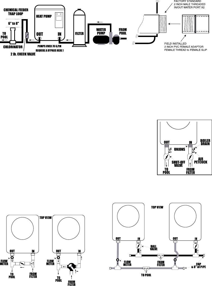
Plumbing & Water Connections
Be sure to install a CHECK VALVE & CHEMICAL TRAP LOOP as shown. The loop should be at least
6 to 8 inches above the chlorinator/feeder top to prevent chlorine backup into the heater when the
water pump is off. Install a 2# check valve on the heater side of the loop as shown above to
prevent chlorine from damaging it. All feeders should be installed at the same or below the
heater piping elevation to prevent chemical back up into the heater.
DO NOT : Install the heater down stream from any chemical feeders.
DO NOT : Allow chemical feeders on the suction side of the water pump.
DO NOT : Allow any chemicals or chlorine to be fed through the skimmer.
DO NOT : Allow the pool water pH to go below 7.4. DO NOT allow the alkalinity to go below 90 p.p.m.
DO NOT : Allow the chlorine to go above 5 p.p.m. for extended periods. Chemical damage is not covered
by and may void warranty.
Bypass for Flow Rates Over 70 G.P.M.
Typically the automatic internal water by-
pass can handle up to a 1.5 H.P. water
pump or 70 G.P.M. If the water pump ex-
ceeds 1.5 H.P. then install either of the op-
tional bypasses as shown below.
Plumb multiple units as shown below. Use flow
meters on each WATER OUT line if two or more
units are plumbed together.
Freezing Condition Plumbing
In areas where extended freezing conditions exist, the heater must be
plumbed as shown so it can be winterized. Water left inside the heater
will freeze and cause damage. Plumb in a union, shut off valve, a boiler
drain and a air petcock valve on the water in and water out lines as
shown here. Isolate the heater with the shut off valves and use pressur-
ized air to clear the heat exchanger of all water. In areas where freezing
conditions are temporary, the water pump should be set to run 24 hours
to prevent freezing. Freeze damage will void warranty.
Multi Unit Water Connections
OFF
Ball Valve or
Jandy™ 3-Way
The installation of a flow meter on the WATER
OUT line is suggested. Adjust the bypass to
divert a minimum of 40 to 50 G.P. M. through
the heater. Flow meters should be installed per
the manufacturers instructions.
Use ball valves to balance the water flow through each
unit. Using T’s, caps and a minimum 6 inch pipe exten-
sion on the plumbing manifold will help equalize the
water flow better than 90˚’s. Flow meters should be in-
stalled per the manufacturers instructions.
For a simple pool only or spa only, install the plumbing piping as shown:
Connections from factory are 2” threaded male pipe, requiring 2 inch female adaptors, see diagram.
Use teflon tape and pipe sealer. Tighten hand tight plus 1/4 to1/2 snug tight with pliers.
Water IN on the RIGHT, Water OUT on the LEFT,
PLUMB AFTER the FILTER & BEFORE any CHLORINATORS or CHEMICAL FEEDERS
See page 6 for pool/spa
combo plumbing.

Page 6
Use this diagram for a separate pool
and spa not connected, and does not
have a spill-over. Where the pool and
the spa have separate pump & filter
systems but using the same heater. If
the water pump exceeds 1.5 H.P. then
install either of the optional bypasses
as shown on page 5.
OFF
OFF
OFF
OFF
OFF
OFF
OFF
POOL
SPA
Plumbing & Water Connections for Pool/Spa Combinations
Use this diagram for a connected pool and spa, where the spa has a spill over type waterfall into
the pool. Where one pump and one heater is used for either the pool or the spa. If the water
pump exceeds 1.5 H.P. then install either of the optional bypasses as shown on page 5.
Plumbing & Water Connections for Separate Pool & Spa
SEE CHLORINATOR LOOP & CHECK
VALVE REQUIREMENT ON PAGE 5.
SEE CHLORINATOR LOOP & CHECK
VALVE REQUIREMENT ON PAGE 5.
OR PR TN
WH
DEF.
SENSOR HIGH
PRESS.
WATER
PRESS. LOW
PRESS. JANDY/
COMPOOL
EXTERNAL
T-STAT SWITCH
POOL SPA
P COM. S
T.C.O.
JUMPERS
SEE
NOTE #4
DEG. F
T.C.O.
TEST
COMP.
RELAY
240 VAC
FAN
POOL
SENSOR
Page 7
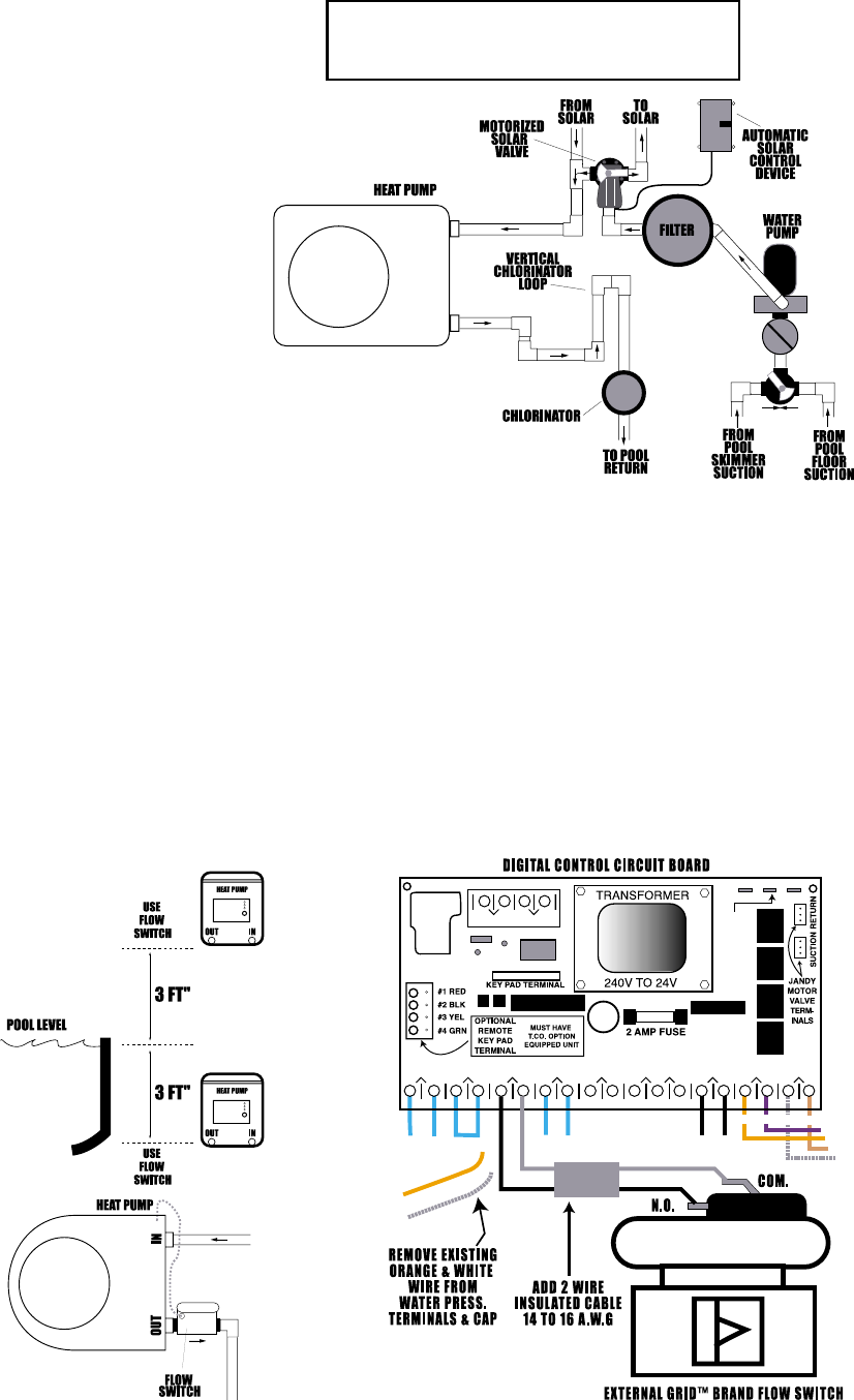
Plumbing & Water Connections with Solar
Plumbing for a system where a
solar pool heater is installed. It is
strongly advised that an auto-
matic solar control device be
used when used with the heat
pump.
The heat pump and solar can be
operated together. The heat
pump will share the heating load
with the solar. If there is no heat
coming from the solar panels, the
solar control device will turn off
the solar by rotating the motor
valve, otherwise it should be
turned off manually. The heat
pump will then maintain the
pool/spa temperature.
To use the heat pump as a backup
to the solar, set the heat pump
thermostat 2 to 4 degrees below
the solar’s target temperature set-
ting. Therefore, if the solar is not
maintaining water temperature,
the heat pump will come on to
assist the solar. Some thermostat
fine tuning may be required by
the user.
If you install the heat pump above or below the pool or spa water level by more than 3 feet, the internal
water pressure switch may be effected by the static pressure of the pool water. In some cases it may
be necessary to install a water FLOW switch. The water flow switch is not effected by changes in
water pressure but only water movement. We suggest installing a 2”, Grid Brand Model 20 flow switch
and disabling the internal water pressure switch. Plumb in the flow switch as shown here. Then run a
TWO wire insulated cable from the flow switch into the heater and attach to the existing water pres-
sure switch leads located behind the large service panel and wire as shown below.
REVIEW UNIT WIRING DIAGRAM ON PAGE 10 ALSO !
Plumbing & Water Connections for Above or Below Water Level
IN
OUT
OFF
OFF
JANDY ™
If the water pump exceeds 1.5 H.P. then
install either of the optional bypasses as
shown on page 5.
NOTE: If the solar is operated on cloudy days, while
raining, at night or at low air temperatures, it may cool
the pool or spa. A automatic solar control will shut the
solar off when there is no solar activity, otherwise it
should be shut off manually during these times.
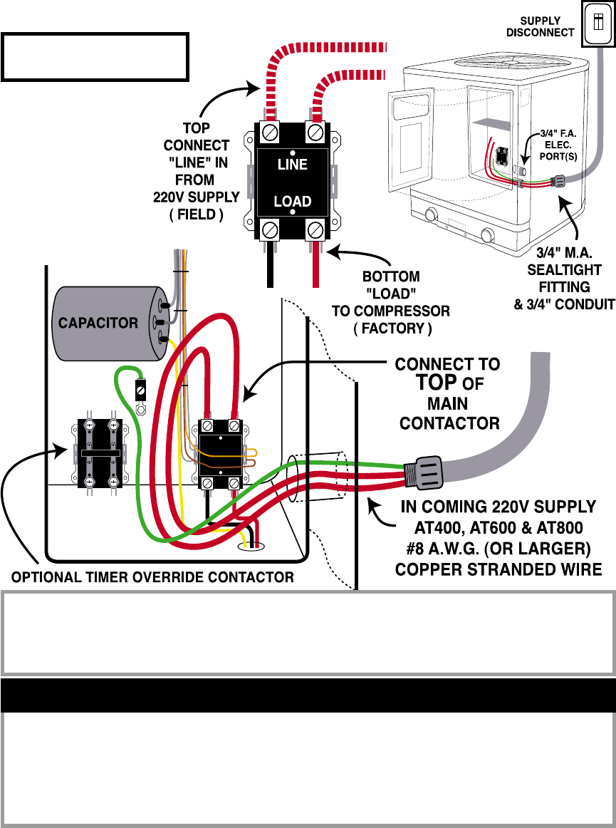
Electrical Connections & Wiring
AT800 & AT600: 50 AMP BREAKER & #8 A.W.G. WIRE OR LARGER
AT400: 50 AMP BREAKER & #8 A.W.G. WIRE OR LARGER
ALL WIRE MUST BE COPPER STRANDED
POWER DISCONNECT SHOULD BE WITHIN 6 FEET OR CLOSER TO THE HEATER !
The AT800, AT600 & AT400 require
a MINIMUM of #8 A.W.G. copper
stranded wire, (or larger if
needed.)
You must increase the wire size
under low voltage, high amp draw,
and/or long-run conditions as re-
quired by National Electrical Code.
You must bond the heater exter-
nally to the pool/spa steel as re-
quired by local codes. A bond-
ing lug is located on the bottom
front exterior of the unit. NOTE :
See wiring diagram on page 10.
See page 20 for factory specifica-
tion listings also.
3 minute compressor delay on break & power up.
30 second compressor delay when switching pool/spa modes.
5 minute compressor delay when T.C.O. enables in pool mode.
5 minute T.C.O. delay when: switching from spa to pool mode, when tem-
perature is reached in pool mode, or if LF (low water flow) is displayed on LED.
When HP is displayed unit must be turned off then back on to reset.
Page 8
3 Phase Compressor Models Are Rotation Sensitive! Use Refrig-
erant Gages! Do Not Go By Fan Rotation Since It Will Always Be
Single Phase!
DANGER FROM ELECTRICAL
SHOCK & ROTATING FAN !
SHUT OFF ALL POWER
BEFORE SERVICING !
CAUTION: MORE THAN ONE
DISCONNECTION MAY BE RE-
QUIRED TO ELIMINATE ALL
POWER TO THIS UNIT INCLUDING
POWER TO THE OPTIONAL TIME
CLOCK OVERRIDE !
BREAKER & WIRE SIZE RECOMMENDATION
TIME DELAYS
3 PHASE COMPRESSOR WARNING
WARNING
DANGER FROM ELECTRICAL SHOCK & ROTATING FAN ! SHUT OFF ALL POWER BEFORE
REMOVING ANY PANELS ! CAUTION: MORE THAN ONE DISCONNECTION MAY BE RE-
QUIRED TO ELIMINATE ALL POWER TO UNIT INCLUDING POWER TO THE OPTIONAL TIME
CLOCK OVERRIDE !
Page 9
The heater has a 3/4” threaded female access port on the left side of the heater. The access port
at the top is for low voltage only ! The bottom run a 3/4” conduit from the main power supply to
the heater. Run the proper wire size from the main supply to the heaters main contactor. The
main contactor is in the bottom of the high voltage compartment. If the unit has the optional
time clock override there will be two contactors. The contactor on the right is for the main
power supply. If there is a contactor on the left, it will be for the optional time clock override
feature shown on pare 11, 12 & 13. POWER DISCONNECT SHOULD BE WITHIN 6 FEET OR
CLOSER TO THE HEATER !
Electrical Connections & Wiring, Continued
EXTERNAL BONDING REQUIREMENTS
A #8 A.W.G. solid copper ”BOND” wire coming from the pool/spa reinforcing
steel must be attached to the external bond lug at the bottom of the heaters
cabinet to meet electrical code. This bond wire can usually be found attached
to the existing pool/spa water pump. Do not confuse this with the internal
“ground” wire !
SEE WIRING DIAGRAM
ON PAGE 10 !
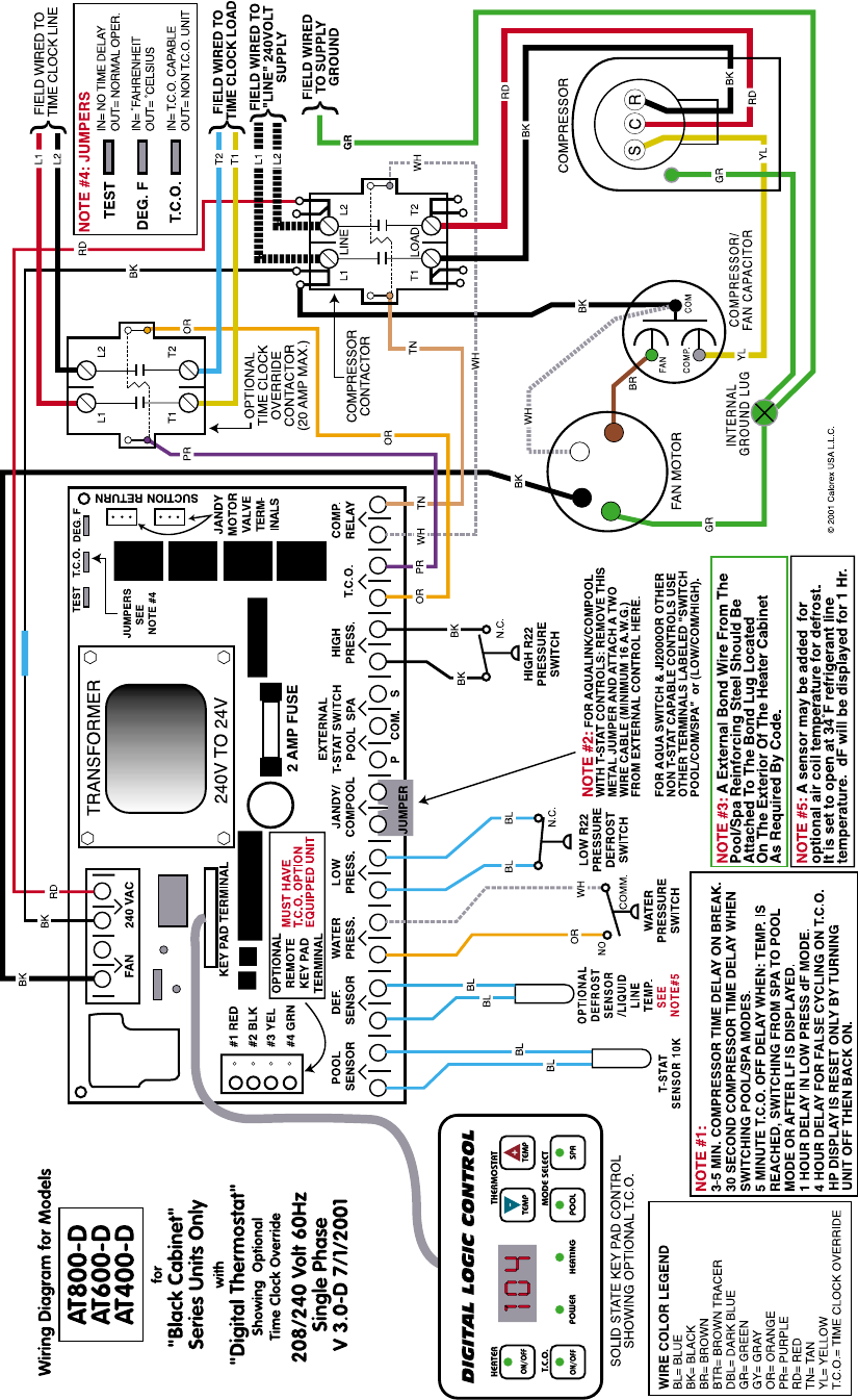
Wiring Diagram AT800, AT600 & AT400 “Digital Logic” Digital Control Models
Single Phase 220 Volts Showing Optional Time Clock Override
Page 10
If HP is displayed the unit must be shut off and then back on to reset unit. The pool light will flash if a 3rd party device is controlling the heater .
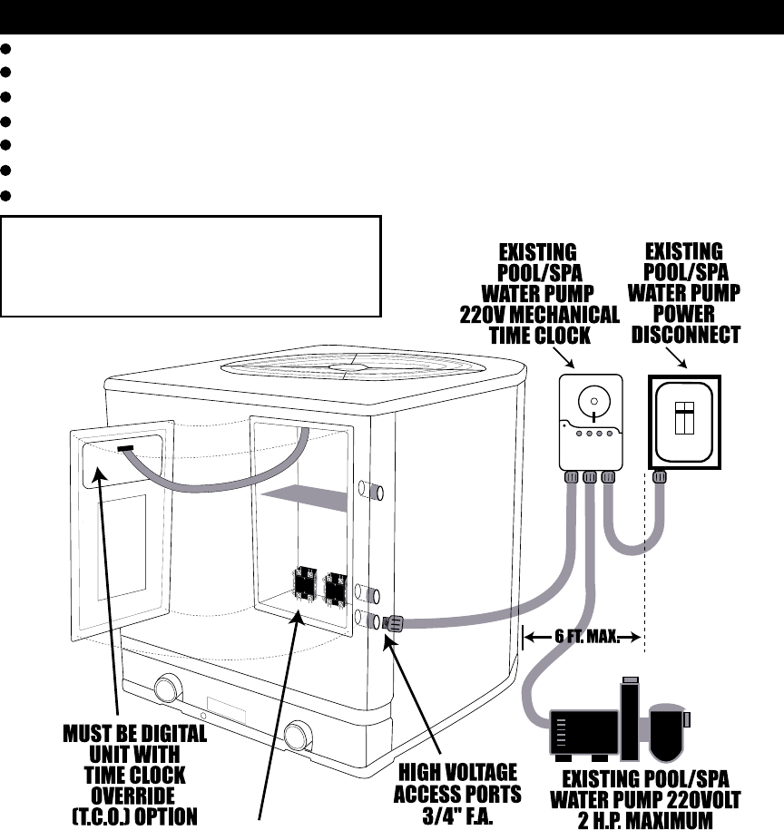
INSTALLATION: Always shut off main power disconnect to the heater AND the water pump
first. Then, install 3/4“ conduit between the heater and the mechanical water pump time clock.
You will be adding four wires to the existing water pump time clock. Wire size should be a
minimum of 12 A.W.G. and be of different suggested colors such as: Red, Black, Yellow and Blue
through the conduit. See pages 12 & 13 also,
Installation for “Optional” Time Clock Override (T.C.O.)
“OPTIONAL” WATER PUMP TIME CLOCK OVERRIDE OPERATION
Since the heater will only heat while the water pump is running, the Time Clock Override option
is available to automatically start the water pump when the nits thermostat is calling for heat.
When the T.C.O. button is set to the ON mode, the Time Clock Override feature will start the
water pump whenever the pool requires heat. Once the pool is up to the set temperature the
heater will stop and then 5 minuets later the water pump will stop. When this button is set to the
OFF mode, the heater will operate only when the water pump is running during the timed period
set on the time clock.
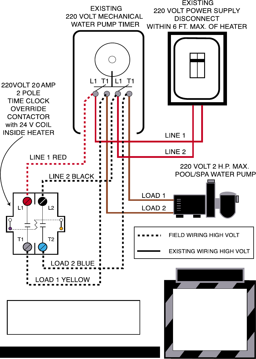
25 AMP 2 POLE 220V
T.C.O. CONTACTOR
(ON LEFT)
* WARNINGS *
Shut off power too heater and water pump first !
Water pump and timer must be 220 volts !
Wire size should be a minimum or #12 A.W.G. copper stranded or larger !
The water pump power disconnect must be within 6 feet maximum of the heater !
Do not connect water pumps exceeding 2 horse power and/or 20 Amps maximum.
Do not remove any existing water pump or water pump timer wires !
Do not cross phase power legs or short will occur and breaker will trip!
NOTE: Do not change any of the exist-
ing water pump timer wiring. You will
only add wires to the existing circuit !
See pages 12 & 13 !
Page 11
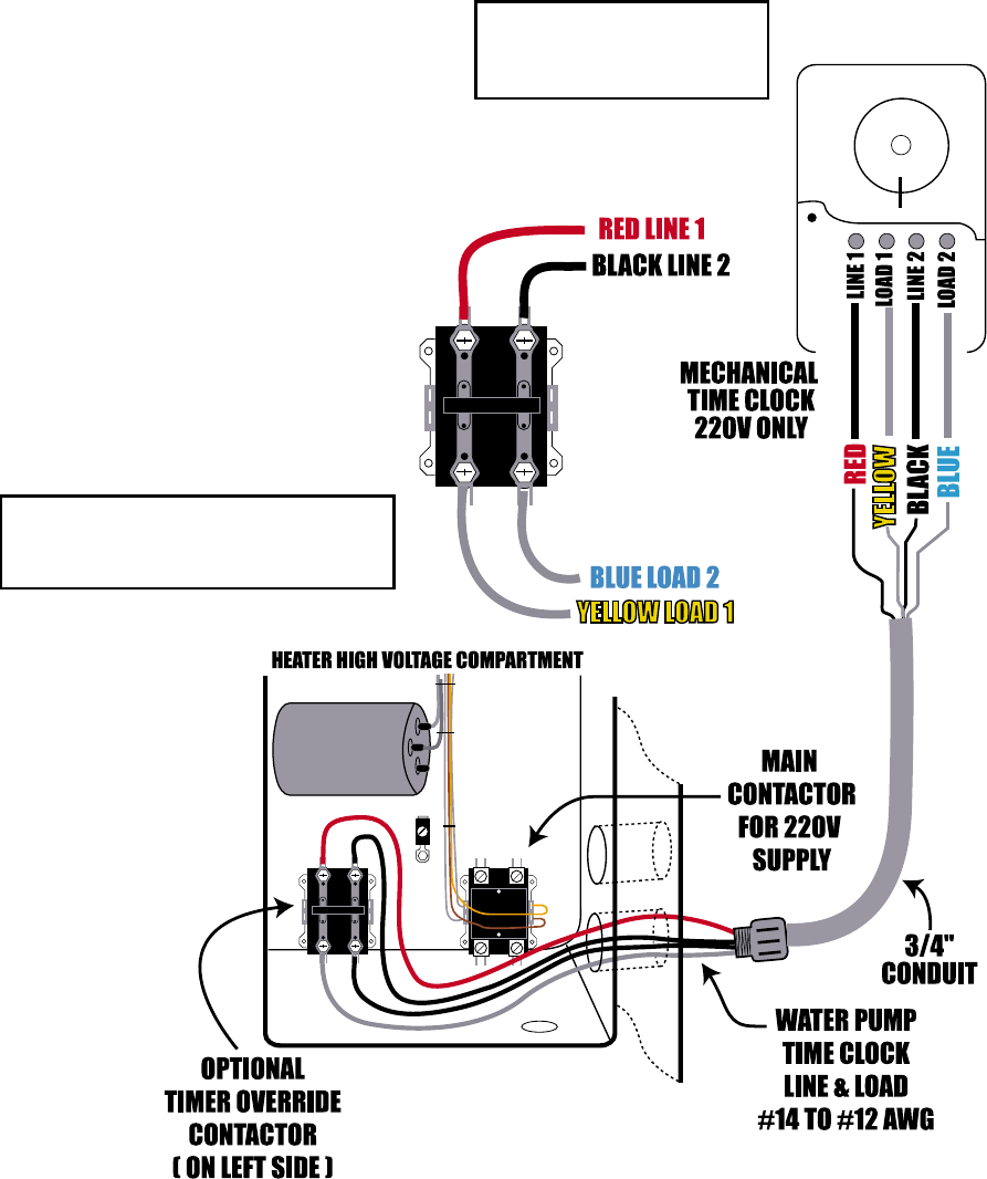
CAPACITOR
Attach wires as shown, see page 13 also.
RED- Time Clock LINE #1
to T.C.O. Contactor Top Left Line
BLACK- Time Clock LINE #2
to T.C.O. Contactor Top Right Line
YELLOW- Time Clock LOAD #1
to T.C.O. Contactor Bottom Left Load
BLUE- Time Clock LOAD #2
to T.C.O. Contactor Bottom Right Load
NOTE: Do not change any of the exist-
ing water pump timer wiring. You will
only add wires to the existing circuit !
Shut off main power
disconnect for heater
& water pump !
NOTE: T.C.O. works best if used during cooler weather conditions where the pool is loosing
more than 8 to 10 degrees over night or when the pool is being heated from “dead cold”.
NOTE: If the T.C.O. starts the water pump and the thermostat does not continue to call for heat
for at least 5 minuets, the control will shut the water pump and heater off. Thereafter it will not re-
attempt to start the water pump for 4 hours. This 4 hour delay can be bypassed by pressing the
T.C.O. button off then back on.
NOTE: When the T.C.O. button is activated while in “spa mode” the water pump will run the
entire time you are in spa mode. When you switch back to pool mode there will be a 5 minute
delay before the water pump shuts off. Page12
Time Clock Override (T.C.O.) Installation (Cont.)
Wiring Diagram for Optional Time Clock Override
* WARNINGS *
Shut off power too heater and water pump first !
Water pump and timer must be 220 volts !
Wire size should be a minimum or #12 A.W.G. copper stranded or larger !
The water pump power disconnect must be within 6 feet maximum of the heater !
Do not connect water pumps exceeding 2 horse power and/or 20 Amps maximum !
Do not remove any existing water pump or water pump timer wires !
Do not cross phase power legs or short will occur and breaker will trip!
NOTE:
Do not change any of the existing water
pump timer wiring. You will only add
wires to the existing circuit !
WARNING
DANGER FROM ELECTRICAL SHOCK
& ROTATING FAN !
CAUTION: MORE THAN ONE
DISCONNECTION MAY BE REQUIRED
TO ELIMINATE ALL POWER TO THIS
UNIT INCLUDING POWER TO THE
OPTIONAL TIME CLOCK OVERRIDE !
SHUT OFF ALL SOURCES OF POWER
BEFORE SERVICING !
Page 13
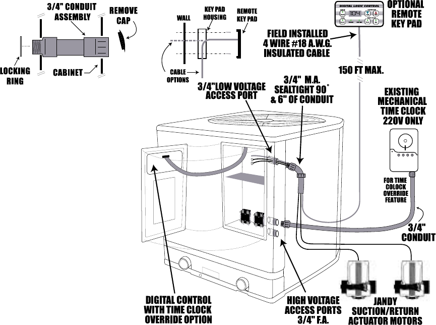
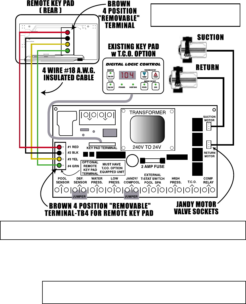
Optional Remote Key Pad Control Wiring Instructions
for ”Digital Logic” Digital Control Models with Time Clock Override Option Only
The AT800, AT600, & AT400 with “Digital Logic” digital control models having the External
Optional Time Clock Override feature can be retrofitted with our simple, “Remote Key Pad” con-
trol. This Remote Key Pad is identical to the key pad on the heater. The heater must have the
time clock override option to use the remote key pad ! The Remote Key Pad will perform
the all the same functions as the heater’s key pad: Heater on/off. Pool temperature readout.
Thermostat settings for pool & spa. Activation of two field installed Jandy™ 2440 actuator
motors via pool/spa select buttons. NOTE: The water pump can be activated via the time clock
override button. When spa mode is selected, the water pump will start and stay running con-
stantly while in spa mode. When in pool mode, the time clock override will only run the water
pump when the thermostat calls for heat.
Installation of the Remote Key Pad is as follows: First, the time clock override feature must be
wired to the heater as shown on pages 11 - 13. Next, mount the Remote Key Pad a maximum of
150 feet from the heater in a dry location at least 6 feet away from the pool/spa water. The
Remote Key Pad is not water resistant and therefore must be kept dry ! Next, remove the 3/4”
threaded cap on the low voltage conduit port. To prevent water penetration, attach a 3/4” M.A.,
90 degree compression type fitting and a minimum 6” of flex conduit to the 3/4” female adaptor
on the top right hand side of the heater. Make sure it is pointing it downward. Use epoxy sealer
to seal the conduit. Next, run a 4 wire, #18 gage (minimum wire size) insulated cable from the
Remote Key Pad through this conduit. Attach the Remote Key Pad wires to the heater’s solid state
circuit board as shown on page 15. WARNING: Improper connection of the Remote Key
Pad wires will short out the control system BE SURE THIS IS DONE CORRECTLY !!!
Assuming the plumbing is similar to the schematics on page 6 and Jandy brand 3-way valves are
in place, you can install two Jandy actuator valve motors. Install one on the suction valve and one
on the return valve. Label the piping on either side of the motor valves (pool or spa) so the valve
position can be identified by the user. The actuator motor wires should ran through the same
conduit and should be installed (plugged into) the heater’s solid state circuit board as shown on
page 15. You do not have to have the remote key pad to install Jandy actuator motors.
Page 14
TIME DELAYS
30 second compressor
delay when switching
pool/spa modes.
5 minute compressor
delay when T.C.O. en-
ables in pool mode.
5 minute T.C.O. off de-
lay when: switching
from spa to pool mode,
when temperature is
reached in pool mode,
or if LF (low water flow)
is displayed on LED.
If water pump loses
prime while motor
valves are rotating there
will be a 3 minute com-
pressor delay.
Optional Remote Key Pad Control Wiring Diagram
for ”Digital Logic” Digital Control Models with Time Clock Override Option Only
P COM. S
240 VACFAN
DIGITAL LOGIC CONTROL
#4 GRN
#3 YEL
#2 BLK
#1 RED
Route all wires through the heater’s low voltage access ports as shown on page 10. Attach the 4
wire, (#18 gage minimum wire size, 150 foot maximum length) insulated cable to the “brown” 4
position terminal located on the heater’s solid state circuit board inside the low voltage com-
partment (top section). Attach the other end of the cable to the “brown” 4 position terminal
located on the backside of Remote Key Pad in the same order:
#1 RED
#2 BLACK
#3 YELLOW
#4 GREEN
Plug-in the Jandy motor valve wire leads to the appropriate sockets (suction/return) on the heater’s
solid state circuit board as shown above. Route all wires through the heater’s low voltage access
ports as shown on page 14.
NOTE: The motor valves will turn when the pool/spa select buttons are pressed. The time clock
override will activate the water pump and keep it running when spa mode is selected. There
will be a 30 second compressor time delay when the pool/spa select buttons are pressed
to allow the motor valves to rotate completely. There will be a 5 minute T.C.O. off
delay when: switching from pool to spa mode, when temperature is reached or if the
water pump loses prime and LF is displayed on the LED panel. Page 15
NOTE: The “brown” 4 position terminal can be unplugged from the solid
state circuit board and from the rear of the remote key pad for easier wiring.
NOTE: All digital models will
operate 2 Jandy motor valves
without the remote key pad.
WARNING: Improper connection of the Remote Key Pad wires will short out the control
system, BE SURE THIS IS DONE CORRECTLY !!
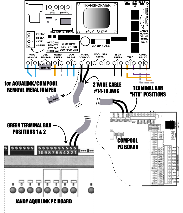
Interfacing “Digital Logic” Digital Control Models with:
Jandy™ AquaLink RS & Compool
OR PR TN
WH
P COM. S
JUMPERS
SEE
NOTE #4
To interface the “Digital Logic” digital control heat pump models with the Jandy™ AquaLink RS
series or Compool, run a 2 wire (16 A.W.G. or larger) insulated cable from the device to the heat
pump.
Remove the 6 screws from the heaters front service access panel and open. Look for the heater’s
solid state circuit board located inside the top portion of the electrical compartment mounted
on the rear wall. Locate, remove and discard the ”METAL JUMPER TAB” attached to the bottom
terminal bar and labeled “Jandy/Compool”. Then, attach the 2 wire cable coming from the
AquaLink RS or the Compool control to the 2 position terminal where the metal jumper tab was
prior.
NOTE for AquaLink RS and Compool: Turn both heater thermostats all the way up and set the
mode selector switch to pool and do not use the heater controls as the Jandy or Compool now
has thermostat control over the heater.
for AquaLink
Attach the 2 wire
cable to positions
#1 and position # 2
on the 10 slot,
green terminal bar
inside the
AquaLink’s power
center. *See the
controllers installa-
tion guide also.
for Compool
Attach the 2 wire
cable to the
Compool’s
power center
board located
on the terminals
labeled “HTR”
*See the control-
lers installation
guide also.
Page 16
Note: The pool light on the heater’s
key pad will flash when an external
device has control of the heater.
*See wiring diagram on page 10.
*See the controller’s installation
guide also.
#12 HIGH/SPA
#13 COMMON
#14 LOW/POOL
OR PR TN
WH
KEY PAD TERMINAL
DEF.
SENSOR HIGH
PRESS.
WATER
PRESS. LOW
PRESS. T.C.O.
JUMPERS
SEE
NOTE #4
DEG. F
T.C.O.
TEST
COMP.
RELAY
240 VACFAN
POOL
SENSOR
Attach the other end of
the 3 wire cable to the
AquaSwitch as follows:
#12 For the HIGH/SPA
#13 For the COMMON
#14 For the LOW/POOL
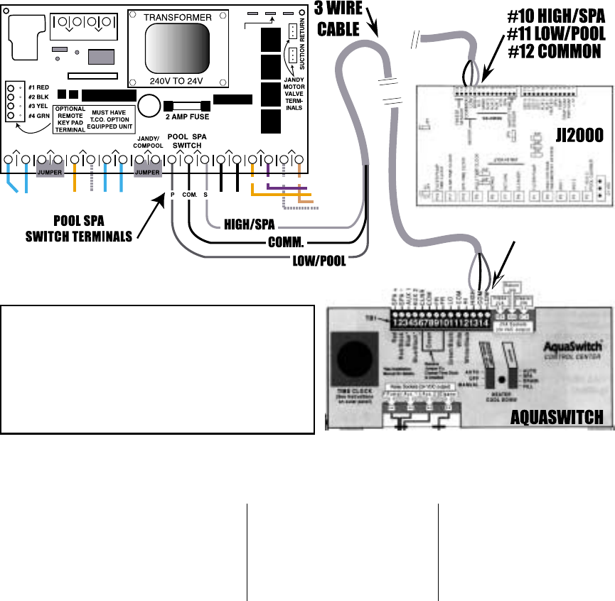
If you are using a Jandy AquaSwitch or JI2000 control run a 3 wire cable from the control to the
heater. Remove the 6 screws from the heaters front service access panel and open. Look for the
heater’s solid state circuit board located inside the top portion of the electrical compartment
mounted on the rear wall. Locate the 3 terminals labeled POOL SPA SWITCH. Attach the 3 wire
cable as shown below. Do not remove any jumpers.
Next, attach the 3 wire cable to the
HEATER to the three terminal positions
labeled POOL SPA SWITCH
LEFT POSITION= LOW/POOL
CENTER POSITION= COMMON
RIGHT POSITION= HIGH/SPA
Attach the other end of the
3 wire cable to the
JI2000 as follows:
#10 For the HIGH/SPA
#11 For the LOW/POOL
#12 For the COMMON
Interfacing “Digital Logic” Digital Control Models with:
Aquaswitch or JI2000
Page 17
NOTE: The control will switch between pool
and spa thermostats.
Most remote control brands that do not
have a thermostat control will hook up simi-
lar to the Jandy™ products.
(Pool/Comm/Spa or Low,Comm,High)
Note: The pool light on the heater’s key pad will flash
when an external device has control of the heater.
*See wiring diagram on page 10.
*See the controller’s installation guide also.
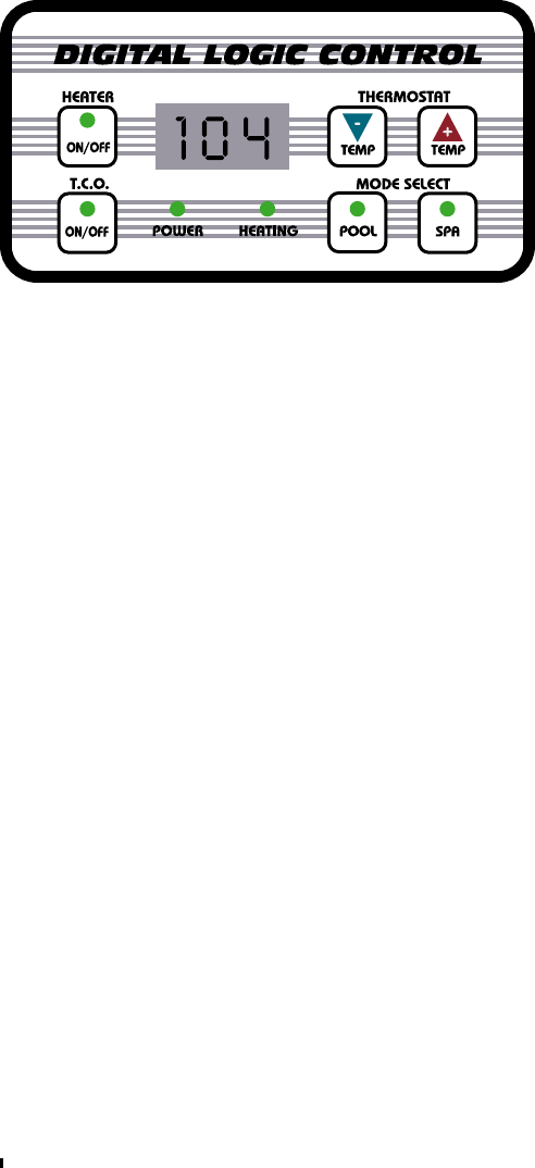
GREEN POWER LIGHT: This light indicates that the heater has control power. WARNING: This is
not a line power indicator and caution should be used since more than one power disconnec-
tion may be required to isolate the heater electrically. WARNING: If the optional Time Clock
Override is installed, you must shut off the water pumps main power disconnect as well.
GREEN HEATING LIGHT: This light indicates that the unit is heating and the compressor is run-
ning. The compressor starts after a 3 to 5 minute time delay. NOTE: The water pump must be
running at the same time in order for the heater to run.
LED STATUS CODE READOUTS:
LFLF
LFLF
LF This light indicates there is no water flow through the heater. The heater is designed to shut
off whenever the water pump is not pumping water through the heater. If LFLF
LFLF
LF is on while the
water pump is running, the water pump may not be supplying enough flow for the heater to
operate properly. During normal operation, the heater will only run if the water pump is running.
dd
dd
dFF
FF
F This readout indicates that the internal defrost safety control has disabled the heater. During
cold weather where the air temperature drops below approximately 45 to 50 degrees (depending
on humidity), the low refrigerant pressure switch (or defrost control) is designed to disable the
compressor only. Once the unit is in defrost mode the compressor will shut off for 1 hour while the
fan continues to help deice and warm the air coil. After 1 hour the compressor will attempt to
restart. If the air temperature has increased to the operational range the compressor will continue
to run, otherwise the compressor will return to the defrost mode for another 1 hour delay cycle.
HP HP
HP HP
HP this readout out indicates high refrigerant pressure. The high refrigerant pressure switch is de-
signed to shut the compressor and fan off if a heat buildup occurs for whatever reason. Typically the
high refrigerant pressure switch will trip if the water flow through the heater is restricted. It may also
trip if the air flow is restricted through the heater. When HP is displayed the heater will be
disabled until is reset by resetting it off then back on.
LED READOUT:
When the unit has power the green
power light will be on and the LED will
display the current water temperature.
THERMOSTAT BUTTONS:
Pressing the + button will raise the set
temperature. Pressing the - button will
lower the set temperature. When either
button is pressed the LED display will
begin to flash. The flashing numbers in-
dicate the thermostat setting.
MODE SELECT BUTTONS-POOL or SPA: The heater has two thermostat modes for two different
desired temperature settings, one for pool mode and one for spa mode. If you do not have a
spa you can use the pool mode only. If you do have a spa, you can connect two Jandy™
motorized plumbing valves as shown on page 11. Therefore when you select either mode the
motorized valves will turn to isolate the heater to either the pool or spa. NOTE: There is a 30
second compressor when switching pool/spa modes.
“OPTIONAL” WATER PUMP TIME CLOCK OVERRIDE OPERATION When the T.C.O. button is set to
the ON mode, the Time Clock Override feature is designed to start the water pump whenever
the pool requires heat. Once the pool is up to the set temperature the heater will stop and then
5 minuets later the water pump will stop. When this button is set to the OFF mode, the heater will
operate only when the water pump is running during the timed period set on the time clock.
NOTE: The time clock override works best if used during cooler weather conditions where the
pool is loosing more than 8 to 10 degrees over night or when the pool is being heated from
“dead cold”. NOTE: If the time clock override starts the water pump and the thermostat does
not continue to call for heat for at least 5 minuets, the control will shut the water pump and
heater off. Thereafter, it will not re-attempt to start the water pump for 4 hours. This 4 hour delay
can be bypassed by pressing the T.C.O. button off then back on. NOTE: When the T.C.O. button
is activated while in “spa mode” the water pump will run the entire time you are in sap mode.
When you switch back to pool mode there will be a 5 minute delay before the water pump
shuts off. The T.C.O. option is built into the heater at the factory and can not be added later.
“Digital Logic” Digital Control Panel Information
Page 18
Water Pump
Starts Flowing
Water Pressure
SW Closes
Thermostat
Sensor
Heater
Stays Off
Low Pressure
Switch
Low Pressure
Switch Opens
LF displayed on LED
Low Pressure
SW Closed
All OK
LF Readout
Displayed on LED
T-Stat Relay
Closes
High Pressure
Switch
High Pressure
SW Closed
All OK
High Pressure
Switch Open
Heater Shuts Off
HP Displayed
Too Much Refrig.
or Low Water Flow
or Bad Hi Switch
Fan Starts
To Run, Green
Heating Light On
220V Power
To Heater
Green Power Light
On
Water Rises To
Set Temp.
Water Press. SW
Stays Open
No Water Flow
To Heater or
Bad Water SW
Compressor Runs
or 3 to 5 Min.
Delay Activates
Heater & Green
Heating
Light Go Off
Water Pump
Timer Activates
Compressor Stops
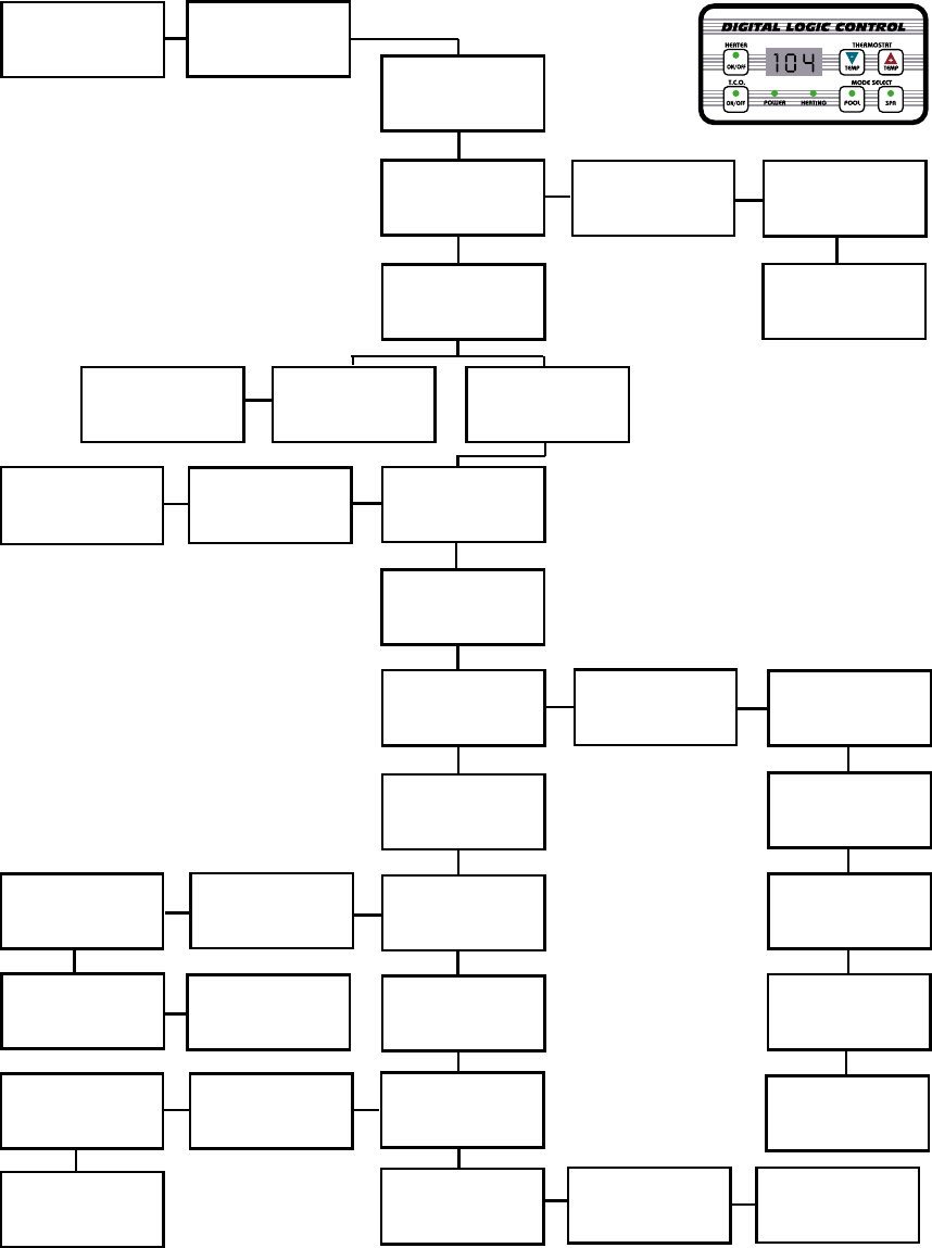
Fan Runs
T-Stat Relay
Does Not Close
Heater Does
Not Activate
After Delay Period
Wait for Heater to
Attempt to Restart
Again
Possible Bad
T-Stat Board, Pot
or Sensor
1 Hour Time Delay
Activates
Water Temperature
is Below Setting
Water Temperature
is Above Setting
Compressor Starts
Green Heating
Light ON
Time Delay Passes or
Air Temp. Increases
Safety Control Resets
Compressor
Restarts
or Below 45 to 50˚F
Air Temp or
Bad Low Press. Sw.
or Below 45 to 50
Deg. Air Temp
Operational Sequence & Troubleshooting Flow Chart
for “Digital Logic” Digital Control Models
Page 19
TIME DELAYS
30 second compressor delay when switching pool/spa modes.
5 minute compressor delay when T.C.O. enables in pool mode.
5 minute T.C.O. off delay when: switching from spa to pool mode, when temperature is
reached in pool mode, or if LF (low water flow) is displayed on LED.
If water pump loses prime there will be a 3 minute compressor delay.
When HP is displayed unit must be turned off then back on to reset.
Shut unit OFF
Then Back ON to
Try Again

Page 20
* Optimum output & efficiency typical of Florida conditions. Ratings outside the scope of
P.H.P.M.A. heat pump pool heater certification program. ** Rated and certified in accor-
dance with A.S.H.R.A.E. standard 146-1998 and P.H.P.M.A. addendum test procedure.
Factory Specifications
Specifications may change without notice.
© 2001 Aquatherm Heat Pumps
a Division of Calorex USA L.L.C.
MEMBER
NATIONAL
POOL & SPA
INSTITUTE
Pool
Heat
Pump
Manufacturers
Association
MEMBER
3 Phase Compressor Is Rogation Sensitive! Use Refrigerant Gages!
Do Not Go By Fan Rotation Since It Will Always Be Single Phase!
WARNING: THREE PHASE MODELS:
Model Number
BTU Output
Coefficient of Performance
Copeland Scroll™ Compressor
Heat Exchanger Condenser
Air Coil Evaporator
Fan Motor
Air Flow
Kilowatt Input
Electrical (208/240v/60Hz)
Typical Running Amps
Minimum Circuit Ampacity
Min/Max Breaker Size
Min. Copper Stranded Wire Size
Min/Max Water Flow
Water Plumbing
Refrigerant Charge
Cabinet Construction
Ship Weight
Dimensions
AT600 AT400
108,000*/102,000** 92,000*/84,000**
6.0*/4.9** 6.4*/5.5**
ZR67 w/ Receiver Tank ZR54 w/ Receiver Tank
Cupronickel Alloy-Water / Copper-Exterior
Oversized: Copper Tube w Lanced Fin
1/4 H.P. @ 1.6 Amps
4000 C.F.M. w/ Cowling Venturi
5.8 Kw/Hour 4.4 Kw/Hour
Single Phase Single Phase
27.4 Amps 20.4 Amps
37 Amps 35 Amps
40/50 Amps 40/50 Amps
#8 A.W.G.or Larger #8 A.W.G.or Larger
20/70 GPM, Over 70 G.P.M. or 1.5 H.P. Add External Bypass
2” Full Flow w Internal Automatic Bypass
R22 R22
Corrosion Proof Molded ABS
305 Lbs. 279 Lbs.
35H x 31W x 34L 29H x 31W x 34L
Model Number
BTU Output
Coefficient of Performance
Compressor
Heat Exchanger Condenser
Air Coil Evaporator
Fan Motor
Air Flow
Kilowatt Input
Electrical (208/240v/60Hz)
Typical Running Amps
Minimum Circuit Ampacity
Min/Max Breaker Size
Min. Copper Stranded Wire Size
Min/Max Water Flow
Water Plumbing
Refrigerant Charge
Cabinet Construction
Ship Weight
Dimensions
AT800
112,000*/104,000**
6.3*/5.3**
Copeland Scroll™ ZR67 w/ Receiver Tank
Cupronickel Alloy-Water / Copper-Exterior
Oversized Mt. Holly Gold™ Polyester Clad
1/4 H.P. @ 1.6 Amps
4200 C.F.M. with Built In Cowling Venturi
5.5 Kw/Hour
Single & Three Phase
26.1 Amps / (18.5 Amps @ 3 Phase)
37.8 Amps / (25.4 Amps @ 3 Phase)
40/50 Amps / (25/35 Amps @ 3 Phase)
#8 A.W.G. or Larger
20/70 GPM, Over 70 G.P.M. or 1.5 H.P. Add External Bypass
2” Full Flow w Internal Automatic Bypass
R22
Corrosion Proof Molded ABS
324 Lbs.
37H x 31W x 36L
a Division of Calorex USA L.L.C.
2213 Andrea Lane Ft. Myers FL 33912
888-297-3826 941-482-0606
www.aquathermheatpumps.com
www.calorexusa.com
HEAT PUMPS
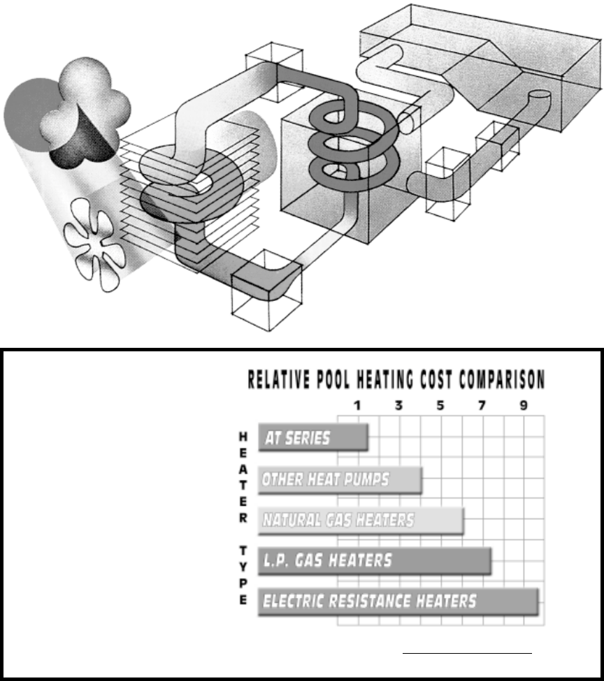
A swimming pool & spa pump utilizes proven refrigerant technology to capture the heat in the
outside air and transfers it to the pool water. Refrigerant is used because of its ability to absorb and
transfer heat energy.
The fan circulates air through the outer evaporator air coil that acts as a heat collector. The liquid
refrigerant in the air coil absorbs the available heat in the ambient air, transforming it into a gas. The
refrigerant gas is then pumped into the compressor. When this warmed gas is compressed, it
intensifies or concentrates the heat, like a magnifying glass in the sun.
This intensely hot gas is then pumped into the heat exchanger condenser, where the actual heat
transfer takes place. As the pool water passes through the heat exchanger, the hot gas gives up its
heat to the cooler pool water.
The refrigerant returns to a liquid state and is pumped through the expansion valve then into the
evaporator air coil to start the process all over again.
How Does A Heat Pump Warm A Pool ?
Operational
Cost Comparison
for Equal Amounts
of Pool Heat
A Heat Pump is the Most
Efficient Way to Heat Your Pool
Compared to L.P. gas heaters, a heat pump produces 5 times more heat
for every $1.00 you spend on operation.
How Efficient Is It ?
Page 21
FAN
WARM
AIR
COOL
AIR
COMPRESSOR
POOL
WATER
PUMP
FILTER
HEAT EXCHANGER
CONDENSER
EXPANSION
VALVE
EVAPORATOR
AIR COIL
WARMED
GAS

Specifications may change without notice.
© 2001 Aquatherm Heat Pumps
a division of Calorex USA L.L.C.
MEMBER
NATIONAL
POOL & SPA
INSTITUTE
Pool
Heat
Pump
Manufacturers
Association
MEMBER
a Division of Calorex USA L.L.C.
2213 Andrea Lane Ft. Myers FL 33912
888-297-3826 941-482-0606
www.aquathermheatpumps.com
www.calorexusa.com
HEAT PUMPS
