Arduino A Quick Start Guide
User Manual:
Open the PDF directly: View PDF ![]() .
.
Page Count: 284 [warning: Documents this large are best viewed by clicking the View PDF Link!]
- Contents
- Acknowledgments
- Preface
- The Parts You Need
- Getting Started with Arduino
- Eight Arduino Projects
- Building Binary Dice
- Building a Morse Code Generator Library
- Sensing the World Around Us
- What You Need
- Measuring Distances with an Ultrasonic Sensor
- Increasing Precision Using Floating-Point Numbers
- Increasing Precision Using a Temperature Sensor
- Transferring Data Back to Your Computer Using Processing
- Representing Sensor Data
- Building the Application's Foundation
- Implementing Serial Communication in Processing
- Visualizing Sensor Data
- What If It Doesn't Work?
- Exercises
- Building a Motion-Sensing Game Controller
- Tinkering with the Wii Nunchuk
- Networking with Arduino
- What You Need
- Using Your PC to Transfer Sensor Data to the Internet
- Registering an Application with Twitter
- Tweeting Messages with Processing
- Networking Using an Ethernet Shield
- Emailing from the Command Line
- Emailing Directly from an Arduino
- Detecting Motion Using a Passive Infrared Sensor
- Bringing It All Together
- What If It Doesn't Work?
- Exercises
- Creating Your Own Universal Remote Control
- Controlling Motors with Arduino
- Appendixes
- Index
Download from Wow! eBook <www.wowebook.com>

What Readers Are Saying About
Arduino: AQuick-Start Guide
The most comprehensive book on the Arduino platform Ihave read.
Loaded with excellent examples and references, Arduino: AQuick-Start
Guide gets beginners up and running in no time and provides experi-
enced developers with awealth of inspiration for their own projects.
Haroon Baig
Creator of the Twitwee Clock, http://www.haroonbaig.com
Excellently paced for those who have never experimented with elec-
tronics or microcontrollers before and packed with valuable tidbits
even for advanced Arduino tinkerers.
Georg Kaindl
Creator, Arduino DHCP, DNS, and Bonjour libs
The Arduino platform is agreat way for anyone to get into embedded
systems, and this book is the road map. From first baby steps to com-
plex sensors and even game controllers, there is no better way to get
going on the Arduino.
T o n y Williamitis
Senior embedded systems engineer
Irecommend this engaging and informative book to software develop-
ers who want to learn the basics of electronics, as well as to anyone
looking to interface their computers with the physical world.
René Bohne
Software developer and creator of LumiNet
Download from Wow! eBook <www.wowebook.com>

Arduino
AQuick-Start Guide
Maik Schmidt
The Pragmatic Bookshelf
Raleigh, North Carolina Dallas, Texas
Download from Wow! eBook <www.wowebook.com>

Many of the designations used by manufacturers and sellers to distinguish their prod-
ucts are claimed as trademarks. Where those designations appear in this book, and The
Pragmatic Programmers, LLC was aware of atrademark claim, the designations have
been printed in initial capital letters or in all capitals. The Pragmatic Starter Kit, The
Pragmatic Programmer, Pragmatic Programming, Pragmatic Bookshelf and the linking g
device are trademarks of The Pragmatic Programmers, LLC.
Every precaution was taken in the preparation of this book. However, the publisher
assumes no responsibility for errors or omissions, or for damages that may result from
the use of information (including program listings) contained herein.
Our Pragmatic courses, workshops, and other products can help you and your team
create better software and have more fun. For more information, as well as the latest
Pragmatic titles, please visit us at http://www.pragprog.com.
The team that produced this book includes:
Editor: Susannah Pfalzer
Indexing: Potomac Indexing, LLC
Copy edit: Kim W i m p s e t t
Layout: Samuel Langhorne
Production: Janet Furlow
Customer support: Ellie Callahan
International: Juliet Benda
Copyright ©2011 Pragmatic Programmers, LLC.
All rights reserved.
No part of this publication may be reproduced, stored in aretrieval system, or transmit-
ted, in any form, or by any means, electronic, mechanical, photocopying, recording, or
otherwise, without the prior consent of the publisher.
Printed in the United States of America.
ISBN-10: 1-934356-66-2
ISBN-13: 978-1-934356-66-1
Printed on acid-free paper.
P1.0 printing, Janurary, 2011
V e r s i o n : 2011-1-24
Download from Wow! eBook <www.wowebook.com>
For Yvonne.
The greatest little sister on earth.
Download from Wow! eBook <www.wowebook.com>
Download from Wow! eBook <www.wowebook.com>

Contents
Acknowledgments 11
Preface 13
Who Should Read This Book ................. 14
What’s in This Book . . . . . . . . . . . . . . . . . . . . . . 14
Arduino Uno and the Arduino Platform . . . . . . . . . . . 16
Code Examples and Conventions ............... 16
Online Resources . . . . . . . . . . . . . . . . . . . . . . . . 17
The Parts Y o u Need 18
Starter Packs . . . . . . . . . . . . . . . . . . . . . . . . . . 18
Complete Parts List ....................... 19
IGetting Started with Arduino 22
1W e l c o m e to the Arduino 23
1.1 What Y o u Need ..................... 24
1.2 What Exactly Is an Arduino? ............. 24
1.3 Exploring the Arduino Board ............. 25
1.4 Installing the Arduino IDE ............... 31
1.5 Meeting the Arduino IDE . . . . . . . . . . . . . . . . 33
1.6 Compiling and Uploading Programs ......... 38
1.7 W o r k i n g with LEDs ................... 41
1.8 What If It Doesn’t W o r k ? . . . . . . . . . . . . . . . . 43
1.9 Exercises ......................... 44
2Inside the Arduino 46
2.1 What Y o u Need ..................... 46
2.2 Managing Projects and Sketches . . . . . . . . . . . 47
2.3 Changing Preferences . . . . . . . . . . . . . . . . . . 48
2.4 Using Serial Ports . . . . . . . . . . . . . . . . . . . . 49
2.5 What If It Doesn’t W o r k ? . . . . . . . . . . . . . . . . 60
2.6 Exercises ......................... 61
Download from Wow! eBook <www.wowebook.com>

CONTENTS 8
II Eight Arduino Projects 62
3 Building Binary Dice 63
3.1 What Y o u Need ..................... 63
3.2 W o r k i n g with Breadboards ............... 64
3.3 Using an LED on aBreadboard . . . . . . . . . . . . 66
3.4 First V e r s i o n of aBinary Die . . . . . . . . . . . . . . 69
3.5 W o r k i n g with Buttons . . . . . . . . . . . . . . . . . . 74
3.6 Adding Our Own Button . . . . . . . . . . . . . . . . 79
3.7 Building aDice Game . . . . . . . . . . . . . . . . . . 80
3.8 What If It Doesn’t W o r k ? . . . . . . . . . . . . . . . . 86
3.9 Exercises ......................... 87
4 Building a Morse Code Generator Library 88
4.1 What Y o u Need ..................... 88
4.2 Learning the Basics of Morse Code . . . . . . . . . . 88
4.3 Building aMorse Code Generator . . . . . . . . . . . 89
4.4 Fleshing Out the Generator’s Interface . . . . . . . . 91
4.5 Outputting Morse Code Symbols . . . . . . . . . . . 92
4.6 Installing and Using the Telegraph Class . . . . . . 94
4.7 Final Touches . . . . . . . . . . . . . . . . . . . . . . 97
4.8 What If It Doesn’t W o r k ? . . . . . . . . . . . . . . . . 99
4.9 Exercises ......................... 100
5Sensing the W o r l d Around Us 102
5.1 What Y o u Need ..................... 103
5.2 Measuring Distances with an Ultrasonic Sensor . . 104
5.3 Increasing Precision Using Floating-Point Numbers 110
5.4 Increasing Precision Using aTemperature Sensor .113
5.5 TransferringData Back to Y o u r Computer Using Pro-
cessing . . . . . . . . . . . . . . . . . . . . . . . . . . 119
5.6 Representing Sensor Data ............... 123
5.7 Building the Application’s Foundation . . . . . . . . 125
5.8 Implementing Serial Communication in Processing 126
5.9 V i s u a l i z i n g Sensor Data . . . . . . . . . . . . . . . . 128
5.10 What If It Doesn’t W o r k ? . . . . . . . . . . . . . . . . 131
5.11 Exercises ......................... 131
Report erratum
this copy is (P1.0 printing, Ja nu ra r y, 2011)
Download from Wow! eBook <www.wowebook.com>

CONTENTS 9
6 Building a Motion-Sensing Game Controller 132
6.1 What Y o u Need ..................... 133
6.2 W i r i n g Up the Accelerometer . . . . . . . . . . . . . . 134
6.3 Bringing Y o u r Accelerometer to Life ......... 135
6.4 Finding and Polishing Edge V a l u e s . . . . . . . . . . 137
6.5 Building Y o u r Own Game Controller ......... 140
6.6 W r i t i n g Y o u r Own Game . . . . . . . . . . . . . . . . 144
6.7 More Projects . . . . . . . . . . . . . . . . . . . . . . 152
6.8 What If It Doesn’t W o r k ? . . . . . . . . . . . . . . . . 153
6.9 Exercises ......................... 153
7Tinkeringwith the Wii Nunchuk 154
7.1 What Y o u Need ..................... 154
7.2 W i r i n g aW i i Nunchuk ................. 155
7.3 Talking to aNunchuk . . . . . . . . . . . . . . . . . . 156
7.4 Building aNunchuk Class ............... 159
7.5 Using Our Nunchuk Class ............... 162
7.6 Rotating a Colorful Cube . . . . . . . . . . . . . . . . 163
7.7 What If It Doesn’t W o r k ? . . . . . . . . . . . . . . . . 169
7.8 Exercises ......................... 169
8Networking with Arduino 170
8.1 What Y o u Need ..................... 171
8.2 Using Y o u r PC to TransferSensor Data to the Inter-
net ............................. 172
8.3 Registering an Application with Twitter ....... 174
8.4 Tweeting Messages with Processing . . . . . . . . . . 175
8.5 Networking Using an Ethernet Shield . . . . . . . . 179
8.6 Emailing from the Command Line . . . . . . . . . . 186
8.7 Emailing Directly from an Arduino . . . . . . . . . . 188
8.8 Detecting Motion Using aPassive Infrared Sensor .192
8.9 Bringing It All Together ................. 196
8.10 What If It Doesn’t W o r k ? . . . . . . . . . . . . . . . . 199
8.11 Exercises ......................... 201
9Creating Y o u r Own Universal Remote Control 202
9.1 What Y o u Need ..................... 203
9.2 Understanding Infrared Remote Controls . . . . . . 204
9.3 Grabbing Remote Control Codes . . . . . . . . . . . 205
9.4 Building Y o u r Own Apple Remote . . . . . . . . . . . 209
9.5 Controlling Devices Remotely with Y o u r Browser . . 212
Report erratum
this copy is (P1.0 printing, Ja nu ra r y, 2011)
Download from Wow! eBook <www.wowebook.com>

CONTENTS 10
9.6 Building an Infrared Proxy ............... 214
9.7 What If It Doesn’t W o r k ? . . . . . . . . . . . . . . . . 221
9.8 Exercises ......................... 222
10 Controlling Motors with Arduino 223
10.1 What Y o u Need ..................... 223
10.2 Introducing Motors ................... 224
10.3 First Steps with aServo Motor . . . . . . . . . . . . 225
10.4 Building aBlaminatr . . . . . . . . . . . . . . . . . . 228
10.5 What If It Doesn’t W o r k ? . . . . . . . . . . . . . . . . 233
10.6 Exercises ......................... 234
III Appendixes 236
A Basics of Electronics 237
A.1 Current, V o l t a g e , and Resistance . . . . . . . . . . . 237
A.2 Learning How to Solder ................. 241
B Advanced Arduino Programming 247
B.1 The Arduino Programming Language ......... 247
B.2 Bit Operations . . . . . . . . . . . . . . . . . . . . . . 249
C Advanced Serial Programming 251
C.1 Learning More About Serial Communication . . . . 251
C.2 Serial Communication Using V a r i o u s Programming
Languages . . . . . . . . . . . . . . . . . . . . . . . . 253
D Bibliography 266
Index 267
Report erratum
this copy is (P1.0 printing, Ja nu ra r y, 2011)
Download from Wow! eBook <www.wowebook.com>

Acknowledgments
W r i t i n g books doesn’t get easier the more often Ido it—I think there
will never be atime when Ican do it on my own. Iwill always depend
on the help of others, and a lot of wonderful people contributed to this
book.
Ihave to start by thanking my unbelievably talented editor, Susannah
Davidson Pfalzer. Only because of her insightful advice, her patience,
and her encouragement have Ifinished this book. Iowe her so much!
Also, the Pragmatic Bookshelf team again has been amazingly profes-
sional, and my publishers have been very sympathetic when Iwent
through some hard times. I am so thankful for that!
This book would not have been possible without the stunning work of
the whole Arduino team! Thank you so much for creating the Arduino!
Abig “thank-you!” goes to all the people who contributed material to
this book: Christian Rattat took all the book’s photos, Kaan Karaca
created the Blaminatr’s display, and Tod E. Kurt kindly allowed me to
use his excellent Ccode for accessing an Arduino via serial port.
Ihave created all circuit diagrams with Fritzing,1and I’d like to thank
the Fritzing team for making such agreat tool available for free!
For an author, there’s nothing more motivating than feedback. I’d like
to thank my reviewers: René Bohne, Stefan Christoph, Georg Kaindl,
Kaan Karaca, Christian Rattat, Stefan Rödder, Christoph Schwaeppe,
Federico Tomassetti, and Tony W i l l i a m i t i s . This book is so much better
because of your insightful comments and suggestions! I am also grate-
ful to all readers who have sent in errata during the beta book period.
When Ihad written the first half of this book, my mother passed away
in February 2010. It has been one of the hardest times in my life, and
1. http://fritzing.org/
Download from Wow! eBook <www.wowebook.com>

ACKNOWLEDGMENTS 12
without the support of my family and my friends, Iwould have never
finished this book. W e miss you so much, Mom!
Finally, I’d like to thank Tanjafor giving me confidence and for bringing
fun back into my life when Ineeded it most!
Report erratum
this copy is (P1.0 printing, Ja nu ra r y, 2011)
Download from Wow! eBook <www.wowebook.com>

Preface
W e l c o m e to the Arduino, and welcome to the exciting world of physical
computing! Arduino2is an open source project consisting of both hard-
ware and software. It was originally created to give designers and artists
aprototyping platform for interaction design courses. Today hobby-
ists and experts all over the world use it to create physical computing
projects, and you can too.
The Arduino lets us get hands-on again with computers in away we
haven’t been able to since the 1980s, when you could build your own
computer. And Arduino makes it easier than ever to develop hand-
crafted electronics projects ranging from prototypes to sophisticated
gadgets. Gone are the days when you had to learn lots of theory about
electronics and arcane programming languages before you could even
get an LED blinking. Y o u can create your first Arduino project in afew
minutes without needing advanced electrical engineering course work.
In fact, you don’t need to know anything about electronics projects to
read this book, and you’ll get your hands dirty right from the begin-
ning. Y o u ’ l l not only learn how to use some of the most important elec-
tronic parts in the first pages, you’ll also learn how to write the software
needed to bring your projects to life.
This book dispenses with theory and stays hands-on throughout. I’ll
explain all the basics you need to build the book’s projects, and every
chapter has atroubleshooting section to help when things go wrong.
This book is a quick-start guide that gets you up to speed quickly and
enables you to immediately create your own projects.
2. http://arduino.cc
Download from Wow! eBook <www.wowebook.com>

WHOSHOULD READ THISBOOK 14
Who Should Read This Book
If you are interested in electronics—and especially in building your
own toys, games, and gadgets—then this book is for you. Although the
Arduino is anice tool for designers and artists, only software developers
are able to unleash its full power. So, if you’ve already developed some
software—preferably with C/C++ or Java—then you’ll get alot out of
this book.
But there’s one more thing: you have to build, try, and modify the
projects in this book. Have fun. Don’t worry about making mistakes.
The troubleshooting sections—and the hands-on experience you’ll gain
as you become more confident project by project—will make it all worth-
while. Reading about electronics without doing the projects yourself
isn’t even half the battle (you know the old saying: we remember 5per-
cent of what we hear, 10 percent of what we write, and 95 percent of
what we personally suffer). And don’t be afraid: you really don’t need
any previous electronics project experience!
If you’ve never written apiece of software before, start with aprogram-
ming course or read abeginner’s book about programming first (Learn
to Program [Pin06]is anice starting point). Then, learn to program in
Cwith The CProgramming Language [KR98]or in C++ with The C++
Programming Language [Str00].
What’s in This Book
This book consists of three parts (“Getting Started with Arduino,” “Eight
Arduino Projects,” and the appendixes). In the first part, you’ll learn all
the basics you need to build the projects in the second part, so read the
chapters in order and do all the exercises. The chapters in the second
part also build on each other, reusing techniques and code from earlier
chapters.
Here’s ashort walk-through:
•The book starts with the basics of Arduino development. Y o u ’ l l
learn how to use the IDE and how to compile and upload pro-
grams. Y o u ’ l l quickly build your first project—electronic dice—that
shows you how to work with basic parts such as LEDs, buttons,
and resistors. By implementing aMorse code generator, you’ll see
how easy it is to create your own Arduino libraries.
Report erratum
this copy is (P1.0 printing, Ja nu ra r y, 2011)
Download from Wow! eBook <www.wowebook.com>

WHAT’SINTHISBOOK 15
•Then you’ll learn how to work with analog and digital sensors.
Y o u ’ l l use atemperature sensor and an ultrasonic sensor to build
avery accurate digital metering ruler. Then you’ll use athree-axis
accelerometer to build your own motion-sensing game controller,
together with acool breakout game clone.
•In electronics, you don’t necessarily have to build gadgets yourself.
Y o u can also tinker with existing hardware, and you’ll see how
easy it is to take full control of Nintendo’s W i i Nunchuk so you
can use it in your own applications.
•Using aNunchuk to control applications or devices is nice, but
often it’s more convenient to have awireless remote control. So,
you’ll learn how to build your own universal remote control that
you can even control using aweb browser.
•Speaking of web browsers: connecting the Arduino to the Inter-
net is easy, so you’ll build aburglar alarm that sends you an
email whenever someone is moving in your living room during your
absence.
•Finally, you’ll work with motors by creating afun device for your
next software project. It connects to your continuous integration
system, and whenever the build fails, it moves an arrow to point
to the name of the developer who is responsible.
•In the appendixes, you’ll learn about the basics of electricity and
soldering. Y o u ’ l l also find advanced information about program-
ming aserial port and programming the Arduino in general.
Every chapter starts with adetailed list of all parts and tools you need
to build the chapter’s projects. Every chapter contains lots of photos
and diagrams showing how everything fits together. Y o u ’ l l get inspired
with descriptions of real-world Arduino projects in sidebars throughout
the book.
Things won’t always work out as expected, and debugging circuits can
be adifficult and challenging task. So in every chapter you’ll find a
“What If It Doesn’t W o r k ? ” section that explains the most common prob-
lems and their solutions.
Before you read the solutions in the “What If It Doesn’t W o r k ? ” sec-
tions, though, try to solve the problems yourself, because that’s the
most effective way of learning. In the unlikely case that you don’t run
Report erratum
this copy is (P1.0 printing, Ja nu ra r y, 2011)
Download from Wow! eBook <www.wowebook.com>

ARDUINO UNOANDTHEARDUINO PLATFORM 16
into any problems, you’ll find alist of exercises to build your skills at
the end of every chapter.
All the projects in this book have been tested on the Arduino Uno, the
Arduino Duemilanove, and with the Arduino IDE versions 18 to 21. If
possible, you should always use the latest version.
Arduino Uno and the Arduino Platform
After releasing several Arduino boards and Arduino IDE versions, the
Arduino team decided to specify aversion 1.0 of the platform. It will
be the reference for all future developments, and they announced it
on the first day of 2010.3Since then, they have released the Arduino
Uno, and they have also improved the IDE and its supporting libraries
step-by-step.
At the moment of this writing, it is still not completely clear what
Arduino 1.0 will look like. The Arduino team tries to keep this release as
backward compatible as possible. This book is up-to-date for the new
Arduino Uno boards. All the projects will also work with older Arduino
boards such as the Duemilanove or Diecimila. This book is current for
version 21 of the Arduino platform. Y o u can follow the progress of the
Arduino platform online.4
Code Examples and Conventions
Although this is abook about open source hardware and electronics,
you will find alot of code examples. W e need them to bring the hardware
to life and make it do what we want it to do.
W e use C/C++ for all programs that will eventually run on the Arduino.
For applications running on our PC, we use Processing,5but in Sec-
tion C.2,Serial Communication Using V a r i o u s Programming Languages,
on page 253,you’ll also learn how to use several other programming
languages to communicate with an Arduino.
Whenever you find aslippery road icon beside aparagraph, slow down
and read carefully. They announce difficult or dangerous techniques.
3. http://arduino.cc/blog/2010/01/01/uno-punto-zero/
4. http://code.google.com/p/arduino/issues/list?q=milestone=1.0
5. http://processing.org
Report erratum
this copy is (P1.0 printing, Ja nu ra r y, 2011)
Download from Wow! eBook <www.wowebook.com>

ONLINE RESOURCES 17
Online Resources
This book has its own web page at http://pragprog.com/titles/msard where
you can download the code for all examples (if you have the ebook ver-
sion of this book, clicking the little gray box above each code example
downloads that source file directly). Y o u can also participate in adis-
cussion forum and meet other readers and me. If you find bugs, typos,
or other annoyances, please let me and the world know about them on
the book’s errata page.6
On the web page you will also find alink to aFlickr7photo set. It
contains all the book’s photos in high resolution. There you can also
see photos of reader projects, and we’d really like to see photos of your
projects, too!
Let’s get started!
6. http://www.pragprog.com/titles/msard/errata
7. http://flickr.com
Report erratum
this copy is (P1.0 printing, Ja nu ra r y, 2011)
Download from Wow! eBook <www.wowebook.com>

The Parts Y o u Need
Here’s alist of the parts you need to work through all the projects in
this book. In addition, each chapter lists the parts you’ll need for that
chapter’s projects, so you can try projects chapter-by-chapter without
buying all the components at once. Although there look to be alot of
components here, they’re all fairly inexpensive, and you can buy all the
parts you need for all the projects in this book for about $200.
Starter P a c k s
Many online shops sell Arduino components and electronic parts. Some
of the best are Makershed8and Adafruit.9They have awesome starter
packs, and I strongly recommend buying one of these.
The best and cheapest solution is to buy the Arduino Projects Pack from
Makershed (product code MSAPK). It contains nearly all the parts you
need to build the book’s examples, as well as many more useful parts
that you can use for your own side projects. If you buy the Arduino
Projects Pack, you’ll need to buy these additional parts separately:
•Parallax PING))) sensor
•TMP36 temperature sensor from Analog Devices
•ADXL335 accelerometer breakout board
• 6 pin 0.1" standard header
•Nintendo Nunchuk controller
• A Passive Infrared Sensor
•An infrared LED
•An infrared receiver
•An Ethernet shield
8. http://makershed.com
9. http://adafruit.com
Download from Wow! eBook <www.wowebook.com>

COMPLETE PARTSLIST 19
Alternatively, Adafruit also sells an Arduino Starter Pack (product ID
170). It’s cheaper, but it doesn’t contain as many parts. For example, it
doesn’t have aProtoshield or atilt sensor.
All shops constantly improve their starter packs, so it’s agood idea to
scan their online catalogs carefully.
Complete P a r t s List
If you prefer to buy parts piece by piece (or chapter by chapter) rather
than astarter pack, here is alist of all the parts used in the book. Each
chapter also has aparts list and photo with all parts needed for that
chapter. Suggested websites where you can buy the parts are listed here
for your convenience, but many of these parts are available elsewhere
also, so feel free to shop around.
Good shops for buying individual components parts are RadioShack,10
Digi-Key,11sparkfun,12and Mouser.13
•An Arduino board such as the Uno, Duemilanove, or Diecimila
available from Adafruit (product ID 50) or Makershed (product
code MKSP4).
• A standard A-B USB cable for USB 1.1 or 2.0. Y o u might already
have afew. If not, you can order it at RadioShack (catalog number
55011289).
• A half-size breadboard from Makershed (product code MKKN2) or
from Adafruit (product ID 64).
•Three LEDs (four additional ones are needed for an optional exer-
cise). Buying LEDs one at a time isn’t too useful; abetter idea is
to buy apack of 20 at RadioShack (catalog number 276-1622).
•One 100Ωresistor, two 10kΩresistors, and three 1kΩresistors.
It’s also not too useful to buy single resistors; buy avalue pack
such as catalog number 271-308 from RadioShack.
•Two pushbuttons. Don’t buy asingle button switch; buy at least
four instead, available at RadioShack (catalog number 275-002).
10. http://radioshack.com
11. http://digikey.com
12. http://sparkfun.com
13. http://mouser.com
Report erratum
this copy is (P1.0 printing, Ja nu ra r y, 2011)
Download from Wow! eBook <www.wowebook.com>

COMPLETE PARTSLIST 20
•Some wires, preferably breadboard jumper wires. Y o u can buy
them at Makershed (product code MKSEEED3) or Adafruit (prod-
uct ID 153).
• A Parallax PING))) sensor (product code MKPX5) from Makershed.
• A Passive Infrared Sensor (product code MKPX6) from Makershed.
• A TMP36 temperature sensor from Analog Devices.14Y o u can get
it from Adafruit (product ID165).
•An ADXL335 accelerometer breakout board. Y o u can buy it at
Adafruit (product ID 163).
• A 6 pin 0.1" standard header (included, if you order the ADXL335
from Adafruit). Alternatively, you can order from sparkfun (search
for breakaway headers). Usually, you can only buy stripes that
have more pins. In this case, you have to cut it accordingly.
• A Nintendo Nunchuk controller. Y o u can buy it at nearly every toy
store or at http://www.amazon.com/,for example.
•An Arduino Ethernet shield (product code MKSP7) from Maker-
shed.
•An infrared sensor such as the PNA4602. Y o u can buy it aAdafruit
(product ID 157) or Digi-Key (search for PNA4602).
•An infrared LED. Y o u can get it from RadioShack (catalog number
276-143) or from sparkfun (search for infrared LED).
• A 5V servo motor such as the Hitec HS-322HD or the V i g o r Hex-
tronic. Y o u can get one from Adafruit (product id 155) or sparkfun.
Search for standard servos with an operating voltage of 4.8V–6V.
For some of the exercises, you’ll need some optional parts:
•An Arduino Proto Shield from Adafruit (product ID 51) or Maker-
shed (product code MKAD6). Y o u ’ l l also need atiny breadboard
(product code MKKN1 at Makershed). Ihighly recommend this
shield!
• A piezo speaker or buzzer. Search for piezo buzzer at RadioShack
or get it from Adafruit (product ID 160).
14. http://www.analog.com/en/sensors/digital-temperature-sensors/tmp36/products/product.html
Report erratum
this copy is (P1.0 printing, Ja nu ra r y, 2011)
Download from Wow! eBook <www.wowebook.com>

COMPLETE PARTSLIST 21
• A tilt sensor. Get it from Adafruit (product ID 173), or buy it at
Mouser (part number 107-2006-EV).
For the soldering tutorial, you need the following things:
• A 25W–30W soldering iron with atip (preferably 1/16") and a sol-
dering stand.
•Standard 60/40 solder (rosin-core) spool for electronics work. It
should have a0.031" diameter.
• A sponge.
Y o u can find these things in every electronics store, and many have
soldering kits for beginners that contain some useful additional tools.
Take alook at Adafruit (product ID 136) or Makershed (product code
MKEE2).
Report erratum
this copy is (P1.0 printing, Ja nu ra r y, 2011)
Download from Wow! eBook <www.wowebook.com>
Part I
Getting Started with Arduino
Download from Wow! eBook <www.wowebook.com>

Chapter 1
W e l c o m e to the Arduino
The Arduino was originally built for designers and artists—people with
little technical expertise. Even without programming experience, the
Arduino enabled them to create sophisticated design prototypes and
some amazing interactive artworks. So, it should come as no surprise
that the first steps with the Arduino are very easy, even more so for
people with astrong technical background.
But it’s still important to get the basics right. Y o u ’ l l get the most out
of working with the Arduino if you’re familiar with the Arduino board
itself, with its development environment, and with techniques such as
serial communication.
One thing to understand before getting started is physical computing.If
you have worked with computers before, you might wonder what this
means. After all, computers are physical objects, and they accept input
from physical keyboards and mice. They output sound and video to
physical speakers and displays. So, isn’t all computing physical com-
puting in the end?
In principle, regular computing is asubset of physical computing: key-
board and mouse are sensors for real-world inputs, and displays or
printers are actuators.But controlling special sensors and actuators,
using aregular computer is very difficult. Using an Arduino, it’s apiece
of cake to control sophisticated and sometimes even weird devices.
In the rest of this book, you’ll learn how, and in this chapter you’ll
get started with physical computing by learning how to control the
Arduino, what tools you need, and how to install and configure them.
Then we’ll quickly get to the fun part: you’ll develop your first program
for the Arduino.
Download from Wow! eBook <www.wowebook.com>

WHAT YOUNEED 24
1.1 What Y o u Need
•An Arduino board such as the Uno, Duemilanove, or Diecimila.
• A USB cable to connect the Arduino to your computer.
•An LED.
•The Arduino IDE (see Section 1.4,Installing the Arduino IDE,on
page 31). Y o u will need it in every chapter, so after this chapter,
I’ll no longer mention it explicitly.
1.2 What Exactly Is an Arduino?
Beginners often get confused when they discover the Arduino project.
When looking for the Arduino, they hear and read strange names such
as Uno, Duemilanove, Diecimila, LilyPad, or Seeduino. The problem is
that there is no such thing as “the Arduino.”
Acouple of years ago the Arduino team designed amicrocontroller
board and released it under an open source license. Y o u could buy fully
assembled boards in afew electronics shops, but people interested in
electronics could also download its schematic1and build it themselves.
Over the years the Arduino team improved the board’s design and
released several new versions. They usually had Italian names such
as Uno, Duemilanove, or Diecimila, and you can find alist of all boards
that were ever created by the Arduino team online.2
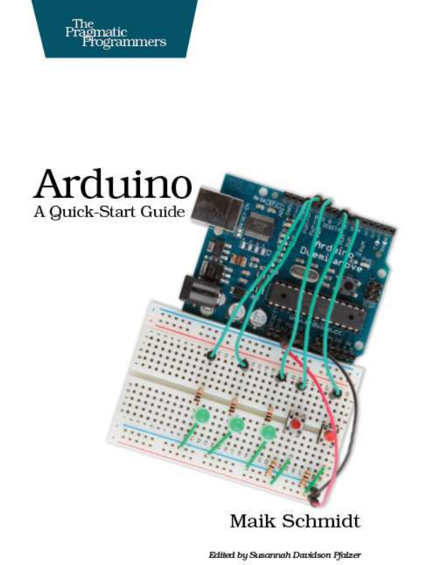
Figure 1.1,on the following page shows asmall selection of Arduinos.
They may differ in their appearance, but they have alot in common,
and you can program them all with the same tools and libraries.
The Arduino team did not only constantly improve the hardware design.
They also invented new designs for special purposes. For example, they
created the Arduino LilyPad3to embed amicrocontroller board into
textiles. Y o u can use it to build interactive T-shirts, for example.
In addition to the official boards, you can find countless Arduino clones
on the W e b . Everybody is allowed to use and change the original board
design, and many people created their very own version of an Arduino-
compatible board. Among many others, you can find the Freeduino,
1. http://arduino.cc/en/uploads/Main/arduino-uno-schematic.pdf
2. http://arduino.cc/en/Main/Boards
3. http://arduino.cc/en/Main/ArduinoBoardLilyPad
Report erratum
this copy is (P1.0 printing, Ja nu ra r y, 2011)
Download from Wow! eBook <www.wowebook.com>
EXPLORING THEARDUINO BOARD 25
Figure 1.1: Y o u can choose fom many different Arduinos.
Seeduino, Boarduino, and the amazing Paperduino,4an Arduino clone
without aprinted circuit board. All its parts are attached to an ordinary
piece of paper.
Arduino is aregistered trademark—only the official boards are named
“Arduino.”—so clones usually have names ending with “duino.” Y o u
can use every clone that is fully compatible with the original Arduino to
build all the book’s projects.
1.3 Exploring the Arduino Board
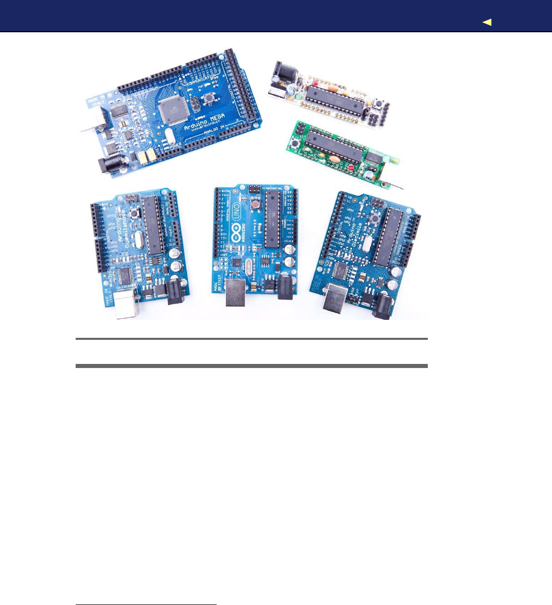
In Figure 1.2,on the next page, you can see aphoto of an Arduino Uno
board and its most important parts. I’ll explain them one by one. Let’s
start with the USB connector. To connect an Arduino to your computer,
4. http://lab.guilhermemartins.net/2009/05/06/paperduino-prints/
Report erratum
this copy is (P1.0 printing, Ja nu ra r y, 2011)
Download from Wow! eBook <www.wowebook.com>
EXPLORING THEARDUINO BOARD 26
Digital I/O Pins
Power Jack
USB Connector
Reset
Button
Micro-
Controller
Power Supply
Analog Input Pins
Figure 1.2: The Arduino’s most important components
you just need an USB cable. Then you can use the USB connection for
various purposes:
•Upload new software to the board (you’ll see how to do this in
Section 1.6,Compiling and Uploading Programs,on page 38).
•Communicate with the Arduino board and your computer (you’ll
learn that in Section 2.4,Using Serial Ports,on page 49).
•Supply the Arduino board with power.
As an electronic device, the Arduino needs power. One way to power it
is to connect it to acomputer’s USB port, but that isn’t agood solution
in some cases. Some projects don’t necessarily need acomputer, and it
would be overkill to use awhole computer just to power the Arduino.
Also, the USB port only delivers 5volts, and sometimes you need more.
Report erratum
this copy is (P1.0 printing, Ja nu ra r y, 2011)
Download from Wow! eBook <www.wowebook.com>

EXPLORING THEARDUINO BOARD 27
Figure 1.3: Y o u can power an Arduino with an AC adapter.
In these situations, the best solution usually is an AC adapter (see
Figure 1.3)supplying 9volts (the recommended range is 7V to 12V).5
Y o u need an adapter with a2.1 mm barrel tip and a positive center (you
don’t need to understand what that means right now; just ask for it in
your local electronics store). Plug it into the Arduino’s power jack, and
it will start immediately, even if it isn’t connected to acomputer. By the
way, even if you connect the Arduino to an USB port, it will use the
external power supply if available.
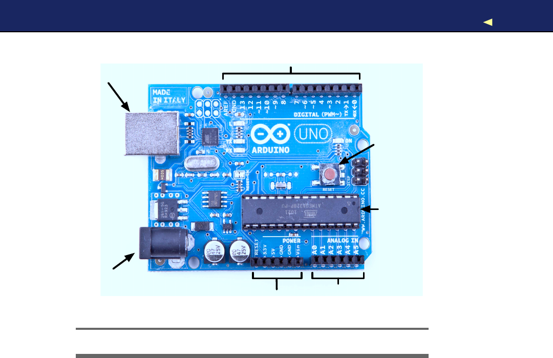
Please note that older versions of the Arduino board (Arduino-NG and
Diecimila) don’t switch automatically between an external power supply
and a USB supply. They come with apower selection jumper labeled
PWR_SEL, and you manually have to set it to EXT or USB, respectively
(see Figure 1.4,on the next page).
Now you know two ways to supply the Arduino with power. But the
Arduino isn’t greedy and happily shares its power with other devices.
At the bottom of Figure 1.2,on the preceding page, you can see several
sockets (sometimes I’ll also call them pins,because internally they are
connected to pins in the microcontroller) related to power supply:
•Using the pins labeled 3V3 and 5V,you can power external devices
connected to the Arduino with 3.3 volts or 5volts.
5. http://www.arduino.cc/playground/Learning/WhatAdapter
Report erratum
this copy is (P1.0 printing, Ja nu ra r y, 2011)
Download from Wow! eBook <www.wowebook.com>
EXPLORING THEARDUINO BOARD 28
Jumper
Figure 1.4: Older Arduinos have apower source selection jumper.
•Two ground pins labeled Gnd allow your external devices to share
acommon ground with the Arduino.
•Some projects need to be portable, so they’ll use aportable power
supply such as batteries. Y o u connect an external power source
such as a battery pack to the Vin and Gnd sockets.
If you connect an AC adapter to the Arduino’s power jack, you can
supply the adapter’s voltage through this pin.
On the lower right of the board, you see six analog input pins named
A0–A5. Y o u can use them to connect analog sensors to the Arduino.
They take sensor data and convert it into anumber between 0 and
1023. In Chapter 5,Sensing the W o r l d Around Us,on page 102,we’ll
use them to connect atemperature sensor to the Arduino.
At the board’s top are 14 digital IO pins named D0–D13. Depending on
your needs, you can use these pins for both digital input and output,
so you can read the state of apushbutton or switch to turn on and off
an LED (we’ll do this in Section 3.5,W o r k i n g with Buttons,on page 74).
Six of them (D3, D5, D6, D9, D10, and D11) can also act as analog
Report erratum
this copy is (P1.0 printing, Ja nu ra r y, 2011)
Download from Wow! eBook <www.wowebook.com>

EXPLORING THEARDUINO BOARD 29
Analog and Digital Signals
Nearly all physical processes are analog. Whenever y o u
observe anatural phenomenon such as electricity or sound,
y o u ’ r e actually receiving an analog signal. One of the most
important properties of these analog signals is that they are
continuous. For e v e r y given point in time, y o u can measure the
strength of the signal, and in principle y o u could register e v e n
the tiniest v a r i a t i o n of the signal.
But although w e live in an analog w o r l d , w e are also living
in the digital age. When the first computers w e r e built a f e w
decades ago, people quickly realized that it’s m u c h easier to
w o r k with real-world information when it’s represented as num-
bers and not as an analog signal such as v o l t a g e or v o l u m e . For
example, it’s m u c h easier to m a n i p u l a t e sounds using a com-
puter whenthe sound w a v e s are stored as a sequence of num-
bers. Every number in this sequence could represent the signal’s
loudness at a certain point in time.
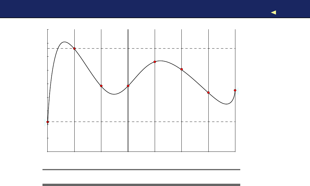
So instead of storing the complete analog signal (as is done
on records), w e measure the signal only at certain points in
time (see Figure 1.5,on the f o l l o w i n g page). W e call this pro-
cess sampling, and the v a l u e s w e store are called samples.The
frequency w e use to determine new samples is called sampling
r a t e .For an audio CD, the sampling r a t e is 44.1 kHz: w e g a t h e r
44,100 samples per second.
W e also have to limit the samples to acertain r a n g e . On an
audio CD, e v e r y sample uses 16 bits. In Figure 1.5,on the next
page, the r a n g e is denoted b y two dashed lines, and w e had
to cut off a peak at the beginning of the signal.
Although y o u can connect both analog and digital devices to
the Arduino, y o u usually don’t have to think m u c h aboutit. The
Arduino automatically performs the conversion from analog to
digital, and vice v e r s a , f o r y o u .
Report erratum
this copy is (P1.0 printing, Ja nu ra r y, 2011)
Download from Wow! eBook <www.wowebook.com>
EXPLORING THEARDUINO BOARD 30
70 1 2 3 4 5 6
Figure 1.5: Digitizing an analog signal
output pins. In this mode, they convert values from 0to 255 into an
analog voltage.
All these pins are connected to amicrocontroller. A microcontroller com-
bines aCPU with some peripheral functions such as IO channels. Many
different types of microcontrollers are available, but the Arduino usu-
ally comes with an ATmega328 or an ATmega168. Both are 8-bit micro-
controllers produced by acompany named Atmel.
Although modern computers load programs from ahard drive, micro-
controllers usually have to be programmed. That means you have to
load your software into the microcontroller via acable, and once the
program has been uploaded, it stays in the microcontroller until it gets
overwritten with anew program. Whenever you supply power to the
Arduino, the program currently stored in its microcontroller gets exe-
cuted automatically. Sometimes you want the Arduino to start right
from the beginning. W i t h the reset button on the right side of the board,
you can do that. If you press it, everything gets reinitialized, and the
program stored in the microcontroller starts again (we use it in Sec-
tion 3.4,First V e r s i o n of a Binary Die,on page 69).
Report erratum
this copy is (P1.0 printing, Ja nu ra r y, 2011)
Download from Wow! eBook <www.wowebook.com>

INSTALLING THEARDUINO IDE 31
In this section, we had acloser look at the Arduino Uno, the newest
Arduino board. But several other types are available, and although
they’re the same in principle, they differ in some details. The Arduino
Mega25606has many more IO pins than all other Arduinos and uses
the powerful ATmega2560 microcontroller, while the Arduino Nano7
was designed to be used on abreadboard, so it doesn’t have any sock-
ets. From my experience, beginners should start with one of the “stan-
dard” boards, that is, with an Uno or aDuemilanove.
1.4 Installing the Arduino IDE
To make it as easy as possible to get started with the Arduino, the
Arduino developers have created asimple but useful integrated devel-
opment environment (IDE). It runs on many different operating sys-
tems. Before you can create your first projects, you have to install it.
Installing the Arduino IDE on Wi ndow s
The Arduino IDE runs on all the latest versions of Microsoft W i n d o w s ,
such as W i n d o w s XP, W i n d o w s V i s t a , and W i n d o w s 7. Installing the
software is easy, because it comes as a self-contained ZIP archive,8so
you don’t even need an installer. Download the archive, and extract it
to alocation of your choice.
Before you first start the IDE, you must install drivers for the Arduino’s
USB port. This process depends on the Arduino board you’re using and
on your flavor of W i n d o w s , but you always have to plug the Arduino
into aUSB port first to start the driver installation process.
On W i n d o w s V i s t a , driver installation usually happens automatically.
Lean back and watch the hardware wizard’s messages pass by until it
says that you can use the newly installed USB hardware.
W i n d o w s XP and W i n d o w s 7may not find the drivers on Microsoft’s
update sites automatically. Sooner or later the hardware wizard asks
you for the path to the right drivers after you have told it to skip auto-
matic driver installation from the Internet. Depending on your Arduino
board, you have to point it to the right location in the Arduino installa-
tion directory. For the Arduino Uno and the Arduino Mega 2560, choose
6. http://arduino.cc/en/Main/ArduinoBoardMega2560
7. http://arduino.cc/en/Main/ArduinoBoardNano
8. http://arduino.cc/en/Main/Software
Report erratum
this copy is (P1.0 printing, Ja nu ra r y, 2011)
Download from Wow! eBook <www.wowebook.com>

INSTALLING THEARDUINO IDE 32
Arduino UNO.inf (respectively, Arduino MEGA 2560.inf)in the drivers direc-
tory. For older boards such as the Duemilanove, Diecimila, or Nano,
choose the drivers/FTDI USB Drivers directory
After the drivers have been installed, you can start the Arduino exe-
cutable from the archive’s main directory by double-clicking it. Follow
the instructions on the screen to install the IDE.
Please note that the USB drivers don’t change as often as the Arduino
IDE. Whenever you install anew version of the IDE, check whether you
have to install new drivers, too. Usually, it isn’t necessary.
Installing the Arduino IDE on Mac OS X
The Arduino IDE is available as a disk image for the most recent Mac
OS X.9Download it, double-click it, and then drag the Arduino icon to
your Applications folder.
If you’re using an Arduino Uno or an Arduino Mega 2560, you are
done and can start the IDE. Before you can use the IDE with an older
Arduino such as the Duemilanove, Diecimila, or Nano, you have to
install drivers for the Arduino’s serial port. Auniversal binary is in the
disk image—double-click the FTDIUSBSerialDriver_10_4_10_5_10_6.pkg file for
your platform, and follow the installation instructions on the screen.
When installing anew version of the Arduino IDE, you usually don’t
have to install the FTDI drivers again (only when amore recent version
of the drivers is available).
Installing the Arduino IDE on Linux
Installation procedures on Linux distributions are still not very homo-
geneous. The Arduino IDE works fine on nearly all modern Linux ver-
sions, but the installation process heavily differs from distribution to
distribution. Also, you often have to install additional software (the Java
virtual machine, for example) that comes preinstalled with other oper-
ating systems.
It’s best to check the official documentation10and look up the instruc-
tions for your preferred system.
Now that we have the drivers and the IDE installed, let’s see what it has
to offer.
9. http://arduino.cc/en/Main/Software
10. http://www.arduino.cc/playground/Learning/Linux
Report erratum
this copy is (P1.0 printing, Ja nu ra r y, 2011)
Download from Wow! eBook <www.wowebook.com>
MEETING THEARDUINO IDE 33
Figure 1.6: The Arduino IDE is well arranged.
1.5 Meeting the Arduino IDE
If you have used an IDE such as Eclipse, Xcode, or Microsoft V i s u a l Stu-
dio before, you’d better lower your expectations, because the Arduino
IDE is really simple. It mainly consists of an editor, acompiler, aloader,
and a serial monitor (see Figure 1.6 or, even better, start the IDE on
your computer).
Report erratum
this copy is (P1.0 printing, Ja nu ra r y, 2011)
Download from Wow! eBook <www.wowebook.com>

MEETING THEARDUINO IDE 34
V e r i f y
Stop
New
Open
Save
Upload
Serial Monitor
Figure 1.7: The IDE’s toolbar gives you quick access to important func-
tions.
It has no advanced features such as a debugger or code completion.
Y o u can change only afew preferences, and as a Java application it
does not fully integrate into the Mac desktop. It’s still usable, though,
and even has decent support for project management.
In Figure 1.7,you can see the IDE’s toolbar that gives you instant
access to the functions you’ll need most:
•W i t h the V e r i f y button, you can compile the program that’s cur-
rently in the editor. So, in some respects, “Verify” is abit of a
misnomer, because clicking the button does not only verify the
program syntactically. It also turns it into arepresentation suit-
able for the Arduino board.
•The New button creates anew program by emptying the content
of the current editor window. Before that happens, the IDE gives
you the opportunity to store all unsaved changes.
•W i t h Open, you can open an existing program from the file system.
•Save saves the current program.
•When you click the Upload button, the IDE compiles the current
program and uploads it to the Arduino board you have chosen in
Report erratum
this copy is (P1.0 printing, Ja nu ra r y, 2011)
Download from Wow! eBook <www.wowebook.com>
MEETING THEARDUINO IDE 35
Power
Status LED
Serial
Communication
Figure 1.8: The Arduino board comes with several LEDs.
the IDE’s Tools >Serial Port menu (you’ll learn more about this in
Section 1.6,Compiling and Uploading Programs,on page 38).
•The Arduino can communicate with acomputer via aserial con-
nection. Clicking the Serial Monitor button opens aserial monitor
window that allows you to watch the data sent by an Arduino and
also to send data back.
•The Stop button stops the serial monitor.
Although using the IDE is easy, you might run into problems or want to
look up something special. In such cases, take alook at the Help menu.
It points to many useful resources at the Arduino’s website that provide
quick solutions not only to all typical problems but also to reference
material and tutorials.
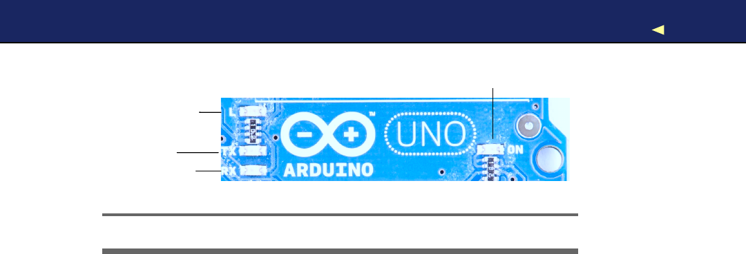
To get familiar with the IDE’s most important features, we’ll create a
simple program that makes an light-emitting diode (LED) blink. An
LED is acheap and efficient light source, and the Arduino already
comes with several LEDs. One LED shows whether the Arduino is cur-
rently powered, and two other LEDs blink when data is transmitted or
received via aserial connection (see them in Figure 1.8).
In our first little project, we’ll make the Arduino’s status LED blink.
The status LED is connected to digital IO pin 13. Digital pins act as a
kind of switch and can be in one of two states: HIGH or LOW. If set to
HIGH, the output pin is set to 5volts, causing acurrent to flow through
the LED, so it lights up. If it’s set back to LOW, the current flow stops,
and the LED turns off. Y o u do not need to know exactly how electricity
works at the moment, but if you’re curious, take alook at Section A.1,
Current, V o l t a g e , and Resistance,on page 237.
Report erratum
this copy is (P1.0 printing, Ja nu ra r y, 2011)
Download from Wow! eBook <www.wowebook.com>

MEETING THEARDUINO IDE 36
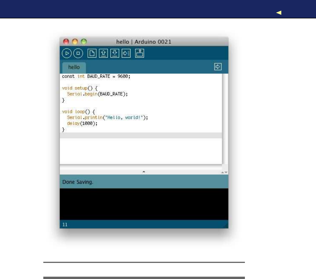
Open the IDE, and enter the following code in the editor:
Download we l co m e /H e ll o Wo r l d /H e l lo Wo r l d. p de
Line 1const unsigned int LED_PIN =13;
-const unsigned int PAUSE =500;
-
-void setup() {
5pinMode(LED_PIN, OUTPUT);
-}
-
-void loop() {
-digitalWrite(LED_PIN, HIGH);
10 delay(PAUSE);
-digitalWrite(LED_PIN, LOW);
-delay(PAUSE);
-}
Let’s see how this works and dissect the program’s source code piece by
piece. In the first two lines we define two int constants using the const
keyword. LED_PIN refers to the number of the digital IO pin we’re using,
and P A U S E defines the length of the blink period in milliseconds.
Every Arduino program needs afunction named setup(), and ours starts
in line 4. Afunction definition always adheres to the following scheme:
<return value type> <function name> ’(’ <list of parameters> ’)’
In our case the function’s name is setup(), and its return value type is
v o i d :it returns nothing. setup( ) doesn’t expect any arguments, so we left
the parameter list empty. Before we continue with the dissection of our
program, you should learn abit more about the Arduino’s data types.
Arduino Data Typ es
Every piece of data you store in an Arduino program needs atype.
Depending on your needs, you can choose from the following:
•boolean values take up one byte of memory and can be true or f a l s e .
•char variables take up one byte of memory and store numbers
from -128 to 127. These numbers usually represent characters
encoded in ASCII; that is, in the following example, c1 and c2 have
the same value:
char c1 ='A';
char c2 =65;
Note that you have to use single quotes for char literals.
•b y t e variables use one byte and store values from 0to 255.
Report erratum
this copy is (P1.0 printing, Ja nu ra r y, 2011)
Download from Wow! eBook <www.wowebook.com>

MEETING THEARDUINO IDE 37
•An int variable needs two bytes of memory; you can use it to store
numbers from -32,768 to 32,767. Its unsigned pendant unsigned
int also consumes two bytes of memory but stores numbers from
0to 65,535.
•For bigger numbers, use long.It consumes four bytes of mem-
ory and stores values from -2,147,483,648 to 2,147,483,647. The
unsigned variant unsigned long also needs four bytes but ranges
from 0to 4,294,967,295.
•float and double are the same at the moment, and you can use
these types for storing floating-point numbers. Both use four bytes
of memory and are able to store values from -3.4028235E+38 to
3.4028235E+38.
•Y o u need v o i d only for function declarations. It denotes that a
function doesn’t return avalue.
•Arrays store collections of values having the same type:
int values[2]; // Atwo-element array
int values[0] =42; // Set the first element
int values[1] =-42; // Set the second element
int more_values[] = { 42, -42 };
int first =more_values[0]; // first == 42
In the preceding example, the arrays v a l u e s and more_values con-
tain the same elements. W e have used only two different ways of
initializing an array. Note that the array index starts at 0, and keep
in mind that uninitialized array elements contain random values.
• A string is an array of char values. The Arduino environment sup-
ports the creation of strings with some syntactic sugar—all these
declarations create strings with the same contents.
char string1[8] = { 'A', 'r', 'd', 'u', 'i', 'n', 'o', '\0' };
char string2[] =
"Arduino"
;
char string3[8] =
"Arduino"
;
char string4[] = { 65, 114, 100, 117, 105, 110, 111, 0};
Strings should always be terminated by azero byte. When you
use double quotes to create astring, the zero byte will be added
automatically. That’s why you have to add one byte to the size of
the corresponding array.
In Section 8.7,Emailing Directly from an Arduino,on page 188,
you’ll learn how to use the Arduino’s new String class.
Report erratum
this copy is (P1.0 printing, Ja nu ra r y, 2011)
Download from Wow! eBook <www.wowebook.com>

COMPILING ANDUPLOADINGPROGRAMS 38
Arduino calls setup( ) once when it boots, and we use it for initializing the
Arduino board and all the hardware we have connected to it. W e use
the pinMode( ) method to turn pin 13 into an output pin. This makes
sure the pin is able to provide enough current to light up an LED. The
default state of apin is INPUT, and both INPUT and OUTPUT are predefined
constants.11
Another mandatory function named loop( ) begins in line 8. It contains
the main logic of aprogram, and the Arduino calls it in an infinite loop.
Our program’s main logic has to turn on the LED connected to pin 13
first. To do this, we use digitalWrite( ) and pass it the number of our pin
and the constant HIGH.This means the pin will output 5volts until
further notice, and the LED connected to the pin lights up.
The program then calls delay( ) and waits for 500 milliseconds doing
nothing. During this pause, pin 13 remains in HIGH state, and the LED
continues to burn. The LED is eventually turned off when we set the
pin’s state back to LOW using digitalWrite( ) again. W e wait another 500
milliseconds, and then the loop( ) function ends. The Arduino starts it
again, and the LED blinks.
In the next section, you’ll learn how to bring the program to life and
transfer it to the Arduino.
1.6 Compiling and Uploading Programs
Before you compile and upload aprogram to the Arduino, you have to
configure two things in the IDE: the type of Arduino you’re using and
the serial port your Arduino is connected to.
Identifying the Arduino type is easy, because it is printed on the board.
Popular types are Uno, Duemilanove, Diecimila, Nano, Mega, Mini, NG,
BT, LilyPad, Pro, or Pro Mini. In some cases, you also have to check
what microcontroller your Arduino uses—most have an ATmega168 or
an ATmega328. Y o u can find the microcontroller type printed on the
microcontroller itself. When you have identified the exact type of your
Arduino, choose it from the Tools >Board menu.
Now you have to choose the serial port your Arduino is connected
to from the Tools >Serial Port menu. On Mac OS X, the name of
the serial port starts with /dev/cu.usbserial or /dev/cu.usbmodem (on my
11. See http://arduino.cc/en/Tutorial/DigitalPins for the official documentation.
Report erratum
this copy is (P1.0 printing, Ja nu ra r y, 2011)
Download from Wow! eBook <www.wowebook.com>

COMPILING ANDUPLOADINGPROGRAMS 39
MacBook Pro, it’s /dev/cu.usbmodemfa141). On Linux systems, it should
be /dev/ttyUSB0,/dev/ttyUSB1,or something similar depending on the
number of USB ports your computer has.
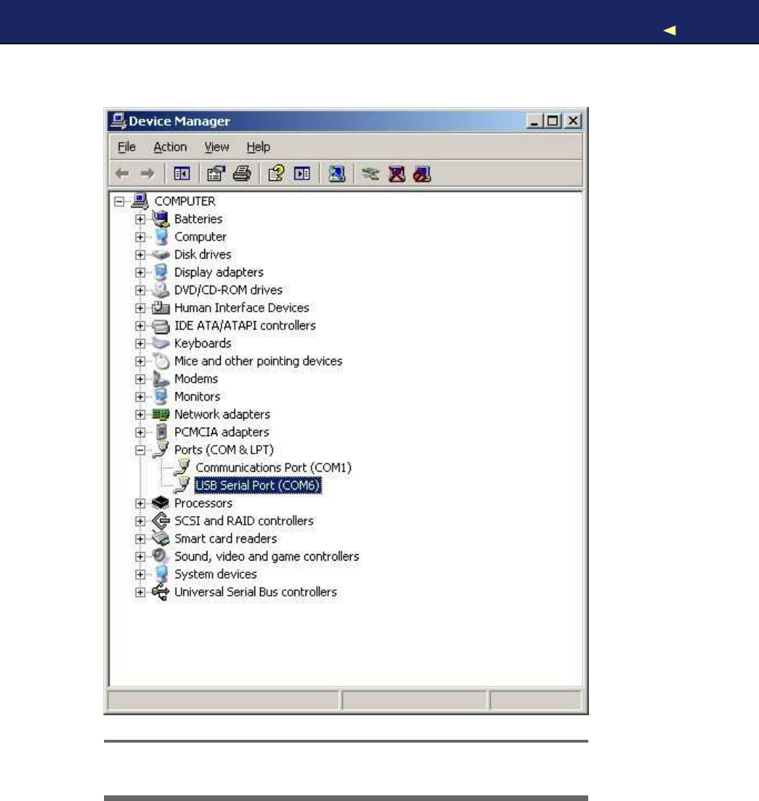
On W i n d o w s systems, it’s abit more complicated to find out the right
serial port, but it’s still not difficult. Go to the Device Manager, and
look for USB Serial Port below the Ports (COM &LPT) menu entry (see
Figure 1.9,on the following page). Usually the port is named COM1,
COM2, or something similar.
After you have chosen the right serial port, click the V e r i f y button, and
you should see the following output in the IDE’s message area (the
Arduino IDE calls programs sketches):
Binary sketch size: 1010 bytes (of a32256 byte maximum)
This means the IDE has successfully compiled the source code into
1,010 bytes of machine code that we can upload to the Arduino. If you
see an error message instead, check whether you have typed in the
program correctly (when in doubt, download the code from the book’s
website).12Depending on the Arduino board you’re using, the byte max-
imum may differ. On an Arduino Duemilanove, it’s usually 14336, for
example.
Now click the Upload button, and after a few seconds, you should see
the following output in the message area:
Binary sketch size: 1010 bytes (of a32256 byte maximum)
This is exactly the same message we got after compiling the program,
and it tells us that the 1,010 bytes of machine code were transferred
successfully to the Arduino. In case of any errors, check whether you
have selected the correct Arduino type and the correct serial port in the
Tools menu.
During the upload process, the TX and RX LEDs will flicker for afew
seconds. This is normal, and it happens whenever the Arduino and
your computer communicate via the serial port. When the Arduino
sends information, it turns on the TX LED. When it gets some bits,
it turns on the RX LED. Because the communication is pretty fast, the
LEDs start to flicker, and you cannot identify the transmission of a
single byte (if you can, you are probably an alien).
12. http://www.pragprog.com/titles/msard
Report erratum
this copy is (P1.0 printing, Ja nu ra r y, 2011)
Download from Wow! eBook <www.wowebook.com>

WORKING WITH LEDS41
Figure 1.10: What’s happening on pin 13 while the LED blinks.
As soon as the code has been transmitted completely, the Arduino exe-
cutes it. In our case, this means the status LED starts to blink. It turns
on for half asecond, then it turns off for half asecond, and so on.
In Figure 1.10,you can see adiagram showing the activity on the pin
while the program is running. The pin starts in LOW state and does not
output any current. W e set it to HIGH in the software using digitalWrite( )
and let it output 5volts for 500 milliseconds. Finally, we set it back to
LOW for 500 milliseconds and repeat the whole process.
Admittedly, the status LED does not look very spectacular. So, in the
next section, we’ll attach a “real” LED to the Arduino.
1.7 W o r k i n g with LEDs
The LEDs that come with the Arduino are nice for testing purposes, but
you should not use them in your own electronics projects. They all have
aspecific meaning, and it’s bad style to use them in adifferent context.
Also, they are very small and not very bright, so it’s agood idea to get
some additional LEDs and learn how to connect them to the Arduino.
It’s really easy.
W e will not use the same type of LEDs that are mounted on the Arduino
board. They are surface-mounted devices (SMD) that are difficult to
handle. Y o u will rarely work with SMD parts, because for most of them
you need special equipment and a lot of experience. They save costs
as soon as you start mass production of an electronic device, but pure
hobbyists won’t need them often.
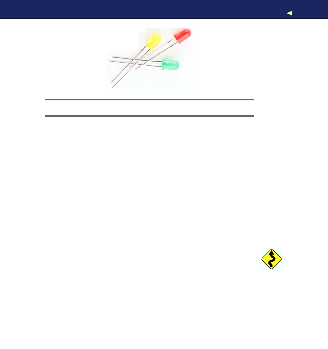
The LEDs that we need are through-hole parts; you can see some in
Figure 1.11,on the following page. They are named through-hole parts
because they are mounted to acircuit board through holes. That’s
Report erratum
this copy is (P1.0 printing, Ja nu ra r y, 2011)
Download from Wow! eBook <www.wowebook.com>
WORKING WITH LEDS42
Figure 1.11: Acollection of through-hole LEDs
why they usually have one or more long wires. First you put the wires
through holes in aprinted circuit board. Then you usually bend, sol-
der, and cut them to attach the part to the board. Where available, you
can also plug them into sockets as we have them on the Arduino or
on breadboards (you’ll learn more about breadboards in Section 3.2,
W o r k i n g with Breadboards,on page 64).
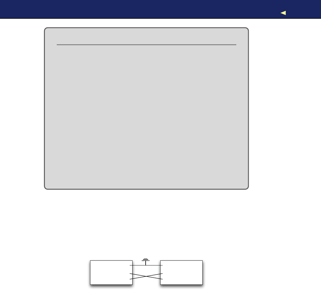
In Figure 1.12,on the following page, you can see how to attach an
LED to an Arduino. Put the short connector of the LED to the ground
pin (GND) and the longer one to pin 13. Y o u can do that while the blink
sketch is still running. Both the status LED and the external LED will
start to blink.
Make absolutely sure that you’re using pin 13! If you connect the LED
to any other pin, it will probably be destroyed. The reason is that pin
13 has an internal resistor that the other pins don’t have (you’ll learn
more about this in Chapter 3,Building Binary Dice,on page 63).
That’s it! Y o u ’ v e just added your first external electronics part to your
Arduino, and you have created your first physical computing project.
Y o u ’ v e written some code, and it makes the world abit brighter. Y o u r
very own digital version of “fiat lux.”13
Y o u will need the theory and skills you have learned in this chapter
for nearly every Arduino project. In the next chapter, you’ll see how to
gain more control over LEDs, and you’ll learn how to benefit from more
advanced features of the Arduino IDE.
13. http://en.wikipedia.org/wiki/Fiat_lux
Report erratum
this copy is (P1.0 printing, Ja nu ra r y, 2011)
Download from Wow! eBook <www.wowebook.com>

WHAT IFITDOESN’TWORK?43
Figure 1.12: Connect an LED to the Arduino.
1.8 What If It Doesn’t W o r k ?
Don’t panic! If it doesn’t work, you’ve probably attached the LED in the
wrong way. When assembling an electronics project, parts fall into two
categories: those you can mount any way you like and those that need
aspecial direction. An LED has two connectors: an anode (positive)
and a cathode (negative). It’s easy to mix them up, and my science
teacher taught me the following mnemonic: the cathode is necative. It’s
also easy to remember what the negative connector of an LED is: it is
shorter, minus, less than. If you are a more positive person, then think
of the anode as being bigger plus more. Y o u can alternatively identify a
LED’s connectors using its case. On the negative side the case is flat,
while it’s round on the positive side.
Report erratum
this copy is (P1.0 printing, Ja nu ra r y, 2011)
Download from Wow! eBook <www.wowebook.com>

EXERCISES 44
Choosing the wrong serial port or Arduino type also is acommon mis-
take. If you get an error message such as “Serial port already in use”
when uploading asketch, check whether you have chosen the right
serial port from the Tools >Serial Port menu. If you get messages
such as “Problem uploading to board” or “programmer is not respond-
ing,” check whether you have chosen the right Arduino board from the
Tools >Board menu.
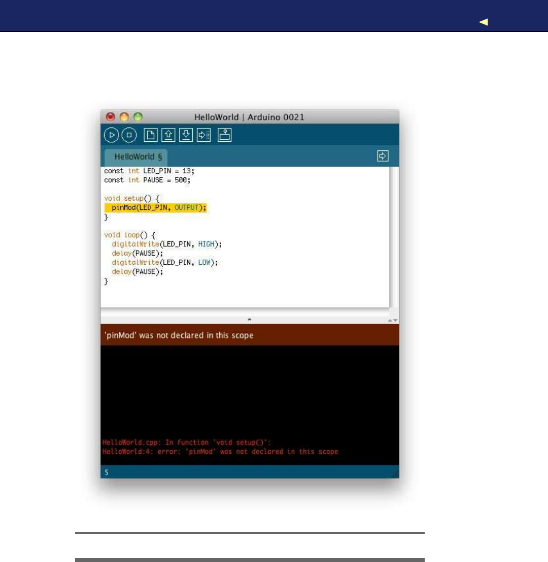
Y o u r Arduino programs, like all programs, will contain bugs. Typos and
syntax errors will be detected by the compiler. In Figure 1.13,on the fol-
lowing page, you can see atypical error message. Instead of pinMode(),
we called pinMod(), and because the compiler did not find afunction
having that name, it stopped with an error message. The Arduino IDE
highlights the line, showing the error with ayellow background, and
prints ahelpful error message.
Other bugs might be more subtle and sometimes you have to care-
fully study your code and use some plain old debugging techniques (in
Debug It! Find, Repair, and Prevent Bugs in Y o u r Code [But09]you can
find plenty of useful advice on this topic).
It might happen—although it’s rare—that you actually have adamaged
LED. If none of the tricks mentioned helps, try another LED.
1.9 Exercises
•Trydifferent blink patterns using more pauses and vary the pause
length (they don’t necessarily have to be all the same). Also, exper-
iment with very short pauses that make the LED blink at a high
frequency. Can you explain the effect you’re observing?
•Let the LED output your name in Morse code.14
14. http://en.wikipedia.org/wiki/Morse_code
Report erratum
this copy is (P1.0 printing, Ja nu ra r y, 2011)
Download from Wow! eBook <www.wowebook.com>

Chapter 2
Inside the Arduino
For simple applications, all you have learned about the Arduino IDE in
the preceding chapter is sufficient. But soon your projects will get more
ambitious, and then it will come in handy to split them into separate
files that you can manage as a whole. So in this chapter, you’ll learn
how to stay in control over bigger projects with the Arduino IDE.
Usually, bigger projects need not only more software but also more
hardware—you will rarely use the Arduino board in isolation. For exam-
ple, you will use many more sensors than you might imagine, and you’ll
have to transmit the data they measure back to your computer. To
exchange data with the Arduino, you’ll use its serial port. This chapter
explains everything you need to know about serial communication. To
make things more tangible, you’ll learn how to turn your computer into
avery expensive light switch that lets you control an LED using the
keyboard.
2.1 What Y o u Need
To try this chapter’s examples, you need only afew things:
•An Arduino board such as the Uno, Duemilanove, or Diecimila
• A USB cable to connect the Arduino to your computer
•An LED (optional)
• A software serial terminal such as Putty (for W i n d o w s users) or
screen for Linux and Mac OS Xusers (optional)
Download from Wow! eBook <www.wowebook.com>

MANAGINGPROJECTS AND SKETCHES 47
2.2 Managing Projects and Sketches
Modern software developers can choose from avariety of development
tools that automate repetitive and boring tasks. That’s also true for
embedded systems like the Arduino. Y o u can use integrated develop-
ment environments (IDEs) to manage your programs, too. The most
popular one has been created by the Arduino team.
The Arduino IDE manages all files belonging to your project. It also pro-
vides convenient access to all the tools you need to create the binaries
that will run on your Arduino board. Conveniently, it does so unob-
trusively. For example, you might have noticed that the Arduino IDE
stores all code you enter automatically. This is to prevent beginners
from losing data or code accidentally (not to mention that even the pros
lose data from time to time, too).
Organizing all the files belonging to aproject automatically is one of
the most important features of an IDE. Under the hood, the Arduino
IDE creates adirectory for every new project, and it stores all the files
belonging to the project in this directory. To add new files to aproject,
click the tabs button on the right to open the tabs pop-up menu, and
then choose New Tab (see Figure 2.1). To add an existing file, use the
Sketch >Add File menu item.
As you might have guessed already from the names of the menu items,
the Arduino IDE calls projects sketches.If you do not choose aname,
it gives them aname starting with sketch_.Y o u can change the name
whenever you like using the Save As command. If you do not save a
sketch explicitly, the IDE stores it in apredefined folder you can look
Figure 2.1: The tabs menu in action
Report erratum
this copy is (P1.0 printing, Ja nu ra r y, 2011)
Download from Wow! eBook <www.wowebook.com>

CHANGING PREFERENCES 48
up in the preferences menu. Y o u can change this behavior so that the
IDE asks you for aname when you create anew sketch. Whenever you
get lost, you can check what folder the current sketch is in using the
Sketch >Show Sketch Folder menu item.
The IDE uses directories not only to organize projects. It also stores
some interesting things in the following folders:
•The examples folder contains sample sketches that you can use as
abasis for your own experiments. Get to them via the File >Open
dialog box. Take some time to browse through them, even if you
do not understand anything you see right now.
•The libraries directory contains libraries for various purposes and
devices. Whenever you use anew sensor, for example, chances are
good that you have to copy asupporting library to this folder.
The Arduino IDE makes your life easier by choosing reasonable defaults
for alot of settings. But it also allows you to change most of these
settings, and you’ll see how in the next section.
2.3 Changing Preferences
For your early projects, the IDE’s defaults might be appropriate, but
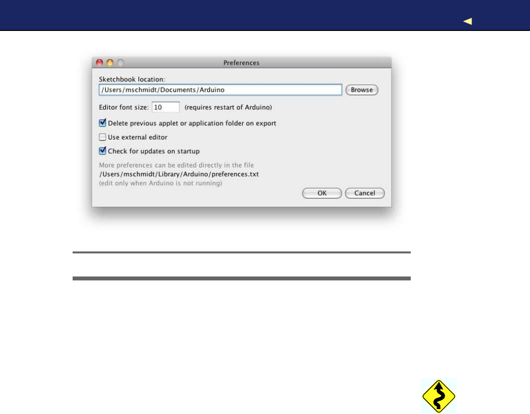
sooner or later you’ll want to change some things. As you can see in
Figure 2.2,on the following page, the IDE lets you change only afew
preferences directly. But the dialog box refers to afile named prefer-
ences.txt containing more preferences. This file is aJava properties file
consisting of key/value pairs. Here you see afew of them:
...
editor.external.bgcolor=#168299
preproc.web_colors=true
editor.font.macosx=Monaco,plain,10
sketchbook.auto_clean=true
update.check=true
build.verbose=true
upload.verbose=true
...
Most of these properties control the user interface; that is, they change
fonts, colors, and so on. But they can also change the application’s
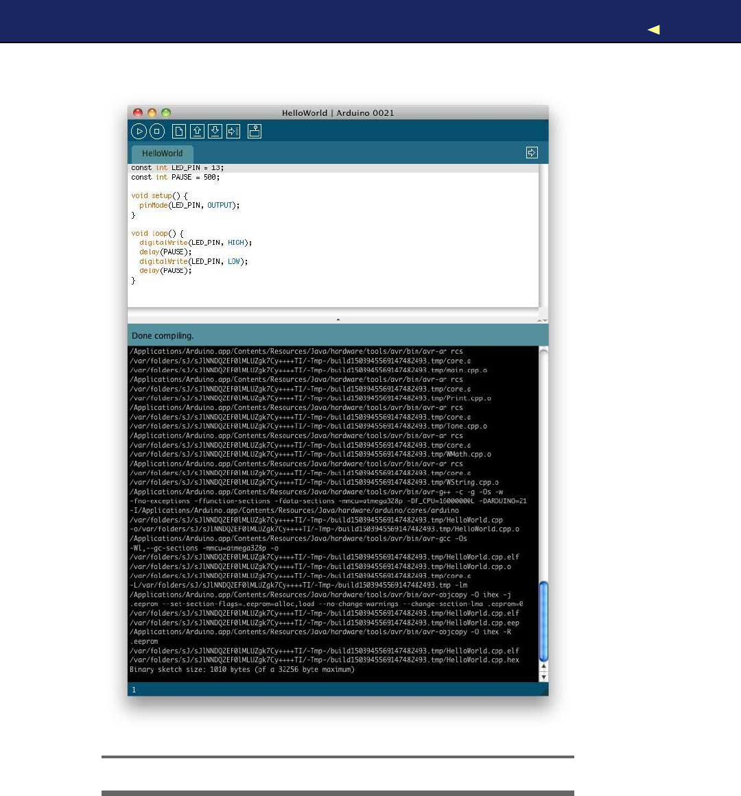
behavior. For example, you can enable more verbose output for opera-
tions such as compiling or uploading asketch. Edit preferences.txt, and
set both build.verbose and upload.verbose to true.Then load the blinking
LED sketch from Chapter 1,W e l c o m e to the Arduino,on page 23 and
Report erratum
this copy is (P1.0 printing, Ja nu ra r y, 2011)
Download from Wow! eBook <www.wowebook.com>
USINGSERIAL PORTS 49
Figure 2.2: The IDE lets you change some preferences.
compile it again. The output in the message panel should look similar
to Figure 2.3,on the following page (in recent versions of the IDE, you
can achieve the same effect by holding down the Shift key when you
click the V e r i f y / C o m p i l e or Upload button in the toolbar).
Note that the IDE updates some of the preferences’ values when it
shuts down. So before you change any preferences directly in the pref-
erences.txt file, you have to stop the Arduino IDE first.
Now that you’re familiar with the Arduino IDE, let’s do some program-
ming. W e ’ l l make the Arduino talk to the outside world.
2.4 Using Serial P o r t s
Arduino makes many stand-alone applications possible—projects that
do not involve any additional computers. In such cases you need to con-
nect the Arduino to acomputer once to upload the software, and after
that, it needs only apower supply. More often, people use the Arduino
to enhance the capabilities of acomputer using sensors or by giving
access to additional hardware. Usually, you control external hardware
via aserial port, so it is agood idea to learn how to communicate seri-
ally with the Arduino.
Report erratum
this copy is (P1.0 printing, Ja nu ra r y, 2011)
Download from Wow! eBook <www.wowebook.com>
USINGSERIAL PORTS 51
The Arduino Programming Language
P e o p l e sometimes seem to be a bit irritated when it comes to
the language the Arduino gets programmed in. That’s m a i n l y
because the typical sample sketches look as if they w e r e writ-
ten in alanguage that has been exclusively designed f o r pro-
gramming the Arduino. But that’s not the case—it is plain old
C++ (which implies that it supports C, too).
Every Arduino uses an A V R microcontroller designed b y acom-
pany named Atmel. (Atmel says that the name A V R does not
stand f o r anything.) These microcontrollers are v e r y popular,
and m a n y hardware projects use them. One of the reasons
f o r their popularity is the excellent tool chain that comes with
them. It is based on the GNU C++ compiler tools and has been
optimized f o r generating code f o r A V R microcontrollers.
That means y o u f e e d C++ code to the compiler that is not
translated into m a c h i n e code f o r y o u r computer but f o r an A V R
microcontroller. This technique is called cross-compiling and is
the usual w a y to program embedded devices.
Although the standards for serial communication have changed over
the past few years (for example, we are using USB today, and our com-
puters no longer have RS232 connectors), the basic working principles
remain the same. In the simplest case, we can connect two devices
using only three wires: acommon ground, aline for transmitting data
(TX), and one for receiving data (RX).
Device #1
GND
TX
RX
Device #2
GND
TX
RX
Serial communication might sound abit old-school, but it’s still the
preferred way for hardware devices to communicate. For example, the
Sin USB stands for “serial”—and when was the last time you saw a
parallel port? (Perhaps this is agood time to clean up the garage and
throw out that old PC that you wanted to turn into amedia center
someday....)
Report erratum
this copy is (P1.0 printing, Ja nu ra r y, 2011)
Download from Wow! eBook <www.wowebook.com>

USINGSERIAL PORTS 52
For uploading software, the Arduino has aserial port, and we can use it
to connect the Arduino to other devices, too (in Section 1.6,Compiling
and Uploading Programs,on page 38,you learn how to look up the
serial port your Arduino is connected to). In this section, we will use
it to control Arduino’s status LED using our computer’s keyboard. The
LED should be turned on when you press 1, and it should be turned
off when you press 2. Here’s all the code we need:
Download we l c o m e / Le dS wi tc h / L e d S w it ch .p de
Line 1const unsigned int LED_PIN =13;
-const unsigned int BAUD_RATE =9600;
-
-void setup() {
5pinMode(LED_PIN, OUTPUT);
-Serial.begin(BAUD_RATE);
-}
-
-void loop() {
10 if (Serial.available() >0) {
-int command =Serial.read();
-if (command == '1') {
-digitalWrite(LED_PIN, HIGH);
-Serial.println(
"LED on"
);
15 }else if (command == '2') {
-digitalWrite(LED_PIN, LOW);
-Serial.println(
"LED off"
);
-}else {
-Serial.print(
"Unknown command: "
);
20 Serial.println(command);
-}
-}
-}
As in our previous examples, we define aconstant for the pin the LED
is connected to and set it to OUTPUT mode in the setup( ) function. In
line 6, we initialize the serial port using the begin( ) function of the Serial
class, passing abaud rate of 9600 (you can learn what abaud rate is in
Section C.1,Learning More About Serial Communication,on page 251).
That’s all we need to send and receive data via the serial port in our
program.
So, let’s read and interpret the data. The loop( ) function starts by calling
Serial’s available( ) method in line 10. available( ) returns the number of
bytes waiting on the serial port. If any data is available, we read it
using Serial.read(). read( ) returns the first byte of incoming data if data
is available and -1 otherwise.
Report erratum
this copy is (P1.0 printing, Ja nu ra r y, 2011)
Download from Wow! eBook <www.wowebook.com>

USINGSERIAL PORTS 53
F a s h i o n a b l e LEDs
Both pervasive and w e a r a b l e computing got v e r y popular o v e r
the past y e a r s , so T - s h i r t s with an equalizer are still cool but not
that exciting any longer.∗But b y using a f e w LEDs, y o u can cre-
ate some astonishing accessories f o r the ladies. For example,
J a p a n e s e engineers have created LED e y e l a s h e s . †
This particular product does not use an Arduino, but with the
Lilypad,‡y o u can easily create similar things y o u r s e l f . Y o u have
to be extremely careful with LEDs, because most of them are
v e r y bright and can cause serious damage to y o u r e y e s !
∗.http://www.thinkgeek.com/tshirts-apparel/interactive/8a5b/
†.http://blog.makezine.com/archive/2009/10/led_eyelashes.html
‡.http://www.arduino.cc/en/Main/ArduinoBoardLilyPad
If the byte we have read represents the character 1, we switch on the
LED and send back the message “LED on” over the serial port. W e use
Serial.println(), which adds a carriage return character (ASCII code 13)
followed by anewline (ASCII code 10) to the text.
If we received the character 2, we switch off the LED. If we received an
unsupported command, we send back acorresponding message and
the command we did not understand. Serial.print( ) works exactly like
Serial.println(), but it does not add carriage return and newline characters
to the message.
Let’s see how the program works in practice. Compile it, upload it to
your Arduino, and then switch to the serial monitor (optionally you can
attach an LED to pin 13; otherwise, you can only control the Arduino’s
status LED). At first glance, nothing has happened. That’s because we
have not sent acommand to the Arduino yet. Enter a 1 in the text box,
and then click the Send button. Two things should happen now: the
LED is switched on, and the message “LED on” appears in the serial
monitor window (see Figure 2.4,on the next page). W e are controlling a
LED using our computer’s keyboard!
Play around a bit with the commands 1 and 2, and also observe what
happens when you send an unknown command. If you type in an
uppercase A,for example, the Arduino will send back the message
“Unknown command: 65.” The number 65 is the ASCII code of the let-
ter A, and the Arduino outputs the data it got in its most basic form.
Report erratum
this copy is (P1.0 printing, Ja nu ra r y, 2011)
Download from Wow! eBook <www.wowebook.com>
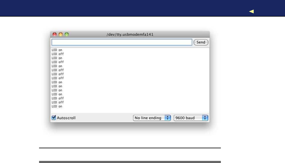
USINGSERIAL PORTS 54
Figure 2.4: The Arduino IDE’s serial monitor
That’s the default behavior of Serial’s print( ) method, and you can change
it by passing aformat specifier to your function calls. To see the effect,
replace line 20 with the following statements:
Serial.println(command, DEC);
Serial.println(command, HEX);
Serial.println(command, OCT);
Serial.println(command, BIN);
Serial.println(command, BYTE);
The output looks as follows when you send the character Aagain:
Unknown command: 65
41
101
1000001
A
Depending on the format specifier, Serial.println( ) automatically converts
abyte into another representation. DEC outputs abyte as a decimal
number, HEX as a hexadecimal number, and so on. Note that such an
operation usually changes the length of the data that gets transmitted.
The binary representation of the single byte 65, for example, needs 7
bytes, because it contains seven characters.
Report erratum
this copy is (P1.0 printing, Ja nu ra r y, 2011)
Download from Wow! eBook <www.wowebook.com>

USINGSERIAL PORTS 55
Numbering Systems
It’s an evolutionary accident that 10 is the basis for our numbering
system. If we had only four fingers on each hand, it’d be probably eight,
and we’d probably have invented computers afew centuries earlier.
For thousands of years, people have used denominational number sys-
tems, and we represent anumber like 4711 as follows:
4×10³+7×10²+1×101+1×100
This makes arithmetic operations very convenient. But when working
with computers that only interpret binary numbers, it’s often advanta-
geous to use numbering systems based on the numbers 2(binary), 8
(octal), or 16 (hexadecimal).
For example, the decimal number 4711 can be represented in octal and
hexadecimal as follows:
•1×84+1×83+1×82+4×81+7×80=011147
•1×163+2×162+6×161+7×160=0x1267
In Arduino programs, you can define literals for all these numbering
systems:
int decimal =4711;
int binary =B1001001100111;
int octal =011147;
int hexadecimal =0x1267;
Binary numbers start with a B character, octal numbers with a0, and
hexadecimal numbers start with 0x.
Using Different Serial T e r m i n a l s
For trivial applications, the IDE’s serial monitor is sufficient, but you
cannot easily combine it with other applications, and it lacks some
features (for example, it could not send newline characters in older IDE
versions). That means you should have an alternative serial terminal to
send data, and you can find plenty of them for every operating system.
Serial T e r m i n a l s f o r Wi ndows
Putty1is an excellent choice for W i n d o w s users. It is free, and it comes
as an executable that does not even have to be installed. Figure 2.5,on
the following page shows how to configure it for communication on a
serial port.
1. http://www.chiark.greenend.org.uk/~sgtatham/putty/
Report erratum
this copy is (P1.0 printing, Ja nu ra r y, 2011)
Download from Wow! eBook <www.wowebook.com>
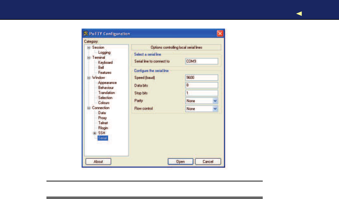
USINGSERIAL PORTS 56
Figure 2.5: Configuring Putty to make it work with Arduino
After you have configured Putty, you can open aserial connection to the
Arduino. In Figure 2.6,on the next page, you can see the corresponding
dialog box. Click Open, and you’ll see an empty terminal window.
Now press 1 and 2 a few times to switch on and off the LED. In Fig-
ure 2.7,on the following page, you can see atypical session.
Serial T e r m i n a l s f o r Linux and Mac OS X
Linux and Mac users can use the screen command to communicate
with the Arduino on aserial port. Check which serial port the Arduino
is connected to (for example, in the IDE’s Tools >Board menu), and
then run acommand like this (with an older board the name of the
serial port might be something like /dev/cu.usbserial-A9007LUY, and on
Linux systems it might be /dev/ttyUSB1 or something similar):
$screen /dev/cu.usbmodemfa141 9600
screen expects the name of the serial port and the baud rate to be used.
In Figure 2.8,on page 58,you can see atypical session. To quit the
screen command, press Ctrl-a followed by Ctrl-k.
Report erratum
this copy is (P1.0 printing, Ja nu ra r y, 2011)
Download from Wow! eBook <www.wowebook.com>
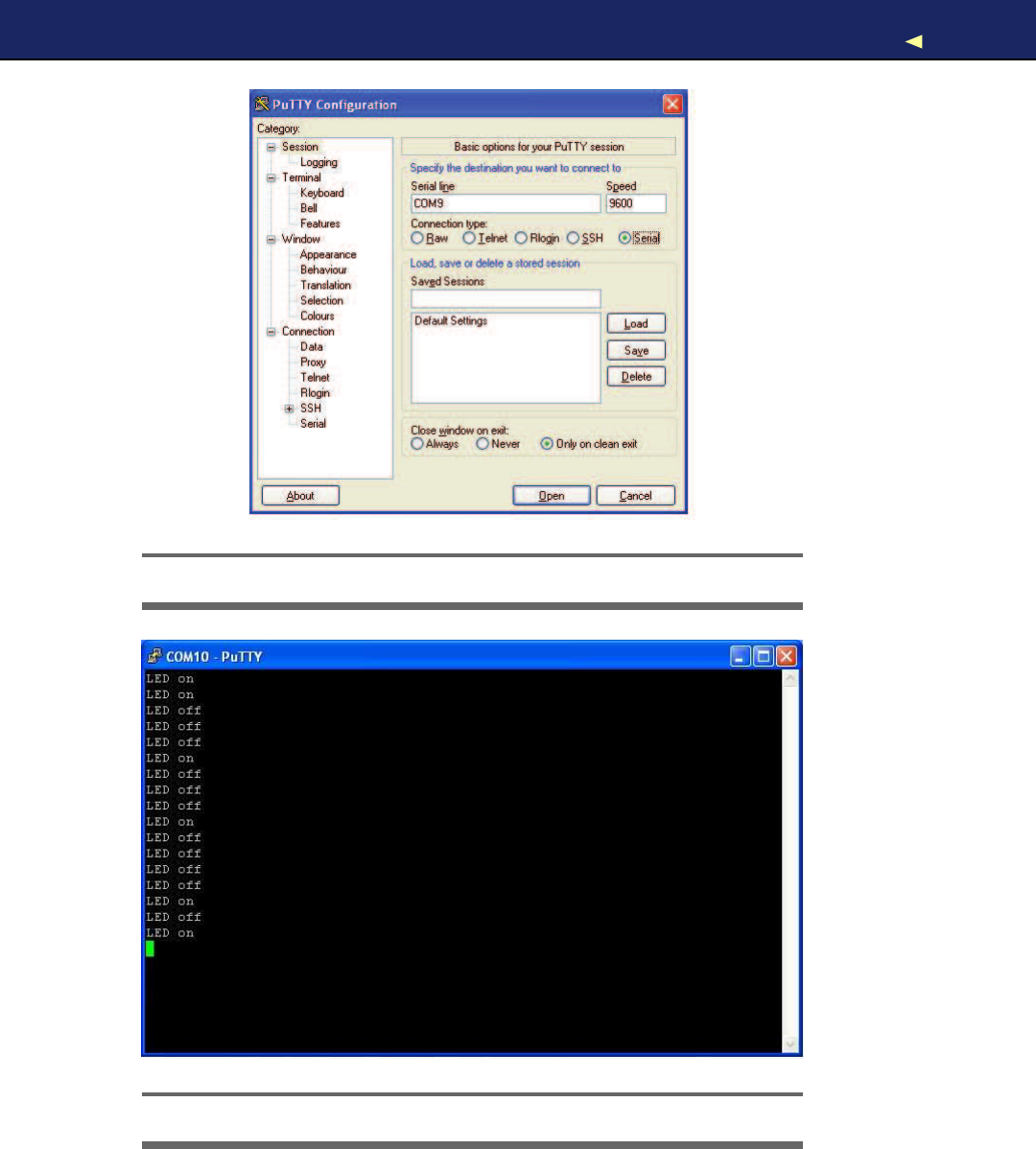
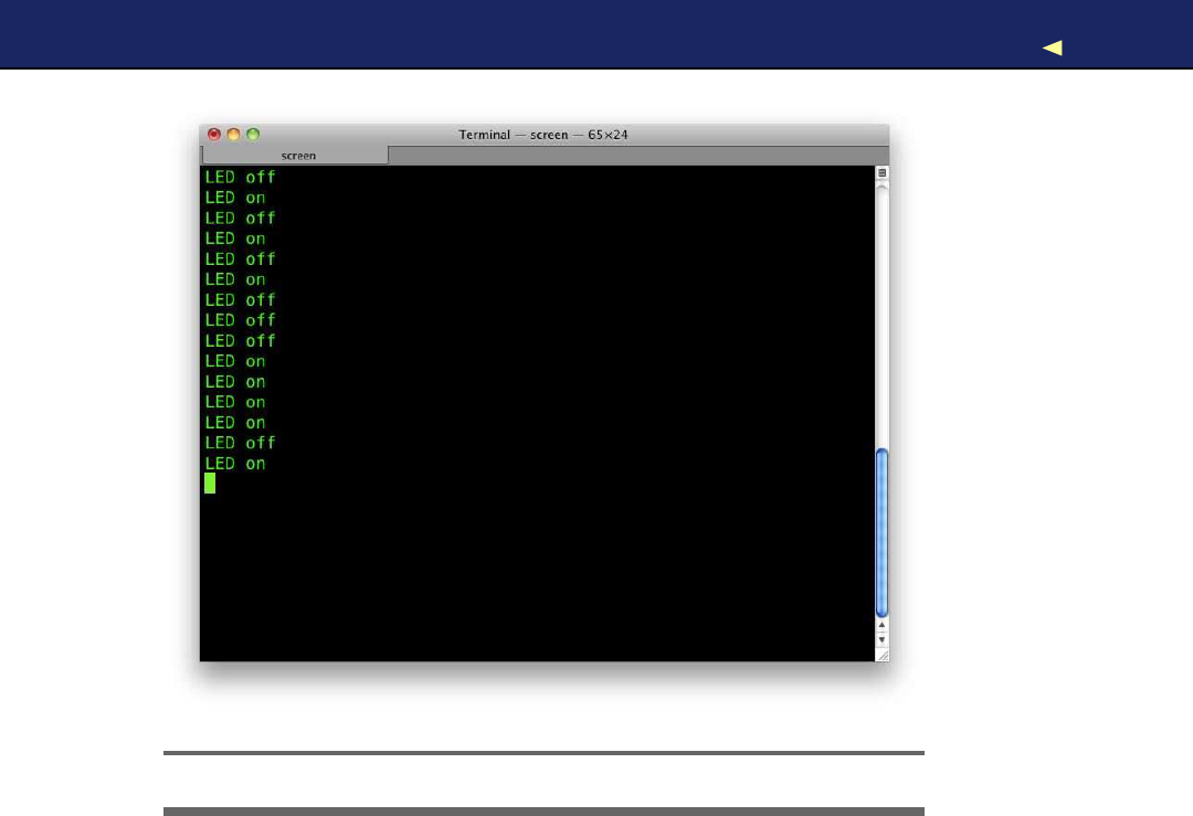
USINGSERIAL PORTS 58
Figure 2.8: The screen command communicates with Arduino.
W e can now communicate with the Arduino, and this has great impli-
cations: whatever is controlled by the Arduino can also be controlled
by your computer, and vice versa. Switching LEDs on and off is not too
spectacular, but try to imagine what’s possible now. Y o u could move
robots, automate your home, or create interactive games.
Here are some more important facts about serial communication:
•The Arduino’s serial receive buffer can hold up to 128 bytes. When
sending large amounts of data at high speed, you have to synchro-
nize sender and receiver to prevent data loss. Usually, the receiver
sends an acknowledgment to the sender whenever it is ready to
consume anew chunk of data.
Report erratum
this copy is (P1.0 printing, Ja nu ra r y, 2011)
Download from Wow! eBook <www.wowebook.com>

USINGSERIAL PORTS 59
Exciting LED Projects
From what y o u have seen in this and the preceding sections,
y o u might think that LEDs are useful but not v e r y exciting. Y o u
can use them f o r showing adevice’s status or e v e n to build a
complete TV set, but that’s something y o u are used to.
But LEDs are the basis f o r some really spectacular projects. One
of the most amazing ones is the BEDAZZLER.∗The BEDAZZLER is
anonlethal w e a p o n that uses blinking LEDs to cause nausea,
dizziness, headache, flash blindness, e y e pain, and v o m i t i n g .
Originally it has been developed f o r the military, but now it is
available as an open source project.†
All scientific curiosity aside, y o u should k e e p in mind that the
BEDAZZLER is aw e a p o n . Do not use it as a toy, and do not target
it at humans or animals.
∗.http://www.instructables.com/id/Bedazzler-DIY-non-lethal-weaponry/
†.http://www.ladyada.net/make/bedazzler/
•Y o u can control many devices using serial communication, but the
regular Arduino has only one serial port. If you need more, take a
look at the Arduino Mega 2560, which has four serial ports.2
• A Universal Asynchronous Receiver/Transmitter (UART)3device
supports serial communication on the Arduino. This device han-
dles serial communication while the CPU can take care of other
tasks. This greatly improves the system’s overall performance.
The UART uses digital pins 0(RX) and 1 (TX), which means you
cannot use them for other purposes when communicating on the
serial port. If you need them, you can disable serial communica-
tion using Serial.end().
•W i t h the SoftwareSerial4library, you can use any digital pin for
serial communication. It has some serious limitations regarding
speed and reliability, and it does not support all functions that
are available when using aregular serial port.
2. http://arduino.cc/en/Main/ArduinoBoardMega2560
3. http://en.wikipedia.org/wiki/UART
4. http://www.arduino.cc/en/Reference/SoftwareSerial
Report erratum
this copy is (P1.0 printing, Ja nu ra r y, 2011)
Download from Wow! eBook <www.wowebook.com>
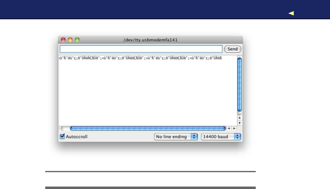
WHAT IFITDOESN’TWORK?60
Figure 2.9: Awrong baud rate creates alot of garbage.
In this chapter, you saw how to communicate with the Arduino using
the serial port, which opens the door to awhole new world of physical
computing projects (see Section C.1,Learning More About Serial Com-
munication,on page 251 for more details about serial communication).
In the next chapters, you’ll learn how to gather interesting facts about
the real world using sensors, and you’ll learn how to change the real
world by moving objects. Serial communication is the basis for letting
you control all these actions using the Arduino and your PC.
2.5 What If It Doesn’t W o r k ?
If anything goes wrong with the examples in this chapter, you should
take alook at Section 1.8,What If It Doesn’t W o r k ? ,on page 43 first.
If you still run into problems, it may be because of some issues with
serial communication. For example, you might have set the wrong baud
rate; in Figure 2.9,you can see what’s happening in such acase.
Make sure that the baud rate you have set in your call to Serial.begin( )
matches the baud rate in the serial monitor.
Report erratum
this copy is (P1.0 printing, Ja nu ra r y, 2011)
Download from Wow! eBook <www.wowebook.com>

EXERCISES 61
2.6 Exercises
•Add new commands to the sample program. For example, the com-
mand 3could make the LED blink for awhile.
•Tryto make the commands more readable; that is, instead of 1,
use the command on, and instead of 2, use off.
If you have problems solving this exercise, read Chapter 4,Build-
ing a Morse Code Generator Library,on page 88 first.
Report erratum
this copy is (P1.0 printing, Ja nu ra r y, 2011)
Download from Wow! eBook <www.wowebook.com>
Part II
Eight Arduino Projects
Download from Wow! eBook <www.wowebook.com>

Chapter 3
Building Binary Dice
Things will really start to get interesting now that you’ve learned the
basics of Arduino development. Y o u now have the skills to create your
first complex, stand-alone projects. After you have worked through this
chapter, you’ll know how to work with LEDs, buttons, breadboards,
and resistors. Combining these parts with an Arduino gives you nearly
endless opportunities for new and cool projects.
Our first project will be creating an electronic die. While regular dice
display their results using one to six dots, ours will use LEDs instead.
For our first experiments, asingle LED has been sufficient, but for
the dice we need more than one. Y o u need to connect several external
LEDs to the Arduino. Because you cannot attach them all directly to
the Arduino, you’ll learn how to work with breadboards. Also, you need
abutton that rolls the dice, so you’ll learn how to work with pushbut-
tons, too. To connect pushbuttons and LEDs to the Arduino, you need
another important electronic part: the resistor. So, at the end of the
chapter, you’ll have many new tools in your toolbox.
3.1 What Y o u Need
1. Ahalf-size breadboard
2. Three LEDs (for the exercises you’ll need additional LEDs)
3. Two 10kΩresistors (see Section A.1,Current, V o l t a g e , and Resis-
tance,on page 237 to learn more about resistors)
4. Three 1kΩresistors
5. Two pushbuttons
6. Some wires
Download from Wow! eBook <www.wowebook.com>
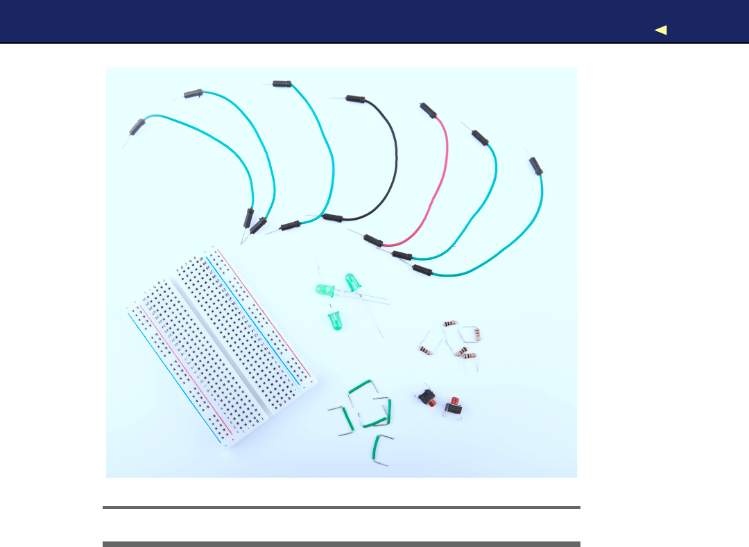
WORKING WITH BREADBOARDS 64
!
"
#$
%
&
&
Figure 3.1: All the parts you need for this chapter
7. An Arduino board such as the Uno, Duemilanove, or Diecimila
8. AUSB cable to connect the Arduino to your computer
9. Atilt sensor (optional)
Figure 3.1 shows the parts needed to build the projects in this chapter.
Y o u ’ l l find such photos in most of the following chapters. The numbers
in the photo correspond to the numbers in the parts list. The photos do
not show standard parts such as the Arduino board or an USB cable.
3.2 W o r k i n g with Breadboards
Connecting parts such as LEDs directly to the Arduino is only an option
in the most trivial cases. Usually, you will prototype your projects on a
breadboard that you connect to the Arduino. Abreadboard “emulates”
Report erratum
this copy is (P1.0 printing, Ja nu ra r y, 2011)
Download from Wow! eBook <www.wowebook.com>

WORKING WITH BREADBOARDS 65
Figure 3.2: Acollection of breadboards
acircuit board. Y o u don’t have to solder parts to the board; instead,
you can simply plug them into it.
Breadboards come in various types and sizes (in Figure 3.2,you can
see two of them), but they all work the same way. They have alot of
sockets that you can use for plugging in through-hole parts or wires.
That alone wouldn’t be abig deal, but the sockets are connected in a
special way. In Figure 3.3,on the next page, you can see how.
As you can see, most sockets are connected in columns. If one socket
of acolumn is connected to apower supply, then automatically all the
other sockets in this column are powered, too. On the bigger board
in the photo, you can also see four rows of connected sockets. This
is convenient for bigger circuits. Usually, you connect one row to your
power supply and one to the ground. This way, you can distribute power
and ground to any point on the board. Now let’s see how to put parts
on abreadboard.
Report erratum
this copy is (P1.0 printing, Ja nu ra r y, 2011)
Download from Wow! eBook <www.wowebook.com>
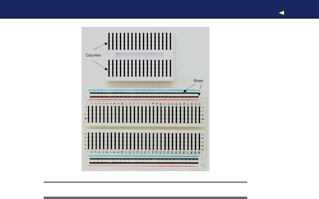
USINGANLED ONABREADBOARD 66
Figure 3.3: How sockets on abreadboard are connected
3.3 Using an LED on aBreadboard
Up to now, we used the LEDs that are installed on the Arduino board,
and we connected one LED directly to the Arduino. In this section, we’ll
plug an LED into abreadboard and then connect the breadboard to the
Arduino.
In Figure 3.4,on the following page, you can see aphoto of our final cir-
cuit. It consists of an Arduino, abreadboard, an LED, three wires, and a
1kΩresistor (more on that part in afew minutes). Connect the Arduino
to the breadboard using two wires. Connect pin 12 with the ninth col-
umn of the breadboard, and connect the ground pin with the tenth
column. This automatically connects all sockets in column 9to pin 12
and all sockets in column 10 to the ground. This choice of columns was
arbitrary, and you could have used other columns instead.
Plug the LED’s negative connector (the shorter one) into column 10 and
its positive connector into column 9. When you plug in parts or wires
into abreadboard, you have to press them firmly until they slip in. Y o u
Report erratum
this copy is (P1.0 printing, Ja nu ra r y, 2011)
Download from Wow! eBook <www.wowebook.com>
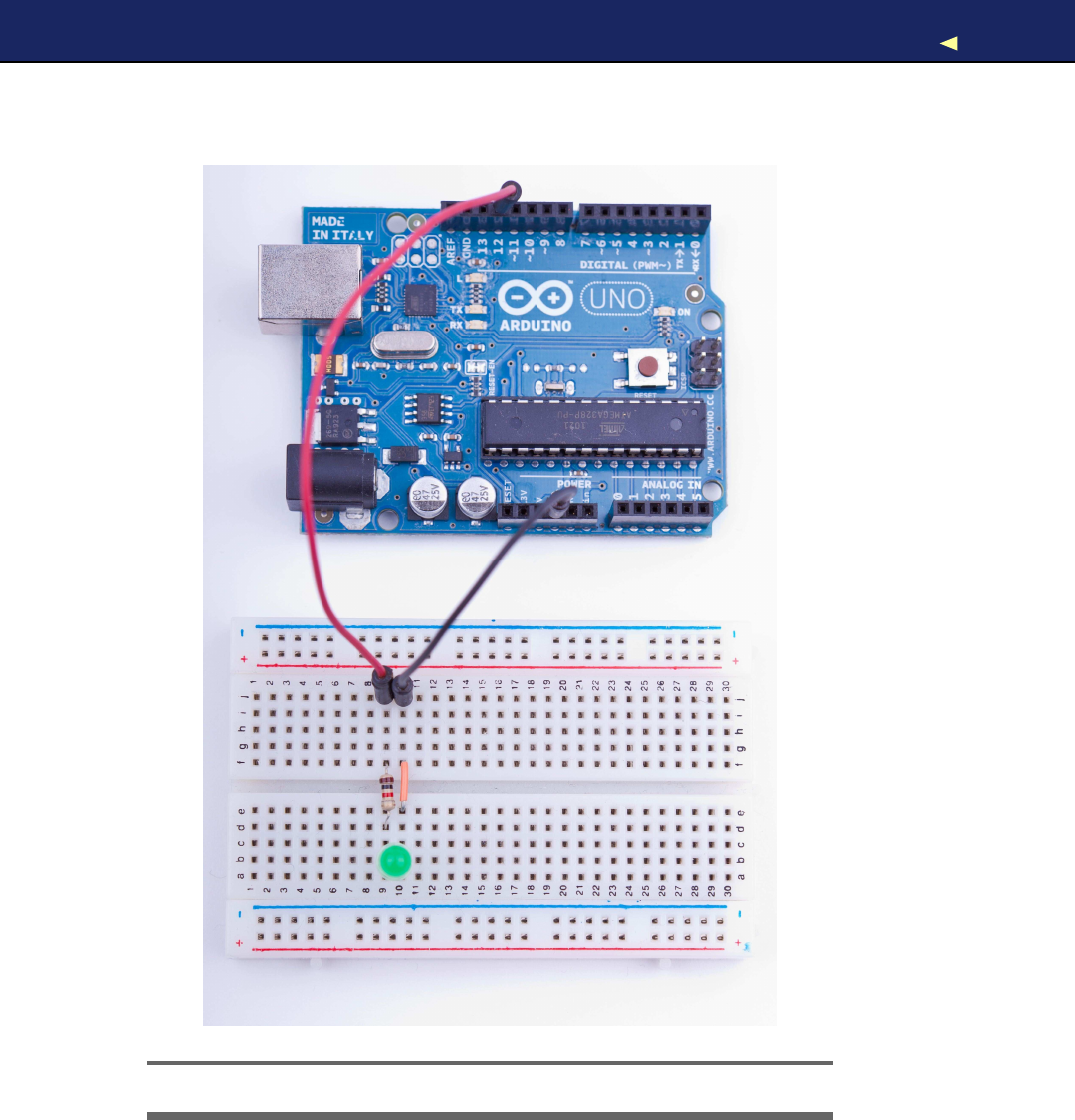
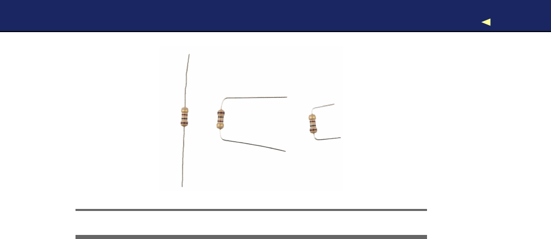
USINGANLED ONABREADBOARD 68
Figure 3.5: Aresistor in various processing stages
might need more than one try, especially on new boards, and it often
comes in handy to shorten the connectors before plugging them into the
breadboard. Make sure that you can still identify the negative and the
positive connector after you have shortened them. Shorten the negative
one abit more, for example. Also wear safety glasses to protect your
eyes when cutting the connectors!
The things we have done until now have been straightforward. That is,
in principle we have only extended the Arduino’s ground pin and its
IO pin number 12. Why do we have to add a resistor, and what is a
resistor? Aresistor limits the amount of current that flows through an
electric connection. In our case, it protects the LED from consuming too
much power, because this would destroy the LED. Y o u always have to
use aresistor when powering an LED! In Section A.1,Current, V o l t a g e ,
and Resistance,on page 237,you can learn more about resistors and
their color bands. In Figure 3.5,you can see aresistor in various stages:
regular, bent, and cut.
Y o u might ask yourself why we didn’t have to use aresistor when we
connected the LED directly to the Arduino. The answer is simple: pin
13 comes with an internal resistor of 1kΩ.Now that we use pin 12, we
have to add our own resistor.
W e don’t want to fiddle around too much with the connectors, so we
build the circuit as shown in Figure 3.6,on the next page. That is, we
use both sides of the breadboard by connecting them with ashort wire.
Note that the resistor bridges the sides, too.
Report erratum
this copy is (P1.0 printing, Ja nu ra r y, 2011)
Download from Wow! eBook <www.wowebook.com>
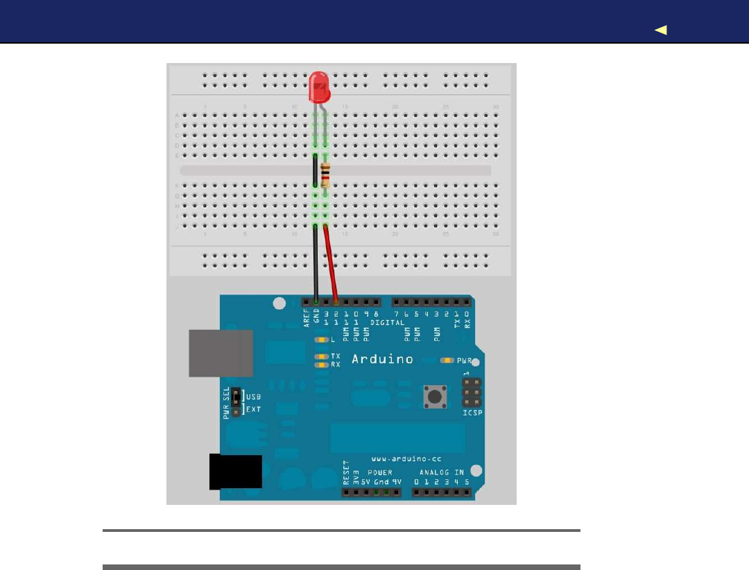
FIRSTVERSION OFABINARYDIE 69
Figure 3.6: Y o u can use both sides of abreadboard.
3.4 First V e r s i o n of aBinary Die
Y o u ’ r e certainly familiar with regular dice displaying results in arange
from one to six. To emulate such dice exactly with an electronic device,
you’d need seven LEDs and some fairly complicated business logic.
W e ’ l l take ashortcut and display the result of adie roll in binary.
For abinary die, we need only three LEDs that represent the current
result. W e turn the result into abinary number, and for every bit that is
set, we will light up acorresponding LED. The following diagram shows
how the die results are mapped to LEDs (a black triangle stands for a
shining LED).
Report erratum
this copy is (P1.0 printing, Ja nu ra r y, 2011)
Download from Wow! eBook <www.wowebook.com>
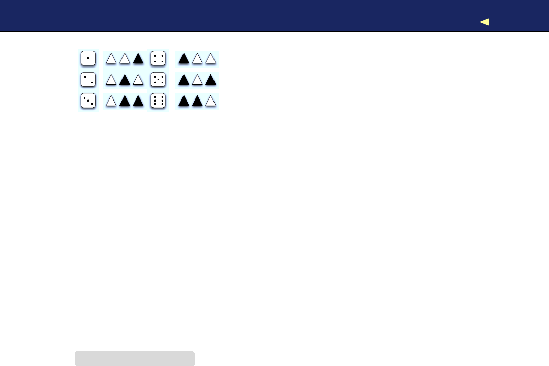
FIRSTVERSION OFABINARYDIE 70
=
=
=
=
=
=
W e already know how to control asingle LED on abreadboard. Con-
trolling three LEDs is similar and requires only more wires, LEDs, 1kΩ
resistors, and pins. In Figure 3.7,on the following page, you can see
the first working version of abinary die.
The most important difference is the common ground. When you need
ground for asingle LED, you can connect it to the LED directly. But
we need ground for three LEDs now, so we’ll use the breadboard’s rows
for the first time. Connect the row marked with ahyphen (-) to the
Arduino’s ground pin, and all sockets in this row will work as ground
pins, too. Then you can connect this row’s sockets to the LEDs using
short wires.
Everything else in this circuit should look familiar, because we only had
to clone the basic LED circuit from the previous section three times.
Note that we have connected the three circuits to pins 10, 11, and 12.
The only thing missing is some software:
Download BinaryDice/BinaryDice.pde
Line 1const unsigned int LED_BIT0 =12;
-const unsigned int LED_BIT1 =11;
-const unsigned int LED_BIT2 =10;
-
5void setup() {
-pinMode(LED_BIT0, OUTPUT);
-pinMode(LED_BIT1, OUTPUT);
-pinMode(LED_BIT2, OUTPUT);
-
10 randomSeed(analogRead(A0));
-long result =random(1, 7);
-output_result(result);
-}
-
15 void loop() {
-}
-
-void output_result(const long result) {
-digitalWrite(LED_BIT0, result &B001);
20 digitalWrite(LED_BIT1, result &B010);
-digitalWrite(LED_BIT2, result &B100);
-}
Report erratum
this copy is (P1.0 printing, Ja nu ra r y, 2011)
Download from Wow! eBook <www.wowebook.com>
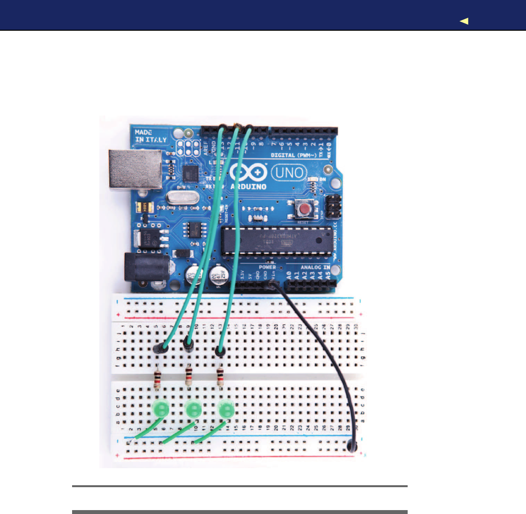

FIRSTVERSION OFABINARYDIE 72
More LEDs, Dice, and Cubes
Building binary dice is fun, and it’s an easy project e v e n f o r
beginners. But what about the opposite—reading real dice?
Steve Hoefer∗has built a dice reader using an Arduino, and
it’s really impressive. He uses five pairs of infrared emitters
and receivers to “scan” adie’s surface. It’s af a i r l y advanced
project, and y o u can learn alot from it.
Another interesting project is an LED cube: building a cube con-
sisting of LEDs.†It’s surprisingly difficult to control more than a
f e w LEDs, but y o u can produce astonishing results.
∗.http://grathio.com/2009/08/dice-reader-version-2.html
†.http://arduinofun.com/blog/2009/12/02/led-cube-and-arduino-lib-build-it/
This is all the code we need to implement the first version of binary
dice. As usual, we define some constants for the output pins the LEDs
are connected to. In the setup( ) function, we set all the pins into OUTPUT
mode. For the dice, we need random numbers in the range between one
and six. The r a n d o m ( ) function returns random numbers in aspecified
range using apseudorandom number generator. In line 10, we initialize
the generator with some noise we read from analog input pin A0 (see
the sidebar on the next page to learn why we have to do that). Y o u might
wonder where the constant A0 is from. Since version 19, the Arduino
IDE defines constants for all analog pins named A0,A1, and so on.
Then we actually generate anew random number between one and six
and output it using the output_result( ) function. (the seven in the call to
r a n d o m ( ) is correct, because it expects the upper limit plus one).
The function output_result( ) takes anumber and outputs its lower three
bits by switching on or off our three LEDs accordingly. Here we use the
&operator and binary literals. The &operator takes two numbers and
combines them bitwise. When two corresponding bits are 1, the result
of the &operator is 1, too. Otherwise, it is 0. The Bprefix allows you to
put binary numbers directly into your source code. For example, B11 is
the same as 3.
Y o u might have noticed that the loop( ) function was left empty, and
you might wonder how such dice work. It’s pretty simple: whenever
you restart the Arduino, it outputs anew number, and to roll the dice
again, you have to press the reset button.
Report erratum
this copy is (P1.0 printing, Ja nu ra r y, 2011)
Download from Wow! eBook <www.wowebook.com>

FIRSTVERSION OFABINARYDIE 73
Generating Random Numbers
Some computing problems are surprisingly difficult, and cre-
ating good r a n d o m numbers is one of them. After all, one
of the most important properties of acomputer is determinis-
tic behavior. Still, w e often need—at least seemingly—random
behavior f o r av a r i e t y of purposes, r a n g i n g from ga m e s to cryp-
tographic algorithms.
The most popular approach (used in Arduino’s r a n d o m ( ) func-
tion, f o r example) is to create pseudorandom numbers.∗They
seem to be r a n d o m , but they actually are the result of af o r -
m u l a . Different kinds of algorithms exist, but usually each new
pseudorandom number is calculated from its predecessors.
This implies that y o u need an initialization v a l u e to create the
first r a n d o m number of the sequence. This initialization v a l u e
is called ar a n d o m seed, and to create different sequences
of pseudorandom numbers, y o u have to use different r a n d o m
seeds.
Creating pseudorandom numbers is cheap, but if y o u know the
algorithm and the r a n d o m seed, y o u can easily predict them.
So, y o u shouldn’t use them f o r cryptographic purposes.
In the real w o r l d , y o u can find countless r a n d o m processes, and
with the Arduino, it’s easy to measure them to create real r a n -
dom numbers. Often it’s sufficient to read some r a n d o m noise
from analog pin 0 and pass it as the r a n d o m seed to the r a n -
domSeed( ) function. Y o u can also use this noise to create real
r a n d o m numbers; there is e v e n alibrary f o r that purpose.†
If y o u need strong r a n d o m numbers, the Arduino is a perfect
device f o r creating them. Y o u can find m a n y projects that
observe natural processes solely to create r a n d o m numbers.
One of them w a t c h e s an hourglass using the Arduino, f o r exam-
ple.‡
∗.http://en.wikipedia.org/wiki/Pseudo-random_numbers
†.http://code.google.com/p/tinkerit/wiki/TrueRandom
‡.http://www.circuitlake.com/usb-hourglass-sand-timer.html
Report erratum
this copy is (P1.0 printing, Ja nu ra r y, 2011)
Download from Wow! eBook <www.wowebook.com>
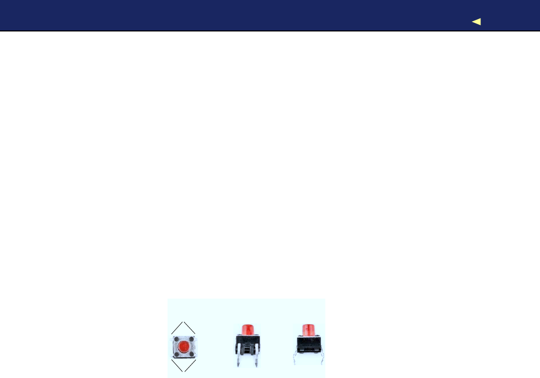
WORKING WITH BUTTONS 74
Compile the code, upload it to the Arduino, and play abit with your
binary dice. Y o u have mastered your first advanced electronics project!
Enjoy it for amoment!
So, whenever you want to see anew result, you have to reset the
Arduino. That’s probably the most pragmatic user interface you can
build, and for afirst prototype, this is OK. But often you need more
than one button, and it’s also more elegant to add your own button
anyway. So, that’s what we’ll do in the next section.
3.5 W o r k i n g with Buttons
In this section, we’ll add our own pushbutton to our binary dice, so
we no longer have to abuse the Arduino’s reset button to roll the dice.
W e ’ l l start small and build acircuit that uses apushbutton to control
asingle LED.
So, what exactly is apushbutton? Here are three views of atypical
pushbutton that can be used as the Arduino’s reset button.
Connected
Connected
T o p Front Side
It has four connectors that fit perfectly on abreadboard (at least after
you have straightened them with apair of pliers). Two opposite pins
connect when the button is pushed; otherwise, they are disconnected.
In Figure 3.8,on the following page, you can see asimple circuit using a
pushbutton. Connect pin 7(chosen completely arbitrarily) to the push-
button, and connect the pushbutton via a10kΩresistor to ground.
Then connect the 5volts power supply to the other pin of the button.
All in all, this approach seems straightforward, but why do we need a
resistor again? The problem is that we expect the pushbutton to return
adefault value (LOW)in case it isn’t pressed. But when the button isn’t
pressed, it would not be directly connected to ground and would flicker
because of static and interference. Alittle bit of current flows through
the resistor, and this helps prevent random noise from changing the
voltage that the input pin sees.
Report erratum
this copy is (P1.0 printing, Ja nu ra r y, 2011)
Download from Wow! eBook <www.wowebook.com>
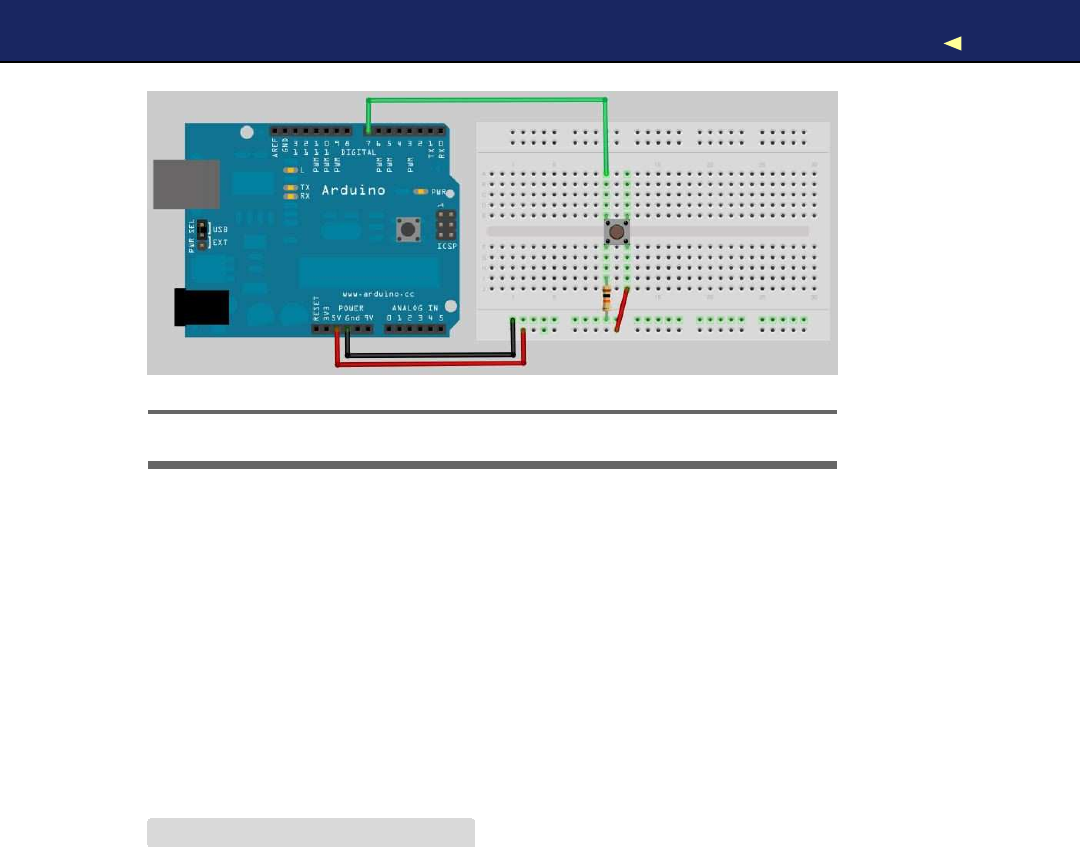
WORKING WITH BUTTONS 75
Figure 3.8: Asimple pushbutton circuit
When the button is pressed, there will still be 5volts at the Arduino’s
digital pin, but when the button isn’t pressed, it will cleanly read the
connection to ground. W e call this apull-down r e s i s t o r ; a pull-up r e s i s t o r
works exactly the other way around. That is, you have to connect the
Arduino’s signal pin to power through the pushbutton and connect the
other pin of the pushbutton to ground using aresistor.
Now that we’ve eliminated all this ugly unstable real-world behavior, we
can return to the stable and comforting world of software development.
The following program checks whether apushbutton is pressed and
lights an LED accordingly:
Download BinaryDice/SimpleButton/SimpleButton.pde
const unsigned int BUTTON_PIN =7;
const unsigned int LED_PIN =13;
void setup() {
pinMode(LED_PIN, OUTPUT);
pinMode(BUTTON_PIN, INPUT);
}
void loop() {
const int BUTTON_STATE =digitalRead(BUTTON_PIN);
if (BUTTON_STATE == HIGH)
digitalWrite(LED_PIN, HIGH);
else
digitalWrite(LED_PIN, LOW);
}
Report erratum
this copy is (P1.0 printing, Ja nu ra r y, 2011)
Download from Wow! eBook <www.wowebook.com>

WORKING WITH BUTTONS 76
W e connect the button to pin 7 and the LED to pin 13 and initialize the
pins accordingly in the setup( ) function. In loop(), we read the current
state of the pin connected to the button. If it is HIGH,we turn the LED
on. Otherwise, we turn it off.
Upload the program to the Arduino, and you’ll see that the LED is on
as long as you press the button. As soon as you release the button,
the LED turns off. This is pretty cool, because now we nearly have
everything we need to control our dice using our own button. But before
we proceed, we’ll slightly enhance our example and turn the button into
areal light switch.
To build alight switch, we start with the simplest possible solution.
Do not change the current circuit, and upload the following program to
your Arduino:
Download BinaryDice/UnreliableSwitch/UnreliableSwitch.pde
Line 1const unsigned int BUTTON_PIN =7;
-const unsigned int LED_PIN =13;
-
-void setup() {
5pinMode(LED_PIN, OUTPUT);
-pinMode(BUTTON_PIN, INPUT);
-}
-
-int led_state =LOW;
10
-void loop() {
-const int CURRENT_BUTTON_STATE =digitalRead(BUTTON_PIN);
-
-if (CURRENT_BUTTON_STATE == HIGH) {
15 led_state =(led_state == LOW) ?HIGH :LOW;
-digitalWrite(LED_PIN, led_state);
-}
-}
W e begin with the usual pin constants, and in setup( ) we set the modes
of the pins we use. In line 9, we define aglobal variable named led_state
to store the current state of our LED. It will be LOW when the LED is
on and HIGH otherwise. In loop(), we check the button’s current state.
When we press the button, its state switches to HIGH, and we toggle the
content of led_state.That is, if led_state was HIGH, we set it to LOW, and
vice versa. At the end, we set the physical LED’s state to our current
software state accordingly.
Our solution is really simple, but unfortunately, it does not work. Play
around with it abit, and you’ll quickly notice some annoying behavior.
Report erratum
this copy is (P1.0 printing, Ja nu ra r y, 2011)
Download from Wow! eBook <www.wowebook.com>

WORKING WITH BUTTONS 77
If you press the button, for example, the LED sometimes will turn on
and then off immediately. Also, if you release it, the LED will often
remain in amore or less arbitrary state; that is, sometimes it will be on
and sometimes off.
The problem is that the Arduino executes the loop( ) method over and
over again. Although the Arduino’s CPU is comparatively slow, this
would happen very often—no matter if we currently press the button
or not. But if you press it and keep it pressed, its state will constantly
be HIGH, and you’d constantly toggle the LED’s state (because this hap-
pens so fast it seems like the LED’s constantly on). When you release
the button, the LED is in amore or less arbitrary state.
To improve the situation, we have to store not only the LED’s current
state but also the pushbutton’s previous state:
Download BinaryDice/MoreReliableSwitch/MoreReliableSwitch.pde
const unsigned int BUTTON_PIN =7;
const unsigned int LED_PIN =13;
void setup() {
pinMode(LED_PIN, OUTPUT);
pinMode(BUTTON_PIN, INPUT);
}
int old_button_state =LOW;
int led_state =LOW;
void loop() {
const int CURRENT_BUTTON_STATE =digitalRead(BUTTON_PIN);
if (CURRENT_BUTTON_STATE != old_button_state &&
CURRENT_BUTTON_STATE == HIGH)
{
led_state =(led_state == LOW) ?HIGH :LOW;
digitalWrite(LED_PIN, led_state);
}
old_button_state =CURRENT_BUTTON_STATE;
}
After initializing the button and LED pins, we declare two variables
now: old_button_state stores the previous state of our pushbutton, and
led_state stores the LED’s current state. Both can be either HIGH or LOW.
In the loop( ) function, we still have to read the current button state,
but now we not only check whether it is HIGH. W e also check whether
it has changed since the last time we read it. Only when both conditions
are met do we toggle the LED’s state. So, we no longer turn the LED
Report erratum
this copy is (P1.0 printing, Ja nu ra r y, 2011)
Download from Wow! eBook <www.wowebook.com>
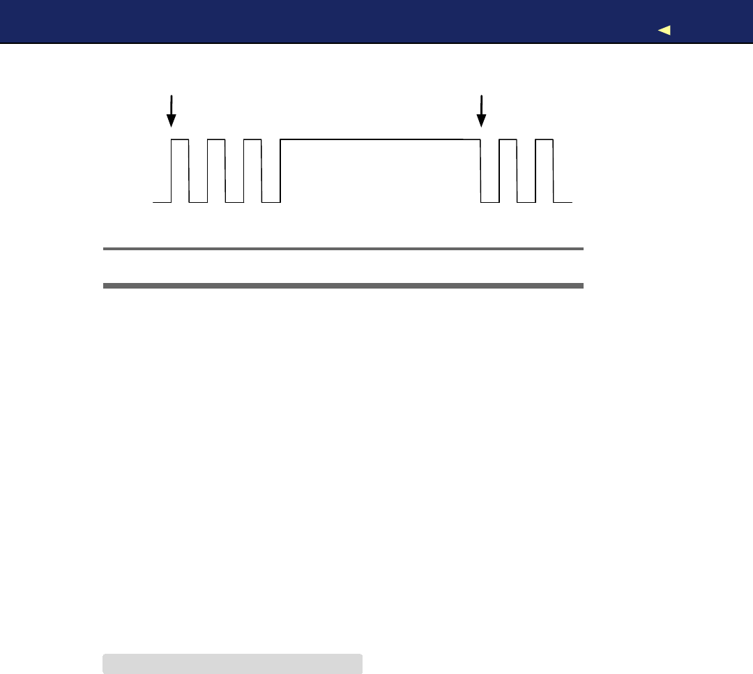
WORKING WITH BUTTONS 78
Button pressed Button released
5 V
0 V
Figure 3.9: Mechanical switches have to be debounced.
on and off over and over again as long as the button is pressed. At
the end of our program, we have to store the button’s current state in
old_button_state.
Upload our new version, and you’ll see that this solution works much
better than our old one. But you will still find some edge cases when
the button does not fully behave as expected. Problems mainly occur in
the moment you release the button.
The cause of these problems is that mechanical buttons bounce for a
few milliseconds when you press them. In Figure 3.9,you can see a
typical signal produced by amechanical button. Right after you have
pressed the button, it doesn’t emit aclear signal. To overcome this
effect, you have to debounce the button. It’s usually sufficient to wait
ashort period of time until the button’s signal stabilizes. Debouncing
makes sure that we react only once to apush of the button. In addition
to debouncing, we still have to store the current state of the LED in a
variable. Here’s how to do that:
Download BinaryDice/DebounceButton/DebounceButton.pde
Line 1const unsigned int BUTTON_PIN =7;
-const unsigned int LED_PIN =13;
-
-void setup() {
5pinMode(LED_PIN, OUTPUT);
-pinMode(BUTTON_PIN, INPUT);
-}
-
-int old_button_state =LOW;
10 int led_state =LOW;
-
Report erratum
this copy is (P1.0 printing, Ja nu ra r y, 2011)
Download from Wow! eBook <www.wowebook.com>

ADDING OUROWNBUTTON 79
-void loop() {
-const int CURRENT_BUTTON_STATE =digitalRead(BUTTON_PIN);
-if (CURRENT_BUTTON_STATE != old_button_state &&
15 CURRENT_BUTTON_STATE == HIGH)
-{
-led_state =(led_state == LOW) ?HIGH :LOW;
-digitalWrite(LED_PIN, led_state);
-delay(50);
20 }
-old_button_state =CURRENT_BUTTON_STATE;
-}
This final version of our LED switch differs from the previous one in
only asingle line: to debounce the button, we wait for 50 milliseconds
in line 19 before we enter the main loop again.
This is everything you need to know about pushbuttons for now. In the
next section, we’ll use two buttons to turn our binary dice into areal
game.
3.6 Adding Our Own Button
Up to now, we had to abuse the Arduino’s reset button to control the
dice. This solution is far from optimal, so we’ll add our own buttons. In
Figure 3.10,on page 81,you can see that we need to change our cur-
rent circuit only slightly. Actually, we don’t have to change the existing
parts at all; we only need to add some things. First we plug abutton
into the breadboard and connect it to pin 7. Then we connect the but-
ton to the ground via a10kΩresistor and use asmall piece of wire to
connect it to the 5volts pin. That’s all the hardware we need. Here’s the
corresponding software:
Download BinaryDice/DiceWithButton/DiceWithButton.pde
const unsigned int LED_BIT0 =12;
const unsigned int LED_BIT1 =11;
const unsigned int LED_BIT2 =10;
const unsigned int BUTTON_PIN =7;
void setup() {
pinMode(LED_BIT0, OUTPUT);
pinMode(LED_BIT1, OUTPUT);
pinMode(LED_BIT2, OUTPUT);
pinMode(BUTTON_PIN, INPUT);
randomSeed(analogRead(A0));
}
int current_value =0;
Report erratum
this copy is (P1.0 printing, Ja nu ra r y, 2011)
Download from Wow! eBook <www.wowebook.com>

BUILDINGADICEGAME 80
int old_value =0;
void loop() {
current_value =digitalRead(BUTTON_PIN);
if (current_value != old_value && current_value == HIGH) {
output_result(random(1, 7));
delay(50);
}
old_value =current_value;
}
void output_result(const long result) {
digitalWrite(LED_BIT0, result &B001);
digitalWrite(LED_BIT1, result &B010);
digitalWrite(LED_BIT2, result &B100);
}
That’s aperfect merge of the original code and the code needed to con-
trol adebounced button. As usual, we initialize all pins we use: three
output pins for the LEDs and one input pin for the button. W e also
initialize the random seed, and in the loop( ) function we wait for new
button presses. Whenever the button gets pressed, we roll the dice and
output the result using the LEDs. W e ’ v e replaced the reset button with
our own!
Now that we know how easy it is to add a pushbutton, we’ll add another
one in the next section to turn our simple dice into agame.
3.7 Building aDice Game
Turning our rudimentary dice into afull-blown game requires adding
another pushbutton. W i t h the first one we can still roll the dice, and
with the second one we can program aguess. When we roll the dice
again and the current result equals our guess, the three LEDs on the
die will blink. Otherwise, they will remain dark.
To enter aguess, press the guess button the right number of times.
If you think the next result will be a3, for example, press the guess
button three times and then press the start button.
To add another button to the circuit, do exactly the same thing as for
the first one. In Figure 3.11,on page 82,you can see that we have
added yet another button circuit to the breadboard. This time we’ve
connected it to pin 5.
Report erratum
this copy is (P1.0 printing, Ja nu ra r y, 2011)
Download from Wow! eBook <www.wowebook.com>
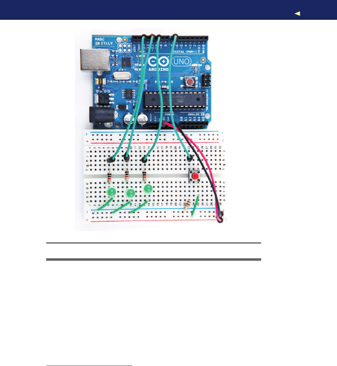
BUILDINGADICEGAME 81
Figure 3.10: Our binary dice with its own start button
Now we need some code to control the new button, and you might be
tempted to copy it from our last program. After all, we copied the hard-
ware design also, right? In the real world, some redundancy is totally
acceptable, because we actually need two physical buttons, even if they
are in principle the same. In the world of software, redundancy is ano-
go, so we won’t copy our debounce logic but use alibrary1that was writ-
ten for this purpose. Download the library, and unpack its content into
~/Documents/Arduino/libraries (on aMac) or My Documents\Arduino\libraries
(on aW i n d o w s box). Usually that’s all you have to do, but it never
1. http://www.arduino.cc/playground/Code/Bounce
Report erratum
this copy is (P1.0 printing, Ja nu ra r y, 2011)
Download from Wow! eBook <www.wowebook.com>
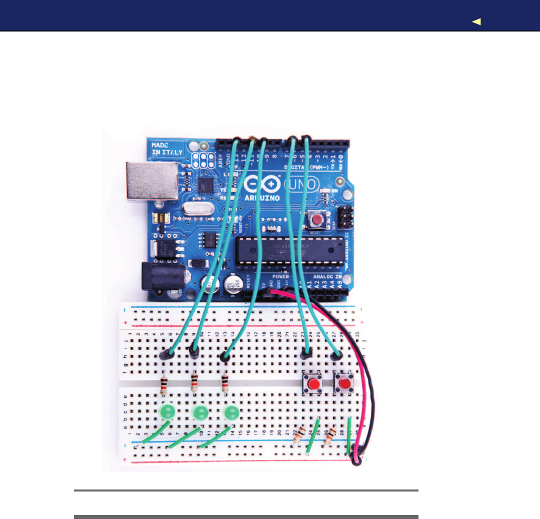

BUILDINGADICEGAME 83
hurts to read the installation instructions and documentation on the
web page.
Here’s the final version of our binary dice code:
Download BinaryDice/DiceGame/DiceGame.pde
Line 1#include <Bounce.h>
-
-const unsigned int LED_BIT0 =12;
-const unsigned int LED_BIT1 =11;
5const unsigned int LED_BIT2 =10;
-const unsigned int START_BUTTON_PIN =5;
-const unsigned int GUESS_BUTTON_PIN =7;
-const unsigned int BAUD_RATE =9600;
-
10 void setup() {
-pinMode(LED_BIT0, OUTPUT);
-pinMode(LED_BIT1, OUTPUT);
-pinMode(LED_BIT2, OUTPUT);
-pinMode(START_BUTTON_PIN, INPUT);
15 pinMode(GUESS_BUTTON_PIN, INPUT);
-randomSeed(analogRead(A0));
-Serial.begin(BAUD_RATE);
-}
-
20 const unsigned int DEBOUNCE_DELAY =20;
-Bounce start_button(START_BUTTON_PIN, DEBOUNCE_DELAY);
-Bounce guess_button(GUESS_BUTTON_PIN, DEBOUNCE_DELAY);
-int guess =0;
-
25 void loop() {
-handle_guess_button();
-handle_start_button();
-}
-
30 void handle_guess_button() {
-if (guess_button.update()) {
-if (guess_button.read() == HIGH) {
-guess =(guess %6) +1;
-output_result(guess);
35 Serial.print(
"Guess: "
);
-Serial.println(guess);
-}
-}
-}
40
-void handle_start_button() {
-if (start_button.update()) {
-if (start_button.read() == HIGH) {
-const int result =random(1, 7);
45 output_result(result);
Report erratum
this copy is (P1.0 printing, Ja nu ra r y, 2011)
Download from Wow! eBook <www.wowebook.com>

BUILDINGADICEGAME 84
-Serial.print(
"Result: "
);
-Serial.println(result);
-if (guess >0) {
-if (result == guess) {
50 Serial.println(
"You win!"
);
-hooray();
-}else {
-Serial.println(
"You lose!"
);
-}
55 }
-delay(2000);
-guess =0;
-}
-}
60 }
-
-void output_result(const long result) {
-digitalWrite(LED_BIT0, result &B001);
-digitalWrite(LED_BIT1, result &B010);
65 digitalWrite(LED_BIT2, result &B100);
-}
-
-void hooray() {
-for (int i = 0; i < 3; i++) {
70 output_result(7);
-delay(500);
-output_result(0);
-delay(500);
-}
75 }
Admittedly that is alot of code, but we know most of it already, and the
new parts are fairly easy. In the first line, we include the Bounce library
we’ll use later to debounce our two buttons. Then we define constants
for all the pins we use, and in the setup( ) method, we initialize all our
pins and set the random seed. W e also initialize the serial port, because
we’ll output some debug messages.
The Bounce library declares aclass named Bounce, and you have to cre-
ate a Bounce object for every button you want to debounce. That’s what
happens in lines 21 and 22. The constructor of the Bounce class expects
the number of the pin the button is connected to and the debounce
delay in milliseconds. Finally, we declare and initialize avariable named
guess that stores our current guess.
Our loop( ) function has been reduced to two function calls. One is
responsible for dealing with guess button pushes, and the other one
handles pushes of the start button. In handle_guess_button(), we use the
Report erratum
this copy is (P1.0 printing, Ja nu ra r y, 2011)
Download from Wow! eBook <www.wowebook.com>
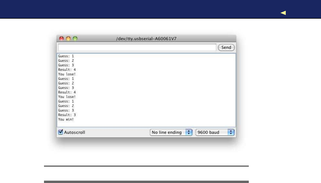
BUILDINGADICEGAME 85
Figure 3.12: W e have awinner!
Bounce class for the first time. To determine the current state of our
guess_button object, we have to call its update( ) method. Afterward, we
read its current status using the read( ) method.
If the button was pressed, its state is set to HIGH, and we increment
the guess variable. To make sure that the guess is always in the range
between 1 and 6, we use the modulus operator (%) in line 33. This
operator divides two values and returns the remainder. For 6, it returns
values between 0 and 5, because when you divide anumber by 6, the
remainder is always between 0 and 5. Add 1to the result, and you get
values between 1 and 6. Finally, we output the current guess using the
three LEDs, and we also print it to the serial port.
The handling of the start button in handle_start_button( ) works exactly
the same as the handling of the guess button. When the start button
was pressed, we calculate anew result and output it on the serial port.
Then we check whether the user has entered aguess (guess is greater
than zero in this case) and whether the user has guessed the right
result. In either case, we print amessage to the serial port, and if the
user guessed right, we also call the hooray( ) method. hooray( ) lets all
three LEDs blink several times.
Report erratum
this copy is (P1.0 printing, Ja nu ra r y, 2011)
Download from Wow! eBook <www.wowebook.com>

WHAT IFITDOESN’TWORK?86
At the end of the method, we wait for two seconds until the game starts
again, and we set back the current guess to zero.
After you’ve uploaded the software to the Arduino, start the IDE’s serial
monitor. It will print the current value of the guess variable whenever
you press the guess button. Press the start button, and the new result
appears. In Figure 3.12,on the preceding page, you can see atypical
output of our binary dice.
In this chapter, you completed your first really complex Arduino project.
Y o u needed abreadboard, LEDs, buttons, resistors, and wires, and you
wrote anontrivial piece of software to make all the hardware come to
life.
In the next chapter, we’ll write an even more sophisticated program for
generating Morse code. Y o u ’ l l also learn how to create your own Arduino
libraries that you can easily share with the rest of the world.
3.8 What If It Doesn’t W o r k ?
Alot of things will probably go wrong when you work with breadboards
for the first time. The biggest problem usually is that you didn’t connect
parts correctly. It takes some time to find the right technique for plug-
ging LEDs, wires, resistors, and buttons into the breadboard. Y o u have
to press firmly but not too hard—otherwise you’ll bend the connectors,
and they won’t fit. It’s usually easier to plug parts in after you’ve short-
ened the connectors. When cutting the connectors, wear safety glasses
to protect your eyes!
While fiddling around with the parts, don’t forget that some of them—
LEDs, for example—need acertain direction. Pushbuttons are candi-
dates for potential problems, too. Take aclose look at the pushbuttons
on page 74 and make sure that you’ve mounted them in the right direc-
tion.
Even simple things such as ordinary wires can lead to problems, espe-
cially if they aren’t the right length. If awire is too short and might
potentially slip out of its socket, replace it immediately. W i r e s are too
cheap to waste your valuable time with unnecessary and annoying
debugging sessions.
Report erratum
this copy is (P1.0 printing, Ja nu ra r y, 2011)
Download from Wow! eBook <www.wowebook.com>

EXERCISES 87
3.9 Exercises
•Binary dice are all very well when you’re playing Monopoly with
your geeky friends, but most people prefer more familiar dice. Try
turning binary dice into decimal dice with seven LEDs. Arrange
the LEDs like the eyes on regular dice.
•The 1kΩresistors we have used to protect our LEDs in this chap-
ter are rather big. Read Section A.1,Resistors,on page 239, and
replace them with smaller ones. Can you see the difference in
brightness?
•LEDs can be used for more than displaying binary dice results.
Provided you have enough LEDs, you can easily build other things,
such as a binary clock.2
Y o u already know enough about electronics and Arduino program-
ming to build your own binary clock. Tryit or think about other
things you could display using afew LEDs.
•Using abutton to roll the dice seems abit awkward, doesn’t it?
Usually, you take dice into both hands and shake them. Y o u can
easily simulate that with atilt sensor.
Tiltsensors detect the tilting of an object and are perfect devices
for simulating the roll of adice. In principle, they work like apush-
button, but you don’t press them—you shake them. Tryto add one
to the binary dice by working your way through the tutorial on the
Arduino website.3
2. http://www.instructables.com/id/LED-Binary-Clock/
3. http://www.arduino.cc/en/Tutorial/TiltSensor
Report erratum
this copy is (P1.0 printing, Ja nu ra r y, 2011)
Download from Wow! eBook <www.wowebook.com>

Chapter 4
Building aMorse Code Generator
Library
Y o u now know enough about the Arduino development environment
and about blinking LEDs to start abigger project. In this chapter, we’ll
develop aMorse code generator that reads text from the serial port and
outputs it as light signals using an LED.
By building this project, you’ll deepen your understanding of serial
communication between the Arduino and your computer. Y o u ’ l l also
learn alot about the typical Arduino development process: how to use
existing libraries and how to structure bigger projects into your own
libraries. At the end, you’ll be able to create alibrary that is ready for
publishing on the Internet.
4.1 What Y o u Need
•An Arduino board such as the Uno, Duemilanove, or Diecimila
• A USB cable to connect the Arduino to your computer
•An LED
• A speaker or abuzzer (they are optional)
4.2 Learning the Basics of Morse Code
Morse code was invented to turn text into sounds.1In principle, it
works like acharacter set encoding such as ASCII. But while ASCII
1. http://en.wikipedia.org/wiki/Morse_Code
Download from Wow! eBook <www.wowebook.com>

BUILDINGAMORSECODE GENERATOR 89
encodes characters as numbers, in Morse code they’re sequences of
dots and dashes (also called dits and dahs). Dits are shorter in length
than dahs. An Ais encoded as ·– and – – · · is Z.
Morse code also specifies atiming scheme that defines the length of the
dits and dahs. It also specifies how long the pauses between symbols
and words have to be. The base unit of Morse code is the length of adit,
and a dah is as long as three dits. Y o u insert apause of one dit between
two symbols, and you separate two letters by three dits. Insert apause
of seven dits between two words.
To transmit amessage encoded in Morse code, you need away to emit
signals of different lengths. The classic approach is to use sounds, but
we will use an LED that is turned on and off for varying periods of time.
Sailors still transmit Morse code using blinking lights.
Let’s implement aMorse code generator!
4.3 Building aMorse Code Generator
The main part of our library will be aC++ class named T e l e g r a p h .In this
section, we’ll define its interface, but we will start with anew sketch
that looks as follows:
Download T e l e g r a p h / T e l e g r a p h . p d e
void setup() {
}
void loop() {
}
This is the most minimalistic Arduino program possible. It does not do
anything except define all mandatory functions, even if they are empty.
W e do this so we can compile our work in progress from time to time
and check whether there are any syntactical errors. Save the sketch as
T e l e g r a p h , and the IDE will create afolder named T e l e g r a p h and a file
named T e l e g r a p h . p d e in it. All the files and directories we need for our
library will be stored in the T e l e g r a p h folder.
Now open anew tab, and when asked for afilename, enter telegraph.h.
Y e s , we will create agood old Cheader file (to be precise, it will even be
aC++ header file). The listing in on the next page.
Report erratum
this copy is (P1.0 printing, Ja nu ra r y, 2011)
Download from Wow! eBook <www.wowebook.com>

BUILDINGAMORSECODE GENERATOR 90
Download T e l e g r a p h / t e l e g r a p h . h
#ifndef __TELEGRAPH_H__
#define __TELEGRAPH_H__
class Telegraph {
public:
Telegraph(const int output_pin, const int dit_length);
void send_message(const char*message);
private:
void dit();
void dah();
void output_code(const char*code);
void output_symbol(const int length);
int _output_pin;
int _dit_length;
int _dah_length;
};
#endif
Ah, obviously object-oriented programming is not only for the big CPUs
anymore! This is an interface description of aT e l e g r a p h class that you
could use in your next enterprise project (provided that you need to
transmit some information as Morse code, that is).
W e start with the classic double-include prevention mechanism; that
is, the body of header file defines apreprocessor macro with the name
__TELEGRAPH_H__.W e wrap the body (that contains this definition) in an
#ifndef,so that the body is only complied if the macro has not been
defined. That way, you can include the header as many times as you
want, and the body will only be compiled once.
The interface of the T e l e g r a p h class consists of apublic part that users
of the class have access to and a private part only members of the class
can use. In the public part, you find two things: aconstructor that
creates new T e l e g r a p h objects and a method named send_message( ) that
sends amessage by emitting it as Morse code. In your applications, you
can use the class as follows:
Telegraph telegraph(13, 200);
telegraph.send_message(
"Hello, world!"
);
In the first line, we create anew T e l e g r a p h object that communicates on
pin 13 and emits dits that are 200 milliseconds long. Then we emit the
message “Hello, world!” as Morse code. This way, we are able to send
Report erratum
this copy is (P1.0 printing, Ja nu ra r y, 2011)
Download from Wow! eBook <www.wowebook.com>

FLESHING OUTTHEGENERATOR’SINTERFACE 91
whatever message we want, and we can change the pin and the length
of adit easily.
Now that we have defined the interface, we will implement it in the next
section.
4.4 Fleshing Out the Generator’s Interface
Declaring interfaces is important, but it’s as important to implement
them. Create anew tab, enter the filename telegraph.cpp, and then
enter the following code:2
Download T e l e g r a p h / t e l e g r a p h . c p p
#include <ctype.h>
#include <WProgram.h>
#include
"telegraph.h"
char*LETTERS[] = {
".-"
,
"-..."
,
"-.-."
,
"-.."
,
"."
,// A-E
"..-."
,
"--."
,
"...."
,
".."
,
".---"
,// F-J
"-.-"
,
".-.."
,
"--"
,
"-."
,
"---"
,// K-O
".--."
,
"--.-"
,
".-."
,
"..."
,
"-"
,// P-T
"..-"
,
"...-"
,
".--"
,
"-..-"
,
"-.--"
,// U-Y
"--.."
// Z
};
char*DIGITS[] ={
"-----"
,
".----"
,
"..---"
,
"...--"
,// 0-3
"....-"
,
"....."
,
"-...."
,
"--..."
,// 4-7
"---.."
,
"----."
// 8-9
};
Like most C++ programs, ours imports some libraries first. Because we
need functions such as toupper( ) later, we include ctype.h. and we have
to include telegraph.h to make our class declaration and its correspond-
ing function declarations available. But what is WProgram.h good for?
Until now we haven’t thought about where constants such as HIGH,
LOW,or OUTPUT came from. They are defined in several header files
that come with the Arduino IDE, and you can find them in the hard-
w a r e / c o r e s / a r d u i n o directory of the IDE. Have alook at WProgram.h, and
2. Older versions of the Arduino IDE have an annoying bug that will prevent you from
creating anew file this way. The IDE claims that a file having the same name already
exists. See http://www.arduino.cc/cgi-bin/yabb2/YaBB.pl?num=1251245246 for aworkaround.
Report erratum
this copy is (P1.0 printing, Ja nu ra r y, 2011)
Download from Wow! eBook <www.wowebook.com>

OUTPUTTING MORSECODE SYMBOLS 92
notice that it includes afile named wiring.h that contains all the con-
stants we have used so far and many more. It also declares many useful
macros and the Arduino’s most basic functions.
When you edit regular sketches, you do not have to worry about includ-
ing any standard header files, because the IDE does it automatically
behind the scenes. As soon as you start to create more complex projects
that contain “real” C++ code, you have to manage everything yourself.
Y o u have to explicitly import all the libraries you need, even for basic
stuff such as the Arduino constants.
After importing all necessary header files, we define two string arrays
named LETTERS and DIGITS.They contain the Morse code for all letters
and digits, and we’ll use them later to translate regular text into Morse
code. Before we do that, we define the constructor that is responsible
for creating and intializing new T e l e g r a p h objects:
Download T e l e g r a p h / t e l e g r a p h . c p p
Telegraph::Telegraph(const int output_pin, const int dit_length) {
_output_pin =output_pin;
_dit_length =dit_length;
_dah_length =dit_length *3;
pinMode(_output_pin, OUTPUT);
}
The constructor expects two arguments: the number of the pin the
Morse code should be sent to and the length of adit measured in mil-
liseconds. Then it stores these values in corresponding instance vari-
ables, calculates the correct length of adah, and turns the communi-
cation pin into an output pin.
Y o u ’ v e probably noticed that all private instance variables start with an
underscore. That is aconvention that Ilike personally. It is not enforced
by C++ or the Arduino IDE.
4.5 Outputting Morse Code Symbols
After everything has been initialized, we can start to output Morse code
symbols. W e use several small helper methods to make our code as
readable as possible:
Download T e l e g r a p h / t e l e g r a p h . c p p
void Telegraph::output_code(const char*code) {
for (int i = 0; i < strlen(code); i++) {
if (code[i] == '.')
Report erratum
this copy is (P1.0 printing, Ja nu ra r y, 2011)
Download from Wow! eBook <www.wowebook.com>

OUTPUTTING MORSECODE SYMBOLS 93
dit();
else
dah();
}
}
void Telegraph::dit() {
Serial.print(
"."
);
output_symbol(_dit_length);
}
void Telegraph::dah() {
Serial.print(
"-"
);
output_symbol(_dah_length);
}
void Telegraph::output_symbol(const int length) {
digitalWrite(_output_pin, HIGH);
delay(length);
digitalWrite(_output_pin, LOW);
}
The function output_code( ) takes aMorse code sequence consisting of
dots and dashes and turns it into calls to dit( ) and dah(). The dit( ) and
dah( ) methods then print adot or adash to the serial port and delegate
the rest of the work to output_symbol(), passing it the length of the Morse
code symbol to be emitted. output_symbol( ) sets the output pin to HIGH
for the length of the symbol, and then it sets it back to LOW. Everything
works exactly as described in the Morse code timing scheme, and only
the implementation of send_message( ) is missing:
Download T e l e g r a p h / t e l e g r a p h . c p p
Line 1void Telegraph::send_message(const char*message) {
-for (int i = 0; i < strlen(message); i++) {
-const char current_char =toupper(message[i]);
-if (isalpha(current_char)) {
5output_code(LETTERS[current_char -'A']);
-delay(_dah_length);
-}else if (isdigit(current_char)) {
-output_code(DIGITS[current_char -'0']);
-delay(_dah_length);
10 }else if (current_char == '') {
-Serial.print(
""
);
-delay(_dit_length *7);
-}
-}
15 Serial.println();
-}
Report erratum
this copy is (P1.0 printing, Ja nu ra r y, 2011)
Download from Wow! eBook <www.wowebook.com>

INSTALLING ANDUSINGTHETELEGRAPH CLASS 94
send_message( ) outputs amessage character by character in aloop. In
line 3, we turn the current character into uppercase, because lower-
case characters are not defined in Morse code (that’s the reason why
you can’t implement achat client using Morse code). Then we check
whether the current character is aletter using C’s isalpha( ) function. If
it is, we use it to determine its Morse code representation that is stored
in the LETTERS array. To do that, we use an old trick: in the ASCII table
all letters (and digits) appear in the right order, that is, A=65, B=66,
and so on. To transform the current character into an index for the LET-
TERS array, we have to subtract 65 (or ’A’)from its ASCII code. When we
have determined the correct Morse code, we pass it to output_symbol( )
and delay the program for the length of adah afterward.
The algorithm works exactly the same for outputting digits; we only
have to index the DIGITS array instead of the LETTERS array, and we have
to subtract the ASCII value of the character 0.
In line 10, we check whether we received ablank character. If yes,
we print ablank character to the serial port and wait for seven dits.
All other characters are ignored: we only process letters, digits, and
blanks. At the end of the method, we send anewline character to the
serial port to mark the end of the message.
4.6 Installing and Using the T e l e g r a p h Class
Our T e l e g r a p h class is complete, and we should now create some exam-
ple sketches that actually use it. This is important for two reasons: we
can test our library code, and for users of our class it’s good documen-
tation for how to use it.
The Arduino IDE looks for libraries in two places: in its global libraries
folder relative to its installation directory and in the user’s local sketch-
book directory. During development it’s best to use the local sketch-
book directory. Y o u can find its location in the IDE’s preferences (see
Figure 4.1,on the next page). Create anew directory named libraries in
the sketchbook directory.
To make our T e l e g r a p h class available, create aT e l e g r a p h subfolder in
the libraries folder. Then copy telegraph.h and telegraph.cpp to that folder
(do not copy T e l e g r a p h . p d e ). Restart the IDE.
Let’s start with the mother of all programs: “Hello, world!” Create anew
sketch named HelloWorld, and enter the following code:
Report erratum
this copy is (P1.0 printing, Ja nu ra r y, 2011)
Download from Wow! eBook <www.wowebook.com>
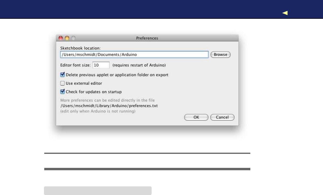
INSTALLING ANDUSINGTHETELEGRAPH CLASS 95
Figure 4.1: Find the sketchbook location in the preferences.
Download T e l e g r a p h / e x a m p l e s / H e l l o W o r l d / H e l l o W o r l d . p d e
#include
"telegraph.h"
const unsigned int OUTPUT_PIN =13;
const unsigned int DIT_LENGTH =200;
Telegraph telegraph(OUTPUT_PIN, DIT_LENGTH);
void setup() {}
void loop() {
telegraph.send_message(
"Hello, world!"
);
delay(5000);
}
This sketch emits the string “Hello, world!” as Morse code every five sec-
onds. To achieve this, we include the definition of our T e l e g r a p h class,
and we define constants for the pin our LED is connected to and for
the length of our dits. Then we create aglobal T e l e g r a p h object and an
empty setup( ) function. In loop(), then we invoke send_message( ) on our
T e l e g r a p h instance every five seconds.
When you compile this sketch, the Arduino IDE automatically compiles
the telegraph library, too. So if you made any syntactical errors in the
library, you’ll be notified now. If you have to correct some errors, make
Report erratum
this copy is (P1.0 printing, Ja nu ra r y, 2011)
Download from Wow! eBook <www.wowebook.com>

INSTALLING ANDUSINGTHETELEGRAPH CLASS 96
sure you change your original source code files. After you’ve fixed the
errors, copy the files to the libraries folder again, and don’t forget to
restart the IDE.
Turning astatic string into Morse code is nice, but wouldn’t it be great
if our program could work for arbitrary strings? So, let’s add a more
sophisticated example. This time, we’ll write code that reads messages
from the serial port and feeds them into aT e l e g r a p h instance. Create a
new sketch named MorseCodeGenerator, and enter the following code:
Download T e l e g r a p h / e x a m p l e s / M o r s e C o d e G e n e r a t o r / M o r s e C o d e G e n e r a t o r . p d e
#include
"telegraph.h"
const unsigned int OUTPUT_PIN =13;
const unsigned int DIT_LENGTH =200;
const unsigned int MAX_MESSAGE_LEN =128;
const unsigned int BAUD_RATE =9600;
const int LINE_FEED =13;
char message_text[MAX_MESSAGE_LEN];
int index =0;
Telegraph telegraph(OUTPUT_PIN, DIT_LENGTH);
void setup() {
Serial.begin(BAUD_RATE);
}
void loop() {
if (Serial.available() >0) {
int current_char =Serial.read();
if (current_char == LINE_FEED || index == MAX_MESSAGE_LEN -1) {
message_text[index] =0;
index =0;
telegraph.send_message(message_text);
}else {
message_text[index++] =current_char;
}
}
}
Again, we include the header file of the T e l e g r a p h class, and as usual we
define some constants: OUTPUT_PIN defines the pin our LED is connected
to, and DIT_LENGTH contains the length of adit measured in milliseconds.
LINE_FEED is set to the ASCII code of the linefeed character. W e need it to
determine the end of the message to be emitted as Morse code. Finally,
we set MAX_MESSAGE_LEN to the maximum length of the messages we
are able to send.
Report erratum
this copy is (P1.0 printing, Ja nu ra r y, 2011)
Download from Wow! eBook <www.wowebook.com>

FINALTOUCHES 97
Next we define three global variables: message_text is acharacter buffer
that gets filled with the data we receive on the serial port. index keeps
track of our current position in the buffer, and telegraph is the T e l e g r a p h
object we’ll use to convert amessage into “blinkenlights.”3
setup( ) initializes the serial port, and in loop( ) we check whether new
data has arrived, calling Serial.available(). W e read the next byte if new
data is available, and we check whether it is alinefeed character or
whether it is the last byte that fits into our character buffer. In both
cases, we set the last byte of message_text to 0, because strings in
C/C++ are null-terminated. W e also reset index so we can read the next
message, and finally we send the message using our telegraph. In all
other cases, we add the latest byte to the current message text and
move on.
Y o u should compile and upload the program now. Open the serial mon-
itor, and choose “Carriage return” from the line endings drop-down
menu at the bottom of the window. W i t h this option set, the serial mon-
itor will automatically append a newline character to every line it sends
to the Arduino. Enter a message such as your name, click the Send
button, and see how the Arduino turns it into light.
Because we’ve encapsulated the whole Morse code logic in the T e l e g r a p h
class, our main program is short and concise. Creating software for
embedded devices doesn’t mean we can’t benefit from the advantages
of object-oriented programming.
Still, we have some minor things to do to turn our project into afirst-
class library. Read more about it in the next section.
4.7 Final T o u c h e s
One of the nice features of the Arduino IDE is its syntax coloring. Class
names, function names, variables, and so on, all have different colors
in the editor. This makes it much easier to read source code, and it’s
possible to add syntax coloring for libraries. Y o u only have to add a file
named k ey wo r d s . t x t to your project:
Download T e l e g r a p h / k e y w o r d s . t x t
#Syntax-coloring for the telegraph library
Telegraph KEYWORD1
send_message KEYWORD2
3. http://en.wikipedia.org/wiki/Blinkenlights
Report erratum
this copy is (P1.0 printing, Ja nu ra r y, 2011)
Download from Wow! eBook <www.wowebook.com>

FINALTOUCHES 98
Lines starting with a # character contain comments and will be ignored.
The remaining lines contain the name of one of the library’s members
and the member’s type. Separate them with atab character. Classes
have the type KEYWORD1,while functions have the type KEYWORD2.For
constants, use LITERAL1.
To enable syntax coloring for the telegraph library, copy ke y wo r d s . t x t to
the libraries folder, and restart the IDE. Now the name of the T e l e g r a p h
class will be orange, and send_message( ) will be colored brown.
Before you finally publish your library, you should add a few more
things:
•Store all example sketches in afolder named examples, and copy
it to the libraries folder. Every example sketch should get its own
subdirectory within that folder.
•Choose alicense for your project, and copy its terms into afile
named LICENSE.4Y o u might think this is abit over the top for many
libraries, but it will give your potential audience confidence.
•Add installation instructions and documentation. Usually, users
expect to find documentation in afile named README, and they
will look for installation instructions in afile named INSTALL.Y o u
should try to install your library on as many operating systems as
possible and provide installation instructions for all of them.
After you’ve done all this, your library folder should look like Figure 4.2,
on the following page.
Finally, create aZIP archive containing all the files in your project. On
most operating systems, it’s sufficient to right-click the directory in the
Explorer, Finder, or whatever you are using and turn the directory into
aZIP archive. On Linux systems and on aMac, you can also use one of
the following command-line statements to create an archive:
maik> zip -r Telegraph Telegraph
maik> tar cfvz Telegraph.tar.gz Telegraph
The first command creates afile named T e l e g r a p h . z i p , and the second
one creates T e l e g r a p h . t a r . g z .Both formats are widespread, and it’s best
to offer them both for download.
4. At http://www.opensource.org/,you can find a lot of background information and many
standard licenses.
Report erratum
this copy is (P1.0 printing, Ja nu ra r y, 2011)
Download from Wow! eBook <www.wowebook.com>
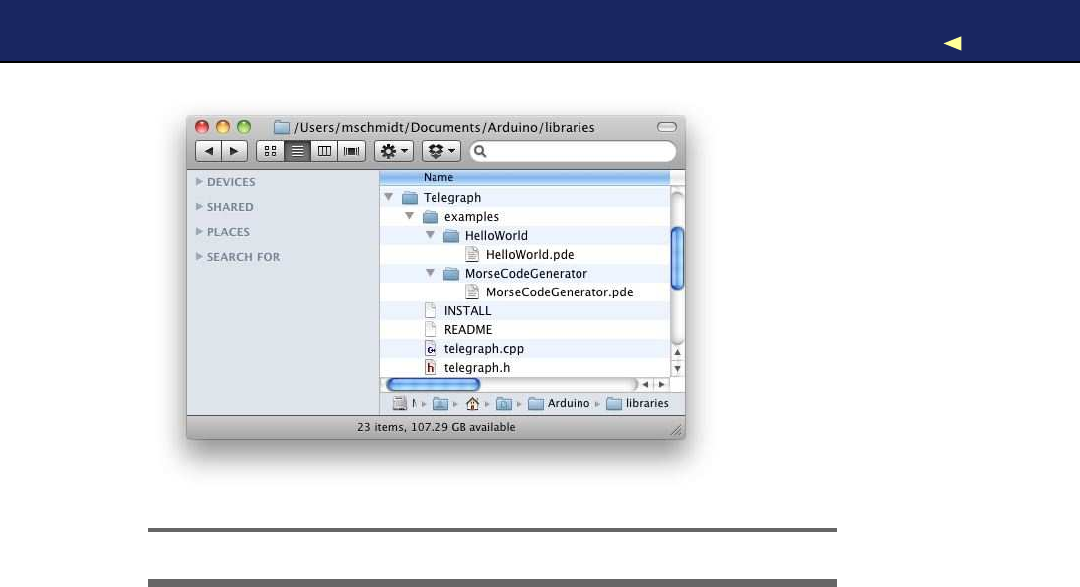
WHAT IFITDOESN’TWORK?99
Figure 4.2: This is what atypical Arduino library needs.
Although you have to perform alot of manual file operations, it’s still
easy to create an Arduino library. So, there’s no excuse: whenever you
think you’ve built something cool, make it publicly available.
Until now our projects have communicated with the outside world using
LEDs (output) and pushbuttons (input). In the next chapter, you’ll learn
how to work with more sophisticated input devices, such as ultrasonic
sensors. Y o u ’ l l also learn how to visualize data that an Arduino sends
to programs running on your computer.
4.8 What If It Doesn’t W o r k ?
The Arduino IDE has astrong opinion on naming files and directories,
and it was built for creating sketches, not libraries. So, you need to
perform afew manual file operations to get everything into the right
place. In Figure 4.2,you can see the final directory layout. If you have
more than one version of the Arduino IDE installed, make sure that
you’re using the right libraries folder.
Remember that you have to restart the IDE often. Whenever you change
one of the files belonging to your library, restart the IDE.
Report erratum
this copy is (P1.0 printing, Ja nu ra r y, 2011)
Download from Wow! eBook <www.wowebook.com>
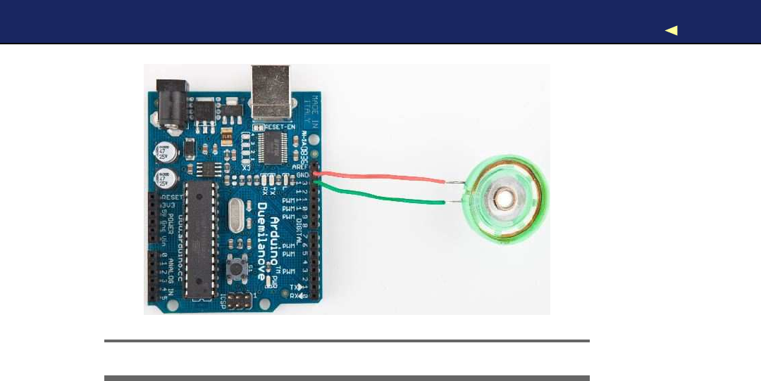
EXERCISES 100
Figure 4.3: It’s easy to connect aspeaker to an Arduino.
If syntax coloring doesn’t work, make sure your keywords file is actually
named k ey wo r d s . t x t .Double-check if you have separated all objects and
type specifiers by atab character! Restart your IDE!
4.9 Exercises
•Morse code supports not only letters and digits. It also defines
symbols such as commas. Improve the T e l e g r a p h class so it under-
stands all characters of the Morse code.
•Blinking LEDs are great, but when we think of Morse code, we
usually think of beeping sounds, so replace the LED with apiezo
speaker, which are cheap and easy to use. Figure 4.3 shows how
you connect it to an Arduino. They have aground pin and a sig-
nal pin, so connect the speaker’s ground to the Arduino’s ground,
and connect the signal pin to Arduino pin 13. Then replace the
output_symbol( ) method with the following code:
void Telegraph::output_symbol(const int length) {
const int frequency =131;
tone(_output_pin, frequency, length);
}
This sends asquare wave to the speaker, and it plays atone having
afrequency of 131 Hertz (find the “Melody” example that comes
Report erratum
this copy is (P1.0 printing, Ja nu ra r y, 2011)
Download from Wow! eBook <www.wowebook.com>

EXERCISES 101
with the Arduino IDE to learn more about playing notes with a
piezo speaker).
•Improve the library’s design to make it easier to support different
output devices. For example, you could pass some kind of Output-
Device object to the T e l e g r a p h constructor. Then derive aLedDevice
and a SpeakerDevice from OutputDevice.It could look as follows:
class OutputDevice {
public:
virtual void output_symbol(const int length);
};
class Led :public OutputDevice {
public:
void output_symbol(const int length) {
// ...
}
};
class Speaker :public OutputDevice {
public:
void output_symbol(const int length) {
// ...
}
};
Y o u can then use these classes as follows:
Led led;
Speaker speaker;
OutputDevice*led_device =&led;
OutputDevice*speaker_device =&speaker;
led_device->output_symbol(200);
speaker_device->output_symbol(200);
The rest is up to you.
•Tryto learn Morse code. Let someone else type some messages
into the serial terminal and try to recognize what he or she sent.
That’s not necessary for learning Arduino development, but it’s a
lot of fun!
Report erratum
this copy is (P1.0 printing, Ja nu ra r y, 2011)
Download from Wow! eBook <www.wowebook.com>

Chapter 5
Sensing the W o r l d Around Us
Instead of communicating via mouse or keyboard as with regular com-
puters, you need to connect special sensors to the Arduino so that it
can sense changes around it. Y o u can attach sensors that measure the
current temperature, the acceleration, or the distance to the nearest
object.
Sensors make up an important part of physical computing, and the
Arduino makes using various sensor types abreeze. In this chapter,
we will use both digital and analog sensors to capture some real-world
state, and all we need is acouple of wires and some small programs.
W e will take aclose look at two sensor types: an ultrasonic sensor
that measures distances and a temperature sensor that measures, well,
temperatures. W i t h the ultrasonic sensor, we will build adigital meter-
ing rule that helps us measure distances remotely. Although ultrasonic
sensors deliver quite accurate results, we can still improve their preci-
sion with some easy tricks. Interestingly, the temperature sensor will
help us with this, and at the end of the chapter, we will have created a
fairly accurate digital metering rule. W e will also build anice graphical
application that visualizes the data we get from the sensors.
But the Arduino doesn’t only make using sensors easy. It also encour-
ages good design for both your circuits and your software. For example,
although we end up using two sensors, they are completely indepen-
dent. All the programs we’ll develop in this chapter will run without
changes on the final circuit.
Download from Wow! eBook <www.wowebook.com>
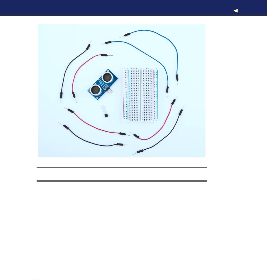
WHAT YOUNEED 103
!
"
#
$
Figure 5.1: All the parts you need in this chapter
5.1 What Y o u Need
1. AParallax PING))) sensor
2. ATMP36 temperature sensor from Analog Devices
3. Abreadboard
4. Some wires
5. An Arduino board such as the Uno, Duemilanove, or Diecimila
6. AUSB cable to connect the Arduino to your computer
7. An installation of the Processing programming language1
1. http://processing.org
Report erratum
this copy is (P1.0 printing, Ja nu ra r y, 2011)
Download from Wow! eBook <www.wowebook.com>

MEASURING DISTANCESWITH ANULTRASONIC SENSOR 104
5.2 Measuring Distances with an Ultrasonic Sensor
Measuring distances automatically and continuously comes in handy
in many situations. Think of arobot that autonomously tries to find
its way or of an automatic burglar alarm that rings abell or calls the
police whenever someone is too near to your house or to the Mona Lisa.
All this is possible with Arduino. But before you can create that burglar
alarm or robot, you need to understand some key concepts.
Many different types of sensors for measuring distances are available,
and the Arduino plays well with most of them. Some sensors use ultra-
sound, while others use infrared light or even laser. But in principle
all sensors work the same way: they emit asignal, wait for the echo to
return, and measure the time the whole process took. Because we know
how fast sound and light travel through the air, we can then convert the
measured time into adistance.
In our first project, we will build adevice that measures the distance
to the nearest object and outputs it on the serial port. For this project,
we use the Parallax PING))) ultrasonic sensor,2because it’s easy to use,
comes with excellent documentation, and has anice feature set. It can
detect objects in arange between 2centimeters and 3 meters, and we
use it directly with abreadboard, so we do not have to solder. It’s also a
perfect example of asensor that provides information via variable-width
pulses (more on that in afew paragraphs). W i t h the PING))) sensor, we
can easily build asonar or arobot that automatically finds its way
through amaze without touching awall.
As mentioned earlier, ultrasonic sensors usually do not return the dis-
tance to the nearest object. Instead, they return the time the sound
needed to travel to the object and back to the sensor. The PING))) is no
exception (see Figure 5.2,on the next page), and its innards are fairly
complex. Fortunately, they are hidden behind three simple pins: power,
ground, and signal.
This makes it easy to connect the sensor to the Arduino. First, connect
Arduino’s ground and 5V power supply to the corresponding PING)))
pins. Then connect the PING)))’s sensor pin to one of the Arduino’s dig-
ital IO pins (we’re using pin 7for no particular reason). For adiagram
of our circuit, see Figure 5.3,on the following page, and for aphoto see
Figure 5.5,on page 108.
2. http://www.parallax.com/StoreSearchResults/tabid/768/txtSearch/28015/List/0/SortField/4/ProductID/92/Default.aspx
Report erratum
this copy is (P1.0 printing, Ja nu ra r y, 2011)
Download from Wow! eBook <www.wowebook.com>
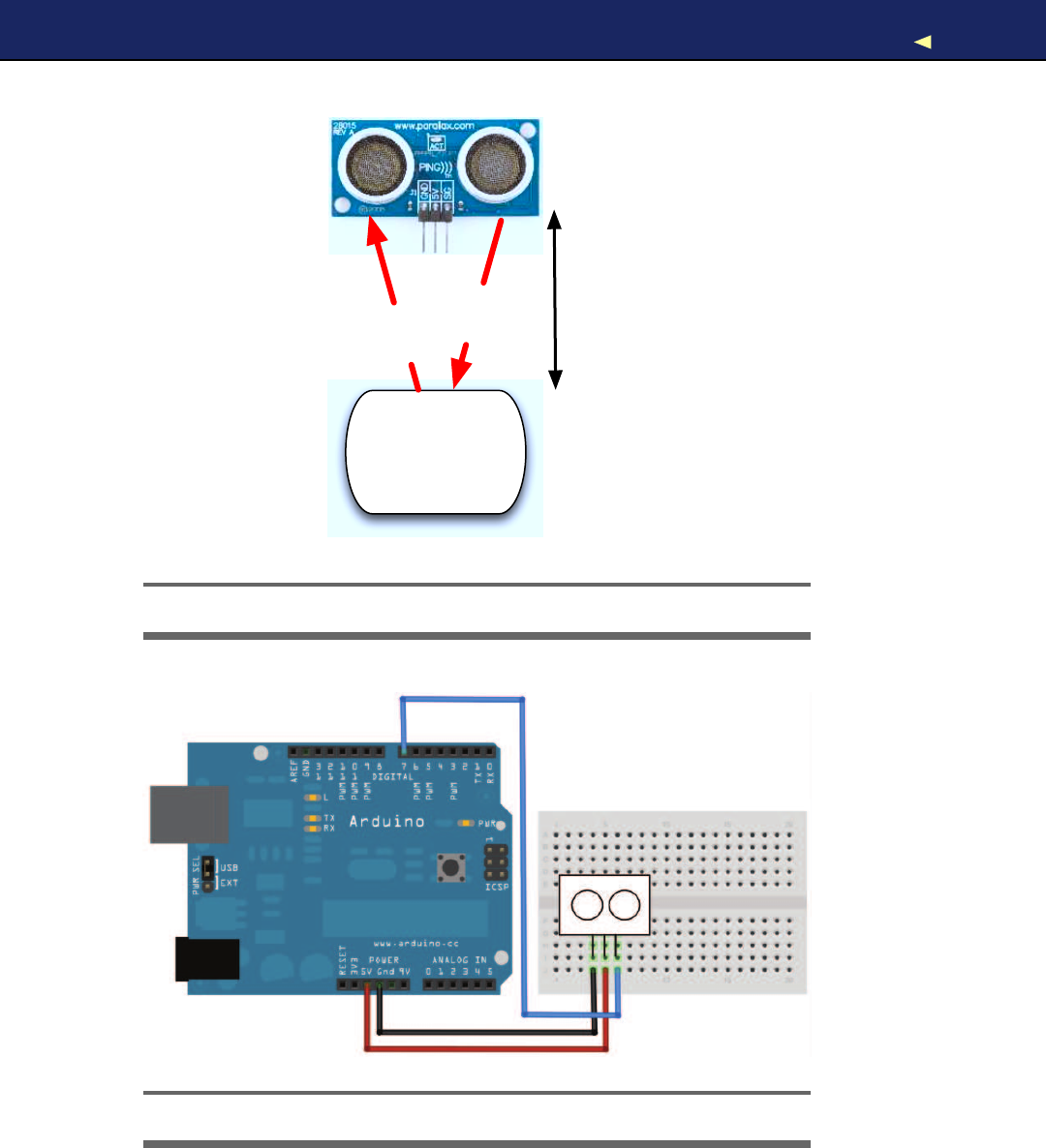

MEASURING DISTANCESWITH ANULTRASONIC SENSOR 106
To bring the circuit to life, we need some code that communicates with
the PING))) sensor:
Download ultrasonic/simple/simple.pde
Line 1const unsigned int PING_SENSOR_IO_PIN =7;
-const unsigned int BAUD_RATE =9600;
-
-void setup() {
5Serial.begin(BAUD_RATE);
-}
-
-void loop() {
-pinMode(PING_SENSOR_IO_PIN, OUTPUT);
10 digitalWrite(PING_SENSOR_IO_PIN, LOW);
-delayMicroseconds(2);
-
-digitalWrite(PING_SENSOR_IO_PIN, HIGH);
-delayMicroseconds(5);
15 digitalWrite(PING_SENSOR_IO_PIN, LOW);
-
-pinMode(PING_SENSOR_IO_PIN, INPUT);
-const unsigned long duration =pulseIn(PING_SENSOR_IO_PIN, HIGH);
-if (duration == 0) {
20 Serial.println(
"Warning: We did not get apulse from sensor."
);
-}else {
-Serial.print(
"Distance to nearest object: "
);
-Serial.print(microseconds_to_cm(duration));
-Serial.println(
"cm"
);
25 }
-
-delay(100);
-}
-
30 unsigned long microseconds_to_cm(const unsigned long microseconds) {
-return microseconds /29 /2;
-}
First we define aconstant for the IO pin the PING))) sensor is connected
to. If you want to connect your sensor to another digital IO pin, you
have to change the program’s first line. In the setup( ) method, we set
the serial port’s baud rate to 9600, because we’d like to see some sensor
data on the serial monitor.
The real action happens in loop( ) where we actually implement the
PING))) protocol. According to the data sheet,3we can control the sensor
using pulses, and it returns results as variable-width pulses, too.
3. http://www.parallax.com/dl/docs/prod/acc/28015-PING-v1.5.pdf
Report erratum
this copy is (P1.0 printing, Ja nu ra r y, 2011)
Download from Wow! eBook <www.wowebook.com>

MEASURING DISTANCESWITH ANULTRASONIC SENSOR 107
Figure 5.4: PING))) pulse diagram
In lines 9to 11, we set the sensor’s signal pin to LOW for 2microsec-
onds to bring it to aproper state. This will ensure clean HIGH pulses
that are needed in the next steps (in the world of electronics, you should
always be prepared for jitters in the power supply).
Finally, it’s time to tell the sensor to do some work. In lines 13 to 15,
we set the sensor’s signal pin to HIGH for 5microseconds to start a
new measurement. Afterward, we set the pin to LOW again, because
the sensor will respond with aHIGH pulse of variable length on the
same pin.
W i t h adigital pin, you have only afew options to transmit information.
Y o u can set the pin to HIGH or LOW, and you can control how long
it remains in aparticular state. For many purposes, this is absolutely
sufficient, and in our case it is, too. When the PING))) sensor sends out
its 40 kHz chirp, it sets the signal pin to HIGH and then sets it back
to LOW when it receives the echo. That is, the signal pin remains in a
HIGH state for exactly the time it takes the sound to travel to an object
and back to the sensor. Loosely speaking, we are using adigital pin
for measuring an analog signal. In Figure 5.4,you can see adiagram
showing typical activity on adigital pin connected to aPING))) sensor.
W e could measure the duration the pin remains in HIGH state manu-
ally, but the pulseIn( ) method already does all the dirty work for us. So,
we use it in line 18 after we have set the signal pin into input mode
again. pulseIn( ) accepts three parameters:
•pin:Number of the pin to read the pulse from.
•type:Type of the pulse that should be read. It can be HIGH or
LOW.
Report erratum
this copy is (P1.0 printing, Ja nu ra r y, 2011)
Download from Wow! eBook <www.wowebook.com>
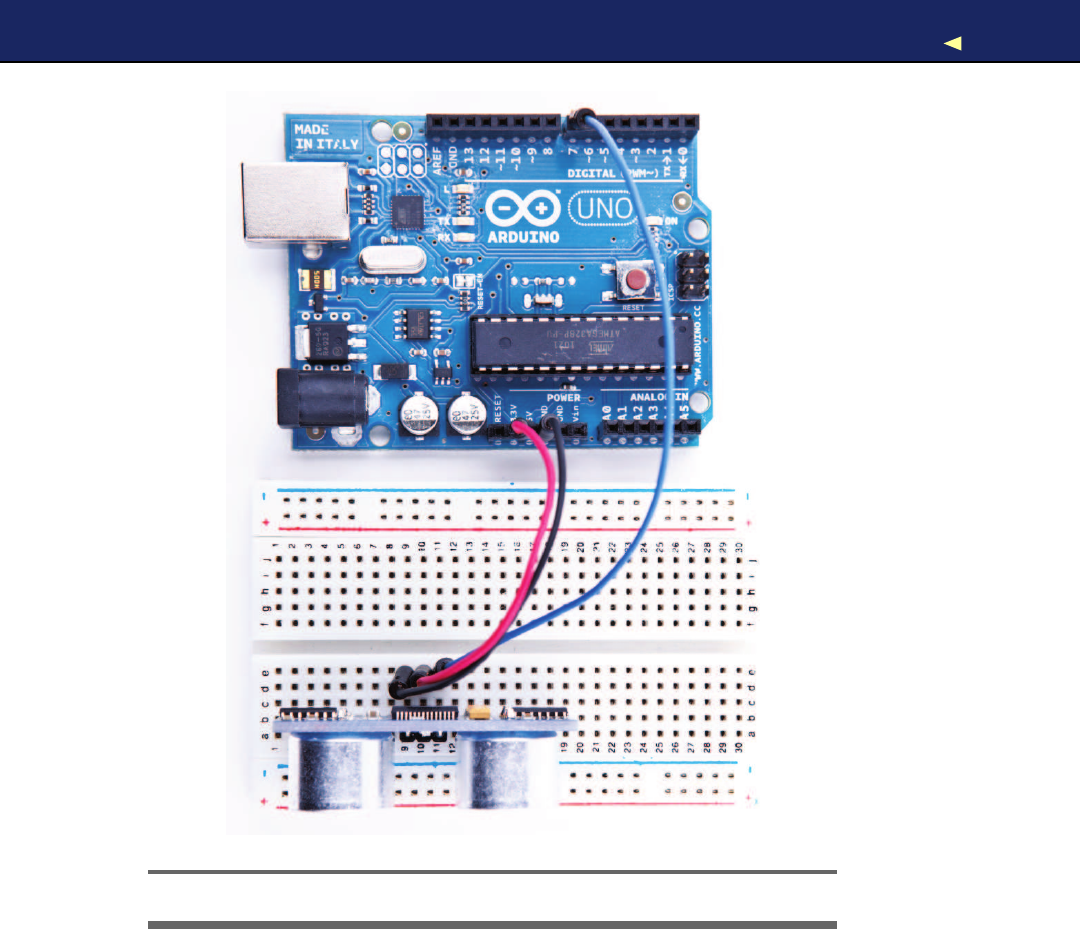
MEASURING DISTANCESWITH ANULTRASONIC SENSOR 108
Figure 5.5: Photo of PING))) basic circuit
•timeout:Timeoutmeasured in microseconds. If no pulse could
be detected within the timeout period, pulseIn( ) returns 0. This
parameter is optional and defaults to one second.
Note that in the whole process only one pin is used to communicate
with the PING))). Sooner or later, you will realize that IO pins are a
scarce resource on the Arduino, so it’s really anice feature that the
PING))) uses only one digital pin. When you can choose between differ-
ent parts performing the same task, try to use as few pins as possible.
Report erratum
this copy is (P1.0 printing, Ja nu ra r y, 2011)
Download from Wow! eBook <www.wowebook.com>

MEASURING DISTANCESWITH ANULTRASONIC SENSOR 109
W e have only one thing left to do: convert the duration we have mea-
sured into alength. Sound travels at 343 meters per second, which
means it needs 29.155 microseconds per centimeter. So, we have to
divide the duration by 29 and then by 2, because the sound has to
travel the distance twice. It travels to the object and then back to the
PING))) sensor. The microseconds_to_cm( ) method performs the calcula-
tion.
According to the specification of the PING))) sensor, you have to wait
at least 200 microseconds between two measurements. For high-speed
measurements, we could calculate the length of apause more accu-
rately by actually measuring the time the code takes. But in our case,
this is pointless, because all the statements that are executed dur-
ing two measurements in the loop( ) method take far more than 200
microseconds. And outputting data to the serial connection is fairly
expensive. Despite this, we have added a small delay of 100 microsec-
onds to slow down the output abit.
Y o u might wonder why we use the const keyword so often. The Arduino
language is based on C/C++, and in these languages it’s considered a
good practice to declare constant values as const (see Effective C++: 50
Specific W a y s to Improve Y o u r Programs and Designs [Mey97]). Not only
will using const make your program more concise and prevent logical
errors early, it will also help the compiler to decrease your program’s
size.
Although most Arduino programs are comparatively small, software
development for the Arduino is still software development and should
be done according to all the best practices we know. So, whenever you
define aconstant value in your program, declare it as such (using const,
not using #define). This is true for other programming languages, too,
so we will use final in our Processing and Java programs alot (you’ll
learn more about Processing in Section 5.5,TransferringData Back to
Y o u r Computer Using Processing,on page 119).
Now it’s time to play around with the sensor and get familiar with
its strengths and weaknesses. Compile the program, upload it to your
Arduino board, and open the serial monitor (don’t forget to set the baud
rate to 9600). Y o u should see something like this:
Distance to nearest object: 42 cm
Distance to nearest object: 33 cm
Distance to nearest object: 27 cm
Distance to nearest object: 27 cm
Report erratum
this copy is (P1.0 printing, Ja nu ra r y, 2011)
Download from Wow! eBook <www.wowebook.com>

INCREASING PRECISION USINGFLOATING-POINTNUMBERS 110
Distance to nearest object: 29 cm
Distance to nearest object: 36 cm
In addition to the output in the terminal, you will see that the LED
on the PING))) sensor is turned on whenever the sensor starts anew
measurement.
Test the sensor’s capabilities by trying to detect big things or very small
things. Try to detect objects from different angles, and try to detect
objects that are below or above the sensor. Y o u should also do some
experiments with objects that do not have aflat surface. Tryto detect
stuffed animals, for example, and you will see that they are not detected
as well as solid objects (that’s probably the reason why bats don’t hunt
bears: they cannot see them).
W i t h only three wires and a few lines of code, we have built afirst
version of adigital metering rule. At the moment, it only outputs cen-
timeter distances in whole numbers, but we will increase its accuracy
tremendously in the next section by changing our software and adding
more hardware.
5.3 Increasing Precision Using Floating-Point Numbers
According to the specification, the PING))) sensor is accurate for objects
that are between 2centimeters and 3 meters away. (By the way, the
reason for this is the length of the pulse that is generated. Its min-
imum length is 115 microseconds, and the maximum length is 18.5
milliseconds.) W i t h our current approach, we do not fully benefit from
its precision because all calculations are performed using integer val-
ues. W e can only measure distances with an accuracy of acentimeter.
To enter the millimeter range, we have to use floating-point numbers.
Normally it is agood idea to use integer operations, because compared
to regular computers the Arduino’s memory and CPU capacities are
severely limited and calculations containing floating-point numbers are
often expensive. But sometimes it’s useful to enjoy the luxury of highly
accurate floating-point numbers, and the Arduino supports them well.
W e will use them to improve our project now:
Download ultrasonic/float/float.pde
Line 1const unsigned int PING_SENSOR_IO_PIN =7;
-const unsigned int BAUD_RATE =9600;
-const float MICROSECONDS_PER_CM =29.155;
-const float MOUNTING_GAP =0.2;
Report erratum
this copy is (P1.0 printing, Ja nu ra r y, 2011)
Download from Wow! eBook <www.wowebook.com>

INCREASING PRECISION USINGFLOATING-POINTNUMBERS 111
5const float SENSOR_OFFSET =MOUNTING_GAP *MICROSECONDS_PER_CM *2;
-
-void setup() {
-Serial.begin(BAUD_RATE);
-}
10
-void loop() {
-const unsigned long duration =measure_distance();
-if (duration == 0)
-Serial.println(
"Warning: We did not get apulse from sensor."
);
15 else
-output_distance(duration);
-}
-
-const float microseconds_to_cm(const unsigned long microseconds) {
20 const float net_distance =max(0, microseconds -SENSOR_OFFSET);
-return net_distance /MICROSECONDS_PER_CM /2;
-}
-
-const unsigned long measure_distance() {
25 pinMode(PING_SENSOR_IO_PIN, OUTPUT);
-digitalWrite(PING_SENSOR_IO_PIN, LOW);
-delayMicroseconds(2);
-
-digitalWrite(PING_SENSOR_IO_PIN, HIGH);
30 delayMicroseconds(5);
-digitalWrite(PING_SENSOR_IO_PIN, LOW);
-
-pinMode(PING_SENSOR_IO_PIN, INPUT);
-return pulseIn(PING_SENSOR_IO_PIN, HIGH);
35 }
-
-void output_distance(const unsigned long duration) {
-Serial.print(
"Distance to nearest object: "
);
-Serial.print(microseconds_to_cm(duration));
40 Serial.println(
"cm"
);
-}
This program does not differ much from our first version. First, we use
the more accurate value 29.155 for the number of microseconds it takes
sound to travel 1centimeter. In addition, the distance calculation now
takes apotential gap between the sensor and the case into account.
If you plug the sensor into abreadboard, for example, usually asmall
gap between the sensor and the breadboard’s edge exists. This gap is
defined in line 5, and it will be used in the distance calculation later
on. The gap is measured in centimeters, and it gets multiplied by two,
because the sound travels out and back.
Report erratum
this copy is (P1.0 printing, Ja nu ra r y, 2011)
Download from Wow! eBook <www.wowebook.com>

INCREASING PRECISION USINGFLOATING-POINTNUMBERS 112
The loop( ) method looks much cleaner now, because the program’s
main functionality has been moved to separate functions. The whole
sensor control logic lives in the measure_distance( ) method and out-
put_distance( ) takes care of outputting values to the serial port. The
big changes happened in the microseconds_to_cm( ) function. It returns
afloat value now, and it subtracts the sensor gap from the measured
duration. To make sure we do not get negative values, we use the m a x ( )
function.
Compile and upload the program, and you should see something like
the following in your serial monitor window:
Distance to nearest object: 17.26 cm
Distance to nearest object: 17.93 cm
Distance to nearest object: 17.79 cm
Distance to nearest object: 18.17 cm
Distance to nearest object: 18.65 cm
Distance to nearest object: 18.85 cm
Distance to nearest object: 18.78 cm
This not only looks more accurate than our previous version, it actually
is. If you have worked with floating-point numbers in any programming
language before, you might ask yourself why the Arduino rounds them
automatically to two decimal digits. The secret lies in the print( ) method
of the Serial class. In recent versions of the Arduino platform it works for
all possible data types, and when it receives afloat variable, it rounds it
to two decimal digits before it gets output. Y o u can specify the number
of decimal digits. For example, Serial.println(3.141592, 4); prints 3.1416.
Only the output is affected by this; internally it is still afloat variable
(by the way, on the Arduino float and double values are the same at the
moment).
So, what does it actually cost to use float variables? Their memory
consumption is 4bytes—that is, they consume as much memory as
long variables. On the other hand, floating-point calculations are fairly
expensive and should be avoided in time-critical parts of your soft-
ware. The biggest costs are the additional library functions that have to
be linked to your program for float support. Serial.print(3.14) might look
harmless, but it increases your program’s size tremendously. Uncom-
ment line 39, and recompile the program to see the effect. W i t h my
current setup, it needs 3,192 bytes without float support for Serial.print( )
and 4,734 bytes otherwise. That’s adifference of 1,542 bytes!
Report erratum
this copy is (P1.0 printing, Ja nu ra r y, 2011)
Download from Wow! eBook <www.wowebook.com>

INCREASING PRECISION USINGATEMPERATURE SENSOR 113
In some cases, you can still get the best of both worlds: float support
without paying the memory tax. Y o u can save alot of space by con-
verting the float values to integers before sending them over aserial
connection. To transfer values with aprecision of two digits, multiply
them by 100, and do not forget to divide them by 100 on the receiving
side. W e will use this trick (including rounding) later.
5.4 Increasing Precision Using aT e m p e r a t u r e Sensor
Support for floating-point numbers is certainly an improvement, but
it mainly increases the precision of our program’s output. W e could
have achieved a similar effect using some integer math tricks. But now
we will add an even better improvement that cannot be imitated using
software: atemperature sensor.
When Itold you that sound travels through air at 343m/s, Iwasn’t
totally accurate, because the speed of sound is not constant—among
other things it depends on the air’s temperature. If you do not take
temperature into account, the error can grow up to a quite significant
12 percent. W e calculate the actual speed of sound Cwith asimple
formula:
C = 331.5 +(0.6 *t)
To use it, we only have to determine the current temperature tin Cel-
sius. W e will use the TMP36 voltage output temperature sensor from
Analog Devices.4It’s cheap, and it’s easy to use.
To connect the TMP36 to the Arduino, connect the Arduino’s ground
and power to the corresponding pins of the TMP36. Then connect the
sensor’s signal pin to the pin A0, that is, the analog pin number 0(see
Figure 5.6,on the following page).
As you might have guessed from its vendor’s name, the TMP36 is an
analog device: it changes the voltage on its signal pin corresponding to
the current temperature. The higher the temperature, the higher the
voltage. For us it is an excellent opportunity to learn how to use the
Arduino’s analog IO pins. So, let’s see some code that uses the sensor:
Download temperature/sensortest/sensortest.pde
Line 1const unsigned int TEMP_SENSOR_PIN =0;
-const float SUPPLY_VOLTAGE =5.0;
4. http://tinyurl.com/msard-analog
Report erratum
this copy is (P1.0 printing, Ja nu ra r y, 2011)
Download from Wow! eBook <www.wowebook.com>
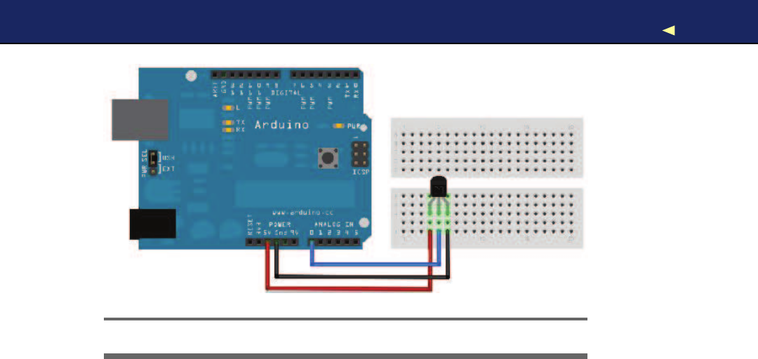
INCREASING PRECISION USINGATEMPERATURE SENSOR 114
Figure 5.6: Connecting the temperature sensor to the Arduino
-const unsigned int BAUD_RATE =9600;
-
5void setup() {
-Serial.begin(BAUD_RATE);
-}
-
-void loop() {
10 Serial.print(get_temperature());
-Serial.println(
"C"
);
-delay(1000);
-}
-
15 const float get_temperature() {
-const int sensor_voltage =analogRead(TEMP_SENSOR_PIN);
-const float voltage =sensor_voltage *SUPPLY_VOLTAGE /1024;
-return (voltage *1000 -500) /10;
-}
In the first two lines, we define constants for the analog pin the sensor
is connected to and for the Arduino’s supply voltage. Then we have a
pretty normal setup( ) method followed by aloop( ) method that outputs
the current temperature every second. The whole sensor logic has been
encapsulated in the get_temperature( ) method.
For the PING))) sensor, we only needed adigital pin that could be
HIGH or LOW. Analog pins are different and represent avoltage rang-
ing from 0V to the current power supply (usually 5V). W e can read
Arduino’s analog pins using the analogRead( ) method that returns a
Report erratum
this copy is (P1.0 printing, Ja nu ra r y, 2011)
Download from Wow! eBook <www.wowebook.com>

INCREASING PRECISION USINGATEMPERATURE SENSOR 115
value between 0 and 1023, because analog pins have aresolution of
ten bits (1024 =210
). W e use it in line 16 to read the current voltage
supplied by the TMP36.
There’s one problem left, though: we have to turn the value returned
by analogRead( ) into an actual voltage value, so we must know the
Arduino’s current power supply. It usually is 5V, but there are Arduino
models (the Arduino Pro, for example) that use only 3.3V. Y o u have to
adjust the constant SUPPLY_VOLTAGE accordingly.
Knowing the supply voltage, we can turn the analog pin’s output into
avoltage value by dividing it by 1024 and by multiplying it with the
supply voltage afterward. That’s exactly what we do in line 17.
W e now have to convert the voltage the sensor delivers into degree Cel-
sius. In the sensor’s data sheet, we find the following formula:
T = ((sensor output in mV) -500) /10
500 millivolts have to be subtracted, because the sensor always outputs
apositive voltage. This way, we can represent negative temperatures,
too. The sensor’s resolution is 10 millivolts, so we have to divide by 10.
Avoltage value of 750 millivolts corresponds to atemperature of (750 -
500) /10 =25◦
C, for example. See it implemented in line 18.
Compile the program, upload it to the Arduino, and you’ll see something
like the following in your serial monitor:
10.06 C
26.64 C
28.62 C
28.50 C
28.50 C
29.00 C
29.00 C
28.50 C
29.00 C
As you can see, the sensor needs some time to calibrate, but its results
get stable fairly quickly. By the way, you’ll always need to insert ashort
delay between two calls to analogRead(), because the Arduino’s internal
analog system needs some time (0.0001 seconds) between two readings.
W e have used adelay of awhole second to make the output easier to
read and because we do not expect the temperature to change rapidly.
Otherwise, adelay of asingle millisecond would be enough.
Report erratum
this copy is (P1.0 printing, Ja nu ra r y, 2011)
Download from Wow! eBook <www.wowebook.com>
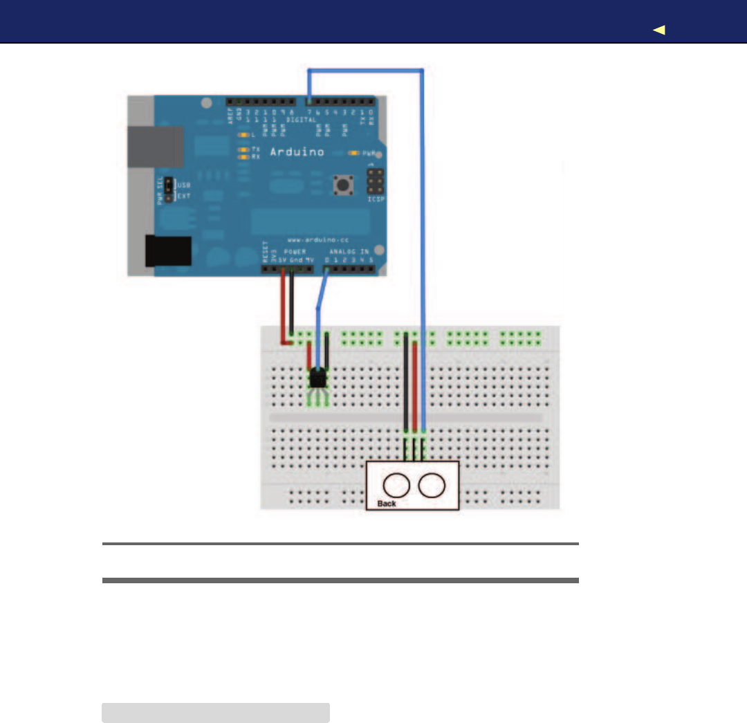
INCREASING PRECISION USINGATEMPERATURE SENSOR 116
Figure 5.7: The TMP36 and the PING))) sensors working together
Now we have two separate circuits: one for measuring distances and
one for measuring temperatures. See them combined to asingle circuit
in Figure 5.7, as well as in Figure 5.8,on page 120.Use the following
program to bring the circuit to life:
Download ultrasonic/PreciseSensor/PreciseSensor.pde
Line 1const unsigned int TEMP_SENSOR_PIN =0;
-const float SUPPLY_VOLTAGE =5.0;
-const unsigned int PING_SENSOR_IO_PIN =7;
-const float SENSOR_GAP =0.2;
5const unsigned int BAUD_RATE =9600;
-
-float current_temperature =0.0;
Report erratum
this copy is (P1.0 printing, Ja nu ra r y, 2011)
Download from Wow! eBook <www.wowebook.com>

INCREASING PRECISION USINGATEMPERATURE SENSOR 117
-unsigned long last_measurement =millis();
-
10 void setup() {
-Serial.begin(BAUD_RATE);
-}
-
-void loop() {
15 unsigned long current_millis =millis();
-if (abs(current_millis -last_measurement) >= 1000) {
-current_temperature =get_temperature();
-last_measurement =current_millis;
-}
20 Serial.print(scaled_value(current_temperature));
-Serial.print(
","
);
-const unsigned long duration =measure_distance();
-Serial.println(scaled_value(microseconds_to_cm(duration)));
-}
25
-long scaled_value(const float value) {
-float round_offset =value <0?-0.5 :0.5;
-return (long)(value *100 +round_offset);
-}
30
-const float get_temperature() {
-const int sensor_voltage =analogRead(TEMP_SENSOR_PIN);
-const float voltage =sensor_voltage *SUPPLY_VOLTAGE /1024;
-return (voltage *1000 -500) /10;
35 }
-
-const float microseconds_per_cm() {
-return 1 / ((331.5 +(0.6 *current_temperature)) /10000);
-}
40
-const float sensor_offset() {
-return SENSOR_GAP *microseconds_per_cm() *2;
-}
-
45 const float microseconds_to_cm(const unsigned long microseconds) {
-const float net_distance =max(0, microseconds -sensor_offset());
-return net_distance /microseconds_per_cm() /2;
-}
-
50 const unsigned long measure_distance() {
-pinMode(PING_SENSOR_IO_PIN, OUTPUT);
-digitalWrite(PING_SENSOR_IO_PIN, LOW);
-delayMicroseconds(2);
-
55 digitalWrite(PING_SENSOR_IO_PIN, HIGH);
-delayMicroseconds(5);
-digitalWrite(PING_SENSOR_IO_PIN, LOW);
-
Report erratum
this copy is (P1.0 printing, Ja nu ra r y, 2011)
Download from Wow! eBook <www.wowebook.com>

INCREASING PRECISION USINGATEMPERATURE SENSOR 118
-pinMode(PING_SENSOR_IO_PIN, INPUT);
60 return pulseIn(PING_SENSOR_IO_PIN, HIGH);
-}
The code is nearly aperfect merge of the programs we used to get
the PING))) and the TMP36 sensors working. Only afew things were
changed:
•The constant MICROSECONDS_PER_CM has been replaced by the
microseconds_per_cm( ) function that determines the microseconds
sound needs to travel 1centimeter dynamically depending on the
current temperature.
•Because the current temperature will usually not change often
or rapidly, we no longer measure it permanently but only once a
second. W e use millis( ) in line 8to determine the number of mil-
liseconds that have passed since the Arduino started. From lines
15 to 19, we check whether more than asecond has passed since
the last measurement. If yes, we measure the current temperature
again.
•W e no longer transfer the sensor data as floating-point numbers
on the serial port but use scaled integer values instead. This is
done by the scaled_value( ) function that rounds afloat value to two
decimal digits and converts it into along value by multiplying it
by 100. On the receiving side, you have to divide it by 100 again.
If you upload the program to your Arduino and play around with your
hand in front of the sensor, you’ll see an output similar to the following:
1940,2818
2914,3032
3045,34156
3005,2843
3045,2476
3085,2414
The output is acomma-separated list of values where the first value
represents the current temperature in degree Celsius, and the second
is the distance to the nearest object measured in centimeters. Both
values have to be divided by 100 to get the actual sensor data.
Our little project now has two sensors. One is connected to adigital pin,
while the other uses an analog one. In the next section, you’ll learn how
to transfer sensor data back to aPC and use it to create applications
based on the current state of the real world.
Report erratum
this copy is (P1.0 printing, Ja nu ra r y, 2011)
Download from Wow! eBook <www.wowebook.com>

TRANSFERRING DATA BACKTOYOUR COMPUTERUSINGPROCESSING 119
How to Encode Sensor Data
Encoding sensor data is a problem that has to be solved often
in Arduino projects, because all the nice data w e collect usu-
ally has to be interpreted b y applications running on regular
computers.
When defining adata f o r m a t , y o u have to take several things
into account. For example, the f o r m a t should not w a s t e the
Arduino’s precious memory. In our case, w e could have used
XML f o r encoding the sensor data, f o r example:
<sensor-data>
<temperature>30.05</temperature>
<distance>51.19</distance>
</sensor-data>
Obviously this is not a good choice, because now w e are w a s t -
ing am u l t i p l e of the actual data’s memory f o r creating the file
f o r m a t ’ s structure. In addition, the receiving applicationhas to
use an XML parser to interpret the data.
But y o u shouldn’t go to the other extreme either. That is, y o u
should use binary f o r m a t s only if it’s absolutely necessary or if
the receiving applicationexpects binary data anyway.
All in all, the simplest data f o r m a t s such as character-separated
v a l u e s (CSV) are often the best choice.
5.5 T r a n s f e r r i n g Data Back to Y o u r Computer Using Processing
All the programs in this chapter transfer sensor data back to your com-
puter using aserial port. But until now we’ve only watched the data
passing by in the IDE’s serial monitor and haven’t used it in our own
applications.
In this section, we will build an application that graphically visualizes
the sensor data. The program will implement akind of inverted sonar:
it draws asmall dot on the screen showing the distance to the nearest
object, while the position of the dot will move in acircle itself (see the
picture on page 130).
To implement the application, we’ll use the Processing programming
language, and in Figure 5.9,on page 121 you can see how we’ll organize
the project. The Processing code runs on our computer while all the
Report erratum
this copy is (P1.0 printing, Ja nu ra r y, 2011)
Download from Wow! eBook <www.wowebook.com>
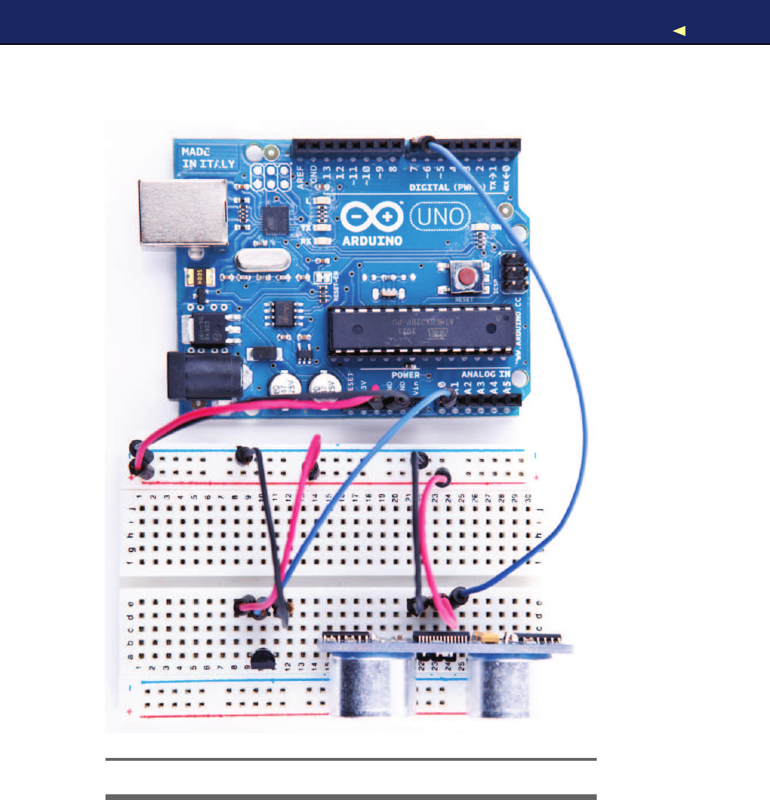

TRANSFERRING DATA BACKTOYOUR COMPUTERUSINGPROCESSING 121
Save the Climate Using Sonar Sensors
Researchers from Northwestern and University of Michigan
have created asonar system that only uses a computer’s
microphone and speakers to detect whether the computer is
currently used or not.∗If it’s not being used, the computer auto-
m a t i c a l l y powers off its screen, saving the environment.
Instead of using a microphone and speakers, y o u can also use
aPING))) sensor. With the lessons y o u ’ v e learned in this chapter,
y o u can build such asystem y o u r s e l f with ease. T r y it!
∗.http://blog.makezine.com/archive/2009/10/using_sonar_to_save_power.html
PC/Mac
Processing
Code
Serial Port
Figure 5.9: System architecture of our inverted Sonar project
PING))) sensor code still runs on the Arduino. Communication between
the Processing code and the Arduino happens via serial port.
Processing is an extension of the Java programming language, and its
focus is on computational art. W i t h Processing, it’s very easy to cre-
ate multimedia applications: applications that produce sound and ani-
mated 2D or 3D graphics. It also has excellent support for user inter-
actions and is well documented (for example, see Processing: Creative
Coding and Computational Art [Gre07]).
Report erratum
this copy is (P1.0 printing, Ja nu ra r y, 2011)
Download from Wow! eBook <www.wowebook.com>
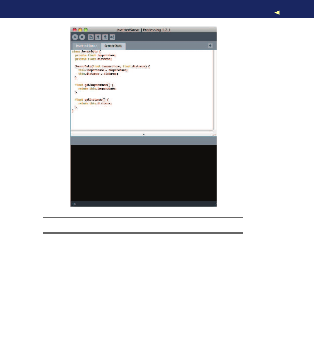
TRANSFERRING DATA BACKTOYOUR COMPUTERUSINGPROCESSING 122
Figure 5.10: The Processing IDE is the basis for the Arduino IDE.
It was originally built for design students who do not have alot of
programming experience but who still wanted to use computers and
electronic devices to create interactive artwork. That’s the reason why
Processing is easy to learn and very beginner-friendly. But many peo-
ple also use it for serious and advanced tasks, especially for presenting
data in visually appealing ways.
Y o u can download Processing for free,5and it comes with aone-click
installer for all popular operating systems. Start it or take alook at Fig-
ure 5.10.Looks familiar, doesn’t it? That is not acoincidence, because
the Arduino IDE was derived from the Processing IDE. Instead of writ-
5. http://processing.org/download/
Report erratum
this copy is (P1.0 printing, Ja nu ra r y, 2011)
Download from Wow! eBook <www.wowebook.com>

REPRESENTING SENSOR DATA 123
ing anew programming environment from scratch, the Arduino team
decided to modify the Processing IDE. That’s the reason why both IDEs
look so similar and why Arduino sketches have the file extension .pde
(Processing Development Environment), for example.
Using Processing as the basis for the Arduino project provided agood
and well-tested IDE for free. Processing and the Arduino are a good
team for several other reasons:
•The Arduino simplifies embedded computing, and Processing sim-
plifies the creation of multimedia applications. So, you can easily
visualize sensor data in often spectacular ways.
•Processing is easy to learn, especially if you already know Java.
•Processing has excellent support for serial communication.
So, for many reasons, Processing is well worth alook, but it’s espe-
cially useful when working with the Arduino. That’s why we’ll use it for
several of the book’s examples.
5.6 Representing Sensor Data
W e start with aProcessing class that represents the current sensor
data we return from the Arduino via serial port. Open anew file in the
Processing IDE, and enter the following code:
Download ultrasonic/InvertedSonar/SensorData.pde
class SensorData {
private float temperature;
private float distance;
SensorData(float temperature, float distance) {
this.temperature =temperature;
this.distance =distance;
}
float getTemperature() {
return this.temperature;
}
float getDistance() {
return this.distance;
}
}
If you are familiar with Java or C++, the SensorData class will be per-
fectly clear to you. It encapsulates atemperature value and a distance
Report erratum
this copy is (P1.0 printing, Ja nu ra r y, 2011)
Download from Wow! eBook <www.wowebook.com>

REPRESENTING SENSOR DATA 124
as floating-point numbers and provides access to the data via accessor
methods (getTemperature( ) and getDistance()). Y o u can create new Sensor-
Data objects using the constructor, passing it the current temperature
and distance.
Processing is an object-oriented programming language and allows us
to define new classes using the c l a s s keyword. Classes have aname and
they contain data (often called attributes or properties) and functions
(often called methods). Our SensorData class contains two attributes
named temperature and distance.They are both of type float, and we
have declared them both private.Now only members of the SensorData
class are allowed to access them. This is considered good style, because
it prevents unwanted side effects and makes future changes much eas-
ier. Aclass should never expose its innards.
To set and get the values of our attributes, we have to use public meth-
ods, and our class has three of them: SensorData(), getTemperature(), and
getDistance(). (Java and C++ programmers should note that in Process-
ing everything is public if not specified otherwise!) Amethod that has
the same name as the class is called aconstructor, and you can use it
for creating and initializing new objects of that particular class. Con-
structors do not have return values, but they may specify parameters.
Ours, for example, takes two arguments and uses them to initialize our
two attributes.
There’s asmall problem, though: our method’s parameters have the
same names as our classes’ attributes. What would happen if we simply
assigned the method parameters to the attributes like this:
temperature =temperature;
distance =distance;
Right: we simply assigned every method parameter to itself, which is
effectively ano-operation. That’s why we use the this keyword. It refers
to the class itself, so we can distinguish between the method parame-
ters and the classes’ attributes. Alternatively, we could have used dif-
ferent names for the method parameters or the attributes, but Iprefer
to use this.
After the constructor, we define the methods getTemperature and getDis-
tance.Their definitions are very similar; we declare the method’s return
type (float), the method’s name, and a list of parameters in parentheses.
In our case, the parameter list is empty. In the methods, we return the
Report erratum
this copy is (P1.0 printing, Ja nu ra r y, 2011)
Download from Wow! eBook <www.wowebook.com>

BUILDINGTHEAPPLICATION’SFOUNDATION 125
current value of the corresponding attributes using the return keyword.
return stops the method and returns its argument to the method’s caller.
Now we can create and initialize new SensorData objects:
SensorData sensorData =new SensorData(31.5, 11.76);
The previous statement creates anew SensorData object named sensor-
Data.It sets temperature to 31.5 and distance to 11.76.To read those
values, we use the corresponding “get” methods:
sensorData.getTemperature(); // -> 31.5
sensorData.getDistance(); // -> 11.76
Because getTemperature( ) and getDistance( ) are members of the Sensor-
Data class, you can only invoke them using an instance of the class.
Our instance is named sensorData, and to call the “get” methods we have
to use the instance name, followed by adot, followed by the method
name.
Now that we can store sensor data, we’ll continue to build our inverted
sonar application in the next section.
5.7 Building the Application’s Foundation
In this section, we’ll create all the boilerplate code we need for our appli-
cation by importing some libraries and defining some global constants
and variables:
Download ultrasonic/InvertedSonar/InvertedSonar.pde
import processing.serial.*;
final int WIDTH =1000;
final int HEIGHT =1000;
final int xCenter =WIDTH /2;
final int yCenter =HEIGHT /2;
final int LINE_FEED =10;
Serial arduinoPort;
SensorData sensorData;
int degree =0;
int radius =0;
To communicate with the Arduino via aserial port, we import Process-
ing’s support for serial communication in the first line. The import state-
ment imports all classes from the processing.serial package and makes
them available in our program.
Report erratum
this copy is (P1.0 printing, Ja nu ra r y, 2011)
Download from Wow! eBook <www.wowebook.com>

IMPLEMENTING SERIAL COMMUNICATIONINPROCESSING 126
Our application will have a1000x1000 pixel screen, so we define con-
stants for its width, height, and its center. W e set the LINE_FEED constant
to the ASCII value of alinefeed character, because we need it later to
interpret the data sent by the Arduino.
Then we define afew global variables (yes, you Java programmers out
there: Processing allows you to define global variables!):
•arduinoPort:An instance of Processing’s Serial class. It’s from the
processing.serial package we have imported and encapsulates the
serial port communication with the Arduino.
•sensorData:The current sensor data that have been transferred
from the Arduino to our application. W e use the SensorData class
we defined in Section 5.6,Representing Sensor Data,on page 123.
•degree:W e will visualize the current distance to the nearest object
on acircle. This variable stores on which degree of the circle we
are right now. V a l u e s range from 0to 359.
•radius:The current distance to the nearest object is interpreted as
aradius value.
5.8 Implementing Serial Communication in Processing
The following functions read data from the serial port the Arduino is
connected to, and they interpret the data the Arduino is sending:
Download ultrasonic/InvertedSonar/InvertedSonar.pde
Line 1void setup() {
-size(WIDTH, HEIGHT);
-println(Serial.list());
-String arduinoPortName =Serial.list()[0];
5arduinoPort =new Serial(this, arduinoPortName, 9600);
-arduinoPort.bufferUntil(LINE_FEED);
-}
-
-void serialEvent(Serial port) {
10 sensorData =getSensorData();
-if (sensorData != null) {
-println(
"Temperature: "
+sensorData.getTemperature());
-println(
"Distance: "
+sensorData.getDistance());
-radius =min(300, int(sensorData.getDistance() *2));
15 }
-}
-
-SensorData getSensorData() {
Report erratum
this copy is (P1.0 printing, Ja nu ra r y, 2011)
Download from Wow! eBook <www.wowebook.com>

IMPLEMENTING SERIAL COMMUNICATIONINPROCESSING 127
-SensorData result =null;
20 if (arduinoPort.available() >0) {
-final String arduinoOutput =arduinoPort.readStringUntil(LINE_FEED);
-result =parseArduinoOutput(arduinoOutput);
-}
-return result;
25 }
-
-SensorData parseArduinoOutput(final String arduinoOutput) {
-SensorData result =null;
-if (arduinoOutput != null) {
30 final int[] data =int(split(trim(arduinoOutput), ','));
-if (data.length == 2)
-result =new SensorData(data[0] /100.0, data[1] /100.0);
-}
-return result;
35 }
setup( ) is one of Processing’s standard functions and has the same
meaning as the Arduino’s setup( ) method. The Processing runtime envi-
ronment calls it only once at application startup time and initializes
the application. W i t h the size( ) method, we create anew screen having
acertain width and height (by the way, you can find excellent reference
material for all Processing classes online6
).
After initializing the screen, we prepare the serial port communication.
First we print alist of all serial devices that are currently connected to
the computer using Serial.list().Then we set the name of the serial port
we are going to use to the first list entry. This might be the wrong port,
so either you hard-code the name of your system’s serial port into the
code or you have alook at the list of serial ports and choose the right
one!
In line 5, we create anew Serial object that is bound to our application
(that’s what this is for). W e use the serial port name we have from the
list of all serial ports and set the baud rate to 9600. If you’d like to
communicate faster, you have to change both the baud rate here and
in the Arduino sketch.
Finally, we tell the Serial object that we want to be notified of new serial
data only when alinefeed has been detected. Whenever we find aline-
feed, we know that awhole line of data was transmitted by the Arduino.
For our application, we chose an asynchronous programming model;
that is, we do not poll for new data in aloop but get notified whenever
6. http://processing.org/reference/
Report erratum
this copy is (P1.0 printing, Ja nu ra r y, 2011)
Download from Wow! eBook <www.wowebook.com>

VISUALIZING SENSOR DATA 128
there’s new data on the serial port (to be concise, we want to be notified
only if anew linefeed was found). This way, we can change our applica-
tion’s state in real time and can prevent disturbing delays between the
arrival of data and graphics updates on the screen.
When new data arrives, serialEvent( ) gets called automatically and is
passed the serial port the data was found on. W e have only one port,
so we can ignore this parameter. W e try to read the current sensor data
using getSensorData(), and if we find some, we print them to the console
for debugging purposes and set the radius to the measured distance.
To make the visualization more appealing, we multiply the distance by
two, and we cut values bigger than 300 centimeters.
getSensorData()’s implementation is fairly simple. First it checks to see
if data is available on the serial port in line 20. This might look redun-
dant, because this method gets called only if data is available, but if
we’d like to reuse it in asynchronous context, the check is necessary.
Then we read all data until we find alinefeed character and pass the
result to parseArduinoOutput().
Parsing the output is easy because of Processing’s split( ) method. W e
use it in line 30 to split the line of text we get from the Arduino at
the comma (trim( ) removes trailing and leading whitespace characters).
It returns atwo-element array containing the textual representation
of two integer values. These strings are turned into integers afterward
using int(). Please note that in our case int( ) takes an array containing
two strings and returns an array containing two int values.
Because it’s possible that we have an incomplete line of text from the
Arduino (the serial communication might start at an arbitrary byte
position), we’d better check whether we actually got two sensor val-
ues. If yes, we create anew SensorData object and initialize it with the
temperature and distance (after we have divided them by 100).
That’s all we need to read the sensor data asynchronously from the
Arduino. From now on, sensor data will be read whenever it’s available,
and the global sensorData and r a d i u s variables will be kept up-to-date
automatically.
5.9 V i s u a l i z i n g Sensor Data
Now that the serial communication between our computer and the
Arduino works, let’s visualize the distance to the nearest object:
Report erratum
this copy is (P1.0 printing, Ja nu ra r y, 2011)
Download from Wow! eBook <www.wowebook.com>

VISUALIZING SENSOR DATA 129
Download ultrasonic/InvertedSonar/InvertedSonar.pde
Line 1void init_screen() {
-background(255);
-stroke(0);
-strokeWeight(1);
5int[] radius_values = { 300, 250, 200, 150, 100, 50 };
-for (int r = 0; r < radius_values.length; r++) {
-final int current_radius =radius_values[r] *2;
-ellipse(xCenter, yCenter, current_radius, current_radius);
-}
10 strokeWeight(10);
-}
-
-void draw() {
-init_screen();
15 int x = (int)(radius *Math.cos(degree *Math.PI /180));
-int y = (int)(radius *Math.sin(degree *Math.PI /180));
-point(xCenter +x, yCenter +y);
-if (++degree == 360)
-degree =0;
20 }
init_screen( ) clears the screen and sets its background color to white in
line 2. It sets the drawing color to black using stroke(0) and sets the
width of the stroke used for drawing shapes to 1pixel. Then it draws
six concentric circles around the screen’s center. These circles will help
us to see how far the nearest object is away from the PING))) sensor.
Finally, it sets the stroke width to 10, so we can visualize the sensor
with asingle point that is 10 pixels wide.
Processing calls the draw( ) method automatically at a certain frame
rate (default is 60 frames per second), and it is the equivalent of the
Arduino’s loop( ) method. In our case, we initialize the screen and cal-
culate coordinates lying on acircle. The circle’s radius depends on the
distance we have from the Arduino, so we have apoint that moves on
acircle. Its distance to the circle’s center depends on the data we mea-
sure with the PING))) sensor.
Report erratum
this copy is (P1.0 printing, Ja nu ra r y, 2011)
Download from Wow! eBook <www.wowebook.com>
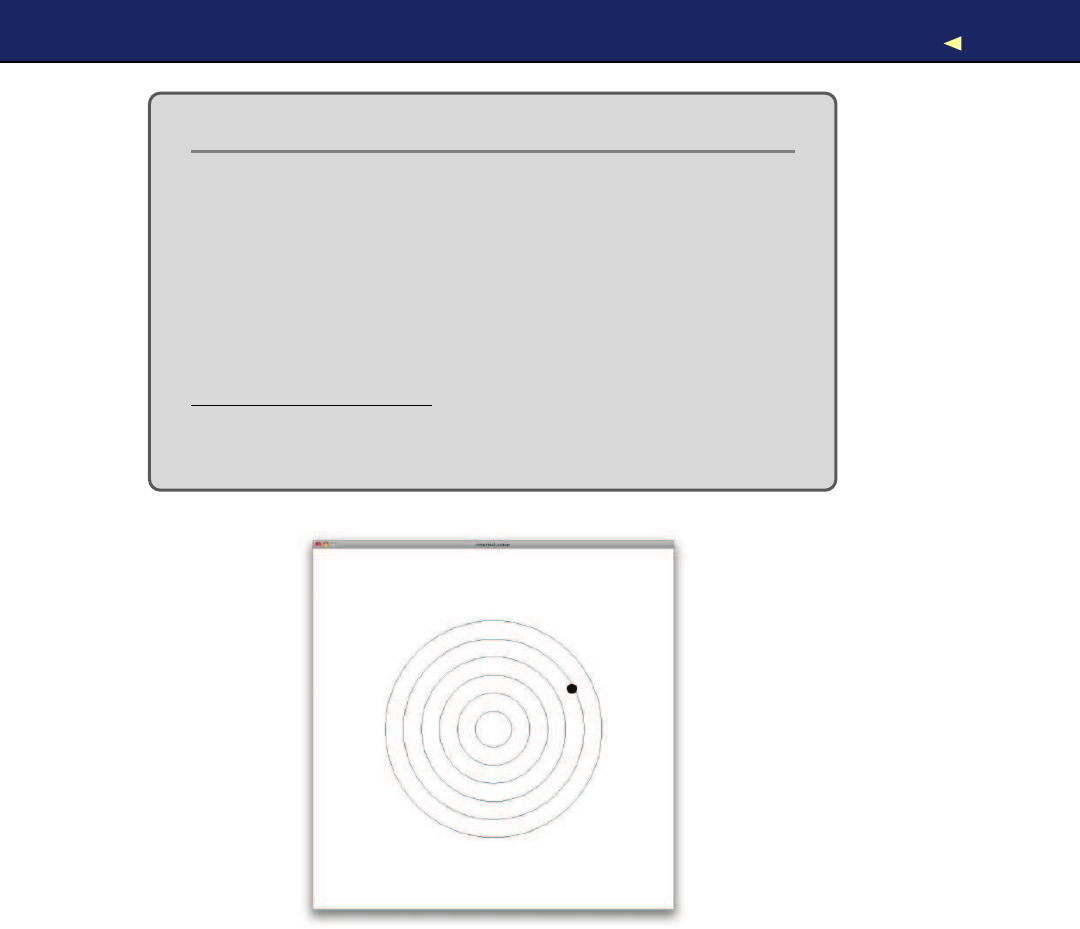
VISUALIZING SENSOR DATA 130
Some Fun with Sensors
With an ultrasonic sensor, y o u can easily detect whether some-
one is nearby. This automatically brings a lot of useful applica-
tions to mind. For example, y o u could open adoor automati-
cally as soon as someone is close enough.
Alternatively, y o u can use advanced technology f o r pure fun.
What about some Halloween gimmicks like a pumpkin that
shoots silly string whenever y o u cross an invisible line?∗It could
be a nice g a g f o r y o u r next party, and y o u can build it using the
PING))) sensor.†
∗.http://www.instructables.com/id/Arduino-controlled-Silly-String-shooter/
†.http://arduinofun.com/blog/2009/11/01/silly-string-shooting-spider-contest-entry/
So, we’ve seen that there are two types of sensor: digital and analog. Y o u
have also learned how to connect both types of sensors to the Arduino
and how to transfer their measurements to your computer. W o r k i n g
with these two different IO types is the basis for all physical computing,
and nearly every project—no matter how complex—is aderivation of the
things you have learned in this chapter.
Report erratum
this copy is (P1.0 printing, Ja nu ra r y, 2011)
Download from Wow! eBook <www.wowebook.com>

WHAT IFITDOESN’TWORK?131
5.10 What If It Doesn’t W o r k ?
See Section 3.8,What If It Doesn’t W o r k ? ,on page 86, and make sure
that you have connected all parts properly to the breadboard. Takespe-
cial care with the PING))) and the TMP36 sensors, because you haven’t
worked with them before. Make sure you have connected the right pins
to the right connectors of the sensors.
In case of any errors with the software—no matter if it’s Processing
or Arduino code—download the code from the book’s website and see
whether it works.
If you have problems with serial communication, double-check whether
you have used the right serial port and the right Arduino type. It might
be that you have connected your Arduino to another port. In this case,
you have to change the index 0in the statement arduinoPort =new
Serial(this, Serial.list()[0],9600); accordingly. Also check whether the baud
rate in the Processing code and serial monitor matches the baud rate
you have used in the Arduino code. Make sure that the serial port is not
blocked by another application like aserial monitor window you forgot
to close, for example.
5.11 Exercises
•Build an automatic burglar alarm that shows astop sign whenever
someone is too close to your computer.7Make the application as
smart as possible. For example, it should have asmall activation
delay to prevent it from showing astop sign immediately when it’s
started.
•The speed of sound not only depends on the temperature but also
on humidity and atmospheric pressure. Do some research to find
the right formula and the right sensors.8Use your research results
to make our circuit for measuring distances even more precise.
•Use an alternative technology for measuring distances, for exam-
ple, an infrared sensor. Tryto find an appropriate sensor, read its
data sheet, and build abasic circuit so you can print the distance
to the nearest object to the serial port.
7. Y o u can find a stop sign here: http://en.wikipedia.org/wiki/File:Stop_sign_MUTCD.svg.
8. Tryhttp://parallax.com.
Report erratum
this copy is (P1.0 printing, Ja nu ra r y, 2011)
Download from Wow! eBook <www.wowebook.com>

Chapter 6
Building aMotion-Sensing Game
Controller
It’s astonishing how quickly we get used to new technologies. Adecade
ago, not many people would have imagined that we’d use devices some-
day to unobtrusively follow our movements. Today it’s absolutely nor-
mal for us to physically turn our smartphones when we want to change
from portrait to landscape view. Even small children intuitively know
how to use motion-sensing controllers for video game consoles such as
Nintendo’s W i i . Y o u can build your own motion-sensing devices using
an Arduino, and in this chapter you’ll learn how.
W e ’ l l work with one of the most widespread motion-sensing devices: the
accelerometer.Accelerometers detect movement in all directions—they
notice if you move them up, down, forward, backward, to the left, or to
the right. Many popular gadgets such as the iPhone and the Nintendo
W i i controllers contain accelerometers. That’s why accelerometers are
cheap.
Both fun and serious projects can benefit from accelerometers. When
working with your computer, you certainly think of projects such as
game controllers or other input control devices. But you can also use
them when exercising or to control areal-life marble maze. Y o u can also
use them to measure acceleration more or less indirectly, such as in a
car.
Y o u will learn how to interpret accelerometer data correctly and how to
get the most accurate results. Then you’ll use an accelerometer to build
your own motion-sensing game controller, and you’ll implement agame
that uses it.
Download from Wow! eBook <www.wowebook.com>
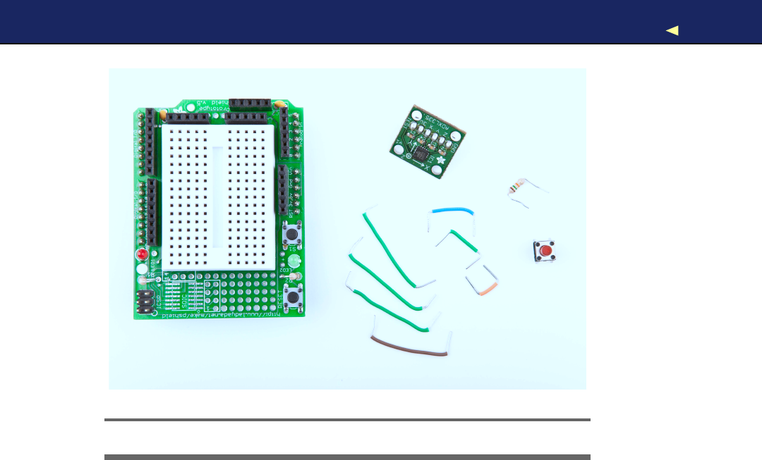
WHAT YOUNEED 133
!
"
#
$
%
Figure 6.1: All the parts you need in this chapter
6.1 What Y o u Need
1. Ahalf-size breadboard or—even better—an Arduino Prototyping
shield with atiny breadboard
2. An ADXL335 accelerometer
3. Apushbutton
4. A10kΩresistor
5. Some wires
6. An Arduino board such as the Uno, Duemilanove, or Diecimila
7. AUSB cable to connect the Arduino to your computer
8. A 6 pin 0.1" standard header
Report erratum
this copy is (P1.0 printing, Ja nu ra r y, 2011)
Download from Wow! eBook <www.wowebook.com>
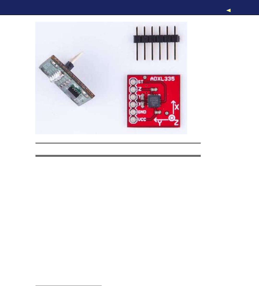
WIRINGUPTHEACCELEROMETER 134
Figure 6.2: An ADXL335 sensor on abreakout board
6.2 Wir ing Up the Accelerometer
There are many different accelerometers, differing mainly in the num-
ber of spacial axes they support (usually two or three). W e use the
ADXL335 from Analog Devices—it’s easy to use and widely available.1
In this section, we’ll connect the ADXL335 to the Arduino and create
asmall demo program showing the raw data the sensor delivers. At
that point, we will have a quick look at the sensor’s specification and
interpret the data.
In Figure 6.2,you see abreakout board containing an ADXL335 sensor
on the right. The sensor is the small black integrated circuit (IC), and
the rest is just acarrier to allow connections. On the top, you see a 6
pin 0.1" standard header. The sensor has six connectors labeled GND,
Z, Y , X, 3V, and TEST. To use the sensor on abreadboard, solder the
standard header to the connectors. This not only makes it easier to
attach the sensor to abreadboard but also stabilizes the sensor, so it
1. http://www.analog.com/en/sensors/inertial-sensors/adxl335/products/product.html
Report erratum
this copy is (P1.0 printing, Ja nu ra r y, 2011)
Download from Wow! eBook <www.wowebook.com>

BRINGING YOUR ACCELEROMETER TOLIFE 135
does not move accidentally. Y o u can see the result on the left side of
the photo (note that the breakout board on the left is not the same as
on the right, but it’s very similar). Don’t worry if you’ve never soldered
before. In Section A.2,Learning How to Solder,on page 241,you can
learn how to do it.
Y o u can ignore the connector labeled TEST, and the meaning of the
remaining connectors should be obvious. To power the sensor, connect
GND to the Arduino’s ground pin and 3V to the Arduino’s 3.3 volts
power supply. X, Y , and Z will then deliver acceleration data for the x-,
y-, and z-axes.
Like the TMP36 temperature sensor we used in Section 5.4,Increasing
Precision Using a Temperature Sensor,on page 113,the ADXL335 is an
analog device: it delivers results as voltages that have to be converted
into acceleration values. So, the X, Y , and Z connectors have to be
connected to three analog pins on the Arduino. W e connect Zto analog
pin 0, Yto analog pin 1, and X to analog pin 2(see Figure 6.3,on the
following page, and double-check the pin labels on the breakout board
you’re using!).
Now that we’ve connected the ADXL335 to the Arduino, let’s use it.
6.3 Bringing Y o u r Accelerometer to Life
Apragmatic strategy to get familiar with anew device is to hook it up
and see what data it delivers. The following program reads input values
for all three axes and outputs them to the serial port:
Download MotionSensor/SensorTest/SensorTest.pde
const unsigned int X_AXIS_PIN =2;
const unsigned int Y_AXIS_PIN =1;
const unsigned int Z_AXIS_PIN =0;
const unsigned int BAUD_RATE =9600;
void setup() {
Serial.begin(BAUD_RATE);
}
void loop() {
Serial.print(analogRead(X_AXIS_PIN));
Serial.print(
""
);
Serial.print(analogRead(Y_AXIS_PIN));
Serial.print(
""
);
Serial.println(analogRead(Z_AXIS_PIN));
delay(100);
}
Report erratum
this copy is (P1.0 printing, Ja nu ra r y, 2011)
Download from Wow! eBook <www.wowebook.com>
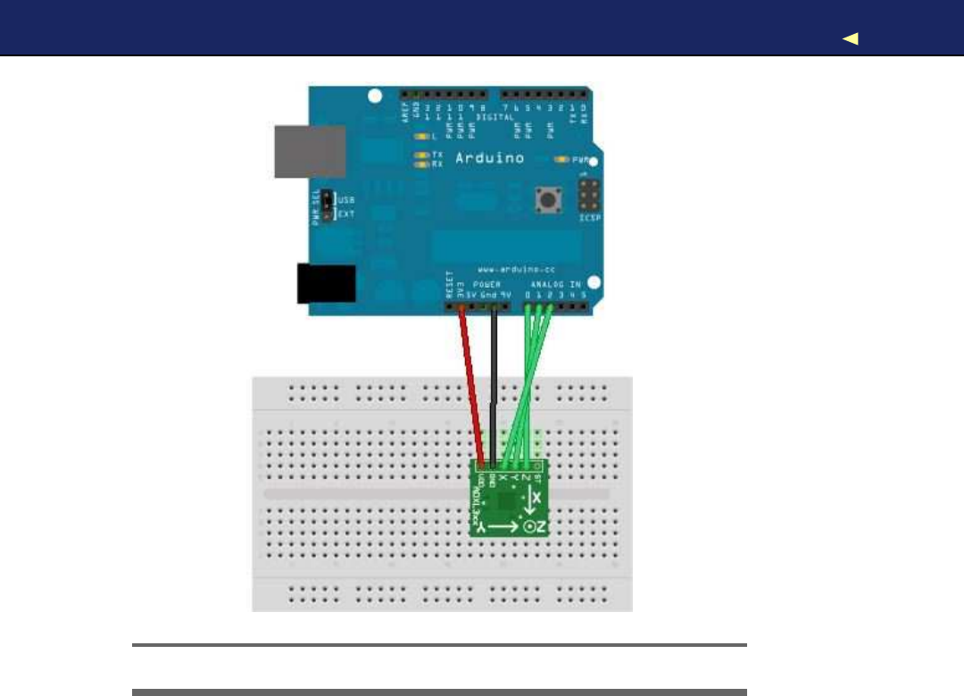
BRINGING YOUR ACCELEROMETER TOLIFE 136
Figure 6.3: How to connect an ADXL335 sensor to an Arduino
Our test program is as simple as it can be. W e define constants for the
three analog pins and initialize the serial port in the setup( ) function.
Note that we did not set the analog pins to INPUT explicitly, because
that’s the default anyway.
In the loop( ) function, we constantly output the values we read from
the analog pins to the serial port. Open the serial monitor, and move
the sensor around a bit—tilt it around the different axes. Y o u should
see an output similar to the following:
344 331 390
364 276 352
388 286 287
398 314 286
376 332 289
370 336 301
379 338 281
Report erratum
this copy is (P1.0 printing, Ja nu ra r y, 2011)
Download from Wow! eBook <www.wowebook.com>

FINDINGANDPOLISHINGEDGE VALUES 137
These values represent the data we get for the x-, y-, and z-axes. When
you move the sensor only around the x-axis, for example, you can see
that the first value changes accordingly. In the next section, we’ll take
acloser look at these values.
6.4 Finding and P o l i s h i n g Edge V a l u e s
The physical world often is far from being perfect. That’s especially true
for the data many sensors emit, and accelerometers are no exception.
They slightly vary in the minimum and maximum values they generate,
and they often jitter abit. They might change their output values even
though you haven’t moved them, or they might not change their output
values correctly. In this section, we’ll determine the sensor’s minimum
and maximum values, and we’ll flatten the jitter.
Finding the edge values of the sensor is easy, but it cannot be eas-
ily automated. Y o u have to constantly read the sensor’s output while
moving it. Here’s aprogram that does the job:
Download MotionSensor/SensorValues/SensorValues.pde
const unsigned int X_AXIS_PIN =2;
const unsigned int Y_AXIS_PIN =1;
const unsigned int Z_AXIS_PIN =0;
const unsigned int BAUD_RATE =9600;
int min_x, min_y, min_z;
int max_x, max_y, max_z;
void setup() {
Serial.begin(BAUD_RATE);
min_x =min_y =min_z =1000;
max_x =max_y =max_z =-1000;
}
void loop() {
const int x = analogRead(X_AXIS_PIN);
const int y = analogRead(Y_AXIS_PIN);
const int z = analogRead(Z_AXIS_PIN);
min_x =min(x, min_x); max_x =max(x, max_x);
min_y =min(y, min_y); max_y =max(y, max_y);
min_z =min(z, min_z); max_z =max(z, max_z);
Serial.print(
"x("
);
Serial.print(min_x);
Serial.print(
"/"
);
Serial.print(max_x);
Report erratum
this copy is (P1.0 printing, Ja nu ra r y, 2011)
Download from Wow! eBook <www.wowebook.com>

FINDINGANDPOLISHINGEDGE VALUES 138
Serial.print(
"), y("
);
Serial.print(min_y);
Serial.print(
"/"
);
Serial.print(max_y);
Serial.print(
"), z("
);
Serial.print(min_z);
Serial.print(
"/"
);
Serial.print(max_z);
Serial.println(
")"
);
}
W e declare variables for the minimum and maximum values of all three
axes, and we initialize them with numbers that are definitely out of the
sensor’s range (-1000 and 1000). In the loop( ) function, we permanently
measure the acceleration of all three axes and adjust the minimum and
maximum values accordingly.
Compile and upload the sketch, then move the breadboard with the
sensor in all directions, and then tilt it around all axes. Move it slowly,
move it fast, tilt it slowly, and tilt it fast. Use long wires, and be careful
when moving and rotating the breadboard so you do not accidentally
loosen aconnection.
After ashort while the minimum and maximum values will stabilize,
and you should get output like this:
x(247/649), y(253/647), z(278/658)
W r i t e down these values, because we need them later, and you’ll prob-
ably need them when you do your own sensor experiments.
Now let’s see how to get rid of the jitter. In principle, it is simple. Instead
of returning the acceleration data immediately, we collect the last read-
ings and return their average. This way, small changes will be ironed
out. The code looks as follows:
Download MotionSensor/Buffering/Buffering.pde
Line 1const unsigned int X_AXIS_PIN =2;
-const unsigned int Y_AXIS_PIN =1;
-const unsigned int Z_AXIS_PIN =0;
-const unsigned int NUM_AXES =3;
5const unsigned int PINS[NUM_AXES] ={
-X_AXIS_PIN, Y_AXIS_PIN, Z_AXIS_PIN
-};
-const unsigned int BUFFER_SIZE =16;
-const unsigned int BAUD_RATE =9600;
10
-int buffer[NUM_AXES][BUFFER_SIZE];
-int buffer_pos[NUM_AXES] = { 0 };
Report erratum
this copy is (P1.0 printing, Ja nu ra r y, 2011)
Download from Wow! eBook <www.wowebook.com>

FINDINGANDPOLISHINGEDGE VALUES 139
-
-void setup() {
15 Serial.begin(BAUD_RATE);
-}
-
-int get_axis(const int axis) {
-delay(1);
20 buffer[axis][buffer_pos[axis]] =analogRead(PINS[axis]);
-buffer_pos[axis] =(buffer_pos[axis] +1) %BUFFER_SIZE;
-
-long sum =0;
-for (int i = 0; i < BUFFER_SIZE; i++)
25 sum += buffer[axis][i];
-return round(sum /BUFFER_SIZE);
-}
-
-int get_x() {return get_axis(0); }
30 int get_y() {return get_axis(1); }
-int get_z() {return get_axis(2); }
-
-void loop() {
-Serial.print(get_x());
35 Serial.print(
""
);
-Serial.print(get_y());
-Serial.print(
""
);
-Serial.println(get_z());
-}
As usual, we define some constants for the pins we use first. This time,
we also define aconstant named NUM_AXES that contains the amount of
axes we are measuring. W e also have an array named PINS that contains
alist of the pins we use. This helps us keep our code more generic later.
In line 11, we declare buffers for all axes. They will be filled with the
sensor data we measure, so we can calculate average values when we
need them. W e have to store our current position in each buffer, so in
line 12, we define an array of buffer positions.
setup( ) only initializes the serial port, and the real action takes place in
the get_axis( ) function. It starts with asmall delay to give the Arduino
some time to switch between analog pins; otherwise, you might get bad
data. Then it reads the acceleration for the axis we have passed and
stores it at the current buffer position belonging to the axis. It increases
the buffer position and sets it back to zero when the end of the buffer
has been reached. Finally, we return the average value of the data we
have gathered so far for the current axis.
Report erratum
this copy is (P1.0 printing, Ja nu ra r y, 2011)
Download from Wow! eBook <www.wowebook.com>
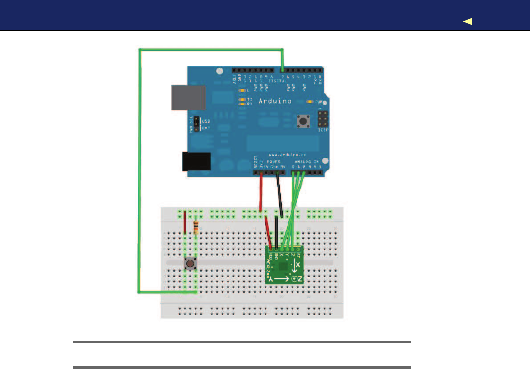
BUILDINGYOUR OWNGAMECONTROLLER 140
Figure 6.4: Game controller with accelerometer and pushbutton
That’s the whole trick. To see its effect, leave the sensor untouched on
your desk, and run the program with different buffer sizes. If you do not
touch the sensor, you would not expect the program’s output to change.
But if you set BUFFER_SIZE to 1, you will quickly see small changes. They
will disappear as soon as the buffer is big enough.
The acceleration data we measure now is sufficiently accurate, and we
can finally build agame controller that will not annoy users because of
unexpected movements.
6.5 Building Y o u r Own Game Controller
To build afull-blown game controller, we only need to add a button to
our breadboard. In Figure 6.4,you can see how to do it (please, double-
check the pin labels on your breakout board!).
Report erratum
this copy is (P1.0 printing, Ja nu ra r y, 2011)
Download from Wow! eBook <www.wowebook.com>
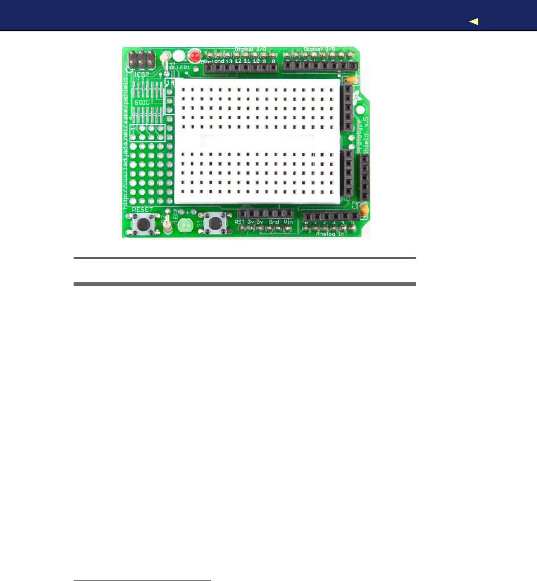
BUILDINGYOUR OWNGAMECONTROLLER 141
Figure 6.5: An Arduino prototyping shield
That’s how it looks inside atypical modern game controller. W e will
not build afancy housing for the controller, but we still should think
about ergonomics for amoment. Our current breadboard solution is
rather fragile, and you cannot really wave around the board when it’s
connected to the Arduino. Sooner or later you will disconnect some
wires, and the controller will stop working.
To solve this problem, you could try to attach the breadboard to the
Arduino using some rubber bands. That works, but it does not look
very pretty, and it’s still hard to handle.
Amuch better solution is to use an Arduino Prototyping shield (see
Figure 6.5). It is apluggable breadboard that lets you quickly build cir-
cuit prototypes. The breadboard is surrounded by the Arduino’s pins,
so you no longer need long wires. Shields are a great way to enhance
an Arduino’s capabilities, and you can get shields for many different
purposes such as adding Ethernet, sound, displays, and so on.2
Using the Proto Shield our game controller looks as in Figure 6.6,on
the next page. Neat, eh?
2. At http://shieldlist.org/,you find a comprehensive list of Arduino shields.
Report erratum
this copy is (P1.0 printing, Ja nu ra r y, 2011)
Download from Wow! eBook <www.wowebook.com>
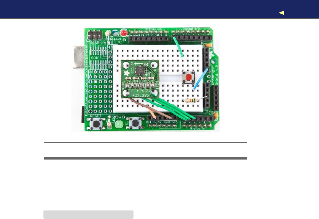
BUILDINGYOUR OWNGAMECONTROLLER 142
Figure 6.6: The complete game controller on aProto shield
Now that the hardware is complete, we need afinal version of the game
controller software. It supports the button we have added, and it per-
forms the anti-jittering we have created in Section 6.4,Finding and
Polishing Edge V a l u e s ,on page 137:
Download MotionSensor/Controller/Controller.pde
#include <Bounce.h>
const unsigned int BUTTON_PIN =7;
const unsigned int X_AXIS_PIN =2;
const unsigned int Y_AXIS_PIN =1;
const unsigned int Z_AXIS_PIN =0;
const unsigned int NUM_AXES =3;
const unsigned int PINS[NUM_AXES] ={
X_AXIS_PIN, Y_AXIS_PIN, Z_AXIS_PIN
};
const unsigned int BUFFER_SIZE =16;
const unsigned int BAUD_RATE =19200;
int buffer[NUM_AXES][BUFFER_SIZE];
int buffer_pos[NUM_AXES] = { 0 };
Bounce button(BUTTON_PIN, 20);
void setup() {
Serial.begin(BAUD_RATE);
pinMode(BUTTON_PIN, INPUT);
}
Report erratum
this copy is (P1.0 printing, Ja nu ra r y, 2011)
Download from Wow! eBook <www.wowebook.com>

BUILDINGYOUR OWNGAMECONTROLLER 143
int get_axis(const int axis) {
delay(1);
buffer[axis][buffer_pos[axis]] =analogRead(PINS[axis]);
buffer_pos[axis] =(buffer_pos[axis] +1) %BUFFER_SIZE;
long sum =0;
for (int i = 0; i < BUFFER_SIZE; i++)
sum += buffer[axis][i];
return round(sum /BUFFER_SIZE);
}
int get_x() {return get_axis(0); }
int get_y() {return get_axis(1); }
int get_z() {return get_axis(2); }
void loop() {
Serial.print(get_x());
Serial.print(
""
);
Serial.print(get_y());
Serial.print(
""
);
Serial.print(get_z());
Serial.print(
""
);
if (button.update())
Serial.println(button.read() == HIGH ?
"1"
:
"0"
);
else
Serial.println(
"0"
);
}
As in Section 3.7,Building a Dice Game,on page 80,we use the Bounce
class to debounce the button. The rest of the code is pretty much stan-
dard, and the only thing worth mentioning is that we use a19200 baud
rate to transfer the controller data sufficiently fast.
Compile and upload the code, open the serial terminal, and play around
with the controller. Move it, press the button sometimes, and it should
output something like the following:
324 365 396 0
325 364 397 0
325 364 397 1
325 364 397 0
325 365 397 0
325 365 397 1
326 364 397 0
Ahomemade game controller is nice, but wouldn’t it be even nicer if we
also had agame that supports it? That’s what we will build in the next
section.
Report erratum
this copy is (P1.0 printing, Ja nu ra r y, 2011)
Download from Wow! eBook <www.wowebook.com>
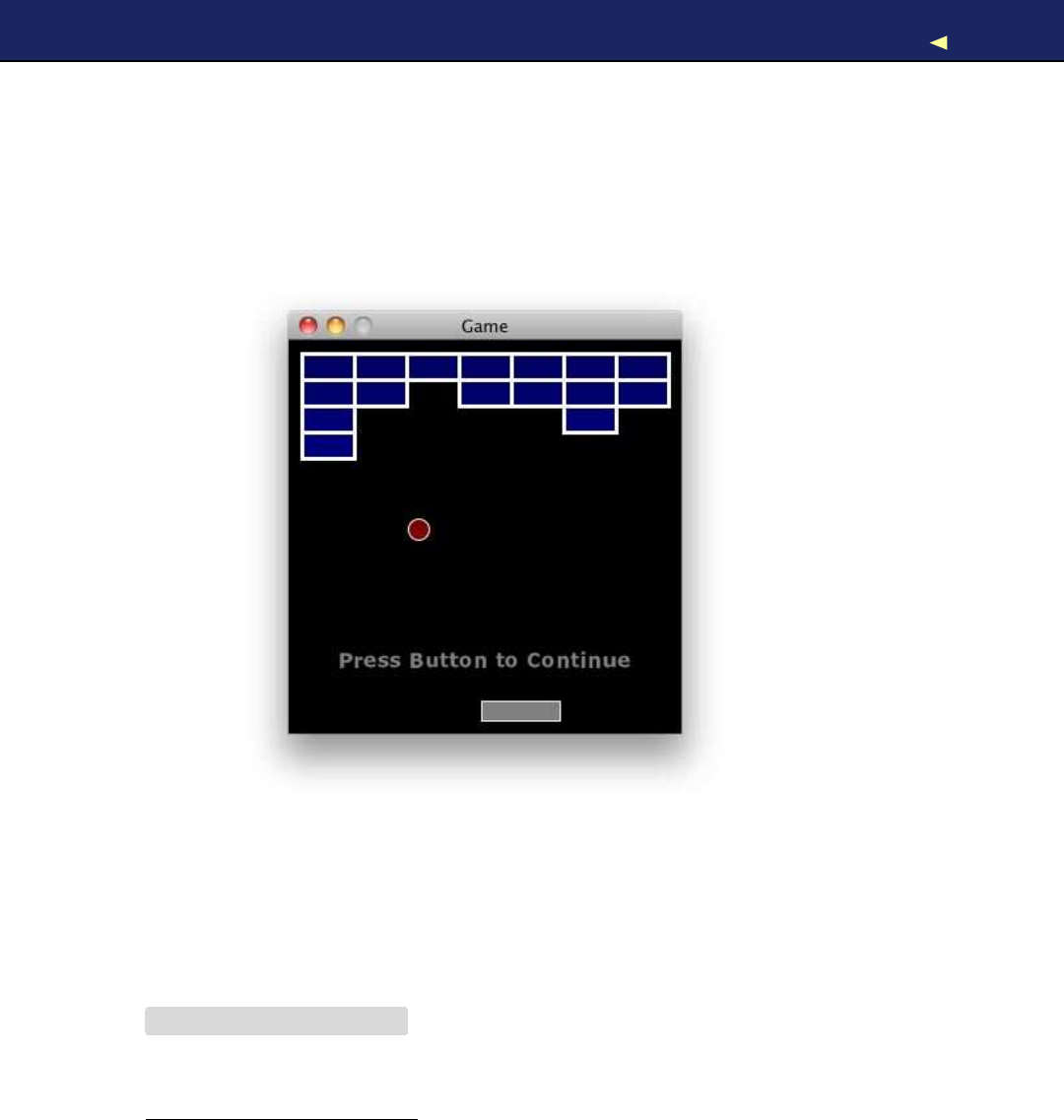
WRITING YOUR OWNGAME 144
6.6 Writing Y o u r Own Game
To test our game controller, we will program asimple Breakout3clone
in Processing. The game’s goal is to destroy all bricks in the upper half
of the screen with aball. Y o u can control the ball with the paddle at the
bottom of the screen, and you can tilt the controller around the x-axis
to move the paddle horizontally. It’ll look something like this:
Although this is not abook about game programming, it will not hurt
to take alook at the game’s innards, especially because game program-
ming with Processing is really pure fun! Download the code from the
book’s website4and play the game before you dive into the code.
Because we will connect our game controller to the serial port, we have
to initialize it:
Download MotionSensor/Game/Game.pde
import processing.serial.*;
Serial arduinoPort;
3. http://en.wikipedia.org/wiki/Breakout_%28arcade_game%29
4. http://www.pragprog.com/titles/msard
Report erratum
this copy is (P1.0 printing, Ja nu ra r y, 2011)
Download from Wow! eBook <www.wowebook.com>

WRITING YOUR OWNGAME 145
Then we define some constants that will help us to customize the game
easily:
Download MotionSensor/Game/Game.pde
final int COLUMNS =7;
final int ROWS =4;
final int BALL_RADIUS =8;
final int BALL_DIAMETER =BALL_RADIUS *2;
final int MAX_VELOCITY =8;
final int PADDLE_WIDTH =60;
final int PADDLE_HEIGHT =15;
final int BRICK_WIDTH =40;
final int BRICK_HEIGHT =20;
final int MARGIN =10;
final int WIDTH =COLUMNS *BRICK_WIDTH + 2 *MARGIN;
final int HEIGHT =300;
final int X_AXIS_MIN =252;
final int X_AXIS_MAX =443;
final int LINE_FEED =10;
final int BAUD_RATE =19200;
Most of these values should be self-explanatory—they define the size
of the objects that appear on the screen. For example, P A D D L E _ W I D T H is
width of the paddle measured in pixels, and COLUMNS and ROWS set
the layout of the bricks. Y o u should replace X_AXIS_MIN and X_AXIS_MAX
the minimum and maximum values you measured for your sensor in
Section 6.4,Finding and Polishing Edge V a l u e s ,on page 137.
Next we choose how to represent the game’s objects:
Download MotionSensor/Game/Game.pde
int px, py;
int vx, vy;
int xpos =WIDTH /2;
int[][] bricks =new int[COLUMNS][ROWS];
W e store the balls’ current x and y coordinates in px and p y .For its
current x and y velocity, we use vx and vy.W e store the paddle’s x
position in xpos.
bricks is atwo-dimensional array and contains the current state of the
bricks on the screen. If an array element is set to 1, the corresponding
brick is still on the screen. 0means that it has been destroyed already.
Finally, we need to store the possible states of the game:
Download MotionSensor/Game/Game.pde
boolean buttonPressed =false;
boolean paused =true;
boolean done =true;
Report erratum
this copy is (P1.0 printing, Ja nu ra r y, 2011)
Download from Wow! eBook <www.wowebook.com>

WRITING YOUR OWNGAME 146
Unsurprisingly, we set buttonPressed to true when the button on the con-
troller is pressed. Otherwise, it is f a l s e .paused tells you whether the
game is currently paused, and done is true when the current level is
done, that is, when all bricks have been destroyed.
Every Processing program needs asetup( ) function, and here is ours:
Download MotionSensor/Game/Game.pde
void setup() {
size(WIDTH, HEIGHT);
noCursor();
textFont(loadFont(
"Verdana-Bold-36.vlw"
));
initGame();
println(Serial.list());
arduinoPort =new Serial(this, Serial.list()[0], BAUD_RATE);
arduinoPort.bufferUntil(LINE_FEED);
}
void initGame() {
initBricks();
initBall();
}
void initBricks() {
for (int x = 0; x < COLUMNS; x++)
for (int y = 0; y < ROWS; y++ )
bricks[x][y] =1;
}
void initBall() {
px =width /2;
py =height /2;
vx =int(random(-MAX_VELOCITY, MAX_VELOCITY));
vy =-2;
}
The setup( ) function initializes the screen, hides the mouse pointer with
noCursor(), and sets the font that we will use to output messages (create
the font using Processing’s Tools >Create Font menu). Then we call
initGame( ) to initialize the bricks array and the ball’s current position
and velocity. Tomake things more interesting, the velocity in xdirection
is set to arandom value. W e set the velocity for the ydirection to -2,
which makes the ball fall at a reasonable speed.
Now that everything is initialized, we can implement the game’s main
loop. Processing’s draw( ) method is aperfect place:5
5. http://processing.org/reference/ has excellent documentation for all Processing classes.
Report erratum
this copy is (P1.0 printing, Ja nu ra r y, 2011)
Download from Wow! eBook <www.wowebook.com>

WRITING YOUR OWNGAME 147
Download MotionSensor/Game/Game.pde
void draw() {
background(0);
stroke(255);
strokeWeight(3);
done =drawBricks();
if (done) {
paused =true;
printWinMessage();
}
if (paused)
printPauseMessage();
else
updateGame();
drawBall();
drawPaddle();
}
W e clear the screen and paint it black using background(). Then we set
the stroke color to white and the stroke weight to three pixels. After
that we draw the remaining bricks. If no bricks are left, we pause the
game and print a“You W i n ! ” message.
If the game is paused, we print acorresponding message, and if it’s not,
we update the game’s current state. Finally, we draw the ball and the
paddle at their current positions using the following functions:
Download MotionSensor/Game/Game.pde
boolean drawBricks() {
boolean allEmpty =true;
for (int x = 0; x < COLUMNS; x++) {
for (int y = 0; y < ROWS; y++) {
if (bricks[x][y] >0) {
allEmpty =false;
fill(0, 0, 100 + y *8);
rect(
MARGIN + x *BRICK_WIDTH,
MARGIN + y *BRICK_HEIGHT,
BRICK_WIDTH,
BRICK_HEIGHT
);
}
}
}
return allEmpty;
}
Report erratum
this copy is (P1.0 printing, Ja nu ra r y, 2011)
Download from Wow! eBook <www.wowebook.com>

WRITING YOUR OWNGAME 148
void drawBall() {
strokeWeight(1);
fill(128, 0, 0);
ellipse(px, py, BALL_DIAMETER, BALL_DIAMETER);
}
void drawPaddle() {
int x = xpos -PADDLE_WIDTH /2;
int y = height -(PADDLE_HEIGHT +MARGIN);
strokeWeight(1);
fill(128);
rect(x, y, PADDLE_WIDTH, PADDLE_HEIGHT);
}
As you can see, the ball is nothing but acircle, and the bricks and the
paddle are simple rectangles. To make them look more appealing, we
give them anice border.
Printing the game’s messages is easy, too:
Download MotionSensor/Game/Game.pde
void printWinMessage() {
fill(255);
textSize(36);
textAlign(CENTER);
text(
"YOU WIN!"
,width /2, height *2 / 3);
}
void printPauseMessage() {
fill(128);
textSize(16);
textAlign(CENTER);
text(
"Press Button to Continue"
,width /2, height *5 / 6);
}
The update( ) function is very important, because it updates the game’s
state—it checks for collisions, moves the ball, and so on:
Download MotionSensor/Game/Game.pde
void updateGame() {
if (ballDropped()) {
initBall();
paused =true;
}else {
checkBrickCollision();
checkWallCollision();
checkPaddleCollision();
px += vx;
py += vy;
}
}
Report erratum
this copy is (P1.0 printing, Ja nu ra r y, 2011)
Download from Wow! eBook <www.wowebook.com>

WRITING YOUR OWNGAME 149
When the player does not hit the ball with the paddle and it drops out
of the playfield, the game stops, and the user is allowed to continue
after pressing the button. In the final game, you’d decrease some kind
of alife counter and print a“Game Over” message when the counter
reaches zero.
If the ball is still in play, we check for various collisions. W e check if the
ball has hit one or more bricks, if it has hit awall, or if it has hit the
paddle. Then we calculate the ball’s new position. The collision checks
look complicated, but they are fairly simple and only compare the ball’s
coordinates with the coordinates of all the other objects on the screen:
Download MotionSensor/Game/Game.pde
boolean ballDropped() {
return py +vy >height -BALL_RADIUS;
}
boolean inXRange(final int row, final int v) {
return px +v>row *BRICK_WIDTH &&
px +v<(row +1) *BRICK_WIDTH +BALL_DIAMETER;
}
boolean inYRange(final int col, final int v) {
return py +v>col *BRICK_HEIGHT &&
py +v<(col +1) *BRICK_HEIGHT +BALL_DIAMETER;
}
void checkBrickCollision() {
for (int x = 0; x < COLUMNS; x++) {
for (int y = 0; y < ROWS; y++) {
if (bricks[x][y] >0) {
if (inXRange(x, vx) && inYRange(y, vy)) {
bricks[x][y] =0;
if (inXRange(x, 0)) // Hit top or bottom of brick.
vy =-vy;
if (inYRange(y, 0)) // Hit left or right side of brick.
vx =-vx;
}
}
}
}
}
void checkWallCollision() {
if (px +vx <BALL_RADIUS || px +vx >width -BALL_RADIUS)
vx =-vx;
if (py +vy <BALL_RADIUS || py +vy >height -BALL_RADIUS)
vy =-vy;
}
Report erratum
this copy is (P1.0 printing, Ja nu ra r y, 2011)
Download from Wow! eBook <www.wowebook.com>

WRITING YOUR OWNGAME 150
More Fun with Motion-Sensing T e c h n o l o g i e s
Since motion-sensing technologies became popular and
cheap, people have used them to create some unbelievably
cool and funny projects. A hilarious example is the Brushduino.∗
Af a t h e r built it to encourage his y o u n g children to brush their
teeth properly. Its m a i n component—apart from an Arduino—
is athree-axis accelerometer. The Brushduino indicates which
section of the mouth to brush next using LEDs, and whenever
the child has successfully finished asection, it plays some m u s i c
from the Super Mario Brothers video g a m e .
But y o u do not need an accelerometer to detect motion and
to create cool new electronic toys. An ordinary tilt sensor is suf-
ficient to build an interactive hacky-sack ga m e , f o r example.†
This hacky-sack blinks and beeps whenever y o u kick it, and
after 30 successful kicks, it plays a song.
∗.http://camelpunch.blogspot.com/2010/02/blog-post.html
†.http://blog.makezine.com/archive/2010/03/arduino-powered_hacky-sack_game.html
void checkPaddleCollision() {
final int cx =xpos;
if (py +vy >= height -(PADDLE_HEIGHT +MARGIN +6) &&
px >= cx -PADDLE_WIDTH / 2 &&
px <= cx +PADDLE_WIDTH /2)
{
vy =-vy;
vx =int(
map(
px -cx,
-(PADDLE_WIDTH /2), PADDLE_WIDTH /2,
-MAX_VELOCITY,
MAX_VELOCITY
)
);
}
}
Note that the collision checks also change the velocity of the ball if
necessary.
Now that the ball is moving, it’d be only fair to move the paddle, too.
As said before, you control the paddle by tilting the game controller
Report erratum
this copy is (P1.0 printing, Ja nu ra r y, 2011)
Download from Wow! eBook <www.wowebook.com>

WRITING YOUR OWNGAME 151
around the x-axis. Here’s the code that gets the controller data via the
serial port:
Download MotionSensor/Game/Game.pde
Line 1void serialEvent(Serial port) {
-final String arduinoData =port.readStringUntil(LINE_FEED);
-
-if (arduinoData != null) {
5final int[] data =int(split(trim(arduinoData), ''));
-if (data.length == 4) {
-buttonPressed =(data[3] == 1);
-if (buttonPressed) {
-paused =!paused;
10 if (done) {
-done =false;
-initGame();
-}
-}
15
-if (!paused)
-xpos =int(map(data[0], X_AXIS_MIN, X_AXIS_MAX, 0, WIDTH));
-}
-}
20 }
Processing calls the serialEvent( ) function whenever new data is avail-
able on the serial port. The controller sends its data line by line. Each
line contains the current acceleration of the x-, y-, and z-axes and the
current state of the button. It separates all attributes by blanks. So, in
serialEvent(), we read the new line, split it at the blank characters, and
convert the resulting strings into int values. This all happens in line 5.
W e check whether we actually got all four attributes, and then we see
whether the player has pushed the button on the game controller. If
yes, we toggle the pause state: if the game currently is in pause mode,
we continue the game; otherwise, we pause it. Also, we check whether
the game has been finished. If yes, we start anew game.
Finally, we read the current X acceleration in line 17 and map it to the
possible xpositions of our paddle. That’s really all we have to do to
move the paddle using our own game controller. Also, it doesn’t matter
if you use the controller to control agame or acompletely different type
of software. Y o u only have to read four integer values from the serial
port when you need them.
In this section, you have learned much more about game program-
ming than about Arduino programming or hardware. But you should
Report erratum
this copy is (P1.0 printing, Ja nu ra r y, 2011)
Download from Wow! eBook <www.wowebook.com>

MORE PROJECTS 152
Creating Games with the Arduino
Y o u can use the Arduino to build more than y o u r o w n cool
g a m e controllers. Y o u can also use it to build some cool g a m e s .
With the right extension shields, y o u can e v e n turn an Arduino
into a powerful g a m i n g console.∗It’s pricey, but suddenly y o u r
Arduino has a320x200 pixel OLED touch screen, an analog
stick, two buttons, and e v e n an vibration motor f o r f o r c e f e e d -
back effects.
While looking f o r acheaper solution, someone built a Super
Mario Bros clone with minimal hardware requirements.†It’s a
perfect example of the unbelievable creativity that the Arduino
sets free.
∗.http://antipastohw.blogspot.com/2009/02/getting-started-with-gamepack-in-3.html
†.http://blog.makezine.com/archive/2010/03/super_mario_brothers_with_an_arduino.html
have also learned that it’s easy to integrate awell-designed electronics
project into your regular software projects. W e carefully analyzed the
analog data returned by the accelerometer, and then we eliminated all
unwanted jitter. This is atechnique you’ll use often in your electronics
projects, and we will use it again in the next chapter.
6.7 More Projects
If you keep your eyes open, you’ll quickly find many more applications
for accelerometers than you might imagine. Here’s asmall collection of
both commercial and free products:
•Nike’s iPod Sport Kit supports you in your daily exercise, and it’s
based on an accelerometer, too. Y o u can learn alot from its inner
workings.6
•It’s alot of fun to create amarble maze computer game and control
it using the game controller we build in this chapter. How much
more fun will it be to build areal marble maze?7
•In this chapter, we have measured only direct acceleration; that
is, we usually have the accelerometer in our hand and move it.
6. http://www.runnerplus.com/read/1-how_does_the_nike_ipod_sport_kit_accelerometer_work/
7. http://www.electronicsinfoline.com/New/Everything_Else/marble-maze-that-is-remote-controlled-using-an-accelerometer.html
Report erratum
this copy is (P1.0 printing, Ja nu ra r y, 2011)
Download from Wow! eBook <www.wowebook.com>

WHAT IFITDOESN’TWORK?153
But you can also build many interesting projects that measure
indirect acceleration, such as when you are driving acar.8
6.8 What If It Doesn’t W o r k ?
All advice from Section 5.10,What If It Doesn’t W o r k ? ,on page 131 also
applies to the project in this section. Still, we have some special items
such as the protoshield. Make sure that it sits correctly on top of the
Arduino and that none of its connectors accidentally slipped past its
socket. Sometimes the headers are out of shape, so it might happen.
Check if you have soldered the pin header correctly to the breakout
board. Use amagnifying glass and study every single solder joint care-
fully. Did you use enough solder? Did you use too much and connect
two joints?
6.9 Exercises
•Create your own computer mouse using the ADXL335 accelerom-
eter. It should work in free air, and it should emit the current
acceleration around the x- and y-axes. It should also have aleft
button and a right button. W r i t e some Processing code (or per-
haps code in aprogramming language of your choice?) to control
amouse pointer on the screen.
8. http://www.dimensionengineering.com/appnotes/Gmeter/Gmeter.htm
Report erratum
this copy is (P1.0 printing, Ja nu ra r y, 2011)
Download from Wow! eBook <www.wowebook.com>

Chapter 7
Tinkeringwith the W i i Nunchuk
One of the most entertaining electronic activities is tinkering: taking an
existing product and turning it into something different or using it for
an unintended purpose. Sometimes you have to open the product and
void its warranty; other times you can safely make it part of your own
project.
In this chapter, you’ll learn how to hijack aNintendo Nunchuk con-
troller. It’s aperfect candidate for tinkering: it comes with athree-axis
accelerometer, an analog joystick, and two buttons, and it is very cheap
(less than $20 at the time of this writing). Even better: because of its
good design and its easy-to-access connectors, you can integrate it into
your own projects surprisingly easily.
W e ’ l l use an ordinary Nunchuk controller and transfer the data it emits
to our computer using an Arduino. Y o u ’ l l learn how to wire it to the
Arduino; how to write software that reads the controller’s current state;
and how to move, rotate, and scale a3D cube on the screen using your
Nunchuk. Y o u don’t even need aNintendo W i i to do any of this—you
only need aNunchuk controller.
7.1 What Y o u Need
•An Arduino board such as the Uno, Duemilanove, or Diecimila
• A USB cable to connect the Arduino to your computer
• A Nintendo Nunchuk controller
•Four wires
Download from Wow! eBook <www.wowebook.com>
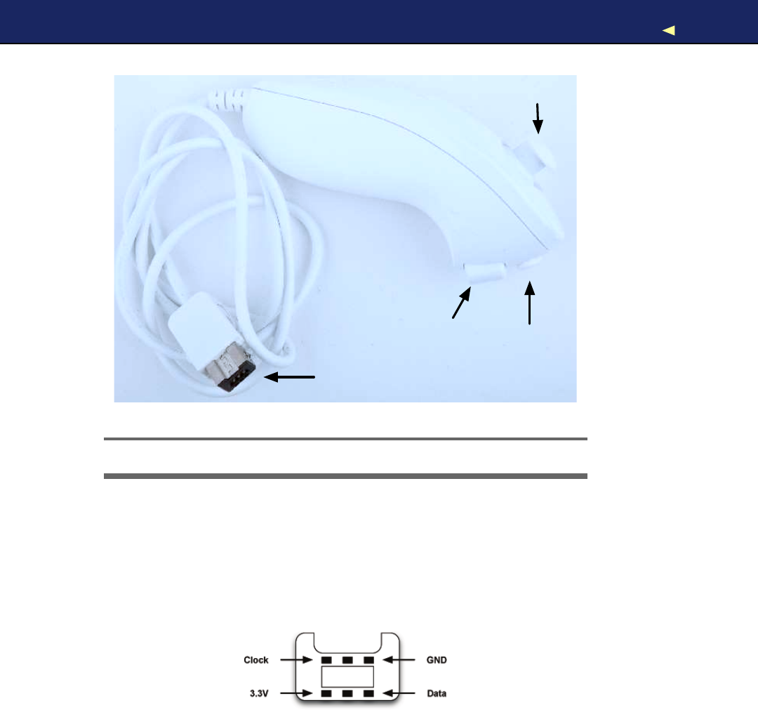
WIRINGAWIINUNCHUK 155
Analog Stick
C Button
Z Button
Connector
Figure 7.1: ANintendo Nunchuk controller
7.2 Wir ing aW i i Nunchuk
W i r i n g aNunchuk to an Arduino really is apiece of cake. Y o u don’t
have to open the Nunchuk or modify it in any way. Y o u only have to
put four wires into its connector and then connect the wires to the
Arduino. Here’s the pinout of aNunchuk plug:
It has six connectors, but only four of them are active: GND, 3.3 V ,
Data, and Clock. Put awire into each connector, and then connect the
wires to the Arduino. Connect the data wire to analog pin 4 and the
clock wire to analog pin 5. The GND wire has to be connected to the
Arduino’s ground pin and the 3.3 Vwire belongs to the Arduino’s 3.3 V
pin.
Report erratum
this copy is (P1.0 printing, Ja nu ra r y, 2011)
Download from Wow! eBook <www.wowebook.com>
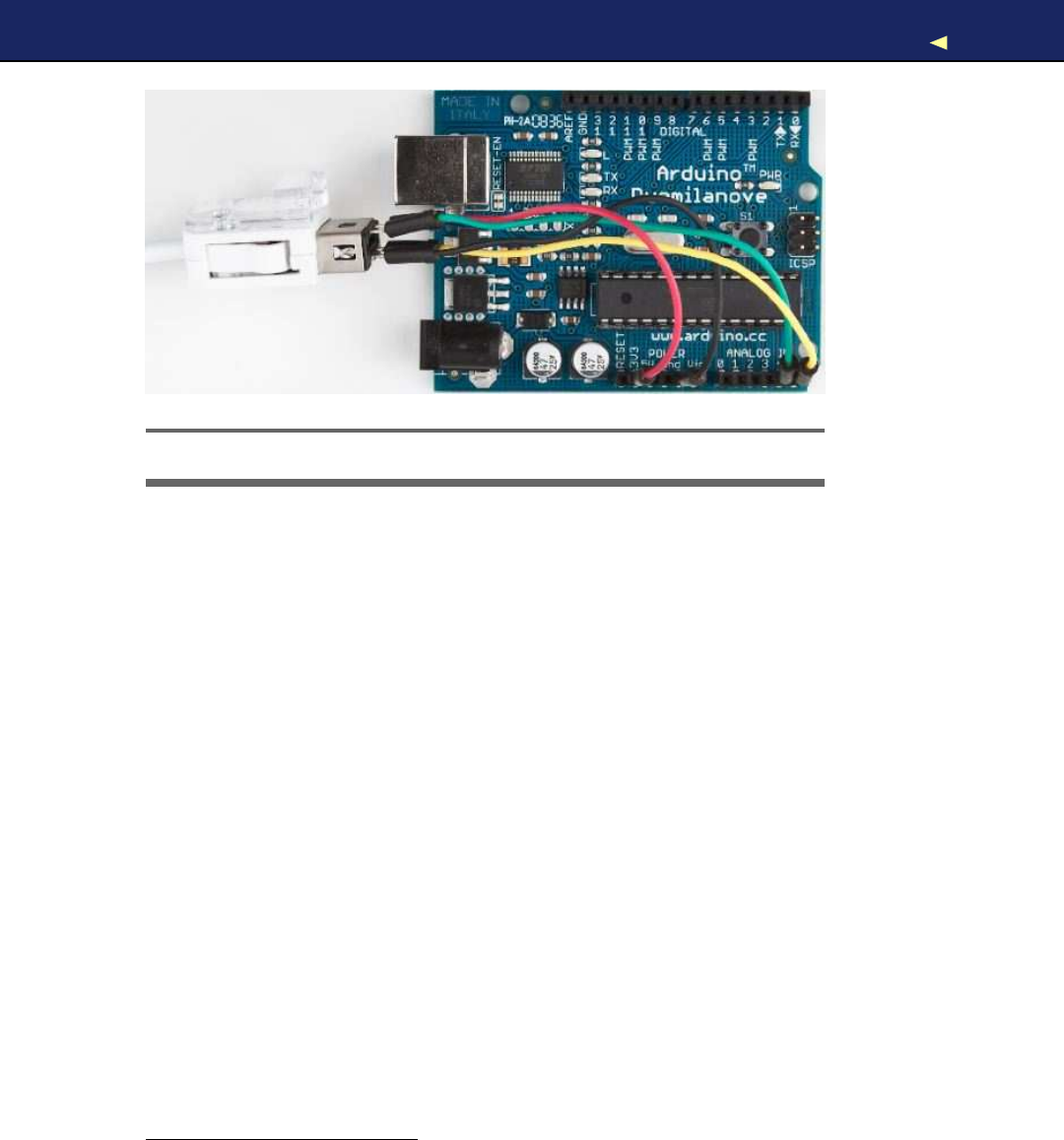
TALKINGTOANUNCHUK 156
Figure 7.2: How to connect aNunchuk to an Arduino
That’s really all you have to do to connect aNunchuk controller to an
Arduino. In the next section, you’ll see that the two wires connected to
analog pins 4 and 5 are all we need to interface with the controller.
7.3 T a l k i n g to a Nunchuk
No official documentation shows how aNunchuk works internally or
how you can use it in anon-Wii environment. But some smart hackers
and makers on the Internet invested alot of time to reverse-engineer
what’s happening inside the controller.1
All in all, it’s really simple, because the Nunchuk uses the Two-Wire
Interface (TWI), also known as I
2
C(Inter-Integrated Circuit) protocol.2
It enables devices to communicate via amaster/slave data bus using
only two wires. Y o u transmit data on one wire (DATA), while the other
synchronizes the communication (CLOCK).
The Arduino IDE comes with alibrary named W i r e that implements the
I
2
Cprotocol. It expects the data line to be connected to analog pin 4
and the clock line to analog pin 5. W e ’ l l use it shortly to communicate
with the Nunchuk, but before that, we’ll have alook at the commands
the controller understands.3
1. http://www.windmeadow.com/node/42
2. http://en.wikipedia.org/wiki/I2c
3. At http://todbot.com/blog/2010/09/25/softi2cmaster-add-i2c-to-any-arduino-pins/,you can
find a library that allows you to use any pair of pins for I
2
Ccommunication.
Report erratum
this copy is (P1.0 printing, Ja nu ra r y, 2011)
Download from Wow! eBook <www.wowebook.com>

TALKINGTOANUNCHUK 157
Improve P e o p l e ’ s Life with Tinkering
Because of its popularity, peripheral equipment f o r modern
g a m e consoles often is unbelievably cheap. Also, it’s no longer
limited to classic controllers; y o u can buy things like snowboard
simulators or cameras. So, it comes as no surprise that creative
people have built m a n y interesting projects using hardware
that w a s originally built f o r playing g a m e s .
An impressive and useful tinkering project is the Eyewriter.∗It
uses the PlayStation Eye (a camera f o r Sony’s PlayStation 3) to
track the movement of human e y e s .
Ateam of hackers built it to enable their paralyzed friend to
draw graffiti using his e y e s . Because of adisease, this friend, an
artist, is almost completely physically paralyzed and can only
move his e y e s . With the Eyewriter, he is ableto create amazing
artwork again.
It’s not an Arduino project but definitely w o r t h alook.
∗.http://www.eyewriter.org/
To be honest, the Nunchuk understands only asingle command: “Give
me all your data.” Whenever it receives this command, it returns six
bytes that have the following meaning (see the data structure in Fig-
ure 7.3,on the following page):
•Byte 1contains the analog stick’s x-axis value, and in byte 2you’ll
find the stick’s y-axis value. Both are 8-bit numbers and range
from about 29 to 225.
•Acceleration values for the x-, y-, and z-axes are three 10-bit num-
bers. Bytes 3, 4, and 5 contain their eight most significant bits.
Y o u can find the missing two bits for each of them in byte 6.
•Byte 6has to be interpreted bit-wise. Bit 0(the least significant
bit) contains the status of the Z-button. It’s 0if the button was
pressed; otherwise, it is 1. Bit 1contains the C-button’s status.
The remaining six bits contain the missing least significant bits of
the acceleration values. Bits 2 and 3 belong to the X axis, bits 4
and 5 belong to Y , and bits 6 and 7 belong to Z.
Now that we know how to interpret the data we get from the Nunchuk,
we can start to build aNunchuk class to control it.
Report erratum
this copy is (P1.0 printing, Ja nu ra r y, 2011)
Download from Wow! eBook <www.wowebook.com>

TALKINGTOANUNCHUK 158
7 6 5 4 3 2 1 0
Joystick x position
Joystick y position
X acceleration bits 9..2
Y a c c e l e r a t i o n b i t s 9 . . 2
Z acceleration bits 9..2
Bit
Byte 1
Byte 2
Byte 3
Byte 4
Byte 5
Byte 6 Z accel.
bits 1..0
Y a c c e l .
bits 1..0
X accel.
bits 1..0 status
ZC
status
Figure 7.3: The Nunchuk always returns 6bytes of data.
Scientific Applications Using Wii Equipment
Because of the Wii’s accuracy and cheap price, m a n y sci-
entists use Wii equipment f o r other things than g a m i n g . Some
h y d r o l o g i s t s use it f o r measuring e v a p o r a t i o n on a body of
w a t e r . ∗Usually, y o u ’ d need equipment costing more than $500
to do that.
Some doctors at the University of Melbourne had acloser look
at the Wii Balance Board, because they w e r e looking f o r a
cheap device to help stroke victims recover.†They’ve published
ascientific paper v e r i f y i n g that the board’s data is clinically
comparable to that of alab-grade “force platform” f o r atiny
fraction of the costs.
∗.http://www.wired.com/wiredscience/2009/12/wiimote-science/
†.http://www.newscientist.com/article/mg20527435.300-wii-board-helps-physios-strike-a-balance-after-strokes.html
Report erratum
this copy is (P1.0 printing, Ja nu ra r y, 2011)
Download from Wow! eBook <www.wowebook.com>

BUILDINGANUNCHUK CLASS 159
7.4 Building a Nunchuk Class
The interface of our Nunchuk class (and the main part of its implemen-
tation) looks as follows:
Download MotionSensor/NunchukDemo/nunchuk.h
Line 1#ifndef __NUNCHUK_H__
-#define __NUNCHUK_H__
-
-#define NUNCHUK_BUFFER_SIZE 6
5
-class Nunchuk {
-public:
-void initialize();
-bool update();
10
-int joystick_x() const {return _buffer[0]; }
-int joystick_y() const {return _buffer[1]; }
-
-int x_acceleration() const {
15 return ((int)(_buffer[2]) << 2) |((_buffer[5] >> 2) &0x03);
-}
-
-int y_acceleration() const {
-return ((int)(_buffer[3]) << 2) |((_buffer[5] >> 4) &0x03);
20 }
-
-int z_acceleration() const {
-return ((int)(_buffer[4]) << 2) |((_buffer[5] >> 6) &0x03);
-}
25
-bool z_button() const {return !(_buffer[5] &0x01); }
-bool c_button() const {return !(_buffer[5] &0x02); }
-
-private:
30 void request_data();
-char decode_byte(const char);
-
-unsigned char _buffer[NUNCHUK_BUFFER_SIZE];
-};
35
-#endif
This small C++ class is all you need to use aNunchuk controller with
your Arduino. It starts with adouble-include prevention mechanism: it
checks whether apreprocessor macro named __NUNCHUK_H__ has been
defined already using #ifndef.If it hasn’t been defined, we define it and
continue with the declaration of the Nunchuk class. Otherwise, the pre-
processor skips the declaration, so you can safely include this header
file more than once in your application.
Report erratum
this copy is (P1.0 printing, Ja nu ra r y, 2011)
Download from Wow! eBook <www.wowebook.com>

BUILDINGANUNCHUK CLASS 160
In line 4, we create aconstant for the size of the array we need to store
the data the Nunchuk returns. W e define this array in line 33, and in
this case, we define the constant using the preprocessor instead of the
const keyword, because array constants must be known at compile time
in C++.
Then the actual declaration of the Nunchuk class begins. To initiate the
communication channel between Arduino and Nunchuk, you have to
invoke the initialize( ) method once. Then you call update( ) whenever you
want the Nunchuk to send new data. Y o u ’ l l see the implementation of
these two methods shortly.
W e have public methods for getting all attributes the Nunchuk returns:
the x and y positions of the analog stick, the button states, and the
acceleration values of the x-, y-, and z-axes. All these methods operate
on the raw data you can find in the buffer in line 33. Their implemen-
tation is mostly trivial and requires only asingle line of code. Only the
assembly of the 10-bit acceleration values needs some tricky bit opera-
tions (see Section B.2,Bit Operations,on page 249).
At the end of the class declaration you find two private helper methods
we need to implement: initialize( ) and update():
Download MotionSensor/NunchukDemo/nunchuk.cpp
Line 1#include <WProgram.h>
-#include <Wire.h>
-#include
"nunchuk.h"
-
5#define NUNCHUK_DEVICE_ID 0x52
-
-void Nunchuk::initialize() {
-Wire.begin();
-Wire.beginTransmission(NUNCHUK_DEVICE_ID);
10 Wire.send(0x40);
-Wire.send(0x00);
-Wire.endTransmission();
-update();
-}
15
-bool Nunchuk::update() {
-delay(1);
-Wire.requestFrom(NUNCHUK_DEVICE_ID, NUNCHUK_BUFFER_SIZE);
-int byte_counter =0;
20 while (Wire.available() && byte_counter <NUNCHUK_BUFFER_SIZE)
-_buffer[byte_counter++] =decode_byte(Wire.receive());
-request_data();
-return byte_counter == NUNCHUK_BUFFER_SIZE;
-}
Report erratum
this copy is (P1.0 printing, Ja nu ra r y, 2011)
Download from Wow! eBook <www.wowebook.com>
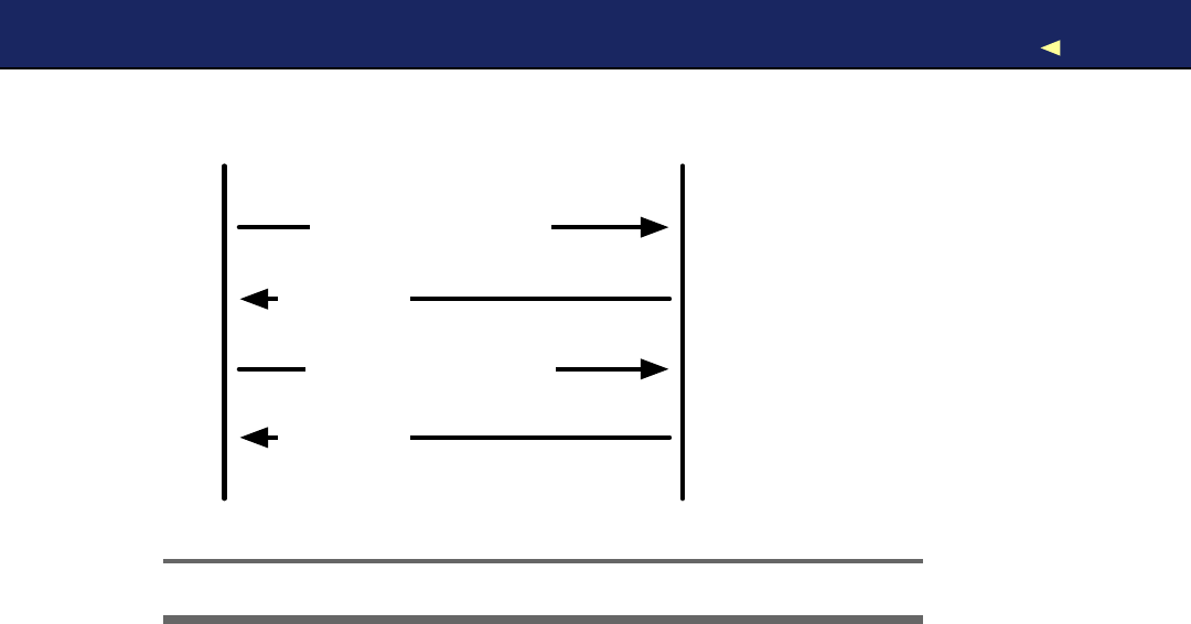
BUILDINGANUNCHUK CLASS 161
Arduino Nunchuk
6 data bytes
Handshake (0x40, 0x00)
Request new data (0x00)
6 data bytes }repeat
Figure 7.4: Message flow between Arduino and Nunchuk
25
-void Nunchuk::request_data() {
-Wire.beginTransmission(NUNCHUK_DEVICE_ID);
-Wire.send(0x00);
-Wire.endTransmission();
30 }
-
-char Nunchuk::decode_byte(const char b) {
-return (b ^0x17) +0x17;
-}
After including all libraries we need, we define the NUNCHUK_DEVICE_ID
constant. I
2
Cis amaster/slave protocol; in our case, the Arduino will
be the master, and the Nunchuk will be the slave. The Nunchuk regis-
ters itself at the data bus using acertain ID (0x52), so we can address
it whenever we need something.
In initialize(), we establish the connection between the Arduino and the
Nunchuk by sending ahandshake. In line 8, we call Wire’s begin( )
method, so the Arduino joins the I
2
Cbus as a master (if you pass
begin( ) an ID, it joins the bus as a slave having this ID). Then we begin
anew transmission to the device identified by NUNCHUCK_DEVICE_ID:our
Nunchuk.
Report erratum
this copy is (P1.0 printing, Ja nu ra r y, 2011)
Download from Wow! eBook <www.wowebook.com>

USINGOURNUNCHUK CLASS 162
W e send two bytes (0x40 and 0x00) to the Nunchuk, and then we end
the transmission. This is the whole handshake procedure, and now
we can ask the Nunchuk for its current status by calling update(). In
Figure 7.4,on the preceding page, we see the message flow between an
Arduino and a Nunchuk.
update( ) first pauses for amillisecond to let things settle abit. Then
we request six bytes from the Nunchuk, calling Wire.requestFrom(). This
does not actually return the bytes, but we have to read them in aloop
and fill our buffer. Wire.available( ) returns the number of bytes that are
available on the data bus, and Wire.receive( ) returns the current byte.
W e cannot use the bytes we get from the Nunchuk directly, because the
controller obfuscates them abit. “Decrypting” them is easy as you can
see in decode_byte().
Finally, we call request_data( ) to tell the Nunchuk to prepare new data.
It transmits asingle zero byte to the Nunchuk, which means “prepare
the next six bytes.”
Before we actually use our Nunchuk class in the next section, take alook
at the documentation of the W i r e library. In the Arduino IDE’s menu,
choose Help > Reference, and click the Libraries link.
7.5 Using Our Nunchuk Class
Let’s use the Nunchuk class to see what data the controller actually
returns:
Download MotionSensor/NunchukDemo/NunchukDemo.pde
#include <Wire.h>
#include
"nunchuk.h"
const unsigned int BAUD_RATE =19200;
Nunchuk nunchuk;
void setup() {
Serial.begin(BAUD_RATE);
nunchuk.initialize();
}
void loop() {
if (nunchuk.update()) {
Serial.print(nunchuk.joystick_x());
Serial.print(
""
);
Serial.print(nunchuk.joystick_y());
Report erratum
this copy is (P1.0 printing, Ja nu ra r y, 2011)
Download from Wow! eBook <www.wowebook.com>

ROTATINGACOLORFUL CUBE 163
Serial.print(
""
);
Serial.print(nunchuk.x_acceleration());
Serial.print(
""
);
Serial.print(nunchuk.y_acceleration());
Serial.print(
""
);
Serial.print(nunchuk.z_acceleration());
Serial.print(
""
);
Serial.print(nunchuk.z_button());
Serial.print(
""
);
Serial.println(nunchuk.c_button());
}
}
No big surprises here: we define aglobal Nunchuk object and initial-
ize it in the setup( ) function. In loop(), we call update( ) to request the
controller’s current status and output all attributes to the serial port.
Compile and upload the program, and then open the serial monitor and
play around with the Nunchuk. Move the stick, move the controller, and
press the buttons, and you should see something like this:
46 109 428 394 651 1 1
49 132 414 380 656 1 0
46 161 415 390 651 1 0
46 184 429 377 648 1 0
53 199 404 337 654 1 0
53 201 406 359 643 10
Y o u have successfully connected aNunchuk controller to your Arduino.
It really isn’t rocket science, and in the next section you’ll learn how to
control objects on the screen using the Nunchuk.
7.6 Rotating aColorful Cube
The Nunchuk was primarily designed for controlling video games by
turning physical movements in the real world into virtual movements
on acomputer screen. So, in this section, we’ll do exactly that and
manipulate a3D cube on the screen with aNunchuk (see ascreenshot
in Figure 7.5,on the next page).
Before we start to draw the cube and use the controller, we have to talk
about an aspect we have ignored until now: jitter. Like the game con-
troller we built in Chapter 6,Building a Motion-Sensing Game Controller,
on page 132,the Nunchuk acceleration data has to be stabilized. W e
use the same technique as in Section 6.4,Finding and Polishing Edge
V a l u e s ,on page 137,but this time we’ll implement it in our Processing
code instead of on the Arduino:
Report erratum
this copy is (P1.0 printing, Ja nu ra r y, 2011)
Download from Wow! eBook <www.wowebook.com>

ROTATINGACOLORFUL CUBE 164
Figure 7.5: Controlling a Rotating Cube with aNunchuk
Download MotionSensor/Cube/SensorDataBuffer.pde
Line 1class SensorDataBuffer {
-private int _maxSamples;
-private int _bufferIndex;
-private int[] _xBuffer;
5private int[] _yBuffer;
-private int[] _zBuffer;
-
-public SensorDataBuffer(final int maxSamples) {
-_maxSamples =maxSamples;
10 _bufferIndex =0;
-_xBuffer =new int[_maxSamples];
-_yBuffer =new int[_maxSamples];
-_zBuffer =new int[_maxSamples];
-}
15
-public void addData(final int x, final int y, final int z) {
-if (_bufferIndex >= _maxSamples)
-_bufferIndex =0;
-
20 _xBuffer[_bufferIndex] =x;
-_yBuffer[_bufferIndex] =y;
-_zBuffer[_bufferIndex] =z;
-_bufferIndex++;
-}
25
-public int getX() {
-return getAverageValue(_xBuffer);
-}
-
Report erratum
this copy is (P1.0 printing, Ja nu ra r y, 2011)
Download from Wow! eBook <www.wowebook.com>

ROTATINGACOLORFUL CUBE 165
30 public int getY() {
-return getAverageValue(_yBuffer);
-}
-
-public int getZ() {
35 return getAverageValue(_zBuffer);
-}
-
-private int getAverageValue(final int[] buffer) {
-int sum =0;
40 for (int i = 0; i < _maxSamples; i++)
-sum += buffer[i];
-return (int)(sum /_maxSamples);
-}
-}
SensorDataBuffer encapsulates three buffers for the acceleration data of
the x-, y-, and z-axes. It also stores abuffer index that contains the
current position in the three buffers. The constructor beginning in line
8expects the maximum number of samples (the buffer size) and initial-
izes the buffers and the index.
The addData( ) method takes new values for all three space axes and
appends them to their corresponding buffers. If the buffer runs full,
the oldest buffer entries will be dropped. W i t h getX(), getY(), and getZ(),
you can request the current average acceleration value for each axis.
All three methods delegate their work to the getAverageValue( ) method.
So, now let’s start and work toward drawing a3D cube. First we ini-
tialize all things related to the serial communication with the Arduino
controlling the Nunchuk:
Download MotionSensor/Cube/Cube.pde
import processing.serial.*;
final int LINE_FEED =10;
final int MAX_SAMPLES =16;
Serial arduinoPort;
SensorDataBuffer sensorData =new SensorDataBuffer(MAX_SAMPLES);
As usual, we import the libraries for serial communication and initialize
aglobal Serial object, and this time we also create aSensorDataBuffer
object.
Now we need some constants for the screen dimensions, the Nunchuk
data ranges, and for our 3D calculations:
Report erratum
this copy is (P1.0 printing, Ja nu ra r y, 2011)
Download from Wow! eBook <www.wowebook.com>

ROTATINGACOLORFUL CUBE 166
Download MotionSensor/Cube/Cube.pde
final int WIDTH =500;
final int HEIGHT =500;
final int BAUD_RATE =19200;
final int X_AXIS_MIN =300;
final int X_AXIS_MAX =700;
final int Y_AXIS_MIN =300;
final int Y_AXIS_MAX =700;
final int Z_AXIS_MIN =300;
final int Z_AXIS_MAX =700;
final int MIN_SCALE =5;
final int MAX_SCALE =128;
final float MX =2.0 /(X_AXIS_MAX -X_AXIS_MIN);
final float MY =2.0 /(Y_AXIS_MAX -Y_AXIS_MIN);
final float MZ =2.0 /(Z_AXIS_MAX -Z_AXIS_MIN);
final float BX =1.0 -MX *X_AXIS_MAX;
final float BY =1.0 -MY *Y_AXIS_MAX;
final float BZ =1.0 -MZ *Z_AXIS_MAX;
X_AXIS_MIN and X_AXIS_MAX define the minimum and maximum acceler-
ation values returned by the Nunchuk for the x-axis. The same is true
for Y_AXIS_MIN, and so on. W e ’ l l need the remaining constants (MX,BX,
and so on) to turn acceleration values into angles later, so don’t worry
too much about them.
Next we need some variables to store the cube’s current state: its posi-
tion, the rotation angle for the different axes, and its current scaling:
Download MotionSensor/Cube/Cube.pde
int xpos =WIDTH /2;
int ypos =HEIGHT /2;
int scale =90;
float xrotate =0.0;
float yrotate =0.0;
float zrotate =0.0;
In the setup( ) method, we initialize the screen and the serial port:
Download MotionSensor/Cube/Cube.pde
Line 1void setup() {
2size(WIDTH, HEIGHT, P3D);
3noStroke();
4colorMode(RGB, 1);
5background(0);
6println(Serial.list());
7arduinoPort =new Serial(this, Serial.list()[0], BAUD_RATE);
8arduinoPort.bufferUntil(LINE_FEED);
9}
Report erratum
this copy is (P1.0 printing, Ja nu ra r y, 2011)
Download from Wow! eBook <www.wowebook.com>

ROTATINGACOLORFUL CUBE 167
The only thing worth mentioning is the call to colorMode( ) in line 4. It
determines that we specify colors as RGB values in the range from 0to
1. This helps us make the cube very colorful (the 3D drawing portion of
this code was derived from one of Processing’s standard examples).
Y o u can draw the cube with Processing as follows:
Download MotionSensor/Cube/Cube.pde
Line 1void draw() {
-background(0);
-pushMatrix();
-
5translate(xpos, ypos, -30);
-rotateX(yrotate);
-rotateY(xrotate);
-rotateZ(zrotate);
-scale(scale);
10
-beginShape(QUADS);
-fill(0, 1, 1); vertex(-1, 1, 1);
-fill(1, 1, 1); vertex( 1, 1, 1);
-fill(1, 0, 1); vertex( 1, -1, 1);
15 fill(0, 0, 1); vertex(-1, -1, 1);
-
-fill(1, 1, 1); vertex( 1, 1, 1);
-fill(1, 1, 0); vertex( 1, 1, -1);
-fill(1, 0, 0); vertex( 1, -1, -1);
20 fill(1, 0, 1); vertex( 1, -1, 1);
-
-fill(1, 1, 0); vertex( 1, 1, -1);
-fill(0, 1, 0); vertex(-1, 1, -1);
-fill(0, 0, 0); vertex(-1, -1, -1);
25 fill(1, 0, 0); vertex( 1, -1, -1);
-
-fill(0, 1, 0); vertex(-1, 1, -1);
-fill(0, 1, 1); vertex(-1, 1, 1);
-fill(0, 0, 1); vertex(-1, -1, 1);
30 fill(0, 0, 0); vertex(-1, -1, -1);
-
-fill(0, 1, 0); vertex(-1, 1, -1);
-fill(1, 1, 0); vertex( 1, 1, -1);
-fill(1, 1, 1); vertex( 1, 1, 1);
35 fill(0, 1, 1); vertex(-1, 1, 1);
-
-fill(0, 0, 0); vertex(-1, -1, -1);
-fill(1, 0, 0); vertex( 1, -1, -1);
-fill(1, 0, 1); vertex( 1, -1, 1);
40 fill(0, 0, 1); vertex(-1, -1, 1);
-endShape();
-
-popMatrix();
-}
Report erratum
this copy is (P1.0 printing, Ja nu ra r y, 2011)
Download from Wow! eBook <www.wowebook.com>

ROTATINGACOLORFUL CUBE 168
draw( ) defines and fills the six surfaces of the cube using fill( ) and v e r-
tex(). W e define the vertices using base coordinates because we’re scal-
ing the cube to areasonable size in line 9 anyway. Moving and rotating
the cube happens in lines 5to 8.
Because Processing’s draw( ) method resets all matrix manipulations
performed by translate( ) and the rotate methods, we use pushMatrix( )
and popMatrix( ) to store and restore them.
Finally, we have to take the Nunchuk data and turn it into suitable
arguments for our vector manipulation functions:
Download MotionSensor/Cube/Cube.pde
Line 1void serialEvent(Serial port) {
-final String arduinoData =port.readStringUntil(LINE_FEED);
-
-if (arduinoData != null) {
5final int[] data =int(split(trim(arduinoData), ''));
-if (data.length == 7) {
-xpos =int(map(data[0], 0x1e, 0xe1, 0, WIDTH));
-ypos =int(map(data[1], 0x1d, 0xdf, HEIGHT, 0));
-
10 if (data[5] == 1) scale++;
-if (data[6] == 1) scale--;
-if (scale <MIN_SCALE) scale =MIN_SCALE;
-if (scale >MAX_SCALE) scale =MAX_SCALE;
-
15 sensorData.addData(data[2], data[3], data[4]);
-
-final float gx =MX *sensorData.getX() +BX;
-final float gy =MY *sensorData.getY() +BY;
-final float gz =MZ *sensorData.getZ() +BZ;
20
-xrotate =atan2(gx, sqrt(gy *gy +gz *gz));
-yrotate =atan2(gy, sqrt(gx *gx +gz *gz));
-zrotate =atan2(sqrt(gx *gx +gy *gy), gz);
-}
25 }
-}
Reading, splitting, and converting the data we read from the serial port
is business as usual. The interesting part starts in line 7where we map
the analog stick’s xposition to anew xcoordinate for our cube. In the
following line, we do the same for the ycoordinate.
W e handle the state of the Nunchuk buttons in lines 10 to 13. If you
press the Z-button, the cube will grow. Press the C-button to shrink it.
Report erratum
this copy is (P1.0 printing, Ja nu ra r y, 2011)
Download from Wow! eBook <www.wowebook.com>

WHAT IFITDOESN’TWORK?169
The rest of the serialEvent( ) method turns the controller’s acceleration
values into angles. I won’t explain the underlying math in detail—it’s
rather complicated and pretty much unrelated to our main topic.
Start the program and play around with the cube. Isn’t it great how
easy it is? W e only needed four wires and a small piece of software,
and now we can use the superb but cheap Nunchuk hardware for our
own projects, both software and hardware. W e could use it to control a
robot; some people even use it to make music.4
The next time you buy anew piece of hardware, try to imagine how
to use it in adifferent context. Often it’s easier than you think. Oh,
and whenever you create aclass such as our Nunchuk class, consider
turning your code into alibrary and making it available on the Internet
(see Chapter 4,Building a Morse Code Generator Library,on page 88 to
learn how to create your own libraries).
7.7 What If It Doesn’t W o r k ?
From amaker’s perspective, this project is an easy one. Still, things can
go wrong, especially with the wiring. Make sure you have connected the
right pins on the Arduino and on the Nunchuk. Also check that the
wires tightly fit into the Nunchuk’s and the Arduino’s sockets. When in
doubt, use wire with alarger diameter.
7.8 Exercises
• Rewrite the game we implemented in Section 6.6,W r i t i n g Y o u r
Own Game,on page 144,so it supports the Nunchuk controller. It
should support both the analog stick and the accelerometer. Per-
haps you can switch between them using the Nunchuk buttons?
•Tinkeringwith Nintendo’s W i i M o t i o n is abit more complicated.5
But it’s anice and cheap way to sharpen your tinkering skills.
4. http://www.youtube.com/watch?v=J4GPS83Rm6M
5. http://randomhacksofboredom.blogspot.com/2009/07/motion-plus-and-nunchuck-together-on.html
Report erratum
this copy is (P1.0 printing, Ja nu ra r y, 2011)
Download from Wow! eBook <www.wowebook.com>

Chapter 8
Networking with Arduino
W i t h astand-alone Arduino, you can create countless fun and useful
projects. But as soon as you turn the Arduino into anetworking device,
you open up awhole new world of possibilities.
Y o u now have access to all information on the Internet, so you could
turn your Arduino into anice geeky weather station simply by reading
data from aweather service. Y o u can also turn the Arduino into aweb
server that provides sensor data for other devices or computers on your
network.
W e will build an emailing burglar alarm in this chapter. It detects
motion in your living room, and the Arduino will send you an email
whenever it detects movement during your absence. Because this is a
somewhat advanced project, we’ll first work on some smaller projects
to learn all techniques and skills needed.
W e ’ l l start with a“naked” Arduino that doesn’t have any network capa-
bilities. Y o u can still attach it to the Internet, as long as you connect it
to aPC.
For our second project, we’ll improve the situation dramatically with
an Ethernet shield. Now your Arduino becomes afull-blown network
device that can directly access IP services such as a DAYTIME service.
This will turn your Arduino into avery accurate clock.
Once we are able to access IP services, we’ll then learn how to send
emails directly from an Arduino with an Ethernet shield. For our bur-
glar alarm, we then only need to know how to detect motion. W e ’ l l use a
passive infrared sensor (PIR) for this purpose, so in this chapter, you’ll
Download from Wow! eBook <www.wowebook.com>
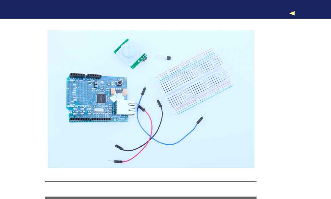
WHAT YOUNEED 171
!
"
#
$
%
Figure 8.1: All the parts you need in this chapter
learn not only various networking technologies but also how to use PIR
sensors.
Finally, we’ll combine all the things we learned and build the emailing
burglar alarm. Y o u ’ l l feel much safer as soon as it’s running.
8.1 What Y o u Need
1. An Ethernet shield for the Arduino
2. An TMP36 temperature sensor
3. APIR infrared motion sensor
4. Abreadboard
5. Some wires
6. An Arduino board such as the Uno, Duemilanove, or Diecimila
7. AUSB cable to connect the Arduino to your computer
Report erratum
this copy is (P1.0 printing, Ja nu ra r y, 2011)
Download from Wow! eBook <www.wowebook.com>

USINGYOUR PCTOTRANSFER SENSOR DATATOTHEINTERNET 172
Internet PC
Serial
Connection
Figure 8.2: Connect your Arduino to the Internet using your PC.
8.2 Using Y o u r PC to T r a n s f e r Sensor Data to the Internet
Remember when you connected your PC to the Internet, oh, around
fifteen years ago? It all started with a38,400 baud modem, Netscape
Navigator 3, and one of those AOL floppy disks or CD-ROMs you got in
the mail. Today you probably have broadband access via cable, satel-
lite, or DSL, and it’s probably available everywhere in your house via
W i F i . So, we’ll start by using your existing connection to connect your
Arduino to the Internet.
In Figure 8.2,you can see atypical setup for connecting an Arduino to
the Internet. Aprogram runs on your PC and communicates with the
Arduino using the serial port. Whenever the application needs Internet
access, the program on the PC deals with it. Using this architecture,
you can tweet1interesting sensor data.
W e ’ l l build asystem that tweets amessage as soon as the temperature
in your working room or office exceeds acertain threshold, that is, 32
degrees Celsius (90 degrees Fahrenheit). Build the temperature sen-
sor example from Section 5.4,Increasing Precision Using a Temperature
Sensor,on page 113 again (try to do it without looking at Figure 5.6,
on page 114), and upload the following sketch to your Arduino:
Download Ethernet/TwitterTemperature/TwitterTemperature.pde
Line 1#define CELSIUS
-
-const unsigned int TEMP_SENSOR_PIN =0;
-const unsigned int BAUD_RATE =9600;
5const float SUPPLY_VOLTAGE =5.0;
1. http://twitter.com
Report erratum
this copy is (P1.0 printing, Ja nu ra r y, 2011)
Download from Wow! eBook <www.wowebook.com>

USINGYOUR PCTOTRANSFER SENSOR DATATOTHEINTERNET 173
-
-void setup() {
-Serial.begin(BAUD_RATE);
-}
10
-void loop() {
-const int sensor_voltage =analogRead(TEMP_SENSOR_PIN);
-const float voltage =sensor_voltage *SUPPLY_VOLTAGE /1024;
-const float celsius =(voltage *1000 -500) /10;
15 #ifdef CELSIUS
-Serial.print(celsius);
-Serial.println(
"C"
);
-#else
-Serial.print(9.0 /5.0 *celsius +32.0);
20 Serial.println(
"F"
);
-#endif
-delay(5000);
-}
This is nearly the same sketch we have used before. Keep in mind that
you have to set SUPPLY_VOLTAGE to 3.3 in line 5, if you’re using an Arduino
that runs with 3.3V instead of 5V.
W e support both Celsius and Fahrenheit values now, and you can con-
trol which unit should be used with apreprocessor constant. If you set
the constant CELSIUS in the first line, the application outputs the tem-
perature in degree Celsius. If you remove the first line or turn it into a
comment line, Fahrenheit will be used.
To change the application’s behavior, we use the #ifdef preprocessor
directive. It checks whether acertain preprocessor constant has been
set, and then it compiles code conditionally. In our case, it will compile
the Celsius-to-Fahrenheit formula in line 19 only if the constant CELSIUS
has not been set.
Upload the sketch, and it will output the current temperature to the
serial port every five seconds. Its output looks as follows:
27.15 C
26.66 C
27.15 C
What we need now is aprogram running on your PC that reads this
output and tweets amessage as soon as the temperature is greater
than 32 degrees Celsius (90 degrees Fahrenheit). W e could use any
programming language that is capable of reading from aserial port and
that supports Twitter, but because we have used Processing in all other
examples, we’ll use it for this project as well.
Report erratum
this copy is (P1.0 printing, Ja nu ra r y, 2011)
Download from Wow! eBook <www.wowebook.com>

REGISTERING ANAPPLICATIONWITHTWITTER 174
W e b Services f o r Publishing Sensor Data
With the advent of cheap open source hardware and sensors,
w e b services f o r publishing sensor data have become popu-
lar o v e r the past f e w y e a r s . Such services allow y o u to publish,
read, and analyze sensor data. P e o p l e from all o v e r the w o r l d
publish data from their w e a t h e r stations, environmental sensors,
and so on, and m a k e it available f o r free on the Internet.
The most popular services are P a c h u b e ∗and Sensorpedia.†In
principle, they all w o r k the same: y o u register an account, and
y o u get back an API k e y. Then y o u can use this k e y to authenti-
cate against the service and upload sensor data.
∗.http://pachube.com
†.http://sensorpedia.com/
8.3 Registering an Application with T w i t t e r
Before we start coding, we have to register our application at the Twitter
website to get an OAuth access token.2OAuth is an authentication
scheme that allows applications to use other applications’ resources.
In our case, we’ll grant our very own application the right to update our
Twitter feed without using our Twitter username and password.
For along time, Twitter supported HTTP Basic Authentication.3Auto-
matic services only needed ausername and password to request or
update Twitter feeds. But as of August 2010, Twitter has removed sup-
port for Basic Authentication and now uses OAuth.
To get the OAuth access token, register your new application in the
developer section of the Twitter website.4After you’ve logged in, click
the “Register an app” link, and fill out the form you see in Figure 8.3,
on the next page. Make sure you set the application type to Client and
the default access type to Read & W r i t e . Y o u can set the application
name to an arbitrary string, and it will appear on your Twitter chan-
nel whenever you use the application to tweet messages. If you set it
to RescueMeFromWork, for example, your tweets will be published via
RescueMeFromWork.
2. http://en.wikipedia.org/wiki/Oauth
3. http://en.wikipedia.org/wiki/Basic_authentication
4. http://dev.twitter.com
Report erratum
this copy is (P1.0 printing, Ja nu ra r y, 2011)
Download from Wow! eBook <www.wowebook.com>
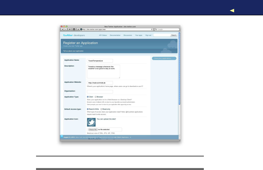
TWEETING MESSAGES WITH PROCESSING 175
Figure 8.3: Register your new Twitter client app first.
After you’ve registered your new application successfully, go to the
application’s settings page to see your consumer key and consumer
secret (see Figure 8.4,on the following page). Y o u need them together
with your OAuth token and your OAuth token secret to allow your
application to modify your Twitter status. To see the OAuth token and
secret, follow the My Access Token link.
Copy the consumer key, the consumer secret, the access token, and
the access token secret. Y o u ’ l l need them in the next section when we
tweet messages using Processing.
8.4 T w e e t i n g Messages with Processing
Processing doesn’t have Twitter support, but in Processing programs,
we have direct access to Java libraries, and you can find several good
Report erratum
this copy is (P1.0 printing, Ja nu ra r y, 2011)
Download from Wow! eBook <www.wowebook.com>

TWEETING MESSAGES WITH PROCESSING 176
Figure 8.4: Consumer credentials are on the settings page.
Twitter libraries for Java. One of them is twitter4j.5W e ’ l l use it because
it’s very mature and has excellent OAuth support.
Download it from its website,6and unpack it to atemporary folder.
Depending on the version you’ve downloaded, you’ll find afile named
twitter4j-core-x.y.z.jar or twitter4j-core-x.y.z-SNAPSHOT.jar in the folder. Open
the Processing IDE, create anew sketch, and then drag and drop the
.jar file to the IDE (the .jar file will automatically be copied to alocal
folder named code). That’s all you have to do to give your application
access to the twitter4j library.
5. http://twitter4j.org/
6. http://twitter4j.org/en/index.html#download
Report erratum
this copy is (P1.0 printing, Ja nu ra r y, 2011)
Download from Wow! eBook <www.wowebook.com>

TWEETING MESSAGES WITH PROCESSING 177
W e proceed with some boilerplate code:
Download Ethernet/TweetTemperature/TweetTemperature.pde
import processing.serial.*;
final float MAX_WORKING_TEMP =32.0;
final int LINE_FEED =10;
final int BAUD_RATE =9600;
final String CONSUMER_KEY =
"<YOUR CONSUMER KEY>"
;
final String CONSUMER_SECRET =
"<YOUR CONSUMER SECRET>"
;
final String ACCESS_TOKEN =
"<YOUR ACCESS TOKEN>"
;
final String ACCESS_TOKEN_SECRET =
"<YOUR ACCESS TOKEN SECRET>"
;
Serial arduinoPort;
void setup() {
println(Serial.list());
arduinoPort =new Serial(this, Serial.list()[0], BAUD_RATE);
arduinoPort.bufferUntil(LINE_FEED);
}
void draw() {}
As usual, we import the serial libraries for communicating with the
Arduino, and then we define some constants we’ll need later. Most of
them contain the credentials we need to access the Twitter service. W i t h
MAX_WORKING_TEMP,you can define at which temperature the applica-
tion starts to tweet. This can be adegree Celsius or Fahrenheit value.
In the setup( ) method, we print out alist of all serial devices available,
and we initialize our serialPort variable with the first one we find, hoping
that it’s the Arduino. Y o u could loop through the list automatically and
search for something that looks like an Arduino port name, but that’d
be fragile, too. W e don’t need any graphical output for our application,
so the draw( ) method remains empty.
Now let’s implement the actual business logic of our “Take me to the
beach” alarm:
Download Ethernet/TweetTemperature/TweetTemperature.pde
void serialEvent(Serial port) {
final String arduinoData =port.readStringUntil(LINE_FEED);
if (arduinoData != null) {
final String[] data =split(trim(arduinoData), '');
if (data.length == 2&&
(data[1].equals(
"C"
)|| data[1].equals(
"F"
)))
{
float temperature =float(data[0]);
Report erratum
this copy is (P1.0 printing, Ja nu ra r y, 2011)
Download from Wow! eBook <www.wowebook.com>

TWEETING MESSAGES WITH PROCESSING 178
println(temperature);
int sleepTime = 5 *60 *1000;
if (temperature >MAX_WORKING_TEMP) {
tweetAlarm();
sleepTime =120 *60 *1000;
}
try {
Thread.sleep(sleepTime);
}
catch(InterruptedException ignoreMe) {}
}
}
}
void tweetAlarm() {
TwitterFactory factory =new TwitterFactory();
Twitter twitter =factory.getInstance();
twitter.setOAuthConsumer(CONSUMER_KEY, CONSUMER_SECRET);
AccessToken accessToken =new AccessToken(
ACCESS_TOKEN,
ACCESS_TOKEN_SECRET
);
twitter.setOAuthAccessToken(accessToken);
try {
Status status =twitter.updateStatus(
"Someone, please, take me to the beach!"
);
println(
"Successfully updated status to '"
+status.getText() +
"'."
);
}
catch (TwitterException e) {
e.printStackTrace();
}
}
In Section 5.8,Implementing Serial Communication in Processing,on
page 126,you learned how to implement serial communication in Pro-
cessing. Whenever new data arrives on the serial port, the runtime envi-
ronment calls the serialEvent( ) method. There we try to read aline of text,
and then we check whether it contains adecimal number followed by
ablank and a Cor Fcharacter. This makes sure we’ve read an actual
temperature data set and not some digital garbage.
If we got asyntactically correct temperature data set, we convert it into
afloat object and check to see if it’s greater than MAX_WORKING_TEMP
(no one should be forced to work at temperatures that high!). If yes, we
call tweetAlarm( ) and tweet amessage to encourage some followers to
rescue us. Then we wait for two hours until our next check. Otherwise,
we wait five minutes and check the temperature again.
Report erratum
this copy is (P1.0 printing, Ja nu ra r y, 2011)
Download from Wow! eBook <www.wowebook.com>
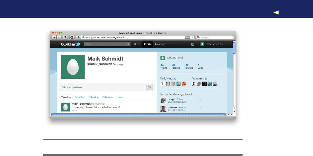
NETWORKING USINGANETHERNET SHIELD 179
Figure 8.5: Ihope someone sees your cry for help.
tweetAlarm( ) updates our Twitter channel and is simple. In good old
Java tradition, we create anew T w i t t e r instance using aT w i t t e r F a c t o r y
and set our consumer credentials by calling setOAuthConsumer(). Then
we set the OAuth credentials calling setOAuthAccessToken(). Finally, we
invoke updateStatus(). If everything went fine, we print asuccess mes-
sage to the console. If anything goes wrong, updateStatus( ) will raise an
exception, and we print its stack trace for debugging purposes.
That’s all the code we need, so connect your Arduino to your PC and
run it! In Figure 8.5,you can see what happens on Twitter when the
temperature in my working room is greater than 32 degrees Celsius (for
your first tests you might have to change 32.0 to asmaller value. If you
don’t have to change it, why aren’t you at the beach?).
Using afull-blown PC as an Internet relay for your Arduino is conve-
nient, but it’s also overkill for most applications. In the next section,
you’ll learn how to turn an Arduino into areal networking device.
8.5 Communicating Over Networks Using an Ethernet Shield
In the previous section, you learned how to build network applications
with an Arduino by using your PC’s network connection. This approach
works nicely, but it also has afew disadvantages. The biggest problem is
Report erratum
this copy is (P1.0 printing, Ja nu ra r y, 2011)
Download from Wow! eBook <www.wowebook.com>

NETWORKING USINGANETHERNET SHIELD 180
T w e e t i n g Arduinos
One of the most popular hardware kits available is the Botani-
call.∗It checks whethery o u r plants need w a t e r , and if they do,
it sends areminder message via http://twitter.com/.As soon as
y o u w a t e r it, it dutifully sends a“Thank Y o u ” message. Although
the official v e r s i o n of the Botanicall is aspecialized piece of
hardware, y o u can build it using an Arduino.†
Botanicalls certainly m a k e y o u r life a bit easier. Whether the
T w i t w e e Clock‡improves y o u r life is am a t t e r of taste. This mod-
ified cuckoo clock looks f o r T w i t t e r updates using a wireless
Internet connection. Whenever it finds a programmable search
term, it displays the corresponding tweets on adisplay and also
pops out acuckoo m a k i n g some noise. Y o u ’ d better ask y o u r
f a m i l y up front before y o u build this project and install it in y o u r
living r o o m .
∗.http://www.botanicalls.com/
†.http://www.botanicalls.com/archived_kits/twitter/
‡.http://www.haroonbaig.com/projects/TwitweeClock/
that you need acomplete PC, while for many applications the Arduino’s
hardware capabilities would be sufficient. In this section, you’ll learn
how to solve this problem with an Ethernet shield.
Y o u can’t connect anaked Arduino to anetwork. Not only are its hard-
ware capabilities too limited, it also doesn’t have an Ethernet port. That
means you can’t plug an Ethernet cable into it, and to overcome this
limitation, you have to use an Ethernet shield. Such shields come with
an Ethernet chip and Ethernet connectors and turn your Arduino into
anetworking device immediately. Y o u only have to plug it in.
Y o u can choose from several products; they all are good and serve their
purpose well.7For prototyping Iprefer the “official” shield,8because it
comes with sockets for all pins (it’s on the left side in Figure 8.6,on the
next page). Also at the time of this writing the Arduino team announced
the Arduino Ethernet, an Arduino board that comes with an Ethernet
port and does not need aseparate shield.
7. See http://www.ladyada.net/make/eshield/,for example.
8. http://www.arduino.cc/en/Main/ArduinoEthernetShield
Report erratum
this copy is (P1.0 printing, Ja nu ra r y, 2011)
Download from Wow! eBook <www.wowebook.com>
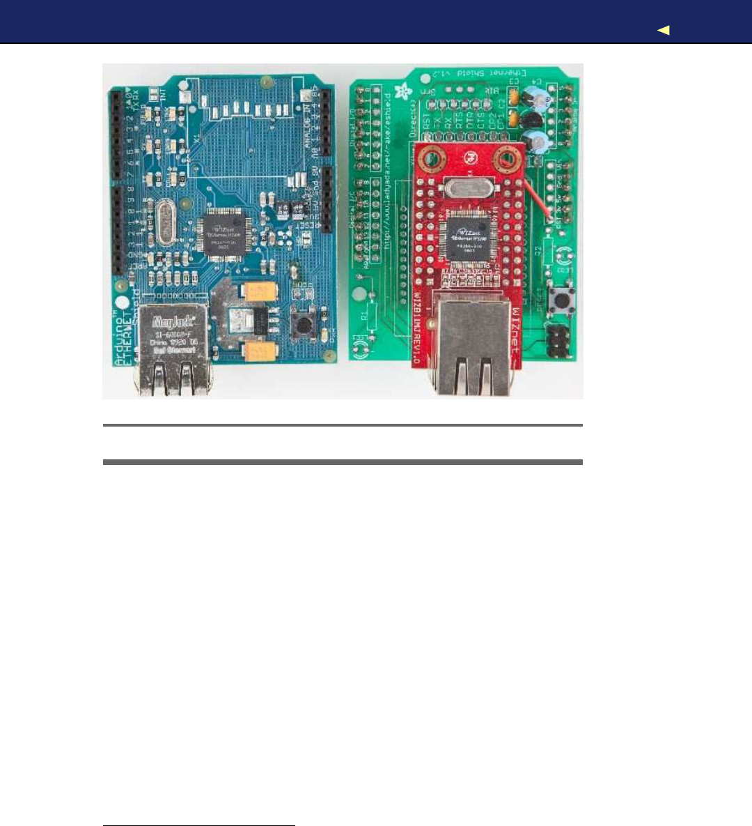
NETWORKING USINGANETHERNET SHIELD 181
Figure 8.6: Two Ethernet shields for the Arduino
Hardware is only one aspect of turning an Arduino into anetwork
device. W e also need some software for network communication. The
Arduino IDE comes with aconvenient Ethernet library that contains a
few classes related to networking. W e will use it now to access a DAY-
TIME service on the Internet.
ADAYTIME service9returns the current date and time as an ASCII
string. DAYTIME servers listen on either TCP or UDP port 13. Y o u
can find many DAYTIME services on the Internet; one of them runs
at time.nist.gov.Before we use the service programmatically with an
Arduino, see how it works using the telnet command:
maik> telnet time.nist.gov 13
Trying 192.43.244.18...
Connected to time.nist.gov.
Escape character is '^]'.
55480 10-10-11 13:25:35 28 0 0 138.5 UTC(NIST) *
Connection closed by foreign host.
9. http://en.wikipedia.org/wiki/DAYTIME
Report erratum
this copy is (P1.0 printing, Ja nu ra r y, 2011)
Download from Wow! eBook <www.wowebook.com>

NETWORKING USINGANETHERNET SHIELD 182
As soon as the telnet command connects to the DAYTIME server, it
sends back the current time and date.10Then the service closes the
connection immediately.
Here’s an implementation of exactly the same behavior for an Arduino
with an Ethernet shield:
Download Ethernet/TimeServer/TimeServer.pde
Line 1#include <SPI.h>
-#include <Ethernet.h>
-
-const unsigned int DAYTIME_PORT =13;
5const unsigned int BAUD_RATE =9600;
-
-byte mac[] ={0xDE, 0xAD, 0xBE, 0xEF, 0xFE, 0xED };
-byte my_ip[] ={192, 168, 2, 120 };
-byte time_server[] ={192, 43, 244, 18 }; // time.nist.gov
10
-Client client(time_server, DAYTIME_PORT);
-
-void setup() {
-Ethernet.begin(mac, my_ip);
15 Serial.begin(BAUD_RATE);
-}
-
-void loop() {
-delay(1000);
20 Serial.print(
"Connecting..."
);
-
-if (!client.connect()) {
-Serial.println(
"connection failed."
);
-}else {
25 Serial.println(
"connected."
);
-delay(1000);
-
-while (client.available()) {
-char c = client.read();
30 Serial.print(c);
-}
-
-Serial.println(
"Disconnecting."
);
-client.stop();
35 }
-}
10. See http://www.nist.gov/physlab/div847/grp40/its.cfm for a detailed description of the date
string’s format.
Report erratum
this copy is (P1.0 printing, Ja nu ra r y, 2011)
Download from Wow! eBook <www.wowebook.com>
NETWORKING USINGANETHERNET SHIELD 183
First, we include the Ethernet library and define aconstant for the
DAYTIME service port (we also have to include the SPI library, because
the Ethernet library depends on it). Then we define three byte arrays:
•m a c contains the MAC address we are going to use for the Eth-
ernet shield. AMAC address is a48-bit number that uniquely
identifies anetwork device.11Usually, the manufacturer sets this
identifier, but for the Ethernet shield, we have to set it ourselves;
we use an arbitrary number.
Important note: the MAC address has to be unique on your net-
work. If you connect more than one Arduino, make sure they all
have different MAC addresses!
•Whenever you connect your PC to the Internet, it probably gets
anew IP address via the Dynamic Host Configuration Protocol
(DHCP).12For most Arduino applications, a DHCP implementation
is comparatively costly, so you usually assign an IP address man-
ually. In most cases, this will be alocal address in the 192.168.x.y
range; we store this address in the m y _ i p array.
•To turn domain names such as time.nist.gov into an IP address,
you need access to the Domain Name System (DNS). The Arduino’s
standard library doesn’t support DNS, so we have to find out the
IP address ourselves. W e assign it to time_server.The telnet com-
mand already turned the DAYTIME service domain name into an
IP address for us. Alternatively, you can use one of the following
commands to determine adomain name’s IP address:
maik> host time.nist.gov
time.nist.gov has address 192.43.244.18
maik> dig +short time.nist.gov
192.43.244.18
maik> resolveip time.nist.gov
IP address of time.nist.gov is 192.43.244.18
maik> ping -c 1time.nist.gov
PING time.nist.gov (192.43.244.18): 56 data bytes
64 bytes from 192.43.244.18: icmp_seq=0 ttl=48 time=173.598 ms
--- time.nist.gov ping statistics ---
1packets transmitted, 1packets received, 0.0% packet loss
round-trip min/avg/max/stddev =173.598/173.598/173.598/0.000 ms
11. http://en.wikipedia.org/wiki/Mac_address
12. http://en.wikipedia.org/wiki/Dynamic_Host_Configuration_Protocol
Report erratum
this copy is (P1.0 printing, Ja nu ra r y, 2011)
Download from Wow! eBook <www.wowebook.com>

NETWORKING USINGANETHERNET SHIELD 184
In line 11, we create anew Client object. This class is part of the Eth-
ernet library and allows us to create network clients that connect to a
certain IP address and port.
Now we have to initialize the Ethernet shield itself; we do this in line
14 in the setup( ) function. W e have to invoke Ethernet.begin(), passing it
our MAC and IP addresses. Then we initialize the serial port so that we
can output some debug messages. At this point, we’ve initialized all the
components we need, so we can finally connect to the DAYTIME server
and read its output.
Please note that you can also pass the IP address of your network gate-
way and your subnet mask to Ethernet.begin(). This is necessary if you
do not connect the Arduino directly to the Internet but use arouter or
acable modem instead. In this case, you can pass the gateway address
as follows:
// ...
byte mac[] ={0xDE, 0xAD, 0xBE, 0xEF, 0xFE, 0xED };
byte my_ip[] = { 192, 168, 2, 120 };
byte time_server[] ={192, 43, 244, 18 }; // time.nist.gov
// Insert IP address of your cable or DSL router below:
byte gateway[] = { 192, 168, 13, 254 };
Client client(time_server, DAYTIME_PORT);
void setup() {
Ethernet.begin(mac, my_ip, gateway);
Serial.begin(BAUD_RATE);
}
// ...
The loop( ) function of our sketch starts with ashort delay, allowing all
components to initialize properly. This is necessary because the Ether-
net shield is an autonomous device that is capable of working in parallel
to the Arduino. In line 22, we try to connect to the DAYTIME service. If
the connection cannot be established, we print an error message. Oth-
erwise, we wait for half asecond to give the service some preparation
time, and then we read and print its output character by character.
Note that the client’s interface is similar to the interface of the Serial
class. W i t h available(), we can check whether some bytes are still avail-
able, and read( ) returns the next byte. At the end, we call stop( ) to
disconnect from the service and then we start again.
Compile and upload the program to the Arduino. Then open the serial
monitor, and you should see something like this:
Report erratum
this copy is (P1.0 printing, Ja nu ra r y, 2011)
Download from Wow! eBook <www.wowebook.com>

NETWORKING USINGANETHERNET SHIELD 185
More Fun with Networking Arduinos
W e a r a b l e s and e-textiles are getting more and more popu-
lar, and they’re still a good w a y to impress y o u r colleagues
and friends. Different types of interactive T - s h i r t s are available
in e v e r y w e l l - a s s o r t e d geek shop. Some of them show the cur-
rent WiFi strength, whileothers come with afull-blown equalizer
that analyzes ambient noise.
With an Arduino Lilypad,∗aBluetooth dongle, and an Android
phone, y o u can build a T - s h i r t that displays the current number
of unread emails in y o u r inbox.†
Not only can y o u show the number of unread email messages
on y o u r T - s h i r t , y o u can also show y o u r current mood using a
pointer device on y o u r desk—at least as long as y o u announce
it in an IRC channel that y o u monitor with an Arduino.‡
Although not built with Arduinos, the Luminet project§is v e r y
impressive. It is anetwork of interconnected intelligent LED pix-
els, and the Luminet team used it to build a really cool interac-
tive jacket.
∗.http://arduino.cc/en/Main/ArduinoBoardLilyPad
†.http://blog.makezine.com/archive/2010/03/email-counting_t-shirt.html
‡.http://blog.makezine.com/archive/2010/01/arduino_powered_mood_meter.html
§.http://luminet.cc
Connecting...connected.
55480 10-10-11 13:32:23 28 0 0 579.9 UTC(NIST) *
Disconnecting.
Connecting...connected.
55480 10-10-11 13:32:26 28 0 0 34.5 UTC(NIST) *
Disconnecting.
W e ’ r e done! Our Arduino is directly connected to the Internet, and it
even does something useful: we’ve turned it into avery accurate clock.
All in all, networking with an Arduino doesn’t differ much from net-
working with aPC, if you use the Ethernet shield. In the next section,
you’ll learn how to send emails with an Arduino.
Report erratum
this copy is (P1.0 printing, Ja nu ra r y, 2011)
Download from Wow! eBook <www.wowebook.com>

EMAILING FROMTHECOMMANDLINE 186
Useful Networking Libraries
The Ethernet library that comes with the Arduino IDE is f a i r l y lim-
ited and not v e r y convenient. For example, it doesn’t support
DNS or DHCP. So f o r advanced projects, y o u should have alook
at the Arduino Ethernet library.∗
If y o u w a n t to turn y o u r Arduino into aw e b server, y o u should
take alook at the W e b d u i n o library.†It has some great f e a t u r e s ,
and it is quite m a t u r e .
But be w a r n e d : all these libraries consume quite a lot of mem-
ory, so there’s not m u c h left f o r y o u r application code. Also,
they are r a t h e r fragile, because they often rely upon the innards
of the official Ethernet library that change from time to time. So,
it might w e l l be that they do not w o r k with the latest Arduino
IDE.
∗.http://gkaindl.com/software/arduino-ethernet
†.http://code.google.com/p/webduino/
8.6 Emailing from the Command Line
Now that we know how to access network services, we’ll continue to
build amore advanced project: an automatic burglar alarm. In case
someone is moving in our living room, we want to get an email, so we
have to learn how to send emails from an Arduino.
Although email is an important service, only afew people know how it
actually works behind the scenes. To send emails from an Arduino, we
could choose the easy path and use aPC as an email relay as we did in
Section 8.4,Tweeting Messages with Processing,on page 175 to tweet
messages. As real hackers, we’ll follow amore sophisticated path and
implement asubset of the Simple Mail TransferProtocol (SMTP).13
SMTP is atypical Internet protocol. It uses only text, and it is mainly
line-based; that is, you exchange information line by line. Atypical
email consists of only afew attributes: a sender, areceiver, asubject,
and a message body. To transmit an email, you have to send arequest
to an SMTP server. The request has to adhere to the SMTP specification.
13. http://en.wikipedia.org/wiki/Smtp
Report erratum
this copy is (P1.0 printing, Ja nu ra r y, 2011)
Download from Wow! eBook <www.wowebook.com>

EMAILING FROMTHECOMMANDLINE 187
Before we send an email using an Arduino and an Ethernet shield,
you should learn how to send an email from acommand line using
the telnet command. To do so, you have to find out the address of an
SMTP server you can use first. The following instructions assume you’re
using aGoogle Mail account (http://gmail.com). If you use adifferent
email provider, you have to adjust the domain names accordingly. In
any case, don’t abuse their service! When in doubt, read their usage
terms!
Open aterminal, and enter the following:
maik> nslookup
>set type=mx
>gmail.com
Server: 192.168.2.1
Address: 192.168.2.1#53
Non-authoritative answer:
gmail.com mail exchanger = 5 gmail-smtp-in.l.google.com.
gmail.com mail exchanger =10 alt1.gmail-smtp-in.l.google.com.
gmail.com mail exchanger =20 alt2.gmail-smtp-in.
>exit
This command returns alist of all the Google Mail exchange servers
(MX) available on your network. Take the first server name, and open
aconnection to the SMTP standard port 25 (replace the server name
gmail-smtp-in.l.google.com and all email addresses accordingly):
⇐maik> telnet gmail-smtp-in.l.google.com 25
⇒Trying 74.125.77.27...
Connected to gmail-smtp-in.l.google.com.
Escape character is '^]'.
220 mx.google.com ESMTP q43si10820020eeh.100
⇐HELO
⇒250 mx.google.com at your service
⇐MAIL FROM: <arduino@example.com>
⇒250 2.1.0 OK q43si10820020eeh.100
⇐RCPT TO: <info@example.com>
⇒250 2.1.5 OK q43si10820020eeh.100
⇐DATA
⇒354 Go ahead q43si10820020eeh.100
⇐from: arduino@example.com
⇐to: info@example.com
⇐subject: This is atest
⇐
⇐Really, this is atest!
⇐.
⇒250 2.0.0 OK 1286819789 q43si10820020eeh.100
⇐QUIT
⇒221 2.0.0 closing connection q43si10820020eeh.100
Connection closed by foreign host.
Report erratum
this copy is (P1.0 printing, Ja nu ra r y, 2011)
Download from Wow! eBook <www.wowebook.com>

EMAILING DIRECTLYFROMANARDUINO 188
Although it is way more complex, this session is similar to our DAYTIME
example. W e only send more complex commands (by the way, you do
not have to write the commands in uppercase). First we send the HELO
command (the spelling is correct) to establish asession with the SMTP
server. Then we tell the server that we’d like to send an email using
MAIL FROM:.The email address we provide with this command will be
used by the server in case our email bounces back. Note that the server
sends back aresponse line for every request. These responses always
start with athree-digit status code.
The RCPT T O : command sets the recipient’s email address. If you’d like
to send an email to more than one recipient, you have to repeat the
command for each of them.
W i t h the D A T A command, we tell the server that we now start to transmit
the email’s attributes. Email attributes are mainly alist of key/value
pairs where key and value are delimited by acolon. So in the first three
lines, we set the attributes “from,” “to,” and “subject,” and they all have
the meaning you’d expect when sending an email.
Y o u separate the email’s body from the attributes using ablank line. To
mark the end of the email body, send aline containing asingle period.
Send the QUIT command to end the session with the SMTP server.
Y o u should find anew email in your inbox. If not, try another MX server
first. Still things can go wrong, and although simple in theory, SMTP
can be acomplex beast in practice. Often SMTP servers return helpful
error messages that might help you to quickly solve your problem.
Don’t proceed until you have successfully sent an email from the com-
mand line, because it is the basis for the next section where you’ll learn
how to send emails with an Arduino.
8.7 Emailing Directly from an Arduino
To send an email from the Arduino, we will basically implement the
telnet session from the previous section line by line. Instead of simply
hardwiring the email’s attributes into the networking code, we will cre-
ate a more advanced design.
Report erratum
this copy is (P1.0 printing, Ja nu ra r y, 2011)
Download from Wow! eBook <www.wowebook.com>

EMAILING DIRECTLYFROMANARDUINO 189
W e start with an Email class:
Download Ethernet/Email/email.h
#ifndef __EMAIL__H_
#define __EMAIL__H_
class Email {
String _from, _to, _subject, _body;
public:
Email(
const String& from,
const String& to,
const String& subject,
const String& body
) : _from(from), _to(to), _subject(subject), _body(body) {}
const String& getFrom() const {return _from; }
const String& getTo() const {return _to; }
const String& getSubject() const {return _subject; }
const String& getBody() const {return _body; }
};
#endif
This class encapsulates an email’s four most important attributes—
the email addresses of the sender and the recipient, asubject, and a
message body. W e store all attributes as String objects.
W a i t aminute...a String class? Y e s ! Since version 19, the Arduino IDE
comes with afull-blown string class.14It does not have as many fea-
tures as the C++ or Java string classes, but it’s still way better than
messing around with char pointers. Y o u ’ l l see how to use it in afew
paragraphs.
The rest of our Email class is pretty straightforward. In the constructor,
we initialize all instance variables, and we have methods for getting
every single attribute. W e now need an SmtpService class for sending
Email objects:
Download Ethernet/Email/smtp_service.h
Line 1#ifndef __SMTP_SERVICE__H_
-#define __SMTP_SERVICE__H_
-
-#include
"email.h"
14. http://arduino.cc/en/Reference/StringObject
Report erratum
this copy is (P1.0 printing, Ja nu ra r y, 2011)
Download from Wow! eBook <www.wowebook.com>

EMAILING DIRECTLYFROMANARDUINO 190
5
-class SmtpService {
-byte*_smtp_server;
-unsigned int _port;
-
10 void read_response(Client& client) {
-delay(4000);
-while (client.available()) {
-const char c = client.read();
-Serial.print(c);
15 }
-}
-
-void send_line(Client& client, String line) {
-const unsigned int MAX_LINE =256;
20 char buffer[MAX_LINE];
-line.toCharArray(buffer, MAX_LINE);
-Serial.println(buffer);
-client.println(buffer);
-read_response(client);
25 }
-
-public:
-
-SmtpService(
30 byte*smtp_server,
-const unsigned int port) :_smtp_server(smtp_server),
-_port(port) {}
-
-void send_email(const Email& email) {
35 Client client(_smtp_server, _port);
-Serial.print(
"Connecting..."
);
-
-if (!client.connect()) {
-Serial.println(
"connection failed."
);
40 }else {
-Serial.println(
"connected."
);
-read_response(client);
-send_line(client, String(
"helo"
));
-send_line(
45 client,
-String(
"mail from: <"
) + email.getFrom() +String(
">"
)
-);
-send_line(
-client,
50 String(
"rcpt to: <"
) + email.getTo() +String(
">"
)
-);
-send_line(client, String(
"data"
));
-send_line(client, String(
"from: "
) + email.getFrom());
-send_line(client, String(
"to: "
) + email.getTo());
55 send_line(client, String(
"subject: "
) + email.getSubject());
Report erratum
this copy is (P1.0 printing, Ja nu ra r y, 2011)
Download from Wow! eBook <www.wowebook.com>

EMAILING DIRECTLYFROMANARDUINO 191
-send_line(client, String(
""
));
-send_line(client, email.getBody());
-send_line(client, String(
"."
));
-send_line(client, String(
"quit"
));
60 client.println(
"Disconnecting."
);
-client.stop();
-}
-}
-};
65
-#endif
Admittedly, this is alot of code, but it’s very simple. First, the SmtpSer-
vice class encapsulates the SMTP server’s IP address and its port.
To communicate with an SMTP server, we have to read its responses,
and we do that using the private read_response( ) method starting on
line 10. It waits for four seconds (SMTP servers usually are very busy,
because they have to send alot of spam), and then it reads all the data
sent back by the server and outputs it to the serial port for debugging
purposes.
Before we can process responses, we have to send requests. send_line( )
beginning in line 18 sends asingle command to an SMTP server. Y o u
have to pass the connection to the server as a Client instance, and the
line you’d like to send has to be aString object.
To send the data stored in aString object, we need to access the char-
acter data it refers to. At the moment of this writing, the Arduino refer-
ence documentation tells you to simply use toCharArray( ) or getBytes( ) to
retrieve this information. Unfortunately, the documentation is wrong.
That is, these two methods do not return apointer. Instead, they expect
you to provide asufficiently large char array and its size. That’s why we
copy line’s content to buffer before we output it to the serial and Ether-
net port. After we’ve sent the data, we read the server’s response and
print it to the serial port.
In the public interface, you do not find any surprises. The construc-
tor expects the SMTP server’s IP address and its port. The send_email( )
method is the largest piece of code in our class, but it’s also one of the
simplest. It mimics exactly our telnet session, and the only thing worth
mentioning is the string handling: we use the Arduino’s new String class,
and to use its concatenation operator (+), we turn every string into a
String object.
Let’s use our classes now to actually send an email:
Report erratum
this copy is (P1.0 printing, Ja nu ra r y, 2011)
Download from Wow! eBook <www.wowebook.com>

DETECTING MOTIONUSINGAPASSIVE INFRARED SENSOR 192
Download Ethernet/Email/Email.pde
Line 1#include <SPI.h>
-#include <Ethernet.h>
-#include
"smtp_service.h"
-
5const unsigned int SMTP_PORT =25;
-const unsigned int BAUD_RATE =9600;
-
-byte mac[] = { 0xDE, 0xAD, 0xBE, 0xEF, 0xFE, 0xED };
-byte my_ip[] = { 192, 168, 2, 120 };
10
-// Insert IP of your SMTP server below!
-byte smtp_server[] ={0, 0, 0, 0};
-
-SmtpService smtp_service(smtp_server, SMTP_PORT);
15
-void setup() {
-Ethernet.begin(mac, my_ip);
-Serial.begin(BAUD_RATE);
-delay(1000);
20 Email email(
-
"arduino@example.com"
,
-
"info@example.net"
,
-
"Yet another subject"
,
-
"Yet another body"
25 );
-smtp_service.send_email(email);
-}
-
-void loop() {}
No surprises here. W e define constants, the MAC address, and so on,
then create an SmtpService instance. In the setup( ) function, we initialize
the serial port and the Ethernet shield, then wait for asecond to let
things settle down abit. On line 20, we create anew Email object and
call its send_email( ) method.
Now we know how to send emails with an Arduino, but to build our
burglar alarm, we still have to learn how to detect motion.
8.8 Detecting Motion Using aP a s s i v e Infrared Sensor
Detecting motion is auseful technique, and you probably already know
devices that turn on the light in your garden or at your door whenever
someone is near enough. Most of them use passive infrared sensors
(PIR)15for motion detection.
15. http://en.wikipedia.org/wiki/Passive_infrared_sensor
Report erratum
this copy is (P1.0 printing, Ja nu ra r y, 2011)
Download from Wow! eBook <www.wowebook.com>
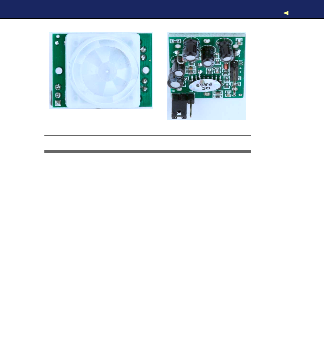
DETECTING MOTIONUSINGAPASSIVE INFRARED SENSOR 193
Figure 8.7: Top and bottom of apassive infrared sensor
Nearly every object emits infrared light, and a PIR sensor (see one in
Figure 8.7)measures exactly this portion of light. Detecting motion is
comparatively easy if you are already able to receive the infrared radia-
tion emitted by objects in the sensor’s field of view. If the sensor receives
the infrared light emitted by awall, for example, and suddenly ahuman
being or an animal moves in front of the wall, the infrared light signal
will change.
Off-the-shelf sensors hide these details, so you can use asingle digital
pin to check whether someone is moving in the sensor’s field of view.
The Parallax PIR sensor16is agood example of such adevice, and we’ll
use it as the basis of our burglar alarm.
The PIR sensor has three pins: power, ground, and signal. Connect
power to the Arduino’s 5V supply, ground to one of the Arduino’s GND
pins, and signal to digital pin 2(see acircuit diagram in Figure 8.8,
on the following page). The sensor also has ajumper that you can use
for changing its behavior. For our project, it has to be in position H;
that is, the jumper has to cover the pin next to the H(Lady Ada has an
excellent tutorial on PIR sensors).17
Then enter the following code in the Arduino IDE:
16. http://www.parallax.com/Store/Sensors/ObjectDetection/tabid/176/ProductID/83/List/0/Default.aspx
17. http://www.ladyada.net/learn/sensors/pir.html
Report erratum
this copy is (P1.0 printing, Ja nu ra r y, 2011)
Download from Wow! eBook <www.wowebook.com>
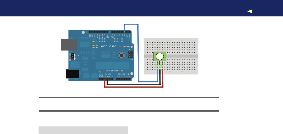
DETECTING MOTIONUSINGAPASSIVE INFRARED SENSOR 194
Figure 8.8: Aminimalistic PIR sensor circuit
Download Ethernet/MotionDetector/MotionDetector.pde
Line 1const unsigned int PIR_INPUT_PIN =2;
-const unsigned int BAUD_RATE =9600;
-
-class PassiveInfraredSensor {
5int _input_pin;
-
-public:
-
-PassiveInfraredSensor(const int input_pin) {
10 _input_pin =input_pin;
-pinMode(_input_pin, INPUT);
-}
-
-const bool motion_detected() const {
15 return digitalRead(_input_pin) == HIGH;
-}
-};
-
-PassiveInfraredSensor pir(PIR_INPUT_PIN);
20
-void setup() {
-Serial.begin(BAUD_RATE);
-}
-
25 void loop() {
-if (pir.motion_detected()) {
-Serial.println(
"Motion detected"
);
-}else {
-Serial.println(
"No motion detected"
);
30 }
-delay(200);
-}
Report erratum
this copy is (P1.0 printing, Ja nu ra r y, 2011)
Download from Wow! eBook <www.wowebook.com>
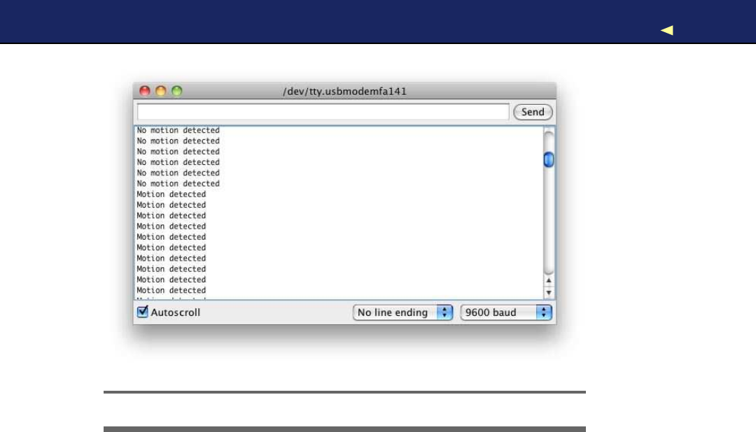
DETECTING MOTIONUSINGAPASSIVE INFRARED SENSOR 195
Figure 8.9: Typical output of aPIR sensor
W i t h the constant PIR_INPUT_PIN,you can define the digital pin you’ve
connected your PIR sensor to. In line 4, we begin the definition of a
class named P a s s i v e I n f r a r e d S e n s o r that encapsulates all things related to
PIR sensors.
W e define amember variable named _input_pin that stores the number
of the digital pin we’ve connected our sensor to. Then we define acon-
structor that expects the pin number as an argument and assigns it to
our member variable.
The only method we need to define is motion_detected(). It returns true
if it has currently detected amotion and f a l s e otherwise. So, it has to
check only whether the current state of the sensor’s digital pin is HIGH
or LOW.
Compile the sketch, upload it to your Arduino, and you should see an
output similar to Figure 8.9 when you start to wave with your hand in
front of the sensor.
Now we’ve built the two main components of our burglar alarm, and
the only thing left to do is to bring them both together. W e ’ l l do that in
the next section.
Report erratum
this copy is (P1.0 printing, Ja nu ra r y, 2011)
Download from Wow! eBook <www.wowebook.com>
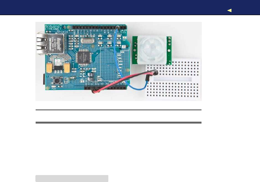
BRINGING ITALLTOGETHER 196
Figure 8.10: An emailing burglar alarm
8.9 Bringing It All T o g e t h e r
W i t h our P a s s i v e I n f r a r e d S e n s o r and SmtpService classes, it’s apiece of cake
to build an emailing burglar alarm. Connect the PIR sensor to the Eth-
ernet shield, as shown in Figure 8.10, and upload the following code to
your Arduino:
Download Ethernet/BurglarAlarm/burglar_alarm.h
Line 1#ifndef __BURGLAR_ALARM_H__
-#define __BURGLAR_ALARM_H__
-
-#include
"pir_sensor.h"
5#include
"smtp_service.h"
-
-class BurglarAlarm {
-PassiveInfraredSensor _pir_sensor;
-SmtpService _smtp_service;
10
-void send_alarm() {
-Email email(
-
"arduino@example.com"
,
-
"info@example.net"
,
15
"Intruder Alert!"
,
-
"Someone's moving in your living room!"
-);
-_smtp_service.send_email(email);
-}
20
Report erratum
this copy is (P1.0 printing, Ja nu ra r y, 2011)
Download from Wow! eBook <www.wowebook.com>

BRINGING ITALLTOGETHER 197
-public:
-
-BurglarAlarm(
-const PassiveInfraredSensor& pir_sensor,
25 const SmtpService& smtp_service) :
-_pir_sensor(pir_sensor),
-_smtp_service(smtp_service)
-{
-}
30
-void check() {
-Serial.println(
"Checking"
);
-if (_pir_sensor.motion_detected()) {
-Serial.println(
"Intruder detected!"
);
35 send_alarm();
-}
-}
-};
-
40 #endif
This defines aclass named BurglarAlarm that aggregates all the code
we’ve written so far. It encapsulates aSmtpService instance and a P a s -
siveInfraredSensor object. Its most complex method is send_alarm( ) that
sends apredefined email.
The rest of the BurglarAlarm class is pretty straightforward. Beginning
in line 23, we define the constructor that initializes all private mem-
bers. The check( ) method checks whether the PIR sensor has detected
amovement. If it did, we send an email.
Let’s use the BurglarAlarm class:
Download Ethernet/BurglarAlarm/BurglarAlarm.pde
#include <SPI.h>
#include <Ethernet.h>
#include
"burglar_alarm.h"
const unsigned int PIR_INPUT_PIN =2;
const unsigned int SMTP_PORT =25;
const unsigned int BAUD_RATE =9600;
byte mac[] = { 0xDE, 0xAD, 0xBE, 0xEF, 0xFE, 0xED };
byte my_ip[] = { 192, 168, 2, 120 };
// Insert IP of your SMTP server below!
byte smtp_server[] ={0, 0, 0, 0};
PassiveInfraredSensor pir_sensor(PIR_INPUT_PIN);
SmtpService smtp_service(smtp_server, SMTP_PORT);
Report erratum
this copy is (P1.0 printing, Ja nu ra r y, 2011)
Download from Wow! eBook <www.wowebook.com>
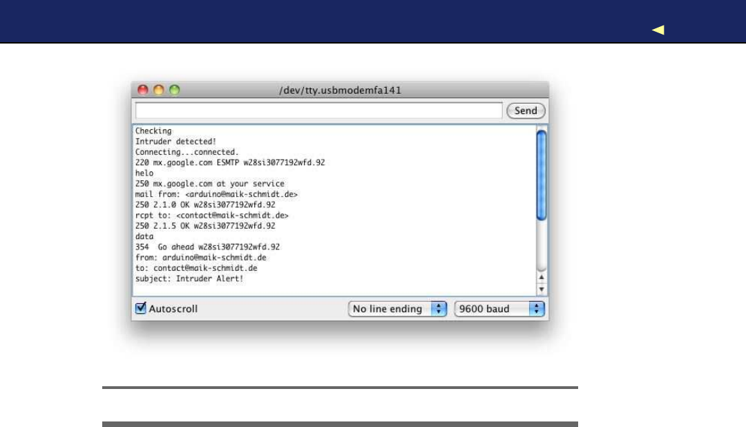
BRINGING ITALLTOGETHER 198
Figure 8.11: The burglar alarm’s output
BurglarAlarm burglar_alarm(pir_sensor, smtp_service);
void setup() {
Ethernet.begin(mac, my_ip);
Serial.begin(BAUD_RATE);
delay(20 *1000);
}
void loop() {
burglar_alarm.check();
delay(3000);
}
First we define all the libraries we need, and we define constants for
the PIR sensor pin and our MAC address. Then we define SmtpService
and P a s s i v e I n f r a r e d S e n s o r objects and use them to define aBurglarAlarm
instance.
In the setup( ) method, we define the serial port and the Ethernet shield.
I’ve also added a delay of twenty seconds, which gives you enough time
to leave the room before the alarm begins to work.
Report erratum
this copy is (P1.0 printing, Ja nu ra r y, 2011)
Download from Wow! eBook <www.wowebook.com>

WHAT IFITDOESN’TWORK?199
The loop( ) function is simple, too. It delegates all the work to the Burglar-
Alarm’s check( ) method. In Figure 8.11,on the previous page, you can
see what happens when the burglar alarm detects an intruder.
Did you notice how easy object-oriented programming on an embedded
device can be? W e ’ v e cleanly hidden the complexity of both email and
the PIR sensor in two small classes. Tobuild the burglar alarm, we then
only had to write some glue code.
One word regarding privacy: do not abuse the project in this chapter to
observe other people without their knowledge. Not only is it unethical,
but in many countries it even is illegal!
In this chapter, you learned different ways of connecting the Arduino
to the Internet. Some of them need an additional PC, while others need
an Ethernet shield, but they all open the door to awhole new range of
embedded computing applications.
Networking is one of those techniques that may have adirect impact
on the outside world. In the next chapter, you’ll learn about another
technique that has similar effects; you’ll learn how to control devices
remotely.
8.10 What If It Doesn’t W o r k ?
Networks are complex and complicated beasts, and many things can
go wrong when trying the examples in this chapter. The most common
problems are the following:
•Y o u have chosen the wrong serial port in the Processing applica-
tion. By default, the application uses the first serial port it can
find. It might be that you have connected your Arduino to another
port. In this case, you have to change the index 0in the statement
arduinoPort =new Serial(this, Serial.list()[0],BAUD_RATE); accordingly.
•Y o u forgot to plug the Ethernet cable into the Ethernet shield.
•Y o u r network router has aMAC whitelist that allows only cer-
tain MAC addresses to access the network. Make sure that the
MAC address you use in your sketches is whitelisted. Check your
router’s documentation.
•Y o u have used the same MAC address twice on your network.
Report erratum
this copy is (P1.0 printing, Ja nu ra r y, 2011)
Download from Wow! eBook <www.wowebook.com>

WHAT IFITDOESN’TWORK?200
Alternative Networking T e c h n o l o g i e s
Ethernet is one of the most popular and most powerful net-
w o r k i n g technologies. Using an Ethernet shield, y o u can easily
connect y o u r Arduino to the Internet both as a client and as a
server.
Depending on y o u r project’s needs, it’s sometimes better to use
awireless connection. With aWiFi shield∗y o u can easily turn
y o u r Arduino into awireless networking device.
But often y o u don’t need the full power of Ethernet, especially if
y o u only need short-range communication in a personal area
network. Y o u can choose from av a r i e t y of options, but Blue-
tooth and ZigBee†are probably the most popular. Excellent
solutions f o r both of them are available f o r the Arduino.
Finally, y o u can e v e n participate in cellular networks with y o u r
Arduino. Plug in aGSM shield‡and y o u r SIM card, and y o u are
ready to go.
∗.WiShield (http://www.asynclabs.com/)and WiFly
(http://www.sparkfun.com/commerce/product_info.php?products_id=9954)are good
products.
†.http://en.wikipedia.org/wiki/Zigbee
‡.http://www.hwkitchen.com/products/gsm-playground/
•Y o u ’ v e used an IP address that is not allowed in your network
or that is used already by another device. Double-check your IP
address.
•Y o u ’ v e used the wrong credentials for accessing a service such as
Twitter. Make sure you use the right OAuth tokens.
•Twitter does not allow duplicate tweets. So, whenever your appli-
cation fails to tweet amessage, make sure you haven’t tweeted it
recently.
•Networks have become very reliable over the last decades, but
sometimes they are still abit fragile. So, it might well be that con-
nections fail or that you run into timeouts. Increase the delays in
your sketches accordingly.
Report erratum
this copy is (P1.0 printing, Ja nu ra r y, 2011)
Download from Wow! eBook <www.wowebook.com>

EXERCISES 201
8.11 Exercises
•Search the W e b for other Ethernet shield projects, and build at
least one of them. For example, you can find chat clients for the
Arduino.18
•Build aproject similar to the burglar alarm, but use another type
of sensor. There’s tons of inspiration out there on the W e b . 19
•Add the current time stamp to the burglar alarm’s email. Get the
timestamp from aDAYTIME service.
18. http://rapplogic.blogspot.com/2009/11/chatduino-aim-client-for-arduinowiznet.html
19. http://www.tigoe.net/pcomp/code/category/arduinowiring/873
Report erratum
this copy is (P1.0 printing, Ja nu ra r y, 2011)
Download from Wow! eBook <www.wowebook.com>

Chapter 9
Creating Y o u r Own Universal
Remote Control
Remote controls add a lot of convenience to our lives, but they aren’t
without annoyances. Sometimes remotes don’t have acertain function
that you’d like to have, such as a sleep timer. Plus, remote controls
seem to reproduce at the same rate as rabbits. They quickly occupy
your whole coffee table, and you have to feed them with expensive bat-
teries that you don’t have at home when you need them during aSun-
day evening football game. Universal remote controls reduce the pain a
bit, but even the most expensive products aren’t perfect.
Although we use remote controls every day, few of us understand how
they work. In this chapter, you’ll find out how remote controls work
from the inside out, and then you’ll build your own universal remote
control that’s better than astore-bought one because you can fully
customize it to your needs. Y o u can easily add all your favorite func-
tions, and you can also add functions other remotes don’t offer. If a
commercial product doesn’t support acertain vendor, you’re usually
stuck. W i t h your own remote, you can easily add new protocols your-
self. It’s even possible not only to support infrared but to add more
transmission technologies such as Bluetooth or W i F i .
Y o u ’ l l get started by learning the basics of infrared light signals, and
you’ll quickly build your first project using an infrared sensor to grab
control codes from any remote you have on hand. Once you grab the
control codes, you can emit them using an infrared LED, and you’ll
start to build your own universal remote control.
Download from Wow! eBook <www.wowebook.com>
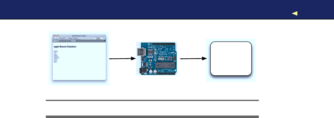
WHAT YOUNEED 203
IR-Controllable
Device
Figure 9.1: Architecture of the infrared proxy
Then we’ll even take the idea of aremote control astep further. Once we
have auniversal remote, we’ll control the Arduino itself using the serial
port or an Ethernet connection. This way, you can control the Arduino
using aweb browser, so you can control your TV set or DVD recorder
using the Internet (see Figure 9.1).
9.1 What Y o u Need
1. An Ethernet shield for the Arduino.
2. Abreadboard.
3. An infrared receiver, preferably the PNA4602.
4. A100Ωresistor.
5. An infrared LED.
6. Some wires.
7. One or more infrared remote controls. They can be from your TV
set, DVD player, or your Mac. Tofollow the chapter’s examples, it’d
be best to have aMac and an Apple Remote, but it’s not necessary.
If you’re not using an Apple Remote, be sure to adjust the protocol
name, bit length, and control codes in the examples accordingly.
If you’re using aremote control belonging to aSony TV set, for
example, set the protocol name to SONY (you’ll learn more about
this in Section 9.3,Grabbing Remote Control Codes,on page 205).
8. An Arduino board such as the Uno, Duemilanove, or Diecimila.
9. AUSB cable to connect the Arduino to your computer.
Report erratum
this copy is (P1.0 printing, Ja nu ra r y, 2011)
Download from Wow! eBook <www.wowebook.com>
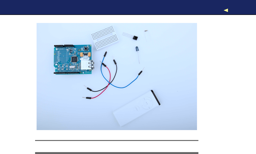
UNDERSTANDING INFRARED REMOTE CONTROLS 204
!
" # $
%
&
'
Figure 9.2: All the parts you need in this chapter
9.2 Understanding Infrared Remote Controls
To control adevice such as a TV set wirelessly, you need asender and
areceiver. The receiver usually is built into the device to be controlled,
and the sender is part of aseparate remote control. Although you can
choose from avariety of technologies such as Bluetooth or W i F i , most
modern remote controls still use infrared light for communication.
Using infrared light for transmitting signals has several advantages.
It is invisible to human beings, so it doesn’t bother you. Also, you can
generate it cheaply with infrared LEDs that can be integrated easily into
electronic circuits. So, for many purposes such as controlling devices
in atypical household, it’s an excellent choice.
But it also has some drawbacks. It doesn’t work through walls or doors,
and the distance between the remote control and the operated device is
fairly limited. Even more importantly, the infrared signal is subject to
interference with other light sources.
Report erratum
this copy is (P1.0 printing, Ja nu ra r y, 2011)
Download from Wow! eBook <www.wowebook.com>

GRABBING REMOTE CONTROL CODES 205
To reduce possible distortions caused by other light sources to amin-
imum, the infrared signal has to be modulated. That means you turn
the LED on and off at a certain frequency, usually somewhere between
36KHz and 40KHz.
That’s one of the problems that makes it abit complicated to build
arobust infrared remote control. The biggest problem is that vendors
have invented countless incompatible protocols. They all use different
frequencies, and they all interpret data differently. Some interpret “light
on” as a 1 bit, while others treat it as 0, and they all define their own
commands that have different lengths. So, to work successfully with
different remote control protocols, we need to know how to obtain all
these properties for aspecific remote control.
Toget this information, we’ll take apragmatic approach. In the next two
sections, you’ll learn how to read infrared signals from acommercial-
grade remote control, and you’ll also learn how to reproduce them.
9.3 Grabbing Remote Control Codes
Because remote controls from different vendors rarely use the same
protocol or even the same commands, before we start sending remote
control codes ourselves, we should know what we have to send to
achieve a certain result. W e have to get as much information as possible
about the remote control we’d like to emulate.
W e have two alternatives for obtaining remote control codes for aspe-
cific device: we could use aremote control database on the Internet
such as the Linux Infrared Remote Control project,1or we could use an
infrared receiver to read them directly from our device’s remote. W e will
choose the latter approach, because we can learn alot from it.
Infrared receivers (see Figure 9.3,on the following page) are fairly com-
plex on the inside, but they are easy to use. They automatically observe
the infrared light spectrum at a certain frequency (usually between
36KHz and 40KHz), and they report their observations using asingle
pin. So, when you’re using such areceiver, you don’t have to deal with
all the complicated transmission details. Y o u can focus on reading and
interpreting the incoming signals.
1. http://www.lirc.org/
Report erratum
this copy is (P1.0 printing, Ja nu ra r y, 2011)
Download from Wow! eBook <www.wowebook.com>
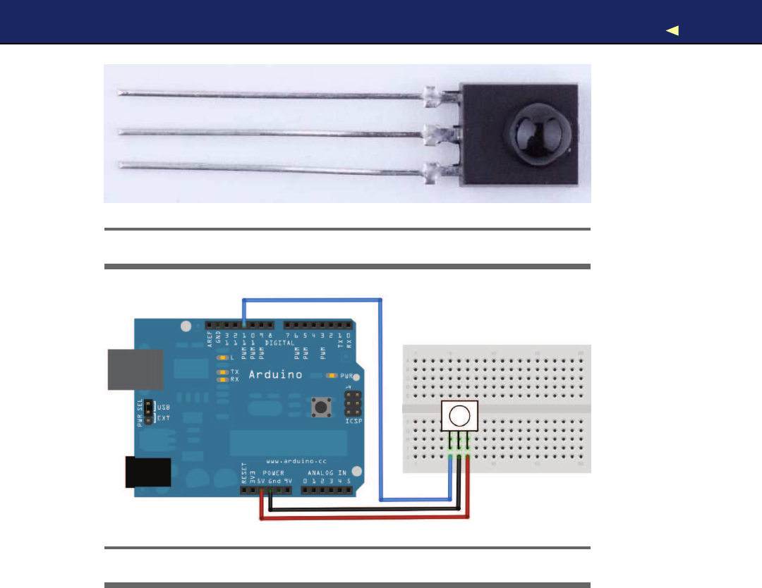
GRABBING REMOTE CONTROL CODES 206
Figure 9.3: APNA4602 infrared sensor
Figure 9.4: Connecting an IR receiver to the Arduino is easy.
In Figure 9.4,you can see how to connect aPNA4602 receiver to an
Arduino. It’s cheap, it’s easy to use, and it works at a frequency of
38KHz, so it detects signals from abroad range of devices. Connect its
ground connector to one of the Arduino’s GND pins, the power supply
to the Arduino’s 5V pin, and the signal pin to digital pin 11.
Y o u might be tempted to write asketch that reads and outputs all
incoming data on pin 11, and I won’t stop you. Call digitalRead( ) in the
loop( ) method and output the results to the serial port. Point your TV
set’s remote to the receiver and see what happens.
Y o u ’ l l probably have ahard time understanding the data you see. The
problem is that decoding the incoming data isn’t easy. Even if the
Report erratum
this copy is (P1.0 printing, Ja nu ra r y, 2011)
Download from Wow! eBook <www.wowebook.com>

GRABBING REMOTE CONTROL CODES 207
receiver has already processed the data, it still has to be transformed
and interpreted according to some complicated rules. Also, Arduino’s
digitalRead( ) method isn’t always accurate enough to deal with all types
of incoming signals. Y o u have to directly access the micro-controller to
get the best results.
Fortunately, we don’t have to do this ourselves, because the IRremote
library2hides the nasty details. It supports the most popular infrared
protocols, and can both receive and send data. After you’ve down-
loaded and extracted the ZIP file,3copy the directory IRremote to either
~/Documents/Arduino/libraries (on aMac) or My Documents\Arduino\libraries
(on aW i n d o w s box). Then restart your IDE.
W i t h the following sketch, you can then decode incoming infrared sig-
nals, if the IRremote library supports their encoding:
Download RemoteControl/InfraredDumper/InfraredDumper.pde
Line 1#include <IRremote.h>
-
-const unsigned int IR_RECEIVER_PIN =11;
-const unsigned int BAUD_RATE =9600;
5
-IRrecv ir_receiver(IR_RECEIVER_PIN);
-decode_results results;
-
-void setup() {
10 Serial.begin(BAUD_RATE);
-ir_receiver.enableIRIn();
-}
-
-void dump(const decode_results*results) {
15 const int protocol =results->decode_type;
-Serial.print(
"Protocol: "
);
-if (protocol == UNKNOWN) {
-Serial.println(
"not recognized."
);
-}else {
20 if (protocol == NEC) {
-Serial.println(
"NEC"
);
-}else if (protocol == SONY) {
-Serial.println(
"SONY"
);
-}else if (protocol == RC5) {
25 Serial.println(
"RC5"
);
-}else if (protocol == RC6) {
-Serial.println(
"RC6"
);
-}
2. http://www.arcfn.com/2009/08/multi-protocol-infrared-remote-library.html
3. http://arcfn.com/files/IRremote.zip
Report erratum
this copy is (P1.0 printing, Ja nu ra r y, 2011)
Download from Wow! eBook <www.wowebook.com>

GRABBING REMOTE CONTROL CODES 208
-Serial.print(
"Value: "
);
30 Serial.print(results->value, HEX);
-Serial.print(
"("
);
-Serial.print(results->bits, DEC);
-Serial.println(
"bits)"
);
-}
35 }
-
-void loop() {
-if (ir_receiver.decode(&results)) {
-dump(&results);
40 ir_receiver.resume();
-}
-}
First we define an IRrecv object named ir_receiver that reads from pin 11.
W e also define adecode_result object that we’ll use to store the attributes
of incoming infrared signals. In setup(), we initialize the serial port, and
we initialize the infrared receiver by calling enableIRIn().
Then we define amethod named dump( ) that nicely formats and out-
puts the content of adecode_result object to the serial port. decode_result
is one of the core data types of the IRremote library. It encapsulates
data such as the protocol type, the length of acommand code, and the
command code itself. In line 15, we read the protocol type that has been
used to encode the incoming signal. Whenever we receive anew signal,
we output all these attributes to the serial port.
The loop( ) method is simple. W e call decode( ) to check whether we’ve
received anew signal. If yes, we call dump( ) to output it to the serial
port, and then we call resume( ) to wait for the next signal.
Compile and upload the sketch to your Arduino, then start the serial
monitor, and point aremote control at the receiver. Push some of the
remote’s buttons, and see what happens. In Figure 9.5,on the following
page, you can see, for example, what happens when you point an Apple
Remote to the receiver and press menu, up, down, previous, next, and
play (if you see the code 0xffffffff from time to time, you’ve pressed one
of the Apple Remote’s keys for too long, because it is the “repeat code”
that indicates that the last command should be repeated).
After you have grabbed aremote’s control codes, you can use them to
build your own remote. Y o u ’ l l learn how to do that in the next section.
Report erratum
this copy is (P1.0 printing, Ja nu ra r y, 2011)
Download from Wow! eBook <www.wowebook.com>
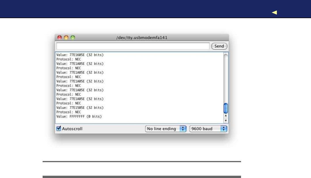
BUILDINGYOUR OWNAPPLE REMOTE 209
Figure 9.5: Capturing the IR codes of an Apple Remote
9.4 Building Y o u r Own Apple Remote
Now that you know the protocol and the codes of the commands the
Apple Remote sends to aMac, you can build your own Apple Remote.
Y o u only need an infrared LED that doesn’t differ much from the LEDs
we’ve used before. The only difference is that it emits “invisible” light. In
Figure 9.6,on the next page, you can see how to connect it to pin 3of
an Arduino (the library we’re using in this section expects the infrared
LED to be connected to pin 3). Note that you can’t use an LED without a
resistor (see Section A.1,Current, V o l t a g e , and Resistance,on page 237
to learn more about it).
W e could try to generate the infrared signals ourselves, but that’d be
tedious and error-prone. It’s better to use the existing implementation
in the IRremote library. W e ’ l l use it to create our own AppleRemote class
that encapsulates all the gory protocol details. The class looks like this:
Report erratum
this copy is (P1.0 printing, Ja nu ra r y, 2011)
Download from Wow! eBook <www.wowebook.com>
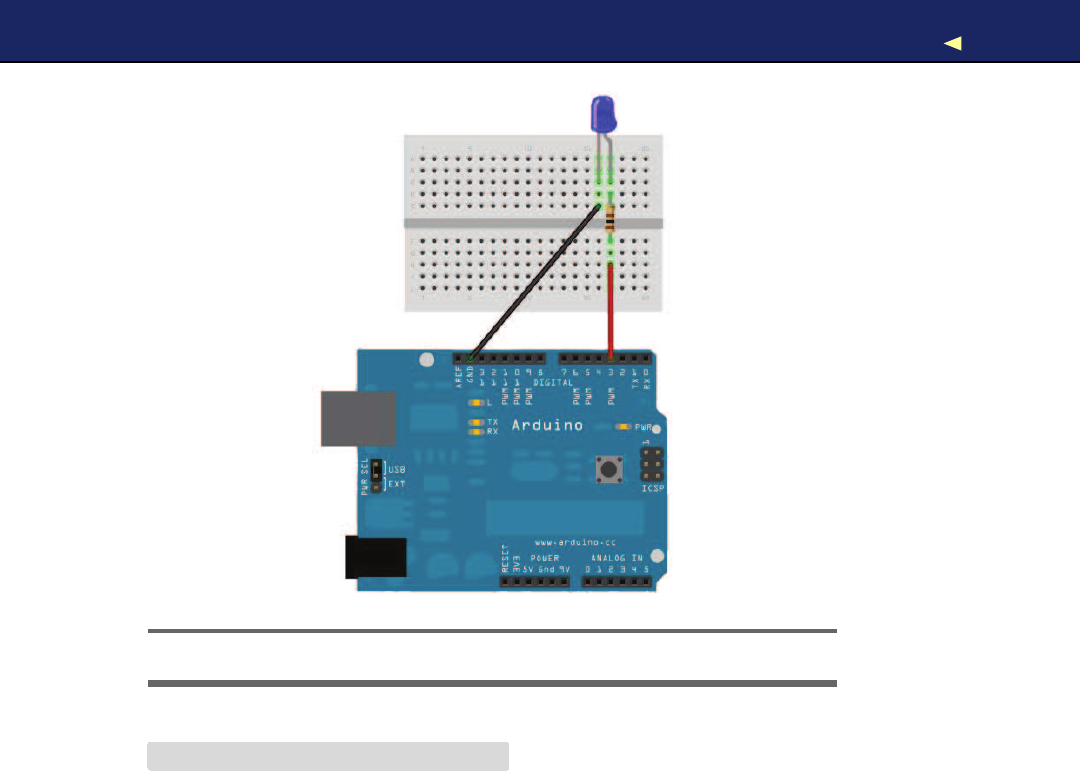
BUILDINGYOUR OWNAPPLE REMOTE 210
Figure 9.6: Connecting an IR LED to the Arduino
Download RemoteControl/AppleRemote/AppleRemote.pde
#include <IRremote.h>
class AppleRemote {
enum {
CMD_LEN =32,
UP =0x77E15061,
DOWN =0x77E13061,
PLAY =0x77E1A05E,
PREV =0x77E1905E,
NEXT =0x77E1605E,
MENU =0x77E1C05E
};
IRsend mac;
void send_command(const long command) {
mac.sendNEC(command, CMD_LEN);
}
Report erratum
this copy is (P1.0 printing, Ja nu ra r y, 2011)
Download from Wow! eBook <www.wowebook.com>

BUILDINGYOUR OWNAPPLE REMOTE 211
public:
void menu() {send_command(MENU); }
void play() {send_command(PLAY); }
void prev() {send_command(PREV); }
void next() {send_command(NEXT); }
void up() {send_command(UP); }
void down() {send_command(DOWN); }
};
The code starts with an enumeration that contains all the constants
we need: the length of each control code and the control codes them-
selves. Then we define an IRsend object named m a c that we’ll use to
send commands using the send_command( ) method. send_command( )
uses IRsend’s sendNEC( ) method because the Apple Remote uses the NEC
protocol.
After we’ve established the basis, we can implement all commands with
asingle function call, so implementing menu(), play(), and so on, is a
piece of cake.
Using the AppleRemote class is easy, too. In the following sketch, we
use it to control aMac from the Arduino’s serial monitor:
Download RemoteControl/AppleRemote/AppleRemote.pde
AppleRemote apple_remote;
const unsigned int BAUD_RATE =9600;
void setup() {
Serial.begin(BAUD_RATE);
}
void loop() {
if (Serial.available()) {
const char command =Serial.read();
switch(command) {
case 'm':
apple_remote.menu();
break;
case 'u':
apple_remote.up();
break;
case 'd':
apple_remote.down();
break;
case 'l':
apple_remote.prev();
break;
case 'r':
Report erratum
this copy is (P1.0 printing, Ja nu ra r y, 2011)
Download from Wow! eBook <www.wowebook.com>

CONTROLLINGDEVICES REMOTELY WITH YOUR BROWSER 212
apple_remote.next();
break;
case 'p':
apple_remote.play();
break;
default:
break;
}
}
}
W e define aglobal AppleRemote object named apple_remote, and in the
setup( ) function we initialize the serial port. In loop(), we wait for new
data on the serial port, and whenever anew byte arrives, we check
whether it’s one of the characters m,u,d,l,r,or p.Depending on the
character we received, we send the control code for menu, up, down,
previous, next, or play accordingly.
Compile and upload the sketch, and you can control aMac using any
serial monitor, which is quite cool already. The interface is still abit
awkward for less geeky people, so in the next section, you’ll learn how
to create amore user-friendly interface.
9.5 Controlling Devices Remotely with Y o u r Browser
W e ’ v e already created alot of projects that you can control using a
serial monitor. For programmers, that’s anice and convenient inter-
face, but as soon as you want to present your projects to your non-
technical friends or to your spouse, you’d better have something more
user-friendly and colorful.
The Seriality4plug-in makes that possible. It adds support for serial
port communication to your web browser’s JavaScript engine.
At the moment, the plug-in is available only for Firefox, Safari, and
Chrome on Mac OS X, but aW i n d o w s port is under development. Seri-
ality is available as a disk image, so you can download it5and install it
as usual.
After you’ve installed Seriality, you can turn your web browser into
an Apple Remote simulator using the following mixture of HTML and
JavaScript code:
4. http://www.zambetti.com/projects/seriality/
5. http://code.google.com/p/seriality/downloads/list
Report erratum
this copy is (P1.0 printing, Ja nu ra r y, 2011)
Download from Wow! eBook <www.wowebook.com>

CONTROLLINGDEVICES REMOTELY WITH YOUR BROWSER 213
Download RemoteControl/AppleRemoteUI/ui.html
Line 1<html>
-<title>Apple Remote Emulator</title>
-<head>
-<script type="text/javascript">
5var serial;
-
-function setup() {
-serial =(document.getElementById(
"seriality"
)).Seriality();
-alert(serial.ports.join(
"\n"
));
10 serial.begin(serial.ports[0], 9600);
-}
-</script>
-</head>
-
15 <body onload="setup();">
-<object type="application/Seriality"
-id="seriality"
-width="0"
-height="0">
20 </object>
-<h2>Apple Remote Emulator</h2>
-<form>
-<button type="button" onclick="serial.write('m');">
-Menu
25 </button>
-<br/>
-<button type="button" onclick="serial.write('u');">
-Up
-</button>
30 <br/>
-<button type="button" onclick="serial.write('d');">
-Down
-</button>
-<br/>
35 <button type="button" onclick="serial.write('l');">
-Previous
-</button>
-<br/>
-<button type="button" onclick="serial.write('n');">
40 Next
-</button>
-<br/>
-<button type="button" onclick="serial.write('p');">
-Play
45 </button>
-<br/>
-</form>
-</body>
-</html>
Report erratum
this copy is (P1.0 printing, Ja nu ra r y, 2011)
Download from Wow! eBook <www.wowebook.com>

BUILDINGANINFRARED PROXY 214
This is avery simple HTML page, and we’ll focus on the JavaScript
parts. In lines 4to 12, we define two things: aglobal variable named
serial and a function named setup(). setup( ) initializes serial and assigns
aSeriality object to it. W e embed aSeriality object into the web page using
the <
object
>tag. Its ID is “seriality,” so we can access it using getEle-
mentById().
As soon as we have areference to the object, we call JavaScript’s alert( )
function and output all serial ports we have found. Y o u have to look up
the index of the serial port your Arduino is connected to and use it in
the following call to the begin( ) method. For simplicity, we always pass
it the first serial device we can find and a baud rate of 9,600. Using the
first serial device is only aguess, and you might have to adjust it. Y o u
already know that pattern from our Processing examples.
W e invoke setup( ) in the onload event handler of the <
body
>element.
Then we can access the Seriality object in the onclick handlers of our six
<
button
>elements.
Upload the sketch from Section 9.4,Building Y o u r Own Apple Remote,
on page 209 to your Arduino, and point your browser to the HTML
page. After you have clicked the OK button of the alert box showing all
serial ports, you should see aweb page like Figure 9.7,on the following
page. Click any button to perform the corresponding action. That’s an
interface even your Grandma could use, isn’t it?
Please note that you cannot access the Arduino hardware directly using
Seriality. Y o u can only access the serial port, so all the things you’d like
to happen on your Arduino have to be accessible via serial communica-
tion. But that’s acommon pattern anyway, so Seriality is really auseful
tool that can greatly improve your project’s user interface.
Y o u still need to connect the Arduino to your computer’s serial port to
control it with aweb browser. In the next section, you’ll learn how to
overcome this and control an Arduino without aserial connection.
9.6 Building an Infrared Proxy
All our previous remote control approaches have one major drawback:
they all depend on aserial connection to aPC. In this section, you’ll
learn how to replace this connection with an Ethernet connection, so
you no longer need aPC but only Internet access. Y o u will directly plug
Report erratum
this copy is (P1.0 printing, Ja nu ra r y, 2011)
Download from Wow! eBook <www.wowebook.com>
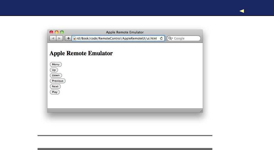
BUILDINGANINFRARED PROXY 215
Figure 9.7: The Apple Remote emulator in action
your Ethernet cable into an Ethernet shield connected to the Arduino
(see Figure 9.8,on the next page), so it is available on your network.
This doesn’t necessarily mean that you have to use your PC’s web
browser to access the Arduino. Y o u could also use the browser on your
PlayStation Portable, on your iPhone, or on your Nintendo DS. Y e s , you
can now control your TV set using your game consoles or your smart-
phone. Oh, and you could replace the Ethernet shield with aW i F i shield
so you don’t have to connect your Arduino physically to your network
router.
Before we dive into the code, we should do alittle planning ahead and
make clear what we’d like to achieve. W e ’ l l build an infrared proxy—
adevice that receives commands via Ethernet and turns them into
infrared signals (see Figure 9.1,on page 203). To make it easy to inte-
grate the device into anetwork, we’ll make it accessible via HTTP. This
way, we can control it using aregular web browser.
W e ’ l l only implement avery small portion of the HTTP standard on the
Arduino—we’ll only support acertain URL scheme. The URLs we will
support look as follows:
http://«
arduino-ip
»/«
protocol-name
»/«
command-length
»/«
command-code
»
Report erratum
this copy is (P1.0 printing, Ja nu ra r y, 2011)
Download from Wow! eBook <www.wowebook.com>
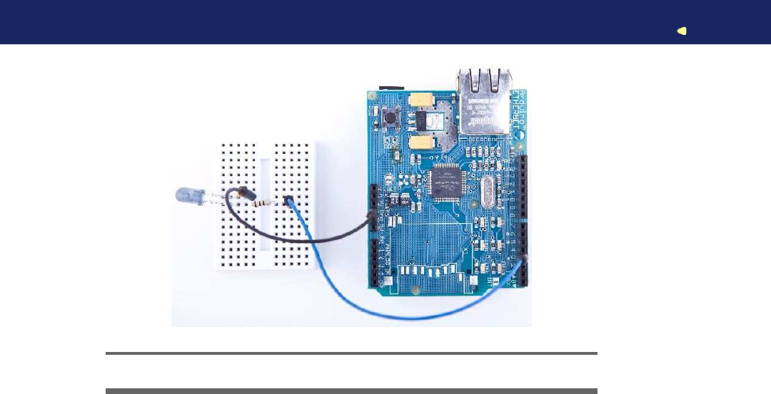
BUILDINGANINFRARED PROXY 216
Figure 9.8: An Ethernet-controllable remote control
W e ’ l l replace «arduino-ip»with the IP address of the Arduino’s Ethernet
shield. The element «protocol-name»can be one of the supported proto-
cols (“NEC,” “SONY,” “RC5,” or “RC6”). «command-length»specifies the
length of the command code in bits, and «command-code»contains the
command code itself as a decimal number.
Let’s assume we’d like to send the code for the menu key on an Apple
Remote, and our Arduino has the IP address 192.168.2.42. Then we’d
have to point our web browser to the following URL:
http://192.168.2.42/NEC/32/2011283550
In this case, the protocol name is NEC, the length of the command
code is 32 bits, and the command code is 2011283550 (the decimal
representation of the hexadecimal number 0x77E1C05E).
W e ’ v e already used the Arduino as a web client in Chapter 8,Network-
ing with Arduino,on page 170,but now we need to turn it into aweb
server. The server waits for new HTTP requests like the one shown pre-
viously, parses the URL, and emits the corresponding infrared signal.
W e ’ l l hide all these details in aclass named InfraredProxy, and to keep
things as easy and as concise as possible, we’ll make use of both the
Ethernet and the IRremote library. The InfraredProxy class is still one of
the book’s most sophisticated examples of Arduino code. Here it is:
Report erratum
this copy is (P1.0 printing, Ja nu ra r y, 2011)
Download from Wow! eBook <www.wowebook.com>

BUILDINGANINFRARED PROXY 217
Download RemoteControl/InfraredProxy/InfraredProxy.pde
Line 1#include <SPI.h>
-#include <Ethernet.h>
-#include <IRremote.h>
-
5class InfraredProxy {
-IRsend _infrared_sender;
-
-void read_line(Client& client, char*buffer, const int buffer_length) {
-int buffer_pos =0;
10 while (client.available() && (buffer_pos <buffer_length -1)) {
-const char c = client.read();
-if (c == '\n')
-break;
-if (c != '\r')
15 buffer[buffer_pos++] =c;
-}
-buffer[buffer_pos] ='\0';
-}
-
20 bool send_ir_data(const char*protocol, const int bits, const long value) {
-bool result =true;
-if (!strcasecmp(protocol,
"NEC"
))
-_infrared_sender.sendNEC(value, bits);
-else if (!strcasecmp(protocol,
"SONY"
))
25 _infrared_sender.sendSony(value, bits);
-else if (!strcasecmp(protocol,
"RC5"
))
-_infrared_sender.sendRC5(value, bits);
-else if (!strcasecmp(protocol,
"RC6"
))
-_infrared_sender.sendRC6(value, bits);
30 else
-result =false;
-return result;
-}
-
35 bool handle_command(char*line) {
-strsep(&line,
""
);
-char*path =strsep(&line,
""
);
-
-char*args[3];
40 for (char**ap =args; (*ap =strsep(&path,
"/"
)) != NULL;)
-if (**ap != '\0')
-if (++ap >= &args[3])
-break;
-const int bits =atoi(args[1]);
45 const long value =atol(args[2]);
-return send_ir_data(args[0], bits, value);
-}
-
-public:
Report erratum
this copy is (P1.0 printing, Ja nu ra r y, 2011)
Download from Wow! eBook <www.wowebook.com>

BUILDINGANINFRARED PROXY 218
50
-void receive_from_server(Server server) {
-const int MAX_LINE =256;
-char line[MAX_LINE];
-Client client =server.available();
55 if (client) {
-while (client.connected()) {
-if (client.available()) {
-read_line(client, line, MAX_LINE);
-Serial.println(line);
60 if (line[0] == 'G' && line[1] == 'E' && line[2] == 'T')
-handle_command(line);
-if (!strcmp(line,
""
)) {
-client.println(
"HTTP/1.1 200 OK\n"
);
-break;
65 }
-}
-}
-delay(1);
-client.stop();
70 }
-}
-};
After including all libraries needed, we declare the InfraredProxy class. W e
define amember variable named _infrared_sender that stores an IRsend
object we need to emit infrared control codes.
In line 8, we define aread_line( ) method that reads one line of data
sent by aclient. Aline ends either with anewline character (\n) or
with acarriage return character followed by anewline character (\r\n).
read_line( ) expects the Ethernet Client object to read data from, achar-
acter buffer to store the data in (buffer), and the maximum length of
the character buffer (buffer_length). The method ignores all newline and
carriage return characters, and it sets the line’s last character to \0, so
the buffer to be filled will always be anull-terminated string.
The next method (send_ir_data()) starts in line 20 and emits an infrared
command specified by aprotocol type (protocol), the length of the code
measured in bits (bits), and the code value to be sent (v a l u e ). Depending
on the name of the protocol, the method delegates all the real work to
our IRsend instance.
handle_command( ) implements one of the most difficult aspects of our
InfraredProxy:it parses the URL addressed by the HTTP request. To
understand what this method does, we have to understand how HTTP
requests work. If you wander up to your web browser’s address bar and
Report erratum
this copy is (P1.0 printing, Ja nu ra r y, 2011)
Download from Wow! eBook <www.wowebook.com>

BUILDINGANINFRARED PROXY 219
enter aURL like http://192.168.2.42/NEC/32/2011283550,your browser will
send an HTTP request that looks like this:
GET /NEC/32/2011283550 HTTP/1.1
host: 192.168.2.42
The first line is aGET request, and handle_command( ) expects astring
containing such arequest. It extracts all information encoded in the
path (/NEC/32/2011283550) and uses it to emit an infrared signal. Parsing
the information is abit tricky, but using C’s strsep( ) function, it’s not
too difficult. strsep( ) separates strings delimited by certain characters.
It expects astring containing several separated strings and a string
containing all delimiters. strsep( ) replaces the first occurrence of any
character in the delimiter string with a\0 character. It returns apointer
to the original string. Before that, it replaces the pointer to the string
we wanted to split with apointer pointing to the first string.
W e use strsep( ) in two different contexts. In the first case, we extract
the path from the GET command: we strip off the string “GET” and
the string “HTTP/1.1.” Both are separated from the path by ablank
character. All this happens in lines 36 and 37. If you were to pass
the URL http://192.168.2.42/NEC/32/2011283550 to handle_command(), for
example, path would contain /NEC/32/2011283550.
At this stage, we have astring consisting of three strings separated by a
slash character (/). It’s time to use strsep( ) again, and if you understand
what happens in lines 40 to 43, then you can call yourself familiar
with both C and the strsep( ) function. In the end, the array args con-
tains all three path elements. W e can pass the protocol name directly
to send_ir_data(), but we have to turn the bit length and the value of
the code into int and long values before. For the conversion, we use the
atoi( ) and atol( ) functions.
Now we have defined all helper methods we need, and we only have
to implement the public interface of the InfraredProxy class. It contains
only one method named receive_from_server(). This method finally imple-
ments the core logic of our InfraredProxy class. It expects an instance of
the Server class that is defined in the Ethernet library. It waits for a
client to connect using Server’s available( ) method in line 54. Whenever
the server is connected to aclient, it checks whether the client has new
data using Client’s available( ) method in line 57.
receive_from_server( ) reads the data sent by the client line by line call-
ing read_line(). It prints each line to the serial port for debugging pur-
Report erratum
this copy is (P1.0 printing, Ja nu ra r y, 2011)
Download from Wow! eBook <www.wowebook.com>

BUILDINGANINFRARED PROXY 220
poses, and for every line it checks whether it begins with “GET.” If yes, it
calls handle_command(); otherwise, it checks whether the line is empty,
because all HTTP messages are terminated by an empty line. In this
case, receive_from_server( ) sends back an “OK” response, waits for amil-
lisecond to give the client some time to process the response, and then
disconnects from the client calling stop().
Admittedly that was alot of code, but the effort was well worth it. Using
the InfraredProxy is really simple now:
Download RemoteControl/InfraredProxy/InfraredProxy.pde
const unsigned int PROXY_PORT =80;
const unsigned int BAUD_RATE =9600;
byte mac[] = { 0xDE, 0xAD, 0xBE, 0xEF, 0xFE, 0xED };
byte ip[] = { 192, 168, 2, 42 };
Server server(PROXY_PORT);
InfraredProxy ir_proxy;
void setup() {
Serial.begin(BAUD_RATE);
Ethernet.begin(mac, ip);
server.begin();
}
void loop() {
ir_proxy.receive_from_server(server);
}
As usual, we define the MAC and IP addresses we’d like to use. Then
we define aServer object, passing it the port it should listen to, 80 (the
standard HTTP port). Also, we initialize anew InfraredProxy object.
In the setup( ) method, we initialize the serial port for debug purposes.
W e also initialize the Ethernet shield, and we call Server’s begin( ) method
to start our server’s listener. In loop(), we only call the InfraredProxy’s
receive_from_server( ) method, passing it our Server instance.
Let’s finally test the code! Attach the Ethernet shield to your Arduino,
and attach the infrared LED circuit to the shield. Configure the MAC
and IP addresses, compile it, and upload it to your Arduino. Point your
web browser to http://192.168.2.42/NEC/32/2011283550 (adjust the URL to
your local settings!), and see what happens to your Mac or whatever
device you want to control (in Figure 9.9,on the following page, you
can see atypical output of the infrared proxy on the serial monitor).
Report erratum
this copy is (P1.0 printing, Ja nu ra r y, 2011)
Download from Wow! eBook <www.wowebook.com>
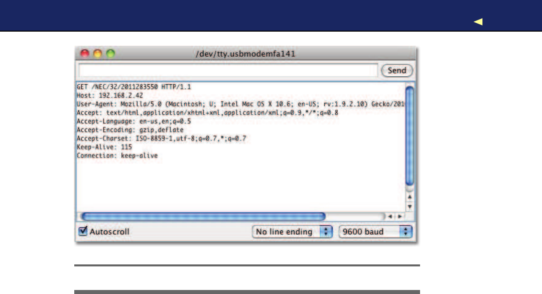
WHAT IFITDOESN’TWORK?221
Figure 9.9: Accessing the infrared proxy with Firefox
Although we’ve used only aminimum amount of hardware (a cheap and
simple infrared LED), this chapter’s projects are very useful and fairly
sophisticated, at least from asoftware development point of view. W e
can now not only control any device that understands infrared signals,
but we can do it using acomputer’s serial port or even aweb browser.
Also, you no longer need to connect the Arduino to your computer’s
USB port. The Infrared proxy, for example, only needs the USB port to
get some power. Plug an AC adapter into your Arduino, and you can get
rid of your USB cable.
For the first time, we’ve controlled real-world devices using an Arduino.
W e ’ l l continue to do so in the next chapter, where you’ll learn how to
control motors.
9.7 What If It Doesn’t W o r k ?
In this chapter, we mainly used LEDs and an Ethernet shield, so all the
advice from Chapter 3,Building Binary Dice,on page 63 and Chapter 8,
Networking with Arduino,on page 170 also apply to this chapter.
In addition, you have to be careful about more things. For example,
the distance between an infrared LED and its receiver is important.
Report erratum
this copy is (P1.0 printing, Ja nu ra r y, 2011)
Download from Wow! eBook <www.wowebook.com>

EXERCISES 222
Control Everything
All the projects in this chapter are based on devices y o u can
control already using an infrared remote control. But y o u can
also add an infrared receiver to existing devices or build com-
pletely new ga d g e t s that come with an infrared receiver.
In principle, y o u could control y o u r refrigerator or y o u r
microwave o v e n with aremote control. But have y o u e v e r
thought aboutaremote-controlled lawn mower?∗I bet not.
∗.http://www.instructables.com/id/Arduino-RC-Lawnmower/
To be on the safe side, you should position the LED near the receiver.
It should also be placed right in front of the receiver, and you should
make sure that there’s not too much ambient light that might disturb
the infrared signal.
For debugging purposes, it’s useful to replace invisible infrared LED
with aregular LED from time to time. This way, you can see whether
your circuit works in principle.
If you’re trying to control aMac, you should unpair any other remote
controls in the security area of the Mac’s system preferences menu.
Finally, you might be using adevice that uses aprotocol that is not
supported by the IRremote library. In this case, you have to add it. This
can be tricky, but IRremote is open source, so at least it’s possible.
9.8 Exercises
•Build an emulator for aremote control you find in your household.
Make its commands available via serial port and via Ethernet.
•Instead of controlling the Arduino via aserial monitor or web
browser, control it using aNintendo Nunchuk. For example, you
could move the analog stick up and down to control your TV set’s
volume, and you could move it left or right to change the channels.
•Design areal universal remote control based on an Arduino. Look
for atouch screen, abutton pad, an SD card shield, and a Blue-
tooth module. Ibet you didn’t think you could build adevice like
this—but you know everything you need to do it now.
Report erratum
this copy is (P1.0 printing, Ja nu ra r y, 2011)
Download from Wow! eBook <www.wowebook.com>

Chapter 10
Controlling Motors with Arduino
So far, we’ve created projects that have had an impact on the real world.
W e ’ v e made LEDs shine, and we’ve controlled devices using infrared
light. In this chapter, we’ll create an even more intense experience: we’ll
control motors that will actually move things. W e won’t go so far as to
build afull-blown autonomous robot, but we’ll create asmall device
that does something useful and funny.
First, though, you’ll learn abit about the basics of different motor types
and their pros and cons. Today you can choose from avariety of motor
types for your projects, and this chapter starts with abrief description
of their differences.
W e ’ l l concentrate on servo motors, because you can use them for awide
range of projects and they’re cheap and easy to use. Y o u ’ l l learn to use
the Arduino servo library and to control aservo using the serial port.
Based on these first steps, we’ll then build amore sophisticated project.
It’s ablaming device that uses nearly the same hardware as the first
project in the chapter but more elaborate software. Y o u ’ l l probably find
many applications for it in your office!
10.1 What Y o u Need
1. Aservo motor such as the Hitec HS-322HD
2. Some wires
3. ATMP36 temperature sensor (it’s optional, and you need it only
for the exercises)
4. An Arduino board such as the Uno, Duemilanove, or Diecimila
5. AUSB cable to connect the Arduino to your computer
Download from Wow! eBook <www.wowebook.com>
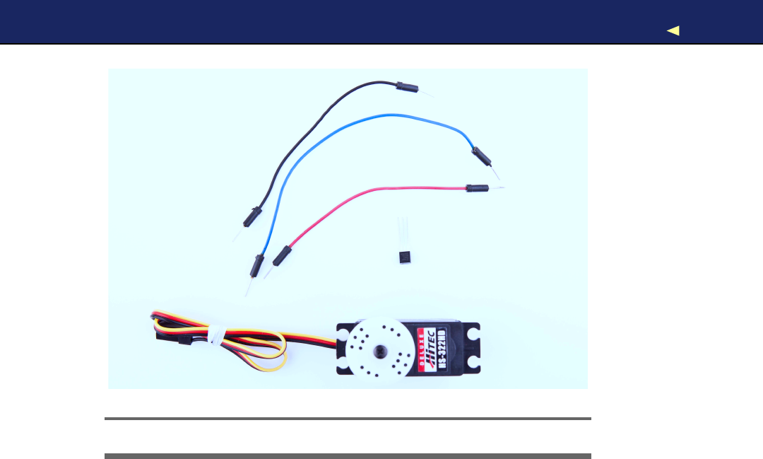
INTRODUCING MOTORS 224
!
"
#
Figure 10.1: All the parts you need in this chapter
10.2 Introducing Motors
Depending on your project’s needs, you can choose from avariety of
motors today. For hobby electronics, you’ll usually use DC motors,
servo motors, or stepper motors (in Figure 10.2,on the next page, you
see afew different types of motors; no DC motor is shown). They mainly
differ in speed, precision of control, power consumption, reliability, and
price.
DC motors are fast and efficient, so you can use them in drill machines,
electric bicycles, or remote-control cars. Y o u can control DC motors
easily, because they have only two connectors. Connect one to apower
supply and the other to ground, and the motor starts to spin. Swap
the connections, and the motor will spin the other way around. Add
more voltage, and the motor spins faster; decrease voltage, and it spins
slower.
DC motors aren’t a good choice if you need precise control. In such
cases, it’s better to use astepper motor, which allows for precise con-
trol in arange of 360 degrees. Although you might not have noticed
Report erratum
this copy is (P1.0 printing, Ja nu ra r y, 2011)
Download from Wow! eBook <www.wowebook.com>

FIRSTSTEPSWITHASERVOMOTOR 225
Figure 10.2: Motor types from left to right: standard servo, continuous
rotation servo, stepper
it, you’re surrounded by stepper motors. Y o u hear them when your
printer, scanner, or disk drive is at work. Controlling stepper motors
isn’t rocket science, but it is abit more complicated than controlling
DC motors and servos.
Servo motors are the most popular among hobbyists, because they are a
good compromise between DC motors and steppers. They’re affordable,
reliable, and easy to control. Y o u can move standard servos only in a
range of 180 degrees, but that’s sufficient for many applications. W i t h
continuous rotation servos, you can increase the range to 360 degrees,
but you lose the ease of control.
In the next section, you’ll learn how easy it is to control standard servo
motors with an Arduino.
10.3 First Steps with aServo Motor
The Arduino IDE comes with alibrary for controlling servo motors that
we’ll use for our first experiments. In Figure 10.3,on the following page,
Report erratum
this copy is (P1.0 printing, Ja nu ra r y, 2011)
Download from Wow! eBook <www.wowebook.com>
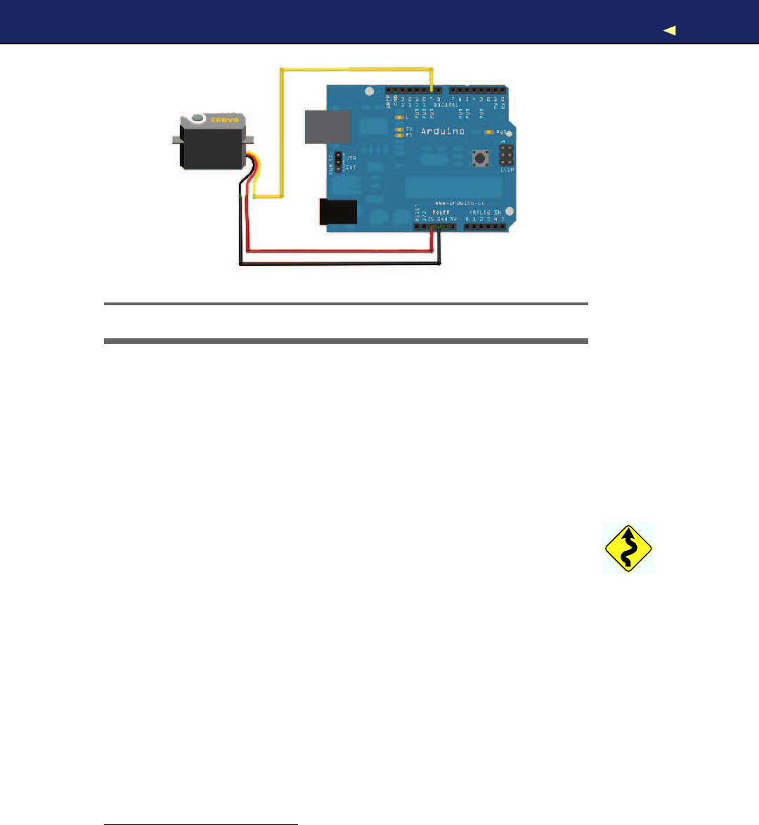
FIRSTSTEPSWITHASERVOMOTOR 226
Figure 10.3: Basic circuit for a5V servo motor
you can see abasic circuit for connecting an Arduino to aservo motor.
Connect the ground wire to one of the Arduino’s GND pins, connect
power to the Arduino’s 5V pin, and connect the control line to pin 9.
Please note that this works only for a5V servo! Many cheap servos use
9V, and in this case, you need an external power supply, and you can
no longer connect the servo to the Arduino’s 5V pin. If you have a9V
servo, attach an external power supply such as an AC-to-DC adapter
or aDC power supply to your Arduino’s power jack. Then connect the
servo to the V i n pin.1Y o u should also check the specification of your
Arduino board. For example, you should not use an Arduino BT2to
control motors, because it can only cope with amaximum of 5.5V.
Figure 10.4,on the next page shows how to connect your servo motor
to your Arduino using wires. Y o u can also use pin headers, but wires
give you more flexibility.
Controlling servo motors is convenient, because you can set the motor’s
shaft to an angle between 0 and 180. W i t h the following sketch, you
can send adegree value via the serial port and move the servo motor
accordingly:
1. http://www.arduino.cc/playground/Learning/WhatAdapter
2. http://arduino.cc/en/Main/ArduinoBoardBluetooth
Report erratum
this copy is (P1.0 printing, Ja nu ra r y, 2011)
Download from Wow! eBook <www.wowebook.com>

FIRSTSTEPSWITHASERVOMOTOR 227
Figure 10.4: Plug three wires into the servo’s connector to attach it to
the Arduino.
Download Motors/SerialServo/SerialServo.pde
Line 1#include <Servo.h>
-
-const unsigned int MOTOR_PIN =9;
-const unsigned int MOTOR_DELAY =15;
5const unsigned int SERIAL_DELAY =5;
-const unsigned int BAUD_RATE =9600;
-
-Servo servo;
-
10 void setup() {
-Serial.begin(BAUD_RATE);
-servo.attach(MOTOR_PIN);
-delay(MOTOR_DELAY);
-servo.write(1);
15 delay(MOTOR_DELAY);
-}
-
-void loop() {
-const int MAX_ANGLE =3;
20
-char degrees[MAX_ANGLE +1];
-
-if (Serial.available()) {
-int i = 0;
25 while (Serial.available() && i < MAX_ANGLE) {
-const char c = Serial.read();
-if (c != -1 && c!= '\n')
-degrees[i++] =c;
Report erratum
this copy is (P1.0 printing, Ja nu ra r y, 2011)
Download from Wow! eBook <www.wowebook.com>

BUILDINGABLAMINATR 228
-delay(SERIAL_DELAY);
30 }
-degrees[i] =0;
-Serial.print(degrees);
-Serial.println(
"degrees."
);
-servo.write(atoi(degrees));
35 delay(MOTOR_DELAY);
-}
-}
W e include the Servo library, and in line 8, we define anew Servo object.
In the setup( ) function, we initialize the serial port, and we attach( ) the
Servo object to the pin we have defined in MOTOR_PIN.After that, we wait
for 15 milliseconds so the servo motor has enough time to process our
command. Then we call write( ) to move back the servo to 1degree. W e
could also move it back to 0degrees, but some of the servos Ihave
worked with make some annoying noise in this position.
The main purpose of the loop( ) function is to read new degree values
from the serial port. These values are in arange from 0to 180, and we
read them as ASCII values. So, we need astring that can contain up
to four characters (remember, strings are null-terminated in C). That’s
why we declare the degrees string with alength of four in line 21.
Then we wait for new data to arrive at the serial port and read it char-
acter by character until no more data is available or until we have read
enough. W e terminate the string with azero byte and print the value
we’ve read to the serial port. Finally, we convert the string into an inte-
ger value using atoi( ) and pass it to the write( ) method of the Servo object
in line 34. Then we wait again for the servo to do its job.
Compile and upload the sketch, and then open the serial monitor. After
the servo motor has initialized, send some degree values such as 45,
180, or 10. See how the motor moves to the angle you have specified.
To see the effect abit better, turn awire or apiece of paper into an
arrow, and attach it to the motor’s gear.
It’s easy to control aservo via the serial port, and the circuit we’ve built
can be the basis for many useful and fun projects. In the next section,
we’ll use it to build an automatic blaming device.
10.4 Building aBlaminatr
Finger-pointing isn’t nice, but it can be perversely satisfying. In this
section, we’ll build adevice that Icall Blaminatr.Instead of blaming
Report erratum
this copy is (P1.0 printing, Ja nu ra r y, 2011)
Download from Wow! eBook <www.wowebook.com>

BUILDINGABLAMINATR 229
Arduino Arts
Y o u can use the Arduino not just f o r g a d g e t s or fun projects
but also in artistic w a y s . Especially in the new-media art area
y o u will find m a n y amazing projects built with the Arduino. One
of them is Anthros,∗aresponsive environment that observes a
small area using a w e b c a m . The area contains some “tenta-
cles,” and whenever a person crosses the area, the tentacles
move into the person’s direction. Servos move the tentacles,
and an Arduino controls the servos.
For all people interested in new-media art, Alicia Gibb’s the-
sis “New Media Art, Design, and the Arduino Microcontroller: A
Malleable T o o l ” †is am u s t - r e a d .
∗.http://www.richgilbank.ca/anthros
†.http://aliciagibb.com/thesis/
someone directly, you can tell the Blaminatr to do so. In Figure 10.5,
on the following page, you can see the device in action. Tell it to blame
me, and it moves an arrow, so it points to “Maik.”
Blaminatrs are perfect office toys that you can use in many situa-
tions. For software developers, it can be agood idea to attach one to
your continuous integration (CI) system. Continuous integration sys-
tems such as CruiseControl.rb3or Luntbuild4help you continuously
check whether your software is in good shape.
Whenever adeveloper checks in changes, the CI automatically compiles
the software and runs all tests. Then it publishes the results via email
or as an RSS feed. Y o u can easily write asmall piece of software that
subscribes to such afeed. Whenever someone breaks the build, you’ll
find anotification in the feed, and you can use the Blaminatr to point
to the name of the developer who has committed the latest changes.5
In the previous section, you learned all about servo motors you need
to build the Blaminatr. Now we only need some creativity to build the
device’s display, and we need more elaborate software. W e start with
3. http://cruisecontrolrb.thoughtworks.com/
4. http://luntbuild.javaforge.com/
5. At http://urbanhonking.com/ideasfordozens/2010/05/19/the_github_stoplight/,you can see an
alternative project. It uses atraffic light to indicate your project’s current status.
Report erratum
this copy is (P1.0 printing, Ja nu ra r y, 2011)
Download from Wow! eBook <www.wowebook.com>
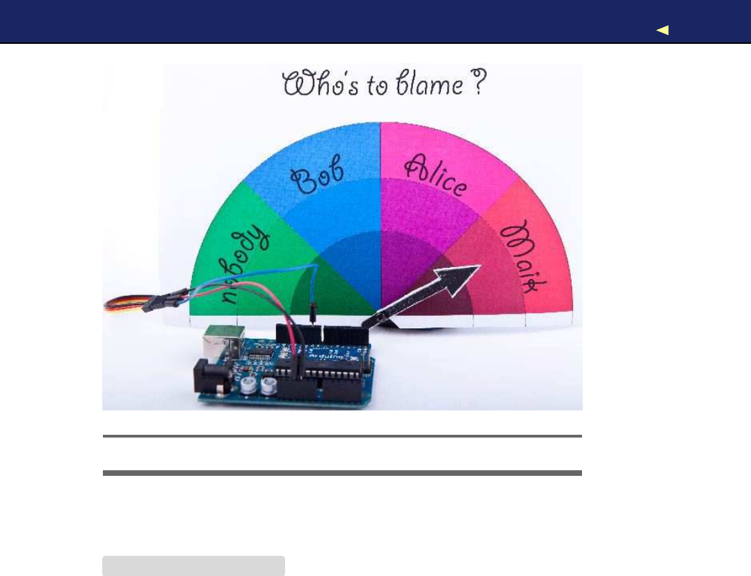
BUILDINGABLAMINATR 230
Figure 10.5: The Blaminatr: blaming has never been easier.
aclass named T e a m that represents the members of our team; that is,
the potential “blamees”:
Download Motors/Blaminatr/Blaminatr.pde
Line 1const unsigned int MAX_MEMBERS =10;
-
-class Team {
-char**_members;
5int _num_members;
-int _positions[MAX_MEMBERS];
-
-public:
-
10 Team(char**members) {
-_members =members;
-
-_num_members =0;
-char**member =_members;
15 while (*member++)
-_num_members++;
-
Report erratum
this copy is (P1.0 printing, Ja nu ra r y, 2011)
Download from Wow! eBook <www.wowebook.com>

BUILDINGABLAMINATR 231
-const int share =180 /_num_members;
-int pos =share /2;
20 for (int i = 0; i < _num_members; i++) {
-_positions[i] =pos;
-pos += share;
-}
-}
25
-int get_position(const char*name) const {
-int position =0;
-for (int i = 0; i < _num_members; i++) {
-if (!strcmp(_members[i], name)) {
30 position =_positions[i];
-break;
-}
-}
-return position;
35 }
-};
The code defines several member variables: _members contains alist
of up to ten team member names, _num_members contains the actual
number of people on the team, and we store the position (angle) of the
team member’s name on the Blaminatr display in _positions.
The constructor expects an array of strings that contains the team
members’ names and that is terminated by aNULL pointer. W e store a
reference to the list, and then we calculate the number of team mem-
bers. W e iterate over the array until we find aNULL pointer. All this
happens in lines 13 to 16.
Then we calculate the position of each team member’s name on the
Blaminatr’s display. Every team member gets their fair share on the
180-degree display, and the Blaminatr will point to the share’s center,
so we divide the share by 2. W e store the positions in the _positions array
that corresponds to the _members array. That means the first entry of
_positions contains the position of the first team member, and so on.
W i t h the get_position( ) method, we get back the position belonging to a
certain name. W e walk through the _members array and check whether
we have found the right member using the strcmp( ) function. As soon as
we’ve found it, we return the corresponding entry of the _positions array.
If we couldn’t find ateam member with the name we are looking for, we
return 0.
Implementing aBlaminatr class is easy now:
Report erratum
this copy is (P1.0 printing, Ja nu ra r y, 2011)
Download from Wow! eBook <www.wowebook.com>

BUILDINGABLAMINATR 232
Download Motors/Blaminatr/Blaminatr.pde
#include <Servo.h>
const unsigned int MOTOR_PIN =9;
const unsigned int MOTOR_DELAY =15;
class Blaminatr {
Team _team;
Servo _servo;
public:
Blaminatr(const Team& team) :_team(team) {}
void attach(const int sensor_pin) {
_servo.attach(sensor_pin);
delay(MOTOR_DELAY);
}
void blame(const char*name) {
_servo.write(_team.get_position(name));
delay(MOTOR_DELAY);
}
};
ABlaminatr object aggregates a T e a m object and a Servo object. The con-
structor initializes the T e a m instance while we can initialize the Servo
instance by calling the attach( ) method.
The most interesting method is blame(). It expects the name of the team
member to blame, calculates his position, and moves the servo accord-
ingly. Let’s put it all together now:
Download Motors/Blaminatr/Blaminatr.pde
Line 1const unsigned int MAX_NAME =30;
-const unsigned int BAUD_RATE =9600;
-const unsigned int SERIAL_DELAY =5;
-
5char*members[] = {
"nobody"
,
"Bob"
,
"Alice"
,
"Maik"
,NULL };
-Team team(members);
-Blaminatr blaminatr(team);
-
-void setup() {
10 Serial.begin(BAUD_RATE);
-blaminatr.attach(MOTOR_PIN);
-blaminatr.blame(
"nobody"
);
-}
-
15 void loop() {
-char name[MAX_NAME +1];
Report erratum
this copy is (P1.0 printing, Ja nu ra r y, 2011)
Download from Wow! eBook <www.wowebook.com>

WHAT IFITDOESN’TWORK?233
-if (Serial.available()) {
-int i = 0;
-while (Serial.available() && i < MAX_NAME) {
20 const char c = Serial.read();
-if (c != -1 && c!= '\n')
-name[i++] =c;
-delay(SERIAL_DELAY);
-}
25 name[i] =0;
-Serial.print(name);
-Serial.println(
"is to blame."
);
-blaminatr.blame(name);
-}
30 }
W e define alist of member names that is terminated by aNULL pointer.
The list’s first entry is “nobody,” so we don’t have to deal with the rare
edge case when nobody is to blame. Then we use members to initialize
anew T e a m object and pass this object to the Blaminatr’s constructor.
In the setup( ) function, we initialize the serial port and attach the Blami-
natr’s servo motor to the pin we defined in MOTOR_PIN.Also, we initialize
the Blaminatr by blaming “nobody.”
The loop( ) function is nearly the same as in Section 10.3,First Steps
with aServo Motor,on page 225.The only difference is that we do not
control aservo directly but call blame( ) in line 28.
That’s it! Y o u can now start to draw your own display and create your
own arrow. Attach them directly to the motor or—even better—put
everything into anice box. Compile and upload the software and start
to blame.
Of course, you can use motors for more serious projects. For example,
you can use them to build robots running on wheels or similar devices.
But you cannot attach too many motors to a“naked” Arduino, because
it is not meant for driving bigger loads. So if you have aproject in mind
that needs asignificant number of motors, you should consider buying
amotor shield6or use aspecial shield such as the Roboduino.7
10.5 What If It Doesn’t W o r k ?
W o r k i n g with motors is surprisingly easy, but still alot of things can
go wrong. The biggest problem is that motors consume alot of power,
6. Y o u can find them at http://adafruit.com or http://makershed.com.
7. http://store.curiousinventor.com/roboduino.html
Report erratum
this copy is (P1.0 printing, Ja nu ra r y, 2011)
Download from Wow! eBook <www.wowebook.com>

EXERCISES 234
More Motors Projects
Motors are f a s c i n a t i n g . Search the ’net and y o u ’ l l find numer-
ous projects combining the Arduino with them. Afun project
is the Arduino Hypnodisk.∗It uses a servo motor to r o t a t e a
h y p n o disc—a r o t a t i n g disk with aspiral printed on it that has an
h y p n o t i c effect. An infrared r a n g e fi n d e r changes the motor’s
speed, so the closer y o u get to the disc, the f a s t e r it spins.
A useful and exciting project is the USB hourglass.†It uses an
Arduino and a servo motor to turn asand timer, and it observes
the f a l l i n g sand using an optical sensor. Whenever all the sand
has f a l l e n through, the device turns the timer automatically.
That’s all nice, but the device’s m a i n purpose is to generate
true r a n d o m numbers. F a l l i n g sand is a perfect basis f o r gener-
ating true r a n d o m n e s s (see the sidebar on page 73), and the
USB hourglass uses the signals from its optical sensor to generate
r a n d o m numbers, sending them to the serial port.
∗.http://www.flickr.com/photos/kevino/4583084700/in/pool-make
†.http://home.comcast.net/~hourglass/
so you cannot simply attach every motor to an Arduino. Also, you can-
not easily drive more than one motor, especially not with the small
amount of power you get from aUSB port. If your motor does not run
as expected, check its specification, and attach an AC or DC adapter to
your Arduino if necessary.
Y o u also shouldn’t attach too much weight to your motor. Moving an
arrow made of paper is no problem, but you might run into problems
if you attach bigger and heavier things. Also, be careful not to put any
obstacles into the motor’s way. The motor’s shaft always needs to move
freely.
Some motors have to be adjusted from time to time, and usually you
have to do that with avery small screw driver. Refer to the motor’s
specification for detailed instructions.
10.6 Exercises
•Add an Ethernet shield to the Blaminatr so you can blame peo-
ple via Internet and not only via the serial port. Pointing your
Report erratum
this copy is (P1.0 printing, Ja nu ra r y, 2011)
Download from Wow! eBook <www.wowebook.com>

EXERCISES 235
Figure 10.6: Amotorized thermometer
web browser to an address such as http://192.168.1.42/blame/Maik
should blame me, for example.
•Create athermometer based on aTMP36 temperature sensor and
aservo motor. Its display could look like Figure 10.6;that is, you
have to move an arrow that points to the current temperature.
•Use an IR receiver to control the Blaminatr. For example, you
could use the channel key of your TV set’s remote control to pro-
ceed the Blaminatr from one name to the other.
Report erratum
this copy is (P1.0 printing, Ja nu ra r y, 2011)
Download from Wow! eBook <www.wowebook.com>
Part III
Appendixes
Download from Wow! eBook <www.wowebook.com>

Appendix A
Basics of Electronics
W e didn’t need alot of theory or background to create our first Arduino
projects. But it’s agood idea to learn abit about electricity and about
soldering if you want to build bigger and more sophisticated projects.
In this appendix, you’ll learn the basics of electricity, and you’ll learn
about Ohm’s law, which is probably the most important law in electron-
ics. Also, you’ll learn more about resistors, and you’ll see that soldering
isn’t as difficult as it might seem.
A.1 Current, V o l t a g e , and Resistance
To build your first projects with the Arduino, you didn’t need to know
much about electricity. But at some point, you’ll need to understand
what current, voltage, and resistance is all about. For example, you
already know that you always have to put aresistor in front of an LED,
but you might not know exactly why, and you might not know how to
calculate the resistor’s size for agiven LED. Let’s remedy that.
An electrical circuit resembles awater circuit in many respects. In Fig-
ure A.1,on the following page, you can see awater circuit on the left
and an electrical circuit on the right. Isn’t it fascinating how similar
they are and that you can even find aconnection between them when
you use awater-driven dynamo that acts as a power supply? Let’s take
acloser look at their most important attributes.
While water flows in awater circuit, electrons flow in an electrical cir-
cuit. V o l t a g e is electricity’s equivalent of water pressure and is mea-
sured in volts (V). V o l t a g e is the initial cause for acurrent, and the
higher the voltage, the faster the current flows.
Download from Wow! eBook <www.wowebook.com>
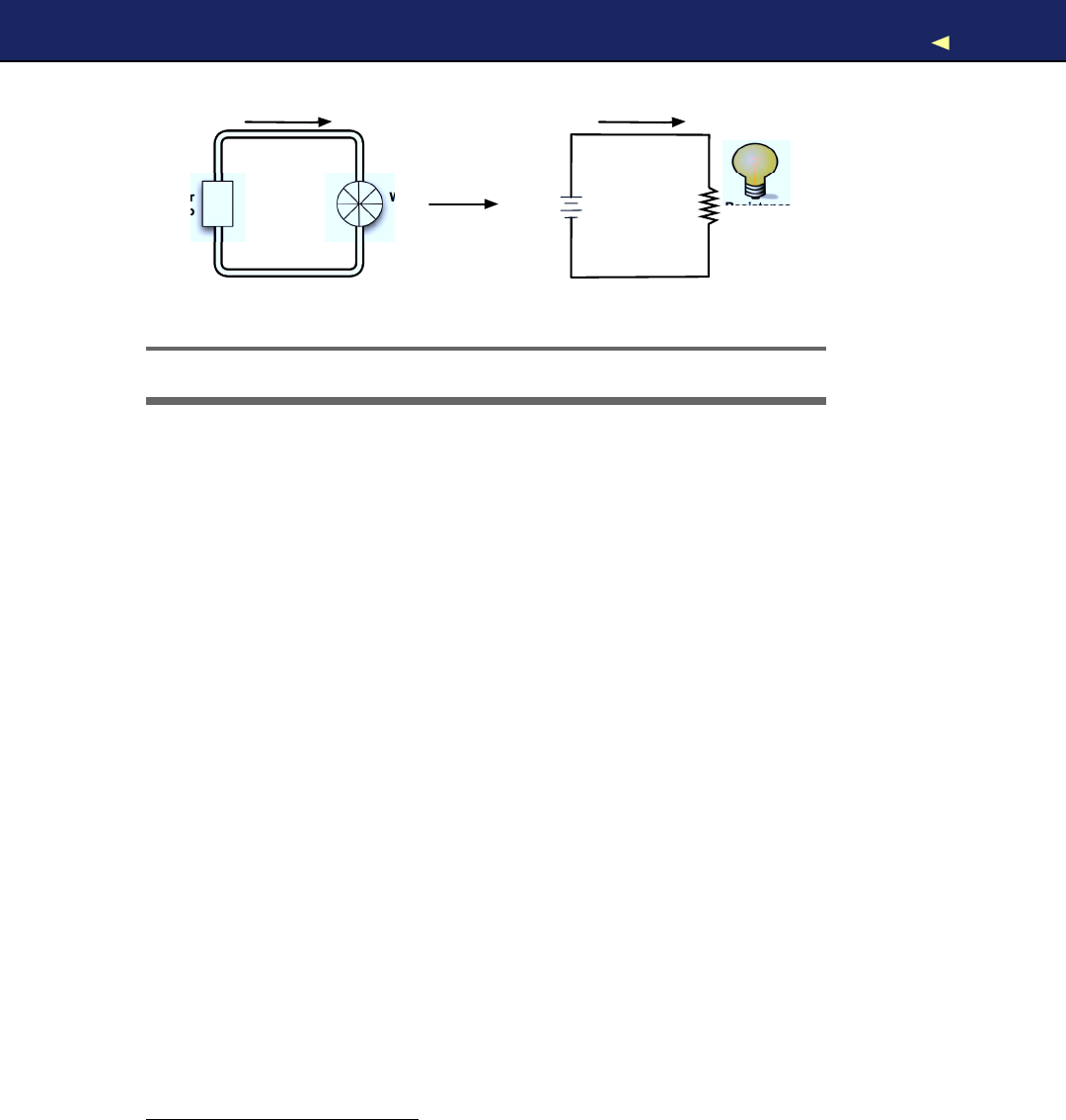
CURRENT,VOLTAGE,AND RESISTANCE 238
Current
Pipe
W a t e r
Pump
W a t e r
Mill
+
-
Current (I)
Power
Supply
V o l t a g e
(V)
Resistance (R)
Wire
Dynamo
Figure A.1: W a t e r circuits and electrical circuits are similar.
In electronics, current is the amount of electricity flowing through an
electric line. It is the equivalent of the actual flow of water in awater
circuit. While we measure the water flow in liters per minute, we mea-
sure current in ampere. One ampere means that approximately 6.24 ×
1018electrons are flowing per second.
Every component in acircuit—be it water or electricity—resists some
amount of current. In awater circuit, it’s the pipes the water is flowing
through or perhaps awater mill. In an electrical circuit, it is the wire
or alight bulb. Resistance is an important physical phenomenon that
is closely related to current and voltage. W e measure it in Ohms, and
its official symbol is Ω.
The German physicist Georg Ohm found out that current depends on
voltage and resistance. He postulated the following form we call Ohm’s
law today:1
• I (current) = V (voltage) / R (resistance)
This is equivalent to the following:
• R (resistance) = V (voltage) / I (current)
• V (voltage) = R (resistance) ×I(current)
So, for two given values, you can calculate the third one. Ohm’s law is
the only formula you’ll absolutely have to learn when learning electron-
1. W e use Ias the current’s letter for historical reasons. In the past, it stood for induc-
tance.
Report erratum
this copy is (P1.0 printing, Ja nu ra r y, 2011)
Download from Wow! eBook <www.wowebook.com>

CURRENT,VOLTAGE,AND RESISTANCE 239
ics. When working with LEDs, for example, it helps you calculate the
size of the resistor you need.
If you look at a LED’s data sheet, you’ll usually find two values: afor-
ward voltage and a current rating. The forward voltage usually is some-
where between 1.8V and 3.6V, and the maximum current often is 20
mA (milliamperes). Let’s say we have an LED with amaximum of 2.5
volts and a safe current of 20 mA. W e also assume that we have apower
supply delivering 5volts (as the Arduino does, for example). What’s the
right size of the resistor we need to put in front of the LED?
W e have to make sure that the resistor takes 5 – 2.5 =2.5 volts from the
circuit, so only 2.5 volts are left for the LED. This value is called voltage
drop.Also, we want amaximum of 20 mA to flow through the LED.
This implies that amaximum of 20 mA (0.02 A) should flow through
our resistor also.
Now that we know that 2.5 V and 0.02 Ashould pass the LED, we can
use Ohm’s law to calculate the resistance R:
R = V / I
In our case, we have the following:
R = 2.5V /0.02A =125Ω
This means we need a125Ωresistor for our LED. If you do not have a
125Ωresistor, use abigger one such as 150Ωor 220Ω.It will still protect
the LED and only slightly decrease its brightness. That’s because we’d
decrease the current even more:
I = 2.5V /150Ω=17mA
I = 2.5V /220Ω=11mA
Resistors
Y o u ’ l l hardly ever find an electronics project that doesn’t need resistors.
So, you’ll need them often and should get familiar with them abit more.
Usually you’ll use carbon or metal resistors. Metal resistors are more
precise and don’t create so much noise, but carbon resistors are a bit
cheaper. In simple circuits, it usually doesn’t matter which type you
use.
The most important attribute of aresistor is its resistance value that is
measured in Ohm. Only afew vendors actually print this value on the
resistor, because resistors are small parts, and it’s hard to read text
Report erratum
this copy is (P1.0 printing, Ja nu ra r y, 2011)
Download from Wow! eBook <www.wowebook.com>

CURRENT,VOLTAGE,AND RESISTANCE 240
Color
Code
Zeros
Black
0
-
Brown
1
0
Red
2
00
Orange
3
000
Y e l l o w
4
0000
Green
5
00000
Blue
6
000000
V i o l e t
7
0000000
Gray
8
00000000
White
9
000000000
Figure A.2: Resistor values are encoded using colors.
that is so small it fits on them. So, they use atrick and encode the
value using colored stripes.
Usually you find four or five stripes on aresistor (at least on through-
hole parts; SMD resistors don’t have them). One of them is separated
from the others by agap (see Figure A.3,on the next page). The separate
stripe is on the right side of the resistor, and it tells you about the
resistor’s accuracy. Gold stands for an accuracy of ±5percent, silver
for ±10 percent, and no stripe means ±20 percent. Using the remaining
stripes, you can calculate the resistor value.
Y o u read the stripes from left to right, and every color stands for adigit
(see Figure A.2). The rightmost stripe—that is the third or fourth one—
stands for an amount of zeros to be added to the preceding digits. In
Figure A.3,on the next page, you can see three examples:
•On the first resistor we find four stripes: brown (1), green (5),
brown (1 zero), silver (±10%). That means we have aresistor value
of 150Ω.
•The second resistor has four stripes again: yellow (4), violet (7),
orange (3 zeros), gold (±5%). So, this resistor has avalue of
47000Ω=47k Ω.
•The third resistor has five stripes: brown (1), red (2), red (2), green
(5 zeros), silver (±10%), so the value is 12,200,000Ω=12.2MΩ.
Report erratum
this copy is (P1.0 printing, Ja nu ra r y, 2011)
Download from Wow! eBook <www.wowebook.com>
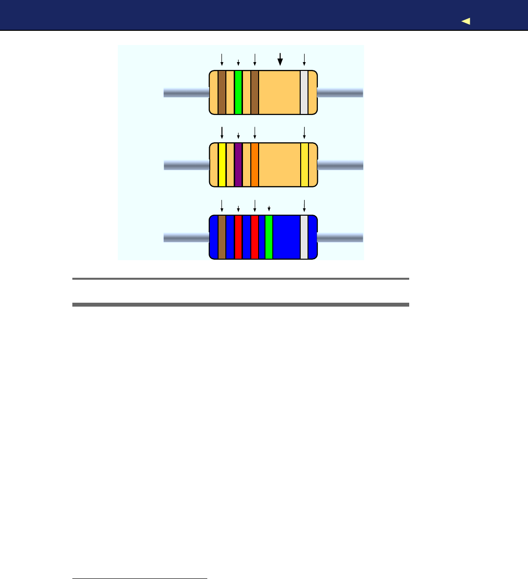
LEARNING HOWTOSOLDER 241
150Ω
± 10%
47kΩ
± 5%
12.2MΩ
± 10%
Gap
brown
green
brown silver
yellowviolet
orange gold
brown red red silver
green
Figure A.3: Colored stripes tell you about resistor values.
In the beginning, the color coding seems to be complicated, but you’ll
get used to it quickly. Also, you can find countless tools for determining
resistor values on the Internet.2
For the book’s projects, this is all the theory of electricity you need to
know. To learn more about electronics, have alook at Make: Electronics
[Pla10]or at http://lcamtuf.coredump.cx/electronics/.
A.2 Learning How to Solder
Y o u can build nearly all of the book’s projects by plugging parts into
abreadboard or directly into the Arduino board. But sooner or later
you’ll have to learn how to solder if you want to become an expert in
electronics. That’s mainly because you’ll learn the most by building
projects, and even the simplest kits require some sort of soldering.
Alot of people think that soldering is difficult or requires expensive
equipment, so they never try to do it. The truth is that it’s cheap and
2. http://harkopen.com/tutorials/using-wolfram-alpha-electric-circuits
Report erratum
this copy is (P1.0 printing, Ja nu ra r y, 2011)
Download from Wow! eBook <www.wowebook.com>
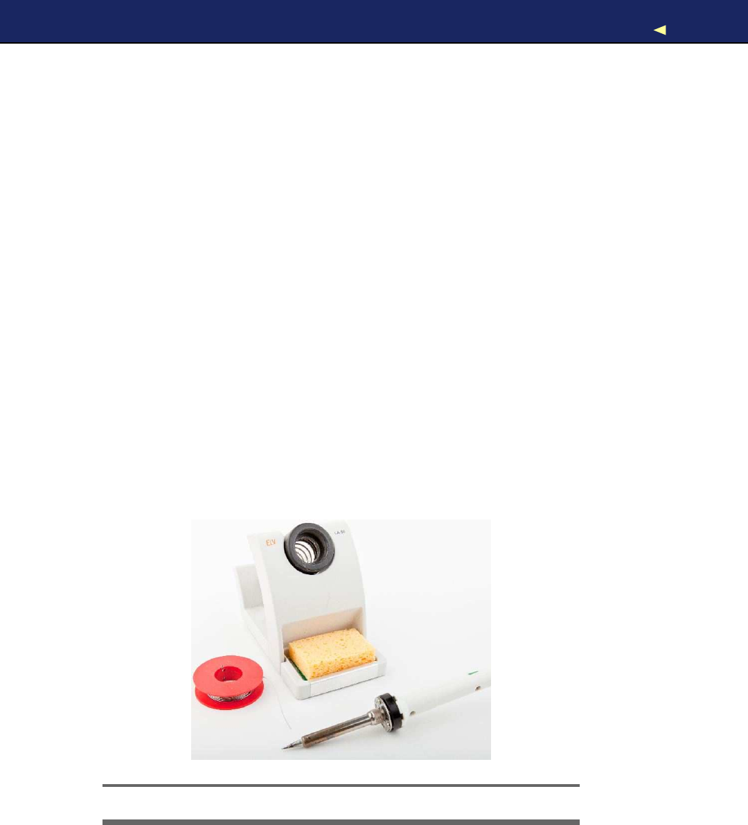
LEARNING HOWTOSOLDER 242
pretty easy. It requires some practice, but after only afew solder joints
you’ll see that it’s not rocket science.
In this book, we have one project that requires you to solder apin
header to an ADXL335 breakout board. W e need it for building the
motion-sensing game controller in Chapter 6,Building a Motion-Sensing
Game Controller,on page 132.In this section, you’ll learn how to do it,
and you’ll need the following equipment (shown in Figure A.4):
• A 25–30 watt soldering iron with atip (preferably 1/16") and a
soldering stand.
•Standard 60/40 solder (rosin-core) spool for electronics work. It
should have a0.031" diameter.
• A sponge.
Before you start to solder, prepare your work area. Make sure that you
can easily access all your tools and that you have something to protect
your work area from drops of solder. W e a r i n g safety glasses is always
agood idea! Even seemingly simple and harmless activities such as
cutting wires, for example, can be very dangerous!
Bring all parts into the right position: attach the pin header to the
breakout board, and make sure you cannot accidentally move it while
soldering.
Figure A.4: Y o u need these tools for soldering.
Report erratum
this copy is (P1.0 printing, Ja nu ra r y, 2011)
Download from Wow! eBook <www.wowebook.com>

LEARNING HOWTOSOLDER 243
Figure A.5: Y o u have to attach the pin header to the breakout board.
People get very creative when it comes to locking parts into acertain
position. But you have to be careful—don’t use flammable materials to
bring parts together. Y o u should not use parts that distribute heat very
well either, especially if they are in touch with other parts. Duct tape
might work in some cases, but be careful with it, too.
Try to find apiece of wood or something similar that has the right
height: the height of the pin headers. Then you can put the breakout
board on top of it and attach the pin headers. If you’re planning to sol-
der more often and build some electronics projects, you should always
look for these little tools that make your life easier.
In Figure A.5,you can see how Ihave prepared all parts with ahelping
hand, auseful tool for locking parts into aposition. They usually come
with amagnifying glass, and they are cheap. If you plan to solder often,
you should get one (see Figure A.6,on the next page).
After you’ve prepared everything, it’s time to heat up the soldering iron.
The main purpose of soldering is to join metallic surfaces. In our case,
we’d like to join the surface of the pin header with the metal in the
Report erratum
this copy is (P1.0 printing, Ja nu ra r y, 2011)
Download from Wow! eBook <www.wowebook.com>

LEARNING HOWTOSOLDER 244
Figure A.6: A“helping hand” really deserves its name.
breakout board. To achieve this, we’ll heat up the metallic parts and
then connect them using molten solder.
This process depends on acertain temperature, and the wrong temper-
ature is one of the most common soldering problems. If the tempera-
ture is too low, your solder joints might become fragile, and you also
might have to touch the parts for too long, so you can damage them. An
extremely high temperature can damage your parts right away. Experts
can debate for hours and days about “the right temperature,” but 600
to 650 F(315 to 350 C) is agood compromise.
W e t the sponge (it shouldn’t be too wet), and clean the tip by wiping
it over the sponge afew times. Then tin the tip by putting asmall
Report erratum
this copy is (P1.0 printing, Ja nu ra r y, 2011)
Download from Wow! eBook <www.wowebook.com>
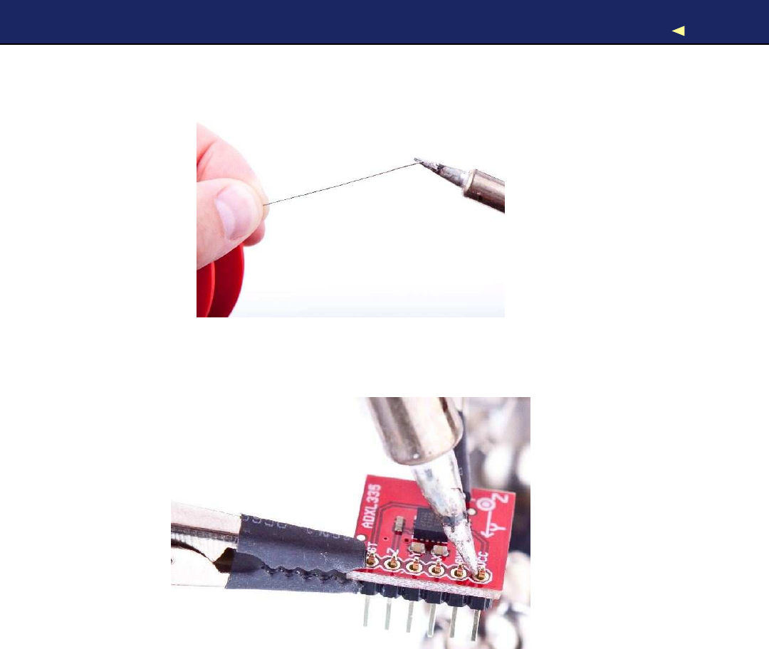
LEARNING HOWTOSOLDER 245
amount of solder back onto the tip. This helps protect the tip, and it
also improves the heat transfer to components:
Soldering is mainly about heat distribution, and now it’s time to heat
the joint. Make sure the tip of the soldering iron touches the part (pin
header) and the pad of the breakout board at the same time:
Keep it there for about a second, and then feed asmall amount of solder
between the tip and the pin:
Report erratum
this copy is (P1.0 printing, Ja nu ra r y, 2011)
Download from Wow! eBook <www.wowebook.com>
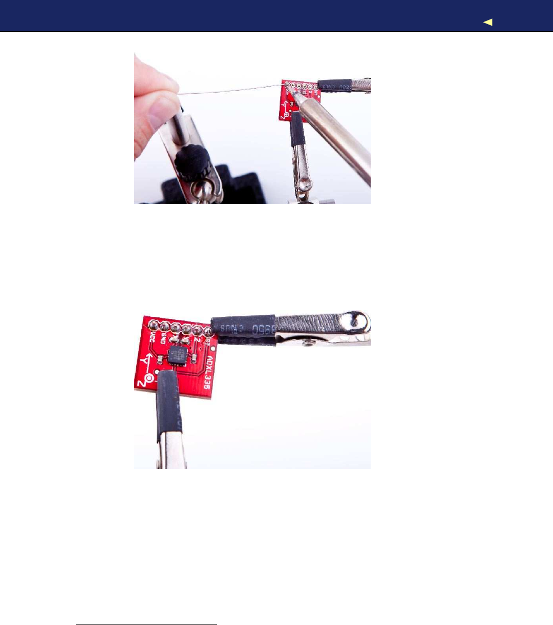
LEARNING HOWTOSOLDER 246
As soon as the solder starts to flow, you’re safer, because the solder
distributes heat automatically. Feed some more solder (not too much!)
until you have anice, shiny solder joint. The whole process shouldn’t
take more than two to three seconds. When you’re done, remove the
iron tip quickly, and give the joint afew seconds to cool down.
Repeat this for all six pin headers, and the result should look like this:,
Test it by building the motion-sensing game controller, and play avideo
game to relax abit.
Congratulations! Y o u have just finished your first soldering job!
This tutorial is only astarting point for your new shiny soldering career.
At least you know by now that soldering isn’t too difficult. Y o u can now
try to build some beginner’s kits. All electronics stores offer them, and
they usually come with soldering instructions, too. Y o u can also find
excellent tutorials and even videos on the Internet to build your skills.3
3. http://store.curiousinventor.com/guides/How_to_Solder
Report erratum
this copy is (P1.0 printing, Ja nu ra r y, 2011)
Download from Wow! eBook <www.wowebook.com>

Appendix B
Advanced Arduino Programming
In reality, the Arduino programming language is nothing but C++, but it
has some restrictions, and it uses aspecial tool suite. In this appendix,
you’ll learn what the restrictions are. Also, you’ll find ashort section
showing how bit operators work, because you need them often when
working with sensors and other devices.
B.1 The Arduino Programming Language
The first sketches you’ll write for an Arduino might seem to be written in
aspecial “Arduino Language,” but they aren’t. To program the Arduino,
you usually use plain old C/C++ and have to cross-compile your source
code into machine code suitable for the Arduino’s microcontroller.
These microcontrollers are all part of the A V R family produced by a
company named Atmel. To make software development for A V R micro-
controllers as easy as possible, Atmel has developed awhole tool chain
based on the GNU compiler tools. All tools work like the originals, but
they have been optimized for generating code for the A V R microcon-
trollers.
For nearly all GNU development tools such as gcc,ld,or as,there’s
an A V R variant: avr-gcc,avr-ld, and so on. Y o u can find them in the
hardware/tools/bin directory of the Arduino IDE.
The IDE is mainly agraphical wrapper that helps you avoid using the
command-line tools directly. Whenever you compile or upload apro-
gram using the IDE, it delegates all work to the A V R tools. As aseri-
ous software developer, you should turn on amore verbose output, so
you can see all command-line tool invocations. Edit preferences.txt as
Download from Wow! eBook <www.wowebook.com>

THEARDUINO PROGRAMMING LANGUAGE 248
described in Section 2.3,Changing Preferences,on page 48, and set
both build.verbose and upload.verbose to true.Then load our blinking
LED sketch and compile it. The output in the message panel should
look similar to Figure 2.3,on page 50.
The command invocations look abit weird at first, because of the names
of the many temporary files that are created. Y o u should still be able
to identify all compile and link steps that are necessary to build even
asimple sketch like our blinking LED example. That’s the most impor-
tant thing that the Arduino team did: they hid all these nasty details
well behind the IDE, so even people with no software development expe-
rience are able to program the Arduino. For programmers, it’s agood
idea to work in verbose mode, because the best way to learn about all
the A V R tools is to see them in action.
Upload the program to the Arduino now to see avrdude in action. This
tool is responsible for loading code into the Arduino and can be used
for programming many other devices, too. Interestingly, the A V R tools
make it even possible to use the Arduino IDE for non-Arduino projects
such as the Meggy Jr.1
“But wait!” you say, “I’m aC++ programmer, and I’m missing am a i n ( )
function!” And you’re right: that’s another difference between Arduino
programming and regular old C++ code. When programming for the
Arduino, you don’t define m a i n ( ) yourself, because it is already defined
in the libraries provided by the Arduino developers. As you might have
guessed, it calls setup( ) first and then runs the loop( ) function in aloop.
There are further restrictions when programming C++ on A V R micro-
controllers:2
•Y o u cannot use the Standard Template Library (STL), because it’s
way too big for the small A V R microcontrollers.
• Exception handling is not supported. That’s why you see the -fno-
exceptions switch often when the avr-gcc compiler is invoked.
•Dynamic memory management using new( ) and delete( ) is cur-
rently not supported.
In addition to all that, you should keep an eye on performance. For
example, C++ automatically creates alot of functions (copy construc-
1. http://www.evilmadscientist.com/article.php/meggyjr
2. http://www.nongnu.org/avr-libc/user-manual/FAQ.html#faq_cplusplus
Report erratum
this copy is (P1.0 printing, Ja nu ra r y, 2011)
Download from Wow! eBook <www.wowebook.com>

BITOPERATIONS 249
tors, assignment operators, and so on) in the background that are
rarely needed on the Arduino. Even with these restrictions, the Arduino
supports apowerful subset of the C++ programming language. So,
there’s no excuse for sloppy coding!
B.2 Bit Operations
In embedded computing, you often have to manipulate bits. For exam-
ple, you sometimes have to read single bits to get some sensor data. In
other cases, you have to set bits to turn adevice into acertain status
or make it perform some action.
For bit manipulation, you need only afew operations. The simplest is
the not operation that inverses abit. It turns a 0 into a1, and vice
versa. Most programming languages implement the not operation with
a!-operator:
int x = 42; // In binary this is 101010
int y = !x; // y== 010101
In addition, you’ll find three binary operations named AND,OR, and
XOR (eXclusive OR). Most programming languages call the correspond-
ing operators &,|, and ^, and their definitions are as follows:
a b a AND b a OR b a XOR b
a & b a |b a ^ b
0 0 0 0 0
1 0 0 1 1
0 1 0 1 1
1 1 1 1 0
W i t h these operators, it’s possible to mask bits in anumber. For exam-
ple, you can extract certain bits. If you’re interested only in the lower
two bits of anumber, you can do it as follows:
int x = 42; // In binary this is 101010
int y = x & 0x03; // y== 2== B10
Y o u can also set or clear one or more bits in anumber using the OR
operation. The following code sets the fifth bit in xno matter if this bit
is 0or 1.
int x = 42; // In binary this is 101010
int y = x | 0x10; // y== 58 == B111010
Report erratum
this copy is (P1.0 printing, Ja nu ra r y, 2011)
Download from Wow! eBook <www.wowebook.com>

BITOPERATIONS 250
The bit shift operators << and >> let you move bits to acertain position
before you work with them. The first one moves bits to the left, and the
second moves them to the right:
int x = 42; // In binary this is 101010
int y = x << 1; // y== 84 == B1010100
int z = x >> 2; // z== 10 == B1010
Shifting operations might seem intuitive, but you have to be careful
when shifting signed values.3Although they look similar, binary opera-
tors are not the same as boolean operators. Boolean operators such as
&& and || do not operate on the bit level. They implement the rules of
boolean algebra.4
3. http://en.wikipedia.org/wiki/Arithmetic_shift
4. http://en.wikipedia.org/wiki/Boolean_algebra_%28logic%29
Report erratum
this copy is (P1.0 printing, Ja nu ra r y, 2011)
Download from Wow! eBook <www.wowebook.com>

Appendix C
Advanced Serial Programming
In nearly all the book’s projects, we’ve used the Arduino’s serial port.
Sometimes we only emitted debug messages to monitor the current
state of our sketches, but often we needed it to actually output infor-
mation or to send commands. And the fact is, we’ve used the Serial class
without explaining how serial communication actually works. W e catch
that up in this appendix.
Tocommunicate with an Arduino, we used the Processing programming
language, and we used JavaScript. But many developers prefer other
languages, and in this appendix, you’ll also learn how to use C/C++,
Java, Ruby, Python, and Perl to talk to an Arduino.
C.1 Learning More About Serial Communication
In Chapter 2,Inside the Arduino,on page 46,you saw that you only
need three wires for serial communication: acommon ground, aline for
transmitting data (TX), and one for receiving data (RX) (see the diagram
on page 51).
Data is transmitted as electrical pulses, so both communication part-
ners need areference for the voltage level, and that’s what the common
ground is for. The transmission line is used to send data to the recipient
and has to be connected to the recipient’s receiving line. This enables
full-duplex communication where both partners can send and receive
data simultaneously (wouldn’t it be great if people could also commu-
nicate full-duplex?).
W e now know how to connect two devices, but we still have to transmit
some data. Therefore, both communication partners have to agree on
Download from Wow! eBook <www.wowebook.com>
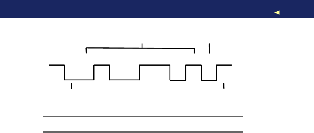
LEARNING MORE ABOUT SERIAL COMMUNICATION 252
0 1 00000 111 1
Start Bit
Parity
Stop Bit
Data
Figure C.1: Serial communication on the bit level
aprotocol, and in Figure C.1,you can see what atypical serial com-
munication looks like. The different states of abit are represented by
different voltage levels. Usually, a 0 bit is represented by 0volts, while 5
volts stands for a 1 bit (some protocols use -12V and 12V, respectively).
The following parameters control aserial communication:
• A start bit indicates the beginning of adata word and is used to
synchronize transmitter and receiver. It is always 0.
• A stop bit tells us when the last data bit has been sent and sep-
arates two consecutive data words. Depending on the particular
protocol agreement, there can be more than one stop bit, but that
happens rarely.
•Information is transferred as binary data bits;that is, if you’d like
to transmit the letter Mfor example, you have to turn it into a
number first. Several character set encodings are available, but
when working with the Arduino, the ASCII encoding fits best. In
ASCII, an uppercase Mis encoded as the decimal number 77,
which is 01001101 in binary. This is the bit sequence that even-
tually gets transmitted.
•The parity bit indicates whether the number of 1s in the data has
been odd or even. This is asimple error checking algorithm that is
rarely used and that stems from atime when network connections
have been less reliable than they are today.
Report erratum
this copy is (P1.0 printing, Ja nu ra r y, 2011)
Download from Wow! eBook <www.wowebook.com>

SERIAL COMMUNICATIONUSINGVARIOUSPROGRAMMING LANGUAGES 253
Parity control can be “none” (no parity bit is sent), “odd” (the parity
bit is set if the amount of 1s in the data bits is odd; otherwise, it
is 0), or “even” (the parity bit is set if the amount of 1s in the data
bits is even; otherwise, it is 0). W e chose odd parity for our data,
and because there are 4 bits set to 1in 01001101, the parity bit
is 0.
•The baud rate defines the transmission speed and is measured in
transmission steps per second. When working with the Arduino,
typical baud rates are 9600, 14400, 19200, or even 115200. Note
that the baud rate does not define how much data is actually
transferred per second, because you have to take the control bits
into account. If your connection settings are 1 start bit, 1stop bit,
no parity, and 8 bits per byte, then you have to transfer 1 + 1 + 8 =
10 bits to transfer asingle byte. W i t h abaud rate set to 9600, you
can then theoretically send 9600 /10 =960 bytes per second—at
least if every bit gets transferred in exactly one transmission step.
C.2 Serial Communication Using V a r i o u s Programming
Languages
In this book, we’ve already used different programming languages to
access an Arduino connected to your computer’s serial port. In Chap-
ter 6,Building a Motion-Sensing Game Controller,on page 132,we used
Processing, and in Chapter 9,Creating Y o u r Own Universal Remote Con-
trol,on page 202,we used JavaScript.
When working with the Arduino, you often have to program serial ports.
So in this section, you’ll learn how to do that in various programming
languages. For demonstration purposes, we’ll use the same Arduino
sketch for all of them:
Download SerialProgramming/AnalogReader/AnalogReader.pde
const unsigned int BAUD_RATE =9600;
const unsigned int SERIAL_DELAY =5;
const unsigned int NUM_PINS =6;
void setup() {
Serial.begin(BAUD_RATE);
}
void loop() {
const int MAX_PIN_NAME =3;
Report erratum
this copy is (P1.0 printing, Ja nu ra r y, 2011)
Download from Wow! eBook <www.wowebook.com>

SERIAL COMMUNICATIONUSINGVARIOUSPROGRAMMING LANGUAGES 254
char pin_name[MAX_PIN_NAME +1];
if (Serial.available()) {
int i = 0;
while (Serial.available() && i < MAX_PIN_NAME) {
const char c = Serial.read();
if (c != -1 && c!= '\n')
pin_name[i++] =c;
delay(SERIAL_DELAY);
}
pin_name[i] =0;
if (strlen(pin_name) > 1 &&
(pin_name[0] == 'a' || pin_name[0] == 'A'))
{
const int pin =atoi(&pin_name[1]);
if (pin <NUM_PINS) {
Serial.print(pin_name);
Serial.print(
": "
);
Serial.println(analogRead(pin));
}else {
Serial.print(
"Unknown pin: "
);
Serial.println(pin);
}
}else {
Serial.print(
"Unknown pin name: "
);
Serial.println(pin_name);
}
}
}
This program waits for the name of an analog pin (a0, a1, ... a5) and
returns its current value. So, all our clients have to send data to the
Arduino (the name of the pin), and they have to receive the result (in
Figure C.2,on the next page, you can see it working with the IDE’s
serial monitor).
All clients will look similar: they expect the name of the serial port to
connect to as a command-line argument. They will constantly send the
string “a0” to the Arduino to get back the current value of analog pin 0.
Then they print the result to the console. They all use aconstant baud
rate of 9600, and they all wait for two seconds after opening the serial
port, because many Arduinos reboot upon opening aserial connection.
To learn more about serial communication in general, take alook at
Section C.1,Learning More About Serial Communication,on page 251.
For some of the clients, you need to install additional libraries. In some
cases, you have to do that as an admin user on your machine. Iwon’t
mention that explicitly in the following sections. Also, you should make
Report erratum
this copy is (P1.0 printing, Ja nu ra r y, 2011)
Download from Wow! eBook <www.wowebook.com>
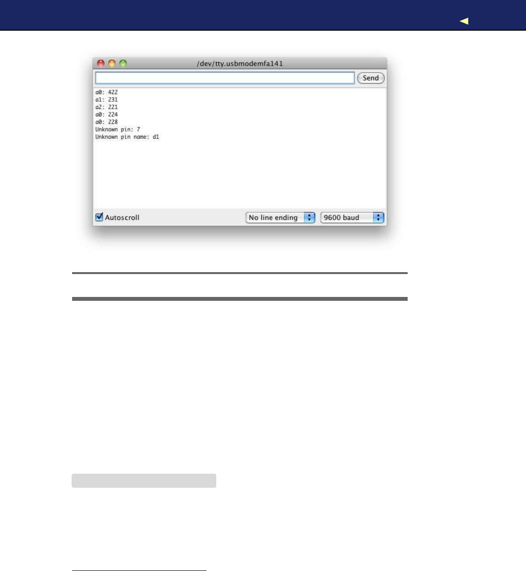
SERIAL COMMUNICATIONUSINGVARIOUSPROGRAMMING LANGUAGES 255
Figure C.2: Our test sketch returns the current values of analog pins.
sure you do not have any serial monitor windows open when running
one of the examples in the following sections.
C/C++
Although you program the Arduino in C++, you don’t need to write
clients talking to the Arduino in C++ or C. Still, you can, and it’s easy,
if you use Tod E. Kurt’s excellent arduino_serial.c1as a basis.
The original program implements acomplete command-line tool offer-
ing alot of useful options. For our purpose, that’s not necessary, so I’ve
extracted its four major functions into a C header file:
Download SerialProgramming/c/arduino-serial.h
#ifndef __ARDUINO_SERIAL__
#define __ARDUINO_SERIAL__
#include <fcntl.h>
#include <sys/ioctl.h>
#include <termios.h>
1. http://todbot.com/blog/2006/12/06/arduino-serial-c-code-to-talk-to-arduino/
Report erratum
this copy is (P1.0 printing, Ja nu ra r y, 2011)
Download from Wow! eBook <www.wowebook.com>

SERIAL COMMUNICATIONUSINGVARIOUSPROGRAMMING LANGUAGES 256
#include <stdint.h>
#include <string.h>
int serialport_init(const char*serialport, int baud);
int serialport_writebyte(int fd, uint8_t b);
int serialport_write(int fd, const char*str);
int serialport_read_until(int fd, char*buf, char until);
#endif
Their meaning is as follows:
•serialport_init( ) opens aserial port connection. It expects the name
of the serial port to be opened and the baud rate to be used. It
returns afile descriptor if everything went fine, and it returns -1
otherwise.
•W i t h serialport_writebyte(), you can send asingle byte to an Arduino
connected to your computer’s serial port. Simply pass it the file
descriptor returned by serialport_init( ) and the byte to be written. It
returns -1 if an error occurred. Otherwise, it returns 0.
•serialport_write( ) writes an entire string to the serial port. It expects
afile descriptor and the string to be written. It returns -1 if an
error occurred. Otherwise, it returns 0.
•Use serialport_read_until( ) to read data from aserial port. Pass it
afile descriptor and a buffer to be filled with the data read. The
method also expects adelimiter character. serial_port_read_until( )
reads data until it finds that character and it always returns 0.
Just for the sake of completeness, we’ll have alook at the implementa-
tion of our four functions:
Download SerialProgramming/c/arduino-serial.c
#include
"arduino-serial.h"
int serialport_writebyte(int fd, uint8_t b) {
int n = write(fd, &b, 1);
return (n != 1) ?-1 :0;
}
int serialport_write(int fd, const char*str) {
int len =strlen(str);
int n = write(fd, str, len);
return (n != len) ?-1 :0;
}
int serialport_read_until(int fd, char*buf, char until) {
Report erratum
this copy is (P1.0 printing, Ja nu ra r y, 2011)
Download from Wow! eBook <www.wowebook.com>

SERIAL COMMUNICATIONUSINGVARIOUSPROGRAMMING LANGUAGES 257
char b[1];
int i = 0;
do {
int n = read(fd, b, 1);
if (n == -1)
return -1;
if (n == 0) {
usleep(10 *1000);
continue;
}
buf[i++] =b[0];
}while (b[0] != until);
buf[i] =0;
return 0;
}
int serialport_init(const char*serialport, int baud) {
int fd =open(serialport, O_RDWR |O_NOCTTY |O_NDELAY);
if (fd == -1) {
perror(
"init_serialport: Unable to open port"
);
return -1;
}
struct termios toptions;
if (tcgetattr(fd, &toptions) <0) {
perror(
"init_serialport: Couldn't get term attributes"
);
return -1;
}
speed_t brate =baud;
switch(baud) {
case 4800: brate =B4800; break;
case 9600: brate =B9600; break;
case 19200: brate =B19200; break;
case 38400: brate =B38400; break;
case 57600: brate =B57600; break;
case 115200: brate =B115200; break;
}
cfsetispeed(&toptions, brate);
toptions.c_cflag &= ~PARENB;
toptions.c_cflag &= ~CSTOPB;
toptions.c_cflag &= ~CSIZE;
toptions.c_cflag |= CS8;
toptions.c_cflag &= ~CRTSCTS;
toptions.c_cflag |= CREAD |CLOCAL;
toptions.c_iflag &= ~(IXON |IXOFF |IXANY);
toptions.c_lflag &= ~(ICANON |ECHO |ECHOE |ISIG);
toptions.c_oflag &= ~OPOST;
Report erratum
this copy is (P1.0 printing, Ja nu ra r y, 2011)
Download from Wow! eBook <www.wowebook.com>

SERIAL COMMUNICATIONUSINGVARIOUSPROGRAMMING LANGUAGES 258
toptions.c_cc[VMIN] =0;
toptions.c_cc[VTIME] =20;
if (tcsetattr(fd, TCSANOW, &toptions) <0) {
perror(
"init_serialport: Couldn't set term attributes"
);
return -1;
}
return fd;
}
If you’re familiar with Unix file handling, everything will make perfect
sense to you. If not, well, then you still have the code to access an
Arduino connected to your computer’s serial port. Here’s how to use
the code for communicating with our analog reader sketch (note that
the following code will run on your PC and not on your Arduino):
Download SerialProgramming/c/analog_reader.c
Line 1#include <stdio.h>
-#include <unistd.h>
-#include
"arduino-serial.h"
-
5#define MAX_LINE 256
-
-int main(int argc, char*argv[]) {
-if (argc == 1) {
-printf(
"You have to pass the name of aserial port.\n"
);
10 return -1;
-}
-
-int baudrate =B9600;
-int arduino =serialport_init(argv[1], baudrate);
15 if (arduino == -1) {
-printf(
"Could not open serial port %s.\n"
,argv[1]);
-return -1;
-}
-sleep(2);
20
-char line[MAX_LINE];
-while (1) {
-int rc =serialport_write(arduino,
"a0\n"
);
-if (rc == -1) {
25 printf(
"Could not write to serial port.\n"
);
-}else {
-serialport_read_until(arduino, line, '\n');
-printf(
"%s"
,line);
-}
30 }
-return 0;
-}
Report erratum
this copy is (P1.0 printing, Ja nu ra r y, 2011)
Download from Wow! eBook <www.wowebook.com>

SERIAL COMMUNICATIONUSINGVARIOUSPROGRAMMING LANGUAGES 259
First we import all the libraries we need, and we define aconstant for
the maximum length of the lines we are going to read from the Arduino.
Then we define am a i n ( ) function.
After we’ve made sure that the name of aserial port was passed on the
command line, we initialize aserial port in line 14. Then we sleep for
two seconds to give the Arduino some time to get ready. After that, we
start aloop where we constantly send the string “a0” to the Arduino in
line 23. W e check the result of serialport_write(), and if it was successful,
we read the result sent by the Arduino in line 27. Let’s compile our little
program:
maik> gcc arduino-serial.c analog_reader.c -o analog_reader
Determine what serial port your Arduino is connected to (mine is con-
nected to /dev/tty.usbmodemfa141), and run the program like this:
maik> ./analog_reader /dev/tty.usbmodemfa141
a0: 495
a0: 376
a0: 368
^C
Everything works as expected, and accessing a serial port using Cisn’t
that difficult. To embed this code into aC++ program, you should wrap
it in aclass named SerialPort or something similar.
J a v a
The Java platform standardizes alot, and it also defines how to access
aserial port in the Java Communications API.2But the API is only a
specification that still has to be implemented. Agood implementation
is the RXTX project.3
Download the most current release, and follow the installation instruc-
tions for your platform. Make sure that RXTXcomm.jar is on your class
path. Then enter the following code in your favorite IDE or text editor:
Download SerialProgramming/java/AnalogReaderTest.java
import java.io.InputStream;
import java.io.OutputStream;
import gnu.io.CommPortIdentifier;
import gnu.io.SerialPort;
class AnalogReader {
2. http://java.sun.com/products/javacomm/
3. http://rxtx.qbang.org/
Report erratum
this copy is (P1.0 printing, Ja nu ra r y, 2011)
Download from Wow! eBook <www.wowebook.com>

SERIAL COMMUNICATIONUSINGVARIOUSPROGRAMMING LANGUAGES 260
private InputStream _input;
private OutputStream _output;
public AnalogReader(
final String portName,
final int baudRate) throws Exception
{
final int timeout =1000;
final String appName =
"analog reader client"
;
CommPortIdentifier portId =
CommPortIdentifier.getPortIdentifier(portName);
SerialPort port =(SerialPort)portId.open(
appName,
timeout
);
_input =port.getInputStream();
_output =port.getOutputStream();
port.setSerialPortParams(
baudRate,
SerialPort.DATABITS_8,
SerialPort.STOPBITS_1,
SerialPort.PARITY_NONE
);
}
public void run() throws Exception {
byte[] buffer =new byte[255];
Thread.sleep(2000);
while (true){
_output.write(
"a0\n"
.getBytes());
Thread.sleep(100);
if (_input.available() >0) {
_input.read(buffer);
System.out.print(new String(buffer));
}
}
}
}
public class AnalogReaderTest {
public static void main(String[] args) throws Exception {
if (args.length != 1) {
System.out.println(
"You have to pass the name of aserial port."
);
System.exit(1);
}
AnalogReader analogReader =new AnalogReader(args[0], 9600);
analogReader.run();
}
}
Report erratum
this copy is (P1.0 printing, Ja nu ra r y, 2011)
Download from Wow! eBook <www.wowebook.com>

SERIAL COMMUNICATIONUSINGVARIOUSPROGRAMMING LANGUAGES 261
This file defines two classes named AnalogReader and AnalogReaderTest.
AnalogReader actually encapsulates access to the Arduino. It stores an
InputStream object in _input to receive data, and it stores an OutputStream
object in _output to send data to the Arduino.
The constructor initializes the serial port connection and assigns its
input and output streams to our member variables. To obtain aserial
port connection, we have to get aCommPortIdentifier object first. From
this object, we can then create aSerialPort object. This object gives us
access to the underlying streams, and it also allows us to set the port’s
parameters, such as the baud rate.
W e implement the protocol for our Arduino sketch in the run( ) method.
There we wait for two seconds, and then we start aloop. In the loop,
we send the string “a0” to the serial port using OutputStream’s write( )
method. Before we send the string, we turn it into abyte array calling
getBytes(). To give the Arduino some time to create aresult, we wait for
another 100 milliseconds. Afterward, we check if aresult is available
and read it by invoking InputStream’s read( ) method.
AnalogReaderTest is only asmall driver class that implements am a i n ( )
method, creates an AnalogReader object, and calls run( ) on it. Here’s
how to compile and use the program:
maik> javac AnalogReaderTest.java
maik> java AnalogReaderTest /dev/tty.usbmodemfa141
Experimental: JNI_OnLoad called.
Stable Library
=========================================
Native lib Version =RXTX-2.1-7
Java lib Version =RXTX-2.1-7
a0: 496
a0: 433
a0: 328
a0: 328
^C
After some debug output from the libraries we are using, the Analo-
gReaderTest does exactly what it’s intended to do: it permanently prints
the values of the analog pin 0. Accessing aserial port in Java is apiece
of cake if you use the right libraries.
Ruby
Even dynamic languages such as Ruby give you instant access to your
computer’s serial port and to an Arduino if you connect it to it. But
before that, you need to install the serialport gem:
Report erratum
this copy is (P1.0 printing, Ja nu ra r y, 2011)
Download from Wow! eBook <www.wowebook.com>

SERIAL COMMUNICATIONUSINGVARIOUSPROGRAMMING LANGUAGES 262
maik> gem install serialport
Using it, you can connect to the Arduino in just 30 lines of code.
Download SerialProgramming/ruby/analog_reader.rb
Line 1require
'rubygems'
-require
'serialport'
-
-if ARGV.size != 1
5puts
"You have to pass the name of aserial port."
-exit 1
-end
-
-port_name =ARGV[0]
10 baud_rate =9600
-data_bits =8
-stop_bits =1
-parity =SerialPort::NONE
-
15 arduino =SerialPort.new(
-port_name,
-baud_rate,
-data_bits,
-stop_bits,
20 parity
-)
-
-sleep 2
-while true
25 arduino.write
"a0"
-line =arduino.gets.chomp
-puts line
-end
W e create anew SerialPort object in line 15, passing it all the usual
parameters. After we sleep for two seconds, we start aloop and call
write( ) on the SerialPort object. To get the result back from the Arduino,
we call gets( ) and then we print the result to the console. Here you can
see the program in action:
maik> ruby analog_reader.rb /dev/tty.usbserial-A60061a3
a0: 496
a0: 456
a0: 382
^Canalog_reader.rb:21:in `gets': Interrupt
from analog_reader.rb:21
Using Ruby for accessing an Arduino is agood choice, because you can
fully concentrate on your application. All the ugly real-world details you
have to deal with in other programming languages are well hidden.
Report erratum
this copy is (P1.0 printing, Ja nu ra r y, 2011)
Download from Wow! eBook <www.wowebook.com>

SERIAL COMMUNICATIONUSINGVARIOUSPROGRAMMING LANGUAGES 263
Python
Python is another dynamic programming language that you can use to
quickly create Arduino clients. For programming aserial port, down-
load and install the pyserial library first.4There is aspecial installer for
W i n d o w s , but usually it’s sufficient to install it like this:
maik> python setup.py install
After you’ve installed pyserial, you can use it to create aclient for our
analog reader sketch:
Download SerialProgramming/python/analog_reader.py
Line 1import sys
-import time
-import serial
-
5if len(sys.argv) != 2:
-print "You have to pass the name of aserial port."
-sys.exit(1)
-
-serial_port =sys.argv[1]
10 arduino =serial.Serial(
-serial_port,
-9600,
-serial.EIGHTBITS,
-serial.PARITY_NONE,
15 serial.STOPBITS_ONE)
-time.sleep(2)
-
-while 1:
-arduino.write(
'a0'
)
20 line =arduino.readline().rstrip()
-print line
W e make sure that we have the name of aserial port on the command
line. Then we create anew Serial object in line 10, passing it all the
parameters we’d like to use for serial communication.
After sleeping for two seconds, we start an infinite loop. In the loop, we
send the string “a0” to the serial port calling write(). W e read the result
returned by the Arduino using the readline( ) method and output the
result to the console. Here’s what atypical session looks like:
maik> python analog_reader.py /dev/tty.usbserial-A60061a3
a0: 497
a0: 458
a0: 383
^C
4. http://sourceforge.net/projects/pyserial/files/
Report erratum
this copy is (P1.0 printing, Ja nu ra r y, 2011)
Download from Wow! eBook <www.wowebook.com>

SERIAL COMMUNICATIONUSINGVARIOUSPROGRAMMING LANGUAGES 264
Isn’t that code beautiful? W i t h about 20 lines of Python code, you get
full control over your Arduino sketch. So, Python is another excellent
choice for writing Arduino clients.
P e r l
Perl is still one of the most widely used dynamic programming lan-
guages, and it has good support for serial communication. Some distri-
butions come with libraries for programming the serial port, but usually
you have to install amodule first.
W i n d o w s users should have alook at W i n 3 2 : : S e r i a l P o r t . 5For the rest,
Device::SerialPort is agood choice. Y o u can install it as follows:
maik> perl -MCPAN -e 'install Device::SerialPort'
Then use it like this:
Download SerialProgramming/perl/analog_reader.pl
Line 1use strict;
-use warnings;
-use Device::SerialPort;
-
5if ($#ARGV != 0) {
-die
"You have to pass the name of aserial port."
;
-}
-
-my $serial_port =$ARGV[0];
10 my $arduino =Device::SerialPort->new($serial_port);
-$arduino->baudrate(9600);
-$arduino->databits(8);
-$arduino->parity(
"none"
);
-$arduino->stopbits(1);
15 $arduino->read_const_time(1);
-$arduino->read_char_time(1);
-
-sleep(2);
-while (1) {
20 $arduino->write(
"a0\n"
);
-my ($count, $line) =$arduino->read(255);
-print $line;
-}
W e check whether the name of aserial port was passed on the com-
mand line. Then we create anew Device::SerialPort instance in line 10.
W e configure all serial port parameters, and in line 15, we set atimeout
5. http://search.cpan.org/dist/Win32-SerialPort/
Report erratum
this copy is (P1.0 printing, Ja nu ra r y, 2011)
Download from Wow! eBook <www.wowebook.com>

SERIAL COMMUNICATIONUSINGVARIOUSPROGRAMMING LANGUAGES 265
value for read( ) calls. If we did not set it, read( ) would return imme-
diately, giving the Arduino no time to respond. read_char_time( ) sets a
timeout for the waiting period between two characters.
Then we sleep for two seconds and start an infinite loop. Here we send
the string “a0” to the serial port and read Arduino’s response using the
read( ) method. read( ) expects amaximum number of bytes to be read,
and it returns the actual number of bytes read and the data it received.
Finally, we output the result to the console. Atypical program run looks
as follows:
maik> perl analog_reader.pl /dev/tty.usbserial-A60061a3
a0: 496
a0: 366
a0: 320
^C
That’s it! It takes only about twenty lines of Perl code to create aclient
for the analog reader Arduino sketch. So, Perl is agood choice for pro-
gramming Arduino clients, too.
Report erratum
this copy is (P1.0 printing, Ja nu ra r y, 2011)
Download from Wow! eBook <www.wowebook.com>

Appendix D
Bibliography
[But09] Paul Butcher. Debug It!: Find, Repair, and Prevent Bugs in
Y o u r Code.The Pragmatic Programmers, LLC, Raleigh, NC,
and Dallas, TX, 2009.
[Gre07] Ira Greenberg. Processing: Creative Coding and Computa-
tional Art.Apress, Berkeley, CA, USA, 2007.
[KR98] Brian W . Kernighan and Dennis Ritchie. The CProgramming
Language.Prentice Hall PTR, Englewood Cliffs, NJ, second
edition, 1998.
[Mey97] Scott Meyers. Effective C++: 50 Specific W a y s to Improve Y o u r
Programs and Designs.Addison W e s l e y Longman, Reading,
MA, second edition, 1997.
[Pin06] Chris Pine. Learn to Program.The Pragmatic Programmers,
LLC, Raleigh, NC, and Dallas, TX, 2006.
[Pla10] Charles Platt. Make: Electronics.O’Reilly Media, Inc.,
Sebastopol, CA, 2010.
[Str00] Bjarne Stroustrup. The C++ Programming Language.Addi-
son W e s l e y Longman, Reading, MA, 2000.
Download from Wow! eBook <www.wowebook.com>

Index
Symbols
!operator, 249
<< operator, 250
>> operator, 250
&operator, 72,249
%operator, 85
^operator, 249
|operator, 249
3V3 pin, 27
5V pin, 27
A
AC adapter, 27
see also power supply
acceleration, indirect, 153
accelerometers
connecting, 134–140
ideas for, 132,152
mouse exercise, 153
access tokens, OAuth, 174
Adafruit, 18
adding files, 47
analog versus digital signals, 29
analog pins
connecting sensors to, 113
constants, 72
digital I/O pins, 30
illustration, 25f
input, 28
voltage and, 114
analogRead() method, 114
AnalogReader class, 261
AnalogReaderTest class, 261
AND operator, 249
Anthros, 229
Apple remote, see remote control
project
AppleRemote class, 209
archives, 98
Arduino
about, 13,23,24
configuring, 38
identifying types, 38
schematic, 24
versions, 16
Arduino Ethernet, 180
Arduino Hypnodisk, 234
Arduino IDE
error messages, 44
file management, 47
functions, 33
installation, 31
preferences, 48
Processing IDE and, 123
toolbar, 34
Arduino LilyPad, 24,53,185
Arduino Mega2560, 31
Arduino Nano, 31
Arduino Projects packs, 18
Arduino Prototyping shield, 141
Arduino Starter Pack, 19
Arduino Uno, 16
arduino_serial.c, 255
arduinoPort variable, 126
arrays, value, 37
art projects, 229
ATmega168, 30
ATmega2560, 31
ATmega328, 30
Atmel, 30,247
authentication, Twitter, 174
available() function, 52
A V R microcontrollers, see
microcontrollers
avrdude tool, 248
B
background(),147
Download from Wow! eBook <www.wowebook.com>

BATTERY PACKS DECODING INFRARED SIGNALS
battery packs, connecting, 28
baud rate, 60,131,253
BEDAZZLER, 59
begin() function, 52
BIN, 54
binary clock exercise, 87
binary dice project, 63–87
further exercises, 87
version 1, 69–74
version 2(with start button), 74–80
version 3(with guess button), 80–86
binary literals, 72
binary numbering systems, 55
binary operators, 249
bit operations, 249
bit shift operators, 250
bits, masking and moving, 249
blame() method, 232
Blaminatr project, 229–234
blinking LED project, 35–44
Bluetooth, 200
boards
components of, 25f, 25–31
configuring, 38
errors uploading to, 44
identifying, 38
types of, 24,38
Boarduino, 25
boolean values, 36
Botanicall, 180
Bounce class, 84,143
Bounce library, 83
Bounce object, 84
breadboards
connecting accelerometer, 134
connecting LEDs to, 66
ground and, 70
troubleshooting, 86
types, 65
brick game, 144–152
Nunchuk exercise, 169
Brushduino, 150
buffer, serial receive, 58
bugs error messages, 44
build.verbose setting, 48,248
burglar alarm project, 170–200
email, 186–192
exercise, 131
motion detector, connecting,
192–195
BurglarAlarm class, 197
buttons, see pushbuttons
BYTE, 54
byte maximum, 39
b y t e variables, 36
C
C++, 51,92,109,247,255–259
cable modem connections, 184
carriage return option, 97
cellular networks, 200
char variables, 36
circuits, see electrical circuits
classes, Processing, 124
clocks
binary, 87
cuckoo, 180
clones, 25
clothes, see textiles
color codes for resistor values, 240
color, drawing, 129,167
coloring, syntax, 97,100
CommPortIdentifier object, 261
communication, serial, see serial
communication
compiler tools, 51,247
compiling, 34,39
configuring, 38
const keyword, 36,109
constant values, defining, 109
constructors, 124
converting analog and digital signals,
29
converting output formats, 54
cross-compiling, 51,247
cube project, LED, 72
cube rotation project, 163–169
cuckoo clock, 180
current, 238,239
cursor, hiding, 146
D
dah() method, 93
data transfer, 58
data types, 36
DAYTIME services, 181
DC motors, 224
debouncing, 78,83,143
DEC, 54
decimals, specifying number of digits,
112
decoding infrared signals, 207
268
Download from Wow! eBook <www.wowebook.com>

DEGREE VARIABLE GUESS BUTTON
degree variable, 126
delay() method, 38
delayMicroseconds() method, 106
delete(),248
dice project, 63–87
further exercises, 87
version 1, 69–74
version 2(with start button), 74–80
version 3(with guess button), 80–86
dice reader, 72
Diecimila, 16
Digi-Key, 19
digital versus analog signals, 29
digital I/O pins
analog output, 30
illustration, 25f
serial communication with, 59
voltage, 35
digitalWrite() method, 38,41
distance sensors
project, 102–131
types, 104
dit() method, 93
domain names, 183
double,37
draw() method, 129,147,168
drivers, installing, 31,32
Duemilanove, 16
dynamic memory management, 248
E
edge values, 137
electrical circuits, 237
see also resistors; voltage
electronics, basic theory of, 237–241
see also resistors; voltage
email
direct, 189–192
from command line, 186–188
T-shirt,185
Email class, 189
encoding sensor data, 119
end() function, 59
error messages, 44
Ethernet connections, 180–185
Blaminatr project, 235
exercises, 201
remote control project, 215
troubleshooting, 199
examples folder, 48,98
exception handling, 248
eXclusive OR operator, 249
exercises
binary clock, 87
blinking LEDs, 44
computer mouse, 153
controlling status LED, 61
dice, 87
Morse code, 100
motor control, 235
networking, 201
Nintendo Nunchuk, 169
remote control, 222
resistor brightness, 87
tilt sensor, 87
ultrasonic sensor, 131
see also projects
Eyewriter, 157
F
file management, 47
fill(),168
flickering LEDs while uploading, 39
Flickr, 17
floating-point numbers, 37,110–113,
118
fonts, setting, 146
format specifier, 54
forward voltage, 239
Freeduino, 25
function definition scheme, 36
G
game, see brick game
game controller, motion sensing,
132–153
adding pushbutton, 140–143
brick game, 144–152
connecting accelerometer, 134–140
gaming console project, 152
gateway addresses, 184
get_axis() function, 139
getDistance() method, 124
getSensorData(),128
getTemperature() method, 124
Gibb, Alicia, 229
global variables, 126
Gnd pins, 28,70
GNU C++ compiler tools, 51,247
ground pins, 28,70
GSM shield, 200
guess button, adding, 80–86
269
Download from Wow! eBook <www.wowebook.com>

HACKY SACK TOY LIBRARIES
H
hacky sack toy, 150
handle() command, 219
handle_guess button, 85
handle_start button, 85
header files, 92
helping hand, 243
HEX, 54
hexadecimal numbering systems, 55
Hoefer, Steve, 72
hooray method, 85
hourglass, USB, 234
HTTP access, 215–221
Hypnodisk, 234
I
I2C(Inter-Integrated Circuit), 156
IDE, see Arduino IDE
index variable, 97
indirect acceleration, 153
infrared LEDs, 209,222
infrared receivers, 205,235
see also remote control project
infrared remote control, see remote
control project
infrared sensors
burglar alarm project, 192–200
distance measuring, 131
proxy, 215–221
InfraredProxy class, 216
init_screen(),129
initialization value for random number
generation, 73
initializing
Ethernet shield, 184
random number generator, 72,73
serial port, 52,261
_input,261
input pins, see analog pins; digital I/O
pins
InputStream object, 261
installation instructions, 98
installing Arduino IDE, 31
Integrated Development Environment,
see Arduino IDE
Inter-Integrated Circuit (I2C), 156
Internet connections
Blaminatr project, 235
Ethernet shield, 180–185
PC relay, 172–179
remote control project, 215
inverted sonar project, see distance
sensor project
IP addresses, 183,200
iPod Sport Kit, 152
IR receiver, see infrared receivers
IRemote library, 207,209,222
isalpha() function, 94
J
Java, 259–261
Java Communications API, 259
JavaScript, 212
jitter, 137,138,163
K
key words.t xt file, 97,100
Kurt, Tod E., 255
L
lawn-mower project, 222
LEDs
BEDAZZLER, 59
blinking project, 35–44
calculating resistor size, 239
connecting, 41,43,66
controlling status LED project, 52,
61
cube project, 72
fashion projects, 53,185
flickering while uploading, 39
infrared, 209,222
SMD LEDs, 41
libraries
debouncing, 83
directory, 48,94
Ethernet, 181
examples folder, 98
IRemote, 207,209,222
output exercise, 101
random seed, 73
serial programming and, 254,263,
264
Servo, 228
SoftwareSerial, 59
SPI,183
STL (Standard Template Library),
248
syntax color, 97
troubleshooting, 99
Twitter, 176
270
Download from Wow! eBook <www.wowebook.com>

LIBRARIES DIRECTORY NUNCHUCK CLASS
Wire,156,162
libraries directory, 48
licenses, 98
light switch, pushbutton, 76
LilyPad, 24,53,185
Linux
installation, 32
serial port configuration, 39
serial terminals, 56
Linux Infrared Remote Control project,
205
long values, 37
loop() function, 52
setup() loop, 38
Luminet project, 185
M
MAC addresses, 183,199
Mac OS X
installation, 32
remote control, 222
serial port configuration, 39
serial terminals, 56
m a i n ( ) function, 248
Makershed, 18
marble maze, 152
masking bits, 249
MAX_MESSAGE_LEN constant, 96
maze, marble, 152
measure_distance() method, 112
Mega2560, 59
Meggy Jr., 248
memory
data types and, 36
dynamic memory management, 248
encoded sensor data, 119
floating-point numbers and, 110,
112
message_text variable, 97
microcontrollers
about, 30
code, 51,247
identifying, 38
illustration, 25f
microseconds_to_cm() method, 109,112,
118
modulus operator, 85
Morse code, 89
Morse code generator, 88–101
motion detectors, see burglar alarm
project; game controller, motion
sensing
motion-sensing game controller, see
game controller, motion sensing
motion_detected() method, 195
motor control project, 223–234
Blaminatr, 229–234
connecting servo motor, 226–228
exercises, 235
troubleshooting, 234
motors
power supply, 226,234
shields, 233
troubleshooting, 234
types, 224
see also motor control project
mouse exercise, 153
Mouser, 19
N
naming sketches, 47
networking project, 170–200
Ethernet, 180–185
exercises, 201
PC Internet relay, 170–179
troubleshooting, 199
wireless, 200
New Media Art, 229
new(),248
Nike iPod Sport Kit, 152
Nintendo W i i Balance Board, 158
Nintendo W i i Nunchuk project,
154–169
connecting, 155–163
exercises, 169,222
Nunchuck class, 160–163
rotating cube, 163–169
troubleshooting, 169
Nintendo W i i , scientific uses, 158
Nintendo W i i M o t i o n , 169
noCursor(),146
not operator, 249
numbering systems, 55
numbers, floating-point, 110–113,118
numbers, random, 72,73,234
Nunchuck, see Nintendo Nunchuk
project
Nunchuck class, 160–163
271
Download from Wow! eBook <www.wowebook.com>

OAUTH PROTOTYPING SHIELD
O
OAuth, 174,176,200
OCT, 54
octal numbering systems, 55
Ohm’s law, 238
Ohm, Georg, 238
OR operator, 249
output
devices exercise, 101
edge values, 137
floating-point numbers and, 112
fonts, 146
format specifier, 54
Morse code, 93
parsing, 128
verbose, 48,247
_output,261
output pins, see analog pins; digital
I/O pins
output_code(),93
output_distance() method, 112
output_result() function, 72
output_symbol(),93
OutputStream object, 261
P
Pachube, 174
Paperduino, 25
Parallax PING))) ultrasonic sensor, see
ultrasonic sensors
Parallax PIR sensor, see PIR sensors
parity bit, 252
parity control, 252
parseArduinoOutput(),128
parts list, 18–21
passive infrared sensors, see PIR
sensors
PC relay, 172–179
Perl, 264
physical computing, 23
piezo speakers, 100
Pin 13, internal resistor, 42,68
PING))) ultrasonic sensor, see
ultrasonic sensors
pinMode() method, 38
pins, see analog pins; digital I/O pins
PIR sensors
burglar alarm project, 192–200
connecting, 193
principles, 193
plant water alarm, 180
PlayStation Eye, 157
PNA4602 receiver, 206
see also remote control project
popMatrix(),168
power jack, 25f
power selection jumper, 27
power supply
analog pin voltage and, 115
motors and, 226,234
pins, 25f, 27
sharing with devices, 27
USB port, 26
preferences, 48
print() function, 53
println() function, 53
Processing
brick game, 144–152
conventions, 124
development of, 121
drawing cube with, 167
IDE, 123
rotating cube project, 163–169
sensor visualizer project, 121–131
serial communication, 125
Twitter support, 176
programming languages, 16
C++, 51,92,109,247,255–259
Java, 259–261
Perl, 264
Python, 263
Ruby, 261–262
serial communications, 253–265
see also Processing
programming, serial, 251–265
programs, see sketches
project management, 47
projects
binary dice, 63–87
blinking LED, 35–44
controlling status LED, 52,61
distance sensor, 102–131
game controller, motion sensing,
132–153
Morse code generator, 88–101
motor controlling, 223–234
networking, 170–200
Nintendo Nunchuk, 154–169
remote control, 202–222
rotating cube, 163–169
Prototyping shield, 141
272
Download from Wow! eBook <www.wowebook.com>

PSEUDORANDOM NUMBER GENERATOR SERIAL PORT
pseudorandom number generator, 72,
73
publishing services, sensor data, 174
pull-down resistors, 75
pull-up resistors, 75
pulseln() method, 107
pushbuttons
adding to binary dice project, 74–86
adding to game controller, 140–143
connecting, 74,79
debouncing, 78,143
pushMatrix(),168
Putty, 55
PWR_SEL switch, 27
pyserial library, 263
Python, 263
R
RadioShack, 19
radius variable, 126
random number generators, 72,73,
234
random seed, 73
random() function, 72,73
randomSeed() function, 73
read() function, 52
remote control codes, 205
remote control project, 202–222
browser control, 212–221
building remote, 209–212
exercises, 222
infrared principles, 204
infrared proxy, 215–221
interface, 212–214
obtaining codes, 205
troubleshooting, 221
reset button, 25f, 30
resistance, 238,240
resistors
calculating size of, 239
exercise, 87
internal (Pin 13), 42,68
need for, 68,74
pull-down, 75
pull-up, 75
pushbuttons and, 74
resistance values of, 240
types of, 239
resources
online, 17
parts, 18–21
return keyword, 125
RGB values, 167
Roboduino, 233
router connections, 184
Ruby, 261–262
RX LED, 39
RXTX project, 259
S
sampling and sampling rate, 29
saving, 34,47
scaled values, 118
schematic, Arduino, 24
screen command, 56
screens, clearing, 129
Seeduino, 25
send_message() method, 90,94
SensorData class, 124,126
Sensorpedia, 174
sensors
accelerometers, 134–140
connecting, 28,104,113,134
distance, 102–131
encoding sensor data, 119
floating-point numbers, 110–113,
118
infrared, 131
publishing services, 174
temperature, 113–131,172–179,235
tilt, 87,150
troubleshooting, 131
tweeting data, 172–185
ultrasonic, 102–131
visualizer, 119–131
serial communication
through digital pins, 59
disabling, 59
principles of, 51,251
Processing, 125
programming languages, 253–265
troubleshooting, 60,131
Serial Monitor button, 35
serial monitor, LED control project, 52,
61
serial port
configuring, 38
errors, 44
initializing, 52,261
multiple, 59
Perl programming, 264
Processing communication, 127
273
Download from Wow! eBook <www.wowebook.com>

SERIAL PROGRAMMING TROUBLESHOOTING
Seriality plug-in for JavaScript, 212
see also serial programming
serial programming, advanced,
251–265
serial receive buffer, 58
serial terminals, 55
serialEvent() function, 151
Seriality plug-in, 212
serialport functions, 256
SerialPort object, 261,262
Servo library, 228
servo motors, 225–228
setup() function, 36,38
in Processing, 127
shields
GSM, 200
motor, 233
Prototyping, 141
troubleshooting, 153
W i F i , 200
see also Ethernet connections
shifting operations, 249
Simple Mail TransferProtocol, see
SMTP (Simple Mail Transfer
Protocol)
sketchbook directory, 94
sketches
examples folder, 48
file management, 47
storing example, 98
SMD LEDs, 41
SMTP (Simple Mail TransferProtocol),
186
SmtpService class, 189
SoftwareSerial library, 59
soldering
basics, 241–246
equipment, 242
parts for, 21
temperatures, 244
troubleshooting, 153
sonar project, see distance sensor
project
spark-fun, 19
speakers, see piezo speakers
speed of sound, 113,131
SPI library, 183
split method, 128
Standard Template Library (STL), 248
start bit, 252
start button, adding, 74–86
starter packs, 18
status LED project, 52,61
stepper motors, 225
STL (Standard Template Library), 248
stop bit, 252
String class, 189
strings syntax, 37
strsep() function, 219
Super Mario Bros clone, 152
surface mounted devices (SMD) LEDs,
41
synchronizing data transfer, 58
syntax coloring, 97,100
syntax errors, 44
T
Tabs menu, 47
T e l e g r a p h class, 89,94
telegraph variable, 97
telnet command, 181
temperature sensors
distance sensor project, 113–131
motorized, 235
tweeting alarm, 172–179
voltage and, 113
textiles, 24,53,185
thermometer project, 235
tilt sensor
binary dice exercise, 87
hacky sack toy, 150
timestamp exercise, 201
tinning, 245
TMP36 voltage output temperature
sensor, see temperature sensors
toolbar functions, 34
toothbrush project, 150
trim method, 128
troubleshooting
board errors, 44
breadboard connections, 86
Ethernet connections, 199
LED connections, 43
libraries, 99
motors, 234
networking project, 199
Nunchuk project, 169
remote control project, 221
sensor connections, 131
serial communication, 60,131
serial port errors, 44
shields, 153
274
Download from Wow! eBook <www.wowebook.com>

TWEETALARM() ZIGBEE
soldering, 153
syntax coloring, 100
tweetAlarm(),179
Twitter
libraries, 176
registering applications, 174
troubleshooting, 200
tweeting sensor data, 172–185
twitter4j() method, 176
Twitwee Clock, 180
Two-Wire Interface (TWI), 156
TX LED, 39
U
UART (Universal Asynchronous
Receiver/Transmitter), 59
ultrasonic sensors
connecting, 104
distance sensor project, 102–131
ideas for, 130
principles of, 104
Universal Asynchronous
Receiver/Transmitter (UART), 59
universal remote control, see remote
control project
unsigned int variable, 37
unsigned long values, 37
upload.verbose setting, 48,248
uploading, 35,39
USB connector, 26
USB hourglass, 234
V
value arrays, 37
values, data, 36
values, edge, 137
values, RGB, 167
verbose output setting, 48,247
V e r i f y button, 34,39
versions, 16
v e r t e x ( ) ,168
V i n pin, 28
visualizer, sensor, 119–131
v o i d value type, 37
voltage
analog pins and, 114
defined, 237
digital pin states and, 35
drop, 239
forward, 239
Ohm’s law, 238
power supply, 27
serial communication and, 252
see also resistors
W
weapons, 59
web publishing services, 174
W i F i shield, 200
wii Nunchuck, see Nintendo Nunchuk
project
W i n d o w s
installation, 31
serial port configuration, 39
serial terminals, 55
W i r e library, 156,162
wireless networking, 200
WProgram.h,91
X
XOR operator, 249
Z
ZigBee, 200
275
Download from Wow! eBook <www.wowebook.com>

The Pragmatic Bookshelf
Available in paperback and DRM-free eBooks, our titles are here to help you stay on top of
your game. The following are in print as of December 2010; be sure to check our website at
pragprog.com for newer titles.
Title Y e a r ISBN Pages
Advanced Rails Recipes: 84 New W a y s to Build
Stunning Rails Apps
2008 9780978739225 464
Agile Coaching 2009 9781934356432 248
Agile Retrospectives: Making Good Teams Great 2006 9780977616640 200
Agile W e b Development with Rails 2009 9781934356166 792
Beginning Mac Programming: Develop with
Objective-C and Cocoa
2010 9781934356517 300
Behind Closed Doors: Secrets of Great
Management
2005 9780976694021 192
Best of Ruby Quiz 2006 9780976694076 304
Cocoa Programming: AQuick-Start Guide for
Developers
2010 9781934356302 450
Core Animation for Mac OS X and the iPhone:
Creating Compelling Dynamic User Interfaces
2008 9781934356104 200
Core Data: Apple’s API for Persisting Data on
Mac OS X
2009 9781934356326 256
Data Crunching: Solve Everyday Problems
using Java, Python, and More
2005 9780974514079 208
Debug It! Find, Repair, and Prevent Bugs in Y o u r
Code
2009 9781934356289 232
Design Accessible W e b Sites: 36 Keys to
Creating Content for All Audiences and
Platforms
2007 9781934356029 336
Desktop GIS: Mapping the Planet with Open
Source Tools
2008 9781934356067 368
Domain-Driven Design Using Naked Objects 2009 9781934356449 375
Driving Technical Change: Why People on Y o u r
Team Don’t Act on Good Ideas, and How to
Convince Them They Should
2010 9781934356609 200
Enterprise Recipes with Ruby and Rails 2008 9781934356234 416
Everyday Scripting with Ruby: for Teams,
Testers, and Y o u
2007 9780977616619 320
ExpressionEngine 2: A Quick-Start Guide 2010 9781934356524 250
From Java To Ruby: Things Every Manager
Should Know
2006 9780976694090 160
FXRuby: Create Lean and Mean GUIs with Ruby 2008 9781934356074 240
GIS for W e b Developers: Adding Where to Y o u r
W e b Applications
2007 9780974514093 275
Continued on next page
Download from Wow! eBook <www.wowebook.com>

Title Y e a r ISBN Pages
Google Maps API: Adding Where to Y o u r
Applications
2006 PDF-Only 83
Grails: A Quick-Start Guide 2009 9781934356463 200
Groovy Recipes: Greasing the Wheels of Java 2008 9780978739294 264
Hello, Android: Introducing Google’s Mobile
Development Platform
2010 9781934356562 320
Interface Oriented Design 2006 9780976694052 240
iPad Programming: AQuick-Start Guide for
iPhone Developers
2010 9781934356579 248
iPhone SDK Development 2009 9781934356258 576
Land the Tech Job Y o u Love 2009 9781934356265 280
Language Implementation Patterns: Create Y o u r
Own Domain-Specific and General Programming
Languages
2009 9781934356456 350
Learn to Program 2009 9781934356364 240
Manage It! Y o u r Guide to Modern Pragmatic
Project Management
2007 9780978739249 360
Manage Y o u r Project Portfolio: Increase Y o u r
Capacity and Finish More Projects
2009 9781934356296 200
Mastering Dojo: JavaScript and Ajax Tools for
Great W e b Experiences
2008 9781934356111 568
Metaprogramming Ruby: Program Like the Ruby
Pros
2010 9781934356470 240
Modular Java: Creating Flexible Applications
with OSGi and Spring
2009 9781934356401 260
Pomodoro Technique Illustrated: The Easy W a y
to Do More in Less Time
2009 9781934356500 144
Practical Programming: An Introduction to
Computer Science Using Python
2009 9781934356272 350
Practices of an Agile Developer 2006 9780974514086 208
Pragmatic Guide to Git 2010 9781934356722 168
Pragmatic Guide to JavaScript 2010 9781934356678 150
Pragmatic Guide to Subversion 2010 9781934356616 150
Pragmatic Project Automation: How to Build,
Deploy, and Monitor Java Applications
2004 9780974514031 176
Pragmatic Thinking and Learning: Refactor Y o u r
W e t w a r e
2008 9781934356050 288
Pragmatic Unit Testing in C# with NUnit 2007 9780977616671 176
Pragmatic Unit Testing in Java with JUnit 2003 9780974514017 160
Pragmatic V e r s i o n Control using CVS 2003 9780974514000 176
Pragmatic V e r s i o n Control Using Git 2008 9781934356159 200
Pragmatic V e r s i o n Control using Subversion 2006 9780977616657 248
Programming Clojure 2009 9781934356333 304
Continued on next page
Download from Wow! eBook <www.wowebook.com>

Title Y e a r ISBN Pages
Programming Cocoa with Ruby: Create
Compelling Mac Apps Using RubyCocoa
2009 9781934356197 300
Programming Erlang: Software for aConcurrent
W o r l d
2007 9781934356005 536
Programming Groovy: Dynamic Productivity for
the Java Developer
2008 9781934356098 320
Programming Ruby: The Pragmatic
Programmers’ Guide
2004 9780974514055 864
Programming Ruby 1.9: The Pragmatic
Programmers’ Guide
2009 9781934356081 944
Programming Scala: Tackle Multi-Core
Complexity on the Java Virtual Machine
2009 9781934356319 250
Prototype and script.aculo.us: Y o u Never Knew
JavaScript Could Do This!
2007 9781934356012 448
Rails for .NET Developers 2008 9781934356203 300
Rails for PHP Developers 2008 9781934356043 432
Rails Recipes 2006 9780977616602 350
Rapid GUI Development with QtRuby 2005 PDF-Only 83
Release It! Design and Deploy Production-Ready
Software
2007 9780978739218 368
Scripted GUI Testing with Ruby 2008 9781934356180 192
Seven Languages in Seven W e e k s : APragmatic
Guide to Learning Programming Languages
2010 9781934356593 300
Ship It! APractical Guide to Successful Software
Projects
2005 9780974514048 224
SQL Antipatterns: Avoiding the Pitfalls of
Database Programming
2010 9781934356555 352
Stripes ...and Java W e b Development Is Fun
Again
2008 9781934356210 375
Test-Drive ASP.NET MVC 2010 9781934356531 296
TextMate: Power Editing for the Mac 2007 9780978739232 208
The Agile Samurai: How Agile Masters Deliver
Great Software
2010 9781934356586 280
The Definitive ANTLR Reference: Building
Domain-Specific Languages
2007 9780978739256 384
The Passionate Programmer: Creating a
Remarkable Career in Software Development
2009 9781934356340 232
The RSpec Book: Behaviour-Driven Development
with RSpec, Cucumber, and Friends
2010 9781934356371 448
ThoughtWorks Anthology 2008 9781934356142 240
Ubuntu Kung Fu: Tips,Tricks,Hints, and Hacks 2008 9781934356227 400
W e b Design for Developers: AProgrammer’s
Guide to Design Tools and Techniques
2009 9781934356135 300
Download from Wow! eBook <www.wowebook.com>

Debugging &Better SQL
Debug It!
Debug It! will equip you with the tools, techniques,
and approaches to help you tackle any bug with
confidence. These secrets of professional debugging
illuminate every stage of the bug life cycle, from
constructing software that makes debugging easy;
through bug detection, reproduction, and
diagnosis; to rolling out your eventual fix. Learn
better debugging whether you’re writing Java or
assembly language, targeting servers or embedded
micro-controllers, or using agile or traditional
approaches.
Debug It! Find, Repair, and Prevent Bugs in Y o u r
Code
Paul Butcher
(232 pages) ISBN: 978-1-9343562-8-9. $34.95
http://pragprog.com/titles/pbdp
SQL Antipatterns
If you’re programming applications that store data,
then chances are you’re using SQL, either directly
or through amapping layer. But most of the SQL
that gets used is inefficient, hard to maintain, and
sometimes just plain wrong. This book shows you
all the common mistakes, and then leads you
through the best fixes. What’s more, it shows you
what’s behind these fixes, so you’ll learn alot about
relational databases along the way.
SQL Antipatterns: Avoiding the Pitfalls of
Database Programming
Bill Karwin
(300 pages) ISBN: 978-19343565-5-5. $34.95
http://pragprog.com/titles/bksqla
Download from Wow! eBook <www.wowebook.com>

Agile Techniques
The Agile Samurai
Faced with asoftware project of epic proportions?
Tiredof over-committing and under-delivering?
Enter the dojo of the agile samurai, where agile
expert Jonathan Rasmusson shows you how to
kick-start, execute, and deliver your agile projects.
Y o u ’ l l see how agile software delivery really works
and how to help your team get agile fast, while
having fun along the way.
The Agile Samurai: How Agile Masters Deliver
Great Software
Jonathan Rasmusson
(275 pages) ISBN: 9781934356586. $34.95
http://pragprog.com/titles/jtrap
Driving Technical Change
Y o u r co-workers’ resistance to new technologies
can be baffling. Learn to read users’ "patterns of
resistance"—and then dismantle their objections.
Every developer must master the art of
evangelizing. W i t h these techniques and strategies,
you’ll help your organization adopt your
solutions—without selling your soul to
organizational politics.
Driving T e c h n i c a l Change: Why People On Y o u r
T e a m Don’t Act On Good Ideas, and How to
Convince Them They Should
Terrence Ryan
(200 pages) ISBN: 978-1934356-60-9. $32.95
http://pragprog.com/titles/trevan
Download from Wow! eBook <www.wowebook.com>

More On Languages
Seven Languages in Seven Weeks
In this book you’ll get ahands-on tour of Clojure,
Haskell, Io, Prolog, Scala, Erlang, and Ruby.
Whether or not your favorite language is on that
list, you’ll broaden your perspective of
programming by examining these languages
side-by-side. Y o u ’ l l learn something new from each,
and best of all, you’ll learn how to learn alanguage
quickly.
Seven Languages in Seven W e e k s : APragmatic
Guide to Learning Programming Languages
Bruce A. Tate
(300 pages) ISBN: 978-1934356-59-3. $34.95
http://pragprog.com/titles/btlang
Language Implementation Patterns
Learn to build configuration file readers, data
readers, model-driven code generators,
source-to-source translators, source analyzers, and
interpreters. Y o u don’t need a background in
computer science—ANTLR creator Terence Parr
demystifies language implementation by breaking it
down into the most common design patterns.
Pattern by pattern, you’ll learn the key skills you
need to implement your own computer languages.
Language Implementation Patterns: Create Y o u r
Own Domain-Specific and General Programming
Languages
Terence Parr
(350 pages) ISBN: 978-1934356-45-6. $34.95
http://pragprog.com/titles/tpdsl
Download from Wow! eBook <www.wowebook.com>

Apple iOS &Mac
Beginning Mac Programming
Aimed at beginning developers without prior
programming experience. Takes you through
concrete, working examples, giving you the core
concepts and principles of development in context
so you will be ready to build the applications you’ve
been imagining. It introduces you to Objective-C
and the Cocoa framework in clear,
easy-to-understand lessons, and demonstrates how
you can use them together to write for the Mac, as
well as the iPhone and iPod.
Beginning Mac Programming: Develop with
Objective-C and Cocoa
TimIsted
(300 pages) ISBN: 978-1934356-51-7. $34.95
http://pragprog.com/titles/tibmac
iPad Programming
It’s not an iPhone and it’s not alaptop: the iPad is a
groundbreaking new device. Y o u need to create true
iPad apps to take advantage of all that is possible
with the iPad. If you’re an experienced iPhone
developer, iPad Programming will show you how to
write these outstanding new apps while completely
fitting your users’ expectation for this device.
iPad Programming: AQuick-Start Guide for
iPhone Developers
Daniel HSteinberg and Eric TFreeman
(250 pages) ISBN: 978-19343565-7-9. $34.95
http://pragprog.com/titles/sfipad
Download from Wow! eBook <www.wowebook.com>
Ruby &Rails
Programming Ruby 1.9 (The Pickaxe for 1.9)
The Pickaxe book, named for the tool on the cover,
is the definitive reference to this highly-regarded
language.
•Up-to-date and expanded for Ruby version 1.9
•Complete documentation of all the built-in
classes, modules, and methods •Complete
descriptions of all standard libraries •Learn more
about Ruby’s web tools, unit testing, and
programming philosophy
Programming Ruby 1.9: The Pragmatic
Programmers’ Guide
Dave Thomas with Chad Fowler and Andy Hunt
(992 pages) ISBN: 978-1-9343560-8-1. $49.95
http://pragprog.com/titles/ruby3
Agile W e b Development with Rails
Rails just keeps on changing. Rails 3and Ruby 1.9
bring hundreds of improvements, including new
APIs and substantial performance enhancements.
The fourth edition of this award-winning classic
has been reorganized and refocused so it’s more
useful than ever before for developers new to Ruby
and Rails. This book isn’t just arework, it’s a
complete refactoring.
Agile W e b Development with Rails: Fourth
Edition
Sam Ruby, Dave Thomas, and David Heinemeier
Hansson, et al.
(500 pages) ISBN: 978-1-93435-654-8. $43.95
http://pragprog.com/titles/rails4
Download from Wow! eBook <www.wowebook.com>

The Pragmatic Bookshelf
The Pragmatic Bookshelf features books written by developers for developers. The titles
continue the well-known Pragmatic Programmer style and continue to garner awards and
rave reviews. As development gets more and more difficult, the Pragmatic Programmers
will be there with more titles and products to help you stay on top of your game.
V i s i t Us Online
Home P a g e f o r Arduino: AQuick-Start Guide
http://pragprog.com/titles/msard
Source code from this book, errata, and other resources. Come give us feedback, too!
Register f o r Updates
http://pragprog.com/updates
Be notified when updates and new books become available.
Join the Community
http://pragprog.com/community
Read our weblogs, join our online discussions, participate in our mailing list, interact
with our wiki, and benefit from the experience of other Pragmatic Programmers.
New and Noteworthy
http://pragprog.com/news
Check out the latest pragmatic developments, new titles and other offerings.
Buy the Book
If you liked this eBook, perhaps you’d like to have a paper copy of the book. It’s available
for purchase at our store: pragprog.com/titles/msard.
Contact Us
Online Orders: www.pragprog.com/catalog
Customer Service: support@pragprog.com
Non-English V e r s i o n s : translations@pragprog.com
Pragmatic Teaching: academic@pragprog.com
Author Proposals: proposals@pragprog.com
Contact us: 1-800-699-PROG (+1 919 847 3884)
Download from Wow! eBook <www.wowebook.com>
