Arduino Project Handover Manual
Arduino%20Project%20Handover%20Manual
User Manual:
Open the PDF directly: View PDF ![]() .
.
Page Count: 22
1"
"
Arduino(Weld(Quality(Monitoring(Project((
Handover(Document(
"
"
Description:,,Document" detailing" the" preparation" and" handling" of" the"
Arduino" system" developed" by" Sava" Arsenijevic" during" his"
honours"project."
"
"
Project,Sponsors:,,Dr."Matthew"Doolan,"Mr."Cameron"Summerville."
"
"
Author:,, , Mr."Sava"Arsenijevic."
"
"
Date:,,,09/11/2018,
,
,
,
,
,
,
,
,
,
,
,
2"
"
,
Arduino,Weld,Quality,Monitoring,Project,..........................................................,1"
Handover,Document,..........................................................................................,1"
1"Introduction,.................................................................................................,3"
2"Project,Details,.............................................................................................,3"
2.1" DELIVERABLES"....................................................................................................."3"
2.2" WORKING"LIGHTS"................................................................................................"4"
2.3" DEFINE"WELDING"SCENARIO".................................................................................."4"
2.3.1"Welder*Parameters*.................................................................................*4"
2.3.2"Metal*Parameters*...................................................................................*5"
2.4" DEFINE"TRAINING"THE"ARDUINO"SYSTEM"/"STREAMLINE"..............................................."6"
2.5" MAKE"THE"ARDUINO"SYSTEM"PRESENTABLE"..............................................................."6"
2.6" WORKS"WITH"AT"LEAST"1"REPRODUCIBLE"FAULT"........................................................."7"
2.7" INCLUDED"EXTRA"PARTS"........................................................................................"7"
2.8" NOT"INCLUDED"..................................................................................................."7"
3"Setup,...........................................................................................................,8"
3.1" GLOSSARY".........................................................................................................."8"
3.1.1"General*terms*..........................................................................................*8"
3.1.2"training_set_gatherer.ino*.....................................................................*11"
3.1.3"weld_classifier.ino*.................................................................................*11"
3.2" LAPTOP"SETUP".................................................................................................."13"
3.3" TRAIN"ARDUINO"SYSTEM"...................................................................................."14"
3.4" TEST"ARDUINO"SYSTEM"......................................................................................"18"
4"Troubleshooting,.........................................................................................,20"
5"References,.................................................................................................,22"
"
"

3"
"
"
This" document" details" the" procedure" to" set" up" the" Arduino" Weld" Quality" Monitoring" system."
Information" regarding" the" overall" function," troubleshooting" methods," and" areas" for" further"
work"are"also"provided.""
"
Information" regarding" the" strengths" and" limitations" of" the" Arduino" Weld" Quality" Monitoring"
system" is" detailed" below." Whilst" the" system" has" been" upgraded" since" it" was" last" worked" on"
during"the"honours"project,"there"are"still"some"limitations."These"limitations"are"regarding"the"
environment" it" can" work" in" and" as" well" as" some" reliability" issues." However," by" following" the"
setup"procedure"accurately"and"maintaining"a"consistent"welding"environment,"the"system"will"
work"adequately."""
"
2.1
Deliverables(
Most"of"the"deliverables"outlined"at"the"start"of"the"project"have"been"met"and"are"displayed"in"
Table"1"below."
"
"
"
(
(
(
(
1 Introduction,
2 Project,Details,
Deliverable,
Completed?,
Working"lights"
Yes"
Define"welding"scenario"
Yes"
Define" training" the" Arduino" system" /"
streamline"
Yes"
Make"the"Arduino"system"presentable"
Partially"
Handover"manual"
Yes"
Works"with"at"least"1"reproducible"fault"
Yes"
Table*1*-*Project*Deliverables*

4"
"
2.2
Working(Lights(
A" new" LED" has" been" installed" which" emits" a" green" or" red" light" depending" on" whether" the"
system"determines"a"good"or"bad"weld"occurring."
2.3
Define(Welding(Scenario(
Steps" have" been" taking" to" further" define" and" restrict" the" scenario" which" the" system" can"
function" under." The" programs" to" be" uploaded" to" the" Arduino" have" been" streamlined" so" that"
variables"related"to"the"welding"environment"can"be"changed"easily.""
"
An"ideal"welding"environment"has"also"been"defined."Although"the"system"is"able"to"function"in"
differing" conditions" (MFDC" welder)" with" minor" changes" to" the" program" code," most" of" the"
testing"has"been"conducted"under"the"following"conditions:"
"
2.3.1 Welder,Parameters,
The" following" parameters" were" set" on" the" AC-DN" 50" welder" to" test" the" Arduino" system." Key"
information" includes" a" welding" current" of" 225," based" on" a" scale" of" 1-450" used," as" well" as" 12"
weld" cycles." The" Arduino" system" should" be" able" to" function" under" different" weld" conditions,"
but"these"have"not"been"tested.""
"
Parameter,,
Number,,
Setting,,
Pre-press""
1""
50""
Squeeze""
2""
25""
Preheat"current""
3""
0""
Preheat"time""
4""
0""
Cooling"time""
5""
0""
Slow"rising""
6""
0""
Welding"current""
7""
225""
Welding"time""
8""
12""
Cooling"time""
9""
0""
Slow"falling""
10""
0""
Temper"current""
11""
0""
Temper"time""
12""
0""
Hold"time""
13""
25""
Off"time""
14""
0""
Table*2*-*Welding*Parameters.*
5"
"
"
"
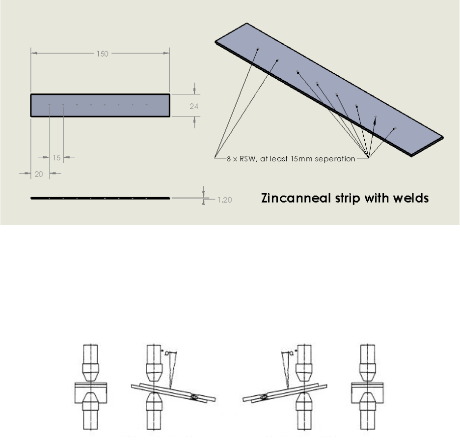
2.3.2 Metal,Parameters,
Zincanneal" strips" of" 150mmx24mmx1.2mm" dimensions" were" used" to" test" this" system." Welds"
should"be"conducted"at"intervals"of"15mm"at"the"minimum"during"the"testing"procedure,"with"
the" strips" to" be" changed" if" there" is" no" room" left" on" the" sample." These" numbers" have" been"
determined" empirically" but" seem" to" work" well" enough." If" welds" are" made" too" close" to" one"
another,"incorrect"classifications"are"made"due"to"weld"shunting."""
"
Figure*1*-*Specifications*of*Zincanneal*Strip*with*weld*spacing.*
"
To" simulate" a" “good”" weld," the" samples" should" be" placed" at" an" angle" perpendicular" to" the"
electrodes." To" simulate" a" “bad”" weld," the" metal" sample" should" be" placed" at" an" angle" of" ±15"
degrees" with" respect" to" the" flat" sample." Figure" 2" and" Figure" 3" show" the" orientations" for" a"
misaligned"sample"and"a"flat"sample"respectively.""
"
Figure*2*-*Misaligned*Sample*Orientation*at*+15*degrees*(left)*and*-15*degrees*(right).*Source:*(Li*et*al.,*
2000).*
6"
"
"
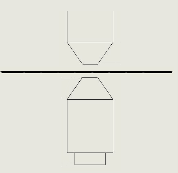
Figure*3*-*Flat*Sample*Orientation.**
2.4
Define(training(the(Arduino(system(/(streamline(
Defining" and" streamlining" the" Arduino" system" has" been" fulfilled" by" creating" a" Setup" process"
seen"on"Page"8."Precise"instructions"to"follow"have"been"tested"to"provide"accurate"results."A"
troubleshooting"section"on"Page"20"has"also"been"provided"to"assist"with"common"errors"that"
might"occur."
"
2.5
Make(the(Arduino(system(presentable(
This" deliverable" has" only" been" partially" achieved." There" were" some" issues" regarding" the"
reliability"of"the"system"that"caused"this"deliverable"to"not"be"finished."Some"planned"changes"
to"the"presentability"of"the"system,"such"as"a"transparent"box"to"view"the"system,"were"not"able"
to"be"installed"due"to"a"fear"of"comprising"the"overall"function"of"the"system."Some"efforts"have"
been"made"to"minimise"unnecessary"wiring"and"components.""
"
"
"
7"
"
2.6
Works(with(at(least(1(reproducible(fault(
This"deliverable"has"been"met."The"system"can"determine"between"a"flawed"and"a"normal"weld"
if"the"setup"procedure"has"been"followed."Sometimes"the"system"will"not"make"a"correct"weld"
classification," but" 100%" correct" classification" is" not" to" be" expected." If" incorrect" classification"
occurs"too"regularly,"this"can"be"fixed"by"checking"the"troubleshooting"section"on"Page"20."""
"
2.7
Included(Extra(Parts(
1. Some"extra"3"prong"LEDs"and"associated"100ohm"resistors.""
2. Extra"wires."
3. Approx."2m"long"lead"from"the"breadboard"to"the"welder"ground."
4. 4x"1N5408"capacitors."
5. A"box"
2.8
Not(included(
1. SD"card"reader"adapter"for"computers"lacking"an"SD"card"slot.""
"
"
"
"
"
"
"
"
"
"
"
"
"
"
"
"
"
"
"
"

8"
"
"
3.1
Glossary(
This"section"contains"a"glossary"of"relevant"variables"that"are"used"in"the"Arduino"Weld"Quality"
Monitoring"System."
3.1.1 General,terms,
3.1.1.1 Trigger)
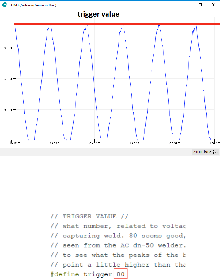
“trigger”"refers"to"the"voltage"at"which"the"Arduino"should"start"recording"a"weld"as"occurring."
This" point" depends" on" the" characteristics" of" the" background" noise" as" well" as" the" weld" signal"
characteristics." The" first" value" recorded" of" the" weld" signature" will" be" below" this" value" (see"
Figure"4"below)."Heuristically,"when"this"value"is"set"between"100-250"(490mV-~1250mV),"the"
start"of"the"weld"is"seen,"and"the"weld"signal"is"captured"properly.""
"
Figure*4*–*“trigger”*example*
"
"
"
"
"
3 Setup,
9"
"
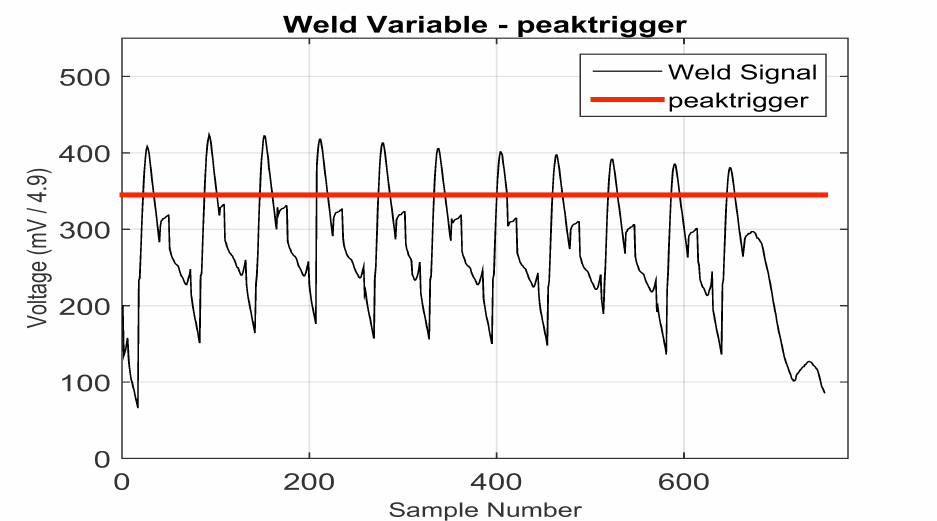
3.1.1.2 peaktrigger)
“peaktrigger”" refers" to" the" voltage" value" just" above" the" values" of" the" false" peaks" shown" in"
Figure" 5" below." This" value" is" determined" from" the" “threshold”" value" on" the" PCA" MATLAB"
program"and"should"work"as"long"as"it"is"above"the"“false”"improperly"rectified"weld"peaks.""
"
Figure*5*–*“peaktrigger”*example*
"
"
"
"
"
"
"
"
"
"
"
"
"
"
"
"
10"
"
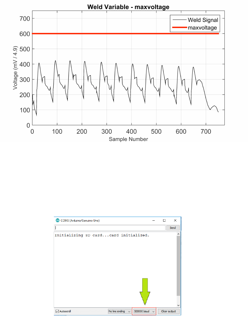
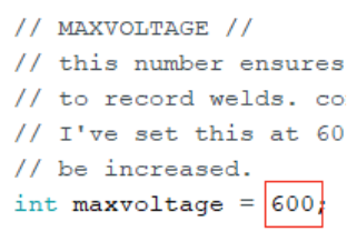
3.1.1.3 maxvoltage)
“maxvoltage”"refers"to"the"maximum"voltage"indicative"of"a"weld."This"value"is"here"to"remove"
the" effect" of" voltage" spikes" tricking" the" system" into" thinking" a" weld" has" occurred." As" seen" in"
Figure" 6" below," this" value" should" be" about" 150" units" (~750mV)" above" the" “good”" weld" peak"
values.""
"
Figure*6*–*“maxvoltage”*example*
3.1.1.4 baudrate)
baudrate" refers" to" the" rate" at" which" information" is" sent" through" the" Arduino." When" the"
baudrate"is"too"slow,"the"data"sampling"rate"of"the"system"is"too"low"and"information"about"the"
weld"is"lost."The"creator"of"this"system"doesn’t"really"understand"how"this"works."Just"keep"it"at"
500000"for"training_set_gatherer.ino" and" weld_classifier.ino."230400"for" ground_tester.ino" as"
500000"is"too"fast."
"
"
Figure*7*-*baudrate*location*
11"
"
3.1.2 training_set_gatherer.ino,
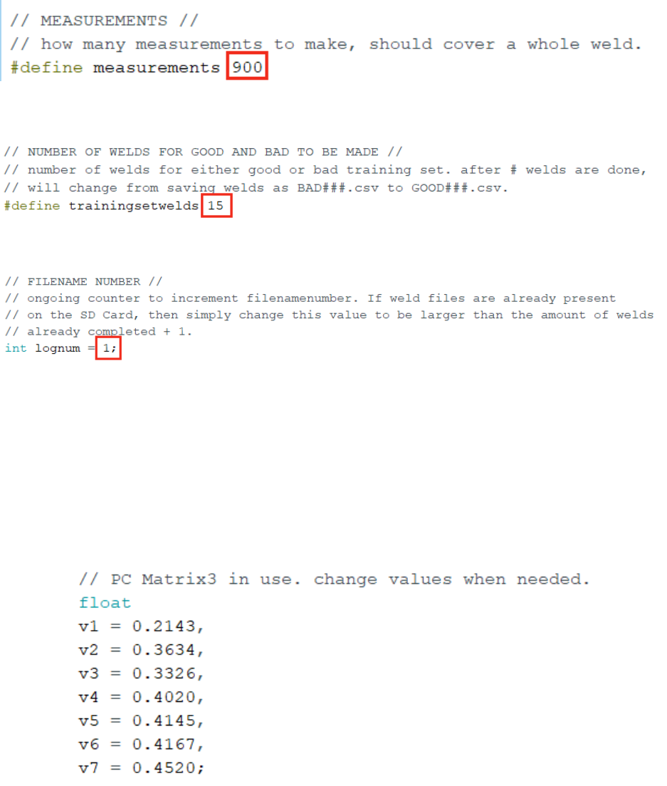
3.1.2.1 measurements)
"
3.1.2.2 trainingsetwelds)
"
3.1.2.3 lognum)
"
"
3.1.3 weld_classifier.ino,
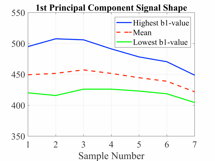
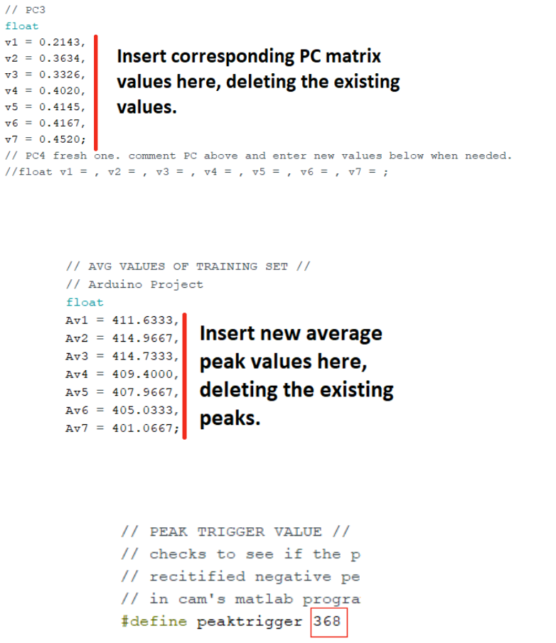
3.1.3.1 v1,)v2…)
First"Principal"Component"values."Gathered"from"Principal"Component"Analysis."Insert"new"1st"
PC"values"when"a"new"training"set"has"been"gathered."Depending"on"the"data"provided,"should"
be"a"1x7"matrix.""
"
Figure*8*-*v1,*v2....*location*of*first*PC*matrix*
"
12"
"
3.1.3.2 Av1,)Av2…)
Mean"values"of"each"of"the"first"seven"peaks"from"the"training"set"data."Shown"as"‘mean’"curve"
in"Figure"9"below.""
"
Figure*9*-*Av1,*Av2*...*data.*shown*as*'mean'*curve.*Source:*(Summerville,*2018).*
"
"
"
"
"
"
"
"
"
"
"
"
"
"

13"
"
3.2
Laptop(Setup(
(ONLY" DO" 3.2" LAPTOP" SETUP" IF" THE" COMPUTER" USED" TO" UPLOAD" FILES" TO" THE" ARDUINO"
HASN’T"BEEN"USED"WITH"THIS"SYSTEM"BEFORE.)"
a. Download"and"Install"Arduino"IDE"https://www.arduino.cc/en/Main/Software."
b. Connect"Arduino"to"laptop"via"blue"USB"cable"and"check"the"following."
i. Tools">"Board">"Arduino/Genuino"Uno."
ii. Tools">"Port">"COM#"(Arduino/Genuino"Uno.)."
c. Download"and"Save"(Clone"or"download"->"Download"ZIP)"Arduino"Programs"on"
Laptop"Drive"from"https://github.com/savdogmillionaire/RSW-Arduino-Files-
Sava"(or"wherever"else"the"RSW-Arduino-Files-Sava"folder"is"kept).""
i. training_set_gatherer.ino."
ii. weld_classifier.ino."
iii. ground_tester.ino."
d. Extract"files"from"ZIP."
e. Open"training_set_gatherer.ino"on"Arduino"IDE."
i. Sketch">"Include"Library">"Manage"Libraries."
ii. Install"CircularBuffer"by"AgileWare."
iii. Install"SdFat"by"Bill"Greiman."
iv. Save"training_set_gatherer.ino."
v. Close"training_set_gatherer.ino."
f. Open"weld_classifier.ino"on"Arduino"IDE."
i. Sketch">"Include"Library">"Manage"Libraries."
ii. Install"CircularBuffer"by"AgileWare."
iii. Install"SdFat"by"Bill"Greiman."
iv. Install"BasicLinearAlgebra"by"Tom"Stewart."
v. Save"weld_classifier.ino."
vi. Close"weld_classifier.ino."
g. Open"ground_test.ino"on"Arduino"IDE."
i. Sketch">"Include"Library">"Manage"Libraries."
ii. Install"CircularBuffer"by"AgileWare."
iii. Install"SdFat"by"Bill"Greiman."
iv. Save"ground_test.ino."
v. Close"ground_test.ino."
h. Close"and"reopen"Arduino"IDE."Check"each"program"is"compiling"(ctrl+r).
14#
#
3.3
Train(Arduino(System(
i. Connect#Arduino#to#computer#through#blue#USB#lead.#
i. Connect#grounding#lead#to#earth#at#the#base#of#the#welder.#
ii. Connect#voltage#lead#from#welder#into#Arduino#jack.#
iii. Insert#empty#FAT32#SD#Card#into#Arduino.#
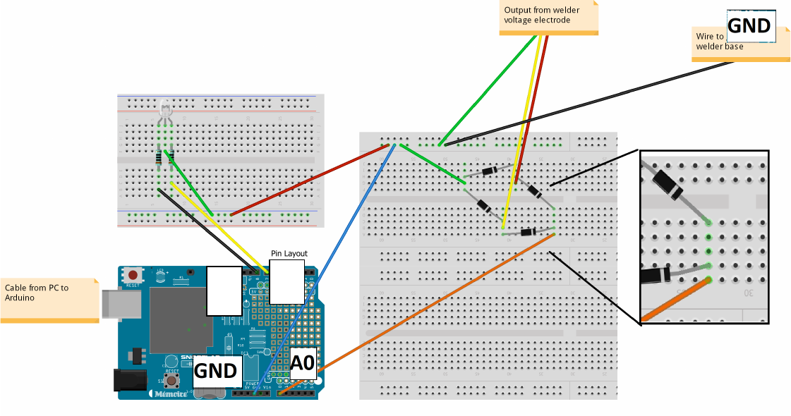
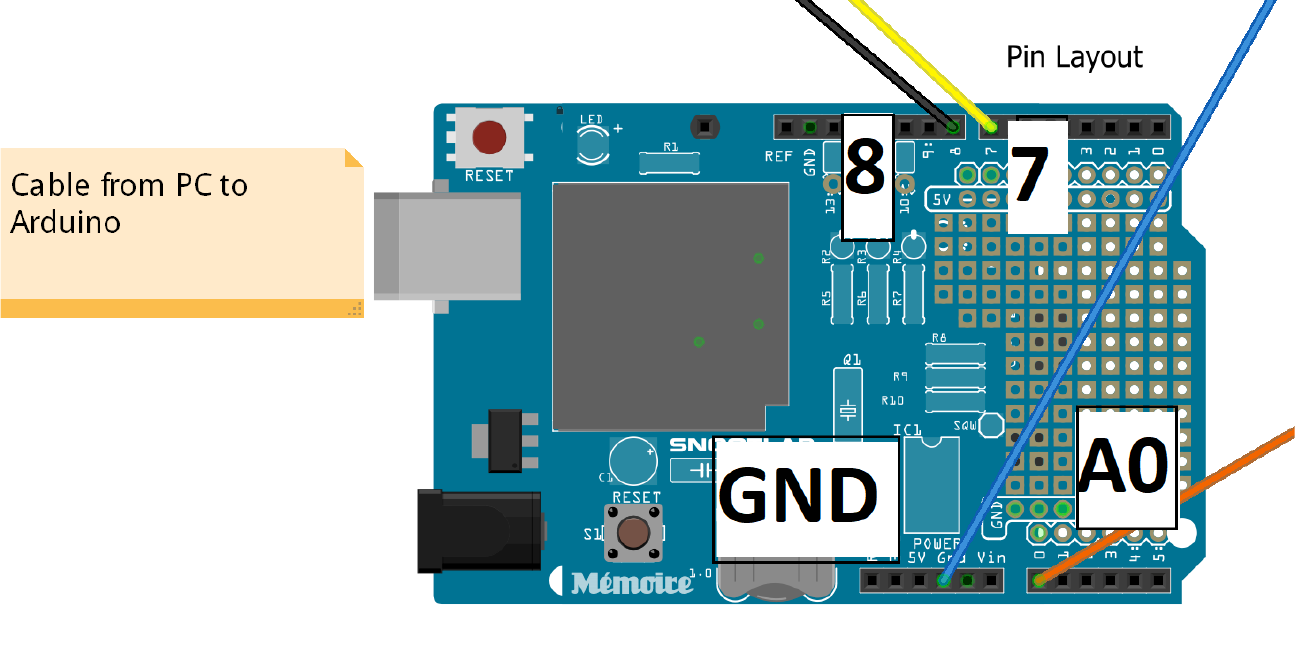
iv. Check#wires#are#all#connected#(refer#to#Figure#10#and#Figure#11#below).#
#
Figure'10'-'Arduino'Circuit'Layout.'
#
8#
7#
15#
#
#
#
Figure'11'–'Closeup'of'pin'connections'on'Arduino.
!
! ! 16!
j. Open!ground_test.ino!and!Upload!to!Arduino!(ctrl+u).!
k. Open!Serial!Plotter!(ctrl+Shift+L)!and!set!baud!rate!to!230400!in!bottom!right!
of!window.!
l. Inspect!incoming!signal!from!welder.!Should!be!the!background!noise!of!the!
system.!Visually!estimate!the!peak!value!of!the!background!noise!(see!Figure!
12!below),!and!note!this!value!down.!
!
Figure!12!-!Example!of!background!noise.!
m. Close!ground_test.ino.!
n. Open!training_set_gatherer.ino.!
o. Insert!visually!inspected!peak!background!noise!value!+!30!!
under!//!TRIGGER!VALUE!//!(see!Figure!13!below).!
!
Figure!13!-!Trigger!Value.!
p. Save!and!upload!to!Arduino!(ctrl!+!s),!(ctrl!+!u).!
!
!
!
!
!
!
!
!
!
! ! 17!
q. Open!Serial!Monitor!(Ctrl!+!Shift!+!m).!
r. Set!baud!rate!to!500000!in!bottom!right!of!window.!
i. Dress!Electrode!tips!and!conduct!15!Good!Welds!(repeat!steps!1-5!
below!15!times).!
1. Place!flat!sample!holder!on!bottom!electrode.!
2. Insert!2x!Zincanneal!strips.!
3. Conduct!weld.!
4. Verify!weld!has!been!saved!(look!at!serial!monitor!for!Saved!
and!Weld!number).!
5. Prepare!Zincanneal!strip!for!next!weld!by!moving!at!least!
15mm!along.!
ii. Dress!Electrode!tips!and!conduct!15!Bad!Welds,!alternating!between!a!
+15!degree!orientation!and!-15!degree!orientation!(Figure!2).!
!(repeat!steps!1-5!below!15!times).!
1. Place!Misaligned!sample!holder.!
2. Insert!2x!Zincanneal!strips.!
3. Conduct!weld.!
4. Verify!weld!has!been!saved!(look!at!serial!monitor!for!Saved!
and!Weld!number).!
5. Prepare!Zincanneal!strip!for!next!weld!by!moving!at!least!
15mm!along!strip.!
iii. Close!Serial!Monitor.!
iv. Remove!SD!card!from!Arduino.!
v. Conduct!PCA!on!SD!card!files!to!calculate!a!new!PC!matrix!and!average!
peak!values!of!training!set.!!
vi. Also!need!to!find!the!maximum!peak!voltage!value!reached,!as!well!as!
peak!threshold!for!the!weld!classifier!program.!!
!
!
!
!
!
!
!
!
!
!
!
!
!
!
!
! ! 18!
3.4
Test(Arduino(System(
s. Connect!and!Prepare!System.!
i. Connect!Arduino!to!computer!through!blue!USB!lead.!
ii. Connect!grounding!lead!to!earth,!at!the!base!of!the!welder.!
iii. Connect!voltage!lead!from!welder!into!Arduino!jack.!
iv. Insert!empty!FAT32!SD!Card.!
v. Check!wires!are!all!in.!refer!to!Figure!10!and!Figure!11.!
!
t. Open!weld_classifier.ino.!(see$3.1$Glossary$for$definitions).!
i. insert!new!first!PC!matrix!values!under!//!PRINCIPAL!COMPONENT!
MATRICES!//!-!//!PC3!(Figure!14).!
!
Figure!14!-!PC!Matrix!Values.!
ii. Insert!new!Average!peak!values!under!//!AVG!VALUES!OF!TRAINING!
SET!//!(Figure!15).!
!
Figure!15!-!Average!Peak!Values.!
iii. Insert!new!peak!threshold!value!under!//!PEAK!TRIGGER!VALUE!//!
(Figure!16).!
!
Figure!16!-!Peak!Trigger!Value.!
!
!
!
!
! ! 19!
iv. Insert!new!maximum!voltage!value,!which!should!be!about!150!units!
above!the!maximum!weld!peaks!under!//!MAXVOLTAGE!//!(Figure!17).!
!
Figure!17!-!Max!Voltage!Value.!
!
!
u. Save!and!upload!weld_classifier.ino!to!Arduino!(ctrl+U).!
v. Open!the!serial!monitor!(ctrl+shift+m),!check!baud!rate!is!set!to!500k.!
w. Randomly!select!and!place!a!flat!or!misaligned!sample!holder.!
x. Insert!2x!Zincanneal!sheet.!
y. Conduct!weld.!
z. If!Flat!sample!holder!is!placed!and!LED!is!Green!!
OR!!
misaligned!sample!holder!is!placed,!and!LED!is!Red,!!
then!test!is!considered!a!success.!Can!visually!inspect!the!b!value!produced!by!
looking!at!serial!monitor!display.!
aa. Repeat!however!many!times.!!
!
!
!
!
!
!
!
!
!
!
!
!
!
!
!
!
!
!
!
!
! ! 20!
1. I!open!Serial!Monitor!or!Serial!Plotter!and!gibberish!characters!appear?!
A. Remember!to!change!baud!rate!to!necessary!value.!230400!for!ground_tester.ino!and!
500000!for!other!programs.!!
!
2. I!have!attempted!to!save!a!weld,!but!nothing!appears!on!the!Serial!Monitor?!
A. Sometimes! the! program! has! difficulty! saving! the! first! weld! conducted! on! a! new!
sample.!!Check!everything!is!connected!properly!(see!Figure!10).!Could!also!either!be!a!
small!glitch!from!the!welder!or!the!trigger!values!aren’t!being!set!appropriately.!!
!
3. Weld!files!are!being!saved!but!they!appear!to!be!corrupted.!!
A. Probably! the! SD! card! module! has! failed! after! of! time.! Can! attach! a! new! one.!
(https://www.jaycar.com.au/sd-card-shield-for-arduino/p/XC4552!)!CAT!NO,!XC4552.!!
!
4. Welder!cannot!classify!weld!correctly!an!appropriate!amount!of!the!time.!!
A. This!is!a!tough!one.!First!thing!to!do!is!to!ensure!that!the!all!the!conditions!from!when!
the!training!set!was!collected!are!identical!to!the!conditions!when!testing!the!weld.!!
!
Inspect!the!peak!values!shown!on!the!serial!monitor!screen.!If!they!seem!to!be!too!low!
or! too! high! from! the! values! collected! in! the! training! set,! then! something! about! the!
welding!conditions!may!have!changed.!
!
If!the!system!doesn’t!classify!a!weld!when!it!has!occurred,!then!more!than!likely!the!
system!isn’t!being!triggered!to!collect!peak!data!(peak!trigger!value!too!high)!OR!the!
peak!trigger!value!is!too!low!and!captures!false!peaks!within!the!data.!!
!
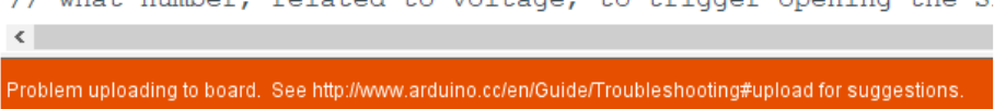
5. “problem!uploading!to!board.”!
! !
A. Most!often!I!would!get! this! problem!because!I!didn’t!have!the!correct! board! or! port!
selected.!To!fix!this,!check:!
i.!Tools!>!Board!>!Arduino/Genuino!Uno.!
ii.Tools!>!Port!>!COM#!(Arduino/Genuino!Uno.).!
Sometimes! I! would! get! this! problem! because! I! inserted! the! Arduino! cable! into! the!
faulty!USB!port!on!my!laptop.!Just!put!the!cable!into!another!USB!port.!!
!
4 Troubleshooting$
!
! ! 21!
Another!problem!is!that!the!lead!to!the!“GND”!pin!on!the!Arduino!may!be!accidentally!
inserted!into!the!“VIN”!pin!next!to!it.!Make!sure!the!blue!lead!in!Figure!11!goes!from!
the!ground!on!the!breadboard!to!the!“GND”!pin!on!Arduino.!‘!
!
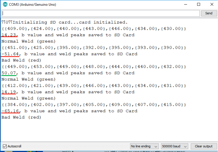
6. The!b!value!calculated!from!a!“bad!weld”!is!less!than!a!“good!weld”!but!it!is!still!positive?!
An!example!of!this!occurring:!
!
Figure!18!-!some!example!welds!
!
!
There!are!five!welds!shown!in!Figure!18.!The!first!two!welds!are!misaligned,!the!third!weld!is!
flat,!and!the!last!two!are!misaligned.!Two!of!the!misaligned!samples!are!positive,!but!lower!
than!the!“good”!weld.!What’s!happening!here!is!the!sample!for!welds!1!and!4!are!misaligned!
15!degrees!with!respect!to!the!flat!sample,!but!30!degrees!with!respect!to!the!configuration!
shown!in!Figure!2.!The!reason!for!this!discrepancy!is!that!I!believe!the!training!set!was!taken!
with! a! misaligned! weld! measurement! only! taken! at! -15! degrees! with! respect! to! the! flat!
sample,!and!not!+15!degrees!with!respect!to!the!flat!sample.!!
!
Another!big! cause! for!incorrect! classifications!from! high!b! values! is!that! the!electrode! tips!
are!clean.!Once!the!electrode!wears!a!bit,!the!b!values!tend!to!decrease!to!normal.!!
!
You! can! also! try! commenting! the! currently! used! 1st! PC! matrix! and! avg.! values,! and!
uncomment!the!other!ones.!The!currently!commented!1st!PC!matrix!and!avg.!values!tend!to!
provide!slightly!higher!b!values!in!my!experience.!!
!
!
! ! 22!
7. What!are!these!MATLAB!files!for?!
A. These! MATLAB! files! are! predominantly! what! I! used! for! my! own! troubleshooting.! I!
would!save!a!weld!to!the!SD!card!using!the!Arduino!and!then!inspect!the!files!using!the!
MATLAB!programs.!I!haven’t!been!able!to!comment!them!at!all!but!if!you!are!familiar!
with!MATLAB,!you!should!be!able!to!use!these!if!you!require.!Pc1tester!checks!what!b!
value!is!being!calculated!from!a!set!of!saved!welds.!Peakfunctest!tests!the!peak!finding!
function! I! have! created! on! the! Arduino! to! the! inbuilt! MATLAB! one.! Sdcardplotter!
displays!collected!weld!signals!from!the!training!set.!
!
8. When! collecting! welds! for! the! training! set,! why! are! files! created! that! do! not! contain! a!
weld?!
A. This! happens! sometimes! when! the! training! set! collector! is! triggered! for! unknown!
reasons.!Usually!this!would!happen!when!working!with!the!small!AC!welder,!and!not!
the! automated! MFDC! welder.! I! believe! this! has! to! do! with! electrical! interference!
tricking!the!system!into!believing!a!weld!has!occurred.!To!fix!this,!ensure!that!there!are!
as!few!objects!possible!in!the!vicinity!of!the!weld!location.!It!would!also!help!to!test!
parts!of!the!system!separately!to!check!that!everything!is!working!as!expected.!!
!
The!code!used!to!collect!training!sets!may!need!some!refinement.!It!appears!to!trigger!
sometimes!even!though!welds!have!not!occurred.!I!would!look!at!making!the!code!able!
to!ignore!voltage!spikes!due!to!background!noise.!System!seems!to!work!quite!well!in!the!
more!controlled!environment!found!at!the!MFDC!welder.!!
!
Further!work!is!probably!required!on!the!overall!presentability!of!the!system.!Difficult!to!
achieve!during!the!limited!time!in!the!project!without!causing!delays!due!to!altering!the!
way!the!system!is!able!to!collect!data.!!!!
!
LI, W., CHENG, S., HU, S. J. & SHRIVER, J. 2000. Statistical Investigation on Resistance
Spot Welding Quality Using a Two-State, Sliding-Level Experiment. Journal of
Manufacturing Science and Engineering, 123, 513-520.
LING, S.-F., WAN, L.-X., WONG, Y.-R. & LI, D.-N. 2010. Input electrical impedance as
quality monitoring signature for characterizing resistance spot welding. NDT & E
International, 43, 200-205.
!
!
5 $Further$Work$
6 References$
