Arduino Beginners Manual
User Manual:
Open the PDF directly: View PDF ![]() .
.
Page Count: 101 [warning: Documents this large are best viewed by clicking the View PDF Link!]


Earthshine Electronics Arduino Starters Kit Manual - A Complete Beginners Guide to the Arduino
www.EarthshineElectronics.com
3
©2009 M.R.McRoberts
Published 2009 by Earthshine Electronics
www.earthshineelectronics.com
Design: Mike McRoberts
First Edition - May 2009
Revision 1 - July 2009
Revision 2 - September 2009
Revision 3 - March 2010
Revision 4 - August 2010
Revision 5 - August 2010
License
THE WORK (AS DEFINED BELOW) IS PROVIDED UNDER THE TERMS OF THIS CREATIVE COMMONS PUBLIC LICENSE ("CCPL"
OR "LICENSE"). THE WORK IS PROTECTED BY COPYRIGHT AND/OR OTHER APPLICABLE LAW. ANY USE OF THE WORK
OTHER THAN AS AUTHORIZED UNDER THIS LICENSE OR COPYRIGHT LAW IS PROHIBITED.
BY EXERCISING ANY RIGHTS TO THE WORK PROVIDED HERE, YOU ACCEPT AND AGREE TO BE BOUND BY THE TERMS OF
THIS LICENSE. TO THE EXTENT THIS LICENSE MAY BE CONSIDERED TO BE A CONTRACT, THE LICENSOR GRANTS YOU THE
RIGHTS CONTAINED HERE IN CONSIDERATION OF YOUR ACCEPTANCE OF SUCH TERMS AND CONDITIONS.
1. Definitions
a. "Adaptation" means a work based upon the Work, or upon the Work and other pre-existing works, such as a translation,
adaptation, derivative work, arrangement of music or other alterations of a literary or artistic work, or phonogram or
performance and includes cinematographic adaptations or any other form in which the Work may be recast, transformed, or
adapted including in any form recognizably derived from the original, except that a work that constitutes a Collection will not be
considered an Adaptation for the purpose of this License. For the avoidance of doubt, where the Work is a musical work,
performance or phonogram, the synchronization of the Work in timed-relation with a moving image ("synching") will be
considered an Adaptation for the purpose of this License.
b. "Collection" means a collection of literary or artistic works, such as encyclopedias and anthologies, or performances,
phonograms or broadcasts, or other works or subject matter other than works listed in Section 1(f) below, which, by reason of
the selection and arrangement of their contents, constitute intellectual creations, in which the Work is included in its entirety in
unmodified form along with one or more other contributions, each constituting separate and independent works in themselves,
which together are assembled into a collective whole. A work that constitutes a Collection will not be considered an Adaptation
(as defined above) for the purposes of this License.
c. "Distribute" means to make available to the public the original and copies of the Work through sale or other transfer of
ownership.
d. "Licensor" means the individual, individuals, entity or entities that offer(s) the Work under the terms of this License.
e. "Original Author" means, in the case of a literary or artistic work, the individual, individuals, entity or entities who created the
Work or if no individual or entity can be identified, the publisher; and in addition (i) in the case of a performance the actors,
singers, musicians, dancers, and other persons who act, sing, deliver, declaim, play in, interpret or otherwise perform literary or
artistic works or expressions of folklore; (ii) in the case of a phonogram the producer being the person or legal entity who first
fixes the sounds of a performance or other sounds; and, (iii) in the case of broadcasts, the organization that transmits the
broadcast.
f. "Work" means the literary and/or artistic work offered under the terms of this License including without limitation any production
in the literary, scientific and artistic domain, whatever may be the mode or form of its expression including digital form, such as
a book, pamphlet and other writing; a lecture, address, sermon or other work of the same nature; a dramatic or dramatico-
musical work; a choreographic work or entertainment in dumb show; a musical composition with or without words; a
cinematographic work to which are assimilated works expressed by a process analogous to cinematography; a work of drawing,
painting, architecture, sculpture, engraving or lithography; a photographic work to which are assimilated works expressed by a
process analogous to photography; a work of applied art; an illustration, map, plan, sketch or three-dimensional work relative to
geography, topography, architecture or science; a performance; a broadcast; a phonogram; a compilation of data to the extent it
is protected as a copyrightable work; or a work performed by a variety or circus performer to the extent it is not otherwise
considered a literary or artistic work.
g. "You" means an individual or entity exercising rights under this License who has not previously violated the terms of this
License with respect to the Work, or who has received express permission from the Licensor to exercise rights under this
License despite a previous violation.
h. "Publicly Perform" means to perform public recitations of the Work and to communicate to the public those public recitations,
by any means or process, including by wire or wireless means or public digital performances; to make available to the public
Works in such a way that members of the public may access these Works from a place and at a place individually chosen by
them; to perform the Work to the public by any means or process and the communication to the public of the performances of
the Work, including by public digital performance; to broadcast and rebroadcast the Work by any means including signs, sounds
or images.
i. "Reproduce" means to make copies of the Work by any means including without limitation by sound or visual recordings and
the right of fixation and reproducing fixations of the Work, including storage of a protected performance or phonogram in digital
form or other electronic medium.

Earthshine Electronics Arduino Starters Kit Manual - A Complete Beginners Guide to the Arduino
www.EarthshineElectronics.com
4
2. Fair Dealing Rights. Nothing in this License is intended to reduce, limit, or restrict any uses free from copyright or rights arising from
limitations or exceptions that are provided for in connection with the copyright protection under copyright law or other applicable laws.
3. License Grant. Subject to the terms and conditions of this License, Licensor hereby grants You a worldwide, royalty-free, non-
exclusive, perpetual (for the duration of the applicable copyright) license to exercise the rights in the Work as stated below:
a. to Reproduce the Work, to incorporate the Work into one or more Collections, and to Reproduce the Work as incorporated in
the Collections; and,
b. to Distribute and Publicly Perform the Work including as incorporated in Collections.
The above rights may be exercised in all media and formats whether now known or hereafter devised. The above rights include the right
to make such modifications as are technically necessary to exercise the rights in other media and formats, but otherwise you have no
rights to make Adaptations. Subject to 8(f), all rights not expressly granted by Licensor are hereby reserved, including but not limited to
the rights set forth in Section 4(d).
4. Restrictions. The license granted in Section 3 above is expressly made subject to and limited by the following restrictions:
a. You may Distribute or Publicly Perform the Work only under the terms of this License. You must include a copy of, or the
Uniform Resource Identifier (URI) for, this License with every copy of the Work You Distribute or Publicly Perform. You may not
offer or impose any terms on the Work that restrict the terms of this License or the ability of the recipient of the Work to exercise
the rights granted to that recipient under the terms of the License. You may not sublicense the Work. You must keep intact all
notices that refer to this License and to the disclaimer of warranties with every copy of the Work You Distribute or Publicly
Perform. When You Distribute or Publicly Perform the Work, You may not impose any effective technological measures on the
Work that restrict the ability of a recipient of the Work from You to exercise the rights granted to that recipient under the terms of
the License. This Section 4(a) applies to the Work as incorporated in a Collection, but this does not require the Collection apart
from the Work itself to be made subject to the terms of this License. If You create a Collection, upon notice from any Licensor
You must, to the extent practicable, remove from the Collection any credit as required by Section 4(c), as requested.
b. You may not exercise any of the rights granted to You in Section 3 above in any manner that is primarily intended for or directed
toward commercial advantage or private monetary compensation. The exchange of the Work for other copyrighted works by
means of digital file-sharing or otherwise shall not be considered to be intended for or directed toward commercial advantage or
private monetary compensation, provided there is no payment of any monetary compensation in connection with the exchange
of copyrighted works.
c. If You Distribute, or Publicly Perform the Work or Collections, You must, unless a request has been made pursuant to Section 4
(a), keep intact all copyright notices for the Work and provide, reasonable to the medium or means You are utilizing: (i) the
name of the Original Author (or pseudonym, if applicable) if supplied, and/or if the Original Author and/or Licensor designate
another party or parties (e.g., a sponsor institute, publishing entity, journal) for attribution ("Attribution Parties") in Licensor's
copyright notice, terms of service or by other reasonable means, the name of such party or parties; (ii) the title of the Work if
supplied; (iii) to the extent reasonably practicable, the URI, if any, that Licensor specifies to be associated with the Work, unless
such URI does not refer to the copyright notice or licensing information for the Work. The credit required by this Section 4(c)
may be implemented in any reasonable manner; provided, however, that in the case of a Collection, at a minimum such credit
will appear, if a credit for all contributing authors of Collection appears, then as part of these credits and in a manner at least as
prominent as the credits for the other contributing authors. For the avoidance of doubt, You may only use the credit required by
this Section for the purpose of attribution in the manner set out above and, by exercising Your rights under this License, You
may not implicitly or explicitly assert or imply any connection with, sponsorship or endorsement by the Original Author, Licensor
and/or Attribution Parties, as appropriate, of You or Your use of the Work, without the separate, express prior written permission
of the Original Author, Licensor and/or Attribution Parties.
d. For the avoidance of doubt:
i. Non-waivable Compulsory License Schemes. In those jurisdictions in which the right to collect royalties through
any statutory or compulsory licensing scheme cannot be waived, the Licensor reserves the exclusive right to collect
such royalties for any exercise by You of the rights granted under this License;
ii. Waivable Compulsory License Schemes. In those jurisdictions in which the right to collect royalties through any
statutory or compulsory licensing scheme can be waived, the Licensor reserves the exclusive right to collect such
royalties for any exercise by You of the rights granted under this License if Your exercise of such rights is for a
purpose or use which is otherwise than noncommercial as permitted under Section 4(b) and otherwise waives the
right to collect royalties through any statutory or compulsory licensing scheme; and,
iii. Voluntary License Schemes. The Licensor reserves the right to collect royalties, whether individually or, in the event
that the Licensor is a member of a collecting society that administers voluntary licensing schemes, via that society,
from any exercise by You of the rights granted under this License that is for a purpose or use which is otherwise than
noncommercial as permitted under Section 4(b).
e. Except as otherwise agreed in writing by the Licensor or as may be otherwise permitted by applicable law, if You Reproduce,
Distribute or Publicly Perform the Work either by itself or as part of any Collections, You must not distort, mutilate, modify or
take other derogatory action in relation to the Work which would be prejudicial to the Original Author's honor or reputation.
5. Representations, Warranties and Disclaimer
UNLESS OTHERWISE MUTUALLY AGREED BY THE PARTIES IN WRITING, LICENSOR OFFERS THE WORK AS-IS AND MAKES NO
REPRESENTATIONS OR WARRANTIES OF ANY KIND CONCERNING THE WORK, EXPRESS, IMPLIED, STATUTORY OR
OTHERWISE, INCLUDING, WITHOUT LIMITATION, WARRANTIES OF TITLE, MERCHANTIBILITY, FITNESS FOR A PARTICULAR

Earthshine Electronics Arduino Starters Kit Manual - A Complete Beginners Guide to the Arduino
www.EarthshineElectronics.com
5
PURPOSE, NONINFRINGEMENT, OR THE ABSENCE OF LATENT OR OTHER DEFECTS, ACCURACY, OR THE PRESENCE OF
ABSENCE OF ERRORS, WHETHER OR NOT DISCOVERABLE. SOME JURISDICTIONS DO NOT ALLOW THE EXCLUSION OF
IMPLIED WARRANTIES, SO SUCH EXCLUSION MAY NOT APPLY TO YOU.
6. Limitation on Liability. EXCEPT TO THE EXTENT REQUIRED BY APPLICABLE LAW, IN NO EVENT WILL LICENSOR BE LIABLE
TO YOU ON ANY LEGAL THEORY FOR ANY SPECIAL, INCIDENTAL, CONSEQUENTIAL, PUNITIVE OR EXEMPLARY DAMAGES
ARISING OUT OF THIS LICENSE OR THE USE OF THE WORK, EVEN IF LICENSOR HAS BEEN ADVISED OF THE POSSIBILITY OF
SUCH DAMAGES.
7. Termination
a. This License and the rights granted hereunder will terminate automatically upon any breach by You of the terms of this License.
Individuals or entities who have received Collections from You under this License, however, will not have their licenses
terminated provided such individuals or entities remain in full compliance with those licenses. Sections 1, 2, 5, 6, 7, and 8 will
survive any termination of this License.
b. Subject to the above terms and conditions, the license granted here is perpetual (for the duration of the applicable copyright in
the Work). Notwithstanding the above, Licensor reserves the right to release the Work under different license terms or to stop
distributing the Work at any time; provided, however that any such election will not serve to withdraw this License (or any other
license that has been, or is required to be, granted under the terms of this License), and this License will continue in full force
and effect unless terminated as stated above.
8. Miscellaneous
a. Each time You Distribute or Publicly Perform the Work or a Collection, the Licensor offers to the recipient a license to the Work
on the same terms and conditions as the license granted to You under this License.
b. If any provision of this License is invalid or unenforceable under applicable law, it shall not affect the validity or enforceability of
the remainder of the terms of this License, and without further action by the parties to this agreement, such provision shall be
reformed to the minimum extent necessary to make such provision valid and enforceable.
c. No term or provision of this License shall be deemed waived and no breach consented to unless such waiver or consent shall
be in writing and signed by the party to be charged with such waiver or consent.
d. This License constitutes the entire agreement between the parties with respect to the Work licensed here. There are no
understandings, agreements or representations with respect to the Work not specified here. Licensor shall not be bound by any
additional provisions that may appear in any communication from You. This License may not be modified without the mutual
written agreement of the Licensor and You.
e. The rights granted under, and the subject matter referenced, in this License were drafted utilizing the terminology of the Berne
Convention for the Protection of Literary and Artistic Works (as amended on September 28, 1979), the Rome Convention of
1961, the WIPO Copyright Treaty of 1996, the WIPO Performances and Phonograms Treaty of 1996 and the Universal
Copyright Convention (as revised on July 24, 1971). These rights and subject matter take effect in the relevant jurisdiction in
which the License terms are sought to be enforced according to the corresponding provisions of the implementation of those
treaty provisions in the applicable national law. If the standard suite of rights granted under applicable copyright law includes
additional rights not granted under this License, such additional rights are deemed to be included in the License; this License is
not intended to restrict the license of any rights under applicable law.
PLAIN LANGUAGE SUMMARY:
You are free:
to Share - to copy, distribute and transmit the work
Under the following conditions:
Attribution - You must attribute this work to Mike McRoberts and Earthshine Electronics (with link)
Noncommercial - You may not use this work for commercial purposes.
No Derivative Works - You may not alter, transform, or build upon this work.
http://creativecommons.org/licenses/by-nc-nd/3.0/
Disclaimer
The information contained in this eBook is for general information purposes only. The information is provided by Mike McRoberts of
Earthshine Design and whilst we endeavour to keep the information up-to-date and correct, we make no representations or warranties of
any kind, express or implied, about the completeness, accuracy, reliability, suitability or availability with respect to the eBook or the
information, products, services, or related graphics contained on the website for any purpose. Any reliance you place on such information
is therefore strictly at your own risk.

Earthshine Electronics Arduino Starters Kit Manual - A Complete Beginners Guide to the Arduino
www.EarthshineElectronics.com
6
Contents
Introduction
7
Project 11 - Piezo Sounder Melody Player
66
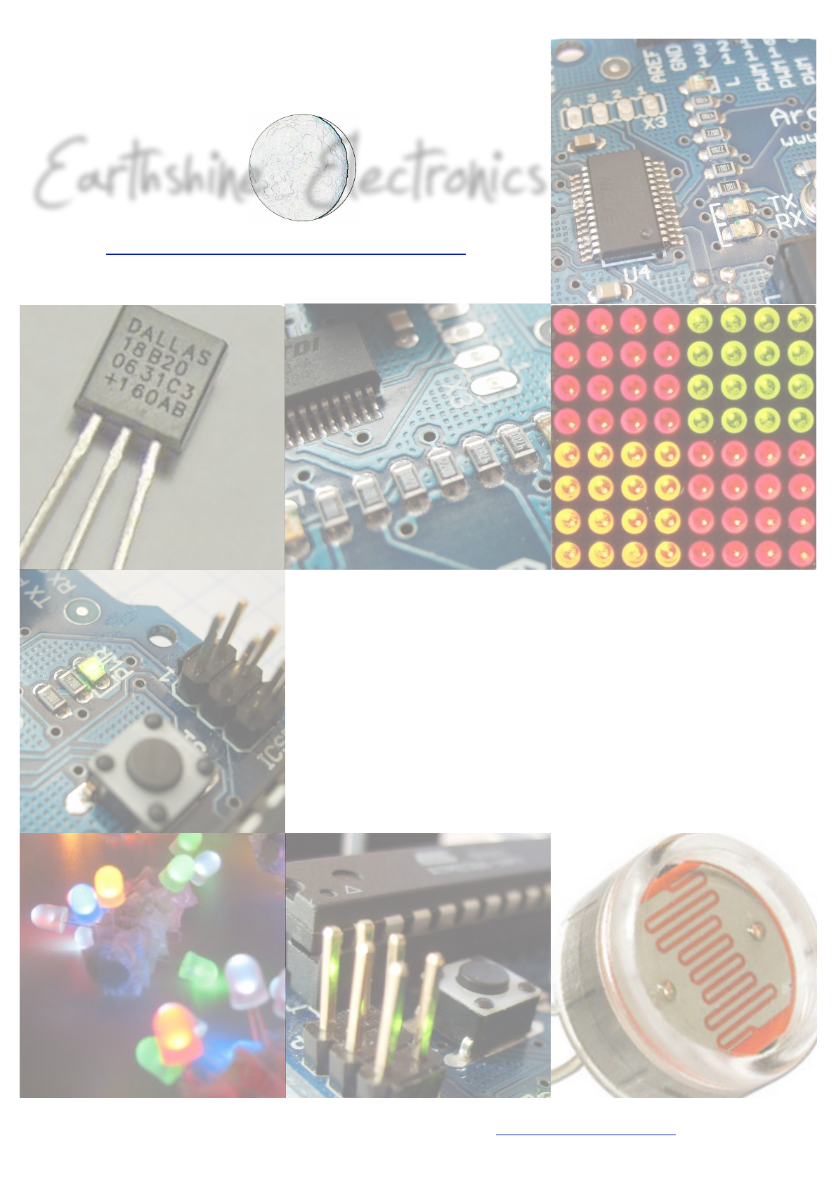
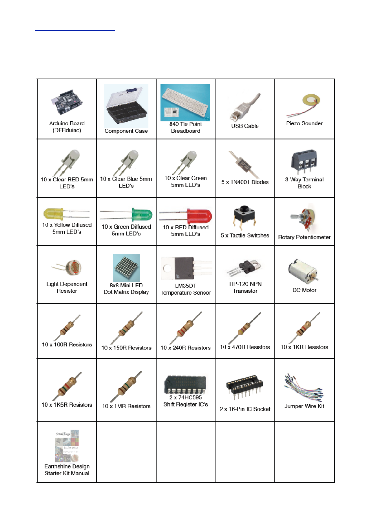
The Starter Kit Contents
8
!Code Overview
68
What exactly is an Arduino?
9
!Hardware Overview
70
Getting Started
11
Project 12 - Serial Temperature Sensor
71
Upload your first sketch
13
!Code Overview
73
The Arduino IDE
15
!Hardware Overview
75
The Projects
19
Project 13 - Light Sensor
76
Project 1 - LED Flasher
21
!Code Overview
78
!Code Overview
22
!Hardware Overview
79
!Hardware Overview
25
Project 14 - Shift Register 8-Bit Binary Counter
80
Project 2 - SOS Morse Code Signaller
29
!The Binary Number System
83
!Code Overview
30
!Hardware Overview
84
Project 3 - Traffic Lights
32
!Code Overview
86
Project 4 - Interactive Traffic Lights
34
!Bitwise Operators
87
!Code Overview
37
!Code Overview (continued)
88
Project 5 - LED Chase Effect
41
Project 15 - Dial 8-Bit Binary Counters
89
!Code Overview
42
!Code & Hardware Overview
92
Project 6 - Interactive LED Chase Effect
44
Project 16 - LED Dot Matrix - Basic Animation
93
!Code Overview
45
!Hardware Overview
97
!Hardware Overview
46
!Code Overview
99
Project 7 - Pulsating Lamp
48
!Code Overview
49
Project 8 - Mood Lamp
51
!Code Overview
52
Project 9 - LED Fire Effect
55
!Code Overview
56
Project 10 - Serial Controlled Mood Lamp
58
!Code Overview
60

Earthshine Electronics Arduino Starters Kit Manual - A Complete Beginners Guide to the Arduino
www.EarthshineElectronics.com
7
Introduction
Thank you for purchasing the Earthshine Electronics
Arduino Starter Kit. You are now well on your way in
your journey into the wonderful world of the Arduino
and microcontroller electronics.
This book will guide you, step by step, through using
the Starter Kit to learn about the Arduino hardware,
software and general electronics theory. Through the
use of electronic projects we will take you from the
level of complete beginner through to having an
intermediate set of skills in using the Arduino.
The purpose of this book and the kit is to give you a
gentle introduction to the Arduino, electronics and
programming in C and to set you up with the
necessary skills needed to progress beyond the book
and the kit into the world of the Arduino and
microcontroller electronics.
The booklet has been written presuming that you have
no prior knowledge of electronics, the Arduino
hardware, software environment or of computer
programming. At no time will we get too deep into
electronics or programming in C. There are many
other resources available for free that will enable you
to learn a lot more about this subject if you wish to go
further. The best possible way to learn the Arduino,
after using this kit of course, is to join the Arduino
Forum on the Arduino website and to check out the
code and hardware examples in the ʻPlaygroundʼ
section of the Arduino website too.
We hope you enjoy using the kit and get satisfaction
from creating the projects and seeing your creations
come to life.
How to use it
The book starts off with an introduction to the Arduino,
how to set up the hardware, install the software, etc.
We then explain the Arduino IDE and how to use it
before we dive right into some projects progressing
from very basic stuff through to advanced topics. Each
project will start off with a description of how to set up
the hardware and what code is needed to get it
working. We will then describe separately the code
and the hardware and explain in some detail how it
works.
Everything will be explained in clear and easy to follow
steps. The book contains a lot of diagrams and
photographs to make it as easy as possible to check
that you are following along with the project correctly.
What you will need
Firstly, you will need access to the internet to be able
to download the Arduino IDE (Integrated Development
Environment) and to also download the Code Samples
within this book (if you donʼt want to type them out
yourself) and also any code libraries that may be
necessary to get your project working.
You will need a well lit table or other flat surface to lay
out your components and this will need to be next to
your desktop or laptop PC to enable you to upload the
code to the Arduino. Remember that you are working
with electricity (although low voltage DC) and
therefore a metal table or surface will first need to be
covered in a non-conductive material (e.g. tablecloth,
paper, etc.) before laying out your materials.
Also of some benefit, although not essential, may be a
pair of wire cutters, a pair of long nosed pliers and a
wire stripper.
A notepad and pen will also come in handy for drawing
out rough schematics, working out concepts and
designs, etc.
Finally, the most important thing you will need is
enthusiasm and a willingness to learn. The Arduino is
designed as a simple and cheap way to get involved in
microcontroller electronics and nothing is too hard to
learn if you are willing to at least ʻgive it a goʼ. The
Earthshine Design Arduino Starter Kit will help you on
that journey and introduce you to this exciting and
creative hobby.
Mike McRoberts
mike@earthshineelectronics.com
May 2009

Earthshine Electronics Arduino Starters Kit Manual - A Complete Beginners Guide to the Arduino
www.EarthshineElectronics.com
9
Now that you are a proud owner of an Arduino, or an
Arduino clone, it might help if you knew what it was
and what you can do with it.
In its simplest form, an Arduino is a tiny computer that
you can program to process inputs and outputs going
to and from the chip.
The Arduino is what is known as a Physical or
Embedded Computing platform, which means that it is
an interactive system, that through the use of
hardware and software can interact with itʼs
environment.
For example, a simple use of the Arduino would be to
turn a light on for a set period of time, letʼs say 30
seconds, after a button has been pressed (we will
build this very same project later in the book). In this
example, the Arduino would have a lamp connected to
it as well as a button. The Arduino would sit patiently
waiting for the button to be pressed. When you press
the button it would then turn the lamp on and start
counting. Once it had counted 30 seconds it would
then turn the lamp off and then carry on sitting there
waiting for another button press. You could use this
set-up to control a lamp in an under-stairs cupboard
for example. You could extend this example to sense
when the cupboard door was opened and
automatically turn the light on, turning it off after a set
period of time.
The Arduino can be used to develop stand-alone
interactive objects or it can be connected to a
computer to retrieve or send data to the Arduino and
then act on that data (e.g. Send sensor data out to the
internet).
The Arduino can be connected to LEDʼs. Dot Matrix
displays, LED displays, buttons, switches, motors,
temperature sensors, pressure sensors, distance
sensors, webcams, printers, GPS receivers, ethernet
modules,
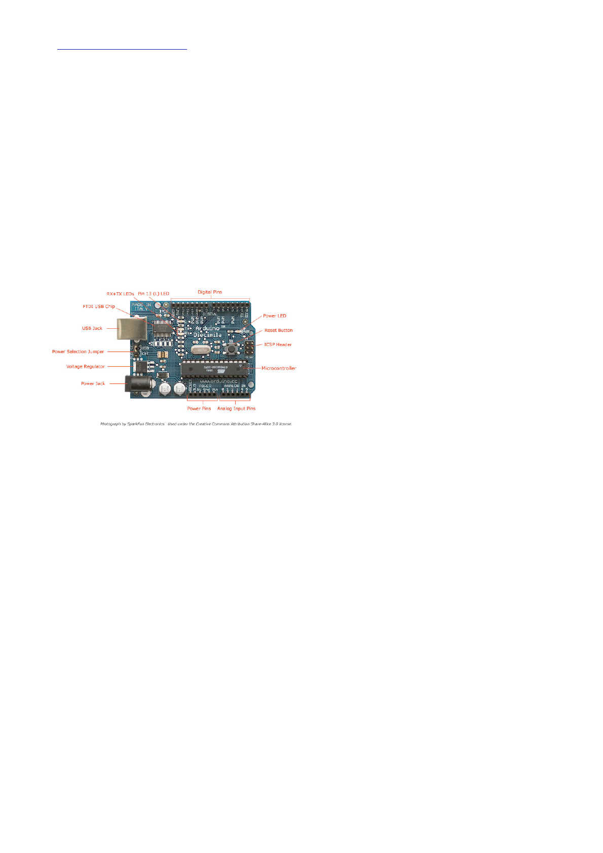
The Arduino board is made of an an Atmel AVR
Microprocessor, a crystal or oscillator (basically a
crude clock that sends time pulses to the
microcontroller to enable it to operate at the correct
speed) and a 5-volt linear regulator. Depending on
what type of Arduino you have, you may also have a
USB connector to enable it to be connected to a PC or
Mac to upload or retrieve data. The board exposes the
microcontrollerʼs I/O (Input/Output) pins to enable you
to connect those pins to other circuits or to sensors,
etc.
To program the Arduino (make it do what you want it
to) you also use the Arduino IDE (Integrated
Development Environment), which is a piece of free
software, that enables you to program in the language
that the Arduino understands. In the case of the
Arduino the language is C. The IDE enables you to
write a computer program, which is a set of step-by-
step instructions that you then upload to the Arduino.
Then your Arduino will carry out those instructions and
interact with the world outside. In the Arduino world,
programs are known as ʻSketchesʼ.
The Arduino hardware and software are both Open
Source, which means the code, the schematics,
design, etc. are all open for anyone to take freely and
do what they like with it.
This means there is nothing stopping anyone from
taking the schematics and PCB designs of the Arduino
and making their own and selling them. This is
perfectly legal, and indeed the whole purpose of Open
Source, and indeed the Freeduino that comes with the
Earthshine Design Arduino Starter Kit is a perfect
example of where someone has taken the Arduino
PCB design, made their own and are selling it under
the Freeduino name. You could even make your own
What exactly is an Arduino?
Earthshine Electronics Arduino Starters Kit Manual - A Complete Beginners Guide to the Arduino
www.EarthshineElectronics.com
10
Arduino, with just a few cheap components, on a
breadboard.
The only stipulation that the Arduino development
team put on outside developers is that the Arduino
name can only be used exclusively by them on their
own products and hence the clone boards have
names such as Freeduino, Boarduino, Roboduino, etc.
As the designs are open source, any clone board,
such as the Freeduino, is 100% compatible with the
Arduino and therefore any software, hardware,
shields, etc. will all be 100% compatible with a
genuine Arduino.
The Arduino can also be extended with the use of
ʻShieldsʼ which are circuit boards containing other
devices (e.g. GPS receivers, LCD Displays, Ethernet
connections, etc.) that you can simply slot into the top
of your Arduino to get extra functionality. You donʼt
have to use a shield if you donʼt want to as you can
make the exact same circuitry using a breadboard,
some veroboard or even by making your own PCBʼs.
There are many different variants of the Arduino
available. The most common one is the Diecimila or
the Duemilanove. You can also get Mini, Nano and
Bluetooth Arduinoʼs.
New to the product line is the new Arduino Mega with
increased memory and number of I/O pins.
Probably the most versatile Arduino, and hence the
reason it is the most popular, is the Duemilanove. This
is because it uses a standard 28 pin chip, attached to
an IC Socket. The beauty of this systems is that if you
make something neat with the Arduino and then want
to turn it into something permanent (e.g. Or under-
stairs cupboard light), then instead of using the
relatively expensive Arduino board, you can simply
use the Arduino to develop your device, then pop the
chip out of the board and place it into your own circuit
board in your custom device. You would then have
made a custom embedded device, which is really cool.
Then, for a couple of quid or bucks you can replace
the AVR chip in your Arduino with a new one. The chip
must be pre-programmed with the Arduino Bootloader
to enable it to work with the Arduino IDE, but you can
either burn the Bootloader yourself if you purchase an
AVR Programmer, or you can buy these pre-
programmed from many suppliers around the world.
Of course, Earthshine Design provide pre-
programmed Arduino chips in itʼ store for a very
reasonable price.
If you do a search on the Internet by simply typing
ʻArduinoʼ into the search box of your favourite search
engine, you will be amazed at the huge amount of
websites dedicated to the Arduino. You can find a
mind boggling amount of information on projects made
with the Arduino and if you have a project in mind, will
easily find information that will help you to get your
project up and running easily.
The Arduino is an amazing device and will enable you
to make anything from interactive works of art to
robots. With a little enthusiasm to learn how to
program the Arduino and make it interact with other
components a well as a bit of imagination, you can
build anything you want.
This book and the kit will give you the necessary skills
needed to get started in this exciting and creative
hobby.
So, now you know what an Arduino is and what you
can do with it, letʼs open up the starter kit and dive
right in.
Earthshine Electronics Arduino Starters Kit Manual - A Complete Beginners Guide to the Arduino
www.EarthshineElectronics.com
11
Getting Started
This section will presume you have a PC running
Windows or a Mac running OSX (10.3.9 or later). If
you use Linux as your Operating System, then refer to
the Getting Started instructions on the Arduino website
at http://www.arduino.cc/playground/Learning/Linux
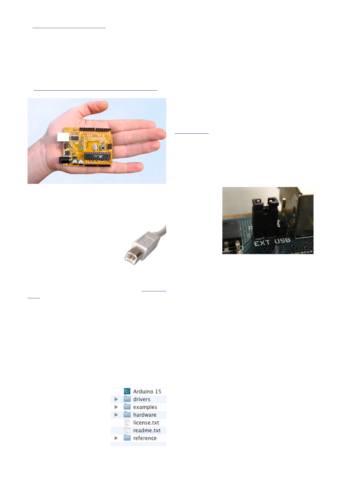
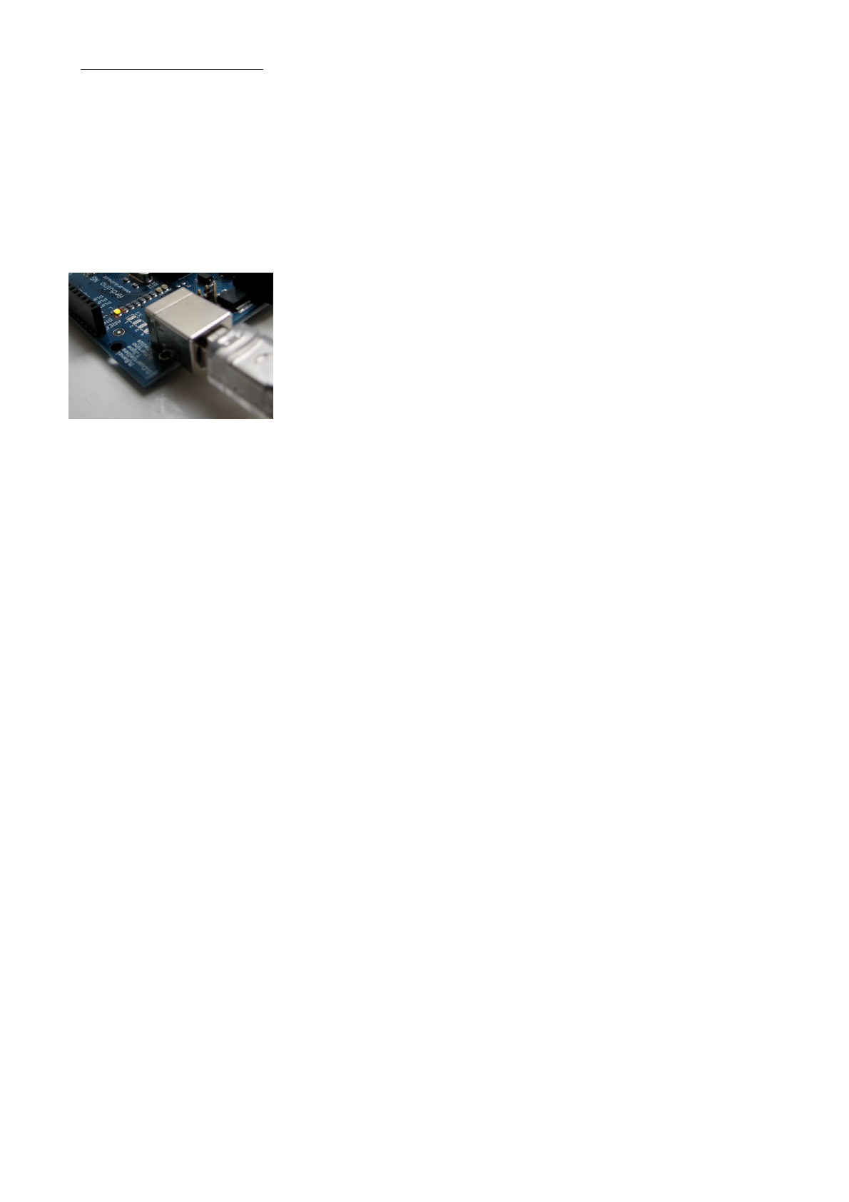
Get the Freeduino and the USB Cable
Firstly, get your Freeduino board and lay it on the table
in front of you. Take the USB cable
and plug the B plug (the fatter
squarer end) into the USB socket
on the Freeduino.
At this stage do NOT connect the
Freeduino to your PC or Mac yet.
Download the Arduino IDE
Download the Arduino IDE from the Arduino download
page. As of the time of writing this book, the latest
IDE version is 0015. The file is a ZIP file so you will
need to uncompress it. Once the download has
finished, unzip the file, making sure that you preserve
the folder structure as it is and do not make any
changes.
If you double-click the folder, you will see a few files
and sub-folders inside.
Install the USB Drivers
If you are using Windows you will find the drivers in
the drivers/FTDI USB
Drivers directory of the
Arduino distribution. In the
next stage (“Connect the
Freeduino”), you will point
Windowʼs Add New
Hardware wizard to these
drivers.
If you have a Mac these are in the drivers directory.
If you have an older Mac like a PowerBook, iBook, G4
or G5, you should use the PPC drivers:
FTDIUSBSerialDriver_v2_1_9.dmg. If you have
a newer Mac with an Intel chip, you need the Intel
drivers:
FTDIUSBSerialDriver_v2_2_9_Intel.dmg.
Double-click to mount the disk image and run the
included FTDIUSBSerialDriver.pkg.
The latest version of the drivers can be found on the
FTDI website.
Connect the Freeduino
First, make sure that the little power jumper, between
the power and USB sockets, is set to USB and not
EXTernal power (not applicable if you have a
Roboduino board, which has an Auto Power Select
function).
U s i n g t h i s
jumper you can
either power the
board from the
USB port (good
for low current
devices like
LEDʼs, etc.) or
from an external
power supply (6-12V DC).
Now, connect the other end of the USB cable into the
USB socket on your PC or Mac. You will now see the
small power LED (marked PWR above the RESET
switch) light up to show you have power to the board.
If you have a Mac, this stage of the process is
complete and you can move on to the next Chapter. If
you are using Windows, there are a few more steps to
complete (Damn you Bill Gates!).
Earthshine Electronics Arduino Starters Kit Manual - A Complete Beginners Guide to the Arduino
www.EarthshineElectronics.com
12
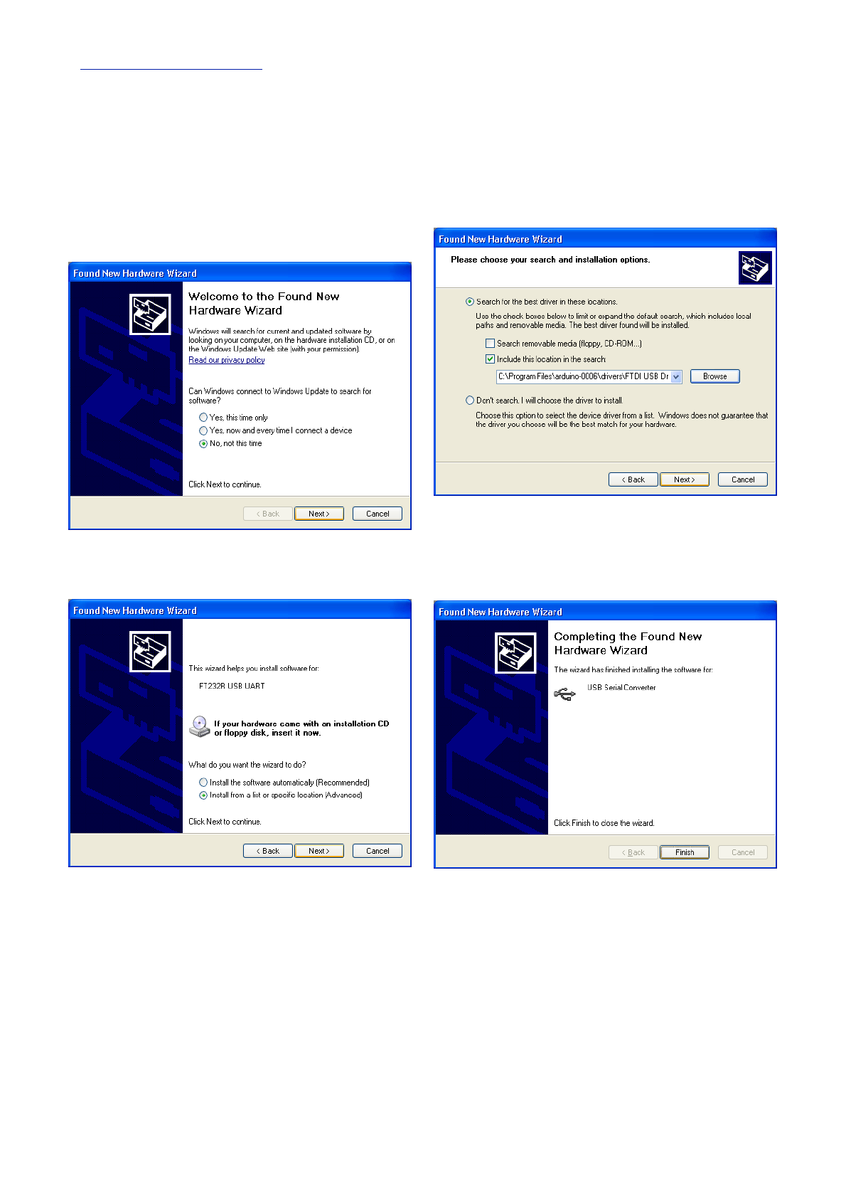
On Windows the Found New Hardware Wizard will
now open up as Windows will have detected that you
have connected a new piece of hardware (your
Freeduino board) to your PC. Tell it NOT to connect to
Windows update (Select No, not at this time) and
then click Next.
On the next page select “Install from a list or
specific location (Advanced)” and click Next.
Make sure that “Search for the best driver in these
locations” is checked.
Uncheck “Search removable media”. Check “Include
this location in the search” and then click the
Browse button. Browse to the location of the USB
drivers and then click Next.
The wizard will now search for a suitable driver and
then tell you that a “USB Serial Convertor” has been
found and that the hardware wizard is now complete.
Click Finish.
You are now ready to upload your first Sketch.

Earthshine Electronics Arduino Starters Kit Manual - A Complete Beginners Guide to the Arduino
www.EarthshineElectronics.com
13
Upload your first Sketch
Now that your Freeduino has been connected and the
drivers for the USB chip have been installed, we are
now ready to try out the Arduino for the first time and
upload your first Sketch.
Navigate to your newly unzipped Arduino folder and
look for the Arduino IDE icon, which looks something
like this....
Double click the ICON to open up the
IDE. You will then be presented with a
blue and white screen with a default
sketch loaded inside.
This is the Arduino IDE (Integrated Development
Environment) and is where you will write your
Sketches (programs) to upload to your Arduino board.
We will take a look at the IDE in a little more detail in
the next chapter. For now, simply click File in the file
menu and scroll down to
Sketchbook. Then scroll
down to Examples and
click it. You will be
presented with a list of
Example sketches that you
can use to try out your
Arduino. Now click on
Digital and inside there you
will find an example Sketch called Blink. Click on this.
T h e B l i n k
Sketch will
now be
loaded into
the IDE and
you will see the Sketch inside the white code window.
Now, before we upload the Sketch, we need to tell the
IDE what kind of Arduino we are using and the details
of our USB port. Go to the file menu and click Tools,
then click on Board. You will be presented with a list of
all of the different kinds of Arduino board that can be
connected to the IDE. Our Freeduino board will either
be fitted with an Atmega328 or an Atmega168 chip so
choose “Arduino Duemilanove w/ATmega328” if you
have a 328 chip or “Arduino Diecimila or Duemilanove
w/ ATmega168” if you have a 168 chip.
Now you need to tell the IDE the details of your USB
port, so now click on Tools again, scroll down to Serial
Port and a list of the available serial ports on your
system will be displayed. You need to choose the one
that refers to your USB cable, which is usually listed
as something like /dev/tty.usbserial-xxxx on a
Mac or something like Com 4 on Windows so click on
that. If not sure, try each one till you find one that
works.
Now that you have selected the correct board and
USB port you are ready to upload the Blink Sketch to
the board.
You can either click the Upload button, which is the 6th
button from the left at the top with an arrow pointing to
the right (hover your mouse pointer over the buttons to
see what they are) or by clicking on File in the file
menu and scrolling down to Upload to I/O Board and
clicking on that.
Presuming everything has been set up correctly you
will now see the RX and TX LEDʼs (and also LED 13)
on the Freeduino flash on and off very quickly as data
is uploaded to the board. You will see Uploading to I/O
Board.... Just below the code window too.
Earthshine Electronics Arduino Starters Kit Manual - A Complete Beginners Guide to the Arduino
www.EarthshineElectronics.com
14
Once the data has been uploaded to the board
successfully you will get a Done Uploading message
in the IDE and the RX/TX LEDʼs will stop flashing.
The Arduino will now reset itself and immediately start
to run the Sketch that you have just uploaded.
The Blink sketch is
a very simple sketch
that blinks LED 13,
which is a tiny green
LED soldered to the
board and also
connected to Digital
Pin 13 from the
Microcontroller, and
will make it flash on
and off every 1000 milliseconds, or 1 second.
If your sketch has uploaded successfully, you will now
see this LED happily flashing on and off slowly on your
board.
If so, congratulations, you have just successfully
installed your Arduino, uploaded and ran your first
sketch.
We will now explain a bit more about the Arduino IDE
and how to use it before moving onto the projects that
you can carry out using the hardware supplied with the
kit. For our first project we will carry out this Blink LED
sketch again, but this time using an LED that we will
physically connect to one of the digital output pins on
the Arduino. We will also explain the hardware and
software involved in this simple project. But first, letʼs
take a closer look at the Arduino IDE.

Earthshine Electronics Arduino Starters Kit Manual - A Complete Beginners Guide to the Arduino
www.EarthshineElectronics.com
15
The Arduino IDE
When you open up the Arduino IDE it will look very
similar to the image above. If you are using Windows
or Linux there will be some slight differences but the
IDE is pretty much the same no matter what OS you
are using.
The IDE is split up into the Toolbar across the top, the
code or Sketch Window in the centre and the Serial
Output window at the bottom.
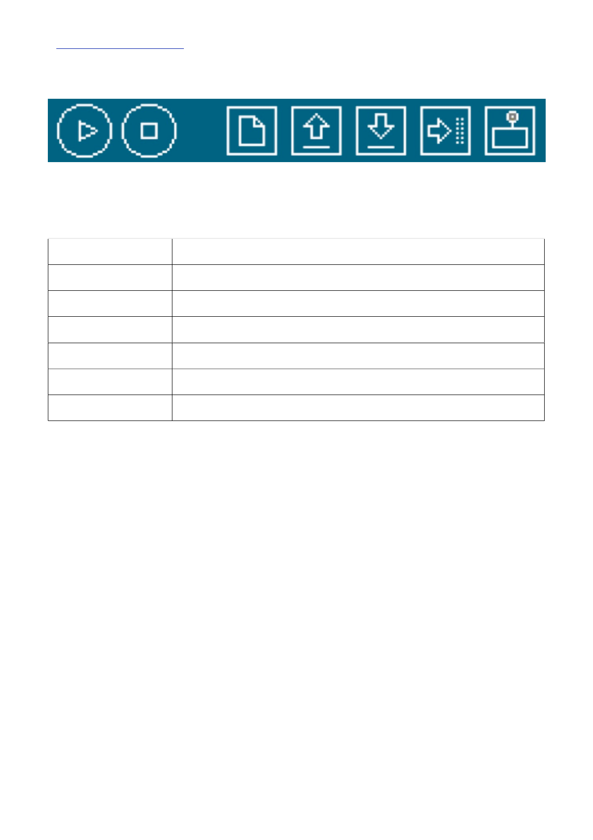
The Toolbar consists of 7 buttons, underneath the
Toolbar is a tab, or set of tabs, with the filename of the
code within the tab. There is also one further button on
the far right hand side.
Along the top is the file menu with drop down menus
headed under File, Edit, Sketch, Tools and Help. The
buttons in the Toolbar provide convenient access to
the most commonly used functions within this file
menu.
Earthshine Electronics Arduino Starters Kit Manual - A Complete Beginners Guide to the Arduino
www.EarthshineElectronics.com
16
The Verify/Compile button is used to check that your
code is correct, before you upload it to your Arduino.
The Stop button will stop the Serial Monitor from
operating. It will also un-highlight other selected
buttons. Whilst the Serial Monitor is operating you may
wish to press the Stop button to obtain a ʻsnapshotʼ of
the serial data so far to examine it. This is particularly
useful if you are sending data out to the Serial Monitor
quicker than you can read it.
The New button will create a completely new and
blank Sketch read for you to enter code into. The IDE
will ask you to enter a name and a location for your
Sketch (try to use the default location if possible) and
will then give you a blank Sketch ready to be coded.
The tab at the top of the Sketch will now contain the
name you have given to your new sketch.
The Open button will present you with a list of
Sketches stored within your sketchbook as well as a
list of Example sketches you can try out with various
peripherals once connected.
The Save button will save the code within the sketch
window to your sketch file. Once complete you will get
a ʻDone Saving message at the bottom of the code
window.
The Upload to I/O Board button will upload the code
within the current sketch window to your Arduino. You
need to make sure that you have the correct board
and port selected (in the Tools menu) before
uploading. It is essential that you Save your sketch
before you upload it to your board in case a strange
error causes your system to hang or the IDE to crash.
It is also advisable to Verify/Compile the code before
you upload to ensure there are no errors that need to
be debugged first.
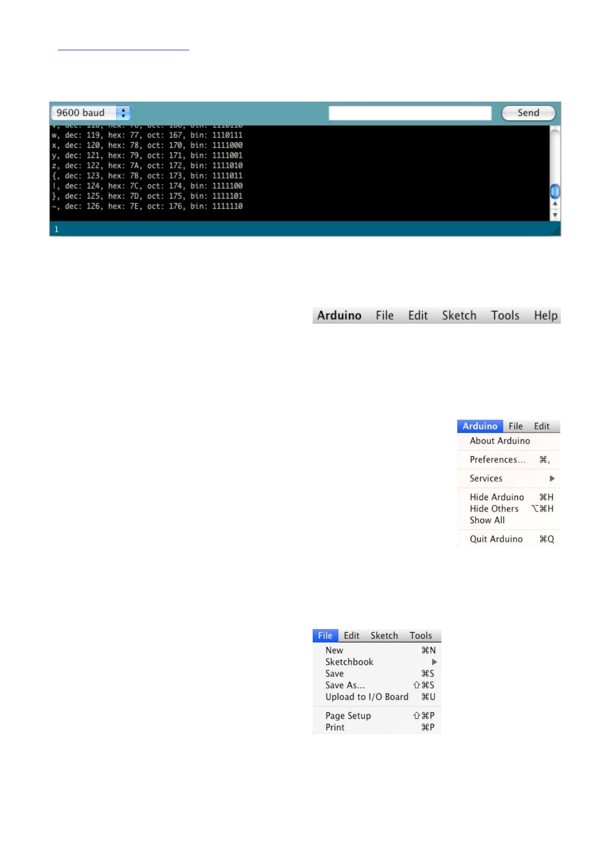
The Serial Monitor is a very useful tool, especially for
debugging your code. The monitor displays serial data
being sent out from your Arduino (USB or Serial
board). You can also send serial data back to the
Arduino using the Serial Monitor. If you click the Serial
Monitor button you will be presented with an image
like the one above.
On the left hand side you can select the Baud Rate
that the serial data is to be sent to/from the Arduino.
The Baud Rate is the rate, per second, that state
changes or bits (data) are sent to/from the board. The
default setting is 9600 baud, which means that if you
were to send a text novel over the serial
communications line (in this case your USB cable)
then 9600 letters, or symbols, of the novel, would be
sent per second.
Verify/
Compile
Stop
Stop
New
Open
Save
Upload
Serial
Monitor
The Toolbar buttons are listed above. The functions of each button are as follows :-
The Toolbar buttons are listed above. The functions of each button are as follows :-
The Toolbar buttons are listed above. The functions of each button are as follows :-
The Toolbar buttons are listed above. The functions of each button are as follows :-
The Toolbar buttons are listed above. The functions of each button are as follows :-
The Toolbar buttons are listed above. The functions of each button are as follows :-
The Toolbar buttons are listed above. The functions of each button are as follows :-
The Toolbar buttons are listed above. The functions of each button are as follows :-
The Toolbar buttons are listed above. The functions of each button are as follows :-
Verify/Compile
Verify/Compile
Checks the code for errors
Checks the code for errors
Checks the code for errors
Checks the code for errors
Checks the code for errors
Checks the code for errors
Checks the code for errors
Stop
Stop
Stops the serial monitor, or un-highlights other buttons
Stops the serial monitor, or un-highlights other buttons
Stops the serial monitor, or un-highlights other buttons
Stops the serial monitor, or un-highlights other buttons
Stops the serial monitor, or un-highlights other buttons
Stops the serial monitor, or un-highlights other buttons
Stops the serial monitor, or un-highlights other buttons
New
New
Creates a new blank Sketch
Creates a new blank Sketch
Creates a new blank Sketch
Creates a new blank Sketch
Creates a new blank Sketch
Creates a new blank Sketch
Creates a new blank Sketch
Open
Open
Shows a list of Sketches in your sketchbook
Shows a list of Sketches in your sketchbook
Shows a list of Sketches in your sketchbook
Shows a list of Sketches in your sketchbook
Shows a list of Sketches in your sketchbook
Shows a list of Sketches in your sketchbook
Shows a list of Sketches in your sketchbook
Save
Save
Saves the current Sketch
Saves the current Sketch
Saves the current Sketch
Saves the current Sketch
Saves the current Sketch
Saves the current Sketch
Saves the current Sketch
Upload
Upload
Uploads the current Sketch to the Arduino
Uploads the current Sketch to the Arduino
Uploads the current Sketch to the Arduino
Uploads the current Sketch to the Arduino
Uploads the current Sketch to the Arduino
Uploads the current Sketch to the Arduino
Uploads the current Sketch to the Arduino
Serial Monitor
Serial Monitor
Displays serial data being sent from the Arduino
Displays serial data being sent from the Arduino
Displays serial data being sent from the Arduino
Displays serial data being sent from the Arduino
Displays serial data being sent from the Arduino
Displays serial data being sent from the Arduino
Displays serial data being sent from the Arduino
Earthshine Electronics Arduino Starters Kit Manual - A Complete Beginners Guide to the Arduino
www.EarthshineElectronics.com
17
To the right of this is a blank text box for you to enter
text to send back to the Arduino and a Send button to
send the text within that field. Note that no serial data
can be received by the Serial Monitor unless you have
set up the code inside your sketch to do so. Similarly,
the Arduino will not receive any data sent unless you
have coded it to do so.
Finally, the black area is where your serial data will be
displayed. In the image above, the Arduino is running
the ASCIITable sketch, that can be found in the
Communications examples. This program outputs
ASCII characters, from the Arduino via serial (the USB
cable) to the PC where the Serial monitor then
displays them.
To start the Serial Monitor press the Serial Monitor
button and to stop it press the Stop button. On a Mac
or in Linux, Arduino board will reset itself (rerun the
code from the beginning) when you click the Serial
Monitor button.
Once you are proficient at communicating via serial to
and from the Arduino you can use other programs
such as Processing, Flash, MaxMSP, etc. To
communicate between the Arduino and your PC.
We will make use of the Serial Monitor later on in our
projects when we read data from sensors and get the
Arduino to send that data to the Serial Monitor, in
human readable form, for us to see.
The Serial Monitor window is also were you will see
error messages (in red text) that the IDE will display to
you when trying to connect to your board, upload code
or verify code.
Below the Serial Monitor at the bottom left you will see
a number. This is the current line that the cursor,
within the code window, is at. If you have code in your
window and you move down the lines of code (using
the ↓ key on your keyboard) you will see the number
increase as you move down the lines of code. This is
useful for finding bugs highlighted by error messages.
Across the top of the IDE window (or across the top of
your screen if you are using a Mac) you will see the
various menus that you can click on to access more
menu items.
The menu bar across the top of the IDE looks like the
image above (and slightly different in Windows and
Linux). I will explain the menus as they are on a Mac,
the details will also apply to the Windows and Linux
versions of the IDE.
The first menu is the Arduino
menu. Within this is the
About Arduino option, which
when pressed will show you
the current version number, a
list of the people involved in
making this amazing device
and some further information.
Underneath that is the
Preferences option. This will
bring up the Preferences
window where you can change various IDe options,
such as were you default Sketchbook is stored, etc.
Also, is the Quit option, which will Quit the program.
The next menu is the
File menu. In here you
get access to options to
create a New sketch,
take a look at Sketches
s t o r e d i n y o u r
Sketchbook (as well as
the Example Sketches),
options to Save your
Sketch (or Save As if
you want to give it a different name). You also have
the option to upload your sketch to the I/O Board
(Arduino) as well as the Print options for printing out
your code.
Earthshine Electronics Arduino Starters Kit Manual - A Complete Beginners Guide to the Arduino
www.EarthshineElectronics.com
18
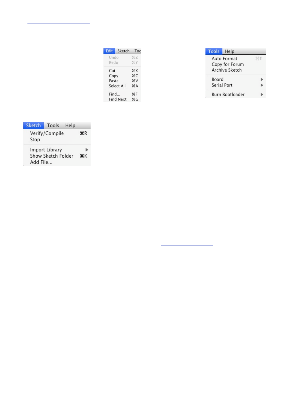
Next is the Edit menu. In here you
get options to enable you to Cut,
Copy and Paste sections of code.
Select All of your code as well as
Find certain words or phrases
within the code. Also included are
the useful Undo and Redo options
which come in handy when you
make a mistake.
Our next menu is the Sketch menu which gives us
access to the Verify/Compile functions and some other
useful functions you
will use later on.
These include the
Import Library option,
which when clicked
will bring up a list of
the available
libraries, stored
w i t h i n y o u r
libraries folder.
A Library, is a collection of code, that you can include
in your sketch, to enhance the functionality of your
project. It is a way of preventing you from ʻre-inventing
the wheelʼ by reusing code already made by someone
else for various pieces of common hardware you may
encounter whilst using the Arduino.
For example, one of the libraries you will find is
Stepper, which is a set of functions you can use
within your code to control a Stepper Motor.
Somebody else has kindly already created all of the
necessary functions necessary to control a stepper
motor and by including the Stepper library into our
sketch we can use those functions to control the motor
as we wish. By storing commonly used code in a
library, you can re-use that code over and over in
different projects and also hide the complicated parts
of the code from the user.
We will go into greater detail concerning the use of
libraries later on. Finally within the Sketch menu is the
Show Sketch Menu option, which will open up the
folder were your Sketch is stored. Also, there is the
Add File option which will enable you to add another
source file to your Sketch. This functionality allows you
to split larger sketches into smaller files and then Add
them to the main Sketch.
The next menu in the
IDE is the Tools menu.
Within this are the
options to select the
Board and Serial Port
we are using, as we did
when setting up the
Arduino for the first time.
Also we have the Auto
Format function that
formats your code to make it look nicer.
The Copy for Forum option will copy the code within
the Sketch window, but in a format that when pasted
into the Arduino forum (or most other Forums for that
matter) will show up the same as it is in the IDE, along
with syntax colouring, etc.
The Archive Sketch option will enable you to compress
your sketch into a ZIP file and asks you were you want
to store it.
Finally, the Burn Bootloader option can be used to
burn the Arduino Bootloader (piece of code on the chip
to make it compatible with the Arduino IDE) to the
chip. This option can only be used if you have an AVR
programmer and have replaced the chip in your
Arduino or have bought blank chips to use in your own
embedded project. Unless you plan on burning lots of
chips it is usually cheaper and easier to just buy an
ATmega chip with the Arduino Bootloader already pre-
programmed. Many online stores stock pre-
programmed chips and obviously these can be found
in the Earthshine Design store.
The final menu is the Help menu were you can find
help menus for finding out more information about the
IDE or links to the reference pages of the Arduino
website and other useful pages.
Donʼt worry too much about using the IDE for now as
you will pick up the important concepts and how to use
it properly as we work our way through the projects.
So, on that note, letʼs get on with it.

Earthshine Design Arduino Starters Kit Manual - A Complete Beginners Guide to the Arduino
19
Earthshine Design
Arduino Starters Kit Manual
A Complete Beginners guide to the Arduino
The Projects

Earthshine Design Arduino Starters Kit Manual - A Complete Beginners Guide to the Arduino
20
Project 1
LED Flasher

Earthshine Design Arduino Starters Kit Manual - A Complete Beginners Guide to the Arduino
21
Project 1 - LED Flasher
In this project we are going to repeat what we did in
setting up and testing the Arduino, that is to blink an
LED. However, this time we are going to use one of
the LEDʼs in the kit and you will also learn about some
electronics and coding in C along the way.
What you will need
Breadboard
Red LED
150Ω Resistor
Jumper Wires
Connect it up
Now, first make sure that your Arduino is powered off.
You can do this either by unplugging the USB cable or
by taking out the Power Selector Jumper on the
Arduino board. Then connect everything up like this :-
It doesnʼt matter if you use different coloured wires or
use different holes on the breadboard as long as the
components and wires are connected in the same
order as the picture. Be careful when insterting
components into the Breadboard. The Breadboard is
brand new and the grips in the holes will be stiff to
begin with. Failure to insert components carefully
could result in damage.
Make sure that your LED is connected the right way
with the longer leg connected to Digital Pin 10. The
long led is the Anode of the LED and always must go
to the +5v supply (in this case coming out of Digital
Pin 10) and the short leg is the Cathode and must go
to Gnd (Ground).
When you are happy that everything is connected up
correctly, power up your Arduino and connect the USB
cable.
Enter the code
Now, open up the Arduino IDE and type in the
following code :-
Now press the Verify/Compile button at the top of the
IDE to make sure there are no errors in your code. If
this is successful you can now click the Upload button
to upload the code to your Arduino.
If you have done everything right you should now see
the Red LED on the breadboard flashing on and off
every second.
Now letʼs take a look at the code and the hardware
and find out how they both work.
// Project 1 - LED Flasher
int ledPin = 10;
void setup() {
!pinMode(ledPin, OUTPUT);
}
void loop() {
!digitalWrite(ledPin, HIGH);
!delay(1000);
!digitalWrite(ledPin, LOW);
!delay(1000);
}

Earthshine Design Arduino Starters Kit Manual - A Complete Beginners Guide to the Arduino
22
Project 1 - Code Overview
// Project 1 - LED Flasher
int ledPin = 10;
void setup() {
!pinMode(ledPin, OUTPUT);
}
void loop() {
!digitalWrite(ledPin, HIGH);
!delay(1000);
!digitalWrite(ledPin, LOW);
!delay(1000);
}
So letʼs take a look at the code for this project. Our
first line is
// Project 1 - LED Flasher
This is simply a comment in your code and is ignored
by the compiler (the part of the IDE that turns your
code into instructions the Arduino can understand
before uploading it). Any text entered behind a //
command will be ignored by the compiler and is simply
there for you, or anyone else that reads your code.
Comments are essential in your code to help you
understand what is going on and how your code
works. Comments can also be put after commands as
in the next line of the program.
Later on as your projects get more complex and your
code expands into hundreds or maybe thousands of
lines, comments will be vital in making it easy for you
to see how it works. You may come up with an
amazing piece of code, but if you go back and look at
that code days, weeks or months alter, you may forget
how it all works. Comments will help you understand it
easily. Also, if your code is meant to be seen by other
people (and as the whole ethos of the Arduino, and
indeed the whole Open Source community is to share
code and schematics. We hope when you start
making your own cool stuff with the Arduino you will be
willing to share it with the world) then comments will
enable that person to understand what is going on in
your code.
You can also put comments into a block statement by
using the /* and */ commands. E.g.
/* All of the text within
the slash and the asterisks
is a comment and will be
ignored by the compiler */
The IDE will automatically turn the colour of any
commented text to grey.
The next line of the program is
int ledPin = 10;
This is what is know as a variable. A variable is a
place to store data. In this case you are setting up a
variable of type int or integer. An integer is a number
within the range of -32,768 to 32,767. Next you have
assigned that integer the name of ledPin and have
given it a value of 10. We didnʼt have to call it ledPin,
we could have called it anything we wanted to. But, as
we want our variable name to be descriptive we call it
ledPin to show that the use of this variable is to set
which pin on the Arduino we are going to use to
connect our LED. In this case we are using Digital Pin
10. At the end of this statement is a semi-colon. This is
a symbol to tell the compiler that this statement is now
complete.
Although we can call our variables anything we want,
every variable name in C must start with a letter, the
rest of the name can consist of letters, numbers and
underscore characters. C recognises upper and lower
case characters as being different. Finally, you cannot
use any of C's keywords like main, while, switch etc as
variable names. Keywords are constants, variables
and function names that are defined as part of the
Arduino language. Donʼt use a variable name that is
the same as a keyword. All keywords within the sketch
will appear in red.
So, you have set up an area in memory to store a
number of type integer and have stored in that area
the number 10. Imagine a variable as a small box
where you can keep things. A variable is called a
variable because you can change it. Later on we will
carryout mathematical calculations on variables to
make our program do more advanced stuff.
Next we have our setup() function
void setup() {
!pinMode(ledPin, OUTPUT);
}
An Arduino sketch must have a setup() and loop()
function otherwise it will not work. The setup() function
is run once and once only at the start of the program
and is where you will issue general instructions to
prepare the program before the main loop runs, such
as setting up pin modes, setting serial baud rates, etc.
Basically a function is a block of code assembled into
one convenient block. For example, if we created our
own function to carry out a whole series of
complicated mathematics that had many lines of code,
we could run that code as many times as we liked
simply by calling the function name instead of writing
Earthshine Design Arduino Starters Kit Manual - A Complete Beginners Guide to the Arduino
23
out the code again each time. Later on we will go into
functions in more detail when we start to create our
own.
In the case of our program the setup() function only
has one statement to carry out. The function starts
with
void setup()
and here we are telling the compiler that our function
is called setup, that it returns no data (void) and that
we pass no parameters to it (empty parenthesis). If
our function returned an integer value and we also had
integer values to pass to it (e.g. for the function to
process) then it would look something like this
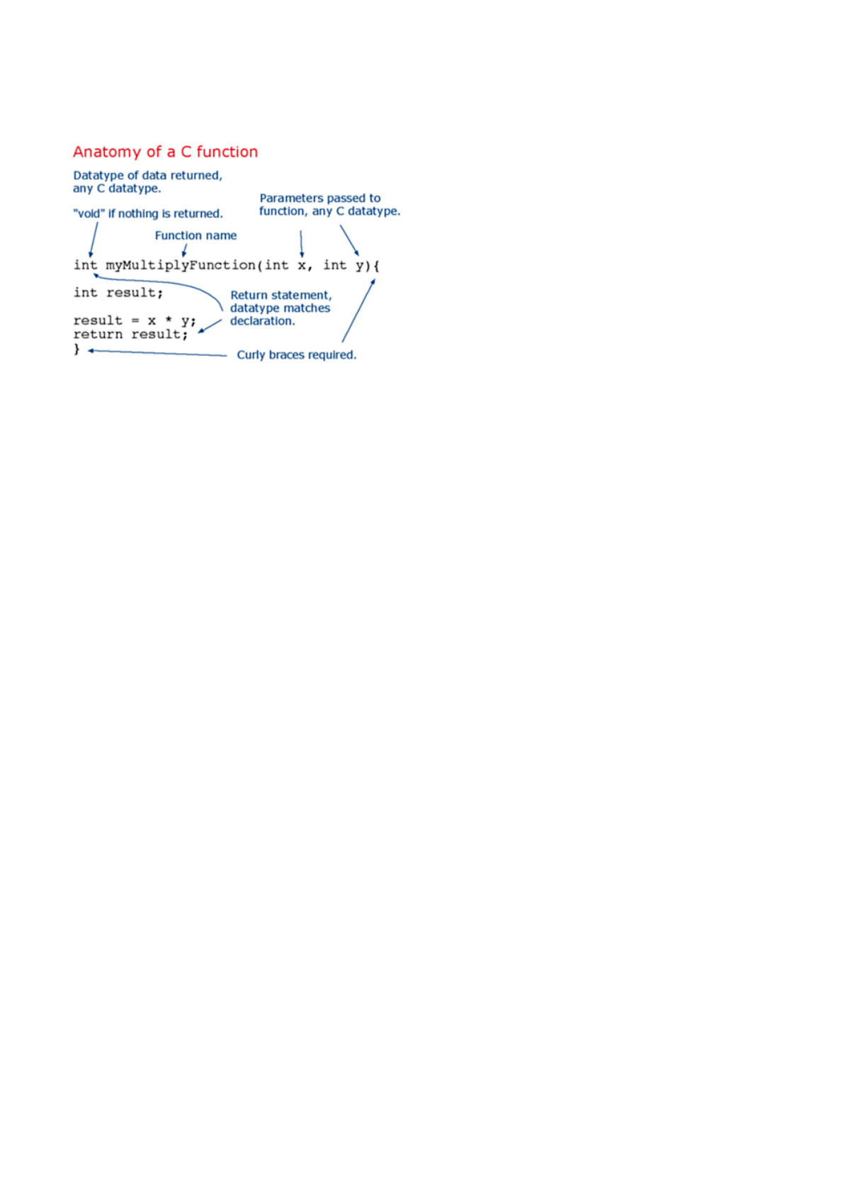
int myFunc(int x, int y)
In this case we have created a function (or a block of
code) called myFunc. This function has been passed
two integers called X and Y. Once the function has
finished it will then return an integer value to the point
after where our function was called in the program
(hence int before the function name).
All of the code within the function is contained within
the curly braces. A { symbol starts the block of code
and a } symbol ends the block. Anything in between
those two symbols is code that belongs to the
function.
We will go into greater detail about functions later on
so donʼt worry about them for now. All you need to
know is that in this program, we have two functions,
the first function is called setup and itʼs purpose is to
setup anything necessary for our program to work
before the main program loop runs.
void setup() {
!pinMode(ledPin, OUTPUT);
}
Our setup function only has one statement and that is
pinMode. Here we are telling the Arduino that we want
to set the mode of one of our digital pins to be Output
mode, rather than Input. Within the parenthesis we put
the pin number and the mode (OUTPUT or INPUT).
Our pin number is ledPin, which has been previously
set to the value 10 in our program. Therefore, this
statement is simply telling the Arduino that the Digital
Pin 10 is to be set to OUTPUT mode.
As the setup() function runs only once, we now move
onto the main function loop.
void loop() {
!digitalWrite(ledPin, HIGH);
!delay(1000);
!digitalWrite(ledPin, LOW);
!delay(1000);
}
The loop() function is the main program function and
runs continuously as long as our Arduino is turned on.
Every statement within the loop() function (within the
curly braces) is carried out, one by one, step by step,
until the bottom of the function is reached, then the
loop starts again at the top of the function, and so on
forever or until you turn the Arduino off or press the
Reset switch.
In this project we want the LED to turn on, stay on for
one second, turn off and remain off for one second,
and then repeat. Therefore, the commands to tell the
Arduino to do that are contained within the loop()
function as we wish them to repeat over and over.
The first statement is
digitalWrite(ledPin, HIGH);
and this writes a HIGH or a LOW value to the digital
pin within the statement (in this case ledPin, which is
Digital Pin 10). When you set a digital pin to HIGH you
are sending out 5 volts to that pin. When you set it to
LOW the pin becomes 0 volts, or Ground.
This statement therefore sends out 5v to digital pin 10
and turns the LED on.
After that is
delay(1000);
and this statement simply tells the Arduino to wait for
1000 milliseconds (to 1 second as there are 1000
milliseconds in a second) before carrying out the next
statement which is
digitalWrite(ledPin, LOW);

Earthshine Design Arduino Starters Kit Manual - A Complete Beginners Guide to the Arduino
24
which will turn off the power going to digital pin 10 and
therefore turn the LED off. There is then another delay
statement for another 1000 milliseconds and then the
function ends. However, as this is our main loop()
function, the function will now start again at the
beginning. By following the program structure step by
step again we can see that it is very simple.
// Project 1 - LED Flasher
int ledPin = 10;
void setup() {
!pinMode(ledPin, OUTPUT);
}
void loop() {
!digitalWrite(ledPin, HIGH);
!delay(1000);
!digitalWrite(ledPin, LOW);
!delay(1000);
}
We start off by assigning a variable called ledPin,
giving that variable a value of 10.
Then we move onto the setup() function where we
simply set the mode for digital pin 10 as an output.
In the main program loop we set Digital Pin 10 to high,
sending out 5v. Then we wait for a second and then
turn off the 5v to Pin 10, before waiting another
second. The loop then starts again at the beginning
and the LED will therefore turn on and off continuously
for as long as the Arduino has power.
Now that you know this you can modify the code to
turn the LED on for a different period of time and also
turn it off for a different time period.
For example, if we wanted the LED to stay on for 2
seconds, then go off for half a second we could do
this:-
void loop() {
!digitalWrite(ledPin, HIGH);
!delay(2000);
!digitalWrite(ledPin, LOW);
!delay(500);
}
or maybe you would like the LED to stay off for 5
seconds and then flash briefly (250ms), like the LED
indicator on a car alarm then you could do this:-
void loop() {
!digitalWrite(ledPin, HIGH);
!delay(250);
!digitalWrite(ledPin, LOW);
!delay(5000);
}
or make the LED flash on and off very fast
void loop() {
!digitalWrite(ledPin, HIGH);
!delay(50);
!digitalWrite(ledPin, LOW);
!delay(50);
}
By varying the on and off times of the LED you create
any effect you want. Well, within the bounds of a
single LED going on and off that is.
Before we move onto something a little more exciting
letʼs take a look at the hardware and see how it works.
Earthshine Design Arduino Starters Kit Manual - A Complete Beginners Guide to the Arduino
25
Project 1 - Hardware Overview
The hardware used for this project was :-
Breadboard
Red LED
150Ω Resistor
Jumper Wires
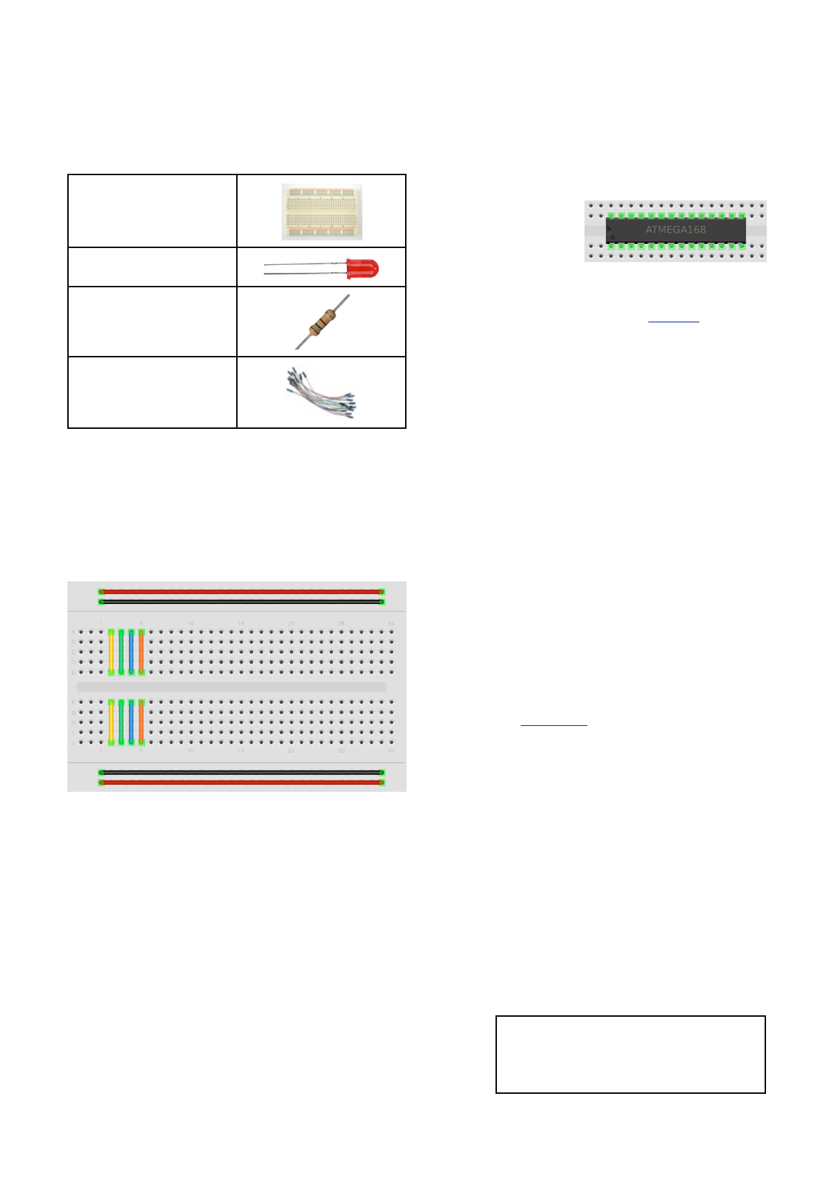
The breadboard is a reusable solderless device used
generally to prototype an electronic circuit or for
experimenting with circuit designs. The board consists
of a series of holes in a grid and underneath the board
these holes are connected by a strip of conductive
metal. The way those strips are laid out is typically
something like this:-
The strips along the top and bottom run parallel to the
board and are design to carry your power rail and your
ground rail. The components in the middle of the
board can then conveniently connect to either 5v (or
whatever voltage you are using) and Ground. Some
breadboards have a red and a black line running
parallel to these holes to show which is power (Red)
and which is Ground (Black). On larger breadboards
the power rail sometimes has a split, indicated by a
break in the red line. This is in case you want different
voltages to go to different parts of your board. If you
are using just one voltage a short piece of jumper wire
can be placed across this gap to make sure that the
same voltage is applied along the whole length of the
rail
The strips in the centre run at 90 degrees to the power
and ground rails in short lengths and there is a gap in
the middle to allow you to put Integrated Circuits
across the gap and
have each pin of the
chip go to a different
set of holes and
therefore a different
rail.
The next component we have is a Resistor. A resistor
is a device designed to cause ʻresistanceʼ to an
electric current and therefore cause a drop in voltage
across itʼs terminals. If you imagine a resistor to be
like a water pipe that is a lot thinner than the pipe
connected to it. As the water (the electric current)
comes into the resistor, the pipe gets thinner and the
current coming out of the other end is therefore
reduced. We use resistors to decrease voltage or
current to other devices. The value of resistance is
known as an Ohm and itʼs symbol is a greek Omega
symbol Ω.
In this case Digital Pin 10 is outputting 5 volts DC at
(according to the Atmega datasheet) 40mA (milliamps)
and our LEDʼs require (according to their datasheet) a
voltage of 2v and a current of 20mA. We therefore
need to put in a resistor that will reduce the 5v to 2v
and the current from 40mA to 20mA if we want to
display the LED at itʼs maximum brightness. If we want
the LED to be dimmer we could use a higher value of
resistance.
To work out what resistor we need to do this we use
what is called Ohmʼs law which is I = V/R where I is
current, V is voltage and R is resistance. So to work
out the resistance we arrange the formula to be R = V/
I which is R = 3/0.02 which is 150 Ohms. V is 3
because we need the Voltage Drop, which is the
supply voltage (5v) minus the Forward Voltage (2v) of
the LED (found in the LED datasheet) which is 3v. We
therefore need to find a 150Ω resistor. So how do we
do that?
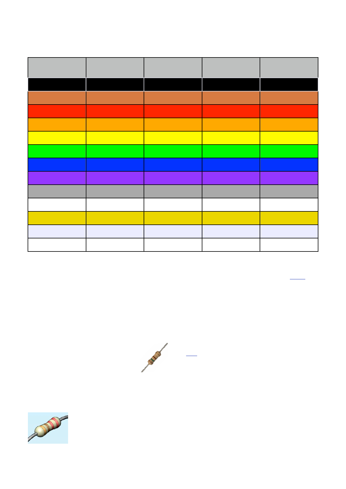
A resistor is too small to put writing onto that could be
readable by most people so instead resistors use a
colour code. Around the resistor you will typically find
4 coloured bands and by using the colour code in the
chart on the next page you can find out the value of a
resistor or what colour codes a particular resistance
will be.
WARNING:
Always put a resistor (commonly known as a current
limiting resistor) in series with an LED. If you fail to
do this you will supply too much current to the LED
and it could blow or damage your circuit.
Earthshine Design Arduino Starters Kit Manual - A Complete Beginners Guide to the Arduino
26
We need a 150Ω resistor, so if we look at the colour
table we see that we need 1 in the first band, which is
Brown, followed by a 5 in the next band which is
Green and we then need to multiply this by 101
(in
other words add 1 zero) which is Brown in the 3rd
band. The final band is irrelevant for our purposes as
this is the tolerance. Our resistor has a gold band and
therefore has a tolerance of ±5% which means the
actual value of the resistor can vary between 142.5Ω
and 157.5Ω. We therefore need a resistor with a
Brown, Green, Brown, Gold colour band combination
which looks like this:-
If we needed a 1K (or 1 kilo-ohm)
resistor we would need a Brown, Black,
Red combination (1, 0, +2 zeros). If we
needed a 570K resistor the colours
would be Green, Violet and Yellow.
In the same way, if you found a resistor and wanted to
know what value it is you would do the same in
reverse. So if you found this resistor
and wanted to find out what value it
was so you could store it away in
your nicely labelled resistor storage
box, we could look at the table to
see it has a value of 220Ω.
Our final component is an LED (Iʼm sure you can
figure out what the jumper wires do for yourself),
which stands for Light Emitting Diode. A Diode is a
device that permits current to flow in only one
direction. So, it is just like a valve in a water system,
but in this case it is letting electrical current to go in
one direction, but if the current tried to reverse and go
back in the opposite direction the diode would stop it
from doing so. Diodes can be useful to prevent
someone from accidently connecting the Power and
Ground to the wrong terminals in a circuit and
damaging the components.
An LED is the same thing, but it also emits light. LEDʼs
come in all kinds of different colours and brightnesses
and can also emit light in the ultraviolet and infrared
part of the spectrum (like in the LEDʼs in your TV
remote control).
If you look carefully at the LED you will notice two
things. One is that the legs are of different lengths and
also that on one side of the LED, instead of it being
cylindrical, it is flattened. These are indicators to show
you which leg is the Anode (Positive) and which is the
Cathode (Negative). The longer leg gets connected to
the Positive Supply (3.3v) and the leg with the
flattened side goes to Ground.
Colour
1st Band
2nd Band
3rd Band
(multiplier)
4th Band
(tolerance)
Black
0
0
x100
Brown
1
1
x101
±1%
Red
2
2
x102
±2%
Orange
3
3
x103
Yellow
4
4
x104
Green
5
5
x105
±0.5%
Blue
6
6
x106
±0.25%
Violet
7
7
x107
±0.1%
Grey
8
8
x108
±0.05%
White
9
9
x109
Gold
x10-1
±5%
Silver
x10-2
±10%
None
±20%

Earthshine Design Arduino Starters Kit Manual - A Complete Beginners Guide to the Arduino
27
If you connect the LED the wrong way, it will not
damage it (unless you put very high currents through
it) and indeed you can make use of that ʻfeatureʼ as
we will see later on.
It is essential that you
always put a resistor in
series with the LED to
ensure that the correct
current gets to the LED.
You can permanently
damage the LED if you
fail to do this.
As well as single colour
resistors you can also
obtain bi-colour and tri-
colour LEDʼs. These will have several legs coming out
of them with one of them being common (i.e. Common
anode or common cathode).
Supplied with your kit is an RGB LED, which is 3
LEDʼs in a single package. An RGB LED has a Red,
Green and a Blue (hence RGB) LED in one package.
The LED has 4 legs, one will be a common anode or
cathode, common to all 3 LEDʼs and the other 3 will
then go to the anode or cathode of the individual Red,
Green and Blue LEDʼs. By adjusting the brightness
values of the R, G and B channels of the RGB LED
you can get any colour you want. The same effect can
be obtained if you used 3 separate red, green and
blue LEDʼs.
Now that you know how the components work and
how the code in this project works, letʼs try something
a bit more interesting.

Earthshine Design Arduino Starters Kit Manual - A Complete Beginners Guide to the Arduino
28
Project 2
S.O.S. Morse Code Signaler

Earthshine Design Arduino Starters Kit Manual - A Complete Beginners Guide to the Arduino
29
Project 2 - SOS Morse Code Signaler
What you will need
For this project we are going to leave
the exact same circuit set up as in
Project 1, but will use some different
code to make the LED display a
message in Morse Code. In this case,
we are going to get the LED to signal
the letters S.O.S., which is the
international morse code distress signal.
Morse Code is a type of character
encoding that transmits letters and
numbers using patterns of On and Off. It
is therefore nicely suited to our digital
system as we can turn an LED on and
off in the necessary pattern to spell out
a word or a series of characters. In this
case we will be signaling S.O.S. which
in the Morse Code alphabet is three dits
(short flash), followed by three dahs
(long flash), followed by three dits again.
We can therefore now code our sketch
to flash the LED on and off in this
pattern, signaling SOS.
Enter the code
Create a new sketch and then type in
the code listed above. Verify your code
is error free and then upload it to your
Arduino.
If all goes well you will now see the LED
flash the Morse Code SOS signal, wait 5
seconds, then repeat.
If you were to rig up a battery operated
Arduino to a very bright light and then
place the whole assembly into a
waterproof and handheld box, this code
could be used to control an SOS
emergency strobe light to be used on
boats, whilst mountain climbing, etc.
So, letʼs take a look at this code and
work out how it works.
// Project 2 - SOS Morse Code Signaler
// LED connected to digital pin 10
int ledPin = 10;
// run once, when the sketch starts
void setup()
{
// sets the digital pin as output
pinMode(ledPin, OUTPUT);
}
// run over and over again
void loop()
{
// 3 dits
for (int x=0; x<3; x++) {
digitalWrite(ledPin, HIGH); // sets the LED on
delay(150); // waits for 150ms
digitalWrite(ledPin, LOW); // sets the LED off
delay(100); // waits for 100ms
}
// 100ms delay to cause slight gap between letters
delay(100);
// 3 dahs
for (int x=0; x<3; x++) {
digitalWrite(ledPin, HIGH); // sets the LED on
delay(400); // waits for 400ms
digitalWrite(ledPin, LOW); // sets the LED off
delay(100); // waits for 100ms
}
// 100ms delay to cause slight gap between letters
delay(100);
// 3 dits again
for (int x=0; x<3; x++) {
digitalWrite(ledPin, HIGH); // sets the LED on
delay(150); // waits for 150ms
digitalWrite(ledPin, LOW); // sets the LED off
delay(100); // waits for 100ms
}
// wait 5 seconds before repeating the SOS signal
delay(5000);
}

Earthshine Design Arduino Starters Kit Manual - A Complete Beginners Guide to the Arduino
30
Project 2 - Code Overview
So the first part of the code is identical to the last
project where we initialise a variable and then set pin
10 to be an output. In the main code loop we can see
the same kind of statements to turn the LEDʼs on and
off for a set period of time, but this time the statements
are within 3 separate code blocks.
The first block is what outputs the 3 dits
for (int x=0; x<3; x++) {
digitalWrite(ledPin, HIGH);
delay(150);
digitalWrite(ledPin, LOW);
delay(100);
}
We can see that the LED is turned on for 150ms and
then off for 100ms and we can see that those
statements are within a set of curly braces and are
therefore in a separate code block. But, when we run
the sketch we can see the light flashes 3 times not just
once.
This is done using the for loop.
for (int x=0; x<3; x++) {
This statement is what makes the code within itʼs code
block execute 3 times. There are 3 parameters we
need to give to the for loop. These are initialisation,
condition, increment. The initialisation happens first
and exactly once. Each time through the loop, the
condition is tested; if it's true, the statement block,
and the increment is executed, then the condition is
tested again. When the condition becomes false, the
loop ends.
So, first we need to initialise a variable to be the start
number of the loop. In this case we set up variable X
and set it to zero.
int x=0;
We then set a condition to decide how many times the
code in the loop will execute.
x<3;
In this case the code will loop if X is smaller than (<) 3.
The code within a for loop will always execute once no
matter what the condition is set to.
The < symbol is what is known as a ʻcomparison
operatorʼ. They are used to make decisions within
your code and to compare two values. The symbols
used are:-
== (equal to)
!= (not equal to)
< (less than)
> (greater than)
<= (less than or equal to)
>= (greater than or equal to)
In our code we are comparing x with the value of 3 to
see if it is smaller than 3. If x is smaller than 3, then
the code in the block will repeat again.
The final statement is
x++
this is a statement to increase the value of x by 1. We
could also have typed in x = x + 1; which would
assign to x the value of x + 1. Note there is no need to
put a semi-colon after this final statement in the for
loop.
You can do simple mathematics using the symbols +,
-, * and / (addition, subtraction, multiplication and
division). E.g.
1 + 1 = 2
3 - 2 = 1
2 * 4 = 8
8 / 2 = 4
So, our for loop initialises the value of x to 0, then runs
the code within the block (curly braces). It then
increases the increment, in this case adds 1 to x.
Finally it then checks that the condition is met, which
is that x is smaller than 3 and if so repeats.
So, now we know how the for loop works, we can see
in our code that there are 3 for loops, one that loops 3
times and displays the ʻditsʼ, the next one repeats 3
times and displays the ʻdahsʼ, then there is a repeat of
the ditʼs again.
It must be noted that the variable x has a local ʻscopeʼ,
which means it can only be seen by the code within
itʼs own code block. Unless you initialise it before the
setup() function in which case it has ʻglobal scopeʼ and
can be seen by the entire program. If you try to access
x outside the for loop you will get an error.
In between each for loop there is a small delay to
make a tiny visible pause between letters of SOS.
Finally, the code waits for 5 seconds before the main
program loop starts again from the beginning.
OK now letʼs move onto using multiple LEDʼs.

Earthshine Design Arduino Starters Kit Manual - A Complete Beginners Guide to the Arduino
31
Project 3
Traffic Lights
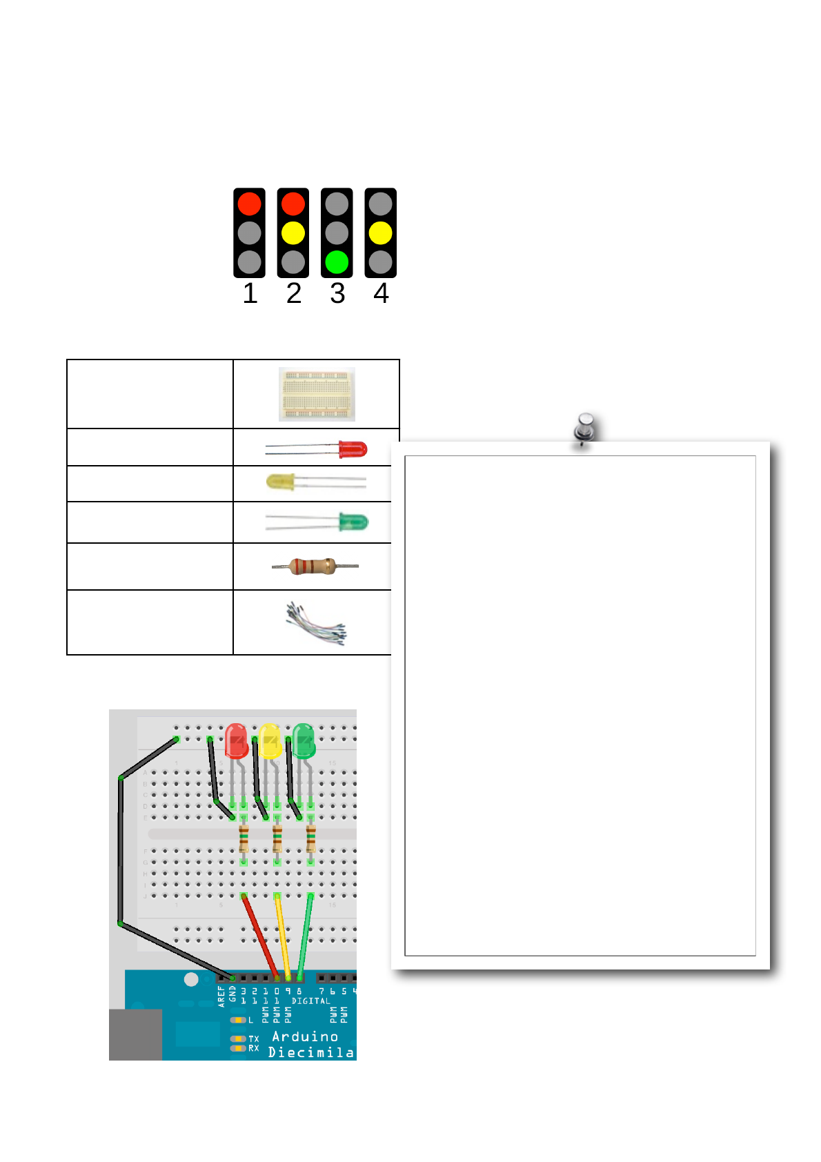
Earthshine Design Arduino Starters Kit Manual - A Complete Beginners Guide to the Arduino
32
Project 3 - Traffic Lights
We are now going to create a set of UK traffic lights
that will change from green to red, via amber, and
back again, after a set
length of time using the
4-state system. This
project could be used
on a model railway to
make a set of working
traffic lights or for a
childʼs toy town.
What you will need
Breadboard
Red Diffused LED
Yellow Diffused LED
Green Diffused LED
3 x 220Ω Resistors
Jumper Wires
Connect it up
This time we have connected 3 LEDʼs with the Anode
of each one going to Digital Pins 8, 9 and 10, via a
220Ω resistor each.
We have taken a jumper wire from Ground to the
Ground rail at the top of the breadboard and a ground
wire goes from the Cathode leg of each LED to the
common ground rail.
Enter the code
Enter the following code, check it and upload.
If youʼve read up on Projects 1 & 2 then this code will
be self explanatory as will the hardware.
In the next project, we are going add to this project by
including a set of pedestrian lights and adding a push
button to make the lights interactive.
// Project 3 - Traffic Lights
int ledDelay = 10000; // delay in between changes
int redPin = 10;
int yellowPin = 9;
int greenPin = 8;
void setup() {
pinMode(redPin, OUTPUT);
pinMode(yellowPin, OUTPUT);
pinMode(greenPin, OUTPUT);
}
void loop() {
// turn the red light on
digitalWrite(redPin, HIGH);
delay(ledDelay); // wait 5 seconds
digitalWrite(yellowPin, HIGH); // turn on yellow
delay(2000); // wait 2 seconds
digitalWrite(greenPin, HIGH); // turn green on
digitalWrite(redPin, LOW); // turn red off
digitalWrite(yellowPin, LOW); // turn yellow off
delay(ledDelay); // wait ledDelay milliseconds
digitalWrite(yellowPin, HIGH); // turn yellow on
digitalWrite(greenPin, LOW); // turn green off
delay(2000); // wait 2 seconds
digitalWrite(yellowPin, LOW); // turn yellow off
// now our loop repeats
}

Earthshine Design Arduino Starters Kit Manual - A Complete Beginners Guide to the Arduino
33
Project 4
Interactive Traffic Lights
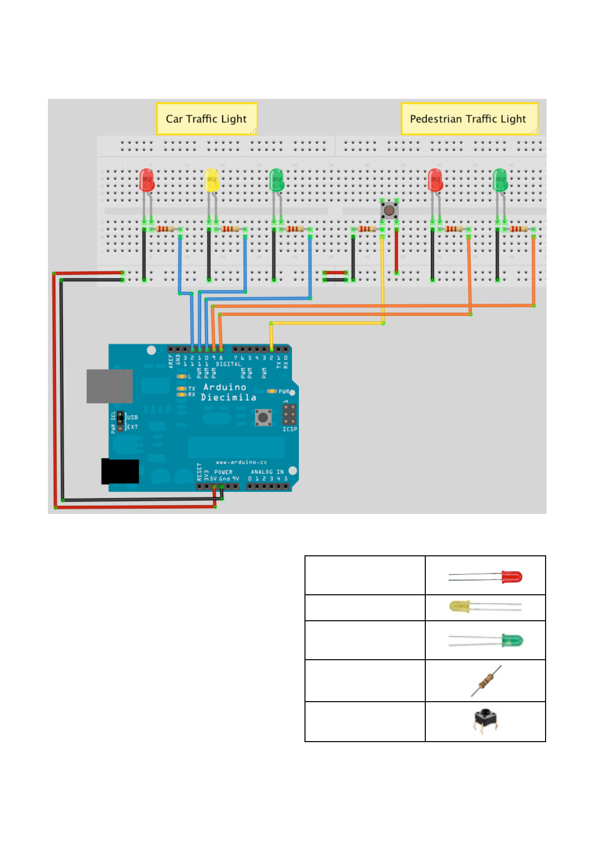
Earthshine Design Arduino Starters Kit Manual - A Complete Beginners Guide to the Arduino
34
Project 4 - Interactive Traffic Lights
This time we are going to extend the previous project
to include a set of pedestrian lights and a pedestrian
push button to request to cross the road. The Arduino
will react when the button is pressed by changing the
state of the lights to make the cars stop and allow the
pedestrian to cross safely.
For the first time we are able to interact with the
Arduino and cause it to do something when we
change the state of a button that the Arduino is
watching (i.e. Press it to change the state from open to
closed). In this project we will also learn how to create
our own functions.
From now on when connecting the components we
will no longer list the breadboard and jumper wires.
Just take it as read that you will always need both of
those.
What you will need
2 x Red Diffused
LEDʼs
Yellow Diffused LED
2 x Green Diffused
LEDʼs
6 x 150Ω Resistors
Tactile Switch

Earthshine Design Arduino Starters Kit Manual - A Complete Beginners Guide to the Arduino
35
Connect it up
Connect the LEDʼs and the switch up as in the
diagram on the previous page. You will need to shuffle
the wires along from pins 8, 9 and 10 in the previous
project to pins 10, 11 and 12 to allow you to connect
the pedestrian lights to pins 8 and 9.
Enter the code
Enter the code on the next page, verify and upload it.
When you run the program you will see that the car
traffic light starts on green to allow cars to pass and
the pedestrian light is on red.
When you press the button, the program checks that
at least 5 seconds have gone by since the last time
the lights were changed (to allow traffic to get moving),
and if so passes code execution to the function we
have created called changeLights(). In this function
the car lights go from green to amber then red, then
the pedestrian lights go green. After a period of time
set in the variable crossTime (time enough to allow the
pedestrians to cross) the green pedestrian light will
flash on and off as a warning to the pedestrians to get
a hurry on as the lights are about to change back to
red. Then the pedestrian light changes back to red
and the vehicle lights go from red to amber to green
and the traffic can resume.
The code in this project is similar to the previous
project. However, there are a few new statements and
concepts that have been introduced so letʼs take a
look at those.

Earthshine Design Arduino Starters Kit Manual - A Complete Beginners Guide to the Arduino
36
// Project 4 - Interactive Traffic Lights
int carRed = 12; // assign the car lights
int carYellow = 11;
int carGreen = 10;
int pedRed = 9; // assign the pedestrian lights
int pedGreen = 8;
int button = 2; // button pin
int crossTime = 5000; // time allowed to cross
unsigned long changeTime; // time since button pressed
void setup() {
pinMode(carRed, OUTPUT);
pinMode(carYellow, OUTPUT);
pinMode(carGreen, OUTPUT);
pinMode(pedRed, OUTPUT);
pinMode(pedGreen, OUTPUT);
pinMode(button, INPUT); // button on pin 2
// turn on the green light
digitalWrite(carGreen, HIGH);
digitalWrite(pedRed, HIGH);
}
void loop() {
int state = digitalRead(button);
/* check if button is pressed and it is
over 5 seconds since last button press */
if (state == HIGH && (millis() - changeTime) > 5000) {
// Call the function to change the lights
changeLights();
}
}
void changeLights() {
digitalWrite(carGreen, LOW); // green off
digitalWrite(carYellow, HIGH); // yellow on
delay(2000); // wait 2 seconds
digitalWrite(carYellow, LOW); // yellow off
digitalWrite(carRed, HIGH); // red on
delay(1000); // wait 1 second till its safe
digitalWrite(pedRed, LOW); // ped red off
digitalWrite(pedGreen, HIGH); // ped green on
delay(crossTime); // wait for preset time period
// flash the ped green
for (int x=0; x<10; x++) {
digitalWrite(pedGreen, HIGH);
delay(250);
digitalWrite(pedGreen, LOW);
delay(250);
}
// turn ped red on
digitalWrite(pedRed, HIGH);
delay(500);
digitalWrite(carYellow, HIGH); // yellow on
digitalWrite(carRed, LOW); // red off
delay(1000);
digitalWrite(carGreen, HIGH);
digitalWrite(carYellow, LOW); // yellow off
// record the time since last change of lights
changeTime = millis();
// then return to the main program loop
}

Earthshine Design Arduino Starters Kit Manual - A Complete Beginners Guide to the Arduino
37
Project 4 - Code Overview
Most of the code in this project you will understand
and recognise from previous projects. However, let us
take a look at a few new keywords and concepts that
have been introduced in this sketch.
unsigned long changeTime;
Here we have a new data type for a variable.
Previously we have created integer data types, which
can store a number between -32,768 and 32,767. This
time we have created a data type of long, which can
store a number from -2,147,483,648 to 2,147,483,647.
However, we have specified an unsigned long, which
means the variable cannot store negative numbers,
which gives us a range from 0 to 4,294,967,295. If we
were to use an integer to store the length of time since
the last change of lights, we would only get a
maximum time of 32 seconds before the integer
variable reached a number higher than it could store.
As a pedestrian crossing is unlikely to be used every
32 seconds we donʼt want our program crashing due
to our variable ʻoverflowingʼ when it tries to store a
number too high for the variable data type. That is why
we use an unsigned long data type as we now get a
huge length of time in between button presses.
4294967295 * 1ms = 4294967 seconds
4294967 seconds = 71582 minutes
71582 minutes - 1193 hours
1193 hours - 49 days
As it is pretty inevitable that a pedestrian crossing will
get itʼs button pressed at least once in 49 days we
shouldnʼt have a problem with this data type.
You may well ask why we donʼt just have one data
type that can store huge numbers all the time and be
done with it. Well, the reason we donʼt do that is
because variables take up space in memory and the
larger the number the more memory is used up for
storing variables. On your home PC or laptop you
wonʼt have to worry about that much at all, but on a
small microcontroller like the Atmega328 that the
Arduino uses it is essential that we use only the
smallest variable data type necessary for our purpose.
There are various data types that we can use as our
sketches and these are:-
Data type
RAM
Number Range
void keyword
N/A
N/A
boolean
1 byte
0 to 1 (True or False)
byte
1 byte
0 to 255
char
1 byte
-128 to 127
unsigned char
1 byte
0 to 255
int
2 byte
-32,768 to 32,767
unsigned int
2 byte
0 to 65,535
word
2 byte
0 to 65,535
long
4 byte
-2,147,483,648 to
2,147,483,647
unsigned long
4 byte
0 to 4,294,967,295
float
4 byte
-3.4028235E+38 to
3.4028235E+38
double
4 byte
-3.4028235E+38 to
3.4028235E+38
string
1 byte + x
Arrays of chars
array
1 byte + x
Collection of variables
Each data type uses up a certain amount of memory
on the Arduino as you can see on the chart above.
Some variables use only 1 byte of memory and others
use 4 or more (donʼt worry about what a byte is for
now as we will discuss this later). You can not copy
data from one data type to another, e.g. If x was an int
and y was a string then x = y would not work as the
two data types are different.
The Atmega168 has 1Kb (1000 bytes) and the
Atmega328 has 2Kb (2000 bytes) of SRAM. This is
not a lot and in large programs with lots of variables
you could easily run out of memory if you do not
optimise your usage of the correct data types. From
the list above we can clearly see that our use of the int
data type is wasteful as it uses up 2 bytes and can
store a number up to 32,767. As we have used int to
store the number of our digital pin, which will only go
as high as 13 on our Arduino (and up to 54 on the
Arduino Mega), we have used up more memory than
was necessary. We could have saved memory by
using the byte data type, which can store a number
between 0 and 255, which is more than enough to
store the number of an I/O pin.

Earthshine Design Arduino Starters Kit Manual - A Complete Beginners Guide to the Arduino
38
Next we have
pinMode(button, INPUT);
This tells the Arduino that we want to use Digital Pin 2
(button = 2) as in INPUT. We are going to use pin 2 to
listen for button presses so itʼs mode needs to be set
to input.
In the main program loop we check the state of digital
pin 2 with this statement:-
int state = digitalRead(button);
This initialises an integer( yes itʼs wasteful and we
should use a boolean) called ʻstateʼ and then sets the
value of state to be the value of the digital pin 2. The
digitalRead statement reads the state of the digital
pin within the parenthesis and returns it to the integer
we have assigned it to. We can then check the value
in state to see if the button has been pressed or not.
if (state == HIGH && (millis() - changeTime) >
5000) {
// Call the function to change the lights
changeLights();
}
The if statement is an example of a control structure
and itʼs purpose is to check if a certain condition has
been met or not and if so to execute the code within
itʼs code block. For example, if we wanted to turn an
LED on if a variable called x rose above the value of
500 we could write
if (x>500) {digitalWrite(ledPin, HIGH);
When we read a digital pin using the digitalRead
command, the state of the pin will either be HIGH or
LOW. So the if command in our sketch looks like this
if (state == HIGH && (millis() - changeTime) >
5000)
What we are doing here is checking that two
conditions have been met. The first is that the variable
called state is high. If the button has been pressed
state will be high as we have already set it to be the
value read in from digital pin 2. We are also checking
that the value of millis()-changeTime is greater
than 5000 (using the logical AND command &&). The
millis() function is one built into the Arduino language
and it returns the number of milliseconds since the
Arduino started to run the current program. Our
changeTime variable will initially hold no value, but
after the changeLights) function has ran we set it at
the end of that function to the current millis()
value.
By subtracting the value in the changeTime variable
from the current millis() value we can check if 5
seconds have passed since changeTime was last set.
The calculation of millis()-changeTime is put
inside itʼs own set of parenthesis to ensure that we
compare the value of state and the result of this
calculation and not the value of millis() on its own.
The symbol ʻ&&’ in between
state == HIGH
and the calculation is an example of a Boolean
Operator. In this case it means AND. To see what we
mean by that, letʼs take a look at all of the Boolean
Operators.
&&!Logical AND
||!Logical OR
!!NOT
These are logic statements and can be used to test
various conditions in if statements.
&& means true if both operands are true, e.g. :
if (x==5 && y==10) {....
This if statement will run itʼs code only if x is 5 and
also y is 10.
|| means true if either operand is true, e.g. :
if (x==5 || y==10) {.....
This will run if x is 5 or if y is 10.
The ! or NOT statement means true if the operand is
false, e.g. :
if (!x) {.......
Will run if x is false, i.e. equals zero.
You can also ʻnestʼ conditions with parenthesis, for
example
if (x==5 && (y==10 || z==25)) {.......
In this case, the conditions within the parenthesis are
processed separately and treated as a single condition
and then compared with the second condition. So, if
we draw a simple truth table for this statement we can
see how it works.

Earthshine Design Arduino Starters Kit Manual - A Complete Beginners Guide to the Arduino
39
x
y
z
True/False?
4
9
25
FALSE
5
10
24
TRUE
7
10
25
FALSE
5
10
25
TRUE
The command within the if statement is
changeLights();
and this is an example of a function call. A function is
simply a separate code block that has been given a
name. However, functions can be passed parameters
and/or return data too. In this case we have not
passed any data to the function nor have we had the
function return any date. We will go into more detail
later on about passing parameters and returning data
from functions.
When changeLights(); is called, the code execution
jumps from the current line to the function, executes
the code within that function and then returns to the
point in the code after where the function was called.
So, in this case, if the conditions in the if statement
are met, then the program executes the code within
the function and then returns to the next line after
changeLights(); in the if statement.
The code within the function simply changes the
vehicles lights to red, via amber, then turns on the
green pedestrian light. After a period of time set by the
variable crossTime the light flashes a few time to
warn the pedestrian that his time is about to run out,
then the pedestrian light goes red and the vehicle light
goes from red to green, via amber and returns to itʼs
normal state.
The main program loop simply checks continuously if
the pedestrian button has been pressed or not and if it
has, and (&&) the time since the lights were last
changed is greater than 5 seconds, it calls the
changeLights() function again.
In this program there was no benefit from putting the
code into itʼs own function apart from making the code
look cleaner. It is only when a function is passed
parameters and/or returns data that their true benefits
come to light and we will take a look at that later on.
Next, we are going to use a lot more LEDʼs as we
make a ʻKnight Riderʼ style LED chase effect.

Earthshine Design Arduino Starters Kit Manual - A Complete Beginners Guide to the Arduino
40
Project 5
LED Chase Effect
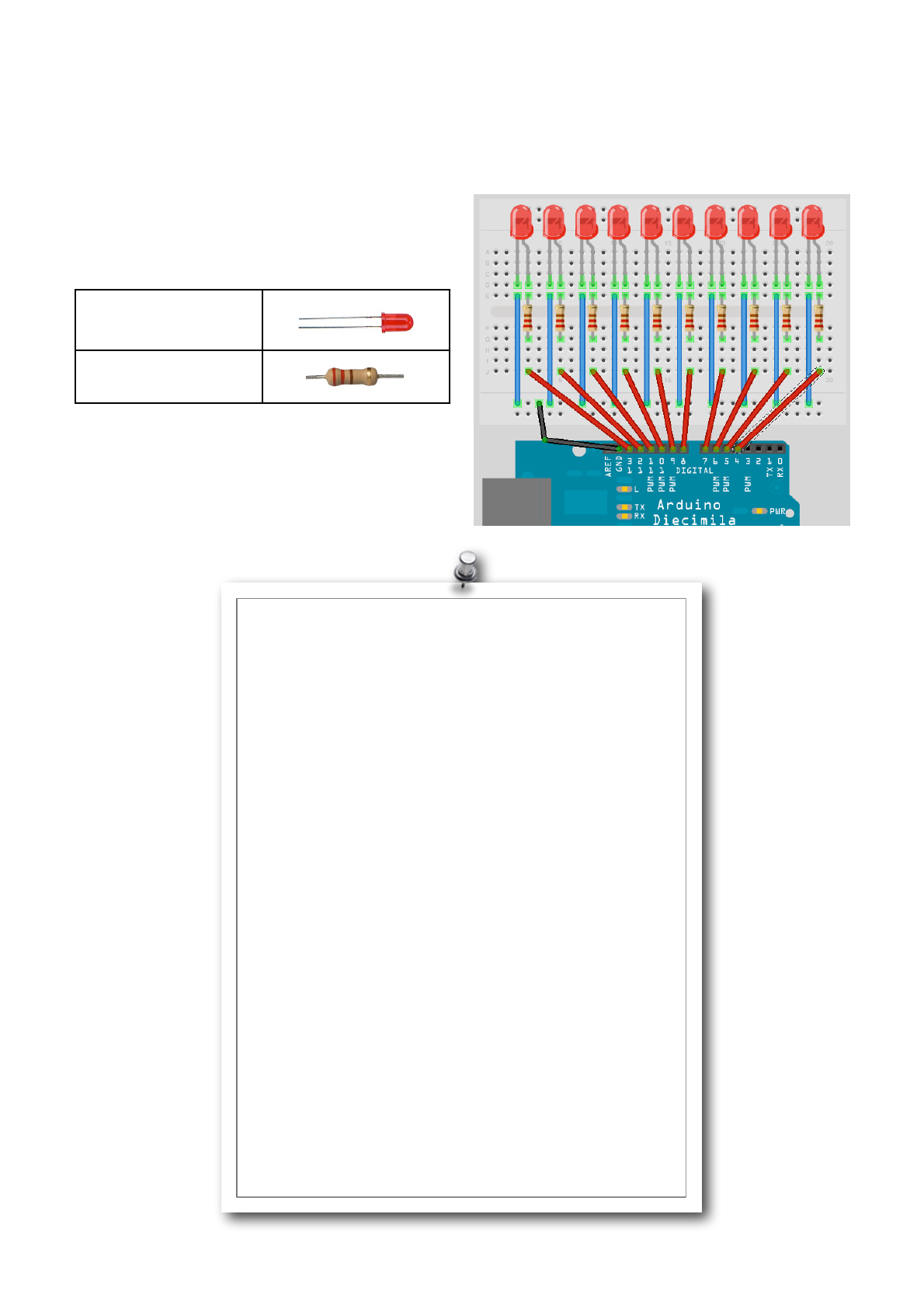
Earthshine Design Arduino Starters Kit Manual - A Complete Beginners Guide to the Arduino
41
Project 5 - LED Chase Effect
We are now going to use a string of LEDʼs (10 in total)
to make an LED chase effect, similar to that used on
the car KITT in the Knightrider TV Series and on the
way introduce the concept of arrays.
What you will need
10 x Red Diffused
LEDʼs
10 x 220Ω Resistors
Connect it up
Enter the code
// Project 5 - LED Chase Effect
// Create array for LED pins
byte ledPin[] = {4, 5, 6, 7, 8, 9, 10, 11, 12, 13};
int ledDelay(65); // delay between changes
int direction = 1;
int currentLED = 0;
unsigned long changeTime;
void setup() {
// set all pins to output
for (int x=0; x<10; x++) {
pinMode(ledPin[x], OUTPUT); }
changeTime = millis();
}
void loop() {
// if it has been ledDelay ms since last change
if ((millis() - changeTime) > ledDelay) {
changeLED();
changeTime = millis();
}
}
void changeLED() {
// turn off all LED's
for (int x=0; x<10; x++) {
digitalWrite(ledPin[x], LOW);
}
// turn on the current LED
digitalWrite(ledPin[currentLED], HIGH);
// increment by the direction value
currentLED += direction;
// change direction if we reach the end
if (currentLED == 9) {direction = -1;}
if (currentLED == 0) {direction = 1;}
}

Earthshine Design Arduino Starters Kit Manual - A Complete Beginners Guide to the Arduino
42
Project 5 - Code Overview
Our very first line in this sketch is
byte ledPin[] = {4, 5, 6, 7, 8, 9, 10, 11, 12,
13};
and this is a declaration of a variable of data type
array. An array is a collection of variables that are
accessed using an index number. In our sketch we
have declared an array of data type byte and called it
ledPin. We have then initialised the array with 10
values, which are the digital pins 4 through to 13. To
access an element of the array we simply refer to the
index number of that element. Arrays are zero
indexed, which simply means that the first index starts
at zero and not 1. So in our 10 element array the index
numbers are 0 to 9.
In this case, element 3 (ledPin[2]) has the value of
6 and element 7 (ledPin[6]) has a value of 10.
You have to tell the size of the array if you do not
initialise it with data first. In our sketch we did not
explicitly choose a size as the compiler is able to
count the values we have assigned to the array to
work out that the size is 10 elements. If we had
declared the array but not initialised it with values at
the same time, we would need to declare a size, for
example we could have done this:
byte ledPin[10];
and then loaded data into the elements later on. To
retrieve a value from the array we would do something
like this:
x = ledpin[5];
In this example x would now hold a value of 8. To get
back to your program, we have started off by declaring
and initialising an array and have stored 10 values that
are the digital pins used for the outputs to our 10
LEDʼs.
In our mail loop we check that at least ledDelay milli-
seconds have passed since the last change of LEDʼs
and if so it passes control to our function. The reason
we are only going to pass control to the changeLED()
function in this way, rather than using delay()
commands, is to allow other code if needed to run in
the main program loop (as long as that code takes
less than ledDelay to run.
The function we created is
void changeLED() {
// turn off all LED's
for (int x=0; x<10; x++) {
digitalWrite(ledPin[x], LOW);
}
// turn on the current LED
digitalWrite(ledPin[currentLED], HIGH);
// increment by the direction value
currentLED += direction;
// change direction if we reach the end
if (currentLED == 9) {direction = -1;}
if (currentLED == 0) {direction = 1;}
}
and the job of this function is to turn all LEDʼs off and
then turn on the current LED (this is done so fast you
will not see it happening), which is stored in the
variable currentLED.
This variable then has direction added to it. As
direction can only be either a 1 or a -1 then the
number will either increase (+1) or decrease by one
(currentLED +(-1)).
We then have an if statement to see if we have
reached the end of the row of LEDʼs and if so we then
reverse the direction variable.
By changing the value of ledDelay you can make the
LED ping back and forth at different speeds. Try
different values to see what happens.
However, you have to stop the program and manually
change the value of ledDelay then upload the
amended code to see any changes. Wouldnʼt it be
nice to be able to adjust the speed whilst the program
is running? Yes it would, so letʼs do exactly that in the
next project by introducing a way to interact with the
program and adjust the speed using a potentiometer.

Earthshine Design Arduino Starters Kit Manual - A Complete Beginners Guide to the Arduino
43
Project 6
Interactive LED Chase Effect
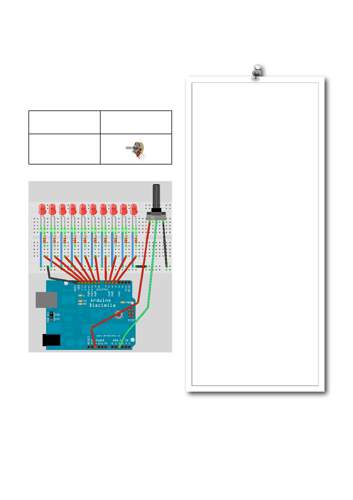
Earthshine Design Arduino Starters Kit Manual - A Complete Beginners Guide to the Arduino
44
Project 6 - Interactive LED Chase Effect
We are now going to use a string of LEDʼs (10 in total)
to make an LED chase effect, similar to that used on
the car KITT in the Knightrider TV Series and on the
way introduce the concept of arrays.
What you will need
Parts from previous
project plus....
4K7 Potentiometer
Connect it up
This is the same circuit as in Project 5, but we have
simply added the potentiometer and connected it to
5v, Ground and Analog Pin 5.
Enter the code
This time when verify and upload your code, you
should now see the lit LED appear to bounce back
and forth between each end of the string of lights as
before. But, by turning the knob of the potentiometer,
you will change the value of ledDelay and speed up
or slow down the effect.
Letʼs take a look at how this works and find our what a
potentiometer is.
// Create array for LED pins
byte ledPin[] = {4, 5, 6, 7, 8, 9, 10,
11, 12, 13};
int ledDelay; // delay between changes
int direction = 1;
int currentLED = 0;
unsigned long changeTime;
int potPin = 2; // select the input
pin for the potentiometer
void setup() {
// set all pins to output
for (int x=0; x<10; x++) {
pinMode(ledPin[x], OUTPUT); }
changeTime = millis();
}
void loop() {
// read the value from the pot
ledDelay = analogRead(potPin);
// if it has been ledDelay ms since
last change
if ((millis() - changeTime) >
ledDelay) {
changeLED();
changeTime = millis();
}
}
void changeLED() {
// turn off all LED's
for (int x=0; x<10; x++) {
digitalWrite(ledPin[x], LOW);
}
// turn on the current LED
digitalWrite(ledPin[currentLED],
HIGH);
// increment by the direction value
currentLED += direction;
// change direction if we reach the
end
if (currentLED == 9) {direction =
-1;}
if (currentLED == 0) {direction = 1;}
}

Earthshine Design Arduino Starters Kit Manual - A Complete Beginners Guide to the Arduino
45
Project 6 - Code Overview
// Create array for LED pins
byte ledPin[] = {4, 5, 6, 7, 8, 9, 10, 11,
12, 13};
int ledDelay; // delay between changes
int direction = 1;
int currentLED = 0;
unsigned long changeTime;
int potPin = 2; // select the input pin
for the potentiometer
void setup() {
// set all pins to output
for (int x=0; x<10; x++) {
pinMode(ledPin[x], OUTPUT); }
changeTime = millis();
}
void loop() {
// read the value from the pot
ledDelay = analogRead(potPin);
// if it has been ledDelay ms since last
change
if ((millis() - changeTime) > ledDelay) {
changeLED();
changeTime = millis();
}
}
void changeLED() {
// turn off all LED's
for (int x=0; x<10; x++) {
digitalWrite(ledPin[x], LOW);
}
// turn on the current LED
digitalWrite(ledPin[currentLED], HIGH);
// increment by the direction value
currentLED += direction;
// change direction if we reach the end
if (currentLED == 9) {direction = -1;}
if (currentLED == 0) {direction = 1;}
}
The code for this Project is almost identical to the
previous project. We have simply added a
potentiometer to our hardware and the code has
additions to enable us to read the values from the
potentiometer and use them to adjust the speed of the
LED chase effect.
We first declare a variable for the potentiometer pin
int potPin = 2;
as our potentiometer is connected to analog pin 2. To
read the value from an analog pin we use the
analogRead command. The Arduino has 6 analog
input/outputs with a 10-bit analog to digital convertor
(we will discuss bits later on). This means the analog
pin can read in voltages between 0 to 5 volts in integer
values between 0 (0 volts) and 1023 (5 volts). This
gives a resolution of 5 volts / 1024 units or 0.0049
volts (4.9mV) per unit.
We need to set our delay using the potentiometer so
we will simply use the direct values read in from the
pin to adjust the delay between 0 and 1023
milliseconds. We do this by directly reading the value
of the potentiometer pin into ledDelay. Notice that we
do not need to set an analog pin to be an input or
output like we need to with a digital pin.
ledDelay = analogRead(potPin);
This is done during our main loop and therefore it is
constantly being read and adjusted. By turning the
knob you can adjust the delay value between 0 and
1023 milliseconds (or just over a second) and
therefore have full control over the speed of the effect.
OK letʼs find out what a potentiometer is and how it
works.
Earthshine Design Arduino Starters Kit Manual - A Complete Beginners Guide to the Arduino
46
Project 6 - Hardware Overview
The only additional piece of hardware used in this
project was the 4K7 (4700Ω)
potentiometer.
You have already come
across a resistor and know
how they work. The
potentiometer is simply an
adjustable resistor with a range
from 0 to a set value (written on
the side of the pot). In the kit you
have been given a 4K7 or 4,700Ω potentiometer which
means itʼs range is from 0 to 4700 Ohms.
The potentiometer has 3 legs. By connecting up just
two legs the potentiometer becomes a variable
resistor. By connecting all 3 legs and applying a
voltage across it, the pot becomes a voltage divider.
This is how we have used it in our circuit. One side is
connected to ground, the other to 5v and the centre
pin to our analog pin. By adjusting the knob, a voltage
between 0 and 5v will be leaked from the centre pin
and we can read the value of that voltage on Analog
Pin 2 and use itʼs value to change the delay rate of the
light effect.
The potentiometer can be very useful in providing a
means of adjusting a value from 0 to a set amount,
e.g. the volume of a radio or the brightness of a lamp.
In fact, dimmer switches for your home lamps are a
kind of potentiometer.
Exercises
1. Get the LEDʼs at BOTH ends of the strip to start as on, then to both
move towards each other, appear to bounce off each other and
then move back to the end.
2. Make a bouncing ball effect by making the LED start at one end,
ʻdropʼ toward the other end, bounce back up, but to only go up 9
spaces, bounce, go up 8 spaces, then 7, then 6, etc. To give the
effect it is a bouncing ball, getting bouncing up to a lower height on
each bounce.

Earthshine Design Arduino Starters Kit Manual - A Complete Beginners Guide to the Arduino
47
Project 7
Pulsating Lamp
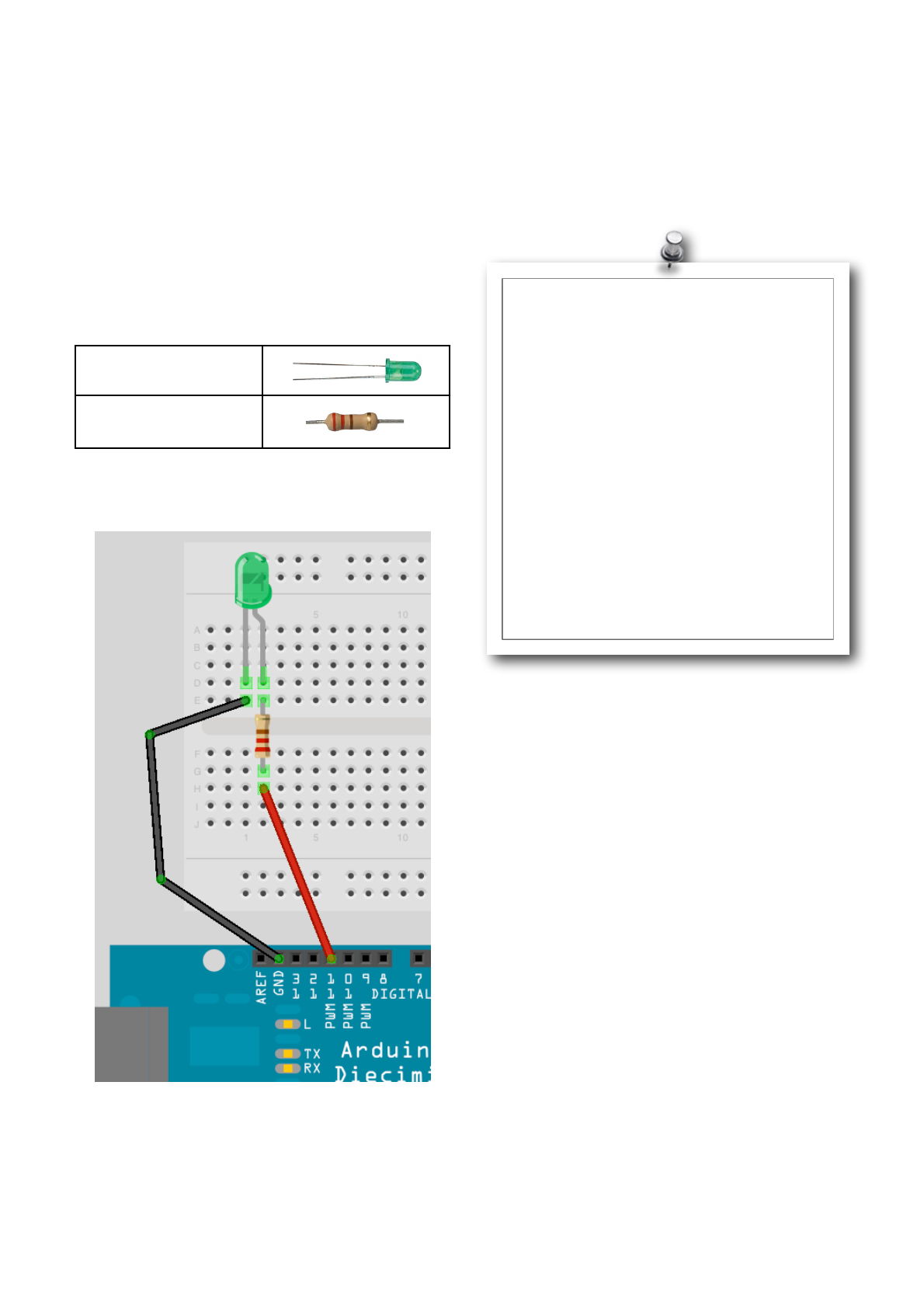
Earthshine Design Arduino Starters Kit Manual - A Complete Beginners Guide to the Arduino
48
Project 7 - Pulsating Lamp
We are now going to delve further into a more
advanced method of controlling LEDʼs. So far we have
simply turned the LED on or off. How about being able
to adjust itʼs brightness too? Can we do that with an
Arduino? Yes we can.
Time to go back to basics.
What you will need
Green Diffused LED
220Ω Resistor
Connect it up
Enter the code
Enter this simple program.
Verify and upload. You will now see your LED pulsate
on and off steadily. Instead of a simple on/off state we
are now adjusting itʼs brightness. Letʼs find out how
this works.
// Project 7 - Pulsating lamp
int ledPin = 11;
float sinVal;
int ledVal;
void setup() {
pinMode(ledPin, OUTPUT);
}
void loop() {
for (int x=0; x<180; x++) {
// convert degrees to radians
// then obtain sin value
sinVal = (sin(x*(3.1412/180)));
ledVal = int(sinVal*255);
analogWrite(ledPin, ledVal);
delay(25);
}
}

Earthshine Design Arduino Starters Kit Manual - A Complete Beginners Guide to the Arduino
49
Project 7 - Code Overview
The code for this project is very simple, but requires
some explanation.
// Project 7 - Pulsating lamp
int ledPin = 11;
float sinVal;
int ledVal;
void setup() {
pinMode(ledPin, OUTPUT);
}
void loop() {
for (int x=0; x<180; x++) {
// convert degrees to radians
// then obtain sin value
sinVal = (sin(x*(3.1412/180)));
ledVal = int(sinVal*255);
analogWrite(ledPin, ledVal);
delay(25);
}
}
We first set up the variables for the LED Pin, a float
(floating point data type) for a sine wave value and
ledVal which will hold the integer value to send out to
Pin 11.
The concept here is that we are creating a sine wave
and having the brightness of the LED follow the path
of that wave. This is what makes the light pulsate in
that way instead of just fade up to full brightness and
back down again.
We use the sin() function, which is a mathematical
function to work out the sine of an angle. We need to
give the function the degree in radians. We have a for
loop that goes from 0 to 179, we donʼt want to go past
halfway as this will take us into negative values and
the brightness value we need to put out to Pin 11
needs to be from 0 to 255 only.
The sin() function requires the angle to be in radians
and not degrees so the equation of x*(3.1412/180) will
convert the degree angle into radians. We then
transfer the result to ledVal, multiplying it by 255 to
give us our value. The result from the sin() function will
be a number between -1 and 1 so we need to multiply
that by 255 to give us our maximum brightness. We
ʻcastʼ the floating point value of sinVal into an integer
by the use of int() in the statement
ledVal = int(sinVal*255);
Then we send that value out to Digital Pin 11 using the
statement
analogWrite(ledPin, ledVal);
But, how can we send an analog value to a digital pin?
Well, if we take a look at our Arduino and look at the
Digital Pins you can see that 6 of those pins (3, 5, 6, 9,
10 & 11) have PWM written next to them. Those pins
differ from the remaining digital pins in that they are
able to send out a PWM signal.
PWM stands for Pulse Width Modulation. PWM is a
technique for getting analog results from digital
means. On these pins the Arduino sends out a square
wave by switching the pin on and off very fast. The
pattern of on/offs can simulate a varying voltage
between 0 and 5v. It does this by changing the amount
of time that the output remains high (on) versus off
(low). The duration of the on time is known as the
ʻPulse Widthʼ.
For example, if you were to send the value 0 out to Pin
11 using analogWrite() the ON period would be zero,
or it would have a 0% Duty Cycle. If you were to send
a value of 64 (25% of the maximum of 255) the pin
would be ON for 25% of the time and OFF for 75% of
the time. The value of 191 would have a Duty Cycle of
75% and a value of 255 would have a duty cycle of
100%. The pulses run at a speed of approx. 500Hz or
2 milliseconds each.
So, from this we can see in our sketch that the LED is
being turned on and off very fast. If the Duty Cycle
was 50% (a value of 127) then the LED would pulse
on and off at 500Hz and would display at half the
maximum brightness. It is basically an illusion that we
can use to our advantage by allowing us to use the
digital pins to output a simulated analog value to our
LEDʼs.
Note that even though only 6 of the pins have the
PWM function, you can easily write software to give a
PWM output from all of the digital pins if you wish.
Later on we will revisit PWM as we can utilise it to
create audible tones using a piezo sounder.

Earthshine Design Arduino Starters Kit Manual - A Complete Beginners Guide to the Arduino
50
Project 8
Mood Lamp
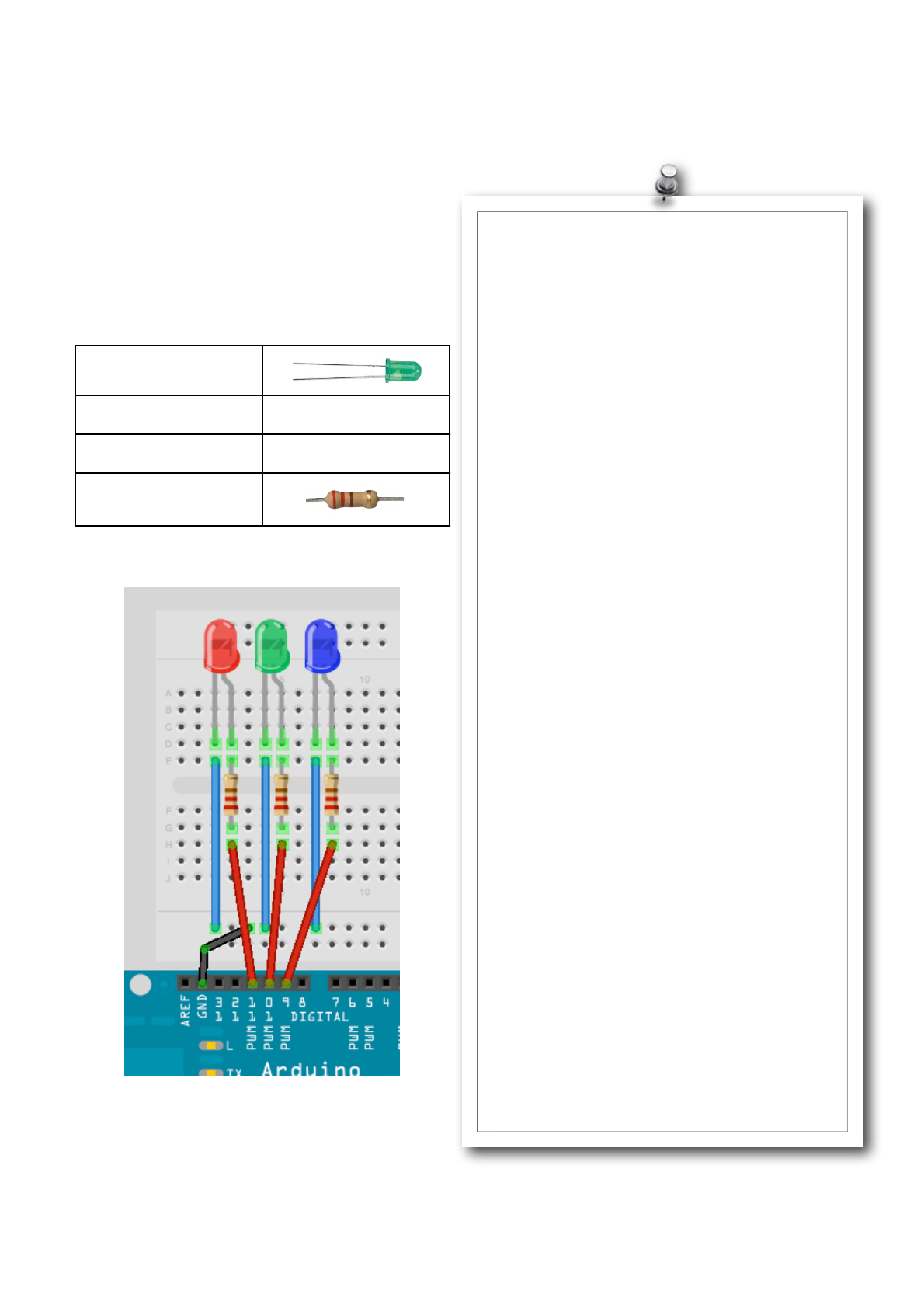
Earthshine Design Arduino Starters Kit Manual - A Complete Beginners Guide to the Arduino
51
Project 8 - Mood Lamp
In the last project we saw that we could adjust the
brightness of an LED using the PWM capabilities of
the Atmega chip. We will now take advantage of this
capability by using a red, green and blue LED and by
mixing their colours to create any colour we wish.
From that, we will create a mood lamp similar to the
kind you see for sale all over the place nowadays.
What you will need
Red Clear LED
Green Clear LED
Blue Clear LED
3 x 220Ω Resistor
Connect it up
Get a piece of paper about A5 size, roll it into a
cylinder then tape it so it remains that way. Then place
the cylinder over the top of the 3 LEDʼs.
Enter the code
When you run this you will see the colours slowly
change. Youʼve just made youʼre own mood lamp.
// Project 8 - Mood Lamp
float RGB1[3];
float RGB2[3];
float INC[3];
int red, green, blue;
int RedPin = 11;
int GreenPin = 10;
int BluePin = 9;
void setup()
{
Serial.begin(9600);
randomSeed(analogRead(0));
RGB1[0] = 0;
RGB1[1] = 0;
RGB1[2] = 0;
RGB2[0] = random(256);
RGB2[1] = random(256);
RGB2[2] = random(256);
}
void loop()
{
randomSeed(analogRead(0));
for (int x=0; x<3; x++) {
INC[x] = (RGB1[x] - RGB2[x]) / 256; }
for (int x=0; x<256; x++) {
red = int(RGB1[0]);
green = int(RGB1[1]);
blue = int(RGB1[2]);
analogWrite (RedPin, red);
analogWrite (GreenPin, green);
analogWrite (BluePin, blue);
delay(100);
RGB1[0] -= INC[0];
RGB1[1] -= INC[1];
RGB1[2] -= INC[2];
}
for (int x=0; x<3; x++) {
RGB2[x] = random(556)-300;
RGB2[x] = constrain(RGB2[x], 0, 255);
delay(1000);
}
}
Earthshine Design Arduino Starters Kit Manual - A Complete Beginners Guide to the Arduino
52
Project 8 - Code Overview
The LEDʼs that make up the mood lamp are red, green
and blue. In the same way that your computer monitor
is made up of tiny red, green and blue (RGB) dots, the
map can generate different colours by adjusting the
brightness of each of the 3 LEDʼs in such a way to
give us a different RGB value.
An RGB value of 255, 0, 0 would give us pure red. A
value of 0, 255, 0 would give pure green and 0, 0, 255
pure blue. By mixing these we can get any colour we
like with This is the additive colour model. If you were
just turn the LEDʼs ON or OFF (i.e. Not have different
brightnesses) you would still get different colours as in
this table.
Red
Green
Blue
Colour
255
0
0
Red
0
255
0
Green
0
0
255
Blue
255
255
0
Yellow
0
255
255
Cyan
255
0
255
Magenta
255
255
255
White
By adjusting the brightnesses using PWM we can get
every other colour in between too. By placing the
LEDʼs close together and by mixing their values, the
light spectra of the 3 colours added together make a
single colour. By diffusing the light with our paper
cylinder we ensure the colours are mixed nicely. The
LEDʼs can be placed into any object that will diffuse
the light or you can bounce the light off a reflective
diffuser. Try putting the lights inside a ping pong ball or
a small white plastic bottle (the thinner the plastic the
better).
The total range of colours we can get using PWM with
a range of 0 to 255 is 16,777, 216 colours
(256x256x256) which is way more than we would ever
need.
In the code, we start off by declaring some floating
point arrays and also some integer variables that will
store our RGB values as well as an increment value.
float RGB1[3];
float RGB2[3];
float INC[3];
int red, green, blue;
In the setup function we have
randomSeed(analogRead(0));
The randomSeed command is used for creating
random (actually pseudo-random) numbers. Computer
chips are not able to produce truly random numbers
so they tend to look at data in a part of itʼs memory
that may differ or look at a table of different values and
use those as a pseudo-random number. By setting a
ʻseedʼ, you can tell the computer where in memory or
in that table to start counting from. In this case the
value we give to the randomSeed is a value read from
Analog Pin 0. As we donʼt have anything connected to
Analog Pin 0 all we will read is a random number
created by analog noise.
Once we have set a ʻseedʼ for our random number we
can create one using the random() function. We then
have two sets of RGB values stored in a 3 element
array. RGB1 is the RGB values we want the lamp to
start with (in this case all zeros or off).
RGB1[0] = 0;
RGB1[1] = 0;
RGB1[2] = 0;
Then the RGB2 array is a set of random RGB values
that we want the lamp to transition to,
RGB2[0] = random(256);
RGB2[1] = random(256);
RGB2[2] = random(256);
In this case we have set them to a random number set
by random(256) which will give is a number between 0
and 255 inclusive (as the number will always range
from zero upwards).
If you pass a single number to the random() function
then it will return a value between 0 and 1 less than
the number, e.g. random(1000) will return a number
between 0 and 999. If you supply two numbers as itʼs
parameters then it will return a random number
between the lower number inclusive and the maximum
number (-1). E.g. random(10,100) will return a random
number between 10 and 99.
In the main program loop we first take a look at the
start and end RGB values and work out what value is
needed as an increment to progress from one value to
the other in 256 steps (as the PWM value can only be
between 0 and 255). We do this with
for (int x=0; x<3; x++) {
INC[x] = (RGB1[x] - RGB2[x]) / 256; }

Earthshine Design Arduino Starters Kit Manual - A Complete Beginners Guide to the Arduino
53
This for loop sets the INCrement values for the R, G
and B channels by working out the difference between
the two brightness values and dividing that by 256.
We then have another for loop
for (int x=0; x<256; x++) {
red = int(RGB1[0]);
green = int(RGB1[1]);
blue = int(RGB1[2]);
analogWrite (RedPin, red);
analogWrite (GreenPin, green);
analogWrite (BluePin, blue);
delay(100);
RGB1[0] -= INC[0];
RGB1[1] -= INC[1];
RGB1[2] -= INC[2];
}
and this sets the red, green and blue values to the
values in the RGB1 array, writes those values to pins
9, 10 and 11, then deducts the increment value then
repeats this process 256 times to slowly fade from one
random colour to the next. The delay of 100ms in
between each step ensures a slow and steady
progression. You can of course adjust this value if you
want it slower or faster or you can add a potentiometer
to allow the user to set the speed.
After we have taken 256 slow steps from one random
colour to the next, the RGB1 array will have the same
values (nearly) as the RGB2 array. We now need to
decide upon another set of 3 random values ready for
the next time. We do this with another for loop
for (int x=0; x<3; x++) {
RGB2[x] = random(556)-300;
RGB2[x] = constrain(RGB2[x], 0, 255);
delay(1000);
}
The random number is chosen by picking a random
number between 0 and 556 (256+300) and then
deducting 300. The reason we do that is to try and
force primary colours from time to time to ensure we
donʼt always just get pastel shades. We have 300
chances out of 556 in getting a negative number and
therefore forcing a bias towards one or more of the
other two colour channels. The next command makes
sure that the numbers sent to the PWM pins are not
negative by using the constrain() function.
The constrain function requires 3 parameters - x, a
and b as in constrain(x, a, b) where x is the number
we want to constrain, a is the lower end of the range
and b is the higher end. So, the constrain functions
looks at the value of x and makes sure it is within the
range of a to b. If it is lower than a then it sets it to a, if
it is higher than b it sets it to b. In our case we make
sure that the number is between 0 and 255 which is
the range or our PWM output.
As we use random(556)-300 for our RGB values,
some of those values will be lower than zero and the
constrain function makes sure that the value sent to
the PWM is not lower than zero.
Forcing a bias towards one or more of the other two
channels ensures more vibrant and less pastel shades
of colour and also ensures that from time to time one
or more channels are turned off completely giving a
more interesting change of lights (or moods).
Exercise
See if you can make the lights cycle through the colours of the
rainbow rather than between random colours.

Earthshine Design Arduino Starters Kit Manual - A Complete Beginners Guide to the Arduino
54
Project 9
LED Fire Effect
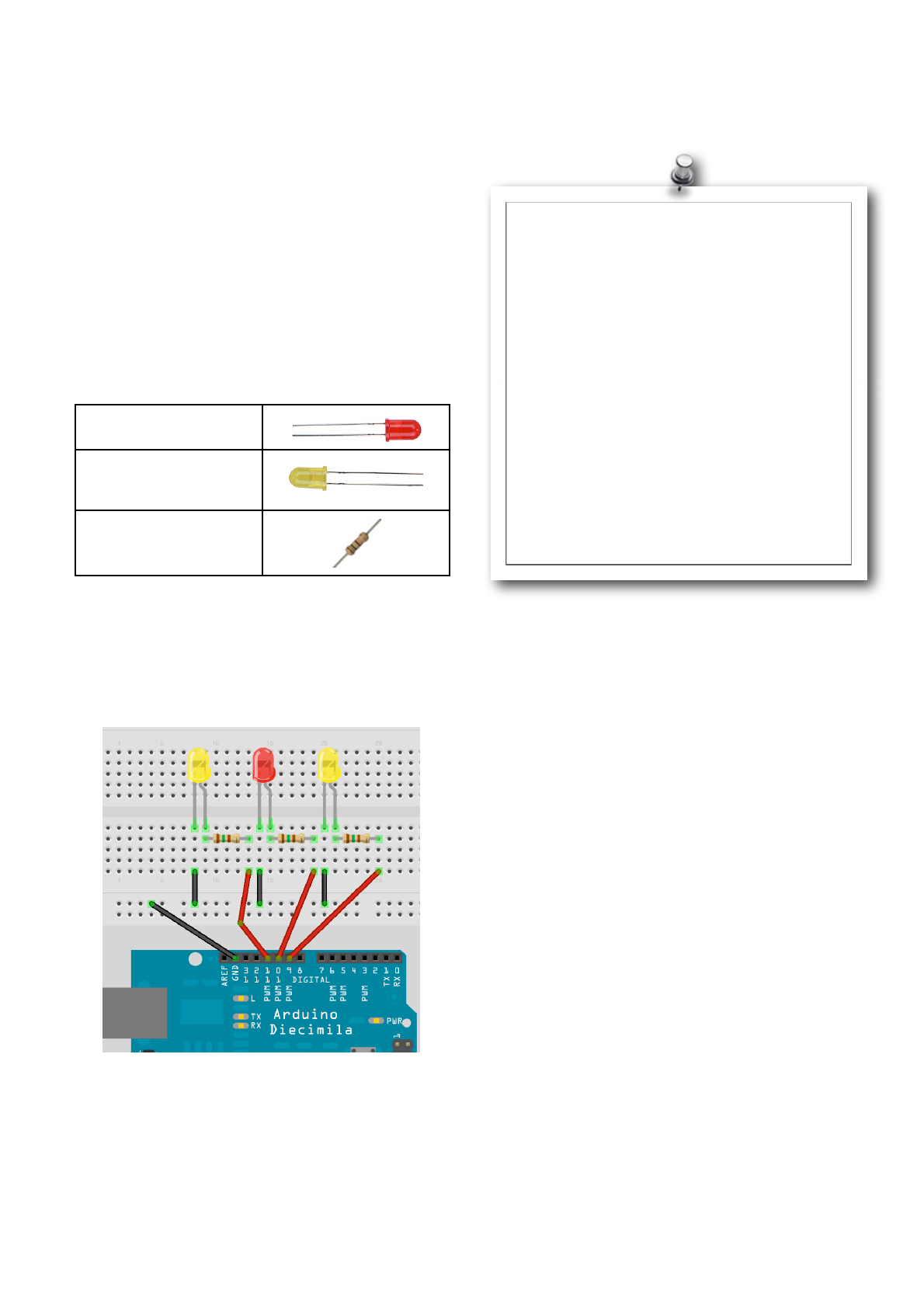
Earthshine Design Arduino Starters Kit Manual - A Complete Beginners Guide to the Arduino
55
Project 9 - LED Fire Effect
Project 9 will use LEDʼs and a flickering random light
effect, using PWM again, to recreate the effect of a
flickering flame. If you were to place these LEDʼs
inside a model house on a model railway layout, for
example, you could create a special effect of the
house being on fire, or you could place it into a fake
fireplace in your house to give a fire effect. This is a
simple example of how LEDʼs can be used to create
SFX for movies, stage plays, model dioramaʼs, model
railways, etc.
What you will need
Red Diffused LED
2 x Yellow Diffused
LEDʼs
3 x 150Ω Resistor
Connect it up
Now, first make sure that your Arduino is powered off.
You can do this either by unplugging the USB cable or
by taking out the Power Selector Jumper on the
Arduino board. Then connect everything up like this :-
When you are happy that everything is connected up
correctly, power up your Arduino and connect the USB
cable.
Enter the code
Now, open up the Arduino IDE and type in the
following code :-
Now press the Verify/Compile button at the top of the
IDE to make sure there are no errors in your code. If
this is successful you can now click the Upload button
to upload the code to your Arduino.
If you have done everything right you should now see
the LEDʼs flickering in a random manner to simulate a
flame or fire effect.
Now letʼs take a look at the code and the hardware
and find out how they both work.
// Project 9 - LED Fire Effect
int ledPin1 = 9;
int ledPin2 = 10;
int ledPin3 = 11;
void setup()
{
pinMode(ledPin1, OUTPUT);
pinMode(ledPin2, OUTPUT);
pinMode(ledPin3, OUTPUT);
}
void loop()
{
analogWrite(ledPin1, random(120)+135);
analogWrite(ledPin2, random(120)+135);
analogWrite(ledPin3, random(120)+135);
delay(random(100));
}

Earthshine Design Arduino Starters Kit Manual - A Complete Beginners Guide to the Arduino
56
Project 9 - Code Overview
// Project 9 - LED Fire Effect
int ledPin1 = 9;
int ledPin2 = 10;
int ledPin3 = 11;
void setup()
{
pinMode(ledPin1, OUTPUT);
pinMode(ledPin2, OUTPUT);
pinMode(ledPin3, OUTPUT);
}
void loop()
{
analogWrite(ledPin1, random(120)+135);
analogWrite(ledPin2, random(120)+135);
analogWrite(ledPin3, random(120)+135);
delay(random(100));
}
So letʼs take a look at the code for this project. First
we declare and initialise some integer variables that
will hold the values for the Digital Pins we are going to
connect our LEDʼs to.
int ledPin1 = 9;
int ledPin2 = 10;
int ledPin3 = 11;
We then set them up to be outputs.
pinMode(ledPin1, OUTPUT);
pinMode(ledPin2, OUTPUT);
pinMode(ledPin3, OUTPUT);
The main program loop then sends out a random
value between 0 and 120, and then add 135 to it to get
full LED brightness, to the PWM pins 9, 10 and 11.
analogWrite(ledPin1, random(120)+135);
analogWrite(ledPin2, random(120)+135);
analogWrite(ledPin3, random(120)+135);
Then finally we have a random delay between on and
100ms.
delay(random(100));
The main loop then starts again causing the flicker
light effect you can see.
Bounce the light off a white card or a mirror onto your
wall and you will see a very realistic flame effect.
As the hardware is simple and we should understand
it by now we will jump right into Project 10.
Exercises
1. Using a blue LED or two, see if you can recreate the effect of the
flashes of light from an arc welder.
2. Using a Blue and Red LED recreate the effect of the lights on an
emergency vehicle.

Earthshine Design Arduino Starters Kit Manual - A Complete Beginners Guide to the Arduino
57
Project 10
Serial Controlled Mood Lamp

Earthshine Design Arduino Starters Kit Manual - A Complete Beginners Guide to the Arduino
58
Project 10 - Serial Controlled Mood Lamp
We will now use the same circuit as in Project 9, but will now delve into the world of serial communications and
control our lamp by sending commands from the PC to the Arduino using the Serial Monitor in the Arduino IDE.
This project also introduces how we manipulate text strings. So leave the hardware set up the same as before
and enter the new code.
Enter the code
// Project 10 - Serial controlled RGB Lamp
char buffer[18];
int red, green, blue;
int RedPin = 11;
int GreenPin = 10;
int BluePin = 9;
void setup()
{
Serial.begin(9600);
Serial.flush();
pinMode(RedPin, OUTPUT);
pinMode(GreenPin, OUTPUT);
pinMode(BluePin, OUTPUT);
}
void loop()
{
if (Serial.available() > 0) {
int index=0;
delay(100); // let the buffer fill up
int numChar = Serial.available();
if (numChar>15) {
numChar=15;
}
while (numChar--) {
buffer[index++] = Serial.read();
}
splitString(buffer);
}
}
void splitString(char* data) {
Serial.print("Data entered: ");
Serial.println(data);
char* parameter;
parameter = strtok (data, " ,");
while (parameter != NULL) {
setLED(parameter);
parameter = strtok (NULL, " ,");
}
// Clear the text and serial buffers
for (int x=0; x<16; x++) {
buffer[x]='\0';
}
Serial.flush();
}
(continued on next page.......)

Earthshine Design Arduino Starters Kit Manual - A Complete Beginners Guide to the Arduino
59
(continued from previous page.......)
void setLED(char* data) {
if ((data[0] == 'r') || (data[0] == 'R')) {
int Ans = strtol(data+1, NULL, 10);
Ans = constrain(Ans,0,255);
analogWrite(RedPin, Ans);
Serial.print("Red is set to: ");
Serial.println(Ans);
}
if ((data[0] == 'g') || (data[0] == 'G')) {
int Ans = strtol(data+1, NULL, 10);
Ans = constrain(Ans,0,255);
analogWrite(GreenPin, Ans);
Serial.print("Green is set to: ");
Serial.println(Ans);
}
if ((data[0] == 'b') || (data[0] == 'B')) {
int Ans = strtol(data+1, NULL, 10);
Ans = constrain(Ans,0,255);
analogWrite(BluePin, Ans);
Serial.print("Blue is set to: ");
Serial.println(Ans);
}
}
Once youʼve verified the code, upload it to your
Arduino.
Now when you upload the program nothing seems to
happen. This is because the program is waiting for
your input. Start the Serial Monitor by clicking itʼs icon
in the Arduino IDE taskbar.
In the Serial Monitor text window you can now enter
the R, G and B values for each of the 3 LEDʼs
manually and the LEDʼs will change to the colour you
have input.
E.g. If you enter R255 the Red LED will display at full
brightness.
If you enter R255, G255, then both the red and green
LEDʼs will display at full brightness.
Now enter R127, G100, B255 and you will get a nice
purplish colour.
If you type, r0, g0, b0 all the LEDʼs will turn off.
The input text is designed to accept both a lower-
case or upper-case R, G and B and then a value
from 0 to 255. Any values over 255 will be dropped
down to 255 maximum. You can enter a comma or a
space in between parameters and you can enter 1, 2
or 3 LED values at any one time.
E.g.
r255 b100
r127 b127 g127
G255, B0
B127, R0, G255
Etc.

Earthshine Design Arduino Starters Kit Manual - A Complete Beginners Guide to the Arduino
60
Project 10 - Code Overview
This project introduces a whole bunch of new
concepts, including serial communication, pointers
and string manipulation. So, hold on to your hats this
will take a lot of explaining.
First we set up an array of char (characters) to hold
our text string. We have made it 18 characters long,
whichis longer than the maximum of 16 we will allow
to ensure we donʼt get “buffer overflow” errors.
char buffer[18];
We then set up the integers to hold the red, green
and blue values as well as the values for the digital
pins.
int red, green, blue;
int RedPin = 11;
int GreenPin = 10;
int BluePin = 9;
In our setup function we set the 3 digital pins to be
outputs. But, before that we have the Serial.begin
command.
void setup()
{
Serial.begin(9600);
Serial.flush();
pinMode(RedPin, OUTPUT);
pinMode(GreenPin, OUTPUT);
pinMode(BluePin, OUTPUT);
}
Serial.begin tells the Arduino to start serial
communications and the number within the
parenthesis, in this case 9600, sets the baud rate
(characters per second) that the serial line will
communicate at.
The Serial.flush command will flush out any
characters that happen to be in the serial line so that
it is empty and ready for input/output.
The serial communications line is simply a way for
the Arduino to communicate with the outside world, in
this case to and from the PC and the Arduino IDEʼs
Serial Monitor.
In the main loop we have an if statement. The
condition it is checking for is
if (Serial.available() > 0) {
The Serial.available command checks to see if any
characters have been sent down the serial line. If any
characters have been received then the condition is
met and the code within the if statements code block
is now executed.
if (Serial.available() > 0) {
int index=0;
delay(100); // let the buffer fill up
int numChar = Serial.available();
if (numChar>15) {
numChar=15;
}
while (numChar--) {
buffer[index++] = Serial.read();
}
splitString(buffer);
}
}
An integer called index is declared and initialised as
zero. This integer will hold the position of a pointer to
the characters within the char array.
We then set a delay of 100. The purpose of this is to
ensure that the serial buffer (the place in memory
where the serial data that is received is stored prior
to processing) is full before we carry on and process
the data. If we donʼt do that, it is possible that the
function will execute and start to process the text
string, before we have received all of the data. The
serial communications line is very slow compared to
the speed the rest of the code is executing at. When
you send a string of characters the Serial.available
function will immediately have a value higher than
zero and the if function will start to execute. If we
didnʼt have the delay(100) statement in there it could
start to execute the code within the if statement
before all of the text string had been received and the
serial data may only be the first few characters of the
line of text entered.
After we have waited for 100ms for the serial buffer
to fill up with the data sent, we then declare and
initialise the numChar integer to be the number of
characters within the text string.
E.g. If we sent this text in the Serial Monitor:
R255, G255, B255
Then the value of numChar would be 17. It is 17 and
not 16 as at the end of each line of text there is an
invisible character called a NULL character. This is a
ʻnothingʼ symbol and simply tells the Arduino that the
end of the line of text has been reached.
The next if statement checks if the value of numChar
is greater than 15 or not and if so it sets it to be 15.
This ensures that we donʼt overflow the array char
buffer[18];

Earthshine Design Arduino Starters Kit Manual - A Complete Beginners Guide to the Arduino
61
After this comes a while command. This is something
we havenʼt come across before so let me explain.
We have already used the for loop, which will loop a
set number of times. The while statement is also a
loop, but one that executes only while a condition is
true.
The syntax is
while(expression) {
!// statement(s)
}
In our code the while loop is
while (numChar--) {
buffer[index++] = Serial.read();
}
The condition it is checking is simply numChar, so in
other words it is checking that the value stored in the
integer numChar is not zero. numChar has -- after it.
This is what is known as a post-decrement. In other
words, the value is decremented AFTER it is used. If
we had used --numChar the value in numChar would
be decremented (have one subtracted from it) before
it was evaluated. In our case, the while loop checks
the value of numChar and then subtracts one from it.
If the value of numChar was not zero before the
decrement, it then carries out the code within its code
block.
numChar is set to the length of the text string that we
have entered into the Serial Monitor window. So, the
code within the while loop will execute that many
times.
The code within the while loop is
buffer[index++] = Serial.read();
Which sets each element of the buffer array to each
character read in from the Serial line. In other words,
it fills up the buffer array with the letters we have
entered into the Serial Monitorʼs text window.
The Serial.read() command reads incoming serial
data, one byte at a time.
So now that our character array has been filled with
the characters we entered in the Serial Monitor the
while loop will end once numChar reaches zero (i.e.
The length of the string).
After the while loop we have
splitString(buffer);
Which is a call to one of the two functions we have
created and called splitString(). The function looks
like this:
void splitString(char* data) {
Serial.print("Data entered: ");
Serial.println(data);
char* parameter;
parameter = strtok (data, " ,");
while (parameter != NULL) {
setLED(parameter);
parameter = strtok (NULL, " ,");
}
// Clear the text and serial buffers
for (int x=0; x<16; x++) {
buffer[x]='\0';
}
Serial.flush();
}
We can see that the function returns no data, hence
itʼs data type has been set to void. We pass the
function one parameter and that is a char data type
that we have called data. However, in the C and C++
programming languages you are not allowed to send
a character array to a function. We have got around
that by using a pointer. We know we have used a
pointer as an asterisk ʻ*ʼ has been added to the
variable name *data. Pointers are quite an advanced
subject in C so we wonʼt go into too much detail
about them. All you need to know for now is that by
declaring ʻdataʼ as a pointer it is simply a variable that
points to another variable.
You can either point it to the address that the variable
is stored within memory by using the & symbol, or in
our case, to the value stored at that memory address
using the * symbol. We have used it to ʻcheatʼ the
system, as we are not allowed to send a character
array to a function. However we are allowed to send
a pointer to a character array to our function. So, we
have declared a variable of data type Char and called
it data, but the * symbol before it means that it is
ʻpointing toʼ the value stored within the ʻbufferʼ
variable.
When we called splitString we sent it the contents of
ʻbufferʼ (actually a pointer to it as we saw above).
splitString(buffer);
So we have called the function and passed it the
entire contents of the buffer character array.
The first command is

Earthshine Design Arduino Starters Kit Manual - A Complete Beginners Guide to the Arduino
62
Serial.print("Data entered: ");
and this is our way of sending data back from the
Arduino to the PC. In this case the print command
sends whatever is within the parenthesis to the PC,
via the USB cable, where we can read it in the Serial
Monitor window. In this case we have sent the words
“Data entered: “. Text must be enclosed within quotes
“”. The next line is similar
Serial.println(data);
and again we have sent data back to the PC, this
time we send the char variable called data. The Char
type variable we have called ʻdataʼ is a copy of the
contents of the ʻbufferʼ character array that we
passed to the function. So, if our text string entered
was
R255 G127 B56
Then the
Serial.println(data);
Command will send that text string back to the PC
and print it out in the Serial Monitor window (make
sure you have enabled the Serial Monitor window
first).
This time the print command has ln on the end to
make it println. This simply means ʻprintʼ with a
ʻlinefeedʼ.
When we print using the print command, the cursor
(the point at where the next symbol will appear)
remains at the end of whatever we have printed.
When we use the println command a linefeed
command is issued or in other words the text prints
and then the cursor drops down to the next line.
Serial.print("Data entered: ");
Serial.println(data);
If we look at our two print commands, the first one
prints out “Data entered: “ and then the cursor
remains at the end of that text. The next print
command will print ʻdataʼ, or in other words the
contents of the array called ʻbufferʼ and then issue a
linefeed, or drop the cursor down to the next line.
This means that if we issue another print or println
statement after this whatever is printed in the Serial
Monitor window will appear on the next line
underneath the last.
We then create a new char data type called
parameter
Char* parameter;
and as we are going to use this variable to access
elements of the ʻdataʼ array it must be the same type,
hence the * symbol. You cannot pass data from one
data type type variable to another as the data must
be converted first. This variable is another example
of one that has ʻlocal scopeʼ. It can be ʻseenʼ only by
the code within this function. If you try to access the
parameter variable outside of the splitString function
you will get an error.
We then use a strtok command, which is a very
useful command to enable us to manipulate text
strings. Strtok gets itʼs name from String and Token
as itʼs purpose is to split a string using tokens. In our
case the token it is looking for is a space or a
comma. It is used to split text strings into smaller
strings.
We pass the ʻdataʼ array to the strtok command as
the first argument and the tokens (enclosed within
quotes) as the second argument. Hence
parameter = strtok (data, " ,");
And it splits the string at that point. So we are using it
to set ʻparameterʼ to be the part of the string up to a
space or a comma.
So, if our text string was
R127 G56 B98
Then after this statement the value of ʻparameterʼ will
be
R127
as the strtok command would have split the string up
to the first occurrence of a space of a comma.
After we have set the variable ʻparameterʼ to the part
of the text string we want to strip out (i.e. The bit up
to the first space or comma) we then enter a while
loop whose condition is that parameter is not empty
(i.e. We havenʼt reached the end of the string) using
while (parameter != NULL) {
Within the loop we call our second function
setLED(parameter);

Earthshine Design Arduino Starters Kit Manual - A Complete Beginners Guide to the Arduino
63
Which we will look at later on. Then it sets the
variable ʻparameterʼ to the next part of the string up
to the next space or comma. We do this by passing
to strtok a NULL parameter
parameter = strtok (NULL, " ,");
This tells the strtok command to carry on where it last
left off.
So this whole part of the function
char* parameter;
parameter = strtok (data, " ,");
while (parameter != NULL) {
setLED(parameter);
parameter = strtok (NULL, " ,");
}
is simply stripping out each part of the text string that
is separated by spaces or commas and sending that
part of the string to the next function called setLED().
The final part of this function simply fills the buffer
array with NULL character, which is done with the /0
symbol and then flushes the Serial data out of the
Serial buffer ready for the next set of data to be
entered.
// Clear the text and serial buffers
for (int x=0; x<16; x++) {
buffer[x]='\0';
}
Serial.flush();
The setLED function is going to take each part of the
text string and set the corresponding LED to the
colour we have chosen. So, if the text string we enter
is
!G125 B55
Then the splitString() function splits that into the two
separate components
!G125
!B55
and send that shortened text string onto the setLED()
function, which will read it, decide what LED we have
chosen and set it to the corresponding brightness
value.
So letʼs take a look at the second function called
setLED().
void setLED(char* data) {
if ((data[0] == 'r') || (data[0] == 'R'))
{
int Ans = strtol(data+1, NULL, 10);
Ans = constrain(Ans,0,255);
analogWrite(RedPin, Ans);
Serial.print("Red is set to: ");
Serial.println(Ans);
}
if ((data[0] == 'g') || (data[0] == 'G'))
{
int Ans = strtol(data+1, NULL, 10);
Ans = constrain(Ans,0,255);
analogWrite(GreenPin, Ans);
Serial.print("Green is set to: ");
Serial.println(Ans);
}
if ((data[0] == 'b') || (data[0] == 'B'))
{
int Ans = strtol(data+1, NULL, 10);
Ans = constrain(Ans,0,255);
analogWrite(BluePin, Ans);
Serial.print("Blue is set to: ");
Serial.println(Ans);
}
}
We can see that this function contains 3 very similar
if statements. We will therefore take a look at just one
of them as the other 2 are almost identical.
if ((data[0] == 'r') || (data[0] == 'R')) {
int Ans = strtol(data+1, NULL, 10);
Ans = constrain(Ans,0,255);
analogWrite(RedPin, Ans);
Serial.print("Red is set to: ");
Serial.println(Ans);
}
The if statement checks that the first character in the
string data[0] is either the letter r or R (upper case
and lower case characters are totally different as far
as C is concerned. We use the logical OR command
whose symbol is || to check if the letter is an r OR an
R as either will do.
If it is an r or an R then the if statement knows we
wish to change the brightness of the Red LED and so
the code within executes. First we declare an integer
called Ans (which has scope local to the setLED
function only) and use the strtol (String to long
integer) command to convert the characters after the
letter R to an integer. The strtol command takes 3
parameters and these are the string we are passing
it, a pointer to the character after the integer (which
we donʼt use as we have already stripped the string
using the strtok command and hence pass a NULL
character) and then the ʻbaseʼ, which in our case is
base 10 as we are using normal decimal numbers

Earthshine Design Arduino Starters Kit Manual - A Complete Beginners Guide to the Arduino
64
(as opposed to binary, octal or hexadecimal which
would be base 2, 8 and 16 respectively). So in other
words we declare an integer and set it to the value of
the text string after the letter R (or the number bit).
Next we use the constrain command to make sure
that Ans goes from 0 to 255 and no more. We then
carry out an analogWrite command to the red pin and
send it the value of Ans. The code then sends out
“Red is set to: “ followed by the value of Ans back to
the Serial Monitor. The other two if statements do
exactly the same but for the Green and the Blue
LEDʼs.
We have covered a lot of ground and a lot of new
concepts in this project. To make sure you
understand exactly what is going on in this code I am
going to set the project code side by side with
pseudo-code (an fake computer language that is
essentially the computer language translated into a
language humans can understand).
The C Programming Language
// Project 10 - Serial controlled RGB Lamp
char buffer[18];
int red, green, blue;
int RedPin = 11;
int GreenPin = 10;
int BluePin = 9;
void setup()
{
Serial.begin(9600);
Serial.flush();
pinMode(RedPin, OUTPUT);
pinMode(GreenPin, OUTPUT);
pinMode(BluePin, OUTPUT);
}
void loop()
{
if (Serial.available() > 0) {
int index=0;
delay(100); // let the buffer fill up
int numChar = Serial.available();
if (numChar>15) {
numChar=15;
}
while (numChar--) {
buffer[index++] = Serial.read();
}
splitString(buffer);
}
}
void splitString(char* data) {
Serial.print("Data entered: ");
Serial.println(data);
char* parameter;
parameter = strtok (data, " ,");
while (parameter != NULL) {
setLED(parameter);
parameter = strtok (NULL, " ,");
}
// Clear the text and serial buffers
for (int x=0; x<16; x++) {
buffer[x]='\0';
}
Serial.flush();
}
Continued on next page......
Pseudo-Code
A comment with the project number and name
Declare a character array of 18 letters
Declare 3 integers called red, green and blue
An integer for which pin to use for Red LED
“ “ Green
“ “ Blue
The setup function
Set serial comms to run at 9600 chars per second
Flush the serial line
Set the red led pin to be an output pin
Same for green
And blue
The main program loop
If data is sent down the serial line...
Declare integer called index and set to 0
Wait 100 millseconds
Set numChar to the incoming data from serial
If numchar is greater than 15 characters...
Make it 15 and no more
While numChar is not zero (subtract 1 from it)
Set element[index] to value read in (add 1)
Call splitString function and send it data in
buffer
The splitstring function references buffer data
Print “Data entered: “
Print value of data and then drop down a line
Declare char data type parameter
Set it to text up to the first space or comma
While contents of parameter are not empty..
!Call the setLED function
Set parameter to next part of text string
Another comment
We will do the next line 16 times
Set each element of buffer to NULL (empty)
Flush the serial comms

Earthshine Design Arduino Starters Kit Manual - A Complete Beginners Guide to the Arduino
65
The C Programming Language
(continued from previous page.......)
void setLED(char* data) {
if ((data[0] == 'r') || (data[0] == 'R')) {
int Ans = strtol(data+1, NULL, 10);
Ans = constrain(Ans,0,255);
analogWrite(RedPin, Ans);
Serial.print("Red is set to: ");
Serial.println(Ans);
}
if ((data[0] == 'g') || (data[0] == 'G')) {
int Ans = strtol(data+1, NULL, 10);
Ans = constrain(Ans,0,255);
analogWrite(GreenPin, Ans);
Serial.print("Green is set to: ");
Serial.println(Ans);
}
if ((data[0] == 'b') || (data[0] == 'B')) {
int Ans = strtol(data+1, NULL, 10);
Ans = constrain(Ans,0,255);
analogWrite(BluePin, Ans);
Serial.print("Blue is set to: ");
Serial.println(Ans);
}
}
Pseudo-Code
A function called setLED is passed buffer
If first letter is r or R...
Set integer Ans to number in next part of text
Make sure it is between o and 255
Write that value out to the red pin
Print out “Red is set to: “
And then the value of Ans
If first letter is g or G...
Set integer Ans to number in next part of text
Make sure it is between o and 255
Write that value out to the green pin
Print out “Green is set to: “
And then the value of Ans
If first letter is b or B...
Set integer Ans to number in next part of text
Make sure it is between o and 255
Write that value out to the blue pin
Print out “Blue is set to: “
And then the value of Ans
Hopefully you can use this ʻpseudo-codeʼ to make
sure you understand exactly what is going on in this
projects code.
We are now going to leave LEDʼs behind for a little
while and look at how to makes sounds with your
Arduino.

Earthshine Design Arduino Starters Kit Manual - A Complete Beginners Guide to the Arduino
66
Project 11
Piezo Sounder Melody PLayer

Earthshine Design Arduino Starters Kit Manual - A Complete Beginners Guide to the Arduino
67
Project 11 - Piezo Sounder Melody Player
In this project we are going to use a super simple
circuit to produce sounds from our Arduino using a
Piezo Sounder.
What you will need
Piezo Disc
Terminal Block
Connect it up
When you run this code the
Arduino will play a very nice
(yeah ok itʼs terrible) rendition
of ʻTwinkle Twinkle Little Starʼ.
Sounding very similar to those
annoying birthday cards you
can buy that play a tune when
you open it up.
Letʼs take a look at this code
and see how it works and find
out what a piezo disc is.
(courtesy of http://www.arduino.cc/en/Tutorial/Melody)
// Project 11 - Melody Player
int speakerPin = 9;
int length = 15; // the number of notes
char notes[] = "ccggaagffeeddc "; // a space represents a rest
int beats[] = { 1, 1, 1, 1, 1, 1, 2, 1, 1, 1, 1, 1, 1, 2, 4 };
int tempo = 300;
void playTone(int tone, int duration) {
for (long i = 0; i < duration * 1000L; i += tone * 2) {
digitalWrite(speakerPin, HIGH);
delayMicroseconds(tone);
digitalWrite(speakerPin, LOW);
delayMicroseconds(tone);
}
}
void playNote(char note, int duration) {
char names[] = { 'c', 'd', 'e', 'f', 'g', 'a', 'b', 'C' };
int tones[] = { 1915, 1700, 1519, 1432, 1275, 1136, 1014, 956 };
// play the tone corresponding to the note name
for (int i = 0; i < 8; i++) {
if (names[i] == note) {
playTone(tones[i], duration);
}
}
}
void setup() {
pinMode(speakerPin, OUTPUT);
}
void loop() {
for (int i = 0; i < length; i++) {
if (notes[i] == ' ') {
delay(beats[i] * tempo); // rest
} else {
playNote(notes[i], beats[i] * tempo);
}
// pause between notes
delay(tempo / 2);
}
}

Earthshine Design Arduino Starters Kit Manual - A Complete Beginners Guide to the Arduino
68
Project 11 - Code Overview
In this project we are making sounds using a piezo
disc. A piezo disc can do nothing more than make a
click when we apply a voltage to it. So to get the
tones we can hear out of it we need to make it click
many times a second fast enough that it becomes a
recognisable note.
The program starts off by setting up the variables we
need. The piezo sounders positive (red) cable is
attached to Pin 9.
int speakerPin = 9;
The tune we are going to play is made up of 15
notes.
int length = 15; // the number of notes
The notes of the tune are stored in a character array
as a text string.
char notes[] = "ccggaagffeeddc ";
Another array, this time of integers, is set up to store
the length of each note.
int beats[] = { 1, 1, 1, 1, 1, 1, 2, 1, 1, 1, 1,
1, 1, 2, 4 };
And finally we set a tempo for the tune to be played
at,
int tempo = 300;
Next you will notice that we declare two functions
before our setup() and loop() functions. It doesnʼt
matter if we put our own functions before or after
setup() and loop(). When the program runs, the code
within these two functions will not run before setup()
runs as we have not called those functions yet.
Letʼs look at the setup and loop functions before we
look at the playTone and playNote functions.
All that happens in setup() is we assign the speaker
pin (9) as an output.
void setup() {
pinMode(speakerPin, OUTPUT);
}
In the main program loop we have an if/else
statement inside a for loop.
for (int i = 0; i < length; i++) {
if (notes[i] == ' ') {
delay(beats[i] * tempo); // rest
} else {
playNote(notes[i], beats[i] * tempo);
}
As you can see, the first if statement has as itʼs
condition, that the array element [i] that the element
contains a space character.
if (notes[i] == ' ')
If this is TRUE then the code within itʼs block is
executed.
delay(beats[i] * tempo); // rest
and this simply works out the value of beats[i] *
tempo and causes a delay of that length to cause a
rest in the notes. We then have an else statement.
else {
playNote(notes[i], beats[i] * tempo);
}
After an if statement we can extend it with an else
statement. An else statements is carried out if the
condition within the if statement is false. So, for
example. Letʼs say we had an integer called test and
itʼs value was 10 and this if/else statement:
if (test == 10) {
digitalWrite(ledPin, HIGH)
} else {
digitalWrite(ledPin, LOW)
}
Then if ʻtestʼ had a value of 10 (which it does) the
ledPin would be set to HIGH. If the value of test was
anything other than 10, the code within the else
statement would be carried out instead and the
ledPin would be set to LOW.
The else statement calls a function called playNote
and passes two parameters. The first parameter is
the value of notes[i] and the second is the value
calculated from beats[i] * tempo.
playNote(notes[i], beats[i] * tempo);
After if/else statement has been carried out, there is
a delay whose value is calculated by dividing tempo
by 2.
delay(tempo / 2);
Let us now take a look at the two functions we have
created for this project.

Earthshine Design Arduino Starters Kit Manual - A Complete Beginners Guide to the Arduino
69
The first function that is called from the main program
loop is playNote.
void playNote(char note, int duration) {
char names[] = { 'c', 'd', 'e', 'f', 'g', 'a',
'b', 'C' };
int tones[] = { 1915, 1700, 1519, 1432, 1275,
1136, 1014, 956 };
// play the tone corresponding to the note name
for (int i = 0; i < 8; i++) {
if (names[i] == note) {
playTone(tones[i], duration);
}
}
}
Two parameters have been passed to the function
and within the function these have been given the
names note (character) and duration (integer).
The function sets up a local variable array of data
type char called ʻnamesʼ. This variable has local
scope so is only visible to this function and not
outside of it.
This array stores the names of the notes from middle
C to high C.
We then create another array of data type integer
and this array stores numbers that correspond to the
frequency of the tones, in Kilohertz, of each of the
notes in the names[] array.
int tones[] = { 1915, 1700, 1519, 1432, 1275,
1136, 1014, 956 };
After setting up the two arrays there is a for loop that
looks through the 8 notes in the names[] array and
compares it to the note sent to the function.
for (int i = 0; i < 8; i++) {
if (names[i] == note) {
playTone(tones[i], duration);
}
}
The t une th at i s s ent to this fu nc ti on is
ʻccggaagffeeddc’ so the first note will be a middle C.
The for loop compares that note with the notes in the
names[] array and if there is a match, calls up the
second function, called playTone, to play the
corresponding tone using in the tones[] array using a
note length of ʻdurationʼ.
The second function is called playTone.
void playTone(int tone, int duration) {
for (long i = 0; i < duration * 1000L; i +=
tone * 2) {
digitalWrite(speakerPin, HIGH);
delayMicroseconds(tone);
digitalWrite(speakerPin, LOW);
delayMicroseconds(tone);
}
}
Two parameters are passed to this function. The first
is the tone (in kilohertz) that we want the piezo
speaker to reproduce and the second is the duration
(made up by calculating beats[i] * tempo.
The function starts a for loop
for (long i = 0; i < duration * 1000L; i += tone
* 2)
As each for loop must be of a different length to
make each note the same length (as the delay differs
between clicks to produce the desired frequency) the
for loop will run to ʻdurationʼ multiplied by 1000 and
the increment of the loop is the value of ʻtoneʼ
multiplied by 2.
Inside the for loop we simply make the pin connected
to the piezo speaker go high, wait a short period of
time, then go low, then wait another short period of
time, then repeat.
digitalWrite(speakerPin, HIGH);
delayMicroseconds(tone);
digitalWrite(speakerPin, LOW);
delayMicroseconds(tone);
These repetitive clicks, of different lengths and with
different pauses (of only microseconds in length) in
between clicks, makes the piezo produce a tone of
varying frequencies.
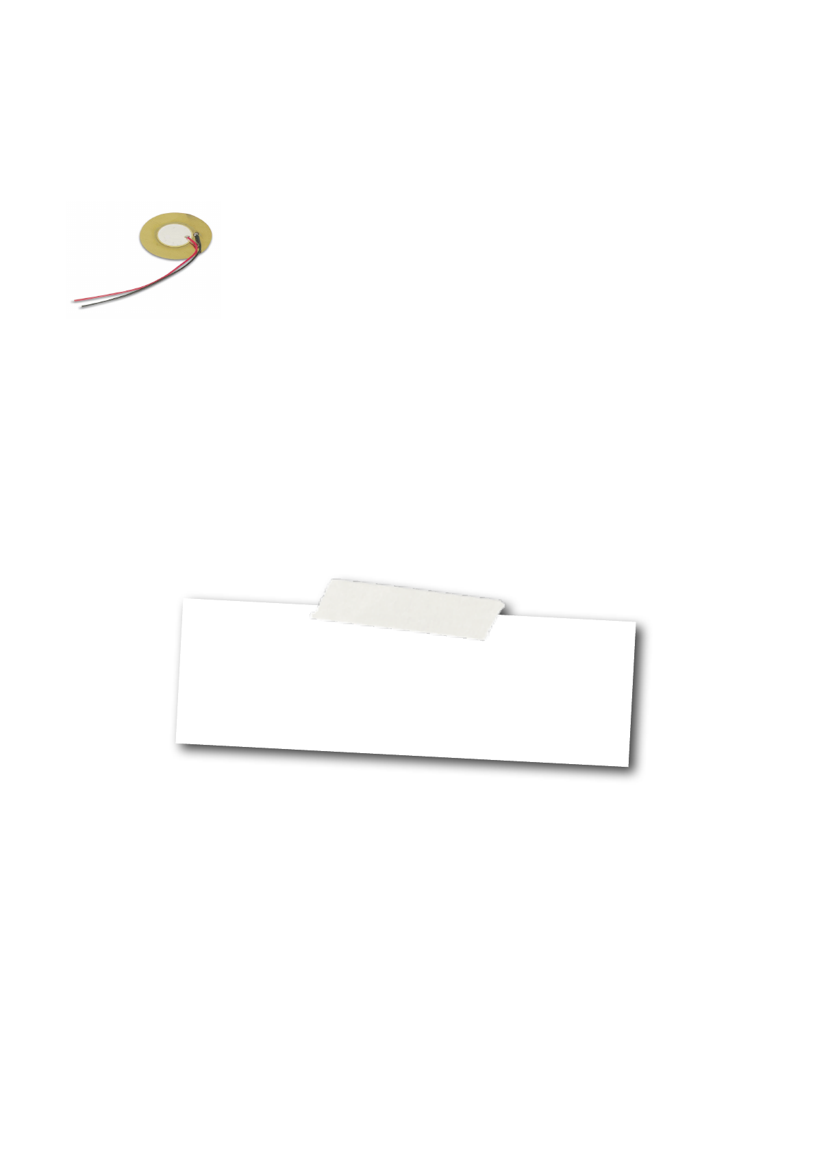
Earthshine Design Arduino Starters Kit Manual - A Complete Beginners Guide to the Arduino
70
Project 11 - Hardware Overview
The only piece of hardware used in this project is a
piezo sounder. This simple device is made up of a
thin layer of ceramic bonded to a metallic disc.
Piezoelectric materials,
which are some crystals
and ceramics, have the
ability to produce
electricity when
mechanical stress is
applied to them. The
effect finds useful
applications such as the
production and detection of sound, generation of high
voltages, electronic frequency generation,
microbalances, and ultra fine focusing of optical
assemblies.
The effect is also reversible, in that if an electric field
is applied across the piezoelectric material it will
cause the material to change shape (by as much as
0.1% in some cases).
To produce sounds from a piezo disc, an electric field
is turned on and off very fast, to make the material
change shape and hence cause a ʻclickʼ as the disc
pops out and back in again (like a tiny drum). By
changing the frequency of the pulses, the disc will
deform hundreds or thousands of times per second
and hence causing the buzzing sound. By changing
the frequency of the clicks and the time in between
them, specific notes can be produced.
You can also use the piezoʼs ability to produce an
electric field to measure movement or vibrations.
Exercise
1. Change the notes and beats to make other tunes such as ʻHappy
Birthdayʼ or ʻMerry Christmasʼ.
2. Write a program to make a rising and falling tone from the piezo,
similar to a car alarm or police siren.

Earthshine Design Arduino Starters Kit Manual - A Complete Beginners Guide to the Arduino
71
Project 12
Serial Temperature Sensor
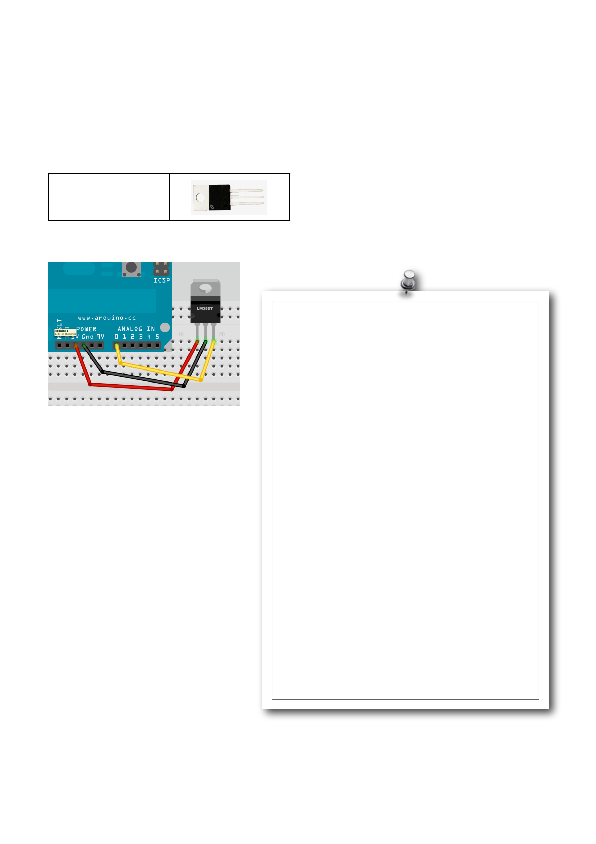
Earthshine Design Arduino Starters Kit Manual - A Complete Beginners Guide to the Arduino
72
Project 12 - Serial Temperature Sensor
Now we are going to make use of the Temperature
Sensor in your kit, the LM35DT. You will need just one
component.
What you will need
LM35DT
Connect it up
Enter the Code
Enter the code, then press the Serial Monitor button
on the Arduino IDE. You will now get a reading every
half a second(ish) that shows the analog reading from
Pin 0 and also the temperature (after conversion) from
the LM35DT sensor.
Leave it a little while to stabilise and then hold the
sensor. You will see the temperature rise as it reads
the temperature of your skin. Hold something cold
against it and see it drop. The sensor can read
between 0 and 100 degrees C.
int potPin = 0;
float temperature = 0;
void setup()
{
Serial.begin(9600);
Serial.println("LM35 Thermometer ");
analogReference(INTERNAL);
}
void printTenths(int value) {
// prints a value of 123 as 12.3
Serial.print(value / 10);
Serial.print(".");
Serial.println(value % 10);
}
void loop() {
int span = 20;
int aRead = 0;
for (int i = 0; i < span; i++) {
aRead = aRead+analogRead(potPin);
}
aRead = aRead / 20;
temperature = ((100*1.1*aRead)/1024)*10;
// convert voltage to temperature
Serial.print("Analog in reading: ");
Serial.print(long(aRead));
// print temperature value on serial monitor
Serial.print(" - Calculated Temp: ");
printTenths(long(temperature));
delay(500);
}

Earthshine Design Arduino Starters Kit Manual - A Complete Beginners Guide to the Arduino
73
Project 12 - Code Overview
We begin by setting variables to store the Analog Pin
we will be using and a place to store the temperature
read in from the sensor.
int potPin = 0;
float temperature = 0;
Then in our setup function a Serial object is created
running at 9600 baud. A message stating “LM35
Thermometer” is sent to the Serial Monitor (with a
newline).
void setup()
{
Serial.begin(9600);
Serial.println("LM35 Thermometer ");
Finally, we come across a new command
analogReference(INTERNAL);
The analogReference command configures the
reference voltage used for the analog inputs. When
you use an analogRead() function (like we did in
Project 6 to read values from a potentiometer), the
function will return a value of 1023 for an input equal
to the reference voltage.
The options for this function are:
•DEFAULT: the default analog reference of 5 volts
•INTERNAL: an in-built reference, equal to 1.1 volts
•EXTERNAL: the voltage applied to the AREF pin is
used as a reference
In our case we have used an internal reference (of 1.1
volts) which means voltages of 1.1v or higher from the
temperature sensor will give an analog reading of
1023. Anything lower will give a lower value, e.g. 0.55
volts will give 512.
We use a reference of 1.1v because the maximum
voltage out from the LM35DT Temperature Sensor is 1
volt. The sensor can read between 0 Degrees C and
100 Degrees C with 0 Degrees C being an output
voltage of 0 volts and 100 Degrees C being a voltage
of 1 volt. If we were to not use the INTERNAL setting
and leave it at the default (5 volts) then we would be
reducing the resolution of the sensor readings as 100
Degrees C would only be using 20% of the resolution
of the Arduinoʼs ADC (Analog to Digital Convertor)
which can convert analog voltages between 0 and 5
volts into digital readings between 0 and 1023.
Next we create a function called printTenths
(remember we can put functions before or after setup
and loop).
void printTenths(int value) {
// prints a value of 123 as 12.3
Serial.print(value / 10);
Serial.print(".");
Serial.println(value % 10);
}
This function is designed to turn the integer values
from analog pin 0 and show the fractions of a degree.
The Arduinoʼs ADC reads values between 0 and 1023.
Our reference voltage is 1.1 volts and so the
maximum reading we will get (at 100 Degrees C) will
be 931 (1024/1.1). Each of the 1024 values from the
ADC increment in steps of 0.00107421875 volts (or
just over 1 millivolt). The value from the ADC is an
integer value so the printTenths function is designed to
show the fraction part of the temperature reading.
We pass the function an integer ʻvalueʼ, which will be
the reading from the temperature sensor. The function
prints the value divided by 10. E.g. If the reading were
310, this would equate to 33.3 degrees (remember
100 Degrees C is a reading of 931 and 1/3 of that is
310 (the value passed to printTenths is worked out in
the main loop and we will come to see how that is
calculated shortly).
When the Serial.print(value / 10) command
prints out 33.3, it will only print the 33 part of that
number as the variable ʻvalueʼ is an integer and
therefore unable to store fractions of 1. The program
then prints a decimal point after the whole number
Serial.print(".");
Finally, we print out what is after the decimal point
using the modulo (%) command. The modulo
command works out the remainder when one integer
is divided by another. In this case we calculate value
% 10 which divides ʻvalueʼ by 10, but gives us the
remainder instead of the quotient. This is a clever way
of printing a floating pointer number, which was
derived from an integer value.
Letʼs now take a look at the main loop of the program
and see what is going on here.

Earthshine Design Arduino Starters Kit Manual - A Complete Beginners Guide to the Arduino
74
void loop() {
int span = 20;
int aRead = 0;
for (int i = 0; i < span; i++) {
aRead = aRead+analogRead(potPin);
}
aRead = aRead / 20;
temperature = ((100*1.1*aRead)/1024)*10;
// convert voltage to temperature
Serial.print("Analog in reading: ");
Serial.print(long(aRead));
// print temperature value on serial
monitor
Serial.print(" - Calculated Temp: ");
printTenths(long(temperature));
delay(500);
}
The start of the loop sets up two local variables
(variables whose ʻscopeʼ, or visibility, is only between
the curly braces of the function it is within) called
ʻspanʼ and ʻaReadʼ. A for loop is then set up to loop
between zero and 20 (or whatever value is stored in
the ʻspanʼ variable). Within the for loop the value read
in from analogPin(0) is added to the value stored in
aRead.
for (int i = 0; i < span; i++) {
aRead = aRead+analogRead(potPin);
}
aRead = aRead / 20;
The, after the for loop, the total value of aRead is
divided by 20 (or whatever value is stored in ʻspanʼ).
This gives us an average value read in from the
temperature sensor, averaged out over 20 consecutive
readings. The reason we do that is because analog
devices, such as our temperature sensor, are prone to
fluctuations caused by electrical noise in the circuit,
interference, etc. and therefore each reading, out of a
set of 20, will differ slightly. To give a more accurate
reading, we take 20 values from the sensor and then
average them out to give us a more accurate reading.
The readings are taken one after the other, without
any delay and therefore it will take only a tiny fraction
of a second for the Arduino to perform this task.
We now have an averaged reading from the analogPin
connected to the temperature sensor, which will be
some value between 0 and 930 (o to 100 degrees C
respectively). That value now needs to be converted
into a temperature in degrees C and the next line
performs that function:
temperature = ((100*1.1*aRead)/1024)*10;
This calculation multiplies the value from the digital pin
by 1.1 (our reference voltage) and again by 100. What
this does is stretch out or values from 0 to 930 to be a
value between 0 and 1023 (100*1.1*aRead). This
value is then divided by 1024 to give is a maximum
value of 100, which in turn is multiplied by 10 to add
an extra digit to the end, enabling the modulo function
to work.
Letʼs look at that calculation step by step. Let us
presume, for example, that the temperature being
read is 50 degrees C. As we are using a reference
voltage of 1.1 volts, our maximum value from the
sensor will be 930 as the sensors maximum output
voltage is 1 volt. 50 Degrees C will therefore be half of
that, or 465.
If we put that value into our equation we get :-
(100 * 1.1 * 465.5) = 51205
51205 / 1024 = 50
50 * 10 = 500
When passed to the printTenths() function we will get
a temperature of 50.0
Letʼs try another example. The temperature is 23.5
Degrees C. This will be read as a value of 219
(100 * 1.1 * 219) = 24090
24090 /1024 - 23.525
23.525 * 10 = 235
When passed to the printTenths() function we get 23.5
After we have calculated the temperature, the program
then prints out “Analog in reading: : to the Serial
Monitor, then displays the value of aRead followed by
“Calculated Temp: “ and the value stored in
ʻtemperatureʼ. (passed to the printTenths function).
The value of ʻtemperatureʼ has the word long before it
when we pass it to printTenths. This is an example of
ʻcastingʼ or forcing one variable type to become
another. The printTenths function is expecting an
integer, we pass it a long type instead. Any values
after the decimal point are truncated (ignored).
E.g.
int i;
float f;
f = 3.6;
i = (int) f; // now i is 3
In this example we have cast the floating point
variable f into an integer.
Finally the program delays half a second and then
repeats.
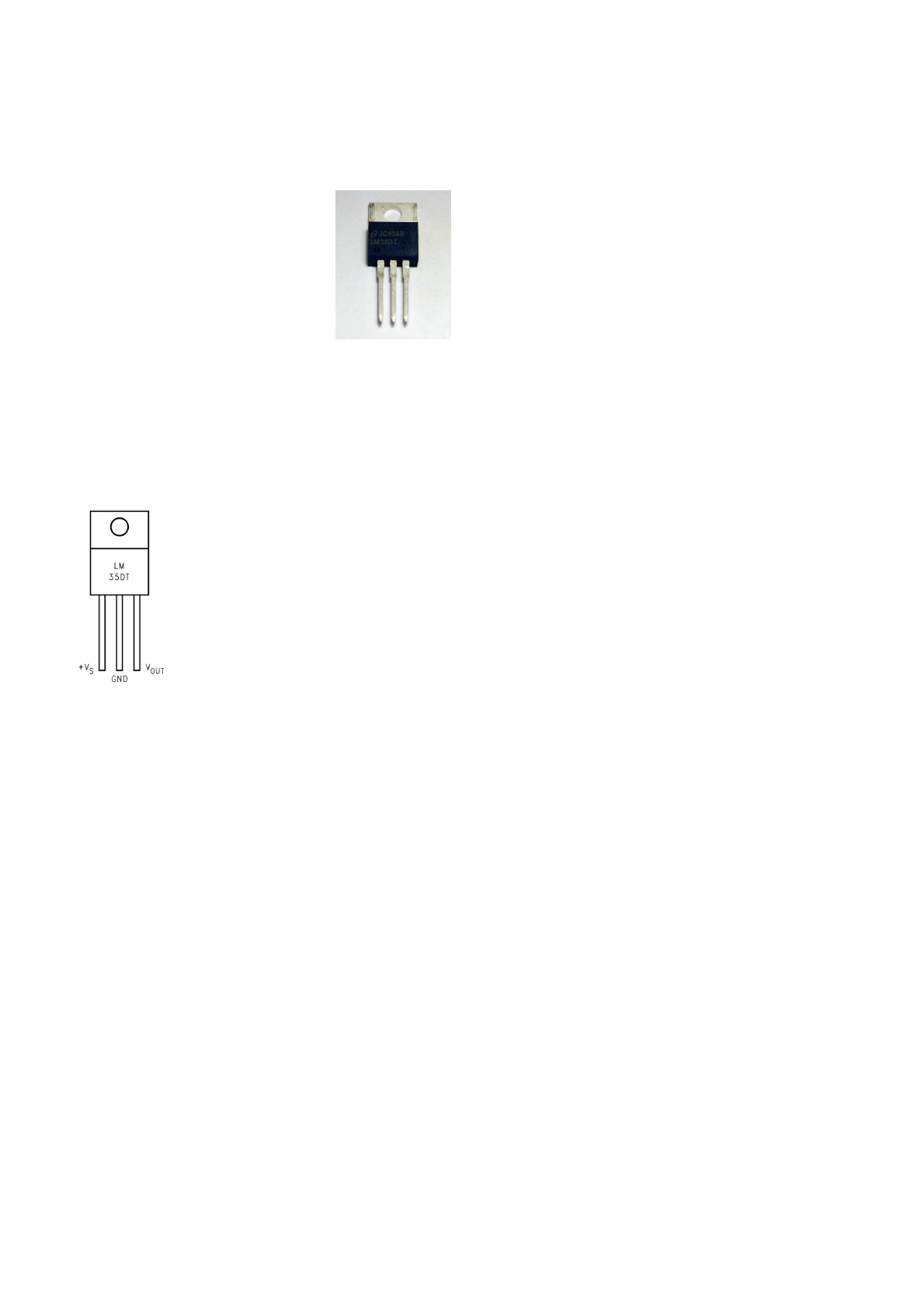
Earthshine Design Arduino Starters Kit Manual - A Complete Beginners Guide to the Arduino
75
Project 12 - Hardware Overview
The hardware used for this project is very simply a
LM35DT Temperature Sensor and
3 wires.
The LM35DT is an analogue
temperature sensor that can read
from 0 to 100 Degrees C and is
accurate to within 0.5 degrees.
The device requires a power
supply of anywhere between 4 to
30V DC. The output from the LM35DT will be
dependent on input voltage. In our case we are giving
the device 5V from the Arduino and therefore 0
Degrees C will give an output voltage of 0 volts. 100
Degrees C will give the maximum output voltage
(which will match the input voltage) of 5 volts.
If we take a look at the diagram of the
pinouts from the LM35DT datasheet,
you can see that there are 3 legs to
the device. The left hand leg (with the
device number facing you and
heatsink away from you) is the input
voltage. The middle leg goes to
ground and the right hand leg gives
you the output voltage, which will be
your temperature reading.

Earthshine Design Arduino Starters Kit Manual - A Complete Beginners Guide to the Arduino
76
Project 13
Light Sensor
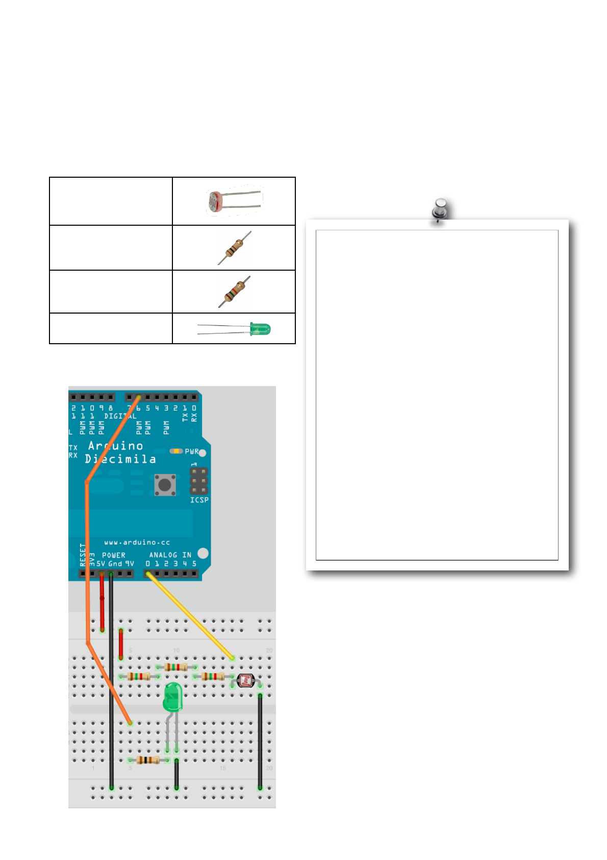
Earthshine Design Arduino Starters Kit Manual - A Complete Beginners Guide to the Arduino
77
Project 13 - Light Sensor
In this project we are going to use the Light
Dependent Resistor in our kit to read values from it
and adjust the speed of a flashing LED.
What you will need
Light Dependent
Resistor
100Ω Resistor
3 x 1K5Ω Resistors
Green LED
Connect it up
Enter the Code
Enter the code, then upload it to your Arduino. You will
see the LED flashing on and off. If you cover the LDR
(Light Dependent Resistor) you will see the LED flash
slower. Now shine a bright light onto the LDR and you
will see it flash faster.
//Project 13 - Light Sensor
// Pin we will connect to LED
int ledPin = 6;
// Pin connected to LDR
int ldrPin = 0;
// Value read from LDR
int lightVal = 0;
void setup()
{
!// Set both pins as outputs
!pinMode(ledPin, OUTPUT);
}
void loop()
{
!// Read in value from LDR
!lightVal = analogRead(ldrPin);
!// Turn LED on
!digitalWrite(ledPin, HIGH);
!// Delay of length lightVal
!delay(lightVal);
!// Turn LED off
!digitalWrite(ledPin, LOW);
!// Delay again
!delay(lightVal);
}

Earthshine Design Arduino Starters Kit Manual - A Complete Beginners Guide to the Arduino
78
Project 13 - Code Overview
This code is pretty simple and you should be able to
work out what it does yourself by now.
The code starts off by initialising variables related to
Digital Pin 6, which the LED is connected to and
Analogue Pin 0, which the LDR is connect to. We also
initialise a variable called lightVal which will store the
values red in from the LDR.
int ledPin = 6;
// Pin connected to LDR
int ldrPin = 0;
// Value read from LDR
int lightVal = 0;
The setup function sets the pinmode of the LED pin to
output.
!pinMode(ledPin, OUTPUT);
In the main loop of the program we read in analog
value from Analog Pin 0 and store it in the ʻlightValʼ
variable.
!lightVal = analogRead(ldrPin);
Then the LED is turned on and off, with a delay equal
to the value read in from the analog pin.
!digitalWrite(ledPin, HIGH);
!delay(lightVal);
!digitalWrite(ledPin, LOW);
!delay(lightVal);
As more light falls on the LDR the value read in from
Analog Pin 0 decreases and the LED flashes faster.
Letʼs find out how this circuit works.
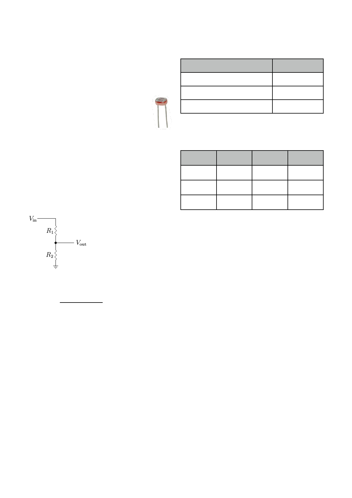
Earthshine Design Arduino Starters Kit Manual - A Complete Beginners Guide to the Arduino
79
Project 13 - Hardware Overview
The only additional component used in this circuit is
the LDR or Light Dependent Resistor (sometimes
called a photoresistor). An LDR initially has a very high
resistance. But, as light falls on it, the resistance will
drop, allowing more current through.
Our LDR is connected in series with 3 x
1.5KΩ Resistors and the input into Analog
Pin 0 is between these 2. This is what is
known as a voltage divider. We will explain
this in a second.
The 3 x 1.5K give a total resistance of 4500Ω (4.5KΩ).
Resistors in series have a resistance equal to the sum
of their individual resistances. In this case the value is
3 x 1500 = 4500.
A voltage divider is a circuit consisting of two
resistances across a voltage supply. An output
between the two resistances will give a lower voltage
depending on the values of the two resistors.
The diagram on the left
shows a voltage divider
made up of two resistors.
The value of Vout will be
lower than the value of Vin.
To work out the value of Vout
we use the following
calculation:
Vout =
R2
Vin
Vout =
R1 + R2
Vin
We are providing 5 volts into the circuit so letʼs work
out what values we will get out. Using a multimeter I
have measured the resistance from the LDR in
different conditions.
Conditions
Resistance
LDR Covered by Finger
8KΩ
Light in room (overcast day)
1KΩ
Held under a bright light
150Ω
So using these values of resistance, the input voltage
and the calculation we listed above, the approx. output
voltage can be calculated thus:
Vin
R1
R2
Vout
5v
4500Ω
8000Ω
3.2v
5v
4500Ω
1000Ω
0.9v
5v
4500Ω
150Ω
0.16v
As you can see, as the resistance of the LDR (R2)
decreases, the voltage out of the voltage divider
decreases also, making the value read in from the
Analog Pin lower and therefore decreasing the delay
making the LED flash faster.
A voltage divider circuit could also be used for
decreasing a voltage to a lower one if you used 2
standard resistors, rather than a resistor and an LDR
(which is a variable resistor). Alternatively, you could
use a potentiometer so you can adjust the voltage out
by turning the knob.

Earthshine Design Arduino Starters Kit Manual - A Complete Beginners Guide to the Arduino
80
Project 14
Shift Register 8-Bit Binary Counter
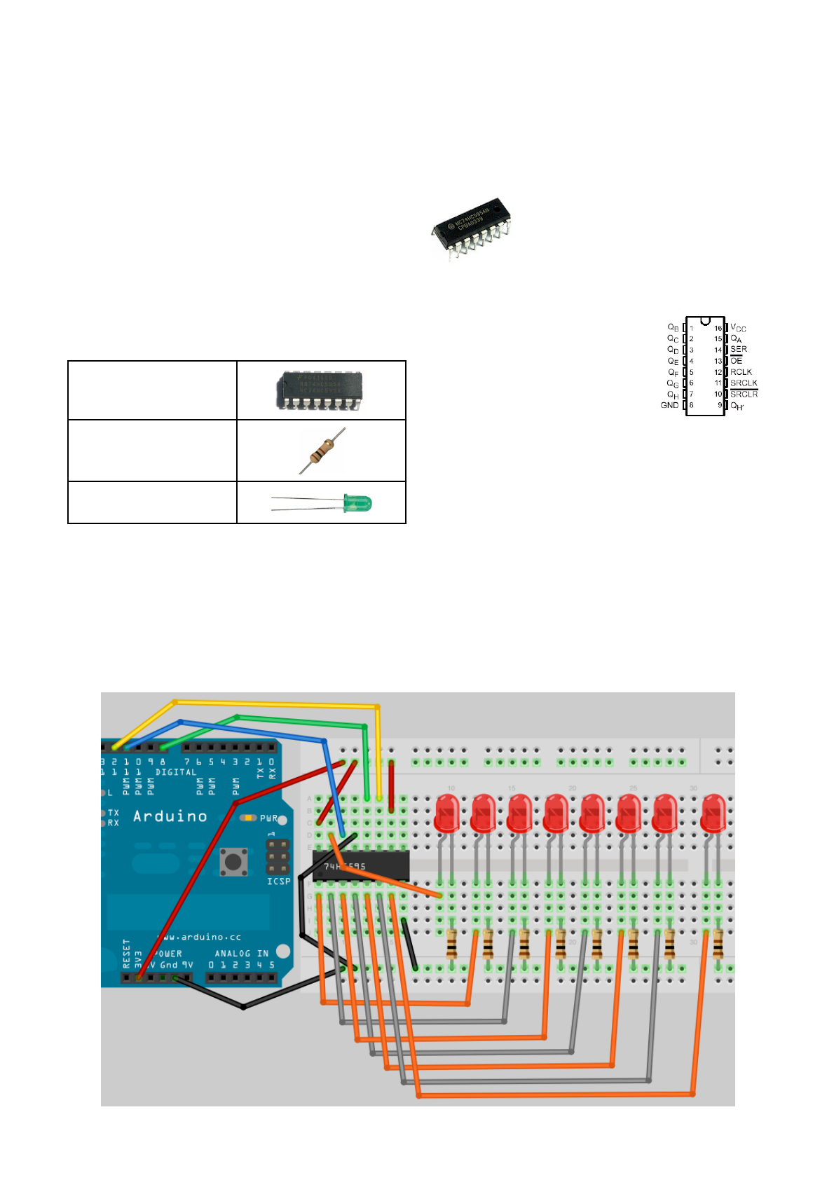
Earthshine Design Arduino Starters Kit Manual - A Complete Beginners Guide to the Arduino
81
Project 14 - Shift Register 8-Bit Binary Counter
Right, we are now going to delve into some pretty
advanced stuff so you might want a stiff drink before
going any further.
In this project we are going to use additional ICʼs
(Integrated Circuits) in the form of Shift Registers, to
enable us to drive LEDʼs to count in Binary (we will
explain what binary is soon). In this project we will
drive 8 LEDʼs independently using just 3 output pins
from the Arduino.
What you will need
1 x 74HC595 Shift
Registers
8 x 240Ω Resistor
8 x Green LED
Connect it up
Examine the diagram carefully.
Connect the 3.3v to the top rail of
your Breadboard and the Ground to
the bottom. The chip has a small
dimple on one end, this dimple goes
to the left. Pin 1 is below the dimple,
Pin 8 at bottom right, Pin 9 at top right
and Pin 16 at top left.
You now need wires to go from
the 3.3v supply to Pins 10 & 16.
Also, wires from Ground to Pins
8 & 13.
A wire goes from Digital Pin 8 to
Pin 12 on the IC. Another one
goes from Digital Pin 12 to Pin 14 and finally one from
Digital Pin 11 to Pin 11.
The 8 LEDʼs have a 240Ω resistor between the
cathode and ground, then the anode of LED 1 goes to
Pin 15. The anode of LEDʼs 2 to 8 goes to Pins 1 to 7
on the IC.
Once you have connected everything up, have one
final check your wiring is correct and the IC and LEDʼs
are the right way around. Then enter the following
code. Remember, if you donʼt want to enter the code
by hand you can download it from the website on the
same page you obtained this book.
Earthshine Design Arduino Starters Kit Manual - A Complete Beginners Guide to the Arduino
82
Enter the Code
Enter the following code and upload it to your Arduino.
Once the code is run you will see the LEDʼs turn on
and off individually as the LEDʼs count up in Binary
from 0 to 255, then start again.
// Project 14
//Pin connected to Pin 12 of 74HC595 (Latch)
int latchPin = 8;
//Pin connected to Pin 11 of 74HC595 (Clock)
int clockPin = 12;
//Pin connected to Pin 14 of 74HC595 (Data)
int dataPin = 11;
void setup() {
//set pins to output
pinMode(latchPin, OUTPUT);
pinMode(clockPin, OUTPUT);
pinMode(dataPin, OUTPUT);
}
void loop() {
//count from 0 to 255
for (int i = 0; i < 256; i++) {
//set latchPin low to allow data flow
digitalWrite(latchPin, LOW);
shiftOut(i);
//set latchPin to high to lock and send data
digitalWrite(latchPin, HIGH);
delay(500);
}
}
void shiftOut(byte dataOut) {
// Shift out 8 bits LSB first,
// on rising edge of clock
boolean pinState;
//clear shift register ready for
sending data
digitalWrite(dataPin, LOW);
digitalWrite(clockPin, LOW);
// for each bit in dataOut send out
a bit
for (int i=0; i<=7; i++) {
//set clockPin to LOW prior to sending bit
digitalWrite(clockPin, LOW);
// if the value of DataOut and (logical
AND) a bitmask
// are true, set pinState to 1 (HIGH)
if ( dataOut & (1<<i) ) {
pinState = HIGH;
}
else {!
pinState = LOW;
}
//sets dataPin to HIGH or LOW depending on
pinState
digitalWrite(dataPin, pinState);
//send bit out on rising edge of clock
digitalWrite(clockPin, HIGH);
}
//stop shifting out data
digitalWrite(clockPin, LOW);
}
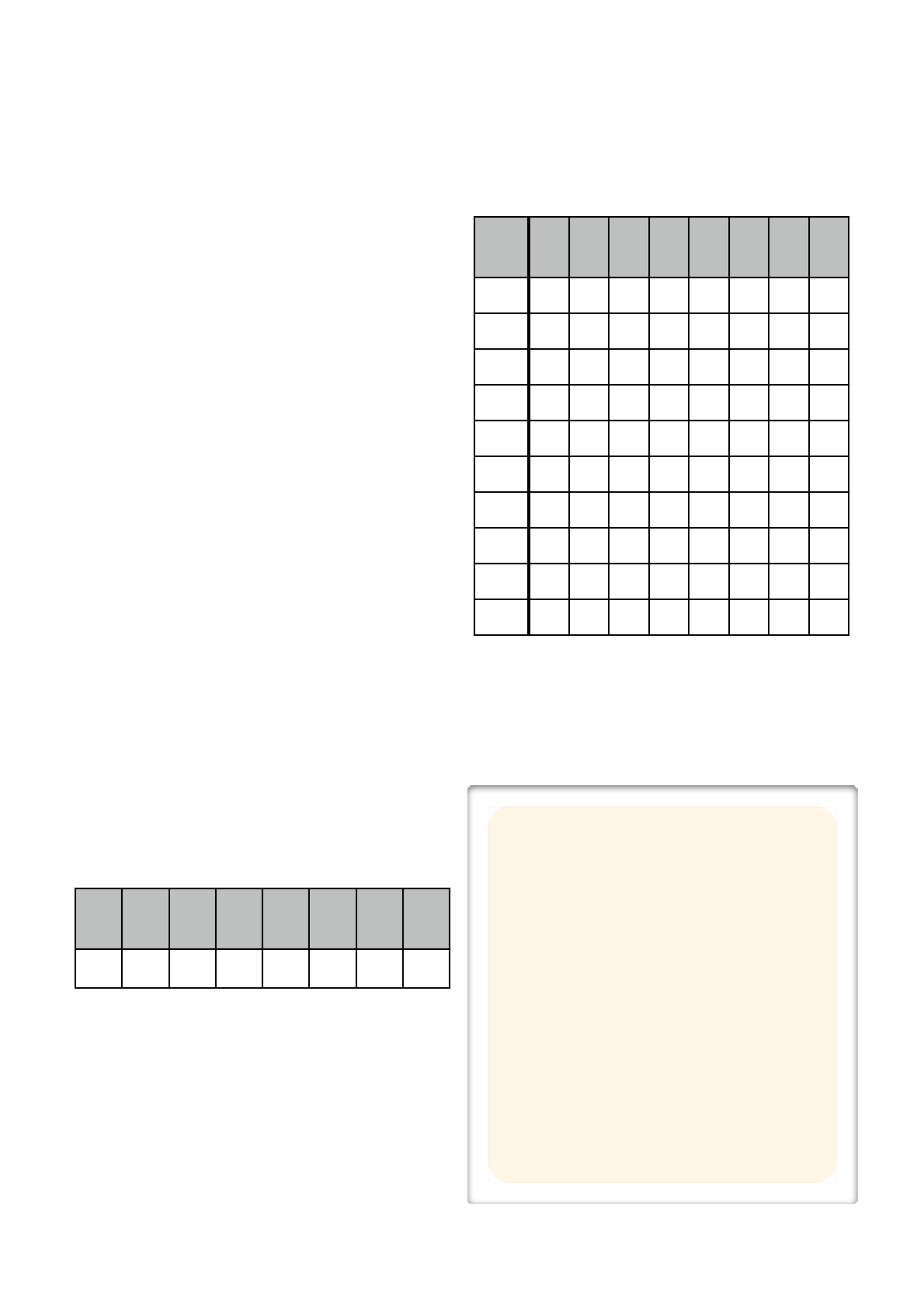
Earthshine Design Arduino Starters Kit Manual - A Complete Beginners Guide to the Arduino
83
The Binary Number System
Now before we take a look at the code and the
hardware for Project 15, it is time to take a look at the
Binary Number System, as it is essential to
understand Binary to be able to successfully program
a microcontroller.
Human beings use a Base 10, or Decimal number
system, because we have 10 fingers on our hands.
Computers do not have fingers and so the best way
for a computer to count is using itʼs equivalent of
fingers, which is a state of either ON or OFF (1 or 0).
A logic device, such as a computer, can detect if a
voltage is there (1) or if it is not (0) and so uses a
binary, or base 2 number system as this number
system can easily be represented in an electronic
circuit with a high or low voltage state.
In our number system, base 10, we have 10 digits
ranging from 0 to 9. When we count to the next digit
after 9 the digit resets back to zero, but a 1 is
incremented to the tens column to its left. Once the
tens column reaches 9, incrementing this by 1 will
reset it to zero, but add 1 to the hundreds column to
itʼs left, and so on.
000,001,002,003,004,005,006,007,008,009
010,011,012,013,014,015,016,017,018,019
020,021,023 ………
In Binary the exact same thing happens, except the
highest digit is 1 so adding 1 to 1 results in the digit
resetting to zero and 1 being added to the column to
the left.
000, 001
010, 011
100, 101...
An 8 bit number (or a byte) is represented like this
27
128
26
64
25
32
24
16
23
8
22
4
21
2
20
1
0
1
0
0
1
0
1
1
The number above in Binary is 1001011 and in
Decimal this is 75.
This is worked out like this :
1 x 1 = 1
1 x 2 = 2
1 x 8 = 8
1 x 64 = 64
Add that all together and you get 75.
Here are some other examples:
Dec
27
128
26
64
25
32
24
16
23
8
22
4
21
2
20
1
75
0
1
0
0
1
0
1
1
1
0
0
0
0
0
0
0
1
2
0
0
0
0
0
0
1
0
3
0
0
0
0
0
0
1
1
4
0
0
0
0
0
1
0
0
12
0
0
0
0
1
1
0
0
27
0
0
0
1
1
0
1
1
100
0
1
1
0
0
1
0
0
127
0
1
1
1
1
1
1
1
255
1
1
1
1
1
1
1
1
...and so on.
So now that you understand binary (or at least I hope
you do) we will first take a look at the hardware, before
looking at the code.
TOP TIP
You can use Google to convert between a Decimal
and a Binary number and vice versa.
E.g to convert 171 Decimal to Binary type
171 in Binary
Into the Google search box returns
171 = 0b10101011
The 0b prefix shows the number is a Binary number
and not a Decimal number.
So the answer is 10101011.
To convert a Binary number to decimal do the
reverse. E.g. Enter
0b11001100 in Decimal
Into the search box returns
0b11001100 = 204
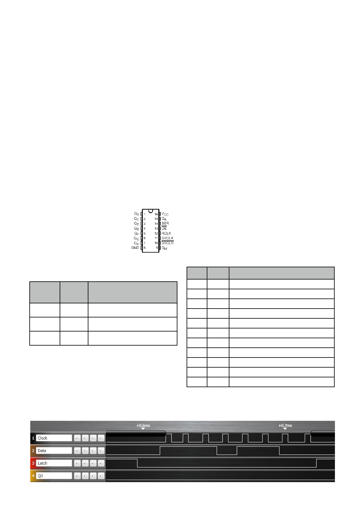
Earthshine Design Arduino Starters Kit Manual - A Complete Beginners Guide to the Arduino
84
Project 14 - Hardware Overview
We are going to do things the other way around for
this project and take a look at the hardware before we
look at the code.
We are using a Shift Register. Specifically the
74HC595 type of Shift Register. This type of Shift
Register is an 8-bit serial-in, serial or parallel-out shift
register with output latches. This means that you can
send data in to the Shift Register in series and send it
out in parallel. In series means 1 bit at a time. Parallel
means lots of bits (in this case 8) at a time. So you
give the Shift Register data (in the form of 1ʼs and 0ʼs)
one bit at a time, then send out 8 bits all at the exact
same time. Each bit is shunted along as the next bit is
entered. If a 9th bit is entered before the Latch is set
to HIGH then the first bit entered will be shunted off
the end of the row and be lost forever.
Shift Registers are usually used for serial to parallel
data conversion. In our case, as
the data that is output is 1ʼs and
0ʼs (or 0v and 3.3v) we can use it
to turn on and off a bank of 8
LEDʼs.
The Shift Register, for this
project, requires only 3 inputs
from the Arduino. The outputs of
the Arduino and the inputs of the 595 are as follows:
Arduino
Pin
595
Pin
Description
8
12
Storage Register Clock Input
11
14
Serial Data Input
12
11
Shift Register Clock Input
We are going to refer to Pin 12 as the Clock Pin, Pin
14 as the Data Pin and Pin 11 as the Latch Pin.
Imagine the Latch as a gate that will allow data to
escape from the 595. When the gate is lowered (LOW)
the data in the 595 cannot get out, but data can be
entered. When the gate is raised (HIGH) data can no
longer be entered, but the data in the SHift Register is
released to the 8 Pins (QA-QH). The Clock is simply a
pulse of 0ʼs and 1ʼs and and the Data Pin is where we
send data from the Arduino the the 595.
To use the Shift Register the Latch Pin and Clock Pin
must be set to LOW. The Latch Pin will remain at LOW
until all 8 bits have been set. This allows data to be
entered into the Storage Register (the storage register
is simply a place inside the IC for storing a 1 or a 0).
We then present either a HIGH or LOW signal at the
Data Pin and then set the Clock Pin to HIGH. By
setting the Clock Pin to HIGH this stores the data
presented at the Data Pin into the Storage Register.
Once this is done we set the Clock to LOW again,
then present the next bit of data at the Data Pin. Once
we have done this 8 times, we have sent a full 8 bit
number into the 595. The Latch Pin is now raised
which transfers the data from the Storage Register
into the Shift Register and outputs it from QA to QH
(Pin 15, 1 to 7).
I have connected a Logic Analyser (a device that lets
you see the 1ʼs and 0ʼs coming out of a digital device)t
o my 595 whilst this program is running and the image
at the bottom of the page shows the output.
The sequence of events here is:
Pin
State
Description
Latch
LOW
Latch lowered to allow data to be entered
Data
HIGH
First bit of data (1)
Clock
HIGH
Clock goes HIGH. Data stored.
Clock
LOW
Ready for next Bit. Prevent any new data.
Data
HIGH
2nd bit of data (1)
Clock
HIGH
2nd bit stored
...
...
…
Data
LOW
8th bit of data (0)
Clock
HIGH
Store the data
Clock
LOW
Prevent any new data being stored
Latch
HIGH
Send 8 bits out in parallel
In the image below, you can see that the binary
number 00110111 (reading from right to left) or
Decimal 55 has been sent to the chip.
Earthshine Design Arduino Starters Kit Manual - A Complete Beginners Guide to the Arduino
85
So to summarise the use of a single Shift Register in this project, we have 8 LEDʼs attached to the 8 outputs of
the Register. The Latch is set to LOW to enable data entry. Data is sent to the Data Pin, one bit at a time, the
CLock Pin is set to HIGH to store that data, then back down to low ready for the next bit. After all 8 bits have
been entered, the latch is set to HIGH which prevents further data entry and sets the 8 output pins to either High
(3.3v or LOW (0 volts) depending on the state of the Register.
If you want to read up more about the shift register you have in your kit, then take a look at the serial number on
the IC (e.g. 74HC595N or SN74HC595N, etc.) and enter that into Google. You can then find the specific
datasheet for the IC and read more about it.
Iʼm a huge fan of the 595 chip. It is very versatile
and can of course increase the number of digital
output pins that the Arduino has. The standard
Arduino has 19 Digital Outputs (the 6 Analog Pins
can also be used as Digital Pins numbered 14 to
19). Using 8-bit Shift Registers you can expand that
to 49 (6 x 595ʼs plus one spare pin left over). They
also operate very fast, typically at 100MHz. Meaning
you can send data out at approx. 100 million times
per second if you wanted to. This means you can
also send PWM signals via software to the ICʼs and
enable brightness control of the LEDʼs too.
As the outputs are simply ONʼs and OFFʼs of an output voltage, they can also be used to switch other low
powered (or even high powered devices with the use of transistors or relays) devices on and off or to send data
to devices (e.g. An old dot matrix printer or other serial device).
All of the 595 Shift Registers from any manufacturer are just about identical to each other. There are also larger
Shift Registers with 16 outputs or higher. Some ICʼs advertised as LED Driver Chips are, when you examine the
datasheet, simply larger Shift Registers (e.g. The M5450 and M5451 from STMicroelectronics).

Earthshine Design Arduino Starters Kit Manual - A Complete Beginners Guide to the Arduino
86
Project 14 - Code Overview
The code for Project 14 looks pretty daunting at first
look. But when you break it down into itʼs component
parts.
First, 3 variables are initialised for the 3 pins we are
going to use.
int latchPin = 8;
int clockPin = 12;
int dataPin = 11;
Then, in setup, the pins are all set to Outputs.
pinMode(latchPin, OUTPUT);
pinMode(clockPin, OUTPUT);
pinMode(dataPin, OUTPUT);
The main loop simply runs a for loop counting from 0
to 255. On each iteration of the loop the latchPin is set
to LOW to enable data entry, then the function called
shiftOut is called, passing the value of i in the for loop
to the function. Then the latchpin is set to HIGH,
preventing further data entry and setting the outputs
from the 8 pins. Finally there is a delay of half a
second before the next iteration of the loop
commences.
void loop() {
//count from 0 to 255
for (int i = 0; i < 256; i++) {
//set latchPin low to allow data flow
digitalWrite(latchPin, LOW);
shiftOut(i);
//set latchPin to high to lock and send
data
digitalWrite(latchPin, HIGH);
delay(500);
}
}
The shiftOut function receives as a parameter a Byte
(8 bit number), which will be our number between 0
and 255. We have chosen a Byte for this usage as it is
exactly 8 bits in length and we need to send only 8 bits
out to the Shift Register.
void shiftOut(byte dataOut) {
Then a boolean variable called pinState is initialised.
This will store the state we wish the relevant pin to be
in when the data is sent out (1 or 0).
boolean pinState;
The Data and Clock pins are set to LOW to reset the
data and clock lines ready for fresh data to be sent.
digitalWrite(dataPin, LOW);
digitalWrite(clockPin, LOW);
After this, we are ready to send the 8 bits in series to
the 595 one bit at a time.
A for loop that iterates 8 times is set up.
for (int i=0; i<=7; i++) {
The clock pin is set low prior to sending a Data bit.
digitalWrite(clockPin, LOW);
Now an if/else statement determines if the pinState
variable should be set to a 1 or a 0.
if ( dataOut & (1<<i) ) {
pinState = HIGH;
}
else {!
pinState = LOW;
}
The condition for the if statement is:
dataOut & (1<<i).
This is an example of what is called a ʻbitmaskʼ and
we are now using Bitwise Operators. These are logical
operators similar to the Boolean Operators we used in
previous projects. However, the Bitwise Operators act
on number at the bit level.
In this case we are using the Bitwise and (&) operator
to carry out a logical operation on two numbers. The
first number is dataOut and the second is the result of
(1<<i). Before we go any further letʼs take a look at the
Bitwise Operators.

Earthshine Design Arduino Starters Kit Manual - A Complete Beginners Guide to the Arduino
87
Bitwise Operators
The Bitwise Operators perform calculations at the bit
level on variables. There are 6 common Bitwise
Operators and these are:
!&!Bitwise and
!|!Bitwise or
!^!Bitwise xor
!~!Bitwise not
!<<!Bitshift left
!>>!Bitshift right
Bitwise Operators can only be used between integers.
Each operator performs a calculation based on a set
of logic rules. Let us take a close look at the Bitwsie
AND (&) Operator.
Bitwise AND (&)
The Bitwise AND operator act according to this rule:-
If both inputs are 1, the resulting outputs are 1,
otherwise the output is 0.
Another way of looking at this is:
!0 0 1 1!Operand1
!0 1 0 1!Operand2
!-------
!0 0 0 1!(Operand1 & Operand2)
A type int is a 16-bit value, so using & between two int
expressions causes 16 simultaneous AND operations
to occur. In a section of code like this:
int x = 77; //binary: 0000000001001101
int y = 121; //binary: 0000000001111001
int z = x & y;//result: 0000000001001001
Or in this case 77 & 121 = 73
The remaining operators are:
Bitwise OR (|)
If either or both of the inputs is 1, the result is 1,
otherwise it is 0.
!0 0 1 1!Operand1
!0 1 0 1!Operand2
!-------
!0 1 1 1!(Operand1 | Operand2)
Bitwise XOR (^)
If only 1 of the inputs is 1, then the output is 1. If both
inputs are 1, then the output 0.
!0 0 1 1!Operand1
!0 1 0 1!Operand2
!-------
!0 1 1 0!(Operand1 ^ Operand2)
Bitwise NOT (~)
The Bitwise NOT Operator is applied to a single
operand to its right.
The output becomes the opposite of the input.
!0 0 1 1!Operand1
!-------
!1 1 0 0!~Operand1
Bitshift Left (<<), Bitshift Right (>>)
The Bitshift operators move all of the bits in the integer
to the left or right the number of bits specified by the
right operand.
variable << number_of_bits
E.g.
byte x=9 ; // binary: 00001001
byte y=x<<3; //binary: 01001000 (or 72 dec)
Any bits shifted off the end of the row are lost forever.
You can use the left bitshift to multiply a number by
powers of 2 and the right bitshift to divide by powers of
2 (work it out).
Now that we have taken a look at the Bitshift
Operators letʼs return to our code.
Earthshine Design Arduino Starters Kit Manual - A Complete Beginners Guide to the Arduino
88
Project 14 - Code Overview (continued)
The condition of the if/else statement was
!dataOut & (1<<i)
And we now know this is a Bitwise AND (&) operation.
The right hand operand inside the parenthesis is a left
bitshift operation. This is a ʻbitmaskʼ. The 74HC595 will
only accept data one bit at a time. We therefore need
to convert the 8 bit number in dataOut into a single bit
number representing each of the 8 bits in turn. The
bitmask allows us to ensure that the pinState variable
is set to either a 1 or a 0 depending on what the result
of the bitmask calculation is. The right hand operand is
the number 1 bit shifted i number of times. As the for
loop makes the value of i go from 0 to 7 we can see
that 1 bitshifted i times, each time through the loop,
will result in these binary numbers:
Value of I
Result of (1<<i) in Binary
0
00000001
1
00000010
2
00000100
3
00001000
4
00010000
5
00100000
6
01000000
7
10000000
So you can see that the 1 moves from right to left as a
result of this operation.
Now the & operatorʼs rules state that
If both inputs are 1, the resulting outputs are 1,
otherwise the output is 0.
So, the condition of
dataOut & (1<<i)
will result in a 1 if the corresponding bit in the same
place as the bitmask is a 1, otherwise it will be a zero.
For example, if the value of dataOut was Decimal 139
or 10001011 binary. Then each iteration through the
loop will result in
Value of I
Result of b10001011(1<<i) in Binary
0
00000001
1
00000010
2
00000000
3
00001000
4
00000000
Value of I
Result of b10001011(1<<i) in Binary
5
00000000
6
00000000
7
10000000
So every time there is a 1 in the I position (reading
from right to left) the value comes out at higher than 1
(or TRUE) and every time there is a 0 in the I position,
the value comes out at 0 (or FALSE).
The if condition will therefore carry out its code in the
block if the value is higher than 0 (or in other words if
the bit in that position is a 1) or ʻelseʼ (if the bit inthat
position is a 0) it will carry out the code in the else
block.
So looking at the if/else statement once more
if ( dataOut & (1<<i) ) {
pinState = HIGH;
}
else {!
pinState = LOW;
}
And cross referenciong this with the truth table above,
we can see that for every bit in the value of dataOut
that has the value of 1 that pinState will be set to
HIGH and for every value of 0 it will be set to LOW.
The next piece of code writes either a HIGH or LOW
state to the Data Pin and then sets the Clock Pin to
HIGH to write that bit into the storage register.
digitalWrite(dataPin, pinState);
digitalWrite(clockPin, HIGH);
Finally the Clock Pin is set to low to ensure no further
bit writes.
digitalWrite(clockPin, LOW);
So, in simple terms, this section of code looks at each
of the 8 bits of the value in dataOut one by one and
sets the data pin to HIGH or LOW accordingly, then
writes that value into the storage register.
This is simply sending the 8 bit number out to the 595
one bit at a time and then the main loop sets the Latch
Pin to HIGH to send out those 8 bits simultaneously to
Pins 15 and 1 to 7 (QA to QH) of the Shift Register,
thus making our 8 LEDʼs show a visual representation
of the binary number stored in the Shift Register.

Earthshine Design Arduino Starters Kit Manual - A Complete Beginners Guide to the Arduino
89
Project 15
Dual 8-Bit Binary Counters
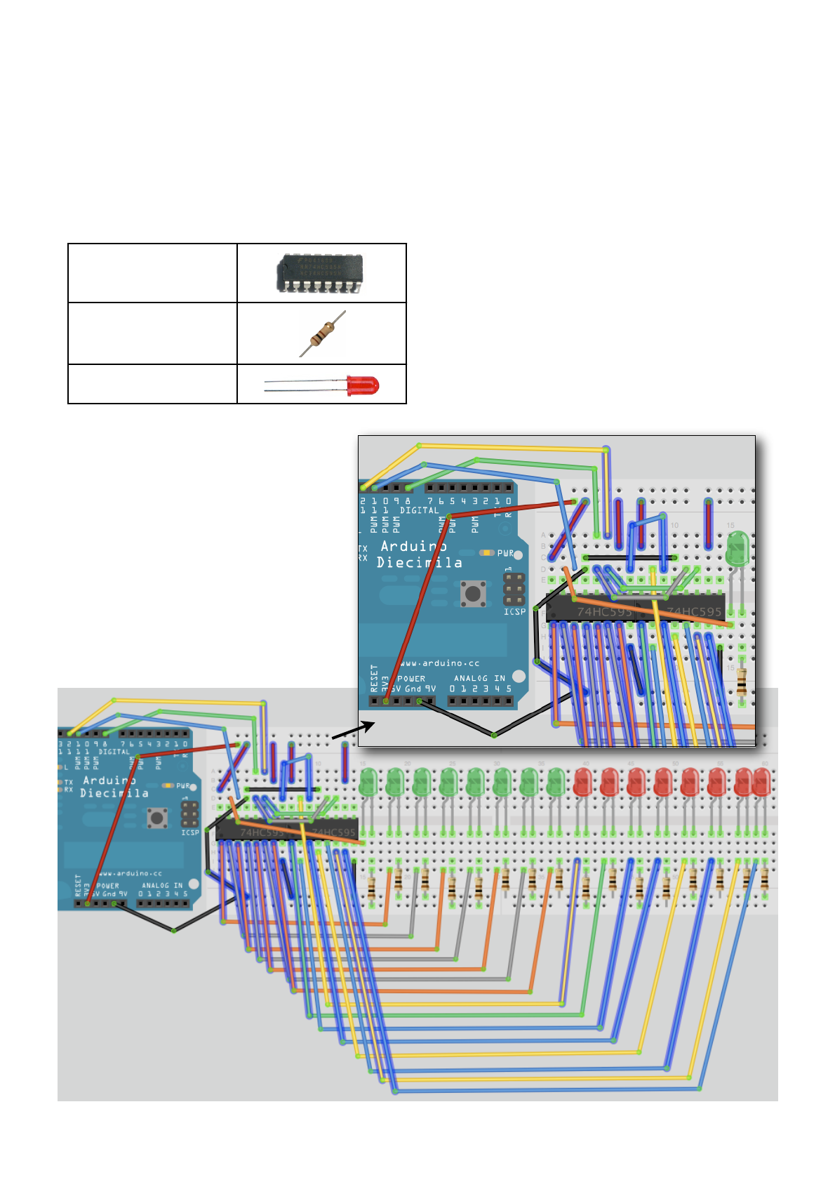
Earthshine Design Arduino Starters Kit Manual - A Complete Beginners Guide to the Arduino
90
Project 15 - Dual 8-Bit Binary Counters
In Project 15 we will daisy chain another 74HC595 IC
onto the one used in Project 14 to create a dual binary
counter.
What you will need
2 x 74HC595 Shift
Registers
8 x 240Ω Resistor
8 x Red LED
Connect it up
The first 595 is wired the same as in Project 15. The
2nd 595 has +5v and Ground wires going to the same
pins as on the 1st 595. Then, add a wire from Pin 9 on
IC 1 to Pin 14 on IC 2. Add another from Pin 11 on IC
1 to Pin 11 on IC 2 and Pin 12 on IC 1 to Pin 12 on IC
2.
The same outputs as on the 1st 595 going to the first
set of LEDʼs go from the 2nd IC to the 2nd set of
LEDʼs.
Examine the diagrams carefully.

Earthshine Design Arduino Starters Kit Manual - A Complete Beginners Guide to the Arduino
91
Enter the Code
Enter the following code and upload it to your Arduino.
When you run this code you will see the Red set of
LEDʼs count up (in Binary) from 0 to 255 and the
Green LEDʼs count down from 255 to 0 at the same
time.
// Project 15
//Pin connected to Pin 12 of 74HC595 (Latch)
int latchPin = 8;
//Pin connected to Pin 11 of 74HC595 (Clock)
int clockPin = 12;
//Pin connected to Pin 14 of 74HC595 (Data)
int dataPin = 11;
void setup() {
//set pins to output
pinMode(latchPin, OUTPUT);
pinMode(clockPin, OUTPUT);
pinMode(dataPin, OUTPUT);
}
void loop() {
//count from 0 to 255
for (int i = 0; i < 255; i++) {
//set latchPin low to allow data flow
digitalWrite(latchPin, LOW);
shiftOut(i);
shiftOut(255-i);
//set latchPin to high to lock and send data
digitalWrite(latchPin, HIGH);
delay(250 );
}
}
void shiftOut(byte dataOut) {
// Shift out 8 bits LSB first,
// on rising edge of clock
boolean pinState;
//clear shift register read for
sending data
digitalWrite(dataPin, LOW);
digitalWrite(clockPin, LOW);
// for each bit in dataOut send
out a bit
for (int i=0; i<=7; i++) {
//set clockPin to LOW prior to
sending bit
digitalWrite(clockPin, LOW);
// if the value of DataOut and
(logical AND) a bitmask
// are true, set pinState to 1
(HIGH)
if ( dataOut & (1<<i) ) {
pinState = HIGH;
}
else {!
pinState = LOW;
}
//sets dataPin to HIGH or LOW
//depending on pinState
digitalWrite(dataPin, pinState);
//send bit out on rising edge of clock
digitalWrite(clockPin, HIGH);
digitalWrite(dataPin, LOW);
}
//stop shifting
digitalWrite(clockPin, LOW);
}

Earthshine Design Arduino Starters Kit Manual - A Complete Beginners Guide to the Arduino
92
Project 15 - Code & Hardware Overview
The code for Project 15 is identical to that in Project
14 apart from the addition of
shiftOut(255-i);
In the main loop. The shiftOut routine sends 8 bits, to
the 595. In the main loop we have put 2 sets of calls to
shiftOut. One sending the value of I and the other
sending 255-i. We call shiftOut twice before we set the
latch to HIGH. This will send 2 sets of 8 bits, or 16 bits
in total, to the 595 chips before the latch is set HIGH
to prevent further writing to the registers and to output
the contents of the shift register to the output pins,
which in turn make the LEDʼs go on or off.
The 2nd 595 is wired up exactly the same as the 1st
one. The clock and latch pins are tied to the pins of
the first 595. However, we have a wire going from Pin
9 on IC 1 to Pin 14 on IC 2. Pin 9 is the data output pin
and pin 14 is the data input pin.
The data is input to Pin 14 on the 1st IC from the
Arduino. The 2nd 595 chip is ʻdaisy chainedʼ to the
first chip by Pin 9 on IC 1, which is outputting data,
into Pin 14 on the second IC, which is the data input.
What happens is, as you enter a 9th bit and above,
the data in IC 1 gets shunted out of its data pin and
into the data pin of the 2nd IC. So, once all 16 bits
have been sent down the data line from the Arduino,
the first 8 bits sent would have been shunted out of
the first chip and into the second. The 2nd 595 chip
will contain the FIRST 8 bits sent out and the 1st 595
chip will contain bits 9 to 16.
An almost unlimited number of 595 chips can be daisy
chained in this manner.
Exercise
1. Re-create the Knight Rider light effect using all 16 LEDʼs

Earthshine Design Arduino Starters Kit Manual - A Complete Beginners Guide to the Arduino
93
Project 16
LED Dot Matrix -
Basic Animation
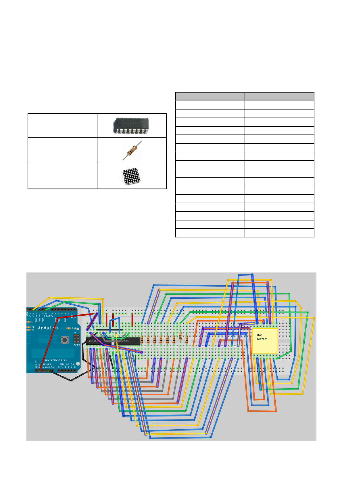
Earthshine Design Arduino Starters Kit Manual - A Complete Beginners Guide to the Arduino
94
Project 16 - LED Dot Matrix - Basic Animation
In this project we are going to use the 74HC595 chips
to control a Dot Matrix array of 64 LEDʼs (8x8) and
produce some basic animations.
This Project requires the Mini Dot Matrix Display.
What you will need
2 x 74HC595 Shift
Registers
8 x 240Ω Resistor
Mini Dot Matrix
Connect it up
The two 595 chips are left the same as in Project 16.
Leave the first 8 resistors and remove the 2nd 8. Put
your Dot Matrix unit at the end of the breadboard.
Make sure it is the right way around. To do this turn it
upside down and make sure the words are the right
way up then flip it over (from right to left) in your hand.
Push it in carefully.
If you take it that bottom left pin of the matrix is Pin 1,
bottom right is Pin 8, top right is Pin 9 and top left is
Pin 16 then connect jumper wires between the 16
outputs as follows :-
Output
Pin
1
9
2
14
3
8
4
12
5
1
6
7
7
2
8
5
9
13
10
3
11
4
12
10
13
6
14
11
15
15
16
16
Examine the diagrams carefully.

Earthshine Design Arduino Starters Kit Manual - A Complete Beginners Guide to the Arduino
95
Enter the Code
// Project 16
#include <TimerOne.h>
//Pin connected to Pin 12 of 74HC595 (Latch)
int latchPin = 8;
//Pin connected to Pin 11 of 74HC595 (Clock)
int clockPin = 12;
//Pin connected to Pin 14 of 74HC595 (Data)
int dataPin = 11;
uint8_t led[8];
long counter1 = 0;
long counter2 = 0;
void setup() {
//set pins to output
pinMode(latchPin, OUTPUT);
pinMode(clockPin, OUTPUT);
pinMode(dataPin, OUTPUT);
led[0] = B11111111;
led[1] = B10000001;
led[2] = B10111101;
led[3] = B10100101;
led[4] = B10100101;
led[5] = B10111101;
led[6] = B10000001;
led[7] = B11111111;
Timer1.initialize(10000);
Timer1.attachInterrupt(screenUpdate);
}
void loop() {
counter1++;
if (counter1 >=100000) {counter2++;}
if (counter2 >= 10000) {
counter1 = 0;
counter2 = 0;
for (int i=0; i<8; i++) {
led[i]= ~led[i];
}
}
}
void screenUpdate() {
uint8_t row = B00000001;
for (byte k = 0; k < 9; k++) {
// Open up the latch ready to receive data
!digitalWrite(latchPin, LOW);
shiftIt(~row );
shiftIt(led[k] ); // LED array
// Close the latch, sending the data in the registers out to the
matrix
digitalWrite(latchPin, HIGH); row = row << 1;
}
}

Earthshine Design Arduino Starters Kit Manual - A Complete Beginners Guide to the Arduino
96
When this code is run, you will see a very basic animation of a heart that flicks back and forth between a positive
and a negative image.
Before this code will work you will need to download the TimerOne library from the Arduino website. It can be
downloaded from http://www.arduino.cc/playground/uploads/Code/TimerOne.zip
Once downloaded, unzip the package and place the folder, called TimerOne, into the hardware/libraries
directory.
void shiftIt(byte dataOut) {
// Shift out 8 bits LSB first,
// on rising edge of clock
boolean pinState;
//clear shift register read for sending data
digitalWrite(dataPin, LOW);
// for each bit in dataOut send out a bit
for (int i=0; i<8; i++) {
//set clockPin to LOW prior to sending bit
digitalWrite(clockPin, LOW);
// if the value of DataOut and (logical AND) a bitmask
// are true, set pinState to 1 (HIGH)
if ( dataOut & (1<<i) ) {
pinState = HIGH;
}
else {!
pinState = LOW;
}
//sets dataPin to HIGH or LOW depending on pinState
digitalWrite(dataPin, pinState);
//send bit out on rising edge of clock
digitalWrite(clockPin, HIGH);
digitalWrite(dataPin, LOW);
}
//stop shifting
digitalWrite(clockPin, LOW);
}
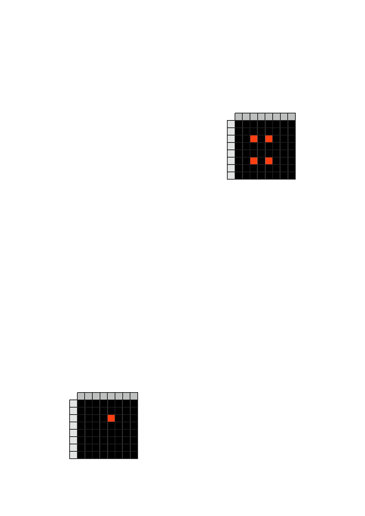
Earthshine Design Arduino Starters Kit Manual - A Complete Beginners Guide to the Arduino
97
Project 16 - Hardware Overview
For this Project we will take a look at the Hardware
before we look at how the code works.
The 74HC595 and how to use them has been
explained in the previous projects. The only addition to
the circuit this time was an 8x LED Dot Matrix unit.
Dot Matrix units typically come in either an 5x7 or 8x8
matrix of LEDʼs. The LEDʼs are wired in the matrix
such that either the anode or cathode of each LED is
common in each row. E.g. In a Common Anode LED
DOt Matrix unit, each row of LEDʼs would have all of
their anodes in that row wired together. The Cathodes
of the LEDʼs would all be wired together in each
column. The reason for this will become apparent
soon.
A typical single colour 8x8 Dot Matrix unit will have 16
pins, 8 for each row and 8 for each column. You can
also obtain bi-colour units (e.g. Red and Green) as
well as Full Colour RGB (Red, Green and Blue) Units,
such as is used in large video walls. Bi or Tri (RGB)
colour units have 2 or 3 LEDʼs in each pixel of the
array. These are very small and next to each other.
By turning on different combinations of Red, Green or
Blue in each pixel and by varying their brightnesses,
any colour can be obtained.
The reason the rows and columns are all wired
together is to minimise the number of pins required. If
this was not the case, a single colour 8x8 Dot Matrix
unit would have to have 65 pins. One for each LED
and a common Anode or Cathode connector. By wiring
the rows and columns together only 16 pin outs are
required.
However, this now poses a problem. If we want a
particular LED to light in a certain position. If for
example we had a Common Anode unit and wanted to
light the LED at X, Y position 5, 3 (5th column, 3rd
row), then we would apply a current to the 3rd Row
and Ground the 5th column pin. The LED in the 5th
column and 3rd row would now light.
1
2
3
4
5
6
7
8
1
2
3
4
5
6
7
8
Now let us imagine that we want to also light the LED
at column 3, row 6. So we apply a current to the 6th
row and ground the 3rd column pin. The LED at
column 3, row 6 now illuminates. But wait… The
LEDʼs at column 3, row 6 and column 5, row 6 have
also lit up.
1
2
3
4
5
6
7
8
1
2
3
4
5
6
7
8
This is because we are applying power to row 3 and 6
and grounding columns 3 and 5. We canʼt turn off the
unwanted LEDʼs without turning off the ones we want
on also. It would appear that there is no way we can
light just the two required LEDʼs with the rows and
columns wired together as they are. The only way this
would work would be to have a separate pinout for
each LED meaning the number of pins would jump
from 16 to 65. A 65 pin Dot Matrix unit would be very
hard to wire up and also to control as youʼd need a
microcontroller with at least 64 digital outputs.
Is there a way to get around this problem? Yes there
is, and it is called ʻmultiplexingʼ (or muxing).
Multiplexing
Multiplexing is the technique of switching one row of
the display on at a time. By selecting the appropriate
columns that we want an LED to be lit in that row and
then turning the power to that row (or the other way
round for common cathode displays) on, the chosen
LEDʼs in that row will illuminate. That row is then
turned off and the next row is turned on, again with the
appropriate columns chosen and the LEDʼs in the 2nd
row will now illuminate. Repeat with each row till we
get to the bottom and then start again at the top.
If this is done fast enough (more than 100Hz or 100
times per second) then the phenomenon of
ʻpersistance of visionʼ (where an afterimage remains
on the retina for approx 1/25th of a second) will mean
that the display will appear to be steady, even though
each row is turned on and off in sequence.
By using this technique we get around the problem of
being able to display individual LEDʼs without other
LEDʼs in the same column or row also being lit.
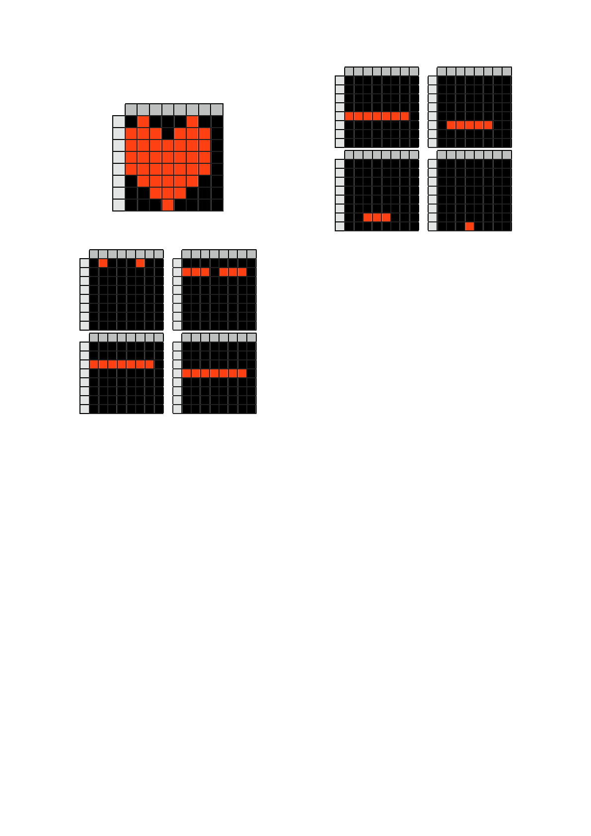
Earthshine Design Arduino Starters Kit Manual - A Complete Beginners Guide to the Arduino
98
For example, we want to display the following image
on our display:-
1
2
3
4
5
6
7
8
1
2
3
4
5
6
7
8
Then each row would be lit in turn like so…
1
2
3
4
5
6
7
8
1
2
3
4
5
6
7
8
1
2
3
4
5
6
7
8
1
2
3
4
5
6
7
8
1
2
3
4
5
6
7
8
1
2
3
4
5
6
7
8
1
2
3
4
5
6
7
8
1
2
3
4
5
6
7
8
1
2
3
4
5
6
7
8
1
2
3
4
5
6
7
8
1
2
3
4
5
6
7
8
1
2
3
4
5
6
7
8
1
2
3
4
5
6
7
8
1
2
3
4
5
6
7
8
1
2
3
4
5
6
7
8
1
2
3
4
5
6
7
8
By scanning down the rows and illuminating the
respective LEDʼs in each column of that row and doing
this very fast (more than 100Hz) the human eye will
perceive the image as steady and the image of the
heart will be recognisable in the LED pattern.
We have used this multiplexing technique in our
Project's code and that is how we are able to display
the heart animation without also displaying extraneous
LEDʼs.

Earthshine Design Arduino Starters Kit Manual - A Complete Beginners Guide to the Arduino
99
Project 16 - Code Overview
The code for this project uses a feature of the Atmega
chip called a Hardware Timer. This is essentially a
timer on the chip that can be used to trigger an event.
In our case we are setting our ISR (Interrupt Service
Routine) to fire every 10000 microseconds, which is
every 100th of a second.
We make use of a library that has already been written
for us to enable easy use of interrupts and this is the
TimerOne library. TimerOne makes creating an ISR
very easy. We simply tell the function what the interval
is, in this case 10000 microseconds, and the name of
the function we wish to activate every time the
interrupt is fired, in our case this is the ʻscreenUpdateʼ
function.
TimerOne is an external library and we therefore need
to include it in our code. This is easily done using the
include command.
#include <TimerOne.h>
After this the pins used to interface with the shift
registers are declared.
//Pin connected to Pin 12 of 74HC595 (Latch)
int latchPin = 8;
//Pin connected to Pin 11 of 74HC595 (Clock)
int clockPin = 12;
//Pin connected to Pin 14 of 74HC595 (Data)
int dataPin = 11;
We now create an array of type uint8_t that has 8
elements and two counters of type long. An uint8_t is
simply the same as a byte. It is an unsigned integer of
8 bits.
uint8_t led[8];
long counter1 = 0;
long counter2 = 0;
The led[8] array will be used to store the image we are
going to display on the Dot Matrix display. The
counters will be used to create a delay.
In the setup routine we set the latch, clock and data
pins as outputs.
void setup() {
//set pins to output
pinMode(latchPin, OUTPUT);
pinMode(clockPin, OUTPUT);
pinMode(dataPin, OUTPUT);
Once the pins have been set to outputs, the led array
is loaded with the 8-bit binary images that will be
displayed in each row of the 8x8 Dot Matrix Display.
led[0] = B11111111;
led[1] = B10000001;
led[2] = B10111101;
led[3] = B10100101;
led[4] = B10100101;
led[5] = B10111101;
led[6] = B10000001;
led[7] = B11111111;
By looking at the array above you can make out the
image that will be displayed, which is a box within a
box. You can, of course, adjust the 1ʼs and 0ʼs yourself
to make any 8x8 sprite you wish.
After this the Timer1 function is used. First, the
function needs to be initialised with the frequency it
will be activated at. In this case we set its period to
10000 microseconds, or 1/100th of a second. Once the
interrupt has been initialised we need to attach to the
interrupt a function that will be executed every time the
time period is reached. This is the ʻscreenUpdateʼ
function which will fire every 1/100th of a second.
Timer1.initialize(10000);
Timer1.attachInterrupt(screenUpdate);
In the main loop we set a counter that counts to
1,000,000,000 to create a delay. This is done by two
loops, one that loops 100,000 times and the other one
that loops 10,000 times. I have done it this way,
instead of using delay() as the current version of the
Timer1 library seems to interfere with the delay
function. You may try delay() instead and see if it
works (updates to the libraries are occurring from time
to time). counter1 and counter2 are reset to zero once
they reach their targets.
void loop() {
counter1++;
if (counter1 >=100000) {counter2++;}
if (counter2 >= 10000) {
counter1 = 0;
counter2 = 0;
Once the end of the delay is reached, a for loop cycles
through each of the 8 elements of the led array and
inverts the contents using the ~ or NOT bitwise
operator.
for (int i=0; i<8; i++) {
led[i]= ~led[i];
}
}
}
This simply turns the binary image into a negative of
itself by turning all 1ʼs to 0ʼs and all 0ʼs to 1ʼs.

Earthshine Design Arduino Starters Kit Manual - A Complete Beginners Guide to the Arduino
100
We now have the screenUpdate function. This is the
function that the interrupt is activating every 100th of a
second. This whole routine is very important as it is
responsible for ensuring our LEDʼs in the DOt Matrix
array are lit correctly and displays the image we wish
to convey. It is a very simple but very effective
function.
void screenUpdate() {
uint8_t row = B00000001;
for (byte k = 0; k < 9; k++) {
// Open up the latch ready to receive
data
!digitalWrite(latchPin, LOW);
shiftIt(~row );
shiftIt(led[k] ); // LED array
// Close the latch, sending the data in
the registers out to the matrix
digitalWrite(latchPin, HIGH); row = row
<< 1;
}
}
An 8 bit integer called ʻrowʼ is declared and initialised
with the value B00000001.
uint8_t row = B00000001;
We now simply cycle through the led array and send
that data out to the Shift Registers preceded by the
row (which is processed with the bitwise NOT ~ to
make sure the row we want to display is turned off, or
grounded).
for (byte k = 0; k < 9; k++) {
// Open up the latch ready to receive
data
!digitalWrite(latchPin, LOW);
shiftIt(~row );
shiftIt(led[k] ); // LED array
Once we have shifted out that current rows 8 bits the
value in row is bitshifted left 1 place so that the next
row is displayed.
row = row << 1;
Remember from the hardware overview that the
multiplexing routine is only displaying one row at a
time, turning it off and then displaying the next row.
This is done at 100Hz which is too fast for the human
eye to see the flicker.
Finally, we have a ShiftOut function, the same as in
the previous Shift Register based projects, that sends
the data out to the 74HC595 chips.
void shiftIt(byte dataOut)
So, the basic concept here is that we have an interruot
routine that executes every 100th
of a second. In that
routine we simply take a look at the contents of a
screen buffer array (in this case led[] ) and display it
on the dot matrix unit one row at a time, but do this so
fast that to the human eye it all seems to be lit at once.
The main loop of the program is simply changing the
contents of the screen buffer array and letting the ISR
do the rest.
The animation in this project is very simple, but by
manipulating the 1ʼs and 0ʼs in the buffer we can make
anything we like appear on the Dot Matrix unit from
shapes to scrolling text.