Aspen EFDPFDPilots Guide
User Manual:
Open the PDF directly: View PDF ![]() .
.
Page Count: 248 [warning: Documents this large are best viewed by clicking the View PDF Link!]


EFD1000 PFD Pilot’s Guide
Page PB 091-00005-001 REV E EFD1000 PFD Pilot’s Guide Page iii
091-00005-001 REV E

EFD1000 PFD Pilot’s Guide
Page iv 091-00005-001 REV E EFD1000 PFD Pilot’s Guide Page v
091-00005-001 REV E
Document Revisions
REVISION DESCRIPTION of CHANGE
E Deleted from the Table of Contents: Table of Figures, Table of Tables, and Table of Tasks; Added Evolution Databases to Chapters 1 & 7;
Grammatical, pictorial, and technical updates. Revised to update for software v2.3.1, and v2.4.1.
Software v2.3.1 include the following:
• Knob function improvements
• BARO function moved to dedicated Hot Key preventing inadvertent adjustment
• Map Declutter function removed from Hot Key to the MENU Map Settings page
• Support for ADF1 and ADF2 Bearing Pointer sources
• Support for Radio Altitude Display
• MINIMUMS annunciation relocated to Selected Minimums Field
• Battery annunciation relocated to top left corner below Selected Airspeed Field
• Overvoltage protection whenever aircraft’s electrical system generates more than 33 volts, PFD automatically switches to its
battery power
• Support for Redline or Barber pole airspeed limits that vary with pressure altitude
• Support for MACH number displayed in Data Bar for Mmo aircraft
• Single dedicated Hot Key for Trac Overlay and Trac Altitude Filter when congured with optional EHA
• RSM GPS can be congured to share its position among all Evolution Displays when all the panel-mounted GPS units fail
Software v2.4.1 include the following:
• Hot Key Color Legend improvements
• “ON” setting removed from Flight Plan, Airports, VOR, and Intersections/NDB Basemap features

EFD1000 PFD Pilot’s Guide
Page iv 091-00005-001 REV E EFD1000 PFD Pilot’s Guide Page v
091-00005-001 REV E
REVISION DESCRIPTION of CHANGE
DUpdated for software v2.2 and v2.2.3 Grammatical, pictorial, and technical updates
CUpdated for software v2.1
BGrammatical, pictorial, and technical updates
Added Index.
AUsing new part number 091-00005-001
Grammatical, pictorial, and technical updates. Revised to update for software v2.0, including the following:
• All images updated with v2.0 images
• Updated Color philosophy
• Annotate features unavailable on EFD1000 Pilot PFD
• Hot Key update. Menu update
• Added Altitude Trend Vector
• Added Minimums Marker
• Updated range settings; 2 and 3 NM, delete 2.5 NM
• Added ability to select Celsius or Fahrenheit units of measure for OAT
• Entire Emergency and Abnormal Procedures Chapter updated
• Added Map Auto Range
• Updated Vspeed conguration
• Added additional GPSS information
• Addition of Hazard Awareness options, WX-500/Lightning, Data Link Weather, and Trac

EFD1000 PFD Pilot’s Guide
Page vi 091-00005-001 REV E EFD1000 PFD Pilot’s Guide Page PB
091-00005-001 REV E
REVISION DESCRIPTION of CHANGE
C*
( )
**Part number change: old part number A-01-184-00 REV C; new part number 091-00005-001 REV ( ).
Grammatical, pictorial, and technical corrections and updates. Revised to update for software version 1.1, which include:
• New start-up splash screen
• Failure message for RSM and Cong Module link
• Brightness changes
• Auto brightness range 1% - 70%
• Manual brightness range 1% - 100%
• During internal battery operation, brightness capped at 40% for Auto mode and 70% for Manual mode
• When temperature is above ≥ 70° C, brightness capped at 30% for Auto mode and 70% for Manual mode
• Menu, System Status Page added Unit S/N
• Wind Speed and Direction Degrees do not display when
• When aircraft is on the ground
• When wind speed is ≤10. Additionally, the Wind Arrow does not display
Added Title page, Revision page and Index
BLayout Update
AInitial Release
* Legacy P/N revision is displayed above the new CI number Revision
EFD1000 PFD Pilot’s Guide
Page PB 091-00005-001 REV E EFD1000 PFD Pilot’s Guide Page vii
091-00005-001 REV E
Table of Contents
Document Revisions ................................................................................ iv
Copyrights, Trademarks and Patents .................................................... xi
Approvals ................................................................................................... xii
LIMITED WARRANTY Aspen Avionics, Inc. ..........................................xiii
Weather Data Warranty ......................................................................... xvi
XM WX Satellite Radio Service Agreement ....................................... xvii
Conventions.............................................................................................. xix
Covered Functionality ..................................................................................................xix
Terminology ....................................................................................................................... xix
Color Philosophy .............................................................................................................xxi
Warnings, Cautions, and Notes..............................................................................xxii
Example Graphics .........................................................................................................xxiii
Pilot Familiarity ................................................................................................................xxiii
Information Covered in this Pilot’s Guide ......................................................xxiv
Chapter 1
Welcome and Introduction ....................................................... 1-1
1.1. System Overview .................................................................................................. 1-4
1.1.1. Primary Flight Display Unit (PFD) ............................................. 1-5
1.1.2. Conguration Module (CM) ........................................................ 1-6
1.1.3. Analog Converter Unit (ACU)1 .................................................... 1-6
1.1.4. Remote Sensor Module (RSM) ................................................... 1-7
1.1.5. Evolution Weather Receiver (EWR50)1 ................................... 1-7
1.1.6. Evolution Databases ........................................................................ 1-8
Chapter 2
Controls and Display ................................................................. 2-1
2.1. Controls & Display Orientation .......................................................................2-2
2.2. Controls ...................................................................................................................... 2-4
2.2.1. Left and Right Knobs ...................................................................... 2-4
2.2.1.1. Left Knob Functions .......................................................... 2-5
2.2.1.2. Right Knob Functions ...................................................... 2-5
2.2.1.3. SYNC Function...........................................................2-6
2.2.1.4. Using the Knobs (Example) .......................................... 2-8
2.2.2. Navigation Source Select Buttons1 ......................................... 2-8
2.2.2.1. CDI Navigation Source Select Button1 ................... 2-9
2.2.2.2. Bearing Pointer Source Select Buttons1 ..............2-10
2.2.3. Hot Keys ................................................................................................2-11
2.2.4. Menu .......................................................................................................2-14
2.2.4.1. Using the Menus ...............................................................2-14
2.2.4.2. Display Lighting ................................................................2-18
2.2.5. Range Buttons ...................................................................................2-19
2.2.6. REV Button ...........................................................................................2-19
2.3. Display .....................................................................................................................2-20
2.3.1. Cleaning the Display Screen .....................................................2-21
2.3.2. Attitude Display ................................................................................2-22
2.3.2.1. Attitude Director Indicator (ADI) .............................2-24
2.3.2.2. Airspeed Tape and Bug .................................................2-25
2.3.2.2.a. Mach Number Display for Mmo Aircraft ............ 2-26
2.3.2.3. Altitude Tape, Altitude Alerter,
and Vertical Speed............................................................2-27
EFD1000 PFD Pilot’s Guide
Page viii 091-00005-001 REV E EFD1000 PFD Pilot’s Guide Page ix
091-00005-001 REV E
2.3.2.4. Instrument Approach Indicators1 ...........................2-28
2.3.3. Data Bar .................................................................................................2-29
2.3.4. Navigation Display ..........................................................................2-30
2.3.4.1. Numerical Direction Indicator
(Magnetic Compass) .......................................................2-32
Compass Modes: 360º vs. ARC .............................................2-32
Navigation Information ..........................................................2-33
2.3.4.2. Horizontal Situation Indicator (HSI)1 ......................2-34
2.3.4.3. Course Pointer
and Course Deviation Indicator (CDI)1 ................2-34
2.3.4.4. Deviation O-Scale Indication1 ........................................... 2-35
2.3.4.5. Auto Course Select1 .........................................................2-35
2.3.4.6. Bearing Pointers1 ...............................................................2-36
2.3.4.7. Rate of Turn Indicator ....................................................2-37
2.3.4.8. Vertical Speed Indicator (VSI) ...................................2-37
2.3.4.9. Situational Awareness Map .......................................2-38
Chapter 3
Flying the Pro PFD ...................................................................... 3-1
3.1. Quick Controls Overview .................................................................................3-3
3.2. Example Flight Scenario ................................................................................... 3-5
3.2.1. Pre-Departure (Startup) ................................................................. 3-6
3.2.2. Departure .............................................................................................3-17
3.2.3. Enroute ..................................................................................................3-19
3.2.4. Arrival and Approach to Landing ...........................................3-22
3.3. Conclusion ...............................................................................................3-27
Chapter 4
Reference Guide ......................................................................... 4-1
4.1. Air Data, Attitude and Heading Reference System (ADAHRS) .. 4-2
4.1.1. Attitude.................................................................................................... 4-3
4.1.2. Pitot Obstruction Monitor ............................................................ 4-4
4.1.3. Heading ................................................................................................... 4-5
4.1.4. Free Gyro Mode .................................................................................. 4-6
4.1.5. Degraded ADAHRS Performance ............................................. 4-7
4.2. Attitude Display ..................................................................................................... 4-8
4.2.1. Attitude Indicator .............................................................................. 4-8
4.2.1.1. Roll Scale .................................................................................. 4-9
4.2.1.2. Pitch Scale ............................................................................... 4-9
4.2.1.3. Slip/Skid Indicator .............................................................. 4-9
4.2.1.4. Flight Director1 ..................................................................... 4-9
4.2.2. Airspeed Indicator ...........................................................................4-10
4.2.2.1. Selected Airspeed ...........................................................4-12
4.2.2.2. Airspeed Display ...............................................................4-13
4.2.2.3. MACH Number Display for Mmo Aircraft ...........4-14
4.2.3. Altimeter ...............................................................................................4-15
4.2.3.1. Barometric Units of Measure .....................................4-16
4.2.3.2. Selected Altitude Field ..................................................4-17
4.2.3.3. Altitude Level-O and Deviation Alert ................4-18
4.2.3.4. MINIMUMS Annunciation1 ..........................................4-19
4.2.3.5. Radio Altitude Display1 ..................................................4-22
4.2.3.6. Altitude Display .................................................................4-23
4.3. Data Bar ...................................................................................................................4-24
EFD1000 PFD Pilot’s Guide
Page viii 091-00005-001 REV E EFD1000 PFD Pilot’s Guide Page ix
091-00005-001 REV E
4.3.1. True Airspeed or Mach Number (when enabled) .........4-24
4.3.2. Ground Speed ...................................................................................4-25
4.3.3. Outside Air Temperature (when enabled) ........................4-25
4.3.4. Wind Speed, Direction, and Arrow (when enabled) ...4-26
4.3.5. Barometric Pressure Setting Display .....................................4-26
4.4. Navigation Display ............................................................................................4-27
4.4.1. Compass ..............................................................................................4-28
4.4.1.1. 360° Compass Mode .......................................................4-28
4.4.1.2. ARC Compass Mode .......................................................4-28
4.4.2. Course Pointer1 ................................................................................4-31
4.4.3. TO/FROM Indicator1 .......................................................................4-32
4.4.4. Course Deviation Indicator and Scale1 ................................ 4-33
4.4.4.a. Localizer Back Course (BC) Operation1 ................................ 4-34
4.4.5. CDI Navigation Source1 ................................................................4-34
4.4.6. Auto Course1 .......................................................................................4-38
4.4.7. CDI Selected Course1 .....................................................................4-39
4.4.8. Bearing Pointer Source Selection1 .........................................4-40
4.4.9. Heading Bug .......................................................................................4-43
4.4.10. Aircraft Heading Display ...........................................................4-44
4.4.11. Rate of Turn Indicator .................................................................4-44
4.4.12. Basemap Overlays ........................................................................4-45
4.4.12.1. Basemap Declutter and Range ..............................4-46
4.4.12.2. Flight Plan1 .........................................................................4-48
4.4.12.3. Map Data Source and Reversion1 .........................4-48
4.4.13. Ground Track Marker1 .................................................................4-49
4.4.14. GPS OBS Operation with a PFD and a Mechanical
Standby Nav Indicator1 ..............................................................................4-49
4.4.15. Course Pointer Operation with Integrated VOR/
Localizer/GPS Navigation Systems1 ....................................................4-49
4.5. Lateral and Vertical Deviation Indicator1 .............................................4-50
4.5.1. Lateral Deviation Indicator1 .......................................................4-50
4.5.2. Vertical Deviation Indicator1 ......................................................4-51
4.6. Vertical Speed Indicator ................................................................................4-52
4.7. Autopilot Integration1 ...................................................................................... 4-53
4.7.1. GPS Steering (GPSS)1 ......................................................................4-54
4.7.2. Flight Director1 ..................................................................................4-58
4.7.3. Typical Autopilot Operations1 ..................................................4-58
4.8. Hazard Awareness1 ........................................................................................... 4-65
4.8.1. Lightning Overlay1 ..........................................................................4-65
4.8.2. Data Link Weather Overlay1 .......................................................4-67
4.8.3. Trac Overlay1 ...................................................................................4-71
4.8.3.1. Trac Symbols1 ..................................................................4-72
4.8.3.2. Trac Altitude Filter1 ......................................................4-74
4.8.3.3. Trac Unavailable1 ..........................................................4-75
Chapter 5
Customizing the PFD ................................................................. 5-1
5.1. Menu Overview ..................................................................................................... 5-1
5.2. Customizing Basemap Symbol Declutter Settings ......................5-12
5.3. Conguring Vspeeds ....................................................................................... 5-15
5.4. LCD Brightness Control ..................................................................................5-20
EFD1000 PFD Pilot’s Guide
Page x 091-00005-001 REV E EFD1000 PFD Pilot’s Guide Page PB
091-00005-001 REV E
Chapter 6
Expanded Emergency and Abnormal Procedures ............... 6-1
6.1. Pitot/Static System Blockage ........................................................................6-2
6.1.1. Identifying and Handling Suspected Pitot
and/or Static System Failures ...................................................... 6-4
6.2. Frequent or Persistent CROSS CHECK ATTITUDE
Annunciation ..........................................................................................................6-7
6.3. Dierence Detected Between the PFD
and Mechanical Attitude Indicators .......................................................... 6-7
6.4. Abnormal Shutdown Procedure ................................................................. 6-8
6.5. Loss of Aircraft Electrical Power .................................................................. 6-9
6.5.1. Overvoltage Protection .................................................................... 6-11
6.6. GPS Failures and RSM Emergency GPS Use1 .....................................6-11
6.7. Power Override ...................................................................................................6-13
6.8. In-Flight AHRS Reset ........................................................................................ 6-14
6.9. GPSS Operation, Annunciations, and Autopilot Modes1 ..........6-16
6.10. Warning, Caution, and Advisory Summary ....................................6-18
Chapter 7
Appendices .................................................................................. 7-1
7.1. Operating Limitations ........................................................................................7-1
7.2. Software Versions and Serial Number .....................................................7-1
7.3. Evolution Database ............................................................................................ 7-3
7.3.1.1. Jeppesen Subscription ................................................... 7-4
7.3.1.2. Monthly Jeppesen Updates ......................................... 7-5
7.3.2. Seattle Avionics Software Database ....................................... 7-6
7.3.2.1. Seattle Avionics Subscription ..................................... 7-6
7.3.2.2. Seattle Avionics Software Updates .......................... 7-7
7.4. MicroSD Card ..........................................................................................................7-7
7.4.1. Loading the microSD Card into the EFD Unit ................... 7-8
7.4.2. Card Installation Procedure and Operational Check..... 7-8
7.4.3. Removal Procedure .......................................................................... 7-9
7.5. Specications ....................................................................................................... 7-10
7.5.1. Primary Flight Display Unit (PFD) ...........................................7-10
7.5.2. Remote Sensor Module (RSM) ................................................7-12
7.5.3. Analog Converter Unit (ACU) ...................................................7-12
7.5.4. Operational Specications .........................................................7-13
7.6. Glossary ...................................................................................................................7-14
7.7. Index ..........................................................................................................................7-18
EFD1000 PFD Pilot’s Guide
Page PB 091-00005-001 REV E EFD1000 PFD Pilot’s Guide Page xi
091-00005-001 REV E
Copyrights, Trademarks and Patents
Copyright 2007-2012.
Aspen Avionics® is a registered trademark of Aspen Avionics, Inc.
Evolution™, EFD1000 Pro PFD™, EFD1000 MFD™, EFD500 MFD™,
EFD1000™, EFD500™, and the Aspen Avionics logo are trademarks of
Aspen Avionics, Inc. These trademarks may not be used without the
express permission of Aspen Avionics, Inc. All rights reserved.
All other trademarks are the property of their respective companies. No
part of the Pilot’s Guide may be reproduced, copied, stored, transmitted,
or disseminated, for any reason, without the express written permission
of Aspen Avionics, Inc. Aspen Avionics hereby grants permission to
download a single copy, and any revision, of the Pilot’s Guide onto a
hard drive or other electronic storage medium for personal use, provided
that such electronic or printed copy of the Pilot’s Guide or revision must
contain the complete text of this copyright notice and provided further
that any unauthorized commercial distribution of the Pilot’s Guide or
revision hereto is strictly prohibited.
The Aspen Avionics EFD1000 Pro PFD when congured with the
Evolution Hazard Awareness options provides access to information
from multiple sources. Aspen Avionics does not control, edit, or review
the content of said information and, as such, is not responsible for
information or the actions or conduct of any company that provides
weather data used by the Aspen Avionics EFD1000 Pro PFD. Therefore,
although Aspen Avionics strives to provide the highest quality service,
ALL SERVICES AND WEATHER DATA ARE PROVIDED AS-IS and neither
Aspen Avionics nor its suppliers, subcontractors, information sources or
developers (collectively called “Suppliers”) are responsible for 1) the
accuracy, completeness, timeliness, reliability, content, or availability
of the Services or any information accessed; 2) loss or damage to your
records or data; or 3) your use of, or results achieved from, the Services
or any information accessed.
Avidyne® is a registered trademark of Avidyne Corporation; Bendix/
King® is a registered trademark of Honeywell; Garmin GTX™is a
trademark of Garmin International, Inc.; NavData® is a registered
trademark of Jeppesen, Inc.; SkyWatch® is a registered trademark of L-3
Communications; Stormscope® WX-500 is a registered trademark of
BFGoodrich Avionics Systems, Inc.; and XM is a registered trademark of
XM Satellite Radio, Inc.
The EFD1000, EFD1000C3, EFD1000H, EFD500, and EFD500H, and
derivatives thereof, are protected under U.S. Patent Number 8,085,168
and additional patents pending.
EFD1000 PFD Pilot’s Guide
Page xii 091-00005-001 REV E EFD1000 PFD Pilot’s Guide Page xiii
091-00005-001 REV E
Approvals
The FAA and the EASA (European Aviation Safety Agency) has approved
the EFD1000 PFD under the following TSOs and ETSOs:
FAA TSO (Technical Standard Order)
TSO-C2d, TSO-C3d, TSO-C4c, TSO-C6d, TSO-C8d, TSO-C10b,TSO-C106,
TSO-C113
EASA ETSO (European Technical Standard Order)
ETSO-C2D, ETSO-C3D, ETSO-C4C, ETSO-C6D, ETSO-C8D, ETSO-C10B,
ETSO-C106, ETSO-C113
The following certication levels also apply to this product:
• Environmental Certication Level: RTCA DO-160E
• Software Certication Level: RTCA DO-178B Level C
This Pilot’s Guide provides information on the use and operation of the
Evolution Flight Display 1000 Primary Flight Display (EFD1000 PFD).
This guide is current as of the latest revision listed on the Document
Revisions page. Specications and operational details are subject to
change without notice when using an earlier or later software version.
Please visit the Aspen Avionics web site for the most up-to-date Pilot’s
Guide.
Installation of the EFD1000 PFD in a type-certicated aircraft must be
performed in accordance with the latest revision of the EFD1000 and
EFD500 Installation Manual.
Aspen Avionics, Inc.
5001 Indian School Road NE
Albuquerque, NM 87110
Phone: (505) 856-5034
Fax: (505) 314-5440
www.aspenavionics.com
EFD1000 PFD Pilot’s Guide
Page xii 091-00005-001 REV E EFD1000 PFD Pilot’s Guide Page xiii
091-00005-001 REV E
LIMITED WARRANTY
Aspen Avionics, Inc.
1. YOUR WARRANTY. Aspen Avionics, Inc. (“Aspen”) warrants
to you, the original purchaser, that its Products (if purchased from an
authorized dealer) will comply with applicable specications (as set
forth in the owner’s manual) in all material respects and will be free from
material defects in workmanship or materials for a period of twenty-
four (24) months beginning with the date that the aircraft in which
the Product has been installed has been returned to service following
installation by an Aspen authorized dealer (“Return to Service Date”).
“Product” means new end equipment or hardware items, replaceable
units and components of those units.
2. YOUR REMEDY. During the term of this warranty, Aspen will
repair or replace, at its discretion, without charge (see Section 13 below
for information on covered transportation costs), any Product that does
not comply with the warranty of Section 1 above (a “Nonconforming
Product”), so long as the warranty claim is timely submitted and the
procedures in Section 14 (below) are followed. Aspen warrants repaired
and/or replacement items only for the unexpired portion of the original
warranty period, or, if the warranty has expired, for six months from
Aspen’s shipment of the repaired or replacement Product.
3. CONDITIONS TO COVERAGE. Aspen’s obligation under this
warranty is conditioned on your fulllment of the obligation to:
A. Maintain records accurately reecting operating time of and
maintenance performed on the Product,
B. Furnish proof sucient to establish that the item is a
Nonconforming Product, and
C. Allow Aspen access to all relevant records in order to
substantiate your warranty claim.
4. EXCLUSIONS. The following are not covered by (and are
expressly excluded from) this warranty:
A. Normal wear and tear and the need for regular overhaul and
maintenance,
B. Exposure of the Product to temperature, environmental,
operating, or other conditions other than those prescribed in
the owner’s manual,
C. Failure to install or operate the Product as prescribed in the
owner’s manual or as Aspen otherwise directs,
D. Alterations or repairs made by anyone other than Aspen or its
authorized service center,
E. Maintenance, repair, installation, handling, transportation,
storage, operation (including, without limitation, operation
of the product’s software or host medium), or use which
is improper or otherwise does not comply with Aspen’s
instructions as set forth in the owner’s manual,
EFD1000 PFD Pilot’s Guide
Page xiv 091-00005-001 REV E EFD1000 PFD Pilot’s Guide Page xv
091-00005-001 REV E
F. Accident, contamination, damage from a foreign object or
weather conditions, abuse, misuse, neglect, or negligence,
G. Exposure of the product or the product’s host medium to any
computer virus or other intentionally disruptive, destructive, or
disabling computer code, and
H. Any damage precipitated by failure of a product Aspen has
supplied that is not under warranty or by any product supplied
by someone else.
5. INVALIDATION OF WARRANTY. This warranty is void if the
product is altered or repair is attempted or made by anyone other than
Aspen or its authorized service center.
6. WARRANTY CARD. The Return to Service Date must be
included in an accurately completed Aspen warranty application form
submitted by the installing authorized dealer within 30 days of the
Return to Service Date. The warranty application must be signed by the
authorized repairman who certies that the equipment has been safely
and properly installed in accordance with all Aspen supplied technical
information and in accordance with all applicable FAA procedures and
requirements. The warranty application form must note the repairman’s
FAA certicate number to be valid. FAILURE TO COMPLETE AND RETURN
THE WARRANTY CARD MAY RESULT IN DENIAL OF WARRANTY CLAIMS.
MAKING CERTAIN THAT THE WARRANTY CARD IS COMPLETED, SIGNED,
AND RETURNED IS YOUR RESPONSIBILITY.
7. SOLE REMEDY. Aspen’s sole obligation, and your
exclusive remedy under this warranty, is limited to either the repair
or replacement, at Aspen’s option, of any Nonconforming Product as
provided herein.
8. EXCLUSIVE WARRANTY. THIS WARRANTY IS EXCLUSIVE
AND IN LIEU OF ALL OTHER WARRANTIES. THE IMPLIED WARRANTY
OF MERCHANTABILITY AND IMPLIED WARRANTY OF FITNESS FOR A
PARTICULAR PURPOSE, AS WELL AS ALL OTHER IMPLIED WARRANTIES
(STATUTORY OR OTHERWISE) EXPIRE AT THE END OF THE WARRANTY
PERIOD PRESCRIBED IN SECTION 1.
Some States do not allow limitations on how long an implied warranty
lasts, so the above limitation may not apply to you.
9. INCIDENTAL DAMAGES. ASPEN SHALL NOT UNDER ANY
CIRCUMSTANCES BE LIABLE FOR ANY SPECIAL, DIRECT, INDIRECT,
INCIDENTAL OR CONSEQUENTIAL LOSS OR DAMAGES OF ANY KIND
(INCLUDING WITHOUT LIMITATION: DAMAGES FOR LOSS OF PROFITS,
LOSS OF REVENUES, OR LOSS OF USE OR BUSINESS INTERRUPTION),
EVEN IF ASPEN HAS BEEN ADVISED OF THE POSSIBILITY OR CERTAINTY
OF THOSE DAMAGES OR IF ASPEN COULD HAVE REASONABLY
FORESEEN THOSE DAMAGES.
Some states do not allow the exclusion of incidental or consequential
damages, so the preceding limitations may not apply to you.
10. LIMITATION OF LIAbILITY. ASPEN’S AGGREGATE LIABILITY
HEREUNDER, WHETHER BASED UPON CONTRACT, TORT (INCLUDING
NEGLIGENCE AND STRICT LIABILITY), INDEMNITY, OR OTHERWISE, WILL
NOT EXCEED THE PRICE PAID BY YOU FOR THE WARRANTED PRODUCT.
THE EXCLUSIONS OF TYPES OF DAMAGES CONTAINED HEREIN WILL BE
DEEMED INDEPENDENT OF, AND WILL SURVIVE, ANY FAILURE OF THE
ESSENTIAL PURPOSE OF ANY LIMITED REMEDY UNDER THE TERMS OF
ANY AGREEMENT.
EFD1000 PFD Pilot’s Guide
Page xiv 091-00005-001 REV E EFD1000 PFD Pilot’s Guide Page xv
091-00005-001 REV E
11. EXTENSION OF WARRANTY. No extension of this warranty
will be binding upon Aspen unless set forth in writing and signed by
Aspen’s authorized representative.
12. DEALER WARRANTIES. Any express or implied warranty
or remedy in addition to or dierent from those stated herein that is
oered by a dealer (“Dealer Warranty”) will be the sole responsibility
of the dealer, who will be solely responsible for all liability, loss, cost,
damage, or expense arising out of or in connection with any such Dealer
Warranty. Although Aspen provides training and assistance to dealers,
it cannot control the installation of its Products by its dealers, which are
independent businesses not owned or controlled by Aspen.
13. TRANSPORTATION COSTS. Aspen will assume round
trip transportation costs for a Product determined by Aspen to be a
Nonconforming Product in an amount not to exceed normal (non
express) shipping charges within the continental United States. You
are responsible for all import/export fees, taxes, duties, customs,
documentation fees, clearance fees, and similar fees and charges.
You may contact Aspen to obtain a freight courier account number
for prepaid shipping of the return. If Aspen subsequently determines
that the Product is not a Nonconforming Product, that this warranty
is inapplicable, that the Product is out of warranty, that the defect or
malfunction is excluded from coverage, or that the warranty is invalid,
Aspen will invoice you for repair or replacement costs and the shipping
costs. Risk of loss or damage for any Product in transit will be borne by
the party initiating the transportation.
14. WARRANTY PROCEDURE. If you require warranty service,
you may contact your local Aspen Authorized Dealer or you may
contact Aspen directly as described below. An original or copy of
the sales receipt from the original Aspen Authorized dealer will be
required to obtain any warranty service. You may contact Aspen for
warranty service directly by calling Aspen Customer Service at (505)
856-5034; by writing to Aspen Customer Service Department, Aspen
Avionics, Inc., 5001 Indian School Road NE, Albuquerque, New Mexico,
87110; or by visiting the Aspen Website at http://www.aspenavionics.
com.
This warranty gives you specic legal rights, and you may also have other
rights, which vary from State to State.
EFD1000 PFD Pilot’s Guide
Page xvi 091-00005-001 REV E EFD1000 PFD Pilot’s Guide Page xvii
091-00005-001 REV E
Weather Data Warranty
THE WEATHER DATA SOFTWARE PRODUCT IS PROVIDED “AS IS.” ALL OTHER
WARRANTIES, EXPRESSED OR IMPLIED, INCLUDING ANY WARRANTY OF
MERCHANTABILITY OR FITNESS FOR A PARTICULAR PURPOSE OR OF NON-
INFRINGEMENT ARE HEREBY EXCLUDED.
PILOT SAFETY.
If you use XM Services, it is your responsibility to exercise prudent
discretion and observe all safety measures required by law and your own
common sense. You assume the entire risk related to your use of the
Services. XM and Aspen assume no responsibility for accidents resulting
from or associated with use of the Services. Your Radio Service includes
weather information, and you acknowledge that such information is not
for “safety for life,” but is merely supplemental and advisory in nature, and
therefore cannot be relied upon as safety-critical in connection with any
aircraft. This information is provided “as is” and XM and Aspen disclaim
any and all warranties, express and implied, with respect thereto or the
transmission or reception thereof. XM and Aspen further do not warrant
the accuracy, disclosed on the Radio Service. In no event will XM and
Aspen, their data suppliers, service providers, marketing/distribution,
software or Internet partners or hardware manufacturers be liable to you
or to any third party for any direct, indirect, incidental, consequential,
special, exemplary or punitive damages or lost prots resulting from use
of or interruptions in the transmission or reception of the Services.
LIMITS ON OUR RESPONSIbILITY
A. DISCLAIMERS. EXCEPT AS EXPRESSLY PROVIDED HEREIN,
WE MAKE NO WARRANTY OR REPRESENTATION, EITHER
EXPRESS OR IMPLIED, REGARDING THE RADIO SERVICE.
YOUR USE OF THE SERVICE IS AT YOUR SOLE RISK. THE
CONTENT AND FUNCTIONALITY OF THE SERVICE IS
PROVIDED “AS IS” WITHOUT ANY WARRANTY OF ANY
KIND, EXPRESS OR IMPLIED. ALL SUCH WARRANTIES OR
REPRESENTATIONS (INCLUDING, WITHOUT LIMITATION, THE
IMPLIED WARRANTIES OF MERCHANTABILITY, FITNESS FOR
A PARTICULAR PURPOSE, TITLE AND NON-INFRINGEMENT)
ARE HEREBY DISCLAIMED.
B. LIMITATIONS OF LIAbILITY. WE ARE NOT RESPONSIBLE
FOR ANY SPECIAL, INCIDENTAL, OR CONSEQUENTIAL
DAMAGES OR LOSSES RELATING TO THE USE OF THE RADIO
SERVICE, WHETHER BASED ON NEGLIGENCE OR OTHERWISE.
OUR TOTAL LIABILITY TO YOU AND ANY OTHER PERSONS
RECEIVING OUR SERVICES, REGARDLESS OF THE CAUSE, WILL
IN NO EVENT EXCEED THE AMOUNTS THAT YOU HAVE PAID
TO US FOR THE SERVICE THAT YOU RECEIVED DURING THE
SIX (6) MONTH PERIOD IMMEDIATELY PRIOR TO THE SPECIFIC
EVENT THAT GAVE RISE TO THE APPLICABLE DAMAGE OR
LOSS. THIS ALLOCATION OF RISK IS REFLECTED IN OUR
PRICES. YOU MAY HAVE GREATER RIGHTS THAN DESCRIBED
ABOVE UNDER YOUR STATE’S LAWS.
EFD1000 PFD Pilot’s Guide
Page xvi 091-00005-001 REV E EFD1000 PFD Pilot’s Guide Page xvii
091-00005-001 REV E
XM WX Satellite Radio
Service Agreement
Hardware and required monthly subscription sold separately.
Subscription fee is consumer only. Other fees and taxes, including a
one-time activation fee may apply. All programming fees and weather
data are subject to change. XM WX weather data displays and individual
product availability vary by hardware equipment. Reception of the
XM signal may vary depending on location. Subscriptions subject to
Customer Agreement included with the XM Welcome Kit and available
at xmradio.com and are available only in the 48 contiguous United
States. XM WX is a trademark of XM WX Satellite Radio Inc.
Contact XM WX Satellite Radio by phone at (800) 985-9200 to subscribe
to XM WX Weather.
EFD1000 PFD Pilot’s Guide
Page xviii 091-00005-001 REV E EFD1000 PFD Pilot’s Guide Page PB
091-00005-001 REV E
This Page Intentionally Left Blank

EFD1000 PFD Pilot’s Guide
Page PB 091-00005-001 REV E EFD1000 PFD Pilot’s Guide Page xix
091-00005-001 REV E
Conventions
The following conventions, functionality, terminology, color philosophy,
and denitions are used in this manual and on the EFD1000 PFD.
Covered Functionality
This guide covers all the functions available in the EFD1000 PFD and the optional
Evolution Hazard Awareness that is only available with the Pro PFD model.
Some of the functions not available with the Pilot model are noted in the text as “Not
available with the Pilot PFD ”.
For the optional Evolution Synthetic Vision (ESV) functions, refer to the Aspen Avionics
document 091-00031-001 Evolution Synthetic Vision Pilot’s Guide Supplement.
For complete instructions on the EFD1000 MFD and the EFD500 MFD, refer to the
Aspen Avionics document number 091-00006-001 EFD1000/500 MFD Pilot’s Guide
Terminology
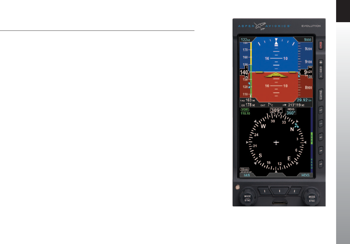
The term “PFD”, is used throughout this Pilot’s Guide and refers to the EFD1000 PFD.
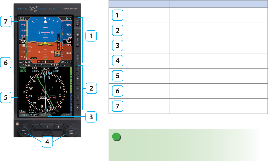
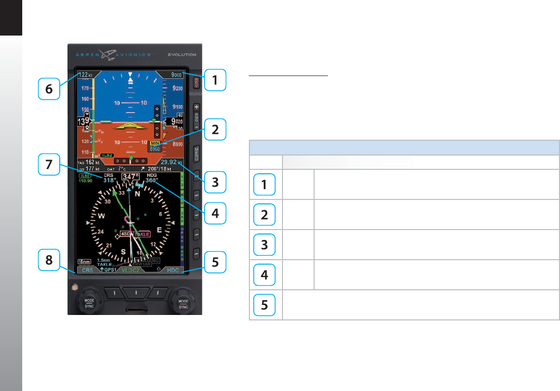
Figure 1 shows a typical EFD1000 PFD display. This guide uses the terminology listed in
Table 1 when referring to specic parts of the PFD and Chapter 4 provides an in-depth
discussion and step-by-step instructions for all the available functionality.
EFD1000 PFD Pilot’s Guide
Page xx 091-00005-001 REV E EFD1000 PFD Pilot’s Guide Page xxi
091-00005-001 REV E
Term Example
Buttons REV Button, Range Buttons, MENU Button
Hot Keys / Menu Keys Five keys on the lower right of the display
Buttons Lower Left Button, CDI Navigation Source Select Button,
Lower Right Button
Knobs Left (CRS) Knob, Right (HDG) Knob
Navigation Display
Data Bar
Attitude Display
Table 1
EFD1000 PFD Display, Knobs , Buttons, and Keys
Figure 1
EFD1000 PFD Display, Knobs , Buttons, and Keys
NOTE
As the number of colors used on the display is limited, to ensure adequate color
dierentiation under all lighting conditions, there are a few cases where a given color is
used in a slightly dierent context than described in Table 2.

EFD1000 PFD Pilot’s Guide
Page xx 091-00005-001 REV E EFD1000 PFD Pilot’s Guide Page xxi
091-00005-001 REV E
Color Philosophy
Table 2 provides the operational philosophy of color usage on the PFD display.
COLOR PURPOSE COLOR PURPOSE
RED
Used to indicate ight envelope and system limits, and
for warning annunciations that require immediate pilot
recognition and which may require immediate pilot
correction or compensatory action. Red is used to indicate
Data Link Weather precipitation areas.
GREEN
Used for navigation information or mode data related to
or provided by the navigation source currently selected for
display on the Course Deviation Indicator (CDI) (i.e., navigation
deviations, equipment operating state, waypoint information).
Green is also used to indicate Data Link Weather precipitation
areas and the status of user controls (i.e., ON, enabled, or
active).
AMBER
Used to indicate abnormal information sources, and for
caution information that requires immediate pilot awareness
and for which subsequent pilot action may be required.
Amber is used to indicate Data Link Weather precipitation
areas.
WHITE Used to show primary ight data (e.g., IAS, ALT, HDG), scales,
and Menu items that are selectable for editing.
MAGENTA
Used for pilot-selectable references (bugs) enabled for editing,
for depicting the active GPS navigation leg on a moving map
display, and for depicting the ight director bar.
GR AY Used to show supplemental ight data, and for Hot Key and
Menu legends that are OFF, disabled, or inactive.
CYAN
Used to indicate editable values that are not currently selected
for editing. CYAN is also used to display bearing pointers,
proximity and other trac icons, and GPS track marker.
BLUE Used to indicate the sky and Data Link Weather precipitation
areas.
BROWN Used to indicate the ground.
Table 2
Color Guide

EFD1000 PFD Pilot’s Guide
Page xxii 091-00005-001 REV E EFD1000 PFD Pilot’s Guide Page xxiii
091-00005-001 REV E
Warnings, Cautions, and Notes
Where applicable warnings, cautions, and notes are given. Aspen Avionics uses the
following icons and denitions (Table 3).
Icon Denition
Warning
Emphasizes a crucial operating or maintenance procedure, which, if not
strictly observed, could result in injury to, or death of, personnel or long
term health hazards.
Indicates a hazard that may require immediate corrective action.
Caution
Indicates an essential operating or maintenance procedure, which,
if not strictly observed, could result in damage to, or destruction of,
equipment.
Indicates the possible need for future corrective action.
Note
Highlights an important operating or maintenance procedure,
condition, or statement.
Safe operation.
Table 3
Warning, Caution, and Note
EFD1000 PFD Pilot’s Guide
Page xxii 091-00005-001 REV E EFD1000 PFD Pilot’s Guide Page xxiii
091-00005-001 REV E
Example Graphics
The example graphics and screen shots used throughout this Pilot’s Guide are provided
for reference only and are taken from a simulated ight. They should not be used for
actual ights.
Most of the example graphics and screen shots used throughout this Pilot’s Guide
& Reference are based on ying the ILS 16R instrument approach into Reno/Tahoe
International Airport (KRNO) in Reno, Nevada, USA. Those images with the airplane in
a right bank show the airplane completing the procedure turn in-bound to intercept
the Localizer, descending through 8,660 feet to the target altitude of 8,500 feet. The
other main group of images, showing the airplane straight and level, are earlier in the
approach, tracking outbound for the procedure turn.
Pilot Familiarity
While the PFD is reasonably intuitive and easy to use, some familiarity with Electronic
Flight Instrument Systems (EFIS) and Horizontal Situation Indicators (HSI) is required.
Aspen Avionics strongly recommends that new users of the PFD get some dual
instruction from an experienced instrument CFI, and spend some time becoming
familiar with the PFD in day VFR conditions with a safety pilot, before ying in actual
instrument meteorological conditions (IMC). To reduce pilot workload, the use of an
autopilot (when available) is strongly encouraged.

EFD1000 PFD Pilot’s Guide
Page xxiv 091-00005-001 REV E EFD1000 PFD Pilot’s Guide Page PB
091-00005-001 REV E
Information Covered in this Pilot’s Guide
This Pilot’s Guide covers all the features and options available for an EFD1000 PFD.
Because of individual conguration and options purchased, some features may not be
available on your particular PFD.
Additionally, the Pilot PFD model does not oer the following features:
• Horizontal Situation Indicator (HSI)
• Dual Bearing Pointers
• Lateral and Vertical Deviation Indicators
• Minimums
• GPS and VLOC Navigation ARINC 429 Interface
• GPS Steering (GPSS)
• Optional Trac
• Optional Lightning
• Optional Weather
NOTE
The Pilot PFD supports the display of ight plan and
background navigation data from ARINC 429 GPS
Interfaces.
NOTE
The Pilot PFD does not support the display of lateral or
vertical deviations from an ARINC 429, or Analog GPS
interface .
The Pilot PFD does not support the display of lateral or
vertical deviations from an ARINC 429, or Analog VLOC
interface.

CHAPTER 1 WELCOME
EFD1000 PFD Pilot’s Guide
Page PB 091-00005-001 REV E EFD1000 PFD Pilot’s Guide Page 1-1
091-00005-001 REV E
Chapter 1
Welcome and Introduction
Welcome to Aspen Avionics’ Evolution Flight Display (EFD) System, the
most exible, expandable, and upgradable Electronic Flight Instrument
System (EFIS) available for general aviation aircraft. Designed to replace
traditional mechanical primary ight instruments—in whole or in part,
all at once, or in phases. This modularity and upgradability allows the
system to grow with you and your airplane, over time and aordably.
The EFD system is built around the EFD1000 PFD, which replaces a vertical pair of your
six primary ight instruments. The PFD has a bright, high-resolution, six-inch diagonal
LCD display, and a number of knobs, buttons, and keys the pilot uses to control the
system. The three-inch diameter, four-inch deep can on the back of the display slides
into existing panel cutouts (where the top mechanical instrument used to be) (Figure
1-1).
Figure 1-1
EFD1000 Primary Flight Display Unit
CHAPTER 1 WELCOME
EFD1000 PFD Pilot’s Guide
Page 1-2 091-00005-001 REV E EFD1000 PFD Pilot’s Guide Page 1-3
091-00005-001 REV E
Figure 1-3
Dual Display System: PFD & MFD
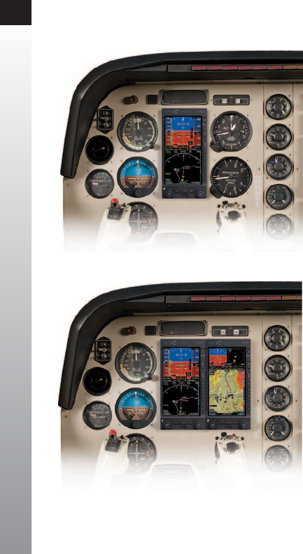
Figure 1-2
Single Display EFD1000 PFD System
The center of the EFD System is the EFD1000 Primary Flight Display (PFD), which
replaces the traditional mechanical Attitude Indicator (AI) and Directional Gyro (DG)
or Horizontal Situation Indicator (HSI) (Figure 1-2).
The PFD is available in two models—the EFD1000 Pilot and the EFD1000 Pro.
Add a second EFD1000 congured as a Multi-Function Display (MFD) (Figure 1-3),
replacing the Altimeter and Vertical Speed Indicator (VSI), and you’ll double the
capabilities of your system, while also providing complete redundancy and backup to
your PFD. The EFD1000 MFD contains the same AHRS, ADC, and I/O capabilities as the
PFD for full redundancy and can assume the role of the PFD should it ever fail.
CHAPTER 1 WELCOME
EFD1000 PFD Pilot’s Guide
Page 1-2 091-00005-001 REV E EFD1000 PFD Pilot’s Guide Page 1-3
091-00005-001 REV E
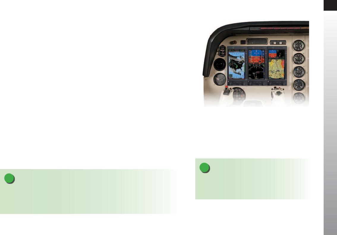
Adding another MFD, replacing the Airspeed Indicator (ASI) and Turn Coordinator,
to round out a complete six-pack replacement and gain even more capability and
exibility (Figure 1-4). When you are ready to upgrade, simply contact an Aspen
Avionics Authorized Dealer for more information.
This Pilot’s Guide covers the EFD1000 Pilot model* and the EFD1000 Pro PFD model.
These systems are powerfully exible, and can be congured in a variety of ways,
depending on the other aircraft systems with which they are integrated.
*The Pilot PFD model does not oer the following features:
• Horizontal Situation Indicator (HSI)
• Dual Bearing Pointers
• Lateral and Vertical Deviation Indicators
• Minimums
• GPS and VLOC Navigation ARINC 429 Interface
• GPSS
• Optional Trac
• Optional Lightning
• Optional Weather
Figure 1-4
Trio Display System: PFD & Dual MFDs
NOTE
With multiple EFD installations, an independent,
standby attitude indicator must be within the pilot’s
primary maximum eld of view.
NOTE
Please spend some time with your avionics installer to understand exactly how your PFD
is installed and congured in your particular aircraft, to understand the features and
capabilities available to you, and to understand how various aircraft system failures and
abnormalities may aect your PFD.
CHAPTER 1 WELCOME
EFD1000 PFD Pilot’s Guide
Page 1-4 091-00005-001 REV E EFD1000 PFD Pilot’s Guide Page 1-5
091-00005-001 REV E
1.1. System Overview
The PFD system typically consists of four components:
1. EFD1000 Display Unit (PFD)
2. Conguration Module (CM)
3. Remote Sensor Module (RSM)
4. Analog Converter Unit (ACU)1
The ACU converts older analog signals and interfaces to the
industry-standard digital ARINC 429 interface, which is the
native language of the PFD. In some installations, generally
when the aircraft is not equipped with an autopilot and has
only digital GPS/Nav/Comm, the ACU may be omitted.
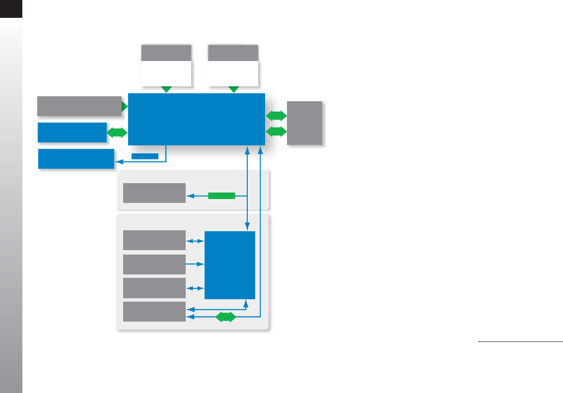
The system architecture in Figure 1-5 shows the relationships
of the PFD, RSM, CM and ACU.
Digital GPS/VLOC
Analog GPS/VLOC via ACU
EFD1000 Pro PFD
(Primary Flight Display)
Analog
Converter Unit
(ACU)
Aircraft Power
Conguration Module (CM)
Optional Tone Generator
12C
SPI
RS-232
Digital VLOC/GPS
Sources
Analog NAV Sources
Radar Altimeter
Autopilot
Legacy GPS
RS-232
Discrete
PitotStatic
Existing Aircraft
Static Line
Existing Aircraft
Pitot Line
Remote
Sensor
Module
(RSM)
ARINC 429
Figure 1-5
Pro PFD System Architecture 1. Not available with the Pilot PFD
CHAPTER 1 WELCOME
EFD1000 PFD Pilot’s Guide
Page 1-4 091-00005-001 REV E EFD1000 PFD Pilot’s Guide Page 1-5
091-00005-001 REV E
1.1.1. Primary Flight Display Unit (PFD)
The Primary Flight Display Unit (PFD) is a digital system that consists of a high
resolution, six-inch diagonal color LCD display, user controls, photocell, and microSD
data card slot. The three-inch diameter, four-inch deep can on the back of the display
contains a non-removable electronics module that includes:
• A Sensor Board with solid-state Attitude and Heading Reference System (AHRS) and
digital Air Data Computer (ADC)
• A Main Application Processor (MAP) board with Central Processing Unit (CPU),
graphics processor and system memory
• An Input-Output Processor (IOP) board for integrating communications with other
aircraft systems
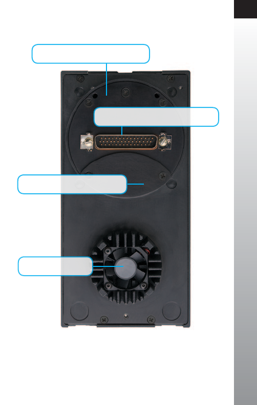
Also on the rear of the unit (Figure 1-6) are:
• An access cover for removing and replacing the built-in backup battery
• Pneumatic connections to the aircraft’s pitot and static systems
• 44-pin D-sub connector for electrical connections to the PFD
• A cooling fan, to cool the electronics and LCD backlights
The PFD mounts to the front surface of the instrument panel using the standard
installation kit; an optional ush-mount installation kit is also available.
Figure 1-6
EFD1000 Display Unit
Rear Connections
44-pin D-Sub for Electrical Connections
Access Cover to Internal Battery
Pitot & Static System Connections
Cooling Fan

CHAPTER 1 WELCOME
EFD1000 PFD Pilot’s Guide
Page 1-6 091-00005-001 REV E EFD1000 PFD Pilot’s Guide Page 1-7
091-00005-001 REV E
1.1.2. Conguration Module (CM)
The Conguration Module (Figure 1-7), contains an EEPROM device that retains system
conguration and calibration data and provides two primary functions:
• Retains aircraft-specic conguration information, calibration data, and user
settings, allowing the PFD to be swapped for service purposes without re-entering
or re-calibrating the installation
• Contains a license key that congures the PFD software features
The CM is typically attached to the wire bundle coming out of the D-sub connector on
the display unit.
1.1.3. Analog Converter Unit (ACU)1
The Analog Converter Unit (ACU) (Figure 1-8), included with most Pro PFD systems,
enables the all-digital, EFD1000 System to interface with analog avionics when required.
The ACU converts multiple analog interfaces to the digital ARINC 429 buses supported
by the PFD. Control parameters, such as desired heading, are also sent from the Pro PFD
to the ACU for conversion to analog format for autopilot support. The ACU is required
when any of the following capabilities are required in a Pro PFD installation:
• Interface to supported autopilots
• Interface to conventional VHF navigation radios
• Interface to legacy (non-ARINC 429) GPS navigators
• Interface to supported radar altimeter decision height annunciations
If ARINC 429-based digital radios, such as the Garmin 400/500-series GPS/nav/comm
radios are installed in the aircraft and no other aircraft interfaces are desired, the ACU is
not required.
Figure 1-7
Conguration Module (CM)
Figure 1-8
Analog Converter Unit (ACU)
1. Not available with the Pilot PFD

CHAPTER 1 WELCOME
EFD1000 PFD Pilot’s Guide
Page 1-6 091-00005-001 REV E EFD1000 PFD Pilot’s Guide Page 1-7
091-00005-001 REV E
1.1.4. Remote Sensor Module (RSM)
The Remote Sensor Module (RSM) (Figure 1-9), is an integral part of the EFD1000
system and works together with the display unit sensors as part of the AHRS and ADC.
The RSM looks and mounts like a GPS antenna and is mounted on the exterior of the
fuselage, typically aft of the cabin.
The RSM contains the following sub-systems:
• 3D magnetic ux (heading) sensors
• Outside Air Temperature (OAT) sensor
• Emergency backup GPS engine and antenna
The RSM communicates with the PFD via a digital cable connection.
1.1.5. Evolution Weather Receiver (EWR50)1
The optional Evolution Weather Receiver, EWR50 (Figure 1-10) converts the XM
WX Satellite Weather data into a digital format displayed on the EFD1000 Pro PFD.
The EWR50 provides the ability to receive XM WX Satellite Weather data with a paid
subscription to XM WX Satellite Weather service. The EWR50 consists of a receiver and
antenna. Figure 1-10
Evolution Weather Receiver (EWR50) - Optional
NOTE
A single EWR50 Receiver will supply data to all EFD units installed on the aircraft.
Figure 1-9
Remote Sensor Module (RSM)
1. Not available with the Pilot PFD

CHAPTER 1 WELCOME
EFD1000 PFD Pilot’s Guide
Page 1-8 091-00005-001 REV E EFD1000 PFD Pilot’s Guide Page PB
091-00005-001 REV E
1.1.6. Evolution Databases
The Evolution Flight Display System includes two separate databases loaded on a
microSD card; one from Jeppesen and one from Seattle Avionics Software.
• The Jeppesen database consists of NavData®, Obstacle, Cultural, and Terrain data.
• The Seattle Avionics database features Instrument Approach Procedure (IAP)
charts, Departure charts, Standard Terminal Arrival Route (STAR) charts, and airport
diagrams.
Refer to Chapter 7 Appendices, for additional information and instructions about
updating the databases onto the microSD card.
NOTE
For aircraft with an EFD1000 PFD only and the Evolution Synthetic Vision (ESV) option
installed:
Only the Jeppesen database is required to be loaded on the microSD card.
NOTE
For aircraft congured with multiple EFDs; PFD and MFD(s):
The MFD requires both databases loaded on the microSD card; the Jeppesen database for
all mapping functions and the Seattle Avionics database for displaying chart data.
Whenever the Evolution Synthetic Vision (ESV) option is installed, the preloaded microSD
card is compatible with either the PFD or the MFD and may be interchanged
NOTE
The PFD only requires a preloaded microSD card to
support the Evolution Synthetic Vision (ESV) option
when installed. Otherwise, the PFD does not require a
microSD card.
NOTE
When congured with the ESV option, refer to the
Evolution Synthetic Vision Pilot’s Guide Supplement,
091-00031-001.
CHAPTER 2 CONTROLS AND DISPLAY
EFD1000 PFD Pilot’s Guide
Page PB 091-00005-001 REV E EFD1000 PFD Pilot’s Guide Page 2-1
091-00005-001 REV E
Chapter 2
Controls and Display
The PFD is a at-panel LCD primary ight instrument that presents
the pilot with all of the information from the traditional six-pack of
mechanical instruments: Airspeed, Attitude, Altitude, Turn Coordinator,
Heading Indicator (or HSI) and Vertical Speed Indicator (VSI). Modern
technology and standard EFIS symbology enable the consolidation of
all six instruments into a single display, tightening the pilot’s instrument
scan and reducing pilot workload.
The PFD is a single vertical instrument that replaces the existing Attitude Indicator
and Heading Indicator/HSI. The display is divided into three parts: an upper Attitude
Display, a lower Navigation Display, and a Data Bar between the upper and lower halves.
The Attitude and Navigation displays are highly customizable — from stripped-down,
minimalist presentations, to dense, information-rich displays — depending on pilot
preference and phase of ight.
This chapter gives an overview of all the instruments, information, and controls of
the PFD. Table 2-1 and Figure 2-2 identify the controls and display orientation (see
Chapter 4, Reference Guide for more details).
Figure 2-1
Pilot PFD
CHAPTER 2 CONTROLS AND DISPLAY
EFD1000 PFD Pilot’s Guide
Page 2-2 091-00005-001 REV E EFD1000 PFD Pilot’s Guide Page 2-3
091-00005-001 REV E
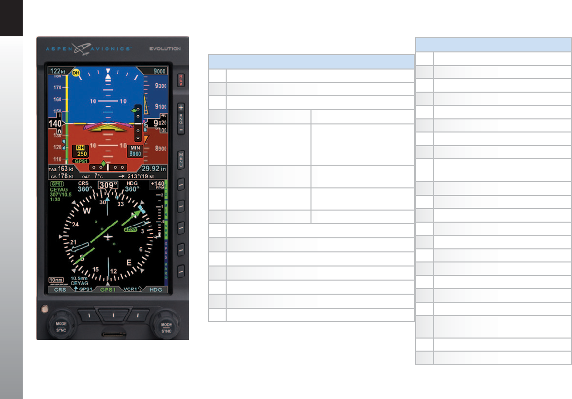
2.1. Controls & Display Orientation ATTITUDE DISPLAY
16 Attitude Display
17 Aircraft Reference Symbol
18 Single-Cue Flight Director 2, 4
19 Roll Pointer
20 Slip/Skid Indicator
21 Altitude Tape
22 Selected Altitude Field (controls the Altitude Bug)
23 Altitude Alerter
24 Numerical Altitude Indication, Altitude Drum/
Pointer
25 Altitude Trend Vector
26 Altitude Bug
27 Decision Height Annunciation 3, 4
28 Selected Minimums Field 4
29 Radio Altitude 3, 4
30 MINIMUMS Marker 4
31 LDI Navigation Source Annunciation 4
32 Airspeed Tape
33 Selected Airspeed Field (controls the Airspeed Bug)
34 Airspeed Bug
35 Numerical Airspeed Indicator, Airspeed Drum/
Pointer
36 Vertical Deviation Indicator (VDI) 4
37 Lateral Deviation Indicator (LDI) 4
Figure 2-1a
Pro PFD
CONTROLS
1Reversion and Power Button
2Range Buttons
3Menu Button
41/2 Hot Key Menu 1 of 2 42/2 Hot Key Menu 2 of 2 1, 4, 5
5MIN - Minimums 4
On/O
LTNG 4 – Data link Lightning
Overlay On/O
STRK 4 – WX-500 Strikes Overlay
CELL 4 – WX-500 Cells Overlay
6360/ARC View NXRD 4 – Data Link Weather
Overlay On/O
7GPSS - GPS Steering 4
On/O
TRFC 4 – Trac Overlay On/O
8BARO BARO 4
9Right Knob
10 Lower Right Button, Double-Line Bearing Pointer Source Select 4
11 CDI Navigation Source Select Button 4
12 Lower Left Button, Single-Line Bearing Pointer Source Select 4
13 Left Knob
14 Automatic Dimming Photocell
15 microSD Card Slot
CHAPTER 2 CONTROLS AND DISPLAY
EFD1000 PFD Pilot’s Guide
Page 2-2 091-00005-001 REV E EFD1000 PFD Pilot’s Guide Page 2-3
091-00005-001 REV E
1
2
3
4
68
5
6
7
8
913
12 11 10
15
14
33 22
32
35
18
16
19
20
21
17
2 9
36
31
23
34
24
37
26
28
43
38
404142
39
66 59
60
65
51 50
44
61
53
49
46
48
45
55
54
58
47
52 56
57
63
62
64 67
25
27
70
69
30
30
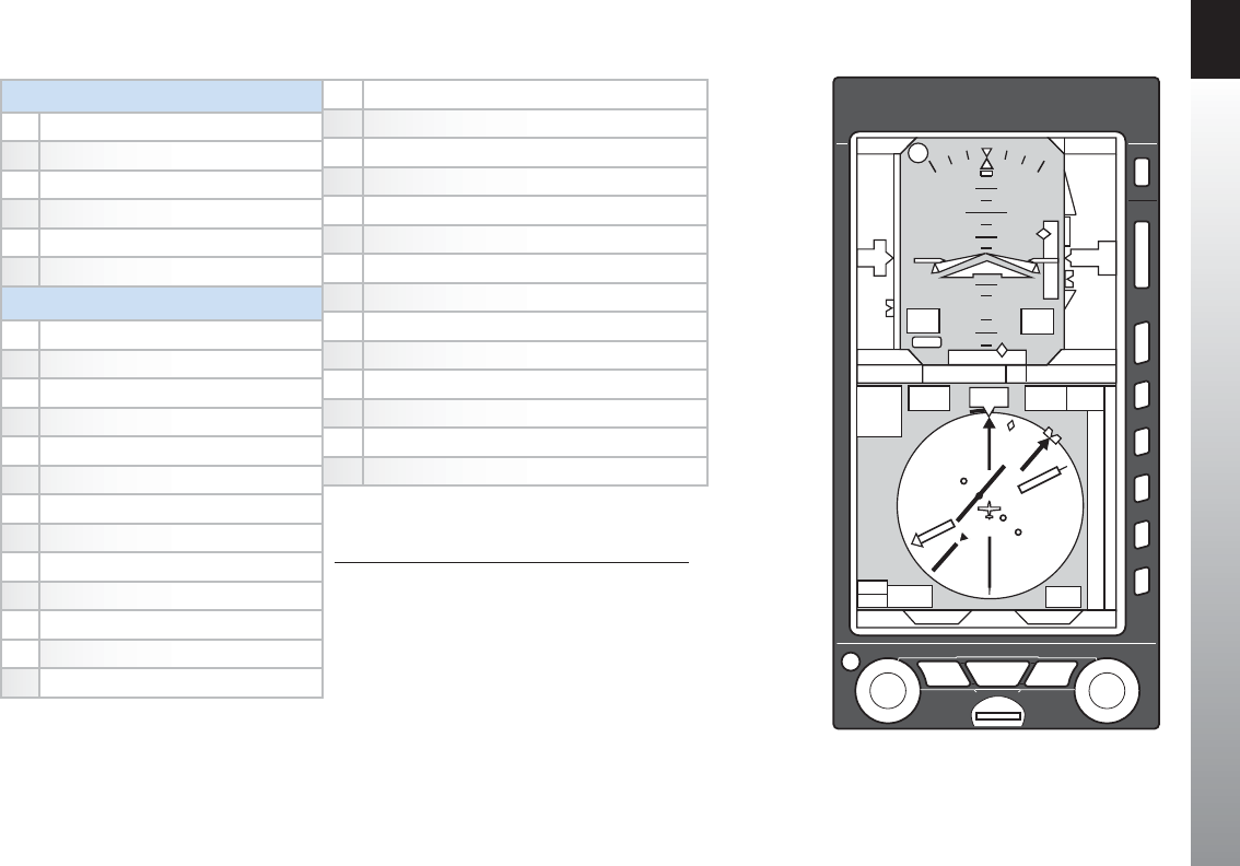
DATA BAR
38 True Airspeed (TAS) or Mach number
39 Barometric Pressure Setting Field
40 Wind Direction and Speed
41 Wind Direction Arrow
42 Outside Air Temperature (OAT)
43 Ground Speed
NAVIGATION DISPLAY
44 Navigation Display
45 Ownship Symbol
46 Course Pointer 4
47 TO/FROM Indicator 4
48 Rate of Turn Indicator
49 Ground Track Marker
50 Numerical Direction Indicator
51 Selected Course (CRS) Field 4
52 Selected Heading Field
53 Heading Bug
54 Course Deviation Scale 4
55 Course Deviation Indicator 4
56 Vertical Speed Numerical Value
Figure 2-2
Pro PFD Display Elements
Table 2-1
PFD Components
57 Vertical Speed Tape
58 Single-Line Bearing Pointer 4
59 Single-Line Bearing Pointer Source 4
60 Single-Line Bearing Pointer Source Info Block 4
61 Double-Line Bearing Pointer 4
62 Double-Line Bearing Pointer Source 4
63 Double-Line Bearing Pointer Source Info Block 4
64 Selected CDI Navigation Source 4
65 Selected CDI Navigation Source Information Block 4
66 Left Knob State
67 Right Knob State
68 Hot Key Label
69 Basemap Range
70 Declutter Level
1. The Hot Key menu 2/2 is only available when the Pro PFD is
congured with the optional Evolution Hazard Awareness
option and the associated sensor(s)
2. With compatible autopilots
3. With compatible radar altimeters
4. Not available with the Pilot PFD
5. When congured with the Evolution Synthetic Vision option,
refer to the Evolution Synthetic Vision Pilot Guide Supplement
091-00031-001 for additional Hot Key menu

CHAPTER 2 CONTROLS AND DISPLAY
EFD1000 PFD Pilot’s Guide
Page 2-4 091-00005-001 REV E EFD1000 PFD Pilot’s Guide Page 2-5
091-00005-001 REV E
2.2. Controls
The primary means for the pilot to control the PFD are the two knobs and three buttons
at the bottom of the display. The knobs control setting CRS and HDG, and additional
bugs and altitude settings. The lower three buttons control selection of navigation
sources for the CDI and Bearing Pointers. There are three additional buttons above
the Hot Keys to control entering and exiting the Menu, setting the Map Range, and
Reversion or Manual Power Control.
Five Hot Keys to the right of the Navigation Display toggle various features on and o.
The function of each is indicated by the label on the display to the left of each key.
2.2.1. Left and Right Knobs
The Left and Right Knobs are designed to provide immediate operation yet minimize
the possibility of an inadvertent operation. This is accomplished by requiring that the rst
action of the knob “wakes up” the knob and changes the label from cyan to magenta.
The rst click when the knob is turned or the rst press on the knob, “wakes up” the knob
function.
Press the knob more than once to cycle through its Menu options in a round-robin
sequence or press and hold the knob to synchronize (SYNC) the function’s value (see
Section 2.2.1.3. SYNC Function). After 10 seconds of inactivity, the knob returns to its
default setting.
NOTE
The Pilot PFD Navigation Display has a slaved
Directional Gyro instead of an HSI. It does not have
a Course Pointer, Course Deviation Indicator, or
Bearing Pointers.
The Pilot PFD also does not include an approach
minimums (MIN) setting. Therefore, these knob
functions are not available on the Pilot PFD.

CHAPTER 2 CONTROLS AND DISPLAY
EFD1000 PFD Pilot’s Guide
Page 2-4 091-00005-001 REV E EFD1000 PFD Pilot’s Guide Page 2-5
091-00005-001 REV E
2.2.1.1. Left Knob Functions
The Left Knob is used to set the Course (CRS) and Airspeed Bug (IAS). Course (CRS) is the
default setting for the Left Knob.
Refer to Table 2-1 and Figure 2-2
• Rotate the Left Knob one click or Press the knob once to set the course (CRS)
(Refs. 46 and 51 and see NOTE about Auto Course)
• Press the Left Knob twice to set the Airspeed Bug (IAS) and Selected Airspeed
Field (Refs. 33 and 34)
2.2.1.2. Right Knob Functions
The Right Knob is used to set Heading (HDG), Selected Altitude Field (ALT), Barometric
Pressure (BARO), and Instrument Approach Minimums (MIN)1. Successive presses of
the Right Knob will cycle through HDG and ALT (and MIN1, if selected) in a round-robin
sequence. Rotate the Right Knob to the left or right to decrease or increase the value of
selected eld. Heading (HDG) is the default setting for the Right Knob.
Refer to Table 2-1 and Figure 2-2
• Rotate the Right Knob one click or Press the knob once to set the Selected
Heading Field/Heading Bug (HDG) (Refs. 52 and 53)
• Press the Right Knob twice to set the Selected Altitude Field (ALT)/Altitude
Bug (Refs. 22 and 26)
• When the MIN Hot Key is selected1, press the Right Knob three times to set
the Selected Minimums Field (MIN) (Ref. 28)
NOTE1
MIN will only be shown if the MIN function is already
active. When the MIN function is active, the MIN Hot
Key label (Ref. 5) is shown in green with dark blue
letters, and the MIN value is shown on the Attitude
Display (Ref. 28).
When the MIN function is inactive (blue label with
green letters), pressing the MIN Hot Key will both
activate the function and immediately make it
available for editing.
NOTE
When the CDI navigation source is selected to a GPS
receiver and the Auto Course is enabled in the Menu,
the course is set automatically by the GPS and is not
pilot-adjustable (see Section 4.4.6). This state is
indicated by the CRS eld and Knob label shown in
green with an inverse “A”. In this case, pressing the Left
Knob will enable you to set only the Airspeed Bug(IAS).
1. Not available with the Pilot PFD
CHAPTER 2 CONTROLS AND DISPLAY
EFD1000 PFD Pilot’s Guide
Page 2-6 091-00005-001 REV E EFD1000 PFD Pilot’s Guide Page 2-7
091-00005-001 REV E
2.2.1.3. SYNC Function
Knob SYNC Function
1. Press the Knob until its state shows the value you want to set in magenta.
2. Press and hold the Knob for approximately one (1) second to SYNC the eld’s
value according to the rules shown in Table 2-2.
3. After 10 seconds of inaction, the knob reverts to its home state (CRS or HDG),
and the labels and eld turn to cyan (inactive).
Right Knob
SYNC Action
ALT Altitude Bug and Altitude Alerter are set to the current altitude.
MIN Set to the current altitude.
BARO Set to 29.92 in Hg or 1013 mB.
HDG Set to the current heading.
Right Knob -Current State default setting: HDG
Cyan indicates eld is inactive.
Figure 2-3
Left and Right Knobs and Corresponding Fields

CHAPTER 2 CONTROLS AND DISPLAY
EFD1000 PFD Pilot’s Guide
Page 2-6 091-00005-001 REV E EFD1000 PFD Pilot’s Guide Page 2-7
091-00005-001 REV E
Left Knob
SYNC Action
IAS Set to the current indicated airspeed.
CRS
VOR navigation
Course Pointer points to the VOR. CRS value
is the reciprocal of the current VOR radial. The
deviation bar centers with a “TO” indication.
ILS navigation Current aircraft heading.
GPS
Course Pointer points to the active GPS
waypoint. The deviation bar centers with a “TO”
indication. (AUTOCRS must be disabled).
GPS
AUTOCRS enabled No eect.
Left Knob - Current State default setting: CRS
Cyan indicates eld is inactive.
Table 2-2
Left and Right Knob SYNC Description
CHAPTER 2 CONTROLS AND DISPLAY
EFD1000 PFD Pilot’s Guide
Page 2-8 091-00005-001 REV E EFD1000 PFD Pilot’s Guide Page 2-9
091-00005-001 REV E
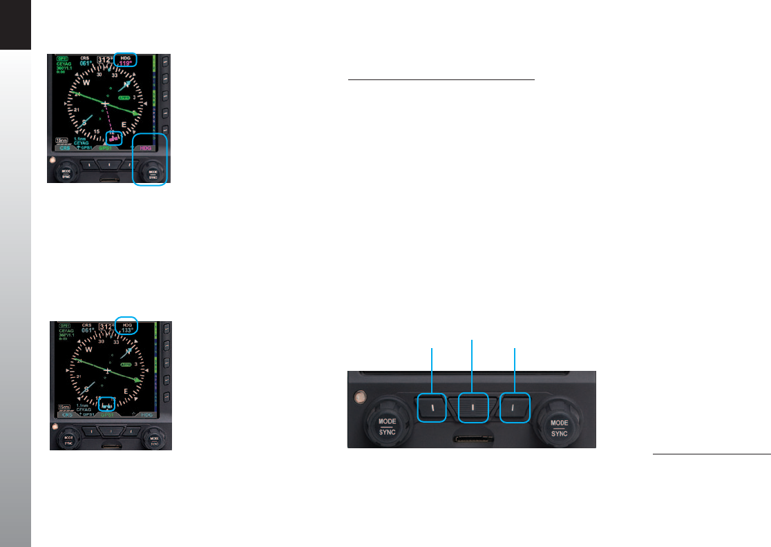
2.2.1.4. Using the Knobs (Example)
How to Set the Heading Bug (HDG)
1. Rotate the Right Knob to the desired heading value, shown both by the
position of the Heading Bug and the numeric value in the Selected Heading
Field (Figure 2-5). The HDG label, Heading Bug and the Selected Heading
Field appears in magenta
2. After 10 seconds of inactivity, the knob defaults to HDG. The HDG label,
Heading Bug and Selected Heading Field value will appear in cyan (Figure
2-6).
2.2.2. Navigation Source Select Buttons1
The three buttons on the bottom of the PFD (Figure 2-7) allow the pilot to select the
navigation source for the CDI and Bearing Pointers (see Section 4.4.5. CDI Navigation
Source and Section 4.4.8. Bearing Pointer Source Selection for more detailed
information).
Figure 2-5
Editing the HDG eld
Figure 2-6
HDG eld updated and inactive
Figure 2-7
CDI and Bearing Pointer Source Select Buttons
Single-Line Bearing
Pointer Source
CDI Nav
Source Double-Line Bearing
Pointer Source
1. Not available with the Pilot PFD

CHAPTER 2 CONTROLS AND DISPLAY
EFD1000 PFD Pilot’s Guide
Page 2-8 091-00005-001 REV E EFD1000 PFD Pilot’s Guide Page 2-9
091-00005-001 REV E
2.2.2.1. CDI Navigation Source Select Button1
The CDI Nav Source Select Button is the center button (Figure 2-7). It selects which
of the available navigation sources will couple to the CDI, which in turn couples to
the autopilot (if available). Each press of the CDI Nav Source Button selects the next
available nav source, cycling through all available sources in a round-robin sequence.
The currently coupled CDI nav source is displayed directly above the CDI Nav Source
Select Button.
The available navigation sources are congured when the PFD was installed (depending
on what is installed in the aircraft and connected to the PFD). The available navigation
source choices are: GPS1, GPS2, VLOC1, and VLOC2.
If a navigation source is congured to be available, but is not providing valid navigation
data, its navigation source annunciation will be shown with a red slash through it, and
the CDI will not be shown with the Course Pointer. The pilot is able to select the invalid
source, but no navigation data is provided.
When one or more of the connected navigation sources is a combined GPS/Nav device
(e.g., some of the Garmin 400/500-series), the list of navigation sources available for
selection will be determined by the current CDI mode of the GPS navigator.
NOTE
When GPS is selected as the CDI’s nav source, but no
active waypoint is programmed in the GPS navigator,
that source will be shown as invalid until an active
ight plan or direct-to waypoint is programmed into
theGPS.
For example, with a Garmin GNS-430 installed as
the #1 navigation source, when “GPS” is shown
immediately above the CDI Button on the GNS-430,
the PFD will show GPS1 as an available , but invalid,
nav source. When the pilot presses the CDI Button on
the GNS-430 so that VLOC is now displayed on the
GNS-430, the PFD will show VLOC1 as the available nav
source, and GPS1 cannot be selected.
NOTE
The Pilot PFD does not display any CDI or Bearing
Pointers. Its center CDI Nav Source Select Button is used
only to select which connected GPS source (GPS1 or
GPS2) is used to display the GPS ight plan, waypoints ,
and basemap symbols.
1. Not available with the Pilot PFD

CHAPTER 2 CONTROLS AND DISPLAY
EFD1000 PFD Pilot’s Guide
Page 2-10 091-00005-001 REV E EFD1000 PFD Pilot’s Guide Page 2-11
091-00005-001 REV E
2.2.2.2. Bearing Pointer Source Select Buttons1
The Lower Left Button and the Lower Right Button are the Bearing Pointer Nav Source
Select Buttons (Figure 2-7). The Lower Left Button controls the Single-Line Bearing
Pointer and the Lower Right Button controls the Double-Line Bearing Pointer. Each
button controls which nav source is connected to the respective Bearing Pointer.
The Bearing Pointers act like a conventional RMI (Radio Magnetic Indicator); the needle
points to the station. Unlike a conventional RMI, the PFD Bearing Pointers can also
point to the active waypoint of a GPS navigator whether that is a VOR, NDB, airport,
intersection, or missed approach point.
Each Bearing Pointer can be connected to any of the available navigation sources; GPS1,
VOR1, GPS2, VOR2, ADF1 or ADF2 (depending on conguration), or to none. Each press
of the Bearing Pointer Nav Source Select Button selects the next available nav source,
cycling through all available nav sources and none, in a round-robin sequence. The
currently connected nav source is displayed directly above its respective button; blank
with only the Bearing Pointer icon indicates that no nav source is selected, and the
Bearing Pointer is removed from the display.
If the selected nav source is a valid choice, but no usable nav data is being received
(e.g., the VOR station is out of range, or the VLOC is tuned to a localizer frequency), the
Bearing Pointer will not be displayed.
1. Not available with the Pilot PFD

CHAPTER 2 CONTROLS AND DISPLAY
EFD1000 PFD Pilot’s Guide
Page 2-10 091-00005-001 REV E EFD1000 PFD Pilot’s Guide Page 2-11
091-00005-001 REV E
2.2.3. Hot Keys
The ve Buttons along the lower right side of the PFD function as either single-action
Hot Keys for frequently used commands or as Menu Keys when the Menu has been
activated. The Hot Key functions are accessible at any time, except when the Menu is
active.
Each Hot Key provides instant access to the assigned command. Each press of a Hot Key
toggles between the settings that each key controls (see Table 2-3).
The Hot Key labels use the following color philosophy (see Figure 2-8 and Figure 2-9).
• A green label and dark blue letters (also known as inverse green) indicates
that the Hot Key function is enabled
• A dark blue label and green letters indicates that the Hot Key function is
diabled
• A dark blue label and gray letters indicates that the Hot Key function is not
available
• A dark blue label without letters indicates that the Hot Key has no function
The 360/ARC Hot Key labels indicate which mode is currently active on the Navigation
Display.
NOTE1
When congured with the Evolution Hazard Awareness
option, there are two levels of Hot Keys controlled
by the rst Hot Key (1/2 or 2/2). The second level
(2/2) provides access to Hazard Awareness overlays
as described in Chapter 4, Section 4.8. Hazard
Awareness.
NOTE
The TRFC Filter Hot Key is blank when Trac Software
Option is not installed.
1. Not available with the Pilot PFD
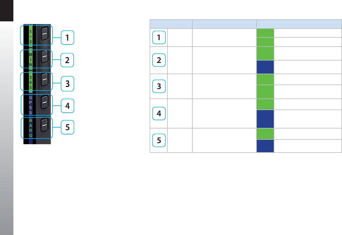
CHAPTER 2 CONTROLS AND DISPLAY
EFD1000 PFD Pilot’s Guide
Page 2-12 091-00005-001 REV E EFD1000 PFD Pilot’s Guide Page 2-13
091-00005-001 REV E
HOT KEY DESCRIPTION OPTIONS
1/2 1Hot Key Menu selection
1/2 Hot Key Menu 1 of 2
2/2 Hot Key Menu 2 of 2 5
MIN 1
Enables and displays, or
disables and hides, Minimums
Alerter 1, 2 (see Section 4.2.3.4.)
MIN Minimums displayed and
Altitude Alerter enabled 2
MIN Minimums alerter disabled
360 / ARC
Toggles between 360 and ARC
modes of Navigation Display
(see Section 4.4.1.)
360 ARC Compass Mode
ARC 360° Compass Mode
GPSS 1, 3, 4
Toggles between GPS Steering
(GPSS) Mode and HDG mode
for Autopilot/Flight Director 4
(see Section 4.7.1.)
GPSS GPSS on
GPSS GPSS O, HDG mode active
BARO
Toggles between BARO
adjustment on or o for
Barometric Pressure setting
BARO BARO adjustment on
BARO BARO adjustment o
Figure 2-8
Hot Key Menu 1 of 2

CHAPTER 2 CONTROLS AND DISPLAY
EFD1000 PFD Pilot’s Guide
Page 2-12 091-00005-001 REV E EFD1000 PFD Pilot’s Guide Page 2-13
091-00005-001 REV E
HOT KEY DESCRIPTION OPTIONS
2/2 1, 5 Hot Key Menu selection
2/2 Hot Key Menu 2 of 2
1/2 Hot Key Menu 1 of 2
LTNG 1, 5
Toggles between Lightning
Overlay options (see Section
4.8.1.)
LTNG Data Link Lightning Overlay on
STRK WX-500 Strike Overlay on
CELL WX-500 Cell Overlay on
LTNG All Lightning o
NXRD 1, 5
Displays Data Link Weather and
Radar Coverage overlay (see
Section 4.8.2.)
NXRD NEXRAD Overlay on
NXRD NEXRAD Overlay o
TRFC 1, 6 Displays Trac overlay (see
Section 4.8.3.)
TFCN Normal Filter
TFCU Unrestricted (No Filtering)
TFCA Above Filter
TFCB Below Filter
TRFC Trac Overlay o
BARO 1
Toggles between BARO
adjustment on or o for
Barometric Pressure setting
BARO BARO adjustment on
BARO BARO adjustment o
Table 2-3
Hot Key Descriptions
1. Not available with the Pilot PFD
2. When the Minimums eld is rst enabled with the MIN Hot Key, the MIN value is immediately available for editing
3. Flight plan legs and waypoints display available in all installations including a GPS navigator. Basemap display of nearby waypoints available with all ARINC 429 GPS navigators
and some RS-232 GPS navigators
4. GPSS available only with ARINC 429-based navigators
5. Hazard awareness overlays are available only on the Pro PFD with the Evolution Hazard Awareness (EHA) option and compatible hazard awareness sensors are installed and
congured to the Pro PFD. The Hot Key label is blank when function is not available
6. The Trac Filter Hot Key label is blank when the Trac overlay function is not available
Figure 2-9
Hot Key Menu 2 of 2

CHAPTER 2 CONTROLS AND DISPLAY
EFD1000 PFD Pilot’s Guide
Page 2-14 091-00005-001 REV E EFD1000 PFD Pilot’s Guide Page 2-15
091-00005-001 REV E
2.2.4. Menu
The MENU button is used to access the EFD1000 PFD’s Menu to change options, and
also to change the PFD’s display brightness.
2.2.4.1. Using the Menus
Press the MENU button to activate the Menu (Ref. 3). The current menu page name is
shown on the bottom center of the Navigation Display. Directly below the menu page
name is a segmented menu page bar, giving a graphical representation of the current
page relative to the total number of menu pages. The current menu page number is
shown in the lower right corner of the Navigation Display.
Menu Page 1, General Settings A, is the one most commonly used in ight. It allows
the pilot to enable or disable the AUTO COURSE SELECT mode, to display or hide the
Vspeeds on the airspeed tape, and to choose CDI type for the ARC Compass mode.
The other menu pages are used for barometric pressure and Outside Air Temperature
(OAT) units of measure settings, Auto Range, Vspeeds and map customization, PFD
power management, product version information, and information and option settings,
relative to your specic equipment and installed options.
The Menu operates either in the Navigation or Edit mode, as indicated by the label
directly above the Right Knob. When the MENU button is rst pressed, the Main Menu
is in the Navigation mode, indicated by the magenta label SEL PAGE directly above
the Right Knob (Figure 2-15). When in the Navigation mode, rotating the Right Knob
navigates through the menu pages. Rotate the Right Knob clockwise to advance to the
next menu page, counterclockwise to return to the previous page.
Figure 2-15
Menu Navigation Mode
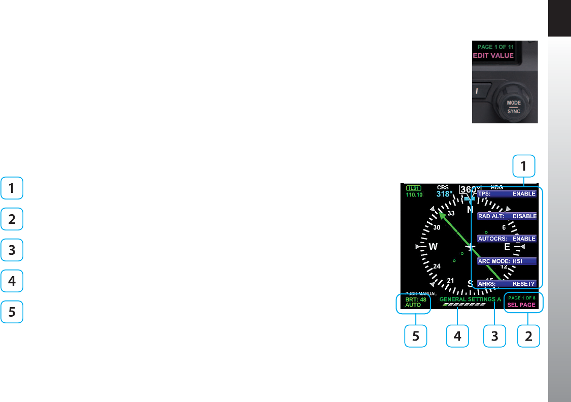
CHAPTER 2 CONTROLS AND DISPLAY
EFD1000 PFD Pilot’s Guide
Page 2-14 091-00005-001 REV E EFD1000 PFD Pilot’s Guide Page 2-15
091-00005-001 REV E
Each Menu Page has up to ve selectable options, each adjacent to one of the ve
Hot Keys which double as Menu Keys when the Menu is active (Item 1 of Figure 2-17
and Table 2-4). After navigating to the Menu Page containing the option you want to
change, press the Menu Key adjacent to that option label, which initiates the Menu’s
Edit mode. When the Menu is in the Edit mode, the label, EDIT VALUE, is shown above
the Right Knob in magenta (Figure 2-16), and the label of the item selected for editing
is also shown in magenta. Rotate the Right Knob to change the value of the selected
item. When nished, either select another displayed Menu option to change , or press
the Right Knob to exit the Edit mode and return to Navigation mode to select another
Menu Page.
When you are nished changing Menu options, press the MENU Button to exit.
Menu Options
Menu Page number and mode (Navigation mode shown)
Menu Page Name
Menu Page graphical bar
Brightness Control (see Section 2.2.4.2.)
Table 2-4
Menu
Figure 2-16
Menu Edit Mode
Figure 2-17
Main Menu
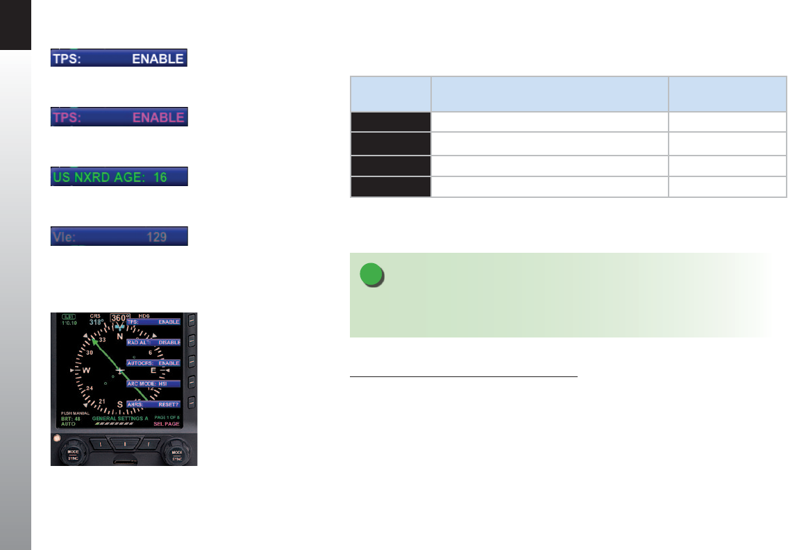
CHAPTER 2 CONTROLS AND DISPLAY
EFD1000 PFD Pilot’s Guide
Page 2-16 091-00005-001 REV E EFD1000 PFD Pilot’s Guide Page 2-17
091-00005-001 REV E
The MENU text will display in one of the four colors listed and described in Table 2-5.
DISPLAY
TEXT DESCRIPTION DISPLAY
WHITE Editable option Figure 2-18
MAGENTA Editable option enabled Figure 2-19
GREEN Status Only Figure 2-20
GR AY Disabled (Not available for selection or editing) Figure 2-21
Table 2-4
Menu Text
NOTE
These steps are provided as a basic overview. Each menu command is covered in detail in
Chapter 5.
Access To and Navigation Within the Menu
1. Press the MENU button. The Menu displays on the Navigation Display
adjacent to the Hot Keys (Figure 2-22).
2. Rotate the Right Knob to navigate through the dierent pages of the
Menu. Rotating the Right Knob clockwise advances the Menu Pages,
counterclockwise returns to previous pages.
3. Press the MENU Button to exit.
Figure 2-22
Menu Display
Figure 2-18
Menu Text - Editable
Figure 2-19
Menu Text - Enabled for Editing
Figure 2-20
Menu Text - Status Only
Figure 2-21
Menu Text - Disabled

CHAPTER 2 CONTROLS AND DISPLAY
EFD1000 PFD Pilot’s Guide
Page 2-16 091-00005-001 REV E EFD1000 PFD Pilot’s Guide Page 2-17
091-00005-001 REV E
Edit Main Menu Items
1. Press the MENU Button.
2. Navigate to the desired Menu Page.
3. Press the Menu Key of the desired option. The Menu label turns magenta, and
the EDIT VALUE label displays above the Right Knob (Figure 2-23).
4. Rotate the Right Knob to the desired value.
5. Press the Right Knob to return to Menu navigation mode.
6. Press the MENU Button to exit.
Figure 2-23
EDIT VALUE Displays Above Right Knob
NOTE
Upon reaching the end of a list of editable menu
options, continued rotation of the knob will not result in
the continuous wrapping through the available editable
menu options. Spinning the knob fully clockwise will
go to the last menu page, while spinning the knob fully
counterclockwise will go to the rst menu page.
NOTE
Pressing the Right Knob returns to Navigation mode
and allows selection of other menu options on dierent
pages. Pressing another menu key on the current menu
page saves any changes made and activates the newly
selected option for editing.
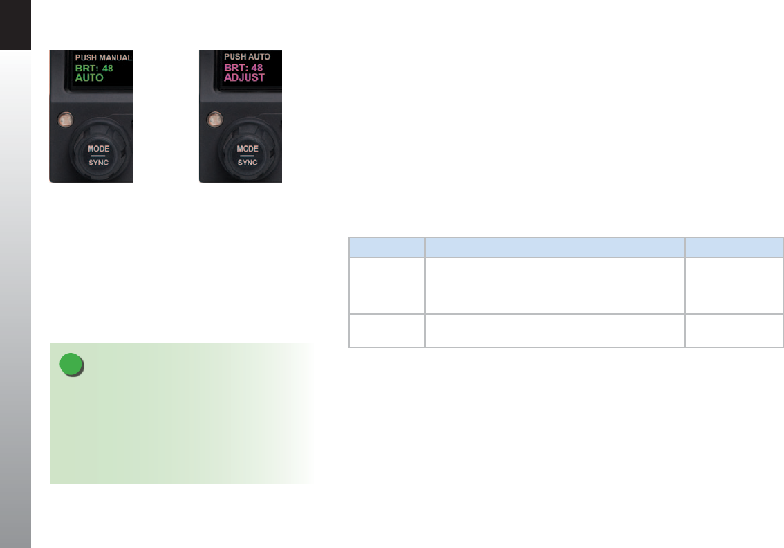
CHAPTER 2 CONTROLS AND DISPLAY
EFD1000 PFD Pilot’s Guide
Page 2-18 091-00005-001 REV E EFD1000 PFD Pilot’s Guide Page 2-19
091-00005-001 REV E
2.2.4.2. Display Lighting
When the MENU button is pressed and the Menu is active, the Left Knob can be used to
adjust the PFD display brightness.
By default, the LCD brightness operates in AUTO mode, and is adjusted based on
photocell sensing of ambient lighting conditions. When the MENU is active and the
LCD is in the BRT AUTO mode, the word, “AUTO”, and a brightness level of 1-100 will be
displayed in green above the Left Knob (Figure 2-24).
To override the AUTO brightness setting, press the Left Knob once to switch to the BRT
ADJUST mode, and then rotate the Left Knob to set the brightness to the desired level
(Figure 2-25). To return to AUTO brightness control, press the Left Knob again.
LCD MODE DESCRIPTION DISPLAY
Automatic
BRT AUTO
LCD backlight intensity is automatically adjusted based
on the ambient lighting conditions sensed by the
Automatic Dimming Photocell. The maximum intensity
in AUTO mode is 70%.
Figure 2-24
Manual
BRT ADJUST
Allows the pilot to adjust the PFD display brightness
from 1-100%
Figure 2-25
Table 2-5
Brightness Control
Figure 2-24
Display Brightness in BRT AUTO Mode
Figure 2-25
Display Brightness in BRT ADJUST Mode
NOTE
The BRT AUTO display brightness level is determined
by the amount of light detected by the photocell on
the front of the PFD. If a light is used to illuminate the
instrument panel, the photocell will respond, resulting
in a bright display. When this happens, use the manual
BRT ADJUST mode to reduce the brightness.

CHAPTER 2 CONTROLS AND DISPLAY
EFD1000 PFD Pilot’s Guide
Page 2-18 091-00005-001 REV E EFD1000 PFD Pilot’s Guide Page 2-19
091-00005-001 REV E
2.2.5. Range Buttons
When the MAP is enabled, the RNG (Range) Button is used to zoom the map in or out.
Press the RNG (+) Button to increase map range. Press the RNG (-) Button to decrease
map range. Additionally, an Auto Range control feature is available.
Pressing and holding either the RNG (+) or (-) Button will cause the map range to scale
continuously to its maximum or minimum range, respectively. When the map range is
at its maximum or minimum setting, release and then press and hold the RNG Button
again to activate the Auto Range control mode (see Section 4.4.12.1. for moredetails).
2.2.6. REV Button
The red REV Button on the PFD can be used to override automatic power control in
abnormal or emergency situations (see Chapter 6, Section 6.4. and Figure 6-29 for
more details).
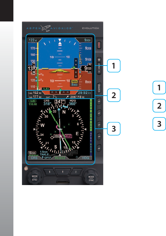
CHAPTER 2 CONTROLS AND DISPLAY
EFD1000 PFD Pilot’s Guide
Page 2-20 091-00005-001 REV E EFD1000 PFD Pilot’s Guide Page 2-21
091-00005-001 REV E
2.3. Display
The PFD replaces the existing Attitude Indicator and HSI or DG in the center of the
primary ight instrument cluster. Like the instruments it replaces, the top half presents
an Attitude Display and the bottom half contains a Navigation Display (Figure2-26).
Between the two halves is the Data Bar. The Data Bar contains a dedicated display of
real-time winds, Outside Air Temperature (OAT), True Airspeed (TAS), and GPS Ground
Speed (GS).
Attitude Display
Data Bar
Navigation Display
Unlike the mechanical indicators it typically replaces, PFD can also display all the data
provided by the remaining four instruments in the six pack (airspeed, altitude, turn and
slip, and vertical speed), and much more. Concentrating all primary ight information
onto a single instrument directly in front of the pilot improves instrument scan and
reduces pilot workload, thereby enhancing safety, especially in busy phases of ight.
Additionally, analog backup instruments can be retained in the pilot’s primary eld
of view, and should be included in the instrument scan to cross-check indications of
both the primary (EFIS) and backup (analog) instruments.
Figure 2-26
PFD Display Areas

CHAPTER 2 CONTROLS AND DISPLAY
EFD1000 PFD Pilot’s Guide
Page 2-20 091-00005-001 REV E EFD1000 PFD Pilot’s Guide Page 2-21
091-00005-001 REV E
The PFD generally follows standard display conventions for Electronic Flight Instrument
Systems (EFIS), so a pilot with some experience and familiarity with other EFIS PFDs
will usually transition quickly to using the EFD1000. Pilots for whom the EFD1000
PFD is their rst real exposure to EFIS and glass cockpit ying, however, should get
some transition training from a certied instrument ight instructor (CFII) with EFIS
experience. Pilots are also encouraged to study some of the excellent publications and
training videos now available to help with the transition.
This section gives an overview of the main display elements and features. (see Chapter
4, Reference Guide for more details).
2.3.1. Cleaning the Display Screen
The PFD Display Unit has an LCD screen that is prone to damage from scratches,
smudging, and clouding caused by the use of improper cleaning agents and abrasive
cloths. Exercise care when cleaning, using the following tips:
• Only clean the display when the PFD is o.
• Use a clean, soft, lint-free cloth dampened with a 50/50 solution of isopropyl
alcohol and water, a pre-moistened lens cleaning tissue, such as Bausch &
Lomb Sight Savers®, or a cleaning solution made especially for LCD displays.
• Never spray any cleaning solutions directly onto the screen; spray it into the
cleaning cloth.
• Gently wipe the screen in a circular motion. Do not press hard on the screen.
• Remove all excess moisture to prevent damage to the display.
• The display should be dry before turning on the PFD.
CAUTION
Use caution when using isopropyl alcohol as it is
ammable. Using any other chemicals or materials
voids the warranty.

CHAPTER 2 CONTROLS AND DISPLAY
EFD1000 PFD Pilot’s Guide
Page 2-22 091-00005-001 REV E EFD1000 PFD Pilot’s Guide Page 2-23
091-00005-001 REV E
2.3.2. Attitude Display
The Attitude Display includes an Attitude Director Indicator (ADI) with a single-
cue Flight Director command V-bars (when connected to a compatible autopilot),
an Airspeed tape, an Altimeter tape, an Altitude Alerter, Radio Altitude, approach
minimums annunciations, and approach course and glide slope indicators (Table 2-7
and Figure 2-27), (see Chapter 4, Reference Guide for more details).
The Airspeed and Altitude tapes are the most obvious dierences from a mechanical
ADI. These tapes are common on most EFIS PFDs and will be immediately familiar to
pilots with EFIS experience. Pilots without prior EFIS experience may need some training
and experience to become to get comfortable with the Airspeed and Altimeter tapes as
their primary references.
In single-display PFD installations, where the mechanical airspeed indicator and
altimeter remain in their original locations, transitioning pilots can use either their
familiar mechanical instruments or the PFD tapes for airspeed and altitude references.
Many pilots new to EFIS quickly nd themselves relying on the tapes within a ight or
two. Should the tapes prove distracting, the pilot can remove them from the display
by disabling them in the Menu. (Page 1, GENERAL SETTINGS A — single display
installations only).

CHAPTER 2 CONTROLS AND DISPLAY
EFD1000 PFD Pilot’s Guide
Page 2-22 091-00005-001 REV E EFD1000 PFD Pilot’s Guide Page 2-23
091-00005-001 REV E
ATTITUDE DISPLAY
16 Attitude Display 27 Decision Height Annunciation 2, 3
17 Aircraft Reference Symbol 28 Selected Minimums Field 2
18 Single-Cue Flight Director 1, 2 29 Radio Altitude 2, 3
19 Roll Pointer 30 MINIMUMS Marker 2
20 Slip/Skid Indicator 31 LDI Navigation Source Annunciation 2
21 Altitude Tape 32 Airspeed Tape
22 Selected Altitude Field 33 Selected Airspeed Field
23 Altitude Alerter 34 Airspeed Bug
24 Numerical Altitude Value,
Altitude Drum/Pointer
35 Numerical Airspeed Value, Airspeed
Drum/Pointer
25 Altitude Trend Vector 36 Vertical Deviation Indicator (VDI) 2
26 Altitude Bug 37 Lateral Deviation Indicator (LDI) 2
Table 2-6
Attitude Display Components
1. With compatible autopilots
2. Not available with the Pilot PFD
3. With compatible radar altimeters
33 22
32
35
18
16
19
20
21
17
29
36
31
23
34
37
26
28
27
25
30
30
24
Figure 2-27
Attitude Display Components

CHAPTER 2 CONTROLS AND DISPLAY
EFD1000 PFD Pilot’s Guide
Page 2-24 091-00005-001 REV E EFD1000 PFD Pilot’s Guide Page 2-25
091-00005-001 REV E
2.3.2.1. Attitude Director Indicator (ADI)
The Attitude Director Indicator (ADI) features a conventional blue (sky) over brown
(ground) background, with a white horizon line dividing the two areas. A triangular
Aircraft Reference Symbol (Ref. 17) is in a xed position and shows aircraft attitude
relative to the horizon.
The pitch scale (or ladder) indicates degrees of nose up (blue) or nose down (brown)
pitch relative to the apex of the aircraft symbol. Minor pitch marks are shown every
2.5º up to +/-20º of pitch, with major pitch marks every 10º up to +/-90º of pitch. The
distance between pitch marks is greater than on most mechanical attitude indicators,
making it easier for the pilot to y more precise pitch attitudes.
At extreme pitch attitudes (above 30º nose up or below 25º nose down), red Unusual
Attitude Recovery chevrons come into view, pointing towards the horizon or ground
as applicable (see Chapter 4, Section 4.2.1.2. Pitch Scale). At extreme pitch attitudes,
some sky (blue) or ground (brown) will always be displayed to help maintain situational
awareness, even though the horizon line may be o-scale.
At the top of the ADI are the roll scale, roll pointer, and slip/skid indicator (Figure 2-28).
The roll scale is indicated by tick marks at 10º, 20º, 30º, 45º, and 60º on both sides of the
zero roll inverted solid white triangle. The 45º marks are represented as hollow triangles.
Slip/skid is indicated by the lateral position of the white rectangle under the roll pointer.
One rectangle width is equivalent to one ball width of a conventional inclinometer.
When connected to a compatible autopilot system, the PFD will display a single-cue
Flight Director (FD) (Figure 2-29). The Flight Director command bars visually represent
the lateral and vertical steering cues transmitted to the PFD by the autopilot. When
the FD output from the autopilot is unavailable or invalid, the FD command bars are
removed from the display.
Figure 2-28
Slip/Skid
Figure 2-29
Flight Director

CHAPTER 2 CONTROLS AND DISPLAY
EFD1000 PFD Pilot’s Guide
Page 2-24 091-00005-001 REV E EFD1000 PFD Pilot’s Guide Page 2-25
091-00005-001 REV E
2.3.2.2. Airspeed Tape and Bug
Airspeed is indicated by a moving airspeed tape against a xed position airspeed
pointer, shown on the left-hand side of the Attitude Display (Figure 2-30). A numerical,
rolling drum readout indicating airspeed values to the closest one knot or mile per hour
is provided adjacent to the xed pointer. Tick marks are provided on the airspeed tape
every 10 knots (or mph, if so congured). Airspeeds between 20 kts (23 mph) to 450 kts
(518 mph) are displayed. Outside of this range, the airspeed value is dashed.
Color speed bands are displayed on the indicated airspeed tape, corresponding to the
color arcs found on a mechanical airspeed indicator.
Color speed markers are also displayed on the indicated airspeed tape, corresponding
to the markers found on traditional airspeed indicators. All aircraft have a red line for
aircraft never-exceed speed (Vne). Multi-engine aircraft will usually also have another
red line for single-engine minimum control speed (Vmc), and a blue line for single-
engine best rate of climb speed (Vyse). If the aircraft manufacturer has published an
initial ap extension speed, a white triangle will be presented on the airspeed tape at
this speed.
Redline or Barber Pole airspeed limits that vary with pressure altitude can be displayed
when congured by the installer. The colors are congured to correspond with your
aircraft’s approved markings on the mechanical airspeed indicator.
Textual Vspeed markers can also be shown on the airspeed tape (e.g., Vx, Vy, Va, etc.).
These are typically programmed at installation, and (if left unlocked during installation)
may also be adjusted by the pilot. Vspeed display can be enabled or disabled by the
pilot from Page 1 of the Menu (see Chapter 5).
Figure 2-30
Airspeed Tape

CHAPTER 2 CONTROLS AND DISPLAY
EFD1000 PFD Pilot’s Guide
Page 2-26 091-00005-001 REV E EFD1000 PFD Pilot’s Guide Page 2-27
091-00005-001 REV E
The pilot can set a target airspeed using the Left Knob (see Section 4.2.2.1.). The target
airspeed is shown on the Airspeed Tape as an Airspeed Bug with its setting displayed
numerically above the Airspeed Tape (Figure 4-10 and Figure 4-11). The Airspeed
Bug and numerical value are for visual reference only, to help the pilot maintain a target
airspeed; there is no alerting for deviations from the target.
2.3.2.2.a. Mach Number Display for Mmo Aircraft
The Mach number for Mmo aircraft is displayed in the Data Bar (Figure 2-30a). The
Mach number can be congured to be displayed whenever the aircraft is above the
selected transition altitude or above a selected Mach number.
When the conguration is set to ALTITUDE transition, the TAS indication will be
replaced by the Mach number whenever the aircraft is above the selected transition
altitude.
When the conguration is set to SPEED transition, the TAS indication will be replaced
by the Mach number whenever the aircraft is above the selected transition Mach
number (see Chapter 5, Table 5-2 for MACH Display setting options).
Figure 2-30a
Mach Number Display

CHAPTER 2 CONTROLS AND DISPLAY
EFD1000 PFD Pilot’s Guide
Page 2-26 091-00005-001 REV E EFD1000 PFD Pilot’s Guide Page 2-27
091-00005-001 REV E
2.3.2.3. Altitude Tape, Altitude Alerter, and Vertical Speed
Altitude is indicated by a moving altitude tape against a xed position altitude pointer
(Figure 2-2, No. 21, 24), shown on the right-hand side of the Attitude Display
(Figure 2-31). A numerical rolling drum readout indicating altitude values to the closest
20 feet is provided adjacent to the xed pointer. When climbing or descending, a
magenta Altitude Trend Vector displays above or below the altitude pointer, indicating
the altitude that will be reached in six seconds if the current rate of climb or descent is
maintained.
Minor tick marks are provided on the tape at 20-foot intervals, and major tick marks are
provided at 100-foot intervals. The thousand and ten-thousand digits are larger than
other digits on the tape. Negative altitudes are indicated by a “-“ sign preceding the
numerical altitude value in the drum.
The current altimeter barometric pressure setting is shown just below the Altitude tape
in the Data Bar (Figure 2-2, No. 39), and can be adjusted by pressing the BARO Hot Key
and rotating the Right Knob.
The Altitude Tape also includes a built-in Altitude Alerter, which consists of an
Altitude Bug on the Altitude Tape (Figure 2-2, No. 26), a Selected Altitude Field
(Figure 2-2, No. 22), a visual Altitude alert (Figure 2-2, No. 23), and an optional audio
alert. For more information on using the Altitude Alerter, see Chapter 3 and Chapter 4.
A Vertical Speed Indicator (VSI) is shown as a tape on the Navigation Display (Figure
2-48 and Figure 2-2, No. 57) to the right of the HSI in 360 Compass mode. A numerical
vertical rate is shown in the upper right-hand corner of the Navigation Display during
climbs and descents (Figure 2-2, No. 56). The VSI tape is not shown in ARC Compass
mode, but the numerical value display is shown in both 360 and ARC Compass modes.
Figure 2-31
Altitude Tape
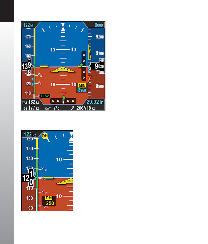
CHAPTER 2 CONTROLS AND DISPLAY
EFD1000 PFD Pilot’s Guide
Page 2-28 091-00005-001 REV E EFD1000 PFD Pilot’s Guide Page 2-29
091-00005-001 REV E
2.3.2.4. Instrument Approach Indicators1
Additional indicators are shown on the Attitude Display when ying certain types of
instrument approaches. These enable the pilot to maintain a tighter instrument scan on
the ADI, reducing workload and improving safety (Figure 2-32).
A Lateral Deviation Indicator (LDI) (Figure 2-2, No. 37) is presented on the attitude
indicator whenever the pilot has selected an ILS, LOC, LOC Back Course (BC), or a GPS
approach and valid lateral course guidance is being received. The LDI’s navigation source
is annunciated to the left of the LDI (Figure 2-2, No. 31). A Vertical Deviation Indicator
(VDI) (Figure 2-2, No. 34)) is presented on the attitude indicator whenever the LDI is
shown and valid glide slope signal is being received, such as from an ILS or WAAS GPS LPV.
Whenever the lateral or vertical deviation exceeds the maximum displayable range of
LDI or VDI scale (2.5 dots), the deviation diamond turns into a hollow, ghosted image
pegged to the corresponding side. As soon as the deviation diamond comes into range,
the diamond turns solid green, making it easy to identify when the needle is “alive”.
Additionally, the pilot can pre-set the instrument approach minimums (MIN) with
the MIN Hot Key. Once the MIN data eld value is set to a Decision Altitude, Decision
Height, or Minimum Descent Altitude, the PFD provides a MINIMUMS annunciation
when the aircraft reaches or descends below this altitude (Figure 2-2, No. 28).
Additionally there are three minimums markers shown on the altitude tape — a green
marker 500 feet above minimums; a hollow yellow triangle in the area from 100 feet to
200 feet above minimums; and a red and yellow marker at the programmed Selected
Minimums value (see Section 4.2.3.4. MINIMUMS Annunciation for more details).
If a Radar Altimeter is installed in the aircraft and connected to the PFD, a Decision
Height annunciation (Figure 2-2, No. 27 and No. 29) will be displayed when the
aircraft descends to, or below, the selected radar altitude (Figure 2-33).
Figure 2-32
Instrument Approach Indications
Figure 2-33
Decision Height Annunciation 1. Not available with the Pilot PFD

CHAPTER 2 CONTROLS AND DISPLAY
EFD1000 PFD Pilot’s Guide
Page 2-28 091-00005-001 REV E EFD1000 PFD Pilot’s Guide Page 2-29
091-00005-001 REV E
2.3.3. Data Bar
The Data Bar visually separates the upper and lower halves of the PFD display. When
available, True Airspeed (TAS) or Mach Number, GPS Ground Speed (GS), Outside Air
Temperature (OAT), Wind Vector arrow, Wind Direction, Wind Speed, and Barometric
Pressure Setting are presented in the Data Bar (Table 2-8 and Figure 2-34).
When any of these values are not available or invalid, the corresponding data eld is
dashed. If the Wind Direction and Speed are not available or invalid the Wind Direction
Arrow is removed. A GPS navigator must be connected and providing valid ground
speed and ground track to display GS and wind data.
The Data Bar is discussed in detail in Section 4.3.
DATA BAR
38 True Airspeed (TAS) or Mach Number
39 Barometric Pressure Setting Field
40 Wind Direction and Speed
41 Wind Direction Arrow
42 Outside Air Temperature (OAT)
43 Ground Speed (GS)
Table 2-7
Data Bar Components
43
38
404142
39
Figure 2-34
Data Bar Components
NOTE
When the winds aloft are less than 10 knots, the wind
data is not displayed.

CHAPTER 2 CONTROLS AND DISPLAY
EFD1000 PFD Pilot’s Guide
Page 2-30 091-00005-001 REV E EFD1000 PFD Pilot’s Guide Page 2-31
091-00005-001 REV E
2.3.4. Navigation Display
The lower half of the PFD is the Navigation Display (Table 2-9 and Figure 2-35), which
shows a wide range of navigation information and ight data, including:
• Horizontal Situation Indicator (HSI), Course Pointer and Deviation Indicator
(CDI), and Heading Bug.
• 360° and ARC Compass rose display modes.
• Numeric displays of current magnetic heading, selected heading (HDG), and
selected course (CRS).
• Information about the selected CDI navigation source, or active GPS waypoint.
• Ground Track Marker.
• Vertical Speed Indicator (VSI) tape and numerical rate value.
• Rate of Turn Indicator.
• Dual bearing pointers (RMI) (360° Compass mode only).
• Situational Awareness Map display.
• Course Deviation Indicators (CDI) and Bearing Pointers, navigation source
information.
• GPS annunciations (TERM, APPR, WPT, and MSG).
• Caution annunciations for abnormal GPS status.
When connected to a GPS navigator, basic mapping can also be displayed under
the HSI, including GPS ight plan legs and waypoints, (and when connected to a
compatible GPS) Basemap data (airports, VORs, NDBs, and intersections).
NOTE
The Vertical Deviation Indicator (VDI) and Lateral
Deviation Indicator (LDI) are part of the navigation
instruments and are displayed on the Attitude Display
during instrument approaches.
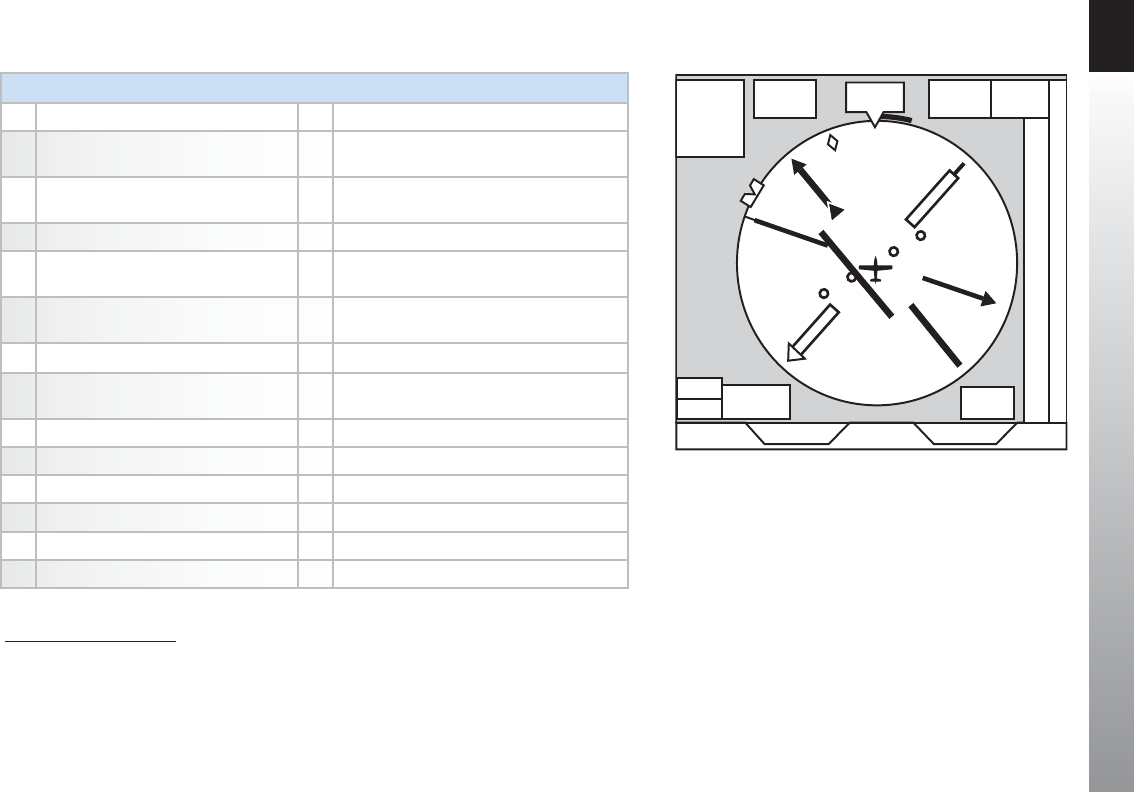
CHAPTER 2 CONTROLS AND DISPLAY
EFD1000 PFD Pilot’s Guide
Page 2-30 091-00005-001 REV E EFD1000 PFD Pilot’s Guide Page 2-31
091-00005-001 REV E
NAVIGATION DISPLAY
44 Navigation Display 58 Single-Line Bearing Pointer 1
45 Ownship Symbol 59 Single-Line Bearing Pointer Navigation
Source 1
46 Course Pointer 160 Single-Line Bearing Pointer Navigation
Source Info Block 1
47 TO/FROM Indicator 161 Double-Line Bearing Pointer 1
48 Rate of Turn Indicator 62 Double-Line Bearing Pointer Navigation
Source 1
49 Ground Track Marker 63 Double-Line Bearing Pointer Navigation
Source Info Block 1
50 Numerical Direction Indicator 64 Selected CDI Navigation Source 1
51 Selected Course (CRS) Field 165 Selected CDI Navigation Source
Information Block 1
52 Selected Heading (HDG) Field 66 Left Knob State
53 Heading Bug 67 Right Knob State
54 Course Deviation Scale 168 Hot Key Legend
55 Course Deviation Indicator 169 Navigation Display Range
56 Vertical Speed Numerical Value 70 Navigation Display Declutter Level
57 Vertical Speed Indicator Tape
Table 2-8
Navigation Display Components
66 59
60
70
69
65 51 50
44
61
53
49
46
48
45
55
54
58
47
52 56
57
68
63
62
64 67
Figure 2-35
Navigation Display Components
1. Not available with the Pilot PFD
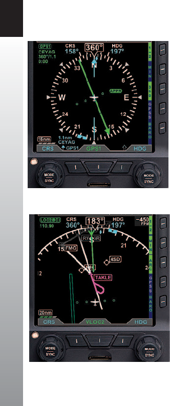
CHAPTER 2 CONTROLS AND DISPLAY
EFD1000 PFD Pilot’s Guide
Page 2-32 091-00005-001 REV E EFD1000 PFD Pilot’s Guide Page 2-33
091-00005-001 REV E
2.3.4.1. Numerical Direction Indicator (Magnetic Compass)
The center of the Navigation Display is the Numerical Direction Indicator. Like a
magnetic compass, the NDI always shows the current magnetic heading of the aircraft.
This slaved NDI compensates both for the turning and acceleration errors exhibited by
wet compasses and for precession errors found in common Directional Gyros. The pilot
does not ever need to make adjustments to the NDI.
The NDIs of both the Pilot PFD and the Pro PFD share many common features, while the
Pro PFD adds features for instrument navigation.
The Pilot PFD Direction Indicator is a slaved Directional Gyro (DG) with Heading Bug.
The Pro PFD Direction Indicator adds an electronic Horizontal Situation Indicator (HSI)
and dual Bearing Pointers. The HSI features are explained in Section 2.3.4.2.
Compass Modes: 360º vs. ARC
The NDI on the PFD can be presented in either a full 360º Compass Mode (shown in
Figure 2-36), or in a 100º ARC mode (Figure 2-37).
The 360° Compass Mode resembles the mechanical instrument, with the ownship
position in the center of the display.
The ARC Compass Mode provides an extended forward view with the ownship position
near the bottom of the Navigation Display. The ARC Compass is especially good for
displaying ight plan and basemap details.
The 360/ARC Hot Key is used to toggle the display between 360° and ARC Compass
Modes, with the current mode shown in green adjacent to the Hot Key.
Figure 2-36
360° Compass Mode
Figure 2-37
ARC CDI Compass
Mode with Basemap

CHAPTER 2 CONTROLS AND DISPLAY
EFD1000 PFD Pilot’s Guide
Page 2-32 091-00005-001 REV E EFD1000 PFD Pilot’s Guide Page 2-33
091-00005-001 REV E
Navigation Information
Regardless of Compass Mode setting, the current magnetic heading is always shown
at the top center of the Navigation Display (Figure 2-2, No. 50 and Figure 2-38). The
HDG Bug setting is shown in the Selected Heading Field (Figure 2-2, No. 52). This eld
is always visible even if the HDG Bug itself is only partially visible in ARC Compass Mode.
Similarly, on the EFD1000 Pro PFD HSI, the current Course setting (CRS) (Figure 2-2, No.
51) is always shown, whether or not the Course Pointer itself is visible in ARC Compass
Mode.
A Selected CDI Navigation Source Information Block (Figure 2-2, No. 65 and Figure
2-39) is presented in the upper left corner of the Navigation Display. The Source
Information Block indicates the Selected CDI Navigation Source (coupled to the CDI
on the Pro PFD HSI), and its associated mode (e.g., GPS, VOR, ILS, LOC) . Information is
provided about the selected source, including, when available, the waypoint identier
or navaid frequency, waypoint bearing and distance, and the estimated time to the
active waypoint.
Ground Track Marker
When the PFD is connected to a compatible GPS, a blue Ground Track Marker is
displayed on the compass rose at the value that corresponds to the aircraft’s ground
track (Figure 2-2, No. 49 and Figure 2-40).
When the Ground Track Marker is aligned with the Course Pointer on the Pro PFD HSI,
the aircraft is tracking on, or parallel to its desired track.
To align the Ground Track Marker with the Course Pointer, turn away from the direction
in which the diamond is oset from the Course Pointer (think of it as a turn to pull the
Ground Track Marker toward the Course Pointer).
Figure 2-40
Ground Track Marker
Figure 2-38
Magnetic Heading
Figure 2-39
Navigation Source Information Block

CHAPTER 2 CONTROLS AND DISPLAY
EFD1000 PFD Pilot’s Guide
Page 2-34 091-00005-001 REV E EFD1000 PFD Pilot’s Guide Page 2-35
091-00005-001 REV E
2.3.4.2. Horizontal Situation Indicator (HSI)1
The traditional HSI is an instrument that combines a slaved magnetic Heading Indicator
overlaid with a rotating Course Pointer and Course Deviation Indicator (CDI). This combination
helps the pilot better visualize the aircraft’s position relative to the desired course. The HSI is
a vast improvement over the older, separate Directional Gyro (DG) and OBS course deviation
indicator, because the compass heading is always correct (slaved to a remote magnetic ux
detector), and the integration of the CDI onto the compass simplies the instrument scan
and provides better situational awareness.
Pilots experienced with the mechanical HSI will nd the PFD 360º Compass Mode
immediately familiar. In its basic form, it is just an electronic representation of a mechanical
HSI. Pilots transitioning from ying a DG and OBS should seek dual instruction from a CFII on
the dierences in ying an HSI.
2.3.4.3. Course Pointer and Course Deviation Indicator (CDI)1
In the 360º Compass Mode, the Course Pointer and CDI resemble those of a mechanical HSI,
with an arrowhead pointing to the selected course, and a movable center bar indicating
course deviation against a scale of two dots to either side of the center. A TO/FROM indication
is shown as a triangle above (TO) or below (FROM) the ends of the CDI.
The ARC Compass Mode has two dierent CDI formats -ARC HSI Mode and ARC CDI Mode.
The ARC HSI Mode, presents a full rotating Course Pointer with a CDI, which resembles that
used in the HSI in the 360° Compass Mode. The ARC CDI Mode presents a short Course
Pointer stub on the compass arc and a xed CDI at the bottom of the display, similar to the
LDI and resembling that used in contemporary GPS navigation displays. The ARC CDI Mode
allows more open space for ight plan and basemap details. A TO indication is shown to the
left of the xed CDI, and a FROM indication is shown to its right.
1. Not available with the Pilot PFD

CHAPTER 2 CONTROLS AND DISPLAY
EFD1000 PFD Pilot’s Guide
Page 2-34 091-00005-001 REV E EFD1000 PFD Pilot’s Guide Page 2-35
091-00005-001 REV E
2.3.4.4. Deviation O-Scale Indication1
Whenever the course deviation exceeds the maximum displayable range of 2.5 dots,
the CDI or deviation diamond is shown as a hollow, ghosted image pegged to the
corresponding side (Figure 2-41 and Figure 2-42). As soon as the CDI or deviation
diamond comes into range, it turns solid green, making it easy to identify when the
indicator is “alive”.
2.3.4.5. Auto Course Select1
When a GPS is selected as the CDI’s navigation source, the default setting of the
EFD1000 Pro PFD is Auto Course Select. When Auto Course Select is enabled, the
GPS will automatically set the Course Pointer to the current GPS course (CRS) value
whenever the GPS sequences between waypoints. This capability relieves the pilot from
having to manually set the course at each waypoint along a GPS route. When Auto
Course Select is enabled, the pilot cannot adjust the CRS value.
Auto Course Select is indicated by an inverse A on a green background, adjacent
to both the numerical CRS value and the CRS Left Knob State. (Figure 2-43 and
Figure2-44).
If the GPS navigator enters the OBS or HOLD mode, Auto Course Select is automatically
disabled on the EFD1000 Pro PFD until the GPS navigator resumes waypoint
sequencing. The pilot can disable Auto Course Select from Page 1 of the Menu.
Figure 2-41
O Scale CDI Bar
Figure 2-42
O Scale Deviation Diamond, ARC CDI Mode
Figure 2-43
Auto Course Indication on CRS Field
Figure 2-44
Auto Course Indication over Left Knob
1. Not available with the Pilot PFD
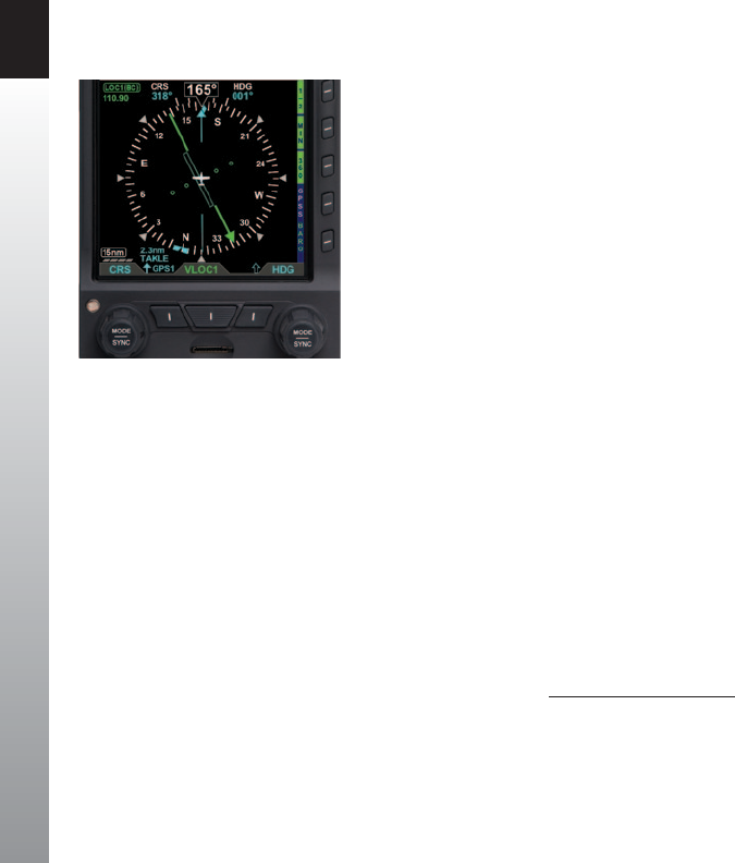
CHAPTER 2 CONTROLS AND DISPLAY
EFD1000 PFD Pilot’s Guide
Page 2-36 091-00005-001 REV E EFD1000 PFD Pilot’s Guide Page 2-37
091-00005-001 REV E
2.3.4.6. Bearing Pointers1
The Single- (Figure 2-2, No. 58) or Double-line (Figure 2-2, No. 61) Bearing Pointers
can be overlaid on the HSI (Figure 2-45). Use the Lower Left and Lower Right buttons
(Figure 2-2, No. 12 and No. 10) to select the navigation sources for the Bearing
Pointers, or select none (blank) to remove a Bearing Pointer from the display.
Bearing Pointers always point to a VOR or waypoint. When coupled to a VOR source,
the tail of the Bearing Pointer indicates the VOR radial on which the aircraft is currently
located. Bearing Pointers are excellent tools for identifying crossing radials, ying DME
arcs, and improving situational awareness.
Bearing Pointers are only available in the 360° Compass Mode. Any available navigation
source may be coupled to either Bearing Pointer. If coupled to a source that does not
provide angular bearing data, such as a localizer, the Bearing Pointer is not shown, and
the Bearing Pointer Source is slashed as invalid.
Each Bearing Pointer has an associated Source Information Block that displays
information about the source of the Bearing Pointer data. This may include distance
to station (if coupled to a GPS waypoint) and the tuned frequency for a VOR. This
information is only presented when it is reported to the Pro PFD by the connected
equipment.
Figure 2-45
BRG#1 Set to GPS1 TAKLE (Single Line Bearing Pointer)
1. Not available with the Pilot PFD
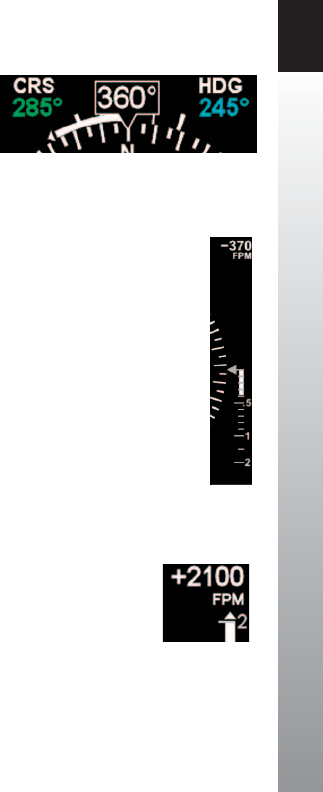
CHAPTER 2 CONTROLS AND DISPLAY
EFD1000 PFD Pilot’s Guide
Page 2-36 091-00005-001 REV E EFD1000 PFD Pilot’s Guide Page 2-37
091-00005-001 REV E
2.3.4.7. Rate of Turn Indicator
A Rate of Turn Indicator (Figure 2-2, No. 48) with a range of 0 to 6 degrees per second
is provided for both the 360 and ARC Compass Modes. The indicator consists of a
curved white tape that extends from the Numerical Heading Indicator’s lubber line and
in the direction of the turn, along the outer curve of the compass card.
The Rate of Turn Indicator features an outer thick white tick mark for a Standard Rate
turn, and an inner thin white tick mark for Half-Standard Rate turns. A Standard Rate,
two-minute turn equals 3 degrees per second. When the rate of turn exceeds 6 degrees
per second, an arrowhead is added to the end of the tape to show that the rate of turn
has exceeded the limits of the indicator (Figure 2-46).
2.3.4.8. Vertical Speed Indicator (VSI)
Whenever the vertical speed exceeds +/- 100 feet per minute (fpm), the vertical
speed is indicated by a rising/sinking white vertical tape and associated scale markers
immediately to the right of the compass rose (Figure 2-2, No. 57 and Figure2-47).
A numerical value of the aircraft’s vertical speed is shown directly above the tape, in
the upper right-hand corner of the Navigation Display (Figure 2-2, No. 56). Rates of
up to ±2,000 fpm are indicated by the tape, while the numerical value will display rates
of up to ±9,990 fpm. A white triangle caps the tape whenever rates exceed ±2,000 fpm
(Figure 2-48). The Vertical Speed Numerical Value will be dashed whenever the vertical
speed exceeds +/- 10,000 fpm. In the ARC Compass Mode, only the Vertical Speed
Numerical Value is presented.
Figure 2-46
Rate of Turn Indicator, Rate Shown >6º/second
Figure 2-47
VSI Tape Showing 370 fpm Descent
Figure 2-48
VSI Tape Capped, Digital Value
Showing 2,100 FPM Climb
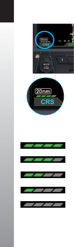
CHAPTER 2 CONTROLS AND DISPLAY
EFD1000 PFD Pilot’s Guide
Page 2-38 091-00005-001 REV E EFD1000 PFD Pilot’s Guide Page PB
091-00005-001 REV E
2.3.4.9. Situational Awareness Map
When the PFD is connected to a compatible GPS navigator, basemap symbols can be
displayed underneath the Direction Indicator in either 360º or ARC Compass Modes.
Most GPS navigators output data for the PFD to display the GPS ight plan legs and
waypoints. The active GPS ight plan leg, waypoint, and its identier are shown in
magenta. Other waypoints and legs are shown in white.
Some GPS navigators (typically those using the ARINC 429 data protocol, such as
the Garmin 400/500 series) output basemap data (e.g., airports, VORs, NDBs, and
intersections). Often, these GPS navigators also display curved ight paths, such as arcs,
course reversals, and holding patterns.
The basemap is always oriented with magnetic North heading up and centered so that
the current aircraft position coincides with the aircraft ownship symbol. These basemap
symbols underlay all other instruments and annunciations in the Navigation Display.
The Map Declutter Settings can be found in the 360 or ARC MAP SETTINGS page of
the Menu. Pressing the desired 360 or ARC DCLTR LVL Menu Key and rotating the Right
Knob will select Declutter Levels 4, 3, 2, 1, or OFF (Figure 2-50, 2-51, 2-52, 2-53, 2-54).
The map display range is controlled by the RNG Button (Figure 2-2, Ref. 2), enabling
the pilot to zoom in or out on the map. Automatic declutter logic changes the map
features displayed depending on the selected maprange.
The current range and declutter level map settings are shown in the lower left-hand
corner of the navigation display (Figure 2-49). The map range is displayed in nautical
miles, measuring the distance from the ownship symbol to the outside edge of the
compass rose. The map declutter level is indicated by one to four green parallelograms
below the range value. More parallelograms indicate that more basemap features are
displayed.
Figure 2-50
Declutter Level 4
Figure 2-51
Declutter Level 3
Figure 2-52
Declutter Level 2
Figure 2-53
Declutter Level 1
Figure 2-54
Declutter Level 0 (O)
Figure 2-49
Map in ARC Compass Mode,
20nm Range at Declutter Level 3

CHAPTER 3 FLYING THE EFD1000 PRO PFD
EFD1000 PFD Pilot’s Guide
Page PB 091-00005-001 REV E EFD1000 PFD Pilot’s Guide Page 3-1
091-00005-001 REV E
Chapter 3
Flying the Pro PFD
This chapter provides an overview of ying the Pro PFD on an IFR cross-
country ight, explaining how to access and change the necessary
settings of the PFD. Refer to Chapter 4 for detailed step-by-step
instructions for all PFD functionality.
While you can jump right in to using the PFD with this chapter, it may be
helpful to rst read Chapter 2 to become more familiar with the controls,
operating logic, and display elements of the PFD.
The PFD is a powerful Electronic Flight Instrument System (EFIS), oering the same
capabilities and features found in larger glass cockpit systems in airliners, business
jets, and newer general aviation aircraft. It is capable of far more than the analog
instruments it typically replaces. It will take some time and experience to master all of its
advanced capabilities, especially if this is your rst exposure to ying an EFIS and a glass
cockpit. Nonetheless, in its most basic conguration, the PFD will look immediately
familiar to anyone accustomed to ying mechanical instruments, and its basic operation
is very similar and intuitive.
Before ying your new PFD on an actual IFR ight, rst be sure to spend some time
with your installer to understand exactly how your aircraft is congured. It’s also
recommended to get some dual instruction and practice in VFR conditions until you are
comfortable with how the PFD performs and integrates with the other avionics in your
airplane.
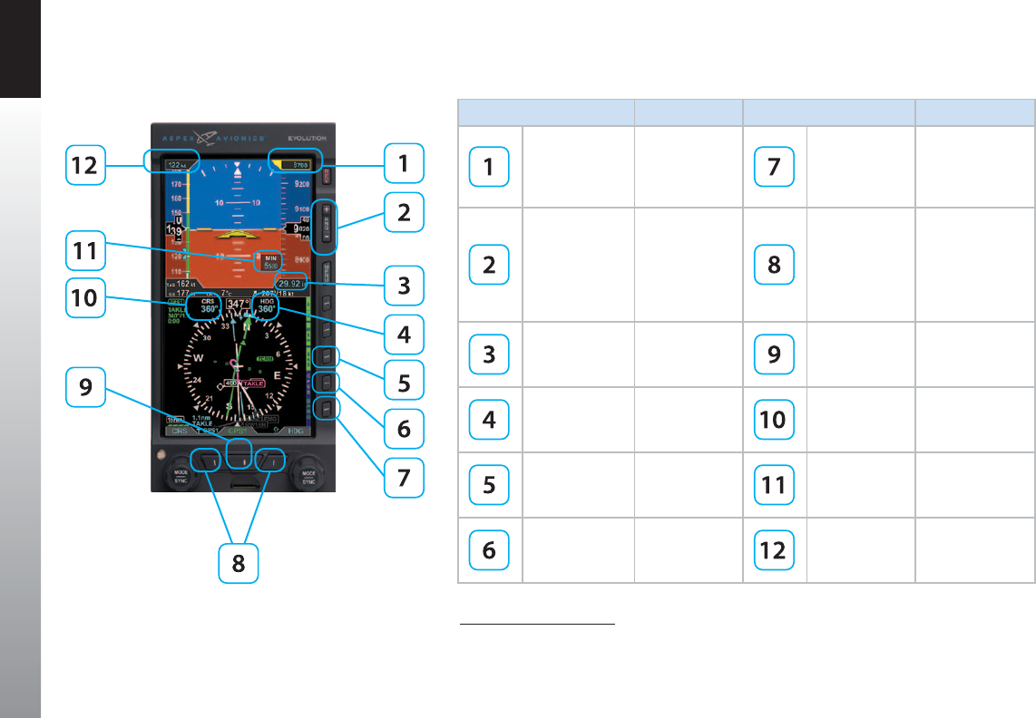
CHAPTER 3 FLYING THE EFD1000 PRO PFD
EFD1000 PFD Pilot’s Guide
Page 3-2 091-00005-001 REV E EFD1000 PFD Pilot’s Guide Page 3-3
091-00005-001 REV E
FEATURE SETTING FEATURE SETTING
Selected
Altitude Set as desired
Barometric
Pressure
(BARO) Hot
Key
Allows for BARO
adjustment
Map RNG
(Range)
Buttons
Set as desired
Lower Left
and Right
Buttons,
Bearing
Pointers Nav
Source1
Select as desired
Barometric
Pressure
Setting Field
on/o
CDI
Navigation
Source Select1
Select as desired
Heading Bug
Value Set as desired
Selected
Course (CRS)
Pointer Field1
Set as desired
Compass
Mode Hot Key:
360 or ARC
Set as desired MINIMUMS
Setting1
Set approach
minimums
GPS Steering
(GPSS) Hot
Key1
on/o Selected
Airspeed Set as desired
Table 3-1 Basic PFD Settings
Figure 3-1
Basic PFD Settings
1. Not available with the Pilot PFD

CHAPTER 3 FLYING THE EFD1000 PRO PFD
EFD1000 PFD Pilot’s Guide
Page 3-2 091-00005-001 REV E EFD1000 PFD Pilot’s Guide Page 3-3
091-00005-001 REV E
3.1. Quick Controls Overview
Chapter 2 explains the PFD controls in detail. The following is a quick summary:
Knobs
(See Chapter 2, Section 2.2.1. for details)
The Left or Right Knob each has a Home State, to which it returns after 10 seconds of
inactivity. The Left Knob is the CRS Knob, and the Right Knob is the HDG Knob.
• The current function of each knob is shown by its State, displayed
immediately above the knob. If the knob state is shown in magenta, turning
the knob will change the value of the function shown. If the legend is shown
in cyan or green, turning the knob will have no eect.
• From the Home State, pressing the knob once will enable the current
function to be set (Knob State color changes from cyan to magenta).
Successive presses of the knob will cycle through the functions that knob can
control. When the function you want to change is shown in magenta, turning
the knob will change its value.
• The Left Knob sets the Course Pointer (CRS, except when Auto Course Select
is enabled) and Indicated Airspeed Bug (IAS).
• The Right Knob sets Heading (HDG), Selected Altitude (ALT), Barometric
Pressure Setting (BARO), and Approach Minimums (MIN).
• Pressing and holding a knob syncs the selected function.

CHAPTER 3 FLYING THE EFD1000 PRO PFD
EFD1000 PFD Pilot’s Guide
Page 3-4 091-00005-001 REV E EFD1000 PFD Pilot’s Guide Page 3-5
091-00005-001 REV E
Navigation Source Buttons
• Three Buttons at the bottom of the display couple the available navigation
sources to the CDI and the Bearing Pointers.
• The Center Button - CDI Navigation Source Select Button (Figure 2-2, Ref.
11) selects the nav source to couple to the CDI and to drive the autopilot (if
installed).
• The Lower Left Button and Lower Right Button (Figure 2-2, Refs. 12 and
10) select which nav source couples to each of the two Bearing Pointers or
none to hide the bearing pointers (see Chapter 2, Section 2.2.2 for details)
Hot Keys
• The ve keys on the lower right-hand side of the display are Hot Keys,
the function of which is shown by the legend on the screen immediately
adjacent to each key.
• The current status of each Hot Key is shown by the legend in a green label
and dark blue letters if active or in a blue label and green letters if inactive.
• Each press of a Hot Key will either toggle its function on or o, or will cycle
among available settings (see Chapter 2, Section 2.2.3 for details).

CHAPTER 3 FLYING THE EFD1000 PRO PFD
EFD1000 PFD Pilot’s Guide
Page 3-4 091-00005-001 REV E EFD1000 PFD Pilot’s Guide Page 3-5
091-00005-001 REV E
3.2. Example Flight Scenario
This section will walk you through using the Pro PFD on an IFR ight from Albuquerque
International Sunport (KABQ) to Reno/Tahoe International Airport (KRNO), ying Victor
airways to the ILS16R approach into KRNO. This scenario uses one pilot’s technique for
setting up the navigation instruments, but there are many other valid possibilities. Use
whatever techniques work best for you.
Our aircraft for this example ight scenario is a Beechcraft Baron P58TC, equipped with
dual Garmin GNS-430W WAAS GPS/Nav/Comm and the Bendix/King KFC-200 Autopilot.
The Pro PFD is congured with Auto Course Select enabled, BARO setting in inches Hg,
Vspeed text markers displayed, ARC compass mode in CDI, and Basemap congured
with its default settings.
The Garmin 430Ws are congured with ILS CDI Capture set to AUTO, meaning that
when an ILS approach is loaded and active in the GPS, and the aircraft is established
inbound to the FAF, the 430W will automatically switch its CDI output from GPS to the
VHF localizer frequency. The PFD will follow this switch on its CDI Navigation Source
Select, automatically changing from GPS1 to VLOC1.
NOTE
The tasks and procedures you will use in your airplane
will vary depending on your aircraft and equipment,
and on how they are congured and integrated with
the PFD in your specic installation

CHAPTER 3 FLYING THE EFD1000 PRO PFD
EFD1000 PFD Pilot’s Guide
Page 3-6 091-00005-001 REV E EFD1000 PFD Pilot’s Guide Page 3-7
091-00005-001 REV E
3.2.1. Pre-Departure (Startup)
Once the pre-ight inspections and checklists are complete, start the engines and turn
on the PFD Master switch.
When power is applied to the PFD, the bezel backlighting illuminates and within a few
seconds the PFD splash screen displays while it initializes and the AHRS data is validated
(Figure 3-2).
As the software initializes and the PFD warms up, the Attitude and Navigation Displays
will appear rst (typically within 20-30 seconds), with red X’s showing for the airspeed
and altitude tapes and the CDI Navigation Source is slashed as invalid (Figure 3-3).
Depending on how cold the aircraft is, the air data sensors will quickly warm to
operating temperature, and the airspeed and altitude tapes will appear. At this point,
the red X’s will disappear and, the PFD is ready.
NOTE
Start-up times for the PFD are highly dependent on aircraft temperature. In extremely cold
weather, when the aircraft has been cold soaked, it may take several minutes (usually no
more than ve) for the PFD to be fully operational. On the second or third ight of the day,
and/or on very hot days, the PFD may initialize within 30 seconds or less.
Figure 3-2
EFD1000 PFD Initializing
Figure 3-3
CDI Navigation Source Slashed Invalid

CHAPTER 3 FLYING THE EFD1000 PRO PFD
EFD1000 PFD Pilot’s Guide
Page 3-6 091-00005-001 REV E EFD1000 PFD Pilot’s Guide Page 3-7
091-00005-001 REV E
Turn the Avionics Master ON. Until the navigation radios are operational, the CDI
Navigation Source annunciations on the PFD is slashed as invalid (Figure 3-4), and
the GPS1, GPS2 caution annunciations on the left (Figure 3-5), and INTEG caution
annunciated on the right edge of the display. The CDI Navigation Source Select will
default to VLOC1 the rst time the PFD is turned on. After that the CDI Navigation
Source Select will display the last used CDI Source. Once the nav radios have warmed
up, the red line will be removed from the CDI Navigation Source annunciation.
NOTE
GPS navigators will not output valid navigation information until programmed with
an active ight plan or direct-to waypoint, and thus will be treated as invalid by the
PFD and cannot be selected as a CDI or Bearing Pointer navigation source until they are
programmed with an active waypoint.
When the PFD is interfaced to a Garmin 4xx /5xx or 4xx(W)/5xx(W) navigator, and the
navigator’s Instrument Panel Self-Test page is displayed, the indicated lateral deviation
can be veried on the Pro PFD CDI. This conrms that a valid digital signal has been
received from the Garmin system.
The interface between the Garmin 4xx/5xx and EFD1000 system should be considered
fully operational once the presence of the digital signal is conrmed. If there is no
GPS failure annunciation on the PFD the lateral deviation indication on the PFD HSI
correlates to the indication on the Garmin 4xx/5xx Instrument Panel Self-Test Page, and
then the digital signal is conrmed, and the interface is operational.
Figure 3-4
CDI Source Slashed Invalid
Figure 3-5
GPS Caution Annunciations
NOTE
The graphics used in this chapter illustrate the
descriptions of the features and tasks, but do not
necessarily correspond to the values associated with
this example ight scenario.
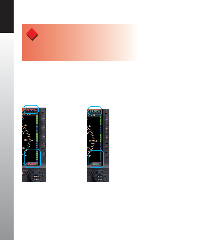
CHAPTER 3 FLYING THE EFD1000 PRO PFD
EFD1000 PFD Pilot’s Guide
Page 3-8 091-00005-001 REV E EFD1000 PFD Pilot’s Guide Page 3-9
091-00005-001 REV E
The navigator’s indicated lateral and vertical deviations cannot be compared to the
EFD1000’s Lateral Deviation Indicator (LDI) and Vertical Deviation Indicator (VDI)
because the 4xx/5xx Instrument Panel Self-Test Page does not send an Approach Mode
signal to the EFD1000 Pro PFD..
Once the radios are available, we listen to the ATIS and learn that the local altimeter
setting is 30.15 and that Runway 8 is in use for departures.
First set the standby altimeter to 30.15, and then set the PFD barometric pressure
setting.
Set the Barometric Pressure
1. Press the BARO Hot Key. The BARO label above the Right Knob and Barometric
Pressure Setting Field appear in magenta - enabled for editing (Figure3-6).
2. Rotate the Right Knob clockwise to increase or counterclockwise to decrease
the value of the Barometric Pressure Setting Field.
3. Once the correct value is selected, press the BARO Hot Key or any knob,
button/key to exit the BARO function. After 10 seconds of inaction or if any
other button/key is pressed, the BARO function is disabled and the Right
Knob returns to normal operation (Figure3-7).
Figure 3-6
BARO Setting Field Enabled
Figure 3-7
BARO Setting Field Disabled
WARNING
Whenever there is a new altimeter setting, set both the
PFD and the standby altimeter.
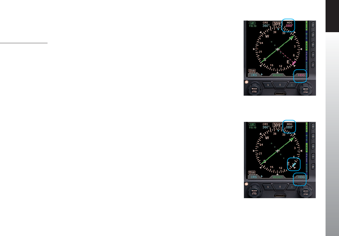
CHAPTER 3 FLYING THE EFD1000 PRO PFD
EFD1000 PFD Pilot’s Guide
Page 3-8 091-00005-001 REV E EFD1000 PFD Pilot’s Guide Page 3-9
091-00005-001 REV E
Next, since we’ll be departing from Runway 8, we set our Heading Bug to runway
heading, 080°.
Set the Heading Bug
1. Press the Right Knob until HDG displays above the knob and the HDG eld
is enabled for editing, both rendered in magenta (Figure 3-8). The Heading
Bug will also be rendered in magenta, and a dashed magenta line will extend
from the ownship symbol to the Heading Bug to make it easier to see the
bug position.
2. Rotate the Right Knob to change the value of the Selected Heading eld.
Rotate clockwise to increase, or counterclockwise to decrease, the value.
Once the correct heading is selected and after 10 seconds of inaction, the
eld is disabled, and the label and eld are rendered in cyan (Figure 3-9).
We call Clearance Delivery to pick up our IFR clearance. It is:
Baron N1234 is cleared to the Reno/Tahoe Airport via the LARGO2 departure,
Zuni (ZUN) transition, then as led; Maintain 7,000; Expect 10,000 in ve minutes;
Departure frequency is 127.4; Squawk 0123.
We copy and read back our clearance, and then set up our avionics for an instrument
departure. We set our transponder code and comm radio frequencies. Then we enter
our ight plan into GPS1, load the LARGO2 departure, crossll into GPS2, and activate
the ight plan. We make sure the CDI button on the 430W is set to GPS.
The LARGO2 departure calls for vectors to our route. From past experience, we expect
to be vectored past ABQ VOR, and then given a vector to join the departure on the
ABQ-to-ZUN leg (a 255º course). While we navigate with GPS, for situational awareness,
we tune those rst two VOR xes into our nav radios. We tune the ABQ VOR (113.2) into
VLOC1 and the ZUN VOR (113.4) into VLOC2.
Figure 3-8
Selected Heading Field Enabled
Figure 3-9
Selected Heading Field Disabled
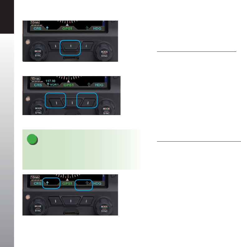
CHAPTER 3 FLYING THE EFD1000 PRO PFD
EFD1000 PFD Pilot’s Guide
Page 3-10 091-00005-001 REV E EFD1000 PFD Pilot’s Guide Page 3-11
091-00005-001 REV E
Select GPS1 as the CDI Navigation Source. Because we have enabled Auto Course
Select, the Course Pointer automatically slews to 261º (the initial course from the airport
to the rst x on the LARGO2 departure, ABQ VOR).
Select the CDI Navigation Source
• Press the CDI Navigation Source Select Button (Figure 3-10) until the desired
navigation source is shown above the Button (in this case, GPS1).
For a traditional RMI view, we could use our two Bearing Pointers to monitor our
passing the ABQ VOR and then intercepting the course to ZUN. We’d use the left,
Single-Line Bearing Pointer Source Select Button to select VOR1 (ABQ), and use the right
Double-Line Bearing Pointer Source Select Button to select VOR2 (ZUN). Since the ZUN
VOR is too far away to receive on the ground at Albuquerque, VLOC2 will be shown with
a red line through it above the Double Bearing Pointer Source Select Button, and the
Double-Line Bearing Pointer will not be displayed. But we know that the station will
be received, and the pointer will be shown, by the time we climb to our initial cruise
altitude.
Select Bearing Pointer Nav Sources
• Press the Lower Left Button (Single-Line Bearing Pointer) or the Lower Right
Button (Double-Line Bearing Pointer) until the desired navigation source is
shown above the Button (Figure 3-11).
For even better situational awareness, we choose to display the map of our ight plan
legs and waypoints. We press the MAP Hot Key to bring up the Basemap. We use the
Range Control Buttons to select the 20nm range, which will give a good perspective for
intercepting the course to ZUN. Our initial ight plan leg, from the airport to the ABQ
VOR, is shown in magenta, with subsequent legs and waypoints shown in white.
Figure 3-10
CDI Navigation Source Selection Button
Figure 3-11
Bearing Pointer Nav Source Select Buttons
Figure 3-12
No Bearing Pointer Sources Selected
NOTE
When no source is selected, only the Bearing Pointer
icon is shown above the applicable button (Figure
3-12).
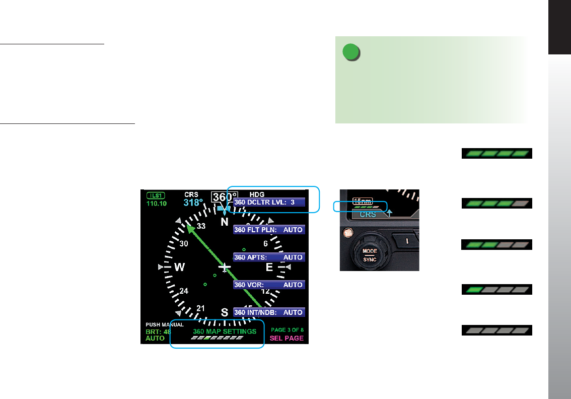
CHAPTER 3 FLYING THE EFD1000 PRO PFD
EFD1000 PFD Pilot’s Guide
Page 3-10 091-00005-001 REV E EFD1000 PFD Pilot’s Guide Page 3-11
091-00005-001 REV E
Select Map Declutter Level
The Map Declutter function can be found in the 360 MAP SETTINGS page or in the ARC
MAP SETTINGS page of the MENU (Figure 3-13). The Map Declutter Icon is located
on the bottom left of the Nav Display (Figure 3-13a) The Declutter settings can be
congured to Levels 4, 3, 2, 1, or 0 (Figures 3-13b thru 3-13f) (see Chapter 5, Table 5-9
for more details).
To change the Map Declutter Level
1. Press the MENU Button and rotate the Right Knob to the 360 MAP SETTINGS
or the ARC MAP SETTINGS page.
2. Press the DCLTR LVL Menu Key and rotate the Right Knob to select the
desired declutter level, then press MENU Button to exit.
NOTE
The Basemap symbols and ight plan legs rendered
for each of the map’s declutter levels (4, 3, 2, 1, or 0) are
based on the selected map range. These are manually
congured to display or not in the Main Menu. Detailed
information is provided in Chapter 5, Section 5.2.
Figure 3-13
Changing the Map Declutter Level
Figure 3-13a
Map Declutter Icon Location
Figure 3-13b
Declutter Level 4
Figure 3-13c
Declutter Level 3
Figure 3-13d
Declutter Level 2
Figure 3-13e
Declutter Level 1
Figure 3-13f
Declutter Level 0
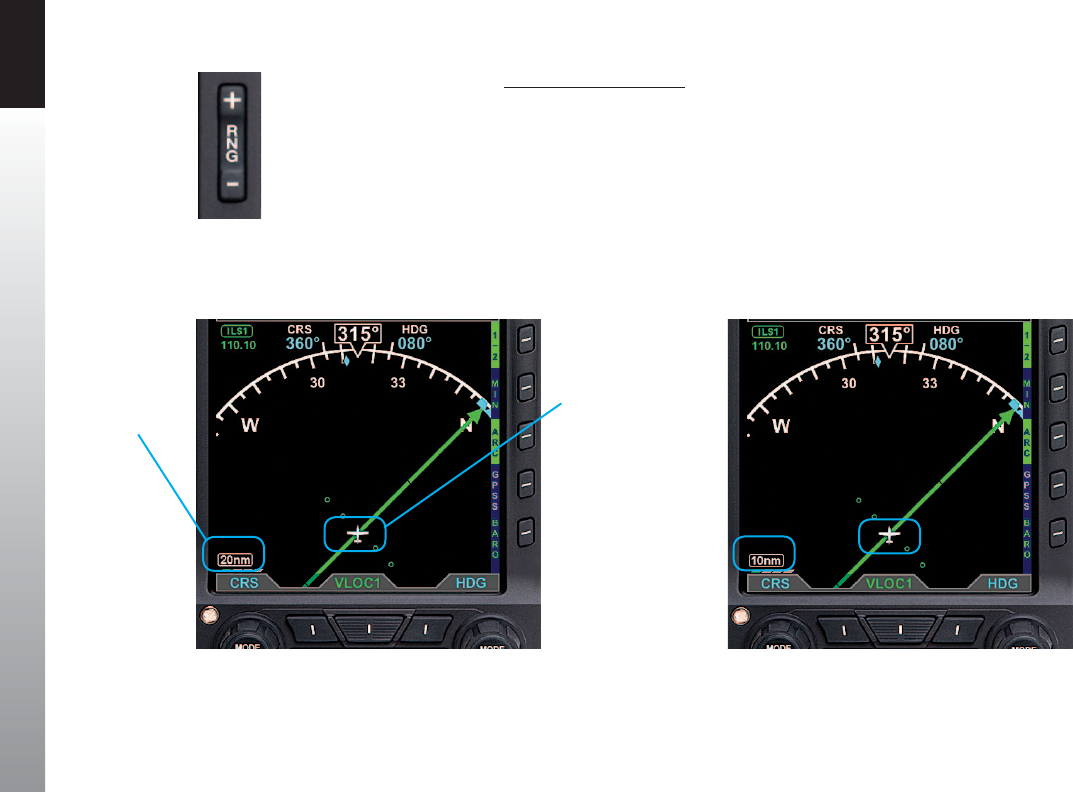
CHAPTER 3 FLYING THE EFD1000 PRO PFD
EFD1000 PFD Pilot’s Guide
Page 3-12 091-00005-001 REV E EFD1000 PFD Pilot’s Guide Page 3-13
091-00005-001 REV E
Change the Map Range
• Press the RNG (Range) Buttons (Figure 3-14) UP (+) to increase the range,
or DOWN (-) to decrease the range, until the desired range is shown
(Figures 3-15 and 3-16).
Figure 3-15
Current Range 20nm from Ownship to Edge of Compass Rose
Current Range
Ownship
Symbol
Figure 3-14
Range Button
Figure 3-16
Current Range 10nm from Ownship to Edge of Compass Rose
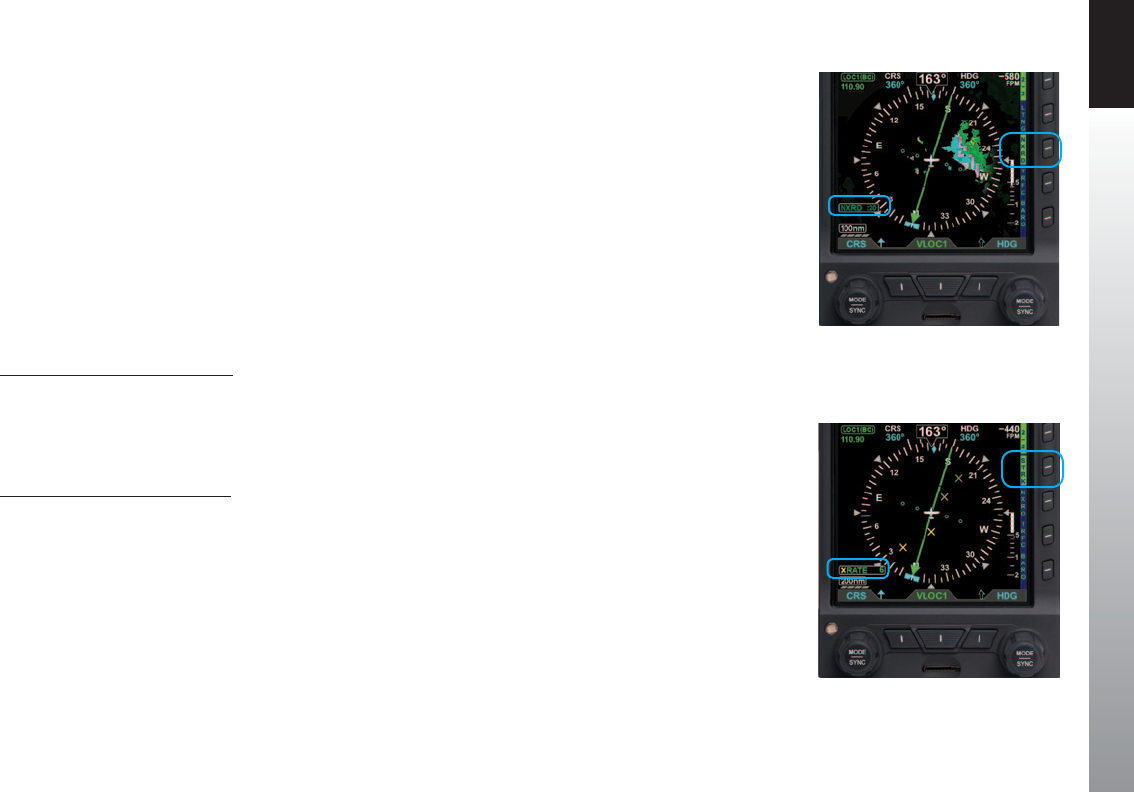
CHAPTER 3 FLYING THE EFD1000 PRO PFD
EFD1000 PFD Pilot’s Guide
Page 3-12 091-00005-001 REV E EFD1000 PFD Pilot’s Guide Page 3-13
091-00005-001 REV E
Aspen’s Evolution Hazard Awareness (EHA) option allows the EWR50 XM WX Data Link
Weather Receiver, WX500 Stormscope®, and Trac system to be connected to the Pro
PFD. These options enable weather and trac hazards to be overlaid on the Navigation
Display.
Our pre-ight weather brieng noted a line of thunderstorms west and south of
Albuquerque, moving northeast at 15 knots. Our ight plan route should keep us clear
of the weather, but we want to check the latest NEXRAD images before departure just to
be sure. So we zoom the map out to its farthest range and turn on the Data Link NEXRAD
Precipitation and Lightning overlays to see how things look along our route of ight. (In
ight, we’ll also use our WX500 Stormscope® for real-time lightning detection, but on the
ground, Data Link Lightning will give us a better indication of where the thunderstorms
are located).
Display the Data Link Weather
1. Display the 2/2 Hot Key Menu.
2. Press the NXRD Hot Key to turn Data Link Weather on (label turns inverse green
Figure 3-17).
Display the Lightning Overlay
1. Display the 2/2 Hot Key Menu.
2. Press the LTNG Hot Key until the desired overlay is selected (LTNG, STRK, or
CELL). Figure 3-18 shows STRK selected.
We see the storms are still moving about as forecast and that our planned route still looks
like it will keep us well clear. We leave the Weather overlays turned on so we can monitor
them in-ight, and then zoom the map back to the 20nm range for departure.
Since the Albuquerque area is sometimes busy with VFR trac, turn on the Trac overlay.
Figure 3-17
Data Link Weather Overlay On
Figure 3-18
Lightning Overlay On Displaying WX-500 Strike Data

CHAPTER 3 FLYING THE EFD1000 PRO PFD
EFD1000 PFD Pilot’s Guide
Page 3-14 091-00005-001 REV E EFD1000 PFD Pilot’s Guide Page 3-15
091-00005-001 REV E
Display the Trac Overlay
1. Display the 2/2 Hot Key Menu.
2. Press the TRFC Hot Key to select the desired Altitude Filter. The label turns
inverse green for TFCN (Normal), TFCU (Unrestricted), TFCA (Above), and
TFCB (Below). The TFRC annunciation displays in the lower left of the display
(Figure 3-19).
3. Press the 1/2 Hot Key Menu for access to GPSS for departure.
Altitude Alerter
Next, we set our assigned initial altitude of 7,000 feet in the Selected Altitude Field
which enables the Altitude Alerter. We press the Right Knob twice, changing the legend
above the knob to ALT in magenta. Then we turn the Right Knob to set 7,000. This will
help us capture and maintain our assigned altitude.
NOTE
Setting the Altitude Alerter provides visual and aural cues to help the pilot capture and
maintain target altitudes. When set to a new altitude, the Alerter will illuminate a yellow
ag adjacent to the target altitude display and sound a one-second tone; 15 seconds (or
200 feet) before the aircraft will reach the target altitude (based on current rate of climb
or descent). The yellow ag will extinguish once the target is reached. Subsequently,
if the aircraft deviates more than 200 feet above or below the target altitude, the ag
will again illuminate, and another one-second tone will sound to alert the pilot to
thedeviation.
Figure 3-19
Trac Overlay On
(Trac Normal selected)
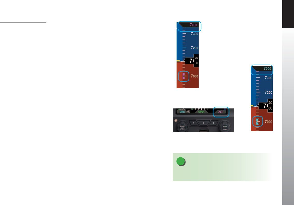
CHAPTER 3 FLYING THE EFD1000 PRO PFD
EFD1000 PFD Pilot’s Guide
Page 3-14 091-00005-001 REV E EFD1000 PFD Pilot’s Guide Page 3-15
091-00005-001 REV E
Set the Altitude Alerter
1. Press the Right Knob until ALT displays above the Right Knob and the
Selected Altitude numerical eld and Bug are enabled for editing, all three
rendered in magenta (Figures 3-20 and 3-21).
2. Rotate the Right Knob to change the value of the Selected Altitude eld.
Rotate clockwise to increase, or counterclockwise to decrease, the value.
3. Once the correct value is selected, and after 10 seconds of inaction, the eld
is disabled and the label, Selected Altitude eld, and Bug are rendered in cyan
(Figure 3-22).
Figure 3-20
Altitude Bug Enabled
Figure 3-22
Altitude Bug Disabled
Figure 3-21
Altitude Field Enabled
NOTE
Synchronizing the altitude sets the selected altitude to
the current altitude (see Chapter 2, Section 2.2.1.3.)
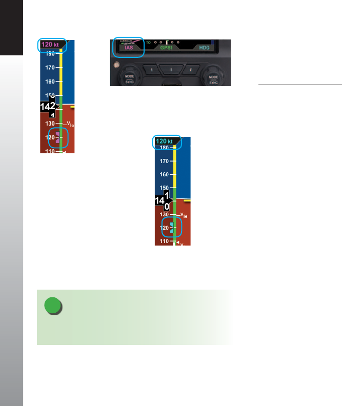
CHAPTER 3 FLYING THE EFD1000 PRO PFD
EFD1000 PFD Pilot’s Guide
Page 3-16 091-00005-001 REV E EFD1000 PFD Pilot’s Guide Page 3-17
091-00005-001 REV E
Our normal climb speed is 120 KIAS, so we set the Airspeed Bug as a reminder. To do so,
we press the Left Knob twice, until it shows IAS in magenta above the knob. Then turn
the knob until 120 shows in the Selected Airspeed Field.
Set the Airspeed Bug
1. Press the Left Knob until IAS displays above the Left Knob and the Selected
Airspeed eld and bug are enabled for editing, all three rendered in magenta
(Figures 3-23 and 3-24).
2. Rotate the Left Knob to change the value of the Selected Airspeed eld.
Rotate clockwise to increase, or counterclockwise to decrease, the value.
3. Once the correct value is selected, and after 10 seconds of inaction, the eld
is disabled, and the label and eld are rendered in cyan (Figure 3-25).
We plan to hand-y the plane until reaching our nal enroute altitude of 10,000 feet,
but would like to use the Flight Director (FD) (Figure 3-26). So, as part of our Before
Takeo set-up, we press the FD button on the autopilot mode selector, and the
magenta V-bars display on the PFD. As an easy way to give us guidance on the takeo,
we press the Go Around button. This commands wings level and about a 10º pitch-up
attitude, which works well for our initial climb.
Now our avionics are all set, so we taxi out to the runway, do our run-up, and call tower,
ready for departure. As we taxi into position and hold on Runway 8, we verify that our
PFD compass shows 080º, lined-up with our pre-set Heading Bug. As tower clears us for
takeo, it tells us to wait until reaching the end of the runway, and then to turn left to
heading 250º. Rotate the Right Knob to set the Heading Bug to 250°.
Figure 3-23
Selected Airspeed Field Enabled
Figure 3-25
Selected Airspeed Field Disabled
Figure 3-24
Selected Airspeed Field Enabled
NOTE
Synchronizing the airspeed sets the selected airspeed to
the current airspeed (see Chapter 2, Section 2.2.1.3.)

CHAPTER 3 FLYING THE EFD1000 PRO PFD
EFD1000 PFD Pilot’s Guide
Page 3-16 091-00005-001 REV E EFD1000 PFD Pilot’s Guide Page 3-17
091-00005-001 REV E
3.2.2. Departure
As we start the takeo roll, we note the airspeed on the PFD comes “alive” at 20 KIAS. All
indications are normal, so we continue the takeo, rotate at 80 KIAS and y the Flight
Director command bars at 10º pitch up with wings level. As we run out of usable runway
to land, we bring the gear up, and soon we’re over the end of the 13,800 ft. runway.
We engage HDG mode on the autopilot mode selector, and the FD commands a left
turn to our assigned 250º heading, which we have already set with the Heading Bug.
Through 1,000 feet AGL, we power back and adjust the pitch attitude to maintain our
target 120 KIAS climb speed, as shown by the Airspeed Bug on the airspeed tape, and
set the FD pitch to that attitude.
Soon we hear a one-second tone and see the yellow ag appear next to our Selected
Altitude eld at the top of the PFD airspeed tape (Figure 3-27). This means we are
15 seconds away from reaching our assigned altitude. We begin to shallow our climb,
and level o at 7,000 feet, engaging ALT hold on the AP/FD mode selector. The yellow
Altitude Alert on the PFD goes out as we capture and hold our altitude.
While on the 250º vector, we pass abeam the ABQ VOR. The Single-Line Bearing Pointer
points abeam, toward the VOR, and then swings behind the aircraft. We also notice that
the GPS then sequences to the next ight plan waypoint, the ZUN VOR.. The PFD Course
Pointer automatically swings left to the new course, 255º, and the leg on our Basemap
turns magenta.
Albuquerque Departure now tells us to y heading 220º to join the LARGO2 departure,
and climb and maintain 10,000. Departure also calls out slower trac at our 10 o’clock,
seven miles, west-bound at 8,000, and asks us to expedite our climb through 8,000.
1. Rotate the Right Knob and turn it left to set the Heading Bug to 220º.
2. Press the Right Knob twice to activate ALT, and turn it right to set 10,000 in the
Selected Altitude eld at the top of the Altitude Tape.
Figure 3-26
Flight Director V-bars
Figure 3-27
Altitude Alerter Flag Illuminated
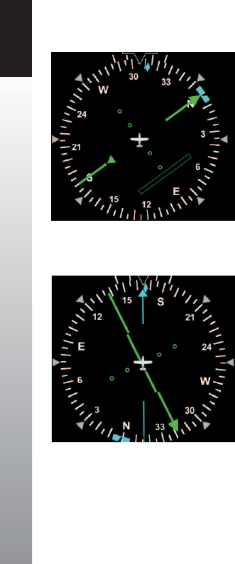
CHAPTER 3 FLYING THE EFD1000 PRO PFD
EFD1000 PFD Pilot’s Guide
Page 3-18 091-00005-001 REV E EFD1000 PFD Pilot’s Guide Page 3-19
091-00005-001 REV E
Auto Course Select has already set our Course Pointer to the 255º course from ABQ to
ZUN on the LARGO2 departure, and a 220º heading sets us up for a nice intercept. We
disengage ALT hold on the autopilot, set our cruise climb attitude and power,, set the
V-bars to that pitch, and initiate the climb from 7,000 to 10,000 feet. We pitch a little
higher to climb at 115 KIAS through 8,000 for trac, then lower the nose to maintain
our target airspeed of 120 KIAS by reference to the Airspeed Bug.
Even though our trac should be right ahead of us and about ve miles by now, we
don’t see it out the window. But we see the trac target on our PFD Navigation Display
and continue to monitor it even though it appears not to be a factor.
At about 9,700 feet, the Altitude Alerter tone sounds, and the yellow alert ag by the
Selected Altitude eld illuminates, telling us we are 15 seconds from reaching our
assigned 10,000 feet. We begin our level-o, and upon reaching 10,000 feet, engage ALT
hold on the autopilot’s mode selector.
Departure calls again to hand us o to Albuquerque Center on 133.0. As we’re tuning
the radio, we hear an alert tone. A glance at the PFD shows the Altitude Alerter ag
ashing, our altitude indicates 10,200 and climbing, and our Flight Director V-bars
are commanding pitch down. We quickly stop the climb, correct back down to our
assigned altitude of 10,000, and engage the autopilot before calling to check in
withCenter.
As we level out, accelerate to cruise speed, and then power back, we nally see our
trac out the left window, same direction, now about two miles and 2,000 feet below
us — just where the trac symbol on our PFD says it should be.
Figure 3-29
CDI “Alive” and Shown Solid
Figure 3-28
CDI Shown Hollow at Full-Scale Deection
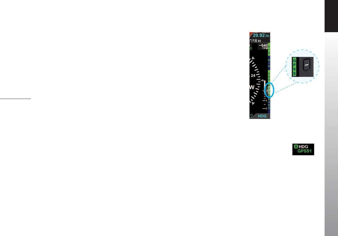
CHAPTER 3 FLYING THE EFD1000 PRO PFD
EFD1000 PFD Pilot’s Guide
Page 3-18 091-00005-001 REV E EFD1000 PFD Pilot’s Guide Page 3-19
091-00005-001 REV E
3.2.3. Enroute
Albuquerque Center gives us a new altimeter setting of 30.11. We set 30.11 on the
standby altimeter and then on the PFD.
• Press the BARO Hot Key and rotate the Right Knob to set 30.11.
• Press the BARO Hot Key, or any knob, button/key to exit.
Soon, the CDI comes “alive” and attracts our attention as it changes from hollow (Figure
3-28) to solid green (Figure 3-29) and begins to move in towards the Course Pointer as
we intercept our course. We enable GPSS to complete the intercept and steer us along
the airways all the way to Reno, and engage the autopilot.
Engage GPSS
1. Press the GPSS Hot Key to Enable GPS Steering (Figure 3-30).
2. Verify indications that GPSS is now enabled on the PFD.
• The GPSS legend adjacent to the GPSS Hot Key should be shown in
inverse green.
• The annunciation GPSS1 (or GPSS2, depending on the selected CDI
Navigation Source), along with an inverse A, should be shown next to
the HDG reference at the top of the navigation display (Figure 3-31).
3. Select HDG mode on the autopilot’s mode selector.
• The Flight Director V-bars should be showing appropriate steering cues
to intercept and track the course.
4. Engage the autopilot (if desired).
Figure 3-30
GPSS Enabled legend in Green
Figure 3-31
GPSS Enabled
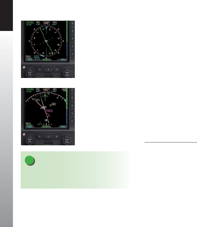
CHAPTER 3 FLYING THE EFD1000 PRO PFD
EFD1000 PFD Pilot’s Guide
Page 3-20 091-00005-001 REV E EFD1000 PFD Pilot’s Guide Page 3-21
091-00005-001 REV E
With GPS Steering (GPSS), a compatible GPS navigator (in this case, a Garmin 430W)
drives the autopilot directly via the autopilot’s HDG mode, telling it how to bank to
stay centered on course. GPSS can drive the autopilot far more accurately than the NAV
mode (which is based on course deviation indications) because the GPS always knows
the ground track and how to adjust to maintain that track, implicitly accounting for
changing wind conditions. The GPS also includes turn anticipation based on current
ground speed and track, enabling it to turn early and roll out centered on the new
course without overshooting. As we’ll soon see when ying an instrument approach, an
autopilot with a WAAS GPS and GPSS enabled can even y procedure turns and holding
patterns. For more detail on GPSS (see Chapter 4, Section 4.7.1.).
Now that we’re established at our nal cruise altitude and in the enroute phase of our
ight, we’ll switch to the ARC Compass mode of the HSI to maximize a forward view.
1. Press the 360 Hot Key and observe that HSI changes to its ARC Compass
mode and the Hot Key label changes from 360 to ARC.
2. Press the RNG Buttons to adjust the map range to suit your preference.
Select a Compass Mode
• Press the 360/ARC Hot Key to alternately select either the 360° (Figure 3-32)
or the ARC (Figure 3-33) Compass Mode.
We set cruise power and lean the mixture. As the airplane stabilizes in cruise, we check
the Data Bar to monitor performance. True Airspeed (TAS) is close to book performance
for this altitude and power setting. OAT is close to ISA. Winds aloft are close to forecast,
about a 30º left quartering headwind at 15 knots, so we’ll expect to gain some ground
speed due to a stronger tailwind component when we turn northwest toward Reno.
Figure 3-32
360° Compass Mode
Figure 3-33
ARC CDI Compass Mode
NOTE
Each HSI Compass Mode (360 and ARC) retains its own
Range and Map declutter settings when switching
between the two.
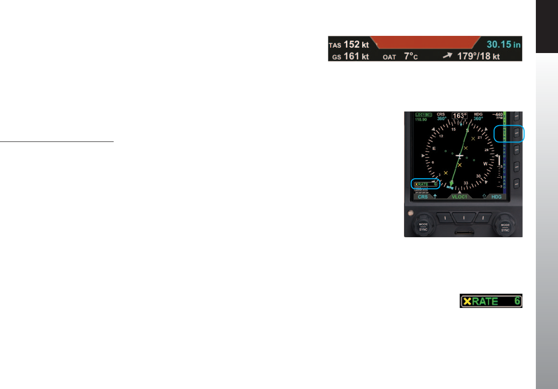
CHAPTER 3 FLYING THE EFD1000 PRO PFD
EFD1000 PFD Pilot’s Guide
Page 3-20 091-00005-001 REV E EFD1000 PFD Pilot’s Guide Page 3-21
091-00005-001 REV E
Check TAS, GS, and winds and temperature aloft on the Data Bar (Figure 3-34).
Ahead, we can see out the window some threatening convective buildups, those
that were mentioned in our weather brieng and which we checked using Data Link
Weather on the ground in Albuquerque. We still have the NEXRAD precipitation (NXRD)
and Data Link Lightning (LTNG) overlays selected, and the PFD Nav Display shows
the weather clearly ahead of us. For a more real-time look at lightning activity in the
buildup, we switch to our WX500 Stormscope® and see lots of strikes appearing as we
also see the lightning ashes out the window.
Display the Lightning Overlay
1. Display the 2/2 Hot Key Menu.
2. Press the LTNG Hot Key until the STRK label is shown in green next to the Hot
Key (Figure 3-35).
3. The STRK mode annunciation appears in the lower left-hand corner of the
Navigation Display, showing a yellow X for Strike mode, and a strike rate of 6
(moderate lightning activity) (Figure 3-36).
Fortunately, the Nav Display shows our ight plan will make a right turn at Winslow
(INW) and a another right turn at Flagsta (FLG), which will keep us clear of the weather.
Continuing enroute, we monitor progress along our ight plan on the extended
forward view of ARC mode, watching as GPSS keeps us exactly centered on course
through several turns on the airways.
Figure 3-35
Lightning Overlay On Displaying WX-500 Strike Data
Figure 3-36
WX-500 Strike Rate Annunciation
Figure 3-34
Data Bar
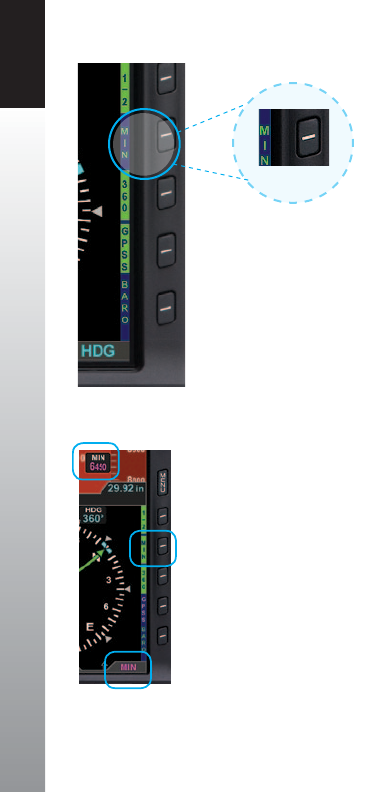
CHAPTER 3 FLYING THE EFD1000 PRO PFD
EFD1000 PFD Pilot’s Guide
Page 3-22 091-00005-001 REV E EFD1000 PFD Pilot’s Guide Page 3-23
091-00005-001 REV E
3.2.4. Arrival and Approach to Landing
As we near Reno, we prepare for our arrival. Within range, we pick up the ATIS:
Reno-Tahoe International Airport, Information Romeo, 2253 Zulu. Winds 180 at
17. Ceiling 1,400 broken. Temperature 23, dewpoint 18, altimeter 30.08. ILS16R
approach in use. Advise on initial contact you have Information Romeo.
Our route along V105 brings us to the Mustang VOR (FMG), which has a published
transition to TAKLE, an Initial Approach Fix (IAF) for the ILS RWY 16R instrument
approach procedure. Because we’d like some practice with our new PFD and GPSS, we’ll
ask to y the full procedure with pilotnav.
We load the KRNO ILS16R approach into the GPS, selecting TAKLE as our IAF and the
ILS frequency (110.9) is placed in the standby window of the 430W. With Auto Course
Select enabled on the PFD, the HSI Course Pointer will be slewed automatically once
we turn inbound to the Final Approach Course of 164º. Brieng the approach, we load
the Ground and Tower frequencies into our #2 comm and note our Decision Height is
6,446 feet. We set our approach MINIMUMS on the PFD to 6,450 feet (MINIMUMS are
set in increments of 10 feet, so we round up), and we set our Selected Airspeed for the
approach at 120 KIAS.
1. Press the MIN Hot Key (Figure 3-37).
The Selected Minimums Field appears on the lower right-hand corner of
the Attitude Display and the Right Knob State changes from HDG to MIN in
magenta, ready for setting (Figure 3-38).
2. Turn the Right Knob to set 6,450 on the Selected Minimums Field.
3. Press the Left Knob twice to select IAS for editing.
4. Turn the Left Knob to set 120 kt as our target airspeed.
Figure 3-37
MIN Hot Key (shown disabled)
Figure 3-38
MIN Display Selected for Editing

CHAPTER 3 FLYING THE EFD1000 PRO PFD
EFD1000 PFD Pilot’s Guide
Page 3-22 091-00005-001 REV E EFD1000 PFD Pilot’s Guide Page 3-23
091-00005-001 REV E
We’re all set up for the approach. Nearing Mustang VOR (FMG), Oakland Center hands
us o to Reno Approach, and we request nav for the ILS16R. Approach gives us the new
altimeter setting of 30.08, clears us down to 9,000 feet, and after FMG direct TAKLE. We
initiate the descent, set 30.08 in the standby altimeter and on the PFD:
1. Press the Right Knob twice to select ALT for editing.
2. Turn the Right Knob left to set 9,000 as our Selected Altitude.
3. Press the BARO Hot Key to select BARO for editing
4. Turn the Right Knob left to set 30.08 as our barometric pressure setting.
Fifteen seconds before reaching 9,000 feet, the Altitude Alerter ag illuminates, and
the alert tone sounds. We begin our level-o and re-engage ALT hold on the autopilot
upon reaching 9,000 feet. We leave the autopilot in HDG mode and continue with GPSS
enabled on the PFD.
Approaching FMG, the GPS turn anticipation sequences to TAKLE, our Course Pointer
swings automatically from 302º to 316º, and GPSS steers us through the turn, rolling
out precisely on course. We power back and select the rst notch of aps to slow
down. Reno Approach calls, reports us six miles from TAKLE, and clears us for the ILS16R
approach.
We activate the approach on the GPS and move the ILS frequency into the
activewindow.
GPSS continues to steer the plane to the initial approach x, TAKLE, and at TAKLE,
turns us outbound on a 344º course for the procedure turn (Figure 3-39). We see the
procedure turn drawn on the Basemap ahead of us, and watch it turn magenta as the
Figure 3-39
360º Mode Showing Procedure Turn,
GPSS Enabled

CHAPTER 3 FLYING THE EFD1000 PRO PFD
EFD1000 PFD Pilot’s Guide
Page 3-24 091-00005-001 REV E EFD1000 PFD Pilot’s Guide Page 3-25
091-00005-001 REV E
GPSS turns and ies the procedure turn for us, with no further pilot action required.
As GPSS completes the procedure turn and rolls out centered on our nal approach
course of 164º, we begin a descent down to 8,500 feet, which we will maintain until
glideslope intercept.
1. Press the Right Knob twice to select ALT for editing.
2. Turn the Right Knob to set 8,500 as our Selected Altitude.
3. On reaching 8,500, re-engage ALT hold on the autopilot.
We are still navigating along the ILS16R approach using GPS, with GPSS driving the
autopilot in HDG mode. We know we’ll have to switch the autopilot to APPR mode
before glideslope intercept in order for the autopilot to capture the glideslope and y us
down the ILS. But we’ll continue in GPSS and HDG mode a while longer because it tracks
the course more accurately with our aging autopilot.
Along this intermediate segment of the approach, watch for the 430W to switch
automatically from GPS to VLOC output on its CDI.
• Watch for the EFD1000 CDI Source Select eld to change from GPS1 toVLOC1.
This automatic switch from GPS to VLOC should occur 2–10nm outside the Final
Approach Fix (FAF). If it has not occurred automatically by 2nm outside the FAF, manually
press the CDI button on the 430W to make the switch to the ILS frequency, and the PFD
will follow by switching its Navigation Source Select to VLOC1.
As the PFD navigation source switches to the ILS on VLOC1, the LDI and VDI (Figure 2-2,
Refs. 36 and 37) will appear on the Attitude Display.
1. The LDI Navigation Source Annunciation (Figure 2-2, Ref. 31) will show ILS,
if it is receiving a valid glide slope signal, or LOC, if it is not receiving the glide
slope (GS).
2. The CDI Source Information Block (Figure 2-2, Ref. 65) will also show ILS
orLOC.

CHAPTER 3 FLYING THE EFD1000 PRO PFD
EFD1000 PFD Pilot’s Guide
Page 3-24 091-00005-001 REV E EFD1000 PFD Pilot’s Guide Page 3-25
091-00005-001 REV E
Even though the PFD Navigation Source for the CDI has switched to VLOC1 and the ILS,
and the CDI, LDI and VDI are showing deviations relative to the localizer and glideslope,
we still have GPSS Enabled with the autopilot in HDG mode. We are not yet ying the
ILS, required for this approach. GPSS is still shown in the inverse green label next to the
GPSS Hot Key, and GPSS1 and an inverse A are still shown at the top of the Navigation
Display where the numerical HDG value is usually shown.
The PFD now permits GPSS to be enabled even when VLOC is selected as the CDI
Navigation Source.
Whenever GPSS is enabled on the PFD, and the autopilot is in HDG mode, the autopilot
will y the GPS ight plan. The autopilot must be switched to APPR mode in order to y
the VLOC source selected for the CDI and to capture and track the glideslope of an ILS,
or even an RNAV approach with vertical guidance.
A couple of miles outside the FAF (TAKLE), we switch to APPR mode on the autopilot,
which begins to track the localizer and is armed for glideslope capture. At this point, we
could disable the GPSS by pressing the GPSS Hot Key to remove potentially confusing
annunciations on the PFD, but we know our equipment well. We understand fully that
GPSS is just another form of HDG as far as the autopilot is concerned, and the autopilot
will not y GPSS unless it is in HDG mode. So we leave GPSS enabled on the PFD,
planning to use it to y the Missed Approach if necessary.
With that setup, if we have to y the Missed Approach, we’ll do so by hitting Go Around
mode on the autopilot and climbing straight ahead to 6,700 feet. Then we’ll press the
OBS button on the GPS to allow the missed approach ight plan to sequence. Engage
the autopilot in the HDG mode and begin the climb out. With GPSS still enabled, the
autopilot will navigate the aircraft directly to the FMG VOR. If the GPS supports curved
ight plans, such as a WAAS GPS, the autopilot will automatically enter and y the hold.
All we have to do is level o when reaching 11,000 feet - and if we had Altitude Pre-
Select on the autopilot, it would even do that for us, too!
CAUTION
The Garmin 400/500 series navigators continue to
output GPS Steering commands to follow the GPS ight
plan even when the CDI source is set to VLOC.
The PFD permits GPSS to be enabled even when VLOC is
selected as the CDI navigation source.
Whenever the GPSS is on and the autopilot is in the
HDG mode, the autopilot will y the GPS ight plan. The
autopilot must be switched to APPR mode in order to y
the VLOC source selected on for the CDI and to capture
and track the glideslope of an ILS or even an RNAV
approach with vertical guidance.

CHAPTER 3 FLYING THE EFD1000 PRO PFD
EFD1000 PFD Pilot’s Guide
Page 3-26 091-00005-001 REV E EFD1000 PFD Pilot’s Guide Page 3-27
091-00005-001 REV E
When the glideslope is full-scale deection above us, the Deviation Indicator on the
VDI will show as a hollow diamond at the top of the scale (Figure 3-40). When the
glideslope comes “alive”, the Indicator will change to a solid green diamond and begin
to move down the VDI. Just before intercepting the glideslope, we drop the gear
and check for three green lights. At glideslope intercept, we verify that the autopilot
switches to glideslope-capture and begins to y the aircraft down the glide slope.
We continue to monitor the approach and verify that the autopilot is tracking both
localizer and glide slope. The weather is well above minimums, and we intend to land
out of the approach but will let the autopilot y it down to minimums. As we get
close to minimums, a green triangle appears on the Altimeter Tape at 500 feet above
minimums; a hollow yellow triangle appears with its tip at 200 feet above minimums
and its base at 100 feet above. A red-striped triangle appears at the MINIMUMS setting.
These three color markers on the Altimeter Tape give us visual cues that we are
approaching or at minimums.
On reaching the pre-set minimums (6,450 feet):
• The MINIMUMS alert displays below the Aircraft Reference Symbol in the
Attitude Display (Figure 3-41).
• The MINIMUMS alert tone sounds three times.
We disconnect the autopilot and hand-y the plane, continuing to y the Flight Director
and track the glide slope down to a smooth landing.
Figure 3-40
Vertical and Horizontal Deviation
Indicator, Showing Glide Slope
Figure 3-41
MINIMUMS Alert

CHAPTER 3 FLYING THE EFD1000 PRO PFD
EFD1000 PFD Pilot’s Guide
Page 3-26 091-00005-001 REV E EFD1000 PFD Pilot’s Guide Page 3-27
091-00005-001 REV E
3.3. Conclusion
The Pro PFD is a powerful addition to any cockpit, providing far more capability,
information, and automation than the mechanical instruments it typically replaces.
While it is simple and intuitive enough to start using with only a short orientation, fully
understanding and exploiting all of its features require some study andexperience.
Chapter 4 covers all of the Pro PFD features in detail.
Chapter 5 explains how to customize the PFD to suit your preferences.
Chapter 6 addresses Emergency and Abnormal procedures.
Please read through these chapters to fully understand how to use your PFD.

CHAPTER 3 FLYING THE EFD1000 PRO PFD
EFD1000 PFD Pilot’s Guide
Page 3-28 091-00005-001 REV E EFD1000 PFD Pilot’s Guide Page PB
091-00005-001 REV E
This Page Intentionally Left Blank

CHAPTER 4 REFERENCE GUIDE
EFD1000 PFD Pilot’s Guide Page 4-1
091-00005-001 REV E
Chapter 4
Reference Guide
The PFD is a panel-mounted Electronic Flight Instrument System (EFIS)
that presents the pilot with displays of attitude, altitude, indicated
airspeed, heading, rate of turn, slip/skid, and navigation course deviation
information. The system also displays supplemental ight data, such as
winds, TAS, OAT, groundspeed, moving maps, pilot-selectable indices
(bugs), and various annunciations to increase situational awareness and
enhance ight safety. Moving map situational awareness information is
displayed when the unit is connected to compatible GPS equipment.
The PFD system components include the PFD display head, a Remote Sensor Module
(RSM), a Conguration Module (CM), and the optional Analog Converter Unit (ACU).
Chapter 1, Welcome and Introduction, provides a detailed discussion on the PFD
system components.
When interfaced with a compatible autopilot, the Pro PFD system provides heading
and course information to the autopilot, which enables the autopilot to follow the
Course and Heading values set by the pilot on the PFD in much the same way as with a
mechanical HSI. When interfaced with a compatible GPS, the Pro PFD can provide GPS
Steering (GPSS) to an autopilot.
NOTE
The optional ACU enables the interface of the Pro PFD
system with legacy panel-mounted GPS navigators,
VOR/Localizer radios, and autopilots.

CHAPTER 4 REFERENCE GUIDE
EFD1000 PFD Pilot’s Guide
Page 4-2 091-00005-001 REV E
4.1. Air Data, Attitude and Heading Reference
System (ADAHRS)
One of the many benets of glass cockpit systems like the Aspen Evolution system is
that they replace old, less-reliable mechanical instruments and sensors with electronic
equivalents. For aircraft primary ight instruments, spinning metal gyros are replaced
with electronic gyros and accelerometers, and mechanical air data instruments
(airspeed indicator, altimeter, and VSI) are replaced by electronic sensors to measure
static and ram air pressures. As we’ve all seen with computers and consumer goods,
these modern electronic systems tend to be smaller, faster, cheaper, and more reliable
than the older technologies they replace, while also enabling many new, advanced
features and capabilities.
An electronic system that replaces the functions of the six primary ight instruments is
often called an ADAHRS (Air Data, Attitude, and Heading Reference System). Sometimes,
two separate systems work together to deliver those functions: an AHRS for attitude
and heading, and an ADC (Air Data Computer) for airspeed, altitude, and vertical speed.
Aspen uses an integrated ADAHRS mounted to the back of the PFD display. While
such systems deliver the same basic information to the pilot as the old mechanical
instruments, they work in very dierent ways. It is important that the pilot have at least a
basic understanding of how an ADAHRS works to better understand the sorts of failure
modes or degraded performance than can occur, how to recognize the symptoms, and
what corrective actions the pilot can take.
The PFD uses Micro Electro-Mechanical Systems (MEMS) technology and solid-state
accelerometers and magnetometers on all three axes to provide the attitude reference.
Generally, MEMS attitude solutions use multiple sensors and inputs, processed through
Kalman lter software, to derive and validate the attitude solution.
The Aspen system uses more than a dozen dierent inputs to determine and monitor
the aircraft attitude. In this way, the system can validate the derived attitude indication
by cross-checking the various inputs to the solution for consistency.

CHAPTER 4 REFERENCE GUIDE
EFD1000 PFD Pilot’s Guide Page 4-3
091-00005-001 REV E
4.1.1. Attitude
The Aspen ADAHRS attitude solution uses inputs from its internal three-axis
accelerometers, rate gyros, and magnetometers, supplemented by ram and static air
pressure inputs from the aircraft pitot-static system. Failures or incorrect input from any
of these sensors (such as might occur if the pitot tube or static system become blocked)
will aect the attitude solution. The PFD is designed to be robust to such failures, either
by being tolerant to incorrect inputs, or by detecting and annunciating a degraded
attitude solution.
The Aspen ADAHRS includes a Cross-Check Monitor, which predicts the quality of the
attitude solution by performing a continuous, real-time statistical analysis of the various
parameters computed within the AHRS Kalman lter. When the predicted quality of
the attitude calculation drops below a certain threshold, CROSS CHECK ATTITUDE is
annunciated on the attitude indicator (Figure 4-1). The annunciation thresholds for
the CROSS CHECK ATTITUDE message were determined during company ight tests,
and strike a balance between minimizing nuisance annunciations (when the attitude
solution is ne) and failing to annunciate (when the attitude solution is signicantly
degraded). This balance can occasionally result in momentary CROSS CHECK ATTITUDE
annunciations, especially during aggressive maneuvering, steep or high-G turns, abrupt
pitch changes, etc.
In such situations, these annunciations indicate that the statistical quality of the attitude
solution is less than nominal, and that the pilot should cross-check the AHRS against
alternate attitude indications. Should the annunciation persist, then degraded AHRS
performance is statistically more likely to be experienced. In other words, momentary
CROSS CHECK ATTITUDE annunciations indicate that the AHRS solution is working
hard enough that the AHRS quality measure has degraded to something less than that
associated with normal, unaccelerated ight. This situation demands increased pilot
vigilance and cross-monitoring of other cockpit instrumentation.
Figure 4-1
Cross Check Attitude
Annunciation

CHAPTER 4 REFERENCE GUIDE
EFD1000 PFD Pilot’s Guide
Page 4-4 091-00005-001 REV E
4.1.2. Pitot Obstruction Monitor
Most light aircraft have only a single pitot and static system available for ight
instrument use. As such, a common pitot and static input is shared between the PFD
and analog standby instruments. Should one or both of these pitot and static lines
become blocked, both the PFD and any standby airspeed and altitude indicators
could display erroneous airspeed and altitude information. Furthermore, because
the PFD uses pitot and static pressures as part of the AHRS attitude calculations, loss
or corruption of the pitot or static pressures can also inuence the accuracy of the
displayed attitude information.
The PFD has been tested to be robust to these failures, either by being tolerant to
incorrect pitot or static inputs, or by detecting and annunciating a degraded attitude
solution. When connected to an IFR-certied GPS, the system is further able to detect
and annunciate blockages in the pitot system and will fail the attitude solution before
it becomes degraded. In that case, the system will red X the attitude and heading
information, and display a CHECK PITOT HEAT message as a reminder to the pilot to
check for ice accumulating on the pitot probe.
Once the system detects that the pitot obstruction has been cleared, the CHECK PITOT
HEAT annunciation is removed and the system automatically performs an AHRS in-ight
reset.
Should a GPS failure be experienced in ight, the Pitot Obstruction Monitor continues
to operate in a fail-safe mode and will continue to detect obstructions in the pitot
system that may occur while airborne. However, after landing, the monitor remains
active, and, as the airplane slows to taxi speeds, the system will indicate a failure of the
AHRS and annunciate CHECK PITOT HEAT. In this circumstance, restoring the GPS will
restore normal monitor operation.

CHAPTER 4 REFERENCE GUIDE
EFD1000 PFD Pilot’s Guide Page 4-5
091-00005-001 REV E
In summary, loss or degradation of the PFD attitude solution is unlikely if the pilot
assures the proper operation of the pitot-static system. If the pitot or static system
becomes blocked, an ADAHRS internal sensor fails, or a CROSS CHECK ATTITUDE
indication is frequent or persists, the attitude indication on the PFD should be
considered to be compromised. In this case, the pilot must use the backup attitude
indicator for attitude reference until the cause of the problem has been identied and
resolved and normal system operation has been restored.
4.1.3. Heading
The PFD ADAHRS also includes a slaved compass system that provides accurate
magnetic heading indications throughout most operating conditions and phases
of ight. Its electronic gyros compensate for turning and acceleration errors, and its
remote uxgate compensates for gyroscopic precession errors, so there is no need for
the pilot to adjust heading throughout the ight. Nonetheless, all compass systems are
subject to some error, and the pilot should be aware of when and how the PFD heading
indication can be aected.
The earth’s magnetic eld is measured directly by a 3-axis uxgate magnetometer built
into the Remote Sensor Module (RSM), and magnetic heading is derived from the ux
on a plane perpendicular to gravity, providing immunity from pitching and rolling
eects. Electronic gyros and accelerometers in the PFD system are then used to stabilize
that raw heading data to eliminate the short-term turning and acceleration errors seen
in traditional magnetic compasses.
Together, these systems provide accurate heading indications even during aggressive
maneuvering. The gyros stabilize magnetic errors while maneuvering and are slaved
to the uxgate, which continuously updates heading to compensate for gyroscopic
precession. The end result is a compass system that requires no pilot action to show
accurate magnetic heading throughout the ight.

CHAPTER 4 REFERENCE GUIDE
EFD1000 PFD Pilot’s Guide
Page 4-6 091-00005-001 REV E
Just like other compass systems, the accuracy of the uxgate is aected by its location
on the airframe. Ferrous metal structures, electrical elds produced by motors, pumps,
wiring, magnets in cabin speakers and other airframe-related sources of interference
either constant or momentary (i.e. operating an electric trim motor, windshield heat,
pumps, etc) can all aect the accuracy of the compass. The installer can compensate
for much of this interference when calibrating the RSM, but some eects cannot be
eliminated. Proper location of the RSM during installation of the PFD is critical to the
AHRS performance and accuracy.
Furthermore, all magnetic compass systems are susceptible to local disturbances in the
earth’s magnetic eld (some of which are shown on aviation charts or by NOTAM) and
will exhibit degraded performance when operating in extreme northern and southern
latitudes close to the earth’s magnetic poles.
4.1.4. Free Gyro Mode
When the PFD system detects that the horizontal component of the earth’s magnetic
eld is no longer strong enough to provide reliable heading data, the PFD will detect
the condition and annunciate that the heading system is no longer slaved to magnetic
north. If the condition persists, attitude and heading indications are removed.
While the condition can occur at greater distances, it is most likely to be observed
within 750 nautical miles from the magnetic poles. In the Northern Hemisphere, this
equates to operations in the Arctic Islands found north of continental North America.

CHAPTER 4 REFERENCE GUIDE
EFD1000 PFD Pilot’s Guide Page 4-7
091-00005-001 REV E
Two minutes after detection, a FREE GYRO MODE annunciation will be presented across
the HSI, indicating the heading system no longer can be aligned with magnetic north.
Some precession of the heading is possible, especially during abrupt maneuvers. If the
condition persists for four more minutes (six minutes total) the attitude and heading
indicators will be removed and replaced with red X indications. When the conditions
causing Free Gyro Mode are no longer present, attitude and heading indications will be
restored after an automatic AHRS reset.
4.1.5. Degraded ADAHRS Performance
For Degraded ADAHRS Performance, reference the following:
• Sections6.1.Pitot/StaticSystemBlockage
• Sections6.8.In-FlightAHRSReset
• GeographicLimitationsin the AircraftFlightManualSupplement that was
installed in the aircraft with your PFD.
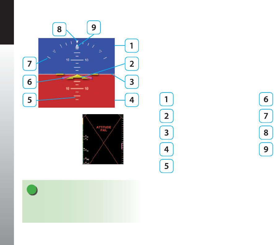
CHAPTER 4 REFERENCE GUIDE
EFD1000 PFD Pilot’s Guide
Page 4-8 091-00005-001 REV E
4.2. Attitude Display
4.2.1. Attitude Indicator
The Attitude Indicator consists of an aircraft reference symbol on a blue (sky) and
brown (ground) background. The white horizon line separates the sky from the ground
and extends to the edge of the display. The Roll Scale curves over the top of the
Attitude Indicator while the Pitch Scale extends vertically in the middle. The slip/skid
rectangle is directly underneath the roll pointer (Figure 4-2).
Sky Flight Director
Aircraft Reference Symbol Roll Scale
Horizon Line Roll Pointer
Ground Slip/Skid Indicator
Pitch Scale
The Attitude Indicator cannot be disabled by the pilot. The Aircraft Reference Symbol is
xed relative to the Attitude Indicator and overlays all other Attitude Indicator symbols.
Pitch and roll panel tilt adjustments are is provided to installers to compensate for
variations in installations and tilted panels.
NOTE
A red X and the annunciation ATTITUDE FAIL displays
on the Attitude Indicator as long as pitch or roll
attitude data is invalid (Figure 4-3).
Figure 4-3
Pitch and/or Roll Data Invalid
Figure 4-2
Attitude Indicator

CHAPTER 4 REFERENCE GUIDE
EFD1000 PFD Pilot’s Guide Page 4-9
091-00005-001 REV E
4.2.1.1. Roll Scale
The Roll Scale is displayed at the top of the Attitude Indicator and comprises a moving
scale set against a xed, white, triangle roll pointer. Tick marks are displayed at 0º, 10º,
20º, 30º, 45º, and 60º of roll. The 45º marks are triangles.
4.2.1.2. Pitch Scale
The pitch scale consists of minor pitch marks in 2.5º increments up to ±20º and major
pitch marks in 10º increments up to ±90º. Red chevrons come into view for nose-up
pitch angles of 15º or more (Figure 4-4), and nose-down pitch angles of 10º or less
(Figure 4-5). The pitch chevrons aid the pilot in unusual attitude recovery.
The range of movement of the background sky and ground boundaries are limited so
that some sky or ground is always visible.
4.2.1.3. Slip/Skid Indicator
The Slip/Skid Indicator is the small white rectangle under the roll pointer. The Slip/
Skid Indicator moves left and right relative to the roll pointer in proportion to lateral
acceleration. The width of the rectangle is equivalent to the width of the ball in a
mechanical inclinometer.
4.2.1.4. Flight Director1
When connected to a compatible autopilot and congured through an ACU during
installation, the PFD displays a single-cue (two-axis) ight director on the Attitude
Indicator (Figure 4-6). The pilot may follow the ight director’s pitch and roll cues, even
when the autopilot is not engaged, to remain on heading or altitude, climb or descend,
turn, or navigate along a programmed ight path.
Figure 4-4
Pitch Markings
Large Pitch Down
Figure 4-5
Pitch Markings
Large Pitch Up
Figure 4-6
Flight Director
NOTE
Refer to the autopilot’s AFMS for information on the
operation of the flight director. The Flight Director
is a visual representation of the pitch and roll
commands from the autopilot. The Flight Director’s
pitch and bank limits are based on the emulation
mode set at installation and are limited to +/- 45°
roll and +/- 25° pitch.
1. Not available with the Pilot PFD
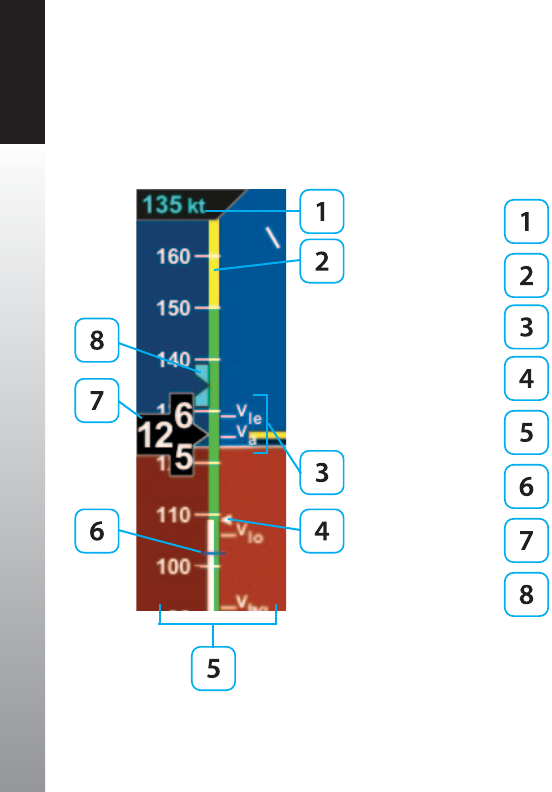
CHAPTER 4 REFERENCE GUIDE
EFD1000 PFD Pilot’s Guide
Page 4-10 091-00005-001 REV E
4.2.2. Airspeed Indicator
The Airspeed Indicator comprises a moving tape, airspeed bug, and numerical airspeed
value (drum). Textual Vspeeds, color Speed Bands, and Speed Markers are also rendered
on the moving tape (Figure 4-7).
Selected Airspeed Field
Color Speed Bands
Textual Vspeeds
Initial Flap Extension Speed Marker
Airspeed Tape
Speed Marker
Numerical Airspeed Value (drum)
Selected Airspeed Bug
Figure 4-7
Airspeed Indicator

CHAPTER 4 REFERENCE GUIDE
EFD1000 PFD Pilot’s Guide Page 4-11
091-00005-001 REV E
Indicated airspeed is displayed in knots, miles per hour or Mach number, set at
installation, with tick marks rendered on the Airspeed tape every ten (10) units. Speed
Bands and Speed Markers are congured during installation and cannot be changed
or removed by the pilot. The textual Vspeeds are pilot-congurable and are discussed
in Chapter5,CustomizingthePFD. Although the pilot can set the selected airspeed
(bug), there is no visual or aural annunciation provided when the actual airspeed
deviates from the selected airspeed value.
The numerical airspeed value is displayed in a rolling drum format in the center of the
airspeed tape with numbers moving downward as speed increases, and upward as
speed decreases. The display range of the indicated airspeed is 20–450 (knots or miles
per hour). The numerical airspeed value is displayed in red when Vne is exceeded or
when the airspeed drops below Vs0 during stalls or landing roll-outs (Figure 4-8).
Figure 4-8
Actual Airspeed Greater Than the Vne
Figure 4-9
Pitot Obstruction Monitoring
Airspeed <30kts, Ground Speed >50kts
Annunciation
NOTE
When airspeed is less than 30 knots but ground GPS speed is greater than 50 knots, a
red X and annunciation of CHECK PITOT HEAT is displayed on the Attitude Indicator
(Figure 4-9).
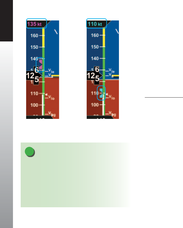
CHAPTER 4 REFERENCE GUIDE
EFD1000 PFD Pilot’s Guide
Page 4-12 091-00005-001 REV E
4.2.2.1. Selected Airspeed
The Selected Airspeed Field value and associated Airspeed Bug are shown on the
Airspeed Tape. The Selected Airspeed Field value is shown at the top of the Airspeed
Tape. The Airspeed Bug is displayed next to the Airspeed Tape when the Selected
Airspeed value is within the visible range of the tape. The Selected Airspeed Field’s
default value is 20 knots Indicated Airspeed (IAS), or the value previously set. SYNCing
the IAS eld sets the Selected Airspeed Field value to the current indicated airspeed
(Section 2.2.1.3). Setting the Selected Airspeed Field to a value less than 20 disables
the Airspeed Bug and dashes the Selected Airspeed Field value.
Set Airspeed Bug
1. Press the Left Knob until IAS is shown above the Left Knob.
The Airspeed Field and Airspeed Bug appear in magenta - enabled for editing (Figure
4-10).
2. Rotate the Left Knob clockwise to increase, or counterclockwise to decrease
the airspeed value in the Selected Airspeed Field.
After 10 seconds of inactivity, label, eld and bug appear in cyan (Figure 4-11).
Figure 4-10
Airspeed Bug Selected to Edit
Figure 4-11
New Airspeed Selected
NOTE
A typical installation sets the Tapes (TPS) display
to UNLOCKED, allowing the pilot to display or
hide the Airspeed and Altitude Tapes as desired. If
the Airspeed and Altitude Tapes were LOCKED ON
during installation, the Tapes will remain on. If the
Airspeed and Altitude Tapes were LOCKED OFF during
installation, the Tapes will not display.
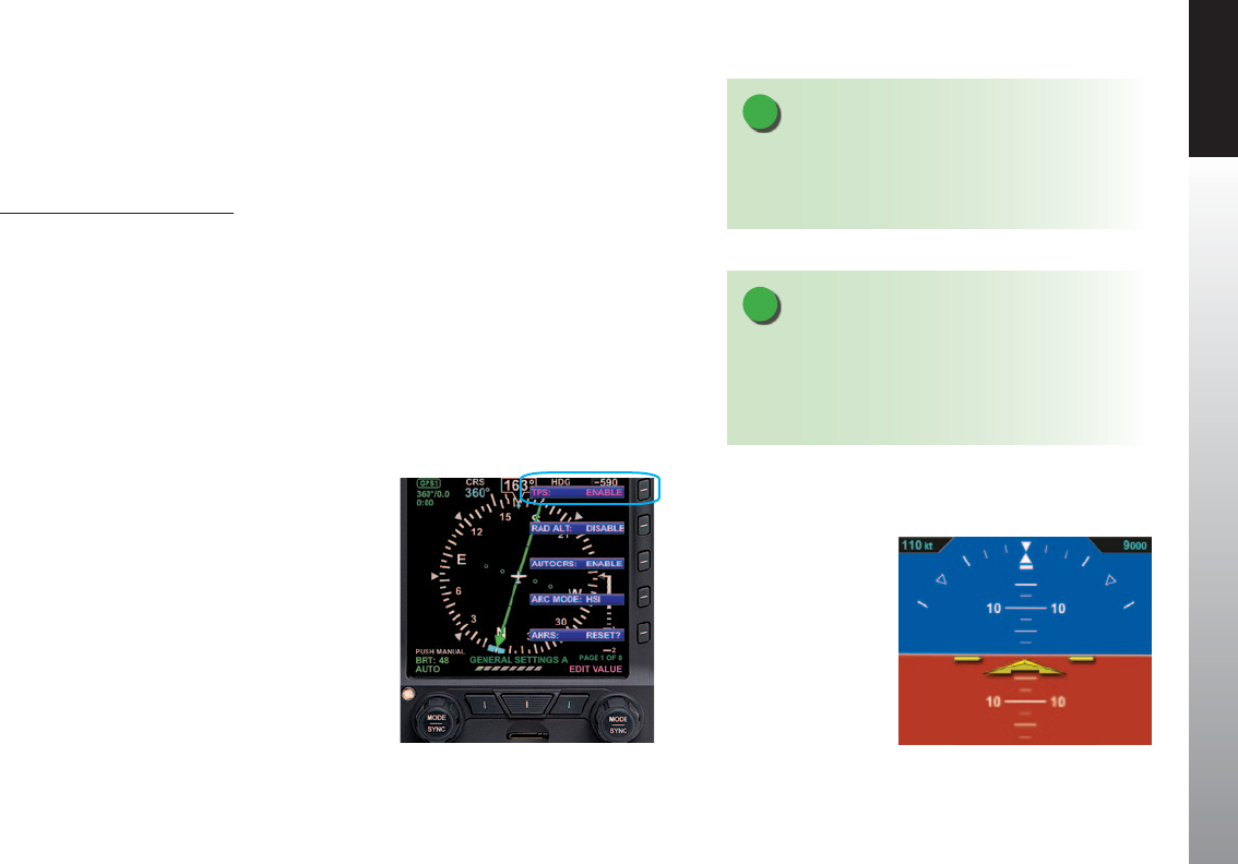
CHAPTER 4 REFERENCE GUIDE
EFD1000 PFD Pilot’s Guide Page 4-13
091-00005-001 REV E
4.2.2.2. Airspeed Display
In some congurations, such as a stand-alone PFD, the airspeed tape can be turned o
at the pilot’s discretion to facilitate screen declutter. This setting will be retained when
the PFD system is turned o then powered on again.
Hide/Display Airspeed Tape
1. Press MENU Button.
2. Rotate Right Knob until rst Menu Key displays TPS (Figure 4-12).
3. Press TPS Menu Key.
TPS label and EDIT VALUE label (above Right Knob) appear in magenta.
4. Rotate Right Knob to the desired value: ENABLE or DISABLE (Figure 4-13).
5. Press MENU Button to exit.
Figure 4-12
Editing Airspeed Tape Display
Figure 4-13
Airspeed Tape Disabled
NOTE
The Altitude Tape can also be turned off for screen
declutter. Setting will be retained when PFD is
turned off.
NOTE
When the Airspeed Tape is disabled, the numerical
display of the selected airspeed remains An installer
can disable and remove the Selected Airspeed Field
from the display.

CHAPTER 4 REFERENCE GUIDE
EFD1000 PFD Pilot’s Guide
Page 4-14 091-00005-001 REV E
4.2.2.3. MACH Number Display for Mmo Aircraft
For Mmo aircraft, the PFD can show aircraft Mach number in the Data Bar with a
display resolution of 0.01 Mach.
The Mach number (congured during initial installation) can be displayed for either
altitude or speed transition.
When congured to ALTITUDE transition, the TAS indication will be replaced by the
Mach number whenever the aircraft is above the selected transition altitude.
When congured to SPEED transition, the TAS indication will be replaced by the Mach
number whenever the aircraft is above the selected transition Mach number.
Select the Altitude or Speed Transition setting
1. Press the MENU Button and rotate the Right Knob to the GENERAL
SETTINGS C page.
2. Press the MACH DSPL Menu Key and rotate the Right Knob to the desired
Altitude setting (Figure 4-13a) or Speed setting (Figure 4-13b).
3. Press the MENU Button to exit.
NOTE
The installer will congure the PFD to display redline or barber pole airspeed limits that
vary with pressure altitude. The colors are congured to correspond with the aircraft’s
approved markings on the mechanical airspeed indicator.
NOTE
Refer to Chapter5,Table5-3, Menu - General Settings
C for the available Altitude and Speed settings
Figure 4-13a
Altitude Transition Setting
Figure 4-13b
Speed Transition Setting

CHAPTER 4 REFERENCE GUIDE
EFD1000 PFD Pilot’s Guide Page 4-15
091-00005-001 REV E
4.2.3. Altimeter
The altimeter comprises an Altitude Bug, Numerical Altitude Value (drum), Altitude Tape,
Altitude Trend Vector, MINIMUMS annunciation, Selected Altitude Field value, Decision
Height Annunciation, Altitude Alerter and an aural tone (when congured) DH (Figure
4-14).
Altitude Alerter Altitude Tape
Selected Altitude Field MINIMUMS Annunciation/
Selected MINIMUMS Field
Minimums Marker Radio Altitude / Decision
Height Window
Numerical Altitude Value Decision Height
Annunciation
Altitude Trend Vector
The Altitude Tape range is from -1,600 to 51,000 feet. Major tick marks are provided
every 100 feet and minor tick marks every 20 feet. A barometric pressure adjustment
(BARO) is provided to the pilot to accurately display the aircraft’s altitude above mean
sea level.
The Numerical Altitude Value is shown in a rolling drum format in the center of the
Altimeter Tape, with numbers moving downward as the altitude increases and upward
as altitude decreases. The Numerical Altitude Value shows the altitude to the nearest
20 feet.
Figure 4-14
Altimeter
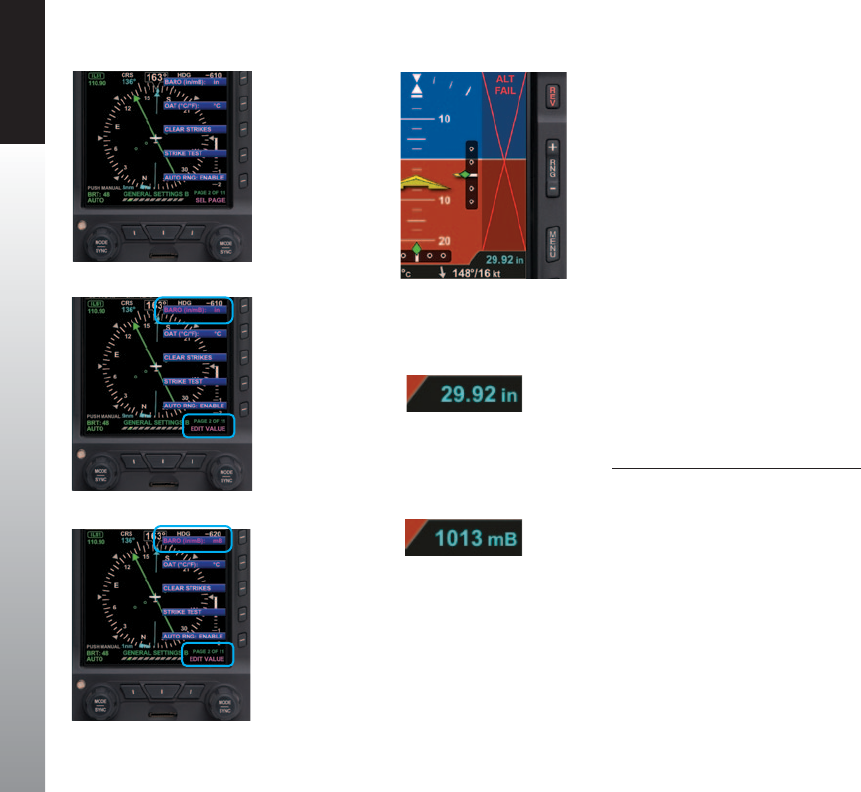
CHAPTER 4 REFERENCE GUIDE
EFD1000 PFD Pilot’s Guide
Page 4-16 091-00005-001 REV E
Figure 4-16
Baro Shown in Inches of Mercury
Figure 4-17
Baro Shown in Millibars
Figure 4-15
Altitude Failure
Figure 4-18
Editing BARO
Units of Measure
GENERAL SETTINGS B
Figure 4-19
Editing BARO
from in to mB
Figure 4-20
BARO Set to mB (millibars)
An adjacent, magenta Altitude Trend Vector predicts the anticipated
altitude, in the next six seconds, if the current rate of climb or decent is
maintained. Like the VSI, there is a slight lag in the indication. If the ribbon
meets or exceeds the display limit, the vertical trend is large. The Altitude
Trend Vector does not display when the altitude remains constant.
If the altitude exceeds 51,000 feet, the Numerical Altitude Value is dashed,
and the tape is frozen at this limit. All altitude information is removed and
replaced with a red X with the textual annunciation of ALT FAIL when
altitude data is invalid (Figure 4-15).
4.2.3.1. Barometric Units of Measure
Barometric units of measure adjustment may be made in either inches of
mercury (in) (Figure 4-16) or millibars (mB) (Figure 4-17), as congured
by the pilot in the Menu. The adjustment range is 28.10 – 30.99 inches
Hg or 946 – 1049 mB. The barometric pressure default value is 29.92
inches, or as previously set.
Set Barometric Units of Measure
1. Press the MENU Button.
2. Rotate the Right Knob to select the GENERAL SETTINGS B page
(Figure4-18).
3. Press the BARO Menu Key.
The Menu label turns magenta, and the EDIT VALUE label displays above
the Right Knob (Figure 4-19).
4. Rotate the Right Knob to select either in or mB (Figure 4-20).
5. Press the MENU Button to exit.

CHAPTER 4 REFERENCE GUIDE
EFD1000 PFD Pilot’s Guide Page 4-17
091-00005-001 REV E
NOTE
Since the altitude tape display is limited to
approximately 400 feet, the altitude bug symbol is
shown on the altitude tape when the Selected Altitude
Field value is within the visible range of the current
altitude.
WARNING
Always check and set the PFD BARO whenever the
mechanical altimeter is adjusted
Set the Barometric Pressure
1. Press the BARO Hot Key.
The BARO label above the Right Knob and Barometric Pressure Setting Field appear
in magenta (Figure4-21).
2. Rotate the Right Knob to change the value of the Barometric Pressure
Setting Field.
3. Press the BARO Hot Key or any knob, button/key to exit.
If no action is taken, after 10 seconds of inactivity, the label, and eld are rendered in
cyan.
4.2.3.2. Selected Altitude Field
The Selected Altitude Field value is displayed at the top of the Altitude Tape. The
Selected Altitude Field range is 100 to 51,000 feet, in 100 foot increments. The
default value for the Selected Altitude value is 100 feet, or the previously set value.
Additionally, the Altitude Bug is displayed adjacent to the Altitude Tape and at the
Selected Altitude Field value when within the visible range of the current altitude.
Set Altitude Bug and Altitude Alerter
1. Press the Right Knob until ALT displays above the Right Knob.
The Selected Altitude Field and bug are enabled for editing, all rendered in magenta
(Figure 4-22).
2. Rotate the Right Knob (clockwise to increase, or counterclockwise to
decrease) to change the value of the Selected Altitude Field.
Once the correct value is selected, and after 10 seconds of inaction, the eld is
disabled, and the label, eld, and bug are rendered in cyan.
Figure 4-21
BARO Field Enabled

CHAPTER 4 REFERENCE GUIDE
EFD1000 PFD Pilot’s Guide
Page 4-18 091-00005-001 REV E
4.2.3.3. Altitude Level-O and Deviation Alert
The Altitude (level-o ) Alert is ARMED and rendered on-screen as a yellow alert ag
next to the Selected Altitude value when the aircraft altitude transitions to within
200 feet or 15 seconds of reaching the selected altitude (Figure 4-23). If an optional
Sonalert tone generator device is installed, a one-second tone also sounds. Once
the current altitude is within ± 25 feet of the Selected Altitude, the Altitude Alert
extinguishes (Figure 4-24).
After reaching the Selected Altitude, if the aircraft’s current altitude diers from the
selected altitude by more than 200 feet, the yellow alert ag ashes. If an optional
Sonalert tone generator device is installed, a one-second tone also sounds.
Figure 4-22
Altitude Bug and Altitude Alerter Enabled
NOTE
Rotating the knob quickly will change the altitude
value in larger increments.
Figure 4-23
Altitude Alert
Figure 4-24
Altitude Alert Extinguishes at
Selected Altitude
NOTE
Setting the Altitude Alerter provides visual and aural cues to help the pilot capture and
maintain target altitudes. When set to a new altitude, the Alerter will illuminate a yellow ag
adjacent to the target altitude display and sound a one-second tone; 15 seconds (or 200 feet)
before the aircraft will reach the target altitude (based on current rate of climb or descent).
The yellow ag will extinguish once the target is reached. Subsequently, if the aircraft
deviates more than 200 feet above or below the target altitude, the ag will again illuminate,
and another one-second tone will sound to alert the pilot to thedeviation.

CHAPTER 4 REFERENCE GUIDE
EFD1000 PFD Pilot’s Guide Page 4-19
091-00005-001 REV E
4.2.3.4. MINIMUMS Annunciation1
The Pro PFD provides an adjustable MINIMUMS eld to enhance situational awareness
during instrument approaches. The Pro PFD provides a MINIMUMS annunciation with a
series of markers on the Altitude Tape that provide the pilot with improved awareness
when approaching and operating at minimums. There are three dierent color
markers that are shown on the altitude tape that are associated with the MINIMUMS
Annunciation, as described in Table 4-1.
Marker Color Description
Green The aircraft is 500 feet above selected
MINIMUM.
Figure 4-25
Minimums Green Triangle
Hollow Yellow
The aircraft is 100 feet to 200 feet above the
selected MINIMUM.
The marker base is at 100 feet above
MINIMUM, and the tip is at 200 feet above
MINIMUM. Figure 4-26
Minimums Hollow Yellow Triangle
Red and
Yellow stripes The aircraft is at the selected MINIMUM.
Figure 4-27
Minimums Red/ Yellow Striped Triangle
Table 4-1
Selected MINIMUMS Markers
1. Not available with the Pilot PFD
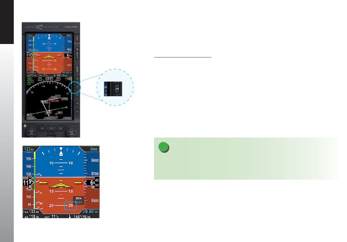
CHAPTER 4 REFERENCE GUIDE
EFD1000 PFD Pilot’s Guide
Page 4-20 091-00005-001 REV E
Once the Selected Minimums eld value is set to a Decision Altitude, Decision Height,
or Minimum Descent Altitude, the Pro PFD provides an alert when the aircraft descends
below this altitude. To activate this feature, enable the Selected Minimums (MIN) eld
and set the value with the Right Knob.
Display/Hide Minimums
1. Press the MIN Hot Key to alternately hide or display the Selected Minimums
Field, MINIMUMS Annunciation, and Markers (Figures 4-28 and 4-29).
The range for the MIN data eld is 0 – 15,000 feet, in increments of 10 feet. SYNCing sets
the Selected Minimums eld value to the current altitude (Section 2.2.1.3). The default
value is 100 feet, or the previously set value.
Figure 4-28
MIN Hot Key – Selected MINIMUMS
Annunciation and Markers Disabled
Figure 4-29
Selected MINIMUMS
Annunciation and Markers
Enabled
NOTE
Pressing the MIN Hot Key presents the MINIMUMS Markers on the Altitude Tape and the
Selected Minimums Field on the Attitude Display. The MIN label above the Right Knob and
the MIN eld value are rendered in magenta for editing.

CHAPTER 4 REFERENCE GUIDE
EFD1000 PFD Pilot’s Guide Page 4-21
091-00005-001 REV E
Set Altitude Minimum
1. Press the MIN Hot Key to set the altitude minimum.
The Selected MINIMUMS Field and the MIN label above the Right Knob are rendered in
magenta (Figure4-30).
2. Rotate the Right Knob to change the value of the Selected MINIMUMS Field.
Once the correct value is selected, and after 10 seconds of inaction, the eld is disabled
(Figure 4-31).
Whenever the aircraft is at or below the Selected MINIMUMS setting, the MIN legend in
the Selected Minimums Field turns inverse amber (Figure 4-32) and when congured
with an optional Sonalert, a one-second stuttered tone is generated.
The inverse amber MIN Annunciation is cancelled when the aircraft is 100 feet above
the selected minimums setting or when the selected minimums is set to a new altitude.
Additionally, the MINIMUMS Markers on the Altitude Tape provide the pilot with
additional awareness of aircraft altitude with respect to the set MINIMUMS.
Figure 4-30
Selected MINIMUMS Field -
MIN Enabled
Figure 4-31
New Selected MINIMUMS
Annunciation Setting
Figure 4-32
MINIMUMS
Annunciation Active
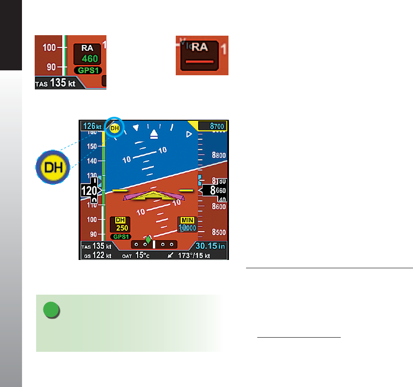
CHAPTER 4 REFERENCE GUIDE
EFD1000 PFD Pilot’s Guide
Page 4-22 091-00005-001 REV E
4.2.3.5. Radio Altitude Display1
When a compatible radio altimeter is connected to the Evolution Display, radio altitude
height in feet above ground level (AGL) can be displayed at the bottom left of the
Attitude Display Figure 4-32a. When the aircraft is above the maximum range of
the radio altimeter, the Radio Altimeter display window is removed. The maximum
displayed altitude value will depend on the range of the radar altimeter equipment
installed in the aircraft.
Radio Altitudes that are greater than or equal to 500 feet AGL are displayed in 100 foot
increments (RA 500, RA 600, RA 700...) and altitudes less than 500 feet AGL are displayed
in 10 foot increments (RA 490, RA 480, RA 470...)
The digital readout in the Radio Altitude (RA) window is normally displayed in green,
however, when the aircraft is at or below the Decision Height (DH) set on the onboard
radio altimeter’s indicator (if applicable), the RA window on the PFD will show the DH
legend as inverse amber and the current RA readout in amber. An amber DH (Decision
Height annunciation is also displayed near the upper left corner of the Attitude Display
(Figure 4-33).
If the PFD detects a malfunction on the onboard radio altimeter, the RA window is
displayed with a red slash through the digital readout Figure 4-32b.
Enable or Disable the Radio Altitude Display
1. Press the MENU Button and rotate the Right Knob to the GENERAL SETTINGS
A page.
2. Press the RAD ALT Menu Key and rotate the Right Knob to toggle between
ENABLE or DISABLE.
3. Press the MENU Button to exit.
NOTE
“RAD ALT: DISABLE” Menu Key label is shown in gray if
a compatible radio altimeter is not installed.
Figure 4-33
DH Annunciation
Figure 4-32a
Radio Altitude
Figure 4-32b
Radio Altitude with
red slash
1. Not available with the Pilot PFD
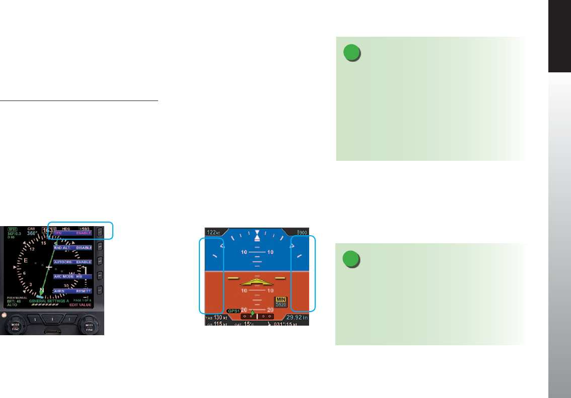
CHAPTER 4 REFERENCE GUIDE
EFD1000 PFD Pilot’s Guide Page 4-23
091-00005-001 REV E
4.2.3.6. Altitude Display
In some congurations, such as a stand-alone PFD, the altitude tape can be turned o,
at the pilot’s discretion, to facilitate screen declutter. Both Airspeed and Altitude tapes
are aected by this action.
Hide/Display Airspeed and Altitude Tape
1. Press the MENU Button.
2. Rotate the Right Knob counterclockwise until GENERAL SETTINGS A page
displays (Figure 4-34).
3. Press the TPS Menu Key.
The Menu label turns magenta, and the EDIT VALUE label displays above the Right
Knob.
4. Rotate the Right Knob to the desired value, ENABLE (On) or DISABLE (O )
(Figure 4-35).
5. Press the MENU Button to exit.
NOTE
When the Altitude tape is disabled, the numerical
display of the selected altitude and altitude minimums
remain on. However, an installer can disable and
remove the Selected Altitude and Minimums Fields,
and the MINIMUMS Annunciation and Markers from
the display.
NOTE
A typical PFD only installation sets the tapes display
to UNLOCKED, allowing the pilot to display or hide
the Airspeed and Altitude tapes as desired. If the
Airspeed and Altitude Tapes were LOCKED ON during
installation, such as the case with a PFD and MFD
conguration, then the tapes must remain on. If the
Airspeed and Altitude Tapes were LOCKED OFF during
installation, the tapes will not display.
Figure 4-34
Editing Airspeed and Altitude Tape Display
Figure 4-35
Airspeed and Altitude Tape Disabled
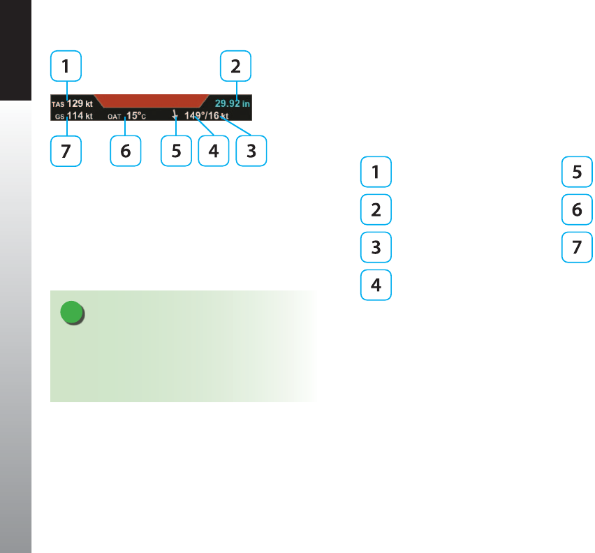
CHAPTER 4 REFERENCE GUIDE
EFD1000 PFD Pilot’s Guide
Page 4-24 091-00005-001 REV E
4.3. Data Bar
The Data Bar presents True Airspeed (TAS) or the Mach number, GPS Ground Speed (GS),
Outside Air Temperature (OAT), Wind Direction, Wind Speed, and Barometric Pressure
Setting, as shown in Figure 4-36. The Data Bar is always present on the display. Invalid
or out-of-range Data Bar values are dashed.
True Airspeed (TAS) or MACH Wind Direction Arrow
Barometric Pressure Setting
Field Outside Air Temperature (OAT)
Wind Speed Ground Speed (GS)
Wind Direction
4.3.1. True Airspeed or Mach Number (when enabled)
The True Airspeed (TAS) or the Mach number is displayed in the upper left of the Data
Bar. The TAS has a range of 20–999 knots or mph, using the same unit of measurement
as the aircraft’s Airspeed Indicator. The TAS is a correction of the IAS for nonstandard
pressure and temperature.
The Mach number can be congured to be displayed whenever the aircraft is above
a selected altitude or above a selected Mach number and is shown with a display
resolution of 0.01 Mach.
Figure 4-36
Data Bar
NOTE
If the OAT was set to disabled during installation, as
would be the case if the RSM is mounted internally
to the aircraft structure, then the OAT, TAS, and Wind
Speed and Direction are not displayed.
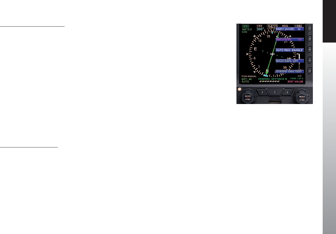
CHAPTER 4 REFERENCE GUIDE
EFD1000 PFD Pilot’s Guide Page 4-25
091-00005-001 REV E
Select the Transition Setting
1. Press the MENU Button and rotate the Right Knob to the GENERAL SETTINGS
C page.
2 Press the MACH DSPL Hot Key and rotate the Right Knob to the desired
Altitude or Speed setting.
3. Press the MENU Button to exit.
4.3.2. Ground Speed
The Ground Speed (GS) comes from a congured GPS navigator and is digitally
displayed in the lower left corner of the Data Bar with a value range of 5–999 knots or
mph, using the same unit of measurement as the Airspeed Indicator.
4.3.3. Outside Air Temperature (when enabled)
The Outside Air Temperature (OAT) is displayed in the center of the Data Bar (Figure
4-36). The temperature is obtained from the temperature sensor located in the RSM.
Temperature sensor ranges from -55°C to +80°C (-67°F to +176°F).
Set OAT Units of Measure
1. Press the MENU Button.
2. Rotate the Right Knob counterclockwise until GENERAL SETTINGS B page
displays.
3. Press the OAT Menu Key.
The Menu label turns magenta and the EDIT VALUE label displays above the Right Knob
(Figure 4-37).
4. Rotate the Right Knob to select either °C or °F (Figure 4-37).
5. Press the MENU Button to exit.
Figure 4-37
Select OAT Units of Measure

CHAPTER 4 REFERENCE GUIDE
EFD1000 PFD Pilot’s Guide
Page 4-26 091-00005-001 REV E
4.3.4. Wind Speed, Direction, and Arrow (when enabled)
The Wind Speed, Direction, and Direction Arrow are displayed in the lower right portion
of the Data Bar. The Wind Speed has a range of 10–999 knots or mph, using the same
unit of measure as the Airspeed Indicator.
The Wind Direction and Arrow (Figure 4-38) have a range of 001°–360°, using the same
direction reference used by the Direction Indicator. The arrow points in the direction of
the wind and is displayed relative to the current direction of ight. For example, if the
current direction of ight is 360° and the wind is from 360°, the arrow will point straight
down on the display (a headwind blowing toward your aircraft).
When the computed wind speed is below 10 knots or mph (depending on aircraft
conguration) the wind speed and direction values are blank, and the wind arrow is
removed. If the wind data is out of range or invalid, the values are dashed, and the wind
arrow is removed.
4.3.5. Barometric Pressure Setting Display
The Barometric Pressure Setting Field is displayed on the upper right corner of the Data
Bar and is pilot-adjustable, as discussed in Section 4.2.3.1. When the Altitude Tape is
disabled, the Barometric Pressure Setting eld remains visible. However, an installer can
disable the eld and remove it from the display. Section 4.2.3.1 provides complete
information and step-by-step instructions for setting the barometric pressure.
Figure 4-38
Wind Direction Arrow
NOTE
The wind computations require a GPS-provided
ground track and ground speed to compute the wind
direction and speed. If a GPS is not connected to the
PFD or the data are invalid, the wind direction and
speed are dashed and the wind direction arrow is
removed.
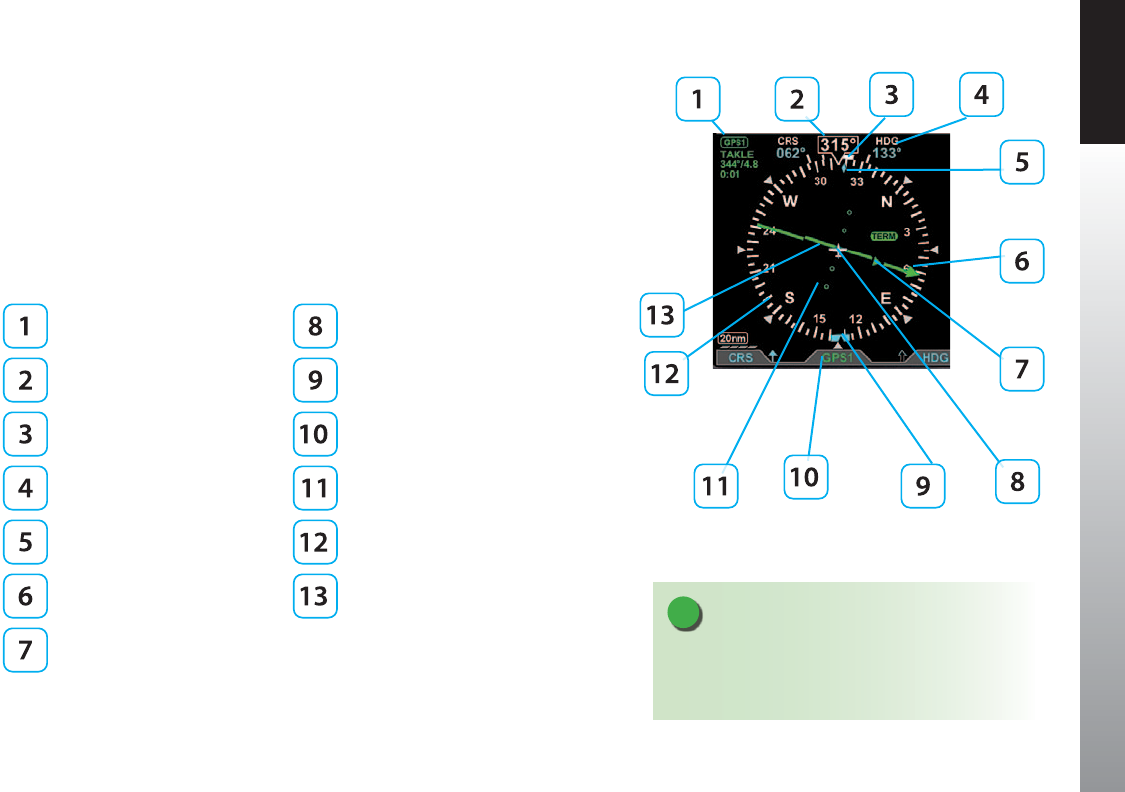
CHAPTER 4 REFERENCE GUIDE
EFD1000 PFD Pilot’s Guide Page 4-27
091-00005-001 REV E
4.4. Navigation Display
The Horizontal Situation Indicator (HSI) on the Navigation Display of the PFD, combines
a Direction Indicator with a Course Deviation Indicator (CDI) (Figure 4-39).
The Direction Indicator comprises a compass, numerical direction indication, heading
bug, Ground Track Marker (when GPS ground track information is available), rate of turn
indicator, and aircraft ownship symbol. The CDI is comprises a selected course pointer,
Deviation Scale and indicator, TO/FROM indicators, and selected navigation source label
and information block.
CDI Source Info Block Aircraft Ownship Symbol
Magnetic Heading Heading Bug
Rate of Turn Indicator Selected CDI Navigation Source
Selected Heading Field Course Deviation Scale
Ground Track Marker Compass Scale
Course Pointer Course Deviation Indicator
TO/FROM Indicator
Figure 4-39
Horizontal Situation Indicator
NOTE
The size, shape and location of the Course Pointer,
Deviation Scale, and Deviation Indicator depend on
the Compass Mode selected..
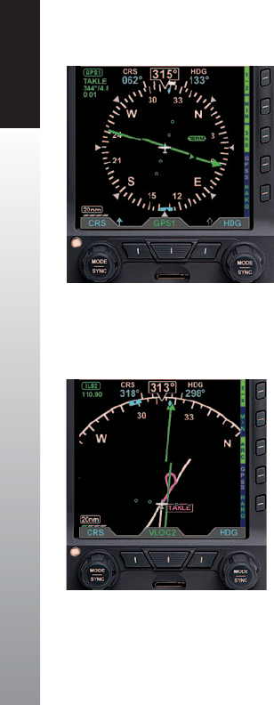
CHAPTER 4 REFERENCE GUIDE
EFD1000 PFD Pilot’s Guide
Page 4-28 091-00005-001 REV E
All Magnetic Headings are displayed in degrees. The value range is from 001° - 360°,
always displayed in three digits, and use leading zeros when applicable. The Magnetic
North is expressed as 360°.
4.4.1. Compass
The PFD oers three Compass Modes: 360°, ARC HSI, and ARC CDI. The default Compass
Mode is 360. The aircraft’s heading is always expressed degrees magnetic. The magnetic
headings inside of the compass scale omit the last zero for brevity (i.e., 30°, 60°, 120°,
150°, 210°, 240°, 300°, and 330° are labeled 3, 6, 12, 15, 21, 24, 30, and 33, respectively).
The four cardinal compass headings are shown as letters (i.e., N for 360°, E for 090°, S for
180°, and W for 270°).
4.4.1.1. 360° Compass Mode
The 360° Compass Mode displays a full 360° compass rose with all other components
of the Direction Indicator. The 360° compass rose rotation centers on the aircraft
ownship symbol so that the numerical direction indication corresponds to the current
aircraft heading (Figure 4-40).
4.4.1.2. ARC Compass Mode
The two ARC Compass Modes have an abbreviated 100° ARC compass scale. All
other elements of the Direction Indicator are retained. The ARC Compass Mode’s
scale rotation centers on the aircraft ownship symbol so that the numerical direction
indication corresponds to the current aircraft heading. The default ARC Compass Mode
is ARC HSI.
The ARC HSI Compass Mode presents a rotating CDI, similar to that used in the 360°
Compass Mode (Figure 4-41).
Figure 4-40
360° Compass Mode
Figure 4-41
ARC HSI Compass Mode
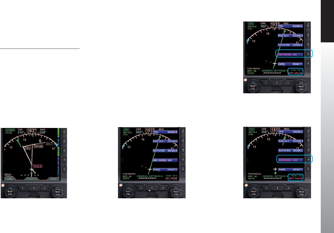
CHAPTER 4 REFERENCE GUIDE
EFD1000 PFD Pilot’s Guide Page 4-29
091-00005-001 REV E
The ARC CDI Compass Mode uses a xed CDI, resembling a contemporary GPS
navigation deviation display. The ARC CDI Compass Mode is intended to maximize the
lower display area for map and ight plan data (Figure 4-42).
Select ARC CDI/HSI Compass Mode
1. Press the MENU Button.
2. Rotate the Right Knob to the GENERAL SETTINGS A Menu page
(Figure 4-43).
3. Press the ARC MODE Menu Key. The Menu label turns magenta, and the EDIT
VALUE label displays above the Right Knob (Figure 4-44).
4. Rotate the Right Knob to select either HSI or CDI (Figure 4-45).
5. Press the MENU Button to exit.
Figure 4-43
GENERAL SETTINGS A
Figure 4-42
ARC CDI Compass Mode
Figure 4-45
ARC CDI Compass MODE Selected
Figure 4-44
Changing the ARC Compass MODE

CHAPTER 4 REFERENCE GUIDE
EFD1000 PFD Pilot’s Guide
Page 4-30 091-00005-001 REV E
Select Compass Type
1. Press the 360/ARC Hot Key (Figure 4-46) to alternately select either the 360°
or ARC Compass Mode.
The Navigation Display changes and the Hot Key label reects the currently selected
Compass Mode (Figures 4-47 and 4-48).
Figure 4-46
360/ARC Hot Key
Figure 4-47
ARC CDI Compass Mode
Figure 4-48
360˚ Compass Mode
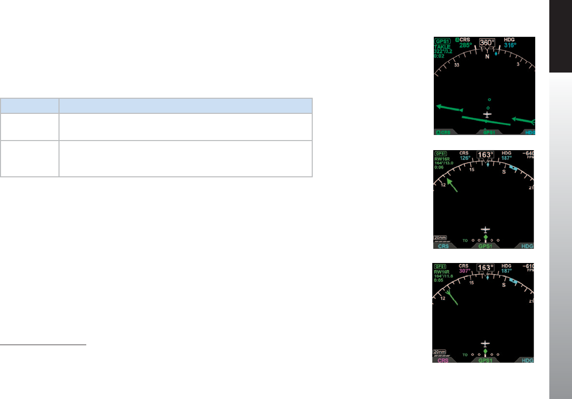
CHAPTER 4 REFERENCE GUIDE
EFD1000 PFD Pilot’s Guide Page 4-31
091-00005-001 REV E
4.4.2. Course Pointer1
For all Compass Modes, the arrowhead of the Course Pointer aligns with the
corresponding value on the compass scale regardless of the aircraft heading. The ARC
Compass HSI and CDI Course Pointers are dierent and are described in Table 4-2.
COMPASS DESCRIPTION
ARC HSI The Course Pointer length shortens as necessary when rotated to remain
within the display area (Figure 4-49).
ARC CDI
The Course Pointer is shown as a stub arrow or tail whenever the CRS value
or its reciprocal falls within the displayable range of the compass scale arc
(Figure 4-50 and 4-51).
Table 4-2
ARC Compass Mode Course Pointer Display
Figure 4-49
Reduced Length Course Pointer,
ARC HSI Compass Mode
Figure 4-50
Stub Course Arrowhead ,
ARC CDI Compass Mode
Figure 4-51
Stub Course Tail , ARC
CDI Compass Mode
Figure 4-49
Reduced Length Course Pointer,
ARC HSI Compass Mode
Figure 4-50
Stub Course Arrowhead,
ARC CDI Compass Mode
Figure 4-51
Stub Course Tail,
ARC CDI Compass Mode
1. Not available with the Pilot PFD
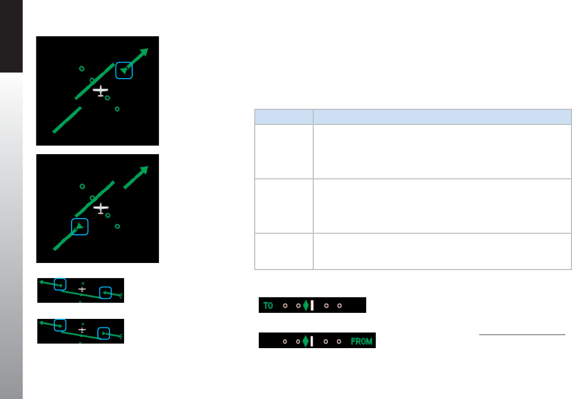
CHAPTER 4 REFERENCE GUIDE
EFD1000 PFD Pilot’s Guide
Page 4-32 091-00005-001 REV E
4.4.3. TO/FROM Indicator1
Each of the Compass Modes has a TO/FROM indicator. The TO/FROM indicator shows
whether the aircraft is heading toward a waypoint or radio navaid, or from a waypoint
or radio navaid. For each Compass Mode, the TO/FROM indication is slightly dierent, as
described in Table 4-3.
COMPASS DESCRIPTION
360°
The TO indicator is an arrowhead on the top half of the Course Pointer,
oriented in the same direction as the course arrowhead
(Figure 4-52). The FROM indicator is an arrowhead on the bottom half
of the Course Pointer, oriented in the direction opposite to the course
arrowhead (Figure 4-53).
ARC HSI
The TO indicator is shown as two arrowheads, one on each half of the
Course Pointer, oriented in the same direction as the course arrowhead
(Figure 4-54). The FROM indicator is shown as two arrowheads, one on
each half of the Course Pointer, oriented opposite to the direction of the
course arrowhead (Figure 4-55).
ARC CDI
The TO indication is shown as TO on the left side of the Deviation Scale
(Figure 4-56). The FROM indication is shown as FROM on the right of the
Deviation Scale (Figure 4-57).
Table 4-3
TO/FROM Indicator Description
Figure 4-52
360° TO Indication
Figure 4-56
CDI TO Indication
Figure 4-55
HSI FROM Indication
Figure 4-54
HSI TO Indication
Figure 4-53
360° FROM Indication
Figure 4-57
CDI FROM Indication 1. Not available with the Pilot PFD
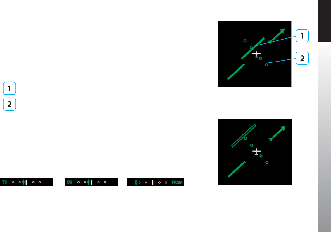
CHAPTER 4 REFERENCE GUIDE
EFD1000 PFD Pilot’s Guide Page 4-33
091-00005-001 REV E
4.4.4. Course Deviation Indicator and Scale1
Selected course deviation is depicted by a Course Deviation Indicator and Scale.
Deviation is indicated by positioning the Course Deviation Indicator on the Scale
corresponding to the lateral deviation value.
The 360° and ARC HSI Compass Modes show the CDI as a green line centered on the
display and parallel with the Course Pointer. The scale is a set of four hollow, green dots
that are perpendicular to the Course Pointer (Figure 4-58).
Course Deviation Indicator
Course Deviation Scale
The ARC CDI Compass Mode’s CDI and Scale are located at the bottom of the lower
display. The indicator is a green diamond, and the Scale is a set of four hollow, white
dots with a white index mark at the center (Figure 4-59). When in the ARC CDI
Compass Mode, on a Localizer Back Course approach, a BC label is presented to the left
of the scale, and the Indicator corrects for reverse sensing (Figure 4-60).
When the lateral deviation exceeds the maximum displayable range of 2.5 dots,
the Deviation Indicator bar or diamond, as applicable, becomes hollow and darker
(Figure 4-61 and 4-62).
Figure 4-58
Deviation Indicator, 360° and
ARC HSI Compass Modes
Figure 4-59
Course Deviation Indicator, ARC CDI
Compass Mode
Figure 4-60
Course Deviation Indicator, ARC CDI
Compass Mode with Back Course
Figure 4-62
Deviation Exceeded, ARC CDI
Figure 4-61
Exceeded Deviation, 360° and
ARC HSI Compass Modes
1. Not available with the Pilot PFD
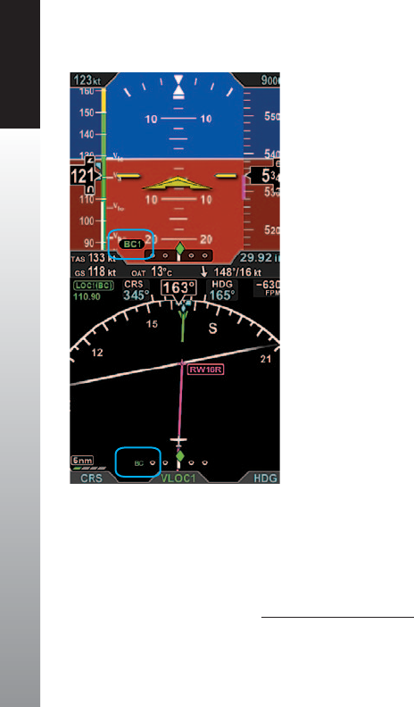
CHAPTER 4 REFERENCE GUIDE
EFD1000 PFD Pilot’s Guide
Page 4-34 091-00005-001 REV E
4.4.4.a. Localizer Back Course (BC) Operation1
When ying a Back Course nal approach (the aircraft heading is opposite to the localizer
front course), set the CRS value to the front course localizer or ILS approach value. The tail
of the CDI will match the back course runway’s magnetic orientation.
When the LOC(BC) mode is active, two “BC” annunciations are shown; on the Attitude
Display left of the Lateral Deviation Indicator (LDI) and on the ARC Compass left of the
Course Deviation Scale (Figure 4-62a). The left/right deviation indications are corrected
for reverse sensing and will behave intuitively, the same as with a front course localizer.
4.4.5. CDI Navigation Source1
When the PFD powers up, the default Selected CDI Navigation Source is the last source
selected. The pilot can select from any of the installed navigation sources using the
Lower Center Button. The PFD supports navigation information display from VHF Omni-
directional Radio Range (VOR) navaids, Localizers (LOC), Glide Slope receivers (GS), and
Global Positioning Systems (GPS). There can be up to four dedicated, two integrated, or
a combination of one integrated and two dedicated navigation systemsinstalled.
When individual GPS and VLOC devices are installed, the GPSS signal source, Basemap
GPS position, ight plan, and Basemap information for VLOC1, VLOC2, and GPS1
are provided by the GPS1 navigation source whenever GPS1 is selected as the CDI
navigation source and by GPS2 whenever GPS2 is selected as the Selected CDI
navigation source.
When integrated GPS/VLOC equipment are installed, the GPSS signal source, Basemap
GPS position, ight plan and Basemap information for the integrated GPS-VLOC is
provided by the associated GPS whenever the CDI navigation source is selected to
either the GPS side or the VLOC side of the integrated GPS/VLOC receiver.
Figure 4-62a
Back Course (BC) Annunciation Locations
1. Not available with the Pilot PFD
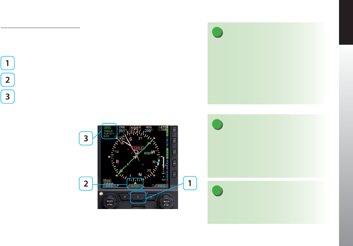
CHAPTER 4 REFERENCE GUIDE
EFD1000 PFD Pilot’s Guide Page 4-35
091-00005-001 REV E
Select the CDI Navigation Source
• Press the CDI Navigation Source Select button until the desired navigation
source is displayed above the button (e.g., GPS1, GPS2, VLOC1, VLOC2)
(Figure 4-63).
CDI Navigation Source Select Button
Selected CDI Source Label
CDI Source Information Block
Figure 4-63
CDI Source selection and Information
NOTE
For integrated systems, the CDI navigation source label
indicates the current operating mode (GPS or VLOC) of
the GPS/VHF NAV system.
When an integrated system is selected but not
reporting its operating mode, VLOC1 or VLOC2 is
shown as the Selected CDI Navigation Source.
Refer to the GPS or VHF NAV AFMS for information on
the operation of the connected navigation equipment.
NOTE
There are many radio congurations available. Your
authorized Aspen Avionics Dealer can explain the
conguration used on your aircraft.
NOTE
When the PFD is connected to some GPS and the
active ight plan is changed (e.g. “Direct To” is selected),
the display of the active (magenta) leg on the Nav
Map may be delayed for up to 20 seconds. The Course
Pointer and autopilot will react immediately to the
ight plan change.
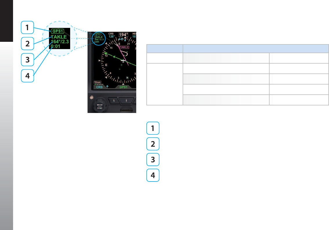
CHAPTER 4 REFERENCE GUIDE
EFD1000 PFD Pilot’s Guide
Page 4-36 091-00005-001 REV E
Whenever the CDI Navigation Source’s data is valid, a CDI Source Information Block
for the selected source is shown in the upper left corner of the Navigation Display, as
shown in Figure 4-64 and described in Table 4-4.
Radio Mode Information Block Label
GPS GPS1 or GPS2
VHF
VOR VOR1 or VOR2
Localizer LOC1 or LOC2
Localizer Back LOC1(BC) or LOC2 (BC)
ILS ILS1 or ILS2
Table 4-4
VHF NAV Radio Modes
Selected CDI Navigation Source
Waypoint identier or tuned frequency (when available)
Bearing (in degrees)/Distance (in Nautical Miles) to waypoint or navaid
(when available)
Estimated Time Enroute (Hours:Minutes)
If both the station identier and the tuned frequency of the associated VHF NAV
radio are available, only the station identier is displayed on the second line of the
information block. In most cases, however, only the tuned frequency is available for
display from integrated GPS/VLOC devices.
Figure 4-64
CDI Source Information Block

CHAPTER 4 REFERENCE GUIDE
EFD1000 PFD Pilot’s Guide Page 4-37
091-00005-001 REV E
When available, the bearing and distance to station is displayed on the third line of the
information block in the format dddº/nnnn or dddº/nn.n, where ddd is the bearing in
degrees and nnnn or nn.n is the distance in nautical miles (e.g., 360º/1103 or 322º/3.2,
shown in Figure 4-64). The distance to waypoint is displayed as follows:
• Distance to waypoint < 100 NM, display is in tenths of a mile, i.e., ##.#.
• Distance to waypoint is 100–9999 NM, display in whole miles, i.e., ####.
• Distance to waypoint is > 9999 NM, display is dashed, i.e., ----.
When available, the estimated time enroute information is displayed on the fourth line
of the information block in the format h:mm (where h is hours and mm is minutes).
When CDI Navigation Source data is invalid or unavailable from a congured navigation
source, the HSI course deviation bar and the TO/FROM indicator are removed from the
display (Figure 4-65). Additionally, the selected CDI Navigation Source label in the CDI
Source Information Block is slashed with a red line (Figure 4-66).
When information for a congured and selected navigation source is unavailable or is
invalid, the CDI Source Information Block is blank (Figure 4-67).
Figure 4-66
Invalid CDI Navigation Source Label
Figure 4-65
No Course Deviation Bar or
TO/FROM Indicator
Figure 4-67
CDI Source Information Blank Block
Figure 4-68
Menu, GENERAL SETTINGS
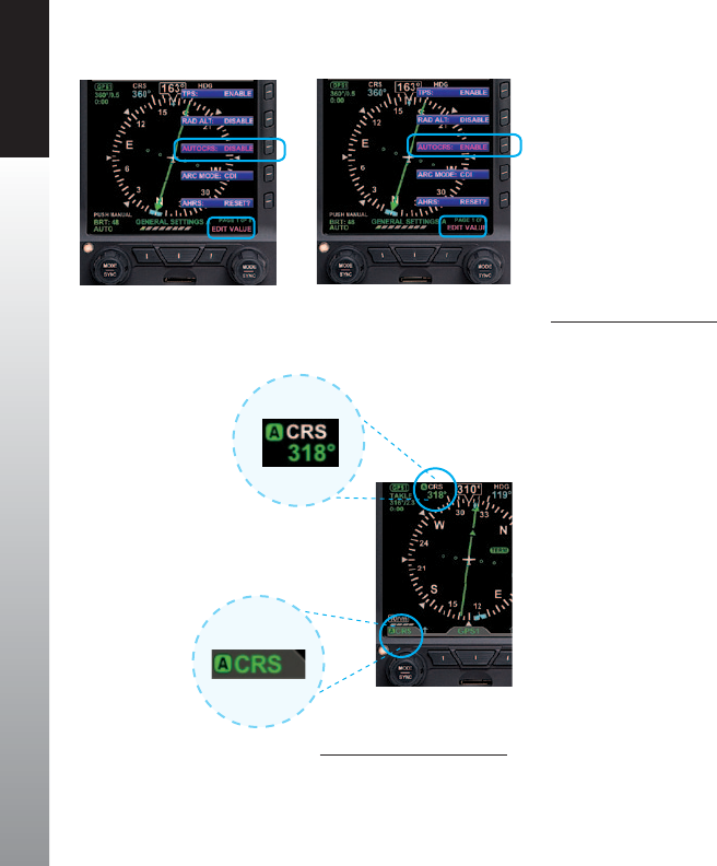
CHAPTER 4 REFERENCE GUIDE
EFD1000 PFD Pilot’s Guide
Page 4-38 091-00005-001 REV E
4.4.6. Auto Course1
The pilot can either use the Auto Course (AUTOCRS) or manually set a CRS value. By
default, AUTOCRS is enabled. When the selected CDI Navigation Source is a connected
GPS receiver and AUTOCRS is enabled, CRS is not adjustable (current course value
is automatically slewed and controlled by the desired track from the GPS). When
AUTOCRS is enabled, the CDI navigation source is a GPS, and that system is congured
for automatic waypoint sequencing (i.e., not OBS or HOLD modes) then Auto Course
Select is active.
Enable Auto Course
1. Press the MENU Button.
2. Rotate the Right Knob to the GENERAL SETTINGS A page (Figure 4-68).
3. Press the AUTOCRS Menu Key.
The Menu label turns magenta, and the EDIT VALUE label displays above the Right Knob
(Figure 4-69).
4. Rotate the Right Knob to select ENABLE (Figure 4-70).
5. Press the MENU Button to exit.
When AUTOCRS is enabled, the CRS value is set to the desired track output from the CDI
Navigation Source. The CRS value is shown in the upper left of the lower display area
in green under the CRS label. Additionally, an inverse green A is shown beside the CRS
label in the upper left of the lower display area and in the legend above the Left Knob.
This indicates that the course is being automatically adjusted (Figure 4-71).
Figure 4-69
Editing AUTOCRS
Figure 4-70
AUTOCRS Enabled
Figure 4-71
AUTOCRS Enabled
1. Not available with the Pilot PFD
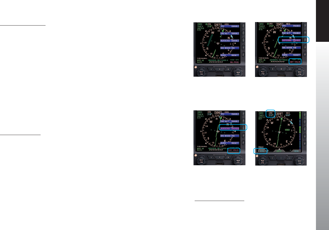
CHAPTER 4 REFERENCE GUIDE
EFD1000 PFD Pilot’s Guide Page 4-39
091-00005-001 REV E
Disable Auto Course
1. Press the MENU Button.
2. Rotate the Right Knob to the GENERAL SETTINGS A page (Figure 4-72).
3. Press the AUTOCRS Menu Key.
The Menu label turns magenta, and the EDIT VALUE label displays above the Right Knob
(Figure 4-73).
4. Rotate the Right Knob to select DISABLE (Figure 4-74).
5. Press the MENU Button to exit.
4.4.7. CDI Selected Course1
When the CDI source changes from a GPS source with AUTOCRS to another CDI source,
the CRS value reverts to the last set value. When the CDI source is set to a VHF receiver
operating in the VOR or Localizer modes, editing the CRS value adjusts the current
selected CRS value. When the CDI source is set to a GPS receiver, and AUTOCRS is
disabled, the CRS value may be adjusted.
Select CDI Course
1. Press the Left Knob.
The CRS label above the Left Knob and the Course eld are enabled for editing, both
rendered in magenta (Figure 4-75).
2. Rotate the Left Knob to change the value of the Course eld.
Once the CRS value is set, and after 10 seconds of inaction, the CRS eld is disabled, and
both the label and eld are rendered in cyan.
Figure 4-72
Menu, GENERAL SETTINGS
Figure 4-74
AUTOCRS Disabled Figure 4-75
CRS Field Enabled for Editing
Figure 4-73
Editing AUTOCRS
1. Not available with the Pilot PFD
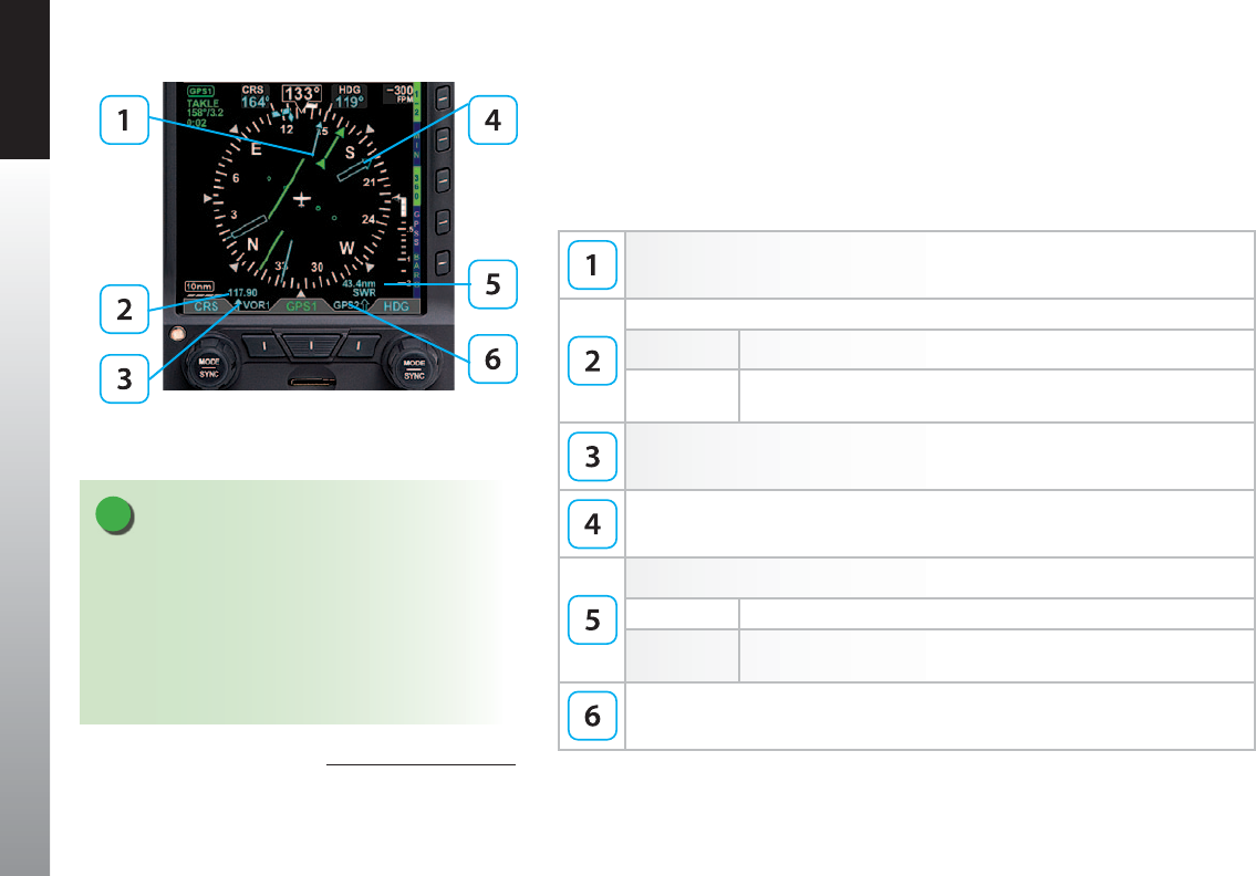
CHAPTER 4 REFERENCE GUIDE
EFD1000 PFD Pilot’s Guide
Page 4-40 091-00005-001 REV E
Figure 4-76
Bearing Pointer Description
4.4.8. Bearing Pointer Source Selection1
When the 360° Compass mode is selected, single- and double-line bearing pointers are
available (Figure 4-76). The bearing pointers are independent of the CDI and provide
supplemental navigation information by pointing to active GPS waypoints or navaids.
By default, the bearing pointers are o and not displayed.
Single-Line Bearing Pointer
Single-Line Bearing Pointer Source Information
Top Line Distance (NM) to active GPS waypoint
Bottom Line Waypoint identier, station identier (when available, or the tuned
frequency of the associated VHF NAV radio (when available)
Single-Line Bearing Pointer Icon
Double-Line Bearing Pointer
Double-Line Bearing Pointer Source Information
Top Line Distance (NM) to active GPS waypoint
Bottom Line Waypoint identier, station identier (when available), or the tuned
frequency of the associated VHF NAV radio (when available)
Double-Line Bearing Pointer Source
NOTE
Distance to waypoint < 100 NM, display is in tenths of
a mile, i.e., ##.#.
Distance to waypoint is 100 – 9999 NM, display in
whole miles, i.e., ####.
Distance to waypoint is > 9999 NM, display is dashed,
i.e., ----.
1. Not available with the Pilot PFD
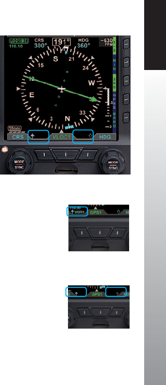
CHAPTER 4 REFERENCE GUIDE
EFD1000 PFD Pilot’s Guide Page 4-41
091-00005-001 REV E
The Bearing Pointers indicate only the bearing information provided by their selected
navigation sources. They resemble and perform like traditional Radio Magnetic Indicator
(RMI) needles. Each Bearing Pointer’s head and tail is aligned with the corresponding
bearing/radial value on the compass. The pilot can select a navigation source for each
of the Bearing Pointers from the same VOR and GPS sources available to the CDI or
simply turn o the Bearing Pointer and Source Information.
Each Bearing Pointer is associated with a Lower Left Button or a Lower Right Button,
its source, and Information Block. The Lower Left Button, immediately adjacent to the
CDI Navigation Source Selection Button is associated with and controls the Single-
Line Bearing Pointer. Likewise, the Lower Right Button controls the Double-Line
Bearing Pointer. The Bearing Pointers’ Source Information is shown directly above their
respective Buttons.
Unlike the CDI’s Course Pointer, which can be adjusted by the pilot, no adjustments can
be made to the Bearing Pointers. When a VOR is selected as the source, the arrow of
the needle points to the VOR navaid to which the receiver is tuned. The position of the
Bearing Pointer tail, with respect to the compass, indicates the aircraft’s current position
on the VOR radial. When a GPS source is selected, the Bearing Pointer indicates the
bearing to the active waypoint.
When the Bearing Pointer Source Information is unavailable or invalid, the Bearing
Pointer and its Source Information are removed (Figure 4-77). The Bearing Pointer’s
Source is also source legend slashed with a red line (Figure 4-78).
When a Bearing Pointer is turned OFF, only the Bearing Pointer’s icon is shown.
The Selected Source, the Source Information, and the Bearing Pointer are removed
(Figure 4-79).
Figure 4-79
Icons when Bearing Pointers are OFF
Figure 4-78
Invalid Bearing Pointer Source
Figure 4-77
Bearing Pointers OFF
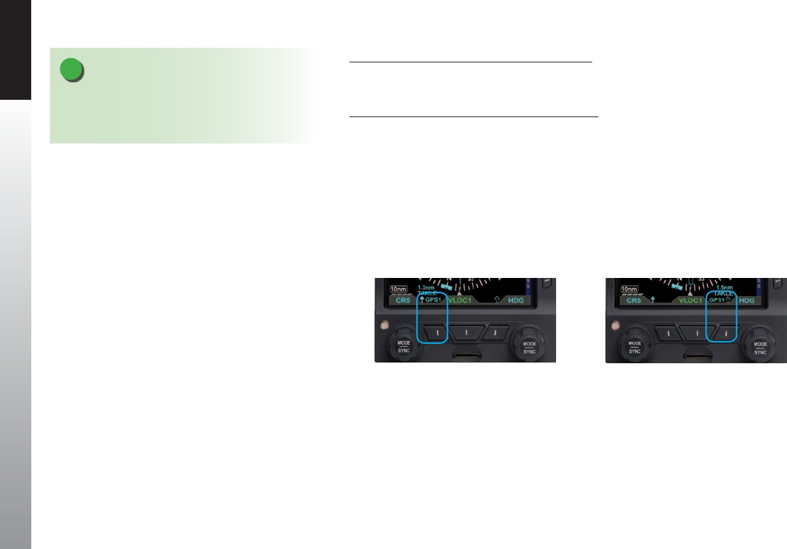
CHAPTER 4 REFERENCE GUIDE
EFD1000 PFD Pilot’s Guide
Page 4-42 091-00005-001 REV E
Select the Single-Line Bearing Pointer Source
1. Press the Single-Line Bearing Pointer Button (Lower Left Button, Figure 4-80)
until the desired navigation source is shown above the Button.
Select the Double-Line Bearing Pointer Source
1. Press the Double-Line Bearing Pointer Button (Lower Right Button,
Figure 4-81) until the desired navigation source is shown above the Button.
Figure 4-80
Single-Line Bearing Pointer and Button
Figure 4-81
Double-Line Bearing Pointer and Button
NOTE
A VOR that is tuned to a localizer frequency is
considered an invalid Bearing Pointer source since
Localizer signals provide no bearing information.
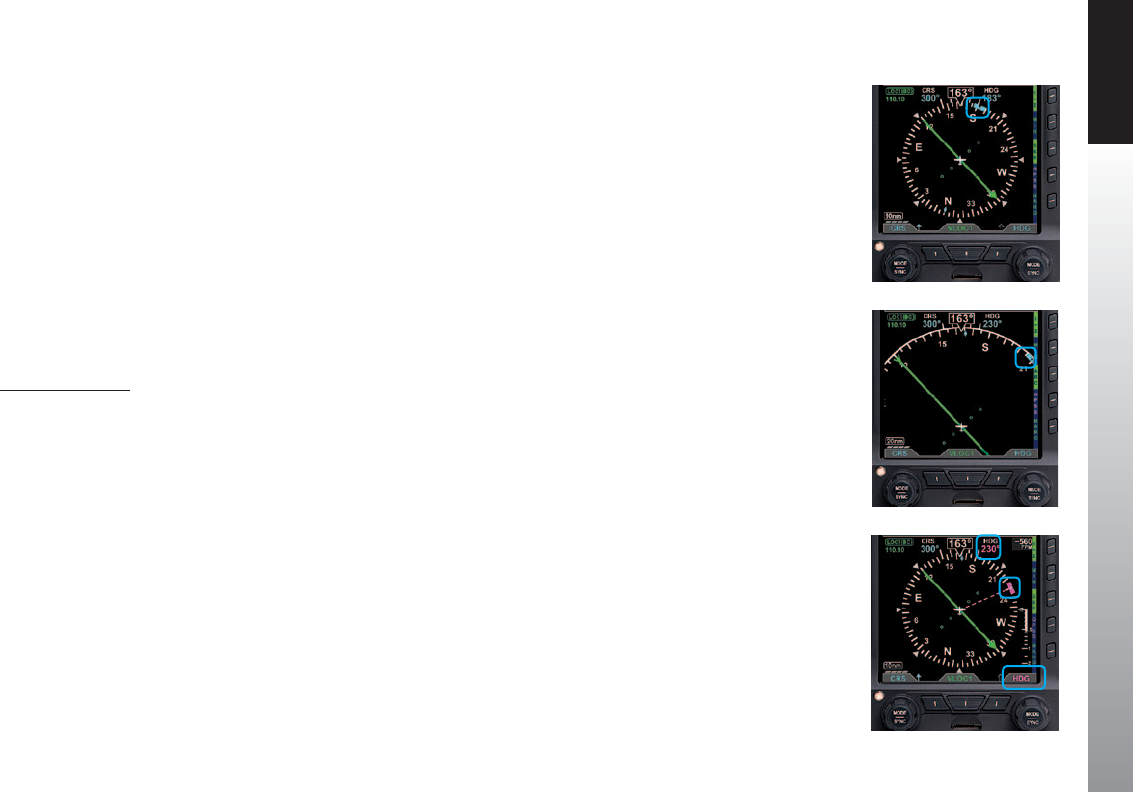
CHAPTER 4 REFERENCE GUIDE
EFD1000 PFD Pilot’s Guide Page 4-43
091-00005-001 REV E
4.4.9. Heading Bug
The PFD oers a pilot-selectable Heading Bug. The Heading Bug symbol is positioned
on the compass scale according to the Selected Heading Field value (HDG) set by the
pilot (Figure 4-82).
When the Selected HDG Field value is outside the visible compass scale range in the
ARC Compass mode, only a portion of the Heading Bug is shown at the edge of the
compass arc, closest to the HDG value (Figure 4-83).
When selected for editing, the Heading Bug and the Selected HDG Field value are
shown in magenta. Additionally, a dashed magenta line extends from the Ownship
Symbol to the Heading Bug, corresponding to the HDG value. When the Heading Bug is
SYNCed, the HDG value is set to the current heading.
Set Heading Bug
1. Press the Right Knob.
The HDG label above the Right Knob and the Selected Heading Field are enabled for
editing, both rendered in magenta (Figure 4-84).
2. Rotate the Right Knob to change the value of the Selected Heading Field.
Once the HDG value is set, and after 10 seconds of inaction, the Selected HDG Field is
disabled, and both the Right Knob State and the Selected Heading Field are displayed
in cyan.
Figure 4-82
Heading Bug and Selected
Heading Field
Figure 4-83
Selected Heading Bug Outside of
the ARC Compass Scale Range
Figure 4-84
Heading Selected to Edit
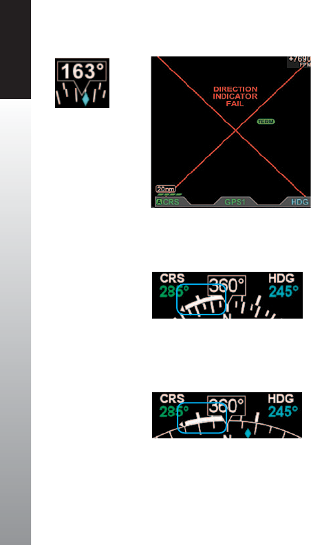
CHAPTER 4 REFERENCE GUIDE
EFD1000 PFD Pilot’s Guide
Page 4-44 091-00005-001 REV E
4.4.10. Aircraft Heading Display
The aircraft heading is displayed in degrees magnetic (Figure 4-85).
If the aircraft’s heading is unavailable or invalid, all heading and navigation information,
including the CDI and bearing pointers (if previously displayed), is removed and
replaced with a single red X covering the entire lower display area, along with the
annunciation DIRECTION INDICATOR FAIL (Figure 4-86).
4.4.11. Rate of Turn Indicator
The Rate of Turn Indicator consists of a curved white line originating from the
corresponding side of the aircraft heading (i.e., a left turn indication starts on the left
side of the index mark) and extends in the direction of the turn along the outer radius
of the compass scale. The turn rate indication is provided for every compass mode, 360°
(Figure 4-87) and ARC (Figure 4-88).
The Rate of Turn Indicator features tick marks for full and half-standard rate turns (a
standard rate turn = 3° per second).
The Rate of Turn Indicator has a range of 0° – 6° per second. When the turn rate exceeds
6° per second, an arrowhead is added to the end of the tape to show that the rate of
turn has exceeded the limits of the instrument.
Figure 4-85
Direction of Flight
Numerical Display
Figure 4-86
Direction Indicator Fail
Figure 4-88
Rate of Turn Indicator
(ARC Compass Mode)
Figure 4-87
Rate of Turn Indicator
(360° Compass Mode)
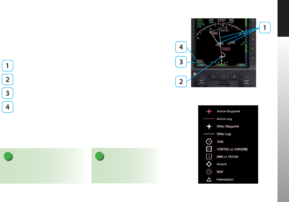
CHAPTER 4 REFERENCE GUIDE
EFD1000 PFD Pilot’s Guide Page 4-45
091-00005-001 REV E
4.4.12. Basemap Overlays
The Basemap comprises symbols depicting the location of ight plan waypoints and
legs, airports, VORs, DMEs, NDBs, and intersections. The Basemap is always oriented
with magnetic heading up and centered so that the current aircraft position coincides
with the aircraft’s Ownship Symbol. The current Basemap declutter level and range are
shown on the lower left side of the display (Figure 4-89).
Basemap Symbols
Aircraft Ownship Symbol
Basemap Declutter Level
Basemap Range
When enabled, the Basemap features on the Navigation Display are displayed and
layered as detailed in Table 5-12. The GPS ight plan is rendered in either straight or
curved lines, as supported by the congured GPS navigator. The displayed symbol set
includes active waypoints, active ight plan leg, ight plan waypoints, ight plan legs,
airports, VORs, VORTACs, TACANs, DMEs, intersections, and NDBs (Figure 4-90).
NOTE
A VORTAC is shown as a combined
VOR and DME symbol. A TACAN is
rendered as a DME symbol.
Figure 4-89
Basemap (ARC CDI Compass Mode Shown)
Figure 4-90
Basemap Symbol Set
NOTE
All map and ight plan elements are received
from the GPS and are only available from
compatible GPS navigators (e.g. GNS 430/530).
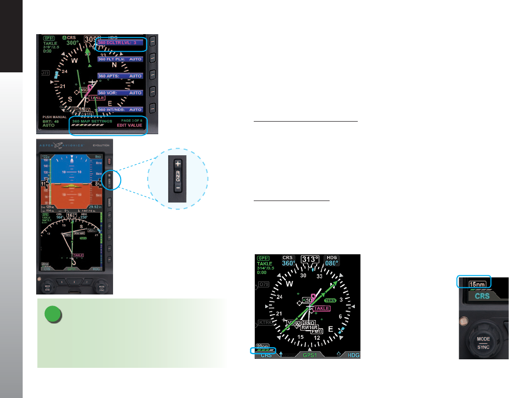
CHAPTER 4 REFERENCE GUIDE
EFD1000 PFD Pilot’s Guide
Page 4-46 091-00005-001 REV E
4.4.12.1. Basemap Declutter and Range
To turn the Basemap on or o, the pilot selects one of the declutter levels as described
in Section 5.2. The default map declutter level is Level 4. The map range corresponds
to the outside radius of the compass scale, 2, 3, 5, 10, 15, 20, 30, 40, 60, 80, 100, or 200
nautical miles from the aircraft Ownship Symbol. The default range is 15nm. Both the
map declutter level and range are pilot-adjustable.
Select Map Declutter Level
1. Press the MENU Button and rotate the Right Knob to MAP SETTINGS page.
2. Press the DCLTR LVL Menu Key (Figure 4-91) and rotate the Right Knob to
select the desired map declutter level.
3. Press the MENU Button to exit.
The new Basemap display level appears above the Left Knob (Figure 4-92).
Change Map Range
1. Press the Range Up (RNG +) or the Range Down (RNG -) Button (Figure 4-93).
until the desired range is displayed (Figure 4-94).
NOTE
When connected to a GPS that does not provide
compatible Basemap data, only OFF and FP ONLY
declutter levels are available.
Figure 4-93
Basemap Range Buttons
Figure 4-91
MAP Hot Key
Figure 4-94
New Basemap Range
Figure 4-92
New Basemap Display Level
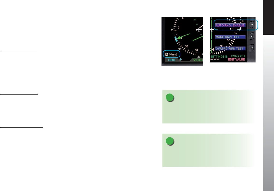
CHAPTER 4 REFERENCE GUIDE
EFD1000 PFD Pilot’s Guide Page 4-47
091-00005-001 REV E
The PFD has an Auto Range feature that automatically scales the range (to the closest
range setting) to t the Aircraft Ownship and the active waypoint within the Navigation
Display, e.g., if the active waypoint is 84 miles away, Auto Range will select a 100nm
range (the closest range setting is 100nm). When Auto Range is active, an inverse white
A is shown next to the range value (Figure 4-95).
Enable Auto Range
1. Press the MENU Button.
2. Rotate the Right Knob to the GENERAL SETTINGS B Menu page.
3. Press the AUTO RNG Menu Key.
The AUTO RNG label turns magenta (Figure4-96).
4. Rotate the Right Knob to the desired value, either ENABLE or DISABLE.
5. Press the MENU Button to exit.
Activate Auto Range
1. Press the RNG +/- button to select the highest or lowest map range.
2. Release and then press and hold the RNG +/- button for two seconds.
The map range changes and the new map range is indicated on the map. An inverse
white A displays next to the numeric range value.
Deactivate Auto Range
1. Press the RNG +/- Button once to deactivate Auto Range mode.
The inverse white A next to the numeric range value is removed.
Pressing RNG + moves to the next higher range; pressing RNG - moves to the next
lower range.
Figure 4-95
Auto Range Mode
NOTE
The map range increases or decreases one increment
each time the RNG + or - Button is pressed. Press and
hold to continuously increase or decrease the range.
NOTE
The Basemap declutter setting can determine what is
displayed for a particular range. Refer to Chapter5,
Table5-9 for more information.
Figure 4-96
GENERAL SETTINGS B Page Editing
Auto Range Setting

CHAPTER 4 REFERENCE GUIDE
EFD1000 PFD Pilot’s Guide
Page 4-48 091-00005-001 REV E
Auto Range is only available when a ight plan is active. Since Auto Range uses the
distance between the present position and the next active waypoint to compute the
appropriate map range, if the currently Selected CDI Navigation Source does not have
a valid ight plan, then Auto Range is not selectable. If Auto Range cannot be selected
check:
• To ensure a ight plan is active
• The GPS source with the ight plan is the Selected CDI Navigation Source
• That Auto Range is enabled from the General Settings B Menu page
4.4.12.2. Flight Plan1
When a ight plan is provided by a congured GPS, the map shows ight plan
waypoints and legs. The active leg and waypoint and associated identier are displayed
in magenta. Other waypoints and legs are white. Straight and curved ight plan details
are rotated within the map display to maintain their correct relative orientations at
alltimes.
4.4.12.3. Map Data Source and Reversion1
If the selected GPS data is unavailable or invalid:
• The associated ight plan and map data are retained and displayed, as long as an
alternate source of position information remains available.
• The ight plan and waypoints become inactive and are displayed in white.
• Position is provided from:
1. Another congured GPS source if providing valid position data. In this case, a
GPS# REVERSION annunciation is shown above the Selected CDI Navigation
Source (Figure 4-97) (# indicates the congured GPS source that is now
providing the aircraft’s position, either 1 or 2).
2. The RSM GPS, if enabled, and position data are available. In this case, a RSM
GPS REVERSION EMER USE ONLY annunciation is shown above the Selected
CDI Navigation Source (Figure 4-98).
Figure 4-97
GPS1 Failure, Reversionary Navigation
Figure 4-98
RSM GPS Reversionary Navigation
1. Not available with the Pilot PFD

CHAPTER 4 REFERENCE GUIDE
EFD1000 PFD Pilot’s Guide Page 4-49
091-00005-001 REV E
When a GPS source’s position data are invalid or no longer available, an amber
annunciation, GPS1, GPS2, or RSM GPS, is shown in the lower left corner of the
Navigation Display to indicate which has failed (Figure 4-99).
4.4.13. Ground Track Marker1
When congured with a GPS that provides ground track data, a Ground Track Marker is
displayed on the compass scale to indicate the aircraft’s ground track. This marker may be
used to compensate for wind drift during ight (Figures 4-100 and 4-101). The Ground
Track Marker is removed from the display when ground track data is not available or invalid.
4.4.14. GPS OBS Operation with a PFD and a Mechanical
Standby Nav Indicator1
When the PFD and a mechanical standby Nav indicator are both connected to an integrated
VOR/Localizer/GPS Navigation system, the standby indicator and the PFD operate normally in
all VOR, GPS and localizer modes.
When the GPS OBS mode is selected, the PFD Selected Course (CRS) control commands the
GPS OBS course and the mechanical standby nav indicator’s OBS course selector is ignored
by the integrated navigation system. Deviation indications are shown on both displays.
When the PFD is turned o, the course selector on the mechanical standby Nav indicator
commands the GPS OBS value.
4.4.15. Course Pointer Operation with Integrated VOR/
Localizer/GPS Navigation Systems1
During manual or automatic operation of the integrated system, when transitioning from
GPS guidance to VOR or localizer guidance, the course pointer on the should manually be set
to the appropriate course.
Figure 4-99
Invalid or Failed GPS Annunciations
Figure 4-100
ARC Compass Mode, Ground Track Marker
Figure 4-101
360° Compass Mode, Ground Track Marker
1. Not available with the Pilot PFD

CHAPTER 4 REFERENCE GUIDE
EFD1000 PFD Pilot’s Guide
Page 4-50 091-00005-001 REV E
4.5. Lateral and Vertical Deviation Indicator1
In addition to the CDI in the Navigation Display, separate displays of lateral and vertical
deviation information are shown in the Attitude Display during instrument approaches.
A Lateral Deviation Indicator (LDI) and a Vertical Deviation Indicator (VDI) (Figure
4-102) will automatically appear, depending on the operating mode of the selected
navigation sensor and the validity of the associated signal, as described below.
Vertical Deviation Indicator (VDI)
Lateral Deviation Indicator (LDI)
LDI Navigation Source Annunciation
4.5.1. Lateral Deviation Indicator1
The LDI and corresponding LDI Navigation Source Annunciation automatically display
when:
• The active navigation source is a GPS radio, GPS is in the Approach mode, and the
signal is valid.
Or
• The active navigation source is a VHF navigation radio and a valid LOC, LOC(BC), or
ILS signal is received.
Figure 4-102
Lateral and Vertical Deviation Indicators
and Source Information
1. Not available with the Pilot PFD

CHAPTER 4 REFERENCE GUIDE
EFD1000 PFD Pilot’s Guide Page 4-51
091-00005-001 REV E
When the LOC(BC) mode is active, deviation indications (corrected for reverse sensing)
are displayed. The deviation shown on the LDI directly corresponds to the deviation
indicated on the CDI in the Navigation Display. When the lateral deviation exceeds the
displayable range of 2.5 dots, the Course Deviation Diamond becomes dim and hollow,
and is parked at the extreme edge of the LDI scale (Figure 4-103).
When the LDI navigation source is invalid or is no longer available, the Lateral Deviation
Diamond is removed from view, and the Navigation Source Annunciation is slashed by
a red horizontal line (Figure 4-104).
4.5.2. Vertical Deviation Indicator1
The Vertical Deviation Indicator (VDI) is enabled and is shown on the Attitude Display
when the active navigation source is a VHF navigation radio, the ILS mode is active, and
a valid localizer signal is being received. The VDI is also displayed for a GPS, supplying
valid vertical deviation data, when in the Approach mode.
The VDI will only display with a valid vertical guidance signal. When the vertical
deviation exceeds the displayable range, the Glide Slope Deviation Diamond becomes
dim and hollow, and is parked at the extreme edge of the VDI scale (Figure 4-105).
Figure 4-105
Vertical Deviation Diamond O Scale Indication
Figure 4-104
LDI Source Invalid
Figure 4-103
Lateral Deviation Diamond
O Scale Indication
1. Not available with the Pilot PFD

CHAPTER 4 REFERENCE GUIDE
EFD1000 PFD Pilot’s Guide
Page 4-52 091-00005-001 REV E
4.6. Vertical Speed Indicator
When the 360° Compass Mode is selected, the Vertical Speed Indicator (VSI) is rendered
on the right side of the Navigation Display, showing a numerical and graphical
representations of vertical speed. The VSI shows the change in pressure altitude over
time. The graphical display is a white VSI Tape, with the numerical value at the top
(Figure 4-106). In either ARC Compass mode, only the numerical value isshown.
The VSI Tape displays rates of ±2,000 FPM while the numerical value displays rates up to
±9,990 FPM. When the vertical speed exceeds ±2,000 FPM, a triangle caps the VSI Tape
(Figure 4-107).
The VSI Tape is nonlinear, giving more display area to the 0 to ±1,000 FPM range than
to the ±1,000 to ±2,000 FPM range. Tick marks are presented only in the direction of
the climb or descent to provide visual cues for trends. The VSI’s numerical value, tape,
and scale are only shown if the aircraft is climbing or descending more than ±100 FPM.
During level ight in calm air conditions, the Tape, scale, and zero reference line are
removed from the display. The numerical value is always enabled and shows dashes
when vertical rates are out of range. If vertical speed is invalid, the Tape and numerical
display are replaced with a red X and the annunciation, VSIFAIL (Figure 4-108).
Figure 4-106
VSI
Figure 4-107
VSI Tape O-Scale
Figure 4-108
VSI Fail – 360° Compass Mode

CHAPTER 4 REFERENCE GUIDE
EFD1000 PFD Pilot’s Guide Page 4-53
091-00005-001 REV E
4.7. Autopilot Integration1
The Pro PFD can connect with many dierent legacy autopilot systems that are typically
found in general aviation aircraft. The PFD emulates the HSI and/or Flight Director (FD)
with which the autopilot was originally certied. Autopilot integration is limited to
heading and navigation modes, including vertical approachmodes.
When connected to an autopilot system that includes Nav or Approach couplers, the
PFD also acts as the navigation source selector switch to the autopilot. This assures that
the navigation information selected for the PFD is the same as that being provided
to the autopilot. This arrangement also eliminates the need for external autopilot
navigation source selector switches and relays that were previously used to select
which navigation radio would be connected to the autopilot. Selection of autopilot
modes and mode control is unaected by the installation of the PFD.
The PFD does not currently provide vertical coupling to barometric references, such as
altitude hold, vertical speed, or altitude capture.
See Section4.7.3.TypicalAutopilotOperation for more details on PFD operation
with the autopilot systems during typical aircraft operations, such as VOR/ILS/GPS
approaches.
NOTE
Refer to the autopilot AFMS for information on the
operation of the autopilot or Flight Director.
1. Not available with the Pilot PFD

CHAPTER 4 REFERENCE GUIDE
EFD1000 PFD Pilot’s Guide
Page 4-54 091-00005-001 REV E
WARNING
GPS Steering is a powerful automation tool that
can substantially reduce pilot workload. However,
using GPSS safely and eectively requires a thorough
understanding of your specic aircraft installation and
the interaction between the PFD, your GPS navigator,
and your autopilot. Pilot actions required to use
GPSS safely can vary signicantly depending on the
autopilot and GPS navigator installed, especially when
used on instrument approaches, especially those with
vertical guidance.
It is imperative that pilots new to GPSS gain experience
with it in VFR conditions and, ideally, get dual
instruction from a CFII who thoroughly understands
GPSS and the autopilot and GPS navigator in your
airplane before using GPSS on instrument procedures
in IMC.
4.7.1. GPS Steering (GPSS)1
GPS Steering represents a modern approach to ying between ight plan waypoints,
and oers many advantages of over traditional methods of ying direct course lines
between waypoints.
With traditional point-to-point navigation, the autopilot is provided with desired course
and cross-track deviation information associated with the current ight leg. From there,
it will maneuver the aircraft to center the needle and track the desired course. The
autopilot does not anticipate upcoming course changes, nor can it y curved ight
paths without pilot assistance, and it has to recompute wind corrections following each
course change. Upon reaching a waypoint, the pilot must set the course for the next
leg (unless AUTOCRS is enabled, see Section4.4.6.AutoCourse), and the autopilot will
then intercept and track that leg. In this type of operation, the CDI must always be set to
the desired course.
With GPSS, the PFD can unlock the GPS Steering capability already available in many
models of general aviation GPS navigators. With GPSS, the navigator continuously
computes the desired bank angle to track the GPS ight plan, and outputs that
information over a digital data bus. The GPS Steering command anticipates upcoming
turns; this includes the turn rate and turn initiation point required to roll out centered
on the next leg.
Some GPS navigators, such as the Garmin 4xx/5xxW series of WAAS navigators, even
provide GPS Steering commands for complex procedures, such as DME arcs, holding
patterns, and procedure turns allowing the autopilot to y these maneuvers without
pilot intervention. Check with your GPS manufacturer to see if your GPS supports these
capabilities.
1. Not available with the Pilot PFD
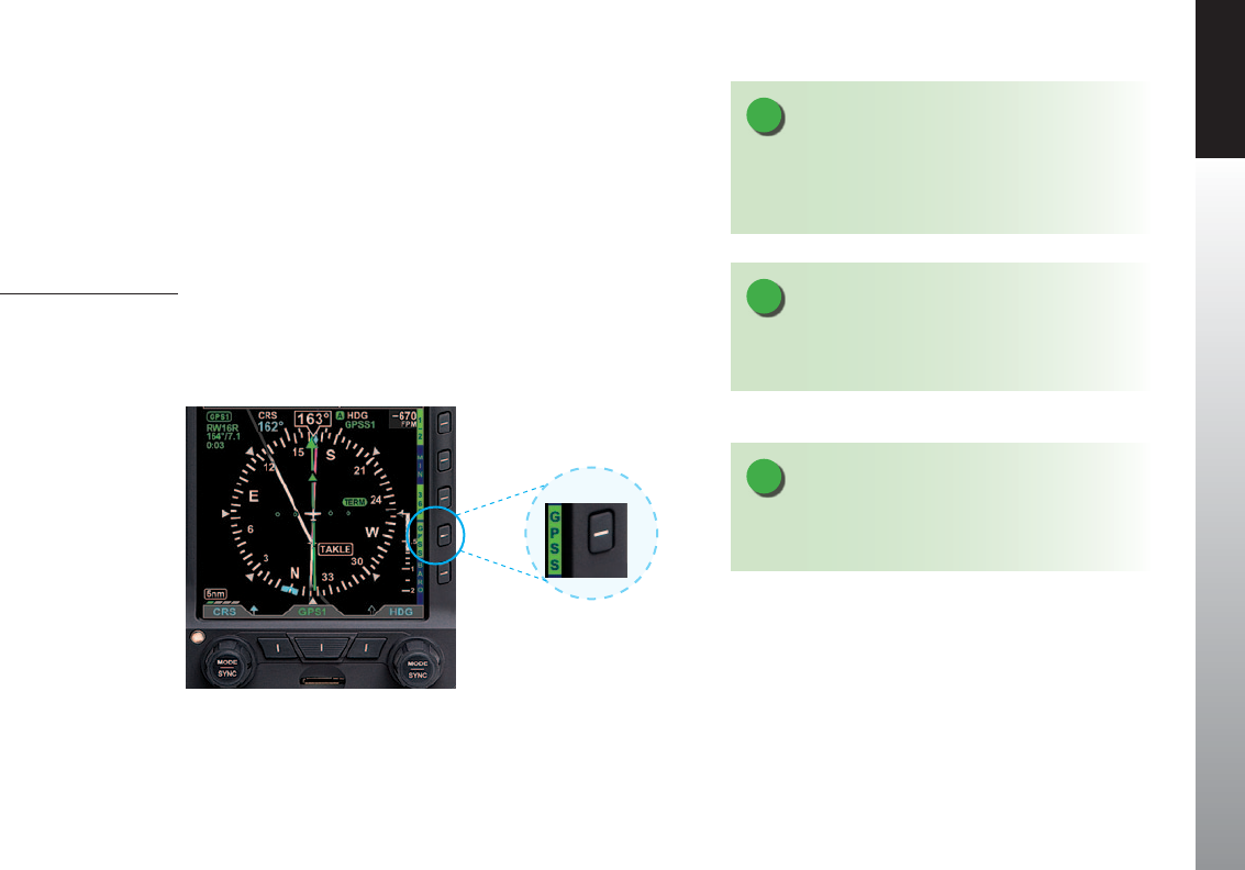
CHAPTER 4 REFERENCE GUIDE
EFD1000 PFD Pilot’s Guide Page 4-55
091-00005-001 REV E
The PFD translates GPS Steering commands received over a digital data bus into a
signal that is compatible with the autopilot Heading channel. Thus, by selecting GPSS
on the PFD and the Heading mode of the autopilot, the autopilot is able to y GPSS
commands.
If the connected GPS does not provide the required steering commands, the GPSS
legend adjacent to the GPSS Hot Key will be rendered in gray, and it will not be possible
to enable GPSS with the Hot Key.
Enable/Disable GPSS
1. Press the GPSS Hot Key to alternately enable or disable GPS Steering
(Figure 4-109).
NOTE
Refer to the Aircraft Flight Manual Supplement for your
GPS for information about GPSS commands that may
be output by that system.
NOTE
When GPSS is selected on the PFD, the autopilot must
be in Heading mode to follow the GPSScommands.
NOTE
When GPSS is disabled, the autopilot will follow the
Heading Bug.
Figure 4-109
GPSS Hot Key
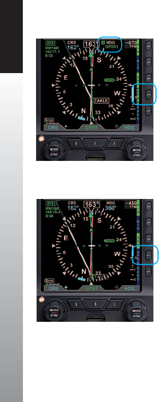
CHAPTER 4 REFERENCE GUIDE
EFD1000 PFD Pilot’s Guide
Page 4-56 091-00005-001 REV E
When GPSS is enabled, and the autopilot is in HDG mode, the autopilot will follow the
steering commands from the GPS. A GPSS enabled state will be indicated on the PFD
in two locations: 1) the GPSS legend adjacent to the GPSS Hot Key will be shown in
inverse green; and 2) the annunciation GPSS1 (or GPSS2, depending on the selected
source), along with an inverse A, will be shown next to the HDG reference at the top of
the Navigation Display, to the right of the Magnetic heading indication (Figure 4-110).
When GPSS is disabled, and the autopilot is in HDG mode, the autopilot will follow the
PFD Heading Bug. A GPSS disabled state will be indicated on the PFD in two locations:
1) the GPSS legend adjacent to the GPSS Hot Key will be shown in gray; and 2) the
Selected Heading Field will return. (Figure 4-111).
When the PFD Basemap navigation source is GPS1, enabling GPSS with the autopilot
in HDG mode will cause the autopilot to track the ight plan in GPS1, and GPSS1 will
be annunciated by the HDG reference at the top of the Navigation Display. Similarly,
when GPS2 is the Basemap navigation source on the PFD, and GPSS is enabled, the
autopilot in HDG mode will track the GPS2 ight plan, and GPSS2 will be annunciated
at the top of the navigation display. See Section4.4.5 for additional information on the
relationship among the CDI navigation source, Basemap navigation sources, and GPSS
navigation source.
When using GPSS with a stand-alone VLOC receiver, or with a combined GPS/VLOC
navigator (e.g., the GNS-430/530), GPSS will continue to follow the GPS output of that
combined navigator, even when VLOC is selected as the PFD Selected CDI Navigation
Source. With combined GPS/VLOC receivers, the transition from GPS to VLOC may occur
automatically, depending on how that system has been congured by the pilot.
Figure 4-110
GPSS Enabled with Autopilot in
HDG Mode
Figure 4-111
GPSS Disabled and Autopilot in
HDG Mode

CHAPTER 4 REFERENCE GUIDE
EFD1000 PFD Pilot’s Guide Page 4-57
091-00005-001 REV E
For example, suppose you use a GNS-430 to y a GPS ight plan and have an ILS
instrument approach loaded and active, and the GNS-430 is set for Auto ILS CDI
changeover once you are established inbound on the nal approach course. With GPSS
enabled on the PFD and the autopilot in HDG mode, the GPSS will steer the autopilot
laterally through the ight plan using GPS, even after the GNS-430 CDI automatically
switches to VLOC, and the PFD navigation source similarly switches to VLOC. However,
until you switch the autopilot into the Approach mode, it will not arm or capture the
glideslope to y the ILS approach. This feature is particularly useful for autopilots that
do not automatically transition from Heading mode to Nav mode when the selected
course is intercepted.
When ying an ILS on a WAAS GNS-430W, the autopilot in HDG mode can use the GPSS
to y the full course reversal automatically, and the GNS-430W will automatically switch
to VLOC once established inbound to the Final Approach Fix. But the pilot must then
engage the Approach mode on the autopilot to track the localizer and couple to the
glideslope.
Several conditions can cause GPSS to be disabled automatically (switching to a dierent
GPS steering source on the PFD, losing the GPS navigator source, canceling the ight
plan, etc.). If this happens, the PFD will send a Wings Level command to the autopilot
when in HDG mode, the GPSS Hot Key will annunciate the condition by showing
GPSS in inverse amber, and the GPSS# and inverse A annunciation at the top of the
Navigation Display will be shown with a red slash. (See Figure 4-112). To re-engage
GPSS, select a valid GPS navigation source (with valid ight plan or direct-to selection
on the GPS navigator), and then press the GPSS Hot Key. If a valid GPSS signal cannot
be restored, pressing the GPSS Hot Key will cancel GPSS mode and restore the Heading
Bug’s output to the autopilot. More detail on these abnormal conditions, and corrective
pilot actions, can be found in Chapter6,ExpandedEmergencyandAbnormal
Procedures. See also Chapter4,Section4.7.3.TypicalAutopilotOperations.
WARNING
It is your responsibility as Pilot in Command to ensure
that you are familiar with the operation of all installed
equipment. Operation of the PFD in IMC conditions
should not be attempted unless you are procient in its
use and operation, as describedherein.
NOTE
Refer to the autopilot systems Aircraft Flight Manual
Supplement and/or POH for details regarding use and
operation of the autopilot system.
Examples here are provided for reference only, based on
operation of the Bendix/King KFC-200 autopilot, and
actual operation may vary depending on the autopilot
system installed in your aircraft.

CHAPTER 4 REFERENCE GUIDE
EFD1000 PFD Pilot’s Guide
Page 4-58 091-00005-001 REV E
Figure 4-113
Flight Director
4.7.2. Flight Director1
When connected to a compatible autopilot system, the PFD will display a single-cue
Flight Director (FD). The FD’s command bars visually represent the lateral and vertical
steering cues transmitted to the PFD by the autopilot (Figure 4-113). When the FD
output from the autopilot is unavailable or invalid, the FD command bars are removed
from the display. To hand y using the FD, maneuver the airplane to tuck the Aircraft
Reference Symbol into the FD’s command bars.
4.7.3. Typical Autopilot Operations1
Whenever the PFD’s installed conguration includes connections to GPS, VLOC, and
autopilot systems, it acts as a data conduit between the navigators and the autopilot.
This enables any compatible navigator to be coupled to the autopilot.
NOTE
With the autopilot in HDG mode, if GPSS is automatically disabled, the autopilot will roll
wings level; it will not follow the Heading Bug.
Figure 4-112
GPSS Automatically
Disabled — Wings Level Mode
1. Not available with the Pilot PFD

CHAPTER 4 REFERENCE GUIDE
EFD1000 PFD Pilot’s Guide Page 4-59
091-00005-001 REV E
HDG Mode Operation – Heading Bug Steering
1. Set the PFD Heading Bug to the desired heading (Section 4.4.9).
2. Verify that GPSS is not selected.
3. Select the autopilot’s Heading (HDG) mode.
4. Engage the autopilot and verify that the autopilot turns the aircraft to the
selected heading.
HDG Mode Operation – GPS Steering (GPSS)
1. Couple the PFD CDI to a GPS navigation source with an active ight plan.
2. Enable GPSS by pressing the GPSS Hot Key.
3. Select the autopilot’s Heading (HDG) mode.
4. Engage the autopilot and verify that the autopilot turns the aircraft to follow
the GPS ight plan.
NAV Mode Operation – VLOC Navigation
1. Using the CDI Source Select button, couple a tuned/valid VLOC radio to the
PFD CDI and adjust the Course Pointer (CRS) to a value that will intercept the
course.
2. Set the PFD Heading Bug
3. Engage the autopilot in Heading (HDG) mode and verify that the aircraft turns
to the desired heading.
4. If your autopilot supports automatic Heading to Navigation mode transitions,
arm Navigation capture on the autopilot by selecting its Navigation (NAV)
mode. Otherwise, select the autopilot’s Navigation (NAV) mode when the
autopilot’s navigation signal capture criteria are satised (see your autopilot
AFMS for more information).
5. Monitor the PFD CDI deection and verify that, upon intercepting the desired
course, the autopilot modes transition appropriately and the autopilot tracks
the desired course.
NOTE
When GPSS is enabled, the HSI Heading Bug is not
coupled to the autopilot. To connect the Heading Bug
to the autopilot, disable GPSS with the GPSS Hot Key.
NOTE
The autopilot must be in Heading (HDG) Mode to
receive GPSS signals from the PFD.
NOTE
When using an integrated GPS/VLOC navigator, select
VLOC or GPS with the CDI source button on the GPS
select until the desired CDI Navigation Source is shown
on the PFD (SeeSection4.4.5.)

CHAPTER 4 REFERENCE GUIDE
EFD1000 PFD Pilot’s Guide
Page 4-60 091-00005-001 REV E
NOTE
Not all autopilots operate in the manner described
here for intercepting courses. See the AFMS for your
autopilot installation to understand how to adapt
these example procedures to your particular autopilot.
NOTE
In order for the autopilot to couple to vertical guidance
on GPS WAAS approaches, most autopilots must rst
be established on the nal approach course and in the
Altitude (ALT) Hold mode at least two miles outside the
Final Approach Fix (FAF). The Approach (APPR) mode
must be annunciated on both the PFD and the GPS.
NAV Mode Operation – GPS Navigation
1. With a valid ight plan programmed and active in the GPS, use the CDI
Source Select button to couple the GPS to the PFD (seeSection4.4.5.).
2. If AUTOCRS is disabled, set the Course Pointer to the desired course (CRS) (see
Section4.4.7.), or enable AUTOCRS (see Section4.4.6.).
3. With GPSS disabled, set the PFD Heading Bug (see Section4.4.9.) to a value
that will intercept the active leg of the ight plan, or enable GPSS via the
GPSS Hot Key.
4. Engage the autopilot in Heading (HDG) mode and verify that the aircraft turns
to a heading to intercept the active leg of the ight plan.
5. If your autopilot supports automatic heading to nav mode transitions, arm
the navigation capture on the autopilot by selecting its Navigation (NAV)
mode. Otherwise, select the autopilot Navigation (NAV) mode when the
autopilot navigation signal capture criteria are satised (see your autopilot
AFMS for more information).
6. Monitor the PFD CDI deection and verify that, upon intercepting the ight
plan leg, the autopilot modes transition appropriately and the autopilot tracks
the desired course.

CHAPTER 4 REFERENCE GUIDE
EFD1000 PFD Pilot’s Guide Page 4-61
091-00005-001 REV E
APPR Mode Operation – ILS Approach with Vectors to Final
1. Using the CDI Source Select button, couple a tuned/valid ILS radio frequency
to the PFD CDI, and adjust the course (CRS) (Section 4.4.7).
2. Set the PFD Heading Bug to a value that will intercept the desired course, or
as instructed by ATC (Section 4.4.9).
3. Engage the autopilot in Heading (HDG) and Altitude (ALT) Hold modes and
verify that the aircraft turns to the desired heading.
4. Once cleared for the ILS approach, arm the autopilot’s Approach (APPR)
mode, or continue to y Heading (HDG) mode until the CDI centers.
5. Monitor the CDI’s deection and verify (if supported by your autopilot) that,
upon intercepting the localizer, the autopilot switches to Approach (APPR)
capture, and tracks the localizer course. Otherwise, engage the autopilot
Navigation or Approach mode per the procedures in your autopilot’s AFMS.
6. Monitor the autopilot localizer tracking performance. Upon intercepting the
glide slope, verify that the autopilot captures the Glide Slope (GS) and initiates
a descent to track the glide slope.

CHAPTER 4 REFERENCE GUIDE
EFD1000 PFD Pilot’s Guide
Page 4-62 091-00005-001 REV E
APPR Mode Operation – GPS or GPS/RNAV APV WAAS Approach
1. With a valid GPS approach programmed in the GPS, use the CDI Source Select
Button to couple the GPS to the PFD (see Section4.4.5.).
2. If AUTOCRS is disabled, set the Course Pointer to the desired course (see Section
4.4.7.), or enable AUTOCRS (seeSection4.4.7.).
3. With GPSS disabled, set the PFD Heading Bug to a value that will intercept the
active leg of the ight plan (see Section4.4.9.) or enable GPSS via GPSS Hot Key.
4. Engage the autopilot in Heading (HDG) mode and verify that the aircraft turns to a
heading to intercept the active leg of the approach.
5. For autopilots that do not support automatic heading mode to Navigation (NAV)
or Approach (APPR) mode transitions, use the Heading Bug to establish the aircraft
inbound to the Final Approach Fix (FAF) and then engage the autopilot’s Approach
(APPR) mode.
6. For autopilots that support automatic Heading (HDG) to Approach (APPR) mode
transitions, monitor the PFD CDI and verify that, upon intercepting the active leg of
the approach, the autopilot turns to track the GPS approachcourse guidance.
THE FOLLOWING APPLY FOR WAAS GPS/RNAV APV APPROACHES ONLY
7. Once cleared for the GPS/RNAV approach, select the autopilot’s Approach (APPR)
mode.
8. Monitor the PFD CDI and verify that the autopilot intercepts and tracks the nal
approach course and the GPS switches to its Approach mode.
9. Most WAAS GPS navigators will not arm or activate vertical guidance until the
aircraft is within two miles of the FAF (unlike an ILS where the VDI will display as
soon as the aircraft is established on the nal approach course and a valid localizer
signal with glide slope signal is received). As you approach the FAF, watch for the
VDI to appear on the PFD Attitude Display. This indicates that the autopilot is
ready to capture the glide slope.
10. Monitor the autopilot lateral approach course tracking with the PFD CDI and LDI.
Upon intercepting the WAAS GPS glide slope, verify that the autopilot switches
captures the glide slope and starts a descent.
NOTE
WAAS GPS navigators can provide vertical guidance
on several types of GPS/RNAV instrument approaches.
RNAV (GPS) APV (Approaches with Vertical Guidance),
such as LPV and LNAV/VNAV approaches, often have
lower approach minima shown on the approach
plate. Aircraft equipped with appropriate WAAS GPS
equipment may use these lower minima.
Even with more traditional lateral guidance- only
GPS/RNAV approaches (e.g. (LNAV) with step-down
altitudes) WAAS GPS may still provide a pseudo-glide
slope that enables a continuous descent to the MDA
(Minimum Descent Altitude). The autopilot may
consider this a glide slope and attempt to y it. For this
type of instrument approach, the vertical guidance
is advisory only and the MDA is the appropriate
approach minimum.
These types of approaches are set up and own the
same way, much like an ILS approach. The pilot must
be aware of the dierences and which minima to use.

CHAPTER 4 REFERENCE GUIDE
EFD1000 PFD Pilot’s Guide Page 4-63
091-00005-001 REV E
GPS APPR Mode Operation – WAAS GPS Underlay to ILS Approach
Using Pilot Navigation and GPSS
1. With a valid ILS approach loaded and activated in the GPS, use the CDI
Source Select button to couple the GPS to the PFD CDI (see Section
4.4.5.).
2. Verify that the correct ILS frequency is tuned.
3. When the active flight plan leg is the course to the Initial Approach Fix
(IAF), enable GPSS via the GPSS Hot Key.
4. Engage the autopilot in Heading (HDG) and Altitude (ALT) Hold modes
and verify that the aircraft continues to fly the course to the IAF.
5. Monitor the PFD CDI and aircraft track to ensure the aircraft flies to the IAF
and then turns outbound for the course reversal.
6. A WAAS GPS navigator provides guidance along curved flight paths, and
will guide the aircraft through the course reversal and establish it inbound
to the FAF without pilot intervention.
7. Once established on the final approach course to the FAF, engage the
autopilot’s Approach (APPR) mode.
8. Use the PFD CDI Source Select button to change to the VLOC for the
approach (if not done automatically by the GPS/nav receiver).
9. Monitor the PFD CDI localizer deflection and verify that, upon intercepting
the localizer, the autopilot captures the final approach course and
switches to the Approach (APPR) mode.
10. Monitor the autopilot localizer tracking performance. Upon intercepting
the glide slope, verify that the autopilot captures glide slope and initiates
a descent.
NOTE
The PFD supports GPS LPV approaches (Approaches
with Vertical Guidance) by providing the autopilot
with GPS lateral and vertical deviation signals that are
identical to those typically provided by an ILS radio.
To y GPS LPV approaches, congure and operate the
autopilot as you would for an ILSapproach.
NOTE
Some IFR GPS navigators include ILS approaches
in their procedures database. GPS may be used to
navigate the initial segments of the ILS approach, but
the pilot must switch to VLOC navigation outside the
FAF and before glide slope intercept.
Some integrated GPS/NAV receivers (like the
Garmin 4xx/5xx series) can be congured to switch
automatically, and the PFD Selected CDI Navigation
Source will follow automatically. It is the pilot’s
responsibility to verify that the PFD CDI source is
correctly set to VLOC# before reaching either glide slope
intercept or the FAF..

CHAPTER 4 REFERENCE GUIDE
EFD1000 PFD Pilot’s Guide
Page 4-64 091-00005-001 REV E
GPS APPR Mode Operation – WAAS GPS Underlay to ILS Approach With ATC
Vectors to Final
1. With a valid ILS approach loaded and activated in the GPS, use the CDI Source
Select Button to couple the PFD GPS to the CDI (see Section4.4.5.).
2. Verify that the correct ILS frequency is tuned.
3. Set the Heading Bug to the heading assigned by ATC (see Section4.4.9.).
4. Disable GPSS via the GPSS Hot Key.
5. Engage the autopilot in Heading (HDG) mode and verify that the aircraft turns
to the Selected Heading.
6. When cleared for the approach and given the nal heading to intercept
the nal approach course by ATC, arm the autopilot’s Approach (APPR) and
Altitude (ALT) Hold modes.
7. Monitor the CDI and aircraft track to verify that the autopilot intercepts the
nal approach course and begins to track inbound to the FAF.
8. Use the PFD CDI Navigation Source Select Button to change to the
VLOC source for the approach (if not done automatically by the GPS/nav
receiver).
9. Monitor the PFD CDI localizer deection and verify that, upon intercepting
the localizer, the autopilot captures the nal approach course and switches to
the Approach (APPR) mode.
10. Monitor the autopilot localizer tracking performance. Upon intercepting the
glide slope, verify that the autopilot captures the glide slope and initiates a
descent to.

CHAPTER 4 REFERENCE GUIDE
EFD1000 PFD Pilot’s Guide Page 4-65
091-00005-001 REV E
4.8. Hazard Awareness1
Evolution Hazard Awareness (EHA) oers three hazard awareness options;
• Lightning (Data Link Weather and Stormscope® WX-500)
• NEXRAD
• Trac
Each option requires additional sensors. For Data Link Lightning and NEXRAD, an
additional subscription to XM WX Satellite Weather is required. Each hazard awareness
option is accessed by a Hot Key and displayed on the Navigation Display (Figure
4-114).
4.8.1. Lightning Overlay1
The LTNG Hot Key is a three position Hot Key (LTNG, STRK, and CELL) that permits
display of satellite lightning information or Stormscope® WX-500 data overlaid on the
HSI.
When enabled, the lightning displays as described in Table 4-5. The LTNG Hot Key label
is inverse green (green label and dark blue letters) when enabled or a blue label and
green letters when disabled.
Figure 4-114
Navigation Display Showing
Hazard Awareness
1. Not available with the Pilot PFD

CHAPTER 4 REFERENCE GUIDE
EFD1000 PFD Pilot’s Guide
Page 4-66 091-00005-001 REV E
Hot
Key
Display
Symbol
Annunciation Description
LTNG
Figure 4-115
Data Link Lightning
Symbol
Figure 4-116 Lightning Time
Annunciation displays in
the lower left corner of
the Navigation Display
showing the age of
received data.
Data Link Lightning Symbols
display as cyan lighting symbols
at full intensity for 5 minutes after
information is received.
Symbols are positioned on the
display relative to the Ownship
Symbol.
After 5 minutes, the symbols will
fade over the next 15minutes.
STRK
Figure 4-117
WX-500 Strike Symbol
Figure 4-118 WX-500 Strike Rate
Annunciation displays in
the lower left corner of
the Navigation Display
showing the current
strike rate.
Symbols are positioned on the
display relative to the Ownship
Symbol.
CELL
Figure 4-119
WX-500 Cell Symbol
Figure 4-120 WX-500 Cell Rate
Annunciation displays in
the lower left corner of
the Navigation Display
showing the current
cell rate.
Symbols are positioned on the
display relative to the Ownship
Symbol.
Table 4-5
Lighting Display
NOTE
WX-500 Lightning Symbols and rate annunciation are
removed from the Basemap for ranges less than 20nm.
NOTE
WX-500 data will not display, and the rate
annunciation displays with a red line when the
Stormscope receiver reports a fault or error, aircraft
heading is invalid or unavailable, or WX-500 data is
notdetected (Figure 4-121).
Figure 4-121
WX-500 Data is Not Available
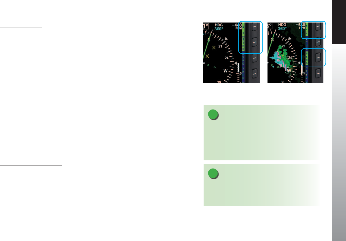
CHAPTER 4 REFERENCE GUIDE
EFD1000 PFD Pilot’s Guide Page 4-67
091-00005-001 REV E
Display Lightning
1. Select the 2/2 Hot Key Menu.
2. Press the LTNG Hot Key to select the desired option.
The LTNG Hot Key label turns inverse green when enabled. Each press of the Hot Key
cycles through the available options; LTNG, STRK, CELL, or LTNG disabled. (STRK is
selected in Figure 4-122).
4.8.2. Data Link Weather Overlay1
The NXRD Hot Key enables the display of NEXRAD (Next Generation Radar) and
precipitation data overlaid on the Navigation Display relative to the Ownship Symbol.
The Hot Key label is green when enabled and gray when disabled. The Data Link
Weather default setting is o. NEXRAD coverageincludes:
• U.S. and Puerto Rico NEXRAD
• U.S. Precipitation type
• Canada Radar
• U.S. NEXRAD Coverage
• Canada Coverage
Display Data Link Weather
1. Select the 2/2 Hot Key Menu.
2. Press the NXRD Hot Key to enable Data Link Weather
The NXRD Hot Key label turns inverse green when enabled (Figure 4-123).
NOTE
When US and Puerto Rico NEXRAD and Canada Radar
exceeds the specied expiration time, the depiction for
the respective radar is rendered as no Radar Coverage.
Figure 4-123
Data Link Weather Enabled
Figure 4-122
Lightning Overlay Enabled
Displaying WX-500 Strike Data
NOTE
When Strike or Cell mode is displayed, pressing
and holding the CELL or STRK Hot Key will reset the
respective RATE to zero and remove all stormscope
symbols from the display. This function may also be
performed from the MENU.
1. Not available with the Pilot PFD

CHAPTER 4 REFERENCE GUIDE
EFD1000 PFD Pilot’s Guide
Page 4-68 091-00005-001 REV E
NEXRAD coverage displays using the following methodology:
• If US Precipitation Type is unavailable and US NEXRAD Radar is available, the US
weather depiction is displayed as rain.
• If US Precipitation Type is available and US NEXRAD Radar is unavailable, the US
weather depiction is not displayed.
• If US coverage is unavailable or expired and US NEXRAD is available, the US
weather depiction is displayed as if all US radar sites are valid.
• If Canada coverage is unavailable and Canada radar is available, the Canada
weather depiction is displayed as if all US radar sites are valid.
• If US NEXRAD Radar or Canada Radar exceed the specied expiration time, the
depiction for the respective radar is displayed as no Radar Coverage.
• If Puerto Rico NEXRAD Radar exceeds the specied expiration time, the Puerto Rico
NEXRAD Radar depiction for the respective radar displays as no Radar Coverage.
• Radar data is displayed as outlined in Figure 4-124. Areas without radar coverage
are indicated by translucent gray. Radar cells indicating reectivity below 10 dBZ
are not displayed. The PFD oers a Data Link Weather legend accessible from the
MENU.
Display Data Link Weather Legend
1. Press the MENU Button.
2. Rotate the Right Knob to the XM RECEIVER C Menu page.
3. Press and hold the HOLD FOR LGND Menu Key.
The Data Link Weather Legend displays until the Menu Key is released (Figure 4-125).
4. Press the MENU Button to exit.
NOTE
Areas of no coverage are gray. If the aircraft is on the
ground before data is received, or in an area of no
coverage and the range setting is low, the entire HSI
may be underplayed in translucent gray.
Figure 4-124
NEXRAD Radar Data
Figure 4-125
Data Link Weather Legend
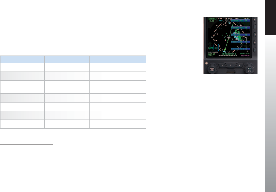
CHAPTER 4 REFERENCE GUIDE
EFD1000 PFD Pilot’s Guide Page 4-69
091-00005-001 REV E
When the Data Link Weather is enabled, an age annunciation is shown in the lower left
corner of the Navigation Display (Figure 4-126). The age annunciation indicates the
elapsed time in minutes since the information was generated. Each weather product
has an age limit and is usually updated at the update frequency indicated in Table 4-6.
The age of each weather product is displayed in XM RECEIVER B and XM RECEIVER C
Menu pages (Figure 4-126).
Weather Product Expiration Time (min.) Update Frequency (min.)
U.S. NEXRAD 30 5
Puerto Rico NEXRAD 30 5
High Resolution
(Canada) Radar 30 10
U.S. Radar Coverage 30 5
Canada Radar Coverage 30 10
Precipitation Type 30 5
Data Link Lightning 30 5
Table 4-6
Weather Product Age Limits and Update Frequency
View Data Link Weather Age
1. Press the MENU Button.
2. Rotate the Right Knob to the XM RECEIVER B Menu page.
The age of each Data Link Weather product is shown (Figure 4-126).
3. Press the MENU Button to exit.
Figure 4-126
Data Link Weather Product Age
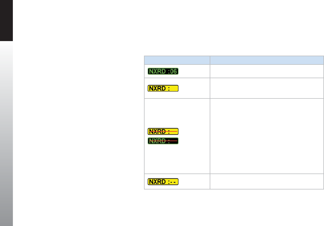
CHAPTER 4 REFERENCE GUIDE
EFD1000 PFD Pilot’s Guide
Page 4-70 091-00005-001 REV E
The data age (except Puerto Rico NEXRAD) will display in Amber whenever the data
link receiver has failed or stops reporting. When the expiration time has been reached
and no updates have been received, the age annunciation is shown with a red slash
and all data are removed from the Navigation Display. Table 4-7 describes the age
annunciations.
Age Annunciation Conditions
NEXRAD data is being received and updated.
The data link receiver has failed or the data are unavailable,
but not expired and may still be valid. Check local
weatherconditions.
NEXRAD data are removed and the age annunciation is
slashed with a red line, for any of the following conditions:
• The age of the data exceeds the expiration time
identied in Table 4-6; additionally, the corresponding
NEXRAD data are removed from the display.
• The data age of all displayed products exceeds the
specied expiration time.
• No valid data have not yet been received for 15
minutes.
• GPS position information is unavailable or invalid.
Valid data has not yet been received from theNEXRAD
receiver after the PFD is turned on.
Table 4-7
Weather Age Annunciations

CHAPTER 4 REFERENCE GUIDE
EFD1000 PFD Pilot’s Guide Page 4-71
091-00005-001 REV E
4.8.3. Trac Overlay1
The TRFC Hot Key enables the trac display overlaid on the Navigation Display when
the PFD is congured with one of the following trac sensors:
• Avidyne TAS 600/610/620 (TAS)
• Bendix/King KMH 880 (TAS)
• Bendix/King KTA 870 (TAS)
• Garmin GTX 330 (TIS)
• RYAN 9900BX (TAS)
• SKYWATCH SKY 497 (TAS)
• SKYWATCH SKY 899 (TAS)
The TRFC Hot Key enables the Trac Overlay and the selection of a Trac Altitude Filter.
The Hot Key Label is inverse green (green label with dark blue letters) when enabled
(Figure4-127) or a blue label with green letters when disabled.
When the Trac Overlay is enabled, a TRFC annunciation is presented on the lower left
of the Navigation Display. The trac setting that was previously reset over a power cycle
is retained as last congured by the pilot.
Display the Trac Overlay
1. Select the 2/2 Hot Key Menu.
2. Press the TRFC Hot Key to select the desired Altitude Filter.
Figure 4-127
Trac Overlay Enabled
NOTE
Because of their importance, the PFD will show Trac
Advisories on the Navigation Display even when Trac
Overlay is disabled.
1. Not available with the Pilot PFD

CHAPTER 4 REFERENCE GUIDE
EFD1000 PFD Pilot’s Guide
Page 4-72 091-00005-001 REV E
4.8.3.1. Trac Symbols1
The PFD will display trac symbols prioritized in the order received from the
congured trac sensor. The PFD includes three threat levels using TCAS symbology;
Trac Advisory (amber circle), Proximity Advisory (cyan diamond), and Other Trac
(hollow cyan diamond). All trac symbols within the current display range and the
selected altitude lter are shown relative to the Ownship Symbol (Figure 4-128).
The Trac Advisory System (TAS) use an airborne interrogator with a half-second
update rate; coverage follows the aircraft. The Trac Information Service (TIS) system
use a GTX 330 transponder with a ve-second update rate; coverage is limited to
specic areas listed in the Aeronautical Information Manual(AIM).
WARNING
Do not rely on the PFD as the sole source of data for collision avoidance. It is the pilot’s
responsibility to visually acquire other aircraft for safe ight. Maneuver your aircraft based
only on ATC guidance or positive acquisition of conicting trac. Trac information is:
• Provided as a proximity warning only
• Intended to assist the pilot in the visual acquisition of other aircraft
• Not intended to provide recommended avoidance maneuvers
• Not provided for aircraft that are not transponder equipped, experiencing a
transponder failure, or out of radar coverage
Figure 4-128
Trac Symbology
NOTE
Refer to your trac sensor’s Pilot Guide for detailed
information about the sensor limitations and
operational ranges.
Additionally, see the Aeronautical Information
Manual section entitled Trac Information Service
(TIS) for detailed information about TIS requirements,
capabilities and limitations..
Trac Advisory
Proximity
Advisory
Other Trac
1. Not available with the Pilot PFD

CHAPTER 4 REFERENCE GUIDE
EFD1000 PFD Pilot’s Guide Page 4-73
091-00005-001 REV E
Figure 4-129
Trac Symbol Data Block
NOTE
Trac that is within 100 feet of the ownship shown an
altitude value of 00, above or below the trac symbol
as appropriate.
NOTE
When the trac is ying level, no arrow is shown.
When the trac is not reporting an altitude, neither the
arrow nor the altitude indication is shown.
The PFD displays trac information from the sensor with the threat level assigned by
the sensor. The sensor and type of trac system denes the threat data, range, bearing,
altitude, and altitude trend. Each trac symbol is positioned at a location representing
the relative range and bearing to the Ownship Symbol.
A data block is provided for each trac symbol with the relative altitude and vertical
direction (as acquired from the sensor). The data block text color is the same as the
trac symbol, amber for Trac Advisories and cyan for Proximity Advisories and Other
Trac (Figure 4-129).
The relative altitude is shown as two digits indicating the relative altitude dierence, in
hundreds of feet, from your aircraft. The altitude value for trac above the ownship is
preceded by a plus symbol (+) and is displayed under the symbol. The altitude value for
trac below the ownship is preceded by a minus symbol (-) and is displayed under the
symbol.
An arrow next to the trac symbol gives the direction of vertical movement in relation
to the your aircraft. Trac climbing or descending at a rate greater than 500 fpm are
given an up-arrow (climbing), or down-arrow (descending) to the right of the trac
symbol. Trac that is at the same altitude, with no vertical trend, is given an altitude
value of 00 below the trac symbol.
For example, the Trac Advisory shown in Figure 4-128 is 400 feet above your aircraft
and descending. No altitude information is shown in the data block when the altitude is
unavailable.
Trac Advisories that are outside the current range are indicated by a half-symbol at
the edge of the Navigation Display with the appropriate data block. Proximity Advisories
and Other Trac that are outside of the current range are not displayed.
When multiple trac symbols partially or completely overlap, the symbols are visually
stacked, with the highest priority alert data on top, obscuring the lower priority alert.
NOTE
Depending on the position of the Trac Advisory at the
edge of the screen, the trac symbol data block may or
may notdisplay.

CHAPTER 4 REFERENCE GUIDE
EFD1000 PFD Pilot’s Guide
Page 4-74 091-00005-001 REV E
When a trac symbol and the Ownship Symbol partially or completely overlap, the
trac symbol and data block will overlay the ownship symbol.
4.8.3.2. Trac Altitude Filter1
There are ve Altitude Filters available: O, Normal, Unrestricted, Above, and Below
(Table 4-6). Only trac within the selected altitude lter value will display.
Hot Key Label Altitude Filter Level Trac Display Volume
TRFC O None
TFCN Normal ±2,700 ft
TFCU Unrestricted ±9,900 ft
TFCA Above +9,900 ft to -2,700 ft
TFCB Below +2,700 ft to -9,000 ft
Table 4-8
Trac Filter Parameters
The pilot adjusts the altitude lter value by continuously pressing the TRFC Hot Key, which
cycles through each of the lter levels.
Change the Trac Altitude Filter
1. Select the 2/2 Hot Key Menu
2. Press the TRFC Hot Key to select the desired lter level.
The TRFC annunciation displays in the lower left of the display (Figure 4-117).
NOTE
The altitude lters listed in Table 4-8 are referenced to
your aircraft and the PFD altitudes. The trac sensor
congured with the PFD may have dierent (i.e., lower)
altitude thresholds. Check your trac sensor pilot’s
manual for specics.
Figure 4-130
Trac Altitude Filter
1. Not available with the Pilot PFD

CHAPTER 4 REFERENCE GUIDE
EFD1000 PFD Pilot’s Guide Page 4-75
091-00005-001 REV E
4.8.3.3. Trac Unavailable1
When the TAS (Trac Advisory System) sensor’s status is STANDBY, TEST or FAIL:
• an Invalid Trac Sensor annunciation (Figure 4-131) is displayed and the Trac
symbols are removed from view
When the trac interface is a TIS (Trac Information Service) and the Trac data is:
• Unavailable – TRFC UNVL is annunciated
• Not refreshed within 6 seconds – TRFC COAST is annunciated
• Not refreshed within 12 seconds – TRFC RMVD is annunciated and the Trac
symbols are removed from view
• Not refreshed for 60 seconds – TRFC RMVD annunciation is removed from view
Figure 4-131
Trac Sensor Invalid
1. Not available with the Pilot PFD

CHAPTER 4 REFERENCE GUIDE
EFD1000 PFD Pilot’s Guide
Page 4-76 091-00005-001 REV E
This Page Intentionally Left Blank
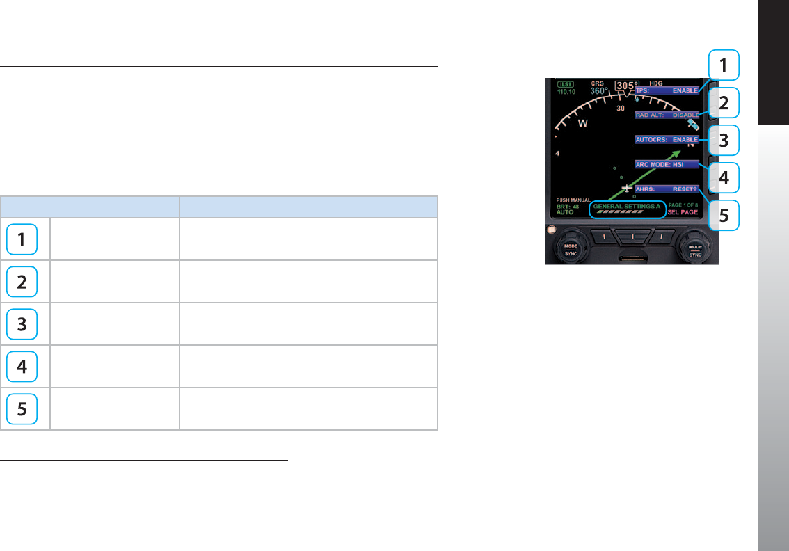
CHAPTER 5 CUSTOMIZING THE EFD1000 PFD
EFD1000 PFD Pilot’s Guide
Page PB 091-00005-001 REV E EFD1000 PFD Pilot’s Guide Page 5-1
091-00005-001 REV E
Chapter 5
Customizing the PFD
5.1. Menu Overview
The following tables and gures provide a brief overview of each menu page and its
menu options.
KEY DESCRIPTION OPTIONS
Displays Airspeed and
Altitude Tapes 1DISABLE or ENABLE
Radio Altitude 2DISABLE or ENABLE
Auto Course Select 2DISABLE or ENABLE
ARC Compass Mode 2HSI or CDI
AHRS Reset Action
Table 5-1
Menu – GENERAL SETTINGS A
Figure 5-1
GENERAL SETTINGS A
1. Available only in those installations where an additional airspeed indicator
and altimeter are added or retained within the pilot’s maximum field of view.
2. Not available with the Pilot PFD
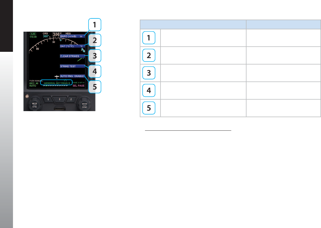
CHAPTER 5 CUSTOMIZING THE EFD1000 PFD
EFD1000 PFD Pilot’s Guide
Page 5-2 091-00005-001 REV E EFD1000 PFD Pilot’s Guide Page 5-3
091-00005-001 REV E
KEY DESCRIPTION OPTIONS
Barometer Pressure Setting Units of Measure in Hg or mB
Outside Air Temperature Units of Measure °C or °F
Clear WX-500 Strike/Cell Count 1, 2 Action
WX-500 Strike Test 1, 2 Action
Auto Range DISABLE or ENABLE
Table 5-2
Menu – GENERAL SETTINGS B
Figure 5-2
GENERAL SETTINGS B
1. Pro PFD Only when congured with Stormscope® WX-500.
2. Not available with the Pilot PFD
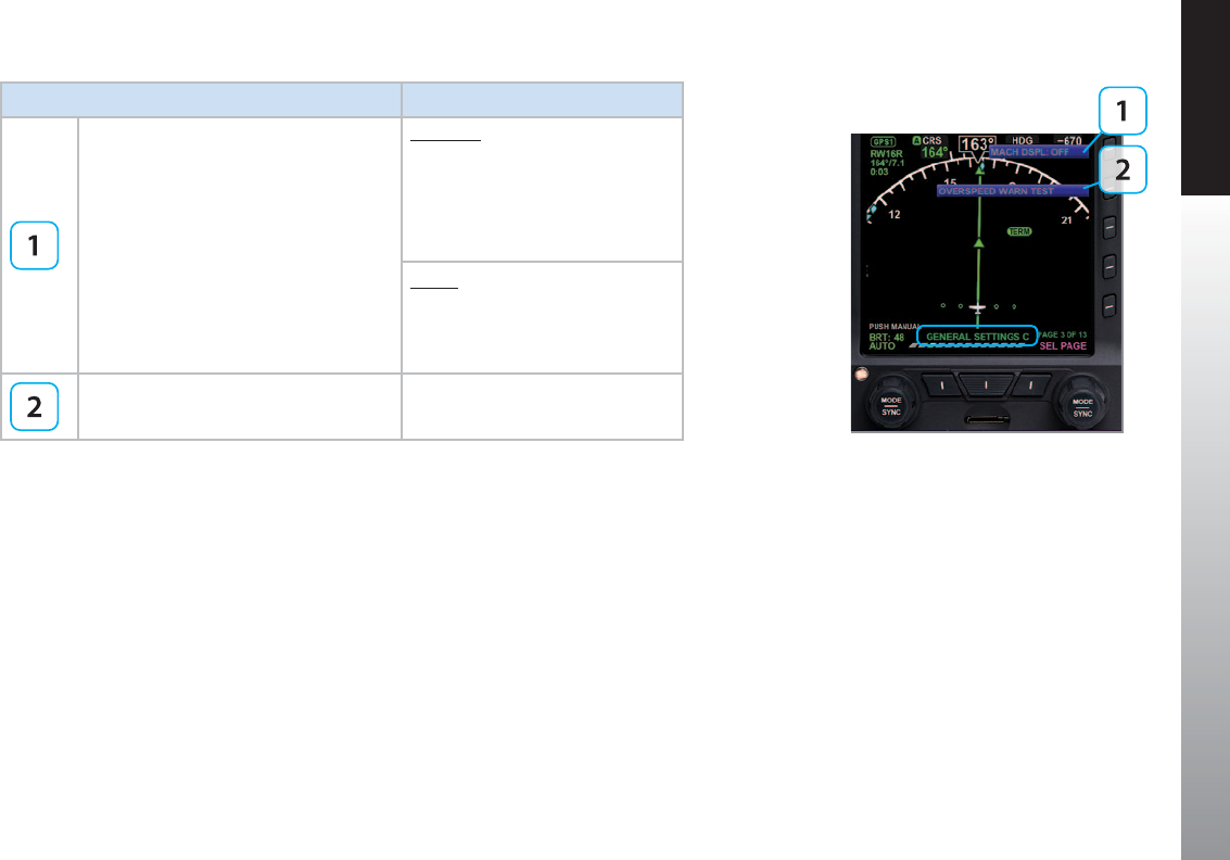
CHAPTER 5 CUSTOMIZING THE EFD1000 PFD
EFD1000 PFD Pilot’s Guide
Page 5-2 091-00005-001 REV E EFD1000 PFD Pilot’s Guide Page 5-3
091-00005-001 REV E
Figure 5-3
GENERAL SETTINGS C
KEY DESCRIPTION OPTIONS
MACH Display
ALTITUDE:
OFF, ON>5K, ON>6K, ON>7K,
ON>8K, ON>9K, ON>10K,
ON>11K, ON>12K, ON>13K,
ON>14K, ON>15K, ON>16K,
ON>17K, ON>18K
SPEED:
OFF, ON>0.1, ON>0.2, ON>0.3,
ON>0.4, ON>0.5, ON>0.6, ON>0.7
Overspeed Warning Test Action
Table 5-3
Menu – GENERAL SETTINGS C

CHAPTER 5 CUSTOMIZING THE EFD1000 PFD
EFD1000 PFD Pilot’s Guide
Page 5-4 091-00005-001 REV E EFD1000 PFD Pilot’s Guide Page 5-5
091-00005-001 REV E
KEY DESCRIPTION OPTIONS
360° Declutter Level 0, 1, 2, 3, 4
360° Flight Plan OFF, AUTO
360° Airports OFF, AUTO
360° VORs (High, Low and Terminal) OFF, AUTO
360° Intersections / NDB OFF, AUTO
Table 5-4
Menu – 360° MAP SETTINGS
Figure 5-4
360° MAP SETTINGS
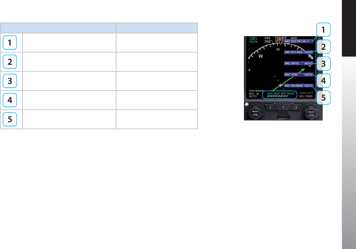
CHAPTER 5 CUSTOMIZING THE EFD1000 PFD
EFD1000 PFD Pilot’s Guide
Page 5-4 091-00005-001 REV E EFD1000 PFD Pilot’s Guide Page 5-5
091-00005-001 REV E
KEY DESCRIPTION OPTIONS
ARC Declutter Level 0, 1, 2, 3, 4
ARC Flight Plan OFF, AUTO
ARC Airports OFF, AUTO
ARC VORs (High, Low and Terminal) OFF, AUTO
ARC Intersections / NDB OFF, AUTO
Table 5-5
Menu – ARC MAP SETTINGS
Figure 5-5
ARC MAP SETTINGS
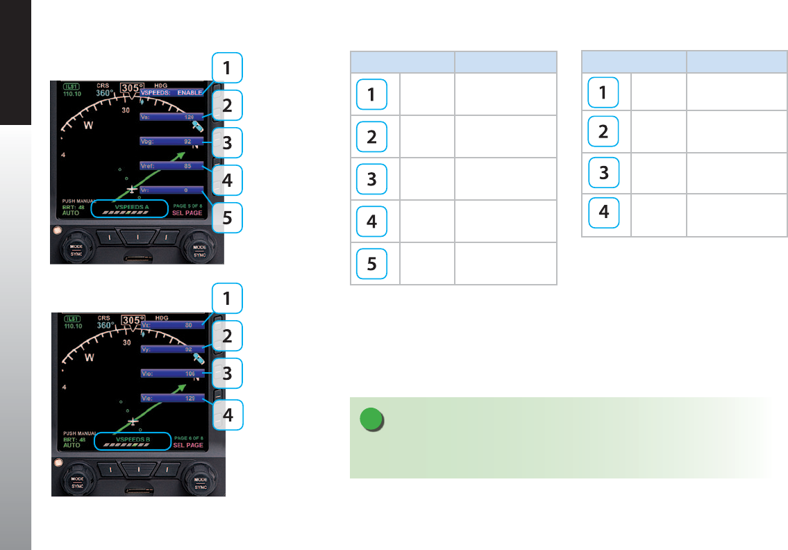
CHAPTER 5 CUSTOMIZING THE EFD1000 PFD
EFD1000 PFD Pilot’s Guide
Page 5-6 091-00005-001 REV E EFD1000 PFD Pilot’s Guide Page 5-7
091-00005-001 REV E
KEY DESCRIPTION OPTIONS
VSPEEDS DISABLE or ENABLE
Va 0 to 450 or LOCKED
Vbg 0 to 450 or LOCKED
Vref 0 to 450 or LOCKED
Vr 0 to 450 or LOCKED
Table 5-6
Menu – VSPEEDS A
Figure 5-6
VSPEEDS A
Figure 5-7
VSPEEDS B
NOTE
When V Speeds are LOCKED at installation, the legend and set value are shown in gray.
Setting any of the above values to zero removes the aected V Speed.
KEY DESCRIPTION OPTIONS
Vx 0 to 450 or LOCKED
Vy 0 to 450 or LOCKED
Vlo 0 to 450 or LOCKED
Vle 0 to 450 or LOCKED
Table 5-7
Menu – VSPEEDS B

CHAPTER 5 CUSTOMIZING THE EFD1000 PFD
EFD1000 PFD Pilot’s Guide
Page 5-6 091-00005-001 REV E EFD1000 PFD Pilot’s Guide Page 5-7
091-00005-001 REV E
KEY DESCRIPTION OPTIONS
XM Serial Number 1, 2 Status Only
XM Receiver Signal Quality 1, 2 Status Only
XM Status 1, 2 Status Only
Table 5-8
Menu – XM RECEIVER A
Figure 5-8
XM RECEIVER A
1. Pro PFD Only when congured with an EWR50 Weather
Receiver and a subscription to XM WX Satellite Weather®.
2. Not available with the Pilot PFD
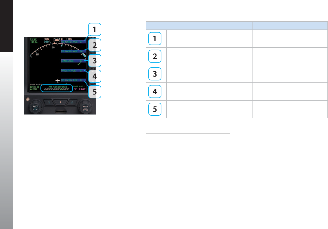
CHAPTER 5 CUSTOMIZING THE EFD1000 PFD
EFD1000 PFD Pilot’s Guide
Page 5-8 091-00005-001 REV E EFD1000 PFD Pilot’s Guide Page 5-9
091-00005-001 REV E
KEY DESCRIPTION OPTIONS
US NEXRAD Age 1, 2 Status Only
Puerto Rico NEXRAD Age 1, 2 Status Only
Lightning Age 1, 2 Status Only
Precipitation Age 1, 2 Status Only
US Coverage Age 1, 2 Status Only
Table 5-9
Menu – XM RECEIVER B
Figure 5-9
XM RECEIVER B
1. Pro PFD Only when congured with an EWR50 Weather
Receiver and a subscription to XM WX Satellite Weather®.
2. Not available with the Pilot PFD

CHAPTER 5 CUSTOMIZING THE EFD1000 PFD
EFD1000 PFD Pilot’s Guide
Page 5-8 091-00005-001 REV E EFD1000 PFD Pilot’s Guide Page 5-9
091-00005-001 REV E
KEY DESCRIPTION OPTIONS
Canada Radar Age 1, 2 Status Only
Canada Coverage Age 1, 2 Status Only
Display Weather Legend 1, 2 Action
Table 5-10
Menu – XM RECEIVER C
Figure 5-10
XM RECEIVER C
1. Pro PFD Only when congured with an EWR50 Weather
Receiver and a subscription to XM WX Satellite Weather®.
2. Not available with the Pilot PFD
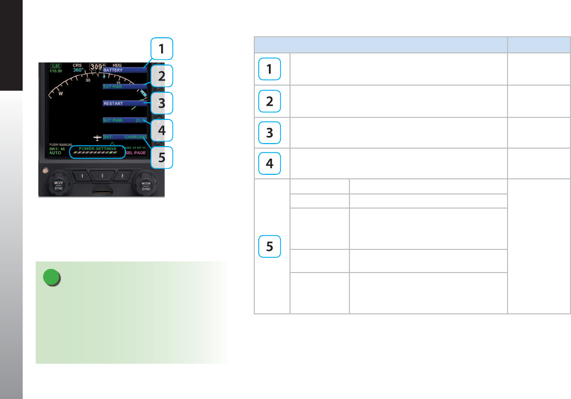
CHAPTER 5 CUSTOMIZING THE EFD1000 PFD
EFD1000 PFD Pilot’s Guide
Page 5-10 091-00005-001 REV E EFD1000 PFD Pilot’s Guide Page 5-11
091-00005-001 REV E
KEY DESCRIPTION OPTIONS
Operating from or Switch to Battery Power. Green when current
state (Pressing key performs no action). White if selection is
possible.
Status or Action
Operating from or Switch to External Power. Green when current
state (Pressing key performs no action). White if selection is
possible.
Status or Action
Restart (Depending on Air/Ground Logic State). Action
External Power Source Voltage. Displays voltage level of
inputpower. Status Only
Battery Status Description
Status Only
##% Displays battery % charge.
CHARGING
The battery has sucient voltage and can
accept charging, aircraft power is available,
and the temperature sensor is within limits
(0°C to +55°C).
FAILED The battery voltage is less than 6 volts; i.e.
insucient for charging.
READY
The connected battery and battery voltage are
satisfactory, but the temperature limits (0°C
to +55°C) that will permit charging have been
exceeded.
Table 5-11
Menu – POWER SETTINGS
Figure 5-11
POWER SETTINGS
NOTE
For external/battery power control, the legend of
the current power source is shown in green; pressing
the associated menu key will perform no action. The
legend of an available power source is shown in white,
and pressing the associated menu key changes input
power to that power source.

CHAPTER 5 CUSTOMIZING THE EFD1000 PFD
EFD1000 PFD Pilot’s Guide
Page 5-10 091-00005-001 REV E EFD1000 PFD Pilot’s Guide Page 5-11
091-00005-001 REV E
KEY DESCRIPTION OPTIONS
Main Application Processor Software Version Status Only
Input Output Processor Software Version Status Only
Unit Serial Number Status Only
Table 5-12
Menu – SYSTEM STATUS
Figure 5-12
SYSTEM STATUS
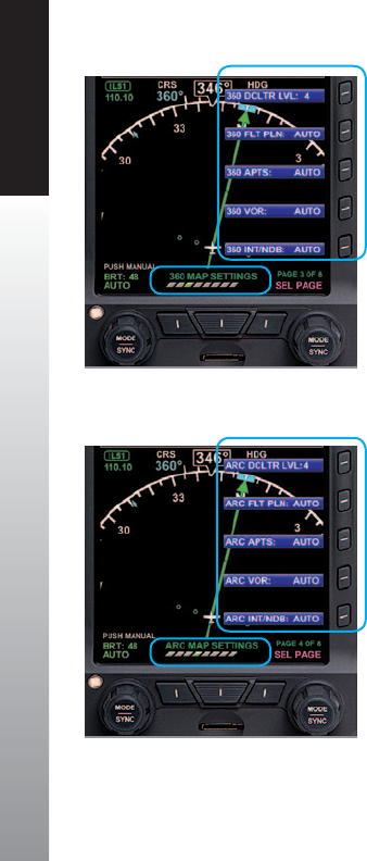
CHAPTER 5 CUSTOMIZING THE EFD1000 PFD
EFD1000 PFD Pilot’s Guide
Page 5-12 091-00005-001 REV E EFD1000 PFD Pilot’s Guide Page 5-13
091-00005-001 REV E
5.2. Customizing Basemap Symbol Declutter Settings
The pilot can customize the Basemap symbol declutter settings to Level 4, Level 3,
Level 2, Level 1, or Level 0 (OFF) by pressing the MENU Button and selecting the 360
MAP SETTINGS Menu page or the ARC MAP SETTINGS Menu page.
Each Compass Mode has its own Menu page for Map Setting basemap symbol
display.
• The 360 MAP SETTINGS Menu page oers Map Setting options for the 360°
Compass Mode (Figure 5-12).
• The ARC MAP SETTINGS Menu page oers Map Setting options for the ARC
Compass Mode (Figure 5-13).
As described in Table 5-9, the selected declutter level and range determine which
Basemap symbols are displayed. Basemap symbol identiers may also be shown next to
their symbol.
See Chapter 4, Section 4.4.1. for more details about Compass Mode options
Figure 5-13
ARC Compass Mode Display Options
Figure 5-12
360° Compass Mode Display Options
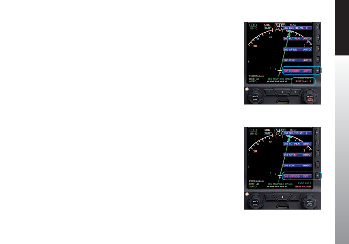
CHAPTER 5 CUSTOMIZING THE EFD1000 PFD
EFD1000 PFD Pilot’s Guide
Page 5-12 091-00005-001 REV E EFD1000 PFD Pilot’s Guide Page 5-13
091-00005-001 REV E
Set Map Symbol Display
1. Press the MENU Button.
2. Rotate the Right Knob to navigate to the appropriate Map Settings Menu
page.
3. Press the desired Map Symbol Menu Key.
The menu label turns magenta, and the EDIT VALUE label displays above the
Right Knob (Figure 5-14 and 5-15).
4. Rotate the Right Knob to the desired value.
5. Select another Map Symbol Menu Key and edit the display option or press
the MENU Button to exit.
Figure 5-14
Editing 360° NDB Display Option
Figure 5-15
360° NDB Display Option Set To OFF

CHAPTER 5 CUSTOMIZING THE EFD1000 PFD
EFD1000 PFD Pilot’s Guide
Page 5-14 091-00005-001 REV E EFD1000 PFD Pilot’s Guide Page 5-15
091-00005-001 REV E
Feature Group and Layer Order
(from Top to Bottom)
Max Range Declutter Setting
Figure 5-16 Level 4 Figure 5-17 Level 3 Figure 5-18 Level 2 Figure 5-19 Level 1 Figure 5-20 Level 0 (O)
Trac Overlay Symbols 1 Overlay – enabled
via Hot Key Always ON, regardless of declutter level
No symbols, legs,
or waypoints —
regardless
of selected
range — are
displayed.
When selected,
the basemap
declutter and
range display
for two seconds
and then are
removed from
view. The MAP
Hot Key legend
is shown in gray.
Ownship Symbol 2 Always ON, regardless of declutter level
Instruments 1 and Annunciations 23 Always ON, regardless of declutter level
Flight Plan Legs and Waypoints 34 200
Airports 35 100
NDBs 36 15
VORs, (HIGH, LOW, Terminal) 37 200
Intersections 8 15
WX-500 or Data Link Lightning 9 Overlay – enabled
via Hot Key Always ON 4
NEXRAD Weather 10 Overlay – enabled
via Hot Key Always ON
Table 5-12
Map Feature Group Layering, Range, and Declutter Levels 1. e.g., VSI, Direction Indicator, CDI, TO/FROM.
2. e.g., NAV INFO Block, Range.
3. Shown only when data is provided by a compatible and connected GPS
system.
4. Removed at ranges less than 20nm.

CHAPTER 5 CUSTOMIZING THE EFD1000 PFD
EFD1000 PFD Pilot’s Guide
Page 5-14 091-00005-001 REV E EFD1000 PFD Pilot’s Guide Page 5-15
091-00005-001 REV E
5.3. Conguring Vspeeds
Vspeeds are used to designate dierent operating speeds of the aircraft and are dened
in Table 5-13.
Vspeed DEFINITION PRE-SET
BANDS
ADJUSTABLE
TEXT LABELS
PRE-SET
MARKERS
Vne Never exceed
(Red Line)
Vno Maximum structural
cruising speed
Vfe Maximum full ap
extension speed
Vs No ap stall
Vso Stall speed in landing
conguration
Va Design maneuvering
speed
Vbg Best glide
Vr Rotation speed
Vref Landing reference speed
Vx Best angle of climb
Vy Best rate of climb
Vle Maximum landing gear
extended speed

CHAPTER 5 CUSTOMIZING THE EFD1000 PFD
EFD1000 PFD Pilot’s Guide
Page 5-16 091-00005-001 REV E EFD1000 PFD Pilot’s Guide Page 5-17
091-00005-001 REV E
Vspeed DEFINITION PRE-SET
BANDS
ADJUSTABLE
TEXT LABELS
PRE-SET
MARKERS
Vlo Maximum landing gear operating
speed
Vmc (Multi-engine) Single-engine
minimum control airspeed
(Red Line)
Vyse (Multi-engine) Best single-engine rate
of climb
(Blue Line)
Maximum initial ap extension speed
Table 5-13
Vspeed Denitions
NOTE
Setting the value of the white triangle, Vyse, and Vmc
markers to zero (0) during installation disables the
markers. Setting any of the adjustable Vspeed values to
zero (0) disables the associated label.

CHAPTER 5 CUSTOMIZING THE EFD1000 PFD
EFD1000 PFD Pilot’s Guide
Page 5-16 091-00005-001 REV E EFD1000 PFD Pilot’s Guide Page 5-17
091-00005-001 REV E
The PFD uses color speed bands, color speed markers, and textual labels to help the
pilot recall Vspeed settings and limits. The speed band markings are determined by the
Federal Regulations and correspond to the aircraft operating speeds that are identied
in the Aircraft Flight Manual. They have a range between two speeds that are pre-set at
installation as outlined in Table 5-14 and shown in Figure 5-21.
Speed markers are also pre-set during installation, indicating important aircraft-specic
speeds, where applicable. The textual Vspeed labels are made pilot adjustable or locked
during the PFD installation.
BAND COLOR SPEED RANGE
Red Band (High Speed) Vne (Top of tape) Never Exceed
Yellow Band Vno – Vne Caution Range
Green Band Vs – Vno Normal Operating Range
White Band Vs0 – Vfe Flap Operating Range
Red Band (Low Speed) Vs0 (Bottom of tape) Disabled on the ground and during takeo
Table 5-14
Speed Band Ranges
Figure 5-21
Speed Bands
NOTE
On aircraft without aps, the white band is disabled,
and the green band is shown full width, as there isn’t
an applicable Flap Extend (Vfe) or Full Flap Stall (Vs0)
speed. These two speeds are set to the same speed as
the No Flap Stall (Vs) speed. This gives the white band a
value of zero, eectively disabling it.
NOTE
The color speed bands and color speed markers on the PFD Airspeed Tape are congured
to match the certied mechanical airspeed indicator.
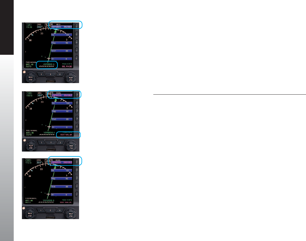
CHAPTER 5 CUSTOMIZING THE EFD1000 PFD
EFD1000 PFD Pilot’s Guide
Page 5-18 091-00005-001 REV E EFD1000 PFD Pilot’s Guide Page 5-19
091-00005-001 REV E
On aircraft with aps, setting the upper and lower thresholds of the white and/or yellow
bands to the same value disables the applicable band. When disabled, the band does
not display.
When using the Vspeed textual markers, the pilot must rst ENABLE the display of
the markers and then set values for each Vspeed. The value range for Vspeed textual
markers is 0 – 450 or LOCKED. The default setting is 0 unless previously set to another
value. When the value is 0, the Vspeed is individually disabled, and the marker is not
shown on the Airspeed Tape. Once the values are set, the pilot can choose to disable all
the Vspeed textual markers to declutter the Airspeed Tape.
Display or Hide the Vspeed Textual Markers on the Airspeed Tape
1. Press the MENU Button.
2. Rotate the Right Knob to the VSPEEDS A Menu page (Figure5-22).
3. Press the VSPEEDS Menu Key.
The Menu label turns magenta, and the EDIT VALUE label displays above the
Right Knob (Figure 5-23).
4. Rotate the Right Knob to select ENABLE or DISABLE (Figure 5-24).
ENABLE will display the Vspeeds on the Airspeed Tape and DISABLE will hide
the Vspeeds to declutter the Airspeed Tape
5. Press the MENU Button to exit.
Figure 5-24
VSPEEDS Disabled
Figure 5-23
Editing VSPEEDS
Figure 5-22
VSPEEDS A

CHAPTER 5 CUSTOMIZING THE EFD1000 PFD
EFD1000 PFD Pilot’s Guide
Page 5-18 091-00005-001 REV E EFD1000 PFD Pilot’s Guide Page 5-19
091-00005-001 REV E
Set Textual Vspeed Labels
1. Press the MENU Button.
2. Rotate the Right Knob to the appropriate Vspeed Menu page (Figure 5-25).
3. Press the appropriate Vspeed Menu Key.
The Menu label turns magenta, and the EDIT VALUE label displays above the
Right Knob (Figure 5-26).
4. Rotate the Right Knob to the desired value (Figure 5-27).
5. Select another Menu Key to edit another Vspeed or press the MENU Button to
exit.
Figure 5-25
VSPEEDS A
Figure 5-26
Editing Va Vspeed
Figure 5-27
Va Vspeed Set With New Value
NOTE
A typical installation sets the Airspeed Textual Markers to UNLOCKED, allowing the pilot to
edit the indicated Vspeed labels. If the Vspeed setting was LOCKED during installation, no
pilot adjustment is allowed.
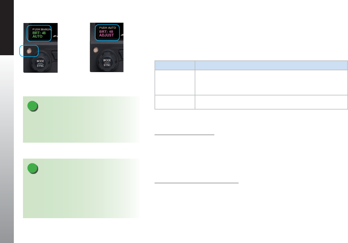
CHAPTER 5 CUSTOMIZING THE EFD1000 PFD
EFD1000 PFD Pilot’s Guide
Page 5-20 091-00005-001 REV E EFD1000 PFD Pilot’s Guide Page PB
091-00005-001 REV E
5.4. LCD Brightness Control
The LCD brightness of the PFD operates in either of two modes, Automatic or Manual
(Figures 5-28 and 5-29). The LCD brightness range is displayed as a value from 1–100,
displayed above the Left Knob.
LCD MODE DESCRIPTION
AUTOMATIC
BRT AUTO
LCD backlight intensity is automatically adjusted based on the ambient
lighting conditions sensed by the Automatic Dimming Photocell (Figure
5-28). When using the auto-brightness, the maximum brightness level is
70%.
MANUAL
BRT ADJUST
Allows the pilot to adjust the LCD backlight intensity. (Figure 5-29) from
1–100%.
Table 5-15
Brightness Control
Change Brightness Mode
1. Press the MENU Button.
2. Press the Left Knob to select the desired LCD Brightness Control mode, either
Automatic (BRT AUTO) (Figure 5-28), or Manual (BRT ADJUST) (Figure 5-29).
3. Press the MENU Button to exit.
Adjust Display Brightness Manually
1. Switch to manual LCD Brightness Control mode (BRT ADJUST) (Figure 5-29).
2. Rotate the Left Knob clockwise to increase the display brightness or
counterclockwise to decrease the display brightness. The BRT: value changes
accordingly.
3. Press the MENU Button to exit and retain the selected brightness level.
Figure 5-29
Display Brightness in BRT ADJUST Mode
Figure 5-28
Display Brightness in BRT AUTO Mode
NOTE
When the PFD is operating on the internal battery,
the maximum brightness level is capped at 40% in
automatic mode and 70% in manual mode to preserve
battery operating time.
NOTE
To facilitate cooling of the PFD display unit, when
the backlight temperature is greater than or equal to
70°C, the display brightness level is limited to 30% in
automatic mode and 70% in manual mode. The limits
are removed when the PFD display temperature drops
below 60°C.

EFD1000 PFD Pilot’s Guide
Page PB 091-00005-001 REV E EFD1000 PFD Pilot’s Guide Page 6-1
091-00005-001 REV E
CHAPTER 6 EXPANDED EMERGENCY AND ABNORMAL PROCEDURES
Chapter 6
Expanded Emergency and Abnormal
Procedures
This section supplements and provides an expanded description of the
emergency and abnormal procedures included in the FAA-approved
Aircraft Flight Manual Supplement. The information provided here is
intended to provide additional background information to enhance
the pilot’s understanding of the emergency and abnormal conditions
and the associated procedures provided in the AFMS. This pilot guide
is provided for supplementary purposes only. The approved cockpit
reference for in-ight use is the AFMS. Both the Pilot Guide and the
AFMS must be immediately available to the pilot at all times in ight. In
the event of any conict between this document and the FAA-approved
AFMS, the AFMS instructions must be followed.

EFD1000 PFD Pilot’s Guide
Page 6-2 091-00005-001 REV E EFD1000 PFD Pilot’s Guide Page 6-3
091-00005-001 REV E
CHAPTER 6 EXPANDED EMERGENCY AND ABNORMAL PROCEDURES
6.1. Pitot/Static System Blockage
A pitot line blockage will result in the airspeed indicator behaving like an altimeter
when the aircraft’s altitude changes, and it will not respond to airspeed changes. A pitot
line blockage can also aect the PFD’s attitude indication.
A static line blockage will result in altitude remaining xed and a zero vertical speed
despite aircraft pitch and/or power setting changes. In addition, IAS indications will
be incorrect if the static line is blocked. Errors will typically be noticed during climbs
or descents. When descending, ambient pressure increases which will result in the
indicated airspeed reading more than the actual airspeed. The opposite eect will be
observed in a climb. A static line blockage can also aect the PFD’s attitudeindication.
Indication of an obstructed pitot system is provided for PFD when the PFD’s indicated
airspeed is less than 30 KIAS (35 mph) and GPS ground speed is greater than 50
kts (58 mph), then attitude and heading instruments are replaced with red Xs and
textual annunciations to indicate their failure. In this case, an amber CHECK PITOT
HEAT annunciation accompanies the ATTITUDE FAIL annunciation. When the pitot
obstruction is subsequently removed and indicated airspeed ≥ 30 KIAS (35 mph), the
CHECK PITOT HEAT annunciation will be removed in 15 seconds. This indicates that
the PFD is performing an automatic AHRS reset in the background. No pilot action is
required to reset the system.

EFD1000 PFD Pilot’s Guide
Page 6-2 091-00005-001 REV E EFD1000 PFD Pilot’s Guide Page 6-3
091-00005-001 REV E
CHAPTER 6 EXPANDED EMERGENCY AND ABNORMAL PROCEDURES
Blocked Pitot or Static Line Suspected
1. Turn Pitot heat ON
2. Open the Alternate Static Source
3. Refer to alternate attitude, airspeed, altitude, and heading sources for primary
ight information
4. Consider exiting IMC
5. Land as soon as practicable
CAUTION
Most light aircraft have only a single pitot and static port available for ight instrument
use. As such, the pitot and static lines used by the PFD are shared with those lines used by
the standby airspeed indicator and altimeter. Should these lines become blocked, such
as might occur due to an inadvertent icing encounter, the PFD, the standby airspeed
indicators and the altimeters will display erroneous information.
Because the PFD uses pitot and static pressures as part of the ADAHRS solution, loss or
corruption of this data, such as from a line blockage, will aect the attitude and heading
information.
Whenever an erroneous pitot input is detected by the PFD inight, it will replace
the aected instruments with red Function Fail Xs and display a CHECK PITOT HEAT
annunciation. In this case, the pilot should check pitot heat, select the aircraft’s
alternate static source and refer to secondary sources of attitude, airspeed, and heading
information.

EFD1000 PFD Pilot’s Guide
Page 6-4 091-00005-001 REV E EFD1000 PFD Pilot’s Guide Page 6-5
091-00005-001 REV E
CHAPTER 6 EXPANDED EMERGENCY AND ABNORMAL PROCEDURES
6.1.1. Identifying and Handling Suspected Pitot and/or
Static System Failures
Blocked pitot and/or static system ports will compromise the PFD’s attitude solution
and soon cause it to Red-X (fail). Immediately begin ying by reference to backup
attitude sources. Therefore, the pilot must be especially vigilant about verifying proper
operation of the pitot and static systems both before and during ight.
It is important to check the pitot tube and static system ports, and to verify pitot heater
performance, as part of a thorough pre-ight inspection, especially when anticipating
ight in low IMC.
On takeo roll, it is good practice to note and call out “airspeeds alive” when the
airspeed indicators (both primary and backup) begin moving and to compare and call
out readings at a pre-determined airspeed close to, but before rotation speed (e.g.
“60 knots cross check”), consciously noting the performance on each takeo. If the
airspeed indicators do not come “alive” when they usually do or whenever there is a
signicant dierence between the primary and backup indicators and sucient runway
is remaining, aborting the takeo may be a prudent decision. Follow the Flight Manual
procedures for your aircraft.
When the static port is blocked on takeo, it is imperative to quickly recognize the
condition. Sometimes the airspeed indicator will show substantially less than normal
and the airspeed will reduce in the climb. The natural—but incorrect—response is to
lower the nose. In this situation, maintaining proper pitch attitude to climb is vital. The
airspeed will continue to reduce as you climb, and at about 1,000 feet AGL the PFD
attitude and heading indications will be Red-X due to the reduced airspeed indication.
As soon as you suspect a blocked static port, try switching to an alternate static source.
Know the location of the alternate static air control in your airplane and learn how it
works.

EFD1000 PFD Pilot’s Guide
Page 6-4 091-00005-001 REV E EFD1000 PFD Pilot’s Guide Page 6-5
091-00005-001 REV E
CHAPTER 6 EXPANDED EMERGENCY AND ABNORMAL PROCEDURES
On the initial climb-out after takeo, it is also good practice to note and call out passing
through a pre-determined altitude above ground level (AGL) a couple of minutes after
takeo and ideally before entering the clouds (e.g., “2,000 feet”). If your primary and
backup instruments are not showing the altitude and airspeed you normally expect to
see at that point, you might have partially blocked static system ports. This AGL check
and call-out is also a good time to verify that no fuel is siphoning out from the fuel caps,
etc. If indications suggest a static system blockage, try switching to an alternate static
air source and consider landing to correct the problem.
In ight, if airspeed or altitude anomalies consistent with an obstructed pitot or static
line are observed, the pilot should recognize that the PFD’s attitude indication will soon
be compromised. If in IMC, immediately use the backup attitude indicator to y the
airplane and turn pitot heat ON if icing is suspected. If at any time there is suspicion of
an obstructed pitot or static line, use the backup attitude indicator until the situation
isresolved.
If the pitot tube becomes blocked in ight, the most common cause is icing. In-ight
indications of a blocked pitot tube are typically:
1) All airspeed indicators incorrectly show zero (or close to zero);
or
2) Airspeed in level ight does not change in response to changes in power or
drag and airspeed indications act like an altimeter (decreasing in a descent
and increasing in a climb, exactly the opposite of normal behavior).

EFD1000 PFD Pilot’s Guide
Page 6-6 091-00005-001 REV E EFD1000 PFD Pilot’s Guide Page 6-7
091-00005-001 REV E
CHAPTER 6 EXPANDED EMERGENCY AND ABNORMAL PROCEDURES
Airspeed going to zero is by far the most common symptom of a blocked pitot tube.
If you see either of these indications of a blocked pitot tube, the rst thing to do is turn
on the pitot heat to remove any ice blockage. This will quickly restore the attitude and
airspeed indications on the PFD systems (it takes about 40 seconds to recover after the
pitot pressure is restored).
To maintain proper aircraft attitude during the event (and if the heated pitot does
not work), use the outside horizon if possible, or use the backup attitude indicator to
continue safe ight. The autopilot attitude source is also independent of the PFD’s
attitude indicator and may be another means to maintain level ight. Use the autopilot
carefully and constantly monitor its performance against other ight instruments.
If in ight you suspect blocked static ports (probably due to icing), try switching to the
alternate static air source. If the static air sources are blocked, recognize that the readout
from the transponder and reports from ATC will be in error because of the blocked
static system.
If GPS altitude is available on your GPS navigator, become familiar with how the GPS
altitude is displayed. Although it can be in error, it might be your only source of altitude
information (WAAS GPS altitude is reasonably accurate).
If an instrument approach is necessary, consider a precision approach that will permit
vertical guidance with less reliance on the barometric pressure altitude indications.

EFD1000 PFD Pilot’s Guide
Page 6-6 091-00005-001 REV E EFD1000 PFD Pilot’s Guide Page 6-7
091-00005-001 REV E
CHAPTER 6 EXPANDED EMERGENCY AND ABNORMAL PROCEDURES
6.2. Frequent or Persistent CROSS CHECK
ATTITUDE Annunciation
Refer to alternate attitude, airspeed, altitude, and heading sources for primary ight
information. Consider the following:
CROSS CHECK ATTITUDE
1. Reference standby mechanical attitude indicator.
2. Turn Pitot heat ON.
3. Consider exiting IMC.
4. Land as soon as practicable
For a detailed explanation of when and why the PFD may display a CROSS CHECK
ATTITUDE annunciation, either momentarily or persistently, see Chapter 4, Section 4.1.
Air Data, Attitude and Heading Reference System (ADAHRS).
6.3. Dierence Detected Between the PFD and
Mechanical Attitude Indicators
Once diagnosed, ensure the correct attitude source is the only one referenced during
the remainder of the ight.
Compare Alternate Sources of Available Attitude, Airspeed, and Attitude
1. Compare all available sources of attitude, airspeed, and attitude information
to diagnose a faulty indicator.
2. Consider exiting IMC.
3. Land as soon as practicable .
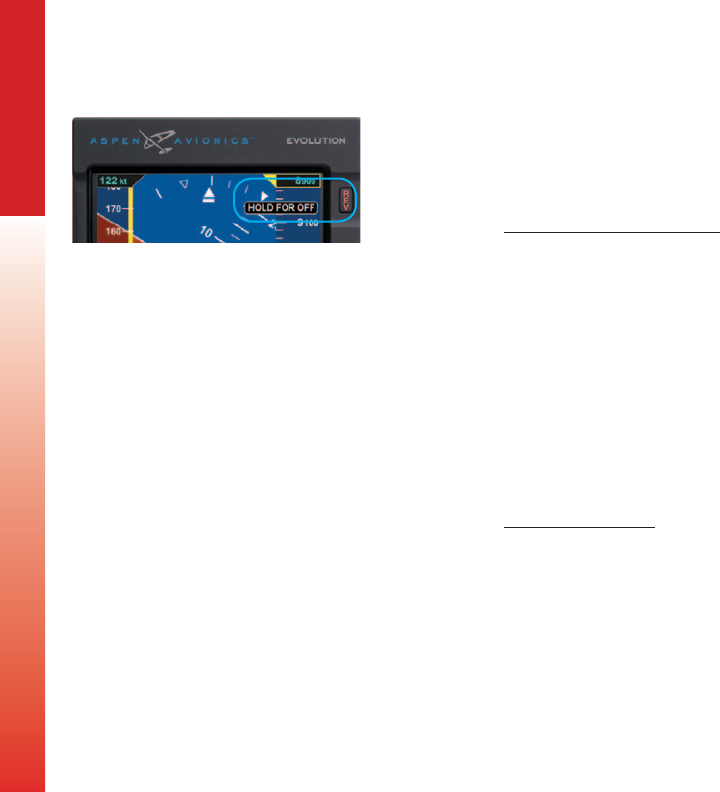
EFD1000 PFD Pilot’s Guide
Page 6-8 091-00005-001 REV E EFD1000 PFD Pilot’s Guide Page 6-9
091-00005-001 REV E
CHAPTER 6 EXPANDED EMERGENCY AND ABNORMAL PROCEDURES
6.4. Abnormal Shutdown Procedure
The PFD is typically powered through an PFD master switch that is connected to the
aircraft’s Battery bus. Normally, the PFD will power down when the PFD Master switch
is turned OFF or when aircraft power is removed when on the ground. To force the PFD
to power down, the following procedures are provided.
Shutdown PFD (on ground)
1. PFD Master switch OFF
2. Press and hold the REV Button until the display turns o (Figure 6-1)
Or
1. Press the MENU Button.
2. Rotate the Right Knob to the POWER SETTINGS Menu page
3. Press the SHUT DOWN Menu Key. The power down sequence initiates, and a
power down message displays
A powering o annunciation displays indicating that the unit will shut down in 5
seconds. The pilot can press any control to abort the power-down sequence.
Power On Manually
• Press and hold the REV Button until the PFD powers on.
Figure 6-1
Powering O the
PFD
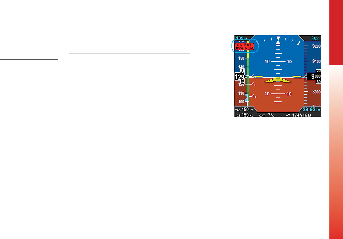
EFD1000 PFD Pilot’s Guide
Page 6-8 091-00005-001 REV E EFD1000 PFD Pilot’s Guide Page 6-9
091-00005-001 REV E
CHAPTER 6 EXPANDED EMERGENCY AND ABNORMAL PROCEDURES
6.5. Loss of Aircraft Electrical Power
In the event that aircraft generated power is degraded or fails, the PFD will
automatically switch to its own dedicated battery (Figure 6-2). When continued safe
operation depends on the PFD, UNRESTORABLE LOSS OF EXTERNAL POWER IS AN
EMERGENCY SITUATION. The aircraft should divert to the nearest suitable airport.
Loss of or Degraded Aircraft Power or ON BAT Annunciation
1. Electrical System .....................................................Follow AFM procedures to restore
power
2. If unable to restore power ................................Land as soon as possible
The internal battery will normally provide between 30-60 minutes of operation at
approximately 20°C and warmer. At extreme cold temperatures, operation of the
internal battery is not assured.
When on battery the auto backlight intensity level defaults to 40% and manual
backlight intensity is limited to 70%. Changing the backlight intensity will aect the
battery duration, which is reected in the % remaining indication.
A fully charged battery will indicate a charge level of 99% for some time before
beginning to discharge. The charge level will steadily decrease when below 95%, with a
slight acceleration as the battery nears 0%.
The “ON BAT” annunciation, along with the estimated battery charge remaining, is
displayed whenever the system is operating on battery.
Figure 6-2
Battery Charge Remaining
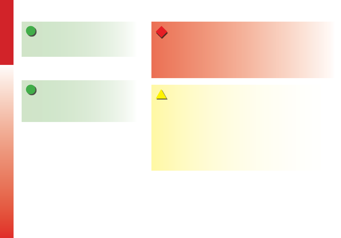
EFD1000 PFD Pilot’s Guide
Page 6-10 091-00005-001 REV E EFD1000 PFD Pilot’s Guide Page 6-11
091-00005-001 REV E
CHAPTER 6 EXPANDED EMERGENCY AND ABNORMAL PROCEDURES
NOTE
When operating on the internal battery, the display
backlight intensity is limited to a value of 70.
NOTE
Setting the brightness to a value of greater than 40%
will reduce the battery operation time to less than 30
minutes.
CAUTION
During situations where a high electrical demand is placed on the aircraft electrical
system, electrical transients that cause aircraft voltage to drop below 9.0V momentarily
or 12.3V for 2 minutes (14V electrical system) or 18.0V momentarily or 24.6V for 2 minutes
(28V electrical system) will cause the PFD display to automatically switch to its internal
battery.
This will be accompanied by an ON BAT annunciation.
The ON BAT annunciation should extinguish shortly after the electric transient demand
goes away. If the ON BAT annunciation does not extinguish, then an aircraft power source
failure has most likely occurred.
WARNING
When fully charged, the internal battery will power the PFD to provide ADAHRS and
emergency RSM GPS position (if enabled) for approximately 30 minutes. When continued
safe operation depends on the PFD’s primary ight data, UNRESTORABLE LOSS OF
EXTERNAL POWER IS AN EMERGENCY SITUATION. The pilot should follow the
electrical failure checklist in the Aircraft Flight Manual land as soon as possible.

EFD1000 PFD Pilot’s Guide
Page 6-10 091-00005-001 REV E EFD1000 PFD Pilot’s Guide Page 6-11
091-00005-001 REV E
CHAPTER 6 EXPANDED EMERGENCY AND ABNORMAL PROCEDURES
6.5.1. Overvoltage Protection
In the event of an overvoltage condition in the aircraft’s electrical system, (greater
than 33 volts) the PFD will automatically switch to its battery power and continue to
operate without any pilot action. Operation from the aircraft electrical system will not
be possible while the overvoltage condition is present. When aircraft power decreases
below 33 volts, pilot action is required to manually switch from the PFD battery power.
Restore Aircraft Power to the PFD
1. Press the MENU Button and rotate the Right Knob to the POWER Settings
page
2. Press the EXT PWR Menu Key
3. Press the MENU Button to exit
6.6. GPS Failures and RSM Emergency GPS Use1
Position and ight plan data for the PFD is provided from aircraft panel-mounted GPS
equipment. The PFD may be congured to receive data from one or two external GPS
receivers. In addition, if all aircraft GPS receivers fail, the RSM’s emergency GPS receiver
will provide position data if enabled by the installer.
The Basemap will follow an automatic position reversion scheme to determine which
GPS is used to provide position data to the map. The primary GPS is always the one
selected by the pilot using CDI Navigation Source Select Button. If the selected GPS
fails, the PFD automatically switches to the other aircraft’s GPS (if installed) and will
annunciate GPS# REVERSION, where # represents the GPS source providing the position
data (Figure 6-22).
1. Not available with the Pilot PFD
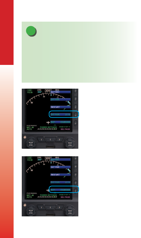
EFD1000 PFD Pilot’s Guide
Page 6-12 091-00005-001 REV E EFD1000 PFD Pilot’s Guide Page 6-13
091-00005-001 REV E
CHAPTER 6 EXPANDED EMERGENCY AND ABNORMAL PROCEDURES
If all aircraft panel-mounted GPS receivers experience a failure, the RSM Emergency
GPS receiver will provide position data that is shared among all EFDs. In addition, a text
alert is presented at the bottom center of the Navigation Display annunciating RSM
GPS REVERSION EMER USE ONLY (Figure 6-23). This “sharing” feature permits any EFD
(as congured by the installer), to receive and display the RSM GPS position data, thus
assuring continuous navigational awareness to the pilot. In this case, the Basemap data
is approved for emergency use only
Whenever the map has reverted to an alternate position source, all map features and
capabilities are retained, including the display of the ight plan from the selected panel-
mount GPS. However, when the selected GPS is no longer providing position data, the
ight plan is displayed without an active (magenta) leg. The ight plan and Basemap
data from each of the aircraft’s GPS receivers is retained independently. If two external
GPSs were connected prior to failure of both, and if each had a dierent ight plan at
the time of failure, both retained ight plans remain available to the pilot and may be
selected using the PFD’s Navigation Source Select Button.
In the unlikely event that there is a complete loss of all GPS data to the EFD, including
failure of the RSM GPS receiver, all mapping information would be removed from the
EFD display.
NOTE
When airborne, if the PFD’s input voltage is below the
12.8V (14V Electrical System) or 25.6V (28V Electrical
System) automatic battery transition threshold, and
EXT PWR is selected through the POWER SETTINGS
Menu, the PFD will automatically remain connected to
its internal battery.
Figure 6-3
External Power Voltage Status
Figure 6-4
Battery Status

EFD1000 PFD Pilot’s Guide
Page 6-12 091-00005-001 REV E EFD1000 PFD Pilot’s Guide Page 6-13
091-00005-001 REV E
CHAPTER 6 EXPANDED EMERGENCY AND ABNORMAL PROCEDURES
6.7. Power Override
In the event that the pilot wishes to override the PFD’s automatic power conguration,
proceed as follows:
Power Override
1. MENU .............................................................................“POWER SETTINGS” Page
To switch FROM aircraft power to Internal Battery:
2. “BATTERY” LINE SELECT KEY ..............................PRESS
To switch FROM internal Battery TO aircraft power:
3. “EXT PWR” LINE SELECT KEY .............................PRESS
View External Voltage Status
1. Press the MENU Button.
2. Rotate the Right Knob to the POWER SETTINGS Menu displays.
3. The EXT PWR Menu Key (Figure 6-3) displays the external power voltage.
4. Press the MENU Button to exit.
View Internal Battery Status
1. Press the MENU Button.
2. Rotate the Right Knob to the POWER SETTINGS Menu displays.
3. The BAT Menu Key (Figure 6-4) displays the current Battery Status as either
Charging or a Percentage of Charge.
4. Press the MENU Button to exit.
NOTE
When airborne, if the PFD’s input voltage is below the
12.8V (14V Electrical System) or 25.6V (28V Electrical
System) automatic battery transition threshold, and
EXT PWR is selected through the POWER SETTINGS
Menu, the PFD will automatically remain connected to
its internal battery.
Figure 6-3
External Power Voltage Status
Figure 6-4
Battery Status
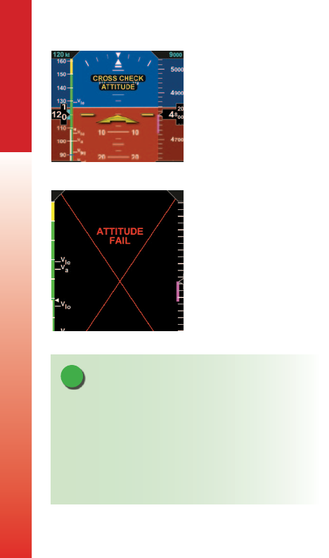
EFD1000 PFD Pilot’s Guide
Page 6-14 091-00005-001 REV E EFD1000 PFD Pilot’s Guide Page 6-15
091-00005-001 REV E
CHAPTER 6 EXPANDED EMERGENCY AND ABNORMAL PROCEDURES
6.8. In-Flight AHRS Reset
In the unlikely event the PFD determines a potential degradation of attitude
information, a warning annunciation, CROSS CHECK ATTITUDE, is shown (Figure 6-5).
If the attitude pitch or roll data become invalid, a red X and the textual annunciation
of ATTITUDE FAIL replaces the Attitude Indicator, and all aircraft roll, pitch, and
slip information is removed from the Attitude Display (Figure 6-6). Use alternate,
mechanical ight instruments for primary ight information and reset the PFD’s AHRS as
soon as possible.
During the In-Flight AHRS Reset, the aircraft should not be subjected to excessive turn
rates. Typical in-ight Resets will take approximately 30 seconds, but can take longer if
the reset is initiated while banked or maneuvering.
NOTE
When the PFD’s AHRS is reset in ight, it performs an
abbreviated initialization.
The AHRS Reset is considered complete when the PFD’s
attitude and heading is once again displayed, stable,
and correct with respect to the horizon or standby
attitude indicator.
Figure 6-5
Attitude Degraded Performance
Figure 6-6
Attitude Failure
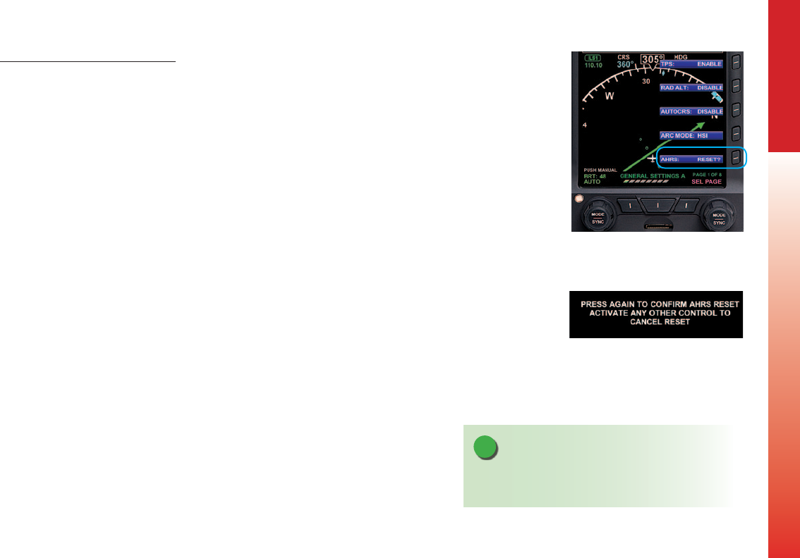
EFD1000 PFD Pilot’s Guide
Page 6-14 091-00005-001 REV E EFD1000 PFD Pilot’s Guide Page 6-15
091-00005-001 REV E
CHAPTER 6 EXPANDED EMERGENCY AND ABNORMAL PROCEDURES
Perform an In-Flight AHRS Reset
1. Maintain straight and level ight.
2. Consider exiting IMC.
3. Fly by visual reference or by standby instruments.
4. Disconnect the autopilot.
5. Press the MENU Button.
6 Rotate the Right Knob to display the GENERAL SETTINGS A Menu page.
7. Press the AHRS RESET? Menu Key (Figure6-7).
A conrmation message displays, prompting the user to conrm the reset
request (Figure 6-8).
8. Press the AHRS Menu Key again to conrm the AHRS reset. The AHRS reset is
performed, and the conrmation messages clears.
9. Press the MENU Button to exit. Figure 6-7
AHRS Reset Menu Key
Figure 6-8
AHRS Reset Conrmation Message
NOTE
Pressing any other key, button, or knob cancels the
AHRS reset and clears the conrmation message.

EFD1000 PFD Pilot’s Guide
Page 6-16 091-00005-001 REV E EFD1000 PFD Pilot’s Guide Page 6-17
091-00005-001 REV E
CHAPTER 6 EXPANDED EMERGENCY AND ABNORMAL PROCEDURES
6.9. GPSS Operation, Annunciations, and Autopilot
Modes1
The Pro PFD oers GPSS. Three modes, Enabled, Wings Level, and Disabled, are possible
and annunciated in the PFD’s Navigation Display. When enabled, the congured GPS
source not only provides the Basemap and ight plan data, but also passes GPSS as
the heading input to a congured autopilot. When engaged, a congured autopilot
will interpret GPSS commands as heading inputs and follow the active GPS ight plan,
including anticipated turns, if provided. The GPSS Enabled mode is indicated by a green
GPSS Hot Key label and a GPSS1 with an inverse A placed next to the Selected Heading
Field to describe the source (Figure 6-9) .
If GPSS is enabled and the GPS source is lost or changed, the GPSS mode automatically
changes to the Wings Level mode and annunciates as shown in Figure 6-10.
NOTE
When using GPSS with combined GPS / VLOC navigators (e.g. GNS 430/530), VLOC may
be selected as the navigation source while GPSS is engaged. To avoid confusion, note
the PFD Selected CDI Navigation Source controls the CDI and the autopilot’s navigation
and approach modes when engaged. GPSS reects the heading commands required
to navigate the active ight plan leg and controls the autopilot’s heading mode when
engaged. Complete understanding of autopilot mode functions and their proper selection
is recommended.
Figure 6-9
Operating in GPSS Mode
Figure 6-10
GPSS in Wings Level Mode 1. Not available with the Pilot PFD
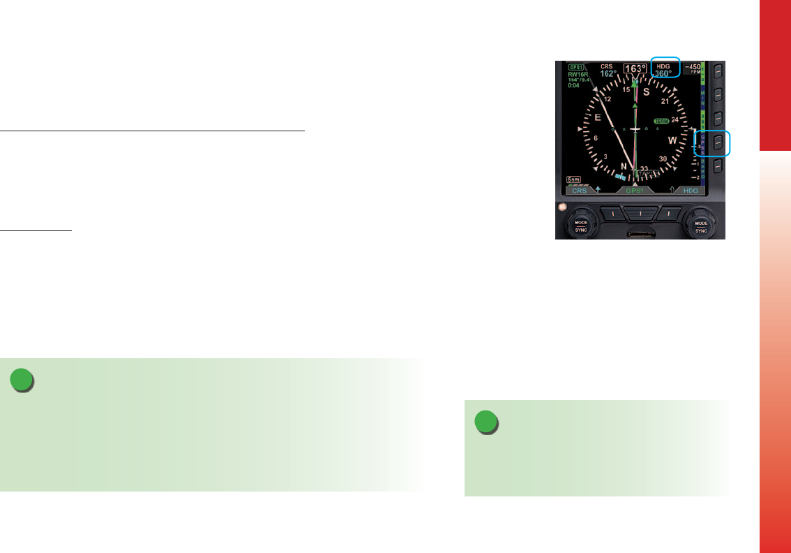
EFD1000 PFD Pilot’s Guide
Page 6-16 091-00005-001 REV E EFD1000 PFD Pilot’s Guide Page 6-17
091-00005-001 REV E
CHAPTER 6 EXPANDED EMERGENCY AND ABNORMAL PROCEDURES
The Wings Level mode removes roll steering inputs to the autopilot, causing the
aircraft to roll wings level, and displays a red slash through the annunciated A HDG and
GPSS# source. The amber GPSS Hot Key label requires pilot action. If this occurs, do the
following:
When GPSS Automatically Changes to Wings Level Mode
1. Check the congured GPS source.
2. Check the PFD Selected CDI Navigation Source.
3. If the selected GPSS source is restored or changed and GPSS is still desired,
press the GPSS Hot Key to activate GPSS (The GPSS Hot Key label turns inverse
green).
Disable GPSS
1. Adjust the PFD HDG bug as desired.
2. Check or set the Autopilot Control Panel modes as desired.
3. Press the GPSS Hot Key until the Hot Key label turns gray (Figure 6-11).
NOTE
The congured GPS source must provide an active ight plan (or Direct-To waypoint) for
GPSS to remain engaged or to be restored.
When the PFD navigation source is changed to another congured GPS or VLOC source
for longer than 2 seconds, the GPSS Enabled mode will change to Wings Level. The pilot
must then press the GPSS Hot Key to restore or disable GPSS, as desired.
Figure 6-11
GPSS Disabled
NOTE
When the GPSS is enabled and the autopilot is
engaged in the Heading (HDG) mode, disabling the
GPSS will cause the autopilot to follow the HDG Bug.
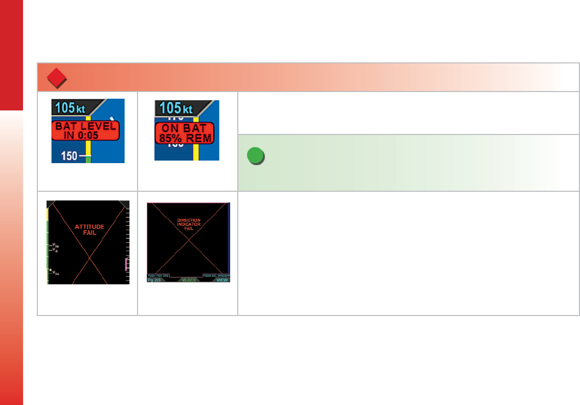
EFD1000 PFD Pilot’s Guide
Page 6-18 091-00005-001 REV E EFD1000 PFD Pilot’s Guide Page 6-19
091-00005-001 REV E
CHAPTER 6 EXPANDED EMERGENCY AND ABNORMAL PROCEDURES
6.10. Warning, Caution, and Advisory Summary
WARNINGS
Presented when the PFD is operating on the internal battery. The countdown timer begins at 15
seconds and is then replaced by the ON BAT annunciation with the battery’s % charge remaining.
NOTE
If the battery temperature is less than 0° C, the countdown timer will begin at 10 minutes.
Figure 6-14
Attitude Fail
Figure 6-15
Direction Indicator Fail
Presented when the PFD has determined that the associated function is invalid or failed and should
not be used. The data is removed from the display and replaced by a red X over the aected display
feature.
Figure 6-12
Battery Countdown
Figure 6-13
Battery Charge Remaining

EFD1000 PFD Pilot’s Guide
Page 6-18 091-00005-001 REV E EFD1000 PFD Pilot’s Guide Page 6-19
091-00005-001 REV E
CHAPTER 6 EXPANDED EMERGENCY AND ABNORMAL PROCEDURES
WARNINGS
Figure 6-16
Chevrons indicate Pitch Down
Figure 6-17
Chevrons indicate Pitch Up
When the Attitude Indicator display extreme pitch up or extreme pitch down attitudes, the red
chevrons indicate the direction to restore level ight.
Table 6-1
Warning Annunciations

EFD1000 PFD Pilot’s Guide
Page 6-20 091-00005-001 REV E EFD1000 PFD Pilot’s Guide Page 6-21
091-00005-001 REV E
CHAPTER 6 EXPANDED EMERGENCY AND ABNORMAL PROCEDURES
CAUTION
Figure 6-18
Cross Check Attitude
Presented when the PFD AHRS internal integrity monitor determines that attitude is potentially
degraded. When a CROSS CHECK ATTITUDE annunciation is presented, the pilot should cross check
attitude, airspeed, and altitude indications with other sources of primary ight information.
Figure 6-19
Check Pitot Heat
The CHECK PITOT HEAT annunciation accompanies the ATTITUDE FAIL annunciation and is
presented when the software detects an obstruction in the pitot system that could potentially
degrade the attitude solution. This annunciation is removed when the detected condition is
resolved, which would be followed by an automatic AHRS reset. A GPS is required for this monitor
to be enabled.

EFD1000 PFD Pilot’s Guide
Page 6-20 091-00005-001 REV E EFD1000 PFD Pilot’s Guide Page 6-21
091-00005-001 REV E
CHAPTER 6 EXPANDED EMERGENCY AND ABNORMAL PROCEDURES
CAUTION
Figure 6-20
GPS Invalid
Figure 6-21
RSM GPS
Presented when a congured GPS source’s data is invalid or unavailable. GPS# or RSM REVERSION
annunciations indicate the current GPS Basemap source1
Figure 6-22
GPS Reversion Figure 6-23
GPS Reversion Emergency
Figure 6-24
GPS Integrity Flag
Presented when the PFD’s Selected CDI Navigation Source is a GPS and that GPS is sending an
Integrity alert. See the GPS AFMS for more information1
Figure 6-25
Altitude Caution
Presented to indicate the aircraft is reaching (steady) or deviating (ashing) from the preset altitude.
May be accompanied by a one-second steady tone from an optional tone generator1.
Figure 6-26
Decision Height Caution
Presented when a connected radio altimeter indicates it has reached the altitude set by the pilot.
See the Radio Altimeter AFMS for more information1

EFD1000 PFD Pilot’s Guide
Page 6-22 091-00005-001 REV E EFD1000 PFD Pilot’s Guide Page 6-23
091-00005-001 REV E
CHAPTER 6 EXPANDED EMERGENCY AND ABNORMAL PROCEDURES
CAUTION
Figure 6-27
GPSS Source Lost/Changed
Presented when the previously enabled and valid GPSS source is lost or has changed. Indicates the
GPSS Wings Level mode1.
Data Link Weather product data not received for 30 seconds after an error is detected1.
The Minimums Markers are presented on the altitude tape and the Selected Minimums Field is
presented on the Attitude Display when the MIN Hot Key is selected. The markers include three
components – a green triangle at 500 ft. above minimums, a hollow yellow triangle at 100 ft. to 200
ft. above minimums, and a red and yellow striped triangle at the selected minimums1.
The MIN legend in the Selected Minimums Field turns inverse amber to alert the pilot whenever
the aircraft is at or below the selected minimums setting. When congured, an optional Sonaltert
generates a one-second stuttered tone1.
1. Not available with the Pilot PFD
Figure 6-28
Data Link Weather Data Error
Figure 6-29
Minimums Caution
Table 6-2
Caution Annunciations

EFD1000 PFD Pilot’s Guide
Page 6-22 091-00005-001 REV E EFD1000 PFD Pilot’s Guide Page 6-23
091-00005-001 REV E
CHAPTER 6 EXPANDED EMERGENCY AND ABNORMAL PROCEDURES
ADVISORY
Figure 6-30
REV Button O
Presented when the REV Button is pressed.
Figure 6-31
GPSS On
Presented when GPSS is enabled and the GPS source is valid. Either GPSS1 or GPSS2 may be
annunciated, depending on selection and the number of congured GPS navigators. This also
indicates the autopilot heading source1.
NOTE
GPSS will always reect the GPS Basemap source in the Navigation Display and follow its source.

EFD1000 PFD Pilot’s Guide
Page 6-24 091-00005-001 REV E EFD1000 PFD Pilot’s Guide Page 6-25
091-00005-001 REV E
CHAPTER 6 EXPANDED EMERGENCY AND ABNORMAL PROCEDURES
ADVISORY
Figure 6-32
GPS Annunciations
Associated with the GPS and the Selected CDI Navigation Source. See the GPS AFMS for
moreinformation1.
NOTE
These annunciations do not display for RS232-based GPS.
Figure 6-33
Trac Enabled
Indicates the trac sensor is enabled1.
Figure 6-34
WX-500 Strike Rate
WX-500 Strike display mode selected. The rate indicates the approximate number of lightning
strikes detected per minute
1.
Figure 6-35
WX-500 Cell Rate
WX-500 Cell clustering display mode selected. The rate indicates the approximate number of
lightning strikes detected per minute1.
Figure 6-36
WX-500 Self-Test
Self-test mode annunciation that replaces WX-500 Strike/Cell rate information1.

EFD1000 PFD Pilot’s Guide
Page 6-24 091-00005-001 REV E EFD1000 PFD Pilot’s Guide Page 6-25
091-00005-001 REV E
CHAPTER 6 EXPANDED EMERGENCY AND ABNORMAL PROCEDURES
ADVISORY
Figure 6-37
Data Invalid or Unavailable
A horizontal red line through any legend indicates that the data is invalid or unavailable1.
Figure 6-38
Navigation Source Invalid or Unavailable
A horizontal red line through the Selected CDI Navigation Source indicates that the data from the
source is invalid or unavailable1.
Figure 6-39
GPSS Disabled
GPSS Hot Key label with a blue background and gray letters indicate that the GPSS is disabled1.
Table 6-3
Advisory Annunciations
1. Not available with the Pilot PFD

EFD1000 PFD Pilot’s Guide
Page 6-26 091-00005-001 REV E EFD1000 PFD Pilot’s Guide Page PB
091-00005-001 REV E
CHAPTER 6 EXPANDED EMERGENCY AND ABNORMAL PROCEDURES
Page Intentionally Left Blank

CHAPTER 7 APPENDICES
EFD1000 PFD Pilot’s Guide
Page PB 091-00005-001 REV E EFD1000 PFD Pilot’s Guide Page 7-1
091-00005-001 REV E
Chapter 7
Appendices
7.1. Operating Limitations
Refer to the latest version of the Airplane Flight Manual Supplement (AFMS), Aspen
Avionics document 900-00008-001 for the limitations that apply to your specic aircraft
installation.
The AFMS and this Pilot’s Guide must be carried in the aircraft and be immediately
available to the pilot while in ight.
For installations that include the optional EFD1000 MFD and/or the EFD500 MFD, the
EFD1000/500 MFD Pilot’s Guide 091-00006-001, must be carried in the aircraft and be
immediately available to the pilot while in ight.
7.2. Software Versions and Serial Number
The system software versions for the Main Application Processor (MAP), the Input-
Output Processor (IOP), and the unit Serial Number (S/N) are recorded in the SYSTEM
STATUS page of the Menu.
The ACU software version and serial number are recorded on a label axed to the ACU
unit.
NOTE
To view the software version, press the MENU Button
and rotate the Right Knob to the Systems Status
page. The “MAP VER:” (Main Application Processor
Version) displays the software version your unit is
operating (see Figure 7-1).
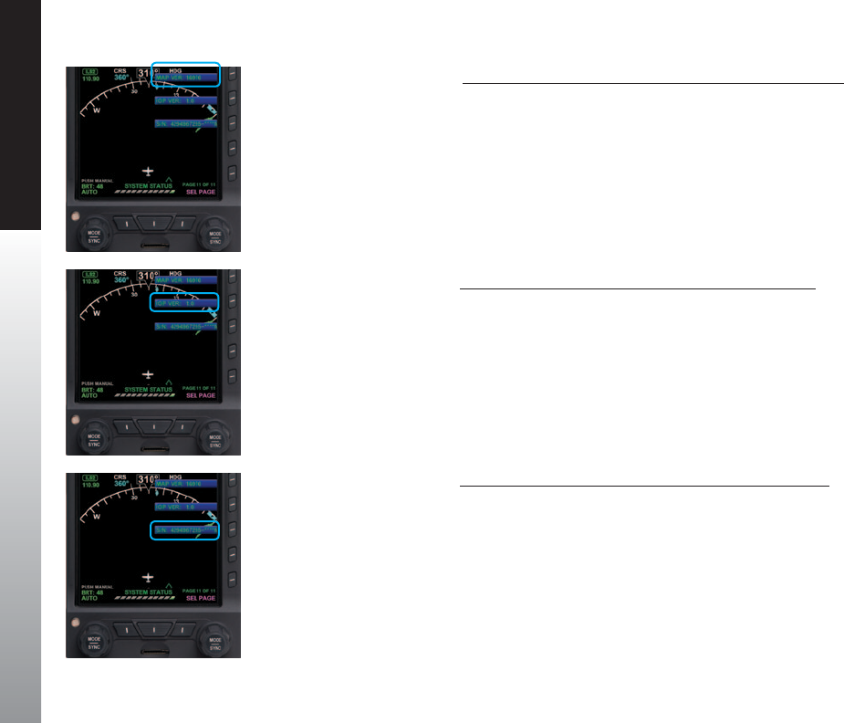
CHAPTER 7 APPENDICES
EFD1000 PFD Pilot’s Guide
Page 7-2 091-00005-001 REV E EFD1000 PFD Pilot’s Guide Page 7-3
091-00005-001 REV E
View the Input/Output Processor Software Version
1. Press the MENU Button.
2. Rotate the Right Knob to the SYSTEM STATUS Menu page.
3. The IOP VER Menu Key displays the current Input/Output Processor Software
Version (Figure 7-2).
4. Press the MENU Button to exit.
.View the Main Application Processor Software Version
1. Press the MENU Button.
2. Rotate the Right Knob to the SYSTEM STATUS Menu page.
3. The MAP VER Menu Key displays the current Main Application Processor
Software Version (Figure 7-1).
4. Press the MENU Button to exit.
Figure 7-3
View Unit Serial Number
Figure 7-2
View Input/Output Processor
Software Version
Figure 7-1
View Main Application Processor
Software Version
View the Primary Flight Display Unit’s Serial Number
1. Press the MENU Button.
2. Rotate the Right Knob to the SYSTEM STATUS Menu page.
3. The S/N Menu Key displays the unit’s serial number (Figure 7-3).
4. Press the MENU Button to exit.

CHAPTER 7 APPENDICES
EFD1000 PFD Pilot’s Guide
Page 7-2 091-00005-001 REV E EFD1000 PFD Pilot’s Guide Page 7-3
091-00005-001 REV E
7.3. Evolution Databases
The Evolution Flight Display System (EFD1000 PFD with EFD1000/500 MFD includes two
separate databases loaded on a microSD card; one from Jeppesen and one from Seattle
Avionics Software.
Separate data subscriptions are required from both Jeppesen and Seattle Avionics
Software to maintain the currency of the data for the EFD1000/500 MFD.
For aircraft congured with a PFD only:
• A microSD card (loaded with only the Jeppesen database) is provided with the
purchase of Evolution Synthetic Vision option. The Seattle Avionics database is not
required.
For aircraft congured with multiple EFDs; PFD and MFD(s):
• The MFD requires both Jeppesen and Seattle Avionics Software databases for
moving map, terrain, charts, and synthetic vision functions to operate correctly.
• Whenever the Evolution Synthetic Vision option is installed, the microSD card is
compatible with either the PFD or the MFD and may be interchanged.
The Evolution system uses a single database conguration in both the PFD and the
MFD products. A microSD card (loaded with both Jeppesen and Seattle Avionics
databases) is provided with each Evolution EFD1000/500 MFD.
7.3.1. Jeppesen Database
The Jeppesen database features the following data types:
• NavData® Airports, runways and runway information, frequencies, navaids,
controlled and restricted airspace.
• Obstacle Data Depiction of the location and height of man-made obstacles
that extend above the ground.
NOTE
For aircraft congured with multiple EFDs and the
Evolution Synthetic Vision option is installed, the
microSD card data conguration is the same for either
the PFD or the MFD and is interchangeable between
the displays.
The PFD can only read the Jeppesen database
whenever the ESV option is installed.
NOTE
The PFD only requires a preloaded microSD card to
support the Evolution Synthetic Vision (ESV) option
when installed. Otherwise, the PFD does not require a
microSD card.
NOTE
When congured with the ESV option, refer to the
Evolution Synthetic Vision Pilot’s Guide Supplement,
091-00031-001.

CHAPTER 7 APPENDICES
EFD1000 PFD Pilot’s Guide
Page 7-4 091-00005-001 REV E EFD1000 PFD Pilot’s Guide Page 7-5
091-00005-001 REV E
• Cultural Data Contains boundary and reference information for countries,
other major political subdivisions, large water bodies, coastlines, time zones,
and other physical and political features.
• Terrain Data Depicts the contours and shapes of the surface of the earth.
7.3.1.1. Jeppesen Subscription
Jeppesen provides new Aspen customers a complimentary trial subscriptions for three
consecutive months (three 28-day cycles) of Jeppesen NavData® updates at no charge.
A Jeppesen database is pre-loaded onto the microSD card that is shipped with the
Evolution Flight Display unit.
Thereafter, the data must be updated via an active Jeppesen data subscription.
NavData®, obstacle, cultural, and terrain data are combined into a single update which
is delivered via Jeppesen Services Update Manager (JSUM) every 28 days.
To activate your complimentary Jeppesen data subscription
1. Go to www.aspenavionics.com/customerport
2. Click the Register button on the login screen and ll out the easy-to-follow
registration form
The registration form consists of the following headings:
• Owner & aircraft Information
• Aspen Product Information
• Register for Jeppesen data
• Set Up Your Customer Port Login
Aspen Avionics will automatically forward your Evolution Flight Display product
registration information to Jeppesen for activation of the complimentary service.
NOTE
Aspen recommends that Aspen customers maintain
current data on their Evolution Displays.

CHAPTER 7 APPENDICES
EFD1000 PFD Pilot’s Guide
Page 7-4 091-00005-001 REV E EFD1000 PFD Pilot’s Guide Page 7-5
091-00005-001 REV E
You will receive a conrmation email directly from Jeppesen indicating service activation
as well as instructions on how to use the Jeppesen Services Update Manager (JSUM).
Although we make every eort to turn the registrations around very quickly, the entire
process may take up to 3-4 days
If you already have a login and password and need to register an additional
Evolution Flight Display unit
1. Login to the Customer Port at www.aspenavionics.com/customerport.
2. Click on Register Your Product link on the sidebar to register additional Aspen
Products.
7.3.1.2. Monthly Jeppesen Updates
The Jeppesen database updates are located in the Jeppesen Services Update Manager
(JSUM). JSUM must be downloaded onto your computer to obtain updates. A
compatible computer with the ability to write to a microSD card is required.
To download the Jeppesen Services Update Manager (JSUM)
1. Go to www.jeppesen.com.
2. Under Downloads / Quick Links, click on the Jeppesen Services Update
Manager (JSUM) button.
3. From the Technical support- Jeppesen Services Update Manager (JSUM) page,
under the User Guide button, click on the highlighted Download JSUM v #.#. #
to download JSUM onto your computer.
For additional information, click on the Troubleshooting or FAQs button, or contact
Jeppesen Customer Service (800-621-5377).
Overview on downloading the monthly Jeppesen Update
1. Insert the card in your computer’s card slot.
2. Start the JSUM application and login to your account using the credentials
provided to you by Jeppesen.

CHAPTER 7 APPENDICES
EFD1000 PFD Pilot’s Guide
Page 7-6 091-00005-001 REV E EFD1000 PFD Pilot’s Guide Page 7-7
091-00005-001 REV E
3. Click on the service you want to download to the microSD card.
4. Click on the Start button in JSUM to initiate the download.
For complete detailed instructions, refer to jeppesen.com. Once the download is
completed with the latest Jeppesen data, download the latest Seattle Avionics data.
7.3.2. Seattle Avionics Software Database
Seattle Avionics Software Database applies to the MFD only
The Seattle Avionics Software database features the following data types:
• Instrument Approach Procedure (IAP) charts
• Standard Instrument Departure (SID) Procedures
• Standard Terminal Arrival Route (STAR) Procedures
• Airport Diagrams
• Radar Instrument Approach Minimums
• IFR Takeo Minimums
• Obstacle Departure Procedures (ODP)
• IFR Alternate Minimums
7.3.2.1. Seattle Avionics Subscription
Seattle Avionics Software provides new Aspen customers a complimentary trial
subscription for three consecutive months (three 28-day cycles) of Seattle Avionics
ChartData™ updates at no charge. The Seattle Avionics ChartData™ database is pre-loaded
on the microSD card that is shipped with your Evolution Flight Display unit. Thereafter, the
data must be updated via an active Seattle Avionics Software data subscription.
To activate your complimentary Seattle Avionics Software data subscription
1. Go to www.seattleavionics.com/aspen
2. Create New Account by typing in the required information then click on the
Create Account button.
3. Download the Data Manager to your computer.
CAUTION
• Do not expose the cards to electrostatic
discharge or electrical interference.
• Keep the cards out of direct sunlight.

CHAPTER 7 APPENDICES
EFD1000 PFD Pilot’s Guide
Page 7-6 091-00005-001 REV E EFD1000 PFD Pilot’s Guide Page 7-7
091-00005-001 REV E
For complete detailed instructions, click on How to download and install new data or
contact Seattle Avionics Technical Support Sta (425-806-0249).
7.3.2.2. Seattle Avionics Software Updates
The Seattle Avionics Updates are located in the Seattle Avionics ChartData Manager.
The Data Manager must be downloaded onto your computer to obtain updates from
the Seattle Avionics ChartData Manager. A compatible computer with the ability to
write to a microSD card is required.
Overview for downloading the Seattle Avionics Updates
1. Insert the card in your computer’s card slot.
2. Start the Data Manager application and login to your Seattle Avionics
account.
3. From the Seattle Avionics ChartData Manager, select Aspen
4. Click on the Download Now button to initiate the download.
For complete detailed instructions, refer to seattleavionics.com/aspen and click on How
to download and install new data or contact Seattle Avionics Technical Support Sta
(425-806-0249).
Once the microSD card is updated with the latest Jeppesen data and Seattle Avionics
data, the card is ready for use.
7.4. MicroSD Card
This section contains the instructions for inserting the preloaded microSD card into the
Evolution Flight Display unit. Each unit that uses the database must have a microSD
card (Figure 7-4).
NOTE
Each new MFD unit comes with a microSD card
provided by Aspen or Jeppesen. The card is specially
formatted and preloaded with the Jeppesen
NavData® and the Seattle Avionics ChartData™.
Only microSD cards received from Aspen Avionics
or Jeppesen may be used. Use of any other card can
adversely aect system operation or performance
and is NOT AUTHORIZED
Figure 7-4
MicroSDHC (Secure Digital High Capacity) Card
Label side facing up
NOTE
Replacement or additional cards supplied from
Jeppesen are preloaded with terrain data only and
must be updated as described in Sections 7.3.1
and 7.3.2 before use.
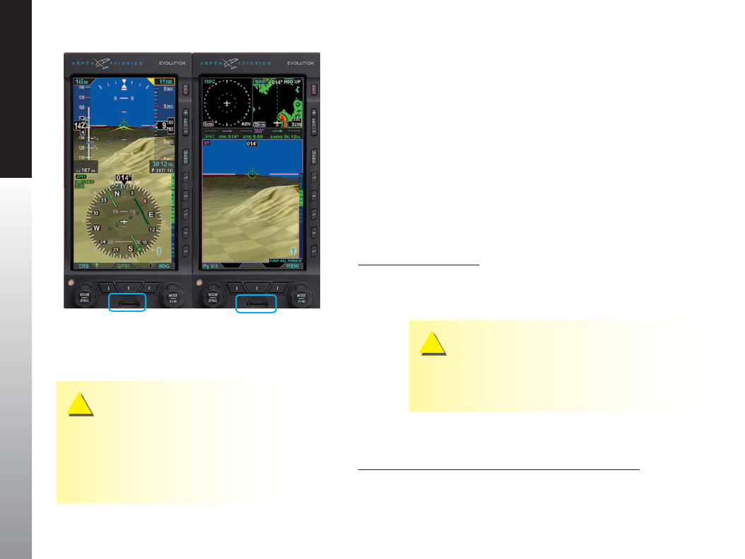
CHAPTER 7 APPENDICES
EFD1000 PFD Pilot’s Guide
Page 7-8 091-00005-001 REV E EFD1000 PFD Pilot’s Guide Page 7-9
091-00005-001 REV E
Lost or misplaced microSD card? Contact Jeppesen Customer Service (800-621-5377) or
email captain@jeppesen.com to purchase a replacement or additional microSD card(s)
pre-loaded with terrain data.
7.4.1. Loading the microSD Card into the EFD Unit
The microSD card slot on the EFD is a small horizontal slot located on the bottom
center part of the bezel (Figure 7-5). The slot is spring-loaded with an integral locking
mechanism. Pushing the card in once locks the card in place. Pushing it again releases
the locking mechanism for removal.
7.4.2. Card Installation Procedure and Operational Check
Installation Procedure
1. Remove the microSD card from the packaging
2. Slide the microSD card into the unit’s card slot (Figure 7-5) with the metal
contacts facing down.
CAUTION
Ensure the card label side is facing up and the metal contacts are
facing down towards the unit. Do not force the card. The card
only goes one way.
3. Press the card against the spring tension until it is fully inserted, then slowly
release the pressure. The card will lock into place
Operational Check after Installing the microSD card
1. Turn on the EFD unit(s) and check the Conrmation Screen for validity dates
of the Jeppesen Database and the Charts Database (Figures 7-6 and 7-7).
Figure 7-5
MicroSD Card Slot Locations
CAUTION
It is possible to jam the card between the bezel and
the outer edge of the card slot. If the card does not
slide in smoothly, something is wrong. Make sure
the card is in the card slot and oriented correctly
before fully inserting it into the bezel.

CHAPTER 7 APPENDICES
EFD1000 PFD Pilot’s Guide
Page 7-8 091-00005-001 REV E EFD1000 PFD Pilot’s Guide Page 7-9
091-00005-001 REV E
2. Select the functions that use the databases (moving map, terrain, charts, and
synthetic vision).
3. Verify the functions can be accessed.
Database Conrmation Screen
The Database Conrmation Screen is presented at system startup and displays the
validity dates of the currently loaded:
• Jeppesen Database and the
• Seattle Avionics Software Charts Database (Figures 7-6 and 7-7).
At startup, the pilot must acknowledge this operational limitation and the validity dates
on the Database Conrmation Screen by pressing either the Left or Right Knob.
7.4.3. Removal Procedure
microSD Card Removal
1. Have a suitable packaging available to accept and protect the microSD card.
2. Press the card against the spring tension, then slowly release the pressure.
3. When the card is unlocked, grasp the card with the thumb and forenger and
remove the card.
4. Place the microSD card in the packaging.
Figure 7-6
PFD Conrmation Screen
Jeppesen Database
(ESV Option Installed)
Figure 7-7
MFD Conrmation Screen
Jeppesen Database and
Seattle Avionics Software
Charts Database
NOTE
Whenever a preloaded microSD card (loaded with
both databases) is inserted into the PFD, the PFD can
only read the Jeppesen database (see Figure 7-6).
CAUTION
It is possible to push the card in with a ngernail and then suddenly release it, ejecting the
microSD card out of the card slot. If the card is dropped, keep in mind that it can be resting
on its side.

CHAPTER 7 APPENDICES
EFD1000 PFD Pilot’s Guide
Page 7-10 091-00005-001 REV E EFD1000 PFD Pilot’s Guide Page 7-11
091-00005-001 REV E
7.5. Specications
7.5.1. Primary Flight Display Unit (PFD)
GENERAL SPECIFICATIONS
Width 3.50 in. (Measured at Bezel)
Height 7.00 in. (Measured at Bezel)
Can Depth 4.15 in. (Rear of Bezel to Rear of Can)
Overall Depth 6.35 in. (Knob to Rear Pressure Fitting)
Weight 2.9 lbs. (with Mounting Bracket)
Display Type 6.0 in. Diagonal TFT Active Matrix LCD (400x760)
Display Colors 32,768
Face Anti-Reective Coated Glass
Backlight High Intensity White LED
Rotary Knobs Optical Encoder with Momentary Press
Dimming Manual & Automatic (Front Bezel Mounted Sensor)
OPERATIONAL SPECIFICATIONS
Operating Temp -20°C to +55°C
Storage Temp -55°C to +85°C
Max Un-Pressurized Operating Altitude 35,000 ft.
Max Pressurized Operating Altitude 55,000 ft.
Cooling Integral Fan
Max Humidity 95% at 50°C

CHAPTER 7 APPENDICES
EFD1000 PFD Pilot’s Guide
Page 7-10 091-00005-001 REV E EFD1000 PFD Pilot’s Guide Page 7-11
091-00005-001 REV E
Input Voltage +8 to +32 Volts DC
Max Current 2.4 Amps @ 28 VDC
4.8 Amps @ 14 VDC
I/O SPECIFICATIONS
ARINC 429 Inputs 5
ARINC 429 Outputs 1
RS-232 Inputs 5
RS-232 Outputs 3
Pitot / Static Quick Connect
CERTIFICATION SPECIFICATIONS
FAA Technical Standard Order
EASA (European Aviation Safety Agency)
ETSO (European Technical Standard
Order)
TSO-C2d / ETSO-C2D.......................................................................Airspeed Instruments
TSO-C3d / ETSO-C3D................................................................Turn and Slip Instrument
TSO-C4c / ETSO-C4C...........................................................Bank and Pitch Instruments
TSO-C6d / ETSO-C6D..................................................Direction Instrument Magnetic
(Gyroscopically Stabilized)
TSO-C8d / ETSO-C8D.......................Vertical Velocity Instrument (Rate of Climb)
TSO-C10b / ETSO-C10B......................Altitude Pressure Activated Sensitive Type
TSO-C106 / ETSO-C106.........................................................................Air Data Computer
TSO-C113 / ETSO-C113....................Airborne Multipurpose Electronic Displays
Software RTCA DO-178B Level C
Environmental RTCA DO-160E
Categories See Environmental Qualication Sheet found in the Installation Manual.
Table 7-1
Primary Flight Display Unit (PFD) Specications

CHAPTER 7 APPENDICES
EFD1000 PFD Pilot’s Guide
Page 7-12 091-00005-001 REV E EFD1000 PFD Pilot’s Guide Page 7-13
091-00005-001 REV E
7.5.2. Remote Sensor Module (RSM)
Width 2.65 in.
Length 4.40 in.
Height 1.00 in.
Weight 0.2 lbs.
Input Voltage Provided by PFD
Max Current Included in PFD Current
Table 7-2
Remote Sensor Module (RSM) Specications
7.5.3. Analog Converter Unit (ACU)
Width 5.75 in. (including mounting ange)
Length 4.30 in. (including connector)
Height 1.60 in. (including mounting ange)
Weight 0.8 lbs.
Input Voltage +10 to +32 VDC
Max Current 0.5 Amps @ 28 VDC
1.0 Amps @ 14 VDC
Interfaces ARINC-429 and RS-232
Table 7-3
Analog Converter Unit (ACU) Specications

CHAPTER 7 APPENDICES
EFD1000 PFD Pilot’s Guide
Page 7-12 091-00005-001 REV E EFD1000 PFD Pilot’s Guide Page 7-13
091-00005-001 REV E
7.5.4. Operational Specications
Airspeed Range Minimum displayed airspeed 20 KIAS
Maximum displayed airspeed 500 KIAS
Altitude Range Minimum displayed altitude -1,600 ft. MSL
Maximum displayed altitude 51,000 ft. MSL
Vertical Speed
Range
Maximum displayed vertical speed rates (tape) +/-2,000 fpm
Maximum displayed vertical speed rates (numerical
value)
+/- 9,990 fpm
Turn Rate Maximum displayed turn rate 6.0 °/second
Barometric
Pressure
Correction Range
28.10 to 30.99 In Hg (946 to 1049 mB)
Internal Battery Minimum operating time while on internal battery 30 minutes 1
Table 7-4
Operational Specications
1. At extreme cold temperatures the internal current limit-
ing protections of the internal battery may cause the
battery to shut o and not power the display.

EFD1000 PFD Pilot’s Guide
Page 7-14 091-00005-001 REV E
CHAPTER 7 APPENDICES
7.6. Glossary
ºC Degrees Celsius
ºF Degrees Fahrenheit
Accuracy Estimated position accuracy in feet or meters
A/D Analog to Digital
AC Alternating Current
ACU Analog Converter Unit
ADC Air Data Computer
ADI Attitude Director Indicator
AFMS Airplane Flight Manual Supplement
AGL Above Ground Level
AHRS Attitude Heading Reference System
AI Attitude Indicator
AIM Aeronautical Information Manual
AIRMET Airman’s Meteorological Information
Altitude Elevation above mean sea level
APPR Approach
APT Airport
ARC Partial Compass Rose, arc format (100°)
ARINC Aeronautical Radio, Inc.
ATC Air Trac Control
ATIS Automatic Terminal Information Service
AWOS Automated Weather Observation System
Back Course Localizer back course approach where the
signal on the back side of the localizer is used
for alignment to the runway opposite of normal
localizer alignment.
Battery Time The time remaining on the battery before it is
fully discharged.
BC Back Course
Bearing The compass direction from the current position
to the destination.
BP Bearing Pointer
Calibrated Airspeed Indicated airspeed corrected for installation and
instrument errors.
CDI Course Deviation Indicator
CFR Code of Federal Regulations
CM Conguration Module
Comm Communication radio
Course The route taken from the starting position to
destination.
Course to Steer The recommended direction to steer in order to
reduce cross-track error and return to the course
line.
Cross Track The perpendicular distance, left or right, away
from the selected course.

EFD1000 PFD Pilot’s Guide Page 7-15
091-00005-001 REV E
CHAPTER 7 APPENDICES
Crosstrack Error The distance the aircraft is o the desired course.
CRS Course
CTS Course to Steer
dBZ decibels ‘Z’ (radar return)
DC Direct Current
Decision Height A specied height or altitude in the precision
approach at which a missed approach must
be initiated if the required visual reference to
continue the approach has not been acquired.
This allows the pilot sucient time to safely
recongure the aircraft to climb and execute
the missed approach procedures while avoiding
terrain and obstacles.
Declutter Reduce the number of basemap symbols
displayed on screen.
Deg Degree
Desired Track The desired course between the active “FROM”
and “TO” waypoints.
DH Decision Height
Distance (Next) The great circle distance from current location
to a Go To destination or the nal waypoint in a
route.
DME Distance Measuring Equipment
DTK Desired Track
EASA European Aviation Safety Agency
EFD Evolution Flight Display
EFIS Electronic Flight Instrument System
Elevation The height above mean sea level.
ETA (Destination) Estimated Time of Arrival. The estimated time
you will reach a Go To destination or the nal
waypoint in a route.
ETA (Next) Estimated Time of Arrival. The estimated time
you will reach a Go To destination or the next
waypoint in a route.
ETE (Destination) Estimated Time Enroute. The estimated time
required to reach a Go To destination or the nal
waypoint in a route.
ETE (Next) Estimated Time Enroute. The estimated time
required to reach a Go To destination or the next
waypoint in a route.
ETSO European Technical Standard Order
FAA Federal Aviation Administration
FAF Final Approach Fix
FD Flight Director
fpm Feet Per Minute
ft Feet
GPS Global Positioning System
GPSS GPS Steering
Ground Track see Track

EFD1000 PFD Pilot’s Guide
Page 7-16 091-00005-001 REV E
CHAPTER 7 APPENDICES
Ground Speed The velocity that the aircraft is travelling relative
to a ground position.
GS Glide Slope or Ground Speed
Heading The direction an aircraft is pointed, based upon
indications from a magnetic compass or a
properly set directional gyro.
Hg Mercury
HSI Horizontal Situation Indicator
Hz Hertz (frequency)
IAF Initial Approach Fix
IAS Indicated Air Speed
IFR Instrument Fight Rules
ILS Instrument Landing System
IMC Instrument Meteorological Conditions
in Hg Inches of Mercury
Indicated Information provided by properly calibrated and
set instruments on the aircraft panel.
IOP Input/Output Processor
JSUM Jeppesen Services Update Manager
kHz Kilohertz
KIAS Knots Indicated Air Speed
km Kilometer
kt Knots
LAT Latitude
LCD Liquid Crystal Display
LDI Lateral Deviation Indicator
Leg The portion of a ight plan between two
waypoints
LOC Localizer
MAP Main Application Processor
mB Millibars
MFD Multi-Function Display
MHz Megahertz
MSG Message
MSL Mean Sea Level
NAVAID Navigation Aid
NDB Non-Directional Beacon
NXRD Next Generation Weather Radar
nm Nautical Miles
NRST Nearest
OAT Outside Air Temperature
OBS Omni-Bearing Selector
PFD Primary Flight Display
RMI Radio Magnetic Indicator
RSM Remote Sensor Module
SDHC Secure Digital High Capacity (microSDHC card)
TA Trac Advisory

EFD1000 PFD Pilot’s Guide Page 7-17
091-00005-001 REV E
CHAPTER 7 APPENDICES
TACAN Tactical Air Navigation System
TAS True Air Speed
TCAS Trac Collision Avoidance System
TERM Terminal Mode
TIS Trac Information System
Track Direction of aircraft movement relative to a
ground position; also Ground Track’
TSO Technical Standard Order
VAC Volts, Alternating Current
VDC Volts, Direct Current
VDI Vertical Deviation Indicator
VFR Visual Flight Rules
VHF Very High Frequency
VLOC VOR/Localizer
VOR VHF Omni-Directional Radio Range
VORTAC VHF Omni-Directional Radio Range and Tactical
Air Navigation
VSI Vertical Speed Indicator
WAAS Wide Area Augmentation System
WPT Waypoint
WX Weather

EFD1000 PFD Pilot’s Guide
Page 7-18 091-00005-001 REV E
CHAPTER 7 APPENDICES
7.7. Index
Symbols
1/2, Hot Key ............................................................................................................................. 2-12
2/2, Hot Key ............................................................................................................................. 2-12
360/ARC, Hot Key .................................................................................................................2-12
A
ABV, Hot Key ............................................................................................................................2-13
ADAHRS ..............................................................................................................................4-2–4-7
Attitude ..................................................................................................................................... 4-3
Free Gyro Mode .........................................................................................................4-6–4-7
Heading ..........................................................................................................................4-5–4-6
Pitot Obstruction Monitor ............................................................................................. 4-4
Advisory ........................................................................................................................ 6-22–6-24
Data Invalid or Unavailable ........................................................................................6-24
GPS Annunciations .........................................................................................................6-23
GPSS On .................................................................................................................................6-22
Navigation Source Invalid or Unavailable ........................................................6-24
REV Button O ................................................................................................................... 6-22
Trac Enabled ................................................................................................................... 6-23
WX-500 Cell Rate ..............................................................................................................6-23
WX-500 Self-Test ...............................................................................................................6-23
WX-500 Strike Rate .........................................................................................................6-23
AHRS Reset, In-Flight ..........................................................................................................6-13
Perform ..................................................................................................................................6-14
Aircraft Ownship Symbol ................................................................................................ 4-26
Air Data, Attitude and Heading Reference System ..................................4-2–4-7
See alsoADAHRS
Airspeed Indicator (Airspeed) ..........................................................................4-10–4-13
Airspeed ................................................................................................................................4-10
Bug ....................................................................................................................................... 4-10
Bug, Set ..................................................................................................................3-16, 4-12
Range ..................................................................................................................................4-11
Airspeed Display ..............................................................................................................4-13
Tape ..........................................................................................................................................4-10
Hide/Display ...................................................................................................................4-13
Tape and Bug ..................................................................................................................... 2-25
Speed Markers .............................................................................................................. 2-25
Altimeter .......................................................................................................................4-14–4-22
Decision Height ................................................................................................................4-21
MINIMUMS ...........................................................................................................................4-17
Altitude .............................................................................................................. 4-14, 4-16–4-17
Alerter ..................................................................................................................................... 4-14
Alerter, Set ............................................................................................................................ 3-15
Bug ..........................................................................................................................................4-14
Bug, Set .................................................................................................................................. 4-17
Caution ...................................................................................................................................6-20
Display .................................................................................................................................... 4-22
Level-O and Deviation Alert .................................................................................. 4-17
Tape ..........................................................................................................................................4-14
Hide/Display ...................................................................................................................4-22
Tape and Alerter ............................................................................................................... 2-26
Trend Vector ........................................................................................................................4-14

EFD1000 PFD Pilot’s Guide Page 7-19
091-00005-001 REV E
CHAPTER 7 APPENDICES
Altitude Display
Attitude Indicator .........................................................................................2-24, 4-8–4-9
Analog Converter Unit .........................................................................................................1-7
Approvals ....................................................................................................................................xxiv
APV (Approaches with Vertical Guidance) ...........................................................4-61
ARC/360, Hot Key .................................................................................................................2-12
Attitude Display .................................................................................2-22–2-27, 4-8–4-22
Airspeed Indicator ..............................................................................................4-10–4-13
Altimeter ..................................................................................................................4-14–4-22
Attitude Indicator ...............................................................................................................4-8
Components ......................................................................................................................2-23
Attitude Fail ..............................................................................................................................6-17
Attitude Indicators, Dierence ........................................................................................6-7
Auto Course .............................................................................................................................4-37
Disable ....................................................................................................................................4-38
Enable ..................................................................................................................................... 4-37
Select .......................................................................................................................................2-34
Autopilot Integration ............................................................................................4-52–4-63
Autopilot Operations, Typical .......................................................................... 4-57–4-63
APPR Mode Operation - GPS or GPS/RNAV APV WAAS Approach ....4-61
APPR Mode Operation - ILS Approach with Vectors to Final ...............4-60
GPS APPR Mode Operation - WAAS GPS Underlay to ILS Approach
Using Pilot Nav and GPSS ..............................................................................4-62
GPS APPR Mode Operation - WAAS GPS Underlay to ILS Approach
With ATC Vectors to Final ...............................................................................4-63
HDG Mode Operation - GPS Steering (GPSS .................................................. 4-58
HDG Mode Operation - Heading Bug Steering ............................................4-58
NAV Mode Operation - GPS Navigation ............................................................ 4-59
NAV Mode Operation - VLOC Navigation ......................................................... 4-58
Auto Range
Activate .................................................................................................................................. 4-46
Deactivate ............................................................................................................................ 4-46
Enable ..................................................................................................................................... 4-46
B
Barometer ..............................................................................................................2-5–2-8, 4-23
Barometric Pressure Adjustment ..............................................................4-15–4-16
Barometric Pressure, Set .....................................................................................3-8, 4-16
Barometric Pressure Setting Display .................................................................... 4-25
Barometric Units of Measure, Set ..........................................................................4-15
Battery
Countdown ......................................................................................................................... 6-17
Operational ..........................................................................................................................6-17
Status, View ..........................................................................................................................6-12
Bearing Pointers .................................................................................................................... 2-35
Double-Line Bearing Pointer Source, Select ...................................................4-41
Nav Sources, Select ........................................................................................................3-10
Single-Line Bearing Pointer Source, Select ......................................................4-41
Source Select Buttons ...................................................................................................2-10
Source Selection ................................................................................................. 4-39–4-41
BLW, Hot Key ........................................................................................................................... 2-13
Brightness Control ...............................................................................................................5-19
See alsoLighting
BRT ADJUST ............................................................................................................................. 2-18
BRT AUTO .................................................................................................................................. 2-18
Buttons ....................................................................................................................................... xxxii
C
Cautions ........................................................................................................................6-19–6-21
Altitude Caution ............................................................................................................... 6-20
Check Pitot Heat ...............................................................................................................6-19
Cross Check Attitude .....................................................................................................6-19
Data link Weather Data Error ....................................................................................6-21
Decision Height Caution .............................................................................................6-20
Explained .............................................................................................................................xxxiv
GPS Integrity Flag ............................................................................................................ 6-20

EFD1000 PFD Pilot’s Guide
Page 7-20 091-00005-001 REV E
CHAPTER 7 APPENDICES
GPS Invalid ........................................................................................................................... 6-20
GPS Reversion ....................................................................................................................6-20
GPS Reversion Emergency .........................................................................................6-20
GPSS Source Lost/Changed ...................................................................................... 6-21
Minimums Caution .........................................................................................................6-21
RSM GPS ................................................................................................................................ 6-20
CDI
Course, Select .....................................................................................................................4-38
Navigation Source ..............................................................................................4-33–4-36
Radio Mode, GPS ......................................................................................................... 4-35
Radio Source, VHF .......................................................................................................4-35
Select ......................................................................................................................3-10, 4-34
Nav Source Select Button ..............................................................................................2-9
Selected Course ................................................................................................................4-38
Source Information Block ........................................................................................... 4-34
Source Label ....................................................................................................................... 4-34
Source Select Button .....................................................................................................4-34
Check Pitot Heat ................................................................................................................... 6-19
CHECK PITOT HEAT .................................................................................................................4-4
Cleaning the Display Screen ......................................................................................... 2-21
Color Philosophy ................................................................................................................. xxxiii
Compass ....................................................................................................................... 4-27–4-29
360° Compass Mode .....................................................................................................4-27
ARC CDI/HSI Compass Mode, Select ...................................................................4-28
ARC Compass Mode ......................................................................................................4-27
Compass Scale ..................................................................................................................4-26
Compass Type, Select ...................................................................................................4-29
Modes: 360º vs. ARC .......................................................................................................2-31
Select .......................................................................................................................................3-20
Conguration Module .........................................................................................................1-6
Conguring V-speeds ...........................................................................................5-14–5-18
Controls
Knobs ...............................................................................................................................2-4–2-8
Left Knob Functions .....................................................................................................2-5
Right Knob Functions ..................................................................................................2-5
SYNC Function .......................................................................................................2-6–2-7
Controls and Display ................................................................................................2-1–2-38
Controls .......................................................................................................................2-4–2-19
Elements ........................................................................................................................2-2–2-3
Conventions ............................................................................................................... xxxi–xxxvi
Color Philosophy .............................................................................................................xxxiii
Covered Functionality ....................................................................................................xxxi
Example Graphics ............................................................................................................xxxv
Information Covered in this Pilot’s Guide ........................................................ xxxvi
Pilot Familiarity .................................................................................................................. xxxv
Terminology .......................................................................................................................... xxxi
Warnings, Cautions, Notes ........................................................................................xxxiv
Copyrights and Trademarks .............................................................................................xxiii
Course Deviation Indicator and Scale .....................................................................4-32
Course Pointer ........................................................................................................................4-30
Course Pointer and Deviation Indicator ................................................................2-33
Covered Functionality .........................................................................................................xxxi
CROSS CHECK ATTITUDE .............................................................................. 4-3, 6-7, 6-19
CRS ................................................................................................................................... 2-5–2-8
Customizing the EFD1000 PFD .........................................................................5-1–5-19
Customizing the Map ...........................................................................................5-11–5-13
D
Data Bar ............................................................................................................. 2-28, 4-23–4-25
Databases ............................................................................................................................. 1-8, 7-3
Data Invalid or Unavailable ............................................................................................ 6-24
Data Link Weather ..................................................................................................4-66–4-69
Age Annunciations .........................................................................................................4-69

EFD1000 PFD Pilot’s Guide Page 7-21
091-00005-001 REV E
CHAPTER 7 APPENDICES
Age, View ..............................................................................................................................4-68
Data Error ..............................................................................................................................6-21
Legend, Display ................................................................................................................4-67
NEXRAD Methodology .................................................................................................4-67
Product Age Limits and Update Frequency ...................................................4-68
Underlay, Display .................................................................................................3-13, 4-66
Decision Height ....................................................................................................................4-21
Alert .......................................................................................................................................... 4-14
Caution ...................................................................................................................................6-20
Declutter
Settings .................................................................................................................................. 5-13
Deviation
Indicator ................................................................................................................................ 4-26
O Scale Indication ........................................................................................................ 2-34
Scale .........................................................................................................................................4-26
Direction Indicator Fail ......................................................................................................6-17
Direction Indicator (Magnetic Compass) .....................................2-31–2-32, 4-26
Display ..................................................................................................................1-5, 2-20–2-37
Attitude Display ................................................................................................... 2-22–2-27
Cleaning the Display Screen .....................................................................................2-21
Lighting .................................................................................................................................2-18
Document Revisions ...........................................................................................................iv–v
Dual Display ................................................................................................................................1-2
E
Electrical Power, Loss of Aircraft ..................................................................................... 6-9
Emergency and Abnormal Procedures ........................................................6-1–6-24
Pitot/Static System Blockage .............................................................................6-2–6-6
Evolution Flight Display (EFD) system ........................................................................1-1
Dual Display ...........................................................................................................................1-2
Single Display ........................................................................................................................1-2
System Overview ................................................................................................................ 1-4
Trio Display ....................................................................................................................1-3, 1-4
Evolution Weather Receiver .............................................................................................1-7
Example Flight .............................................................................................................3-5–3-27
Arrival and Approach to Landing ............................................................. 3-22–3-27
Departure ................................................................................................................3-17–3-18
En Route ................................................................................................................... 3-19–3-21
Pre-Departure ..........................................................................................................3-6–3-16
Example Graphics ................................................................................................................ xxxv
External Voltage Status, View ........................................................................................ 6-12
Extreme Pitch ..........................................................................................................................6-18
F
Flight Director ...............................................................................................................4-9, 4-57
Flight Plan ................................................................................................................................. 4-47
Free Gyro Mode ..............................................................................................................4-6–4-7
G
GENERAL SETTINGS A ...........................................................................................................5-1
GENERAL SETTINGS B ........................................................................................................... 5-2
GPS
Annunciations ...................................................................................................................6-23
Failures ....................................................................................................................................6-11
Integrity Flag .......................................................................................................................6-20
Invalid ......................................................................................................................................6-20
Reversion ..............................................................................................................................6-20
Reversion Emergency ................................................................................................... 6-20
GPSS 4-53–4-57
Disable ....................................................................................................................................6-16
Enable/Disable .................................................................................................................. 4-54
Engage ................................................................................................................................... 3-19
Hot Key ...................................................................................................................................2-12
Operation, Annunciations, and Autopilot Modes ....................................... 6-15

EFD1000 PFD Pilot’s Guide
Page 7-22 091-00005-001 REV E
CHAPTER 7 APPENDICES
Source Lost/Changed ................................................................................................... 6-21
Wings Level ......................................................................................................................... 6-16
Ground Speed ........................................................................................................................4-23
Ground Track Marker ..........................................................................................................2-32
H
Hazard Awareness ..................................................................................................4-64–4-74
Data Link Weather ..............................................................................................4-66–4-69
Lightning .................................................................................................................4-64–4-66
Trac ..........................................................................................................................4-70–4-74
Heading .....................................................................................................................................4-26
Display .................................................................................................................................... 4-43
Heading and Heading Bug ........................................................................................4-42
Heading Bug, Set .......................................................................................... 2-8, 3-9, 4-42
Horizontal Situation Indicator ...................................................................................... 2-33
Hot Keys ......................................................................................................................... xxxii, 2-11
I
IAS 2-5–2-8
ILS Approaches ......................................................................................................................4-62
Examples ..................................................................................................................3-22–3-27
Information Covered in this Pilot’s Guide ............................................................xxxvi
Initial Flap Extension Speed Marker .........................................................................4-10
Instrument Approach Indicators ................................................................................2-27
Internal Battery Status, View ..........................................................................................6-12
Introduction .....................................................................................................................1-1–1-3
K
Knobs xxxii, 2-4–2-8
Left Knob Functions ..........................................................................................................2-5
Right Knob Functions ......................................................................................................2-5
SYNC Function ............................................................................................................2-6–2-7
SYNC Function, Perform ................................................................................................. 2-6
Using the Knobs (Example) .......................................................................................... 2-8
L
Lateral Deviation Indicator ................................................................................4-49–4-50
Lighting .......................................................................................................................... 2-18, 5-19
Lightning ......................................................................................................................4-64–4-66
Data Link Lightning Symbol ..................................................................................... 4-65
Underlay, Display .....................................................................................3-13, 3-21, 4-66
WX-500 Cell Symbol ......................................................................................................4-65
WX-500 Strike Symbol ..................................................................................................4-65
Loss of Aircraft Electrical Power .....................................................................................6-9
LPV Approaches ....................................................................................................................4-62
LTNG, Hot Key .........................................................................................................................2-13
M
Main Menu ..................................................................................................................2-14–2-17
Brightness Control ..........................................................................................................2-15
Menu Text .............................................................................................................................2-16
Overview .....................................................................................................................5-1–5-10
360° MAP SETTINGS ......................................................................................................5-3
ARC MAP SETTINGS ...................................................................................................... 5-4
GENERAL SETTINGS A ..................................................................................................5-1
GENERAL SETTINGS B .................................................................................................. 5-2
POWER SETTINGS ...........................................................................................................5-9
SYSTEM STATUS ............................................................................................................ 5-10
VSPEEDS A ..........................................................................................................................5-5
VSPEEDS B ...........................................................................................................................5-5
XM RECEIVER A ................................................................................................................5-6
XM RECEIVER B ................................................................................................................. 5-7
XM RECEIVER C ................................................................................................................5-8

EFD1000 PFD Pilot’s Guide Page 7-23
091-00005-001 REV E
CHAPTER 7 APPENDICES
Page graphical bar .......................................................................................................... 2-15
Page Name ..........................................................................................................................2-15
Page number and mode .............................................................................................2-15
Using the Menus .................................................................................................2-14–2-17
Access and Navigate ................................................................................................. 2-16
Edit Main Menu Items .............................................................................................. 2-17
Map
Auto Range ..........................................................................................................................4-46
Data Source and Reversion ....................................................................................... 4-47
Declutter Settings ............................................................................................................5-13
Declutter and Range ..................................................................................................... 4-45
Declutter Level, Select ...................................................................................... 3-11, 4-45
Feature Group & Layer Order ....................................................................................5-13
Flight Plan .............................................................................................................................4-47
Max Range ........................................................................................................................... 5-13
Range, Change ...................................................................................................... 3-12, 4-45
Symbol Display, Set ........................................................................................................ 5-12
Underlays .................................................................................................................4-44–4-48
MAP, Hot Key ...........................................................................................................................2-12
MEMS .............................................................................................................................................4-2
Menu Keys ................................................................................................................................ xxxii
Micro Electro-Mechanical Systems .............................................................................. 4-2
MicroSD Card ..................................................................................................................... 1-8, 7-7
MINIMUMS ..................................................................................................................4-17–4-20
Adjustment ..........................................................................................................................4-14
Alert .......................................................................................................................................... 4-14
Caution ...................................................................................................................................6-21
Display/Hide ....................................................................................................................... 4-19
MIN, Hot Key ....................................................................................................2-5–2-8, 2-12
Set ..........................................................................................................................................4-20
N
Navigation
Information ..........................................................................................................................2-32
Source .....................................................................................................................................4-26
Source Info Block .............................................................................................................4-26
Source Invalid or Unavailable ...................................................................................6-24
Source Select Buttons .........................................................................................2-9–2-10
Navigation Display ........................................................................2-29–2-37, 4-26–4-48
Aircraft Heading Display ..............................................................................................4-43
Auto Course ...........................................................................................................4-37–4-38
Auto Course Select ......................................................................................................... 2-34
Bearing Pointers ...............................................................................................................2-35
Bearing Pointer Source Selection .............................................................4-39–4-41
CDI Navigation Source .................................................................................... 4-33–4-36
CDI Selected Course ...................................................................................................... 4-38
Compass ...................................................................................................................4-27–4-29
Components ......................................................................................................................2-30
Course Deviation Indicator and Scale ................................................................4-32
Course Pointer ................................................................................................................... 4-30
Course Pointer and Deviation Indicator ............................................................2-33
Deviation O Scale Indication .................................................................................2-34
Direction Indicator (Magnetic Compass) .............................................2-31–2-32
Ground Track Marker ..................................................................................................... 4-48
Heading and Heading Bug ........................................................................................4-42
Horizontal Situation Indicator ..................................................................................2-33
Map Underlays .................................................................................................................. 4-44
Rate of Turn Indicator ........................................................................................2-36, 4-43
Situational Awareness Map ....................................................................................... 2-37
TO/FROM Indicator .........................................................................................................4-31
Vertical Speed Indicator ..............................................................................................2-36

EFD1000 PFD Pilot’s Guide
Page 7-24 091-00005-001 REV E
CHAPTER 7 APPENDICES
Navigation Source
Select Buttons
Bearing Pointer Source Select Buttons ..........................................................2-10
CDI Nav Source Select Button ................................................................................2-9
NEXRAD Methodology .....................................................................................................4-67
Notes
See alsoAdvisory
Explained .............................................................................................................................xxxiv
NRM, Hot Key ..........................................................................................................................2-13
Numerical Airspeed Value ..............................................................................................4-10
Numerical Altitude Value ................................................................................................4-14
NXRD, Hot Key ........................................................................................................................2-13
O
Operating Limitations ..........................................................................................................7-1
Outside Air Temperature .....................................................................................4-23, 4-24
OAT Units of Measure, Set .......................................................................................... 4-24
P
Pilot Familiarity .......................................................................................................................xxxv
Pilot PFD ....................................................................................................................................xxxvi
Pitch Scale ....................................................................................................................................4-9
Pitot and/or Static System Failures, Identifying .................................................... 6-4
Pitot Obstruction Monitor .................................................................................................4-4
Pitot/Static System Blockage .............................................................................. 6-2–6-24
Suspected ...............................................................................................................................6-3
Power On Manually ...............................................................................................................6-8
Power Override ......................................................................................................................6-12
R
Range Button ..........................................................................................................................2-19
Rate of Turn Indicator ................................................................................2-36, 4-26, 4-43
Rear Connections ....................................................................................................................1-5
Remote Sensor Module ......................................................................................................1-6
REV Button ................................................................................................................................2-19
O ..........................................................................................................................................6-22
Right Knob Functions ...........................................................................................................2-5
RNAV Instrument Approaches ..................................................................................... 4-61
Roll Scale ......................................................................................................................................4-9
RSM Emergency GPS Use ................................................................................................6-11
RSM GPS .....................................................................................................................................6-20
S
Service Agreement, XM WX Satellite Radio ...........................................................xxix
Shutdown Procedure, Abnormal ..................................................................................6-8
Single Display ............................................................................................................................1-2
Situational Awareness Map ...........................................................................................2-37
Slip/Skip Indicator ...................................................................................................................4-9
Software Versions .......................................................................................................... 7-1–7-2
Input/Output Processor Software Version, View ............................................. 7-2
Main Application Processor Software Version, View ..................................... 7-1
Specications ..................................................................................................................7-3–7-6
Analog Converter Unit ....................................................................................................7-5
EFD1000 Display Unit .......................................................................................................7-3
Operational .............................................................................................................................7-6
Remote Sensor Module .................................................................................................. 7-5
Speed Bands ...........................................................................................................................4-10
Ranges ....................................................................................................................................5-16
Speed Markers ...........................................................................................................2-25, 4-10
Startup Splash Screen ..........................................................................................................3-6

EFD1000 PFD Pilot’s Guide Page 7-25
091-00005-001 REV E
CHAPTER 7 APPENDICES
SYNC Function ................................................................................................................2-6–2-7
System Architecture ..............................................................................................................1-4
System Overview ....................................................................................................................1-4
T
Terminology ................................................................................................................. xxxi–xxxii
Buttons ................................................................................................................................... xxxii
Hot Keys ................................................................................................................................ xxxii
Knobs ...................................................................................................................................... xxxii
Menu Keys ........................................................................................................................... xxxii
TO/FROM Indicators ............................................................................................... 4-26, 4-31
Track Marker ................................................................................................................4-26, 4-48
Trac .............................................................................................................................4-70–4-74
Altitude Filter ......................................................................................................................4-73
Change .............................................................................................................................. 4-73
Enabled ..................................................................................................................................6-23
Overlay, Display .....................................................................................................3-14, 4-70
Symbols .................................................................................................................... 4-70–4-72
Unavailable ..........................................................................................................................4-74
TRFC, Hot Key ......................................................................................................................... 2-13
Trio Display .................................................................................................................................. 1-3
True Airspeed ..........................................................................................................................4-23
U
Unit Serial Number, View .................................................................................................... 7-2
UNR, Hot Key ...........................................................................................................................2-13
Using the Menus .................................................................................................................. 2-14
V
Vertical Deviation Indicator .............................................................................. 4-49–4-50
Vertical Speed Indicator ....................................................................................... 2-36, 4-51
Voltage Status, View ...........................................................................................................6-12
Vspeeds ...................................................................................................................................... 4-10
Conguring ............................................................................................................ 5-14–5-18
Denitions ...............................................................................................................5-14–5-15
Initial Flap Extension ......................................................................................................5-15
Textual Labels, Enable ................................................................................................... 5-17
Textual Vspeed Labels, Set ......................................................................................... 5-18
W
WAAS Approaches ..............................................................................................................4-61
Warning, Caution, and Advisory Summary .............................................6-17–6-24
Warnings .......................................................................................................................6-17–6-18
Attitude Fail ......................................................................................................................... 6-17
Battery Countdown ........................................................................................................6-17
Battery Operational ........................................................................................................ 6-17
Direction Indicator Fail ................................................................................................. 6-17
Explained .............................................................................................................................xxxiv
Extreme Pitch ..................................................................................................................... 6-18
Warranty ..........................................................................................................................xxv–xxvii
Card ......................................................................................................................................... xxvi
Conditions ...............................................................................................................................xxv
Dealer ...................................................................................................................................... xxvii
Exclusions ................................................................................................................................xxv
Exclusive ................................................................................................................................. xxvi
Extension of ........................................................................................................................ xxvii
Incidental Damages ........................................................................................................ xxvi

EFD1000 PFD Pilot’s Guide
Page 7-26 091-00005-001 REV E
CHAPTER 7 APPENDICES
Invalidation ........................................................................................................................... xxvi
Limitation of Liability ...................................................................................................... xxvi
Procedure ............................................................................................................................. xxvii
Remedy .....................................................................................................................................xxv
Transportation Costs ..................................................................................................... xxvii
Weather Data ....................................................................................................................xxviii
Weather
Age Annunciations .........................................................................................................4-69
Data Warranty ................................................................................................................... xxviii
Product Age Limits and Update Frequency ...................................................4-68
Wind
Direction ...............................................................................................................................4-23
Direction Arrow ................................................................................................................4-23
Speed ...................................................................................................................................... 4-23
Speed, Direction, and Arrow .....................................................................................4-24
Wings Level ..............................................................................................................................4-57
WX-500
Cell Rate .................................................................................................................................6-23
Self-Test ..................................................................................................................................6-23
Strike Rate .............................................................................................................................6-23
X
XM WX Satellite Radio Service Agreement ............................................................xxix

Aspen Avionics, Inc.
5001 Indian School Road NE
Albuquerque, NM 87110
Phone: 888-99ASPEN (888-992-7736)
Phone, International: (505) 856-5034
Fax: (505) 314-5440
info@aspenavionics.com
www.aspenavionics.com
091-00005-001 REV E Printed in USA
