Assembling Instructions
User Manual:
Open the PDF directly: View PDF ![]() .
.
Page Count: 41
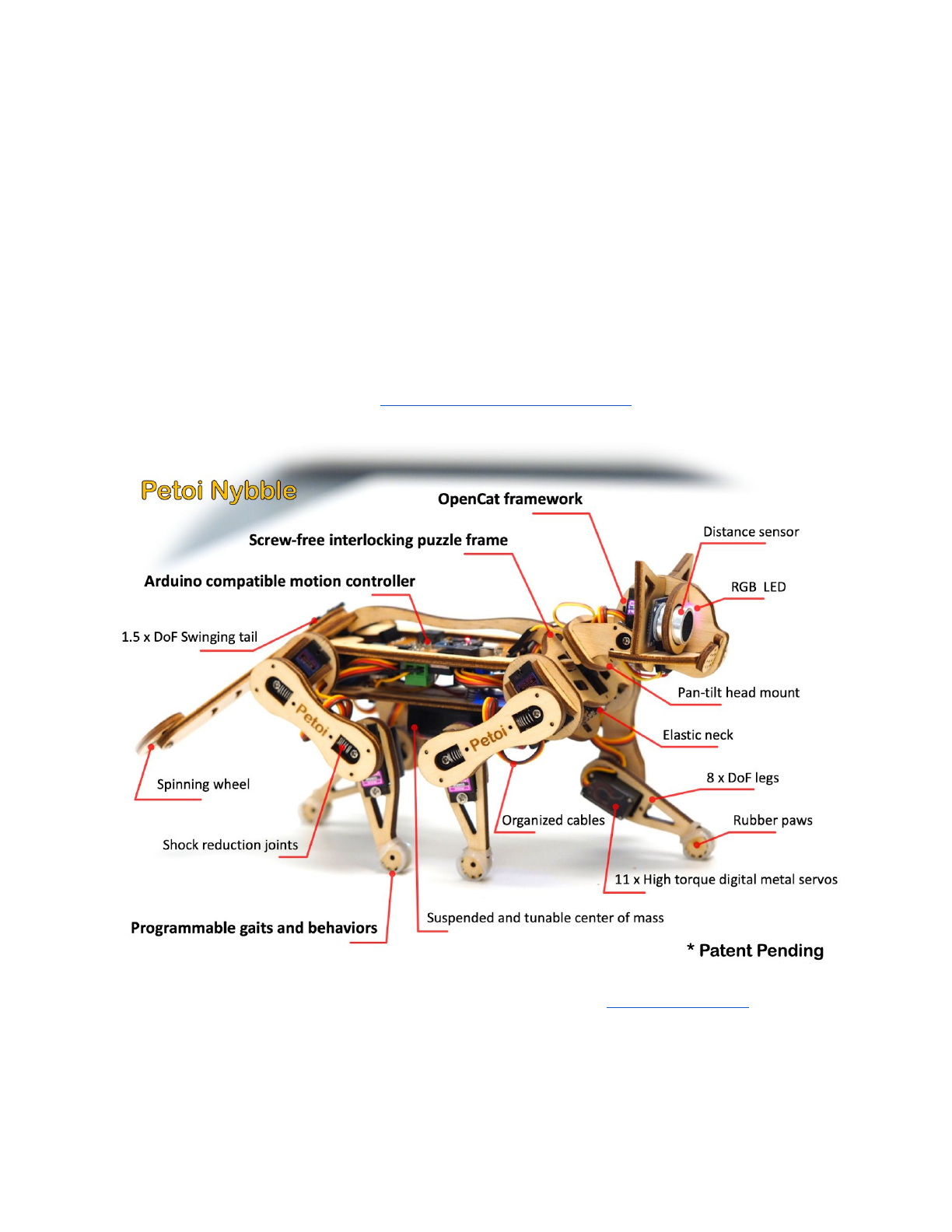
Assembling Instructions for Nybble
Rongzhong Li
Jan. 25, 2019
To keep this instruction simple to use, I’m focusing on the assembly rather than
in-depth explanation. If you have specific questions on “why” rather than “how”,
please post on our forum at https://www.petoi.com/forum.
The crowdfunding campaign is active on Indiegogo: igg.me/at/nybble. Our
social media account is @PetoiCamp. Share your build with us by tagging #nybble
#petoi or #opencat so that we can repost for you!
1. Tools and Preparation
1.1. Prepare a clean desk and some small boxes to unzip the package.
It’s better to work in a room without carpet or textured mosaic. Little screws and
springs can magically hide themselves if dropped onto the ground.
1.2. Tools and accessories
Required
Tool
Notes
Utility knife
Cut the tabs holding the wooden puzzle pieces
Flat and phillips screwdrivers
Computer with Arduino IDE
Install the latest Arduino IDE
USB to mini USB cable
Connect the uploader to computer. Not micro
USB
2 x 14500 Li-ion batteries
Rated 3.7V. Don’t mix with regular AA batteries!
Smart charger for batteries
Optional
Soldering iron w/ accessories
Solder the decorative LED to ultrasound sensor
HC-05 bluetooth module
Wirelessly upload sketch and communicate
Color paints
Give your Nybble a unique look
3D printer w/ accessories
Add your special design
Arduino/Raspberry Pi kit
Add more gadgets to Nybble
Multimeter
Test and debug
Oscilloscope
Test and debug
Hot glue/super glue
Avoid using them. OpenCat is designed to be soft!
1
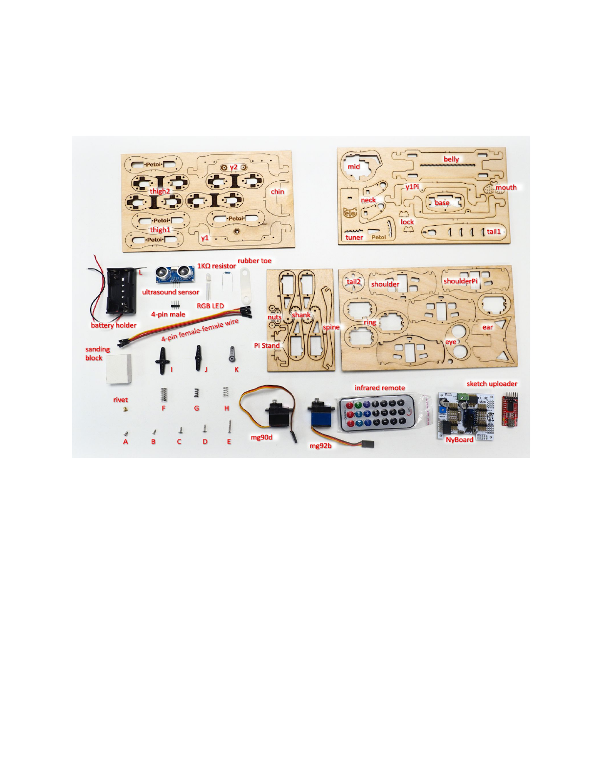
2. Open box. Get familiar with the components.
There’s a larger picture in the Appendix. Packaging method may vary.
This instruction will keep consistent with the current namespace.
2.1. Cut body pieces off the baseboard.
There might be some tar residue on the wooden pieces from laser cutting. Use a
wet soft tissue to clean up the board.
The functional pieces are attached to the baseboard by lightly cut tabs. Though
you could pop those pieces out by hand, it’s highly recommended that you use a
knife to cut on the back side of the tabs to avoid potential damage to the middle
layer, where the fiber direction is perpendicular to the surface fiber.
After taking out all the pieces from the baseboard, you are encouraged to bend
and break the remaining structures on the baseboard, to understand the
2
mechanical properties of plywood, such as anisotropic strength, elasticity, etc. That
will give you confidence in later handling.
2.2. Remove pointy fibers.
Use the sanding foam to clean up any thorn on the pieces. Don’t sand too much
or it may affect the tightness between joints.
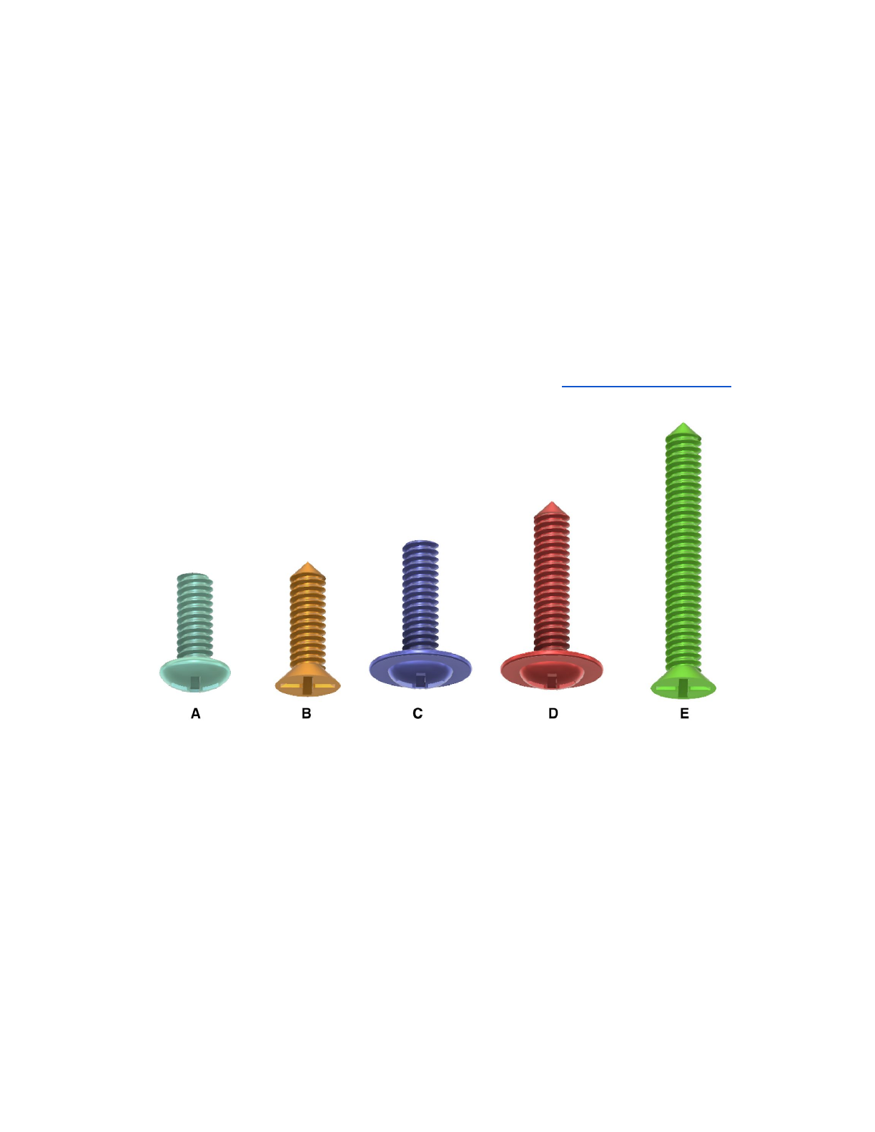
2.3. Screws
There are five different screws used in the kit. I’m coloring them differently to
better indicate their locations. Not all screws are required to assemble Nybble. Not
all holes on the puzzle pieces need screws. Observe the assembling animation
carefully to locate them.
●A is for attaching servo arms. D (sharp tip) is for attaching servos to the frame. A
and D come in each servo's accessory pouch with plastic servo arms.
●B is for attaching servo arms/circuit boards to the frame. In later versions it may
be replaced by C to avoid confusion. In that case, if the hole is too small for
screw C’s flat tip, use screw D to pre-tap.
●C (flat tip) is for binding the thighs.
●E (always the longest) is for attaching the battery holder.
For earlier packages, B, C and E are located in the Shank board within the
multi-punched blocks shown here:
3
2.4. Springs
There are three different springs: F, G, H.
●The big spring F is used for elastic connection in the thigh. There’s one spare
unit;
●The hard short spring G is for the neck. It could be replaced by spring F;
●The soft short spring H is for attaching the battery holder.
3. Assemble the frame
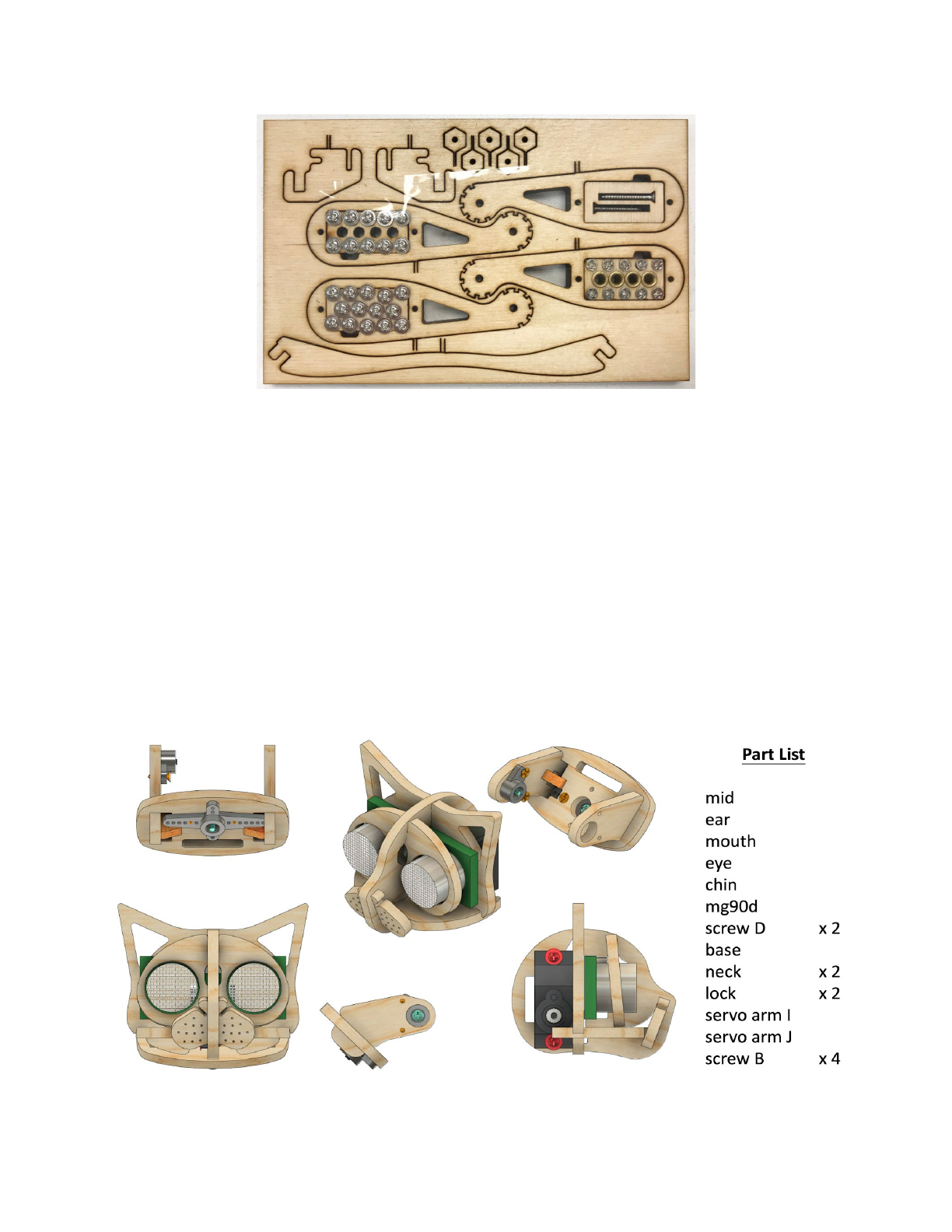
3.1. Head and neck
3.1.1. Part list
4
3.1.2. Solder on the optional LED to ultrasound sensor.
The obstacle avoidance algorithm using the ultrasound sensor has not yet been
integrated in the code. The optional RGB LED can be soldered to the four pins of the
ultrasound sensor (instructions) to indicate its working status, or can be
programmed as decorative lights.
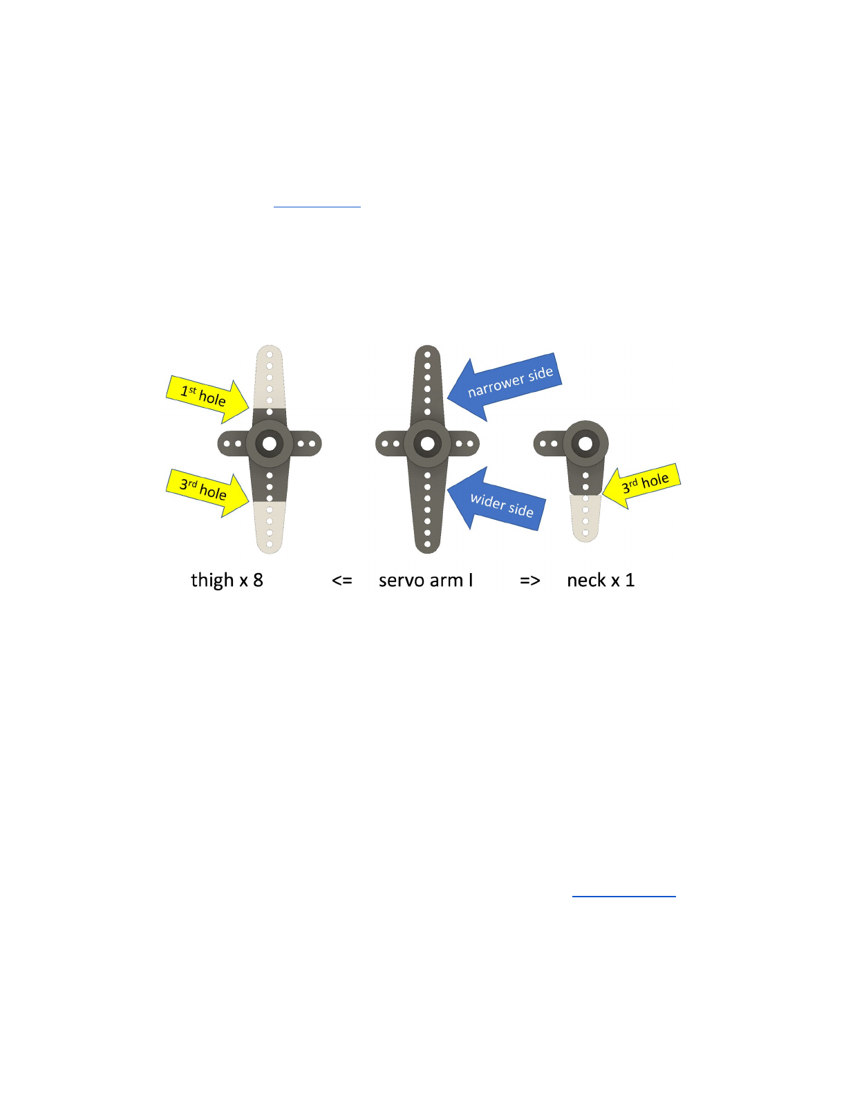
3.1.3. Trim the servo arms for attaching servos.
Pay attention to the width difference between servo arm I’s two long sides, as
well as the trimming location (using screw holes as references).
Most of the servo arms on the model are trimmed from the cross shaped arm I.
Since there will be more unused straight arms, you can practice trimming with them
first.
An alternative method to trimming is using a half burned knife to cut the plastic
parts off. Leave a little bit longer length because melted plastic will have rounded
edge.
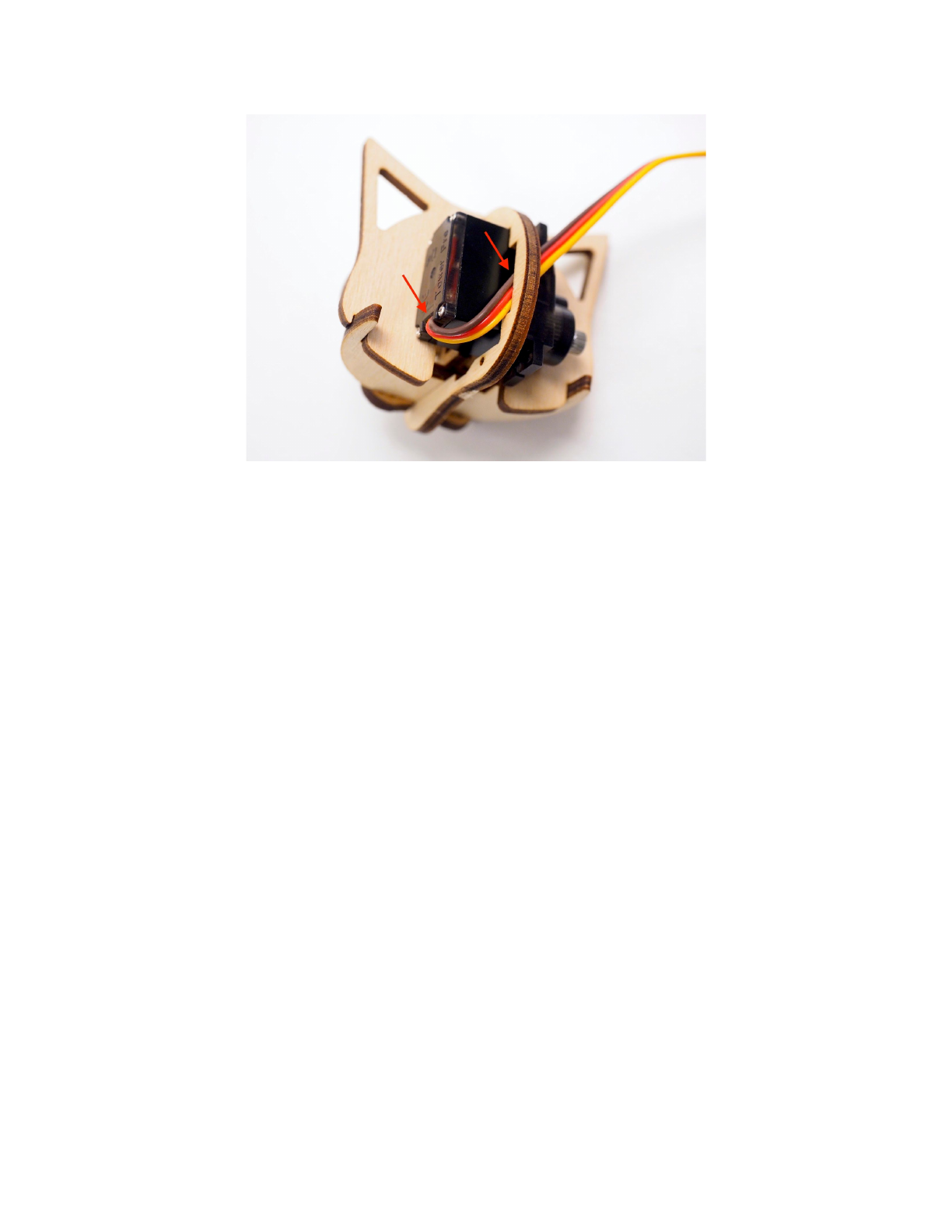
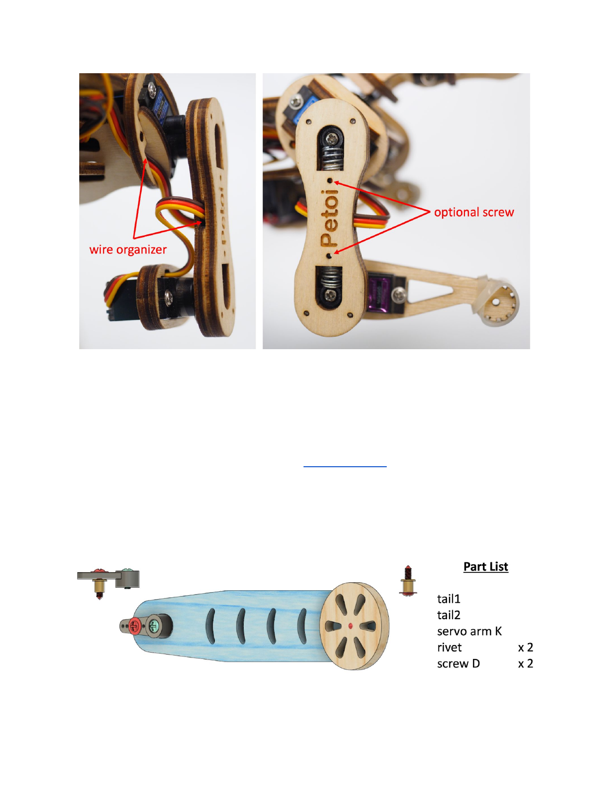
3.1.4. Assemble the head group.
Note that the base should only be partially assembled for later calibration. Otherwise it
will be difficult to insert the servo between neck pieces. Also notice how the servo wire is
organized in the head. Assemble the head group as shown in the head animation
5
3.1.5. DO NOT connect the head with neck yet, because the tilt servo on the head
has to be calibrated.
3.2. Body
3.2.1. Part list
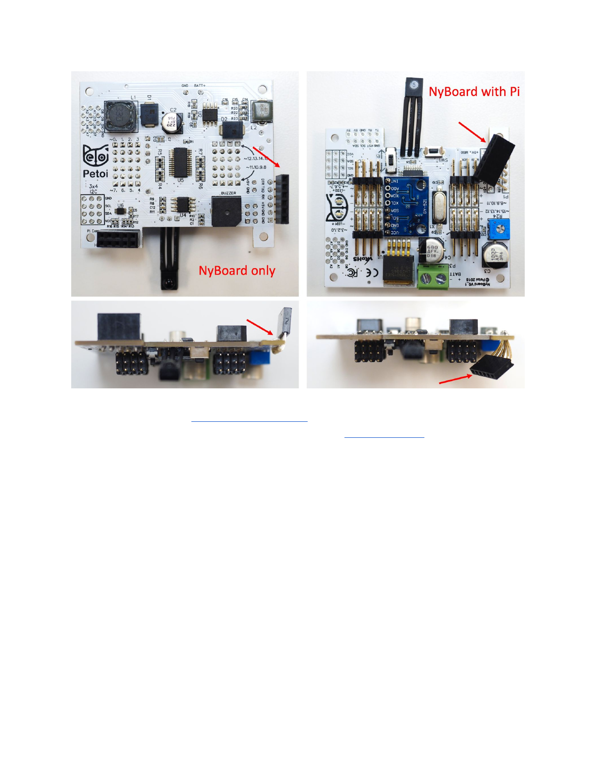
●NyBoard only
6
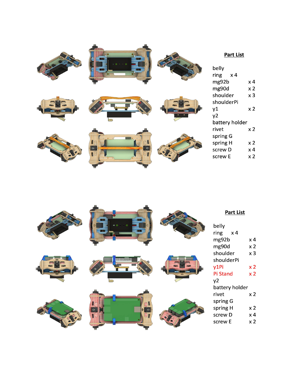
●NyBoard with Raspberry Pi: use y1Pi to replace y1, and add Pi Stand. Pay
attention to the location of pink pieces.
7
●Other controllers
I also included 5 x 1”/4 nuts for mounting other circuit boards.
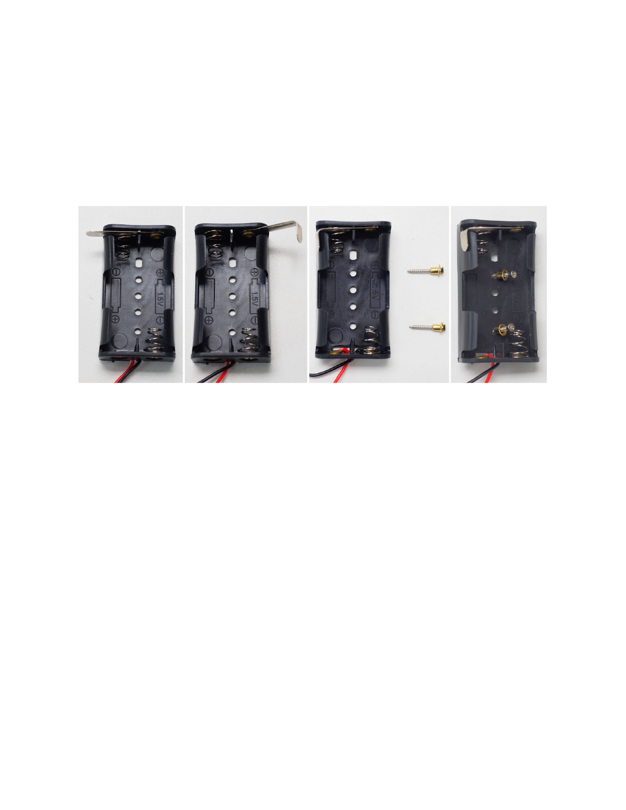
3.2.2. Install the adjustable battery holder to belly
Bend the hinge L of battery holder to 90 degree, close to the wall. It functions as
a switch. Insert the long screw E through the rivet so that you can better handle the
rivet. Insert and push the rivet into the hole on the bottom of the battery holder. Pay
attention to the holes’ locations.
The spring attached structure of the battery holder is used for shifting the center
of mass when fine tuning gaits.
The battery holder is generic for AA (1.5V) batteries. But Nybble uses 3.7V Li-ion
batteries.
3.2.3. Assemble the body group
Pay attention to the long pins of infrared receiver and FTDI port. They are
designed to be bent to favorable directions. Don’t bend the pins too often or it will
lead to metal fatigue.
8
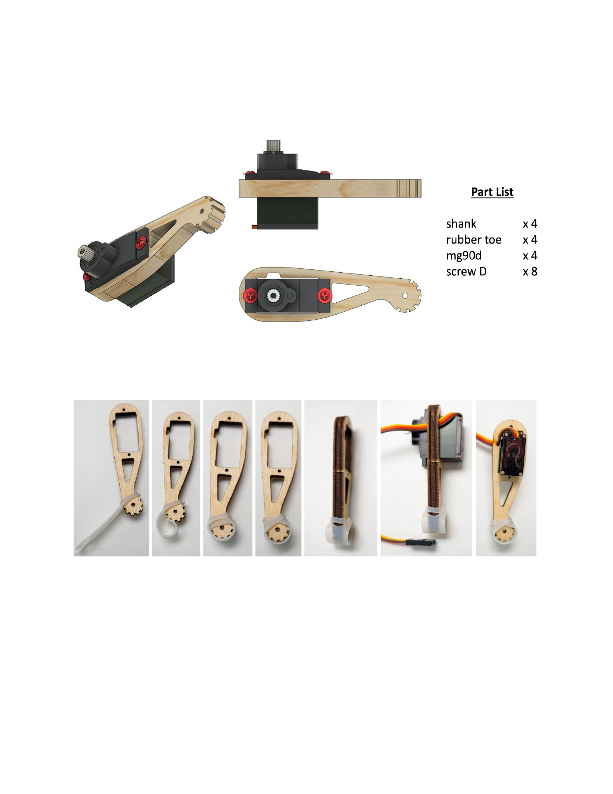
3.3. Shank
3.3.1. Part list
3.3.2. Attach the rubber to the tip of the shank.
The serrated structure on the tip of shank is already good for walking. The
rubber toe is optional to increase friction and soften each step.
3.3.3. Insert the servo into the slot on the shank.
Pay attention to the direction that the wire is twisted. The small dent on the long
edge is designed to let wire go through. Think about symmetry of the four legs.
10
3.3.4. Assemble the shank as shown in the shank animation. Don’t install the servo
screw A yet.
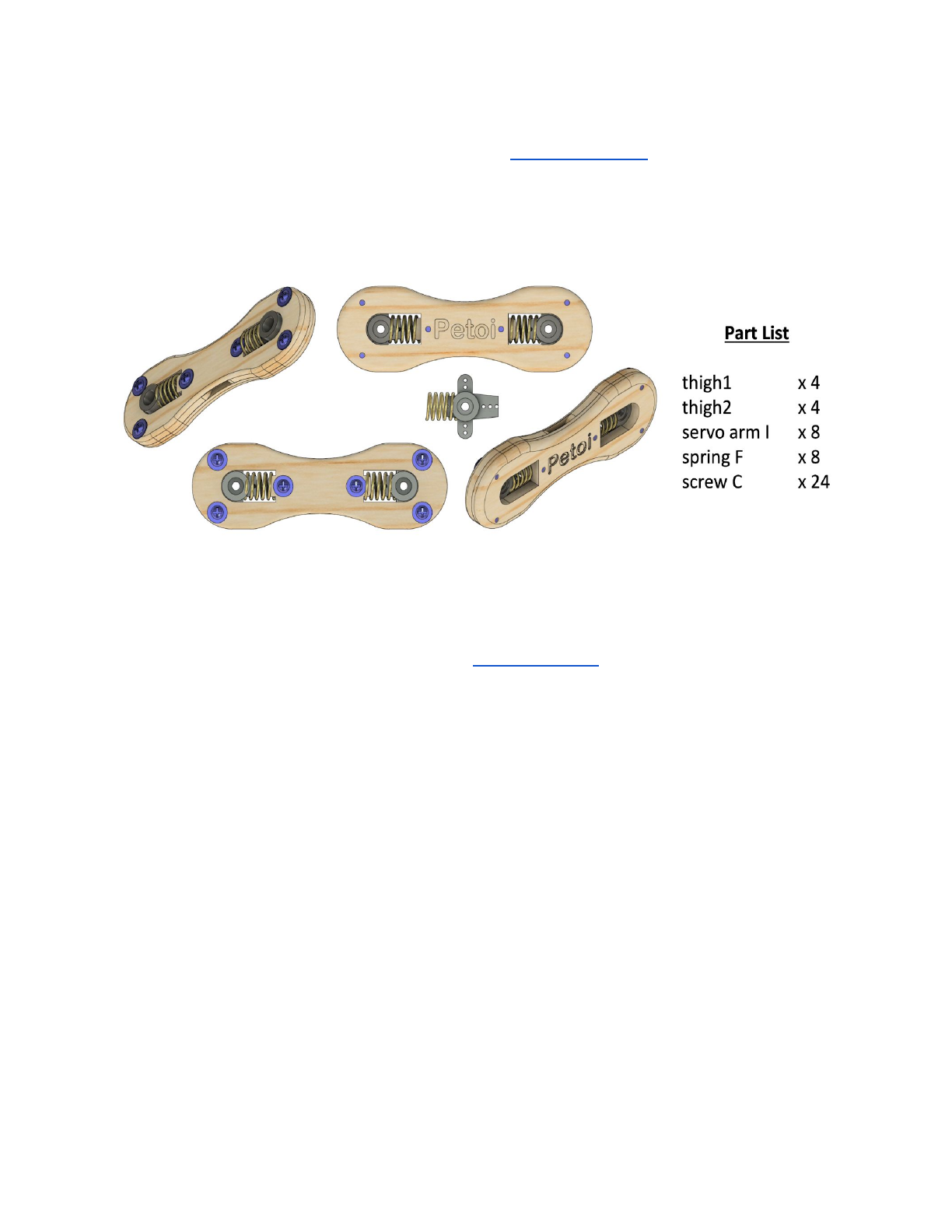
3.4. Thigh
3.4.1. Part list
3.4.2. Trim the servo arms for attaching servos.
The location has been shown in the Head and Neck section. The trimmed
narrower servo arm is designed to be inserted into spring F.
3.4.3. Assemble the thigh.
Before closing thigh1 and thigh2, put the wire of the shank through the slot in
the middle of the thigh. Think about symmetry of the four legs.
11
The servo arm should be able to slide in the track on thigh2 with subtle friction
after thigh1 and thigh2 are screwed together. You can tune the tightness of screw C
to achieve proper friction. If you need more control on the tightness:
●Scratch the track using a flat screw driver to reduce friction.
●Apply a little paper glue in the track and let dry to increase friction.
Assemble the thigh as shown in the thigh animation.
3.5. Tail
3.5.1. Part list
12

3.5.2. Assemble the tail.
The screw D is installed in the third hole counted from the center of the servo
arm K. Pay attention to the order that every piece are stacked. The wheel (tail2)
should be able to rotate with little friction, and the whole tail should be able to tilt by
a small degree.
Assemble the tail as shown in the tail animation.
3.5.3. DO NOT connect the tail to body yet.
3.6. DO NOT screw neck and legs to the body’s servos yet
4. Configure Arduino IDE and NyBoard
4.1. NyBoard
4.1.1. Read the user manual for NyBoard V0.
4.1.2. Dial the potentiometer clockwisely to start from the lowest voltage.
Higher voltage will increase the servos’ torque, making Nybble move faster. The
downside is it will increase current draw, reduce battery life, affect the stability of
circuit, and increase the wearing of the servos. Based on my tests, 5.5V seems to
result in a balanced performance.
4.1.3. Dial the I2C switch (SW2) to Ar.
The I2C switch changes the master of I2C devices (gyro/accelerometer, servo
driver, external EEPROM). On default “Ar”, NyBoard uses the on-board ATmega328P
as the master chip; On “Pi”, NyBoard uses external chips connected through the I2C
ports (SDA, SCL) as the master chip.
4.2. Downloads and installations
Note: You will need the newest Arduino IDE to set up the environment. Older
versions tend to compile larger hex files that may exceed the memory limit.
If you have previously added other libraries and see error message "XXX library
is already installed", I would recommend you delete them first (instruction:
https://stackoverflow.com/questions/16752806/how-do-i-remove-a-library-from-th
e-arduino-environment). Due to different configurations of your Arduino IDE
installation, if you see any error messages regarding missing libraries during later
compiling, just google and install them to your IDE.
13
4.2.1. Install through library manager
Go to the library manager of Arduino IDE (instruction:
https://www.arduino.cc/en/Guide/Libraries), search and install Adafruit PWM
Servo Driver, IRremote and QList.
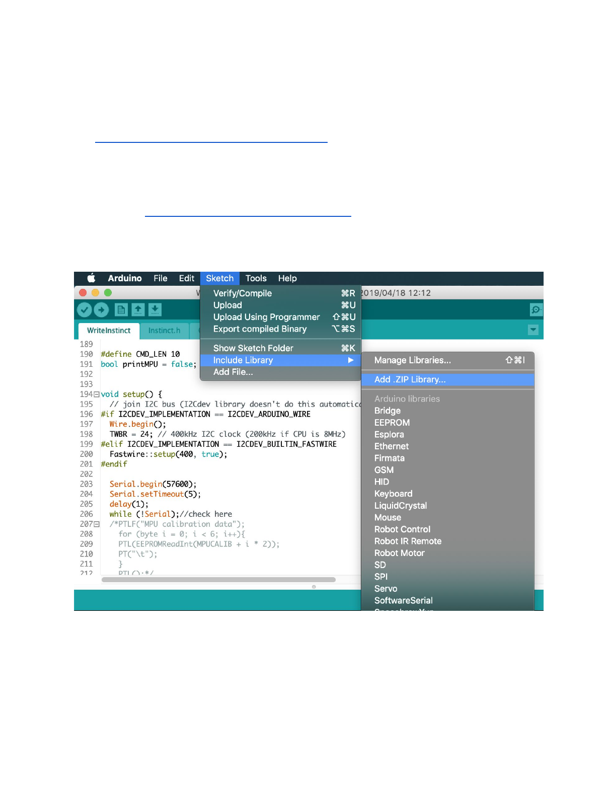
4.2.2. Install by adding .ZIP library
Go to https://github.com/jrowberg/i2cdevlib, download the zip file and unzip.
You can also git clone the whole repository.
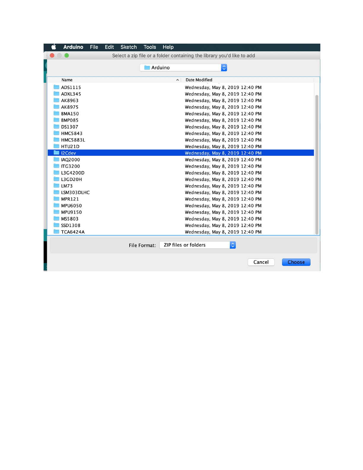
Use Add .ZIP Library to find Arduino/MPU6050/ and Arduino/I2Cdev/. Click on
the folders and add them one by one. They don’t have to be .ZIP files.
14
4.2.3. Create and add NyBoard
●Locate the files
Mac location:
/Users/UserName/Library/Arduino15/packages/arduino/hardware/avr/ve
rsion#/
Or:
/Applications/Arduino.app/Contents/Java/hardware/arduino/avr
To access, right click on Arduino.app and choose Show Package Contents
Windows location:
C:\Program Files(x86)\Arduino\hardware\arduino\avr\
Linux
15

Fedora: boards.txt is symlinked under:
/etc
Arch: boards.txt is found at:
/usr/share/arduino/hardware/archlinix-arduino/avr/
Ubuntu: ?
●Make a copy of boards.txt in case you want to roll back.
●Create new boards.txt.
You can download my boards.txt file, or:
Edit your boards.txt with admin privilege. Find the section of
pro.name=Arduino Pro or Pro Mini
and insert the
## Arduino Pro or Pro Mini (5V, 20 MHz) w/ ATmega328P
code block. Save and quit your editor.
##############################################################
pro.name=Arduino Pro or Pro Mini
pro.upload.tool=avrdude
pro.upload.protocol=arduino
pro.bootloader.tool=avrdude
pro.bootloader.unlock_bits=0x3F
pro.bootloader.lock_bits=0x0F
pro.build.board=AVR_PRO
pro.build.core=arduino
pro.build.variant=eightanaloginputs
## Arduino Pro or Pro Mini (5V, 20 MHz) w/ ATmega328P
## --------------------------------------------------
pro.menu.cpu.20MHzatmega328=ATmega328P (5V, 20 MHz) NyBoard
pro.menu.cpu.20MHzatmega328.upload.maximum_size=30720
pro.menu.cpu.20MHzatmega328.upload.maximum_data_size=2048
pro.menu.cpu.20MHzatmega328.upload.speed=57600
pro.menu.cpu.20MHzatmega328.bootloader.low_fuses=0xFF
pro.menu.cpu.20MHzatmega328.bootloader.high_fuses=0xDA
pro.menu.cpu.20MHzatmega328.bootloader.extended_fuses=0xFD
16
pro.menu.cpu.20MHzatmega328.bootloader.file=atmega/ATmega328_20MHz.hex
pro.menu.cpu.20MHzatmega328.build.mcu=atmega328p
pro.menu.cpu.20MHzatmega328.build.f_cpu=20000000L
## Arduino Pro or Pro Mini (5V, 16 MHz) w/ ATmega328P
## --------------------------------------------------
...
●Download ATmega328_20MHz.hex and put it in your Arduino folder
./bootloaders/atmega/. You should see other bootloaders with .hex suffix in
the save folder.
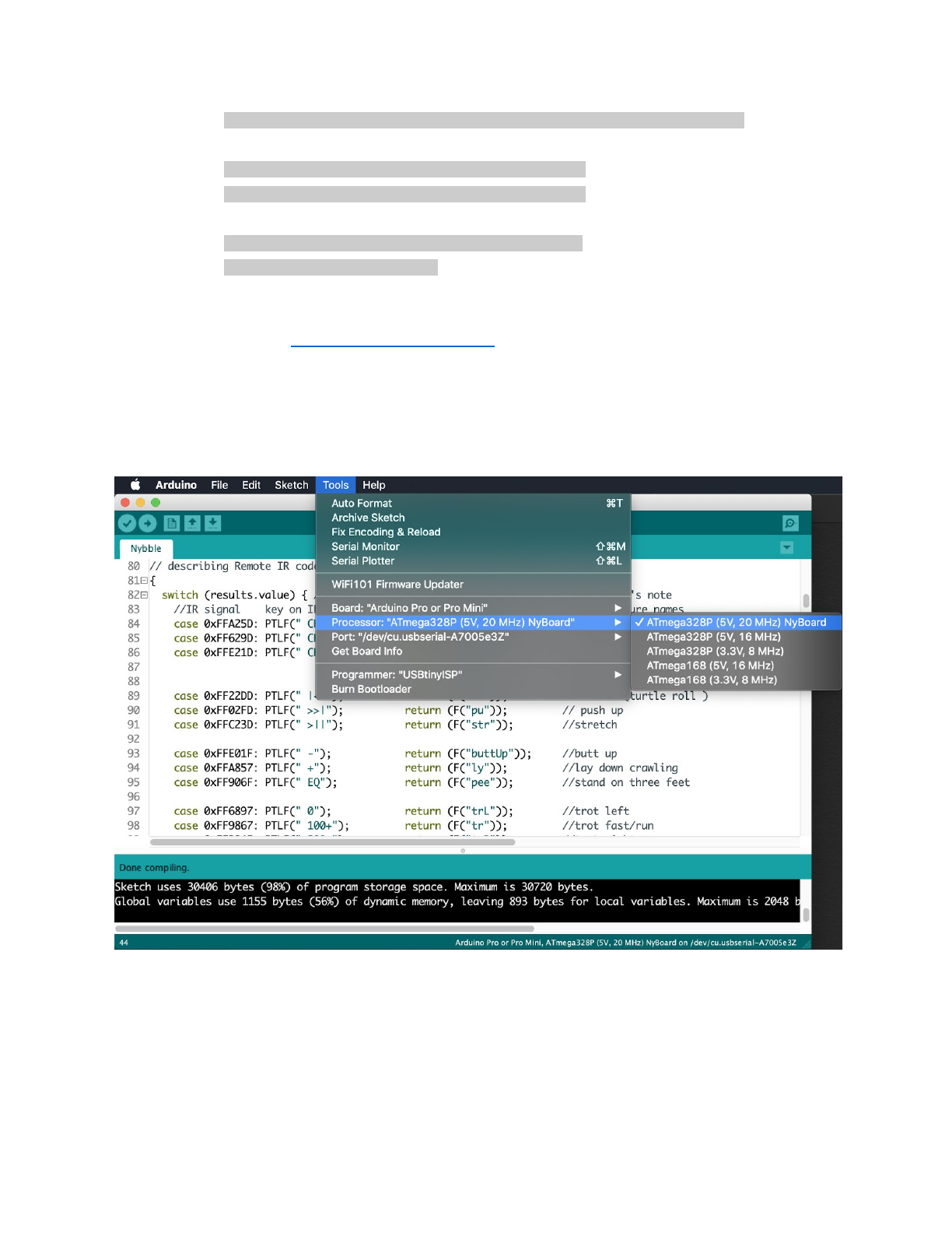
●Restart your Arduino IDE. In Tools->Boards, select Arduino Pro or Pro Mini.
You should find ATmega328P (5V, 20 MHz) in Processor menu.
●Note: If you cannot find the board, your Arduino IDE may be using the
boards.txt in another path. Search boards.txt in all the folders on your
computer. Find out the right file that's in effect.
17
4.2.4. Burn the bootloader (only if the bootloader of NyBoard collapsed)
●What is a bootloader?
Every NyBoard has to go through functionality checks before shipping, so they
should already have compatible bootloader installed. However, in rare cases, the
bootloader may collapse then you won't be able to upload sketch through Arduino
IDE.
Well, it's not always the bootloader if you cannot upload your sketch:
●Sometimes your USB board will detect a large current draw from a device
and deactivate the whole USB service. You will need to restart your USB
service, or even reboot your computers;
●You need to install the driver for the FTDI USB 2.0 to UART uploader;
●You haven't selected the correct port;
●Bad contacts;
●Bad luck. Tomorrow is another day!
If you really decide to re-burn the bootloader:
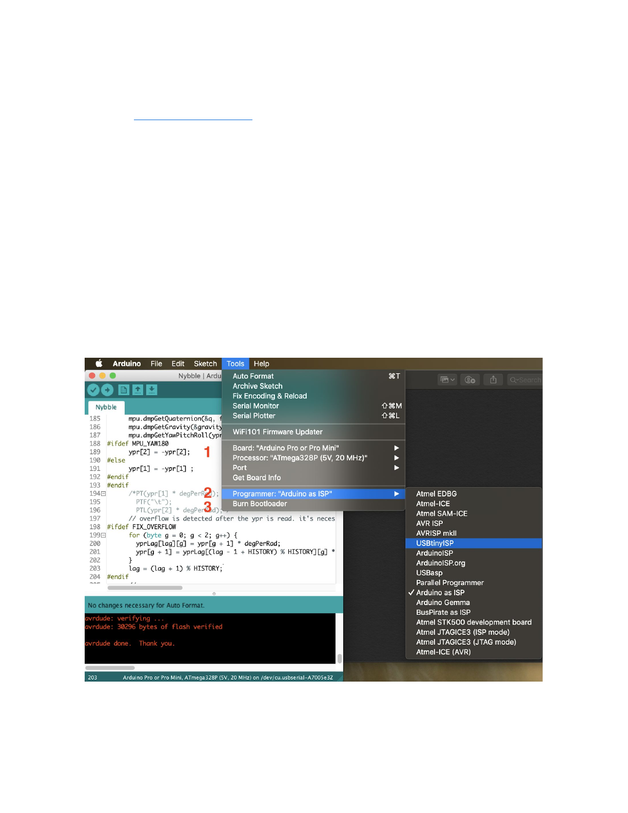
●Select the ATmega328P (5V, 20 MHz) board under the Tool tab of Arduino
IDE.
18
●Select your ISP (In-System Programmer). The above screenshot shows two
popular programmers: the highlighted USBtinyISP is a cheap bootloader you
can buy, while the checked Arduino as ISP can let you use a regular Arduino
as ISP!
●Burn bootloader. If it's your first time doing so, wait patiently until you see
several percent bars reach 100% and no more messages pop up for one
minute.
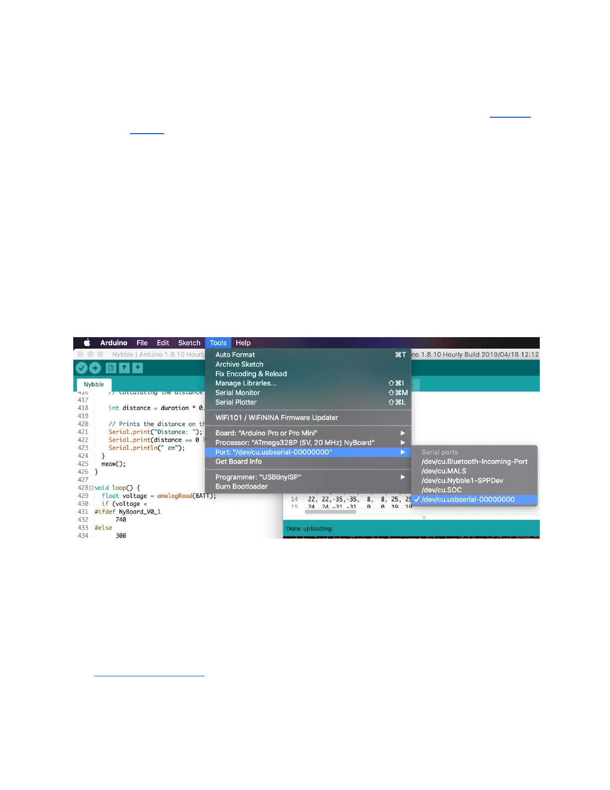
4.2.5. Connect FTDI uploader
Connect your computer with the FTDI uploader (the red chip with 6 male pins)
through USB-miniUSB cable. The uploader has three LEDs, power, Tx and Rx. Right
after connection, the Tx and Rx should blink for one second indicating initial
communication, then dim. Only the power LED should keep litting up. You can find a
new port under Tool->Port as “/dev/cu.usbserial-xxxxxxxx” (Mac) or “COM#”
(Windows).
If Tx and Rx keep litting up, there’s something wrong with the USB
communication. You won’t see the new port. It’s usually caused by overcurrent
protection by your computer, if you’re not connecting NyBoard with external power
supply and the servos move all at once.
4.2.6. Connect bluetooth uploader (optional)
It’s possible to program and communicate with Nybble wirelessly. Check out the
bluetooth instruction on the OpenCat forum (PetoiCamp).
19
4.2.7. Download OpenCat package
●Download a fresh OpenCat repository from GitHub. It’s better if you utilize
GitHub’s version control feature. Otherwise make sure you download the
WHOLE FOLDER every time. All the codes should be the same version to
work together.
●Open any testX.ino sketch with prefix “test”. (I recommend using
testBuzzer.ino as your first test sketch)
●Choose board as Arduino Pro or Pro Mini and compile. There should be no
error messages. Upload the sketch to your board and you should see Tx and
Rx LEDs blink rapidly. Once they stop blinking, messages should appear in
the serial monitor. Make sure that your baud rate setting (57600) and board
frequency(16MHz or 20MHz) matches with the configuration.
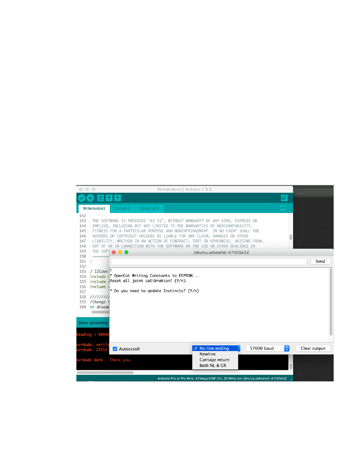
●If there're input prompts, make sure you set "No line ending". Otherwise the
invisible '\n' or '\r' characters will confuse the parsing functions.
20
4.3. Arduino IDE as interface
With the FTDI to USB converter connecting NyBoard and Arduino IDE, you have
the ultimate interface to communicate with NyBoard and change every byte on it.
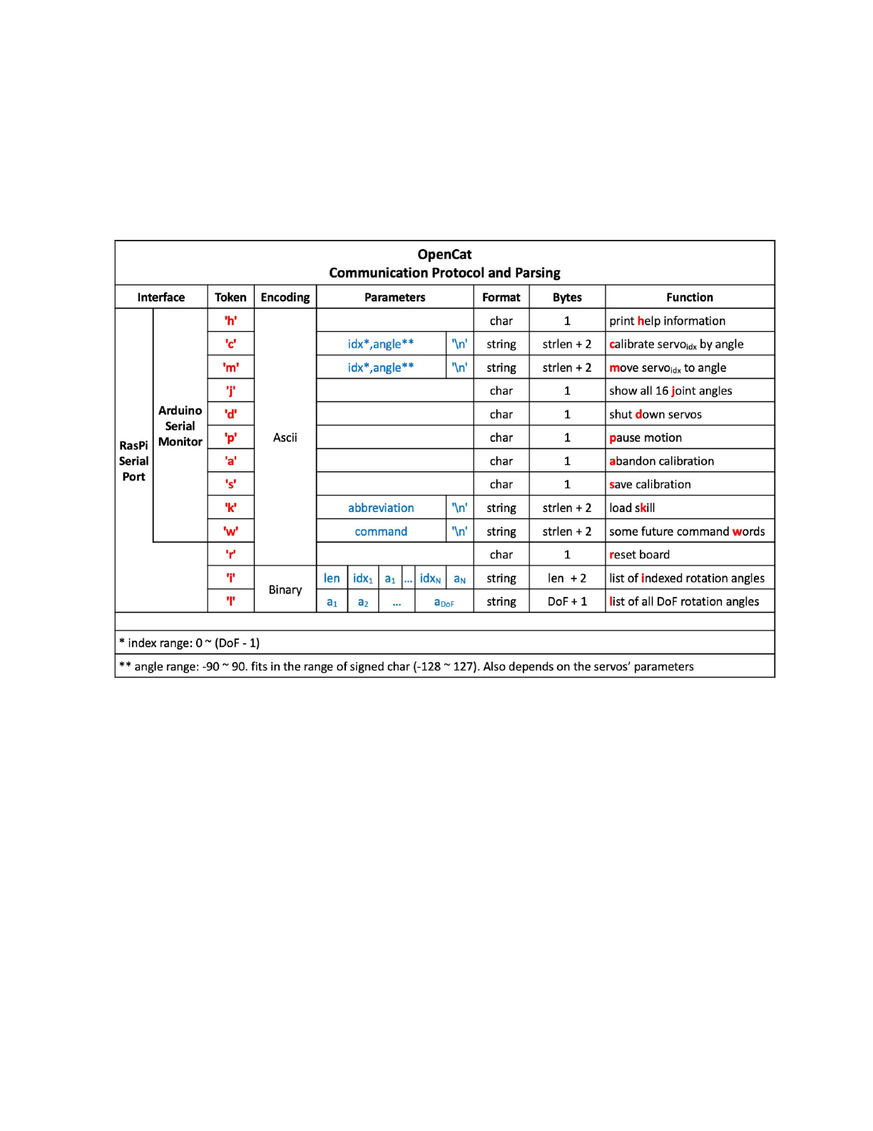
I have defined a set of serial communication protocol for NyBoard:
All the token starts with a single Ascii encoded character to specify its parsing
format. They are case-sensitive and usually in lower case.
Note: Some tokens haven't been implemented, such as 'h'. Token 'i' and 'l' still
have some bugs.
4.4. Raspberry Pi serial port as interface (only if you are going to use Pi as
a master controller)
As shown in the serial protocol, the arguments of tokens supported by Arduino
IDE's serial monitor are all encoded as Ascii char strings for human readability.
While a master computer (e.g. RasPi) supports extra commands, mostly encoded
as binary strings for efficient encoding.
21

4.4.1. Config Raspberry Pi serial port
In Pi's terminal, type sudo raspi-config
Under Interface option, find Serial. Disabled the serial login shell and enable the
serial interface.
A good tutorial on Instructable
If you plug Pi into NyBoard's 2x5 socket, their serial ports should be
automatically connected at 3.3V. Otherwise pay attention to the Rx and Tx pins on
your own AI chip, and its voltage rating. The Rx on your chip should connect to the
Tx of NyBoard, and Tx should connect to Rx.
4.4.2. Change the permission of ardSerial.py
If you want to run it as bash command, you need to make it executable:
chmod +x ardSerial.py
You may need to change the proper path of your Python binary on the first line:
#!/usr/bin/python
4.4.3. Use ardSerial.py as the commander of Nybble
You need to UNPLUG the FTDI converter if you want to control Nybble with Pi's
serial port.
Typing ./ardSerial.py <args> is almost equivalent to typing <args> in Arduino's
serial monitor.
For example, ./ardSerial.py kcr means "perform skill crawl".
Both ardSerial.py and the parsing section in Nybble.ino need more
implementations to support all the serial commands in the protocol.
Note: Reduced motion capability when connected to Pi!
With the additional current draw by Pi, Nybble will be less capable for intense
movements, such as trot (the token is “ktr”). The system is currently powered by
two 14500 batteries in series. You may come up with better powering solutions,
such as using high drain 7.4 Lipo batteries, or 2S-18650. There're a bunch of
considerations to collaborate software and hardware for a balanced performance.
With Nybble's tiny body, it's better to serve as a platform for initiating the
communication framework and behavior tree rather than a racing beast.
22

4.5. Battery
Though you can program NyBoard directly with the FTDI uploader, external
power is required to drive the servos.
When powering the NyBoard with only USB FTDI, there's obviously charging and
uncharging in the servo's capacitor and cause the yellow LED to pulse. However the
USB's current is not sufficient to keep the servos working. The servo circuit has to
be powered by external batteries to work properly.
4.5.1. Voltage
NyBoard requires 7.4~12V external power to drive the servos. That's usually two
li-ion or li-poly batteries connected in series. A single battery is 4.2V when fully
charged and can work normally until voltage drops to 3.6V. That’s about 7.2V with
two batteries connected in series. Before installation, dial the potentiometer on
NyBoard clockwisely to try minimum output first for best output stability. You can
turn it up depending on your future needs.
Note:
When looking for batteries, search for keywords “14500 3.7V li-ion battery”. I’ve
noticed that the overcurrent protection of some batteries could be triggered by peak
current draw(usually >2.5A), causing NyBoard to reset. Try find batteries with higher
discharge rating.
4.5.2. Dimensions
The included battery holder is sized for 14500 batteries, that’s 14 mm in
diameter, and 50 mm in length. 50 ± 1 mm should still fit in. They are the same size
as AA batteries, but much more powerful. Make sure not to use them in regular AA
devices. If you are in the US, we have tested with EBL 14500 li-ion batteries.
You can also design other battery holders to carry larger batteries for better
performance. That’s especially necessary if you mount a Raspberry Pi or want
Nybble run faster.
4.5.3. Connection
Be careful with the polarity when connecting the power supply. Reversed
connection may damage NyBoard! Make sure you can find the positive (+)
and negative (-) sign on both the NyBoard's power terminal and your power supply.
23

Loosen the screws of the power block. Insert the wires of the battery holder then
tighten the screws. When turn the switch on, both the blue LED (for chip) and the
yellow LED (for servo) should lit up.
4.5.4. Battery life varies according to usage
It can last hours if you're mainly coding and testing postures, or less than 30
mins if you keep Nybble running.
When the battery is low, the yellow LED will blink slowly. Although NyBoard can
still drive one or two servos, it will be very unstable to drive multiple servos at once.
That will lead to repeatedly restarting the program, or awkward joint rotations. In
rare cases, it may even alter the bits in EEPROM. You will need to reupload the
codes and re-save the constants to recover.
4.5.5. Charging
You will need compatible smart chargers for the batteries. Keep batteries
attended during charging.
4.5.6. After use
After playing, remember to remove the batteries from battery holder to avoid
over discharging.
4.5.7. Signal Interference
It's ok to connect both FTDI and battery at the same time. You can type in serial
commands while the battery is connected. I do notice that the USB serial port could
be disabled randomly. I think that's due to the sudden current draw by servos. It will
trigger the computer’s over current protection and disable the USB port. In that
case, you can change the USB port you're connecting to, reset the USB bus, or
restart the computer. So actually it’s better to power the board by battery before
plug in the FTDI.
5. Connect servos
5.1. Joint map
Nybble's servos are connected to NyBoard's PWM pins symmetrically and
resembles the nerves along the spinal cord. Though Nybble doesn't have shoulder
roll DoF, those indexes(4~7) are reserved for the full OpenCat framework.
24
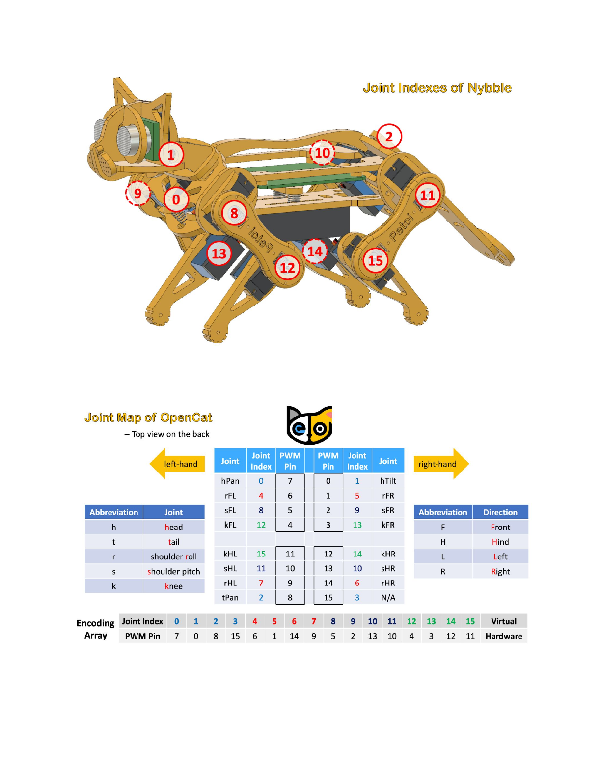
Use h for head, t for tail, r for shoulder roll joint, s for shoulder pitch joint, k for
knee joint, F for front, H for hind, L for left, R for right, the full joints map of OpenCat
is:
25
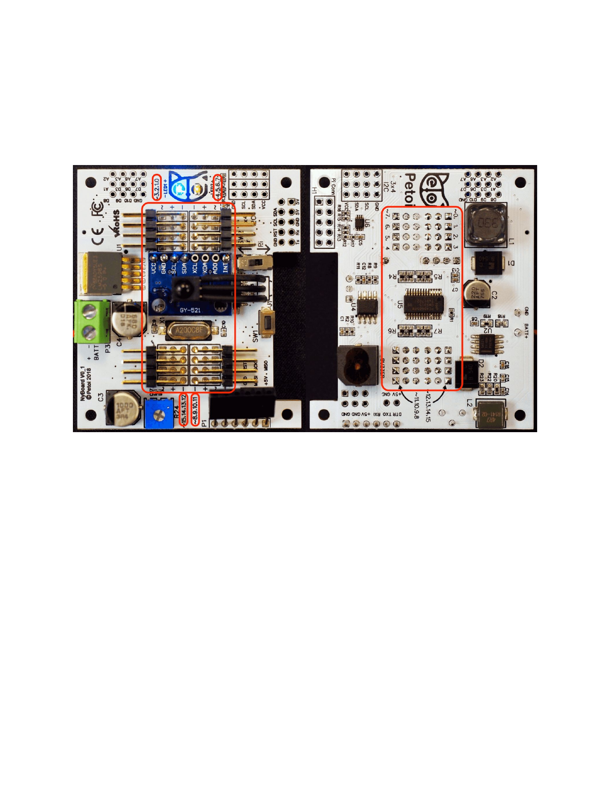
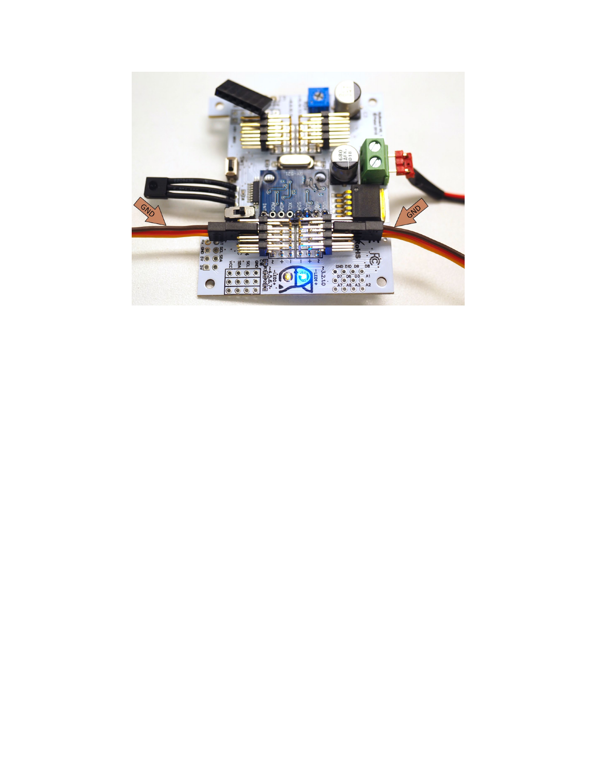
5.2. Plug in the servos
Observe the indexing pattern to connect servos with correct PWM pins. Be
careful with the wires’ direction. The brown wire of servo is GND, while the GND on
NyBoard V0_1 are along the centerline. On NyBoard V0_2 they are opposite.
A quick check is that all the brown wires should be on top of the other two wires.
On NyBoard V0_2 the yellow wires should be on top of the other two wires.
26
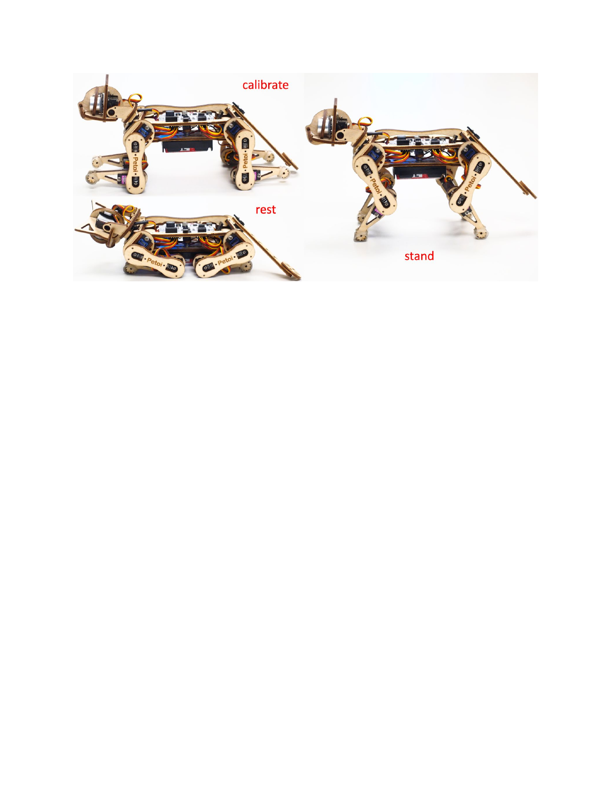
6. Calibration
Calibration is vital for Nybble to work properly.
In previous sections, we have prepared those body parts but haven’t screw them
onto servos. If we don’t calibrate the servos before attaching them, they may rotate
to any direction, get stuck, and cause damage to either the servos or body parts.
The calibration has four steps: 1.Write constants to the board; 2. Power on the
circuit, let servos rotate freely to zero angle/calibration state; 3. Attach body parts
to the servos; 4. Fine tune the offsets in software.
6.1. Write constants
6.1.1. There are three types of constants to be saved to NyBoard:
●Assembly related definitions, like joint mapping, rotation direction, sensor
pins. They are pretty fixed and are mostly defined in OpenCat.h. They are
even kept consistent with my future robots;
●Calibration related parameters, like MPU6050 offsets and joint corrections.
They are measured in realtime and are saved in on-board EEPROM. They only
need to be measured once;
●Skill related data, like postures, gaits, and pre-programmed behaviors. They
are mostly defined in Instinct.h. You can add more customized skills too.
27
6.1.2. Upload and run WriteInstinct.ino.
The role for WriteInstinct.ino is to write constants to either onboard or I2C
EEPROM, and save calibration values. It will be overwritten by the main sketch
Nybble.ino afterward.
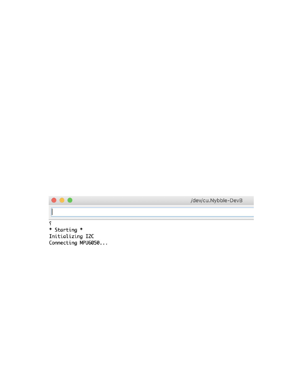
After finish uploading WriteInstinct.ino, open the serial monitor. You will see
several questions:
●Reset all joint calibration? (Y/n)
If you have never calibrated the joints, or if you want to recalibrate the
servos with fresh start, type ‘Y’ to the question. The ‘Y’ is CASE SENSITIVE!
●Do you need to update Instincts? (Y/n)”
If you have modified the Instinct.h in any way, you should type ‘Y’. Though
it’s not always necessary once you have a deeper understanding of the
memory management.
●Calibrate MPU? (Y/n)
If you have never calibrated the MPU6050, i.e. the gyro/accelerometer
sensor, type ‘Y’.
Sometimes the program could hang at the connection stage. You can close the
serial monitor and reopen it, or press the reset button on NyBoard, to restart the
program.
6.2. Enter calibration mode
The calibration state is defined as the middle point of servo’s reachable range.
Calibration for servos can be done in either WriteInstinct.ino or Nybble.ino. I
recommend you do it with WriteInstinct.ino in case there’s something wrong with
the constants.
You MUST plug in all the servos and battery for proper calibration. Then in the
serial monitor, type ‘c’ to enter calibration mode. The servos should rotate, make
noise, then stop. You will see the calibration table:
28
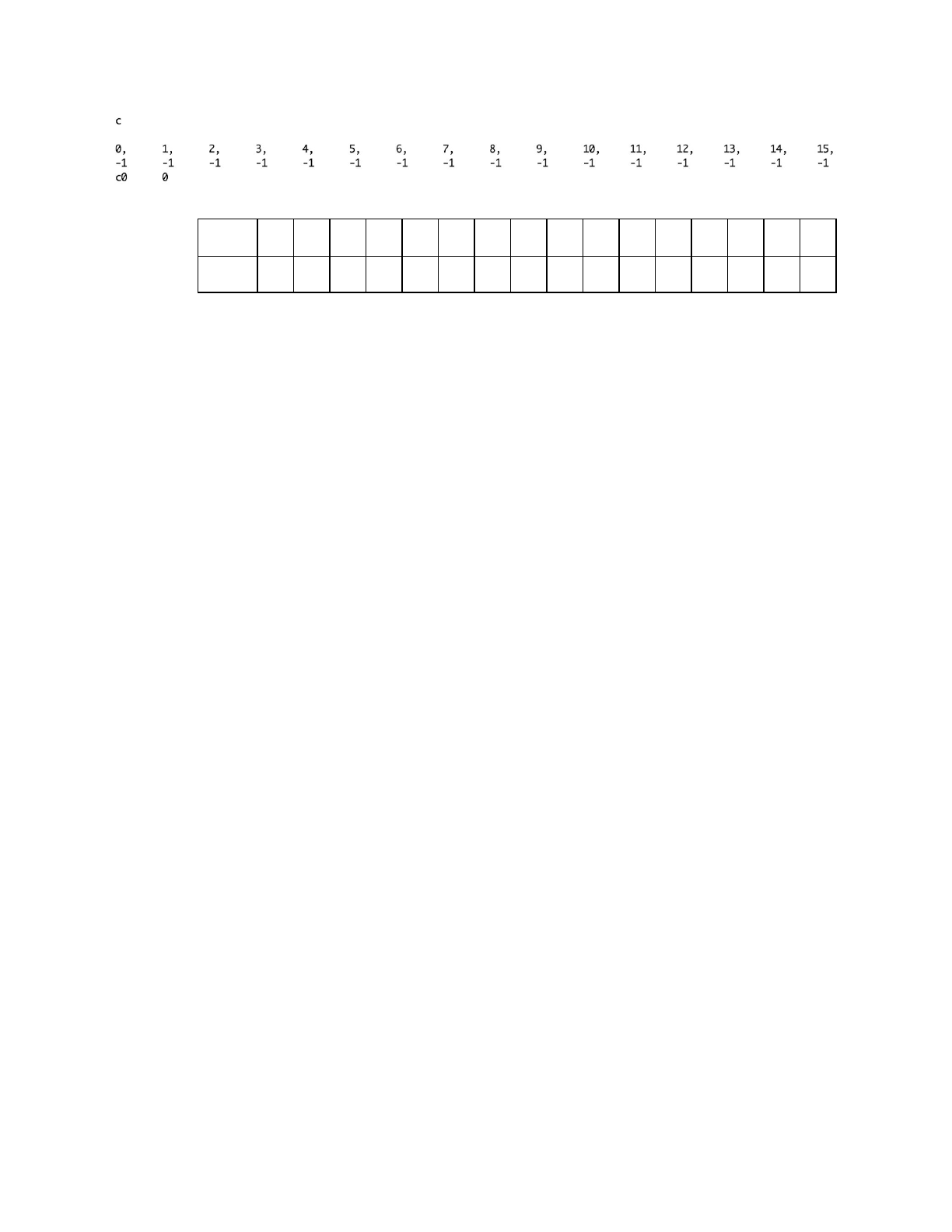
The first row is the joint indexes, the second row is their calibration offsets:
Index
0
1
2
3
4
5
6
7
8
9
10
11
12
13
14
15
Offset
-1
-1
-1
-1
-1
-1
-1
-1
-1
-1
-1
-1
-1
-1
-1
-1
Initial values are “-1”, and should be changed by later calibration.
Note: The servos are using potentiometer in feedback loop for position control.
When holding at static position, they tend to vibrate around target angle. This
Parkinson’s will develop after a short period of use. It won’t affect much during
continuous motion. Better servos without this troubles could cost 10 times more. So
replacing failed unit is a more cost effective solution.
6.3. Attach head, tail, and legs.
6.3.1. Coordinate system
With all servos rotated to their zero angle, now attached the head, tail, and legs
prepared in previous section to the body. They are generally perpendicular to their
linked body frames. Avoid rotating the servo shaft during the operation.
Rotating the limbs counter-clockwise from their zero state will be positive (same
as in polar coordinates). The only exception is the tilt angle for head. It’s more
natural to say head up, while it’s the result from rotating clockwisely.
29
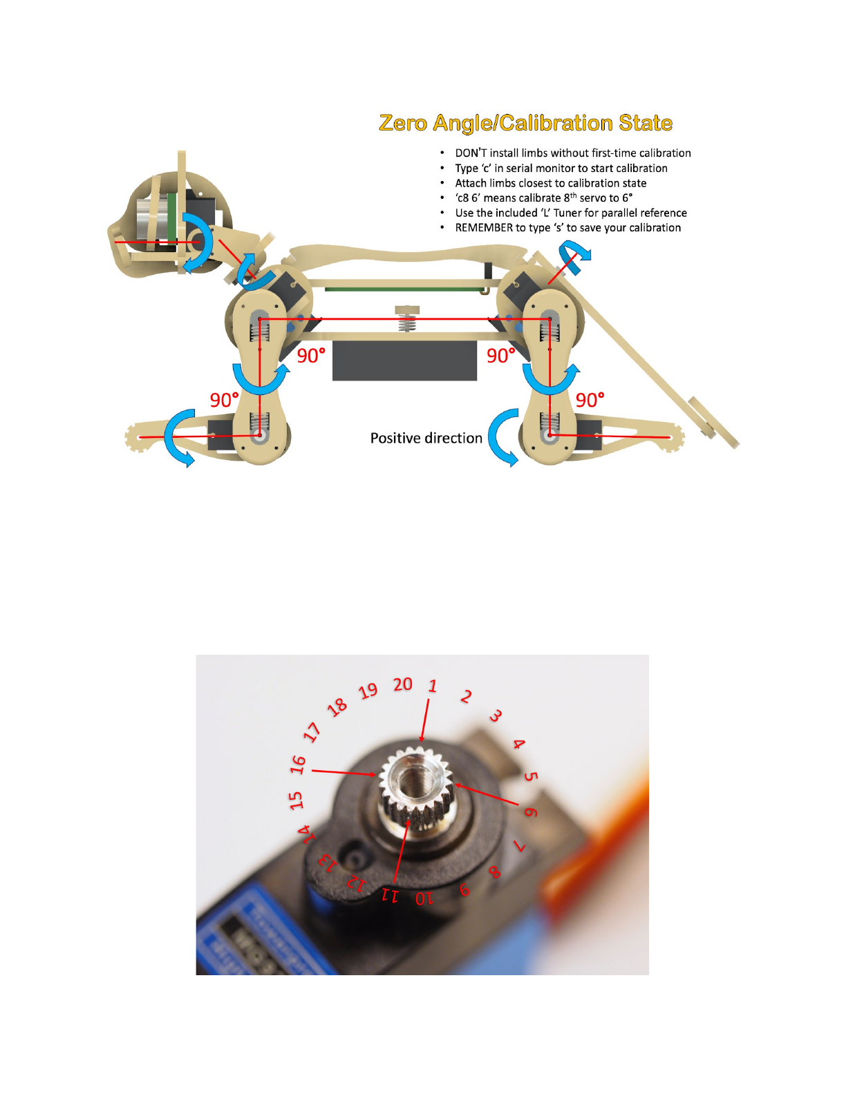
6.3.2. Understand the angle divisions
If we take a close look at the servo shaft, we can see it has a certain number of
teeth. That’s for attaching the servo arms, and avoid sliding in the rotational
direction. In our servo sample, the gears are dividing 360 degrees to 20 sectors,
each taking 18 degrees. That means we cannot always get exact perpendicular
installation. But try to get them as close as possible to their zero states. Use screw
A to fix the limbs onto servos.
30
6.4. Find and save calibration offsets
6.4.1. Fine tune the calibration on software side
The command for calibration (refer to the serial communication protocol for
NyBoard) is formatted as cIndex Offset. Notice that there’s a space between Index
and Offset.
For example, c8 6 means giving the 8th servo an offset of 6 degrees. Find the
best offset that can bring the limb to zero state.
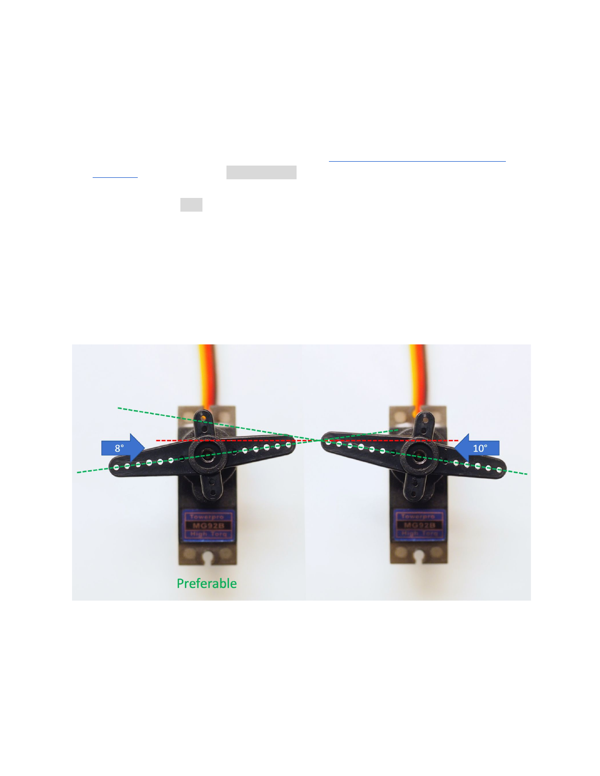
Note that if you find the absolute value of offset is larger than 9, that means you
are not attaching the limb closest to its zero state. That will result in decreased
reachable range of the servo on either side. Take off the limb and rotate it by one
tooth. It will result in an opposite but smaller offset.
For example, if you have to use -13 as the calibration value, take the limb off,
rotate by one tooth then attach back. The new calibration value should be around 5,
i.e., they sum up to 18. Avoid rotating the servo shaft during this adjustment.
After calibration, remember to type ‘s’ to save the offsets. Otherwise they will be
forgotten when exiting the calibration state. You can even save every time after
you’re done with one servo.
31
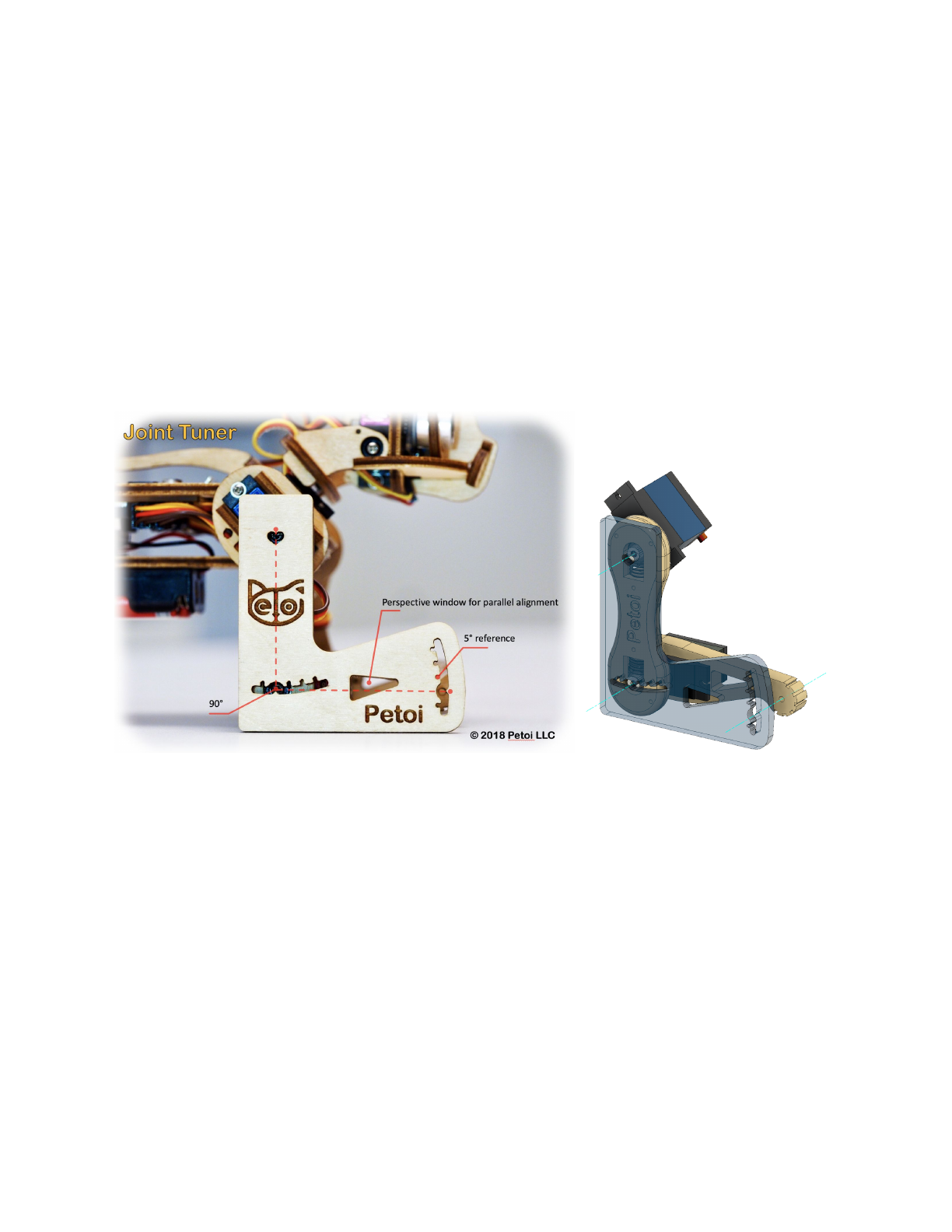
6.4.2. ‘L’ shaped joint tuner
When watching at something, the observation will change from different
perspectives. That’s why when measuring length, we always want to read directly
above the ruler.
It’s especially important that you keep parallel perspective when calibrating
Nybble. Use the 'L' shaped joint tuner as a parallel reference to avoid reading errors.
Align the tips on the tuner with the center of the screws in shoulder and knee joints,
and the little hole on the tip of the foot. Look along the co-axis of the centers. For
each leg, calibrate shoulder servos (indexed 8~11) first, then the knee
servos(indexed 12~15). When calibrating the knee, use the matching triangle
windows on both the tuner and shank to ensure parallel alignment.
6.4.3. Validation
After calibration, type ‘d’ or ‘kbalance’ to validate the calibration. It will result in
Nybble symmetrically moving its limbs between rest and stand state.
32
6.4.4. Center of mass
Try to understand how Nybble keeps balance even during walking. If you are
adding new components to Nybble, try your best to distribute its weight
symmetrically about the spine. You may also need to slide the battery holder back
and forth to find the best spot for balancing.
7. Play with Nybble (default usage)
7.1. Control with Arduino IDE
The quotation mark just indicates they are character strings. Don’t type
quotation mark in the serial monitor.
●“ksit”
●“m0 30”
●“m0 -30”
●“kbalance”
●“ktr”
●“ktrL”
●“d”
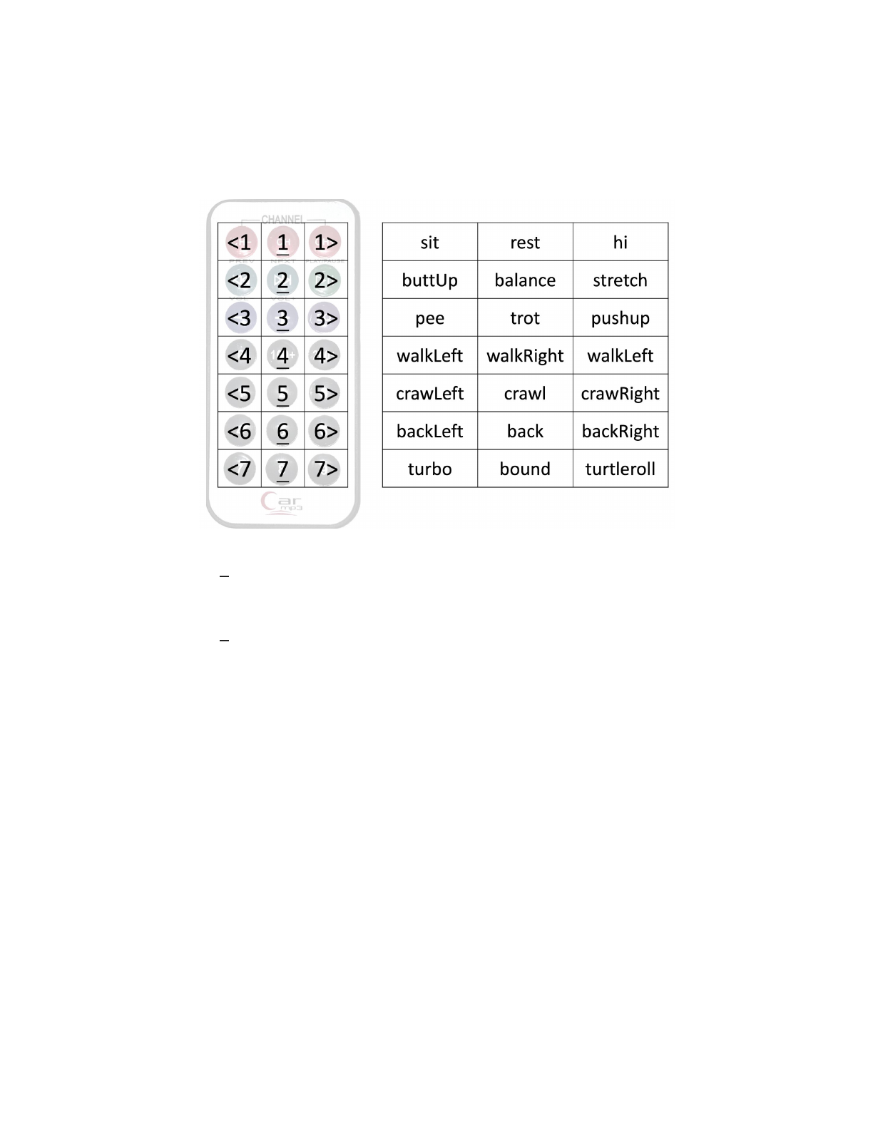
7.2. Control with Infrared remote
7.2.1. Key map
Only the position of the buttons matters, though those symbols can help you
remember the functionalities. I’m going to define position related symbols to refer
to those keys.
33
I’m using abbreviations for key definitions to reduce SRAM usage. The following
map is just an illustration. Check function String translateIR(){...} in Nybble.ino for
the actual key definitions. I always change the definitions for fun. They are also
open to your customization.
7.2.2. Check out the following featured motions
● Button 1 shuts down the servos and send Nybble to sleep. It's always safe to click it if
Nybble is doing something AWKWARD. I’m serious. There’s still some ghost in the
system I don’t fully understand.
● Button 2 is the neutral standing posture. You can push Nybble from side, or make it
stand up will hind legs and tail. You can test its balancing ability on a fluctuating board.
Actually balancing is activated in most postures and gaits.
● Lift Nybble at the middle of its spine so that all its legs can move freely in the air. Click
all the buttons on the IR remote to see what they do. Then put Nybble on a wide flat
table and try those buttons again. Different surface have different friction and will
affect walking performance. Carpet will be too bushy for Nybble’s short legs. It can
only crawl (command kcr) over this kind of tough terrain.
● You can pull the battery pack down and slide along the longer direction of the belly.
That will tune the center of mass, which is very important for walking performance.
Otherwise it may keep falling down.
● When Nybble is walking, you can let it climb up/down a small slope (<10 degrees)
● Whatever Nybble is doing, you can lift it vertically, and it will stop moving, just like a
cat scruffed on the neck.
● The servos are designed to be driven by internal gears. Avoid rotating the servos too fast
from outside.
34
● Don’t keep Nybble walking for too long. That will overheat the electronics and reduce
the servos’ life span. It’s possible to reconfigure NyBoard V0_1 to make Nybble run
longer.
● Sometimes the program may halt due to voltage fluctuation. Check if the battery is
running low (< 3.5V each or <7.0V in series). Press the reset button on NyBoard to
restart the program.
● Be kind as if you were playing with a real kitten. (^=◕◕=^)
8. Teach Nybble new skills (advanced)
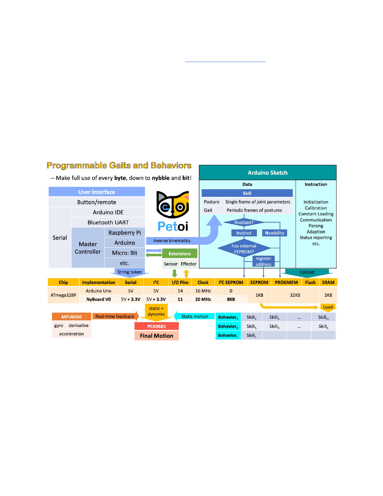
8.1. Understand skills in Instinct.h.
One frame of joint angles defines a static posture, while a series of frames
defines a periodic motion, usually a gait.
EEPROM has limited (1,000,000) write cycles. So I want to minimize write
operations on it.
There are two kinds of skills: Instincts and Newbility. The addresses of both are
written to the onboard EEPROM(1KB) as a lookup table, but the actual data is
stored at different memory locations:
●I2C EEPROM (8KB) stores Instincts.
35

The Instincts are already fine-tuned/fixed skills. You can compare them to
“muscle memory”. Multiple Instincts are linearly written to the I2C EEPROM only
once with WriteInstinct.ino. Their addresses are generated and saved to the lookup
table in onboard EEPROM during the runtime of WriteInstinct.ino.
●PROGMEM (sharing the 32KB flash with the sketch) stores Newbility.
A Newbility is any new experimental skill that requires a lot of tests. It's not
written to the I2C nor onboard EEPROM, but the flash memory in the format of
PROGMEM. It has to be uploaded as one part of Arduino sketch. Its address is also
assigned during the runtime of the code, though the value rarely changes if the total
number of skills (including all Instincts and Newbilities) is unchanged.
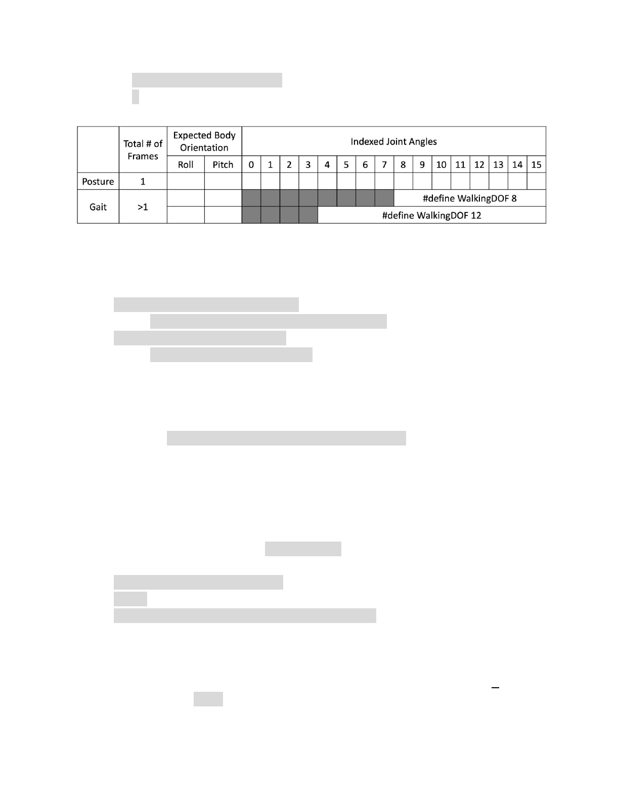
8.2. Example Instinct.h
#define WalkingDOF 8
#define NUM_SKILLS 6
#define I2C_EEPROM
const char cr[] PROGMEM = {
26, 0, -5,
35, 37,-46,-53,-23,-32, -3, 12,
40, 28,-42,-59,-24,-28, -4, 12,
...
33, 39,-47,-51,-22,-32, -3, 11,
};
const char stair[] PROGMEM = {
54, 0, 30,
44, 90,-39,-38, 10,-32,-10, 32,
45, 90,-32,-46, 16,-38,-16, 38,
…
43, 90,-44,-32, 6,-26, -6, 26,
};
const char pu1[] PROGMEM = {
1, 0, 0,
0,-30, 0, 0, 0, 0, 0, 0, 20, 20, 60, 60, 60, 60,-55,-55,};
const char pu2[] PROGMEM = {
1, 0, 0,
0, 10, 0, 0, 0, 0, 0, 0, 60, 60, 40, 40,-45,-45,-55,-55,};
const char rest[] PROGMEM = {
36

1, 0, 0,
-30,-80,-45, 0, -3, -3, 3, 3, 60, 60,-60,-60,-45,-45, 45, 45,};
const char zero[] PROGMEM = {
1, 0, 0,
0, 0, 0, 0, 0, 0, 0, 0, 0, 0, 0, 0, 0, 0, 0, 0,};
#if !defined(MAIN_SKETCH) || !defined(I2C_EEPROM)
const char* skillNameWithType[] =
{"crI", "stairN", "pu1I", "pu2I", "restI", "zeroN",};
const char* progmemPointer[] =
{cr, stair, pu1, pu2, rest, zero, };
#else
const char* progmemPointer[] = {stair, zero};
#endif
8.2.1. Defined constants
#define WalkingDOF 8
Means the number of DoF for walking is 8 on Nybble.
#define NUM_SKILLS 6
Means the total number of skills is 6. It should be the same as the number of
items in list const char* skillNameWithType[].
#define I2C_EEPROM
Means there’s an I2C EEPROM on NyBoard to save Instincts. If you are
building your own circuit board that doesn’t have it, comment out this line.
Then both kinds of skills will be saved to the flash as PROGMEM.
8.2.2. Data structure of skill array
Observe the following two skills:
const char rest[] PROGMEM = {
1, 0, 0,
-30,-80,-45, 0, -3, -3, 3, 3, 60, 60,-60,-60,-45,-45, 45, 45,};
const char cr[] PROGMEM = {
26, 0, -5,
35, 37,-46,-53,-23,-32, -3, 12,
40, 28,-42,-59,-24,-28, -4, 12,
...
37
33, 39,-47,-51,-22,-32, -3, 11,
};
They are formatted as:
8.2.3. Suffix for indicating Instinct and Newbility
You must upload WriteConst.ino to have the skills written to EEPROM for the
first time. The following information will be used:
const char* skillNameWithType[] =
{"crI", "stairN", "pu1I", "pu2I", "restI", "zeroN",};
const char* progmemPointer[] =
{cr, stair, pu1, pu2, rest, zero, };
Notice the suffix I or N in the skill name strings. They tell the program where to
store skill data and when to assign their addresses.
Later, if the uploaded sketch is main sketch Nybble.ino, and if you are using
NyBoard that has an I2C EEPROM, the program will only need the pointer to
Newbility list const char* progmemPointer[] = {stair, zero}; to extract the full
knowledge of pre-defined skills.
8.3. Define new skills
There’s already a skill named “zeroN” in Instinct.h. It’s a posture at zero state
waiting for your new definition.
You can first use command mIndex Offset to move individual joint to your target
position, then replace the joint angles (bold fonts) in array at once:
const char zero[] PROGMEM = {
1, 0, 0,
0, 0, 0, 0, 0, 0, 0, 0, 0, 0, 0, 0, 0, 0, 0, 0,};
Because it’s declared as a Newbility and doesn’t require writing to I2C EEPROM,
you can simply upload Nybble.ino everytime you change the array (without
uploading WriteInstinct.ino). You can trigger the new posture by pressing 7 on the
IR remote, or type kzero in the serial monitor.
38
You can rename this skill, but remember to update the keymap of IR remote. You
can also write short programs to perform multiple skills sequentially, like the push
up behavior in Nybble.ino. By integrating sensory data, you can even define
behaviors that’s triggered by certain interactions!
9. Understand parameters in OpenCat.h (research)
10. Mess up with the code and hardware.
To be written by YOU!
Share your knowledge and creativity with the community at
https://www.petoi.com/forum.
39
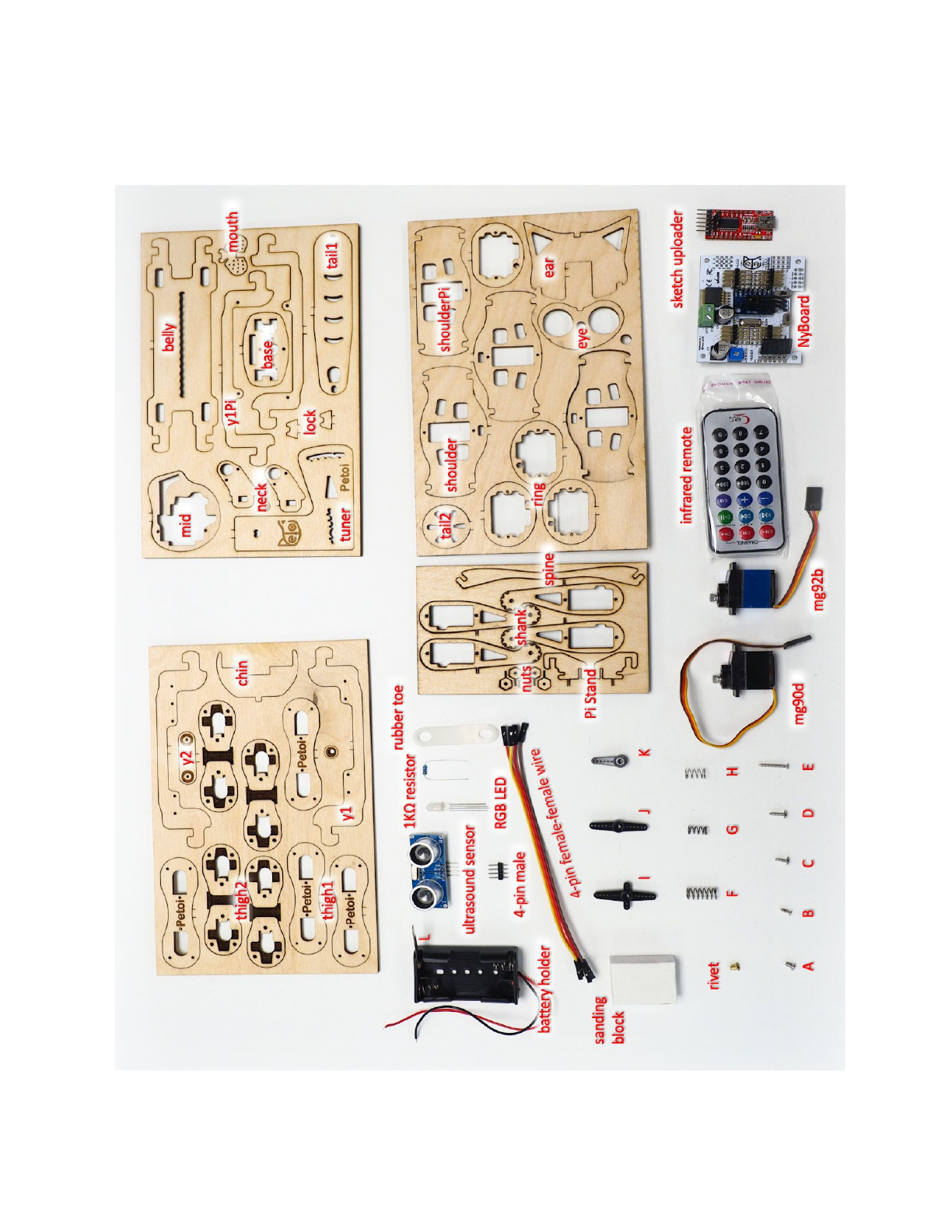
Appendix I: Parts
40
