Assembly Manual For Finger
User Manual:
Open the PDF directly: View PDF ![]() .
.
Page Count: 29
Assembly manual for finger + gearbox
Step 0:
Make sure to read chapter 3 of “Dexterous Gripper” and familiarize yourself with the tendon principle.
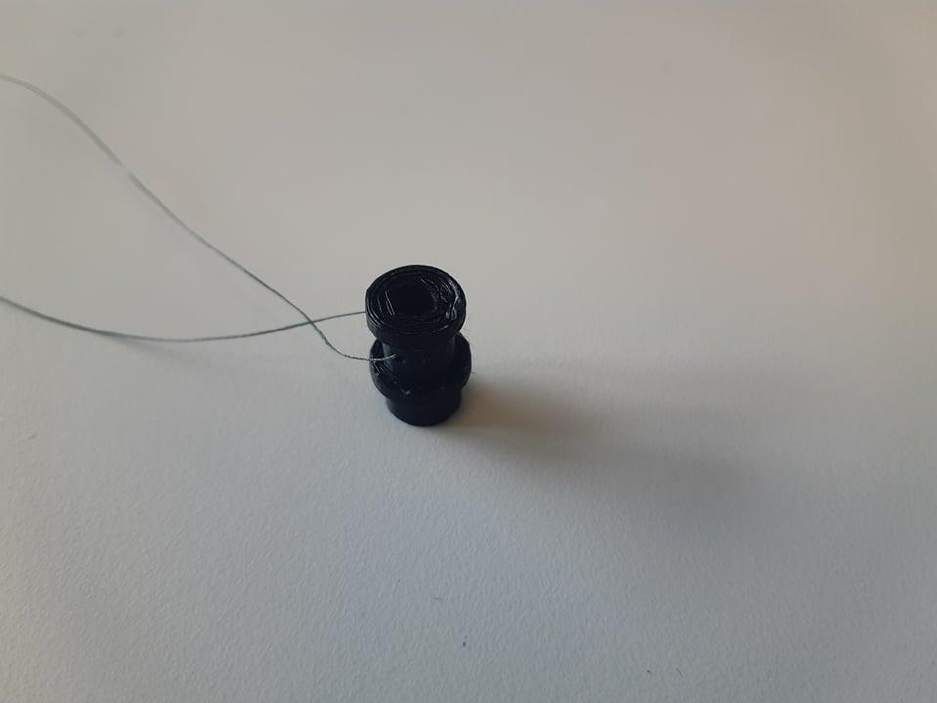
Step 1:
Insert 1m of string through the locking hole of the motor spindle, with equal length of string sticking out
on both sides.
Step 2:
Gently push the motorspindle onto the motor. Don’t push it all the way down. It will be pushed in place
by the front/back plate later.
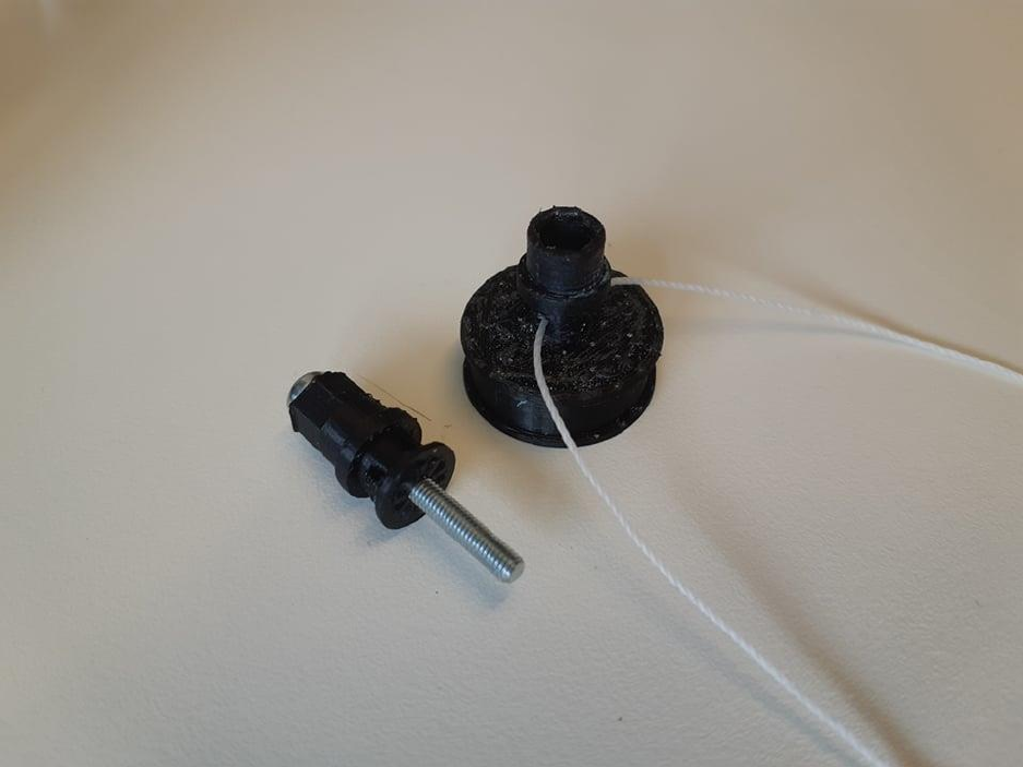
Step 3:
Insert 1m of string through the locking hole of the gear spindle. Insert the 30mm M3 bolt through the
gear top
Step 4:
Use the bolt to push the string out of the hole in the middle of the gearspindle. The string will later be
locked in place when the hex nut is placed at the end of the bolt.
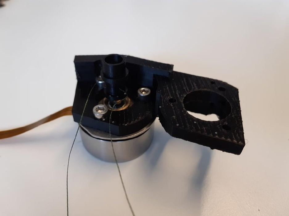
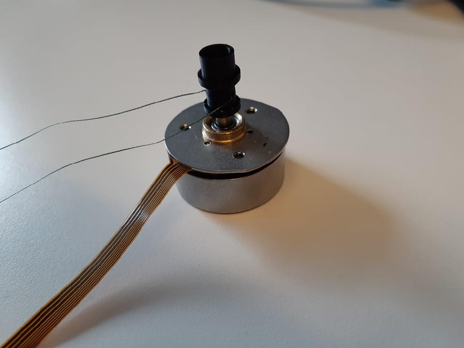
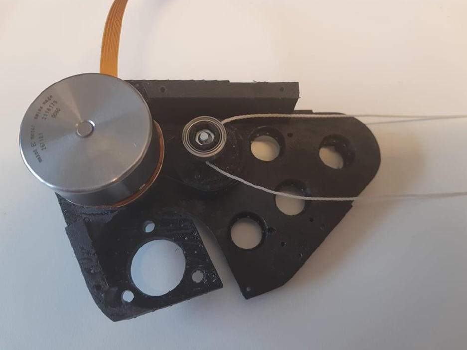
Step 5:
Fasten the motor to the motor bracket as seen in the picture
Step 6:
Use 10mm M2 bolts to fasten the inner bracket, and the the backplate. Then place the motorspindle in
the slot next to the motor. The motorspindle and backplate has a hole which can be used to lock the
gearsindle in place and keep it from rotating, which makes the string easier to wind around the motor
spindle. To lock the motor in place, use tape.
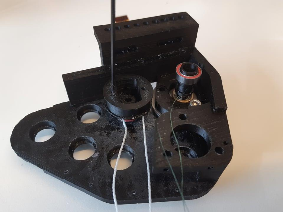
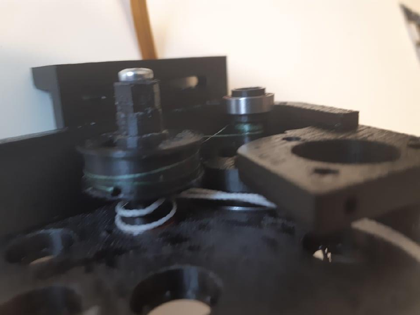
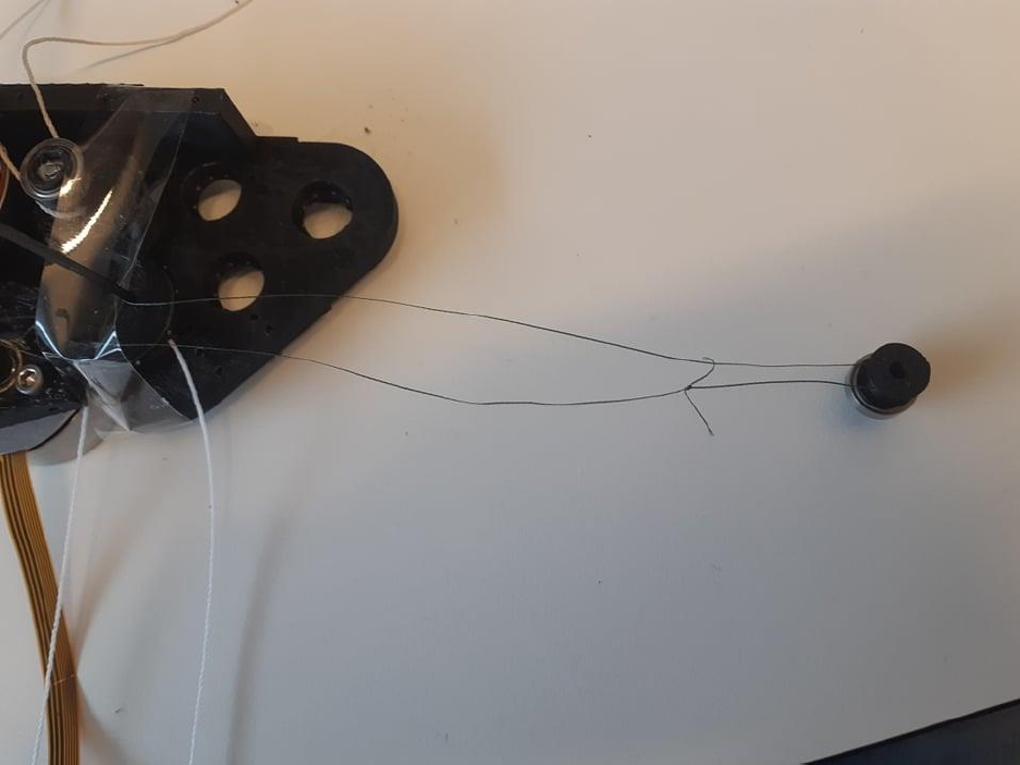
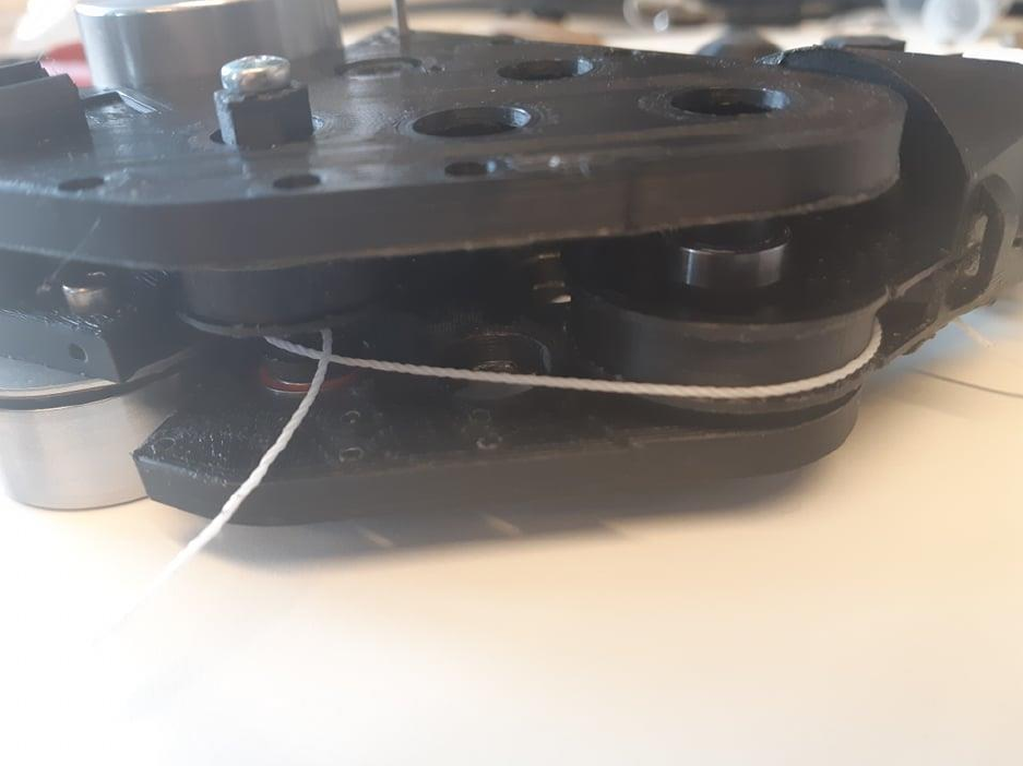
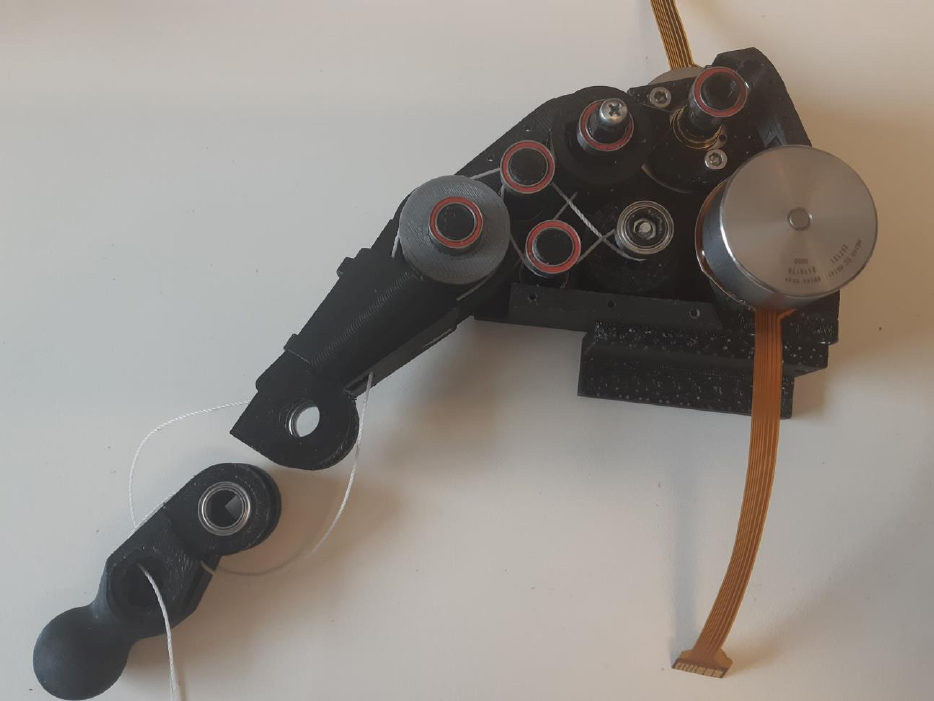
Step 7:
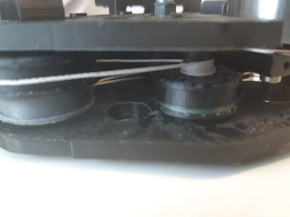
Take one side of the string from the motor spindle, and wind it 8 times around the motor spindle
downwards in a spiral. Then, without a single turn around the gear spindle, route it directly through the
bottom hole on the top pulley, as seen in the picture.
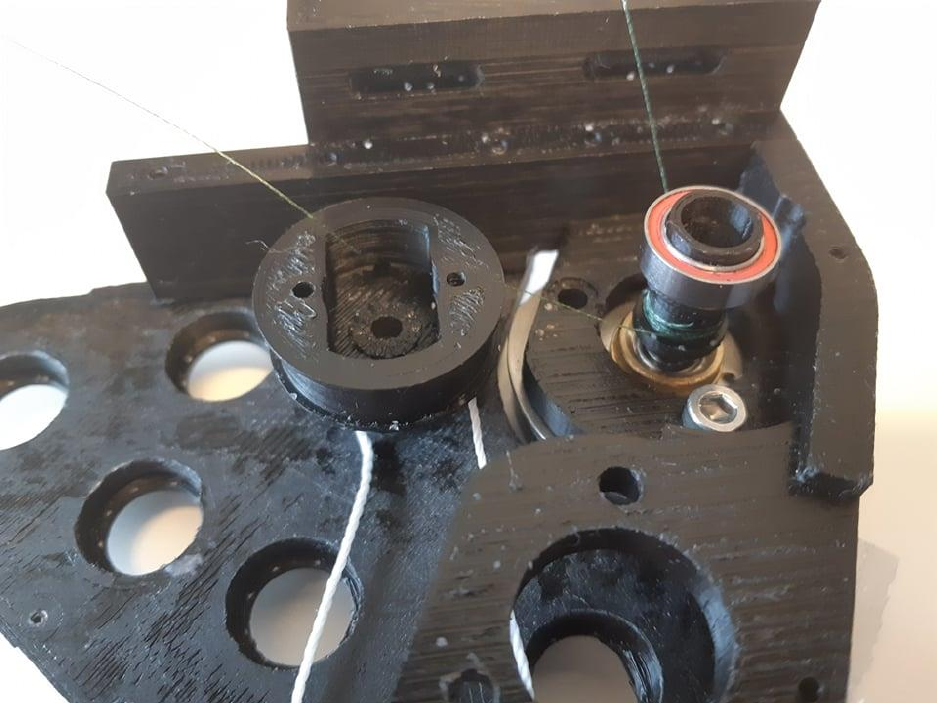
Step 8
The other side of the string goes directly from the motor spindle and is wound around the gear spindle
until it is of the same length as the string that is already in place

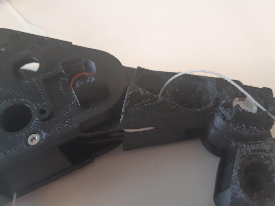
Step 9:
The string is then fastened to the gear spindle top. It needs to be connected in a loop so that the tension
in both side has a chance to equalize. In the picture below, this is done by using another loop. However,
just tying it to itself in a loop is sufficient.
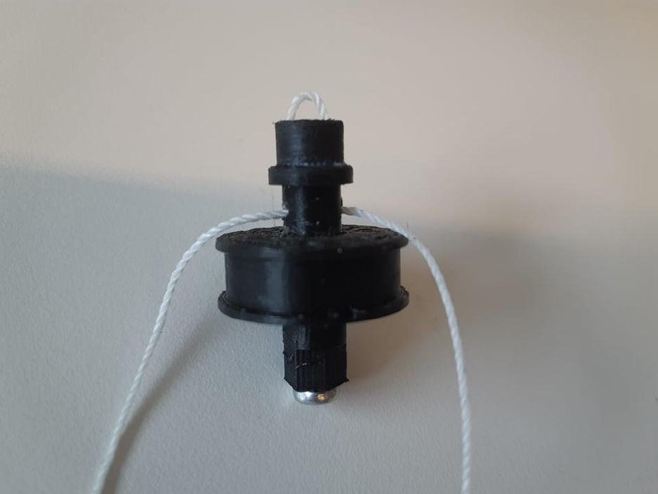
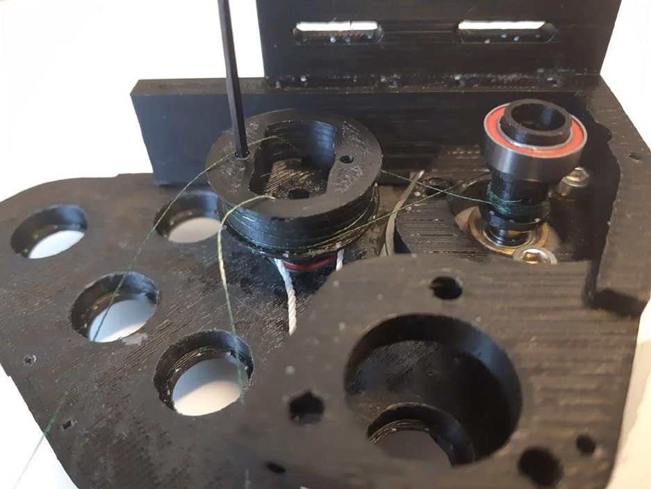
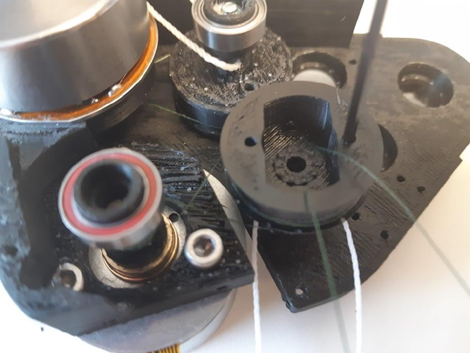
Step 10:
The gear spindle top is then wound around to tighten the string and inserted on top of the gear spindle.
Make sure the string does not wind around the bolt, as sharp edges will cut the string.
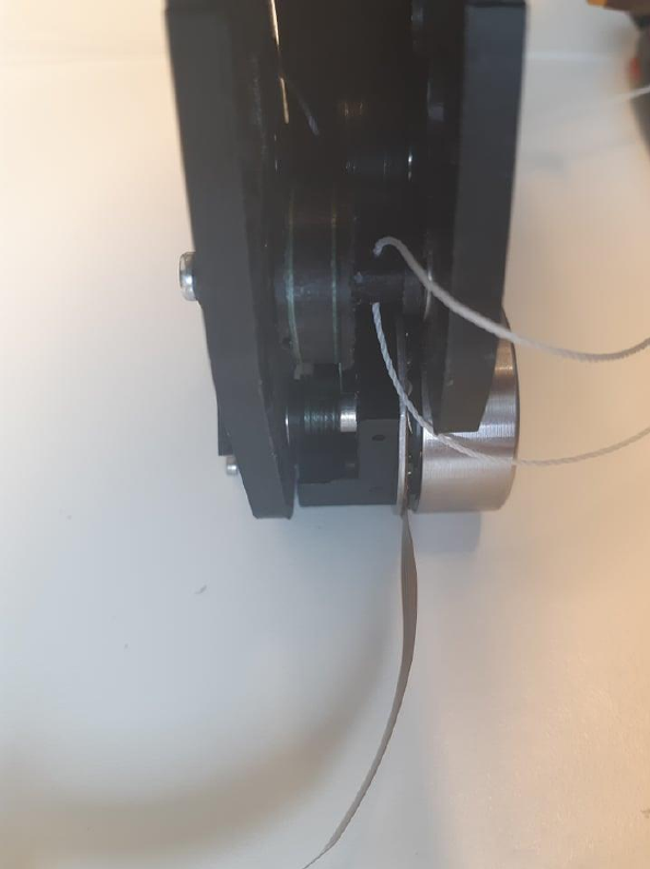
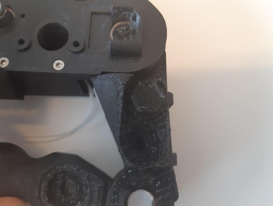
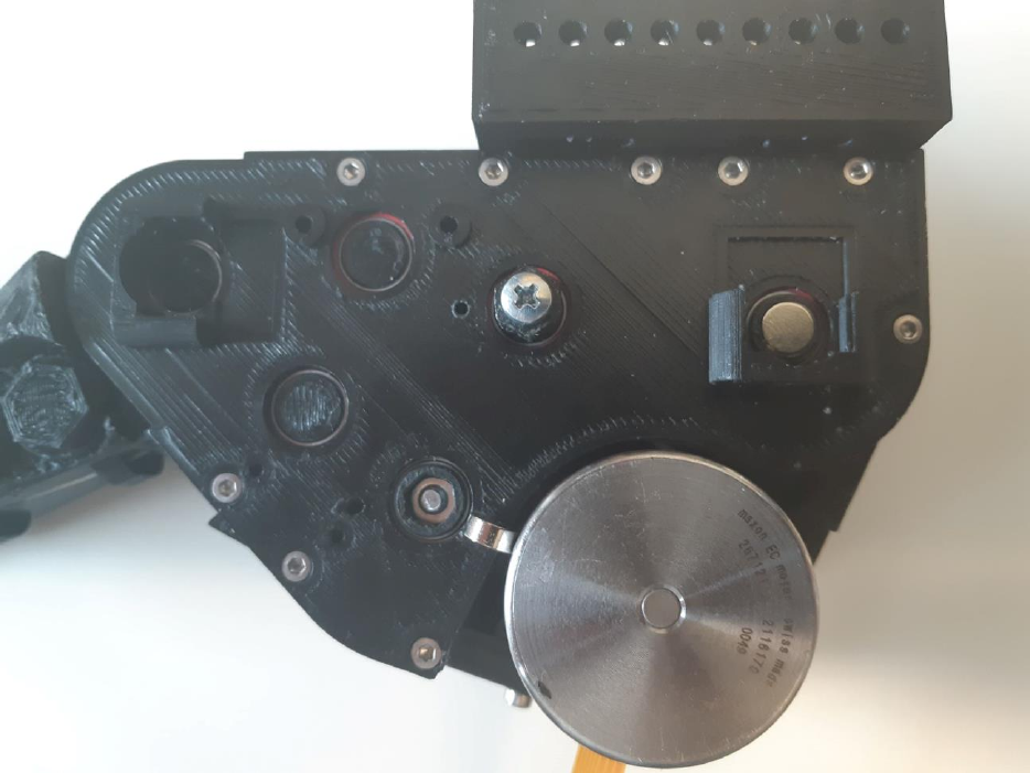
Step 11:
The frontplate is attached, and the blackplate is removed, revealing the the gearbox from the oposite
side. Here the hex nut which keeps the gear top from unwinding and locks the string on the second
stage is revealed.
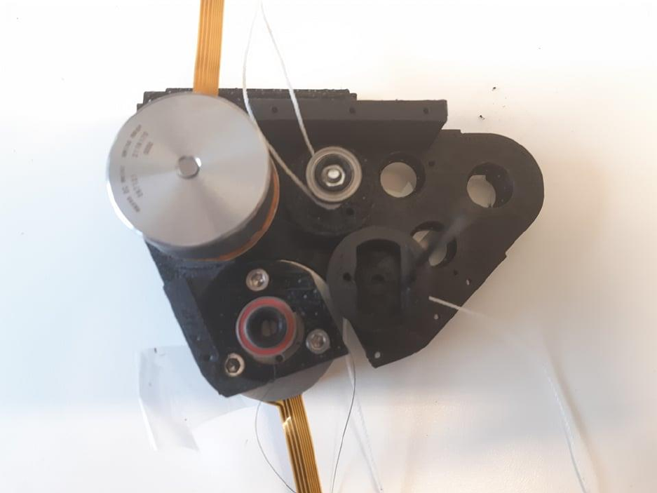
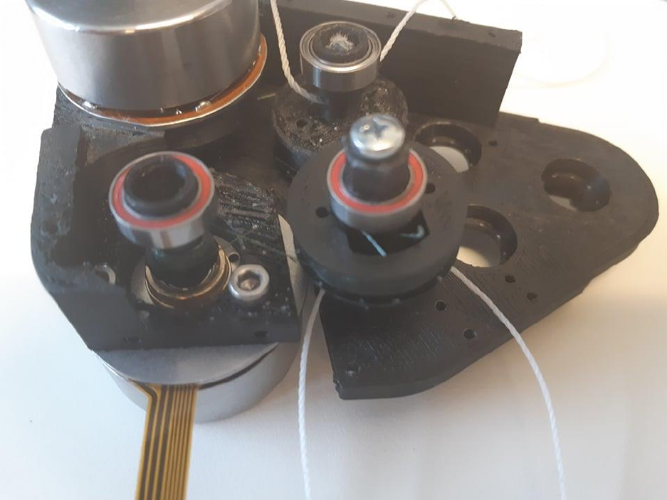
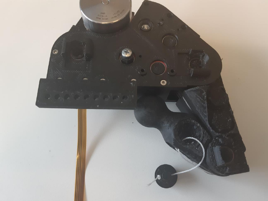
Step 12:
The process of readying the gear spindle and motor spindle is repeated, and the motor spindle and gear
spindle is mounted on the frontplate as in the picture below.
Step 13:
In the same way as with the previous motor: One side of the string is wound 8 times around the motor
spindle, then it goes directly into the gear spindle without any turns. The other side leaves the motor
spindle without any turns, and is then wound around the gear spindle until the string is of equal length.
Step 14:
Again, the strings are attached to the gear spindle top in a loop.
Step 15:
Mount the gear top, and tighten the string by twisting it around. Then lock it in place by inserting the
hex nut and tightening the bolt.
Step 16:
With both the backplate and front plate in place; move the motor back and forth and try to make the
string between the gear spindle and motor spindly into a nice and tidy spiral. Tighten any slack.
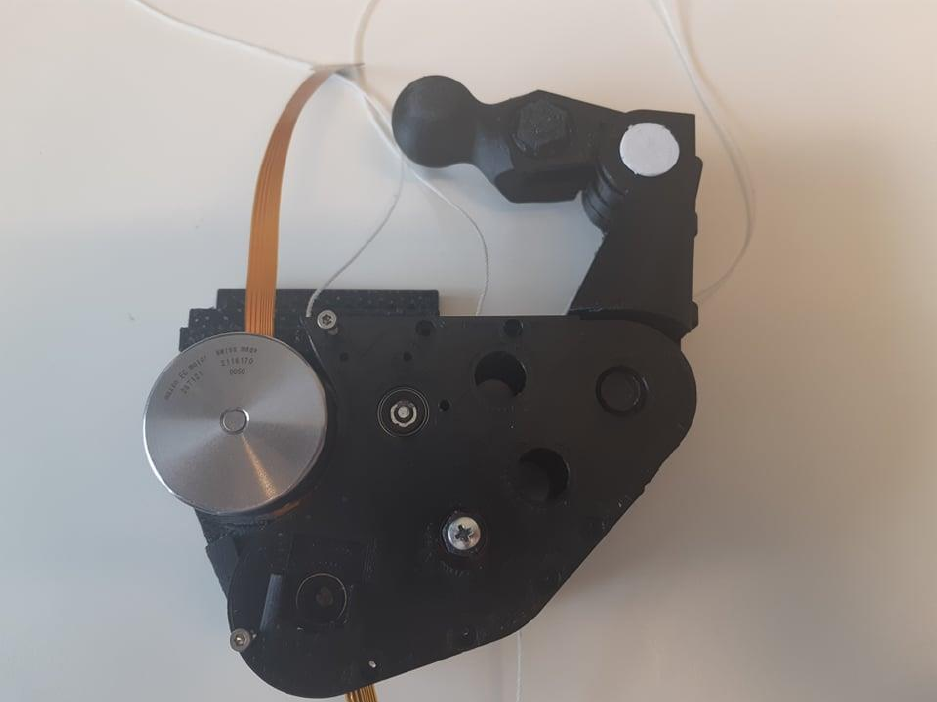
Step 17:
Insert the finger in place in the gearbox.
Step 18:
Turn the motor until it reaches the end position. Take the tendon end that will be tightened by moving it
away from the end position and route it into the PIP joint pulley as seen in the picture below.
Step 19:
In the picture below, the finger has been rotated to reveal the side where the string comes out of when
inserted into the pulley. There is a groove which ends in a hole where the string is led to the tightening
slots.
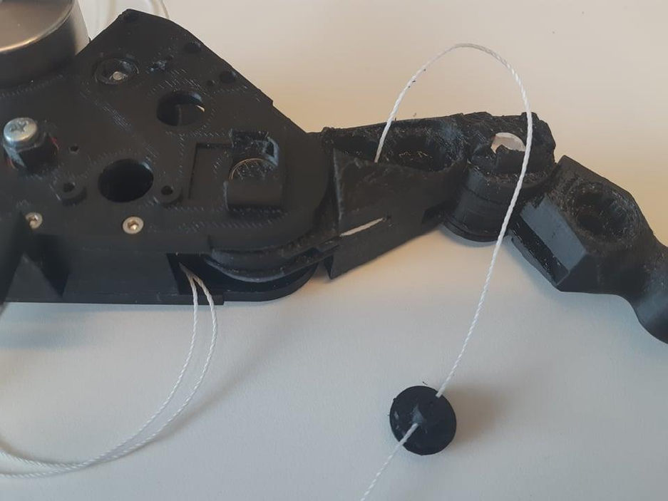
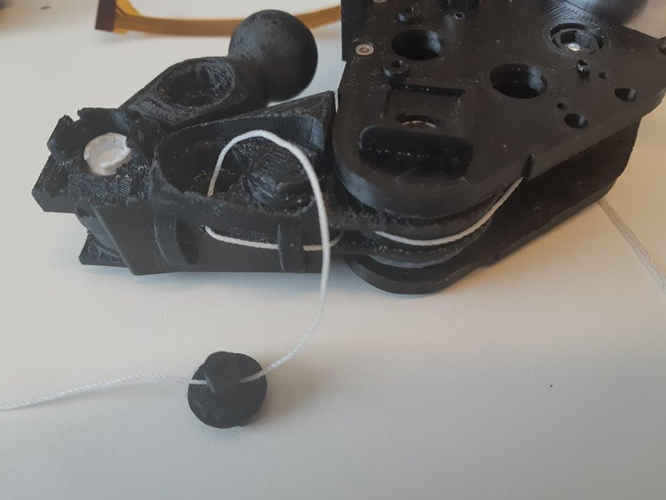
Step 20:
Tie the string to the tuning peg
Step 21:
Rotate the tuning peg to tighten the string and insert it into the slot.
Step 22:
Take the other side of the string and rotate it 3 times around the gear spindle before routing it around
the other side of the PIP joint.
Step 23:
On the other side of the pulley, the string goes into a groove which leads to a hole into the tightening
slot. Fasten the string to the tuning peg, and tighten the tendon.
Step 24:
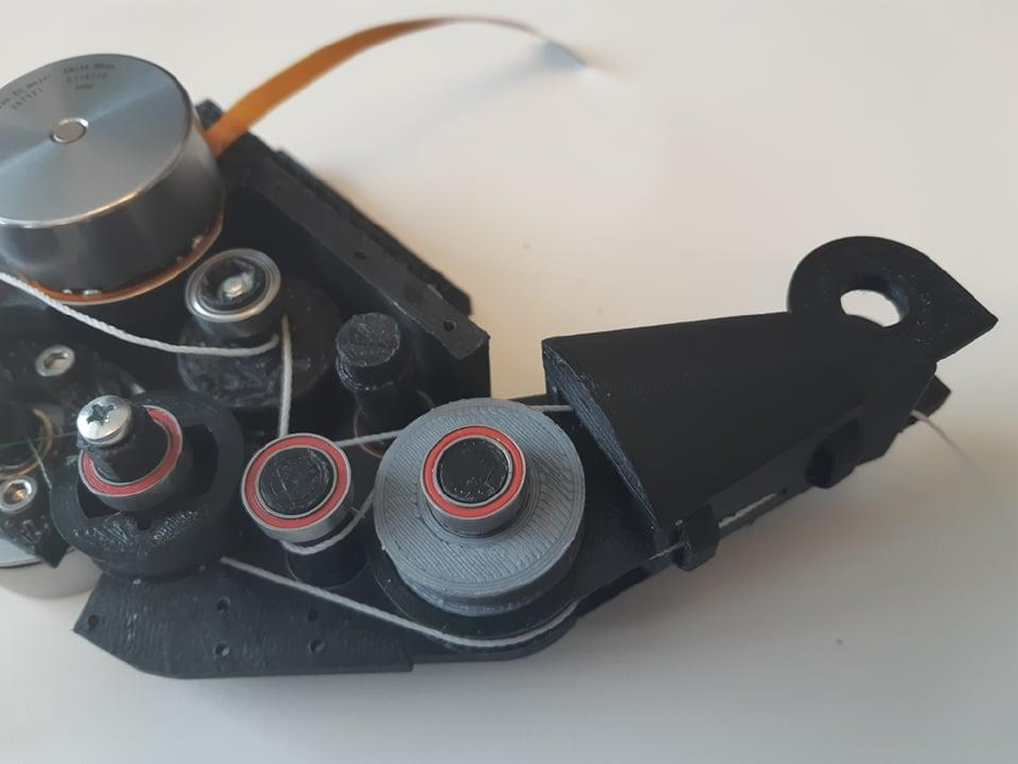
Insert the tension pulleys as it is done in the picture below. Then the motor is driven to its end position.
The string that is tightened by moving away from the end position is routed as in the picture below. It
passes by one tension pulley and then the wheel before it goes into the proximal phalanx to the MCP
joint.
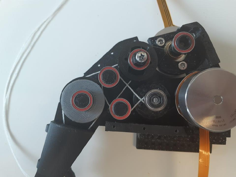
Step 25:
The other side is twisted 3 times around the motorspindle before being routed around the other pulley,
and wheel before it goes into proximal phalanx.
Step 26:
From the wheel, to the MCP joint, the tendon is in crossed configuration. Route them around the last
pulley and into the tightening slot
Step 27:
Fasten the joint and tie the tendon to the tuning peg. Tigheten both sides of the tendon.
Step 28:
Insert magnets into the cup of the motor spindles, and joints.
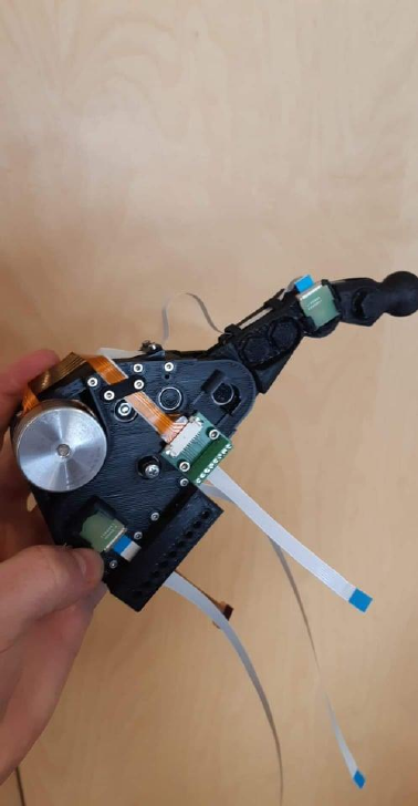
Step 29:
Slide sensors into sensor slots and attach the cables. Cable clamps can be mounted anywhere to route
the cables as you see fit.
