ASTRO Series/Astro Digital Spectra & Plus Basic Service Manual 6881076C20 E
User Manual: -ASTRO Series/Astro Digital Spectra & Digital Spectra Plus Basic service manual 6881076C20-E
Open the PDF directly: View PDF ![]() .
.
Page Count: 176 [warning: Documents this large are best viewed by clicking the View PDF Link!]
- ASTRO® Digital Spectra® and Digital Spectra Plus, UHF, VHF, 800 MHz Mobile Radios Basic Service Manual
- Front Cover
- Inside Front Cover
- Foreword
- Table of Contents
- Foreword ii
- Commercial Warranty xii
- Model Numbering, Charts, and Specifications xv
- Chapter 1 Introduction 1-1
- Chapter 2 Basic Maintenance 2-1
- Chapter 3 Basic Theory of Operation 3-1
- Chapter 4 Test Equipment, Service Aids, and Tools 4-1
- Chapter 5 Performance Checks 5-1
- Chapter 6 Radio Alignment Procedure 6-1
- Chapter 7 Encryption 7-1
- Chapter 8 Disassembly/Reassembly Procedures 8-1
- Chapter 9 Basic Troubleshooting 9-1
- Chapter 10 Functional Block Diagrams and Connectors 10-1
- Chapter 11 Exploded Views and Parts Lists 11-1
- Appendix A Replacement Parts Ordering A-1
- Glossary Glossary-1
- Index Index-i
- Commercial Warranty
- Model Numbering, Charts, and Specifications
- Mobile Radio Model Numbering Scheme
- ASTRO Digital Spectra Motorcycle 15 Watt (Ranges 1 and 2) Model Chart
- ASTRO Digital Spectra Motorcycle 15 Watt (Ranges 3 and 3.5) Model Chart
- ASTRO Digital Spectra VHF 10–25 Watt Model Chart
- ASTRO Digital Spectra VHF 25–50 and 50–110 Watt Model Chart
- ASTRO Digital Spectra VHF 10–25 and 50–110 Watt Model Chart (cont.)
- ASTRO Digital Spectra UHF 10–25 Watt Model Chart
- ASTRO Digital Spectra UHF 20–40 Watt Model Chart
- ASTRO Digital Spectra UHF 20–40 Watt Model Chart (cont.)
- ASTRO Digital Spectra UHF 50–110 Watt Model Chart
- ASTRO Digital Spectra UHF 50–110 Watt Model Chart (cont.)
- ASTRO Digital Spectra 800 MHz Model Chart
- ASTRO Digital Spectra Plus VHF 25–50 and 50–110 Watt Model Chart
- ASTRO Digital Spectra Plus VHF 25–50 and 50–110 Watt Model Chart (cont.)
- ASTRO Digital Spectra Plus UHF 20–40 Watt Model Chart
- ASTRO Digital Spectra Plus UHF 20–40 Watt Model Chart (cont.)
- ASTRO Digital Spectra Plus UHF 50–110 Watt Model Chart
- ASTRO Digital Spectra Plus UHF 50–110 Watt Model Chart (cont.)
- ASTRO Digital Spectra Plus 800 MHz Model Chart
- ASTRO Digital Spectra Plus 800 MHz Model Chart (cont.)
- VHF Radio Specifications
- UHF Radio Specifications
- 800 MHz Radio Specifications
- Chapter 1 Introduction
- Chapter 2 Basic Maintenance
- Chapter 3 Basic Theory of Operation
- 3.1 Introduction
- 3.2 General Overview
- 3.3 Analog Mode of Operation
- 3.4 ASTRO Mode of Operation
- 3.5 Control Head Assembly
- 3.5.1 Display (W4, W5, and W7 Models)
- 3.5.2 Display (W9 Model)
- 3.5.3 Vacuum Fluorescent (VF) Display Driver
- 3.5.4 Vacuum Fluorescent (VF) Voltage Source (W9 Model)
- 3.5.5 Controls and Indicators
- 3.5.6 Status LEDs
- 3.5.7 Backlight LEDs
- 3.5.8 Vehicle Interface Port (VIP)
- 3.5.9 Power Supplies
- 3.5.10 Ignition Sense Circuits
- 3.6 Power Amplifier
- 3.7 Front-End Receiver Assembly
- 3.8 Radio Frequency (RF) Board
- 3.9 Voltage-Controlled Oscillator (VCO)
- 3.10 Command Board
- 3.11 VOCON (Vocoder/Controller) Board
- Chapter 4 Test Equipment, Service Aids, and Tools
- Chapter 5 Performance Checks
- Chapter 6 Radio Alignment Procedure
- Chapter 7 Encryption
- Chapter 8 Disassembly/Reassembly Procedures
- 8.1 Introduction
- 8.2 Replacement Procedures
- 8.3 Final Reassembly
- 8.4 Fastener Torque Chart
- Chapter 9 Basic Troubleshooting
- Chapter 10 Functional Block Diagrams and Connectors
- 10.1 Digital Spectra Functional Block Diagram (Models W3, W4, W5, W7, and W9)
- 10.2 Digital Spectra Plus Functional Block Diagram (Models W3, W4, W5, W7, and W9)
- 10.3 Radio Connectors
- 10.4 Radio Connector Locations
- 10.5 Radio Connector Locations (cont.)
- 10.6 Extender Cable (P501)
- 10.7 Control Head Cabling Diagram
- Chapter 11 Exploded Views and Parts Lists
- 11.1 Model W3 Hand-Held Control Head Exploded View
- 11.2 Model W4 Rotary Control Head Exploded View
- 11.3 Models W5 and W7 Pushbutton Control Head Exploded View
- 11.4 Model W9 Pushbutton Control Head Exploded View
- 11.5 Low-Power (15W) Radio Exploded View
- 11.6 Mid-Power (20-40/25-50/35W) Radio Exploded View
- 11.7 High-Power (50-110W) Radio Exploded View
- 11.8 Motorcycle Interconnect Board and Assembly
- 11.9 Low- and Mid-Power Interconnect Board and Assembly
- 11.10 Small Pushbutton Parts
- 11.11 Large Pushbutton Parts
- Appendix A Replacement Parts Ordering
- Glossary
- Index
- Back Cover
ASTRO® Digital Spectra®
and Digital Spectra Plus
UHF
VHF
800 MHz
Mobile Radios
Basic Service Manual

i
Title Page ® Digital Spectra®
and Digital Spectra Plus
VHF/UHF/800 MHz Digital Mobile Radios
Basic Service Manual
Motorola, Inc.
8000 West Sunrise Boulevard
Fort Lauderdale, Florida 33322 6881076C20-E

ii
Foreword
This manual covers all models of the ASTRO® Digital Spectra® and ASTRO Digital Spectra Plus mobile radios (models W3,
W4, W5, W7, and W9), unless otherwise specified. It includes all the information necessary to maintain peak product
performance and maximum working time, using levels 1 and 2 maintenance procedures. This level of service goes down to
the board replacement level and is typical of some local service centers, self-maintained customers, and distributors.
For details on radio operation or component-level troubleshooting, refer to the applicable manuals available separately. A
list of related publications is provided in the section, “Related Publications,” on page xii.
Product Safety and RF Exposure Compliance
ATTENTION!
This radio is restricted to occupational use only to satisfy FCC RF energy exposure requirements.
Before using this product, read the RF energy awareness information and operating instructions in the
Product Safety and RF Exposure booklet enclosed with your radio (Motorola Publication part number
6881095C99) to ensure compliance with RF energy exposure limits.
For a list of Motorola-approved antennas, batteries, and other accessories, visit the following web site
which lists approved accessories: http://www.motorola.com/cgiss/index.shtml
Manual Revisions
Changes which occur after this manual is printed are described in FMRs (Florida Manual Revisions). These FMRs provide
complete replacement pages for all added, changed, and deleted items. To obtain FMRs, contact the Customer Care and
Services Division (refer to “Appendix A Replacement Parts Ordering”).
Computer Software Copyrights
The Motorola products described in this manual may include copyrighted Motorola computer programs stored in
semiconductor memories or other media. Laws in the United States and other countries preserve for Motorola certain
exclusive rights for copyrighted computer programs, including, but not limited to, the exclusive right to copy or reproduce in
any form the copyrighted computer program. Accordingly, any copyrighted Motorola computer programs contained in the
Motorola products described in this manual may not be copied, reproduced, modified, reverse-engineered, or distributed in
any manner without the express written permission of Motorola. Furthermore, the purchase of Motorola products shall not
be deemed to grant either directly or by implication, estoppel, or otherwise, any license under the copyrights, patents or
patent applications of Motorola, except for the normal non-exclusive license to use that arises by operation of law in the
sale of a product.
Document Copyrights
No duplication or distribution of this document or any portion thereof shall take place without the express written permission
of Motorola. No part of this manual may be reproduced, distributed, or transmitted in any form or by any means, electronic
or mechanical, for any purpose without the express written permission of Motorola.
Disclaimer
The information in this document is carefully examined, and is believed to be entirely reliable. However, no responsibility is
assumed for inaccuracies. Furthermore, Motorola reserves the right to make changes to any products herein to improve
readability, function, or design. Motorola does not assume any liability arising out of the applications or use of any product
or circuit described herein; nor does it cover any license under its patent rights nor the rights of others.
Trademarks
MOTOROLA, the Stylized M logo, FLASHport, and ASTRO are registered in the US Patent & Trademark Office. All other
product or service names are the property of their respective owners.
© Motorola, Inc. 2003.
Before using this product, read the operating instructions
for safe usage contained in the Product Safety and RF
Exposure booklet enclosed with your radio.
!
C
a u t i o
n

Table of Contents iii
6881076C20-E February 3, 2003
Table of Contents
Foreword.........................................................................................................ii
Product Safety and RF Exposure Compliance............................................................................................ii
Manual Revisions ........................................................................................................................................ii
Computer Software Copyrights ...................................................................................................................ii
Document Copyrights..................................................................................................................................ii
Disclaimer....................................................................................................................................................ii
Trademarks .................................................................................................................................................ii
Commercial Warranty ..................................................................................xii
Limited Warranty .......................................................................................................................................xii
MOTOROLA COMMUNICATION PRODUCTS............................................................................1-xii
I. What This Warranty Covers And For How Long ....................................................................xii
II. General Provisions................................................................................................................xii
III. State Law Rights ................................................................................................................. xiii
IV. How To Get Warranty Service ............................................................................................ xiii
V. What This Warranty Does Not Cover................................................................................... xiii
VI. Patent And Software Provisions .........................................................................................xiv
VII. Governing Law...................................................................................................................xiv
Model Numbering, Charts, and Specifications..........................................xv
Mobile Radio Model Numbering Scheme..................................................................................................xv
ASTRO Digital Spectra Motorcycle 15 Watt (Ranges 1 and 2) Model Chart............................................xvi
ASTRO Digital Spectra Motorcycle 15 Watt (Ranges 3 and 3.5) Model Chart........................................ xvii
ASTRO Digital Spectra VHF 10–25 Watt Model Chart........................................................................... xviii
ASTRO Digital Spectra VHF 25–50 and 50–110 Watt Model Chart.........................................................xix
ASTRO Digital Spectra VHF 10–25 and 50–110 Watt Model Chart (cont.) ..............................................xx
ASTRO Digital Spectra UHF 10–25 Watt Model Chart ............................................................................xxi
ASTRO Digital Spectra UHF 20–40 Watt Model Chart ........................................................................... xxii
ASTRO Digital Spectra UHF 20–40 Watt Model Chart (cont.) ............................................................... xxiii
ASTRO Digital Spectra UHF 50–110 Watt Model Chart ........................................................................ xxiv
ASTRO Digital Spectra UHF 50–110 Watt Model Chart (cont.) ..............................................................xxv
ASTRO Digital Spectra 800 MHz Model Chart.......................................................................................xxvi
ASTRO Digital Spectra Plus VHF 25–50 and 50–110 Watt Model Chart.............................................. xxvii
ASTRO Digital Spectra Plus VHF 25–50 and 50–110 Watt Model Chart (cont.) ..................................xxviii
ASTRO Digital Spectra Plus UHF 20–40 Watt Model Chart .................................................................. xxix
ASTRO Digital Spectra Plus UHF 20–40 Watt Model Chart (cont.) ........................................................xxx
ASTRO Digital Spectra Plus UHF 50–110 Watt Model Chart ................................................................ xxxi
ASTRO Digital Spectra Plus UHF 50–110 Watt Model Chart (cont.) .................................................... xxxii
ASTRO Digital Spectra Plus 800 MHz Model Chart..............................................................................xxxiii
ASTRO Digital Spectra Plus 800 MHz Model Chart (cont.).................................................................. xxxiv
VHF Radio Specifications...................................................................................................................... xxxv
UHF Radio Specifications..................................................................................................................... xxxvi
800 MHz Radio Specifications..............................................................................................................xxxvii

iv Table of Contents
February 3, 2003 6881076C20-E
Chapter 1 Introduction ......................................................................... 1-1
1.1 Notations Used in This Manual......................................................................................................1-1
1.2 Radio Descriptions.........................................................................................................................1-1
1.2.1 FLASHport®......................................................................................................................1-2
1.3 Control Head Descriptions.............................................................................................................1-2
1.3.1 General .............................................................................................................................1-2
1.3.1.1 Model W3 Control Head...........................................................................................1-3
1.3.1.2 Model W3 Controls ..................................................................................................1-3
1.3.1.3 Models W4, W5, W7, and W9 Controls Head.......................................................... 1-4
1.3.1.4 Models W4, W5, W7, and W9 Controls ...................................................................1-5
Chapter 2 Basic Maintenance.............................................................. 2-1
2.1 Introduction ....................................................................................................................................2-1
2.2 Preventive Maintenance ................................................................................................................2-1
2.2.1 Reference Oscillator .........................................................................................................2-1
2.2.2 Inspection..........................................................................................................................2-1
2.2.3 Cleaning............................................................................................................................2-1
2.2.4 Cleaning External Plastic Surfaces...................................................................................2-2
2.2.5 Cleaning Internal Circuit Boards and Components...........................................................2-2
2.3 Handling Precautions.....................................................................................................................2-2
Chapter 3 Basic Theory of Operation ................................................. 3-1
3.1 Introduction ....................................................................................................................................3-1
3.2 General Overview ..........................................................................................................................3-1
3.3 Analog Mode of Operation.............................................................................................................3-2
3.3.1 Receive Operation ............................................................................................................ 3-2
3.3.2 Transmit Operation ...........................................................................................................3-2
3.4 ASTRO Mode of Operation............................................................................................................3-2
3.5 Control Head Assembly .................................................................................................................3-2
3.5.1 Display (W4, W5, and W7 Models)...................................................................................3-2
3.5.2 Display (W9 Model)...........................................................................................................3-3
3.5.3 Vacuum Fluorescent (VF) Display Driver..........................................................................3-3
3.5.4 Vacuum Fluorescent (VF) Voltage Source (W9 Model)....................................................3-3
3.5.5 Controls and Indicators.....................................................................................................3-3
3.5.6 Status LEDs......................................................................................................................3-3
3.5.7 Backlight LEDs..................................................................................................................3-3
3.5.8 Vehicle Interface Port (VIP) ..............................................................................................3-4
3.5.8.1 Remote-Mount .........................................................................................................3-4
3.5.8.2 Dash-Mount .............................................................................................................3-4
3.5.9 Power Supplies .................................................................................................................3-4
3.5.10 Ignition Sense Circuits ......................................................................................................3-4
3.6 Power Amplifier..............................................................................................................................3-4
3.6.1 Gain Stages ......................................................................................................................3-4
3.6.2 Power Control ...................................................................................................................3-5
3.6.3 Circuit Protection............................................................................................................... 3-5
3.6.4 DC Interconnect................................................................................................................3-5
3.7 Front-End Receiver Assembly .......................................................................................................3-5
3.8 Radio Frequency (RF) Board.........................................................................................................3-5
3.9 Voltage-Controlled Oscillator (VCO)..............................................................................................3-6

Table of Contents v
6881076C20-E February 3, 2003
3.9.1 VHF Radios ...................................................................................................................... 3-6
3.9.2 UHF and 800 MHz Radios................................................................................................ 3-6
3.10 Command Board............................................................................................................................ 3-6
3.11 VOCON (Vocoder/Controller) Board.............................................................................................. 3-7
3.11.1 ASTRO Digital Spectra.....................................................................................................3-7
3.11.2 ASTRO Digital Spectra Plus ............................................................................................. 3-7
Chapter 4 Test Equipment, Service Aids, and Tools......................... 4-1
4.1 Recommended Test Equipment .................................................................................................... 4-1
4.2 Service Aids and Recommended Tools......................................................................................... 4-2
4.3 Field Programming Equipment ...................................................................................................... 4-5
4.3.1 ASTRO Digital Spectra..................................................................................................... 4-5
4.3.1.1 ASTRO Digital Spectra W3 Smart RIB Issue .......................................................... 4-6
4.3.1.2 ASTRO Digital Spectra Remote W3 Y Cable .......................................................... 4-6
4.3.2 ASTRO Digital Spectra Plus ............................................................................................. 4-7
4.3.2.1 ASTRO Digital Spectra Plus Model W3................................................................... 4-7
Chapter 5 Performance Checks .......................................................... 5-1
5.1 Introduction.................................................................................................................................... 5-1
5.2 Test Setup ..................................................................................................................................... 5-1
5.2.1 ASTRO Digital Spectra..................................................................................................... 5-1
5.2.2 ASTRO Digital Spectra Plus ............................................................................................. 5-2
5.3 Test Mode...................................................................................................................................... 5-2
5.3.1 Entering Test Mode .......................................................................................................... 5-2
5.3.2 RF Test Mode ................................................................................................................... 5-3
5.3.3 Control Head Test Mode................................................................................................... 5-5
5.4 Receiver Performance Checks ...................................................................................................... 5-6
5.5 Transmitter Performance Checks.................................................................................................. 5-7
Chapter 6 Radio Alignment Procedure............................................... 6-1
6.1 Introduction.................................................................................................................................... 6-1
6.2 RSS ............................................................................................................................................... 6-1
6.2.1 ASTRO Digital Spectra..................................................................................................... 6-1
6.2.2 Softpot .............................................................................................................................. 6-2
6.2.3 Reference Oscillator Alignment ........................................................................................ 6-3
6.2.4 Transmit Power Alignment................................................................................................ 6-4
6.2.5 Transmit Current Limit Alignment ..................................................................................... 6-6
6.2.6 Transmit Deviation Balance (Compensation) Alignment .................................................. 6-7
6.2.7 Transmit Deviation Limit Alignment .................................................................................. 6-8
6.2.8 Bit Error Rate (BER) Performance Check ...................................................................... 6-10
6.3 ASTRO Digital Spectra and Digital Spectra Plus Tuner Software ............................................... 6-10
6.3.1 Radio Information ........................................................................................................... 6-14
6.3.2 Reference Oscillator Alignment ...................................................................................... 6-14
6.3.3 Transmit Power Alignment.............................................................................................. 6-16
6.3.4 Transmit Current Limit Alignment ................................................................................... 6-18
6.3.5 Transmit Deviation Balance (Compensation) Alignment ................................................ 6-18
6.3.6 Transmit Deviation Limit Alignment ................................................................................ 6-20
6.3.7 Bit Error Rate (BER) Test ............................................................................................... 6-22

vi Table of Contents
February 3, 2003 6881076C20-E
6.3.8 Transmitter Test Pattern .................................................................................................6-23
Chapter 7 Encryption ........................................................................... 7-1
7.1 Universal Crypto Module Kits.........................................................................................................7-1
7.1.1 ASTRO Digital Spectra .....................................................................................................7-1
7.1.2 ASTRO Digital Spectra Plus .............................................................................................7-1
7.1.3 Secure Dispatch Operation...............................................................................................7-1
7.1.4 Secure Emergency Operation...........................................................................................7-2
7.2 Load an Encryption Key.................................................................................................................7-2
7.2.1 Model W3..........................................................................................................................7-2
7.2.2 Models W4, W5, W7, and W9........................................................................................... 7-3
7.3 Erase a Key ...................................................................................................................................7-3
7.3.1 Model W3..........................................................................................................................7-3
7.3.2 Models W4, W5, W7, and W9........................................................................................... 7-4
7.4 Erase a Single Key (Model W3).....................................................................................................7-5
7.5 Erase All Keys................................................................................................................................7-5
7.5.1 Model W3..........................................................................................................................7-5
7.5.2 Models W4, W5, W7, and W9........................................................................................... 7-6
7.6 Over-the-Air Rekeying ...................................................................................................................7-6
7.6.1 ASTRO Digital Spectra Model W3....................................................................................7-7
7.6.2 ASTRO Digital Spectra Models W4, W5, W7, and W9 .....................................................7-9
7.7 Advanced Secure Operation........................................................................................................7-10
7.7.1 Multikey Operation.......................................................................................................... 7-10
Chapter 8 Disassembly/Reassembly Procedures ............................. 8-1
8.1 Introduction ....................................................................................................................................8-1
8.2 Replacement Procedures ..............................................................................................................8-1
8.2.1 Required Tools and Supplies............................................................................................8-2
8.2.2 Control Head Boards ........................................................................................................8-2
8.2.2.1 Model W3.................................................................................................................8-2
8.2.2.2 Models W4, W5, and W7 .........................................................................................8-3
8.2.2.3 Model W9.................................................................................................................8-4
8.2.3 Remote Back Housing Interface Board.............................................................................8-5
8.2.3.1 Models W4, W5, and W7 .........................................................................................8-5
8.2.4 Remote Interconnect Board ..............................................................................................8-6
8.2.4.1 Low-/Mid-Power Radios...........................................................................................8-6
8.2.4.2 High-Power Radios..................................................................................................8-6
8.2.5 Power Amplifier Board ......................................................................................................8-7
8.2.5.1 Low-/Mid-Power Radios...........................................................................................8-7
8.2.5.2 High-Power Radios..................................................................................................8-7
8.2.5.3 800 MHz Radios ...................................................................................................... 8-8
8.2.5.3.1 Back-End Removal ........................................................................................... 8-8
8.2.5.3.2 PC Board Removal ...........................................................................................8-8
8.2.5.3.3 PC Board Installation ........................................................................................8-9
8.2.5.3.4 Back-End Installation ......................................................................................8-10
8.2.6 VOCON (Vocoder/Controller) Board...............................................................................8-11
8.2.7 Command Board............................................................................................................. 8-11
8.2.7.1 Low-/Mid-Power Radios.........................................................................................8-11
8.2.7.2 High-Power Radios................................................................................................8-12
8.2.8 Receiver Front-End Board ..............................................................................................8-13

Table of Contents vii
6881076C20-E February 3, 2003
8.2.8.1 Low-/Mid-Power Radio .......................................................................................... 8-13
8.2.8.2 High-Power Radio.................................................................................................. 8-13
8.2.9 VCO Board ..................................................................................................................... 8-14
8.2.9.1 Low-/Mid-Power Radio .......................................................................................... 8-14
8.2.9.2 High-Power Radio.................................................................................................. 8-15
8.2.10 RF Board ........................................................................................................................ 8-15
8.2.10.1 Low-/Mid-Power Radio .......................................................................................... 8-15
8.2.10.2 High-Power Radio.................................................................................................. 8-16
8.3 Final Reassembly ........................................................................................................................ 8-16
8.3.1 Power Amplifiers............................................................................................................. 8-16
8.3.2 Command Board............................................................................................................. 8-17
8.3.3 Dash Control Head Board............................................................................................... 8-17
8.3.4 Model W3 Hand-Held Control Head ............................................................................... 8-17
8.4 Fastener Torque Chart ................................................................................................................ 8-18
Chapter 9 Basic Troubleshooting ....................................................... 9-1
9.1 Introduction.................................................................................................................................... 9-1
9.2 Replacement Board Procedures.................................................................................................... 9-1
9.3 Power-Up Error Codes .................................................................................................................. 9-1
9.3.1 ASTRO Digital Spectra..................................................................................................... 9-2
9.3.2 ASTRO Digital Spectra Plus ............................................................................................. 9-3
9.4 Operational Error Codes................................................................................................................ 9-4
9.4.1 ASTRO Digital Spectra..................................................................................................... 9-4
9.4.2 ASTRO Digital Spectra Plus ............................................................................................. 9-5
9.5 Transmitter Troubleshooting.......................................................................................................... 9-5
9.6 Receiver Troubleshooting.............................................................................................................. 9-9
9.7 Synthesizer Troubleshooting ....................................................................................................... 9-12
Chapter 10 Functional Block Diagrams and Connectors ................. 10-1
10.1 Digital Spectra Functional Block Diagram (Models W3, W4, W5, W7, and W9) ......................... 10-2
10.2 Digital Spectra Plus Functional Block Diagram (Models W3, W4, W5, W7, and W9) ................. 10-3
10.3 Radio Connectors........................................................................................................................ 10-4
10.4 Radio Connector Locations ......................................................................................................... 10-5
10.5 Radio Connector Locations (cont.) .............................................................................................. 10-5
10.6 Extender Cable (P501) ................................................................................................................ 10-6
10.7 Control Head Cabling Diagram.................................................................................................... 10-6
Chapter 11 Exploded Views and Parts Lists...................................... 11-1
11.1 Model W3 Hand-Held Control Head Exploded View ................................................................... 11-2
11.2 Model W4 Rotary Control Head Exploded View .......................................................................... 11-3
11.3 Models W5 and W7 Pushbutton Control Head Exploded View ................................................... 11-4
11.4 Model W9 Pushbutton Control Head Exploded View .................................................................. 11-5
11.5 Low-Power (15W) Radio Exploded View..................................................................................... 11-6
11.6 Mid-Power (20-40/25-50/35W) Radio Exploded View ................................................................. 11-7
11.7 High-Power (50-110W) Radio Exploded View............................................................................. 11-8
11.8 Motorcycle Interconnect Board and Assembly ............................................................................ 11-9
11.9 Low- and Mid-Power Interconnect Board and Assembly............................................................. 11-9
11.10 Small Pushbutton Parts ............................................................................................................. 11-10

viii Table of Contents
February 3, 2003 6881076C20-E
11.11 Large Pushbutton Parts ............................................................................................................. 11-10
Appendix A Replacement Parts Ordering..............................................A-1
A.1 Basic Ordering Information ............................................................................................................A-1
A.2 Transceiver Board and VOCON Board Ordering Information........................................................A-1
A.3 Motorola Online..............................................................................................................................A-1
A.4 Mail Orders ....................................................................................................................................A-1
A.5 Telephone Orders..........................................................................................................................A-2
A.6 Fax Orders.....................................................................................................................................A-2
A.7 Parts Identification .........................................................................................................................A-2
A.8 Product Customer Service.............................................................................................................A-2
Glossary.........................................................................................Glossary-1
Index......................................................................................................Index-i

List of Figures ix
6881076C20-E February 3, 2003
List of Figures
Figure 1-1. Typical W3 Hand-Held Control Head....................................................................................1-3
Figure 1-2. Typical W4 Rotary Control Head........................................................................................... 1-4
Figure 1-3. Typical W5 Pushbutton Control Head...................................................................................1-4
Figure 1-4. Typical W7 Pushbutton Control Head...................................................................................1-4
Figure 1-5. Typical W9 Pushbutton Control Head...................................................................................1-5
Figure 5-1. ASTRO Digital Spectra Performance Checks Test Setup..................................................... 5-1
Figure 5-2. ASTRO Digital Spectra Plus Performance Checks Test Setup............................................. 5-2
Figure 5-3. Rotary Control Head Key-Closure Displays (W4)................................................................. 5-5
Figure 5-4. Pushbutton Control Head Key-Closure Displays (W5 and W7)............................................ 5-6
Figure 5-5. Pushbutton Control Head Key-Closure Displays (W9) ......................................................... 5-6
Figure 6-1. ASTRO Digital Spectra Radio Alignment Test Setup............................................................ 6-1
Figure 6-2. RSS Service Menu Layout.................................................................................................... 6-2
Figure 6-3. Softpot Concept .................................................................................................................... 6-2
Figure 6-4. Reference Oscillator Alignment Screen................................................................................6-4
Figure 6-5. Transmit Power Alignment Screen ....................................................................................... 6-5
Figure 6-6. Transmit Current Limit Alignment Screen ............................................................................. 6-6
Figure 6-7. Transmit Deviation Balance (Compensation) Alignment Screen .......................................... 6-8
Figure 6-8. Transmit Deviation Limit Alignment Screen.......................................................................... 6-9
Figure 6-9. ASTRO Digital Spectra Plus Radio Alignment Test Setup.................................................. 6-11
Figure 6-10. Tuner Menu Layout............................................................................................................. 6-12
Figure 6-11. Typical Softpot Adjustment Screen..................................................................................... 6-13
Figure 6-12. Radio Information Screen ................................................................................................... 6-14
Figure 6-13. Reference Oscillator Alignment Screen.............................................................................. 6-15
Figure 6-14. Typical Transmit Power Alignment Screen ......................................................................... 6-16
Figure 6-15. Transmit Current Limit Alignment Screen ........................................................................... 6-18
Figure 6-16. Transmit Deviation Balance (Compensation) Alignment Screen ........................................ 6-20
Figure 6-17. Transmit Deviation Limit Alignment Screen........................................................................ 6-21
Figure 6-18. Bit Error Rate Test Screen.................................................................................................. 6-23
Figure 6-19. Transmitter Test Pattern Screen ......................................................................................... 6-23
Figure 8-1. Model W4 Rotary Control Head Assembly Screw and Snap Sequence............................... 8-3
Figure 8-2. Models W5 and W7 Pushbutton Control Head Assembly Screw Sequence ........................ 8-3
Figure 8-3. PA Board Screw Fastening Sequence (800 MHz 15-Watt PA) ............................................. 8-9
Figure 8-4. PA Board Screw Fastening Sequence (800 MHz 20- and 35-Watt PA).............................. 8-10
Figure 8-5. Installing the Final Device................................................................................................... 8-10
Figure 10-1. Digital Spectra Models W3, W4, W5, W7, and W9 Functional Block Diagram ................... 10-2
Figure 10-2. Digital Spectra Plus Models W3, W4, W5, W7, and W9 Functional Block Diagram ........... 10-3
Figure 10-3. J0103 Remote-Mount Control Head Connector.................................................................. 10-4
Figure 10-4. J5 Control Cable for Remote-Mount Control Head............................................................. 10-4
Figure 10-5. J6 Radio Operations Connector.......................................................................................... 10-4
Figure 10-6. J2 Rear Accessory Connector ............................................................................................ 10-4
Figure 10-7. P104 Microphone Jack ....................................................................................................... 10-4
Figure 10-8. Dash-Mount Radio Connector Locations............................................................................ 10-5
Figure 10-9. Remote-Mount Radio Connector Locations........................................................................ 10-5
Figure 10-10.Command Board Connector Locations.............................................................................. 10-5
Figure 10-11.VOCON Board Connector Locations ................................................................................. 10-5
Figure 10-12.P501 Extender Cable......................................................................................................... 10-6
Figure 10-13.Control Head Cabling Diagram.......................................................................................... 10-6
Figure 11-1. Model W3 Hand-Held Control Head Exploded View........................................................... 11-2
Figure 11-2. Model W4 Rotary Control Head Exploded View ................................................................. 11-3
Figure 11-3. Models W5 and W7 Pushbutton Control Head Exploded View .......................................... 11-4

xList of Figures
February 3, 2003 6881076C20-E
Figure 11-4. Model W9 Pushbutton Control Head Exploded View.......................................................... 11-5
Figure 11-5. Low-Power (15W) Radio Exploded View ............................................................................ 11-6
Figure 11-6. Mid-Power (20-40/25-50/35W) Radio Exploded View......................................................... 11-7
Figure 11-7. High-Power (50-110W) Radio Exploded View .................................................................... 11-8
Figure 11-8. Motorcycle Interconnect Board and Assembly (HLN6365) Exploded View ........................ 11-9
Figure 11-9. Low- and Mid-Power Interconnect Board and Assembly (HLN6344) Exploded View......... 11-9

List of Tables xi
6881076C20-E February 3, 2003
List of Tables
Table 1-1. ASTRO Digital Spectra/Spectra Plus Basic Features ........................................................... 1-2
Table 4-1. Recommended Motorola Test Equipment............................................................................. 4-1
Table 4-2. Wattmeter Plug-In Elements ................................................................................................. 4-2
Table 4-3. Recommended Non-Motorola Test Equipment..................................................................... 4-2
Table 4-4. Common Service Aids for Board-Level Troubleshooting ...................................................... 4-3
Table 4-5. Service Aids for ASTRO Digital Spectra Board-Level Troubleshooting ................................ 4-4
Table 4-6. Service Aids for ASTRO Digital Spectra Plus Board-Level Troubleshooting ........................ 4-5
Table 4-7. Recommended Tools for Board-Level Troubleshooting........................................................ 4-5
Table 4-8. ASTRO Digital Spectra Field Programming Items ................................................................ 4-6
Table 4-9. ASTRO Digital Spectra Plus Field Programming Items ........................................................ 4-7
Table 5-1. Test-Mode Displays .............................................................................................................. 5-2
Table 5-2. Test Frequencies .................................................................................................................. 5-4
Table 5-3. Signaling Types .................................................................................................................... 5-5
Table 5-4. Receiver Performance Checks ............................................................................................. 5-6
Table 5-5. Transmitter Performance Checks ......................................................................................... 5-7
Table 6-1. Reference Oscillator Alignment ............................................................................................ 6-4
Table 6-2. Transmit Power Settings....................................................................................................... 6-5
Table 6-3. Reference Oscillator Alignment .......................................................................................... 6-16
Table 6-4. Transmit Power Settings..................................................................................................... 6-17
Table 7-1. ASTRO Digital Spectra UCM Listing.....................................................................................7-1
Table 7-2. ASTRO Digital Spectra Plus UCM Listing............................................................................. 7-1
Table 8-1. Required Alignments After Board Replacement ................................................................... 8-1
Table 8-2. Required Tools and Supplies ................................................................................................ 8-2
Table 8-3. Fastener Torque Chart........................................................................................................ 8-18
Table 9-1. ASTRO Digital Spectra Power-Up Error Codes.................................................................... 9-2
Table 9-2. ASTRO Digital Spectra Plus Power-Up Error Codes............................................................ 9-3
Table 9-3. ASTRO Digital Spectra Operational Error Codes ................................................................. 9-4
Table 9-4. ASTRO Digital Spectra Plus Operational Error Codes ......................................................... 9-5
Table 9-5. Transmitter Troubleshooting Chart ....................................................................................... 9-5
Table 9-6. Receiver Troubleshooting Chart ........................................................................................... 9-9
Table 9-7. Synthesizer Troubleshooting Chart.....................................................................................9-12
Table 11-1. Model W3 Hand-Held Control Head Exploded View Parts List........................................... 11-2
Table 11-2. Model W4 Rotary Control Head Parts List.......................................................................... 11-3
Table 11-3. Models W5 and W7 Pushbutton Control Head Parts List ................................................... 11-4
Table 11-4. Model W9 Pushbutton Control Head Parts List ................................................................. 11-5
Table 11-5. Low-Power (15W) Radio Parts List.....................................................................................11-6
Table 11-6. Mid-Power (20-40/25-50/35W) Radio Parts List ................................................................. 11-7
Table 11-7. High-Power (50-110W) Radio Parts List............................................................................. 11-8
Table 11-8. Motorcycle Interconnect Board and Assembly (HLN6365) Parts List................................. 11-9
Table 11-9. Low- and Mid-Power Interconnect Board and Assembly (HLN6344) Parts List ................. 11-9
Table 11-10. Small Pushbutton Parts List.............................................................................................. 11-10
Table 11-11. Large Pushbutton Parts List.............................................................................................. 11-10

xii Related Publications
February 3, 2003 6881076C20-E
Related Publications
ASTRO Digital Spectra and Digital Spectra Plus Model W3 User’s Guide ..................................6881090C61
ASTRO Digital Spectra and Digital Spectra Plus Models W4, W5, W7, and W9 User’s Guide ..6881090C62
ASTRO Digital Spectra Hand-Held Control Head User’s Guide (Model W3)...............................6881073C25
ASTRO Digital Spectra (Model W4, W5, W7, and W9) User’s Guide..........................................6881074C80
ASTRO Digital Spectra and Digital Spectra Plus Mobile Radios Detailed Service Manual .........6881076C25
ASTRO Digital Spectra Mobile Radios Dual Control Head Radio System Service Manual.........6881091C78
ASTRO Spectra and Digital Spectra FM Two-Way Mobile Radios Installation Manual ...............6881070C85
ASTRO Spectra Motorcycle Radios Supplemental Installation Manual......................................6880103W01
CPS Programming Installation Guide ..........................................................................................6881095C44
KVL 3000 User’s Manual ............................................................................................................. 6881131E16
Spectra VHF VCO Section Detailed Service Manual Supplement...............................................6881074C48
Spectra High-Power Power Amplifier Detailed Service Manual Supplement...............................6881077C25
Spectra Systems 9000 Control Unit Detailed Service Manual Supplement.................................6881077C30
Spectra A5 and A7 Control Head Instruction Manual ..................................................................6881109C33
Spectra A4 Control Head Instruction Manual ..............................................................................6881109C34
6881076C20-E February 3, 2003
Commercial Warranty xiii
Commercial Warranty
Limited Warranty
MOTOROLA COMMUNICATION PRODUCTS
I. What This Warranty Covers And For How Long
MOTOROLA INC. (“MOTOROLA”) warrants the MOTOROLA manufactured Communication
Products listed below (“Product”) against defects in material and workmanship under normal use and
service for a period of time from the date of purchase as scheduled below:
Motorola, at its option, will at no charge either repair the Product (with new or reconditioned parts),
replace it (with a new or reconditioned Product), or refund the purchase price of the Product during
the warranty period provided it is returned in accordance with the terms of this warranty. Replaced
parts or boards are warranted for the balance of the original applicable warranty period. All replaced
parts of Product shall become the property of MOTOROLA.
This express limited warranty is extended by MOTOROLA to the original end user purchaser only
and is not assignable or transferable to any other party. This is the complete warranty for the Product
manufactured by MOTOROLA. MOTOROLA assumes no obligations or liability for additions or
modifications to this warranty unless made in writing and signed by an officer of MOTOROLA.
Unless made in a separate agreement between MOTOROLA and the original end user purchaser,
MOTOROLA does not warrant the installation, maintenance or service of the Product.
MOTOROLA cannot be responsible in any way for any ancillary equipment not furnished by
MOTOROLA which is attached to or used in connection with the Product, or for operation of the
Product with any ancillary equipment, and all such equipment is expressly excluded from this
warranty. Because each system which may use the Product is unique, MOTOROLA disclaims
liability for range, coverage, or operation of the system as a whole under this warranty.
II. General Provisions
This warranty sets forth the full extent of MOTOROLA'S responsibilities regarding the Product.
Repair, replacement or refund of the purchase price, at MOTOROLA's option, is the exclusive
remedy. THIS WARRANTY IS GIVEN IN LIEU OF ALL OTHER EXPRESS WARRANTIES. IMPLIED
WARRANTIES, INCLUDING WITHOUT LIMITATION, IMPLIED WARRANTIES OF
MERCHANTABILITY AND FITNESS FOR A PARTICULAR PURPOSE, ARE LIMITED TO THE
DURATION OF THIS LIMITED WARRANTY. IN NO EVENT SHALL MOTOROLA BE LIABLE FOR
DAMAGES IN EXCESS OF THE PURCHASE PRICE OF THE PRODUCT, FOR ANY LOSS OF
USE, LOSS OF TIME, INCONVENIENCE, COMMERCIAL LOSS, LOST PROFITS OR SAVINGS
OR OTHER INCIDENTAL, SPECIAL OR CONSEQUENTIAL DAMAGES ARISING OUT OF THE
USE OR INABILITY TO USE SUCH PRODUCT, TO THE FULL EXTENT SUCH MAY BE
DISCLAIMED BY LAW.
ASTRO Digital Spectra and Digital Spectra
Plus Units One (1) Year
Product Accessories One (1) Year

February 3, 2003 6881076C20-E
xiv Commercial Warranty
III. State Law Rights
SOME STATES DO NOT ALLOW THE EXCLUSION OR LIMITATION OF INCIDENTAL OR
CONSEQUENTIAL DAMAGES OR LIMITATION ON HOW LONG AN IMPLIED WARRANTY
LASTS, SO THE ABOVE LIMITATION OR EXCLUSIONS MAY NOT APPLY.
This warranty gives specific legal rights, and there may be other rights which may vary from state to
state.
IV. How To Get Warranty Service
You must provide proof of purchase (bearing the date of purchase and Product item serial number)
in order to receive warranty service and, also, deliver or send the Product item, transportation and
insurance prepaid, to an authorized warranty service location. Warranty service will be provided by
Motorola through one of its authorized warranty service locations. If you first contact the company
which sold you the Product, it can facilitate your obtaining warranty service. You can also call
Motorola at 1-888-567-7347 US/Canada.
V. What This Warranty Does Not Cover
A. Defects or damage resulting from use of the Product in other than its normal and customary
manner.
B. Defects or damage from misuse, accident, water, or neglect.
C. Defects or damage from improper testing, operation, maintenance, installation, alteration,
modification, or adjustment.
D. Breakage or damage to antennas unless caused directly by defects in material workmanship.
E. A Product subjected to unauthorized Product modifications, disassemblies or repairs (includ-
ing, without limitation, the addition to the Product of non-Motorola supplied equipment) which
adversely affect performance of the Product or interfere with Motorola’s normal warranty
inspection and testing of the Product to verify any warranty claim.
F. Product which has had the serial number removed or made illegible.
G. Rechargeable batteries if:
- any of the seals on the battery enclosure of cells are broken or show evidence of tamper-
ing.
- the damage or defect is caused by charging or using the battery in equipment or service
other than the Product for which it is specified.
H. Freight costs to the repair depot.
I. A Product which, due to illegal or unauthorized alteration of the software/firmware in the Prod-
uct, does not function in accordance with MOTOROLA’s published specifications or the FCC
type acceptance labeling in effect for the Product at the time the Product was initially distrib-
uted from MOTOROLA.
J. Scratches or other cosmetic damage to Product surfaces that does not affect the operation of
the Product.
K. Normal and customary wear and tear.

6881076C20-E February 3, 2003
Commercial Warranty xv
VI. Patent And Software Provisions
MOTOROLA will defend, at its own expense, any suit brought against the end user purchaser to the
extent that it is based on a claim that the Product or parts infringe a United States patent, and
MOTOROLA will pay those costs and damages finally awarded against the end user purchaser in
any such suit which are attributable to any such claim, but such defense and payments are
conditioned on the following:
A. that MOTOROLA will be notified promptly in writing by such purchaser of any notice of such
claim;
B. that MOTOROLA will have sole control of the defense of such suit and all negotiations for its
settlement or compromise; and
C. should the Product or parts become, or in MOTOROLA’s opinion be likely to become, the
subject of a claim of infringement of a United States patent, that such purchaser will permit
MOTOROLA, at its option and expense, either to procure for such purchaser the right to con-
tinue using the Product or parts or to replace or modify the same so that it becomes nonin-
fringing or to grant such purchaser a credit for the Product or parts as depreciated and accept
its return. The depreciation will be an equal amount per year over the lifetime of the Product
or parts as established by MOTOROLA.
MOTOROLA will have no liability with respect to any claim of patent infringement which is based
upon the combination of the Product or parts furnished hereunder with software, apparatus or
devices not furnished by MOTOROLA, nor will MOTOROLA have any liability for the use of ancillary
equipment or software not furnished by MOTOROLA which is attached to or used in connection with
the Product. The foregoing states the entire liability of MOTOROLA with respect to infringement of
patents by the Product or any parts thereof.
Laws in the United States and other countries preserve for MOTOROLA certain exclusive rights for
copyrighted MOTOROLA software such as the exclusive rights to reproduce in copies and distribute
copies of such Motorola software. MOTOROLA software may be used in only the Product in which
the software was originally embodied and such software in such Product may not be replaced,
copied, distributed, modified in any way, or used to produce any derivative thereof. No other use
including, without limitation, alteration, modification, reproduction, distribution, or reverse
engineering of such MOTOROLA software or exercise of rights in such MOTOROLA software is
permitted. No license is granted by implication, estoppel or otherwise under MOTOROLA patent
rights or copyrights.
VII. Governing Law
This Warranty is governed by the laws of the State of Illinois, USA.
January 29, 2003 6881076C20-E
xvi Model Numbering, Charts, and Specifications
Model Numbering, Charts, and Specifications
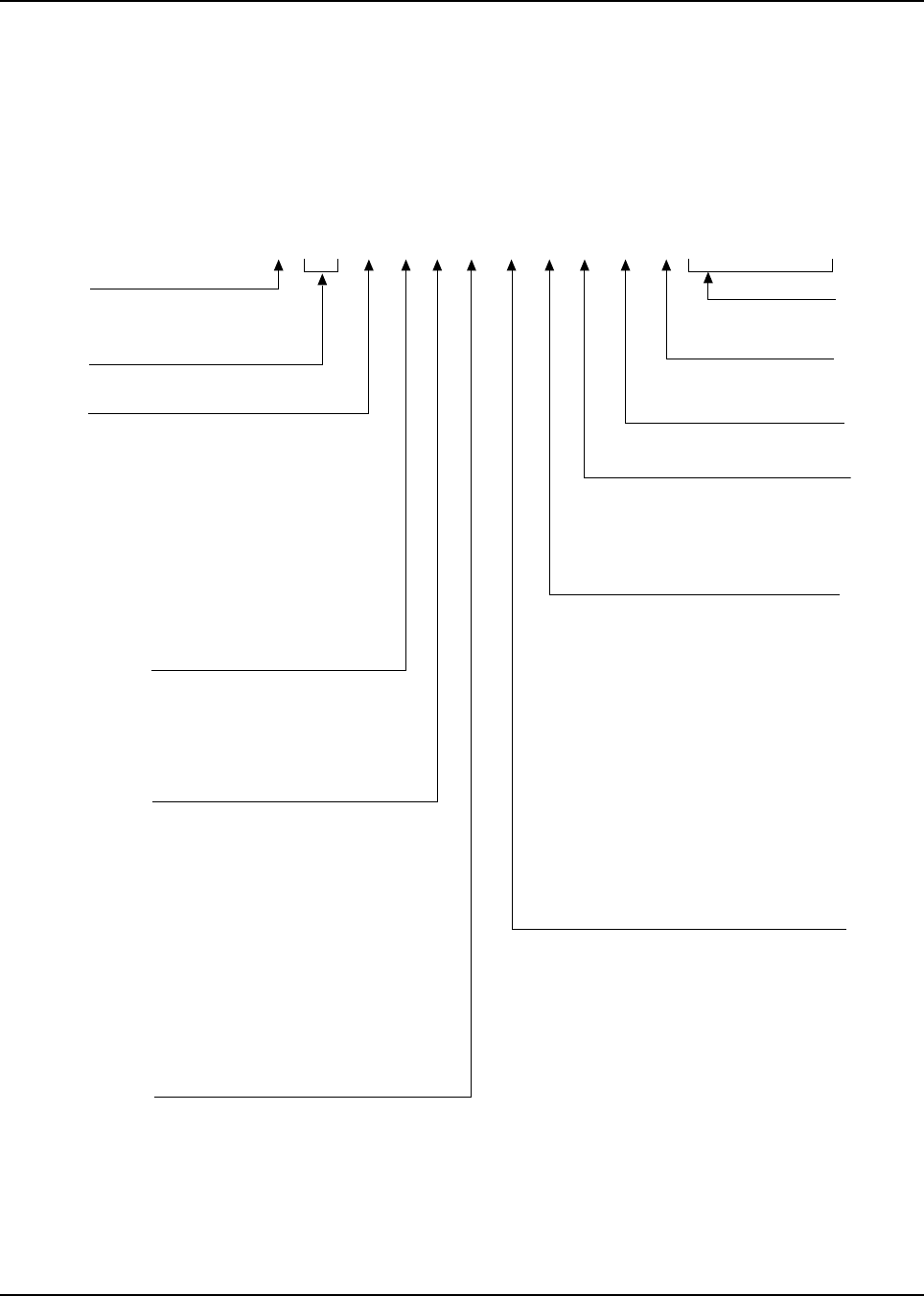
Mobile Radio Model Numbering Scheme
Position 1 - Type of Unit
D = Dash-Mounted Mobile Radio
M = Motorcycle Mobile Radio
T =Trunk-Mounted Mobile Radio
Positions 2 & 3 - Model Series
Position 4 - Frequency Band
Less than 29.7MHz
29.7 to 35.99MHz
36 to 41.99MHz
42 to 50MHz
66 to 80MHz
74 to 90MHz
Product Specific
136 to 162MHz
146 to 178MHz
174 to 210MHz
190 to 235MHz
336 to 410MHz
403 to 437MHz
438 to 482MHz
470 to 520MHz
Product Specific
806 to 870MHz
825 to 870MHz
896 to 941MHz
1.0 to 1.6GHz
1.5 to 2.0GHz
Values given represent range only; they are
not absolute.
Position 5 - Power Level
0 to 0.7 Watts
0.7 to 0.9 Watts
1.0 to 3.9 Watts
4.0 to 5.0 Watts
5.1 to 6.0 Watts
6.1 to 10 Watts
Position 6 - Physical Packages
RF Modem Operation
Receiver Only
Standard Control; No Display
Standard Control; With Display
Limited Keypad; No Display
Limited Keypad; With Display
Full Keypad; No Display
Full Keypad; With Display
Limited Controls; No Display
Limited Controls; Basic Display
Limited Controls; Limited Display
Rotary Controls; Standard Display
Enhanced Controls; Enhanced Display
Low Profile; No Display
Low Profile; Basic Display
Low Profile; Basic Display, Full Keypad
Position 7 - Channel Spacing
1 = 5kHz
2 = 6.25kHz
3 = 10kHz
4 = 12.5kHz
5 = 15kHz
6 = 20/25kHz
7 = 30kHz
9 = Variable/Programmable
T
ypical Model Number:
Position:
Position 8 - Primary Operation
Conventinal/Simplex
Conventional/Duplex
Trunked Twin Type
Dual Mode Trunked
Dual Mode Trunked/Duplex
Trunked Type I
Trunked Type II
FDMA* Digital Dual Mode
TDMA** Digital Dual Mode
Single Sideband
Global Positioning Satellite Capable
Amplitude Companded Sideband (ACSB)
Programmable
Integrated Voice and Data
* FDMA = Frequency Division Multiple Access
** TDMA = Time Division Multiple Access
Position 9 - Primary System Type
Conventional
Privacy Plus
Clear SMARTNET
Advanced Conventional Stat-Alert
Enhanced Privacy Plus
Nauganet 888 Series
Japan Specialized Mobile Radio (JSMR)
Multi-Channel Access (MCA)
CoveragePLUS
MPT1327* - Public
MPT1327* - Private
Radiocom
Tone Signalling
Binary Signalling
Phonenet
Programmable
Secure Conventional
Secure SMARTNET
* MPT = Ministry of Posts and Telecommunications
Position 10 - Feature Level
1 = Basic
2 = Limited Package
3 = Limited Plus
4 = Intermediate
5 = Standard Package
6 = Standard Plus
7 = Expanded Package
8 = Expanded Plus
9 = Full Feature/
Programmable
Position 11 - Version
Version Letter (Alpha) - Major Change
Position 12 -
Unique Model Variations
C = Cenelec
N = Standard Package
Positions 13 - 16
SP Model Suffix
1 23 4 5 6 7 8 9 10 11 1213141516
T04 S LF 9 P W 7 A N S P 0 1
04 = ASTRO
A
B
C
D
F
G
H
J
K
L
M
=
=
=
=
=
=
=
=
=
=
=
P
Q
R
S
T
U
V
W
Y
Z
=
=
=
=
=
=
=
=
=
=
A
B
C
D
E
F
=
=
=
=
=
=
10.1 to 15 Watts
16 to 25 Watts
26 to 35 Watts
36 to 60 Watts
G
H
J
K
L
=
=
=
=
A
B
C
D
E
F
G
H
J
K
L
M
N
P
Q
R
=
=
=
=
=
=
=
=
=
=
=
=
=
=
=
=
A
B
C
D
E
F
G
H
J
K
L
M
P
S
=
=
=
=
=
=
=
=
=
=
=
=
=
=
A
B
C
D
E
F
G
H
J
K
L
M
N
P
Q
W
X
Y
=
=
=
=
=
=
=
=
=
=
=
=
=
=
=
=
=
=
= 61 to 110 Watts
MAEPF-27247-O

6881076C20-E January 29, 2003
Model Numbering, Charts, and Specifications xvii
ASTRO Digital Spectra Motorcycle 15 Watt (Ranges 1 and 2) Model Chart
Model Number Description
M04JGF9PW4AN Model W4 (136-162 MHz), Range 1, 15 Watt, 128 Channels
M04JGF9PW5AN Model W5 (136-162 MHz), Range 1, 15 Watt, 128 Channels
M04JGH9PW7AN Model W7 (136-162 MHz), Range 1, 15 Watt, 128 Channels
M04KGF9PW4AN Model W4 (146-174 MHz), Range 2, 15 Watt, 128 Channels
M04KGF9PW5AN Model W5 (146-174 MHz), Range 2, 15 Watt, 128 Channels
M04KGH9PW7AN Model W7 (146-174 MHz), Range 2, 15 Watt, 128 Channels
M04RGF9PW4AN Model W4 (438-470 MHz), Range 2, 15 Watt, 128 Channels
M04RGF9PW5AN Model W5 (438-470 MHz), Range 2, 15 Watt, 128 Channels
M04RGH9PW7AN Model W7 (438-470 MHz), Range 2, 15 Watt, 128 Channels
M04UGF9PW4AN Model W4 (800 MHz), 15 Watt, 128 Channels
M04UGF9PW5AN Model W5 (800 MHz), 15 Watt, 128 Channels
M04UGH9PW7AN Model W7 (800 MHz), 15 Watt, 128 Channels
Item No. Description
XXXHLD6066_ VHF Power Amplifier Board, 25-Watt
XXXXXXXXXXXX HKN6062_ Cable, Control Head to Radio
XXXHLD4342_ VHF VCO Carrier
XXXHLD4343_ VHF VCO Carrier, CEPT
XXXHLD6032_ VHF Power Amplifier Board, Range 2, 25-Watt
XXXHLD6061_ VHF VCO, Range 1, 136-162 MHz
XXXHLD6062_ VHF VCO Board, Range 2, 146-174 MHz
XXXHLE6046_ UHF VCO Carrier, Range 2
XXXHLE6062_ UHF RF Power Amplifier Board, Range 2, 25-Watt
XXXHLE6102_ UHF VCO Board, Range 2
XXX HLF6078_ 800 MHz RF Power Amplifier Board, 15-Watt
XXX HLF6079_ 800 MHz VCO Board
XXX HLF6080_ 800 MHz VCO Carrier Board
XXXXXXXXXXXX HLN1368_ White Motorcycle Enclosure and Hardware
XXXXXXXXXXXX HLN6127_* Low-Power Dash Hardware
XXXXXXXXXX HLN6193_ MPL Button Kit
XXXXXXXXXXXX HLN6342_* Motorcycle Hardware
XXXXXXXXXXXX HLN6365_ Interface Board Kit
XXXXXXXXXXXX HLN6418_* Transceiver Hardware
XXX X X HLN6444_* W5 Motorcycle Control Head Hardware
XXX HLN6445_* W7 Motorcycle Control Head Hardware
XHLN6454_ Motorcycle Control Head Board Kit
XXXXXXXXXXXX HLN6458_ Vocoder Controller
XXHLN6459_ Interface Board
XXXX HLN6523_* W7 Button Kit
XXXXHLN6548_* W5 Button Kit
X X HLN6549_* W4 Button Kit
XXXXXXXXXXXX HLN6562_ Motorcycle Command Board Kit
XXXXXXXX HLN6563_ Motorcycle Control Head
XXXXHLN6571_ Spare Button Kit
XXXXXXXXXXXX HMN1079_ Weatherproof Microphone
XXXHRD6001_ VHF Receiver Board, Range 1, Standard
XXXHRD6002_ VHF Receiver Board, Range 2, Standard
XXXHRE6002_ UHF Receiver Board, Range 2, Standard
XXX HRF6004_ 800 MHz FX Front-End
XXXHRN4009_ VHF RF Board
XXXHRN4010_ UHF RF Board
XXXHRN6014_ VHF RF Board, ASTRO
XXX HRN6019_ 800 MHz RF Board, ASTRO
XXXXXXXXXXXX HSN6003_ Weatherproof Speaker
XXXXPMLN4019_ W4 Motorcycle Control Head
XRAE4024_ UHF Antenna, Quarterwave
XXX RAF4011_ 800 MHz Antenna, 3 dB Gain
X = Item Included
_ = the latest version kit. When ordering a kit, refer to your specific kit for the suffix number.
* = kit not available. Order piece parts from the Customer Care and Services Division.

January 29, 2003 6881076C20-E
xviii Model Numbering, Charts, and Specifications
ASTRO Digital Spectra Motorcycle 15 Watt (Ranges 3 and 3.5)
Model Chart
Model Number Description
M04RGF9PW4ANSP02 Model W4 (450-482 MHz), Range 3, 15 Watt, 128 Channels
M04RGF9PW5ANSP02 Model W5 (450-482 MHz), Range 3, 15 Watt, 128 Channels
M04RGF9PW4ANSP01 Model W4 (453-488 MHz), Range 3.5, 15 Watt, 128 Channels
M04RGF9PW5ANSP01 Model W5 (453-488 MHz), Range 3.5, 15 Watt, 128 Channels
M04RGH9PW7ANSP01 Model W7 (453-488 MHz), Range 3.5, 15 Watt, 128 Channels
Item No. Description
XXXX X HKN6062_ Cable, Control Head to Radio
XXHLE6000_ UHF VCO Carrier, Range 3
XX X HLE6000_SP01 UHF VCO Carrier, Range 3.5
XXHLE6043_ UHF RF Power Amplifier Board, Range 3, 40-Watt
XX X HLE6043_SP01 UHF RF Power Amplifier Board, Range 3.5, 40-Watt
XXHLE6103_ UHF VCO Hybrid, Range 3
XX X HLE6103_SP01 UHF VCO Hybrid, Range 3.5
XXXX X HLN1368_ White Motorcycle Enclosure and Hardware
XXXX X HLN6127_* Low-Power Dash Hardware
XX X HLN6193_ MPL Button Kit
XXXX X HLN6342_* Motorcycle Hardware
XXXX X HLN6365_ Interface Board Kit
XXXX X HLN6418_* Transceiver Hardware
XX HLN6444_* W5 Motorcycle Control Head Hardware
X HLN6445_* W7 Motorcycle Control Head Hardware
XXXX X HLN6458_ Vocoder Controller
X HLN6523_* W7 Button Kit
XX HLN6548_* W5 Button Kit
XXHLN6549_* W4 Button Kit
XXXX X HLN6562_ Motorcycle Command Board Kit
XX X HLN6563_ Motorcycle Control Head
XXXX X HLN6571_ Spare Button Kit
XXXX X HMN1079_ Weatherproof Microphone
XXHRE6003_ UHF Receiver Board, Range 3, Standard
XX X HRE6003_SP01 UHF Receiver Board, Range 3.5, Standard
XXXX X HRN6020_ UHF RF Board, ASTRO
XXXX X HSN6003_ Weatherproof Speaker
XXPMLN4019_ W4 Motorcycle Control Head
XXXX X RAE4024_ UHF Antenna, Quarterwave
X = Item Included
_ = the latest version kit. When ordering a kit, refer to your specific kit for the suffix number.
* = kit not available. Order piece parts from the Customer Care and Services Division.

6881076C20-E January 29, 2003
Model Numbering, Charts, and Specifications xix
ASTRO Digital Spectra VHF 10–25 Watt Model Chart
Model Number Description
D04JHH9PW3AN Model W3 (136-145.9 MHz), 10-25 Watt, 255 Channels
D04JHF9PW4AN Model W4 (136-162 MHz), 10-25 Watt, 128 Channels
D04JHF9PW5AN Model W5 (136-162 MHz); 10-25 Watt, 128 Channels
D04JHH9PW7AN Model W7 (136-162 MHz), 10-25 Watt, 255 Channels
T04JHH9PW9AN Model W9 (136-162 MHz), 10-25 Watt, 255 Channels
D04KHH9PW3AN Model W3 (146-145.9 MHz), 10-25 Watt, 255 Channels
D04KHF9PW4AN Model W4 (146-174 MHz), 10-25 Watt, 128 Channels
D04KHF9PW5AN Model W5 (146-174 MHz), 10-25 Watt, 128 Channels
D04KHH9PW7AN Model W7 (146-174 MHz), 10-25 Watt, 255 Channels
T04KHH9PW9AN Model W9 (146-174 MHz), 10-25 Watt, 255 Channels
Item No. Description
XXXXX HRD6001_ Front-End Receiver Board Kit (Range 1, 136-162 MHz)
XXXX HRD6002_ Front-End Receiver Board Kit (Range 2, 146-174 MHz)
XXXXX XXX HRN6014_ RF Board Kit
XXXXX XXXX HLD4342_ VCO Board Kit
XXXXX HLD6061_ VCO Hybrid Kit (Range 1, 136-162 MHz)
XXXXX HLD6062_ VCO Hybrid Kit (Range 2, 146-174 MHz)
XXXXXXXXXX HLN5558_ Command Board Kit
XXXXXXXXXX HLN6458_ VOCON Board Kit
XXXXX XXXX HLD6066_ Power Amplifier Board
XX HLN6344_ Interface Board
XXX X XX HLN6401_ Control Head Interconnect Board
X X AAHN4045_ W4 Control Head
X X XX HLN6396_ W5,W7 Control Head Board
XX HCN1078_ W9 Control Head
XXX X XX HMN1080_ Microphone
XX HMN1061_ Microphone
XXXXXXXXXX HSN4018_ Speaker
XX HLN4921_ Control Head (W9) Trunnion
XX HLN5488_ Radio Microphone Installation Hardware (W9 Trunnion)
XXXXXXXX HLN6015_ Trunnion/Hardware (Dash Mount)
XXX X XX HLN6060_ Dash-Mount Hardware
X X X X HLN6185_* Remote-Mount, SECURENET Control-Head Hardware
XXXXXXXXXX HLN6418_* Transceiver Hardware
X X HLN6440_* Control Head without Keypad Hardware
X X HLN6441_* Control Head with Keypad Hardware
XHLN6493_* Plug Kit
XX HLN4952_ Fuse Kit
XX HKN4356_ Radio Cable (Length -17 Feet)
XXXXXXXX HKN4191_ Power Cable (Length - 20 Feet)
XX HKN4192_ Power Cable (Length - 20 Feet)
XX HLN6481_* Systems 9000 E9 Clear Button Kit
X X HLN6549_* C4 Button Kit
X X HLN6105_ Emergency/Secure/MPL Button Kit
X X XX HLN6193_ Emergency/MPL Field Option Button Kit
X X HLN6548_* SMARTNET Button Kit
X X HLN6523_* SMARTNET Button Kit
XX HLN6167_ Option Button Kit
XHLD4343_ VCO Board Kit; VHF CEPT
XHLD6032_ Power Amplifier Board Kit
XXHLN6127_ Hardware, Radio Dash Low-Power
XXHLN6459_ W3 Interface Board
XXHMN4044_ ASTRO Handheld Control Head (W3)
XHRN4009_ RF Board Kit
X = Item Included
_ = the latest version kit. When ordering a kit, refer to your specific kit for the suffix number.
* = kit not available. Order piece parts from the Customer Care and Services Division.

January 29, 2003 6881076C20-E
xx Model Numbering, Charts, and Specifications
ASTRO Digital Spectra VHF 25–50 and 50–110 Watt Model Chart
Model Number Description
D04JKH9PW3AN Model W3 (136-145.9 MHz), 25-50 Watt, 128 Channels
D04JKF9PW4AN Model W4 (136-162 MHz), 25-50 Watt, 128 Channels
D04JKF9PW5AN Model W5 (136-162 MHz); 25-50 Watt, 128 Channels
D04JKH9PW7AN Model W7 (136-162 MHz), 25-50 Watt, 255 Channels
T04JKH9PW9AN Model W9 (136-162 MHz), 25-50 Watt, 255 Channels
D04KKF9PW3AN Model W3 (146-174 MHz), 25-50 Watt, 128 Channels
D04KKF9PW4AN Model W4 (146-174 MHz), 25-50 Watt, 128 Channels
D04KKF9PW5AN Model W5 (146-174 MHz), 25-50 Watt, 128 Channels
D04KKH9PW7AN Model W7 (146-174 MHz), 25-50 Watt, 255 Channels
T04KKH9PW9AN Model W9 (146-174 MHz), 25-50 Watt, 255 Channels
T04JLH9PW3AN Model W3 (136-145.9 MHz), 50-110 Watt, 128 Channels
T04JLF9PW4AN Model W4 (136-162 MHz), 50-110 Watt, 128 Channels
T04JLF9PW5AN Model W5 (136-162 MHz), 50-110 Watt, 128 Channels
T04JLH9PW7AN Model W7 (136-162 MHz), 50-110 Watt, 255 Channels
T04JLH9PW9AN Model W9 (136-162 MHz), 50-110 Watt, 255 Channels
T04KLH9PW3AN Model W3 (146-174 MHz), 50-110 Watt, 255 Channels
T04KLF9PW4AN Model W4 (146-174 MHz), 50-110 Watt, 128 Channels
T04KLF9PW5AN Model W5 (146-174 MHz), 50-110 Watt, 128 Channels
T04KLH9PW7AN Model W7 (146-174 MHz), 50-110 Watt, 255 Channels
T04KLH9PW9AN Model W9 (146-174 MHz), 50-110 Watt, 255 Channels
Item No. Description
XXXXX XXXXXHRD6001_ Front-End Rcvr Board Kit (Range 1, 136-162 MHz)
XXXXX XXX X X HRD6002_ Front-End Rcvr Board Kit (Range 2, 146-174 MHz)
XXXXXXXXXXXXXXXXXX X X HRN6014_ RF Board Kit
XXXXXXXXXXXXXXXXXXXXHLD4342_ VCO Board Kit
XXXXX XXXXXHLD6061_ VCO Hybrid Kit (Range 1, 136-162 MHz)
XXXXX XXXXXHLD6062_ VCO Hybrid Kit (Range 2, 146-174 MHz)
XXXXXXXXXXXXXXXXXXXXHLN5558_ Command Board Kit
XXXXXXXXXXXXXXXXXXXXHLN6458_ VOCON Board Kit
XXXXXHLD6064_ Power Amplifier Board
(50-110W, Range 1, 136-162 MHz)
XXXXXXXXXX HLD6022_ Power Amplifier Board
(25-50W, Range 1, 136-174 MHz)
XXXXXHLD6063_ Power Amplifier Board
(50-110W, Range 2, 146-174 MHz)
X X HLN6344_ Interface Board
XXX XXXHLN6401_ Control Head Interconnect Board
XX X X AAHN4045_ W4 Control Head
XXXXXXXXHLN6486_ High-Power Interconnect Board
XXX XX X HLN6432_ Control Head Back Housing
XX X X XX X X HLN6396_ W5,W7 Control Head Board
XXXX HCN1078_ W9 Control Head
XXX XXXXXX XX X HMN1080_ Microphone
XXXX HMN1061_ Microphone
XXXXXXXXXX HSN4018_ Speaker
XXXXXXXXXXHSN6001_ Speaker
XXXX HLN4921_ Control Head (W9) Trunnion
X X HLN5488_ Radio Microphone Installation Hardware (W9 Trunnion)
XX X X HLN6185_* Remote-Mount, SECURENET Control-Head Hardware
XXX XX X HLN6231_ Remote W4, W5, W7 Control-Head Trunnion
XXXXXXXXXXHLN6233_* Option Connector Hardware
X = Item Included
_ = the latest version kit. When ordering a kit, refer to your specific kit for the suffix number.
* = kit not available. Order piece parts from the Customer Care and Services Division.
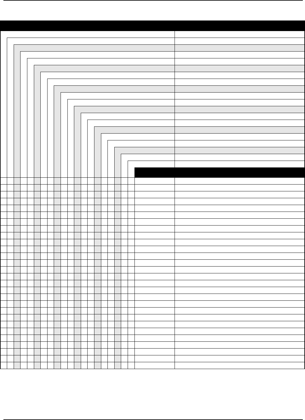
6881076C20-E January 29, 2003
Model Numbering, Charts, and Specifications xxi
ASTRO Digital Spectra VHF 10–25 and 50–110 Watt Model Chart (cont.)
Model Number Description
D04JKH9PW3AN Model W3 (136-145.9 MHz), 25-50 Watt, 128 Channels
D04JKF9PW4AN Model W4 (136-162 MHz), 25-50 Watt, 128 Channels
D04JKF9PW5AN Model W5 (136-162 MHz); 25-50 Watt, 128 Channels
D04JKH9PW7AN Model W7 (136-162 MHz), 25-50 Watt, 255 Channels
T04JKH9PW9AN Model W9 (136-162 MHz), 25-50 Watt, 255 Channels
D04KKF9PW3AN Model W3 (146-174 MHz), 25-50 Watt, 128 Channels
D04KKF9PW4AN Model W4 (146-174 MHz), 25-50 Watt, 128 Channels
D04KKF9PW5AN Model W5 (146-174 MHz), 25-50 Watt, 128 Channels
D04KKH9PW7AN Model W7 (146-174 MHz), 25-50 Watt, 255 Channels
T04KKH9PW9AN Model W9 (146-174 MHz), 25-50 Watt, 255 Channels
T04JLH9PW3AN Model W3 (136-145.9 MHz), 50-110 Watt, 128 Channels
T04JLF9PW4AN Model W4 (136-162 MHz), 50-110 Watt, 128 Channels
T04JLF9PW5AN Model W5 (136-162 MHz), 50-110 Watt, 128 Channels
T04JLH9PW7AN Model W7 (136-162 MHz), 50-110 Watt, 255 Channels
T04JLH9PW9AN Model W9 (136-162 MHz), 50-110 Watt, 255 Channels
T04KLH9PW3AN Model W3 (146-174 MHz), 50-110 Watt, 255 Channels
T04KLF9PW4AN Model W4 (146-174 MHz), 50-110 Watt, 128 Channels
T04KLF9PW5AN Model W5 (146-174 MHz), 50-110 Watt, 128 Channels
T04KLH9PW7AN Model W7 (146-174 MHz), 50-110 Watt, 255 Channels
T04KLH9PW9AN Model W9 (146-174 MHz), 50-110 Watt, 255 Channels
Item No. Description
XXXXXXXXXXHLN6132_* High-Power Installation Hardware
XXXX XXXXHLN6015_ Trunnion/Hardware (Dash Mount)
XXXX XXXXHLN6060_ Dash-Mount Hardware
XXXXXXXXXXHLN6121_* High-Power Radio Hardware
XXXXXXXXXX HLN6418_* Transceiver Hardware
XXXX HLN6440_* Control Head without Keypad Hardware
XXXX HLN6441_* Control Head with Keypad Hardware
XXXXXXXXXXHLN6525_* High-Power Transceiver Hardware
X X XXX X HLN6493_* Plug Kit
XXXXXXXXXXXHLN4952_ Fuse Kit
X X XXXXXXXXHKN4356_ Radio Cable (Length -17 Feet)
XXXXXXXXXXHKN6039_ Cable (Length - 17 Feet)
XXXXXXXXXXHKN4051_ Cable and Fuse
XXXX XXXXHKN4191_ Power Cable (Length - 20 Feet)
X X HKN4192_ Power Cable (Length - 20 Feet)
XXXX HLN6481_* Systems 9000 E9 Clear Button Kit
XXXXHLN6549_* C4 Button Kit
XXXXHLN6105_ Emergency/Secure/MPL Button Kit
XX X X XX X X HLN6193_ Emergency/MPL Field Option Button Kit
XXXX HLN6548_* SMARTNET Button Kit
XXXX HLN6523_* SMARTNET Button Kit
XXXX HLN6167_ Option Button Kit
XXHLN6459_ W3 Interface Board Kit
XXXXHMN4044_ ASTRO Handheld Control Head (W3)
XXXXTLN5277_ Filter Kit
XXHKN6096_ Handheld Control Head “Y” Cable Kit
XXHLN6291_ Installation Hardware Kit
XXHLN6574_ W3 Interconnect Board Kit
X = Item Included
_ = the latest version kit. When ordering a kit, refer to your specific kit for the suffix number.
* = kit not available. Order piece parts from the Customer Care and Services Division.

January 29, 2003 6881076C20-E
xxii Model Numbering, Charts, and Specifications
ASTRO Digital Spectra UHF 10–25 Watt Model Chart
Model Number Description
D04RHH9PW3AN Model W3 (438-470 MHz), 10-25 Watt, 255 Channels
D04RHF9PW4AN Model W4 (438-470 MHz), 10-25 Watt, 128 Channels
D04RHF9PW5AN Model W5 (438-470 MHz), 10-25 Watt, 128 Channels
D04RHH9PW7AN Model W7 (438-470 MHz), 10-25 Watt, 255 Channels
T04RHH9PW9AN Model W9 (438-470 MHz), 10-25 Watt, 255 Channels
Item No. Description
XAAHN4045_ Front Housing
XXXX X HAE4003_ Antenna
XXXX HKN4191_ Power Cable (Length-20 Feet)
XXXX X HLE6046_ VCO Carrier, Range 2
XXXX X HLE6062_ Power Amplifier, 25W, Range 2
XXXX X HLE6102_ VCO Hybrid Kit, Range 2
XXXX X HLN5558_ Command Board Kit
XXXX HLN6015_ Trunnion
XXX HLN6073_ Dash-Mount Hardware
XHLN6105_ Emergency/Secure/MPL Button Kit
XHLN6549_* C4 Button Kit
XXX HLN6401_ Control Head Interconnect Board
XXXX X HLN6418_* Transceiver Hardware
XXXX X HLN6458_ VOCODER Controller
XXX HMN1080_ Microphone
XXXX X HRE6002_ Receiver, Range 2
XXX X HRN6020_ RF Board Kit
XXXX X HSN4018_ Speaker
XHLN6548_* SMARTNET Button Kit
XX HLN6193_ Emergency/MPL Field Option Button Kit
XX HLN6396_ DEK Compatible Control Head
XHLN6440_* Control Head without Keypad Hardware
X HLN6441_* Control Head with Keypad Hardware
X HLN6523_* SMARTNET Button Kit
X HCN1078_ W9 Control Head
X HKN4192_ Power Cable (Length-20 Feet)
X HKN4356_ Radio Cable
X HLN4921_ Trunnion
X HLN4952_ Fuse Kit
X HLN5488_ Installation Hardware
X HLN6162_* Remote Hardware
X HLN6167_ Option Button Kit
XX HSN6185_ Remote-Mount, SECURENET Control-Head Hardware
X HLN6344_ Interface Board
X HLN6481_* Systems 9000 E9 Clear Button Kit
X HLN6493_* Plug Kit
X HMN1061_ Microphone
XHLN6127_ Dash Hardware, Low-Power Kit
XHLN6459_ W3 Interface Board Kit
XHMN4044_ ASTRO Handheld Control Head (W3)
XHRN4010_ Low-Power RF Board Kit
XTLN5277_ Filter Kit
X = Item Included
_ = the latest version kit. When ordering a kit, refer to your specific kit for the suffix number.
* = kit not available. Order piece parts from the Customer Care and Services Division.
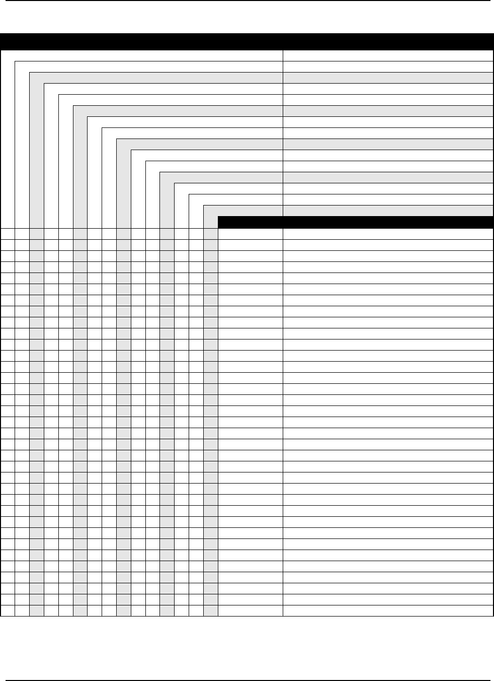
6881076C20-E January 29, 2003
Model Numbering, Charts, and Specifications xxiii
ASTRO Digital Spectra UHF 20–40 Watt Model Chart
Model Number Description
D04QKH9PW3AN Model W3 (403-433 MHz), 20-40 Watt, 128 Channels
D04QKF9PW4AN Model W4 (403-433 MHz), 20-40 Watt, 128 Channels
D04QKF9PW5AN Model W5 (403-433 MHz), 20-40 Watt, 128 Channels
D04QKH9PW7AN Model W7 (403-433 MHz), 20-40 Watt, 255 Channels
T04QKH9PW9AN Model W9 (403-433 MHz), 20-40 Watt, 255 Channels
D04RKH9PW3ANSP01 Model W3 (450-482 MHz), 20-40 Watt, 128 Channels
D04RKF9PW4AN Model W4 (450-482 MHz), 20-40 Watt, 128 Channels
D04RKF9PW5AN Model W5 (450-482 MHz), 20-40 Watt, 128 Channels
D04RKH9PW7AN Model W7 (450-482 MHz), 20-40 Watt, 255 Channels
T04RKH9PW9AN Model W9 (450-482 MHz), 20-40 Watt, 255 Channels
D04SKH9PW3AN Model W3 (482-512 MHz), 20-40 Watt, 128 Channels
D04SKF9PW4AN Model W4 (482-512 MHz), 20-40 Watt, 128 Channels
D04SKF9PW5AN Model W5 (482-512 MHz), 20-40 Watt, 128 Channels
D04SKH9PW7AN Model W7 (482-512 MHz), 20-40 Watt, 255 Channels
T04SKH9PW9AN Model W9 (482-512 MHz), 20-40 Watt, 255 Channels
Item No. Description
XXXAAHN4045_ Front Housing
XXXXX HAE4002_ Antenna, Roof Top
XXXX XXXXXXXX HKN4191_ Power Cable (Length-20 Feet)
XXX HKN4192_ Power Cable (Length-20 Feet)
XXX HKN4356_ Radio Cable (Length-17 Feet)
XXXXX HLE6045_ VCO Carrier, Range 1
XXXXX HLE6049_ Power Amplifier, 40W, Range 1
XXXXX HLE6101_ VCO Hybrid Kit, Range 1
XXX HLN4921_ Trunnion
XXX HLN4952_ Fuse Kit
XXX HLN5488_ Installation Hardware
XXXXXXXXXXXXXXX HLN5558_ Command Board Kit
XXXX XXXXXXXX HLN6015_ Trunnion/Hardware (Dash Mount)
XXXX XXXXXXXX HLN6073_ Dash-Mount Hardware
XXXHLN6548_* SMARTNET Button Kit
XHLN6162_* Remote-Mount Hardware
XXX HLN6167_ Option Button Kit
XXXX X HLN6185_* Remote-Mount, SECURENET Control-Head Hardware
XX X X XX HLN6193_ Emergency/MPL Field Option Button Kit
XX X X XX HLN6396_ Control Head Deck Compatible
XX X HLN6105_ Emergency/Secure/MPL Button Kit
XX X HLN6549_* C4 Button Kit
XXX HLN6344_ Interface Board
XXX XXXXXX HLN6401_ Control Head Interconnect Board
XXXXXXXXXXXXXXX HLN6418_* Transceiver Hardware
X X X HLN6440_* Control Head without Keypad Hardware
XXXHLN6441_* Control Head with Keypad Hardware
XXXXXXXXXXXXXXX HLN6458_ VOCODER Controller
XXX HLN6481_* Systems 9000 E9 Clear Button Kit
XXX HLN6493_* Plug Kit
XXXHLN6523_* SMARTNET Button Kit
XXX XXXXXX HMN1080_ Microphone
XXXXX HRE6001_ Receiver F/E, Range 1
XXXXXXXXXXXXXXX HRN6020_ RF Board
XXX HMN1061_ Microphone
X = Item Included
_ = the latest version kit. When ordering a kit, refer to your specific kit for the suffix number.
* = kit not available. Order piece parts from the Customer Care and Services Division.
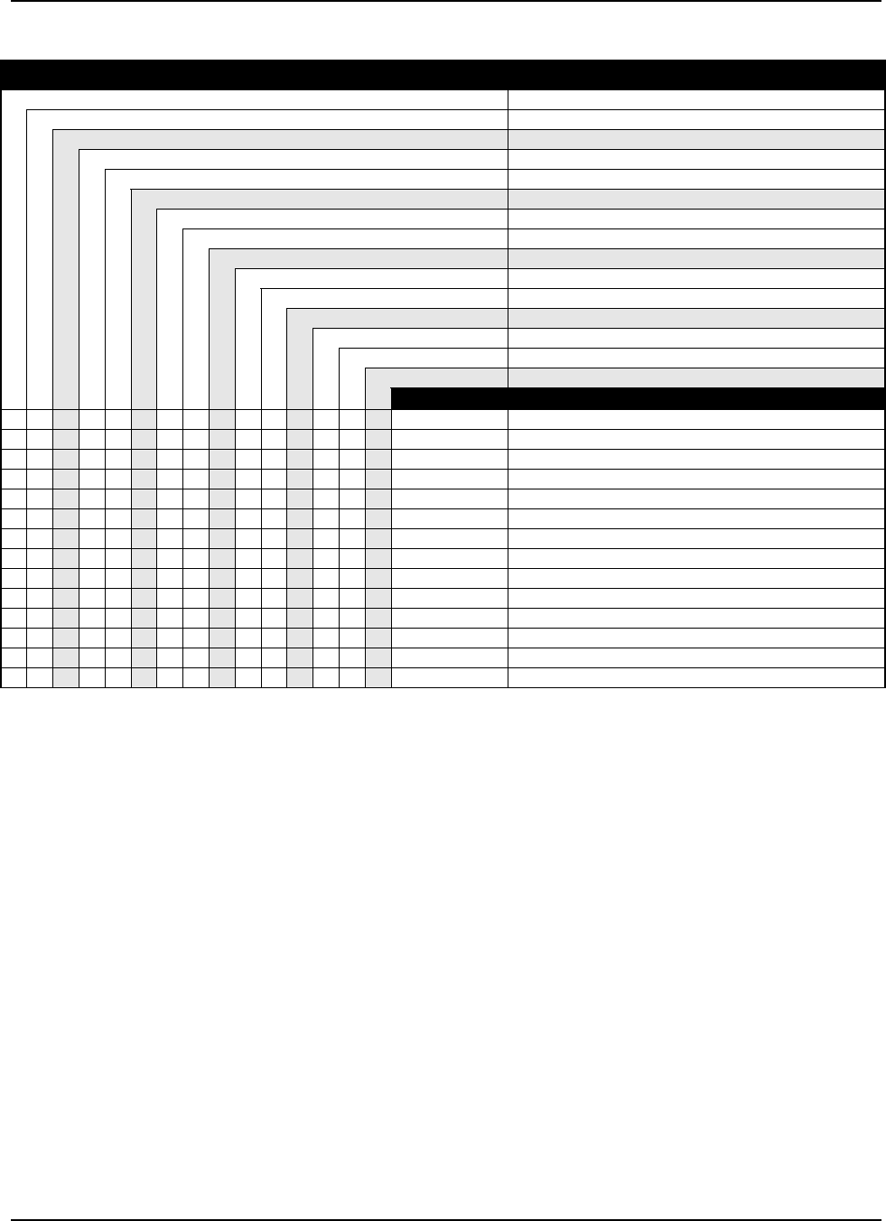
January 29, 2003 6881076C20-E
xxiv Model Numbering, Charts, and Specifications
ASTRO Digital Spectra UHF 20–40 Watt Model Chart (cont.)
Model Number Description
D04QKH9PW3AN Model W3 (403-433 MHz), 20-40 Watt, 128 Channels
D04QKF9PW4AN Model W4 (403-433 MHz), 20-40 Watt, 128 Channels
D04QKF9PW5AN Model W5 (403-433 MHz), 20-40 Watt, 128 Channels
D04QKH9PW7AN Model W7 (403-433 MHz), 20-40 Watt, 255 Channels
T04QKH9PW9AN Model W9 (403-433 MHz), 20-40 Watt, 255 Channels
D04RKH9PW3ANSP01 Model W3 (450-482 MHz), 20-40 Watt, 128 Channels
D04RKF9PW4AN Model W4 (450-482 MHz), 20-40 Watt, 128 Channels
D04RKF9PW5AN Model W5 (450-482 MHz), 20-40 Watt, 128 Channels
D04RKH9PW7AN Model W7 (450-482 MHz), 20-40 Watt, 255 Channels
T04RKH9PW9AN Model W9 (450-482 MHz), 20-40 Watt, 255 Channels
D04SKH9PW3AN Model W3 (482-512 MHz), 20-40 Watt, 128 Channels
D04SKF9PW4AN Model W4 (482-512 MHz), 20-40 Watt, 128 Channels
D04SKF9PW5AN Model W5 (482-512 MHz), 20-40 Watt, 128 Channels
D04SKH9PW7AN Model W7 (482-512 MHz), 20-40 Watt, 255 Channels
T04SKH9PW9AN Model W9 (482-512 MHz), 20-40 Watt, 255 Channels
Item No. Description
XXXXX HAE4003_ Antenna, Quarterwave
XXXX HLE6000_ VCO Carrier, Range 3
XXXX HLE6043_ Power Amplifier, 40W, Range 3
XXXX HLE6103_ VCO Hybrid Kit, Range 3
XXXX HRE6003_ Receiver F/E, Range 3
XXXXXXXXXXXXXXX HSN4018_ Speaker
XXX HCN1078_ W9 Control Head
XXXXX HAE4004_ Antenna, Roof Top
XXXXX HLE6041_ VCO Carrier, Range 4
XXXXX HLE6044_ Power Amplifier, 40W, Range 4
XXXXX HLE6104_ VCO Hybrid Kit, Range 4
XXXXX HRE6004_ Receiver F/E, Range 4
XX X HLN6459_ W3 Interface Board
XX X HMN4044_ ASTRO Handheld Control Head (W3)
X = Item Included
_ = the latest version kit. When ordering a kit, refer to your specific kit for the suffix number.
* = kit not available. Order piece parts from the Customer Care and Services Division.
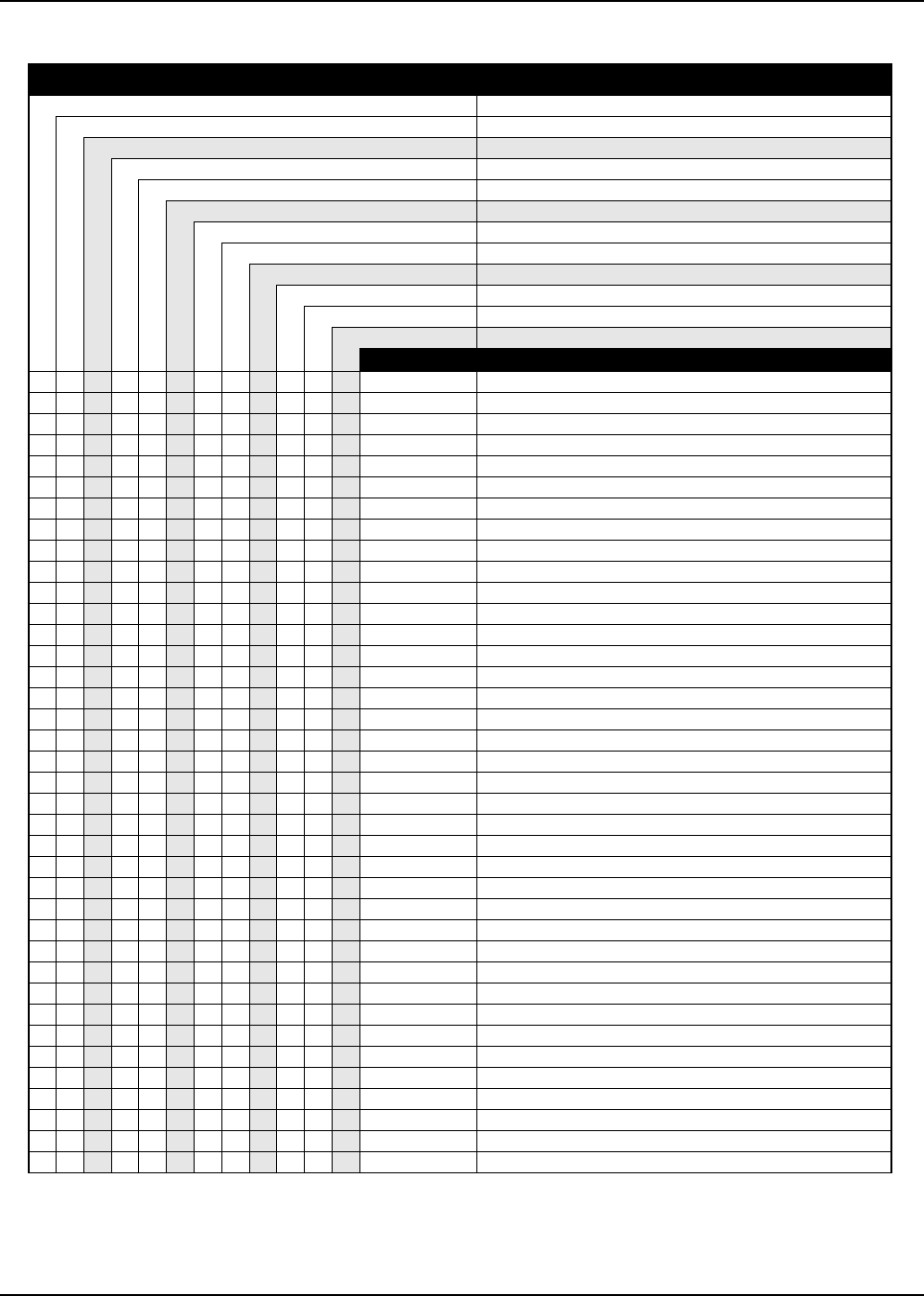
6881076C20-E January 29, 2003
Model Numbering, Charts, and Specifications xxv
ASTRO Digital Spectra UHF 50–110 Watt Model Chart
Model Number Description
T04QLF9PW4AN Model W4 (403-433 MHz), 50-110 Watt, 128 Channels
T04QLF9PW5AN Model W5 (403-433 MHz), 50-110 Watt, 255 Channels
T04QLH9PW7AN Model W7 (403-433 MHz), 50-110 Watt, 255 Channels
T04QLH9PW9AN Model W9 (403-433 MHz), 50-110 Watt, 255 Channels
T04RLF9PW4AN Model W4 (450-482 MHz), 50-110 Watt, 128 Channels
T04RLF9PW5AN Model W5 (450-482 MHz), 50-110 Watt, 128 Channels
T04RLH9PW7AN Model W7 (450-482 MHz), 50-110 Watt, 255 Channels
T04RLH9PW9AN Model W9 (450-482 MHz), 50-110 Watt, 255 Channels
T04SLF9PW4AN Model W4 (482-512 MHz), 50-110 Watt, 128 Channels
T04SLF9PW5AN Model W5 (482-512 MHz), 50-110 Watt, 128 Channels
T04SLHPW7AN Model W7 (482-512 MHz), 50-110 Watt, 128 Channels
T04SLHPW9AN Model W9 (482-512 MHz), 50-110 Watt, 128 Channels
Item No. Description
XXXAAHN4045_ Front Housing
XXXX HAE4002_ Antenna, Roof Top
XXXX HAE4003_ Antenna, Quarterwave
XXXX HAE4004_ Antenna, Roof Top
XXXXXXXXXXXX HKN4051_ Cable and Fuse
XXXXXXXXXXXX HKN4356_ Radio Cable (Length-17 Feet)
XXXXXXXXXXXX HKN6039_ Cable (Length-17 Feet)
XXXX HLE6039_ VCO Carrier, Range 3
XXXX HLE6040_ Power Amplifier Board, Range 4
XXXX HLE6041_ VCO Carrier, Range 4
XXXX HLE6045_ VCO Carrier, Range 1
XXXX HLE6051_ Power Amplifier Board, 100W, Range 1
XXXX HLE6101_ VCO Hybrid Kit, Range 1
XXXX HLE6103_ VCO Hybrid Kit, Range 3
XXXX HLE6104_ VCO Hybrid Kit, Range 4
XXXXXXXXXXXX HLN4952_ Fuse Kit
XXXXXXXXXXXX HLN5558_ Command Board Kit
XX X HLN6105_ Emergency/Secure/MPL Button Kit
XXXXXXXXXXXX HLN6121_* High-Power Radio Hardware
XXXXXXXXXXXX HLN6132_* Installation Hardware, High-Power
XXXXXX XXX HLN6231_ Remote W4, W5, W7 Control-Head Trunnion
XXXXXXXXXXXX HLN6233_* Option Connector Hardware
XX X HLN6549_* C4 Button Kit
XXXXXX XXX HLN6432_ Back Housing, Control Head
XXXXXXXXXXXX HLN6458_ VOCON Board Kit
XXXXXXXXXXXX HLN6486_ Interconnect Board
X X XXX HLN6493_* Plug Kit
XXXXXXXXXXXX HLN6525_* High-Power Transceiver Hardware
XXXXXXX XXX HMN1080_ Microphone
XXXX XX HMN1061_ Microphone
XHRE6001_ Receiver Board Kit, Range 1
XXXX HRE6003_ Receiver Board Kit, Range 3
XXXX HRE6004_ Receiver Board Kit, Range 4
XXXXXXXXXXXX HRN6020_ RF Board
XXXXXXXXXXX HSN6001_ Speaker
XX X HLN6548_* SMARTNET Button Kit
XXXX XX HLN6193_ Emergency/MPL Field Option Button Kit
XXXX XX HLN6396_ W5, W7 Control Head Board
X = Item Included
_ = the latest version kit. When ordering a kit, refer to your specific kit for the suffix number.
* = kit not available. Order piece parts from the Customer Care and Services Division.
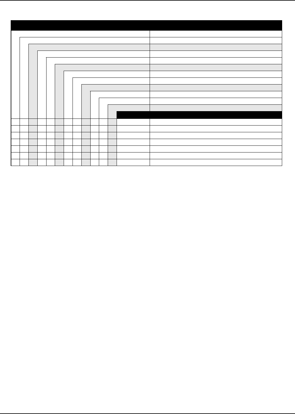
January 29, 2003 6881076C20-E
xxvi Model Numbering, Charts, and Specifications
ASTRO Digital Spectra UHF 50–110 Watt Model Chart (cont.)
Model Number Description
T04QLF9PW4AN Model W4 (403-433 MHz), 50-110 Watt, 128 Channels
T04QLF9PW5AN Model W5 (403-433 MHz), 50-110 Watt, 255 Channels
T04QLH9PW7AN Model W7 (403-433 MHz), 50-110 Watt, 255 Channels
T04QLH9PW9AN Model W9 (403-433 MHz), 50-110 Watt, 255 Channels
T04RLF9PW4AN Model W4 (450-482 MHz), 50-110 Watt, 128 Channels
T04RLF9PW5AN Model W5 (450-482 MHz), 50-110 Watt, 128 Channels
T04RLH9PW7AN Model W7 (450-482 MHz), 50-110 Watt, 255 Channels
T04RLH9PW9AN Model W9 (450-482 MHz), 50-110 Watt, 255 Channels
T04SLF9PW4AN Model W4 (482-512 MHz), 50-110 Watt, 128 Channels
T04SLF9PW5AN Model W5 (482-512 MHz), 50-110 Watt, 128 Channels
T04SLHPW7AN Model W7 (482-512 MHz), 50-110 Watt, 128 Channels
T04SLHPW9AN Model W9 (482-512 MHz), 50-110 Watt, 128 Channels
Item No. Description
XXXHLN6440_* Control Head without Keypad Hardware
XXXHLN6441_* Control Head with Keypad Hardware
XXXHLN6523_* SMARTNET Button Kit
XXX HCN1078_ W9 Control Head
XXX HLN4921_ Trunnion
XXX HLN6167_ Option Button Kit
XXX HLN6481_* Systems 9000 E9 Clear Button Kit
X = Item Included
_ = the latest version kit. When ordering a kit, refer to your specific kit for the suffix number.
* = kit not available. Order piece parts from the Customer Care and Services Division.

6881076C20-E January 29, 2003
Model Numbering, Charts, and Specifications xxvii
ASTRO Digital Spectra 800 MHz Model Chart
Model Number Description
D04UJF9PW3AN Model W3 (800 MHz), 35 Watt, 128 Channels
D04UJF9PW4AN Model W4 (800 MHz), 35 Watt, 128 Channels
D04UJF9PW5AN Model W5 (800 MHz), 35 Watt, 128 Channels
D04UJF9PW7AN Model W7 (800 MHz), 35 Watt, 255 Channels
T04UJF9PW9AN Model W9 (800 MHz), 35 Watt, 255 Channels
Item No. Description
XAAHN4045_ Front Housing
XXXX HKN4191_ Power Cable (Length-20 Feet)
XXXX X HLF6077_ Power Amplifier
XXXX X HLF6079_ VCO Hybrid
XXXX X HLF6080_ VCO Carrier
XXXX HLN6015_ Trunnion/Hardware
XHLN6040_ Phon/Page/Emer/MPL Button
XXXX X HLN6126_* Mid-Power Dash Mount Radio Hardware
XX HLN6193_ Emergency/MPL Field Option Button Kit
XHLN6549_* C4 Button Kit
XXX HLN6401_ Control Head Interconnect Board
XXX X HLN6418_* Transceiver Hardware
XXX HMN1080_ Microphone
XXXX X HRF6004_ Front-End Receiver Kit
XXXX X HRN6019_ RF Board Kit
XXXX X HSN4018_ Speaker
XXXX X RRA4914_ Antenna
XXXX X HLN5558_ Command Board Kit
XHLN6548_* SMARTNET Button Kit
XX HLN6396_ Control Head Deck Compatible
XHLN6440_* Control Head without Keypad Hardware
XXXX X HLN6458_ VOCODER Controller
X HLN6441_* Control Head with Keypad Hardware
X HLN6523_* SMARTNET Button Kit
X HCN1078_ W9 Control Head
X HKN4192_ Power Cable (Length-20 Feet)
X HKN4356_ Radio Cable (Length-17 Feet)
X HLN4921_ Trunnion, Control Head w9
X HLN4952_ Fuse Kit
X HLN5488_ Installation Hardware (W9 Trunnion) Radio Microphone
X HLN6167_ Option Button Kit
XX HLN6185_* Remote-Mount, SECURENET Control Head Hardware
X HLN6344_ Interface Board
X HLN6481_* Systems 9000 E9 Clear Button Kit
X HLN6493_* Plug Kit
X HMN1061_ Microphone
X = Item Included
_ = the latest version kit. When ordering a kit, refer to your specific kit for the suffix number.
* = kit not available. Order piece parts from the Customer Care and Services Division.

January 29, 2003 6881076C20-E
xxviii Model Numbering, Charts, and Specifications
ASTRO Digital Spectra Plus VHF 25–50 and 50–110 Watt Model Chart
Model Number Description
D04JKH9SW7AN Model W7 (136-162 MHz), 25-50 Watt, 512 Channels
D04KKH9SW3AN Model W3 (146-174 MHz), 25-50 Watt, 512 Channels
D04KKF9SW4AN Model W4 (146-174 MHz), 25-50 Watt, 512 Channels
D04KKF9SW5AN Model W5 (146-174 MHz); 25-50 Watt, 512 Channels
D04KKH9SW7AN Model W7 (146-174 MHz), 25-50 Watt, 512 Channels
T04KKH9SW9AN Model W9 (146-174 MHz), 25-50 Watt, 512 Channels
T04KLH9SW3AN Model W3 (146-174 MHz), 50-110 Watt, 512 Channels
T04KLF9SW4AN Model W4 (146-174 MHz), 50-110 Watt, 512 Channels
T04KLF9SW5AN Model W5 (146-174 MHz), 50-110 Watt, 512 Channels
T04KLH9SW7AN Model W7 (146-174 MHz), 50-110 Watt, 512 Channels
T04KLH9SW9AN Model W9 (146-174 MHz), 50-110 Watt, 512 Channels
Item No. Description
XHRD6001_ Front-End Rcvr Board Kit (Range 1, 136-162 MHz)
XXXXXXXXXX HRD6002_ Front-End Rcvr Board Kit (Range 2, 146-174 MHz)
XXXXXXXXXXX HRN6014_ RF Board Kit
XXXXXXXXXXX HLD4342_ VCO Board Kit
XHLD6061_ VCO Hybrid Kit (Range 1, 136-162 MHz)
XXXXXXXXXX HLD6062_ VCO Hybrid Kit (Range 2, 146-174 MHz)
XXXXXXXXXXX HLN5558_ Command Board Kit
XXXXXXXXXXX HLN6837_ VOCON Board Kit
XXXXXX HLD6022_ Power Amplifier Board (25-50W, Range 2, 146-174 MHz)
XXXXX HLD6063_ Power Amplifier Board (50-110W, Range 2, 146-174 MHz)
XHLN6344_ Interface Board
XXXXHLN6401_ Control Head Interconnect Board
X X AAHN4045_ W4 Control Head
XXXX HLN6486_ High-Power Interconnect Board
XXX HLN6432_ Control Head Back Housing
X X X XX HLN6396_ W5,W7 Control Head Board
XX HCN1078_ W9 Control Head
OOOOOOOOOOO NTN9801_ ASTRO Spectra Plus UCM
XXX X XX HMN1080_ Microphone
XX HMN1061_ Microphone
XXXXXX HSN4018_ Speaker
XXXXX HSN6001_ Speaker
XX HLN4921_ Control Head (W9) Trunnion
XX HLN5488_ Radio Microphone Installation Hardware (W9 Trunnion)
X X HLN6185_* Remote-Mount, SECURENET Control-Head Hardware
XXX HLN6231_ Remote W4, W5, W7 Control-Head Trunnion
XXXXX HLN6233_* Option Connector Hardware
XXXXX HLN6132_* High-Power Installation Hardware
XXXXXHLN6015_ Trunnion/Hardware (Dash Mount)
XXXXXHLN6060_ Dash-Mount Hardware
XXXXX HLN6121_* High-Power Radio Hardware
XXXXXX HLN6866_* Transceiver Hardware
X X HLN6440_* Control Head without Keypad Hardware
X X X HLN6441_* Control Head with Keypad Hardware
XXXXX HLN6525_* High-Power Transceiver Hardware
XX HLN6493_* Plug Kit
X X XXX HLN4952_ Fuse Kit
X X XXX HKN4356_ Radio Cable (Length -17 Feet)
X = Item Included
O = Optional item
_ = the latest version kit. When ordering a kit, refer to your specific kit for the suffix number.
* = kit not available. Order piece parts from the Customer Care and Services Division.
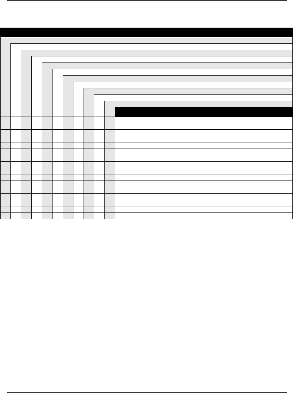
6881076C20-E January 29, 2003
Model Numbering, Charts, and Specifications xxix
ASTRO Digital Spectra Plus VHF 25–50 and 50–110 Watt Model Chart
(cont.)
Model Number Description
D04JKH9SW7AN Model W7 (136-162 MHz), 25-50 Watt, 512 Channels
D04KKH9SW3AN Model W3 (146-174 MHz), 25-50 Watt, 512 Channels
D04KKF9SW4AN Model W4 (146-174 MHz), 25-50 Watt, 128 Channels
D04KKF9SW5AN Model W5 (146-174 MHz); 25-50 Watt, 128 Channels
D04KKH9SW7AN Model W7 (146-174 MHz),25-50 Watt, 512 Channels
T04KKH9SW9AN Model W9 (146-174 MHz), 25-50 Watt, 512 Channels
T04KLH9SW3AN Model W3 (146-174 MHz), 50-110 Watt, 512 Channels
T04KLF9SW4AN Model W4 (146-174 MHz), 50-110 Watt, 128 Channels
T04KLF9SW5AN Model W5 (146-174 MHz), 50-110 Watt, 128 Channels
T04KLH9SW7AN Model W7 (146-174 MHz), 50-110 Watt, 512 Channels
T04KLH9SW9AN Model W9 (146-174 MHz), 50-110 Watt, 512 Channels
Item No. Description
XXXXX HKN4051_ Cable and Fuse
XXXXXHKN4191_ Power Cable (Length - 20 Feet)
XHKN4192_ Power Cable (Length - 20 Feet)
XXXXX HKN6039_ Cable (Length - 17 Feet)
XX HLN6481_* Systems 9000 E9 Clear Button Kit
X X HLN6549_* C4 Button Kit
XXXXX XXXX HLN6105_ Emergency/Secure/MPL Button Kit
X X HLN6548_* SMARTNET Button Kit
X X X HLN6523_* SMARTNET Button Kit
XX HLN6167_ Option Button Kit
XHLN6459_ W3 Interface Board Kit
X X HMN4044_ ASTRO Handheld Control Head (W3)
X X TLN5277_ Filter Kit
XHKN6096_ Handheld Control Head “Y” Cable Kit
XHLN6291_ Installation Hardware Kit
XHLN6574_ W3 Interconnect Board Kit
X = Item Included
O = Optional item
_ = the latest version kit. When ordering a kit, refer to your specific kit for the suffix number.
* = kit not available. Order piece parts from the Customer Care and Services Division.

January 29, 2003 6881076C20-E
xxx Model Numbering, Charts, and Specifications
ASTRO Digital Spectra Plus UHF 20–40 Watt Model Chart
Model Number Description
D04QKH9SW3AN Model W3 (403-433 MHz), 20-40 Watt, 512 Channels
D04QKF9SW4AN Model W4 (403-433 MHz), 20-40 Watt, 128 Channels
D04QKF9SW5AN Model W5 (403-433 MHz), 20-40 Watt, 128 Channels
D04QKH9SW7AN Model W7 (403-433 MHz), 20-40 Watt, 512 Channels
T04QKH9SW9AN Model W9 (403-433 MHz), 20-40 Watt, 512 Channels
D04RKH9SW3AN Model W3 (450-482 MHz), 20-40 Watt, 512 Channels
D04RKF9SW4AN Model W4 (450-482 MHz), 20-40 Watt, 128 Channels
D04RKF9SW5AN Model W5 (450-482 MHz), 20-40 Watt, 128 Channels
D04RKH9SW7AN Model W7 (450-482 MHz), 20-40 Watt, 512 Channels
T04RKH9SW9AN Model W9 (450-482 MHz), 20-40 Watt, 512 Channels
Item No. Description
X X AAHN4045_ Control Head Assembly (W4)
XXXXX HAE4002_ Antenna, Roof Top
XXXXX HAE4003_ Antenna, Quarterwave
XX HCN1078_ W9 Control Head
XXXXXXXX HKN4191_ Power Cable (Length-20 Feet)
XX HKN4192_ Power Cable (Length-20 Feet)
XX HKN4356_ Radio Cable (Length-17 Feet)
XXXXX HLE6000_ VCO Carrier, Range 3
XXXXX HLE6043_ Power Amplifier, 40W, Range 3
XXXXX HLE6045_ VCO Carrier, Range 1
XXXXX HLE6049_ Power Amplifier, 40W, Range 1
XXXXX HLE6101_ VCO Hybrid Kit, Range 1
XXXXX HLE6103_ VCO Hybrid Kit, Range 3
XX HLN4921_ Trunnion
XX HLN4952_ Fuse Kit
XX HLN5488_ Installation Hardware
XXXXXXXXXX HLN5558_ Command Board Kit
XXXXXXXX HLN6015_ Trunnion/Hardware (Dash Mount)
XXXXXXXX HLN6073_ Dash-Mount Hardware
XXXX XXXX HLN6105_ Emergency/Secure/MPL Button Kit
XX HLN6167_ Option Button Kit
XX HLN6185_* Remote-Mount, SECURENET Control-Head Hardware
XX HLN6344_ Interface Board
X X XX HLN6396_ Control Head Deck Compatible
XXX X XX HLN6401_ Control Head Interconnect Board
XXXXXXXXXX HLN6418_* Transceiver Hardware
X X HLN6440_* Control Head without Keypad Hardware
X X HLN6441_* Control Head with Keypad Hardware
XXHLN6459_ W3 Interface Board
XX HLN6481_* Systems 9000 E9 Clear Button Kit
XX HLN6493_* Plug Kit
X X HLN6523_* SMARTNET Button Kit
X X HLN6548_* SMARTNET Button Kit
X X HLN6549_* C4 Button Kit
XXXXXXXXXX HLN6837_ VOCODER Controller
XX HMN1061_ Microphone
XXX X XX HMN1080_ Microphone
XXHMN4044_ ASTRO Handheld Control Head (W3)
X = Item Included
O = Optional
_ = the latest version kit. When ordering a kit, refer to your specific kit for the suffix number.
* = kit not available. Order piece parts from the Customer Care and Services Division.
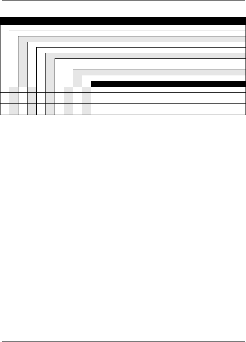
6881076C20-E January 29, 2003
Model Numbering, Charts, and Specifications xxxi
ASTRO Digital Spectra Plus UHF 20–40 Watt Model Chart (cont.)
Model Number Description
D04QKH9SW3AN Model W3 (403-433 MHz), 20-40 Watt, 512 Channels
D04QKF9SW4AN Model W4 (403-433 MHz), 20-40 Watt, 128 Channels
D04QKF9SW5AN Model W5 (403-433 MHz), 20-40 Watt, 128 Channels
D04QKH9SW7AN Model W7 (403-433 MHz), 20-40 Watt, 512 Channels
T04QKH9SW9AN Model W9 (403-433 MHz), 20-40 Watt, 512 Channels
D04RKH9SW3AN Model W3 (450-482 MHz), 20-40 Watt, 512 Channels
D04RKF9SW4AN Model W4 (450-482 MHz), 20-40 Watt, 128 Channels
D04RKF9SW5AN Model W5 (450-482 MHz), 20-40 Watt, 128 Channels
D04RKH9SW7AN Model W7 (450-482 MHz), 20-40 Watt, 512 Channels
T04RKH9SW9AN Model W9 (450-482 MHz), 20-40 Watt, 512 Channels
Item No. Description
XXXXX HRE6001_ Receiver F/E, Range 1
XXXX HRE6003_ Receiver F/E, Range 3
XXXXXXXXXX HRN6020_ RF Board
XXXXXXXXXX HSN4018_ Speaker
OOOOOOOOOO NTN9801_ UCM, ASTRO Spectra Plus
X = Item Included
O = Optional
_ = the latest version kit. When ordering a kit, refer to your specific kit for the suffix number.
* = kit not available. Order piece parts from the Customer Care and Services Division.
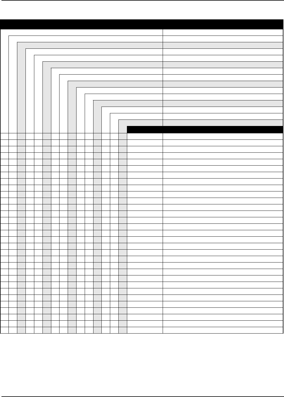
January 29, 2003 6881076C20-E
xxxii Model Numbering, Charts, and Specifications
ASTRO Digital Spectra Plus UHF 50–110 Watt Model Chart
Model Number Description
T04QLH9SW3AN Model W3 (403-433 MHz), 50-110 Watt, 512 Channels
T04QLF9SW4AN Model W4 (403-433 MHz), 50-110 Watt, 128 Channels
T04QLF9SW5AN Model W5 (403-433 MHz), 50-110 Watt, 128 Channels
T04QLH9SW7AN Model W7 (403-433 MHz), 50-110 Watt, 512 Channels
T04QLH9SW9AN Model W9 (403-433 MHz), 50-110 Watt, 512 Channels
T04RLH9SW3AN Model W3 (450-482 MHz), 50-110 Watt, 512 Channels
T04RLF9SW4AN Model W4 (450-482 MHz), 50-110 Watt, 128 Channels
T04RLF9SW5AN Model W5 (450-482 MHz), 50-110 Watt, 128 Channels
T04RLH9SW7AN Model W7 (450-482 MHz), 50-110 Watt, 512 Channels
T04RLH9SW9AN Model W9 (450-482 MHz), 50-110 Watt, 512 Channels
T04SLH9SW3AN Model W3 (482-512 MHz), 50-110 Watt, 512 Channels
T04SLF9SW4AN Model W4 (482-512 MHz), 50-110 Watt, 128 Channels
T04SLF9SW5AN Model W5 (482-512 MHz), 50-110 Watt, 128 Channels
T04SLH9SW7AN Model W7 (482-512 MHz), 50-110 Watt, 512 Channels
T04SLH9SW9AN Model W9 (482-512 MHz), 50-110 Watt, 512 Channels
Item No. Description
XXXAAHN4045_ Control Head Assembly (W4)
XXXXX HAE4002_ Antenna, Roof Top
XXXXX HAE4003_ Antenna, Quarterwave
XXXXX HAE4004_ Antenna, Roof Top
XXX HCN1078_ W9 Control Head
XXXXXXXXXXXXXXX HKN4051_ Cable and Fuse
XXXX XXXX XXXX HKN4356_ Radio Cable (Length-17 Feet)
XXXXXXXXXXXXXXX HKN6039_ Power Cable (Length-17 Feet)
XX X HKN6096_ Handheld Control Head “Y” Cable Kit
XXXXX HLE6039_ VCO Carrier, Range 3
XXXXX HLE6040_ Power Amplifier Board, Range 4
XXXXX HLE6041_ VCO Carrier, Range 4
XXXXX HLE6045_ VCO Carrier, Range 1
XXXXX HLE6051_ Power Amplifier Board, 100W, Range 1
XXXXX HLE6101_ VCO Hybrid Kit, Range 1
XXXXX HLE6103_ VCO Hybrid Kit, Range 3
XXXXX HLE6104_ VCO Hybrid Kit, Range 4
XXX HLN4921_ Trunnion
XXXX XXXX XXXX HLN4952_ Fuse Kit
XXXXXXXXXXXXXXX HLN5558_ Command Board Kit
XX X HLN6105_ Emergency/Secure/MPL Button Kit
XXXXXXXXXXXXXXX HLN6121_* High-Power Radio Hardware
XXXXXXXXXXXXXXX HLN6132_* Installation Hardware, High-Power
XXX HLN6167_ Option Button Kit
XXX XXXXXX HLN6231_ Remote W4, W5, W7 Control-Head Trunnion
XXXXXXXXXXXXXXX HLN6233_* Option Connector Hardware
XX X HLN6291_ Installation Hardware Kit
XX X X XX HLN6396_ W5, W7 Control Head Board
XXX XXXXXX HLN6432_ Back Housing, Control Head
XXXHLN6440_* Control Head without Keypad Hardware
XXXHLN6441_* Control Head with Keypad Hardware
X = Item Included
O = Optional
_ = the latest version kit. When ordering a kit, refer to your specific kit for the suffix number.
* = kit not available. Order piece parts from the Customer Care and Services Division.
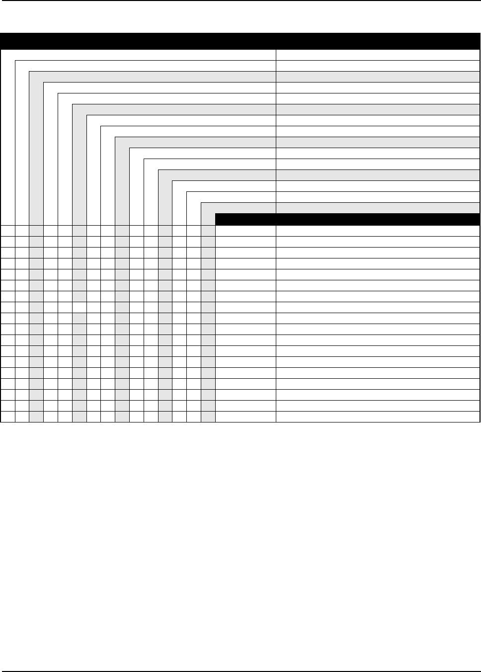
6881076C20-E January 29, 2003
Model Numbering, Charts, and Specifications xxxiii
ASTRO Digital Spectra Plus UHF 50–110 Watt Model Chart (cont.)
Model Number Description
T04QLH9SW3AN Model W3 (403-433 MHz), 50-110 Watt, 512 Channels
T04QLF9SW4AN Model W4 (403-433 MHz), 50-110 Watt, 128 Channels
T04QLF9SW5AN Model W5 (403-433 MHz), 50-110 Watt, 128 Channels
T04QLH9SW7AN Model W7 (403-433 MHz), 50-110 Watt, 512 Channels
T04QLH9SW9AN Model W9 (403-433 MHz), 50-110 Watt, 512 Channels
T04RLH9SW3AN Model W3 (450-482 MHz), 50-110 Watt, 512 Channels
T04RLF9SW4AN Model W4 (450-482 MHz), 50-110 Watt, 128 Channels
T04RLF9SW5AN Model W5 (450-482 MHz), 50-110 Watt, 128 Channels
T04RLH9SW7AN Model W7 (450-482 MHz), 50-110 Watt, 512 Channels
T04RLH9SW9AN Model W9 (450-482 MHz), 50-110 Watt, 512 Channels
T04SLH9SW3AN Model W3 (482-512 MHz), 50-110 Watt, 512 Channels
T04SLF9SW4AN Model W4 (482-512 MHz), 50-110 Watt, 128 Channels
T04SLF9SW5AN Model W5 (482-512 MHz), 50-110 Watt, 128 Channels
T04SLHSW7AN Model W7 (482-512 MHz), 50-110 Watt, 512 Channels
T04SLHSW9AN Model W9 (482-512 MHz), 50-110 Watt, 512 Channels
Item No. Description
XXX HLN6481_* Systems 9000 E9 Clear Button Kit
XXXX XXXX XXXX HLN6486_ Interconnect Board
XXX HLN6493_* Plug Kit
XXXHLN6523_* SMARTNET Button Kit
XXXXXXXXXXXXXXX HLN6525_* High-Power Transceiver Hardware
XXXHLN6548_* SMARTNET Button Kit
XX X HLN6549_* C4 Button Kit
XX X HLN6574_ W3 Interface Board
XXXXXXXXXXXXXXX HLN6837_ VOCON Board Kit
XXX XXXXXX HMN1080_ Microphone
XXX HMN1061_ Microphone
HMN4044_ Handheld Control Head
XXXXX HRE6001_ Receiver Board Kit, Range 1
XXXXX HRE6003_ Receiver Board Kit, Range 3
XXXXX HRE6004_ Receiver Board Kit, Range 4
XXXXXXXXXXXXXXX HRN6020_ RF Board
XXXXXXXXXXXXXX HSN6001_ Speaker
OOOOOOOOOOOOOOO NTN9801_ UCM, ASTRO Spectra Plus
X = Item Included
O = Optional
_ = the latest version kit. When ordering a kit, refer to your specific kit for the suffix number.
* = kit not available. Order piece parts from the Customer Care and Services Division.
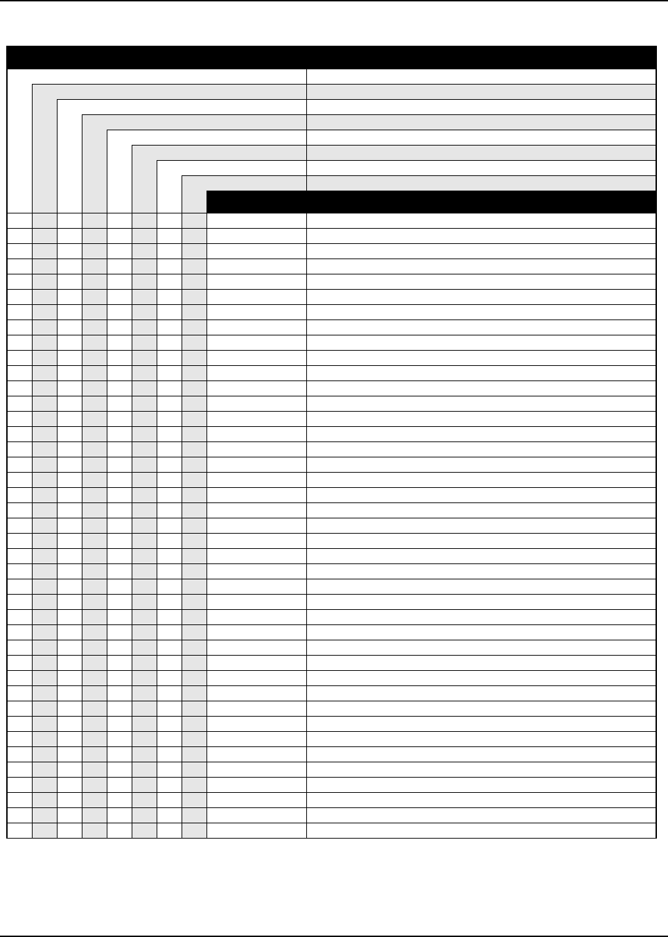
January 29, 2003 6881076C20-E
xxxiv Model Numbering, Charts, and Specifications
ASTRO Digital Spectra Plus 800 MHz Model Chart
Model Number Description
M04UGF9SW4AN Model W4 (800 MHz), 15 Watt, 128 Channels
M04UGF9SW5AN Model W5 (800 MHz), 15 Watt, 128 Channels
M04UGH9SW7AN Model W7 (800 MHz), 15 Watt, 512 Channels
D04UJH9SW3AN Model W3 (800 MHz), 35 Watt, 512 Channels
D04UJF9SW4AN Model W4 (800 MHz), 35 Watt, 128 Channels
D04UJF9SW5AN Model W5 (800 MHz), 35 Watt, 128 Channels
D04UJH9SW7AN Model W7 (800 MHz), 35 Watt, 512 Channels
T04UJH9SW9AN Model W9 (800 MHz), 35 Watt, 512 Channels
Item No. Description
XAAHN4045_ Front Housing, W4 Control Head
XXXX HKN4191_ Power Cable (Length-20 Feet)
XXXXX HLF6077_ Power Amplifier
XXX HLF6078_ 15W. 800 MHz Power Amplifier
XXXXXXXX HLF6079_ VCO Hybrid
XXXXXXXX HLF6080_ VCO Carrier
XXXX HLN6015_ Trunnion/Hardware
XXX XXXX HLN6688A_ Phon/Page/Emer/MPL Button
XXXXX HLN6126_ Mid-Power Dash Mount Radio Hardware
XXX XXXX HLN6645A_ Emergency/MPL Field Option Button Kit
XHLN6549_* W4 Button Kit
XXX HLN6401_ Control Head Interconnect Board
XXX HLN6365_ Interface Board, Motorcycle
XXXXXXXX HLN6418_* Transceiver Hardware
XXX HMN1080_ Microphone, Modified Standard
XXXXXXXX HRF6004_ Front-End Receiver Kit
XXXXXXXX HRN6019_ RF Board Kit
XXXXX HSN4018_ Speaker
XXXXX RRA4914_ Antenna
XXXXX HLN5558_ Command Board Kit
XXX HLN6562_ Command Board, Motorcycle
X X HLN6548_* SMARTNET Button Kit
XX HLN6396_ Control Head Deck Compatible
XHLN6440_* W5 Control Head without Keypad Hardware
XPMLN4019_ W4 ASTRO Motorcycle Control Head
XX HLN6563_ Motorcycle Control Head
XHLN6445_* Hardware, Control Head, Motorcycle
XHLN6208_ Button, Spectra SECURENET
XHLN6441_* W7 Control Head with Keypad Hardware
X X HLN6523_* SMARTNET Button Kit
X HCN1078_ W9 Control Head
OOOOX HKN4192_ Power Cable (Length-20 Feet)
OOOX HKN4356_ Remote Mount Radio Cable (Length-17 Feet)
X HLN4921_ Trunnion, Control Head W9
X HLN4952_ Fuse Kit
X HLN5488_ Installation Hardware (W9 Trunnion)
X HLN6167_ Option Button Kit
XOOOX HLN6185_* Remote-Mount, SECURENET Control Head Hardware
OOOX HLN6344_ Interface Board, Remote Mount
X HLN6481_* Systems 9000 E9 Clear Button Kit
X HMN1061_ Microphone
X = Item Included
O = Optional
_ = the latest version kit. When ordering a kit, refer to your specific kit for the suffix number.
* = kit not available. Order piece parts from the Customer Care and Services Division.
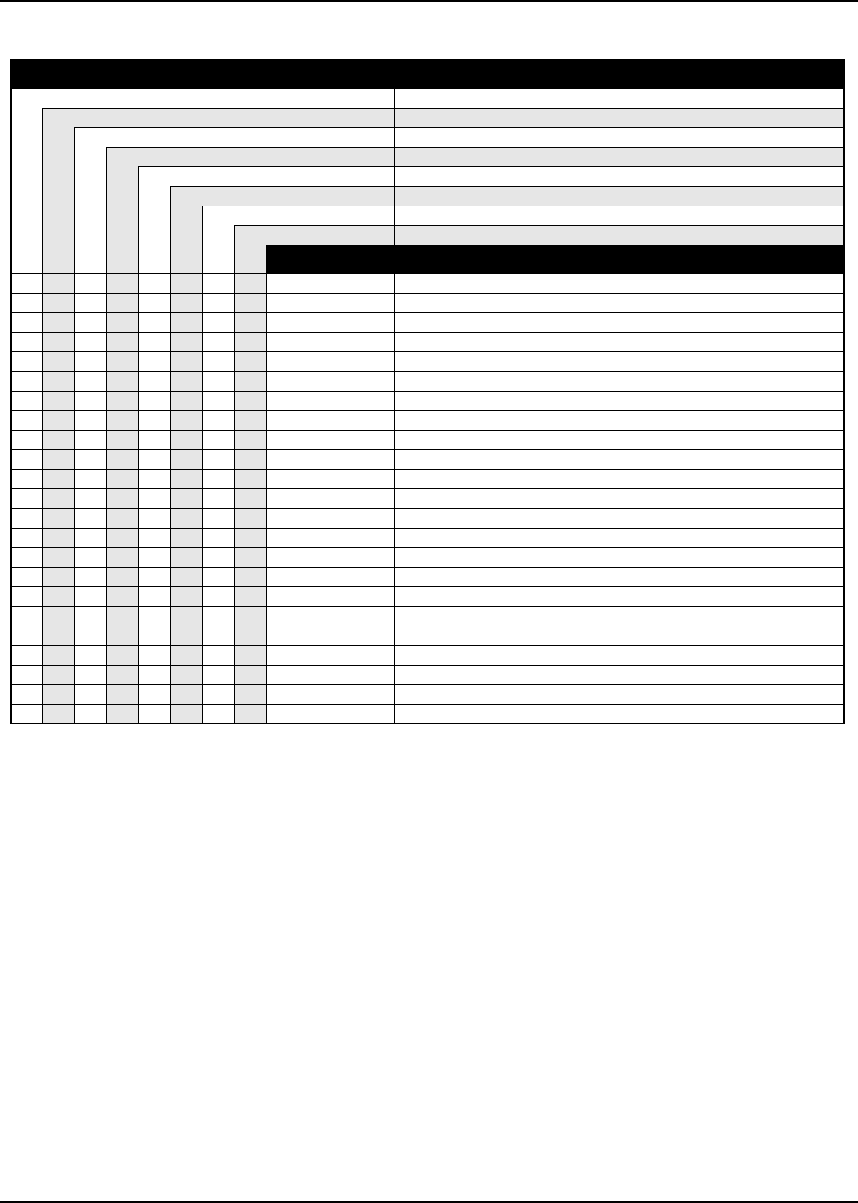
6881076C20-E January 29, 2003
Model Numbering, Charts, and Specifications xxxv
ASTRO Digital Spectra Plus 800 MHz Model Chart (cont.)
Model Number Description
M04UGF9SW4AN Model W4 (800 MHz), 15 Watt, 128 Channels
M04UGF9SW5AN Model W5 (800 MHz), 15 Watt, 128 Channels
M04UGH9SW7AN Model W7 (800 MHz), 15 Watt, 512 Channels
D04UJH9SW3AN Model W3 (800 MHz), 35 Watt, 512 Channels
D04UJF9SW4AN Model W4 (800 MHz), 35 Watt, 128 Channels
D04UJF9SW5AN Model W5 (800 MHz), 35 Watt, 128 Channels
D04UJH9SW7AN Model W7 (800 MHz), 35 Watt, 512 Channels
T04UJH9SW9AN Model W9 (800 MHz), 35 Watt, 512 Channels
Item No. Description
XHLN6638_ Radio Hardware
XXXXXXXX HLN6837_ Vocoder/Controller
XXXX HLN6073_ Radio Hardware
XHLN6459_ Interface Board
XHMN4044_ Handheld Control Head
XHLN6613_ Transceiver Hardware
XX HLN6493_* Large Black Plug Kit
XXX XXXX HLN6105_ Spare Button Kit
X HLN6675_* System 9000 Button Kit Secure
XXX HLN6639_* Radio Hardware
XXX HKN6062_ Cable, Control Head to Radio
XXX HLN6179_ Motorcycle Adapter Control Head Speaker
XXX HKN6032_ Motorcycle Power Cable
XXX HLN6180_ Motorcycle Mounting Hardware
XXX HLN6342_* Motorcycle Hardware Secure
XHLN6249_* Button, Secure
XXX RAF4011_ 800 MHz Antenna, 3 dB Gain
XXX HSN6003_ Motorcycle Waterproof Speaker
XXX HMN1079_ Modified Motorcycle Waterproof Microphone
X X HLN6524_ Button, Conventional
OOO HKN6432_ Back Housing Kit
OOO HLN6231_ Hardware, Remote-Mount Dash
XHLN6444_* Hardware, Control Head, Motorcycle
X = Item Included
O = Optional
_ = the latest version kit. When ordering a kit, refer to your specific kit for the suffix number.
* = kit not available. Order piece parts from the Customer Care and Services Division.

January 29, 2003 6881076C20-E
xxxvi Model Numbering, Charts, and Specifications
VHF Radio Specifications
GENERAL RECEIVER TRANSMITTER
FCC Designations: AZ492FT3772 Frequency Range: Frequency Range:
AZ492FT3773 Range 1: 136–162 MHz Range 1: 136–162 MHz
Range 2: 146–174 MHz Range 2: 146–174 MHz
Temperature Range:
Operating: –30°C to +60°C Channel Spacing: 12.5 kHz, 25 kHz Rated Output Power:
Storage: –40°C to +85°C Low-Power Radio: 10–25 Watt Variable
Input Impedance: 50 Ohm Mid-Power Radio: 25–50 Watt Variable
Power Supply: 12 Vdc Negative Ground Only High-Power Radio: 50–110 Watt Variable
Frequency Separation:
Battery Drain: (Maximum) Range 1: 26 MHz Channel Spacing: 12.5 kHz, 25 kHz
10–25 Watt Variable: Range 2: 28 MHz
Standby @ 13.8 V: 0.8 A Channel Increment Step: 2.5 kHz
Receive at Rated Audio @ 13.8 V: 3.0 A Sensitivity: (per EIA spec. RS204C)
Transmit @ Rated Power: 7.0 A 20 dB Quieting: (25/30 kHz Channel Spacing) Output Impedance: 50 Ohm
25–50 Watt Variable: With Optional Preamp: 0.30 µV
Standby @ 13.8 V: 0.8 A Without Optional Preamp: 0.50 µV Frequency Separation:
Receive at Rated Audio @ 13.8 V: 3.0 A 12 dB SINAD (25/30 kHz Channel Spacing) Range 1: 26 MHz
Transmit @ Rated Power: 13.5 A With Optional Preamp: 0.20 µV Range 2: 28 MHz
50–110 Watt Variable: Without Optional Preamp: 0.35 µV
Standby @ 13.8 V: 0.9 A Frequency Stability:
Receive at Rated Audio @ 13.8 V: 4.0 A Selectivity: (per EIA Specifications) (–30 to +60°C; 25°C Ref.): ±0.00025%
Transmit @ Rated Power: 27.5 A (Measured in the Analog Mode)
25/30 kHz Channel Spacing: –80 dB Modulation Limiting:
Dimensions (H x W x D) 12.5 kHz Channel Spacing: –70 dB 25 kHz/30 kHz Channel Spacing: ±5.0 kHz
W4, W5, and W7 Models: 12.5 kHz Channel Spacing: ±2.5 kHz
Remote-Mount Control Head: 2.0" x 7.1"x 2.2" Intermodulation: (per EIA Specifications)
(50.8 mm x 180.3 mm x 55.9 mm) (Measured in the Analog Mode) FM Hum and Noise:
Dash-Mount Radio: 2.0" x 7.1"x 8.6" With Optional Preamp: –70 dB (Measured in the Analog Mode): –45 dB
(50.8 mm x 180.3 mm x 218.4 mm) Without Optional Preamp: –80 dB
W9 Model: Emission (Conducted and Radiated): –75 dB
Remote-Mount Control Head: 3.4" x 6.5"x 1.7" Spurious Rejection:
(86.4 mm x 165.1 mm x 43.2 mm) With Optional Preamp: –80 dB Audio Sensitivity:
Speaker: (excluding mounting bracket) Without Optional Preamp: –83 dB (For 60% Max. Deviation at 1 kHz): 0.08V ±3 dB
5.5" x 5.5"x 2.5"
(139.7 mm x 139. 7mm x 63.5 mm) Frequency Stability: Audio Response:
(–30° to +60°C; 25°C Reference): ±0.00025% (Measured in the Analog Mode)
Weight: (6 dB/Octave Pre-Emphasis 300 to 3000 Hz):
Mid-Power Radio: 6.1 lbs (2.8 kg) Audio Output: (per EIA Specifications) +1, –3 dB
High-Power Radio: 11.2 lbs (5.1 kg) (Measured in the Analog Mode):
Speaker: 1.5 lbs (0.7 kg) 5 Watts at Less Than 3% Distortion Emissions Designators:
10 Watts Optional with Reduced Duty Cycle 8K10F1E, 11K0F3E, 15K0F2D, 16K0F3E,
12 Watts for High-Power Radios 20K0F1E, and 15K0F1D
AZ492FT3771: 11K0F1D, 11K0F2D
AZ492FT3772: 10K0F1D, 10K0F2D
AZ492FT3773: 11K0F1D, 11K0F2D
Specifications subject to change without notice.
All measurements are taken in the test mode at 25 kHz channel spacing except where indicated.

6881076C20-E January 29, 2003
Model Numbering, Charts, and Specifications xxxvii
UHF Radio Specifications
GENERAL RECEIVER TRANSMITTER
FCC Designations: AZ492FT4786 Frequency Range: Frequency Range:
AZ492FT4787 Range 1: 403–433 MHz Range 1: 403–433 MHz
Range 2: 438–470 MHz Range 2: 438–470 MHz
Temperature Range: Range 3: 450–482 MHz Range 3: 450–482 MHz
Operating: –30°C to +60°C Range 4: 482–512 MHz Range 4: 482–512 MHz
Storage: –40°C to +85°C
Channel Spacing: 12.5 kHz or 25 kHz Rated Output Power:
Power Supply: 12 Vdc Negative Ground Only Low-Power Radio: 1–6 Watt Variable
Input Impedance: 50 Ohm Mid-Power Radio: 10–25 Watt Variable
Battery Drain: (Maximum) 20–40 Watt Variable
1–6 Watt Variable: Frequency Separation: High-Power Radio: 50–110* Watt Variable
Standby @ 13.8 V: 0.7 A Range 1 and 4: 30 MHz
Receive at Rated Audio @ 13.8 V: 3.0 A Range 2 and 3: 32 MHz Channel Spacing: 12.5 kHz or 25 kHz
Transmit @ Rated Power: 4.0 A
10–25 Watt Variable: Sensitivity: (per EIA spec. RS204C) Output Impedance: 50 Ohm
Standby @ 13.8 V: 0.7 A 20 dB Quieting: (25 kHz Channel Spacing)
Receive at Rated Audio @ 13.8 V: 3.0 A With Optional Preamp: 0.30 µV Frequency Separation:
Transmit @ Rated Power: 7.0 A Without Optional Preamp: 0.50 µV Range 1 and 4: 30 MHz
20–40 Watt Variable: 12 dB SINAD (25 kHz Channel Spacing) Range 2 and 3: 32 MHz
(30 W Max. in Talkaround Mode) With Optional Preamp: 0.20 µV
Standby @ 13.8 V: 0.7 A Without Optional Preamp: 0.35 µV Frequency Stability:
Receive at Rated Audio @ 13.8 V: 3.0 A (–30° to +60°C; 25°C Ref.): ±0.00025%
Transmit @ Rated Power: 13.0 A Selectivity: (per EIA Specifications)
78 Watt (Range 3 & 4)/110 W (Range 1 & 3): (Measured in the Analog Mode) Modulation Limiting:
Standby @ 13.8 V: 0.8 A 25 kHz Channel Spacing: –75 dB 25 kHz Channel Spacing: ±5.0 kHz
Receive at Rated Audio @ 13.8 V: 4.0 A 12.5 kHz Channel Spacing: –70 dB 12.5 kHz Channel Spacing: ±2.5 kHz
Transmit @ Rated Power: 31.5 A
Intermodulation: (per EIA Specifications) FM Hum and Noise:
Dimensions (H x W x D) (Measured in the Analog Mode) (Measured in the Analog Mode): –45 dB
W4, W5, and W7 Models: With Optional Preamp: –70 dB
Remote-Mount Control Head: 2.0" x 7.1"x 2.2" Without Optional Preamp: –75 dB Emission (Conducted and Radiated): –70 dB
(50.8 mm x 180.3 mm x 55.9 mm)
Dash-Mount Radio: 2.0" x 7.1"x 8.6" Spurious Rejection: Audio Sensitivity:
(50.8 mm x 180.3 mm x 218.4 mm) With Optional Preamp: –80 dB (For 60% Max. Deviation at 1 kHz): 0.08V ±3 dB
W9 Model: Without Optional Preamp: –83 dB
Remote-Mount Control Head: 3.4" x 6.5"x 1.7" Audio Response:
(86.4 mm x 165.1 mm x 43.2 mm) Frequency Stability: (Measured in the Analog Mode)
Speaker: (excluding mounting bracket) (–30° to +60°C; 25°C Reference): ±0.00025% (6 dB/Octave Pre-Emphasis 300 to 3000Hz):
5.5" x 5.5"x 2.5" +1,–3 dB
(139.7 mm x 139.7 mm x 63.5 mm) Audio Output: (per EIA Specifications)
(Measured in the Analog Mode): Emissions Designators:
Weight: 5 Watts at Less Than 3% Distortion 8K10F1E, 11K0F3E, 15K0F2D, 16K0F3E,
Mid-Power Radio: 6.1 lbs (2.8 kg) 10 Watts Optional with Reduced Duty Cycle 20K0F1E, 15K0F1D, 11K0F1D, and 11K0F2D
High-Power Radio: 11.2 lbs (5.1 kg) 12 Watts for High-Power Radios
Speaker: 1.5 lbs (0.7 kg)
Specifications subject to change without notice.
All measurements are taken in the test mode at 25 kHz channel spacing except where indicated.
* Maximum power 78 Watts above 470 MHz.

January 29, 2003 6881076C20-E
xxxviii Model Numbering, Charts, and Specifications
800 MHz Radio Specifications
GENERAL RECEIVER TRANSMITTER
FCC Designations: AZ492FT5759 Frequency Range: 851–869 MHz Frequency Range:
AZ492FT5751 Repeater Mode: 806–824 MHz
Channel Spacing: 12.5 kHz/20 kHz/25 kHz Talkaround Mode: 851–869 MHz
Temperature Range:
Operating: –30°C to +60°C Input Impedance: 50 Ohm Rated Output Power:
Storage: –40°C to +85°C Mid-Power Radio: 15 Watt
Frequency Separation: 18 MHz High-Power Radio: 35 Watt
Power Supply: 12 Vdc Negative Ground Only
Sensitivity: (per EIA spec. RS204C) Channel Spacing: 12.5 kHz/20 kHz/25 kHz
Battery Drain: (Maximum) 20 dB Quieting: (25 kHz Channel Spacing):
15 Watt: 0.50µV Output Impedance: 50 Ohm
Standby @ 13.8 V: 0.7 A 12 dB SINAD: (25 kHz Channel Spacing):
Receive at Rated Audio @ 13.8 V: 3.0 A 0.35µV Frequency Separation: 18 MHz
Transmit @ Rated Power: 6.5 A
35 Watt: (30 W max. in Talkaround mode) Digital Sensitivity: Frequency Stability:
Standby @ 13.8 V: 0.7 A 1% BER (12.5 kHz channel): 0.30µV (–30° to +60°C; 25°C Ref.): ±0.00015%
Receive at Rated Audio @ 13.8 V: 3.0 A 5% BER (12.5 kHz channel): 0.25µV
Transmit @ Rated Power: 14.0 A Modulation Limiting:
Selectivity: (per EIA Specifications) 25 kHz Channel Spacing: ±5.0 kHz
Dimensions (H x W x D) (Measured in the Analog Mode)
W4, W5, and W7 Models: 25 kHz Channel Spacing: –75 dB Modulation Fidelity (C4FM):
Remote-Mount Control Head: 2.0" x 7.1"x 2.2" 12.5 kHz Digital Channel: ±2.8 kHz
(50.8 mm x 180.3 mm x 55.9 mm) Intermodulation: (per EIA Specifications)
Dash-Mount Radio: 2.0" x 7.1"x 8.6" (Measured in the Analog Mode): –75 dB FM Hum and Noise:
(50.8 mm x 180.3 mm x 218.4 mm) (Measured in the Analog Mode): –40 dB
W9 Model: Spurious Rejection: –90 dB
Remote-Mount Control Head: 3.4" x 6.5"x 1.7" Emission (Conducted and Radiated): –60 dBc
(86.4 mm x 165.1 mm x 43.2 mm) Frequency Stability:
Speaker: (excluding mounting bracket) (–30° to +60°C; 25°C Reference): ±0.00015% Audio Sensitivity:
5.5" x 5.5"x 2.5" (For 60% Max. Deviation at 1 kHz): 0.08V ±3 dB
(139.7 mm x 139.7 mm x 63.5 mm) Audio Output: (per EIA Specifications)
(Measured in the Analog Mode): Audio Response:
Weight: 5 Watts at Less Than 3% Distortion (Measured in the Analog Mode)
Mid-Power Radio: 6.1 lbs (2.8 kg) 10 Watts Optional with Reduced Duty Cycle (6 dB/Octave Pre-Emphasis 300 to 3000Hz):
High-Power Radio: 11.2 lbs (5.1 kg) 12 Watts for High-Power Radios +1,–3 dB
Speaker: 1.5 lbs (0.7 kg)
Emissions Designators:
8K10F1E, 15K0F1D, 10K0F2D, 11K0F3E,
15K0F2D, 10K0F1D, 16K0F3E, and 20K0F1E
Specifications subject to change without notice.
All measurements are taken in the test mode at 25 kHz channel spacing except where indicated.
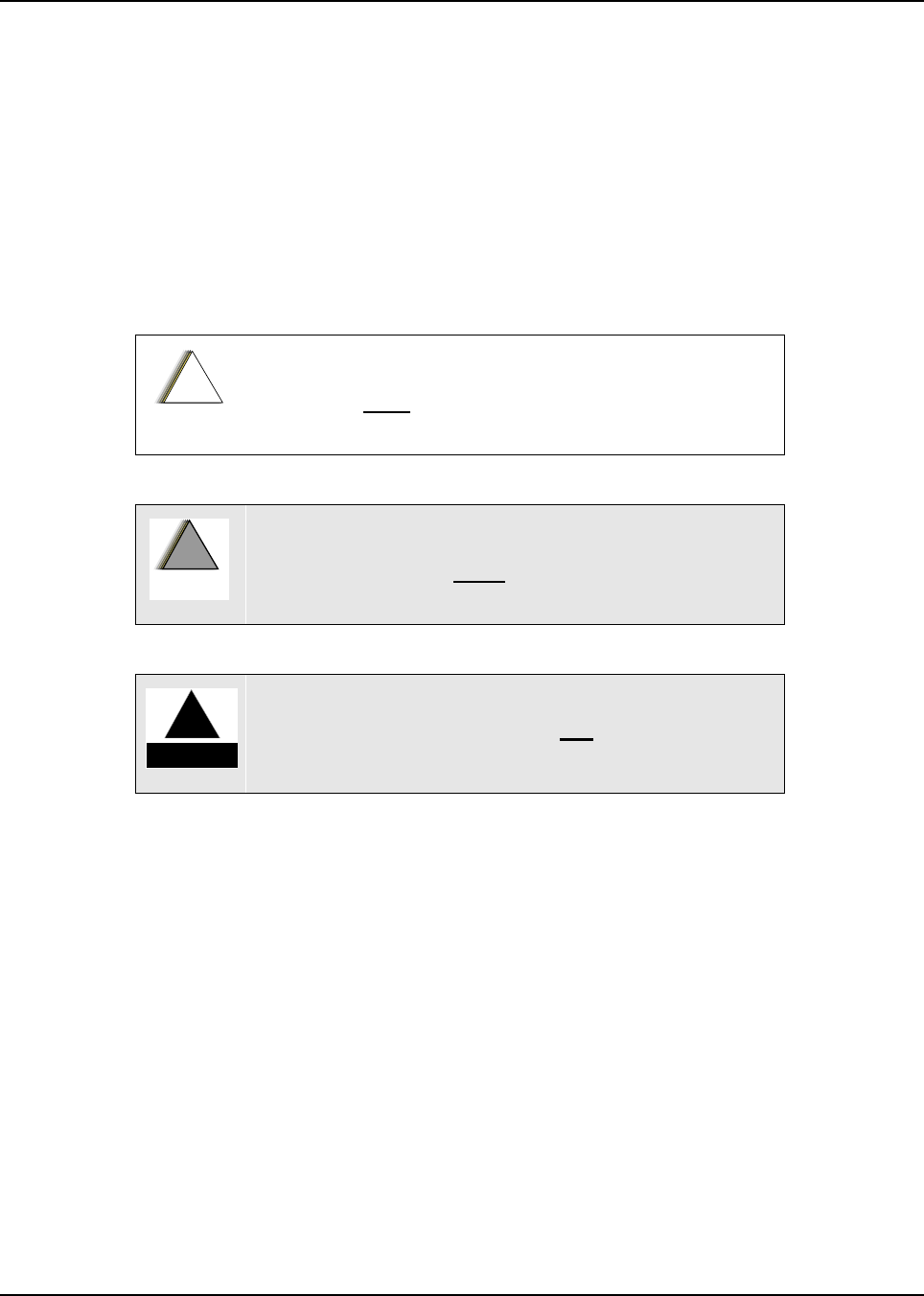
Chapter 1 Introduction
1.1 Notations Used in This Manual
Throughout the text in this publication, you will notice the use of note, caution, warning, and danger
notations. These notations are used to emphasize that safety hazards exist, and due care must be
taken and observed.
NOTE: An operational procedure, practice, or condition that is essential to emphasize.
1.2 Radio Descriptions
The ASTRO Digital Spectra and Digital Spectra Plus radios are among the most sophisticated two-
way radios available. The ASTRO Digital Spectra is available with VHF, UHF, and 800 MHz bands,
and the Digital Spectra Plus is available with VHF and 800 MHz bands only.
The ASTRO Digital Spectra and Digital Spectra Plus radios provide improved voice quality across
more coverage area. The digital process called “embedded signaling” intermixes system signaling
information with digital voice, resulting in improved system reliability and the capability of supporting
a multitude of advanced features. Such features add up to better, more cost-effective two-way radio
communications.
CAUTION indicates a potentially hazardous situation which, if
not avoided, might result in equipment damage.
WARNING indicates a potentially hazardous situation
which, if not avoided, could result in death or injury.
DANGER indicates an imminently hazardous
situation which, if not avoided, will result in death or
injury.
!
C
a u t i o
n
!
W
A R N I N
G
!
D A N G E R
!

February 3, 2003 6881076C20-E
1-2 Introduction: Control Head Descriptions
ASTRO Digital Spectra and Digital Spectra Plus radios are available in five models. Table 1-1
provides a description of basic features for the five models covered in this manual.
1.2.1 FLASHport®
The ASTRO Digital Spectra and Digital Spectra Plus radios utilize Motorola’s revolutionary
FLASHport technology. FLASHport makes it possible to add software that drives the radio’s
capabilities both at the time of purchase and later on. Previously, changing a radio’s features and
capabilities meant significant modifications, or buying a new radio. But now, the radio’s features and
capabilities can be upgraded with FLASHport software, similar to the way a computer can be loaded
with different software.
1.3 Control Head Descriptions
1.3.1 General
The control heads used with ASTRO Digital Spectra and Digital Spectra Plus radios have
microprocessor circuitry that operates the standard and optional features built into the system. The
control head design allows installation in even the smallest of vehicles. Systems that have many
options require more control head buttons, not larger control heads.
The control heads may be field-programmed to add options or alter the information stored in certain
areas of its electronic memory.
The following illustrations show some typical ASTRO Digital Spectra and Digital Spectra Plus control
heads.
Table 1-1. ASTRO Digital Spectra/Spectra Plus Basic Features
Feature W3 W4 W5 W7 W9
Display 2 line/14
characters
Liquid-Crystal
Display (LCD)
with 8 Status
Annunciators
1 line/8
characters
Vacuum
Fluorescent
Display
1 line/8
characters
Vacuum
Fluorescent
Display
1 line/8
characters
Vacuum
Fluorescent
Display
1 line/11
characters
Vacuum
Fluorescent
Display
Mode &
Volume
Controls
Rocker Switches Rotary Mode &
Volume Controls Rocker Switch
Mode &
Volume Controls
Rocker Switch
Mode &
Volume Controls
Rocker Switch
Mode &
Volume Controls
Numeric
Keypad YesNoNoYesYes
Channel
Capability
(Digital
Spectra)
255 128 128 255 255
Channel
Capability
(Digital
Spectra Plus)
512 128 128 512 512
Remote Mount Available Available Available Available Available
Dash Mount Available Available Available Available Not Available
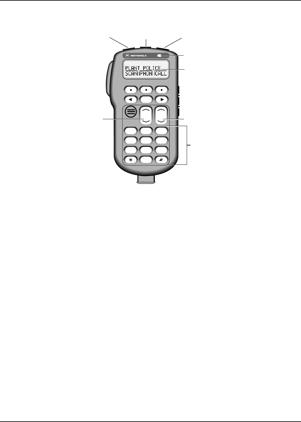
6881076C20-E February 3, 2003
Introduction: Control Head Descriptions 1-3
1.3.1.1 Model W3 Control Head
Figure 1-1. Typical W3 Hand-Held Control Head
1.3.1.2 Model W3 Controls
• On/Off Button (T1) — Turns the radio on and off.
• Orange Programmable Button (T2) — Programmed at the factory for emergency. Field-
programmable by a qualified radio technician.
• Programmable Button (T3) — Field-programmable by a qualified radio technician.
• LED Indicator — Green/red light-emitting diode indicates operating status.
•Display — Two-line x 14-character display provides visual information about many radio
features.
•Keypad — Provides control of, and data interface with, many features.
• Programmable Side Button 1 (S1) — Field-programmable by a qualified radio technician.
• Programmable Side Button 2 (S2) — Field-programmable by a qualified radio technician.
• Programmable Side Button 3 (S3) — Field-programmable by a qualified radio technician.
• Mode Control — Is used for selecting modes and programming menus.
• Volume Control — Is used for selecting the volume level, editing names, and making certain
radio adjustments.
• Push-To-Talk (PTT) Button — Engages the transmitter.
MODE
HOME
2ABC1QZ 3DEF
4GHI 5JKL 6MNO
7PRS 8TUV 9WXY
0
VOL
Side Button 1 (S1)
Side Button 2 (S2)
Side Button 3 (S3)
On/Off
Button
(T1)
Push-To-Talk
(PTT) Switch
LED
Indicator
Alphanumeric
Keypad
Volume
Control Mode Control
Orange Programmable
Button
(T2)
Programmable
Button
(T3)
Display
Button
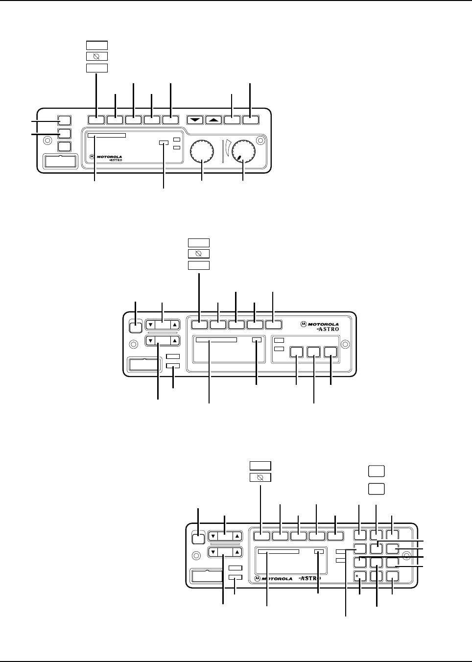
February 3, 2003 6881076C20-E
1-4 Introduction: Control Head Descriptions
1.3.1.3 Models W4, W5, W7, and W9 Controls Head
Figure 1-2. Typical W4 Rotary Control Head
Figure 1-3. Typical W5 Pushbutton Control Head
Figure 1-4. Typical W7 Pushbutton Control Head
PHONE
PAGE
or
SECURE
or
EMERGENCY
Page
Emer
CALL DIRECT
XMIT
BUSY
Mode Volume
Pwr
Phon Call SelScan
Mic
Home
Dim
H/L
Dir Mon
SCAN SELECT MONITOR
MODE
KNOB POWER ON/OFF/
VOLUME KNOB
HOME
HORN/
LIGHTS
PRIORITY/
NON-PRIORITY
INDICATORS DIRECT
INDICATOR
Mode
Vol
Mic
Phon Call Sel
H/L Mon Dir
PWR
Scan
XMIT
BUSY
DIM
HOME
MODE
POWER
ON/OFF
PAGE
or
SECURE
or
EMERGENCY
Page
Emer
PHONE
SCAN
CALL
SELECT
VOLUME PRIORITY/
NON-PRIORITY
INDICATORS
DIRECT
INDICATOR HORN/
LIGHTS
MONITOR
DIRECT
HOME
POWER
ON/OFF
2
2Pge
or
SITE
LOCK
MESSAGE
REPROGRAM
DIRECT
O
#
Del Rcl
Mode
Vol
Mic
Phon Call Sel
PWR
Scan
XMIT
BUSY
DIM
HOME
1Ste 23Lck
4Sts 5Rpg 6Msg
7
H/L
8
Mon
9
Dir
MODE
EMERGENCY
or
SECURE
Emer
PHONE
SCAN
CALL
SELECT
PAGE
VOLUME
DIRECT
INDICATOR DELETE
RECALL
MONITOR
STATUS
HORN/LIGHTS
HOME
PRIORITY/
NON-PRIORITY
INDICATORS
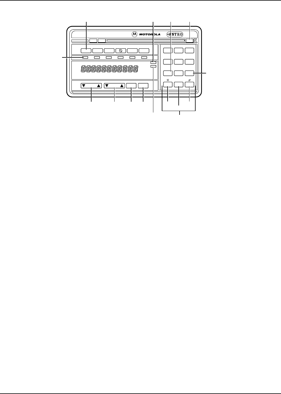
6881076C20-E February 3, 2003
Introduction: Control Head Descriptions 1-5
Figure 1-5. Typical W9 Pushbutton Control Head
1.3.1.4 Models W4, W5, W7, and W9 Controls
• Power Switch — The power (PWR) switch turns the radio and its accessories on or off. The
power switch is part of the rotary volume knob on the W4 model, a push-type switch on the W5
and W7 models, and a slide switch on the right-hand bottom surface of the W9 model.
• Mode Switch — The Mode switch is used for selecting modes and programming menus. The
Mode switch is a rotary switch on the W4 model and a rocker switch on the W5, W7, and W9
models. Pressing the right side of this rocker switch increases the mode number. Pressing the
left side decreases the mode number. If you press and hold the switch, it scrolls the mode
number up or down. The mode names appear in the display window.
• Volume Switch — The Volume switch is used for selecting the volume level, editing names, and
making certain radio adjustments. The Volume switch is a rotary switch on the W4 model and a
rocker switch on the W5, W7, and W9 models. On the pushbutton models, pressing and
releasing the volume switch checks the volume setting. Your display will show “VOLUME_ _”
and a number value (0-15). Press and hold the left side to decrease the volume. The number
value scrolls up or down to your desired level. The Volume rocker switch also controls the
volume level of the public address (PA) and external radio speaker (Ex Rd) options when they
are enabled. The display window shows “PA VOL _ _” when public address is on and the
Volume rocker switch is pressed.
• Dim Button — The DIM button is used to control the brightness of the display and button
backlighting. When you turn on the system, the display comes on at the brightness level it was
on before the system was last turned off. Press the DIM button once to reduce the brightness of
the display to medium level and twice for low brightness level. Press the DIM button a third time
to turn the display and button backlighting off. This is called the “surveillance” mode.
• Home Button — The Home button is used for restoring preprogrammed mode, establishing
programmed mode, selecting programming entries, etc. Press the Home button to go to the
radio’s preprogrammed “home” mode. On the W7 models, you may use the Home button
instead of Mode switch to change modes. Hold the Home button until a beep sounds to enter
the configuration state. The display shows an entry prompt. Use the keypad to enter your new
mode choice and press the Home button again. Your mode is now changed without scrolling.
• Select Button — The Sel button is used to configure radio options.
XMIT BUSY
Call
ScanEmer
DIM
Pri
Non
Pri
123
456
789
0
Mode Vol Sel Home
Phon H/L
Rcl Sql Del
Dir
Sts Msg
VOLUME
ROCKER
MODE
ROCKER SELECT HOME
KEYPAD
RECALL
SQUELCH
DELETE
DIMMER
CONTROL
PRIORITY
INDICATOR
FUNCTION
BUTTON
NON-PRIORITY
INDICATOR
FUNCTION
ON/OFF
INDICATORS
* Optional buttons (included but not installed or programmed)
MESSAGE*
STATUS*

February 3, 2003 6881076C20-E
1-6 Introduction: Control Head Descriptions
• Option Buttons — The option buttons are used for turning options on and off, such as Phone,
Scan, Emergency Call, and Secure.
• Display — The vacuum fluorescent (VF) display’s primary function is to display mode numbers,
mode names, volume level, and the status of options. It also functions as an on-off indicator for
the entire system and plays an integral role in the operator’s reconfiguration of options. The
display is 8 characters on W4, W5, and W7 models; 11 characters on the W9 model.
• XMIT and BUSY Indicators — The XMIT indicator lights when the radio is transmitting. The
BUSY indicator lights when the selected channel is busy.
• Scan Indicators — When scan operation detects activity on a non-priority (NON-PRI) channel,
the NON-PRI indicator light comes on. Activity on a second priority channel causes the priority
(PRI) indicator to light. First priority channel activity causes PRI to flash.
• 12-Button Keypad (W7 and W9) — The keypad is used to change the status of options and for
entering numbers. Several keys serve multiple functions. See the ASTRO Digital Spectra or
Digital Spectra Plus User’s Guide for a complete description of keypad operation.
-Site (Ste - #1 key) — Forces the radio to scan for a new site when the automatic multiple-
site select (AMSS) feature for wide-area coverage is in use.
- Page (2 or 2Pge - #2 Key) — Initiates a Call Alert page/enters Call ID list programming.
-Lock (Lck - #3 key) — Locks the radio onto the current site when the AMSS feature is in
use.
-Status (Sts - #4 key) — Used alone or in conjunction with other keypad buttons and the Sel
button to send a status transmission, indicating a predetermined condition change.
- Regroup (Rpg - #5 key) — Requests a change in the radio’s talkgroup assignment when
the dynamic regrouping feature is used.
- Message (Msg - #6 key) — Used alone or in conjunction with other keypad buttons and the
Sel button to transmit a message, indicating a response or temporary condition.
- Horn/Lights (H/L - #7 key) — Selects/enables radio external alarms.
- Monitor (Mon - #8 key) — Monitors the radio for channel traffic.
- Direct/Simplex (Dir - #9 key) — Used for talkaround (mobile-to-mobile) conversations.
- Recall (Rcl - * key) — Reviews modes in scan and phone lists.
- Delete (Del - # key) — Used when editing stored lists.

Chapter 2 Basic Maintenance
2.1 Introduction
This section of the manual describes preventive maintenance, handling precautions, and some basic
repair procedures and techniques. Each of these topics provides information vital to the successful
operation and maintenance of your radio.
2.2 Preventive Maintenance
Radios are shipped from the factory with a worst-case frequency error of ±200 Hz for VHF, ±300 Hz
for UHF, and ±500 Hz for 800 MHz. These specifications are tighter than the most stringent FCC-
required specifications of 2 ppm (parts per million) for both VHF and UHF, and 1.5 ppm for 800 kHz,
within which the radio will operate to specification.
2.2.1 Reference Oscillator
For radios that have been in storage for over six months from the factory ship date, the reference
oscillator should be checked when the radio is initially deployed to the field. It is strongly
recommended that the reference oscillator be checked every time the radio is serviced or at least
once a year, whichever comes first.
The crystal contained in the reference oscillator naturally drifts over time due to its aging
characteristic. Periodic (annual) adjustment of the reference oscillator is important for proper radio
operation.
Improper adjustment can result in both poor performance and interference with other users operating
on adjacent channels.
A recommended test setup and tuning procedure is detailed in Chapter 6. Radio Alignment
Procedure. The frequency counter used for this procedure must have a stability of 0.1 ppm or better.
2.2.2 Inspection
Check that the external surfaces of the radio are clean, and that all external controls and switches
are functional. A detailed inspection of the interior electronic circuitry is not needed.
2.2.3 Cleaning
The following procedures describe the recommended cleaning agents and the methods to be used
when cleaning the external and internal surfaces of the radio. External surfaces include the control
head and radio chassis. These surfaces should be cleaned whenever a periodic visual inspection
reveals the presence of smudges, grease, and/or grime. Internal surfaces should be cleaned only
when the radio is disassembled for servicing or repair.
The only recommended agent for cleaning the external radio surfaces is a 0.5% solution of a mild
dishwashing detergent in water. The only factory recommended liquid for cleaning the printed circuit
boards and their components is isopropyl alcohol (70% by volume).

February 3, 2003 6881076C20-E
2-2 Basic Maintenance: Handling Precautions
2.2.4 Cleaning External Plastic Surfaces
The detergent-water solution should be applied sparingly with a stiff, non-metallic, short-bristled
brush to work all loose dirt away from the radio. A soft, absorbent, lint-free cloth or tissue should be
used to remove the solution and dry the radio. Make sure that no water remains entrapped near the
connectors, cracks, or crevices.
2.2.5 Cleaning Internal Circuit Boards and Components
Isopropyl alcohol may be applied with a stiff, non-metallic, short-bristled brush to dislodge embedded
or caked materials located in hard-to-reach areas. The brush stroke should direct the dislodged
material out and away from the inside of the radio.
Alcohol is a high-wetting liquid and can carry contamination into unwanted places if an excessive
quantity is used. Make sure that controls or tunable components are not soaked with the liquid. Do
not use high-pressure air to hasten the drying process, since this could cause the liquid to puddle
and collect in unwanted places.
Upon completion of the cleaning process, use a soft, absorbent, lint-free cloth to dry the area. Do not
brush or apply any isopropyl alcohol to the frame, front cover, or back cover.
NOTE: Always use a fresh supply of alcohol and a clean container to prevent contamination by
dissolved material (from previous usage).
2.3 Handling Precautions
Complementary metal-oxide semiconductor (CMOS) devices, and other high-technology devices,
are used in this family of radios. While the attributes of these devices are many, their characteristics
make them susceptible to damage by electrostatic discharge (ESD) or high-voltage charges.
Damage can be latent, resulting in failures occurring weeks or months later. Therefore, special
precautions must be taken to prevent device damage during disassembly, troubleshooting, and
repair. Handling precautions are mandatory for this radio, and are especially important in low-
humidity conditions. DO NOT attempt to disassemble the radio without observing the following
handling precautions:
• Eliminate static generators (plastics, Styrofoam, etc.) in the work area.
• Remove nylon or double-knit polyester jackets, roll up long sleeves, and remove or tie back
loose-hanging neckties.
• Store and transport all static-sensitive devices in ESD-protective containers.
• Disconnect all power from the unit before ESD-sensitive components are removed or inserted
unless otherwise noted.
• Use a static-safeguarded workstation, through the use of an anti-static kit (Motorola part
number 01-80386A82). This kit includes a wrist strap, two ground cords, a static-control table
mat and a static-control floor mat.
NOTE:Be sure that the table and floor mats are properly grounded.
When these items are not readily available, observing the following techniques will minimize the
chance of damage:
The effects of certain chemicals and their vapors can have
harmful results on certain plastics. Aerosol sprays, tuner
cleaners, and other chemicals should be avoided.
!
C
a u t i o
n

6881076C20-E February 3, 2003
Basic Maintenance: Handling Precautions 2-3
• If a static-sensitive device is to be temporarily set down, use a conductive surface for
placement of the device.
• Make skin contact with a conductive work surface first and maintain this contact when the
device is set down or picked up.
• Always wear a conductive wrist strap when servicing this equipment. The Motorola part number
for a replacement wrist strap that connects to the table mat is 42-80385A59.
• For additional information, refer to Service and Repair Note SRN-F1052, Static Control
Equipment for Servicing ESD Sensitive Products, available from the Literature Distribution
Center.
Motorola
Literature Distribution Center
2200 Galvin Drive, Suite 2218
Elgin, IL 60123
(847) 783-2522
(847) 783-2523/2524 (Fax)

February 3, 2003 6881076C20-E
Notes
2-4 Basic Maintenance: Handling Precautions

Chapter 3 Basic Theory of Operation
3.1 Introduction
The following theory will help isolate the problem to a particular board. Using circuit board
replacement as the basic service approach maximizes the working time of the radio.
3.2 General Overview
The ASTRO Digital Spectra and Digital Spectra Plus radios are wideband, synthesized, fixed-tuned
radios. The ASTRO Digital Spectra is available with VHF, UHF, and 800 MHz bands. The ASTRO
Digital Spectra Plus is available with VHF and 800 MHz bands only. All ASTRO Digital Spectra radios
are capable of both analog operation and ASTRO mode (digital) in 12.5 kHz, 20 kHz, 25 kHz, or 30
kHz bandwidths.
The ASTRO Digital Spectra and Digital Spectra Plus radios consist of seven major assemblies, six of
which are in the main radio chassis. They are:
• Control Head Assembly (Dash- or Remote-Mount) — is connected, directly or remotely, to the
front of the transceiver by the interconnect board or remote interconnect board and control
cable. This assembly contains a vacuum fluorescent (VF) display, VF driver, microprocessor
and serial bus interface.
• Power Amplifier (PA) — contains antenna switch, directional coupler/detector, and amplifier(s).
• Front-End Receiver Assembly — contains pre-amplifier, preselector, mixer, and injection filter.
• Radio-Frequency (RF) Board — contains receiver IF amplifier, demodulator, synthesizer logic
and filtering circuitry, and digital receiver back-end integrated circuit (IC).
• VCO/Buffer/Divider Board — contains voltage-controlled oscillator (VCO), divider, receive and
transmit buffers.
• Command Board — contains power control/regulator, digital-to-analog (D/A) IC, serial bus inter-
face, and audio power amplifier (PA).
• VOCON (Vocoder/Controller) Board (Digital Spectra radio) — contains the microcomputer unit
(MCU), its associated memory and memory management integrated circuit, and the digital-sig-
nal processor (DSP) and its associated memories and support IC.
For the ASTRO Digital Spectra Plus radio, the VOCON board architecture is based on a Dual-Core
processor, which contains a DSP Core, an MCORE 210 Microcontroller Core, and custom
peripherals. The board also contains memory ICs and DSP-support ICs.

February 3, 2003 6881076C20-E
3-2 Basic Theory of Operation: Analog Mode of Operation
3.3 Analog Mode of Operation
3.3.1 Receive Operation
When the radio is receiving, the signal comes from the antenna/antenna-switch on the power
amplifier board to the front-end receiver assembly. The signal is then filtered, amplified, and mixed
with the first local-oscillator signal generated by the voltage-controlled oscillator (VCO). The resulting
intermediate frequency (IF) signal is fed to the IF circuitry on the RF board, where it is again filtered
and amplified. This amplified signal is passed to the digital back-end IC, where it is mixed with the
second local oscillator to create the second IF at 450 kHz. The analog IF is processed by an analog-
to-digital (A/D) converter, where it is converted to a digital bit stream and divided down to a baseband
signal, producing digital samples. These samples are converted to current signals and sent to the
digital-signal processor (DSP)-support IC. The DSP-support IC digitally filters and discriminates the
signal, and passes it to the DSP. The DSP decodes the information in the signal and identifies the
appropriate destination for it. For a voice signal, the DSP routes the digital voice data to the DSP-
support IC for conversion to an analog signal. The DSP-support IC then presents the signal to the
audio power amplifier on the command board, which drives the speaker. For signaling information,
the DSP decodes the message and passes it to the microcomputer.
3.3.2 Transmit Operation
When the radio is transmitting, microphone audio is passed to the command board limiter, then to
the DSP-support IC where the signal is digitized. The DSP-support IC passes digital data to the DSP
where pre-emphasis and low-pass (splatter) filtering are done. The DSP returns this signal to the
DSP-support IC where it is reconverted into an analog signal and scaled for application to the
voltage-controlled oscillator as a modulation signal. Transmitted signaling information is accepted by
the DSP from the microcomputer, coded appropriately, and passed to the DSP-support IC, which
handles it the same as a voice signal. Modulation information is passed to the synthesizer along the
modulation line. A modulated carrier is provided to the power amplifier (PA) board, which transmits
the signal under dynamic power control.
3.4 ASTRO Mode of Operation
In the ASTRO mode (digital mode) of operation, the transmitted or received signal is limited to a
discrete set of deviation levels, instead of continuously varying. The receiver handles an ASTRO-
mode signal identically to an analog-mode signal up to the point where the DSP decodes the
received data.
In the ASTRO receive mode, the DSP uses a specifically defined algorithm to recover information.
In the ASTRO transmit mode, microphone audio is processed the same as an analog mode with the
exception of the algorithm the DSP uses to encode the information. This algorithm will result in
deviation levels that are limited to discrete levels.
3.5 Control Head Assembly
3.5.1 Display (W4, W5, and W7 Models)
The control head assembly for W4, W5, and W7 models has an 8-character, alphanumeric, vacuum
fluorescent display. The anodes and the grids operate at approximately 34 Vdc when on and 0 Vdc
when off. The filament operates at approximately 24 Vrms. The voltage for the display is generated
by a fixed-frequency, variable duty-cycle controlled “flyback” voltage converter. The switching
frequency is approximately 210 kHz. The internal microprocessor controls the voltage converter,
which provides approximately 3.7 Vdc to the vacuum fluorescent (VF) driver and approximately 2.4
Vrms to the VF display.

6881076C20-E February 3, 2003
Basic Theory of Operation: Control Head Assembly 3-3
3.5.2 Display (W9 Model)
The control head assembly for a W9 model has an 11-character, alphanumeric, vacuum fluorescent
display. It needs three separate voltages to operate: the cathode needs 35V to accelerate electrons
to the anode; the grid needs 40V to totally shut off current flow; the filament needs 3.8 Vrms at 80
mA. These voltages are obtained from the transformer on the display controller board.
3.5.3 Vacuum Fluorescent (VF) Display Driver
This VF display driver receives ASCII data from the VOCON board, decodes it into display data, and
then scans the display with the data. Once properly loaded into the display, data is refreshed without
any further processor action. The display driver is periodically reset by the actions of transistors that
watch the clock line from the microprocessor to the display driver. When the clock line is held low for
more than 600 milliseconds, the display driver resets and new display data follows.
3.5.4 Vacuum Fluorescent (VF) Voltage Source (W9 Model)
Voltage for the VF display is generated by a fixed frequency, variable-duty cycle driven, flyback
voltage converter. An emitter-coupled astable multivibrator runs at approximately 150 kHz. The
square wave output from this circuit is integrated to form a triangle that is applied to the non-inverting
input of half an integrated circuit (IC).
During start up, the inverting input is biased at 3.7V. A transistor is on while the non-inverting input
voltage is below 3.7V. This allows current to flow in a transformer, building a magnetic field. When
the triangle wave exceeds 3.7V, the transistor turns off and the magnetic field collapses, inducing
negative current in the transformer.
This current flow charges two capacitors. As the voltage on one of the capacitors increases beyond
35V, a diode begins to conduct, pulling the integrated circuit’s inverting input below 3.7V. This
decreases the cycle time to produce the 35V. The 41V supply is not regulated, but it tracks the 35V
supply.
Similarly, the ac supply for VF filament is not regulated, but is controlled to within one volt by an
inductor on the display board.
3.5.5 Controls and Indicators
The control head assembly processes all the keypad (button) inputs and visual indicators through
the microprocessor. Some of the buttons double as function keys for radio options. All buttons are
backlit to allow operation in low light. Refer to Chapter 1. Introduction (page 1-3 and page 1-5) for a
functional description of each control switch, button, or indicator.
3.5.6 Status LEDs
These LEDs are driven by the display driver as though they were decimal points on the VF display.
Level shifting transistors are required for this since the display driver uses 39 Vdc for control signals.
3.5.7 Backlight LEDs
The microprocessor operates the backlight LEDs. A transistor supplies base current to the individual
LED driver transistors. The driver transistors act as constant current sources to the LEDs. Some
backlight LEDs are connected to a thermistor. This circuit allows more current to flow through these
LEDs at room temperature and reduces current as the temperature rises.

February 3, 2003 6881076C20-E
3-4 Basic Theory of Operation: Power Amplifier
3.5.8 Vehicle Interface Port (VIP)
3.5.8.1 Remote-Mount
The VIPs allow the control head to operate outside circuits and to receive inputs from outside the
control head. There are three VIP outputs that are used for relay control. There are also three VIP
inputs that accept inputs from switches. See the cable kit section for typical connections of VIP input
switches and VIP output relays.
The VIP output pins are located on the back of the control head below the area labeled “VIP.” These
connections are used to control relays. One end of the relay should be connected to switched B+,
while the other side is connected to a software-controlled on/off switch inside the control head. The
relay can be normally on or normally off depending on how the VIP outputs are configured. The
function of these VIP outputs can be defined by field programming the radio. Typical applications for
VIP outputs are external horn/lights alarm and horn ring transfer relay control.
3.5.8.2 Dash-Mount
The VIP outputs are driven by a serial-to-parallel shift register. The output transistors are capable of
sourcing 300mA current. Primarily, these transistors control external relays. The relay is connected
between the collector and switched B+.
Each VIP input transistor is connected to a dedicated input port through transistors used for input
protection. These VIP inputs are connected to ground with either normally open or normally closed
switches.
3.5.9 Power Supplies
The +5V supply is a three-terminal regulator IC to regulate the 12V SWB+ down for the digital logic
hardware.
3.5.10 Ignition Sense Circuits
A transistor senses the vehicle ignition’s state, disabling the radio when the ignition is off. For
negative-ground systems, the orange lead is typically connected to the fuse box (+12V).
3.6 Power Amplifier
The power amplifier (PA) is a multi-stage, discrete-transistor RF amplifier consisting of the following:
• Low-level power controlling stage
•Drivers
• Final amplifier
• Directional coupler
• Antenna switch
• Harmonic filter
3.6.1 Gain Stages
The first stage buffers the RF signal, filters harmonics, and acts as a variable amplifier. All of the
amplifying stages are matched using transmission lines, capacitors, and inductors and are supplied
with dc from either A+, keyed 9.4V, or 9.6V sources. Following the last gain stage, PIN diodes switch
the signal flow either from the antenna to the receiver, or from the last gain stage to the antenna.

6881076C20-E February 3, 2003
Basic Theory of Operation: Front-End Receiver Assembly 3-5
3.6.2 Power Control
A directional coupler and detector network controls power. It senses the forward power from the last
gain stage and feeds the detected voltage back to the command board control circuitry, where it is
compared to a reference voltage set during power-set procedures. The dc feed voltage is corrected
and supplied to the “controlled” stage of the power amplifier. Circuitry on the power amplifier board
controls the gain of the first stage and is proportional to the dc control voltage.
3.6.3 Circuit Protection
Current and temperature sensing circuitry on the power amplifier board feed sensed voltages to the
command board for comparison. If the command board suspects a fault condition, it overrides the
power control function and cuts the power back to a level that is safe for the conditions.
3.6.4 DC Interconnect
The ribbon cable connector carries sensed voltages for power and protection to the command board.
It also carries A+ feed to the command board for distribution throughout the internal transceiver
chassis and carries control voltage from the command board to the power amplifier board.
The rear battery connector carries A+ from the battery to the power amplifier board. The red lead
goes directly to the A+ terminal on the PA board. The black lead from the battery connector ties to
the chassis, and connection to the power amplifier board is made through the board mounting
screws.
A+ ground connection for the internal transceiver chassis is through the RF coax ground connectors
and through the mechanical connection of the power amplifier heatsink to the rest of the radio.
During test conditions in which the power amplifier assembly (board and heatsink) is physically
disconnected from the rest of the radio, it is acceptable to rely on the coax cable connections to carry
ground to the internal chassis.
3.7 Front-End Receiver Assembly
The receiver front-end consists of a preselector, a mixer circuit, and an injection filter. The receiver
injection (1st local oscillator) comes from the VCO assembly through a coax cable. The injection filter
is either fixed-tuned or tuned at the factory depending upon the bandsplit. The output of the filter is
connected to the mixer.
The preselector is a fixed-tuned filter. The receiver signal is fed to the preselector from the antenna
switch in the PA for the 800 MHz radios, or the preamp output for VHF and UHF. The signal is then
sent to the mixer integrated circuit where it is connected to the mixer transistor. The receiver injection
is also fed to this point. The mixer output is at the 1st IF center frequency of 109.65MHz. This signal
is sent to the 1st IF on the RF board through a coaxial cable.
3.8 Radio Frequency (RF) Board
The RF board contains the common synthesizer circuits and dual IF receiver and demodulation
circuits. A 4-pole crystal filter at 109.65MHz provides first IF selectivity. For HRN6014D, HRN6020C,
HRN6019C, HRN4009D, HRN4010C, and later RF board kits, two 2-pole crystal filters provide first
IF selectivity at 109.65MHz. The output of the filter circuit is fed directly to the custom digital back-
end circuit module. An amplifier (at 109.65MHz), the second mixer, the second IF amplifiers (at 450
kHz), the IF digital-to-analog converter, and the baseband down-converter are part of the digital
backend circuit module. The digital backend circuit module also converts a 2.1MHz reference to a
2.4MHz clock for the DSP support circuit module.

February 3, 2003 6881076C20-E
3-6 Basic Theory of Operation: Voltage-Controlled Oscillator (VCO)
Synthesizing for the first and second VCO is performed by the prescaler and synthesizer ICs. These
ICs are programmed through a serial data bus from signals generated on the VOCON board. A dc
voltage, generated on the command board, sets the synthesizer’s reference oscillator frequency of
16.8MHz. This voltage is controlled by the digital-to-analog converter (D/A), and is the only element
of the RF board requiring alignment.
The second local oscillator runs at 109.2MHz (low-side injection), and consists of a VCO that is
frequency-locked to the reference oscillator. Part of the local oscillator’s circuitry is in the prescaler
IC.
A clamp and rectifier circuit on the RF board generates a negative dc voltage of 4 volts (nominal) for
increasing the total voltage available to the first VCO and second local oscillator’s VCO. The circuit
receives a 300 kHz square wave output from the prescaler IC, then clamps, rectifies, and filters the
signal for use as the negative steering line for the two VCOs.
3.9 Voltage-Controlled Oscillator (VCO)
3.9.1 VHF Radios
The voltage-controlled oscillator (VCO) assembly utilizes a common-gate FET in a Colpitts
configuration as the gain device. The LC tank circuit’s capacitive portion consists of a varactor bank
and a laser-trimmed stub capacitor. The inductive portion consists of microstrip transmission line
resonators. The stub capacitor serves to tune out build variations. Tuning is performed at the factory
and is not field adjustable. The varactor network changes the oscillator frequency when the dc
voltage of the steering line changes. The microstrip transmission lines are shifted in and out of the
tank by PIN diodes for coarse frequency jumps. A third varactor is used in a modulation circuit to
modulate the oscillator during transmit.
The VCO output is coupled to a transistor for amplification and for impedance buffering. The output
of this stage passes through a low-pass filter where the signal is split into three paths. One path
feeds back to the synthesizer prescaler; the other two provide injection for the RX and TX
amplification strings. The receive injection signal is further amplified and passed to the RX front-end
injection filter. The transmit signal goes to an ECL divider, which divides the signal by two. The signal
is amplified and buffered and then injected into the transmitter’s low-level amplifier.
A 5V regulator provides power to the divider. All transmit circuitry operates from keyed 9.4 volts to
conserve current drain while the radio is receiving. A transistor/resistor network drives the PIN
diodes in the VCO tank. These driver networks provide forward bias current to turn diodes on and
reverse the bias voltage to turn the diodes off. AUX 1 AND AUX 2 lines control the PIN diode driver
networks.
3.9.2 UHF and 800 MHz Radios
The VCO assembly generates variable frequency output signals controlled by the two steering lines.
The negative steering line increases the tuning range of the VCO, while the positive steering line
affects the synthesizer control loop to incrementally change the frequency.
The VCO generates a signal in the required frequency range. For UHF and 800 MHz radios, this
signal is fed to the doubler/buffer circuit which, in turn, doubles the VCO output frequency and
amplifies it to the power level required by the TX buffer and RX mixer. A PIN diode switch routes the
signal to the TX port when the keyed 9.4V is high. Otherwise, the signal is routed to the RX port. The
VCO assembly’s synthesizer feedback output is the same as the doubler output frequency.
3.10 Command Board
The serial input/output IC provides command board functions including buffers for PTT, channel
active, squelch mute, busy, and data transmission, and logic functions for switched B+, emergency,
reset, and power control.

6881076C20-E February 3, 2003
Basic Theory of Operation: VOCON (Vocoder/Controller) Board 3-7
The regulator and power control circuits include an unswitched +5V discrete circuit and the regulator/
power control IC, which produces both switched +5V and 9.6V. The unswitched +5V source is used
as a reference for its switched +5V source. Filtered unswitched +5V is used for the microcontrol
circuits. Switched +5V and 9.6V are controlled by a digital transistor from the serial input/output IC.
The power control circuitry receives power set and limit inputs from the digital-to-analog IC, and
feedback from the RF power amplifier. Based on those inputs, the power control circuitry produces a
control voltage to maintain a constant RF power level to the antenna.
The reset circuits consist of the power-on reset, high/low battery voltage reset, and the external bus
system reset. The reset circuits allow the microcomputer to recover from an unstable situation; for
example, no battery on the radio, battery voltage too high or too low, and remote devices on the
external bus not communicating. Communication in RS-232 protocol is provided by an IC which
interfaces to the rear accessory connector (J2).
3.11 VOCON (Vocoder/Controller) Board
The VOCON board, located on the top side of the radio chassis, contains a microcontrol unit (MCU)
with its flash memory, DSP, and DSP-support ICs. The VOCON board controls receive/transmit
frequencies, the display, and various radio functions, using either direct logic control or serial
communication to external devices. The connector J801 provides interface between the encryption
module and the VOCON board for encrypting voice messages.
3.11.1 ASTRO Digital Spectra
The VOCON board executes a stored program located in the FLASH ROM. Data is transferred to
and from memory by the microcontrol unit data bus. The memory location from which data is read, or
to which data is written, is selected by the address lines.
The support-logic IC acts as an extension of the microcontrol unit by providing logic functions such
as lower address latch, reset, memory address decoding, and additional control lines for the radio.
The VOCON board controls a crystal-pull circuit to adjust the crystal oscillator frequency on the
microcontrol unit, so that the E-clock harmonics do not cause interference with the receive channel.
The vocoder circuitry on the VOCON board is powered by a switched +5 volt regulator located on the
command board. This voltage is removed from the board when the radio is turned off by the control
head switch.
The DSP IC performs signaling, voice encoding/decoding, audio filtering, and volume control
functions. This IC performs Private-Line/Digital Private-Line (PL/DPL) encode and alert-tone
generation. The DSP IC transmits pre-emphasize analog signals and applies a low-pass (splatter)
filter to all transmitted signals. It requires a 33MHz crystal to function. An 8 kHz interrupt signal
generated by the DSP-support IC is also required for functionality. This device is programmed using
parallel programming from the microcontrol unit and the DSP-support IC.
The DSP-support IC performs analog-to-digital and digital-to-analog conversions on audio signals. It
contains attenuators for volume, squelch, deviation, and compensation, and it executes receiver
filtering and discrimination. The IC requires a 2.4MHz clock to function (generated by the digital
back-end IC) and is programmed by the microcontrol unit’s SPI bus.
3.11.2 ASTRO Digital Spectra Plus
The VOCON board, located on the top-side of the chassis, contains a Dual-Core processor, which, in
turn, contains a DSP Core, an MCORE Microcontroller Core, and custom peripherals. The board
also contains memory ICs and DSP support ICs.

February 3, 2003 6881076C20-E
3-8 Basic Theory of Operation: VOCON (Vocoder/Controller) Board
The VOCON board controls receive/transmit frequencies, the display, and various radio functions,
using either direct logic control or serial communication to external devices. The connector J801
provides an interface between the encryption module and the VOCON board for encrypting voice
messages.
The VOCON board executes a stored program located in the FLASH ROM. Data is transferred to
and from memory by the microcontroller unit data bus. The memory location from which data is read,
or to which data is written, is selected by the address lines.
The vocoder circuitry on the VOCON board is powered by two regulated voltage supplies: 3.0 Vdc
and 1.8 Vdc. These regulated supplies are powered by a switched 5 Vdc regulator located on the
command board. This 5 Vdc supply also powers some vocoder circuitry. This voltage is removed
from the board when the radio is turned off by the control head switch.
The DSP Core inside the Dual-Core processor performs signaling, voice encoding/decoding, audio
filtering, and volume control functions. This core performs Private-Line/Digital Private-Line (PL/DPL)
encode and alert-tone generation. The DSP Core transmits pre-emphasized analog signals and
applies a low-pass (splatter) filter to all transmitted signals. The Dual-Core processor requires a
16.8MHz and a 32 kHz clock to function.
The DSP-support ICs perform analog-to-digital and digital-to-analog conversions on audio signals.
They contain attenuators for volume, squelch, deviation, and compensation. The receiver interface
IC requires a 2.4MHz clock to function (generated by the digital back-end IC) and is programmed by
the microcontroller unit’s SPI bus.

Chapter 4 Test Equipment, Service Aids, and Tools
4.1 Recommended Test Equipment
The list of equipment contained in Table 4-1 includes most of the standard test equipment required
for servicing Motorola mobile radios, as well as several unique items designed specifically for
servicing this family of radios. The Characteristics column is included so that equivalent equipment
can be substituted; however, when no information is provided in this column, the specific Motorola
model listed is either a unique item or no substitution is recommended.
Table 4-1. Recommended Motorola Test Equipment
Motorola
Model Number Description Characteristics Application
R-1013_* or
R-1370_* SINAD Meter
SINAD Meter with RMS
Voltmeter
w/o RMS audio voltmeter
w/RMS audio voltmeter Receiver sensitivity
measurements
R-1074_* Fluke 87 Digital
Multimeter True RMS metering, 200kHz
frequency counter, 32-segment
bar graph with backlit display
Recommended for ac/dc voltage
and current measurements
R-1151_* Code Synthesizer 2,
Expanded Injection of audio and digital
signaling codes
R-1377_* AC Voltmeter 1mV to 300V, 10-Megohm input
impedance Audio voltage measurements
R-1439_ or
R-1440_
(See Table 4-2 for
plug-in elements)
BIRD Wattmeter
BIRD Wattmeter
Power range: 100 mW to 100W,
2MHz to 1GHz,
UHF-F connector
Power range: 100 mW to 100W,
2MHz to 1GHz,
N-female connector
Transmitter power
measurements
R-1611_ Dual-Channel 100Mhz
Oscilloscope (Agilent) Two-channel, 100MHz
bandwidth, 200 M sample rate/
sec., 2MB memory/channel
Waveform measurements
R-2600 Series System Analyzer This item will substitute for items
with an asterisk (*). Frequency/deviation meter and
signal generator for wide-range
troubleshooting and alignment
S-1339_ RF Millivolt Meter 100µV to 3V RF
10 kHz to 1GHz RF-level measurements
S-1348_ DC Power Supply,
Programmable 0-20 Vdc, 0-5 Amps current
limited Bench supply for 7.5 Vdc
SLN-6435 Audio Isolation
Transformer Audio measurements (audio PA
must NOT be grounded)
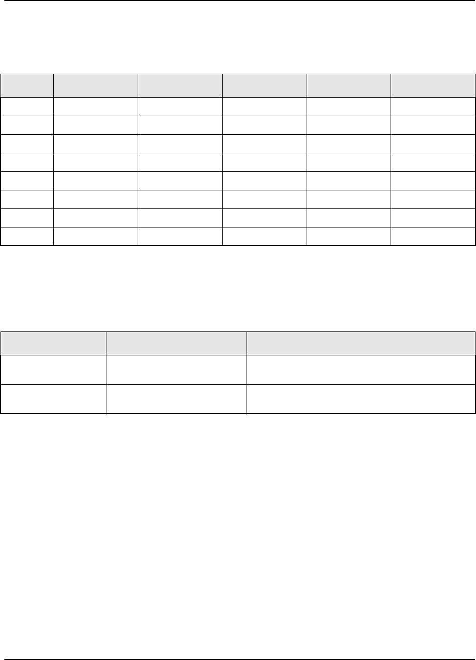
February 3, 2003 6881076C20-E
4-2 Test Equipment, Service Aids, and Tools: Service Aids and Recommended Tools
Table 4-2 contains a listing of the plug-in elements that are available for the BIRD wattmeters listed in
the Table 4-1.
Table 4-3 contains a listing of non-Motorola test equipment recommended for servicing mobile
radios.
4.2 Service Aids and Recommended Tools
Refer to the tables in this section for a listing and description of the service aids and tools designed
specifically for servicing this family of radios, as well as the more common tools required to
disassemble and properly maintain the radio. These kits and/or parts are available from the Motorola
Parts Division offices listed in the Replacement Parts Ordering section located on page A-1of this
manual.
Table 4-4 lists recommended service aids common to both ASTRO Digital Spectra and ASTRO
Digital Spectra Plus radios. While all of these items are available from Motorola, most are standard
shop equipment items, and any equivalent item capable of the same performance can be substituted
for the item listed.
Table 4-2. Wattmeter Plug-In Elements
Power 25-60MHz 50-125MHz 100-250MHz 200-500MHz 400-1000MHz
5W --- 01-80305F21 01-80305F29 01-80305F38 01-80305F46
10W --- 01-80305F22 01-80305F30 01-80305F39 01-80305F47
25W 01-80305F15 01-80305F23 01-80305F31 01-80305F40 01-80305F48
50W 01-80305F16 01-80305F24 01-80305F32 01-80305F41 01-80305F49
100W 01-80305F17 01-80305F25 01-80305F33 01-80305F42 01-80305F50
250W 01-80305F18 01-80305F26 01-80305F34 01-80305F43 01-80305F51
500W 01-80305F19 01-80305F27 01-80305F35 01-80305F44 01-80305F52
1000W 01-80305F20 01-80305F28 01-80305F36 01-80305F45 01-80305F53
Table 4-3. Recommended Non-Motorola Test Equipment
Model Number Description Application
Agilent 8901_ Modulation Analyzer Reference oscillator deviation and compensation
measurements
Weinschel 49 30 43 30 dB RF Attenuator For tests that require a modulation analyzer or
wattmeter
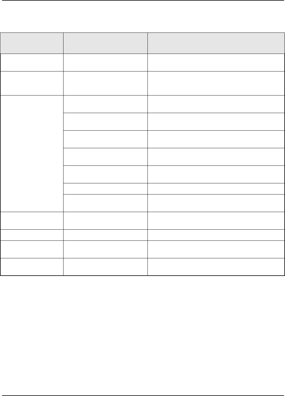
6881076C20-E February 3, 2003
Test Equipment, Service Aids, and Tools: Service Aids and Recommended Tools 4-3
Table 4-4. Common Service Aids for Board-Level Troubleshooting
Motorola
Part Number Description Application
30-80370E06 Extender Cable Provides extension cable for VOCON Board
(connectors P501/J501)
RPX-4725A (includes
30-80370E05
Extender Cable)
Command and Control Service
Cable Kit Provides extension cables for servicing digital and
analog circuits
RPX-4724A
(includes: RF Service Cable Kit Provides interface cables needed to service the RF
boards
28-84606M01 Crimp-On Mini UHF Male
Connector Adapts any coax of appropriate size (RPG58 or
equivalent) for mating to antenna connector
30-80373B25 RX Injection Board Connects to the RX injection output of the VCO
assembly for testing RX injection level
30-80373B26* Output Cable BNC Male to SMB
Male Cable Mates to printed-circuit board mounted SMB female
connectors
30-80373B41* BNC Female to Taiko-Denki Male
Cable Mates to printed-circuit board mounted Taiko-Denki
female connectors
30-80373B27** BNC Male to SMB Female Cable Mates to cable-mounted SMB male connectors
01-80355A28**) BNC Female to Taiko-Denki
Female Adapter Mates to cable-mounted Taiko-Denki male connectors
TKN-8531 Key-Variable Loader Cable Used to load encryption keys into the radio (see also 58-
80219R01 below)
58-80219R01 Adapter Cable Must be ordered and used with TKN-8531
58-80367B21 Mini UHF Male to ‘N’ Female
Adapter
58-80367B22 Mini UHF Male to UHF Female
Adapter
* These cables allow connection to:
- VCO injection output to power amplifier for testing TX injection level
- Receiver front-end/mixer output for testing the proper mixer conversion gain
- Synthesizer feedback input for testing feedback buffer and prescaler operation
- RF board IF input for testing receiver back-end sensitivity
- RX injection output of the VCO assembly
**These cables allow connection to:
- Power amplifier test input
- Receiver input cable for testing RX loss through harmonic filter and antenna switch
- VCO synthesizer feedback level
- Receiver front-end/mixer output for testing the proper mixer conversion gain
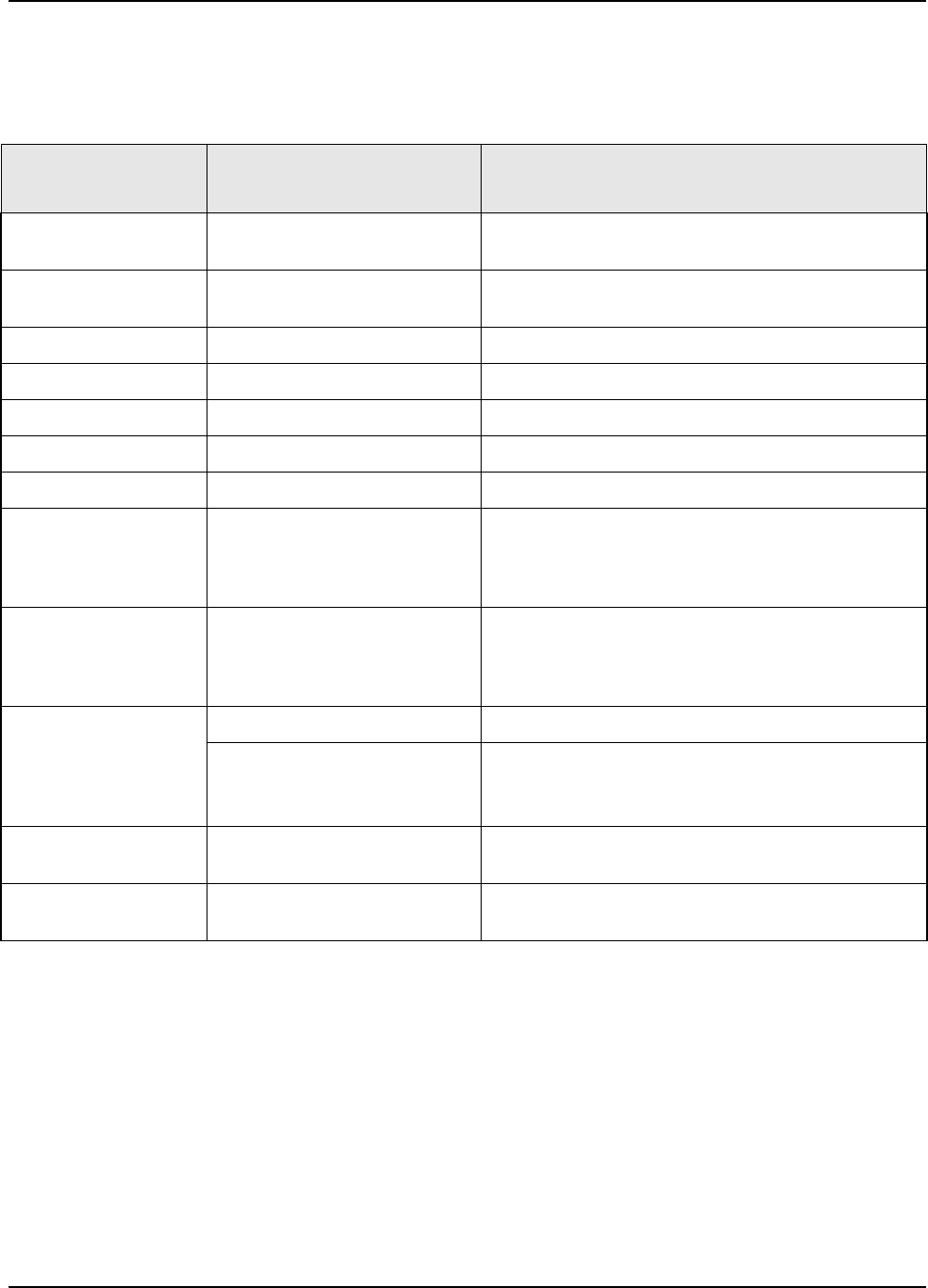
February 3, 2003 6881076C20-E
4-4 Test Equipment, Service Aids, and Tools: Service Aids and Recommended Tools
Table 4-5 lists additional service aids that can be used in troubleshooting ASTRO Digital Spectra
radios.
Table 4-6 lists additional service aids that can be used in troubleshooting ASTRO Digital Spectra
Plus radios.
Table 4-5. Service Aids for ASTRO Digital Spectra Board-Level Troubleshooting
Motorola
Part Number Description Application
RLN-4008_ Radio Interface Box (RIB) Enables communications between the radio and the
RSS
RLN-1015_ Smart RIB (SRIB) Enables communications between the radio and the
RSS. Required to FLASH the radio
RLN-4488_ Battery Pack Used to supply backup power to SRIB
01-80357A57 Wall-Mounted Power Supply Used to supply power to the RIB (120 Vac)
01-80358A56 Wall-Mounted Power Supply Used to supply power to the RIB (220 Vac)
01-80302E27 Adapter Used to supply power to the SRIB (120 Vac)
25-80373E86 Adapter Used to supply power to the SRIB (220 Vac)
30-80369B71 (25-pin to
15-pin) or
30-80369B72 (9-pin to
15-pin)
Computer Interface Cable Connects the computer’s serial communications
adaptor to the RIB
30-80390B48 (9-pin to
9-pin) or
30-80390B49 (25-pin to
9-pin)
Computer Interface Cable Connects the computer’s serial communications
adaptor to the SRIB
30-80369B73 or
01-80300B10
Radio Interface Cable Connects low-power and mid-power radios to the RIB
Radio Interface Cable Connects high-power radios to the RIB
RVN-4184 Radio Service Software
(DOS Version) Replaces RVN-4124. Software on 3-1/2 in. and 5-1/4 in.
floppy disks
RVN-4183 Customer Programming
Software (Windows Version) Programming software; available only on CD.
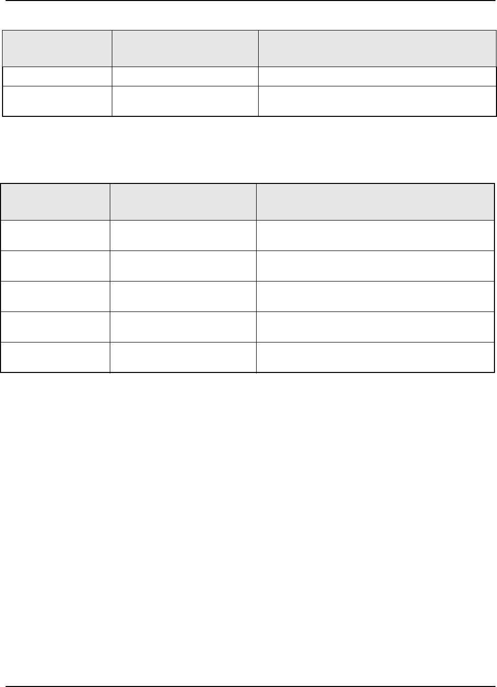
6881076C20-E February 3, 2003
Test Equipment, Service Aids, and Tools: Field Programming Equipment 4-5
4.3 Field Programming Equipment
The ASTRO family of radios can be aligned and programmed in the field. This requires specific
equipment and special instructions. For ASTRO Digital Spectra radios, refer to the applicable Radio
Service Software User’s Guide for complete field programming information. For ASTRO Digital
Spectra Plus radios, refer to the online help in the Customer Programming Software.
4.3.1 ASTRO Digital Spectra
The ASTRO Digital Spectra radios use an electrically erasable, programmable read-only memory
(EEPROM) device to store information on frequencies, squelch codes, signaling codes, time-out
timer durations, and other parameters.
The ASTRO Digital Spectra radios can be programmed in the field any number of times without
removing the EEPROM from the radio. To program, an IBM® or IBM PC-compatible computer is
connected to the radio through the rear accessory connector. Once the computer is connected to the
radio, the prompts provided by the software can be followed.
Table 4-6. Service Aids for ASTRO Digital Spectra Plus Board-Level Troubleshooting
Motorola
Part Number Description Application
30-85001D01 Programming Flash Cable Used with Tuner Software, CPS, and FLASHport
RVN-4185 Customer Programming
Software and Tuner Software Programming and radio alignment software on CD
Table 4-7. Recommended Tools for Board-Level Troubleshooting
Motorola
Part Number Description Application
01-80386A82 Anti-Static Grounding Kit Used during radio assembly and disassembly
procedures
RSX-4043_ Roto-Torq Adjustable Torque
Screwdriver Used during radio assembly and disassembly
procedures
66-80163F01 Insertion and Extraction Tool Provides assistance in installation and/or removal of
wires from VIP and accessory connectors
01-80370B87 L-Shaped Hex Key Set Used during radio assembly and disassembly
procedures
01-80320B16 Magnetic Screwdriver Set with
Bits Used during radio assembly and disassembly
procedures
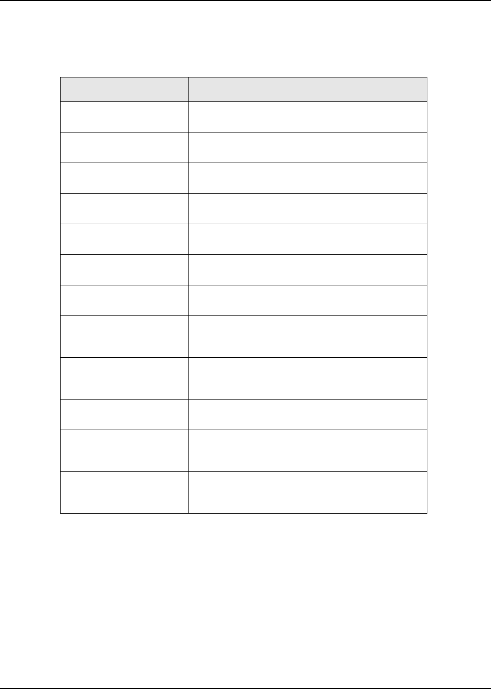
February 3, 2003 6881076C20-E
4-6 Test Equipment, Service Aids, and Tools: Field Programming Equipment
The following items, available through the Customer Care and Services Division (except the
computer), are required when programming ASTRO Digital Spectra Model radios.
4.3.1.1 ASTRO Digital Spectra W3 Smart RIB Issue
When flashing a Model W3 mobile radio, the smart RIB box tends to reset if the correct power-up
sequence is not observed. To avoid this problem, you must power up the radio before you use the
smart RIB box. You might damage the control head or the RIB box if you use a modified RIB box to
flash Model W3 radios.
4.3.1.2 ASTRO Digital Spectra Remote W3 Y Cable
The remote Y cable required for high-power Model W3 radios cannot be used for programming. The
accessory connector in this cable does not have the BUS+, BUS-, and BUSY lines.
Table 4-8. ASTRO Digital Spectra Field Programming Items
Type or Part Number Description
01-80300B10
Programming Cable Used to connect high-power radios (50W-110W) directly
to the RIB or SRIB.
30-80369B71
Computer Interface Cable RLN-4008 RIB-to-computer cable. For computers with a
25-pin serial (COM) port.
30-80369B72
Computer Interface Cable RLN-4008 RIB-to-computer cable. For computers with a
9-pin serial (COM) port.
30-80369B73
Programming Cable RIB-to-radio programming cable for low- and mid-power
radios.
30-80390B48
Computer Interface Cable RLN-1015 SRIB-to-computer cable. For computers with
a 9-pin serial (COM) port.
30-80390B49
Computer Interface Cable RLN-1015 SRIB-to-computer cable. For computers with
a 25-pin serial (COM) port.
Computer, IBM or IBM PC-
compatible
CVN-6085 Radio Service
Software (3-1/2” disks) Software that provides the capability of changing the
radio frequencies, squelch codes, and other radio
parameters. Replaces RVN-4100.
RLN-1015A
Smart Radio Interface Box
(SRIB)
A voltage-level shifter to enable communications
between the radio and the computer’s RS-232 port.
Allows use of FLASHport technology.
RLN-4008B
Radio Interface Box (RIB) A voltage-level shifter to enable communications
between the radio and the computer’s RS-232 port.
RPX-4719 Radio Service
Software Package Kit containing software licensing agreement, software
order forms, and a list of available software. Must be
ordered prior to ordering any software.
RKN-4047A EEPROM
Flash Program
Interface Cable
Used to load the radio with new features using
FLASHport technology. Requires RLN-1015 SRIB.
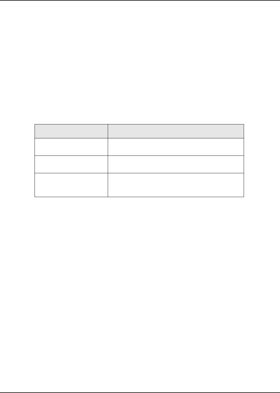
6881076C20-E February 3, 2003
Test Equipment, Service Aids, and Tools: Field Programming Equipment 4-7
In mid-power radios, when this cable is used, programming must be done through the rear
accessory connector.
4.3.2 ASTRO Digital Spectra Plus
The ASTRO Digital Spectra Plus radios use a flash memory device to store information on
frequencies, squelch codes, signaling codes, time-out timer durations, and other parameters.
The ASTRO Digital Spectra Plus radios can be programmed in the field any number of times without
removing the flash memory from the radio. To program, an IBM or IBM PC-compatible computer is
connected to the radio through the front connector using the programming cable. Once the computer
is connected to the radio, the prompts provided by the user-friendly software can be followed.
The following items, available through the Customer Care and Services Division (except the
computer), are required when programming ASTRO Digital Spectra Plus radios.
4.3.2.1 ASTRO Digital Spectra Plus Model W3
For the ASTRO Digital Spectra Plus radio with a W3 control head, it is possible for the message
FL01/90 to display while using the HKN6155 programming cable for tuner, CPS, or flash
programming. Upon completion of the operation, a reset will clear the message. Powering on the
radio before attaching the programming cable will decrease the occurrence of the FL01/90
message.
Table 4-9. ASTRO Digital Spectra Plus Field Programming Items
Type or Part Number Description
30-85001D01 Programming
Cable Used to connect radio directly to the computer.
Computer, IBM or IBM PC-
compatible
RVN-4185 Customer Pro-
gramming Software and
Tuner Software
This software enables you to program the radio’s
features and align its parameters.

February 3, 2003 6881076C20-E
Notes
4-8 Test Equipment, Service Aids, and Tools: Field Programming Equipment
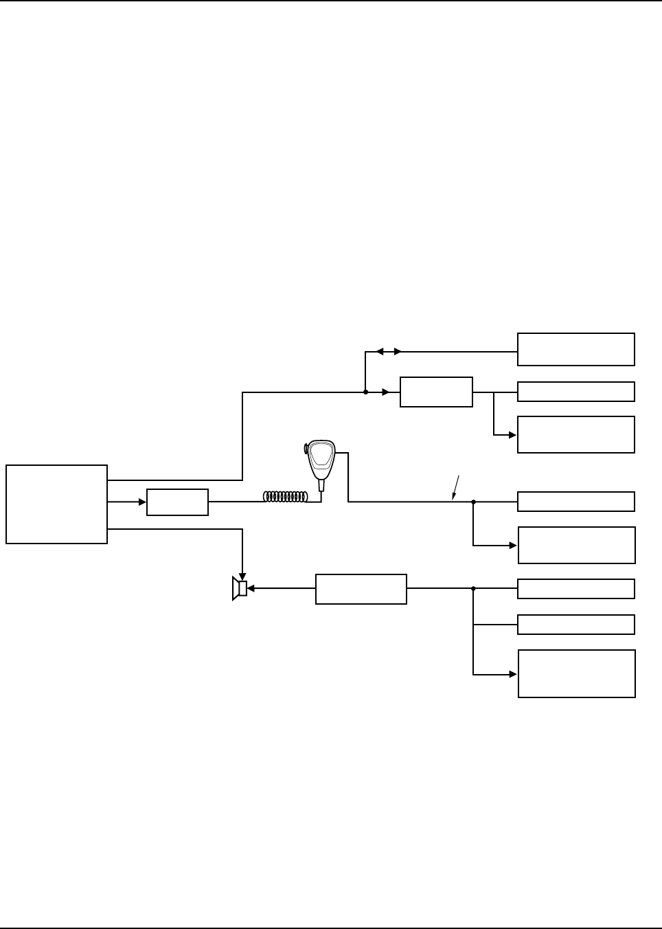
Chapter 5 Performance Checks
5.1 Introduction
This section covers performance checks used to verify that the radio meets published specifications.
The recommended test equipment listed in the previous section approaches the accuracy of the
manufacturing equipment, with a few exceptions. Accuracy of the equipment must be maintained in
compliance with the manufacturer’s recommended calibration schedule.
5.2 Test Setup
The equipment required for performance checks is connected as shown in the following diagrams.
5.2.1 ASTRO Digital Spectra
Figure 5-1. ASTRO Digital Spectra Performance Checks Test Setup
AUDIO GENERATOR
SINAD METER
AC VOLTMETER
TX
RX
COMMUNICATIONS
ANALYZER
AGILENT 8901B
MODULATION
ANALYZER
COMMUNICATIONS
ANALYZER
(MODOUT Connector)
WATTMETER
MAEPF-27500-O
RADIO
SET TO APPROX. 80mVrms FOR MAXIMUM DEVIATION
MATCHING
TRANSFORMER
CONTROL
HEAD
TEST
SPEAKER
DUMMY
MICROPHONE
RF PORT
RF
ATTENUATOR
COMMUNICATIONS
ANALYZER
Vert/SINAD Dist/
DVM Counter
OR
OR
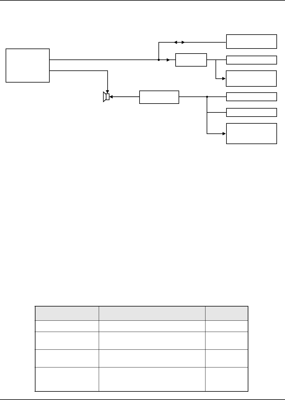
February 3, 2003 6881076C20-E
5-2 Performance Checks: Test Mode
5.2.2 ASTRO Digital Spectra Plus
Figure 5-2. ASTRO Digital Spectra Plus Performance Checks Test Setup
5.3 Test Mode
NOTE: The test mode for the ASTRO Spectra radio is different from the standard Spectra radio, but
is similar to the ASTRO portable test mode.
Be sure to transmit into a load when keying a radio under test.
5.3.1 Entering Test Mode
1. To enter test mode, turn the radio on.
2. Within 10 seconds after Self Test is complete, press the Home button five times in
succession. The Self Test for the ASTRO Digital Spectra Plus radio is displayed as
SPECTRA+.
3. The radio will show a series of displays that will give information regarding various version
numbers and subscriber-specific information. The displays are described in Table 5-1.
Table 5-1. Test-Mode Displays
Display Name Description Appears
SERVICE Indicates the radio has entered test mode Always
Radio Host Software
Version The version of radio firmware Always
DSP Software Version The version of firmware being used by the
DSP Always
EMC Secure Version Version of the encryption hardware When the
radio is secure
equipped
COMMUNICATIONS
ANALYZER
WATTMETER
RADIO
MATCHING
TRANSFORMER
TEST
SPEAKER
RF PORT
SINAD METER
AC VOLTMETER
RX
COMMUNICATIONS
ANALYZER
Vert/SINAD Dist/
DVM Counter
OR
AGILENT 8901B
MODULATION
ANALYZER
RF
ATTENUATOR
MAEPF-27501-O
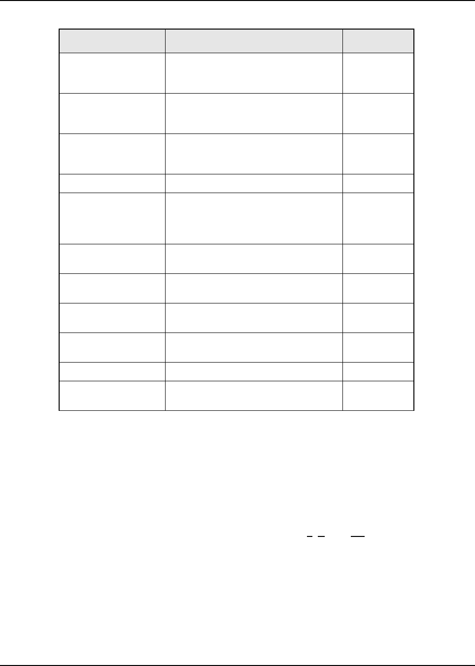
6881076C20-E February 3, 2003
Performance Checks: Test Mode 5-3
4. Pressing the Mode rocker will cause the displays to stop. The test mode menu, CH TEST, will
be displayed.
5. Pressing the Home button will cause the displays to stop. The RF test mode will be entered.
The display will show 1 CSQ, indicating test frequency 1, Carrier SQuelch mode.
6. Go to the RF Test Mode section.
5.3.2 RF Test Mode
A special routine, called RF TEST MODE or air test, has been incorporated in the radio.
1. Enter the RF test mode by pressing the Home button when the test mode menu RF
TEST is displayed. Use the Mode rocker to cause the radio to display the test mode
menu, RF TEST, if the display reads CH TEST.
Encryption Firmware Firmware version for encryption When the
radio is secure
equipped
Encryption Type 1 Type of encryption being used When the
radio is secure
equipped
Encryption Type 2 Type of encryption being used When the
radio is secure
equipped
Control Head Version Control head firmware version number Always
Auxiliary Control Head Firmware version for the auxiliary control
head When an
auxiliary
control head is
present
Siren Version Firmware version for the siren When a siren
is present
VRS Version Number Firmware version for the VRS When VRS is
present
Model Number The radio’s model number, as
programmed in the codeplug Always
Serial Number The radio’s serial number, as programmed
in the codeplug Always
ROM Size Memory capacity of the flash port Always
FLASHcode The FLASHcodes, as programmed as a
part of the radio’s codeplug Always
Note: All displays are temporary and will expire without any user
intervention. If the information is longer than the physical length
of the control head display, it will wrap around to the next display.
After the last display, RF TEST will be displayed.
Table 5-1. Test-Mode Displays (Continued)
Display Name Description Appears
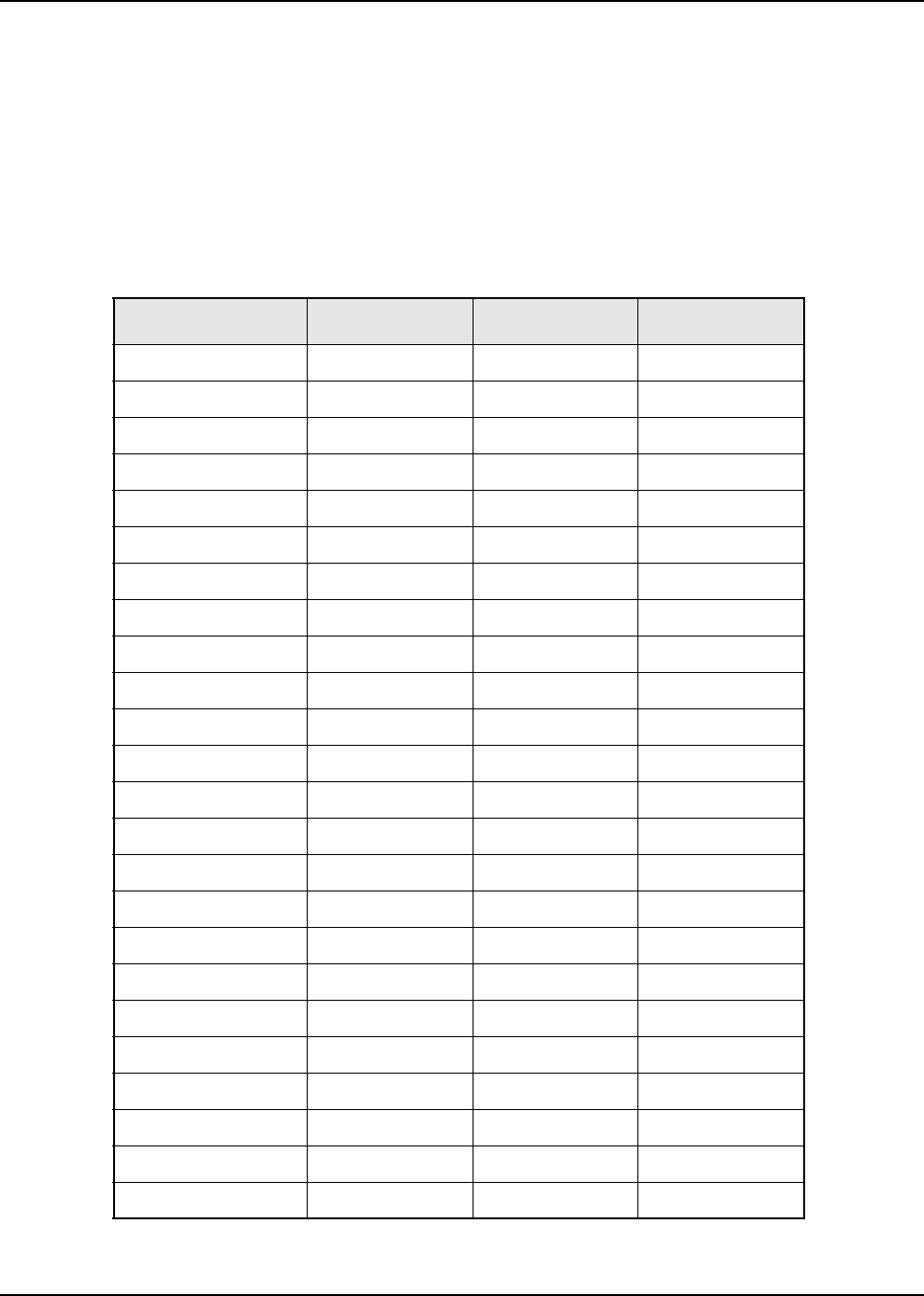
February 3, 2003 6881076C20-E
5-4 Performance Checks: Test Mode
2. In RF test mode, press the Volume rocker to adjust the volume. The volume display for the
ASTRO Digital Spectra will be in 256 increments, not the usual 16, while in the test mode.
This allows for precise setting of rated audio, etc.
For the ASTRO Digital Spectra Plus, the volume is still displayed as a value between 0 to 15.
3. Press the Home button to move the cursor back and forth between the frequency and
signaling type (See Table 5-2 on this page and Table 5-3 on page 5-5). The first digit will flash
to indicate which type is currently selected. Press the Mode button to scroll through the
available selections.
Table 5-2. Test Frequencies
Test Channel VHF UHF 800 MHz
Range 1 - TX #1 136.050 403.050 806.050
Range 1 - RX #1 136.025 403.025 851.025
Range 1 - TX #2 149.050 418.050 823.950
Range 1 - RX #2 149.025 418.525 860.025
Range 1 - TX #3 161.950 432.950 868.950
Range 1 - RX #3 161.975 432.975 868.975
Range 2 - TX #1 146.050 438.050 None
Range 2 - RX #1 146.025 438.025 None
Range 2 - TX #2 160.050 454.050 None
Range 2 - RX #2 160.025 454.025 None
Range 2 - TX #3 173.950 469.950 None
Range 2 - RX #3 173.975 469.975 None
Range 3 - TX #1 None 450.050 None
Range 3 - RX #1 None 450.025 None
Range 3 - TX #2 None 466.050 None
Range 3 - RX #2 None 466.025 None
Range 3 - TX #3 None 481.950 None
Range 3 - RX #3 None 481.975 None
Range 4 - TX #1 None 482.050 None
Range 4 - RX #1 None 482.025 None
Range 4 - TX #2 None 497.050 None
Range 4 - RX #2 None 497.025 None
Range 4 - TX #3 None 511.950 None
Range 4 - RX #3 None 511.975 None
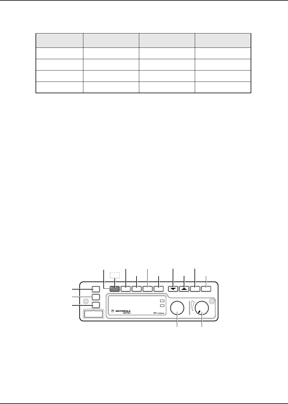
6881076C20-E February 3, 2003
Performance Checks: Test Mode 5-5
When in the transmit test mode, DTMF modulation produces a sidetone in the speaker. All signaling
types will continually modulate the transmitted signal for detection/measurement by external
instruments.
5.3.3 Control Head Test Mode
The control head test mode is part of the diagnostics built into the radio and is entered through the
front panel programming sequence. This test mode allows you to perform button and display tests to
verify proper operation.
1. Enter the control head test mode by pressing the Home button when the test mode
menu, CH TEST, is displayed. Use the Mode rocker to cause the radio to display the test
mode menu, CH TEST, if the display reads RF TEST.
2. Press the Mode switch to change the test mode from the RF test mode to the control head
test mode (CH TEST).
NOTE:Once the CH Test has been selected by pressing Home, pressing the Mode switch
will not change the control head test mode back to the RF test mode. You must turn
the radio off and reenter the RF test mode as described earlier.
3. When the control head test mode is selected (CH TEST), press the Home button. The display
will show the interpreted key number. Status of the key press is indicated to the right of the
key number.
Figure 5-3. Rotary Control Head Key-Closure Displays (W4)
Table 5-3. Signaling Types
Display Modulation Demodulation Type
CSQ None None Carrier Squelch
TPL 192Hz 192Hz Private-Line
AST 1200Hz N/A ASTRO (digital)
USQ None None Open Squelch
XMIT
BUSY
Mode Volume
Pwr
Phon Call SelScan
Mic
Home
Dim
H/L
Dir Mon
Emer
KEY 97
KEY 100
KEY 99
KEY 103
KEY 104
KEY 105
KEY 106
KEY 107
KEY 02
KEY 96
KEY 101
KEY 102
KEY 04
KEY 98
PR
12/1/93 EH
12/1/93
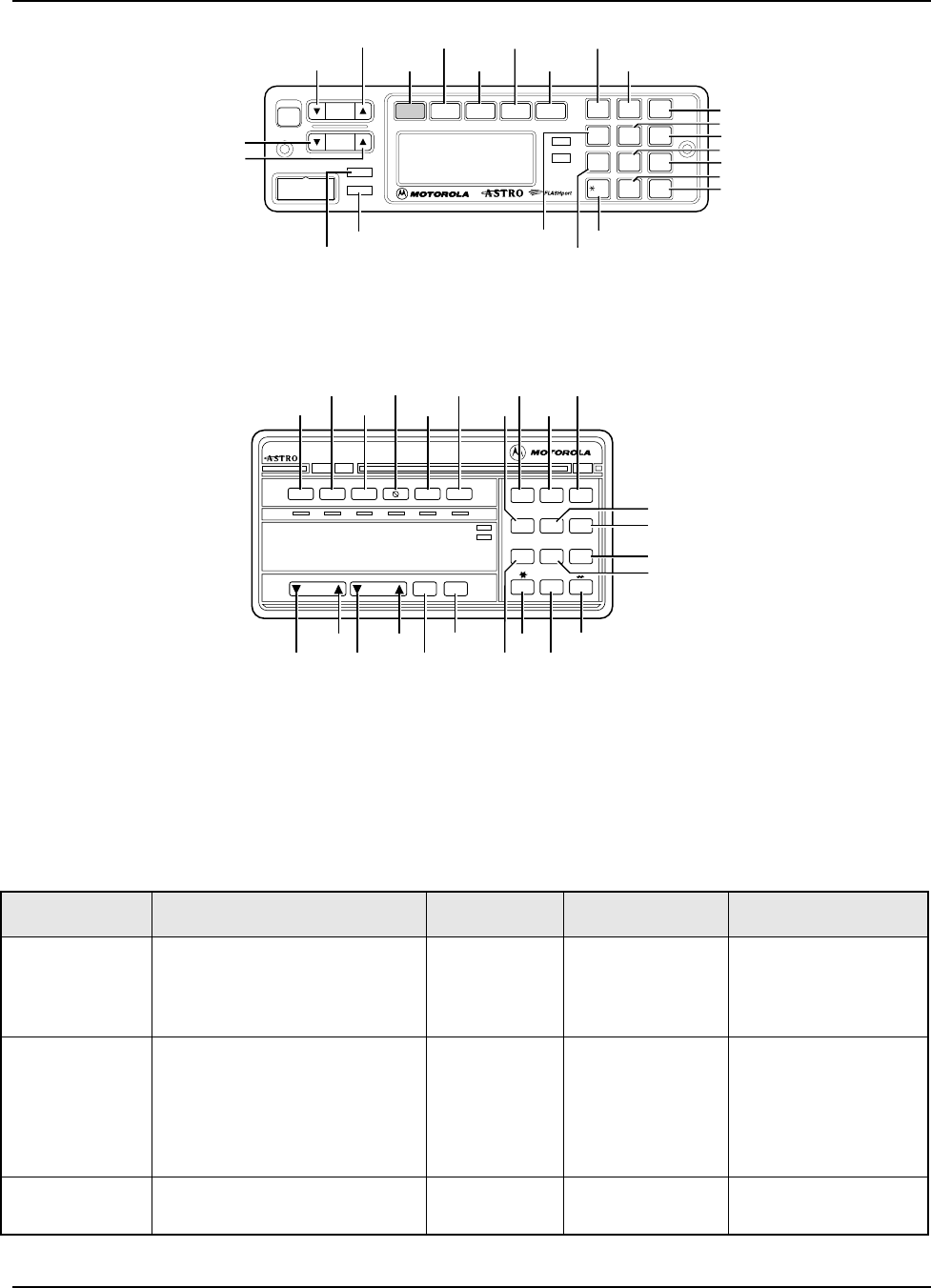
February 3, 2003 6881076C20-E
5-6 Performance Checks: Receiver Performance Checks
Figure 5-4. Pushbutton Control Head Key-Closure Displays (W5 and W7)
Figure 5-5. Pushbutton Control Head Key-Closure Displays (W9)
4. Switch the radio power off temporarily to exit the test mode and return to normal radio
operation.
5.4 Receiver Performance Checks
Table 5-4. Receiver Performance Checks
Test Name System Analyzer Radio Test Condition Comments
Reference
Frequency Mode: PWR MON
1st channel test frequency*
Monitor: Frequency error
Input at RF In/Out
TEST MODE,
1 CSQ output
at antenna
Press and hold
PTT switch. Frequency error to be
± 70 Hz (VHF)
± 150 Hz (UHF)
± 150 Hz (800 MHz)
Rated Audio Mode: GEN
Output level: 1.0mV RF
1st channel test frequency*
Mod: 1 kHz tone at 3 kHz
deviation
Monitor: DVM: ac Volts
TEST MODE,
1 CSQ Release PTT
switch. Set volume control to
6.3 Vrms across the
speaker
Distortion As above, except to distortion TEST MODE,
1 CSQ Release PTT
switch. Distortion < 3.0%
O#Del Rcl
Mode
Vol
Mic
Phon Call Sel
PWR Scan
XMIT
BUSY
DIM
HOME
12
3
4
Sts
56
Msg
7
H/L
8
Mon
9
Dir
MAEPF-24120-A
KEY 97
KEY 82
KEY 99
KEY 100
KEY 101
KEY 102
KEY 103
KEY 81
KEY 54
KEY 49
KEY 50
KEY 52
KEY 55
KEY 58
KEY 51
KEY 53
KEY 56
KEY 57
KEY 48
KEY 59
MIC PTT: KEY 01
MIC HUB*: KEY 06
IGN SENSE: KEY 07
* TAKE MIC OFF HOOK
VIP IN 1: KEY 16
VIP IN 2: KEY 17
VIP IN 3: KEY 18
KEY 96
KEY 80
KEY 83
PR
12/1/93 EH
12/1/93
PR
5/9/94 JP
5/9/94
XMIT BUSY
123
456
789
0
DIM
Pri
Non
Pri
Emer Dir Scan Call
Mode Vol Sel
Home
Page Rpgm Site
Phon H/L Lock
Rcl Sql Del
Sts Msg
Srch
KEY 54
KEY 100
KEY 99 KEY 103
KEY 104
KEY 52
KEY 49
KEY 50
KEY 51
KEY 59
KEY 53
KEY 101
KEY 102
KEY 58
KEY 48KEY 55
KEY 57
KEY 56
KEY 97KEY 83
KEY 96
KEY 81
KEY 80 KEY 82
6881076C20-E February 3, 2003
Performance Checks: Transmitter Performance Checks 5-7
5.5 Transmitter Performance Checks
Sensitivity
(SINAD) As above, except SINAD, lower
the RF level for 12 dB SINAD TEST MODE,
1 CSQ Release PTT
switch. RF input to be
< 0.35µV
Noise Squelch
Threshold
(only radios with
conventional
system need to
be tested)
RF level set to 1 mV RF TEST MODE,
1 CSQ Release PTT
switch. Set volume control to
3.16 Vrms across the
speaker
As above, except change
frequency to a conventional
system. Raise RF level from zero
until radio unsquelches.
Out of TEST
MODE;
select a
conventional
system
Release PTT
switch. Unsquelch to occur at
< 0.25 µV
* Test frequencies are listed in Table 5-2.
Table 5-5. Transmitter Performance Checks
Test Name System Analyzer Radio Test
Condition Comments
Reference
Frequency Mode: PWR MON
1st channel test frequency**
Monitor: Frequency error
Input at RF In/Out
TEST MODE,
1 CSQ Press and hold
PTT switch. Frequency error to be
± 70 Hz (VHF)
± 150 Hz (UHF)
± 150 Hz (800 MHz)
Power RF As above TEST MODE,
1 CSQ Press and hold
PTT switch. Refer to the Radio
Specifications in the
front of the manual.
Voice Modulation Mode: PWR MON
1st channel test frequency** atten
to –70,
input to RF In/Out,
Monitor: DVM, ac Volts
Set 1 kHz Mod Out level for 0.025
Vrms at test set,
80 mVrms at dummy microphone
input
TEST MODE,
1 CSQ Press and hold
PTT switch. Deviation:
VHF, UHF, and 800
MHz:
>= 3.6 kHz but <= 5.0
kHz
Voice Modulation
(internal) Mode: PWR MON
1st channel test frequency** atten
to –70, input to RF In/Out
TEST MODE,
1 CSQ, output
at antenna
Remove
modulation input
from dummy
microphone.
Press and hold
PTT switch.
Press PTT switch on
microphone and say
“four” loudly into the
radio mic.
Measure deviation:
VHF, UHF, and 800
MHz:
>= 3.8 kHz but <= 5.0
kHz
Table 5-4. Receiver Performance Checks (Continued)
Test Name System Analyzer Radio Test Condition Comments

February 3, 2003 6881076C20-E
5-8 Performance Checks: Transmitter Performance Checks
PL Modulation
(radios with
conventional, clear
mode, coded
squelch operation
only)
Change frequency to 1st channel
test frequency**;
B/W to narrow
TEST MODE,
1 TPL Remove
modulation input
from dummy
microphone.
Press and hold
PTT switch.
Deviation:
VHF, UHF, and 800
MHz:
>= 500 Hz but <= 1000
Hz
Talkaround
Modulation (radios
with conventional,
clear mode,
talkaround
operation only)
Change frequency to conventional
talkaround frequency.
Mode: PWR MON
deviation, attenuation to –70,
input to RF In/Out
Monitor: DVM, ac volts
Set 1 kHz Mod Out level for 80
mVrms at dummy microphone.
Conventional
talkaround
personality
(clear mode
operation)
1 CSQ
Press and hold
PTT switch. Deviation:
UHF and 800 MHz:
>= 3.8 kHz but <= 5.0
kHz
Talkaround
Modulation (radios
with conventional,
secure mode,
talkaround
operation only) *
Change frequency to conventional
talkaround frequency.
Mode: PWR MON
deviation, attenuation to –70,
input to RF In/Out
Monitor: DVM, ac volts
Mod: 1 kHz out level for 80 mVrms
at dummy microphone.
Conventional
talkaround
personality
(secure mode
operation).
Load key into
radio 1 sec.
Press and hold
PTT switch. Deviation:
UHF and 800 MHz:
>= 3.6 kHz but <= 4.4
kHz
* The secure mode, talkaround modulation test is only required for radios that do not have clear mode
talkaround capability.
** Test frequencies are listed in Table 5-2.
Table 5-5. Transmitter Performance Checks (Continued)
Test Name System Analyzer Radio Test
Condition Comments
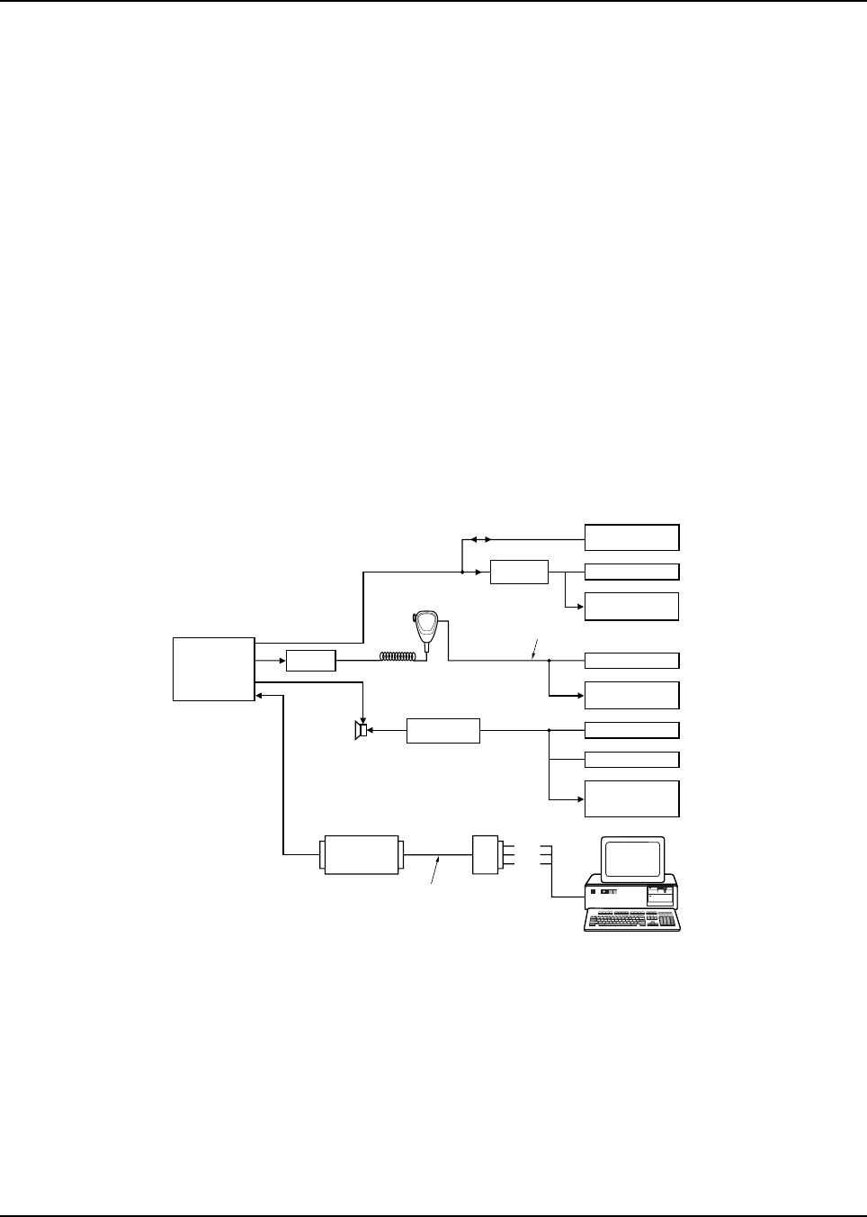
Chapter 6 Radio Alignment Procedure
6.1 Introduction
This section describes both receiver and transmitter radio alignment procedures using either of the
following radio alignment software:
• ASTRO Digital Spectra Radio Service Software (DOS-based)
• ASTRO Digital Spectra and Digital Spectra Plus Tuner software (Windows-based)
6.2 RSS
6.2.1 ASTRO Digital Spectra
An IBM or IBM PC-compatible computer and radio service software (RSS) are required to align the
ASTRO Digital Spectra radio. Refer to the applicable RSS manual for installation and setup
procedures for the software.
To perform the alignment procedures, the radio must be connected to the computer, radio interface
box (RIB), and a universal test set as shown in Figure 6-1.
Figure 6-1. ASTRO Digital Spectra Radio Alignment Test Setup
All service and tuning procedures are performed from the SERVICE menu, which is selected by
pressing F2 from the MAIN MENU. Figure 6-2 illustrates how the RSS alignment SERVICE screens
are organized.
RIB
COMPUTER INTERFACE
CABLE
DATA
BUSY
GND
COMPUTER
AUDIO GENERATOR
SINAD METER
AC VOLTMETER
TX
RX
COMMUNICATIONS
ANALYZER
AGILENT 8901B
MODULATION
ANALYZER
COMMUNICATIONS
ANALYZER
(MODOUT Connector)
WATTMETER
MAEPF-27245-O
RADIO
SET TO APPROX. 80mVrms FOR MAXIMUM DEVIATIO
N
MATCHING
TRANSFORMER
CONTROL
HEAD
TEST
SPEAKER
DUMMY
MICROPHONE
RF PORT
RADIO-TO-RIB CABLE
RF
ATTENUATOR
COMMUNICATIONS
ANALYZER
Vert/SINAD Dist/
DVM Counter
OR
OR
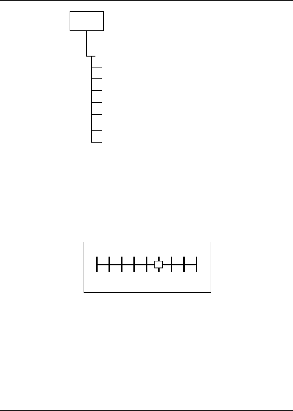
February 3, 2003 6881076C20-E
6-2 Radio Alignment Procedure: RSS
Figure 6-2. RSS Service Menu Layout
All SERVICE screens read and program the radio codeplug directly; you do NOT have to use the
RSS GET/SAVE functions to use the SERVICE menus.
6.2.2 Softpot
The SERVICE screens introduce the concept of the softpot, an analog SOFTware-controlled
POTentiometer used for adjusting all transceiver alignment controls.
Each SERVICE screen provides the capability to increase or decrease the softpot value with the
keyboard UP/DOWN arrow keys respectively. A graphical scale is displayed indicating the minimum,
maximum, and proposed value of the softpot, as shown in Figure 6-3.
Figure 6-3. Softpot Concept
Adjusting the softpot value sends information to the radio to increase (or decrease) dc voltage in the
corresponding circuit. For example, pressing the UP arrow key at the Reference Oscillator screen
instructs the radio’s microcomputer to increase the voltage across a varactor in the reference
oscillator, which increases the frequency.
In ALL cases, the softpot value is just a relative number corresponding to a digital-to-analog (D/A)
generated voltage in the radio.
Perform the following alignment procedures in the sequence indicated.
NOTE: Some of the following screens may vary depending upon the radio under test and the version
of radio service software you are using. Refer to your radio service software user’s guide.
REFERENCE OSCILLATOR ALIGNMENT
TRANSMIT CURRENT LIMIT
TRANSMITTER ALIGNMENT MENU
TRANSMIT DEVIATION BALANCE
(COMPENSATION) ALIGNMENT
TRANSMIT DEVIATION LIMIT ALIGNMENT
F2 -
F2 -
F4 -
F5 -
F6 -
SERVICE
HELPF1 -
EXIT, RETURN TO SERVICE MENUF10 -
TRANSMIT POWER ALIGNMENTF3 -
Min.
Value Max.
Value
015

6881076C20-E February 3, 2003
Radio Alignment Procedure: RSS 6-3
6.2.3 Reference Oscillator Alignment
Radios are shipped from the factory with a worst-case frequency error of ±200 Hz for VHF, ±300 Hz
for UHF, and ±500 Hz for 800 MHz. These specifications are tighter than the more stringent FCC
requirement of 1.5 ppm for all bands.
For radios that have been in storage for over six months from the factory ship date, the reference
oscillator should be checked when the radio is initially deployed to the field. It is strongly
recommended that the reference oscillator be checked every time the radio is serviced or at least
once a year, whichever comes first.
The crystal contained in the reference oscillator naturally drifts over time due to its aging
characteristic. Periodic (annual) adjustment of the reference oscillator is important for proper radio
operation.
Improper adjustment can result in both poor performance and interference with other users operating
on adjacent channels.
This test can be done with either the R-2670 Communication Analyzer or the 8901_ Modulation
Analyzer.
1. Initial set up using the R-2670 Communication Analyzer:
- RF Control: MONITOR
- B/W: WB
- Freq: RSS frequency under test
- Attenuation: 20dB
- Mon RF in: RF I/O
- Meter: RF Display
- Mode: STD
- Input Level: uV or W
- Display: Bar Graphs
- Squelch: Mid-range or adjust as necessary
2. Initial set up using the 8901_ Series Modulation Analyzer:
- Press the green Automatic Operation button on the analyzer.
- Press the FREQ key.
- Type 7.1 followed by the SPCL button to set the 8901_ modulation analyzer for maximum
accuracy.
3. Read the radio using the RSS.
4. From the SERVICE MENU, press F2 to select the TRANSMITTER ALIGNMENT MENU.
5. Press F2 again to select the REFERENCE OSCILLATOR alignment screen (Figure 6-4).
February 3, 2003 6881076C20-E
6-4 Radio Alignment Procedure: RSS
Figure 6-4. Reference Oscillator Alignment Screen
6. If you are using the R-2670 Communication Analyzer, enter the frequency displayed on the
RSS screen in the “RF control” section of the R-2670. Under the “Meter” section of the
display, choose RF DISPLAY.
7. Press F6 to key the radio. The screen will indicate that the radio is transmitting.
8. Wait 5 seconds until the analyzer reading settles. Record the transmitter frequency (or note
the frequency error reading on the screen).
9. Use the Up and Down arrow keys on your computer keyboard to adjust the reference
oscillator softpot value. Allow approximately five seconds for the analyzer frequency reading
to stabilize after each change.
10. Adjust the frequency error, as indicated in Table 6-1.
11. Press F6 again to dekey the radio.
12. Press F8 to program the new softpot value.
13. Press F10 once to return to the TRANSMITTER ALIGNMENT MENU, or press F10 twice to
return to the SERVICE MENU.
6.2.4 Transmit Power Alignment
NOTE: All power measurements are to be made at the antenna port.
NOTE: The transmitter power setting keeps the radiated power at or below the level specified in the
exclusionary clause for low power devices of IEEE Standard C95.1-1991.
Table 6-1. Reference Oscillator Alignment
Band Target
VHF ±70Hz
UHF ±150Hz
800 MHz ±150Hz
MOTOROLA Radio Service Software Use UP/DOWN Arrows To Adjust Softpot.
ASTRO Model: T04SLF9PW7AN
MAIN:SERVICE:TX ALIGN:REF OSC
REFERENCE OSCILLATOR
--------------------
Frequency Current Value
--------- -------------
869.9875 72 New Softpot Value......72
Transmitter..On
0 255
MIN |----+----+----+----X----+----+----+----+----+----+----+----| MAX
F1 F2 F3 F4 F5 F6 F7 F8 F9 F10
HELP TOGGLE PROGRAM EXIT
PTT VALUE
6881076C20-E February 3, 2003
Radio Alignment Procedure: RSS 6-5
NOTE: The power amplifier must be firmly mounted to the transceiver for accurate power adjustment.
1. From the SERVICE MENU, press F2 to select the TRANSMITTER ALIGNMENT MENU.
2. Press F3 to select the TRANSMIT POWER alignment screen. The screen will indicate the
transmit frequencies to be used (Figure 6-5).
Figure 6-5. Transmit Power Alignment Screen
3. Press Tab (or Enter or Return) to select a frequency field (starting with the highest frequency
shown).
4. Press F6 to key the radio. The screen will indicate that the radio is transmitting.
5. Use the UP/DOWN arrow keys to adjust the transmit power per the values shown in
Table 6-2.
Table 6-2. Transmit Power Settings
VHF Rated Output Power Min. Level Max. Level
10-25W 10.5W 28W
25-50W 26.5W 56W
50-110W 54W 113W
UHF Rated Output Power Min. Level Max. Level
6W 6W 7W
10-25W 10.5W 28W
20-40W 20.5W 45W
78W 76W 80W
15W 16W 19W
50-110W 54W 110W
MOTOROLA Radio Service Software Use UP/DOWN Arrows To Adjust Softpot.
ASTRO Model: T04SLF9PW7AN
MAIN:SERVICE:TX ALIGN:TX POWER
TRANSMIT POWER
--------------
Current Value New Softpot Value
Frequency High Pwr Mid Pwr Low Pwr High Pwr Mid Pwr Low Pwr
--------- -------- ------- ------- -------- ------- -------
806.0125 35 35 35 10 23 23
821.0125 42 42 42 11 28 28
851.0125 50 50 50 20 33 33
866.0125 60 60 66 33 40 40
869.9875 70 70 70 43 45 45
Transmitter..On
0 127
MIN |----+----+----+----X----+----+----+----+----+----+----+----| MAX
F1 F2 F3 F4 F5 F6 F7 F8 F9 F10
HELP TOGGLE PROGRAM EXIT
PTT VALUE
February 3, 2003 6881076C20-E
6-6 Radio Alignment Procedure: RSS
6. Press F6 to dekey the radio.
7. Press F8 to program the value.
8. Repeat steps 3-7 for the remaining frequencies.
9. Press F10 once to return to the TRANSMITTER ALIGNMENT MENU, or press F10 twice to
return to the SERVICE MENU.
6.2.5 Transmit Current Limit Alignment
1. From the SERVICE MENU, press F2 to select the TRANSMITTER ALIGNMENT MENU.
2. Press F4 to select the TRANSMIT CURRENT LIMIT alignment screen. The screen will
indicate the transmit frequencies to be used (Figure 6-6).
NOTE:The current limit before alignment should be set to 15 (for no limiting).
Figure 6-6. Transmit Current Limit Alignment Screen
3. Press Tab (or Enter or Return) to select a frequency field (starting with the test frequency
with the highest current drain).
4. Press F6 to key the radio. The screen will indicate that the radio is transmitting.
5. Use the DOWN arrow key to decrease the current limit relative value until the transmit power
output begins to drop.
6. Then, increase the current limit value by one increment.
7. Press F8 to program the new softpot value.
800 MHz Rated Output Power Min. Level Max. Level
15W 15W 20W
35W (Repeater Mode) 37W 42W
30W (Talkaround Mode) 32W 42W
Table 6-2. Transmit Power Settings (Continued)
MOTOROLA Radio Service Software Use UP/DOWN Arrows To Adjust Softpot.
ASTRO Model: T04SLF9PW7AN
MAIN:SERVICE:TX ALIGN:CURRENT LIMIT
CURRENT LIMIT
-------------
Frequency Current Value New Softpot Value
--------- ------------- -----------------
806.0125 11 11
821.0125 11 11
851.0125 11 11
866.0125 11 11
869.9875 11 11
Transmitter..On
0 15
MIN |----+----+----+----X----+----+----+----+----+----+----+----| MAX
F1 F2 F3 F4 F5 F6 F7 F8 F9 F10
HELP TOGGLE PROGRAM EXIT
PTT VALUE

6881076C20-E February 3, 2003
Radio Alignment Procedure: RSS 6-7
8. Press F10 once to return to the TRANSMITTER ALIGNMENT MENU, or press F10 twice to
return to the SERVICE MENU.
6.2.6 Transmit Deviation Balance (Compensation) Alignment
NOTE: Compensation alignment is only required after replacing (or servicing) the command board,
VOCON (vocoder/controller) board, RF board, or the VCO board.
Compensation alignment balances the modulation sensitivity of the VCO and reference modulation
(synthesizer low-frequency port) lines. The compensation algorithm is critical to the operation of
signaling schemes that have very-low-frequency components (for example, DPL) and could result in
distorted waveforms if improperly adjusted.
Compensation values are adjusted at the different test frequencies to achieve a flat VCO modulation
sensitivity with respect to the RF frequency and with respect to the low frequency response of the
synthesizer.
This test can be done with either the R-2670 Communication Analyzer or the 8901_ Series
Modulation Analyzer. The R-2670 analyzer is recommended.
1. Initial set up using the R-2670 Communication Analyzer:
- Connect a BNC cable between the “DEMOD OUT” port and the “VERT/SINAD DIST/DMM
COUNTER IN” port on the R-2670.
-Press the SPF key on the R-2670 to display the “SPECIAL FUNCTIONS MENU.” Move the
cursor to “High Pass,”and select 5 Hz via the soft key menu. Select 20 kHz for the “Low
Pass” setting.
- In the “RF Control” section of the R-2670, enter the frequency displayed on the RSS screen
(choose a test frequency from the list of frequencies displayed under Transmit Deviation
Balance [Compensation] in RSS). Move the cursor to the “B/W” setting and select “WIDE
+/- 100 kHz” via the soft key menu.
- Place the R-2670 cursor in the “Display” zone. Select “AC VOLTS” on the soft key menu.
Move the cursor to the “Range” setting and select “AUTO.”
2. Initial set up using the 8901_ Series Modulation Analyzer:
- Press the FM MEASUREMENT button. (The “Error 03-input level too low” indication is
normal until an input signal is applied.)
- Simultaneously press the Peak – and Peak + buttons. Both LEDs on the buttons should
light.
- Press the 15 kHz LP filter button.
3. From the SERVICE MENU, press F2 to select the TRANSMITTER ALIGNMENT MENU.
4. Press F5 to select the TRANSMIT DEVIATION BALANCE (COMPENSATION) alignment
screen (Figure 6-7).

February 3, 2003 6881076C20-E
6-8 Radio Alignment Procedure: RSS
Figure 6-7. Transmit Deviation Balance (Compensation) Alignment Screen
5. Press Tab to select and start the alignment at the lowest frequency listed.
6. Press F3 (TOGGLE LOW TONE PTT) to key the radio. Wait approximately five seconds until
the frequency displayed on the analyzer stabilizes.
7. Measure and record the deviation value from the 8901_ analyzer or the ac voltage value from
the R-2670 analyzer.
8. Press F3 to dekey the radio.
9. Press F6 (TOGGLE HIGH TONE PTT) to key the radio. Wait approximately 5 seconds until
the voltage shown on R-2670 analyzer, or the deviation shown on the 8901_ analyzer,
stabilizes.
10. Use the Up and Down arrow keys on the computer keyboard to adjust the deviation to within
±1.5%) of the value recorded in step 6.
11. Press F6 to dekey the radio, and then press F6 again to verify the deviation setting.
12. Press F8 to program the new softpot value.
13. Repeat steps 4 through 10 to ensure the correct deviation balance value has been saved.
14. Repeat steps 4 through 11 for each of the remaining frequencies.
15. Press F10 once to return to the TRANSMITTER ALIGNMENT MENU, or press F10 twice to
return to the SERVICE MENU.
6.2.7 Transmit Deviation Limit Alignment
This test can be done with either the R-2670 communication analyzer or the 8901_ Series
Modulation Analyzer. The R-2670 is recommended.
1. Initial set up using the R-2670 Communication Analyzer:
- Connect a BNC cable between the “DEMOD OUT” port and the “VERT/SINAD DIST/DMM
COUNTER IN” port of the R-2670.
- Press the SPF key on the R-2670 to display the “SPECIAL FUNCTIONS MENU.”Move the
cursor to “High Pass,”and select 5 Hz via the soft key menu. Select 20 kHz for the “Low
Pass” setting.
MOTOROLA Radio Service Software Use UP/DOWN Arrows To Adjust Softpot.
ASTRO Model: T04SLF9PW7AN
MAIN:SERVICE:TX ALIGN:BAL ATTN
TRANSMIT DEVIATION BALANCE (COMPENSATION)
-----------------------------------------
Current
Frequency Value New Softpot Value
--------- ------- -----------------
806.0125 30 30
821.0125 30 30
851.0125 30 30
866.0125 45 45
869.9875 45 45
Transmitter..Off
0 63
MIN |----+----+----+----X----+----+---+----+----+----+----+----| MAX
F1 F2 F3 F4 F5 F6 F7 F8 F9 F10
HELP TOGGLE LOW TOGGLE HIGH PROGRAM EXIT
TONE PTT TONE PTT VALUE

6881076C20-E February 3, 2003
Radio Alignment Procedure: RSS 6-9
- In the “RF Control” section of the R-2670, enter the frequency displayed on the RSS screen
(choose a test frequency from the list of frequencies displayed under TRANSMIT
DEVIATION LIMIT screen in RSS). Move the cursor to the “B/W” setting and select “WIDE
+/- 100 kHz” via the soft key menu.
- Place the R-2670 cursor in the “Display” zone. Move the cursor to the “Meter” setting and
select “AC VOLTS” via the soft key menu. Move the cursor to the “Range” setting and
select “AUTO.”
2. Initial set up using the 8901_ Series Modulation Analyzer:
- Press the FM MEASUREMENT button. (The “Error 03-input level too low” indication is
normal until an input signal is applied.)
- Simultaneously press the Peak – and Peak + buttons. Both LEDs on the buttons should
light.
- Press the 15 kHz LP filter button.
3. From the SERVICE MENU, press F2 to select the TRANSMITTER ALIGNMENT MENU.
4. Press F6 to select the TRANSMIT DEVIATION LIMIT alignment screen (Figure 6-8).
Figure 6-8. Transmit Deviation Limit Alignment Screen
5. Press Tab to select and start the alignment at the lowest frequency listed.
6. Press F6 and observe the measurement.
7. Wait approximately 5 seconds until the voltage shown on the R-2670 analyzer, or the
deviation shown on the 8901_ analyzer, stabilizes.
8. Adjust the deviation limit to within 0.158 to 0.163 Vac on the R-2670 analyzer, or 2.785 to
2.885 kHz on the 8901_ analyzer. The optimum setting is 0.160 Vac (2.83 kHz).
9. Press F6 again to dekey the radio.
10. Press F8 to program the new softpot value.
11. Repeat steps 4 through 7 to ensure the correct deviation limit is saved.
12. Repeat steps 3 through 7 for each of the remaining frequencies.
13. If the transmit limit adjustment required was excessive, repeat or recheck the transmit
deviation balance (compensation) procedure on page 6-7.
14. Press F10 once to return to the TRANSMITTER ALIGNMENT MENU, or press F10 twice to
return to the SERVICE MENU.
MOTOROLA Radio Service Software Use UP/DOWN Arrows To Adjust Softpot.
ASTRO Mobile Model: T04SLF9PW7AN
MAIN:SERVICE:TX ALIGN:DEVIATION
TRANSMIT DEVIATION LIMIT
------------------------
Current
Frequency Value New Softpot Value
--------- --------- ------------------
813.4750 11750 11750
822.4750 11750 11750
858.4750 11800 11800
867.9750 11800 11800
Transmitter..Off
0 32767
MIN |----+----+----+----X----+----+----+----+----+----+----+----| MAX
F1 F2 F3 F4 F5 F6 F7 F8 F9 F10
HELP TOGGLE PROGRAM EXIT
PTT VALUE

February 3, 2003 6881076C20-E
6-10 Radio Alignment Procedure: ASTRO Digital Spectra and Digital Spectra Plus Tuner Software
6.2.8 Bit Error Rate (BER) Performance Check
This check tests the Bit Error Rate (BER) of the radio’s receiver at a desired frequency.
Required equipment and software: R-2670 system analyzer, with P25 option; IBM PC-compatible
computer, RSS
In Generate mode, the R-2670 system analyzer modulates the RF carrier with a 1011Hz tone test
pattern to test the Unit Under Test (UUT) receiver. The test pattern received by the UUT is compared
in the UUT with a stored version of the test pattern to compute a BER.
1. Connect the RF Input port of the UUT to the RF IN/OUT port of the analyzer.
2. Set up the R-2670 as follows:
- Place the cursor in the RF Zone, and configure the analyzer as follows:
RF control: Generate
Preset: B/W: NB
Freq: Desired test frequency; for example, 851.0625MHz
Output Level: -50.0 dBm
Gen RF Out: RF I/O
- Place the cursor on the Mode field in the Display Zone.
- Select PROJECT 25 STD.
- Set the METER field to RF DISPLAY.
- Place the cursor on the CODE field in the Audio Zone.
- Select the 1011 Hz PAT softkey.
This generates a 1011Hz tone test pattern. If this pattern is received correctly by the UUT,
the measured BER should be zero.
- Set the deviation in the Audio Zone as PROJ25Dev: 2.83 kHz ~.
3. Using the RSS, configure the UUT as follows:
- In the RSS Main Menu, press F2 to select SERVICE: Alignment.
-Press F5 to select Performance Testing.
-Press F2 to select Bit Error Rate.
- Enter the desired test frequency in the Rx Frequency (MHz) field; for example,
851.0625MHz.
- Set the Modulation Type to 12.5 kHz/C4FM.
- Set the BER Integration Time (sec) to not less than 7.200.
-Press F6 (Start/Stop) to begin the test.
4. Monitor the radio’s received BER (%) results on the computer.
5. Reduce the analyzer output level to achieve a standard Bit Error Rate of 5%. The analyzer
RF output level should be within the SINAD specification of the UUT.
6.3 ASTRO Digital Spectra and Digital Spectra Plus Tuner Software
A personal computer (PC) and Tuner Software are required to align the radio. Please refer to the
CPS Programming Installation Guide (Motorola part number 6881095C44) for installation and setup
procedures for the software. To perform the alignment procedures, the radio must be connected to
the computer and to a universal test set, as shown in the following figure.
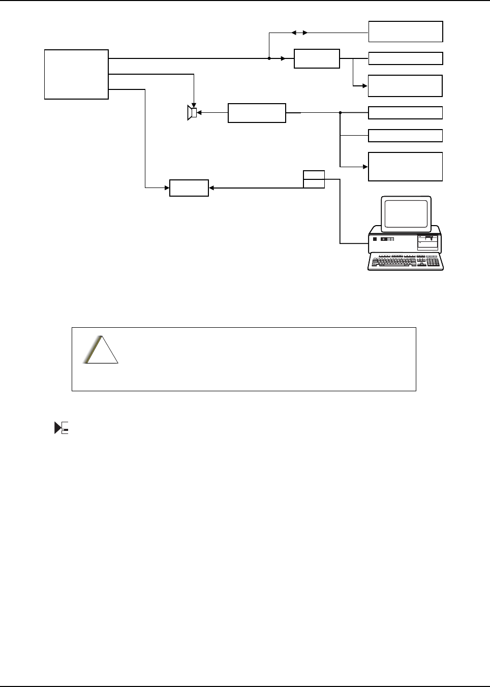
6881076C20-E February 3, 2003
Radio Alignment Procedure: ASTRO Digital Spectra and Digital Spectra Plus Tuner Software 6-11
Figure 6-9. ASTRO Digital Spectra Plus Radio Alignment Test Setup
Select Tuner from the START menu. To read the radio, use the File ➝ Read Device menu or click
on .
Figure 6-10 illustrates how the alignment screens are organized. To access a screen,
double-click on the desired screen name in the Tuner menu.
These procedures should only be attempted by qualified
service personnel. Failure to perform alignment procedures
properly may result in seriously degraded radio or system
performance.
RX
30-85001D01
TX
GND
COMMUNICATIONS
ANALYZER
WATTMETER
RADIO
MATCHING
TRANSFORMER
CONTROL
HEAD
TEST
SPEAKER
RF PORT
For dash mount applications, ASTRO Spectra Plus program/flash cable
(30-85001D01) will be connected to the microphone port on the control head.
For remote mount the 30-85001D01 will be connected to the flashport
connector on the front face of the radio (P506).
Do not attempt to use a microphone while cable is connected.
*
*
COMPUTER
SINAD METER
AC VOLTMETER
RX
COMMUNICATIONS
ANALYZER
Vert/SINAD Dist/
DVM Counter
OR
AGILENT 8901B
MODULATION
ANALYZER
RF
ATTENUATOR
MAEPF-27246-O
!
C
a u t i o
n
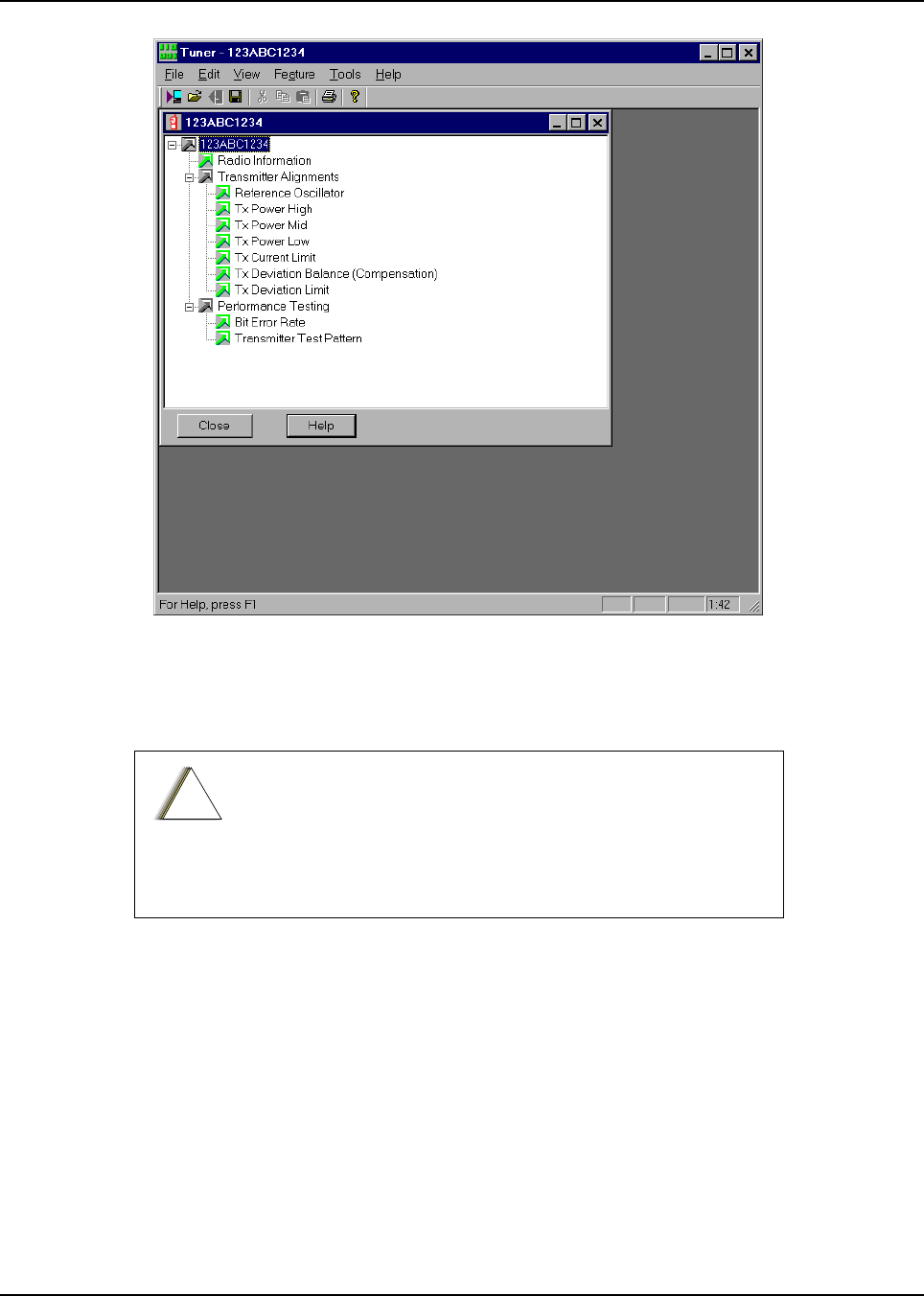
February 3, 2003 6881076C20-E
6-12 Radio Alignment Procedure: ASTRO Digital Spectra and Digital Spectra Plus Tuner Software
Figure 6-10. Tuner Menu Layout
The alignment screens introduce the concept of the “softpot,” an analog SOFTware-controlled
POTentiometer used for adjusting all transceiver alignment controls.
Each alignment screen provides the ability to increase or decrease the softpot value by using the
slider or the screen’s spin buttons (▲ and ▼), or by entering the new value from the keyboard. A
graphical scale on the display indicates the minimum, maximum, and proposed value of the softpot;
see Figure 6-11.
Do NOT switch radios in the middle of any alignment
procedure. Always left-click the Close button on the screen to
return to the MAIN menu screen before disconnecting the
radio. Improper exits from the Alignment screens may leave
the radio in an improperly configured state and result in
seriously degraded radio or system performance.
!
C
a u t i o
n
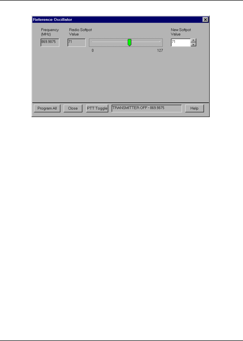
6881076C20-E February 3, 2003
Radio Alignment Procedure: ASTRO Digital Spectra and Digital Spectra Plus Tuner Software 6-13
Figure 6-11. Typical Softpot Adjustment Screen
Adjusting the softpot value sends information to the radio to increase (or decrease) a voltage in the
corresponding circuit. For example, left-clicking the UP spin button (▲) on the Reference
Oscillator screen instructs the radio’s microcomputer to increase the voltage across a varactor in
the reference oscillator, which increases the frequency.
In ALL cases, the softpot value is just a relative number corresponding to a digital-to-analog (D/A)
generated voltage in the radio.
Digital Spectra only: Each Digital Spectra tuning screen contains a Program button. Pressing the
Program button sets only the softpot value associated with the currently selected frequency, so it is
necessary to press the Program button after tuning each softpot at each and every frequency.
Digital Spectra Plus only: Each Digital Spectra tuning screen contains a Program All button.
Pressing the Program All button sets all softpot values shown on the screen at the same time, which
makes it possible to first adjust all the softpot values and then press the Program All button to set
the values before leaving a screen. Pressing the Program All button more than once has no
adverse effect on the new values.
Perform the following procedures in the sequence indicated.
NOTE: Some of the following screens may vary depending on the radio under test and the version of
tuner software you are using. Refer to the software’s on-line help.
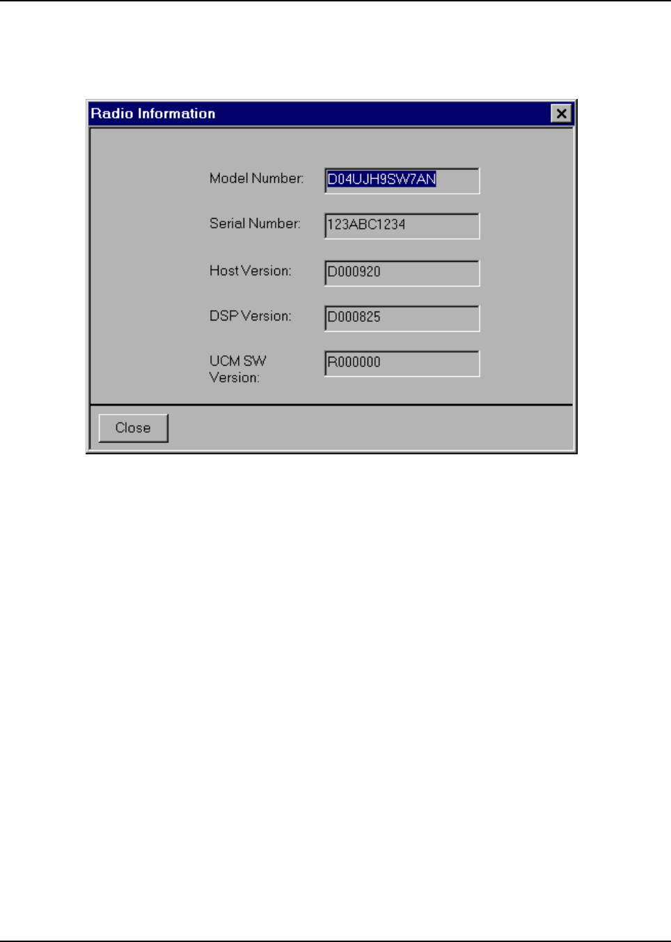
February 3, 2003 6881076C20-E
6-14 Radio Alignment Procedure: ASTRO Digital Spectra and Digital Spectra Plus Tuner Software
6.3.1 Radio Information
Figure 6-12 shows a typical Radio Information screen. All of the data appearing here is informational
and cannot be changed..
Figure 6-12. Radio Information Screen
6.3.2 Reference Oscillator Alignment
Reference oscillator alignment is required after replacing (or servicing) the transceiver board.
Radios are shipped from the factory with a worst-case frequency error of ±200 Hz for VHF, ±300 Hz
for UHF, and ±500 Hz for 800 MHz. These specifications are tighter than the more stringent FCC
requirements of 1.5 ppm for all bands.
For radios that have been in storage for over six months from the factory ship date, the reference
oscillator should be checked when the radio is initially deployed to the field. It is strongly
recommended that the reference oscillator be checked every time the radio is serviced or at least
once a year, whichever comes first.
The crystal contained in the reference oscillator naturally drifts over time due to its aging
characteristic. Periodic (annual) adjustment of the reference oscillator is important for proper radio
operation.
Improper adjustment can result in both poor performance and interference with other users operating
on adjacent channels.
This test can be done with either the R-2670 Communication Analyzer or the 8901_ Modulation
Analyzer.
• Initial set up using the R-2670 Communication Analyzer:
- RF Control: MONITOR
- B/W: WB
- Freq: RSS frequency under test
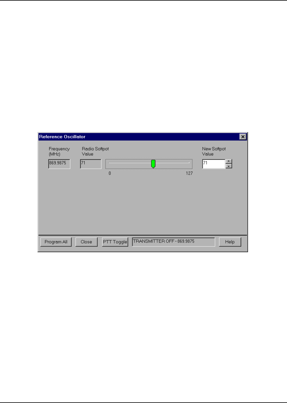
6881076C20-E February 3, 2003
Radio Alignment Procedure: ASTRO Digital Spectra and Digital Spectra Plus Tuner Software 6-15
- Attenuation: 20dB
- Mon RF in: RF I/O
- Meter: RF Display
- Mode: STD
- Input Level: uV or W
- Display: Bar Graphs
- Squelch: Mid-range or adjust as necessary
• Initial set up using the 8901_ Series Modulation Analyzer:
- Press the green Automatic Operation button on the analyzer.
- Press the FREQ key.
- Type 7.1 followed by SPCL button to set the 8901_ modulation analyzer for maximum
accuracy.
1. Select the Reference Oscillator alignment screen. See Figure 6-13.
Figure 6-13. Reference Oscillator Alignment Screen
2. If you are using the R-2670 analyzer, enter the frequency displayed on the RSS screen in the
“RF control” section of the R-2670. Under the “Meter” section of the display, choose RF
DISPLAY.
3. Left-click the PTT Toggle button on the screen to make the radio transmit. The screen
indicates whether the radio is transmitting.
4. Wait five seconds until the analyzer reading stabilizes, and then record the transmitter
frequency.
5. Adjust the reference oscillator’s softpot value until the measured value is as close as possible
to the frequency shown on the screen. Allow approximately five seconds for the analyzer
frequency reading to stabilize after each change. See Table 6-1 on page 6-4 and Table 6-3 on
page 6-16.
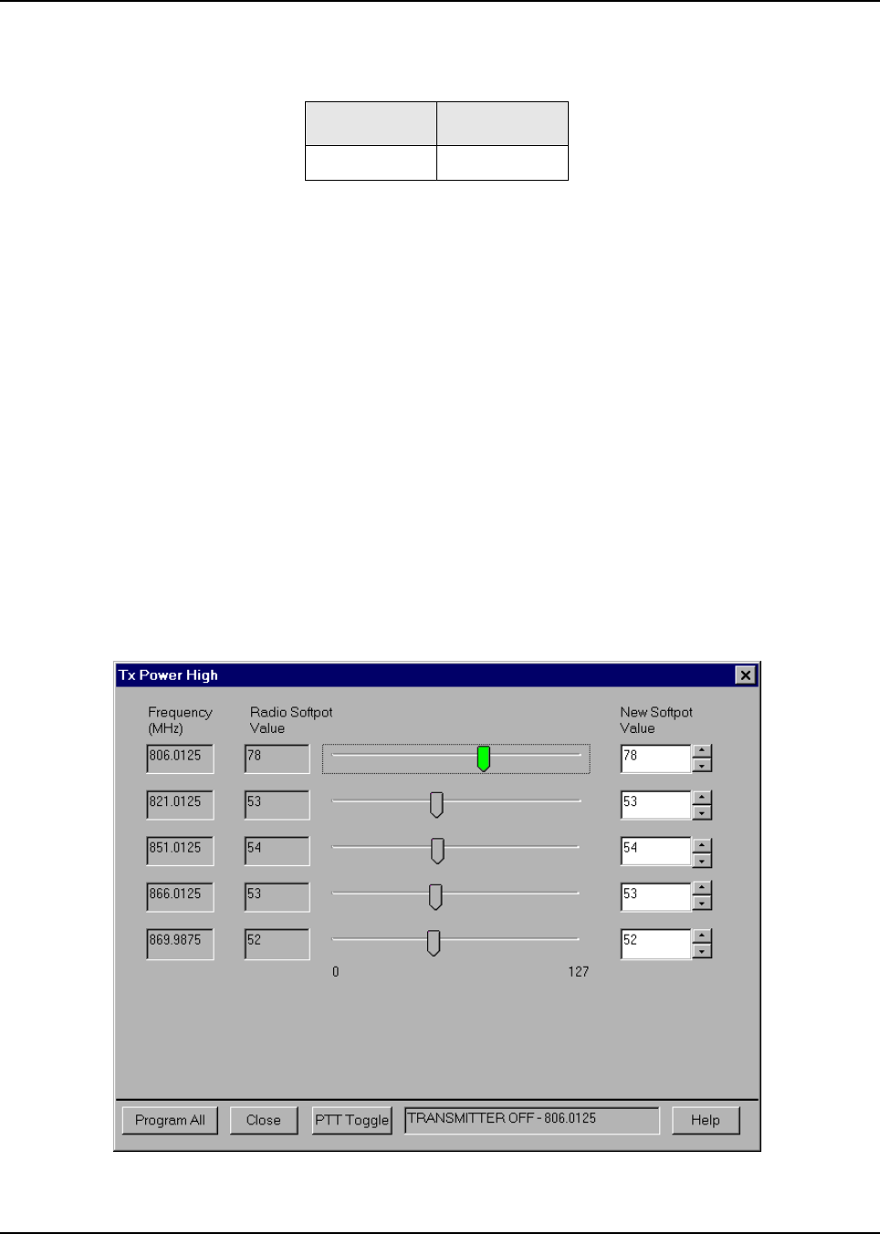
February 3, 2003 6881076C20-E
6-16 Radio Alignment Procedure: ASTRO Digital Spectra and Digital Spectra Plus Tuner Software
6. Left-click the Program (Digital Spectra) or Program All (Digital Spectra Plus) button on the
screen to dekey the radio and save the tuned values.
7. Left-click the Close button on the screen to return to the Transmitter Alignments menu.
6.3.3 Transmit Power Alignment
Transmit Power alignment is required after replacing (or servicing) the transceiver board.
This alignment procedure adjusts the transmit power of the radio and must be performed for two
different power levels, at multiple frequencies for each power level, to allow for proper alignment
across the entire RF band. The RF band is divided into frequency zones with a calibration point
(value) in each zone.
Notes
• The same softpot attenuation value will result in DIFFERENT radio output power levels at
different frequencies.
• All power measurements are to be made at the antenna port.
1. Select the TX Power (High, Mid, or Low) alignment screen. The screen will indicate the
transmit frequencies to be used. See Figure 6-14.
Figure 6-14. Typical Transmit Power Alignment Screen
Table 6-3. Reference Oscillator Alignment
Band Target
800 MHz ±100 Hz
6881076C20-E February 3, 2003
Radio Alignment Procedure: ASTRO Digital Spectra and Digital Spectra Plus Tuner Software 6-17
2. Left-click the desired frequency field (starting with the highest frequency shown).
3. Left-click the PTT Toggle button on the screen to make the radio transmit. The screen
indicates whether the radio is transmitting.
4. Measure the transmit power of the radio with a service monitor.
5. Adjust the softpot value until the required power, as shown in Table 6-4, is indicated on the
service monitor.
6. Repeat the above process for all frequencies and all power levels.
7. Left-click the Program (Digital Spectra) or Program All (Digital Spectra Plus) button on the
screen to dekey the radio and save the tuned values.
Left-click the Close button on the screen to return to the Transmitter Alignments menu.
Table 6-4. Transmit Power Settings
VHF Rated Output Power** Min. Level Max. Level
10-25W 10.5W 28W
25-50W 26.5W 56W
50-110W 54W 113W
UHF Rated Output Power* Min. Level Max. Level
6W 6W 7W
10-25W 10.5W 28W
20-40W 20.5W 45W
78W 76W 80W
15W 16W 19W
50-110W 54W 110W
800 MHz Rated Output Power** Min. Level Max. Level
15W 15W 20W
35W (Repeater Mode) 37W 42W
30W (Talkaround Mode) 32W 42W
*These transmit power settings are used for Digital Spectra radios only.
**These transmit power settings are used for both Digital Spectra and
Digital Spectra Plus radios.
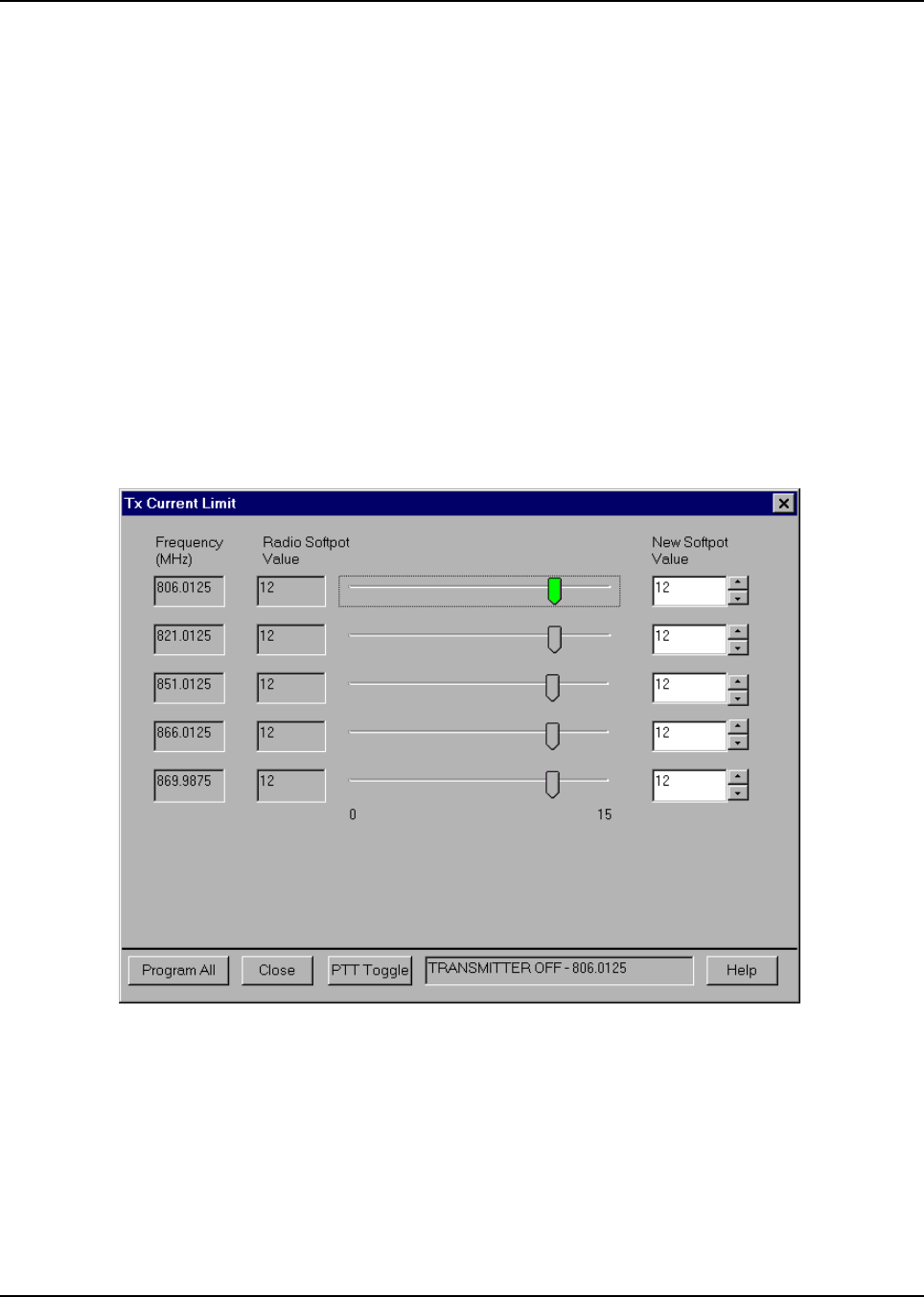
February 3, 2003 6881076C20-E
6-18 Radio Alignment Procedure: ASTRO Digital Spectra and Digital Spectra Plus Tuner Software
6.3.4 Transmit Current Limit Alignment
This procedure is required for mobile radios only. Transmit Current Limit adjustment is required after
replacing (or servicing) the RF Board.
This alignment procedure limits the transmitter current drain of the radio.
1. Click on the PTT Toggle button to make the radio transmit.
2. While transmitting, measure the current drain at each of the test frequencies.
3. Re-select the frequency which had the highest current reading (This only needs to be done
on a single frequency since all other frequencies will be adjusted automatically).
4. Adjust the softpot value by manipulating the slider bar, incrementing the New Softpot Value
spin box, or directly entering the desired value into the New Softpot Value spin box. Using a
service monitor to measure transmit power, decrease the softpot value from its maximum
until the measured transmit power begins to drop.
5. Increase the softpot value by one unit.
6. Press the Program (Digital Spectra) or Program All (Digital Spectra Plus) button to save the
tuned value in the radio.
.
Figure 6-15. Transmit Current Limit Alignment Screen
6.3.5 Transmit Deviation Balance (Compensation) Alignment
This alignment is required after replacing (or servicing) the VOCON board or the transceiver board.
This alignment procedure balances the modulation contributions of the low- and high-frequency
portions of a baseband signal. Proper alignment is critical to the operation of signaling schemes that
have very low frequency components (for example, DPL) and could result in distorted waveforms if
improperly adjusted.

6881076C20-E February 3, 2003
Radio Alignment Procedure: ASTRO Digital Spectra and Digital Spectra Plus Tuner Software 6-19
This procedure needs to be performed at multiple frequencies to allow for proper alignment across
the entire RF band. The RF band is divided into frequency zones with a calibration point (value) in
each zone.
Proper alignment requires a modulation analyzer or meter with a frequency response to less than
10Hz modulating frequency. The modulation analyzer settings during this test should be set for
average deviation, a 15 kHz low-pass filter, no de-emphasis, and no high-pass filter, if these settings
are supported.
This test can be done with either the R-2670 Communication Analyzer or the 8901_ Series
Modulation Analyzer. The method of choice is the R-2670 analyzer.
1. Initial set up using the R-2670 Communication Analyzer:
- Connect a BNC cable between the “DEMOD OUT” port and the “VERT/SINAD DIST/DMM
COUNTER IN” port on the R-2670.
-Press the SPF key on the R-2670 to display the “SPECIAL FUNCTIONS MENU.” Move the
cursor to “High Pass,” and select 5 Hz on the soft key menu. Select 20 kHz for the “Low
Pass” setting.
- In the “RF Control” section of the R-2670, enter the frequency displayed on the RSS
screen. Move the cursor to the “B/W” setting and select “WIDE +/- 100 kHz” on the soft key
menu.
- Place the R-2670 cursor in the “Display” zone. Select “AC VOLTS” on the soft key menu.
Move the cursor to the “Range” setting and select “AUTO.”
2. Initial set up using the 8901_ Series Modulation Analyzer:
- Press the FM MEASUREMENT button. (The “Error 03-input level too low” indication is
normal until an input signal is applied.)
- Simultaneously press the Peak – and Peak + buttons. Both LEDs on the buttons should
light.
- Press the 15 kHz LP filter key.
3. Select the TX Deviation Balance alignment screen. The screen will indicate the transmit
frequencies to be used. See Figure 6-16.
4. Left-click the desired frequency field (starting with the highest frequency shown).
5. Left-click the PTT Toggle button on the screen to make the radio transmit. The screen
indicates whether the radio is transmitting.
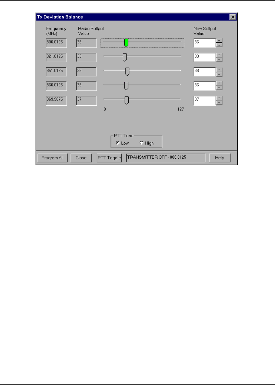
February 3, 2003 6881076C20-E
6-20 Radio Alignment Procedure: ASTRO Digital Spectra and Digital Spectra Plus Tuner Software
Figure 6-16. Transmit Deviation Balance (Compensation) Alignment Screen
6. Left-click the PTT Tone: Low button.
7. Left-click the PTT Toggle button on the screen to enable transmission. The screen indicates
whether the radio is transmitting. Wait approximately 5 seconds until the voltage shown on R-
2670, or the deviation shown on the 8901_ analyzer, stabilizes.
8. Measure and record the ac voltage value from the R-2670 analyzer or the deviation value
from the 8901_ series analyzer.
9. Left-click the PTT Tone: High button.
10. Adjust the softpot value until the measured deviation/voltage, when using the high tone, is
within +/- 1.5% of the value observed when using the low tone.
11. Repeat the above process for all frequencies.
12. Left-click the Program (Digital Spectra) or Program All (Digital Spectra Plus) button on the
screen to dekey the radio and save the tuned values.
13. Left-click the Close button on the screen to return to the Transmitter Alignments menu.
6.3.6 Transmit Deviation Limit Alignment
This alignment is required after replacing (or servicing) the VOCON board or the transceiver board.
This alignment procedure limits the modulation of a baseband signal. It is used for primary
modulation limiting.
This procedure needs to be performed at multiple frequencies to allow for proper alignment across
the entire RF band. The RF band is divided into frequency zones with a calibration point (value) in
each zone.
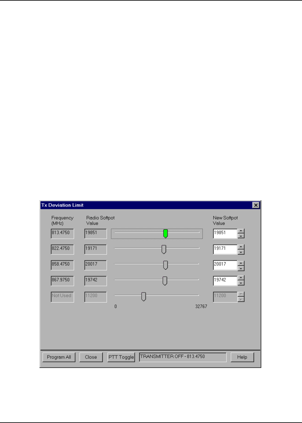
6881076C20-E February 3, 2003
Radio Alignment Procedure: ASTRO Digital Spectra and Digital Spectra Plus Tuner Software 6-21
This test can be done with either the R-2670 Communication Analyzer or the 8901_ Series
Modulation Analyzer. The method of choice is the R-2670 analyzer.
1. Initial set up using the R-2670 Communication Analyzer:
- Connect a BNC cable between the “DEMOD OUT” port and the “VERT/SINAD DIST/DMM
COUNTER IN” port on the R-2670.
-Press the SPF key on the R-2670 to display the “SPECIAL FUNCTIONS MENU.” Move the
cursor to “High Pass,” and select 5 Hz on the soft key menu. Select 20 kHz for the “Low
Pass” setting.
- In the “RF Control” section of the R-2670, enter the frequency displayed on the RSS
screen. Move the cursor to the “B/W” setting and select “WIDE +/- 100 kHz” on the soft key
menu.
- Place the R-2670 cursor in the “Display” zone. Select “AC VOLTS” on the soft key menu.
Move the cursor to the “Range” setting and select “AUTO.”
2. Initial set up using the 8901_ Series Modulation Analyzer:
- Press the FM MEASUREMENT button. (The “Error 03-input level too low” indication is
normal until an input signal is applied.)
- Simultaneously press the Peak – and Peak + buttons. Both LEDs on the buttons should
light.
- Press the 15 kHz LP filter key.
3. Select the TX Deviation Limit alignment screen. The screen will indicate the transmit
frequencies to be used. See Figure 6-17.
Figure 6-17. Transmit Deviation Limit Alignment Screen
4. Left-click the desired frequency field (starting with the highest frequency shown).

February 3, 2003 6881076C20-E
6-22 Radio Alignment Procedure: ASTRO Digital Spectra and Digital Spectra Plus Tuner Software
5. Left-click the PTT Toggle button on the screen to make the radio transmit. Wait
approximately 5 seconds until the deviation/voltage displayed on the analyzer stabilizes. The
screen indicates whether the radio is transmitting.
6. Adjust the deviation limit to within 0.158 to 0.163 Vac on the R-2670 (2.785 to 2.885 kHz).
The optimum setting is 0.160 Vac (2.83 kHz).
7. Repeat the above process for all frequencies.
8. Left-click the Program (Digital Spectra) or Program All (Digital Spectra Plus) button on the
screen to dekey the radio and save the tuned values.
9. Left-click the Close button on the screen to return to the Transmitter Alignments menu.
6.3.7 Bit Error Rate (BER) Test
This screen is used to test the Bit Error Rate (BER) of the radio’s receiver at a desired frequency and
contains the following fields:
• Rx Frequency:
This field selects the Receive Frequency directly in MHz.
• Test Pattern:
This field selects the Digital test pattern — TIA. Choices are: Standard Tone Test Pattern
(framed 1011) and Standard Interface Test Pattern (CCITT V.52).
• Modulation Type:
This field represents the digital modulation type of the incoming signal on which BER is to
be calculated.
• Continuous Operation:
This field allows the user to make the BER test repeat indefinitely. A selection of Yes will
cause the radio to calculate BER on a continuous basis and update the results on this
screen after each integration time. A selection of No will cause the BER test to execute for
only one sample of the integration time and then update the display.
NOTE:When Continuous Operation = Yes, all fields will be grayed out while test is in
progress. They will be enabled when the test is complete, or if the STOP button is
pressed.
When Continuous Operation = No, a wait cursor will be displayed while the test is
in progress and return to normal when the test is done.
•Audio:
This field allows the user to select the audio output during a test. Selecting Internal will
cause the radio's built-in speaker to unmute to any signals at the desired frequency that are
present during the test. Selecting External will route the same signal to the radio’s
accessory connector audio output. Selecting Mute will disable the audio output.
• Integration Time:
This field represents the amount of time over which the Bit Error Rate is to be calculated.
The range is from 0.360 to 91.8 seconds in increments of 0.360 seconds.
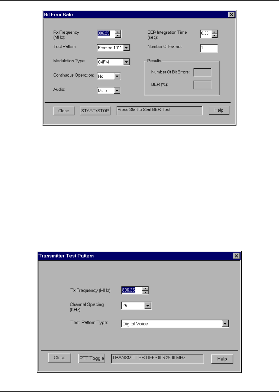
6881076C20-E February 3, 2003
Radio Alignment Procedure: ASTRO Digital Spectra and Digital Spectra Plus Tuner Software 6-23
Figure 6-18. Bit Error Rate Test Screen
6.3.8 Transmitter Test Pattern
This screen is used to transmit specific test patterns at a desired frequency so that the user can
perform tests on the radio’s transmitter and contains the following fields:
• Tx Frequency:
This field selects the Transmit Frequency directly in MHz.
• Channel Spacing:
This field allows the user to select the desired transmit deviation.
• Test Pattern Type:
This field represents the type of test pattern which will be transmitted by the radio when the
PTT TOGGLE button is pressed.
NOTE:Channel Spacing and Test Pattern Type fields will be grayed out while radio is
transmitting.
Figure 6-19. Transmitter Test Pattern Screen

February 3, 2003 6881076C20-E
Notes
6-24 Radio Alignment Procedure: ASTRO Digital Spectra and Digital Spectra Plus Tuner Software
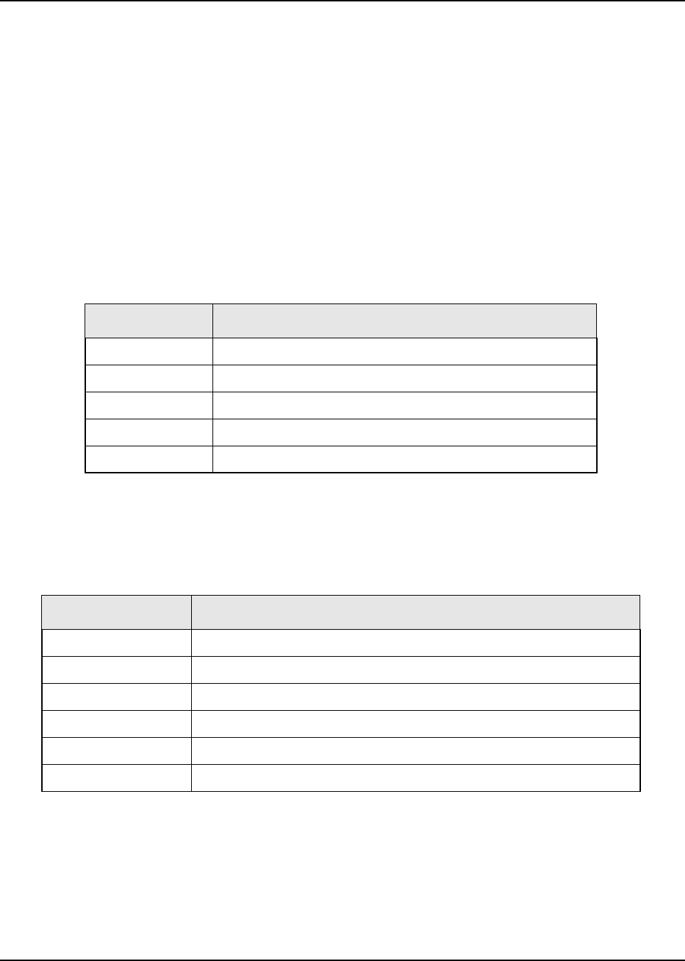
Chapter 7 Encryption
7.1 Universal Crypto Module Kits
This information applies to both conventional and trunked systems.
The following tables contain the Universal Crypto Module (UCM) kits for the ASTRO Digital Spectra
and Digital Spectra Plus radios.
7.1.1 ASTRO Digital Spectra
7.1.2 ASTRO Digital Spectra Plus
7.1.3 Secure Dispatch Operation
On personalities or talkgroups that are programmed to be secure-selectable, press and release the
Secure button to toggle between secure and clear.
• The secure status annunciator lit solid (ON) indicates that the transmitted signal is encrypted
when the PTT button is pressed.
Table 7-1. ASTRO Digital Spectra UCM Listing
Kit Number Description
HLN1441 DES, DES-XL, DES-OFB ENCRYPTION KIT - UCM
NTN1147 DVP-XL ENCRYPTION KIT - UCM
NTN1158 DVI-XL ENCRYPTION KIT - UCM
NTN1369 DES-XL / DVP-XL ENCRYPTION KIT - UCM
NTN1565 DES-OFB / DVP-XL ENCRYPTION KIT - UCM
Table 7-2. ASTRO Digital Spectra Plus UCM Listing
Kit Number Description
NNTN4024A DES, DES-XL, DES-OFB ENCRYPTION KIT - UCM
NNTN4025A DVI-XL ENCRYPTION KIT - UCM
NNTN4026A DVP-XL ENCRYPTION KIT - UCM
NNTN4027A DES, DES-XL, DES-OFB WITH DVP-XL ENCRYPTION KIT - UCM
NNTN4204A AES WITH DES ENCRYPTION KIT - UCM
NNTN4205A AES WITH DES, DES-XL, DES-OFB ENCRYPTION KIT - UCM

February 3, 2003 6881076C20-E
7-2 Encryption: Load an Encryption Key
• The secure status annunciator not lit (OFF) indicates that the transmitted signal is non-
encrypted.
Whether the current personality is strapped for secure or clear, the secure status annunciator
correctly displays the transmit operation as being either secure (encrypted) or clear (non-encrypted).
NOTE: You cannot change from secure to clear while the PTT button is pressed. The radio will
generate an illegal tone and the transmission will be terminated.
Secure-equipped radios automatically determine whether a secure or clear voice message is being
received. This allows you to receive either type of message without having to reset the
programmable secure button.
7.1.4 Secure Emergency Operation
Clear or secure emergency-call operation is determined by the programming of the selected mode
(or talkgroup) or the default emergency mode, if set up. Otherwise, transmit operation is controlled
by the setting of the secure, programmable button. You will not be able to change from secure to
clear, or from clear to secure, operation during an emergency call.
7.2 Load an Encryption Key
7.2.1 Model W3
To load an encryption key into a Model W3 radio:
1. Ensure that an encryption module is installed in the radio.
2. Load an encryption key into the radio’s memory from a key-
variable loader (KVL) using the correct loader for the radio’s
encryption type.
To load the key, attach the keyloader cable to the front of the
radio. (Refer to the KVL instruction manual for loading.)
3. KEYLOADING is
displayed on your
radio while the key
transfer is in progress.
For single-key radios, a short tone sounds when a key is
successfully loaded.
For multikey radios, an alternating tone sounds for a few
seconds after keys are successfully loaded.
NOTE:An invalid encryption key aborts a secure
transmission. KEYFAIL is displayed and a keyfail tone
(consecutive medium-pitched beeps) sounds until
you release the PTT button.
4. If a mode is not programmed for either secure or clear-only
operation, use the secure programmable button to select
secure or clear transmission.
NOTE:You cannot change from secure to clear, or from clear
to secure, while pressing the PTT button.
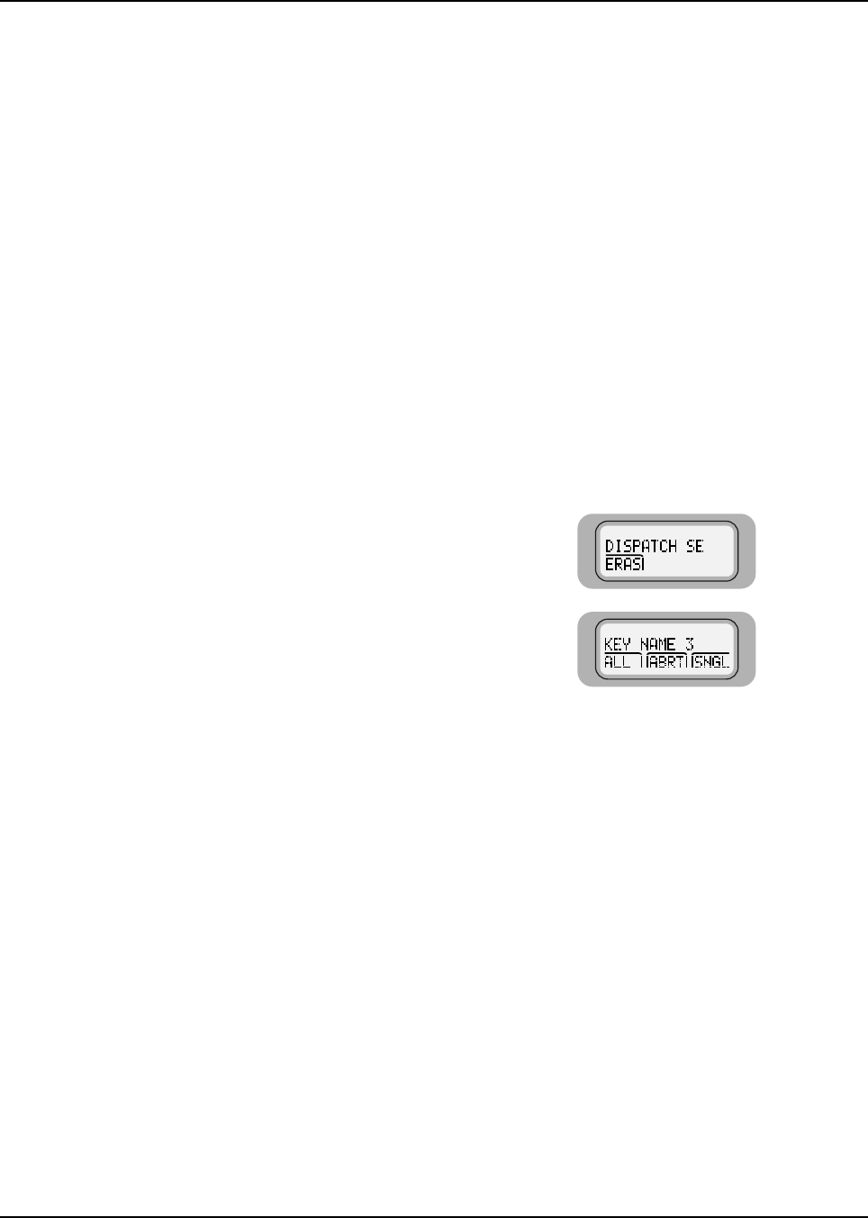
6881076C20-E February 3, 2003
Encryption: Erase a Key 7-3
7.2.2 Models W4, W5, W7, and W9
To load an encryption key into a Model W4, W5, W7, or W9 radio:
7.3 Erase a Key
This feature allows you to select any one, or all, of the encryption keys to erase.
7.3.1 Model W3
1. Turn on the radio and set the volume level.
The position of the D button is not important.
2. Connect the cable from the key-variable loader (KVL) to the
microphone connector on the radio.
3. Load an encryption key into the radio’s memory from a KVL
using the correct loader for the radio’s encryption type.
Refer to your KVL user’s manual for more information on
keyloading.
1. Press to scroll to
ERAS.
2. Press the button
below ERAS.
The last selected and
stored key is displayed.
3. Do one of the following:
NOTE:ERASED alternates with the key name if you go to a key
that has been erased.
Press to scroll forward in the list; press to scroll
backward.
OR
With Direct Entry, press the numeric keys to jump to the desired
encryption key.
4. Go to Section 7.4: “Erase a Single Key (Model W3)” on page 7-5.
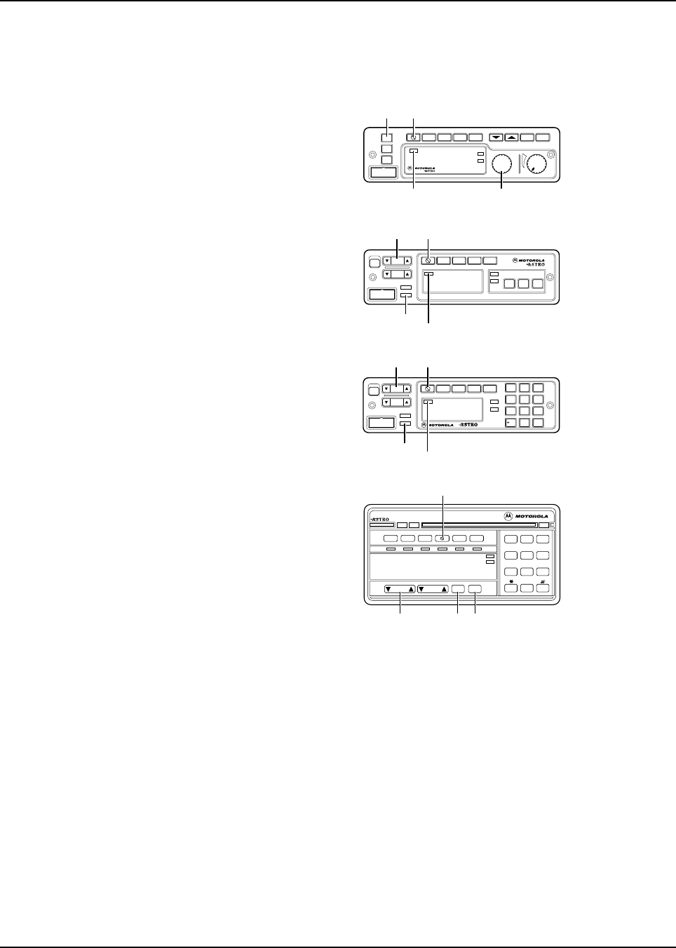
February 3, 2003 6881076C20-E
7-4 Encryption: Erase a Key
7.3.2 Models W4, W5, W7, and W9
The Select Key to Erase feature allows you to manually select any one, or all, of the encryption keys
to erase.
1. To enter the Advanced
Secure menu, press
and hold the button
until a tone sounds.
2. Turn the Mode knob (W4) or press the Mode rocker switch
(W5, W7, W9) to scroll to the ERASE KEY option.
3. Press the Sel button to enter the Key Erase menu.
The display changes to show the last key that was selected and
stored after the Key Erase menu was entered.
4. Turn the Mode knob (W4) or press the Mode rocker switch
(W5, W7, W9) to scroll to the desired key.
5. To delete the selected key, press the Sel Button.
The radio deletes the key, and the display alternates between
the key name and ERASED.
NOTE:When you scroll to an erased key, the display
alternates between the key name and ERASED.
XMIT
BUSY
Mode Volume
Pwr
Phon Call SelScan
Mic
Home
Dim
H/L
Dir Mon
SECURE
INDICATOR MODE
KNOB
HOME SECURE
Model W4
Mode
Vol
Mic
Phon Call Sel
H/L Mon Dir
PWR
Scan
XMIT
BUSY
DIM
HOME
MODE
HOME
SECURE
INDICATOR
SECURE
Model W5
O#Del Rcl
Mode
Vol
Mic
Phon Call Sel
PWR
Scan
XMIT
BUSY
DIM
HOME
1Ste 23Lck
4Sts 5Rpg 6Msg
7
H/L
8
Mon
9
Dir
MODE
HOME
SECURE
INDICATOR
SECURE
Model W7
Model W9
XMIT BUSY
123
456
789
0
DIM
Pri
Non
Pri
Emer Dir Scan Call
Mode Vol Sel
Home
Page
Rpgm
Site
Phon H/L Lock
Rcl Sql Del
MODE SELECT HOME
Sts Msg
Srch
SECURENET
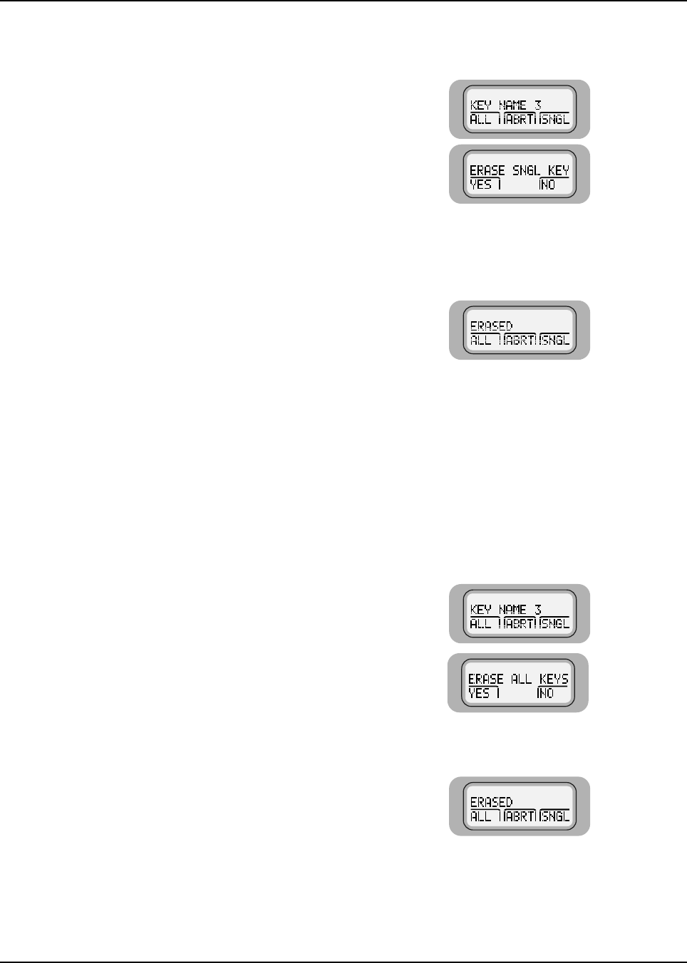
6881076C20-E February 3, 2003
Encryption: Erase a Single Key (Model W3) 7-5
7.4 Erase a Single Key (Model W3)
To erase a single key:
7.5 Erase All Keys
7.5.1 Model W3
To erase all keys at the same time:
1. Press the button
below SNGL to request
erasure of the
selected key.
ERASE SNGL KEY, YES
and NO are displayed.
2. Press the button
below YES.
The internal selected
key is set to zero.
ERASED is alternately
displayed with the key
name confirming the
erasure.
3. To exit the menu without erasing a key, press the m button
below ABRT, or the PTT button, or the mode button, or O.
The home mode is displayed.
1. Press the button
below ALL to request
erasure of all keys.
ERASE ALL KEYS, YES
and NO are displayed.
2. Press the button
below YES. All keys
are erased.
ERASED is alternately
displayed with the key
name confirming the
erasure.
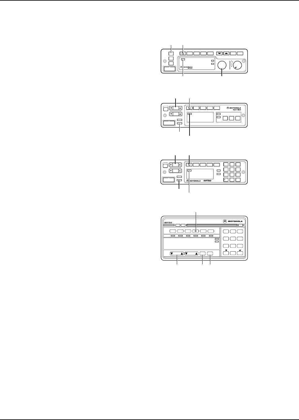
February 3, 2003 6881076C20-E
7-6 Encryption: Over-the-Air Rekeying
7.5.2 Models W4, W5, W7, and W9
7.6 Over-the-Air Rekeying
The over-the-air rekeying (OTAR) feature allows the dispatcher to reprogram the encryption keys in
the radio remotely.
1. To enter the Advanced
Secure menu, press
and hold the button
until a tone sounds.
2. Turn the Mode knob (W4) or press the Mode rocker switch
(W5, W7, W9) to scroll to the ALL option.
3. Press the Sel button to erase all the keys in the radio.
The display shows PLS WAIT (W4, W5, W7) or PLEASE WAIT
(W9) for two seconds, followed by ERASED being shown for
about two seconds, then the display reverts back to ALL.
4. To abort from the key-erase menu, press the HOME button or
the PTT button.
Pressing the PTT button causes the radio to transmit.
XMIT
BUSY
Mode Volume
Pwr
Phon Call SelScan
Mic
Home
Dim
H/L
Dir Mon
SECURE
INDICATOR MODE
KNOB
HOME SECURE
Model W4
Mode
Vol
Mic
Phon Call Sel
H/L Mon Dir
PWR
Scan
XMIT
BUSY
DIM
HOME
MODE
HOME
SECURE
INDICATOR
SECURE
Model W5
O#Del Rcl
Mode
Vol
Mic
Phon Call Sel
PWR
Scan
XMIT
BUSY
DIM
HOME
1Ste 23Lck
4Sts 5Rpg 6Msg
7
H/L
8
Mon
9
Dir
MODE
HOME
SECURE
INDICATOR
SECURE
Model W7
Model W9
XMIT BUSY
123
456
789
0
DIM
Pri
Non
Pri
Emer Dir Scan Call
Mode Vol Sel
Home
Page
Rpgm
Site
Phon H/L Lock
Rcl Sql Del
MODE SELECT HOME
Sts Msg
Srch
SECURENET
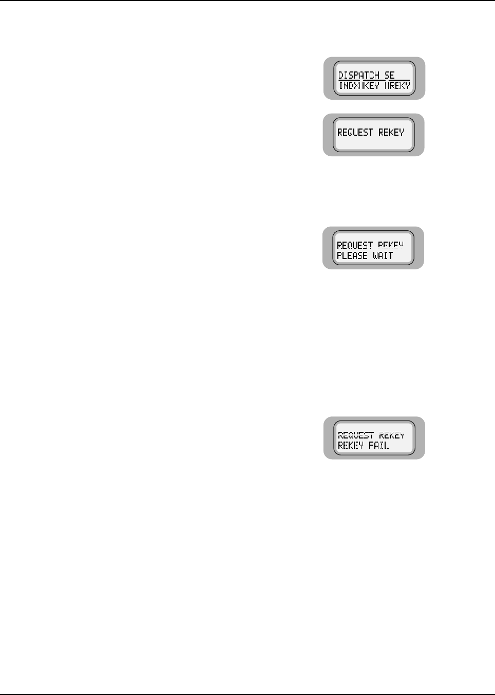
6881076C20-E February 3, 2003
Encryption: Over-the-Air Rekeying 7-7
7.6.1 ASTRO Digital Spectra Model W3
1. Press until REKY
appears.
2. Press below
REKY.
REQUEST REKY is
displayed.
3. Press the PTT button
to send the rekey
request.
PLEASE WAIT is
displayed.
4. One of the following
occurs:
The radio sounds five
tones when the
dispatcher has
received the request.
NOTE:Any subsequent pressing of the PTT button will exit
the feature and allow you to transmit in the normal
manner. Pressing or the emergency button also
exits the feature.
If the display
momentarily shows
REKEY FAIL and a
bad-key tone sounds,
the rekey operation
failed because the
radio does not contain
the Unique Shadow
Key (USK).
You have to load the
USK into the radio
using the KVL before
the radio can be
reprogrammed over
the air.
NOTE:If you exit at this point, but stay on the current channel
in the dispatch mode, the radio momentarily shows
REKEYED or DENIED and sounds a tone indicating the
status of the rekey request.
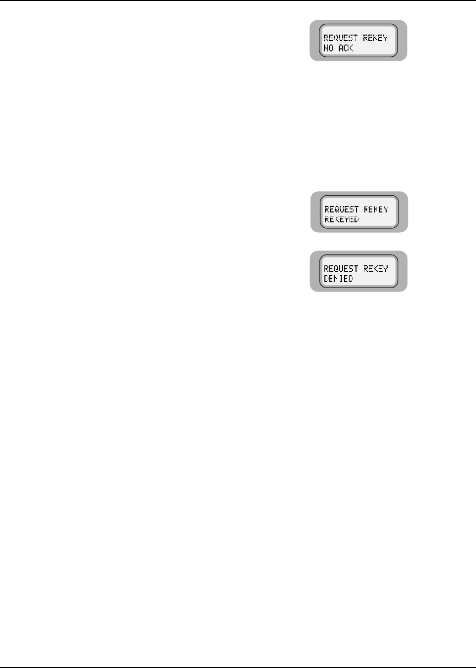
February 3, 2003 6881076C20-E
7-8 Encryption: Over-the-Air Rekeying
If the display shows NO
ACK and a bad-key
tone sounds, then the
dispatcher has not
acknowledged your
request after the radio
has tried five times to
send it.
The radio then returns
to the display
message in step 2,
allowing you to retry
the request.
If the request is
accepted and the
radio is successfully
rekeyed, the display
momentarily shows
REKEYED.
If the display
momentarily shows
DENIED and a bad-key
tone sounds, the
request has been
denied by the
dispatcher, and the
radio returns to the
home display.
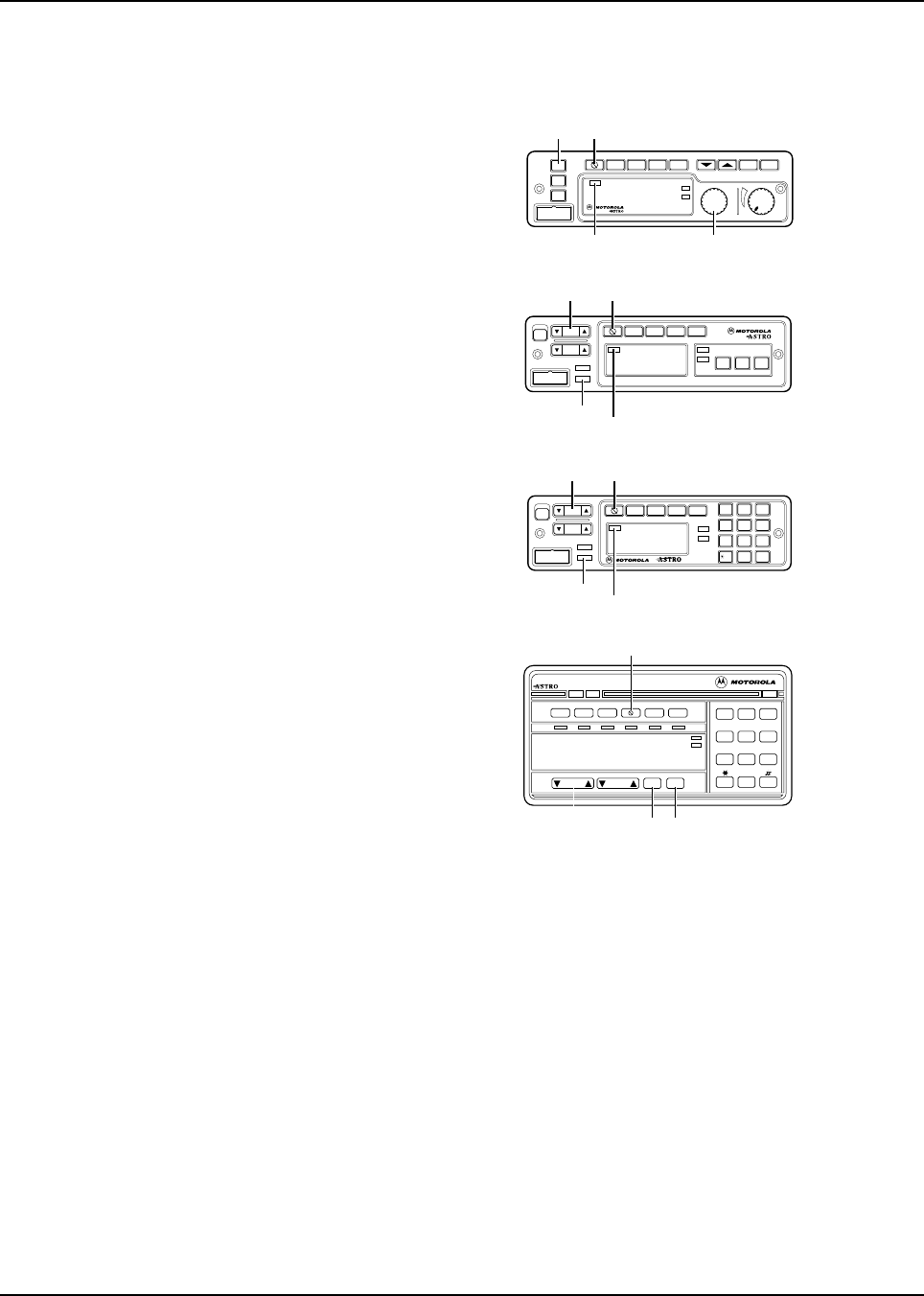
6881076C20-E February 3, 2003
Encryption: Over-the-Air Rekeying 7-9
7.6.2 ASTRO Digital Spectra Models W4, W5, W7, and W9
1. To enter the Advanced
Secure menu, press
and hold the button
until a tone sounds.
2. Do one of the following;
Model W4: Using the Mode knob, scroll to the REKY option.
OR
Models W5, W7, or W9: Using the Mode rocker switch, scroll
to the REKY REQ option.
3. To enter the rekey request menu, press and release the SEL
button.
4. To initiate a rekey request, press and release either the Sel
button or the PTT button.
The radio displays PLS WAIT (W4, W5, W7) or PLEASE WAIT
(W9).
XMIT
BUSY
Mode Volume
Pwr
Phon Call SelScan
Mic
Home
Dim
H/L
Dir Mon
SECURE
INDICATOR MODE
KNOB
HOME SECURE
Model W4
Mode
Vol
Mic
Phon Call Sel
H/L Mon Dir
PWR
Scan
XMIT
BUSY
DIM
HOME
MAEPF A
MODE
HOME
SECURE
INDICATOR
SECURE
Model W5
O#Del Rcl
Mode
Vol
Mic
Phon Call Sel
PWR Scan
XMIT
BUSY
DIM
HOME
1
Ste
23
Lck
4
Sts
5
Rpg
6
Msg
7
H/L
8
Mon
9
Dir
MODE
HOME
SECURE
INDICATOR
SECURE
Model W7
Model W9
XMIT BUSY
123
456
789
0
DIM
Pri
Non
Pri
Emer Dir Scan Call
Mode Vol Sel
Home
Page Rpgm Site
Phon H/L Lock
Rcl Sql Del
MODE SELECT HOME
Sts Msg
Srch
SECURENET
SECURE

February 3, 2003 6881076C20-E
7-10 Encryption: Advanced Secure Operation
7.7 Advanced Secure Operation
NOTE: The Advanced Secure feature is available only on radios that have been equipped by the
factory to support it. The radio must also be equipped with an encryption module.
Advanced Secure incorporates the Multikey feature and a dual-encryption feature into the existing
secure system. Multikey allows a radio to be equipped with multiple encryption keys. A default key is
included and is associated with the current mode. The keys are strapped to a given mode or are
operator-selectable and can be indexed into groups of keys (for example, 16 keys can be indexed
into two groups of eight keys). The keys are loaded using a manual keyloader.
In addition, your radio can support up to eight different encryption algorithms simultaneously.
7.7.1 Multikey Operation
The multikey feature can be used in both conventional and trunked applications.
•Conventional Multikey - The encryption keys can be selectively strapped, one per each chan-
nel, by a qualified radio technician. In addition, you can have operator-selectable keys, opera-
tor-selectable indices, and operator-selectable key erasure. Encryption keys are loaded into the
radio through a KVL.
•Trunked Multikey - If you use your radio for both conventional and trunked applications, the
encryption keys have to be strapped for trunking on a per talkgroup, or announcement group,
basis. In addition, a different encryption key can be strapped to other features such as private
call, dynamic regrouping, failsoft, interconnect, system wide, or emergency talkgroup.
5. One of the following occurs:
If the radio receives an acknowledgment from the dispatcher,
five tones sound.
If the radio does not receive an acknowledgment from the
dispatcher, the display shows NO ACK.
After the radio is rekeyed, it displays REKEYED and returns to
dispatch mode.
If the dispatcher does not allow it to be rekeyed, the radio
displays DENIED and returns to dispatch mode after three
seconds.
6. Press to exit and return to normal operation.
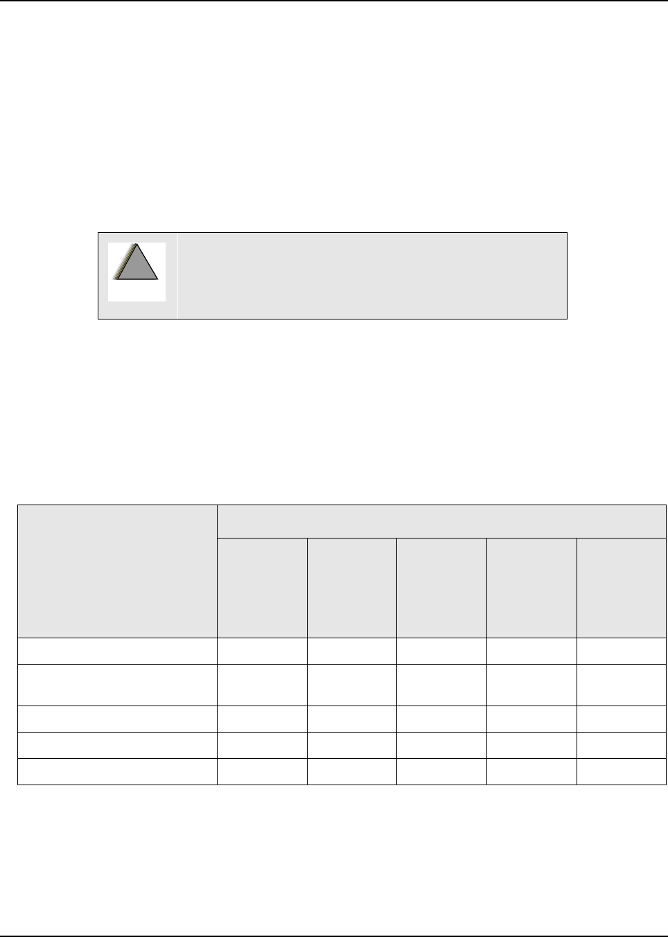
Chapter 8 Disassembly/Reassembly Procedures
8.1 Introduction
This section details the procedures necessary to remove and replace the printed circuit boards in the
ASTRO Digital Spectra and Digital Spectra Plus radios. After troubleshooting and determining which
board needs to be replaced, disconnect the test equipment, the antenna cable, and unhook the dc
power.
Locate the exploded view drawing of the radio in Chapter 11: Exploded Views and Parts Lists. Keep
it handy for reference when disassembling and reassembling the radio.
When installing a new circuit board, all mounting screws should be started before any are torqued.
This helps assure proper board alignment with the chassis.
After installing a new board, refer to Table 8-1 and perform the alignment procedures indicated for
the replaced board.
8.2 Replacement Procedures
NOTE: After performing alignment procedures, always exit the SERVICE menu entirely (to the MAIN
MENU) to save all changes properly. Failure to do so can result in a alignment (or other)
failure.
Disconnect all dc power to the radio before removing any
boards from the radio. Failure to remove power can result
in unit damage caused by transients or accidental shorts,
as well as a shock hazard.
Table 8-1. Required Alignments After Board Replacement
Board Replaced Alignment Required
Reference
Oscillator
Transmit
Deviation
Balance
(compen-
sation)
Transmit
Deviation
Limit
Transmit
Power
Transmit
Current
Limit
Command Board X
VCO (Voltage Controlled
Oscillator) XX
RF (Radio Frequency) Board X X X
PA (Power Amplifier) Board X X
VOCON Board XXXXX
!
W
A R N I N
G
!

February 3, 2003 6881076C20-E
8-2 Disassembly/Reassembly Procedures: Replacement Procedures
8.2.1 Required Tools and Supplies
8.2.2 Control Head Boards
8.2.2.1 Model W3
NOTE: Numbers shown in brackets in the following procedure refer to item numbers in Figure 11.1:
“Model W3 Hand-Held Control Head Exploded View,” on page 11-2, and in Table 11.1, “Model
W3 Hand-Held Control Head Exploded View,” on page 11-2.
1. Remove the strain-relief boot (part of cable assembly [15]) from the housing assembly [7] by
applying downward pressure on the boot and pulling it away from the control head until they
are completely separated.
2. Carefully remove the rubber seal (part of cable assembly [15]) from the housing assembly [7]
opening.
NOTE:Take care to avoid damaging this seal.
3. Using a small screwdriver, remove the seal support wedge [14] from the control head.
4. Using a small screwdriver to depress the telco lever, remove the telco connector (part of
cable assembly [15]) from the control head, and pull the cable assembly away from the
housing (like a telephone jack).
5. Remove the rear cover assembly [2] from the control head.
6. Locate the recesses in the lower portion of the housing on both sides of the rear cover’s snap
features and, prying the snaps until the two parts separate, remove the rear cover from the
unit.
7. Remove the two snap retainers [4] from between the circuit board [5] and the housing
assembly [7].
8. Disconnect the microphone assembly [8] connector from the circuit board [5].
9. Carefully remove the microphone cable assembly from the keypad [6].
10. Carefully pry the housing’s snap features from the circuit board [5].
NOTE:Be careful to avoid damaging circuit board components.
There are seven snaps locking the circuit board to the housing. As the snap features are deflected,
push the circuit board upward, using the keypad, to release the circuit board from the snap features.
Table 8-2. Required Tools and Supplies
Tools and Supplies
Small, flat-blade screwdriver
2.5 mm hex-key driver
Torx® T8, T10, and T15 drivers
3.0 mm Allen wrench
Thermal compound (Motorola part number 11-83166A01, or equivalent)
Electromagnetic Interference (EMI) metallic shielding tape (Motorola part
number 11-85984D01, or equivalent)
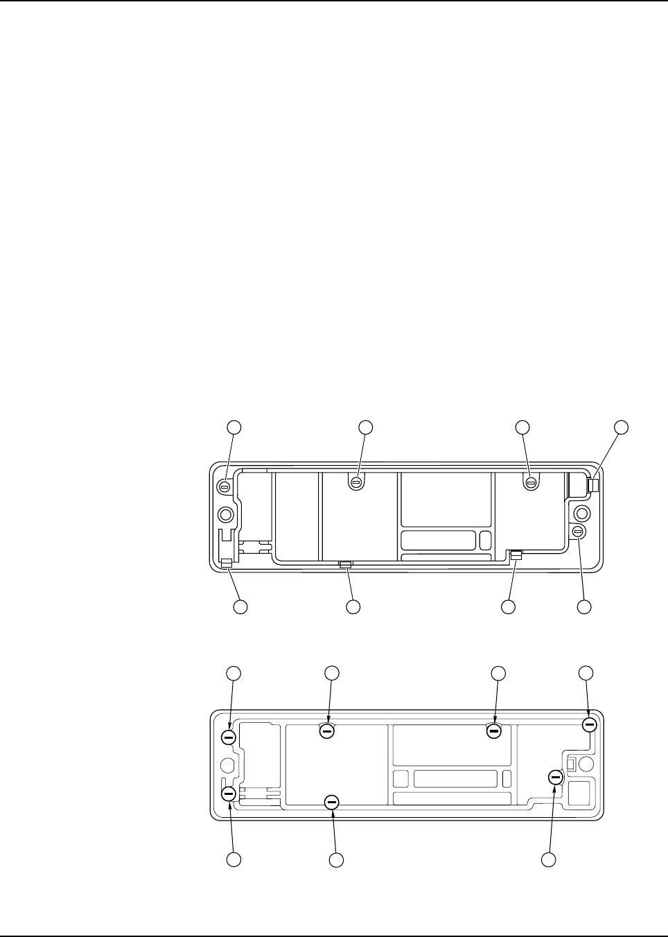
6881076C20-E February 3, 2003
Disassembly/Reassembly Procedures: Replacement Procedures 8-3
11. Remove the circuit board assembly from the housing.
12. Remove the keypad [6] from the housing assembly [7].
8.2.2.2 Models W4, W5, and W7
NOTE: For the following procedure, refer to Chapter 11: Exploded Views and Parts Lists, beginning
on page 11-3, for the exploded view and associated parts list applicable to the model being
disassembled.
1. Unplug the microphone.
2. Remove the two front panel screws using a 2.5mm hex-key driver.
3. Disconnect the control cable on remote models.
4. Grasp the front panel firmly, and carefully unplug the control head assembly from the radio or
remote control head back housing.
5. Lay the control head face down on a clean, flat surface, being careful not to scratch or mar
the display.
6. Using a Torx T10 driver, remove the control head screws:
- Model W4: four screws [callouts 5-8], as shown in Figure 8-1.
The Model W4 has, in addition to the screws, four snap features [callouts 1-4], which are shown in
Figure 8-1.
- Model W5 and Model W7: seven screws, as shown in Figure 8-2.
Figure 8-1. Model W4 Rotary Control Head Assembly Screw and Snap Sequence
Figure 8-2. Models W5 and W7 Pushbutton Control Head Assembly Screw Sequence
7 1
58
3
42 6
416
2
5
3
7
February 3, 2003 6881076C20-E
8-4 Disassembly/Reassembly Procedures: Replacement Procedures
7. Carefully separate the printed circuit board, internal spacer, and elastomer keypad assembly
from the front panel.
On rotary control head models, care must be taken not to damage the flex circuit when
separating the printed circuit board from the front housing. Do not disturb the buttons in the
front panel.
On rotary control head models, the flex circuit must also be unplugged.
8. On rotary control head models, desolder the XMIT and BUSY LED before removing the
elastomer keypad.
9. Remove the elastomer keypad from the printed circuit board.
NOTE:Before you unsnap the PC board, notice that the board slips under a hook on the
right and snaps on the left. This will facilitate assembly.
10. Remove the PC board from the internal spacer. The PC board snaps into and out of the
spacer.
11. To reassemble, snap the PC board into the internal spacer. Before you press the elastomer
keypad into the board, make sure that the conductive pads in the board and the elastomer
keypad are clean and free of any foreign material.
12. On rotary control head models, solder the XMIT and Busy LEDs onto the PC board.
NOTE:On rotary control head models, the flex circuit must be connected to the PC board
prior to attaching the PC board to the spacer.
13. Install the PC board internal spacer and elastomer keypad assembly into the front panel.
Replace the screws and torque them to 6-8 in.-lbs.
14. For dash-mounted radios, plug the interconnect board into the radio, then plug in the control
head assembly and fasten it with the two front panel screws (torqued to 4-6 in.-lbs).
OR
For remote-mount control heads, replace the front panel into the remote control head back
housing, make sure the gasket is in place, then torque the screws to 4-6 in.-lbs. Replace any
plugs and cables on the rear of the control head.
8.2.2.3 Model W9
NOTE: Before disassembling the W9 control head, note the location of the labeled bottom.
NOTE: Refer to Figure 11-4: “Model W9 Pushbutton Control Head Exploded View,” on page 11-5 and
Table 11-4, “Model W9 Pushbutton Control Head Parts List,” on page 11-5 for the callout
numbers in this section.
1. Using a Torx T15 driver, remove the two 30mm machine screws [29] from the back housing
[31] of the control head.
2. Fold the front housing [41] over so that the front housing is face down and the back housing is
on your working surface with the flex cable [18] attached.
Take care to avoid misalignment of connector pins. On dash mount
radios, remove the radio top cover to allow visual inspection during
connector alignment.
!
C
a u t i o
n

6881076C20-E February 3, 2003
Disassembly/Reassembly Procedures: Replacement Procedures 8-5
3. Using a Torx T10 driver, remove the five 8mm tapping screws [17] from the Display Board Kit
[37], the two 10mm captive screws [12] with the leaf assembly spring [11], and the two 16mm
tapping screws [38] from the control PC board.
4. Remove the Command Board Kit [36] from the back housing and the Display Board Kit [37]
from the front housing.
5. Remove the elastomer keypad [7], ON/OFF switch gasket [34], the “D” Connector Gasket
[33], the solder side shield [16], and the component side shield [19] from the PC boards.
NOTE:Be careful to not bend the tabs on the shields when removing them and align them
carefully when replacing the shields. When working with chips and SOT (small
outline transistor) parts, use extreme caution when heating. Never reuse a chip or
SOT part; always replace with the correct Motorola part.
6. Install the new PC board with the elastomer keypad, the ON/OFF switch gasket, the “D”
Connector Gasket, the “D” Connector O-ring, the solder-side shield, and the component-side
shield in the appropriate locations.
7. Reassemble the Command Board Kit [36] into the back housing [31], making sure that the
power switch is in the proper location and replace the two tapping screws [38], torquing them
to 6-8 in.-lbs.
8. Reassemble the Display Board Kit [37] into the front housing [41], making sure that the
elastomer keypad [7] is in the proper location.
9. Replace the captive screws [12] and the leaf assembly spring [11] in the front housing, and
torque them to 6-8 in.-lbs.
NOTE:Before assembling the leaf assembly spring, check that the insulator [10] on the
board is present. Ensure that the leaf assembly spring and captive screws are
aligned properly to prevent stripping the front housing screw bosses.
10. Close the assembly by replacing the front housing [41] and the two screws in the back
housing [31]. Torque the screws to 6-8 in.-lbs.
8.2.3 Remote Back Housing Interface Board
8.2.3.1 Models W4, W5, and W7
1. Unplug the microphone.
2. Disconnect the control cable from the control head on remote models.
3. Remove the two front panel screws using a 2.5mm hex-key driver.
4. Grasp the front panel firmly, and carefully unplug the control head assembly from the radio or
remote control head back housing.
5. Remove the two remote back housing interface attachment screws.
6. Remove the remote control head interface board from the remote control head back housing.
7. Attach the new interface PC board to the back housing with two screws torqued to 6-8 in.-lbs.
8. Reassemble the back housing to the front housing with two screws torqued to 4-6 in.-lbs.
Take care to avoid misalignment of connector pins.
!
C
a u t i o
n
February 3, 2003 6881076C20-E
8-6 Disassembly/Reassembly Procedures: Replacement Procedures
8.2.4 Remote Interconnect Board
8.2.4.1 Low-/Mid-Power Radios
1. Remove the two front panel screws using a 2.5mm hex key driver.
2. Grasp the front panel firmly, and carefully unplug it from the radio.
3. Remove the three screws that hold the remote interconnect board to the front panel using a
Torx T10 driver.
4. Install the new remote interconnect board onto the front panel, and replace the screws.
Torque the screws to 6-8 in.-lbs.
5. Reassemble the front panel into the radio and replace the screws.
6. Torque the screws to 4-6 in.-lbs.
8.2.4.2 High-Power Radios
1. Use a Torx T15 driver to remove the two screws in the radio top cover. Remove the radio top
cover.
2. Remove the ribbon cable [38-conductor] from between the command board and the
interconnect board by first disconnecting the cable at the command board side and then at
the interconnect board.
3. Disengage the retaining wire on the back of the interconnect board at the chassis side.
4. Use the radio key to unlatch the radio handle and use a Torx T15 driver to remove the two
interconnect board screws that are inside the handle.
5. Turn the radio upside down and use a Torx T15 driver to remove the four bottom-cover
screws. Remove the bottom cover.
6. Remove the RF board shield and unplug the coaxial cable that comes up from the other side
of the radio. Move the end of the coaxial cable out from behind the interconnect board.
7. Pull the retaining wire up into position so that the interconnect board can be slid back away
from the front of the radio, and then up and out from the radio chassis.
8. Remove the rubber gasket from the front of the interconnect board by pulling it up and over
the D-connectors.
9. Gently pry each of the arms on the interconnect board spacer so that the snap feature on the
arms can be slid past the interconnect board.
10. Place the interconnect board spacer onto the new interconnect board, by making sure that
each arm is aligned in the proper slot and snaps securely into place.
11. Replace the rubber gasket, retaining wire, coaxial cable, bottom cover (torque four screws to
6-8 in.-lbs), and interconnect board screws (torque two screws to 10-12 in.-lbs).
12. Turn the radio top side up and re-insert the ribbon cable [38-conductor] by first connecting the
command board side, and then the interconnect board side. This cable is connected to two
38-pin connectors. The cable is keyed so that the cable fits only in the correct position.
Take care to avoid misalignment of connector pins. Remove the
radio top cover to allow visual inspection during connector alignment.
!
C
a u t i o
n

6881076C20-E February 3, 2003
Disassembly/Reassembly Procedures: Replacement Procedures 8-7
13. Fold the ribbon cable down flat. Replace the top cover and torque the two screws to 6-8 in.-
lbs. These screws are self-tapping and caution should be used so that the screws enter the
previously cut threads.
8.2.5 Power Amplifier Board
8.2.5.1 Low-/Mid-Power Radios
1. Use a Torx T15 driver to remove the four screws from the PA cover, and then remove the
cover and the PA shield.
2. Use a metric 3.0mm Allen wrench to remove the two Allen-head screws from the heatsink.
3. Carefully separate the PA assembly from the transceiver chassis.
NOTE:Before disconnecting, note which RF cable goes to the VCO (TX injection) and
which goes to the RX front end. This will facilitate assembly.
4. Disconnect the large ribbon-cable connector from the command board, the small connector
from the PA board, and two RF cables from their respective boards in the transceiver chassis.
5. Install the feed-through plat and grounding clip, making sure the RF cable is installed into the
clip.
6. Install the receiver cable clip, making sure the cable is routed under the clip, and then fold the
cables.
7. Connect the large ribbon-cable connector to the command board connector.
8. Connect the small connector to the PA.
9. Connect the RF cables to their respective boards in the transceiver chassis.
10. Be careful not to pinch the RF or ribbon cables, and position the PA assembly on the chassis.
11. Install the two Allen-head screws through the heatsink. Before tightening the mounting
screws, check that the command board connector and RF connectors are in place. Torque
the mounting screws to 14 in.-lbs.
12. Press the PA compartment shield and install the PA cover. Torque the screws to 10-12 in.-lbs.
13. Perform the radio alignment procedures and performance check procedures recommended
in Table 8-1 on page 8-1.
8.2.5.2 High-Power Radios
1. Use a Torx T15 driver to remove the top cover by removing the two screws.
2. Disconnect the 12-conductor ribbon cable from the bottom of the power amplifier board.
3. Disconnect the red (A+) power cable from the bottom of the PA board.
4. Turn the radio upside down. Use a Torx T15 driver to remove the four bottom-cover screws.
Remove the bottom cover.
5. Remove the PA shield.
6. Remove the harmonic filter cover.
7. Desolder the mini UHF cable connector from the PA board and the coax clip.
8. Disconnect the two coaxial cables from the board-mounted receptacles and the coax clip,
noting where each cable goes for reassembly.
9. Use a Torx T15 driver to remove the two screws that anchor the PA board to the chassis.
10. Use a Torx T8 driver to remove the nine screws that anchor the components to the chassis.
11. Remove the PA board by carefully lifting the board out of the chassis while guiding it past the
coaxial cables.

February 3, 2003 6881076C20-E
8-8 Disassembly/Reassembly Procedures: Replacement Procedures
NOTE:Before disconnecting, note which RF cable goes to the VCO (TX injection) and
which goes to the RX front end. This will facilitate assembly.
12. Apply a thin white coat of thermal compound (for example, Motorola part no. 11-83166A01) in
the power transistor mounting locations of the chassis where the thermal compound was
removed.
13. Locate the new PA board into the chassis cavity by feeding the short coaxial cable through
the hole in the board and starting all the screws. After the ten PA screws are started, torque
them to 8-10 in.-lbs.
14. Install the new strip outline emitters onto the new PA board by replacing the eight screws, and
torque to 6-8 in.-lbs.
15. Solder the collector leads to the board.
16. Plug the coaxial cables into the mating receptacles on the board.
17. Solder the braided coaxial cable to the power amplifier board at the tip and at the braid.
18. Snap the harmonic-filter shield into place, and replace the power-amplifier shield over the
power amplifier cavity. Make sure that the PA cover is firmly seated into the chassis cavity.
19. Replace the bottom cover, and torque the four bottom-cover screws to 6-8 in.-lbs.
20. Turn the radio top side up, and reconnect the 12-conductor ribbon cable to the bottom of the
PA board.
21. Reconnect the red (A+) power lead to the bottom of the PA board.
22. Replace the radio top cover and torque the two screws to 6-8 in.-lbs.
8.2.5.3 800 MHz Radios
8.2.5.3.1 Back-End Removal
1. 20- and 35-watt radios only: Use a Torx T15 driver to remove four screws from the PA cover,
and then remove the cover and lift the PA shield and the harmonic filter shield cover.
2. Use a metric 3.0-mm Allen wrench to remove the two Allen-head screws from the heatsink.
3. Carefully separate the PA assembly from the chassis.
NOTE:Before disconnecting, note which RF cable goes to the VCO and which goes to the
RX front-end. This will facilitate assembly.
4. Disconnect the large ribbon cable connector from the command board, the small connectors
from the PA board, and the two RF cables from their respective boards in the chassis.
8.2.5.3.2 PC Board Removal
NOTE: Before unfolding the RF cables, note how each is routed. This will facilitate assembly.
1. 15-watt radios: Insert a small, flat-blade screwdriver into the clip slot to deflect the snap
holding one side of the clip to the shield and remove the two plastic clips that hold the RF
cables to the shield. Unfold the RF cables and remove the PA compartment shield.
20- and 35-watt radios: Use a Torx T15 driver to remove two screws, and pull feed-through
plate from the side of the PA assembly. Remove RF cable clip. Unfold the RF cables and
push them through the slots in the PA compartment.
2. Unsolder the three leads for pass device Q9500.
3. Use a Torx T8 driver to remove two screws from the power shield.
4. 35-watt radios only: Remove two screws from the final device.
5. Disconnect the red power lead.
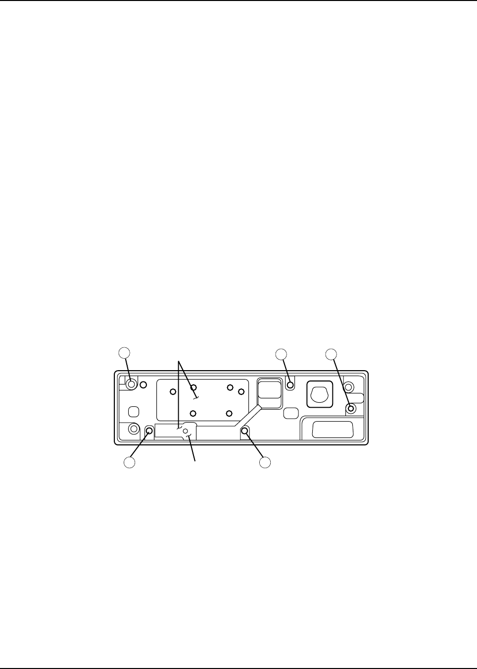
6881076C20-E February 3, 2003
Disassembly/Reassembly Procedures: Replacement Procedures 8-9
6. Use a Torx T15 driver to remove the larger screws. (Five screws are used on 15-watt, six on
the 20- and 35-watt.)
7. Carefully lift the PC board from the heatsink.
NOTE:Before unsoldering the RF cables, note which cable is attached to each connector
on the board. This will facilitate assembly since the cables differ in length.
8. Unsolder the antenna coax cable attached to the bottom of the board.
9. Unsolder and remove the power module shield.
10. Unsolder the RF cables from the board.
8.2.5.3.3 PC Board Installation
1. Solder the RF cables to the board connectors.
2. Clean any old thermal compound from the mounting surfaces of the power transistor, power
module, and (on 20- and 35-watt models) the final device.
If the power transistor insulator was not disturbed, it is not necessary to clean beneath it.
3. Apply a new, uniform coat of thermal compound (e.g., Motorola part no. 11-83166A01), which
is thick enough to fill all small air voids, to the mounting surfaces.
NOTE:Do not use a thick coating of compound and do not allow any small bits of dirt or
debris to get in the compound; such would degrade the thermal efficiency of the
heatsink.
4. Solder the three leads of the Q9500 pass device.
5. Install the PC board, and then attach and tighten the screws (torque 8-10 in.-lbs.) in the
sequence shown in Figure 8-3.
Figure 8-3. PA Board Screw Fastening Sequence (800 MHz 15-Watt PA)
6. 20- and 35-watt radios only: Install the final device with two screws (torque 8-10 in.-lbs.). The
properly oriented final device is shown in Figure 8-4.
12
34
5
APPLY TERMINAL
COMPOUND HERE
PASS DEVICE
INSULATOR HERE
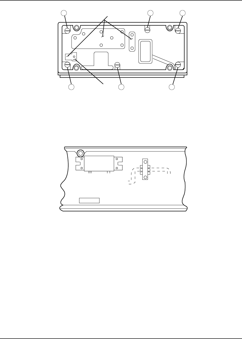
February 3, 2003 6881076C20-E
8-10 Disassembly/Reassembly Procedures: Replacement Procedures
Figure 8-4. PA Board Screw Fastening Sequence (800 MHz 20- and 35-Watt PA)
7. Place the power module shield over the power module.
8. Install the power module and shield with two compression washers and screws (torque 6-8
in.-lbs.).
9. 20- and 35-watt radios only (Figure 8-5): Solder the final device leads and five caps. Caps
must be soldered flat to the board, and each cap surrounding the final device must be
soldered as close to the device as possible.
Figure 8-5. Installing the Final Device
10. Solder the power module leads, module shield, and transistor leads.
11. Install the red power lead.
8.2.5.3.4 Back-End Installation
1. 15-watt radios: Carefully position the RF cables through the slots in the PA shield and install
the shield. Fold the RF cables under metal clips and install the two plastic clips.
20- and 35-watt radios: Push the RF cables through the slots in the PA compartment. Install
the feed-through plate making sure the RF cable is routed under the plate. Install RF cable
clip making sure the cable is routed under clip; fold the cables.
2. Connect the large ribbon cable connector to the command board connector.
3. Connect the small connector to the PA.
4. Connect the RF cables to their respective boards in the chassis.
5. Be careful not to pinch the RF or ribbon cables, and position the PA assembly on the chassis.
6. Install the two Allen-head screws through the heatsink. Before tightening the mounting
screws, check that the command board connector and RF connectors are in place.
624
135
APPLY TERMINAL
COMPOUND HERE
PASS DEVICE
INSULATION HERE
POWER MODULE
U9850
D.C. CONN.
Q9850
FINAL COLLECTOR
LEAD NOTCH
6881076C20-E February 3, 2003
Disassembly/Reassembly Procedures: Replacement Procedures 8-11
7. Tighten the mounting screws (torque 8-10 in.-lbs.).
8. 20- and 35-watt radios only: Press the PA compartment shield, and install the PA cover.
8.2.6 VOCON (Vocoder/Controller) Board
NOTE: If you want to keep the information currently stored in the radio code plug, save its contents
with the appropriate application software before you remove the original VOCON board. Refer
to the Radio Service Software (RSS) user’s manual, or the Customer Programming Software
online help.
1. Use a Torx T15 driver to remove the top cover by removing the four screws.
2. Remove the VOCON board shield.
3. Remove the board from the command board after reading the NOTES and CAUTIONS in this
section.
4. Place the new board into the radio by aligning the pins and pressing the board firmly into
place, and then replace the board shield.
5. Replace the radio top cover, and use four new screws (torque to 10-12 in.-lbs.) to secure the
top cover. Ensure the screws are aligned with the holes.
NOTE:Replacement VOCON boards are preprogrammed to enable the radio to function
only at test mode level. To restore the radio to complete operation, you must
program the VOCON board via the radio service software or the Customer
Programming Software.
6. Program the VOCON board as indicated in Table 8-1 on page 8-1. Programming procedures
are found in Chapter 6: Radio Alignment Procedure of this manual.
8.2.7 Command Board
8.2.7.1 Low-/Mid-Power Radios
1. Remove the radio top cover.
2. Remove the PA assembly.
3. Remove the VOCON board according to previous instructions. See CAUTION notes in
VOCON board replacement section.
4. Disconnect the PA connector and the control head connector.
5. Remove the heatsink clip from the power transistor on the command board.
6. Use a Torx T15 driver to remove six mounting screws.
To remove the VOCON board, gently pry the board up at the center
of the connector end of the board. This will help prevent damage or
bending of the connector pins.
Once installed, a replacement VOCON board may not be initialized
a second time. Use the radio test modes to ensure that replacing the
VOCON board will solve the problem before you initialize it.
!
C
a u t i o
n
!
C
a u t i o
n

February 3, 2003 6881076C20-E
8-12 Disassembly/Reassembly Procedures: Replacement Procedures
7. Carefully lift the command board from the housing, making sure that the floating header is
with the RF board.
8. To reassemble the command board, apply a thin coat of thermal compound (for example,
Motorola part no. 11-83166A01) to the audio amplifier mounting surface.
NOTE:Do not use a thick coating of compound as it could degrade the thermal efficiency
of the heatsink.
Prior to installing the command board, make sure the male-to-male command board
header is fully seated in the RF board.
9. Install the new command board, and clip the power devices to the chassis, being sure that the
insulator is in place behind the devices.
10. Install new mounting screws (torque 8-10 in.-lbs.), starting with the screw holding down the
audio amplifier. Ensure the screws are aligned with the holes.
11. Connect the VOCON board and option board.
12. Install the VOCON board shield.
13. Reconnect the two connectors.
14. Install the PA assembly, control head, and radio covers.
8.2.7.2 High-Power Radios
1. Use a Torx T15 driver to remove the two screws. Remove the top cover.
2. Disconnect and remove the 12-connector ribbon cable from the command board and the PA
board.
3. Disconnect the 38-conductor ribbon cable from the command board.
4. Remove the heatsink clip from the three transistors in the corner of the board.
5. Remove the VOCON board shield.
6. Remove the VOCON board from the command board after reading the NOTES and
CAUTIONS in the VOCON board section.
7. Use a Torx T15 driver to remove the six screws retaining the command board.
8. Gently work the command board out of the chassis cavity and then remove the foam piece
from the crystal near the PA ribbon connector.
9. To reassemble the command board, apply a thin coat of thermal compound (for example,
Motorola Part No. 11-83166A01) to the audio amplifier mounting surface.
NOTE:Do not use a thick coating of compound as it could degrade the thermal efficiency
of the heatsink. Prior to installing the command board, make sure the male-to-male
command board header is fully seated in the RF board.
10. Install the new command board into the chassis cavity.
11. Replace the foam piece.
12. Using six new screws, start all the screws, and then torque them to 8-10 in.-lbs. Ensure the
screws are aligned with the holes.
13. Replace the heatsink.
14. Connect the 12-connector ribbon cable from the command board to the PA board.
15. Connect the 38-conductor ribbon cable to the command board.
16. Reassemble the VOCON board.

6881076C20-E February 3, 2003
Disassembly/Reassembly Procedures: Replacement Procedures 8-13
17. Replace the section VOCON board shield and the top cover, and then torque the screws to 6-
8 in.-lbs.
8.2.8 Receiver Front-End Board
8.2.8.1 Low-/Mid-Power Radio
1. Remove the radio top cover.
2. Remove the two mounting screws and unplug the control head.
3. Remove the EMI metallic shielding tape (Motorola Part No.11-85984D01).
Be careful to prevent any tape particles from falling inside the chassis.
4. Disconnect the coaxial cable that passes through the front of the chassis from the RF board.
5. Remove the PA assembly.
6. Disconnect the coaxial cable that passes through the rear of the chassis to the receiver front
end.
7. Remove the four screws and front-end cover, and carefully lift the receiver front-end board
from the chassis.
NOTE:Be careful to insert the Rx injection coaxial cable straight into the receptacle on the
VCO board, and be sure it is fully inserted. Be careful not to bend the tip of the
coaxial cable, which provides the contact for the connection.
8. Install the new assembly, being careful not to damage the RF connection that passes through
the chassis to the VCO.
9. Reconnect both coaxial cables.
10. Clean the chassis surface with isopropyl alcohol, and place a new piece of EMI metallic
shielding tape (Motorola Part No. 11-85984D01) over the coaxial cable passing through the
front of the chassis.
NOTE:The EMI metallic shielding tape must cover the hole in the receiver front-end board.
This same piece of tape must also cover at least half of the coaxial cable.
11. Install the front end cover and four mounting screws.
12. Install the PA assembly, control head, and radio cover.
NOTE:No alignment is necessary.
8.2.8.2 High-Power Radio
1. Turn the radio top side down and use a Torx T15 driver to remove the four bottom-cover
screws.
2. Remove the bottom cover.
3. Remove the power amplifier and RF board shields.
4. Disconnect the RX coaxial cable that comes through the power amplifier board.
5. Disconnect the coaxial cable from the RF board.
6. Feed both cables back to the top side of the radio.
7. Using a Torx T15 driver, remove the two top cover screws, and then remove the radio top
cover.
8. Using a Torx T15 driver remove the four screws to the receiver front-end shield, and then
remove the shield.

February 3, 2003 6881076C20-E
8-14 Disassembly/Reassembly Procedures: Replacement Procedures
9. Carefully remove the front-end receiver board from the radio chassis cavity and disconnect
the coaxial cable beneath it.
NOTE:Be careful to insert the Rx injection coaxial cable straight into the receptacle on the
VCO board, and be sure it is fully inserted.
Also, be careful to not bend the tip of the coaxial cable, which provides the contact
for the connection. Make sure all connections are tight, and that all shields are
pressed firmly into their proper cavities.
10. Install the new front-end receiver board into the radio chassis cavity.
11. Reconnect the coaxial cable beneath the front-end board.
12. Feed the coaxial cables through the chassis into the opposite side.
13. Using four new screws and a Torx T15 driver, install the receiver front-end shield, and then
torque the screws to 8-10 in.-lbs. Ensure the screws are aligned with the holes.
14. Replace the radio top cover, and torque the two top-cover screws to 6-8 in.-lbs.
15. Turn the radio topside down and reconnect the coaxial cable into the power amplifier board
and RF board receptacles.
16. Replace the power amplifier shield, RF board shield, and bottom cover.
17. Torque the four bottom-cover screws to 6-8 in.-lbs.
NOTE:No alignment is necessary.
8.2.9 VCO Board
8.2.9.1 Low-/Mid-Power Radio
1. Remove the radio bottom cover.
2. Remove the PA assembly and disconnect the TX injection coax that passes through the
chassis to the VCO board.
3. Remove the RF board cover.
4. Remove the six mounting screws and the cover.
5. Carefully lift the board far enough to expose the Rx injection coaxial cable underneath, which
runs from a receptacle on the VCO through a hole in the chassis to the receiver front end
assembly.
6. Unplug the coaxial cable from the receptacle on the VCO board, and then lift straight up on
the VCO board to remove it from the chassis.
7. To install the new board, plug in the Rx injection coaxial cable (from the receiver front end)
into the receptacle near the outer edge of the board.
8. Align the opposite edge connector with the RF board connector and snap it into place.
NOTE:Be sure the board and gasket are straight and that the board does not bind as the
screws are tightened, pulling the board down to the cavity ledge. Tighten the screws
evenly to avoid warping the board. It is very important to use proper screw torque
to ensure proper operation in vibration environments. Use only new screws.
9. Connect the PA board’s RF cable to the VCO board connector (through the chassis).
10. Using six new mounting screws, install the VCO cover, and then torque the screws to 8-10
in.-lbs. Ensure the screws are aligned with the holes.
11. Install the PA assembly and the radio cover.

6881076C20-E February 3, 2003
Disassembly/Reassembly Procedures: Replacement Procedures 8-15
8.2.9.2 High-Power Radio
1. Turn the radio topside down and remove the four bottom-cover screws, and remove the
bottom cover.
2. Remove the power amplifier and RF board shields.
3. Remove the six VCO board shield screws and remove the VCO board shield.
4. Gently pry up on the VCO board, where it extends over the RF board, until the VCO board is
disconnected from the RF board.
5. Disconnect the two coaxial cables that plug into the VCO board and remove the board.
6. Remove the metal VCO gasket from around the VCO board.
7. Place the VCO metal gasket around the new VCO board.
NOTE:Be sure the board and gasket are straight and that the board does not bind as the
screws are tightened, pulling the board down to the cavity ledge. Tighten the screws
evenly to avoid warping the board. It is very important to use proper screw torque
to ensure proper operation in vibration environments. Use only new screws.
8. Reconnect both of the coaxial cables to the VCO board.
9. Place the board into the chassis cavity by aligning the pins on the VCO board with the mating
part on the RF board, and pressing the board firmly into place.
10. Replace the VCO board shield using six new mounting screws, and then torque the screws to
8-10 in.-lbs.
11. Install the power amplifier and RF board shields.
12. Replace the bottom cover, and torque the four bottom-cover screws to 6-8 in.-lbs.
8.2.10 RF Board
8.2.10.1 Low-/Mid-Power Radio
1. See the previous paragraph and remove the VCO board.
2. Remove the control head.
3. Disconnect the RF cable that passes through the chassis to the RF board.
4. Remove the six mounting screws, and then remove the RF board.
5. Install the new RF board, and connect the RF cable through the front of the chassis to the RF
board.
6. Install six new mounting screws in the RF board, but wait to tighten them until after you install
the VCO board. Ensure the screws are aligned with the holes.
NOTE:Make sure the male-to-male command board header is fully seated in the command
board before installing the RF board.
7. Install the VCO board.
8. Tighten the new RF and VCO board mounting screws (torque to 8-10 in.-lbs.). Ensure the
screws are aligned with the holes.
NOTE:It is very important to use proper screw torque on both boards to ensure proper
operation in vibration environments.
9. Install the control head and radio covers.

February 3, 2003 6881076C20-E
8-16 Disassembly/Reassembly Procedures: Final Reassembly
8.2.10.2 High-Power Radio
1. Turn the radio topside down, remove the four bottom-cover screws, and then remove the
bottom cover.
2. Remove the six VCO board shield screws.
3. Remove the VCO board and the RF board shields from the radio chassis.
4. Gently pry up on the VCO board, where it extends over the RF board, until the VCO board is
disconnected from the RF board.
5. Remove the six RF board screws, and then move the VCO board out of the way.
NOTE:The coaxial cables that go to the VCO board do not need to be disconnected in
order to move the VCO board out of the way. Make sure the male-to-male command
board header is fully seated in the command board before installing the RF board.
6. Gently pry the RF board up away from the chassis cavity to disconnect the RF board from the
command board on the other side of the chassis.
7. Plug the 24-pin connector from between the RF board and the command board into the new
RF board.
8. Carefully place the new RF board into the chassis cavity.
9. Connect the RF board to the command board with the 24-pin connector.
10. Install the VCO board into place, making sure that the VCO board is properly connected to
the RF board.
11. Install six new mounting screws in the RF board, and then torque them to 8-10 in.-lbs. Ensure
the screws are aligned with the holes.
12. Replace the VCO board shield.
13. Install six new mounting screws in the VCO board, and then torque them to 8-10 in.-lbs.
Ensure the screws are aligned with the holes.
14. Replace the bottom cover, and torque the four bottom-cover screws to 6-8 in.-lbs.
8.3 Final Reassembly
8.3.1 Power Amplifiers
1. Apply a thin coat of thermal compound (for example, Motorola Part No. 11-83166A01) to the
pre-driver, driver and final device heatsink mounting surfaces.
NOTE:Do not use a thick coating of compound as it could degrade the thermal efficiency
of the heatsink.
2. Tighten mounting screws on the pre-driver, driver, and final device before you attempt to
transmit. This will insure proper thermal conduction.
3. Tighten the antenna connector nut (refer to Table 8-3: “Fastener Torque Chart” on page 8-18
for torque value) to ensure the connector is well grounded.
Do not bend or twist the PA board. Such stress may crack the surface
mount components and hybrid circuit.
!
C
a u t i o
n

6881076C20-E February 3, 2003
Disassembly/Reassembly Procedures: Final Reassembly 8-17
8.3.2 Command Board
NOTE: This assumes the PA is attached, the control head is detached, and the control head
interconnect board is disconnected.
1. Before reassembly, apply a thin coat of thermal compound (for example, Motorola Part No.
11-83166A01) to the bottom of the audio PA.
2. Insert the command board into the PA accessory connector (J503) before inserting it into the
RF board connector (P500). It might be necessary to angle the command board towards the
PA.
3. Ensure the accurate placement of the insulator between Q500, Q502, and Q521 and the
chassis wall. Be careful, when placing the command board, not to fold or damage the
insulator.
4. Start all six of the mounting screws before tightening and then tighten them evenly to ensure
you do not warp the board.
5. Reconnect the control head interconnect board to command board.
6. Plug and secure the control head with two screws.
7. Reconnect the VOCON board and option board (if any) prior to installing covers.
8.3.3 Dash Control Head Board
When reassembling the control head, make sure the microphone pins are properly inserted through
the elastomeric keypad. Also make sure the elastomeric keypad inserts are secured to the PC board.
8.3.4 Model W3 Hand-Held Control Head
NOTE: Numbers shown in parentheses in the following procedure refer to item numbers in
Table 11.1, “Model W3 Hand-Held Control Head Exploded View,” on page 11-2.
1. To reassemble the housing assembly [7]:
A. Insert the transmit indicator [11] into the housing. Ensure that the top surface of the
lightpipe is below the label recess of the housing.
B. Attach the nameplate label [13] to the front of the housing. Ensure that the label is
securely attached.
C. Install the PTT actuator [9] into the housing. Ensure that its lip is seated in the grove in the
housing.
D. Install the PTT lever [10] and the PTT boot [12] into the housing. Ensure that the lever is
seated in its nest and the boot is located properly in the recesses in the housing.
E. Install the keypad [6] into the housing. Ensure that all of the keys are located in the correct
openings in the housing.
2. Install the microphone assembly [8] into the keypad. Ensure that the front surface of the
cartridge is located up against the keypad membrane.
NOTE:The membrane is the rain seal and is very sensitive to puncture by sharp objects.
3. Connect the microphone cable connector to the mating location on the circuit board [5].
4. Install the circuit board [5] into the housing assembly [7] as follows:
A. Hold the housing assembly so that its key openings face downward and its top faces away
from you.

February 3, 2003 6881076C20-E
8-18 Disassembly/Reassembly Procedures: Fastener Torque Chart
B. Pivot the circuit board’s display down under the retention features in the housing and
rotate the board downward, ensuring that the board is positioned between the snap fea-
tures. Ensure that the microphone assembly’s [8] wire passes through the opening in the
circuit board.
C. Press downward firmly on the board until the seven snap features lock the board into
place.
5. Install the two snap retainers [4] between the circuit board and the side wall of the housing
assembly [7], one on each side.
6. Install the main seal [3] onto the rear cover assembly [2], placing the seal under the retainer
features around the perimeter of the cover.
7. Install the rear cover assembly [2] onto the housing assembly [7].
Starting at the top of the cover, pivot the cover toward the housing and squeeze the two
halves together until the snap features at the lower end of the rear cover engage the
housing’s features and snap closed.
8. Insert the cable assembly’s [15] telco connector into the opening in the bottom of the housing,
ensuring that it correctly is oriented.
9. Press the telco connector in place until it snaps in (like a phone plug).
10. Place the seal support wedge [14] into the housing’s opening, orientating it so that its long
portion is under the telco connector lever, and then push until it is properly seated.
11. Push the rubber seal (part of the cable assembly [15]) into the housing’s opening and ensure
that it is properly seated.
NOTE:This seal must be inserted completely into the housing to ensure the rain seal.
12. Push the strain relief boot (part of the cable assembly [15]) into the housing, and ensure that
it is properly seated.
13. Insert the kit label [1] into the recess on the rear cover, ensuring that it is securely attached.
8.4 Fastener Torque Chart
Table 8-3 lists the various fasteners by part number and description, followed by the torque values
and the location where used. Torque all fasteners to the recommended value when assembling the
radio.
Table 8-3. Fastener Torque Chart
Part Number Description Repair
Torque
(in.-lbs.) Where Used
N/A Hex nut, 7/16 6-8 Mini-UHF antenna
connector
03-10907A97 Screw, M3.5X30 10-12 Interconnect board (high-
power)
03-10911A11 Screw, machine M3X8 6-8 PA boards device
attachment
03-10943A10 Screw, machine M3X6 8-10 TO-39 heatsink
(PA, Q3804) (very low-, low-,
and mid-power)
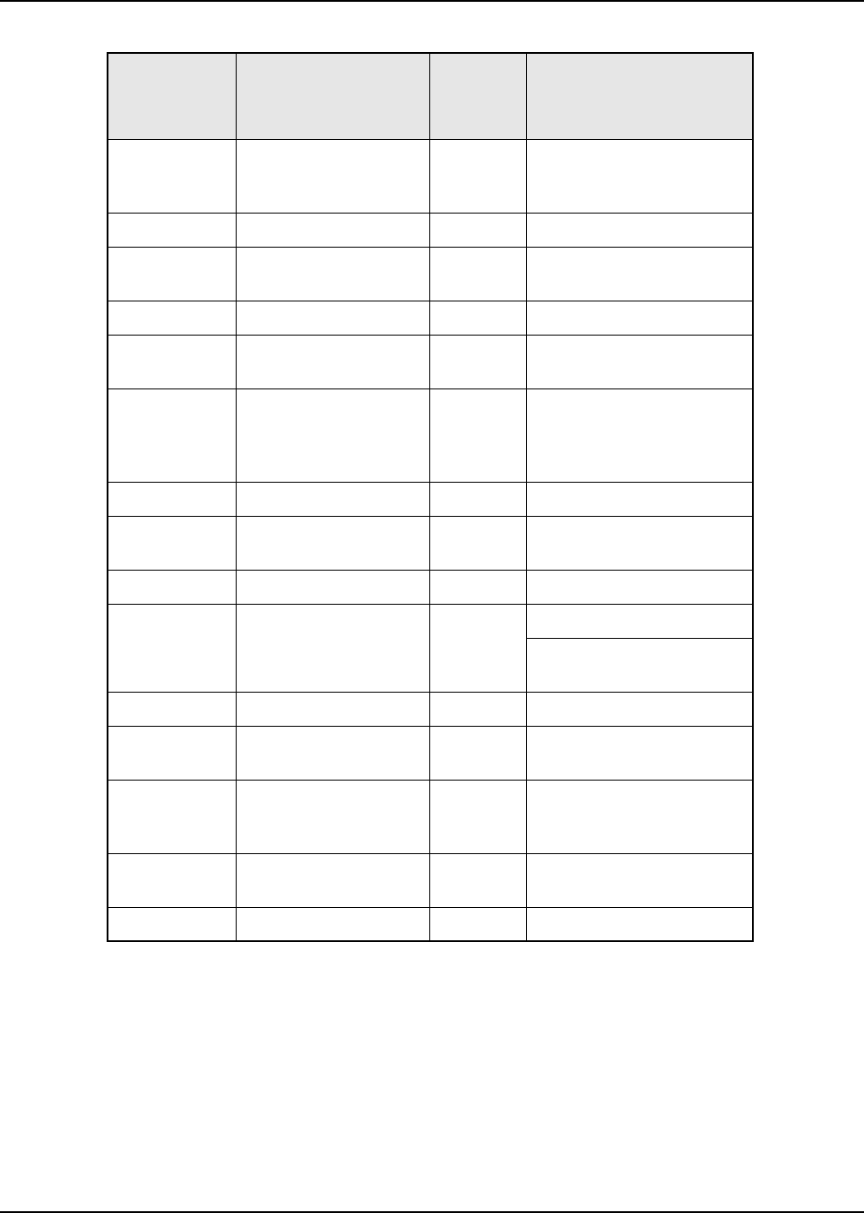
6881076C20-E February 3, 2003
Disassembly/Reassembly Procedures: Fastener Torque Chart 8-19
03-10943J15 Screw, tapping M3.5X8 8-10 Controller board attachment
(except for control head and
remote dash board)
03-10943R55 Screw, tapping M3X8 6-8 Pivot pin (high-power)
03-10945A11 Screw, plastite M3X16 6-8 Control head and remote
dash board attachment
03-10945A14 Screw, plastite M3X8 6-8 Remote control cable cover
03-1098A33 Screw, machine 6-8 Back housing W9 control
head
03-12016A27 Screw, tapping,
M3.5X22 8-10 All PC board attachment
(except for control head,
controller board, and remote
dash board)
03-80041S01 Screw, captive 6-8 Control head leaf spring
03-80043L01 Screw, tapping M3X10 6-8 External power connector
accessory clip
03-80043L01 Screw, M3.0X10 6-8 Lock housing (high-power)
03-80077M01 Screw, hex M3X18 4-6 Control heat mounting
Remote front housing
mounting
03-80077M04 Screw, hex M3X22 6-8 Remote cable mounting
03-80077M06 Screw, hex M4X16 10-12 Mid-power heatsink
mounting
03-80102P01 Screw, tapping
M3.5X10 6-8 Mid-power PA cover, top and
bottom radio covers (high-,
mid-, and low-power)
03-80114M02 Screw, machine M5X10 10-12 Radio mounting (very
low-, low-, and mid-power)
03-84244C06 Wing screw M5X10 10-12 Radio mounting
Table 8-3. Fastener Torque Chart (Continued)
Part Number Description Repair
Torque
(in.-lbs.) Where Used

February 3, 2003 6881076C20-E
Notes
8-20 Disassembly/Reassembly Procedures: Fastener Torque Chart

Chapter 9 Basic Troubleshooting
9.1 Introduction
This section of the manual contains troubleshooting charts, error codes, a functional block diagram,
interconnect diagrams, and flexible circuit information. This section can help you isolate a problem to
the board level. Board-level troubleshooting does not attempt to isolate problems to the component
level. Component-level service information can be found in the ASTRO Digital Spectra and Digital
Spectra Plus Mobile Radios Detailed Service Manual. (Refer to the “Related Publications” section of
this manual on page xii for the specific manual number.)
NOTE: To access the various connector pins, use the housing eliminator/test fixture along with the
diagrams found in this section of the manual. (Refer to the section, “Service Aids and
Recommended Tools,” on page 4-2 for the appropriate Motorola service aids and tools parts
numbers.)
9.2 Replacement Board Procedures
Once a problem has been isolated to a specific board, use one of the following recommended repair
procedures:
• Install a good board from your inventory into the radio.
• Order a replacement board from Customer Care and Services Division at 1-800-422-4210.
• Troubleshoot the defective board using the ASTRO Digital Spectra and Digital Spectra Plus
Mobile Radios Detailed Service Manual. (Refer to the “Related Publications” section of this
manual on page xii for the specific manual number.)
9.3 Power-Up Error Codes
When the radio is turned on (power-up), the radio performs cursory tests to determine if its basic
electronics and software are in working order. Problems detected during these tests are presented
as error codes on the radio’s display. The presence of an error should prompt the user that a
problem exists and that a service technician should be contacted.
Self-test errors are classified as either fatal or non-fatal. Fatal errors inhibit user operation; non-fatal
errors do not. Use the following tables to aid in understanding particular power-up error code
displays.
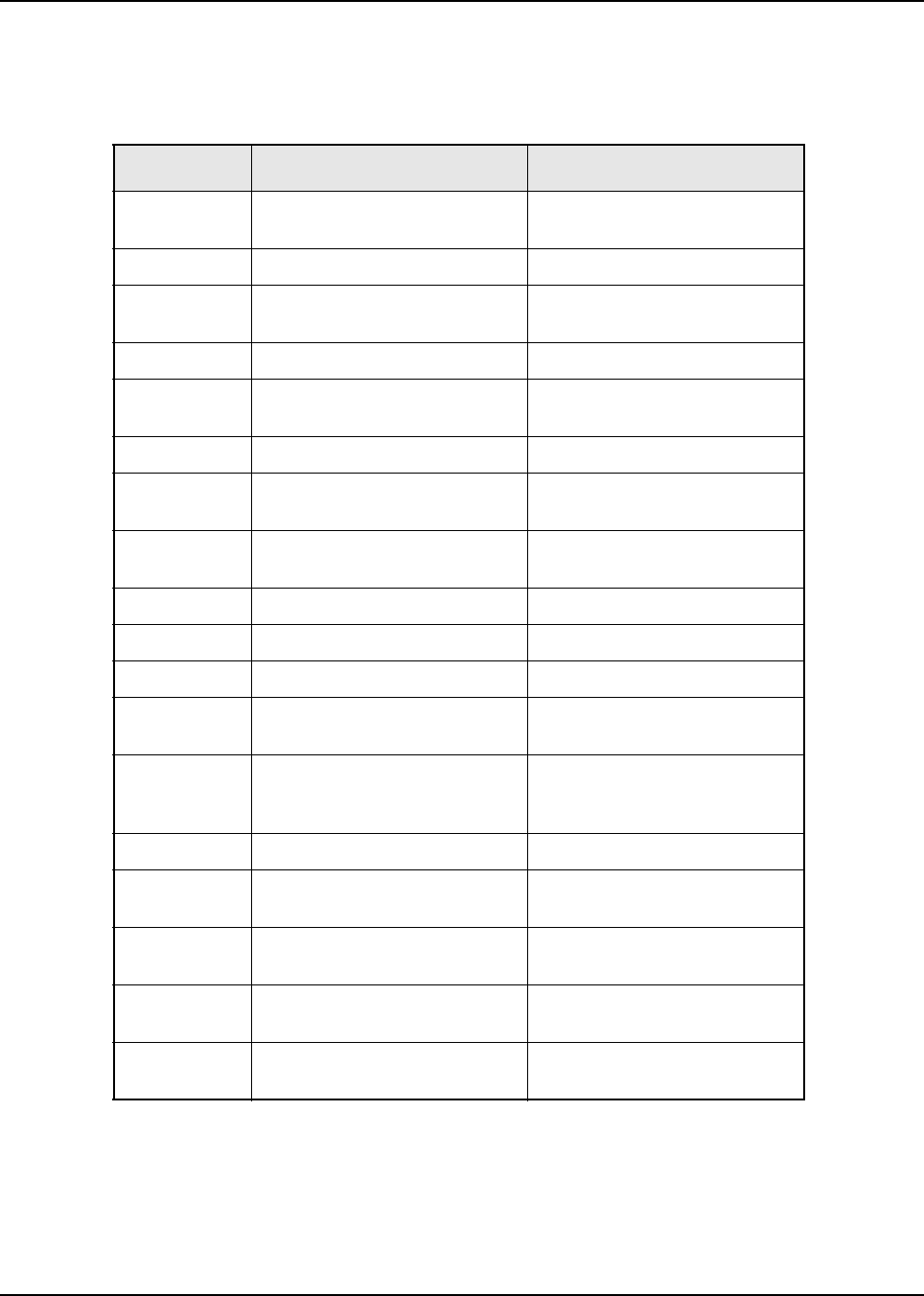
February 3, 2003 6881076C20-E
9-2 Basic Troubleshooting: Power-Up Error Codes
9.3.1 ASTRO Digital Spectra
Table 9-1. ASTRO Digital Spectra Power-Up Error Codes
Error Code Description Corrective Action
01/02 External EEPROM checksum
non-fatal error Reprogram the codeplug.
01/81 ROM checksum failure Reprogram the FLASH memory.
01/82 External EEPROM checksum
failure Reprogram the codeplug.
01/84 EEPROM is blank Program the EEPROM.
01/88 RAM failure - Note: not a
checksum failure Turn the radio off, then on.
01/90 General hardware failure Turn the radio off, then on.
01/92 Internal EEPROM checksum
failure Reprogram the codeplug.
02/10 DSP support IC checksum non-
fatal error Turn the radio off, then on.
02/81 DSP ROM checksum failure Reprogram the FLASH memory.
02/82 DSP RAM 1 failure Replace the VOCON board.
02/84 DSP RAM 2 failure Replace the VOCON board.
02/88 DSP RAM failure - Note: not a
checksum failure Turn the radio off, then on.
02/90 General DSP hardware failure
(DSP startup message not
received correctly)
Turn the radio off, then on.
02/A0 ADSIC checksum failure Replace the VOCON board.
05/10 Control head not communicating
with radio Turn the radio off, then on.
05/81 Control head ROM checksum
failure Replace the control head.
08/10 Siren/PA not communicating with
radio Turn the radio off, then on.
09/10 Secure option not
communicating with radio Turn the radio off, then on.
6881076C20-E February 3, 2003
Basic Troubleshooting: Power-Up Error Codes 9-3
9.3.2 ASTRO Digital Spectra Plus
Table 9-2. ASTRO Digital Spectra Plus Power-Up Error Codes
Error Code Description Error
Type Corrective Action
ERROR 01/02 FLASH ROM Codeplug
Checksum NON-
FATAL Reprogram the codeplug.
ERROR 01/12 Security Partition
Checksum NON-
FATAL Reprogram the security
partition.
ERROR 01/22 Tuning Codeplug
Checksum NON-
FATAL Reprogram the tuning
partition.
FAIL 01/81 FLASH ROM Checksum FATAL Reprogram the radio
firmware.
FAIL 01/82 FLASH ROM Codeplug
Checksum FATAL Reprogram the codeplug.
FAIL 01/88 External RAM Fail FATAL Turn the radio off, then on.
FAIL 01/90 General Hardware FATAL Turn the radio off, then on.
FAIL 01/92 Security Partition
Checksum FATAL Reprogram the security
partition.
FAIL 01/93 Flashport AUTHENT
CODE Failure FATAL Replace the VOCON board.
FAIL 01/98 Internal RAM Fail FATAL Replace the VOCON board.
FAIL 01/A2 Tuning Codeplug
Checksum FATAL Reprogram the tuning
partition.
FAIL 02/81 DSP ROM Checksum FATAL Reprogram the DSP
firmware.
FAIL 02/88 DSP RAM Fatal Error FATAL Turn the radio off, then on.
FAIL 02/90 General DSP Hardware
Failure FATAL Turn the radio off, then on.
ERROR 05/10 Control Head Hardware
Error NON-
FATAL Turn the radio off, then on.
FAIL 05/81 Control Head ROM
Checksum Error FATAL Replace the control head.
ERROR 06/10 Aux Control Head
Hardware Error NON-
FATAL Turn the radio off, then on.
FAIL 06/81 Aux Control Head ROM
Checksum Error FATAL Replace the aux. control
head.
ERROR 08/10 Siren Hardware Error NON-
FATAL Turn the radio off, then on.
February 3, 2003 6881076C20-E
9-4 Basic Troubleshooting: Operational Error Codes
9.4 Operational Error Codes
During radio operation, the radio performs dynamic tests to determine if the radio is working properly.
Problems detected during these tests are presented as error codes on the radio’s display. The
presence of an error code should prompt a user that a problem exists and that a service technician
should be contacted. Use the following tables to aid in understanding particular operational error
codes.
9.4.1 ASTRO Digital Spectra
FAIL 08/81 Siren ROM Checksum
Error FATAL Replace the siren.
ERROR 09/10 Secure Hardware Error NON-
FATAL Replace the secure module.
FAIL 09/90 Secure Hardware Fatal
Error FATAL Replace the secure module.
ERROR 12/10 VRS Hardware Error NON-
FATAL Turn the radio off, then on.
FAIL 12/81 VRS ROM Checksum
Error FATAL Replace the VRS.
ERROR 1C/10 TRC Hardware Error NON-
FATAL Turn the radio off, then on.
FAIL 1C/81 TRC ROM Checksum
Error FATAL Replace the TRC.
Table 9-3. ASTRO Digital Spectra Operational Error Codes
Error Code Description Corrective Action
FAIL 001 Synthesizer Out-of-Lock 1. Reprogram codeplug
2. Replace RF board.
FAIL 002 Selected Mode/Zone Codeplug
Checksum Error Reprogram codeplug.
Table 9-2. ASTRO Digital Spectra Plus Power-Up Error Codes (Continued)
Error Code Description Error
Type Corrective Action
6881076C20-E February 3, 2003
Basic Troubleshooting: Transmitter Troubleshooting 9-5
9.4.2 ASTRO Digital Spectra Plus
9.5 Transmitter Troubleshooting
The following table can help you troubleshoot problems that might occur in the transmitter section of
your radio.
Table 9-4. ASTRO Digital Spectra Plus Operational Error Codes
Error Code Description Error
Type Corrective Action
FAIL 001 Synthesizer Out-of-Lock NON-
FATAL 1. Reprogram codeplug
2. Replace RF board.
FAIL 002 Personality checksum or
system block error NON-
FATAL Reprogram codeplug.
Table 9-5. Transmitter Troubleshooting Chart
Symptom Possible Cause Correction or Test (Measurements
Taken at Room Temperature)
No RF Power
Output TX Power Level
Programming Check TX power level programming (from
the appropriate radio programming
software).
No Keyed 9.4 Vdc from
Command Board Check for keyed 9.4 Vdc on J500 pin 15
with transmitter keyed.
If none, replace the command board.
No Injection to Power
Amplifier 1. Check the lock line (J500 pin 14). If not
less than 2 Vdc, go to the Synthesizer
Troubleshooting Chart on page 9-12.
2. Measure injection, which should be
> +18 dBm.
If low, replace the VCO board.
Power Amplifier Measure PA control voltage (P503 pin 2).
If >6 Vdc, replace the PA board.
Power Control Circuit If PA control voltage above was
<6 Volts, replace the command board.
February 3, 2003 6881076C20-E
9-6 Basic Troubleshooting: Transmitter Troubleshooting
No Modulation VCO Board 1. All modulation testing should be done
with the radio keyed and 1Vrms on the
microphone high line of the microphone.
2. Is radio properly tuned? (See Chapter
6. Radio Alignment Procedure.)
3. Is there > 400 mVrms at J500 pin 11?
If so, replace the VCO board.
Command Board If there is > 400 mVrms (ac coupled) at
P501 pin 49 and not at J500 pin 11,
replace the command board.
VOCON Board If there is >200 mVrms modulation at J501
pin 39 and no modulation at J501 pin 49,
replace the VOCON board.
Distorted
Modulation Bandwidth Is the correct bandwidth selected (use the
appropriate radio programming software)?
Is radio properly tuned?
(See Chapter 6: Radio Alignment
Procedure.)
Compensation Not Set/
Working
(DPL Distorted)
Check compensation setting.
If compensation won’t adjust, go to Can’t
Set Compensation below.
VOCON Board With 80 mVrms on the mic high line, is the
signal on pin 49 of P501 distorted (ac
coupled)?
If so, replace the VOCON board.
Command Board With 80 mVrms on the mic high line, is the
output of the command board VCO Mod
(pin 11 of J500) distorted?
If so, replace the command board.
VCO Board Replace VCO board.
Table 9-5. Transmitter Troubleshooting Chart (Continued)
Symptom Possible Cause Correction or Test (Measurements
Taken at Room Temperature)
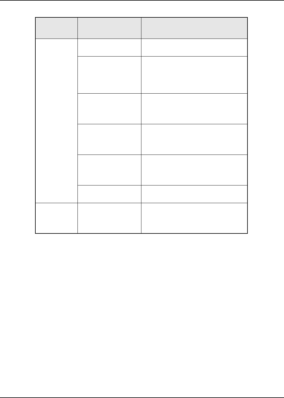
6881076C20-E February 3, 2003
Basic Troubleshooting: Transmitter Troubleshooting 9-7
Bad
Microphone
Sensitivity
Check Deviation and
Compensation Retune, if necessary.
Microphone Speak loudly into the microphone while
monitoring the microphone line (pin 6 of
P502).
If it is not >80 mVrms, then replace the
microphone.
Command Board With 80 mVrms on the mic high line, check
pin 39 of P501.
If not >100 mVrms (ac coupled), replace
the command board.
VOCON Board With 80 mVrms on the mic high line, check
pin 49 of P501.
If not >100 mVrms (ac coupled), replace
the VOCON board.
Command Board With 80 mVrms on the mic high line,
monitor the VCO mod line (pin 11 on
J500). Voltage should be >200 mVrms.
If not, replace the command board.
VCO Board If correct voltage was found on pin 11 of
J500, replace the VCO board.
No/Low
signaling (PL,
DPL, Trunking,
MDC)
Check Programming Reprogram codeplug.
Table 9-5. Transmitter Troubleshooting Chart (Continued)
Symptom Possible Cause Correction or Test (Measurements
Taken at Room Temperature)

February 3, 2003 6881076C20-E
9-8 Basic Troubleshooting: Transmitter Troubleshooting
NOTE:The P501 pins can be probed on the extender cable (see the P501 Extender Cable
diagram on page 10-6).
Can’t Set
Compensation VOCON Board Vary deviation and compensation controls
from maximum to minimum.
With the low frequency source active
(using the appropriate radio programming
software–see Chapter 6: Radio
Alignment Procedure) voltage or pin 48
of P501 should vary from <100 mVrms to
>3 mVrms.
With the high frequency source active,
voltage on pin 49 of P501 (ac coupled)
should vary from <100 mVrms to >3
mVrms.
Command Board 1. All modulation testing should be done
with the radio keyed and 1 Vrms on the
mic high line of the microphone.
Check that normal voice deviation is OK.
Otherwise, go to No Modulation or Bad
Microphone Sensitivity.
2. Set deviation and compensation
controls to maximum.
Voltage on pin 17 of J500 should be > 3 V
p-p.
Voltage @ pin 11 of J500 should be >3 V
p-p.
If not, replace the command board.
RF Board If maximum deviation can be set to > 5.0
kHz, but compensation cannot be set,
then replace the RF board.
Otherwise, replace the VCO board.
Table 9-5. Transmitter Troubleshooting Chart (Continued)
Symptom Possible Cause Correction or Test (Measurements
Taken at Room Temperature)
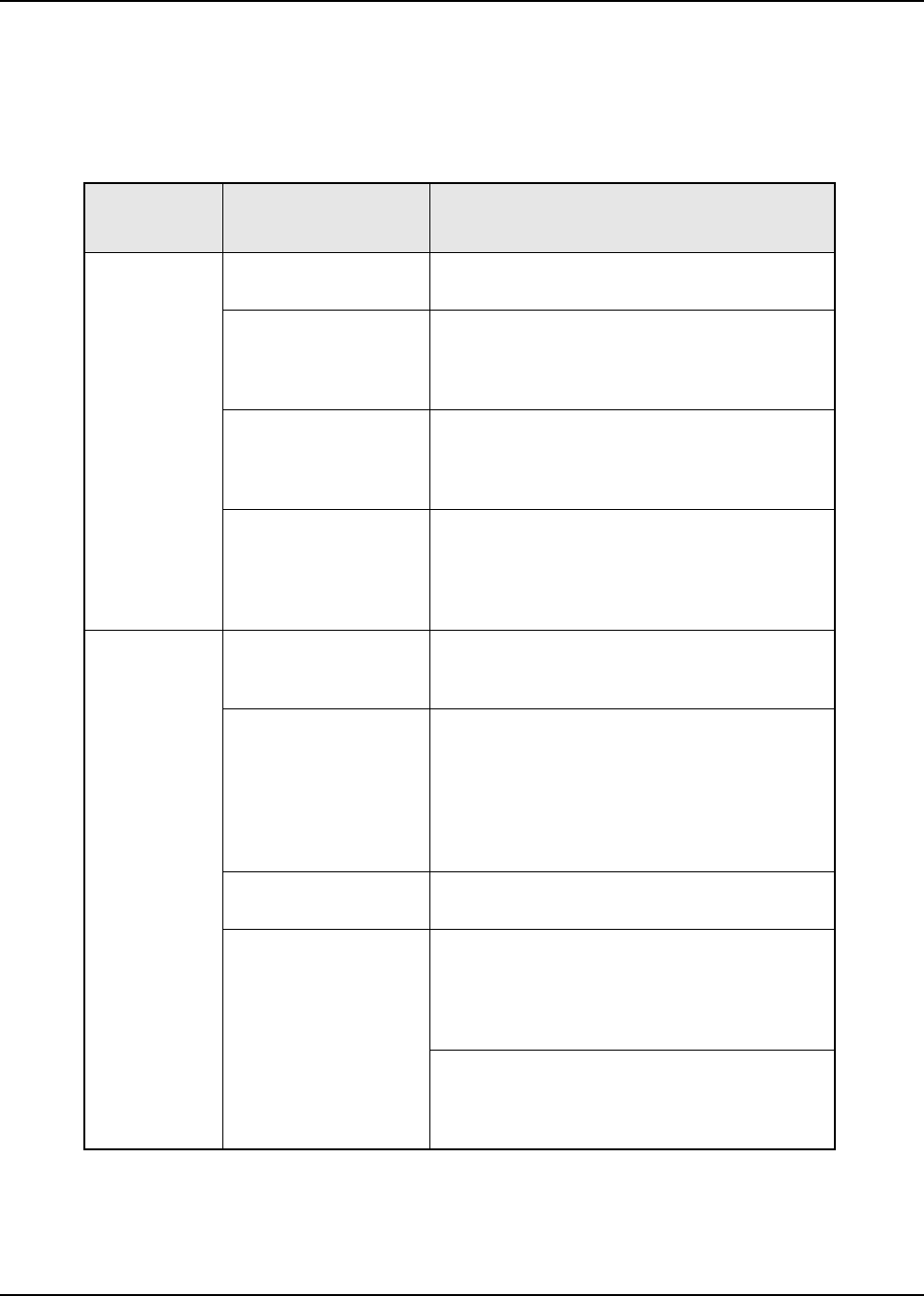
6881076C20-E February 3, 2003
Basic Troubleshooting: Receiver Troubleshooting 9-9
9.6 Receiver Troubleshooting
The following table can help you troubleshoot problems that might occur in the receiver section of
your radio.
Table 9-6. Receiver Troubleshooting Chart
Symptom Possible Cause Correction or Test (Measurements Taken
at Room Temperature)
Radio Dead,
Display Does
Not Light Up
Blown Fuse Check fuse in red lead of power cable (or green
lead if used.)
On/Off Switch (Control
Head) Check for SWB+ at pin 31 of J502 on the
command board.
If not there, check for SWB+ at pin 21 of P502 on
the control head.
Regulators (Command
Board) Check for 9.6 Vdc on pin 10 of J500 and +5V on
pin 1 of J500.
If not there, check for A+ at pin 30 of 502.
If OK, then replace the command board.
ASTRO Spectra Plus
VOCON Board Check U410 pin 1 for 1.8 Vdc.
Check U411 pin 1 for 3.0 Vdc.
Check TP401 for 16.8 MHz.
If any of these is missing, replace the VOCON
board.
Radio Dead,
Display Lights
Up
Audio PA Circuit Check continuity of F500 on command board.
If open, check for speaker leads shorted to
ground, replace. F500 is located just above U450.
Synthesizer (RF Board) Check the synthesizer A Clock line (pin 19 of
J500).
If >3V, then go to the Synthesizer Troubleshooting
Chart on page 9-12.
If <3V, check P501 pin 8.
If <3V there, replace control head; otherwise,
replace the command board.
RF Board Check pin 7 of P501 for 2.4 MHz.
If <3V, replace the RF board.
Regulators (Command
Board) 1. Check for 9.6 Vdc on pin 10 of J500 and +5 Vdc
on pin 1 of J500.
If not there, then check for A+ at pin 30 of P502
and SWB+ at pin 31 of J502.
If OK, replace the command board.
2. Check pin 38 of P501 for A+.
If not there, replace the command board.
Check pins 33, 34, 37 of P501 for 5 Vdc.
If not there, replace the command board.
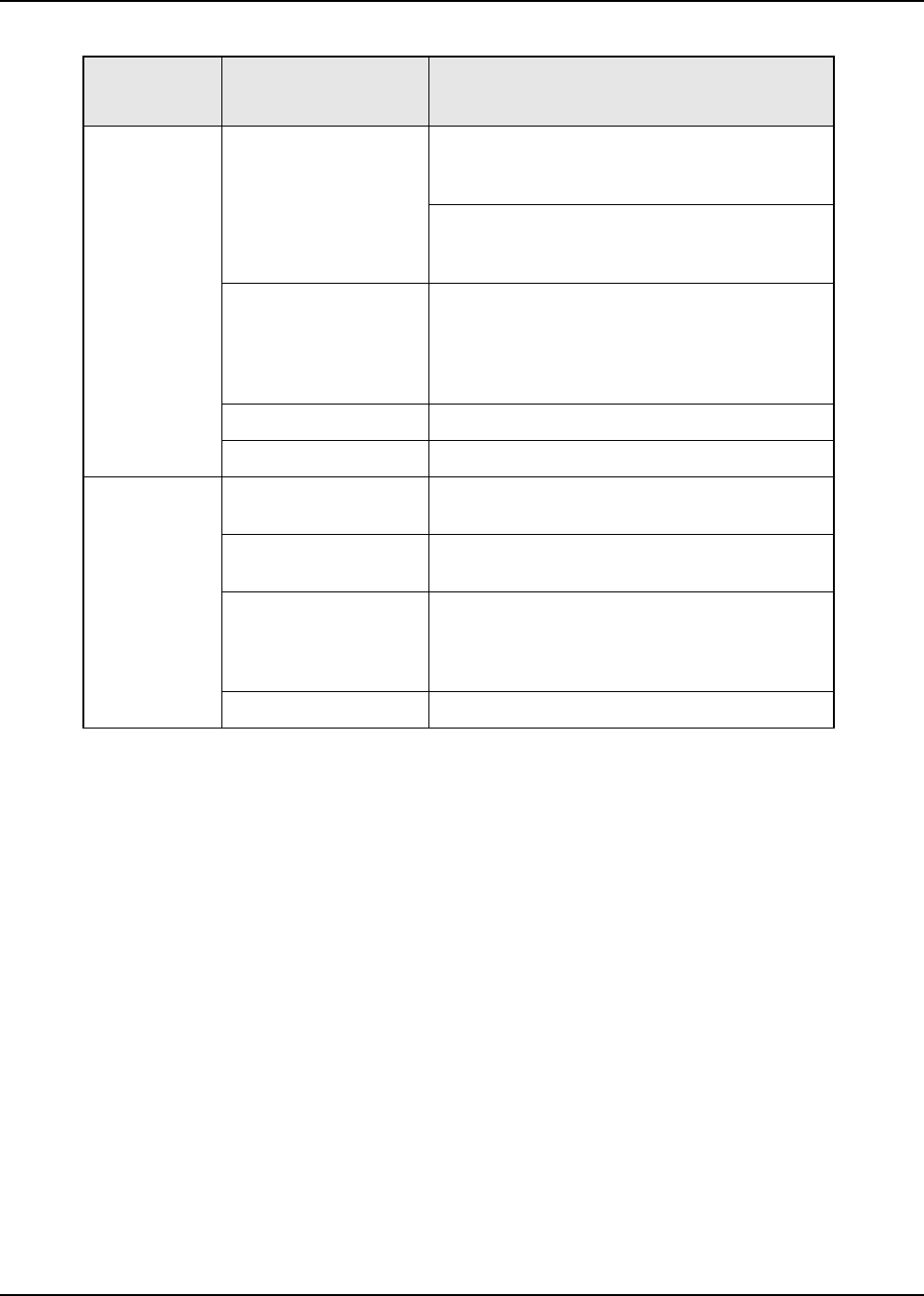
February 3, 2003 6881076C20-E
9-10 Basic Troubleshooting: Receiver Troubleshooting
No Receiver
Audio or
Receive Does
Not Unsquelch
Audio PA Circuit 1. Check codeplug to ensure correct frequency
and signaling (PL, DPL) is enabled (use the
appropriate radio programming software).
2. Check continuity of F500 on command board.
If open, check for speaker leads shorted to
ground. Replace, if necessary.
Regulators (Command
Board) Check for 9.6 Vdc on pin 10 of J500 and +5V on
pin 1 of J500.
If not there, then check for A+ at pin 30 of P502
and SWB+ at pin 31 of P502.
If OK, replace the command board.
RF Board Replace RF board.
VOCON Board Replace VOCON board.
Audio
Distorted or
Not Loud
Enough
Codeplug Is the codeplug properly configured including
bandwidth and signaling?
VOCON Board Is there >100 mVrms audio on pin 40 of P501?
If not, replace VOCON board.
Synthesizer Not On
Frequency/Working Check synthesizer frequency across pins 14 and
16 of P503.
If off by more than 250Hz, then go to the
Synthesizer Troubleshooting Chart on page 9-12.
Command Board Replace command board.
Table 9-6. Receiver Troubleshooting Chart (Continued)
Symptom Possible Cause Correction or Test (Measurements Taken
at Room Temperature)
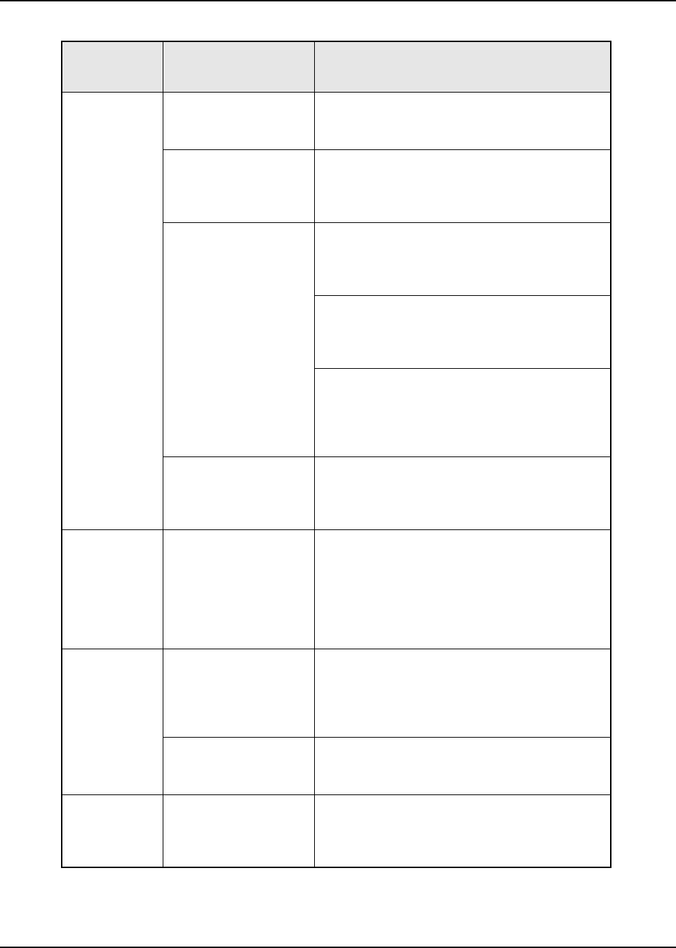
6881076C20-E February 3, 2003
Basic Troubleshooting: Receiver Troubleshooting 9-11
RF Sensitivity
Poor Synthesizer Not On
Frequency/Working Check local oscillator frequency.
If off by more than 250 Hz, then go to the
Synthesizer Troubleshooting Chart (page 9-12).
Antenna Switch
(Amplifier Board) Check insertion loss from antenna connector to
Rx front end coax from the PA.
If loss is less than 1.8 dB, then the problem is in
the transceiver housing.
Receiver Front-End
Assembly or VCO
Board
1. Measure the gain of the front end assembly by
injecting a signal at the desired receive frequency
and measuring the output level at 109.65 MHz.
Net conversion gain should be >8 dB.
2. If conversion gain is <8 dB, then check the dc
supply voltage fed into the front end on the center
conductor of the output coax to the RF board.
If it is less than 9.4 Vdc, check the RF board.
3. Check the injection level from the VCO board.
If it is less than +2 dBm, then replace the VCO
board.
If injection is OK, then replace the receiver front-
end assembly.
RF Board Using a TEK-10 probe, check the sensitivity into
the RF board @ 109.65 MHz.
If sensitivity is worse than -118.5 dBm for 12 dB
SINAD, replace the RF board.
Radio Will Not
Squelch Codeplug Check the offending channel for spurious activity
by monitoring with a known-good radio or service
monitor.
If possible, remove the offending source
(computer, etc.).
If not, increase the squelch level using the
appropriate radio programming software.
Radio Will Not
Turn Off On/Off Switch (Control
Head) Check for SWB+ pin 31 P502 on the command
board.
If SWB+ is not there, check for SWB+ at pin 21 of
P502 on the command board.
Replace the control head.
Command Board Does SWB+ on pin 31 of P502 switch on and off
as the control head switch is operated?
If so, replace the command board.
Excessive
Noise in
Fading
Conditions
Check Programming for
Correct Bandwidth Reprogram codeplug with correct bandwidth.
Table 9-6. Receiver Troubleshooting Chart (Continued)
Symptom Possible Cause Correction or Test (Measurements Taken
at Room Temperature)

February 3, 2003 6881076C20-E
9-12 Basic Troubleshooting: Synthesizer Troubleshooting
NOTE:The P501 pins can be probed on the extender cable (see the P501 Extender Cable
diagram on page 10-6).
9.7 Synthesizer Troubleshooting
The following table can help you troubleshoot problems that might occur in the synthesizer section of
your radio.
Table 9-7. Synthesizer Troubleshooting Chart
Symptom Possible Cause Correction or Test (Measurements
Taken at Room Temperature)
Does Not Lock
on Any
Channel
VCO With radio in receive mode, measure pin 1
of J601 using a high impedance probe.
Measured level should be -5 dBm ±6 dB,
and the frequency should be 370 to
380MHz.
If not, replace the VCO board.
Reference Oscillator/RF
Board Is there >1.5 Vp-p of 2.1 MHz on pin 21 of
J500?
If not, replace the RF board.
VOCON Board Do both the chip select lines (pins 16 & 20
of J500) go low during mode changes?
Is there data on the clock & data lines
going into the RF board (pins 18 & 19 of
J500)?
If not, replace the VOCON board.
Does Not Lock
on Some
Channels
Programming Check the mode programming information
to ensure that the correct frequency
programming information has been
entered.
VCO With the radio in receive mode; unplug the
loop feedback coax from the VCO board
to the RF board.
Measured level should be -5 dBm ±5 dB,
and the frequency should be 370 to 380
MHz.
If not, replace the VCO board.
RF Board Replace the RF board.
Does Not Lock
in Tx (or
Talkaround
RF Board Check the Aux bit states (pin 9 & 11 J601).
When changing from receive to transmit to
talkaround, pin 9 and 11 of J601 should
alternate between a high voltage (>8V)
and a low voltage (<1V).
If either pin does not alternate between
these voltages, replace the RF board.
VCO Replace the VCO board.
6881076C20-E February 3, 2003
Basic Troubleshooting: Synthesizer Troubleshooting 9-13
Synthesizer
Malfunctioning Synthesizer Not Locked Check the synthesizer lock line (pin 14 of
J500).
If > 1 V, then the synthesizer is not locked.
Go to Does Not Lock on Some Channels
above.
Reference Oscillator
Not On Frequency/
Working
1. Check the reference oscillator
frequency.
It should be 16.8 MHz ±4 Hz.
THIS MUST BE MEASURED @ 25° C
(77° F) TO BE ACCURATE.
2. Retune the reference oscillator if
frequency is incorrect.
VOCON Board If the reference oscillator will not tune on
frequency, is reference control voltage (pin
2 of J500) tuning 1.5 to 3.0 volts, and is
the 5 volt supply 5 V ±.2 V? If not, replace
the VOCON board.
Programming
(EEPROM) Check mode programming information to
ensure that the correct frequency
programming information has been
entered.
RF Board Replace the RF board.
Table 9-7. Synthesizer Troubleshooting Chart (Continued)
Symptom Possible Cause Correction or Test (Measurements
Taken at Room Temperature)

February 3, 2003 6881076C20-E
Notes
9-14 Basic Troubleshooting: Synthesizer Troubleshooting

Chapter 10 Functional Block Diagrams and Connectors
This chapter contains the ASTRO Digital Spectra and Digital Spectra Plus functional block diagrams and connector locations.
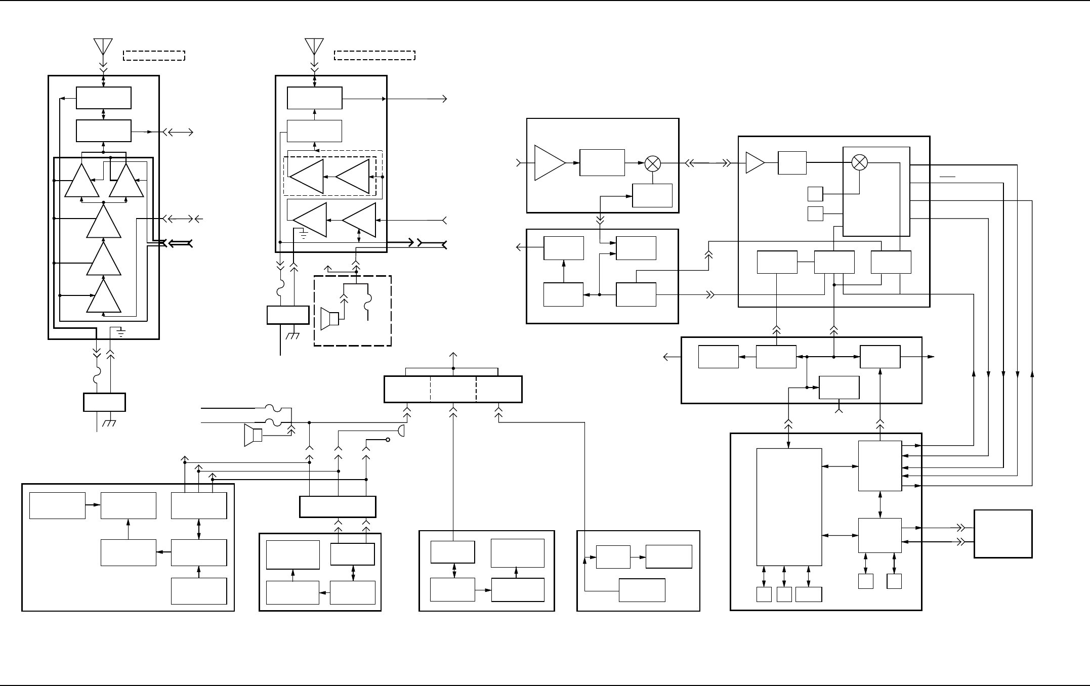
10-2 Functional Block Diagrams and Connectors: Digital Spectra Functional Block Diagram (Models W3, W4, W5, W7, and W9)
February 3, 2003 6881076C20-E
10.1 Digital Spectra Functional Block Diagram (Models W3, W4, W5, W7, and W9)
Figure 10-1. Digital Spectra Models W3, W4, W5, W7, and W9 Functional Block Diagram
PRESELECTOR
MIXER
INJECTION
FILTER
RX
(COAXIAL CABLE)
RX BUFFER
DIVIDER VCO
TX BUFFER
PREAMP
TX
VCO BOARD
FRONT-END RECEIVER BOARD
COAXIAL
CABLE
FROM
POWER
PA
TO
POWER
PA
VF VOLTAGE
SOURCE
MICROPROCESSOR
EEPROM
SERIAL BUS
INTERFACE
TO POSITIVE
TERMINAL OF
VEHICLE
BATTERY
LPF/
ANTENNA SW
TX RX
RX
TX
ANTENNA
CONNNECTOR
HIGH-POWER PA
DC POWER
CABLE
TO POSITIVE
TERMINAL OF
VEHICLE
BATTERY
CHASSIS
GND
FUSE
ANTENNA
CONNNECTOR
MID/LOW-POWER PA
DIRECTIONAL
COUPLER/
DETECTOR
TX RX
TX
DIRECTIONAL
COUPLER/
DETECTOR
LPF/
ANTENNA SW
TX
BUFFER
RIBBON
CABLE
RX
DC POWER
CABLE
CHASSIS
GND
FUSE
REAR ACCESSORY
CONNECTION
J2
P2
VIP
IN/OUT
IGNITION
CABLE
FUSE
DASH MOUNT MODELS
RX
SERIAL BUS
INTERFACE
HIGH VOLTAGE
VF DRIVER MICRO-
PROCESSOR
VACUUM
FLOURESCENT
8 CHARACTER
SPEAKER
REMOTE MOUNT MODELS
FUSE
FUSE
BATT CABLE (GRN)
IGN. CABLE (ORG)
VIP IN/OUT
REMOTE
INTERCONNECT
BOARD
HANDHELD
INTERCONNECT
BOARD
DASH
INTERCONNECT
BOARD
W3 HANDHELD CONTROL HEAD
SWITCHES
MICROPHONE
REMOTE
INTERCONNECT
BOARD
CONTROL HEAD (REMOTE MOUNT)
(W5/W7 PUSHBUTTON AND W4 ROTARY MODELS)
8-CHARACTER
VACUUM
FLOURESCENT
DISPLAY
MICRO-
PROCESSOR
CONTROL HEAD (DASH MOUNT)
(W5/W7 PUSHBUTTON AND W4 ROTARY MODELS)
HIGH VOLTAGE
VF DRIVER
SERIAL BUS
INTERFACE DISPLAY
DRIVER DISPLAY
VACUUM
FLUORESCENT
11-CHARACTER
HIGH VOLTAGE
VF DRIVER
CONTROL HEAD (REMOTE MOUNT)
(W9 PUSHBUTTON MODEL)
MID-
POWER
LOW-POWER
RIBBON
CABLE FROM
COMMAND
BOARD
FROM
VCO
BOARD
TO
FRONT-END
RECEIVER
BOARD
COAXIAL
CABLE
COAXIAL
CABLE TO
FRONT-END
RECEIVER
BOARD
FROM
VCO
BOARD
FROM
COMMAND
BOARD
TO
COMMAND
BOARD
DSP
SUPPORT
CIRCUIT
MODULE
MODULATION OUT
2.4MHz REF
DIGITAL RX IN
SBI
DIGITAL SIGNAL
PROCESSOR
(DSP)
RAM ROM
DATA IN
DATA OUT
ENCRYPTION
BOARD
(OPTIONAL)
MICROCONTROL
UNIT
(MCU)
AND
SUPPORT LOGIC IC
(SLIC)
RAM ROM EEPROM
MBEPF-23553-B
4 POLE
XTAL
SYNTHESIZER PRESCALER
16.8MHz
XTAL
D/A
IC AUDIO
PA
SERIAL
BUS
INTERFACE
POWER
CONTROL/
REGULATOR
REF
TUNE
INPUT
MOSI
INPUT
MOSI
TO
POWER
PA
COMMAND BOARD
TO
INTERCONNECT
BOARD OR
DIRECTLY
TO W9
CONTROL
HEAD
VOCON BOARD
FROM
INTERCONNECT
BOARD
RF BOARD
IF AMP MIXER
L/C
L/C
450Khz
FILTER
109.2MHz
ABACUS
IC
REF
2.1MHz LO
D OUT
D OUT
SBI
ODC
REF
TUNE
MOSI
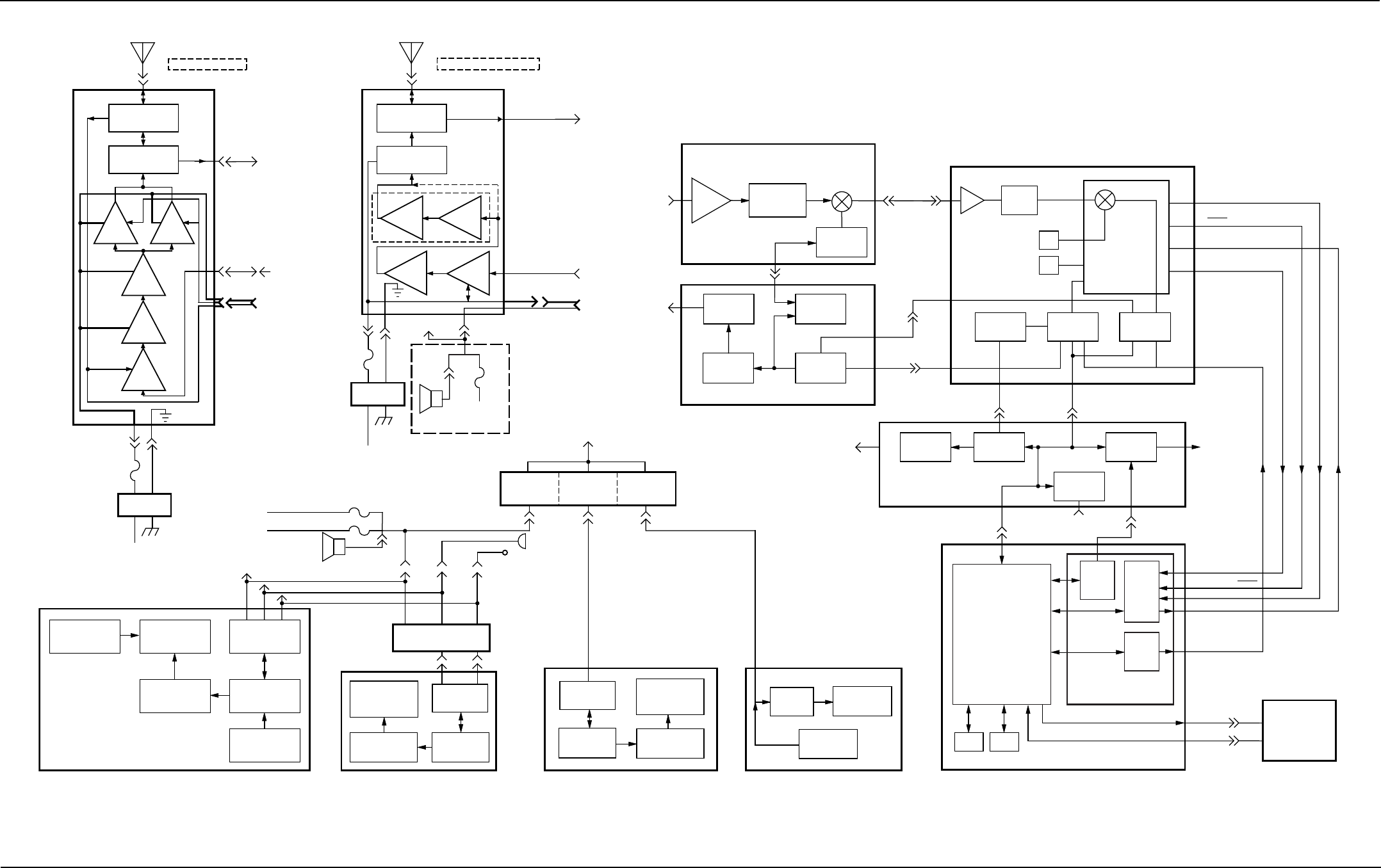
Functional Block Diagrams and Connectors: Digital Spectra Plus Functional Block Diagram (Models W3, W4, W5, W7, and W9) 10-3
6881076C20-E February 3, 2003
10.2 Digital Spectra Plus Functional Block Diagram (Models W3, W4, W5, W7, and W9)
Figure 10-2. Digital Spectra Plus Models W3, W4, W5, W7, and W9 Functional Block Diagram
PRESELECTOR
MIXER
INJECTION
FILTER
RX
(COAXIAL CABLE)
RX BUFFER
DIVIDER VCO
TX BUFFER
PREAMP
TX
VCO BOARD
FRONT-END RECEIVER BOARD
COAXIAL
CABLE
FROM
POWER
PA
TO
POWER
PA
VF VOLTAGE
SOURCE
MICROPROCESSOR
EEPROM
SERIAL BUS
INTERFACE
TO POSITIVE
TERMINAL OF
VEHICLE
BATTERY
LPF/
ANTENNA SW
TX RX
RX
TX
ANTENNA
CONNNECTOR
HIGH-POWER PA
DC POWER
CABLE
TO POSITIVE
TERMINAL OF
VEHICLE
BATTERY
CHASSIS
GND
FUSE
ANTENNA
CONNNECTOR
MID/LOW-POWER PA
DIRECTIONAL
COUPLER/
DETECTOR
TX RX
TX
DIRECTIONAL
COUPLER/
DETECTOR
LPF/
ANTENNA SW
TX
BUFFER
RIBBON
CABLE
RX
DC POWER
CABLE
CHASSIS
GND
FUSE
REAR ACCESSORY
CONNECTION
J2
P2
VIP
IN/OUT
IGNITION
CABLE
FUSE
DASH MOUNT MODELS
RX
SERIAL BUS
INTERFACE
HIGH VOLTAGE
VF DRIVER MICRO-
PROCESSOR
VACUUM
FLOURESCENT
8 CHARACTER
SPEAKER
REMOTE MOUNT MODELS
FUSE
FUSE
BATT CABLE (GRN)
IGN. CABLE (ORG)
VIP IN/OUT
REMOTE
INTERCONNECT
BOARD
HANDHELD
INTERCONNECT
BOARD
DASH
INTERCONNECT
BOARD
W3 HANDHELD CONTROL HEAD
SWITCHES
MICROPHONE
REMOTE
INTERCONNECT
BOARD
CONTROL HEAD (REMOTE MOUNT)
(W5/W7 PUSHBUTTON AND W4 ROTARY MODELS)
8-CHARACTER
VACUUM
FLOURESCENT
DISPLAY
MICRO-
PROCESSOR
CONTROL HEAD (DASH MOUNT)
(W5/W7 PUSHBUTTON AND W4 ROTARY MODELS)
HIGH VOLTAGE
VF DRIVER
SERIAL BUS
INTERFACE DISPLAY
DRIVER DISPLAY
VACUUM
FLUORESCENT
11-CHARACTER
HIGH VOLTAGE
VF DRIVER
CONTROL HEAD (REMOTE MOUNT)
(W9 PUSHBUTTON MODEL)
MID-
POWER
LOW-POWER
RIBBON
CABLE FROM
COMMAND
BOARD
FROM
VCO
BOARD
TO
FRONT-END
RECEIVER
BOARD
COAXIAL
CABLE
COAXIAL
CABLE TO
FRONT-END
RECEIVER
BOARD
FROM
VCO
BOARD
FROM
COMMAND
BOARD
TO
COMMAND
BOARD
CODEC
KRSIC
MODULATION OUT
2.4MHz REF
DIGITAL RX IN D OUT
DIGITAL RX IN D OUT
SBI
ADDAG
DATA IN
DATA OUT
ENCRYPTION
BOARD
(OPTIONAL)
DUAL-CORE
PROCESSSOR
(MCU AND DSP)
MBEPF-27239-O
4 POLE
XTAL
SYNTHESIZER PRESCALER
16.8MHz
XTAL
D/A
IC AUDIO
PA
SERIAL
BUS
INTERFACE
POWER
CONTROL/
REGULATOR
REF
TUNE
INPUT
MOSI
INPUT
MOSI
TO
POWER
PA
COMMAND BOARD
TO
INTERCONNECT
BOARD OR
DIRECTLY
TO W9
CONTROL
HEAD
VOCON BOARD
DSP SUPPORT IC’S
FROM
INTERCONNECT
BOARD
RF BOARD
IF AMP MIXER
L/C
L/C
450Khz
FILTER
109.2MHz
ABACUS
IC
REF
2.1MHz LO
D OUT
D OUT
SBI
ODC
REF
TUNE
MOSI
SRAM FLASH
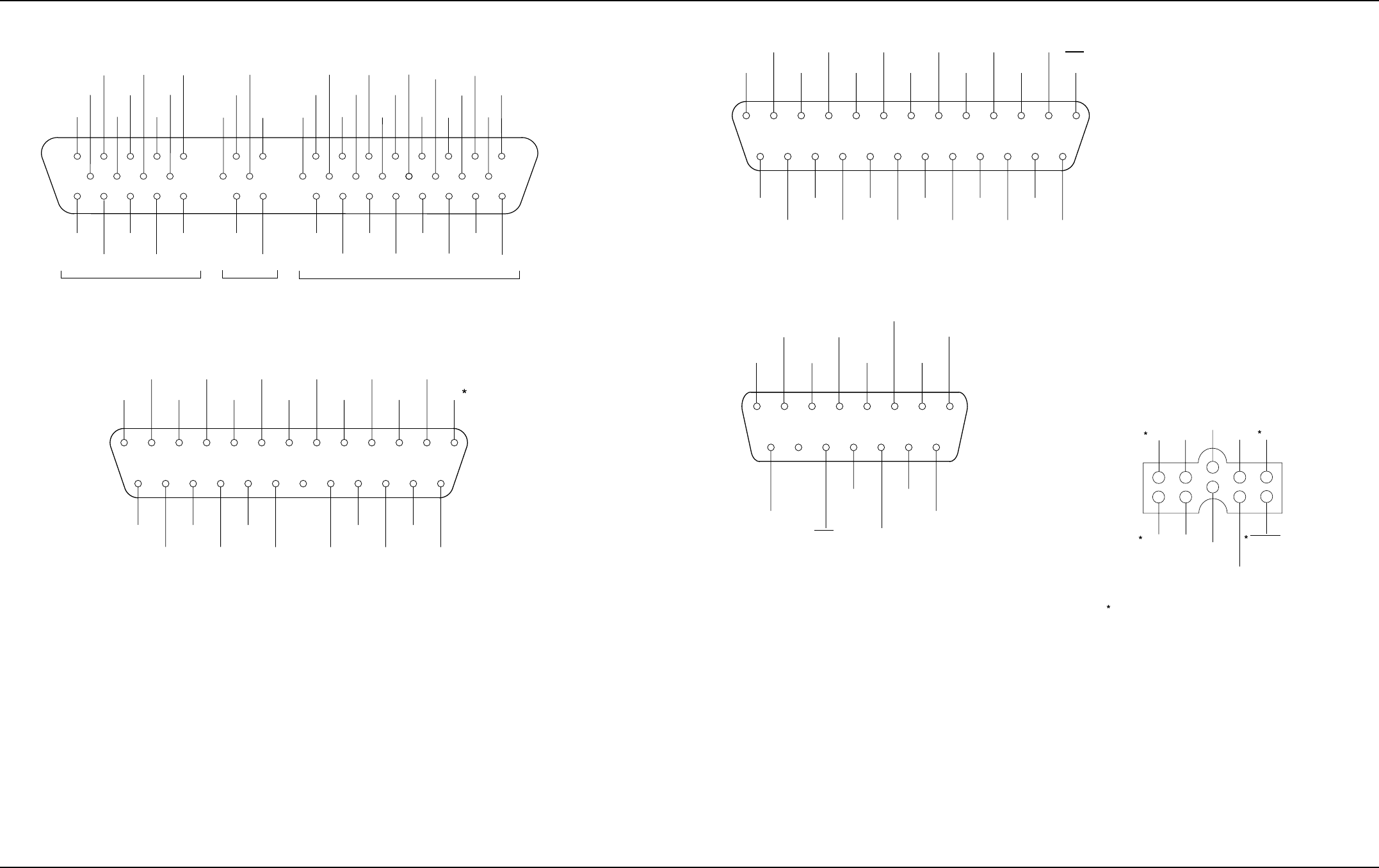
10-4 Functional Block Diagrams and Connectors: Radio Connectors
February 3, 2003 6881076C20-E
10.3 Radio Connectors
Figure 10-3. J0103 Remote-Mount Control Head Connector
Figure 10-4. J5 Control Cable for Remote-Mount Control Head
Figure 10-5. J6 Radio Operations Connector
Figure 10-6. J2 Rear Accessory Connector
Figure 10-7. P104 Microphone Jack
12345 13
12
11
108
714 15 16 17
48 4940 4134 43 4435 36 37 38 45 46 47 50
VIP 2
OUT
VIP 1
OUT
VIP 2
IN
VIP 1
IN
DATA
OUT
MIC
LO
MIC
HI
SPKR
LO
SPKR
LO
MIC
HI
MIC
LO BATT -
VF
SENSE
1 IGN +
ANALOG
GND
BUS +
SWB + DIG
GND
PTT/HUB
REF
PTT
RESET
EMGCY BATT +
(A+)
BATT -
VF
SENSE
2
IGN -
BUSY
SWB +
DIG
GND
SPARE
-1
SPARE
-2
29
28
27
26 30 31 32
18 19 20 21 23 24 33
VIP 3
OUT
SWB +
DIG
GND
VIP 3
IN
CLOCK HUB
SWB +
SPKR
HI NC BATT + DIG
GND
BUSSPKR
HI NC NC
RADIO
MIC
VIP
MAEPF-21670-A
EMER
MIC
HI ANA
GND TX
AUD FLT
AUDIO (FILT-AUD
SHLD)
MIC
LO DET
AUD RX
AUDIO BUS + IGN
RESET
B+
BUSY
SPKR
LO SWB +
SPKR
HI DIG
GND BUS -
123456
13 12 11 10 9 8 7
14
1516
1718192021
2223
24
25
MAEPF-23798-O
(PTT )
BUS
SHLD A +
RESET SPARE-2
SPARE-1
RSSI
EMER
MIC
HI ANA
GND TX
AUD FLT
AUD NC FIL AUD
SHLD
MIC
LO DET
AUD RX
AUD BUS + IGN PTT/
VIP IN 1
SPKR
HI BUSY BUS
SHIELD RESET
SPKR
LO SWB + A + DIG
GND
SPARE
2SPARE
1
RSSI/
VIP IN 2
BUS -
123456
13 12 11 10 9 8 7
14
15
16
1718192021
2223
24
25
MAEPF-21669-A
DIG
GND SPKR
HI EMER
SPKR
LO NOTE 1
IGNITION
VIP OUT 2
NOTE 1
SWB+
PTT/
TX-RS232
BUSY
12345687
9
1011
12131415
MAEPF-23799-O
VRS TX/
CTS-RS232
MIC HI/RESET/
RTS-RS232
BUS+ VIP OUT 1
NOTE1
DISC. AUD/
RX-RS232
BUS-
FUNCTIONAL ONLY IN DASH-MOUNT
CONFIGURATION. N.C. IN REMOTE-MOUNT
CONFIGURATION.
NOTES:
1.
GND
DIG
GND MIC
LO
PTT/
PROGRAM
RESET
9
10
7
8
5
6
MAEPF-23800-A
PROG
RX
DATA
SWB+
PINS 1, 2, 9, AND 10 ARE NO CONNECTIONS (NC)
ON P104 OF A REMOTE-MOUNT CONTROL HEAD.
DETAIL SHOWN FROM
CONTROL HEAP FRONT VIEW
(MALE PIN VIEW)
Vpp
1
2
3
4
HUB/
BUSY
KEYFAIL/
PROG
TX DATA
MIC HI/
PROG
RX/TX ENABLE
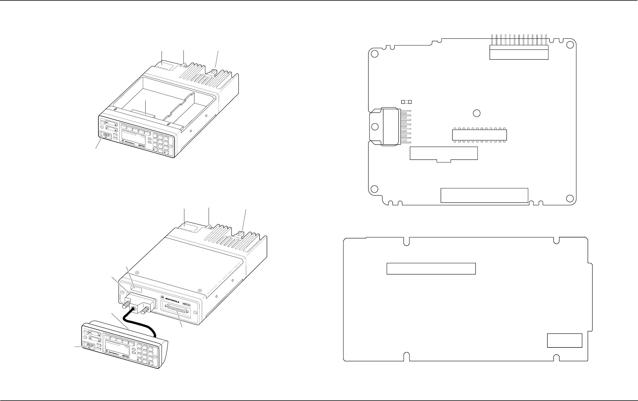
Functional Block Diagrams and Connectors: Radio Connector Locations 10-5
6881076C20-E February 3, 2003
10.4 Radio Connector Locations
Figure 10-8. Dash-Mount Radio Connector Locations
Figure 10-9. Remote-Mount Radio Connector Locations
10.5 Radio Connector Locations (cont.)
Figure 10-10. Command Board Connector Locations
Figure 10-11. VOCON Board Connector Locations
MAEPF-24496-O
0
PWR
Mode Scan
Phon Sel
Call
Vol
DIM
HOME
XMIT
BUSY
123
456
789
0
Sts Msg
H/L MonDir
RclDel
DASH-MOUNT RADIO
J2 ANTENNA PWR
P502
P104
MAEPF-24497-A
0
PWR
ModeScan
PhonSel
Call
Vol
DIM
HOME
XMIT
BUSY
123
456
789
0
Sts Msg
H/L Mon Dir
Rcl Del
J2
J5
P506
REMOTE-MOUNT
CONTROL HEAD
REMOTE-MOUNT
RADIO
J6
J0103
P104
ANTENNA PWR
COMMAND BOARD
(VIEWED FROM SIDE 1)
P503
F500
U450
15
24 19
16
J500
2
50
49 1
25
30
P501
P502
1
38 29
10
20
19
13
12
14 13
12 11
10 9
8
3
65
4
21
7
1
214
13 25
26
VOCON BOARD
(VIEWED FROM SIDE 2)
49
50 J501
25
24
J801
2
1
1
2
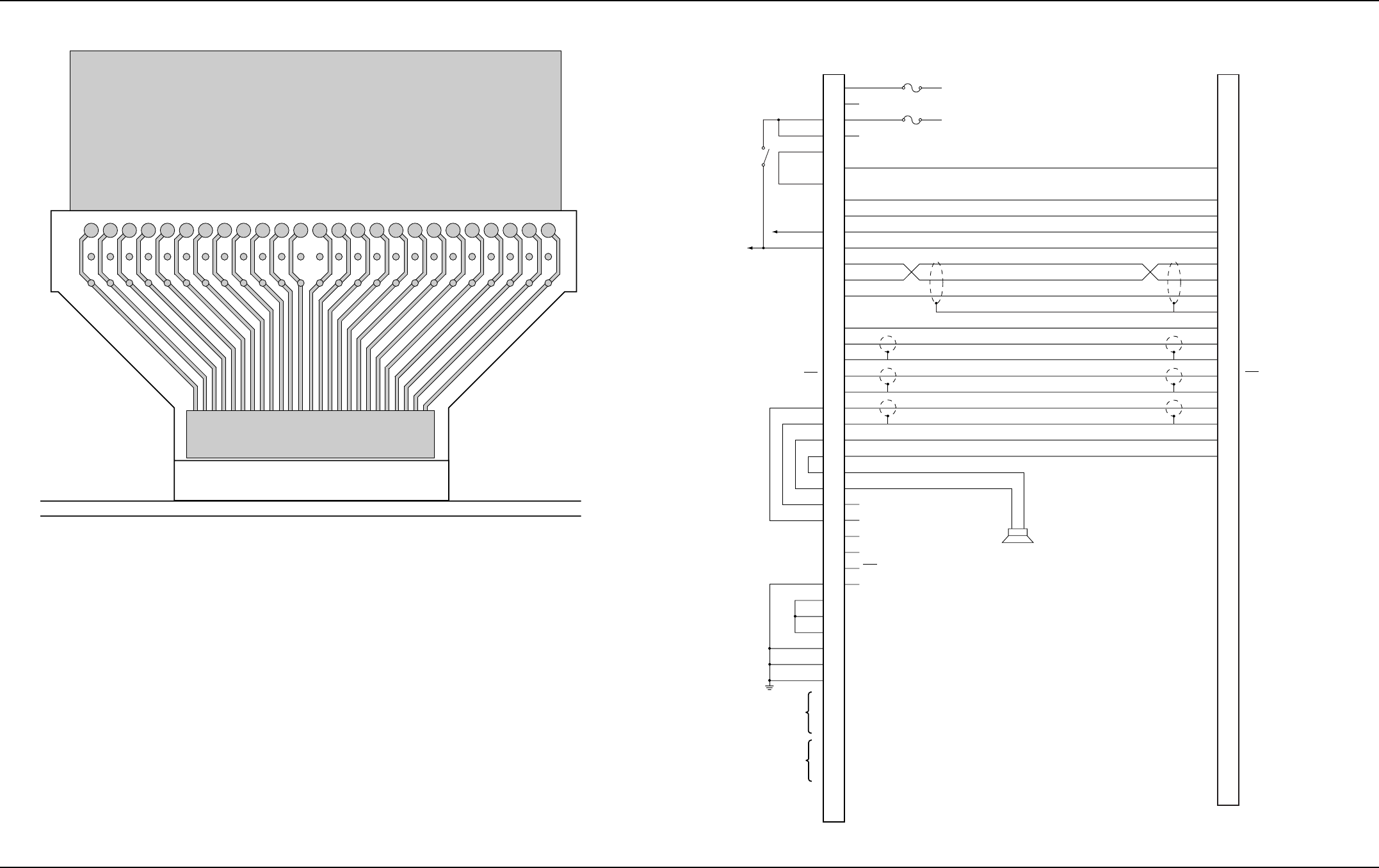
10-6 Functional Block Diagrams and Connectors: Extender Cable (P501)
February 3, 2003 6881076C20-E
10.6 Extender Cable (P501)
Figure 10-12. P501 Extender Cable
10.7 Control Head Cabling Diagram
Figure 10-13. Control Head Cabling Diagram
151719 131197531212325272931333537394143454749
16
18
20 14 12 10 8642
22
2426
2830
32
3436
38
404244
46
4850
P501
EXTENDER
CABLE
(3080370E06)
(FACING TOWARD
CONTROL HEAD)
J501
COMMAND BOARD
P1001
SPARE 2
EMERGENCY
SPARE 1
DIG GND
SWB+
BUS +
BUS -
BUSY
BUS SHIELD
RESET
DET AUDIO
ANA GND
PTT
MIC HI
MIC LO
SPKR HI
SPKR LO
A+
RSSI
RX AUDIO
RED
VIO
BRN
BLU
YEL
WHT
BLK
BLK/RED
BARE
BLK/ORG
BLK/BRN
SHIELD
BLK/GRN
SHIELD
BLK/YEL
SHIELD
ORG
GRN
CONTROL HEAD
ORG
GRN
NC
NC
MIC LO
MIC HI
SWB+
HUB
PTT
PTT/HUB REF
SWB+
SWB+
SWB+
DIG GND
DIG GND
DIG GND
(DATA IN)
(STROBE)
(CLOCK)
(DATA OUT)
BUS +
BUS -
BUSY
RESET
DET AUDIO
ANA GND
PTT
IGN+
IGN-
BATT+
BATT+
BATT-
SPARE 2
BATT-
EMERGENCY
SPARE 1
BLK/GRN
BLK/ORG
DIG GRD
SWB+
P5
RADIO
15
32
47
30
31
29
14
27
28
49
48
17
50
33
26
45
16
46
12
13
44
11
10
43
7
8
41
40
24
23
18
19
3
20
21
36
4
3
37
2
1
34
38
5
SPEAKER
17
13
16
18
22
5
14
23
21
19
9
0
1
12
11
25
24
20
15
7
1
2
3
1
2
3
VIP IN
VIP OUT

Chapter 11 Exploded Views and Parts Lists
This chapter contains the exploded views and associated parts lists for each of the ASTRO Digital Spectra and Digital Spectra Plus control heads. Tables containing pushbutton parts lists are also included.
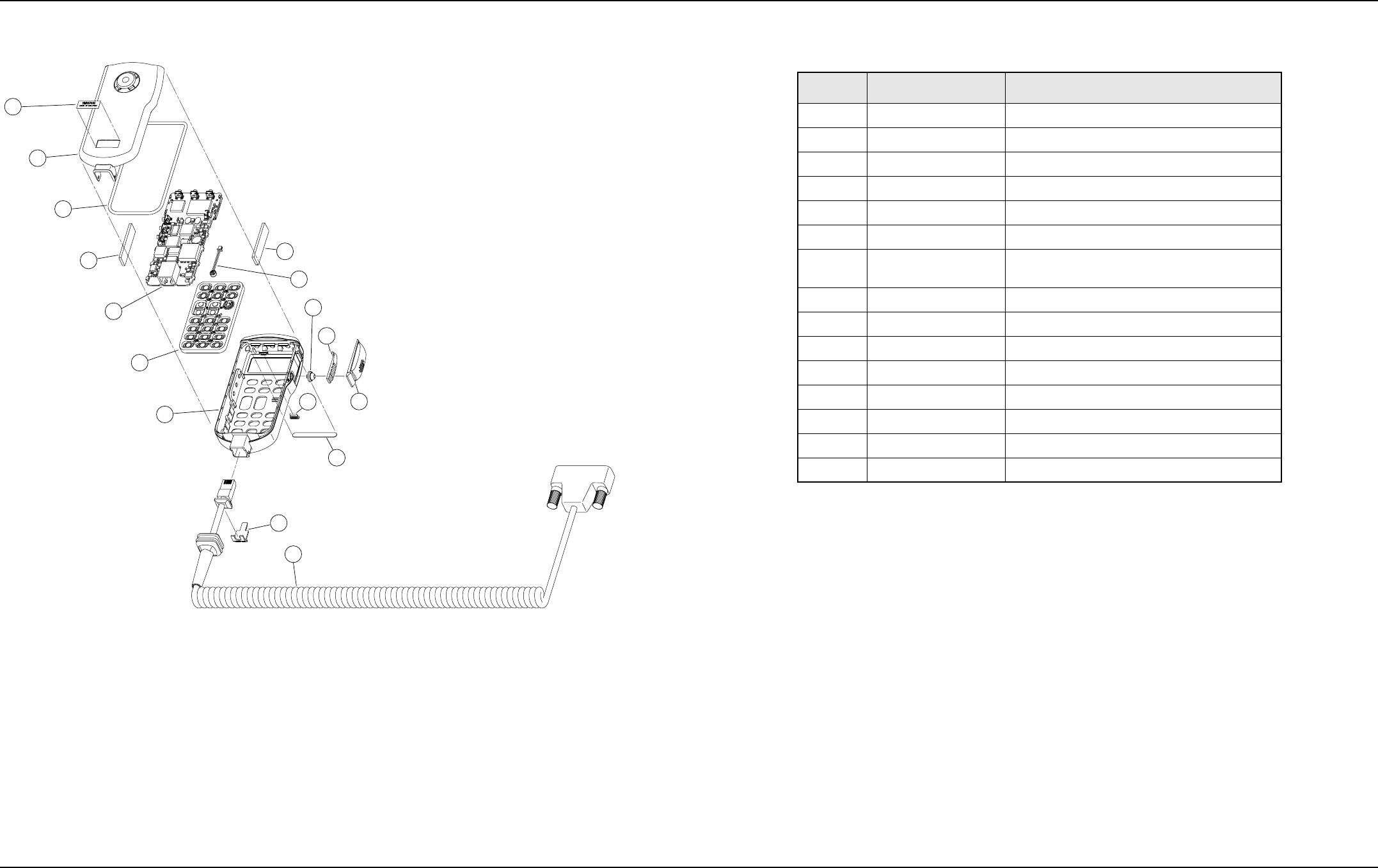
February 3, 2003 6881076C20-E
11-2 Exploded Views and Parts Lists: Model W3 Hand-Held Control Head Exploded View
11.1 Model W3 Hand-Held Control Head Exploded View
Figure 11-1. Model W3 Hand-Held Control Head Exploded View
2
1
3
4
5
6
7
8
4
15
14
10
9
12
11
13
Table 11-1. Model W3 Hand-Held Control Head Exploded View Parts List
Item No. Motorola Part No. Description
1 Not available LABEL
2 0105955T26 ASSEMBLY, Rear Cover
3 3205082E93 SEAL, Main
4 4205343Y01 RETAINER, Snap (Qty 2)
5 0102707D81 BOARD, SB9600 Circuit
6 7505832X01 KEYPAD (Part of Item 7)
7 0102707D86 ASSEMBLY, Housing (Includes Items 6 and 9 thru
13)
8 0102708D08 ASSEMBLY, Microphone
9 7505618V02 ACTUATOR, PTT (Part of Item 7)
10 4505850X01 LEVER, PTT (Part of Item 7)
11 3205839X01 INDICATOR, Transmit (Part of Item 7)
12 3805835X01 BOOT, PTT (Part of Item 7)
13 3305409X17 LABEL (Part of Item 7)
14 3205274V01 WEDGE, Seal Support
15 HKN6095_ ASSEMBLY, Cable
Note: _ = The latest version kit. When ordering, refer to your specific kit
for this suffix letter.
Universal Crypto Module (UCM) part numbers and descriptions are
listed in the Encryption chapter of this manual.
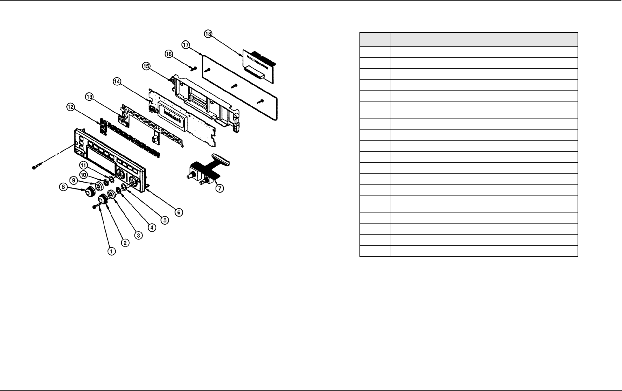
Exploded Views and Parts Lists: Model W4 Rotary Control Head Exploded View 11-3
6881076C20-E February 3, 2003
11.2 Model W4 Rotary Control Head Exploded View
Figure 11-2. Model W4 Rotary Control Head Exploded View
Table 11-2. Model W4 Rotary Control Head Parts List
Item No. Motorola Part No. Description
1 0380077M01 SCREW, Control Head Mounting (Qty 2)
2 3602113Z05 KNOB, Volume Control
3 3205805V01 GASKET, W4 Shaft (Qty 2)
4 0284218M01 NUT, Volume Switch
5 0484219M01 LOCKWASHER, Volume Switch
6 1502117Z07 or
1502117Z08 HOUSING, Front Cover (Mobile)
HOUSING, Front Cover (Motorcycle)
7 0102709J83 ASSEMBLY, Volume and Rotary Switch
8 3602113Z03 KNOB, Mode Control
9 3205805V01 GASKET, W4 Shaft (Qty 2)
10 0284218M02 NUT, Mode Switch
11 0484219M02 LOCKWASHER, Mode Switch
12 6105129X01 LIGHTPIPE
13 7505128X01 KEYPAD
14 AAHN4045_ or
PMLN4019_ ASSEMBLY, Circuit Board (Mobile)
ASSEMBLY, Circuit Board (Motorcycle)
15 4302112Z02 SPACER, Internal
16 0310945A14 SCREW, Machine (Qty 4)
17 3280289L02 GASKET, Housing
18 HLN6401_ ASSEMBLY, Circuit Board Interconnect
Notes: _ = The latest version kit. When ordering, refer to your specific kit
for this suffix letter.
The HKN4356_ Radio Cable is used to remote mount the W4
Control Head.
Universal Crypto Module (UCM) part numbers and descriptions are
listed in the Encryption chapter of this manual.
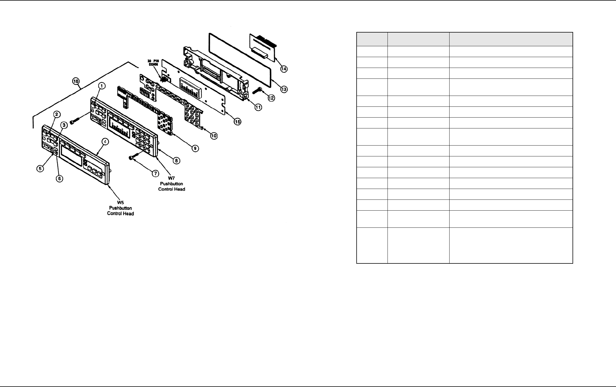
February 3, 2003 6881076C20-E
11-4 Exploded Views and Parts Lists: Models W5 and W7 Pushbutton Control Head Exploded View
11.3 Models W5 and W7 Pushbutton Control Head Exploded View
Figure 11-3. Models W5 and W7 Pushbutton Control Head Exploded View
Table 11-3. Models W5 and W7 Pushbutton Control Head Parts List
Item No. Motorola Part No. Description
1 3880227M04 SWITCH, On/Off Cap
2 3880009P01 SWITCH, Mode Rocker
3 3880009P02 SWITCH, Volume Rocker
4 1580020S17 or
1580020S19 HOUSING, W5 Front Cover (Mobile)
HOUSING, W5 Front Cover (Motorcycle)
5 3880092J05 PUSHBUTTON, HOME
6 3880092J05 PUSHBUTTON, DIM
7 0380077M01 SCREW, (Qty 2)
8 1580020S16 or
1580020S18 HOUSING, W7 Front Cover (Mobile)
HOUSING, W7 Front Cover (Motorcycle)
9 6180017S01 LIGHTPIPE
10 7580012S03 KEYPAD
11 4380019S02 SPACER, Internal Frame
12 0310945A14 SCREW, Tapping (Qty 7)
13 3280289L02 GASKET, Housing
14 HLN6401_ BOARD, Interconnect
15 HLN6396_ or
HLN6563_ BOARD, Control Head (Mobile)
BOARD, Control Head (Motorcycle)
16 0180049S09 or
0180049S11 or
0180049S08 or
0180049S10
ASSEMBLY, W5 Front Cover (Mobile)
ASSEMBLY, W5 Front Cover (Motorcycle)
ASSEMBLY, W7 Front Cover (Mobile)
ASSEMBLY, W7 Front Cover (Motorcycle)
Item 16 includes items 1, 2, 3, 4 or 8, 5, 6, 9, and 10
Notes: _ = The latest version kit. When ordering, refer to your specific kit
for this suffix letter.
The HKN4356_ Radio Cable is used to remote mount the W5 and
W7 Control Head.
Universal Crypto Module (UCM) part numbers and descriptions are
listed in the Encryption chapter of this manual.
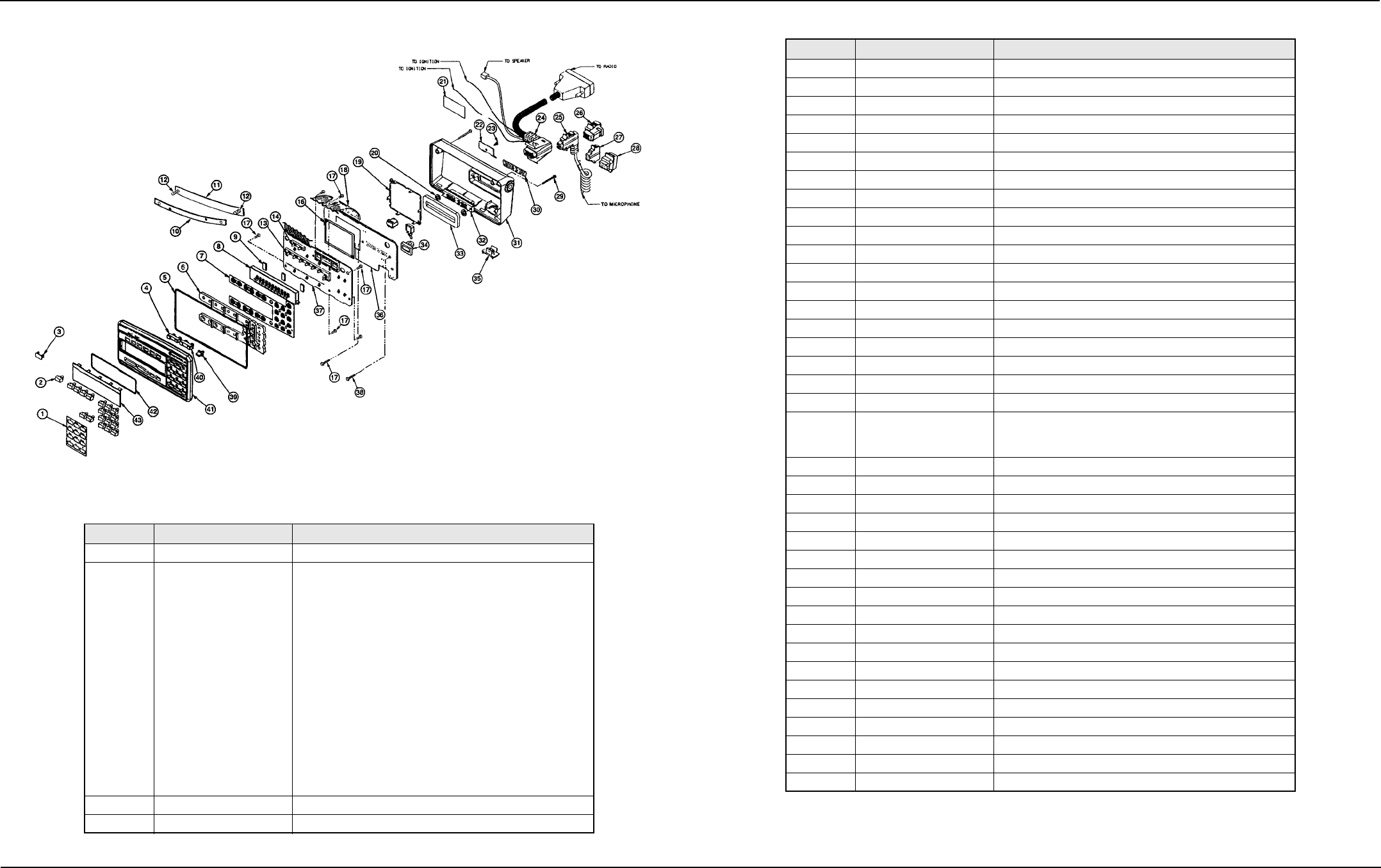
Exploded Views and Parts Lists: Model W9 Pushbutton Control Head Exploded View 11-5
6881076C20-E February 3, 2003
11.4 Model W9 Pushbutton Control Head Exploded View
Figure 11-4. Model W9 Pushbutton Control Head Exploded View
Table 11-4. Model W9 Pushbutton Control Head Parts List
Item No. Motorola Part No. Description
1 1380087J01 ESCUTCHEON
2 HLN5083_
HLN5091_
HLN5066_
HLN5256_
HLN5074_
HLN5268_
HLN5259_
HLN5258_
HLN5090_
HLN5072_
HLN5257_
HLN5076_
HLN5085_
HLN5078_
HLN5087_
HLN5079_
HLN5095_
BUTTON, Emergency
BUTTON, Dir
BUTTON, Scan
BUTTON, Srch
BUTTON, Call
BUTTON, Page
BUTTON, RPGM
BUTTON, Site
BUTTON, PHON
BUTTON, H/L
BUTTON, Lock
BUTTON, RCL
BUTTON, SQL
BUTTON, Del
BUTTON, Home
BUTTON, Sel
BUTTON, Blank
3 3880253K01 PLUG
4 3880195P03 SWITCH, Mode Rocker
5 3205145X01 GASKET, Internal Frame
6 6105126X01 LIGHTPIPE, Keypad
7 7505127X01 KEYPAD
8 7280242J01 DISPLAY, VF
9 7580094M05 PAD, Shock (Qty 3)
10 1405410X01 INSULATOR
11 4180042S01 SPRING, Leaf Assy
12 0380041S01 SCREW, Captive (Qty 4)
13 6180026R02 SPACER, LED (8-Position)
14 6180027R02 SPACER, LED (2-Position)
16 2680190P02 SHIELD, Solder Side (Includes two 1480269K01 insulators)
17 0310945A11 SCREW, Tapping (Qty 5)
18 3080034K01 CABLE, Flex
19 2680190P02 SHIELD, Component Side
20 3205082E90 O-RING "D" Connector (Qty 2)
21 3380178M01 NAMEPLATE
22 0784323C01 BRACKET, Strain Relief
23 0310908A18 SCREW, Machine
24 HKN4356_ CABLE, Radio
25 HMN1050_ or
HMN1080_ or
HMN1061_
KIT, Microphone
26 1580221J01 HOUSING, VIP Connector (Optional)
27 7502118Z01 COVER, Rubber Dust (MIC)
28 7502118Z02 COVER, Rubber Dust (VIP)
29 0310908A33 SCREW, Machine (Qty 2)
30 3205198X01 GASKET, Face
31 1505199X01 HOUSING, Back
32 2805778W01 CONNECTOR, Mini "D" 50 Contact
33 3205143X01 GASKET, "D" Connector
34 3205143X01 GASKET, On/Off Switch
35 3880128J01 KEY, On/Off
36 HCN4046_ BOARD KIT, Command (includes Display Board)
37 HCN4046_ BOARD KIT, Display (includes Command Board)
38 0310945A14 SCREW, Tapping (Qty 2)
39 3880092J05 KEY, Blank
40 3880195P02 SWITCH, Volume Rocker
41 1505125X09 HOUSING, Front
42 3205144X01 GASKET, Lens
43 6105146X01 LENS, VF Display
Note: _ = The latest version kit. When ordering, refer to your specific kit for this suffix
letter.
Universal Crypto Module (UCM) part numbers and descriptions are listed in the
Encryption chapter of this manual.
Table 11-4. Model W9 Pushbutton Control Head Parts List (Continued)
Item No. Motorola Part No. Description
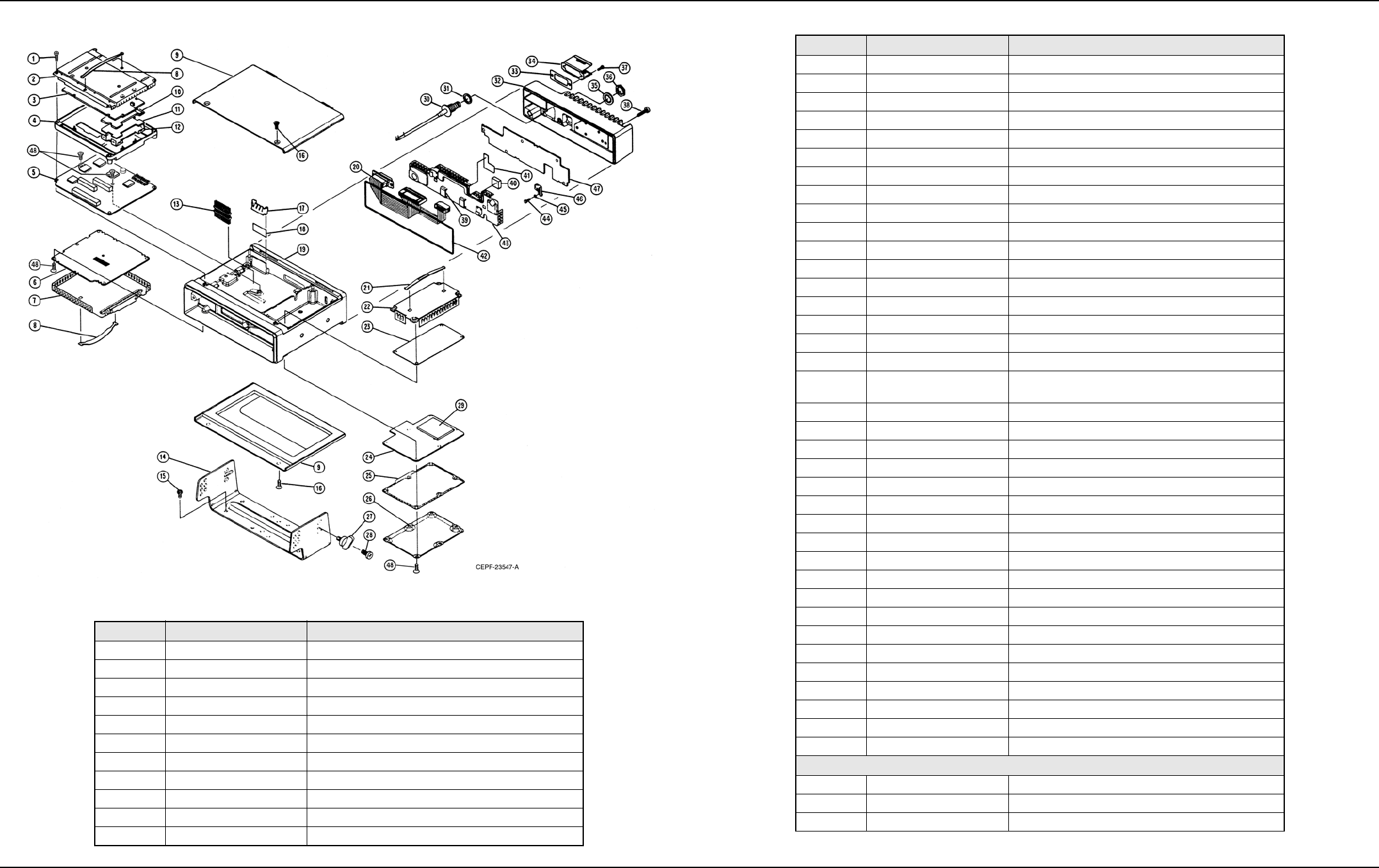
11-6 Exploded Views and Parts Lists: Low-Power (15W) Radio Exploded View
February 3, 2003 6881076C20-E
11.5 Low-Power (15W) Radio Exploded View
Figure 11-5. Low-Power (15W) Radio Exploded View
Table 11-5. Low-Power (15W) Radio Parts List
Item No. Motorola Part No. Description
1 0312016A27 SCREW, Tapping 3.5 x 0.6 x 22 (Board Mounting)
2 2605704V02 SHIELD, Top
3 HLN6458_ KIT, Controller Board
4 2705703V02 CASTING, Controller
5 HLN5558_ KIT, Command Board
6 HRN6019_ KIT, RF Board (800 MHz)
7 1580099L01 SHIELD, RF Board
8 5584300B01 HANDLE (Qty 2)
9 1580264N04 COVER (Includes gasket)
10 2605131X01 SHIELD, Encryption Board (Optional)
11 - - - - - - - - - BOARD, Encryption (Optional)
12 4205566W01 CLIP, Encryption Board (Optional)
13 2880260M03 HEADER, Floating
14 0780086N01 TRUNNION, Mounting
15 0312002B14 SCREW, Self-Drilling 10-16 x 10 (Qty 4)
16 0380102P01 SCREW, Tapping 3.5 x 0.6 x10 (Qty 8)
17 4280007M02 CLIP, Regulator
18 1480001M03 INSULATOR, Regulator
19 2780082N01 CHASSIS, Consolidated
20 3080239N02 CABLE, PA Ribbon
21 5584300B01 HANDLE (Qty 2)
22 1580098L01 COVER, Front-End Receiver
23 HRF6004_ KIT, Front-End Receiver Board (800 MHz)
24 HLF6080_ KIT, VCO Board (800 MHz)
25 3280247N01 GASKET, VCO
26 1580097L01 COVER, VCO Board
27 0384244C06 SCREW, Wing 5 x 0.8 x 10 (Qty 4)
28 0380114M02 SCREW, Machine 5 x 0.8 x 10 (Qty 8)
29 HLF6079_
1580223N02
KIT, VCO Hybrid Board (800 MHz)
COVER, VCO Hybrid (not included in item 29)
30 3080261M05 CABLE, Mini (includes items 35 and 36)
31 3280089M02 GASKET, Antenna
32 2680009M02 HEATSINK
33 3080261M05 GASKET, Accessory Connector
34 4280016M03 CLIP, Accessory Connector
35 0400132718 LOCKWASHER, Internal Tooth
36 0280142M01 NUT, Hex, 7/16"
37 0380043L01 SCREW, Metric 3.0 x 10 (Qty 4)
38 0380077M03 SCREW, Hex Socket (Qty 2)
39 4280265M02 CLIP, PA Coax (Qty 2)
40 4380104N01 SPACER, PA Shield
41 1480143M01 INSULATOR, Shield
42 3280053P01 GASKET, Heatsink
43 2680011M01 SHIELD, PA Board
44 0310911A11 SCREW, Machine 3.5 x 0.5 x 8
45 0480217E01 WASHER, Compression
46 2680187N02 HEATSINK
47 HLF6078_ KIT, Low-Power PA Board (15W; 800 MHz)
48 0310943J15 SCREW, Tapping 3.5 x 0.6 x 8
NON-REFERENCED ITEMS
3080091M01 CABLE, Speaker
7505295B01 PAD, Crystal
7580094M05 PAD, VF Display Shock (Qty 3)
Note: _ = The latest version kit. When ordering, refer to your specific kit for this suffix letter.
Table 11-5. Low-Power (15W) Radio Parts List (Continued)
Item No. Motorola Part No. Description
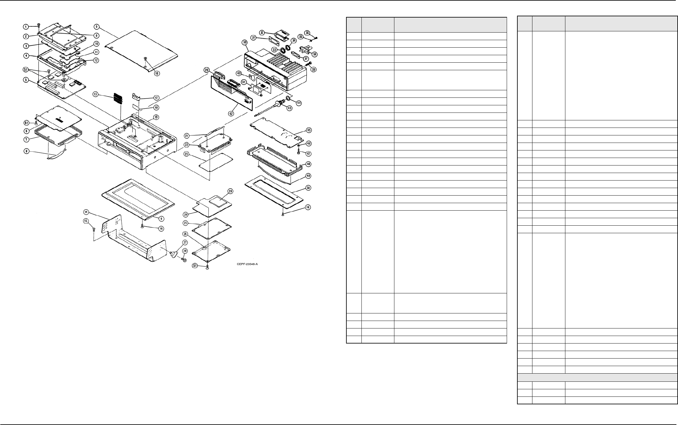
6881076C20-E February 3, 2003
Exploded Views and Parts Lists: Mid-Power (20-40/25-50/35W) Radio Exploded View 11-7
11.6 Mid-Power (20-40/25-50/35W) Radio Exploded View
Figure 11-6. Mid-Power (20-40/25-50/35W) Radio Exploded View
Table 11-6. Mid-Power (20-40/25-50/35W) Radio Parts List
Item
No. Motorola
Part No. Description
1 0312016A27 SCREW, Tapping 3.5 x 0.6 x 22 (Board Mounting)
2 2605704V02 SHIELD, Top
3 HLN6458_ BOARD KIT, Controller
4 2705703V02 CASTING, Controller
5 HLN5558_ Kit, Command Board
6 HRN6014_ or
HRN6020_ or
HRN6019_
KIT, RF Board (VHF)
KIT, RF Board (UHF)
KIT, RF Board (800 MHz)
7 1580099L01 SHIELD, RF Board
8 5584300B01 HANDLE (Qty 2)
9 1580264N04 COVER (Includes gasket)
10 2605131X01 SHIELD, Encryption Board (Optional)
11 - - - - - - - - - BOARD, Encryption (Optional)
12 4205566W01 CLIP, Encryption Board (Optional)
13 2880260M01 HEADER, Floating
14 0780086N01 TRUNNION, Mounting
15 0312002B14 SCREW, Self-Drilling 10-16 x 10 (Qty 4)
16 0380102P01 SCREW, Tapping 3.5 x 0.6 x10 (Qty 8)
17 4280007M01 CLIP, Regulator
18 1480001M01 INSULATOR, Regulator
19 2780082N01 CHASSIS, Consolidated
20 3080239N02 CABLE, PA Ribbon
21 5584300B01 HANDLE (Qty 2)
22 1580098L01 COVER, Front-End Receiver
23 HRD6001_ or
HRD6002_ or
HRE6001_ or
HRE6002_ or
HRE6003_ or
HRE6004_ or
HRF6004_
KIT, Front-End Receiver Board
(VHF Range 1, 136-162MHz)
KIT, Front-End Receiver Board
(VHF Range 2, 146-174MHz)
KIT, Front-End Receiver Board
(UHF Range 1, 403-433MHz)
KIT, Front-End Receiver Board
(UHF Range 2, 438-470MHz)
KIT, Front-End Receiver Board
(UHF Range 3, 450-482MHz)
KIT, Front-End Receiver Board
(UHF Range 4, 482-512MHz)
KIT, Front-End Receiver Board (800 MHz)
24 HLD6000_ or
HLE6046_ or
HLF6080_
KIT, VCO Board (VHF)
KIT, VCO Board (UHF)
KIT, VCO Board (800 MHz)
25 3280247N01 GASKET, VCO
26 1580097L01 COVER, VCO Board
27 0384244C06 SCREW, Wing 5 x 0.8 x 10 (Qty 4)
28 0380114M02 SCREW, Machine 5 x 0.8 x 10 (Qty 8)
29 HLD6061_ or
HLD6062_ or
HLE6101_ or
HLE6102_ or
HLE6103_ or
HLE6104_ or
HLF6079_
1580223N02
KIT, VCO Hybrid Board
(VHF Range 1, 136-162MHz)
KIT, VCO Hybrid Board
(VHF Range 2, 146-174MHz)
KIT, VCO Hybrid Board
(UHF Range 1, 403-433MHz)
KIT, VCO Hybrid Board
(UHF Range 2, 438-470MHz)
KIT, VCO Hybrid Board
(UHF Range 3, 450-482MHz)
KIT, VCO Hybrid Board
(UHF Range 4, 482-512MHz)
Kit, VCO Hybrid Board (800 MHz)
COVER, VCO Hybrid (not included in item 29)
30 2680010M02 HEATSINK, Mid-Power Amplifier (PA)
31 3280088M01 GASKET, Accessory Connector
32 4280016M03 CLIP, Accessory Connector
33 0400132718 LOCKWASHER, Internal Tooth
34 0280142M01 NUT, Hex, 7/16"
35 0400131974 WASHER, Flat
36 0380043L01 SCREW, Metric 3.0 x 10 (Qty. 4)
37 3280015M01 GASKET, Power Connector
38 0980272N02 CONNECTOR, Power
39 0380077M06 SCREW, Hex Socket (Qty 2)
40 4280264M02 CLIP, PA Coax
41 4280192N01 CLIP, Coax
42 3280053P01 GASKET, Heatsink
43 3080261M04 CABLE, Mini (includes items 33 and 34)
44 3280089M02 GASKET, Antenna
45 HLD6066_ or
HLD6032_ or
HLD6022_ or
HLE6049_ or
HLE6062_ or
HLE6043_ or
HLE6044_ or
HLF6077_
KIT, Mid-Power PA Board
(25-50W; VHF Range 1 136-162MHz)
KIT, Mid-Power PA Board
(25-50W; VHF Range 2, 146-174MHz)
KIT, Mid-Power PA Board
(25-50W; VHF Range 2, 146-174MHz)
KIT, Mid-Power PA Board
(20-40W; UHF Range 1, 403-433MHz)
KIT, Mid-Power PA Board
(20-40W; UHF Range 1, 403-433MHz)
KIT, Mid-Power PA Board
(20-40W; UHF Range 3, 450-482MHz)
KIT, Mid-Power PA Board
(20-40W; UHF Range 4, 482-512MHz)
KIT, Mid-Power PA Board (35W; 800 MHz)
46 0480217E01 WASHER, Compression
47 0310911A11 SCREW, Machine 3.5 x 0.5 x 8
48 2680186M01 SHIELD, PA
49 5584300B04 HANDLE
50 1580048N01 Cover, PA Mid-Power
51 0310943J15 SCREW, Tapping 3.5 x 0.6 x 8
NON-REFERENCED ITEMS
3080091M01 CABLE, Speaker
7505295B01 PAD, Crystal
7580094M05 Pad, VF Display Shock (Qty 3)
Note: _ = The latest version kit. When ordering, refer to your
specific kit for this suffix letter.
Table 11-6. Mid-Power (20-40/25-50/35W) Radio Parts List
Item
No. Motorola
Part No. Description
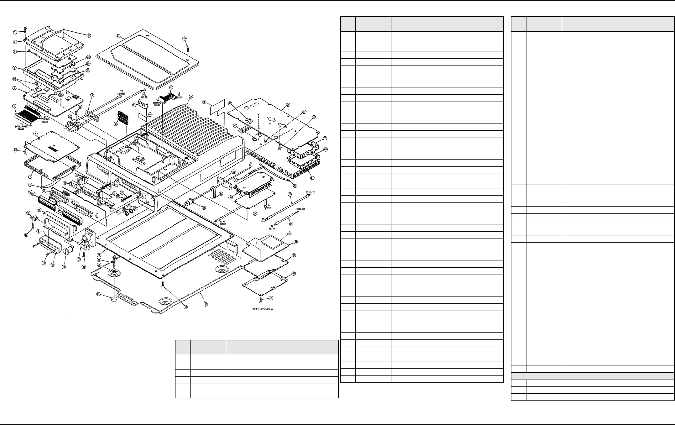
February 3, 2003 6881076C20-E
11-8 Exploded Views and Parts Lists: High-Power (50-110W) Radio Exploded View
11.7 High-Power (50-110W) Radio Exploded View
Figure 11-7. High-Power (50-110W) Radio Exploded View
Table 11-7. High-Power (50-110W) Radio Parts List
Item
No. Motorola
Part No. Description
1 0312016A27 SCREW, Tapping 3.5 x 0.6 x 22 (Board Mounting)
2 2605704V02 SHIELD, Top
3 HLN6458_ KIT, Controller Board
4 2705703V02 CASTING, Controller
5 HLN5558_ KIT, Command Board
6 3080211R01 CABLE, Command Bd to Interconnect Bd Ribbon
7 HRN6014_ or
HRN6020_ or
HRN6019_
KIT, RF Board (VHF)
KIT, RF Board (UHF)
KIT, RF Board (800 MHz)
8 1580099L01 SHIELD, RF Board
9 5584300B01 HANDLE (Qty 2)
10 3280206R01 GASKET, Connector
11 3280206R02 GASKET, SecureNet Connector
12 HLN5558_ KIT, Interconnect Board
13 4380110R01 SPACER, Interconnect Board
14 4280232R01 CLIP, Interconnect Board
15 5580102R01 HANDLE
16 4780176P01 PIN, Pivot
17 0310943R55 SCREW, Tapping
18 3280118R01 COVER Gasket
19 0380214R01 SCREW, Captive
20 3880122R01 CONNECTOR
21 5580370A01 LOCK
22 1580218R01 HOUSING, Lock (Non-replacable item)
23 0380043L01 SCREW, Tapping (Non-replacable item)
24 1580216R01 COVER, Bottom
25 0312002A28 SCREW, Self-Drilling
26 0400007688 LOCKWASHER
27 4382292M01 BUSHING, Spacer
28 4280210R01 RETAINER, Wire
29 0405171J03 WASHER, Fiber
30 0310908A97 SCREW, Machine
31 0280242M01 NUT, Hex; 7/16"
32 0400132718 LOCKWASHER, Internal-Tooth 7/16"
33 0480285R01 WASHER, Special
34 5584300B01 HANDLE
35 2605131X01 SHIELD, Encryption Board (Optional)
36 - - - - - - - - - BOARD, Encryption (Optional)
37 4205566W01 CLIP, Encryption Board (Optional)
38 3205457V01 GASKET, Power Connector
39 0380102P01 SCREW, Tapping
40 3080114R02 CONNECTOR, Power
41 1580217R01 COVER, Top
42 2880260M03 HEADER, Floating
43 4280007M02 CLIP, Regulator
44 1480001M01 INSULATOR, Regulator
45 3080212R01 CABLE, Command Bd to PA Bd Ribbon
46 2780133P02 CHASSIS
47 3380080E01 NAMEPLATE, FCC
48 0780255R01 BRACKET, Feed-Through
49 2680201R01 HEATSINK Diode-Bracket
50 4280261R01 CLIP, Coaxial Antenna
51 3280120R01 GASKET, Mini-Internal Connector
52 1580098L01 SHIELD, Front-End Receiver
53 3080261M03 CABLE, Mini
Table 11-7. High-Power (50-110W) Radio Parts List
Item
No. Motorola
Part No. Description
54 HRD6001_ or
HRD6002_ or
HRE6001_ or
HRE6002_ or
HRE6003_ or
HRE6004_ or
HRF6004_
KIT, Front-End Receiver Board
(VHF Range 1, 136-162MHz)
KIT, Front-End Receiver Board
(VHF Range 2, 146-174MHz)
KIT, Front-End Receiver Board
(UHF Range 1, 403-433MHz)
KIT, Front-End Receiver Board
(UHF Range 2, 438-470MHz)
KIT, Front-End Receiver Board
(UHF Range 3, 450-482MHz)
KIT, Front-End Receiver Board
(UHF Range 4, 482-512MHz)
KIT, Front-End Receiver Board (800 MHz)
55 1580132P01 TRAY, Mounting
56 HLD6064_ or
HLD6063_ or
HLE6051_ or
HLE6039_ or
HLE6040_
KIT, High-Power PA Board
(50-110W; VHF Range 1, 136-162MHz)
KIT, High-Power PA Board
(50-110W; VHF Range 2, 146-174MHz)
KIT, High-Power PA Board
(50-110W; UHF Range 1, 403-433MHz)
KIT, High-Power PA Board
(50-110W; UHF Range 3, 450-482MHz)
KIT, High-Power PA Board
(50-110W; UHF Range 4, 482-512MHz)
57 4280202R01 CLIP, Coaxial
58 0310911A11 SCREW, Machine
59 2680139P01 SHIELD, Harmonic Filter
60 1580208R01 COVER, Harmonic Shield
61 2680138P02 SHIELD, Power Amplifier (PA)
62 5584300B04 HANDLE, PA Shield
63 3080152M15 CABLE, Coaxial Transmitter
64 3080037R12 CABLE, Coaxial Receiver
65 HLD6061_ or
HLD6062_ or
HLE6101_ or
HLE6102_ or
HLE6103_ or
HLE6104_ or
HLF6079_
1580223N02
KIT, VCO Hybrid Board
(VHF Range 1,136-162MHz)
KIT, VCO Hybrid Board
(VHF Range 2,146-174MHz)
KIT, VCO Hybrid Board
(UHF Range 1,403-433MHz)
KIT, VCO Hybrid Board
(UHF Range 2, 438-470MHz)
KIT, VCO Hybrid Board
(UHF Range 3, 450-482MHz)
KIT, VCO Hybrid Board
(UHF Range 4, 482-512MHz)
KIT, VCO Hybrid Board (800 MHz)
COVER, VCO Hybrid (not included in item 29)
66 HLD6000_ or
HLE6046_ or
HLF6080_
Kit, VCO Board (VHF)
Kit, VCO Board (UHF)
Kit, VCO Board (800 MHz)
67 3280247N01 GASKET, VCO
68 1580097L01 COVER, VCO Board
69 0310943J15 SCREW, Tapping 3.5 x 0.6 x 8
NON-REFERENCED ITEMS
3080091M01 CABLE, Speaker
7505295B01 PAD, Crystal
7580094M05 PAD, VF Display Shock (Qty 3)
Note: _ = The latest version kit. When ordering, refer to your specific kit for this
suffix letter.
Table 11-7. High-Power (50-110W) Radio Parts List
Item
No. Motorola
Part No. Description
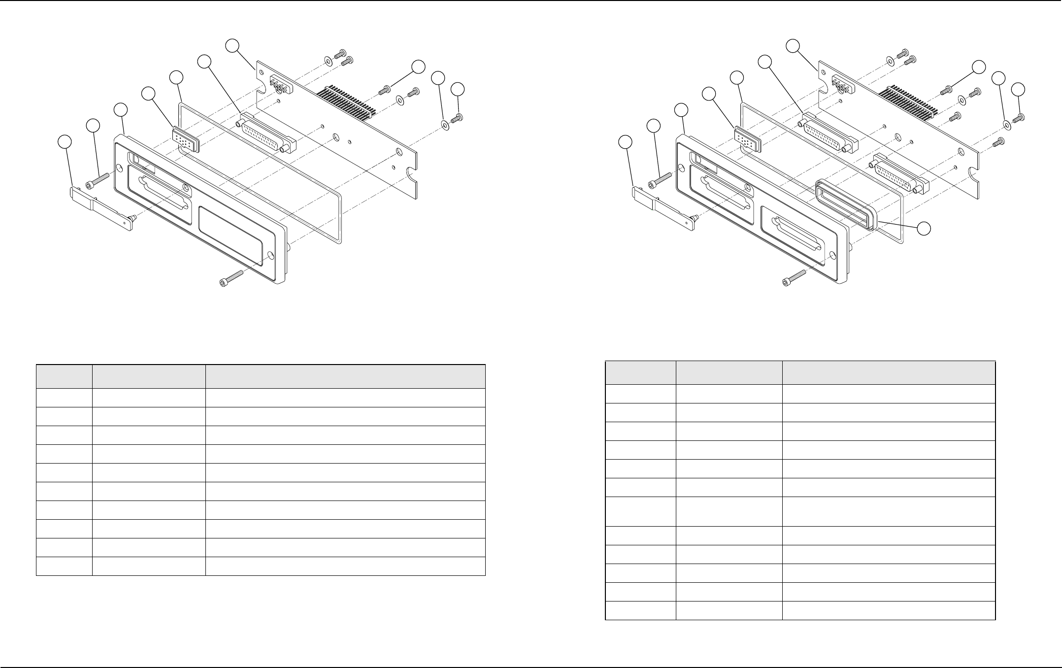
Exploded Views and Parts Lists: Motorcycle Interconnect Board and Assembly 11-9
6881076C20-E February 3, 2003
11.8 Motorcycle Interconnect Board and Assembly
Figure 11-8. Motorcycle Interconnect Board and Assembly (HLN6365) Exploded View
11.9 Low- and Mid-Power Interconnect Board and Assembly
Figure 11-9. Low- and Mid-Power Interconnect Board and Assembly (HLN6344) Exploded View
Table 11-8. Motorcycle Interconnect Board and Assembly (HLN6365) Parts List
Item No. Motorola Part No. Description
1 3880064P01 CAP, DVP Connector
2 0380077M01 SCREW, Front Mount
3 1580062P07 HOUSING, Remote Front
4 3280063P01 GASKET, DVP Connector
5 3280289L02 GASKET, O-Ring
6 0980159P01 CONNECTOR, D-Sub
7 HLNxxxx_ BOARD, Interconnect (See dealer for applicable kit number.)
8 300139581 SCREW, Mach 4-40X5/16 P
9 400131974 WASHER, Flt.130.312
10 0310945A11 SCREW, Tapping P3.12X1.27X8
Note: _ = The latest version kit. When ordering, refer to your specific kit for this suffix letter.
1
2
3
4
5
6
7
8910
MAEPF-27269-O
Table 11-9. Low- and Mid-Power Interconnect Board and Assembly (HLN6344) Parts List
Item No. Motorola Part No. Description
1 3880064P01 CAP, DVP Connector
2 0380077M01 SCREW, Front Mount
3 1580062P06 HOUSING, Remote Front
4 3280063P01 GASKET, DVP Connector
5 3280289L02 GASKET, O-Ring
6 0980159P01 CONNECTOR, D-Sub
7 HLNxxxx_ BOARD, Interconnect (See dealer for applicable kit
number.)
8 300139581 SCREW, Mach 4-40X5/16 P
9 400131974 WASHER, Flt.130.312
10 0310945A11 SCREW, Tapping P3.12X1.27X8
11 3280025R01 GASKET, Remote
Not shown 1580005G01* COVER, Dust
Note: _ = The latest version kit. When ordering, refer to your specific kit for this suffix letter.
* = Used when the option cable is not used or when the radio is stowed.
1
2
3
4
5
6
7
8910
11
MAEPF-27270-O
11-10 Exploded Views and Parts Lists: Small Pushbutton Parts
February 3, 2003 6881076C20-E
11.10 Small Pushbutton Parts 11.11 Large Pushbutton Parts
Table 11-10. Small Pushbutton Parts List
Part Number Graphic
Legend Part Number Graphic
Legend
3805671X02 1 3805671X21 9wxy
3805671X03 2 3805671X22 * Rcl
3805671X04 3 3805671X23 #Del
3805671X05 4 3805671X24 1Ste
3805671X06 5 3805671X25 2Pge
3805671X07 6 3805671X26 3Lck
3805671X08 7 3805671X27 4Sts
3805671X09 8 3805671X28 5Rpg
3805671X10 9 3805671X29 6Msg
3805671X11 0 3805671X30 7H/L
3805671X12 * 3805671X31 8Mon
3805671X13 # 3805671X32 9Dir
3805671X14 2abc 3805671X33 Mon
3805671X15 3def 3805671X34 H/L
3805671X16 4ghi 3805671X35 DIR
3805671X17 5jkl 3805671X36 Urg
3805671X18 6mno 3805671X37 RTT
3805671X19 7prs 3805671X38 Home
3805671X20 8tuv 3805671X39 Dim
Table 11-11. Large Pushbutton Parts List
Part Number Graphic
Legend Part Number Graphic
Legend
3805672X01 - - 3805672X10 H/L
3805672X02 MPL 3805672X11 Sts
3805672X03 Scan 3805672X12 Call
3805672X04 DVP 3805672X13 Msg
3805672X05 PA 3805672X14 Rcl
3805672X06 Sirn 3805672X15 Mode
3805672X07 Wail 3805672X16 ExRd
3805672X08 Hi/Lo 3805672X17 Del
3805672X09 Man 3805672X18 Sel
3805672X19 Mon 3805672X52 Emer
3805672X20 DTMF 3805672X53 Stdy
3805672X21 Yelp 3805672X54 ECC
3805672X22 MVS 3805672X55 Rptr
3805672X23 Play 3805672X56 State
3805672X24 Rply 3805672X57 Reg
3805672X25 Rcrd 3805672X58 AirHn
3805672X26 Emer 3805672X59 TB Scn
3805672X27 Ext 3805672X60 SCC
3805672X28 F/R 3805672X61 Srch
3805672X29 Alt 3805672X62 Lock
3805672X30 Tel 3805672X63 Page
3805672X31 Sql 3805672X64 Rear
3805672X32 DES 3805672X65 Xfer
3805672X33 Txt 3805672X66 ST
3805672X34 Indv 3805672X67 VHF
3805672X35 Pvt 3805672X68 UHF
3805672X36 Site 3805672X69 Aux
3805672X37 AA 3805672X70 QC II
3805672X38 Sub 3805672X71 Mute
3805672X39 Home 3805672X72 Pri
3805672X40 Menu 3805672X73 Blu
3805672X41 Rpgm 3805672X74 Div
3805672X42 Step 3805672X75 RTT
3805672X43 3805672X76 Send
3805672X44 Phon 3805672X77 Front
3805672X45 Dir 3805672X78 Bid
3805672X46 Text 3805672X79 ZONE
3805672X47 Rvw 3805672X80 TRBL
3805672X48 Sec 3805672X81 OVHD
3805672X49 Ø 3805672X82 UNGD
3805672X50 L/S 3805672X83 RSSI
3805672X51 S/S 3805672X84 VRS
3805672X85 A/B 3805669X12 ETrp
3805672X86 Chan 3805669X13 LvTe
3805672X87 PRTT 3805669X14 ArTe
3805672X88 RtRn 3805669X15 LvGg
3805672X89 Emp# 3805669X16 ArGg
3805672X90 Pass 3805669X17 P/in
3805672X91 Cir 3805669X18 P/out
3805672X92 URG 3805669X19 Serv
3805672X93 A 3805669X20 0/S
3805672X94 B 3805669X21 Rev
3805672X95 C 3805669X22 Stby
3805672X96 D 3805669X23 Sts 1
3805672X97 E 3805669X24 Sts 2
3805672X98 F 3805669X25 Sts 3
3805672X99 G 3805669X26 Sts 4
3805669X01 K 3805669X27 Sts 5
3805669X02 L 3805669X28 Sts 6
3805669X03 T/Z 3805669X29 Sts 7
3805669X04 30 3805669X30 Sts 8
Table 11-11. Large Pushbutton Parts List (Continued)
Part Number Graphic
Legend Part Number Graphic
Legend
3805669X05 Entr 3805669X31 Drvr
3805669X06 M/WT 3805669X32 Bdg#
3805669X07 MAck 3805669X33 LnBI
3805669X08 Time 3805669X34 RtBl
3805669X09 SRun 3805669X35 LnRn
3805669X10 ERun 3805669X36 s
3805669X11 STrp 3805669X37 t
Table 11-11. Large Pushbutton Parts List (Continued)
Part Number Graphic
Legend Part Number Graphic
Legend

Appendix A Replacement Parts Ordering
A.1 Basic Ordering Information
When ordering replacement parts or equipment information, the complete identification number
should be included. This applies to all components, kits, and chassis. If the component part number
is not known, the order should include the number of the chassis or kit of which it is a part, and
sufficient description of the desired component to identify it.
Crystal orders should specify the crystal type number, crystal and carrier frequency, and the model
number in which the part is used.
A.2 Transceiver Board and VOCON Board Ordering Information
When ordering a replacement Transceiver Board or VOCON Board, refer to the applicable Model
Chart in the front of this manual, read the Transceiver Board or VOCON Board note, and include the
proper information with your order.
A.3 Motorola Online
Motorola Online users can access our online catalog at
https://www.motorola.com/businessonline
To register for online access, please call 800-814-0601 (for U.S. and Canada Service Centers only).
A.4 Mail Orders
Send written orders to the following addresses:
Replacement Parts/
Test Equipment/Manuals/
Crystal Service Items:
Motorola Inc.
Customer Care and Services
Division*
Attention: Order Processing
1307 E. Algonquin Road
Schaumburg, IL 60196
U.S.A.
Federal Government Orders:
Motorola Inc.
U.S. Federal Government
Markets Division
Attention: Order Processing
7230 Parkway Drive
Landover, MD 21076
U.S.A.
International Orders:
Motorola Inc.
Customer Care and Services
Division*
Attention: Order Processing
1307 E. Algonquin Road
Schaumburg, IL 60196
U.S.A.

February 3, 2003 6881076C25-E
A-2 Replacement Parts Ordering Telephone Orders
A.5 Telephone Orders
Customer Care and Services Division*
(United States and Canada)
7:00 AM to 7:00 PM (Central Standard Time)
Monday through Friday (Chicago, U.S.A.)
1-800-422-4210
1-847-538-8023 (International Orders)
U.S. Federal Government Markets Division (USFGMD)
1-800-826-1913 Federal Government Parts - Credit Cards Only
8:30 AM to 5:00 PM (Eastern Standard Time)
A.6 Fax Orders
Customer Care and Services Division*
(United States and Canada)
1-800-622-6210
847-576-3023 (International)
USFGMD
(Federal Government Orders)
1-800-526-8641 (For Parts and Equipment Purchase Orders)
A.7 Parts Identification
Customer Care and Services Division*
(United States and Canada)
1-800-422-4210, menu 3
A.8 Product Customer Service
Customer Response Center
(Non-technical Issues)
1-800-247-2346
FAX:1-800-247-2347
*The Customer Care and Services Division (CCSD) was formerly known as the Accessories and Aftermarket
Division (AAD).

Glossary Glossary
This glossary contains an alphabetical listing of terms and their definitions that are applicable to
ASTRO portable and mobile subscriber radio products.
Term Definition
A/D See analog-to-digital conversion.
Abacus IC A custom integrated circuit providing a digital receiver intermediate
frequency (IF) backend.
ADC See analog-to-digital converter.
ADDAG See Analog-to-Digital, Digital-to-Analog and Glue.
ALC See automatic level control.
analog Refers to a continuously variable signal or a circuit or device designed
to handle such signals. See also digital.
Analog-to-Digital,
Digital-to-Analog
and Glue
An integrated circuit designed to be an interface between the radio’s
DSP, which is digital, and the analog transmitter and receiver ICs.
analog-to-digital
conversion Conversion of an instantaneous dc voltage level to a corresponding
digital value. See also D/A.
analog-to-digital
converter A device that converts analog signals into digital data. See also DAC.
automatic level
control A circuit in the transmit RF path that controls RF power amplifier output,
provides leveling over frequency and voltage, and protects against high
VSWR.
band Frequencies allowed for a specific purpose.
BBP See baseband interface port.
baseband interface
port Synchronous serial interface to the transceiver board used to transfer
transmit and receive audio data.
BGA See ball grid array.
ball grid array A type of IC package characterized by solder balls arranged in a grid
that are located on the underside of the package.
CODEC See coder/decoder.
coder/decoder A device that encodes or decodes a signal.

February 3, 2003 6881076C20-E
Glossary-2
CPS See Customer Programming Software.
Customer
Programming
Software
Software with a graphical user interface containing the feature set of an
ASTRO radio. See also RSS.
D/A See digital-to-analog conversion.
DAC See digital-to-analog converter.
default A pre-defined set of parameters.
digital Refers to data that is stored or transmitted as a sequence of discrete
symbols from a finite set; most commonly this means binary data
represented using electronic or electromagnetic signals. See also
analog.
digital-to-analog
conversion Conversion of a digital signal to a voltage that is proportional to the input
value. See also A/D.
digital-to-analog
converter A device that converts digital data into analog signals. See also ADC.
Digital Private-Line A type of digital communications that utilizes privacy call, as well as
memory channel and busy channel lock out to enhance communication
efficiency.
digital signal
processor A microcontroller specifically designed for performing the mathematics
involved in manipulating analog information, such as sound, that has
been converted into a digital form. DSP also implies the use of a data
compression technique.
digital signal
processor code Object code executed by the Digital Signal Processor in an ASTRO
subscriber radio. The DSP is responsible for computation-intensive
tasks, such as decoding ASTRO signaling.
DPL See Digital Private-Line. See also PL.
DSP See digital signal processor.
DSP code See digital signal processor code.
DTMF See dual tone multi-frequency.
dual tone multi-
frequency The system used by touch-tone telephones. DTMF assigns a specific
frequency, or tone, to each key so that it can easily be identified by a
microprocessor.
EEPOT Electrically Programmable Digital Potentiometer.
EEPROM See Electrically Erasable Programmable Read-Only Memory.
Term Definition

6881076C20-E February 3, 2003
Glossary-3
Electrically Erasable
Programmable
Read-Only Memory
A special type of PROM that can be erased by exposing it to an
electrical charge. An EEPROM retains its contents even when the
power is turned off.
FCC Federal Communications Commission.
firmware Code executed by an embedded processor such as the Host or DSP in
a subscriber radio. This type of code is typically resident in non-volatile
memory and as such is more difficult to change than code executed
from RAM.
FGU See frequency generation unit.
flash A non-volatile memory device similar to an EEPROM. Flash memory
can be erased and reprogrammed in blocks instead of one byte at a
time.
FLASHcode A 13-digit code which uniquely identifies the System Software Package
and Software Revenue Options that are enabled in a particular
subscriber radio. FLASHcodes are only applicable for radios which are
upgradeable through the FLASHport process.
FLASHport A Motorola term that describes the ability of a radio to change memory.
Every FLASHport radio contains a FLASHport EEPROM memory chip
that can be software written and rewritten to, again and again.
FMR See Florida Manual Revision.
Florida Manual
Revision A publication that provides supplemental information for its parent
publication before it is revised and reissued.
frequency Number of times a complete electromagnetic-wave cycle occurs in a
fixed unit of time (usually one second).
frequency
generation unit This unit generates ultra-stable, low-phase noise master clock and other
derived synchronization clocks that are distributed throughout the
communication network.
General-Purpose
Input/Output Pins whose function is programmable.
GPIO See General-Purpose Input/Output.
host code Object code executed by the host processor in an ASTRO subscriber
radio. The host is responsible for control-oriented tasks such as
decoding and responding to user inputs.
IC See integrated circuit.
IF Intermediate Frequency.
IMBE A sub-band, voice-encoding algorithm used in ASTRO digital voice.
Term Definition

February 3, 2003 6881076C20-E
Glossary-4
inbound signaling
word Data transmitted on the control channel from a subscriber unit to the
central control unit.
integrated circuit An assembly of interconnected components on a small semiconductor
chip, usually made of silicon. One chip can contain millions of
microscopic components and perform many functions.
ISW See inbound signaling word.
key-variable loader A device used to load encryption keys into a radio.
kHz See kilohertz.
kilohertz One thousand cycles per second. Used especially as a radio-frequency
unit.
KVL See key-variable loader.
LCD See liquid-crystal display.
LED See LED.
light emitting diode An electronic device that lights up when electricity is passed through it.
liquid-crystal display An LCD uses two sheets of polarizing material with a liquid-crystal
solution between them. An electric current passed through the liquid
causes the crystals to align so that light cannot pass through them.
LO Local oscillator.
low-speed
handshake 150-baud digital data sent to the radio during trunked operation while
receiving audio.
LSH See low-speed handshake.
Master In Slave Out SPI data line from a peripheral to the MCU.
Master Out Slave In SPI data line from the MCU to a peripheral.
MCU See microcontroller unit.
MDC Motorola Digital Communications.
MDI MCU/DSP Interface internal to the Patriot IC.
MHz See Megahertz.
Megahertz One million cycles per second. Used especially as a radio-frequency
unit.
microcontroller unit Also written as µC. A microprocessor that contains RAM and ROM
components, as well as communications and programming components
and peripherals.
MISO See Master In Slave Out.
Term Definition

6881076C20-E February 3, 2003
Glossary-5
MOSI See Master Out Slave In.
multiplexer An electronic device that combines several signals for transmission on
some shared medium (e.g., a telephone wire).
MUX See multiplexer.
NiCd Nickel-cadmium.
NiMH Nickel-metal-hydride.
OMPAC See over-molded pad-array carrier.
open architecture A controller configuration that utilizes a microprocessor with extended
ROM, RAM, and EEPROM.
oscillator An electronic device that produces alternating electric current and
commonly employs tuned circuits and amplifying components.
OSW See outbound signaling word.
OTAR See over-the-air rekeying.
outbound signaling
word Data transmitted on the control channel from the central controller to the
subscriber unit.
over-molded pad-
array carrier A Motorola custom IC package, distinguished by the presence of solder
balls on the bottom pads.
over-the-air rekeying Allows the dispatcher to remotely reprogram the encryption keys in the
radio.
PA Power amplifier.
paging One-way communication that alerts the receiver to retrieve a message.
Patriot IC A dual-core processor that contains an MCU and a DSP in one IC
package.
PC Board Printed Circuit Board. Also referred to as a PCB.
phase-locked loop A circuit in which an oscillator is kept in phase with a reference, usually
after passing through a frequency divider.
PL See private-line tone squelch.
PLL See phase-locked loop.
private-line tone
squelch A continuous sub-audible tone that is transmitted along with the carrier.
See also DPL.
Programmable
Read-Only Memory A memory chip on which data can be written only once. Once data has
been written onto a PROM, it remains there forever.
PROM See Programmable Read-Only Memory.
Term Definition

February 3, 2003 6881076C20-E
Glossary-6
PTT See Push-to-Talk.
Push-to-Talk The switch or button usually located on the left side of the radio which,
when pressed, causes the radio to transmit. When the PTT is released,
the unit returns to receive operation.
radio frequency The portion of the electromagnetic spectrum between audio sound and
infrared light (approximately 10 kHz to 10 GHz).
radio frequency
power amplifier Amplifier having one or more active devices to amplify radio signals.
Radio Interface Box A service aid used to enable communications between a radio and the
programming software.
Radio Service
Software DOS-based software containing the feature set of an ASTRO radio. See
also CPS.
random access
memory A type of computer memory that can be accessed randomly; that is, any
byte of memory can be accessed without touching the preceding bytes.
RAM See random access memory.
read-only memory A type of computer memory on which data has been prerecorded. Once
data has been written onto a ROM chip, it cannot be removed and can
only be read.
real-time clock A module that keeps track of elapsed time even when a computer is
turned off.
receiver Electronic device that amplifies RF signals. A receiver separates the
audio signal from the RF carrier, amplifies it, and converts it back to the
original sound waves.
registers Short-term data-storage circuits within the microcontroller unit or
programmable logic IC.
repeater Remote transmit/receive facility that re-transmits received signals in
order to improve communications range and coverage (conventional
operation).
repeater/talkaround A conventional radio feature that permits communication through a
receive/transmit facility, which re-transmits received signals in order to
improve communication range and coverage.
RESET Reset line: an input to the microcontroller that restarts execution.
RF See radio frequency.
RF PA See radio frequency power amplifier.
RIB See Radio Interface Box.
ROM See read-only memory.
Term Definition

6881076C20-E February 3, 2003
Glossary-7
RPCIC Regulator/power control IC.
RPT/TA See repeater/talkaround.
RSS See Radio Service Software.
RTC See real-time clock.
RX Receive.
RX DATA Recovered digital data line.
SAP See Serial Audio CODEC Port.
SCI IN Serial Communications Interface Input line.
Serial Audio CODEC
Port SSI to and from the GCAP II IC CODEC used to transfer transmit and
receive audio data.
Serial
Communication
Interface Input Line
A full-duplex (receiver/transmitter) asynchronous serial interface.
SCI IN See Serial Communication Interface Input Line.
Serial Peripheral
Interface How the microcontroller communicates to modules and ICs through the
CLOCK and DATA lines.
signal An electrically transmitted electromagnetic wave.
Signal Qualifier
mode An operating mode in which the radio is muted, but still continues to
analyze receive data to determine RX signal type.
softpot See software potentiometer.
software Computer programs, procedures, rules, documentation, and data
pertaining to the operation of a system.
software
potentiometer A computer-adjustable electronic attenuator.
spectrum Frequency range within which radiation has specific characteristics.
SPI See Serial Peripheral Interface.
squelch Muting of audio circuits when received signal levels fall below a pre-
determined value. With carrier squelch, all channel activity that exceeds
the radio’s preset squelch level can be heard.
SRAM See static RAM.
SRIB Smart Radio Interface Box. See RIB.
SSI See Synchronous Serial Interface.
Term Definition

February 3, 2003 6881076C20-E
Glossary-8
Standby mode An operating mode in which the radio is muted but still continues to
monitor data.
static RAM A type of memory used for volatile, program/data memory that does not
need to be refreshed.
Synchronous Serial
Interface DSP interface to peripherals that consists of a clock signal line, a frame
synchronization signal line, and a data line.
system central
controllers Main control unit of the trunked dispatch system; handles ISW and
OSW messages to and from subscriber units (See ISW and OSW).
system select The act of selecting the desired operating system with the system-select
switch (also, the name given to this switch).
thin small-outline
package A type of dynamic random-access memory (DRAM) package that is
commonly used in memory applications.
time-out timer A timer that limits the length of a transmission.
TOT See time-out timer.
transceiver Transmitter-receiver. A device that both transmits and receives analog
or digital signals. Also abbreviated as XCVR.
transmitter Electronic equipment that generates and amplifies an RF carrier signal,
modulates the signal, and then radiates it into space.
TSOP See thin small-outline package.
TX Transmit.
UART See also Universal Asynchronous Receiver Transmitter.
UHF Ultra-High Frequency.
Universal
Asynchronous
Receiver Transmitter
A microchip with programming that controls a computer’s interface to its
attached serial devices.
Universal Serial Bus An external bus standard that supports data transfer rates of 12 Mbps.
USB See Universal Serial Bus.
VCO See voltage-controlled oscillator.
vector sum excited
linear predictive
coding
A voice-encoding technique used in ASTRO digital voice.
VHF Very-High Frequency.
VIP Vehicle Interface Port.
VOCON See vocoder/controller.
Term Definition

6881076C20-E February 3, 2003
Glossary-9
vocoder An electronic device for synthesizing speech by implementing a
compression algorithm particular to voice. See also voice encoder.
vocoder/controller A PC board that contains an ASTRO radio’s microcontroller, DSP,
memory, audio and power functions, and interface support circuitry.
voice encoder The DSP-based system for digitally processing analog signals, and
includes the capabilities of performing voice compression algorithms or
voice encoding. See also vocoder.
voltage-controlled
oscillator An oscillator in which the frequency of oscillation can be varied by
changing a control voltage.
Term Definition

February 3, 2003 6881076C20-E
Notes
Glossary-10

Index Index
Numerics
800 MHz radio specifications ............................... xxxviii
A
advanced secure operation .....................................7-10
alignment procedures
RSS
BER (bit error rate) performance check ...........6-10
introduction .........................................................6-1
reference oscillator .............................................6-3
transmit current limit ...........................................6-6
transmit deviation balance .................................6-7
transmit deviation limit ........................................6-8
transmit power ....................................................6-4
tuner
BER (bit error rate) test ....................................6-22
introduction .......................................................6-10
reference oscillator ...........................................6-14
transmit current limit .........................................6-18
transmit deviation balance (compensation) ......6-18
transmit deviation limit ......................................6-20
transmit power ..................................................6-16
transmitter test pattern .....................................6-23
analog mode of operation ..........................................3-2
annunciator, secure status ........................................7-1
ASTRO mode of operation ........................................3-2
B
backlight LEDs, control head .....................................3-3
BER (bit error rate)
performance check (RSS) ...................................6-10
test (tuner) ...........................................................6-22
test screen (tuner) ................................................6-23
board theory of operation ..........................................3-7
C
cable, P501 extender ..............................................10-6
cabling, control head ...............................................10-6
codes
operational error ....................................................9-4
power-up error .......................................................9-1
command board
reassembly ..........................................................8-17
replacement .........................................................8-11
theory of operation .................................................3-6
connector locations .................................................10-5
control head
backlight LEDs .......................................................3-3
board replacement .................................................8-2
cabling .................................................................10-6
controls ..................................................................1-5
controls and indicators ..........................................3-3
descriptions ...........................................................1-2
ignition sense circuits ............................................3-4
power supplies ......................................................3-4
status LEDs ...........................................................3-3
theory of operation ................................................3-2
controls, control head .........................................1-5, 3-3
copyrights
computer software .....................................................ii
document ...................................................................ii
D
dash control-head board reassembly ......................8-17
dash-mount vehicle interface port .............................3-4
descriptions
control heads .........................................................1-2
radio ......................................................................1-1
disassembly/reassembly, introduction .......................8-1
displays, front-panel access test-mode .....................5-2
E
encryption
advanced secure operation .................................7-10
conventional multikey ..........................................7-10
erasing
a single key ........................................................7-5
all keys ...............................................................7-5
keys ...................................................................7-3
key loading ............................................................7-2
multikey operation ...............................................7-10
over-the-air rekeying ..............................................7-6
secure status annunciator .....................................7-1
trunked multikey ..................................................7-10
erasing
all encryption keys .................................................7-5
encryption keys .....................................................7-3
single encryption key .............................................7-5
exploded view
high-power (50-110W) ......................................... 11-8
low- and mid-power interconnect board .............. 11-9
low-power (15W) ................................................. 11-6
mid-power (20-40/25-50/35W) ............................. 11-7
Model W3 ............................................................ 11-2
Model W4 ............................................................ 11-3
Model W5 ............................................................ 11-4
Model W7 ............................................................ 11-4
Model W9 ............................................................ 11-5
motorcycle interconnect board ............................ 11-9
extender cable, P501 ..............................................10-6
F
fastener torque values ............................................8-18
features
radio ......................................................................1-2
field programming
ASTRO Digital Spectra ..........................................4-5

Index-ii
February 3, 2003 6881076C20-E
ASTRO Digital Spectra Plus .................................. 4-7
equipment ............................................................. 4-5
FLASHport technology .............................................. 1-2
frequencies, test ....................................................... 5-4
front-end receiver theory of operation ....................... 3-5
front-panel access test-mode displays ...................... 5-2
H
handling precautions ................................................. 2-2
I
ignition sense circuits, control head .......................... 3-4
indicators, control head ............................................. 3-3
interconnect board replacement ............................... 8-6
K
key, erasing encryption ............................................. 7-3
key-variable loader (KVL) ......................................... 7-2
L
limitations, remote W3 Y cable ................................. 4-6
loading encryption keys ............................................ 7-2
M
maintenance
cleaning ................................................................. 2-1
inspection .............................................................. 2-1
preventive .............................................................. 2-1
reference oscillator ................................................ 2-1
manual
notations ................................................................ 1-1
revisions ....................................................................ii
mode
analog operation ................................................... 3-2
ASTRO operation .................................................. 3-2
control-head test ................................................... 5-5
performance checks test ....................................... 5-2
RF test ................................................................... 5-3
model chart
800MHz
Spectra ............................................................ xxvii
Spectra Plus ................................................... xxxiv
motorcycle 15 Watt (ranges 1 and 2) .................... xvii
motorcycle 15 Watt (ranges 3 and 3.5) ................ xviii
UHF 10-25 Watt .................................................... xxii
UHF 20-40 Watt ............................................xxiii, xxx
UHF 50-110 Watt .......................................... xxv, xxxii
VHF 10-25 Watt ....................................xix, xxviii, xxix
VHF 10-25/50-110 Watt ...........................................xx
model numbering scheme ..........................................xvi
multikey operation
conventional ........................................................ 7-10
introduction .......................................................... 7-10
trunked ................................................................ 7-10
N
notations
manual .................................................................. 1-1
warning, caution, and danger ................................ 1-1
O
operation
advanced secure ................................................. 7-10
analog mode ......................................................... 3-2
ASTRO mode ........................................................ 3-2
command board theory ......................................... 3-6
control head .......................................................... 3-2
conventional multikey .......................................... 7-10
front-end receiver assembly theory ....................... 3-5
multikey ............................................................... 7-10
power supply theory .............................................. 3-4
RF board theory ............................................. 3-5, 3-7
trunked multikey .................................................. 7-10
VOCON board theory ............................................ 3-7
voltage-controlled oscillator theory ....................... 3-6
operational error codes ............................................. 9-4
ordering replacement parts ....................................... A-1
over-the-air rekeying ................................................. 7-6
overview, basic theory .............................................. 3-1
P
parts list
high-power (50-110W) ..........................................11-8
large pushbuttons ..............................................11-10
low- and mid-power interconnect board ...............11-9
low-power (15W) ..................................................11-6
mid-power (20-40/25-50/35W) .............................11-7
Model W3 .............................................................11-2
Model W4 .............................................................11-3
Model W5 .............................................................11-4
Model W7 .............................................................11-4
Model W9 .............................................................11-5
motorcycle interconnect board .............................11-9
small pushbuttons ..............................................11-10
parts, ordering replacement ......................................A-1
performance checks
overview ................................................................ 5-1
receiver ................................................................. 5-6
signaling types ...................................................... 5-5
test
frequencies ........................................................ 5-4
mode ................................................................. 5-2
setup .................................................................. 5-1
transmitter ............................................................. 5-7
power amplifier
board replacement ....................................... 8-7, 8-14
reassembly .......................................................... 8-16
theory of operation ................................................ 3-4
power supplies, control head .................................... 3-4
power-up error codes ............................................... 9-1
preventive maintenance, periodic ............................. 2-1
product safety information ............................................ii
programming equipment, field .................................. 4-5
pushbuttons
large ...................................................................11-10

Index-iii
6881076C20-E February 3, 2003
small .................................................................. 11-10
R
radio
descriptions ........................................................... 1-1
features ................................................................. 1-2
information screen ............................................... 6-14
upgrading with FLASHport .................................... 1-2
reassembly
command board .................................................. 8-17
dash control-head board ..................................... 8-17
power amplifier .................................................... 8-16
W3 hand-held control head ................................. 8-17
receiver
front-end board replacement ............................... 8-13
performance checks .............................................. 5-6
troubleshooting ...................................................... 9-9
reference oscillator
alignment
RSS ................................................................... 6-3
tuner ................................................................ 6-14
alignment screen
RSS ................................................................... 6-4
tuner ................................................................ 6-15
remote control-head board replacement ................... 8-5
remote W3 Y cable limitations .................................. 4-6
remote-mount vehicle interface port ......................... 3-4
replacement parts, ordering ......................................A-1
replacing
command board .................................................. 8-11
control-head boards .............................................. 8-2
interconnect board ................................................ 8-6
power amplifier board ............................................8-7
receiver front-end board ...................................... 8-13
remote control-head board .................................... 8-5
RF board ............................................................. 8-15
VCO board .......................................................... 8-14
VOCON board ..................................................... 8-11
RF board
replacement ........................................................ 8-15
theory of operation ................................................ 3-5
RF exposure compliance information ...........................ii
RF test mode ............................................................ 5-3
RIB power-up recommendations .............................. 4-6
RSS
alignment
reference oscillator ............................................ 6-3
transmit current limit .......................................... 6-6
transmit deviation balance (compensation) ....... 6-7
transmit deviation limit ....................................... 6-8
transmit power ................................................... 6-4
bit error rate (BER) performance check .............. 6-10
radio alignment introduction .................................. 6-1
screen
reference oscillator alignment ............................ 6-4
transmit current limit alignment .......................... 6-6
transmit deviation balance (compensation)
alignment .................................................... 6-8
transmit deviation limit alignment ....................... 6-9
transmit power alignment ................................... 6-5
service menu layout .............................................. 6-2
S
screen
RSS
reference oscillator alignment ........................... 6-4
service menu ..................................................... 6-2
transmit current limit alignment ......................... 6-6
transmit deviation balance (compensation)
alignment .................................................... 6-8
transmit deviation limit alignment ...................... 6-9
transmit power alignment .................................. 6-5
tuner
bit error rate (BER) test ................................... 6-23
menu ............................................................... 6-12
radio information .............................................. 6-14
reference oscillator alignment ......................... 6-15
transmit current limit alignment ....................... 6-18
transmit deviation balance (compensation)
alignment .................................................. 6-20
transmit deviation limit alignment .................... 6-21
transmit power alignment ................................ 6-16
transmitter test pattern .................................... 6-23
typical softpot adjustment ................................ 6-13
secure operation, key-variable loader ...................... 7-2
secure status annunciator ........................................ 7-1
service aids, recommended ...................................... 4-2
service menu layout, RSS ........................................ 6-2
signaling types .......................................................... 5-5
smart RIB power-up considerations ......................... 4-6
softpot
adjustment screen (tuner) ................................... 6-13
use ........................................................................ 6-2
values .................................................................... 6-2
specifications
800 MHz ............................................................xxxviii
UHF ....................................................................xxxvii
VHF .....................................................................xxxvi
status LEDs, control head ........................................ 3-3
synthesizer troubleshooting .................................... 9-12
T
test
equipment, recommended .................................... 4-1
frequencies ........................................................... 5-4
setup, performance checks ................................... 5-1
test mode
control-head .......................................................... 5-5
displays ................................................................. 5-2
performance checks .............................................. 5-2
RF ......................................................................... 5-3
theory of operation
command board .................................................... 3-6
control head .......................................................... 3-2
front-end receiver assembly .................................. 3-5
overview ................................................................ 3-1
power amplifier ...................................................... 3-4
RF board ............................................................... 3-5
VOCON board ....................................................... 3-7
voltage-controlled oscillator .................................. 3-6
tools, recommended ................................................. 4-2
torque values, fastener ........................................... 8-18
trademark information ...................................................ii
transmit

Index-iv
February 3, 2003 6881076C20-E
current limit alignment
RSS ................................................................... 6-6
tuner ................................................................ 6-18
current limit alignment screen
RSS ................................................................... 6-6
tuner ................................................................ 6-18
deviation balance (compensation) alignment
RSS ................................................................... 6-7
tuner ................................................................ 6-18
deviation balance (compensation) alignment screen
RSS ................................................................... 6-8
tuner ................................................................ 6-20
deviation limit alignment
RSS ................................................................... 6-8
tuner ................................................................ 6-20
deviation limit alignment screen
RSS ................................................................... 6-9
tuner ................................................................ 6-21
power alignment
RSS ................................................................... 6-4
screen (RSS) ..................................................... 6-5
screen (tuner) .................................................. 6-16
tuner ................................................................ 6-16
power settings
RSS ................................................................... 6-5
tuner ................................................................ 6-17
transmitter
performance checks .............................................. 5-7
test pattern
description ....................................................... 6-23
screen .............................................................. 6-23
troubleshooting ...................................................... 9-5
troubleshooting
introduction ............................................................ 9-1
operational error codes ......................................... 9-4
power-up error codes ............................................ 9-1
receiver ................................................................. 9-9
replacing boards .................................................... 9-1
synthesizer .......................................................... 9-12
transmitter ............................................................. 9-5
trunked multikey operation ...................................... 7-10
tuner
alignment
reference oscillator .......................................... 6-14
transmit current limit ........................................ 6-18
transmit deviation balance (compensation) ..... 6-18
transmit deviation limit ..................................... 6-20
transmit power ................................................. 6-16
transmitter test pattern ..................................... 6-23
bit error rate (BER) test ....................................... 6-22
menu screen ....................................................... 6-12
radio alignment introduction ................................ 6-10
screen
bit error rate (BER) test ....................................6-23
menu ................................................................ 6-12
radio information .............................................. 6-14
reference oscillator alignment .......................... 6-15
transmit current limit alignment ........................ 6-18
transmit deviation balance (compensation)
alignment .................................................. 6-20
transmit deviation limit alignment ..................... 6-21
transmit power alignment ................................. 6-16
transmitter test pattern ..................................... 6-23
typical softpot adjustment ................................ 6-13
types of signaling ...................................................... 5-5
U
UHF specifications .................................................xxxvii
V
VCO
board replacement .............................................. 8-14
theory of operation ................................................ 3-6
vehicle interface port
dash-mount ........................................................... 3-4
remote-mount ........................................................ 3-4
VHF specifications ..................................................xxxvi
view, exploded
high-power (50-110W) ..........................................11-8
low- and mid-power interconnect board ...............11-9
low-power (15W) ..................................................11-6
mid-power (20-40/25-50/35W) .............................11-7
Model W3 .............................................................11-2
Model W4 .............................................................11-3
Model W5 .............................................................11-4
Model W7 .............................................................11-4
Model W9 .............................................................11-5
motorcycle interconnect board .............................11-9
VOCON board
replacement .........................................................8-11
theory of operation ................................................ 3-7
W
W3 hand-held control head reassembly ................. 8-17
warning, caution, and danger notations .................... 1-1

6881076C20-E
*6881076C20*
MOTOROLA, the Stylized M Logo, ASTRO, and Spectra are
registered in the U.S. Patent and Trademark Office. All other
product or service names are the property of their respective owners.
© Motorola, Inc. 2002, 2003.
All rights reserved. Printed in U.S.A.
Motorola, Inc.
8000 West Sunrise Boulevard
Ft. Lauderdale, FL 33322
