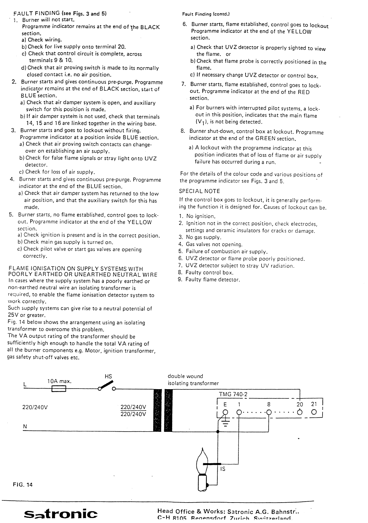
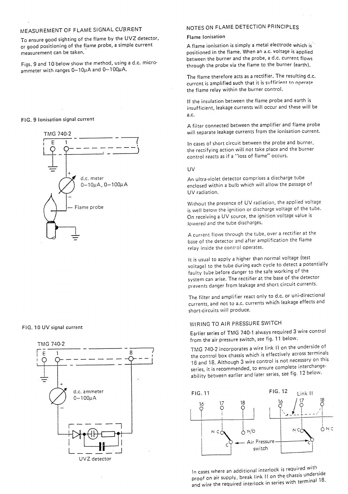
Atmospheric Floor Standing Series
User Manual: Atmospheric Floor Standing Series
Open the PDF directly: View PDF ![]() .
.
Page Count: 259 [warning: Documents this large are best viewed by clicking the View PDF Link!]
- Cover
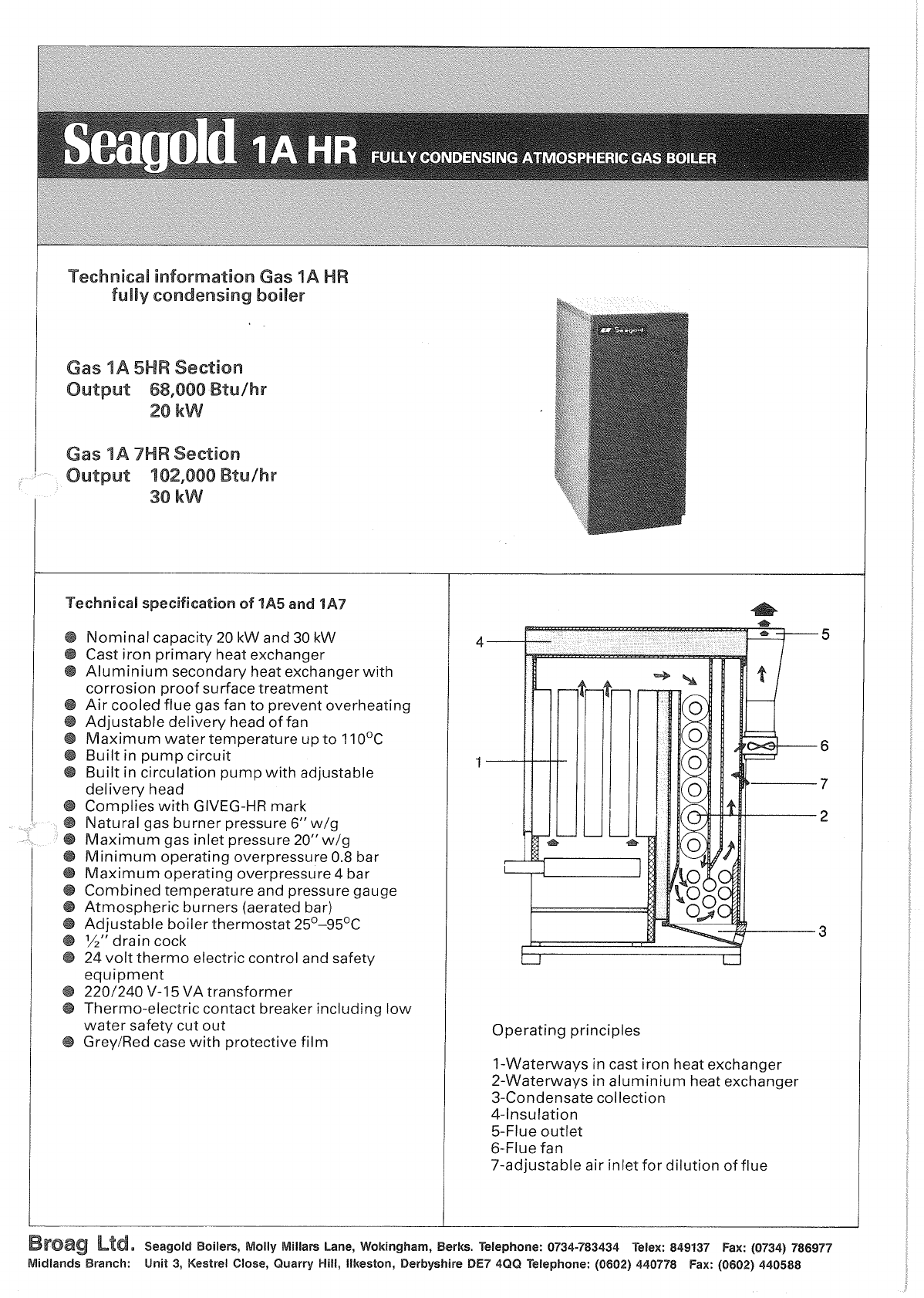
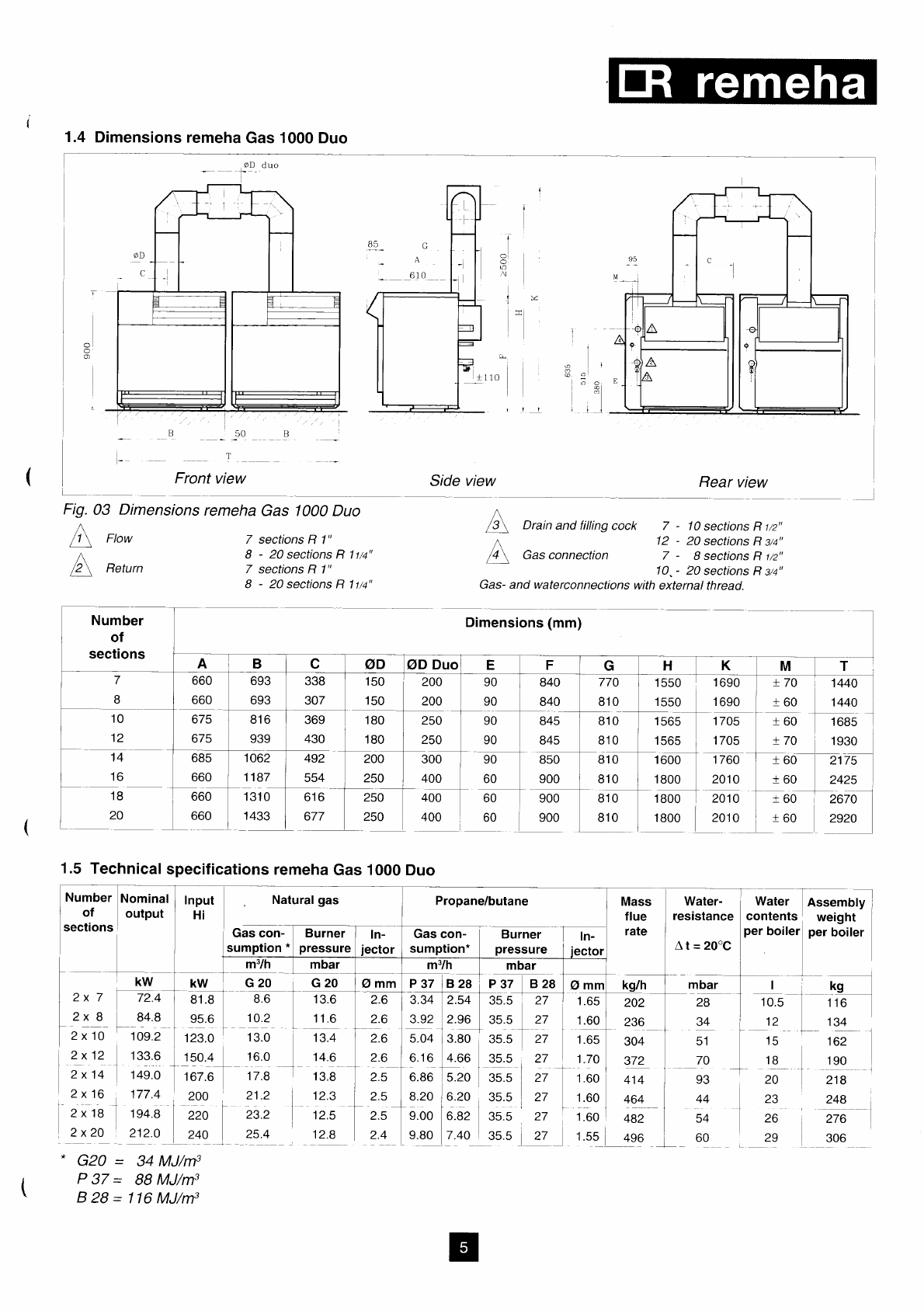
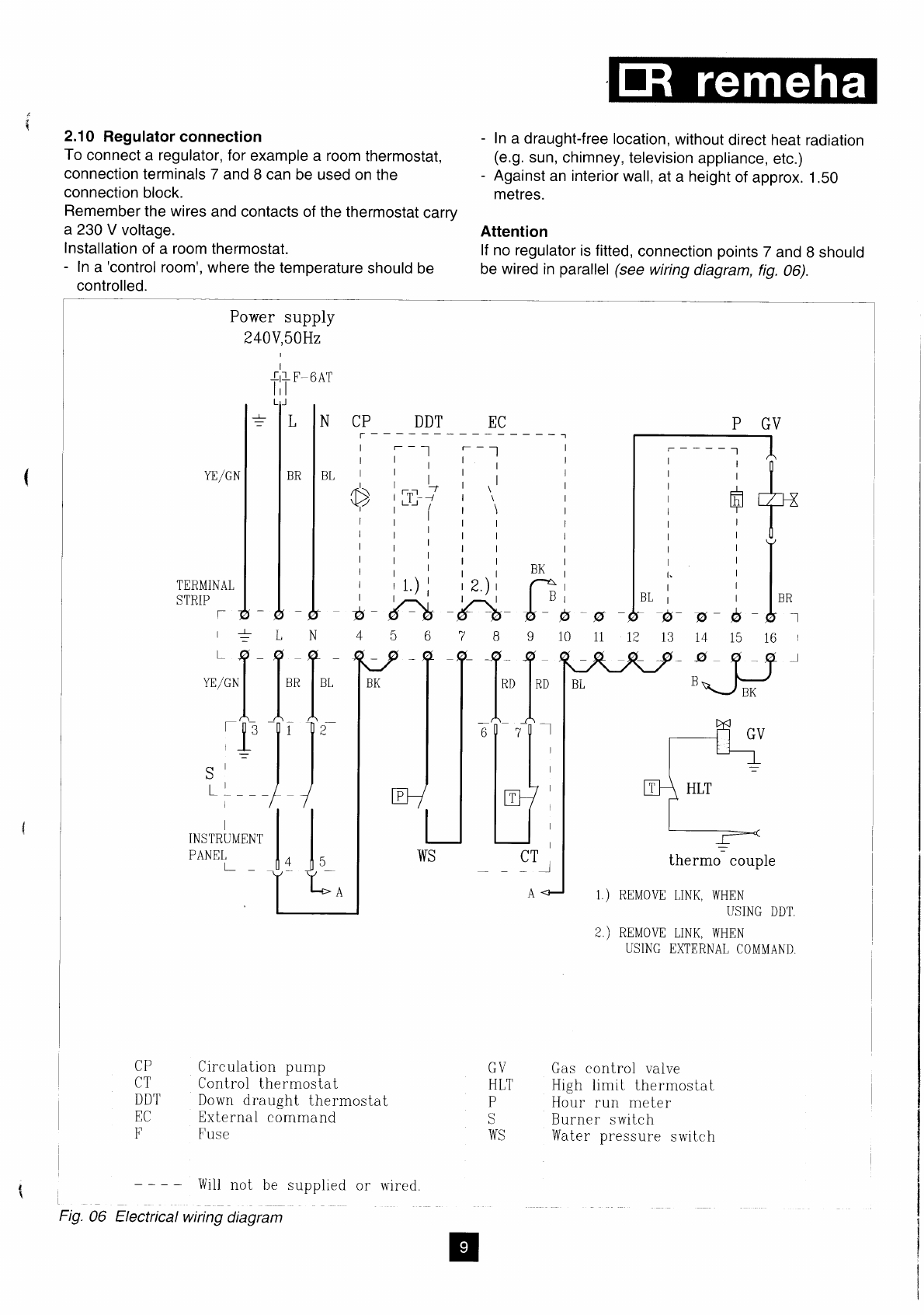
- Gas 1A - Technical Information
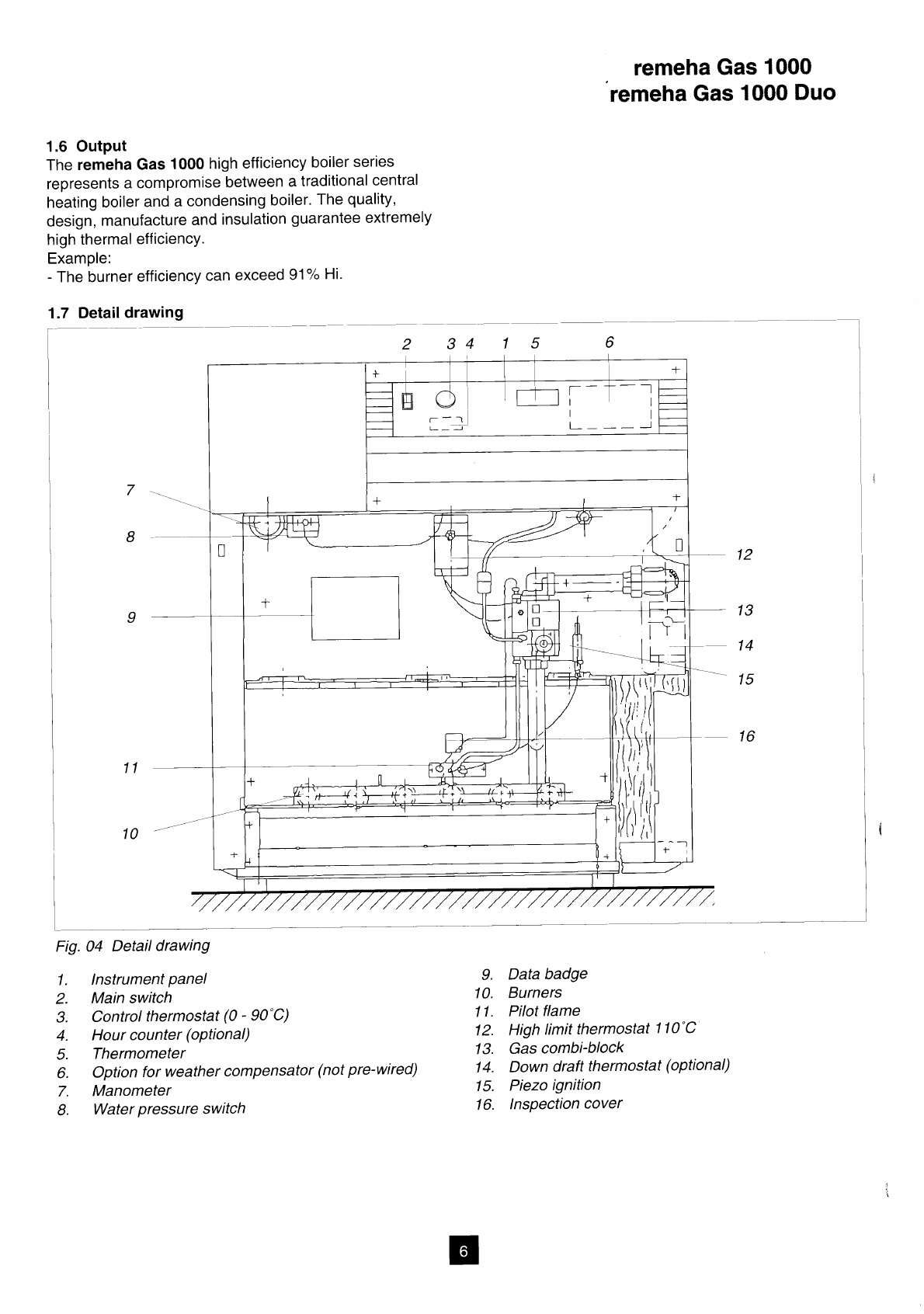
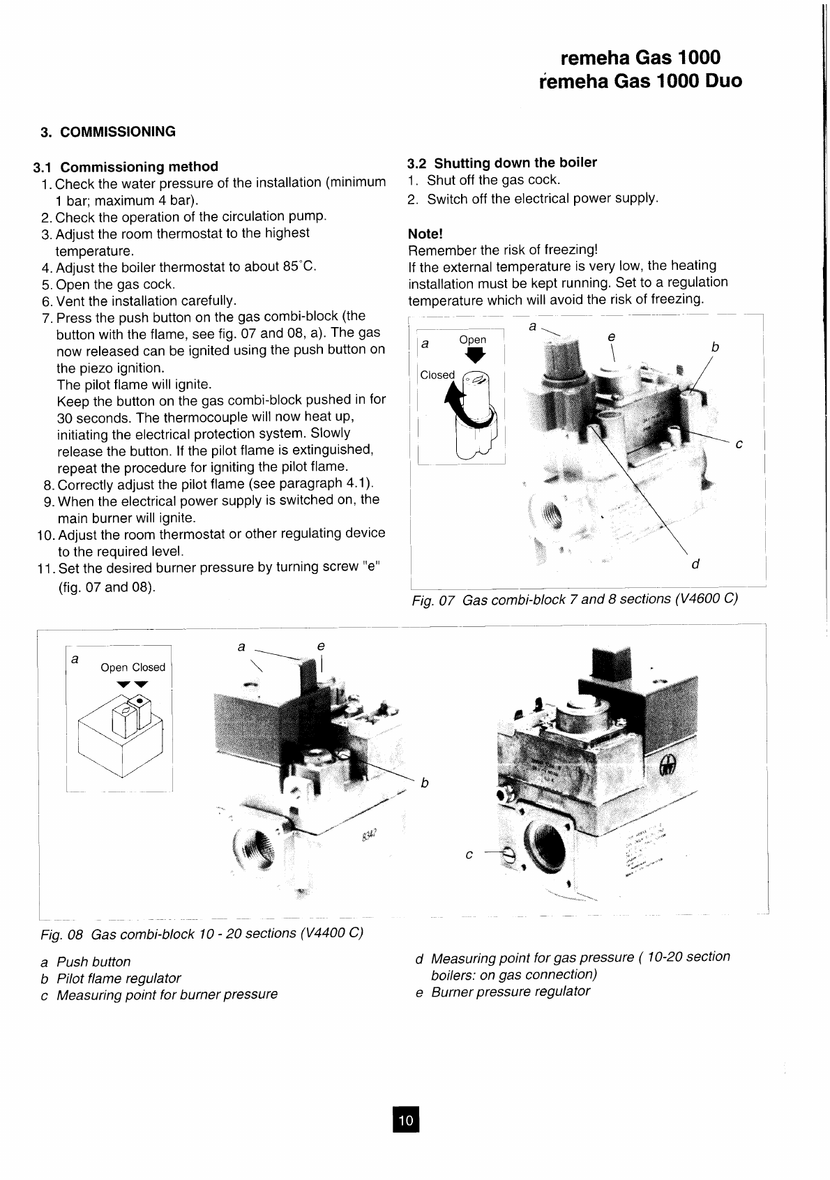
- Gas 1000 - Technical Information
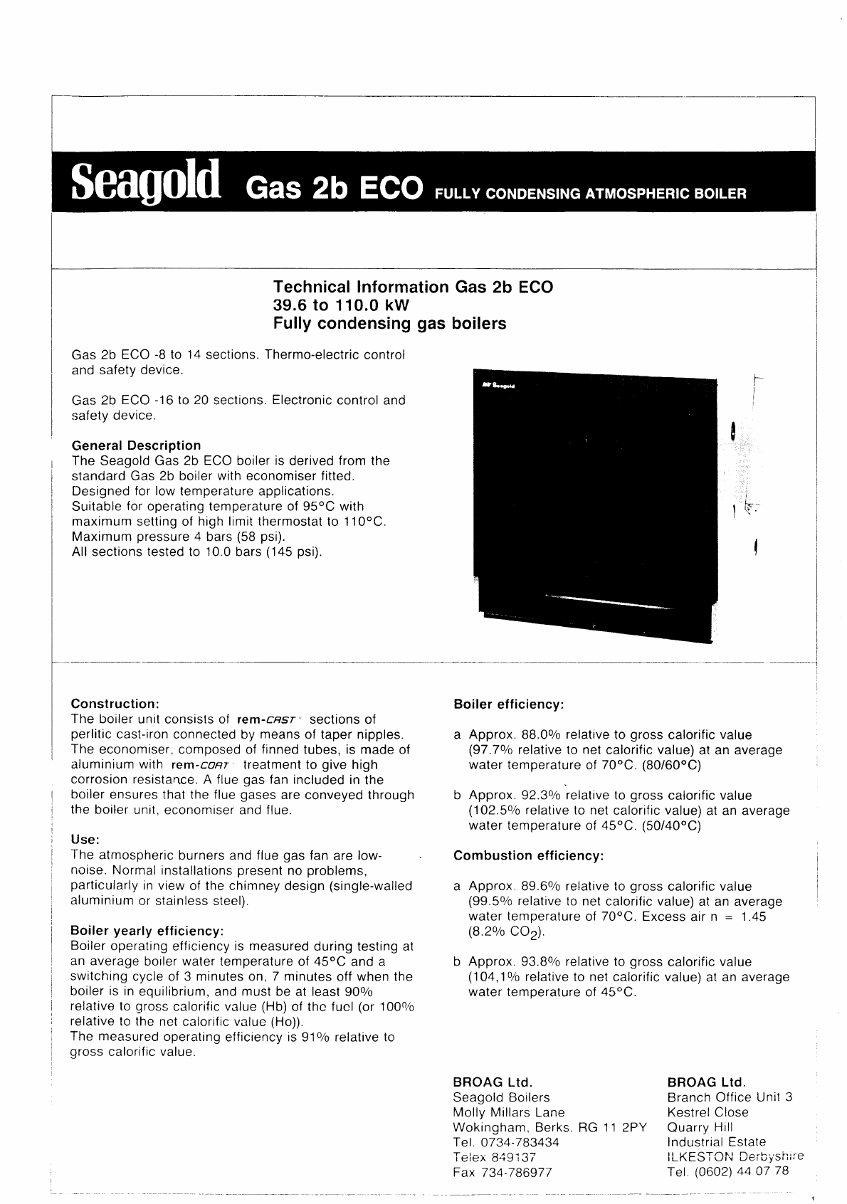
- Gas 2B - Technical Information
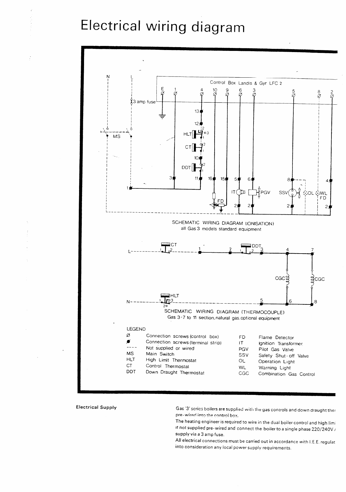
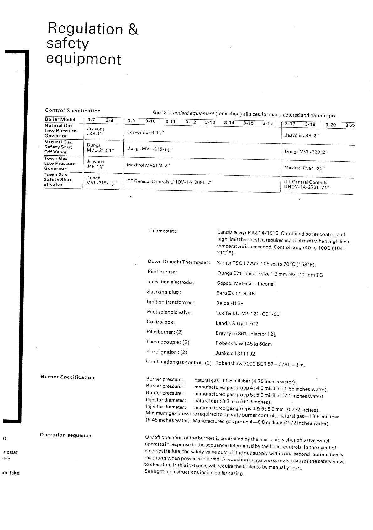
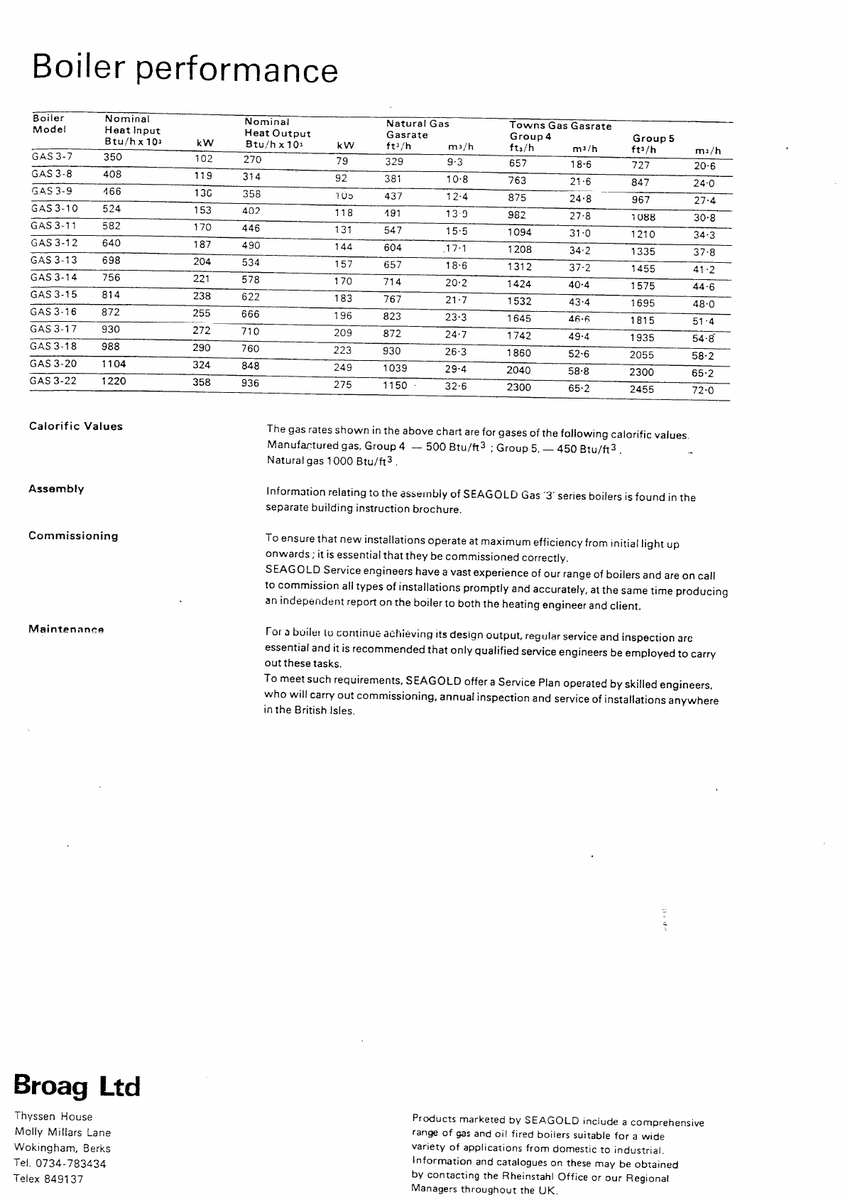
- Gas 3 - Technical Information
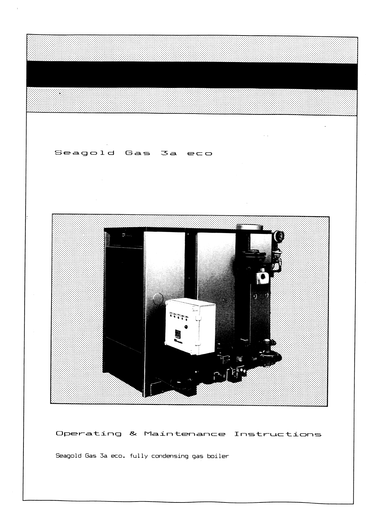
- Gas 3A ECO - Technical Information
- Gas 3C - Technical Information
- Gas 3D - Technical Information
- Gas 3D - Technical Information
- Gas 350 - Technical Information
- Gas 450 - Technical Information
- Gas 550/550 DUO - Technical Information
- Gas 5 - Technical Information
- Gas 5A ECO - Technical Information
- Gas 5A/5A DUO - Technical Information
- Gas 5C/5C DUO - Technical Information
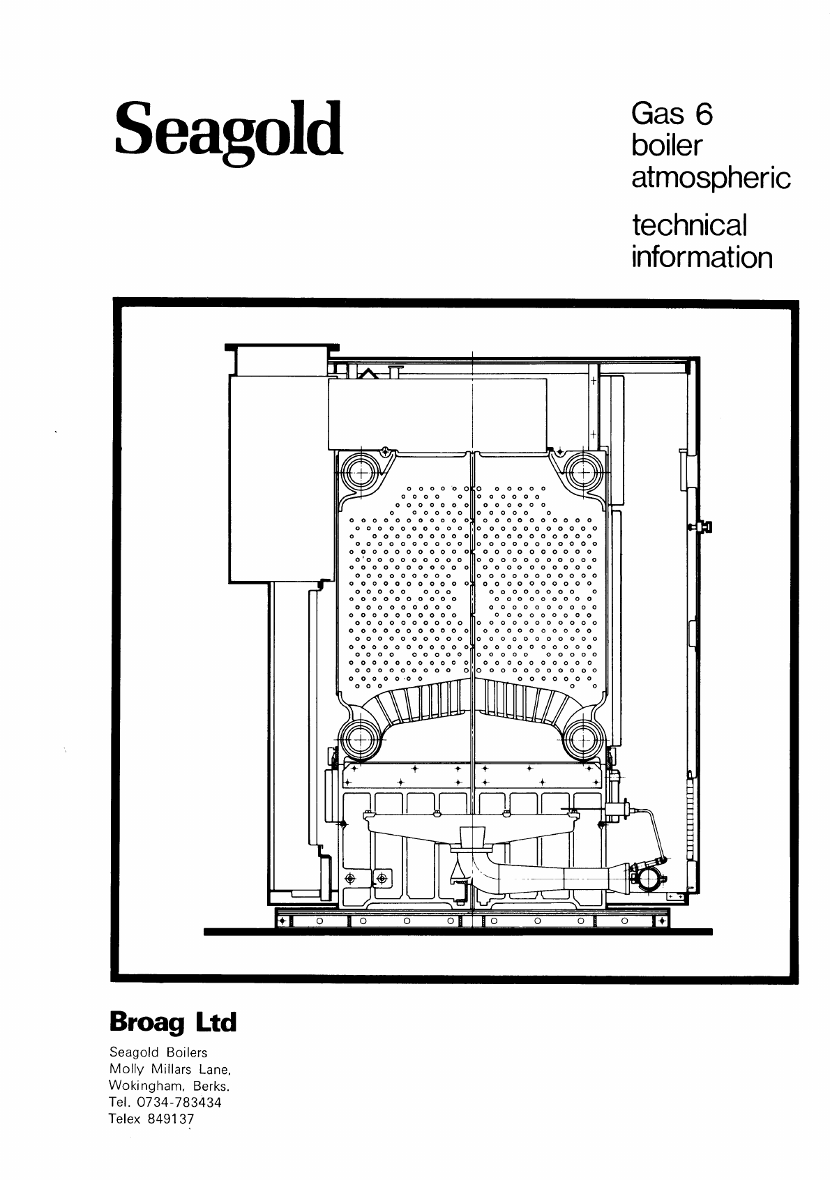
- Gas 6 - Technical Information


2
remeha Gas 3c
CONTENTS
Preface 3
1. Boiler description 3
2. Construction 3
2.1 General 3
2.2 Burners 3
2.3 Boiler base 3
2.4 Assembly 3
3. Technical information and dimensions 4
4. Application 5
4.1 L.P.H.W. system 5
4.1.1 Water temperature 5
4.1.2 Water pressure 5
4.1.3 Water flow 5
4.1.4 Water treatment 5
4.1.5 Noise level 5
4.2 Chimneys 5
4.3 Installation standards 5
5. Typical boiler installations 6
6. Regulation and safety equipment 7
6.1 General 7
6.2 Instrument panel 7
6.3 Standard electronic gas train On/Off or
High/Low 8
6.3.1 Schematic construction 8
6.3.2 Specification 8
6.3.3 Control panel on gas train 8
6.4 Functions 8
6.4.1 Flame protection 8
6.4.2 Down draught thermostat 8
6.4.3 Thermostats 8
7. Assembling and installation guidelines 8
7.1 General 8
7.2 Boiler assembly 8
7.3 Water connections 8
7.4 Pocket for instrument panel 8
7.5 Water pressure 8
8. Gas supply 9
8.1 General 9
8.2 Gas pressure 9
9. Electrical supply 9
9.1 General 9
9.2 Control panel 9
9.3 Electrical connections 9
9.4 Electrical data 9
9.5 Wiring diagram for the instrument panel 9
9.5.1 Simple instrument panel 9
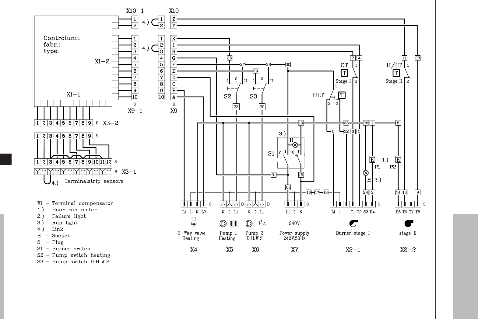
9.5.2 Complete instrument panel
(On/Off or High/Low) 10
9.6 Wiring diagram boiler 11
9.6.1 Complete wiring diagram for
On/Off boiler with simple
instrument panel 11
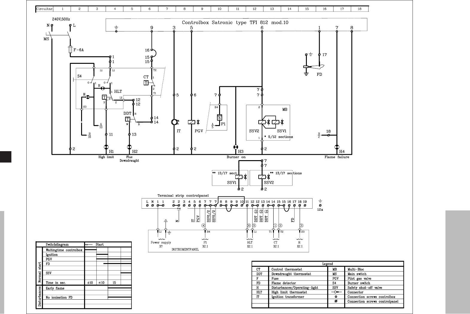
9.6.2 Complete wiring diagram for
On/Off boiler with complete
instrument panel 12
9.6.3 Complete wiring diagram for
High/Low boiler with simple
instrument panel 13
9.6.4 Complete wiring diagram for
High/Low boiler with complete
instrument panel 14
10. Commissioning 15
10.1 Technical information 15
10.2 Commissioning the boiler 15
10.3 Switching off the boiler 15
11. Maintenance 15
11.1 General 15
11.2 Maintening the boiler 15

3
PREFACE
* On request extension cables can be delivered, so that
the gas train can be fitted on the opposite side to the
instrument panel, thermostat pocket and the flow.
1. BOILER DESCRIPTION
The remeha Gas 3c boiler is a cast iron sectional boiler
with atmospheric burners.
Suitable for all qualities of natural gas, cat. I 2 H (20
mbar).
The boiler meets the requirements of the CE regulations
at the following directives:
- Gas appliance directive no. 90/396/EEC
- Efficiency directive no. 90/42/EEC
- Electrical low voltage directive no. 73/23/EEC
- Machinery directive no. 89/392/EEC
- E.M.C. directive no. 89/336/EEC.
Classification type for evacuation of the combustion
products: B11 BS.
For further advice or information contact Broag Ltd.
The remeha Gas 3c is supplied with electronic ignition
and insulated casings.
Water connections Ø 70 mm int.
2. CONSTRUCTION
2.2 Burners
The burners are stainless steel, atmospheric burners.
They guarantee a low noise level.
2.3 Boiler floor
The remeha Gas 3c boiler is supplied as standard with
reflecting floor plates with ventilation underneath.
2.4 Assembling
The boiler must be assembled on site.
2.1 General
- Boiler block of cast iron sections are joined together
with conical nipples.
- Gas train and water connections can be fitted on either
side of the boiler.
The gas train should as standard always be fitted
on the same side as the instrumental panel,
thermostat pocket and the flow*.
- Instrument panel is fitted in the front casing.
- Cleaning of the cast iron block from top of the boiler.
If you have any questions, or if you need more informa-
tion about specific subjects relating to this boiler, please
do not hesitate to contact us.
The data published in these technical instructions is ba-
sed on the latest information and is subject to revisions.
We reserve the right to modify the construction and/or
design of our products at any moment, without being
obliged to adjust earlier supplies accordingly.
These technical instructions contain useful and important
information for the proper operation and maintenance of
the remeha Gas 3c central heating boiler.
Furthermore, important instructions are given to prevent
accidents and serious damage before commissioning and
during operation of the boiler, to ensure safe and trouble
free boiler operation. Read these instructions carefully
before putting the boiler into operation, familiarize your-
self with its operation and control and strictly observe the
instructions given.

4
remeha Gas 3c
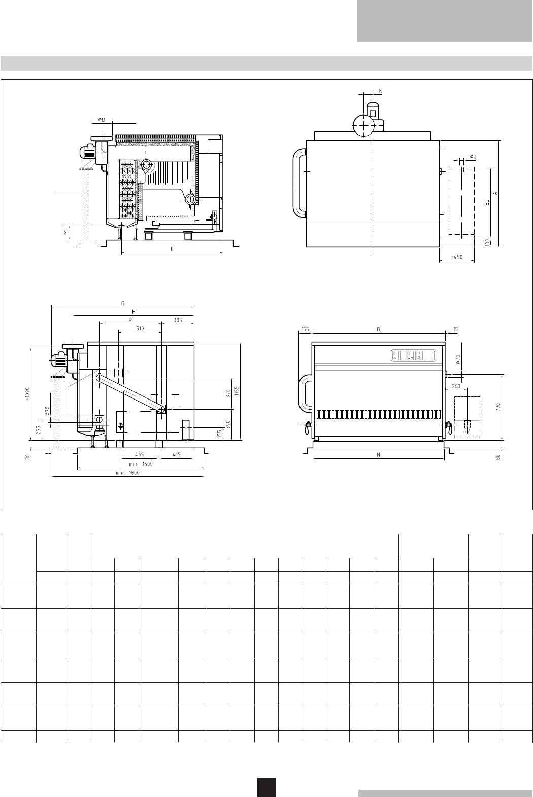
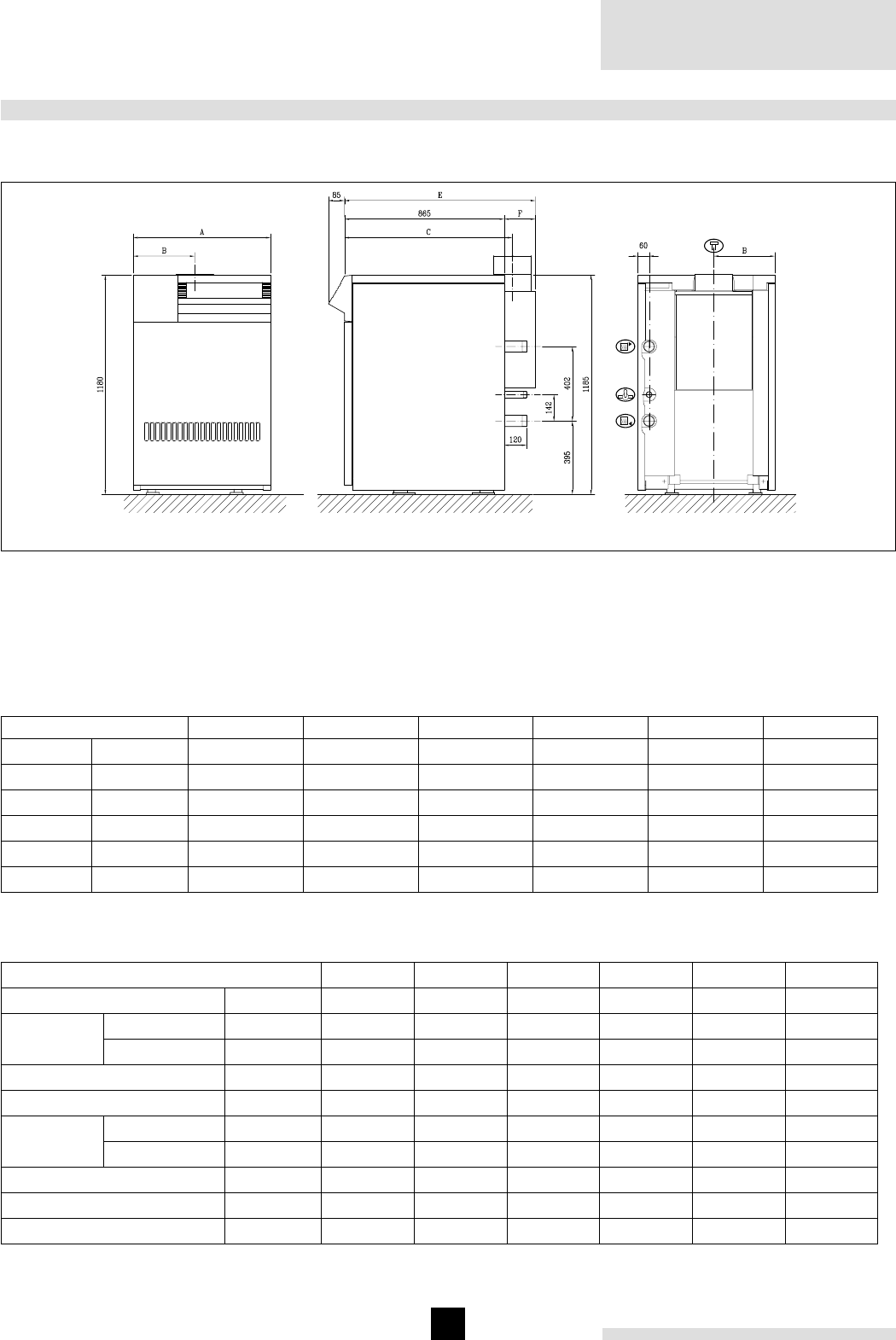
3. TECHNICAL INFORMATION AND DIMENSIONS
Front viewLeft hand side view
Top view
Cross section
51
58
65
71
78
85
91
98
105
111
118
125
131
385
440
495
550
605
665
720
775
830
890
945
1000
1055
Number of
sections Boiler
weight
Water
contents
∆t = 20°C
kW kW
ø70 int.
ø70 int.
Output Input
Hs
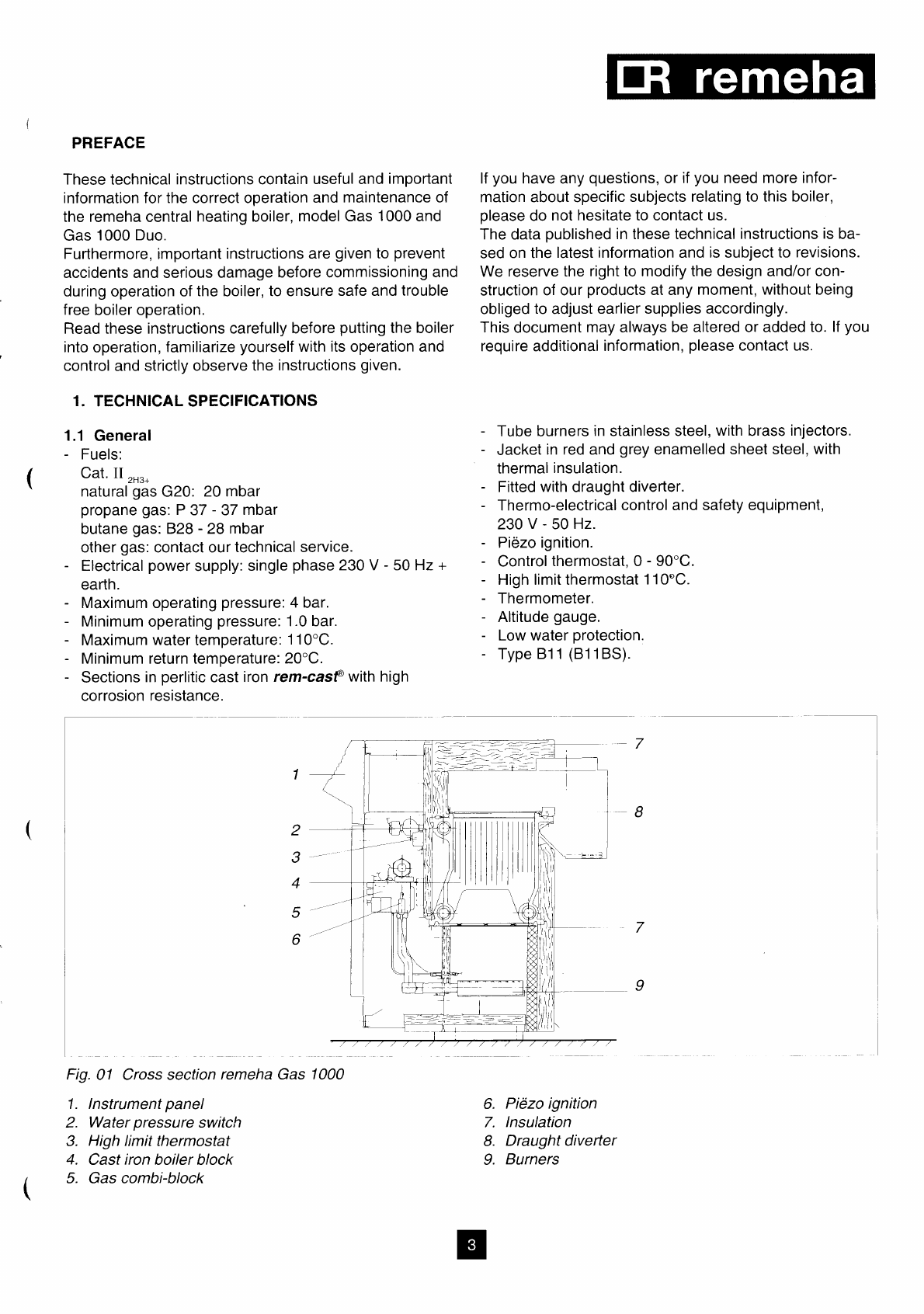
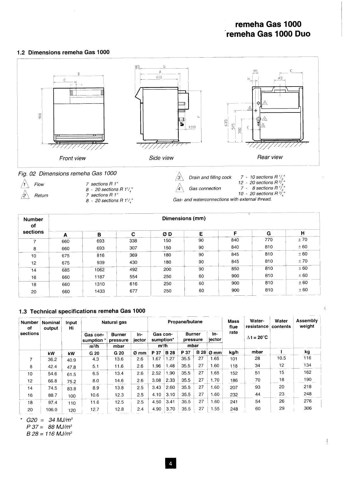
Fig. 01 View figures
Dimensions
A
mm B
mm Ø D
mm ± L
mm
Ø d
"∆t = 10°C
4
6
9
12
15
19
24
29
34
40
46
52
59
16
24
36
48
60
76
96
116
136
160
186
208
236
Water
resistance
114
142
170
200
228
258
286
315
343
369
399
426
454
5
6
7
8
9
10
11
12
13
14
15
16
17
92
115
138
162
186
210
234
256
280
301
325
348
372
1015
1015
1040
1040
1040
1040
1065
1065
1065
1065
1090
1090
1090
675
775
875
975
1075
1175
1275
1375
1475
1575
1675
1775
1875
200
200
200
250
250
250
300
300
300
300
350
350
350
1"
1"
1"
1"
11/4"
11/4"
11/4"
11/4"
2"
2"
2"
2"
2"
1220
1220
1220
1220
1220
1220
1320
1320
1320
1320
1320
1320
1320
670
670
670
670
700
700
700
700
960
960
960
960
960
E
mm mbar mbar l kg

5
4. APPLICATION
4.2 Chimneys
The average flue gas temperature is so low that the chim-
ney must be in accordance with the guidelines of British
Gas and BS 6644.
4.3 Installation standards
The following instructions must be adhered to when the
remeha Gas 3c is installed:
Gas safety (installation and use) Regulations 1984 (as
amended).
All gas appliances must, by law, be installed by compe-
tent persons (e.g. Corgi) in accordance with the above
regulations. Failure to install appliances correctly could
lead to prosecution.
It is in your own interest and that of safety to ensure that
the law is complied with.
In addition to the above regulations, this appliance must
be installed in compliance with the current I.E.E.
Regulations for electrical installation, local building regula-
tions, the Building Standards (Scotland), Consolidation
Regulations and bye laws of the local water undertaking
and Health and Safety Document No. 635 'The Electricity
at Work Regulations 1989'. It should also be in accor-
dance with the relevant recommendations in the current
editions of the following British Standards and Codes of
Practice, viz.
BS 5540 Pt 1 and 2, BS 5449, BS 5546, BS 6798,
BS 6891 and BG.DM2.
Important:
The remeha Gas 3c is certified appliance and must not
be modified or installed in any way contrary to these
'Installation and Servicing Instructions'.
Manufacturers instructions must NOT be taken in any way
as overriding statutory obligations.
93 = ... m3/h
This minimum flow must be maintained for 5 minutes af-
ter the burner stops firing to avoid high temperature shut-
down due to residuel heat gain.
Due to the design and manufacture of the boiler no speci-
fic minimum water flow requirement exists other than for
high-temperature protection.
4.1.4 Water treatment
Water treatment under normal circumstances is not
necessary (see our water quality recommendations).
4.1.5 Noise level
The noise level measured around the boiler depending
on boiler room construction is about 50-55 dBA.
(Noise level taken at 1 meter from the boiler)
Output boiler in kW
4.1 L.P.H.W. system
4.1.1 Water temperature
Maximum water temperature is 110°C (high limit
thermostat).
Highest boiler water temperature is 95°C (control
thermostat).
Minimum return water temperature is 20°C at a flow rate
related at a ∆t of 20°C (flow/return temperature).
4.1.2 Water pressure
Boiler sections pressure test at 12 bar.
Maximum pressure test for the boiler block is 6 bar.
Minimum working pressure boiler is 0.8 bar.
Maximum working pressure is 6 bar.
4.1.3 Water flow
The minimum water flow through the boiler is:
6
remeha Gas 3c
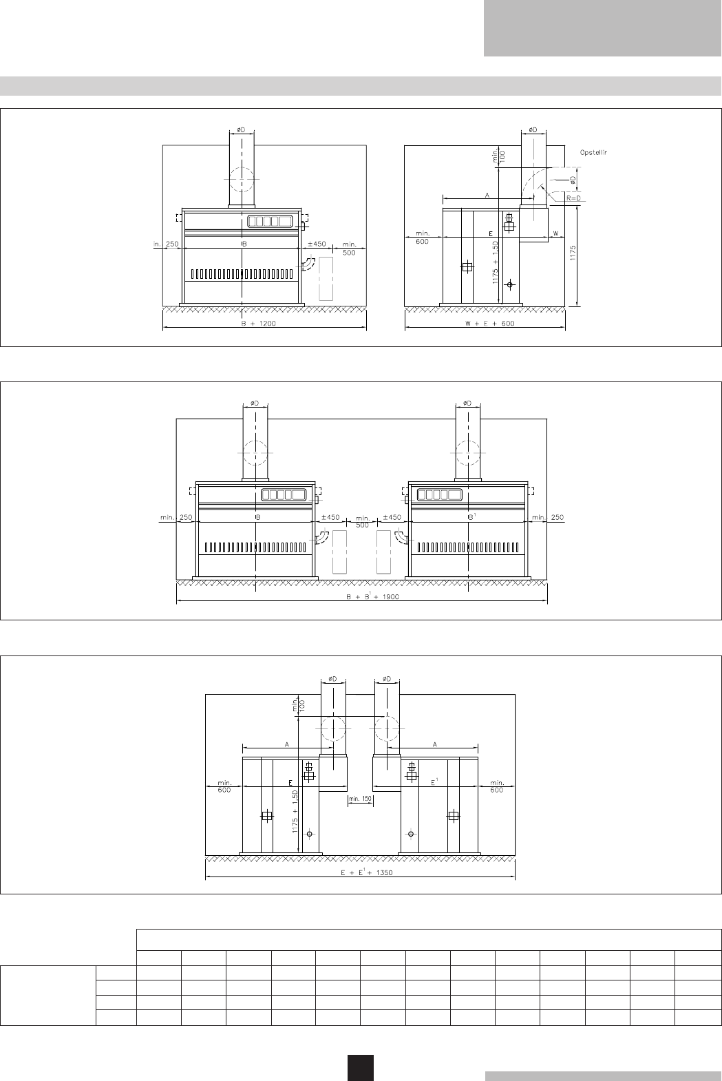
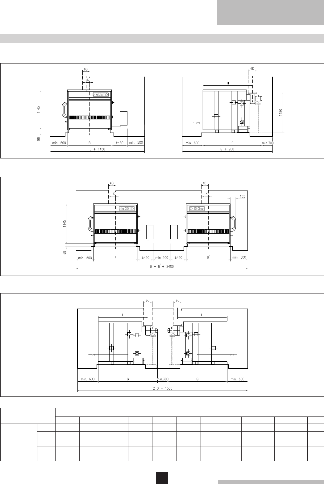
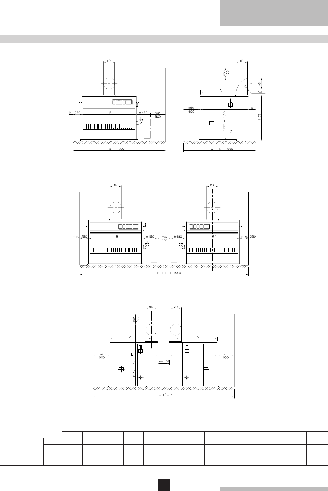
5. TYPICAL BOILER INSTALLATIONS
One boiler in boiler room
Fig. 02 Installation 1
Two boilers in boiler room
Fig. 03 Installation 2
Two boilers in boiler room
back to back
Fig. 04 Installation 3
Number of sections
5678 9 10 11 12 13 14 15 16 17
1015
675
200
1220
1015
775
200
1220
1040
875
200
1220
1040
975
250
1220
1040
1075
250
1220
1040
1175
250
1220
1065
1275
300
1320
1090
1875
350
1320
1090
1775
350
1320
1090
1675
350
1320
1065
1575
300
1320
1065
1475
300
1320
1065
1375
300
1320
Dimensions
(mm)
A
B
Ø D
E
7
* Absent in simple instrument panels
** Absent in simple instrument panel On/Off
*** On request extension cables can be delivered, so
that the gas train can be fitted on the opposite side to
the instrument panel, thermostat pocket and the flow.
6. REGULATION AND SAFETY EQUIPMENT
6.1 General
The remeha Gas 3c is supplied with electronic control
and safety equipment with flame detection.
6.2 Instrument panel
The remeha Gas 3c is supplied with an instrument panel
that is fitted in the front of the boiler, either left or right.
The instrument panel can be delivered in three models:
- simple instrument panel On/Off;
- simple instrument panel High/Low;
- complete instrument panel High/Low.
All connections are pre-wired and fitted with plugs. The
capillaries from the control panel should be fitted in the
pocket of the boiler, wich is fitted in the top front of the
end section.
The instrument panel, pocket and the flow should
always be fitted at one side of the boiler either left or
right and standard on the same side as the gas
train.***
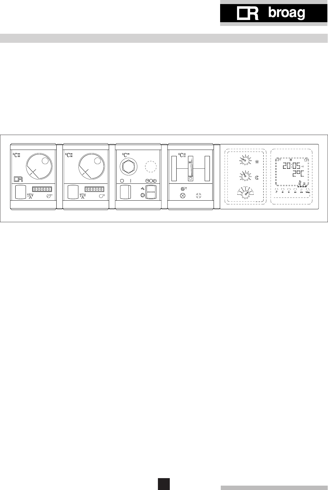
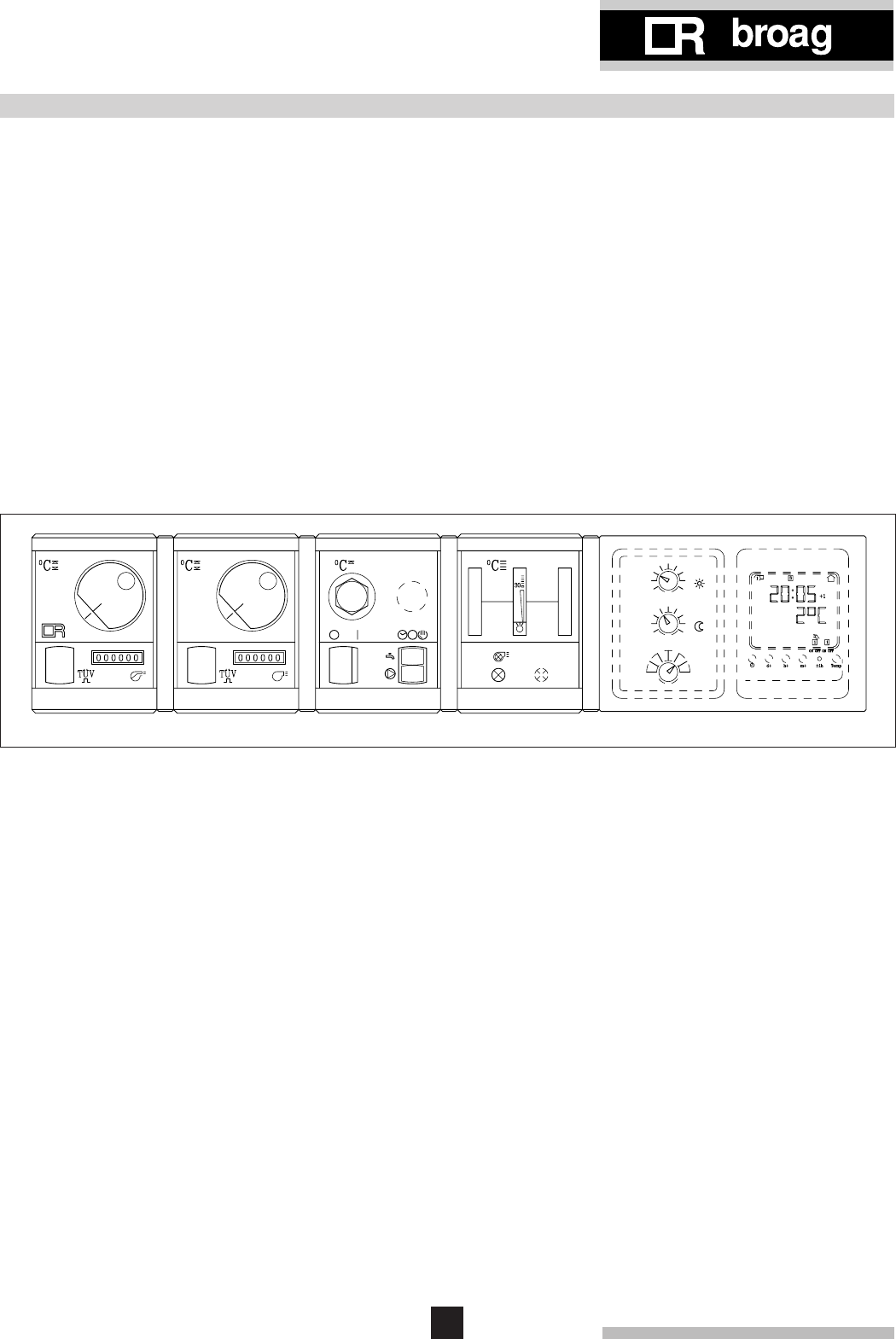
Fig. 05 Layout of the complete instrument panel
BDE
CA
135
4
268
79
11
10
The modules contain:
Module A
1. Control thermostat
Setting between 35°-95°C
2. Hour run meter total running hours*
Module B
3. High-Low thermostat
Setting between 35°-95°C**
4. Hour run meter full load*
Module C
5. High-limit thermostat 110°C (locking)
6. Operating switch (On/Off with optical display)*
7. Switch for circulating pump*
Manual/Off/Automatic
8. Switch for domestic hot water storage pump*
Manual/Off/Automatic
Module D
9. Warning light*
10. Analogue thermometer water temperature
Module E
11. Option for
rematic
® weather compensating boiler
control*
8
remeha Gas 3c
7.1 General
The boiler is suitable for operating at a maximum working
pressure of 6 bar and a minimum pressure of 0.8 bar.
Boiler can be installated in open or closed systems.
7.2 Boiler assembly
Broag provides special tools on loan, for the boiler as-
sembly with detailed building instructions. However, buil-
ding supervision and/or actual boiler erection services
can be provided by Broag or an approved boiler erection
engineer.
7.3 Water connections
The boiler water connections can be fitted on either side
of the boiler.
The water connection is flanged on the boiler with a pipe
connection for welding Ø 70 mm to the installation.
The top blind-flange has an integral cast 1" tapping to
accept a safety valve. The end sections have a 3/4"
tapping to accept drain/off cocks (Tapping BSP).
7.4 Pocket for instrument panel
The pocket should be fitted in the top front end section of
the boiler and at that side of the boiler where the gas train
is fitted. Other end section tapping 1" should be sealed.
7.5 Water pressure
Each section is hydraulically tested to at least 12 bar.
Maximum test pressure for the assembled boiler block is
6 bar.
Operating pressure between 0.8 bar and 6 bar.
7. ASSEMBLY AND INSTALLATION GUIDELINES
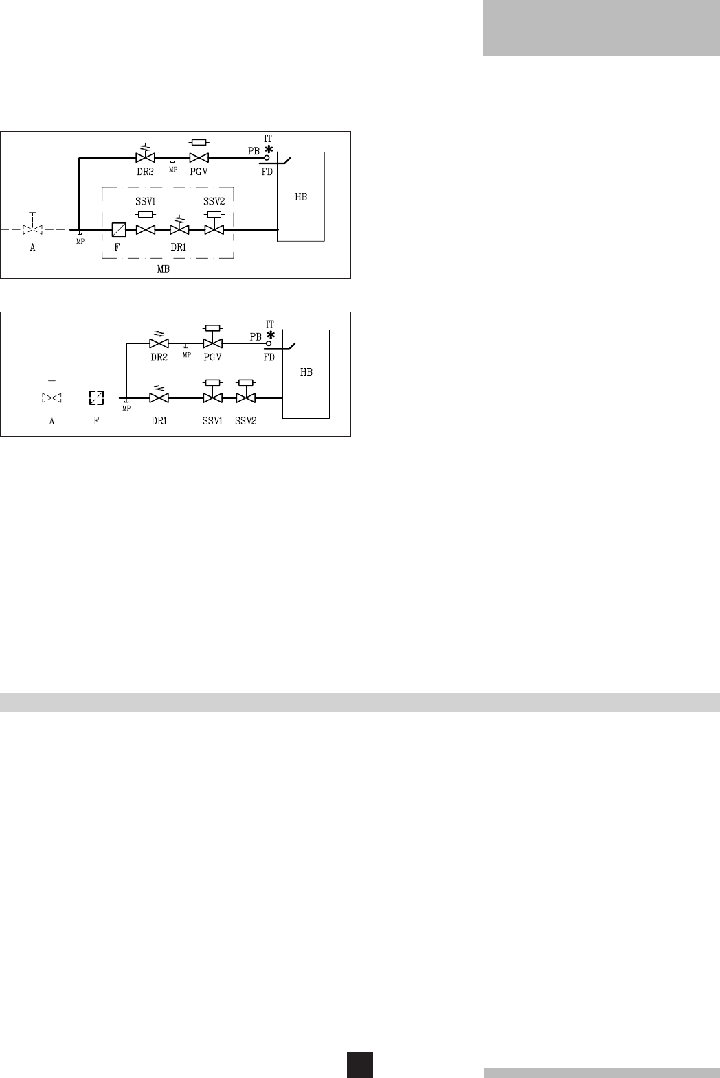
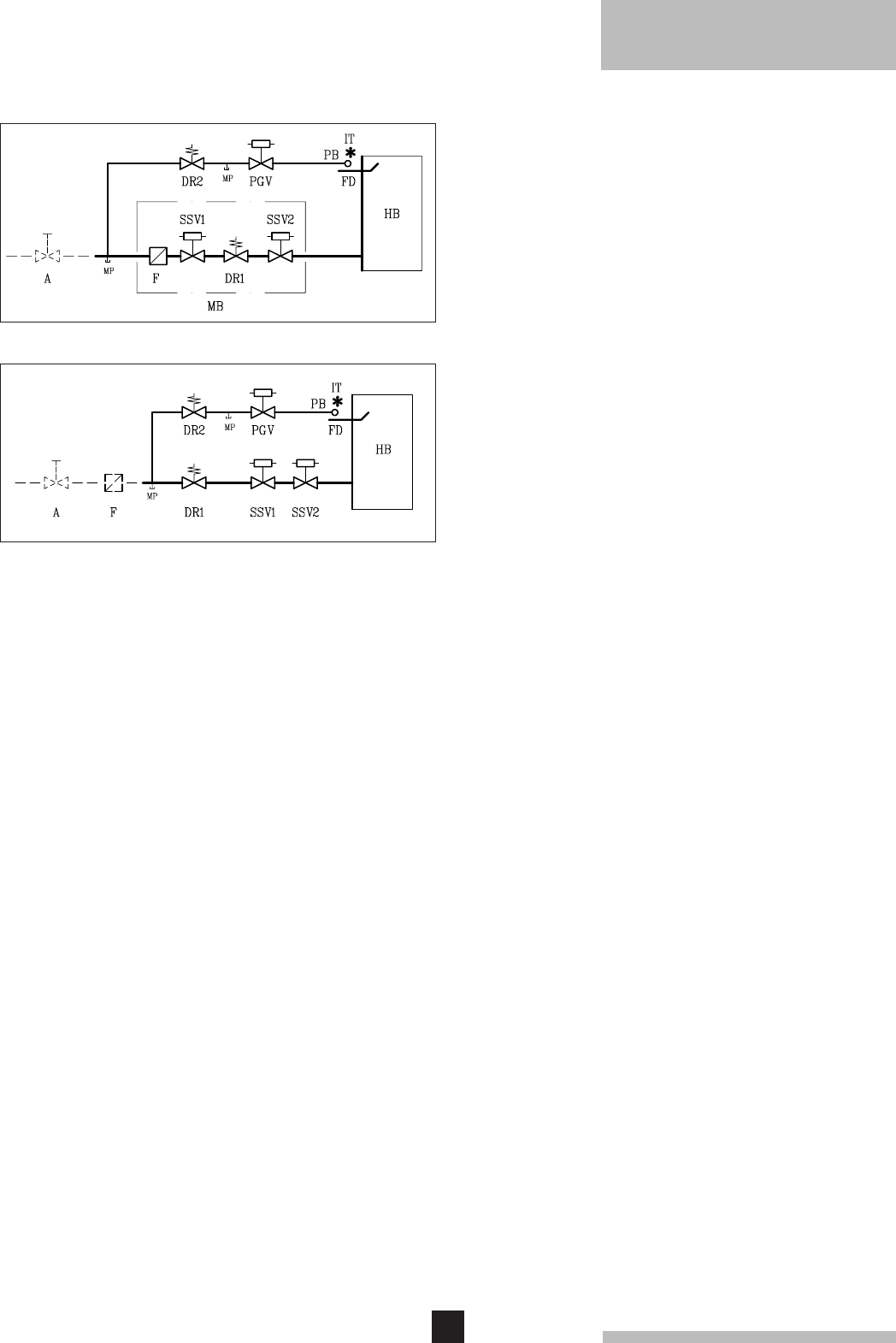
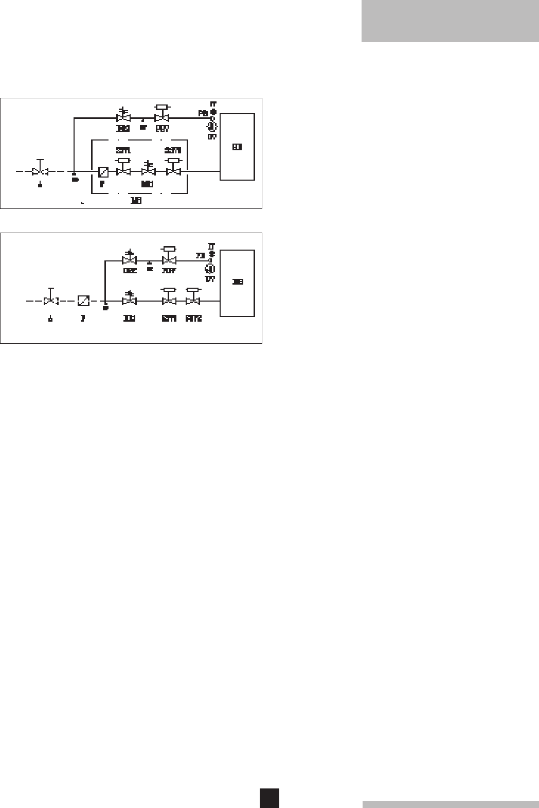
6.3 Standard electronic gas train On/Off or High/Low
6.3.1 Schematic construction
6.3.2 Specification
1 Gas multibloc (5-12 sections)
2 Safety shut-off valves (13-17 sections)
1 Gas governor (13-17 sections)
1 Pilot gas valve
1 Pilot gas governor
1 Ignition transformer 5 kV
1 Pilot burner with flame detector
1 Down draught thermostat set at 70˚C
6.3.3 Control panel on gas train
1 Main switch
1 Control box Satronic
1 Fuse, brusk
1 Signal lamp
6.4 Functions
6.4.1 Flame protection
Flame protection by means of ionisation flame detection.
6.4.2 Down draught thermostat
The boiler is fitted with a down draught thermostat
Honeywell (typ L6068A).
If there is down draught the thermostat will switch off the
boiler. Fixed setpoint is 70°C.
6.4.3 Thermostats
Control thermostat On/Off Landis & Gyr 35°-95°C.
Control thermostat High/Low Landis & Gyr 35°-95°C
(High/Low version only).
High-limit thermostat locks out at 110°C.
Fig. 06 5-12 sections
Fig. 07 13-17 sections
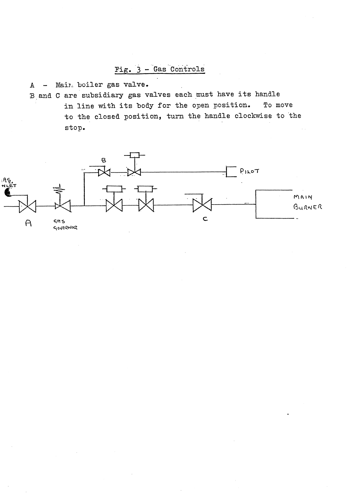
Legend
A Gas cock
PB Pilot burner
DR Gas governor
F Gas filter
HB Main gas burners
MB Gas multibloc
IT Ignition transformer
PGV Pilot gas valve
MP Measuring point
SSV Safety shut-off valve
FD Flame detector
- - - - Not supplied
9
* On request extension cables can be delivered, so that
the gas train can be fitted on the opposite side to the
instrument panel, thermostat pocket and the flow.
8. GAS SUPPLY
8.1 General
The gas train can be fitted on the left or right hand side of
the boiler but as standard is always fitted on the same
side of the boiler instrument panel (fitted in the front
casing).*
The local Gas authority should be consulted to ensure
that an adequate pressure and supply is available at the
boilers maximum output. To minimise risk of sediment or
foreign particles entering the control valves, an approved
filter may be fitted into the pipe work downstream.
The gas supply should be conform to the British Gas
safety regulations.
8.2 Gas pressure
Maximum gas pressure at inlet 100 mbar.
Burner pressure:
- full load : 11.8 mbar (100%)
- part load (High/Low version only): 4.2 mbar (60%)
- injector size: 4.4 mm Ø.
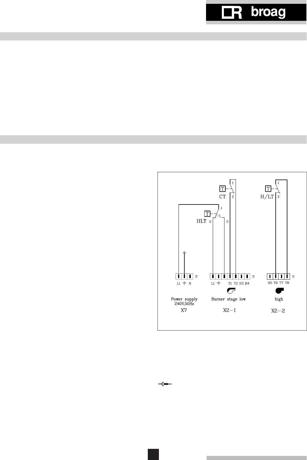
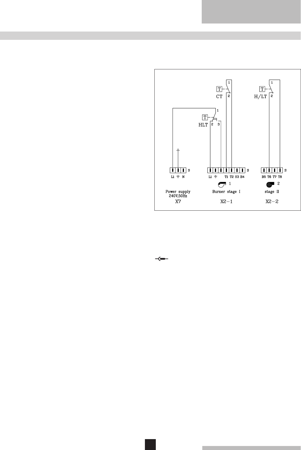
Legend
CT Control thermostat
HLT High limit thermostat
H/LT High/Low thermostat
S Plug
Connector
9.1 General
The electrical installation must conform to the IEE
regulations and also to local authority requirements.
9.2 Control panel
A control panel is fitted on the gas train.
9.3 Electrical connections
The boiler is pre-wired. Only the main supply should be
wired to this control panel.
9.4 Electrical data
Main supply: 240V - 50Hz (L/N).
Running current: 120 W.
Installed fuse: 6 Amp.
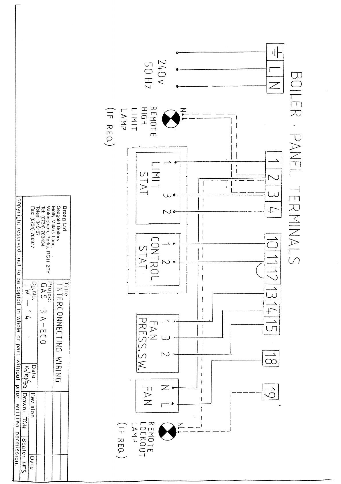
9.5 Wiring diagram for the instrument panel
9.5.1 Simple instrument panel
9. ELECTRICAL SUPPLY
Only
High/Low
Fig. 08 Wiring diagram for the simple instrument panel
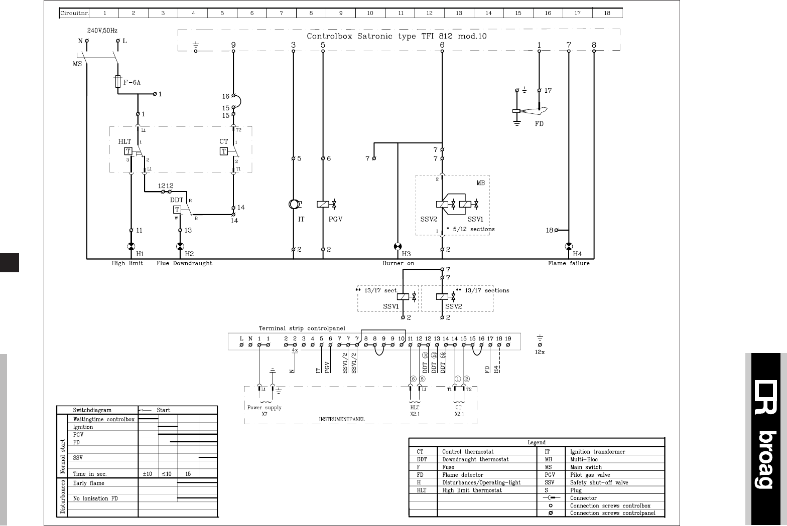
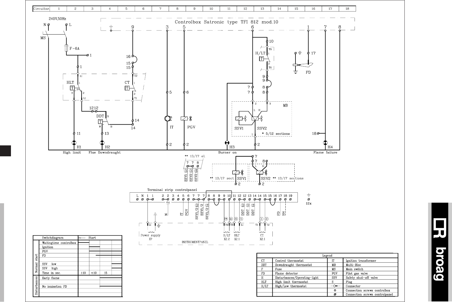
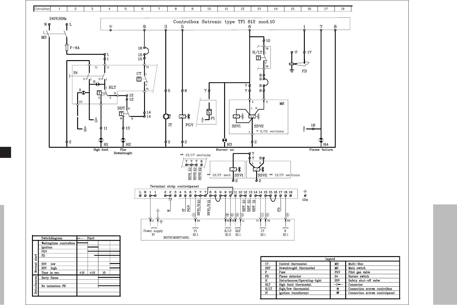

15
10.1 Technical information
Control box: Satronic TFI 812 B mod. 10.
Main supply: 240V - 50 Hz.
Minimum ionisation current: 5 µA.
Reaction time flame protection: 1 sec.
Safety time: < 10 sec.
Maximum ambient temperature: 60°C.
Injector size pilot burner: Ø 0.8 mm.
Injector size main burner: Ø 4.4 mm.
Burner pressure full load: 11.8 mbar (100%).
Burner pressure part load: (High/Low version only):
4.2 mbar (60%).
Warning:
Control box operates on a neutral/phase supply.
10.2 Commissioning the boiler
1. Check gas connections.
2. Check electrical supply (L/N and earth).
3. Check water connections and if the installation is filled.
4. Switch on circulation pump and check rotation direc-
tion.
5. Open main gas cock (release air in gas pipe work).
6. Switch on electrical supply.
7. Set the control thermostats at about 85°C.
8. After a waiting time of about 12 seconds you will get
ignition. At a minimum ionisation current of 5 µAmp
the ignition stops. 15 sec. later the safety gas valve
will open, the boiler is on.
9. Leave the boiler on for a couple of minutes to get rid
of air in the gas pipe.
10. Set the correct burner pressure.
11. Check the thermostats for correct operation.
12. Check the flame protection, start the boiler with
disconnected ionisation probe.
10.3 Switching off the boiler
1. Switch off the electrical supply.
2. Turn off the gas cock.
10. COMMISSIONING
11.1 General
It is essential for a good combustion, to clean the boiler,
the gas train and boiler room once a year.
11.2 Maintening the boiler
1. Clean the internal flue ways of the boiler with a steel
cleaning brush (available from Broag).
Remove top casing and top of the flue hood.
2. Clean the burners internally and externally.
3. Clean boiler room and the floor underneath the boiler.
4. Clean the boiler casings.
5. Clean the gas train, ignition, pilot burner, thermostats
and wiring.
6. Check start program, ignition time and safety times.
7. Check flame protection, and thermostats.
8. Check the boiler input at 100% and 60% load
(High/Low version only).
9. Make a combustion efficiency calculation.
10. Check the boiler and installation for water leakage.
11. Check gas train and gas pipe for gas leakage.
11. MAINTENANCE

Subject to alterations
Art.nr. 50.696/1500/10.96/Bo.
© Copyright
All technical and technological
information contained in these
technical instructions, as well as any
drawings and technical descriptions
furnished by us remain our property
and shall not be multiplied without
our prior consent in writing.
ISO 9001
since 1988
Broag Ltd.
Head office
Remeha house,
Molly Millars Lane,
Wokingham,
Berkshire RG41 2QP.
Tel. 0118 9783434
Fax 0118 9786977
Branch office
Unit 3, Kestrel Close,
Quarry Hill Ind. Estate,
Ilkeston
Derbyshire DE7 4RD
Tel. 0115 9440778
Fax 0115 9440588

2
remeha Gas 3c ECO
CONTENTS
Preface 2
1. Boiler description 3
2. Construction 3
2.1 General 3
2.2 The burners 3
2.3 Boiler floor 3
2.4 Assembly 3
3. Boiler efficiency 3
3.1 General 3
3.2 Condensation 3
4. Technical data and dimensions 4
5. Application 5
5.1 L.P.H.W. system 5
5.1.1 Water temperature 5
5.1.2 Water pressure 5
5.1.3 Water flow 5
5.1.4 Water treatment 5
5.2 Noise level 5
5.3 Chimney/Flues 5
5.3.1 General 5
5.3.2 Fan 5
5.3.3 Safety equipment 5
6. Typical boiler installations 6
7. Control and safety equipment 7
7.1 General 7
7.2 Instrument panel 7
7.3 Standard electronic gas train 8
7.3.1 Specification 8
7.3.2 Control panel on gas train 8
7.4 Functions 8
7.4.1 Flame protection (lock out) 8
7.4.2 Thermostats 8
7.4.3 Air-pressure switch (lock out) 8
8. Assembly and installation guidelines 9
8.1 General 9
8.2 Boiler assembly 9
8.3 Water connections 9
8.4 Pocket for instrument panel 9
8.5 Water pressure 9
8.6 Condensate drain 9
9. Gas supply 9
9.1 General 9
9.2 Gas pressure 9
10. Electric supply 10
10.1 General 10
10.2 Control panel 10
10.3 Electrical connections 10
10.4 Electrical data 10
10.5 Wiring diagram for the instrument panel 10
10.5.1 Simple instrument panel 10
10.5.2 Complete instrument panel 11
10.6 Wiring diagram boiler 12
10.6.1 Complete wiring diagram for boiler
with simple instrument panel 12
10.6.2 Complete wiring diagram for boiler
with complete instrument panel 13
11. Commisioning 14
11.1 Technical information 14
11.2 Commissioning 14
11.3 Switch off the boiler 14
12. Maintenance 15
12.1 General 15
12.2 Maintenance instructions 15
PREFACE
These technical instructions contain useful and important
information for the correct operation and maintenance of
the remeha Gas 3c ECO gas boiler.
Furthermore, important instructions are given to prevent
accidents and serious damage before commissiong and
during operation of the boiler, to ensure safe and trouble-
free operation. Read these instructions carefully before
putting the boiler into operation, familiarize yourself with
its operation and controls and strictly observe the instruc-
tions given.
If you have any questions, or if you need more informa-
tion about specific subjects relating to this boiler, please
do not hesitate to contact us.
The data published in these technical instructions is ba-
sed on the latest information and is given subject to later
revisions.
We reserve the right to modify the design and/or
configuration of our products at any moment, without
being obliged to adjust earlier supplies accordingly.
3
The remeha Gas 3c ECO boiler is a fully condensing
atmospheric gas boiler, with stainless-steel atmospheric
burners.
The boiler meets the requirements of the CE regulations
at the following directives:
- Gas appliance directive no. 90/396/EEC
- Efficiency directive no. 92/42/EEC
- Electrical low voltage directive no. 73/23/EEC
- Machinery directive no. 89/392/EEC
- E.M.C. directive no. 89/336/EEC.
Suitable for all qualities of natural gas and propane.
Cat. II 2H3p
* On request extension cables can be delivered, so that
the gas train can be fitted on the opposite side to the
instrument panel, thermostat pocket and the flow.
1. BOILER DESCRIPTION
Classification type for evacuation of the combustion
products: B23
For further advice or information contact Broag Ltd.
The remeha Gas 3c ECO boiler is fitted with electronic
ignition and is supplied complete with an insulated
casing. Water connections Ø 70 mm.
2. CONSTRUCTIONS
2.2 The burners
The burners are stainless steel, atmospheric burners.
They guarantee a low noise level.
2.3 Boiler floor
The remeha Gas 3c ECO boiler is supplied as standard
with reflecting floor plates which allows for ventilation
underneath.
2.4 Assembly
The boiler is delivered in sections for assembly on site.
2.1 General
- Boiler block (primary heat exchanger) of cast iron
sections connected with conical nipples.
- Economiser (secondary heat exchanger) of anodised
aluminium.
- Gas train can be fitted on the left or right hand side of
the boiler.
- Water connections can be fitted on the left or right hand
side of the boiler. The return is fitted as standard on the
left hand side of the economiser.
The gas train should always be fitted on the same side
as the instrument panel and the flow connection*.
- Instrument panel is fitted in the front casing.
- The boiler block (primary heat exchanger) is cleaned
from the top.
The economiser (secondary heat exchanger) is
cleaned from the top rear side.
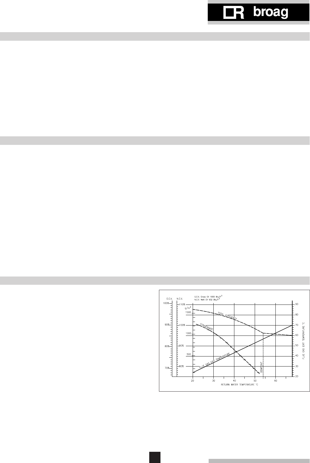
3. BOILER EFFICIENCY
3.1 General
The remeha Gas 3c ECO can operate with exceptionally
low return water temperatures (down to 20°C) and in do-
ing so extracts the maximum efficiency by creating con-
densation within the economiser so releasing the latent
heat from the flue gases. By raising the return water tem-
perature via the economiser the boiler block is protected
at all times, and heat to water efficiences of 86% (G.C.V.)
are can be attained.
3.2 Condensation
Condensation will take place within the economiser when
return temperature drops below 55°C. Above this tempe-
rature no condensing takes place and the latent heat is
not released. Even so, efficiencies well in excess of 95%
are still achieved.
Fig. 01 Relationship between boiler efficiency and return
boiler water temperature
4
remeha Gas 3c ECO
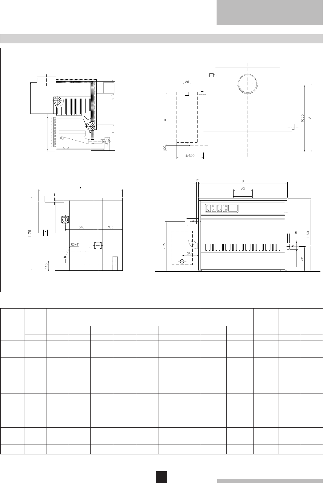
4. TECHNICAL DATA AND DIMENSIONS
Cross section Top view
Left hand side view Front
Output
kW
Water
resistance
Water
content
Litres
Boiler
weight
kg
11
15
23
29
40
47
55
66
78
90
78
88
100
445
500
565
620
690
750
805
875
930
990
1050
1105
1160
* Specified when the boiler is ordered
71
78
90
96
108
115
121
134
141
147
158
165
171
5
6
7
8
9
10
11
12
13
14
15
16
17
101
127
153
179
203
228
254
281
307
330
356
381
407
119
149
178
208
236
265
295
324
354
381
411
440
470
Ø d
"
G
mm
K
mm
N
mm
± L
mm
Ø D
mm
E
mm
H
mm
R
mm
200
200
200
200
200/250*
200/250*
200/250*
300
300
300
350
350
350
1
1
1
1
11/4
11/4
11/4
11/4
2
2
2
2
2
1195
1195
1195
1195
1195
1195
1195
1195
1195
1195
1225
1225
1225
1610
1610
1610
1610
1710
1710
1710
1740
1740
1740
1800
1800
1800
1425
1425
1425
1425
1435
1435
1435
1435
1435
1435
1500
1500
1500
85
85
85
85
107
107
107
131
131
131
131
131
131
736
736
736
736
736
736
736
736
736
736
769
769
769
600
600
800
800
1000
1000
1200
1200
1400
1400
1600
1600
1800
143
143
139
139
134
134
134
123
123
123
116
116
116
670
670
670
670
700
700
700
700
960
960
960
960
960
B
mm
A
mm
1260
1260
1260
1260
1260
1260
1260
1260
1260
1260
1310
1310
1310
675
775
875
975
1075
1175
1275
1375
1475
1575
1675
1775
1875
∆t=10°C
mbar
∆t=20°C
mbar
M
mm
DimensionsInput
Hs
kW
Number
of
sections
44
60
92
116
160
188
220
264
312
360
312
352
400
12-17 sections only
Condense drain
int. Ø 32
Condense drain
intern
Automatic
air-vent.
int.
int.
Fig. 02 Dimensions of the remeha Gas 3c ECO

5
5. APPLICATION
5.1 L.P.H.W. system
5.1.1 Water temperature
Maximum water temperature is 110°C (high limit
thermostat).
Highest operating flow temperature is 95°C (control
thermostat).
Minimum return water temperature is 20°C at a flow rate
related to a ∆t of 20°C (flow/return temperature).
5.1.2 Water pressure
Boiler sections pressure tested to 12 bar.
Maximum test pressure for the boiler block is 6 bar.
Minimum working pressure boiler is 0.8 bar at a maxi-
mum water temperature of 110°C or 0.3 bar at a maxi-
mum water temperature of 95°C.
Maximum working pressure boiler is 6 bar.
5.1.3 Water flow
The minimum water flow through the boiler is:
This minimum flow must be maintained for 5 minutes
after the burner stops firing to avoid high temperature
shut-down due to residuel heat gain. Due to the design
and manufacture of the boiler no specific minimum water
flow requirements exists other than for over-temperature
protection.
The maximum water flow through the boiler is:
5.1.4 Water treatment
Water treatment of all systems, but in particular open
vented systems used with the remeha Gas 3c ECO, is
considered necessary good practice in order to:
- avoid metallic corrosion within the system
- avoid sludge and scale information
- reduce to a minimum the risk of microbiological
contamination of the system
- minimise chemical action and changes which take
place over a period of time when system water is
untreated.
The boiler contains an aluminium heat exchanger and the
system will also contain a variety of metals. Ferrous
metals - cast iron and steel, and non-ferrous metals -
copper, brass and gunmetal, may be present, so it is
essential that treatment is suitable for all of them.
Suitable chemicals and the extent of treatment should be
discussed with specialist manufacturers prior to any work
commencing. The specification of new systems must be
carefully considered. The removal of debris, flux residue,
grease, metal, swarf etc. from new systems, and any
black magnetic iron oxide sludge and other corrosive
residue from old systems is essential.
For information on water treatment we advise direct
contact with either:
Fernox Manufacturing Company Ltd.
Britannia Works
Clavering
Essex, CB1L 4QZ
Tel No: 0179 9550811
or: Sentinal
Grace Dearborne Ltd
Foundry Lane
Widnes
Cheshire WA8 8UD
Tel No: 0151 4951861
5.2 Noise level
The noise level taken at a distance of 3 m around the
boiler depending on boiler room construction is about
64 dBA.
5.3 Chimney/Flues
5.3.1 General
Consideration of flues for condensing appliances can
conveniently be split between a flue dilution system and
other types of flue.
Please contact our technical department for advice.
5.3.2 Fan
At I.D. Fan is supplied with each boiler, this has been
designed to overcome the added resistance through the
heat exchanger and exhaust the combustion gasses
through the relatively cold flues.
5.3.3 Safety equipment
An air pressure switch checks the correct functioning of
the flue fan.
Output boiler in kW
81 = ... m3/h
Output in kW
9.3 = ... m3/h
6
remeha Gas 3c ECO
6. TYPICAL BOILER INSTALLATIONS
5
Number of sections
Dimensions
(mm)
* Specified when the boiler is ordered
Installation 1
One boiler in boiler room
Installation 2
Two boilers in boiler room
Installation 3
Two boilers in boiler room back to back
Fig. 03 Boiler installations
1875
350
1800
1498
131
1775
350
1800
1498
131
1675
350
1800
1498
131
15 16 17
1575
300
1737
1435
131
14
1475
300
1737
1435
131
13
1375
300
1737
1435
131
1211
1075
200/250
1710
1435
107
9
1175
200/250
1710
1435
107
108
975
200/250*
1710*
1435*
107*
76
675
200/250*
1710*
1435*
107*
775
200/250*
1710*
1435*
107*
875
200/250*
1710*
1435*
107*
B
Ø D
G
H
K
1275
200/250
1710
1435
107
Condense drain
Condense drain
7
7. CONTROL AND SAFETY EQUIPMENT
* Absent in the simple instrument panel.
** On request extension cables can be delivered, so that
the gas train can be fitted on the opposite side to the
instrument panel, thermostat pocket and the flow.
7.1 General
The remeha Gas 3c ECO is supplied with electronic con-
trol and safety equipment, with ionisation flame detection.
7.2 Instrument panel
The remeha Gas 3c ECO is supplied with an instrument
panel and it is fitted in the front of the boiler, either left or
right. The panel can be delivered in a simple and a com-
plete version. The instrument panel consists of modules.
The modules contain all the necessary control and mea-
suring instruments required to control the boiler.
All connections are pre-wired and have male connectors.
The capillary from the control panel should be fitted in the
pocket of the boiler, which is located in the top front of the
sections. The instrument panel, pocket and the flow
should be always fitted to the same side of the boiler
either left or right and standard on the same side as the
gas train**.
ABCDE
11
10
9
8
7
6
5
42
13
Fig. 04 Instrument panel
The modules contain:
Module A
1. Control thermostat
Setting between 35°C-95°C
2. Hour run meter total running hours*
Module B
3. High-Low thermostat (not connected)*
Setting between 35°C-95°C
4. Hours run meter counter full load hours*
Module C
5. High-limit thermostat 110°C
6. Operating switch (On/Off) with optical display*
7. Switch for circulating pump*
Manual/Off/Automatic
8. Switch for domestic hot water storage pump*
Manual/Off/Automatic
Module D
9. Analogue thermometer (water temperature)
10. Central warning light*
Module E
11. Facility for incorporating
rematic
® weather
compensator*
8
remeha Gas 3c ECO
7.3.1 Specification
1 Gas multibloc (5-12 sections)
2 Safety gas valves (13-17 sections)
1 Gas governor (13-17 sections)
1 Pilot gas valve
1 Pilot gas governor
1 Ignition transformer 5 kV
1 Pilot burner with ionisation probe
7.3.2 Control panel on gas train
1 Main switch
1 Control box Satronic
1 Fuse, Brusk
5 Signal lamps
7.4 Functions
7.4.1 Flame protection (lock out)
Moniterers by ionisation flame detection
7.4.2 Thermostats
Control thermostat On/Off, T&G 35-95°C.
High Limit lock out at 110°C.
7.4.3 Air-pressure switch (lock out)
An air pressure switch checks the function of the flue fan.
If a failure is detected the boiler is shut down.
7.3 Standard electronic gas train
Fig. 05 5-12 sections
Fig. 06 13-17 sections
Legend
A Gas cock
PB Pilot burner
DR Gas governor
F Gas filter
HB Main gas burner
PGV Pilot gas valve
MP Measuring point
SSV Safety valve
IT Ignition electrode
FD Ionisation probe
MB Multibloc
- - - - Not supplied
9
* On request extension cables can be delivered, so that
the gas train can be fitted on the opposite side to the
instrument panel, thermostat pocket and the flow.
8. ASSEMBLY AND INSTALLATION GUIDELINES
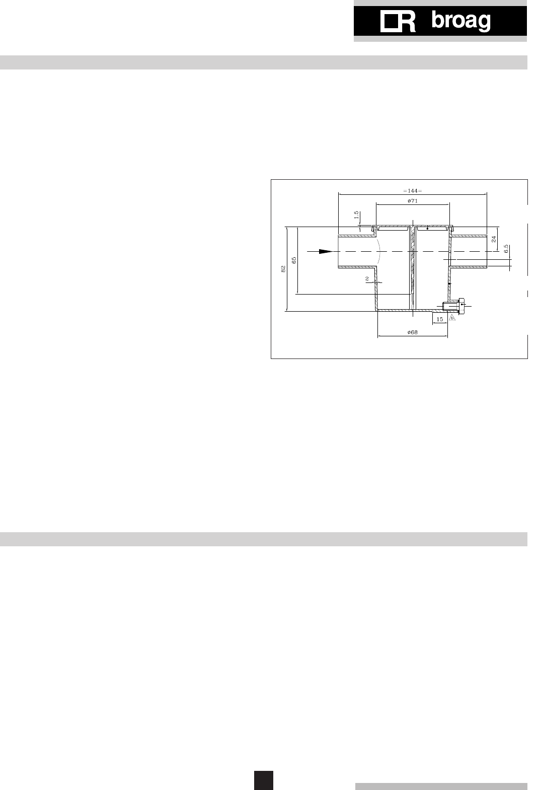
8.6 Condensate drain
A drain pipe with ext. dia. 32 mm can be secured with
adhesive to the siphon trap.
The liquid condensate produced by condensing boilers
must be led away via a pipe to a drain for disposal. This
pipe may be separate from the flue system and incorpo-
rate a water- sealed trap allowing condensate to pass but
preventing the escape of flue gases.
8.1 General
Boiler can be installed in open or closed systems.
8.2 Boiler assembly
Broag provides special tools, on loan, for the boiler
assembly with detailed building instructions. However,
building supervision and/or actual boiler erection services
can be provided by Broag or an approved boiler erection
engineer.
8.3 Water connections
The boiler water connections can be fitted on one side of
the boiler either left or right hand side. The return is fitted
as standard on the left-hand side of the boiler (view from
the front). The return can be fitted on the right; this must
be clearly specified when the boiler is ordered.
The water connection is flanged on the boiler with a pipe
connection for welding Ø 70 mm to the installation.
The top blind-flange has an integral cast 1" tapping to
accept a safety valve. The end sections have a 3/4"
tapping to accept a drain off cock (Tapping BSP). The
economiser has at the bottom a 1/2" tapping for a drain
off cock.
8.4 Pocket for instrument panel
The pocket should be fitted in the top front end section of
the boiler and at that side of the boiler where the gas train
is fitted. Other end section tapping 1" should be plugged.
8.5 Water pressure
Each section is hydraulically tested to at least 12 bar.
Maximum test pressure for the assembled boiler block is
6 bar.
Maximum working pressure is 6 bar.
Minimum working pressure is 0.8 bar at a maximum
working temperature of 110°C or 0.3 bar at a maximum
working temperature of 95°C.
9. GAS SUPPLY
Fig. 07 Siphon trap dimensions
9.1 General
The gas train can be fitted on the left or right hand side of
the boiler but is normally positioned on the same side as
the instrument panel is fitted*.
The local Gas authority should be consulted to ensure
that an adequate pressure and supply is available, at the
boilers maximum output. To minimise risk of sediment or
foreign particles entering the control valves, an approved
filter may be fitted into the pipework downstream. The
gas supply should be conform to the British Gas safety
regulations.
9.2 Gas pressure
Maximum gas pressure at inlet 100 mbar.
(Minimum 20 mbar).
Burner pressure: 12.3 mbar.
10
remeha Gas 3c ECO
10. ELECTRIC SUPPLY
Number
of
sections
5
6
7
8
9
10
11
12
13
14
15
16
17
500
500
500
500
600
600
600
800
800
800
800
800
800
W
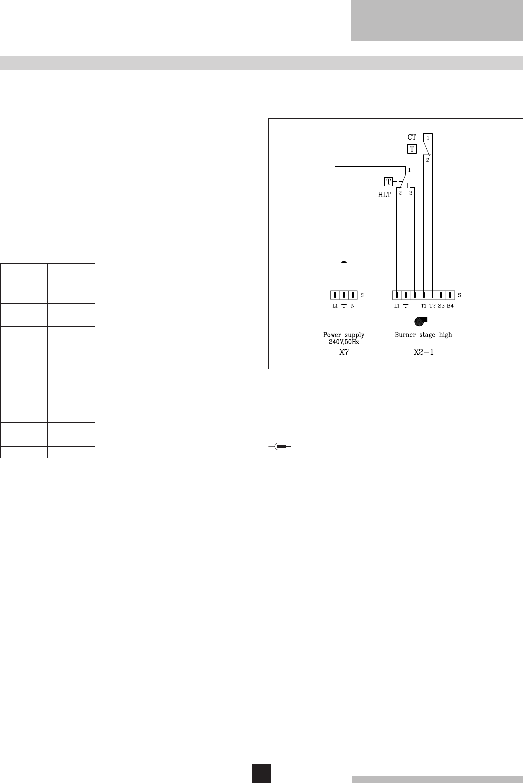
10.5 Wiring diagram for the instrument panel
10.5.1 Simple instrument panel
10.1 General
The electrical installation must conform to the IEE Regu-
lations and also to Local Authority Requirements.
10.2 Control panel
A control panel is fitted on the gas train.
10.3 Electric connections
The boiler is pre-wired. Only the mains supply should be
connected to the control panel.
10.4 Electric data
Main supply: 240 V-50 Hz (L/N)
Installed fuse: 6 Amp.
Running current:
Legend
CT Control thermostat
HLT High limit thermostat
S Plug
Connector
Fig. 08 Simple instrument panel
11
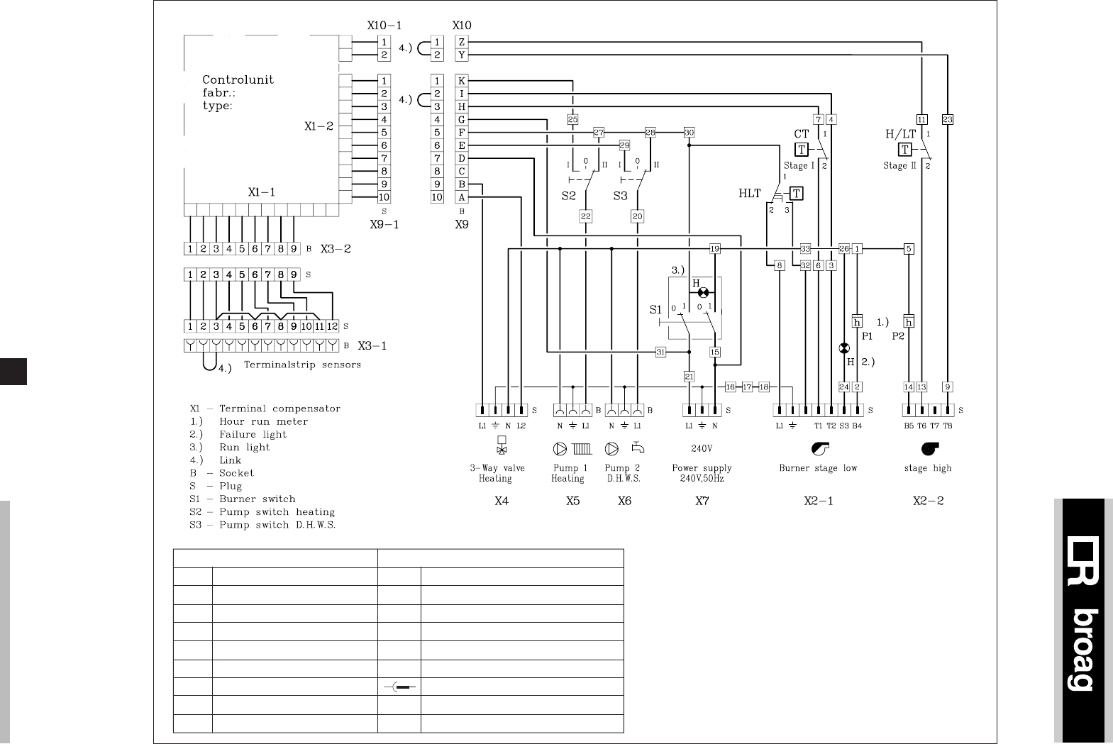
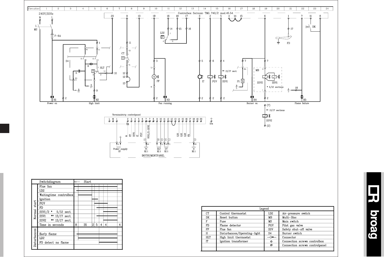
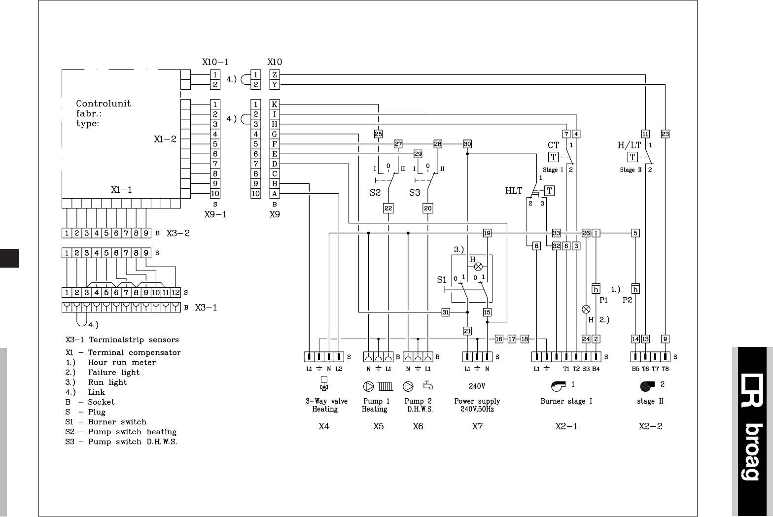
10.5.2 Complete instrument panel
(High/Low thermostat will not be used)
Fig. 09 Complete instrument panel
Legend
CT Control thermostat
DK Reset button
F Fuse
FD Flame detector
FF Flue fan
H Lock out/Operating-light
HLT High limit thermostat
IT Ignition transformator
LD2 Air-pressure switch
MB Multi bloc
MS Main switch
PGV Pilot gas valve
SSV Safety shut-off valve
S1 Boiler switch
Connector
O Connection screws control box
Ø Connection screws control panel
14
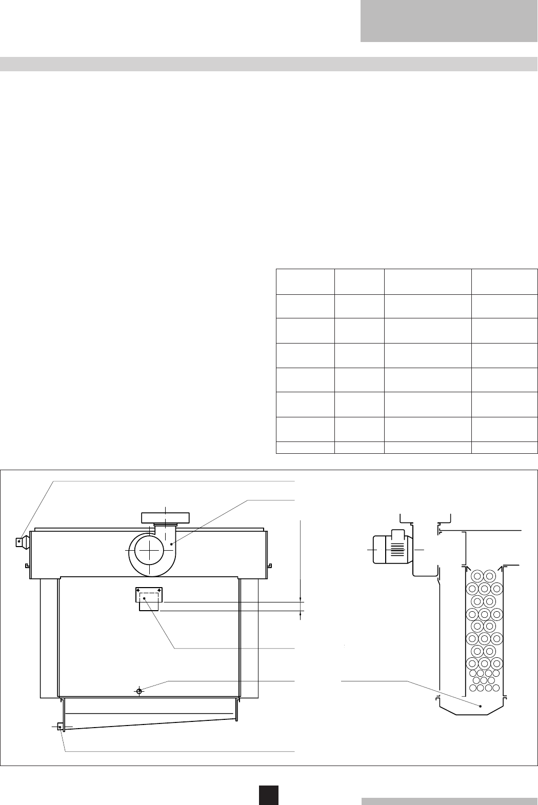
remeha Gas 3c ECO
Fig. 12 Rear view of 'ECO'
Flue Fan
Air-pressure switch
Air control
Condense drain connection
Measuring
point CO2
and flue gas temp.
Cross section
11. COMMISIONING
h
11. Let the boiler run for a couple of minutes to get rid of
air in the gas pipe.
12. Set the correct burner pressure.
13. Optimal combustion efficiency can be obtained by
adjusting the plate on the rear of the economiser so
that a CO2 of 7-8% is obtained at a minimum return
water temperature of 60°C.
14. Check that the thermostats are locked in position.
15. Check for flame protection by starting the boiler with
ionisation probe disconnected.
16. Check the operation of the air-pressure switch.
11.3 Switch off the boiler
1. Switch off the electric supply.
2. Turn off the gas cock.
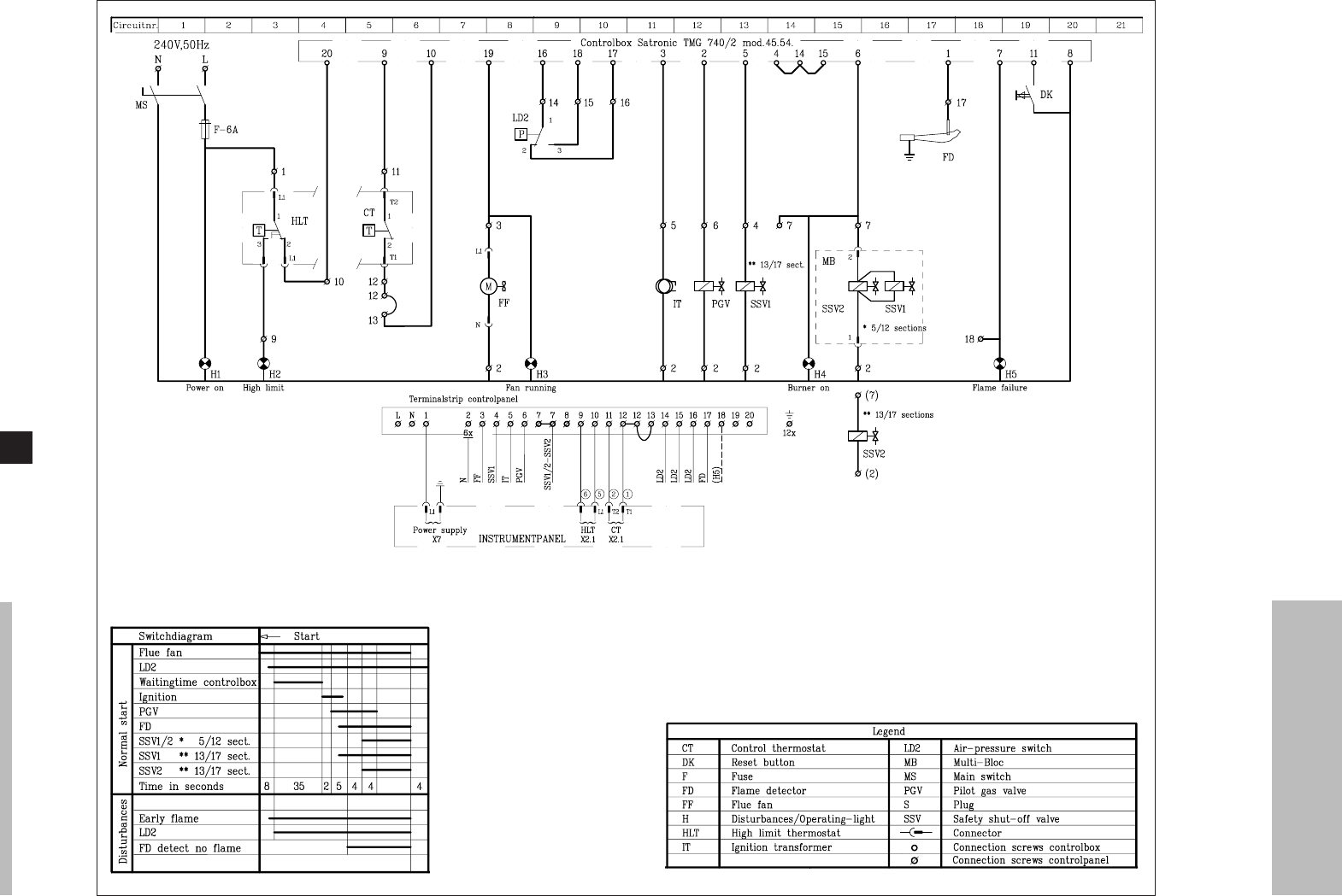
11.1 Technical information
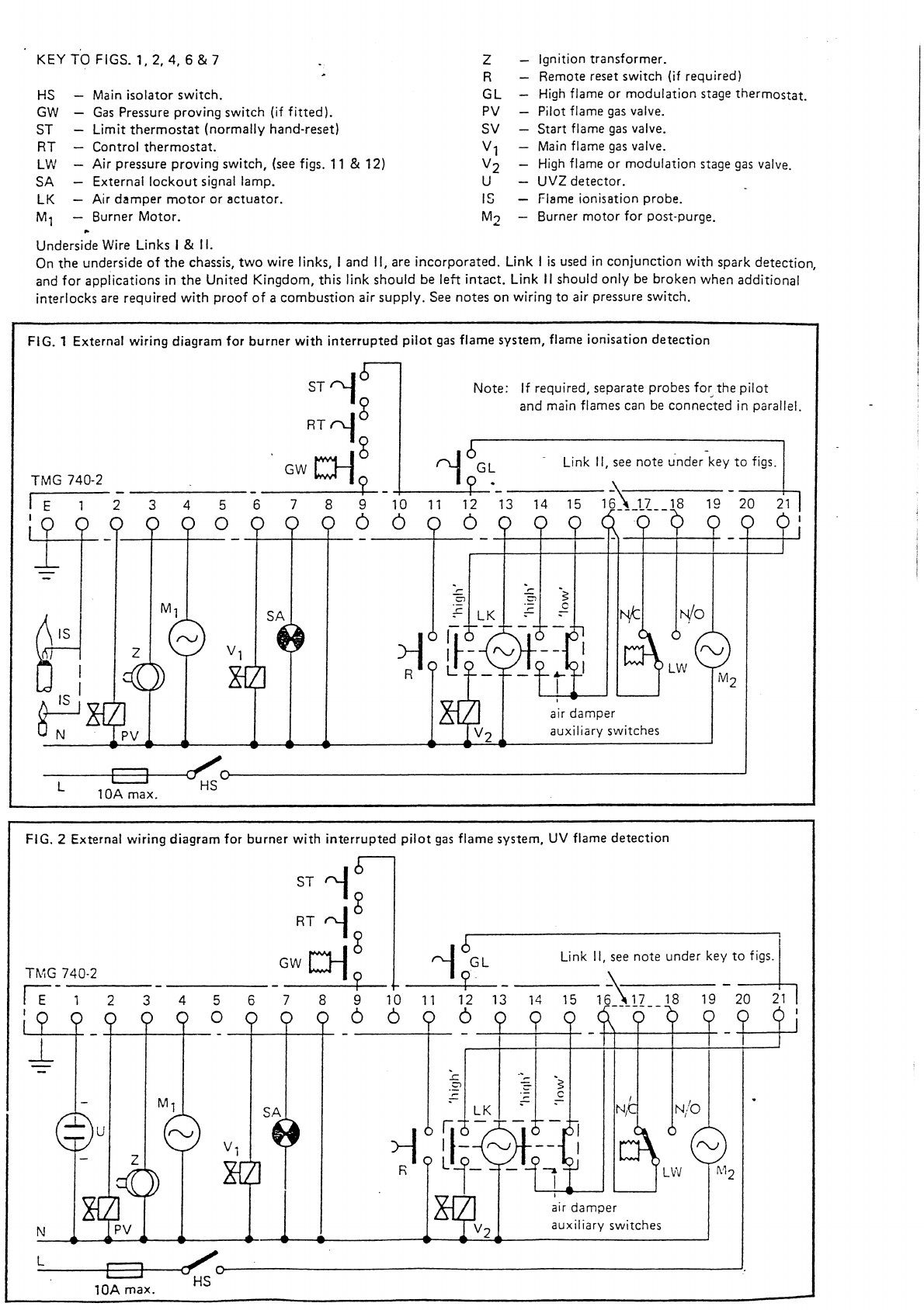
Control box : Satronic TMG 740/2
mod. 45.54.
Main supply : 240 V-50 Hz.
Minimum ionisation current : 7 µA.
Reaction time flame protection : 1 sec.
Safety time : 5 sec.
Maximum ambient temperature : 60°C.
Injector size pilot burner : Ø 0.8 mm.
Injector size main burner : Ø 4.4 mm.
Burner pressure full load : 12.3 mbar.
Pilot burner pressure : 13 mbar
11.2 Commissioning
1. Check gas connections.
2. Check electrical supply (L/N and earth).
The control box operates on a neutral/phase
supply.
3. Check water connections and release the air out of
the ECO and boiler. Fill the syphon with water.
4. Switch on circulation pump and check rotation direc-
tion.
5. Open main gas cock (release air in gas pipe work).
6. Switch on electrical supply.
7. Check rotation direction of the flue fan.
8. Set the control thermostat at about 85°C.
9. Adjust the sliding air inlet (see table).
10. After a waiting time of about 43 seconds you will get
ignition. At a minimum ionisation current of 7 µA the
safety gas valve will open and the pilot gas valve will
close after about 15 seconds. The boiler is on.
5
6
7
8
9
10
11
12
13
14
15
16
17
Number of
sections
Setting 'h'
in mm
Flue Fan Fan power
in kW
34
24
21
27
68
63
43
103
90
86
60
62
65
E 05-S972- 4mF
E 05-S972- 4mF
E 05-S976- 3mF
E 05-S976- 3mF
E 06-S972- 6mF
E 06-S972- 6mF
E 06-S972- 6mF
E 064-S972- 10mF
E 064-S972- 10mF
E 064-S972- 10mF
E 064-S972- 10mF
E 064-S972- 10mF
E 064-S972- 10mF
0.13
0.13
0.24
0.24
0.30
0.30
0.30
0.63
0.63
0.63
0.63
0.63
0.63

15
12. MAINTENANCE
12.1 General
It is essential for a good combustion, to clean the boiler,
the gas train and boiler room once a year.
12.2 Maintenance instructions
1. Clean the internal flue ways of the boiler (cast iron
sections) with a steel cleaning brush (available from
Broag). Remove top casing and the top of the flue
hood.
2. Clean (if necessary) the aluminium economiser.
If it is not too dirty (normal deposition of dust) it is
best be cleaned with water, which can be hosed into
the top of the economiser. This water can be drained
down through the condensate drain. If it is badly
fouled, it should be cleaned by using the nylon clea-
ning brush. In that case, remove the rear panel and
then the intermediate panel. Clean the aluminium
pipes using the special nylon cleaning brush (avai-
lable from Broag). Clean the condensate collector.
Never use the nylon brush for the cast iron sec-
tions and the economiser.
3. Remove the lit of the siphon trap and clean it.
4. Clean the burners internally and externally.
5. Clean the floor underneath the boiler and boiler room.
6. Clean boiler casings.
7. Clean the gas train, ignition, pilot burner, thermostats
and wiring.
8. Check start program, ignition time and safety times.
9. Check flame protection and thermostats.
10. Check boiler input.
11. Check the combustion efficiency.
12. Check the boiler and installation for water leakage
(seals).
13. Check gas train and gas pipe for gas leakage.

16
remeha Gas 3c ECO
© Copyright
All technical and technological infor-
mation contained in these technical
instructions, as well as any drawings
and technical descriptions furnished
by us remain our property and may
not be multiplied without our prior
consent in writing.
Subject to alterations
Art.nr. 50.455/1000/06.96/Bo.
ISO 9001
since 1988
Broag Ltd.
Head office
Remeha House,
Molly Millars Lane,
Wokingham,
Berkshire RG 41 2QP
Tel. 0118 9783434
Fax 0118 9786977
Branch office
Unit 3, Kestrel Close,
Quarry Hill Ind. Estate
Ilkeston,
Derbyshire DE7 4RD
Tel. 0115 9440778
Fax 0115 9440588

remeha Gas 3d
2
CONTENTS
Preface 3
1. Boiler description 3
2. Construction 3
2.1 General 3
2.2 Burners 3
2.3 Boiler base 3
2.4 Assembly 3
3. Technical information and dimensions 4
4. Application 5
4.1 L.P.H.W. system 5
4.1.1 Water temperature 5
4.1.2 Water pressure 5
4.1.3 Water flow 5
4.1.4 Water treatment 5
4.1.5 Noise level 5
4.2 Chimneys 5
4.3 Installation standards 5
5. Typical boiler installations 6
6. Regulation and safety equipment 7
6.1 General 7
6.2 Instrument panel 7
6.3 Standard electronic gas train High/Low 8
6.3.1 Schematic 8
6.3.2 Specification 8
6.3.3 Control panel on gas train 8
6.4 Functions 8
6.4.1 Flame protection 8
6.4.2 Down draught thermostat 8
6.4.3 Thermostats 8
7. Assembly and installation guidelines 9
7.1 General 9
7.2 Boiler assembly 9
7.3 Water connections 9
7.4 Pocket for instrument panel 9
7.5 Water pressure 9
8. Gas supply 9
8.1 General 9
8.2 Gas pressure 9
9. Electrical supply 10
9.1 General 10
9.2 Control panel 10
9.3 Electrical connections 10
9.4 Electrical data 10
9.5 Wiring diagram for the instrument panel 10
9.5.1 Simple instrument panel 10
9.5.2 Complete instrument panel 11
9.6 Wiring diagram boiler 12
9.6.1 Complete wiring diagram for the
boiler with simple instrument panel 12
9.6.2 Complete wiring diagram for the
boiler with complete instrument
panel 13
10. Commissioning 14
10.1 Technical information 14
10.2 Commissioning the boiler 14
10.3 Switching off the boiler 14
11. Maintenance 15
11.1 General 15
11.2 Maintening the boiler 15

3
PREFACE
* On request extension cables can be delivered, so that
the gas train can be fitted on the opposite side to the
instrument panel, thermostat pocket and the flow.
If you have any questions, or if you need more informa-
tion about specific subjects relating to this boiler, please
do not hesitate to contact us.
The data published in these technical instructions is ba-
sed on the latest information and is subject to revisions.
We reserve the right to modify the construction and/or
design of our products at any moment, without being
obliged to adjust earlier supplies accordingly.
These technical instructions contain useful and important
information for the proper operation and maintenance of
the remeha model Gas 3d central heating boiler.
Furthermore, important instructions are given to prevent
accidents and serious damage before commissioning and
during operation of the boiler, to ensure safe and trouble
free boiler operation. Read these instructions carefully
before putting the boiler into operation, familiarize your-
self with its operation and control and strictly observe the
instructions given.
The remeha Gas 3d boiler is a cast iron sectional boiler
with atmospheric burners.
Suitable for all qualities of natural gas, cat. I 2 H (20 mbar).
The boiler meets the requirements of the CE regulations
at the following directives:
- Gas appliance directive no. 90/396/EEC
- Efficiency directive no. 90/42/EEC
- Electrical low voltage directive no. 73/23/EEC
- Machinery directive no. 89/392/EEC
- E.M.C. directive no. 89/336/EEC.
Classification type for evacuation of the combustion
products: B11 BS.
For further advice or information contact Broag Ltd.
The remeha Gas 3d is supplied with electronic ignition
and insulated casings.
Water connections: Ø 70 mm int.
1. BOILER DESCRIPTION
2.1 General
- Boiler block of cast iron sections are joined together
with conical nipples.
- Gas train and water connections can be fitted on either
side of the boiler.
The gas train should as standard always be fitted
on the same side as the instrumental panel,
thermostat pocket and the flow*.
- Instrument panel is fitted in the front casing.
- Cleaning of the cast iron block from top of the boiler.
2.2 Burners
The burners are cast iron, atmospheric
reminox
®-bur-
ners. They guarantee a low noise level and a low NOx-
emission.
2.3 Boiler base
The Broag remeha Gas 3d boiler is supplied as standard
with reflecting floor plates with ventilation underneath.
2.4 Assembly
The boiler must be assembled on site.
2. CONSTRUCTION
remeha Gas 3d
4
3. TECHNICAL INFORMATION AND DIMENSIONS
Top view
Cross section
Left hand side view Front view
ø70 int.
ø70 int.
Fig. 01 View figures
5
6
7
8
9
10
11
12
13
14
15
16
17
Number
of
sections
Output
90
113
135
158
180
203
225
248
270
293
315
338
360
kW
Input
GCV
1015
1015
1040
1040
1040
1040
1065
1065
1065
1065
1090
1090
1090
A
mm
Dimensions Water
contents
1220
1220
1220
1220
1220
1220
1320
1320
1320
1320
1320
1320
1320
51
58
65
71
78
85
91
98
105
111
118
125
131
1"
1"
1"
1"
11/4"
11/4"
11/4"
11/4"
11/2"
11/2"
11/2"
11/2"
11/2"
E
mm
Ø d
"
200
200
200
250
250
250
300
300
300
300
350
350
350
Ø D
mm
B
mm
675
775
875
975
1075
1175
1275
1375
1475
1575
1675
1775
1875
Boiler
weight
dry
425
490
555
620
685
755
820
885
950
1020
1085
1150
1215
kgl
111
139
167
194
222
250
279
306
333
361
389
417
Mass
flue
rate
211
264
316
369
422
475
527
580
633
685
738
791
844
kg/h
670
670
670
670
700
700
700
700
1030
1030
1030
1030
1030
± L
mm mbarmbar
4
6
8
10
13
16
20
25
30
35
40
46
52
∆t = 10°C∆t = 20°C
Water
resistance
16
24
32
40
52
64
80
100
120
140
160
184
208
kW

5
Output boiler in kW
93 = ... m3/h
This minimum flow must be maintained for 5 minutes af-
ter the burner stops firing to avoid high temperature shut-
down due to residuel heat gain.
Due to the design and manufacture of the boiler no speci-
fic minimum water flow requirement exists other than for
high-temperature protection.
4.1.4 Water treatment
Water treatment under normal circumstances is not
necessary (see our water quality recommendations).
4.1.5 Noise level
The noise level measured around the boiler depending
on boiler room construction is about 50 dBA.
(Noise level taken at 1 meter from the boiler)
4. APPLICATION
4.1 L.P.H.W. system
4.1.1 Water temperature
Maximum water temperature is 110°C (high limit
thermostat).
Highest boiler water temperature is 95°C (control
thermostat).
Minimum return water temperature is 20°C at a flow rate
related at a ∆t of 20°C (flow/return temperature).
4.1.2 Water pressure
Boiler sections pressure test at 12 bar.
Maximum pressure test for the boiler block is 6 bar.
Minimum working pressure boiler is 0.8 bar.
Maximum working pressure is 6 bar.
4.1.3 Water flow
The minimum water flow through the boiler is:
4.2 Chimneys
The average flue gas temperature is so low that the chim-
ney must be in accordance with the guidelines of British
Gas and BS 6644.
4.3 Installation standards
The following instructions must be adhered to when the
remeha Gas 3d is installed:
Gas safety (installation and use) Regulations 1984 (as
amended).
All gas appliances must, by law, be installed by compe-
tent persons (e.g. Corgi) in accordance with the above
regulations. Failure to install appliances correctly could
lead to prosecution.
It is in your own interest and that of safety to ensure that
the law is complied with.
In addition to the above regulations, this appliance must
be installed in compliance with the current I.E.E.
Regulations for electrical installation, local building regula-
tions, the Building Standards (Scotland), Consolidation
Regulations and bye laws of the local water undertaking
and Health and Safety Document No. 635 'The Electricity
at Work Regulations 1989'. It should also be in accor-
dance with the relevant recommendations in the current
editions of the following British Standards and Codes of
Practice, viz.
BS 5540 Pt 1 and 2, BS 5449, BS 5546, BS 6798,
BS 6891 and BG.DM2.
Important:
The remeha Gas 3d is a certified appliance and must not
be modified or installed in any way contrary to these
'Installation and Servicing Instructions'.
Manufacturers instructions must NOT be taken in any way
as overriding statutory obligations.
remeha Gas 3d
6
One boiler in boiler room
5. TYPICAL BOILER INSTALLATIONS
Fig. 02 Installation 1
Two boilers in boiler room
Fig. 03 Installation 2
Two boilers in boiler room
back to back
Fig. 04 Installation 3
Number of sections
5678910 11 12 13 14 15 16 17
1015
675
200
1220
1015
775
200
1220
1040
875
200
1220
1040
975
250
1220
1040
1075
250
1220
1040
1175
250
1220
1065
1275
300
1320
1090
1875
350
1320
1090
1775
350
1320
1090
1675
350
1320
1065
1575
300
1320
1065
1475
300
1320
1065
1375
300
1320
Dimensions
(mm)
A
B
Ø D
E

7
6. REGULATION AND SAFETY EQUIPMENT
* Absent in simple instrument panel High/Low
** On request extension cables can be delivered, so
that the gas train can be fitted on the opposite side to
the instrument panel, thermostat pocket and the flow.
6.1 General
The remeha Gas 3d is supplied with electronic control
and safety equipment with UV flame detection.
6.2 Instrument panel
The remeha Gas 3d is supplied with an instrument panel
that is fitted in the front of the boiler, either left or right.
The instrument panel can be delivered in two models:
- simple instrument panel High/Low;
- complete instrument panel High/Low.
All connections are pre-wired and fitted with plugs. The
capillaries from the control panel should be fitted in the
pocket of the boiler, wich is fitted in the top front of the
end section.
The instument panel, pocket and the flow should
always be fitted at one side of the boiler either left or
right and standard on the same side as the gas
train.**
BDE
CA
135
4
268
79
11
10
Fig. 05 Layout of the complete instrument panel
Module D
9. Warning light*
10. Analogue thermometer water temperature
Module E
11. Option for
rematic
® weather compensating boiler
control*
The modules contain:
Module A
1. Control thermostat
Setting between 35°-95°C
2. Hour run meter total running hours*
Module B
3. High-Low thermostat
Setting between 35°-95°C
4. Hour run meter full load*
Module C
5. High-limit thermostat 110°C (locking)
6. Operating switch (On/Off with optical display)*
7. Switch for circulating pump*
Manual/Off/Automatic
8. Switch for domestic hot water storage pump*
Manual/Off/Automatic
remeha Gas 3d
8
6.3 Standard electronic gas train High/Low
6.3.1 Schematic
6.3.2 Specification
1 Gas multiloc (5-12 sections)
2 Safety shut off valves
1 Gas governor
1 Gas filter
2 Safety shut off valves (13-17 sections)
1 Gas governor
1 Pilot gas valve
1 Ignition transformer 5 kV
1 Pilot burner with UV protection
6.3.3 Control panel on gas train
1 Main switch
1 Control box Landis & Gyr
1 Fuse, brusk
1 Signal lamp
6.4 Functions
6.4.1 Flame protection
Flame protection by means of UV flame detection.
6.4.2 Down draught thermostat
The boiler is fitted with a down draught thermostat.
If there is down draught the thermostat will switch off the
boiler. Fixed setpoint is 70°C.
6.4.3 Thermostats
Control thermostat On/Off 35°-95°C.
Control thermostat High/Low 35°-95°C.
High-limit thermostat locks out at 110°C.
Fig. 06 5-12 sections
Fig. 07 13-17 sections
Legend
A Gas cock
PB Pilot burner
DR Gas governor
F Gas filter
HB Main gas burners
MB Gas multibloc
IT Ignition transformer
PGV Pilot gas valve
MP Measuring point
SSV Safety shut-off valve
UV UV diode
- - - - Not supplied

9
7.1 General
The boiler is suitable for operating at a maximum working
pressure of 6 bar and a minimum pressure of 0.8 bar.
Boiler can be installed in open or closed systems.
7.2 Boiler assembly
Broag provides special tools on loan, for the boiler as-
sembly with detailed building instructions. However, buil-
ding supervision and/or actual boiler erection services
can be provided by Broag or an approved boiler erection
engineer.
7.3 Water connections
The boiler water connections can be fitted on either side
of the boiler.
The water connection is flanged on the boiler with a pipe
connection for welding Ø 70 mm to the installation.
The top blind-flange has an integral cast 1" tapping to
accept a safety valve. The end sections have a 3/4"
tapping to accept drain/off cocks (Tapping BSP).
* On request extension cables can be delivered, so that
the gas train can be fitted on the opposite side to the
instrument panel, thermostat pocket and the flow.
7.4 Pocket for instrument panel
The pocket should be fitted in the top front end section of
the boiler and at that side of the boiler where the gas train
is fitted. Other end section tapping 1" should be sealed.
7.5 Water pressure
Each section is hydraulically tested to at least 12 bar.
Maximum test pressure for the assembled boiler block is
6 bar.
Operating pressure between 0.8 bar and 6 bar.
8.1 General
The gas train can be fitted on either side of the boiler but
as standard is always fitted on the same side of the boiler
instrument panel (fitted in the front casing).*
The local Gas authority should be consulted to ensure
that an adequate pressure and supply is available at the
boilers maximum output. To minimise risk of sediment or
foreign particles entering the control valves, an approved
filter may be fitted into the pipe work downstream.
The gas supply should be conform to the British Gas
safety regulations.
8.2 Gas pressure
Maximum gas pressure at inlet 100 mbar.
Burner pressure:
- full load : 13.0 mbar (100%)
- part load : 4.7 mbar (60%)
- injector size: 2.9 mm Ø
8. GAS SUPPLY
7. ASSEMBLY AND INSTALLATION GUIDELINES
remeha Gas 3d
10
9. ELECTRICAL SUPPLY
9.1 General
The electrical installation must conform the IEE
regulations and also to local authority requirements.
9.2 Control panel
A control panel is fitted on the gas train.
9.3 Electrical connections
The boiler is pre-wired. Only the main supply should be
wired to this control panel.
9.4 Electrical data
Main supply: 240 V-50Hz (L/N).
Running current: 120 W.
Installed fuse: 6 Amp.
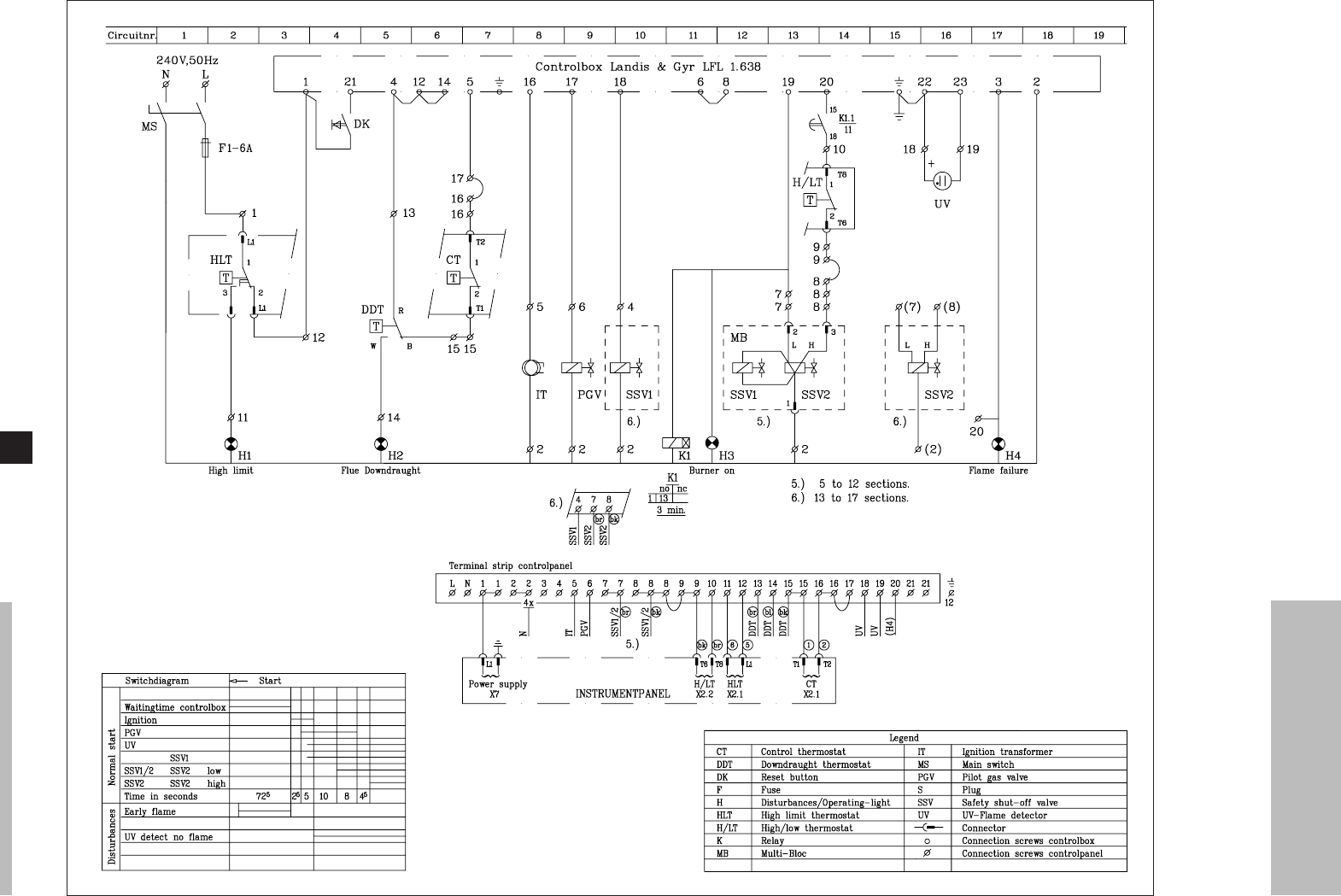
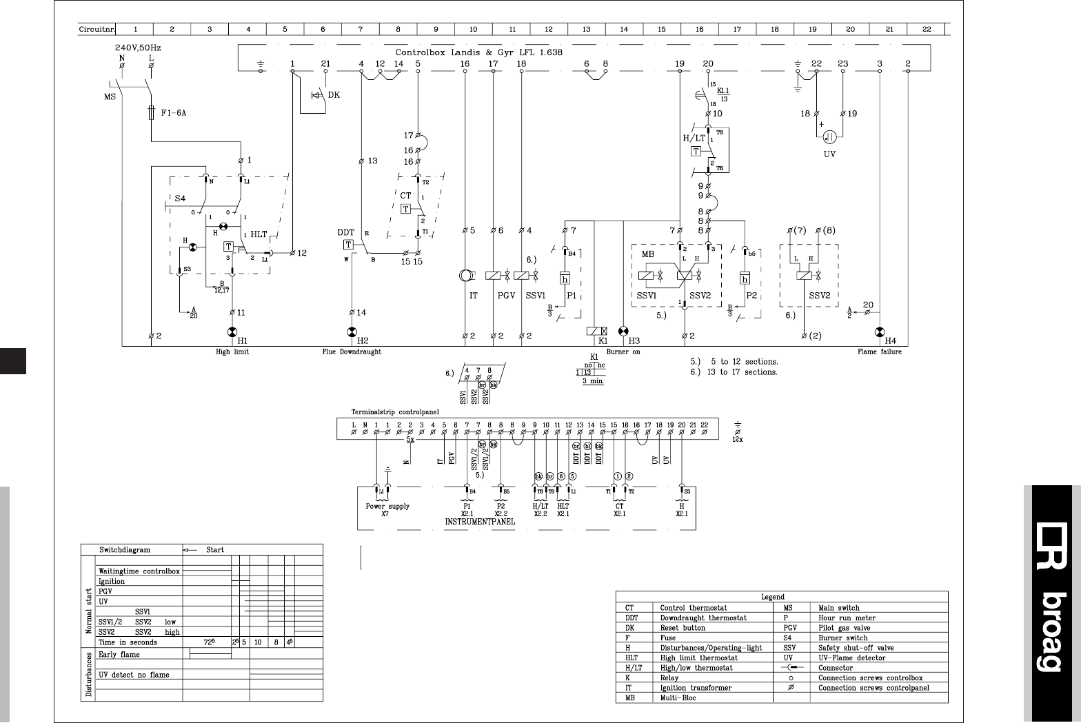
9.5 Wiring diagram for the instrument panel
9.5.1 Simple instrument panel
Fig. 08 Wiring diagram for the simple instrument panel
Legend
CT Control thermostat
HLT High limit thermostat
H/LT High/Low thermostat
S Plug
Connector

remeha Gas 3d
14
10. COMMISSIONING
10.1 Technical information
Control box: Landis & Gyr typ LFL 1.638.
Main supply: 240 V-50 Hz.
Minimum UV current: 100 µA.
Reaction time flame protection: 1 sec.
Safety time: 5 sec.
Maximum ambient temperature: 60°C.
Injector size pilot burner: Ø 0.8 mm.
Injector size main burner: Ø 2.9 mm.
Burner pressure full load: 13.0 mbar (100%).
Burner pressure part load: 4.7 mbar (60%).
Burner pressure pilot burner = 16 mbar.
Warning:
Control box operates on a neutral/phase supply.
10.2 Commissioning the boiler
1. Check gas connections.
2. Check electrical supply (L/N and earth).
3. Check water connections and if the installation is
filled.
4. Switch on circulation pump and check rotation direc-
tion.
5. Open main gas cock (release air in gas pipe work).
6. Switch on electrical supply.
7. Set the control thermostats at about 85°C.
8. After a waiting time of about 72 seconds you will get
ignition. At a minimum UV current of 100 µAmp the
safety gas valve will open and the pilot gas valve will
close after 15 seconds. The boiler is on.
9. Leave the boiler on for a couple of minutes to get rid
of air in the gas pipe.
10. Set the correct burner pressure.
11. Check the thermostats for correct operation.
12. Check the flame protection, start the boiler with
the UV-blindfolded.
10.3 Switching off the boiler
1. Switch off the electrical supply.
2. Turn off the gas cock.

15
11. MAINTENANCE
11.1 General
It is essential for a good combustion, to clean the boiler,
the gas train and boiler room once a year.
11.2 Maintening the boiler
1. Clean the internal flue ways of the boiler with a steel
cleaning brush (available from Broag).
Remove top casing and top of the flue hood.
2. Clean the burners internally and externally.
3. Clean boiler room and the floor underneath the
boiler.
4. Clean the boiler casings.
5. Clean the gas train, ignition, pilot burner, UV, thermo-
stats and wiring.
6. Check start program, ignition time and safety times.
7. Check flame protection, and thermostats.
8. Check the boiler input at 100% and 60% load.
9. Make a combustion efficiency calculation.
10. Check the boiler and installation for water leakage.
11. Check gas train and gas pipe for gas leakage.

Subject to alterations
Art.nr. 50.695/1000/09.96/Bo.
© Copyright
All technical and technological
information contained in these
technical instructions, as well as any
drawings and technical descriptions
furnished by us remain our property
and shall not be multiplied without
our prior consent in writing.
ISO 9001
since 1988
Broag Ltd.
Head office
Remeha house,
Molly Millars Lane,
Wokingham,
Berkshire RG41 2QP.
Tel. 0118 9783434
Fax 0118 9786977
Branch office
Unit 3, Kestrel Close,
Quarry Hill Ind. Estate,
Ilkeston
Derbyshire DE7 4RD
Tel. 0115 9440778
Fax 0115 9440588
Remeha Gas 350
• Atmospheric gas boiler
• 64 - 174 kW
Technical information
Remeha Gas 350

Remeha Gas 350
2
TABLE OF CONTENT
Preface 3
1 Boiler description 3
2 Construction details 3
2.1 General 3
2.2 Burners 3
2.3 Boiler Floor 3
2.4 Delivery 3
3 Dimensions and technical data 4
3.1 Dimensions Remeha Gas 350 4
3.2 Technical data 4
3.3 Quotation specifications 5
4 Application information 5
4.1 L.P.H.W. system 5
4.1.1 Water temperature 5
4.1.2 Water pressure 5
4.1.3 Water flow 5
4.1.4 Water treatment 5
4.1.5 Noise level 6
4.2 Chimneys 6
4.3 Installation standards 6
5 Typical boiler installations 7
5.1 Installation 1 7
5.2 Installation 2 7
6 Control and safety equipment 8
6.1 General 8
6.2 Instrument panel 8
6.3 Standard electronic gas train High/Low 8
6.3.1 Schematic 8
6.4 Specification control box 9
6.4.1 Specification Ignition transformer 9
6.5 Functions 9
6.5.1 General 9
6.5.2 Flame control (lock out) 9
6.5.3 Thermostats (shutdown / lock out) 9
6.5.4 Water pressure switch - optional
(shut down) 9
6.5.5 Gas pressure switch LD - optional
(shut down) 9
6.5.6 Down draught thermostat - optional
(shut down) 9
7 Assembly and installation guidelines 9
7.1 General 9
7.2 Boiler assembly 9
7.3 Water connections 9
7.4 Pocket the thermostat capillaries 9
7.5 Water pressure 9
8 Gas supply 10
8.1 General 10
8.2 Gas pressure 10
8.3 Injectors 10
8.4 Operation on propane 10
9 Electrical supply 10
9.1 General 10
9.2 Control box 10
9.3 Electrical connections 10
9.4 Electrical information 11
9.5 Wiring diagrams 11
10 Commissioning 12
10.1 Commissioning the boiler 12
10.2 Switching off the boiler 13
11 Maintenance 14
12 Trouble shooting 14
12.1 Communication 15
12.2 Fault causes 15
3
PREFACE
These technical instructions contain useful and impor-
tant information for the correct operation and mainte-
nance of the Remeha boiler, model Gas 350.
Read these instructions carefully before putting the
boiler into operation, familiarise yourself with its control
functions and operation, strictly observing the instruc-
tions given. Failure to do so may invalidate warranty or
prevent the boiler from operating.
A competent Engineer, with the relevant certification
(i.e. CORGI, ACOPS, IEE regs. etc.) must carry out the
installation and commissioning of the boiler.
On completion a copy of the boiler log / commissioning
sheet should be returned to Broag Ltd for record pur-
poses.
If you have any questions, or if you need more informa-
tion about specific subjects relating to this boiler, or it’s
installation please do not hesitate to contact us.
The data published in these technical instructions is
based on the latest information (at date of publication)
and may be subject to revisions.
We reserve the right to continuous development in both
design and manufacture, therefore any changes to the
technology employed may not be retrospective nor may
we be obliged to adjust earlier supplies accordingly.
1 BOILER DESCRIPTION
The Remeha Gas 350 boiler is a cast iron sectional
floor standing gas fired boiler with Class II reduced NOX
burners. Supplied c/w control high/low and high limit
thermostats, automatic ignition and flame failure safety
controls. Suitable for all qualities of natural gas and pro-
pane, cat. II2H3B/P
. The Remeha Gas 350 central heating
boiler is approved according to the following European
directives:
- Gas appliance directive no. 90/396/EEC,
- Efficiency directive no. 92/42/EEC,
- E.M.C. directive no. 89/336/EEC,
- Low voltage directive no. 73/23/EEC.
Remeha Gas 350 PIN: 0063AS3842
Classification type for evacuation of the combustion pro-
ducts: B11BS, B 11.
For further advice or information contact Broag Ltd.
The Remeha Gas 350 is supplied with electronic junc-
tion with insulated casings.
2 CONSTRUCTION DETAILS
2.1 General
The Remeha Gas 350 is a floor standing boiler com-
plete with temperature and safety controls. The cast iron
sectional heat exchanger is assembled using conical
nipples and jointing compounds and ceramic rope. The
finished unit is cased in an insulated enamel coated
steel enclosure. The boiler has a built in draught diver-
ter. It has water and gas connections within the casings
at the rear right hand side (when viewed from the front).
The boiler is supplied prewired requiring only permanent
mains supply and external control connections.
2.2 Burners
The burners are stainless steel, atmospheric type with
cooling rods to reduce the flame temperature. They gua-
rantee a low noise level and a reduced NOX-emission.
Front and top access is required for service work to be
carried out.
2.3 Boiler Floor
The Remeha Gas 350 boiler is supplied as standard
with reflecting floor plates with ventilation underneath.
2.4 Delivery
The boilers are supplied in sections for on site assem-
bly. The gas train, control panel, burners and casings
supplied loose for fitting one site by others. The 4 - 6
units can also be delivered pre-assembled with the main
block pressure tested.
Remeha Gas 350
4
3 DIMENSIONS AND TECHNICAL DATA
3.1 Dimensions Remeha Gas 350
fig. 01 Dimensions Remeha Gas 350
É Flow R2” (BSP M)
Ê Return R2”
Ï Gas connection 4 - 6 sections R1”
7 - 9 sections R1¼”
Ñ Flue gas Ø D
Number of sections 456789
A mm 640 740 840 940 1040 1140
B mm 280 330 380 430 480 530
C mm 905 905 905 930 930 930
Ø D mm 200 200 200 200 250 250
E mm 1030 1030 1030 1080 1080 1080
F mm 165 165 165 215 215 215
table 01 Dimensions
Front view
Side view Rear view
3.2 Technical data
Number of sections 4 5 6 7 8 9
Nominal heat output kW 64 87 109 130 152 174
Nominal
heat input
Hi / NCV kW 72 97 121 145 169 193
Hs / GCV kW 80 108 134 161 188 214
Gas consumption m3/h 7.6 10.3 12.8 15.3 17.9 20.4
Flue temperature °C 154 152 146 138 138 142
Water
resistance
∆t = 10°C mbar 5 13 21 30 41 52
∆t = 20°C mbar 2 3 5 8 10 13
Water contents litre 45 51 58 65 71 78
Boiler weight (dry) kg 335 390 445 500 555 610
Flue gas flow rate kg/h 219 239 255 271 398 407
table 02 Technical data Remeha Gas 350

5
3.3 Quotation specifications
General specifications:
- Heat exchanger manufactured from corrosion resist-
ant “pearlite” cast iron
- Maximum operating pressure of 6 bar
- Maximum operating temperature of 95°C
- Electronic ignition as standard
- High/low operation as standard
- Reduced NOX burners (CE class 2)
- Built in draft diverter
- Supplied in broken down form, the models 4-6 sec-
tions can also be delivered pre-assembled
- Powder coated enamel steel casing
- 80 mm thick glass wool insulation
- Suitable for use with a Natural gas (propane available
as an option)
- Minimum return water temperature 20°C
- Supplied as standard with on/off switch, temperature
indication, control and high limit thermostats
- Efficiency 81.5% (GVC)
- Manufactured to ISO 9001
- CE approved
Optional:
- Hours run meters
- BMS contacts for remote indication
- Water pressure switch
- Down draught thermostat
- rematic® control.
4 APPLICATION INFORMATION
4.1 L.P.H.W. system
4.1.1 Water temperature
Maximum water temperature is 110°C (high limit ther-
mostat).
Highest operating boiler water temperature is 95°C (con-
trol thermostat).
Minimum return water temperature is 20°C at a flow rate
related to a ∆t of 20°C (flow/return temp).
4.1.2 Water pressure
Boiler sections are factory pressure tested to 10 bar.
Maximum pressure test boiler block is 8 bar.
Maximum working pressure is 6 bar.
Minimum working pressure is 0.8 (sealed system) or 0.3
(open vented).
4.1.3 Water flow
The minimum water flow through the boiler on shut
down is:
Output boiler in kW = m3/h
93
This minimum flow must be maintained for approximate-
ly 5 minutes after the burner stops firing to avoid high
temperature shut down due to residual heat gain. Due
to the design and manufacture of the boiler no specific
minimum water flow requirements exist other then for
overheating protection.
4.1.4 Water treatment
The system should be filled with mains cold water (for
the UK this will usually have a pH of between 7 and 8).
Pressurised installations with a boiler/system content
ratio of 1:10 or less should not require water treatment,
provided that the following conditions apply:
1. The system is flushed thoroughly to remove all
fluxes and debris and then filled completely once.
2. Make up water is limited to 5 % per annum.
3. The hardness of the water does not exceed 360
ppm (20°D).
All scale deposits will reduce the efficiency of the boiler
and should be prevented. However provided the above
is complied with any scale produced will not be too detri-
mental to the boiler efficiency and will not reduce the
anticipated life expectancy of the boiler.
NOTE: Scale deposits in excess of 3 to 5 mm will
reduce boiler efficiency and greatly increase the risk of
premature casting failure.
As most systems contain a variety of metals which can
react with each other to cause corrosion. It is considered
good practice to provide some form of water treatment
(especially in open vented systems) in order to prevent
or reduce the following:
- Metallic corrosion;
- Formation of scale and sludge;
- Microbiological contamination;
- Chemical changes in the untreated system water.

Remeha Gas 350
6
Suitable chemicals and their use should be discussed
with a specialist water treatment company prior to car-
rying out any work. The specification of the system and
manufacturers recommendations must be taken into
account, along with the age and condition of the system.
New systems should be flushed thoroughly to remove all
traces of flux, debris, grease and metal swarf generated
during installation. Care to be taken with old systems to
ensure any black metallic iron oxide sludge and other
corrosive residues are removed, again by thoroughly
flushing, ensuring that the system is drained completely
from all low points.
NOTE: Please ensure that the new boiler plant is not in
circuit when the flushing takes place, especially if clean-
sing chemicals are used to assist the process.
Under no circumstances is the boiler to be operated
with cleaning chemicals in the system.
To Summarise:
- Minimise water loss;
- Prevent pumping over in open vented systems;
- Provide adequate air venting at all high points;
- Keep pH level between 7 - 9 when using additives;
- Maximum chlorine content of 200 mg/l;
Take advice on the suitability of inhibitors.
4.1.5 Noise level
The noise level measured around the boiler depending
on boiler room construction is about 50 dBA. Noise
levels taken at 1 meter from the boiler.
4.2 Chimneys
The average flue gas temperature is so low (108-
173°C) that the chimney must be made in accordance
with the guidelines of British Gas, BS 6644 and IG 10.
4.3 Installation standards
The following instructions must be adhered to when the
Remeha Gas 350 is installed:
Gas Safety (installation and use) Regulations 1984 (as
amended).
In addition to the above regulations, this boiler must be
installed in compliance with:
- Current I.E.E. Regulations for electrical installations;
- Local building regulations;
- The Building Standards (Scotland);
- (Consolidation) Regulations;
- By-laws of the local water undertaking;
- Health and Safety Document No 635 ‘The Electricity
at Work Regulations 1989’.
It should also be in accordance with the relevant recom-
mendations in the current editions of the following British
Standards and Codes of Practice, viz. BS 5440 Pt 1 and
2, BS 5449, BS 5546,
BS 6798, BS 6891 and BG.DM2.
Lawfully all gas appliances must be installed by compe-
tent persons (e.g. Corgi, ACOPS).
Failure to install appliances correctly could lead to pros-
ecution.
It is in your own interest and that of safety to ensure that
the law is complied with.
Important:
The Remeha Gas 350 is a certified appliance and must
not be modified or installed in any way contrary to these
‘Installation and Servicing Instructions’. Manufacturer
instructions must NOT be taken in any way as when
overriding statutory obligations.
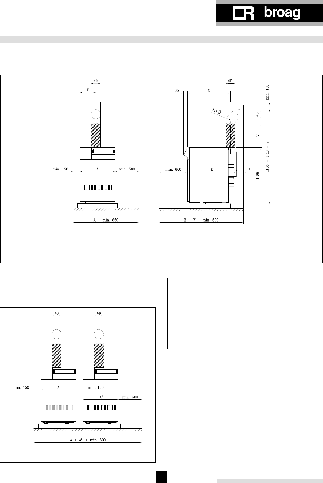
7
5 TYPICAL BOILER INSTALLATIONS
5.1 Installation 1
Recommended layout for one boiler installation, meas-
urements in mm.
V = min. length 0.5 m before elbow, thus avoiding down draught
W = min. 150 mm with vertical flue outlet
W = min. 0.5D + 50 mm with horizontal flue outlet
1 Boiler in boiler room
fig. 02 One boiler
5.2 Installation 2
Recommended layout for two-boiler installation, meas-
urements in mm.
2 Boilers in boiler room
fig. 03 Two boilers
number
of
sections
Dimensions
ABCØ DE
4640 280 905 200 1030
5740 330 905 200 1030
6840 380 905 200 1030
7940 430 930 200 1080
81040 480 930 250 1080
91140 530 930 250 1080
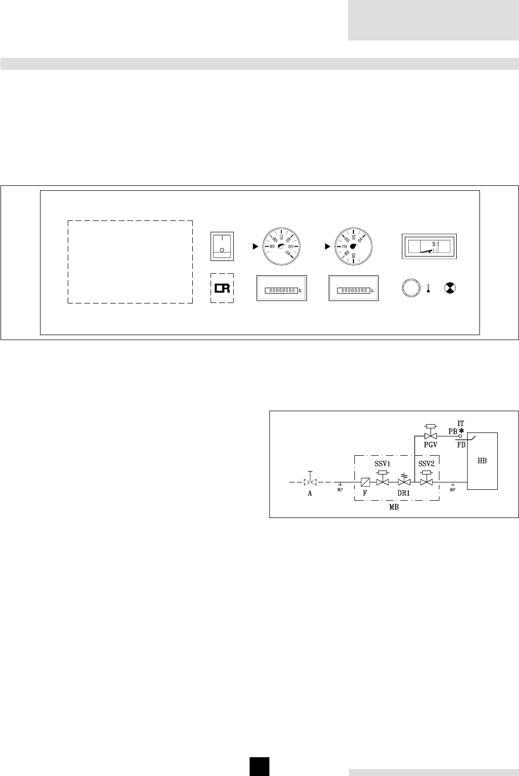
Remeha Gas 350
8
6 CONTROL AND SAFETY EQUIPMENT
6.1 General
The Remeha Gas 350 is supplied with electronic control
and safety equipment with ionisation flame detection.
6.2 Instrument panel
The Remeha Gas 350 is supplied with an instrument
panel that is fitted in the front of the boiler. The standard
instrument panel can be extended with the fitting of
9
123
6
45
7
8
the following options: hour run meters, water pressure
switch, down draught thermostat, simple or complex volt
free modules and/or rematic® control. All connections
are pre-wired and fitted with plugs. The capillaries from
the control panel should be fitted in the pocket of the
boiler, which is fitted in the flow connection of the boiler.
fig. 04 Instrument panel
The instrument panel contains:
1. Operating switch (On/Off);
2. Control thermostat On/Off, range 35°C-95°C;
3. Control thermostat High/Low, range 35°C-95°C;
4. Hour run meter total running hours (option);
5. Hour run meter full load hours (option);
6. Analogue thermometer for flow temperature;
7. High – limit thermostat pre set to 110°C;
8. Lock out warning lamp;
9. Option for rematic® weather compensator.
6.3 Standard electronic gas train High/Low
6.3.1 Schematic
fig. 05 Schematic layout gas train
Legend
A Gas cock
PB Pilot burner
DR Gas pressure governor
F Gas filter
HB Main burners
PGV Pilot gas valve
MP Measuring point
SSV Safety shut off valve
FD Ionisation probe
MB Gas multiblock
IT Ignition transformer
- - - Not supplied as standard

9
6.4 Specification control box
Control box : Satronic DKG 972-27
Mains supply : 230 V – 50 Hz
Minimum ionisation current : min 3 µA (DC)
Reaction time flame protection : 1 sec.
Safety time : ≤ 10 sec.
Maximum ambient temperature : 60 °C
Injector size pilot burner : Ø 0.5 mm
Injector size main burner : Ø 4.0 mm
Burner pressure full load
(high calorific gas) : 14.0 mbar (100%)
Burner pressure part load
(high calorific gas) : 5.0 mbar (60%)
Start repetitions : 5x
Warning: control box is phase / neutral sensitive.
6.4.1 Specification Ignition transformer
Ignition transformer: Satronic ZT. 870
Ignition voltage: 16 kV
Distance electrodes: 3,5 ± 1 mm.
6.5 Functions
6.5.1 General
The following functions (standard and optional) will,
when activated, either lock out or shut down the boiler.
For all options full fitting instructions are included in the
option pack.
6.5.2 Flame control (lock out)
The flame is monitored using ionisation flame detec-
tion. In the event of a flame failure the boiler will lock
out. Manual intervention is required to reset the boiler
(on the control box) once the cause of the problem has
been rectified.
6.5.3 Thermostats (shutdown / lock out)
- Control thermostat On/Off: shutdown (35°C-95°C);
The boiler will automatically resume operation when
the flow temperature falls below the set point.
- Control thermostat High/Low: shutdown (35°C-
95°C);
The boiler will automatically resume operation when
the flow temperature falls below the set point.
- High Limit thermostat: lock out at 110°C;
The boiler will lock out. Manual intervention is
required to reset the boiler (on the instrument panel)
once the cause of the problem has been rectified.
6.5.4 Water pressure switch - optional (shut down)
The boiler can be fitted with an optional water pressure
switch. If the water pressure drops below the set value
(0.8 bar), the boiler will shut down. When the water
pressure returns to 1 bar, the boiler will resume opera-
tion again.
Type: SIT 340
6.5.5 Gas pressure switch LD - optional (shut down)
The boiler can be fitted with an optional gas pressure
switch LD. If the supply gas pressure drops below the
set value (12 mbar; for natural gas only), the boiler will
shut down. When the supply gas pressure returns above
this set value the boiler will resume operation again.
Type: Dungs GW50 A5.
6.5.6 Down draught thermostat - optional (shut
down)
The boiler can be fitted with an optional down draught
thermostat. When the temperature in the draught divert-
er rises above the down draught thermostat set point,
the boiler will shut down. It automatically resets after 3
minutes, provided that the temperature also falls.
Type: Honeywell L6068A; fixed set point is 70°C.
7 ASSEMBLY AND INSTALLATION GUIDELINES
7.1 General
The boiler is suitable for operating at a maximum work-
ing pressure of 6 bar. It can be installed in open vented
system with a minimum pressure of 0.3 bar or in sealed
system with a minimum pressure of 0.8 bar.
7.2 Boiler assembly
The boiler is supplied with full assembly instructions. On
request special assembly tools can be hired from Broag
on a daily basis. However, Broag (or a Broag approved
boiler erection engineer) can provide boiler assembly
services and / or building supervision.
7.3 Water connections
The boiler water connections (2” male thread) are fitted
at the rear of the boiler (right hand connections only).
The two sections have a ¾” BSP tapping, the right hand
end section to accept a drain/off cock and the left hand
end section to accept a plug.
7.4 Pocket the thermostat capillaries
The multi pocket for the thermostat capillaries is fitted in
the flow connection of the boiler.
7.5 Water pressure
Each section is hydraulically tested at 10 bar. Operating
pressure between 0.3 and 6 bar. The boiler can be fitted
with an optional water pressure switch, set at 0.8 bar.
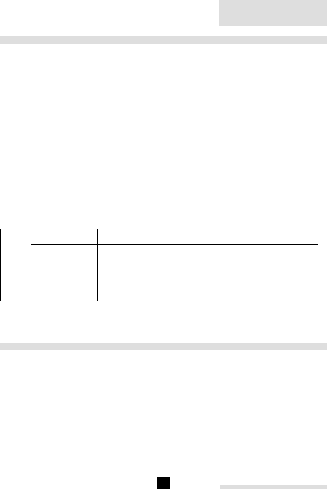
Remeha Gas 350
10
8 GAS SUPPLY
8.1 General
The gas train is fitted behind the front casing.
The local Gas authority should be consulted to ensure
that an adequate pressure and supply is available. To
minimise risk of sediment or foreign particles entering
the control valves, an approved filter can be fitted into
the pipe system downstream. The gas supply should be
conforming to the British Gas safety regulations.
8.2 Gas pressure
Natural gas, cat. I2H 3B/P (20 mbar).
Maximum gas pressure at inlet 100 mbar. Recommend-
ed min gas pressure required at the boiler is 17 mbar
with it operating at high fire.
Main burner pressure settings:
full load: 14.0 mbar
part load: 5.0 mbar
Pilot burner pressure settings: 13 mbar
Gas inlet pressure: 17 - 100 mbar
8.3 Injectors
Injector size main burner: 4.0 mm
Injector size ignition burner: 0.5 mm
8.4 Operation on propane
The boiler is supplied, as standard set for natural gas,
therefore the boiler must be converted to propane
BEFORE the boiler is fired and commissioned for the
first time on propane.
Important: The boiler can only operate ON/OFF once
converted to propane!
For operation on propane the main burner injectors and
pilot burner injector (Ø 0.25 mm) must be replaced. Also
the burner pressure must be adjusted. It is important
to remove the cooling rods from the burners, includ-
ing their supports.
Use our conversion kit for propane and follow the fitting
and commissioning instructions.
Technical data for operation on propane are shown in
table 03
Note: Place the sticker from the conversion kit to indi-
cate that the boiler has been changed for propane firing.
Number
of
sections
Heat
output
Heat
input Hi
Burner
pressure1) Gas consumption2) Injector size
main burner
Injector size
pilot burner
kW kW mbar m3/h kg/h Ø mm Ø mm
464 72 28 2.9 5.6 2.5 0.25
587 97 28 4.0 7.5 2.5 0.25
6109 121 28 4.9 9.4 2.5 0.25
7130 145 28 5.9 11.2 2.5 0.25
8152 169 28 6.9 13.1 2.5 0.25
9174 193 28 7.9 15.0 2.5 0.25
table 03 Technical data propane
1) The burner pressure may never vary more than 20% of the inlet pressure
2) Caloric value propane = 24.44 kWh/m3 = 12.9 kWh/kg
9 ELECTRICAL SUPPLY
9.1 General
The electrical installation must conform to the IEE regu-
lations and also to local authority requirements.
9.2 Control box
The Satronic control box is fitted behind the front casing.
9.3 Electrical connections
The boiler is pre-wired requiring only a mains supply
and external controls connected to the control panel.
The boiler can be fitted as an option, with a basic or an
extended signalling print.
Functions of the basic signalling print:
- general alarm
- operating signals stage 1 and stage 2
Functions of the extended signalling print:
- general alarm
- operating signals stage 1 and stage 2
- no power supply
- valve leakage failure
- burner failure
- low water level
- down draught thermostat
- water level control
- high limit thermostat.
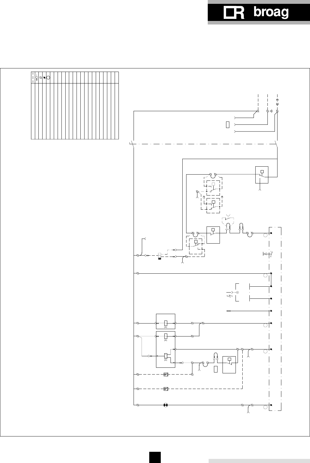
11
9.4 Electrical information
Main supply: 230 V-50 Hz (L/N)
Power consumption running: 110 W
Maximum fuse: 6.3 A (slow blow)
9.5 Wiring diagrams
CA
BM
BS
R
7-6
BS
45
4-9
CA
1-1 1-2
230V-50Hz
L1
N
DS
1-3
*
2
1
3
P
5
4-43
CA3 4T
16
15
*LD P1
221
T
*k1
C
T
1
B
TR1
7-4
7-3
2-1
BS
12
T
23
Tmx 1
4-2
CA1
2-2
1.)
8
7
1
9
*
A2 K1
N
*
2.)
1.)
7-2
27 24 26 25 20 14 11
VA2
4-8
BM-
C
16
17
18
1
Satronic ZT.870
*
CA5
Y1
3Min.
A1
7-9
TB
6
4-10
W
16kV
MK 1
2
22
VA1
1
2
N
3
23
21
IE
2-3
2-4
15
T
bl
8
DK
br
2
N 3
Satronic DKG 972-27
1
5
5
13
12
4
6
4-7
P
P2
L1
BM-
19
P1 H
2.)
TR2
CA4
10
4-5
9
3
7
K2
K2
**
General warning signals
Burner switch
Operating signals contact (230V - 1Amp. min.)
Remove link to control boiler
using an external Volt free16-17 External control High/Low (volt free switch)
7-8 External control On/Off (volt free switch)
Optional
1.) & 2.)
Ignition transformer
Control box
STAGE HIGH
STAGE LOW (230V)
Power supply
F
(230V)
10 Lock out indication (230V)
13 Boiler On (230V)
19 Boiler Hi
g
h fire
(
230
)
P
Tmx
VA
TR
TB
..
MK
LD
DK
DS
CA
BM
H
IE
K
F
BS
Hour run meter
Will not be supplied (optional)
High limit thermostat
Control thermostat
Safety shut-off valve
Down draught thermostat
Terminal strip control box
Cord numbers
Connector
Terminal strip
Gas pressure switch
General warning signals
Water level switch
Ionisation electrode
Disturbance light
Auxilairy relais
Pilot gas valve
Burner switch
Reset button
Fuse
Operating signals
fig. 06 Electrical principle diagram
04.03F.SC.00004
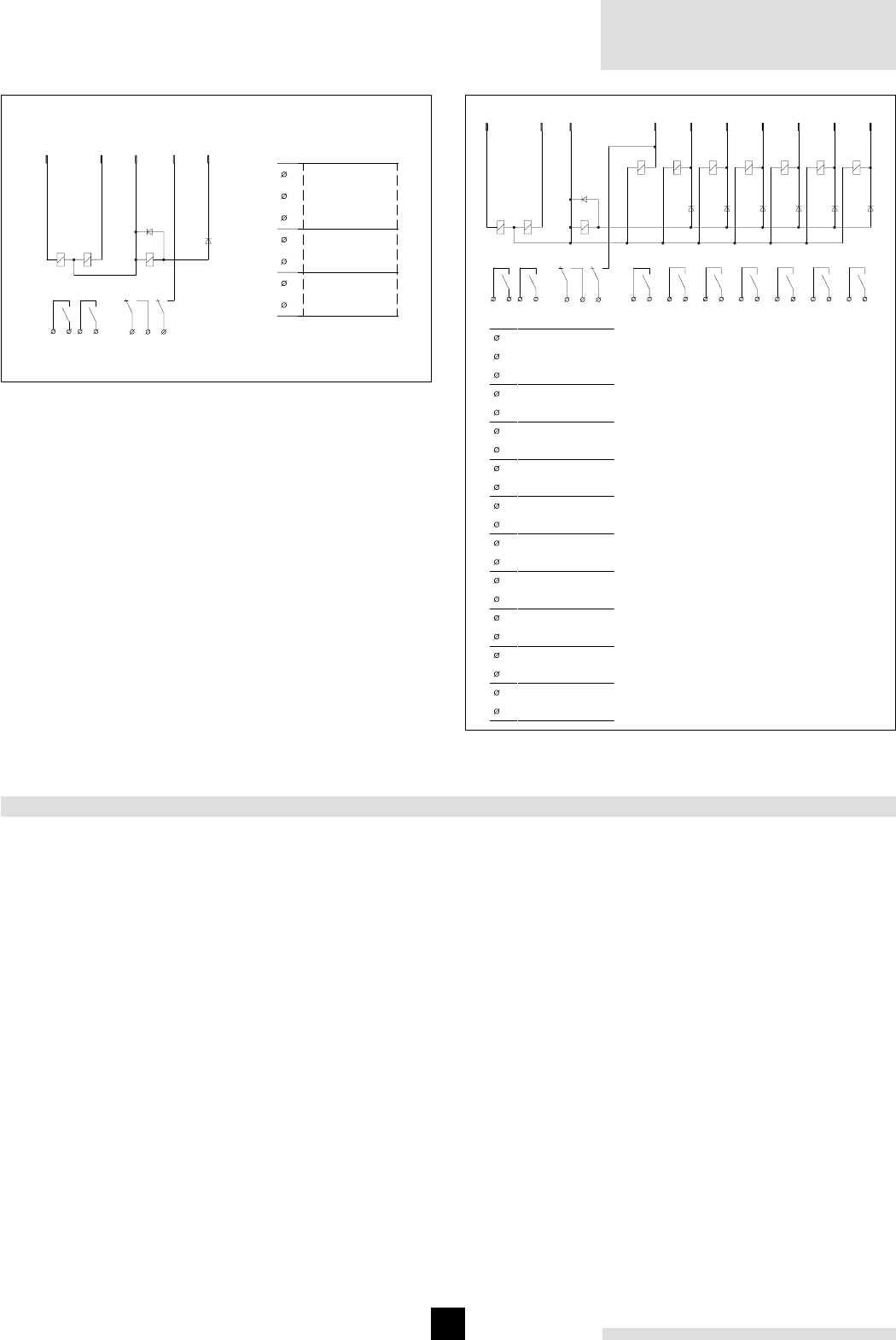
Remeha Gas 350
12
fig. 07 Optional basic signalling print
4A-1 4A-2
D1
K8
4A-9
D7
K9K10
4A-8
4A-7
45
K10-1
6 7
K9-1
2
K8-1
31
K8-2
CON.4A
B
m
B
m
C
al
1
2
3
4
5
6
7
General warning
Operating signal
Operating signal
stage 2
stage 1
signal
K7 K6 K5 K4 K3 K2 K1
4A-1 4A-6 4A-5 4A-4 4A-10 4A-3 4A-2
D6 D5 D4 D3 D2 D1
K8
4A-9
D7
K9K10
4A-8
4A-7
45
K10-1
6 7
K9-1
8 9
K7-1
20 21
K1-1
18 19
K2-1
16 17
K3-1
14 15
K4-1
12 13
K5-1
10 11
K6-1
2
K8-1
31
K8-2
CON.4A
1
2
3
4
5
6
7
8
9
10
11
12
13
14
15
16
17
18
19
20
21
High limit stat
Low water level
Water level
Down draught
Valve leakage
Operating signal
Operating signal
General warning
No power supply
control
thermostat
failure
Burner
failure
stage 2
stage 1
signal
fig. 08 Optional complex signalling print
10 COMMISSIONING
NOTE: Commissioning must only be carried out by a
qualified engineer with the relevant training and certifica-
tion i.e. Acops - Corgi and a commissioning data sheet
/ log book completed and left on site for issue to the
owner.
Important: commissioning for propane, first see par.
8.4
10.1 Commissioning the boiler
1. Check the gas connections.
2. Check the electrical supply (L/N and earth).
Warning: control box is phase / neutral sensitive.
3. Check the water connections and whether the instal-
lation is full and under system pressure.
4. Switch on the circulation pump and check the rota-
tion direction.
5. Open the main gas cock (purge gas pipeline).
6. Switch on the electrical supply.
7. Set both the thermostats to about 85°C.
8. If a control system is built in: put the selector switch
on manual operation.
9. Switch on the boiler.
10. After a waiting time of about 3 seconds the ignition
starts. The magnetic valve MK opens and ignition
burner lights. At a minimum ionisation current of 3
µA the safety gas valve will open. The boiler runs.
11. Let the boiler run for a couple of minutes on high fire
to clear any air still in the gas pipe.
12. Set the correct full load burner pressure by means
of the pressure regulator on the gas multiblock gas
valve (see fig. 09, pos. a).
Warning: When the required burner pressure can
not be reached because of low inlet pressure,
ensure that the pressure regulator remains within it’s
operating range.
Now do the following:
• Set the burner pressure to the highest possible
value (but not over the required full load burner
pressure).
• Turn the pressure regulator anticlockwise until
the burner pressure is affected.
• The burner pressure is now limited, this will
prevent the boiler from being over gassed
should the inlet gas pressure increase.
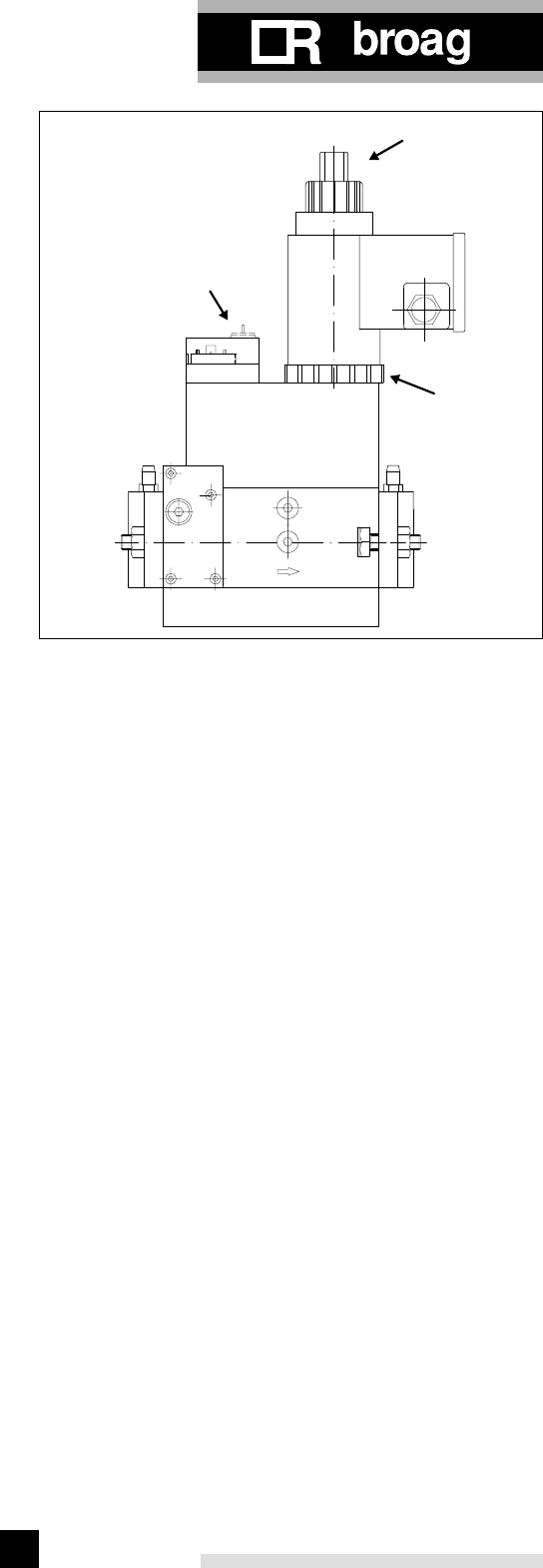
13
13. Set the correct part load burner pressure:
• Turn the High/Low thermostat to its minimum
setting (35°C). When the flow temperature is
over 35°C, the boiler will burn at part load.
• Set the part load burner pressure by turning the
adjustment ring (fig. 09, pos. b).
• To check the high fire setting: Turn the High/Low
thermostat to 85°C and check the full load
burner pressure (if necessary re-adjust).
The speed of opening of the main gas valve can
also be adjusted to ensure a smooth light up. Set-
ting the hydraulic brake on the main gas valve as
follows:
• Remove the setting cap (fig. 09, pos. c) and turn
it upside down on the hydraulic brake.
• Turn it clockwise to slow down, anticlockwise to
speed up.
• Check both burner pressures again and if
necessary re-adjust.
14. Check the thermostats for the correct operation
setting.
15. Check the flame control on the control box
• Start the boiler with disconnected ionisation
probe, after the ignition phase the pilot gas
valve must close. The boiler will lock out.
• Reset by pressing the reset button on the
control box.
• Then disconnect the ionisation probe during
operation, the pilot gas valve must close imme-
diately. The boiler will lock out.
• Reset by pressing the reset button on the
control box.
16. Water level control:
• Check the water level.
• Check the operation of the water level control by
disconnecting the electrode. The boiler should
go to lock out
• Create a shortcut between the electrode and
earth. The boiler should go to lock out
• Reset by pressing the reset button on the instru-
ment panel. The boiler will resume operation
17. Check the down draught thermostat by pressing
the bimetallic strip on the thermostat. The boiler will
shut down for 3 minutes. After that the boiler will
resume operation.
18. Send the initial commissioning report CE to Broag.
a
c
b
fig. 09 Dungs MB-ZRDLE 410/412 B01 S52
a. Pressure regulator
b. Part load adjustment ring
c. Hydraulic brake (setting cap)
10.2 Switching off the boiler
1. Set boiler controls to OFF
2. Allow system to cool
3. Switch off the electric supply
4. Turn off the gas cock.
Warning: The boiler can be damaged, when the tem-
perature falls below freezing point and it is switched off
and full of water.
Note:
Commissioning must only be carried out by a qualified
engineer with the relevant product training and certifica-
tion i.e. Acops - Corgi. A commissioning data sheet / log-
book must be completed on site for issue to owner.
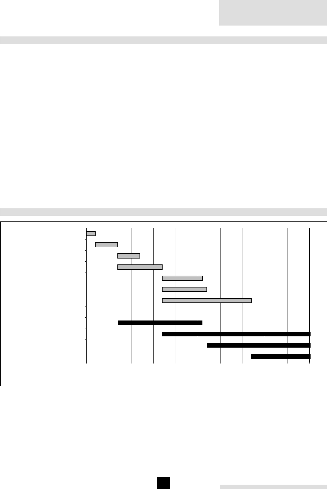
Remeha Gas 350
14
11 MAINTENANCE
To maintain maximum efficiency it is essential to service
the boiler, check safety parameters and re-set combus-
tion once a year.
Normal Service Maintenance
- Isolate power, controls and gas supply.
- Remove front and top casings and flue hood covers.
- Remove gas manifold.
- Remove the burners and floor plates.
- Clean the internal flue ways of the boiler.
- Clean the floor underneath the boiler and boiler
room.
- Clean the burners internally and externally using a
soft brush.
- Clean the plates under the burners as well - they
must be fitted and in the correct place for the com-
bustion to be correct
- Clean the gas train, ignition, pilot burner, ther-
mostats and wiring.
- Check and reset/replace ignition electrode and ioni-
sation probe as found necessary.
- Re-assemble boiler.
- Check ignition and ionisation cables for connections
and continuity.
- Restore power, controls and gas supply.
- Check start program, ignition time and safety times.
- Check flame protection and thermostats.
- Check boiler input at 100% (full load) and 60% (part
load) load.
- Carryout combustion efficiency test.
- Check the boiler and immediate installation connec-
tions for water leaks (seals).
- Check gas train and gas pipe for gas leaks.
- Check flue connections.
- Clean boiler casings.
- Complete a commissioning report and fill in the boi-
ler logbook if available.
12 TROUBLE SHOOTING
Timing diagram begin duration duration 2 end
Main gas valve VA2 (clamp 6) 37 14 50
Ionisation required 27 24 50
Ignition valve + VA1 (clamp 5) 17 34 50
Ignition (clamp 3) 7 19 26
Delay 2nd stage Tv2 17 20 37
Safety time Ts 17 10 27
Post ignition Tn 17 9 26
Pre-ignition time Tvz 710 17
False flame detection Tf 75 12
Waiting time Tw 25 7
Start up processor 022
0 5 10 15 20 25 30 35 40 45 50
Main gas valve VA2 (clamp 6)
Ionisation required
Ignition valve + VA1 (clamp 5)
Ignition (clamp 3)
Delay 2nd stage Tv2
Safety time Ts
Post ignition Tn
Pre-ignition time Tvz
False flame detection Tf
Waiting time Tw
Start up processor
seconds
fig. 10 Switch diagram
15
12.1 Communication
The control box communicates by using a flash code.
An LED inside the reset button of the control box dis-
plays this flash code.
flash code meaning of codes
│││.waiting time Tw
││││.pre-ignition (Tvz)
▌│.safety time (Ts) and post ignition time (Tn)
▌││.delay time to valve V2 (Tv2)
│.running
table 04 Program phases
flash code meaning cause
│▌▌.low mains voltage (shut down)
│▌.Internal fuse defect control box defect
│▌▌▌▌ lock out no flame detection within safety time Ts
││▌▌▌ early flame Ionisation probe may be faulty
││▌▌▌▌▌▌▌▌ manual lock out
table 05 Error messages
▌ = long pulse
│ = short pulse
. = short pause
12.2 Fault causes
In case of a failure the LED is permanently illuminated.
Every 10 seconds the illumination is interrupted by a
flash code.
In case of all failures the gas supply is interrupted.
Fault Possible cause:
Burner not working =>
shut down
- no heat demand
- no mains supply
- voltage < 187 V
- continuously tension on
terminal A
2-3 seconds after apply-
ing mains =>
lock out
- control box not reset
Burner starts, no flame
=> lock out
- false flame detected
- no ignition
- no gas supply
Burner starts, flame
established => lock out
after safety time (Ts)
- ionisation current < 1,5 µA
- phase and neutral
reversed
- ionisation probe damaged
or dirty
table 06 Trouble shooting

16
© Copyright
All technical and technological information contained in these technical instructions,
as well as any drawings and technical descriptions furnished by us remain our pro-
perty and shall not be copied in part or whole without our prior consent in writing.
Subject to alterations
ISO 9001
since 1988
51247-0303
Broag Ltd.
Remeha House
Molly Millars Lane
RG41 2QP WOKINGHAM, Berks.
United Kingdom
Tel: 0118 9783434
Fax: 0118 9786977
uk.remeha.com
boilers@broag-remeha.com
Midlands Branch Office
Unit 3 Kestrel Close
Quarry Hill Industrial Estate
Ilkeston
Derbyshire DE7 4RD
Tel: 0115 944 0778
Fax: 0115 944 0588
Remeha Gas 350
1
Remeha Gas 450
• Atmospheric gas boiler with
reduced NOx emission
• 217 - 344 kW
Technical information
Remeha Gas 450

Remeha Gas 450
2
CONTENTS
Preface 3
1. Boiler description 3
2. Constructions 3
2.1 General 3
2.2 Burners 3
2.3 Boiler floor 3
2.4 Delivery 3
3. Technical information and dimensions 4
4. Application 5
4.1 L.P.H.W. system 5
4.1.1 Water temperature 5
4.1.2 Water pressure 5
4.1.3 Water flow 5
4.1.4 Water treatment 5
4.1.5 Noise level 5
4.2 Chimneys 5
5. Typical boiler installations 6
6. Regulation and safety equipement 7
6.1 General 7
6.2 Instrument panel 7
6.3 Standard electronic gas train High/Low 7
6.3.1 Schematic 7
6.3.2 Specification 7
6.3.3 Control panel behind front panel 7
6.4 Functions 7
6.4.1 Flame protection 7
6.4.2 Down draught thermostat 7
6.4.3 Thermostats 7
7. Assembly and installation guidelines 8
7.1 General 8
7.2 Boiler assembly 8
7.3 Water connections 8
7.4 Pocket for instrument panel 8
7.5 Water pressure 8
8. Gas supply 8
8.1 General 8
8.2 Gas pressure 8
9. Electrical supply 8
9.1 General 8
9.2 Control panel 8
9.3 Electrical connections 8
9.4 Electrical data 8
9.5 Wiring diagram boiler 9
10. Commissioning 10
10.1 Technical information 10
10.2 Commissioning the boiler 10
10.3 Switching off the boiler 10
11. Maintenance 11
11.1 General 11
11.2 Maintaining the boiler 11

3
PREFACE
These technical instructions contain useful and important
information for the proper operation and maintenance
of the Remeha central heating boiler, model Gas 450.
Further it contains important directions to prevent accidents
and serious damage before putting it into service and
during operation of the boiler, to allow as far as possible a
safe and trouble free operation. Read these instructions
carefully before putting the boiler into operation, familiarize
yourself with its operation and control and strictly observe
the directions given.
If you have any questions, or if you want more information
about specific items relating to this boiler, please do not
hesitate to contact us.
The data published in these technical instructions is based
on the most recent information and is given subject to
later revisions.
We reserve the right to modify the construction and/or
design of our products at any moment, without obligation
to update earlier supplies accordingly.
1. BOILER DESCRIPTION
The Remeha Gas 450 boiler is a cast iron sectional boiler
with atmospheric burners.
Suitable for all qualities of natural gas and LPG,
cat. II 2H3P (LPG version on request)
The Remeha Gas 450 central heating boiler is approved
according to the following European directives:
- Gas appliance directive no. 90/396/EEC
- Efficiency directive no. 92/42/EEC
- E.M.C. directive no. 89/336/EEC
and complies with the following directives:
- Low voltage directive no. 73/23/EEC
- Machine directive no. 89/392/EEC.
Classification type for evacuation of the combustion pro-
ducts: B11 BS.
For further advice or information contact Broag Ltd.
The Remeha Gas 450 is supplied with electronic junc-
tion with insulated casings.
Water connections 21/2" BSP.
2. CONSTRUCTIONS
2.2 Burners
The burners are stainless steel, atmospheric burners
with cooling rods to reduce the flame temperature.
They guarantee a low noise level and a reduced NOx-
emission.
2.3 Boiler fl oor
The Remeha Gas 450 boiler is supplied as standard
with reflecting floor plates with ventilation underneath.
2.4 Delivery
The total range is supplied in parts for site assembly.
2.1 General
- Boiler block of cast iron sections nippled together with
conical nipples.
- Gas and water connections are at the rear of the boiler.
- Instrument panel is fitted in the front casing and must
be assembled on the same side as the gas and water
connections.
Instrument panel must be assambled on the same
side of gas and water connections.
- Cleaning of the cast iron block from top of the boiler.
- The control and safety equipment is fitted behind the
front casings.
- The boiler is entirely prewired.
- Gas and water connections can be assembled both
left and right.
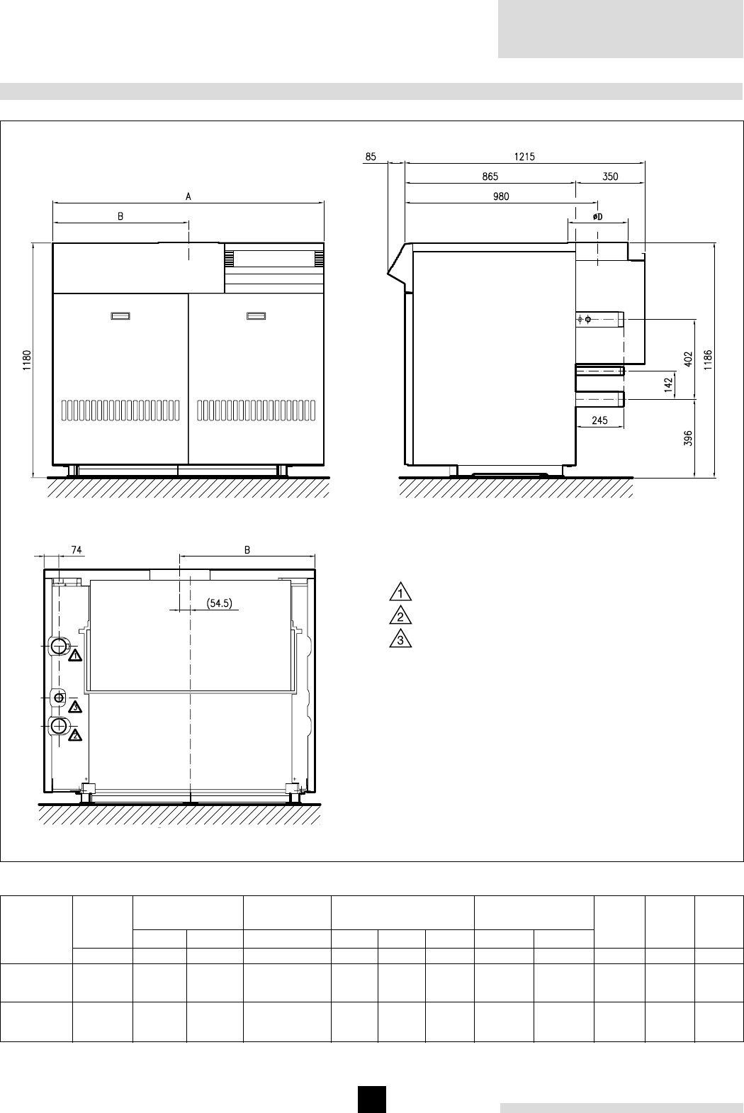
Remeha Gas 450
4
kW
kW
Hi
Hs
3. TECHNICAL INFORMATION AND DIMENSIONS
11
13
15
17
241
290
338
378
268
322
376
420
Number of
sections
Heat
input
Fig. 01 Dimensions
Rear view
Side view
Front view
Heat
output
Gasrate
kW
217
262
307
344
m3/h
25.0
30.1
35.1
39.2
mbarmbar
A
mm
B
mm
³t = 10°C
l
1365
1565
1763
1963
682.5
782.5
881.5
981.5
300
300
350
350
Boiler
weight
Dimensions Water
resistance
Water
content
Ø D
mm
84
120
164
208
³t = 20°C
21
30
41
52
91
105
118
131
725
835
950
1060
kg/h
Mass
flue
rate
544
654
752
831
kg
* Connections can also be assembled on the other side
Flow R 2½"
Return R 2½"
Gas connection: R 1¼"
Note:
Right hand execution is shown: instrument panel,
gas and water connections on the right hand side;
left hand execution is mirror image

5
4.1 L.P.H.W. system
4.1.1 Water temperature
Maximum water temperature is 110°C (high limit
thermostat).
Highest boiler operation water temperature is 95°C
(control thermostat).
Minimum return water temperature is 20°C at a flowrate
related to a ³t of 20°C (flow/return temperature).
4.1.2 Water pressure
Boiler sections pressure test at 10 bar.
Maximum pressure test boiler block is 8 bar.
Maximum working pressure is 6 bar.
Minimum working pressure boiler is 0.8 bar.
Optional a water pressure switch set at 0.8 bar can be
supplied with the boiler.
4.1.3 Water fl ow
The minimum water flow through the boiler is:
Output boiler in kW = ... m3/h
93
This minimum flow must be maintained for 5 minutes after
the burner stops firing to avoid high temperature shut-down
due to residuel heat gain.
Due to the design and manufacture of the boiler no specific
minimum water flow requirement exists other than high-
temperature protection.
4. APPLICATION
4.1.4 Water treatment
Water treatment under normal circumstances is not
necessary (see our water quality recommendations).
4.1.5 Noise level
The noise level measured around the boiler depending
on boiler room construction is about 50 dBA.
(Noise level taken at 1 meter from the boiler).
4.2 Chimneys
The average flue gas temperature is so low that the
chimney must be in accordance with the guidelines of
British Gas and BS 6644.
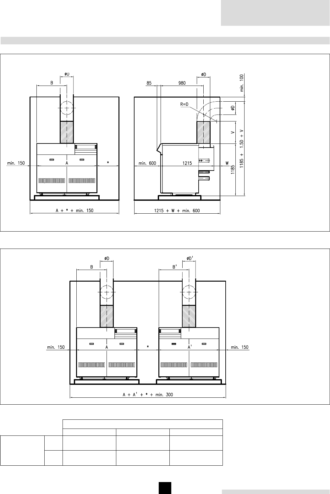
Remeha Gas 450
6
5. TYPICAL BOILER INSTALLATIONS
Fig. 02 Installation 1
Fig. 03 Installation 2
11
13
15
17
Dimensions (mm)
ABØ D
1365
1565
1763
1963
300
300
350
350
Number of
sections
682.5
782.5
881.5
981.5
V = min. length 0.5 m before
elbow, thus avoiding down-
draught
W = min. 150 mm with vertical
flue outlet
W = min. 0.5D + 50 mm with
horizontal flue outlet
* = free access to rear of boiler
Note:
Right hand execution is shown:
instrument panel, gas and
water connections on the right
hand side; left hand
execution is mirror image
* = free access to rear of boiler
Note:
Both right and left hand execu-
tion are shown:
- left boiler: instrument panel,
gas and water connections on
the right hand side;
- right boiler: instrument panel,
gas and water connections on
the left hand side.
1 boiler in boiler room
2 boilers in boiler room
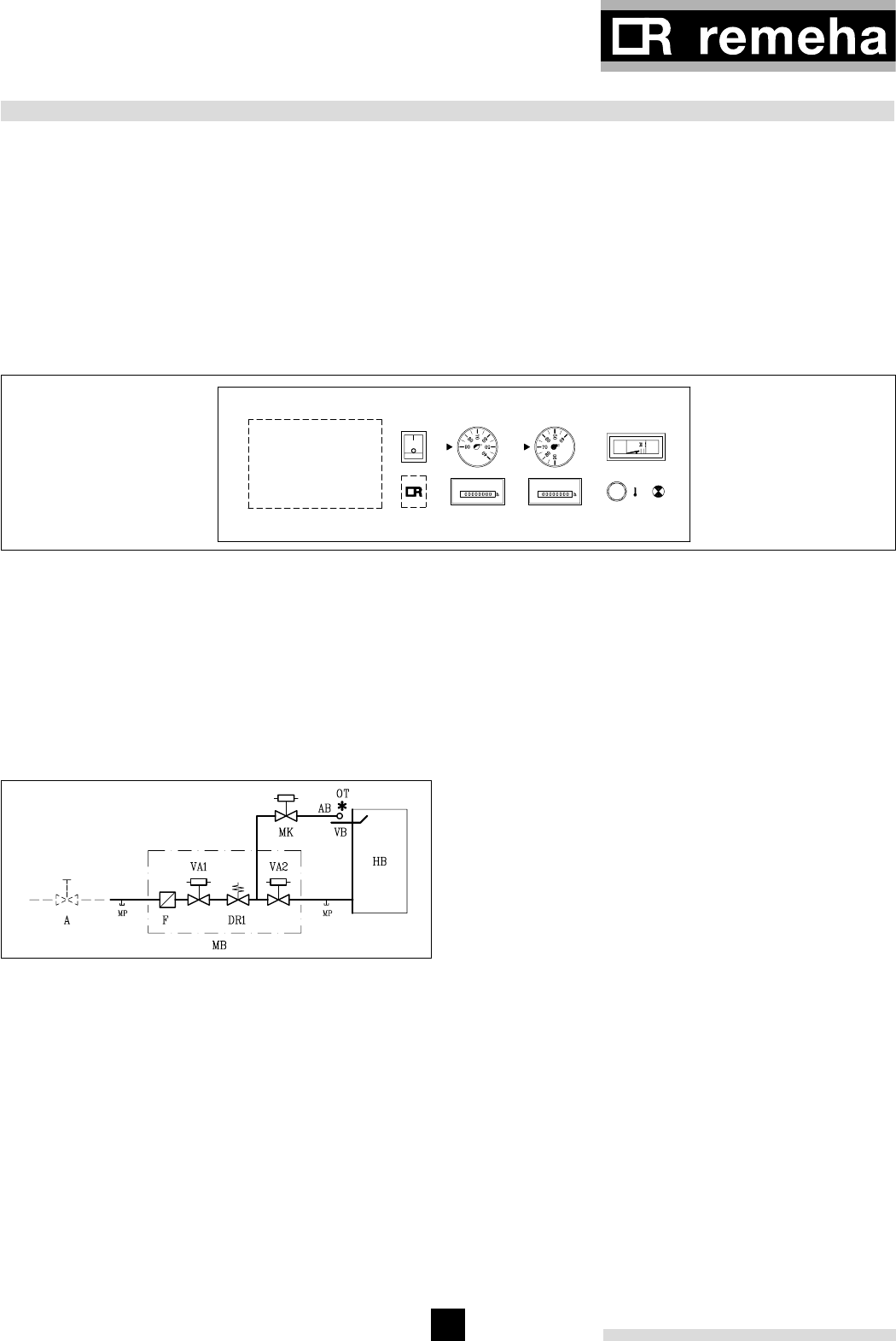
7
6. REGULATION AND SAFETY EQUIPEMENT
6.1 General
The Remeha Gas 450 is supplied with electronic control
and safety equipment with ionisation flame detection.
6.2 Instrument panel
The Remeha Gas 450 is supplied with an instrument
panel that is fitted in the front of the boiler. The standard
instrument panel can be extended with the fitting of
the following options: hour run meters, water pressure
switch, down draught thermostat, no volt contacts and/or
rematic® control.
All connections are pre-wired and fitted with plugs. The
capillaries from the control panel should be fitted in the
pocket of the boiler, which is fitted in the flow connection
of the boiler.
6.3.2 Specifi cation
1 Gas Multi-Bloc contains:
2 Safety shut off valves
1 Gas governor
1 Gas filter
1 Pilot gas valve
1 Pilot burner with ionisation probe
and ignition probe
6.3.3 Control panel behind front panel
1 Control box Satronic
1 Ignition transformer 16 kV
6.4 Functions
6.4.1 Flame protection
Flame protection by means of ionisation flame detection.
6.4.2 Down draught thermostat
Optional the boiler can be fitted with a down draught
thermostat. When there is down draught of the flue gases
this thermostat will switch off the boiler.
Fixed setpoint is 70°C.
6.4.3 Thermostats
Control thermostat On/Off 35°-95°C.
Control thermostat High/Low 35°-95°C.
High-Limit thermostat locks out at 110°C.
6.3 Standard electronic gas train High/Low
6.3.1 Schematic
Fig. 05 Gastrain
Legend
A Gas cock
AB Pilot burner
DR Gas governor
F Gas filter
HB Main gas burners
MB Gas multibloc
OT Ignition transformer
MK Pilot gas valve
MP Measuring point
VA Safety shut off valve
VB Ionisation probe
- - - - Not supplied.
6. Analogue thermometer for water temperature
7. High - Limit thermostat 110°C (pre set)
8. Warning light (lock out)
9. Option for rematic® weather compensator
8
7
5
4
9
1236
Fig. 04 Layout of the instrument panel, extended with hour counters
1. Operating switch (On/Off)
2. Control thermostat On/Off. Setting between 35 - 95°C
3. Control thermostat high/low. Setting between 35 - 95°C
4. Hour run meter total running hours (not standard)
5. Hour run meter full load hours (not standard)

Remeha Gas 450
8
7. ASSEMBLING AND INSTALLATION GUIDELINES
8.1 General
The gas train is fitted behind the front casing.
The local Gas authority should be consulted to ensure
that an adequate pressure and supply is available at the
boilers maximum output. To minimise risk of sediment or
foreign particles entering the control valves, an approved
filter may be fitted into the pipe work downstream.
The gas supply should be conform to the British Gas
safety regulations.
8.2 Gas pressure
Cat. I2H
Maximum gas pressure at inlet 100 mbar.
Burner pressure:
- full load : 14.0 mbar (100%)
- part load : 5.0 mbar (60%)
- injector size: 3.85 mm Ø
Note: LPG version on request.
8. GAS SUPPLY
9. ELECTRICAL SUPPLY
9.1 General
The electrical installation must conform to the IEE
regulations and also to local authority requirements.
9.2 Control panel
A control panel is fitted behind the front casing on the
same side as the water and gas connections.
9.3 Electrical connections
The boiler is pre-wired. Only the main supply should be
wired to the control panel.
9.4 Electrical data
Main supply : 230 V-50Hz (L/N).
Running current : 155 VA.
Installed fuse : 6 Amp.
7.4 Pocket for instrument panel
The thermostat pocket is fitted in the flow connection of
the boiler.
7.5 Water pressure
Each section is hydraulically tested to at least 10 bar.
Maximum test pressure for the assembled boiler block is
8 bar. Operating pressure between 0.8 bar and 6 bar.
Optional the boiler can be fitted with a water pressure
switch, set at 0.8 bar.
7.1 General
The boiler is suitable for operating at a maximum working
pressure of 6 bar and a minimum pressure of 0.8 bar.
Boiler can be installed in open or closed systems.
7.2 Boiler assembly
Broag can provide special tools on loan for the boiler
assembly with detailed building instructions. However, buil-
ding supervision and/or actual boiler erection ser vi ces
can be provided by Broag or an approved boiler erection
engineer.
7.3 Water connections
The boiler water connections (21/2" BSP) are fitted at
the rear of the boiler (can be assembled either left or
right). The two end sections have a 3/4" BSP tapping
with plug, one end section to accept a drain/off cock
(to be assembled on the same side as the gas/water
connections) and other end section to accept a plug.
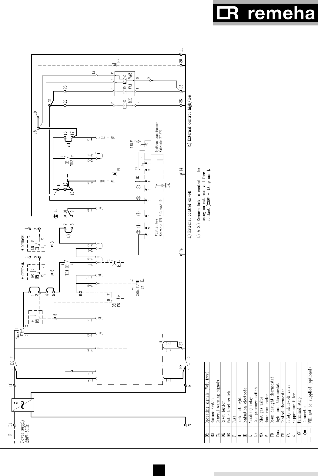
9
9.5 Wiring diagram boiler
Fig. 06 Wiring diagram

Remeha Gas 450
10
10. COMMISSIONING
Note:
Commissioning to only be carried out by a qualified
engineer with the relevant training and certification i.e.
Acops - Corgi and a commissioning data sheet completed
on site for issue to owner.
10.1 Technical information
Control box: Satronic TFI 812-2 mod. 10.
Main supply: 230 V-50 Hz.
Minimum ionisation current: 3 µA.
Reaction time flame protection: 1 sec.
Safety time: < 10 sec.
Maximum ambient temperature: 60°C.
Injector size pilot burner: Ø 0.5 mm.
Injector size main burner: Ø 3.85 mm.
Burner pressure full load: 14.0 mbar (100%).
Burner pressure part load: 5.0 mbar (60%).
Warning:
Control box is neutral/phase sensitive: if incorrectly
connected the boiler will not start.
10.2 Commissioning the boiler
1. Check gas connections.
2. Check electrical supply (L/N and earth).
3. Check water connections and if installation is filled.
4. Switch on circulation pump and check rotation direc-
tion.
5. Open main gas cock (release air in gas pipe work).
6. Switch on electrical supply.
7. Set the control thermostats at about 85°C.
8. After a waiting time of about 3 seconds you will get
ignition. At a minimum ionisation current of 3 µAmp
the safety gas valve will open. The boiler is on.
9. Let the boiler run for a couple of minutes to get rid
of air in the gas pipe.
10. Set the correct burner pressure.
11. Check the thermostats for correct operation.
12. Check the flame protection, by starting with the
ionisation probe disconnected.
13. Send the commissioning reports to Broag.
10.3 Switching off the boiler
1. Set boiler controls to off.
2. Allow system to cool.
3. Switch off the electrical supply.
4. Turn off the gas cock.

11
11.1 General
It is essential for efficient operation, to service the boiler,
the gas train and clean the boiler room once a year.
11.2 Maintaining the boiler
1. Remove the front casing of the boiler.
2. Remove the top casing and the top of the flue hood.
3. Clean the internal flue ways of the boiler with a steel
cleaning brush (available from Broag).
4. Clean the boiler room and the floor underneath the
boiler.
5. Clean the burners internally and externally and
check the kanthal bars.
11. MAINTENANCE
6. Clean the boiler casings.
7. Clean the gas train, ignition, pilotburner, thermostats
and wiring.
8. Check the gas train and pipe for gas leakage.
9. Check the start program, ignition time and safety
times.
10. Check flame protection and thermostats.
11. Check the boiler input at 100% (full load) and 60%
(part load).
12. Make a combustion efficiency calculation.
13. Check the boiler and installation for water leakage.

12
© Copyright
All technical and technological information contained in these technical instructions,
as well as any drawings and technical descriptions furnished by us remain our
property and shall not be copied in part or whole without our prior consent in writing.
ISO 9001
since 1988
Subject to alterations
53899/1.500/0401/Ho.
Broag Ltd.
Head office
Remeha house
Molly Millars Lane
Wokingham,
Berkshire RG41 2QP
Tel.: 0118 978 3434
Fax: 0118 978 6977
E-mail address:
boilers@broag-remeha.com
Branch office
Unit 3, Kestrel Close,
Quarry Hill ind. Estate,
Ilkeston
Derbyshire DE7 4RD
Tel.: 0115 944 0778
Fax: 0115 944 0588
Remeha Gas 450
1
• Atmospheric gas boiler
• 278 - 1058 kW
Remeha Gas 550/550 Duo
Technical information
Remeha Gas 550/550 Duo

Remeha Gas
550/550 Duo
2
TABLE OF CONTENT
Preface 3
1 Boiler description 3
2 Construction details 3
2.1 General 3
2.2 Burners 3
2.3 Assembly 3
3 dimensions and Technical data 4
3.1 Dimensions Remeha Gas 550 4
3.2 Dimensions Remeha Gas 550 Duo 6
4 Application information 7
4.1 L.P.H.W. system 7
4.1.1 Water temperature 7
4.1.2 Water pressure 7
4.1.3 Water flow 7
4.1.4 Water treatment 7
4.1.5 Noise level 8
4.2 Chimneys 8
4.3 Installation standards 8
5 Typical boiler installations 9
5.1 Installation 1 9
5.2 Installation 2 10
6 Control and safety equipment 11
6.1 General 11
6.2 Instrument panel 11
6.3 Standard electronic gas train High/Low 11
6.3.1 Schematic 11
6.3.2 Control panel on gas train 11
6.3.3 Specification control box 11
6.3.4 Specification Ignition transformer 12
6.4 Functions 12
6.4.1 Flame control (lock out) 12
6.4.2 Thermostats (shutdown / lock out) 12
6.4.3 Water level control (lock out) 12
6.4.4 Valve leakage control - optional
( lock out) 12
6.4.5 Gas pressure switch LD - optional
(shut down) 12
6.4.6 Gas pressure switch HD - optional
(lock out) 12
6.4.7 Down draft thermostat;
(optional, shut down) 12
7 Assembly and installation guidelines 13
7.1 General 13
7.2 Boiler assembly 13
7.3 Water connections 13
7.4 Pocket for the thermostat capillaries 13
7.5 Water pressure 13
8 Gas supply 13
8.1 General 13
8.2 Gas pressure 13
8.3 Injectors 13
9 Electrical supply 14
9.1 General 14
9.2 Instrument panel 14
9.3 Control panel 14
9.4 Electrical connections 14
9.5 Electrical information 14
9.6 Water level control 14
9.7 Wiring diagrams 15
10 Commissioning 16
10.1 Switching off the boiler 18
11 Maintenance 18
12 Trouble shooting 19
12.1 Fault causes 19

3
PREFACE
These technical instructions contain useful and impor-
tant information for the correct operation and maintenan-
ce of the Remeha boiler, model Gas 550 and Gas 550
Duo.
Read these instructions carefully before putting the boi-
ler into operation, familiarise yourself with it’s control
functions and operation, strictly observing the instructi-
ons given. Failure to do so may invalidate warranty or
prevent the boiler from operating.
The installation and commissioning of the boiler must be
carried out by a competent Engineer, with the relevant
certification i.e.: CORGI, ACOPS, IEE regs. etc.
On completion a copy of the boiler log / commissioning
sheet should be returned to Broag Ltd for record purpo-
ses.
If you have any questions, or if you need more informa-
tion about specific subjects relating to this boiler, or it’s
installation please do not hesitate to contact us.
The data published in these technical instructions is
based on the latest information (at date of publication)
and may be subject to revisions.
We reserve the right to continuous development in both
design and manufacture, therefore any changes to the
technology employed may not be retrospective nor may
we be obliged to adjust earlier supplies accordingly.
1 BOILER DESCRIPTION
The Remeha Gas 550 series boiler is a cast iron
sectional boiler, with a powder coated enamel steel
casing compleet with glass fibre insulation.It has high /
low atmospheric gas burners, suitable for natural gas,
cat. I 2 H - 20 mbar.
It is supplied in sections for delivery and on site assem-
bly.
The boiler meets the requirements of the CE regulations
at the following directives:
- Gas appliance directive no. 90/396/EEC;
- Efficiency directive no. 92/42/EEC;
- E.M.C. directive no. 89/336/EEC.
And is correspondent with:
- Electrical low voltage directive no. 73/23/EEC.
Remeha Gas 550 (Duo)-reference number: 0063AP6520
Classification type for evacuation of the combustion pro-
ducts, according: EN-656: B11, B11BS.
For further advice or information contact Broag Ltd.
2 CONSTRUCTION DETAILS
2.1 General
The Remeha Gas 550 / 550 Duo is a floor standing
boiler complete with temperature and safety controls.
The cast iron sectional heat exchanger is assembled
using conical nipples and jointing compound.The boiler
has a built in draft diverter. It has water connections at
the side within the casing dimensions and a gas train
to one side.
Note: Both water and gas connections can be handed
on site during assembly. But the instrument panel,
mounted in the front casing should always be fitted on
the same side as the flow connection.
The casings can be fitted after the flue and pipework to
the boiler have been installed and connected.
2.2 Burners
The burners are stainless steel, atmospheric type with a
heat reflecting floor plate providing the correct ventilation
distribution. Front and top access is required for service
work to be carried out.
Note: The Gas 550 Duo has two complete boiler units
within one casing using a common flue connection.
2.3 Assembly
The boiler cannot be supplied pre-assembled and must
be assembled on site.
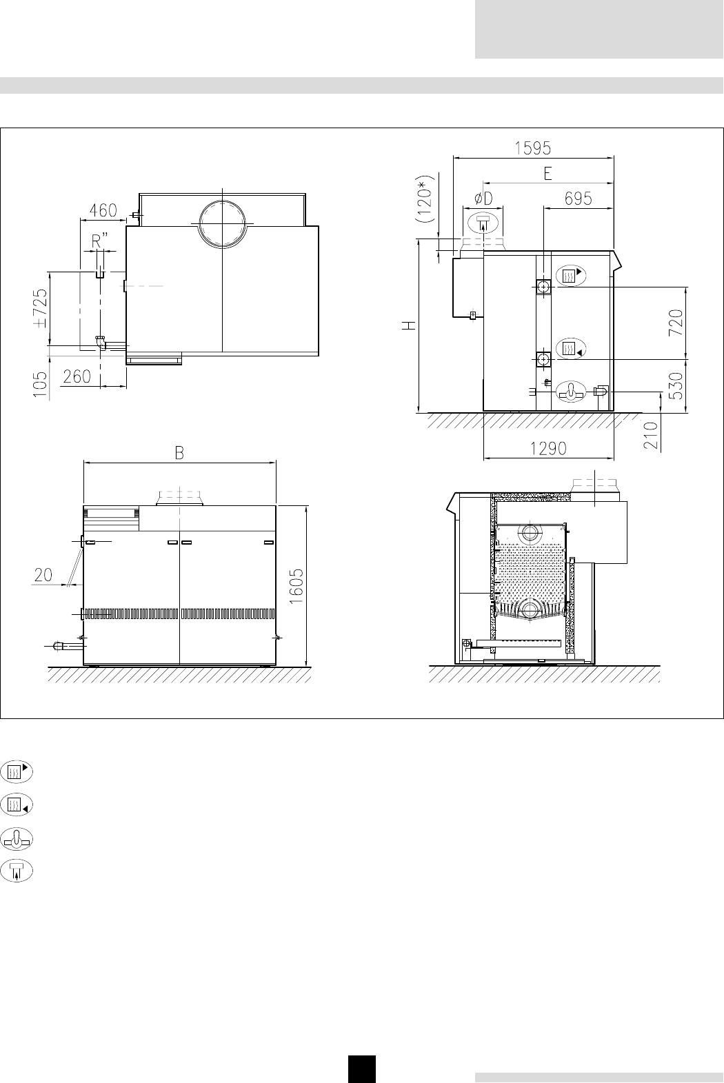
Remeha Gas
550/550 Duo
4
3 DIMENSIONS AND TECHNICAL DATA
3.1 Dimensions Remeha Gas 550
Fig. 01 Dimensions Remeha Gas 550
00.05F.79.00002
Flow Ø107 int.
Return Ø107 int.
Gas 2"
Flue gas Ø
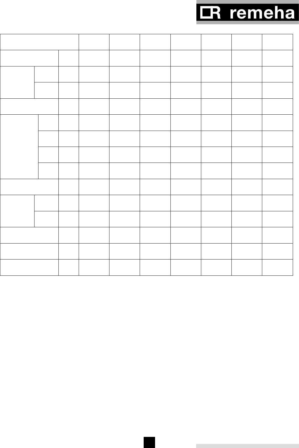
5
Number of sections 10 12 14 16 18 20 22
Nominal heat
output kW 139-278 170-340 202-403 233-466 265-529 296-592 328-656
Hi /
NCV kW 160-309 195-378 232-448 266-518 301-588 337-657 372-728
Nominal
heat input Hs /
GCV kW 177-343 217-420 256-498 296-576 335-653 374-730 414-809
Gas consumption m3/h 33 40 47 55 62 70 77
B mm 1240 1460 1680 1900 2120 2340 2560
Ø D mm 300* 350* 400* 450 450* 500 500*
E mm 1295 1295 1295 1295 1295 1295 1245
Dimensions
H mm 1730 1730 1730 1610 1730 1610 1730
Flue temperature °C 154 152 146 138 138 142 142
t =
10°C mbar 64 72 80 128 160 180 196
Water
resistance t =
20°C mbar 16 18 20 32 40 45 49
Water contents litre 291 349 407 465 523 581 639
Boiler weight (dry) kg 1450 1695 1940 2185 2430 2675 2920
Flue gas flow rate kg/h 692 847 1033 1239 1376 1560 1678
Table 01 Technical data Remeha Gas 550
* Supplied with a flue gas pipe adapter
∆
∆
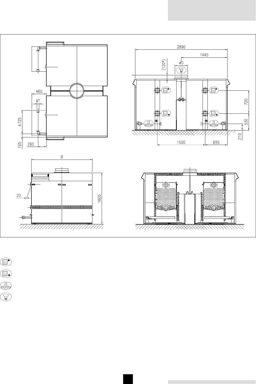
Remeha Gas
550/550 Duo
6
3.2 Dimensions Remeha Gas 550 Duo
Fig. 02 Dimensions Remeha Gas 550 Duo
00.05F.79.00003
Flow Ø107 int.
Return Ø107 int.
Gas 2"
Flue gas Ø
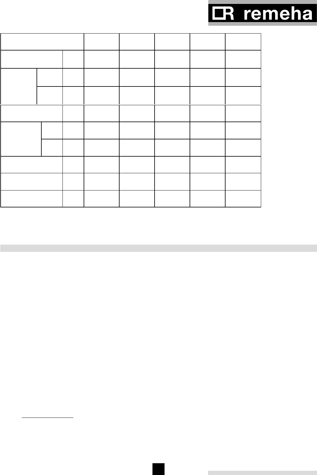
7
Number of sections 2 x 10 2 x 12 2 x 14 2 x 16 2 x 18
Nominal heat
output kW 139-556 170-680 202-806 233-932 265-1058
Hi /
NCV kW 160-618 195-756 232-896 266-1036 301-1176
Nominal
heat input Hs /
GCV kW 177-686 217-840 256-996 296-1152 335-1306
Gas consumption m3/h 66 80 94 110 124
B mm 1240 1460 1680 1900 2120
Dimensions
Ø D mm 450* 500* 600* 650 650*
Water contents litre 582 698 814 930 1046
Boiler weight (dry) kg 2900 3390 3880 4370 4620
Flue gas flow rate kg/h 1385 1694 2066 2478 2752
Table 02 Technical data Remeha Gas 550 Duo
* Supplied with a flue gas pipe adapter
4 APPLICATION INFORMATION
4.1 L.P.H.W. system
4.1.1 Water temperature
Maximum water temperature is 110°C (high limit ther-
mostat).
Highest boiler water temperature is 95°C (control ther-
mostat).
Minimum return water temperature is 20°C at a flow rate
related to a ∆t of 20°C (flow/return temp).
4.1.2 Water pressure
Boiler sections are factory pressure tested at 10 bar.
Maximum pressure test boiler block is 7,8 bar.
Maximum working pressure is 6 bar
Minimum working pressure is 0,8 bar at a maximum
working temperature of 110°C or 0,3 bar at a maximum
working temperature of 95°C.
4.1.3 Water flow
The minimum water flow through the boiler on shut down
is:
Output boiler in kW = m3/h
93
This minimum flow must be maintained for approxima-
tely 5 minutes after the burner stops firing to avoid high
temperature shut down due to residual heat gain.
Due to the design and manufacture of the boiler no
specific minimum water flow requirements exist other
then for overheating protection.
4.1.4 Water treatment
The system should be filled with mains cold water (for
the UK this will usually have a pH of between
7 and 8).
Pressurised installations with a boiler/system content
ratio of 1:10 or less should not require water treatment,
provided that the following conditions apply:
1. The system is flushed thoroughly to remove all fluxes
and debris and then filled completely once.
2. Make up water is limited to 5 % per annum.
3. The hardness of the water does not exceed 360 ppm
(20°D).
All scale deposits will reduce the efficiency of the boiler
and should be prevented. However provided the above
is complied with any scale produced will not be too
detrimental to the boiler efficiency and will not reduce
the anticipated life expectancy of the boiler.
Note: Scale deposits in excess of 3 to 5 mm will reduce
boiler efficiency and greatly increase the risk of prema-
ture casting failure.

Remeha Gas
550/550 Duo
8
As most systems contain a variety of metals which can
react with each other to cause corrosion. It is con-
sidered good practice to provide some form of water
treatment (especially in open vented systems) in order to
prevent or reduce the following:
- Metallic corrosion;
- Formation of scale and sludge;
- Microbiological contamination;
- Chemical changes in the untreated system water.
Suitable chemicals and their use should be discussed
with a specialist water treatment company prior to car-
rying out any work. The specification of the system
and manufacturers recommendations must be taken into
account, along with the age and condition of the system.
New systems should be flushed thoroughly to remove all
traces of flux, debris, grease and metal swarf generated
during installation. Care to be taken with old systems
to ensure any black metallic iron oxide sludge and other
corrosive residues are removed, again by thoroughly
flushing, ensuring that the system is drained completely
from all low points.
Note: Please ensure that the new boiler plant is not
in circuit when the flushing takes place, especially if
cleansing chemicals are used to assist the process.
Under no circumstances is the boiler to be operated
with cleaning chemicals in the system.
To Summarise:
- Minimise water loss;
- Prevent pumping over in open vented systems;
- Provide adequate air venting at all high points;
- Keep pH level between 7 - 9 when using additives;
- Maximum chlorine content of 200 mg/l;
Take advice on the suitability of inhibitors.
4.1.5 Noise level
The noise level measured around the boiler depending
on boiler room construction is about 50-55 dBA. Noise
levels taken at 1 meter from the boiler.
4.2 Chimneys
The average flue gas temperature is so low that the
chimney must be made in accordance with the guide-
lines of British Gas (BS 6644).
4.3 Installation standards
The following instructions must be adhered to when the
Remeha Gas 550/550 Duo is installed:
Gas Safety (installation and use) Regulations 1984 (as
amended).
In addition to the above regulations, this boiler must be
installed in compliance with:
- Current I.E.E. Regulations for electrical installations
- Local building regulations
- The Building Standards (Scotland)
- (Consolidation) Regulations
- By-laws of the local water undertaking
- Health and Safety Document No 635 ‘The Electricity
at Work Regulations 1989’.
It should also be in accordance with the relevant recom-
mendations in the current editions of the following British
Standards and Codes of Practice, viz. BS 5440 Pt 1 and
2, BS 5449, BS 5546,
BS 6798, BS 6891 and BG.DM2.
Lawfully all gas appliances must be installed by compe-
tent persons (e.g. Corgi, ACOPS).
Failure to install appliances correctly could lead to
prosecution.
It is in your own interest and that of safety to ensure that
the law is complied with.
Important:
The Remeha Gas 550/550 Duo is a certified appliance
and must not be modified or installed in any way con-
trary to these ‘Installation and Servicing Instructions’.
Manufacturer instructions must NOT be taken in any way
as when overriding statutory obligations.
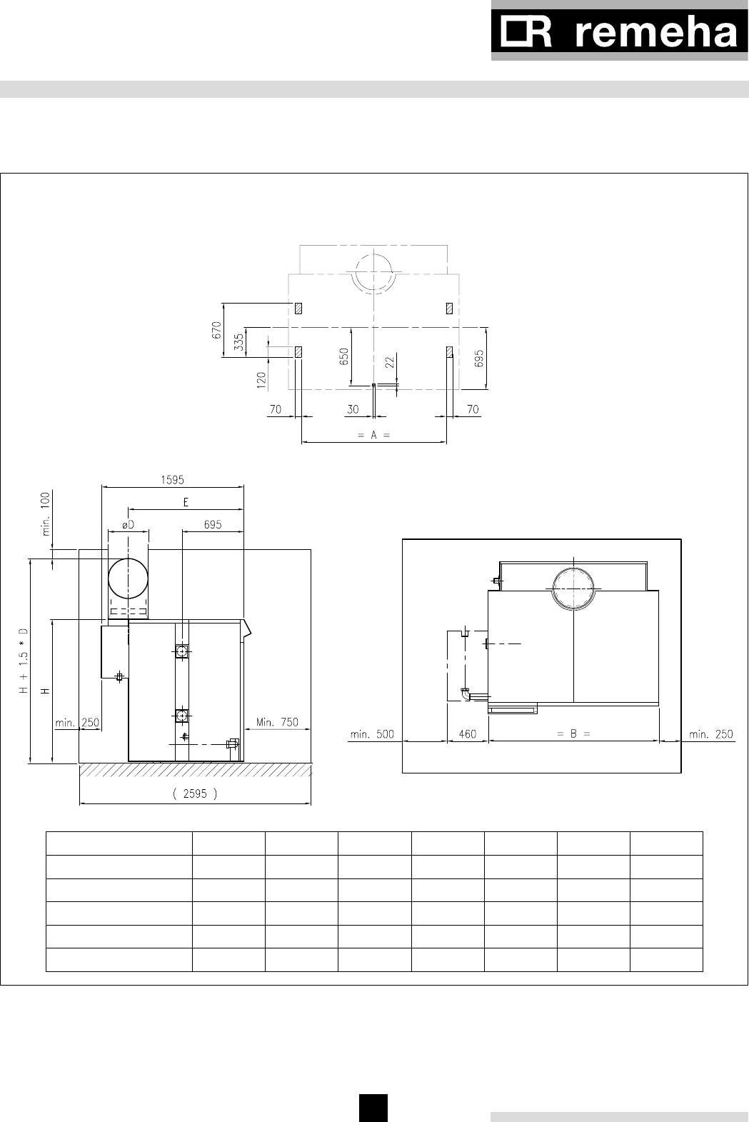
9
5 TYPICAL BOILER INSTALLATIONS
5.1 Installation 1
Recommended layout for boiler installation, measure-
ments in mm.
centre of nipple
holes
floor area
Fig. 03 Remeha Gas 550
00.05F.79.00004
number of sections 10 12 14 16 18 20 22
Size A 965 1185 1405 1625 1845 2065 2285
Size Ø D 300 350 400 450 450 500 500
Size B 1240 1460 1680 1900 2120 2340 2560
Size E 1295 1295 1295 1295 1295 1295 1245
Size H 1730 1730 1730 1610 1730 1610 1730
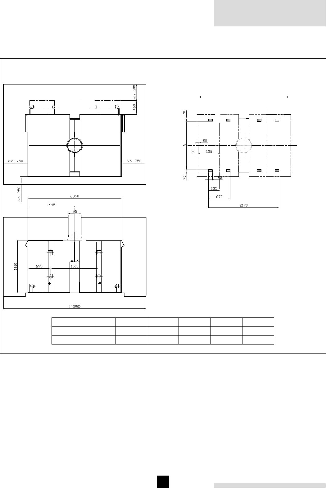
Remeha Gas
550/550 Duo
10
5.2 Installation 2
Recommended layout for boiler installation, measure-
ments in mm.
centre of nipple holes
floor area
number of
sections
Fig. 04 Remeha Gas 550 Duo
00.05F.79.00005
size A
size ØD
number of sections 10 12 14 16 18
Size A 965 1185 1405 1625 1845
Size Ø D 450 500 600 650 650
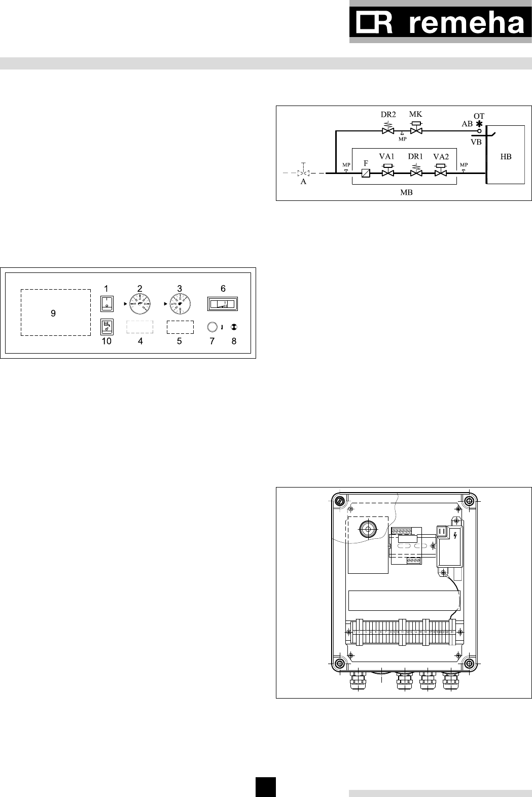
11
6 CONTROL AND SAFETY EQUIPMENT
6.1 General
The Remeha Gas 550 is supplied with electronic control
and safety equipment with ionisation flame detection.
6.2 Instrument panel
The Remeha Gas 550 is supplied with an instrument
panel mounted in the front of the boiler, either left or
right. All connections are pre-wired and fitted with plugs.
The capillaries from the instrument panel should be
fitted in the thermostat pocket of the boiler flow con-
nection, which is fitted in the top front of the end section.
The instrument panel and the flow connection with ther-
mostat pocket should always be fitted on the same side
of the boiler, either left or right.
Fig. 05 Instrument panel
04.05F.79.00001
The instrument panel contains:
1. Operating switch (On/Off);
2. Control thermostat On/Off, range 35°C-95°C;
3. Control thermostat High-Low, range 35°C-95°C;
4. Hour run meter total running hours (option);
5. Hour run meter full load hours (option);
6. Analogue thermometer for flow temperature;
7. High – limit thermostat preset to 110°C;
8. Lock out warning lamp;
9. Option for rematic® weather compensator;
10. Reset for water level control.
The Instrument panel mounted in the front casing also
contains circuit boards for:
- Water level control (see §9.6);
- Common alarm and operating signal.
6.3 Standard electronic gas train High/Low
6.3.1 Schematic
Fig. 06 Schematic layout gas train
04.05F.AP.00001
Legend
A Gas cock
AB Pilot burner
DR Gas pressure regulator
F Gas filter
HB Burners
MK Pilot gas valve
MP Measuring point
VA Safety shut off valve
OT Ignition transformer
VB Ionisation probe
MB Gas multibloc valve
- - - Not supplied as standard
6.3.2 Control panel on gas train
The instrument panel is linked to the control panel on
gas train by means of a cable and connector. If required
the control panel (and gas train) can be fitted on the
opposite side of the boiler by using extension cables
(option).
Fig. 07 Front of Control panel
04.05F.79.00002
1. Control box Satronic MMI 816;
2. Ignition transformer Satronic ZT 870;
3. Operation report circuit board.
12
3

Remeha Gas
550/550 Duo
12
6.4.3 Water level control (lock out)
The boiler is equipped with a water level sensor to
prevent boiler from operating without water. The boiler
will lock out. Manual intervention is required to reset the
boiler (on the instrument panel) once the cause of the
problem has been rectified.
Note: The Gas 550 Duo has two sets.
6.4.4 Valve leakage control - optional ( lock out)
The gas train can be combined with a valve leakage
control, which checks for gas leakage between the val-
ves at every start. The boiler will lock out. Manual inter-
vention is required to reset the boiler (on the valve
leakage control) once the cause of the problem has
been rectified.
Type: Dungs VPS 504.
Note: The Gas 550 Duo requires two sets.
6.4.5 Gas pressure switch LD - optional (shut down)
If the supply gas pressure drops below the set value
(12mbar; for natural gas, cat. I2H only), the boiler will shut
down. When the supply gas pressure returns above this
set value the boiler will resume operation again.
Type: Dungs GW50 A5.
Note: The Gas 550 Duo requires two.
6.4.6 Gas pressure switch HD - optional (lock out)
If the gas arrival pressure rises above the set value
(10mbar; for natural gas, cat. I2H only), the boiler will lock
out. Manual intervention is required to reset the boiler
(on the gas pressure switch) once the cause of the
problem has been rectified.
Type: Dungs UB 50 A2.
Note: The Gas 550 Duo requires two.
6.4.7 Down draught thermostat; (optional, shut
down)
If the themperature in the draft diverter rises above the
down draught thermostat set point, the boiler will shut
down. It automatically resets after 3 minutes, provided
that the temperature also falls.
Type: Honeywell L6068A; fixed setpoint is 70°C.
Note: The Gas 550 Duo requires two.
6.3.3 Specification control box
Control box : Satronic MMI 816
Main supply : 230 V – 50 Hz
Minimum ionisation current : min 3 µA (DC)
Reaction time flame protection : 1 sec.
Safety time : ≤ 10 sec.
Maximum ambient temperature : 60 °C
Injector size pilot burner : Ø 1.0 mm
Injector size main burner : Ø 5.4 mm
Burner pressure full load
(high calorific gas) : 8.4 mbar (100%)
Burner pressure part load
(high calorific gas) : 2.2 mbar (50%)
Burner pressure pilot burner
(high calorific gas) : 13 mbar
Warning: control box is phase neutral sensitive.
6.3.4 Specification Ignition transformer
Ignition transformer : Satronic ZT 870
Ignition voltage : 16 kV
Distance electrodes : 3,5 ± 1 mm.
6.4 Functions
General
The following functions (standard and optional) will,
when activated, either lock out or shut down the boiler.
For all options full fitting instructions are included in the
option pack.
6.4.1 Flame control (lock out)
The flame is monitored using ionisation flame detection.
In the event of a flame failure the boiler will lock out.
Manual intervention is required to reset the boiler (on
the control panel) once the cause of the problem has
been rectified.
Note: The Gas 550 Duo has two sets.
6.4.2 Thermostats (shutdown / lock out)
- Control thermostat On/Off: shutdown (35°C-95°C);
The boiler will automatically resume operation when
the flow temperature falls below the set point.
- Control thermostat High/Low: shutdown (35°C-95°C);
The boiler will automatically resume operation when
the flow temperature falls below the set point.
- High Limit thermostat: lock out at 110°C.
The boiler will lock out. Manual intervention is required
to reset the boiler (on the instrument panel) once the
cause of the problem has been rectified.
Note: The Gas 550 Duo has two sets.

13
7 ASSEMBLY AND INSTALLATION GUIDELINES
7.1 General
The boiler is suitable for operating at a maximum wor-
king pressure of 6 bar. It can be installed in open vented
or sealed systems with a minimum pressure of 0.8 bar
sealed and 0.3 bar open vented.
7.2 Boiler assembly
The boiler is supplied with full assembly instructions. On
request special assembly tools can be hired from Broag
on a daily basis.
However, Broag (or a Broag approved boiler erection
engineer) can provide boiler assembly services and / or
building supervision.
7.3 Water connections
The boiler flow and return connections can be fitted
on either side of the boiler (left or right hand side)
dependant on design or site conditions.
The boiler comes with four flanges, 2 x blank and 2 x Ø
107 mm (int.) weld neck.
The end sections have a 3/4 “ BSP tapping to accept the
supplied drain cock.
Note: The Gas 550 Duo has two sets.
7.4 Pocket for the thermostat capillaries
The multi pocket for the thermostat capillaries should be
fitted in the top front-end section of the boiler and on
the same side of the boiler as the instrument panel. The
water level control electrode should be fitted in the 1”
tapping of the other end section.
Note: The Gas 550 Duo has two sets.
7.5 Water pressure
Each section is hydraulically tested at 10 bar. Maximum
test pressure for the assembled boiler block is 7.8 bar.
Minimum working pressure is 0.8 bar at a maximum
working temperature of 110°C or 0.3 bar at a maximum
working temperature of 95°C. Maximum working pres-
sure is 6 bar.
8 GAS SUPPLY
8.1 General
The instrument panel (mounted in the front casing) must
be mounted on the same side of the boiler as the flow
connection, either left or right (choice on assembly). As
standard the gas train must also be on the same side as
the flow connection. However an extension cable can be
supplied (option) to allow the gas train to be mounted on
the opposite side to the instrument panel.
The local Gas authority should be consulted to ensure
that an adequate pressure and supply is available at the
boilers maximum output. To minimise risk of sediment or
foreign particles entering the control valves, an approved
filter can be fitted into the pipe system downstream.
The gas supply should be conforming to the British Gas
safety regulations.
Note: The Gas 550 Duo requires two gas supplies.
8.2 Gas pressure
Natural gas, cat. I2H (20mbar)
Maximum gas pressure at inlet 100 mbar.
Main burner pressure settings :
- full load : 8.4 mbar
- part load : 2.2 mbar
Pilot burner pressure settings : 13 mbar
Gas inlet pressure : 17 - 25 mbar
8.3 Injectors
Injector size main burner : 5.4 mm
Injector size ignition burner : 1.0 mm
Note: The Gas 550 Duo has two sets.

Remeha Gas
550/550 Duo
14
9 ELECTRICAL SUPPLY
9.1 General
The electrical installation must conform to the IEE regu-
lations and also to local authority requirements.
9.2 Instrument panel
The Gas 550 is supplied with an instrument panel that
is fitted in the front of the boiler, either left or right
(dependant on flow and gas connection).
Note: The Gas 550 Duo has two instrument panels and
requires two sets of power supplies.
9.3 Control panel
A control panel is fitted on the gas train.
Note: The Gas 550 Duo has two control panels and
requires two sets of operating controls and has two sets
of function indication.
9.4 Electrical connections
The boiler is pre-wired. Only the main supply should be
wired to the instrument panel.
9.5 Electrical information
Main supply : 230 V-50 Hz (L/N)
Running current : 150 VA
Maximum fuse : 6 A (slow acting)
Note: The Gas 550 Duo requires two sets of power supplies.
9.6 Water level control
Water level control : Dungs DWEB 53E
Main supply : 230 V – 50 Hz
Running current : 5 W
Electrode voltage : 42 V (AC)
Working area : 100 – 10.000 mA (AC)
Electrode resistance : max. 20 kOhm; min. 1 kOhm
Electrode : Dungs FLE ½”
Must be fitted in one of the end sections (see 7.4).
Note: The Gas 550 Duo has two sets.
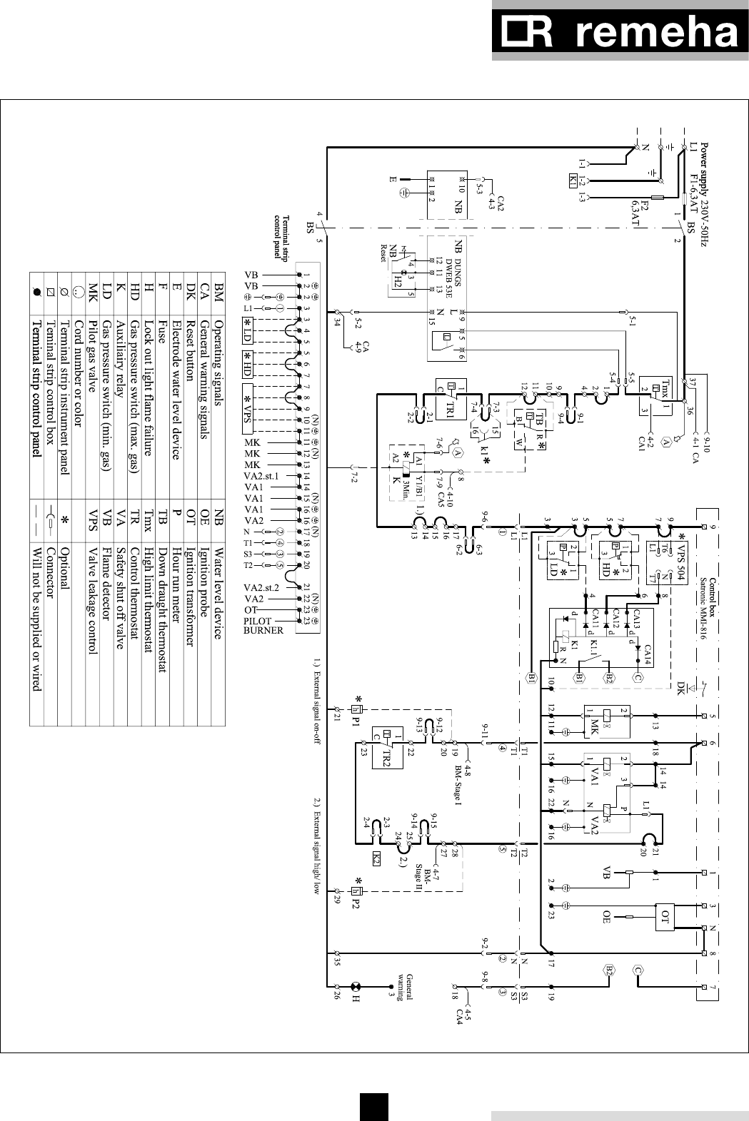
15
9.7 Wiring diagrams
Fig. 08 Electrical principle diagram
04.05F.SC.00001
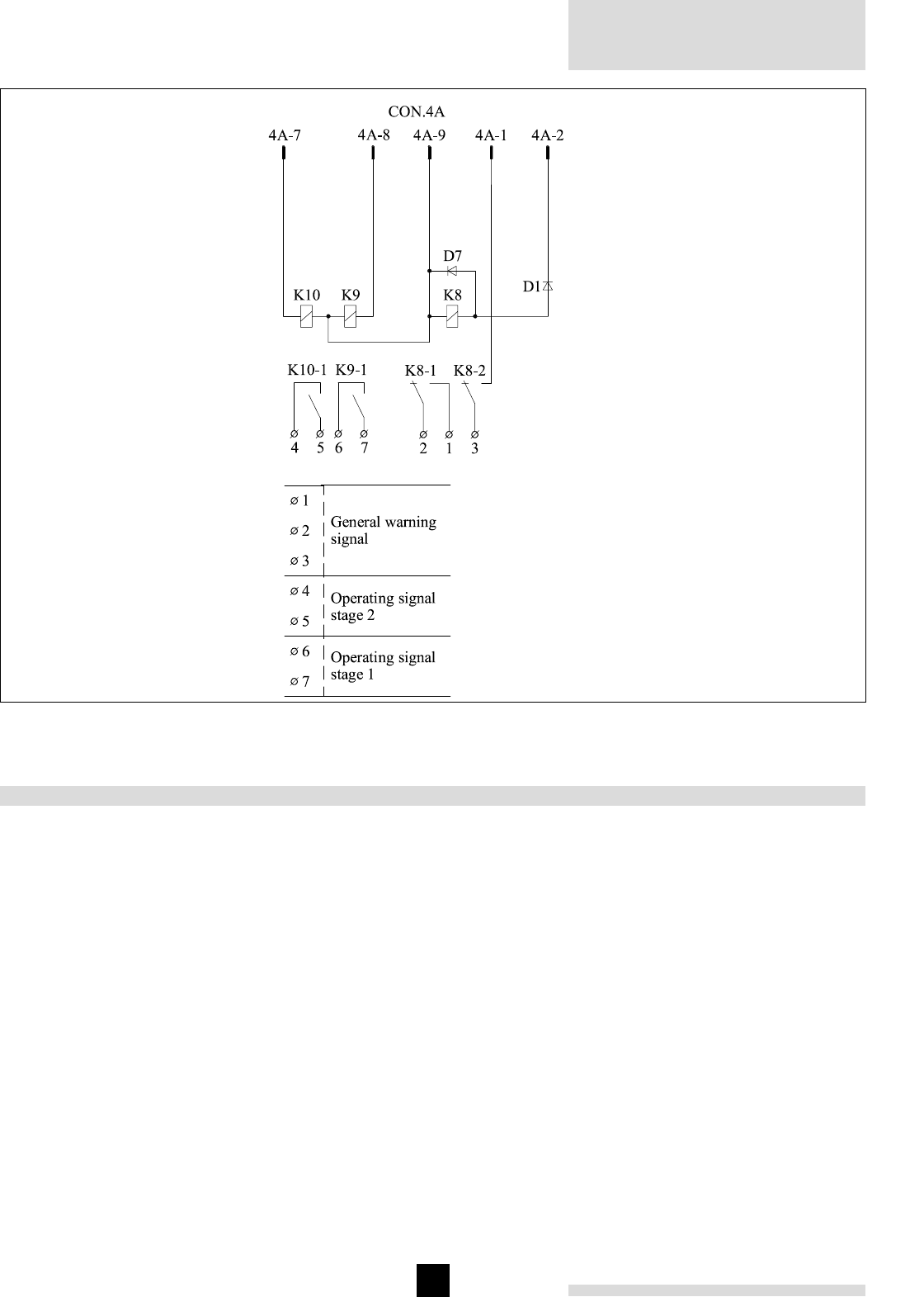
Remeha Gas
550/550 Duo
16
10 COMMISSIONING
Note: Commissioning must only be carried out by a
qualified engineer with the relevant training and certifica-
tion i.e. Acops - Corgi. A commissioning data sheet /
boiler logbook must be completed on site for issue to
owner.
1. Check the gas connections.
2. Check the electrical supply (L/N and earth).
3. Check the water connections and whether the instal-
lation is full and under system pressure.
4. Switch on the circulation pump and check the rota-
tion direction.
5. Open the main gas cock (purge gas pipeline).
6. Switch on the electrical supply.
7. Set both the thermostats to about 85°C.
8. If a control system is built in, put the selector switch-
on manual operation.
9. Switch on the boiler.
- If a valve leakage control is installed the following
will take place:
A membrane pump will create overpressure
between safety valves VA1 & VA2, which are
inside the multibloc gas valve. When, within 27
sec, an overpressure of 30 mbar (compared to the
inlet pressure) is reached, the electric supply is
released to the control box.
10. After a waiting time of about 13 seconds the ignition
starts. The magnetic valve MK opens and ignition
burner lights. At a minimum ionisation current of 3
µA the ignition stops. After 5 seconds the main gas
valves VA1 en VA2 will open. The boiler runs.
11. Let the boiler run for a couple of minutes on high fire
to clear any air still in the gas pipe.
Fig. 09 Electric connection central alarm
00.03F.60.00042

17
12. Set the correct full load burner pressure by means
of the pressure regulator on the gas multibloc gas
valve(see Fig. 10, pos. 1).
Warning: When the required burner pressure can
not be reached because of low inlet pressure, ensu-
re that the pressure regulator remains within it’s
operating range.
Now do the following:
• Set the burner pressure to the highest possible
value (but not over the required full load burner
pressure).
• Turn the pressure regulator anticlockwise until the
burner pressure is affected.
• The burner pressure is now limited, this will pre-
vent the boiler from being over gassed should the
inlet gas pressure increase.
13. Set the correct part load burner pressure:
• Turn the high/low thermostat to it’s minimum set-
ting (35°C). When the flow temperature is over
35°C, the boiler will burn at part load.
• Set the part load burner pressure by turning the
adjustment ring (Fig. 10, pos. 2).
• To check the the high fire setting: Turn the
high/low thermostat to 85°C and check the full
load burner pressure (if necessary re-adjust).
The speed of opening of the main gas valve can
also be adjusted to ensure a smooth light up. Set-
ting the hydraulic brake on the main gas valve as
follows:
• Remove the setting cap (Fig. 10, pos.3) and turn it
upside down on the hydraulic brake.
• Turn it clockwise to slow down, anticlockwise to
speed up.
• Check both burner pressures again and if neces-
sary re-adjust.
14. Adjustment of the gas pressure switch LD (optional):
• Switch the boiler to full load.
• Connect a pressure gauge to measuring point LD.
• Turn the adjustment disc of the pressure switch to
it’s minimum setting.
• Now close the main gas cock slowly until the inlet
pressure drops to the value detailed in the docu-
mentation supplied with the gas pressure switch.
• Slowly turn the adjustment disc of the pressure
switch until the pressure control operates.
• The control box shuts down the gas supply and
will restart.
15. Adjustment of the gas pressure switch HD (optional):
• Switch the boiler to full load.
• Connect a pressure gauge to manifold.
• Set the pressure switch to the value detailed in
the documentation supplied with the gas pressure
switch.
• Check whether the gas pressure switch HD comes
to action at the set value by increasing (Fig. 10,
pos.1) the full load burner pressure to that value.
The boiler will lock out.
• Reset by pressing the reset button on the gas
pressure switch HD. The boiler will resume opera-
tion.
• Set the correct full load burner pressure again
according §10.2.12.
16. Valve leakage control (optional)
• Remove plug Pa during boiler start up (see §10.2.
9).The plug Pa is located opposite the valve lea-
kage control on the multibloc.The boiler will lock
out.
• Reset by pressing the reset button on the valve
leakage control.The boiler will resume normal ope-
ration.
17. Check the thermostats for the correct operation set-
ting.
18. Check the flame control on the control box
• Start the boiler with disconnected ionisation probe,
after the ignition phase the pilot gas valve must
close. The boiler will lock out.
• Reset by pressing the reset button on the control
box.
• Then disconnect the ionisation probe during opera-
tion, the pilot gas valve must close immediately.
The boiler will lock out.
• Reset by pressing the reset button on the control
box.
19. Water level control:
• Check the water level.
• Check the operation of the water level control by
disconnecting the electrode. The boiler should go
to lock out
• Create a shortcut between the electrode and
earth. The boiler should go to lock out
• Reset by pressing the reset button on the instru-
ment panel. The boiler will resume operation
20. Check the down draft thermostat by pressing the
bimetallic strip on the thermostat. The boiler will shut
down for 3 minutes. After that the boiler will resume
operation.
21. Send the initial commissioning report CE to Broag.
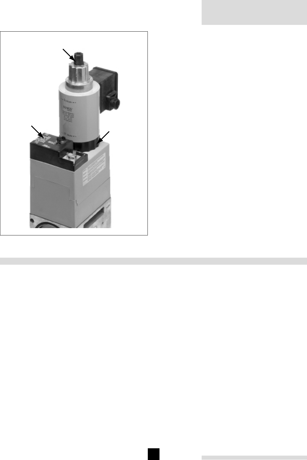
Remeha Gas
550/550 Duo
18
12
3
1. pressure regulator
2. part load adjustment
ring
3. hydraulic brake
(setting cap)
Fig. 10 Dungs MB-ZRDLE 415 / 420 S22.
10.1 Switching off the boiler
1. Switch off the electric supply.
2. Shut off the gas cock.
Warning: When switched off and full of water the boiler
could be damaged if the temperature falls below freezing
point.
Note: Commissioning must only be carried out by a
qualified engineer with the relevant product training and
certification i.e. Acops - Corgi. A commissioning data
sheet / logbook must be completed on site for issue to
owner.
11 MAINTENANCE
To maintain maximum efficiency it is essential to service
the boiler, check safety parameters and re-set combus-
tion once a year.
Normal Service Maintenance
- Isolate power , controls and gas supply.
- Remove front, top casings and flue hood covers.
- Remove gas manifold.
- Remove the burners and floor plates.
- Clean the internal flue ways of the boiler.
- Clean the floor underneath the boiler and boiler room.
- Clean the burners internally and externally using a
soft brush.
- Clean the gas train, ignition, pilot burner, thermostats
and wiring.
- Check and re-set/re-place ignition electrode and ioni-
sation probe as found necessary.
- Re-assemble boiler.
- Check ignition and ionisation cables for connections
and continuity.
- Restore power, controls and gas supply.
- Check start program, ignition time and safety times.
- Check flame protection and thermostats.
- Check boiler input at 100% (full load) and 50% (part
load) load.
- Carryout a combustion efficiency test.
- Check the boiler and immediate installation connecti-
ons for water leaks (seals).
- Check gas train and gas pipe for gas leaks.
- Check flue connections.
- Clean boiler casings.
- Complete a commissioning report.
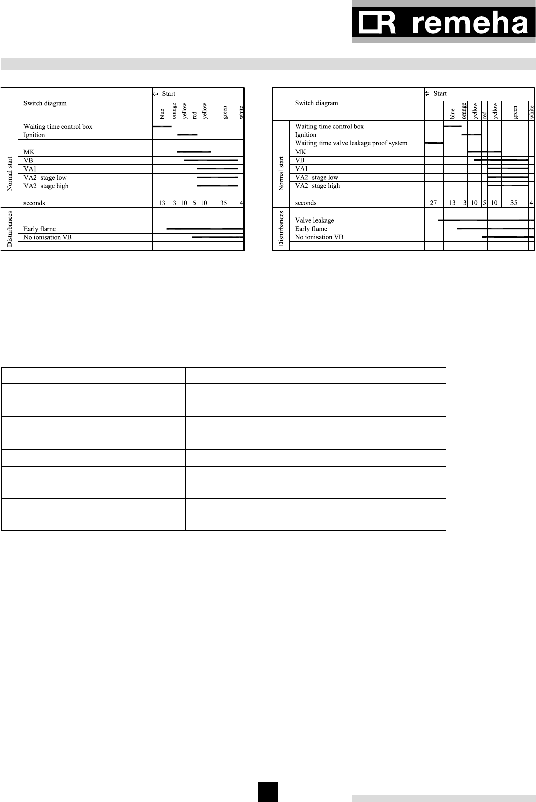
19
12 TROUBLE SHOOTING
Fig. 11 Switch diagram
04.05F.SC.00001
Fig. 12 Switch diagram with valve leakage control (optio-
nal)
04.05F.SC.00001
Indication mark at: Possible cause:
end of green zone;
(no rotation of color disc)
- no tension
- no heat demand
end of yellow zone;
begin of red zone
- no flame (signal) of pilot burner
- no spark
red zone failing or unstable flame of pilot burner
end of yellow zone;
begin of green zone
no flame (signal) of main burner
Green zone;
end of green zone
failing or unstable flame of main burner
12.1 Fault causes
In case of all disturbances the gas supply is interrupted
and the color disc stops rotating.
Check the position of the color disc for a indication of
the cause. The color disc is situated at the side of the
control box.
-
Table 03 Trouble shooting

Broag Ltd
Head Office
Remeha House,
Molly Millars Lane,
Wokingham,
Berkshire RG41 2QP.
Tel.: 0118 9783434
Fax: 0118 9786977
Email: boilers@broag-remeha.com
Internet: www.broag-remeha.com
Branch Office
Unit 3, Kestrel Close,
Quarry Hill Ind. Estate,
Ilkeston,
Derbyshire DE7 4RD
Tel. 0115 9440778
Fax 0115 9440588
© Copyright
All technical and technological information contained in these technical instructions, as well as any
drawings and technical descriptions furnisched by us remain our property and may not be multiplied
without our prior consent in writing.
Subject to alterations
56267/1500/0601/
Ho
.
Remeha Gas 550/550 Duo
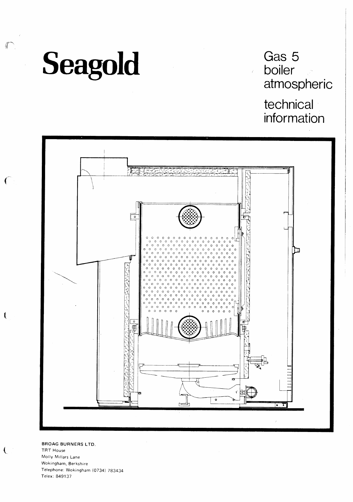
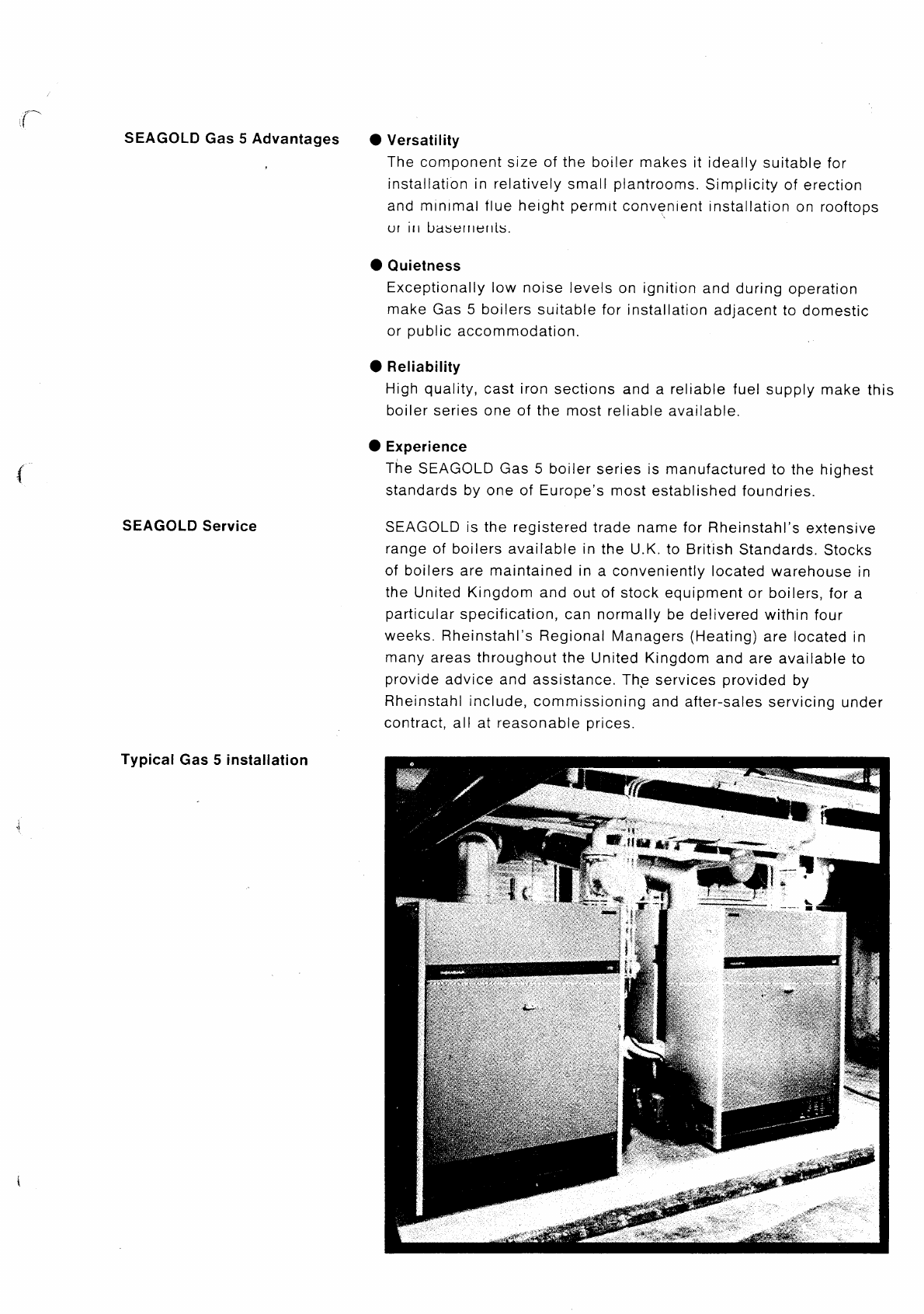
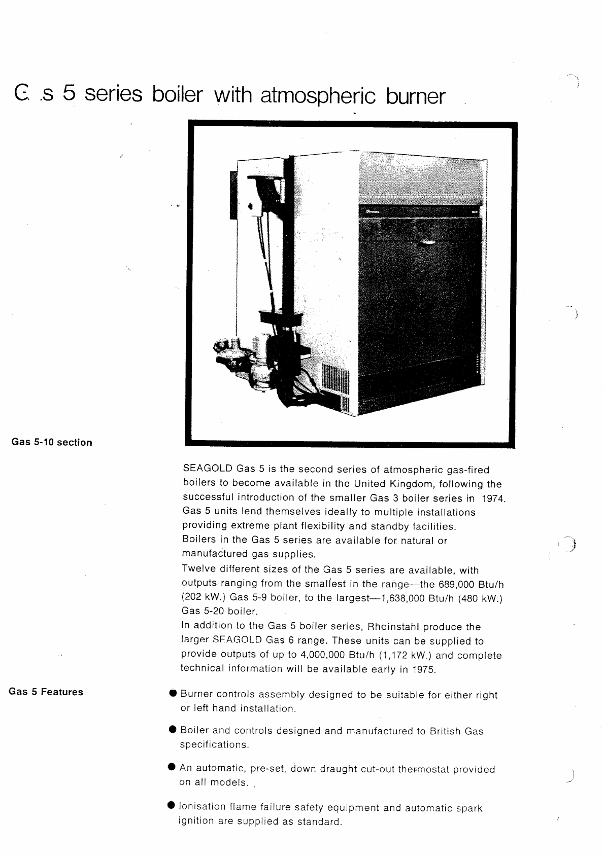
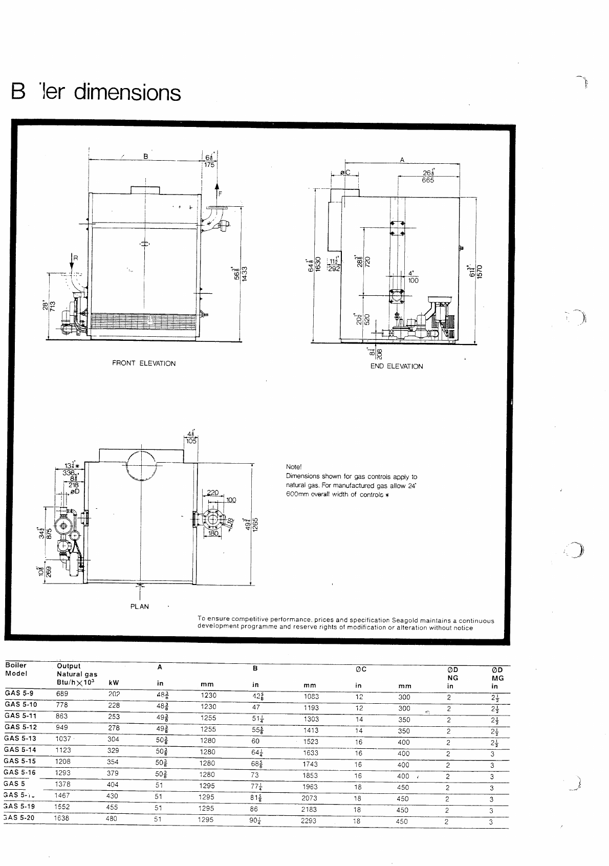
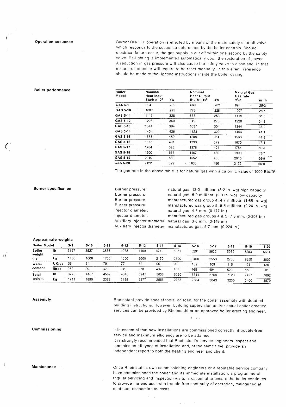
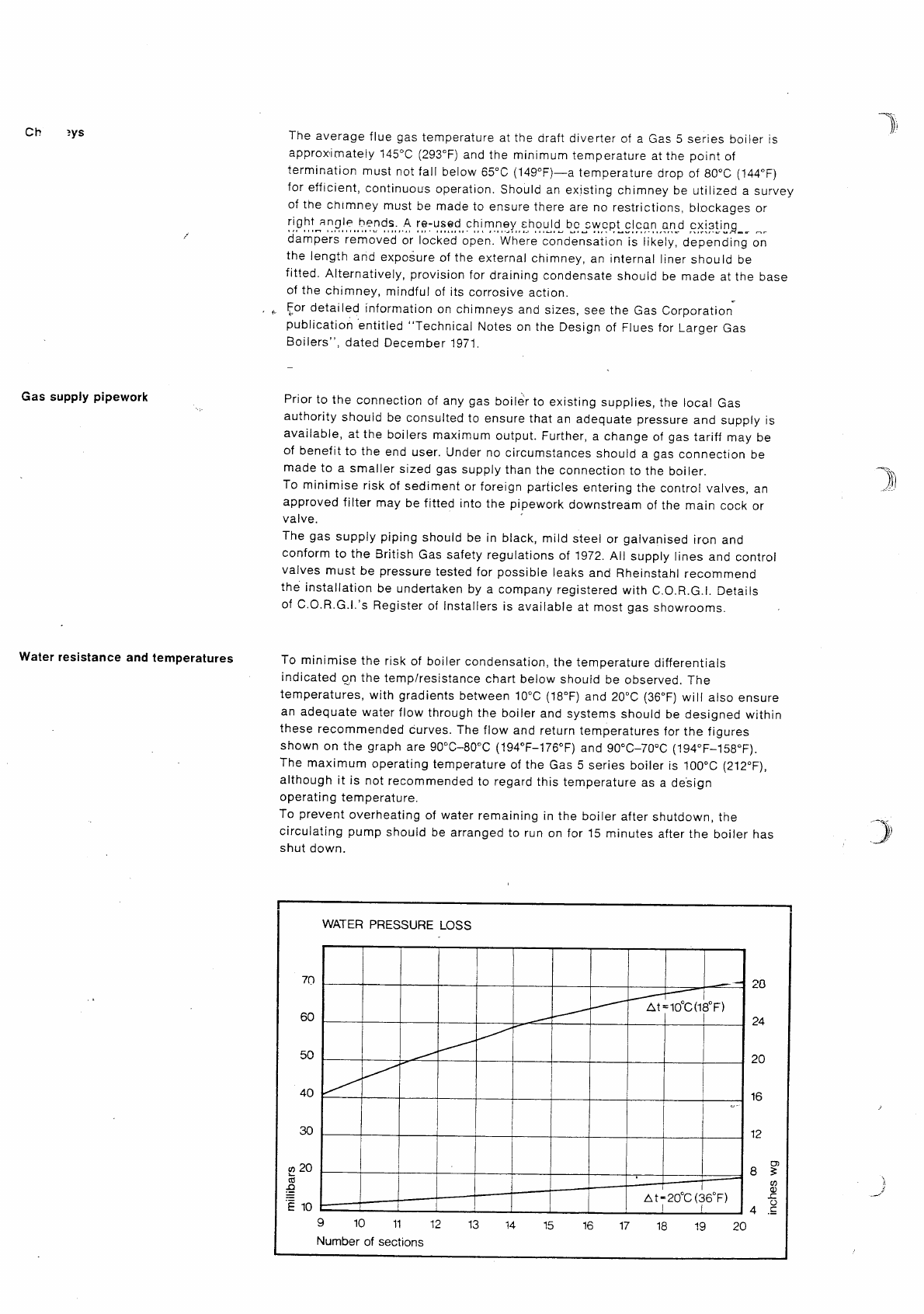
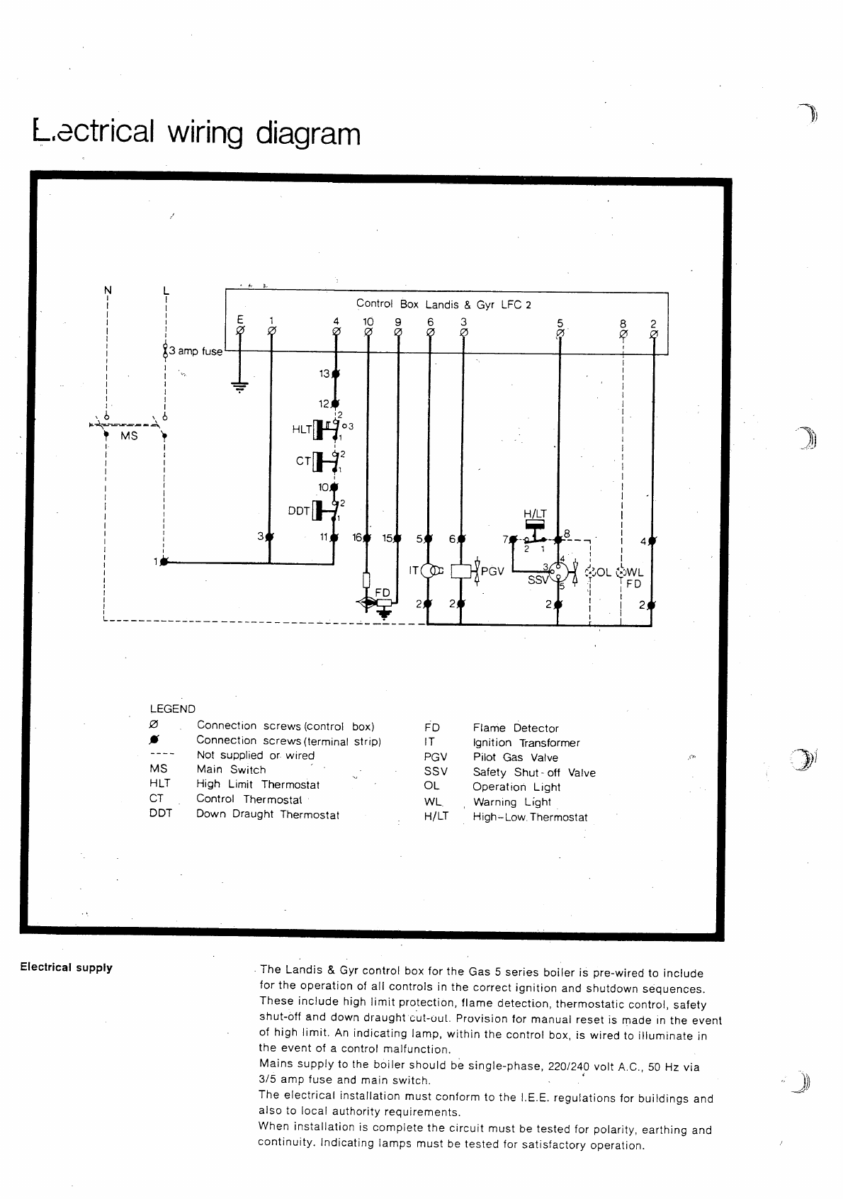
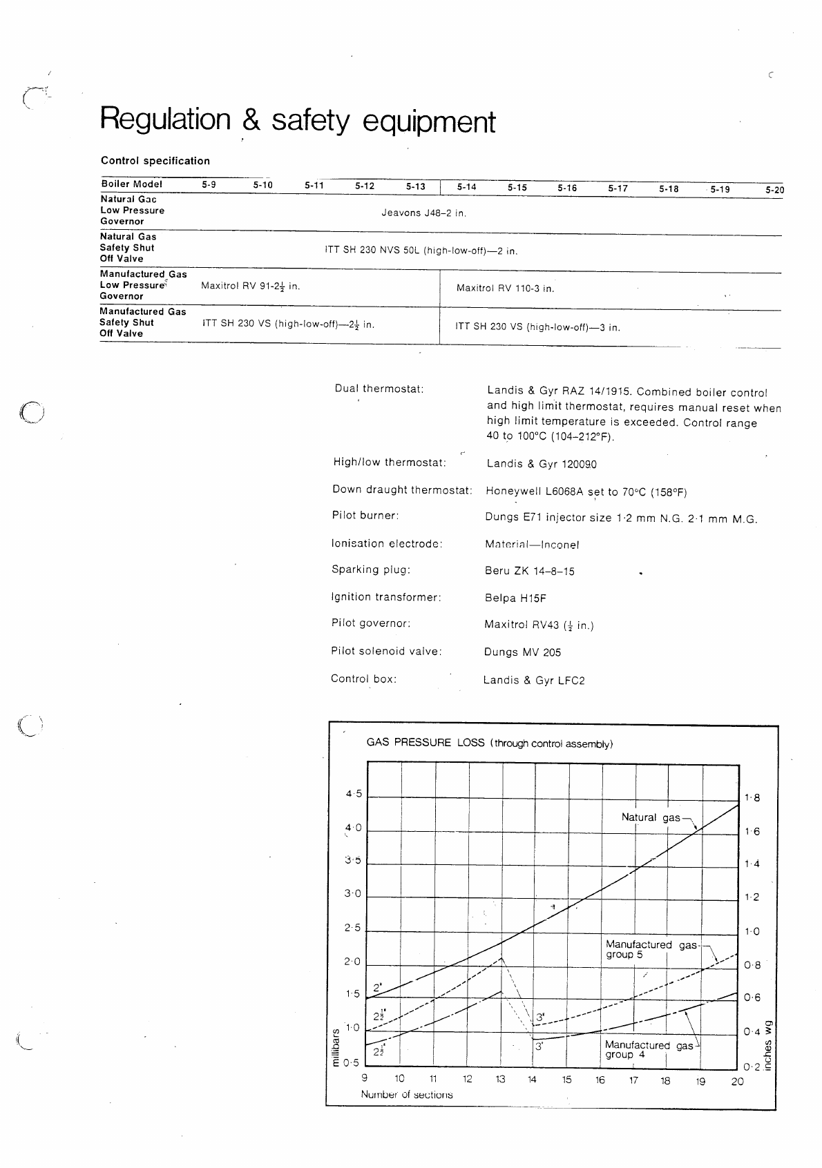
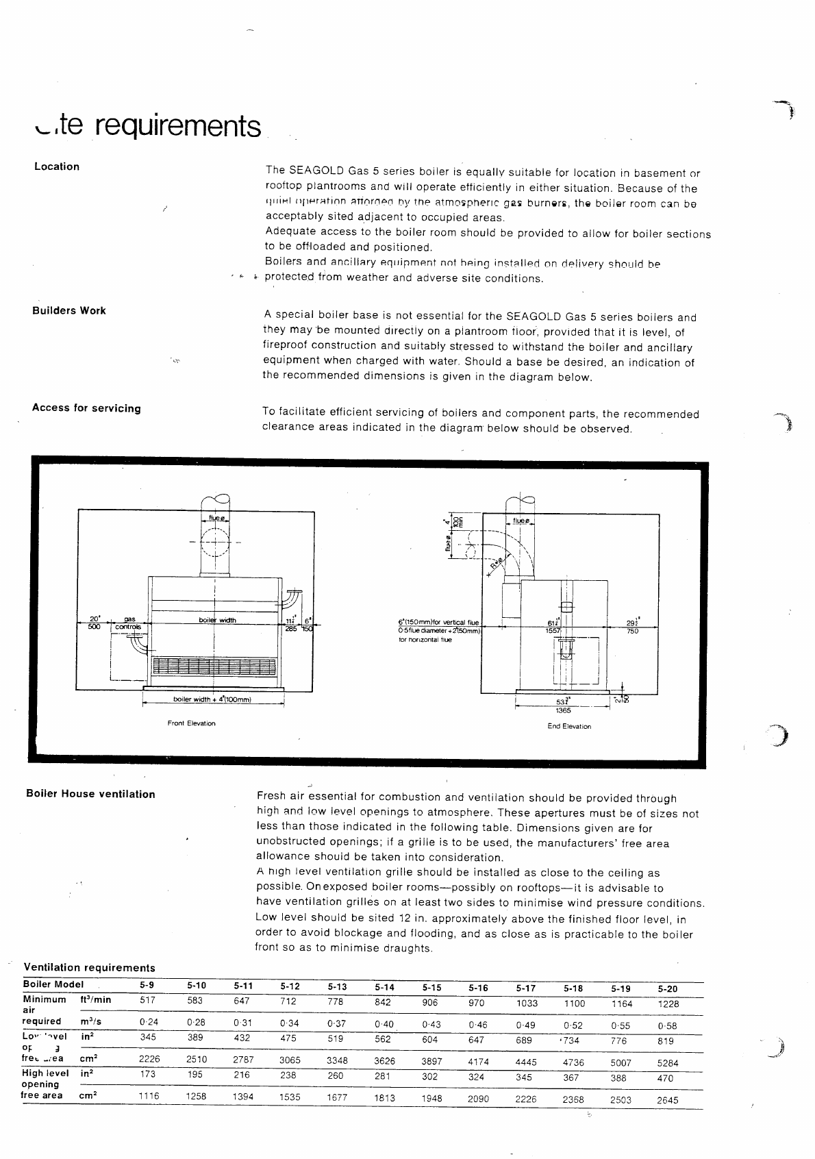
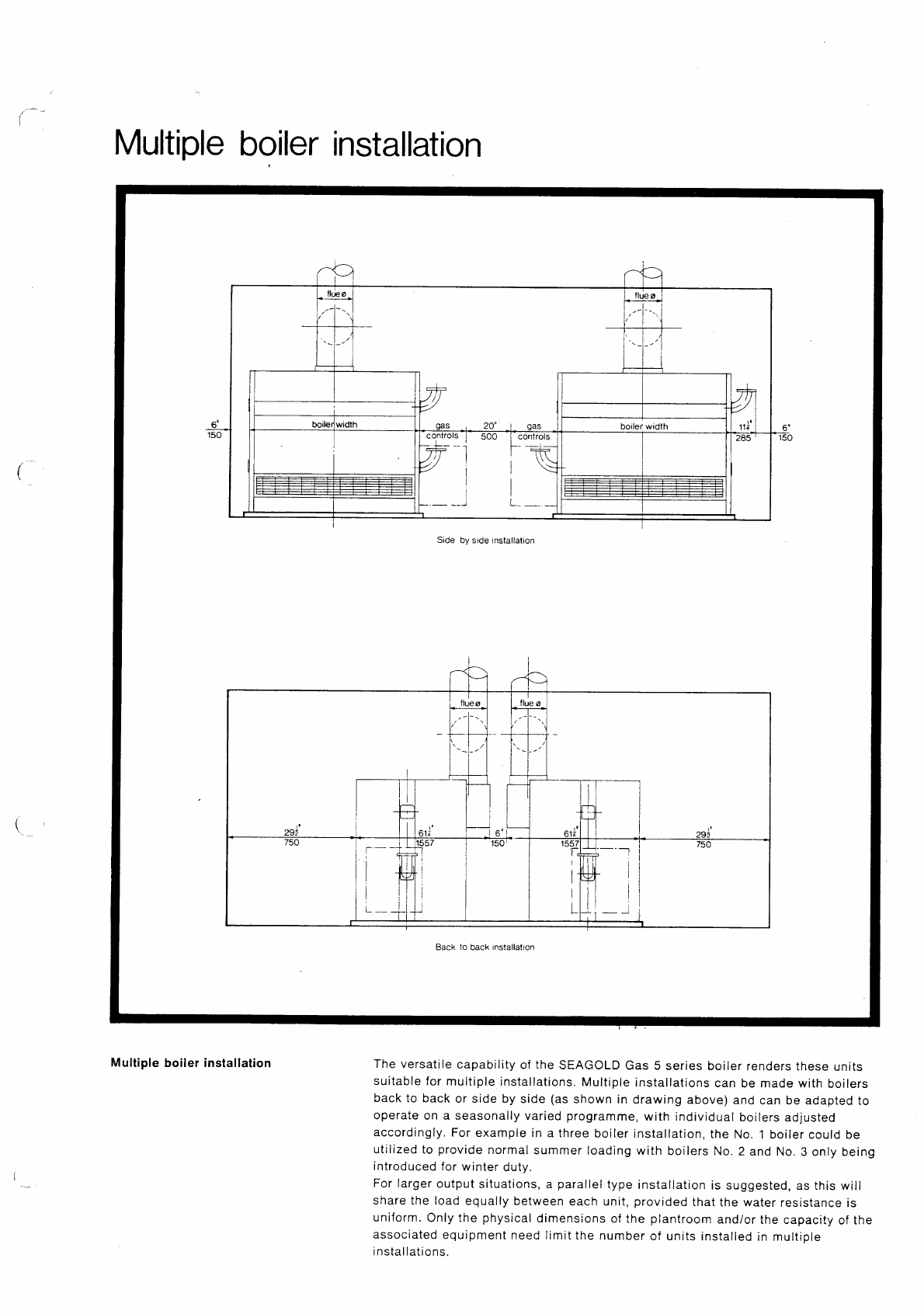
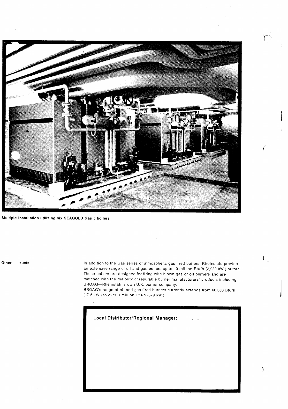
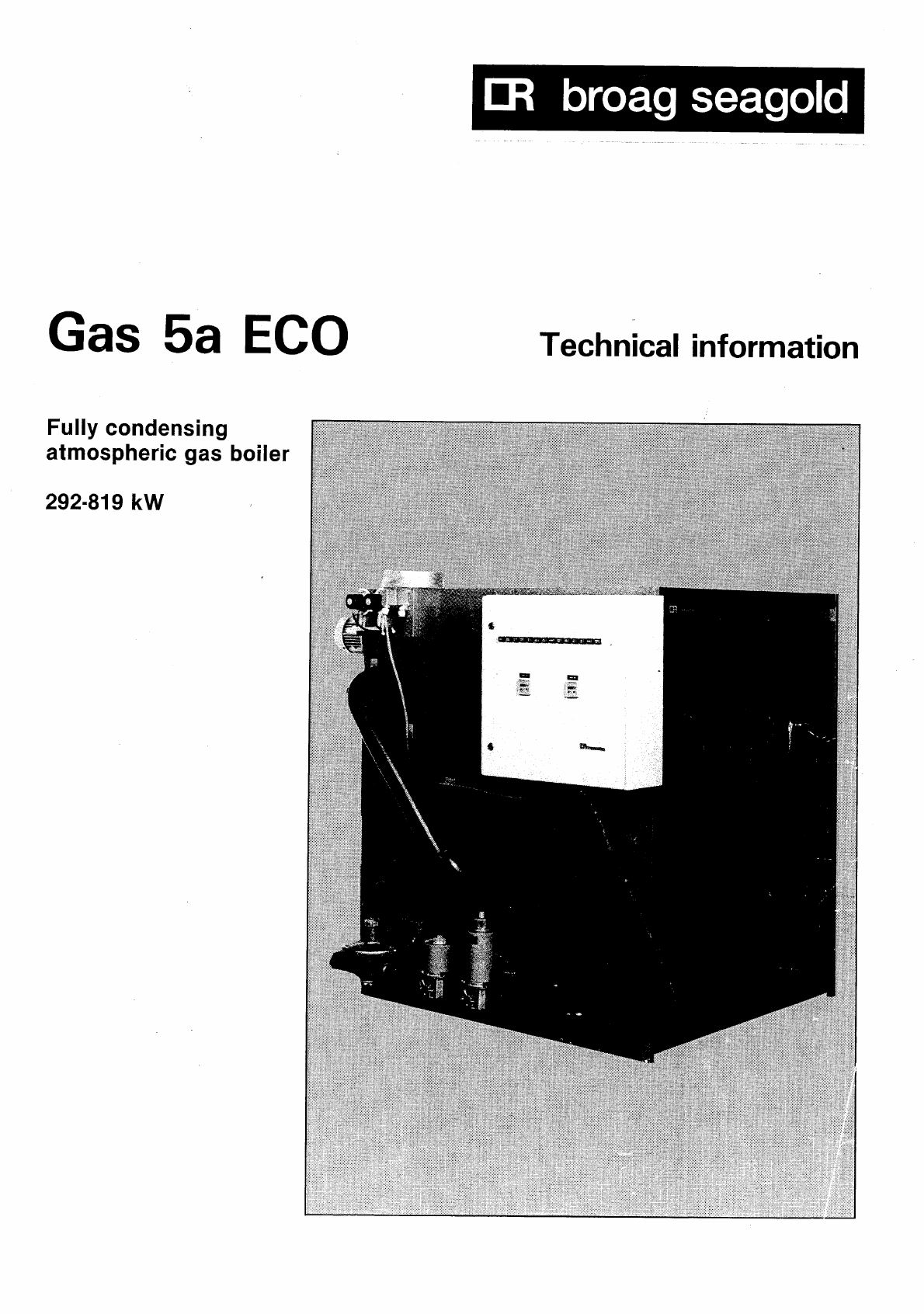
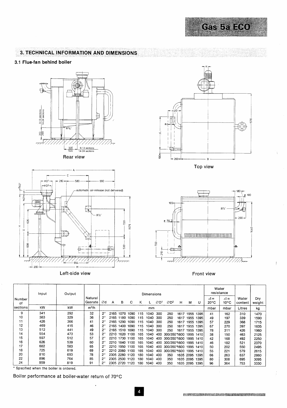
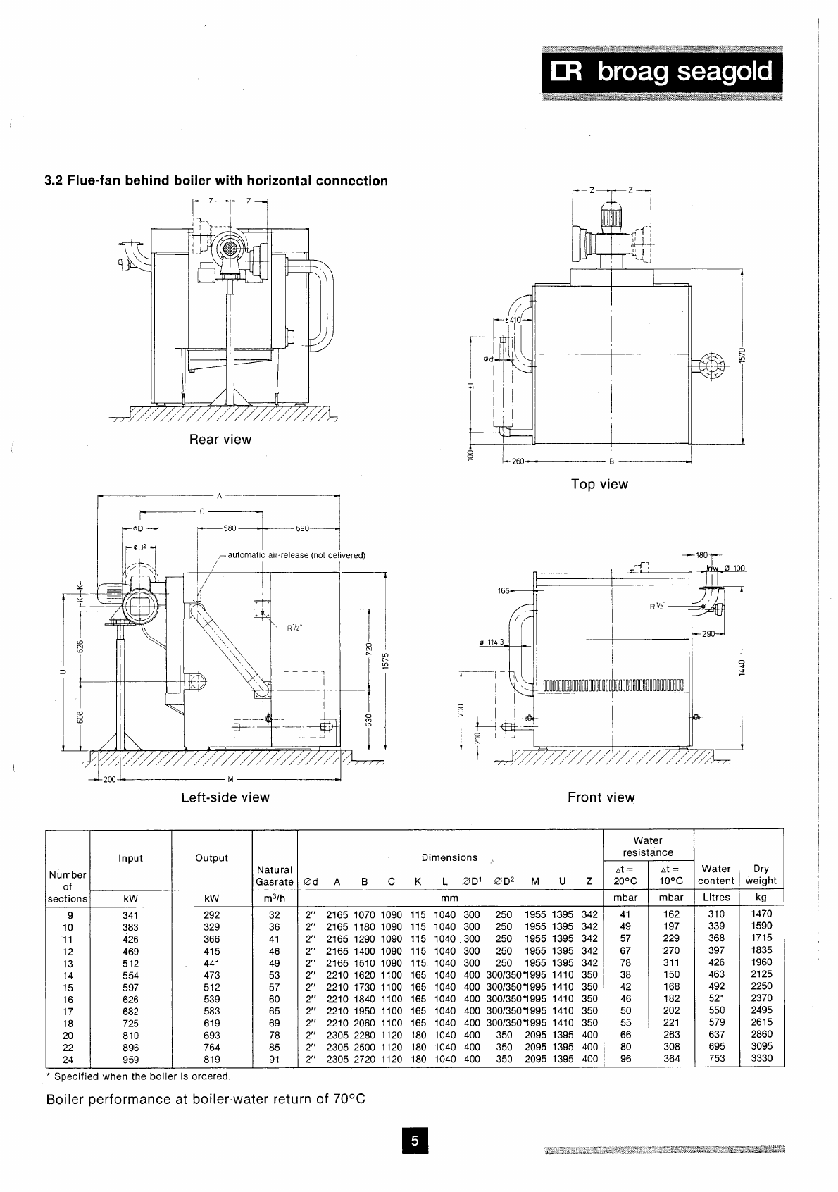
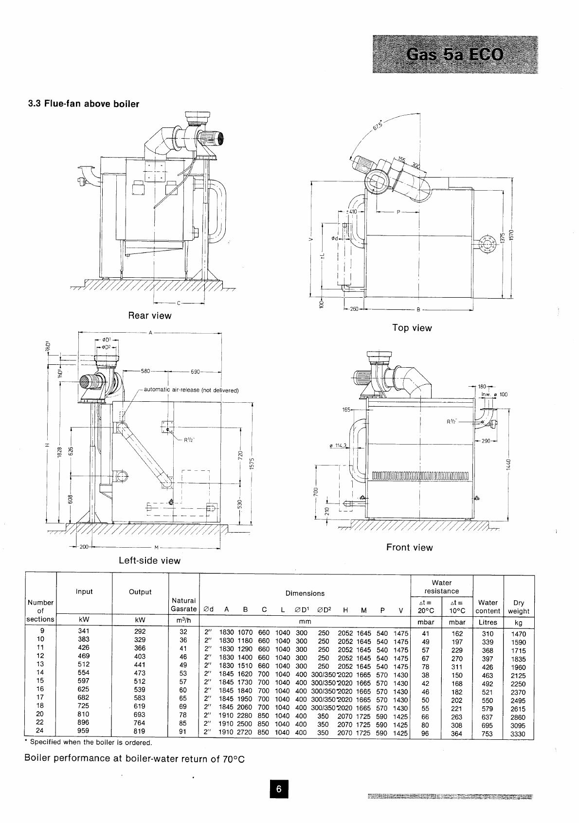

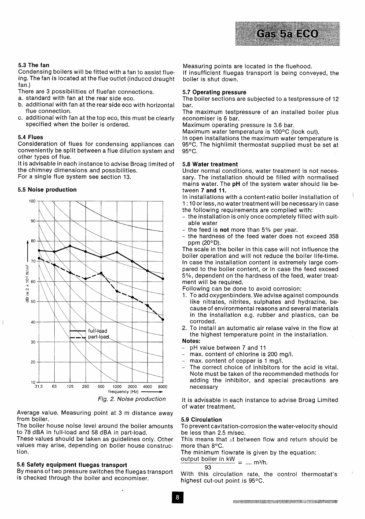
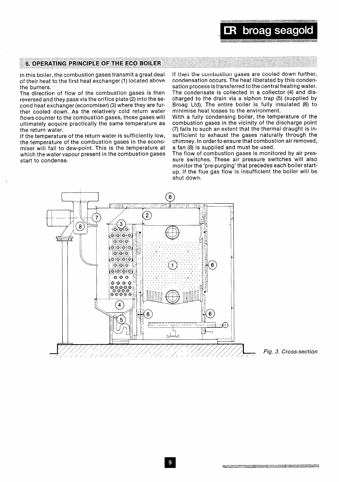
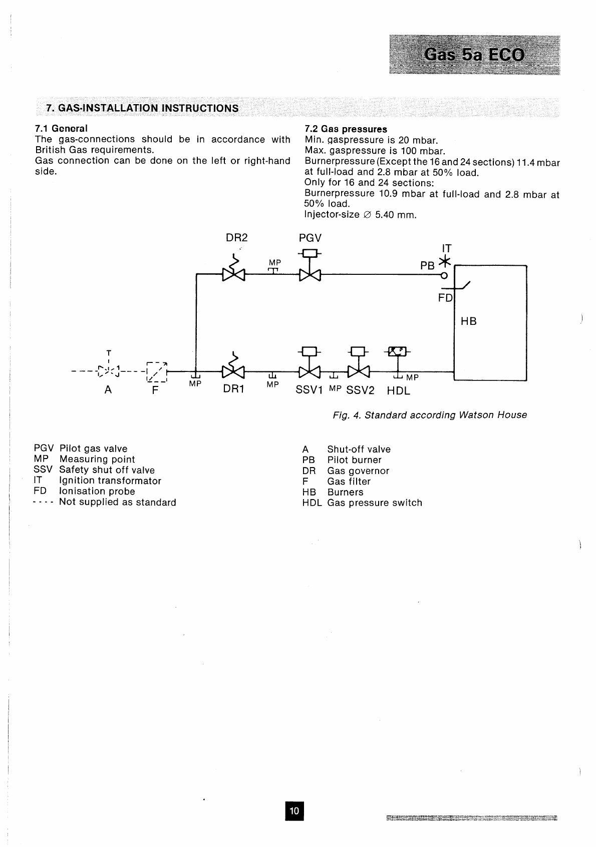
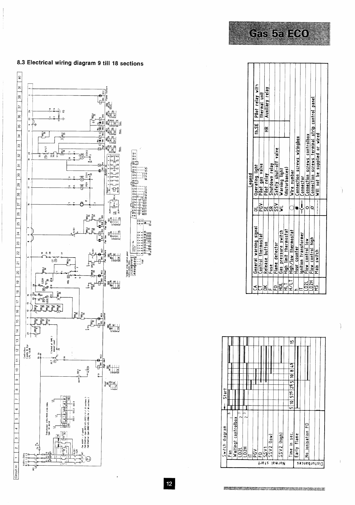
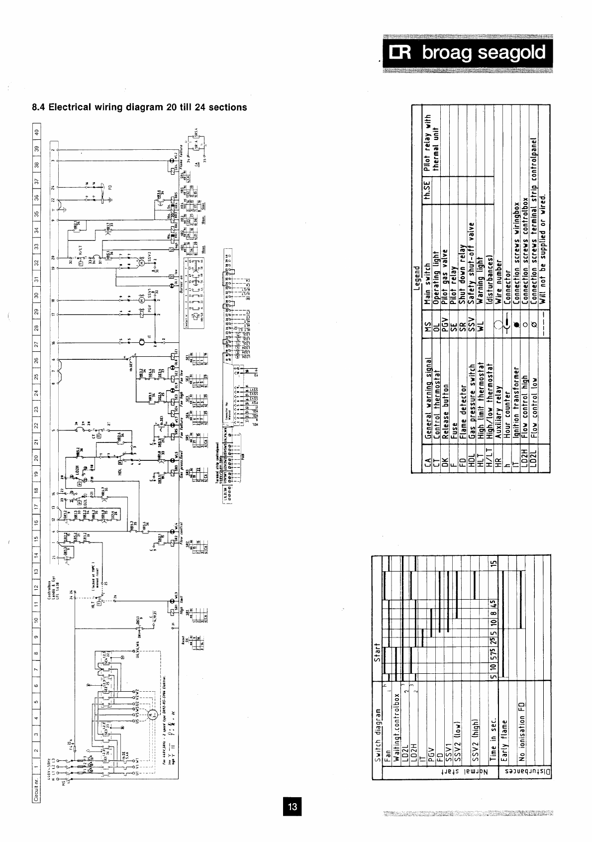
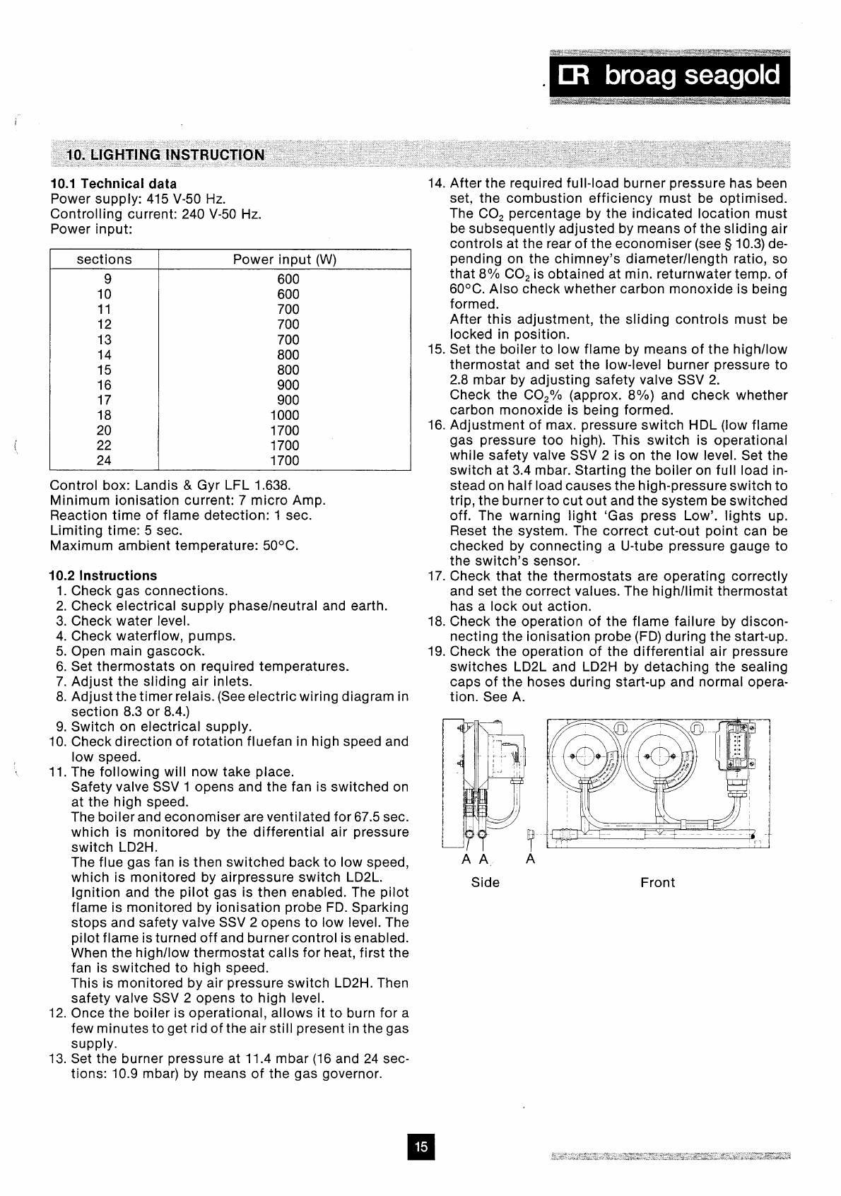
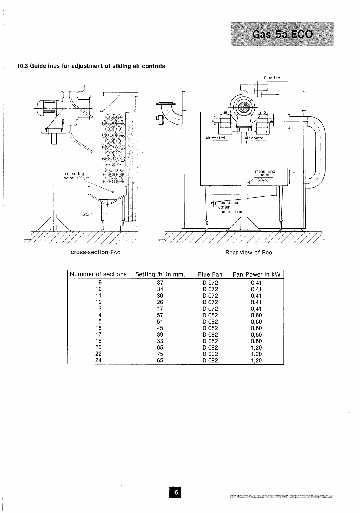
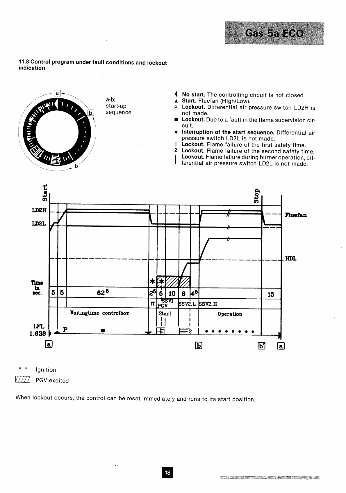
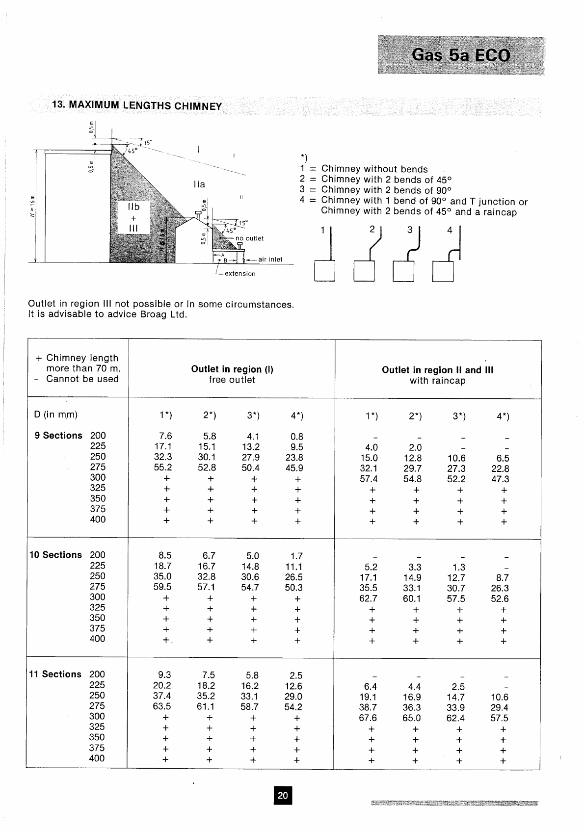
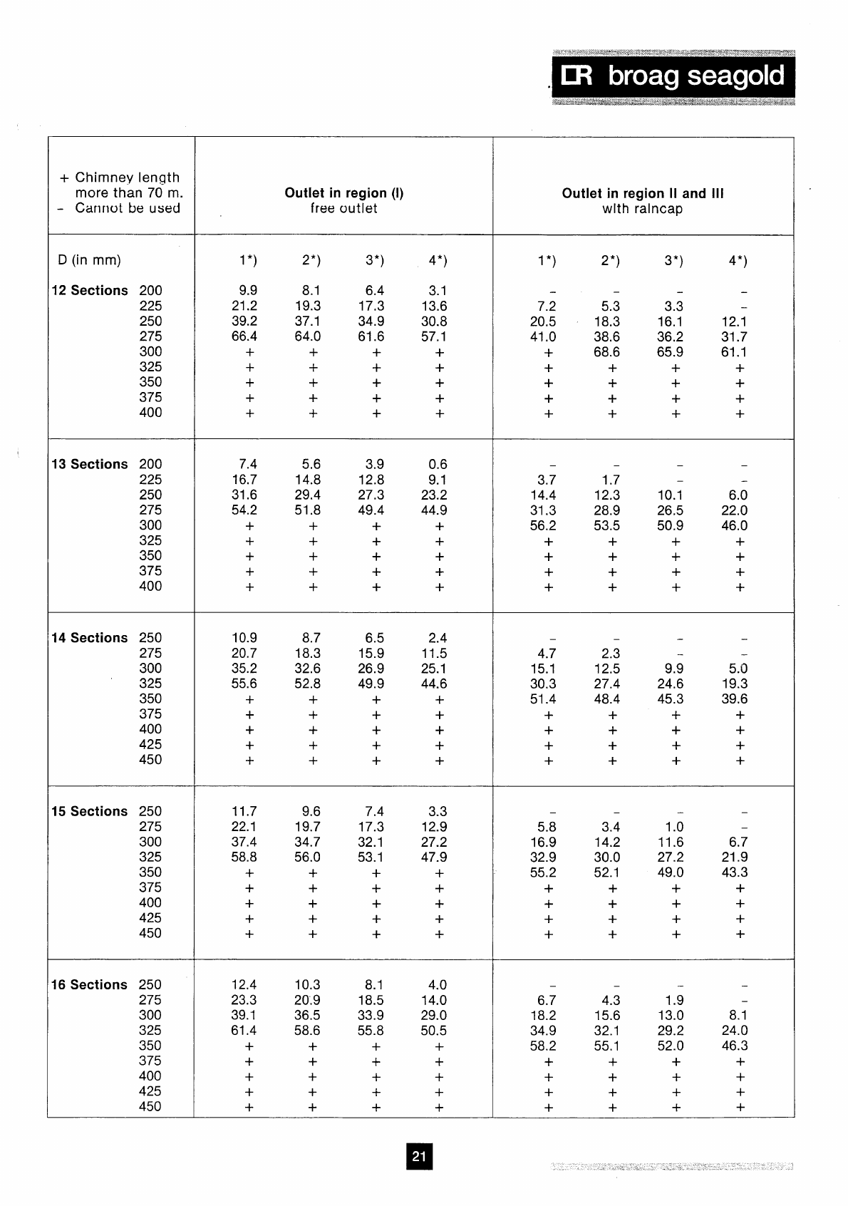
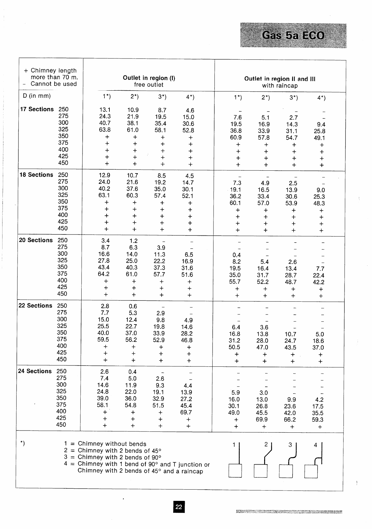
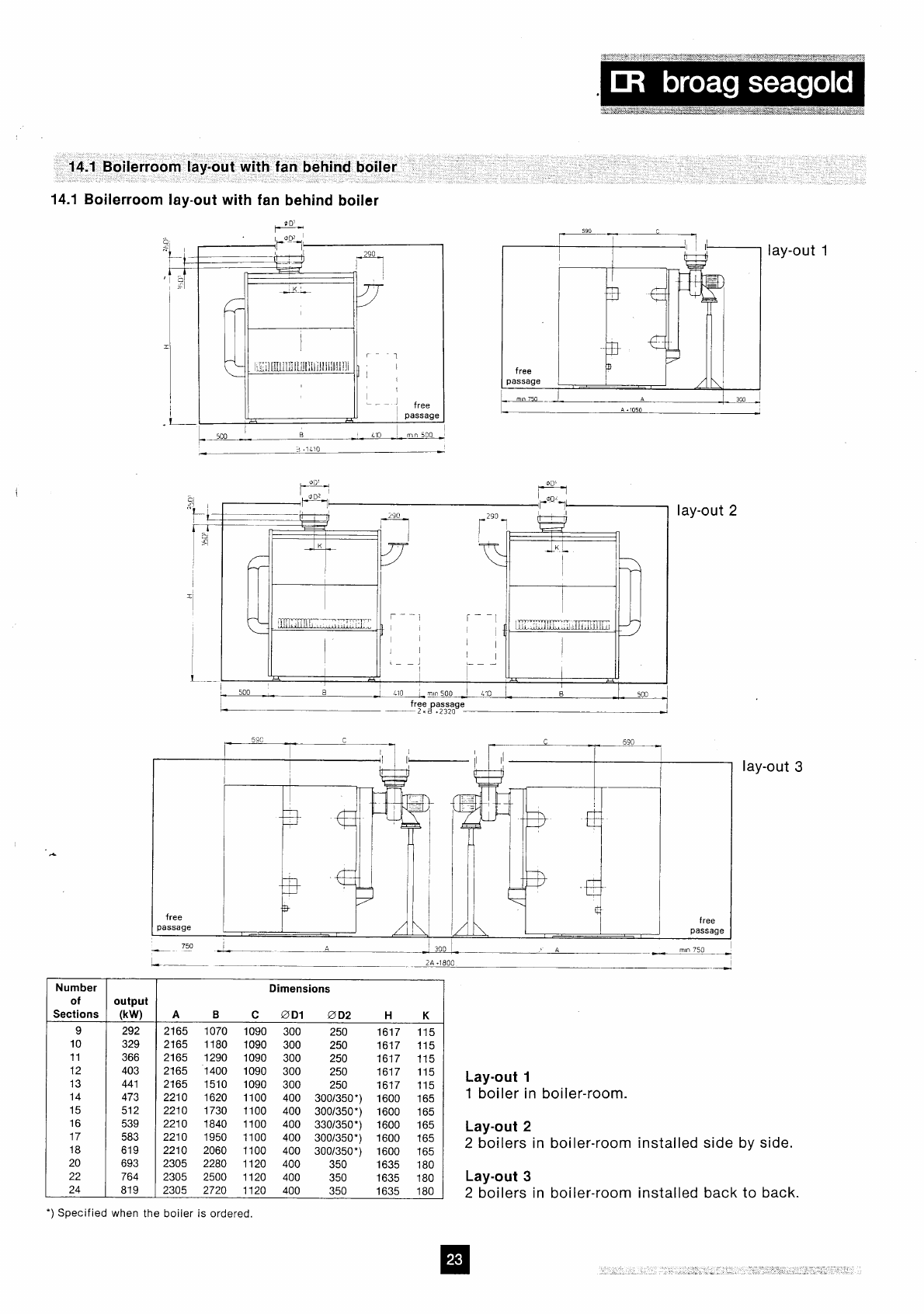
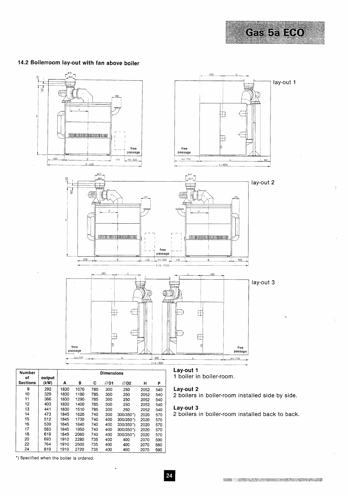
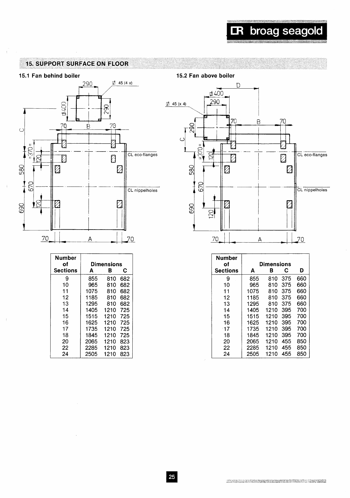
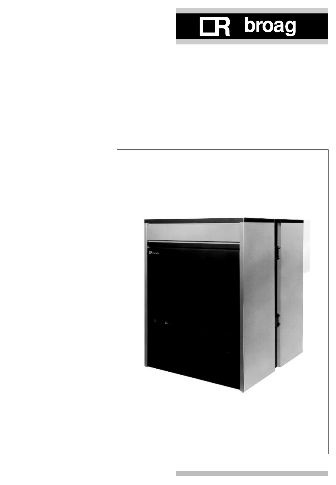

2
remeha Gas 5a/5a Duo
CONTENTS
Preface 3
1. Boiler description 3
2. Construction 3
2.1 General 3
2.2 Burners 3
2.3 Boiler base 3
2.4 Assembling 3
2.5 Boiler dimensions and technical data 4
2.5.1 Broag remeha Gas 5a 4
2.5.2 Broag remeha Gas 5a Duo 5
3. Application 6
3.1 L.P.H.W. system 6
3.1.1 Water temperature 6
3.1.2 Water pressure 6
3.1.3 Water flow 6
3.1.4 Water treatment 6
3.1.5 Noise level 6
3.2 Chimneys 6
4. Typical boiler installation 7
5. Regulation and safety equipment 8
5.1 General 8
5.2 Standard electronic gastrain High/Low 8
5.2.1 Schematic lay out 8
5.2.2 Specification 8
5.3 Functions 8
5.3.1 Flame protection 8
5.3.2 Down draught thermostat 8
5.3.3 Thermostats 8
6. Assembly and installation guidelines 9
6.1 General 9
6.2 Boiler assembly 9
6.3 Water connections 9
6.4 Water pressure 9
7. Gas supply 10
7.1 General 10
7.2 Gas pressure 10
8. Electric supply 11
8.1 General 11
8.2 Electric connections 11
8.3 Electric data 11
8.4 Wiring diagram 12
9. Commissioning 13
9.1 Technical information 13
9.2 Commissioning the boiler 13
10. Maintenance 14
10.1 General 14
10.2 Maintenance instructions 14
11. Fault finding chart 15
11.1 The boiler fails to restart after a normal
shut-down 15
11.2 No ignition 15
11.3 Pilot burner ignites but fails immediately 15
11.4 Pilot burner ignites but gas does not reach
main burners 15

3
If you have any questions, or if you need more informa-
tion about specific subjects relating to this boiler, please
do not hesitate to contact us.
The data published in these technical instructions is
based on the latest information and is given subject to
later revisions.
We reserve the right to modify the design and/or configu-
ration of our products at any moment, without being
obliged to adjust earlier supplies accordingly.
These technical instructions contain useful and important
information for the correct operation and maintenance of
the Broag remeha Gas 5a/5a Duo gas boiler. Futhermo-
re, important instructions are given to prevent accidents
and serious damage before commisioning and during
operation of the boiler, to ensure safe and trouble free
operation. Read these instructions carefully before put-
ting the boiler into operation, familiarize yourself with its
operation and controls and strictly observe the instruc-
tions given.
The Broag remeha Gas 5a boiler is a cast iron sectional
boiler with atmospheric burners.
Suitable for all qualities of natural gas.
The Broag remeha Gas 5a boiler is fitted with electric
ignition and is supplied with an insulated casing.
1. BOILER DESCRIPTION
2. CONSTRUCTION
2.1 General
- Boiler block consists of cast iron sections nippled
together with conical nipples.
- Gas train can be fitted on the left or right hand side of
the boiler.
- Fitting of the casings is possible after the boiler is
installed.
- The boiler is cleaned from the front.
- Water connections can be fitted on the left or right
hand side of the boiler.
2.2 Burners
The burners are stainless steel, atmospheric burners.
They guarantee a low noise level.
2.3 Boiler base
The Broag remeha Gas 5a boiler is supplied as standard
with reflecting floor plates wich allows for ventilation
beneath the boiler.
2.4 Assembling
The boiler is assembled on site.
Water connecties Ø 100 mm.
Output: Gas 5a - 10 to 22 sections : 276 to 644 kW.
Gas 5a Duo - 2 x 10 sections
to 2 x 18 sections : 552 to 1044 kW.
PREFACE
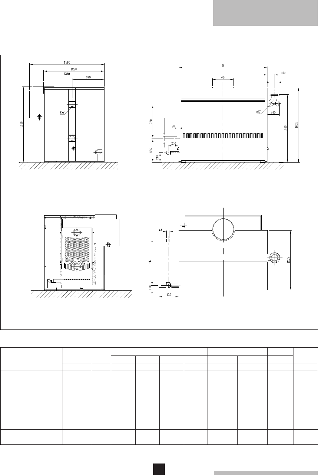
4
remeha Gas 5a/5a Duo
1450
1575
1695
1820
1940
2065
2185
2430
2675
2920
Weight
dry
kg
2.5 Boiler dimensions and technical data
2.5.1 Broag remeha Gas 5a
Model
Broag remeha Gas 5a-10
Broag remeha Gas 5a-11
Broag remeha Gas 5a-12
Broag remeha Gas 5a-13
Broag remeha Gas 5a-14
Broag remeha Gas 5a-15
Broag remeha Gas 5a-16
Broag remeha Gas 5a-18
Broag remeha Gas 5a-20
Broag remeha Gas 5a-22
Front view
Side view
Top view
Cross-section
ø 100
ø 100
Fig. 01 Dimensions of the Broag remeha Gas 5a
Nominal
output
kW
Input
G.C.V.
kW
Dimensions
276
306
338
368
398
430
460
522
582
644
345
383
422
460
498
537
575
652
728
805
Resistance
± L
mm
Ø D
mm
Ø d
"
∆t = 20°C
mbar
∆t = 10°C
mbar
Water
content
l
940
940
940
940
940
940
940
940
940
940
350
400
400
400
450
450
450
500
500
600
2"
2"
2"
2"
2"
2"
2"
2"
2"
2"
15
16
17
18
19
20
35
44
50
54
59
63
67
71
75
78
137
172
195
211
291
320
349
378
407
436
465
523
581
639
B
mm
1240
1350
1460
1570
1680
1790
1900
2120
2340
2560
(only 22 S)
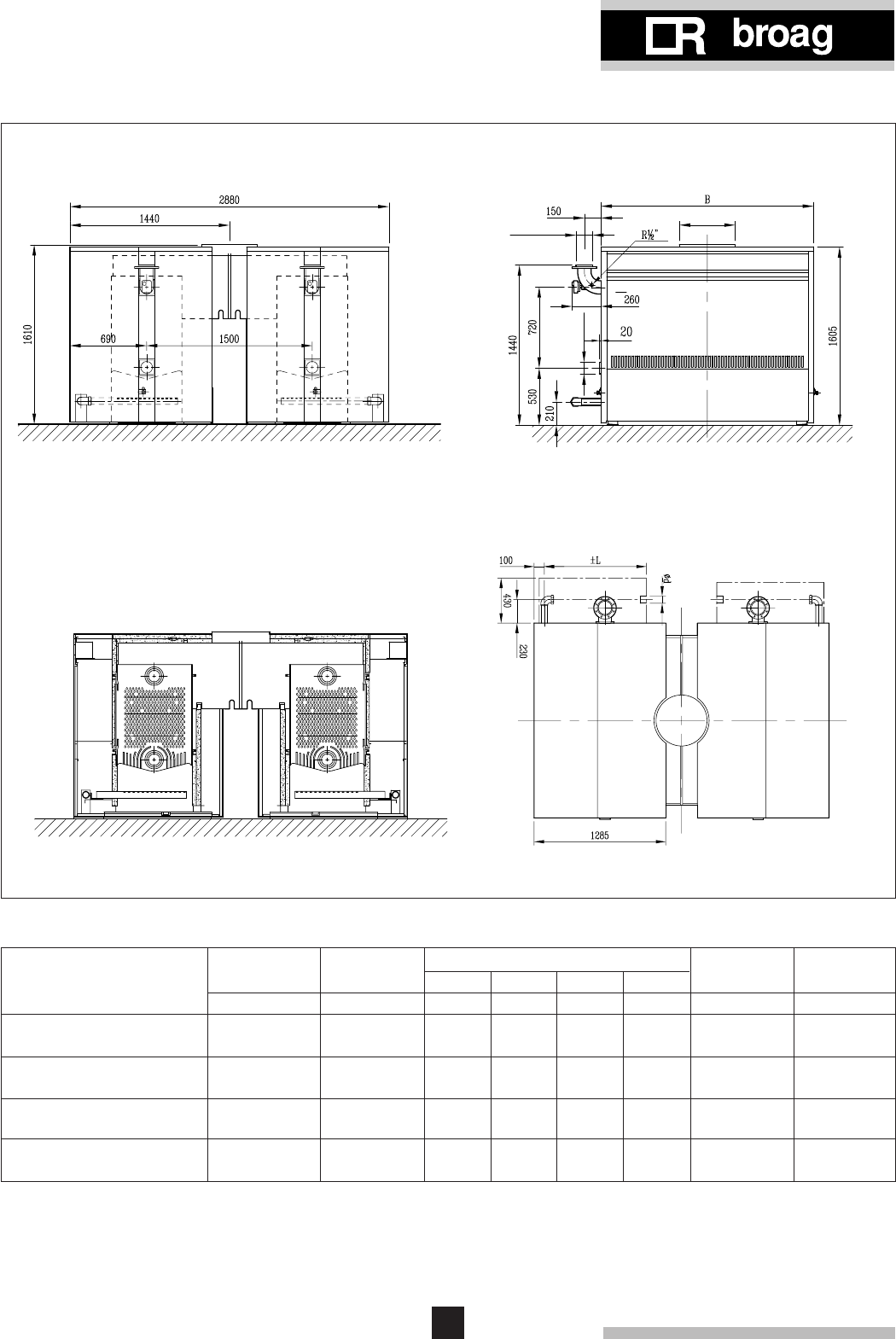
5
Dimensions
2.5.2 Broag remeha Gas 5a Duo
Broag remeha Gas 5a Duo-10
Broag remeha Gas 5a Duo-11
Broag remeha Gas 5a Duo-12
Broag remeha Gas 5a Duo-13
Broag remeha Gas 5a Duo-14
Broag remeha Gas 5a Duo-15
Broag remeha Gas 5a Duo-16
Broag remeha Gas 5a Duo-18
Model
Front view
Side view
Top view
Cross-section
Fig. 02 Dimensions of the Broag remeha Gas 5a Duo
Nominal
output
kW
B
mm
690
766
844
920
996
1074
1150
1304
Input
G.C.V.
kW
552
612
676
736
796
860
920
1044
1240
1350
1460
1570
1680
1790
1900
2120
ø 100
ø 107
ø D
Weight
dry
kg
582
640
698
756
814
872
920
1046
Water
content
l
2900
3150
3390
3640
3880
4130
4270
4860
Ø D
mm
± L
mm
940
940
940
940
940
940
940
940
500
600
600
600
650
650
650
700
Ø d
"
2"
2"
2"
2"
2"
2"
2"
2"

6
remeha Gas 5a/5a Duo
3. APPLICATION
Output boiler in kW
93 = ... m3/h
This minimum flow must be maintained for 5 minutes
after the burner stops firing to avoid high temperature
shut-down due to residual heat gain. Due to the design
and manufacture of the boiler no specific minimum water
flow requirement exists other than for over-temperature
protection.
3.1.4 Water treatment
Water treatment of all systems, but in particular open
vented systems used with the Broag remeha Gas 5a, is
considered necessary good practice in order to:
- avoid metallic corrosion within the system
- avoid sludge and scale information
- reduce to a minimum the risk of microbiological conta-
mination of the system
- minimise chemical action and changes which take
place over a period of time when system water is un-
treated.
The system will contain a variety of metals. Ferrous
metals - cast iron and steel, and non-ferrous metals -
copper, brass and gunmetal, may be present, so it is
essential that treatment is suitable for all of them.
Suitable chamicals and the extent of treatment should be
discussed with specialist manufactures prior to any work
commencing. The specification of new systems and
general condition of older existing systems must be
carefully considered. The removal of debris, flux residue,
grease, metal, swarf etc. from new systems, and any
black magnetic iron exide sludge and other corrosive
residue from old systems is essential.
3.1 L.P.H.W. system
3.1.1 Water temperature
Maximum water temperature is 110°C (high limit
thermostat).
Highest operating flow temperature is 95°C (control
thermostat).
Minimum return water temperature is 20°C at a flowrate
related to a ∆t of 20°C (flow/return temperature).
3.1.2 Water pressure
Boiler sections pressure test at 12 bar.
Maximum pressure test boiler block is 6 bar.
Minimum working pressure boiler is 0.8 bar at a maxi-
mum water temperature of 110°C or 0.3 bar at a maxi-
mum water temperature of 95°C.
Maximum working pressure boiler is 6 bar.
3.1.3 Water flow
The minimum water flow through the boiler is:
For information on water treatment we advise direct
contact with either:
Fernox Manufacturing Company Ltd.
Britannia Works
Clavering
Essex, CB1L 4QZ
Tel No: 0799 550811
or: Sentinal
Grace Dearborn Ltd
Widnes
Cheshire WA8 8UD
Tel No: 051 495 1861
3.1.5 Noise level
The noise level measured around the boiler depending
on boiler room construction is about 50-55 dBA.
Noise levels taken at 1 meter from the boiler.
3.2 Chimneys
The average flue gas temperature is so low that the
chimney must be made in accordance with the guidelines
of British Gas.
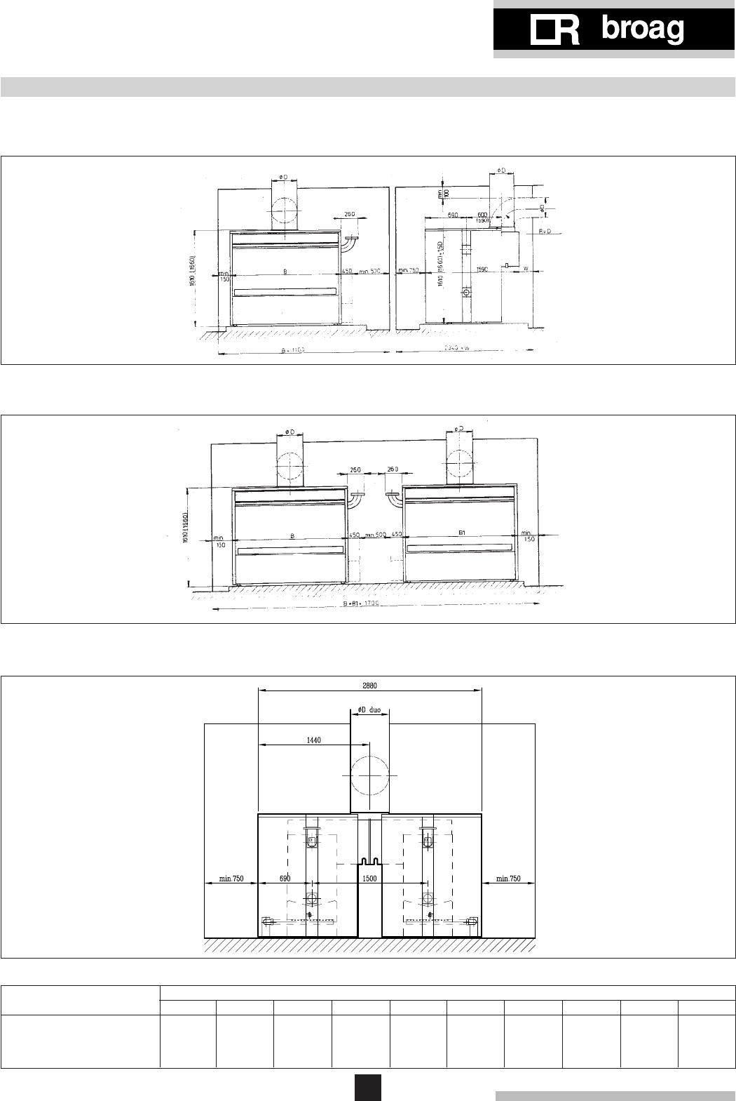
7
4. TYPICAL BOILER INSTALLATION
Installation 1
1 boiler in boiler room
Installation 2
2 boilers in boiler room
Installation 3
Duo arrangement
B
Ø D
Ø D duo
1240
350
500
1350
400
600
1460
400
600
1570
400
600
1680
450
600
1790
450
600
1900
450
650
2120
500
700
2340
500
700
2560
600
800
12 13 15 18 20 22
16141110
Dimensions
mm
Number of sections
Fig. 03 Boiler installations
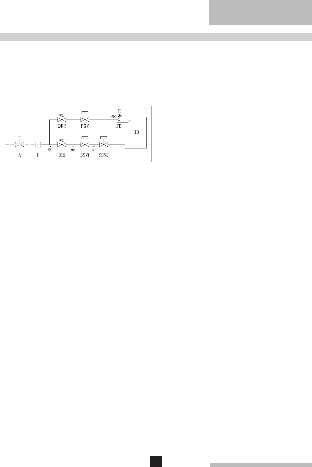
8
remeha Gas 5a/5a Duo
5. REGULATION AND SAFETY EQUIPMENT
5.1 General
The Broag remeha Gas 5a is supplied with electronic
control and safety equipment with ionisation flame detec-
tion.
5.2 Standard electronic gastrain High/Low
5.2.1 Schematic lay out
5.2.2 Specification
2 Safety gas valves
1 Gas governor
1 Pilot gas valve
1 Pilot gas governor
1 Ignition transformer 5 kV
1 Pilot burner with ionisation probe
1 Down draught thermostat set at 70°C
5.3 Functions
5.3.1 Flame protection
5.3.2 Down draught thermostat
The boiler is fitted with a thermo-down draught
thermostat.
If there is a down draught in the chimney the thermostat
will switch off the boiler. Fixed setpoint is 70°C.
5.3.3 Thermostats
Control thermostat On/Off 35-95°C.
Control thermostat High/Low 35-95°C.
High Limit thermostat locks out at 110°C.
Fig. 04 Schematic layout
Legend
A Gas cock (not supplied)
PB Pilot burner
DR Gas governor
F Gas filter (not supplied)
HB Main gas burners
IT Ignition transformer
PGV Pilot gas valve
MP Measuring point
SSV Safety shut off valve
FD Ionisation probe
- - - - Not supplied

9
6. ASSEMBLY AND INSTALLATION GUIDELINES
6.1 General
Boiler can be installed in open or closed systems.
6.2 Boiler assembly
Broag provides special tools on loan, for the boiler
assembly with detailed building instructions. However,
building supervision and/or actual boiler erection services
can be provided by Broag.
6.3 Water connections
The boiler water connections can be fitted on one side of
the boiler either left or right hand side.
The return water connection is flanged on the boiler with
a pipe connection for welding Ø 107/114 mm.
The flow water connection is a cast iron bend flanged on
the boiler and comes complete with a welding neck
flange Ø 107/114 mm according BS10 table D. The flow
bend has 1/2" tappings to accept a dual control/limit
boiler thermostat and the high/low thermostat. The end
sections have a 3/4" tapping to accept drain/off cocks.
(BSP Tapping).
6.4 Water pressure
Each section is hydraulically tested to at least 12 bar.
Maximum test pressure for the assembled boiler block is
6 bar.
Maximum working pressure is 6 bar.
Minimum working pressure is 0.8 bar at a maximum
working temperature of 110°C or 0.3 bar at a maximum
working temperature of 95°C.

10
remeha Gas 5a/5a Duo
7. GAS SUPPLY
7.1 General
The gas train can be fitted on the left or right hand side of
the boiler.
The local Gas authority should be consulted to ensure
that an adequate pressure and supply is available at the
boilers maximum output. To minimise risk of sediment or
foreign particles entering the control valves, an approved
filter may be fitted into the pipework downstream. The
gas supply should be conform to the British Gas safety
regulations.
7.2 Gas pressure
Maximum gas pressure at inlet 100 mbar.
Burner pressure:
- full load : 8.7 mbar (100%)
- part load : 3.5 mbar (60%)

11
8. ELECTRIC SUPPLY
8.1 General
The electrical installation must conform to the IEE
Regulations for Electrical Installations and also to Local
Authority requirements.
8.2 Electric connections
The Satronic control box for the Broag remeha Gas 5a
series boilers is prewired for the operation of all controls
in the correct ignition and shut-down sequences. These
include high limit protection, flame detection, thermostatic
control and safety shut-off. Provision for manual reset is
made in the event of high limit shut-down and flame failu-
re. An indication lamp within the control box illuminates in
the event of control malfunction. A 240 volts ~ 50 Hz
single phase supply should be connected to the live and
neutral terminals in the junction box.
The control box operates on a neutral/phase supply. The
earth conductor should be connected to the earth bar
using the screw provided with an anti-spread washer.
These conductors should be entered via one of the cable
entry glands. A wiring diagram is fixed inside the lid of the
junction box and is also included in this manual (see
section 8.4). Time controls and remote thermostats can
be connected across terminals 12 and 13 after removal of
the link. These controls should be BEAB or BSI
approved.
8.3 Electric data
Main supply: 240 V-50 Hz (L/N).
Running current: 120 W.
Maximum fuse: 6Amp.
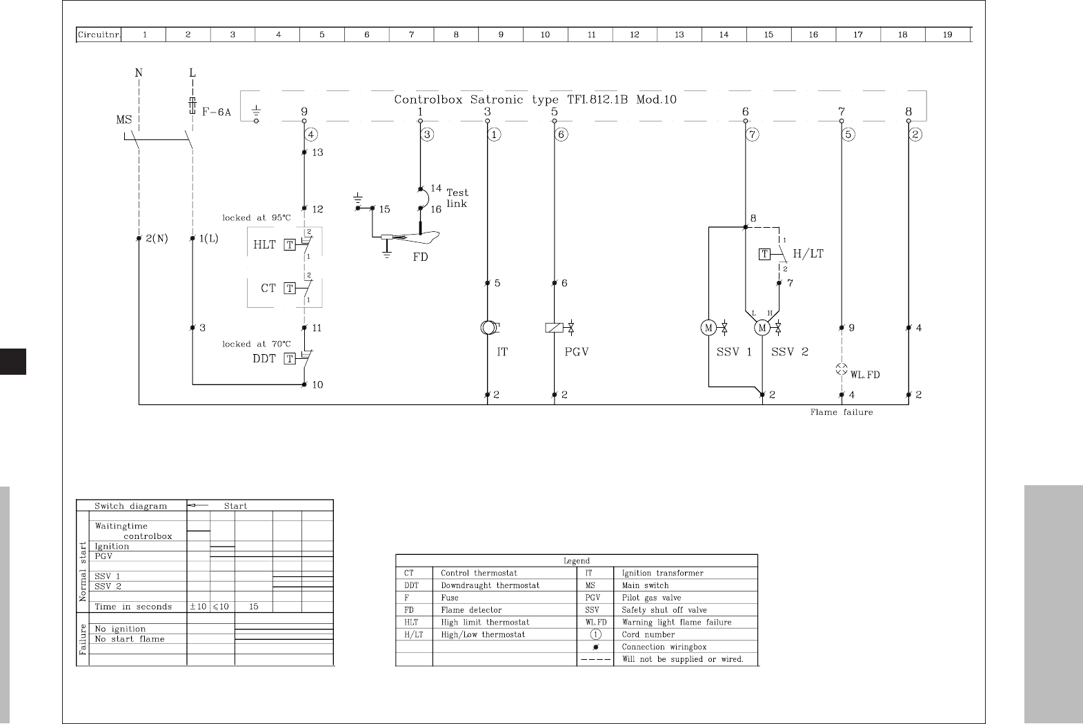
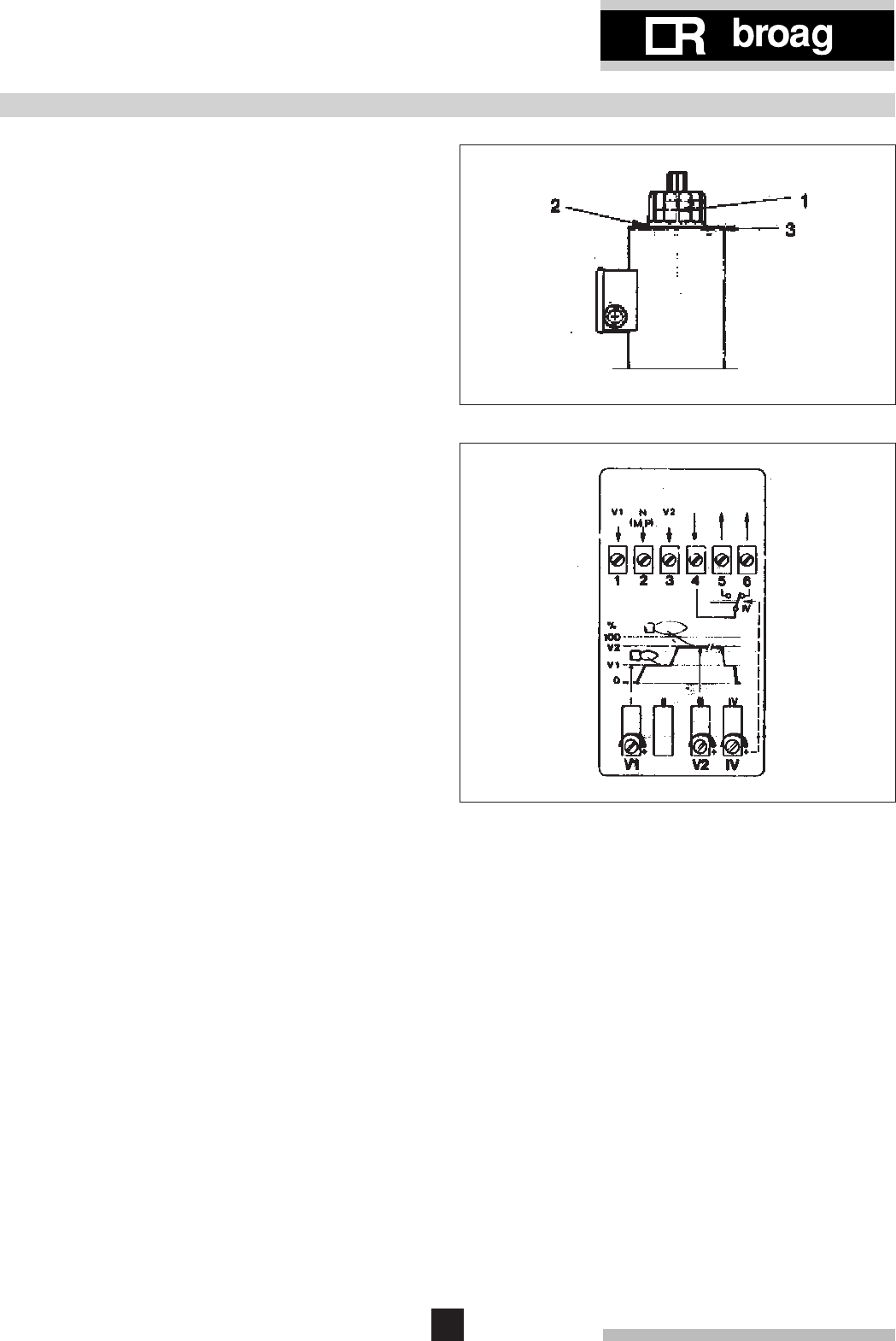
13
9. COMMISSIONING
It is important that the protective plastic coating is remo-
ved from the casing prior to commissioning by a compe-
tent person.
9.1 Technical information
Control box: Satronic TFI 812.1B Mod 10.
Main supply: 240 V-50 Hz.
Minimum Ionisation I.O. current : 5 m Amp.
Reaction time : 5 sec.
Maximum ambient temperature : 60°C.
Injector size pilot burner : Ø 0.8 mm.
Injector size main burners : Ø 5.4 mm.
Burner pressure full load : 8.7 mbar (100%).
Burner pressure part load : 3.5 mbar (60%).
Pilot burner pressure : 13 mbar.
9.2 Commissioning the boiler
1. Check gas connections.
2. Check electrical supply (L/N and earth).
3. Check water connections and if installation is filled.
4. Switch on circulation pump and check rotation direc-
tion.
5. Open main gas cock (bleed the air in gas pipe work).
6. Switch on electrical supply.
7. Set the control thermostats to about 85°C.
8. After a waiting time of about 10 seconds you will get
ignition and the Pilot Gas valve opens. At a minimum
ionisation current of 5 m Amp the safety shut off
valves will open after a waiting time of 15 seconds.
The boiler is on.
9. Let the boiler on for a couple of minutes to get rid of
air in the gas pipe.
10. Set the correct burner pressure.
High flame adustment by means of the gas governor.
Low flame adjustment by means of the safety shut-
off valve.
Details of safety shut-off valves:
9-16 sections (Fig. 06):
- Low flame adjustment can be made by loosening
screw 2 and turning knob 1. Turning clockwise
decreases gasflow. Do not touch sealed screw 3
unless solenoid or hydraulic unit (knob 1) is to be
replaced.
- After adjustments screw 2 must be retightened.
17-22 sections (Fig. 07):
Gas rate adjustment can be made by turning the
screw in the junction box on the valve actuator.
- Turn screw V1 to adjust low flame.
- Turn clockwise to increase gas rate.
Fig. 06 9-16 sections
11.Check the thermostats are operating correctly.
12.Check the flame protection, start the boiler with
the ionisation probe disconnected.
To turn off the boiler:
1. Switch off the electric supply.
2. Shut off the gas cock.
Fig. 07 17-22 sections

14
remeha Gas 5a/5a Duo
10. MAINTENANCE
10.1 General
It is essential for a good combustion, to clean the boiler
the gas train and boiler room once a year.
10.2 Maintenance instructions
1. Clean the internal flue ways of the boiler with a steel
cleaning brush (available from Broag).
Remove top casing and top of the flue hood.
2. Clean the burners internally and externally.
3. Clean the floor underneath the boiler and boiler
room.
4. Clean boiler casings
5. Clean the gas train, ignition, pilot burner, thermostats
and wiring.
6. Check start program, ignition time and safety times.
7. Check flame protection, and thermostats.
8. Check boiler input at 100% and 60% load.
9. Check the combustion efficiency.
10. Check the boiler and installation for water leaks.
11. Check gas train and gas pipework for leaks.

15
11. FAULT FINDING CHART
11.1 The boiler fails to restart after a normal shut-
down
- Ensure that both gas and electricity supplies are
available at the boiler.
- The automatic control box has gone to lockout becau-
se of a fault. Press reset button on control box.
If normal start up does not occur, check whether:
• The appliance manual gas valves are fully open.
• The boiler control thermostat is set at the correct
value. After waiting for two minutes, press the reset
button again, if the boiler does not restart normally,
check as follows.
The ignition cycle should be as follows: After 10 seconds
(approx.) sparking at the pilot electrode will be heard
followed by the main burners crosslighting from the pilot.
11.2 No ignition
If there is no ignition sequence, check:
- Electricity supply isolated.
- Thermostat adjusted to a low temperature.
- Check whether the limit thermostat was activated by
excess temperature. Reset to remove fault.
(If fault persists this should be rectified.)
- Check whether the draught diverter thermostat was
activated by down draught. Reset to remove fault.
(If fault persists this should be rectified.)
- Check voltage (240 V ~) at ignition transformer termi-
nals. If no voltage is registered, the automatic control
box is faulty and should be replaced. If there is voltage,
check the position of the ignition electrode and flame
electrode setting. If spark does not occur, the ignition
transformer is faulty and should be replaced. If electro-
de setting is incorrect, replace complete assembly.
- No ignition gas at pilot burner, pilot safety shut-off valve
fails to open. Check voltage (240 V ~ ) at the terminals
on the pilot safety shut-off valve. If there is no voltage
the automatic control box is faulty and should be repla-
ced. If there is voltage, replace the valve.
- No pilot flame, pilot burner injector/nozzle blocked -
clean.
11.3 Pilot burner ignites but fails immediately
- Check the position of the flame detector probe in rela-
tion to the pilot burner. if electrode setting is incorrect,
replace complete assembly.
- Pilot flame too small - incorrect pilot burner nozzle 1 x
0.8 mm for natural gas. Or pilot burner injector/nozzle
blocked.
- Check current in the flame detector probe, removing
shunt between terminals 14 and 16 and connect a D.C.
Micro Ammeter (range 0-50 µA) in series. Check the
current reading with boiler operating. If reading is zero,
check Satronic Control Box. If reading is below 5 µA or
showing wide variations, check stability of gas flame
and state of ionisation probe.
- If the boiler does not fire, replace the automatic Control
Box.
11.4 Pilot burner ignites but gas does not reach main
burners
- Check voltage (240 V ~ ) at the terminals of the main
burners safety shut-off valves. If there is voltage, the
coil of one of the main gas valves is faulty and should
be replaced.
16
remeha Gas 5a/5a Duo
© Copyright
All technical and technological infor-
mation contained in these technical
instructions, as well as any drawings
and technical descriptions furnished
by us remain our property and may
not be multiplied without our prior
consent in writing.
Subject to alterations
Art.nr. 46.836/2000/01.95/Ho.
Broag Ltd.
Head office
Molly Millars Lane,
Wokingham, Berks.
RG11 2PY
Tel. 01734-783434
Telex 849 137
Fax 01734-786977
Branch office
Unit 3
Kestrel Close, Quarry Hill
Industrial Estate
Ilkeston, Derbyshire
DE7 4QQ
Tel. (01159) 440778
Fax (01159) 440588
ISO 9001
since 1988
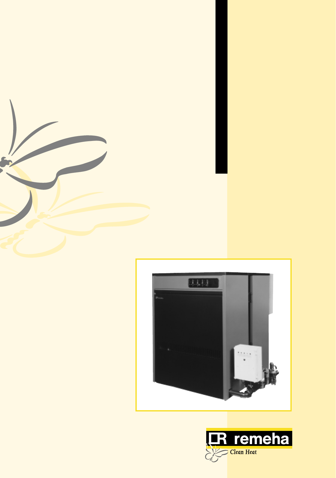
1
Remeha Gas 5c / 5c Duo
• Atmospheric gas boiler
• 278 - 1058 kW
Technical information
Remeha Gas 5c/5c Duo

Remeha
Gas 5c / 5c Duo
2
CONTENTS
7. Assembly and installation guidelines 11
7.1 General 11
7.2 Boiler assembly 11
7.3 Water connections 11
7.4 Pocket for the instrument panel 11
7.5 Water pressure 11
8. Gas supply 11
8.1 General 11
8.2 Gas pressure 11
9. Electrical supply 12
9.1 General 12
9.2 Control panel 12
9.3 Electrical connections 12
9.4 Electrical information 12
9.5 Water level control (lock out) 12
9.6 Wiring diagram for the instrument panel 12
9.6.1 Simple instrument panel 12
9.6.2 Complete instrument panel 13
9.7 Wiring diagram boiler 14
10. Commissioning 15
10.1 Technical information 15
10.2 Commissioning 15
10.3 Switching off the boiler 15
11. Maintenance 15
11.1 General 15
11.2 Maintenance 15
Preface 3
1. Boiler description 3
2. Construction details 3
2.1 General 3
2.2 Burners 3
2.3 Boiler fl oor 3
2.4 Assembly 3
3. Technical data and dimensions 4
3.1 Dimensions Remeha Gas 5c 4
3.2 Dimensions Remeha Gas 5c Duo 5
4. Application information 6
4.1 L.P.H.W. system 6
4.1.1 Water temperature 6
4.1.2 Water pressure 6
4.1.3 Water fl ow 6
4.1.4 Water treatment 6
4.1.5 Noise level 6
4.2 Chimneys 6
4.3 Installation standards 6
5. Typical boiler installations 7
6. Control and safety equipment 9
6.1 General 9
6.2 Instrument panel 9
6.3 Standard electronic gas train High/Low 10
6.3.1 Schematic 10
6.3.2 Specifi cation 10
6.3.3 Control panel on gas train 10
6.4 Functions 10
6.4.1 Flame protection 10
6.4.2 Down draught thermostat 10
6.4.3 Thermostats 10

3
PREFACE
If you have any questions, or if you need more informa-
tion about specifi c subjects relating to this boiler, please
do not hesitate to contact us.
The data published in these technical instructions is
based on the latest information and is subject to revisi-
ons.
We reserve the right to modify the design and/or confi-
guration of our products at any moment without being
obliged to adjust earlier supplies accordingly.
1. BOILER DESCRIPTION
Classifi cation type for evacuation of the combustion pro-
ducts: B11 BS.
For further advice or information contact Broag Ltd.
The Remeha Gas 5c is supplied with electronic junction
with insulated casings.
Water connections Ø 107 mm int.
2. CONSTRUCTION DETAILS
2.2 Burners
The burners are stainless steel, atmospheric type. They
guarantee a low noise level.
2.3 Boiler fl oor
The Remeha Gas 5c boiler is supplied with a refl ecting
fl oor plate with ventilation underneath.
2.4 Assembly
The boiler will be assembled on site.
These technical instructions contain useful and important
information for the correct operation and maintenance of
the Remeha central heating boiler, model Gas 5c/5c Duo.
Furthermore, important instructions are given to prevent
accidents and serious damage before commissioning
and during operation of the boiler, to ensure safe and
trouble free boiler operation.
Read these instructions carefully before putting the boiler
into operation, familiarize yourself with its operation and
control and strictly observe the instructions given.
The Remeha Gas 5c boiler is a cast iron sectional boiler
with atmospheric burners.
Suitable for all qualities of natural gas, cat. I 2 H (20 mbar).
The boiler meets the requirements of the CE regulations
at the following directives:
- Gas appliance directive no. 90/396/EEC
- Electrical low voltage directive no. 73/23/EEC
- Machinery directive no. 89/392/EEC
- E.M.C. directive no. 89/336/EEC
- Effi ciency directive no. 92/42/EEC.
2.1 General
- Boiler block of cast iron sections joined together with
conical nipples.
- Gas train can be fi tted on the left hand or right hand
side of the boiler.
- Water connections can be fi tted on the left hand side
or right hand side of the boiler. The gas train should
if possible always be fi tted on the same side as the
fl ow connection. If required it can be fi tted opposite
(extension cables can be provided on request).
- The casings can be fi tted after the boilers have been
installed.
- Control panel is fi tted in the front casing.
- Cleaning of the cast iron block from top of the boiler.
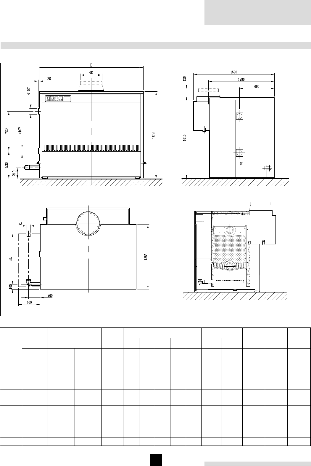
Remeha
Gas 5c / 5c Duo
4
3. TECHNICAL DATA AND DIMENSIONS
Left hand side view
Front view
int.
int.
Top view Cross section
Fig. 01 Dimensions Remeha Gas 5c
1450
1575
1695
1820
1940
2065
2185
2430
2675
2920
3165
Boiler
weight
Number
of
sections
10
11
12
13
14
15
16
18
20
22
24
kg
139 - 278
155 - 310
170 - 340
186 - 372
202 - 403
217 - 434
233 - 466
265 - 529
296 - 592
328 - 656
360 - 720
Nom. heat
output
kW
155 - 309
173 - 345
189 - 378
207 - 414
224 - 448
241 - 482
259 - 518
294 - 588
329 - 657
364 - 728
400 - 799
172 - 343
192 - 383
210 - 420
230 - 460
249 - 498
268 - 535
288 - 576
327 - 653
365 - 730
404 - 809
444 - 888
Nom. heat
input
kW-NCV kW-GCV
2
2
2
2
2
2
2
2
2
21/2
21/2
Ø d
B
Dimensions
mm
1240
1350
1460
1570
1680
1790
1900
2120
2340
2560
2780
Ø D
mm
300 *
350 *
350 *
400 *
400 *
400 *
450 *
450 *
500 *
500 *
500 *
± L
mm
850
850
850
850
850
850
850
985
985
1170
1170
Table 1 Technical data Remeha Gas 5c
"
154
152
150
148
146
142
138
138
142
142
142
Flue
temp.
°C
64
68
72
76
80
84
128
160
180
196
208
mbar
t= 10°C
Water resistence
16
17
18
19
20
21
32
40
45
49
52
mbar
t= 20°C
291
320
349
378
407
436
465
523
581
639
697
Water
contents
litre
33
37
40
44
47
51
55
62
70
77
85
Gas
con-
sumption
m3/h
692
795
847
983
1033
1080
1239
1376
1560
1678
1842
Flue gas
flow rate
kg/h
* Supplied with a flue gas pipe adaptor
3.1 Dimensions Remeha Gas 5c
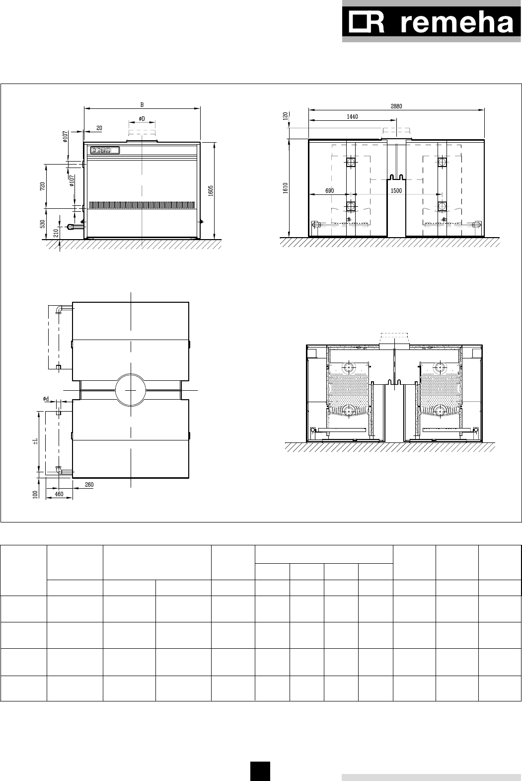
5
172 - 686
192 - 766
210 - 840
230 - 920
249 - 996
268 - 1070
288 - 1152
327 - 1306
3.2 Dimensions Remeha Gas 5c Duo
Left hand side view
Front view
Cross section
Top view
int.
int.
Fig. 02 Dimensions Remeha Gas 5c Duo
2 x 10
2 x 11
2 x 12
2 x 13
2 x 14
2 x 15
2 x 16
2 x 18
139 - 556
155 - 620
170 - 680
186 - 744
202 - 806
217 - 868
233 - 932
265 - 1058
582
640
698
756
814
872
930
1046
Number
of
sections
Nom. heat
input
Nom. heat
output
155 - 618
173 - 690
189 - 756
207 - 828
224 - 896
241 - 964
259 - 1036
294 - 1176
kW kW-NCV kW-GCV
Dimensions
mm
± L
kg
2900
3150
3390
3640
3880
4130
4370
4620
Boiler
weight
litre
Table 2 Technical data Remeha Gas 5c Duo
Water
contents
1385
1590
1694
1966
2066
2160
2478
2752
m3/h
66
74
80
88
94
102
110
124
Gas
consump-
tion
kg/h
Flue gas
flow rate
850
850
850
850
850
850
850
985
B
mm
1240
1350
1460
1570
1680
1790
1900
2120
ØD
mm
450 *
500 *
500 *
600 *
600 *
600 *
650 *
650 *
2
2
2
2
2
2
2
2
"
Ød
* Supplied with a flue gas pipe adaptor

Remeha
Gas 5c / 5c Duo
6
4. APPLICATION INFORMATION
4.2 Chimneys
The average fl ue gas temperature is so low that the
chimney must be made in accordance with the guide-
lines of British Gas (BS 6644).
4.3 Installation standards
The following instructions must be adhered to when the
Remeha Gas 5c / 5c Duo is installed:
Gas Safety (installation and use) Regulations 1984 (as
amended).
All gas appliances must, by law, be installed by compe-
tent persons (e.g. Corgi) in accordance with the above
regulations. Failure to install appliances correctly could
lead to prosecution.
It is in your own interest and that of safety to ensure that
the law is complied with.
In addition to the above regulations, this appliance must
be installed in compliance with the current I.E.E. Regu-
lations for electrical installation, local building regulati-
ons, the Building Standards (Scotland), (Consolidation)
Regulations and by laws of the local water undertaking
and Health and Safety Document No 635 'The Electricity
at Work Regulations 1989'. It should also be in accor-
dance with the relevant recommendations in the current
editions of the following British Standards and Codes of
Practice, viz.
BS 5440 Pt 1 and 2, BS 5449, BS 5546, BS 6798, BS
6891 and BG.DM2.
Important:
The Remeha Gas 5c / 5c Duo is a certified appliance
and must not be modified or installed in any way con-
trary to these 'Installation and Servicing Instructions'.
Manufacturers instructions must NOT be taken in any
way as overriding statutory obligations.
= m3/h
4.1 L.P.H.W. system
4.1.1 Water temperature
Maximum water temperature is 110°C (high limit ther-
mostat). Highest boiler water temperature is 95°C (con-
trol thermostat). Minimum return water temperature is
20°C at a fl owrate related to a t of 20°C (fl ow/return
temp).
4.1.2 Water pressure
Boiler sections pressure tested at 10 bar.
Maximum pressure test boiler block is 7,8 bar.
Minimum working pressure boiler is 0,8 bar.
Maximum working pressure bar is 6 bar.
4.1.3 Water fl ow
The minimum water fl ow through the boiler is:
Output boiler in kW
93
This minimum fl ow must be maintained for approx. 5
minutes after the burner stops fi ring to avoid high tempe-
rature shut down due to residual heat gain.
Due to the design and manufacture of the boiler no
specifi c minimum water fl ow requirements exist other
then for overtemperature propection.
4.1.4 Water treatment
Water treatment is under normal circumstances not
necessary (see our water quality recommendations)
4.1.5 Noise level
The noise level measured around the boiler depending
on boiler room construction is about 50-55 dBA. Noise
levels taken at 1 meter from the boiler.
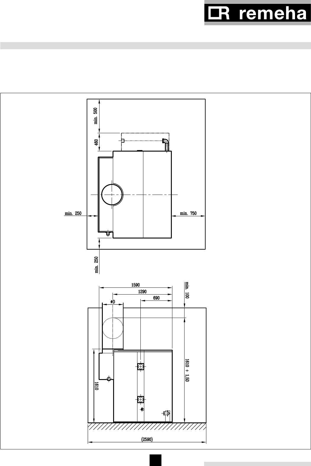
7
5. TYPICAL BOILER INSTALLATIONS
Recommended layout for boiler installation, measure-
ments in mm.
Installation 1
Remeha Gas 5c
Fig. 03 Boiler installation Remeha Gas 5c
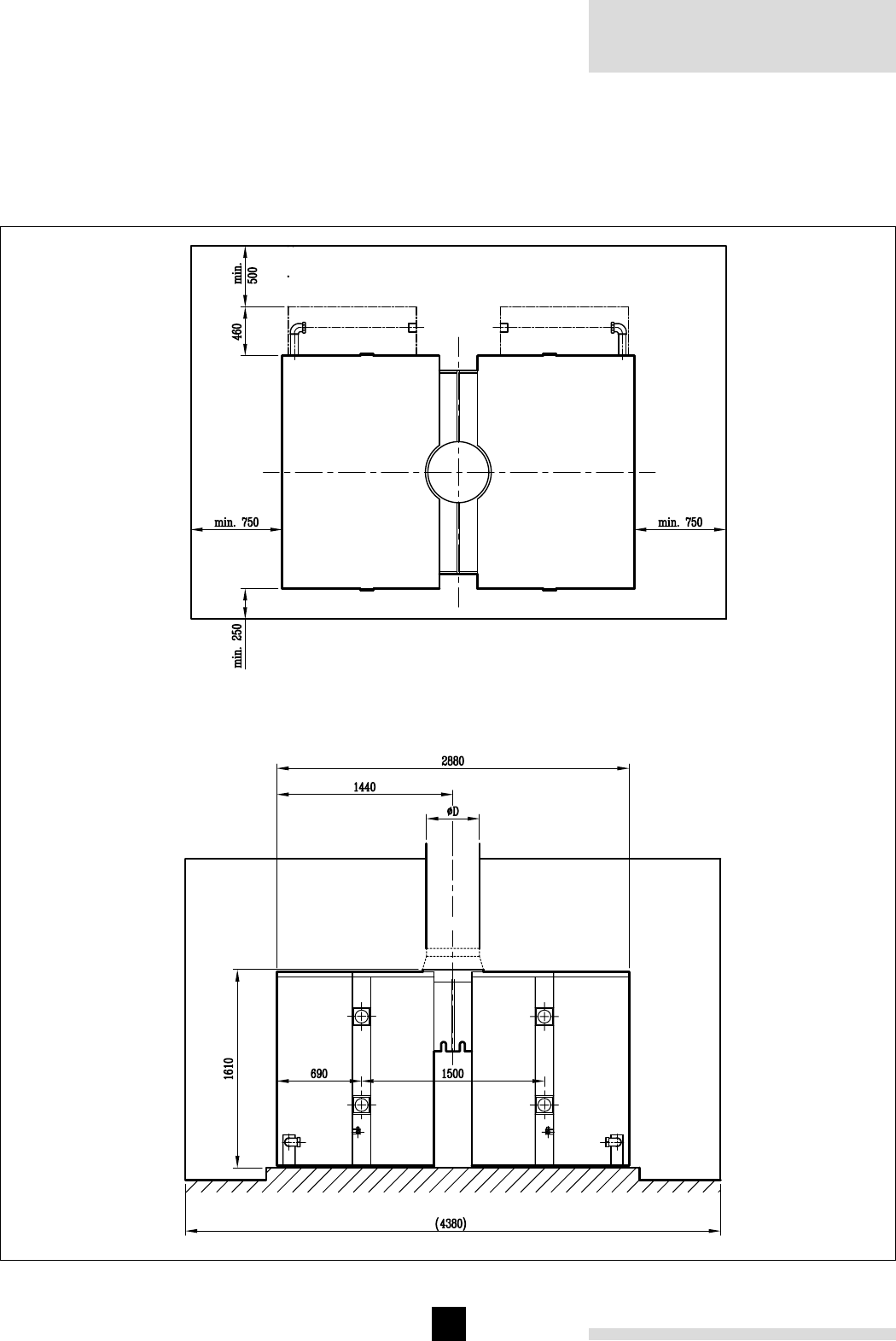
Remeha
Gas 5c / 5c Duo
8
Recommended layout for boiler installation, measure-
ments in mm.
Fig. 04 Boiler installation Remeha Gas 5c Duo
Installation 2
Remeha Gas 5c Duo

9
The modules contain:
Module A
1. Control thermostat,
setting between 35°C-95°C.
2. Hour run meter *.
Module B
3. High-Low thermostat,
setting between 35°C-95°C.
4. Hour run meter *.
Module C
5. High-limit thermostat 110°C (lock out).
6. Operating switch (On/Off with optical display) *.
7. Switch for domestic hot water storage pump *
Manual/Off/Automatic.
8. Switch for circulating pump *
Manual/Off/Automatic.
Module D
9. Warning light *.
10. Analog thermometer water temperature.
Module E
11. Option for rematic weather compensated boiler.
control *.
* Absent in simple instrument panel.
Fig. 5 Complete instrument panel
6.1 General
The Remeha Gas 5c is supplied with electronic control
and safety equipment with ionisation fl ame detection.
6.2 Instrument panel
The Remeha Gas 5c is supplied with an instrument
panel that is fi tted in the front of the boiler, either left or
right. The instrument panel can be delivered in two models:
- simple instrument panel High /Low;
- complete instrument panel High /Low.
The boiler is supplied as standard with the simple in stru-
ment panel. All connections are pre-wired and fi tted with
plugs. The capillaries from the control panel should be
fi tted in the pocket of the boiler, which is fi tted in the top
front of the end section.
The instrument panel, pocket and fl ow connection
should always be fi tted on the same side of the
boi-ler either left or right. If this is not possible
extension cables are available on request.
1
2
3
4
5
67
89
ABCDE
10
11
6. CONTROL AND SAFETY EQUIPMENT
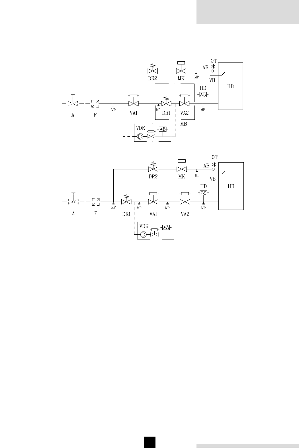
Remeha
Gas 5c / 5c Duo
10
18 - 24 sections
10 - 16 sections
Fig. 06 Schematic construction gas train
6.3.2 Specifi cation
2 Safety gas valves
1 Gas governor
1 Pilot gas valve
1 Pilot gas governor
1 Ignition transformer 5 kV
1 Pilot burner with ionisation probe
1 Down draught thermostat set at 70°C
Legend
A Gas cock
AB Pilot burner
DR Gas governor
F Gas fi lter
HB Burners
HD Gas pressure switch
MK Pilot gas valve
MP Measuring point
VA Safety shut off valve
OT Ignition transformer
VB Ionisation probe
MB Gas multibloc
VDK Valve leakage control box (option)
- - - Not supplied as standard
6.3.3 Control panel on gas train
1 Main switch
1 Control box Satronic
1 Fuse (Brusk)
Signal lamps
1 Water level control
6.4 Functions
6.4.1 Flame protection
Flame protection by means of ionisation flame detection.
6.4.2 Down draught thermostat
Type B11 Bs.
The boiler is fitted with a thermo-down draught ther-
mostat. When there is down draught of the flue gases
this thermostat will switch off the boiler. Fixed set point is
70°C (automatic reset).
6.4.3 Thermostats
Control thermostat On/Off 35°C-95°C.
Control thermostat High/Low 35°C-95°C.
High Limit thermostat lock out at 110°C.
6.3 Standard electronic gas train High/Low
6.3.1 Schematic

11
7. ASSEMBLY AND INSTALLATION GUIDELINES
7.4 Pocket for the instrument panel
The pocket should be fi tted in the top front end section
of the boiler and at that side of the boiler where the
gas train is fi tted. In the other end section tapping 1" the
water level control electrode should be fi tted.
7.5 Water pressure
Each section is hydraulically tested to at least 10 bar.
Maximum test pressure for the assembled boiler block is
7,8 bar. Operating pressure between 0.8 bar and 6 bar.
8. GAS SUPPLY
8.2 Gas pressure
Cat. I 2 H.
Maximum gas pressure at inlet 100 mbar.
Burner pressure :
- full load : 8.4 mbar (100%)
- part load : 2.2 mbar ( 50%).
Min. gas inlet pressure 20 mbar.
8.1 General
The gas train can be fi tted on the left or right hand side
of the boiler and on the same side of the boiler in stru-
ment panel (fi tted in the front casing).
The local Gas authority should be consulted to ensure
that an adequate pressure and supply is available at the
boilers maximum output. To minimise risk of sediment or
foreign particles entering the control valves, an approved
fi lter may be fi tted into the pipework downstream. The
gas supply should be conform to the British Gas safety
regulations.
7.1 General
The boiler is suitable for operating at a maximum working
pressure of 6 bar and a minimum pressure of 0.8 bar.
Boiler can be installated in open or closed systems.
7.2 Boiler assembly
Broag provides special tools on loan, for the boiler
assembly with detailed building instructions. However,
building supervision and/or actual boiler erection ser vi ces
can be provided by Broag or an approved boiler erection
engineer.
7.3 Water connections
The boiler water connections can be fi tted on one side
of the boiler either left or right hand side. The water con-
nection is fl anged on the boiler with a pipe connection for
welding Ø 107 mm (int.) to the installation.
The top blind-fl ange has an integral cast 1" tapping to
accept a safety valve. The end sections have a 3/4 "
tapping to accept a drain/off cock (tapping BSP).
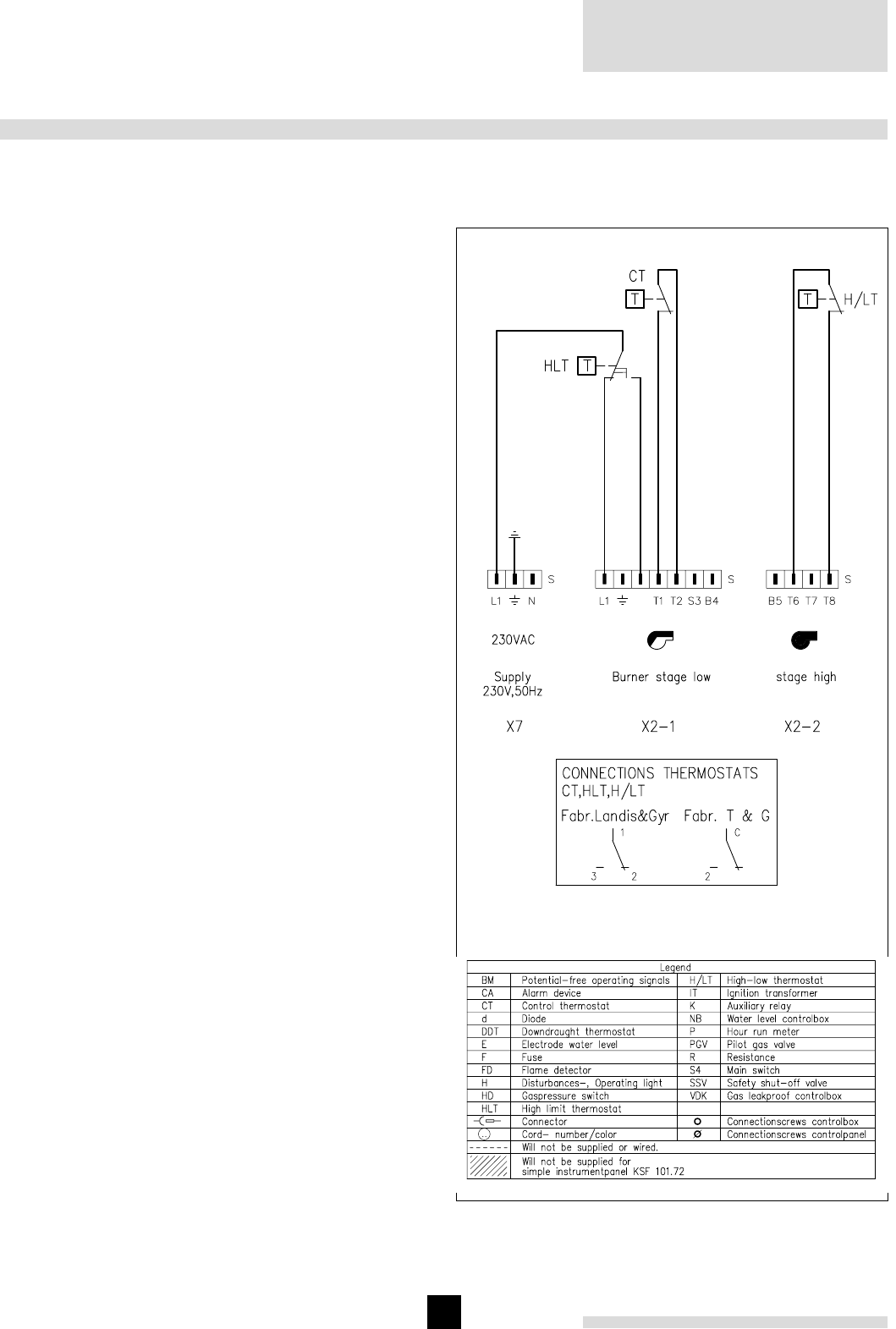
Remeha
Gas 5c / 5c Duo
12
9. ELECTRICAL SUPPLY
9.6 Wiring diagram for the instrument panel
9.6.1 Simple instrument panel
Fig. 07 Scheme simple instrument panel
9.1 General
The electrical installation must conform to the IEE regula-
tions and also to local authority requirements.
9.2 Control panel
A control panel is fi tted on the gas train.
9.3 Electrical connections
The boiler is pre-wired. Only the main supply should be
wired to this control panel.
9.4 Electrical information
Main supply : 230 V-50 Hz (L/N)
Running current : 120 W
Maximum fuse : 6 Amp.
9.5 Water level control (lock out)
a. Water level control : Dungs DWEB 34/2
Main supply : 230V-50 Hz
Running current : 5 W
Electrode current : 42 V (AC)
Working area : 0.5 to 15 mA (AC)
Electrode resistance : max. 20 kOhm
min. 1 kOhm.
b. Electrode : Dungs FLE 1/2"
To be fi tted in one of the end sections (see par. 7.4).
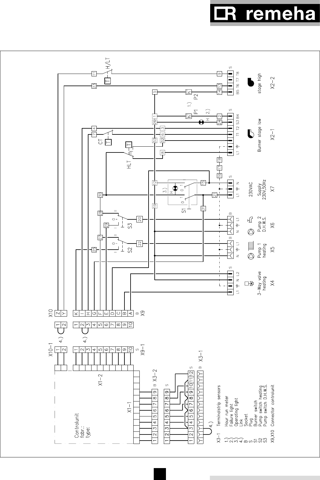
13
9.6.2 Complete instrument panel
Fig. 08 Scheme complete instrument panel
For legend see page 12
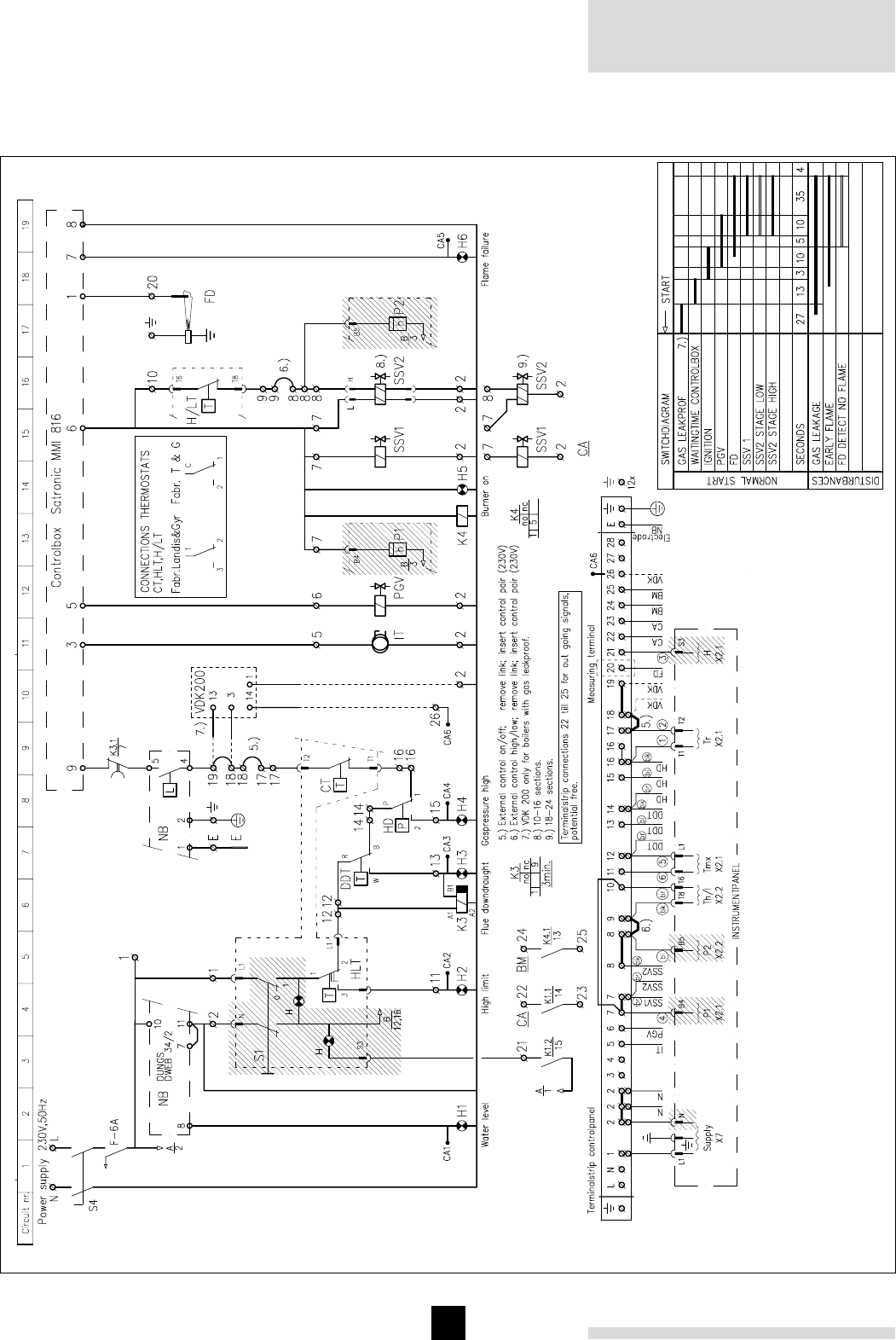
Remeha
Gas 5c / 5c Duo
14
9.7 Wiring diagram boiler
Fig. 09 Wiring diagram boiler
For legend see page 12

15
10.1 Technical information
Control box: Satronic MMI 816
Main supply: 230 V - 50 Hz
Minimum ionisation current: min 3 µA (DC).
Reaction time fl ame protection: 1 sec.
Safety time: 10 sec.
Maximum ambient temperature: 60°C
Injector size pilot burner: Ø 0.8 mm
Injector size main burner: Ø 5.4 mm
Burner pressure full load: 8.4 mbar (100%)
Burner pressure part load: 2.2 mbar (50%)
Burner pressure pilot burner: 13 mbar
Warning
Control box operates on a neutral/phase supply.
10.2 Commissioning
1. Check gas connections.
2. Check electrical supply (L/N and earth).
3. Check water connections and if installation is fi lled.
4. Switch on circulation pump and check rotation direc-
tion.
5. Open main gas cock (release air in gas pipe work).
6. Switch on electrical supply.
7. Set thermostats at about 85°C.
The following will happen:
8. After a waiting time of about 13 seconds you will
get ignition. At a minimum ionisation current of 7
µA the ignition stops. The main gas valve will open.
The boiler runs.
9. Let the boiler run for a couple of minutes to get rid
of air in the gas pipe.
10. Set the correct burner pressure.
11. Check the thermostats for the correct setting.
12. Check the fl ame protection, start the boiler with the
ionisation probe disconnected.
13. Check the water level control.
10.3 Switching off the boiler
1. Switch off the electric supply.
2. Shut off the gas cock.
Be aware of the possibility of the danger of frost.
Note:
Commissioning to only be carried out by a qualifi ed engi-
neer with the relevant training and certifi cation i.e. Acops
- Corgi and a commissioning data sheet completed on site
for issue to owner
11.1 General
It is essential for a good combustion, to clean the boiler,
the gas train and boiler room once a year. This prevents
dust from being aspired and fouling the burners and boi-
ler during operation, thereby avoiding poor combustion
and possibly build-up of soot deposits.
11.2 Maintenance
1. Clean the internal fl ue ways of the boiler. Remove
front casing and cleaning hatches, and remove the
burners.
2. Clean the burners internally and externally.
3. Clean the fl oor underneath the boiler and boiler
room.
4. Clean boiler casings.
5. Clean the gas train, ignition, pilot burner, ther
mostats and wiring.
6. Check start program, ignition time and safety times.
7. Check fl ame protection, and thermostats.
8. Check boiler input at 100% and 50% load.
9. Make a combustion effi ciency calculation.
10. Check the boiler and installation for water leakage
(seals).
11. Check gas train and gas pipe for gas leaks.
11. MAINTENANCE
10. COMMISSIONING

Remeha
Gas 5c / 5c Duo
16
16
Subject to alterations
44430/1.000/11,00/Bo.
Remeha Gas 5c/5c Duo
Broag Ltd.
Head office
Remeha house,
Molly Millars Lane,
Wokingham,
Berkshire RG41 2QP.
Tel. 0118 9783434
Fax 0118 9786977
Email: boilers@broag-remeha.com
Branch office
Unit 3, Kestrel Close,
Quarry Hill Ind. Estate,
Ilkeston
Derbyshire DE7 4RD
Tel. 0115 9440778
Fax 0115 9440588
© Copyright
All technical and technological information contained in these
technical instructions, as well as any drawings and technical des-
criptions furnished by us remain our property and shall not be
multiplied without our prior consent in writing.
Ours is a policy of continuous development. We reserve the right to
alter specifications without prior notification.