Atwood Installation Maintenance
User Manual: Atwood-installation-maintenance
Open the PDF directly: View PDF ![]() .
.
Page Count: 9
1
This water heater design has been certified by the Canadian
Standards Association for installation in recreation vehicles. This
water heater is not for use in marine applications.
SERVICE CALLS & QUESTIONS
Location and phone numbers of qualified Service Centers can
be found at our website http:/www.atwoodmobile.com or call
574-264-2131 to have a Service Center List mailed.
SAFETY ALERT SYMBOLS
Safety Symbols alerting you to potential personal safety hazards.
Obey all safety messages following these symbols.
WARNING CAUTION
avoid possible avoid possible
injury or death injury and/or property damage
Installation and service must be performed by a qualified Service
Technician, Service Center, OEM or Gas Supplier.
WATER HEATER MODEL IDENTIFICATION ............................................1
DIMENSIONS ..........................................................1
WEIGHT ................................................................1
SAFETY INFORMATION..................................................................2-4
Water Heater GENERAL INSTALLATION ..............................................2-3
Electronic Ignition wiring installation
Pilot Relight wiring installation
Heat Exchanger
Combination Gas/Electric
Water Heater PILOT OPERATION......................................................3-4
Electronic Ignition
Pilot Relight
Combination Gas/Electric
Water Heater MAINTENANCE ..........................................................4-5
Electronic Ignition
Electric
FIGURES 1-11 ............................................................................6
WIRING DIAGRAMS ........................................................................7
PART IDENTIFICATION ..................................................................8-9
Water Heater WARRANTY ..............................................................16
EXPLANATION OF MODEL NUMBER (EXAMPLE)
G C H 6 AA - 8 E/P
Electronic Ignition or Pilot Relight
Revision (NUMBER)
Heating Element (SCREW-IN OR BOLT-ON)
4 - 6 - 10 gallon capacity
Engine Heat Exchange
Combination Gas and AC Electric
Gas (PROPANE)
- IF YOUR MODEL NUMBER IS NOT LISTED-
Older revision numbers may be 3, 4, 6, 7, 8 or 9 (_ _ _ _ _ - X _)
Regardless of your revision number the current instructions are still generally
applicable to your unit. If you have questions contact your dealer, an Atwood
Service Center or the Atwood Service Department.
MODEL NUMBER CLARIFICATION
TYPE 4GAL 6GAL 10 GAL
Pilot Ignition G4-7 G6A-7 GC6AA-8P G10-2 GC10A-2
GC6AA-8 GH6-7 G10-2P GC10A-2P
Electronic Ignition G6A-8E GCH6A-9E G10-3E GCH10A-3E
GC6AA-9E GH6-8E GC10A-3E GH10-3E
Pilot Relight P IN MODEL # - SEE MODEL CLARIFICATION ABOVE
Heat Exchange H IN MODEL # - SEE MODEL CLARIFICATION ABOVE
Electronic Ignition E IN MODEL # - SEE MODEL CLARIFICATION ABOVE
Combination Gas/Electric C IN MODEL # - SEE MODEL CLARIFICATION ABOVE
DIMENSIONS SHIPPING WT.
ALL MODEL WIDTH HEIGHT
6 GALLON 16˝ 12.5˝ 6 GALLON 25 lbs
10 GALLON 16˝ 15.5˝ 10 GALLON 32 lbs
ENGLISH, FRANCAIS (et Canada) •Installation •Operation •Maintenance
Effective 11/19/07
LITERATURE NUMBER MPD 93756
L.P. GAS
WATER HEATER
4 - 6 - 10 GALLON
9
WARNING
FIRE OR EXPLOSION
• If the information in this manual is not followed
exactly, a fire or explosion may result causing
property damage, personal injury or loss of life.
➤Do not store or use gasoline or other flammable vapors and
liquids in the vicinity of this or any other appliance.
WHAT TO DO IF YOU SMELL GAS
• Evacuate ALL persons from vehicle.
• Shut off gas supply at gas container or source.
• DO NOT touch any electrical switch, or use any phone or
radio in vehicle.
• DO NOT start vehicle’s engine or electric generator.
• Contact nearest gas supplier or qualified Service Technician
for repairs.
• If you cannot reach a gas supplier or qualified Service
Technician, contact the nearest fire department.
• DO NOT turn on gas supply until gas leak(s) has been
repaired.
http://waterheatertimer.org/Atwood-water-heater-resources.html

2
CRITICAL INSTALLATION WARNINGS
• Install in recreation vehicles only. RV’s are recreation vehicles
designed as temporary living quarters for recreation, camping, or
travel use having their own power or towed by another vehicle.
• All combustion air must be supplied from outside the RV, and all
products of combustion must be vented to outside the RV.
• DO NOT vent water heater with venting system serving another appli-
ance.
• DO NOT vent water heater to an outside enclosed porch area.
• Protect building materials from flue gas exhaust.
• Install water heater on an exterior wall, with access door opening to
outdoors.
• DO NOT modify water heater in any way.
• DO NOT alter water heater for a positive grounding system.
• DO NOT HI-POT water heater unless electronic ignition system (cir-
cuit board) has been disconnected.
• DO NOT use battery charger to supply power to water heater even
when testing.
USA AND CANADA - FOLLOW ALL APPLICABLE STATE AND LOCAL CODES -
IN THE ABSENCE OF LOCAL CODES OR REGULATIONS, REFER TO CURRENT STANDARDS OF:
• Recreation Vehicles ANSI A119.2/NFPA 501C.
• National Fuel Gas Code ANSI Z223.1 and/or CAN/CGA B149 Installation
Codes
• Federal Mobile Home Construction & Safety Standard, Title 24 CFR, part
3280, or when this Standard is not applicable, the Standard for Manufactured
Home Installations (Manufactured Home Sites, Communities and Set-Ups),
ANSI A255.1 and/or CAN/CSA-Z240 MH Series, Mobile Homes.
• National Electrical Code ANSI/NFPA No. 70 and/or CSA C22.1
• Park Trailers A119.5
• CSA standard Z240 RV Series, Recreational Vehicle.
GENERAL INSTALLATION
Below is the most common type of installation for the water heater.
However, there are other approved methods such as baggage com-
partment (refer to MPD 90093) and flush mounting installations (refer
to MPD 93948). Consult your Field Auditor, Account Manager, or the
Atwood Service Department if you have additional questions.
1. Locate water heater on floor of coach before erecting side walls.
The water heater tank must be permanently supported at the same
level as the bottom of sidewall cutout (by the floor or a raised floor).
2. To install water heater on carpeting, you must install appliance on a
metal or wood panel that extends at least three inches beyond the
full width and depth of appliance.
3. If water heater is installed where leakage of connections or tank will
damage adjacent area, install a drain pan which can be drained to
out side of coach, under water heater.
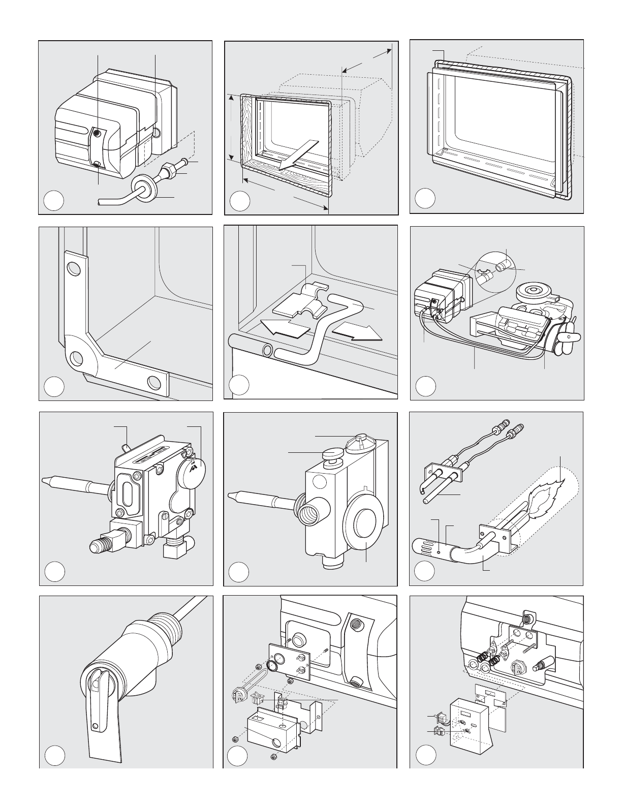
4. Connect both 1/2˝ NPT water lines - hot water outlet female
(FIG 1-A) and cold water inlet female (FIG 1-B) and 3/8˝ flared LP gas
lines (FIG 1-C).
a. Allow flexibility in water and gas lines so you can pull unit for-
ward through wall one inch past skin (FIG 2.
b. Seal gas line entrance opening by sliding grommet (FIG 1-D) onto
3/8˝ tubing (FIG 1-F) before flaring tubing (FIG 1-F). Pull gas line
and grommet through opening in housing (FIG 1-C). Connect flare
fitting (FIG 1-E) and press grommet into opening. If gas line tubing
is already flared, cut grommet on one side. Place split grommet
over gas line and press it into opening.
c. Always use pipe lubricant on threads when connecting hot and
cold water couplings. A suitable plastic fitting is recommended.
CAUTION
PRODUCT DAMAGE
• Do not lift, pull or push main burner tube (FIG 9-C).
5. Erect side walls and cut opening. See chart and FIG 2-A & B.
Frame with 2x2 lumber (or equivalent).
CUTOUT
CAPACITY CUT OUT DIMENSION DEPTH
Gallon A B C
4 - 6 12-5/8˝ 16-1/4˝ 17-5/8˝
10 15-3/4˝ 16-1/4˝ 20-5/8˝
MINIMUM CLEARANCE FROM COMBUSTIBLE CONSTRUCTION
Sides: 0˝ Top: 0˝
Back: 0˝ Bottom: 0˝
6. Bend all flanges 90˚ along scored lines (FIG 3).
7. To prevent water leaks caulk thoroughly around opening, including
bend slots (FIG 3-A). Butyl Tape (1˝x1/8˝) may be substituted for
caulking material.
8. Push unit against caulking, secure 4-corner brackets FIG 4-A to
coach with No.8 - 3/4˝ round head screws (not furnished) or equivalent.
Complete the installation by inserting the same type of #8 screws in the
holes provided around the flange of the water heater housing. Check all
gaskets, they must adhere to the pan creating an air tight seal.
9. Attach access door (FIG 5).
a. Snap hinge pin (FIG 5-A) into clip (FIG 5-B).
b. Slide cover (FIG 5-C) onto hinge pin.
c. Slide hinge pin into cover, snapping into clip at same time (FIG 5-D).
NOTE: To remove hinge pin, support access cover and apply force to
corner of hinge pin as shown FIG 5-E.
10. Disconnect unit and its individual shut-off valve from gas supply
line during any pressure testing of system in excess of 1/2 PSIG
(3.4 kPa, 14˝ water column [W.C.]). DO NOT set inlet pressure higher
than maximum indicated on rating plate of gas valve (13˝ W.C.).
Isolate unit from gas supply line by closing its individual manual
shutoff valve during any pressure testing ≤1/2 psig.
WARNING
FIRE AND/OR EXPLOSION
• DO NOT use matches, candles or other sources of ignition when
checking for gas leaks.
11. Turn on gas and check water heater and all connections for gas
leaks with leak detecting solution.
12. Fill water heater tank, check all connections for water leaks (FIG 1-
A & B).
PRESSURE-TEMPERATURE RELIEF VALVE - (FIG 10)
WARNING
SCALDING INJURY
•Valve is not serviceable, it must be replaced.
•Tampering with valve will result in scalding injury.
•Tampering with valve will void warranty.
WARNING
EXPLOSION
• DO NOT place a valve, plug or reducing coupling on outlet part of
pressure temperature relief valve.
THIS VALVE IS A SAFETY COMPONENT AND MUST NOT BE REMOVED FOR ANY REASON
OTHER THAN REPLACEMENT. This water heater is equipped with a tempera-
ture and pressure relief valve that complies with standard for Relief
Valves and Automatic Gas Shutoff Devices for Hot Water Systems,
ANSI Z21.22.
If you use a discharge line, do not use a reducing coupling or other
restriction smaller than outlet of relief valve. Allow complete drainage
of both valve and line.
FOR REPLACEMENT PARTS:
• DO NOT install anything less than a combination temperature-pressure
relief valve certified by a nationally recognized testing laboratory that
maintains periodic inspection of product of listed equipment or materi-
als, as meeting requirements for Relief Valves and Automatic Gas
Shutoff Devices for Hot Water Supply Systems, ANSI Z21.22. Valve
must have a maximum set pressure not to exceed 150 psi.
• Install valve into opening provided and marked for this purpose on
water heater.
• Installation must conform with local codes or in the absence of local
codes, American National Standard for Recreational Vehicles, ANSI
A119.2/NFPA 50IC.

• For an external electrical source, ground this unit in accordance with
National Electrical Code ANSI/NFPA70.
Your Atwood gas water heater is now ready for operation. Continue to
HOW TO OPERATE YOUR WATER HEATER.
Electronic Ignition continue to Electronic Ignition WIRING INSTRUCTIONS.
Pilot Relight continue to Pilot Relight WIRING INSTRUCTIONS.
For HEAT EXCHANGE continue —
1. Push 5/8˝ dia. 2 or 3 coolant system hose with SAE 053 A Type
“E”clamp attached (FIG 6-E) onto heat exchange tube as far as possi-
ble (FIG 6-B).
2. Spread hose clamp and slide toward heat exchange unit past annular
groove (FIG 6-C) and release.
3. Continue to HOW TO OPERATE YOUR WATER HEATER and/or Electronic
Ignition OPERATION.
For COMBINATION GAS/ELECTRIC MODELS continue —
This water heater is designed to operate with gas, electricity, or a com-
bination of both.
Provide adequate clearance at rear of unit for service of water connec-
tions and operation of manually re-setable high temperature limit switch
on combination gas/electric units.
1. Follow GENERAL INSTALLATION instructions.
NOTE: All wiring must comply with applicable electrical codes.
CAUTION
PRODUCT DAMAGE
• When using Romex®with a bare earth ground, take care to position
ground wire so it does not contact the heating element terminals.
• Use electrical metallic tubing, flexible metal conduit, metal clad cable,
or nonmetallic-sheathed cable with grounding conductor. Wire must
have a capacity of 1500 watts or greater. The wiring method must
conform to applicable sections of article 551 of National Electrical
Code ANSI/NFPA 70.
2. Refer to Wiring Diagram. Make 120 VAC electrical connections from
junction box on back of unit.
a. Connect hot lead to (1) Black.
b. Connect common lead to (2) White.
c. Connect ground wire from electrical service to (3) green ground
lead in junction box 3. Place switch in “OFF” position.
• When a cord and plug connection to the power supply are used on
water heater, power cord must be UL listed as suitable for damp loca-
tions, hard or extra hard usage. It must be a flexible cord such as type
S, SO, ST, STO, SJ, SJT, SJTO, HS or HSO cord as described in
National Electrical Code, ANSI/NFPA 70. The length of external cord to
water heater, measured to face of attachment plug, shall be no less
than 2 feet nor more than 6 feet. Supply cord must be a minimum of
14 AWG and attachment plug must be rated at 15 amps.
CAUTION
ELECTRICAL DAMAGE
• Label all wires before disconnecting when servicing controls.
• Verify proper operation after servicing.
Operation using gas continue to HOW TO OPERATE YOUR WATER HEATER,
electrically continue to COMBINATION Gas/Electric OPERATION.
ELECTRONIC IGNITION - WIRING INSTRUCTIONS
1. Install unit according to GENERAL INSTALLATION instructions.
NOTE: It is recommended unit be connected directly to a 12V DC battery
or to filtered side of an AC/DC converter. Avoid connections to
unfiltered side of an AC/DC converter whenever possible. Use a
minimum of 18 gauge wire, UL and CSA listed.
Refer to WIRING DIAGRAM. Install remote switch in a convenient loca-
tion. Position wall plate with letters up. Before making connections
turn switch OFF. The switch is off when the button is depressed
towards terminal see wiring diagram.
2. Installing wires:
a. blue lead to switch terminal (6) on indicator light of switch
b. terminal (4) on indicator light of switch to negative battery terminal
c. green lead to negative battery terminal
d. brown lead on water heater to terminal (3) on switch
e. terminal 2 on switch to positive battery terminal.
3. Read ELECTRONIC IGNITION OPERATION.
PILOT RELIGHT - WIRING INSTRUCTION
1. Install unit according to GENERAL INSTALLATION instructions.
2. Refer to Wiring Diagram. Use 18 gauge wire, UL/CSA listed.
3. Read PILOT & PILOT RELIGHT OPERATIONS.
CONSUMER SAFETY WARNINGS
WARNING
EXPLOSION OR FIRE
• DO NOT store or use gasoline or other flammable vapors and liquids in
the vicinity of this or any other appliance.
•Should overheating occur, or gas supply fail to shut off, turn OFF
manual gas control valve to appliance, or turn gas OFF at the LP
tank. On ELECTRONIC IGNITION MODEL turn operating switch to OFF
position and remove red wire from left hand terminal of ECO switch
or turn gas OFF at the LP tank.
•Use with LP gas only.
•Shut off gas appliances and pilot lights when refueling.
•On PILOT RELIGHT MODELS, turn off the ignition module when refuel-
ing gasoline tanks or LP tanks.
•Turn gas OFF at the LP tank when vehicle is in motion. This disables
all gas appliances and pilot lights. Gas appliances must never be
operated while vehicle is in motion. Unpredictable wind currents
may be created which could cause flame reversal in the burner
tube, which could result in fire damage. The thermal cut off fuse
could also be unnecessarily activated resulting in a complete shut-
down of the water heater requiring replacement of the thermal cut
off. See maintenance of electronic ignition water heaters for further
explanation of the thermal cut off.
•LP tanks must be filled by a qualified gas supplier only.
HOW TO OPERATE YOUR WATER HEATER
CAUTION
FIRE
•Do not smoke or have any flame near an open faucet.
If water heater has not been used for more than two weeks, hydrogen
gas may form in water line. Under these conditions to reduce the risk
of injury, open hot water faucet for several minutes at kitchen sink
before you use any electrical appliance connected to hot water system.
If hydrogen gas is present, you will probably hear sounds like air
escaping through the pipe as water begins to flow.
WARNING
SCALDING INJURY
• Do not tamper with pilot orifice.
CAUTION
PRODUCT FAILURE
• Do not operate without water in tank.
PILOT OPERATION
1. Turn gas control valve knob (FIG 7-B or FIG 8-B) to OFF position.
2. Wait at least five minutes to allow accumulated gas in burner com-
partment to escape.
3. Water heater may be equipped with a White Rodgers®or
Robertshaw Unitrol®Control.
3

4
FOR WHITE RODGERS®CONTROL (FIG 7)
a. Turn lighting control knob (FIG 7-B) to PILOT position and hold
against stop while lighting pilot burner (FIG 9-D).
b. Allow pilot to burn 30 seconds then release lighting control knob.
c. Turn lighting control knob (FIG 7-B) to ON position.
d. If pilot does not remain lit, repeat operation allowing longer peri-
od before releasing lighting control knob.
e. Set temperature selection lever (FIG 7-A) at mark between warm
and hot position.
f. Close access door.
FOR A ROBERTSHAW UNITROL®(FIG 8)
a. Turn lighting control dial (FIG 8-B) to PILOT position.
b. Depress and hold reset push button (FIG 8-A) while lighting pilot
burner (FIG 9-D).
c. Allow pilot to burn 30 seconds before releasing reset push button.
d. If pilot does not remain lit, repeat operation allowing longer peri-
od before releasing reset push button.
e. Turn lighting control dial (FIG 8-B) to ON position.
f. Set temperature control dial (FIG 8-C) at mid-point position
between warm and hot.
g. Close access door.
4. For complete shut down and before servicing, turn gas control knob
(FIG 7-B or FIG 8-B) to OFF position. When water heater is not in use
set temperature control lever (White Rogers®) or dial (Robertshaw®)
to lowest possible position.
WARNING
SCALDING INJURY
• Setting temperature control dial at a higher position will produce exces-
sively hot water.
The temperature knob or lever is factory adjusted to its lowest dial set-
ting. We recommended the mid-point position between warm and hot,
as noted above. This will provide for energy efficient operation and
sufficient hot water. Valves for reducing point of use temperature by
mixing cold and hot water are available. Consult a licensed plumber or
local plumbing authority.
5. To Adjust Main Burner (FIG 9):
a. Loosen air shutter screw (FIG 9-A).
b. Slide air shutter (FIG 9-B) to right until some yellow appears in
main burner flame.
c. Move air shutter (FIG 9-B) to left until yellow disappears.
d. Retighten air shutter screw (FIG 9-A).
Read MAINTENANCE AND CARE INSTRUCTIONS
ELECTRONIC IGNITION OPERATION
1. Refer to WIRING DIAGRAM. Place remote switch in ON position.
2. If remote switch light stays on longer than 15 seconds, place
remote switch in OFF position and wait 5 minutes.
3. Repeat step one.
4. For complete shut-down and before servicing:
a. Place remote switch in OFF position.
b. Remove red wire from left hand terminal of ECO switch (ECO to
valve).
5. If heater fails to operate due to high water temperature, a lockout
condition occurs (indicator light on). After water cools, reset switch
in OFF position for at least 30 seconds, then turn to ON position.
6. If a lockout condition persists contact an Atwood Service Center.
Read MAINTENANCE AND CARE INSTRUCTIONS & ELECTRONIC IGNITION
MAINTENANCE
PILOT RELIGHT OPERATION
1. Turn the switch located on the spark module to the ON position.
2. Read PILOT OPERATION instructions.
3. For complete shut down, turn lighting control knob on thermostat
and spark module switch to the OFF position.
Read MAINTENANCE AND CARE INSTRUCTIONS
COMBO gas/electric ELECTRIC OPERATION
1. For gas operation refer to Pilot, Pilot Relight or Electronic Ignition
OPERATION section (as applicable).
2. For electrical operation use switch at the rear of water heater.
3. Completely fill tank with water.
4. Turn switch ON (FIG 11-B) (located at rear of water heater).
NOTE: Turning power on to heater without water covering heating ele-
ment may burn out element and void warranty.
5. Check for proper operation. Water temperature is set at 140°F (60°C).
6. If the manual reset high temperature limit switch should operate,
reset switch (FIG 11-A) by depressing with pencil or other nonmetal-
lic object. If still experiencing problems contact an authorized
Atwood Service Center or Atwood Service Department.
Read MAINTENANCE AND CARE INSTRUCTIONS.
MAINTENANCE AND CARE INSTRUCTIONS
SERVICE CALLS & QUESTIONS
Location and phone numbers of qualified Service Centers can be found
at our website http:/www.atwoodmobile.com or call 574-264-2131 to
have a Service Center List mailed.
WARNING
FIRE OR EXPLOSION
• Shut off gas supply at LP container before disconnecting a gas line.
• Keep control compartment clean and free of gasoline, combustible
material, and flammable liquids and vapors.
AFTERMARKET WATER HEATING ELEMENT DEVICES
WARNING
EXPLOSION / BURN INJURY
• DO NOT alter water heater, it will void warranty.
• DO NOT USE Aftermarket heating elements, they can lack critical safety
controls.
• Use of Aftermarket heating elements can lead to an out of control
heating of water tank and a catastrophic wet side explosion.
The use of any aftermarket heating element devices may also result in
damage to components or water heater. Atwood’s written warranty
states - “failure or damage resulting from any alteration to our water
heater is the owner’s responsibility”. Any alteration, like the addition of
an aftermarket heating element device, will void the warranty.
GENERAL INFORMATION
• LP and Water system must be turned on.
• Have gas pressure tested periodically. Should be set at 11 inches of
water column with three appliances running.
• Drain water heater at regular intervals (at least one time during the
year).
• Drain water heater before storing RV for the winter or when the pos-
sibility of freezing exists.
• Keep vent and combustion air grill clear of any obstructions.
• Periodically, compare flame of main and pilot burners with FIG ➈
and main burner adjustments in HOW TO OPERATE YOUR WATER HEATER.
• When water heater is not in use set temperature control lever (White
Rogers) or dial (Robertshaw) to lowest possible position. This will
reduce the effects of low outdoor temperatures on calibration of
temperature control mechanism.
• Presence of soot indicates the need to adjust flue.
ELECTRONIC IGNITION MAINTENANCE
• The water heater comes factory-equipped with a fused circuit board,
which will protect the circuit board from wiring shorts. If the fuse
should activate, the water heater will not operate. Before replacing
the fuse, check for a short external to the board. Once the short is
corrected, replace the 2 amp fuse with a mini ATO style fuse. Do not
install a fuse larger than 3 amps.
• If the fuse is good and the unit is inoperative, check for excessively
high voltage to the unit (more than 14 volts).
• If the previous two steps did not solve the problem, check the ther-
mal cut-off. The thermal cutoff is a device installed in the power
supply line. This device will shut off electrical power and stop
heater operation when activated. For example, if an obstruction
within the flue tube should occur, such as described above in the
Preventative maintenance section, the burner flame/heat may con-
tact the cutoff, resulting in a melting of the fuse element incorporat-
ed in the thermal cutoff. In order to restore power and proper oper-
ation of the water heater, the obstruction must be removed and the
thermal cutoff must be replaced.

5
PREVENTATIVE MAINTENANCE
Spiders, mud wasps, and other insects can build nests in burner tube.
This causes poor combustion, delayed ignition or ignition outside
combustion tube. Listen for a change in burner sounds or in flame
appearance from a hard blue flame to a soft lazy flame or one that is
very yellow. These are indications of an obstruction in burner tube
(FIG 9-C). Inspect and clean on a regular basis.
a. Remove air shutter screw (FIG 9-A) and slide air shutter (FIG 9-B)
down burner tube.
b. Run a flexible wire brush down burner tube (FIG 9-C) until it is visi-
ble at end of burner tube.
c. Vacuum burner where it enters combustion tube.
d. Return air shutter to original position and replace screw.
e. The orifice, burner tube and shutter must be aligned so that the shutter is not
binding on the air tube.
HOW TO CLEAN PILOT MODELS
1. Check main burner orifice and pilot assembly for contamination
(dirt, spider webs, etc.).
2. Clean main burner tube with small brush.
3. Main burner adjustment - open air shutter 1/4 way.
4. Low pilot flame. Check for contamination - if clean have the pilot
orifice replaced.
HOW TO CLEAN ELECTRONIC IGNITION MODEL
1. Check main burner orifice.
2. Clean and adjust main burner.
3. Main burner and valve manifold must align with each other
4. Check electrode for cracked porcelain.
5. Check electrode for proper gap - 1/8” between electrode and
ground.
6. If module board functions intermittently, remove board and clean
terminal block with pencil eraser.
WATER HEATER TANK CARE
WARNING
SCALDING INJURY
• Turn off water heater and allow time for water to cool before remov-
ing drain plug to flush tank.
WINTERIZING (FLUSHING) INSTRUCTIONS
To insure the best performance of your water heater and add to the life
of the tank, periodically drain and flush the water heater tank. Before
long term storage or freezing weather drain and flush the tank.
1. Turn off main water supply (the pump or water supply (the pump or
water hook up source).
2. Drain Water Heater Tank by removing the drain plug. If the water
flows sporadically or trickles instead of a steady stream of water, we
recommend the following action; first open the Pressure
Temperature Relief Valve to allow air into the tank and secondly,
take a small gauge wire or coat hanger and poke through the drain
opening to eliminate any obstructions.
3. After draining the tank, because of the placement of the Drain Plug,
approximately two quarts of water will remain in the tank. This water
contains most of the harmful corrosive particles. To remove these
harmful corrosive particles flush the tank with either air or water.
Whether using air or water pressure, it may be applied through the
inlet or outlet on the rear of the tank or the Pressure Temperature
Relief Valve. (If using the Pressure Temperature Relief Valve the
Support Flange must be removed). The pressure will force out the
remaining water and the corrosive particles.
If you use water pressure, pump fresh water into the tank with the
assistance of the on-board pump or use external water for 90 sec-
onds to allow the fresh water to agitate the stagnant water on the
bottom of the tank and force deposits through the drain opening.
Continue repeating adding water and draining until the particles
have been cleared from the water remaining in the tank.
4. Replace the Drain Plug and close the Pressure Temperature Relieve
Valve. The approximately two quarts of water remining in the tank
after draining will not cause damage to the tank should freezing occur.
PRESSURE-TEMPERATURE RELIEF VALVE
WARNING
EXPLOSION
• Do not place a valve, plug or reducing coupling on outlet part of
pressure-temperature relief valve.
A Pressure Temperature Relief Valve, dripping while the water heater is
running, DOES NOT mean it is defective. During normal expansion of
water, as it is heated in the closed water system of a recreation vehi-
cle, the Pressure Temperature Relief Valve will sometimes drip. The
Atwood water heater tank is designed with an internal air gap at the
top of the tank to reduce the possibility of dripping. In time, the
expanding water will absorb this air and it must be restored.
WARNING
SCALDING INJURY
• Turn off water heater before opening pressure-temperature relief
valve to establish air space. Storage water must be cool.
TO REPLACE THE AIR GAP FOLLOW THESE STEPS:
1. Turn off main water supply (the pump or water hook up source).
2. Let water cool or let run until cool.
3. Open the hot water faucet closest to the water heater.
4. Pull handle of pressure temperature relief valve straight out and
allow water to flow until it stops.
5. Allow pressure temperature relief valve to snap shut; close faucet;
turn on water supply.
6. Turn on water heater and test.
• At least once a year manually operate pressure-temperature relief
valve (FIG 10).
When pressure-temperature relief valve discharges again, repeat above
procedure. For a permanent solution, we recommend one of the following:
• Install a pressure relief valve in cold water inlet line to water heater
and attach a drain line from valve to outside of coach. Set to relieve
at 100-125 PSI.
• Install a diaphragm-type expansion tank in cold water inlet line.
Tank should be sized to allow for expansion of approximately 15 oz.
of water and pre-charged to a pressure equal to water supply pres-
sure. These devices can be obtained from a plumbing contractor or
service center.
FLUSHING TO REMOVE UNPLEASANT ODOR
A rotten egg odor (hydrogen sulfide) may be produced when the electro
galvanic action of the cladding material releases hydrogen from the
water. if sulfur is present in the water supply the two will combine and
produce an unpleasant smell.
1. Turn off main water supply. Drain the water heater tank and reinstall
drain plug. Remove the pressure-temperature relief valve. Mix solu-
tion of 4 parts white vinegar to two parts water. With a funnel, care-
fully pour solution into tank.
2. Cycle water heater with the above solution, letting it run under nor-
mal operation 4-5 times.
3. Remove the drain plug and thoroughly drain all water from the tank.
Flush the water heater to remove any sediment. You may flush the tank
with air pressure or fresh water. pressure may be applied through either
the inlet or outlet valves on the rear of the tank or through the pressure-
temperature relief valve coupling located on the front of the unit.
TO FLUSH TANK WITH AIR PRESSURE:
Insert your air pressure through the pressure-temperature relief valve
coupling. With the drain valve open, the air pressure will force the
remaining water out of the unit.
To flush tank with water pressure:
Fresh water should be pumped into the tank with either the onboard
pump or external water pressure. Continue this flushing process for
approximately 5 minutes, allowing the fresh water to agitate the stag-
nant water on the bottom of the tank and forcing the deposits
through the drain opening.
4. Replace drain plug and pressure-temperature relief valve.
5. Refill tank with fresh water that contains no sulphur.
The Atwood water heater is designed for use in a recreation vehicle. If
you use your vehicle frequently or for long periods of time, flushing the
water heater several times a year will prolong the life of the storage tank.
6
C
D
EF
B
E
5C
A
D
A
4
1
7
AB
A
B
C
D
EF
6
8
AB
C
A
3
10
B
A
2
C
10 GALLON
11
A
B
E
D
AB
C
9
A
B
11
6 GALLON
B
A
6 GAL. SHOWN
6 GAL. SHOWN

7
Gas Solenoid
Valves ECO
Switch
Non-Ignition
Light
Fixed Temperature
Control Thermostat
Remote
Switch 12 volt DC
Spark & Sense
Thermal Cut-Off
RED
RED
BLUE
BROWN
GREEN
GREEN
BROWN BROWN
GREEN
( 6 ) ( 4 )
( 3 ) ( 2 )
Ground
Switch
Element
Fixed Thermostat
Manual Reset
High Temperature
Limit Switch
( 3 )-GREEN
( 1 )-BLACK BLACK
( 2 )-WHITE BLACK
Hot Lead
Ground Lead
Common Lead
Spark
Module High Voltage Lead
to
Burner Electrode
RED
GREEN
GREEN
RED
BATTERY
GREEN
BLUE
( 6 )
( 4 )
( 3 )
( 2 )
BATTERY
REMOTE
SWITCH
BROWN
Dotted lines are wired by customer
• Label all wires before disconnecting when servicing controls.
• Verify proper operation after servicing.
CAUTION
ELECTRICAL DAMAGE
Électrovannes
à gaz Interrupteur
ECO
Voyant lumineux
de non allumage
Thermostat de
commande à température fixe
Interrupteur
à distance 12 V c. c.
Décharger
et détecter
Coupure thermique
ROUGE
ROUGE
BLEU
MARRON
VERT
VERT
MARRON MARRON
VERT
( 6 ) ( 4 )
( 3 ) ( 2 )
Masse
Interrupteur
Élement
Thermostat fixe
Interrupteur limiteur
haute température à
réarmement manuel
( 3 )-
VERT
( 1 )-
NOIR NOIR
( 2 )-
BLANC NOIR
Fil de phase
Fil de masse
Fil neutre
Module d’étincelle
Fil de haute tension
vers l’électrode
du brûleur
ROUGE
VERT
VERT
ROUGE
BATTERIE
VERT
BLEU
( 6 )
( 4 )
( 3 )
( 2 )
BATTERIE
INTERRUPTEUR
À DISTANCE
BRUN
Les lignes en pointillés sont
branchées par le client
• Lors de la réparation des commandes, étiqueter tous
les fils avant de les déconnecter.
• Après toute réparation, vérifier au bon fonctionnement
de l'unité.
ATTENTION
DOMMAGES ÉLECTRIQUES
WIRING DIAGRAMS
SCHÉMAS ÉLECTRIQUES
ALLUMAGE ÉLECTRON-
IQUE
COMBINAISON gaz-élec-
tricité
RALLUMAGE DE
VEILLEUSE
SPARK IGNITION
COMBO gas/electric
PILOT RELIGHT

8
WATER HEATER CHAUFFE-EAU
PILOT RELIGHT RALLUMAGE DE VEILLEUSE
COMBO GAS/ELEC-
TRIC
COMBINAISON
GAZ-ELECTRICITE
ITEM 6 GALLON 10 GALLON
REFERENCE 22 LITRES 38 LITRES PILOT IGNITION ALLUMAGE DE VEILLEUSE
1✗✗ Tank Réservoir
2 90960 90960 Flue Box Assembly Boîtier du conduit
3 91857 91857 Drain Plug Bouchon de vidange
(shown on spark ignition) (Cf. allumage électronique)
4 91604 91604 Pressure-Temperature Soupape de décharge de type
Relief Valve
5 91601 91601 Thermostat Thermostat
6 92615 93221 Main Burner Brûleur principal
7 91603 91603 Pilot Assembly Veilleuse
8✓✓ Exterior Access Door Trappe d'accès extérieur
PILOT RELIGHT RALLUMAGE DE VEILLEUSE
9 93801 93801 Spark Module Module d'allumage
10 93804 93804 Electrode Assembly Électrode
13 93803 93803 Wiring Harness Faisceau électrique
PART IDENTIFICATION
IDENTIFICATION DES PIÈCES
8
Back of 6 gallon unit
17
18
19
Arrière du modèle 22 litres
Back of 10 gallon unit
Arrière du modèle 38 litres
19
18
17
COMBO GAS/ELEC-
TRIC
COMBINAISON
GAZ-ELECTRICITE
1
2
4
5
6
7
10
9
13

Atwood Mobile Products warrants to the original owner and subject to the
below mentioned conditions, that this product will be free of defects in
material or workmanship for a period of two years from the original date of
purchase. Atwood’s liability hereunder is limited to the replacement of the
product, repair of the product, or replacement of the product with a recon-
ditioned product at the discretion of the manufacturer. This warranty is void
if the product has been damaged by accident, unreasonable use, neglect,
tampering or other causes not arising from defects in material workman-
ship. This warranty extends to the original owner of the product only and is
subject to the following conditions:
1. For a period of two years from the date of purchase, Atwood will
replace the complete water heater if the inner tank leaks due to corro-
sion. This warranty includes reasonable labor charges required to
replace the complete water heater.
2. For two years from the date of purchase, Atwood will repair or replace
any part defective in material or workmanship. This warranty includes
reasonable labor charges, required to remove and replace the part.
Service calls to customer’s location are not considered part of these
charges and are, therefore, the responsibility of the owner.
3. This warranty does not cover the following items classified as normal
maintenance:
a. adjustment of gas pressure
b. cleaning or replacement of burner orifice
c. cleaning or adjustment of burner tube
d. cleaning or adjustment of flue
e.
cleaning or adjustment of pilot and thermocouple
f. adjustment of pressure-temperature relief valve
g. replacement of thermal cut-off device.
4. In the event of a warranty claim, the owner must contact, in
advance, either an authorized Atwood Service Center or the
Atwood Service Department. Warranty claim service must be per-
formed at an authorized Atwood Service Center (a list will be pro-
vided at no charge) or as approved by the Consumer Service
Department, Atwood Mobile Products, 1120 North Main St., Elkhart,
IN 46514 USA. Phone: (574-264-2131).
5. Return parts (or water heater) must be shipped to Atwood “Prepaid”.
Credit for shipping costs will be included with the warranty claim. The
defective parts (or water heater) become the property of Atwood Mobile
Products and must be returned to the Consumer Service Department,
Atwood Mobile Products, 6320 Kelly Willis Road, Greenbrier, TN
37073 USA.
6. This warranty applies only if the unit is installed according to the in-stalla-
tion instructions provided and complies with local and state codes.
7. The warranty period on replacement parts (or water heater) is the
unused portion of the original warranty period or ninety (90) days,
whichever is greater.
8. Damage or failure resulting from misuse (including failure to seek proper
repair service), misapplication, alterations, water damage, or freezing
are the owner’s responsibility.
9. Atwood does not assume responsibility for any loss of use of vehicle,
loss of time, inconvenience, expense for gasoline, telephone, travel,
lodging, loss or damage to personal property or revenues. Some states
do not allow the exclusion or limitation of incidental or consequential
damages, so the above limitations or exclusions may not apply to you.
10. Any implied warranties are limited to two (2) years. Some states do not
allow limitations on how long an implied warranty lasts, so the above lim-
itation may not apply to you. This warranty gives you specific legal rights
and you may also have other rights which vary from state to state.
11. Replacement parts (components or tanks) purchased outside of the
original water heater warranty carry a 90 day warranty. This includes
the part at no charge and reasonable labor charges to replace it.
This Atwood heater is designed for use in recreational vehicles for the purpose
of heating water as stated in the “data plate” attached to the water heater. Any
other use, unless authorized in writing by the Atwood Engineering Department,
voids this warranty.
ATWOOD WATER HEATER
LIMITED WARRANTY
