Avionics Setup Guide
User Manual:
Open the PDF directly: View PDF ![]() .
.
Page Count: 5

CS Capstone Team 12 – 2019 Donald “Trey” Elkins
1
Avionics Setup Guide – CS Capstone Team 12, CS 463
The following document details necessary hardware and software for setup and demonstration
operation of the 2019 OSU USLI avionics and telemetry system.
As all the software being run for this part of the project is run on embedded systems and/or
microcontrollers, there is no installation script. Necessary third-party libraries have been
included in the Git repository and links to necessary software downloads are provided in this
document.
Necessary Hardware
PC running Windows 7 or Windows 10
2019 USLI Avionics Ground Station – all components listed below are included in
physical unit and available for hardware demonstration upon request
o Teensy 3.6 Microcontroller
o XBee Pro S3 Transceiver configured for 900 MHz operation
o Charged 7.4 V LiPo Battery
o Connecting hardware (ex. voltage regulator for Teensy)
o 900 MHz directional antenna (‘Yagi’)
2x 2019 USLI Avionics Telemetry Units (ATU)
o Teensy 3.6 Microcontroller
o XBee Pro S3 Transceiver configured for 900 MHz operation + antenna
attachment
o Charged 7.4 V LiPo Battery
o 2019 USLI custom avionics PCB
MicroUSB to USB-A cable
2x MicroSD card
MicroSD card reader
2x Arduino Uno (for 433 MHz prototype demo)
2x SoLu 433 MHz CC 1101 breakout boards (for 433 MHz prototype demo)
Sets of male to female jumper wires (for 433 MHz prototype demo)
2x USB-B cables (for 433 MHz prototype demo)
CS Capstone Team 12 – 2019 Donald “Trey” Elkins
2
Necessary Software
Latest revision of Arduino IDE (1.8.9 as of writing this document)
Latest revision of TeensyDuino (1.45 as of writing this document)
Avionics Setup and Operation
1. Clone https://github.com/OSU-USLI-19/Avionics-2019 to a convenient location.
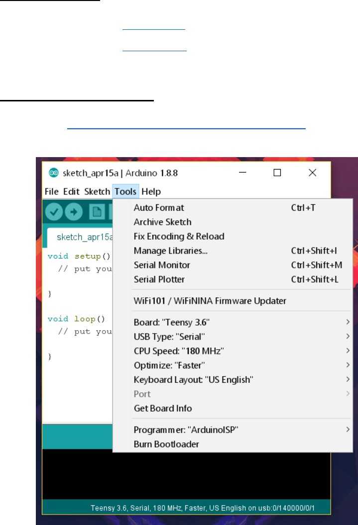
2. Open the Arduino IDE and under the Tools menu, configure with the following settings:
3. Navigate to \Avionics-2019\ATU\FlightATU_TX and open FlightATU_TX.ino.
4. Use the ‘verify’ button (checkmark in the top left) to build the program.
5. Slot MicroSD card into avionics telemetry unit (ATU), connect 7.4 V LiPo battery via
Dean’s connectors, and plug connect to PC via MicroUSB to USB-A cable – an orange
light on the ATU should turn on once the battery is connected.
CS Capstone Team 12 – 2019 Donald “Trey” Elkins
3
Note: The 5 V rails on the Teensy 3.6 microcontrollers have been modified such that
the Teensies cannot be flashed, programmed, or monitored without the batteries
plugged into them. This is to prevent electrical back feed over the USB port.
6. Select the correct port in the Arduino IDE and press the ‘upload’ button (arrow in the top
left) to push the code to the ATU Teensy.
7. Unplug the flight ATU from the computer, then repeat the same process exactly (from
step 2) with the second ATU.
8. Open the avionics ground station and connect the Yagi antenna to the XBee transceiver
9. Plug the 7.4 V LiPo battery into the breadboard via the Dean’s connectors, an orange
light on the Teensy should come on to indicate the device is powered.
10. Navigate to \Avionics-2019\ATU\GroundATU_RX and open GroundATU_RX.ino,
ensuring that the Arduino IDE settings remain the same.
11. Use the ‘verify’ button (checkmark in the top left) to build the program.
12. Connect the ground station to the computer via the MicroUSB to USB-A cable.
13. Select the correct port in the Arduino IDE and press the ‘upload’ button (arrow in the top
left) to push the code to the ATU Teensy.
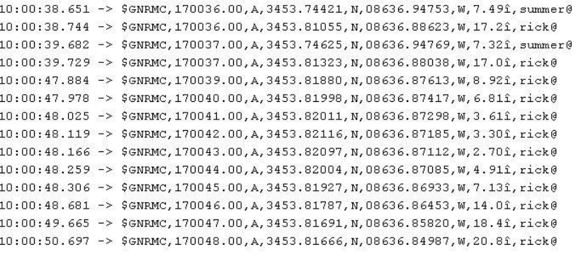
14. Open the Arduino serial monitor using the magnifying glass button in the top right
corner; if transmission lock has been obtained and timestamps are enabled, the serial
monitor will look similar to this image but with significantly more commas:
15. Wait for up to half an hour for the GPS lock to resolve; once GPS lock is obtained for
both ATUs the serial feed will look like the above rather than mostly filled with commas.
A partial lock has been attained when timestamps become accurate.

CS Capstone Team 12 – 2019 Donald “Trey” Elkins
4
16. To test GPS data logging, unplug LiPo batteries from the ATUs and pull the MicroSD
cards from the microcontrollers. Note: the ground station can remain connected to the
computer for the next section of setup and operation.
17. Use the MicroSD card reader to check the ‘DATALOG’ file on both MicroSD cards.
Data should appear similar to the serial monitor above but without the call-signs and with
more types of packets and more information in the $GNRMC packets.
Payload Ejection Controller (PLEC) Setup and Operation
1. Navigate to \Avionics-2019\PLEC\PLEC_TX and open PLEC_TX.ino.
2. Use the ‘verify’ button (checkmark in the top left) to build the program.
3. Connect the ground station to the computer via the MicroUSB to USB-A cable.
4. Select the correct port in the Arduino IDE and press the ‘upload’ button (arrow in the top
left) to push the code to the ATU Teensy.
5. Open the Arduino serial monitor using the magnifying glass button in the top right
corner.
6. When ready, flick the red cover up, flick the switch under the red cover, then press the
green button. A series of hex values will print out over the serial monitor with ‘covfefe’
and a series of other bytes as the result. Enjoy the meme. This is the activation signal for
detonating the ejection charges on the receiving end of the PLEC. Transmission will
cease when the green button is released.
433 MHz Prototype Setup and Operation
1. Navigate to \Avionics-2019\ATU\433MHzPrototype\ElecHouseCC1101Libraries\ and
locate the ELECHOUSE_CC1101.cpp and ELECHOUSE_CC1101.h files.
2. Move the above files to C:\Program Files (x86)\Arduino\libraries or wherever else your
local install of Arduino is. Note: these files should NOT go in the ‘My Documents’
version of the Arduino files.
3. Ensure that Arduino Unos are wired to SoLu 433 MHz CC 1101 modules as follows:

CS Capstone Team 12 – 2019 Donald “Trey” Elkins
5
Pin Name (on SoLu)
Pin Number (on Uno)
VCC
3.3 V
SI
11
SO
12
CSN
10
GND
GND
SCK
13
GO2
9
GO0
2
4. Plug both Arduino Unos into separate USB ports via the USB-B to USB-A cables
5. Go to \Avionics-2019\ATU\433MHzPrototype\ and choose which revision of the 433
MHz prototype code you will be running, then open one Arduino IDE window for TX
and one window for RX. Configure the Arduino IDE for “Arduino/Genuino Uno”.
6. Flash the code to each Arduino Uno, then open the serial monitor on the Arduino that
was flashed with the RX code to view the data stream.
