Azure_Transit_vNet1.1_Deployment_GuideRev1 5x Azure Transit VNet1.1 Deployment Guide
User Manual:
Open the PDF directly: View PDF ![]() .
.
Page Count: 37

© 2018 Palo Alto Networks. Proprietary and Confidential Last Update: September 2018
Transit VNet with the VM-
Series 1.1
Deployment Guide
How to deploy a Transit VNet solution in Azure
http://www.paloaltonetworks.com

Palo Alto Networks Transit VNet 1.1 with the VM-Series Deployment Guide
V1.1 Page 2
Table of Contents
Version History ....................................................................................................... 3
1. About ................................................................................................................. 4
2. Topology ........................................................................................................... 5
3. Support Policy .................................................................................................. 7
4. Prerequisites .................................................................................................... 8
5. Launch the Transit VNet Hub Template ........................................................ 11
6. Launch the Transit VNet Spoke Template .................................................... 19
7. VNet Peering Verification ............................................................................... 27
8. Inbound and Outbound Traffic Tests ............................................................ 29
9. Cleanup ........................................................................................................... 32
10. Gotchas ........................................................................................................... 33

Palo Alto Networks Transit VNet 1.1 with the VM-Series Deployment Guide
V1.1 Page 3
Version History
Version number
Comments
1.1 Panorama is required for this deployment. Adds
Bootstrapping to the Hub, Spoke and Autoscaling
to the Spoke.

Palo Alto Networks Transit VNet 1.1 with the VM-Series Deployment Guide
V1.1 Page 4
1. About
This document will guideline how to deploy a Transit VNet solution on Azure with the VM-Series. A
physical Panorama or Panorama virtual appliance is required to execute this deployment. Panorama is
NOT deployed in this template deployment and must be deployed separately. The Transit VNet uses a hub
and spoke architecture to centralize commonly used services such as security and connectivity. The spoke
architecture provides support for Azure Autoscaling using VMSS. This architecture will automatically scale
out as needed while providing security for public facing workloads. For more details about the advantages
of the hub and spoke topology please refer to this link:
https://docs.microsoft.com/en-us/azure/architecture/reference-architectures/hybrid-networking/hub-
spoke
Note: The Transit VNet with the VM-Series solution is considered advanced. It requires familiarity with
Azure and the VM-Series next generation firewall. This deployment has NOT been tested in Government.
The deployment guide walks through the Palo Alto Networks ARM Templates to deploy a Transit VNet
solution with the VM-Series firewalls in conjunction with, Application Gateways, Standard Load Balancers,
Basic Load Balancers, and User Defined Route Tables. Version 1.1 now includes support for Azure
Autoscaling using Virtual Machine Scale Sets and native bootstrapping. You will need to follow the
instructions in the VM-Series deployment guide on how to bootstrap in Azure Cloud.
Bootstrap the VM-Series Firewall on Azure
https://www.paloaltonetworks.com/documentation/81/virtualization/virtualization/bootstrap-the-vm-
series-firewall/bootstrap-the-vm-series-firewall-in-azure#idd51f75b8-e579-44d6-a809-2fafcfe4b3b6
if you have any issues with this link please use the link from the main ReadMe page
Transit VNet 1.1 requires a previously deployed, physical or virtual Panorama. Panorama will be used for
the spoke deployment to manage the VM-Series firewalls in the Virtual Machine Scale Set. Panorama will
also be used for license deactivation, as well as logging and reporting. For more information on Panorama
please see the Panorama admin guide.
Panorama Administration Guide
https://www.paloaltonetworks.com/documentation/81/panorama
The Transit VNet Hub provides centralized secured outbound internet access and connectivity for all your
Azure VNets Spokes. This secured outbound internet access is provided by two VM-Series firewall pairs
positioned behind an Azure Standard any port load balancer in the Transit Hub VNet. All outbound traffic
originating from your Azure VNet spokes will be provided with a secure single point of exit from your cloud
architecture by way of the Hub VNet. User Define Routes are used to route spoke traffic to the Hub
internal load balancer for packet forwarding to the Hub VM-Series Firewalls. Traffic flowing through the

Palo Alto Networks Transit VNet 1.1 with the VM-Series Deployment Guide
V1.1 Page 5
(cont.) VM-Series is protected from inbound and outbound threats, command-and-control malware, data
exfiltration vulnerabilities and many other potential security concerns.
Azure Application Insights
In PAN-OS 8.1, support for natively publishing PAN-OS metrics to an Azure Application Insights instance
was added. This allows you to monitor firewalls directly from the Azure portal. The Worker node deployed
in the Transit Hub views PAN-OS published metrics via Azure Application Insights to determine if scaling is
needed. The metrics that can be sent to Azure are
Session Utilization %
Total Active Sessions
Dataplane CPU Utilization %
Dataplane Packet Buffer Utilization %
SSL Proxy Utilization %
GlobalProtect Active Tunnels
GlobalProtect Tunnel Utilization %
2. Topology
The Transit VNet solution deploys a classic hub-and-spoke architecture where the Hub and each spoke are
deployed in separate VNets.
VNet Peering
For the different VNets to talk to each other, they must be peered in both the directions. VNet Peering
works under the assumption that the peering networks do not have overlapping subnets. In this topology,
when a VNet spoke is deployed, we will dynamically peer the spoke's VNet and the hub's VNet enabling
traffic to flow between them. For additional information on VNet Peering please reference the link below
https://docs.microsoft.com/en-us/azure/virtual-network/virtual-network-peering-overview
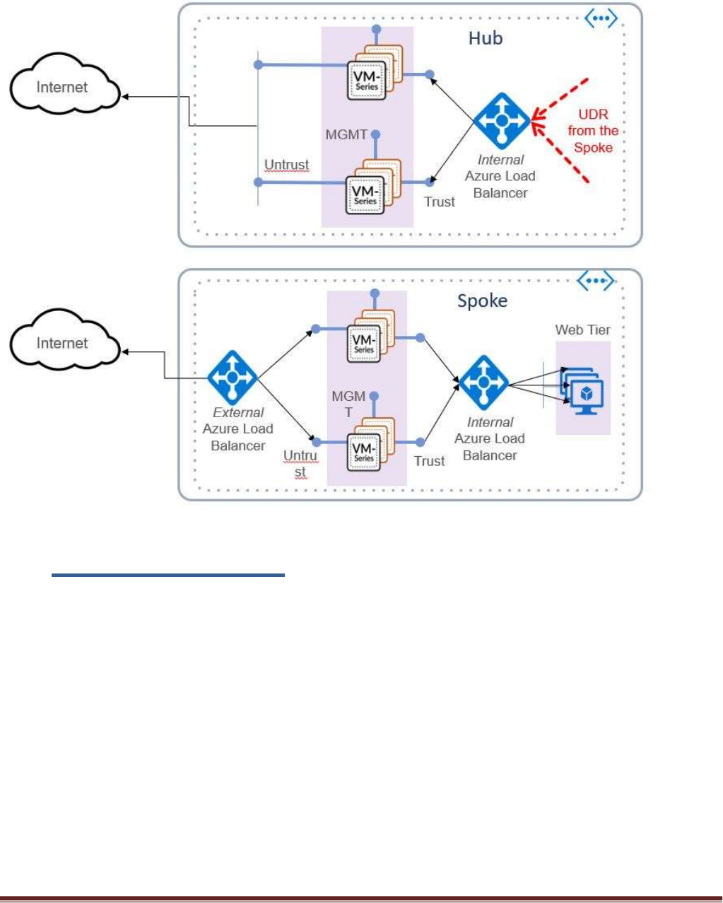
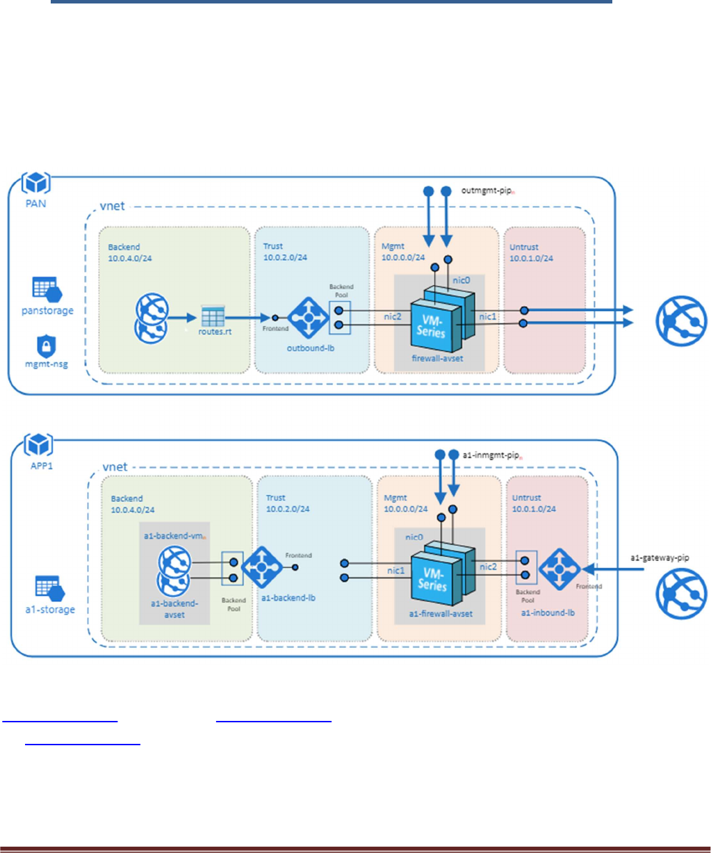
Hub Topology
The Hub VNet consists of Mgmt , Untrust and Trust subnets. An Azure internal LB[Outbound-LB] used for
outbound traffic and a pair of VM-Series FWs in an availability set. The Hub topology serves as the exit
point of all non-return traffic for the Hub and Spoke topology.
The Hub topology consists of
2 VM-Series Firewalls
1 Standard internal Load Balancer
Linux Worker Node

Palo Alto Networks Transit VNet 1.1 with the VM-Series Deployment Guide
V1.1 Page 6
- Worker node uses the Tabular storage table to keep track of the Azure VMSS table and
Panorama device list. During a scale down event the worker node will deactivate the license
in the Support Portal and remove the firewall from Panorama.
- The worker node updates the NAT address object in the Spoke VM-series with the correct IP
address of the spoke ILB.
- The worker node will add the Azure instrumentation key for application insights into the
Panorama template for reach new spoke deployment.
1 Tabular Storage Table
- Stores VMSS device list data
Spoke Topology
The spoke VNet allows an ingress point for all traffic destined to public facing workloads.1 The subnets
consist of Mgmt, Untrust, Trust and Backend Subnets for the application servers. An Application Gateway
doubles as a public facing load balancer and sits on the front end. VM-Series firewalls in a Virtual Machine
Scale Set receive traffic from the public facing LB. An Internal LB sits behind the firewalls and sends traffic
to the backend application servers. All return traffic egresses this same path. When a spoke subscribes to a
hub, a UDR is also defined which has a default route to the Hub's Interal Load Balancer. This is so all
packets that are not destined to the spoke's VNet gets forwarded to the Hub Internal LB for routing.
The Spoke topology consists of
1 Application Gateway functioning as an external load balancer listening on port 80.
Spoke subnets are 1921.168.0.0/21 Spoke1, 1921.168.8.0/21 Spoke2 and so on.
Virtual Machine Scale Set with a VM-Series
Availability Set for VM-Series
1 Internal Load Balancer
2 Linux Web servers
1 UDR sending all default route traffic to the Hub VNet Standard Load Balancer.
1 Bastion host
- Used to connect to VM-Series firewalls in the VMSS via private Mgmt interface IP
Application insights
- Used to process VM-Series metrics used to determine scale in & scale out events
Hub & Spoke Topology
1 The term public facing workload refers to any server reachable from the internet. Web Server etc.
Palo Alto Networks Transit VNet 1.1 with the VM-Series Deployment Guide
V1.1 Page 7
3. Support Policy
Community Supported
This solution is released under an as-is, best effort, support policy. These scripts should be community
supported and Palo Alto Networks will contribute our expertise as and when possible. We do not provide
technical support or help in using or troubleshooting the components of the project through our normal
support options such as Palo Alto Networks support teams, or ASC (Authorized Support Centers) partners
and backline support options. The underlying product used (the VM-Series firewall) by the scripts or
templates are still supported, but the support is only for the product functionality and not for help in
deploying or using the template or script itself.

Palo Alto Networks Transit VNet 1.1 with the VM-Series Deployment Guide
V1.1 Page 8
4. Prerequisites
Here are the prerequisites required to successfully launch this template:
1. Permissions
AZURE account with appropriate permissions.
2. Download appropriate files
Clone or download the files from the following GitHub repository on to your local machine:
https://github.com/PaloAltoNetworks/Azure-transit-VNet
3. Valid License
Without a valid VM-Series Firewall license you will not see any data in the traffic logs. If you don’t
have a license provided by Palo Alto Networks, please select bundle1 or bundle2 in the template
parameters for licensing. For more information on licensing please see the link below.
https://www.paloaltonetworks.com/documentation/81/virtualization/virtualization/license-the-
vm-series-firewall
4. Service Principal and Active Directory Application Setup
You will need to set up an Azure Active Directory application and service principal account. Follow
the link below for details. Make note of your Subscription ID, Azure Application ID, Application
Secret Key, and Tenant ID.
https://docs.microsoft.com/en-us/azure/azure-resource-manager/resource-group-create-service-
principal-portal#check-azure-subscription-permissions
Retrieve Azure Tenant ID
https://docs.microsoft.com/en-us/azure/active-directory/develop/active-directory-howto-tenant
5. Bootstrap Storage Account
Storage accounts setup for bootstrapping in the spoke. Bootstrapping in the Hub is optional. Be
sure to take the .xml configuration files from the Hub and change it to bootstrap.xml for
bootstrapping. For the spoke you will not need a bootstrap.xml file because it will receive it’s
configuration from Panorama. It is recommended to create a separate resource group for your
bootstrap storage account. See bootstrap instructions below.
https://www.paloaltonetworks.com/documentation/81/virtualization/virtualization/bootstrap-the-
vm-series-firewall/bootstrap-the-vm-series-firewall-in-azure#idd51f75b8-e579-44d6-a809-
2fafcfe4b3b6
Creating the bootstrap package

Palo Alto Networks Transit VNet 1.1 with the VM-Series Deployment Guide
V1.1 Page 9
https://www.paloaltonetworks.com/documentation/81/virtualization/virtualization/bootstrap-the-
vm-series-firewall
6. Bootstrap init-cfg.txt for Spoke VM-Series
A sample init-cfg.txt is provided below with explanation –
type=dhcp-client
ip-address=
default-gateway=
netmask=
ipv6-address=
ipv6-default-gateway=
hostname=
vm-auth-key=PanoramaVmAuthKey
panorama-server=PanoramaIP
panorama-server-2=
tplname=<spoke_name> + ”-tmplstk”
dgname=<spoke_name> + ”-dg”
dns-primary=8.8.8.8
dns-secondary=208.67.222.222
op-command-modes=
dhcp-send-hostname=yes
dhcp-send-client-id=yes
dhcp-accept-server-hostname=yes
dhcp-accept-server-domain=yes
7. Panorama Setup
Panorama 8.1 will be used for the spoke deployment to manage the VM-Series firewalls in the
Virtual Machine Scale Set. Panorama will also be used for license deactivation, as well as logging
and reporting. You must allow access to port 3978 to the Mgmt interface of the Panorama for any
device security the Panorama. Port 443 and SSH can be locked down to the IP you will manage your
Panorama from.
https://www.paloaltonetworks.com/documentation/81/panorama/panorama_adminguide/set-up-
panorama/set-up-the-panorama-virtual-appliance#55656
8. Panorama VM Auth Key
To authenticate the API, we need a Panorama API Key. The following link will walk you through
generating an API Key.
https://www.paloaltonetworks.com/documentation/81/pan-os/xml-api/get-started-with-the-pan-
os-xml-api/get-your-api-key
9. Enabling XML API access in Panorama
Palo Alto Networks Transit VNet 1.1 with the VM-Series Deployment Guide
V1.1 Page 10
To program Panorama and deactivate VM Licenses, you need to enable XML API access in
Panorama. As a best practice, create a new role with just API access to perform this. The steps to
do this can be found here.
https://www.paloaltonetworks.com/documentation/81/pan-os/xml-api/get-started-with-the-pan-
os-xml-api/enable-api-access
10. License Deactivation Key
We require a License Deactivation API Key and the “Verify Update Server Identity” to be enabled to
deactivate the license keys from Panorama. The License Deactivation Key should be obtained from
Palo Alto Customer Support Portal. Steps on how to activate this can be found below.
https://www.paloaltonetworks.com/documentation/81/virtualization/virtualization/license-the-
vm-series-firewall/deactivate-the-licenses/install-a-license-deactivation-api-key
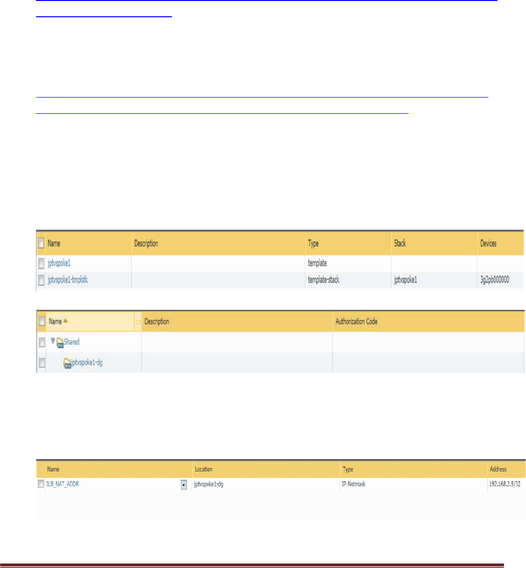
11. Panorama Template and Device Group Name
For every spoke that is launched, a corresponding Device Group, Template and Template Stack
needs to be created in Panorama. Use the name of your Azure Spoke resource group to name your
template and Device Group. For example, if the resource group of your spoke in Azure is named
jptvspoke1, then name your device group jptvspoke1-dg and name your template stack jptvspoke1-
tmplstk. The template should have all the configuration and added to the template stack.
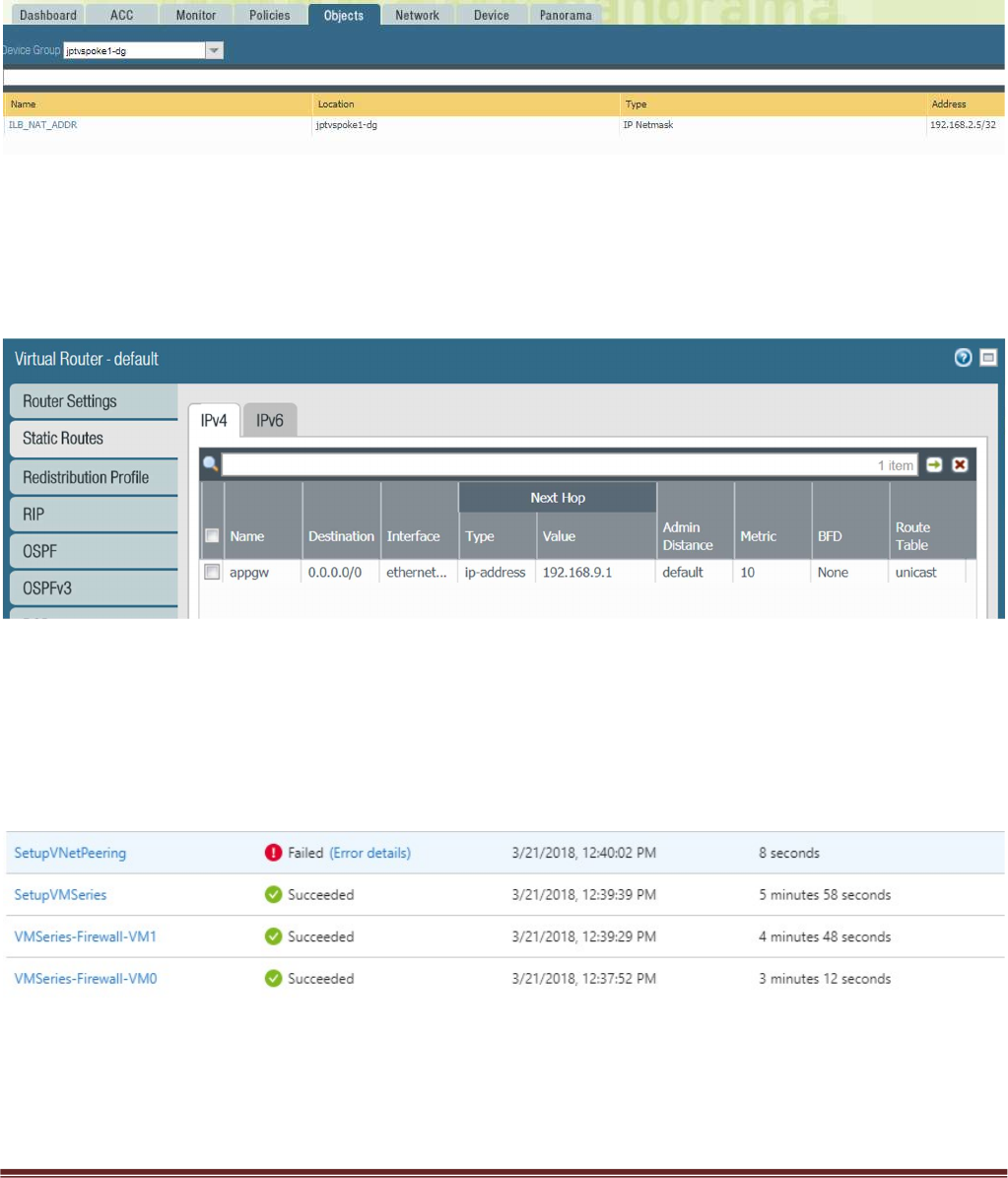
12. Panorama Device Group NAT Object
The Device Group should also have an address object called ILB_NAT_ADDR created with a random
IP address which will be re-programmed by the worker node monitoring script.
13. Panorama Template and Device Group Configuration
Palo Alto Networks Transit VNet 1.1 with the VM-Series Deployment Guide
V1.1 Page 11
You can use the appgw-sample.xml snapshot configuration in the GitHub spoke folder as an
example of how to configure your device group and template in Panorama. Load this configuration
on to a firewall without committing to view the settings while you configure your Panorama. To
avoid issues always validate your configuration prior to attempting a push or bootstrap. See
Gotchas section below.
5. Launch the Transit VNet Hub Template
There are multiple ways to deploy your template. You can use Azure CLI, PowerShell, Deploy to Azure
button or you can deploy the template manually. If the GitHub Repository has a Deploy to Azure button
you can deploy the template by clicking the deploy button for each template. Before launching be sure to
take the working_hub_config.xml and rename it bootstrap.xml for use when bootstrapping VM-Series in
the Hub. The steps below will walk you through how to launch the ARM template manually.
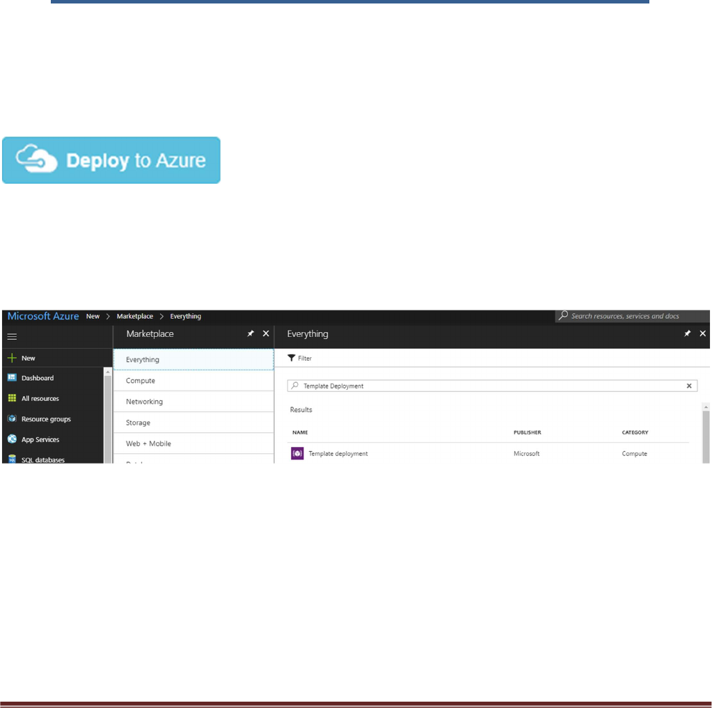
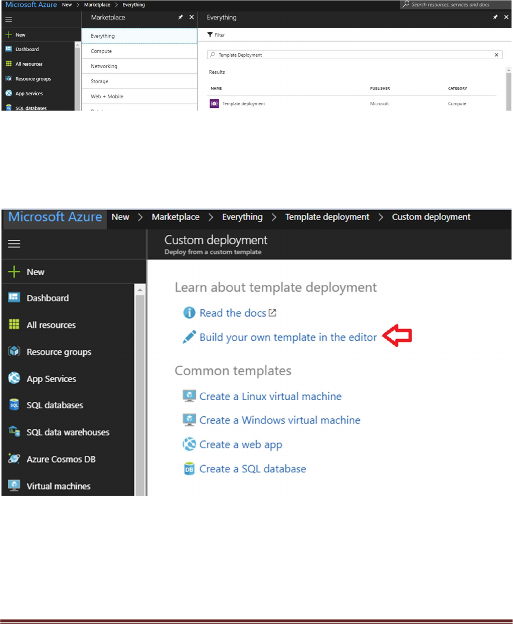
In the Azure Resource Manager console you can launch the azureDeployInfra.json file directly from the
Azure Portal. To do this click “New” then search “Template Deployment”, click the Template Deployment
icon an select “Create”.
Palo Alto Networks Transit VNet 1.1 with the VM-Series Deployment Guide
V1.1 Page 12
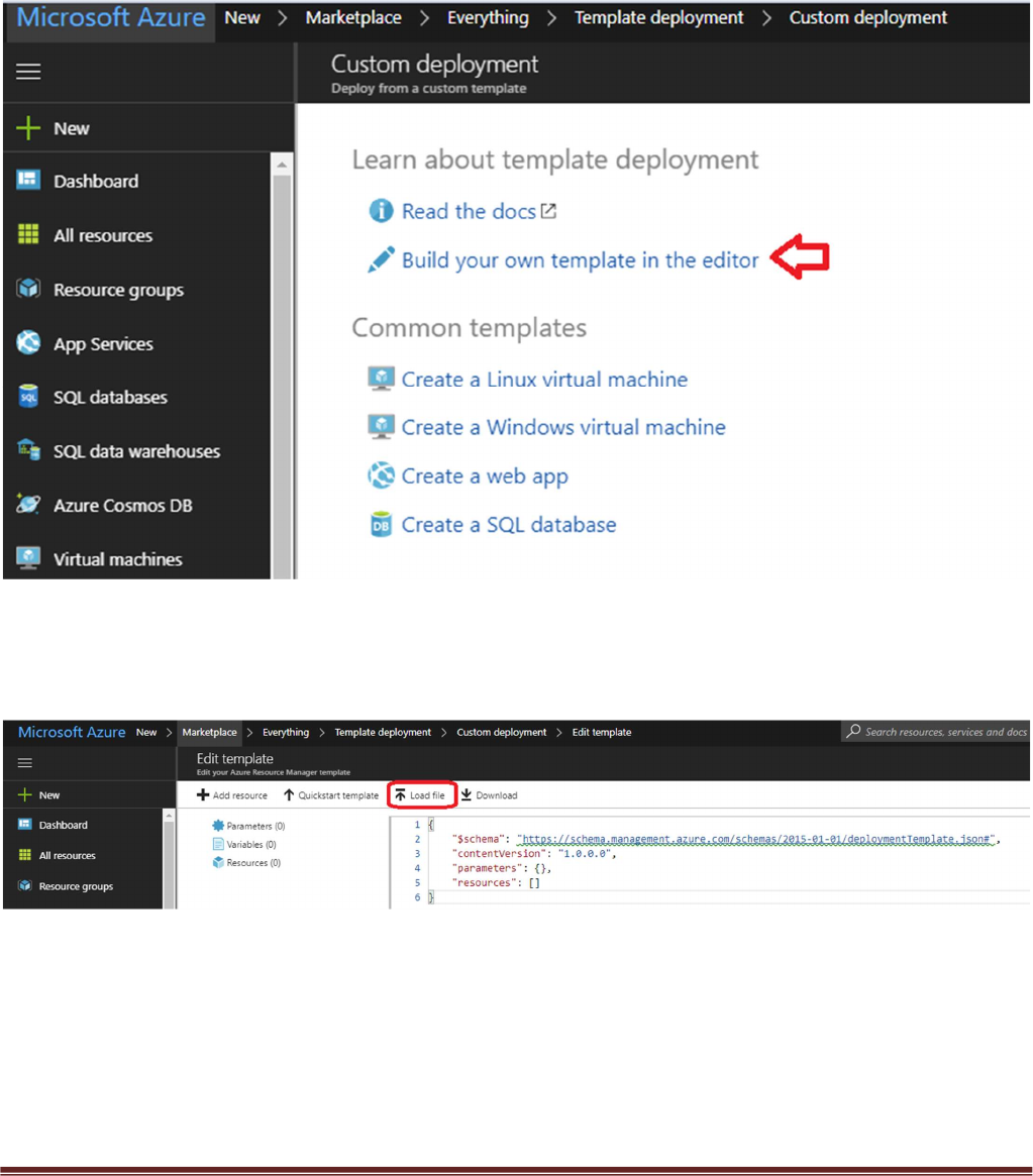
In the next screen click “Build your own template in the editor”
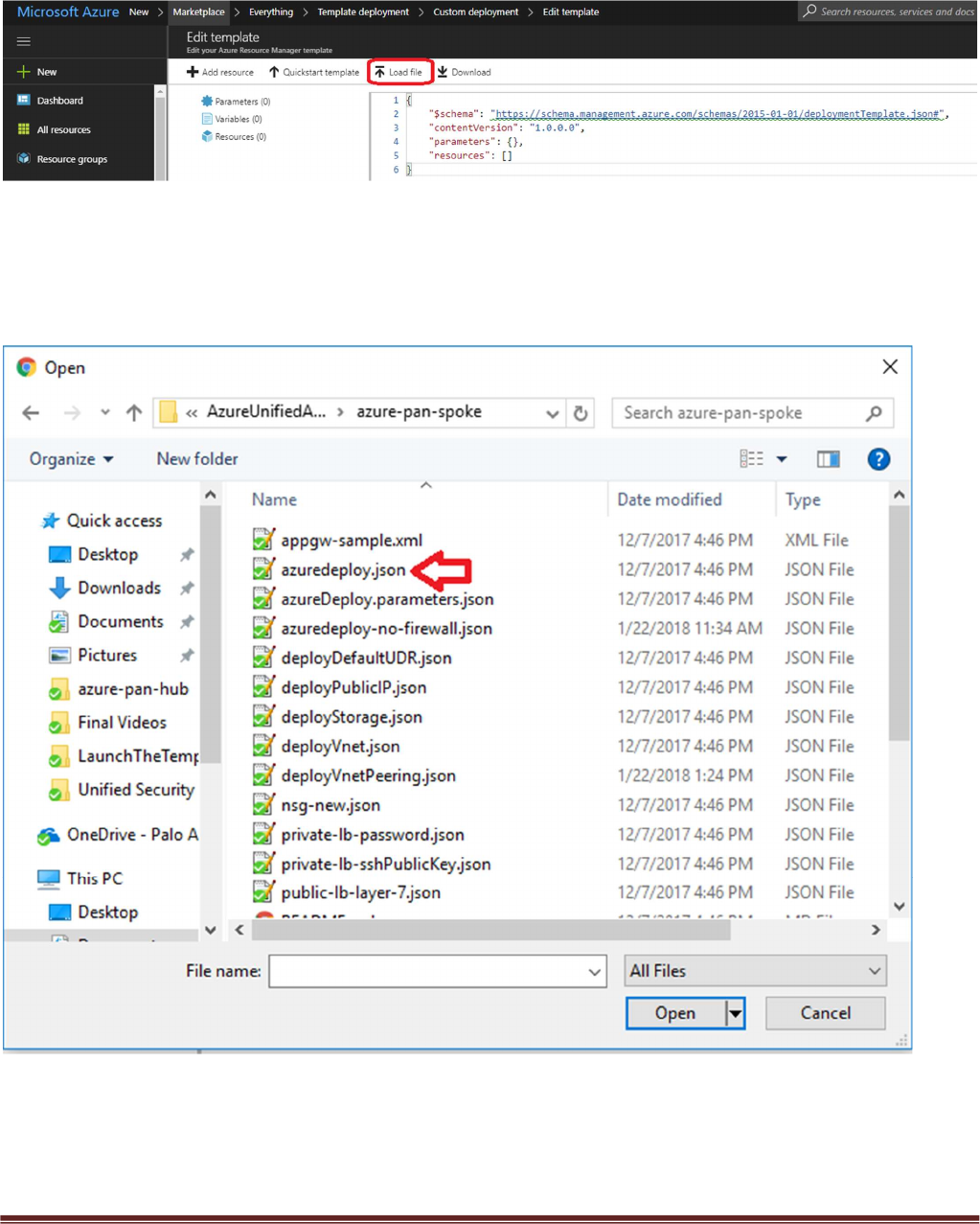
Select “Load File”
Palo Alto Networks Transit VNet 1.1 with the VM-Series Deployment Guide
V1.1 Page 13
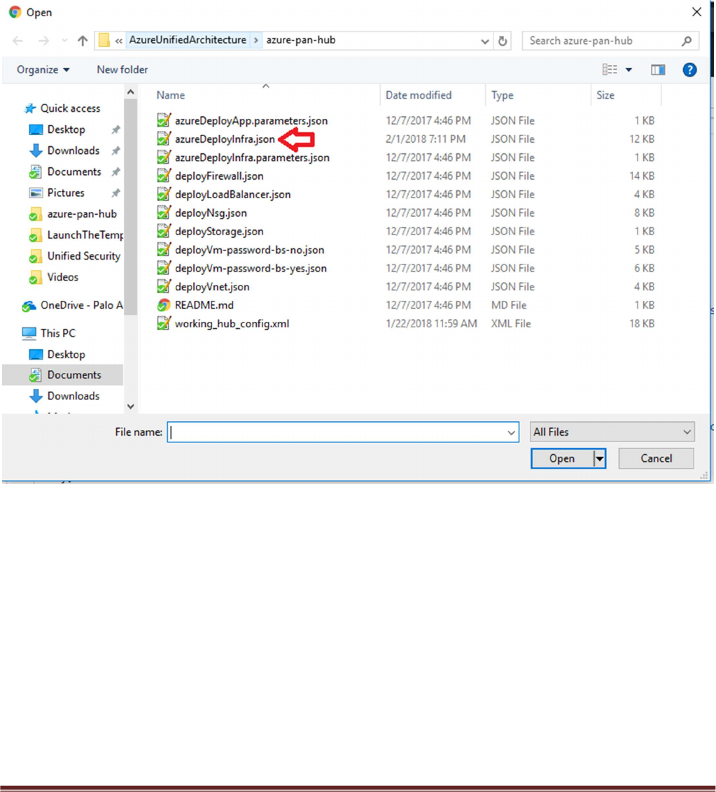
Select “azureDeployInfra.json“ file from the Azure-Transit-VNet/azure-pan-hub directory that you cloned
from GitHub, then click “Save” to bring up the parameters.

Palo Alto Networks Transit VNet 1.1 with the VM-Series Deployment Guide
V1.1 Page 14
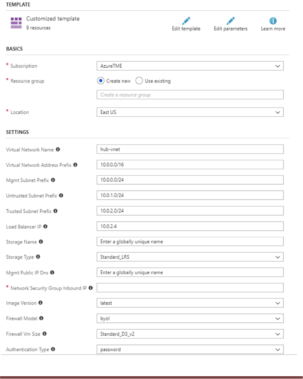
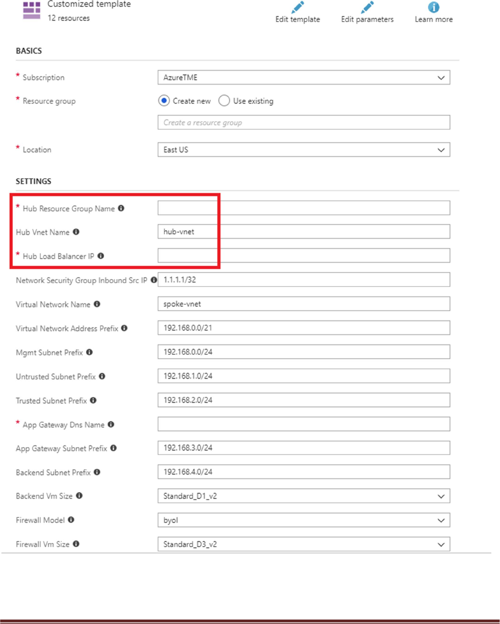
a. Most of the parameters are self-explanatory and should be left at the defaults
b. Resource Group – Always create a new resource Group. The hub template does not work in an
existing resource group
c. Location – Use the location where your bootstrap storage account is created.
d. Virtual Network Name – This will be the name of the hub VNet
e. Virtual Network Address Prefix – Use a network address which will not be used in the spoke
deployment. The defaults should suffice.
f. Load Balancer IP – Use a static IP for Load Balancer in the Trust network. Remember this address
since it is used as an input parameter for the spoke template.
g. Network Security Group Inbound Src IP – This is the IP you will allow explicit access to the
management interface of the virtual machines. For security purposes be sure to set Security Group
Inbound IP for mgmt access to the firewall.
h. Image Version – For image version you must use at minimum PAN-OS 81.1 so select latest.
i. Firewall Model – If you select BYOL you must receive licensing directly from Palo Alto Networks or
reseller.
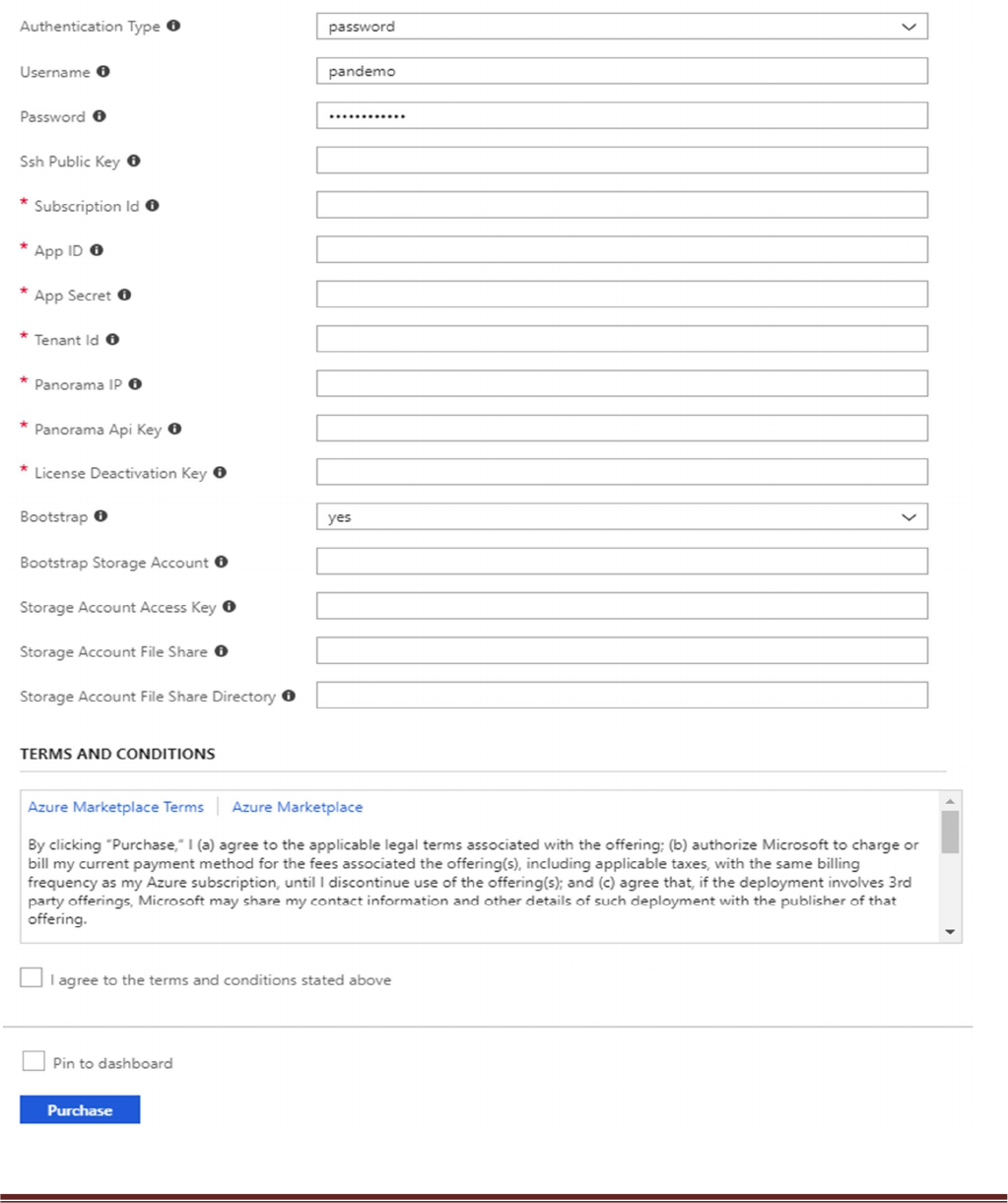
j. Username and password that is entered by default for the devices is:
user:pandemo password:Dem0pa$$w0rd
k. Subscription ID – See Step 4 listed in prerequisites
l. App ID – See Step 4 listed in prerequisites
m. Tenant ID – See Step 4 listed in prerequisites
n. Panorama IP – IP address for the previously deployed Panorama
o. Panorama API Key – See step 9 listed in prerequisites
p. Bootstrap Storage Account – See step 5 listed in prerequisites
q. Storage Account Access Key – See step 5 listed in prerequisites
r. Storage Account File Share – See step 5 listed in prerequisites
s. Storage Account File Share Directory – See step 5 listed in prerequisites
t. It could take up to 10 minutes to complete the launch or longer depending on Azure.
Palo Alto Networks Transit VNet 1.1 with the VM-Series Deployment Guide
V1.1 Page 15
Palo Alto Networks Transit VNet 1.1 with the VM-Series Deployment Guide
V1.1 Page 16
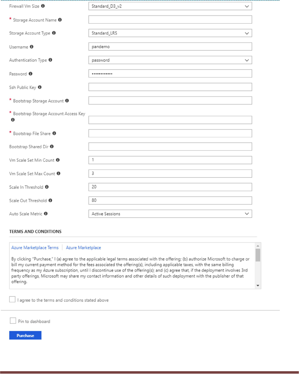
Acknowledge the terms and conditions and click “Purchase”
Palo Alto Networks Transit VNet 1.1 with the VM-Series Deployment Guide
V1.1 Page 17
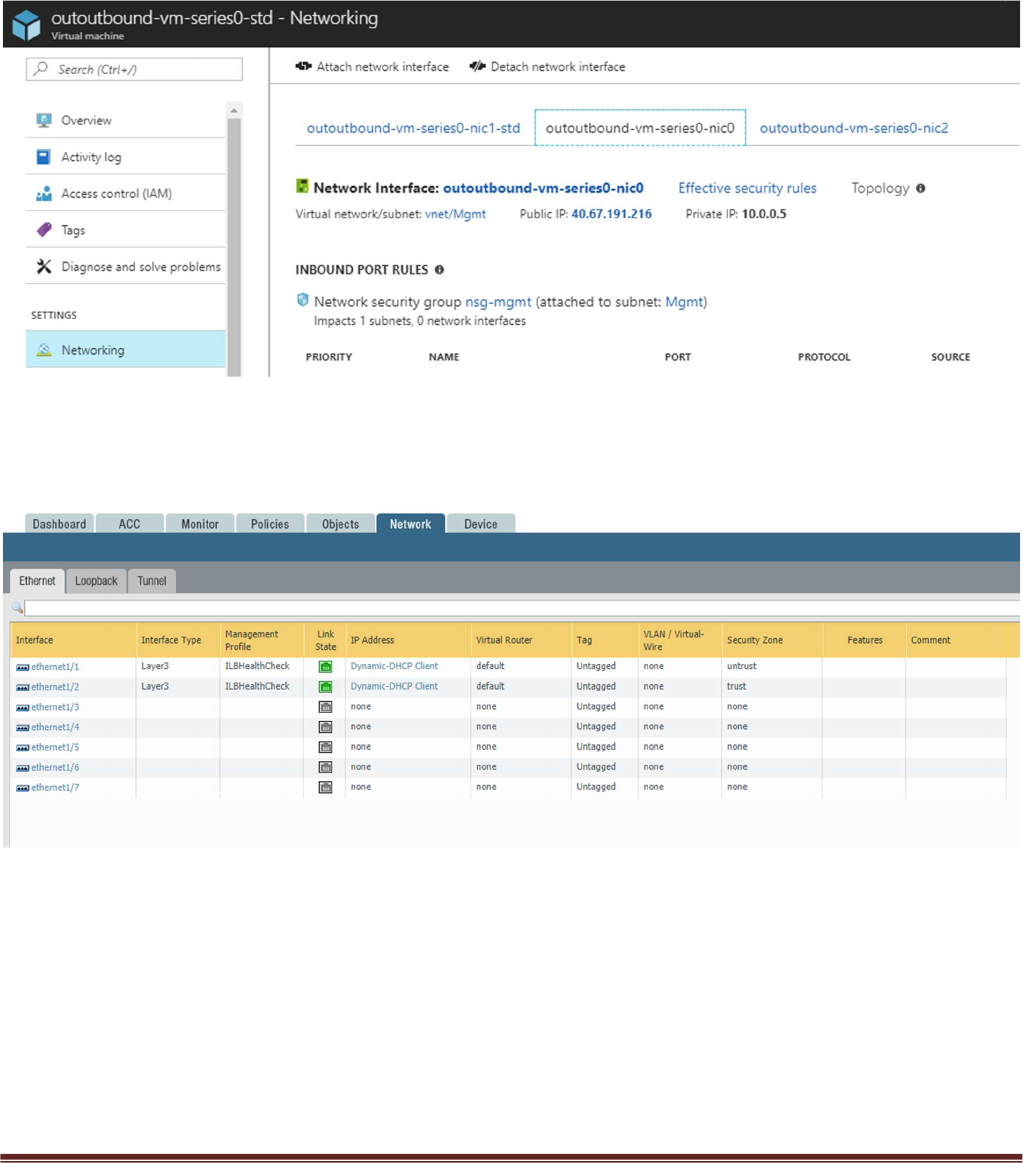
Once the firewalls have launched, locate the Management interface public IP address in Azure.
Log into the hub firewalls using HTTPS. Make sure your ethernet1/1 and Ethernet1/2 interfaces now
show green.
Palo Alto Networks Transit VNet 1.1 with the VM-Series Deployment Guide
V1.1 Page 18
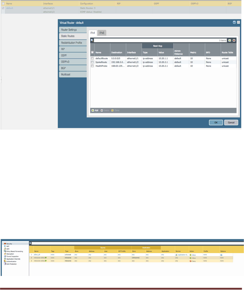
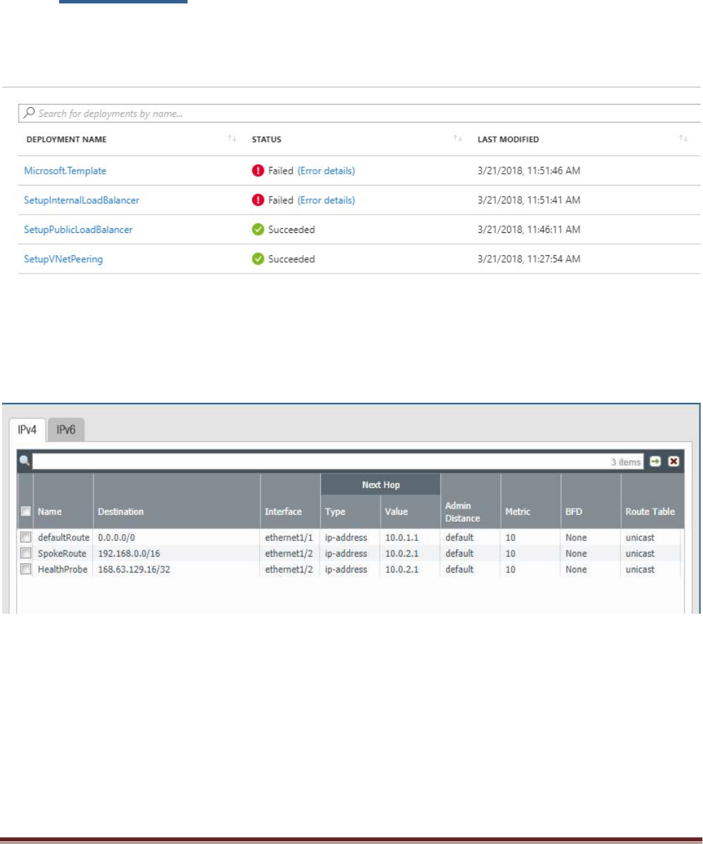
Verify the virtual router has the following configuration.
DefaultRoute: is to forward all outbound traffic to the untrust interface so that it egresses out of the Azure
network.
SpokeRoute: is to forward all the inbound traffic and inter-spoke traffic back to the Trust interface so that
it reaches the appropriate Spoke (application server). Note that the Network address of the all the spokes
VNets should be part of this network address. If a new spoke is added whose network address is not part of
this network address, then a new route needs to be added in the config to forward that traffic to the Trust
interface.
HealthProbe: is to respond to the health probe packets generated by the Internal Load Balancer. For this lab
the health check is configured to port 22 on the firewall Trust interface.
An allow-all security policy is created to forward all traffic. This should be modified to accommodate your
policy preferences.
Palo Alto Networks Transit VNet 1.1 with the VM-Series Deployment Guide
V1.1 Page 19
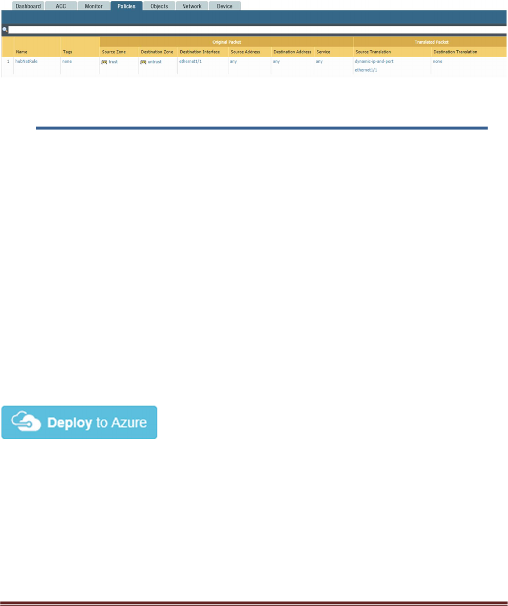
Verify that you have a NAT rule on the hub firewall for outbound traffic
6. Launch the Transit VNet Spoke Template
Spoke Template Options
Azuredeploy.json – This launches the spoke template with VM-Series firewalls sandwiched between an
external and internal load balancer. This provides secured external access to public facing workloads with
return traffic egressing the spoke VNet. All internal originating traffic will be forwarded to the Hub VNet as
the exit route to provide secure outbound access.
Azuredeploy-no-firewall.json – Launches the spoke template with no firewalls but still launches
application servers. This scenario would NOT provide security using the VM-Series for public facing
workloads. All internal originating traffic will be forwarded to the Hub VNet as the exit route to provide
secure outbound access. This template will be available soon.
There are multiple ways to deploy your template. You can use Azure CLI, PowerShell, Deploy to Azure
button or you can deploy the template manually. If the GitHub Repository has a Deploy to Azure button
you can deploy your template by clicking the deploy button for each template. For the spoke you will not
need a bootstrap.xml file because it will receive its configuration from Panorama. Below I will walk you
through how to launch your ARM template manually.
From the Azure-Transit-VNet/azure-pan-spoke GitHub repository that you cloned, launch the
azuredeploy.json file directly from the Azure Portal. You may need to bring up two azure portal browsers
in order to locate information needed to fill out the parameters when launching this template. To do this
Palo Alto Networks Transit VNet 1.1 with the VM-Series Deployment Guide
V1.1 Page 20
click “New” then search “Template Deployment”, click the Template Deployment icon an select “Create”.
In the next screen click “Build your own template in the editor”
Select “Load File”
Palo Alto Networks Transit VNet 1.1 with the VM-Series Deployment Guide
V1.1 Page 21
Select “azuredeploy.json“ file from the Azure-Transit-VNet/azure-pan-spoke directory that you cloned
from GitHub, then click “Save” to bring up the parameters.
a. Most of the parameters are self-explanatory and should be left at the defaults

Palo Alto Networks Transit VNet 1.1 with the VM-Series Deployment Guide
V1.1 Page 22
b. Resource Group – Create a new Resource Group. This template does not work with existing
resource groups.
c. Location – It should be the same location as the hub since VNet peering does not work well across
regions.
d. Hub Resource Group Name – Give the Resource Group name of the hub created resource group.
e. Hub VNet Name – Use the exact VNet name of the hub created earlier.
f. Hub Load Balancer IP – Use the static IP given to the Load Balancer in the created in the hub
template. You can find this information in the load balancer settings
g. Network Security Group Inbound Src IP – This is the IP you will allow explicit access to the
management interface of the virtual machines.
h. Virtual Network Address Prefix – This network address should be the subnet of the network
address given in the “SpokeRoute” in the hub’s firewall configuration.
i. Mgmt, Trust and Untrust subnets should be subnets of the VNet subnet created in the previous
step.
j. Firewall VM Size - Choose the Firewall Model and Size based on requirements. Use Standard D3 or
D3 v2.
k. SSH Public Key – If using a password then leave this section blank.
l. Bootstrap Storage Account – See step 5 listed in prerequisites
m. Storage Account Access Key – See step 5 listed in prerequisites
n. Storage Account File Share – See step 5 listed in prerequisites
o. Storage Account File Share Directory – See step 5 listed in prerequisites
p. VM Scale Set Min Count – Customize based on preference
q. VM Scale Set Max Count – Customize based on preference
r. Scale In Threshold – Customize based on preference
s. Scale Out Threshold – Customize based on preference
t. Auto Scale Metric – Customize based on preference
For more information on Azure Virtual Machine Scale Sets please see the following link
https://docs.microsoft.com/en-us/azure/virtual-machine-scale-sets/overview
Palo Alto Networks Transit VNet 1.1 with the VM-Series Deployment Guide
V1.1 Page 23
Palo Alto Networks Transit VNet 1.1 with the VM-Series Deployment Guide
V1.1 Page 24
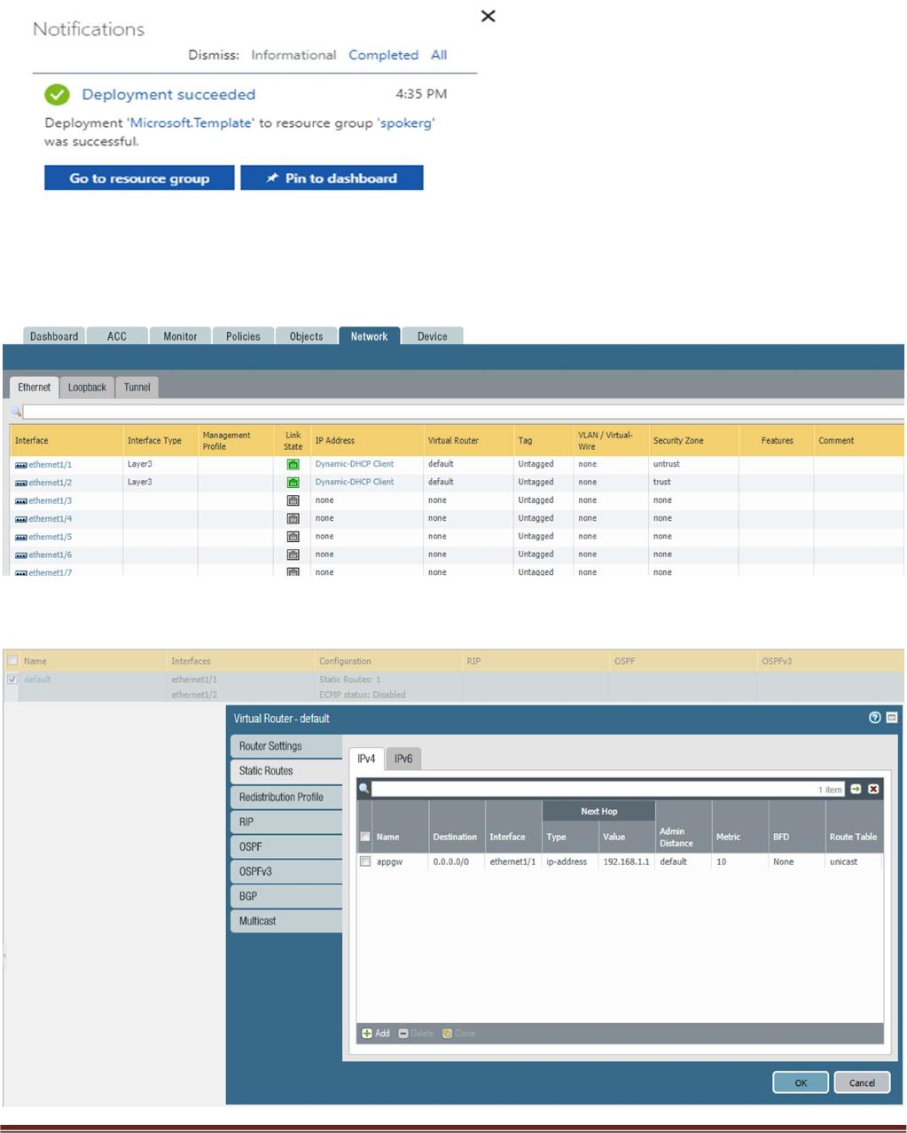
Once the Spoke template has successfully launched you will see Deployment succeeded.
Palo Alto Networks Transit VNet 1.1 with the VM-Series Deployment Guide
V1.1 Page 25
Log into the spoke firewalls using HTTPS. Make sure your ethernet1/1 and Ethernet1/2 interfaces now
show green
Verify the spoke firewall virtual router has the following configuration.
Palo Alto Networks Transit VNet 1.1 with the VM-Series Deployment Guide
V1.1 Page 26
appgw: is to forward all traffic originating from the firewall to the untrust interface. Traffic originating
from spoke resources behind the firewall will egress through the Hub VNet.
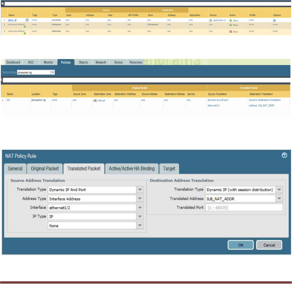
An allow-all security policy on the firewall is created to receive all traffic although the application gateway
load balancer only listens for port 80. This should be modified to accommodate your policy preferences.
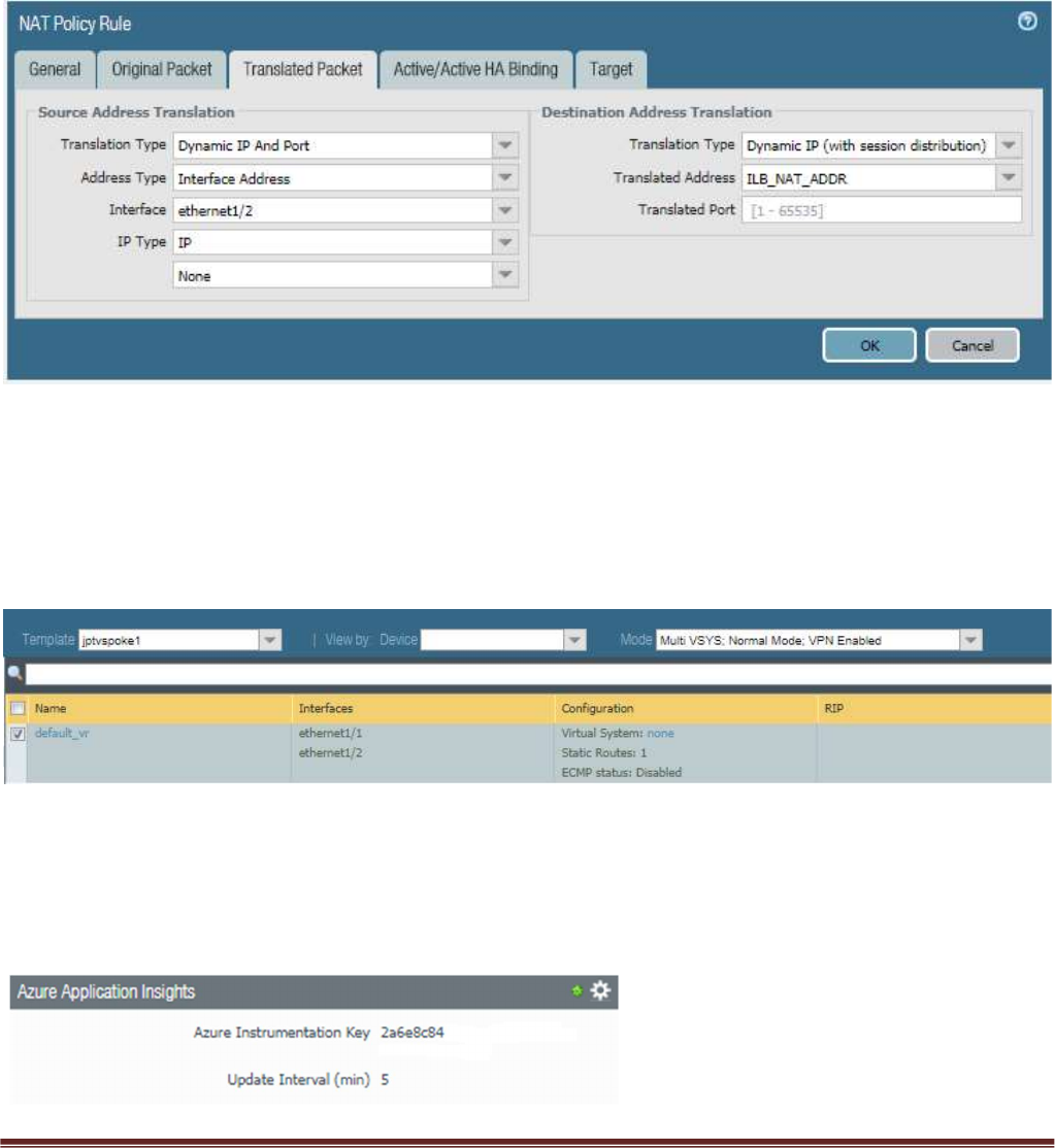
Verify that you have a NAT rule on the spoke firewall for inbound traffic
In order for your NAT policy to work your translated packet for source and destination should be
configured as follows. Do NOT use Static IP
Palo Alto Networks Transit VNet 1.1 with the VM-Series Deployment Guide
V1.1 Page 27
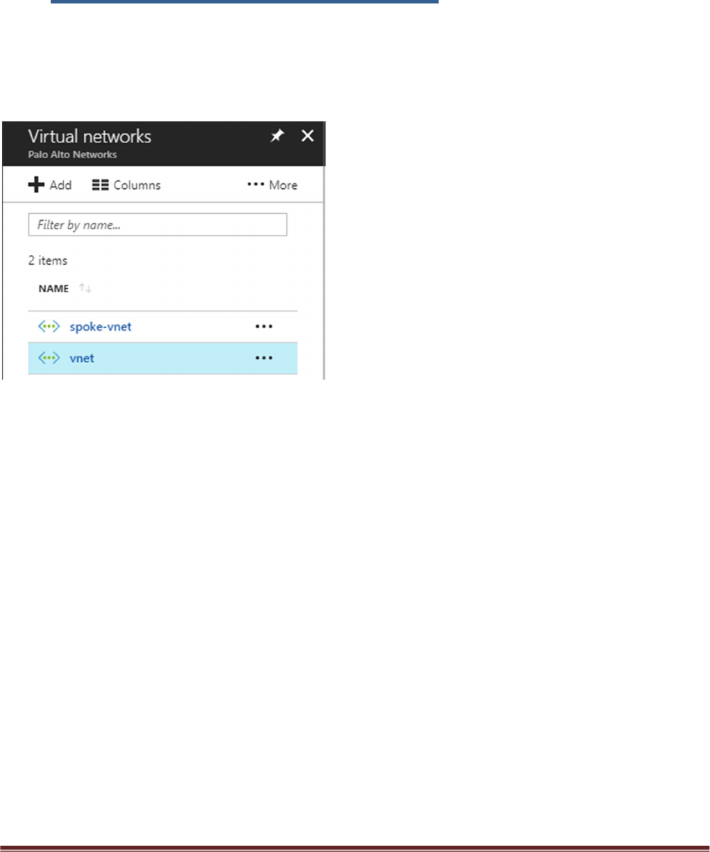
7. VNet Peering Verification
Within Azure Portal verify that VNet Peering has been configured automatically between the Hub
VNet and Spoke VNet. To check this in Azure navigate to Virtual Networks > select the VNet
name.
Palo Alto Networks Transit VNet 1.1 with the VM-Series Deployment Guide
V1.1 Page 28
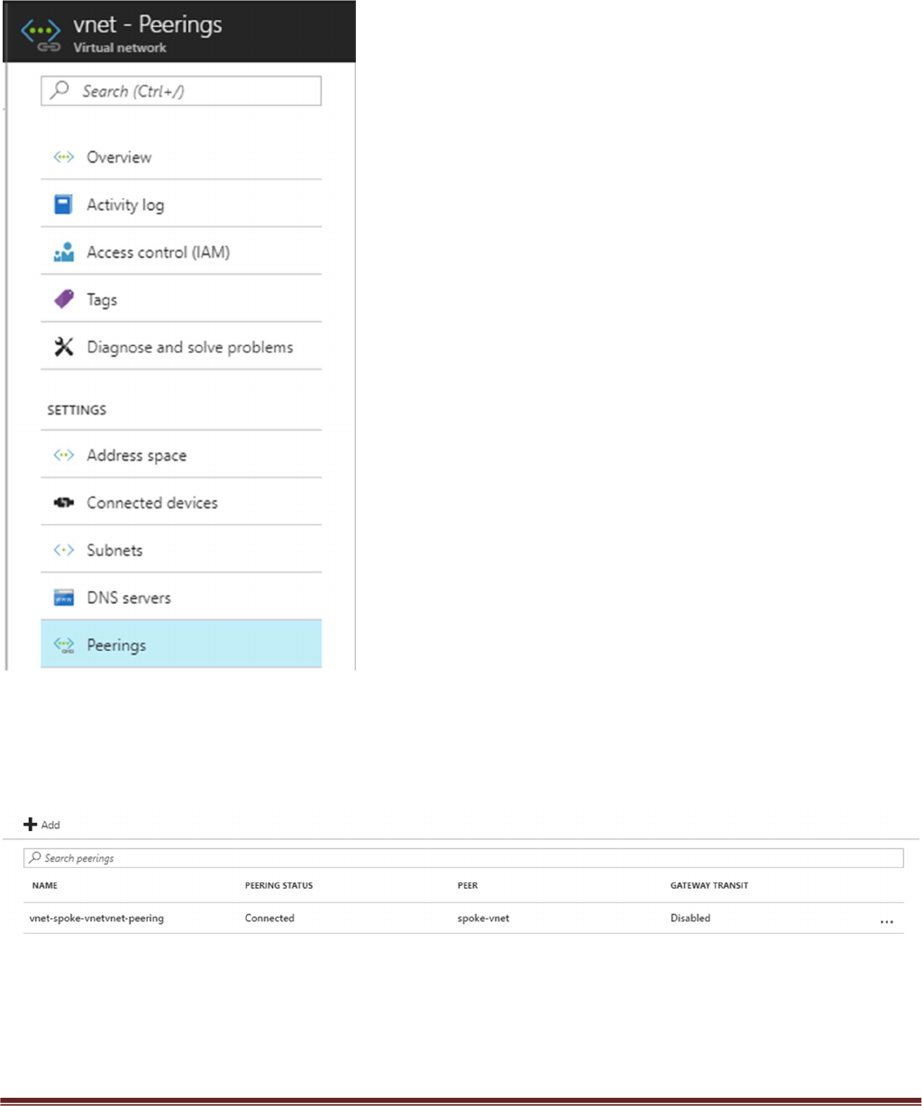
Then select Peerings
Here you should see the name of the peer VNet with a status of connected. Gateway Transit
should be disabled. Check this on both the hub and spoke VNet.
Palo Alto Networks Transit VNet 1.1 with the VM-Series Deployment Guide
V1.1 Page 29
8. Inbound and Outbound Traffic Tests
Once you have confirmed that both the Hub and Spoke templates were successfully deployed, you have
imported and loaded the firewall configuration and confirmed VNet Peering, you will want to test your
proof of concept with live traffic.
Outbound Traffic Test
As per the diagram all traffic originating from within the Azure VNets will exit through the Hub VNet.
One way to test this setup is to originate traffic from a backend Linux VM deployed in the spoke to
www.google.com by using wget www.google.com. From there check the traffic logs of the Hub firewalls
for www.google.com traffic or web-browsing traffic if using another port 80 based website for wget tests.
You will need a license to see logs in the traffic logs or you can edit the template to use PAYG1 or PAYG2.
By default you will not be able to access the Linux servers in the spoke. To access the Linux devices you will
need to add a public IP address to one of the Spoke backend Linux servers. Then add a route on the UDR
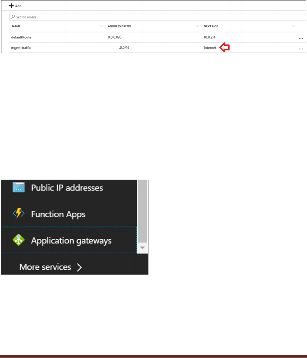
Palo Alto Networks Transit VNet 1.1 with the VM-Series Deployment Guide
V1.1 Page 30
named “defaultBackendUDR” for mgmt traffic, that will allow your public IP address with a next hop of
“Internet”
Another way to accomplish this would be to install a Bastion Host or Jump Box into the Backend Subnet
and SSH from that device.
Inbound Traffic Test
When launching the spoke template with firewalls, the spoke VNet will have an Application Gateway
(External LB), A set of firewalls and an internal Load balancer. This allows the spoke to host its own public
facing workloads. Once you have launched the Spoke template with firewalls you can test access to the
public facing workload by
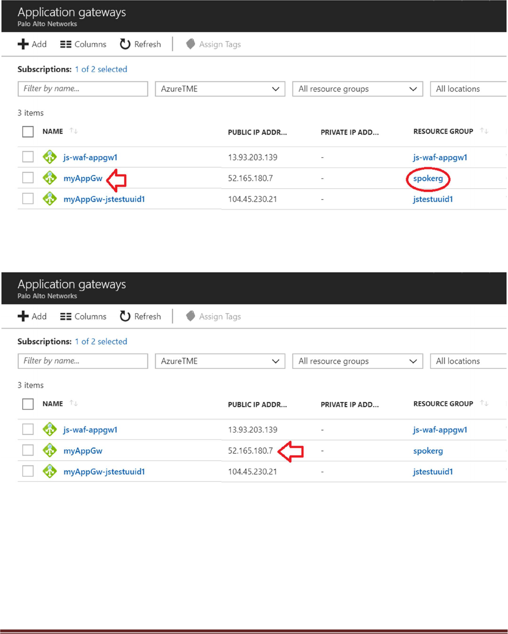
Navigating to “Application gateways” within the Azure Portal
Selecting the name of your Application Gateway that was created when you launched the Transit VNet
Spoke template. You can find the name of your Resource Group to help you differentiate from any other
Application Gateways.
Palo Alto Networks Transit VNet 1.1 with the VM-Series Deployment Guide
V1.1 Page 31
Locale the Public IP address for your Application Gateway.
Palo Alto Networks Transit VNet 1.1 with the VM-Series Deployment Guide
V1.1 Page 32
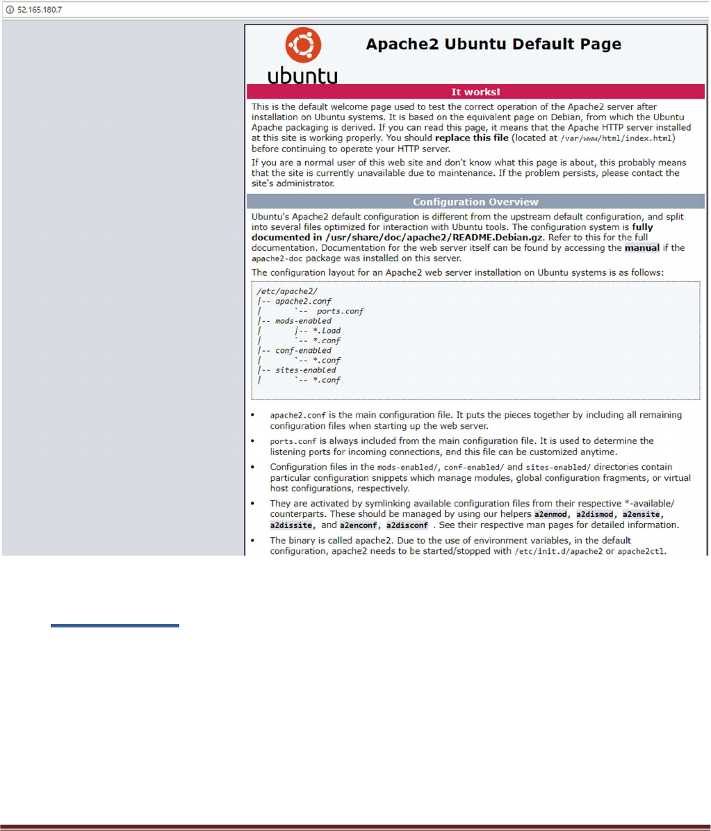
Place the Public IP address in your web browser. This IP address is the public facing IP of the
Application Gateway Load Balancer. You will see the default Ubuntu Page.
9. Cleanup
You can clean up the setup by deleting the resource groups for both the hub and spoke
deployments. Once you have deleted the resource groups for both the hub and spoke you will
have successfully deleted all resources created in this deployment.
Palo Alto Networks Transit VNet 1.1 with the VM-Series Deployment Guide
V1.1 Page 33
10. Gotchas
1. To successfully deploy your spoke template, the hub VM-Series firewalls must but up,
running and configured or the deployment will fail. This means you must import your
configuration snapshot file before launching your spoke template.
2. When adding a new spoke, if the subnet does not fall within the 1921.168.0.0/16 pre-
configured route, be sure to add the new spoke subnet to the hub firewall VM-Series static
route table. Clone the spoke route configuration and change the destination route
Palo Alto Networks Transit VNet 1.1 with the VM-Series Deployment Guide
V1.1 Page 34
3. Address objects are statically defined in the configuration snapshot file. After the
deployment of the spoke, the worker node will populate this object with the correct address.
4. When adding additional spokes using the firewall template you must change the spoke
firewall Default Route to point to the untrust Azure system gateway for the subnet of the
Untrust Interface.
5. Anytime you delete and redeploy a spoke VNet, it’s always best practice to delete the
peering configuration from within the hub VNet. The Azure system route table re-calculates
after peering is established. To add new routes, you must remove the peering association,
add the new routes then recreate the peering association.
Palo Alto Networks Transit VNet 1.1 with the VM-Series Deployment Guide
V1.1 Page 35
6. Your NAT policy in Panorama will fail to push to the firewall unless your translated packet
for source and destination looks like the screenshot below. For Destination do NOT use
static.
7. Be sure to never name something on Panorama the same as what is already configured
locally on the firewall. For example if you name your virtual route in the Panorama
Template “default”, your Panorama push to devices will fail because the local firewall has a
default virtual route. Use something like default_vr instead.
8. If you are not seeing any Metrics being populated within the Metric view within application
insights double check your instrumentation key within the Panorama Template
Configuration.
Palo Alto Networks Transit VNet 1.1 with the VM-Series Deployment Guide
V1.1 Page 36
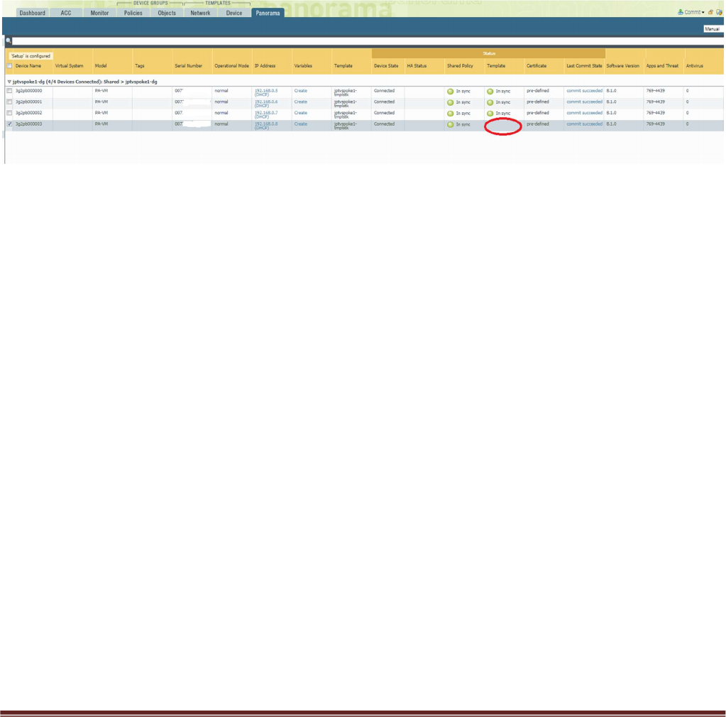
9. After the VM-Series in the VMSS bootstraps it will receive the settings to connect to
Panorama. Once connected the device group and template configuration will be pushed to
the firewall. After this takes place it is important to note that Panorama does NOT commit.
What this means is that after your bootstrap firewall receives its device group and template
configuration it will work as designed HOWEVER a commit will still need to take place on
Panorama to preserve the firewall in the device list. If a scale event takes place and a
firewall is added you will know because, although the template has been pushed to the
firewall it will not show in sync in panorama. See below.
You will want to perform a Panorama commit to avoid an unexpected reboot which will then
cause the Panorama to lose its candidate configuration.
10. When issue #9 happens, you can check the worker node logs to see data. From the Hub
resource group locate the worker node public IP address and log in using the pandemo
user account and password.
Type $sudo bash
Type # cd /root
Type cat worker.log | grep boot
You will see output like the following.
[2018-06-22 02:45:07,716] [INFO] (MainThread) VM 3g2pb000003 found in VMSS but not
in Panorama. May be not yet booted.
11. The worker node handles delicensing. You can check the /root/worker.log for information
on delicensed VM’s
[2018-06-19 21:20:13,324] [INFO] (MainThread) The following VMs need to be delicensed
[{'serial': u'007xxxxxxxxxxxx', 'hostname': u'3g2pb000001', 'name': u'007xxxxxxxxxxxx '}]
12. You can check the worker.log for issues with API calls to Panorama as well.

Palo Alto Networks Transit VNet 1.1 with the VM-Series Deployment Guide
V1.1 Page 37
13. The following output in the worker.log would signify that Panorama is not accessible or the
API key used is incorrect
[2018-06-27 06:05:08,661] [INFO] (MainThread) Executed URL
https://23.991.1341.105/api/?type=config&action=get&key=xxxxxxxxxxxxxxxxxxxxxxxxxxxx
xxxxxxxxxxxxxxxxxxxxxxxxxxxxxxxxxxx=&xpath=/config/devices/entry[@name='localhost.lo
caldomain']/device-group/entry[@name='jptvspoke1-dg']/devices
[2018-06-27 06:07:18,818] [ERROR] (MainThread) Execution of cmd failed with <urlopen
error [Errno 110] Connection timed out>
[2018-06-27 06:07:18,819] [INFO] (MainThread) Getting device list from DG jptvspoke1-dg
failed <urlopen error [Errno 110] Connection timed out>
14. If the Hub resource group worker node is powered off, the script needed to maintain the
relationship between Panorama and the VMSS does not automatically restart. To restart
this cronjob do the following.
#crontab -l
You should see
/tmp/monitor/monitor.py
