Practical Physics Experiment Manual B 03 Compound Pendulum
User Manual:
Open the PDF directly: View PDF ![]() .
.
Page Count: 10
Acceleration Due to Gravity 121
4.5 THE SIMPLE PENDULUM
The simple pendulum is a heavy point mass suspended by a weightless inextensible and
flexible string fixed to a rigid support. But these conditions defines merely an ideal simple
pendulum which is difficult to realize in practice. In laboratory
instead of a heavy point mass we use a heavy metallic spherical
bob tied to a fine thread. The bob is taken spherical in shape be-
cause the position of its centre of gravity can be precisely defined.
The length (l) of the pendulum being measured from the point of
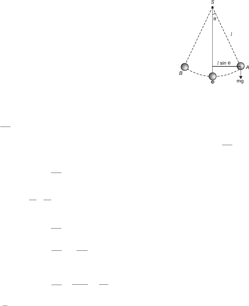
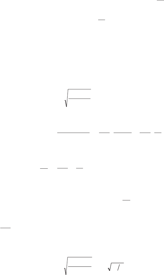
suspension to the centre of mass of the bob. In Fig. 4.1, let S be the
point of suspension of the pendulum and O, the mean or equilib-
rium position of the bob. On taking the bob a little to one side and
then gently releasing it, the pendulum starts oscillating about its
mean position, as indicated by the dotted lines. At any given in-
stant, let the displacement of the pendulum from its mean position
SO into the position SA be q. Then, the weight mg of the bob, acting
vertically downwards, exerts a torque or a moment –mgl sin q
about the point of suspension, tending to bring it back to its mean
position, the negative sign of the torque indicating that it is oppositely directed to the displace-
ment (q).
If d
dt
2
2
q be the acceleration of the bob, towards O, and I, its M.I. about the point of suspen-
sion (S), the moment of the force or the torque acting on the bob is also equal to Id
dt
2
2
q. We,
therefore, have
Id
dt
2
2
q = – mgl sinq
Now, expanding sin q into a power series, in accordance with Maclaurin’s theorem, we
have sin q = qq q
- +
3 5
3 5! ! .... if, therefore, q be small, i.e., if the amplitude of oscillation be small,
we may neglect all other terms except the first and take sin q = q, so that
Id
dt
2
2
q = – mglq
d
dt
2
2
q = -mgl
Iq.
or, since M.I. of the bob (or the point mass) about the point of suspension (S) is ml2, we have
d
dt
2
2
q = -=-= mq
mgl
ml
g
l
2q q –
where g
l= m, the acceleration per unit displacement.
Fig. 4.1
122 Practical Physics
The acceleration of the bob is thus proportional to its angular displacement q and is
directed towards its mean position O. The pendulum thus executes a simple harmonic motion
and its time-period is, therefore, given by
T = 21212
p p p
m= =
g
l
l
g
The displacement here being angular, instead of linear, it is obviously an example of an
angular simple harmonic motion. It is also evident from above expression that the graph
between l and T2 will be a straight line with a slope equal to 42
p
g.
4.6 DRAWBACKS OF A SIMPLE PENDULUM
Though simple pendulum method is the simplest and straightforward method for determina-
tion of ‘g’, it suffers from several defects:
(i) The conditions defining an ideal simple pendulum are never realizable in practice.
(ii) The oscillations in practice have a finite amplitude i.e., the angle of swing is not vanish-
ingly small.
(iii) The motion of the bob is not purely translational. It also possesses a rotatory motion
about the point of suspension.
(iv) The suspension thread has a finite mass and hence a definite moment of inertia about
point of suspension.
(v) The suspension thread is not inextensible and flexible. Hence it slackens when the limits
of swing are reached. Thus effective length of the pendulum does not remain constant
during the swing.
(vi) Finite size of the bob, yielding of the support and the damping due to air drag also need
proper corrections.
(vii) The bob also has a relative motion with respect to the string at the extremities of its
amplitude on either side.
Most of the defects are either absent or much smaller in the case of a rigid or compound
pendulum.
4.7 THE COMPOUND PENDULUM
Also called a physical pendulum or a rigid pendulum, a compound pendulum is just a rigid
body, of whatever shape, capable of oscillating about a horizontal axis passing through it.
The point in which the vertical plane passing through the c.g. of the pendulum meets the
axis of rotation is called its point or centre of suspension and the distance between the point of
suspension and the c.g. of the pendulum measures the length of the pendulum.
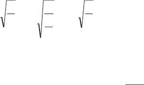
Thus figure shows a vertical section of a rigid body or a compound pendulum, free to
rotate about a horizontal axis passing through the point or centre of suspension S. In its normal
position of rest, its c.g., G, naturally lies vertically below S, the distance S and G giving the
length l of the pendulum.
Acceleration Due to Gravity 123
Let the pendulum be given a small angular displacement q into the
dotted position shown, so that its c.g. takes up the new position G¢ where
SG¢ = l. The weight of the pendulum, mg, acting vertically downwards at
G¢ and its reaction at the point of suspension S constitute a couple (or a
torque), tending to bring the pendulum back into its original position.
Moment of this restoring couple = – mgl sin q, the negative sign indi-
cating that the couple is oppositely directed to the displacement q. If I be
the moment of inertia of the pendulum about the axis of suspension
(through S) and d
dt
2
2
q, its angular acceleration, the couple is also equal to
Id
dt
2
2
q. So that, we have
Id
dt
2
2
q = -mgl sin q
‘Again, sin q = qq q
- +
3 5
3 5! ! ......., so that, if q be small, sin q q» and, therefore,
Id
dt mgl
2
2
qq= - , d
dt
mgl
I
2
2
qq= - F
H
GI
K
J = – mq, where mgl
I= m, the acceleration per unit displace-
ment.
The pendulum thus executes a simple harmonic motion and its time-period is given by
T = 21212
p p p
m= =
( )
mgl
I
I
mgl
Now, if I0 be the moment of inertia of the pendulum about an axis through its c.g., G,
parallel to the axis through S, we have, from the theorem of parallel axes, I = I0 + ml2. And if
k be the radius of gyration of the pendulum about this axis through G, we have I0 = mk2. So that,
I = mk2 + ml2 = m(k2 + l2).
\T = 2 2 2
2 2 2 2
2
p p p
m k l
mgl
k l
gl
k
ll
g
( )
+=+=
+
Thus, the time-period of the pendulum is the same as that of a simple pendulum of length
L = k
ll
2
+
F
H
GI
K
J or k l
l
2 2
+. This length L is, therefore, called the length of an equivalent simple
pendulum or the reduced length of the compound pendulum.
Since k2 is always greater than zero, the length of the equivalent simple pendulum (L) is
always greater than l, the length of the compound pendulum.
Fig. 4.2
124 Practical Physics
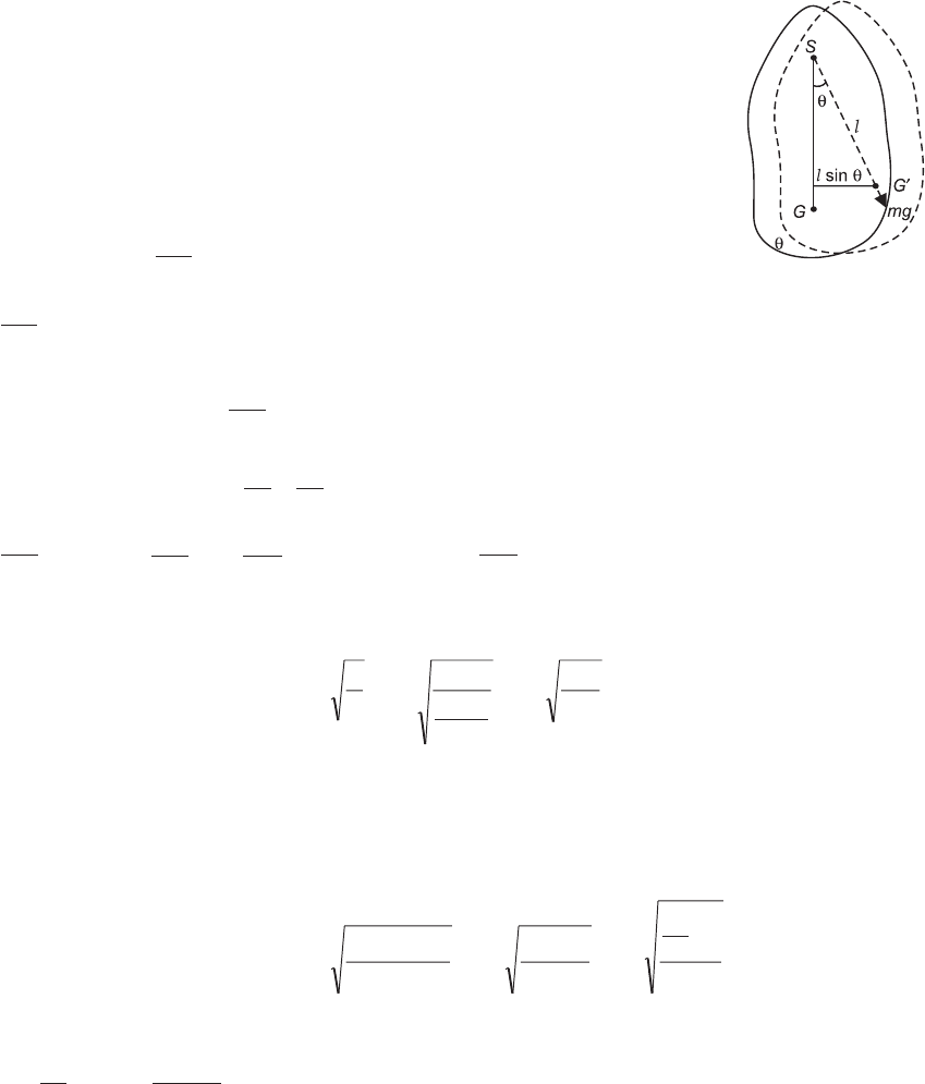
4.8 CENTRE OF OSCILLATION
A point O on the other side of the C.G. (G) of the pendulum in a line with
SG and at a distance k
l
2
from G is called the centre of oscillation of the
pendulum and a horizontal axis passing through it, parallel to the axis of
suspension (through S) is called the axis of oscillation of the pendulum.
Now, GO = k
l
2
and SG = l. So that, SO = SG + GO = l + k
l
2
= L, the
length of the equivalent simple pendulum, i.e., the distance between the
centres of suspension and oscillation is equal to the length of the equiva-
lent simple pendulum or the reduced length (L) of the pendulum and we,
therefore, have
T = 2pL
g
4.9 INTERCHANGEABILITY OF CENTRES OF SUSPENSION
AND OSCILLATION
If we put k
ll
2
=¢, we have L = lk
ll l
+ = + ¢
2
and, therefore,
T = 2pl l
g
+ ¢
b g
If how we invert the pendulum, so that it oscillates about the axis of oscillation through O,
its time period, T¢, say, is given by
T¢ = 2
2 2
p( )
k l
l g
+ ¢
¢
Since k
ll
2
= ¢ , we have k2 = ll¢.
Substituting ll¢ for k2 in the expression for T¢, therefore, we have
T¢ = 2 2
2
p p
( ) ,
ll l
l g
l l
gT
¢ + ¢
¢=+ ¢
F
H
GI
K
J=
i.e. the same as the time-period about the axis of suspension.
Thus, the centres of suspension and oscillation are interchangeable or reciprocal to each
other, i.e., the time-period of the pendulum is the same about either.
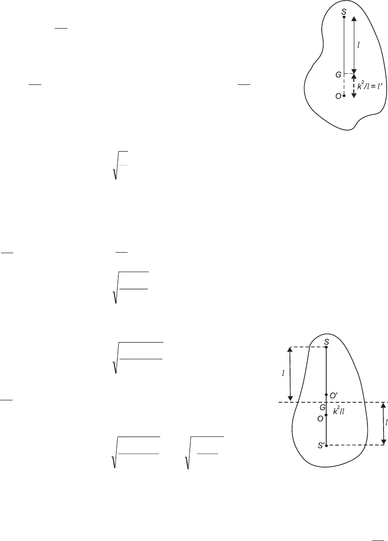
There are two other points on either side of G, about which the time-period of the pendu-
lum is the same as about S and O. For, if with G as centre and radii equal to l and k
l
2
Fig. 4.3
Fig. 4.4
Acceleration Due to Gravity 125
respectively, we draw two circles so as to cut SG produced in S and O¢ above, and at O and S¢
below G, as shown in figure, we have SG = GS¢ = l and GO¢ = GO = k
l
2
= l¢
\O¢S¢ = GS¢ + GO = l + k
l
2
= l + l¢ = SO.
Thus, there are four points in all, viz. S, O, S¢ and O¢, collinear with the c.g. of the pendulum
(G) about which its time-period is the same.
4.10 MAXIMUM AND MINIMUM TIME-PERIOD OF A
COMPOUND PENDULUM
For the time-period of a compound pendulum, we have the relation
T = 2
2 2
p( )
k l
lg
+
squaring which, we have
T2 = 42 2 2
p( )
k l
lg
+ = 4 4
22 2 2 2
p p
g
k l
l g
k
ll
+
F
H
GI
K
J= +
F
H
GI
K
J
Differentiating with respect to l, we have
2TdT
dl = 41
2 2
2
p
g
k
l
- +
F
H
GI
K
J
a relation showing the variation of T with length (l) of the pendulum.
Clearly, T will be a maximum or a minimum when dT
dl i e
=0, . ., when l2 = k2 or l = ± k or
when l = k, because the negative value of k is simply meaningless.
Since d T
dl
2
2 comes out to be positive, it is clear that T is a minimum when l = k, i.e., the time-
period of a compound pendulum is the minimum when its length is equal to its radius of
gyration about the axis through its c.g., And the value of this minimum time-period will be
Tmin = 2
2 2
p( )
k k
kg
+ = 2 2
pk g
If l = 0 or •, T = • or a maximum. Ignoring l = • as absurd, we thus find that the time-
period of a compound pendulum is the maximum when length is zero, i.e., when the axis of
suspension passes through its c.g. or the c.g. itself is the point of suspension.
126 Practical Physics
4.11 ADVANTAGES OF A COMPOUND PENDULUM
(i) The errors due to finite weight of string and its extensibility are eliminated.
(ii) The uncertainty in the motion of the bob is absent.
(iii) Due to larger mass of the body, viscous forces due to air have negligible effect.
(iv) The errors due to finite amplitude of swing and yielding of the support can be deter-
mined and corrections applied for them.
(v) The equivalent length of the simple pendulum in this case can be determined more
accurately as the position of centre of suspension is known and that of the centre of
oscillation is determined graphically.
4.12 DETERMINATION OF THE VALUE OF G
From the interchangeability of the points of suspension and oscillation it would appear that
the easiest method of determining the value of ‘g’ at a place would be to locate two points on
either side of the C.G. of the pendulum about which the time-period of the pendulum is the
same. These points would then correspond to the centres of suspension and oscillation of the
pendulum and the distance between them would give L, the length of the equivalent simple
pendulum. So that, if T be the time-period of the pendulum about either of these, we shall have
T = 2pL
g, and, therefore, g = 42
2
pL
T.
4.13 OBJECT
To determine the value of ‘g’, and the moment of inertia of a bar about C.G. by means of a bar
pendulum.
Apparatus: A bar pendulum, steel knife edge, support for the knife edge, a stop watch,
telescope and a meter scale.
Description of the apparatus: The bar pendulum consists of a uniform rectangular long metal
bar having several holes drilled along its length so that the line of holes passes through the
centre of gravity. Any desired hole may be slipped on to a fixed horizontal knife edge and the
bar can be made to oscillate about it in a vertical plane. The
knife edge is a piece of hard steel grounded to have a sharp
edge. The knife edge rests on two glass plates one on each side
placed on a rigid support. The knife edge is therefore horizon-
tal and the bar swings regularly without twisting.
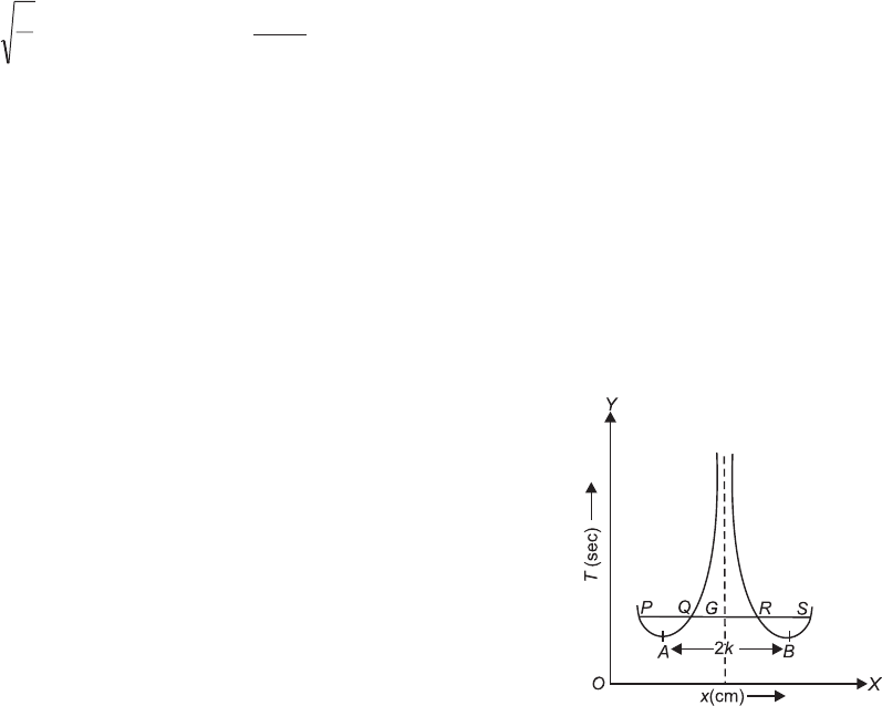
Theory: In this experiment a bar is allowed to oscillate about
horizontal knife edge passing through successive holes from
one end to the other end. Time period is determined for each
case. A graph is then plotted with distance of knife edge from
one end of the bar on x-axis and the corresponding time pe-
riod on y-axis. A graph of the type shown in figure and con-
sisting of two symmetrical branches is obtained. Fig. 4.5
Acceleration Due to Gravity 127
The time period is maximum at points A and B. The distance between these points is
double the radius of gyration k of the bar about a parallel axis through the C.G. of the bar.
These points are symmetrically situated on either side of centre of gravity of the bar. Their
middle point gives the position of C.G. of the bar. In this case the equivalent length of simple
pendulum is L = 2k and the time period is given by
Tmin = 222
p p
k
g
AB
g
=
Any line drawn parallel to distance axis cuts the graph at four points P, Q, R and S, about
which the time periods are equal. Pairs P, S and Q, R are symmetrically situated on either side
of the C.G. of the bar. If P(or S) is taken as point of suspension R (or Q) becomes the point of
oscillation. The equivalent length of simple pendulum L, then equals the distance PR or QS. If
PG = GS = l1 and QG = GR = l2, then time-period about these points is given by
T=21 2
pl l
g
+
Thus knowing l1 + l2 = PR = QS and T we can find the value of ‘g’.
It may be noted that l1 and l2 are related as
l2 = k
l
2
1
Thus the radius of gyration of the bar about a
parallel axis through its centre of gravity is obtained
k = l l PG GR QG GS
1 2
´ = ´ = ´
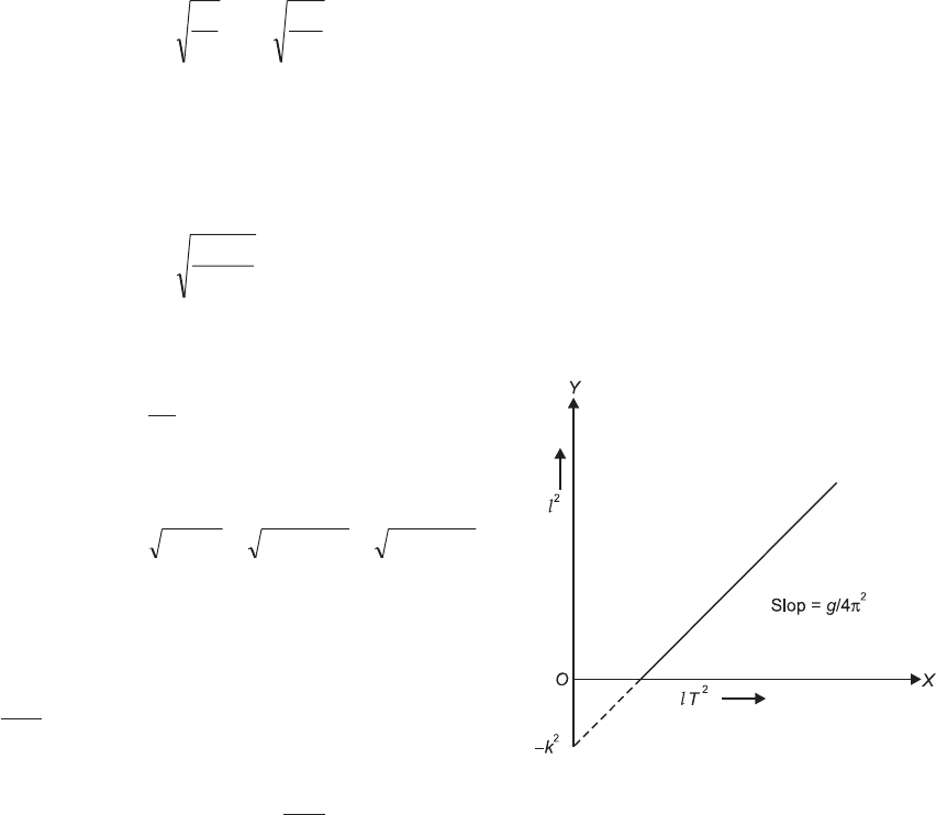
Now, instead of calculating the value of g as
above, a better method, suggested by Ferguson in
the year 1928, is to plot lT2 along the axis of x and l2
along the axis of y, which, from the relation l2 + k2 =
lT g
2
2
4p
F
H
GI
K
J must give a straight line graph, as shown
in figure.
The slope of the curve is g
42
p, from where the value of g may be easily obtained. Further,
the intercept of the curve on the axis of y-gives –k2 and thus the values of both g and k can be
obtained at once.
Procedure
1. Ensure that the knife edge, if fixed, is horizontal otherwise the frame on which movable
knife edge is to be rested is horizontal.
2. Find the mass of the bar.
3. Suspend the bar about the knife edge from the hole nearest to one end. Displace the bar
slightly to one side in vertical plane and release to put it into oscillations. With the help of
Fig. 4.6
128 Practical Physics
a stop watch find the time for 50 oscillations and hence determine the period of oscilla-
tions.
4. Repeat above procedure by suspending bar from successive holes. Beyond the C.G. the
bar will turn upside down. Continue till last hole at the other end is reached.
5. Measure the distance from one fixed end to those points in successive holes where the
knife edge supports the bar.
6. Plot a graph with distances of knife-edge from one end on x-axis and corresponding time
period on y-axis. A curve of the type shown in Fig. 4.5 is obtained.
7. Measure the value 2k = AB from the graph and Tmin and hence calculate the value of ‘g’.
Alternately choose certain value of T and find (l1 + l2) the corresponding mean equivalent
length of simple pendulum and hence calculate the value of g. This procedure may be
repeated to find mean value of ‘g’.
8. Plot the curve lT2 against l2 (Fig. 4.6). Calculate ‘g’ and ‘k’ and compare the results found
in above.
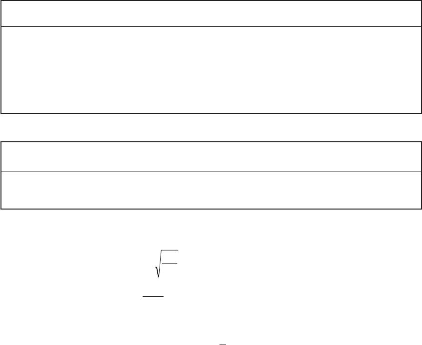
Observations: 1. Mass of the bar =
2. Measurement of periodic time and distance of point of support:
S.No. Order of Holes Distance of support C.G. No. of Oscillations Time (sec) Periodic time (Sec)
(in cm)
1.
2.
3.
4.
5.
Position of Center of gravity (Turn the bar pendulum)
6.
7.
3. Measurement of T, l1, l2 from the graph :
S.No. T(in sec) l1l2l = l1 + l2k2 = l1l2
(in meter) (in meter) (in meter)
1.
2.
3.
Calculation: (i) From graph AB = 2k = ........ cm
Minimum time period Tmin = ....... sec
Since Tmin = 2pAB
g
g = 42
2
p
TAB
min
´ = cm/sec2
(ii) From graph T = sec.
PS = ....... cm, \ l1 = 1
2PS =.... cm

Acceleration Due to Gravity 129
QR = ..... cm, \ l2 = 1
2QR =.... cm
Thus, mean L =l1 + l2 = ..... cm
Hence g = 42
2
p
TL = ..... cm/sec2
Repeat the calculation for two or three different values of T and calculate the mean value
of g.
(iii) From graph, for a chosen value of T,
PS = ...... cm \ l1 = 1
2PS = ...... cm
QR = ...... cm \ l2 = 1
2QR = ..... cm
\k = 1 2 ...... cm
l l
× =
Repeat this calculation for 2 or 3 different values of T and calculate mean value of radius
of gyration.
Result: The value of ‘g’ at ..... is = ....... cm/sec2
Value of ‘g’ from graph =
Value of k from graph =
Moment of Inertia of the bar =
Standard result: The value of g at ....... = ........
Percentage error: ..........%
Sources of error and precautions
1. The knife edge is made horizontal.
2. If the knife edge is not perfectly horizontal the bar may be twisted while swinging.
3. The motion of bar should be strictly in a vertical plane.
4. Time period should be noted only after all types of irregular motions subside.
5. The amplitude of swing should be small (4º – 5º). So that the condition sin q = q assumed
in the derivation of formula remains valid.
6. The time period of oscillation should be determined by measuring time for a large num-
ber of oscillations with an accurate stop watch.
7. The graph should be drawn smoothly.
8. All distances should be measured and plotted from one end of the rod.
Theoretical error: g is given by the formula
g = 42
2
pL
T
Taking log and differentiating
dg
g = d d
L
L
T
T
+ =
2.......
Maximum possible error = ........ %
130 Practical Physics
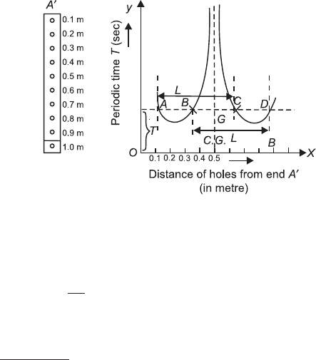
Correct way of plotting graph in period of oscillation T and hole distance: The centre of
gravity of the bar is to be at the centre of bar, it is necessary that distribution of mass in the bar
should be uniform all along its length. A small non-uniformity will, however, shift the position
of C.G. from centre of bar. It is, therefore, always preferred to measure the distance of holes
from one end of the bar instead of measuring from its centre and then plot a graph as shown
in figure.
Fig. 4.7
At a particular time period T1, a horizontal line is drawn giving four points of intersection
with the curve about which time period is same.
From graph AC = BD = lk
lL
+ =
2
.
Centre of AD will point C.G. of bar
we can also find L = ( )
AC BD
+
2.
Drawback: A drawback of the method is that it being well high impossible to pin-point the
position of the c.g. of the bar or the pendulum (as, in fact, of any other body), the distances
measured from it are not vary accurate. Any error due to this is, however, eliminated automati-
cally as the graph is smoothed out into the form of a straight line.
Superiority of a compound pendulum over a simple pendulum: The main points of the
superiority of a compound pendulum over a simple pendulum are the following:
1. Unlike the ideal simple pendulum, a compound pendulum is easily realisable in actual
practice.
2. It oscillates as a whole and there is no lag like that between the bob and the string in the
case of a simple pendulum.
3. The length to be measured is clearly defined. In the case of a simple pendulum, the point
of suspension and the C.G. of the bob, the distance between which gives the length of the
pendulum, are both more or less indefinite points, so that the distance between them, i.e.,
l, cannot be measured accurately.
4. On account of its large mass, and hence a large moment of inertia, it continues to oscillate
for a longer time, thus enabling the time for a large number of oscillations to be noted and
its time-period calculated more accurately.
