Manual Introduction Bil Jax Personal Lift XLT 1571AC B33 01 0062
User Manual: Bil-Jax Personal Lift XLT-1571AC
Open the PDF directly: View PDF ![]() .
.
Page Count: 78
- 1 Safety
- 2 Introduction
- 3 Operation
- 4 Maintenance
- 5 Replacement Decals
- 6 Parts List
- 6-1 TOP MAST PARTS LIST
- 6-2 CENTER MAST PARTS LIST
- 6-3 LOWER MAST PARTS LIST
- 6-4 REAR COMPARTMENT PARTS LIST
- 6-5 HYDRAULIC PUMP COMPARTMENT PARTS LIST
- 6-6 UPPER BASE PARTS LIST
- 6-7 BASE MAST PARTS LIST
- 6-8 LOWER BASE PARTS LIST
- 6-9 PLATFORM PARTS LIST
- 6-10 HYDRAULIC UNIT PARTS LIST
- 6-11 HYDRAULIC FITTINGS AND HOSES DIAGRAM
- 6-12 HYDRAULIC FITTINGS AND HOSES SCHEMATIC
- 6-13 ELECTRICAL DIAGRAM
- 7 ANSI Reprint
Model XLT-1571AC
Operation and
Maintenance Manual
R
Electric Hydraulic Lift Platform
WARNING
XLT
1
5
7
1
W
O
R
K
F
O
R
C
E
WARNING
DANGER
WARNING
WARNING
B33-01-0062

TELESCOPIC PERSONNEL LIFT
This equipment is designed and manufactured in compliance with the duties, re-
sponsibilities, and standards set forth for manufacturers in the ANSI 92.3 standard
in effect at the time of manufacture.
This equipment will meet or exceed applicable OSHA codes and ANSI A92.3 stan-
dards when used in accordance with sections 5, 6, 7, 8, 9 & 10 of ANSI A92.3 and all
other manufacturer’s recommendations.
It is the responsibility of the user of this equipment to follow all applicable ANSI,
OSHA, Federal, State, and local codes and regulations that govern the safe opera-
tion of this equipment.

i
Table of Contents
1 Safety................................................................................................................1-1
1-1 Introduction.........................................................................................1-1
1-2 Before Operation ...............................................................................1-3
1-3 During Operation................................................................................1-4
1-4 Maintenance Safety............................................................................1-6
1-5 Damaged Equipment Policy .............................................................1-6
2 Introduction.....................................................................................................2-1
2-1 General Description...........................................................................2-1
2-2 Specifications......................................................................................2-2
2-3 Warranty .............................................................................................2-2
3 Operation.........................................................................................................3-1
3-1 Operator Controls ..............................................................................3-1
3-2 Normal Operating Procedure............................................................3-2
3-3 Emergency Lowering Procedure ......................................................3-3
4 Maintenance ....................................................................................................4-1
4-1 Scheduled Service Checks................................................................4-1
4-2 Lubrication..........................................................................................4-3
4-3 Hydraulic System...............................................................................4-5
4-4 Electrical System .............................................................................4-11
4-5 Lift Chains And Slide Blocks .......................................................4-12
4-6 Troubleshooting................................................................................4-15
5 Replacement Decals ........................................................................................5-1
6 Parts List..........................................................................................................6-1
6-1 Top Mast Parts List..........................................................................6-2
6-2 Center Mast Parts List......................................................................6-4
6-3 Lower Mast Parts List......................................................................6-6
6-4 Rear Compartment Parts List............................................................6-8
6-5 Hydraulic Pump Compartment Parts List .....................................6-10
6-6 Upper Base Parts List ....................................................................6-12
6-7 Base Mast Parts List ......................................................................6-14
6-8 Lower Base Parts List....................................................................6-16
6-9 Platform Parts List ..........................................................................6-18
6-10 Hydraulic Unit Parts List ...............................................................6-20
6-11 Hydraulic Fittings And Hoses Diagram............................................6-22
6-12 Hydraulic Fittings And Hoses Schematic.....................................6-24
6-13 Electrical Diagram...........................................................................6-25
7 ANSI Reprint..................................................................................................7-1

ii
List of Illustrations
Figure 3-1. Lower Control Box................................................................................. 3-1
Figure 3-2. Upper Control Box................................................................................. 3-2
Figure 3-3. Emergency Lowering Valve................................................................... 3-3
Figure 4-1. Lift Chain Lubrication............................................................................ 4-3
Figure 4-2. Caster Lubrication.................................................................................. 4-4
Figure 4-3. Pressure Relief Valve Adjustment.......................................................... 4-6
Figure 4-4. Flow Restrictor Valve ............................................................................ 4-7
Figure 4-5. Raise Valve Operation Check ................................................................ 4-8
Figure 4-6. Hydraulic Cylinder Exploded View..................................................... 4-10
Figure 4-7. Chain Elongation Inspection ................................................................ 4-12
Figure 4-8. Lift Chain Adjustment.......................................................................... 4-13
Figure 4-9. Slide Block Adjustment........................................................................ 4-14
Figure 5-1. Replacement Decals ............................................................................... 5-2
Figure 5-2. Decal Locations, Side View ................................................................... 5-3
Figure 5-3. Decal Locations, Front View.................................................................. 5-4
Figure 6-1. Top Mast Exploded View....................................................................... 6-2
Figure 6-2. Center Mast Exploded View .................................................................. 6-4
Figure 6-3. Lower Mast Exploded View................................................................... 6-6
Figure 6-4. Rear Compartment Exploded View........................................................ 6-8
Figure 6-5. Hydraulic Pump Compartment Exploded View................................... 6-10
Figure 6-6. Upper Base Exploded View ................................................................. 6-12
Figure 6-7. Base Mast Exploded View ................................................................... 6-14
Figure 6-8. Lower Base Exploded View................................................................. 6-16
Figure 6-9. Platform Exploded View...................................................................... 6-18
Figure 6-10. Hydraulic Unit Assembly..................................................................... 6-20
Figure 6-11. Hydraulic Fittings and Hoses Diagram ................................................ 6-22
Figure 6-12. Hydraulic Fittings and Hoses Schematic.............................................. 6-24
Figure 6-13. Electrical Diagram................................................................................ 6-25
Figure 6-14. Electrical Layout Diagram ................................................................... 6-26

iii
List of Tables
Table 1-1. Minimum Safe Approach Distances .......................................................1-4
Table 2-1. Specifications..........................................................................................2-2
Table 4-1. Daily/Weekly Service Checks.................................................................4-1
Table 4-2. Monthly Service Checks .........................................................................4-2
Table 4-3. Troubleshooting Chart ..........................................................................4-15
Table 5-1. Replacement Decals................................................................................5-1
Table 6-1. Top Mast Parts List.................................................................................6-3
Table 6-2. Center Mast Parts List.............................................................................6-5
Table 6-3. Lower Mast Parts List.............................................................................6-7
Table 6-4. Battery Compartment Parts List..............................................................6-9
Table 6-5. Hydraulic Pump Compartment Parts List .............................................6-11
Table 6-6. Upper Base Parts List............................................................................6-13
Table 6-7. Base Mast Parts List..............................................................................6-15
Table 6-8. Lower Base Parts List ...........................................................................6-17
Table 6-9. Platform Parts List.................................................................................6-19
Table 6-10. Hydraulic Unit Parts List ......................................................................6-21
Table 6-11. Hydraulic Fittings and Hoses Parts List................................................6-23
Table 7-1. Minimum Safe Approach Distance (M.S.A.D.) to energized
(exposed or insulated) power lines and parts....................................7-11

iv

1-1
1
Safety
1-1 INTRODUCTION
Familiarity and proper training are required for the safe operation of mechanical equip-
ment. Equipment operated improperly or by untrained personnel can be dangerous. Read
the operating instructions in this manual and become familiar with the location and
proper use of all controls. Inexperienced operators should receive instruction from some-
one familiar with the equipment before being allowed to operate the machine. The use of
intelligence and common sense in the operation of mechanical equipment is the best
practice in any safety policy. Be professional and always observe the safety procedures
set forth in this manual.
All OSHA, ANSI, state and local codes and regulations pertaining to this equipment
should be obtained, read, and thoroughly understood before attempting to operate this
equipment. Persons under the influence of drugs, alcohol, or prescription medication
should not be on or near this equipment. Common sense should be implemented at all
times during the use of this equipment. Do not operate this equipment in areas where
equipment or user may come in contact with live power source.
The information contained herein is not to be considered as legal advice and is intended
for informational purposes only. This information is offered to alert Bil-Jax customers to
procedures that may be of concern to them.
This information is not intended to be all inclusive and is to be followed in the use of
Bil-Jax equipment only.
For any questions concerning the safe use of this equipment, call 800-537-0540 before
operating.
XLT-1571AC
Safety Notes
This manual contains DANGERS, WARNINGS, CAUTIONS, and NOTES that must be
followed to prevent the possibility of improper service, damage to the equipment, or per-
sonal injury.
DANGER
Dangers warn of equipment operation near electrical power lines that could lead
to personal injury or death.
WARNING
Warnings describe conditions or practices that could lead to personal injury or
death.
CAUTION
Cautions provide information important to prevent errors that could damage ma-
chine or components.
NOTE: Notes contain additional information important to a procedure.
1-2

1 — SAFETY
1-3
1-2 BEFORE OPERATION
Ensure the following general safety precautions are followed before operating the Cougar
Lift.
ALWAYS survey the usage area for potential hazards such as untampered earth
fills, unlevel surfaces, overhead obstructions, and electrically charged conduc-
tors or wires. Be aware of any potential hazards and always consider what could
happen. Watch for moving vehicles in the operating area.
ALWAYS read, understand, and follow the procedures in this manual before at-
tempting to operate equipment.
ALWAYS inspect the equipment for damaged or worn parts. Check for cracked
welds, hydraulic leaks, damaged wiring, loose wire connectors, damaged cast-
ers, and damaged floor pads. Also check for any improper operation. NEVER
operate equipment if damaged in any way. Improperly operating equipment
must be repaired before using.
ALWAYS wear proper clothing for the job. Wear protective equipment as re-
quired by federal, state, or local regulations.
ALWAYS locate, read, and follow all directions and warnings displayed on the
equipment.
ALWAYS inspect the equipment for any “DO NOT USE” tags placed on the
equipment by maintenance personnel. NEVER use any equipment tagged in this
way until repairs are made and all tags are removed by authorized maintenance
personnel.
ALWAYS make sure the platform and shoes are free of mud, grease, or other
foreign material. This will reduce the possibility of slipping.
NEVER allow improperly trained personnel to operate this equipment. Only
trained and authorized personnel shall be allowed to operate this equipment.
NEVER operate this equipment if you are under the influence of alcohol or
drugs or if you feel ill, dizzy, or unsteady in any way. Operators must be physi-
cally fit, thoroughly trained, and not easily excitable.
NEVER modify, alter, or change the equipment in any way that would affect its
original design or operation in any way.
NEVER operate this equipment in ways for which it is not intended.
XLT-1571AC
1-3 DURING OPERATION
Ensure the following general safety precautions are followed during the operation of the
Cougar Lift.
DANGER
This machine is not insulated for use near electrical power lines and DOES NOT
provide protection from contact with or close proximity to any electrically
charged conductor. Operator must maintain safe clearances at all times (10 feet
minimum) and always allow for platform movement such as wind induced sway.
Always contact the power company before performing work near power lines. As-
sume every line is hot. Remember, power lines can be blown by the wind.
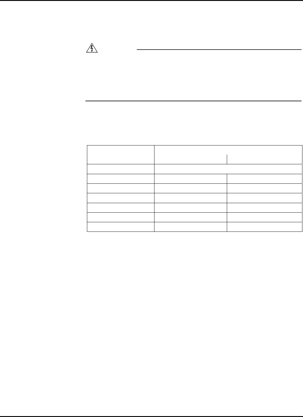
Refer to Table 1-1 for minimum safe approach distances between machine and electrical
power lines.
Table 1-1. Minimum Safe Approach Distances
Minimum Safe Approach Distance
Voltage Range
(Phase to Phase) (Feet) (Meters)
0 to 300V Avoid Contact
Over 300V to 50KV 10 3.05
Over 50KV to 200KV 15 4.60
Over 200KV to 350KV 20 6.10
Over 350KV to 500KV 25 7.62
Over 500KV to 750KV 35 10.67
Over 750KV to 1000KV 45 13.72
ALWAYS position lift far enough away from power sources to ensure that no
part of the lift can accidentally reach into an unsafe area.
ALWAYS operate only on a firm and level surface. NEVER use on surfaces
that do not support the weight of the equipment and its rated load capacity.
ALWAYS keep yourself and all personnel away from potential pinch or shear
points.
ALWAYS report any misuse of equipment to the proper authorities. Horseplay
is prohibited.
ALWAYS maintain good footing on the platform. NEVER wear slippery soled
shoes.
ALWAYS make certain all personnel are clear and there are no obstructions be-
fore repositioning platform.
ALWAYS cordon off area around the base to keep personnel and other equip-
ment away from it while in use.
ALWAYS stay clear of wires, cables, and other overhead obstructions.
ALWAYS disconnect power at the batteries when not in use to guard against
unauthorized use.
1-4

1 — SAFETY
1-5
NEVER allow electrode contact with any part of the platform if welding is be-
ing performed by a worker from the platform.
NEVER use without the floor pads fully based on the floor.
NEVER override or by-pass manufacturer's safety devices.
NEVER release floor locks or move unit with a person or materials on board.
NEVER stand or sit on guardrails. Work only within the platform guardrail area
and do not lean out over guardrails to perform work.
NEVER attempt to increase working height with boxes, ladders, or other means.
NEVER operate this equipment when exposed to high winds, thunderstorms,
ice, or any other weather conditions that would compromise the safety of the
operator.
NEVER climb up or down masts.
NEVER allow ropes, electric cords, hoses, etc. to become entangled in the
equipment when the platform is being raised or lowered.
NEVER exceed manufacturer's platform load limits and make sure all materials
are evenly distributed over the entire platform.
NEVER exceed platform load ratings by transferring loads to platform at ele-
vated heights.
NEVER use guardrails to carry materials and never allow overhang of materials
when raising or lowering platform.

XLT-1571AC
1-6
1-4 MAINTENANCE SAFETY
Ensure the following general safety precautions are observed when maintenance is per-
formed on the Cougar Lift.
ALWAYS perform maintenance procedures according to manufacturer's re-
quirements. NEVER short change maintenance procedures.
ALWAYS check hydraulic system. Make sure all lines, connectors, and fittings
are tight and in good condition.
ALWAYS keep all mechanisms properly adjusted and lubricated according to
maintenance schedule and manufacturers specifications.
ALWAYS perform a function check of operating controls before each use and
after repairs have been made.
ALWAYS locate and protect against possible pinch points prior to performing
maintenance and repairs.
ALWAYS use only factory approved parts to repair or maintain this equipment.
If this equipment is rebuilt, retesting is required in accordance with factory in-
structions.
NEVER add unauthorized fluids to the hydraulic system or battery. Check
manufacturers specifications.
NEVER exceed the manufacturer's recommended relief valve settings.
NEVER attempt repairs you do not understand. Consult manufacturer if you
have any questions regarding proper maintenance, specifications, or repair.
1-5 DAMAGED EQUIPMENT POLICY
Safety Statement
At Bil-Jax, we are dedicated to the safety of all users of our products. Therefore, all
Bil-Jax lifts are designed, manufactured and tested to comply with current applicable
Federal OSHA and ANSI codes and regulations.
Damage Policy
There may be occasions when a Bil-Jax lift is involved in an incident that results in struc-
tural damage to the lift. This can seriously compromise the ability of the lift to perform in
a safe manner. Therefore, whenever a Bil-Jax lift is damaged structurally or when there is
the possibility of structural damage (this damage may be internal and is not always visi-
ble to the naked eye), Bil-Jax requires that the lift be returned to our facility at 125 Tay-
lor Parkway, Archbold, Ohio, for reconditioning. If you have any questions concerning
what constitutes structural damage, please call the Bil-Jax Service Department at
800-537-0540.
Damage Repair Notice
There may be occasions when a Bil-Jax lift is involved in an incident resulting in non-
structural damage. When this occurs and repairs are made by the owner or area distribu-
tor, please notify Bil-Jax of these non-maintenance repairs and request a repair form to
be filled out and returned to Bil-Jax.

2-1
2
Introduction
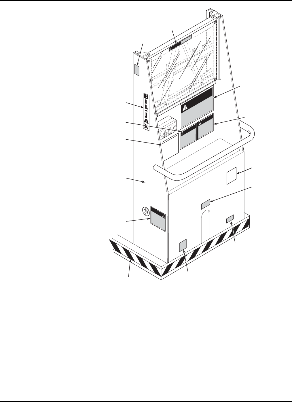
2-1 GENERAL DESCRIPTION
The model XLT-1571 Cougar Lift is designed and manufactured for use as a warehouse
stocking and order picking machine. Its unique guard rail design permits the operator to
ride on the platform with the load, while transferring it from group level to its overhead
storage location. The maximum platform load is limited to 500 lbs.
Platform elevation is accomplished by means of a 1-1/2 inch displacement type hydraulic
cylinder. The lower telescoping section is pushed vertically upward by the cylinder while
the upper sections are raised by a mechanical motion advantage accomplished through
two sets of chains and sheaves. The platform is raised three inches for each one inch of
cylinder extension. Platform elevation and descent is controlled by pushbuttons on the
upper control box located on the platform.
Safety of operation is assured by proper inspection and maintenance procedures as set
forth in this manual. The possibility of platform free-fall is eliminated by proper mainte-
nance and replacement of the chains, sheaves and sheave pins, a properly installed flow
restrictor valve, and a clean mast. The non-adjustable restrictor valve controls and fixes
the rate of platform descent whether empty or fully loaded to approximately 0.6 feet per
second. A hydraulic hose failure will result in the same rate of descent, eliminating free-
fall, when the restrictor valve is installed properly.
Emergency lowering of the platform is accomplished by means of a manual control valve
located on the hydraulic manifold block assembly, next to the pump/motor unit.
The Cougar Lift features a displacement type of cylinder that will not rust or corrode dur-
ing storage since the cylinder rod is immersed in oil. It is important that the cylinder rod
be kept clean and undamaged for the protection of the cylinder head packing.
The floor lock safety switch prevents the unit from raising until the two floor pads have
been properly engaged and helps to make the Cougar Lift a safe, dependable machine.
Carefully read all the safety instructions contained in Section 1 of this manual before op-
erating the Cougar Lift.

XLT-1571AC
2-2
2-2 SPECIFICATIONS
Cougar Lift Electric Hydraulic Lift Platform
Model Number XLT-1571AC Serial Number ________________
Manufactured by: Bil-Jax, Inc.
125 Taylor Parkway
Archbold, Ohio 43502
800-537-0540
Table 2-1. Specifications
Rated Platform Load 500 lbs (227 kg) total including operator [1 person +
materials not to exceed 500 lbs (227 kg)]
Extended Platform Height 14 ft-10 in. (4.5 m)
Retracted Platform Height 18-1/2 in. (0.47 m)
Platform Dimensions 29 in. w x 50 in. l x 42 in. h
(0.74 m x 1.27 m x 1.07 m)
Base Dimensions 30-1/2 in. w x 71 in. l x 77 in. h
(0.77 m x 1.8 m x 1.95 m)
Retracted Dimensions 30-1/2 in. w x 73-1/2 in. l x 77 in. h
(0.77 m x 1.87 m x 1.95 m)
Gross Shipping Weight 1025 lbs (465 kg)
Full Extension Time 20 seconds empty, 32 seconds loaded
Complete Retraction Time 22 seconds empty, 22 seconds loaded
Platform Extension Rate 0.66 ft (0.3 m)/sec. empty
0.42 ft (0.19 m)/sec. loaded
Hydraulic System Pressure 1200 psi empty, 2100 psi loaded
Power Source 110VAC, 60 Hz
2-3 WARRANTY
Bil-Jax warrants its telescopic lifts for three years from the date of delivery against all
defects of material and workmanship, provided the unit is operated and maintained in
compliance with Bil-Jax’s operating and maintenance instructions. Bil-Jax will, at its
option, repair or replace any unit or component part which fails to function properly in
normal use.
This warranty does not apply if the lift and/or its component parts have been altered,
changed, or repaired without the consent of Bil-Jax or by anyone other than Bil-Jax or its
factory trained personnel, nor if the lift and/or its components have been subjected to
misuse, negligence, accident or any conditions deemed other than those considered as
occurring during normal use.
Components not manufactured by Bil-Jax, are covered by their respective manufacturers
warranties. A list of those components and their warranties is available upon written
request to Bil-Jax.
Bil-Jax shall not in any event be liable for the cost of any special, indirect or
consequential damages to anyone, product, or thing. This warranty is in lieu of all other
warranties expressed or implied. We neither assume nor authorize any representative or
other person to assume for us any other liability in connection with the sale, rental, or use
of this product.
3-1
3
Operation
3-1 OPERATOR CONTROLS
The operator controls for the Cougar Lift are contained on the upper and lower control
boxes.
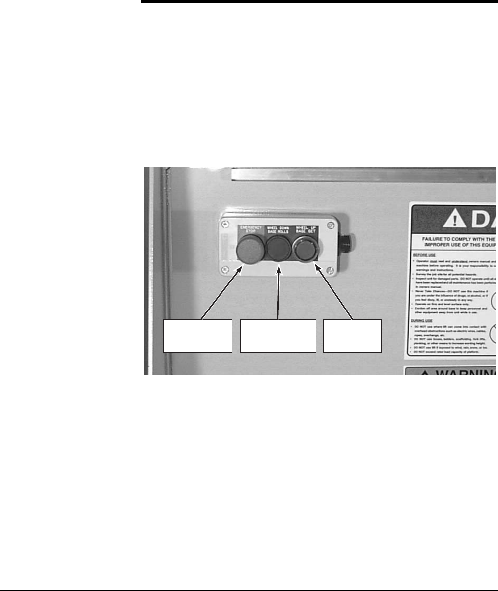
Lower Control Box
The lower control box is located on the front of the base platform and contains 3
pushbutton controls, EMERGENCY STOP, WHEEL DOWN/BASE ROLLS, and WHEEL UP/BASE
SET. The controls on the lower control box are used to set the unit in proper position be-
fore the platform can be raised. Refer to Figure 3-1.
EMERGENCY
STOP
BUTTON
WHEEL DOWN
BASE ROLLS
BUTTON
WHEEL UP
BASE SET
BUTTON
Figure 3-1. Lower Control Box

XLT-1571AC
Upper Control Box
The upper control box is located on the back of the top mast and is accessible from the
platform. The upper control box contains 3 controls, UP/DOWN selector switch,
EMERGENCY STOP pushbutton, and ON pushbutton. The controls on the upper control box
are used to raise and lower the unit. Refer to Figure 3-2.
UP/DOWN
SELECTOR
SWITCH
EMERGENCY
STOP
PUSHBUTTON
ON
PUSHBUTTON
Figure 3-2. Upper Control Box
3-2 NORMAL OPERATING PROCEDURE
Perform the following procedures to operate the Cougar Lift.
1. Read and follow all safety precautions contained in Section 1 and all responsi-
bilities outlined in the ANSI A92.3 reprint contained in Section 7 of this man-
ual.
2. Position the lift at the work area. Make sure the lift is on a firm and level surface
and that there are no potential hazards such as overhead obstructions or electri-
cally charged conductors. Do not operate the lift if such hazards exist.
3. Check the lift for damaged or worn parts and repair or replace as necessary.
4. Check to be sure that the platform is properly attached to the lift.
5. Raise the casters located under the platform by depressing the WHEEL UP/BASE
SET pushbutton located on the lower control box. Raising the casters allows the
base to set firmly on the two foot pads.
6. The lift should be level and positioned on the two foot pads with the WHEEL
UP/BASE SET pushbutton lit green. Ensure that the platform's upward path of
travel is free from obstructions. Reposition the lift if necessary.
NOTE: The lift is equipped with a level sensor that will prevent the lift from rais-
ing if the lift is at a slope greater than 1 degree. The green WHEEL
UP/BASE SET pushbutton will no longer illuminate until the lift is re-
leveled.
7. Enter the platform. Ensure that both side midrails are positioned properly.
3-2
3 — OPERATION
8. The lift is now ready for operation. While depressing the ON pushbutton, select
the desired function, UP or DOWN on the position selector switch. The platform
will raise or lower respectively. The EMERGENCY STOP pushbutton deactivates
the control circuit.
NOTE: Should the platform continue to rise after the UP switch is released, press
the ON pushbutton and select the DOWN position at the same time and the
platform should stop or lower.
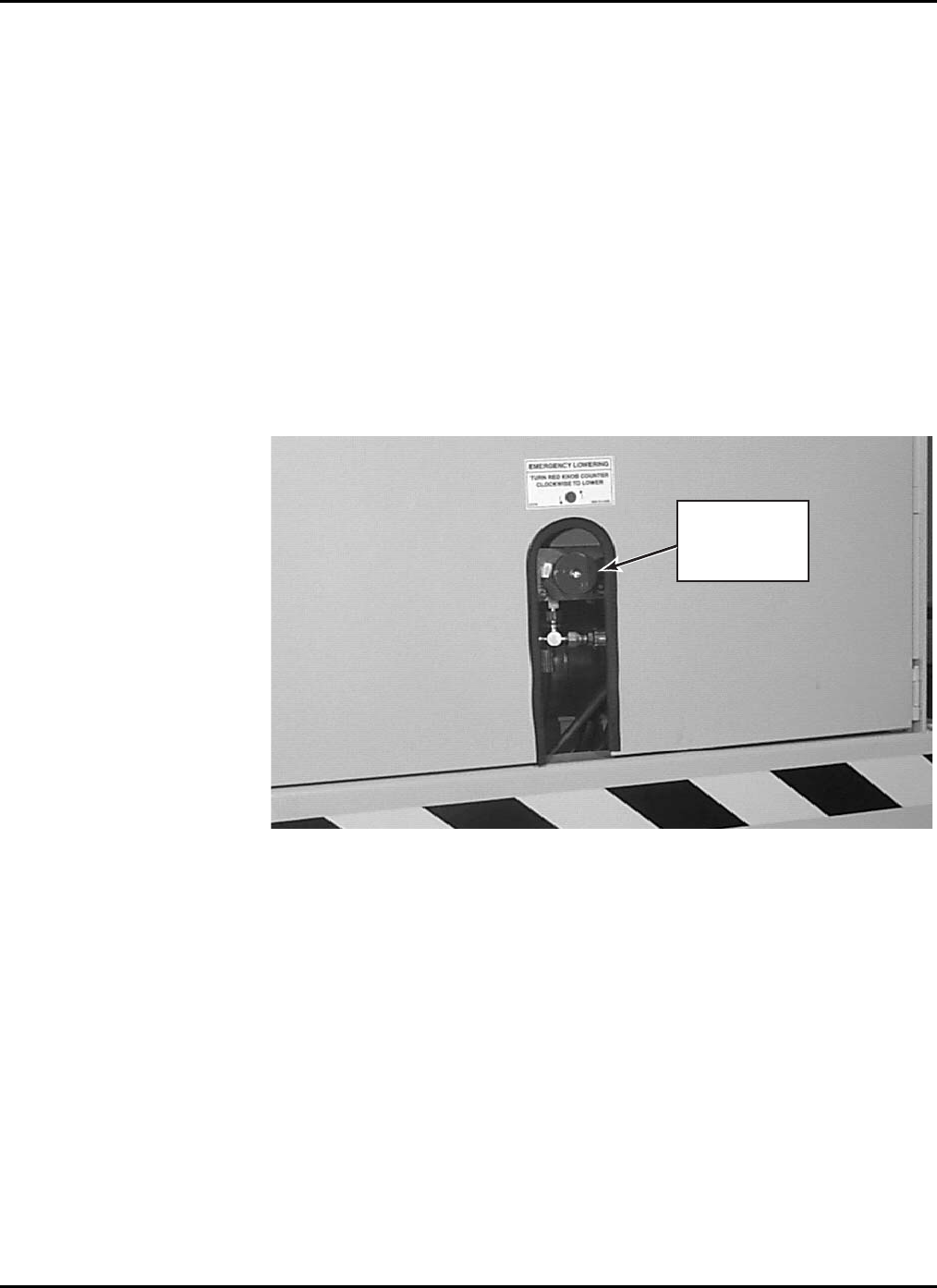
3-3 EMERGENCY LOWERING PROCEDURE
The Cougar Lift is equipped with a manual lowering valve in case of emergency situa-
tions to lower the platform. The emergency lowering valve is located on the hydraulic
block manifold in the hydraulic pump compartment. The valve may be accessed through
the opening on the base door. To lower the platform, turn the red knob on the valve
counterclockwise. Refer to Figure 3-3.
EMERGENCY
LOWERING
VALVE
RED KNOB
Figure 3-3. Emergency Lowering Valve
3-3

XLT-1571AC
3-4

4-1
4
Maintenance
4-1 SCHEDULED SERVICE CHECKS
Daily/Weekly Service Checks
Perform the following daily/weekly service checks as listed in Table 4-1.
Table 4-1. Daily/Weekly Service Checks
Service Check Daily
before use Weekly
Ensure Operation Manual is located in manual tube.
Check chain assemblies for split leaves, loose pins,
excessive wear, or elongation.
Check and retighten all nuts and bolts.
Check cage attachment to the platform is secure and that the
cage side midrails slide freely.
Check to be sure slide blocks and their path are clean and
lightly lubricated with a silicone lubricant.
Check level sensor.
Check to see that all decals are present.
Check that all functions at lower and upper control boxes
are operating properly.
Check for wear on chain sheaves, sheave axles, and
bearings.
Lubricate chains with 40W oil.
Check casters for wear on axles and swivel raceways.
Check surface of casters for cracks or excessive wear.

XLT-1571AC
4-2
Monthly Service Checks
Perform the following monthly service checks as listed in Table 4-2.
Table 4-2. Monthly Service Checks
Service Check Every
month Every
6 months Every
12 months Every
48 months
Check hydraulic raise valve
operation.
Check operation of manual
emergency lowering valve.
Lubricate caster swivels and
axles.
Replace hydraulic oil.
Check slide blocks for wear.
Check for mast sway.
Load test with 500 pounds.
Replace lift chains.
4 — MAINTENANCE
4-2 LUBRICATION
Lubrication makes operation of the Cougar Lift more efficient and extends the life of the
unit. Perform the following lubrication procedures.
1. Oil lift chains with clean 40W oil weekly or as needed. Refer to Figure 4-1.
LIFT
CHAINS
LIFT
CHAINS
Figure 4-1. Lift Chain Lubrication
4-3
XLT-1571AC
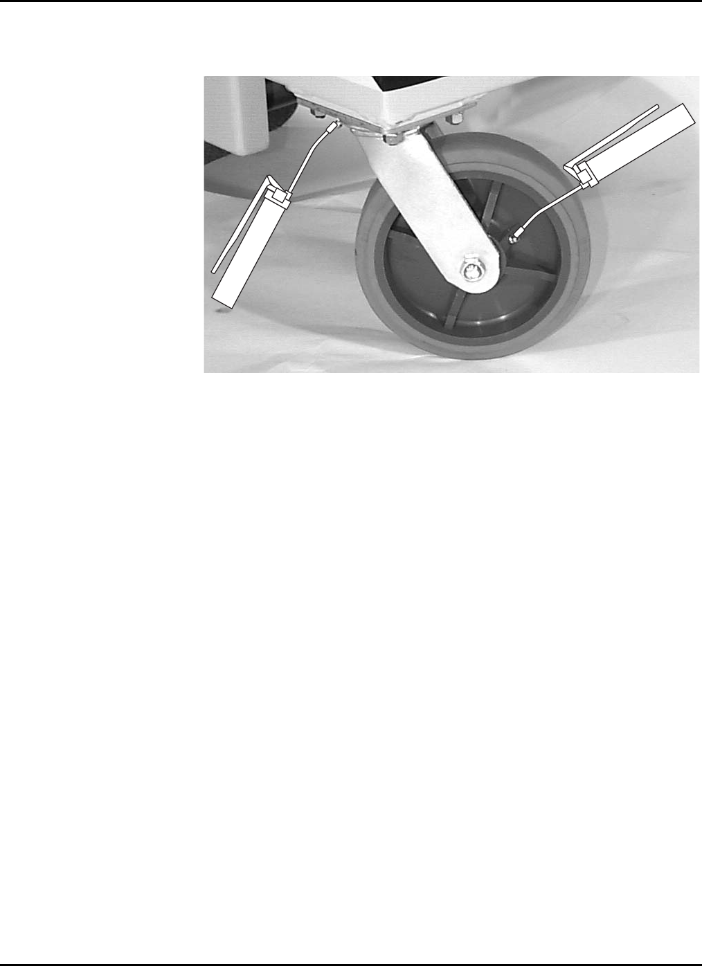
2. Grease all caster axles and swivel raceways at the 2 grease fittings on each
caster semiannually with wheel bearing grease. Refer to Figure 4-2.
Figure 4-2. Caster Lubrication
NOTE: The plastic slide blocks in the mast are made of a bearing material which
has a high degree of lubricity and need only be kept clean. However,
precautions should be taken to ensure that the paths along which the
blocks move are kept clean and lightly lubricated with a dry type silicon
lubricant.
4-4

4 — MAINTENANCE
4-5
4-3 HYDRAULIC SYSTEM
Hydraulic system maintenance varies by the amount of use and the environment in which
the lift is used. Constant attention to keep the oil clean and the reservoir properly filled
will help prevent possible damage to the system.
Hydraulic System Inspection
Check all hydraulic hoses and fittings for leaks and damage daily. Tighten or replace as
necessary to prevent hydraulic oil loss. Refer to the hydraulic schematic diagram in Sec-
tion 6 for general reference.
Fluid Check and Replacement
The reservoir should be filled to within 1/2 inch of the top with the platform in its lowest
position. The lift is shipped from the factory with Energol HLP-HD46 (BP Oil), a high
grade, non-foaming hydraulic oil designed for temperatures as low as -20F/-29C. Use
Dextron Automatic Transmission Fluid Type A for temperatures as low as -40F/-40C.
If either oil is not available, a good grade SAE 10W hydraulic oil may be used where the
minimum climatic temperature is above 32F/0C. SAE 5W hydraulic oil may be used
where temperatures are as low as 0F/-18C. Do not mix different hydraulic oils. Clean
the reservoir sump strainer and replace the hydraulic oil at least once a year or whenever
it becomes contaminated.
Hydraulic System Air Bleeding Procedure
Delayed response or sporadic action in the unit may indicate a presence of air in the cyl-
inder. Perform the following procedure to bleed air from the system.
1. Fill the reservoir with the proper hydraulic fluid.
2. Fully extend the lift.
3. Lower the unit to allow the oil with entrapped air to return to the reservoir, be-
ing careful not to overflow it.
4. Let the unit set while the air escapes the fluid and then repeat if necessary. Each
time the platform is lowered, refill the reservoir to prevent pumping more air
into the cylinder.
XLT-1571AC
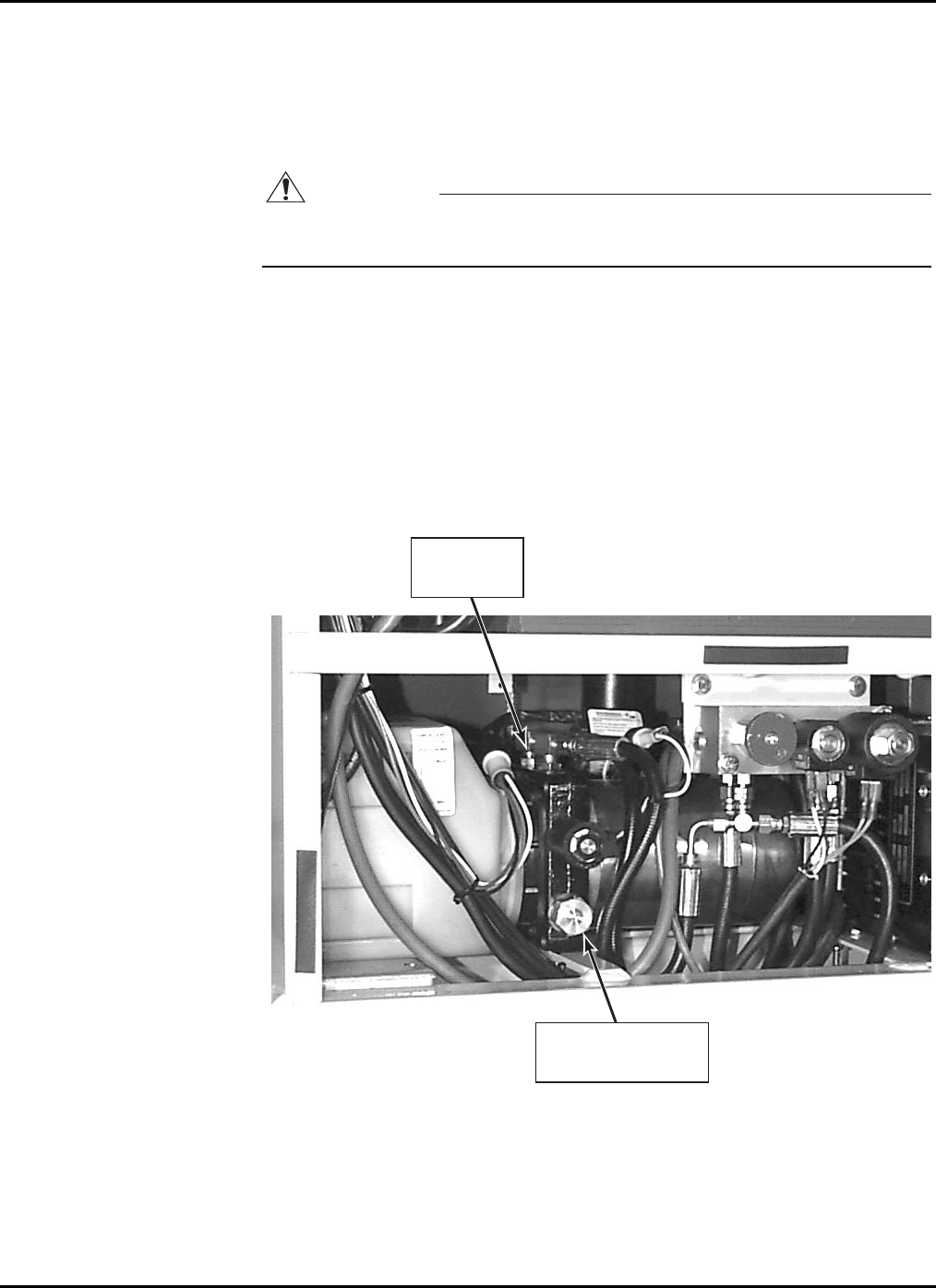
Pressure Relief Valve Reset
Perform the following procedure to reset the pressure relief valve. Refer to Figure 4-3.
1. Disconnect the hydraulic hose from the main pressure port.
2. Install a 4000 psi gauge into the main pressure port in the pump unit.
CAUTION
Do not adjust the pressure relief valve higher than 2100 psi. Overloading may
occur at pressures greater than 2100 psi.
3. Remove the hex cover from the pressure relief valve.
4. While depressing the WHEEL DOWN/BASE ROLLS pushbutton on the lower control
box, adjust the screw until maximum pressure of 2100 psi is obtained.
5. After adjusting the pressure relief valve, replace the hex cover, remove the 4000
psi gauge, and reconnect the hydraulic hose to the main pressure port.
6. If a gauge is unavailable, place 500 pounds on the platform and adjust the pres-
sure relief valve screw so that the load can just be lifted without bypassing oil
through the pressure relief valve.
HEX COVER FOR
PRESSURE
RELIEF VALVE
MAIN
PRESSURE
PORT
Figure 4-3. Pressure Relief Valve Adjustment
4-6
4 — MAINTENANCE
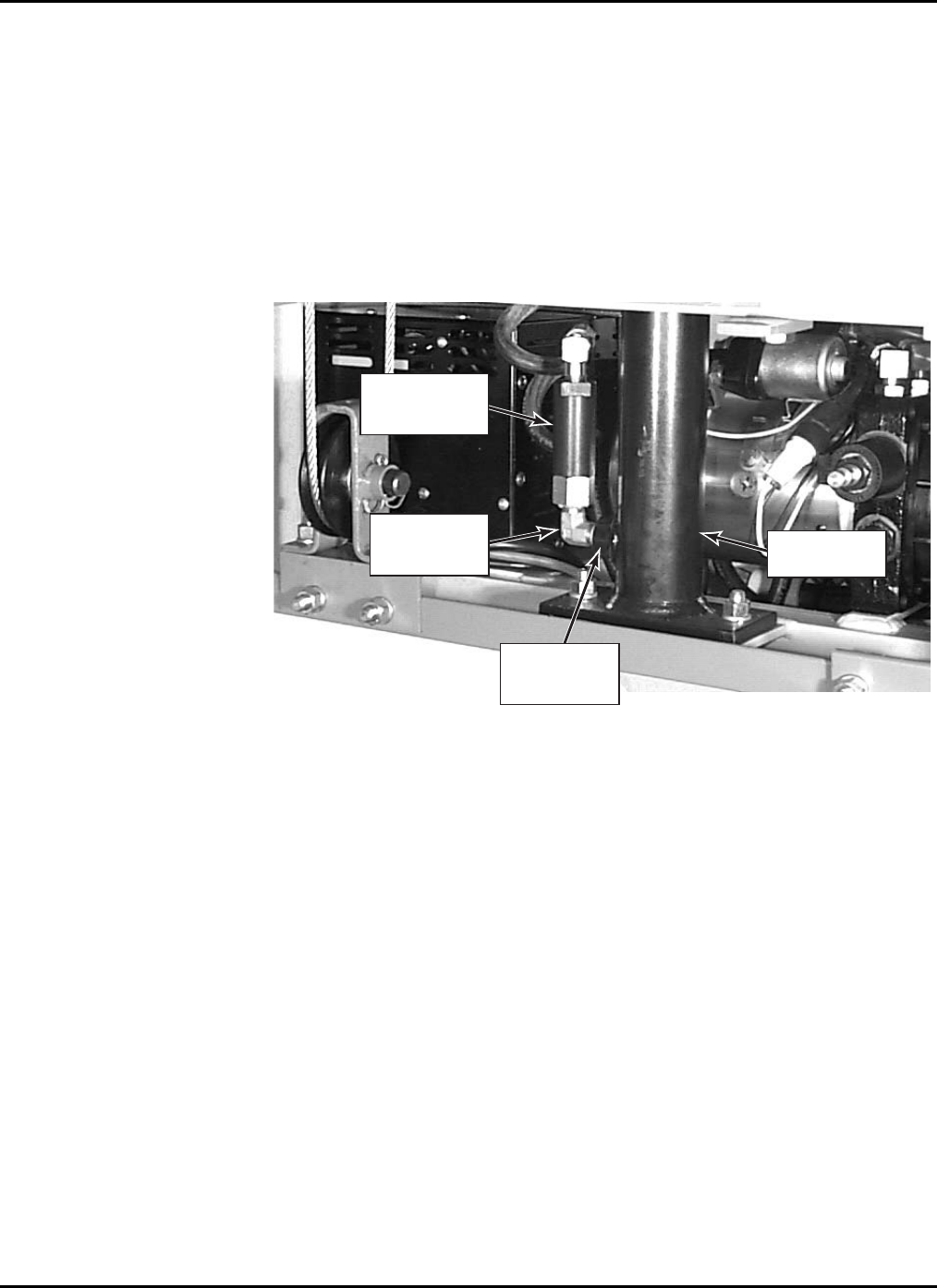
Flow Restrictor Valve Replacement
If the flow restrictor valve Figure 4-4 needs to be removed or replaced, it is important
that it be properly reinstalled. The valve will be marked either with an arrow or with the
word “IN”. If marked with an arrow, the arrow must point away from the hydraulic cyl-
inder port. If marked with the word “IN”, the end of the valve marked “IN” must be to-
ward the hydraulic cylinder port. Only a 1/4 inch NPT hydraulic elbow should be con-
nected between the hydraulic cylinder port and the end of the flow restrictor valve.
Improper installation of the flow restrictor valve or the use of the wrong size elbow will
permit widely varying rates of descent and may result in near free-fall in case of hose
failure.
HYDRAULIC
CYLINDER
PORT
¼ INCH NPT
HYDRAULIC
ELBOW
FLOW
RESTRICTOR
VALVE
HYDRAULIC
CYLINDER
Figure 4-4. Flow Restrictor Valve
4-7
XLT-1571AC
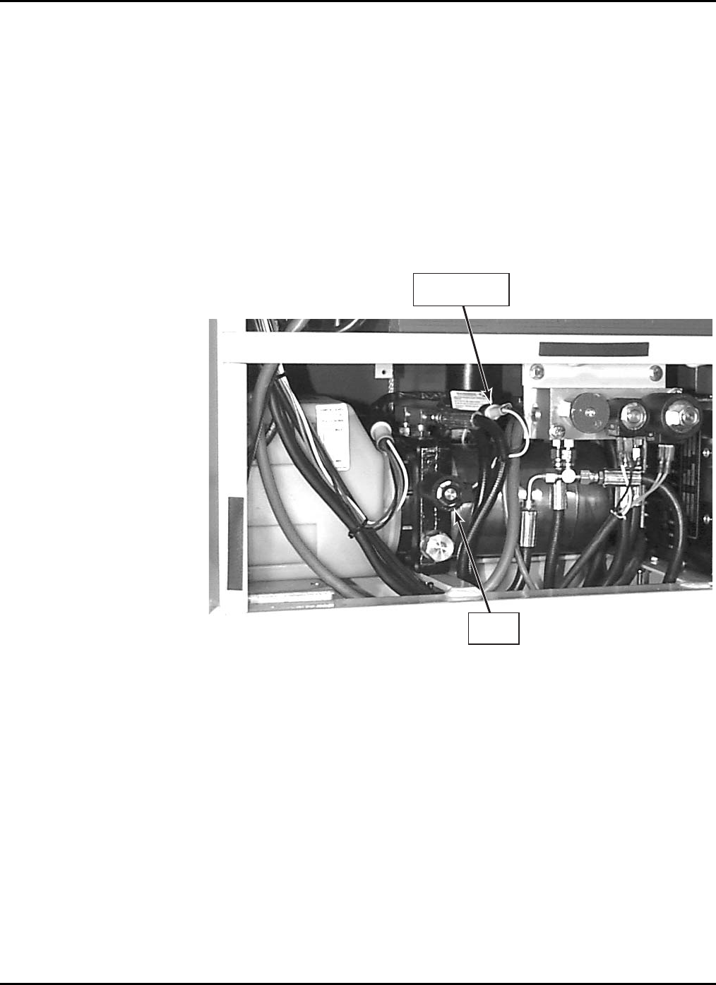
Raise Valve Operation Check
The raise valve is a normally open (N.O.) valve in the hydraulic system. Perform the fol-
lowing procedures to check the operation of the raise valve.
1. Disconnect the black and yellow wires from the solenoid, to the valve at the
wire connector, Figure 4-5.
2. On the upper control box, select UP on the direction selector switch while de-
pressing the ON pushbutton. This should cause the motor to run without the plat-
form raising.
3. If the platform raises, the raise valve must be cleaned or replaced.
4. Reconnect the wires at the connector between the solenoid and the raise valve
upon determining that the valve is functioning properly.
RAISE
VALVE
WIRE
CONNECTOR
Figure 4-5. Raise Valve Operation Check
4-8

4 — MAINTENANCE
Hydraulic Cylinder Repair
CAUTION
Removing the hydraulic cylinder from the Cougar Lift requires major disassem-
bly of the unit. Contact Bil-Jax before removing the hydraulic cylinder from the
unit for assistance.
Hydraulic Cylinder Removal
It is recommended that Bil-Jax be contacted for assistance before removing the hydraulic
cylinder.
1. Be sure cylinder is completely retracted and pressure is released from the sys-
tem. Place a pan underneath the hydraulic cylinder to catch the hydraulic oil.
2. Disconnect the hydraulic hose from the bottom of the cylinder and drain the hy-
draulic oil. Remove the two bolts, washers, and nuts securing the bottom of the
cylinder to the base.
3. Remove the plexiglass cover from the base.
4. Remove the mounting bolt, washer, and nut securing the top of the hydraulic
cylinder to the lower mast.
5. Disconnect the two lift chains from the base mast.
6. Using a crane with at least one ton of lifting capacity, lift the lower mast section
high enough to remove the clamp securing the cylinder to the base, and remove
the cylinder from the unit.
7. After maintenance has been performed on the hydraulic cylinder, follow the re-
moval procedure in reverse to reinstall the cylinder in the unit.
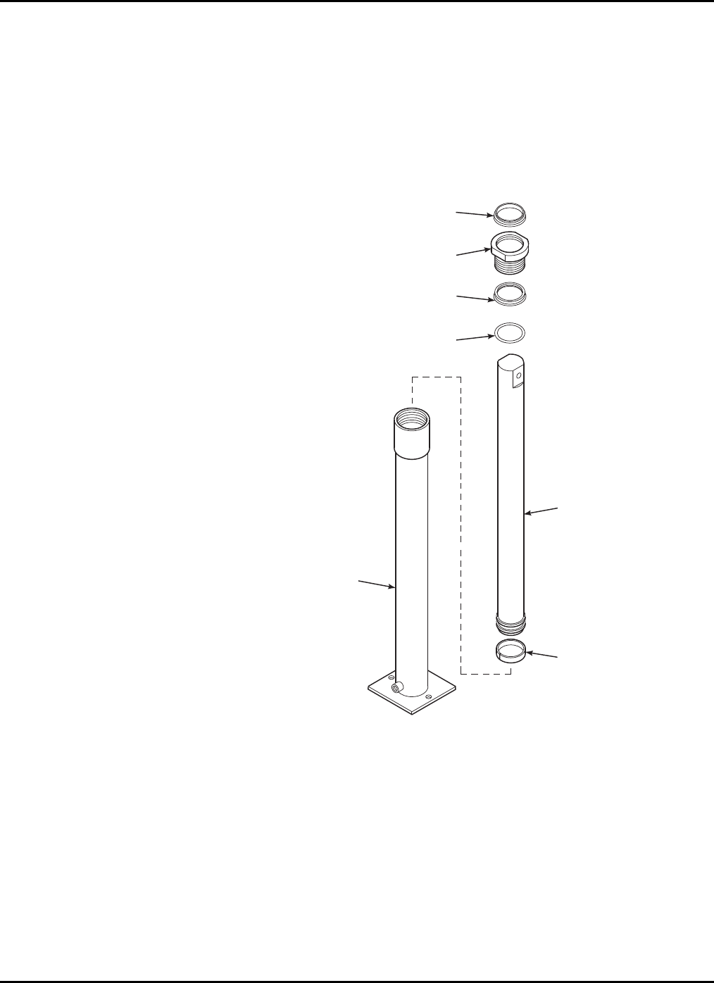
Hydraulic Cylinder Repair Procedure
Perform the following procedure to repair and maintain the hydraulic lift cylinder. Refer
to Figure 4-6. It is recommended that whenever the hydraulic cylinder is disassembled,
all seals be replaced; order seal repair kit B02-13-0097.
1. Remove gland nut (3, Figure 4-6) with gland nut seal (4), rod wiper (2), and
o-ring (5) from the cylinder jacket (1).
2. Remove piston rod (6) and wear ring (7). Inspect piston rod (6) for any
scratches or pits. Pits that go into the base metal are unacceptable. Scratches that
catch the fingernail, but are not through the base metal or less than 1/2 inch long
and are around the rod are acceptable providing they are not sharp enough to cut
the seal. The rod surface should not have any of the chrome worn through. Re-
place the cylinder if any of these conditions are not met.
3. Clean inside the cylinder jacket (1) and inspect for any scratches or pits. Pits
that are deep enough to catch the fingernail are unacceptable. Scratches that
catch the fingernail, but are less than 1/2 inch long and are around the tube are
acceptable providing they are not sharp enough to cut the seal. Replace the cyl-
inder if any of these conditions are not met.
4. Install wear ring (7) into the grooves at the bottom of the piston rod (6). Lubri-
cate assembly with hydraulic fluid and place back into cylinder jacket (1).
5. Lubricate rod wiper (2), gland nut seal (4), and o-ring (5) with hydraulic fluid.
6. Twist gland nut seal (4) into a “C” shape and insert it with lip side down into the
groove inside the gland nut (3). Place o-ring (5) over the threads of the gland
4-9
XLT-1571AC
nut (3) and install in groove. Install rod wiper (2) into the top of the gland nut
(3).
7. Place gland nut (3) complete with a new gland nut seal (4), rod wiper (2), and o-
ring (5) onto the cylinder and tighten down.
8. Reinstall the hydraulic cylinder into the unit and reconnect the hydraulic hose.
Refill hydraulic fluid reservoir.
9. Pressurize the cylinder and extend one full stroke to fill it with hydraulic fluid
and remove any trapped air.
1
5
4
3
2
7
6
Figure 4-6. Hydraulic Cylinder Exploded View
1. Cylinder Jacket
2. Rod Wiper
3. Gland Nut (B02-13-0096)
4. Seal, Gland Nut
5. O-Ring
6. Piston Rod
7. Wear Ring
B02-13-0097 Seal Repair Kit
(Includes items 2, 4, 5, & 7)
B02-03-0018 Complete
Hydraulic Cylinder Assembly
(Includes all items)
4-10

4 — MAINTENANCE
4-11
4-4 ELECTRICAL SYSTEM
Regular maintenance is necessary to keep the electrical system in proper working order.
Check daily all electrical wires for cuts, broken wires, potential short circuits, and any
other damage.
XLT-1571AC
4-5 LIFT CHAINS AND SLIDE BLOCKS
WARNING
Do not operate a unit on which any chain assembly is damaged or in need of re-
placement. Operating a unit with a damaged chain can cause severe injury or
death to personnel and damage to equipment.
Inspect all lift chains daily. Inspect for signs of wear, split leaves, loose pins, clevis dam-
age, and elongation. Replace any chain which is damaged in any way. Chain assemblies
may be ordered from your dealer or direct from the factory. Do not operate a unit on
which any chain assembly is damaged and in need of replacement.
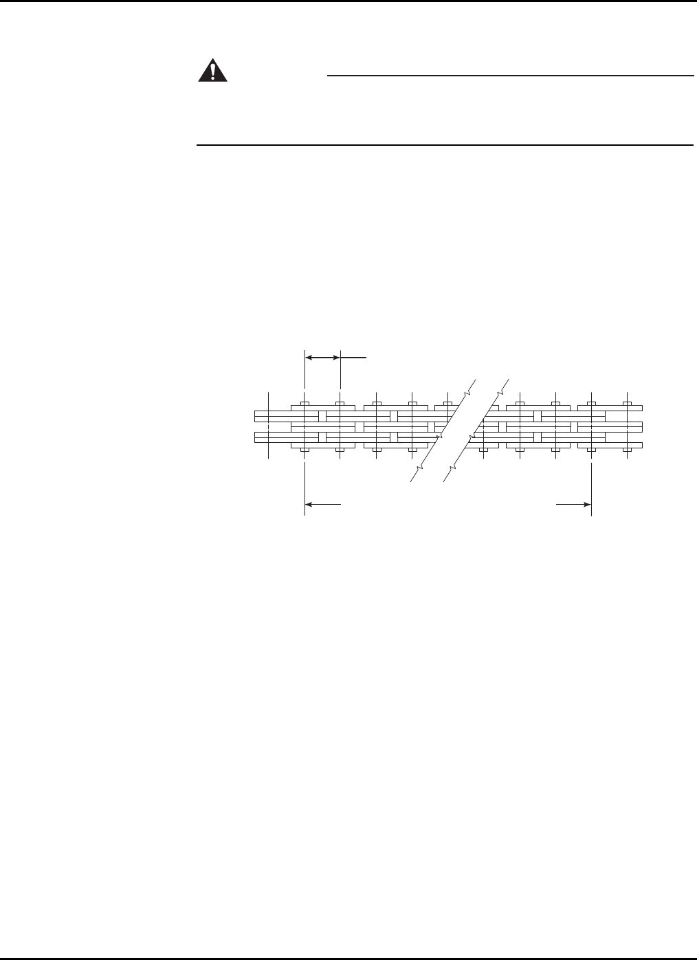
Chain Elongation Inspection
One pitch of chain should measure 5/8 in. (1,5875 cm). Measure 20 pitches of chain. The
ideal measurement for 20 pitches of chain should be 12.5 in. (31,75 cm). Replace the
chain if 20 pitches measure over 12.75 in. (32,385 cm). Refer to Figure 4-7.
5/8 IN. (1,5875 CM) PITCH
20 PITCHES = 12.5 IN. (31,75 CM)
REPLACE CHAIN IF 20 PITCHES MEASURES
OVER 12.75 IN (32,385 CM)
Figure 4-7. Chain Elongation Inspection
NOTE: It is recommended that chains be replaced every four years unless dam-
age or wear requires replacement at a lesser interval.
4-12
4 — MAINTENANCE
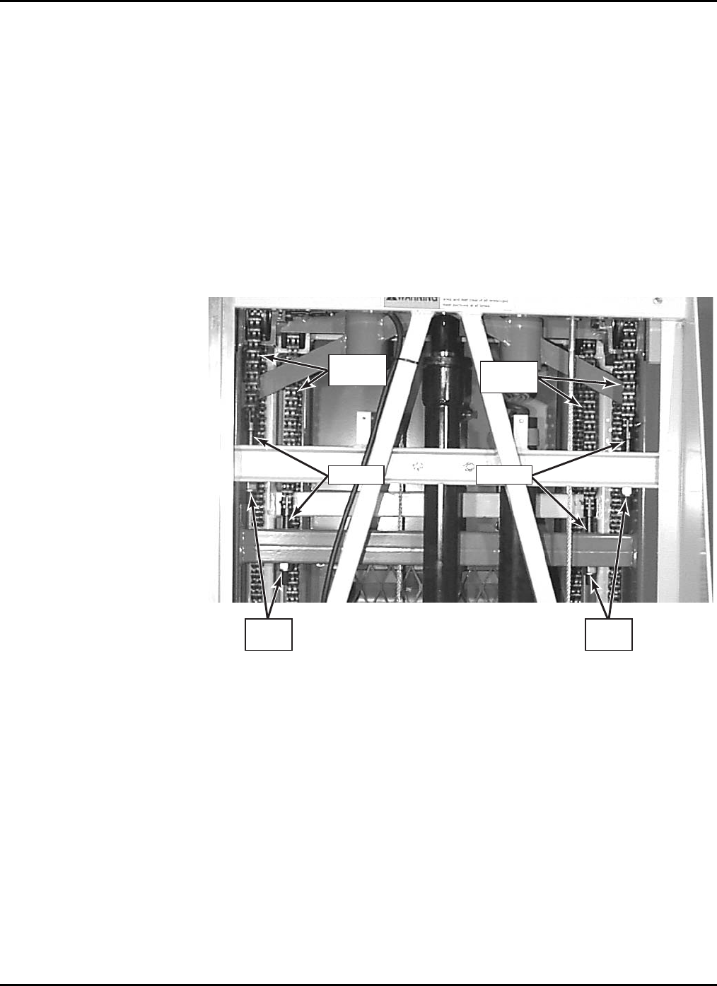
Lift Chain Adjustment
1. Raise the platform to the maximum extended height and then lower it while
someone checks to see that all sheaves are turning and checks for chain damage
or wear.
2. After the platform is completely lowered, remove the plexiglass cover from the
base.
3. Chains should be tight to the touch with no loose play. Check all four lift chains
for snugness. If a chain is loose, tighten the lock nut below the clevis retainer.
Refer to Figure 4-8. Adjust any loose chain until it just becomes snug. Do not
overtighten any chain so that the platform is raised from its resting position.
4. Make sure the lock nuts are turned onto the threaded clevis ends with at least
1/8 in. of the clevis end extending through the nut. Replace any lock nut which
does not stay in position during use. Replace the plexiglass cover.
LIFT
CHAINS LIFT
CHAINS
LOCK
NUT
LOCK
NUT
CLEVIS CLEVIS
Figure 4-8. Lift Chain Adjustment
4-13

XLT-1571AC
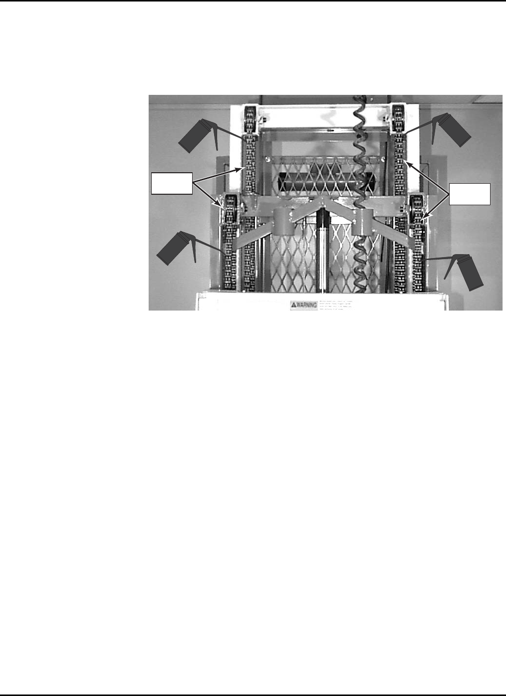
Slide Block Adjustment
Annually check for wear on the slide blocks and replace or retighten as necessary. If the
lift exhibits excessive mast sway, it is probable that the slide blocks need adjustment. The
slide blocks should be adjusted so that there is no air gap between the slide block and the
mast the slide block is moving against. There are 12 slide blocks, 6 upper and 6 lower.
The adjustment procedure is the same for all slide blocks. Three upper slide blocks are
shown in Figure 4-9.
1. Loosen, do not remove, the slotted hex head screw securing the slide block to be
adjusted.
2. Using an allen wrench, turn the set screws in (clockwise). This will push the
block in against the next mast. Do not overtighten. Tighten the slotted hex head
screw to secure the slide block in position.
3. Check all slide blocks and make adjustments as necessary.
4. After all adjustments are made, fully extend the lift. If the platform can be low-
ered without stopping then the blocks are properly adjusted.
SET
SCREWS
SLOTTED
HEX SCREW
SLIDE
BLOCKS
Figure 4-9. Slide Block Adjustment
NOTE: The plastic slide blocks in the mast are made of a bearing material which
has a high degree of lubricity and need only be kept clean. However,
precautions should be taken to ensure that the paths along which the
blocks move are kept clean and lightly lubricated with a dry type silicon
lubricant.
4-14

4 — MAINTENANCE
4-15
4-6 TROUBLESHOOTING
Table 4-3. Troubleshooting Chart
Problem Cause Correction
1. Green WHEEL UP/BASE SET
button will not light. a. Base not firmly set on footpads.
b. *Low voltage.
c. Burned out bulb.
d. Lift is out of level.
e. Broken or loose wire.
a. Depress
WHEEL UP/BASE SET button
raising front casters. This allows lift
to firmly set on footpads.
b. Check incoming power line.
c. Replace bulb.
d. Level lift with two adjusting foot pads
or relocate lift to level surface.
e. Repair or replace wire.
2. When UP switch is selected,
motor runs but unit will not
lift a load.
a. More than 500 lbs. on platform.
b. N.O. (Normally Open) valve is not
being energized.
c. Emergency lowering valve is open.
d. Mast sections are dirty.
a. Ensure load is 500 lbs. or less.
b. Check voltage at N.O. valve. If no
voltage, check for loose or broken
wire. If voltage, ensure at least 9 volts
for start solenoid operation. Check
battery and start solenoid. Repair or
replace as needed.
c. Close emergency lowering valve.
d. Clean and lubricate masts with dry
silicone.
3. Masts have excessive sway
when fully extended. a. Plastic slide blocks are out of adjust-
ment. a. Refer to Slide Block Adjustment in
section 4-5.
*NOTE: Smart start solenoid will not engage if voltage is low.

XLT-1571AC
4-16
Table 4-3. Troubleshooting Chart, Continued
Problem Cause Correction
4. Pump/motor will not run
when UP is selected. a. EMERGENCY STOP button is activated
(pushed in).
b. Green WHEEL UP/BASE SET button is
not lit.
c. Motor start relay is not activating.
d. Motor start relay is activating, but
motor does not run.
e. *Low voltage.
a. Turn
EMERGENCY STOP button coun-
terclockwise to de-activate.
b. Refer to Problem 1.
c. Check voltage at white wire on motor
start relay. If voltage, replace defec-
tive motor start relay. If no voltage,
check for loose or broken wire. Re-
pair or replace wire.
d. Check hydraulic gear pump for sei-
zure. If seized, replace pump. If not,
check motor. Motor may need re-
placement.
e. Check incoming power line.
5. Hydraulic cylinder leaks at
gland nut. a. Loose gland nut.
b. Defective seals.
a. Tighten gland nut.
b. Replace seals in hydraulic cylinder.
Refer to Hydraulic Cylinder Repair,
in section 4-3.
*NOTE: Smart start solenoid will not engage if voltage is low.

5-1
5
Replacement Decals
Refer to Table 5-1, and Figures 5-1, 5-2, and 5-3 for descriptions and locations of decals
on the Cougar Lift.
Table 5-1. Replacement Decals
Decal No. Description of Decal Qty
B06-00-0003 Bil-Jax ID Number (Not available as replacement part) 1
B06-00-0009 Warning...Moving telescopic masts will create... 2
B06-00-0034 Danger...During charging, explosive oxyhydrogen gas... 1
B06-00-0106 XLT-1571 (Transfer type decal) 2
B06-00-0138 Warning...(Maintenance decal) 1
B06-00-0146 Danger...(High voltage line warning) 1
B06-00-0167 Striped Safety Tape - On all four sides (per roll only) 4
B06-00-0170 Maximum Capacity...500 lb. Or... 2
B06-00-0173 Safety Belt Lanyard Attachment Point 2
B06-00-0175 Caution...This machine designed and manufactured... 1
B06-00-0192 Operation And Service Manual Inside 1
B06-00-0225 Warning...Stay clear when raising or lowering 2
B06-00-0228 Serial Number Tag (Not available as replacement part) 1
B06-00-0286 Emergency Lowering 1
B06-00-0289 Check level with cage fully down 1
B06-00-0291 Warning...Level machine before use 1
B06-00-0295 Danger...Failure To Comply With The Following... 1
B06-00-0306 Warning...Stand clear when lowering lift onto the foot pads... 2
B06-00-0339 Warning...Full Body Harness and Lanyard... 1
B06-00-0339BLT Warning...Body Belt and Lanyard... 1
B06-00-0349 Operation Instructions for Battery Charger 1
B06-00-0350 Operation Instructions for Stockpickers 1
B06-00-0455 Bil-Jax (Vertical transfer type decal) 2

XLT-1571AC
B06-00-0350
B06-00-0295
B06-00-0289
B06-00-0175
B06-00-0009
B06-00-0173
B06-00-0286
B06-00-0146
B06-00-0138
B06-00-0228
B06-00-0349
B06-00-0291
B06-00-0455
B06-00-0339
B06-00-0170
B06-00-0034
B06-00-0306
B06-00-0106
B06-00-0192 B06-00-0225
STAY CLEAR
WHILE RAISING
OR LOWERING
B06-00-0225
CCFO
B06-00-0339BLT
Fall protection equipment
must be used at all times
during operation. Failure to
wear fall protection equipment
may allow operator to fall from
platform resulting in serious
UTT/ATT
B06-00-0339BLT
Figure 5-1. Replacement Decals
5-2
5 — REPLACEMENT DECALS
WARNING
XLT
1
5
7
1
W
O
R
K
F
O
R
C
E
WARNING
DANGER
WARNING
WARNING
0106
0173
0137
0173
0192
0170
0339 OR 0339BLT
0146
0009
0291
0170
0225
0306
0167
AROUND COMPLETE
BASE ON ALL SIDES
()
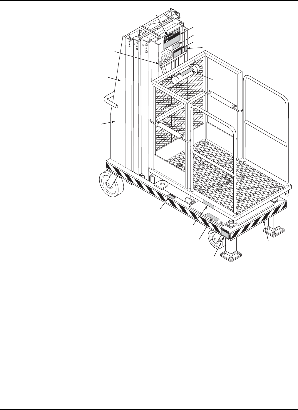
Figure 5-2. Decal Locations, Side View
5-3
XLT-1571AC
WARNING
DANGER
XLT
1
5
7
1
DANGER
CAUTION
WARNING
0034
0286
0106
0138
0350
0455
0228
0175
0295
0009
0167
AROUND COMPLETE
BASE ON ALL SIDES
()
0289
ON RESERVOIR
INSIDE
()
0003
ON CHARGER
INSIDE
()
0349
INSIDE
DOOR
()
Figure 5-3. Decal Locations, Front View
5-4

6-1
6
Parts List

XLT-1571AC
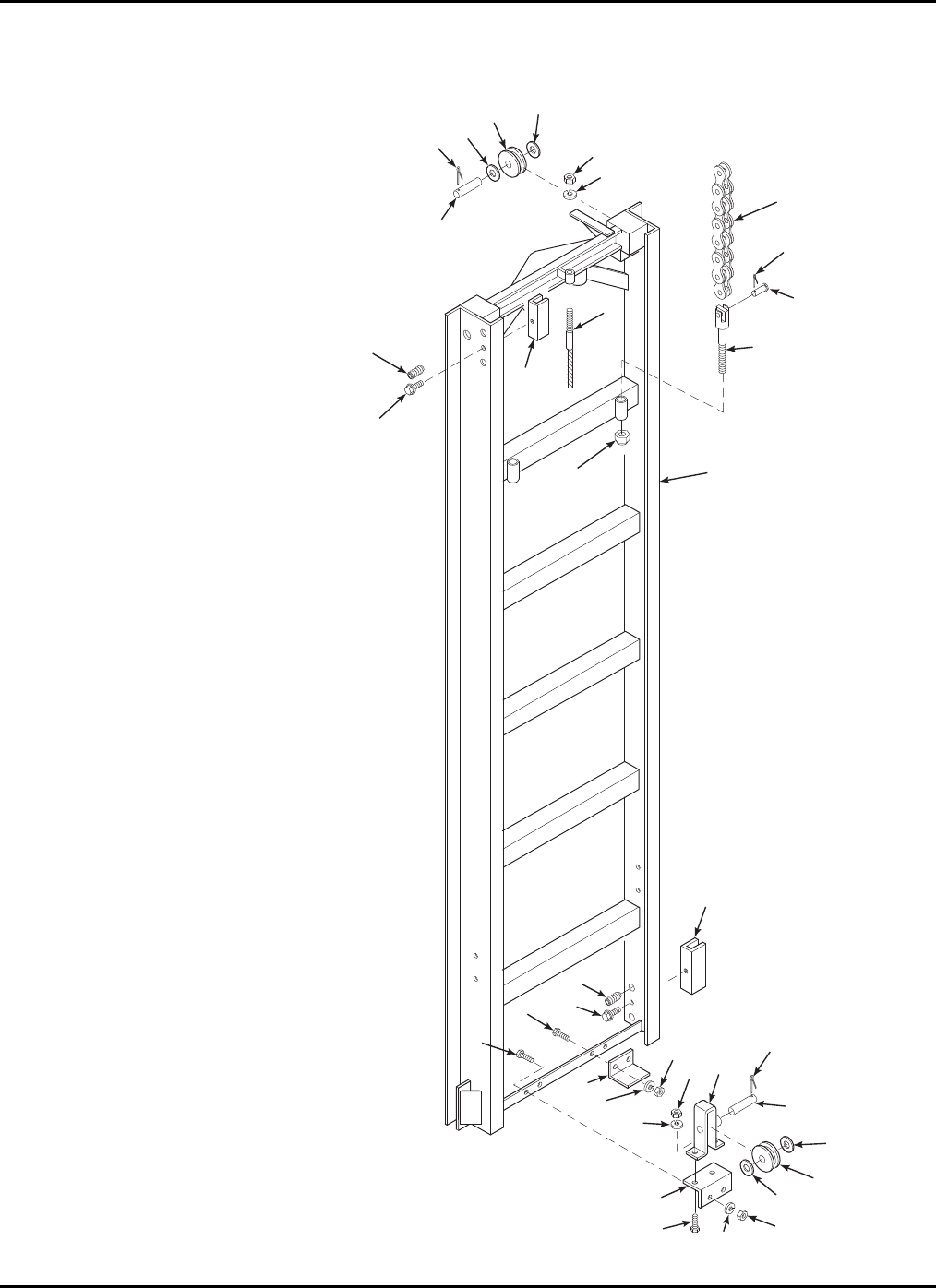
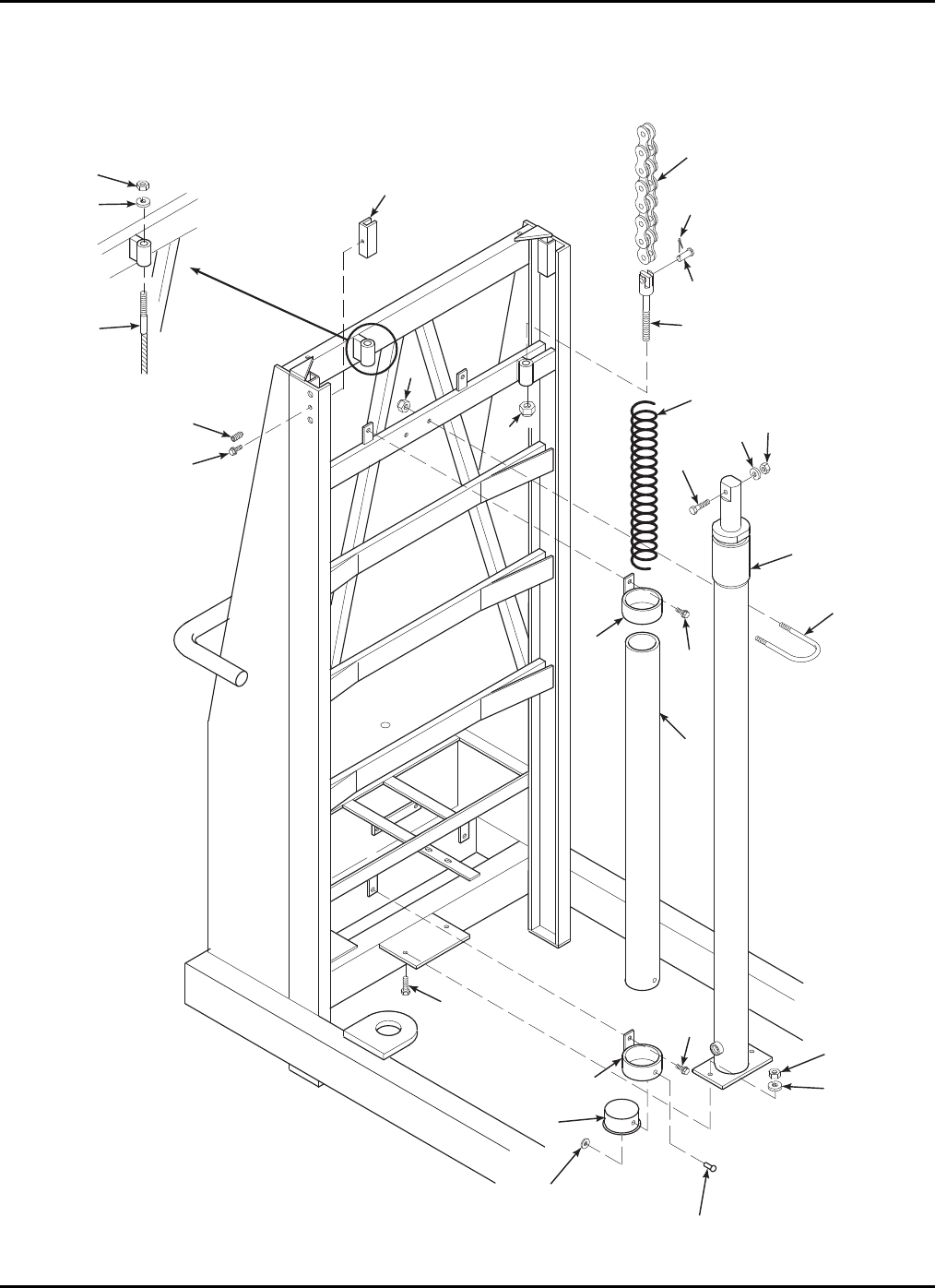
6-1 TOP MAST PARTS LIST
Refer to Table 6-1 for the parts list for the top mast.
15
16
19
18
17
UP 0
ON
DOWN
EMERGENCY
STOP
32
4
120
21
22 21
20
24 23
25
28
28
27
27
26
26
6
5
3
8
9
14
13
12
10
11
7
Figure 6-1. Top Mast Exploded View
6-2

6 — PARTS LIST
6-3
Table 6-1. Top Mast Parts List
Item No. Part No. Description Qty
1 B16-01-0024 Top Mast Weldment 1
2 0090-0014 Screw, 1/4-20 x 2-1/4 in. 2
3 B01-09-0026 Grommet, Plastic 3
4 B29-00-0076 Bracket, Outreach 1
5 0090-0181 Nut, Lock, 8-32 3
6 0090-0813 Screw, 8-32 x 3/4 in. 3
7 B01-02-0059 Box, Control, Upper 1
8 B40-00-0003 Cable, 3/16 in. 1
9 B40-01-0008 Chain, Lift 2
10 B04-07-0078 Pin, Clevis 2
11 B04-07-0087 Clevis, Lower 2
12 0090-0389 Screw, Adjustment, 1/2-20 x 1/2 in. 4
13 0090-0403 Screw, #10 x 1 in. 2
14 B31-00-0001 Slide Block, Plastic 2
15 0090-0206 Washer, Lock, 1/4 in. 2
16 0090-0159 Nut, Hex, 1/4-20 2
17 B01-09-0029 Bushing, Strain Relief 2
18 B05-01-0034 Cable, SJO, 18-2 80 in.
19 0090-0860 Pin, Cotter 2
20 B19-00-0001 Box Only, 3-Position 1
21 B01-02-0005 Contact, NO 4
22 B01-02-0006 Contact, NC 2
23 B00-00-0015 Plate, ON 1
24 B00-00-0017 Plate, Stop, Emergency 1
25 B00-00-0016 Plate, Up/Down 1
26 B01-02-0003 Button, Push, Flush 1
27 B01-02-0004 Button, Stop, Emergency 1
28 B01-02-0025 Switch, Selector 1
* B03-00-0009 Chain Assy, includes items 9, 10, 11, and 19 1
*NOTE: It is recommended that chain parts be purchased as an assembly.
XLT-1571AC
6-2 CENTER MAST PARTS LIST
Refer to Table 6-2 for the parts list for the center mast.
45
4
3
2
6
7
1
8
9
10
13 13
7
6
15
16 8
16
15
13 15 16
422 4
19 20
3
21
14
15 16 18
13
11
12
17
Figure 6-2. Center Mast Exploded View
6-4

6 — PARTS LIST
6-5
Table 6-2. Center Mast Parts List
Item No. Part No. Description Qty
1 B16-01-0020 Center Mast Weldment 1
2 0090-0770 Pin, Cotter 3/16 x 1-1/2 in. 2
3 B36-01-0002 Sheave Axle 3
4 0090-0425 Washer, 5/8 in. 6
5 B26-00-0009 Chain Sheave Assembly 2
6 0090-0389 Screw, Adjustment, 1/2-20 x 1/2 in. 8
7 0090-0403 Screw, #10 x 1 in. 4
8 B31-00-0001 Slide Block, Plastic 4
9 B40-00-0003 Cable, 3/16 in. 1
10 B40-01-0008 Chain, Lift 2
11 B04-07-0078 Pin, Clevis 2
12 B04-07-0087 Clevis, Lower 2
13 0090-0042 Bolt, 3/8-16 x 1 in. 7
14 B29-00-0033 Mast Stop 1
15 0090-0210 Washer, Lock, 3/8 in. 7
16 0090-0162 Nut, 3/8-16 7
17 0090-0860 Pin, Cotter 1
18 0064-0363 Actuator, Limit Switch 1
19 B29-00-0078 Bracket, Weldment 1
20 0090-0147 Pin, Cotter 1
21 B24-01-0008 Mounting Bracket 1
22 B26-00-0001 Sheave, Cable 1
* B03-00-0009 Chain Assy, includes items 10, 11, 12, and 17 1
*NOTE: It is recommended that chain parts be purchased as an assembly.
XLT-1571AC
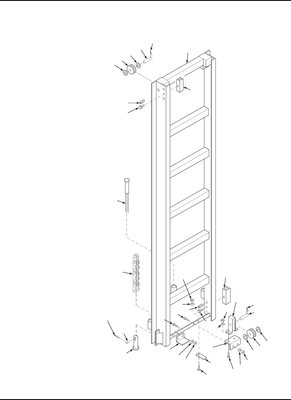
6-3 LOWER MAST PARTS LIST
Refer to Table 6-3 for the parts list for the lower mast.
2
3
4
54
6
7
8
11
16
12
13
14
15
1
17
17
9
10
11
21
18
19
19
18
22
24
3
4
23
4
19
18
17
20
9
10
Figure 6-3. Lower Mast Exploded View
6-6

6 — PARTS LIST
6-7
Table 6-3. Lower Mast Parts List
Item No. Part No. Description Qty
1 B16-01-0021 Lower Mast Weldment 1
2 0090-0770 Pin, Cotter 3/16 x 1-1/2 in. 2
3 B36-01-0002 Sheave Axle 3
4 0090-0425 Washer, Flat, 5/8 in. 6
5 B26-00-0009 Chain Sheave Assembly 2
6 0090-0188 Nut, Lock, 3/8-16 1
7 0090-0422 Washer, Flat, 3/8 1
8 B40-00-0003 Cable 1
9 0090-0389 Screw, Adjustment, 1/2-20 x 1/2 in. 8
10 0090-0403 Screw, #10 x 1 4
11 B31-00-0001 Slide Block, Plastic 4
12 B40-01-0008 Chain, Lift 2
13 0090-0860 Pin, Cotter 2
14 B04-07-0078 Pin, Clevis 2
15 B04-07-0088 Clevis, Upper 2
16 0090-0192 Nut, Lock, 1/2-13 2
17 0090-0042 Bolt, 3/8-16 x 1 in. 6
18 0090-0210 Washer, Lock, 3/8 in. 6
19 0090-0162 Nut, 3/8-16 6
20 B24-01-0008 Mounting Bracket 1
21 B29-00-0033 Mast Stop 1
22 B29-00-0078 Bracket, Weldment 1
23 B26-00-0001 Sheave, Cable 1
24 0090-0147 Pin, Cotter 1
* B03-00-0009 Chain Assy, includes items 12, 13, 14, and 15 1
*NOTE: It is recommended that chain parts be purchased as an assembly.
XLT-1571AC
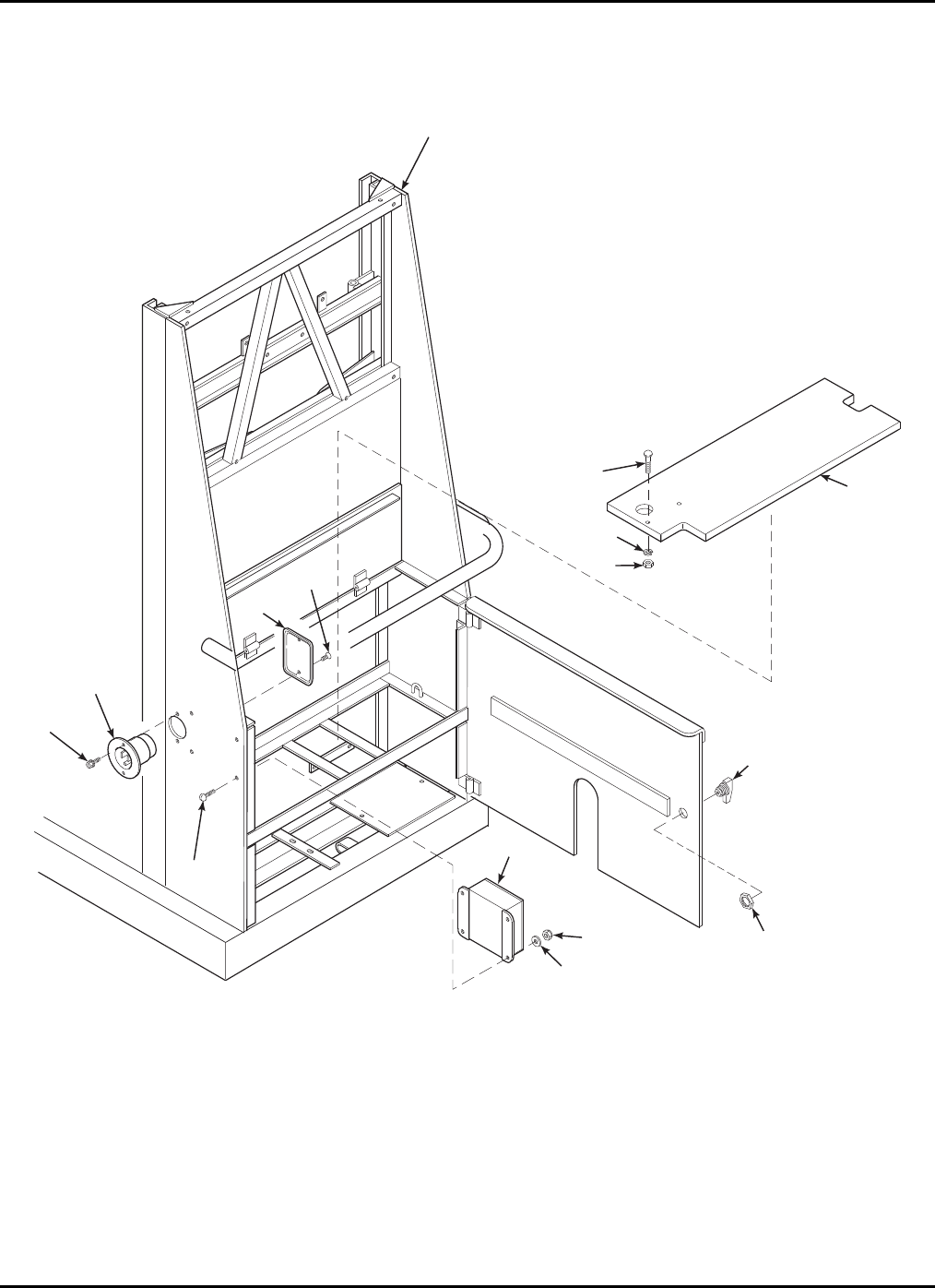
6-4 REAR COMPARTMENT PARTS LIST
Refer to Table 6-4 for the parts list for the rear compartment.
4
2
3
8
9
1
14
14
7
6
5
10
11
12
13
Figure 6-4. Rear Compartment Exploded View
6-8

6 — PARTS LIST
6-9
Table 6-4. Battery Compartment Parts List
Item No. Part No. Description Qty
1 B11-01-0087 Base Weldment 1
2 0090-0344 Screw, Threadcut, 10-24 x 1/2 in. 2
3 B01-10-0003 Receptacle, Flush Mount 1
4 0090-0813 Screw, 8-32 x 3/4 in. 4
5 B19-00-0022 Box, Black, TomCat 1
6 0090-0415 Washer, Flat, #10 4
7 0090-0181 Nut, Lock, 8-32 4
8 B18-00-0026 Cover, (with screws) 1
9 (part of 8) Screw 2
10 0090-0125 Bolt, Carriage, 1/4-20 x 1-1/4 in. 1
11 0090-0206 Washer, Lock, 1/4 in. 1
12 0090-0159 Nut, 1/4-20 1
13 B44-00-0002 Board 1
14 B37-00-0002 Lock Assy., Utility 1
XLT-1571AC
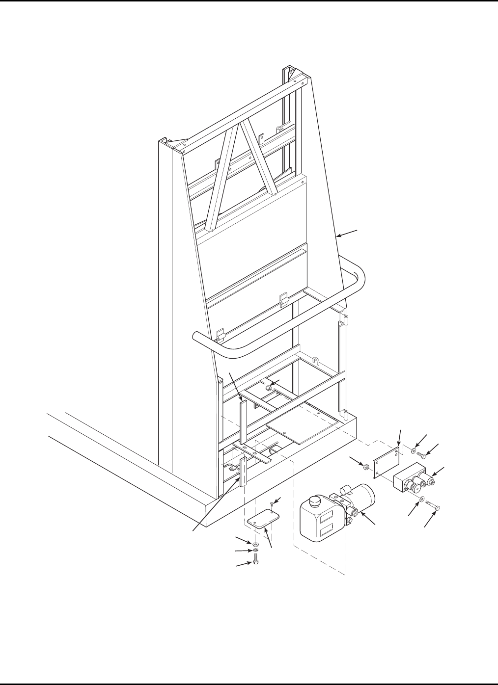
6-5 HYDRAULIC PUMP COMPARTMENT PARTS LIST
Refer to Table 6-5 for the parts list for the hydraulic pump compartment.
1
2
2
3
65
4
8
5
7
9
3
13
12
11
10
13
Figure 6-5. Hydraulic Pump Compartment Exploded View
6-10

6 — PARTS LIST
6-11
Table 6-5. Hydraulic Pump Compartment Parts List
Item No. Part No. Description Qty
1 B11-01-0087 Base Weldment 1
2 B05-00-0006 Tape, Foam Adhesive 2 ft.
3 0090-0183 Nut, Lock, 1/4-20 6
4 0090-0005 Bolt, 1/4-20 x 3/4 2
5 0090-0419 Washer, Flat, 1/4 in. 4
6 B29-00-0116 Bracket, Hydraulic Valve 1
7 0090-0014 Bolt, 1/4-20 x 2-1/2 in. 2
8 B02-04-0047 Valve, Combination 1
9 B02-05-0011 Pump, Hydraulic 1
10 0090-0040 Bolt, 3/8-16 x 3/4 in. 2
11 0090-0210 Washer, Lock 2
12 0090-0422 Washer, Flat 2
13 B18-00-0026 Cover, (with 2 screws) 1
XLT-1571AC
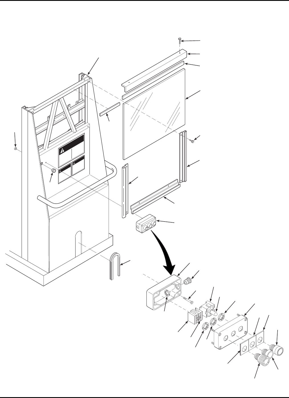
6-6 UPPER BASE PARTS LIST
Refer to Table 6-6 for the parts list for the upper base.
7
WHEEL DOWN
BASE ROLLS WHEEL UP
BASE SET
EMERGENCY
STOP
12
12
15 16
20
19
18
24
19
21
22
18
13
14
17
17
8
23
DANGER
CAUTION
WARNING
1
2
3
4
5
4
6
6
6
2
9
10
11
Figure 6-6. Upper Base Exploded View
6-12

6 — PARTS LIST
6-13
Table 6-6. Upper Base Parts List
Item No. Part No. Description Qty
1 B11-01-0087 Base Weldment 1
2 0090-0344 Screw, Threadcut, 10-24 x 1/2 in. 8
3 B07-01-2003 Edge, Top Cover 1
4 B05-00-0006 Tape, Foam Adhesive 32 in.
5 B18-00-0108 Plexiglass, 1/8 in. 1
6 B24-01-0009 Frame, Aluminum 3
7 B01-02-0058 Box, Control, Lower 1
8 0090-0813 Screw, 8-32 x 3/4 in. 2
9 B34-00-0005 Trim, Rubber 1
10 B01-09-0027 Grommet, Plastic 1
11 0090-0181 Nut, Lock, 8-32 2
12 B19-00-0001 Box Only, 3-Position 1
13 B01-02-0029 Socket, Light, Contact with 1
14 B01-10-0042 Light Bulb, 12v 1
15 B00-00-0091 Plate, Wheel Down 1
16 B00-00-0092 Plate, Wheel Up 1
17 B01-02-0028 Button, Push, Lighted 1
18 B01-02-0003 Button, Push, Flush 1
19 B01-02-0004 Button, Stop, Emergency 1
20 B00-00-0017 Plate, Stop, Emergency 1
21 B01-02-0005 Contact, NO 1
22 B01-02-0006 Contact, NC 1
23 B01-10-0001 Receptacle, Female, 3-Wire 1
24 B04-07-0012 Nut, Elec. Drive, 1/2” 1
XLT-1571AC
6-7 BASE MAST PARTS LIST
Refer to Table 6-7 for the parts list for the base mast.
1
2
3
4
5
6
19
13
9
10
11
12
14
7
15 16
17
18
22
23
25
24
20
21
21
26
27
8
20
Figure 6-7. Base Mast Exploded View
6-14

6 — PARTS LIST
6-15
Table 6-7. Base Mast Parts List
Item No. Part No. Description Qty
1 0090-0188 Nut, Lock, 3/8-16 1
2 0090-0422 Washer, Flat, 3/8 in. 1
3 B40-00-0003 Cable 1
4 0090-0389 Screw, Adjustment, 1/2-20 x 1/2 in. 4
5 0090-0403 Screw, #10 x 1 in. 2
6 B31-00-0001 Slide Block, Plastic 2
7 B01-01-0046 Cord, Retractable 1
8 0090-0684 Rivet, Pop, 3/16 x 1/2 in. 2
9 B40-01-0008 Chain, Lift 2
10 0090-0860 Pin, Cotter, 1.6 mm 2
11 B04-07-0078 Pin, Clevis 2
12 B04-07-0088 Clevis, Upper 2
13 0090-0192 Nut, Lock, 1/2-13 2
14 0090-0071 Bolt, 1/2-13 X 2-1/2 in. 1
15 0090-0212 Washer, Lock, 1/2 in. 1
16 0090-0166 Nut, Hex, 1/2-13 1
17 B02-03-0018 Cylinder, Hydraulic Lift, 1.5 in. Diameter 1
18 0090-0654 Clamp, U-bolt, 5/16-18 x 2-1/2 x 2-5/8 1
19 0090-0185 Nut, Lock, 5/16-18 2
20 0090-0344 Screw, Threadcut, 10-24 x 1/2 2
21 B29-00-0049 Retainer, Tube 2
22 B00-00-0007 Tube, Plastic 1
23 0090-0043 Bolt, 3/8-16 x 1-1/4 2
24 0090-0219 Washer, Lock, 3/8 2
25 0090-0162 Nut, Hex, 3/8-16 2
26 B00-00-0008 Plug, Plastic 1
27 0090-0498 Washer, Flat, 3/16 in. 2
* B03-00-0009 Chain Assy, includes items 9, 10, 11, and 12 1
*NOTE: It is recommended that chain parts be purchased as an assembly.
XLT-1571AC
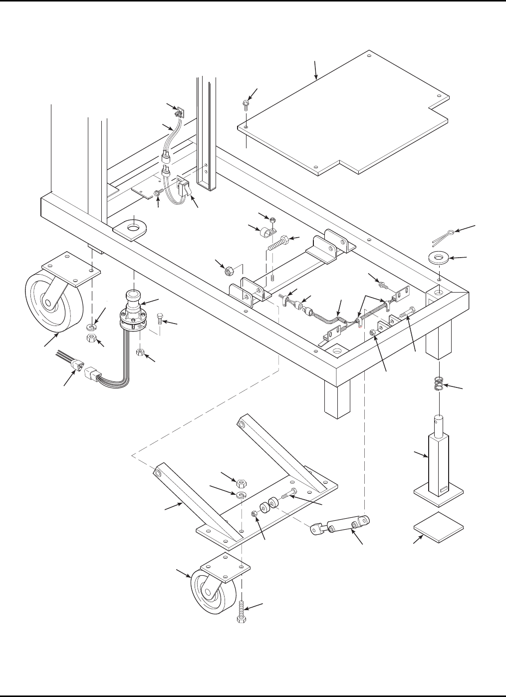
6-8 LOWER BASE PARTS LIST
Refer to Table 6-8 for the parts list for the lower base.
30
31
15
24
32
33
25
24
25
20
21
22
23
19
18
12
13
29
10 11 10
3
14
26
27
28
8
7
2
1
4
5
36
9
16
17
Figure 6-8. Lower Base Exploded View
6-16

6 — PARTS LIST
6-17
Table 6-8. Lower Base Parts List
Item No. Part No. Description Qty
1 0090-0344 Screw, Threadcut, 10-24 x 1/2 in. 4
2 B18-00-0107 Cover 1
3 0090-0344 Screw, Threadcut, 10-24 x 1/2 in. 6
4 B04-07-0015 Clamp, Cable 2
5 B01-01-0123 Cable Assembly, Mast Switch 1
6 B01-03-0040 Switch, Limit, Mast 1
7 0090-0770 Pin, Cotter 2
8 0090-0195 Washer, Flat, 3/4 in. 2
9 B39-00-0027 Spring 2
10 B04-07-0032 Clamp, Cable, DG-6 3
11 B01-01-0122 Cable Assembly, Foot Switch 1
12 B11-01-0085 Foot, Inner 2
13 B23-02-0034 Foot, Pad 2
14 B01-03-0039 Foot Switch Assembly 1
15 0090-0183 Nut, Lock, 1/4-20 2
16 0090-0049 Bolt, 3/8-16 x 2-1/4 in. 1
17 0090-0188 Nut, Lock, 3/8-16 1
18 B02-03-0010 Cylinder, Hydraulic Wheel 1
19 0090-0054 Bolt, 3/8-16 x 3-1/2 in. 1
20 0090-0188 Nut, Lock, 3/8-16 1
21 B11-01-0073 Arm Weldment, Hydraulic Cylinder 1
22 B08-01-0019 Caster, Rigid, 6 in. 2
23 0090-0042 Bolt, 3/8-16 x 1 in. 8
24 0090-0210 Washer, Lock, 3/8 in. 16
25 0090-0162 Nut, Hex, 3/8-16 16
26 0090-0183 Nut, Lock, 1/4-20 3
27 B04-07-0035 Clamp, Cable, DG-14 3
28 0090-0463 Bolt, 1/2-13 x 4 in. 2
29 0090-0192 Nut, Lock, 1/2-13 2
30 B01-10-0135 Sensor, Level 1
31 0090-0005 Bolt, 1/4-20 x 3/4 2
32 B08-01-0002 Caster, 8 in. 2
33 B01-01-0113 Plug, Level Sensor 1
XLT-1571AC
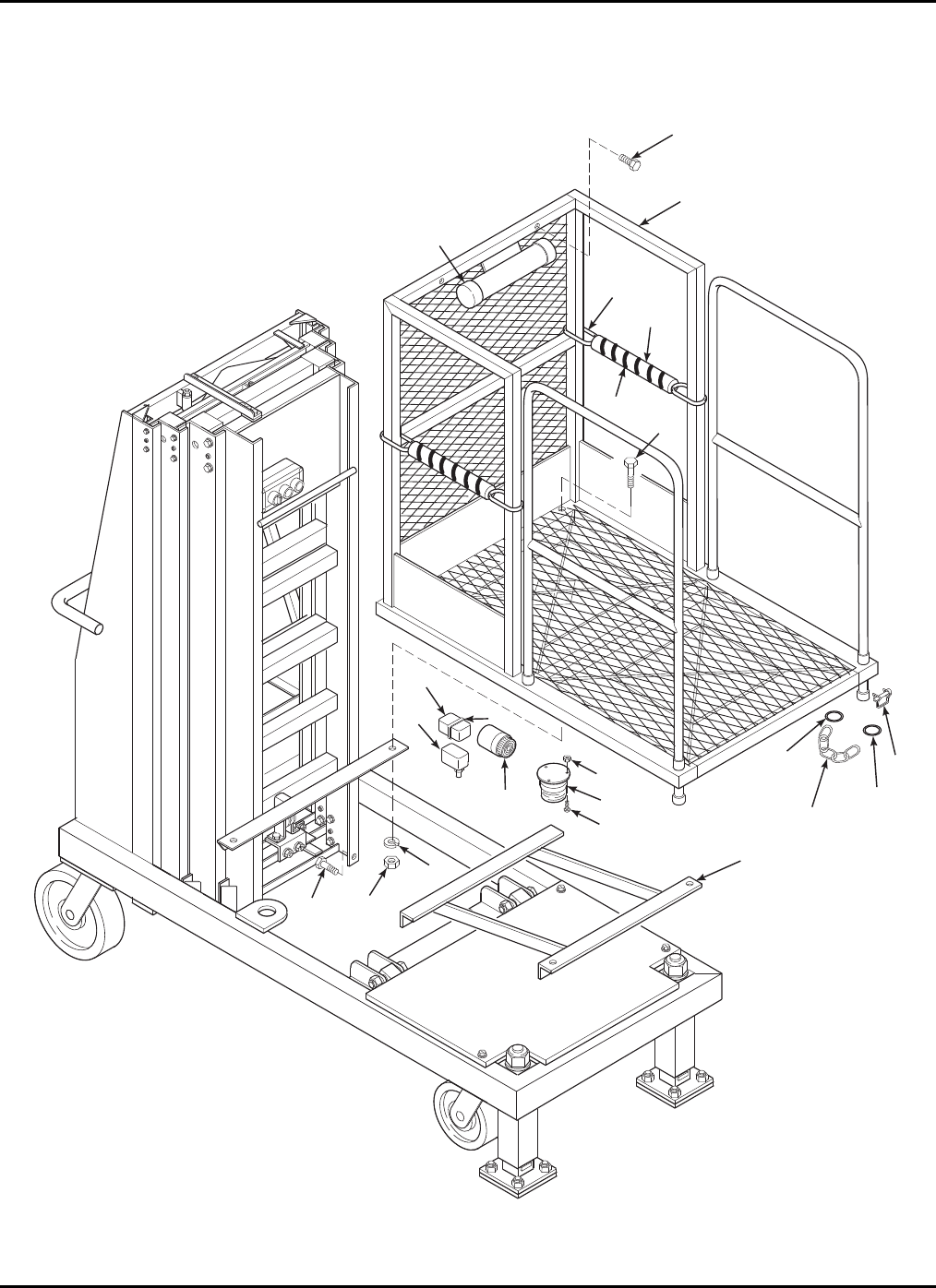
6-9 PLATFORM PARTS LIST
Refer to Table 6-9 for the parts list for the platform.
1
2
5
9
7
6
3
4
8
10
11
12
22
14
13
14
15
19, 20
18
21
17
16
Figure 6-9. Platform Exploded View
6-18

6 — PARTS LIST
6-19
Table 6-9. Platform Parts List
Item No. Part No. Description Qty
1 B17-00-0087 Platform Weldment 1
2 0090-0051 Bolt, 3/8-16 x 2-3/4 in. 4
3 0090-0210 Washer, Lock, 3/8 in. 8
4 0090-0162 Nut, 3/8-16 8
5 0068-061 Pin, Snap 2
6 B01-03-009 Switch, Limit 1
7 B01-10-0002 Alarm, Audible 1
8 B01-10-0004 Light 1
9 0090-0802 Screw, 10-24 x 7/8 in. 3
10 0090-0182 Nut, Lock, 10-24 3
11 B17-00-0058 Support, Platform 1
12 0090-0048 Bolt, 3/8-16 x 2 in. 2
13 B40-00-0019 Chain 2
14 0090-0552 Ring, Key 4
15 B01-03-0002 Cover 1
16 0090-0042 Bolt, 3/8-16 x 1 in. 2
17 B01-09-0030 TyRap 1
18 B05-00-0001 Tube, Foam, 13-1/2 in. 2
19 B00-00-0086 Tube, Split, 8-1/2 in. 4
20 B01-09-0030 TyRap 12
21 B06-00-0167 Tape, Strip, 43 in. 2
22 B00-00-0014 Cap, Manual Tube 2
XLT-1571AC
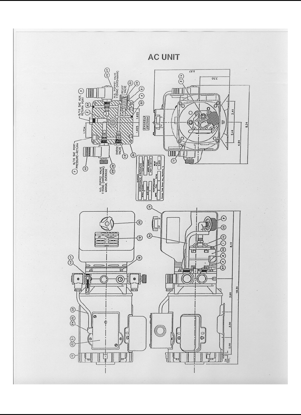
6-10 HYDRAULIC UNIT PARTS LIST
Figure 6-10. Hydraulic Unit Assembly
6-20

6 — PARTS LIST
6-21
Table 6-10. Hydraulic Unit Parts List
Item No. Part No. Description Qty
1 B02-15-0088 Bolt, 5/16-24 x 2.75 Torx 2
2 B02-15-0119 Coupler, 9T-20-40 1
3 B02-02-0087 Plug, #6 ORM 1
4 B02-15-0128 Ball, Steel 1
5 B02-15-0091 Seal, Shaft 1
6 B02-15-0006 Washer 1
7 NA
8 B02-15-0061 Magnet, Plumbing 1
9 B02-15-0121 Filter 1
10 B02-15-0125 Cover, Suction 1
11 B02-15-0126 Screw, Taptite, M6 x 1.0, 12 mm Torx 3
12 NA
13 B02-15-0197 Valve, Check, Cartridge 1
14 B02-15-0170 Bolt, 5/16-18 x 1.00 1
15 B02-15-0171 AC Motor 1
16 B02-15-0382 Bolt, M6 x 1.0 4
17 B02-15-0383 Washer, Lock 4
18 B02-15-0199 Bolt, 12-24 x 0.50 Hex 4
19 B02-15-0206 Tank, Horizontal Mount, Plastic with Drain 1
20 B02-15-0201 Breather Cap, with Check Valve 1
21 B02-15-0127 Spring, Relief 1
22 B01-09-0041 Plug Connector Hirschmann 2
23 B02-15-0174 Wiring Assembly 1
24 B02-15-0175 Adaptor 1
25 B02-15-0176 Strain Relief
26 B02-15-0361 Coil, Solenoid, 115VAC 2
27 B02-15-0073 O-Ring 1
28 B02-15-0203 Head, End 1
29 B02-15-0146 Pump Assembly, 1.2 1
30 B02-15-0030 Cap Assembly, Relief 1
31 B01-10-0148 Timer Delay 1
32 B05-01-0034 18-2 Wire 12
33 B02-15-0204 Plug, 1/16 NPT Flush 2
34 B02-15-0205
Tube, Return, 3/8, 90 1
35 B02-15-0059 Elbow, Nylon 2
36 B02-15-0357 Valve, Cartridge NC 2
37 B02-15-0351 Valve Body, 2 Way NO 1
38 B02-15-0026 Screw, Valve Adjustment 1
XLT-1571AC
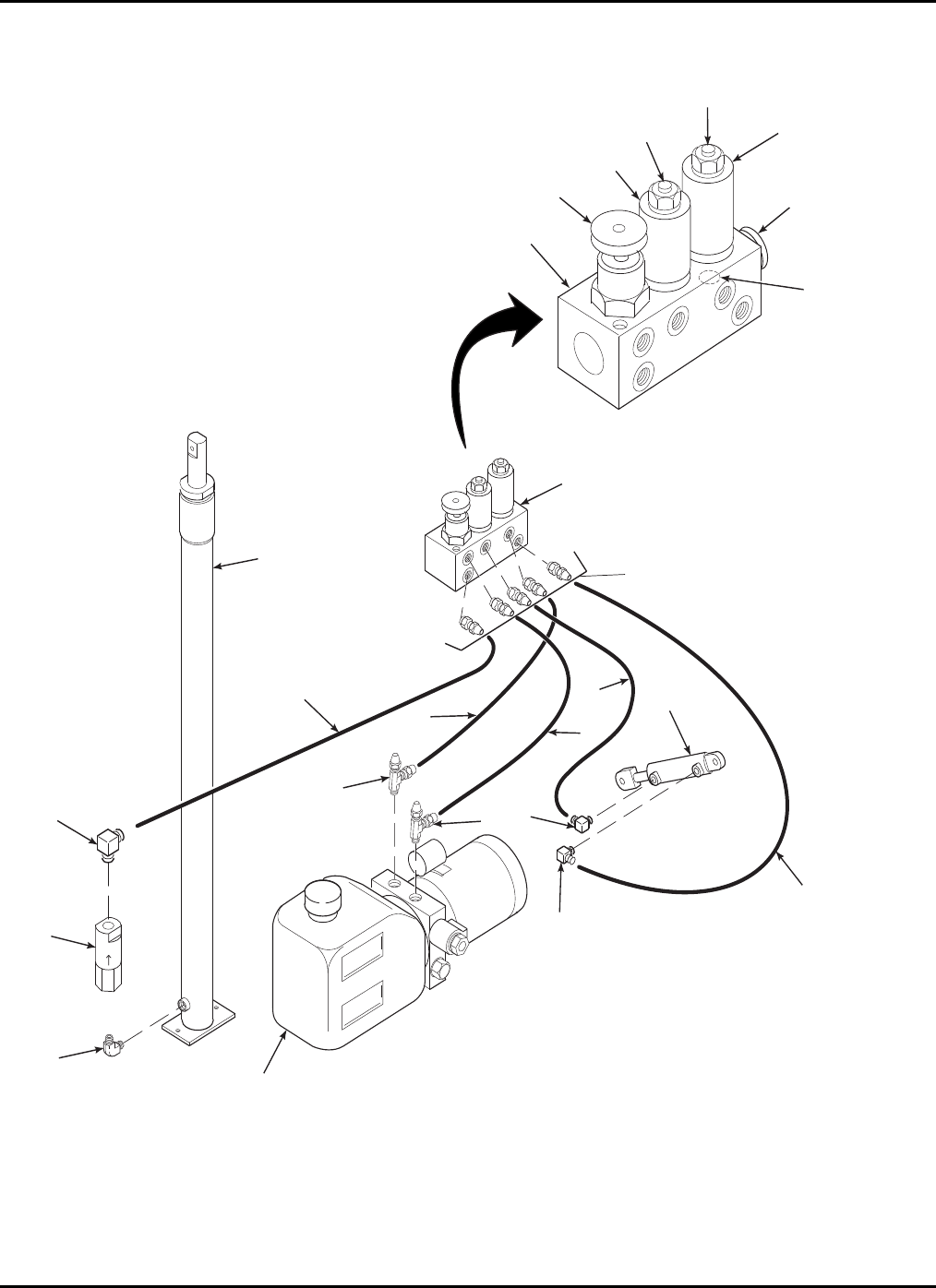
6-11 HYDRAULIC FITTINGS AND HOSES DIAGRAM
L
L
A
A
G
G
W
W
B
B
P
T
1
5
2
3
4
6
7
7
2
2
10
12
8
8
5
9
11
14
13
16
15
17
18
19
20
Figure 6-11. Hydraulic Fittings and Hoses Diagram
6-22

6 — PARTS LIST
6-23
Table 6-11. Hydraulic Fittings and Hoses Parts List
Item No. Part No. Description Qty
1 B02-03-0018 Cylinder, Hydraulic Lift, 1.5 in. Diameter 1
2 B02-02-0002
Fitting, 4JIC-4NPT 90, 2501-4 3
3 B02-04-0002 Valve, Flow Control, 1.25 in. 1
4 B02-02-0041
Fitting, 4NPT-4NPT 90 1
5 B02-01-0110 Hose, Hydraulic, 22 in., 4M3K W/2 4-4FJX 2
6 B02-05-0011 Pump, Hydraulic, Standard AC 1
7 B02-02-0072
Fitting, 4JIC-6ORM 90, 6801-4-6 2
8 B02-01-0113 Hose, Hydraulic, 80 in., 4M3K W/2 4-4FJX 2
9 B02-01-0124 Hose, Hydraulic, 15 in., 4M3K W/2 4-4FJX 1
10 B02-03-0010 Cylinder, Hydraulic Wheel 1
11 B02-04-0047 Manifold Block, Hydraulic 1
12 B02-02-0163 Fitting, 4JIC-6ORM Nip 5
13 B02-04-0047 Valve, Combination (for Stockpickers and
Tom Cats) 1
14 B02-14-0036 Valve, Needle, Emergency Down 1
15 B02-14-0038 Valve, Cartridge, NC, Lift Cylinder 1
16 B01-08-0002 Coil, 12v, Lift 1
17 B02-14-0037 Valve, Cartridge, NC, Wheel Cylinder 1
18 B01-08-0011 Coil, 12v, Wheel 1
19 B02-14-0039 Disc, Orifice 1
20 B02-02-0194 Plug, SAE 4 3

XLT-1571AC
6-12 HYDRAULIC FITTINGS AND HOSES SCHEMATIC
Figure 6-12. Hydraulic Fittings and Hoses Schematic
6-24

6 — PARTS LIST
6-13 ELECTRICAL DIAGRAM
Start
Sol
T10
E-Stop
ON UP
T
13
ONE-Stop Down
T
15
T2
E-Stop Wheel Up
T6
T
13
T
15
DownONE-Stop
UP
Lower Lift
Option
T4
T
17
Wheel
Down Wheel
Set
Upper
Control
Beeper
Light
T1
T
12
R2
R2 T3
T4
T5
Wheel
Valve
T6
Down
ValvePump
T8
T9 Lift
Valve
T7
Foot Switches
RW
B
T17 R2
R3
W
Motor
NO
Valve
T15
R1
T13
1571/1071 Schematic
R 3
T12
Level
Sensor
NC
Lower
Control
Mast
Switch
R2
AC
Switcher
Board
110v
Flush Mt
Recp.
Terminal Connections for Black Box
Terminal No. Wire Color From Terminal No. Wire Color From
1 BLK
BLK Mast Down Limit Switch
Upper Control Box 11 RED
WHT Level Sensor
Left Foot Limit Switch
2 BLK
BLK Lower Control Box
Right Foot Limit Switch 12 WHT
ORG/BLK STR Mast Down Limit Switch
Lower Control Box
3 WHT Hydraulic Pump Motor 13 WHT
YEL Upper Control Box
Lower Control Box
4 BRN/BLK STR Lower Control Box 14
5 RED Hydraulic Manifold 15 GRN
RED/BLK STR Upper Control Box
Lower Control Box
6 YEL/BLK STR Lower Control Box 16
7 17 WHT
RED Level Sensor
Lower Control Box
8 BLK Hydraulic Pump Motor 18
9 BLK Hydraulic Manifold 19 GRN
WHT
BLK
Hydraulic Manifold
Hydraulic Manifold
Level Sensor
10 RED
BLU
GRN
Upper Control Box
Lower Control Box
Hydraulic Pump Motor
20 BRN
BLK Lower Control Box
Base Ground
Figure 6-13. Electrical Diagram
6-25
XLT-1571AC
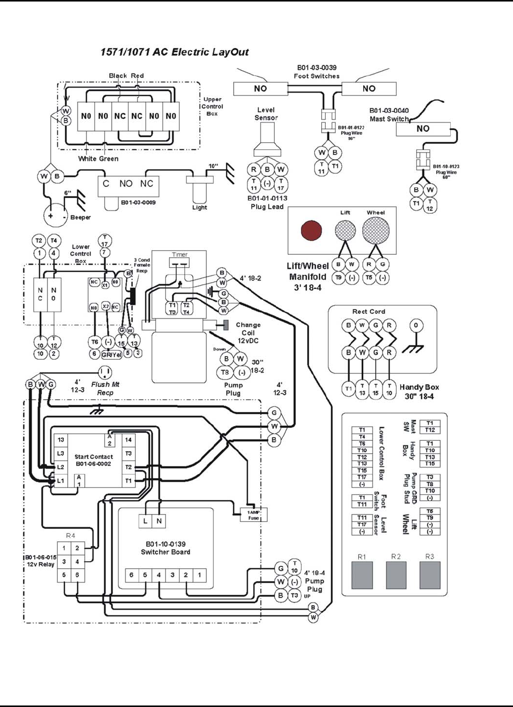
Figure 6-14. Electrical Layout Diagram
6-26

7-1
7
ANSI Reprint
The following sections are reprinted from the ANSI A92.3-2006 code in effect at the
time of manufacture. Permission to reprint has been granted by the Scaffold
Industry Association.
5. Responsibilities of Dealers
5.1 Basic Principles. Sound principles of safety, training, inspection, maintenance, applications, and operation
consistent with all data available regarding the parameters of intended use and expected environment shall be
applied in the training of operators, in maintenance, application, and operation of the aerial platform with due
consideration of the knowledge that the unit will be carrying personnel.
5.2 Manuals
5.2.1 Machine Manual(s). Dealers shall keep and maintain a copy(ies) of the: (1) Operating manual (2) Mainte-
nance manual (3) Parts manual (4) Repair manual The operating manual and maintenance manual shall be
provided upon each rental lease or sale delivery and shall be stored in the weather-resistant storage location on
the aerial platform. Manual(s) are considered an integral part of the aerial platform and are vital to communicate
necessary safety information to owners, users and operators. In addition, repair and parts manuals should be
provided with each sale delivery.
5.2.2 Manual of Responsibilities. The current Manual of Responsibilities for Dealers, Owners, Users, Opera-
tors, Lessors, Lessees, and Brokers of manually propelled elevating work platforms shall be provided and stored
in the weather-resistant storage compartment.
5.3 Predelivery Preparation. Aerial platforms shall be inspected, serviced, and adjusted to manufacturer’s
requirements prior to each delivery by sale, lease, or rental.
5.4 Maintenance, Inspection and Repair.
5.4.1 Maintenance. When a dealer accomplishes preventive maintenance on the aerial platform, it shall be in
accordance with the manufacturer’s recommendations and on the environment and severity of use.
5.4.2 Inspection. When the dealer accomplishes frequent and annual inspections, they shall be in accordance
with the manufacturer’s manuals and instructions.
5.4.3 Repairs. Repairs accomplished to correct malfunctions and problems shall be in accordance with the
manufacturer’s manuals and instructions.
5.5 Maintenance Safety Precautions. Before adjustments and repairs are started on an aerial platform, the
following precautions shall be taken as applicable: (1) All controls in the “off” position and all operating features
secured from inadvertent motion by brakes, blocks, or other means (2) Power plant stopped and starting means
rendered inoperative (3) Elevating assembly and platform lowered to the full down position, if possible, or other-
wise secured by blocking or cribbing to prevent dropping (4) Hydraulic oil pressure relieved from all hydraulic
circuits before loosening or removing hydraulic components (5) Safety props or latches installed where applicable
as described by the manufacturer (6) Precautions specified by the manufacturer
5.6 Replacement Parts. When parts or components are replaced, they shall be identical or equivalent to original
aerial platform parts or components.
5.7 Training. The dealer shall offer appropriate training to facilitate owners, users and operators to comply with
requirements set forth in this standard regarding the inspection, maintenance, use, application and operation of
the aerial platform.
5.8 Familiarization upon Delivery. Upon delivery by sale, lease, rental or any form of use, the dealer shall have
the responsibility with the person designated by the receiving entity for accepting the aerial platform to: (1) Identify
the weather-resistant compartment for manual(s) storage (2) Confirm that the manual(s), as specified by the
manufacturer, are on the aerial platform (3) Review control functions (4) Review safety devices specific to the
model aerial platform being delivered (5) Review loading and unloading procedures and the use of tilt-back fea-
ture(s) when applicable
5.9 Dealer as a User. Whenever a dealer directs personnel to operate an aerial platform (loading, unloading,
inspecting, sales demonstrations, or any form of use), the dealer shall assume the responsibilities of users as
specified in Section 7 of this standard. All personnel authorized to operate the aerial platform shall have been:
(1) Trained (2) Familiarized with the aerial platform to be operated (3) Made aware of the responsibilities of op-
erators as outlined in Section 8 of this standard

XLT-1571AC
7-2
5.10 Assistance to Owners and Users. If a dealer is unable to answer an owner’s or user’s question relating to
rated capacity, intended use, maintenance, repair, inspection, or operation of the aerial platform, the dealer shall
obtain the proper information from the manufacturer and provide that information to the owner or user.
5.11 Record Retention and Dissemination.
5.11.1 Record Retention. The dealer shall retain the following records for at least 4 years: (1) Name and ad-
dress of the purchaser of each aerial platform by serial number and the date of delivery (2) Records of the pre-
delivery preparation performed prior to each delivery (3) Name of the person(s) trained (4) Name of the person(s)
providing the training (5) Name of the person(s) receiving familiarization with the aerial platform upon each deliv-
ery unless the individual has been provided with familiarization on the same model, or one having characteristics
consistent with the one being delivered, within the prior 90 days (6)Name of the person(s) providing the familiari-
zation with the aerial platform upon each delivery (7) Records of frequent and annual machine inspections ac-
complished (8) Records of repairs accomplished to correct malfunctions and problems
5.11.2 Proof of Training. The dealer should provide trainees who successfully complete training a means to
evidence that they are trained if such proof is requested by the trainee. The document evidencing training shall
include the following information: (1) Name of trainee
(2) Name of entity providing training or retraining (3) Name of trainer(s) (4) Clear identification that training cov-
ered Manually Propelled Elevating Work Platforms (5) Date of the training
5.11.3 Record Dissemination. Upon request, the dealer should provide the following information: (1) To the
owner of the aerial platform, a copy of frequent or annual inspections performed (2) To the owner of the aerial
platform, a copy of repairs accomplished
(3) To a user, proof of training for an operator, including name of the trainer and the date of training (4) To a user,
the name of the person(s) receiving familiarization upon delivery of the aerial platform
5.12 Modifications. Modification, alteration or remanufacture of the aerial platform shall be made only with prior
written permission of the manufacturer.
5.13 Manufacturer’s Safety Bulletins. The dealer shall comply with safety-related bulletins as received from the
manufacturer.
5.14 Responsibilities upon Sale. When the aerial platform is sold, the dealer: (1) Shall, upon delivery, ensure
the operating and maintenance manuals are conveyed to the owner (2) Shall, upon delivery, provide a copy of the
current Manual of Responsibilities (3) Should, within 60 days of sale, provide repair and parts manuals (4) Shall,
within 60 days of sale, notify the manufacturer or its successor (if existing) of the sale, providing the full name and
address of the purchaser (5) Should, if the aerial platform is used, accomplish an annual machine inspection prior
to delivery and provide a copy to the purchaser within 60 days of the sale (6) Shall, upon delivery, familiarize the
person designated by the receiving entity with the aerial platform being acquired.
6. Responsibilities of Owners
6.1 Basic Principles. Sound principles of safety, training, inspection, maintenance, application, and operation
consistent with all data available regarding the parameters of intended use and expected environment shall be
applied in the performance of the responsibilities of owners with due consideration of the knowledge that the unit
will be carrying personnel.
6.2 Responsibilities Upon Purchase. Upon purchase of the aerial platform, the buyer: (1) Shall ensure the
operating and maintenance manuals have been received (2) Should acquire repair and parts manuals within sixty
days (60) of acquisition (3) Shall within sixty days (60) of acquisition of the aerial platform provide the manufac-
turer with the full name and address of the buyer along with the model and serial number of the aerial platform
acquired (4) Shall, if the aerial platform is used, ensure that frequent and annual inspections are current (5) Shall
become familiar with and conform to the responsibilities of owners as set forth in the current Manual of Responsi-
bilities for Manually Propelled Elevating Aerial Platforms
6.3 Manuals.
6.3.1 Machine Manual(s). Owners shall provide a copy(ies) of the operating and maintenance manual(s) with
each rental, lease, or sales delivery by ensuring they are properly stored in the weather-resistant compartment
that is a part of the aerial platform. The manual(s) is considered an integral part of the aerial platform and is vital
to communicate necessary safety information to owners, users and operators. In addition, repair and parts man-
ual(s) should be provided upon each sale delivery.
6.3.2 Manual of Responsibilities. The current Manual of Responsibilities for Dealers, Owners, Users, Opera-
tors, Lessors, Lessees, and Brokers of manually propelled elevating work platforms shall be provided and stored
in the weather-resistant storage compartment.
6.4 Maintenance, Inspection and Repair.
6.4.1 Maintenance. The owner of an aerial platform shall arrange that the maintenance specified in this standard
is properly performed on a timely basis. The owner shall establish a preventive maintenance program in accor-

7 — ANSI REPRINT
7-3
dance with the manufacturer’s recommendations and on the environment and severity of use of the aerial plat-
form.
6.4.2 Inspection. The owner shall arrange for frequent and annual inspections to be performed in accordance
with the recommendations of the manufacturer. All malfunctions and problems identified in the inspection shall be
corrected before the aerial platform is returned to service.
6.4.3 Repairs. When the aerial platform is damaged or in need of repair, all malfunctions and problems identified
shall be corrected before the aerial platform is returned to service.
6.5 Predelivery Preparation. Aerial platforms shall be inspected, serviced, and adjusted in accordance with the
manufacturer’s requirements prior to each delivery by sale, lease, or rental.
6.6 Frequent Inspection. The owner of an aerial platform shall ensure that a frequent inspection is performed in
accordance with the manufacturer’s instructions, on an aerial platform: (1) That was purchased used. This inspec-
tion shall be accomplished unless it is determined that the frequent and annual inspections are current (2) That
has been in service for 3 months or 150 hours, whichever comes first (3) That has been out of service for a period
longer than 3 months
The inspection shall be made by a person qualified as a mechanic on the specific type of aerial platform or one
having similar design characteristics. The inspection shall be in accordance with items specified by the manufac-
turer for a frequent inspection and shall include, but not be limited to, the following: (1)All functions and their
controls for speed(s), smoothness, and limits of motion (2) Emergency lowering means (3) All chain and cable
mechanisms for adjustment and worn or damaged parts (4) All emergency and safety devices (5) Lubrication of
all moving parts, inspection of filter element(s), hydraulic oil, engine oil, and coolant, as specified by the manufac-
turer (6) Visual inspection of structural components and other critical components, such as fasteners, pins, shafts,
and locking devices (7) Placards, warnings, and control markings (8) Items specified by the manufacturer (9)
Correction of all malfunctions and problems identified and further inspection, if necessary
6.7 Annual Inspection. The owner of an aerial platform shall ensure that an annual inspection is performed on
the aerial platform no later than 13 months from the date of the prior annual inspection. The inspection shall be
made by a person qualified as a mechanic on the specific type of aerial platform or one having similar design
characteristics. The inspection shall be in accordance with items specified by the manufacturer for an annual
inspection. The owner shall not place the aerial platform into service until all malfunctions and problems have
been corrected.
6.8 Maintenance Safety Precautions. Before adjustments and repairs are started on an aerial platform, the
following precautions shall be taken as applicable: (1) All controls in the “off’ position and all operating features
secured from inadvertent motion by brakes, blocks, or other means (2) Power plant stopped and starting means
rendered inoperative (3) Elevating and platform lowered to the full down position, if possible, or otherwise secured
by blocking or cribbing to prevent dropping (4) Hydraulic oil pressure relieved from all hydraulic circuits before
loosening or removing hydraulic components
(5) Safety props or latches installed where applicable as described by the manufacturer (6) Precautions specified
by the manufacturer
6.9 Replacement Parts. When parts or components are replaced, they shall be identical or equivalent to original
aerial platform parts or components.
6.10 Maintenance Training. The owners shall train their maintenance personnel in inspection and maintenance
of the aerial platform in accordance with 6.2 through 6.11 of this standard, and with the manufacturer’s recom-
mendations.
6.11 Training.
6.11.1 Operator Training. Whenever an owner directs or authorizes an employee to operate an aerial platform
(loading, unloading, inspecting or any form of use) the owner shall assume the responsibilities of the user as
specified in Section 7 of this standard and ensure that the individual has been: (1) Trained (2) Familiarized with
the aerial platform to be operated. (3) Made aware of the responsibilities of operators as outlined in Section 8 of
this standard
6.11.2 Assistance to Users. Upon request of the user, when an owner sells, leases, rents or provides an aerial
platform for any form of beneficial use, the owner at that time shall offer to do training or advise the user where
training may reasonably be secured.
6.12 Familiarization upon Delivery. Upon delivery by sale, lease, rental or any form of use, the owner shall have
the responsibility with the person designated by the receiving entity for accepting the aerial platform to: (1) Identify
the weather-resistant compartment for manual(s) storage (2) Confirm that the manuals, as specified by the manu-
facturer, are on the aerial platform (3) Review control functions (4) Review safety devices specific to the model
aerial platform being delivered (5) Review loading and unloading procedures and the use of tilt-back feature(s)
when applicable

XLT-1571AC
7-4
6.13 Operation. When an owner operates an aerial platform, the owner shall have the responsibilities of users as
specified in Section 7 of this standard, and the operating personnel shall have responsibilities of operators as
specified in Section 8 of this standard.
6.14 Assistance to Users and Operators. If an owner is unable to answer a user’s or operator’s questions
relating to rated capacity, intended use, maintenance, repair, inspection, or operation of the aerial platform, the
owner shall obtain the proper information from the dealer or manufacturer and provide that information to the user
or operator.
6.15 Record Retention and Dissemination.
6.15.1 Record Retention. The owner shall date and retain the following records for at least four (4) years: (1)
Name and address of the purchaser of each aerial platform by serial number and date of delivery (2) Written
records of the frequent and annual inspections and repairs performed. The record shall include deficiencies
found, corrective action accomplished and identification of the person(s) performing the inspection and repairs (3)
Written records of repairs accomplished on the aerial platform. The records shall include corrective action ac-
complished and identification of the person(s) performing the repairs (4) Pre-delivery preparation performed prior
to each delivery (5) Name of the person(s) trained (6) Name of the person(s) providing training (7) Name of the
person(s) receiving familiarization with the aerial platform upon each delivery unless the individual has been
provided with familiarization on the same model, or one having characteristics consistent with the one being
delivered, within the prior 90 days (8) Name of the person(s) providing familiarization
6.15.2 Proof of Training. Owners providing training should provide successful trainees a means to evidence
their training if such proof is requested by the trainee. The document evidencing training shall include the follow-
ing information: (1) Name of trainee (2) Name of entity providing training or retraining (3) Name of trainer(s) (4)
Clear identification that training covered Manually Propelled Elevating Work Platforms (5) Date of the training
6.15.3 Record Dissemination. Upon request, an owner accomplishing training and/ or familiarization should
provide the following: (1) To a user, proof of training for an operator, including name of the trainer and the date of
training (2) To a user, the name of the person(s) receiving familiarization upon delivery of the aerial platform
6.16 Modifications. The owner shall not modify or concur in modifications or alteration to the aerial platform
without the modifications being approved and certified in writing by the manufacturer.
6.17 Manufacturer’s Safety Bulletins. The owner shall comply with safety-related bulletins as received from the
manufacturer or dealer.
6.18 Responsibilities upon Sale. Upon sale of the aerial platform, the seller: (1) Shall, upon delivery, ensure the
operating and maintenance manuals are conveyed to the owner
(2) Shall, upon delivery, provide a copy of the current Manual of Responsibilities for
Manually Propelled Elevating Aerial Platforms to the new owner (3) Should provide repair and parts manuals to
the new owner (4) Shall, upon the request of the new owner, offer training or advice where training may reasona-
bly be obtained.
7. Responsibilities of Users
7.1 Basic Principles. The information in this standard must be supplemented by good job management, safety
control, and the application of sound principles of safety, training, inspection, maintenance, application, and
operation consistent with all data available regarding the parameters of intended use and expected environment.
Since the user has direct control over the application and operation of aerial platforms, conformance with good
safety practices in this area is the responsibility of the user and the operating personnel, including the operator.
Decisions on the use and operation of the aerial platform must always be made with due consideration for the fact
that the aerial platform will be carrying personnel whose safety is dependent on those decisions.
7.2 Manuals.
7.2.1 Machine manuals. Users shall keep and maintain copy(ies) of the operating and maintenance manual(s) in
the weather resistant storage compartment provided by the manufacturer. The manual(s) is considered an inte-
gral part of the aerial platform and is vital to communicate necessary safety information to users and operators.
7.2.2 Manual of Responsibilities. The current Manual of Responsibilities for
Dealers, Owners, Users, Operators, Lessors, Lessees, and Brokers of manually propelled elevating work plat-
forms shall be provided and stored in the weather-resistant storage compartment.
7.3 Inspection and Maintenance. Users shall inspect and maintain the aerial platform as required to ensure
proper operation. The frequency of inspection and maintenance shall be based upon the manufacturer’s recom-
mendations and be compatible with operating conditions and the severity of the operating environment. Aerial
platforms that are not in proper operating condition shall be immediately removed from service until repaired.
Repairs shall be made by a qualified person and the repairs shall be in conformance with the manufacturer’s
recommendations.

7 — ANSI REPRINT
7-5
7.3.1 Frequent Inspection. Users of an aerial platform shall ensure that frequent inspections are conducted as
outlined in 6.6 of this standard.
7.3.2 Annual Inspection. Users of an aerial platform shall ensure that annual inspections are conducted as
outlined in 6.7 of this standard.
7.3.3 Prestart Inspection. Before use each day or at the beginning of each shift, the aerial platform shall be
given a visual inspection and functional test including but not limited to the following: (1) Operating and emer-
gency controls (2) Safety devices (3) Air, hydraulic and fuel system leaks (4) Cables and wiring harness (5) Loose
or missing parts (6) Tires and wheels (7) Placards, warnings, and control markings (8) Outriggers, stabilizers, and
other structures (9) Guardrail system (10) Items specified by the manufacturer
7.3.4 Maintenance Safety Precautions.
Before adjustments and repairs are started on an aerial platform, the following precautions shall be taken as
applicable: (1) All controls in the “off’ position and all operating features secured from inadvertent motion by
brakes, blocks, or other means (2) Power plant stopped and starting means rendered inoperative (3) Platform
lowered to the full down position, if possible, or otherwise secured by blocking or cribbing to prevent dropping (4)
Hydraulic oil pressure relieved from all hydraulic circuits before loosening or removing hydraulic components (5)
Safety props or latches installed where applicable as described by the manufacturer (6) Precautions specified by
the manufacturer
7.4 Replacement Parts. When parts or components are replaced, they shall be identical or equivalent to original
aerial platform parts or components.
7.5 Maintenance Training. The user shall ensure only qualified personnel inspect and maintain the aerial plat-
form in accordance with 7.3, 7.4, and 7.6 of this standard and with the manufacturer’s recommendations.
7.6 Operator Training and Retraining. Whenever a user directs or authorizes an individual to operate an aerial
platform, the user shall ensure that the person has been: (1) Trained before being assigned to operate the aerial
platform
(2) Familiarized with the aerial platform to be operated (3) Made aware of the responsibilities of operators as
outlined in Section 8 of this standard (4) Retrained, if necessary, based on the user’s observation and evaluation
of the operator
7.6.1 Trainee Records. A record of the trainee’s aerial platform instruction shall be maintained by the user for at
least four (4) years.
7.7 Familiarization Before Use. The user shall permit only properly trained personnel to operate an aerial plat-
form. The user shall ensure that before use the operator is familiar with the model of the aerial platform to be
operated, and specifically: (1) Knows where the weather-resistant compartment for manual storage is located (2)
Knows the operating and maintenance manuals supplied by the manufacturer are stored in the weather- resistant
compartment and is familiar with the operating and safety manuals (3) Understands all control functions, placards
and warnings (4) Is aware of and understands all safety devices specific to the model aerial platform being used
(5) Understands loading and unloading procedures and the use of tilt-back feature(s) when applicable
7.8 Work Place Inspection. Before the aerial platform is used and during use, the user shall check the area in
which the aerial platform is to be used for possible hazards such as, but not limited to: (1) Drop-offs or holes (2)
Slopes (3) Bumps and floor obstructions (4) Debris (5) Overhead obstructions and electrical hazards (6) Hazard-
ous locations (reference ANSI/NFPA 505-1996) (7) Inadequate surface and support to withstand all load forces
imposed by the aerial platform in all operating configurations (8) Wind and weather conditions (9) Presence of
unauthorized persons (10) Other possible unsafe conditions
7.9 Determination of Hazardous Locations. It shall be the responsibility of the user to determine the hazard
classification of the intended location of operation. Aerial platforms operated in hazardous locations shall be
approved in accordance with, and of the type required, by ANSI/NFPA 505-1996.
7.10 Operator Warnings and Instruction. The user shall direct personnel operating the aerial platform to be in
compliance with the provisions set forth in this standard. The user shall monitor their performance and supervise
their work to ensure the use, application and operation of the aerial platform is in conformance with the provisions
set forth in section 8 of this standard, warn personnel of potential hazards, provide means to protect against
identified hazards, and explain the potential consequences of not following proper operating guidelines. Instruc-
tions and guidelines regarding proper operation shall include, but not necessarily be limited to the following issues
and subjects: (1) Fall protection. The guardrail system of the aerial platform provides fall protection. If occupant(s)
of the platform are required to wear personal fall protection equipment, occupants shall comply with instructions
provided by the aerial platform manufacturer regarding anchorage(s). (2) Slope. The aerial platform shall not be
operated in any manner on slopes exceeding those for which the aerial platform is rated by the manufacturer. (3)
Deployment of stability enhancing means. Outriggers, stabilizers, extendible axles, axle locks, or other stability
enhancing means shall be deployed and locked into place as required by the manufacturer. (4) Guardrail system.
Guardrails shall be installed and positioned, and access gates or openings shall be closed per the manufacturer’s

XLT-1571AC
7-6
instructions. (5) Distribution of load. The load and its distribution on the platform and any platform extension(s)
shall be in accordance with the manufacturer’s rated capacity for that specific configuration. (6) Maintaining
overhead clearance. The operator shall be instructed to ensure that adequate clearance is maintained from
overhead obstructions and energized electrical conductors and parts. (7) Electrocution hazard. All applicable
safety related work practices intended to prevent electric shock covered by the Code of Federal Regulations
(CFR) 1910.333 shall be defined and explained to the operator by a qualified person. In particular, such person
shall direct the operator, commensurate with the operator's qualifications to maintain the appropriate minimum
approach distance (MAD) from energized power lines and parts covered by CFR 1910.333 (c). (8) Personal
protective equipment. The user shall direct the operator to ensure all personnel on the platform wear personal
protective equipment as required. (9) Personnel footing. The user shall direct the operator to maintain firm footing
on the platform while working thereon. Climbing by occupants on the midrail or top rail of the aerial platform is
prohibited. The use of planks, ladders, or any other devices on the platform for achieving additional height or
reach is prohibited. (10) Precaution for moving equipment. When moving equipment or vehicles are present,
special precautions shall be taken to comply with local ordinances or safety standards established for the work-
place. Warnings such as, but not limited to, flags, roped off areas, flashing lights, and barricades shall be used as
appropriate. (11) Reporting problems or malfunctions.
The user shall direct the operator to immediately report to a supervisor any problem(s) or malfunction(s) that
become evident during operation. The user shall ensure all problems and malfunctions that affect the safeties of
operations are repaired prior to continued use. (12) Reporting potentially hazardous locations. The user shall
direct the operator to immediately report to a supervisor any potentially hazardous location(s) that become evi-
dent during operation. (13) Hazardous location operation. Operation of aerial platforms not approved and marked
for operation in a hazardous location shall be prohibited. (14) Entanglement. Care shall be taken to prevent rope,
electric cords, and hoses, etc., from becoming entangled in the aerial platform. (15) Capacity limitation. Rated
capacity shall not be exceeded when loads are transferred to the platform at any level. (16) Work area. The user
shall direct the operator to ensure that the area surrounding the aerial platform is clear of personnel and equip-
ment before lowering the platform. (17) Fueling. The engine (if applicable) shall be shut down while fuel tanks are
being filled. Fueling shall be done in a well ventilated area free of flames, sparks, or other hazards that may cause
fire or explosion. (18) Battery charging. Batteries shall only be charged in well-ventilated area free of flames,
sparks, or other hazards that may cause fire or explosion. (19) Improper platform stabilization. The aerial platform
shall not be positioned against another object to steady the platform or improve stability. (20) Misuse as a crane.
The aerial platform shall not be used as a crane. (21) Unusual operating support conditions. The aerial platform
shall not be operated from a position on trucks, trailers, railway cars, floating vessels, scaffolds, or similar equip-
ment unless the application is approved in writing by the manufacturer or a qualified person. (22) Propelling. The
user shall ensure that the operator follows the transport instructions of the manufacturer and limit speed accord-
ing to conditions, including the condition of the support surface, congestion, visibility, slope, location of personnel,
and other factors leading to hazards which may cause collision(s) or result in the potential injury(ies) to personnel.
(23) Securing the aerial platform. The user shall direct the operator to implement means provided to protect
against use by an unauthorized person(s). (24) Altering safety devices. Interlocks or other safety devices shall not
be altered or disabled. (25) Snagged platform. If the platform or elevating assembly becomes caught, snagged, or
otherwise prevented from normal motion by adjacent structures or other obstacles such that control reversal does
not free the platform, all personnel shall be removed from the platform before attempts are made to free the
platform using lower controls. (26) Exiting or entering an elevated aerial platform. If permitted by the manufac-
turer, personnel shall only exit or enter a raised aerial platform by following the guidelines and instructions pro-
vided by the manufacturer. (27) Modifications. Modifications or alterations of an aerial platform or the fabrication
and attaching of frameworks, or the mounting of attachments for holding tools or materials onto the platform or
the guardrail system shall only be accomplished with prior written permission of the manufacturer. (28) Assis-
tance to the operator. If an operator encounters any suspected malfunction of the aerial platform, or any hazard or
potentially unsafe condition relating to capacity, intended use or safe operation of the aerial platform, the operator
shall cease operation of the aerial platform and request further information from the user. (29) Problems or mal-
functions. Any problem(s) or malfunction(s) that affect the safety of operations shall be repaired prior to the use of
the aerial platform. (30) Carrying materials (larger than the platform). The user shall ensure that only properly
secured tools and materials which are evenly distributed and can be safely handled by a person(s) working from
the platform, are moved. (31) Rated horizontal force. The user shall direct the operator not to exceed the manu-
facturer’s rated horizontal force. (32) Bridge cranes. When an aerial platform is to operate within the area of travel
of a bridge crane or similar equipment, steps shall be taken to prevent a collision with the aerial platform. (33)
Adequate support requirements. The user shall ensure the support surface is adequate for the aerial platform and
the load carried. (34) Leveling the aerial platform. Outriggers and leveling devices supplied by the manufacturer
shall be utilized to level the aerial platform when provided. (35) Protection against unauthorized use. The user
shall direct the operator not to use, rent, lease, or provide the aerial platform for any form of beneficial use unless

7 — ANSI REPRINT
7-7
so authorized. (36) Loading and tilt-back feature(s). The user shall direct the operator to follow the instructions of
the manufacturer regarding loading, unloading and the use of tilt-back feature(s) when applicable.
7.11 User as Operator. If a user is also the operator of an aerial platform, the user shall have the responsibilities
of operators specified in Section 8 of this standard as well as responsibilities of users as specified in Section 7 of
this standard.
7.12 Assistance to Operator. If a user is unable to answer any operator’s questions relating to rated capacity,
intended use, maintenance, condition, or safety of operation of the aerial platform, the user shall obtain the proper
information from the dealer, owner, or manufacturer and provide that information to the operator before use of the
aerial platform in the application of concern.
7.13 Shutdown of Aerial Platform. The user shall authorize and direct the operating personnel to cease opera-
tion of the aerial platform in case of any suspected malfunctions of the aerial platform, or any hazard or potentially
unsafe condition that may be encountered, and to request further information as to safe operation from the owner,
dealer, or manufacturer before further operation of the aerial platform.
7.14 Record Retention and Dissemination.
7.14.1 Record Retention. The user shall retain the following records for at least 4 years: (1) Names of the opera-
tor(s) trained and retrained (2) Names of the operator(s) provided familiarization (3) The owner (or the entity
designated by the owner) is responsible to ensure frequent and annual inspections are conducted and written
records are maintained. The records shall include the date of inspection, any deficiencies found, the corrective
action recommended and identification of the person(s) performing the inspection (4) When employees of the
user accomplished repairs on the aerial platform, the user shall maintain written records. The records shall in-
clude the date of repair, a description of the work accomplished, and the identification of the person(s) performing
the repair
7.14.2 Record Dissemination. (1) When the user directs personnel to accomplish frequent or annual inspec-
tions, not later than 60 days after the inspections, the appropriate records shall be provided to the owner of the
aerial platform (2) When the user directs personnel to accomplish repairs on the aerial platform, not later than 60
days after the repairs are accomplished, the appropriate records shall be provided to the owner
7.14.3 Proof of Training. Users providing training should provide successful trainees a means to evidence their
training if such proof is requested by the trainee. The document evidencing training shall include the following
information: (1) Name of trainee (2) Name of entity providing training or retraining (3) Name of trainer(s) (4) Clear
identification that training covered Manually Propelled Elevating Work Platforms (5) Date of the training
7.15 Modifications. Modification, alteration or remanufacture of the aerial platform shall be made only with prior
written permission of the manufacturer.
7.16 Manufacturer’s Safety Bulletins. The user shall comply with safety-related bulletins as received from the
manufacturer, dealer, or owner.
8. Responsibilities of Operators
8.1 Basic Principles. The information in this standard shall be supplemented by good judgment, safety control,
and caution in evaluating each situation. Since the operator is in direct control of the aerial platform, conformance
with good safety practices in this area is the responsibility of the operator. The operator shall make decisions on
the use and operation of the aerial platform with due consideration for the fact that his or her own safety as well
as the safety of other personnel on the platform is dependent on those decisions.
8.2 Manuals.
8.2.1 Machine Manuals. The operator shall ensure operating and maintenance manual(s) are stored in the
weather-resistant storage compartment on the aerial platform. The manual(s) is considered an integral part of the
aerial platform and is vital to communication of necessary safety information to operator. The operator shall be
familiar with the manuals and reference them as required.
8.2.2 Manual of Responsibilities. The operator shall be familiar with the requirements for operators as set forth
in Section 8 of the Manual of Responsibilities for Dealers, Owners, Users, Operators, Lessors, Lessees, and
Brokers of manually propelled elevating work platforms. The current Manual of Responsibilities shall be kept with
the aerial platform at all times and stored in the weather-resistant compartment when not in use.
8.3 Prestart Inspection. Before use each day or at the beginning of each shift, the aerial platform shall be given
a visual inspection and functional test including but not limited to the following: (1) Operating and emergency
controls (2) Safety devices (3) Air, hydraulic, and fuel system leaks (4) Cables and wiring harness (5) Loose or
missing parts (6) Tires and wheels (7) Placards, warnings, and control markings (8) Outriggers, stabilizers, and
other structures (9) Guardrail system (10) Items specified by the manufacturer
8.4 Problems or Malfunctions. Any problems or malfunctions that affect the safety of operations shall be re-
paired prior to the use of the aerial platform.
8.5 Training, Retraining, and Familiarization.

XLT-1571AC
7-8
8.5.1 General Training. Only personnel, who have received general instructions regarding the inspection, appli-
cation and operation of aerial platforms, including recognition and avoidance of hazards associated with their
operation, shall operate an aerial platform. Such items covered shall include, but not necessarily be limited to the
following issues and requirements:
(1) The purpose and use of manuals (2) The manual(s) is considered an integral part of the aerial platform and
must be stored properly in the weather-resistant compartment when not in use (3) A pre-start inspection (4)
Responsibilities associated with problems or malfunctions affecting the operation of the aerial platform (5) Factors
affecting stability (6) The purpose of placards and decals (7) Workplace inspection (8) Safety rules and regula-
tions (9) Authorization to operate (10) Operator warnings and instructions (11) Actual operation of the aerial
platform. Under the direction of a qualified person, the trainee shall operate the aerial platform for a sufficient
period of time to demonstrate proficiency in actual operation of the aerial platform
8.5.2 Retraining. The operator shall be retrained, when so directed by the user, based on the user’s observation
and evaluation of the operator.
8.5.3 Familiarization. When the operator is directed to operate an aerial platform he/she is not familiar with, the
operator shall receive instructions regarding the following: (1) The location of the weather-resistant compartment
(for manual storage) (2) The purpose and function of all controls (3) Safety devices and operating characteristics
specific to the aerial platform (4) Loading, unloading and the use of tiltback feature(s) when applicable
8.6 Before Operation. Before operation, the operator shall: (1) Read and understand the manufacturer’s operat-
ing instruction(s) and user’s safety rules, or have them explained (2) Understand all labels, warnings, and instruc-
tions displayed on the aerial platform or have them explained (3) Ensure all occupants of the aerial platform wear
appropriate personal protective equipment for the conditions, including the environment in which the aerial plat-
form will be operated
8.7 Workplace Inspection. Before the aerial platform is used and during use, the operator shall check the area in
which the aerial platform is to be used for possible hazards such as, but not limited to: (1) Drop-offs or holes (2)
Slopes (3) Bumps and floor obstructions (4) Debris (5) Overhead obstructions and electrical hazards (6) Hazard-
ous locations (reference NFPA 505-1996) (7) Inadequate surface and support to withstand all load forces im-
posed by the aerial platform in all operating configurations (8) Wind and weather conditions (9) Presence of
unauthorized persons (10) Other possible unsafe conditions
8.8 Prior to Each Elevation. Before each elevation of the platform, the operator shall ensure:
(1) Outriggers, stabilizers, extendable axles, or other stability enhancing means are used as required by the
manufacturer (2) Guardrails are installed and access gates or openings are closed per manufacturer’s instruc-
tions (3) The load and its distribution on the platform and any platform extensions are in accordance with the
manufacturer’s rated capacity for that specific configuration (4) All personnel on the aerial platform have appro-
priate personal protective equipment for the work and environment envisioned
8.9 Understanding of Hazardous Locations. It shall be the responsibility of the operator to understand the
hazard classification of the intended location of operation according to ANSI/NFPA 505-1996.
8.10 Operator Warnings and Instructions. The operator shall ensure the operation of the aerial platform is in
compliance with the following: (1) Fall protection. The guardrail system of the aerial platform provides fall protec-
tion. If occupant(s) of the platform are required to wear personal fall protection equipment, occupant(s) shall
comply with instructions provided by the aerial platform manufacturer regarding anchorage(s). (2) Slope. The
aerial platform shall not be operated in any manner on slopes exceeding those for which the aerial platform is
rated by the manufacturer. (3) Deployment of stability enhancing means. Outriggers, stabilizers, extendible axles,
axle locks, or other stability enhancing means shall be deployed and locked into place as required by the manu-
facturer. (4) Guardrail system. Guardrails shall be installed and positioned, and access gates or openings shall be
closed per the manufacturer’s instructions. (5) Distribution of load. The load and its distribution on the platform
and any platform extension(s) shall be in accordance with the manufacturer’s rated capacity for that specific
configuration. (6) Maintaining overhead clearance. The operator shall ensure that adequate clearance is main-
tained from overhead obstructions and energized electrical conductors and parts. (7) Electrocution hazard. The
operator shall perform only that work for which he or she is qualified, in compliance with all applicable safety
related work practices intended to prevent electric shock covered by the Code of Federal Regulations (CFR)
1910.333. The operator’s level of competence shall be established only by persons qualified to do so. Operators
shall maintain the appropriate minimum approach distance (MAD) from energized power lines and parts covered
by CFR 1910.333 (c). (8) Personal protective equipment. The operator shall ensure all personnel on the platform
wear personal protective equipment as required. (9) Personnel footing. Personnel shall maintain firm footing on
the platform while working thereon. Climbing by occupants on the midrail or top rail of the aerial platform is pro-
hibited. The use of planks, ladders, or any other devices on the platform for achieving additional height or reach is
prohibited. (10) Precaution for moving equipment. When other moving equipment or vehicles are present, special
precautions shall be taken to comply with local ordinances or safety standards established for the workplace.
Warnings such as, but not limited to, flags, roped off areas, flashing lights, and barricades shall be used as ap-

7 — ANSI REPRINT
7-9
propriate. (11) Reporting problems or malfunctions. The operator shall immediately report to a supervisor any
problem(s) or malfunction(s) that become evident during operation. The operator shall ensure all problems and
malfunctions that affect the safeties of operations are repaired prior to continued use. (12) Reporting potentially
hazardous locations. The operator shall immediately report to a supervisor any potentially hazardous location(s)
that become evident during operation. (13) Hazardous location operation. Operation of aerial platforms not ap-
proved and marked for operation in a hazardous location shall be prohibited. (14) Entanglement. Care shall be
taken to prevent rope, electric cords, and hoses, etc., from becoming entangled in the aerial platform. (15) Capac-
ity limitation. Rated capacity shall not be exceeded when loads are transferred to the platform at any level. (16)
Work area. The operator shall ensure the area surrounding the aerial platform is clear of personnel and equip-
ment before lowering the platform. (17) Fueling. The engine (if applicable) shall be shut down while fuel tanks are
being filled. Fueling shall be done in a well ventilated area free of flames, sparks, or other hazards that may cause
fire or explosion. (18) Battery charging. Batteries shall only be charged in a well-ventilated area free of flames,
sparks, or other hazards that may cause fire or explosion. (19) Improper platform stabilization. The aerial platform
shall not be positioned against another object to steady the platform or improve stability. (20) Misuse as a crane.
The aerial platform shall not be used as a crane. (21) Unusual operating support conditions. The aerial platform
shall not be operated from a position on trucks, trailers, railway cars, floating vessels, scaffolds, or similar equip-
ment unless the application is approved in writing by the manufacturer or a qualified person. (22) Propelling. The
operator shall follow the transport instructions of the manufacturer and limit speed according to conditions, includ-
ing the condition of the support surface, congestion, visibility, slope, location of personnel, and other factors
leading to hazards which may cause collision(s) or result in the potential injury(ies) to personnel. (23) Securing
the aerial platform. The operator shall implement means provided to protect against use by an unauthorized
person(s). (24) Altering safety devices. Interlocks or other safety devices shall not be altered or disabled. (25)
Snagged platform. If the platform or elevating assembly becomes caught, snagged, or otherwise prevented from
normal motion by adjacent structures or other obstacles such that control reversal does not free the platform, all
personnel shall be removed from the platform before attempts are made to free the platform using lower controls.
(26) Exiting or entering an elevated aerial platform. If permitted by the manufacturer, personnel shall only exit or
enter a raised aerial platform by following the guidelines and instructions provided by the manufacturer. (27)
Modifications. Modifications or alterations of an aerial platform or the fabrication and attaching of frameworks, or
the mounting of attachments for holding tools or materials onto the platform or the guardrail system shall only be
accomplished with prior written permission of the manufacturer. (28) Assistance to the operator. If an operator
encounters any suspected malfunction of the aerial platform, or any hazard or potentially unsafe condition relating
to capacity, intended use or safe operation of the aerial platform, the operator shall cease operation of the aerial
platform and request further information from the user. (29) Problems or malfunctions. Any problem(s) or malfunc-
tion(s) that affect the safety of operations shall be repaired prior to the use of the aerial platform. (30) Carrying
materials (larger than the platform). The operator shall ensure that only properly secured tools and materials
which are evenly distributed and can be safely handled by a person(s) working from the platform, are moved. (31)
Rated horizontal force. The operator shall not permit personnel on the platform to exceed the manufacturer’s
rated horizontal force. (32) Bridge cranes. When an aerial platform is to operate within the area of travel of a
bridge crane or similar equipment, steps shall be taken to prevent a collision with the aerial platform. (33) Ade-
quate support requirements. The operator shall ensure the support surface is adequate for the aerial platform and
the load carried. (34) Leveling the aerial platform. Outriggers and leveling devices supplied by the manufacturer
shall be utilized to level the aerial platform when provided. (35) Protection against unauthorized use.
The operator shall not use, rent, lease, or provide the aerial platform for any form of beneficial use to another
entity without the authorization of the user. (36) Loading and tilt-back feature(s). The operator shall follow the
instructions of the manufacturer regarding loading, unloading and the use of tilt-back feature(s) when applicable.
8.11 Record of Training. When provided or when obtained upon the operator’s request, proof of training pro-
vided by the training entity should be retained by the operator. Records shall contain the following information: (1)
Name of Trainee (2) Name of entity providing training or retraining (3) Name of trainer(s) (4) Clear identification
that training covered Manually Propelled Elevating Platforms (5) Date of training
9. Responsibilities of Lessors
9.1 Basic Principles. Sound principles of safety, training, inspection, maintenance, application, and operation
consistent with all data available regarding the parameters of intended use and expected environment shall be
applied in the performance of responsibilities of lessors with due consideration of the knowledge that the unit will
be carrying personnel.
9.2 Lessor as a Dealer. When a lessor uses the aerial platform as a dealer, the lessor shall have the responsi-
bilities of dealers as specified in Section 5 of this standard.
9.3 Lessor as an Owner. When a lessor uses the aerial platform as an owner, the
lessor shall have the responsibilities of owners as specified in Section 6 of this standard.

XLT-1571AC
7-10
9.4 Lessor as a User. When a lessor uses the aerial platform as a user, the lessor shall have the responsibilities
of users as specified in Section 7 of this standard.
9.5 Lessor as an Operator. When a lessor uses the aerial platform as an operator, the
lessor shall have the responsibilities of operators as specified in Section 8 of this standard.
10. Responsibilities of Lessees
10.1 Basic Principles. Sound principles of safety, training, inspection, maintenance, application, and operation
consistent with all data available regarding the parameters of intended use, and the expected environment, shall
be applied in the performance of responsibilities of lessees with due consideration of the knowledge that the
aerial platform will be carrying personnel.
10.2 Lessee as a Dealer. When a lessee uses the aerial platform as a dealer, the lessee shall have the respon-
sibilities of dealers as specified in Section 5 of this standard.
10.3 Lessee as an Owner. When a lessee uses the aerial platform as an owner, the lessee shall have the re-
sponsibilities of owners as specified in Section 6 of this standard.
10.4 Lessee as a User. When a lessee uses the aerial platform as a user, the lessee shall have the responsibili-
ties of users as specified in Section 7 of this standard.
10.5 Lessee as an Operator. When a lessee uses the aerial platform as an operator, the lessee shall have the
responsibilities of operators as specified in Section 8 of this standard.
11. Responsibilities of Broker.
11.1 Responsibilities upon Sale. The broker shall: (1) Upon delivery, ensure the operating and maintenance
manuals are provided to the new owner (2) Upon delivery, provide a copy of the current Manual of Responsibili-
ties to the new owner (3) Maintain records of the sale for a minimum of four (4) years
11.2 Responsibilities upon Re-rent, Lease, or Any Other Form of Beneficial Use. When compensation is
received as a result of re-rent, lease or any other form of beneficial use of an aerial platform, the broker shall: (1)
Upon delivery, ensure the operating and maintenance manuals are provided to the user (2) Upon delivery, pro-
vide a copy of the current Manual of Responsibilities (3) Ensure operating personnel are familiarized with the
aerial platform prior to use (4) Retain records of the transaction for a minimum of four (4) years.
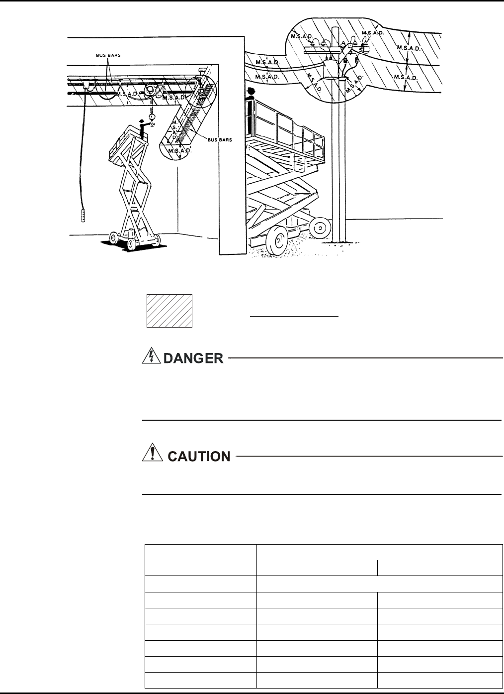
7 — ANSI REPRINT
M.S.A.D. = Minimum Safe Approach Distance (See Table 7-1).
DENOTES PROHIBITED ZONE
• Do not allow machine, personnel, or conductive materials inside prohibited zone.
• Maintain M.S.A.D. from all energized lines and parts as well as those shown.
• Assume all electrical parts and wires are energized unless known otherwise.
Diagrams shown are only for purposes of illustrating M.S.A.D. work positions, not
all work positions.
Table 7-1. Minimum Safe Approach Distance (M.S.A.D.) to energized
(exposed or insulated) power lines and parts.
Minimum Safe Approach Distance
Voltage Range
(Phase to Phase) (Feet) (Meters)
0 to 300V Avoid Contact
Over 300V to 50KV 10 3.05
Over 50KV to 200KV 15 4.60
Over 200KV to 350KV 20 6.10
Over 350KV to 500KV 25 7.62
Over 500KV to 750KV 35 10.67
Over 750KV to 1000KV 45 13.72
7-11

XLT-1571AC
7-12


125 Taylor Parkway
Archbold, OH 43502
Phone (419) 445-8915
(800) 537-0540
Fax (419) 445-0367
