BA Manual
User Manual:
Open the PDF directly: View PDF ![]() .
.
Page Count: 40
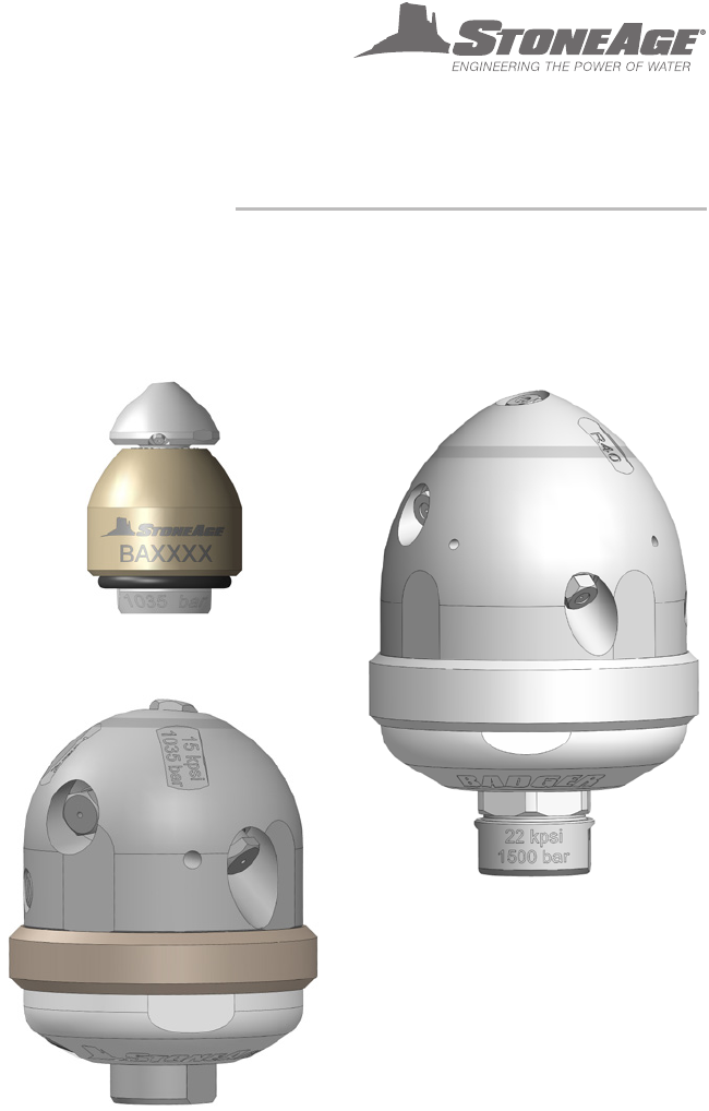
BADGER FAMILY
SELF ROTARY SWIVELS
USER MANUAL
*EXCLUDES BA-H6 4” 40K MODEL
2 INCH
4 INCH
6 INCH
PL 663 REV B
(05/2018)

2866-795-1586 • WWW. SEWERNOZZLES.COM
TABLE OF CONTENTS
This manual must be used in accordance with all applicable national laws. The manual shall be
regarded as a part of the machine and shall be kept for reference until the nal dismantling of the
machine, as dened by applicable national law(s).
MANUFACTURER’S INFORMATION ...........................................................3
SPECIFICATIONS FOR ALL MODELS .....................................................3
KEY FEATURES FOR ALL MODELS .......................................................3
GENERAL JETTING INFORMATION .......................................................4
2” BADGER ....................................................................................5
TOOL DESCRIPTION AND INTENDED USE ...............................................5
OPERATION ...............................................................................6
TROUBLESHOOTING .....................................................................7
TOOL SERVICE INFORMATION ...........................................................8
ASSEMBLY AND PARTS ...................................................................9
4” BADGER ....................................................................................10
TOOL DESCRIPTION AND INTENDED USE ...............................................10
WARNING AND SAFETY INSTRUCTIONS .................................................11
OPERATION ...............................................................................12
TROUBLESHOOTING .....................................................................13
TOOL SERVICE INFORMATION ...........................................................14
FLUID REPLACEMENT ....................................................................15
DISASSEMBLY ............................................................................16
ASSEMBLY ................................................................................17
PART NAMES/NUMBERS .................................................................20
SERVICE KITS .............................................................................21
6” BADGER ....................................................................................22
TOOL DESCRIPTION AND INTENDED USE ...............................................22
WARNING AND SAFETY INSTRUCTIONS .................................................23
OPERATION ...............................................................................24
TROUBLESHOOTING .....................................................................25
TOOL SERVICE INFORMATION ...........................................................26
FLUID REPLACEMENT ....................................................................27
DISASSEMBLY ............................................................................28
ASSEMBLY ................................................................................30
PART NAMES/NUMBERS .................................................................32
SERVICE KITS .............................................................................33
TERMS AND CONDITIONS AND WARRANTY .................................................34
3
866-795-1586 • WWW.SEWERNOZZLES.COM
MANUFACTURER’S INFORMATION
StoneAge Inc.
466 S. Skylane Drive
Durango, CO 81303, USA
Phone: 970-259-2869
Toll Free: 866-795-1586
www.stoneagetools.com
StoneAge Europe
Unit 2, Britannia Business Centre
Britannia Way
Malvern WR14 1GZ
United Kingdom
Phone: +44 (0) 1684 892065
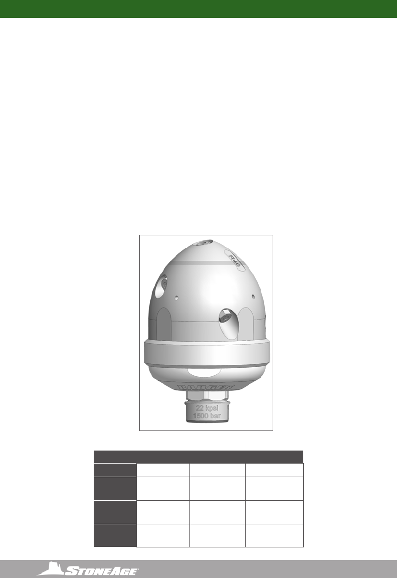
Badger Model Specifications
Tool
Size
Tool Model
Number Pressure Range Flow Range
Inlet
Connection Weight Rotation Speed
Max Water
Temperature
2”
BA-LK-P4
BA-LK-BSPP4
2–15k psi
140–1000 bar
3–20 gpm
11–76 l/min
1/4 NPT
or
1/4 BSPP
0.45 lb
0.20 kg High Speed 250 ºF
120 ºC
BA-LK-MP9L
BA-LK-MP9R
12–22k psi
830 –1500 bar
3–15 gpm
11– 57 l /mi n
9/16 MP
or
M24
0.45 lb
0.20 kg High Speed 250 ºF
120 ºC
4”
BA-P6
BA-BSPP6
2–15k psi
140–1000 bar
13–30 gpm
49 –110 l/m in
3/8 NPT
3/8 BSPP
3.0 lbs
1.4 kg
20-100 rpm (Slow Fluid)
75-250 rpm (Fast Fluid)
250 ºF
120 ºC
BA-TM12 12–22k psi
830 –1500 bar
12–25 gpm
45–95 l/min
3/4 Type
M Male
3.0 lbs
1.4 kg
20–100 rpm (Slow Fluid)
75–250 rpm (Fast Fluid)
250 ºF
120 ºC
BA-H6
(Not included
in this
manual)
44k psi
3000 bar
4.5–12 gpm
17–45.5 l/min
3/8 HP
Female
4.0 lbs
1.8 kg 100–400 rpm 250 ºF
120 ºC
6”
BA-MP9
BA-M24
12–22k psi
840 –1500 bar
14–43 gpm
53–163 l/min
9/16 MP
or
M24
8.0 lbs
3.6 kg
50–300 rpm
(Adjustable)
250 ºF
120 ºC
BA-P8 2–15k psi
140–1000 bar
15–55 gpm
57–208 l/min 1/2 NPT 8.0 lbs
3.6 kg
50–300 rpm
(Adjustable)
250 ºF
120 ºC
Badger Model Features
2”
• The only self-rotary tool on the market that can navigate 2 in. (50 mm) pipes with bends and comes with
head locking technology for increased safety
• Multiple jetting options allow the tool to be optimized for a variety of pump pressures and ows - unplug,
polish, or run longer lines based on jetting
• Optional fairing available to streamline tool during retrieval
4”
• Different jetting congurations allow for more or less pull and forward hitting power
• Navigates elbows as small as 4 in. (102 mm) at up to 43.5k psi (3000 bar)
• Self-rotary, speed controlled head provides complete internal coverage with optimum jet delivery
• Two speeds to choose from to maximize cleaning by choosing slower speeds for hard to clean or plugged
pipes, and faster speeds for polishing easy to clean pipes with a single tool
• Multiple jetting options optimize the tool for a variety of pumps pressures and ows - unplug, polish, or run
longer lines based on jetting
• Designed to easily pair with the AutoBox ABX-500 hose tractor for hands-free pipe cleaning.
6”
• Only rotary pipe cleaning tool on the market with adjustable speed control for ne-tuning to specic
requirements
• Different jetting congurations allow for more or less pull and forward hitting power and optimize the tool for
a variety of pumps pressures and ows.
• Navigates elbows as small as 6 in. (152 mm)
• Speed controlled rotary tools provide complete internal coverage with optimum jet delivery
• Maximize cleaning by choosing slower speeds for hard to clean or plugged pipes, and faster speeds for
polishing easy to clean pipes with a single tool
• Centralizer options for larger pipe sizes available

4866-795-1586 • WWW. SEWERNOZZLES.COM
DETERMINING JET SIZES:
Badger tools come from the factory with installed nozzles, selected based on customer pres-
sure and ow requirements. Jet thrust is used to pull the tool through the pipe. An estimate
of the amount of pulling force required is useful and depends on the number of elbows and
any vertical climbs that must be made. On a horizontal run with no elbows, 1 pound of pull is
required for every ten feet. When climbing vertically, the pulling force must equal the weight
of the tool and the hose. Typically, larger jet sizes using 50 to 80 percent of the total ow
are used in the back ports. As little as 10 percent of the total ow is given to the front jet,
because it pushes the wrong direction and is only used to open up blockages. The remaining
ow goes to the side ports, which help pull as well as clean. Jetting assistance is available
on our jetting app at: http://jetting.stoneagetools.com or through one of our StoneAge
customer service reps at 1-866-795-1586.
See the “Assembly” section of this manual for instructions on to how to install new nozzles.
GENERAL JETTING INFORMATION
5
866-795-1586 • WWW.SEWERNOZZLES.COM
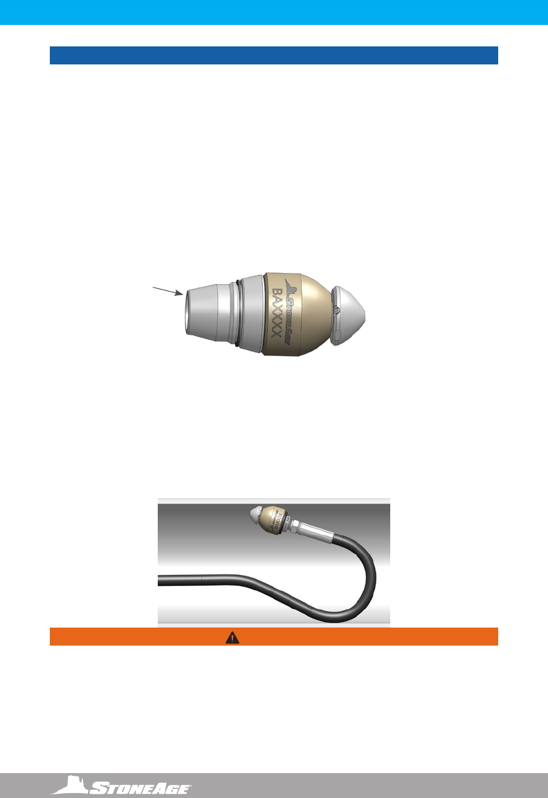
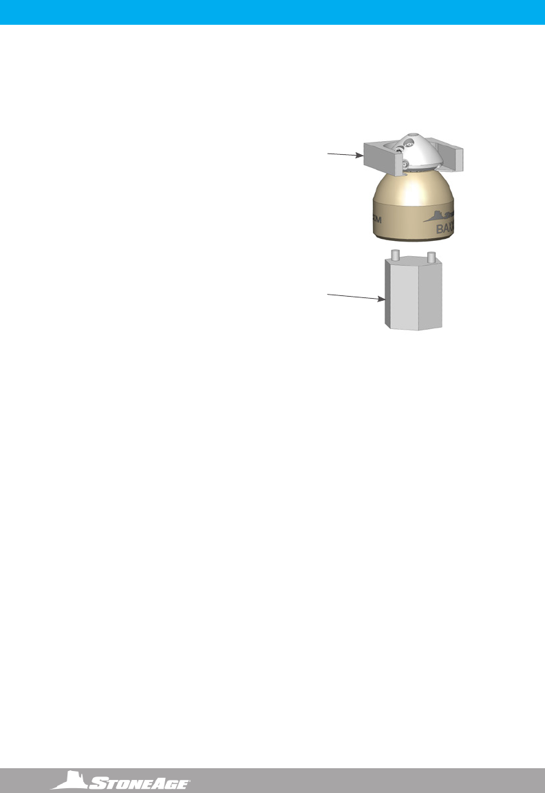
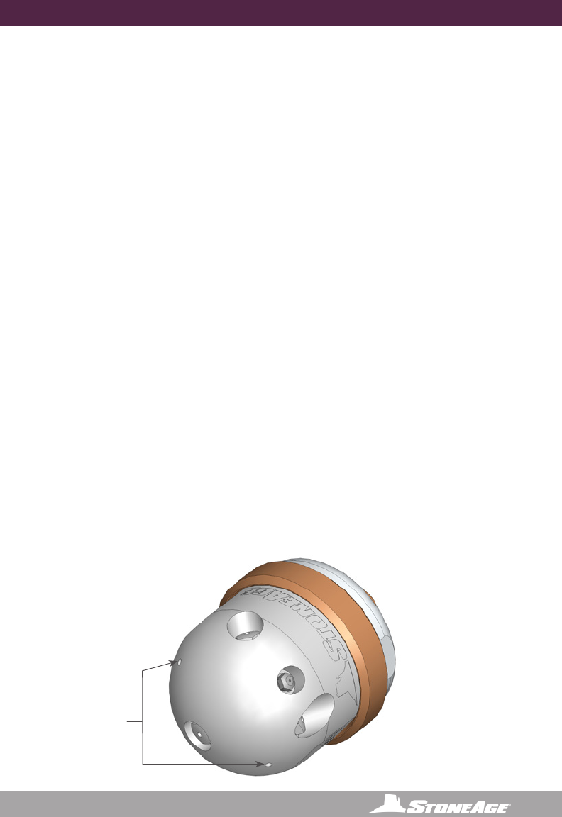
2” BADGER TOOL DESCRIPTION AND INTENDED USE
2” BADGER MODELS DESCRIPTION AND INTENDED USE
The BA-LK-P4 / BA-LK-BSPP4 / BA-LK-MP6R / BA-LK-MP9L / BA-LK-MP9R is a self-rotating
swivel designed for cleaning 2” to 4” tubes and pipes with bends and long radius elbows, such
as U-Tubes and process lines. The P4 and BSPP4 tools can be used at operating pressures up
to 15,000 psi (1035 bar) and the MP6R, MP9L and MP9R tools at up to 22,000 psi
(1500 bar). The P4 and BSPP4 have either a 1/4” NPT or 1/4” BSPP female pipe thread inlet. If
a standard 1/4” NPT or BSPP hose end is used, they can pass through elbows in 3” and larger
pipe. If using the tool in 2” pipe a special shorter hose end is required to allow tool to travel
through elbows. Contact StoneAge for more information on the hose requirements. The
MP6R tool has a 3/8” female right-hand medium pressure inlet. The MP9L tool has a 9/16”
female left-hand medium pressure inlet and the MP9R has a 9/16” female right-hand medium
pressure inlet. The tools do not use any bearings, seals, or
lubricating uid. Rotation is powered by the jet thrust. The
nozzle inserts used in the head determine the ow rate and the
pulling force.
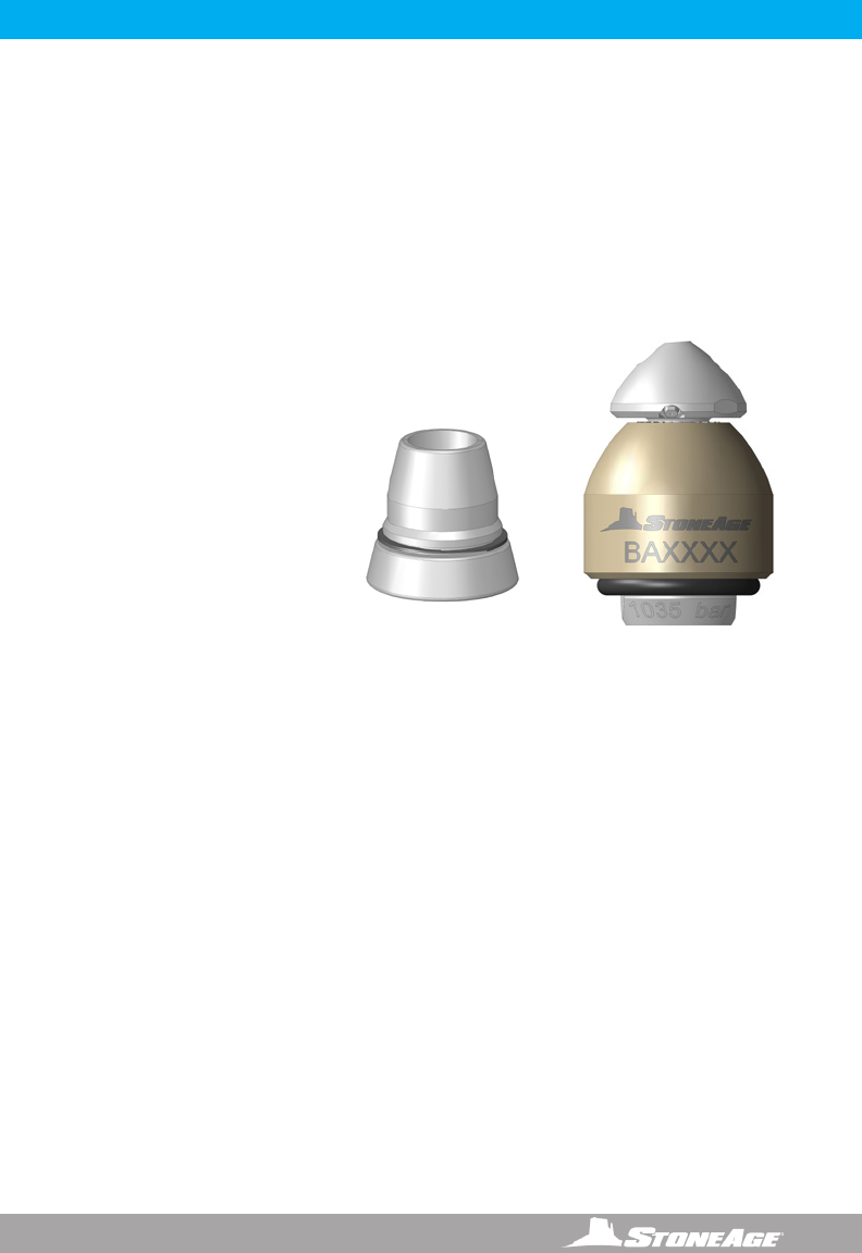
*An OPTIONAL BA 530 Fairing
Assembly is available for all 2”
Badger models when using hose
sizes up to 6mm. The fairing
is designed to be attached to
the back of the 2” Badger to
help prevent the rear edge of
the tool from getting caught on
obstructions during withdrawal
from tubes or pipes.
BA 530 FAIRING
6866-795-1586 • WWW. SEWERNOZZLES.COM
2” BADGER OPERATION
WARNING
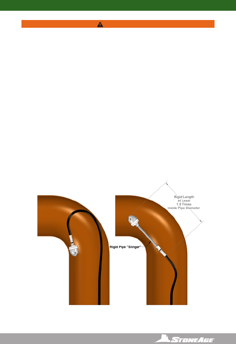
If the 2” BADGER is being used in pipes larger than 4 inch diameter, a rigid stinger should
be installed between the tool inlet and the hose end; otherwise the tool can turn around and
come back toward the operator, causing serious injury or death.
Operations with this equipment can be potentially hazardous. Caution must be exercised
prior to and during machine and water jet tool use. Please read and follow all of these
instructions, in addition to the guidelines in the WJTA Recommended Practices handbook,
available online at www.wjta.org. Deviating from safety instructions and recommended
practices can lead to severe injury and/or death.
NOTICE
The most important items in maintaining the Badger tool;
- Keep debris from entering the tool and preventing it from rotating by ushing high pressure
hoses before use.
OPERATION
• Make sure the operator has a controlled dump in the system and it is operated by the
person closest to the job. Test the dump prior to beginning the job.
• Flush out the high pressure hoses before connecting the Badger to eliminate debris.
• Attach tool to the end of the hose. Use Parker Thread Mate and Teon tape on all pipe
thread connections (P4, BSPP4); use anti-seize on all straight thread connections (MP6R,
MP9L, MP9R) to the swivel inlet.
• The 2” Badger has a large O-Ring (WV 008) around the inlet. This O-Ring helps prevent
the tool from getting caught on the rear edge when pulling the tool back out of the line.
An optional Fairing Assembly (BA 530) will also help prevent snagging during tool removal.
• It is recommended that the hose be marked a few feet from the end with a piece of tape so
the operator knows when to stop on the way back out.
• Position the tool in the pipe opening.
• Close the dump and slowly bring the pump up to pressure the rst time to make sure no
nozzles are plugged and the jet thrust is correct. The Badger™ should begin to slowly
rotate.
• Once operating pressure is reached, feed the tool into the pipe to begin the cleaning job.
• Allow the jets time to do their work by feeding the hose out at a controlled rate.
• 2” BADGER ONLY- After the Badger is removed from the hose, blow out water with compressed
air and spray a light oil such as WD-40 into the tool.
BA 530
FAIRING

7
866-795-1586 • WWW.SEWERNOZZLES.COM
2” BADGER TROUBLESHOOTING
HEAD WILL NOT ROTATE:
• First, make sure the head (BA 044-LK) is still tightened into the shaft (BA 501-LK). A safety
feature built into the shaft stops the tool from rotating if the head comes loose.
• If the head isn’t loose, try spraying a light oil such as WD-40 into the tool and rotate head by
hand until it turns freely again.
• Make sure that the jets in the head are not plugged.
• If the tool still does not rotate after trying the steps above, it may need to be disassembled
and cleaned on the inside. To do this requires a spanner wrench (available in StoneAge Tool
Kit BA-P4 612) inserted into the rear of the shaft to remove the head from the shaft. Begin
by removing the O-ring (WV 008) and the Retaining Ring (WV 010). Pull the Inlet Nut (BA
002-P4,-BSPP4,BA 502-MP9L,BA 502-MP9R) out of the Body (BA 503). Using a spanner
wrench, unscrew the Shaft (BA 501) from the Head (BA 044). Make sure the two small holes
in the side of the shaft are cleaned out; debris plugging these holes is the most likely cause
of the tool not rotating. If the outside of the shaft is badly worn, it needs to be replaced.
• See the “2” Badger Tool Service Information”and the “2” Badger Assembly and Parts”
pages in this manual for more detailed information about service.
8866-795-1586 • WWW. SEWERNOZZLES.COM
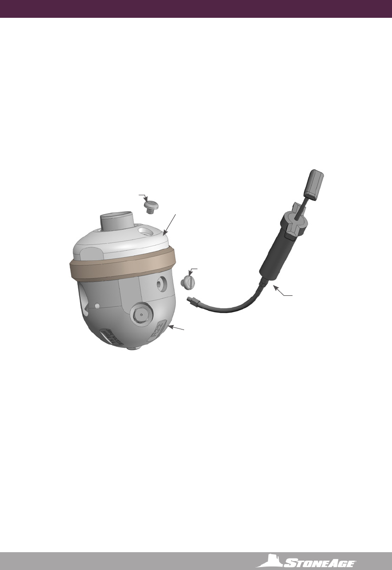
2” BADGER TOOL SERVICE INFORMATION
TOOL SERVICE
***Product training and proper tools are required to service this nozzle. If you are
uncomfortable performing the service, bring the nozzle to your authorized dealer.*
The use of a bench vice is highly helpful. Take care throughout the entire procedure to keep
the internals clean and free from grit, lint, and contamination. Failure to do so could result in
premature failure after service.
LIST OF TOOLS:
• Bench Vice (recommended)
• 7/8”socket
• 3/8” drive torque wrench
• BA 612-LK Tool Kit (For 2” Badger Includes)
BA 182 Head Removal Tool
WV 181 Spanner Wrench
LIST OF MATERIALS:
• Clean lint free rags or blue shop towels
• BA 185 Red Loctite® 262
NOZZLES
The nozzle head has forward jets at 15º, 30º, 45º, two side jets at 90º, and two back jets
at 132º.StoneAge recommends replacing the entire head assembly with the nozzles
installed at the factory.
ASSEMBLY
If assembling tool, apply 2-4 drops of Loctite #262 Red (StoneAge p/n BA 185) around
the circumference of the threads on the Head prior to screwing it into the Shaft. Care
must be taken NOT to allow into the internal shaft bore below the female threads
or onto the tapered external surface of the shaft. Torque to 100 in-lbs using 7/8”
socket on the spanner wrench (available from StoneAge as p/n WV 181). Also replace
Retaining Ring (WV 010) with a new one during each reassembly.
If you do not have the required tools or you are not confident in performing these
procedures please send the tools back to StoneAge for maintenance and repairs.
BA 182
Head removal
tool
WV 181
Spanner
wrench
WD-40® is a registered trademark of the WD-40 Corporation.
Parker Threadmate™ is a registered trademark of Parker Hannin Corporation.
9
866-795-1586 • WWW.SEWERNOZZLES.COM
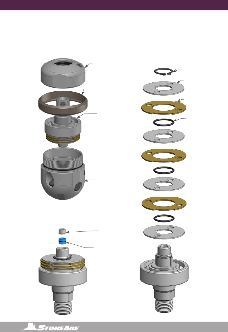
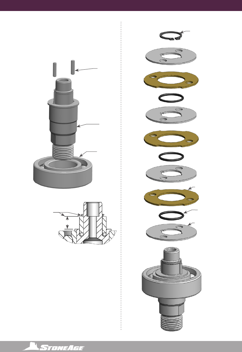
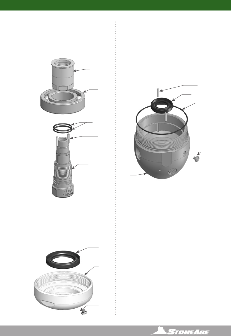
2” BADGER ASSEMBLY AND PARTS
7 Ports:
1 @ 15º
1 @ 30º
1 @ 45º
2 @ 90º
2 @ 132º
15º
30º 45º
90º
90º
2 x 132º
Nozzle Locations
BA 546-LK
Head Assy
DO NOT
REMOVE SET
SCREW
BA 501-LK
Shaft
BA 503
Body
WV 008
O-Ring
WV 010
Retaining Ring
OD3M XXX
Nozzle (7)
BA 002-P4 (15k)
or
BA 002-BSPP4 (15K)
or
BA 502-MP6R (22K)
or
BA 502-MP6L (22K)
or
BA 502-MP9R (22K)
Inlet Nut
Part Diagram
GP 200-BSPP4
Copper Seal Ring .250
REQUIRED FOR BSPP
INLETS ONLY
*Optional
BA 530 Fairing
Accessories
10 866-795-1586 • WWW. SEWERNOZZLES.COM
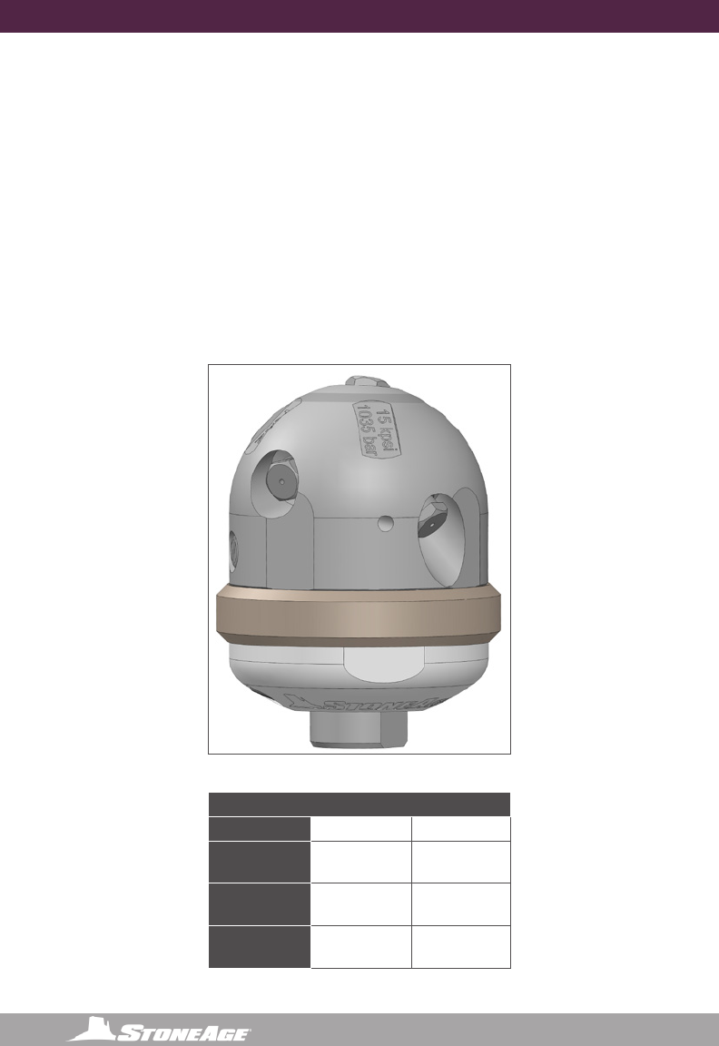
4” BADGER MODELS DESCRIPTION AND INTENDED USE
The Badger™ Rotary Waterblast Nozzle was designed for waterblast cleaning of pipes as
small as 4 inch with elbows. The BA-P6 has a 3/8 NPT female inlet connection and a maximum
operating pressure of 15,000 psi (1035 bar). The BA-BSPP6 has a 3/8 BSPP female inlet
connection and a maximum operating pressure of 15,000 psi (1035 bar). The BA-TM12 has a
3/4 type M male inlet connection and a maximum operating pressure of 22,000 psi (1500 bar).
Two rotation speed ranges are available for each tool; a thick uid is used for rotation speeds
of 20 to 100 rpm, and a thinner uid is used for rotation speeds of 75 to 250 rpm. The uid in
the swivel can be changed to provide either fast or slow rotation. The Badger™ heads have 1/8
NPT ports; one at 15 degrees, two at 100 degrees, and two at 135 degrees.
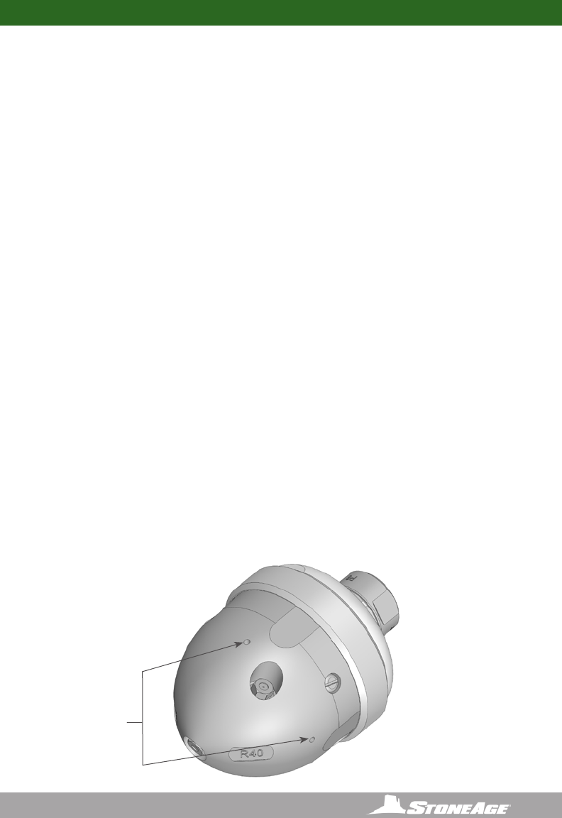
Engraved on each head is R16 or R22; this number is the offset of the head that makes it rotate.
The ow range for each head is given in the table; nozzle sizes must be selected to t within
this ow range. If the ow is less than the range shown, the tool will not rotate; if it is more
than the allowable the tool will rotate too fast and wear out the seals and bearings.
4” BADGER TOOL DESCRIPTION AND INTENDED USE
4” BADGER FLOW RANGE PER HEAD OFFSET CHART
PRESSURE R22 R16
10,000 PSI
(690 bar)
13-21 GPM
(50-80 l/min)
20-30 GPM
(76-114 l/min)
15,000 PSI
(1035 bar)
13-17 GPM
(50-65 l/min)
18-30 GPM
(68-114 l/min)
22,000 PSI
(1500 bar)
12-18 GPM
(45-68 l/min)
15-25 GPM
(57-95 l/min)
4” BADGER WARNING AND SAFETY INSTRUCTIONS
11
866-795-1586 • WWW.SEWERNOZZLES.COM
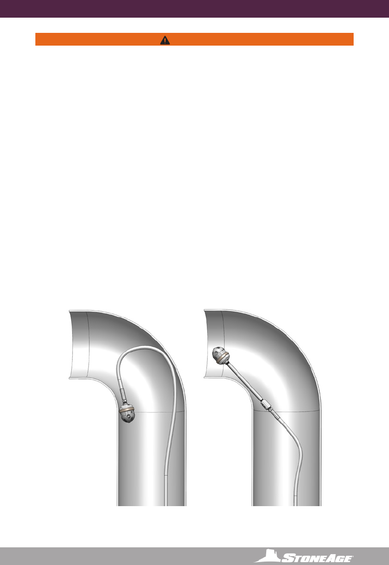
4” BADGER WARNING AND SAFETY INSTRUCTIONS
WARNING
Because of the short length of the Badger, the tool can turn around in large pipes and come
back at the operator at a high rate of speed. If cleaning larger pipes, a rigid “stinger” should
be used between the hose and the tool. It is recommended that the rigid length of the tool
including hose end is 1-1/2 times the inside diameter of the pipe being cleaned (see below).
Make sure there is an operator controlled dump in the system, operated by the person closest
to the cleaning job. Flush out the high pressure hoses before connecting the Badger. It is
recommended that the hose be marked a few feet from the end with a piece of tape so the
operator knows when to stop when retracting the tool. Position the tool in the pipe opening.
Close the dump and slowly bring up to pressure the rst time to make sure no nozzles are
plugged and the jet thrust is correct. The Badger should begin to slowly rotate. Once operating
pressure is reached, feed the tool into the pipe to begin the cleaning job. Allow the jets time
to do their work by feeding the hose out at a controlled rate. The StoneAge ABX-500 Hose
Control Device can be used to achieve consistent feed rates for pipe cleaning. When the work
is complete and the tool is connected from the hose, blow out all water to prolong the life of the
tool. A small amount of oil can be blown into the tool as well as an added measure to maximize
tool life.
Operations with this equipment can be potentially hazardous. Caution must be exercised
prior to and during machine and water jet tool use. Please read and follow all of these
instructions, in addition to the guidelines in the WJTA Recommended Practices handbook,
available online at www.wjta.org. Deviating from safety instructions and recommended
practices can lead to severe injury and/or death.
IMPROPER USE:
Badger will turn around in
large diameter pipe
VERY DANGEROUS!
PROPER USE:
Badger with rigid “stinger”
to prevent turnaround, still
able to pass through elbows.

12 866-795-1586 • WWW. SEWERNOZZLES.COM
4” BADGER OPERATION
OPERATION:
• Make sure the operator has a controlled dump in the system and it is operated by the
person closest to the job. Test the dump prior to beginning the job.
• Flush out the high pressure hoses before connecting the Badger™ to eliminate debris.
NOTICE
The two most important items in maintaining the Badger tools;
- Keep debris from entering the tool and preventing it from rotating by ushing high pressure
hoses before use.
- Keep the 4” and 6” models full of viscous uid to maintain control and rotation speed. When
the viscous uid is lost or contaminated, the rotation speed of the tool will increase, which
reduce the life of the high pressure seal and bearing.
• Attach tool to the end of the hose.
• It is recommended that the hose be marked a few feet from the end with a piece of tape so
the operator knows when to stop on the way back out.
• Position the tool in the pipe opening.
• Close the dump and slowly bring the pump up to pressure the rst time to make sure
no nozzles are plugged and the jet thrust is correct. The Badger should begin to slowly
rotate.
• Once operating pressure is reached, feed the tool into the pipe to begin the cleaning job.
• Allow the jets time to do their work by feeding the hose out at a controlled rate.
• When the work is complete and the tool is disconnected from the hose, blow out all water
to prolong the life of the tool.
• 4” & 6” BADGERS ONLY- A small amount of 3-IN-ONE or equivalent lubricant can be blown
into the tool as well.
13
866-795-1586 • WWW.SEWERNOZZLES.COM
4” BADGER OPERATION
WEEP HOLES
4” BADGER TROUBLESHOOTING
HIGH-PRESSURE WATER SEALS LEAK:
• The high pressure seal may leak initially at lower pressures, but should pop closed as
pressure is increased. A continuous leak at operating pressure from the weep holes
indicates the need to replace the HP Seal and Seat. HP Seals wearing out too quickly
can be an indication that the shaft bore is worn, the HP Seat is installed upside-down,
or the tool is over spinning. Over spinning is caused by low or contaminated viscous
uid, water in the uid chamber (replace shaft seals), or too much jet torque. Relling
the viscous uid every 30-40 hours of operation is important for proper speed control.
Only use StoneAge recommended viscous uid.
TOOL WILL NOT ROTATE:
• Check the nozzles for plugging or wear (nozzles have to be removed to check for
obstructions), Check that the nozzle sizes are correct for the desired ow and that the
desired ow matches the head ow range. Check that the nozzle sizes are installed in
a balanced conguration. If the tool feels rough when manually rotating the head, this
indicates internal damage. Replace bearings, shaft seals, viscous uid, and check the
Inner and Outer Discs for atness. These discs can be deformed if tool is reassembled
when discs are not properly aligned with BA 018 Pins.
TOOL SPINS TOO FAST:
• A signicant increase in rotation speed means that the speed control mechanism
in the tool has lost functionality. This can be a result of viscous uid loss or uid
contamination. Operation of the tool in this state can cause damage to other
components and accelerated wear of the high pressure seal. If this occurs, the rst
step is to ush the tool with new viscous uid as shown in Figure 12.
LOCK-UP TROUBLESHOOTING TIP:
• Rotate in reverse 1 1/4 to 1 1/2 turns to unlock braking mechanism. If tool rotates smoothly
then redress may not be required.
• If the head rotates freely by hand, check the jet sizes and calculate pressure loss through
the coil tubing and check with your distributor or StoneAge® to make certain there is
enough jet torque to provide rotation.
• Verify jetting at http://jetting.stoneagetools.com/#/, contact your factory authorized
Warthog® dealer or contact StoneAge®, Inc.
Figure 12

14 866-795-1586 • WWW. SEWERNOZZLES.COM
WD-40® is a registered trademark of the WD-40 Corporation.
Parker Threadmate™ is a registered trademark of Parker Hannin Corporation.
4” BADGER TOOL SERVICE INFORMATION
TOOL SERVICE
***Product training and proper tools are required to service this nozzle. If you are
uncomfortable performing the service, bring the nozzle to your authorized dealer.*
The use of a bench vice and an arbor press is highly helpful. Take care throughout the entire
procedure to keep the internals clean and free from grit, lint, and contamination. Failure to do
so could result in premature failure after service.
LIST OF TOOLS:
• Bench Vice (recommended)
• Arbor Press (recommended)
• 18” Adjustable Wrench (such as Crescent® C718 Automatic Adjustable Pipe Wrench)
• Medium size at-head screw driver
• Pick
• Bearing Splitter
• 3/8 Drive Ratchet with 3” Extension
• BA 612 Tool Kit (For 4” Badger Includes)
BA 100 Retaining Ring Pliers
BA 105 Seal Press Tool
LIST OF MATERIALS:
• Clean lint free rags or blue shop towels
• Anti-Seize - StoneAge PN (GP 043 Blue Goop)
• Lithium Soap Grease – StoneAge PN (GP 048 Grease)
• Blue Loctite® 242
• Isopropyl Alcohol or Denatured Alcohol
15
866-795-1586 • WWW.SEWERNOZZLES.COM
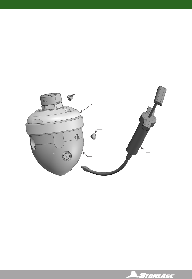
VISCOUS FLUID FLUSH INSTRUCTIONS (4” BADGER)
1. Remove the Port Plugs (BJ 026) in the Nut (BA 002) and Head (BA 040-RXX) (see Figure 1).
2. Fill the Syringe (BC 410) with viscous uid by removing the end near the handle, pulling out
the plunger, and pouring the Viscous Fluid (BJ 048-F) in to ll the Syringe Body. With plunger
re-installed, purge air out of Syringe hose.
3. Thread the syringe end into the port in the Head, and squeeze fresh Viscous Fluid in until
clean Viscous Fluid comes out the port in the Nut. Hold the tool so the port in the Nut is the
highest point. If air bubbles come out of the port on the nut, keep ushing new uid until air
bubbles stop.
4. Install Port Plug into Nut rst. Remove the Syringe and install the Port Plug in the Head.
4” BADGER FLUID REPLACEMENT
BJ 026
Port Plug
(In Nut) BA 002
Nut (1)
BJ 026
Port Plug
(In Head)
BA 040-RXX
Head (15kpsi)
or
BA 240-RXX
Head (22kpsi)
BC 410
Syringe
Figure 1: Viscous Fluid Flush
16 866-795-1586 • WWW. SEWERNOZZLES.COM
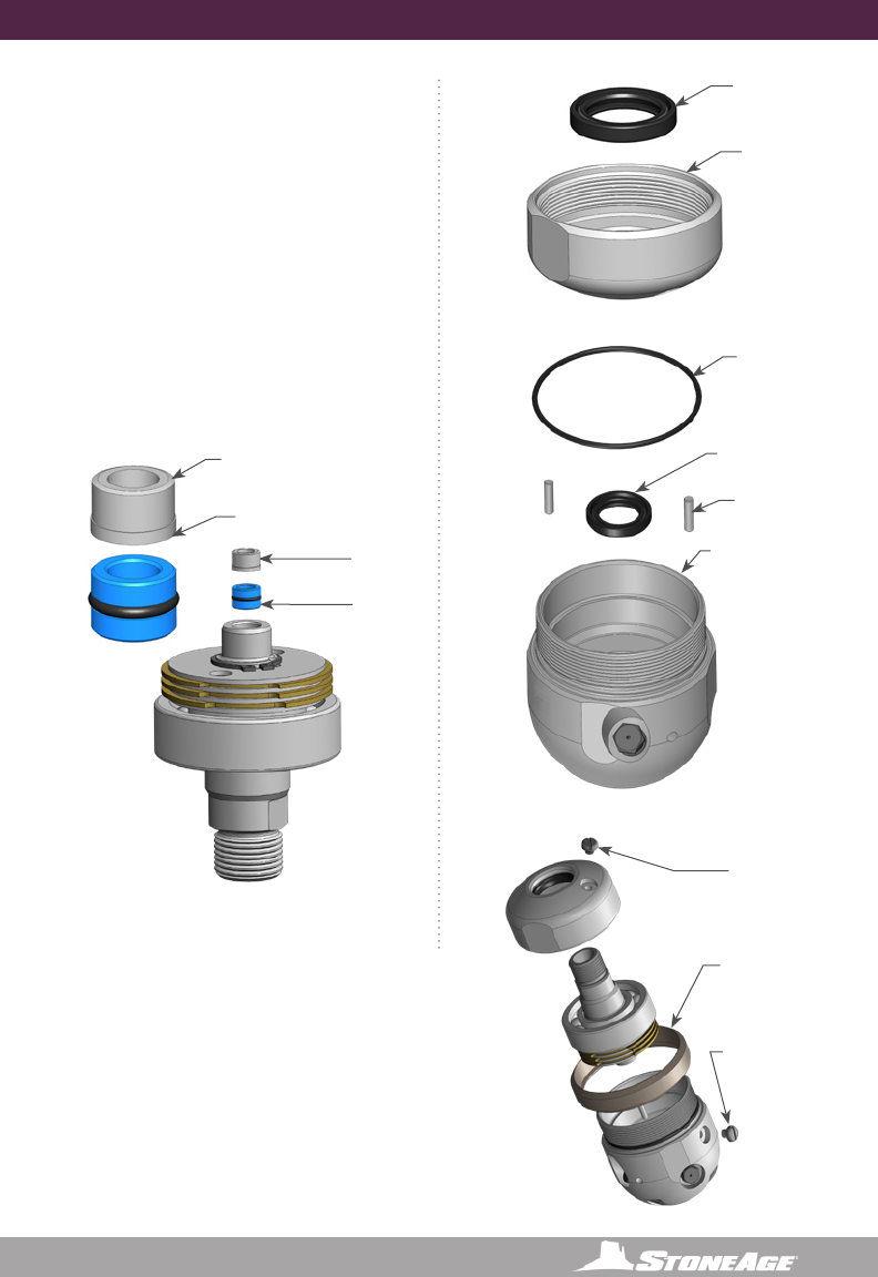
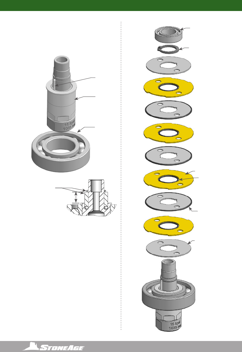
4” BADGER DISASSEMBLY
DISASSEMBLY
1. Unscrew the Nut (BA 002) from the
Head (BA 040/240)
2. Pull the Shaft (BA 001/ BA 001-
BSPP6/ BA 201) out of the head.
Figure 4: For Step 3
BA 017
Retaining Ring
BA 015
Inner Disc (4)
BA 016
Outer Disc (3)
SM 016
O-Ring (3)
Figure 5: For Step 4-5
3. Remove the Seat (RJ 011/RJ 011-KC)
and H.P. Seal (RJ 012-TO/RJ 012-KTO)
from the bore of the Shaft.
Figure 3: For Steps 1-2
BA 030
Wear Ring
BA 002
Nut
BA 001/
BA 001-BSPP6/
BA 201
Shaft
RJ 011/
RJ 011-KC
Seat
RJ 012-TO/
RJ 012-K TO
H.P. Seal
4. Remove Retaining Ring (BA 017) from
the shaft.
5. Pull the Discs (BA 015, BA 016) and
O-Rings (SM 016) off of the Shaft.
BA 040-RXX
Head (15kpsi)
or
BA 240-RXX
Head (22kpsi)
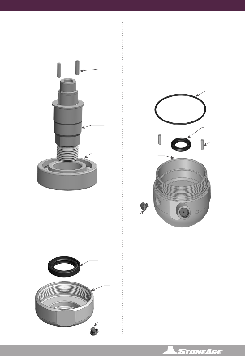
17
866-795-1586 • WWW.SEWERNOZZLES.COM
BA 018
Pins (2)
BA 018
Pins (2)
BA 006
Shaft Seal
WG 008
O-Ring
UH 009
Bearing
BA 001/
BA 001-BSPP6/
BA 201
Shaft
4” BADGER DISASSEMBLY
Figure 6: For Steps 6-7
Figure 7: For Steps 8-9
6. Press the Bearing (UH 009) off of the
Shaft.
7. There is no need to remove the Pins
(BA 018) from the Shaft; however, if
they fall out do not lose them.
10. Remove the Port Plug (BJ 026) from
the Head.
11. Remove the Shaft Seal (BA 006) and
O-Ring (WG 008) if they are damaged.
12. There is no need to remove the Pins
(BA 018); however, if they fall out, do
not lose them.
Figure 8: For Steps 10-12
8. Remove the Shaft Seal (BA 007) if it is
damaged.
9. Remove the Port Plug (BJ 026) from
the Nut.
BA 007
Shaft Seal
BA 002
Nut
BJ 062
Port Plug
BJ 062
Port Plug
BA 040-RXX
Head (15kpsi)
or
BA 240-RXX
Head (22kpsi)
18 866-795-1586 • WWW. SEWERNOZZLES.COM
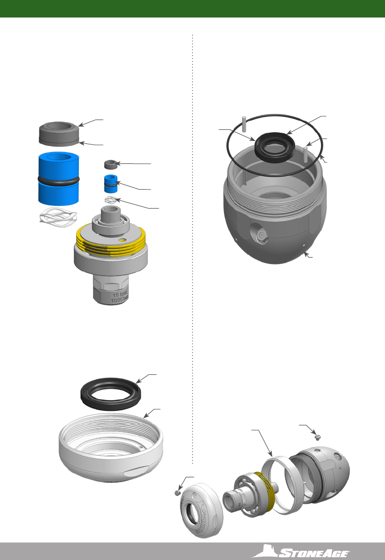
4” BADGER ASSEMBLY
.380
4” BADGER ASSEMBLY
ASSEMBLY
1. Press Bearing (UH 009) onto Shaft
(BA 001 / BA 001-BSPP6)
2. Check that Pins (BA 018) are installed
in Shaft.
3. Place an Inner Disc (BA 015) on Shaft,
aligning with pins.
4. Place an O-Ring (SM 016) on top of
this Disc, stretched around Pins.
5. Place an Outer Disc (BA 016) on top
of this.
6. Repeat these steps until there are three
Outer Discs and four Inner Discs on
the Shaft.
7. Push down on top disc and install the
Retaining Ring (BA 017) in the groove
around the Shaft.
BA 018
Pins (2)
UH 009
Bearing
BA 001/
BA 001-BSPP6/
BA 201
Shaft
Figure 9: For Steps 1-2
Insert Pins just
far enough to
clear groove for
retaining ring
BA 017
Retaining Ring
BA 015
Inner Disc (4)
BA 016
Outer Disc (3)
SM 016
O-Ring (3)
Figure 10: For Step 3-7
19
866-795-1586 • WWW.SEWERNOZZLES.COM
4” BADGER ASSEMBLY
8. Apply grease to and install the H.P.
Seal (RJ 012-TO/RJ 012-KTO) in the bore
of the Shaft.
9. Apply grease to the face of the Seat
(RJ 011/RJ 011-KC) and place in bore of
Shaft, on top of Seal, as shown.
10. Install Shaft Seals (BA 007 and BA 006) in
the Nut (BA 002) and Head (BA 040/240)
as shown.
11. Place O-Ring (WG 008) over threads and
into groove of Head.
12. Check that the Pins (BA 018) are installed
in the Head.
Figure 12: For Step 10
BA 007
Shaft Seal (1)
BA 002
Nut (1)
Figure 11: For Steps 8-9
RJ 011/
RJ 011-KC
Seat
RJ 012-TO/
RJ 012-K TO
H.P. Seal
Chamfered
Face
Flat
Face
Figure 14: For Steps 13-15
BA 330
Wear Ring
BJ 026
Port Plug
BJ 026
Port Plug
BA 018
Pins (2)
BA 006
Shaft Seal
WG 008
O-Ring
BA 040/240
Head
Figure 13: For Steps 10-12
13. Align the notches on the Outer Discs with
the pins in the Head; slide shaft assembly
into the Head.
14. Apply anti-seize to threads on Head;
install Wear Ring (BA 030) onto the Nut
(BA 002); thread the Nut onto the Head.
Tighten to 50 ft-lb.
15. Use syringe to ll the tool with
viscous uid as shown in the “Fluid
Replacement” Section: install Port Plugs
(BJ 026).
20 866-795-1586 • WWW. SEWERNOZZLES.COM
4” BADGER PART NAMES/NUMBERS
BA 017
Retaining Ring
BA 015
Inner Disc (4)
BA 016
Outer Disc (3)
SM 016
O-Ring (3)
RJ 011/ RJ 011-KC
Seat
RJ 012-TO/ RJ 012-K TO
H.P. Seal
BA 018
Pins (2)
UH 009
Bearing
BA 001/
BA 001-BSPP6/
Shaft
BA 201
Shaft
BA 018
Pins (2)
BA 006
Shaft Seal
WG 008
O-Ring
BA 030
Wear Ring
BA 002
Nut
BJ 026
Port Plug
BA 006
Shaft Seal
BA 040/240
Head

21
866-795-1586 • WWW.SEWERNOZZLES.COM
4” BADGER SERVICE KITS
4”
BADGER
MODELS KITS AND KIT CONTENTS
BA-P6 /
BA-BSPP6
(15K)
BA 600-F
SERVICE KIT (FAST)
BA 600-S
SERVICE KIT (SLOW)
BA 602
H.P. SEAL KIT
1 BJ 048-F Visc Fluid, Fast, 6oz
1 BJ 062-S Anti-seize, 2g
1 RJ 011 Brass Seat
1 RJ 012-TO H.P. Seal and O-Ring
1 BC 410 Syringe Assembly
1 GP 025-P2SS Hex Socket Plug,
1/8 NPT Male, SS
1 PL 663 BA Manual
1 BJ 048-S Visc Fluid, Slow, 6oz
1 BJ 062-S Anti-seize, 2g
1 RJ 011 Brass Seat
1 RJ 012-TO H.P. Seal and O-Ring
1 BC 410 Syringe Assembly
1 GP 025-P2SS Hex Socket Plug,
1/8 NPT Male, SS
1 PL 663 BA Manual
1 RJ 011 Brass Seat
1 RJ 012-TO H.P. Seal
and O-Ring
BA 610-F
OVERHAUL KIT (FAST)
BA 610-S
OVERHAUL KIT (SLOW)
BA 612
TOOL KIT
1 BA 006 Seal
1 BA 007 Seal
1 BA 017 Retaining Ring, External .688
1 BJ 026 Port Plug
1 BJ 048-F Visc Fluid, Fast, 6oz
1 PL 663 BA Manual
1 RJ 011 Brass Seat
1 RJ 012-TO H.P. Seal and O-Ring
1 SM 016 Seal, O-Ring
1 UH 009 Bearing, Ball
1 WG 008 O-Ring
1 BA 006 Seal
1 BA 007 Seal
1 BA 017 Retaining Ring, External .688
1 BJ 026 Port Plug
1 BJ 048-S Visc Fluid, Slow, 6oz
1 PL 663 BA Manual
1 RJ 011-KC Brass Seat
1 RJ 012-KTO H.P. Seal and O-Ring
1 SM 016 Seal, O-Ring
1 UH 009 Bearing, Ball
1 WG 008 O-Ring
1 BA 100 Retaining
Ring Pliers
1 BA 105 Tool
BA-TM12
(20K)
BA 600-TM12-F
SERVICE KIT (FAST)
BA 600-TM12-S
SERVICE KIT (SLOW)
BA 602-TM12
H.P. SEAL KIT
1 BJ 048-F Visc Fluid, Fast, 6oz
1 BJ 062-S Anti-seize, 2g
1 RJ 011-KC Brass Seat
1 RJ 012-KTO H.P. Seal and O-Ring
1 BC 410 Syringe Assembly
1 GP 025-P2SS Hex Socket Plug,
1/8 NPT Male, SS
1 PL 663 BA Manual
1 BJ 048-S Visc Fluid, Slow, 6oz
1 BJ 062-S Anti-seize, 2g
1 RJ 011-KC Brass Seat
1 RJ 012-KTO H.P. Seal and O-Ring
1 BC 410 Syringe Assembly
1 GP 025-P2SS Hex Socket Plug,
1/8 NPT Male, SS
1 PL 663 BA Manual
1 RJ 011-KC Brass
Seat
1 RJ 012-KTO H.P. Seal
and O-Ring
BA 610-TM12-F
OVERHAUL KIT (FAST)
BA 610-TM12-S
OVERHAUL KIT (SLOW)
BA 612
TOOL KIT
1 BA 006 Seal
1 BA 007 Seal
1 BA 017 Retaining Ring, External .688
1 BJ 026 Port Plug
1 BJ 048-F Visc Fluid, Fast, 6oz
1 PL 663 BA Manual
1 RJ 011-KC Brass Seat
1 RJ 012-KTO H.P. Seal and O-Ring
1 SM 016 Seal, O-Ring
1 UH 009 Bearing, Ball
1 WG 008 O-Ring
1 BA 006 Seal
1 BA 007 Seal
1 BA 017 Retaining Ring, External .688
1 BJ 026 Port Plug
1 BJ 048-S Visc Fluid, Slow, 6oz
1 PL 663 BA Manual
1 RJ 011-KC Brass Seat
1 RJ 012-KTO H.P. Seal and O-Ring
1 SM 016 Seal, O-Ring
1 UH 009 Bearing, Ball
1 WG 008 O-Ring
1 BA 100 Retaining
Ring Pliers
1 BA 105 Tool
22 866-795-1586 • WWW. SEWERNOZZLES.COM
6” BADGER DESCRIPTION AND INTENDED USE
6” BADGER MODELS DESCRIPTION AND INTENDED USE
The Badger™ P8, MP9 and M24 Rotary Waterblast Nozzles were designed to waterblast clean
pipes as small as 6 inches with elbows. The BA-P8 has a 1/2 NPT female inlet connection
and a maximum working pressure of 15,000 psi (1035 bar). The BA-MP9 has a 9/16 medium
pressure female inlet connection and a maximum working pressure of 22,000 psi (1500 bar).
The BA-M24 has a metric M24x1.5 female face seal inlet connection and a maximum working
pressure of 22,000 psi (1500 bar). The Badger™ has an adjustable speed mechanism that
allows rotation speed to be changed. For the fastest speed setting, the Shaft Adjust Sleeve
(BA 303) is backed out all the way against the shoulder of the shaft. The slowest speed setting
is about 1-1/4 turn inward. Do not force the adjustment in this direction. To adjust the speed,
hold the wrench ats on the shaft while turning the Shaft Adjust Sleeve with wrench (BA 300).
This Badger uses fast viscous uid for speed control and bearing lubrication.
The Badger™ heads have 1/4 NPT ports; one at 15 degrees, two at 100 degrees, and two at
135 degrees. Engraved on each head is R21, R31 or R40; this number is the offset of the head
that makes it rotate. The ow range for each head is given in the table; nozzle sizes must be
selected to t within this ow range. If the ow is less than the range shown, the tool will not
rotate; it is okay to use more than the allowable, but the tool MUST be slowed down using the
adjustable speed mechanism to prevent over-speeding and damaging the tool.
6” BADGER FLOW RANGE PER HEAD OFFSET CHART
PRESSURE R40 R31 R21
10,000
(690 bar)
15-24 GPM
(57-91 l/min)
21-31 GPM
(80-117 l/min)
31-55 GPM
(117-208 l/min)
15,000
(1035 bar)
15-24 GPM
(57-91 l/min)
23-33 GPM
(87-125 l/min)
33-55 GPM
(125-208 l/min)
22,000
(1500 bar)
14-21 GPM
(53-80 l/min)
21-30 GPM
(80-114 l/min)
30-43 GPM
(114-163 l/min)
6” BADGER WARNING AND SAFETY INSTRUCTIONS
23
866-795-1586 • WWW.SEWERNOZZLES.COM
6” BADGER WARNING AND SAFETY INSTRUCTIONS
WARNING
Because of the short length of the Badger, the tool can turn around in large pipes and come
back at the operator at a high rate of speed. If cleaning larger pipes, a rigid “stinger” should
be used between the hose and the tool. It is recommended that the rigid length of the tool
including hose end is 1-1/2 times the inside diameter of the pipe being cleaned (see Figure 1).
Make sure there is an operator controlled dump in the system, operated by the person closest
to the cleaning job. Flush out the high pressure hoses before connecting the Badger. It is
recommended that the hose be marked a few feet from the end with a piece of tape so the
operator knows when to stop when retracting the tool. Position the tool in the pipe opening.
Close the dump and slowly bring up to pressure the rst time to make sure no nozzles are
plugged and the jet thrust is correct. The Badger should begin to slowly rotate. Once operating
pressure is reached, feed the tool into the pipe to begin the cleaning job. Allow the jets time
to do their work by feeding the hose out at a controlled rate. The StoneAge ABX-500 Hose
Control Device can be used to achieve consistent feed rates for pipe cleaning. When the work
is complete and the tool is connected from the hose, blow out all water to prolong the life of the
tool. A small amount of oil can be blown into the tool as well as an added measure to maximize
tool life.
Operations with this equipment can be potentially hazardous. Caution must be exercised
prior to and during machine and water jet tool use. Please read and follow all of these
instructions, in addition to the guidelines in the WJTA Recommended Practices handbook,
available online at www.wjta.org. Deviating from safety instructions and recommended
practices can lead to severe injury and/or death.
IMPROPER USE:
Badger will turn around in
large diameter pipe
VERY DANGEROUS!
PROPER USE:
Badger with rigid “stinger”
to prevent turnaround, still
able to pass through elbows.

24 866-795-1586 • WWW. SEWERNOZZLES.COM
6” BADGER OPERATION
OPERATION:
• Make sure the operator has a controlled dump in the system and it is operated by the
person closest to the job. Test the dump prior to beginning the job.
• Flush out the high pressure hoses before connecting the Badger™ to eliminate debris.
NOTICE
The two most important items in maintaining the Badger tools;
- Keep debris from entering the tool and preventing it from rotating by ushing high pressure
hoses before use.
- Keep the 4” and 6” models full of viscous uid to maintain control and rotation speed. When
the viscous uid is lost or contaminated, the rotation speed of the tool will increase, which
reduce the life of the high pressure seal and bearing.
• Attach tool to the end of the hose.
• It is recommended that the hose be marked a few feet from the end with a piece of tape so
the operator knows when to stop on the way back out.
• Position the tool in the pipe opening.
• Close the dump and slowly bring the pump up to pressure the rst time to make sure
no nozzles are plugged and the jet thrust is correct. The Badger should begin to slowly
rotate.
• Once operating pressure is reached, feed the tool into the pipe to begin the cleaning job.
• Allow the jets time to do their work by feeding the hose out at a controlled rate.
• When the work is complete and the tool is disconnected from the hose, blow out all water
to prolong the life of the tool.
• 4” & 6” BADGERS ONLY- A small amount of 3-IN-ONE or equivalent lubricant can be blown
into the tool as well.
25
866-795-1586 • WWW.SEWERNOZZLES.COM
6” BADGER OPERATION
WEEP HOLES
6” BADGER TROUBLESHOOTING
HIGH-PRESSURE WATER SEALS LEAK:
• The high pressure seal may leak initially at lower pressures, but should pop closed as
pressure is increased. A continuous leak at operating pressure from the weep holes
indicates the need to replace the HP Seal and Seat. HP Seals wearing out too quickly
can be an indication that the shaft bore is worn, the HP Seat is installed upside-down,
or the tool is over spinning. Over spinning is caused by low or contaminated viscous
uid, water in the uid chamber (replace shaft seals), or too much jet torque. Relling
the viscous uid every 30-40 hours of operation is important for proper speed control.
Only use StoneAge recommended viscous uid.
TOOL WILL NOT ROTATE:
• Check the nozzles for plugging or wear (nozzles have to be removed to check for
obstructions), Check that the nozzle sizes are correct for the desired ow and that the
desired ow matches the head ow range. Check that the nozzle sizes are installed in
a balanced conguration. If the tool feels rough when manually rotating the head, this
indicates internal damage. Replace bearings, shaft seals, viscous uid, and check the
Inner and Outer Discs for atness. These discs can be deformed if tool is reassembled
when discs are not properly aligned with BA 018 Pins.
TOOL SPINS TOO FAST:
• A signicant increase in rotation speed means that the speed control mechanism
in the tool has lost functionality. This can be a result of viscous uid loss or uid
contamination. Operation of the tool in this state can cause damage to other
components and accelerated wear of the high pressure seal. If this occurs, the rst
step is to ush the tool with new viscous uid as shown in Figure 12.
LOCK-UP TROUBLESHOOTING TIP:
• Rotate in reverse 1 1/4 to 1 1/2 turns to unlock braking mechanism. If tool rotates smoothly
then redress may not be required.
• If the head rotates freely by hand, check the jet sizes and calculate pressure loss through
the coil tubing and check with your distributor or StoneAge® to make certain there is
enough jet torque to provide rotation.
• Verify jetting at http://jetting.stoneagetools.com/#/, contact your factory authorized
Warthog® dealer or contact StoneAge®, Inc.
Figure 12

26 866-795-1586 • WWW. SEWERNOZZLES.COM
6” TOOL SERVICE INFORMATION
TOOL SERVICE
***Product training and proper tools are required to service this nozzle. If you are
uncomfortable performing the service, bring the nozzle to your authorized dealer.*
The use of a bench vice and an arbor press is highly helpful. Take care throughout the entire
procedure to keep the internals clean and free from grit, lint, and contamination. Failure to do
so could result in premature failure after service.
LIST OF TOOLS:
• Bench Vice (recommended)
• Arbor Press (recommended)
• 18” Adjustable Wrench (such as Crescent® C718 Automatic Adjustable Pipe Wrench)
• Medium size at-head screw driver
• Pick
• Bearing Splitter
• 3/8 Drive Ratchet with 3” Extension
• BA 612-P8/M9 Tool Kit (For 6” Badger Includes)
BA 100 Retaining Ring Pliers
BA 105 Seal Press Tool
LIST OF MATERIALS:
• Clean lint free rags or blue shop towels
• Anti-Seize - StoneAge PN (GP 043 Blue Goop)
• Lithium Soap Grease – StoneAge PN (GP 048 Grease)
• Blue Loctite® 242
• Isopropyl Alcohol or Denatured Alcohol
27
866-795-1586 • WWW.SEWERNOZZLES.COM
VISCOUS FLUID FLUSH INSTRUCTIONS (6” BADGER)
1. Remove the Port Plugs (BJ 026) in the Nut (BA 302) and Head (BA 340-RXX) (see Figure 2).
2. Fill the Syringe (BC 410) with viscous uid by removing the end near the handle, pulling out
the plunger, and pouring the Viscous Fluid (BJ 048-F) in to ll the Syringe Body. With plunger
re-installed, purge air out of Syringe hose.
3. Thread the syringe end into the port in the Head, and squeeze fresh Viscous Fluid in until
clean Viscous Fluid comes out the port in the Nut. Hold the tool so the port in the Nut is the
highest point. If air bubbles come out of the port on the nut, keep ushing new uid until air
bubbles stop.
4. Install Port Plug into Nut rst. Remove the Syringe and install the Port Plug in the Head.
6” BADGER FLUID REPLACEMENT
BJ 026
Port Plug
(In Nut)
BJ 026
Port Plug
(In Nut)
BA 302
Nut (1)
BA 340-RXX
Head (1)
BC 410
Syringe
Figure 1: Viscous Fluid Flush
28 866-795-1586 • WWW. SEWERNOZZLES.COM
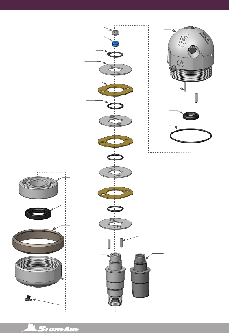
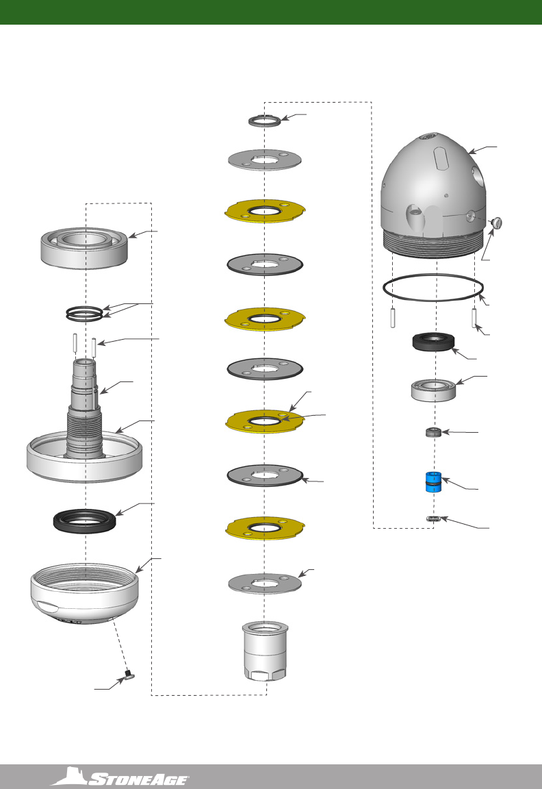
6” BADGER DISASSEMBLY
DISASSEMBLY
1. Unscrew the Nut (BA 002) from the
Head (BA 040/240)
2. Pull the Shaft (BA 001/ BA 001-
BSPP6/ BA 201) out of the head.
Figure 4: For Step 3
CST 141
Retaining Ring
BA 311
Retaining Ring
BA 315
Inner Disc (4)
BA 316
Outer Disc (3)
SM 116
O-Ring (3)
Figure 5: For Step 4-5
3. Remove the Seat (BJ 011-C) and H.P.
Seal (BJ 012-TRO) from the bore of the
Shaft.
Figure 3: For Steps 1-2
BA 330
Wear Ring
BA 302
Nut
BA 340-RXX
Head
BA 301-P8 or
BA 301-M9 or
BA 301-M24x1.5
Shaft
BJ 011- C
Seat
BA 313
Wave
Spring
BJ 012-TRO
H.P. Seal
4. Remove Retaining Ring (BA 017) from
the shaft.
5. Pull the Discs (BA 015, BA 016) and
O-Rings (SM 016) off of the Shaft.
29
866-795-1586 • WWW.SEWERNOZZLES.COM
BA 303
Shaft Adjust
Sleeve
BA318
Pins (2)
BA 312
O-Ring
BA 310
O-Ring (2)
BA 309
Bearing
BA 318
Pins (2)
BA 340-RXX
Head
6” BADGER DISASSEMBLY
Figure 6: For Steps 6-7
Figure 7: For Steps 8-9
6. Press the Bearing (UH 009) off of the
Shaft.
7. There is no need to remove the Pins
(BA 018) from the Shaft; however, if
they fall out do not lose them.
10. Remove the Port Plug (BJ 026) from
the Head.
11. Remove the Shaft Seal (BA 006) and
O-Ring (WG 008) if they are damaged.
12. There is no need to remove the Pins
(BA 018); however, if they fall out, do
not lose them.
Figure 8: For Steps 10-12
8. Remove the Shaft Seal (BA 007) if it is
damaged.
9. Remove the Port Plug (BJ 026) from
the Nut.
BA 307
Shaft Seal
BA 307
Shaft Seal
BA 302
Nut
BJ 062
Port Plug
BJ 062
Port Plug
BA 301-P8 or
BA 301-M9 or
BA 301-M24x1.5
Shaft
30 866-795-1586 • WWW. SEWERNOZZLES.COM
6” BADGER ASSEMBLY6” BADGER ASSEMBLY
ASSEMBLY
1. Press Bearing (BA 309) onto
Shaft (BA 303)
2. Check that Pins (BA 318) are installed
in Shaft.
3. Place an Inner Disc (BA 315) on Shaft,
aligning with pins.
4. Place an O-Ring (SM 116) on top of
this Disc, stretched around the pins.
5. Place an Outer Disc (BA 316) around
the outside of this O-Ring
6. Place another Inner Disc, and also
place an O-Ring (BJ 008) around the
outer edge of this Disc.
7. Repeat steps 4 through 6, until there
are four Outer Discs and ve Inner
Discs on Shaft. Note that there is no
outer O-Ring on the Inner Discs at
each end of the stack.
8. Push down on top disc and install the
Retaining Ring (CST 141) in the groove
around Shaft. Install Bearing (BA 311)
on shaft.
Pins should be
just far enough to
clear groove for
retaining ring
BA 311
Bearing
CST 141
Retaining Ring
BA 315
Inner Disc (5)
BA 316
Outer Disc (4)
SM 116
O-Ring (4)
BJ 008
O-Ring (3)
Figure 10: For Step 3-8
BA 318
Pins (2)
BA 309
Bearing
BA 303
Shaft Adjust
Sleeve
Figure 9: For Steps 1-2
.380
31
866-795-1586 • WWW.SEWERNOZZLES.COM
BJ 011- C
Seat
BA 313
Wave Spring
BJ 012-TRO
H.P. Seal
6” BADGER ASSEMBLY
9. Insert Wave Spring (BA 313) into bore
of Shaft. Apply grease to and install the
H.P. Seal (BJ 012-TRO) in bore of Shaft.
10. Apply grease to the at face of the Seat
(BJ 011-C) and place in bore of Shaft, on
top of Seal, as shown.
Figure 11: For Steps 9-10
Chamfered
Face
Flat
Face
BA 308
Shaft Seal (1)
BA 302
Nut (1)
Figure 12: For Step 11
Figure 13: For Step 11-14
BA 318
Pins (2)
BA 307
Shaft Seal
Lip with
spring
side UP
BA 312
O-Ring
BA 340-RXX
Head
Figure 14: For Steps 15-17
BA 330
Wear Ring
BJ 026
Port Plug
BJ 026
Port Plug
12. Install Shaft Seals (BA 307) in the Head
(BA 340) as shown.
13. Place O-Ring (BA 312) over threads and
into groove of Head.
14. Check that the Pins (BA 318) are
installed in the Head.
11. Install Shaft Seals (BA 308) in the Nut (BA
302) as shown.
15. Align the notches on the Outer Discs
with the pins in the Head; slide shaft
assembly into the Head, taking care
that the outer O-Rings remain captured
between the Discs.
16. Apply anti-seize to threads on Head;
install Wear Ring (BA 330) onto the Nut
(BA 302); thread the Nut onto the Head.
Tighten to 50 ft-lb.
17. Use syringe to ll the tool with viscous
uid as shown in the Maintenance
Section; install the Port Screws (BJ 026).
32 866-795-1586 • WWW. SEWERNOZZLES.COM
6” BADGER PART NAMES/NUMBERS
BA 311
Bearing
CST 141
Retaining Ring
BA 315
Inner Disc (5)
BA 316
Outer Disc (4)
SM 116
O-Ring (4)
BJ 008
O-Ring (3)
BJ 011- C
Seat
BA 313
Wave Spring
BJ 012-TRO
H.P. Seal
BA 318
Pins (2)
BA 307
Shaft Seal
BA 312
O-Ring
BA 340-RXX
Head
BJ 026
Port Plug
BJ 026
Port Plug
BA 309
Bearing
BA 310
O-Ring (2)
BA 318
Pins (2)
BA 301-P8 or
BA 301-M9 or
BA 301-M24x1.5
Shaft
BA 308
Shaft Seal (1)
BA 330
Wear Ring (1)
BA 302
Nut (1)

33
866-795-1586 • WWW.SEWERNOZZLES.COM
6” BADGER SERVICE KITS
6” BADGER KITS AND KIT CONTENTS
BA-P8/
MP9
BA 600-P8/MP9
SERVICE KIT (FAST)
BA 602-P8/MP9
H.P. SEAL KIT
1 BA 313 Wave Spring
1 BC 410 Syringe Assembly
1 BJ 011-C Carbide Seat
1 BJ 012-TRO H.P. Seal and O-Ring
1 BJ 026 Port Plug
1 BJ 048-F Visc Fluid, Fast, 6oz
1 PL 663 BA Manual
1 BJ 011-C Carbide Seat
1 BJ 012-TRO H.P. Seal and O-Ring
BA 610-P8/MP9
OVERHAUL KIT (FAST)
BA 612 P8/MP9
TOOL KIT
1 BA 307 Seal
1 BA 308 Seal
1 BA 309 Bearing, Ball, JEM
2 BA 310 O-Ring
1 BA 311 Bearing, Ball, Open
1 BA 312 O-Ring
1 BA 313 Wave Spring
3 BJ 008 O-Ring
1 BJ 011-C Carbide Seat
1 BJ 012-TRO H.P. Seal & O-Ring
2 BJ 026 Port Plug
1 BJ 048-F Viscous Fluid, Fast - 6oz.
1 CST 141Retaining Ring, HD External .875
4 SM 116 O-Ring, Sealing
1 PL 663 Consumable, BA Manual
1 BA 100 Retaining Ring Pliers
1 BA 305 Tool (6” Badger Elbow)

34 866-795-1586 • WWW. SEWERNOZZLES.COM
TERMS AND CONDITIONS AND WARRANTY INFORMATION TERMS AND CONDITIONS AND WARRANTY INFORMATION
1. Acceptance of Terms and Conditions. Receipt
of these Terms and Conditions of Sale (“Terms and
Conditions”) shall operate as the acceptance by
StoneAge, Inc. (“Seller”) of the order submitted by
the purchaser (“Buyer”). Such acceptance is made
expressly conditional on assent by Buyer to these Terms
and Conditions. Such assent shall be deemed to have
been given unless written notice of objection to any of
these Terms and Conditions (including inconsistencies
between Buyer’s purchase order and this acceptance) is
given by Buyer to Seller promptly on receipt hereof.
Seller desires to provide Buyer with prompt and efcient
service. However, to individually negotiate the terms
of each sales contract would substantially impair
Seller’s ability to provide such service. Accordingly, the
product(s) furnished by Seller are sold only according
to the terms and conditions stated herein and with the
terms and conditions stated in any effective StoneAge
Dealer Agreement or StoneAge Reseller Agreement, if
applicable. Notwithstanding any terms and conditions
on Buyer’s order, Seller’s performance of any contract
is expressly made conditional on Buyer’s agreement
to these Terms and Conditions unless otherwise
specically agreed to in writing by Seller. In the absence
of such agreement, commencement of performance,
shipment and/or delivery shall be for Buyer’s
convenience only and shall not be deemed or construed
to be an acceptance of Buyer’s terms and conditions.
2. Payment/Prices. Unless other arrangements have
been made in writing between Seller and Buyer, payment
for the product(s) shall be made upon receipt of invoice.
The prices shown on the face hereof are those currently
in effect. Prices invoiced shall be per pricelist in effect
at the time of shipment. Prices are subject to increase
for inclusion of any and all taxes which are applicable
and which arise from the sale, delivery or use of the
product(s), and the collection of which Seller is or may
be responsible to provide to any governmental authority,
unless acceptable exemption certicates are provided
by Buyer in accordance with applicable law. Buyer
shall pay all charges for transportation and delivery
and all excise, order, occupation, use or similar taxes,
duties, levies, charges or surcharges applicable to the
product(s) being purchased, whether now in effect
or hereafter imposed by any governmental authority,
foreign or domestic.
3. Warranty. SELLER MAKES NO WARRANTIES OR
REPRESENTATIONS AS TO THE PERFORMANCE
OF ANY PRODUCT EXCEPT AS SET FORTH IN THE
STONEAGE LIMITED WARRANTY PROVIDED WITH THE
PRODUCT.
4. Delivery. Seller is not obligated to make delivery by
a specied date, but will always use its best efforts to
make delivery within the time requested. The proposed
shipment date is an estimate. Seller will notify Buyer
promptly of any material delay and will specify the
revised delivery date as soon as practicable. UNDER
NO CIRCUMSTANCES SHALL SELLER HAVE ANY
LIABILITY WHATSOEVER FOR LOSS OF USE OR
FOR ANY DIRECT OR CONSEQUENTIAL DAMAGES
RESULTING FROM DELAY REGARDLESS OF THE
REASON(S).
All product(s) will be shipped F.O.B. point of origin,
unless specically agreed otherwise, and Buyer shall
pay all shipping costs and insurance costs from that
point. Seller, in its sole discretion, will determine and
arrange the means and manner of transportation of the
product(s). Buyer shall bear all risk of loss commencing
with the shipment or distribution of the product(s) from
Seller’s warehouse. Order shortages or errors must be
reported within fteen (15) business days from receipt of
shipment to secure adjustment. No product(s) may be
returned without securing written approval from Seller.
5. Modication. These Terms and Conditions are
intended by Seller and Buyer to constitute a nal,
complete and exclusive expression of agreement
relating to the subject matter hereof and cannot be
supplemented or amended without Seller’s prior written
approval.
6. Omission. Seller’s waiver of any breach or Seller’s
failure to enforce any of these Terms and Conditions
at any time, shall not in any way affect, limit or waive
Seller’s right thereafter to enforce and compel strict
compliance with every term and condition hereof.
7. Severability. If any provision of these Terms and
Conditions is held to be invalid or unenforceable, such
invalidity or unenforceability shall not affect the validity
or enforceability of the other portions hereof.

35
866-795-1586 • WWW.SEWERNOZZLES.COM
TERMS AND CONDITIONS AND WARRANTY INFORMATION
8. Disputes. Seller and Buyer shall attempt in good
faith to promptly resolve any dispute arising under
these Terms and Conditions by negotiations between
representatives who have authority to settle the
controversy. If unsuccessful, Seller and Buyer shall
further attempt in good faith to settle the dispute
by nonbinding third-party mediation, with fees and
expenses of such mediation apportioned equally to
each side. Any dispute not so resolved by negotiation
or mediation may then be submitted to a court of
competent jurisdiction in accordance with the terms
hereof. These procedures are the exclusive procedures
for the resolution of all such disputes between the Seller
and Buyer.
9. Governing Law. All sales, agreements for sale, offers
to sell, proposals, acknowledgments and contracts
of sale, including, but not limited to, purchase orders
accepted by Seller, shall be considered a contract under
the laws of the State of Colorado and the rights and
duties of all persons, and the construction and effect of
all provisions hereof shall be governed by and construed
according to the laws of such state.
10. Jurisdiction and Venue. Seller and Buyer agree
that the state or federal courts located within the City
and County of Denver, Colorado shall have sole and
exclusive jurisdiction over any litigation concerning any
dispute arising under these Terms and Conditions not
otherwise resolved pursuant to Section 9 as well as any
alleged defects of any Products or damages sustained
as a result of such alleged defects. Seller and Buyer
further agree that should any litigation be commenced
in connection with such a dispute, it shall only be
commenced in such courts. Seller and Buyer agree to
the exclusive jurisdiction of such courts and neither will
raise any objection to the jurisdiction and venue of such
courts, including as a result of inconvenience.
11. Attorney’s Fees. If any litigation is commenced
between Seller and Buyer, or their personal
representatives, concerning any provision hereof,
the party prevailing in the litigation shall be entitled,
in addition to such other relief that is granted, to a
reasonable sum as and for their attorneys’ fees and
costs in such litigation or mediation.
STONEAGE TRADEMARK LIST
View the list of StoneAge’s trademarks and service marks and learn how the trademarks should be used. Use of
StoneAge trademarks may be prohibited, unless expressly authorized.
http://www.StoneAgetools.com/trademark-list/
STONEAGE PATENT DATA
View the list of StoneAge’s current U.S. patent numbers and descriptions.
http://www.sapatents.com
STONEAGE TERMS AND WARRANTY
View StoneAge’s Terms and Warranty Conditions online.
http://www.stoneagetools.com/terms
http://www.stoneagetools.com/warranty

36 866-795-1586 • WWW. SEWERNOZZLES.COM
TERMS AND CONDITIONS AND WARRANTY INFORMATION TERMS AND CONDITIONS AND WARRANTY INFORMATION
Warranties set forth herein extend only to End-Users,
meaning customers acquiring, or that have previously
acquired, a product manufactured by StoneAge
(“Product”) for their own use and not for resale, either
directly from StoneAge Inc. (“StoneAge”) or from a
StoneAge Authorized Dealer or Reseller (“Dealer”). No
warranty of any kind or nature is made by StoneAge
beyond those expressly stated herein.
1. LIMITED WARRANTY PERIOD. Subject to
the limitations and conditions hereinafter set forth,
StoneAge warrants its Product to be free from defects
in workmanship and material for a period of one (1) year
from the date of purchase by the End-User, provided that
the end of the limited warranty period shall not be later
than eighteen (18) months from the date of shipment of
the Product to the Dealer or the End-User by StoneAge
(“Limited Warranty Period”). All replacement parts which
are furnished under this Limited Warranty and properly
installed shall be warranted to the same extent as the
original Product under this Limited Warranty if, and only
if, the original parts were found to be defective within the
original Limited Warranty Period covering the original
Product. Replacement parts are warranted for the
remainder of the original Limited Warranty Period. This
Limited Warranty does not cover any component part of
any Product not manufactured by StoneAge. Any such
component part is subject exclusively to the component
manufacturer’s warranty terms and conditions.
2. LIMITED WARRANTY COVERAGE. StoneAge’s
sole obligation under this Limited Warranty shall be, at
StoneAge’s option and upon StoneAge’s inspection, to
repair, replace or issue a credit for any Product which is
determined by StoneAge to be defective in material or
workmanship. StoneAge reserves the right to examine
the alleged defective Product to determine whether this
Limited Warranty is applicable, and nal determination
of limited warranty coverage lies solely with StoneAge.
No statement or recommendation made by a StoneAge
representative, Dealer or agent to End-User shall
constitute a warranty by StoneAge or a waiver or
modication to any of the provisions hereof or create any
liability for StoneAge.
3. WARRANTY SERVICE PROVIDERS. Service
and repair of the Product is to be performed only by
StoneAge authorized service representatives, including
Dealers who are authorized repair centers, with
StoneAge approved parts. Information about StoneAge
authorized service representatives can be obtained
through the StoneAge website at www.stoneagetools.
com/service. Unauthorized service, repair or
modication of the Product or use of parts not approved
by StoneAge will void this Limited Warranty. StoneAge
reserves the right to change or improve the material and
design of the Product at any time without notice to End-
User, and StoneAge is not obligated to make the same
improvements during warranty service to any Product
previously manufactured.
4. WARRANTY EXCLUSIONS. This Limited Warranty
does not cover, and StoneAge shall not be responsible
for the following, or damage caused by the following:
(1) any Product that has been altered or modied in any
way not approved by StoneAge in advance in writing;
(2) any Product that has been operated under more
severe conditions or beyond the rated capacity specied
for that Product; (3) depreciation or damage caused
by normal wear and tear, failure to follow operation or
installation instructions, misuse, negligence or lack
of proper protection during storage; (4) exposure to
re, moisture, water intrusion, electrical stress, insects,
explosions, extraordinary weather and/or environmental
conditions including, but not limited to lightning, natural
disasters, storms, windstorms, hail, earthquakes, acts
of God or any other force majeure event; (5) damage to
any Product caused by any attempt to repair, replace,
or service the Product by persons other than StoneAge
authorized service representatives; (6) costs of normal
maintenance parts and services; (7) damage sustained
during unloading, shipment or transit of the Product;
or (8) failure to perform the recommended periodic
maintenance procedures listed in the Operator’s Manual
accompanying the Product.
5. REQUIRED WARRANTY PROCEDURES. To be
eligible for warranty service, the End-User must: (1)
report the Product defect to the entity where the Product
was purchased (i.e. StoneAge or the Dealer) within
the Limited Warranty Period specied in this Limited
Warranty; (2) submit the original invoice to establish
ownership and date of purchase; and (3) make the
Product available to a StoneAge authorized service
representative for inspection to determine eligibility
for coverage under this Limited Warranty. This Limited
Warranty shall not extend to any person or entity who
fails to provide proof of original purchase from StoneAge
or a Dealer. No Product may be returned for credit
or adjustment without prior written permission from
StoneAge.
WARRANTY:

37
866-795-1586 • WWW.SEWERNOZZLES.COM
TERMS AND CONDITIONS AND WARRANTY INFORMATION
6. DISCLAIMER OF IMPLIED WARRANTIES AND OTHER
REMEDIES. EXCEPT AS EXPRESSLY STATED HEREIN
(AND TO THE FULLEST EXTENT ALLOWED UNDER
APPLICABLE LAW), STONEAGE HEREBY DISCLAIMS
ALL OTHER WARRANTIES, EXPRESS OR IMPLIED,
INCLUDING WITHOUT LIMITATION ALL IMPLIED
WARRANTIES OF MERCHANTABILITY OR FITNESS
FOR A PARTICULAR PURPOSE, AND ANY AND ALL
WARRANTIES, REPRESENTATIONS OR PROMISES
AS TO THE QUALITY, PERFORMANCE OR FREEDOM
FROM DEFECT OF THE PRODUCT COVERED BY
THIS LIMITED WARRANTY. STONEAGE FURTHER
DISCLAIMS ALL IMPLIED INDEMNITIES.
7. LIMITATION OF LIABILITY. End-User specically
acknowledges that the Product may be operated at
high speeds and/or pressures, and that as such it may
be inherently dangerous if not used correctly. End-
User shall familiarize itself with all operation materials
provided by StoneAge and shall at all times use and
require its agents, employees and contractors to use
all necessary and appropriate safety devices, guards
and proper safe operating procedures. In no event shall
StoneAge be responsible for any injuries to persons or
property caused directly or indirectly by the operation
of the Product if End-User or any agent, employee, or
contractor of End-User: (1) fails to use all necessary
and appropriate safety devices, guards and proper
safe operating procedures; (2) fails to maintain in good
working order such safety devices and guards; (3) alters
or modies the Product in any way not approved by
StoneAge in advance in writing; (4) allows the Product to
be operated under more severe conditions or beyond the
rated capacity specied for the Product; or (5) otherwise
negligently operates the Product. End-User shall
indemnify and hold StoneAge harmless from any and all
liability or obligation incurred by or against StoneAge,
including costs and attorneys’ fees, to or by any person
so injured.
TO THE FULL EXTENT ALLOWED BY APPLICABLE
LAW, STONEAGE SHALL NOT BE LIABLE FOR ANY
INDIRECT, SPECIAL, INCIDENTAL, CONSEQUENTIAL,
OR PUNITIVE DAMAGES (INCLUDING WITHOUT
LIMITATION, LOSS OF PROFITS, LOSS OF GOODWILL,
DIMINUTION OF VALUE, WORK STOPPAGE,
INTERRUPTION OF BUSINESS, RENTAL OF
SUBSTITUTE PRODUCT, OR OTHER COMMERCIAL
LOSS EVEN TO THE EXTENT SUCH DAMAGES WOULD
CONSTITUTE DIRECT DAMAGES), WITH RESPECT TO
THE COVERED STONEAGE PRODUCT, OR OTHERWISE
IN CONNECTION WITH THIS LIMITED WARRANTY,
REGARDLESS OF WHETHER STONEAGE HAS BEEN
ADVISED OF THE POSSIBILITY OF SUCH DAMAGES.
IT IS UNDERSTOOD THAT STONEAGE’S LIABILITY,
WHETHER IN CONTRACT, IN TORT, UNDER ANY
WARRANTY, IN NEGLIGENCE, OR OTHERWISE SHALL
NOT EXCEED THE AMOUNT OF THE PURCHASE
PRICE PAID BY THE END-USER FOR THE PRODUCT.
STONEAGE’S MAXIMUM LIABILITY SHALL NOT
EXCEED, AND END-USER’S REMEDY IS LIMITED
TO EITHER (1) REPAIR OR REPLACEMENT OF THE
DEFECTIVE WORKMANSHIP OR MATERIAL OR, AT
STONEAGE’S OPTION, (2) REFUND OF THE PURCHASE
PRICE, OR (3) ISSUANCE OF A CREDIT FOR THE
PURCHASE PRICE, AND SUCH REMEDIES SHALL BE
END-USER’S ENTIRE AND EXCLUSIVE REMEDY.
YOU, THE END-USER, UNDERSTAND AND EXPRESSLY
AGREE THAT THE FOREGOING LIMITATIONS ON
LIABILITY ARE PART OF THE CONSIDERATION IN
THE PRICE OF THE STONEAGE PRODUCT YOU
PURCHASED.
Some jurisdictions do not allow the limitation or
exclusion of liability for certain damages, so the above
limitations and exclusions may not apply to you. This
Limited Warranty gives you specic legal rights, and you
may also have other rights which vary from jurisdiction
to jurisdiction. If any provisions of this Limited Warranty
is held to be invalid or unenforceable, such invalidity
or unenforceability shall not affect the validity or
enforceability of the other portions hereof.

38 866-795-1586 • WWW. SEWERNOZZLES.COM
NOTES
THIS PAGE LEFT INTENTIONALLY BLANK
NOTES

39
866-795-1586 • WWW.SEWERNOZZLES.COM
NOTES
THIS PAGE LEFT INTENTIONALLY BLANK
NOTES

1-866-795-1586 • www.STONEAGETOOLS.com
© 2017 StoneAge, Inc. All Rights Reserved
