BIS 6595 User Manual(HABEY)
User Manual: BIS-6595 User Manual(HABEY)
Open the PDF directly: View PDF ![]() .
.
Page Count: 50

BIS-6595
Owner’s Manual

Disclaimer
Except for the accessories attached to the product as spec-
ied herein, what is contained in this user manual does not
represent the commitments of Habey USA Company. Habey
USA Company reserves the right to revise this User Manual,
without prior notice, and will not be held liable for any direct,
indirect, intended or unintended losses and/or hidden dan-
gers due to improper installation or operation.
Before ordering products, please learn about the product per-
formance from the distributors to see if it is in line with your
needs.
The contents of this manual are protected by copyright law.
All rights are strictly reserved. Any form of unauthorized re-
production including but not limited to carbon copy, facsimile
transmission and electronic copy or email is prohibited.
i

Safety Instructions
1. Please read the product manual carefully before using this
product.
2. Put all the unused or uninstalled boards or electronic compo-
nents on a static dissipative surface or in static shielding bag.
3. Always ground yourself to remove any static discharge before
touching board. To ground, place your hands on a grounding metal
object or wear a grounding wrist strap (not included) at all times.
4. When taking or fetching the boards or cards, please wear anti-
static gloves and hold the boards by its edges.
5. Make sure that your power supply is set to the correct voltage
in your area. Incorrect voltage may cause personal injuries and
damage the system.
6. To prevent electronic shock hazard or any damage to the prod-
uct, please ensure that all power cables for the devices are un-
plugged when adding or removing any devices or reconguring
the system.
7. To prevent electrical shock, disconnect the power cable from the
electrical outlet before relocating the system.
8. When adding or removing components to or from the system,
ensure that all the power cables for the system are unplugged pri-
or to installation or removal.
9. To prevent any unnecessary damage to the products due to fre-
quent power on/off, please wait at least 30 seconds to restart the
unit after the shutdown.
10. If the system fails during normal operation, do not attempt to
x yourself. Contact a qualied service technician or your retailer.
11. This product is classied as Class A product, which may cause
radio interference in our living environment. In this occasion, users
need to take measures to handle the interference.
ii
Contents
Section 1 Product Introduction ................................................. 1
1.1 Overview ....................................................................... 1
1.2 Specications ................................................................ 1
1.2.1 Notes to use CPU................................................. 3
Section 2 Installation Instructions ............................................. 3
Safety Precautions .............................................................. 4
2.1 Remove the Computer Cover........................................ 5
2.2. Install Motherboard....................................................... 5
2.2.1 Install CPU and Thermal Pad .............................. 5
2.2.2 Dismount Rear Panel .......................................... 6
2.2.3 Install the Motherboard........................................ 6
2.2.4 Mount Rear Panel ............................................... 7
2.3 Install RAM .................................................................... 8
2.4 Install MINI-PCIE Devices ............................................. 9
2.5 Install HDD .................................................................. 10
2.6 Mount the Top Cover ................................................... 13
2.7 Dismount the Bottom Cover ........................................ 13
2.8 Install PCI/PCIE Cards ................................................ 14
2.9 Install PCI/PCIE Devices ............................................. 14
2.10 Mount the Bottom Cover and Racks ......................... 15
2.11 Rack Dimension ........................................................ 16
Section 3 Hardware Functions ............................................... 17
3.1 External Interfaces Location ........................................ 17
3.1.1 Serial Ports ......................................................... 17
3.1.2 Ethernet Port ...................................................... 18
3.1.3 Audio .................................................................. 19
3.1.4 Display Interface................................................. 19
3.1.5 Power Interface .................................................. 20
3.1.6 USB Ports .......................................................... 20
3.2 Jumper Settings ......................................................... 20
3.2.1 CMOS Clear/Hold Jumper Setting ..................... 20
3.2.2 Hardware Switch for System Auto Boot Upon
Power On JAT ....................................................... 22
3.2.3 COM2 Jumper Setting ........................................ 22
3.2.4 LVDS Rated Voltage Select Jumper Setting. ..... 23
3.3 Internal Interfaces........................................................ 24
3.3.1 SATA Port ........................................................... 24
3.3.2 Keyboard & Mouse Interface .............................. 25
3.3.3 GPIO .................................................................. 26
3.3.4 Front Panel Interface .......................................... 27
3.3.5 DIMM Slot........................................................... 28
3.3.6 MINI PCIe Socket ............................................... 28
3.3.7 PCIe X16 ............................................................ 28
iii
Section 4 BIOS Setup ............................................................. 29
AMI BIOS Flash .................................................................29
AMI BIOS Description ........................................................29
BIOS Settings ....................................................................29
4.1 Main Menu ......................................................................30
4.2 Advanced Menu ..............................................................31
4.2.1 ACPI Setting..............................................................31
4.2.2 APM Conguration .................................................... 32
4.2.3 CPU Conguration .................................................... 33
4.2.4 SATA Conguration ................................................... 34
4.2.5 USB Conguration ....................................................35
4.2.6 Supper IO Conguration ...........................................36
4.2.7 H/W Monitor .............................................................. 37
4.3 Chipset Menu ..................................................................37
4.3.1 North Bridge ..............................................................37
4.3.2 South Bridge .............................................................38
4.4 Boot Menu.......................................................................39
4.5 Security Menu ................................................................. 40
4.6 Save&Exit Menu .............................................................40
Appendix ................................................................................. 41
Appendix 1: Install Drives .......................................................41
Appendix 2: Watchdog Programming Guide ...........................42
Appendix 3: Glossary ..............................................................42
iv

Packing List
Thank you for purchasing a Habey USA product. Please
check this package carefully to ensure all parts are pack-
aged. If you nd any defective, damaged, or lost compo-
nents, please contact your vendor or retailer ASAP.
Item QTY.
BIS-6595 1
DC 12V 10A Power Adapter 1
Power Cord 1
Drivers and Utilities 1
Section 1 : Product Introduction
1.1 Overview
BIS-6595 is the latest Intel Cedar Trail powered embedded system
utiliz-ing the next generation “ICEFIN” thermal design. ensures maximum
heat dissipation and a true fanless system with Intel NM10 Chipsets.
2x Mini PCIe and one internal SIM slot provide Wifi and 3G support for
redundant network connectivity, offering system rich ex-pansions. The
DVI+VGA dual independent display output also makes it a great choice
as digital signage systems. Whatever the application, be it automation,
digital signage, information control, point of sale, transpor-tation or even
electronic police, this fanlesss Intel cedar trail dual display system is
designed to be high performance, reliable, rich expansion, se-cure and
easy to manage.
1.2 Specication
Model Number BIS-6
Platform Intel
1

Chassis
Color Black
Dimension 280mm× 219.2mm× 115 mm(W×D×H)
Structure “ICEFIN” Enclosure
Material Aluminum+ Fine Quality Galvanized Steel Sheet
Mother-
board
Model No. BPC-7930
CPU Intel Atom N2800/D2550
Chipset Intel NM10
Memory 1x SO-DIMM supports DDR3 1066MHz RAM upto
4GB
Storage
CF N/A
SSD N/A
HDD 1x 2.5” HDD
System
Features
LAN Realtek RTL8111E,10/100/1000Mbps,2XLAN
USB 6XUSB2.0
COM 1XRS232(DB9),1XRS-232/422/485(DB9)
Display 1x VGA (DB15), 1x DVI-D; VGA + DVI dual inde-
pendent display
Cooling Sys. Fanless, “ICEFIN” thermal design
Audio 1x Mic-in, 1x Line-out
Expansion 2x Mini PCIe and one Inbuilt SIM slot for 3G
Module.
LED Power LED, HDD LED
System Control Power Switch
PS/2 N/A
WLAN 1x 3G/WiFi SMA antenna (optional)
GPIO 2x5Pin GPIO
Power Power Supply DC +12V power adaptor
Reliability
Installation Desktop or Wallmounted
Operating Temp -20°C - 60°C
Storage Temp -40°C - 80°C
Relative Humidity 5%~95% relative humidity, non-condensing
Operating Vibration 0.5g rms/5~500Hz/random operating
EMC CE/FCC Class B
2

1.2.1 Notes to use CPU
This product belongs to the Habey “ICEFIN” series. The BIS-6595 adopts
the “ICEFIN” thermal design. Please note a CPU with a higher power
consumption will dissipate more heat. If a CPU reaches its TJ Maximum
(overheating) the system will underclock and result in a performance
reduction. The following table shows the recommended CPU at different
working temperatures:
Highest Temp Max CPU Consumption Recommended CPU Models
50° C 65W
Intel® Core™ i7-3770S @ 3.90GHz
Intel® Core™ i5-3550S @ 3.00GHz
Intel® Core™ i3-3220 @ 3.30GHz
Intel® Celeron G530 @ 2.4GHz
60° C 35-45W
Intel® Core™ i3-3240T @ 2.90GHz
Intel® Core™ i5-3470T @ 3.60GHz
Intel® Core™ i7-3770T @ 3.70GHz
Intel® Pentium G860T @ 3.60GHz
The CPUs listed in above table are the commonly used CPU. Select different
CPU as per different working temperature.
Section 2 Installation Instructions
Safety
Electricity is used to perform many useful functions, but it can also cause
personal injuries and property damage if improperly handled. This product
has been engineered and manufactured with the highest priority on safety.
However, improper use can result in electric shock and/or re. In order to
ensure your safety and prolong the service life of the system, please ob-
serve the following and read the following precautions when installing and
handling the product.
Warning
Always completely disconnect the power cord from your chassis whenev-
er you work with the hardware. Do not make connections while the power
is on. Sensitive electronic components can be damaged by sudden power
surges. Only experienced electronics personnel should open the Player
chassis.
3
Caution
• Always ground yourself to remove any static discharge before touch-
ing the CPU. Modem electronic devices are very sensitive to static elec-
tric discharges. As a safety precaution, use a grounding wrist strap at all
times. Place all electronic components in a static dissipative surface or
static shielding bags when they are not in the chassis.
•The product specication and pictures are subject to change without pri-
or notice.
Safety Instruction
Electrical Safety
• If the power supply is broken, do not try to x it yourself. Contact a qual-
ied service technician or your retailer.
• When adding or removing devices to or from the system, ensure that
the power cables for the devices are unplugged before the signal cables
are connected. If possible, disconnect all power cables from the existing
system before you add a device.
•To prevent electrical shock hazard, disconnect the power cable from the
electrical outlet before relocating the system.
• Before connecting or removing signal cables from the motherboard,
please ensure that all power cables are unplugged.
•To prevent damage to the power cord, do not place heavy objects on,
stretch, or bend power cord. Damage to the cord may result in or electric
shock.
•Make sure that your power supply is set to the correct voltage in your
area. Incorrect voltage may cause personal injuries and damage the sys-
tem.
Operation Safety
• Before installing the motherboard and adding devices on it, carefully read
all the guides that came with the package.
•To avoid short circuits, keep paper clips, screws, staples, and any other
small metal objects away from connectors, slots, sockets and circuitry.
4
• Do not use the system where there is a lot of dust, humidity is high, or
where the system may come into contact with oil or steam, as this could
lead to re.
• Ensure that the system does not come into contact with water or other
uids. Ensure that no objects such as paper clips or pins enter the sys-
tem as this could lead to electric shock.
• Do not place the system in unsafe places. Do not allow the system to
receive strong shocks or to strongly vibrate. This may cause the system
to fall or topple over damaging the system.
• Do not use the system near heating equipment or in places where there
is likelihood of high temperature, as this may lead to excessive heat and
outbreak of re.
• Do not use the system in places where it may be exposed to direct
sunlight.
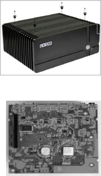
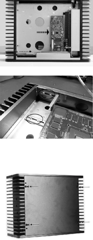
2.1 Remove the Computer Cover
2.2 Install Motherboard
2.2.1 Install CPU & Thermal Pad
Remove the four screws
on cover and dismount the
cover.
The thermal pad is tailored
as per the size of CPU and
Chipset and is pressed
on to the CPU and South-
bridge evenly with ngers.
5
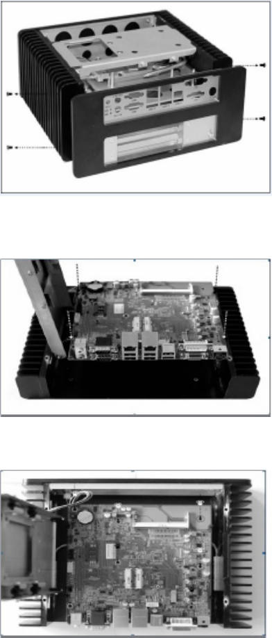
2.2.2 Dismount Rear Panel
Loosen the four screws on
the side of the rear panel
and remove the rear panel
module.
2.2.3 Install the Motherboard
Align the semi-circle guide
holes of the motherboard
with the four guide posts on
the bracket and place the
motherboard on the back
cover evenly.
Tighten the 7 screws on-
board that x the moth-
erboard (M3x6mm screw
x7PCS)
6
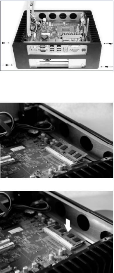
2.2.4 Mount the Rear Panel
2.3 Install RAM
Mount back the rear panel
and tighten the four screws
on panel
Align the memory bank
with the memory slot in the
direction of 45 degree and
then insert the memory
into its socket.
Press the end of the mem-
ory bank down into the
socket with ngers until the
memory bank is xed in
the socket.
7
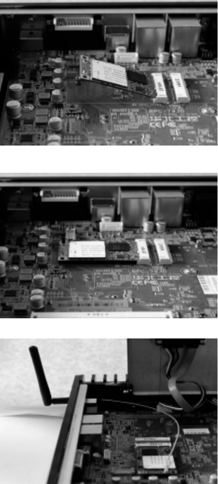
Remove the screws
onboard for xing
the Mini PCIe devic-
es. Then insert the
device into the sock-
et at a 45 degree
angle.
Push against the
other side of the
Mini PCIe device
and press it down
into the socket,
nally tighten the
screws.
If the Mini PCIe
device has a WiFi
antenna, please
connect the Anten-
na connector to the
WiFi Antenna hole
on the rear panel
and then connect
the connector with
Mini PCIe device
inside the chassis.
2.4 Install MINI PCIE Devices
8
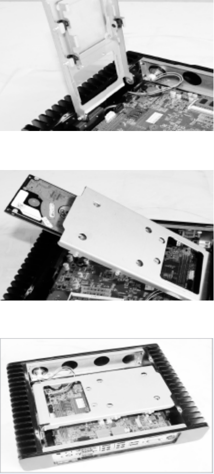
Pull the HDD tray
upward at a 90de-
gree angle.
Then close the HDD
tray.
2.5 Install HDD
Insert the hard disk
into the HDD tray.
9
Use the screwdriver
to tighten the four
screws on the tray ,
so as to x the hard
disk.
(M3x4mm screws
x4PCS)
Connect the HDD
power cable and
data cable to the
HDD port and use
screws to x them
and then connect
the other end of the
cable to the corre-
sponding ports on
the motherboard.
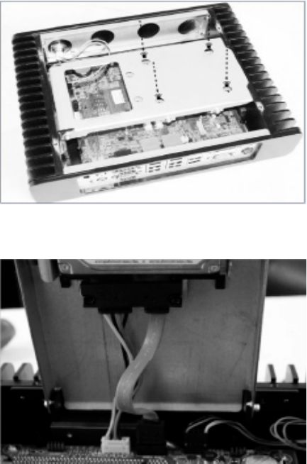
10
Mount the computer top
cover and tighten the four
screws on the cover.
Remove the four screws
on the product footpads
and dismount footpads
and the bottom cover.
2.6 Mount Top Cover
2.7 Dismount the Bottom Cap
11
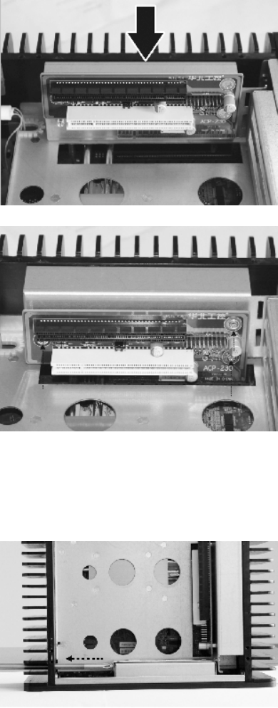
Align the PCI/PCIE expan-
sion cards with the PCI-e
Socket and press down-
ward.
Then use screws to x
the PCI/PCIE Card on the
bracket.
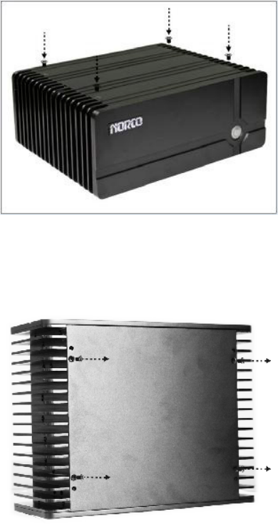
Use cross screwdriver to
remove the rear window
bafe.
2.8 Install PCI / PCIe Cards
2.9 Install PCI / PCIe Devices
12
Insert the PCI or PCI-e
device into its correspond-
ing slots and tighten the
screws on the bafe to x
the PCI/PCI-e device.
Adjust the screws in the
marked position to hold the
PCI/PCIe device and keep
cards from dislodging.
Mount the bottom cover
and tighten the four screws
to x the cover.
2.10 Mount Bottom Cover and Racks
13
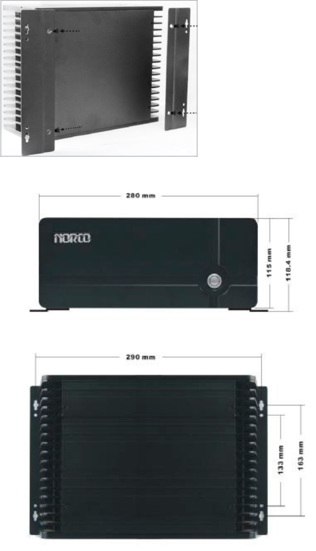
Finally, use screws to x
the racks onto the chassis
base.
2.11 Rack Dimensions
14
Section 3 Hardware Functions
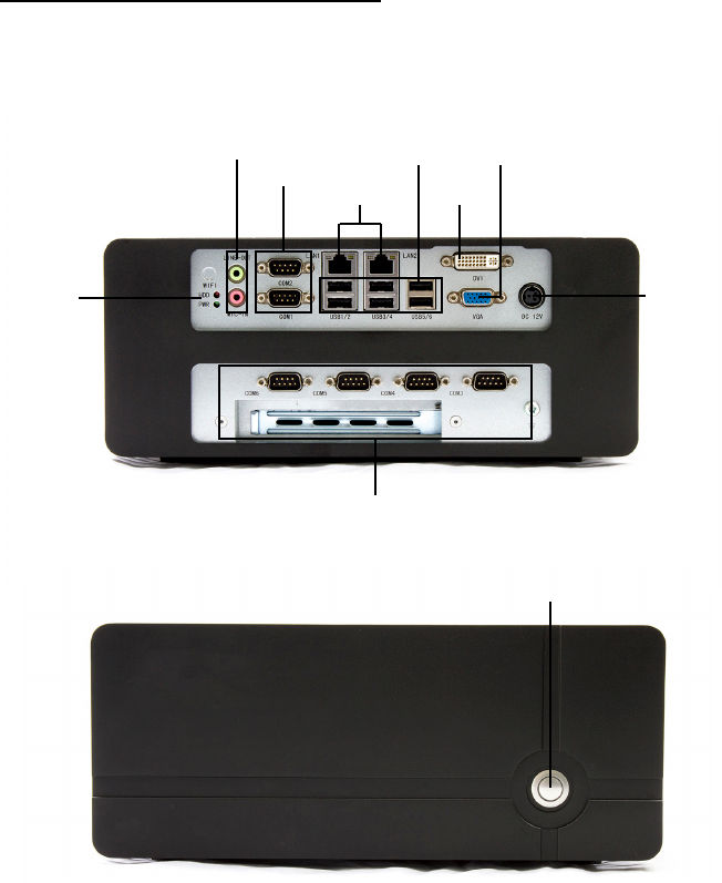
3.1 External Interface Location
3.1.1 Serial Ports (COM1, COM2)
1: BIS-6590 Rear I/O View
2: BIS-6590 Front View
Power
VGA
DVI
USB
LAN
COM
Audio IN/OUT
HDD &
Power
LED
PCI / PCIe Expansion
POWER
Board provides 2x serial ports. COM1/ COM2 are the standard DB9
interface.
COM1 supports RS232.
COM2 supports RS232/RS422/RS485.
15

3.1.2 Ethernet Port (LAN1, LAN2)
COM1/COM2:
PIN Signal Name
1 DCD
2 TXD
3 RXD
4 DTR
5 GND
6 DSR
7RTS
8 CTS
9 RI
COM2: RS232/RS422/RS485, Pins dene as below:
PIN RS232 (Default) RS422 RS485
1 DCD TX- DATA-
2 TXD TX+ DATA+
3 RXD RX+ NC
4 DTR RX- NC
5 GND GND GND
6 DSR NC NC
7RTS NC NC
8 CTS NC NC
9 RI NC NC
BPC-7930 provides 2x RJ-45 Gigabit Ethernet Ports. Both sides of the
RJ-45 interface has one LED lamp. The yellow one indicates data trans-
fer status. The green one indicates network link status.
LILED
(GREEN)
FUNCTION ACTLED
(Yellow)
Function
ON 10/100/1000m Link Flash Data Transfer
16

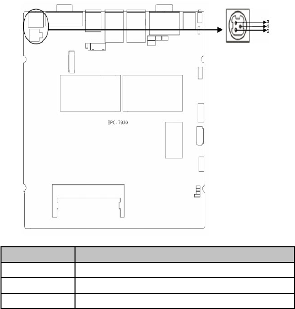
3.1.3 Audio (Line-out, Line-in, Mic-in)
3.1.4 Display Interface (VGA, DVI-D)
BPC-7930 adopts ALC892 audio controller chip. The green one is Line-
out. The pink one is Mic-in. Inbuilt one 1x3Pin Line-in expansion inter-
face.
Pin Signal Name
1 LINE_L
2 GND
3 LINE_R
BPC-7930 provides one standard 15Pin VGA port to connect VGA dis-
play. One DVI-D port to connect DVI-D display.
VGA:
Pin Signal Name Pin Signal Name Pin Signal Name
1 RED 6 GND 11 NC
2 GREEN 7 GND 12 SDA
3 BLUE 8 GND 13 HSYNC
4 NC 9 +5V 14 VSYNC
5 GND 10 GND 15 SCL
DVI-D:
Signal Name Pin Signal Name
TDC2# 1 2 TDC2
GND 3 4 NC
NC 5 6 SD-DDC
SD-DDC 7 8 NC
TDC1# 9 10 TDC1
GND 11 12 NC
NC 13 14 VCC
GND 15 16 HP-DETECT
TDC0# 17 18 TDC0
GND 19 20 NC
NC 12 22 GND
TLC 23 24 TLC#
NC C1 C2 NC
NC C3 C4 NC
17

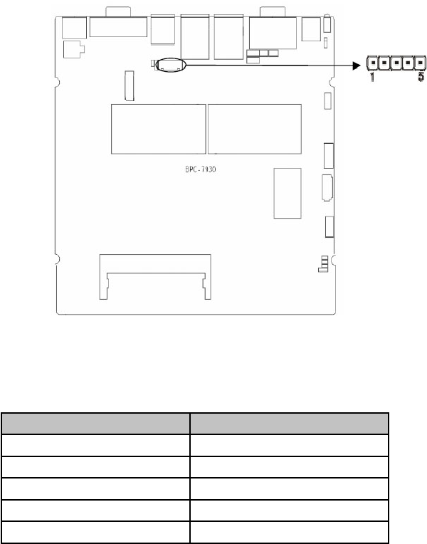
3.1.5 Power Interface (DC_JACK)
3.2 Jumper Settings
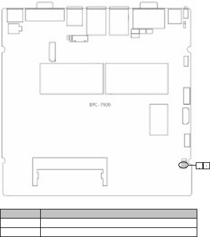
3.2.1 CMOS Clear/Hold Jumper Setting (JCC)
3.1.6 USB Ports (USB12, USB34, USB56)
DC_JACK:
Pin Signal Name
1 +12V
2 GND
3 NC
USB12, USB 34, USB56:
Pin Signal Name
1 +5V
2 USB DATA-
3 USB DATA+
4 GND
CMOS is powered by the onboard button cell. Clear CMOS will lead to
permanent elimination of previous system settings and back to the original
system setting (factory default).
Steps:
(1) Turn off the computer and disconnect power supply.
(2) Use Jumper Cap JCC Pin1-2 short for 5~6 sec. Then restore the de-
fault setting with Pin2-3 connected.
(3) Turn on the computer, then press “DEL” key to enter BIOS setting and
reload optimal defaults.
(4) Save and Exit.
18
13
JCC1:
Settings JCC
1-2 BIOS back to initialization (factory default)
2-3 Normal Status, System Default
* Do not clear CMOS when the computer is power on, otherwise, it will
cause damage to the motherboard.
19
1 2
JAT:
Settings JAT
Open Non-auto boot upon power on
Close Auto boot upon power on
3.2.2 Hardware Switch for System Auto Boot Upon
Power On JAT)
3.2.3 COM2 Jumper Setting (J1, J2, J3)
J1, J2, J3 jumpers are used to congure COM2 transmission mode.
COM2 supports RS232/RS422/RS485. Default mode as RS232.
20
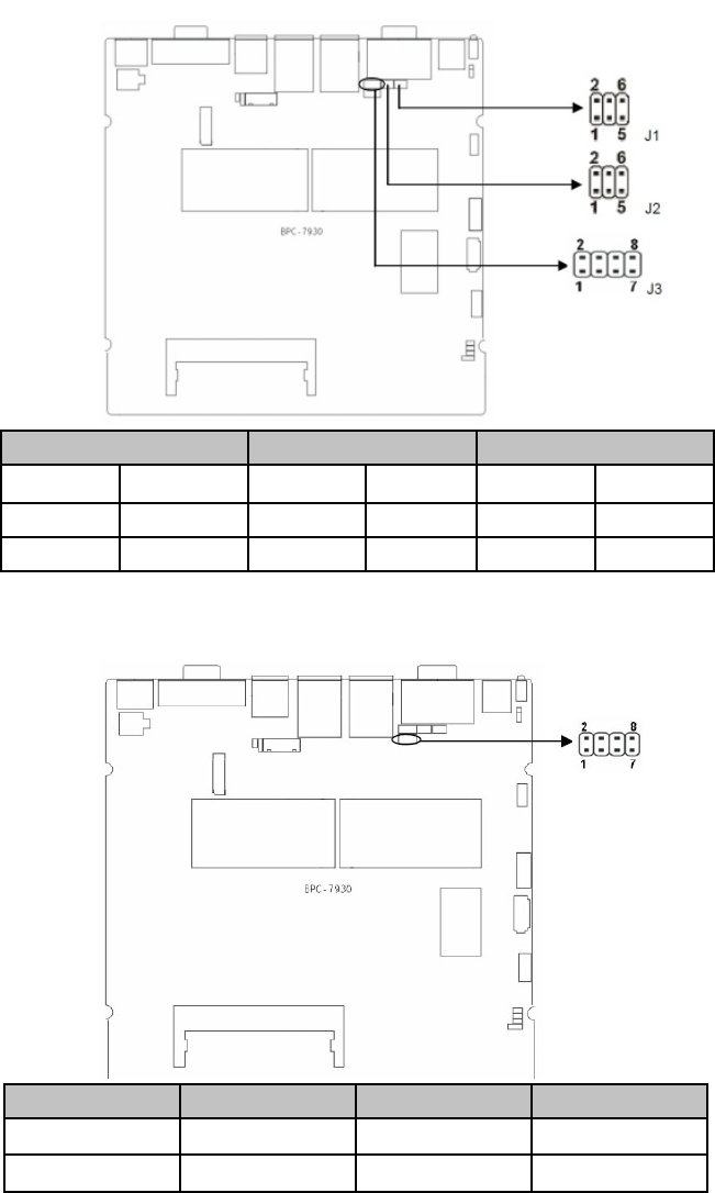
COM2 RS232 COM2 RS422 COM2 RS485
J1 3-5, 4-6 J1 1-3, 2-4 J1 1-3, 2-4
J2 3-5, 4-6 J2 1-3, 2-4 J2 1-3, 2-4
J3 1-2 J3 3-4 J3 5-6, 7-8
3.2.4 LVDS Rated Voltage Select Jumper Setting (JP1,
JP2)
VDO_PANEL 3.3V 5V 12V
JP1 1-2 2-3 X
JP2 X X 1-2
21
1
5
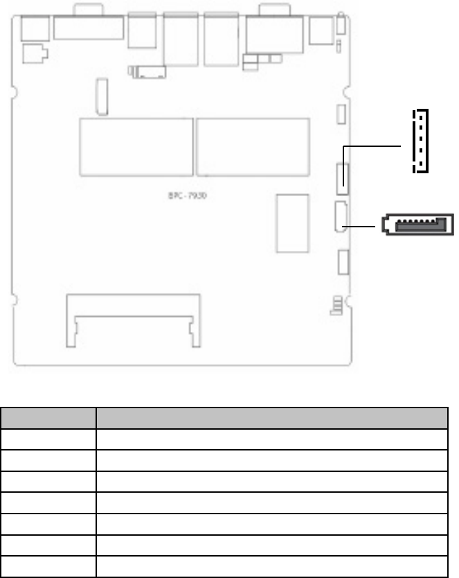
SATA:
Pin Signal Name
1 GND
2 TX+
3 TX-
4 GND
5 RS-
6 RS+
7 GND
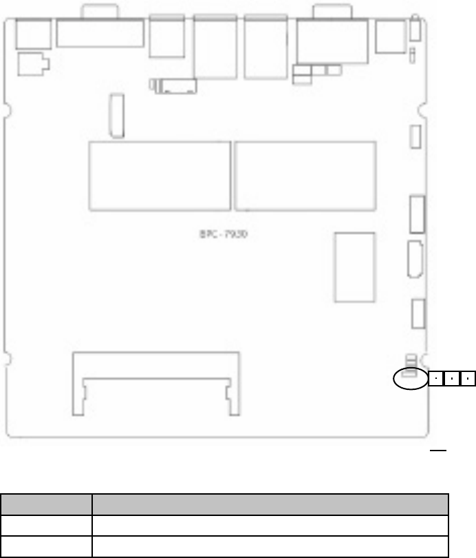
3.3 Internal Interfaces
3.3.1 SATA Port (SATA1)
Board provides one standard 7Pin SATA port and one 5Pin SATA Power
Interface. The SATA power interface (JSATAPWR) is used to provide
power supply to SATA HDD with an extension cable.
22
3.3.2 Keyboard & Mouse Interface (KM)
Board provides one 2×4Pin keyboard and mouse interface, to be con-
verted to standard PS/2 interface with an extension cable.
KM:
Signal Name Pin Signal Name
VCC5 1 2 MS_CLK
GND 3 4 MS_DATA
KB_DATA 5 6 GND
KB_CLK 7 8 VCC5
23
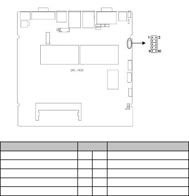
3.3.3 GPIO (JGP)
JLVDS Backlight Control (JLVDSPWR)
JGP:
Pin Signal Name
1 +12V
2 L_BKLT_EN
3 GND
4 L_BKLT_CTL
5 VCC
24
3.3.4 GPIO (JGPIO)
Gerneral Purpose Programmable Input/Output Port.
JGPIO:
Signal Name Pin Signal Name
GPIO1 1 2 VCC
GPIO2 3 4 GPIO5
GPIO3 5 6 GPIO6
GPIO4 7 8 GPIO7
GND 9 10 GPIO8
25
3.3.5 Power Interface (DC_JACK)
Pin Signal Name
1 +12V
2 GND
3 NC
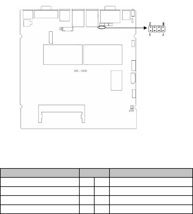
3.3.6 Front Panel Connector (JFP)
JFP is used to connect the function buttons and LED lamps on the front
panel
26
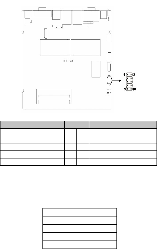
JFP:
Signal Name Pin Signal Name
POWER LED+ 1 2 POWER LED-
HD LED+ 3 4 HD LED-
VCC 5 6 BUZZDATA-
RESET SW 7 8 GND
POWER SW 9 10 GND
Please follow the table below to connect, pay attention to the anode(+)
and cathode(-), otherwise , some function can not be realized.
POWER LED
HDD LED
BUZZ
RESET SW
PWR SW
27
3.3.7 SO_DIMM Slot
Board provides one single channel SO-DIMM slot, supporting DDRIII
1066MHz RAM up to 4GB.
3.3.8 Mini PCIe Socket
Board provides 2x MINI PCIe slots. If you use the Mini PCIE WiFi, the
status of which will be determined by the wireless network that you
choose.(MINI PCIe1 supports standard MINI PCIe port and 3G module;
MINI PCIe2 supports standard MINI PCIe port and EPC/mSATA SSD
(optional). J11 is the LED for MINI PCIe1 device; J12 is the LED for MINI
PCIe2 device.
1) System Power LED Pins (Pin 1/2 for PWRLED)
Connect system power LED cable with these pins.(pin 1 is LED anode)
When system is power on, power LED is on: when system is power off,
power LED is off.
2) HD LED Pins (Pin3/4 for HDD LED)
Case panel with one HD LED indicating HD status. When HD read and
write, the LED will ash, indicating the device is working. Connect the
LED cable to the LED pins ( Pin3 is LED anode).
3) Buzzer Pins (Pin5/6 for SPEAKER)
External Speaker Pins.
4) Reset Button Pins (Pin7/8 for RESET)
Connect the reset button cable to these two pins. When system fails,
reset button can make the system continue to work and no need to turn
on / off the power.
5)Power Button Pins (Pin 9/10 for POWER BUTTON)
Connect these two pins to the bounce switch on the chassis to connect
or disconnect the power supply.
28

Section 4 BIOS Setup
AMI BIOS Flash
BIOS functions as a bridge connecting hardware and operating system.
Hardware and software are upgrading all the time, so when your system
goes wrong, for example, your system can not support the newest CPU,
you need to upgrade BIOS to keep up with the latest technology.
AFUEFI.EXE is the FLASH IC program for BIOS to upgrade, which
needs to be run in DOS mode.
Pls use a boot disk to load DOS, then run AFUDOS.EXE to upgrade
BIOS ( for example: write XXXX.ROM into FLASH IC ).
Operational Commands:
A:\ AFUEFI ****.rom /P /B /N /X
If you need to add other parameters after the order format, pls add
<space>/?
Note:
1. BIOS Flash is only executed when it is necessary
2. Please use the BIOS Read-write programs in the CD-ROM provided by
us or download the latest version on related websites
3. Please do not power off or reboot the system when ash BIOS, other-
wise, the BIOS maybe be damaged or system may not be able to boot
again.
4. After nishing BIOS Flash, load the optimal defaults manually
5.To prevent any unexpected problems, please backup your BIOS in ad-
vance.
AMI BIOS Description
When the computer is power on, BIOS will conduct self-diagnosis to its
hardware on motherboard and congure hardware parameter, nally the
operating system will take control. BIOS is the communication bridge
between hardware and O/S. Correct conguration of BIOS is critical for
maintaining system stability and its optimized performance.
BIOS Settings
1. Power on or restart the system, self-detection message will display on
the screen.
2. When system pops out the prompt “Press <Del> to enter setup, <F11>
to Popup menu “ , please press <Del> key to enter BIOS setup interface.
3. Use the “←↑→↓”to select the option which your want to modify, press
<Enter> to go to the sub-menu.
4. Use the “←↑→↓”and <Enter> to modify the value; press”Enter” to mod-
ify BIOS options that you choose.
5. At any time, press <Esc> can go back to the father-menu.
29

4.1 Main Menu
Aptio Setup Utility_Copyright (C) 2012 American Megatrends,Inc.
BIOS Information Set the Date. Use
[Tab] to switch be-
tween date elements.
BIOS Vendor American Megatrends
BIOS Version 7930T102
Build Date & Time 10/23/2012 11:28:31
CPU Information →←: Select Screen
↑↓: Select Item
Enter: Select
+/-: Change Option
F1: General Help
F2: Previous Value
F9: Optimize Defaults
F10: Save & Exit
ESC: Exit
Inter(R) Atom(TM) CPU D2550 @1.86GHZ
Memory Information
Memory Frequency 1067 MHZ(DDR3
Total Memory 2048 MB (DDR3)
System Date [Fri 01/13/2012]
System Time [03:08:57]
Version 2.14.1219. Copyright (C) 2012 American Megatrends. Inc.
BIOS Vendor
BIOS Vendor: American Megatrends
Project Version
BIOS Version: 7930T102
Build Date and Time
BIOS date and time: 10/23/2012 11:28:31
System Date
System Date Format: Week(Mon.~Sun.)/Month(Jan.-Dec.)/Day(01-31)/
Year (upto 2009).
System Time
System Time Format: Hour(00-23)/Minute(00-59)/Second(00-59)..
30

4.2 Advanced Menu
Aptio Setup Utility_Copyright (C) 2012 American Megatrends,Inc.
Legacy OpROM Support Enable or Disable
Boot Option for Lega-
cy Network Devices.
Launch LAN1 PXE OpROM [Disabled]
Launch LAN2 PXE OpROM [Disabled]
ACPI Setting →←: Select Screen
↑↓: Select Item
Enter: Select
+/-: Change Option
F1: General Help
F2: Previous Value
F9: Optimize Defaults
F10: Save & Exit
ESC: Exit
APM Conguration
CPU Conguration
SATA Conguration
USB Conguration
Super IO Conguration
H/W Monitor
Seri al Port Console Redirection
Version 2.14.1219. Copyright (C) 2012 American Megatrends. Inc.
Launch LAN1/LAN2 PXE OpROM
Enable or disable Boot Option for Legacy Network Devices (Launch
LAN1/LAN2(82574L) PXE OpROM)
4.2.1 ACPI Settings
Aptio Setup Utility_Copyright (C) 2011 American Megatrends,Inc.
ACPI Settings
ACPI Sleep State [S1 (CPU Stop Clock)]
Select the highest ACPI
sleep state the system
will enter when the SUS-
PEND button is pressed.
→←: Select Screen
↑↓: Select Item
Enter: Select
+/-: Change Option
F1: General Help
F9: Optimize Defaults
F10: Save & Exit
ESC: Exit
Version 2.14.1219. Copyright ( C ) 2012 American Megatrends, Inc.
31

4.2.2 APM Conguration
Aptio Setup Utility_Copyright (C) 2011 American Megatrends,Inc.
RTC Power On Function [Disabled] Enable or Disable
System wake on
alarm event. When
enabled,
System will wake
on the hr::min::sec
specied.
→←: Select Screen
↑↓: Select Item
Enter: Select
+/-: Change Option
F1: General Help
F9: Optimize Defaults
F10: Save & Exit
ESC: Exit
Version 2.14.1219. Copyright ( C ) 2012 American Megatrends, Inc.
ACPI Sleep State
Select highest APCI sleep state the system will enter when the SUSPEND
button is pressed. Different modes with different power consumption.
S1(pos): CPU stops working while other devices are still connected to
power supply.
S3(STR): Power is only supplied to system memory.
Aptio Setup Utility_Copyright (C) 2011 American Megatrends,Inc.
RTC Power On Function [ENabled]
RTC Power On Hour 0
RTC Power On Minute 0
RTC Power On Second 0
Enabled for Windows
XP and Linux ( OS
optimized for Hy-
per-Threading Tech-
nology ) And Disabled
for other OS (OS not
optimized for
Hyper Threading
Technology). When
Disabled only one
thread Per dnabled
core is enabled
32

4.2.3 CPU Conguration
Aptio Setup Utility_Copyright (C) 2011 American Megatrends,Inc.
CPU Conguration
rocessor Tyge Intel(R) Atom(TM) CPU
EMT64 Supported
Processor Speed 1865 MHZ
Ratio Status 14
Actual Ratio 14
System Bus Speed 533 MHZ
Processor Steping 30661
Microcode Revision 268
L1 Cache RAM 2x56 K
L1 Cache RAM 2x 512 K
Processor Core Dual
Hyper Threading Supported
Hyper Threading Enabled
Execute Disable Bit Enabled
Limit CPUID Maximum Diabled
EIST Diabled
CPU C State Report Disable
Enabled for Windows
XP and Linux (OS
optimized for Hy-
per-Threading Tech-
nology) And Disabled
for other OS (OS not
optimized for Hyper
Threading Technolo-
gy).
→←: Select Screen
↑↓: Select Item
Enter: Select
+/-: Change Option
F1: General Help
F9: Optimize Defaults
F10: Save & Exit
ESC: Exit
Version 2.14.1219. Copyright ( C ) 2012 American Megatrends, Inc.
→←: Select Screen
↑↓: Select Item
Enter: Select
+/-: Change Option
F1: General Help
F2: Previous Value
F9: Optimize Defaults
F10: Save & Exit
ESC: Exit
Version 2.14.1219. Copyright ( C ) 2012 American Megatrends, Inc.
Hyper-threading
This option is congured to activate or deactivate the CPU Hyper Thread-
ing Technology. Intel® Hyper-Threading Technology uses resources ef
ciently, enabling multiple threads to run on each core, and increasing
processor throughput.
33

Intel Virtualization Technology
Disable or enable Intel Virtualization Technology. Intel virtualization tech-
nology enables to run multiple O/S of the same kind or different kind by
using the same physical platform so as to realize the management and
allocation of computer resources, maximizing the resource utilization.
4.2.4 SATA Conguration
Aptio Setup Utility_Copyright (C) 2011 American Megatrends,Inc.
SATA Conguration
Serial ATA Port 1 SAMSUNG HM160H 160GB
Serial ATA Port 2 Not Present
Serial ATA Controller(s) Enabled
SATA Mode AHC
Serial ATA Port 1 Enabled
Serial ATA Port 2 Enabled
SATA Ports (0-3) De-
vice Names
→←: Select Screen
↑↓: Select Item
Enter: Select
+/-: Change Option
F1: General Help
F9: Optimize Defaults
F10: Save & Exit
ESC: Exit
Version 2.14.1219. Copyright ( C ) 2012 American Megatrends, Inc.
Serial-ATA Controller(S)
To enable or disable the Serial-ATA Controller. Availabel setting values
include [Disabled], [Enhanced], [Compatible].
SATA Mode Selection
SATA Mode Selection, including AHCI mode and IDE mode.
Execute Disable Bit
Execute Disable Bit (EDB) is a hardware-based security feature that in-
troduced to its new generation CPU by Intel, which can help reduce sys-
tem exposure to viruses and malicious code. EDB allows the processor to
classify areas in memory where application code can or cannot execute.
To use Execute Disable Bit you must have Windows XP SP2 operating
system to support this function.
34

4.2.5 USB Conguration
Aptio Setup Utility_Copyright (C) 2012 American Megatrends,Inc.
USB Conguration
USB Devices: 1 Drive, 1Keyboard,1 Hubs
USB Function [Enabled]
USB 2.0(EHCI) Support [Enabled]
Legacy USB Support [Enabled]
Mass Storage Devices:
KingstonDataTraveler G3 1.00 [Auto]
Enables / Disable
USB Function
→←: Select Screen
↑↓: Select Item
Enter: Select
+/-: Change Option
F1: General Help
F9: Optimize Defaults
F10: Save & Exit
ESC: Exit
Version 2.14. 1219. Copyright ( C ) 2012 American Megatrends, Inc.
USB Function
To enable or disable the USB ports. System defaults [Enabled]
USB 2.0 (EHCI) Support
Enable or Disable the USB EHCI (USB 2.0) functions. One EHCI control-
ler must always be enabled.
[Enabled]: Enable USB EHCI (USB 2.0) functions, max. transmission
rate up to 480Mpbs
[Disabled]: Disable USB2.0 function. The transmission rate is 12Mpbs.
Legacy USB Support
To support USB device in DOS mode: such as USB Flash Disk, USB
keyboard, please select <Enabled> or<Auto>. Enables Legacy USB
support. AUTO option disables legacy support if no USB devices are
Connected. DISABLE option will keep USB devices available only for EFI
applications.
Mass Storage Devices
To select the types of the connected USB devices. [Auto], or [ oppy] or
[Forced FDD], [HDD] or CD-ROM. System defaults as [Auto].
35

4.2.6 Super I/O Conguration
Aptio Setup Utility_Copyright (C) 2011American Megatrends,Inc.
Super IO Conguration
Serial Port 1 Conguration
Serial Port 2 Conguration
Set Parameters of
Serial Port 1 (COMA)
→←: Select Screen
↑↓: Select Item
Enter: Select
+/-: Change Option
F1: General Help
F9: Optimize Defaults
F10: Save & Exit
ESC: Exit
Version 2.14.1219. Copyright ( C ) 2012 American Megatrends, Inc.
Serial Port 1 Conguration
1) Serial Port
To enable or disable the serial port functions.
2) Device Setting (Read Only)
Set serial port IRQ and base address.
3) Change Setting
To change serial port settings. Recommend to select [Auto].
Serial Port 2 Conguration follows the same steps as above.
Aptio Setup Utility_Copyright (C) 2011 American Megatrends,Inc.
PC Health Status
CPUTIN temperature : +41°C
CPUVCORE : +1.184 V
+3.3VIN : +3.248 V
+5VIN : +4.966 V
→←: Select Screen
↑↓: Select Item
Enter: Select
+/-: Change Option
F1: General Help
F9: Optimize Defaults
F10: Save & Exit
ESC: Exit
Version 2.14.1219. Copyright ( C ) 2012 American Megatrends. Inc.
PC Health Status
PC Health Status Detect. BIOS will display current system temperature,
CPU temperature, FAN rotate speed, and related voltage value.
Smart Fan Function
Enable or disable the smart fan function(the intelligent fan speed control
function).
4.2.7 H/W Monitor
36

Aptio Setup Utility_Copyright (C) 2011 American Megatrends,Inc.
COM1
Console Redirection [Disabled]
Console Redirection Settings
COM2
Console Redirection [Disabled]
Console Redirection Settings
Serial Port for Out-of-Band Management/
Windows Emergency Management Services
(EMS)
Console Redirection [Disabled]
Console Redirection Settings
Console Redirection
Enable or Disable
→←: Select Screen
↑↓: Select Item
Enter: Select
+/-: Change Option
F1: General Help
F9: Optimize Defaults
F10: Save & Exit
ESC: Exit
Version 2.14.1219. Copyright ( C ) 2012 American Megatrends, Inc.
Console Redirection
Enable or disable the COM Redirection function, which only functions
during system starting up and in DOS.
Windows Emergency Management Services
Enable or disable the System COM Redirection Function
4.3.1 North Bridge
Aptio Setup Utility_Copyright (C) 2011 American Megatrends,Inc.
Boot Display Device [VBIOS Default]
Active LFP [LVDS]
Flat Panel Type [VBIOS Default]
Flat Panel BackIigh 255
Select the video De-
vice which Will be ac-
tivated during POST.
This has no effect
if external Graphics
present
→←: Select Screen
↑↓: Select Item
Enter: Select
+/-: Change Option
F1: General Help
F2: Previous Value
F9: Optimize Defaults
F10: Save & Exit
ESC: Exit
Version 2.14.1219. Copyright ( C ) 2012 American Megatrends, Inc.
4.3 Chipset Menu
37

Boot Display Device
To select the output display device when system boots
Flat Panel Type
LVDS optimal resolution select.
4.3.2 South Bridge
Aptio Setup Utility_Copyright (C) 2011 American Megatrends,Inc.
Audio Controller [Enabled]
LAN1 Controller [Enabled]
LAN2 Controller [Enabled]
Restore AC Power Loss [Power On]
Audio Controller
→←: Select Screen
↑↓: Select Item
Enter: Select
+/-: Change Option
F1: General Help
F9: Optimize Defaults
F10: Save & Exit
ESC: Exit
Version 2.14.1219. Copyright ( C ) 2012 American Megatrends, Inc.
Audio Controller
Enable or disable the onboard Audio Controller.
LAN1/2 Controller
Enable or disable LAN1/2 Controller.
Restore AC Power Loss
This option is to setup the system status while connecting the power
again after the AC Power Loss
<Power Off>:System remains the status of power off. Users need to press
the power button to start the computer.
<Power On>: System will reboot automatically when connecting to power
supply.
<Last State>: Remain the same state as that before the power loss.
38

4.4 Boot Menu
Aptio Setup Utility_Copyright (C) 2011 American Megatrends,Inc.
Boot Conguration
Setup Prompt Timeout 1
Bootup Numlock State [On]
Show Full Logo [Enabled]
Boot Option Priorities
Boot Option #1 [UEFI:Built-in EFI…]
Boot Option #2 [SATA PM: SAMSUNG...]
Boot Option #3 [UEFI:KingstonData…]
Hard Drive BBS Priorities
Number of seconds to
wait for setup activa-
tion key.
65535(0xFFFF)
means indenite
waiting.
→←: Select Screen
↑↓: Select Item
Enter: Select
+/-: Change Option
F1: General Help
F9: Optimize Defaults
F10: Save & Exit
ESC: Exit
Version 2.14.1219. Copyright ( C ) 2012 American Megatrends, Inc.
Setup Prompt Timeout
Number of seconds to wait for setup shortcut key. 60s is the max seconds
of timeout. If don’t press Setup key within the preset time, system will
continue to start.
Bootup Numlock State
This function allows users to activate Numlock function when boot up.
[ON]:Numlock is activated when system boots up
[OFF]: Numlock under cursor control.
Show Full Logo
[Enabled]: Computer boot screen will show supplier’s LOGO.
[Disabled]: Self-detect info will show when system boots.
Boot Option Priorities
System will detect devices according to the preset frequency until to nd a
boot device. Option #1 is the prior boot device.
Hard Drive BBS Priorities
This option contains HDD that can be used as boot device. If multiple
HDDs in this option, priority should set for these HDDs, then the prior one
will show in Boot Option #1.
39

4.5 Security Menu
Aptio Setup Utility_Copyright (C) 2011 American Megatrends,Inc.
Password Description
The password length must be in the following
range:
Minimum length 1
Maximum length 20
Administration Password
User Password
Set Administrator
Password
→←: Select Screen
↑↓: Select Item
Enter: Select
+/-: Change Option
F1: General Help
F9: Optimize Defaults
F10: Save & Exit
ESC: Exit
Version 2.14.1219. Copyright ( C ) 2012 American Megatrends, Inc.
The password length: Min: 1 character, Maximum: 20 characters.
Administrator Password
To setup administrator password.
User Password
To set User Password. If you have set the password, system will display
“Installed”; If not, system will display ”Not Installed”.
4.6 Save & Exit
Aptio Setup Utility_Copyright (C) 2011 American Megatrends,Inc.
Load Defaults
Save Changes and Exit
Discard Changes and Exit
Boot Override
UEFI:KingstonDataTraveler G3 1.00
SATA PM:SAMSUNG HM160HT
UEFI:Built-in EFI shell
Restore/Load Default
values for all the
setup options
→←: Select Screen
↑↓: Select Item
Enter: Select
+/-: Change Option
F1: General Help
F9: Optimize Defaults
F10: Save & Exit
ESC: Exit
Version 2.14.1219. Copyright ( C ) 2012 American Megatrends, Inc.
40

Load Defaults
Restore/Load Default values for all the BIOS setup options.
Save Changes and Exit
Press [Enter] to select this option and press [Enter] to conrm to save all
BIOS changes and Exit.
Discard Changes and Exit
Press [Enter] to select this option and press [Enter] to conrm to discard
all changes and exit.
Appendix
Appendix 1: Install Drives
Please install the driver as per the following steps:
Insert the programmed disk into CD-ROM, so installation of the driver
an be made either automatically or manually. Now manually installation
instructions are given as below:
1) A variety of options are available regarding manually installation, which
you can check from Device Manager.
2) Right click “my computer “, select “management”, and go to “Device
Manager”
3) Right click “display controller” in the menu of graphic card, select
“Properties “, click “Driver”, select “update driver”.
4) Select “Show the list of all drivers which are designated locations so
that choices can be made from it “, select “next.”
5) Select the location of display driver, click “ok”
6) Complete the installation, restart the system.
Proceed with the installation of other drivers after restarting the system,
till all installations are completed. Then user can check from the device
manager that it says device is working.
41
Appendix 2: Watchdog Programming Guide
Watchdog reference code ( C )
------------------------------------------------------------------------------------------------
Set the port to realize watchdog function through DEBUG order, so that it
can carry out Watchdog Timer’s various functions.
Port Instruction:
void main()
{
int indexp = 0x2e,datap = 0x2f;
unsigned char temp;
Outportb(indexp,0x87);
Outportb(indexp,0x87); //unlock
Outportb(indexp,0x2d);
temp = (unsigned char) inportb (datap);
temp &= 0xfe;
Outportb(indexp,0x2d);
Outportb(datap,temp); //set pin for watchdog
Outportb(indexp,0x07);
Outportb(datap,0x08);
Outportb(indexp,0x30);
Outportb(datap,0x01); //enable logical device
Outportb(indexp,0xf5);
Outportb(datap,0x00); //set second
Outportb(indexp,0xf6);
Outportb(datap,0x05); //set 5seconds
Outportb(indexp,0xf7);
Outportb(datap,0x00);
Outportb(indexp,0xaa); //lock
}
Input the last line and press”enter” key, the watchdog function enables
syste to auto reboot.
42
Appendix 3: Glossary
ACPI
Advanced Conguration and Power Management Interface for short.
ACPI specications allow OS to control most power of computer and its
extended devices. Windows 98/98SE, Windows 2000 and Windows ME
are all support ACPI, it provide users a exible system power manage-
ment.
BIOS
Basic input/output system. It’s a kind of software including all in/out control
code interface in PC. It will do hardware testing while system is boot-
ing, then system runs, it provides an interface between OS and hardware.
BIOS is stored in a ROM chip.
BUS
In a computer system, it’s the channels among different parts for exchang-
ing data; it’s also a group of hardware lines. BUS here refers to part lines
inside CPU and main components of memory.
Chipset
Integrated chips for executing one or more functions. Here “Chipset” re-
fers to system level chipset structured by Southbridge & Northbridge; it
determines motherboard’s structure and main functions.
CMOS
Complementary Metal-Oxide Semiconductor, a widely used semicon-
ductor with the characteristic of high speed but low-power-consumption.
CMOS here refers to part of reserved space in on-board CMOS RAM, for
saving date, time, system information and system parameter etc.
COM
Computer-Output Microlmer. A universal serial communication interface,
usually adopts normative DB9 connector.
DIMM
Dual-Inline-Memory-Module. It’s a small circuit board with memory
chipset, providing 64bit RAM bus width.
DRAM
Dynamic Random Access Memorizer. It’s a normal type of universal mem-
ory often with a transistor and a capacitance to store 1 bit. With the de-
velopment of the technology, more and more types of ORAM with vari-
ous specications exist in computer application, such as SDRAM, DDR
SDRAM and RDRAM.
43
LAN
Network interface. Network grouped by correlative computers in a small
area, generally in a company or a building. Local area network is buildup
by sever, workstation, some communications links. Terminals can access
data and devices anywhere through cables, which enables users to share
costly devices and resource.
LED
Light-Emitting Diode. A semiconductor device that shines when power
supply is connected, often used to denote info directly by light, for exam-
ple, to denote power on or HDD work normally.
PnP
Plug-and-Play. It is a specication that allows PC to congure its external
devices automatically and can work independently without the manual op-
eration by its user . To achieve this function, its BIOS should be able to
support PnP and a PnP expansion card
POST
Self-test when power on. While the system is booting, BIOS will do an un-
interrupted testing to the system, including RAM, keyboard, hard disk driv-
er etc.to check if all the components are in normal situation and work well.
PS/2
A keyboard & mouse connective interface specication developed by IBM.
PS/2 is a DIN interface with only 6PIN; it also can connect other devices,
like modem
USB
It is Universal Serial Bus for short. A hardware interface adapts to low
speed peripherals, and is always used to connect keyboard, mouse etc.
One PC can connect maximum 127 USB devices, providing 12Mbit/s
transmit bandwidth USB supports hot swap and multi- data stream, name-
ly, you can plug USB devices while system is running, system can au-
to-detect and makes it work on.
44

21015 Commerce Pointe Drive, Walnut, CA
www. habeyusa.com
Copyright@2013. Habey USA. All Rights Reserved. Version 1.0
