BOMBARDIER ATV DS 650 BAJA X (2004) SHOP MANUAL ENG
User Manual: BOMBARDIER-ATV-DS-650-BAJA-X-(2004)-SHOP MANUAL-ENG
Open the PDF directly: View PDF ![]() .
.
Page Count: 248 [warning: Documents this large are best viewed by clicking the View PDF Link!]


Shop Manual
2004
DS 650TM
DS 650TM BAJA
DS 650TM BAJA X

Legal deposit:
National Library of Quebec
2nd trimester 2003
National Library of Canada 2003
All rights reserved. No parts of this manual may be reproduced in any
form without the prior written permission of Bombardier Inc.
©Bombardier Inc. 2003
Technical Publications
Bombardier Inc.
Valcourt (Québec) Canada
Printed in Canada
® Registered trademarks of Bombardier Inc. and its subsidiaries.
This document contains the trademarks of the following companies:
Kimtowels® is a trademark of Kimberly-Clark
Loctite® is a trademark of Loctite Corporation
Molykote® is a trademark of Dow Corning Corporation
Snap-on® is a trademark of Snap-on Tools Corporation

VMR2004_001_00_02A.FM I
SECTION SUBSECTION PAGE
SAFETY NOTICE................................................................................................................................... III
INTRODUCTION .................................................................................................................................. IV
01 SERVICE TOOLS AND
SERVICE PRODUCTS
01 – Table of contents...................................................................... 01-01-1
02 – Service tools............................................................................. 01-02-1
03 – Service products....................................................................... 01-03-1
02 MAINTENANCE 01 – Table of contents...................................................................... 02-01-1
02 – Maintenance chart.................................................................... 02-02-1
03 – Maintenance/lubrication ........................................................... 02-03-1
04 – Storage/preseason preparation ................................................ 02-04-1
03 ENGINE 01 – Table of contents...................................................................... 03-01-1
02 – Troubleshooting........................................................................ 03-02-1
03 – Leak test................................................................................... 03-03-1
04 – Removal and installation........................................................... 03-04-1
05 – Cooling system......................................................................... 03-05-1
06 – Magneto system ...................................................................... 03-06-1
07 – Lubrication system................................................................... 03-07-1
08 – Cylinder and head..................................................................... 03-08-1
09 – Crankshaft/balancer shaft......................................................... 03-09-1
10 – Clutch ....................................................................................... 03-10-1
11 – Transmission ............................................................................ 03-11-1
04 FUEL SYSTEM 01 – Table of contents...................................................................... 04-01-1
02 – Fuel circuit................................................................................ 04-02-1
03 – Carburetor and air intake silencer............................................. 04-03-1
05 ELECTRICAL 01 – Table of contents...................................................................... 05-01-1
02 – Overview.................................................................................. 05-02-1
03 – Charging system ...................................................................... 05-03-1
04 – Starting system ........................................................................ 05-04-1
05 – Ignition system......................................................................... 05-05-1
06 – Accessories .............................................................................. 05-06-1
06 DRIVE TRAIN 01 – Table of contents...................................................................... 06-01-1
02 – Front drive ................................................................................ 06-02-1
03 – Rear axle .................................................................................. 06-03-1
07 STEERING SYSTEM 01 – Table of contents...................................................................... 07-01-1
02 – Steering system ....................................................................... 07-02-1
08 SUSPENSION 01 – Table of contents...................................................................... 08-01-1
02 – Front suspension...................................................................... 08-02-1
03 – Rear suspension....................................................................... 08-03-1
09 BRAKES 01 – Table of contents...................................................................... 09-01-1
02 – Hydraulic brakes....................................................................... 09-02-1
TABLE OF CONTENTS

II VMR2004_001_00_02A.FM
10 BODY/FRAME 01 – Table of contents ..................................................................... 10-01-1
02 – Body......................................................................................... 10-02-1
03 – Frame....................................................................................... 10-03-1
11 TECHNICAL DATA 01 – SI metric information guide...................................................... 11-01-1
02 – Engine and vehicle ................................................................... 11-02-1
12 WIRING DIAGRAMS 01 – Wiring diagrams....................................................................... 12-01-1
SECTION SUBSECTION PAGE
TABLE OF CONTENTS

VMR2004_001_00_02A.FM III
SAFETY NOTICE 0
This manual has been prepared as a guide to correctly service and repair 2004 ATVs.
This edition was primarily published to be used by ATV mechanic technicians who are already familiar
with all service procedures relating to Bombardier made vehicles. Mechanic technicians should attend
continuous training courses given by Bombardier Training Department.
Please note that the instructions will apply only if proper hand tools and special service tools are used.
This Shop Manual uses technical terms which may be slightly different from the ones used in Parts
Catalog.
It is understood that this manual may be translated into another language. In the event of any discrepancy,
the english version shall prevail.
The content depicts parts and/or procedures applicable to the particular product at its time of writing.
Service and Warranty Bulletins may be published to update the content of this manual. Make sure to read
and understand these. It does not include dealer modifications, whether authorized or not by Bombardier,
after manufacturing the product.
In addition, the sole purpose of the illustrations throughout the manual, is to assist identification of the
general configuration of the parts. They are not to be interpreted as technical drawings or exact replicas
of the parts.
The use of Bombardier parts is most strongly recommended when considering replacement of any com-
ponent. Dealer and/or distributor assistance should be sought in case of doubt.
The engines and the corresponding components identified in this document should not be utilized on
product(s) other than those mentioned in this document.
This manual emphasizes particular information denoted by the wording and symbols:
CAUTION: Denotes an instruction which, if not followed, may damage the ATV and/or components.
NOTE: Indicates supplementary information needed to fully complete an instruction.
Although the mere reading of such information does not eliminate the hazard, your understanding of the
information will promote its correct use. Always use common shop safety practice.
However, Bombardier disclaims liability for all damages and/or injuries resulting from the improper use
of the contents. We strongly recommend that any services be carried out and/or verified by a highly skilled
professional mechanic. It is understood that certain modifications may render use of the vehicle illegal
under existing federal, provincial and state regulations.
WARNING
Indicates a potentially hazardous situation which, if not avoided, could result in serious injury
or death.
WARNING
Torque wrench tightening specifications must be strictly adhered to. Locking devices (ex.: locking
tab, elastic stop nut, self-locking fasteners, etc.) must be installed or replaced with new ones,
where specified. If the efficiency of a locking device is impaired, it must be renewed.
SAFETY NOTICE
IV VMR2004_001_00_02A.FM
INTRODUCTION 0
This Shop Manual covers the following Bombardier
made 2004 ATVs:
2004 Models
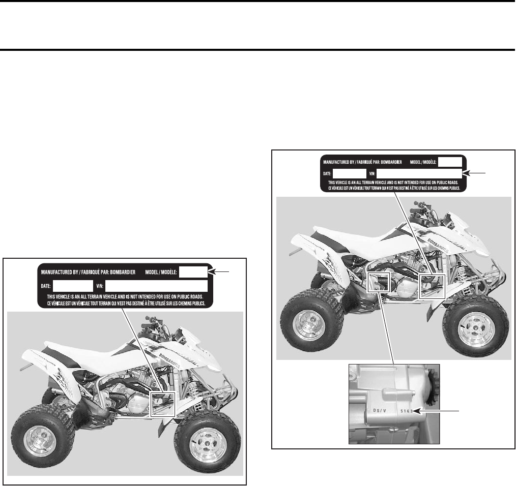
TYPICAL
1. Model number
VEHICLE AND ENGINE SERIAL
NUMBER LOCATION
TYPICAL
1. Vehicle
2. Engine
DS 650TM .....................................................7717
DS 650TM Baja..............................................7718
DS 650TM Baja X ..........................................7995
DS 650TM Intl ...............................................7719
DS 650TM Baja Intl .......................................7720
DS 650TM Baja X Intl....................................7997
1
V02A0PA
1
2
V02A0QA
INTRODUCTION
VMR2004_001_00_02A.FM V
ARRANGEMENT OF THE
MANUAL
The manual is divided into 12 major sections:
Each section is divided in various subsections, and
again, each subsection has one or more divisions.
LIST OF ABBREVIATIONS USED
IN THIS MANUAL
01 SERVICE TOOLS AND SERVICE PRODUCTS
02 MAINTENANCE
03 ENGINE
04 FUEL SYSTEM
05 ELECTRICAL
06 DRIVE TRAIN
07 STEERING SYSTEM
08 SUSPENSION
09 BRAKES
10 BODY/FRAME
11 TECHNICAL DATA
12 WIRING DIAGRAMS
Aampere
amp ampere
Ah ampere-hour
AC alternate current
BDC bottom dead center
BTDC before top dead center
°C degree Celsius
cm centimeter
cm²square centimeter
cm³cubic centimeter
DC direct current
°F degree Fahrenheit
fl. oz fluid ounce
ft foot
GRD ground
hal. halogen
I.D. inside diameter
IDI induction discharge ignition
imp. oz imperial ounce
in inch
in²square inch
in³cubic inch
k kilo (thousand)
kg kilogram
km/h kilometer per hour
kPa kilo pascal
Lliter
lb pound
lbf pound (force)
LH left hand
m meter
MAG magneto
Max. maximum
Min. minimum
mL milliliter
mm millimeter
MPH mile per hour
Nnewton
N.A. not applicable
no. number
00.0 continuity
O.L. overload (open circuit)
O.D. outside diameter
OPT optional
oz ounce
P/N part number
PSI pound per square inch
PTO power take off
RPM revolution per minute
Sp. Gr. specific gravity
TDC top dead center
U.S. oz ounce (United States)
Vvolt
Vac volt (alternative current)
INTRODUCTION
VI VMR2004_001_00_02A.FM
Section 03 ENGINE
Subsection 05 (CYLINDER AND HEAD)
VMR2000_007_03-05A.FM 03-05-1
CYLINDER AND HEAD
CYLINDER AND HEAD
9
12
4
8
21
22
23
27
V02C0ES
10 Nm
(89 lbfin)
10 Nm
(89 lbfin)
33 Nm
(24 lbfft)
10 Nm
(89 lbfin)
Loctite 243
10 Nm
(89 lbfin)
10 Nm
(89 lbfin)
60 Nm
(44 lbfft)
Engine oil
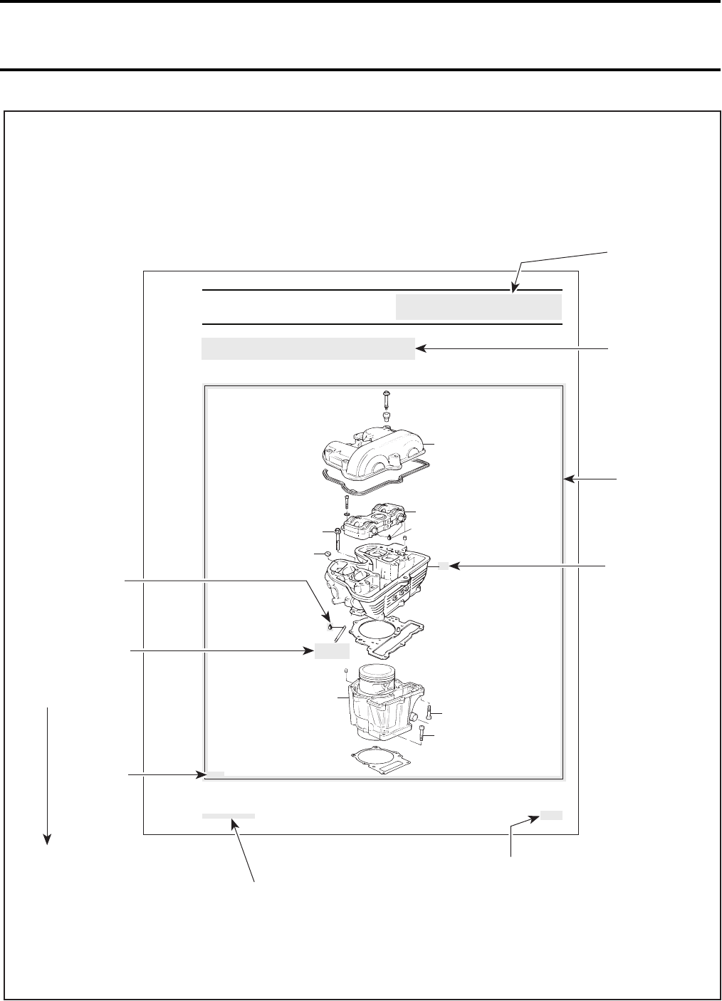
Page heading
indicates section
and subsection
detailed.
Bold face number
indicates special
procedure
concerning this
part.
Tightening torque
nearby fastener. In this
case, nut must be
torqued to
10 Nm or 89 lbfin.
This Shop Manual uses technical terms wich may be
slightly different from the ones in the parts catalog.
Exploded view
assists you in
identifying parts and
related positions.
TYPICAL PAGE
V02A0TS
Illustration
number for
publishing
process.
Subsection title
indicates
beginning of the
subsection.
Drop represents a
liquid product to
be applied to
a surface.
Page numbering system:
03: ENGINE section
05: CYLINDER AND HEAD
subsection
1: First page of this subsection
CAUTION: Pay attention to
torque specifi
cations. Some
of these are in
lbf
ft
instead
of lbf
in
. Use appropriate
torque wrench.
Document
number for
publishing
process.
INTRODUCTION

VMR2004_001_00_02A.FM VII
TYPICAL PAGE
Subtitle indicates
main procedure
to be carried-out.
Reference to look
up a certain section
and subsection.
In this case it
concerns
carburetor and air
intake silencer.
Bold face number
following part name
refers to exploded
view at beginning of
subsection.
Call-outs for
above illustration.
V02A0UT
2
V02C18A
5413
V02C19A
1
V02C05A
Call-out
Section 03 ENGINE
Subsection 02 (REMOVAL AND INSTALLATION)
VMR2000_004_03_02.FM 03-02-3
footrest (refer to BODY)
engine pinion no. 2 (refer to Engine Pinion sec-
tion)
RH SIDE OF ENGINE
1. Exhaust pipes
2. Radiator inlet hose
3. Oil line
4. Brake pedal
5. Footrest
carburetor and carburetor adaptor (refer to CAR-
BURETOR AND AIR INTAKE SILENCER)
gearshift pedal no. 9.
Unscrew neutral switch connector.
Removal
Remove the upper support bracket no. 10 com-
pletely.
Install engine lifting tool (P/N 529 035 610) then,
install a hoist.
Remove:
upper engine support bolt no. 11
lower bolts no. 12 retaining the engine support
no. 13 on either side, then, remove supports
front lower mounting bolt no. 14
rear lower mounting bolt no. 15
rear upper mounting bolt no. 16.
Remove engine from vehicle.
Installation
For installation, reverse the removal procedure,
paying attention to the following details.
Reattach cables, hoses, wiring harness, etc.
Adjust clutch cable.
Bleed rear brake.
Before to start the engine, remove oil filter.
Unfasten pressure bleeding screw.
BEHIND OIL FILTER
1. Bleeding screw
Unscrew and remove one spark plug.
Turn engine using starter until oil emerges in filter
chamber.
Tighten pressure bleeding screw.
Install oil filter.
This operation activated the oil pump. Check if ve-
hicle runs correctly.
2
V02C18A
5413
V02C19A
1
V02C05A
Call-out
INTRODUCTION
VIII VMR2004_001_00_02A.FM
GENERAL INFORMATION
The information and component/system descrip-
tions contained in this manual are correct at time
of publication. Bombardier Inc. however, main-
tains a policy of continuous improvement of its
products without imposing upon itself any obliga-
tion to install them on products previously manu-
factured.
Due to late changes, there may be some differences
between the manufactured product and the descrip-
tion and/or specifications in this document.
Bombardier Inc. reserves the right at any time to dis-
continue or change specifications, designs, features,
models or equipment without incurring obligation.
ILLUSTRATIONS AND
PROCEDURES
Illustrations and photos show the typical construc-
tion of the different assemblies and, in all cases,
may not reproduce the full detail or exact shape of
the parts shown, however, they represent parts
that have the same or a similar function.
CAUTION: Most components in the vehicles are
built with parts dimensioned in the metric sys-
tem. Most fasteners are metric and must not be
replaced by customary fasteners or vice- versa.
Mismatched or incorrect fasteners could cause
damage to the vehicle or possible personal injury.
As many of the procedures in this manual are in-
terrelated, we suggest, that before undertaking
any task, you read and thoroughly understand the
entire section or subsection concerning the proce-
dure.
A number of procedures throughout the book re-
quire the use of special tools. Before starting any
procedure, be sure that you have on hand all re-
quired tools, or approved equivalents.
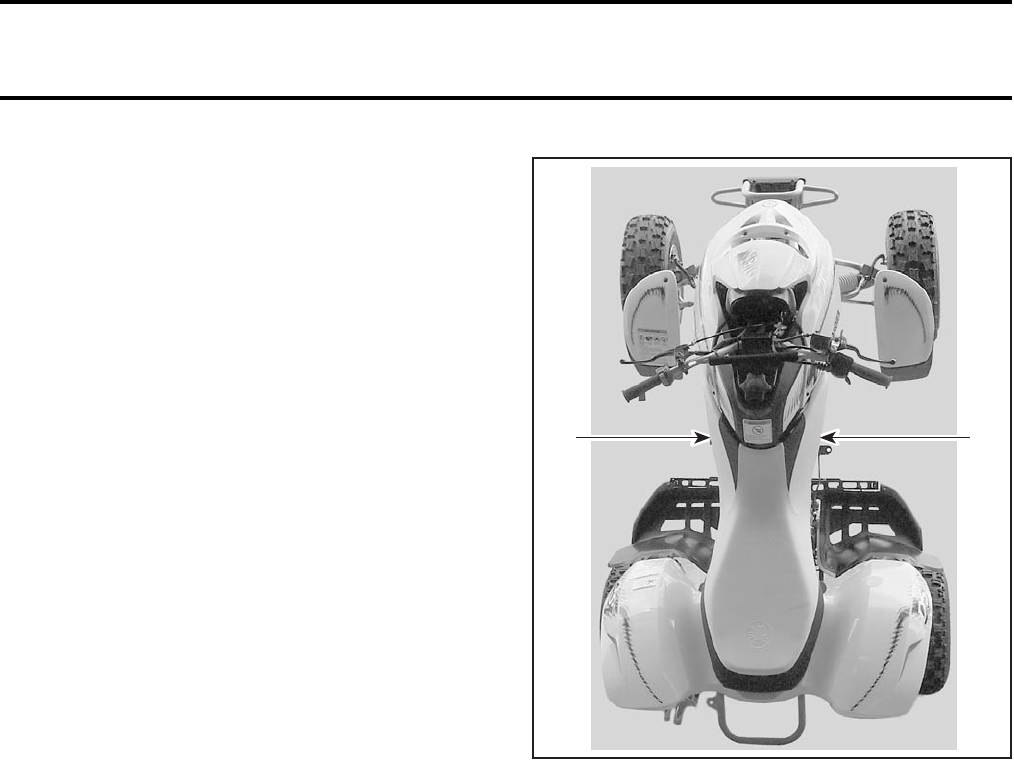
The use of RIGHT and LEFT indications in the text,
always refers to driving position (sitting on the ve-
hicle).
1. Left
2. Right
SELF-LOCKING FASTENERS
PROCEDURE
The following describes the most common appli-
cation procedures when working with self-locking
fasteners.
Use a metal brush or a screwtap to clean the hole
properly then use a solvent (Methyl-Chloride), let
it sit during 30 minutes and wipe off. The solvent
ensures the adhesive works properly.
LOCTITE APPLICATION
PROCEDURE
The following describes the most common appli-
cation procedures when working with Loctite
products.
NOTE: Always use proper strength Loctite prod-
uct as recommended in this Shop Manual.
V02L02A
21
INTRODUCTION
VMR2004_001_00_02A.FM IX
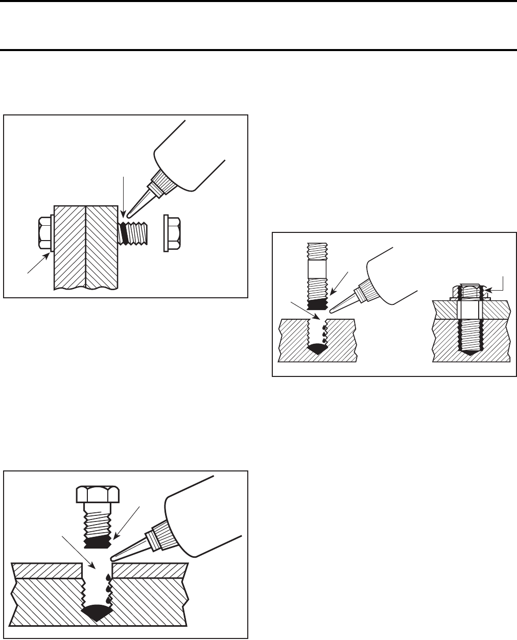
Threadlocker
Uncovered Holes (bolts and nuts)
1. Apply here
2. Do not apply
1. Clean threads (bolt and nut) with solvent.
2. Apply Loctite Primer N (P/N 293 800 041) on
threads and allow to dry.
3. Choose proper strength Loctite threadlocker.
4. Fit bolt in the hole.
5. Apply a few drops of threadlocker at proposed
tightened nut engagement area.
6. Position nut and tighten as required.
Blind Holes
1. On threads
2. On threads and at the bottom of hole
1. Clean threads (bolt and hole) with solvent.
2. Apply Loctite Primer N (P/N 293 800 041) on
threads (bolt and nut) and allow to dry for 30
seconds.
3. Choose proper strength Loctite threadlocker.
4. Apply several drops along the threaded hole and
at the bottom of the hole.
5. Apply several drops on bolt threads.
6. Tighten as required.
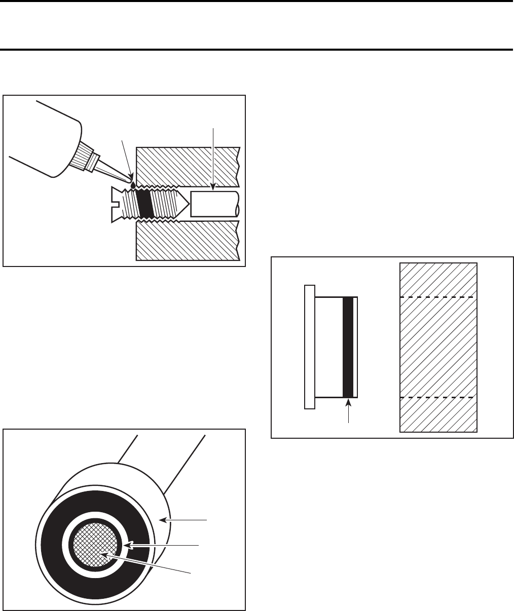
Stud in Blind Holes
1. On threads
2. On threads and in the hole
3. Onto nut threads
1. Clean threads (stud and hole) with solvent.
2. Apply Loctite Primer N (P/N 293 800 041) on
threads and allow to dry.
3. Put several drops of proper strength Loctite
threadlocker on female threads and in hole.
4. Apply several drops of proper strength Loctite
on stud threads.
5. Install stud.
6. Install cover, etc.
7. Apply drops of proper strength Loctite on un-
covered threads.
8. Tighten nuts as required.
A00A3LA
1
2
A00A3MA
1
2
A00A5RA
2
13
INTRODUCTION
XVMR2004_001_00_02A.FM
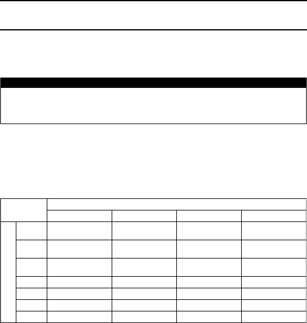
Adjusting Screw
1. Apply here
2. Plunger
1. Adjust screw to proper setting.
2. Apply drops of proper strength Loctite thread-
locker on screw/body contact surfaces.
3. Avoid touching metal with tip of flask.
NOTE: If it is difficult to readjust, heat screw with
a soldering iron (232°C (450°F)).
Mounting on Shaft
Mounting with a Press
1. Bearing
2. Proper strength Loctite
3. Shaft
Standard
1. Clean shaft external part and element internal
part.
2. Apply a strip of proper strength Loctite on shaft
circumference at insert or engagement point.
NOTE: Retaining compound is always forced out
when applied on shaft.
3. DO NOT use anti-seize Loctite or any similar
product.
4. No curing period is required.
Mounting in Tandem
1. Apply retaining compound on internal element
bore.
2. Continue to assemble as shown above.
Case-In Components
Metallic Gaskets
1. Proper strength Loctite
1. Clean inner housing diameter and outer gasket
diameter.
2. Spray housing and gasket with Loctite Primer N
(P/N 293 800 041).
3. Apply a strip of proper strength Loctite on lead-
ing edge of outer metallic gasket diameter.
NOTE: Any Loctite product can be used here. A
low strength liquid is recommended as normal
strength and gap are required.
4. Install according to standard procedure.
5. Wipe off surplus.
6. Allow it to cure for 30 minutes.
NOTE: Normally used on worn-out housings to
prevent leaking or sliding.
It is generally not necessary to remove gasket
compound applied on outer gasket diameter.
A00A3PA
1
2
A00A3UA
1
2
3
A00A3VA 1
INTRODUCTION
VMR2004_001_00_02A.FM XI
TIGHTENING TORQUES
Tighten fasteners to torque mentioned in exploded views and text. When they are not specified refer to
following tables. The tables also give the metric conversion.
In order to avoid a poor assembling, tighten screws and bolts in accordance with the following procedure:
1. Manually screw all screws, bolts and/or nuts.
2. Apply the half of the recommended torque value.
CAUTION: Be sure to use the proper tightening torque for the proper strength grade.
NOTE: When possible, always apply torque on the nut.
3. Torque at the recommended torque value.
NOTE: Always torque screws, bolts and/or nuts in a criss-cross sequence.
WARNING
Torque wrench tightening specifications must be strictly adhered to.
Locking devices (ex.: locking tab, elastic stop nut, self-locking fasteners, etc.) must be installed or
replaced with new ones where specified. If the efficiency of a locking device is impaired, it must
be renewed.
TIGHTENING
TORQUE
STRENGTH GRADE
GRADE 5.8 GRADE 8.8 GRADE 10.9 GRADE 12.9
DIMENSION
M4 1.5 to 2 N•m
(13 to 18 lbf•in)2.5 to 3 N•m
(22 to 27 lbf•in)3.5 to 4 N•m
(31 to 35 lbf•in)4 to 5 N•m
(35 to 44 lbf•in)
M5 3 to 3.5 N•m
(27 to 31 lbf•in)4.5 to 5.5 N•m
(40 to 47 lbf•in)7 to 8.5 N•m
(62 to 75 lbf•in)8 to 10 N•m
(71 to 89 lbf•in)
M6 6.5 to 8.5 N•m
(58 to 75 lbf•in)8 to 12 N•m
(71 to 106 lbf•in)10.5 to 15 N•m
(93 to 133 lbf•in)16 N•m (12 lbf•ft)
M8 15 N•m (11 lbf•ft) 24.5 N•m (18 lbf•ft) 31.5 N•m (23 lbf•ft) 40 N•m (30 lbf•ft)
M10 29 N•m (21 lbf•ft) 48 N•m (35 lbf•ft) 61 N•m (45 lbf•ft) 72.5 N•m (53 lbf•ft)
M12 52 N•m (38 lbf•ft) 85 N•m (63 lbf•ft) 105 N•m (77 lbf•ft) 127.5 N•m (94 lbf•ft)
M14 85 N•m (63 lbf•ft) 135 N•m (100 lbf•ft) 170 N•m (125 lbf•ft) 200 N•m (148 lbf•ft)
INTRODUCTION

We would be pleased if you could
communicate to Bombardier any sug-
gestions you may have concerning
our publications.
✁
Bombardier SERVICE PUBLICATIONS REPORT
Publication title and year ________________________ Page______
Machine___________________ Report of error ❏Suggestion ❏
____________________________________________________________
____________________________________________________________
____________________________________________________________
____________________________________________________________
____________________________________________________________
____________________________________________________________
Name ______________________________________________________
Address ____________________________________________________
City and State/Prov. ________________________ Date___________
Zip code/Postal code ________________________________________
AFFIX
PROPER
POSTAGE
AFFIX
PROPER
POSTAGE
AFFIX
PROPER
POSTAGE
Technical Publications
After Sales Service
565 de la Montagne Street
Valcourt, Québec, Canada J0E 2L0
Technical Publications
After Sales Service
565 de la Montagne Street
Valcourt, Québec, Canada J0E 2L0
Technical Publications
After Sales Service
565 de la Montagne Street
Valcourt, Québec, Canada J0E 2L0

Section 01 SERVICE TOOLS AND SERVICE PRODUCTS
Subsection 01 (TABLE OF CONTENTS)
VMR2004_033_01_01ATOC.FM 01-01-1
TABLE OF CONTENTS 0
SERVICE TOOLS.................................................................................................................... 01-02-1
SERVICE PRODUCTS ............................................................................................................ 01-03-1

Section 01 SERVICE TOOLS AND SERVICE PRODUCTS
Subsection 02 (SERVICE TOOLS)
VMR2004_002_01_02A.FM 01-02-1
SERVICE TOOLS 0
This is a list of tools to properly service ATV vehicles. If you need to replace or add to your tool inventory,
these items can be ordered through the regular parts channel.
Following mention points out new tool:
NEW
Section 01 SERVICE TOOLS AND SERVICE PRODUCTS
Subsection 02 (SERVICE TOOLS)
01-02-2 VMR2004_002_01_02A.FM
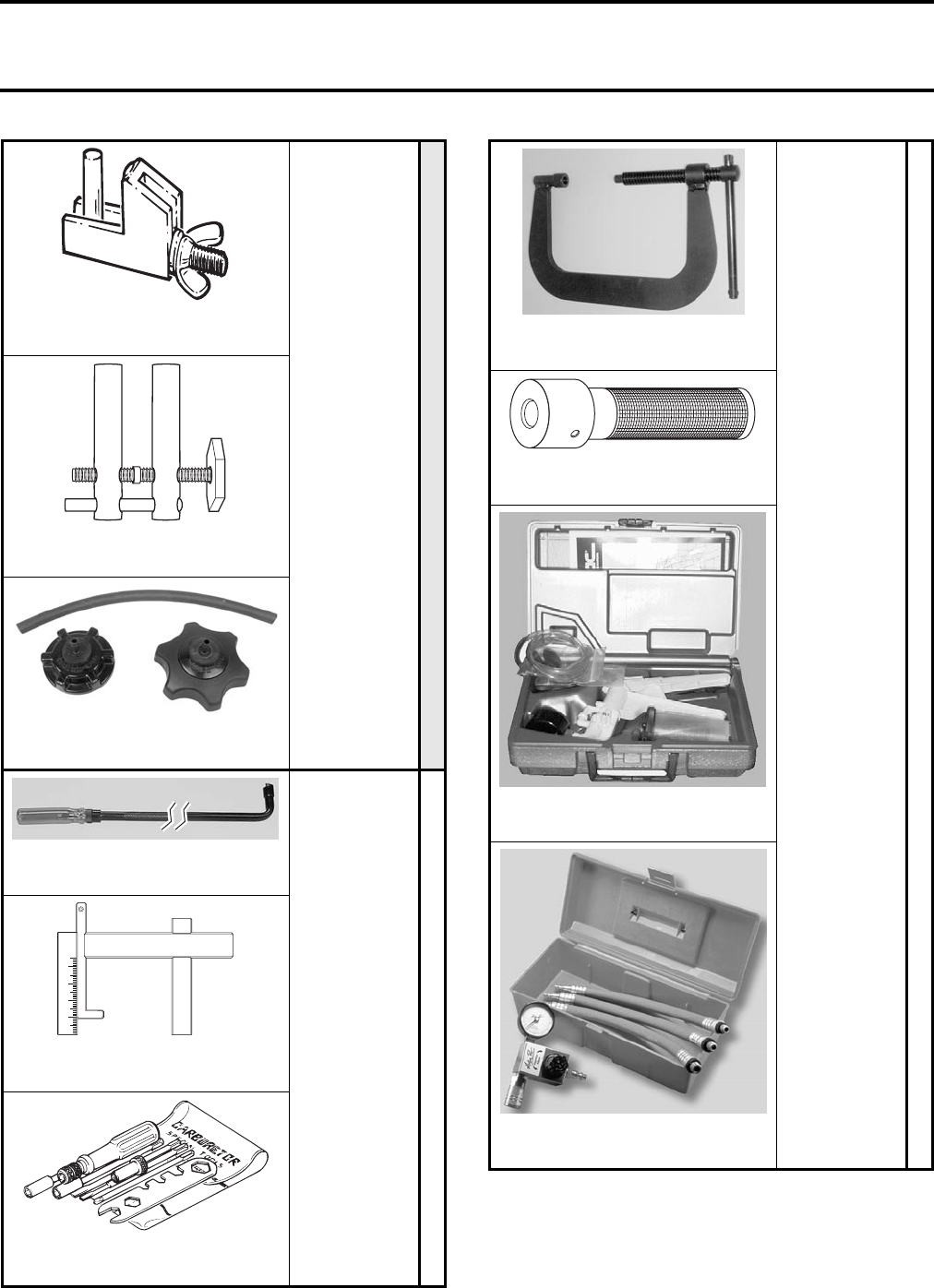
All Models
MANDATORY
Small Hose Pincher
295 000 076
Large Hose Pincher
529 032 500
Fuel System Pressure Tester
529 033 100
All Models
RECOMMENDED
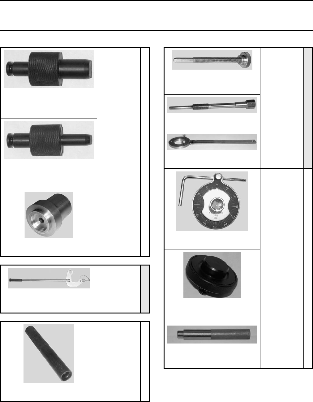
Low Speed Screw Adjuster
529 035 732
Float Level Gauge
529 035 520
Carburetor Kit
404 112 000
1234
All Models
RECOMMENDED
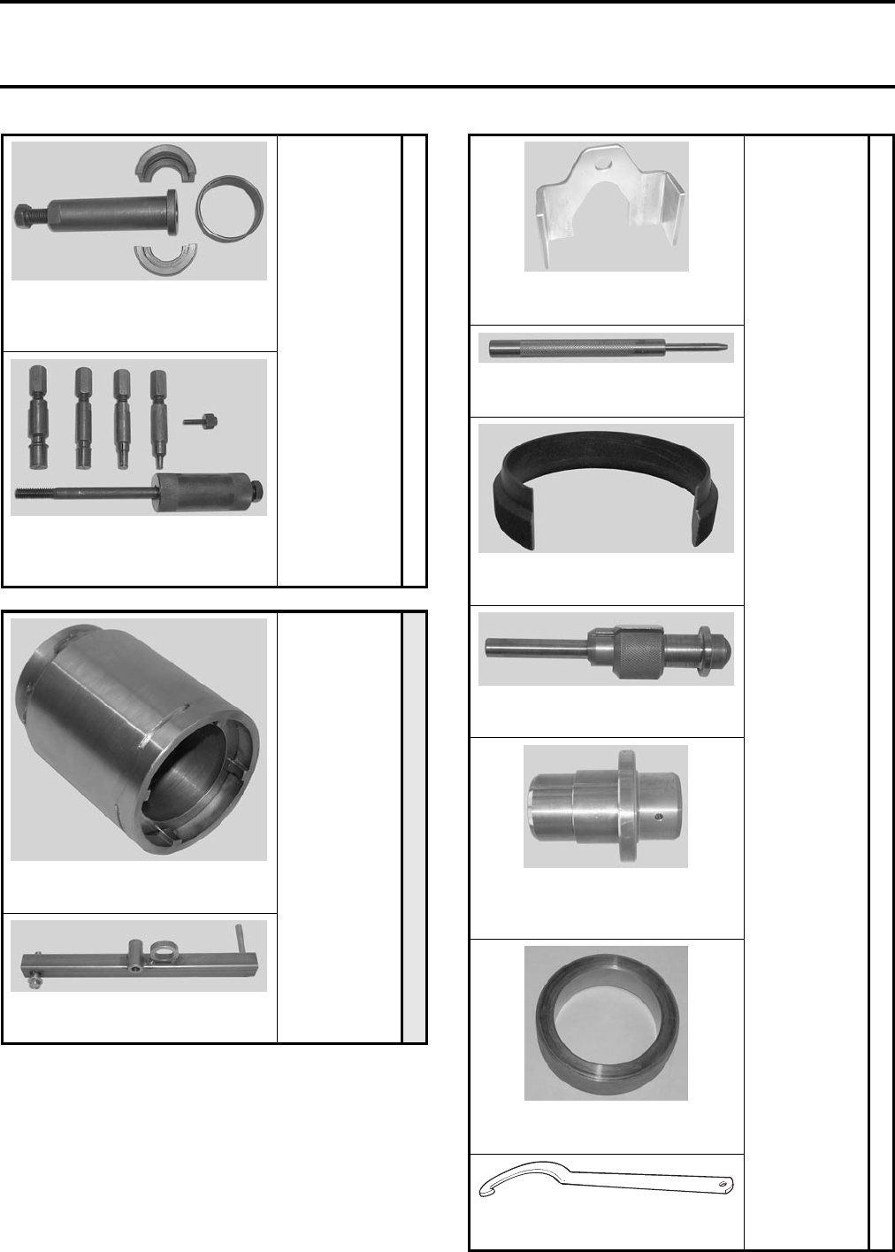
Valve Spring Compressor
529 035 724
Insertion Jig Handle
420 877 650
Vacuum/Pressure Pump
529 021 800
Leak Down Tester
529 035 661
Section 01 SERVICE TOOLS AND SERVICE PRODUCTS
Subsection 02 (SERVICE TOOLS)
VMR2004_002_01_02A.FM 01-02-3
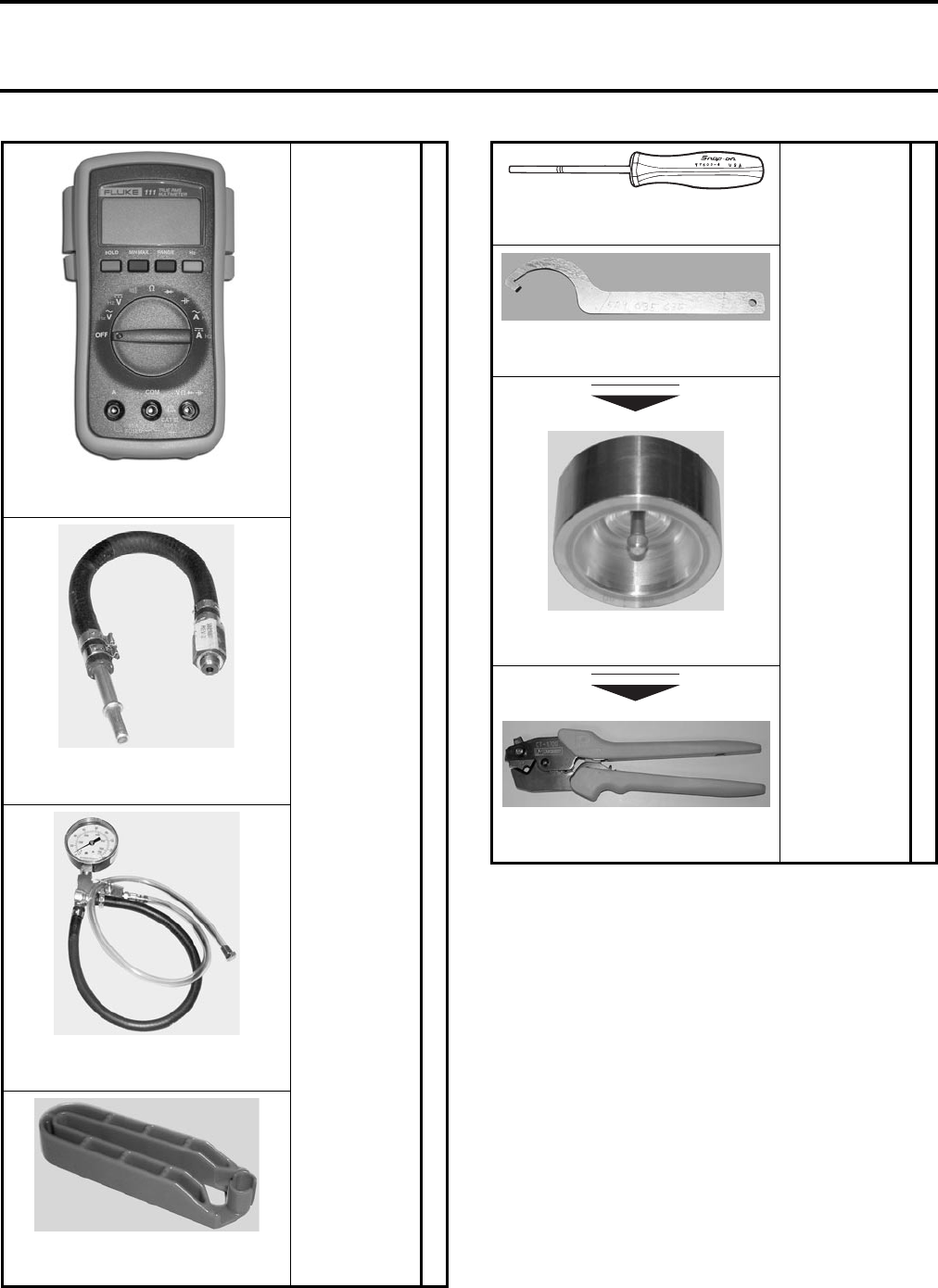
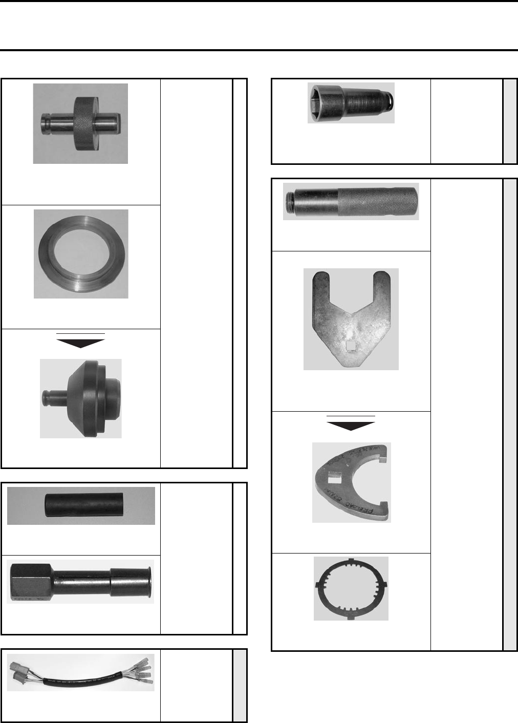
All Models
RECOMMENDED
Multimeter
529 035 868
Oil Pressure Adapter
529 035 652
Oil Pressure Gauge
529 035 709
Connection Tool
529 035 714
All Models
RECOMMENDED
Terminal Remover
Snap-On TT660-4
Shock Tool
529 035 636
Handle Grip Insertion Tool
529 035 897
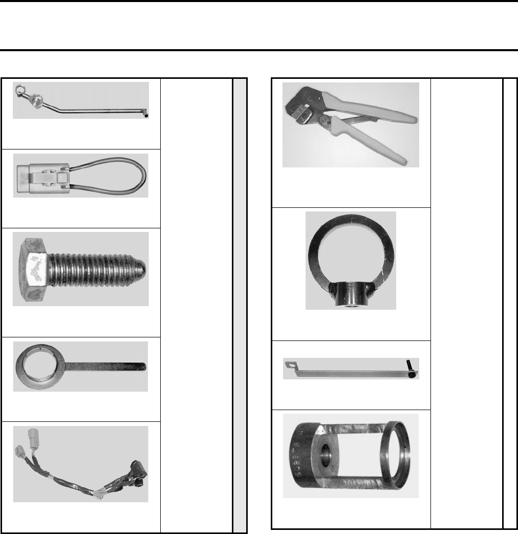
Crimp Plier
529 035 730
NEW
NEW
Section 01 SERVICE TOOLS AND SERVICE PRODUCTS
Subsection 02 (SERVICE TOOLS)
01-02-4 VMR2004_002_01_02A.FM
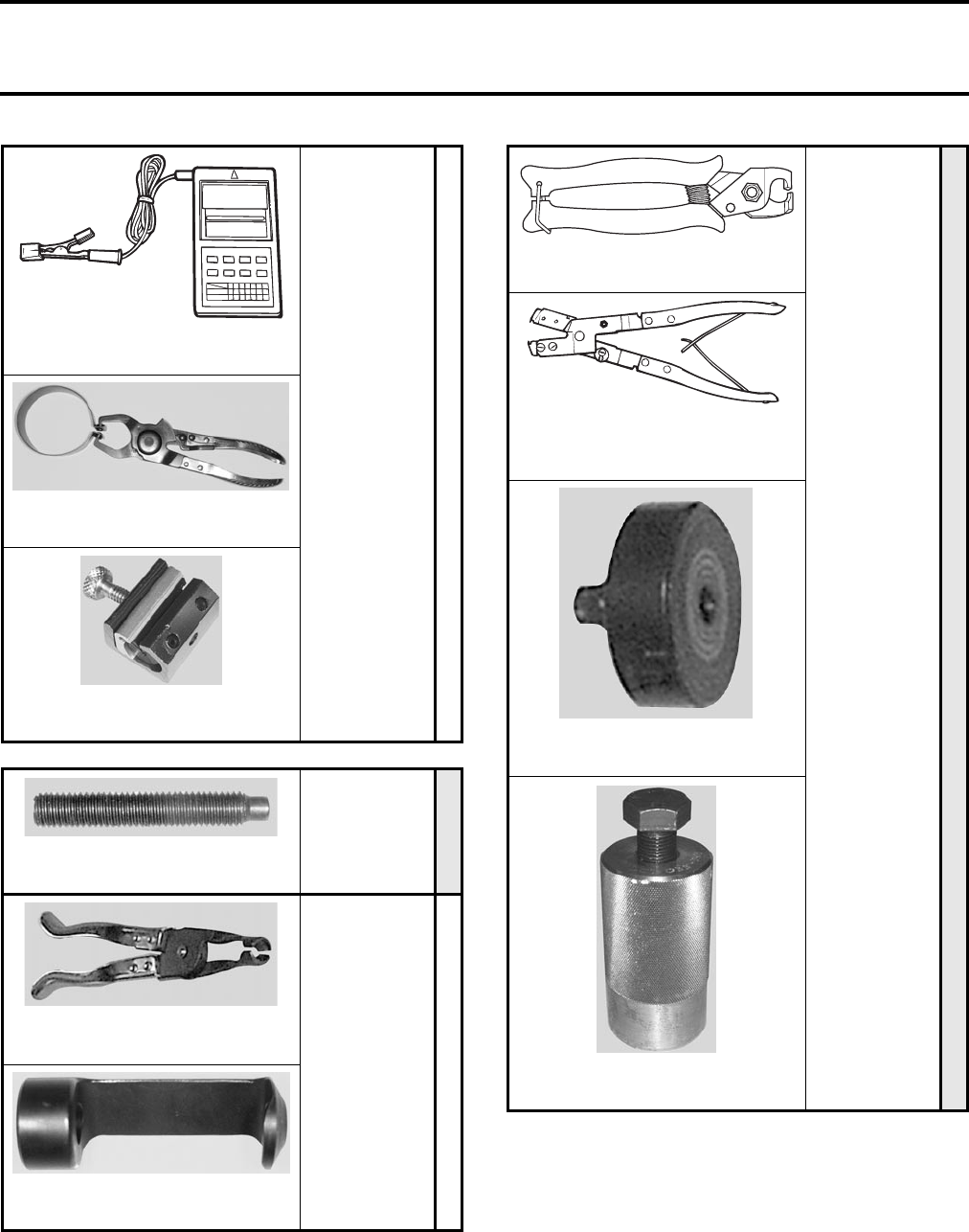
DS 650/Baja/X
Youth models
Outlander 330
Outlander 400
Quest 500/650
Traxter
RECOMMENDED
Digital/Inductive Type Tachometer
529 014 500
Ring Compressor
Snap-On RC980
Cable Luber
529 035 738
DS 650/Baja/X
Outlander 330
Outlander 400
Quest 500/650
Rally 200
MANDATORY
Crankshaft Locking Bolt
529 035 617
DS 650/Baja/X
Outlander 330
Outlander 400
Quest 500/650
Rally 200
RECOMMENDED
Valve Stem Seal Pliers
Snap-On YA 8230
Valve Spring Compressor Cup
529 035 764
DS 650/Baja/X
Outlander 330
Outlander 400
Quest 500/650
Traxter
MANDATORY
Caillau Pliers
295 000 054
CV Boot Clamp Installation and
Removal Tool
295 000 069
Crankshaft Protector
420 876 557
Flywheel Puller
529 035 748
Section 01 SERVICE TOOLS AND SERVICE PRODUCTS
Subsection 02 (SERVICE TOOLS)
VMR2004_002_01_02A.FM 01-02-5
DS 650/Baja/X
Outlander 330
Outlander 400
Quest 500/650
Traxter
RECOMMENDED
Exhaust Spring Installer/Remover
529 035 401
Outlander 330
Outlander 400
Quest 500/650
Rally 200
Traxter
RECOMMENDED
Shock Spring Disassembly Tool
529 035 504
Outlander 330
Outlander 400
Quest 500/650
Rally 200
RECOMMENDED
Needle Bearing Installer
(main shaft in crankcase)
529 035 762
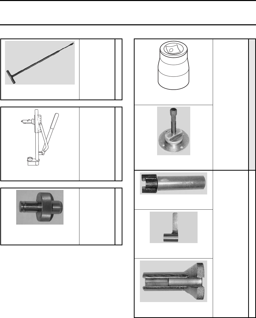
Outlander 330
Outlander 400
Quest 500/650
Traxter
MANDATORY
41 mm Socket
PROTO 5541
Hub Puller
529 035 612
Outlander 330
Outlander 400
Quest 500/650
Traxter
RECOMMENDED
Differential Spanner Socket
529 035 649
Backlash Measurement Tool
529 035 665
Choke Nut Tool
529 035 660
Section 01 SERVICE TOOLS AND SERVICE PRODUCTS
Subsection 02 (SERVICE TOOLS)
01-02-6 VMR2004_002_01_02A.FM
Outlander 330
Outlander 400
Quest 500/650
Traxter
RECOMMENDED
Oil Seal Installer
(crankshaft oil seal
on magneto cover)
529 035 759
Oil Seal Installer
(shift shaft oil seal
on magneto cover)
529 035 758
Water Pump Ceramic Seal Installer
529 035 766
DS 650/Baja/X
Outlander 330
Outlander 400
MANDATORY
Engine Installation and
Removal Tool
529 035 619
DS 650/Baja/X
Outlander 330
Quest 500/650
RECOMMENDED
Valve Stem Seal Installer
529 035 687
Outlander 330
Outlander 400
Quest 500/650
MANDATORY
Bevel Gear Lock Pin/Driven Clutch
Expander
529 035 747
Drive Clutch Puller
529 035 746
Driven Clutch Holding Tool
529 035 771
Outlander 330
Outlander 400
Quest 500/650
RECOMMENDED
Torque Angle
Snap-On TA 36
Oil Seal Installer
(crankshaft oil seal on crankcase)
529 035 760
Needle Bearing Installer
(starter drive pinion in crankcase)
529 035 756
Section 01 SERVICE TOOLS AND SERVICE PRODUCTS
Subsection 02 (SERVICE TOOLS)
VMR2004_002_01_02A.FM 01-02-7
Outlander 330
Outlander 400
Quest 500/650
RECOMMENDED
Needle Bearing Installer
(bevel gear shaft in crankcase)
529 035 763
Crankcase Support (CVT side)
529 035 754
Output Shaft Oil Seal Installer
529 035 941
Quest 500/650
Rally 200
RECOMMENDED
Valve Guide Installer
529 035 853
Blind Hole Bearing Puller
Snap-On
Quest 500/650
Traxter
MANDATORY
6 Pin Harness for Magneto
529 035 604
NEW
Rally 200
Traxter
MANDATORY
46 mm Socket for Crankshaft/
Driven Pulley
529 035 648
DS 650/Baja/X
MANDATORY
Magneto Cover Removal Tool
529 035 622
UP to 2003 models
64 mm (2-1/2 in) Crow-foot
Rear Axle Nut
529 035 729
Rear Axle Key
529 035 951
Clutch Basket Holder
529 035 618
NEW
Section 01 SERVICE TOOLS AND SERVICE PRODUCTS
Subsection 02 (SERVICE TOOLS)
01-02-8 VMR2004_002_01_02A.FM
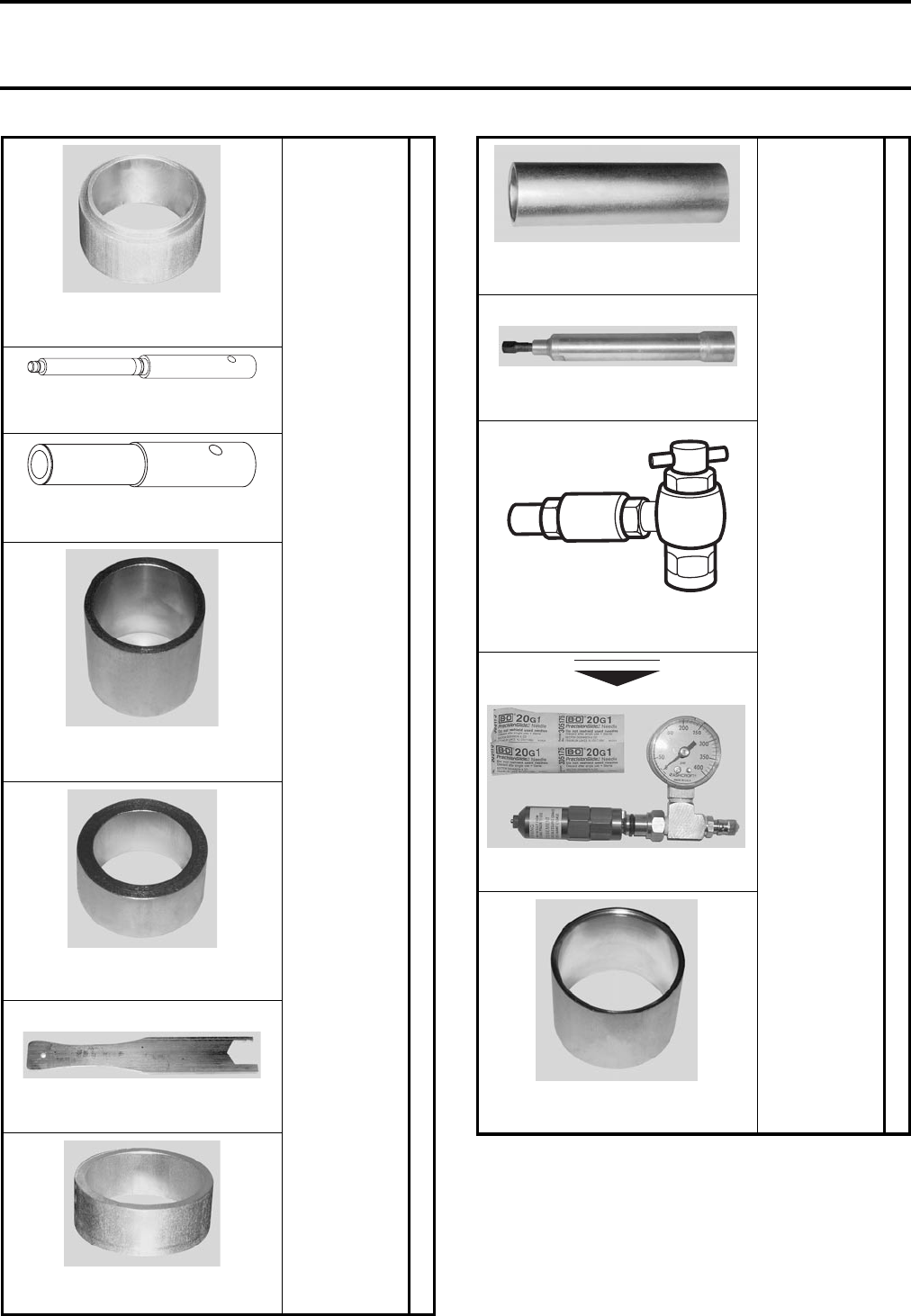
DS 650/Baja/X
RECOMMENDED
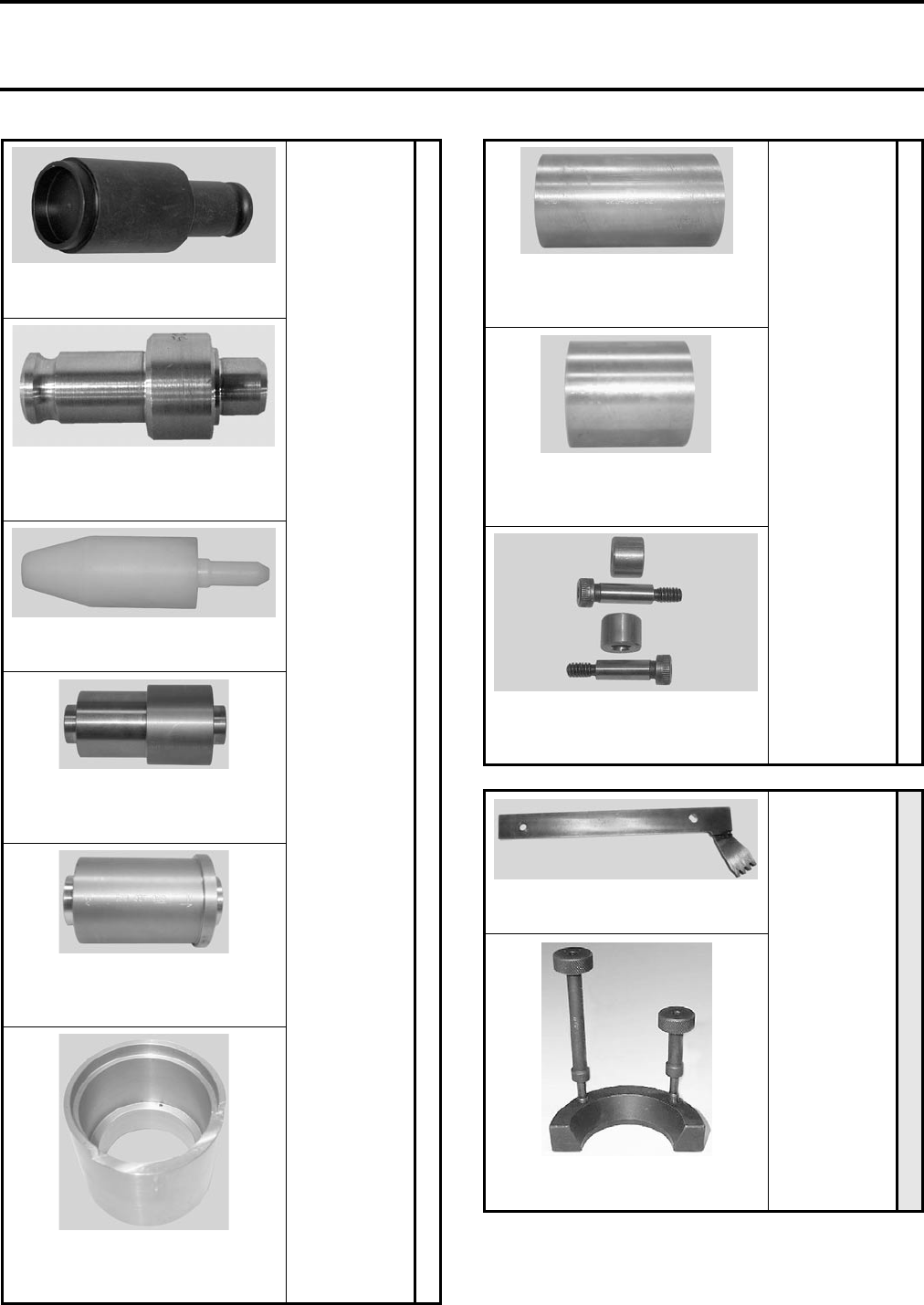
Front Hub Seal Installer
529 035 632
Clutch Shaft Bearing Installer
529 035 691
Clutch Shaft Seal Installer
529 035 693
Ball Joint Guide
529 035 705
Ball Joint Drive
529 035 706
UP to 2003 models
Swing Arm Key
529 035 696
Rear Hub Seal Installer
529 035 634
DS 650/Baja/X
RECOMMENDED
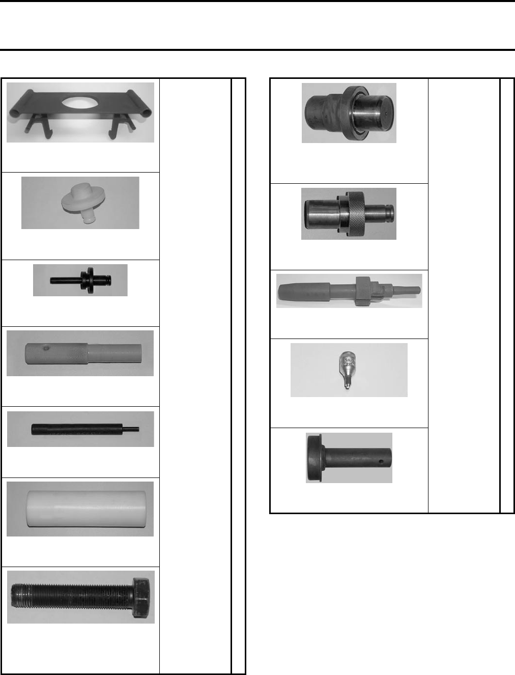
Front Knuckle Wear Ring Installer
529 035 637
UP to 2003 models
Brake Hub Remover
529 035 695
Shock Charging Tool
529 035 570
Gas fill tool kit (needle type)
503 190 102
Rear Axle Wear Ring Installer
529 035 694
NEW
Section 01 SERVICE TOOLS AND SERVICE PRODUCTS
Subsection 02 (SERVICE TOOLS)
VMR2004_002_01_02A.FM 01-02-9
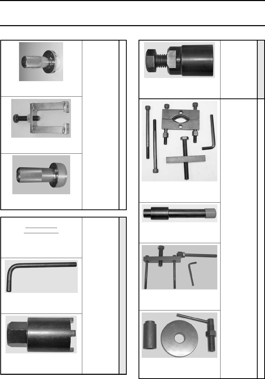
DS 650/Baja/X
RECOMMENDED
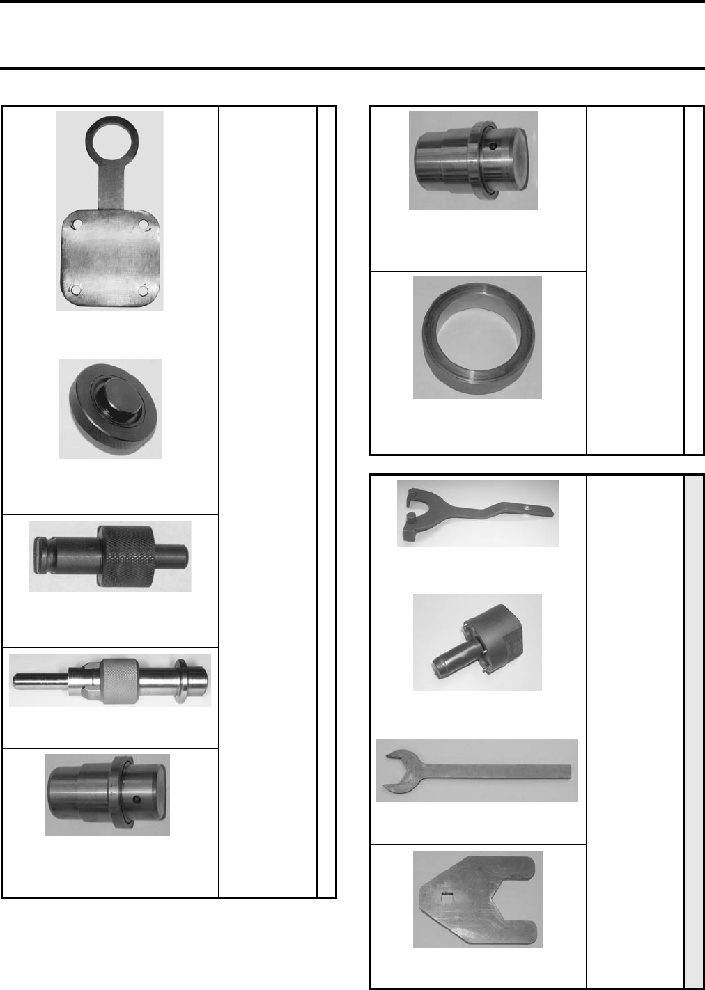
Crankshaft Bushing Installer
529 035 689
Primary Crankshaft Gear Puller
529 035 624
Crankshaft Bushing Remover
529 035 688
ILLUSTRATION
NOT AVAILABLE
Youth models
MANDATORY
Flywheel Puller
(4-stroke engines)
529 035 792
Valve Gap Adjuster
(4-stroke engines)
529 035 793
Oil Filter Rotor Puller
(4-stroke engines)
529 035 795
MANDATORY
Magneto Puller
(4-stroke engines)
529 035 798
Youth models
RECOMMENDED
Crankshaft Bearing Puller
(4-stroke engines)
529 035 791
Valve Seat Remover/Installer
(4-stroke engines)
529 035 794
Crankcase Puller
(2-stroke engines)
529 035 796
Crankcase Installer
(2-stroke engines)
529 035 797
Section 01 SERVICE TOOLS AND SERVICE PRODUCTS
Subsection 02 (SERVICE TOOLS)
01-02-10 VMR2004_002_01_02A.FM
Youth models
RECOMMENDED
Crankshaft Puller
(2-stroke engines)
529 035 799
Bearing Puller Kit
(2-stroke engines)
529 035 800
Outlander 330
Outlander 400
MANDATORY
Trailing Arm Socket
529 035 925
Engine Lifting Tool
529 035 898
Outlander 330
Outlander 400
RECOMMENDED
Camshaft Locking Tool
529 035 926
Valve Guide Remover
529 035 924
Piston Ring Compressor
529 035 919
Piston Circlip Installer
529 035 921
Crankshaft Plain Bearings
Remover/Installer
529 035 917
Crankshaft Support (MAG side)
529 035 916
Clutch Holding Tool
529 006 400
Section 01 SERVICE TOOLS AND SERVICE PRODUCTS
Subsection 02 (SERVICE TOOLS)
VMR2004_002_01_02A.FM 01-02-11
Outlander 330
Outlander 400
RECOMMENDED
Balancer Shaft Oil Seal Installer
529 035 933
Starter drive needle bearing
installer
529 035 934
Oil Seal Protector
529 035 935
Trailing Arm Bearing
Remover/Installer (wheel side)
529 035 918
Trailing Arm Bearing
Remover/Installer (frame side)
529 035 920
Trailing Arm Bearing Removal
Support
529 035 922
Outlander 330
Outlander 400
RECOMMENDED
Wear Ring Installer
(front drive shafts)
529 035 927
Wear Ring Installer
(rear drive shafts)
529 035 915
Adaptor Kit for Shock Spring
Remover (P/N 529 035 504)
529 035 928
Quest 500/650
MANDATORY
Drive Clutch Holding Tool
529 035 745
Bearing Alignment Tool
529 035 806
Section 01 SERVICE TOOLS AND SERVICE PRODUCTS
Subsection 02 (SERVICE TOOLS)
01-02-12 VMR2004_002_01_02A.FM
Quest 500/650
RECOMMENDED
Lifting Ring
529 035 770
Oil Seal Installer
(main shaft oil seal on crankcase)
529 035 761
Oil Seal Installer
(water pump shaft oil seal)
529 035 757
Piston Circlip Installer
529 035 765
Crankcase Plain Bearing
Remover/Installer (CVT side)
529 035 752
Quest 500/650
RECOMMENDED
Crankcase Plain Bearing
Remover/Installer (MAG side)
529 035 753
Crankcase Support
(MAG side)
529 035 755
Rally 200
MANDATORY
Clutch Holding Tool
529 035 862
Clutch Support
529 035 863
51 mm (2 in) Open Wrench
529 035 866
51 mm (2 in) Crow-Foot
529 035 884
Section 01 SERVICE TOOLS AND SERVICE PRODUCTS
Subsection 02 (SERVICE TOOLS)
VMR2004_002_01_02A.FM 01-02-13
Rally 200
RECOMMENDED
Clutch Holding Support
529 035 864
Crankshaft Oil Seal Installer
529 035 847
Water Pump Oil Seal Installer
529 035 849
Shifter Oil Seal Installer
529 035 851
Valve Guide Remover
529 035 852
Gearbox Oil Seal Installer
529 035 854
Magneto Puller
(use bolt from magneto puller
P/N 529 035 748)
529 035 883
Rally 200
RECOMMENDED
Crankshaft Plain Bearing
Remover/Installer
529 035 855
Needle Bearing Installer
529 035 858
Piston Circlip Installer
529 035 859
Allen Wrench
529 035 861
Rear Axle Bearing Puller
420 276 930
Section 01 SERVICE TOOLS AND SERVICE PRODUCTS
Subsection 02 (SERVICE TOOLS)
01-02-14 VMR2004_002_01_02A.FM
Traxter
MANDATORY
Lifting Bar
529 035 610
Jumper for Self Diagnosis
529 035 605
Crankshaft Locking Bolt
529 035 645
Spanner Tool for Clutch Basket
529 035 647
T-Harness for Solenoids Dianosis
529 035 653
Traxter
RECOMMENDED
Crimping Tool
(for AMP connectors)
295 100 164
Lifting Ring
529 035 644
UP to 2000
Front Suspension Spacer Bar
529 035 611
Valve Spring Compressor Cup
529 035 725

Section 01 SERVICE TOOLS AND SERVICE PRODUCTS
Subsection 03 (SERVICE PRODUCTS)
VMR2004_003_01_03A.FM 01-03-1
SERVICE PRODUCTS 0
This is a list of products to properly service ATV vehicles. If you need to replace or add to your tool inventory, these
items can be ordered through the regular parts channel.
Following mention points out new tool:
NEW
Section 01 SERVICE TOOLS AND SERVICE PRODUCTS
Subsection 03 (SERVICE PRODUCTS)
01-03-2 VMR2004_003_01_03A.FM
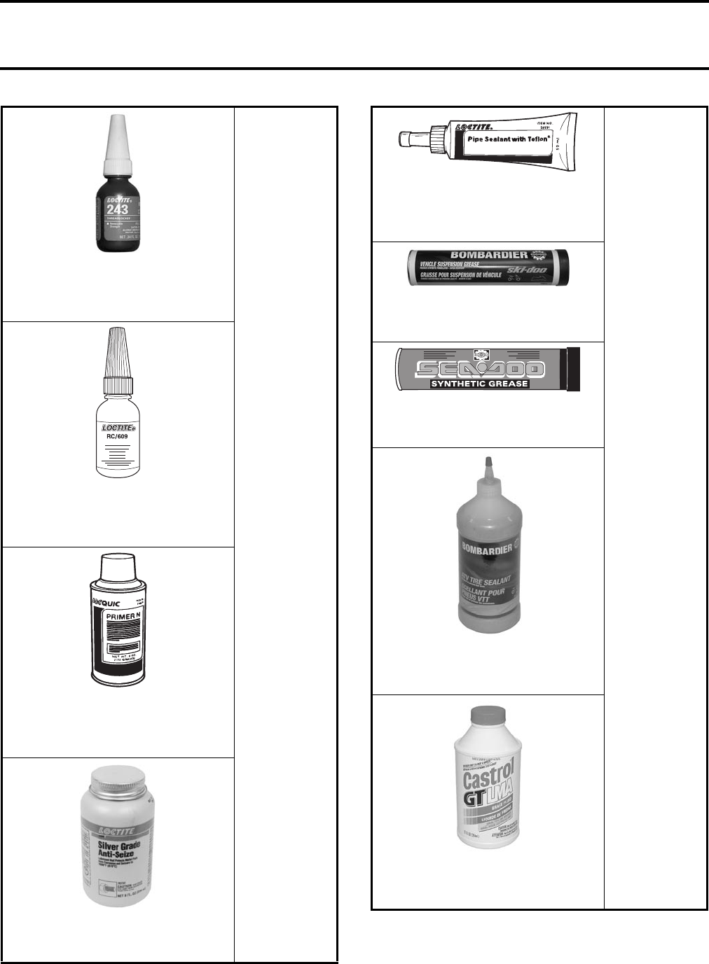
All Models
Loctite® 243
Medium-Strength Threadlocker
(10 mL) (blue)
293 800 060
Loctite® 609
Retaining Compound Loctite RC
(10 mL) (green)
413 703 100
Loctite® Primer
Primer N
128 g (5 oz)
293 800 041
Loctite® Anti-Seize Lubricant
(236 mL)
293 800 070
All Models
Loctite® 567
Pipe Sealant
(250 mL)
293 800 013
Suspension Synthetic Grease
(400 g)
293 550 033
Synthetic Grease
(400 g)
293 550 010
Bombardier ATV Tire Sealant
(946 mL)
715 000 130
Brake Fluid DOT 4
(354 mL)
293 600 062
Section 01 SERVICE TOOLS AND SERVICE PRODUCTS
Subsection 03 (SERVICE PRODUCTS)
VMR2004_003_01_03A.FM 01-03-3
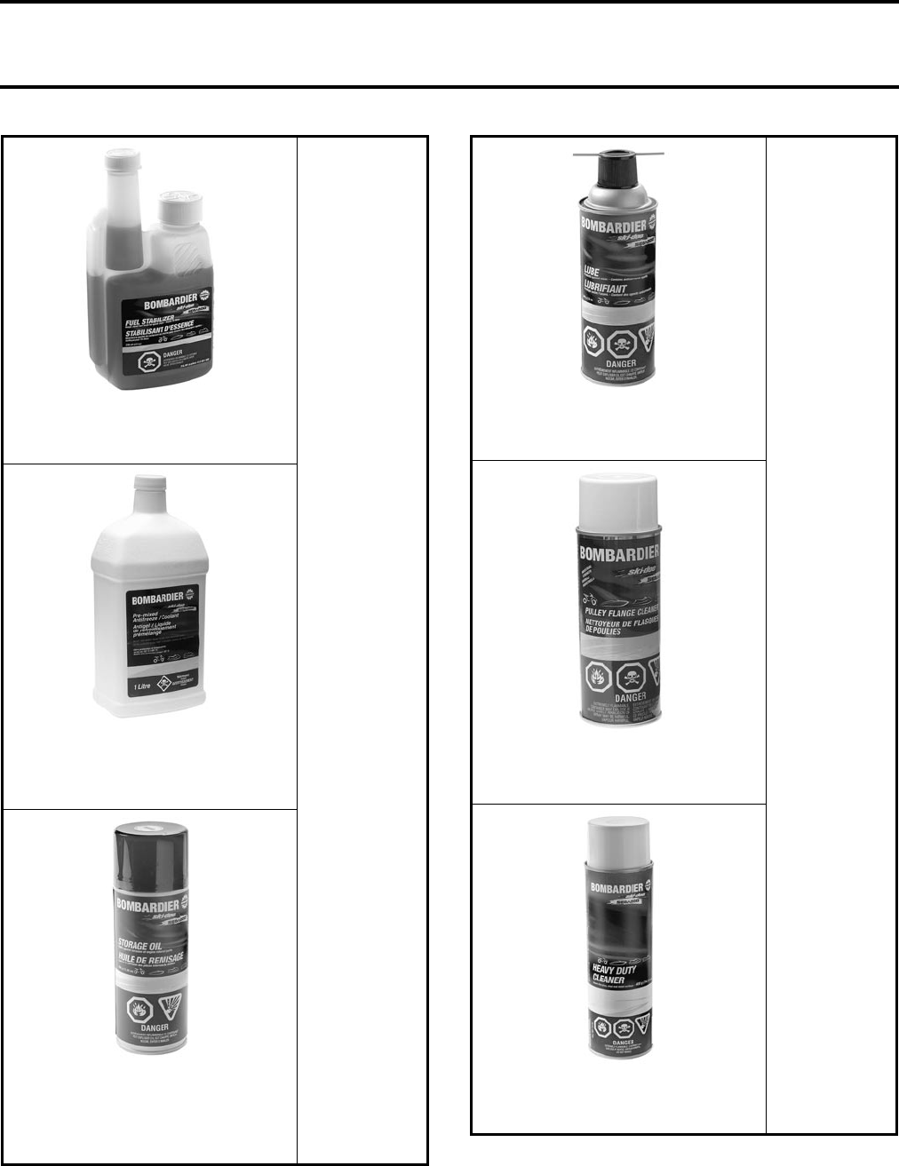
All Models
Bombardier Fuel Stabilizer
(12 x 8 oz)
413 408 600
Bombardier Premixed Coolant 50/50
-37°C (- 35°F)
(16 x 1 L)
293 600 038
Bombardier Storage Oil
(350 g spray can)
(12 x 350 g)
Canada: 413 711 600
U.S.: 413 711 900
All Models
BOMBARDIER LUBE
(12 x 14 oz)
293 600 016
Bombardier Pulley Flange Cleaner
(320 g)
413 711 809
Bombardier Heavy Duty Cleaner
293 110 001 (400 g)
293 110 002 (4 L)
Section 01 SERVICE TOOLS AND SERVICE PRODUCTS
Subsection 03 (SERVICE PRODUCTS)
01-03-4 VMR2004_003_01_03A.FM
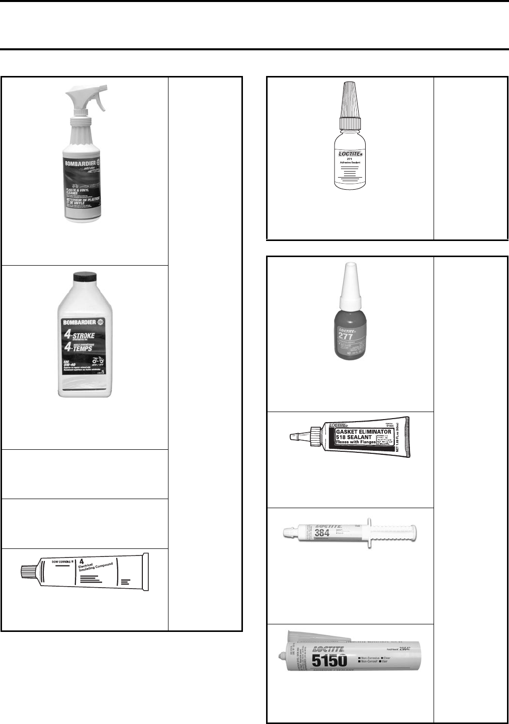
All Models
Bombardier Plastic & Vinyl Cleaner
(6 x 1 L)
413 711 200
Bombardier Synthetic
4-Stroke Oil 5W-40
(12 x 1 L)
293 600 039
Air Filter Cleaner
(2 L)
293 600 059
Air Filter Oil
(1 L)
293 600 058
Silicone Dielectric Grease
(3 oz)
293 550 004
DS 650/Baja/X
Quest 500/650
Traxter
Loctite® 271
High Strength Threadlocker
(10 mL) (red)
293 800 005
Rally 200
Loctite® 277
High Strength Retaining Compound
(10 mL) (red)
293 800 073
Loctite® 518
Paste Gasket
Gasket Eliminator (50 mL)
293 800 038
Loctite® 384
Thermally Conductive Adhesive
(300 mL)
293 800 099
CAUTION: This product must be
stored at 5°C (41°F).
Loctite® 5150
Clear Silicone Sealant
(300 mL)
293 800 086
Section 01 SERVICE TOOLS AND SERVICE PRODUCTS
Subsection 03 (SERVICE PRODUCTS)
VMR2004_003_01_03A.FM 01-03-5
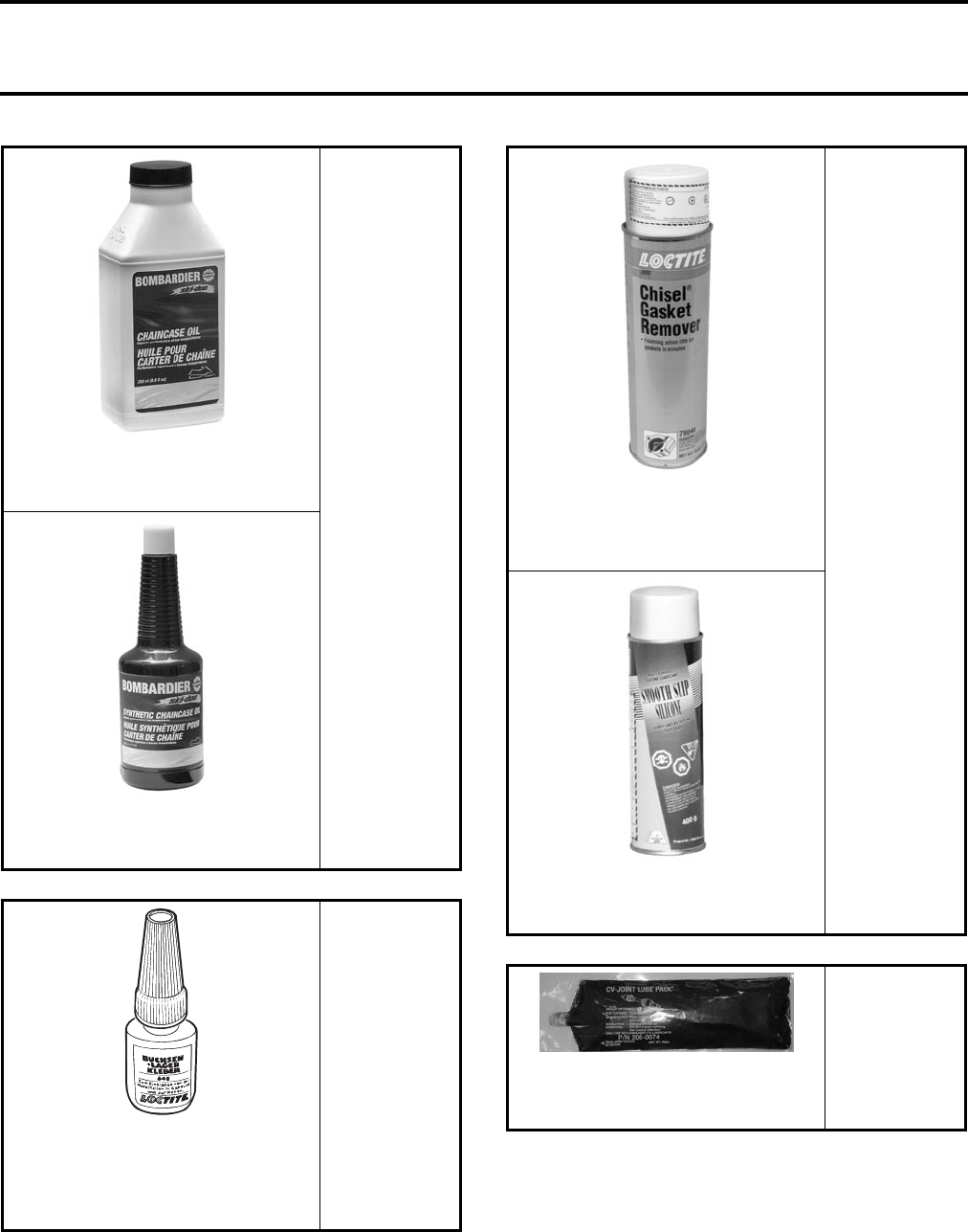
Rally 200
Bombardier Chaincase Oil
(16 x 250 mL)
413 801 900
Bombardier Synthetic Chaincase Oil
(12 x 355 mL)
413 803 300
DS 650/Baja/X
Outlander 330
Outlander 400
Rally 200
Traxter
Loctite® 648
High Temperature and Strength
Retaining Compound
(5 mL) (green)
413 711 400
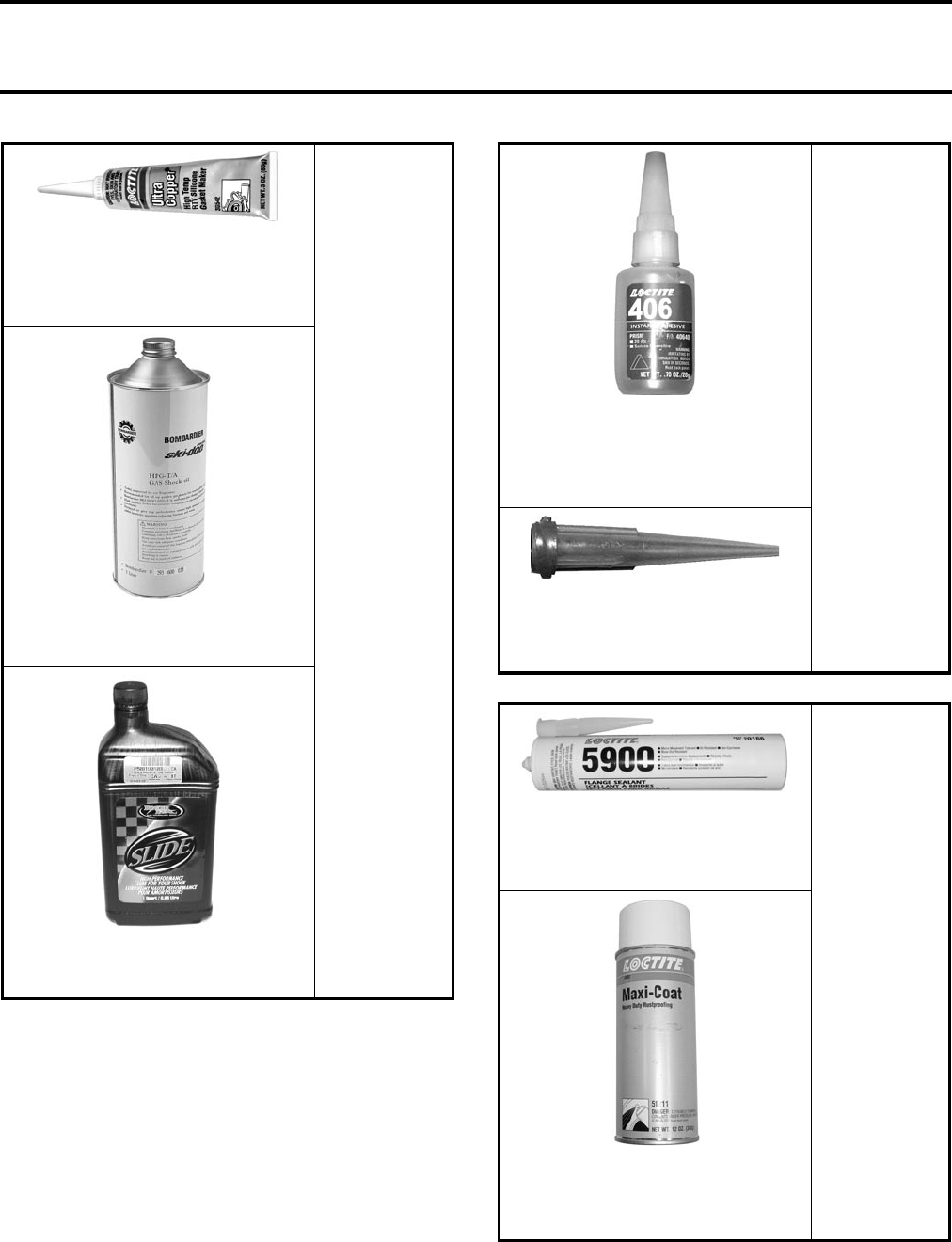
DS 650/Baja/X
Quest 500/650
Rally 200
Traxter
Loctite® Chisel
Gasket/Paint Remover
510 g (18 oz)
413 708 500
Cable Lubricant
(400 g)
293 600 041
DS 650/Baja/X
Outlander 330
Outlander 400
Quest 500/650
Traxter
Synthetic Grease
(60 g)
293 550 019
Section 01 SERVICE TOOLS AND SERVICE PRODUCTS
Subsection 03 (SERVICE PRODUCTS)
01-03-6 VMR2004_003_01_03A.FM
DS 650/Baja/X
High Temp RTV Silicone
ULTRA COPPER
(85 g)
413 800 090
Kayaba shock absorber oil
293 600 035
Marvin shock absorber oil
503 190 103
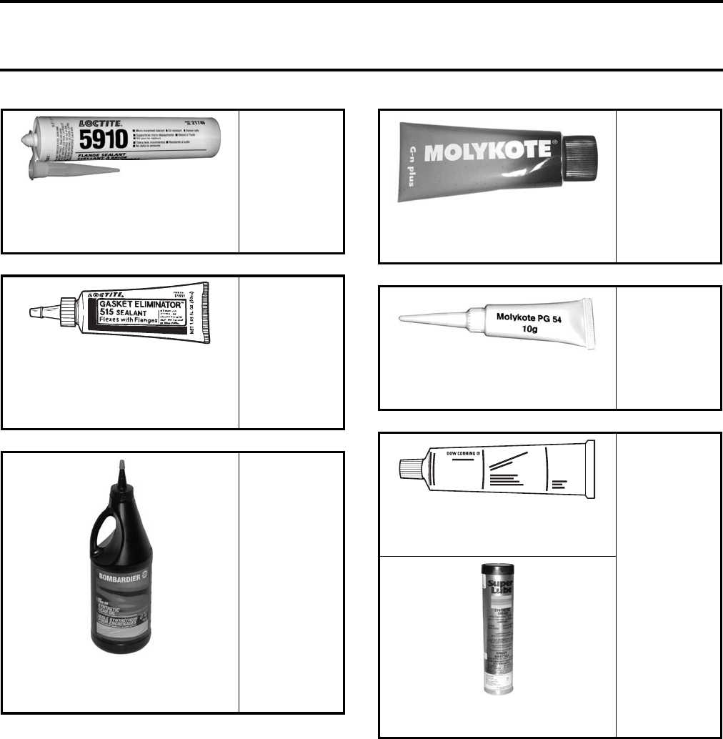
Quest 500/650
Traxter
Loctite® 406
Instant Adhesive
(must be used with tapered tip)
(20 g)
293 800 095
Smoothflow Tapered Tips
16ga #511 rtt-b
(not sold by Bombardier),
call EFD Inc, 1 800 556-3484
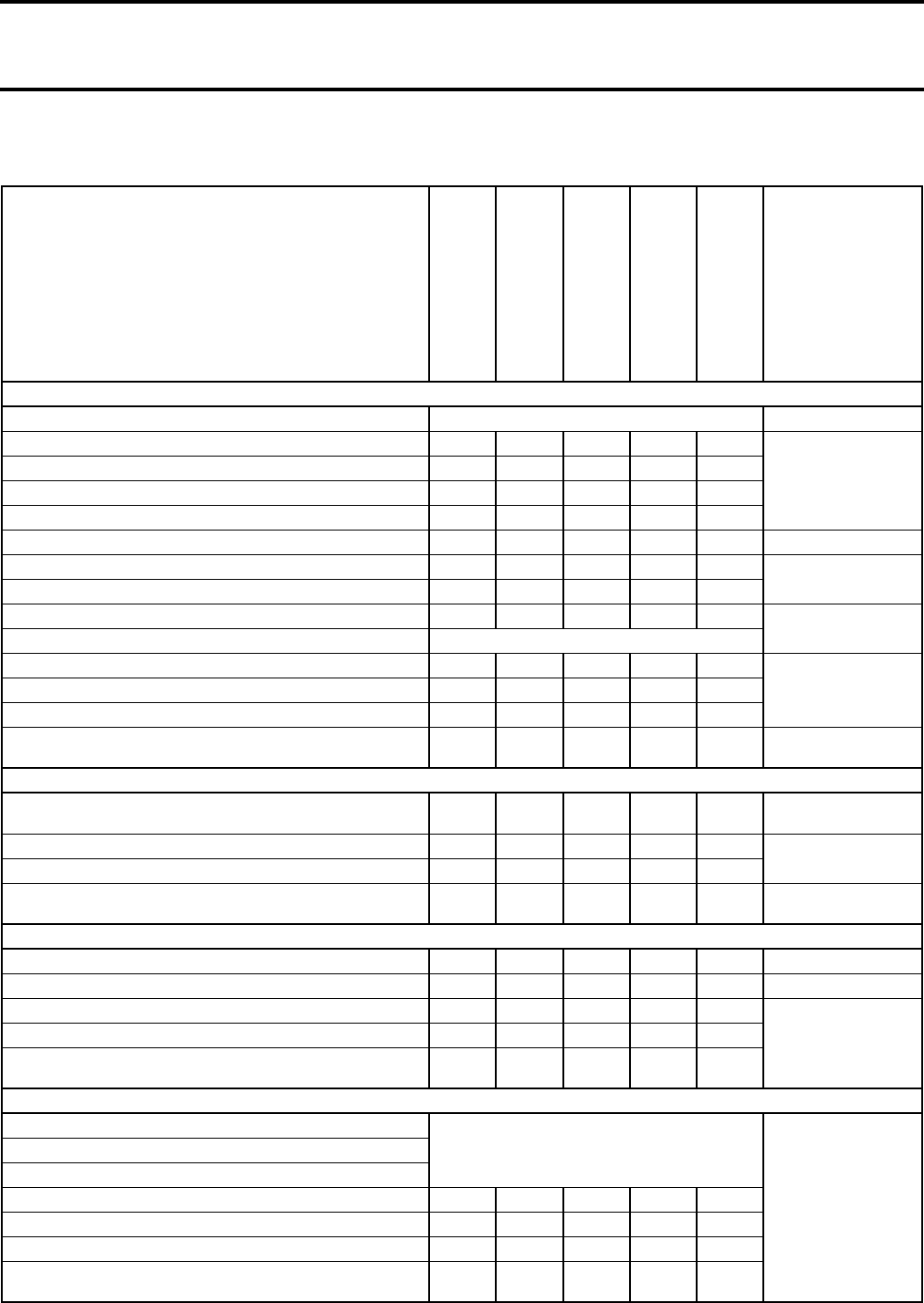
Outlander 330
Outlander 400
Loctite® 5900
RTV Silicone Sealant
(300 mL)
293 800 066
Loctite® Maxi-Coat
Heavy Duty Rustproofing
(340 g)
293 800 105
Section 01 SERVICE TOOLS AND SERVICE PRODUCTS
Subsection 03 (SERVICE PRODUCTS)
VMR2004_003_01_03A.FM 01-03-7
Outlander 330
Outlander 400
Quest 500/650
Loctite® 5910
Flange Sealant
(300 mL)
293 800 081
DS 650/Baja/X
Traxter
Loctite® 515
Paste Gasket
Gasket Eliminator
(50 mL)
413 702 700
Outlander 330
Outlander 400
Quest 500/650
Traxter
Bombardier Differential Oil
(946 mL)
293 600 043
Rally 200
Traxter
Molykote G-n Paste
(50 g)
711 297 433
Outlander 330
Outlander 400
Traxter
Molykote PG 54
(10 g)
420 899 763
DS 650/Baja/X
Rally 200
Traxter
Molykote 111
(150 g)
413 707 000
Super Lube Grease
293 550 030
111

Section 02 MAINTENANCE
Subsection 01 (TABLE OF CONTENTS)
VMR2004_033_02_01ATOC.FM 02-01-1
TABLE OF CONTENTS 0
MAINTENANCE CHART........................................................................................................ 02-02-1
NOISE EMISSION CONTROL SYSTEM REGULATION ................................................... 02-02-1
TAMPERING WITH NOISE CONTROL SYSTEM PROHIBITED ....................................... 02-02-1
AMONG THOSE ACTS PRESUMED TO CONSTITUTE TAMPERING
ARE THE ACTS LISTED BELOW ....................................................................................... 02-02-1
MAINTENANCE CHART.................................................................................................... 02-02-2
MAINTENANCE/LUBRICATION ........................................................................................... 02-03-1
ADJUST VALVE CLEARANCE .......................................................................................... 02-03-1
CLUTCH ADJUSTMENT ................................................................................................... 02-03-1
DRIVE CHAIN ..................................................................................................................... 02-03-2
AIR FILTER CLEANING/DRAINING................................................................................... 02-03-3
BOLTS, FASTENERS AND NUTS ..................................................................................... 02-03-4
ENGINE OIL AND FILTER.................................................................................................. 02-03-4
SPARK ARRESTER ............................................................................................................ 02-03-5
TIRES AND WHEELS ........................................................................................................ 02-03-6
ENGINE AREA ................................................................................................................... 02-03-7
STORAGE/PRESEASON PREPARATION ............................................................................. 02-04-1
STORAGE........................................................................................................................... 02-04-1
FUEL STABILIZER .............................................................................................................. 02-04-1
ENGINE LUBRICATION ..................................................................................................... 02-04-1
RAGS IN AIR INTAKE AND EXHAUST SYSTEM............................................................. 02-04-1
VEHICLE CLEANING AND PROTECTION......................................................................... 02-04-1
COOLANT DENSITY.......................................................................................................... 02-04-2
PRESEASON PREPARATION............................................................................................ 02-04-3

Section 02 MAINTENANCE
Subsection 02 (MAINTENANCE CHART)
VMR2004_004_02_02A.FM 02-02-1
MAINTENANCE CHART 0
NOISE EMISSION CONTROL SYSTEM REGULATION
TAMPERING WITH NOISE CONTROL SYSTEM PROHIBITED
U.S. Federal law and Canadian provincial laws may prohibit the following acts or the causing there of:
1. The removal or rendering inoperative by any person other than for purposes of maintenance, repair or
replacement of any device or element of design incorporated into any new vehicle for the purpose of
noise control prior to its sale or delivery to the ultimate purchaser or while it is in use or
2. The use of the vehicle after such device or element of design has been removed or rendered inoperative
by any person.
AMONG THOSE ACTS PRESUMED TO CONSTITUTE TAMPERING ARE
THE ACTS LISTED BELOW
1. Removal or alteration or the puncturing of the muffler or any engine component which conducts re-
moval of engine exhaust gases.
2. Removal or alteration or the puncturing of any part of the intake system.
3. Replacing any moving parts of the vehicle or parts of the exhaust or intake system, with parts other
than those specified by the manufacturer.
4. Lack of proper maintenance.
Section 02 MAINTENANCE
Subsection 02 (MAINTENANCE CHART)
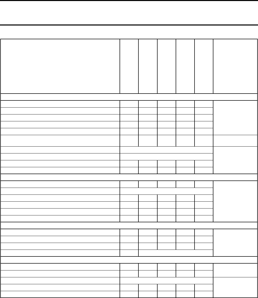
02-02-2 VMR2004_004_02_02A.FM
MAINTENANCE CHART
I: Inspect, verify, clean, adjust, lubricate,
replace if necessary
C: Clean
L: Lubricate
R: Replace
INITIAL 10 HOURS
OR 400 KM (250 M.)
EVERY 25 HOURS
OR 1250 KM (800 M.)
EVERY 50 HOURS
OR 2500 KM (1600 M.)
EVERY 100 HOURS
OR 5000 KM (3100 M.)
OR ONCE A YEAR
EVERY 200 HOURS
OR 10000 KM (6200 M.)
OR TWO YEARS
REFER TO
THE SECTION
ENGINE/TRANSMISSION
Engine/transmission oil level EVERY INSPECTION N.A.
Engine/transmission oil and filter RR
Maintenance/
Lubrication
Spark arrester C
Valve clearance II
Clutch lever II
Oil reservoir strainer CLubrication
Engine mount fasteners II
Removal and
Installation
Exhaust system II
Condition of seals II
N.A.
Coolant level EVERY INSPECTION
Coolant ➀IIR
Cooling SystemRadiator cap/cooling system pressure test II
Radiator condition/cleanliness (radiator fines) II
Clutch and transmission operation IClutch and/or
Transmission
FUEL SYSTEM
Air filter CR Maintenance/
Lubrication
Fuel lines and connections II
Fuel Circuit
Fuel tank strainer replacement R
Carburetor II
Carburetor and Air
Intake Silencer
ELECTRICAL
Spark plugs IRIgnition System
Battery connections IIN.A.
Wiring harness, cables and lines II
Instruments and
Accessories
Ignition switch, engine stop switch and start button II
Lighting system
(hi/lo intensity, brake light, head-lamp aiming, etc.) II
DRIVE TRAIN
Drive chain lubrication
EVERY INSPECTION
Front Drive
and Rear Axle
Drive chain adjustment
Drive chain protector and roller condition
Sprockets II
Wheel bearing IIL
Rear wheel hub L
Rear axle tightness (eccentric axle housing) bolts and
brake hub locking nuts II
Section 02 MAINTENANCE
Subsection 02 (MAINTENANCE CHART)
VMR2004_004_02_02A.FM 02-02-3
N.A.: Not Available
The initial maintenance is very important and must not be neglected.
➀ Every 50 hours, check coolant strength.
NOTE: Some riding conditions and hauling loads may result in requiring more frequent maintenance.
Some items are part of the pre-operation checks and must always be performed prior to operating the
vehicle.
STEERING/CONTROL SYSTEMS
Throttle/housing/cable II
Steering/
Controls System
Handlebar fastener II
Steering system II
Tie rod ends II
Front wheel alignment II
Choke II
Carburetor and Air
Intake Silencer
Tire wear and pressure EVERY INSPECTION
Maintenance/
Lubrication
Front wheel hub EVERY INSPECTION
Wheel nuts and studs II
Wear and condition of tires II
SUSPENSION
Swing arm II
Front Suspension
and/or Rear
Suspension
Swing arm lubrification EVERY INSPECTION
A-arm II + L
Ball joint boot II
Ball joint II
Shock absorber I
BRAKE
Brake fluid front/rear II L
Hydraulic Brakes
Brake system (discs, hoses, etc.) I
Brake pads I
Brake line fittings IEVERY INSPECTION
BODY/FRAME
Engine area CC N.A.
Chassis fasteners I
Skid plate and A-arm protectors EVERY INSPECTION
Body and/or FrameSeat latch I
Frame I
I: Inspect, verify, clean, adjust, lubricate,
replace if necessary
C: Clean
L: Lubricate
R: Replace
INITIAL 10 HOURS
OR 400 KM (250 M.)
EVERY 25 HOURS
OR 1250 KM (800 M.)
EVERY 50 HOURS
OR 2500 KM (1600 M.)
EVERY 100 HOURS
OR 5000 KM (3100 M.)
OR ONCE A YEAR
EVERY 200 HOURS
OR 10000 KM (6200 M.)
OR TWO YEARS
REFER TO
THE SECTION
Section 02 MAINTENANCE
Subsection 03 (MAINTENANCE/LUBRICATION)
VMR2004_004_02_03A.FM 02-03-1
MAINTENANCE/LUBRICATION 0
ADJUST VALVE CLEARANCE
Removal
Remove:
– fuel tank
– valve cover
– spark plugs.
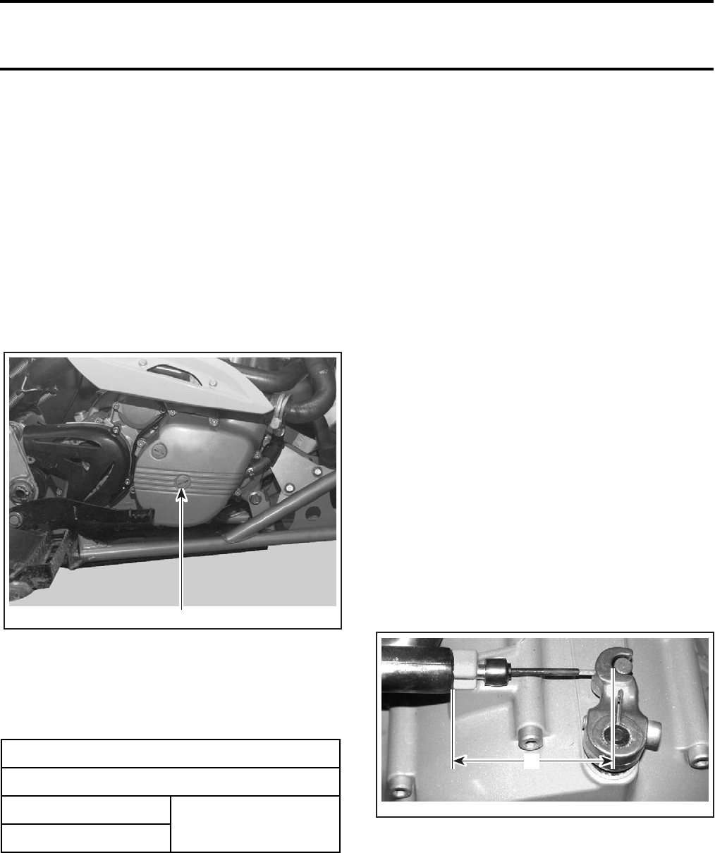
Unfasten centre screw plug to right of engine
housing cover.
RH SIDE OF VEHICLE
1. Remove this screw plug
Move crankshaft into TDC setting with an Allen key.
Use feeler gauge to check valve clearance and
change adjusting plates if necessary.
Note down valve clearance recorded.
Unfasten socket head screw beside support for oil
return and secure crankshaft with the crankshaft
locking bolt (P/N 529 035 617).
NOTE: Check tightness with the allen key.
To adjust valves, remove the camshaft bridges and
the camshafts.
Remove adjusting plates, blow clean with com-
pressed air.
Installation
NOTE: Before installation, check thickness of ad-
justing plates with micrometer.
For installation, reverse the removal procedure.
CLUTCH ADJUSTMENT
Loosen cable tension.
Adjust clutch release mechanism.
The release lever must locate on the spline in such
a way that dimension A is obtained. See the fol-
lowing illustration.
NOTE: If necessary, unscrew the Allen socket
screw and withdraw release lever. Replace the le-
ver at the appropriate position then tighten socket
screw to 19 N•m (14 lbf•ft).
A. 68 to 75 mm (2-11/16 to 2-31/32 in)
VALVE CLEARANCE mm (in)
SERVICE LIMIT
Exhaust 0.10 to 0.15
(.004 to .006)
Intake
1
V02C3LA
V02D08A
A
Section 02 MAINTENANCE
Subsection 03 (MAINTENANCE/LUBRICATION)
02-03-2 VMR2004_004_02_03A.FM
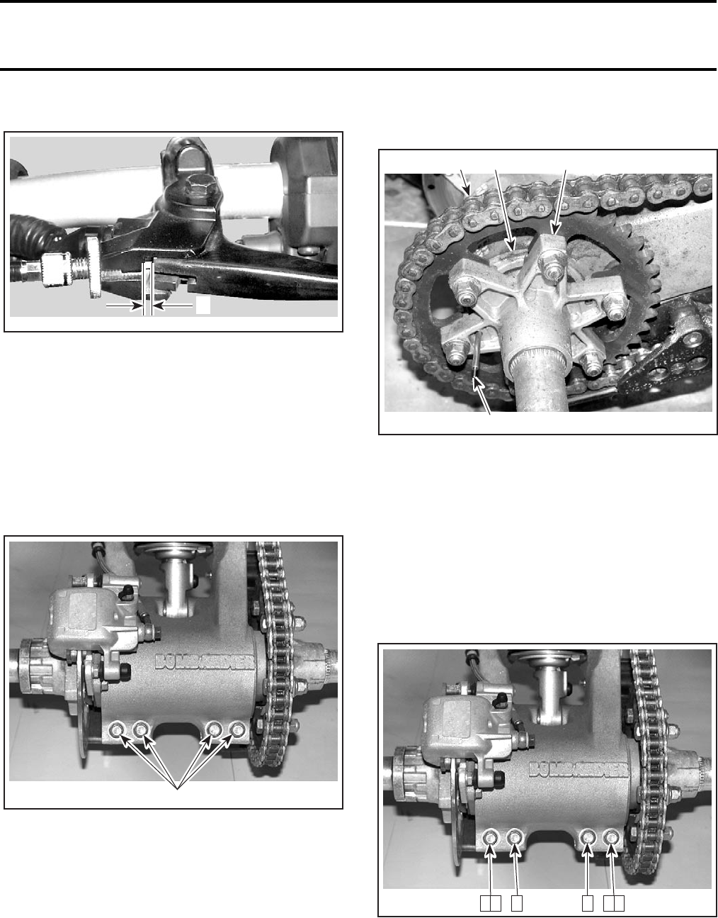
Adjust cable free play.
A. 3.5 ± 0.5 mm (9/64 ± 1/64 in)
DRIVE CHAIN
Adjustment
NOTE: Always adjust drive chain with the driver,
or equivalent weight, installed on the vehicle.
Select a level surface and set transmission to NEU-
TRAL.
Loosen rear axle lock bolts.
1. Rear axle lock bolts
Insert adjuster lock through rear hub and into ec-
centric axle housing.
1. Drive chain
2. Adjuster lock
3. Sprocket hub
4. Eccentric axle housing
Turn the axle forward to increase or backward to
decrease chain slack.
NOTE: Correct chain slack adjustment is 19 to
25.4 mm (3/4 to 1 in) at midway between sprockets.
Tighten the rear axle lock bolts to 23 N•m (17 lbf•ft).
Use the following sequence to tighten the rear
axle lock bolts correctly.
Lift rear of vehicle (without driver or equivalent
weight), by the frame or by the bumper, and re-
check the chain slack. The chain slack should be
44.5 to 51 mm (1-3/4 to 2 in). If not, redo the drive
chain adjustment.
V02D04A
A
V02H15A 1
V02H16A
1
2
43
V02H15B 2 6 4 3 1 5
Section 02 MAINTENANCE
Subsection 03 (MAINTENANCE/LUBRICATION)
VMR2004_004_02_03A.FM 02-03-3
Lubrication and Cleaning
CAUTION: Never wash the chain with a high pres-
sure washer or gasoline. Damage to the O-ring
will result, causing premature wear and drive
chain failure.
Clean the side surfaces of the chain with a dry cloth.
NOTE: Do not brush chain.
Lubricate only with the approved O-ring chain lubri-
cant. Other commercial chain lubricants may con-
tain solvent which could damage the O-rings.
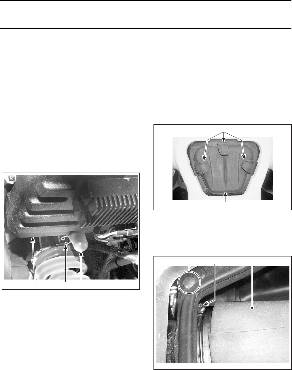
AIR FILTER CLEANING/DRAINING
Air Filter Box Draining
Periodically inspect air filter box drain plug for liquid
or deposits. Refer to the MAINTENANCE CHART.
1. Air filter box
2. Drain plug
3. Clamp
NOTE: If vehicle is used in dusty area, inspect
more frequently than specified in MAINTENANCE
CHART.
If liquid/deposits are found, squeeze the clamp
and remove. Pull drain tube out.
CAUTION: Do not start engine when a liquid is
found in the drain tube.
When liquid/deposits are found, air filter must be
inspected/dried/replaced depending on its condition.
Remove air filter as explained below.
Air Filter Removal
CAUTION: Never remove or modify any compo-
nent in the air box. Always use genuine parts or
suitable equivalent when replacing air filter and
foam. The engine carburation is calibrated to op-
erate specifically with these components. Other-
wise, engine performance degradation or dam-
age can occur.
Remove seat.
Release latches and remove air filter box cover.
1. Latches
2. Air filter cover
Remove screw driver cap, push inside of air box.
Loosen screw on clamp and remove filter.
Remove foam.
1. Clamp
2. Air filter and foam
3. Screw driver cap
Pour cleaning solution (P/N 293 600 059 or an
equivalent) into a bucket. Put the filter in to soak.
While filter soaks, clean inside of air box.
132
V02A0CA
1
2
V02A0DA
1
V02A0ZA
3 2
Section 02 MAINTENANCE
Subsection 03 (MAINTENANCE/LUBRICATION)
02-03-4 VMR2004_004_02_03A.FM
Rinse air filter and foam with warm water.
Squeeze foam to remove excess water. Let dry air
filter and foam thoroughly.
If air filter element or foam is dirty, replace with a
new one.
NOTE: Slight dust may be cleaned using a low-
pressure airgun. Blow compressed air backward
of operating air flow.
When the filter is dried, re-oil with air filter oil
(P/N 293 600 058 or an equivalent).
Properly reinstall removed parts in the reverse or-
der of their removal.
BOLTS, FASTENERS AND NUTS
Check bolts, fasteners and nuts at the regular in-
tervals.
Check that all bolts and nuts are tightened to the
proper torque.
ENGINE OIL AND FILTER
Oil and Oil Filter Change
NOTE: Oil and filter are to be replaced at the same
time. Oil change should be done with a warmed
up engine.
Ensure vehicle is on a level surface.
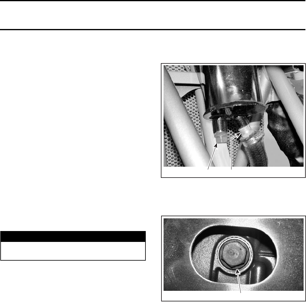
Remove dipstick.
Clean the reservoir drain plug area.
Drain all oil from oil tank by removing oil tank drain
plug. Wipe out any oil spillage.
1. Oil tank drain plug
2. Oil tank strainer
Place a drain pan under the engine drain plug area.
Unscrew engine drain plug.
1. Oil drain plug
Wait a while to allow oil to flow out of oil filter.
Clean and reinstall oil tank drain plug. Torque to
20 N•m (15 lbf•ft).
Unscrew oil filter cover.
WARNING
The engine oil can be very hot. Wait until en-
gine oil is warm.
1
V02C46A 2
1
V02C4XA
Section 02 MAINTENANCE
Subsection 03 (MAINTENANCE/LUBRICATION)
VMR2004_004_02_03A.FM 02-03-5
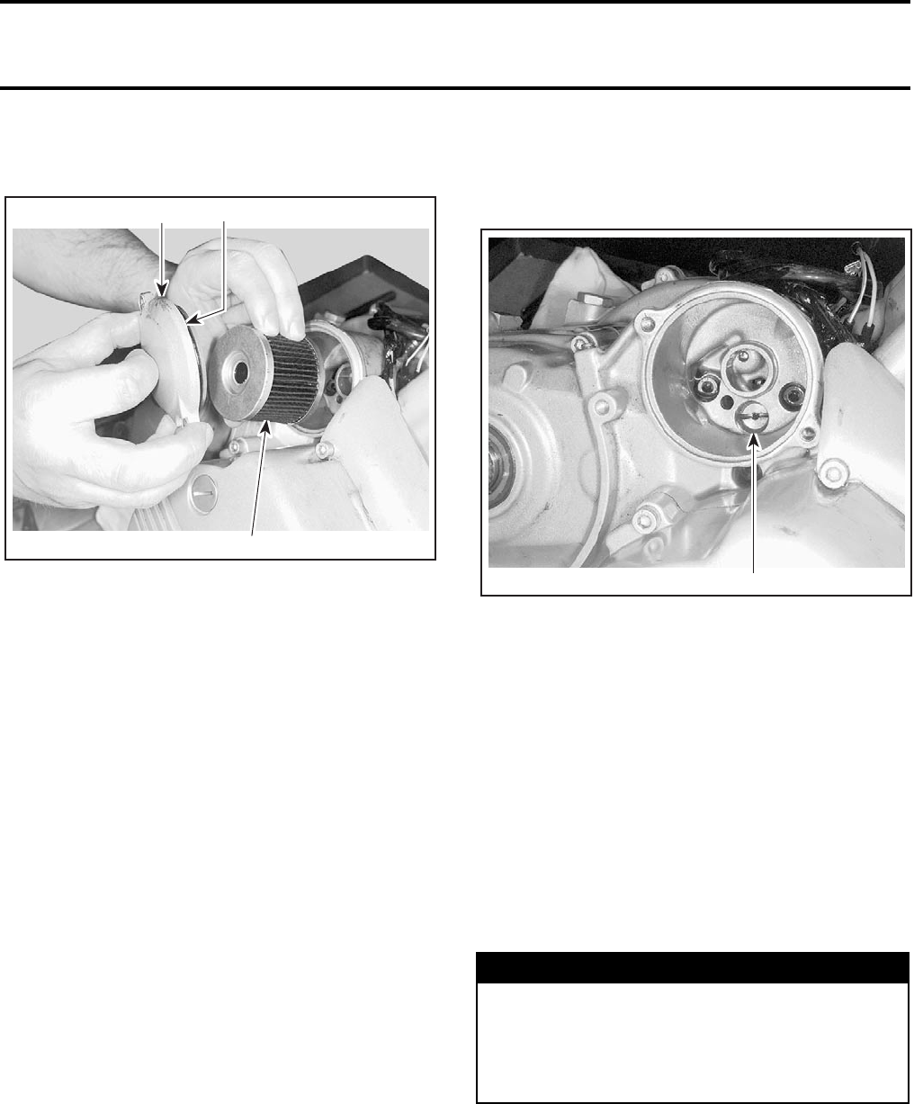
Remove oil filter and replace by a new.
NOTE: Check and change the O-ring, if necessary.
TYPICAL — RH SIDE OF ENGINE
1. Oil filter cover
2. Oil filter
3. O-ring
Wipe out any oil spillage on engine.
Inspect gasket on engine drain plug and replace as
necessary. Clean gasket area on engine and drain
plug then reinstall plug. Torque to 30 N•m (22 lbf•ft).
Refill oil tank at the proper level with the recom-
mended oil. Refer to TECHNICAL DATA for capacity.
NOTE: The same oil lubricates both engine and
transmission. Do not use synthetic oil, other than
Bombardier brand name, any semi-synthetic oil
or any special additives. They affect the clutching
calibration.
Start engine and let idle for a few minutes.
Check if the RED indicator lamp stays ON. If so,
stop engine and bleed system by removing oil fil-
ter and bleeding screw. See procedure below.
Ensure oil filter area, hose and drain plug areas are
not leaking.
Stop engine and check oil level. Refill as necessary.
Dispose oil as per your local environmental regula-
tions.
Bleeding Engine Oil Circuit
Remove oil filter.
Unfasten pressure bleeding screw.
BEHIND OIL FILTER
1. Bleeding screw
Unscrew and remove one spark plug.
Turn engine using starter until oil emerges in filter
chamber.
Tighten pressure bleeding screw. Torque to 25 N•m
(18 lbf•ft).
Install oil filter.
SPARK ARRESTER
The muffler must be periodically purged of accumu-
lated carbon. See the MAINTENANCE CHART.
Removal
2
13
V02C04A
WARNING
Never perform this operation immediately af-
ter the engine has been run because exhaust
system is very hot. Wear eye protection and
gloves. Respect all applicable laws and regu-
lations.
1
V02C05A
Section 02 MAINTENANCE
Subsection 03 (MAINTENANCE/LUBRICATION)
02-03-6 VMR2004_004_02_03A.FM
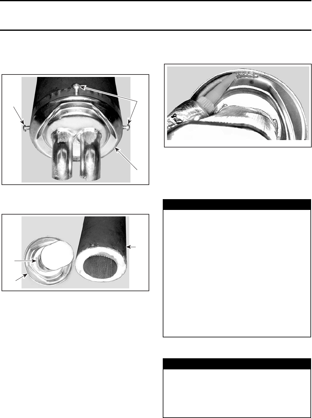
Remove:
–the screws retaining the spark arrester to the
muffler
1. Screws
2. Spark arrester
–spark arrester and sealant joint
1. Spark arrester
2. Sealant joint
3. Muffler
–inner grill with wool.
Remove all carbon deposit in the muffler.
Remove carbon deposits from the spark arrester
using a brush.
NOTE: Use a soft brush and be careful to avoid
damaging spark arrester.
Installation
For installation, reverse the removal procedure, pay-
ing attention to the following details:
Check:
–wool and change if it deteriorate
–the spark arrester condition, it must be free of
breaks and holes. Replace if necessary.
Remove the old sealant joint and replace by a new
one. Use ULTRA COOPER sealant (P/N 293 800 090).
Be sure that insulating material is in place when
inserting grill.
Align grill properly in bottom of muffler shell.
TIRES AND WHEELS
Tire Pressure
Check pressure when tires are cold before using
the vehicle.
1
1
2
V02C06A
1
3
V02C07A
2
WARNING
When the tires are replaced, never install a
bias tire with a radial tire. This combined ap-
plication may create handling and/or stability
problems.
Do not mix tires of different size and/or design
on the same axle.
Front tire pairs or rear tire pairs must be the
identical model and manufacturer.
For unidirectional tread pattern, ensure that
the tires are installed in the correct direction
of rotation.
The radial tires must be installed as a com-
plete set.
Severe injury or death can result if you do not
follow these instructions.
WARNING
Tire pressure greatly affects vehicle handling
and stability. Under pressure may cause tire
to deflate and rotate on wheel. Overpressure
may burst the tire. Always follow recommended
pressure. Since tires are low-pressure types, a
manual pump should be used.
V02C08A
Section 02 MAINTENANCE
Subsection 03 (MAINTENANCE/LUBRICATION)
VMR2004_004_02_03A.FM 02-03-7
NOTE: Tire pressure changes with temperature
and altitude. Recheck pressure if one of these con-
ditions has changed.
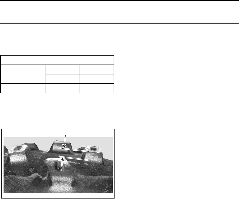
Tire/Wheel Condition
Check tire for damage and wear. Measure thread
height. It should be 4 mm (5/32 in) minimum. Re-
place if damaged or worn.
TYPICAL
A. 4 mm (5/32 in)
NOTE: Do not make a tire rotation. The front and
rear tires have a different size. Besides, these tires
are directional and their rotation must be kept in a
specific direction for proper operation.
Wheel Removal
Untighten nuts then lift vehicle where needed.
Place a support under vehicle. Remove nuts then
withdraw wheel.
At installation, it is recommended to apply anti-
seize lubricant on threads. Gently tighten nuts in a
criss-cross sequence then apply a final torque of
53 N•m (39 lbf•ft).
ENGINE AREA
Check in the engine area, for leak or other dam-
age. Clean mud, leafs, etc. from engine area.
TIRES PRESSURE
RECOMMENDED
FRONT REAR
35 kPa (5 PSI) 35 kPa (5 PSI)
MINIMUM 21 kPa (3 PSI) 21 kPa (3 PSI)
A
V02A10A

Section 02 MAINTENANCE
Subsection 04 (STORAGE/PRESEASON PREPARATION)
VMR2004_005_02_04A.FM 02-04-1
STORAGE/PRESEASON PREPARATION0
STORAGE
If the ATV is to be stored for an extended period
of time more than 1 month, be sure to thoroughly
check the vehicle for needed repairs and have
them performed.
FUEL STABILIZER
A fuel stabilizer (P/N 413 408 600) can be added in
fuel tank to prevent fuel deterioration and avoid
draining fuel system for storage. Follow manufac-
turer’s instructions for proper use.
If above fuel stabilizer is not used, drain fuel sys-
tem including fuel tank and carburetor.
CAUTION: Fuel stabilizer should be added prior
to engine lubrication to ensure carburetor pro-
tection against varnish deposit.
ENGINE LUBRICATION
Engine internal parts must be lubricated to protect
them from possible rust formation during the stor-
age period.
Proceed as follows:
Place the vehicle on blocks to raise all four tires off
the ground.
Start the engine and allow it to run at idle speed
until the engine reaches its operating tempera-
ture.
Stop the engine.
Change engine oil and filter. Refer to the section
MAINTENANCE/LUBRICATION.
Remove air box cover, air filter and foam to spray
storage oil (P/N 413 711 600) into carburetor bore.
Restart engine and run at idle speed.
Inject storage oil until the engine stalls or until a
sufficient quantity of oil has entered the engine
(approximately half a can).
Remove spark plugs and spray storage oil into cyl-
inder. Press start button, 1 or 2 seconds maxi-
mum, to lubricate cylinder.
Stop the engine and remove the battery. Store it
in dry and cool place out of the sun.
Turn the fuel valve to OFF and drain carburetor.
Reinstall the spark plugs, foam, air filter and air box
cover.
RAGS IN AIR INTAKE AND
EXHAUST SYSTEM
At storage preparation, block air intake inlets and
exhaust system outlets using clean rags.
The air intake tubes are located under fuel tank
cover.
NOTE: Remove those rags at preseason prepara-
tion.
VEHICLE CLEANING AND
PROTECTION
Wash and dry the vehicle then remove any dirt or
rust.
CAUTION: Never use a high pressure washer to
clean the vehicle. USE LOW PRESSURE ONLY
(like a garden hose). High pressure can cause
electrical or mechanical damages.
To clean the vinyl or plastic parts, use a flannel cloth
with Bombardier Vinyl & Plastic Cleaner (P/N 413
711 200).
CAUTION: It is necessary to use flannel cloths on
plastic parts to avoid damaging surfaces. Never
clean plastic parts with strong detergent, de-
greasing agent, paint thinner, acetone, products
containing chlorine, etc.
To clean the entire vehicle, including metallic parts,
use Bombardier Cleaner (P/N 293 110 001 (400 g)
or 293 110 002 (4 L)) or an equivalent like Simple
Green® from Sunshine Markers Inc., available at
hardware stores or at automotive parts retailer.
CAUTION: Do not use Bombardier Cleaner on
decals, plastic parts or vinyl.
Inspect the vehicle and repair any damage. Touch
up all metal spots where paint has been scratched
off. Spray all metal parts with BOMBARDIER
LUBE (P/N 293 600 016).
WARNING
This procedure must only be performed in a
well-ventilated area. Do not run engine dur-
ing storage period.

Section 02 MAINTENANCE
Subsection 04 (STORAGE/PRESEASON PREPARATION)
02-04-2 VMR2004_005_02_04A.FM
NOTE: Protect the vehicle with a cover to prevent
dust accumulation during storage.
CAUTION: The vehicle has to be stored in a
cool and dry place and covered with an opaque
tarpaulin. This will prevent sun rays and grime
from affecting plastic components and vehicle
finish.
COOLANT DENSITY
Test the density of the coolant using an antifreeze
hydrometer.
NOTE: Follow manufacturer’s instructions for proper
use.
A 50/50 mixture of antifreeze and distilled water
will provide the optimum cooling, corrosion protec-
tion and antifreeze protection.
Do not use tap water, straight antifreeze or straight
water in the system. Tap water contains minerals
and impurities which build up in the system.
Straight water or antifreeze will cause the system
to freeze.
Change coolant if necessary.

Section 02 MAINTENANCE
Subsection 04 (STORAGE/PRESEASON PREPARATION)
VMR2004_005_02_04A.FM 02-04-3
PRESEASON PREPARATION
N.A.: Not available
➀Replace oil and filter only if it has not been previously performed at the storage.
➁Remove rags in intake and exhaust that were installed at the storage.
➂Before installing new spark plugs at preseason preparation, it is suggested to burn excess storage oil
by starting the engine with the old spark plugs. Only perform this operation in a well-ventilated area.
SYSTEM PRESEASON OPERATIONS TO BE PERFORMED BY REFER TO
CUSTOMER DEALER
ENGINE/
TRANSMISSION
Test Run Vehicle. Check Clutch and Transmission
Operation ✔N.A.
Engine Oil and Filter Oil Replacement ➀✔ Maintenance/
Lubrication
Coolant Replacement and Pressurization
of System ✔Cooling System
Condition of Seals ✔N.A.
Spark Arrester ✔Maintenance/
Lubrication
Exhaust System Condition ✔Removal and
Installation
Rags Removal (intake and exhaust) ➁✔ Maintenance/
Lubrication
FUEL SYSTEM
Fuel Line and Connectors Condition ✔Fuel Circuit
Carburetor Adjustment ✔Carburetor and Air
Intake Silencer
Throttle and Choke Cable Inspection/Adjustment ✔
Air Filter Cleaning/Replacement ✔Maintenance/
Lubrication
ELECTRICAL
Spark Plug Replacement ➂✔Ignition System
Battery Condition/Charging and Installation ✔Starting System
Starter Connections and Routing ✔
Operation of Lighting System ✔Instruments and
Accessories
DRIVE TRAIN
Drive Chain Lubrication ✔
Rear Axle
Drive Chain Adjustment ✔
Drive Chain Protector Condition ✔
Sprockets Inspection ✔
STEERING/
CONTROL
SYSTEM
Steering System Inspection and Adjustment ✔Steering/Controls
System
Handlebar Fastener Tightness ✔
Wheel Tightness ✔Maintenance/
Lubrication
Tire Pressure ✔
Tire Condition ✔
SUSPENSION
Suspension System Inspection ✔
Front/Rear
Suspension
A-Arm Lubrication ✔
Bearing Condition ✔
Swing Arm Condition ✔
BRAKES Brake Fluid Change ✔Hydraulic Brakes
Brake Condition ✔
BODY/FRAME Frame and Skid Plate Condition ✔Body and/or
Frame
Seat Latch ✔

Section 03 ENGINE
Subsection 01 (TABLE OF CONTENTS)
VMR2004_033_03_01ATOC.FM 03-01-1
TABLE OF CONTENTS 0
TROUBLESHOOTING............................................................................................................ 03-02-1
COOLING SYSTEM ........................................................................................................... 03-02-1
MAGNETO SYSTEM ......................................................................................................... 03-02-2
LUBRICATION.................................................................................................................... 03-02-4
CYLINDER AND HEAD ...................................................................................................... 03-02-5
CRANKSHAFT AND BALANCER SHAFT.......................................................................... 03-02-6
GEARBOX .......................................................................................................................... 03-02-7
ENGINE GENERAL ............................................................................................................ 03-02-8
LEAK TEST............................................................................................................................. 03-03-1
VERIFICATION ................................................................................................................... 03-03-1
LEAK TEST PROCEDURE.................................................................................................. 03-03-1
PREPARATION AND TEST................................................................................................ 03-03-1
DIAGNOSE ......................................................................................................................... 03-03-3
INSTALLATION.................................................................................................................. 03-03-3
REMOVAL AND INSTALLATION .......................................................................................... 03-04-1
GENERAL ........................................................................................................................... 03-04-2
ENGINE REMOVAL ........................................................................................................... 03-04-2
ENGINE INSTALLATION................................................................................................... 03-04-4
COUNTERSHAFT SPROCKET........................................................................................... 03-04-4
EXHAUST SYSTEM .......................................................................................................... 03-04-5
OIL TANK ........................................................................................................................... 03-04-5
COOLING SYSTEM ............................................................................................................... 03-05-1
RADIATOR ......................................................................................................................... 03-05-1
WATER PUMP.................................................................................................................... 03-05-2
COOLING SYSTEM LEAK TEST ....................................................................................... 03-05-3
INSPECTION ...................................................................................................................... 03-05-3
DRAINING THE SYSTEM .................................................................................................. 03-05-3
COOLING SYSTEM REFILLING ........................................................................................ 03-05-4
PRESSURE CAP ................................................................................................................. 03-05-4
WATER PUMP.................................................................................................................... 03-05-4
RADIATOR ......................................................................................................................... 03-05-4
RADIATOR PROTECTOR................................................................................................... 03-05-5
THERMOSTAT ................................................................................................................... 03-05-5
COOLANT TANK ............................................................................................................... 03-05-5
FAN AND HEAT SHIELD ................................................................................................... 03-05-6
TEMPERATURE SWITCH .................................................................................................. 03-05-7
TEMPERATURE SENSOR ................................................................................................. 03-05-8
Section 03 ENGINE
Subsection 01 (TABLE OF CONTENTS)
03-01-2 VMR2004_033_03_01ATOC.FM
MAGNETO SYSTEM.............................................................................................................. 03-06-1
GENERAL............................................................................................................................ 03-06-2
STATOR .............................................................................................................................. 03-06-2
ROTOR ................................................................................................................................ 03-06-3
SPRAG CLUTCH ................................................................................................................. 03-06-3
TRIGGER COIL.................................................................................................................... 03-06-4
ROTOR HUB ....................................................................................................................... 03-06-4
LUBRICATION SYSTEM......................................................................................................... 03-07-1
ENGINE LUBRICATION...................................................................................................... 03-07-1
OIL TANK ............................................................................................................................ 03-07-2
GENERAL............................................................................................................................ 03-07-3
ENGINE PRESSURE TEST ................................................................................................. 03-07-3
OIL CHANGE AND OIL FILTER REPLACEMENT .............................................................. 03-07-3
OIL TANK STRAINER ......................................................................................................... 03-07-5
ENGINE OIL PRESSURE REGULATOR ............................................................................. 03-07-5
RETURN OIL PUMP............................................................................................................ 03-07-6
PRESSURE OIL PUMP ....................................................................................................... 03-07-7
ENGINE OIL STRAINER ..................................................................................................... 03-07-7
OIL TANK ............................................................................................................................ 03-07-8
CYLINDER AND HEAD ........................................................................................................... 03-08-1
CYLINDER AND HEAD ....................................................................................................... 03-08-1
VALVE................................................................................................................................. 03-08-2
GENERAL............................................................................................................................ 03-08-3
CYLINDER HEAD COVER................................................................................................... 03-08-3
ADJUST VALVE CLEARANCE ........................................................................................... 03-08-4
CAMSHAFT......................................................................................................................... 03-08-4
CENTRIFUGAL DECOMPRESSOR .................................................................................... 03-08-6
CYLINDER HEAD ................................................................................................................ 03-08-7
VALVE SPRING................................................................................................................... 03-08-7
VALVE ................................................................................................................................. 03-08-7
VALVE STEM SEAL ............................................................................................................ 03-08-8
VALVE GUIDE ..................................................................................................................... 03-08-8
CYLINDER ........................................................................................................................... 03-08-11

Section 03 ENGINE
Subsection 01 (TABLE OF CONTENTS)
VMR2004_033_03_01ATOC.FM 03-01-3
CRANKSHAFT/BALANCER SHAFT ...................................................................................... 03-09-1
PISTON PIN........................................................................................................................ 03-09-2
PISTON............................................................................................................................... 03-09-2
PISTON RINGS .................................................................................................................. 03-09-4
BALANCER SHAFT ............................................................................................................ 03-09-4
BALANCER GEAR.............................................................................................................. 03-09-6
CRANKSHAFT.................................................................................................................... 03-09-6
COUNTER GEAR ............................................................................................................... 03-09-7
CRANKSHAFT BUSHING .................................................................................................. 03-09-7
BALL BEARINGS IN HOUSING ........................................................................................ 03-09-7
RECENTER CRANKSHAFT................................................................................................ 03-09-8
RECENTER BALANCER SHAFT ........................................................................................ 03-09-8
CLUTCH.................................................................................................................................. 03-10-1
GENERAL ........................................................................................................................... 03-10-2
CLUTCH ADJUSTMENT ................................................................................................... 03-10-2
CLUTCH COVER ................................................................................................................ 03-10-2
PRESSURE PLATE............................................................................................................. 03-10-3
PRESSURE PLATE BEARING............................................................................................ 03-10-3
FRICTION DRIVE PLATE, STEEL DRIVEN PLATE AND CLUTCH BASKET..................... 03-10-4
CLUTCH RELEASE SHAFT................................................................................................ 03-10-6
TRANSMISSION....................................................................................................................03-11-1
SHIFTING MECHANISM ................................................................................................... 03-11-2
TRANSMISSION ................................................................................................................ 03-11-3
TRANSMISSION SHAFT BEARINGS................................................................................ 03-11-4
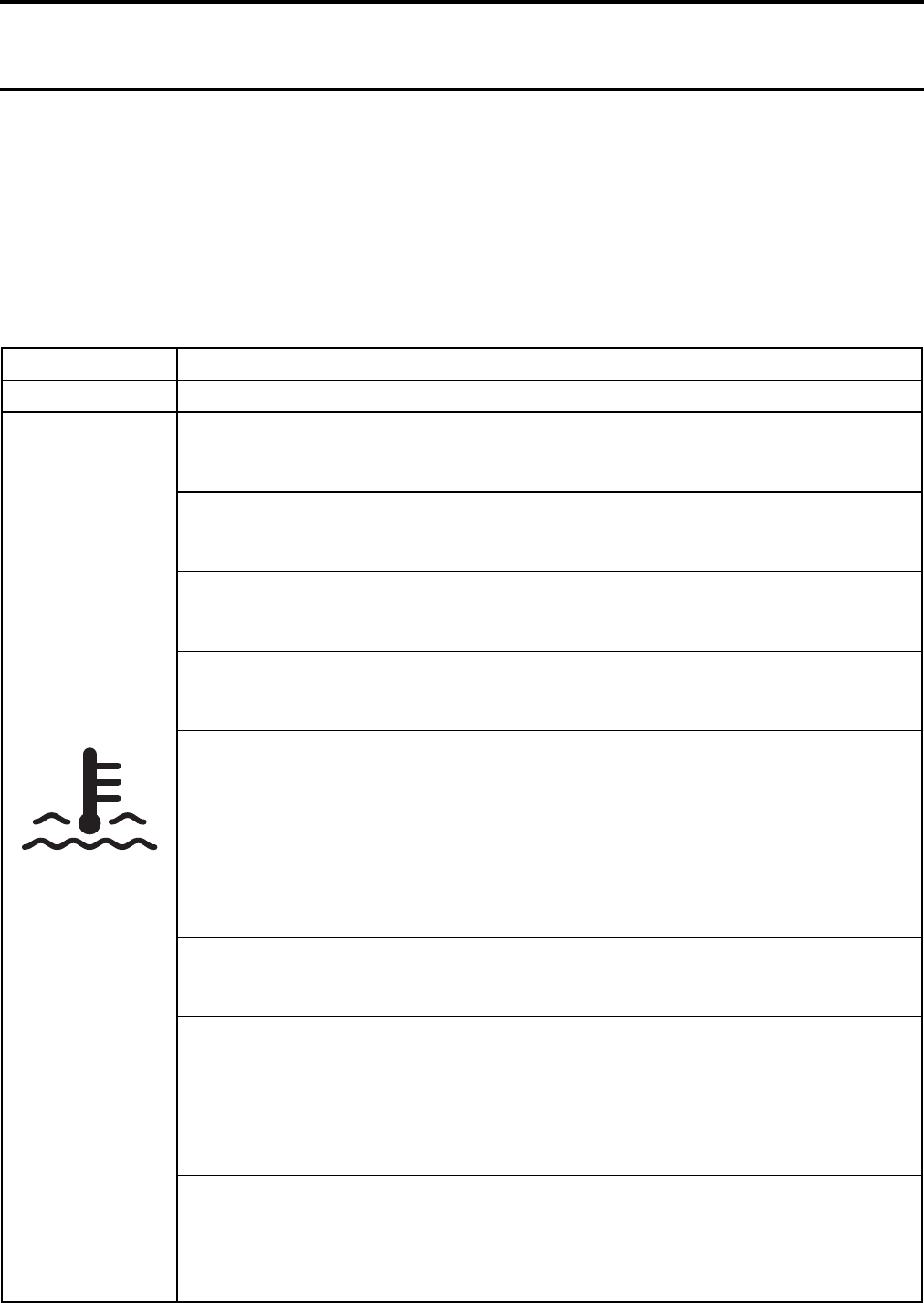
Section 03 ENGINE
Subsection 02 (TROUBLESHOOTING)
VMR2004_006_03_02A.FM 03-02-1
TROUBLESHOOTING 0
The following charts are provided to help in diagnosing the probable source of troubles. It should be used
as a guideline. This section pertains to engine mechanical components only. Some related problems can
come from other systems such as ignition system, fuel system etc. and have an impact on the engine.
Ensure to check the other systems prior to concluding that the engine is in fault.
COOLING SYSTEM
SYMPTOM HIGH ENGINE OPERATING TEMPERATURE.
CONDITION NORMAL USE.
Test/Inspection 1. Check coolant level.
a. Coolant less than recommended level.
Refill.
2. Check temperature sensor for electrical/mechanical failure.
a. Temperature sensor defective.
Replace.
3. Check thermostat (located on cylinder head).
a. Thermostat defective (does not open when engine gets hot).
Replace thermostat.
4. Check weep hole (water pump housing area) if coolant leaks.
a. Coolant leaking from weep hole means a damaged water pump rotary seal .
Replace rotary seal (refer to COOLING SYSTEM and MAGNETO COVER).
5. Check coolant bleeding screw on water pump housing.
a. Screw looses and/or gasket ring is missing.
Retighten screw and/or place gasket ring.
6. Check condition of hoses and hose clamps fixation.
a. Hoses are brittle and/or hard.
Replace.
b. Hose clamps are loose.
Retighten clamps.
7. Check condition of impeller located on the water pump shaft.
a. Impeller wings broken and/or impeller thread is damaged.
Replace.
8. Check gasket(s) on water pump housing.
a. Gasket on water pump housing leaks.
Retighten screws and/or replace gasket(s).
9. Check cylinder head and/or cylinder base gasket.
a. Worn out gasket(s) is(are) causing water leakage.
Replace.
10. Check cooling fan and connection.
a. Fan motor faulty.
Replace.
b. Wire harness is brittle or hard (no connection).
Replace.
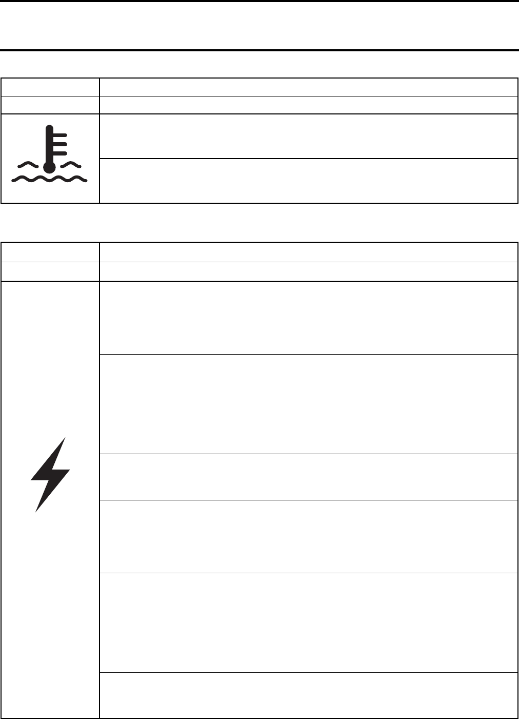
Section 03 ENGINE
Subsection 02 (TROUBLESHOOTING)
03-02-2 VMR2004_006_03_02A.FM
MAGNETO SYSTEM
11. Check coolant drain screw on water pump housing (marked “Drain”).
a. Copper ring on drain screw leaks.
Retighten screw and/or replace copper gasket ring.
12. Check intermediate gear(s) behind magneto cover.
a. Worn out and/or broken gear(s) is (are) causing less coolant supply.
Replace worn out and/or broken gear(s) (refer to LUBRICATION/MAGNETO SYSTEM).
SYMPTOM NO SPARK.
CONDITION NORMAL USE.
Test/Inspection 1. Check spark plug electrode condition.
a. Gap is too big.
Readjust gap (refer to TECHNICAL DATA).
b. Spark plug tip light grey and therefore heat range is too high.
Replace by Bombardier recommended spark plug (refer to TECHNICAL DATA).
2. Check ignition coils for damage and/or electrical failure.
a. Ignition coils damaged.
Replace ignition coils.
b. Connector is corroded or ignition coils shows electrical failure.
Clean ignition coils area and replace ignition coils.
c. Wire harness is brittle or hard (no connection).
Replace.
3. Check wire harness for cracks or other damages.
a. Harness shows electrical failure and/or other damages.
Replace wire harness.
4. Check magneto for damage and/or electrical failure.
a. Windings of stator have electrical failure.
Replace magneto.
b. Connector on magneto is damaged and/or has electrical failure.
Repair and clean contacts of connector.
5. Check electronic module.
a. Module shows electrical failure or violent damages.
Replace electronic module.
b. Connectors are corroded.
Clean and reconnect.
c. Electronic module has bad ground.
Clean metal surface for good ground.
6. Check engine stop switch position.
a. Engine stop switch is in OFF position.
Place engine stop switch to RUN position.
SYMPTOM HIGH ENGINE OPERATING TEMPERATURE.
CONDITION NORMAL USE.
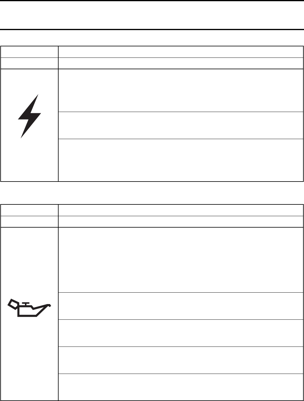
Section 03 ENGINE
Subsection 02 (TROUBLESHOOTING)
VMR2004_006_03_02A.FM 03-02-3
LUBRICATION
7. Check battery.
a. Battery shows less power.
Charge battery.
b. Battery has electrical failure.
Replace battery.
8. Check condition of fuse(s).
a. Faulty fuse(s).
Replace.
9. Check Trigger coil for damage and/or electrical failure.
a. Connector is corroded.
Clean and reconnect.
b. Resistance value is out of specification (refer to TECHNICAL DATA).
Replace trigger coil.
SYMPTOM NO SPARK.
CONDITION NORMAL USE.
SYMPTOM LOW OR NO OIL PRESSURE
CONDITION NORMAL USE.
Test/Inspection 1. Check oil level and search for leakage on crankcase and/or defective gaskets.
a. Crankcase is leaking due to damage.
Rebuild engine with new crankcase and gasket parts.
Use Bombardier recommended oil (refer to TECHNICAL DATA).
b. Crankcase is leaking due to loose screws.
Retighten screws with recommended torque.
c. Sealing rings, O-rings and/or gaskets are brittle and/or hard or damaged.
Replace damaged parts.
2. Check oil drain plug on engine bottom.
a. Plug is loosed and/or gasket ring is missing.
Retighten the plug and/or place gasket ring.
3. Check oil strainer cover on engine bottom.
a. Screw(s) is(are) loose and/or gasket is damaged, brittle or hard.
Retighten screws and/or replace gasket.
4. Check weep hole if oil leaks.
a. Oil leaking from weep hole means a damaged oil seal on water pump shaft.
Replace oil seal (refer to COOLING SYSTEM and MAGNETO COVER).
5. Check oil pressure switch function.
a. Oil pressure switch damaged.
Replace oil pressure switch.
Section 03 ENGINE
Subsection 02 (TROUBLESHOOTING)
03-02-4 VMR2004_006_03_02A.FM
Test/Inspection 6. Check piston rings for heavy wear, breaking or incorrect installation.
a. Piston rings worn out (blue coloured engine exhaust emission).
Replace piston rings (refer to CYLINDER AND HEAD).
b. Piston rings are broken (low compression).
Replace piston rings (refer to CYLINDER AND HEAD).
7. Check valve stem seal for leakage.
a. Valve stem seal damaged and/or sealing lip is hard and/or brittle.
Replace all valve stem seals.
8. Check oil orifice(s) on the oil pump suction side.
a. Oil orifice(s) is(are) clogged.
Clean from contamination. Replace oil and oil filter if necessary
(refer to MAINTENANCE or LUBRICATION).
9. Check oil pump operation.
a. Oil pump rotor is out of wear limit.
Replace oil pump shaft (refer to LUBRICATION).
b. Oil pump seized due to oil leakage and/or air inclusion.
Replace oil pump (refer to LUBRICATION).
c. Gears driving oil pump are broken or otherwise damaged.
Replace gears.
d. Incorrect oil being used.
Use Bombardier recommended oil (refer to TECHNICAL DATA).
10. Check oil pressure regulator valve (spring) function.
a. Valve spring damaged (valve always open).
Replace spring.
b. Valve piston is stuck in oil pump housing.
Repair valve piston.
11. Check plain bearings in crankcase for heavy wear.
a. Plain bearings out of specification (increased clearance).
Replace plain bearings.
SYMPTOM LOW OR NO OIL PRESSURE
CONDITION NORMAL USE.
Section 03 ENGINE
Subsection 02 (TROUBLESHOOTING)
VMR2004_006_03_02A.FM 03-02-5
CYLINDER AND HEAD
SYMPTOM OIL CONTAMINATION (WHITE APPEARANCE)
CONDITION NORMAL USE.
Test/Inspection 1. Check weep hole if water and oil leaks.
a. Leakage of oil/water mixture from bore means damaged water pump seal ring and
rotary seal.
Replace sealing ring, rotary seal and refill with recommended oil and/or coolant
(refer to COOLING SYSTEM and MAGNETO COVER).
2. Check cylinder head and/or cylinder base gasket.
a. Gasket damaged or leaking.
Retighten cylinder head with recommended torque and/or replace gasket.
3. Check screws for torque.
a. Screws not fixed.
Retighten screws with recommended torque and/or replace oil.
4. Check oil for particles (may indicate possible damages inside the engine).
a. Oil contamination due to metal or plastic particles.
Replace possibly damaged parts. Use Bombardier recommended oil
(refer to TECHNICAL DATA).
SYMPTOM UNUSUAL ENGINE NOISE AND/OR VIBRATION IN IDLE SPEED.
CONDITION NORMAL USE.
Test/Inspection 1. Check operation of decompressor located on camshaft.
a. Decompressor shaft stucks and/or torsion spring is damaged.
Replace spring and/or decompressor mechanism.
2. Check chain tensioner operation.
a. Faulty chain tensioner.
Replace spring and/or mechanism.
SYMPTOM UNUSUAL ENGINE NOISE AND/OR VIBRATIONS WHILE OPERATING.
CONDITION NORMAL USE.
Test/Inspection 1. Check items 1 and 2 of UNUSUAL ENGINE NOISE AND/OR VIBRATION IN IDLE
SPEED.
2. Check noise coming from cylinder head area.
a. Chain guide worn out.
Replace chain guide.
b. Stretched chain and/or worn out sprockets.
Replace chain and sprockets.
c. Sprocket screws got loose.
Retighten screws with recommended torque.
Section 03 ENGINE
Subsection 02 (TROUBLESHOOTING)
03-02-6 VMR2004_006_03_02A.FM
CRANKSHAFT AND BALANCER SHAFT
SYMPTOM OIL CONTAMINATION ON CYLINDER AND/OR HEAD.
CONDITION NORMAL USE.
Test/Inspection 1. Check screws for torque.
a. Loose screws.
Retighten screws with recommended torque.
b. Gaskets are brittle, hard, worn out or otherwise damaged.
Replace damaged gaskets, O-rings or the V-ring on breather.
SYMPTOM UNUSUAL ENGINE NOISE AND/OR VIBRATIONS
CONDITION NORMAL USE.
Test/Inspection 1. Check for possible plain bearing failure.
a. Oil pressure is out of specified values.
Replace damaged parts (refer to LUBRICATION).
b. Connecting rod small end bearing is damaged and/or out of specification.
Replace damaged and/or worn out part(s).
c. Connecting rod big end clearance is out of specification.
Replace damaged and/or worn out part(s).
d. Crankshaft plain bearing MAG/PTO side is damaged and/or out of specification.
Replace crankshaft and plain bearing MAG/PTO at the same time
(refer to CRANKSHAFT).
2. Check ball bearing(s) on balancer shaft end(s).
a. Ball bearing(s) do(es) not move freely.
Replace bearing(s).
3. Check if mark on balancer shaft corresponds with crankshaft position mark.
a. Marks on balancer shaft and crankshaft are not aligned.
Readjust position of balancer shaft and crankshaft.
4. Check thrust washer(s) on crankshaft MAG/PTO side.
a. Thrust washer(s) is(are) missing on MAG and/or PTO side.
Fit thrust washer(s).
Section 03 ENGINE
Subsection 02 (TROUBLESHOOTING)
VMR2004_006_03_02A.FM 03-02-7
GEARBOX
SYMPTOM UNUSUAL ENGINE NOISE AND/OR VIBRATIONS
CONDITION NORMAL USE.
Test/Inspection 1. Check oil level in engine.
a. Oil leakage from engine.
Replace damaged gasket(s) and/or oil seal(s), torque screws and refill with oil up
to specified level (refer to TECHNICAL DATA).
2. Check for knocking noise.
a. Tooth of gears are damaged and/or worn.
Replace respective gears.
3. Check bearings in the gearbox for free movement.
a. Bearing(s) do(es) not move freely.
Replace bearing(s).
SYMPTOM GEAR INDICATION FAILS
CONDITION NORMAL USE.
Test/Inspection 1. Check contact screws on MAG side for damage and/or wear.
a. Shifting indicator switch pin is worn and/or otherwise damaged.
Replace shifting indicator switch.
b. Contact is corroded and/or contact screw for wire harness got loose.
Clean contact surface and retighten contact screw with recommended torque.
c. Isolating washer located on the shift drum is worn and/or damaged.
Replace isolating washer.
d. Wire harness has broken cables.
Replace wire harness.
2. Check connector condition and/or electronical system.
a. Connector contact is corroded and/or otherwise damaged.
Clean connector(s) and/or replace wire harness if damaged.
b. Electrical system failed and/or otherwise damaged.
Repair and/or replace damaged part(s).
Section 03 ENGINE
Subsection 02 (TROUBLESHOOTING)
03-02-8 VMR2004_006_03_02A.FM
ENGINE GENERAL
SYMPTOM GEAR(S) IS (ARE) HARD TO SHIFT.
CONDITION NORMAL USE.
Test/Inspection 1. Check shift drum and/or shift forks for wear and/or damages.
a. Shift drum has worn out and/or damaged tracks.
Replace shift drum.
b. Shift fork(s) is (are) worn out and/or engagement pins are damaged.
Replace shift fork(s).
c. Shift fork(s) is (are) worn out and/or fork(s) is (are) damaged.
Replace shift fork(s).
d. Shift gear(s) is (are) worn out.
Replace shift gear(s).
e. Shift shaft teeth do not correspond with shift drum position.
Readjust shift shaft (refer to TRANSMISSION).
2. Check engine idle speed (choke in use).
a. Idle speed is to high (CVT starts to work).
Adjust idle speed.
b. Choke is in use and increases the engine RPM.
Release choke.
SYMPTOM ENGINE BACKFIRES.
CONDITION NORMAL USE.
Test/Inspection 1. Check spark plug and/or electrical system.
a. Carbon accumulation caused by defective spark plug.
Clean carbon accumulation and replace spark plug.
b. Electrical system has failure.
Replace defective part(s).
2. Check leakage on intake manifold.
a. Air leak on intake system.
Retighten screws and/or replace intake manifold.
3. Check exhaust air leaking.
a. Exhaust gasket is leaking.
Retighten screws and/or replace exhaust gasket.
4. Check intake valve(s) for leaking.
a. Intake valve(s) is(are) leaking.
Repair or replace valve(s).
5. Check if fuel supply is too less at high RPM.
a. Fuel line is contaminated and/or bent (engine gets lean).
Clean and/or replace defective part(s).
Section 03 ENGINE
Subsection 02 (TROUBLESHOOTING)
VMR2004_006_03_02A.FM 03-02-9
SYMPTOM ENGINE SUDDENLY TURNS OFF.
CONDITION NORMAL USE.
Test/Inspection 1. Check spark plug cap contact and/or cable.
a. Spark plug cap loose.
Replug cap.
b. Spark plug cable melted and/or damaged.
Replace spark plug cable.
2. Check condition of spark plug (blue spark ideal).
a. Red, jumping spark means a damaged spark plug.
Replace spark plug with appropriate heat range (refer to TECHNICAL DATA).
b. Condition of spark plug.
Readjust carburetor and/or replace spark plug.
3. Check fuel supply to engine intake.
a. Fuel valve is switched off.
Turn on fuel valve.
b. Run out of fuel.
Turn fuel valve to “RES” position and refill (after refilling return the fuel valve to
“ON” position).
c. Poor quality and/or wrong fuel.
Clean from contamination and use appropriate fuel (refer to TECHNICAL DATA).
d. Carburetor contaminated.
Clean jets and carburetor float chamber from contamination.
e. Fuel line clogged and/or bent.
Clean fuel supply from contamination and/or replace defective part(s).
f. Fuel supply insufficient at high RPM.
Clean fuel supply from contamination.
4. Perform engine leak test. Refer to ENGINE LEAK TEST procedure. Check for possible
piston seizure.
a. Damaged head gasket and/or seal and/or leaking inlet/exhaust valve(s).
Replace and/or repair defective parts.
5. “Four-corner“ seizure of piston.
a. Accelerating too fast when engine is cold. Piston expands faster than cylinder.
Replace pistons. Ask driver to refer to warm-up procedure in Operator’s Guide.
6. Piston seizure (arrow to piston exhaust side).
a. Spark plug heat range is too warm.
Install spark plug with appropriate heat range (refer to TECHNICAL DATA).
b. Improper ignition timing.
Replace failed part(s) in electrical system (electronic module).
c. Compression ratio is too high.
Install genuine parts.
d. Poor oil quality.
Use BOMBARDIER recommended oil.
e. Leaks at air intake manifold (engine gets too lean).
Retighten screws or replace air intake manifold.
Section 03 ENGINE
Subsection 02 (TROUBLESHOOTING)
03-02-10 VMR2004_006_03_02A.FM
Test/Inspection 7. Melted and/or perforated piston dome; melted section at ring end gap.
a. When piston reaches TDC, mixture is ignited by heated areas in combustion
chamber. This situation is due to an incomplete combustion of a poor oil quality.
Clean residue accumulation in combustion chamber and replace piston. Use
Bombardier recommended oil.
b. Spark plug heat range is too high.
Install recommended spark plug (refer to TECHNICAL DATA).
8. Piston color is dark due to seizure on intake and exhaust sides.
a. Cooling system leaks and lowers coolant level.
Tighten clamps or replace defective parts. Add antifreeze in cooling system until
appropriate level is reached.
9. Cracked or broken piston.
a. Cracked or broken piston due to excessive piston/cylinder clearance or engine
overreving.
Replace piston. Check piston/cylinder clearance (refer to CYLINDER AND HEAD).
10. Check piston rings and cylinder surface for grooves.
a. Poor oil quality.
Use Bombardier recommended oil.
b. Contamination (like sand) through engine intake.
Replace defective part(s) and use new air filter.
11. Check crankshaft movement.
a. Oil pump failure due to leak of oil.
Repair and replace defective parts and use Bombardier recommended oil.
b. Oil contamination due to clogged oil filter/oil sieve. Oil passes through bypass valve
Replace oil, replace defective part(s) (refer to MAINTENANCE CHART).
12. Check valve springs exhaust/inlet.
a. Broken valve spring damages the cylinder head, valve(s), rocker arm(s)/piston/
piston rings and conrod.
Replace defective part(s).
13. Check if fuel supply is too less at high RPM.
a. Fuel line is contaminated and/or bent.
Clean and/or replace defective part(s).
SYMPTOM ENGINE SUDDENLY TURNS OFF.
CONDITION NORMAL USE.
Section 03 ENGINE
Subsection 02 (TROUBLESHOOTING)
VMR2004_006_03_02A.FM 03-02-11
SYMPTOM ENGINE DOES NOT OFFER MAXIMUM POWER AND/OR DOES NOT REACH
MAXIMUM OPERATING RPM.
CONDITION NORMAL USE.
Test/Inspection 1. Check items of ENGINE SUDDENLY TURNS OFF.
2. Check air intake system.
a. Air filter is clogged due to contamination.
Replace air filter.
3. Check spark plug condition and/or gap.
a. Fouled spark plug or wrong spark plug gap.
Readjust gap and clean spark plug or replace.
4. Check spark plug type.
a. Improper spark plug heat range.
Install recommended spark plug (refer to TECHNICAL DATA).
5. Perform engine leak test. Refer to ENGINE LEAK TEST procedure. Check for
possible piston seizure.
a. Damaged head gasket and/or seal and/or leaking inlet/exhaust valve(s).
Replace and/or repair defective parts.
6. Check for water in fuel or contaminated fuel by other products (kerosene,
diesel, etc.).
a. There is water in fuel or contaminated fuel.
Drain fuel system, search for leakage and refill it with appropriate fuel.
7. Check engine compression.
a. Worn piston(s) and/or piston ring(s).
Replace (refer to CYLINDER AND HEAD).
SYMPTOM ENGINE TURNS OVER BUT FAILS TO START.
CONDITION NORMAL USE.
Test/Inspection 1. Check if single-spark ignition coil fits on spark plug (refer to ENGINE DOES NOT
START-NO SPARK AT SPARK PLUG).
2. Check spark plug.
a. Define spark plug (no spark) or wrong spark plug gap.
Readjust gap and clean spark plug or replace.
3. Check for fuel on spark plug.
a. Flooded engine (spark plug wet when removed).
Do not overchoke. Remove wet spark plug, turn ignition switch to OFF and crank
engine several times. Install clean dry spark plug. Start engine following usual
starting procedure.
4. Check engine compression.
a. Insufficient engine compression.
Replace defective part(s) (ex.:piston, ring(s), etc.).
5. During cold weather check engine decompressor (located on camshaft).
a. Centrifugal weight spring is not engaged and/or damaged.
Readjust spring or replace centrifugal weight if damaged.
Section 03 ENGINE
Subsection 02 (TROUBLESHOOTING)
03-02-12 VMR2004_006_03_02A.FM
SYMPTOM HIGH ENGINE OPERATING TEMPERATURE.
CONDITION NORMAL USE.
Test/Inspection 1. Check if cooling system shows any failure (see COOLING SYSTEM).
a. System is leaking.
Repair and/or replace damaged part(s).
2. Check function of lubrication system (see LUBRICATION).
a. Lubrication is not working properly.
Repair and/or replace damaged part(s).
3. Check air leakage on engine intake.
a. Leaks.
Repair or replace.
4. Check condition and heat range of spark plug.
a. Melted spark plug tip or inadequate heat range.
Replace.
SYMPTOM STARTER TURNS, BUT ENGINE DOES NOT CRANK.
CONDITION NORMAL USE.
Test/Inspection 1. Check gear condition on electric starter.
a. Worn and/or damaged starter gear.
Replace electric starter and/or starter drive.
2. Check condition of starter pinion gear.
a. Worn and/or damaged starter pinion and/or ring gear.
Replace starter drive and/or drive pulley fixed half.
3. Check engine stop switch.
a. Engine stop switch set to OFF position.
Place switch to RUN position.
4. Check gear position.
a. The transmission is not on NEUTRAL position.
Select NEUTRAL position or press the clutch lever.
Section 03 ENGINE
Subsection 02 (TROUBLESHOOTING)
VMR2004_006_03_02A.FM 03-02-13
SYMPTOM ENGINE DOES NOT START - NO SPARK AT SPARK PLUG (SEE MAGNETO SYSTEM).
CONDITION AT ENGINE CRANKING.
Test/Inspection 1. Verify spark plug condition.
a. Defective, improperly set, worn out, fouled.
Identify source of problem and correct. Replace spark plug.
2. Verify ignition coils resistance with an ohmmeter.
a. Defective part.
Replace ignition coil(s).
3. Verify trigger coil resistance with an ohmmeter and connector condition.
a. Defective coil. Corroded connector terminal.
Replace magneto. Clean terminals and apply silicone dielectric grease.
4. Verify condition of ignition coils.
a. Mechanically damaged part. Vibration problem. Electrically damaged part.
Replace ignition coil(s).
5. Verify condition of trigger coil.
a. Mechanically damaged part. Vibration problem. Electrically damaged part.
Replace trigger coil and/or tighten mounting screw(s).
6. Check magneto for damage and/or electrical failure.
a. Windings of stator have electrical failure (no charging causes an empty battery).
Replace magneto.
SYMPTOM THE CLUTCH “SLIPS”.
CONDITION NORMAL USE.
Test/Inspection 1. Check clutch discs condition.
a. Clutch discs worn or distorted.
Replace.
2. Check clutch springs condition.
a. Clutch springs exhausted.
Replace.
3. Check clutch adjustment.
a. Clutch cable is not adjusted correctly.
Adjust and lubricate.
4. Verify engine oil.
a. Engine oil is not to specifications.
Drain engine oil and refill with the recommended oil.
Section 03 ENGINE
Subsection 02 (TROUBLESHOOTING)
03-02-14 VMR2004_006_03_02A.FM
SYMPTOM THE CLUTCH DOES NOT “DISENGAGE”.
CONDITION NORMAL USE.
Test/Inspection 1. Verify engine oil.
a. Engine oil is not to specifications.
Drain engine oil and refill with the recommended oil.
2. Check clutch discs condition.
a. Clutch discs stuck together.
Clean or replace.
b. Clutch discs or support plate distorted.
Replace.
3. Check clutch cable or clutch release mechanism adjustment.
a. Clutch cable or clutch release mechanism not adjusted correctly
Adjust clutch cable and/ or clutch release mechanism. see MAINTENANCE or
CLUTCH Section.
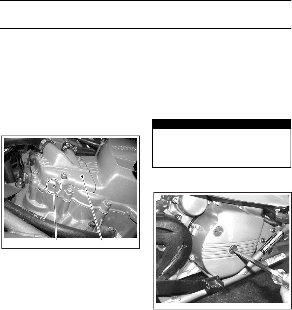
Section 03 ENGINE
Subsection 03 (LEAK TEST)
VMR2004_007_03_03A.FM 03-03-1
LEAK TEST 0
VERIFICATION
Before performing the cylinder leak test, verify the
following:
–clamp(s) tightness
–radiator and hoses condition
–oily contamination on leak indicator hole (under
water pump cover) means a damaged oil seal
on water pump shaft
1. Leak indicator hole
2. Water pump cover
–coolant out of leak indicator hole means a dam-
aged seal on water pump shaft
(refer to COOLING SYSTEM)
–coolant escaping from water pump housing means
damaged gasket(s) and/or loosened screws
(refer to COOLING SYSTEM).
NOTE: For all the above mentioned check see the
appropriate engine section to diagnose and repair
the engine.
LEAK TEST PROCEDURE
PREPARATION AND TEST
NOTE: The following procedures should be done
with a cold engine.
Disconnect battery.
Unplug and remove one spark plug only.
On RH side, remove center plug on MAG cover.
1
V02C3OA 2
WARNING
Always respect this order for disassembly;
disconnect BLACK (-) cable first. Electrolyte or
fuel vapors can be present in engine compart-
ment and a spark may ignite them and possi-
bly cause personal injuries.
V02C3PA
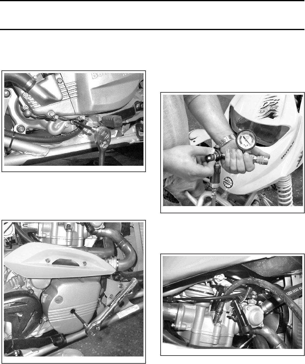
Section 03 ENGINE
Subsection 03 (LEAK TEST)
03-03-2 VMR2004_007_03_03A.FM
On LH side, remove the larger socket screw then
quickly install the crankshaft locking bolt (P/N 529
035 617) to avoid oil leakage. Do not tighten.
NOTE: A little quantity of engine oil will come out
of the hole. After leak test, check oil level and refill
if necessary.
Using an Allen key through the MAG cover, bring
crankshaft to TDC, compression stroke.
Torque the crankshaft locking bolt to lock crank-
shaft.
Remove radiator cap and dipstick.
Connect leak tester to adequate air supply.
Set needle of measuring gauge to zero.
NOTE: Each tester will have specific instruction
on the gauge operation and required pressure.
Install gauge adapter into previously cleaned spark
plug hole.
V02C3QA
V02C3RA
V02C3SA
V02C3TA
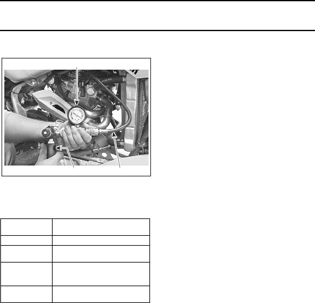
Section 03 ENGINE
Subsection 03 (LEAK TEST)
VMR2004_007_03_03A.FM 03-03-3
Supply combustion chamber with air pressure.
1. Leak tester
2. Adequate adapter for spark plug hole
3. Air supply hose
Note the amount of leaking or percentage (de-
pending on tester).
DIAGNOSE
Listen for air leaks:
–air escaping from spark plug means poor spark
plug tightness or defective spark plug gasket
–air escaping from intake means leaking intake
valve
–air escaping from exhaust means leaking exhaust
valve
–air/oil escaping from crankcase means damaged
gasket and/or loosened screws
(refer to CRANKSHAFT/BALANCER SHAFT)
–air bubbles out of radiator means leaking cylin-
der head gasket
–air/coolant escaping from cylinder/head means
damaged gasket(s) and/or loosened screws.
(refer to CYLINDER AND HEAD)
–air escaping into crankcase area means exces-
sively worn cylinder and/or broken piston rings.
NOTE: For all the check mentioned above see the
appropriate engine section to diagnose and repair
the engine.
INSTALLATION
NOTE: At reassembly, use the torque values and
Loctite products from the exploded views (refer to
particular engine sections).
For installation, reverse the preparation procedure.
LEAKAGE
PERCENTAGE ENGINE CONDITION
0% to 7% Excellent condition.
8% to 15% Fair condition; proceed with tuned
up or adjustment.
16% to 30% Poor condition; engine will run and
performance might be down in
some cases.
30% and higher Very poor condition, diagnose and
repair engine.
1
3
V02C3UA 2
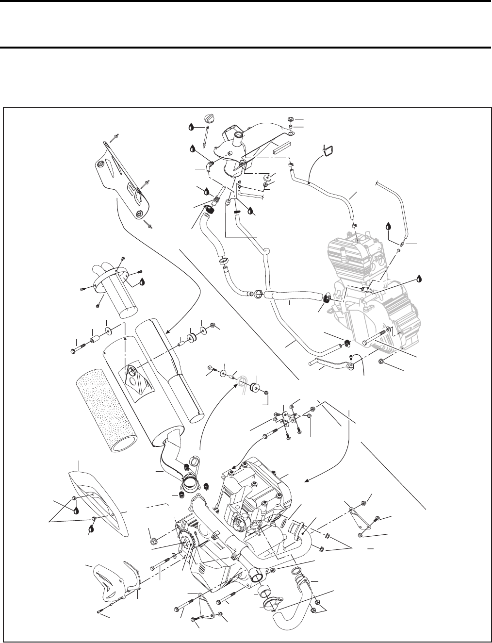
Section 03 ENGINE
Subsection 04 (REMOVAL AND INSTALLATION)
VMR2004_008_03_04A.FM 03-04-1
REMOVAL AND INSTALLATION 0
V02C43S
Loctite
414
Pipe sealant
2.5 Nm
(22 lbfin)
Pipe
sealant
20 Nm
(15 lbfft)
5 Nm
(44 lbfin)
20 Nm
(15 lbfft)
Pipe sealant
3 Nm
(27 lbfin)
36
35
38
37
1
Pipe
sealant
5 Nm
(44 lbfin)
Loctite 277
2.5 Nm
(22 lbfin)
2
17
64 Nm
(47 lbfft)
19 Nm
(14 lbfft)
4
3
Loctite
Ultra Copper
28
32
31
30
34
29
26 Nm
(19 lbfft)
25
26
27 33
10 Nm
(89 lbfin)
25 Nm
(18 lbfft)
11
25 Nm
(18 lbfft)
64 Nm
(47 lbfft)
39
23
10 Nm
(89 lbfin)
Loctite
271
Loctite
271
8
9
7 Nm
(62 lbfin)
16
135 Nm
(100 lbfft)
140 Nm
(103 lbfft)
10
14
12 13 26 Nm
(19 lbfft)
15
21
20 19
11 Nm
(97 lbfin)
615 Nm
(133 lbfin)
64 Nm
(47 lbfft)
22 11 Nm
(97 lbfin)
26 Nm
(19 lbfft)
13
64 Nm
(47 lbfft)
14
7
24
18
5
25 Nm
(18 lbfft)
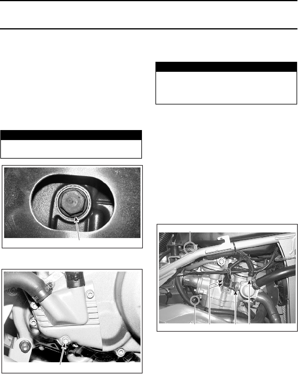
Section 03 ENGINE
Subsection 04 (REMOVAL AND INSTALLATION)
03-04-2 VMR2004_008_03_04A.FM
GENERAL
For installation, use the torque values and Loctite
products from the exploded views. Clean threads
before using Loctite when installing the screws.
ENGINE REMOVAL
Vehicle Preparation
Close fuel valve.
Drain engine oil and engine coolant by drain plugs.
UNDER ENGINE
1. Engine oil plug
LH SIDE OF ENGINE
1. Engine coolant plug
Disconnect BLACK (-) cable from battery, then
RED (+) cable.
Remove:
–seat
–front facia
–fuel tank (refer to FUEL CIRCUIT).
Engine Preparation
Unplug:
–spark plug cables
–oil pressure sensor, on the top of oil filter housing
–temperature sensor and temperature sender,
located near thermostat housing
–magneto and trigger coil wiring harness connec-
tors.
1. Spark plug cables
2. Oil pressure sensor
3. Temperature sensor
4. Temperature sender
5. Magneto and trigger coil connectors
On left side of vehicle, remove or disconnect the
following items:
–oil tank vent no. 1 on the top of engine
–radiator outlet hose
–oil inlet hose no. 2
–self-bleeding line
–clutch cable
WARNING
The engine oil can be very hot. Wait until en-
gine oil is warm.
1
V02C4XA
V02C10A 1
WARNING
Always disconnect battery exactly in the spec-
ified order, BLACK (-) cable first. It is recom-
mended to disconnect electrical connections
prior to disconnecting fuel lines.
1
V02C44A 243
5
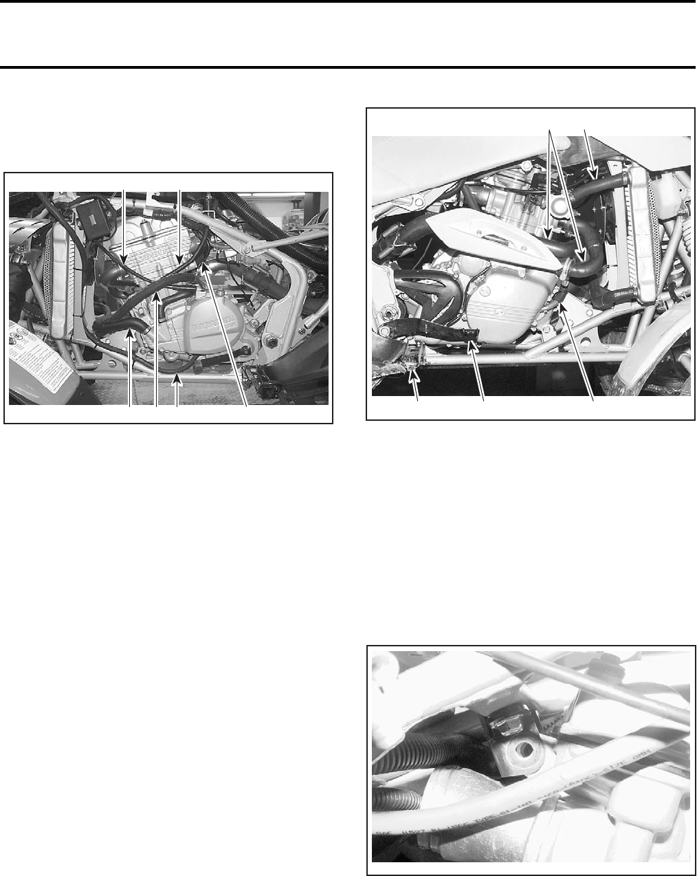
Section 03 ENGINE
Subsection 04 (REMOVAL AND INSTALLATION)
VMR2004_008_03_04A.FM 03-04-3
–starter cable
–oil outlet hose no. 3
–gearshift pedal no. 4.
LH SIDE OF ENGINE
1. Radiator outlet hose
2. Oil inlet hose
3. Self-bleeding line
4. Clutch cable
5. Starter cable
6. Oil outlet hose
On the right side of vehicle, remove or disconnect
the following items:
–exhaust pipe shield no. 5, exhaust pipes no. 6
and no. 7 (refer to EXHAUST SYSTEM section)
–radiator inlet hose
–oil line vent hose
–brake pedal (refer to HYDRAULIC BRAKES)
–RH footrest (refer to BODY)
–countershaft sprocket cover no. 8
–metallic chain guard no. 9
–countershaft sprocket no. 10
(refer to COUNTERSHAFT SPROCKET section)
RH SIDE OF ENGINE
1. Exhaust pipes
2. Radiator inlet hose
3. Vent oil line
4. Brake pedal
5. Footrest
–carburetor and carburetor adaptor (refer to CAR-
BURETOR AND AIR INTAKE SILENCER)
Unscrew neutral switch connector.
Removal
Remove the upper support bracket no. 11 com-
pletely.
1
V02C45A 26 3
54
1
5
V02C3KA 4 3
2
V02C19A
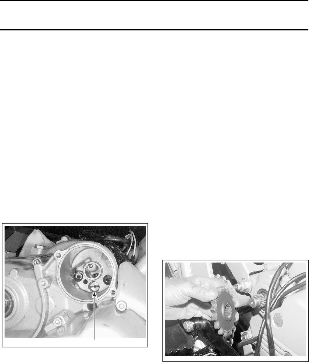
Section 03 ENGINE
Subsection 04 (REMOVAL AND INSTALLATION)
03-04-4 VMR2004_008_03_04A.FM
Install engine lifting tool (P/N 529 035 610) then,
install a hoist.
Remove:
–upper engine support bolt no. 12
–lower bolts no. 13 retaining the engine support
no. 14 on either side, then, remove supports
–front lower mounting bolt no. 15
–rear lower mounting bolt no. 16
–rear upper mounting bolt no. 17.
Remove engine no. 18 from vehicle.
ENGINE INSTALLATION
For installation, reverse the removal procedure,
pay attention to the following details.
Reattach cables, hoses, wiring harness, etc.
Adjust clutch cable.
Bleed rear brake.
Before starting engine, remove oil filter.
Unfasten pressure bleeding screw.
BEHIND OIL FILTER
1. Bleeding screw
Unscrew and remove one spark plug.
Turn engine using starter until oil emerges in filter
chamber.
Tighten pressure bleeding screw. Torque to 25 N•m
(18 lbf•ft).
Install oil filter.
This operation activated the oil pump. Check if ve-
hicle runs correctly.
COUNTERSHAFT SPROCKET
Removal
Slack drive chain.
Remove countershaft sprocket cover no. 8 and
metallic chain guard no. 9.
Select the first gear.
Unlock tab washer then, unscrew the retaining nut.
NOTE: Discard the tab washer.
Remove countershaft sprocket no. 10 and drive
chain together.
Inspection
Check sprocket for wear or other damage. Replace
if necessary.
Installation
CAUTION: Replace chain and sprocket togeth-
er to prevent rapid chain and sprocket wear.
Install a new tab washer each time the sprocket
is removed.
For the installation, reverse the removal procedure.
Pay attention to the following details.
Install countershaft sprocket with lips on the
engine side.
NOTE: Install the countershaft sprocket with the
chain assembly.
Install tab washer then retaining nut.
Torque retaining nut to 140 N•m (103 lbf•ft), then
lock tab washer.
Adjust drive chain. Refer to MAINTENANCE.
1
V02C05A
V02C1AA

Section 03 ENGINE
Subsection 04 (REMOVAL AND INSTALLATION)
VMR2004_008_03_04A.FM 03-04-5
EXHAUST SYSTEM
Exhaust Pipe Removal
RH Exhaust Pipe
Remove heat shield no. 5.
Remove exhaust pipe nuts no. 19.
Unscrew exhaust clamp no. 20.
Pull exhaust pipe no. 6 forward.
Remove pipe gasket no. 21.
LH Exhaust Pipe
Remove RH exhaust pipe.
Remove exhaust pipe nuts no. 22.
Remove springs no. 23 retaining exhaust pipe
no. 7 and muffler no. 39. Use exhaust spring
installer/remover (P/N 529 035 401).
Pull exhaust pipe forward.
Remove pipe gasket no. 24.
Exhaust Pipe Installation
RH Exhaust Pipe
For installation, reverse the removal procedure,
pay attention to the following details.
Use a new exhaust pipe gasket and make sure
that it is properly installed.
Tighten flange nuts, making sure RH exhaust pipe
is properly aligned inside LH exhaust pipe.
LH Exhaust Pipe
For installation, reverse the removal procedure,
pay attention to the following details.
Use a new exhaust pipe gasket and make sure
that it is properly installed.
Install flange nuts, making sure exhaust pipe is
properly aligned inside muffler ball socket then in-
stall retaining springs after pushing muffler for-
ward in exhaust pipe. Do not torque yet.
Install RH exhaust pipe.
Torque all flange nuts.
Muffler Removal
Remove exhaust pipes no. 6 and no. 7.
Remove screw no. 25, washer no. 26 and spacer
no. 27.
Under rear fender, remove screw no. 28, washer
no. 29, bushing no. 30, another washer no. 31
and spacer no. 32.
Remove muffler no. 39.
Muffler Installation
For installation, reverse the removal procedure.
NOTE: Check rubber bushings nos. 33 and 34 for
cracks or other damages, change if necessary.
OIL TANK
Removal
Remove front facia. Refer to BODY.
Remove head light. Refer to ACCESSORIES.
Drain engine oil.
Remove:
–oil inlet hose no. 2
–oil outlet hose no. 3
–oil tank vent no. 1.
Unscrew bolts retaining oil tank and fuel tank
cover to the frame.
Unscrew nut no. 35 under oil tank.
Pull oil tank.
Installation
For installation, reverse the removal procedure.
Pay attention to the following details.
Install rubber washer no. 36 between oil tank and
frame.
Do not forget spacers no. 37 in the grommets
no. 38.
Bleed engine if necessary. Refer to MAINTENANCE.
WARNING
Never touch exhaust system components
immediately after the engine has been run
because these components are very hot.
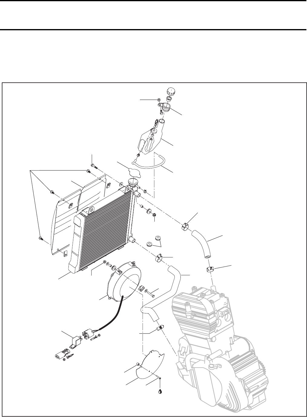
Section 03 ENGINE
Subsection 05 (COOLING SYSTEM)
VMR2004_009_03_05A.FM 03-05-1
COOLING SYSTEM 0
RADIATOR
V02C4ES
11 Nm
(97 lbfin)
25
Loctite 271
9
2
1
3.5 Nm
(31 lbfin)
21
19
8
28
31
32 30
1.5 Nm
(14 lbfin)
2.5 Nm
(22 lbfin)
2.5 Nm
(22 lbfin)
17
2.5 Nm
(22 lbfin)
18
2.5 Nm
(22 lbfin)
11 Nm
(97 lbfin)
34
29
27
11 Nm
(97 lbfin)
20
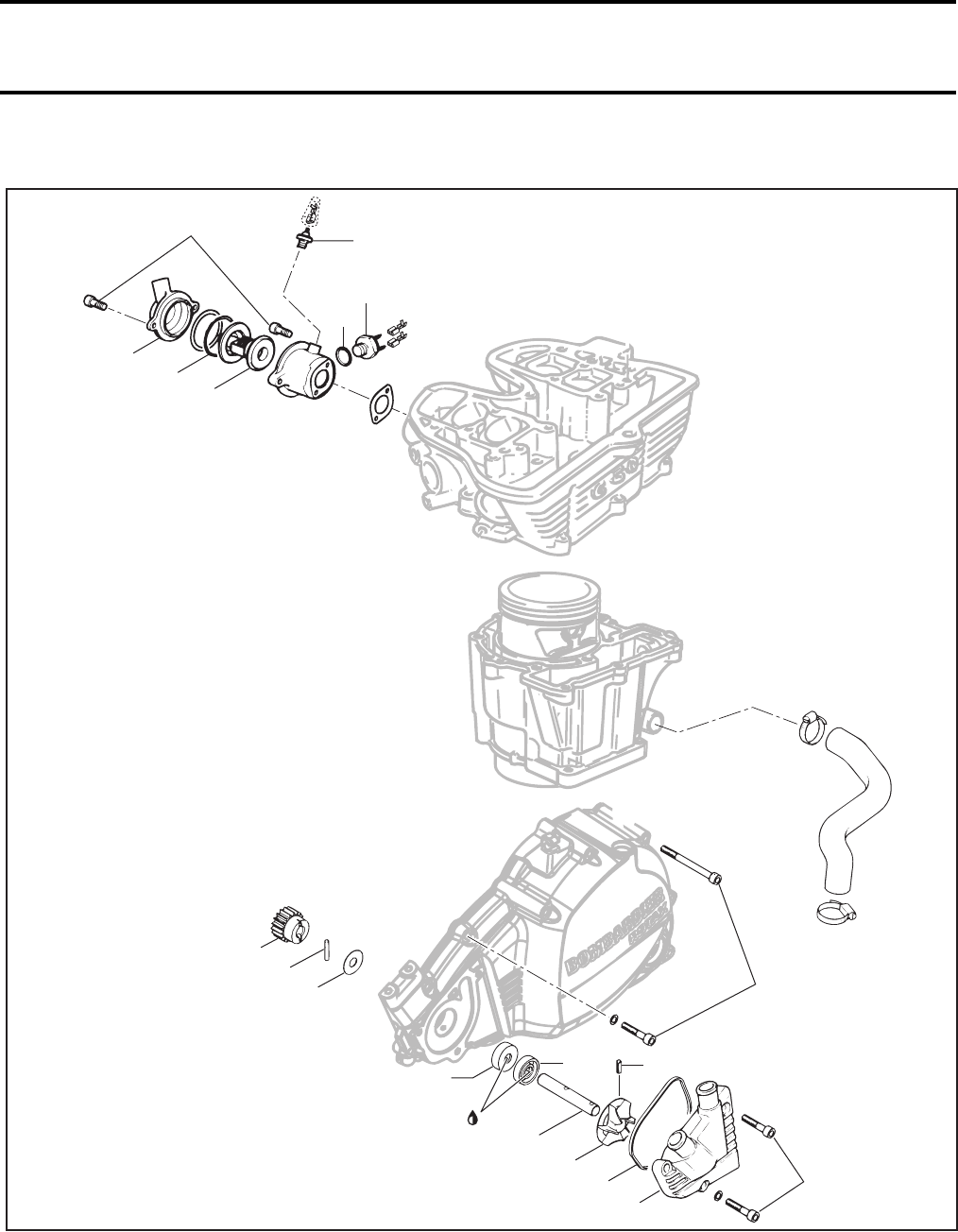
Section 03 ENGINE
Subsection 05 (COOLING SYSTEM)
03-05-2 VMR2004_009_03_05A.FM
WATER PUMP
V02C4FS
6 Nm
(53 lbfin)
23
24
22
712 Nm
(106 lbfin)
26 35 Nm
(26 lbfft)
33
10 Nm
(89 lbfin)
11
Molykote 111
13
43
12
10
6
510 Nm
(89 lbfin)
14
15
16
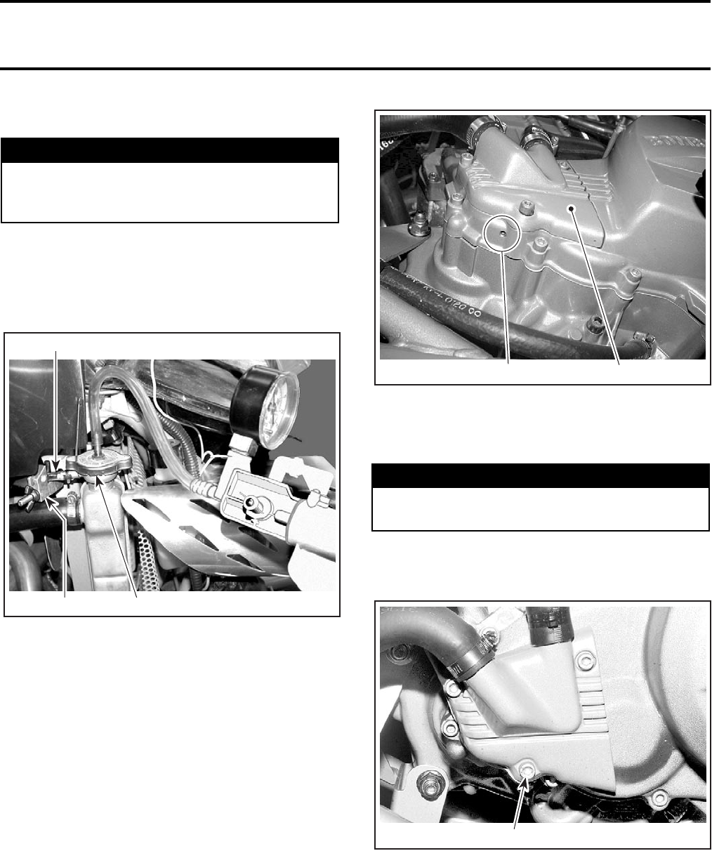
Section 03 ENGINE
Subsection 05 (COOLING SYSTEM)
VMR2004_009_03_05A.FM 03-05-3
COOLING SYSTEM LEAK TEST
Remove radiator pressure cap no. 1.
Install special plug (radiator cap) (P/N 529 021 400)
and hose pincher (P/N 529 009 900) on overflow
hose no. 2. Pressurize all system through coolant
reservoir to 103 kPa (15 PSI).
1. Special radiator plug
2. Hose pincher
3. Overflow hose
Check all hoses, radiator and cylinder/base for cool-
ant leaks. Spray a soap/water solution and look for
air bubbles.
INSPECTION
Check general condition of hoses and clamp tight-
ness.
Check the weep hole if there is oil or water.
NOTE: Water indicates a damaged seal no. 3. Oil
out of the weep hole indicates a non working oil
seal no. 4.
1. Weep hole
2. Water pump housing
DRAINING THE SYSTEM
To drain cooling system, unscrew cooling plug
no. 5 on water pump cover no. 6 and remove ra-
diator pressure cap no. 1.
1. Cooling plug
WARNING
To prevent burning yourself, do not remove
the radiator cap or loosen the engine drain
plug if the engine is hot.
1
V02C4GA 2
3
WARNING
Never drain or refill cooling system when en-
gine is hot.
1
V02C3OA 2
V02C10A 1
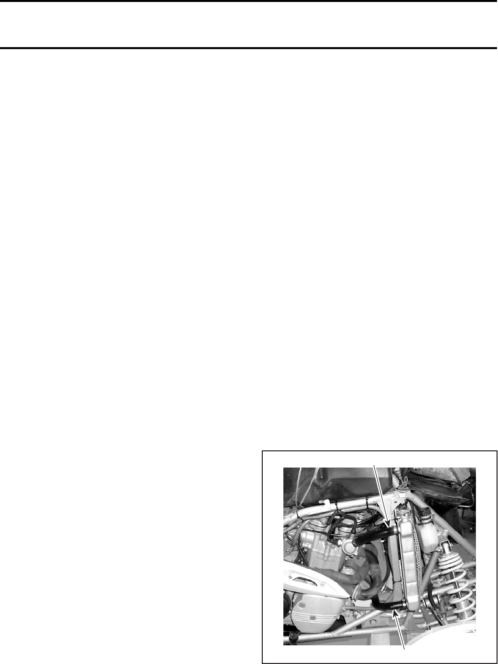
Section 03 ENGINE
Subsection 05 (COOLING SYSTEM)
03-05-4 VMR2004_009_03_05A.FM
COOLING SYSTEM REFILLING
Recommended Coolant
Use a blend of 50% antifreeze with 50% water.
CAUTION: To prevent rust formation or freezing
condition, always replenish the system with 50%
antifreeze and 50% water. Pure antifreeze without
water freezes. Always use ethylene-glycol anti-
freeze containing corrosion inhibitors specifically
recommended for aluminum engines.
System Capacity
Refer to TECHNICAL DATA.
Refilling Procedure
With vehicle on a flat surface, engine cold, remove
the temperature sensor no. 7 on the top of ther-
mostat housing. Fill radiator no. 8 until coolant get
out by the temperature sensor hole. Install the
temperature sensor and continue the cooling sys-
tem filling by the radiator. Fill coolant tank no. 9 up
to cold level mark. Install radiator pressure cap.
Run engine for brief period then stop engine. Refill
up to mark, if necessary.
When engine has completely cooled down, re-
check coolant level in radiator no. 8 and coolant
tank no. 9 and top up if necessary.
Check coolant concentration (freezing point) with
proper tester.
PRESSURE CAP
Check if radiator pressure cap no. 1 pressurizes
the system. If not, install a new 110 kPa (16 PSI)
radiator pressure cap (do not exceed this pres-
sure).
WATER PUMP
Removal
Drain coolant.
Remove water pump cover no. 6 from water
pump with O-ring no. 10.
Drive out spring pin no. 11 and remove impeller
no. 12.
Remove left engine housing cover.
Remove shaft no. 13 by pulling inwards.
Remove thrust washer no. 14, needle pin no. 15
and gear no. 16.
Press out sealing rings no. 3 and no. 4.
Inspection
Check shaft no. 13 for traces of sealing rings and
replace if necessary.
Check if the O-ring no. 10 in water pump cover is
brittle, hard or otherwise damaged.
Installation
For installation, reverse the removal procedure.
NOTE: Do not drive spring pin into impeller until
engine housing cover has been installed.
Drive internal sealing ring no. 4 firmly into place.
Fill cavity between sealing rings with Molykote 111
paste.
Drive external sealing ring no. 3 into place with the
relevant adapter until flush with the race.
RADIATOR
Removal
Drain cooling system.
Remove:
–front facia (refer to BODY)
–inlet no. 17 and outlet no. 18 hoses
1. Radiator inlet hose
2. Radiator outlet hose
1
V02C11A 2
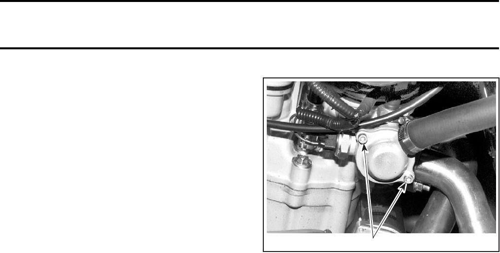
Section 03 ENGINE
Subsection 05 (COOLING SYSTEM)
VMR2004_009_03_05A.FM 03-05-5
–overflow hose no. 2
–headlight
–ignition coils
–radiator protector
–radiator mounting bolts no. 19 on the top.
Pull radiator no. 8 out of frame by the RH side.
Inspection
Check radiator air passage for clogging or damage.
Remove insects, mud or other obstructions with
compressed air or low pressure water.
Check for any coolant leakage from radiator and
hoses.
Installation
For installation, reverse the removal procedure.
Refill radiator.
NOTE: Do not forget rubber bushings no. 34 un-
der radiator.
RADIATOR PROTECTOR
Removal
Remove screws no. 20 retaining protector no. 21
on radiator.
Inspection
Check protector air passage for damage.
Remove insects, mud or other obstructions with
compressed air or low pressure water.
Installation
For installation, reverse the removal procedure.
THERMOSTAT
The thermostat no. 22 is a single action type.
Removal
The thermostat is located on the RH side of engine.
Unfasten cover no. 23 from thermostat housing.
RH SIDE OF ENGINE
1. Remove screws
Pull out thermostat. Catch spilled coolant.
Remove O-ring no. 24. Check O-ring for damage
and change if necessary.
Test
To check thermostat, put in water and heat water.
Thermostat should begin to open when water
temperature reaches 75°C (167°F).
Installation
For installation, reverse the removal procedure.
Install the thermostat cover then torque screws to
6 N•m (53 lbf•in).
Check coolant level in radiator and coolant tank
and top up if necessary.
COOLANT TANK
Overflow Coolant Tank
The coolant expands as the temperature (up to
100 - 110°C (212 - 230°F)) and pressure rise in the
system. If the limiting system working pressure
cap is reached 110 kPa (16 PSI), the pressure relief
valve in the pressure cap is lifted from its seat and
allows coolant to flow through the overflow hose
into the overflow coolant tank.
Removal
Remove overflow hose no. 2.
Unfasten the hose anchor no. 25 retaining coolant
tank.
Empty coolant tank.
V02C12A 1

Section 03 ENGINE
Subsection 05 (COOLING SYSTEM)
03-05-6 VMR2004_009_03_05A.FM
Installation
The installation is the reverse of the removal pro-
cedure.
FAN AND HEAT SHIELD
Test
Unplug temperature switch connectors.
Install a jumper wire end between both connec-
tors. Turn ignition key ON.
If the fan works correctly:
–Check temperature switch no. 26. Refer to
TEMPERATURE SWITCH section.
If the fan no. 27 does not work, check:
–fuse
1. Fan (15 A)
2. Charging system (25 A)
–fan relay no. 28
(Baja model only, see procedure below)
1. Fan relay
2. Electronic box
3. Fuel tank cover
–wiring harness and connectors.
If the fan does not work after all tests, replace it.
Fan Relay Testing Procedure
Baja Model Only
The relay is located near the electronic box, on the
left side of vehicle.
Use the following points to check the fan relay.
Remove relay.
Jump the temperature switch connectors, install
another jumper between RED/VIOLET and BLACK
wires of relay connector.
Replace the relay if the fan works properly.
If the fan does not work, check wiring harness and
connectors. Replace fan if necessary.
V02C4HA
1
2
V02G0TA
2
3
V02G0UA 1
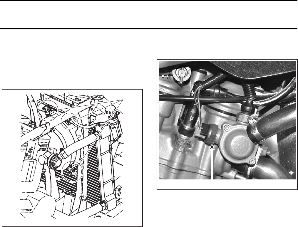
Section 03 ENGINE
Subsection 05 (COOLING SYSTEM)
VMR2004_009_03_05A.FM 03-05-7
Fan Removal
Unscrew bolts no. 29, and pull fan in exhaust di-
rection.
NOTE: The exhaust can be remove to allow an
easy access to the fan.
1. Remove bolts (two bolts on each side)
Unplug fan connector.
Fan Installation
For the installation, reverse the removal proce-
dure.
Heat Shield Removal
Remove fan.
Remove bolts no. 30 and spacers no. 31 retaining
heat shield no. 32.
Heat Shield Installation
The installation is the reverse of the removal pro-
cedure.
NOTE: Apply Loctite 271 on threads.
TEMPERATURE SWITCH
1. Temperature switch
Removal
Unplug temperature switch connectors.
Unscrew temperature switch no. 26.
Test
Using a multimeter, measure the resistance be-
tween both temperature switch connectors.
The multimeter should indicate an infinite resis-
tance (O.L.), if not change the temperature switch.
If the resistance is infinite (O.L.), heat the temper-
ature sender, above 95°C (203°F). The resistance
should be 0.1 Ω. If not, change the temperature
sender.
Installation
The installation is the reverse of the removal pro-
cedure, paying attention to the following detail.
Check gasket no. 33 and change if necessary.
CAUTION: Do not apply any product on the
threads or on the gasket.
1
V02C4JA
1
V02C4IA
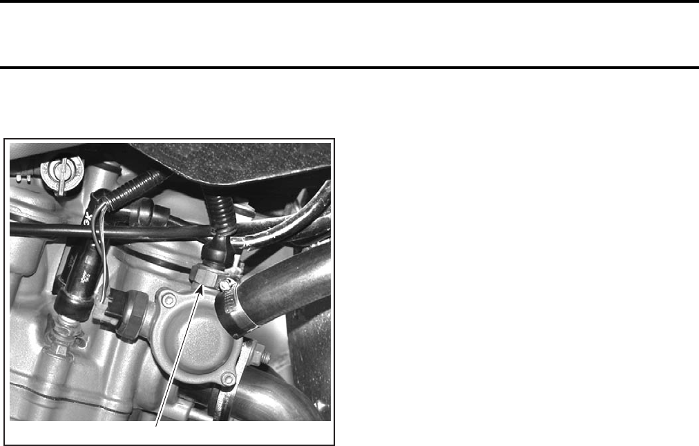
Section 03 ENGINE
Subsection 05 (COOLING SYSTEM)
03-05-8 VMR2004_009_03_05A.FM
TEMPERATURE SENSOR
1. Temperature sensor
Removal
Unplug temperature sensor connector.
Unscrew temperature sensor no. 7.
Test
Using a multimeter, measure the resistance be-
tween connector on the top of temperature sen-
sor and threads.
The multimeter should indicate an infinite resis-
tance (O.L.), if not change the temperature sensor.
If the resistance is infinite (O.L.), heat the temper-
ature sensor, above 115°C (239°F). The resistance
should be 0.1 Ω. If not, change the temperature
sensor.
Installation
The installation is the reverse of the removal pro-
cedure.
CAUTION: Do not apply any product on the
threads.
1
V02C4IB
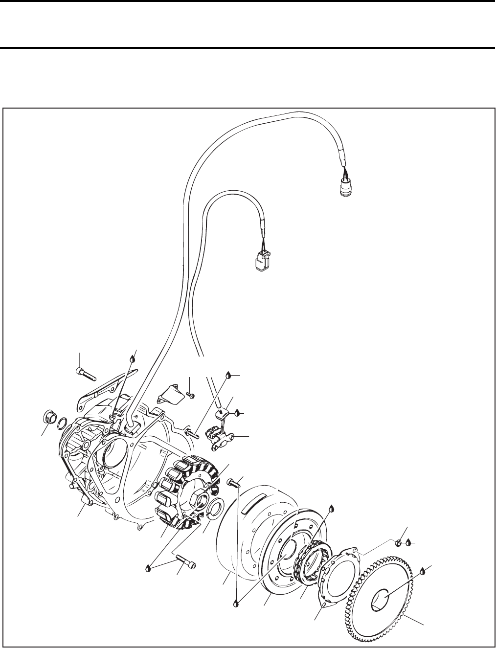
Section 03 ENGINE
Subsection 06 (MAGNETO SYSTEM)
VMR2004_010_03_06A.FM 03-06-1
MAGNETO SYSTEM 0
V02C0MT
10 Nm
(89 lbfin)
5
6
1
7
10 Nm
(89 lbfin)
Loctite
243
2
10
12
Engine
oil
Loctite
648
10 Nm
(89 lbfin)
3
Engine
oil
Loctite
648
11
10 Nm (89 lbfin)
14
180 Nm (133 lbfft)
9
4
2
15
Loctite 243
8 Nm
(71 lbfin)
8 Nm
(71 lbfin)
Sealing
Compound
Dreibond
Sealing
Compound
Dreibond
13
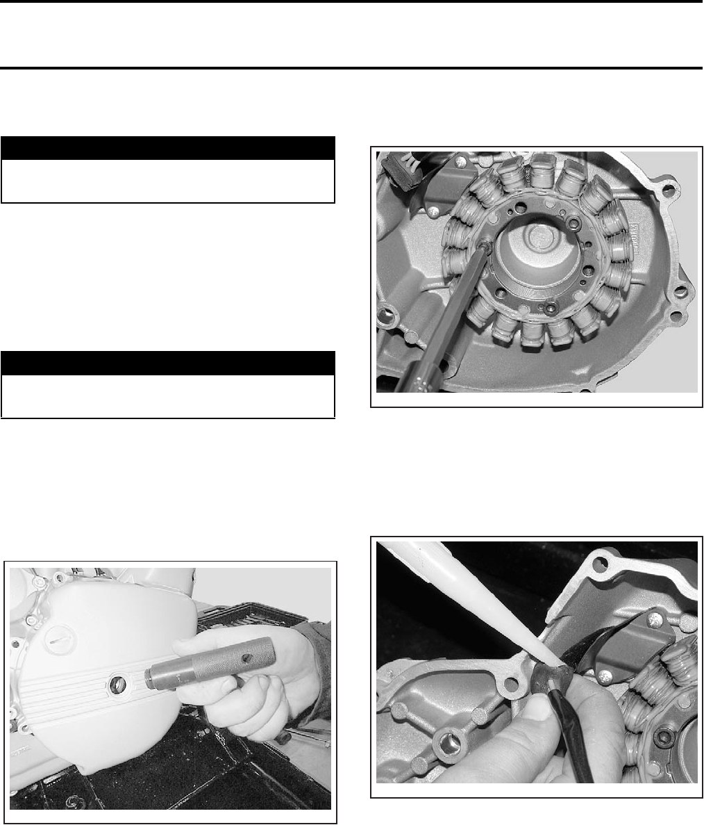
Section 03 ENGINE
Subsection 06 (MAGNETO SYSTEM)
03-06-2 VMR2004_010_03_06A.FM
GENERAL
The engine removal is not necessary to work on
the magneto system.
At installation, use torque values and Loctite prod-
ucts from the exploded view. Clean threads before
using Loctite products when installing screws.
STATOR
Removal
To reach the stator no. 1, unfasten socket screws
on ignition cover.
Unfasten central screw plug no. 5, screw in the
handle (P/N 529 035 622) and remove ignition
cover no. 6.
RH SIDE
Remove gasket.
NOTE: Clean all metal component in a non-ferrous
metal cleaner. Use Bombardier gasket remover
(P/N 413 708 500) or suitable equivalent.
Remove all socket screws no. 7 retaining stator to
ignition cover then pull stator.
Installation
For installation, reverse the removal procedure.
Pay attention to the following details.
Seal rubber grommet no. 8 on electrical line with
sealing compound Dreibond (P/N 420 297 906).
Screw handle in center bore.
Fit ignition cover and screw down.
Unfasten handle and install screw plug in ignition
cover.
NOTE: Install a new gasket on ignition cover.
WARNING
Always disconnect BLACK (-) cable first and
reconnect last.
WARNING
Never disconnect harness on ignition system
while engine is running.
V02C0NA
V02C4QA
V02C4RA
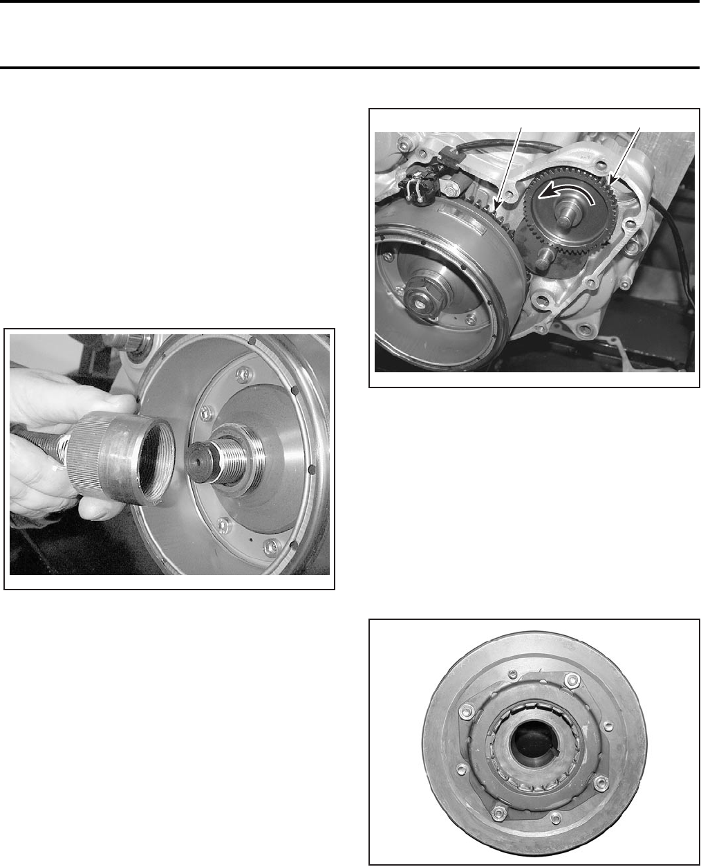
Section 03 ENGINE
Subsection 06 (MAGNETO SYSTEM)
VMR2004_010_03_06A.FM 03-06-3
ROTOR
Removal
Lock crankshaft with locking bolt (P/N 529 035
617). Refer to CRANKSHAFT/BALANCER SHAFT.
Remove ignition cover no. 6.
Unscrew nut no. 9 retaining rotor no. 2.
Remove lock washer no. 10.
Install magneto puller (P/N 420 976 235) and
crankshaft protector (P/N 420 876 557) then re-
move rotor.
Installation
For installation, reverse the removal procedure.
Pay attention to the following details.
Apply light coat of Loctite 648 to taper on rotor hub
no. 11.
CAUTION: Taper on crankshaft and rotor must
be free of grease.
Oil sprag clutch no. 3 in sprag clutch housing
no. 12.
Slide rotor onto crankshaft. The woodruff key and
groove must be aligned in one line.
Rotate starter double gear counterclockwise to
enable the sprag clutch no. 3 to slide on the collar
of sprag clutch gear no. 13.
1. Starter double gear
2. Sprag clutch gear
Install lock washer and nut on crankshaft end. Ap-
ply Loctite 243 on threads. Torque to 180 N•m
(133 lbf•ft).
SPRAG CLUTCH
Removal
Remove rotor no. 2.
Unscrew all socket screws no. 14 retaining rotor
and sprag clutch housing no. 12.
Remove sprag clutch no. 3 from sprag clutch
housing.
V02C0OA
1
V02C4SA
2
V02C4TA
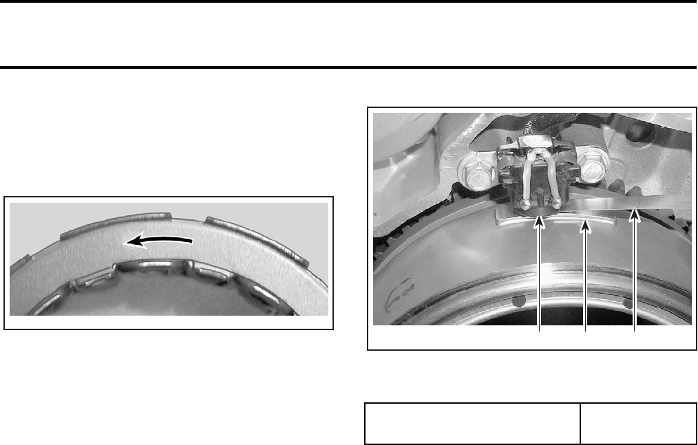
Section 03 ENGINE
Subsection 06 (MAGNETO SYSTEM)
03-06-4 VMR2004_010_03_06A.FM
Installation
For installation, reverse the removal procedure.
NOTE: Apply engine oil on sprag clutch.
Install sprag clutch. The arrow should be visible.
TRIGGER COIL
Test
Refer to IGNITION SYSTEM for the proper proce-
dure.
Removal
Remove the ignition cover no. 6.
Unscrew taptite screws no. 15 retaining trigger
coil no. 4 to housing then remove trigger coil.
Installation
Coat rubber grommet no. 8 of trigger coil with
sealing compound Dreibond (P/N 420 297 906)
and install in housing.
Secure trigger coil with taptite screws and fix
screws with Loctite 243.
Twist rotor no. 2 until guide piece faces towards
trigger coil.
Use feeler gauge to measure gap between guide
piece and trigger coil.
1. Guide piece
2. Trigger coil
3. Feeler gauge
If necessary, correct gap by bending the retaining
plate.
Coat rubber grommet on trigger coil and line from
magneto in ignition cover beside sealing face with
sealing compound Dreibond (P/N 420 297 906).
Fit gasket.
ROTOR HUB
The rotor hub no. 11 is located behind the rotor.
Removal
Remove:
–rotor no. 2
–sprag clutch housing no. 12 and sprag clutch
no. 3
–socket screws no. 14 retaining rotor and rotor
hub assembly.
Separate rotor hub from rotor.
V02C0PA
GAP BETWEEN GUIDE PIECE
AND TRIGGER COIL
0.75 ± 0.25 mm
(.03 ± .01 in)
2
V02C0QA 13
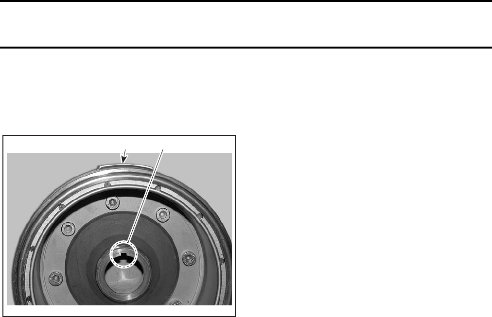
Section 03 ENGINE
Subsection 06 (MAGNETO SYSTEM)
VMR2004_010_03_06A.FM 03-06-5
Installation
Reinstall all parts.
Before torque, check if the protrusion of rotor is
aligned with the key way in the center of rotor hub.
1. Rotor protrusion
2. Rotor hub key way
1
V02C4UA
2
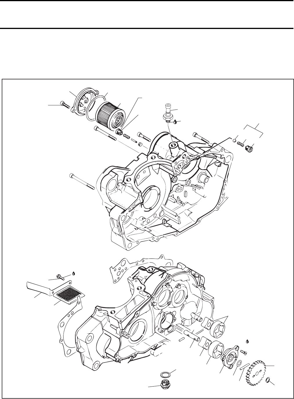
Section 03 ENGINE
Subsection 07 (LUBRICATION SYSTEM)
VMR2004_011_03_07A.FM 03-07-1
LUBRICATION SYSTEM 0
ENGINE LUBRICATION
V02C3VS
10 Nm
(89 lbfin)
8 9
1
11
25 Nm
(18 lbfft)
Loctite 243
3
10 Nm
(89 lbfin)
1615
14
13
10 Nm
(89 lbfin)
10 Nm
(89 lbfin)10 Nm
(89 lbfin)
25 Nm
(18 lbfft)
8 Nm
(71 lbfin)
28
Loctite 243
29
27
30 Nm
(22 lbfft)
7
10
23
24
25
22 21
20 18
19
6 Nm
(53 lbfin)
Loctite 243
17
26
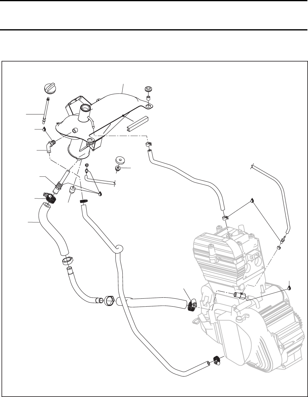
Section 03 ENGINE
Subsection 07 (LUBRICATION SYSTEM)
03-07-2 VMR2004_011_03_07A.FM
OIL TANK
Loctite
pipe sealant
Loctite 277
12
6
20 Nm
(15 lbfft)
Loctite
pipe sealant
3.5 Nm
(31 lbfin)
30
2
4
5
2.5 Nm
(22 lbfin)
2.5 Nm
(22 lbfin)
5 Nm
(44 lbfin)
Loctite
pipe sealant
V02C3WS
20 Nm
(15 lbfft)
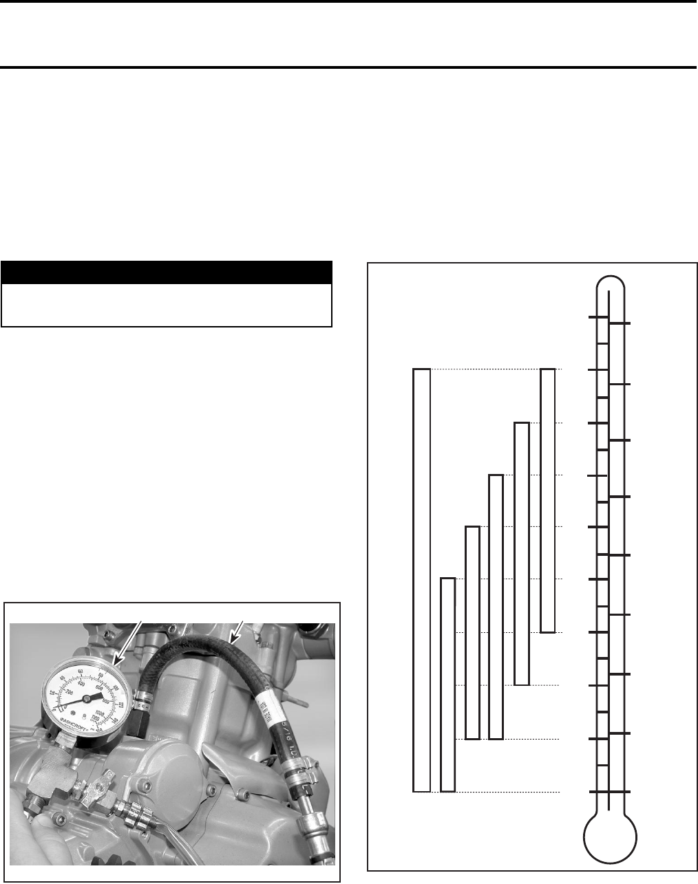
Section 03 ENGINE
Subsection 07 (LUBRICATION SYSTEM)
VMR2004_011_03_07A.FM 03-07-3
GENERAL
Prior to changing the engine oil, ensure vehicle is
on a level surface.
Oil and oil filter no. 1 must be replaced at the same
time and oil tank strainer no. 2 must be cleaned
too. Oil change, oil filter replacement and oil tank
strainer cleaning should be done with a warm en-
gine.
Dispose oil and filter as per your local environmen-
tal regulations.
At installation, use torque values and Loctite prod-
ucts from the exploded view. Clean threads before
using Loctite products when installing screws.
ENGINE PRESSURE TEST
NOTE: The engine pressure test should be done
with a warm engine and with the recommended
oil at the proper level.
Remove the oil pressure switch no. 3 above oil
filter and install the engine oil pressure adapter
(P/N 529 035 652) and the oil pressure gauge
(P/N 529 035 709).
1. Oil pressure adapter
2. Oil pressure gauge
The engine pressure should be 50 kPa (7 PSI) min-
imum at idle and 300 kPa (44 PSI) at 6000 RPM.
NOTE: The maximum oil pressure is 600 kPa
(87 PSI).
If the engine pressure is out of specifications,
check the points described in TROUBLESHOOT-
ING section.
OIL CHANGE AND OIL FILTER
REPLACEMENT
Ensure vehicle is on a level surface.
Remove dipstick no. 4.
Clean the reservoir drain plug area.
WARNING
The engine oil can be very hot. Wait until en-
gine oil is warm.
1
V02C3XA
2
SAE 10W30
SAE 10W40
SAE 15W40
SAE 20W50
°C °F
60
50
40
30
20
10
-10
-20
-30
0
140
120
100
80
60
40
20
0
-20
SAE 5W30
V01A37A
BOMBARDIER SYNTHETIC OIL 5W40 (P/N 293 600 039)
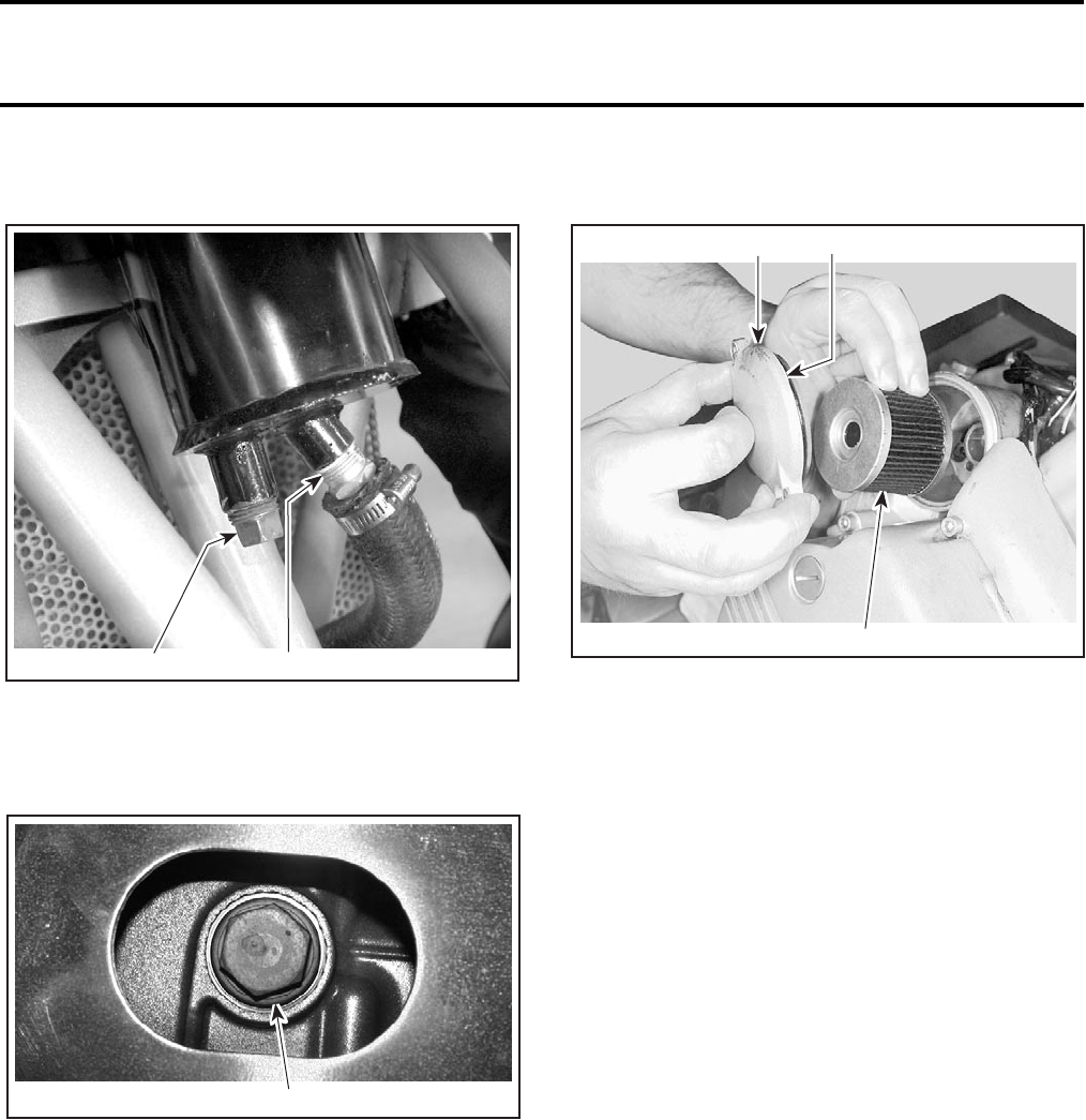
Section 03 ENGINE
Subsection 07 (LUBRICATION SYSTEM)
03-07-4 VMR2004_011_03_07A.FM
Drain all oil from oil tank no. 5 by removing oil tank
drain plug no. 6. Wipe out any oil spillage.
1. Oil tank drain plug
2. Oil tank strainer
Place a drain pan under the engine drain plug area.
Unscrew engine drain plug no. 7.
UNDER VEHICLE
1. Oil drain plug
Wait a while to allow oil to flow out of oil filter.
Unscrew oil filter cover no. 8.
Remove oil filter and replace by a new.
NOTE: Check and change O-ring no. 9, if neces-
sary.
TYPICAL — RH SIDE OF VEHICLE
1. Oil filter cover
2. Oil filter
3. O-ring
Wipe out any oil spillage on engine.
Change gasket no. 10 on engine drain plug. Clean
gasket area on engine and drain plug then reinstall
plug. Refill oil tank at the proper level with the
recommended oil. Refer to TECHNICAL DATA
for capacity.
Start engine and let idle for a few minutes. Ensure
oil filter area, hoses and drain plug areas are not
leaking.
Check if the RED indicator lamp stays ON, if so,
stop engine and bleed system by removing oil
filter and bleeding screw no. 11. Refer to BLEED-
ING ENGINE OIL CIRCUIT below.
If the RED indicator light turns OFF, the system is
good.
Stop engine and recheck oil level. Refill as neces-
sary.
Dispose oil as per your local environmental regu-
lations.
1
V02C3YA 2
1
V02C4XA
2
13
V02C04A
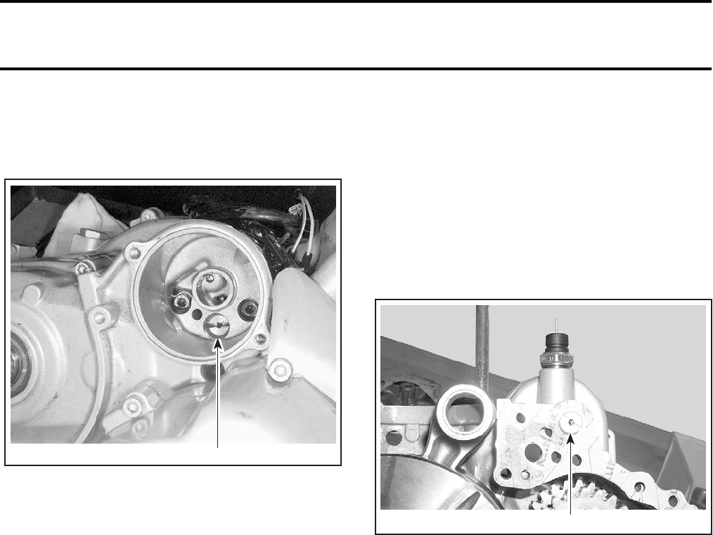
Section 03 ENGINE
Subsection 07 (LUBRICATION SYSTEM)
VMR2004_011_03_07A.FM 03-07-5
Bleeding Engine Oil Circuit
Remove oil filter no. 1.
Unfasten bleeding screw no. 11.
BEHIND OIL FILTER
1. Bleeding screw
Unscrew and remove one spark plug.
Turn engine using starter until oil emerges in filter
chamber.
Install bleeding screw.
Install oil filter.
OIL TANK STRAINER
The oil tank strainer no. 2 is located under oil tank
no. 5.
Removal
Ensure vehicle is on a level surface.
Drain oil tank.
Remove hose no. 12 under oil tank.
Unscrew and remove oil tank strainer.
Cleaning and Inspection
Clean oil tank strainer with a parts cleaner then
use an air gun to dry it.
Installation
For installation, reverse the removal procedure.
NOTE: Apply Loctite pipe sealant on oil tank strainer
threads.
ENGINE OIL PRESSURE
REGULATOR
The engine oil pressure regulator no. 13 is located
in magneto side of the crankcase housing.
1. Engine oil pressure regulator
Removal
Separate both crankcase housings. Refer to
CRANKSHAFT/BALANCER SHAFT section.
Remove plug screw no. 14, compression spring
no. 15 and ball no. 16.
Inspection
Check compression spring for squareness or oth-
er damage.
Installation
For installation, reverse the removal procedure.
1
V02C05A
1
V02C0CA
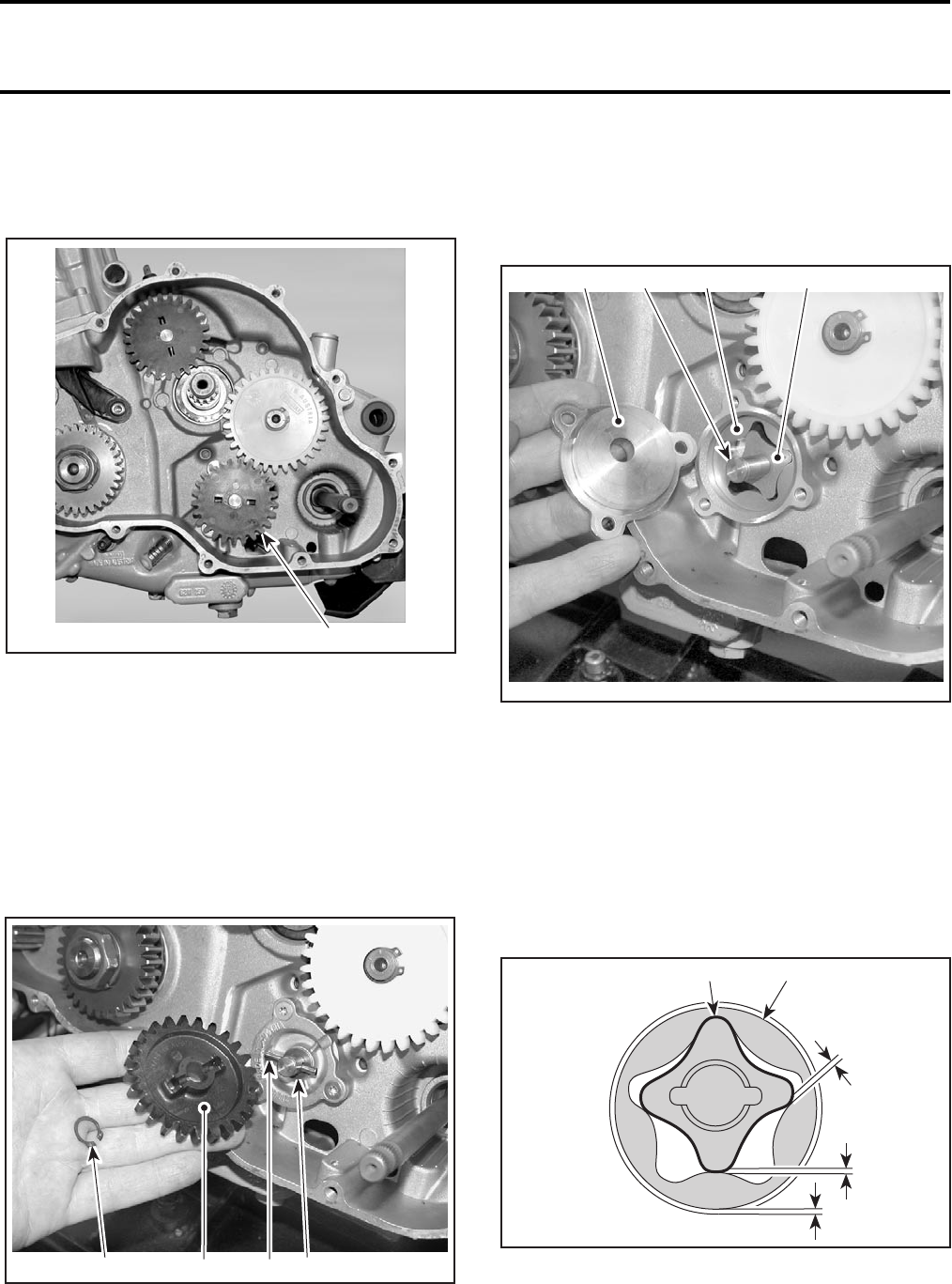
Section 03 ENGINE
Subsection 07 (LUBRICATION SYSTEM)
03-07-6 VMR2004_011_03_07A.FM
RETURN OIL PUMP
The return oil pump no. 17 is located on the clutch
side of the crankcase housing.
1. Return oil pump
Removal
Remove clutch. Refer to CLUTCH.
Remove:
–snap ring no. 18
–oil pump gear no. 19
–needle pin no. 20
–thrust washer no. 21
1. Snap ring
2. Oil pump gear
3. Needle pin
4. Thrust washer
–oil pump cover no. 22
–oil pump shaft no. 23
–oil pump rotor no. 24
–inner rotor no. 25.
1. Oil pump cover
2. Oil pump shaft
3. Oil pump rotor
4. Inner rotor
Inspection
Inspect oil pump for marks or other damages, spe-
cially scratches in crankcase between inlet and
outlet parts.
Using a feeler gauge, measure the clearance be-
tween oil pump rotor and inner rotor.
1. Oil pump rotor
2. Inner rotor
1
V02C3ZA
1
V02C40A 234
1
V02C41A
23 4
V01C1VA
2 1
C
B
A
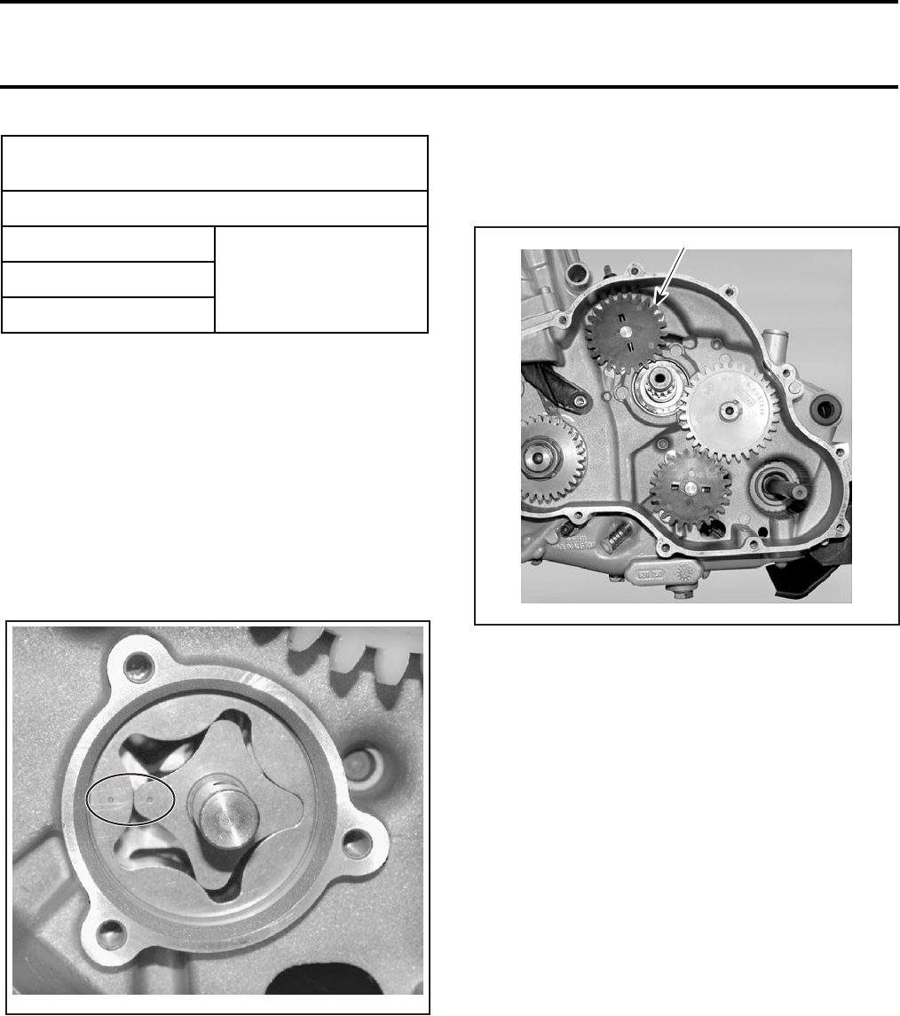
Section 03 ENGINE
Subsection 07 (LUBRICATION SYSTEM)
VMR2004_011_03_07A.FM 03-07-7
Measure oil pump rotor thickness and oil pump
rotor bore depth.
Difference between measurements should not
exceed 0.25 mm (0.009 in). If so, replace oil pump
rotor.
Installation
For installation, reverse the removal procedure.
Pay attention to the following details.
Markings on inner rotor and oil pump rotor must
be visible.
Coat inner rotor and oil pump rotor with oil.
PRESSURE OIL PUMP
The pressure oil pump no. 26 is located near the
return oil pump.
1. Pressure oil pump gear
For removal, inspection and installation, use the
same procedures that return oil pump.
ENGINE OIL STRAINER
The engine oil strainer no. 27 is located between
both crankcase housings.
Removal
Separate both crankcase housings. Refer to
CRANKSHAFT/BALANCER SHAFT section.
Unscrew the bolts no. 28 retaining the oil strainer
guide no. 29.
Cleaning and Inspection
Clean engine oil strainer with a parts cleaner then
use an air gun to dry it.
Check engine oil strainer for damage and change
if necessary.
Installation
For installation, reverse the removal procedure.
OIL PUMP ROTOR AND INNER ROTOR
CLEARANCE
SERVICE LIMIT
A
0.25 mm (0.009 in)B
C
V02C42A
1
V02C3ZB

Section 03 ENGINE
Subsection 07 (LUBRICATION SYSTEM)
03-07-8 VMR2004_011_03_07A.FM
OIL TANK
The oil tank is located under front facia, near the
headlight.
Removal
Drain oil tank.
Remove the front facia.
Unscrew headlight then disconnect and remove it.
Remove nut no. 30.
Unscrew bolts retaining fuel tank cover and oil
tank to the frame.
Unplug all hoses then remove oil tank.
Installation
The installation is the reverse of the removal pro-
cedure.
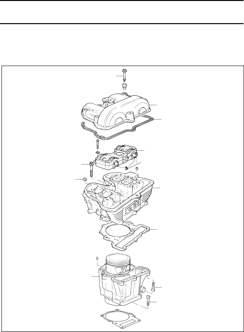
Section 03 ENGINE
Subsection 08 (CYLINDER AND HEAD)
VMR2004_012_03-08A.FM 03-08-1
CYLINDER AND HEAD 0
CYLINDER AND HEAD
V02C47S
10 Nm
(89 lbfin)
10 Nm
(89 lbfin)
33 Nm
(24 lbfft)
10 Nm
(89 lbfin)
10 Nm
(89 lbfin)
60 Nm
(44 lbfft)
Engine oil
1
6
21
29
20
19
18
30
2
3
22
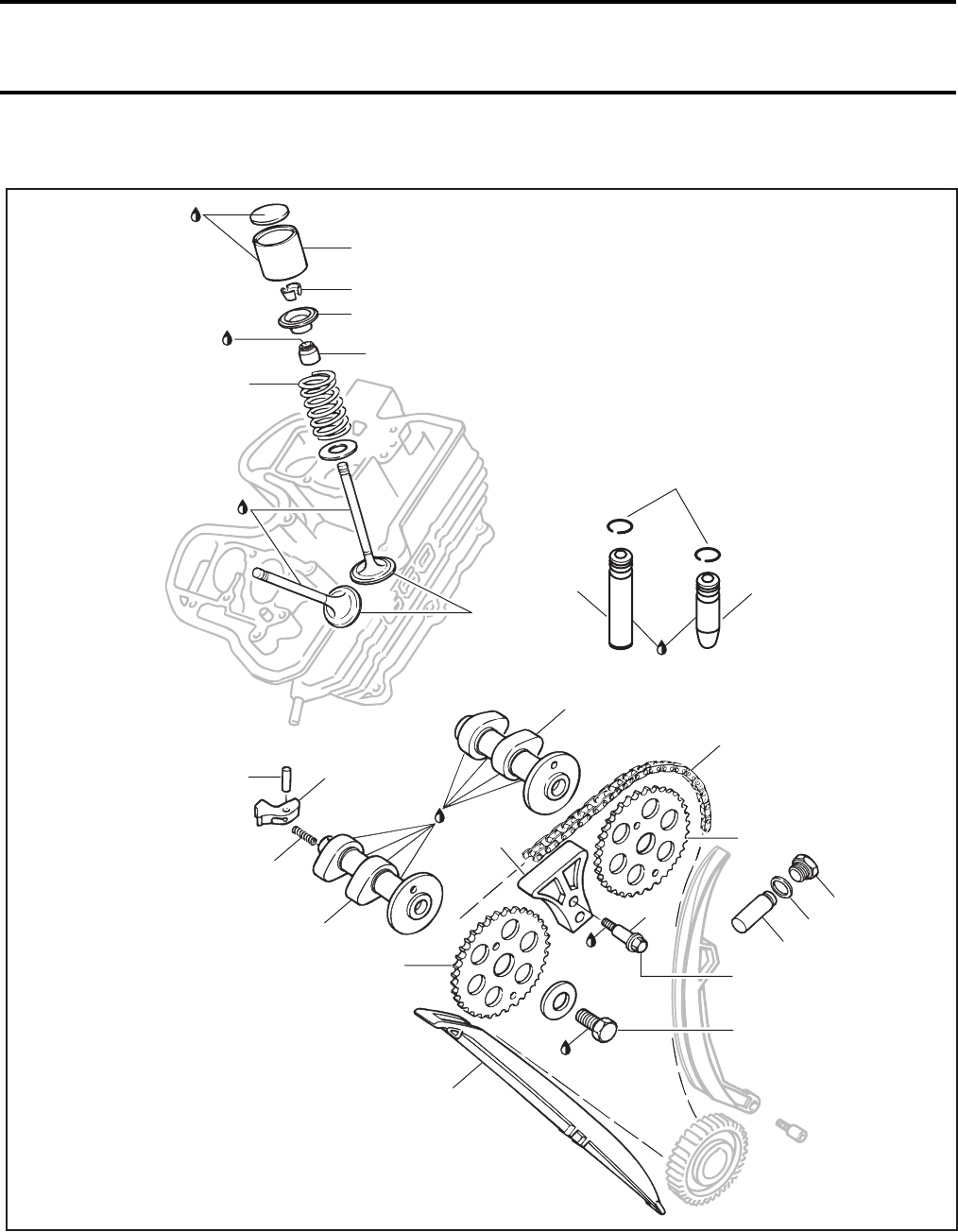
Section 03 ENGINE
Subsection 08 (CYLINDER AND HEAD)
03-08-2 VMR2004_012_03-08A.FM
VALVE
V02C4YS
Engine oil
23
24
25
28
26
27
Engine oil
Engine oil
8
7
15
17
16
10
11
13
14
4
9
9
5
12
10 Nm
(89 lbfin)
Loctite
243
Loctite
648
50 Nm
(37 lbfft)
40 Nm
(30 lbfft)
Super Lube
grease
31
32
32
Anti-seize
lubricant
Section 03 ENGINE
Subsection 08 (CYLINDER AND HEAD)
VMR2004_012_03-08A.FM 03-08-3
GENERAL
NOTE: When diagnosing an engine problem, al-
ways perform the cylinder leak test. This will help
pin-point a problem. Refer to the instructions in-
cluded with your leak tester and LEAK TEST sec-
tion for procedures.
Always place the vehicle on a level surface.
NOTE: For a better understanding, the following
illustrations are taken with engine out of vehicle.
To perform the following instructions, it is not nec-
essary to remove engine from vehicle.
Always disconnect the negative wire from the bat-
tery before working the engine.
Even if the removal of many parts is not necessary
to reach another part, it is recommended to re-
move these parts in order to check them.
During assembly/installation, use the torque val-
ues and service products as in the exploded views.
Clean threads before applying a threadlocker. Re-
fer to SELF-LOCKING FASTENERS and LOCTITE AP-
PLICATION at the beginning of this manual for com-
plete procedure.
When disassembling parts that are duplicated in
the engine, (eg: valves, springs, etc.), it is strongly
recommended to note their position (PTO, MAG
side) and to keep the parts of the same assembly
as a “group”. If you find a defective component,
it will be much easier to find the cause of the fail-
ure among its group of parts (eg: you found a worn
valve guide. A bent spring could be the cause; it
will be easy to know which one of the springs is
the cause and to replace it if you grouped the parts
of the same assembly at disassembly). Besides,
since used parts have matched together during
the engine operation, they will keep their matched
fit when you reassemble them together within
their “group”.
CYLINDER HEAD COVER
Removal
Remove fuel tank. Refer to FUEL CIRCUIT sec-
tion.
Remove the breather hose on the top of cylinder
head cover no. 1.
Unscrew all bolts no. 2 retaining the cover.
Remove the cover with the gasket no. 3.
Inspection
Check the cylinder head cover for cracks or other
damages.
Check if the gasket is brittle, hard or otherwise
damaged.
Replace all defective parts.
Installation
Reinstall the cover. To do this, reverse the removal
procedure.
Take care that the gasket is located properly into
the groove in the cover.
WARNING
Always disconnect BLACK (-) cable first and
reconnect last.
WARNING
Torque wrench tightening specifications must
strictly be adhered to.
Locking devices (ex.: locking tabs, elastic stop
nuts, self-locking fasteners, cotter pin, etc.)
must be installed or replaced with new ones
where specified. If the efficiency of a locking
device is impaired, it must be renewed.
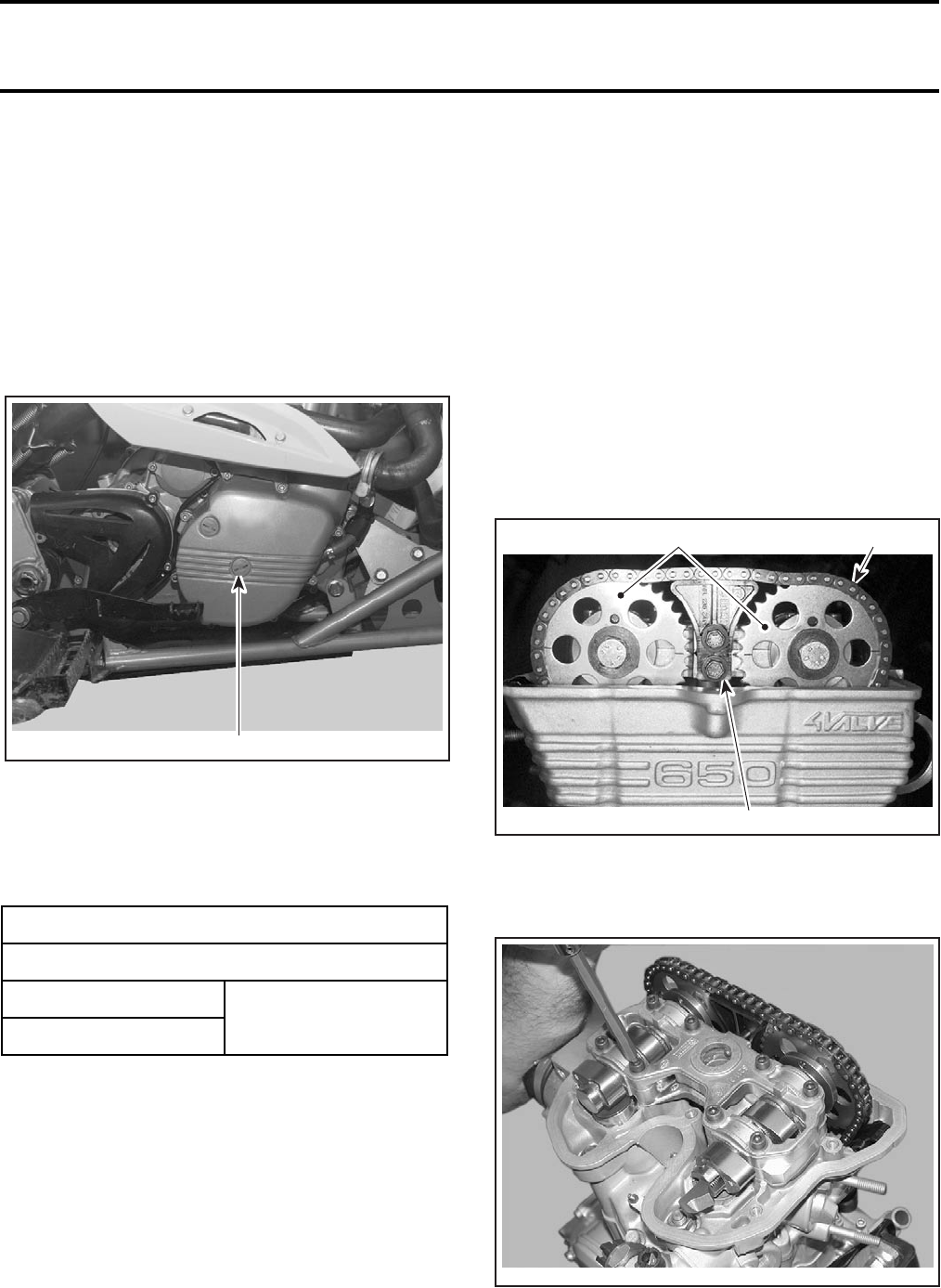
Section 03 ENGINE
Subsection 08 (CYLINDER AND HEAD)
03-08-4 VMR2004_012_03-08A.FM
ADJUST VALVE CLEARANCE
Removal
Remove:
–fuel tank
–valve cover
–spark plugs.
Unfasten centre screw plug to right of engine
housing cover.
RH SIDE OF VEHICLE
1. Remove this screw plug
Move crankshaft into TDC setting with an Allen key.
Use feeler gauge to check valve clearance and
change adjusting plates if necessary.
Note down valve clearance recorded.
Unfasten socket head screw beside support for oil
return and secure crankshaft with the crankshaft
locking bolt (P/N 529 035 617).
NOTE: Check tightness with the allen key.
To adjust valves, remove the camshaft bridges and
the camshafts.
Remove adjusting plates, blow clean with com-
pressed air.
Installation
NOTE: Before installation, check thickness of ad-
justing plates with micrometer.
For installation, reverse the removal procedure.
CAMSHAFT
Removal
Using the crankshaft locking bolt (P/N 529 035
617), lock the crankshaft into TDC setting. Refer to
CRANKSHAFT/BALANCER SHAFT section.
Remove cylinder head cover no. 1.
Remove chain tensioner no. 4.
Unfasten chain guide no. 5.
1. Chain guide
2. Timing chain
3. Timing gears
Remove the upper section of camshaft carrier no. 6.
VALVE CLEARANCE
SERVICE LIMIT
Exhaust 0.10 to 0.15 mm
(.004 to .006 in)
Intake
1
V02C3LA
V02C0HA
1
32
V02C48A
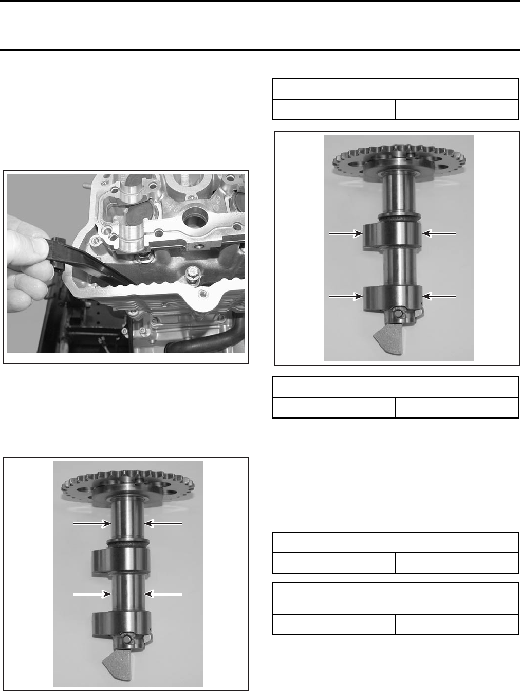
Section 03 ENGINE
Subsection 08 (CYLINDER AND HEAD)
VMR2004_012_03-08A.FM 03-08-5
Remove camshafts no. 7 and no. 8 with timing
gears no. 9.
NOTE: Unfasten timing gears only if they need to
be replaced.
Secure timing chain no. 10 with a retaining wire.
Remove front chain rail no. 11.
Inspection
Check each lobe for scoring, scuffing, cracks, or
other signs of wear.
Measure camshaft base circle diameter and lobe
height, using a micrometer. Measure clearance between camshaft and cam-
shaft carriers, using the plastic feeler gauge.
NOTE: The plastic feeler gauge is available at au-
tomotive parts retailer.
Tighten camshaft carrier to specified torque.
Unfasten camshaft carrier and determine clear-
ance using comparative scale.
V02C49A
V02C4AA
CAMSHAFT DIAMETER
MINIMUM 21.950 mm (.864 in)
CAMSHAFT LOBE HEIGHT
SERVICE LIMIT 39.7 mm (1.56 in)
I.D. DIAMETER OF CAMSHAFT CARRIER
MAXIMUM 22.040 mm (.868 in)
CLEARANCE BETWEEN CAMSHAFT AND
CAMSHAFT CARRIER
MAXIMUM 0.09 mm (.004 in)
V02C4AB
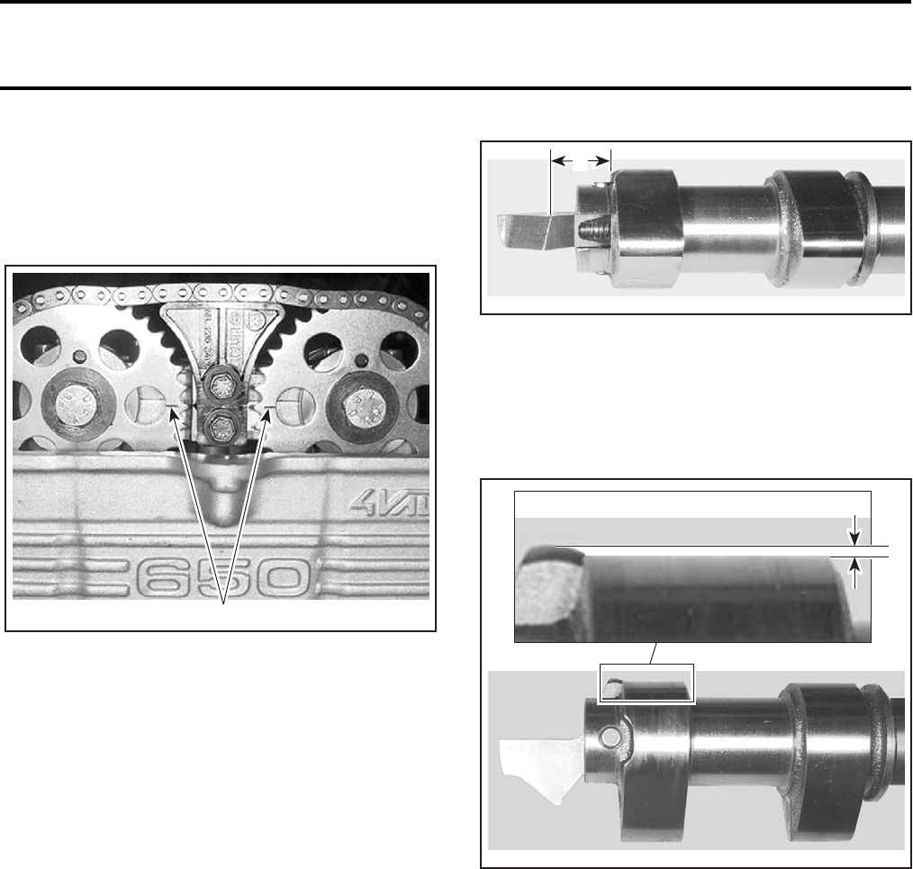
Section 03 ENGINE
Subsection 08 (CYLINDER AND HEAD)
03-08-6 VMR2004_012_03-08A.FM
Installation
CAUTION: Install the timing gears so that the
markings on the gears must be aligned and so
that the dowel pin on each camshaft must be lo-
cated on the top, as shown in the next illustration.
1. Align marks
Tighten screws no. 12 for chain guide with Loctite
243, hand tight.
Fit upper section of camshaft carrier and tighten
down.
Check valve clearance. Refer to MAINTENANCE/
LUBRICATION.
Install chain tensioner no. 4 and tighten screw
no. 13 with sealing ring no. 14.
Install cylinder head cover with gasket.
Unscrew and remove crankshaft locking bolt. Install
the screw plug with sealing ring. Torque to 24 N•m
(18 lbf•ft).
CENTRIFUGAL DECOMPRESSOR
Inspection
Hold down exhaust camshaft no. 7 in horizontal
position with cam tips facing downwards.
The spring no. 15 must press the lever upwards
to dimension “A”, replace spring if necessary.
A. 11.5 mm (.45 in)
NOTE: Never stretch spring since this alters the
defined spring force.
When activated, the amount of lifting arm protrud-
ing over the cam pitch circle must not be less than
dimension “B”.
B. 0.4 mm (.0157 in)
Disassembly
Remove the exhaust camshaft no. 7.
Press shaft no. 16 out of centrifugal weight no. 17.
Assembly
Reassemble in the reverse order of disassembly.
Paying attention to the following detail.
If the centrifugal decompressor was dismounted,
ALWAYS replace the spring.
After assembly, check if the centrifugal weight
moves smoothly.
V02C0IA
1
V02C0JA
A
V02C0KA
B
Section 03 ENGINE
Subsection 08 (CYLINDER AND HEAD)
VMR2004_012_03-08A.FM 03-08-7
CYLINDER HEAD
Removal
Remove:
–engine from vehicle
(refer to INSTALLATION AND REMOVAL)
–starter (refer to STARTING SYSTEM)
–camshafts
–chain guide no. 5
–socket screws no. 18
–bolts no. 19
–nuts no. 20.
Remove cylinder head no. 21 and gasket no. 22.
Inspection
Check for crack between valve seats or other dam-
age, if so, replace cylinder head.
Installation
For installation, reverse the removal procedure.
Pay attention to the following details.
Fitting cylinder head gasket.
Slide timing chain through chain duct.
First, tighten nuts no. 20 crosswise.
Install and torque bolts no. 19.
Tighten socket screws no. 18 on cylinder base.
Install camshafts.
VALVE SPRING
Removal
Remove:
–cylinder head no. 21
–valve tappet no. 23.
Compress valve spring, use a spring compressor
(P/N 529 035 724) and compressor cup (P/N 529
035 725).
Remove valve cotters no. 24.
Remove spring compressor, valve spring retainer
no. 25 and valve spring no. 26.
Inspection
Check valve spring for rust or corrosion and free
length.
Installation
For installation, reverse the removal procedure.
VALVE
Removal
Remove valve spring no. 26.
Push the valve stem then pull valve no. 27 out of
cylinder head.
Inspection
Valve Clearance
Refer to MAINTENANCE/LUBRICATION.
Valve
Inspect valve surface, check for abnormal stem
wear and bending. If so, replace by a new one.
Valve Stem
Check valve stem for wear or friction surfaces, if
so, replace parts.
Measure valve stem in three places, using a mi-
crometer.
Change valve if valve stem is out of specification.
Valve Face and Seat
Check valve face and seat for burning, pitting and
other signs of damage.
Apply some lapping compound to valve face and
work valve on its seat with a lapping tool.
Measure valve face contact width.
NOTE: The location of contact area should be in
center of valve face.
VALVE SPRING FREE LENGTH
SERVICE LIMIT 44.5 mm (1-3/4 in)
VALVE STEM DIAMETER
SERVICE LIMIT
Exhaust 5.935 mm (.233 in)
Intake 5.95 mm (.234 in)
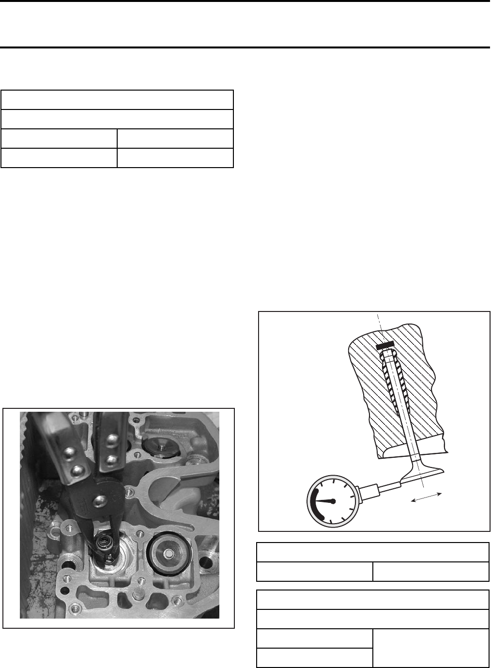
Section 03 ENGINE
Subsection 08 (CYLINDER AND HEAD)
03-08-8 VMR2004_012_03-08A.FM
Measure valve seat width, using a caliper.
If valve seat contact width is too wide, too narrow
or has spots, the seat must be ground or cylinder
head replaced.
Installation
Install valve.
NOTE: Remove assembly sleeve once again.
Install valve spring and valve plate spring.
NOTE: Install valve tappets with a small amount
of grease to facilitate assembly.
VALVE STEM SEAL
Removal
Remove valve.
Remove valve stem seal no. 28 with a special
pliers such as Snap-On YA 8230.
Inspection
Inspection of valve stem seals is not needed as
new seals should always be installed whenever a
cylinder head is diassembled.
Installation
For installation, reverse the removal procedure.
VALVE GUIDE
Inspection
Insert a new valve in valve guide until it contacts
the seal.
NOTE: Clean valve guide to remove carbon de-
posits before measuring.
Measure the maximum tilt clearance with a dial
gauge placed as shown in the following illustra-
tion.
VALVE SEAT CONTACT WIDTH
SERVICE LIMIT
Exhaust 1.8 mm (.07 in)
Intake 1.6 mm (.06 in)
V02C4BA
TILT CLEARANCE
MAXIMUM 0.04 mm (.016 in)
I.D. VALVE GUIDE
SERVICE LIMIT
Exhaust 6.080 mm (.239 in)
Intake
V02C4CA
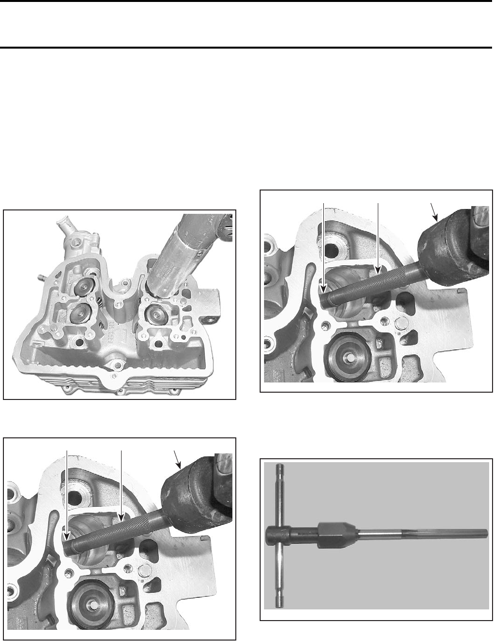
Section 03 ENGINE
Subsection 08 (CYLINDER AND HEAD)
VMR2004_012_03-08A.FM 03-08-9
Valve Guide Removal
Remove:
–cylinder head (see CYLINDER HEAD above)
–valve spring (see VALVE SPRING above)
–valve (see VALVE above).
NOTE: Clean valve guide area from contamination
before removal.
Heat the valve guide area using a heat gun for ap-
proximately 10 minutes to 100°C (212°F).
Using valve guide remover/installer (P/N 529 035
852), remove valve guide no. 32.
1. Valve guide remover/installer
2. Valve guide
3. Hammer
Installation
For installation, reverse the removal procedure.
Pay attention to the following details.
Clean the valve guide bore before reinstalling the
valve guide into cylinder head.
Install circlip no. 31 on the valve guide
Use valve guide remover/installer (P/N 529 035
852) to install valve guide no. 32.
1. Valve guide remover/installer
2. Valve guide
3. Hammer
Valve guide to be grinded in diameter by using a
hand reamer.
HAND REAMER
V02C4ZA
V02C50A
2 1 3
V02C50A
2 1 3
V02B0XA
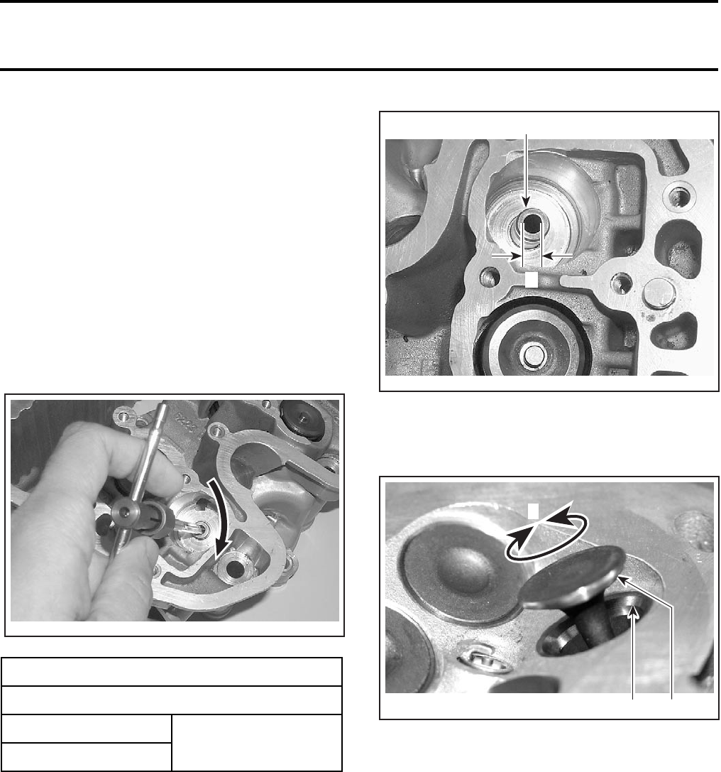
Section 03 ENGINE
Subsection 08 (CYLINDER AND HEAD)
03-08-10 VMR2004_012_03-08A.FM
Hand reamer (F1111 Hand Reamer 6H7) ordering
and other information can be obtained from the
following company:
TITEX PRECISION CUTTING TOOLS
TITEX USA
301 Industrial Avenue,
Crystal Lake, IL 60012
Tel.: 1 (815) 4592040
Toll-free: 1 800 262-2436
Fax: 1 (413) 774-2110
e-mail: titex.usa@sandvik.com
www.titex.com
NOTE: Use cutting oil and ensure to turn reamer
the right way (clockwise) as shown below.
1. Valve guide
A. Valve guide diameter
Apply some lapping compound to valve face and
work valve on its seat with a lapping tool.
TYPICAL
1. Valve seat
2. Valve face (contact surface to valve seat)
3. Turn valve while pushing again cylinder head
NOTE: Ensure to seat valves properly. Apply
marking paste to ease checking contact pattern.
I.D. VALVE GUIDE
SERVICE LIMIT
Exhaust 6.080 mm (.239 in)
Intake
V02C52A
V02C51A
1
A
R175motr92A 1 2
3
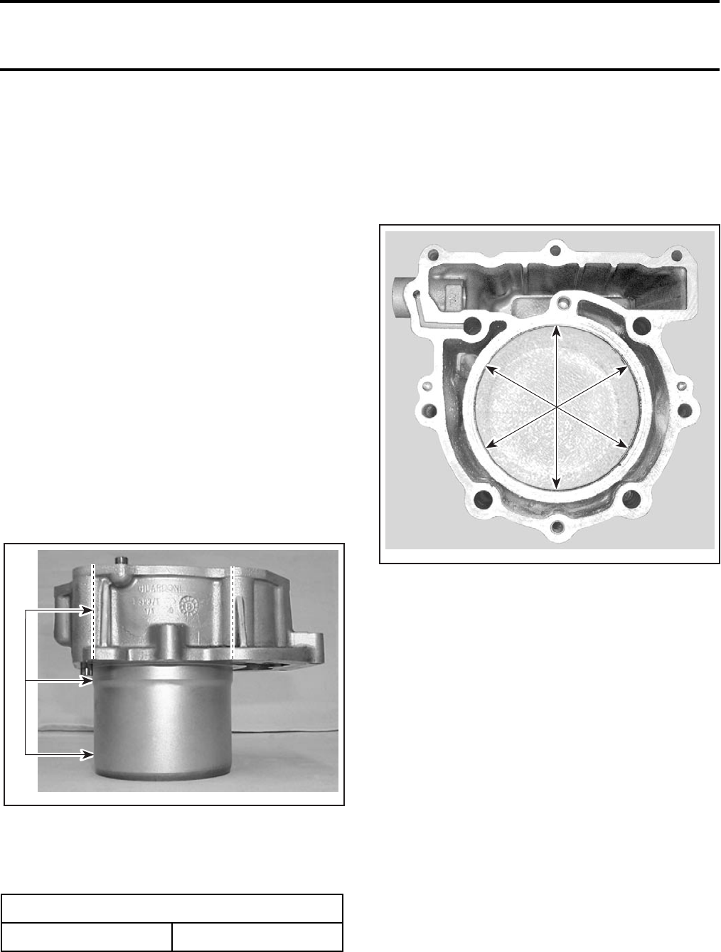
Section 03 ENGINE
Subsection 08 (CYLINDER AND HEAD)
VMR2004_012_03-08A.FM 03-08-11
CYLINDER
Removal
Remove:
–cylinder head no. 21, if necessary
NOTE: If the cylinder head does not have to be
disassembled, do not separate cylinder head from
cylinder no. 29.
–water cooling hose from cylinder
–socket screws no. 30 retaining cylinder to the
crankcase housing.
Pull cylinder.
Inspection
Cylinder
Check cylinder for cracks, scoring, rust and wear
ridges on the top and bottom of the cylinder.
Cylinder Taper
Measure cylinder diameter 16 mm (5/8 in) from
top of cylinder then half-way through and finally at
13 mm (1/2 in) from bottom.
TYPICAL
1. Measure at three points
Difference between measurements should not
exceed 0.10 mm (.004 in). If so, replace cylinder.
Cylinder Out of Round
Measure cylinder bore at distance of 60 mm (2-3/8 in)
from the upper edge with an internal micrometer
at three points. Difference between measurements
should not exceed 0.10 mm (.004 in). If so, replace
cylinder.
Installation
Coat piston rings with oil and slide the ring com-
pressor over piston rings from above, allowing pis-
ton to protrude approximately 2 mm (3/32 in) from
ring compressor.
Slide timing chain through chain duct, then slide
cylinder over piston.
Remove the ring compressor.
Secure cylinder on crankcase housing with the
socket screws no. 30. Do not torque yet.
Fit cylinder head then torque nuts and bolts.
Torque socket screws.
CYLINDER BORE CLEARANCE
SERVICE LIMIT 100.03 mm (3.9382 in)
V01C1JA
1
V02C0LA
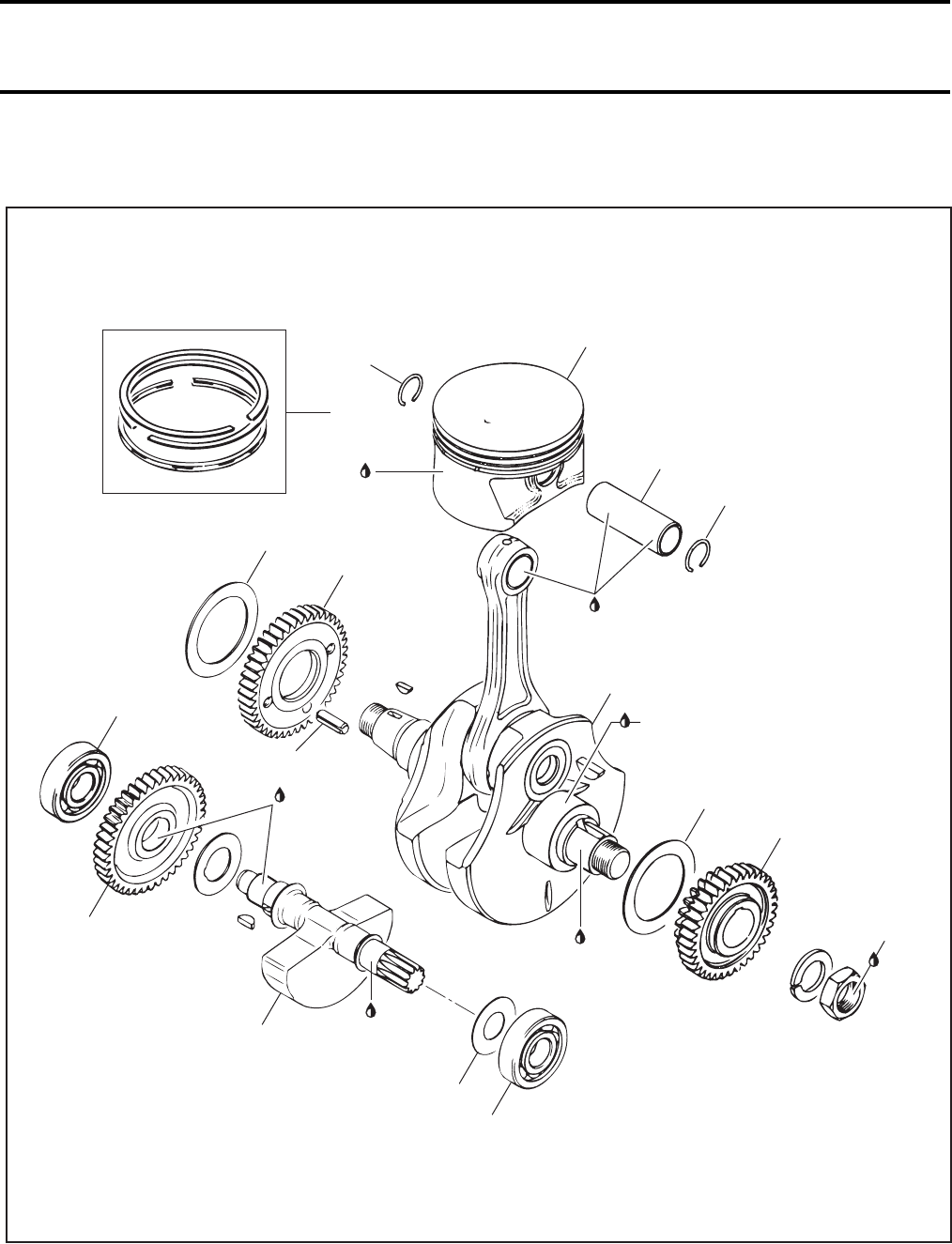
Section 03 ENGINE
Subsection 09 (CRANKSHAFT/BALANCER SHAFT)
VMR2004_013_03-09A.FM 03-09-1
CRANKSHAFT/BALANCER SHAFT 0
Anti-seize
lubricant
Anti-seize
lubricant
3
8
2
1
8
180 Nm
(133 lbfft)
Engine oil
13
7
6
10
9
Engine
oil
11
5
4
15
12
Loctite
243
V02C3FT
14
Anti-seize
lubricant
Anti-seize
lubricant
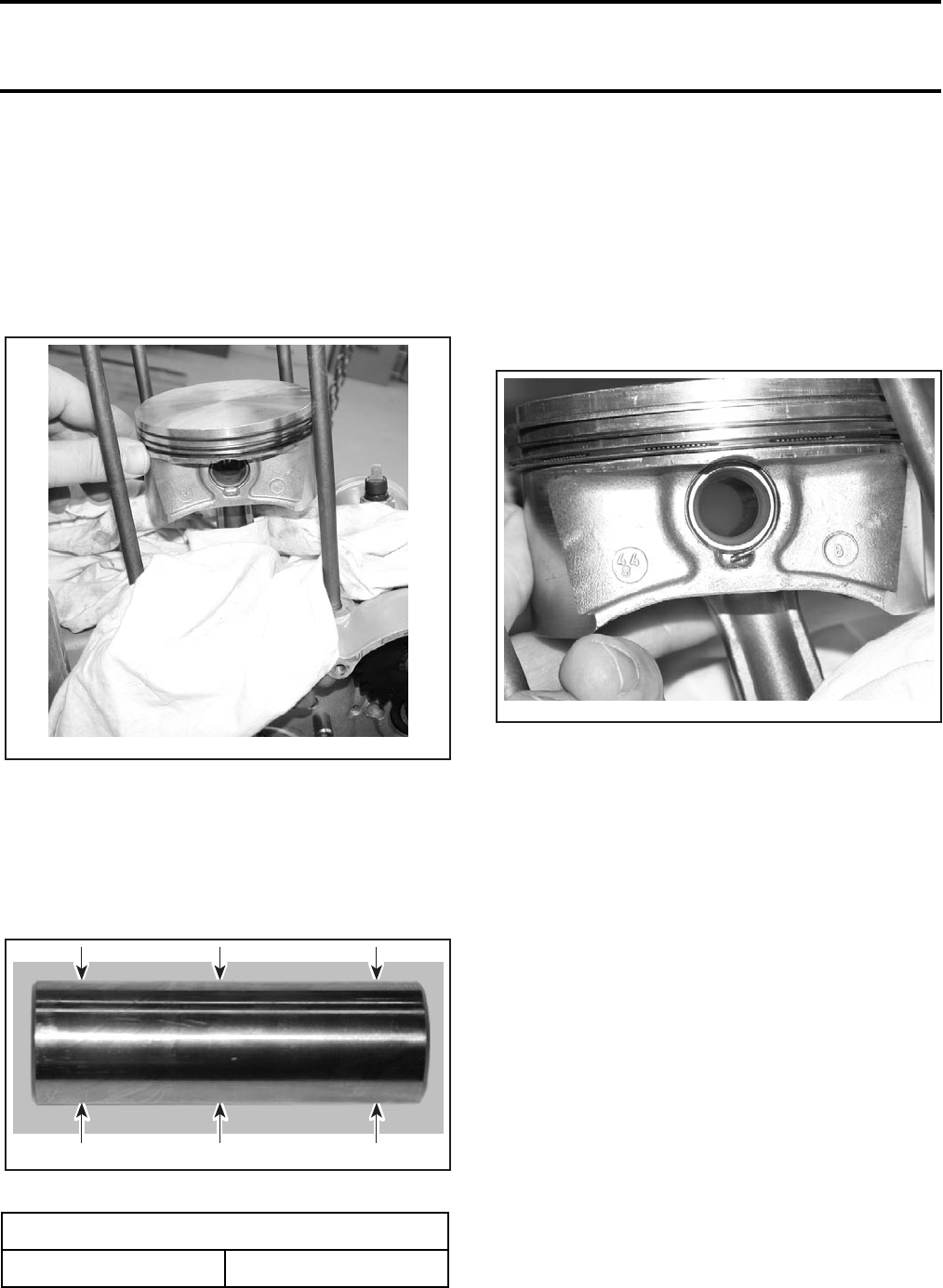
Section 03 ENGINE
Subsection 09 (CRANKSHAFT/BALANCER SHAFT)
03-09-2 VMR2004_013_03-09A.FM
PISTON PIN
Removal
Remove engine. Refer to REMOVAL AND IN-
STALLATION.
Remove cylinder. Refer to CYLINDER AND HEAD.
Place a rag under piston no. 2.
Remove one piston pin circlip no. 8 then press out
piston pin no. 1.
Inspection
Check piston pin for crack or other damage.
Measure piston pin with a micrometer.
A. Piston pin diameter
Installation
For installation, reverse the removal procedure.
Pay attention to the following details.
Apply anti-seize lubricant on the piston pin.
Insert piston pin into piston and connecting rod.
Secure piston pin with a new piston pin circlip.
NOTE: Do not align the end gap of the piston pin
circlips with the cutout in the piston bore.
PISTON
Removal
Remove piston pin no. 1.
Detach piston from connecting rod.
NOTE: Mark base of piston on exhaust end.
Inspection
Inspect piston for scoring, cracking or other dam-
ages.
PISTON PIN DIAMETER
SERVICE LIMIT 21.98 mm (.865 in)
V02C4KA
A
V02C4LA AA
V02C4MA
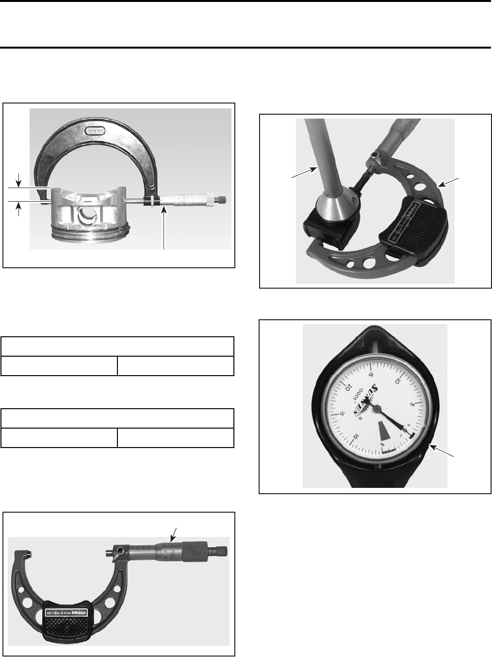
Section 03 ENGINE
Subsection 09 (CRANKSHAFT/BALANCER SHAFT)
VMR2004_013_03-09A.FM 03-09-3
Using a micrometer, measure piston at 16 mm
(5/8 in) perpendicularly (90°) to piston pin axis.
TYPICAL
1. Measuring perpendicularly (90°) to piston pin axis
A. 16 mm (5/8 in)
The measured dimension should be as described
in the previous table. If not, replace piston.
Piston/Cylinder Clearance
NOTE: Make sure used piston is not worn. See
PISTON MEASUREMENT table above.
Adjust and lock a micrometer to the piston dimen-
sion.
1. Micrometer set to the piston dimension
With the micrometer set to the dimension, adjust
a cylinder bore gauge to the micrometer dimen-
sion and set the indicator to 0 (zero).
1. Use the micrometer to set the cylinder bore gauge
2. Dial bore gauge
TYPICAL
1. Indicator set to 0 (zero)
Position the dial bore gauge at 16 mm (5/8 in) be-
low cylinder top edge, measuring perpendicularly
(90°) to piston pin axis.
Read the measurement on the cylinder bore gauge.
The result is the exact piston/cylinder wall clear-
ance. If clearance exceeds specified tolerance, re-
place cylinder or rebore. See previous table.
NOTE: Make sure the cylinder bore gauge indica-
tor is set exactly at the same position as with the
micrometer, otherwise the reading will be false.
PISTON MEASUREMENT
SERVICE LIMIT 99.94 mm (3.9346 in)
PISTON/CYLINDER CLEARANCE
SERVICE LIMIT 0.09 mm (.004 in)
V01C3KA
A
1
F00B08A
1
F00B09A
1
2
F00B0AA
1
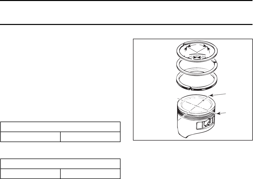
Section 03 ENGINE
Subsection 09 (CRANKSHAFT/BALANCER SHAFT)
03-09-4 VMR2004_013_03-09A.FM
Installation
For installation, reverse the removal procedure.
NOTE: Install piston with removal mark (on base
of piston) in direction of exhaust end.
PISTON RINGS
Inspection
Piston Ring/Piston Groove Clearance
Using a feeler gauge measure each piston ring/piston
groove clearance. If the clearance is too large, the pis-
ton should be replaced.
Piston Ring End Gap
Position piston ring 16 mm (5/8 in) from top of cyl-
inder.
NOTE: In order to correctly position the piston ring
in the cylinder, use piston as a pusher.
Using a feeler gauge, check piston ring end gap.
Replace piston ring, if gap exceeds specified toler-
ance. See above table.
Installation
For installation, reverse the removal procedure.
Pay attention to the following details.
NOTE: Use a piston ring expander to prevent
breakage during installation. The oil ring must be
installed by hand.
Check that rings rotate smoothly after installation.
Space the piston ring end gaps 120° apart and do
not align the gaps with the piston pin bore or the
thrust side axis.
1. DO NOT align ring gap with piston thrust side axis
2. DO NOT align ring gap with piston pin bore axis
A. 120°
BALANCER SHAFT
Removal
Remove:
–engine from vehicle
(refer to REMOVAL AND INSTALLATION)
–cylinder (refer to CYLINDER AND HEAD)
–piston no. 2.
Clutch Side
Remove:
–clutch (refer to CLUTCH)
–double drive gear no. 9 and timing chain
–oil pump intermediate gear.
PISTON RING/PISTON CLEARANCE
SERVICE LIMIT 0.15 mm (.006 in)
PISTON RING END GAP
SERVICE LIMIT 1.0 mm (.040 in)
A31C2OA
1
2
AA
A
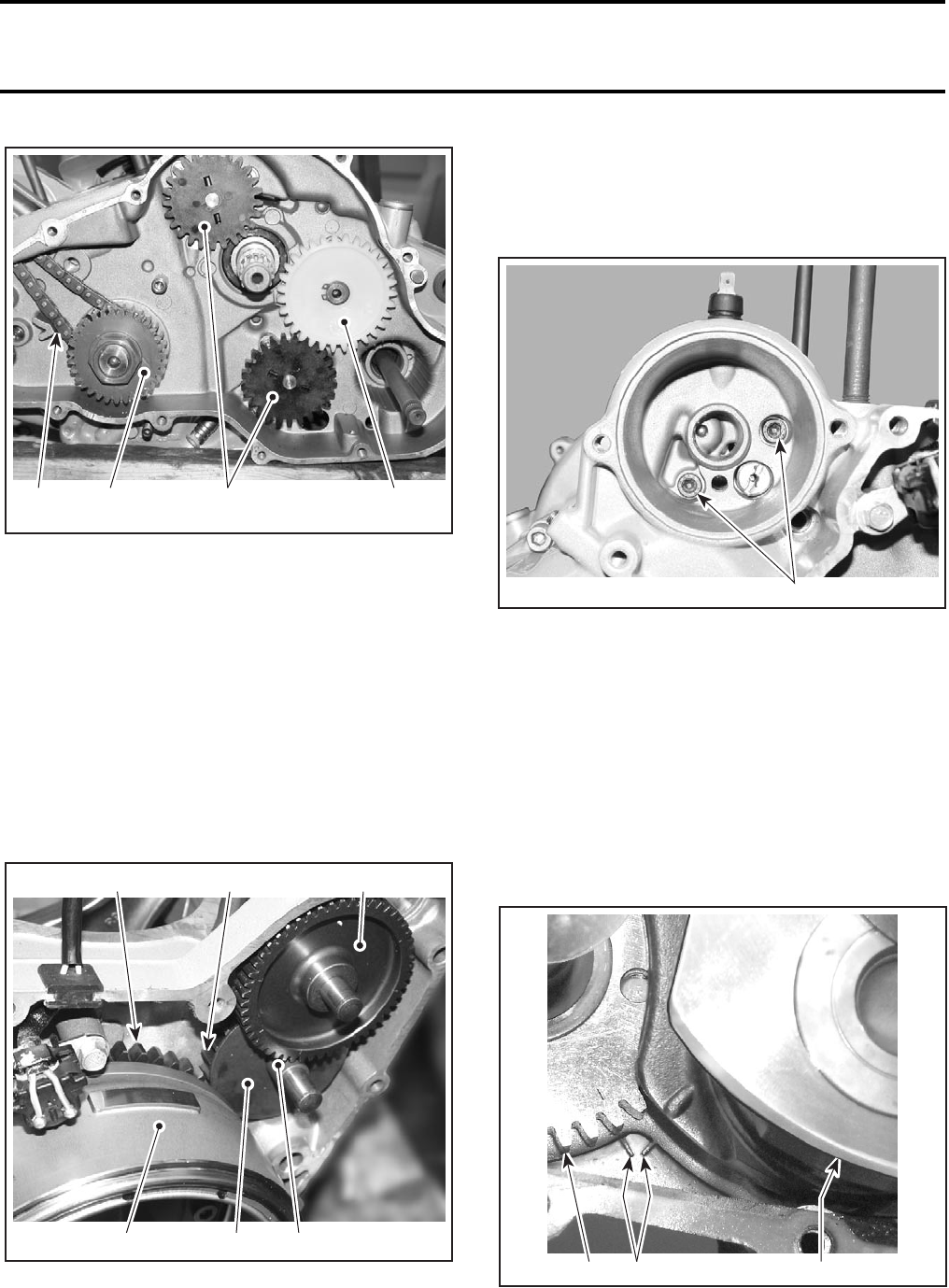
Section 03 ENGINE
Subsection 09 (CRANKSHAFT/BALANCER SHAFT)
VMR2004_013_03-09A.FM 03-09-5
1. Double drive gear
2. Timing chain
3. Oil pump intermediate gear
4. Oil pump gears
Magneto Side
Remove:
–rotor (refer to MAGNETO SYSTEM)
–spacer
–thrust washer
–sprag clutch gear
–starter double gear
–idle gear (behind thrust washer)
1. Rotor
2. Spacer
3. Thrust washer
4. Sprag clutch gear
5. Starter double gear
6. Idle gear
–oil filter
–all bolts retaining housing.
NOTE: Do not forget the bolts inside the oil filter
housing.
1. Bolts to be removed
Lift up clutch side of engine housing, striking alter-
nate gentle blows with plastic hammer on main-
shaft, countershaft and balancer shaft to ensure
that these remain on magnet side.
CAUTION: Do not tilt engine housing; this can
cause damage to bearing cup.
Remove shims no. 10 and no. 15 on crankshaft
and balancer shaft.
Align marks on balancer shaft and crankshaft with
marks on housing.
1. Balancer shaft
2. Crankshaft
3. Marks on housing
3
V02C4NA
412
V02C4PA 1
1
4
V02C4OA
65
32
V02C4PA 1
13 2
V02C0SA
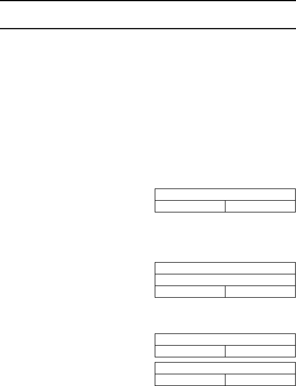
Section 03 ENGINE
Subsection 09 (CRANKSHAFT/BALANCER SHAFT)
03-09-6 VMR2004_013_03-09A.FM
First lift out crankshaft, then balancer shaft.
NOTE: Take care of spacer discs on crankshaft.
Inspection
Check balancer shaft bearings nos. 11 and 12 in
front and rear housing for excessive play and
smooth operation. Replace if necessary.
Installation
Install balancer shaft in engine housing, mark
must be aligned with mark on housing.
Coat thrust washer no. 13 with oil and install in
crankshaft.
Rotate crankshaft before installing so that mark is
aligned with mark on housing.
Fit gasket.
NOTE: Coat bearing points on shafts. Recenter
crankshaft and balancer shaft if either housing,
crankshaft or balancer shaft were replaced. See
RECENTER CRANKSHAFT.
BALANCER GEAR
Removal
Mount balancer shaft in vise with protective jaws.
Using a suitable puller, remove the balancer gear
no. 5.
Inspection
Check gears teeth for damage. Change if neces-
sary.
Installation
For installation, reverse the removal procedure.
Pay attention to the following detail.
Heat balancer gear to 80°C (176°F).
CRANKSHAFT
Removal
Use the same removal procedure that balancer
shaft.
Inspection
Crankshaft Bearing Radial Play
Measure bearing journal diameter. The minimum di-
ameter for bearing journal is 47.975 mm (1.888 in).
If the measure exceeds specified tolerance, replace
the crankshaft.
Measure the interior diameter of the crankshaft
bushing.
Subtract bearing journal diameter from inside bush-
ing diameter. The result is the main bearing radial
play. If the measure exceeds specified tolerance,
replace the crankshaft and/or bushing.
Connecting Rod Big End Axial Play
Using a feeler gauge, measure distance between
thrust washer and crankshaft counterweight. If
the distance exceeds specified tolerance, replace
the crankshaft.
Connecting Rod/Piston Pin Clearance
Measure piston pin. Compare to inside diameter
of connecting rod.
CRANKSHAFT BEARING RADIAL PLAY
SERVICE LIMIT 0.10 mm (.004 in)
CONNECTING ROD BIG END
SERVICE LIMIT
Axial play 0.80 mm (.031 in)
CONNECTING ROD SMALL END DIAMETER
SERVICE LIMIT 22.04 mm (.868 in)
PISTON PIN BORE CLEARANCE
SERVICE LIMIT 0.06 mm (.002 in)
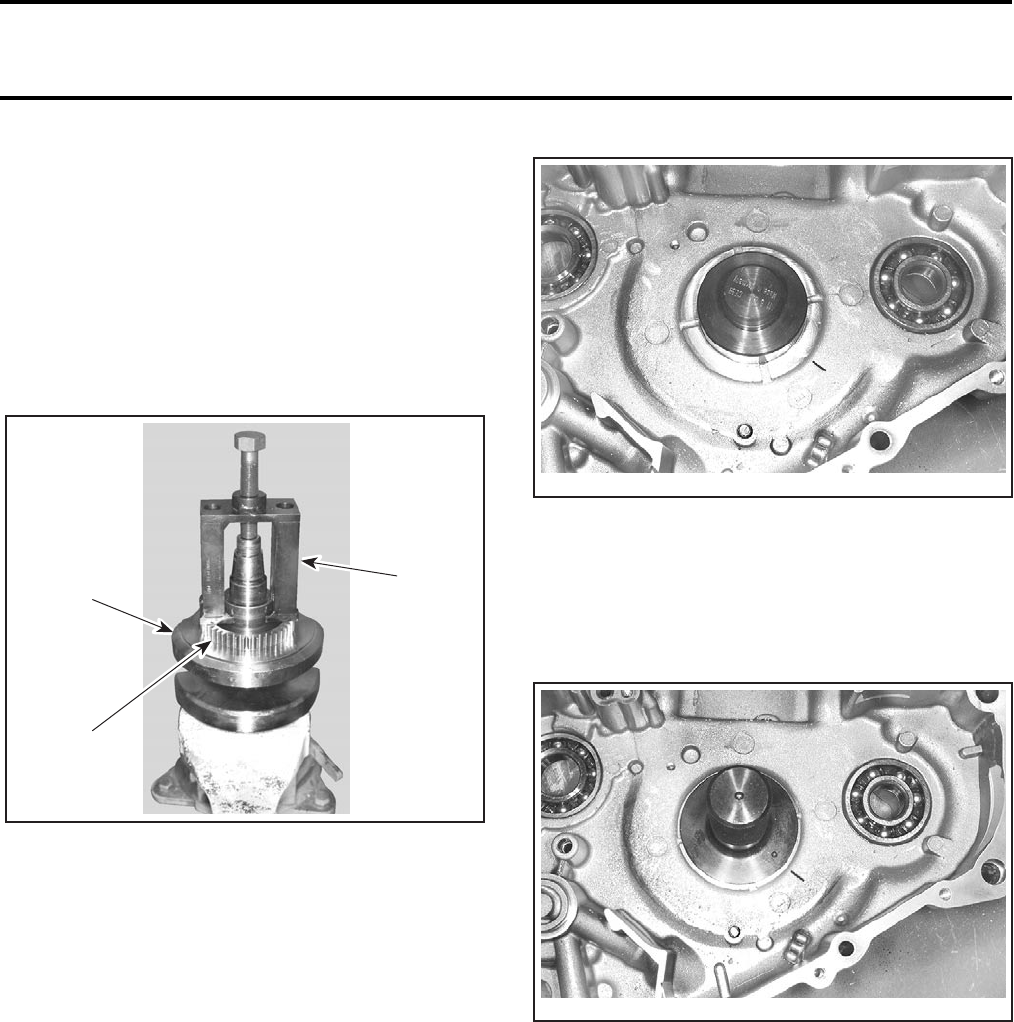
Section 03 ENGINE
Subsection 09 (CRANKSHAFT/BALANCER SHAFT)
VMR2004_013_03-09A.FM 03-09-7
Installation
For installation, refer to balancer shaft installation.
COUNTER GEAR
Removal
Clamp crankshaft in vise with protective jaws.
Using extractor (P/N 529 035 624) extract counter
gear.
1. Counter gear
2. Crankshaft
3. Extractor
Inspection
Check counter gear teeth for damage. Replace if
necessary.
Installation
Heat counter gear to 140°C (284°F).
CAUTION: The roller pin no. 14 must not pro-
trude from bore in counter gear; this is the sup-
port face for the thrust washer.
CRANKSHAFT BUSHING
Removal
Heat engine housing to 100°C (212°F).
Drive out bushing with punch (P/N 529 035 688).
Installation
Heat engine housing to 100°C (212°F).
Coat bushing with Klueber grease (P/N 711 297 616)
and drive home with punch (P/N 529 035 689), strik-
ing from inside.
CAUTION: Mark position of oil hole in bushing
on housing. Align mark on punch with mark on
housing. Bushing must be inset behind oil
holes. The notch on the bushing should always
face the balancer shaft.
BALL BEARINGS IN HOUSING
Removal
Heat output shaft in the housing to 80°C (176°F).
Using a suitable slide hammer, extract ball bearing.
Installation
Place the housing in oven to 100°C (212°F).
3
V02C0UA
2
1
V02C0VA
V02C0WA
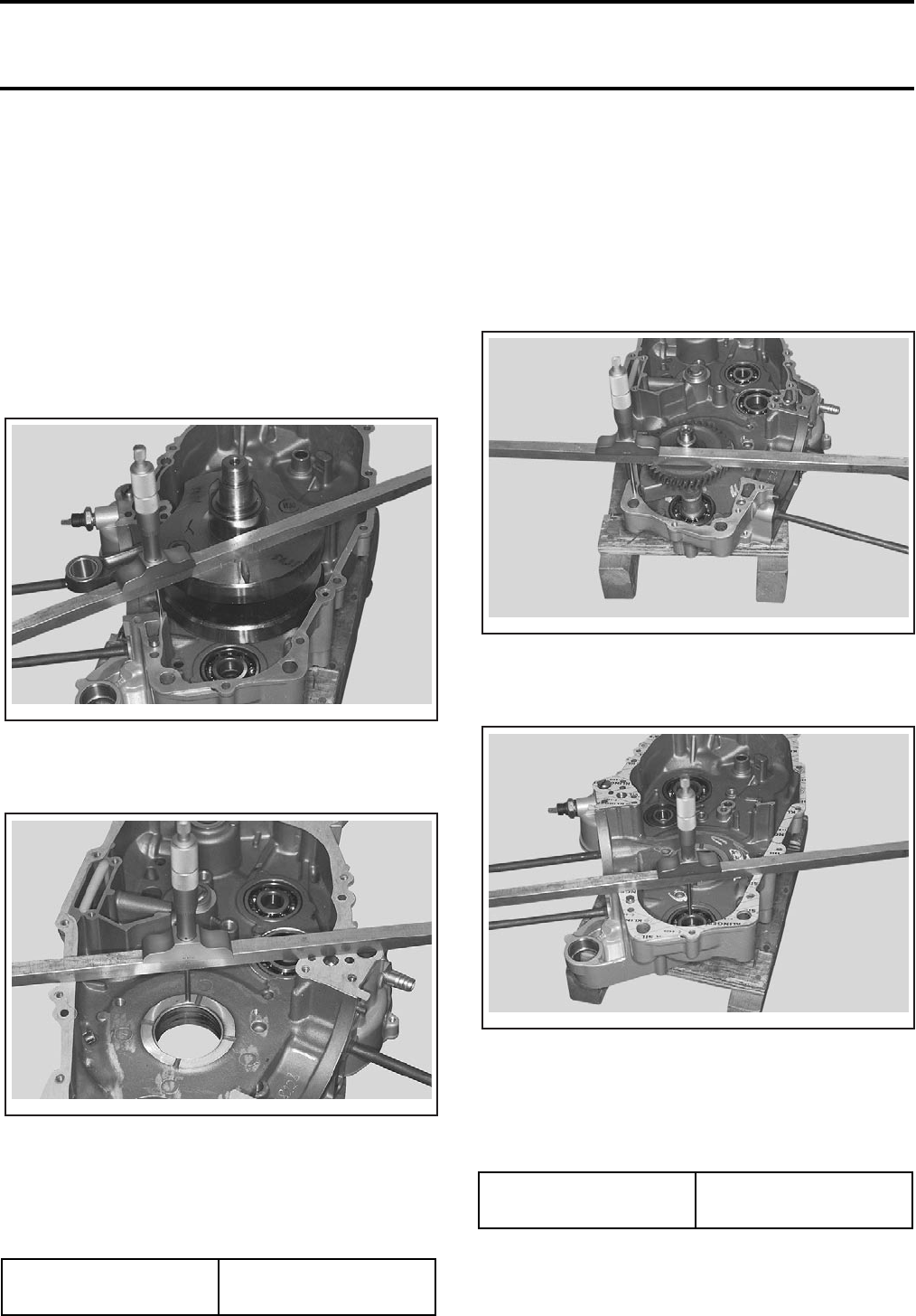
Section 03 ENGINE
Subsection 09 (CRANKSHAFT/BALANCER SHAFT)
03-09-8 VMR2004_013_03-09A.FM
NOTE: The sealed ends of the cage must point
outwards.
RECENTER CRANKSHAFT
NOTE: Only fit shim on clutch end. On magneto
side, the washer is always 1.0 mm (.04 in).
Place crankshaft into right engine housing (mag-
neto side). Do not install shim on clutch side.
Using depth gauge, measure distance between
crank web and housing joint. This is the dimension
“B”.
Determine dimension between compressed gas-
ket in left engine housing (clutch side) and washer
contact face. This is the dimension “A”.
Subtract dimension “B” from dimension “A”, the
result is the end float of crankshaft plus shim thick-
ness.
Select suitable shim to ensure the correct end
float is obtained.
RECENTER BALANCER SHAFT
NOTE: Only fit shim on clutch end.
Place balancer shaft into left engine housing
(clutch side). Do not install shim on clutch side.
Using depth gauge, measure distance between
the top of balancer gear and housing joint. This is
the dimension “B”.
Determine dimension between compressed gas-
ket in right engine housing (magneto side) and in-
ner ring of bearing. This is the dimension “A”.
Subtract dimension “B” from dimension “A”, the
result is the end float of balancer shaft plus shim
thickness.
Select suitable shim to ensure the correct end
float is obtained.
END FLOAT OF
CRANKSHAFT
0.1 to 0.3 mm
(.004 to .012 in)
V02C3GA
V02C3HA
END FLOAT OF
BALANCER SHAFT
0.1 to 0.3 mm
(.004 to .012 in)
V02C3IA
V02C3JA
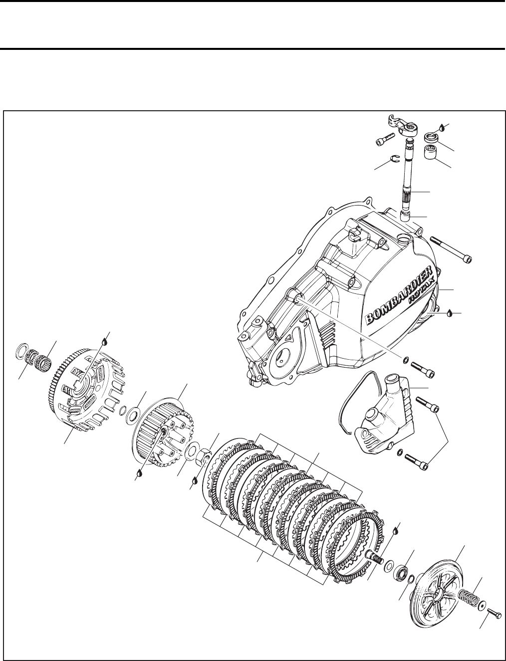
Section 03 ENGINE
Subsection 10 (CLUTCH)
VMR2004_014_03-10A.FM 03-10-1
CLUTCH 0
V02D06U
9
10 Nm
(89 lbfin)
10
1
2
3
12
11
4
15
13
Loctite
243
140 Nm
(103 lbfft)
14
16
Engine
oil
17
18
Super
Lube
grease
21
22
8 Nm
(71 lbfin)
19
6
20
10 Nm
(89 lbfin)
8
10 Nm
(89 lbfin)
7
10 Nm
(89 lbfin)
Super
Lube
grease
Super
Lube
grease
Anti-seize
lubricant
5
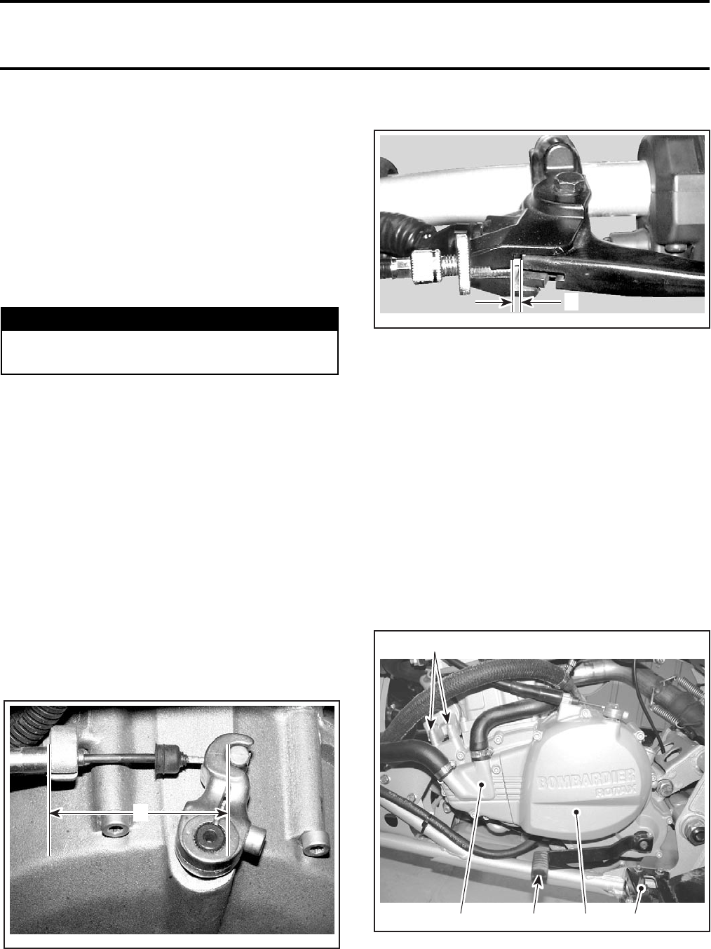
Section 03 ENGINE
Subsection 10 (CLUTCH)
03-10-2 VMR2004_014_03-10A.FM
GENERAL
At installation, use torque values and Loctite prod-
ucts from the exploded view. Clean threads before
using Loctite products when installing screws.
NOTE: For a better understanding, the following
illustrations are taken with engine out of vehicle.
To perform the following instructions, it is not nec-
essary to remove engine from vehicle.
Always disconnect the negative wire from the bat-
tery before working the engine.
When the repair is done. Test drive to confirm all
is working well. If the test drive is good, perform
a change of engine oil.
CLUTCH ADJUSTMENT
The clutch adjustment is necessary after any works
in the clutch system.
Loosen cable tension.
Adjust clutch release mechanism.
The release lever must locate on the spline in such
a way that dimension A is obtained. See the fol-
lowing illustration.
NOTE: If necessary, unscrew the Allen socket
screw and remove release lever. Replace the lever
at the appropriate position then tighten socket
screw to 8 N•m (71 lbf•in).
A. 68 to 75 mm (2-11/16 to 2-31/32 in)
Adjust cable free play.
A. 3.5 ± 0.5 mm (9/64 ± 1/64 in)
CLUTCH COVER
Removal
Drain engine oil and coolant.
Detach clutch cable.
Remove:
–LH footpeg
–shifting pedal
–water pump cover
–starter bolts
–all bolts retaining clutch cover
–clutch cover no. 8.
1. Footpeg
2. Shifting pedal
3. Water pump cover
4. Starter bolts
5. Clutch cover
WARNING
Always disconnect BLACK (-) cable first and
reconnect last.
V02D03A
A
V02D04A
A
V02D0EA
4
3251
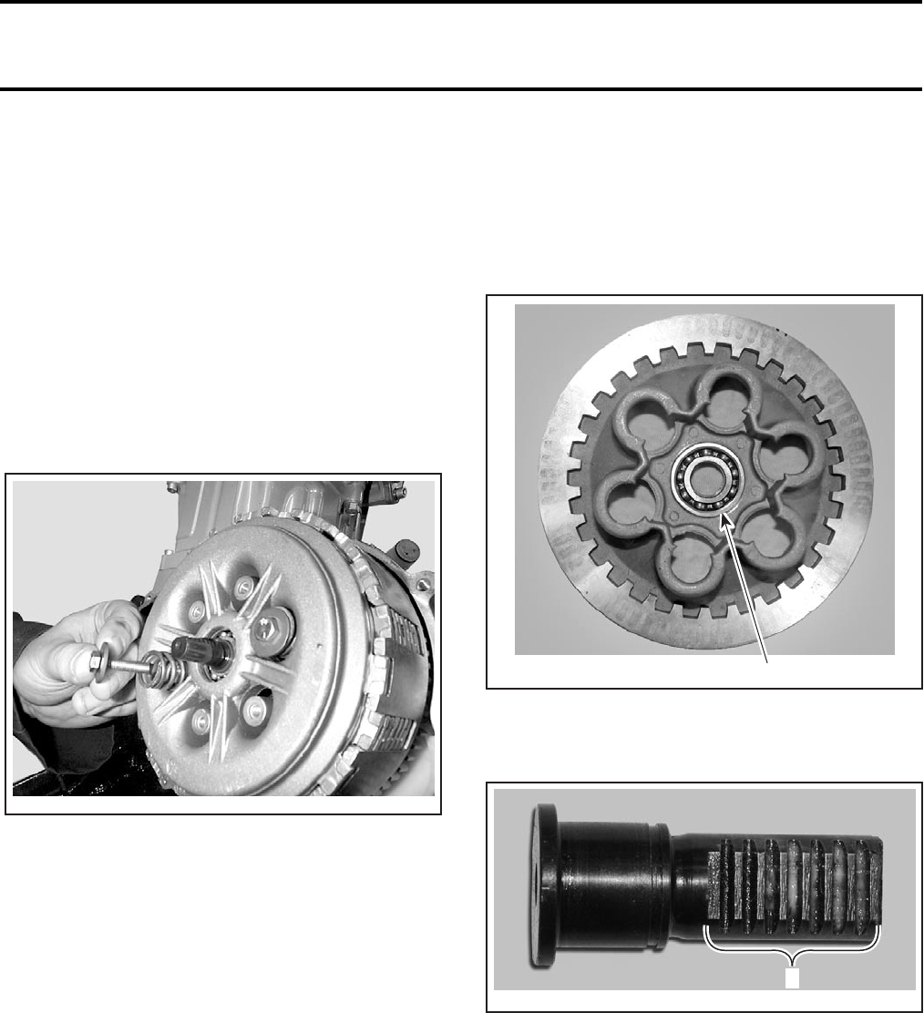
Section 03 ENGINE
Subsection 10 (CLUTCH)
VMR2004_014_03-10A.FM 03-10-3
Installation
For installation, reverse the removal procedure.
NOTE: Place the clutch actuator rack no. 11 in line
with the clutch release lever. Do not force the
clutch cover. The pressure plate bearing may
come out of pressure plate.
PRESSURE PLATE
Removal
Remove clutch cover.
Unfasten screws no. 9, retaining clutch spring
no. 10 and pressure plate no. 1, crosswise.
Lift off pressure plate completely.
Inspection
Check pressure plate for crack or other damage.
Change if necessary.
Installation
For installation, reverse the removal procedure.
CAUTION: Never pull clutch release lever back-
wards. The pressure plate bearing may come
out of pressure plate.
PRESSURE PLATE BEARING
Inspection
Check the pressure plate bearing no. 2 for exces-
sive play and smooth operation. Replace if neces-
sary.
1. Pressure plate bearing
Check spline on clutch actuator rack no. 11. Change
if necessary.
1. Splines of clutch actuator rack
V02D09A
V02D0FA 1
V02D0GA
1

Section 03 ENGINE
Subsection 10 (CLUTCH)
03-10-4 VMR2004_014_03-10A.FM
Disassembly
Remove the retaining ring no. 12 with retaining ring
pliers.
1. Retaining ring
2. Clutch actuator rack
3. Pressure plate
Heat pressure plate to 80°C (176°F) then remove
pressure plate bearing.
Assembly
For assembly, reverse the disassembly order.
CAUTION: Never pull clutch release lever back-
wards. The pressure plate bearing may come
out of pressure plate.
FRICTION DRIVE PLATE, STEEL
DRIVEN PLATE AND CLUTCH
BASKET
Disassembly
Remove the pressure plate no. 1.
Remove friction drive plates no. 3 and steel driven
plates no. 4 from clutch basket no. 5.
1. Friction drive plate
2. Steel driven plate
3. Clutch basket
Unlock the tab washer no. 13 then install spanner
tool for clutch basket (P/N 529 035 618).
Unscrew the clutch lock nut no. 14 then remove
tab washer.
Remove clutch hub no. 15, clutch basket including
thrust washer no. 16 and needle bearings no. 17
and no. 18.
1
V02D0HA 23
3
V02D0IA
21
V02D0AA
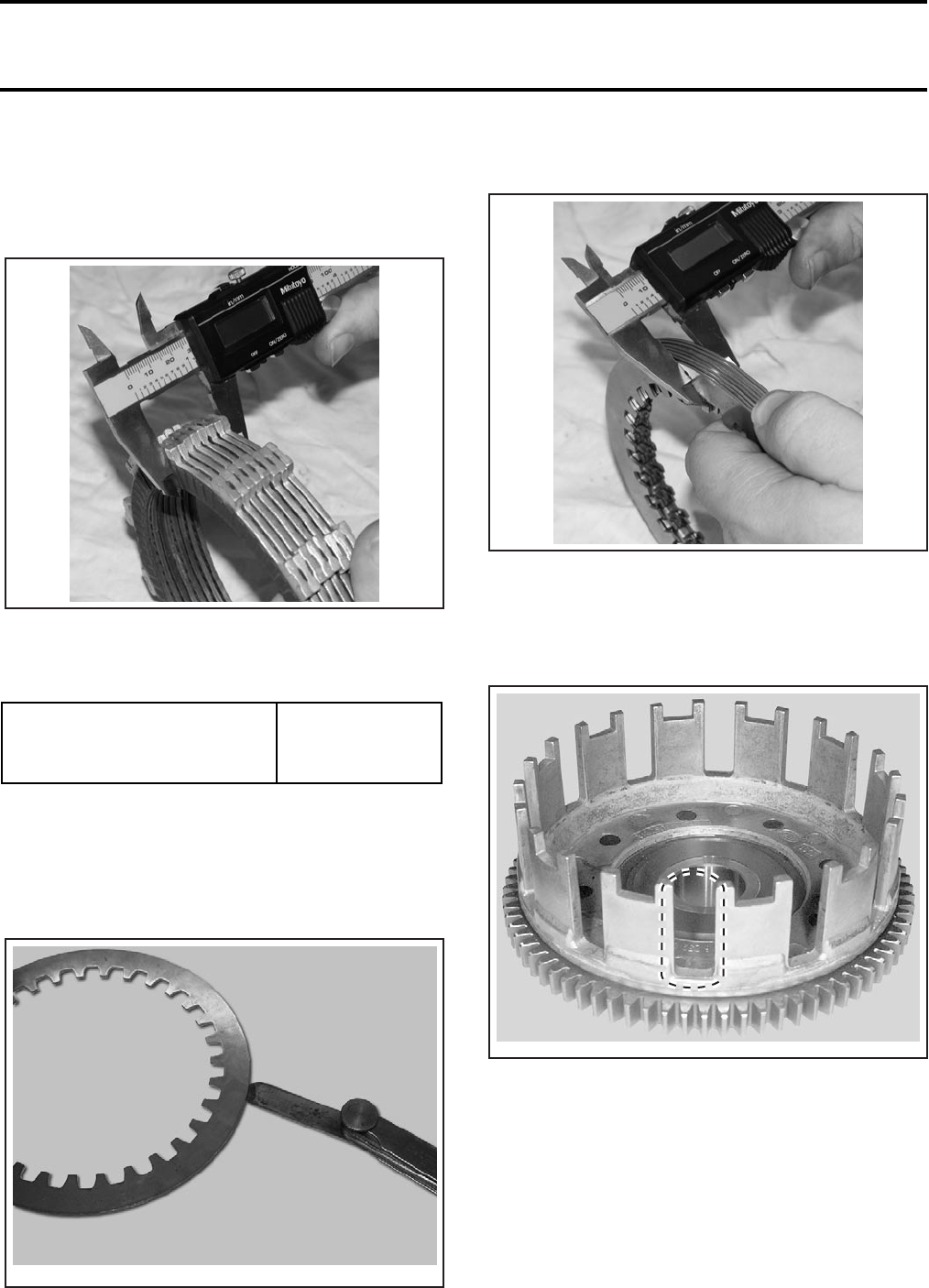
Section 03 ENGINE
Subsection 10 (CLUTCH)
VMR2004_014_03-10A.FM 03-10-5
Inspection
Friction Drive Plate
Measure the package of friction drive plate thick-
ness.
Friction drive plates must be replaced when thick-
ness is 27.5 mm (1.0827 in) thick or less for the
whole package.
The friction drive plate maximum warpage should
fall through a slot of 3.75 mm (.148 in).
Steel Driven Plate
The steel driven maximum warpage should fall
through a slot of 1.63 mm (.064 in).
The wear limit of the whole package is 11.5 mm
(.453 in).
Clutch Basket
Check slots of clutch basket for damage or wear
caused by friction drive plates.
Change if necessary.
TYPICAL
FRICTION DRIVE PLATE
MINIMUM THICKNESS FOR
THE WHOLE PACKAGE
27.5 mm
(1.0827 in)
V02D0JA
V02D0KA
V02D0LA
V01D09A
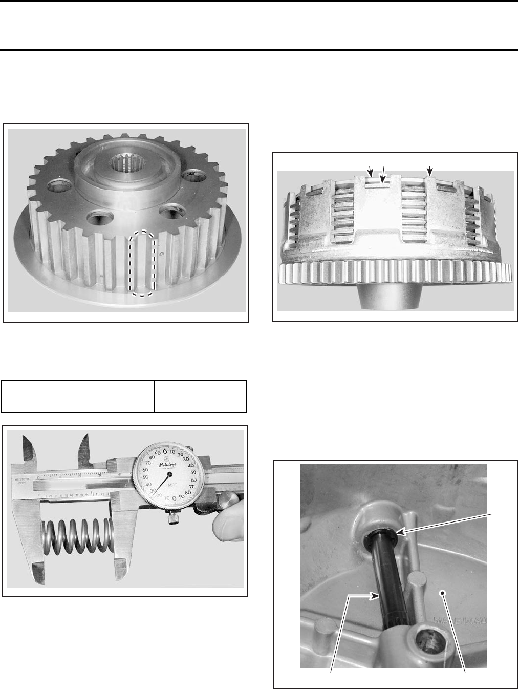
Section 03 ENGINE
Subsection 10 (CLUTCH)
03-10-6 VMR2004_014_03-10A.FM
Clutch Hub
Check grooves of clutch hub for damage or wear
caused by steel driven plates.
TYPICAL
Clutch Spring
Measure each clutch springs free length.
TYPICAL
Assembly
Assembly in the reverse sequence of disassembly.
Pay attention to the following details.
Install the needle bearings.
NOTE: Install small needle bearing underneath.
Coat spline on countershaft with Loctite anti-seize.
First, install steel driven plate, then friction drive
plate in alternate order.
NOTE: Place the last friction drive plate in short
slots of clutch basket.
1. Last friction drive plate
2. Retaining plate
3. Clutch basket
CLUTCH RELEASE SHAFT
Removal
Detach clutch cable.
Remove clutch cover.
Remove the retaining ring no. 19.
1. Retaining ring
2. Clutch release shaft
3. Clutch cover
Withdraw clutch release shaft from housing.
CLUTCH SPRING
MINIMUM LENGTH 43 mm (1.69 in)
V01D0AA
V01D0CA
2
V01D0DA
13
2
1
V02D0MA 3
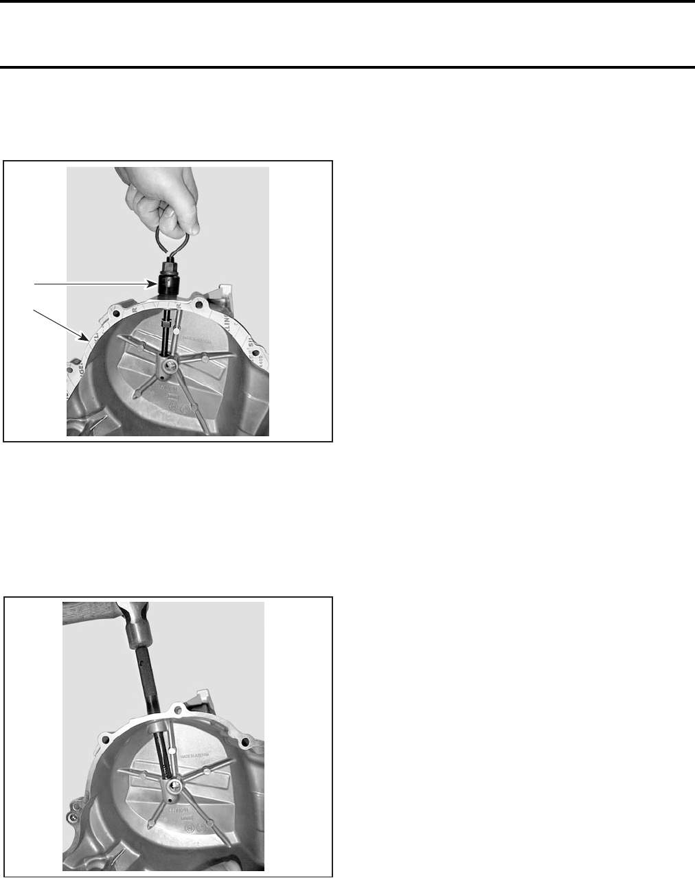
Section 03 ENGINE
Subsection 10 (CLUTCH)
VMR2004_014_03-10A.FM 03-10-7
With the extractor (P/N 529 035 690), remove both
needle bearings nos. 20 and 21, and seal no. 22
together.
1. Clutch cover
2. Extractor
NOTE: With a heat gun, heat the clutch cover near
bearings area.
Installation
Drive in lower and upper needle bearing together
using the punch (P/N 529 035 691).
Insert clutch release shaft.
Using punch (P/N 529 035 693), drive in seal.
Install clutch cover and do not forget gasket.
CAUTION: Never pull clutch release lever back-
wards. The pressure plate bearing may come
out of pressure plate.
V02D0BA
1
2
V02D0CA
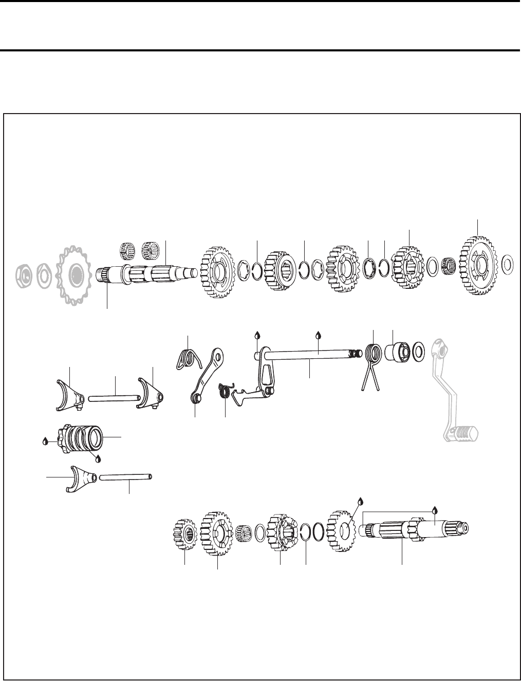
Section 03 ENGINE
Subsection 11 (TRANSMISSION)
VMR2004_015_03-11A.FM 03-11-1
TRANSMISSION 0
V02E07S
15
16
18191720
13
Anti-seize
lubricant
4
87
3
210
11 12
9
5
6
21 22 23 24 14
Anti-seize
lubricant
Engine oil
Super Lube
grease
Engine oil
Engine
oil
Engine oil
1

Section 03 ENGINE
Subsection 11 (TRANSMISSION)
03-11-2 VMR2004_015_03-11A.FM
SHIFTING MECHANISM
Removal
Remove engine from vehicle. Refer to REMOVAL
AND INSTALLATION.
Separate both crankcase housings. Refer to
CRANKSHAFT/BALANCER SHAFT.
Press shift pawl slightly outwards and withdraw
shift shaft no. 1 with shift pawl.
Remove index lever no. 2 and index spring no. 3.
Remove shift fork shafts nos. 4 and 5 from shift
forks nos. 6, 7 and 8.
Swivel shift forks outwards and remove.
Withdraw shift drum no. 9.
Inspection
Check for:
–worn or scored shifting forks
–rounded engagement dogs and slots
–bent shift forks
–bent shift fork shafts
–worn tracks on shift drum.
Measure the shift fork claw thickness.
A. Shift fork claw thickness
Measure the O.D. of the shift fork shaft in three
places using an outside micrometer.
Installation
1. Index lever
2. Index spring
3. Pawl spring
4. Sleeve
SHIFT FORK CLAW THICKNESS
SERVICE LIMIT 3.45 mm (.136 in)
O.D. OF SHIFT FORK SHAFT
SERVICE LIMIT 5.85 mm (.230 in)
V02E08A A
V02E04A
4
32
1
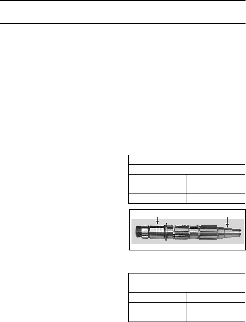
Section 03 ENGINE
Subsection 11 (TRANSMISSION)
VMR2004_015_03-11A.FM 03-11-3
Install index lever no. 2 with index spring no. 3 in
housing.
Attach pawl spring no. 10 to pawl.
Insert shift shaft no. 1 in housing and secure index
lever.
Slide spring no.11 and sleeve no. 12 onto shift
shaft.
Attach spring to shift shaft pivot.
Insert shift fork no. 6 in selector gear of clutch
shaft.
Install shift fork shaft no. 5 with the selector fork
in the direction of the crankshaft.
Insert shift fork no. 7 and no. 8 in the correspond-
ing selector gears of the mainshaft.
Install shift fork shaft no. 4 with the shift forks out-
wards.
Install shift drum no. 9 in the idle setting.
Press back index lever and shift pawl and install
the shift drum.
Move index lever and shift pawl into mesh.
Check transmission function: shift up and down
through all gears, checking that the detent in all
gears disengages smoothly from the shift pawl.
Assemble engine.
Once again, shift up and down through all gears,
slowly allowing selector lever to return to its orig-
inal position. The clicking noise of the engaging
shift pawl must be clearly audible.
Install engine.
TRANSMISSION
Removal
Remove the shifting mechanism. Refer to the
above section.
Remove shift fork shafts nos. 4 and 5.
Swivel shift forks nos. 6, 7 and 8 outwards and
remove.
Withdraw shift drum no. 9.
Using a plastic mallet, tap mainshaft no. 13 to as-
sist withdrawing mainshaft together with clutch
shaft no. 14.
NOTE: Before removal withdraw the separate
gears nos. 15 and 16 from mainshaft.
Disassembly
Mainshaft
Using special pliers slide circlip no. 17 slightly
backwards to remove circlip no. 18 which is se-
cured by the angled ring no. 19.
Remove gears.
Remove circlip no. 20 and withdraw gear.
CAUTION: Retaining ring must not be over-
stretched.
Clutch Shaft
Remove gear nos. 21, 22 and 23.
Remove circlip no. 24 with special pliers.
Remove gear.
Inspection
Check mainshaft for wear.
1. Magneto end
2. Clutch side
Check clutch shaft for wear.
MAINSHAFT
SERVICE LIMIT
Magneto end 24.98 mm (.98 in)
Clutch side 16.98 mm (.67 in)
Run-out 0 mm (0 in)
CLUTCH SHAFT
SERVICE LIMIT
Magneto end 16.98 mm (.67 in)
Clutch side 24.97 mm (.98 in)
Run-out 0 mm (0 in)
V02E05A
12
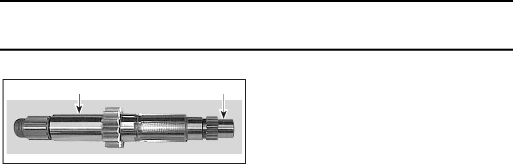
Section 03 ENGINE
Subsection 11 (TRANSMISSION)
03-11-4 VMR2004_015_03-11A.FM
1. Magneto end
2. Clutch side
Check all bearings, bearing points, tooth flanks,
taper grooves and annular grooves. Annular grooves
must have sharp edges.
Replace gears only together with the correspond-
ing meshing gears.
NOTE: Always replace circlips and install using
special pliers.
Assembly and Installation
For assembly and installation, reverse the disas-
sembly and removal procedures. Pay attention to
the following details.
Install clutch shaft and mainshaft together, and
coat main bearing points with Loctite anti-seize.
Seat shafts fully home by tapping them into place
with a plastic hammer.
NOTE: Before installation of the transmission
shafts, remove crankshaft to simplify assembly
operation.
Install the shifting mechanism.
TRANSMISSION SHAFT
BEARINGS
Removal
Heat left or right engine housing to 80 - 100°C
(170 - 212°F).
Using the suitable bearing extractor to remove
bearings.
Tap out the mainshaft sealing ring from the inside.
Installation
Place new bearings in a freezer for 10 minutes be-
fore installation.
Place left or right engine housing in oven to 100°C
(212°F) to ease bearings installation.
NOTE: Always replace the mainshaft sealing ring
by a new one.
V02E06A
2 1

Section 04 FUEL SYSTEM
Subsection 01 (TABLE OF CONTENTS)
VMR2004_033_04_01ATOC.FM 04-01-1
TABLE OF CONTENTS 0
FUEL CIRCUIT........................................................................................................................ 04-02-1
FUEL LINE .......................................................................................................................... 04-02-2
FUEL TANK ........................................................................................................................ 04-02-2
FUEL VALVE ...................................................................................................................... 04-02-2
FUEL SYSTEM PRESSURIZATION ................................................................................... 04-02-3
CARBURETOR AND AIR INTAKE SILENCER ....................................................................... 04-03-1
CARBURETOR ................................................................................................................... 04-03-1
AIR INTAKE SILENCER ..................................................................................................... 04-03-2
GENERAL ........................................................................................................................... 04-03-3
CARBURETOR ................................................................................................................... 04-03-3
THROTTLE CABLE............................................................................................................. 04-03-6
AIR INTAKE SILENCER ..................................................................................................... 04-03-8
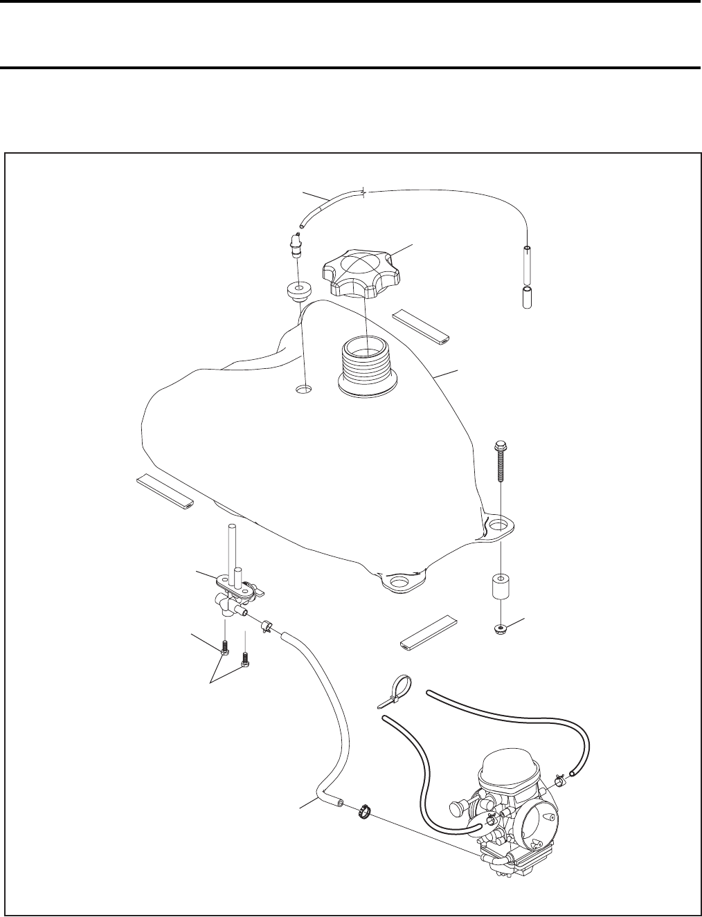
Section 04 FUEL SYSTEM
Subsection 02 (FUEL CIRCUIT)
VMR2004_016_04_02A.FM 04-02-1
FUEL CIRCUIT 0
V02F0JS
7 Nm
(62 lbfin)
5 Nm
(44 lbfin)
6
4
1
2
5
3
Section 04 FUEL SYSTEM
Subsection 02 (FUEL CIRCUIT)
04-02-2 VMR2004_016_04_02A.FM
FUEL LINE
When replacing fuel line, be sure to use hoses as
available from Bombardier parts department. This
will ensure continued proper and safe operation.
CAUTION: Whenever working on fuel system,
always verify for water or dust infiltration in
reservoir.
FUEL TANK
Draining
Turn fuel valve no. 2 to the position OFF.
Obstruct line no. 3 with a hose pincher (P/N 295
000 076) then disconnect fuel line from carburetor.
Place fuel line in a reservoir, turn fuel valve on RE-
SERVE and remove hose pincher.
NOTE: To accelerate fuel tank no. 1 draining and
ensure complete draining, remove cap no. 4.
When the fuel tank is empty, turn valve OFF.
Removal
Drain fuel tank.
Remove following items from body. Refer to BODY
for complete detailed procedure:
–seat
– front facia
– fuel tank cover.
Inspection
Inspect fuel tank for any damage or cracks which
may result in fuel leaks. If so, replace tank by a
new.
Installation
Reverse removal procedure, however pay atten-
tion to the following:
Check so that the vent hose is not pinched.
Perform fuel system pressurization as described
further in this section.
FUEL VALVE
Removal
Remove fuel tank.
Place fuel tank on the side.
Unscrew bolts no. 5 retaining fuel valve to fuel
tank.
Remove fuel valve.
Inspection
Check strainer on each end of fuel valve rods. If
one strainer is damaged, change fuel valve.
Check gasket between fuel valve and fuel tank for
damage. If so, replace by a new.
Installation
For installation, reverse the removal procedure.
Clean strainer on each end of fuel valve rods.
Perform fuel system pressurization as described
in the following procedure.
WARNING
Replace any damaged, leaking or deteriorat-
ed fuel line. Use of improper fuel line could
compromise fuel system integrity.
WARNING
When draining a fuel tank or whenever a fuel
line is disconnected, obstruct line with a hose
pincher (P/N 295 000 076) or equivalent de-
vice. Fuel is flammable and explosive under
certain conditions. Ensure work area is well
ventilated. Do not smoke or allow open flames
or sparks in the vicinity.
WARNING
Always disconnect battery exactly in the
specified order, BLACK (-) cable first. It is rec-
ommended to disconnect electrical connec-
tions prior to disconnecting fuel lines.
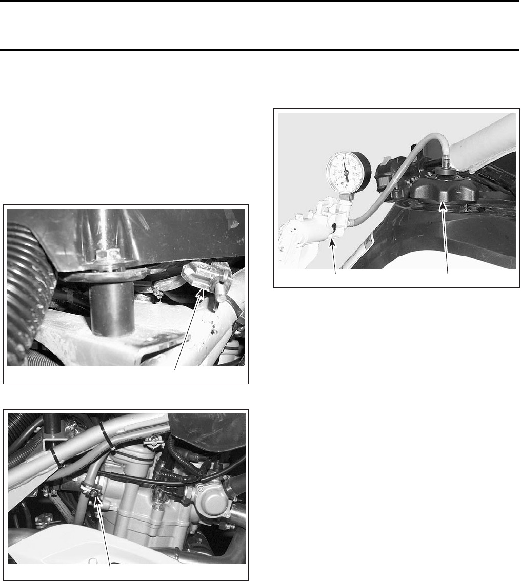
Section 04 FUEL SYSTEM
Subsection 02 (FUEL CIRCUIT)
VMR2004_016_04_02A.FM 04-02-3
FUEL SYSTEM PRESSURIZATION
Fill up fuel tank no. 1.
Remove seat.
Install on fuel tank the special cap included in the
fuel and oil system tester kit (P/N 529 033 100).
Install hose pinchers (P/N 295 000 076) on fuel
tank vent line no. 6 and on the outlet hose no. 3
at carburetor, as shown in the following photos.
1. Hose pincher installed on fuel tank vent line
1. Hose pincher installed on fuel pump outlet
Using air pump (P/N 529 021 800) inject air into
fuel tank. See next photo.
1. Special cap on tank
2. Air pump
Pressurize fuel system to 21 kPa (3 PSI). That pres-
sure must not drop during 3 minutes.
If pressure drops, locate fuel leak(s) and repair/
replace leaking component(s).
To ease locating leak(s) at fuel tank vent fitting or
fuel cap spray soapy water on components, bub-
bles will indicate leak location(s).
V02N03B 1
V02N04B 1
V02N05A 12
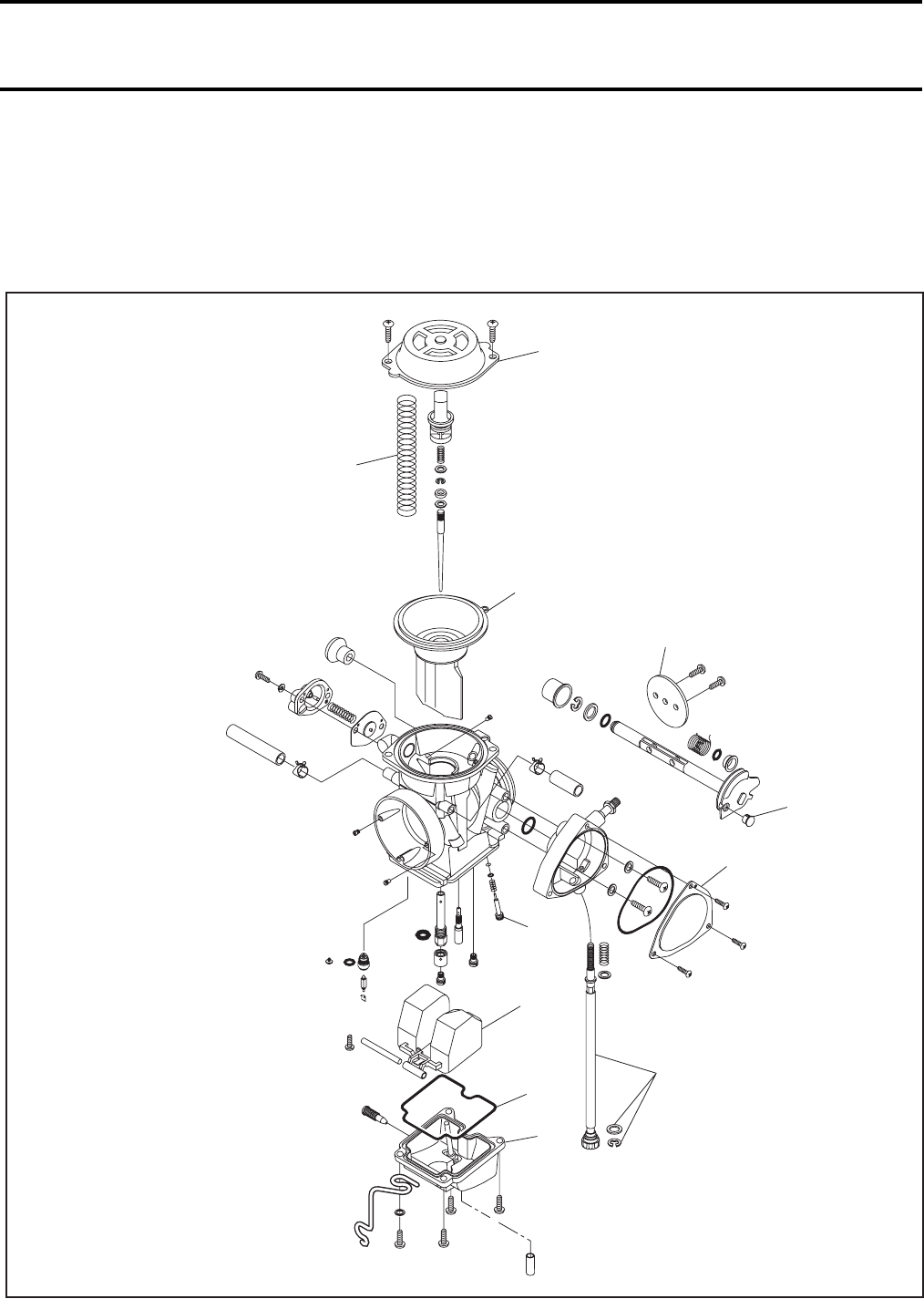
Section 04 FUEL SYSTEM
Subsection 03 (CARBURETOR AND AIR INTAKE SILENCER)
VMR2004_017_04_03A.FM 04-03-1
CARBURETOR AND AIR INTAKE
SILENCER 0
CARBURETOR
V02F0BS
10
8
11
12
7
5
4
3
2
6
9
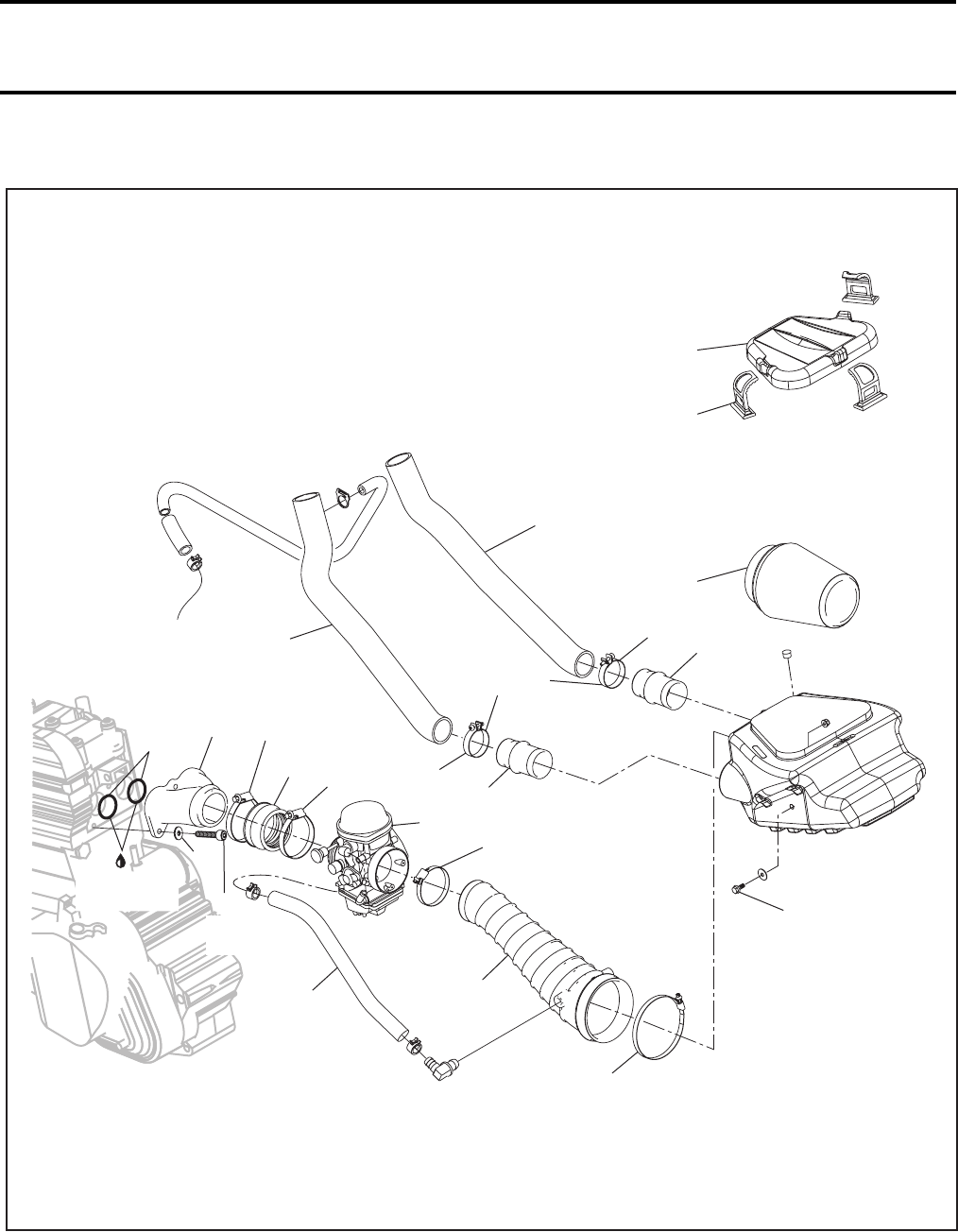
Section 04 FUEL SYSTEM
Subsection 03 (CARBURETOR AND AIR INTAKE SILENCER)
04-03-2 VMR2004_017_04_03A.FM
AIR INTAKE SILENCER
Engine
V02F0CS
24
16 15
17
19
17
19
13
14
22
20
25
28
27
26
23
18
18
Super Lube
grease
10 Nm
(89 lbfin)10 Nm
(89 lbfin)
1.2 Nm
(10 lbfin)
0.6 Nm
(5 lbfin)
12.5 Nm
(22 lbfin)
0.6 Nm
(5 lbfin)
1.2 Nm
(10 lbfin)
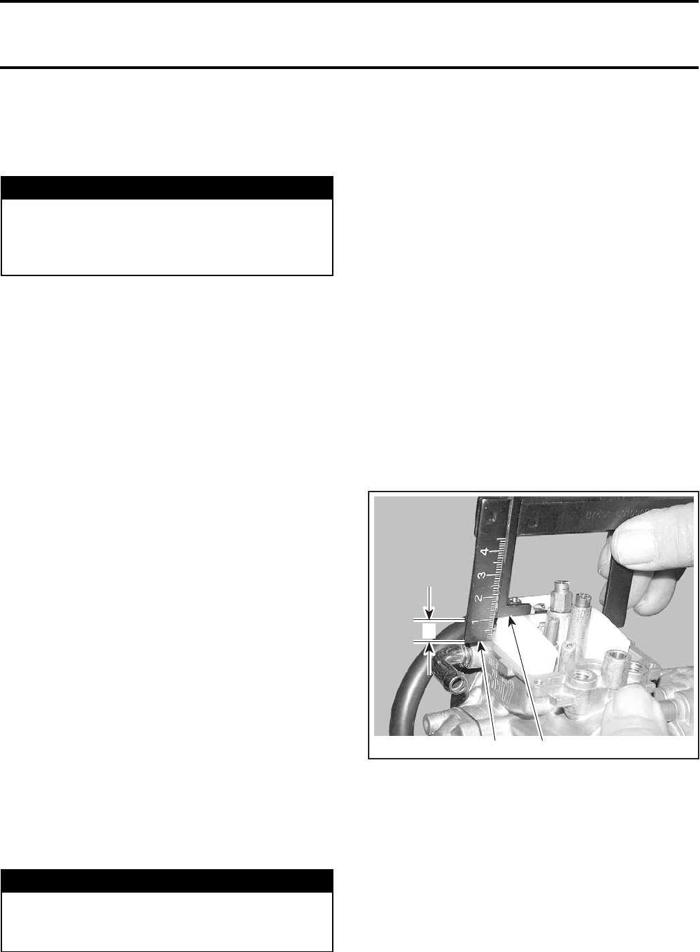
Section 04 FUEL SYSTEM
Subsection 03 (CARBURETOR AND AIR INTAKE SILENCER)
VMR2004_017_04_03A.FM 04-03-3
GENERAL
Before performing any job on fuel system, always
disconnect BLACK (-) cable from battery.
CARBURETOR
CAUTION: Although some jets can be replaced
by other jets from other carburetors, such mod-
ifications shouldn’t be performed. They can
greatly affect engine calibration and can cause
severe damage to engine. Use only recommend-
ed jetting specific for this carburetor.
Removal
Remove seat.
Loosen both carburetor and air box clamps.
Unplug all hoses from carburetor no. 1.
NOTE: To ease reinstallation, mark all hoses be-
fore unplugging.
Turn carburetor to place the throttle cable housing
on top, then remove the throttle cable. Refer to
THROTTLE CABLE further in this section.
Pull out carburetor.
Cleaning and Inspection
The entire carburetor should be cleaned with a
general solvent and dried with compressed air be-
fore disassembly.
CAUTION: Heavy duty carburetor cleaner may
be harmful to the float material and to the rub-
ber parts, O-rings, etc. Therefore, it is recom-
mended to remove those parts prior to cleaning.
Carburetor body and jets should be cleaned in a
carburetor cleaner following manufacturer’s in-
structions.
Check the diaphragm for crack or other damages.
Replace if necessary.
Carburetor Float Level Adjustment
Correct fuel level in float chamber is vital toward
maximum engine efficiency. To check for correct
float level proceed as follows:
–Remove float bowl no. 2 and gasket no. 3 from
carburetor.
–Make sure that float arm no. 4 is symmetric,
not distorted.
With carburetor chamber up side down:
–Measure height between bowl seat and the
top edge of float arm. Use float level gauge
(P/N 529 035 520).
–Keep float level gauge perfectly vertical and in line
with main jet hole.
Ensure that both float level gauge tips are properly
positioned on carburetor body and that “L” arm is
leaning on float with compressing valve spring.
Refer to following photos for proper float level gauge
positioning and to TECHNICAL DATA for proper
level.
TYPICAL
1. Gauge tips
2. “L” arm
A. Height
WARNING
Always disconnect battery exactly in the
specified order, BLACK (-) cable first. It is rec-
ommended to disconnect electrical connec-
tions prior to disconnecting fuel lines.
WARNING
Solvent with a low flash point such as gaso-
line, naphtha, benzol, etc., should not be used
as they are flammable and explosive.
2
V02F0DA 1
A
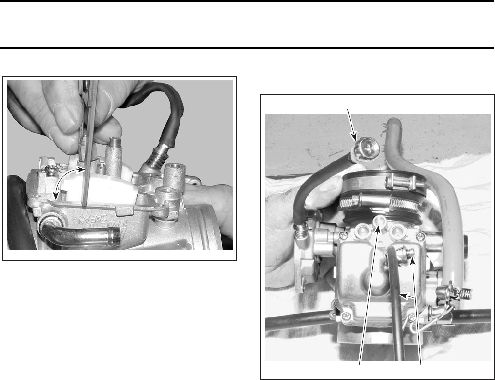
Section 04 FUEL SYSTEM
Subsection 03 (CARBURETOR AND AIR INTAKE SILENCER)
04-03-4 VMR2004_017_04_03A.FM
TYPICAL — GAUGE ALIGNED WITH MAIN JET
To adjust height, bend the contact tab of float arm
until the specified height is reached.
CAUTION: When adjusting lever, do not pry it.
This will apply pressure on needle and damage
valve seat/needle.
Installation
To install carburetor on engine, inverse removal pro-
cedure, as described:
–Inspect throttle cable housing prior to installa-
tion.
–Reinstall and adjust throttle cable, then side cov-
er. Refer to CARBURETOR ADJUSTMENTS.
–Reinstall carburetor on engine.
When reinstalling carburetor on engine, pay atten-
tion to the following:
CAUTION: The carburetor adaptor must be
checked for cracks and/or damage. At assembly,
the carburetor adaptor must be perfectly matched
with the carburetor and intake adaptor or severe
engine damage will occur.
Install clamps in a way that their tightening bolts
are staggered, not aligned.
Carburetor Adjustments
BOTTOM VIEW
1. Idle speed screw
2. Pilot screw
3. Drain tube and screw
Pilot Screw Preliminary Adjustment
NOTE: The pilot screw no. 5 is factory pre-set.
Adjustment is not necessary unless the carburetor
is overhauled or replaced.
Completely close the pilot screw (until a slight
seating resistance is felt) then back off as speci-
fied.
Refer to TECHNICAL DATA for specifications.
V02F0EA
90°
V02F05A
2 3
1
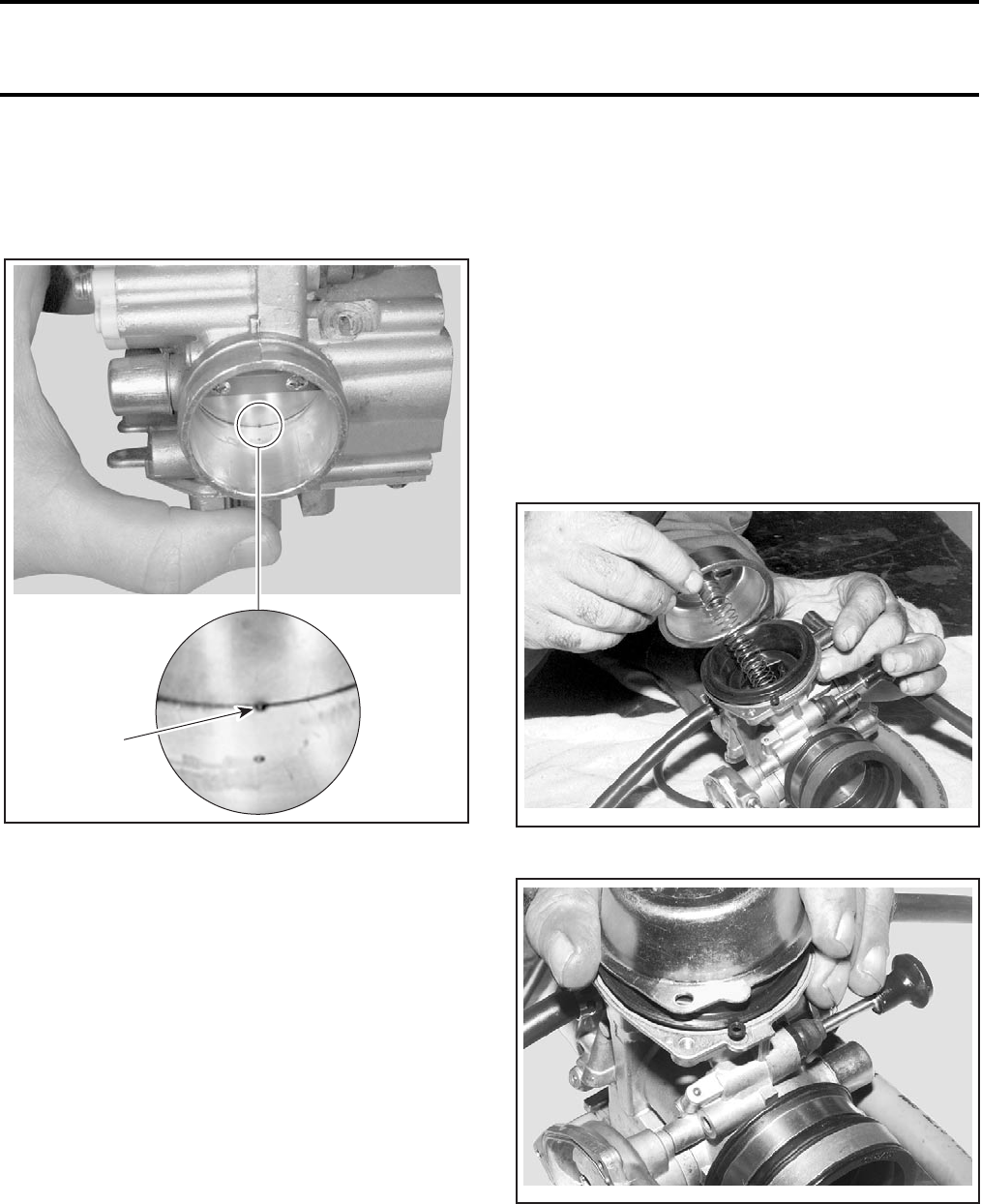
Section 04 FUEL SYSTEM
Subsection 03 (CARBURETOR AND AIR INTAKE SILENCER)
VMR2004_017_04_03A.FM 04-03-5
Idle Speed Preliminary Adjustment
Adjust idle speed screw no. 6 to 1-1/2 turn or so
that throttle valve no. 7 closes bypass hole by half,
as shown in the next photo.
TYPICAL
1. Bypass hole closes to halfway
Idle Speed Adjustment
Start engine and allow it to warm then adjust idle
speed to specifications by turning idle speed
screw clockwise to increase engine speed or
counterclockwise to decrease it.
NOTE: Use the digital induction tachometer
(P/N 529 014 500). Turn tachometer wire around
spark plug wire, about 4 or 5 turns, for the best
measure.
CAUTION: Do not attempt to set the idle speed
by using the pilot screw.
Refer to TECHNICAL DATA for idle speed specifi-
cations.
Pilot Screw Adjustment
NOTE: The pilot screw is factory pre-set. Adjust-
ment is not necessary unless the carburetor is
overhauled or replaced. Warm the engine to oper-
ating temperature.
Turn the pilot screw clockwise until you hear the
engine misses or decreases air speed, then turn
counterclockwise until the engine again misses or
decreases air speed.
Center the pilot screw exactly between these too
extreme positions.
If idle speed changes after adjustment of the pilot
screw, readjust the idle speed screw.
Diaphragm Installation
Carefully replace diaphragm no. 8 in its original po-
sition.
Make sure spring no. 9 is located properly in car-
buretor cover no. 10 before screwing.
NOTE: Check and place correctly the indexation lob.
1
V01F0WA
V02F06A
V02F07A

Section 04 FUEL SYSTEM
Subsection 03 (CARBURETOR AND AIR INTAKE SILENCER)
04-03-6 VMR2004_017_04_03A.FM
THROTTLE CABLE
NOTE: To ease reinstallation, take note cable rout-
ing.
Removal
Remove carburetor side cover no. 11.
1. Carburetor side cover
Using thumb, release tension on throttle lever.
With long nose pliers, rotate cable end bushing
no. 12 so that cable aligns with throttle lever re-
cess, then lift cable end. See next photo.
1. Release tension on throttle lever
2. Cable end bushing
Separate cable end bushing from throttle cable
end, as shown in the next photo. Keep bushing.
REMOVE CABLE END BUSHING
Loosen throttle cable nut.
1. Loosen this nut
Pull cable out from carburetor.
Before adjusting the throttle cable, adjust idle
speed (preliminary adjustment).
On the carburetor, loosen lock nut and adjust throt-
tle cable.
Retorque lock nut.
1
V02F0FA
1
V02F0GA 2
V02F0HA
1
V02F0IA
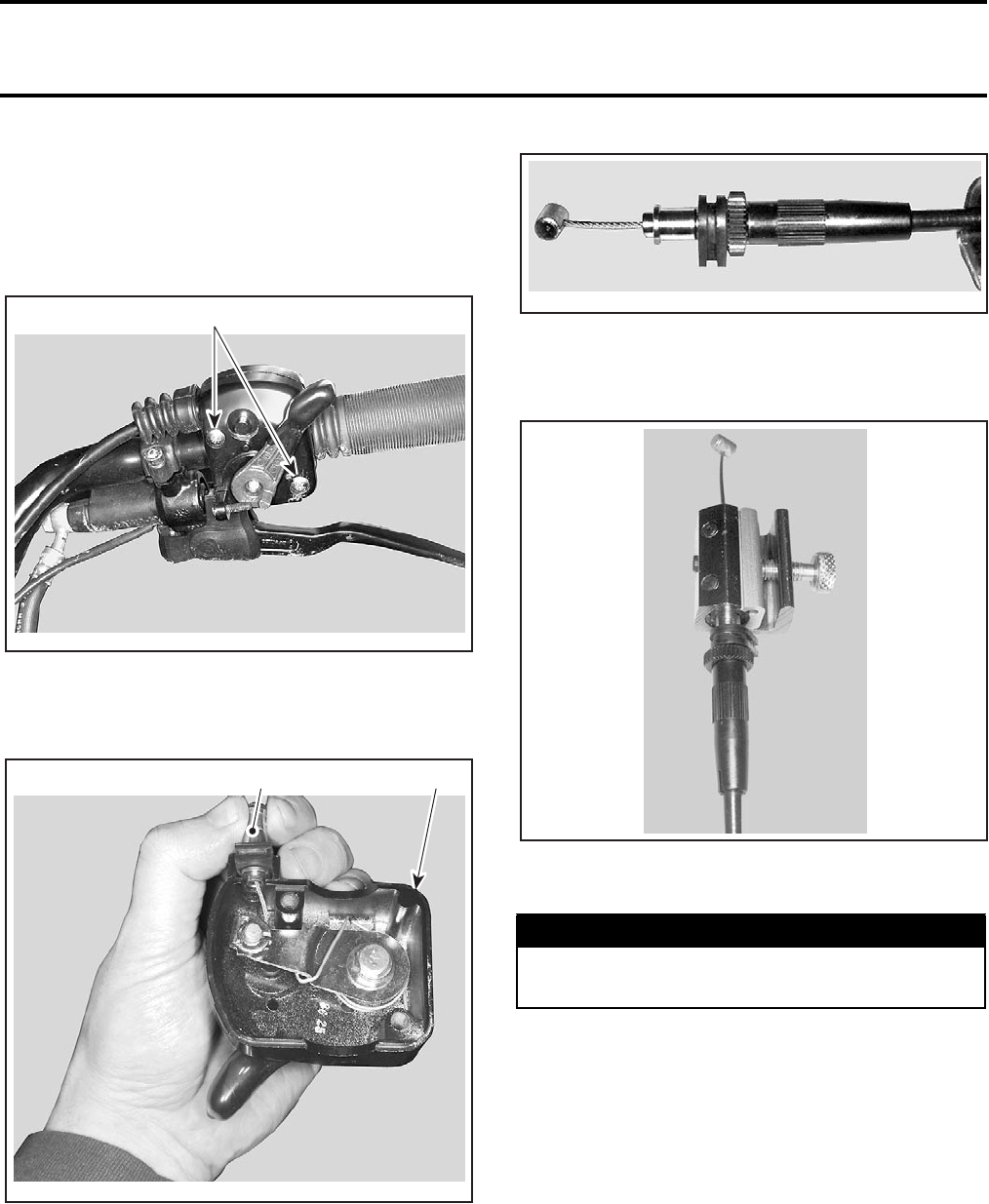
Section 04 FUEL SYSTEM
Subsection 03 (CARBURETOR AND AIR INTAKE SILENCER)
VMR2004_017_04_03A.FM 04-03-7
Throttle Cable Lubrication
The throttle cable must be lubricated with cable
lubricant (P/N 293 600 041) or an equivalent prod-
uct.
Open the throttle lever.
1. Remove screws
Remove:
–the cable from the throttle lever
1. Throttle handle housing
2. Throttle cable
NOTE: Slide cable in clip slot and remove the end
of cable from clip.
–the seal on the throttle cable.
Remove the carburetor side cover.
Install the cable luber (P/N 529 035 738) on the
cable.
Insert the needle of lubricant can on the cable lu-
ber hole.
NOTE: Place a rag around the cable luber to pre-
vent the lubricant splash.
Put the lubricant until it passes through the cable.
Reinstall the cable.
Spray a little quantity of lubricant on the throttle
lever mechanism then close the housing.
Adjust the throttle lever.
Throttle Lever Adjustment
Slide rubber protector back to expose throttle ca-
ble adjuster.
Loosen lock nut then turn the adjuster to obtain
correct throttle lever free play.
V01I0ZA
1
V01I10A
12
WARNING
Always wear eye protection and gloves
when you lubricate a cable.
V00I02A
V00I03A
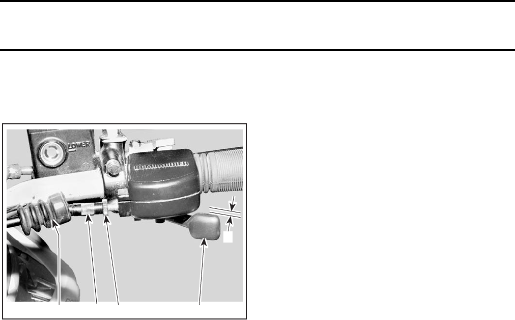
Section 04 FUEL SYSTEM
Subsection 03 (CARBURETOR AND AIR INTAKE SILENCER)
04-03-8 VMR2004_017_04_03A.FM
NOTE: Measure throttle free play at the tip of
throttle lever.
Tighten lock nut and reinstall protector.
1. Throttle lever
2. Protector
3. Cable adjuster
4. Lock nut
A. 3 to 8 mm (1/8 to 5/16 in)
AIR INTAKE SILENCER
Air Filter Box
Removal
Remove:
–seat
–air box cover no. 13
–air filter no. 14
–rectifier located under air filter box.
Disconnect the air intake tube no. 15 from carbu-
retor.
Unplug from air intake tube, the hose no. 16 on
the LH side.
Unscrew clamps no. 17 retaining the vent hoses
no. 18 to the deflectors no. 19.
Unscrew bolts no. 20.
Pull air filter box no. 21 out of frame with air intake
tube.
Inspection
Check air filter box for cracks or other damages.
Change air filter box if necessary.
Check air filter box latches no. 22 for cracks or
other damages. Change the air filter box latches if
necessary.
Installation
For installation, reverse the removal procedure.
Air Intake Tube
Removal
Remove air filter box.
Separate air intake tube no. 15 from air filter box.
Inspection
Check air intake tube for cracks or other damages.
Change it if necessary.
Installation
For installation, reverse the removal procedure.
Carburetor Adaptor
Removal
Remove carburetor.
Unscrew clamp no. 23.
Separate the carburetor adaptor no. 24 from the
intake adaptor no. 25.
Inspection
Check carburetor adaptor for cracks or other dam-
ages. Change it if necessary.
Installation
For installation, reverse the removal procedure.
Intake Adaptor
Removal
Remove carburetor.
Unscrew socket screws no. 26 and washers no. 27
then remove intake adaptor no. 25.
Inspection
Check intake adaptor for cracks or other damages,
change if necessary.
Check O-rings no. 28 and change if necessary.
Installation
For installation, reverse the removal procedure.
V02I04A 234 1
A

Section 05 ELECTRICAL
Subsection 01 (TABLE OF CONTENTS)
VMR2004_033_05_01ATOC.FM 05-01-1
TABLE OF CONTENTS 0
OVERVIEW............................................................................................................................. 05-02-1
GENERAL OPERATION INFORMATION ........................................................................... 05-02-1
CHARGING SYSTEM......................................................................................................... 05-02-1
STARTING SYSTEM .......................................................................................................... 05-02-1
IGNITION SYSTEM............................................................................................................ 05-02-2
ACCESSORIES ................................................................................................................... 05-02-2
GENERAL TESTING/ TROUBLESHOOTING INFORMATION ......................................... 05-02-2
FUSES LOCATION............................................................................................................. 05-02-3
SERVICING PACKARD CONNECTORS ............................................................................ 05-02-3
SERVICING DEUTSCH CONNECTORS ............................................................................ 05-02-3
IDENTIFICATION OF MAJOR CONNECTOR PINS .......................................................... 05-02-5
CHARGING SYSTEM............................................................................................................. 05-03-1
TESTING PROCEDURE ..................................................................................................... 05-03-1
STARTING SYSTEM.............................................................................................................. 05-04-1
BATTERY ............................................................................................................................ 05-04-1
TROUBLESHOOTING ........................................................................................................ 05-04-1
BATTERY TESTING ........................................................................................................... 05-04-1
REMOVAL........................................................................................................................... 05-04-1
CLEANING ......................................................................................................................... 05-04-1
INSPECTION ...................................................................................................................... 05-04-2
BATTERY STORAGE.......................................................................................................... 05-04-2
ACTIVATION OF A NEW BATTERY................................................................................... 05-04-2
INSTALLATION .................................................................................................................. 05-04-2
STARTING SYSTEM TROUBLESHOOTING..................................................................... 05-04-3
STARTING SYSTEM TESTS ............................................................................................. 05-04-4
GENERAL ........................................................................................................................... 05-04-4
ELECTRIC STARTER.......................................................................................................... 05-04-5
REMOVAL .......................................................................................................................... 05-04-5
INSTALLATION.................................................................................................................. 05-04-5
CABLE TERMINAL INSTALLATION .................................................................................... 05-04-5
Section 05 ELECTRICAL
Subsection 01 (TABLE OF CONTENTS)
05-01-2 VMR2004_033_05_01ATOC.FM
IGNITION SYSTEM ................................................................................................................ 05-05-1
IGNITION SYSTEM TESTING PROCEDURE..................................................................... 05-05-1
GENERAL............................................................................................................................ 05-05-1
IGNITION SYSTEM TEST .................................................................................................. 05-05-1
IGNITION TIMING .............................................................................................................. 05-05-4
SPARK PLUG ...................................................................................................................... 05-05-5
DISASSEMBLY ................................................................................................................... 05-05-5
FOULING............................................................................................................................. 05-05-5
SPARK PLUG ANALYSIS ................................................................................................... 05-05-5
SPARK PLUG INSTALLATION ........................................................................................... 05-05-5
NGK SPARK PLUG SYMBOL EXPLANATION .................................................................. 05-05-6
ACCESSORIES ....................................................................................................................... 05-06-1
REMOVAL AND INSTALLATION ...................................................................................... 05-06-1
HEADLAMP......................................................................................................................... 05-06-1
TAILLIGHT........................................................................................................................... 05-06-2
AUXILIARY HEADLAMP .................................................................................................... 05-06-2
TACHOMETER .................................................................................................................... 05-06-3
IGNITION SWITCH ............................................................................................................. 05-06-3
INDICATOR LIGHTS ........................................................................................................... 05-06-3
TESTS ................................................................................................................................. 05-06-4
COOLING FAN OPERATION TEST.................................................................................... 05-06-4
HEADLAMP......................................................................................................................... 05-06-4
MULTI-FUNCTION SWITCH .............................................................................................. 05-06-4
INDICATOR LIGHTS ........................................................................................................... 05-06-4
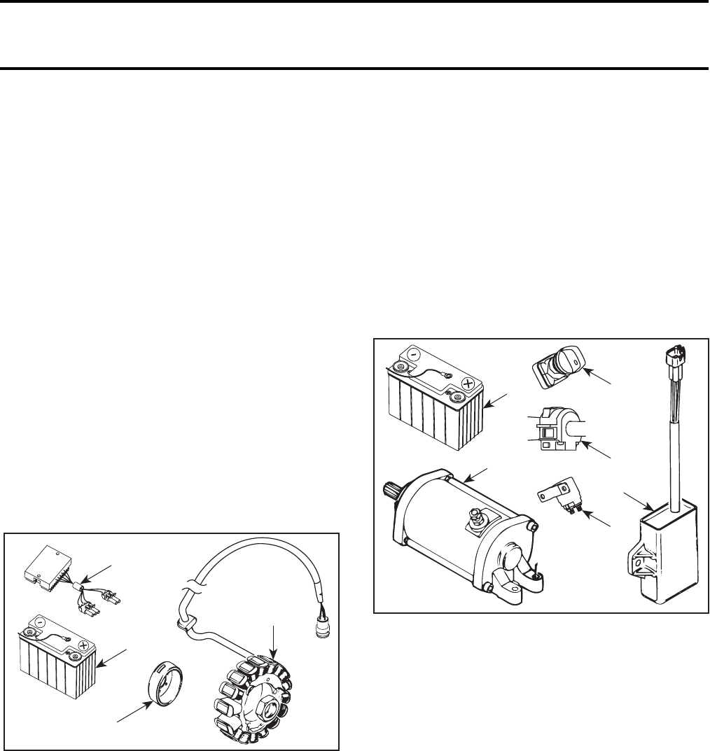
Section 05 ELECTRICAL
Subsection 02 (OVERVIEW)
VMR2004_018_05_02A.FM 05-02-1
OVERVIEW 0
GENERAL OPERATION
INFORMATION
The electrical system consists of different sub-
systems where some are inter-related:
• charging system
• starting system
• ignition system
• accessories.
The following gives an outline of each components.
CHARGING SYSTEM
It is the source of electrical energy to charge the
battery and keep it at a full state of charge. The mag-
neto is coupled to the engine and it transforms mag-
netic field into electric current through a 3-phase,
delta wound stator on 18 poles.
The magneto supplies unregulated AC (alternative
current) to the voltage regulator/rectifier.
1. Magneto flywheel
2. Stator
3. Voltage regulator/rectifier
4. Battery
Voltage Regulator/Rectifier
A 3-phase full-wave series-type voltage regulator/
rectifier receives the AC voltage and rectifies (con-
verts) it into DC. The voltage is also regulated to a
maximum of 14.7 ± 0.4 volts (DC).
Battery
The battery supplies the entire vehicle. Therefore, DC
current only is used in the entire electrical system.
STARTING SYSTEM
When ignition switch is turned on and start button
is pressed, a signal is sent to the starting solenoid.
The battery then supplies the starter through the
starting solenoid to start the engine.
TYPICAL
1. Battery
2. Ignition switch
3. Start button
4. Electronic module
5. Solenoid
6. Electric starter
Engine can be started in any gear (from 1 to 5).
Transmission must be on NEUTRAL or the clutch
lever pulled in to allow engine starting.
3
V02G04A
4
1
2
1
V02G05A
2
3
4
6
5
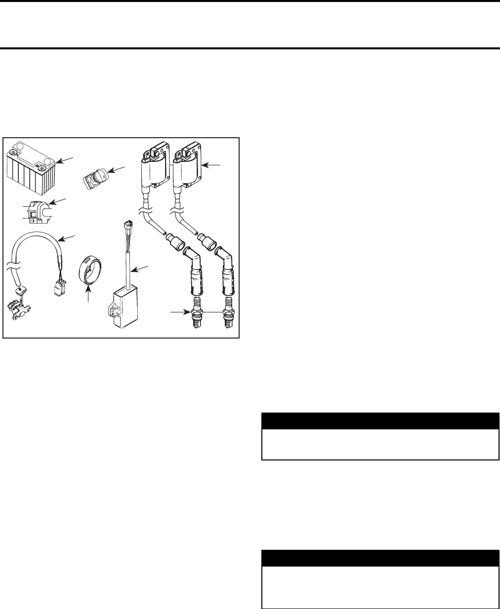
Section 05 ELECTRICAL
Subsection 02 (OVERVIEW)
05-02-2 VMR2004_018_05_02A.FM
IGNITION SYSTEM
An CDI (Capacitor Discharge Ignition) system is
utilized. The ignition system is made up of the fol-
lowing components:
TYPICAL
1. Battery
2. Ignition switch
3. Start button
4. Electronic module
5. Magneto flywheel
6. Trigger coil
7. Ignition coils
8. Spark plugs
Battery/Ignition Switch
The ignition switch allows battery to supply the
electronic module for the ignition system.
Start Button
Besides enabling the starting system, the start but-
ton enables the ignition system.
Magneto Flywheel/Trigger Coil
The magneto flywheel features one projection
mark that works with the trigger coil. The trigger
coil sends the signals to the electronic module to
be processed for the ignition system.
Ignition Coils/Spark Plugs
The ignition coil receives its signal from the elec-
tronic module. The ignition coil steps up the input
voltage for the CDI system and the end result is
firing of the spark plugs. It is two coils that pro-
vides a separate spark to each spark plug.
ACCESSORIES
The battery supplies the DC current to all accessories.
GENERAL TESTING/
TROUBLESHOOTING
INFORMATION
The following gives general electrical-related prob-
lems. For specific system-related problems, refer
to proper system section.
It is possible that a component seems to operate
in static condition but in fact, it is defective. In this
case, the best way to solve this problem is to re-
move the original part and replace it with one
which is in good condition.
IMPORTANT: When having to solve an electrical
problem, the first thing to do is to check battery
condition as well as its cables and connections.
Also ensure the ignition switch is turned on. Check
solidity (close to battery) and related-circuit fuse
condition with an ohmmeter (visual inspection
could lead to false results). Also visually examine
harness and connections.
CAUTION: It is recommended to always dis-
connect the battery when replacing any electric
or electronic parts.
To perform verifications, a good quality multimeter
such as Fluke 111 (P/N 529 035 868) should be used.
Pay particular attention to ensure that pins are not
out of their connectors or out of shape. The trou-
bleshooting procedures cover problems not re-
sulting from one of these causes.
+
-
1
V02G06A
3
2
6
5
4
8
7
WARNING
Always disconnect BLACK (-) cable first and
reconnect last.
WARNING
Ensure all terminals are properly crimped on
wires and connector housings are properly
fastened.
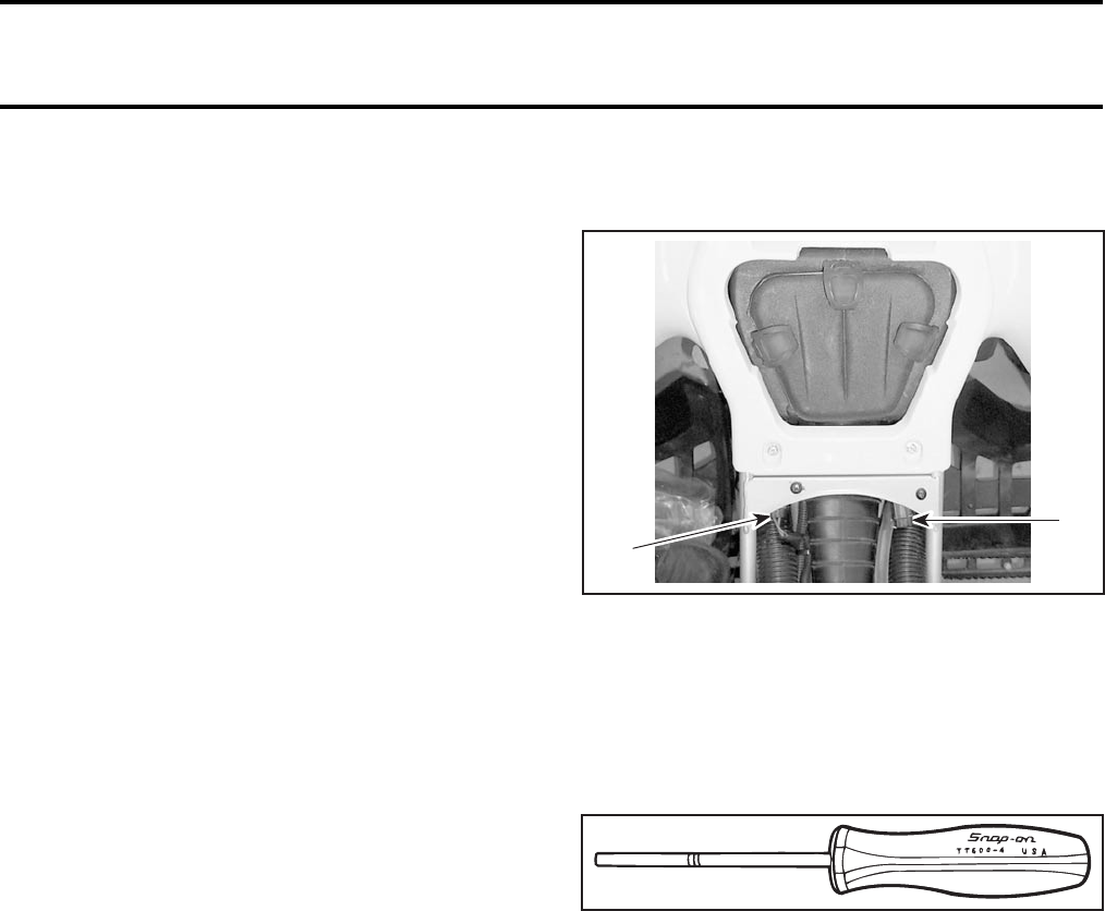
Section 05 ELECTRICAL
Subsection 02 (OVERVIEW)
VMR2004_018_05_02A.FM 05-02-3
Before replacing any electric or electronic part(s),
always check electrical connections. Make sure
that they are very tight and they make good con-
tact and that they are corrosion-free. The voltage
and current might be too weak to go through dirty
wire pins. Check carefully if posts show signs of
moisture, corrosion or if they look dull. Clean pins
properly and then coat them with silicon-based di-
electric grease or other appropriate lubricant (ex-
cept if otherwise specified) when reassembling
them. See connectors information below.
IMPORTANT: In usual electric circuit, the battery
supplies a switch which then supplies the electric
consumer. Therefore the switch opens and closes
the positive side of the circuit. Take this into ac-
count when troubleshooting the electrical system.
Pay attention to grounding wires.
Checking for Shorts Between 2 Wires
When checking continuity of a wire in a circuit,
wires should be checked for short circuit as fol-
lows.
Make sure to isolate circuit wires by unplugging
connectors.
Let’s suppose that the circuit to be checked has a
RED and a BLACK wire. Using an ohmmeter, mea-
sure the resistance between the RED and the
BLACK wire. The resistance should be infinite
(0 L). Otherwise, there is a short circuit between
both wires. We must therefore identify and cor-
rect the fault.
FUSES LOCATION
If a fuse is damaged, replace it by one of the same
rating.
CAUTION: Do not use a higher rated fuse as this
can cause severe damage.
Fuses are located under seat, between engine and
air box.
1. Fan (15 A)
2. Main (25 A)
SERVICING PACKARD
CONNECTORS
To remove terminal from Packard connector hous-
ing, use Snap-on TT600-4 tool.
SERVICING DEUTSCH
CONNECTORS
Waterproof Connector Housing
Female and Male Connector Housing
To remove:
–Using a long nose pliers, pull out the lock.
V02A0OA
1
2
F01B1JA
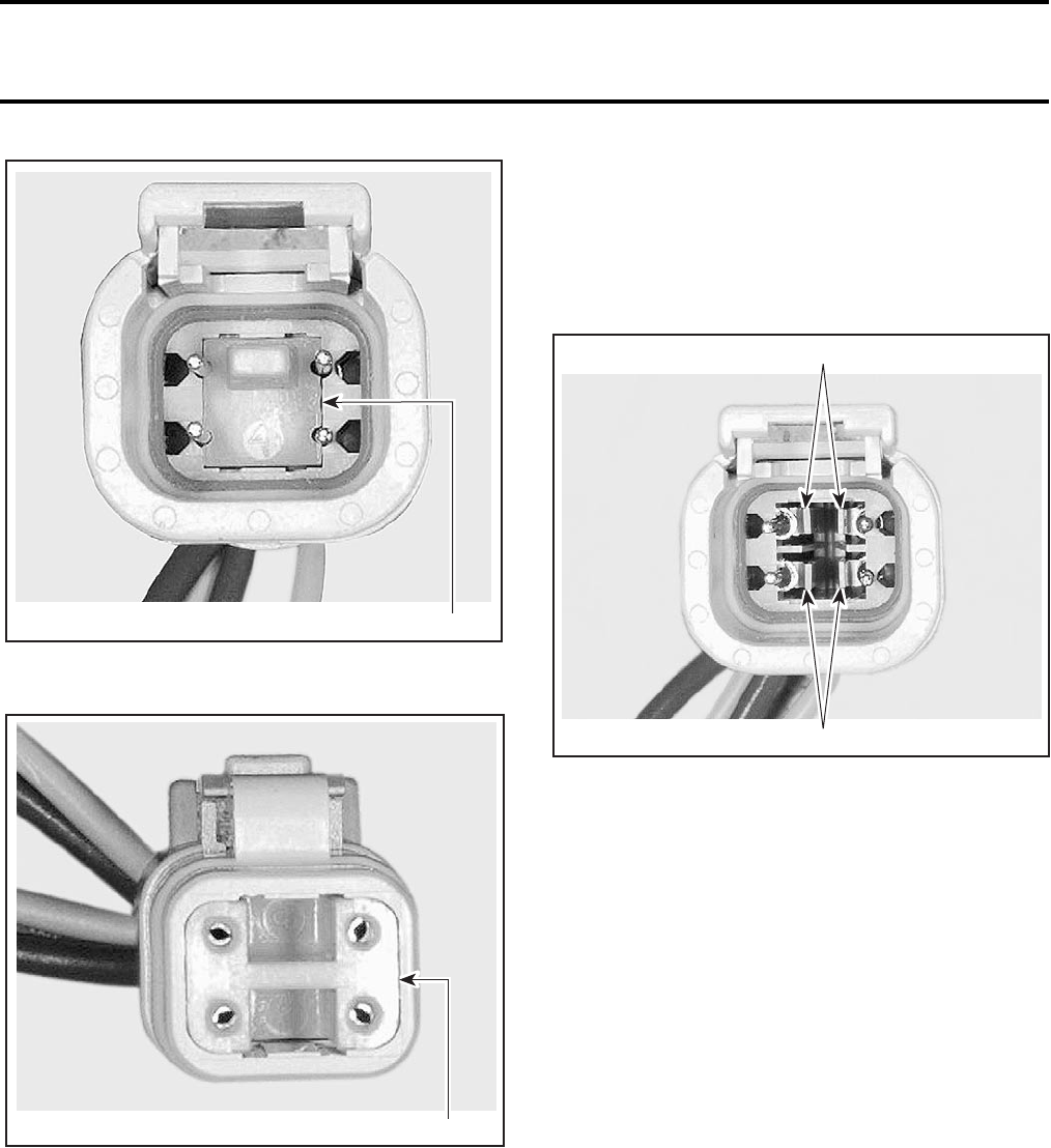
Section 05 ELECTRICAL
Subsection 02 (OVERVIEW)
05-02-4 VMR2004_018_05_02A.FM
FEMALE HOUSING
1. Female lock
MALE HOUSING
1. Male lock
NOTE: Before extraction, push wire forward to re-
lieve pressure on retaining tab.
–Insert a 4.8 mm (.189 in) wide screwdriver blade
inside the front of the contact cavity.
–Pry back the retaining tab while gently pulling
wire back until contact is removed.
FEMALE CONNECTOR HOUSING
1. Retaining tab
To install:
–For insertion of signal contact, make sure the
lock is removed.
–Insert contact into appropriate circuit cavity and
push as far as it will go.
–Pull back on the contact wire to be sure the re-
tention fingers are holding the contact.
–After all required contacts have been inserted,
the lock must be installed.
CAUTION: Never apply dielectric grease on con-
tacts in plug connector. The use of dielectric
grease will make the seal swell and move out of
the connector. Do not lubricate.
1
V01G0OA
V01G0PA 1
V01G0QA
1
1
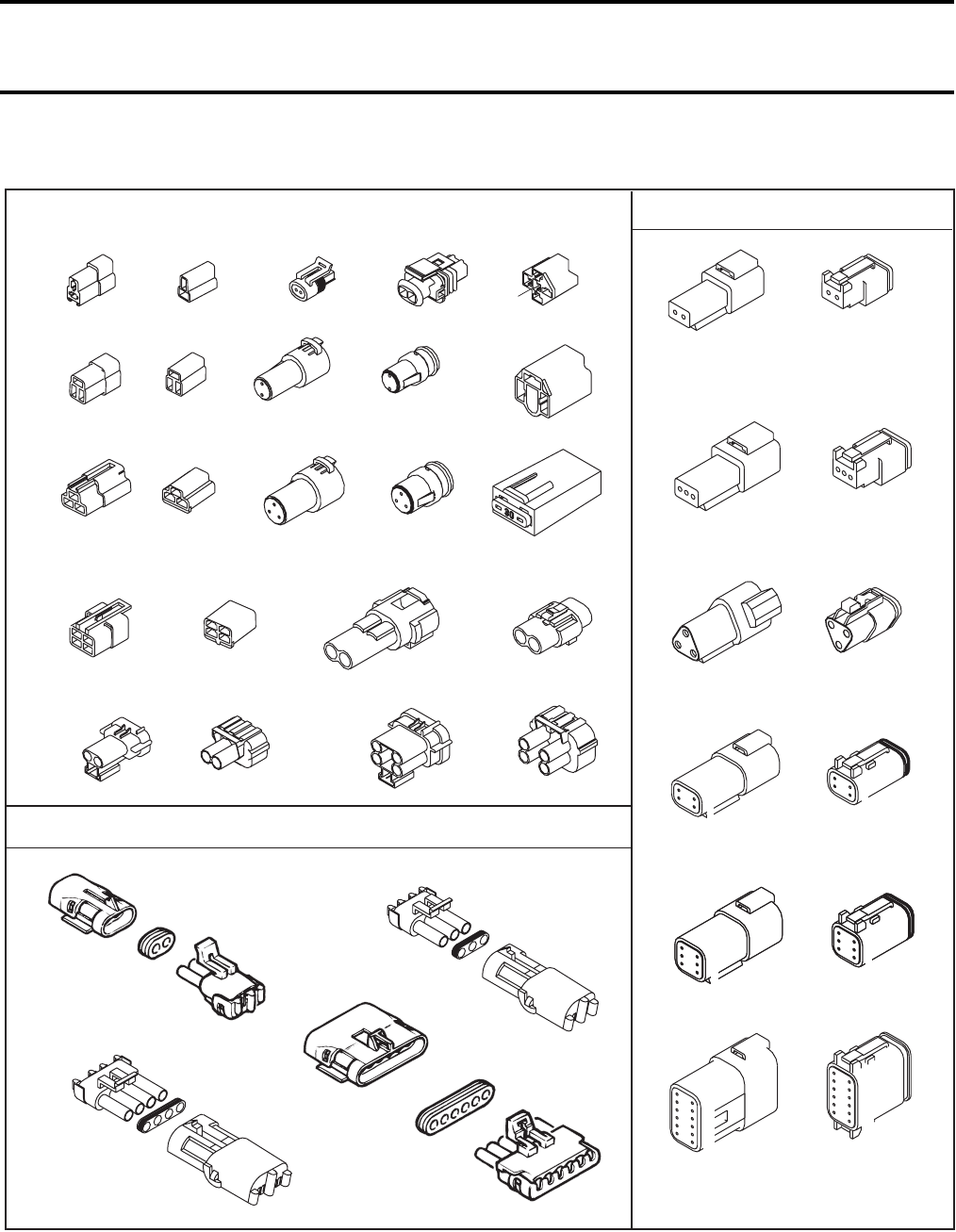
Section 05 ELECTRICAL
Subsection 02 (OVERVIEW)
VMR2004_018_05_02A.FM 05-02-5
IDENTIFICATION OF MAJOR CONNECTOR PINS
V01G0ES
DEUTSCH
2
1
1
2
3
3
A
B
C
A
B
C
1
2
3
4
5
6
12
11
10
9
8
7
12
11
10
9
8
7
1
2
3
4
5
6
1
2
36
5
4
6
5
41
2
3
1
2
4
3
4
31
2
2
1
1
2
A
B
A
B
B
A
2
1
85
87
30
86
87a
A
B
C
A
BC
A
B
A
C
B
A
B
AB
C
A
B
C
A
B
B
A
A
BC
A
D
CB
B
CA
D
AB
A
D
CB
A
B
C
A
B
PACKARD
B
A
B
A
BA
C
BA
C
BA
C
D
B
A
C
D
A
B
C
D
E
F
B
CDA
A
B
C
D
E
F
A
B
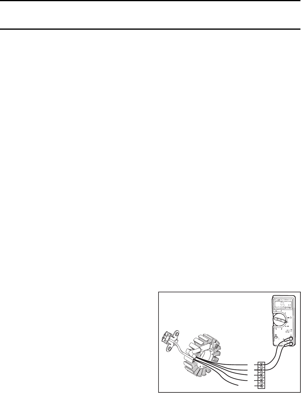
Section 05 ELECTRICAL
Subsection 03 (CHARGING SYSTEM)
VMR2004_019_05_03A.FM 05-03-1
CHARGING SYSTEM 0
TESTING PROCEDURE
NOTE: First, ensure that battery is in good condi-
tion prior to performing the following test using a
current inductive ammeter such as Snap-on MT
110.
If the battery is regularly discharged, check main
(25 amp) fuse condition.
The voltage regulator/rectifier could be the culprit
of a blown fuse. To check, simply disconnect the
voltage regulator/rectifier from the circuit.
If the fuse still burns, check for a defective wire.
CAUTION: Do not use a higher rated fuse as this
can cause severe damage.
Voltage Regulator/Rectifier
STATIC TEST: CONTINUITY
1. Due to internal circuitry, there is no static test
available.
DYNAMIC TEST
Current Test
Proceed as follows:
–Start engine.
–Lay an inductive ammeter on positive cable of
battery.
–Bring engine to approximately 3500 RPM.
Depending on battery charge, current reading
should be approximately 5 amperes. If not, check
magneto output prior to concluding that voltage
regulator/rectifier is faulty.
Voltage Test
Proceed as follows:
–Start engine.
–Connect a multimeter to battery posts. Set mul-
timeter to Vdc scale.
–Bring engine to approximately 3500 RPM.
If multimeter reads over 15 volts, voltage regulator/
rectifier is defective. Replace it.
NOTE: Whatever the voltmeter type used (peak
voltage or RMS), the voltage must not exceed
15 V. A faulty voltage regulator/rectifier will allow
voltage to exceed 15 V as engine speed is in-
creased.
NOTE: If the battery will not stay charged, the
problem can be any of the charging circuit compo-
nents. If these all check good, you would be accu-
rate in assuming the problem to be in the voltage
regulator/rectifier.
If there is no charging at the battery with the pre-
ceding voltage test, the following test can also be
performed.
NOTE: If the voltage regulator/rectifier is within
the specification, the wiring harness between the
voltage regulator/rectifier and battery is defective.
If the voltage regulator/rectifier is out of specifica-
tion and the stator test good, the voltage regulator/
rectifier is defective.
Stator
STATIC TEST: CONTINUITY
1. Disconnect the magneto wiring harness connec-
tor. With the recommended multimeter, place
the 2 meter test probes onto the stator wire
leads AC-1 and AC-2 of the stator. The resis-
tance should be between 0.1 Ω and 1.0 Ω.
TYPICAL
V02G01A
YL
GN-YL
YL
YL
BL
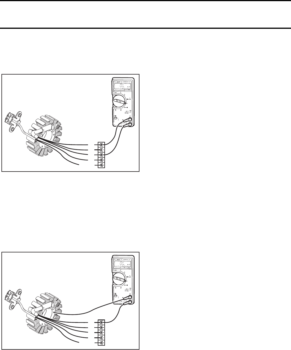
Section 05 ELECTRICAL
Subsection 03 (CHARGING SYSTEM)
05-03-2 VMR2004_019_05_03A.FM
2. Place either meter test probe into the remaining
stator lead (AC-3) and note the resistance (same
as step no. 1). If the readings are out of specifi-
cation, the stator will need to be replaced.
TYPICAL
STATIC TEST: INSULATION
With the stator leads disconnected, insert either
meter test probe onto AC-1 and ground the other
meter test probe to the engine or the stator iron
core and note the reading. There should be no con-
tinuity (infinity) between the stator insulated coils
and ground. If there is a reading, the stator coils
and/or the wiring from the coils is grounded and
needs to be replaced/repaired respectively.
TYPICAL
DYNAMIC TEST
1. Unplug magneto wiring harness connector.
2. On magneto side, connect test probes of the
multimeter to two of the YELLOW wires.
3. Set multimeter to Vac scale.
4. Start engine. The obtained value should be be-
tween 10 and 12 Vac.
5. Repeat operation 3 times.
6. If the stator is out of specification, replace it.
V02G02A
YL
GN-YL
YL
YL
BL
V02G03A
YL
GN-YL
YL
YL
BL
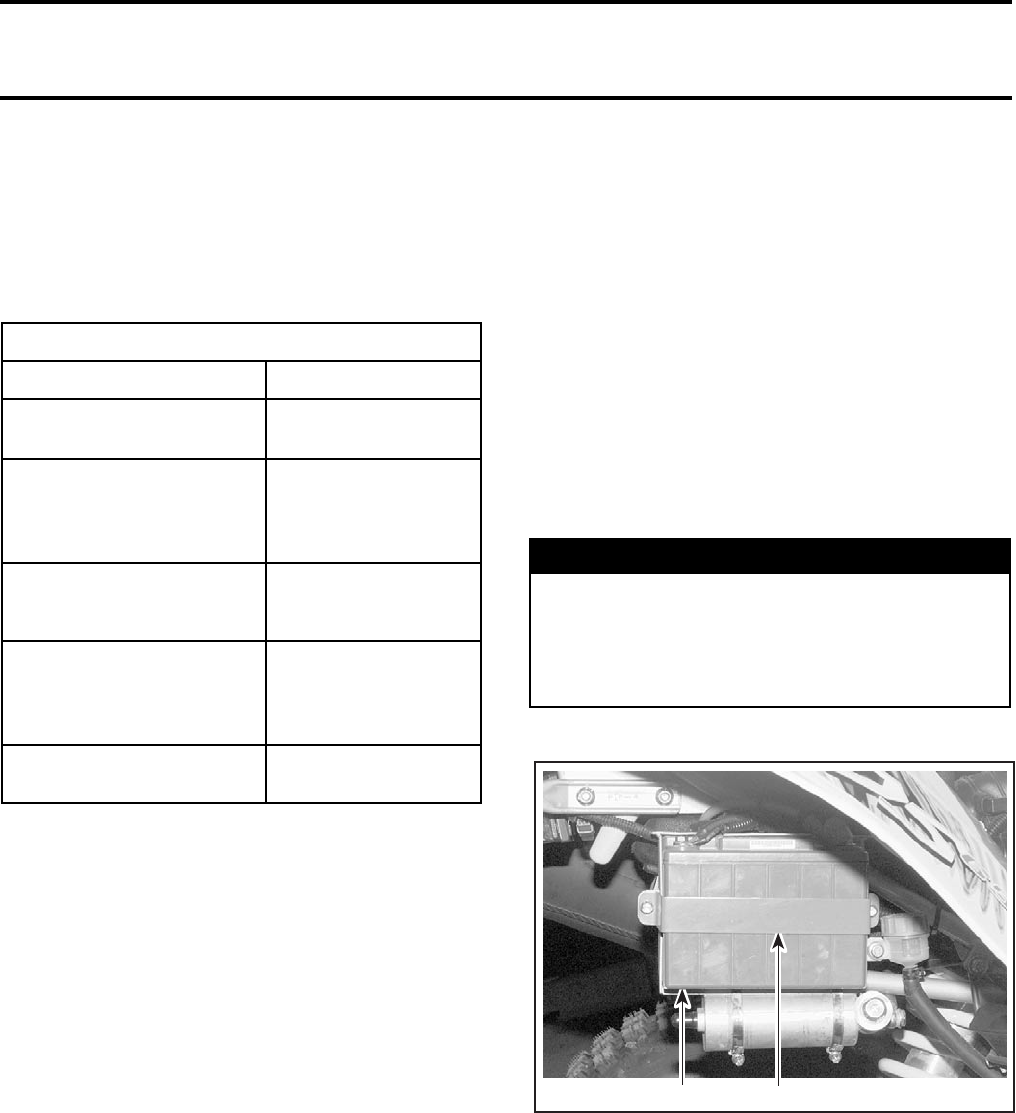
Section 05 ELECTRICAL
Subsection 04 (STARTING SYSTEM)
VMR2004_020_05_04A.FM 05-04-1
STARTING SYSTEM 0
BATTERY
TROUBLESHOOTING
* To test charging system, refer to CHARGING
SYSTEM.
BATTERY TESTING
There are 2 types of battery tests: unloaded and
loaded. An unloaded test is made on a battery with-
out discharging current. It is the simplest and com-
monly used. However, be aware that the voltage
test can be good while the battery has not enough
power to start the engine. A load test gives more
accuracy of the battery condition.
Unload Test
Check charge condition using a multimeter.
With a multimeter, voltage readings appear instant-
ly to show the state of charge. Always respect po-
larity. A fully charged battery will have a reading of
12.6 Vdc.
Load Test
This is the best test of battery condition under a
starting load. Use a load testing device that has an
adjustable load.
Apply a load of 3 times the ampere-hour rating of
the battery. At 14 seconds into the test, check bat-
tery voltage; if battery is in good condition, it will
have at least 10.5 Vdc.
REMOVAL
Disconnect BLACK (-) cable first then positive cable.
Remove bolts retaining battery holder from rack.
1. Battery holder
2. Rack
CLEANING
Clean the battery casing, cables and battery posts
using a solution of baking soda and water.
Remove corrosion (if so) from battery cable termi-
nals and battery posts using a firm wire brush.
Rinse with clear water and dry well.
SYMPTOM: DISCHARGED OR WEAK BATTERY
CAUSE REMEDY
1. Battery posts and/or
cable terminal oxidized. Clean and coat with
dielectric grease.
2. Loose or
bad connections. Check wiring and
connector cleanliness,
damaged or short
circuit.
3. Faulty battery
(doesn’t keep a full
charge loose rectifier).
Replace.
4. Main system fuse burnt
or faulty voltage
regulator/rectifier.*
First check charging
system. If it is in good
condition replace fuse
or rectifier.
5. Faulty charging system
generator coil.* Replace.
WARNING
Always respect this order for disassembly;
disconnect BLACK (-) cable first. Electrolyte
or fuel vapors can be present in engine com-
partment and a spark may ignite them and
possibly cause personal injuries.
V02F01A 21
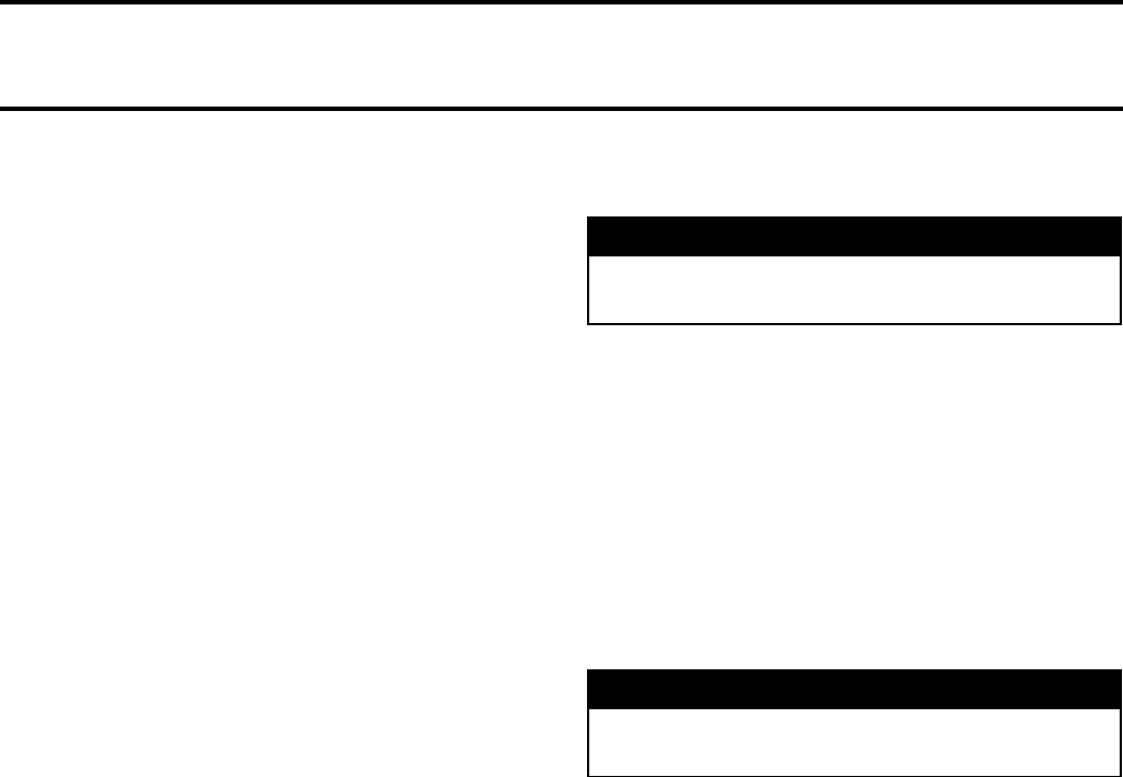
Section 05 ELECTRICAL
Subsection 04 (STARTING SYSTEM)
05-04-2 VMR2004_020_05_04A.FM
INSPECTION
Visually inspect battery casing for cracks or other
possible damage. If casing is damaged, replace
battery and thoroughly clean battery rack with wa-
ter and baking soda.
Inspect battery rack mounting.
Inspect battery posts for security of mounting.
BATTERY STORAGE
If the battery is in storage or used infrequently,
disconnect the battery cables to eliminate drain
from electrical equipment. Charge the battery ev-
ery two weeks.
For extended storage, remove the battery from
vehicle and charge to 100%. Charge the battery
every month if stored at temperature below 16°C
(60°F). If stored in a warm area, above 16°C (60°F),
charge every two weeks. Make sure battery is
stored out of reach of children.
Clean battery terminals and cable connections using
a wire brush. Apply a light coat of dielectric grease
(P/N 293 550 004) on terminals.
Clean battery casing using a solution of baking
soda and water. Rinse battery with clear water and
dry well using a clean cloth.
Store battery on a wooden shelf in a cool dry place.
Such conditions reduce self-discharging to a min-
imum.
ACTIVATION OF A NEW BATTERY
1. Connect a 10 A battery charger until the battery
is fully charged.
2. Disconnect battery charger.
3. Test battery state of charge. Use a multimeter.
NOTE: It is recommended to verify the battery
charge once a month. If necessary, fully charge bat-
tery.
INSTALLATION
Reinstall battery in vehicle. Fasten battery holder.
WARNING
Never charge or boost battery while installed
on vehicle.
WARNING
Always connect RED (+) cable first then BLACK
(-) cable.

Section 05 ELECTRICAL
Subsection 04 (STARTING SYSTEM)
VMR2004_020_05_04A.FM 05-04-3
STARTING SYSTEM TROUBLESHOOTING
SYMPTOM CAUSE REMEDY
Starter does not turn. Ignition switch is in the OFF position. Turn switch in the ON position.
Engine stop switch is in the OFF posi-
tion. Place the engine stop switch to run po-
sition.
Burnt fuse. Check main fuse and wiring condition.
Transmission is not set on Neutral. Set transmission in Neutral or squeeze
the clutch lever.
Poor contact of battery terminal(s) or
ground cable connections. Clean and tighten terminal(s).
Weak battery. Recharge battery.
Poor contact or open circuit of:
start button, engine stop switch,
ignition switch or starting solenoid.
Check and replace defective part.
Neutral switch is defective. Check neutral switch and wiring condi-
tion.
Clutch switch is defective. Check clutch switch and wiring condi-
tion.
Engine mechanical problem
(ensure that other electric
components are good).
Check and replace defective part.
Starter turns; but does not
crank the engine. Poor contact of battery terminal(s). Clean and tighten terminal(s).
Poor battery ground cable connection. Clean and tighten.
Burnt or poor contact of solenoid
switch contact disc. Replace starting solenoid.
Poor contact of brush. Straighten commutator and brush or re-
place electric starter.
Burnt commutator. Turn commutator in a lathe or replace
electric starter.
Worn commutator segments. Undercut mica or replace electric start-
er.
Shorted armature. Replace electric starter.
Weak brush spring tension. Replace electric starter.
Weak magnet. Replace electric starter.
Worn bushings. Replace electric starter.
Weak battery. Recharge or replace battery.
Starter turns, but overrunning
clutch pinion does not mesh
with ring gear.
Worn clutch pinion gear. Replace electric starter.
Defective clutch. Replace electric starter.
Poor movement of clutch on splines. Replace electric starter.
Worn clutch bushing. Replace electric starter.
Worn ring gear. Recharge ring gear.
Starter motor keeps running. Shorted starting solenoid switch wind-
ing. Replace starter solenoid.
Melted solenoid contacts. Replace starter solenoid.
Sticking or defective starter clutch. Lubricate or replace electric starter.
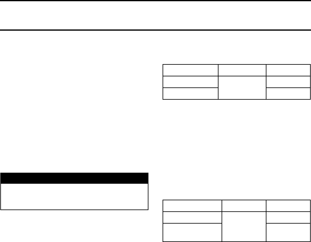
Section 05 ELECTRICAL
Subsection 04 (STARTING SYSTEM)
05-04-4 VMR2004_020_05_04A.FM
STARTING SYSTEM TESTS
GENERAL
First ensure the problem is not related to engine
mechanical components. Then, test the starting
system.
Causes of troubles are not necessarily related to
starter but may be due to a burnt fuse faulty bat-
tery, start button, ignition switch, engine stop
switch, starting solenoid, electrical cables or con-
nections or the electronic module.
Check these components before removing starter.
Consult also the STARTING SYSTEM TROUBLE-
SHOOTING table above for a general view of pos-
sible problems.
Fuses
Make sure the main fuse is in good condition. If
the fuse tests good, continue the next tests.
Battery
To check battery condition, refer to BATTERY
above. If it tests good, continue the next tests.
Ignition Switch
A quick test to validate it is working. Turn the igni-
tion switch ON then place the headlight switch in
ON position. If the lights turn on, the ignition
switch is good. Otherwise, refer to IGNITION SYS-
TEM for testing procedure. If it tests good, contin-
ue the next tests.
Engine Stop Switch
If engine does not turn when placing engine stop
switch to RUN and pressing the start button, test
the engine stop switch as follows.
Remove the front facia (refer to BODY) and unplug
the multi-function switch connector.
Using a multimeter, measure the resistance be-
tween the following wires.
Replace multi-function switch if defective.
If switch tests good, check wiring. If it tests good,
continue the next tests.
Start Button
If engine does not turn when pressing the start
button, test the switch as follows.
Remove the front facia and unplug the multi-function
switch connector.
Using a multimeter, measure the resistance be-
tween the following wires.
Replace multi-function switch if defective.
If switch tests good, check wiring going to electron-
ic module. If it tests good, continue the next tests.
Starting Solenoid
NOTE: Solenoid is located on frame, behind bat-
tery rack.
Ensure the solenoid receives electric current as
follows. Using a multimeter, measure the voltage
between the YELLOW/RED and YELLOW/BLACK
wires when pressing the start button with the ig-
nition key turned ON.
NOTE: Disconnect wires from solenoid.
If solenoid does not properly receive current, the
electronic module can be suspected. See ELEC-
TRONIC MODULE section below.
If solenoid receives current, test the solenoid as
follows.
Disconnect large cables from solenoid.
WARNING
To avoid the possibility of short circuit while
working on starter, always disconnect the bat-
tery.
POSITION WIRE RESISTANCE
Switch to OFF BLACK and
BLACK/WHITE
1Ω max.
Switch to RUN Infinite (0.L)
POSITION WIRE RESISTANCE
Switch released RED/VIOLET
and
YELLOW/RED
Infinite (0.L)
Switch depressed
and held 0.6 Ω max.
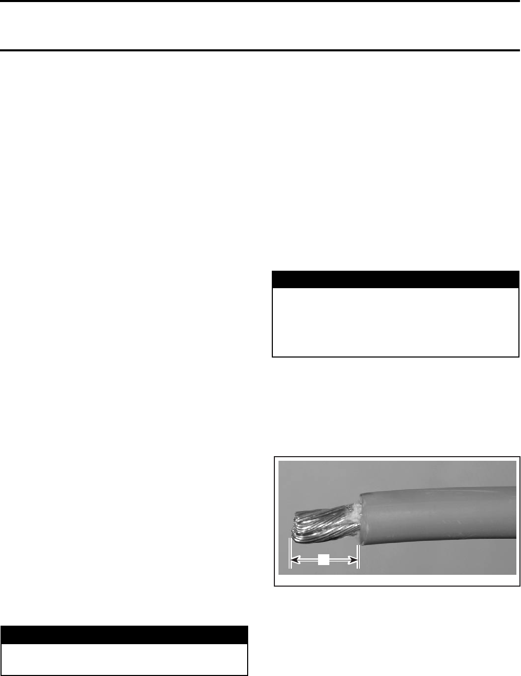
Section 05 ELECTRICAL
Subsection 04 (STARTING SYSTEM)
VMR2004_020_05_04A.FM 05-04-5
Inspect connections and clean as necessary. Sole-
noid condition can be checked with an ohmmeter.
Install test probes on large connectors of solenoid.
Measure resistance when current is applied to small
connectors; if it is more than a few ohms, replace
solenoid.
If solenoid test good, check the electric starter. If
starter test good, the electronic module can be
suspected. See ELECTRONIC MODULE below.
Electrical Cables or Connections
Check all connections, cables and wires. Tighten
any loose cables. Replace any chafe wires/cables.
If wiring and connectors are good, check the elec-
tric starter. See below.
Electric Starter
Using boosting cables, carefully supply current
from the battery directly to the starter. Connect
the BLACK (-) cable first. Then connect the remain-
ing jump cable from the battery then to the starter.
If starter now turns ensure the cables/connections
from battery to solenoid and to starter are in good
condition. If they test good, the electronic module
can be suspected. See ELECTRONIC MODULE
below.
If starter does not turn, check for mechanical prob-
lems in the starter.
Electronic Module
When other components have been tested above
and are good, the electronic module can be sus-
pected. Ensure wiring and connectors are in good
condition prior to replacing the electronic module.
ELECTRIC STARTER
REMOVAL
Turn OFF ignition switch.
Disconnect BLACK (-) cable from battery.
Disconnect RED (+) cable from starter.
Clean starter area.
Remove starter mount screws.
Pull starter out.
INSTALLATION
Installation is essentially the reverse of removal
procedure. However, pay particular attention to
the following.
Make sure that starter and engine mating surfaces
are free of debris. Serious trouble may arise if
starter is not properly aligned.
Torque starter screws to 10 N•m (89 lbf•in).
Connect the RED (+) cable to the starter and
torque nut to 6 N•m (53 lbf•in). Apply dielectric
grease on terminal and nut.
First connect RED (+) cable to battery then con-
nect the BLACK (-) cable.
Test starter operation.
CABLE TERMINAL INSTALLATION
Carefully strip the wire approximately to 12 mm
(1/2 in) in length, using a wire stripping tool or
sharp blade/knife.
A. 12 mm (1/2 in)
NOTE: Make sure not to cut wire strands while
stripping the wire.
WARNING
Always disconnect BLACK (-) cable first and
reconnect last.
WARNING
Always connect RED (+) cable first then
BLACK (-) cable last. Whenever connecting
the RED (+) cable to the starter motor make
sure the battery cables are disconnected to
prevent electric shock.
A32E2QA
A
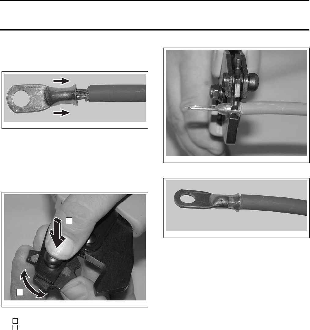
Section 05 ELECTRICAL
Subsection 04 (STARTING SYSTEM)
05-04-6 VMR2004_020_05_04A.FM
Install the appropriate terminal on the wire accord-
ing to the requirement. Refer to appropriate parts
catalog.
INSTALLATION OF TERMINAL
Follow the instructions provided with the crimp plier
(P/N 529 035 730) to select the proper position of
the tool.
NOTE: Different wires require different crimp plier
settings, so make sure to follow the instruction sup-
plied with the tool.
POSITIONING THE CRIMP PLIER
Step : Press
Step : Rotate
After positioning the crimp plier, crimp the termi-
nal already installed on wire.
CRIMPING OF WIRE
PROPERLY CRIMPED WIRE
To verify, if the wire is properly crimped, hold the
wire with one hand and the terminal with the other
and pull with some force.
CAUTION: Never weld the wire to the terminal.
Welding can change the property of the wire
and it can become brittle and break.
Install the protective heat shrink rubber tube (P/N
278 001 692) on the terminal. Heat the heat shrink
rubber tube using the heat gun so that it grasps
the wire and the terminal.
CAUTION: Make sure that the protective heat
shrink rubber tube has been properly installed
and no part of wire is exposed.
A32E2RA
2
A32E2SA
1
1
2
A32E2TA
A32E2UA

Section 05 ELECTRICAL
Subsection 05 (IGNITION SYSTEM)
VMR2004_021_05_05A.FM 05-05-1
IGNITION SYSTEM 0
IGNITION SYSTEM TESTING
PROCEDURE
GENERAL
Ignition Problems
When dealing with ignition problems, the follow-
ing items should be checked in this order. After
one item has been checked and it is found not to
be the problem, continue with the next item:
1. main fuse condition
2. spark occurrence
3. battery condition
4. ignition switch
5. trigger coil
6. ignition coil
7. electronic module.
Intermittent Ignition Problems
In dealing with intermittent problems there is no
easy diagnosis. For example, problems that occur
only at normal engine operating temperature have
to be tested under similar conditions.
In most cases of temperature and/or vibration fail-
ure, only parts replacement might solve the prob-
lem as most of these failures return to normal
when engine is not running.
Multiple Problems
There is always the possibility of more than one
faulty part. If after a component has been re-
placed, the problem still persists, carefully repeat
the complete test procedure to find the other
faulty part.
IGNITION SYSTEM TEST
Safety Precautions
Main Fuse Condition
Check main fuse condition. Replace burnt fuse as
necessary.
Spark Occurrence
Remove one spark plug and connect to its cable.
While holding the spark plug against a metallic part
of the engine, start the engine. Look for a spark at
the spark plug tip. Proceed the same with the oth-
er spark plug. Replace defective spark plug.
NOTE: If a spark plug is found defective, replace
both spark plugs at the same time.
Both spark plugs must be checked individually. If
one works and the other doesn’t, try another spark
plug.
Keep in mind that a spark plug might test good this
way while not being able to work properly under
combustion chamber mixture and pressure.
If known good spark plug(s) does(do) not work,
continue the other tests.
NOTE: Spark occurrence can be checked with a
tester such as Superex Canada Ltd (P/N 15-785)
or the equivalent.
WARNING
To prevent powerful electric shocks while
cranking engine, neither touch any electronic
ignition components (ignition coil, high ten-
sion wire, wire harness, etc.) nor tester lead
clips. Also make sure that tester leads do not
touch any metallic object.
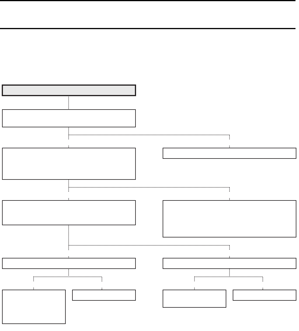
Section 05 ELECTRICAL
Subsection 05 (IGNITION SYSTEM)
05-05-2 VMR2004_021_05_05A.FM
TROUBLESHOOTING
NOTE: Check that the transmission is in NEUTRAL position and the engine stop switch is in RUN
position. Check that main fuse is not burned and if battery is fully-charged before diagnosing.
No spark or poor spark.
Check ignition system connector for poor
connections.
Measure battery voltage between
BLACK and RED/VIOLET wires at the
electric module with the ignition switch
in ON position.
Poor connections of circuit connectors.
Measure ignition coil primary peak voltage.
NOTE: This method is applicable only with a
multimeter and a peak voltage adaptor.
Inspect ignition coil.
Faulty ignition switch.
Faulty engine stop switch.
Broken wire harness or poor connections
of circuit connectors.
CORRECT
CORRECT
INCORRECT
LOOSENESS
INCORRECT
CORRECT
INCORRECTCORRECT INCORRECTCORRECT
Faulty electronic
module.
Poor connection of
ignition connector.
Faulty ignition coil. Poor connection of
the spark plug cap.
Faulty spark plug.
Inspect spark plug.
V02G1RS
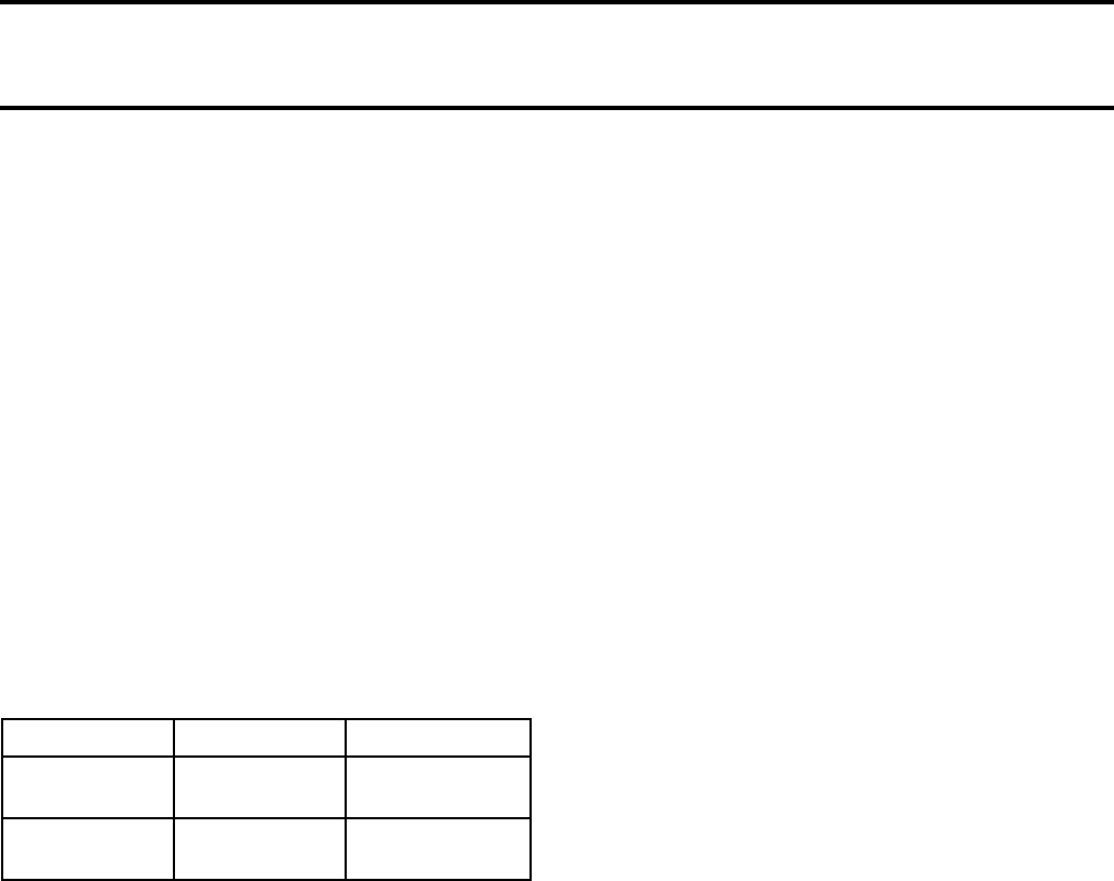
Section 05 ELECTRICAL
Subsection 05 (IGNITION SYSTEM)
VMR2004_021_05_05A.FM 05-05-3
Battery Condition
A battery must be present in the vehicle to allow
the ignition system to work. Also, at least 8 V is re-
quired for proper operation. Check battery voltage.
Ignition switch
A quick test to validate it is working. Turn the igni-
tion switch ON then place the headlight switch in
ON position. If the headlight turn on, the ignition
switch is good.
Test
Disconnect ignition switch.
Measure voltage between RED supply wire and
the battery ground. If voltage is lower than battery
voltage, test the wiring. If voltage is good, test
switch.
Use a multimeter and measure the resistance be-
tween the following wires.
Replace switch if defective.
If switch is good, continue the next tests.
Trigger Coil Voltage Testing
NOTE: The trigger coil is not adjustable.
STATIC TEST: CONTINUITY
Check resistance with a high-sensitivity ohmme-
ter.
1. Disconnect the Deutsch 2-pin connector. Refer
to OVERVIEW.
2. Connect multimeter probes to the GREEN/
YELLOW wire and to the BLUE wire.
3. Measure resistance; it should be between 190 -
300 ohms.
DYNAMIC TEST
1. Disconnect the Deutsch 2-pin connector.
2. Connect one of the multimeter probes to the
GREEN/YELLOW wire and the other to the en-
gine, then bring selector switch to and scale
to 00.0Vac.
3. Press START button, note result. The obtained
value should be between 0.4 and 0.7 Vac. Re-
peat operation 3 times.
4. If the trigger coil is out of specification, replace
it. If it tests good continue the next tests.
Ignition Coil
NOTE: An ignition coil with good resistance mea-
surement can still be faulty. Voltage leak can occur
at high voltage level which is not detectable with
an ohmmeter. Replacing the ignition coil may be
necessary as a test.
Primary Winding
Disconnect the wire connector on the primary side
of the ignition coil.
Using a multimeter, check the resistance between
the terminal and the ignition coil body ground.
The resistance should be between 0.2 and 0.5 Ω
at 20°C (68°F).
If not within specification, replace the ignition coil.
If the ignition coil test good, check the power sup-
ply on the electronic module.
There should be 12 Vdc between the RED/VIOLET
and BLACK/WHITE wires.
If there is no voltage, either the electronic module
or the wiring harness is defective.
Secondary Winding
Due to the integrated diode, it is not possible to
take any resistance measurement.
The output voltage should not be less than 12 kV
(12 000 V).
The ignition coil outlet caps and the spark plug
caps include a resistance. They should be checked
prior to replacing a suspected ignition coil.
Measure resistance between ignition coil termi-
nals and spark plug caps. The obtained value should
be between 6 and 13 KΩ. If resistance is good, con-
tinue check. If not, change spark plug wires.
DYNAMIC TEST
An ignition coil tester available from after-market
tool/equipment suppliers can be used.
CAUTION: Do NOT use coil tester on metal work
bench. Follow manufacturer instructions.
If the ignition coil is out of specification, replace it.
If it tests good ensure the wiring and connectors
are in good condition then continue the next tests.
POSITION WIRE RESISTANCE
OFF WHITE and
BROWN Infinite (0.L)
ON WHITE and
BROWN 0.6 Ω max.
V
˜
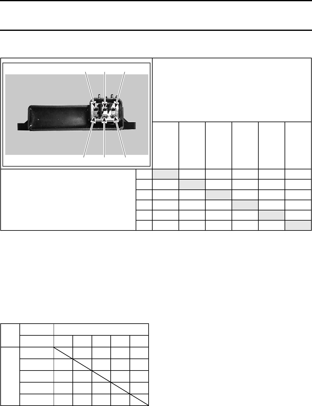
Section 05 ELECTRICAL
Subsection 05 (IGNITION SYSTEM)
05-05-4 VMR2004_021_05_05A.FM
Electronic Module
When every other components above have been
tested and are good, the electronic module can be
suspected. Ensure wiring and connectors are in
good condition prior to replacing the electronic
module.
TEST
NOTE: On the multimeter, set measuring range
from 1 KΩ − 10 KΩ. Make sure that positive and
negative tester probes are installed on the appro-
priate wires.
SYMBOLS:
Ο: Open circuit, value/pointer change continuously
Χ: No open circuit, value/pointer do not register any change
∆: Value/pointer changer and move to ∞
If a fault is detected, the electronic module must
be replaced.
IGNITION TIMING
It is impossible to check the ignition timing with a
timing lamp because there is no access window or
mark.
NEGATIVE (-) TESTER LINE
ABCDE F
POSITIVE (+) TESTER LINE
A2.18 MΩ2.18 MΩUP to- ∞2.18 MΩ2.18 MΩ
BO.L. 2590 ΩUP to- ∞2590 Ω5.58 KΩ
CO.L. 2590 ΩUP to- ∞0.02 Ω2965 Ω
DO.L. UP to ∞UP to ∞UP to ∞UP to ∞
EO.L. 2590 Ω0.02 ΩUP to- ∞2960 Ω
FO.L. 5.68 KΩ2977 ΩUP to- ∞2977 Ω
A
V06G06A BDF
CE
NEGATIVE (-) TESTER LINE
COLORS BL WH OR RD BK
POSITIVE (+)
TESTER LINE
BL ΟΟΟΟ
WH ΟΟΟΟ
OR Χ∆ ∆Χ
RD ΟΟΟ Ο
BK ΟΟΟΟ
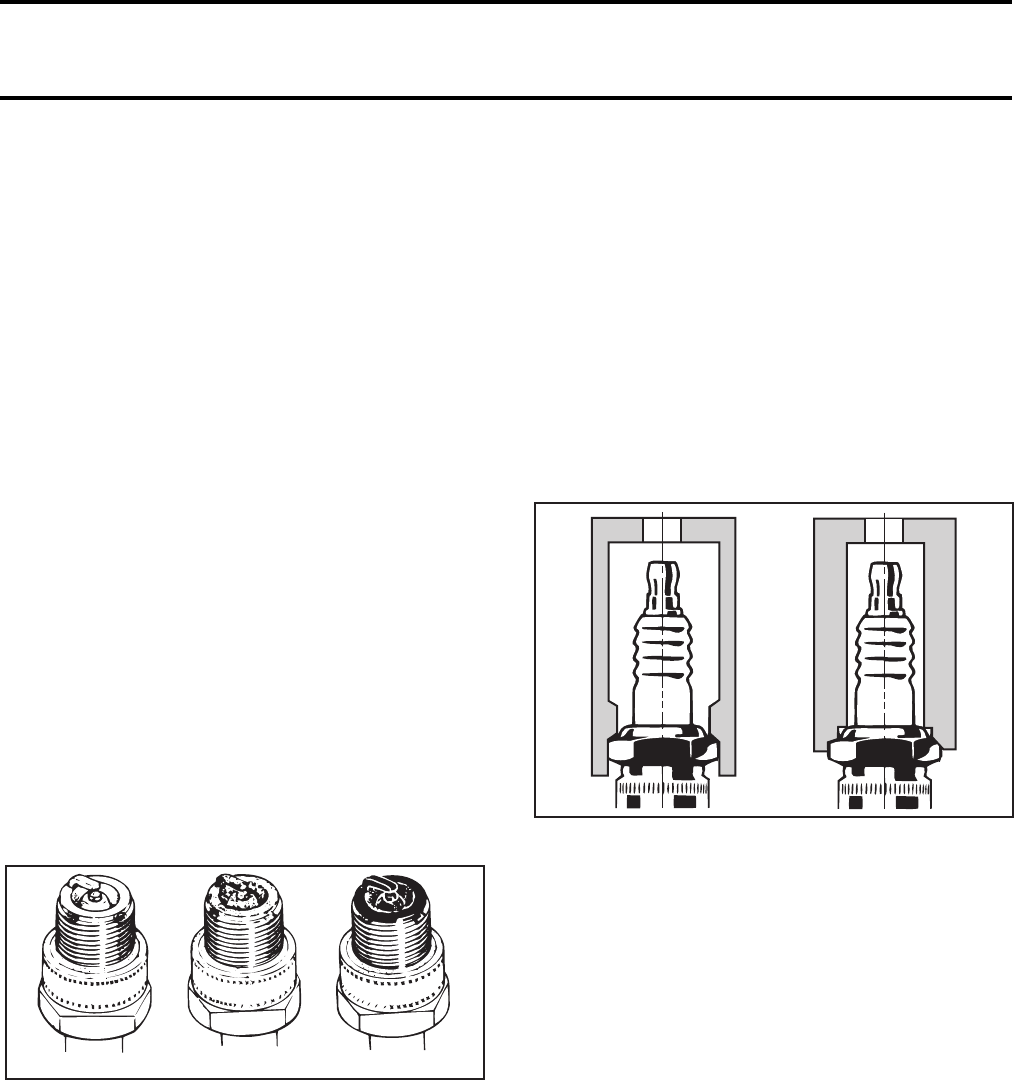
Section 05 ELECTRICAL
Subsection 05 (IGNITION SYSTEM)
VMR2004_021_05_05A.FM 05-05-5
SPARK PLUG
DISASSEMBLY
Unplug the spark plug cable
Unscrew the spark plug one turn.
Clean the spark plug and cylinder head with pres-
surized air then completely unscrew.
FOULING
Fouling of the spark plug is indicated by irregular
running of the engine, decreased engine speed
due to misfiring, reduced performance, and in-
creased fuel consumption. This is due to a loss of
compression. Other possible causes are: prolonged
idling or low-speed riding, or running on a too rich
mixture due to abuse of choke, a clogged air filter,
a faulty carburetor adjustment, incorrect fuel, de-
fective ignition system, incorrect ignition timing,
incorrect spark plug gap, lubricating oil entering
the combustion chamber, or too cold spark plug.
The plug face of a fouled spark plug has either a
wet black deposit or a black carbon fouling. Such
coatings form a conductive connection between
the center electrode and ground.
SPARK PLUG ANALYSIS
TYPICAL
1. Overheated (light grey, white)
2. Normal (light brown, brown)
3. Fouled (black, wet or dry, dark deposits, grey, melted coating)
The plug face reveals the condition of the engine,
operating condition, method of driving and fuel
mixture. For this reason it is advisable to inspect
the spark plug at regular intervals, examining the
plug face (i.e. the part of the plug projecting into
the combustion chamber).
SPARK PLUG INSTALLATION
CAUTION: Always use the recommended
spark plug.
Prior to installation make sure that contact surfaces
of the cylinder head and spark plug are free of
grime.
1. Using a wire feeler gauge, set electrode gap ac-
cording to the following chart.
2. Apply anti-seize lubricant over the spark plug
threads to prevent possible seizure.
3. Hand screw spark plug into cylinder head and
tighten with a torque wrench and a proper socket.
1. Proper socket
2. Improper socket
4. Torque spark plug to 20 N•m (15 lbf•ft).
A00E0AA 123
A00E0BA
2
1
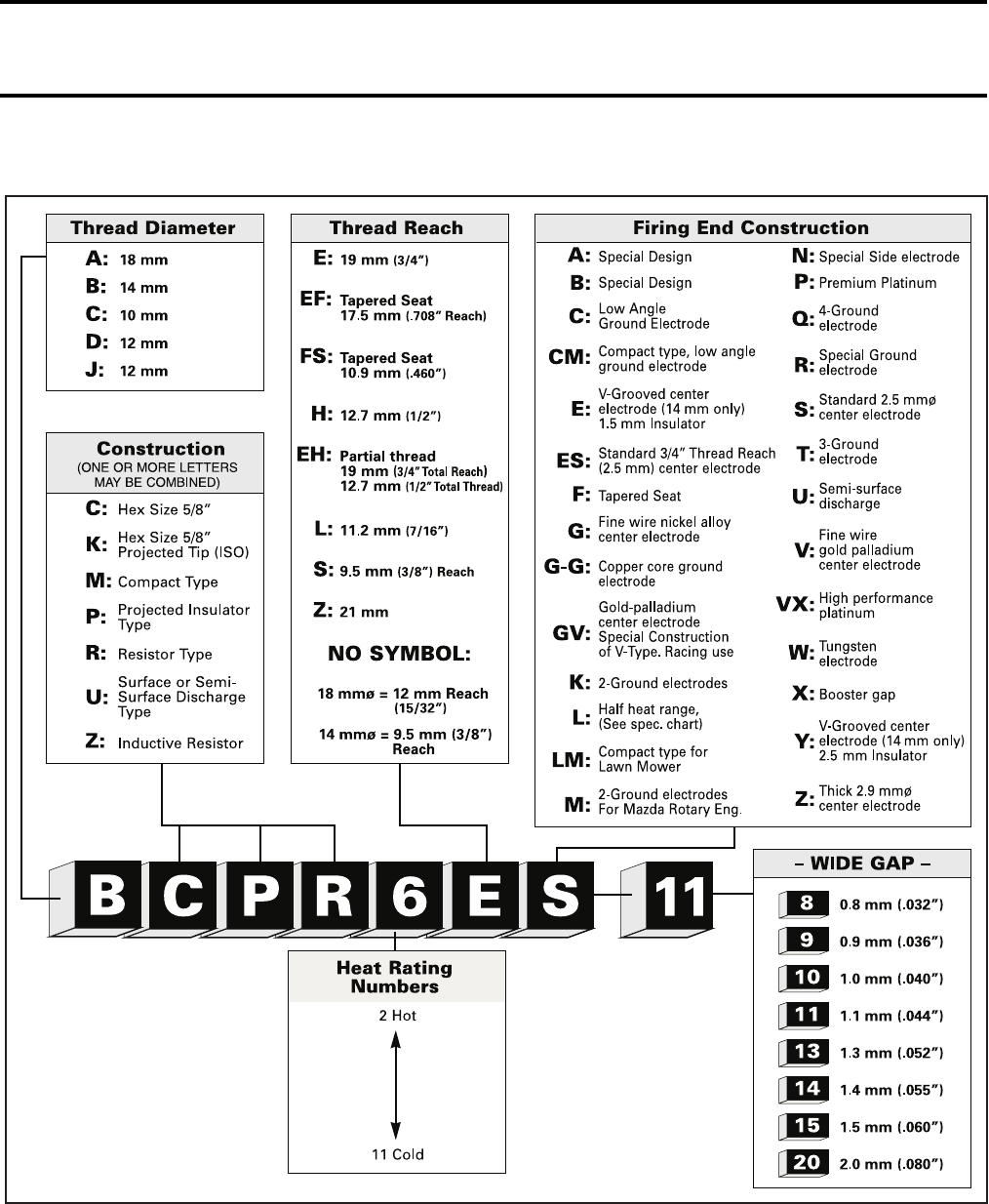
Section 05 ELECTRICAL
Subsection 05 (IGNITION SYSTEM)
05-05-6 VMR2004_021_05_05A.FM
NGK SPARK PLUG SYMBOL EXPLANATION
V04G0DS
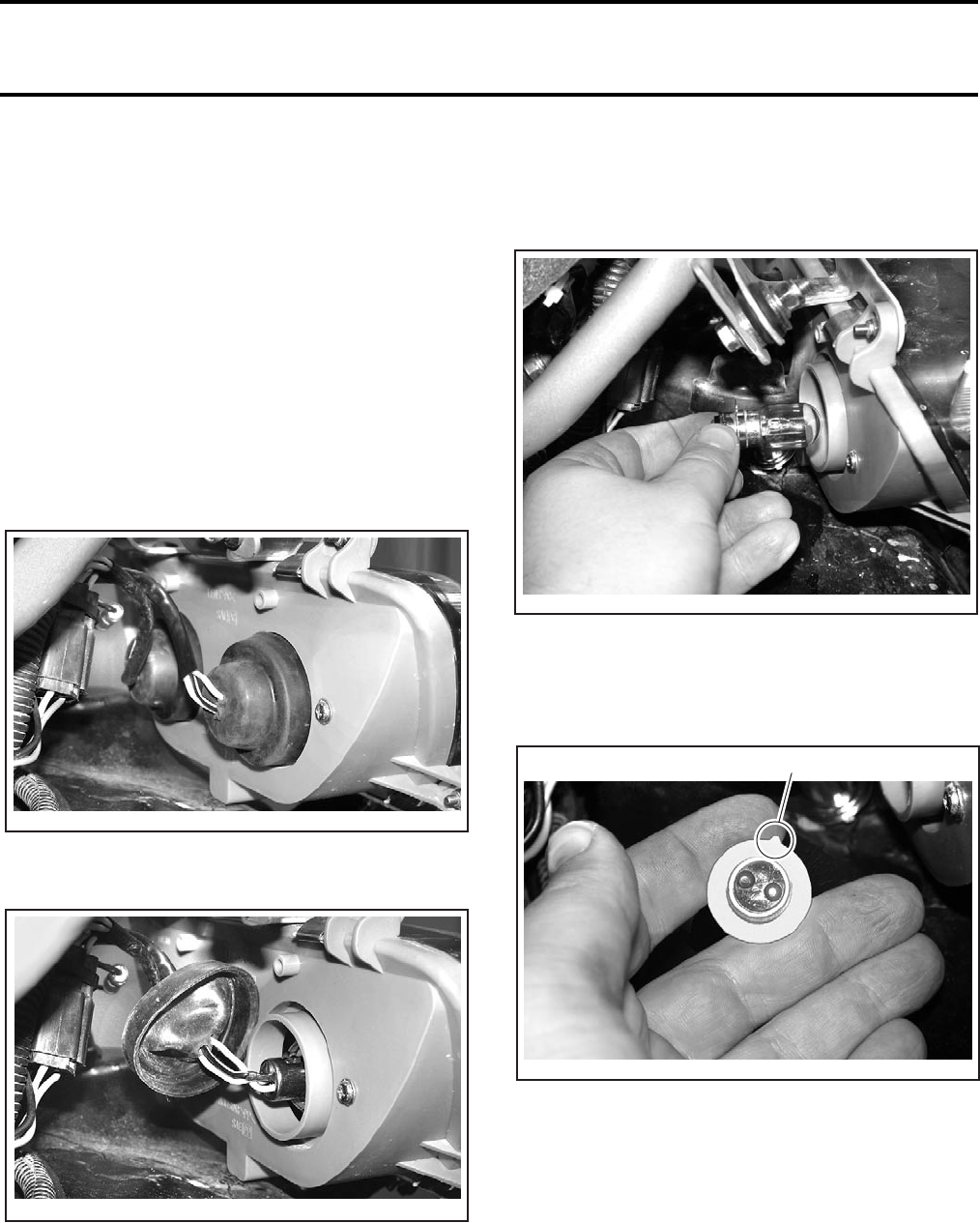
Section 05 ELECTRICAL
Subsection 06 (ACCESSORIES)
VMR2004_022_05_06A.FM 05-06-1
ACCESSORIES 0
REMOVAL AND
INSTALLATION
CAUTION: It is recommended to always dis-
connect the battery when replacing any electric
or electronic parts.
HEADLAMP
Bulb Replacement
Remove front facia.
Remove rubber boot.
Push and turn counterclockwise bulb retaining
ring then remove it.
Detach bulb and replace.
Properly reinstall removed parts in the reverse or-
der of their removal.
NOTE: Align the bulb socket tab with the notch in
the headlamp housing.
1. Bulb socket tab
Removal
Remove front facia and dashboard. Refer to BODY.
Unscrew the bolts retaining headlamp then un-
plug the connector.
Installation
Properly reinstall removed parts in the reverse or-
der of their removal.
V02G1MA
V02G1NA
V02G1OA
V02G1PA
1
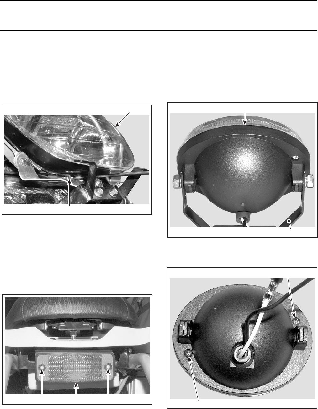
Section 05 ELECTRICAL
Subsection 06 (ACCESSORIES)
05-06-2 VMR2004_022_05_06A.FM
Beam Aiming Adjustment
Adjust beam aiming as follows:
Remove the front facia.
Using a long screwdriver, turn the adjusting screw
clockwise to lift the inside of headlamp and coun-
terclockwise to go down it.
1. Headlamp
2. Adjustment screw
Adjust beam height to your convenience then re-
install the front facia.
TAILLIGHT
Bulb Replacement
Unscrew lens screws to expose bulb.
1. Lens
2. Screws
Push bulb in and hold while turning courterclock-
wise to release.
Install the new bulb by first pushing in while turn-
ing clockwise.
AUXILIARY HEADLAMP
Baja and Baja X Models
Bulb Replacement
Disconnect the auxiliary headlamp then remove it
from support.
1. Auxiliary headlamp
2. Support
Remove the back cover of auxiliary headlamp.
1. Remove these screws
2
1
V02G1QA
2
V02A06A 12
2
1
V02G0NA
1
1
V02G0OA
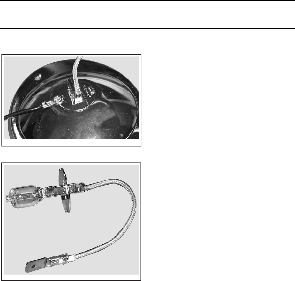
Section 05 ELECTRICAL
Subsection 06 (ACCESSORIES)
VMR2004_022_05_06A.FM 05-06-3
Remove the screw retaining the BLACK wire.
Detach bulb and replace.
BULB WITH WIRE ASSEMBLY
NOTE: ALWAYS USE A 35 WATTS BULB. If the
55 watts bulb is used, the regulator might not be
able to recharge the battery properly.
Properly reinstall removed parts in the reverse or-
der of their removal.
CAUTION: Never touch glass portion of an halo-
gen bulb with bare fingers, it shortens its operat-
ing life. If glass is touched, clean it with isopropyl
alcohol which will not leave a film on the bulb.
TACHOMETER
Baja and Baja X Models
Bulb Replacement
The bulb in the tachometer is not replaceable. If the
tachometer bulb is burnt, replace the tachometer.
Removal
Remove dashboard.
Unplug wires under tachometer.
Push the tachometer out of dashboard.
Installation
The installation is the reverse of removal proce-
dure.
NOTE: Make sure the retainer is inserted be-
tween the tachometer and the rubber grommet.
IGNITION SWITCH
Test
Refer to IGNITION SYSTEM.
Removal
Lift the dashboard and unscrew the ignition switch
nut.
Unplug the switch connectors.
Installation
For the installation, reverse the removal proce-
dure.
INDICATOR LIGHTS
Test
Refer to TESTS section.
Removal
Remove dashboard.
Unplug wires on indicator lamp.
V02G0PA
V02G0QA
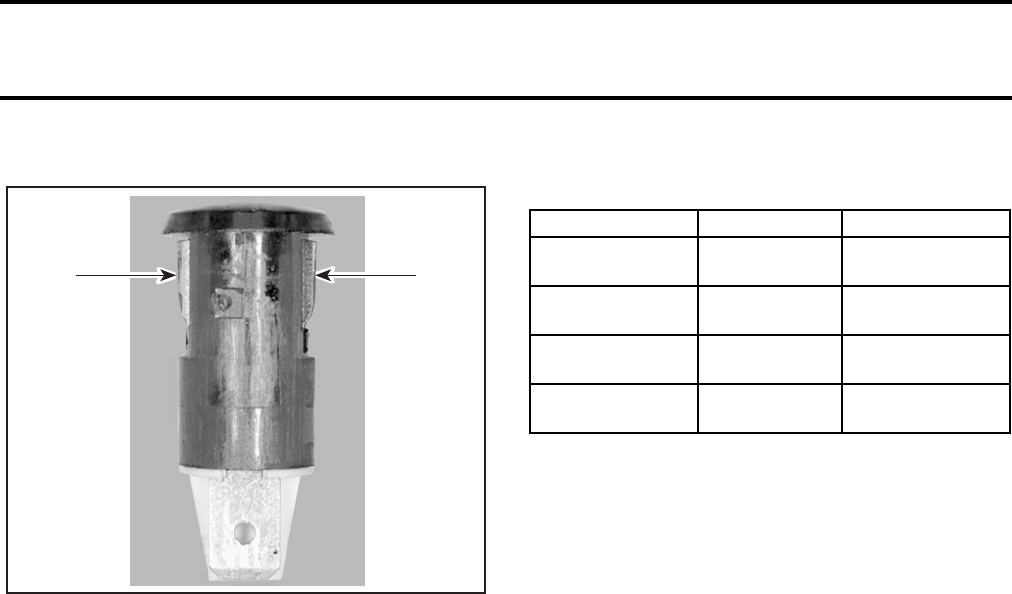
Section 05 ELECTRICAL
Subsection 06 (ACCESSORIES)
05-06-4 VMR2004_022_05_06A.FM
Press both tabs then push indicator lamp out of hole.
1. Tabs
Installation
For the installation, reverse the removal procedure.
NOTE: The LED have polarity. Make sure to recon-
nect the RED/VIOLET wire on the positive (+) tab.
TESTS
COOLING FAN OPERATION TEST
Unplug the temperature sender connectors.
Install a jumper wire end in each connector. Turn
key ON. Replace the fan if it does not work.
HEADLAMP
Start the engine.
Using a multimeter, measure the voltage between
GREEN and BLACK wires at LOW beam and be-
tween BLUE and BLACK wires at HI beam.
The obtained value should be between 12 and
14.5 Vdc.
–No voltage:
•Check wiring condition and HI-LO switch.
–Voltage is good:
•Change headlamp.
MULTI-FUNCTION SWITCH
Unplug connector located near oil tank, under
front facia.
Using a multimeter, measure the resistance be-
tween the following wires.
Replace switch if defective.
INDICATOR LIGHTS
Remove steering cover.
Neutral Indicator Light (GREEN)
Unplug the neutral indicator light connectors.
Put the RED probe of the multimeter to the posi-
tive (+) connector on the LED and the black probe
to the other connector.
Select the testing diodes/continuity function on
the multimeter.
NOTE: Do not use Ω function to check LED.
The measure should be between 1.6 and 2.0.
–LED is good:
•Check wiring condition.
•Check neutral switch. Refer to TRANSMIS-
SION.
–LED is burned:
•Change indicator light.
Engine Indicator Light (RED)
Unplug the engine indicator light connectors.
Test LED with a multimeter. Refer to NEUTRAL
INDICATOR LIGHT for proper procedure.
–LED is good:
•Check wiring condition.
•Check oil sensor. Refer to LUBRICATION
SYSTEM.
•Check temperature sensor. Refer to COOLING
SYSTEM.
–LED is burned:
•Change indicator light.
1
V02A0FA
1
POSITION WIRE RESISTANCE
Switch OFF RED/VIOLET
and GREEN Infinite (0.L)
Switch OFF RED/VIOLET
and BLUE Infinite (0.L)
Switch to LO RED/VIOLET
and GREEN 0.4 Ω max.
Switch to HI RED/VIOLET
and BLUE 0.4 Ω max.

Section 06 DRIVE TRAIN
Subsection 01 (TABLE OF CONTENTS)
VMR2004_033_06_01ATOC.FM 06-01-1
TABLE OF CONTENTS 0
FRONT DRIVE ........................................................................................................................ 06-02-1
GENERAL ........................................................................................................................... 06-02-2
WHEEL HUB....................................................................................................................... 06-02-2
WHEEL HUB BEARING ..................................................................................................... 06-02-2
KNUCKLE ........................................................................................................................... 06-02-3
REAR AXLE ............................................................................................................................ 06-03-1
GENERAL ........................................................................................................................... 06-03-2
DRIVE CHAIN ..................................................................................................................... 06-03-2
SLIDER-SHOE .................................................................................................................... 06-03-3
CHAIN ROLLER .................................................................................................................. 06-03-3
REAR WHEEL HUB ............................................................................................................ 06-03-3
REAR SPROCKET .............................................................................................................. 06-03-4
BRAKE DISC HUB.............................................................................................................. 06-03-4
REAR AXLE ........................................................................................................................ 06-03-7
REAR SPROCKET HUB...................................................................................................... 06-03-8
ECCENTRIC AXLE HOUSING ........................................................................................... 06-03-9
ECCENTRIC AXLE BEARINGS .......................................................................................... 06-03-11
PROTECTORS .................................................................................................................... 06-03-12
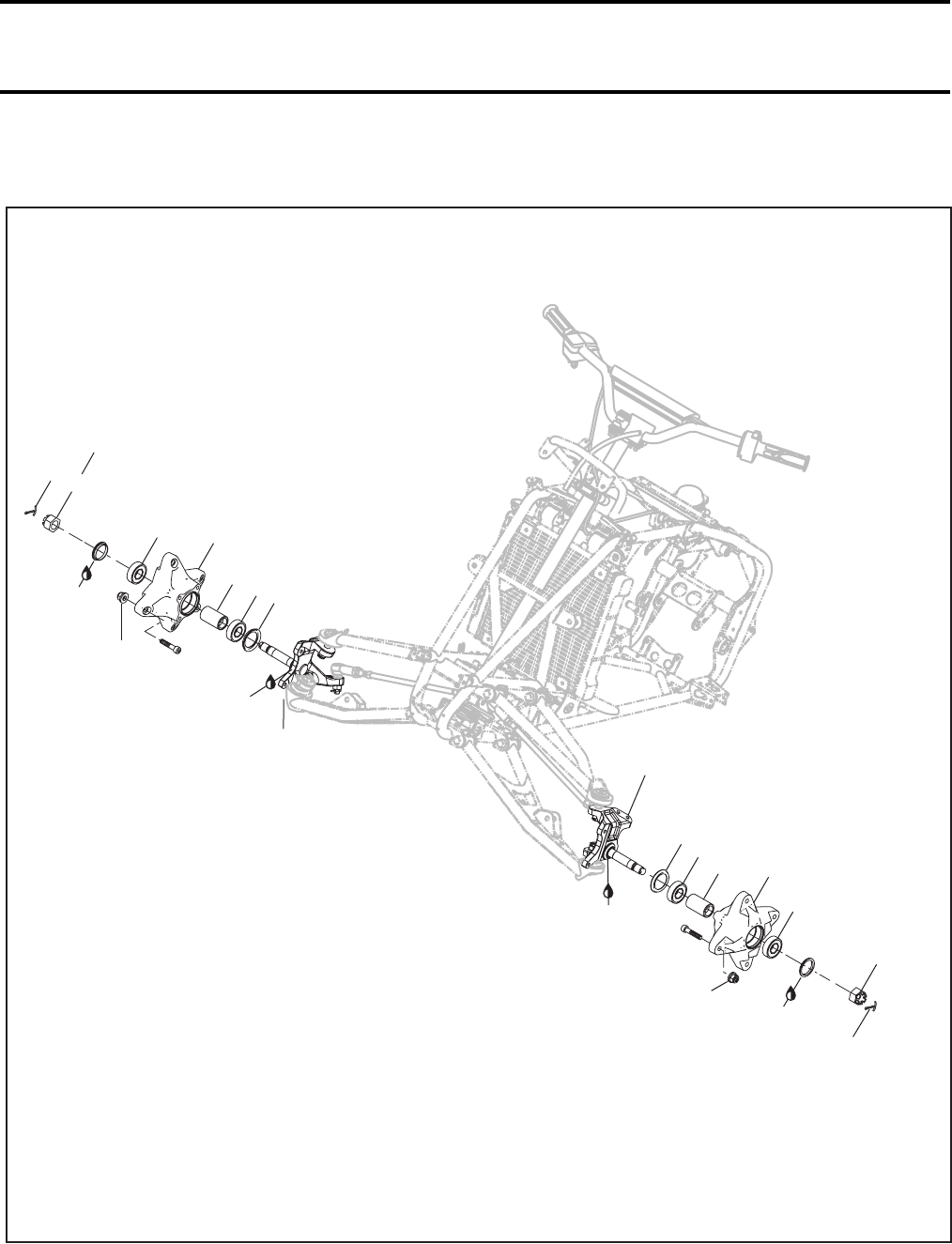
Section 06 DRIVE TRAIN
Subsection 02 (FRONT DRIVE)
VMR2004_023_06_02A.FM 06-02-1
FRONT DRIVE 0
V02H18S
4
Synthetic
grease
5
21
726
3
Synthetic
grease
3
62
71
2
5
4
Synthetic
grease
135 Nm
(100 lbfft)
MINIMUM
Synthetic
grease
52.5 Nm
(39 lbfft)
135 Nm
(100 lbfft)
MINIMUM
52.5 Nm
(39 lbfft)
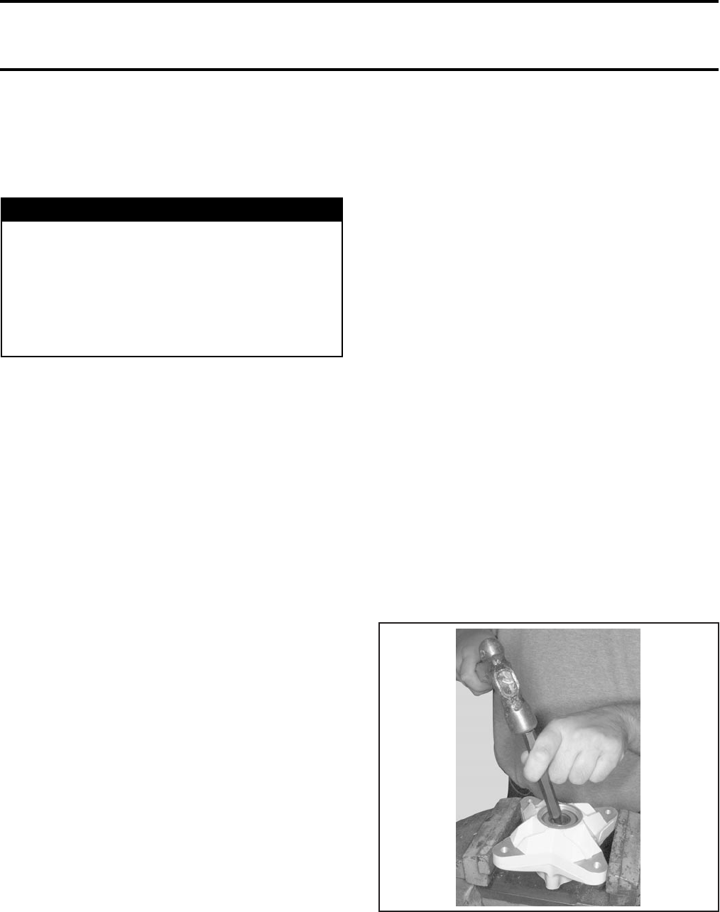
Section 06 DRIVE TRAIN
Subsection 02 (FRONT DRIVE)
06-02-2 VMR2004_023_06_02A.FM
GENERAL
For installation, use the torque values and Loctite
products from the exploded views. Clean threads
before using Loctite when installing the screws.
WHEEL HUB
Lift the front of vehicle and install jack stands un-
der the frame to support the front of vehicle off
the ground.
Removal
Remove:
– wheel
– wheel cap
– cotter pin no. 4 (discard)
– castellated nut no. 5
– caliper (refer to HYDRAULIC BRAKES)
– wheel hub no. 1 with brake disc
NOTE: Use a plastic hammer if necessary.
– brake disc from wheel hub
(refer to HYDRAULIC BRAKES).
Inspection
Check hub for cracks or other damage. Replace as
necessary.
Installation
For installation, reverse the removal procedure.
Pay attention to the following details.
Apply grease to wear ring located on the knuckle.
Install a new seal into wheel hub until it is flush
with hub surface.
Tighten castellated nut to the specific torque and
further tighten until its grooves align with cotter
pin hole.
Install a new cotter pin. Both ends of cotter pin
must be folded.
CAUTION: Make sure each end of cotter pin
does not protrude too far and rubs against the
wheel cap.
Reinstall wheel cap.
WHEEL HUB BEARING
Inspection
Check inner race of each bearing no. 2 with a fin-
ger. The bearing should turn smoothly and quietly.
Check if bearing outer race fits tightly in the hub.
Remove and discard bearings if races do not turn
smoothly and quietly or if they fit loosely in hub.
Replace bearings and hub if bearings fit loosely
into hub.
NOTE: Replace wheel hub bearings in pairs. Do
not reuse old bearings.
Removal
Remove seal no. 6 (discard).
Place wheel hub in vise.
Insert a punch into the inside bushing no. 7.
Place the end of punch on the inside bushing lips
and drive bearing out of wheel hub.
TYPICAL
Remove the inside bushing no. 7 and drive out the
outer bearing.
WARNING
Torque wrench tightening specifications must
strictly be adhered to.
Locking devices (ex.: locking tabs, elastic stop
nuts, self-locking fasteners, etc.) must be in-
stalled or replaced with new ones where
specified. If the efficiency of a locking device
is impaired, it must be replaced.
V02H08A
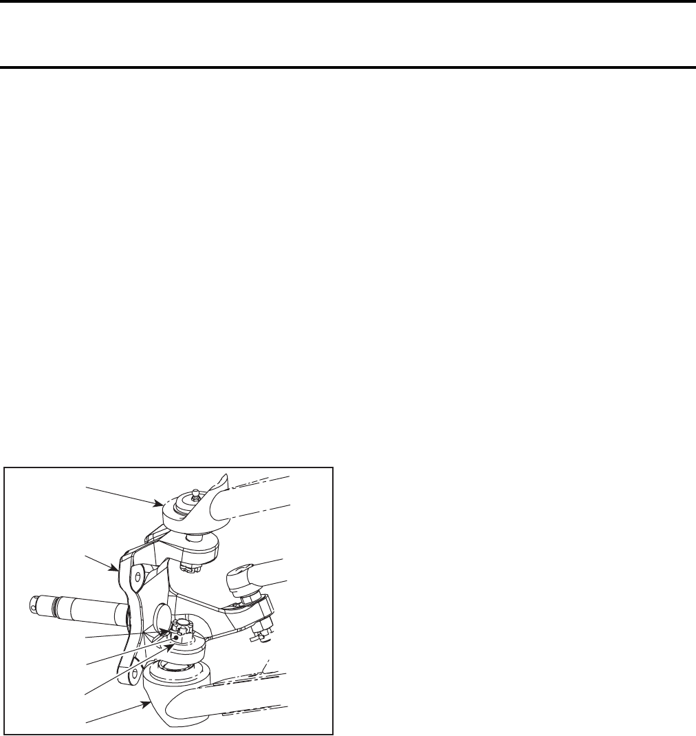
Section 06 DRIVE TRAIN
Subsection 02 (FRONT DRIVE)
VMR2004_023_06_02A.FM 06-02-3
Installation
Drive in a new bearing squarely until it is fully seat-
ed.
Install inside bushing and drive the outer new
bearing squarely until it is fully seated.
Install a new seal.
KNUCKLE
Removal
Remove:
–wheel hub
–tie-rod from knuckle
(refer to STEERING AND CONTROLS SYSTEM)
–cotter pins from the upper and lower A-arm ball
joints (discard cotter pins)
–castellated nuts
–hardened washer.
1. Knuckle
2. Castellated nut
3. Cotter pin
4. Hardened washer
5. Upper A-arm
6. Lower A-arm
Use a ball joint remover and detach upper and low-
er A-arm from knuckle.
CAUTION: Never hit the knuckle with a hammer.
Inspection
Check knuckle for damage, cracks or pitting. Re-
place as necessary.
Installation
The installation is the reverse of the removal pro-
cedure. However, pay attention to the following
details.
Install knuckle onto the upper and lower A-arms
with hardened washer and castellated nut.
Tighten castellated nut to the specific torque and
further tighten until its grooves align with the next
cotter pin hole.
Install a new cotter pin. Both ends of cotter pin
must be folded.
6
5
V02I0XA
1
4
2
3
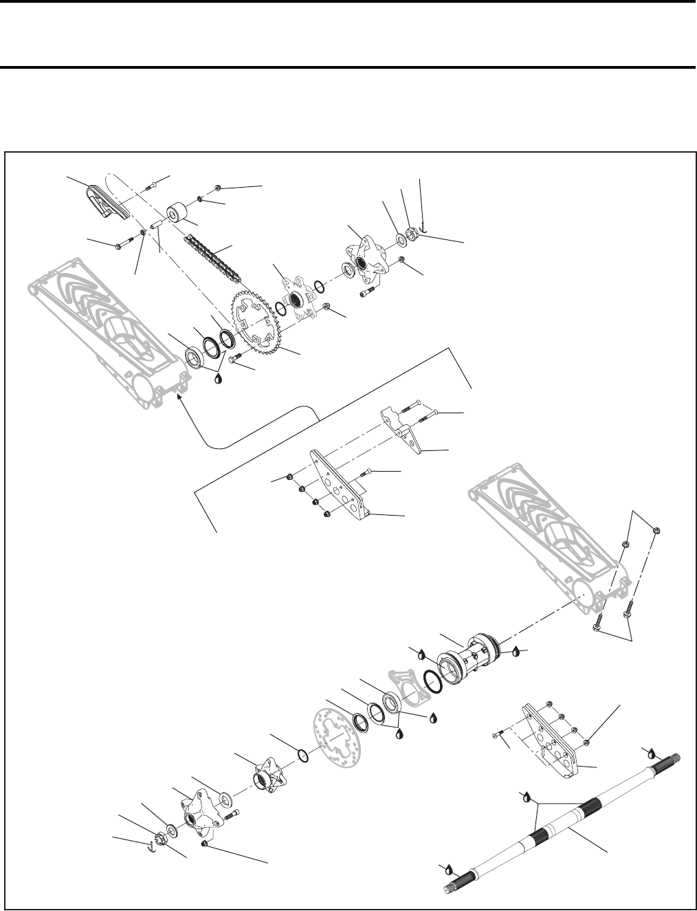
Section 06 DRIVE TRAIN
Subsection 03 (REAR AXLE)
VMR2004_024_06-03A.FM 06-03-1
REAR AXLE 0
4 Nm
(35 lbfin)
11
19 1
15
13
3
18
17 16
14
7
21
24
2
5
12
16
17
18
3
20
29
4
21
24 7
6
10
26
27
9
28
8
25
22
235 Nm
(173 lbfft)
V02H19S
Synthetic
grease
XL845
Grease
Texaco
Grease
Texaco
Grease
Texaco
23 Nm
(17 lbfft)
4 Nm
(35 lbfin)
Synthetic
grease
XL845
53 Nm
(39 lbfft)
Synthetic
grease XL845
4 Nm
(35 lbfin)
Synthetic
grease
XL845
80 Nm
(59 lbfft)
53 Nm
(39 lbfft)
235 Nm
(173 lbfft)
23 Nm
(17 lbfft)
23
22
Loctite
609
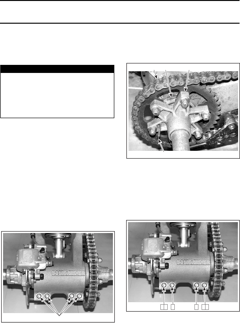
Section 06 DRIVE TRAIN
Subsection 03 (REAR AXLE)
06-03-2 VMR2004_024_06-03A.FM
GENERAL
For installation, use the torque values and Loctite
products from the exploded views. Clean threads
before using Loctite when installing the screws.
CAUTION: During installation, make sure every
part is free from old grease and dirt. This allows
for a clean re-assembly and will avoid prema-
ture wear caused by dirt contamination.
After each job, ride the vehicle for a few minutes
and make sure the job is successful; i.e. axle is not
loose, chain is not rubbing on any part or making
noise, rear brake operates correctly, etc.
DRIVE CHAIN
Adjustment
NOTE: Always adjust drive chain with the driver,
or equivalent weight, seated on the vehicle.
Select a level surface and set transmission to NEU-
TRAL.
Loosen rear axle lock bolts.
1. Rear axle lock bolts
Insert adjuster lock (from the vehicle’s tool kit)
through rear hub and into eccentric axle housing.
Turn the axle forward to increase or backward to
decrease chain free play.
TYPICAL
1. Drive chain
2. Adjuster lock
3. Sprocket hub
4. Eccentric axle housing
NOTE: Correct chain free play adjustment is 19 to
25.4 mm (3/4 to 1 in) midway between sprockets.
Tighten the rear axle lock bolts to 23 N•m (17 lbf•ft).
Use the following sequence to tight the rear axle
lock bolts correctly.
Lift rear of vehicle (without driver), by the frame or
by the bumper, and recheck the chain free play. The
chain free play should be 44.5 to 51 mm (1-3/4 to
2 in). If not, redo the drive chain adjustment.
WARNING
Torque wrench tightening specifications
must strictly be adhered to.
Locking devices (ex.: locking tabs, elastic stop
nuts, self-locking fasteners, etc.) must be in-
stalled or replaced with new ones where
specified. If the efficiency of a locking device
is impaired, it must be renewed.
V02H15A 1
V02H16A
1
2
43
V02H15B 2 6 4 3 1 5
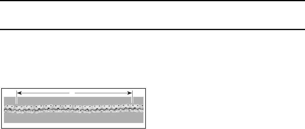
Section 06 DRIVE TRAIN
Subsection 03 (REAR AXLE)
VMR2004_024_06-03A.FM 06-03-3
Inspection
With the drive chain no. 1 installed on vehicle and
the free play adjusted correctly, measure the dis-
tance between a span of 13 links from pin center
to pin center.
A. 403 mm (15-7/8 in)
Change drive chain if the distance exceeds the ser-
vice limits.
CAUTION: Replace chain, engine sprocket and
rear sprocket together to prevent rapid chain
and sprockets wear. Install a new tab washer
each time the engine sprocket is removed.
Removal
Lift the rear of vehicle and install jack stands under
the frame to support the rear of vehicle off the
ground.
Remove metallic chain guard on engine.
Remove chain protector no. 9.
Loosen rear axle lock bolts no. 12.
Insert adjuster lock through hub axle and into ec-
centric axle housing.
Turn the axle forward.
Remove adjuster lock.
Detach the swing arm from the frame. Refer to
REAR SUSPENSION.
Remove drive chain from rear sprocket no. 2 and
engine sprocket.
Installation
Installation is the reverse of the removal.
Adjust drive chain. Refer to ADJUSTMENT for the
proper procedure.
SLIDER-SHOE
Removal
Remove swing arm. Refer to REAR SUSPENSION.
Remove slide-shoe.
Installation
Installation is the reverse of the removal.
CHAIN ROLLER
Removal
Unscrew bolt no. 19 retaining the chain roller
no. 11.
Remove the chain roller with ball bearings no. 22
and bushing no. 23.
Installation
For installation, reverse the removal procedure.
REAR WHEEL HUB
Removal
Lift rear of vehicle and install jack stands under the
frame to support the rear of vehicle off the ground.
NOTE: Use the same procedure for both wheel
hubs.
Apply rear brake.
CAUTION: Do not use the transmission to lock
the rear axle. Do not use an impact pneumatic
tool to loosen nuts. Because of the high tignten-
ing torque, impacts might damage the bearings.
Remove rear wheel.
Remove cap, cotter pin no. 16 and unscrew cas-
tlelated nut no. 17. Discard the cotter pin.
Remove hardened washer no. 18.
Pull out wheel hub no. 3.
Remove spacer no. 20.
Inspection
Check wheel hub for cracks splines wear or other
damage. Change if necessary.
V02H01B
A
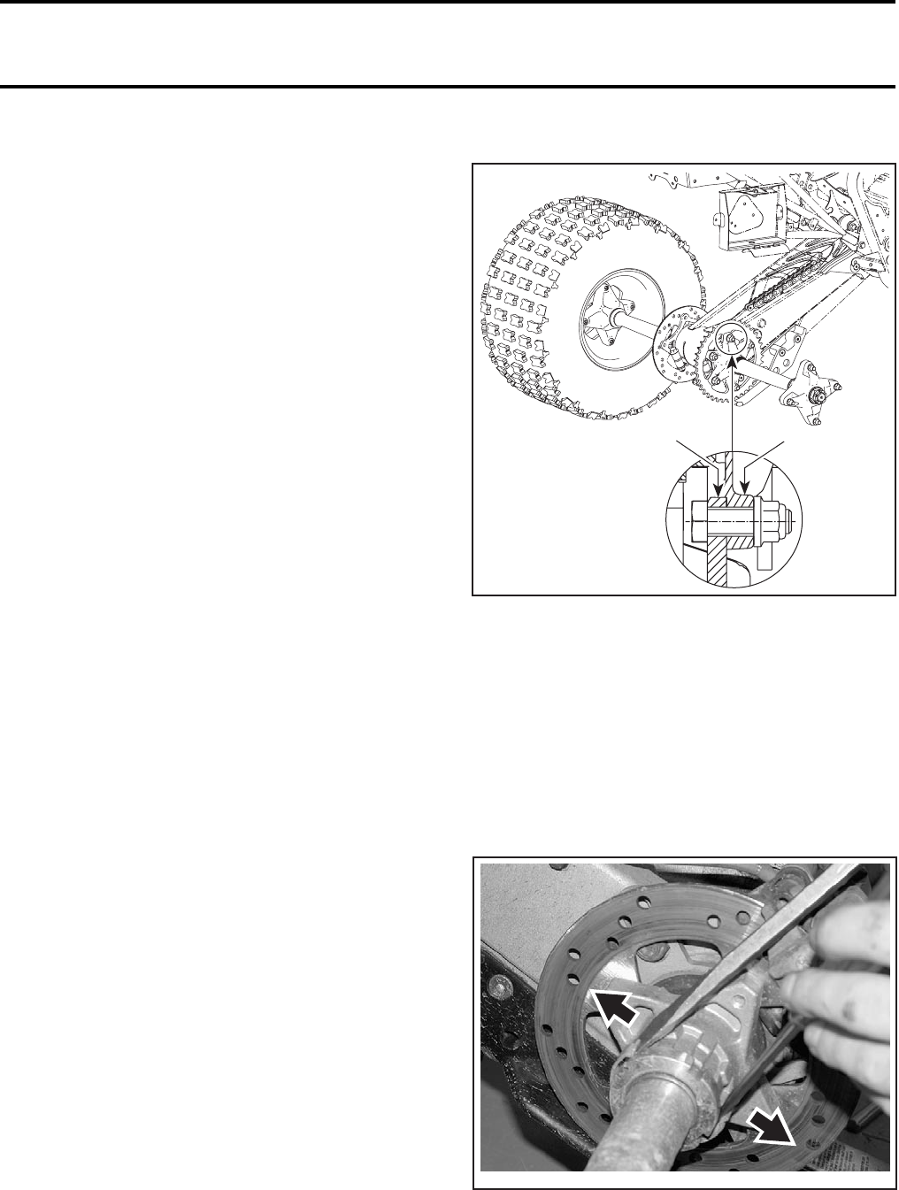
Section 06 DRIVE TRAIN
Subsection 03 (REAR AXLE)
06-03-4 VMR2004_024_06-03A.FM
Installation
For installation, reverse the removal procedure.
Pay attention to the following details.
Apply synthetic grease (P/N 293 550 019) on splines.
IMPORTANT: Do not apply grease on axle
threads.
Install wheel hub.
Put the washer and nut in place.
Torque nut to 220 N•m (162 lbf•ft).
NOTE: If, after applying the proper torque to the
nut, the cotter pin cannot be inserted in its hole,
continue tightening until slot aligns without ex-
ceeding 250 N•m (184 lbf•ft).
Install a new cotter pin. Both ends of cotter pins
must be folded over nut.
Reinstall cap.
Install both rear wheels and tighten nuts to 53 N•m
(39 lbf•ft) in a criss-cross sequence.
CAUTION: Always use the recommended wheel
nuts (P/N 732 610 084). Using a different nut could
cause damages to the rim.
Put vehicle back on the ground.
Adjust chain tension. Refer to DRIVE CHAIN
above.
REAR SPROCKET
Removal
Lift rear of vehicle and install jack stands under the
frame to support the rear of vehicle off the ground.
Remove RH rear wheel and wheel hub no. 3.
Unfasten bolts no. 14 and nuts no. 15 retaining
chain sprocket no. 2 to rear sprocket hub.
Remove chain sprocket.
Installation
CAUTION: Replace chain, engine sprocket and
rear sprocket together to prevent rapid chain
and sprockets wear. Install a new tab washer
each time the engine sprocket is removed.
For installation, reverse the removal procedure.
Install sprocket with the flat side on hub side.
1. Sprocket
2. Sprochet hub
BRAKE DISC HUB
Removal
Remove the left wheel hub and spacer no. 20.
Using 2 screwdrivers, gently pry out the ends of
the locking tab just enough to release them from
their notches. Then, slide locking tab out as
shown.
V02H0BA
12
V02H1AA
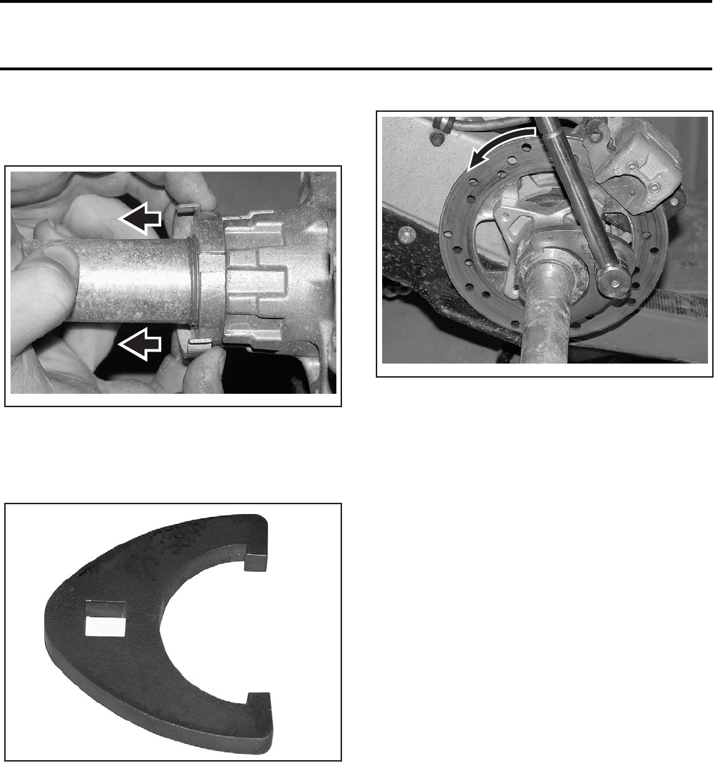
Section 06 DRIVE TRAIN
Subsection 03 (REAR AXLE)
VMR2004_024_06-03A.FM 06-03-5
CAUTION: Do not try to “open” the ends to re-
lease the locking tab. It would impair its effi-
ciency. To remove it, slide it out.
Place transmission on first gear and/or apply rear
brake.
Use rear axle key (P/N 529 035 951) to loosen
brake hub locking nut.
Release rear brake.
Remove caliper and place it on the swing arm. Re-
fer to HYDRAULIC BRAKES.
Slide out the brake disc hub. Remove brake disc.
Refer to HYDRAULIC BRAKES.
Remove O-ring no. 29.
Inspection
Check brake disc hub for cracks or other damage.
Replace if necessary.
Check for worn splines and free play on the rear
axle splines.
Check if wear ring no. 21 is worn or damaged. If
the ring is grooved, it must be replaced. Remove
old ring and, using tool P/N 529 035 694, press a
new one in place.
Press the wear ring on the hub until it bottoms.
V02H1BA
V02H1CA
V02H1DA
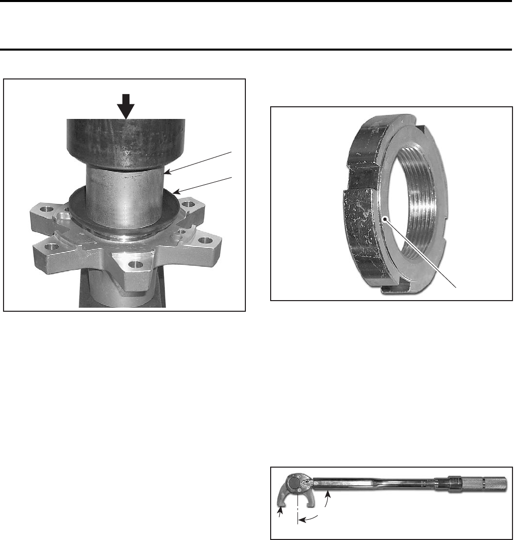
Section 06 DRIVE TRAIN
Subsection 03 (REAR AXLE)
06-03-6 VMR2004_024_06-03A.FM
1. Wear ring
2. Tool (P/N 529 035 694)
3. Press until it bottoms
If the brake disc hub has been damaged, replace
it too.
Check for distorted or enlarged locking tab. If so,
replace with a new one.
Installation and Bearing Preload
It is very important to set the correct amount of
preload on the brake hub nut to properly apply the
preload to the rear axle bearings.
Clean splines of rear axle and hubs with pulley
flange cleaner (P/N 413 711 809).
Install a new O-ring no. 29.
Apply synthetic grease (P/N 293 550 019) on splined
region of the axle.
IMPORTANT: Do not apply grease on axle
threads.
Slide the brake disc hub over the axle.
Install the nut. Pay attention to position the
flanged side of nut against the hub.
1. Flanged side against brake hub
Temporarily tighten nut by hand.
Install brake caliper and tighten bolts to 25 N•m
(18 lbf•ft).
Place transmission on first gear and/or apply rear
brake.
Use rear axle key (P/N 529 035 951) to tighten
brake hub locking nut.
Ensure to install the tool perpendicularly (90°) to
torque wrench to apply the proper torque to the
nut.
1. Tool perpendicular (90°) to torque wrench
CAUTION: Not installing the tool as shown will
change the torque applied to the nut. Proper
torque and tightening sequence are important.
To properly set the parts, first apply a preload
torque of 92 N•m (68 lbf•ft). Then, loosen nut
and apply a torque of 28 N•m (21 lbf•ft).
2
V02H1RA
1
3
V02H1QA 1
V02H1EA
90°
1
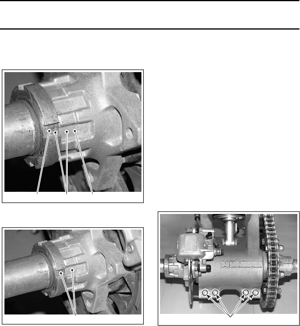
Section 06 DRIVE TRAIN
Subsection 03 (REAR AXLE)
VMR2004_024_06-03A.FM 06-03-7
NOTE: If slots of nut are not properly aligned with
slots of disc hub, continue tightening nut until
slots align without exceeding 35 N•m (26 lbf•ft).
1. Slot of nut
2. Slot of brake hub
3. If not aligned, continue tightening
1. Slots aligned. Do not exceed 35 N•m (26 lbf•ft)
Slide locking tab over nut and insert properly in
slots.
Release rear brake.
Install rear wheel hub (refer to procedure men-
tioned above).
REAR AXLE
Removal
Lift rear of vehicle and install jack stands under the
frame to support the rear of vehicle out off the
ground.
Remove rear wheels.
Loosen chain. Refer to DRIVE CHAIN above.
Remove the LH wheel hub no. 3 and brake disc
hub no. 4.
Remove protector no. 8.
Unscrew the 6 bolts retaining the sprocket to its
sprocket hub.
Separate the sprocket from the sprocket hub and
place it away with the chain over the swing arm
tube. This will ease the removal and the insertion
of the axle into the swing arm because the chain
will not be in the way.
Loosen the locking bolts on the swing arm used
to set the chain tension.
1. Rear axle lock bolts
Slide out the axle from the right side of the swing
arm. If the vehicle ran with failed bearings, it may
have damaged many parts around the bearing area.
It is possible that the axle will not slide out easily if
the bearings are seized on it.
V02H1OA 1 3 2
V02H1PA 1V02H15A 1

Section 06 DRIVE TRAIN
Subsection 03 (REAR AXLE)
06-03-8 VMR2004_024_06-03A.FM
Inspection
Check axle for bending, torsion or other damage.
Change if necessary.
Check axle for spots of rust. A spot of rust indicates
a possible damage to axle. Change axle if necessary.
If bearings are seized on the axle, the axle must be
replaced or its surface cleaned. Bearings must still
have a slide fit on the axle, otherwise it will result
in a faulty re-assembly and a failure may occur.
Bearing races on the axle must be in good condi-
tion.
On sprocket hub side, check the wear ring where
the seal runs. It must be in good condition. Check
for grooves or excessive wear. If the ring is
grooved, it must be replaced. Remove old ring
and, using tool P/N 529 035 694, press a new one
into place. If the sprocket hub has been damaged,
replace it too.
Installation
Insert the axle assembly into the chain first, then
into the swing arm from the right side.
Install the brake disc hub and wheel hub.
CAUTION: It is important to follow the preload
procedure to avoid seal and bearing damage.
Refer to BRAKE DISC HUB for the procedure.
Install sprocket and tighten bolts to 61 N•m (45
lbf•ft).
Install protector no. 8.
Install both rear wheels and tighten nuts to 53 N•m
(39 lbf•ft) in a criss-cross sequence.
CAUTION: Always use the recommended wheel
nuts (P/N 732 610 084). Using a different nut could
cause damages to the rim.
Perform drive chain adjustment. Refer to DRIVE
CHAIN above.
REAR SPROCKET HUB
Removal
CAUTION: Removing rear sprocket hub from
rear axle will permanently damage the hub
splines. Do not remove hub needlessly.
Remove rear axle. Refer to REAR AXLE below.
NOTE: The wear ring can be removed without re-
moving the sprocket hub. Use 2 large screwdriv-
ers each side of wear ring and pry it out. Discard
ring.
Remove the RH wheel hub.
Using an appropriate steel tube as a pusher, press
the hub down approximately 2 mm (.080 in) to al-
low C-clip removal.
NOTE: Heat sprocket hub in the center area to al-
low hub displacement.
1. Rear sprocket hub
2. Steel tube used as a pusher
3. C-clip
Pull tube out and remove C-clip.
WARNING
Wear asbestos gloves to handle the parts to
protect your hands from the heated parts.
V02H1SA
2
1
3
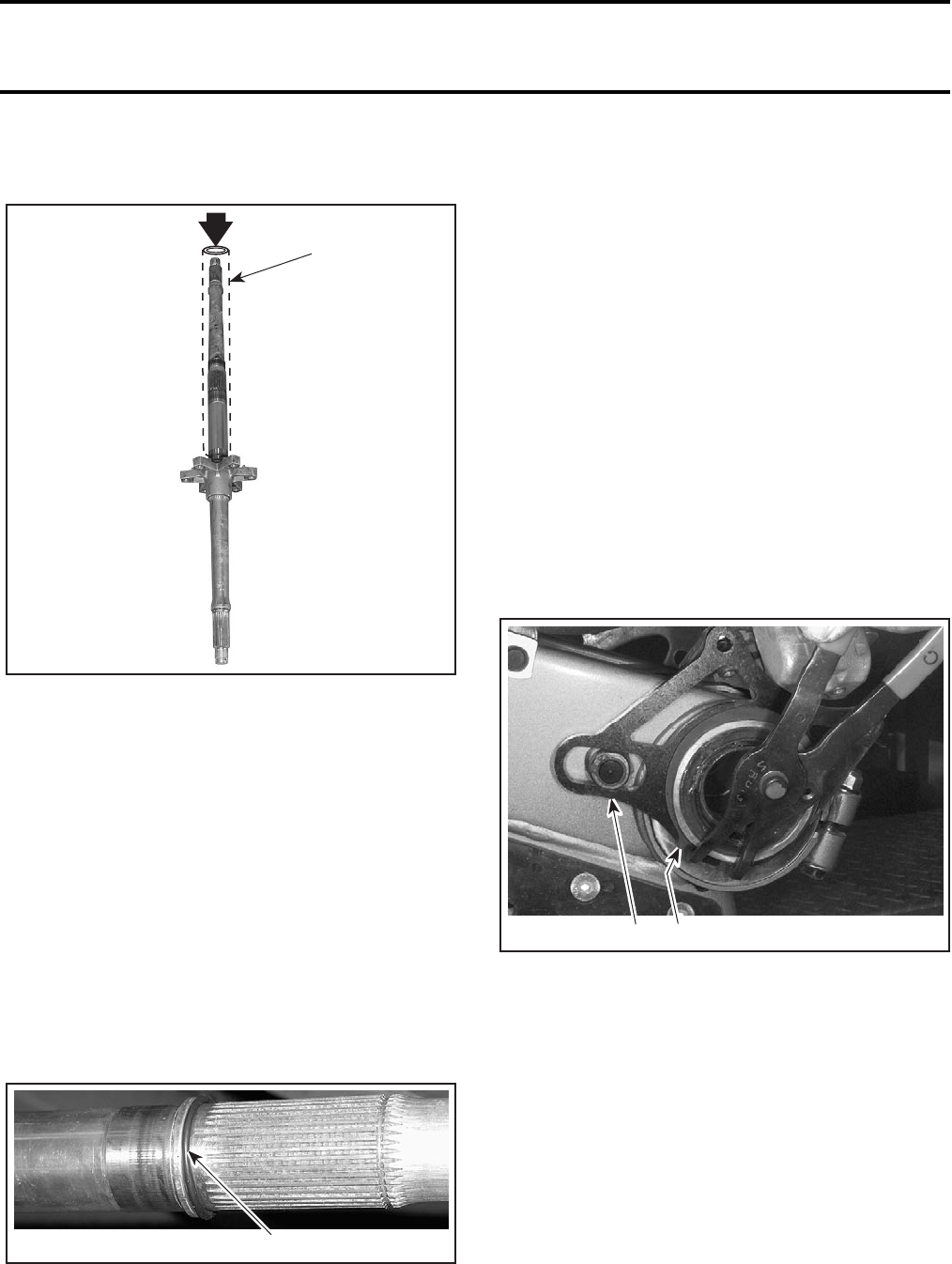
Section 06 DRIVE TRAIN
Subsection 03 (REAR AXLE)
VMR2004_024_06-03A.FM 06-03-9
Turn rear axle upside down.
Press the hub out of rear axle.
1. Steel tube used as a pusher
Discard hub.
Installation
CAUTION: Never reinstall a removed sprocket
hub. Always install a new one.
Install a new wear ring on sprocket hub. Using an
appropriate steel tube as a pusher, press the wear
ring on the hub until it bottoms.
NOTE: The wear ring could be installed after
sprocket hub installation.
Clean rear axle splines with pulley flange cleaner
(P/N 413 711 809).
Install a new O-ring on rear axle and properly seat
against the axle flange.
1. Push the new O-ring against the flange
Apply some synthetic grease (P/N 293 550 019)
on splines.
IMPORTANT: Do not apply grease on axle
threads.
Using the same steel tube as for removal, press
hub until the C-clip groove allows C-clip insertion.
CAUTION: Be careful not to press more than
needed. Otherwise, the O-ring might be dam-
aged.
Install C-clip.
Press hub in the opposite direction until hub bot-
toms on the C-clip.
ECCENTRIC AXLE HOUSING
Removal
Remove the rear axle.
Remove the snap ring retaining the caliper bracket.
1. Caliper bracket
2. Snap ring
Remove the caliper bracket by pulling it out.
Slide out the eccentric axle housing from the right
side of the swing arm.
Dirt inside the swing arm may cause resistance
during removal procedure. Carefully spread swing
arm split using screwdrivers.
V02H1KA
1
V02H1NA 1
1
V02H10A 2
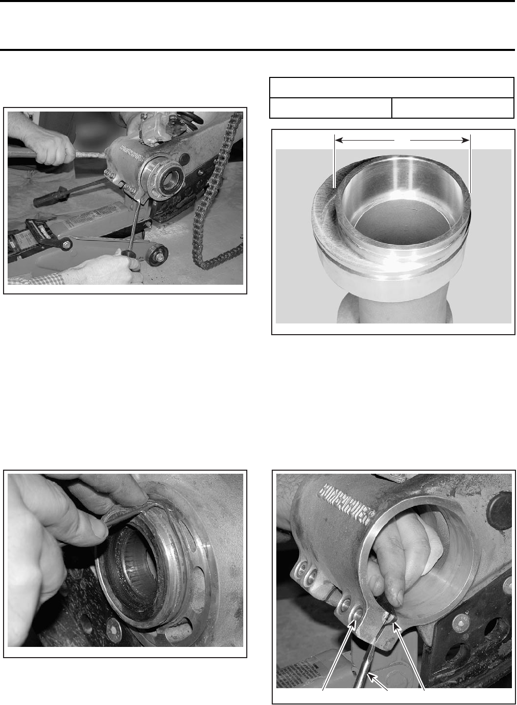
Section 06 DRIVE TRAIN
Subsection 03 (REAR AXLE)
06-03-10 VMR2004_024_06-03A.FM
CAUTION: Be carful not to damage the seal be-
tween surfaces.
Use a soft tool to hammer out the eccentric axle
housing if required. Seal leakage will occur after
assembly if its bore is dented.
Inspection
Look at the eccentrial axle housing for damage.
The bore must be free of scratches in order to re-
ceive new bearings and seals.
Check for worn diameter where the caliper brack-
et seats.
Inspect O-ring condition where the caliper bracket
seats.
Inspect rubber seal condition between the split
surfaces of swing arm.
A. 75 mm (2.95 in)
Installation
Installation is the reverse of the removal.
If rubber seal has been removed, install it as fol-
lows.
–Carefully spread swing arm split using a screw-
driver.
–Insert seal in one corner of the split.
1. Pry here to spread the split
2. Insert seal in one corner
3. Align seal hole with swing arm hole
V02H1GA
V02H1HA
ECCENTRIC AXLE LH O.D.
SERVICE LIMIT 75 mm (2.95 in)
A
V02H0CA
V02H1IA 3 1 2
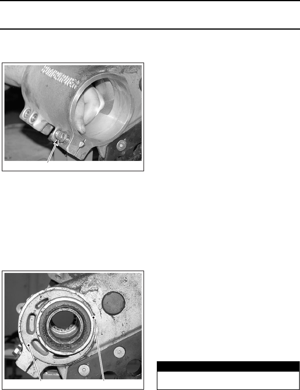
Section 06 DRIVE TRAIN
Subsection 03 (REAR AXLE)
VMR2004_024_06-03A.FM 06-03-11
–Align its hole with swing arm hole then insert
a screw to retain the seal in place.
1. Install a screw to retain seal in place
–Spread the other corner of swing arm.
–Place the seal in the split.
–Install remaining screws. Keep screws loose.
Do not apply any lubricant on contact surfaces of
the eccentric axle housing and swing arm. Other-
wise the chain tension will not remain adjusted.
Carefully slide the eccentric axle housing in the
swing arm; the snap ring groove side of the eccen-
tric axle housing goes toward left side.
Ensure to position the eccentric as shown.
1. Eccentric axle housing
2. Position thin side here
Install caliper bracket in place.
Install the circlip into the groove of the eccentric
axle housing.
NOTE: Make sure it is fully seated.
Install all other parts.
CAUTION: It is important to follow the preload
procedure to avoid seal and bearing damage.
Refer to BRAKE DISC HUB for the procedure.
ECCENTRIC AXLE BEARINGS
Inspection
The eccentric axle bearings should turn smoothly
and quietly. If not, change the bearings.
If bearings are seized on the axle, the axle must
be replaced or its surface cleaned. Bearings must
still have a slide fit on the axle, otherwise it will
result in a faulty re-assembly and a failure may oc-
cur. Bearing races on the axle must be in good
condition.
Removal
NOTE: Bearings and seals must be replaced if re-
moved.
Pry out drive axle seals no. 24. Be careful not to
damage seal bore or eccentric axle housing.
Use a punch and drive bearings cup outward from
opposite end of housing.
Installation
The seal and bearing must be pressed into a dry
bore. Use the Pulley flange cleaner (P/N 413 711
809) to make sure the bore is free of grease where
the bearing and seal go.
Place new bearings in a freezer for 10 minutes be-
fore installation.
Apply Loctite 609 (P/N 413 703 100) in axle hous-
ing on the bearing contact area. Press the new
race into the eccentric axle housing. To ease the
assembly, it is possible to heat the eccentric axle
housing at 100°C (212°F), 30 minutes in oven.
Using a bearing packer, pack the bearing with
Bombardier Sea-Doo® bearing grease (P/N 293
550 010).
V02H1JA 1
V02H1FA 1 2
WARNING
Clean all grease, outside and inside, from ec-
centric housing before putting in oven.
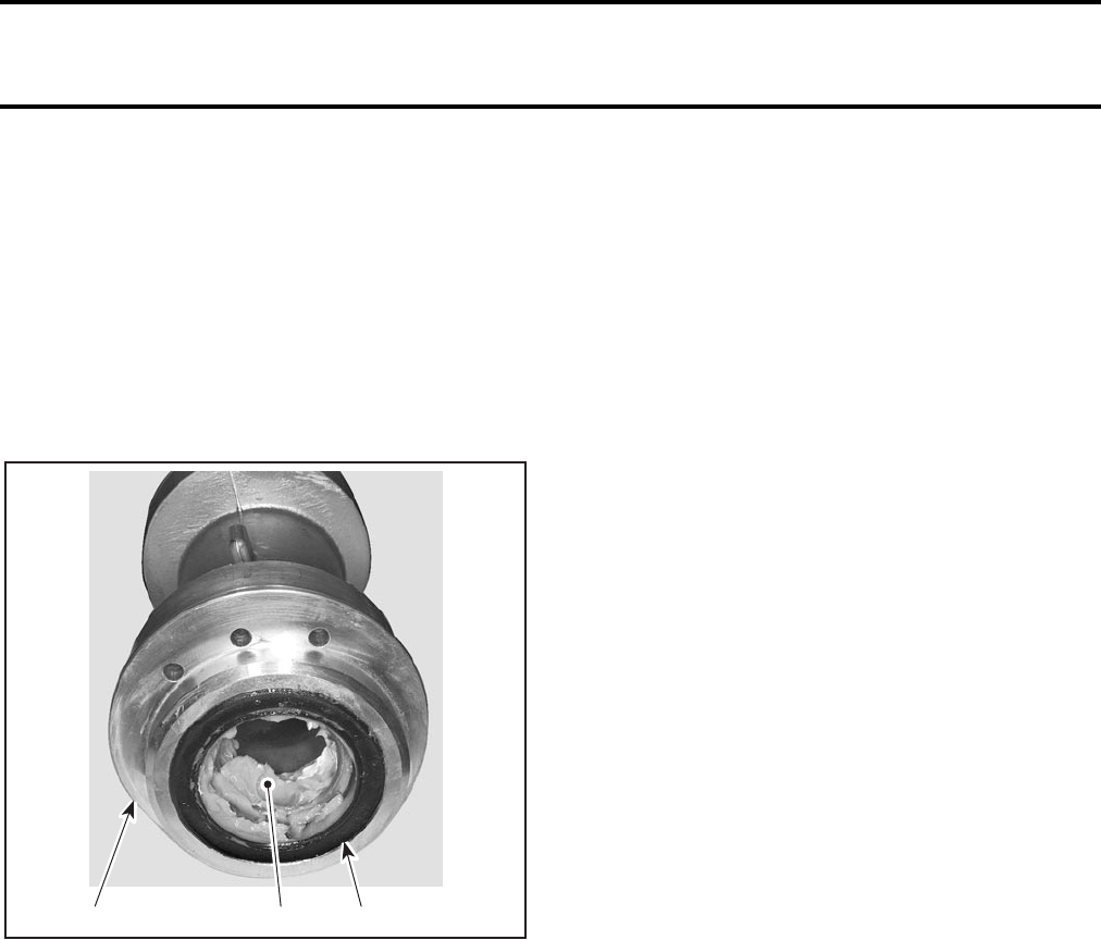
Section 06 DRIVE TRAIN
Subsection 03 (REAR AXLE)
06-03-12 VMR2004_024_06-03A.FM
Apply grease to the race in the eccentric axle
housing.
CAUTION: If the seal is pressed into a slippery
bore, it will misalign or pop out when the vehi-
cle will be running, which will lead to bearing
failure.
Press the seal in place. Properly installed, it is flush
with the edge of the eccentric axle housing.
Apply grease on seal lips and fill the area between
the bearing and the seal.
TYPICAL
1. Eccentric axle housing
2. Packed with grease
3. Seal installed flush with edge of eccentric axle housing
Install all other parts.
CAUTION: The preload procedure is very im-
portant to avoid seals and bearings damages.
Refer to BRAKE DISC HUB for the procedure.
PROTECTORS
Removal
LH Protector
Remove brake disc hub with brake disc.
Unfasten socket head screws no. 25.
Remove LH protector no. 8 from swing arm.
RH Protector
Remove:
–sprocket hub on rear hub
–socket head screws no. 26 retaining the chain
protector no. 27 to the RH protector no. 9
–the other socket head screws no. 28 retaining
RH protector to swing arm
–RH protector from swing arm.
Installation
For installation, reverse the removal procedure.
CAUTION: The preload procedure is very im-
portant to avoid seals and bearings damages.
Refer to BRAKE DISC HUB for the procedure.
1
V02H11A 2 3

Section 07 STEERING SYSTEM
Subsection 01 (TABLE OF CONTENTS)
VMR2004_033_07_01ATOC.FM 07-01-1
TABLE OF CONTENTS 0
STEERING SYSTEM .............................................................................................................. 07-02-1
GENERAL ........................................................................................................................... 07-02-2
HANDLEBAR GUARD........................................................................................................ 07-02-2
HANDLEBAR GRIP ............................................................................................................ 07-02-2
HANDLEBAR ...................................................................................................................... 07-02-3
STEERING COLUMN......................................................................................................... 07-02-3
TIE-ROD.............................................................................................................................. 07-02-3
STEERING COLUMN BEARING........................................................................................ 07-02-4
MULTI-FUNCTION SWITCH ............................................................................................. 07-02-4
THROTTLE HANDLE.......................................................................................................... 07-02-5
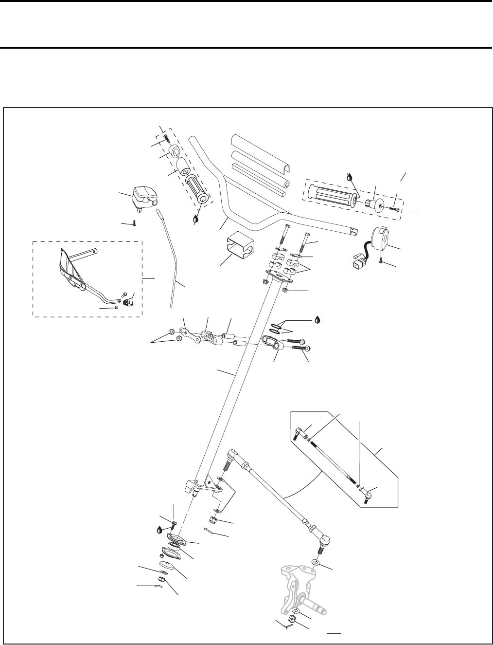
Section 07 STEERING SYSTEM
Subsection 02 (STEERING SYSTEM)
VMR2004_025_07_02A.FM 07-02-1
STEERING SYSTEM 0
V02I0ZS
23 Nm
(17 lbfft)
5 Nm
(44 lbfin)
10 Nm
(89 lbfin)
Loctite
406
Synthetic
grease
23 Nm
(17 lbfft)
.4 Nm
(3.5 lbfin)
3 Nm
(27 lbfin)
23 Nm
(17 lbfft)
34 Nm
(25 lbfft)
70 Nm
(52 lbfft)
38 Nm
(28 lbfft)
Loctite
243
10 Nm
(89 lbfin)70 Nm
(52 lbfft)
DS 650 Baja/ Baja X
9
10
11
26
26
25
24
26
25
24
31
19
18
17
12
1
14 15 16
13
15
22
21
28
33
35
8
36
23
34
32
20
2
6
7
3
27
30
Loctite
406
DS 650
DS 650 Baja/ Baja X
4
5
29
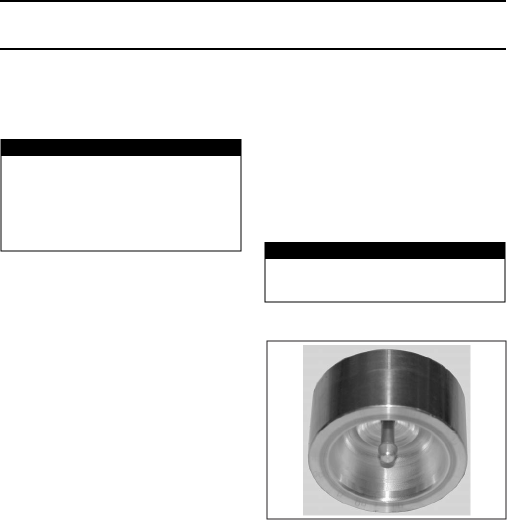
Section 07 STEERING SYSTEM
Subsection 02 (STEERING SYSTEM)
07-02-2 VMR2004_025_07_02A.FM
GENERAL
For installation, use the torque values and Loctite
products from the exploded views. Clean threads
before using Loctite when installing the screws.
HANDLEBAR GUARD
Removal
Baja and Baja X Models
Remove:
– handle grip screw no. 1 at the end of handlebar
guard no. 2
NOTE: Discard the handlebar grip screw.
– handlebar guard arm bracket no. 3.
Installation
The installation is the reverse of removal procedure.
NOTE: Install a new handlebar grip screw.
HANDLEBAR GRIP
Removal
DS 650 Models
Remove:
– throttle lever and/or multi-function switch from
handlebar
–screw no. 4
– end cap no. 5.
Baja and Baja X Models
Remove:
– handlebar guard no. 2
– adjusting sleeve no. 6
– tightening sleeve no. 7.
All Models
NOTE: If handlebar grip needs to be replaced, the
grip can be cut with a knife for removal.
Insert the open side of a 23 mm (7/8 in) wrench
against the inner end of grip.
Using a plastic hammer, tap on the side of the
wrench end to make the grip sliding out.
Installation
Clean handlebar ends and inside of handlebar grip
with pulley flange cleaner (P/N 413 711 809). Let
dry before installation.
Use the insertion tool (P/N 529 035 897) to prop-
erly install handlebar grip.
CAUTION: Installing handlebar grip without the
special tool is likely to damage it.
Position the insertion tool at the outside end of grip.
Using a plastic hammer, tap on tool to push grip
on. Continue to tap until grip bottoms.
Install all other removed parts.
WARNING
Torque wrench tightening specifications
must strictly be adhered to.
Locking devices (ex.: locking tabs, elastic stop
nuts, self-locking fasteners, etc.) must be in-
stalled or replaced with new ones where
specified. If the efficiency of a locking device
is impaired, it must be renewed. WARNING
Handlebar end and inside of handlebar grip
must be clean and dry before installing han-
dlebar grip to ensure proper installation.
A32G2BA

Section 07 STEERING SYSTEM
Subsection 02 (STEERING SYSTEM)
VMR2004_025_07_02A.FM 07-02-3
HANDLEBAR
Removal
Remove:
–steering cover no. 8
–steering clamp mounting bolts no. 9, reinforce-
ments no. 10 and steering clamps no. 11
–handlebar no. 12.
NOTE: Remove throttle lever, multi-function switch
and handlebar guards from the handlebar if it is re-
placed with a new one.
Inspection
Inspect the handlebar for damage, cracks or bend-
ing, replace if any problem is detected.
Installation
For the installation, reverse the removal procedure.
STEERING COLUMN
Removal
Top Side
Remove:
–front facia and dashboard (refer to BODY)
–handlebar
–fuel tank (refer to FUEL CIRCUIT)
NOTE: Do not remove fuel tank completely, sep-
arate fuel tank from frame only. Do not remove
fuel lines.
–headlamp (refer to ACCESSORIES)
–oil tank (refer to REMOVAL AND INSTALLATION)
–half housing bolts no. 13
–stopper plates no. 14
–half housings no. 15
–housing bushings no. 16.
Bottom Side
Remove:
–cotter pin no. 17 (discard)
–castellated nut no. 18
–flat washer no. 19
–washer no. 20
–tie-rod ends no. 21 from the steering column
no. 22. Refer to TIE-ROD section.
Pull steering column.
Inspection
Inspect steering column for cracks, bending or oth-
er damages. Replace if any problem is detected.
Check if the O-rings no. 23 are brittle, hard or oth-
erwise damaged. Replace if necessary.
Check steering column bearing for excessive play
and smooth operation. Replace if necessary. See
further in this section for the proper procedure.
Installation
For the installation, reverse the removal procedure.
NOTE: Install new cotter pin. Both ends of cotter
pin must be folded.
TIE-ROD
Removal
Place the vehicle on jack stands and remove front
wheel(s).
Remove front fender with fender support. Refer to
BODY.
Remove cotter pins no. 24 (discard), castellated
nuts no. 25 and hardened washers no. 26.
Remove tie-rod no. 27.
CAUTION: Never tap the knuckle with a hammer.
Inspection
Inspect tie-rod ends no. 21 and no. 28 for wear or
looseness, if excessive, replace.
Check for cracks on rubber boot.
Installation
For the installation, reverse the removal proce-
dure. Pay attention to the following details.
At the time of the reinstallation or the new tie-rod(s)
installation, screw threaded end of tie-rod into ball
joint.
NOTE: Match the corresponding left or right threads
of tie rod end with ball joint.
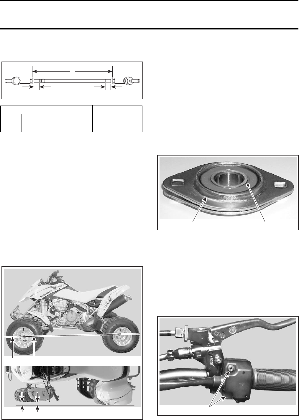
Section 07 STEERING SYSTEM
Subsection 02 (STEERING SYSTEM)
07-02-4 VMR2004_025_07_02A.FM
The maximum length for tie-rod groove to ball joint
end must be the value A in the following chart:
Before installing tie-rods, ensure that both heads
of tie-rod ends are aligned. If the heads are not
aligned, the tie-rod end play and its durability will
be greatly reduced.
Install new cotter pin. Both ends of cotter pin must
be folded.
Perform the toe-out adjustment.
Toe Adjustment
Place vehicle on level surface.
Check that handlebar is straight.
Use a long rule and check if the rear and front
wheels are aligned.
Adjust alignment with tie-rod.
Adjust toe-out to 0.5 ± 0.5 mm (.0197 ± .0197 in)
on each side.
NOTE: Take measure on the rim.
A - B = 0.5 ± 0.5 mm (.0197 ± .0197 in) on each side
STEERING COLUMN BEARING
Removal
Place vehicle on jack stands and remove front
wheels.
Remove steering column.
Remove bolts no. 29 and first bearing flange no. 30.
Remove bearing no. 31.
Installation
For installation, reverse the removal procedure.
Pay attention to the following detail.
Place flanged collar toward outside.
1. Flanged collar
2. Bearing
MULTI-FUNCTION SWITCH
Test
Refer to ACCESSORIES.
Removal
Remove screws no. 32 under multi-function switch
no. 33.
TYPICAL
1. Remove the screws
MODEL A B
DS mm 20 ± 5 311 ± 1
in 25/32 ± .197 12-1/4 ± .039
B
V01I0YA
AA
V02I0AB
BA
BA
V02I08A 1 2
V02I09A 1
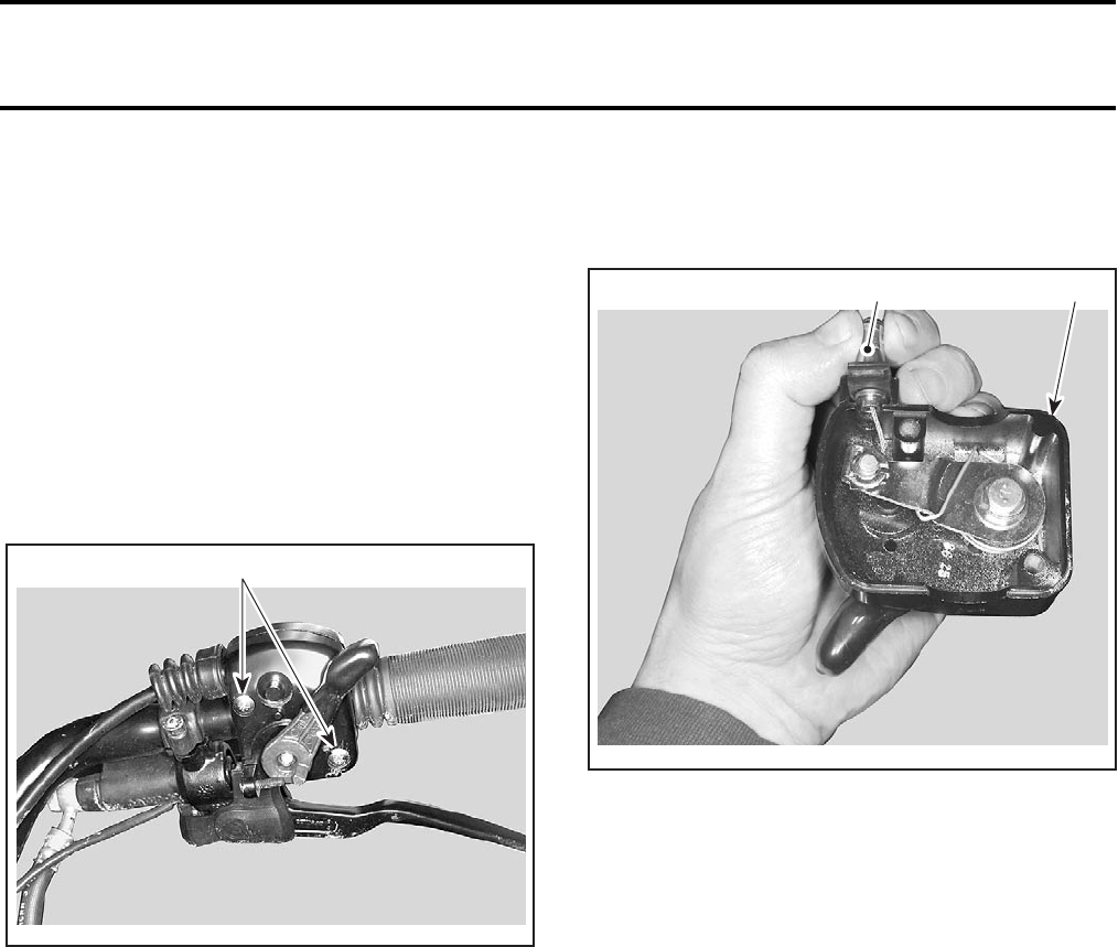
Section 07 STEERING SYSTEM
Subsection 02 (STEERING SYSTEM)
VMR2004_025_07_02A.FM 07-02-5
Separate multi-function switch from handlebar.
Remove front facia. Refer to BODY.
Unplug multi-function switch connector.
Installation
For installation, reverse the removal procedure.
THROTTLE HANDLE
Removal
Remove screws no. 34 under throttle handle
no. 35.
TYPICAL
1. Remove screws
Separate throttle handle from handlebar.
Unscrew the locking nut of the cable adjuster then
screw the adjuster to release the cable tension.
Remove throttle cable no. 36 from housing.
TYPICAL
1. Throttle handle housing
2. Throttle cable
Slide cable in clip slot and remove the end of the
cable from clip.
Installation
For installation, reverse the removal procedure.
Refer to CARBURETOR AND AIR INTAKE SILENC-
ER for adjustment procedure.
V01I0ZA
1
V01I10A
12

Section 08 SUSPENSION
Subsection 01 (TABLE OF CONTENTS)
VMR2004_033_08_01ATOC.FM 08-01-1
TABLE OF CONTENTS 0
FRONT SUSPENSION ........................................................................................................... 08-02-1
GENERAL ........................................................................................................................... 08-02-2
SHOCKS ABSORBER ASS’Y............................................................................................. 08-02-2
SHOCK ABSORBER REBUILDING .................................................................................... 08-02-3
UPPER A-ARM ................................................................................................................... 08-02-7
LOWER A-ARM.................................................................................................................. 08-02-9
BALL JOINT ....................................................................................................................... 08-02-10
REAR SUSPENSION............................................................................................................. 08-03-1
GENERAL ........................................................................................................................... 08-03-2
SHOCK ABSORBER ASS’Y ............................................................................................... 08-03-2
SHOCK ABSORBER REBUILDING .................................................................................... 08-03-5
SWING ARM ...................................................................................................................... 08-03-10
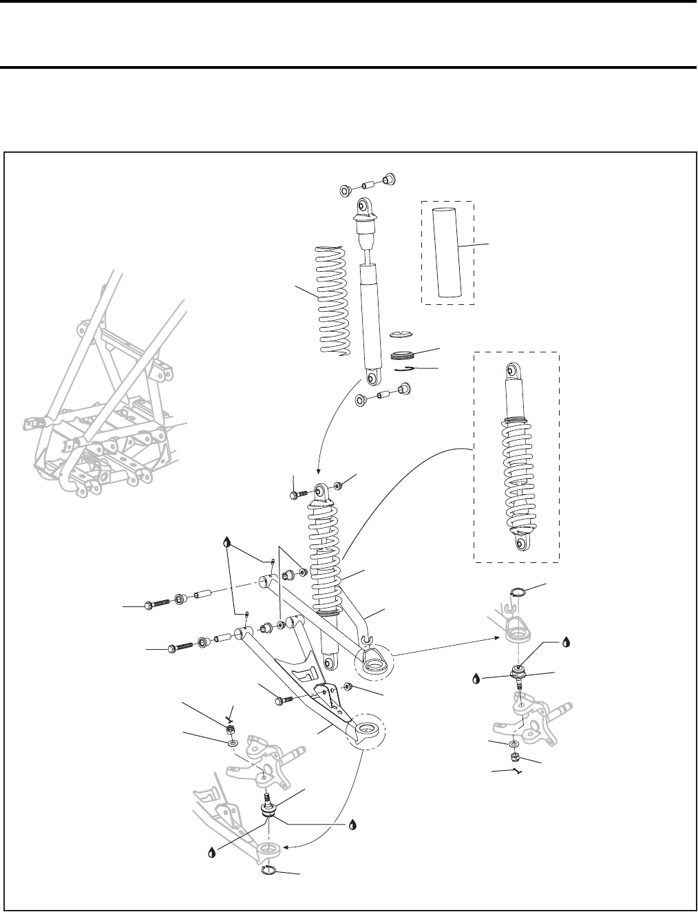
Section 08 SUSPENSION
Subsection 02 (FRONT SUSPENSION)
VMR2004_026_08_02A.FM 08-02-1
FRONT SUSPENSION 0
V02J1BS
3
8
9
14
16
12
11 10
12
15
4
7
6
5
17
11
10
17
13
Baja/Baja X
2
1
48 Nm
(35 lbfft)
Loctite
609
50 Nm
(37 lbfft)
Loctite 609
50 Nm
(37 lbfft)
Suspension synthetic grease
48 Nm
(35 lbfft)
63 Nm
(46 lbfft)
Baja X
Suspension
synthetic grease
Suspension
synthetic grease
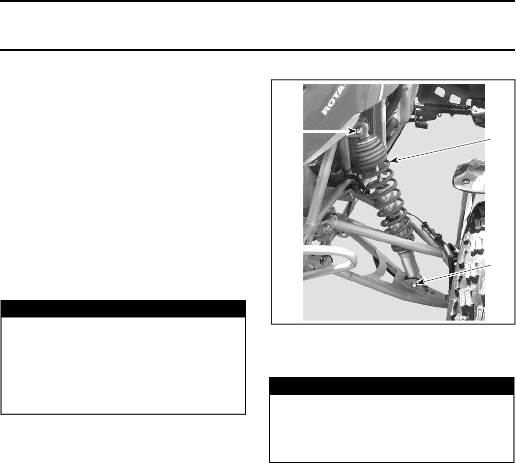
Section 08 SUSPENSION
Subsection 02 (FRONT SUSPENSION)
08-02-2 VMR2004_026_08_02A.FM
GENERAL
CAUTION: The Baja and Baja X models are
equipped with shocks absorber protectors. Open
or remove them if the vehicle is used intensively
or if the ambient temperature is high. Otherwise,
shock absorber performance degradation or
damage can occur.
NOTE: On Baja X models, do not remove the shock
absorber protectors if the vehicle is used in a stony
area.
During assembly/installation, use the torque val-
ues and service products as in the exploded views.
Clean threads before applying a threadlocker. Re-
fer to SELF-LOCKING FASTENERS and LOCTITE AP-
PLICATION at the beginning of this manual for com-
plete procedure.
CAUTION: When reinstalling the brake line, in-
stall new screws with regular M6 threads. Re-
installing self-tapping screws would damage
the A-arm threads.
SHOCKS ABSORBER ASS’Y
Removal
Lift front of vehicle and install jack stands under
the frame to support the vehicle off the ground.
NOTE: Lift up vehicle high enough to have the
wheel off the ground.
On Baja and Baja X models, remove the shock
absorber protector no. 2.
Remove lower bolt no. 4 then upper bolt no. 3 of
shock.
1. Remove bolts
2. Front shock assembly
Disassembly
Remove snap ring no. 5 under spring seat no. 6.
Unscrew the spring seat completely and remove
the spring no. 7.
Inspection
Inspect the spring for damage. Replace if necessary.
Inspect shock for oil leakage. Extend and compress
the piston several times over its entire stroke.
Check piston rod for excessive wear or pitting.
Check that it moves smoothly and with uniform
resistance with its rod upwards. Any of the follow-
ing conditions will denote a defective shock:
– A skip or hang back when reversing stroke at
mid travel.
– Seizing or binding condition except at extreme
end of either stroke.
– A gurgling noise after completing one full com-
pression and extension stroke.
WARNING
Torque wrench tightening specifications
must strictly be adhered to.
Locking devices (ex.: locking tabs, elastic stop
nuts, self-locking fasteners, etc.) must be in-
stalled or replaced with new ones where
specified. If the efficiency of a locking device
is impaired, it must be renewed.
WARNING
The shock absorber on Baja X models con-
tains high pressure nitrogen gas. Do not at-
tempt to disassemble before removing the
pressure. Dispose of gas and oil as per your
local environmental regulations.
1
V02J0LA
2
1
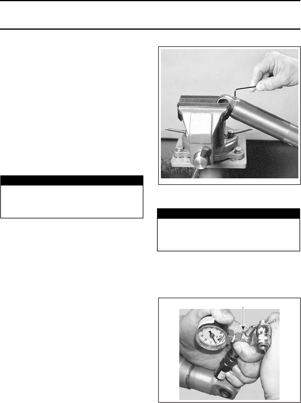
Section 08 SUSPENSION
Subsection 02 (FRONT SUSPENSION)
VMR2004_026_08_02A.FM 08-02-3
Replace shock if any of these conditions are found.
On both ends, check the bushings for excessive
wear or other damages. Replace bushings in pair.
Assembly and Installation
For assembly and installation, reverse the disas-
sembly and removal procedures. Pay attention to
the following details.
Extend the piston before installing spring, spring
seat and snap ring.
On Baja and Baja X models, reinstall the shock
protector, make sure not to block venting holes.
On Baja X models, reinstall piston rod of shock
absorber to the bottom lower A-arm.
Adjustment
Preload Adjustment
Shorten the spring for a firmer ride and rough road
condition.
Lengthen the spring for a light load and a smooth
road condition.
SHOCK ABSORBER REBUILDING
Baja X Models
Remove spring and adjuster. See SHOCK AB-
SORBER ASS’Y above.
Disassembly
Clean all the parts prior to disassembling.
Tightly secure the shock absorber bottom eyelet
in a vise with soft jaws.
CAUTION: Never clamp on shock absorber body.
Remove screw on top of valve.
Place the needle guide of gas refill needle type
shock tool (P/N 503 190 102) on the shock valve.
Press the detente pin and push forward the needle
assembly very slowly towards rubber of needle
valve.
Push on shock tool valve center rod to release gas
pressure.
WARNING
Adjust both springs to the same load. Uneven
adjustment can cause poor handling and loss
of stability, and/or control, and increase the
risk of an accident. WARNING
Whenever working with high pressure gas,
use eye wear protection. Never direct gas
pressure toward anybody. Allow gas to es-
cape before removing components.
V02J1CA
503 190 102
A32F37A
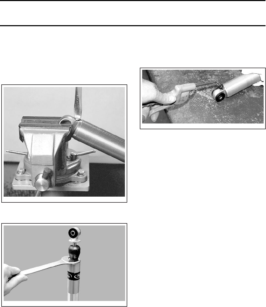
Section 08 SUSPENSION
Subsection 02 (FRONT SUSPENSION)
08-02-4 VMR2004_026_08_02A.FM
NOTE: If an oil mist occurs, it is an indication of a
faulty sealing of the floating piston either caused
by wear of shock absorber or floating piston seal-
ing.
Remove tool from shock.
Remove valve from shock absorber.
Using an appropriate open wrench, unscrew
shock absorber seal carrier cover.
Gently pull piston rod out. Remove slowly to re-
duce oil spillage and prevent piston seal damage
on body threads. Wrap body in a rag to capture oil
overflow while removing piston rod.
Empty oil from shock absorber. Ensure to dispose
oil according to your local environmental regula-
tions.
Remove floating piston as follows.
Hold a rag over shock absorber end to catch float-
ing piston. Allow room for parts to leave shock ab-
sorber. Using compressed air pressure in valve
hole, carefully push piston out.
Clean inner walls of shock absorber and reservoir
with pulley flange cleaner (P/N 413 711 809). Be
careful not to splash O-rings, piston and seals etc.
Dry parts with compressed air.
Inspection
Check the following:
–Compression bumpers for chipping, cracking
or missing.
–O-rings for nicks, cuts or cracks.
–Piston rod for straightness, wear, nicks or
burrs.
–Seal carrier and rod seals.
–Piston seal ring for wear.
–Valve discs for kinks or waves.
–Inner walls of shock absorber and reservoir
for scratches, burrs or excessive wear.
–Floating piston seal for wear, cuts, chipped or
nicked edges.
–Inner wall of shock absorber for excessive
wear in working area of floating piston.
Replace any defective/worn part.
Valving
Rebound stack:
Ø32 x t0.30
Ø28 x t0.30
Ø25 x t0.15
Ø18 x t0.10
V02J1DA
V02J1EA
V02J1FA
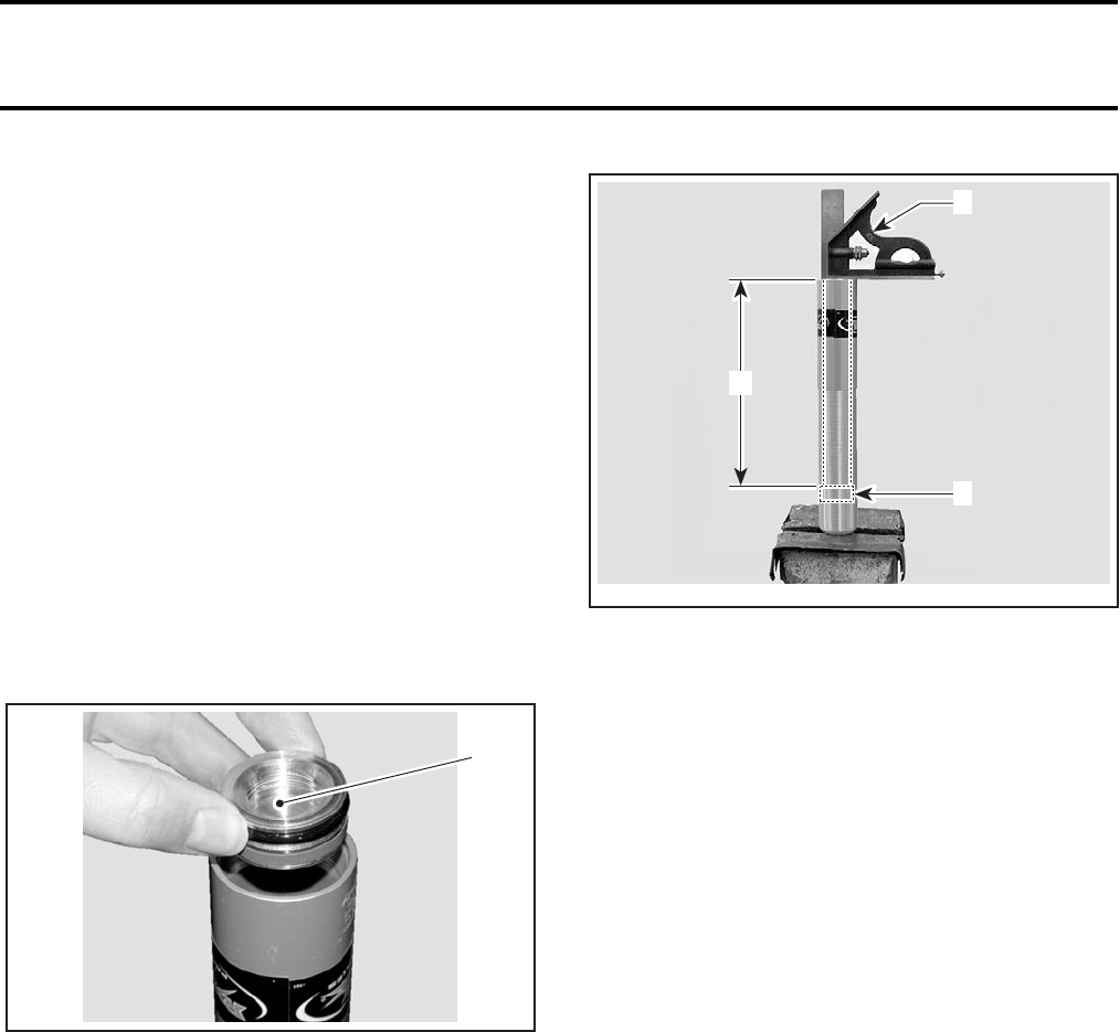
Section 08 SUSPENSION
Subsection 02 (FRONT SUSPENSION)
VMR2004_026_08_02A.FM 08-02-5
Compression stack:
Ø28 x t0.38
Ø32 x t0.30
Ø33 x t0.25
Ø18 x t0.30
Ø33 x t0.3
Piston:
1 - Ø2.4
Assembly
Tightly secure the shock absorber base in a vise
with soft jaws.
Apply shock absorber oil on floating piston seal.
Reinstall floating piston into damper body (ensure
that valve is still removed).
Ensure to install hollow side of piston as shown.
1. Hollow side here
CAUTION: Failure to install floating piston cor-
rectly could result in shock damage.
Using a machinist square, position floating piston
at 204 mm (8.0 in) from top.
1. Floating piston
2. Machinist square
A. 204 mm (8.0 in) from top
Apply grease on O-ring and reinstall valve.
Bleeding
Pour Ryde FX slide high performance lube (P/N 503
190 103) in shock absorber. Fill shock absorber up
to bottom of threads.
CAUTION: Use new oil only. Do not reuse the
same oil. Do not use any other oil.
Allow a few minutes for air bubbles to surface.
NOTE: Although we do not measure the exact
amount of oil added, approximately 185 mL (6.3 U.S.
oz) will be used.
Wrap shock absorber in a rag to capture oil over-
flow while installing piston rod.
Apply shock absorber oil on piston seal ring.
Carefully insert piston rod in shock absorber.
CAUTION: Pay attention not to damage piston
seal on shock absorber threads.
Push seal carrier down, close to piston.
1
V02J1GA
V02J1HA
A
1
2
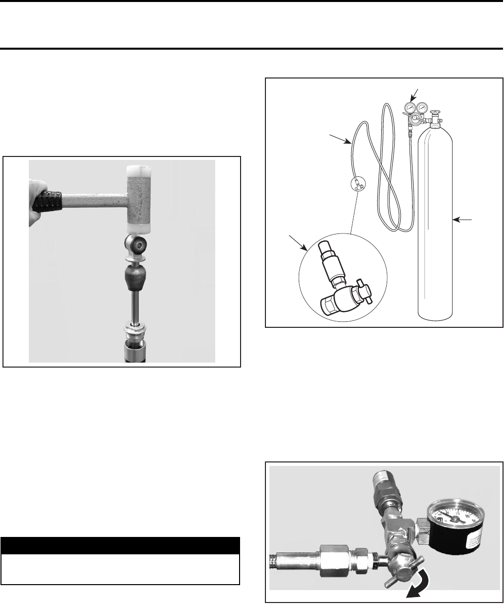
Section 08 SUSPENSION
Subsection 02 (FRONT SUSPENSION)
08-02-6 VMR2004_026_08_02A.FM
Slowly push piston into shock absorber to prevent
displacement of the floating piston. Apply a short
stroke of slight up and down movement to allow
air to pass through piston stack assembly.
Gently tap with a clean soft hammer on the shock
eye to dislodge air trapped in the submerged piston.
Be careful not to drive the shaft any deeper into the
oil than it is necessary to just cover the shim stack.
Be also careful to maintain oil above piston stack.
Otherwise repeat the operation.
Seal carrier assembly can now be screwed into
body. This should be done slowly to minimize float-
ing piston displacement.
After the seal carrier is completely installed, avoid
pushing the piston rod into the body until the nitro-
gen charge is added.
Using an appropriate open wrench, torque seal
carrier cover to 75 N•m (55 lbf•ft).
Use the gas shock valve tool (P/N 529 035 570)
and tightly install it to the nitrogen tank.
1. High pressure hose
2. Two stage regulator
3. High pressure cylinder filled with industrial grade nitrogen (N2)
4. Gas shock valve tool
Proceed as follows:
1. Adjust nitrogen tank regulator to 0 kPa (0 PSI).
2. Install the gas refill needle type shock tool (P/N
503 190 102) on gas shock valve tool
3. Turn tappet valve of gas shock valve tool clock-
wise up to the end.
4. Place the needle guide of gas refill tool on the
shock valve. While depressing the detente pin
of the gas refill tool and pushing forward the
needle assembly, insert the needle through the
rubber core of the pressure valve assembly of
the shock. Ensure to firmly keep the tool sat
squarely on shock valve.
WARNING
Do not use any other type of gas than Nitrogen
(N2).
V02J1IA
4
2
1
3
A06F0QA
V02J1JA
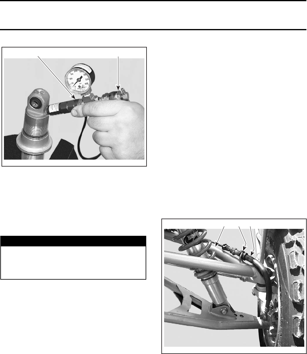
Section 08 SUSPENSION
Subsection 02 (FRONT SUSPENSION)
VMR2004_026_08_02A.FM 08-02-7
NOTE: For replacement of the needle or filling the
shock, carefully follow the instructions provided
with the gas refill needle type tool kit (P/N 503 190
102).
5. Open nitrogen tank valve and gradually set pres-
sure of regulator to 2068 kPa (300 PSI), this gas
pressure will restore the correct pressure of the
shock absorber.
CAUTION: Do not exceed the recommended
pressure value.
6. Wait a little so that pressure stabilizes.
7. Unscrew tappet valve of gas shock valve tool
counterclockwise.
8. Quickly pull off the refill needle type shock tool
from shock absorber valve.
9. Close nitrogen tank valve.
Shock absorber gas pressure cannot be confirmed
by using a pressure gauge. The volume of gas in
the shock is very small, and the amount lost during
gauge installation will lower the pressure too
much and would require refilling.
Carefully inspect shock absorber for gas or oil leaks.
Any leak must be corrected before continuing.
Stroke the piston rod to ensure full travel and
smooth compression and rebound action. If the
shaft moves in or out erratically or if you hear a
gurgling sound, this could indicate air is trapped
inside. If the piston rod does not move or has par-
tial travel then it may be hydraulically or mechani-
cally locked. In either event the shock must be re-
built again.
Reinstall screw on top of valve.
Reinstall spring and adjuster then perform adjust-
ments. See SHOCK ABSORBER ASS’Y.
UPPER A-ARM
Removal
NOTE: Both upper no. 8 and lower no. 9 A-arms
can be removed without removing the tie rods.
Detach brake hose from upper A-arm.
Discard screws.
TYPICAL
1. Upper A-arm
2. Detach brake hose from tubing
3. Brake hose
WARNING
Stay away from shock absorber when apply-
ing pressure to avoid possible projected out
components that might have been improper-
ly installed.
503 190 102
A32F38A
529 035 570
1
V02J0MA
23
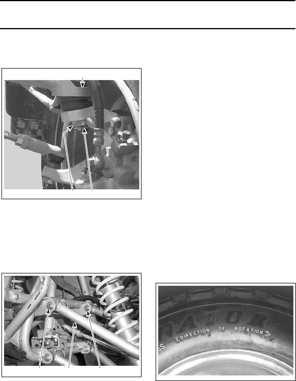
Section 08 SUSPENSION
Subsection 02 (FRONT SUSPENSION)
08-02-8 VMR2004_026_08_02A.FM
Remove cotter pin no. 10 (discard), castellated nut
no. 11 and hardened washer no. 12 from upper
ball joint no. 13.
1. Remove cotter pin
2. Castellated nut
3. Upper ball joint
Remove wheel(s).
Use a ball joint remover and detach upper A-arm
from knuckle.
CAUTION: Never tap the knuckle with a hammer.
Remove bolts no. 14 retaining upper A-arm to
frame.
1. Upper A-arm
2. Remove bolts
Remove upper A-arm no. 8 from vehicle.
Inspection
Check upper A-arm for cracks, pitting, distortion or
other damages. Replace as required.
Inspect pivot bushings for wear or damages.
Replace pivot bushings if necessary.
Check ball joint bellows on upper A-arm for cracks
or any other damage and inspect ball joint stud for
damages. Ensure stud is moving freely. Refer to
BALL JOINT section below.
Installation
Position upper A-arm and install bolts no. 14 and
nuts.
Torque nuts to 63 N•m (46 lbf•ft).
Attach upper A-arm to knuckle. Install hardened
washer no. 12 and castellated nut no. 11.
Tighten castellated nut to 50 N•m (37 lbf•ft) and
further tighten until its grooves align with cotter
pin hole.
Install a new cotter pin. Both ends of cotter pins
must be folded.
Secure brake hose to upper A-arm.
CAUTION: When reinstalling the brake line, install
new screws with regular M6 threads. Reinstalling
self tapping screws would damage the A-arm
threads.
Install wheel(s).
NOTE: Do not interchange left and right tires.
Check direction of rotation mark on tires.
DIRECTION OF ROTATION
Torque wheel nuts to 53 N•m (39 lbf•ft) in a criss-
cross sequence.
Grease each A-arm pivot.
3
V02J0NA 21
V02J0CA
1 22
V02J09A
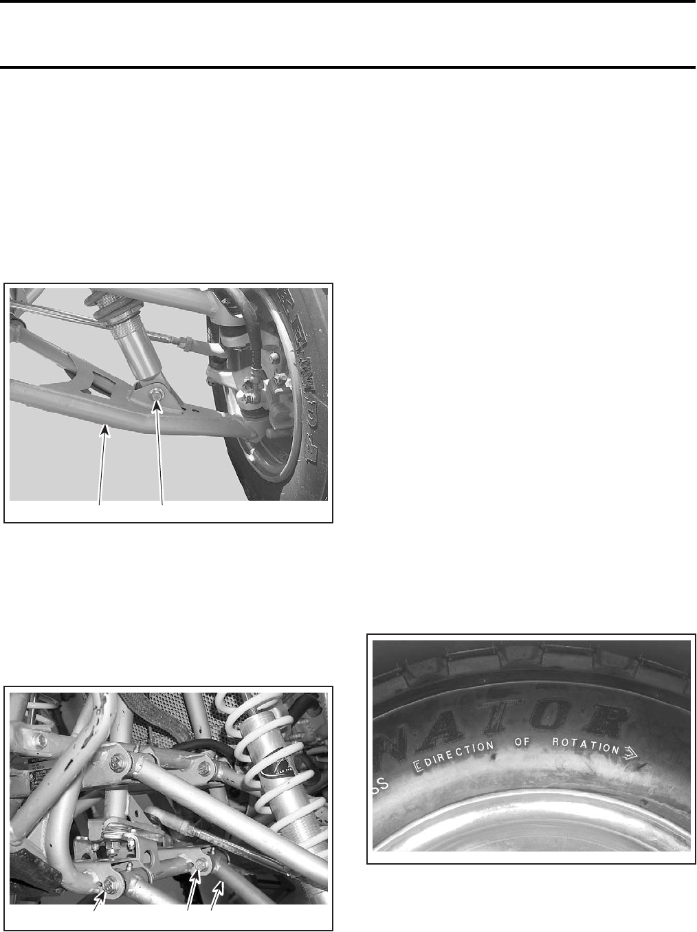
Section 08 SUSPENSION
Subsection 02 (FRONT SUSPENSION)
VMR2004_026_08_02A.FM 08-02-9
LOWER A-ARM
Removal
Remove cotter pin no. 10 (discard), castellated nut
no. 11 and hardened washer no. 12 retaining low-
er A-arm no. 9 to ball joint no. 15 on the knuckle.
Remove wheel(s).
Remove bolt no. 4 retaining the shock absorber
no. 1 to lower A-arm no. 9.
1. Lower A-arm
2. Remove nut and bolt
Use a ball joint remover and detach knuckle from
the lower A-arm.
CAUTION: Never tap the knuckle with a hammer.
Remove A-arm protector (if so equipped).
Remove nuts and bolts no. 16 retaining lower A-arm
to frame.
1. Lower A-arm
2. Remove nuts and bolts
Remove lower A-arm from vehicle.
Inspection
Check lower A-arm for cracks, distortion or other
damages. Replace as required.
Inspect pivot bushings for wear or damages.
Replace pivot bushings if necessary.
Check ball joint bellows on lower A-arm for cracks
or any other damage and inspect ball joint stud for
damages. Ensure stud is moving freely. Refer to
BALL JOINT section below.
Installation
For assembly, reverse the disassembly proce-
dure. However, pay attention to the following.
Position lower A-arm and install bolts no. 16 and
nuts.
Torque nuts to 63 N•m (46 lbf•ft).
Attach lower A-arm to knuckle. Install hardened
washer no. 12 and castellated nut no. 11.
Reinstall A-arm protector (if so equipped).
Tighten castellated nut to 50 N•m (37 lbf•ft) and
further tighten until its grooves align with cotter
pin hole.
Install a new cotter pin. Both ends of cotter pins
must be folded.
Install wheel(s).
NOTE: Do not interchange left and right tires.
Check direction of rotation mark on tires.
DIRECTION OF ROTATION
Torque wheel nuts to 53 N•m (39 lbf•ft) in a criss-
cross sequence.
Grease each A-arm pivot.
2
V02J0OA 1
V02J0CB
2 1
2
V02J09A
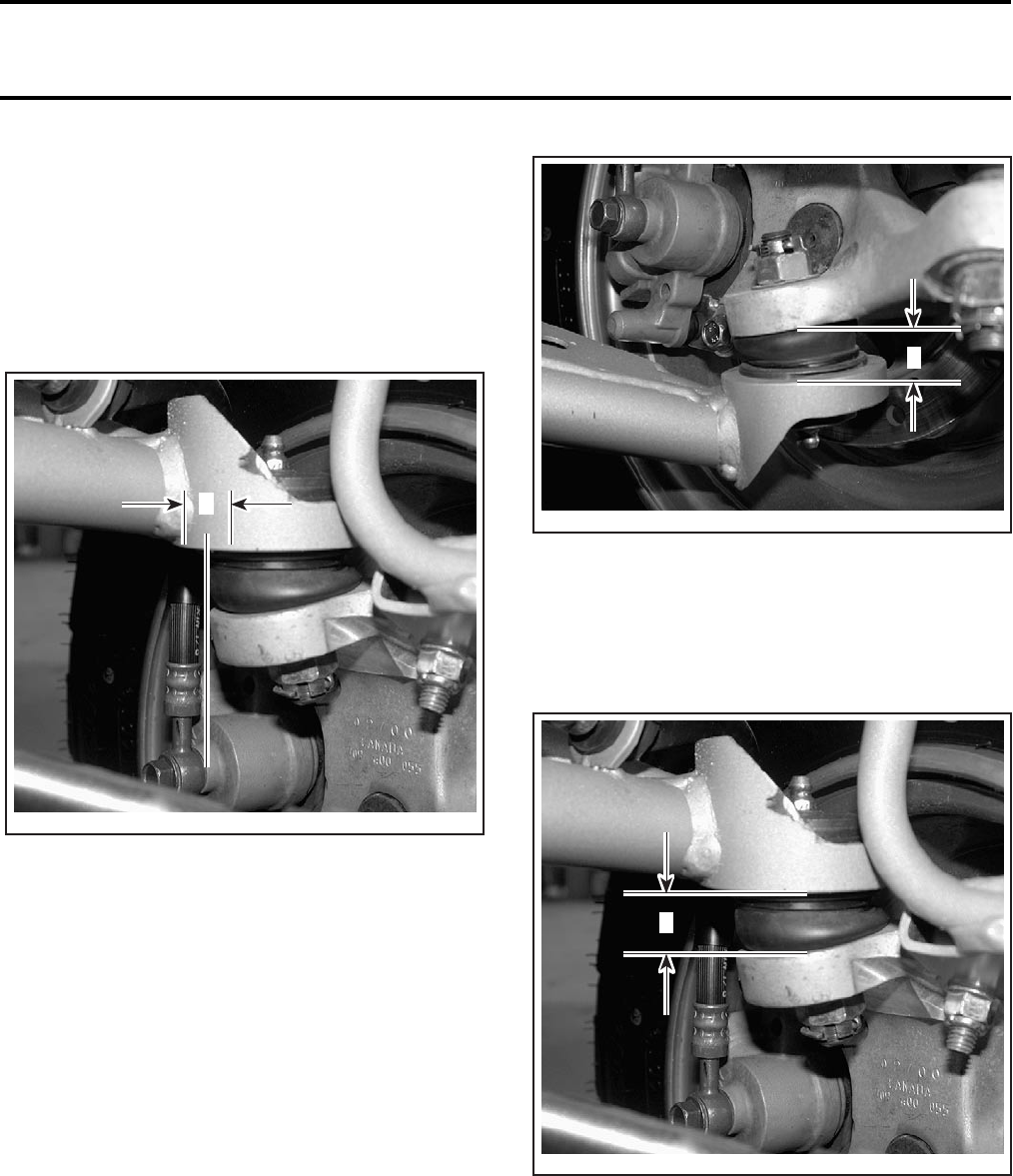
Section 08 SUSPENSION
Subsection 02 (FRONT SUSPENSION)
08-02-10 VMR2004_026_08_02A.FM
BALL JOINT
Inspection
Upper Ball Joint
Take the top of tire and check upper ball joint lateral
play, by push and pull. The maximum lateral play
should be 1.5 mm (.060 in). If the lateral play is out
of specification, change the ball joints no. 13.
UPPER BALL JOINT LATERAL PLAY
A. Maximum lateral play 1.5 mm (0.060 in)
Lower Ball Joint
Place a jack under A-arm and raise vehicle high
enough to have the wheel off the ground.
Take tire by the bottom and lift it up. The maximum
axial play should be 1.5 mm (.060 in). If the axial
play is out of specification, change the lower ball
joints no. 15.
LOWER BALL JOINT AXIAL PLAY
A. Maximum axial play (measurement A +1.5 mm (.060 in))
Upper Ball Joint
Move the upper A-arm vertically. The maximum ax-
ial play should be 1.5 mm (.060 in). If the axial play
is out of specification, change the upper ball joints.
UPPER BALL JOINT AXIAL PLAY
A. Maximum axial play (measurement A +1.5 mm (.060 in))
Check ball joint bellows for cracks or any other dam-
age and inspect ball joint stud for damages. Ensure
stud is moving freely. Replace ball joint if necessary.
NOTE: It is recommended to change both left or
right ball joints at the same time.
Install a new circlip.
V02J0GA
A
A
V02J0HA
V02J0IA
A
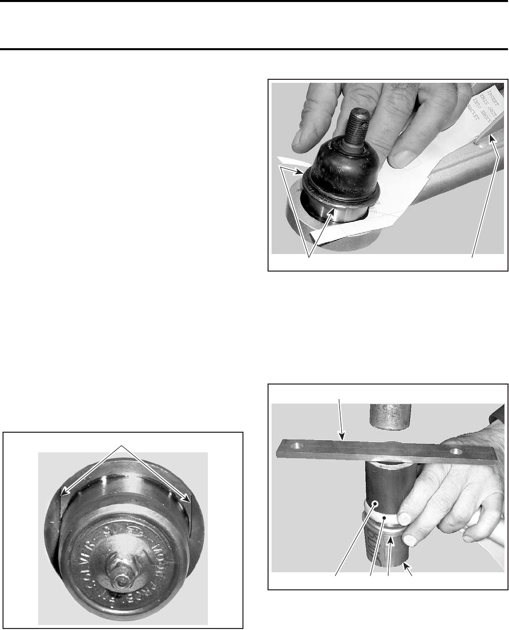
Section 08 SUSPENSION
Subsection 02 (FRONT SUSPENSION)
VMR2004_026_08_02A.FM 08-02-11
Removal
Remove upper or lower A-arm.
Remove the circlip no. 17.
Extract the ball joint.
Installation
CAUTION: The ball joints have an oblong shape
and therefore must be properly installed in their
oblong openings in the A-arms. Use the appro-
priate template, supplied at the end of this sec-
tion to ensure proper orientation of the ball joint
relative to the A-arm.
NOTE: Use the same tools for the lower and up-
per ball joints.
Attach template page on a light cardboard.
Cut the templates.
Right/Left Lower Ball Joints
NOTE: Use the same template for the lower RH
and LH ball joints.
Apply a layer (0.3 mL) of Loctite 609 on the outside
diameter of new ball joint (surface that contacts
arm). Wipe any excess.
Insert the ball joint into the template with the cor-
rect orientation. Flat grooves of ball joint must be
in contact with the flat sides of the template.
1. Flat grooves
Place the ball joint and the template on the A-Arm
and orient it into place, the narrow section of the
template aligns inside the shock bracket.
1. Shock bracket
2. Flat grooves
Remove the template and keep the orientation of
the ball joint.
Use both ball joint drivers (P/N 529 035 705 and
P/N 529 035 706) and a press machine to press
the ball joint in place. A hammer may also be used
but care should be taken.
1. Flat bar
2. Driver
3. Arm
4. Driver
5. Tab lock
NOTE: Be sure that the flat groove is perpendicu-
lar to rotation axis before mounting.
1
V02I0QA
V02I0PA 21
1
V02I0LA 2345
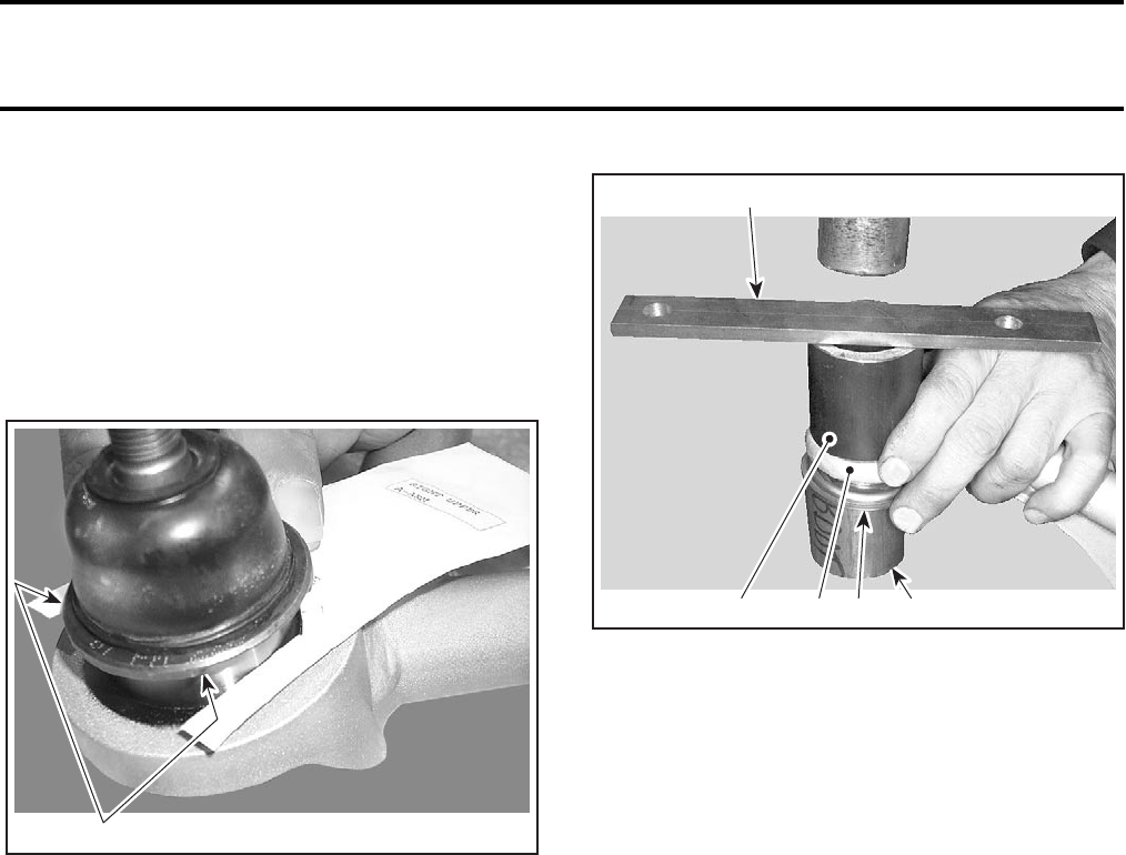
Section 08 SUSPENSION
Subsection 02 (FRONT SUSPENSION)
08-02-12 VMR2004_026_08_02A.FM
Right/Left Upper Ball Joints
Bend the template down, at the mark indicated.
Insert the ball joint into the template with the cor-
rect orientation. Flat grooves of ball joint must be
in contact with the flat sides of the template.
Place the ball joint and the template on the A-Arm
and orient it in the way that the bent section of the
template is between the two tubes of the A-arm.
1. Flat grooves
Remove the template and keep the orientation of
the ball joint.
Use both ball joint drivers (P/N 529 035 705 and
P/N 529 035 706) and a press machine to press
the ball joint in place. A hammer may also be used
but care should be taken.
1. Flat bar
2. Driver
3. Arm
4. Driver
5. Flat groove
NOTE: Be sure that the flat groove is perpendicu-
lar to rotation axis before mounting.
Secure ball joint with its snap ring.
Reinstall all removed parts with supplied new cot-
ter pins.
CAUTION: Insure that washer is in place before
installing castellated nut.
Grease the new ball joints.
1
V02I0RA
1
V02I0LA 2345
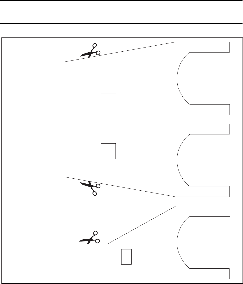
Section 08 SUSPENSION
Subsection 02 (FRONT SUSPENSION)
VMR2004_026_08_02A.FM 08-02-13
Insert
this section
into shock
bracket
Lower
A-arm
Index the ball
joint here
Bend down
this section
and place
between
the 2 tubes
RIGHT
upper
A-arm
Index the ball
joint here
Bend down
this section
and place
between
the 2 tubes
LEFT
Upper
A-arm
Index the ball
joint here
V02I0SS
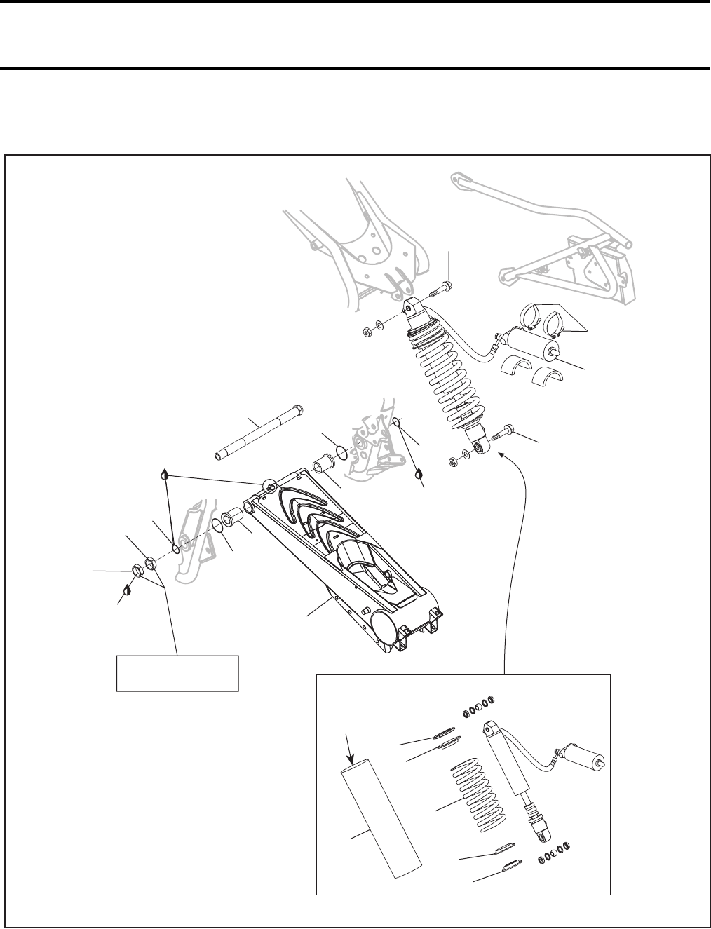
Section 08 SUSPENSION
Subsection 03 (REAR SUSPENSION)
VMR2004_027_08_03A.FM 08-03-1
REAR SUSPENSION 0
V02J0QS
2
6
5
3
16
17
15
17
7
8
11
10
9
12
18
18
12
13
4
Synthetic
grease
14
Loctite 243
See special
procedure inside
85 Nm
(63 lbfft)
3.5 Nm
(31 lbfin)
85 Nm
(63 lbfft)
Suspension
synthetic
grease
Baja
Baja X

Section 08 SUSPENSION
Subsection 03 (REAR SUSPENSION)
08-03-2 VMR2004_027_08_03A.FM
GENERAL
CAUTION: The Baja and Baja X models are
equipped with shocks absorber protectors.
Open or remove them if the vehicle is used in-
tensively or if the ambient temperature is high.
Otherwise, shock absorber performance deg-
radation or damage can occur.
For installation, use the torque values and Loctite
products from the exploded views. Clean threads
before using Loctite when installing the screws.
SHOCK ABSORBER ASS’Y
Removal
Lift rear of vehicle until rear shock absorber no. 1
is fully extended.
Install a jack stand or a block under the frame to
support the vehicle.
Unscrew clamps no. 3 retaining the reservoir no. 4.
Remove upper bolt no. 5 retaining shock absorber.
Remove brake caliper and move aside. Unlock
disc brake hub and slide it aside to gain access to
lower bolt of shock absorber. Loosen chain and
remove rear sprocket. Refer to REAR AXLE.
Remove LH and RH access plugs of shock absorb-
er lower bolt.
1. LH plug removed to access shock absorber bolt
Unscrew the lower bolt no. 6.
TYPICAL
1. Upper bolt and nut
2. Lower bolt and nut
3. Reservoir
4. Clamps
5. Brake caliper
6. Disc brake hub
WARNING
Torque wrench tightening specifications
must strictly be adhered to.
Locking devices (ex.: locking tabs, elastic stop
nuts, self-locking fasteners, etc.) must be in-
stalled or replaced with new ones where
specified. If the efficiency of a locking device
is impaired, it must be renewed.
1
V02J0RA
3
1
V02J0VA
4
5
6
2
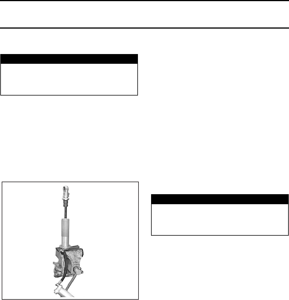
Section 08 SUSPENSION
Subsection 03 (REAR SUSPENSION)
VMR2004_027_08_03A.FM 08-03-3
Disassembly
On Baja models and Baja X, remove the shock
absorber protector no.13.
Unscrew the adjusting nuts nos. 7 and 8.
Remove spring stopper no. 9 and spring seat
no. 10.
Remove spring no. 11.
Inspection
Secure the shock absorber body end in a vise with
its rod upward.
Check shock absorber body for leaks, dents, ab-
normal wear and piston rod dents or bend. Re-
place any defective part.
Fully compress piston rod. When released, it
should extend smoothly.
Pay attention to the following conditions that will
denote a defective shock absorber:
–a skip or a hang back when reversing stroke at
mid travel
–seizing or binding condition except at extreme
end of either stroke
–oil leakage
–a gurgling noise, after completing one full com-
pression stroke.
Rebuilt if any fault is present.
Assembly and Installation
For assembly and installation, reverse the disas-
sembly and removal procedures.
On Baja and Baja X models, reinstall the shock
absorber protector, make sure not to block venting
holes.
Adjustment
Gas Pressure
Refer to SHOCK ABSORBER REBUILDING be-
low.
Spring Preload
Spring preload may vary from rider to rider depend-
ing upon their weight. Preload can be changed by
setting the two adjusting nuts up or down to com-
press the spring to different lengths. Shortening or
lengthening the spring length will increase or de-
crease the preload.
WARNING
The shock absorber contains high pressure ni-
trogen gas. Do not attempt to disassemble
before removing the pressure. Dispose of gas
as per your local environmental regulations.
V02J1KA
WARNING
The shock absorber contains high pressure ni-
trogen gas. Do not attempt to disassemble
before removing the pressure. Dispose of gas
as per your local environmental regulations.
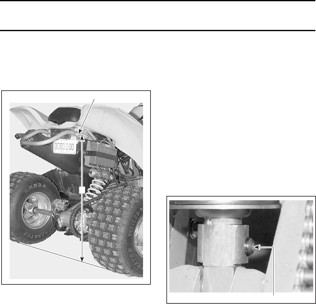
Section 08 SUSPENSION
Subsection 03 (REAR SUSPENSION)
08-03-4 VMR2004_027_08_03A.FM
Before adjusting the spring preload, first measure
the ATV’s height, without rider, from the rear bumper
nut to the ground.
NOTE: Lift the vehicle by the rear bumper. The
shock should be fully extended.
1. Rear bumper nut
A. Measure between rear bumper nut and ground
Next, sit the rider with gear on the ATV and mea-
sure the distance between the same two points.
CAUTION: Add all other loads and accessories
before measuring the height of the vehicle with
the rider on. Do not exceed the total vehicle load
allowed.
Calculate the difference between the two lenghts.
If the vehicle’s height decreases more than 127 mm
(5 in), increase the preload by 3 mm (1/8 in) incre-
ments. If the vehicle’s height decreases of less than
102 mm (4 in), decrease the preload by 3 mm
(1/8 in) increments. The optimum adjustment range
is between 102 mm (4 in) and 127 mm (5 in) but, for
heavier or more aggressive riders, it could be be-
tween 76 mm (3 in) and 102 mm (4 in).
Preload Adjustment:
To reduce:
•Turn the shock spring adjuster counterclock-
wise for a light load and smooth condition.
To increase:
•Turn the shock spring adjuster clockwise for
a firmer ride and rough conditions.
Rebound Damping:
NOTE: It is recommended to turn the adjuster one
click at a time and then to test the effect.
To reduce:
•Turn the shock adjuster counterclockwise for
a light load and smooth conditions.
To increase:
•Turn the shock adjuster clockwise for a firmer
ride and rough conditions.
BOTTOM OF SHOCK ABSORBER
1. Adjuster
Compression Damping:
NOTE: It is recommended to turn the adjuster one
click at a time and then to test the effect.
To reduce:
•Turn the reservoir adjuster counterclockwise
for a light load and smooth conditions.
To increase:
•Turn the reservoir adjuster clockwise for a
firmer ride and rough conditions.
V02A0WA
1
A
V02J03A 1
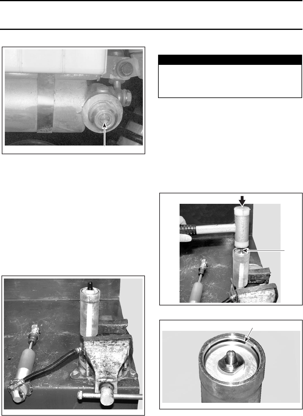
Section 08 SUSPENSION
Subsection 03 (REAR SUSPENSION)
VMR2004_027_08_03A.FM 08-03-5
RESERVOIR END
1. Adjuster
SHOCK ABSORBER REBUILDING
Remove spring and adjuster. See SHOCK AB-
SORBER ASS’Y above.
Disassembly
Clean all the parts prior to disassembling.
Turn compression and rebound adjusters counter-
clockwise so that their valves are the most open.
Reservoir
Gently secure the reservoir in a vise with soft
jaws.
CAUTION: Never clamp on reservoir.
Unscrew valve cap from reservoir.
Place a rag over valve to protect against possible
mist and to prevent gas being directed towards
someone. Using a small tool, press valve pin to
release pressure. Ensure to completely empty the
reservoir.
NOTE: If a mist of oil is sprayed, it indicates that
the bladder is damaged.
Remove valve pin.
Using a clean soft hammer, gently tap down res-
ervoir cover just enough to free the C-clip. Using
a small tool, remove the C-clip.
1. Gently tap cover down to free C-clip
1. C-clip
V02J04A 1
V02J0XA
WARNING
Whenever working with high pressure gas,
use eye wear protection. Never direct gas
pressure toward anybody. Release gas pres-
sure before removing components.
1
V02J0YA
1
V02J0ZA
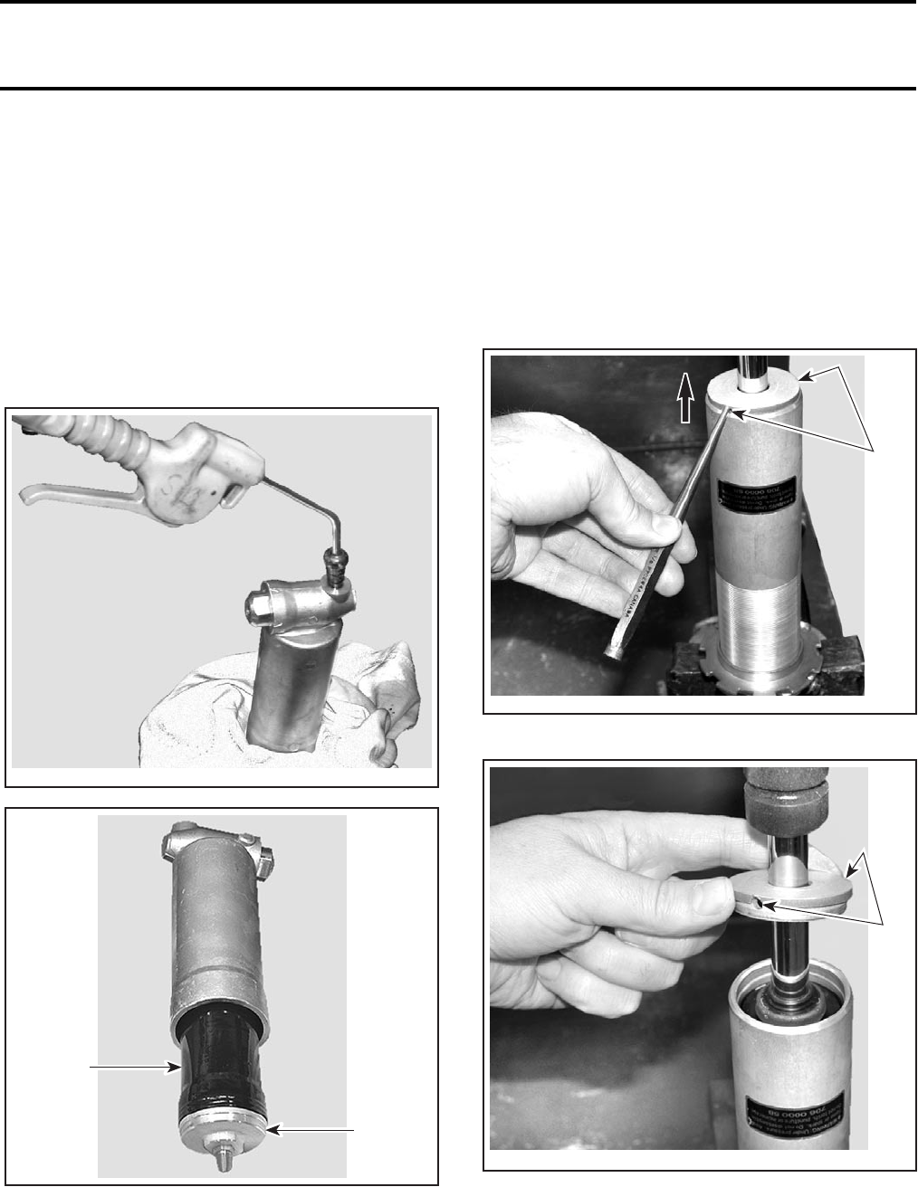
Section 08 SUSPENSION
Subsection 03 (REAR SUSPENSION)
08-03-6 VMR2004_027_08_03A.FM
CAUTION: Be careful not to scratch inside wall
of reservoir or C-clip. Also be careful not to dis-
tort the C-clip.
Empty oil from reservoir. Dispose of oil according
to your local environnemental regulations.
Note position of hose and detach hose from res-
ervoir.
Hold a rag over reservoir end to catch bladder and
its cover. Allow room for parts to leave reservoir.
Using compressed air pressure in hose hole, care-
fully push bladder out.
1. Bladder
2. Cover
Shock Absorber
Tightly secure the shock absorber bottom eyelet
in a vise with soft jaws.
Push piston down to empty shock absorber.
Note position of hose and detach hose from shock
absorber.
Using a suitable punch in the cover holes, gently
punch cover out alternating each side.
1. Punch out alternating each side
1. Cover and its holes
V02J10A
2
1
V02J11A
1
V02J12A
1
V02J13A
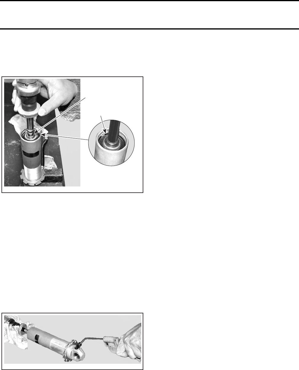
Section 08 SUSPENSION
Subsection 03 (REAR SUSPENSION)
VMR2004_027_08_03A.FM 08-03-7
Using a suitable punch, gently punch seal carrier
ass’y down alternating each side. Push down just
enough to free the C-clip. Using a small tool, re-
move the C-clip.
1. Gently push seal carrier ass’y down to free C-clip
2. C-clip
CAUTION: Be careful not to scratch inside wall of
shock absorber or C-clip. Also be careful not to dis-
tort the C-clip.
Gently pull piston rod out. Remove slowly to re-
duce oil spillage and prevent piston seal damage
on body groove. Wrap body in a rag to collect oil
overflow while removing piston rod.
NOTE: If piston rod is hard to remove, use com-
pressed air as described below.
Hold a rag over shock absorber end to catch piston
rod. Allow room for parts to leave shock absorber.
Using compressed air pressure in hose hole, care-
fully push piston rod out.
Empty oil from shock absorber.
Clean inner walls of shock absorber and reservoir
with Pulley flange cleaner (P/N 413 711 809). Be
careful not to splash O-rings, piston and seals etc.
Dry parts with compressed air.
Inspection
Check the following:
–Compression bumpers for chipping, cracking
or missing.
–O-rings for nicks, cuts or cracks.
–Piston rod for straightness, wear, nicks or
burrs.
–Seal carrier and rod seals.
–Piston seal ring for wear.
–Valve discs for kinks or waves.
–Innner walls of shock absorber and reservoir
for scratches, burrs or excessive wear.
–Bladder for tears, cracks or holes.
Replace any defective/worn part.
Valving
Rebound stack:
Ø36 x t0.30 x 10
Ø22 x t0.30 x 1
Compression stack:
Ø40 x t0.25 x 9
Ø22 x t0.20 x 1
Ø40 x t0.25 x 12
Ø22 x t0.30 x 2
Piston:
1 - Ø2.0
Assembly
Turn compression and rebound adjusters counter-
clockwise so that their valves are the most open.
Reinstall hose to shock absorber and reservoir. En-
sure to position properly.
Tightly secure the shock absorber base in a vise
with soft jaws.
Bleeding
Hold reservoir higher than shock absorber and
pour Kayaba shock absorber oil (P/N 293 600 035)
in reservoir. Half fill reservoir.
CAUTION: Use new oil only. Do not reuse the
oil. Only use the recommended oil.
2
V02J14A
1
V02J17A
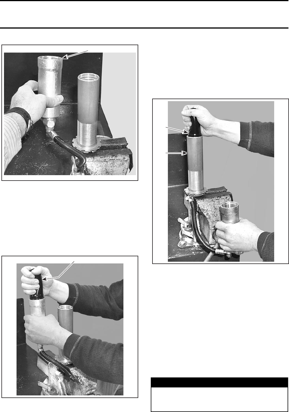
Section 08 SUSPENSION
Subsection 03 (REAR SUSPENSION)
08-03-8 VMR2004_027_08_03A.FM
1. Hold reservoir higher than shock absorber
Half fill shock absorber with recommended oil.
NOTE: Although we do not measure the exact
amount of oil added, approximately 317 mL (10.7
U.S. oz ) will be used.
Temporarily install bladder upside down on reser-
voir. Push down enough to have a tight seal.
Squeeze bladder to pump oil towards shock ab-
sorber. Ensure enough oil remains in reservoir.
PUMP BLADDER TO BLEED HOSE
1. Bladder installed upside down
Air will escape in shock absorber. Repeat the
pumping twice.
Hold reservoir lower than shock absorber.
Temporarily install bladder upside down on shock
absorber. Push down enough to have a tight seal.
Squeeze bladder to pump oil towards reservoir.
Ensure enough oil remain in shock absorber.
PUMP BLADDER TO BLEED HOSE
1. Hold reservoir higher than shock absorber
2. Bladder installed upside down
Air will escape in reservoir if present. Repeat the
pumping twice.
Reservoir
Add oil in reservoir to half-fill.
Wrap reservoir in a rag to collect oil overflow while
installing bladder.
Lightly apply shock absorber oil outside of bladder
and install bladder/cover ass’y in reservoir. Ensure
some oil flows out to be sure there is no air
trapped inside reservoir.
Push cover down just enough to secure C-clip.
1
V02J18A
1
V02J19A
WARNING
If C-clip is not properly locked, parts might be
projected out when filling with high pressure
nitrogen.
1
2
V02J1AA
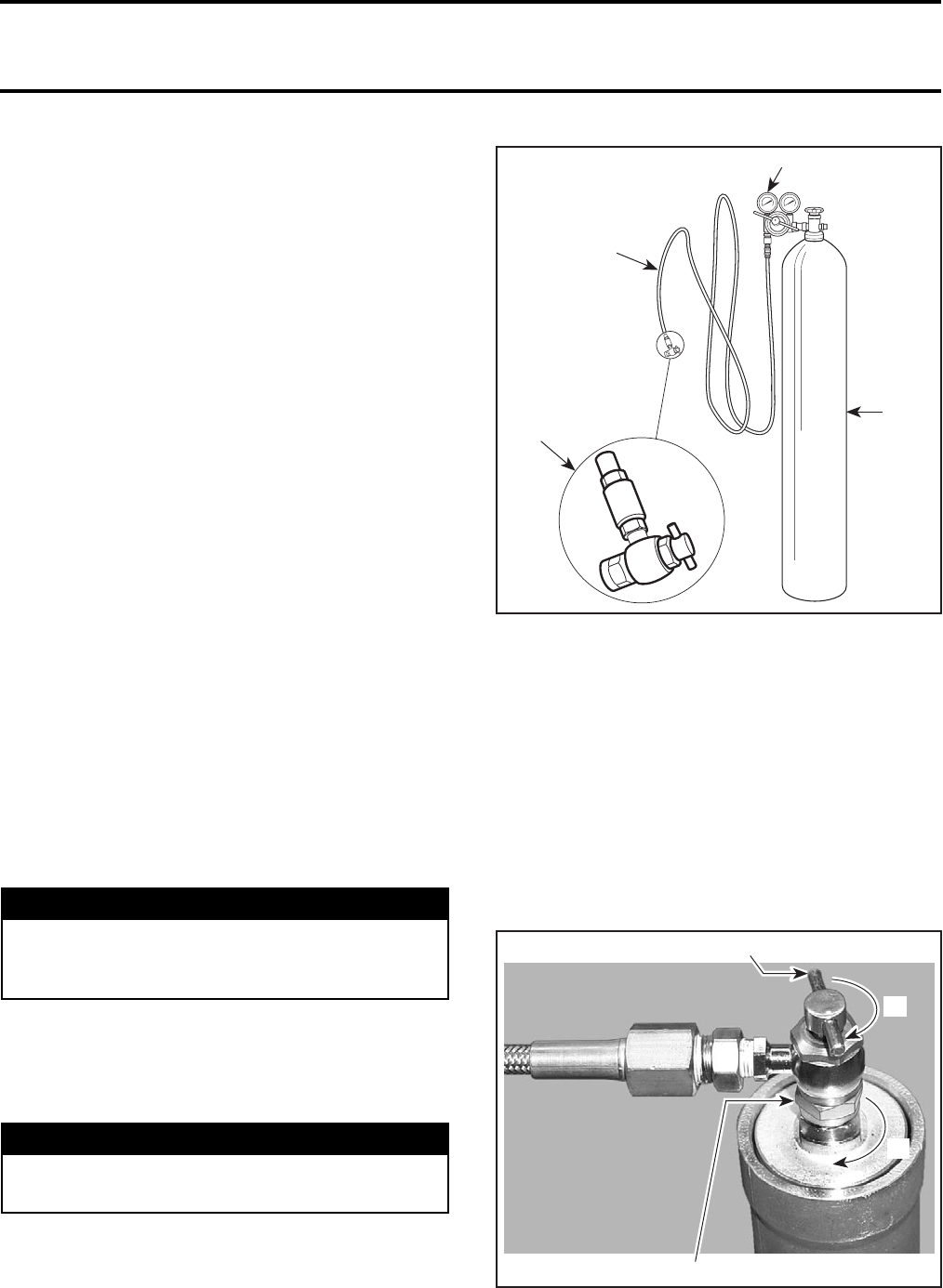
Section 08 SUSPENSION
Subsection 03 (REAR SUSPENSION)
VMR2004_027_08_03A.FM 08-03-9
Reinstall valve pin in reservoir valve.
Shock Absorber
Wrap shock absorber in a rag to collect oil over-
flow while installing piston rod.
Apply shock absorber oil on piston seal ring.
Pour oil in shock absorber so that it is filled to 3/4.
Carefully insert piston rod in shock absorber.
CAUTION: Be careful not to damage piston
seal on shock absorber edge.
Slowly push piston into shock absorber to prevent
compressing the bladder. Apply a short stroke of
slight up and down movement to allow air to pass
through piston stack assembly.
Gently tap with a clean soft hammer on the shock
eye to dislodge air trapped in the submerged pis-
ton.
Be careful not to drive the shaft any deeper into the
oil than it is necessary to just cover the piston
stack. Be also careful to maintain oil above piston
stack. Otherwise repeat the operation.
Fill shock absorber up to 10 mm (3/8 in) below cir-
clip groove.
Seal carrier assembly can now be pushed into body.
This should be done slowly ensuring some oil flows
out to ensure no air is trapped inside shock absorb-
er. Push down just enough to secure C-clip.
After the seal carrier is completely installed, avoid
pushing the piston rod into the body until the nitro-
gen charge is added.
Reinstal cover.
Nitrogen (N2) can now be added in the reservoir.
Gas Pressure
Use the Gas shock valve tool (P/N 529 035 570)
and tightly install it to the nitrogen tank.
1. High pressure hose
2. Two stage regulator
3. High pressure cylinder filled with industrial grade nitrogen (N2)
4. Gas shock valve tool
Proceed as follows:
NOTE: Proceeding this way and using the recom-
mended tool will prevent any pressure leak of
shock absorber when removing valve tool. When
removing valve tool, the leaking sound comes
from the remaining nitrogen in tank hose.
1. Adjust nitrogen tank regulator to 0 kPa (0 PSI).
2. Tightly screw gas shock valve tool to reservoir
valve. Turn its tap clockwise up to the end.
1. Valve tool
2. Valve tool tap
WARNING
If C-clip is not properly locked, parts might be
projected out when filling with high pressure
nitrogen.
WARNING
Do not use any other type of gas than Nitro-
gen (N2).
4
2
1
3
A06F0QA
1
2
V02J0WA
1°
2°
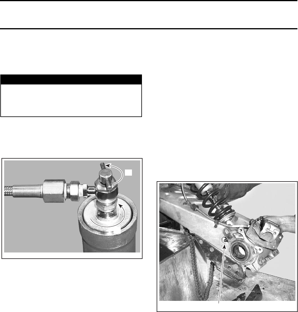
Section 08 SUSPENSION
Subsection 03 (REAR SUSPENSION)
08-03-10 VMR2004_027_08_03A.FM
3. Open nitrogen tank valve and gradually set reg-
ulator pressure to 980 kPa (142 PSI), this gas
pressure will restore the correct pressure into
the reservoir.
CAUTION: Do not exceed the recommended
pressure value.
4. Wait a little for pressure to stabilize.
5. Unscrew tap counterclockwise.
6. Close nitrogen tank valve.
7. Remove gas shock valve tool from shock ab-
sorber reservoir.
Reservoir gas pressure cannot be tested with a
pressure gauge. The volume of gas in the shock
being very small, the amount lost during gauge in-
stallation would lower the pressure too much,
which would require refilling.
Carefully inspect shock absorber and reservoir for
gas or oil leaks. Any leak must be corrected before
continuing.
Stroke the piston rod to ensure full travel and
smooth compression and rebound action. If the
shaft moves in or out erratically or if you hear a gur-
gling sound, this could indicate air is trapped inside
shock absorber. If the piston rod does not move or
has partial travel then it may be hydraulically locked.
In either event, the shock must be rebuilt again.
Reinstall valve cap.
Reinstall spring and adjuster, then perform adjust-
ments. See shock absorber ASS’Y.
SWING ARM
Removal
Lift rear of vehicle until rear shock absorber is fully
extended.
Install a jack stand or a block under the frame to
support the vehicle.
Remove LH wheel, LH wheel hub, brake caliper
and disc brake hub. Loosen chain and remove rear
axle towards RH side. Remove eccentric axle
housing. Refer to REAR AXLE.
Remove LH and RH access plugs of shock absorb-
er lower bolt.
1. LH plug removed to access shock absorber bolt
Remove lower bolt no. 6 retaining shock.
Raise bottom of shock absorber and brake caliper
then temporarily fasten to vehicle body with a
cord.
WARNING
When filling the reservoir with gas, keep away
from shock absorber to avoid being harmed
by parts which, if improperly installed, could
be ejected by gas pressure.
V02J0WB
2°
1°
1
V02J0RA
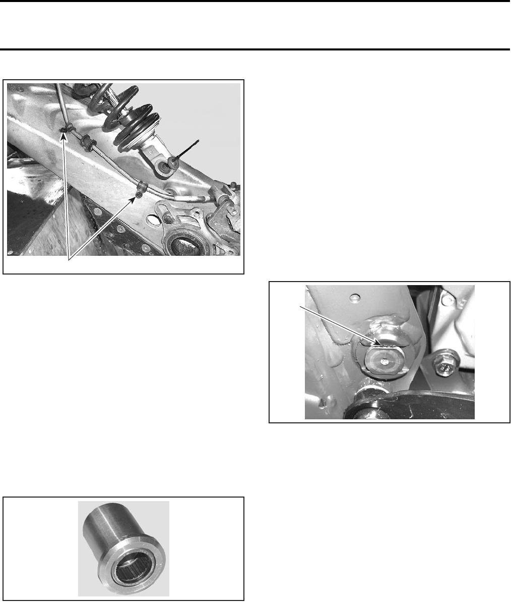
Section 08 SUSPENSION
Subsection 03 (REAR SUSPENSION)
VMR2004_027_08_03A.FM 08-03-11
1. Unfasten from swing arm
Detach brake line from swing arm.
Discard screws.
On the LH side, unscrew both nuts no. 14 and
no. 15.
Remove the swing arm shaft no. 16.
Pull swing arm no. 2 out of frame.
Inspection
Check condition of swing arm. Inspect for distor-
tion, bending, pitting, cracks or other damage. Re-
place swing arm with a new one if damaged.
Check condition of bushings no. 17 with their nee-
dle bearings and O-rings nos. 18 and 12. Change
if necessary.
1. Bushing with its bearing
Ensure bushings no. 17 are well seated against
swing arm. Otherwise, press them until they bot-
tom.
Check condition of swing arm shaft no. 16. With
your finger nail, feel bearing contact surface of
shaft. If any irregular surface is found, replace
shaft.
Measure shaft diameter on bearing contact sur-
face. If it is lower than 19.7 mm (.776 in), replace
shaft.
Installation
Installation is essentially the reverse of removal
procedure. However, pay attention to the follow-
ing details.
Insert O-rings no. 12 in the groove into frame.
Place O-rings no. 18 on bushings no. 17 then in-
stall the swing arm.
Install the swing arm shaft no. 16 then push the
O-rings no. 18 between frame and bushings. En-
sure the flat sides of shaft are well positionned in
frame.
1. Ensure shaft is well inserted in frame
Install the nut no. 15. Torque to 90 N•m (66 lbf•ft)
then, unscrew the nut a quarter turn.
NOTE: Check if the swing arm moves freely.
Apply Loctite 243 and install the other nut no. 14.
Torque to 90 N•m (66 lbf•ft).
NOTE: Hold the first nut with a key when the sec-
ond nut is torqued.
CAUTION: When reinstalling the brake line, in-
stall new screws with regular M6 threads. Re-
installing self tapping screws would damage
the swing arm threads.
Install rear shock and rear axle.
Apply grease through grease fitting.
Adjust shock absorber preload and damping then
adjust drive chain.
1
V02J0SA
V02J0UA
1
V02J0TA

Section 09 BRAKES
Subsection 01 (TABLE OF CONTENTS)
VMR2004_033_09_01ATOC.FM 09-01-1
TABLE OF CONTENTS 0
HYDRAULIC BRAKES............................................................................................................ 09-02-1
FRONT BRAKES ................................................................................................................ 09-02-1
REAR BRAKE ..................................................................................................................... 09-02-2
GENERAL ........................................................................................................................... 09-02-3
HYDRAULIC BRAKES SYSTEM ........................................................................................ 09-02-3
MASTER CYLINDER .......................................................................................................... 09-02-4
CALIPER ............................................................................................................................. 09-02-6
BRAKE PADS ..................................................................................................................... 09-02-7
BRAKE DISC....................................................................................................................... 09-02-8
BRAKE LEVER.................................................................................................................... 09-02-9
BRAKE PEDAL ................................................................................................................... 09-02-9
BRAKE LIGHT SWITCH ..................................................................................................... 09-02-10
REAR CALIPER BRACKET ................................................................................................. 09-02-10
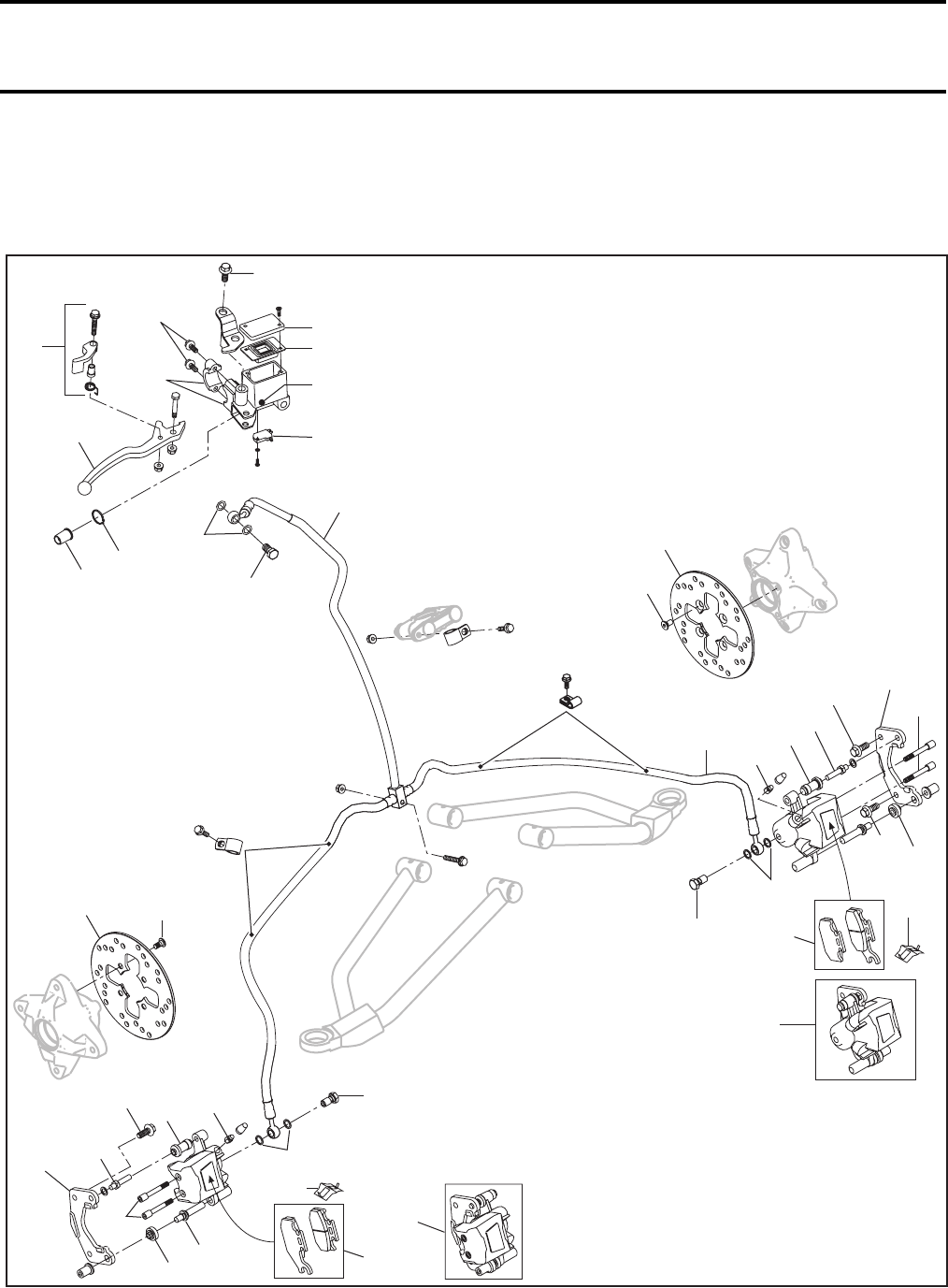
Section 09 BRAKES
Subsection 02 (HYDRAULIC BRAKES)
VMR2004_028_09_02A.FM 09-02-1
HYDRAULIC BRAKES 0
FRONT BRAKES
V02K0NS
13 Nm
(115 lbfin)
25 Nm
(18 lbfft)
34 Nm
(25 lbfft)
28 Nm
(21 lbfft)
25 Nm
(18 lbfft)
15 Nm
(133 lbfin)
25 Nm
(18 lbfft)
28 Nm
(21 lbfft)
21
12
13
4
1
2
8
22
23
20 Nm
(15 lbfft)
10
9
11
39
38
31 35 3
36
33 29
34
28
6
33
35
39
38
30
3
3533
31
31 35
36
34
7
29
28
45
32
37
37
32
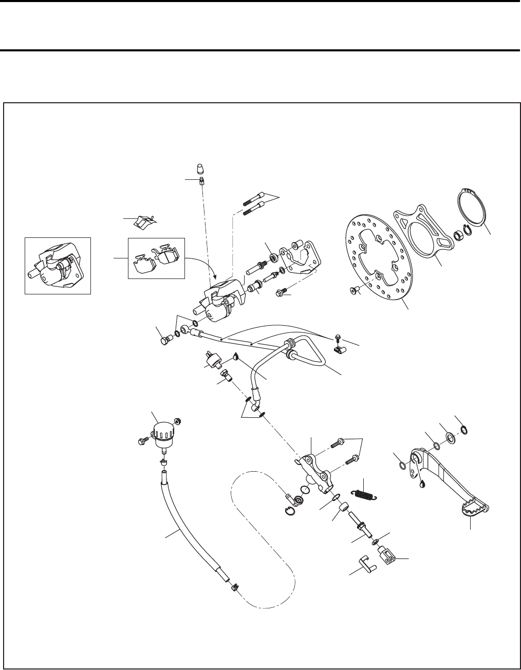
Section 09 BRAKES
Subsection 02 (HYDRAULIC BRAKES)
09-02-2 VMR2004_028_09_02A.FM
REAR BRAKE
V02K05V
34
37
3
15 Nm
(133 lbfin)
36
35
35 31 39
38
48
47
18
25 Nm
(18 lbfft)
28 Nm
(21 lbfft) 34 Nm
(25 lbfft)
28
29
8 Nm
(71 lbfin)46
16
25 Nm
(18 lbfft)
17
Loctite 567
pipe sealant
14 20
41
4243 44
40
5
6 Nm
(53 lbfin)
Synthetic
grease
26
27
24
19
15
1,2
3 Nm
(27 lbfin)
25
5 Nm
(44 lbfin)
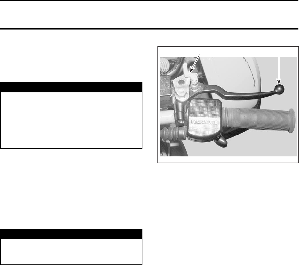
Section 09 BRAKES
Subsection 02 (HYDRAULIC BRAKES)
VMR2004_028_09_02A.FM 09-02-3
GENERAL
For installation, use the torque values and Loctite
products from the exploded views. Clean threads
before using Loctite when installing the screws.
CAUTION: Avoid spilling brake fluid on plastic,
rubber or painted parts. Protect these parts
with a rag when servicing brake system.
HYDRAULIC BRAKES SYSTEM
The brake system consists of two separate cir-
cuits. Each system has its own master cylinder
and reservoir.
Both front and rear brakes are disc type.
Parking Brake
The parking brake operates the front brakes only.
It is activated by a locking mechanism on RH brake
lever.
1. RH brake lever
2. Locking mechanism
Brake Fluid Replacement
CAUTION: To avoid serious damage to the
braking system, do not use fluids other than the
recommended one, nor mix different fluids for
topping.
Brake Fluid Draining (front and rear brake)
Remove reservoir cover no. 1 with diaphragm no. 2.
Connect bleed hose to bleed valve no. 3.
Loosen bleed valve and pump brake lever no. 4 or
brake pedal no. 5 until no more fluid flows out of
bleed valve.
Brake Fluid Filling and Bleeding
Close bleed valve.
Fill reservoir with DOT 4 brake fluid.
CAUTION: Do not mix different types of brake
fluid. Use only DOT 4 brake fluid from a sealed
container. Do not use brake fluid taken from old
or already opened containers.
Install a commercial available brake bleeder to
brake valve. See the manufacturer’s operating in-
structions.
Pump brake bleeder and loosen bleed valve. Close
bleed valve and refill reservoir when the fluid level
is low.
WARNING
Torque wrench tightening specifications
must strictly be adhered to.
Locking devices (ex.: locking tabs, elastic stop
nuts, self-locking fasteners, etc.) must be in-
stalled or replaced with new ones where
specified. If the efficiency of a locking device
is impaired, it must be renewed.
WARNING
Periodically check the brake hoses for damag-
es or leaks. Repair any damage before oper-
ating the vehicle.
V02I02A
2 1
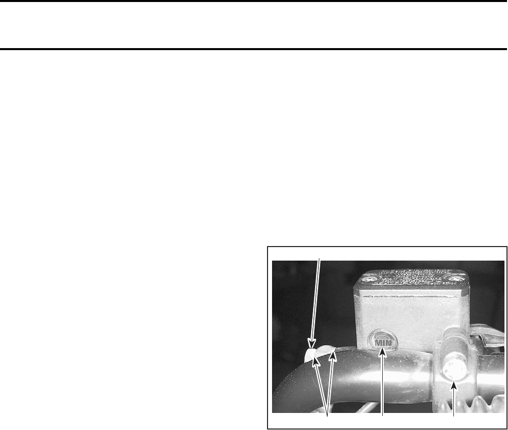
Section 09 BRAKES
Subsection 02 (HYDRAULIC BRAKES)
09-02-4 VMR2004_028_09_02A.FM
NOTE: Check fluid level often to prevent air from
being pumped into the system.
Repeat the procedures until air bubbles don’t ap-
pear in bleed hose.
NOTE: For the front brake system, switch to LH
and RH caliper. Turn handle bar to full RH side
when bleeding right caliper no. 6 and turn to the
LH side for the left caliper no. 7. This helps the
bleeder to reach air into the caliper.
Close bleed valves and operate brake lever no. 4
or brake pedal no. 5. If it still feels spongy, bleed
system again.
Fill reservoir to the upper level with DOT 4 brake
fluid.
Install diaphragm and cover on reservoir.
If brake bleeder is not available, use the following
procedure.
Install a tube to bleed valve.
Open bleeder. Fill reservoir and pump lever until
fluid freely flows out of the tube.
Close bleed valve.
Pump up system pressure with brake lever or brake
pedal until lever or pedal resistance is felt.
Squeeze brake lever or depress brake pedal, open
bleed valve and then close it.
NOTE: Do not release brake lever or brake pedal
until bleed valve has been closed. For the front
brake system, switch to LH and RH caliper. Turn
handle bar to full RH side when bleeding right cal-
iper no. 6 and turn to the LH side for the left caliper
no. 7. This helps the bleeder to reach air into the
caliper.
Release brake lever or brake pedal slowly.
Repeat the procedures until air bubbles don’t ap-
pear in tube and lever or pedal is stiff.
MASTER CYLINDER
Removal
Front Brakes
Drain brake fluid from master cylinder no. 8.
Remove Banjo bolt no. 9 and sealing washers
no. 10 retaining brake hose no. 11 to master cyl-
inder.
Discard sealing washers.
Remove screws no. 12 from master cylinder hold-
er no. 13 and remove master cylinder from han-
dlebar.
TYPICAL
1. Oil level mark
2. Bolt
3. Sealing washers
4. Remove screws
Rear Brake
Remove RH foot protector. Refer to BODY.
Unplug brake switch connectors from rear
brake switch no. 46.
Drain brake fluid from rear master cylinder no. 14.
Disconnect flexible hose no. 15 from master cyl-
inder and plug the end to avoid brake fluid spillage.
NOTE: At this time, check hoses and fittings for
damages or leaks.
Remove banjo fitting no. 16 and sealing washers
no. 17 retaining brake hose no. 18 to master cyl-
inder.
V01K12A
2
314
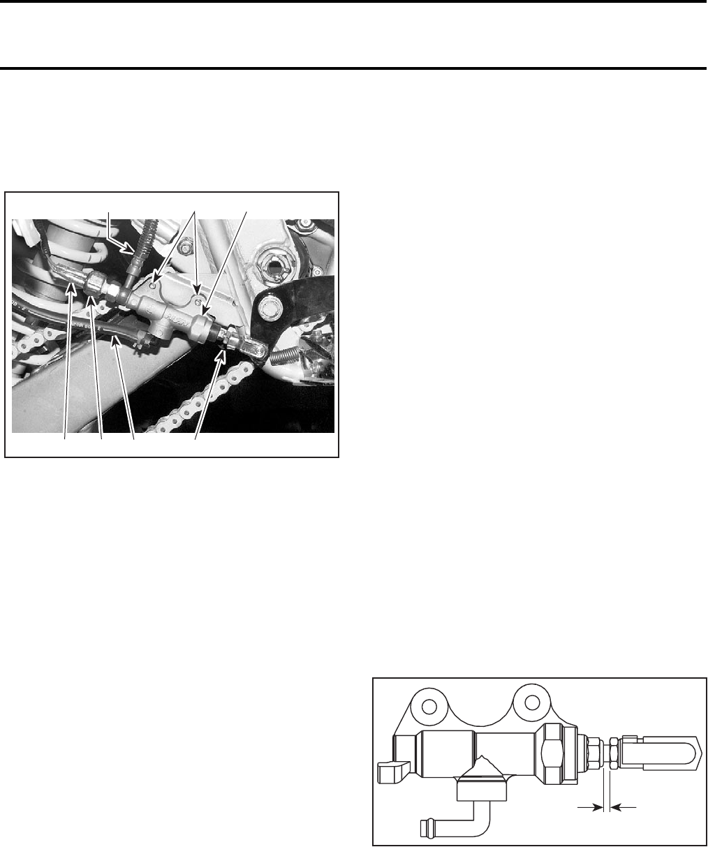
Section 09 BRAKES
Subsection 02 (HYDRAULIC BRAKES)
VMR2004_028_09_02A.FM 09-02-5
Discard sealing washers.
Unhook push rod no. 19 from brake pedal no. 5.
Remove bolts no. 20 retaining master cylinder to
frame.
1. Master cylinder
2. Flexible hose
3. Rear brake hose
4. Push rod
5. Remove bolts
6. Rear brake switch
7. Rear brake switch connectors
Disassembly
Front Master Cylinder
Remove brake lever no. 4 and locking mechanism
no. 21 for parking brake.
Remove piston boot no. 22, snap ring no. 23,
master piston and spring.
Rear Master Cylinder
Remove boot no. 24 from master cylinder.
Remove snap ring no. 25 and push rod no. 19 us-
ing snap ring pliers.
Remove master piston and spring.
Inspection and Lubrication
Discard any remaining fluid inside reservoir.
Clean reservoirs, master pistons and master cylin-
ders thoroughly with clean brake fluid.
Check:
–boots nos. 22 and 24 for cracks
–springs for damage
–piston cups for wear, deterioration or damage
–master cylinders and pistons for scoring, scratch-
es or other damage.
Change part(s) if necessary.
Check locking pin no. 26 for excessive wear, re-
place if necessary.
NOTE: If master cylinder is damaged or leaking,
replace as an assembly.
Assembly
Front Master Cylinder
Coat master piston and piston cups with clean
brake fluid.
Install:
–spring onto master piston
–master piston into master cylinder
–snap ring into groove in the master cylinder
–boot into master cylinder and the groove in pis-
ton.
Apply silicone grease to the brake lever contacting
surface of the piston.
Install brake lever and locking mechanism.
NOTE: Apply silicone grease on lever pivot bolt.
Rear Master Cylinder
For the rear master cylinder use the same proce-
dure that front master cylinder, however pay at-
tention to the following:
If push rod yoke no. 27 is reinstalled, adjust push
rod length, see the following illustration.
A. 3 ± 1 mm (1/8 ± 1/32 in)
Installation
For the installation, reverse the removal proce-
dure, pay attention to the following details.
NOTE: Always replace with standard screw, if
ever the brake hose retaining clip taptite screw
has been removed.
V02K06B
1
24
5
3
67
V02K07A
A
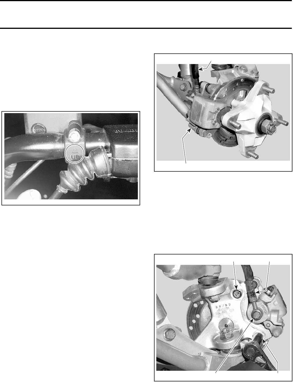
Section 09 BRAKES
Subsection 02 (HYDRAULIC BRAKES)
09-02-6 VMR2004_028_09_02A.FM
Front Brakes
Place the master cylinder no. 8 on the handlebar.
Position cylinder holding bracket with the UP mark
upward.
Install bolts and tighten loosely.
With the handlebar in straight ahead position, po-
sition cylinder reservoir parallel to the ground.
Tighten upper bolt in first then lower bolt.
TYPICAL
Connect brake hose no. 11 to master cylinder
with Banjo bolt no. 9 and new sealing washers.
Bleed front brake system.
Check for leaks and make sure the brakes operate
normally before driving.
Rear Brake
Install master cylinder to frame.
Install rear brake hose no. 18 to master cylinder
using new sealing washers.
Connect flexible hose from master cylinder.
Fill up reservoir with clean brake fluid.
CAUTION: Do not mix different types of brake
fluid. Use only DOT 4 brake fluid from a sealed
container. Do not use brake fluid taken from old
or already opened containers.
Bleed rear brake system.
Check for leaks and make sure the brakes operate
normally before driving.
CALIPER
Removal
Loosen wheel nuts.
Raise vehicle and support it securely.
Remove wheels.
RH FRONT BRAKE
1. Caliper
2. Brake hose
Drain brake fluid from brake system.
Remove Banjo bolt no. 28 with sealing washers
no. 29 and detach brake hose no. 18 or no. 30 from
caliper.
Catch spilled fluid with a rag.
Unscrew bolts no. 31 retaining caliper to knuckle
and remove caliper. Discard bolts.
TYPICAL
1. Remove Banjo bolt and washers
2. Unscrew bolts
3. Brake hose
V01K13A
V02K08A
2
1
V02K09A
2
1
3
2
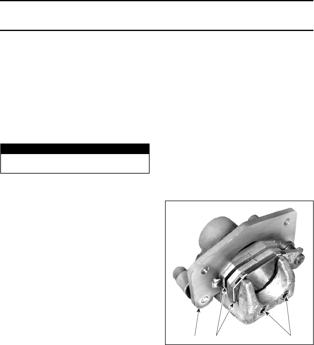
Section 09 BRAKES
Subsection 02 (HYDRAULIC BRAKES)
VMR2004_028_09_02A.FM 09-02-7
Disassembly
Remove brake pads, see the following section.
Remove:
–caliper bracket no. 32
–slide pins no. 33
–pad spring no. 34.
Place rag over piston.
Place caliper body with piston down and apply
small squirts of air pressure to the fluid inlet to
remove piston.
Remove piston seal.
CAUTION: Be careful not to damage piston slid-
ing surface.
Clean piston grooves, caliper cylinder and piston
with clean brake fluid.
Clean slide pins with brake cleaner and a rag.
Inspection
If boots no. 35 are deteriorated or hard, replace by
the new ones.
Check caliper cylinder and piston for scratches,
rust or other damages. If so, replace caliper.
Assembly
Coat piston seal with clean brake fluid and install
it into piston grooves in caliper.
Coat piston with clean brake fluid and install into
cylinder with the closing toward caliper body.
Apply silicone grease into sliding bores and install
slide pins.
NOTE: Make sure that rubber boots no. 35 are
correctly installed in slide pins grooves.
Install pad spring, caliper bracket and pads.
Installation
For the installation, reverse the removal proce-
dure, pay attention to the following details.
Use new sealing washers when installing Banjo
bolt retaining brake hose to caliper.
Install caliper to knuckle with the new self-locking
bolts.
If hose was disconnected, bleed the brakes.
Check for leaks and make sure the brakes operate
normally before driving.
BRAKE PADS
Removal
Raise vehicle and support it securely.
Remove wheels.
Loosen pad pins no. 36.
TYPICAL
1. Pad pins
2. Caliper bracket
3. Pads
Remove caliper from knuckle.
CAUTION: Don’t let the caliper hang by the hose
and don’t stretch or twist the hose.
It’s very important to clean remaining O.D. of pis-
ton out from caliper with brake fluid before push-
ing the piston back in. Make sure the piston is free
of any contaminant and is shiny.
Push piston all the way in to allow installation of
new pads.
WARNING
Do not use high pressure air or bring nozzle
too close to inlet.
2 3 1
V02K0MA
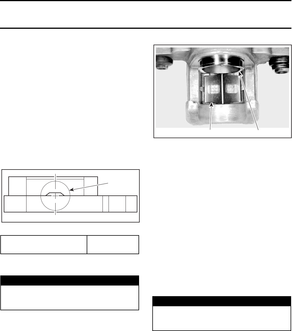
Section 09 BRAKES
Subsection 02 (HYDRAULIC BRAKES)
09-02-8 VMR2004_028_09_02A.FM
Unscrew pad pins and remove pads no. 37.
Discard pad pins.
Inspection
CAUTION: Do not clean brake pads in petro-
leum based solvent. Use brake system cleaner.
Soiled brake pads must be replaced by new
ones.
Measure brake pad lining thickness.
Brake pads must be replaced when lining is 1 mm
(1/32 in) thick or less, or, look at the hollow places
on both sides on the pad lining.
There are four hollow places on one set of brake
pads. When the pad wear reaches one of the hol-
low places, the pad change is necessary even if
the pad wear does not reach another hollow place.
1. Hollow place
CAUTION: Brake pads must always be replaced
in pairs.
Installation
For installation, reverse the removal procedure.
Paying attention to the following details.
Make sure that pad spring no. 34 is in position.
1. Pad spring
2. Piston
Install new brake pads.
Install new pad pins by pushing in the pads against
pad spring to align pad slots in the pads and caliper
body.
Install brake caliper so the disc is positioned be-
tween pads.
NOTE: Be careful not to damage pads and that
pads are correctly inserted in their location.
After the job is completed, firmly depress the
brake lever a few times to bring the pads in con-
tact with the disc.
Check for leaks and make sure the brakes operate
normally before driving. The pads must rest flat on
the disc.
BRAKE DISC
Inspection
Brake discs no. 38 can be inspected without re-
moving from the vehicle.
Raise vehicle and support it securely. Remove
wheels and visually inspect disc surfaces for scratch-
es or grooves. Make sure to check both sides of disc.
BRAKE PAD LINING
MINIMUM THICKNESS 1 mm (1/32 in)
WARNING
Avoid getting oil or grease on brake pads.
Contaminated brake pads can affect stopping
capacities. Discard any contaminated pads.
1
V02K0FA
WARNING
A contaminated brake disc reduces stopping
power. Clean a contaminated disc with a high
quality brake degreasing agent.
V02K0BA 12
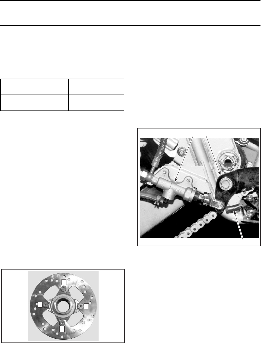
Section 09 BRAKES
Subsection 02 (HYDRAULIC BRAKES)
VMR2004_028_09_02A.FM 09-02-9
Measure thickness of the disc. Minimum thick-
ness is 3.5 mm (.13 in).
Replace disc if not within specifications.
CAUTION: Brake discs should never be machined.
Turn the disc by hand and check run out.
Removal
Front Brake Disc
Remove caliper as described previously.
After removing the caliper, suspend it out of the
way.
CAUTION: Do not let the caliper hang by the
hose and don’t stretch or twist the hose.
Wheel hub has to be removed from vehicle to re-
place brake disc Refer to FRONT DRIVE.
Remove screws no. 39 retaining brake disc no. 38
to wheel hub. Discard screws.
NOTE: Heat up disc around screws to facilitate re-
moval.
Rear Brake Disc
Refer to REAR AXLE for brake hub removal instruc-
tions.
Installation
Install brake disc on hub and tighten in a criss-
cross sequence.
Install new self-locking screws no. 39 and torque
them.
BRAKE LEVER
Removal and Installation
Use the same procedure than the front master
cylinder.
BRAKE PEDAL
Removal
Remove RH side foot protector.
Refer to BODY for removal procedure.
Unhook the return spring no. 40.
1. Master cylinder
2. Return spring
3. Brake pedal
Remove circlip no. 41, washer no. 42 and O-ring
no. 43 then remove pedal no. 5 from pivot.
Remove the O-ring no. 44 on the pivot.
NOTE: Clean O-ring and pivot pin with BOMBARDIER
LUBE (P/N 293 600 016).
Installation
For installation, reverse the removal procedure.
Check O-rings for damage, change if necessary.
Apply synthetic grease (P/N 293 550 010).
DISC MINIMUM
THICKNESS 3.5 mm (.13 in)
MAXIMAL DISC RUN
OUT 0.5 mm (.02 in)
1
V02K0OA
4
2
3
V02K0DA
1
2
3
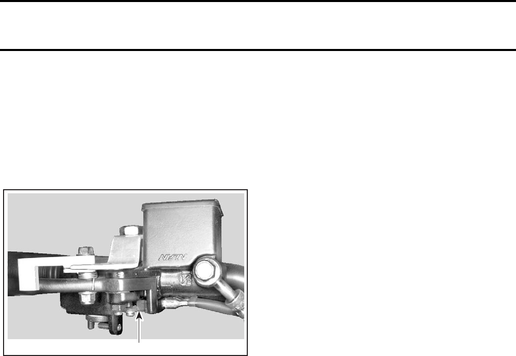
Section 09 BRAKES
Subsection 02 (HYDRAULIC BRAKES)
09-02-10 VMR2004_028_09_02A.FM
BRAKE LIGHT SWITCH
Removal
Front Brake Light Switch
The front brakes switch no. 45 is located on the
master cylinder and cannot be adjusted. Check
that switch is securely installed and operates rear
light properly.
1. Front brake light switch
Rear Brake Light Switch
The rear brake switch is located on the rear master
cylinder banjo fitting no. 16.
The rear brake light switch no. 46 cannot be ad-
justed.
Remove RH foot protector. Refer to BODY for re-
moval procedure.
Disconnect connectors.
Unscrew rear brake light switch no. 46 from banjo
fitting no. 16. Catch spilled fluid with a rag.
Installation
For installation, reverse the removal procedure.
NOTE: Apply pipe sealant on threads.
Bleed the brake system.
REAR CALIPER BRACKET
Removal
Remove brake hub. Refer to REAR AXLE.
Remove the large circlip no. 47.
Pull the caliper bracket no. 48.
Inspection
Check for wear or other damage on the O-ring,
eccentric bearing carrier and on the bracket. Re-
place parts if free play is excessive.
Installation
For installation, reverse the removal procedure.
V02K0EA 1
Section 10 BODY/FRAME
Subsection 01 (TABLE OF CONTENTS)
VMR2004_033_10_01ATOC.FM 10-01-1
TABLE OF CONTENTS 0
BODY...................................................................................................................................... 10-02-1
BODY PARTS ..................................................................................................................... 10-02-1
SEAT................................................................................................................................... 10-02-3
SEAT................................................................................................................................... 10-02-4
DASHBOARD ..................................................................................................................... 10-02-4
FRONT SKID PLATE/FRONT BUMPER............................................................................. 10-02-4
MUDGUARD/FRONT FENDER/SUPPORT........................................................................ 10-02-4
FRONT FACIA .................................................................................................................... 10-02-5
FRONT FACIA BRACKET................................................................................................... 10-02-5
AUXILIARY HEADLAMP SUPPORT.................................................................................. 10-02-5
FUEL TANK COVER ........................................................................................................... 10-02-5
FOOT PROTECTOR/FOOT PROTECTOR SUPPORT ........................................................ 10-02-6
REAR FENDER ................................................................................................................... 10-02-6
REAR BUMPER .................................................................................................................. 10-02-6
ENGINE SKID PLATE......................................................................................................... 10-02-6
A-ARM PROTECTOR PLATE ............................................................................................. 10-02-7
NERF BAR .......................................................................................................................... 10-02-8
LATCH BASE/LATCH LEVER/SPRING .............................................................................. 10-02-8
SEAT ADJUSTMENT ........................................................................................................ 10-02-8
SEAT COVER REPLACEMENT .......................................................................................... 10-02-9
SEAT CLEANING ............................................................................................................... 10-02-9
DECALS REPLACEMENT .................................................................................................. 10-02-9
PLASTIC MAINTENANCE/REPAIR ................................................................................... 10-02-10
MAINTENANCE ................................................................................................................. 10-02-10
REPAIR................................................................................................................................ 10-02-10
FRAME ................................................................................................................................... 10-03-1
FOOTPEG ........................................................................................................................... 10-03-2
DASHBOARD SUPPORT ................................................................................................... 10-03-2
REAR FRAME EXTENSION ............................................................................................... 10-03-2
FRAME ............................................................................................................................... 10-03-2
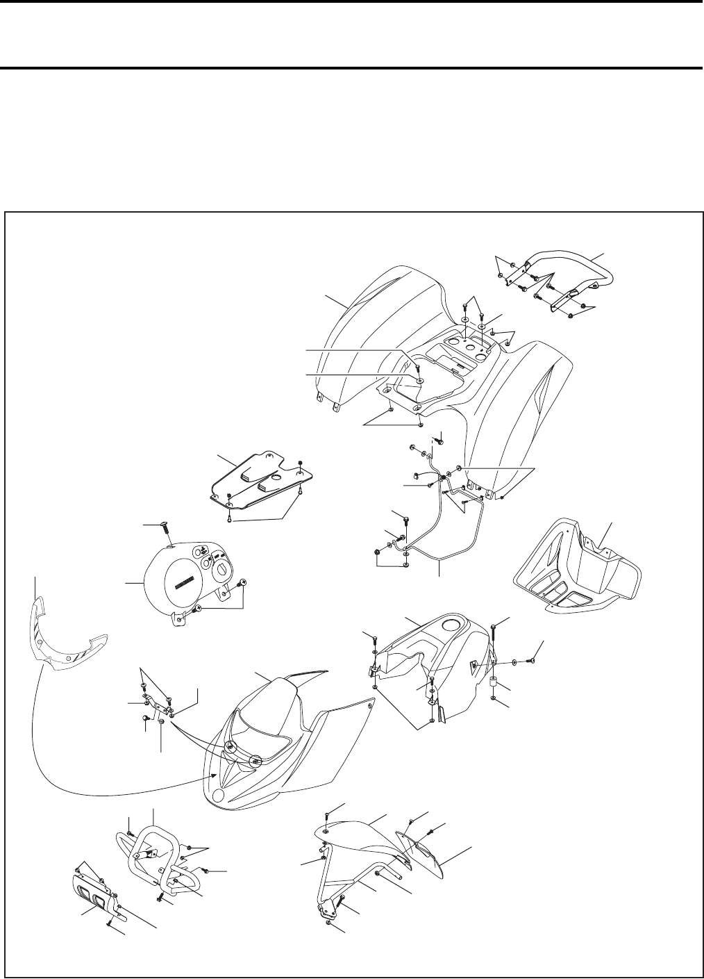
Section 10 BODY/FRAME
Subsection 02 (BODY)
VMR2004_029_10_02A.FM 10-02-1
BODY 0
BODY PARTS
DS 650 Models
V02L0IS
23 Nm
(17 lbfft)
32
33
8 Nm (71 lbfin)
34
35
30
36
39
10 Nm
(89 lbfin)
4 Nm
(35 lbfin)
28
27
27
31
30
10 Nm
(89 lbfin)
4
2 Nm
(18 lbfin)
5
26
23
19
17
20
2.5 Nm
(22 lbfin)
9
8
6
7
8
12
14 11
10
13
10 Nm
(89 lbfin)
16
15
23 Nm
(17 lbfft)
6
23 Nm
(17 lbfft)
5 Nm
(44 lbfin)
2.5 Nm
(22 lbfin)
8
2.5 Nm
(22 lbfin)
10 Nm
(89 lbfin)
23
3.5 Nm
(31 lbfin)
25
6.5 Nm
(58 lbfin)
18
24
29
37
38
23 Nm
(17 lbfft)
2.5 Nm
(22 lbfin)
23 Nm
(17 lbfft)
2.5 Nm
(22 lbfin)
2 Nm
(18 lbfin)
4
40
3.5 Nm
(31 lbfin)
45
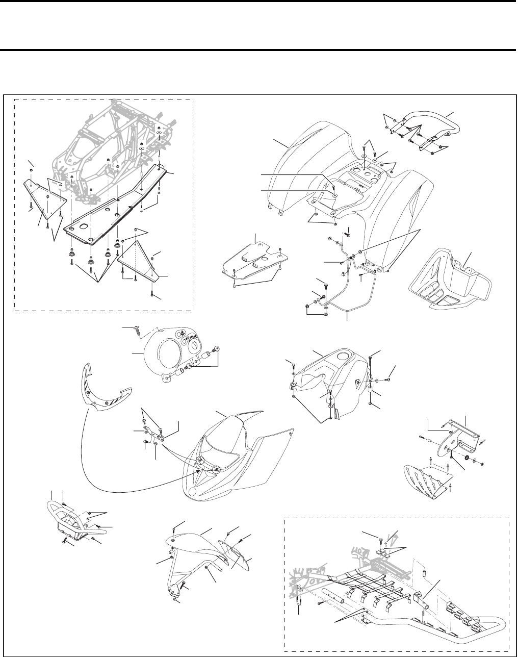
Section 10 BODY/FRAME
Subsection 02 (BODY)
10-02-2 VMR2004_029_10_02A.FM
DS 650 Baja and Baja X Models
V02L0TS
23 Nm
(17 lbfft) 38
23 Nm
(17 lbfft)
37
8 Nm (71 lbfin)
32
33
35
34
10 Nm
(89 lbfin)4 Nm
(35 lbfin)
30
27
27
28
40 30
31
24
18
2.5 Nm
(22 lbfin)
25
26
10 Nm
(89 lbfin)
29
23
23
2 Nm
(18 lbfin)
2.5 Nm
(22 lbfin)
3.5 Nm
(31 lbfin)
6.5 Nm
(58 lbfin)
36
3.5 Nm
(31 lbfin)
39
2 Nm
(18 lbfin)
2.5 Nm
(22 lbfin)
5
17 19
4
21
13
10
11
14
12
23 Nm
(17 lbfft)
5 Nm
(44 lbfin)10 Nm
(89 lbfin)
16
25
8
23 Nm
(17 lbfft)
8
9
23 Nm
(17 lbfft)
8
10 Nm
(89 lbfin)
20
4
10 Nm
(89 lbfin)22
46
47
52
51
48
49
50
47
X models only
52
50
49
51
48
54 53
58
55
56 57 X models only
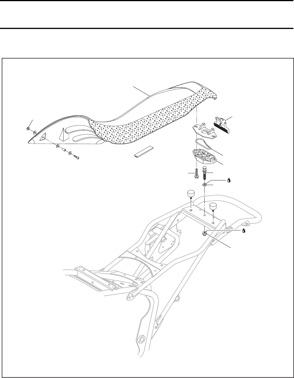
Section 10 BODY/FRAME
Subsection 02 (BODY)
VMR2004_029_10_02A.FM 10-02-3
SEAT
V02L0KS
Loctite 271
3
41
44
42
43
1
29 Nm
(21 lbfft)
2
5 Nm
(44 lbfin)
5.5 Nm
(49 lbfin)
Loctite 271
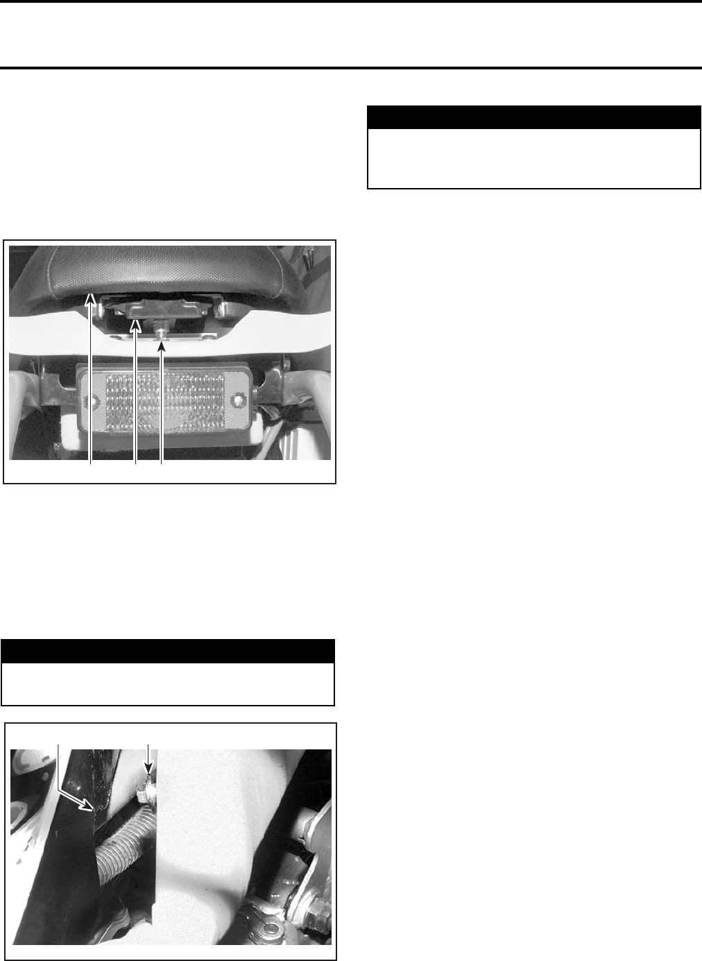
Section 10 BODY/FRAME
Subsection 02 (BODY)
10-02-4 VMR2004_029_10_02A.FM
SEAT
Removal
Pull latch lever no. 1 upward while gently lifting
rear of seat no. 2. Continue lifting movement until
you can release the front retaining devices, then,
completely remove seat.
1. Seat
2. Latch
3. Seat lock pin
Installation
Insert seat front tabs into hooks. Pull latch lever to
insert it over the seat lock pin no. 3. Release latch
lever then firmly push on rear of the seat to
relatch.
1. Seat front tab
2. Body hook
DASHBOARD
Removal
Remove screws no. 4.
Lift dashboard no. 5.
Disconnect:
– ignition switch
– indicator lamps
– tachometer (Baja models).
Remove dashboard completely.
Installation
Installation is the reverse order of removal.
FRONT SKID PLATE/FRONT
BUMPER
Removal
Front Skid Plate
DS 650 Models
Remove screws no. 6.
Front Bumper
Remove front skid plate no. 7 (DS 650 models).
Remove bolts no. 8 then the front bumper no. 9.
Installation
Installation is the reverse order of removal.
MUDGUARD/FRONT FENDER/
SUPPORT
Removal
Mudguard
Remove screws no. 10 and dart no. 11.
Front Fender
Remove screws nos. 10 and 12.
Front Fender Support
If necessary, remove mudguard no. 13 and front
fender no. 14.
WARNING
Make sure both front tabs are properly hooked
on frame before riding.
3
V02L0CA 12
21
V02L07A
WARNING
Periodically, verify the seat lock pin and tighten
if needed. Make sure seat is securely latched
before riding.
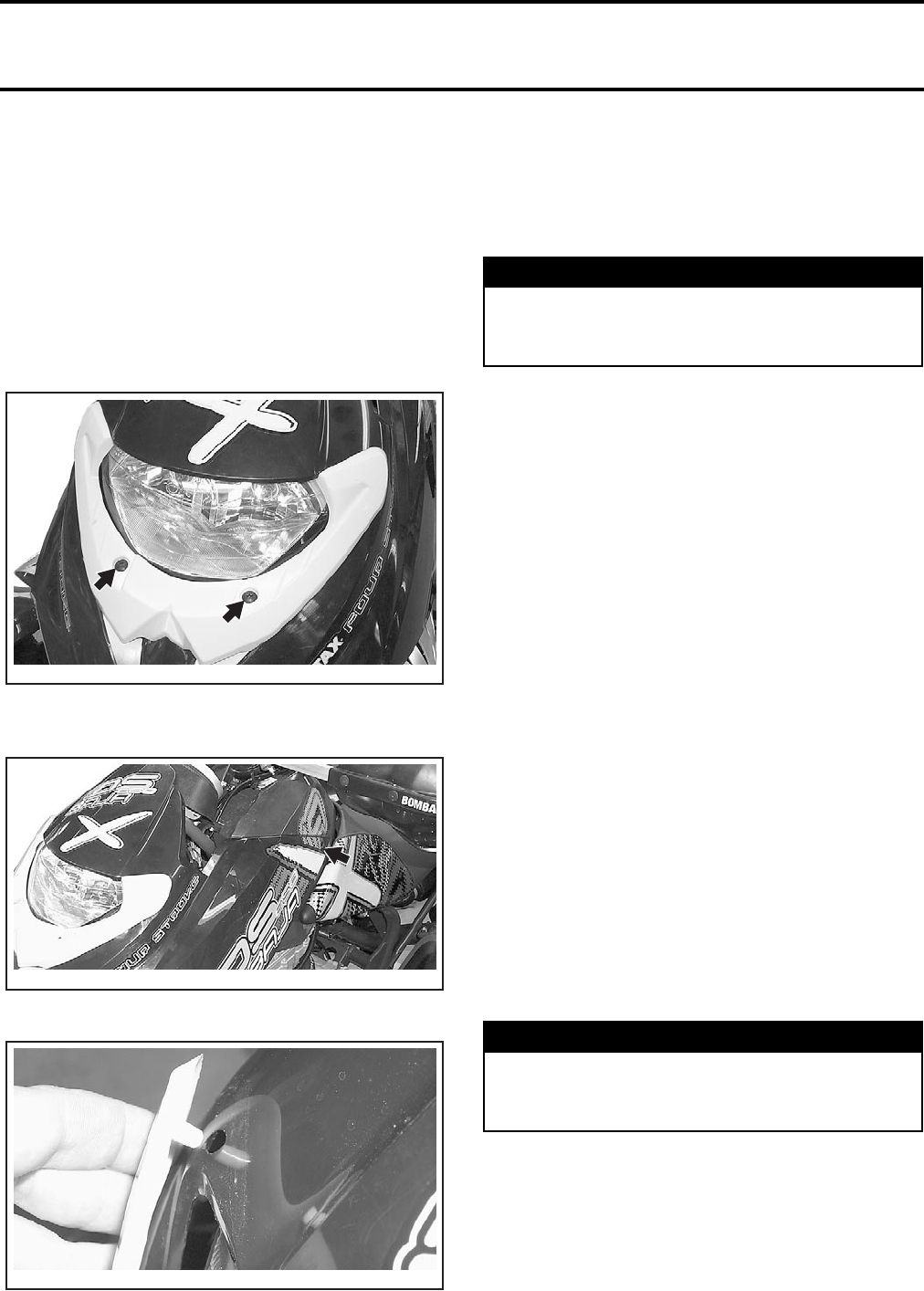
Section 10 BODY/FRAME
Subsection 02 (BODY)
VMR2004_029_10_02A.FM 10-02-5
Remove bolts no. 15 retaining the support no. 16
to the knuckle.
Installation
For the installation, reverse the removal procedure.
FRONT FACIA
Removal
Remove screws no. 17 under headlamp.
Remove screws no. 18 on each side of fuel tank
cover.
If required, remove the headlamp cover no. 45.
Remove the front facia no. 19.
Installation
Installation is the reverse order of removal.
FRONT FACIA BRACKET
Removal
Remove the front facia.
Unscrew the bolts no. 20 retaining the front facia
bracket to the oil tank.
Installation
For the installation, reverse the removal procedure.
AUXILIARY HEADLAMP
SUPPORT
Baja Models
Removal
Remove:
–front facia
–bolt no. 21 retaining the auxiliary headlamp sup-
port no. 22 to the upper bracket of shock ab-
sorber.
Disconnect the auxiliary headlamps.
Installation
For installation, reverse the removal procedure.
FUEL TANK COVER
Removal
Remove:
–seat
–front facia
–fuel tank cap.
V02L0UA
V02L0VA
V02L0WA
WARNING
Never perform this operation immediately af-
ter the engine has been run because the oil
tank can be very hot. Wait until oil tank is warm.
WARNING
Never perform this operation immediately af-
ter the engine has been run because the oil
tank can be very hot. Wait until oil tank is warm.
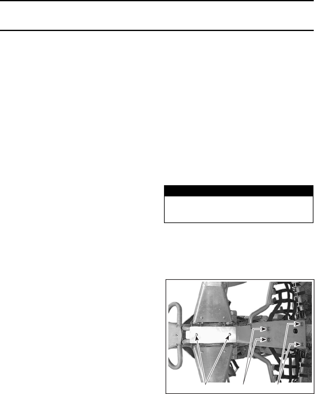
Section 10 BODY/FRAME
Subsection 02 (BODY)
10-02-6 VMR2004_029_10_02A.FM
On the front side, unscrew the bolts no. 23 retain-
ing the fuel tank cover and oil tank.
On the rear side, unscrew the bolts no. 24 and
remove spacers no. 25.
Pull fuel tank cover no. 26 and fuel tank backward
then remove fuel tank cover.
Installation
Installation is the reverse order of removal.
FOOT PROTECTOR/FOOT
PROTECTOR SUPPORT
Removal
Foot Protector
Unfasten screws nos. 27 and 28 then remove foot
protector no. 29.
Foot Protector Support
Remove foot protector.
Unscrew bolts no. 30 retaining support no. 31 to
the frame.
Installation
Installation is the reverse order of removal.
NOTE: Install all bolts before torquing.
REAR FENDER
Removal
Remove:
–seat
–screws no. 32 and washers no. 33 near the lock
pin no. 3
–screws no. 34 and washers no. 35 located in
front of air box cover
–screws no. 27 retaining foot protector to rear
fender no. 36.
Installation
Installation is the reverse order of removal.
REAR BUMPER
Removal
Remove screws no. 37 then the screw retaining
rear bumper no. 38 and muffler.
Installation
Installation is the reverse order of removal.
ENGINE SKID PLATE
Inspection
The skid plate protects the engine. Check for dam-
age, cracks or looseness.
Change if skid plates no. 39 and no. 46 are dam-
aged or cracked.
Removal
All Models
Under vehicle, remove bolts no. 40.
Baja X Models only
To remove skid plate no. 46, lift front of vehicle
completely untill it rests on its back wheels and
rear bumper, vertically; secure it safely in this po-
sition.
Remove the bolts no. 47 to remove the skid plate
no. 46.
1. Bolts to be removed
Installation
All Models
Installation is the reverse of the removal.
NOTE: Install all bolts before torquing.
WARNING
Engine and muffler must be cold and fuel valve
must be shut off before removing the skid
plate. Otherwise, serious injuries may occur.
V02L0XA 1 1 1
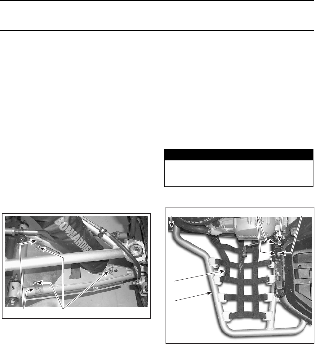
Section 10 BODY/FRAME
Subsection 02 (BODY)
VMR2004_029_10_02A.FM 10-02-7
Baja X Models only
Installation is the reverse of the removal but pay
attention to the following:
–align skid plate no. 46 then secure it starting
with middle square hole; tighten loosely
–then secure in this sequence: forward square
hole, forward round holes and rearward round
holes; tighten loosely
–validate proper positioning of skid plate, then
torque all bolts and nuts
–safely lower vehicle back on the ground.
A-ARM PROTECTOR PLATE
Removal
Baja X Models only
Procedure for RH and LH side is the same.
Remove the A-arm protector retaining nuts
no. 49, and no. 51 and U-clamps.
1. Nuts to be removed
2. U-Clamps
Remove the A-arm protector plate no. 48.
Inspection
Check the A-arm protector plate for damage or
cracks. Replace if necessary.
Installation
For installation, reverse the removal procedure.
However, pay attention to the following.
Position A-arm protector no. 48 under A-arms. On
frame side, install U-clamps over the A-arm tubing
and fasten with bolts no. 50 and nuts no. 49. Do
not tighten yet.
On wheel side, secure with a bolt no. 52 and a nut
no. 51.
Fully turn the handlebar into both directions and
check for interference.
Fully compress front suspension and check for in-
terference.
Adjust as necessary, secure in place and torque fas-
teners.
NERF BAR
Removal
Baja X Models only
1. Nerf bar tube
2. Net strap
3. U-bolt and nuts
4. Short plate
5. Bolt
6. Nut
Unfasten the net strap and slide it out from the
frame.
Remove nuts no. 53 and U-bolt no. 54.
Remove short plates no. 55, bolt no. 56, and nut
no. 57. Slide out the nerf bar assembly and secure
the tube no. 58.
NOTE: The procedure for LH and RH side nerf bar
is the same.
V02L0YA 2 1
WARNING
Engine and muffler must be cold before re-
moving the nerf bar. Otherwise, serious inju-
ries may occur.
V02L0ZA
2
3
1
54 6
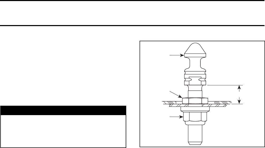
Section 10 BODY/FRAME
Subsection 02 (BODY)
10-02-8 VMR2004_029_10_02A.FM
Inspection
Check nerf bar for cracks or bents and net strap
for wear. Change or repair as required.
Installation
Installation is essentially the reverse of removal
procedure but pay attention to the following:
After installing the net strap on the frame, make
sure to tight it properly.
LATCH BASE/LATCH LEVER/
SPRING
Removal
Latch Base
Remove bolts no. 41 and separate latch base
no. 42 from latch lever no. 1 and spring no. 43.
Latch Lever
Remove latch base.
Separate latch lever from spring.
Spring
Remove latch base.
Separate spring from latch base and latch lever.
SEAT ADJUSTMENT
For lock pin no. 3 adjustment, unscrew the lock
pin nut no. 44 and screw or unscrew the lock pin
to the best height. See the following illustration.
1. Lock pin
2. Lock pin nut (apply Loctite 271)
3. Adjustment nut (apply Loctite 271)
A. 14 ± 2 mm (9/16 ± 5/64 in)
Torque the lock pin nut.
SEAT COVER REPLACEMENT
Remove the old seat cover. Check the foam and
replace if necessary.
Install staples with an electric tacker such as Ar-
row tacker no. ETN-50 or with a manual tacker
such as Arrow tacker no. T-50.
NOTE: For an easier installation, it’s highly recom-
mended to use an electric tacker.
Ensure that the seat rests firmly against a hard sur-
face such as a piece of wood. This is done to get
the staples completely pushed in place.
WARNING
Make sure the net is not too tight on nerf bar
tube. Check for clearance by standing up on
footpegs and moving feet in all directions.
Feet must not interfere with nerf bar net. Oth-
erwise, serious injuries may occur. V02L0EB
A
3
1
2
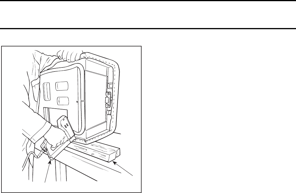
Section 10 BODY/FRAME
Subsection 02 (BODY)
VMR2004_029_10_02A.FM 10-02-9
TYPICAL
1. Piece of wood
2. ETN-50 (electric) or T-50 (manual)
After cover installation cut the excess of material
all around the seat.
SEAT CLEANING
It is recommended to clean the seat with a solu-
tion of warm soapy water, using a soft clean
cloth.
CAUTION: Avoid use of harsh detergents such
as strong soaps, degreasing solvents, abrasive
cleaners, paint thinners, etc. that may cause
damage to the seat cover.
DECALS REPLACEMENT
Removal
Using a heat gun warm up one end of decal for a
few seconds until decal can roll off when rubbing
with your finger.
Pull decal slowly and when necessary apply more
heat to ease removal on the area that has to be
peeled off.
If decal tears while pulling off, it has to be heated
for a few seconds longer. If decal tends to stretch
while pulling off, stop heating and wait a few sec-
onds to let it cool, then peel it off.
Installation
There are 2 types of decals used on ATV’s. One
has a protective film on back side and the other
has a protective film on both sides. They are used
on 2 types of materials; plastic and metal.
Decals Having a Protective Film
on Back Side Only
These decals usually contain written information
(ex.: warning).
Clean surface with a good solvent such as ACRYL-
ICLEAN DX 330 from PPG or equivalent (refer to
manufacturer instructions).
Using a pencil and the decal as a template, mark
the area where decal will be located.
Remove half of the decal back protective film and
align decal with marks. Start sticking it from center
and remove the other half of the film to stick it
completely. Carefully squeegee decal beginning at
center and working outward using, firm, short,
overlapping strokes.
Decals Having a Protective Film on Both Sides
These decals usually contain graphics.
Installation on Plastic
Clean surface with isopropyl alcohol.
Using a pencil and the decal as a template, mark
the area where decal will be located.
Apply an activator (P/N 293 530 036) to prepare the
surface using a clean cloth. After a few seconds,
when the activator evaporates, the surface is ready.
CAUTION: Do not use soapy water to locate de-
cal on plastic parts.
Remove back protective film from decal and care-
fully align decal with marks. When well aligned
squeegee decal beginning at center and working
outward using firm, short, overlapping strokes.
PLASTIC
MAINTENANCE/REPAIR
MAINTENANCE
Clean the vehicle thoroughly, removing all dirt and
grease accumulation.
To clean use a soft clean cloth and either soapy
water or isopropyl alcohol.
To remove grease, oil or glue use isopropyl alcohol.
CAUTION: Do not apply isopropyl alcohol or ac-
etone directly on decals.
F01L3YA 2
1

Section 10 BODY/FRAME
Subsection 02 (BODY)
10-02-10 VMR2004_029_10_02A.FM
CAUTION: The following products must not be
used to clean or wax any of the plastic compo-
nents used on the vehicles:
–gasoline
–brake fluid
–kerosene
–diesel fuel
–lighter fluid
–varsol
–naphtha
–acetone
–strong detergents
–abrasive cleaners
–waxes containing an abrasive or a cleaning agent
in their formula.
REPAIR
The plastic parts are produced in high density poly-
ethylene (HDPE) or in low density polyethylene
(LDPE). These materials are not reparable.
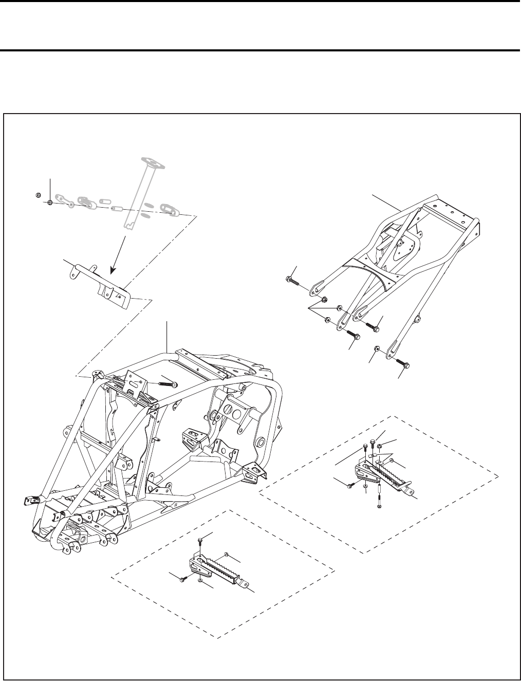
Section 10 BODY/FRAME
Subsection 03 (FRAME)
VMR2004_030_10_03A.FM 10-03-1
FRAME 0
10 Nm
(89 lbfin)
V02L0QS
2
23 Nm
(17 lbfft)
4
8
3
8
9
48 Nm
(35 lbfft)
5
56
6
10 Nm
(89 lbfin)
10 Nm
(89 lbfin)
1
9
48 Nm
(35 lbfft)
7
610 Nm
(89 lbfin)
1
DS 650
DS 650 Baja/Baja X
11
5
10
6
12
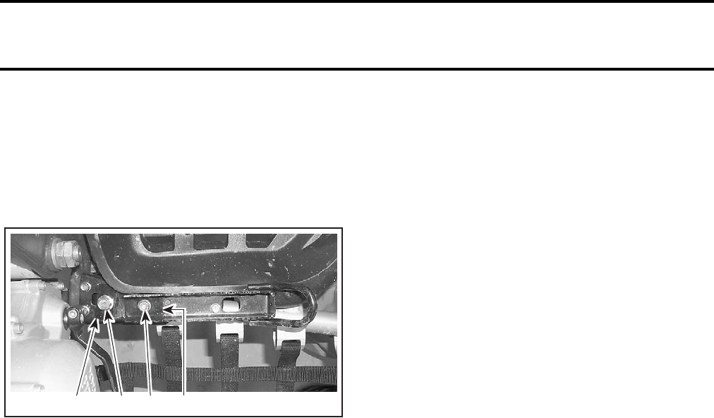
Section 10 BODY/FRAME
Subsection 03 (FRAME)
10-03-2 VMR2004_030_10_03A.FM
FOOTPEG
Removal
Baja X Models
Remove short plates no. 10,bolt no. 11 and nut
no. 12.
1. Short plates
2. Bolt
3. Nut
All Models
Unfasten foot protector supports from footpeg
no. 1 by removing mounting flanged bolts no. 5
and flanged nuts no. 6.
Inspection
Check for cracks or bent plate. Change or repair if
necessary.
Installation
Installation is essentially the reverse of removal
procedure. Pay attention to align the nerf bar, dur-
ing installation on Baja X Models.
DASHBOARD SUPPORT
Removal
Remove:
–dashboard (refer to BODY)
–fuel tank (refer to FUEL CIRCUIT)
–headlight (refer to ACCESSORIES)
–handle bar
(refer to STEERING/CONTROL SYSTEM)
–half housing bolts no. 7, stopper plates, half
housings and housing bushings retaining steer-
ing column
(refer to STEERING/CONTROL SYSTEM).
Pull out the dashboard support no. 2.
Inspection
Check for cracks or bent tube. Change or repair if
necessary.
Installation
For installation, reverse the removal procedure.
REAR FRAME EXTENSION
Removal
Remove:
–rear fender (refer to BODY)
–battery, starting solenoid and all wire attached
to frame extension
–muffler (refer to REMOVAL AND INSTALLATION)
–rear shock absorber reservoir
(refer to REAR SUSPENSION)
–rear brake fluid reservoir and brake hoses
(refer to HYDRAULIC BRAKES)
–upper bolts of foot protectors supports
(refer to BODY)
–air intake silencer (refer to CARBURETOR AND
AIR INTAKE SILENCER)
–brake light.
Unscrew bolts nos. 8 and 9 retaining rear exten-
sion frame no. 3 to the frame no. 4.
Inspection
Check for cracks, bent tube or other damage. Re-
pair or change if necessary.
Installation
Installation is the reverse of removal procedure.
NOTE: On the RH side, the lower bolt no. 9 must
be installed with the head inside the frame.
FRAME
Removal
Remove all parts. Refer to the proper sections.
Installation
For installation, reverse the removal procedure.
V02L0RA 1 12 3

Section 10 BODY/FRAME
Subsection 03 (FRAME)
VMR2004_030_10_03A.FM 10-03-3
Cleaning
Clean frame no. 4 and rear extension frame no. 3
with appropriate cleaners and rinse with high pres-
sure hose.
Touch up all metal spots where paint has been
scratched off. Spray all bare metal parts of vehicle
with metal protector.
Welding
Steel Frame:
–electric welding
–amperage: 70 - 110 A
–voltage: 20 - 24 V
–rod: E-7014 (3/32 in).
CAUTION: Before performing electrical weld-
ing anywhere on the vehicle, unplug the elec-
tronic module. Also unplug the negative cable
and the voltage regulator. This will protect the
electronic module and battery against damage
caused by flowing current when welding.
NOTE: Install the ground as close as possible to
the repaired area.
CAUTION: If welding is to be done near plastic
material, it is recommended to either remove the
part from the area or to protect it with aluminum
foil to prevent damage.

Section 11 TECHNICAL DATA
Subsection 01 (SI METRIC INFORMATION GUIDE)
VMR2004_031_11_01A.FM 11-01-1
TECHNICAL DATA 0
SI* METRIC INFORMATION GUIDE
* The international system of units abbreviates SI in all languages.
†To obtain the inverse sequence, divide by the given factor. To convert ’’mm’’ to ’’in’’, divide by 25.4.
NOTE: Conversion factors are rounded off to 2 decimals for easier use.
BASE UNITS
DESCRIPTION UNIT SYMBOL
length ..................................................................
mass ....................................................................
force ....................................................................
liquid ....................................................................
temperature ........................................................
pressure ..............................................................
torque ..................................................................
speed ..................................................................
meter .....................................................
kilogram .................................................
newton ...................................................
liter .........................................................
Celsius ...................................................
kilopascal ................................................
newton•meter .......................................
kilometer per hour ..................................
m
kg
N
L
°C
kPa
N•m
km/h
PREFIXES
PREFIX SYMBOL MEANING VALUE
kilo ................................
centi .............................
milli ...............................
micro ............................
k ...............................
c ...............................
m ..............................
µ...............................
one thousand .........................................
one hundredth ........................................
one thousandth ......................................
one millionth ..........................................
1 000
0.01
0.001
0.000001
CONVERSION FACTORS
TO CONVERT TO †MULTIPLY BY
in .........................................................................
in .........................................................................
in2........................................................................
in3........................................................................
ft ..........................................................................
oz .........................................................................
lb .........................................................................
lbf ........................................................................
lbf•in ...................................................................
lbf•ft ....................................................................
lbf•ft ....................................................................
PSI .......................................................................
imp. oz .................................................................
imp. oz .................................................................
imp. gal ................................................................
imp. gal ................................................................
U.S. oz .................................................................
U.S. gal ................................................................
MPH ....................................................................
Fahrenheit ...........................................................
Celsius .................................................................
mm .........................................................
cm ..........................................................
cm2.........................................................
cm3.........................................................
m ............................................................
g .............................................................
kg ...........................................................
N ............................................................
N•m .......................................................
N•m .......................................................
lbf•in ......................................................
kPa .........................................................
U.S. oz ....................................................
mL ..........................................................
U.S. gal ...................................................
L .............................................................
mL ..........................................................
L .............................................................
km/h ......................................................
Celsius ...................................................
Fahrenheit ..............................................
25.4
2.54
6.45
16.39
0.3
28.35
0.45
4.4
0.11
1.36
12
6.89
0.96
28.41
1.2
4.55
29.57
3.79
1.61
(°F - 32) ÷ 1.8
(°C x 1.8) + 32

Section 11 TECHNICAL DATA
Subsection 02 (ENGINE AND VEHICLE)
VMR2004_031_11_02A.FM 11-02-1
ENGINE AND VEHICLE
VEHICLE MODEL DS 650 DS 650 BAJA DS 650 BAJA X
ENGINE
Engine Type 4 Stroke, Double Overhead Camshaft,
Bush Chain Drive, Liquid Cooled
Starting System Electric (start in any gear with clutch applied or on neutral)
Number of Cylinder(s) 1
Number of Valves 4 Bucket Tappet-Operated Valves
Decompressor Type Automatic
Bore mm (in) 100 (3.94)
Stroke mm (in) 83 (3.27)
Displacement cm3 (in3)652 (39.7)
Compression Ratio 9.7: 1
Intake Valve Opening 17° BTDC
Intake Valve Closing 45° ABDC
Exhaust Valve Opening 47° BBDC
Exhaust Valve Closing 15° ATDC
Valve Clearance When Engine Cold
(maximum 35°C/95°F) Exhaust/Intake mm (in) 0.1 to 0.15 (.004 to .006)
Valve Length Intake mm (in) 90.91 and 90.76 (3.579 and 3.573)
Exhaust mm (in) 90.65 and 90.05 (3.568 and 3.545)
Plate Diameter Intake mm (in) 36 (1.42)
Exhaust mm (in) 31 (1.22)
Shaft Diameter Intake mm (in) 5.95 (.24)
Exhaust mm (in) 5.935 (.23)
Valve Seat Angle Intake mm (in) 45°
Exhaust mm (in) 30°
Piston Ring End Gap
New Minimum mm (in) 0.2 (.008)
New Maximum mm (in) 0.4 (.016)
Wear Limit mm (in) 1 (.04)
Ring/Piston Groove Clearance
New Minimum mm (in) 0.03 (.0012)
New Maximum mm (in) 0.065 (.0026)
Wear Limit mm (in) 0.15 (.006)
Piston/Cylinder Clearance Wear Limit mm (in) 0.09 (.004)
Cylinder
New Minimum mm (in) 100 (3.9371)
New Maximum mm (in) 100.012 (3.9376)
Wear Limit mm (in) 100.03 (3.9382)
Crankshaft Balance Factor % 47 ± 3
Crankshaft Deflection mm (in) 0.1 (.004)
Connecting Rod Big End Axial Play Wear Limit mm (in) 0.8 (.794)
Connecting Rod Small End I.D. Wear Limit mm (in) 22.04 (.868)
Connecting Rod/Piston Pin Clearance Wear Limit mm (in) 0.06 (.002)
Camshaft
(intake and exhaust)
Bearing
Point Ø mm (in) 21.95 (.864)
Cam Height mm (in) 39.7 (1.56)
Timing Chain
(gap from sealing face to piston of chain tensioner) mm (in) 9.5 (.374)
Lubrication Dry Sump Lubrication by Oil Pump Replaceable Oil Filter
Oil Filter Main-Flow Type
Air Filter Type Cleanable Synthetic Panelette/Foam
Exhaust System Type Bombardier, Stainless Header Pipe Painted Steel Muffler
Spark Arrester USFS Approved
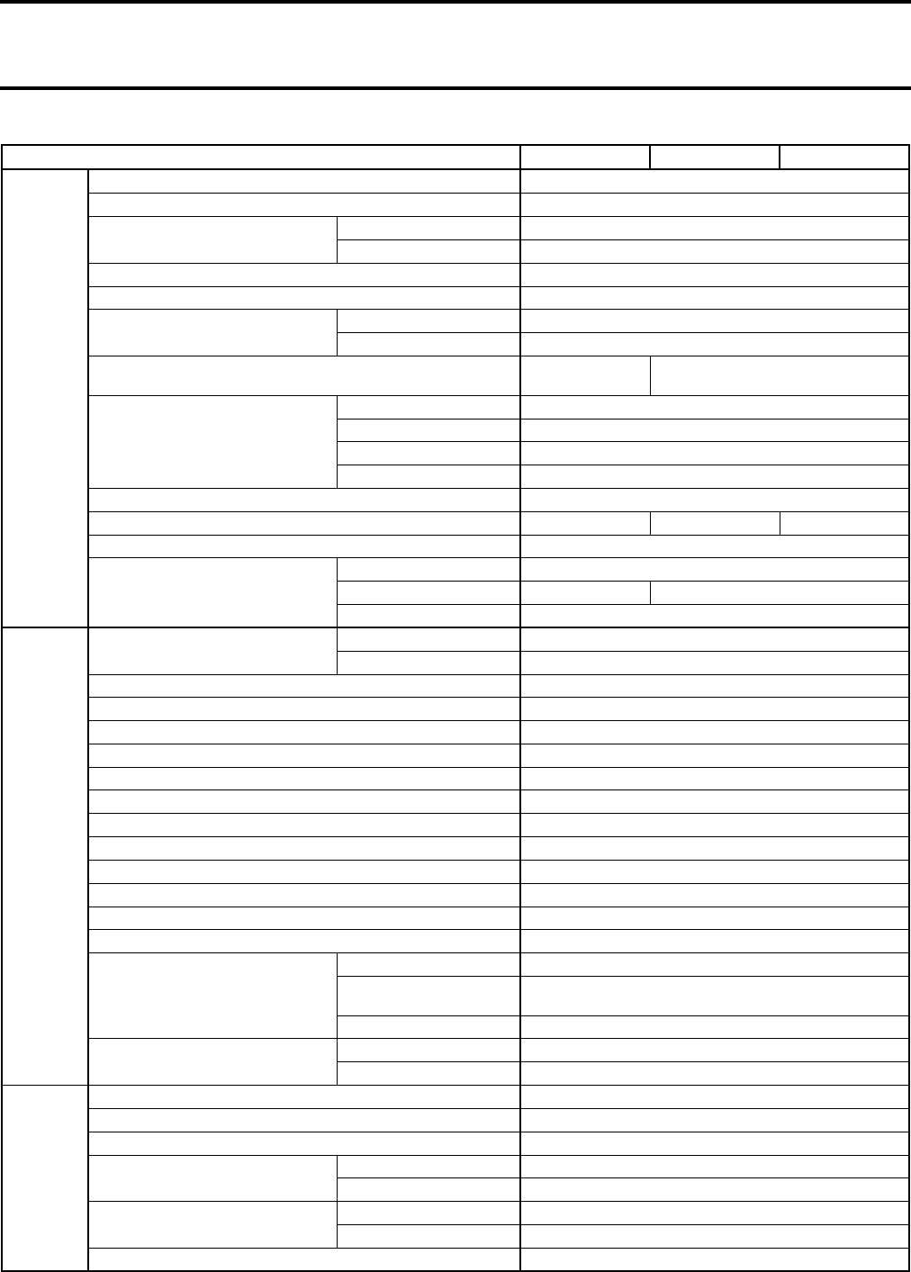
Section 11 TECHNICAL DATA
Subsection 02 (ENGINE AND VEHICLE)
11-02-2 VMR2004_031_11_02A.FM
VEHICLE MODEL DS 650 DS 650 BAJA DS 650 BAJA X
ELECTRICAL
Magneto/Generator 290 W @ 6000 RPM
Ignition System Type CDI (Capacitor Discharge Ignition)
Spark Plug Make and Type NGK DR8EA
Gap mm (in) 0.65 (.026)
Trigger Coil Ω190 - 300
Battery Charging Coil Ω0.3 @ 0.5
Ignition Coil Primary Ω0.4 to 0.9 @ 20°C (68°F)
Secondary kΩ6 @ 13
Engine RPM Limiter 7700 (any gear in
forward) 7900 (any gear in forward)
Battery
Type Dry Battery Type
Voltage 12 Volts
Nominal Rating 13 A•h
Power Starter Output 0.9 KW
Head Lamp 30/30
Auxiliary Head Light N.A. 2 x 35 W, H3 2 x 35 W, H3
Taillight and Brake Light 8/27 W, 1157
Fuse
Fan 15 A
Auxiliary Headlights N.A. 15 A
Main 25 A
CARBURATION
Carburetor Type Mikuni Constant Depression Type with Manual Choke
Model BSR42-4
Idle Engine Speed RPM 1300 ± 100
Main Jet 165
Needle Jet O0
Jet Needle 6BCY22-60-4
Needle Valve and Seat 3.0 Hi Flow
Pilot Jet 40
Starter Jet No. 1 and No. 2 mm (in) 45 - Ø 2 (1.77 - Ø .079)
Main Air Jet 120
Pilot Air Jet No. 1 110
Pilot Air Jet No. 2 mm (in) 1.3 (.05)
Clip Position Number 4
Choke Plunger Position 2
Adjustment
Preliminary Pilot Screw Turn Position for Maximum Speed at Idle
Idle Speed Preliminary
Adjustment At Least 1 Turn
Float Level mm (in) 10 ± .5 (.394 ± .020)
Fuel Type Super Unleaded Gasoline
Octane No. 91 (Ron + Mon)/2
COOLING
Cooling Type Liquid Cooled with Integrated Water Pump
Radiator Front Mounted
Fan Thermostatic
Fan Thermostat Opening Temperature 90°C (205°F)
Closing Temperature 95°C (221°F)
Engine Thermostat Opening Temperature 85°C (185°F)
Closing Temperature 75°C (167°F)
Radiator Cap Opening Pressure 110 kPa (16 PSI)
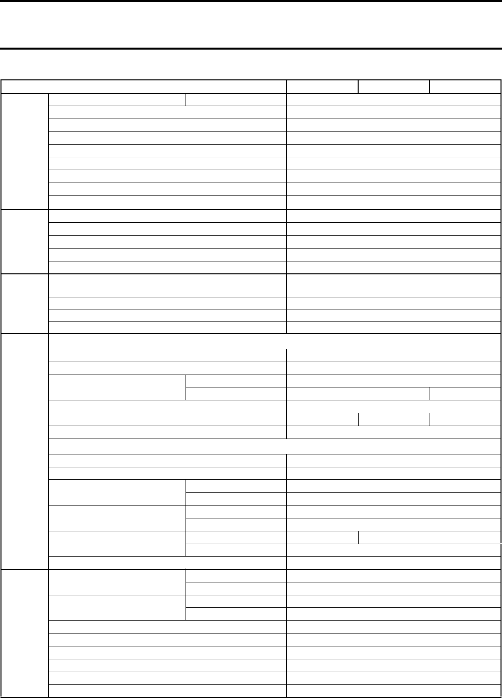
Section 11 TECHNICAL DATA
Subsection 02 (ENGINE AND VEHICLE)
VMR2004_031_11_02A.FM 11-02-3
VEHICLE MODEL DS 650 DS 650 BAJA DS 650 BAJA X
TRANSMISSION
Transmission Type Integrated 5-Speed Constant Mesh Transmission
Clutch 1 Multi-Disc
Clutch Drum I.D. mm (in) 145 (5.71)
Friction Plate Warpage (fall through a slot) mm (in) 3.75 (.1476)
Friction Plate Wear Limit of the Whole Package mm (in) 27.5 (1.0827)
Steel Driven Plate Warpage (fall through a slot) mm (in) 1.63 (.0642)
Steel Driven Plate Wear Limit of the Whole Package mm (in) 11.5 (.4528)
Clutch Spring Minimum Rate 27.4 mm @ 210 N (1.0787 in @ 47 lbf)
Clutch Spring Minimum Length mm (in) 43 (1.69)
DRIVE
TRAIN
Drive Chain Regina 530 ORT4
Engine Pinion Teeth 16
Axle Sprocket Teeth 40
Rear Axle Shaft Driven/Solid Axle
Rear Axle Ratio 3.6: 1
STEERING/
CONTROL
Turning Radius mm (in) 3159 (124)
Total Toe-Out (vehicle on ground) mm (in) 0.5 ± 0.5 (.0197 ± .0197)
Camber Angle/Caster Angle 0°/5.7°
Tie-Rod Maximum Length Unengaged mm (in) 20 ± 5 (.787 ± .197)
Tie-Rod Maximum Length mm (in) 452 (17.78)
SUSPENSION
FRONT
Suspension Type Independent Suspension — Double A-Arm
Suspension Travel mm (in) 305 (12)
Shock Absorber Qty 2
Type Oil Oil/Gas
Spring Free Length mm (in) 368 (14.5)
Spring Color Code Gold/Blue/Black Gold/Green/Black Green/Blue/Blue
Front Preload Adjustment Seat of Spring Threaded
REAR
Suspension Type Rigid Swing Arm
Suspension Travel mm (in) 279.4 (11)
Shock Absorber Qty 1
Type Oil/Gas
Spring Free Length Short mm (in) 52.7 (2.07)
Long mm (in) 251.5 (9.90)
Spring Color Code Short White/Yellow/Black Silver/Yellow/Black
Long Blue/Red/Red
Rear Preload Adjustment Seat of Spring Threaded
BRAKES
Front Brake Qty 2 discs
Type Hydraulic
Rear Brake Qty 1 disc
Type Hydraulic
Parking Device RH Brake Lever Includes a Lock on Front Wheels
Lining Material Metallic
Minimum Pad Thickness 1 mm (0.04 in) or Refer to the Mark on the Pad
Minimum Brake Disk Thickness mm (in) 3.5 (.138)
Maximum Brake Disk Warpage mm (in) 0.25 (.01)
Caliper Floating

Section 11 TECHNICAL DATA
Subsection 02 (ENGINE AND VEHICLE)
11-02-4 VMR2004_031_11_02A.FM
VEHICLE MODEL DS 650 DS 650 BAJA DS 650 BAJA X
TIRES AND WHEELS
TIRE
Pressure
Front Recommended 34 kPa (5 PSI)
Minimum 21 kPa (3 PSI)
Rear Recommended 34 kPa (5 PSI)
Minimum 21 kPa (3 PSI)
Minimum Tire Thread Depth mm (in) 4 (0.16)
Size Front 22 x 7 x 10
Rear 20 x 10 x 9
WHEELS
Size Front 10 x 5.5
Rear 9 x 8.5
DIMENSION
Overall Length mm (in) 1956 (77) 1968 (77.5)
Overall Width Front mm (in) 1232 (48.5)
Rear mm (in) 1232 (48.5)
Overall Height mm (in) 1206 (47.5)
Dry Weight kg (lb) 225 (495)
Total Vehicle Load Allowed kg (lb) 125 (275.5)
Wheel Base mm (in) 1244 (49)
Wheel Track Front mm (in) 1048 (41)
Rear mm (in) 978 (38.5)
Front and Under Engine Ground Clearance mm (in) 297 (11.7)
Rear Rigid Axle Ground Clearance mm (in) 120 (4.75)
CAPACITIES
LIQUID
Fuel Tank 12 L (3.5 U.S. gal)
Fuel Tank Reserve 2.4 L (0.6 U.S. gal)
Engine/Transmission Oil
Capacity 3 L (0.8 U.S. gal)
Recommended
SAE 10W40, 4 Stroke Mineral Based Oil SG, SH or SJ
or Bombardier synthetic oil 5W40 (P/N 293 600 039).
Do Not Use Synthetic Oil, other than Bombardier brand name or
any Synthetic Blend Oil.
Refer to OIL VISCOSITY CHART for proper grade.
Hydraulics Brakes Capacity 250 mL (8.5 U.S. oz)
Recommended Brake Fluid DOT 4, ONLY
Cooling System Capacity 1.75 L (0.58 U.S. gal)
Recommended Use Coolant Specially Designed for Aluminum Engine
Ethylene-Glycol Concentration 50%
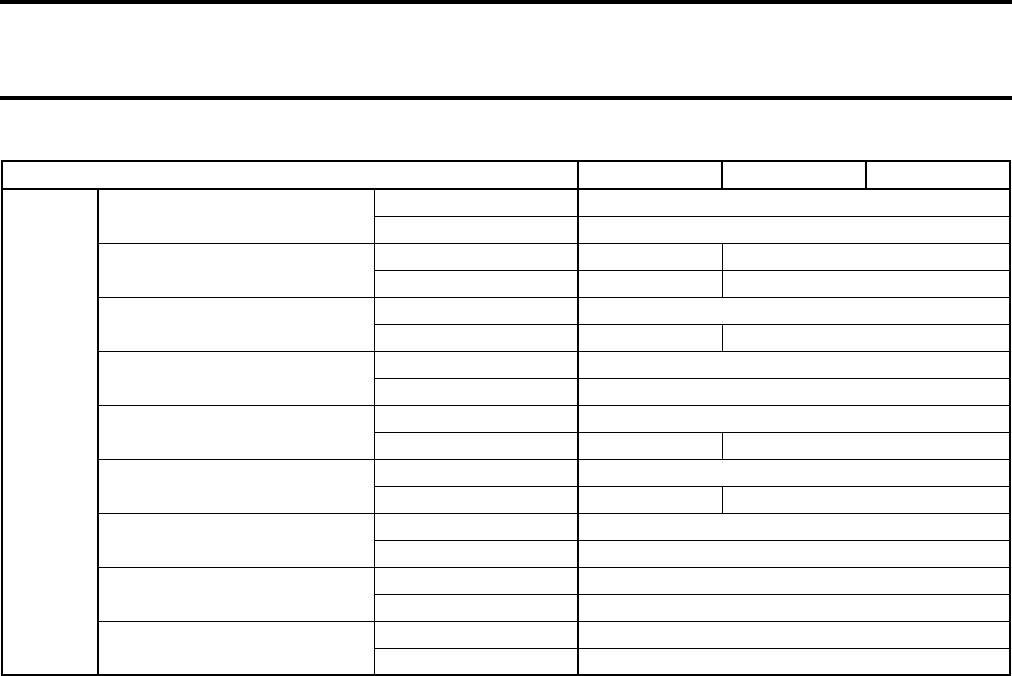
Section 11 TECHNICAL DATA
Subsection 02 (ENGINE AND VEHICLE)
VMR2004_031_11_02A.FM 11-02-5
VEHICLE MODEL DS 650 DS 650 BAJA DS 650 BAJA X
MATERIAL
Frame Material Steel
Color Grey
Front/Rear Bumper Material Steel Aluminum
Color Grey Aluminum
Front/Rear Fender Material High Density Polyethylene
Color Yellow or Black Orange
Fuel Tank Cover Material High Density Polyethylene
Color Black
Steering Cover Material Foam and Vinyl
Color Yellow or Black Orange
Front Facia Material High Density Polyethylene
Color Red Black
Air Box and Cover Material Low Density Polyethylene
Color Black
Mudguard Material Synprene
Color Black
Seat Cover Material Vinyl
Color Black/Orange
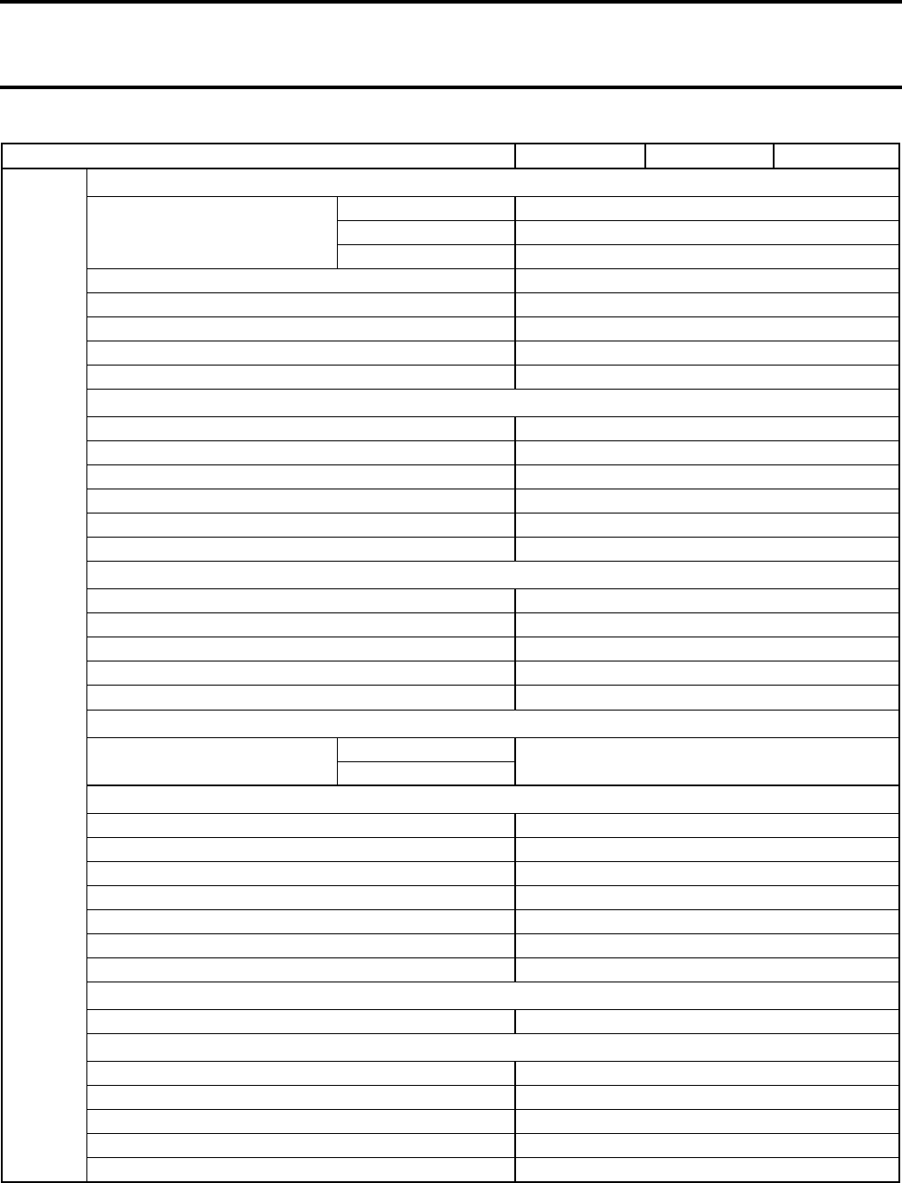
Section 11 TECHNICAL DATA
Subsection 02 (ENGINE AND VEHICLE)
11-02-6 VMR2004_031_11_02A.FM
VEHICLE MODEL DS 650 DS 650 BAJA DS 650 BAJA X
TORQUE
ENGINE
Engine Support
M8 26 N•m (19 lbf•ft)
M10 64 N•m (47 lbf•ft)
M14 135 N•m (100 lbf•ft)
Spark Plug 20 N•m (15 lbf•ft)
Magneto Nut 180 N•m (133 lbf•ft)
Starter 10 N•m (89 lbf•in)
Starter Red (+) Cable 6 N•m (53 lbf•in)
Oil Pressure Switch 12 N•m (106 lbf•in)
COOLING
Radiator Mount Screw/Nut 10 N•m (89 lbf•in)
Radiator Protector 1.5 N•m (13 lbf•in)
Temperature Sensor 22 N•m (16 lbf•ft)
Water Pump Cover 10 N•m (89 lbf•in)
Fan Mount Screw/Nut 11 N•m (97 lbf•in)
Temperature Sender 35 N•m (26 lbf•ft)
EXHAUST
Exhaust Pipe Nut 11 N•m (97 lbf•in)
Heat Shield Screws 10 N•m (89 lbf•in)
Exhaust Pipe Collar 15 N•m (133 lbf•in)
Muffler Support 26 N•m (19 lbf•ft)
Pipe Support 10 N•m (89 lbf•in)
FUEL
Carburetor Mounting Clamp Engine Side 2.5 N•m (22 lbf•in)
Air Box Side
DRIVE TRAIN
Front Wheel Hub Nut 135 N•m (100 lbf•ft) (MINIMUM)
Rear Wheel Hub Nut 235 N•m (173 lbf•ft) (MINIMUM)
Rear Axle Adjusting Nut Refer to REAR AXLE section for the proper torquing sequence.
Sprocket Protector 4 N•m (35 lbf•in)
Eccentric Axle Housing Bolts 44 N•m (32 lbf•ft)
Sprocket Nuts 80 N•m (59 lbf•ft)
Chain Roller 23 N•m (17 lbf•ft)
WHEEL
Wheel Nuts 53 N•m (39 lbf•ft)
STEERING/CONTROL
Tie Rod Ends 75 N•m (55 lbf•ft)
Steering Arm (castellated nut) 58 N•m (43 lbf•ft)
Steering Column Support Screws 23 N•m (17 lbf•ft)
Handlebar Screws 23 N•m (17 lbf•ft)
Flanged Bearing Bolts 10 N•m (89 lbf•in)
Section 11 TECHNICAL DATA
Subsection 02 (ENGINE AND VEHICLE)
VMR2004_031_11_02A.FM 11-02-7
VEHICLE MODEL DS 650 DS 650 BAJA DS 650 BAJA X
TORQUE
SUSPENSION
Shock Absorber Bolt Front 48 N•m (35 lbf•ft)
Rear 85 N•m (63 lbf•ft)
Rear Swing Arm LH First Nut 100 N•m (74 lbf•ft), Unscrew Nut a Quarter Turn
Rear Swing Arm LH Nut 100 N•m (74 lbf•ft)
Upper/Lower A-Arm Lock Nut 60 N•m (48 lbf•ft)
Ball Joint Nuts 50 N•m (37 lbf•ft) MINIMUM
BRAKE
Caliper Brake Screws 24 N•m (17 lbf•ft)
Brake Disk Screws 34 N•m (25 lbf•ft)
BODY/FRAME
Front Bumper 24 N•m (17 lbf•ft)
Rear Extension Frame 48 N•m (35 lbf•ft)
Footrest 10 N•m (89 lbf•in)
Skid Plate 4 N•m (35 lbf•in)
Section 12 WIRING DIAGRAMS
Subsection 01 (WIRING DIAGRAMS)
VMR2004_032_12_01A.FM 12-01-1
WIRING DIAGRAMS 0
WIRE COLORS
It identifies the color of a wire. When a 2-color
scheme is used, the first color is the main color
while the second color is the tracer color.
Example: YL/BK is a YELLOW wire with a BLACK
stripe.
WARNING
Ensure all terminals are properly crimped on
the wires and all connector housings are
properly fastened.
COLOR CODE
BK — BLACK
BL — BLUE
BR — BROWN
GN — GREEN
GY — GREY
OR — ORANGE
PK — PINK
RD — RED
TA — TAN
VI — VIOLET
WH — WHITE
YL — YELLOW

Section 12 WIRING DIAGRAMS
Subsection 01 (WIRING DIAGRAMS)
12-01-2 VMR2004_032_12_01A.FM
DS 650
LOW
HI
+
-
GND
OUT
IN -
IN +
NEUTRAL
CHECK
YL
YL
YL
RD / VI
YL / GY
RD / VI
BR / WH
BK / GY
BR / BK
OFF
ON
RD / VI
RD / OR
YL / GY
VI / BL
RD
RD
BK
BK / GY
BK
BN
RD
BK
BP
BK BK
RD
RD
25A
STARTER
BL
GN
TA
BL
GN
BK
BK
TA
RUN
OFF
BK / WH
BK
BK / WH
YL / RD
RD / VI
START
LOW
OFF
BK / YL
BK
RD / VI
BK / YL
BK / WH
BK
BK
RD
RD
+12V
BK / WH
RED
GREEN
NEUTRAL LED OIL/TEMP LED
LT
KEY SWITCH
CC
FRONT BRAKE SWITCH
FV
REAR BRAKE SWITCH
FR
TAIL LIGHT
PR
HEAD LIGHT
PV
ELECTRONIC MODULE
ME
IGNITION COILS
BA
BA
TRIGGER COIL
CA
MAGNETO
MA
VOLTAGE REGULATOR
RV
M
BATTERY
CLUTCH
SWITCH
IE
NEUTRAL
SWITCH
IN
D1
STARTER
SOLENOID
SS
MAIN FUSE
BF1
FAN THERMOSTATIC
FT
OIL PRESSURE
SWITCH
PM
N.C
OVERHEAT
SWITCH
OH
N.D
15A
FAN SWITCH
IT
FAN FUSE
BF2
MULTI-FUNCTION SWITCH
MG
MG MG
DS 650
V02Z01
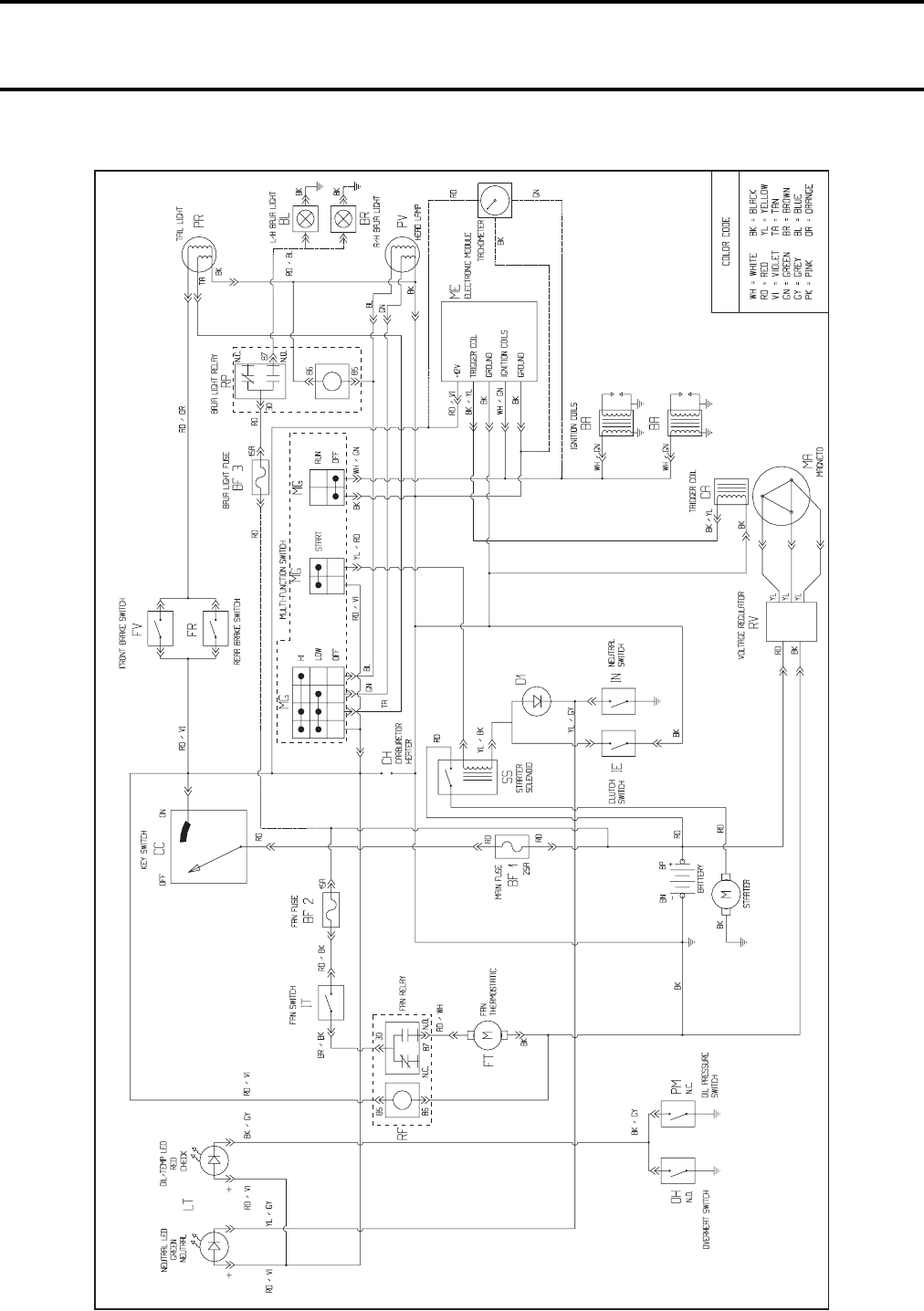
Section 12 WIRING DIAGRAMS
Subsection 01 (WIRING DIAGRAMS)
VMR2004_032_12_01A.FM 12-01-3
DS 650 Baja/Baja X
DS 650 BAJA/BAJA X
V02Z03
