BPI Bit User Manual
User Manual:
Open the PDF directly: View PDF ![]() .
.
Page Count: 21
Banana Pi BPI:bit
User Manual
Hardware introduction
Software introduction
How to setup and start
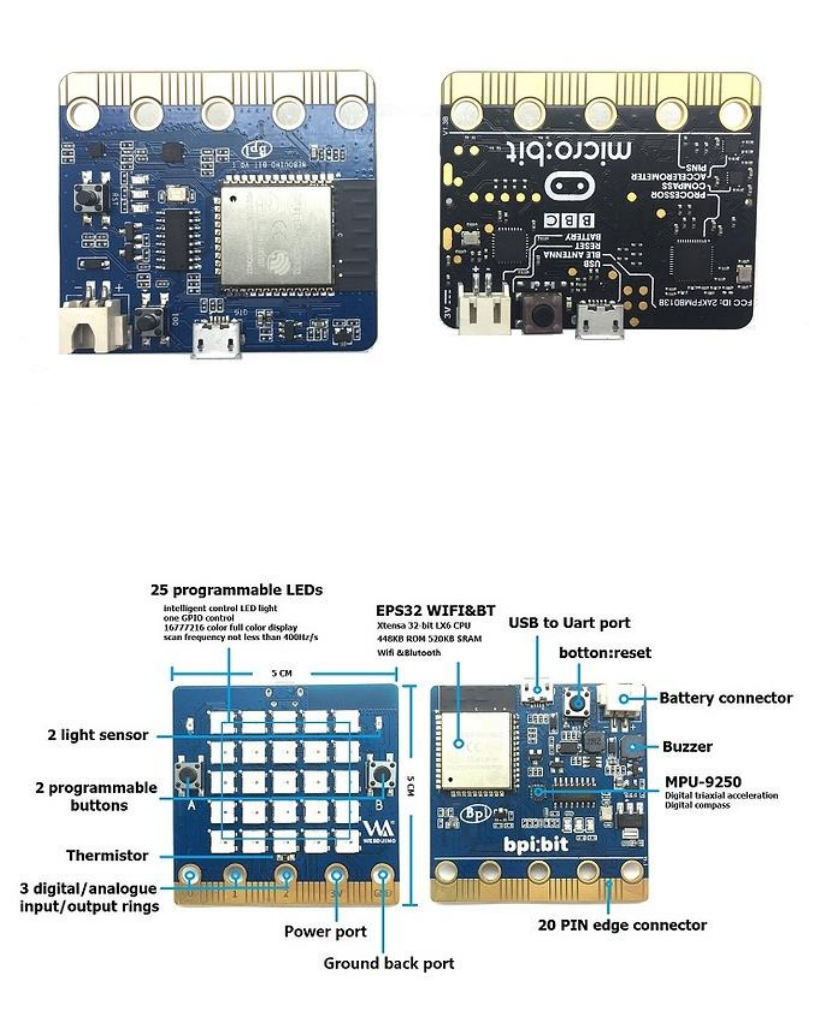
Hardware introduction
BPI:bit uses the ESP-WROOM-32 of espressif company as MCU. ESP32 is a single-chip
solution integrating 2.4GHz Wi-Fi and Bluetooth dual mode. The 40 nanometer technology
of TSMC has the best power consumption, RF performance, stability, versatility and reliability.
It can deal with various application scenarios.
Two separate controlled CPU cores, the main frequency can be up to 240MHz, 448KB ROM,
520KB SRAM.
BPI:bit The appearance size is fully matched with Arduino UNO R3
Hardware Interface:
The BPI:bit is powered by a microUSB or 5.5mm DC power adapter and has an automatic
switching circuit.
BPI:bit hardware spec
Hardware Specification of Banana pi BPI:bit
CPU
Xtensa® 32-bit LX6 single / dual core processor
ROM
448KB
SRAM
520KB
Flash
4MB(On board),A maximum of 4 Flash/SRAM, each Flash maximum 16MB
Power
5V@1A microUSB power or 5.5mm 12V DC port
GPIO
12-bits SAR ADC 18 channel, 2*8-bit D/A converter, 4*SPI, 2*I2S, 2*I2C,
3*UART, Host SD/eMMC/SDIO, Slave SDIO/SPI
Wi-Fi
802.11 b/g/n/e/i 802.11 n(2.4GHz 150Mbps) 802.11 e(Quality of
Service)
Bluetooth
BT4.2 & BLE
Buzzer
Passive buzzer
LEDs
RGB LED/POWER LED/Receive LED/Transmit LED
Sizes
68mm*53mm
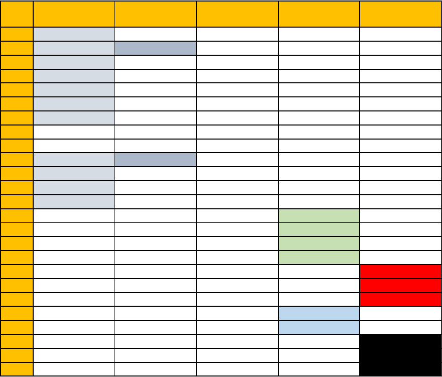
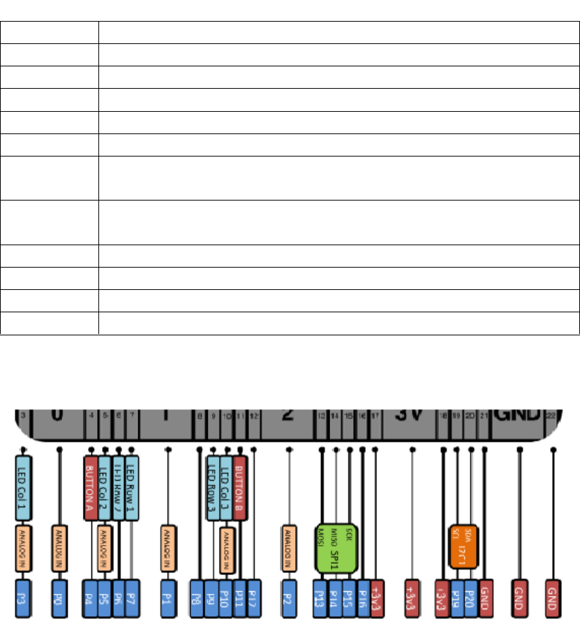
BPI:bit Pin Define
Pin
Name
Analog Function1 Analog Function2 Function1 Function2 Power
P3
ADC2_CH4 GPIO13
P0
ADC2_CH8 DAC_1 GPIO25
P4
ADC2_CH3 GPIO16
P5
ADC1_CH7 GPIO35
P6
ADC2_CH5 GPIO12
P7
ADC2_CH6 GPIO14
P1
ADC1_CH4 GPIO32
P8
GPIO16
P9
GPIO17
P10
ADC2_CH9 DAC_2 GPIO26
P11
ADC2_CH7 GPIO27
P12
ADC2_CH2 GPIO02
P2
ADC1_CH5 GPIO33
P13
GPIO18 SPI_SS
P14
GPIO19 SPI_SCK
P15
GPIO23 SPI_MISO
P16
GPIO05 SPI_MOSI
3V3
POWER:3V3
3V3
POWER:3V3
3V3
POWER:3V3
P19
GPIO22 I2C_SCL
P20
GPIO21 I2C_SDA
GND
GROUND
GND
GROUND
GND
GROUND

Software introduction
BP:bit can be programmed by many compiling environments, such as PlatformIO for
Atom/VS Code, Arduino IDE, uPyCraft (microPyhton) and ESP-IDF, etc.
PlatformIO for Atom/VSCode Project examples can be viewed:
https://github.com/yelvlab/BPI-
uno32_Webduino/blob/master/Test_Code/PlatformIO_VSCode/src/main.cpp
PlatformIO for Atom/VS Code detailed installation introduction please click the following
connection:
http://docs.platformio.org/en/latest/ide.html#platformio-ide
Arduino The IDE installation method can look at the official Arduino forum, the links:
http://www.arduino.cn/thread-41132-1-1.html
You can also look at GitHub's introduction to the Arduino IDE burning document:
https://github.com/yelvlab/BPI-uno32_Webduino/tree/master/Burning/Arduino_IDE
uPyCraft(microPython)The GitHub link of the related data is:
https://github.com/DFRobot/uPyCraft
Programming & Burning:
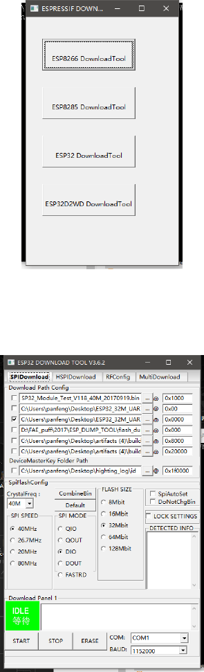
ESPFlashDownloadTool:
Tools: ESP FLASH DOWNLOAD TOOL
First, download the FLASH_DOWNLOAD_TOOLS_V3.6.2 compression package, unpack the
file in the package and run the tool.
Run step: when double click open ESPFlashDownloadTool_v3.6.2, select ESP32 DownloadTool
After the selection, the following software interface will be displayed:
For the ESP32 burning test, the test firmware should be selected and the following
modifications should be made:
Download Path Config

We choose firmware files in turn and modify the burning location. The firmware files are
corresponding to the burning location (the location is test firmware folder in the compressed
package).
bootloader.bin
0x1000
partitions.bin
0x8000
boot_app0.bin
0xe000
firmware.bin
0x10000
1. CrystalFreq
Modify it to 26M
2. SPI SPEED
Select 80MHz
3. SPI MODE
Select DIO
4. FLASH SIZE
Select 32Mbit
5. BAUD
Modify it to115200
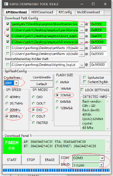
Set as below:
Then select the hardware to connect the serial port, click START to start automatically
downloading, the above is the successful software state (FINISH completes), reset the
hardware or re power up, so that the software will start running.
Firmware introduction: firmware is divided into four BIN files, and four files must be burned
to ensure normal operation. Firmware content is a blink program with LED_Pin IO2. After
burning, the IO2 pin level can be measured, and the level interval is 1s.
Arduino IDE:
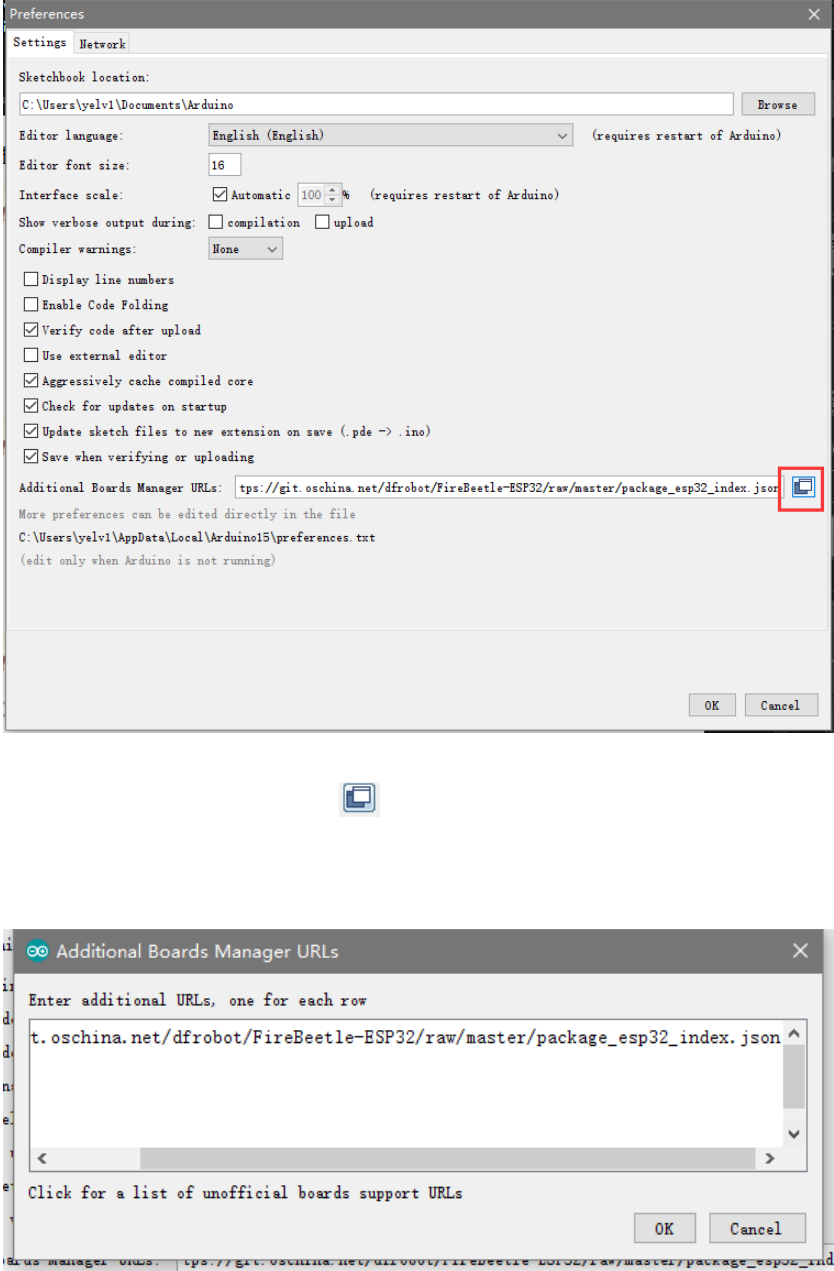
1. Open File -> Preferences, as shown in the following figure:
2. Click the button in the red circle above and add the following URL
in the newly popped window:
https://git.oschina.net/dfrobot/FireBeetle-
ESP32/raw/master/package_esp32_index.json
As shown below:
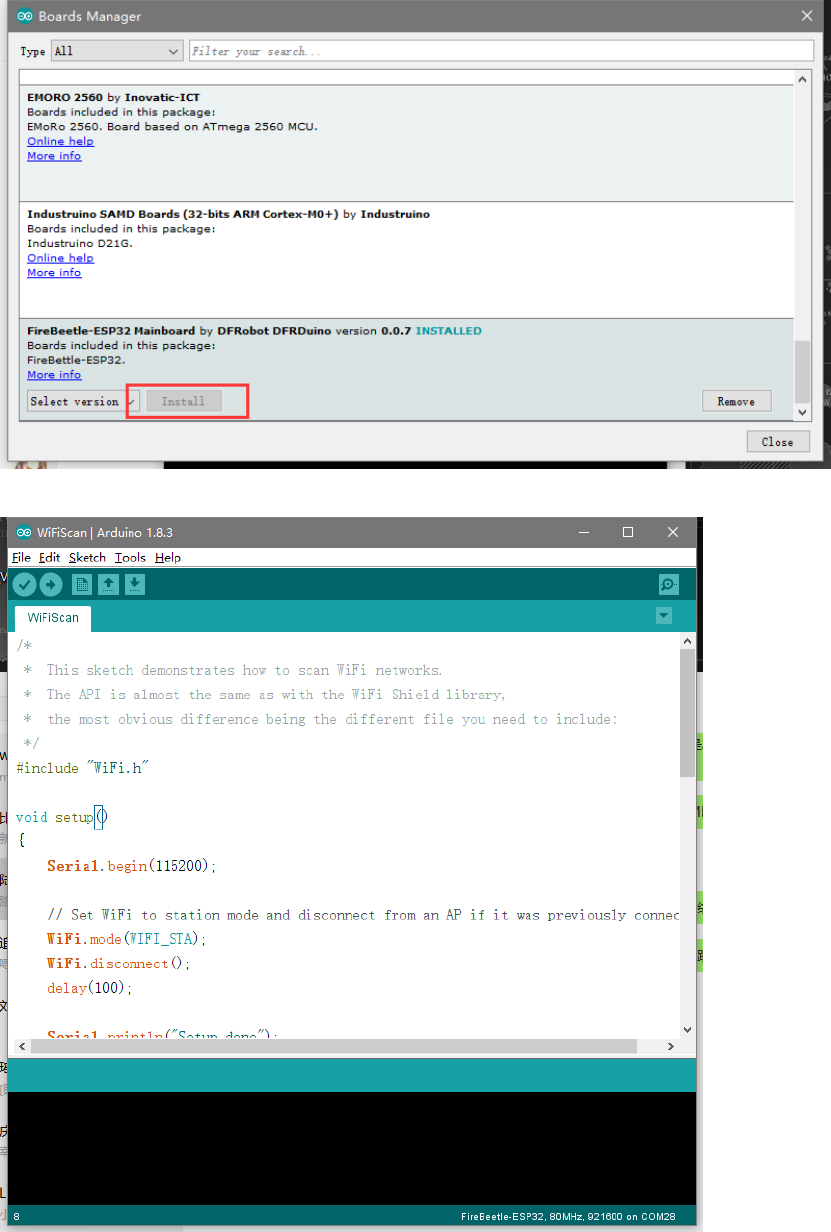
3. Open Tools->Board->Board Manager. Pull down to see FireBeetle-ESP32 and click Install.
4. Open a project in the upper left corner of the file, or open an example.
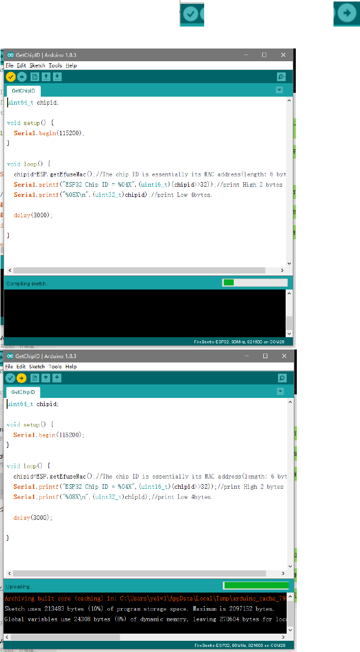
5. Select a correct port in Tools -> Ports, then click will be compiled code,click
will be burn program。
PlatformIO for Atom/VS Code
1. First open the PlatformIO Home page, then click Open Project to open the project. (You
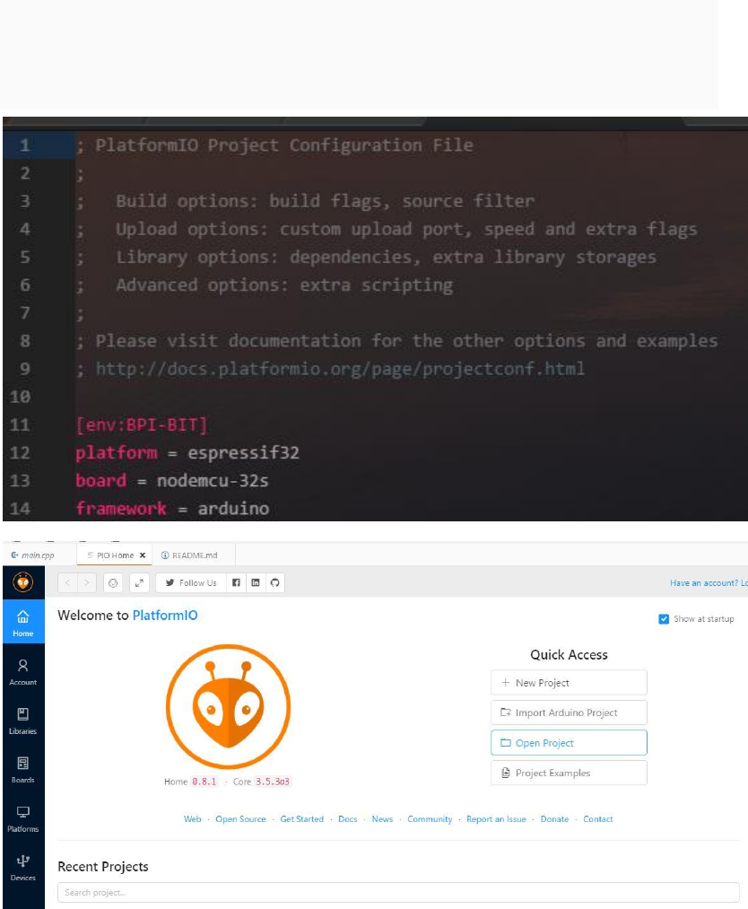
can choose the test code.) If you write your own code to burn, then the platformio.ini file
should write the following code
[env:BPI-BIT]
platform = espressif32
board = nodemcu-32s
framework = arduino
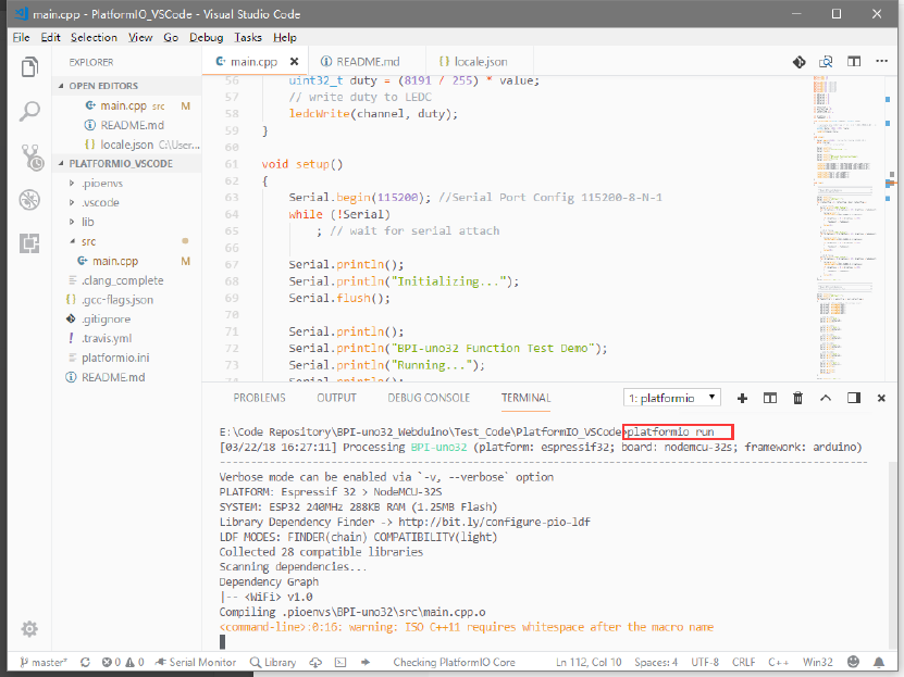
2. The code path under PlatformIO project is generally src/main.cpp. Open the code and
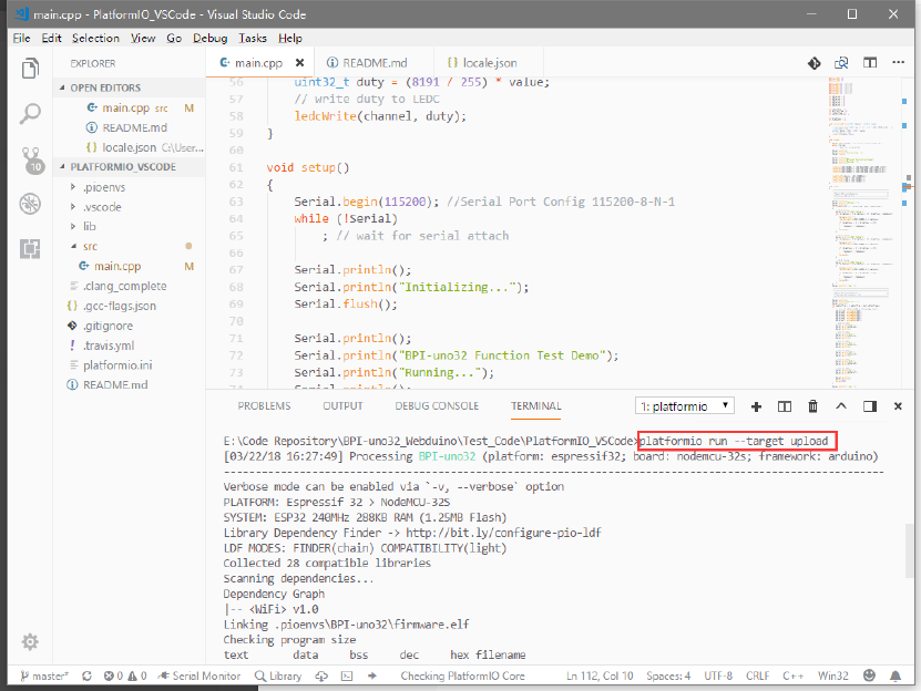
use Ctrl+` to open the terminal debugger. Enter platformio run --target upload.
3. Make sure the board is connected. The program will be compiled first and then burned
into the BPI-uno32 board. There are some points to note. If the above code does not
specify the port, please try to avoid other serial devices connected on the computer. For
serial port numbers, run platformio --help.
uPyCraft(microPyhton):
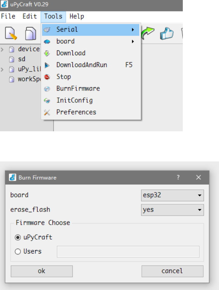
1. first open the uPyCraft software, click the Tools->Serial port to select the port in the upper
toolbar. After selecting port, the software will automatically decide whether to burn the
firmware, if necessary, the interface will be popped up.
2. when the software interface is opened, we choose ESP32 in board. If erase_flash chooses
yes, it will wipe out the original flash first, and generally choose to erase it, so that the
original flash will have an impact on it now.
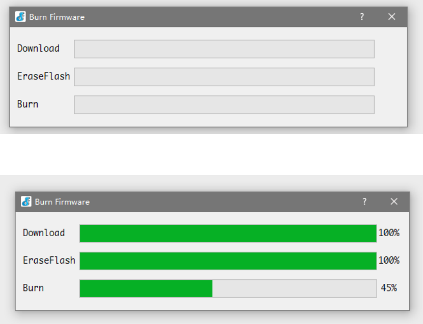
3. after the selection, click Yes to start the burning, there will be the following dialog, only
to wait for it.
when the Burn column is full, the dialog box automatically closes and displays the software
master interface.
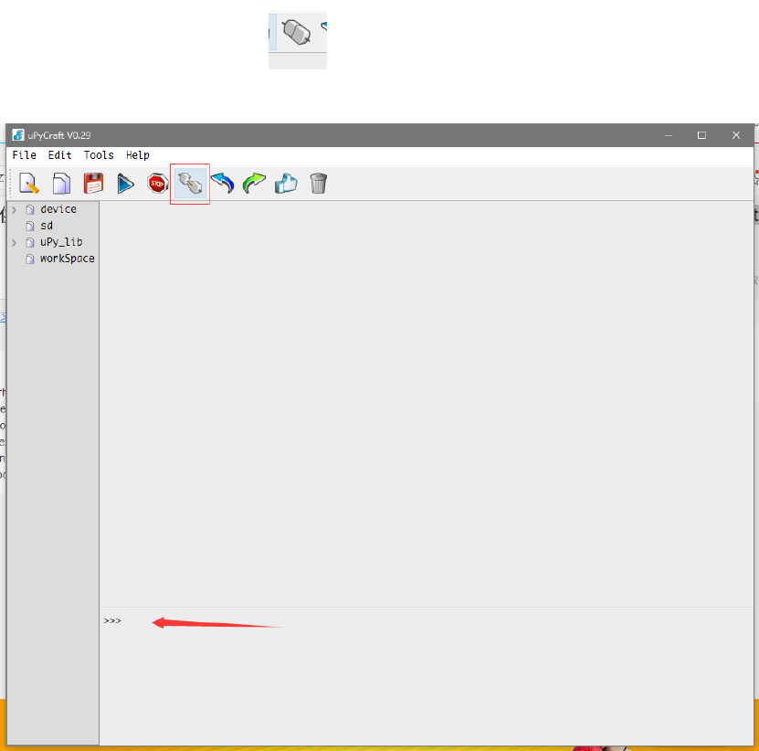
4. In the main interface we can click to connected. It is located in the lower row of the
toolbar. The following interface will appear after the connection
This means we can appear > > > for interactive programming like to Python in the following
dialogue.

Basic function test:
You can visit GitHub to download the test code, compile, burn, and observe the test results
through the serial port.
Project link (PlatformIO):
https://github.com/yelvlab/BPI-
BIT/tree/master/Test_Code/BasicFunction/PlatformIO_VSCode
MPU9250 test:
You can visit GitHub to download the test code, compile, burn, and observe the test results
through the serial port.
https://github.com/yelvlab/BPI-BIT/tree/master/Test_Code/MPU9250/PlatformIO_VSCode
How to setup and start
Need to be prepared:BPI-UNO32*1、Jumper Cap*4、microUSB*1
quickstart:
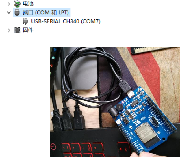
1. connect the four jumper caps to the top of the board, respectively, to connect the RGB
LED to the buzzer. Then use the microUSB line to connect the development board to the
computer.
Port:
connected:
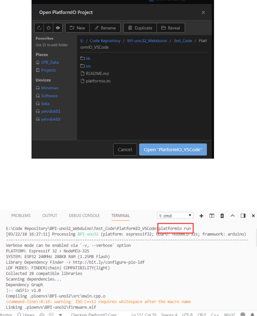
open VS Code (you can also choose other compilers) and open BPI-UNO32 on the
PlatformIO Home page Code project, for example, to open a test code engineering
folderPlatformIO_VSCode。
Project:
open the VS Code terminal console, input <platformio run>, compile the program, input
<platformio run --target upload>, compile and burn the program. (if it hasn't been
compiled before, it may be slow to compile the first time and need to be connected
because he needs to get the corresponding platform information).
platformio run:
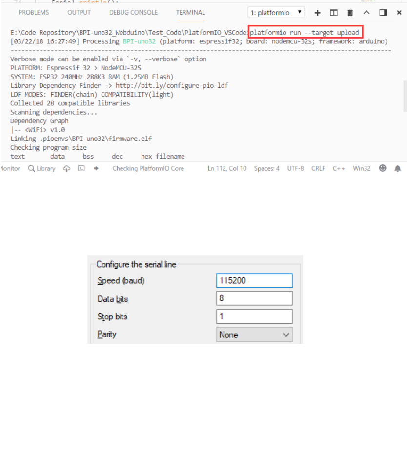
platformio run --target upload:
2. then open the serial port assistant tool, select BPI-UNO32 on the computer
corresponding to the serial serial number, the serial port settings are selected as:
Baud rate: 115200 Data bit: 8 Parity check: no Stop bit: 1
Serial Config:
3. Test content:
RGB LED fading.
AD acquisition and testing of 6 ADC_channel1.
WiFi scan testing.
Control test of buzzer gradient.
