BRUEL & KJAER/BRUEL KJAER 2238 Basic SLM Software
User Manual: BRUEL & KJAER/BRUEL & KJAER 2238 Basic SLM Software
Open the PDF directly: View PDF ![]() .
.
Page Count: 165 [warning: Documents this large are best viewed by clicking the View PDF Link!]

Technical
Documentation
English BB1119 – 11
2238 Mediator
Integrating Sound Level Meter
Basic SLM Software BZ7126

February 1999
Brüel & Kjær BB1119 – 11
2238 Mediator
Integrating Sound Level Meter
Basic SLM Software BZ 7126

0–4 Brüel & Kjær2238 Mediator
User Manual
Trademarks
2238 Mediator is a trademark of Brüel&Kjær A/S. Microsoft, Win-
dows, and MS-DOS are trademarks of Microsoft Corporation.
Copyright © 1998, Brüel & Kjær Sound & Vibration Measurement A/S
All rights reserved. No part of this publication may be reproduced or
distributed in any form, or by any means, without prior consent in writ-
ing from Brüel & Kjær Sound & Vibration Measurement A/S, Nærum,
Denmark.

BB1119 – 11 0–5
2238 Mediator
User Manual
4
1
Contents
About this manual and the 2238 Mediator. Overview of
measurement parameters, menus and navigation
Basic introduction to the Mediator: Fitting batteries, pushkey
definitions, Measurement Window and changing the language
Explains how to set up parameters in the System menu
Explains how to set up parameters in the Measurement Set-up menu
Explains how to perform simple measurements: Calibrating,
starting a new measurement, measurement control and changing
the displayed measurement parameters
Explains how the data file system works: Storing, recalling, printing
and deleting data
Explains how to export data to a PC and post-processing programs,
how to set up a printer
Service, repair, care, cleaning and storage of the Mediator
Introduction
2
Getting Started
3
The System Menu
The Measurement Set-up Menu
5
Measuring
6
Data Handling
7
Printing and Transferring Data
8
Maintenance and Repair

0–6 Brüel & Kjær2238 Mediator
User Manual
9Specifications for the Mediator
Specifications
10 Appendix 1: General
Appendix 2: Interface
Index
Information about: Exchange Rate, listing of default parameters and
interface error messages
11
12
Explains the programming and operation of the serial interface for
the Mediator: Formats for interface messages, setting up the PC and
interface jobs

BB1119 – 11 1–1
2238 Mediator
User Manual
Chapter 1
Introduction
1.1 About this Manual.............................................................. 1–2
Summary of Contents........................................................ 1 – 2
About this Volume............................................................. 1 – 3
1.2 About the 2238 Mediator ................................................. 1 – 4
How the Mediator Works .................................................. 1 – 5
Application Programs........................................................ 1 – 5
1.3 Measurement Parameters............................................... 1 – 7
1.4 Menu Structure.................................................................. 1 – 10
Navigation........................................................................ 1 – 10
System Menu ................................................................... 1 – 11
Measurement Set-up Menu ............................................ 1 – 11
Calibration Menu ............................................................ 1 – 12
File System ...................................................................... 1 – 12
1.5 Backlight ............................................................................... 1 – 14

Chapter 1 – Introduction
About this Manual
1–2 Brüel & Kjær2238 Mediator
User Manual
1.1 About this Manual
1.1.1 Summary of Contents
●Chapter 1 – Introduction: provides a general overview
of the Mediator and its functions.
●Chapter 2 – Getting Started: provides basic informa-
tion including: replacing batteries, using the pushkeys,
reading the screen, and setting the language.
●Chapter 3 – System Menu: provides an overview of the
System menu and gives instructions for setting up the
parameters.
●Chapter 4 – Measurements Set-up Menu: provides an
overview of the Measurement Set-up menu and gives
instructions for setting up the measurement parameters.
●Chapter 5 – Measuring: gives instructions for calibrat-
ing the Mediator and for checking the calibration and the
calibration history. It provides information about starting
a new measurement.
●Chapter 6 – Data Handling: contains information and
instructions about using the file managing system.
●Chapter 7 – Printing and Transferring Data: pro-
vides information about outputting data to a printer or
a PC and setting up the output connectors.
●Chapter 8 – Maintenance and Repair: gives informa-
tion about care, cleaning and storage and contains service
and repair information.
●Chapter 9 – Specifications: – technical specifications.
●Appendix 1: General: – describes the exchange rate
parameter and lists the default parameters and interface
error messages.
●Appendix 2: Interface: – gives a general description of
the terminology for the interface messages and instruc-
tions for using the interface commands and queries
●Index

Chapter 1– Introduction
About this Manual
BB1119 – 11 1–3
2238 Mediator
User Manual
1.1.2 About this Volume
This volume of the User Manual deals with all the general
aspects of handling and setting up the Mediator and includes
instructions for the functionality of the Basic version (Basic
SLM Software BZ7126). If your Mediator has been upgraded
to other version(s), you must refer to the associated User
Manual(s) for the special functions related to these software
versions.
Conventions Used in this Manual
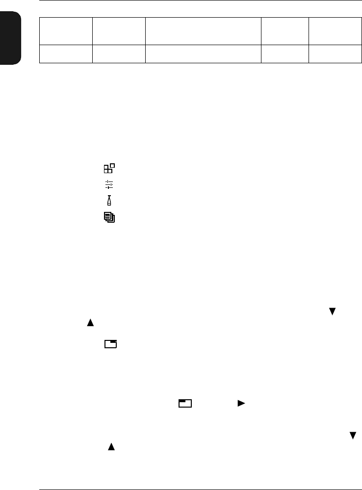
Pushkeys
References to buttons on the 2238 Mediator are shown with
the pushkey’s pictogram as it appears on the instrument (for
example ). Refer to section 2.3 for a complete list of button
pictograms and their functions.
Soft Keys
Mediator has two “soft keys” that have different functions
depending on the current context. The soft keys functions are
denoted by chevrons (<>) and courier type face. The current
functions of the soft keys are always shown on the display.
The soft key can have the following functions: <Select>,
<Save>, <Ok> or <Menu>. The soft key can have func-
tions: <Cancel>, <Undo> or <Close>. This is similar to
the functionality from the familiar Windows environment.
Parameter Text
Text which refers directly to text on the instrument’s screen
or printouts is indicated using a Courier type face.
For example: Press until Language is highlighted in the
System menu.
Sockets
Reference to sockets is made in bold type face (for example,
Aux 1)

Chapter 1 – Introduction
About the 2238 Mediator
1–4 Brüel & Kjær2238 Mediator
User Manual
1.2 About the 2238 Mediator
Standards
2238 Mediator Integrating Sound Level Meter complies with
the coming IEC1672 Class 1 standard. This standard will
supersede the IEC651 and IEC 804 Type 1 standards. This
implies that the Mediator also complies with current inter-
national and national standards. The Mediator is categorized
as a Group X sound level meter according to IEC 1672, i.e. a
self-contained battery-operated instrument that requires no
external connections to other apparatus to measure sound
levels.
Basic Configuration
The Mediator comprises the following:
●2238 Mediator Integrating Sound Level Meter
●Basic SLM Software BZ 7126
●Microphone Preamplifier ZC 0030
●Prepolarized free-field 1/2″ Condenser Microphone Type
4188
●9-pole cable with 25-pole Adaptor AO 1386 (null-modem
cable for serial interface)
●Shoulder Bag KE 0323
●Protective Cover UA1236
●4×Alkaline Batteries QB 0013
1.2.1 How Mediator Works
The Mediator can be configured to a wide range of require-
ments with different software packages or a combination of
these packages. You can easily upgrade the software via the
serial RS – 232 interface or it can be performed at a
Brüel & Kjær service centre. The Frequency Analysis Soft-
ware option requires Type 2238 – A – F (with filter set) or a
hardware upgrade (installation of filter set 2238MUF), that

Chapter 1– Introduction
About the 2238 Mediator
BB1119 – 11 1–5
2238 Mediator
User Manual
must be made at a Brüel& Kjær service centre. If the Medi-
ator is ordered with Frequency Analysis Software BZ 7123,
the filter set is part of the instrument.
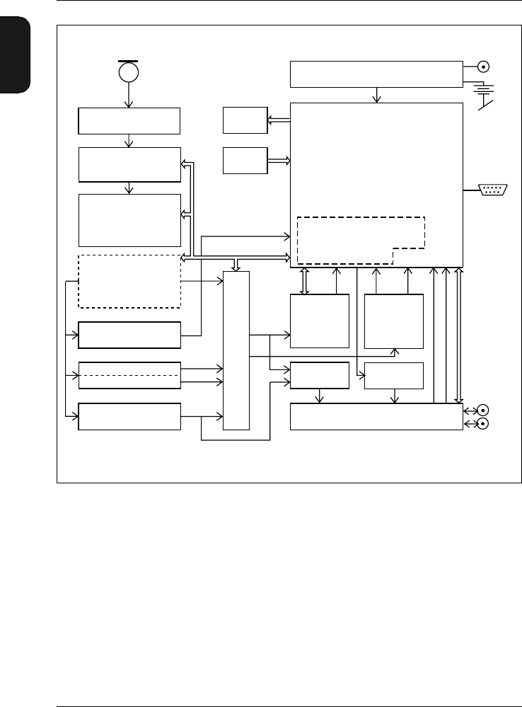
Refer to the block diagram in Fig.1.1 for an overview of how
the Mediator works. The signal from the microphone is fed
through the appropriate amplifiers, the desired filters (“A”,
“C”, “L” or octave filters (if fitted)) and correction filters
(“Sound Incidence”, “Windscreen”). The multiplexer switches
two signals (either the same signal or with different weight-
ings) through to the RMS and the RMS/Peak detectors and
succeeding Time Weighting filters. At this point the signals
are still in the analogue domain. The signals are now con-
verted in the D/A-converter and all subsequent signal process-
ing is in the digital domain. Finally the signals are fed
through the D/A-converter and the buffered signals are out-
put to the Aux 1 and Aux 2 connectors via the multiplexer.
Detectors
One of the main features of the Mediator is that it contains
two detectors with independent frequency weighting func-
tions. In the basic package, one is an RMS detector and the
other a Peak detector. Linear and A- and C-weighting can be
selected for both detectors. F (Fast), S (Slow) and I (Impulse)
time weighting must be selected in the basic version. Both
frequency and time weightings must be selected before a
measurement is performed.
1.2.2 Application Programs
The following software modules are available for upgrading
the Mediator:
●Frequency Analysis Software BZ 7123 — general purpose
module for scanning 1/1- and 1/3-octave bands. BZ7123
requires the 1/1-octave and 1/3-octave filter set (2238
MUF). If the Filter Set has already been installed, you
can order BZ7123 alone. Refer to ordering information
in the associated Product Data sheet.
●Logging SLM Software BZ7124 — allows a large range
of parameters to be logged. This module allows logging
Chapter 1 – Introduction
About the 2238 Mediator
1–6 Brüel & Kjær2238 Mediator
User Manual
of all relevant parameters from Enhanced SLM Software
BZ 7125.
●Enhanced SLM Software BZ 7125 — adds a number of
powerful features to the basic version. Including: statis-
tics, back-erase function and the possibility of two simul-
taneous RMS measurements.
Fig.1.1 Simplified block diagram for 2238 Mediator
L-filter MUX Aux 1
Aux 2
A-filter
C-filter
Overload detector
1/1- and 1/3-Octave
Filter Set
Correction filter
(Sound Incidence,
Windscreen)
Amplifier
10 dB/step
(Cal. adjustment)
Preamplifier
MUX
Buffer
AC out
RMS
detector
Time weighting1
Buffer
DC out
Peak/RMS2
detector
Digital control
and processing
Power supply
Display
Keys
Microphone
RMS 1 RMS 23PEAK AUX1/23
External
power
supply
980091e
Batteries 6V
(4 x AA size)
Serial
interface
1 No time weighting with peak detector
2 Only peak detector in basic version
3 Not available in Basic Version

Chapter 1– Introduction
Measurement Parameters
BB1119 – 11 1–7
2238 Mediator
User Manual
Filter Set
The 1
/1-octave and 1/3-octave filter set is required with the
frequency analysis module, but the filter set can be installed
and used with all modules. In this case the filter bands are
available as a frequency weighting that can be selected man-
ually.
Changing Application
Push the key to display the System menu from which
you can select the desired application module. Refer to section
4.1 in Chapter 3 for more details about the System menu.
1.3 Measurement Parameters
Table 1.1 lists the discrete parameters available with the
Basic package. The X and Y suffixes in the parameter names
refer respectively to frequency weightings (A, C or L) and
time weightings (S, F or I).
You can change the displayed parameters during measure-
ment or in pause mode. Press the key to enter set-up
mode and use the and keys to select (highlight) the
desired parameter in the Measurement Window. Use the
or keys to change the parameter. When you have set up
the desired parameters, exit the set-up mode by going to the
top or the bottom of the window with the or keys.

Chapter 1 – Introduction
Measurement Parameters
1–8 Brüel & Kjær2238 Mediator
User Manual
Detector 1 — RMS Parameters
Parameter Default
screen
parameter Definition Freq.
Weight-
ing
Time
Weighting
LXeq LAeq Equivalent continuous level
for the duration of the
measurement as defined
by IEC 1672
“A”, “C”
or “L” –
LXYav4 LAFav4 Averaged sound level with
an Exchange Rate of 4 dB
(LDOD)
“A”, “C”
or “L” “F” or “S”
LXYav5 LAFav5 Averaged sound level with
an Exchange Rate of 5 dB
(LOSHA)
“A”, “C”
or “L” “F” or “S”
LXE LAE Frequency weighted sound
exposure level for the dura-
tion of the measurement as
defined by IEC1672
(SEL, 1 s)
“A” –
LXep,d LAFep,d Daily Personal Noise Expo-
sure. Recommended by
EEC Directive EEC/86/188
“A” –
EAEA,d Total sound exposure for
the duration of the meas-
urement in Pa2h
––
LXYp LAFp Sound pressure level
(SPL) “A”, “C”
or “L” “F”, “S” or
“I”
LXYmax LAFmax Max. LXYp value detected
within the elapsed time
“A”, “C”
or “L” “F”, “S” or
“I”
LXYmin LAFmin Min. LXYp value detected
within the elapsed time
“A”, “C”
or “L” “F”, “S” or
“I”
LXYinst LAFInst Randomly sampled instan-
taneous value of RMS level “A”, “C”
or “L” “F”, “S” or
“I”
Table 1.1 Parameters available with the Basic package

Chapter 1– Introduction
Measurement Parameters
BB1119 – 11 1–9
2238 Mediator
User Manual
Detector 2 — Peak Parameters
LXpk LCpk Instantaneous peak level “C” or
“Lin.” –
LXpkmax LCpkmax Max. Peak level detected
during the measurement “C” or
“Lin.” –
General – other parameters
Number of
Peaks #cPeaks Counts the number of sec-
onds where a specified
peak level is exceeded dur-
ing a measurement
“C” or
“Lin.” –
Dose%XADose The dose percentage
based on the LXeq (3 dB
exchange rate)
“A” “F” or “S”
Dose%XY4 AFDose4 The dose percentage
based on the Lav and a
4 dB exchange rate
“A” “F” or “S”
Dose%XY5 AFDose5 The dose percentage
based on the Lav and a
5 dB exchange rate
“A” “F” or “S”
Overload% Over-
load%
The percentage of time that
an overload occurred dur-
ing a measurement
––
Under-
range% Under-
range% The percentage of time that
an underrange occurred
during a measurement
––
Elapsed
Time Elapsed
Time The amount of time that
has passed since the cur-
rent measurement began
(measurement time exclud-
ing pauses)
––
Start Time Start
Time
The start time for the cur-
rent measurement ––
Table 1.1 (Cont.) Parameters available with the Basic package
Chapter 1 – Introduction
Menu Structure
1–10 Brüel & Kjær2238 Mediator
User Manual
1.4 Menu Structure
Mediator has four main menu modes, each initiated by a
dedicated hard key:
● System menu. section 1.4.2
● Measurement Set-up menu. See section 1.4.3 below
● Calibration menu. See section 5.1
● Data Files. See section 1.4.5 below
The Mediator must be in pause mode before you can select
one of the these menus.
1.4.1 Navigation
Press the desired main menu hard key (see above) when the
normal Measurement Window is displayed. Use the and
keys to step through the available Settings. The selected
Setting is indicated as inverse text. Press the <Cancel> soft
key if you want to go to another menu.
Note: You must always revert to the Measurement Window
before you can change menu.
When you reach a Setting you want to change, press the
<Select> soft key or the cursor key. The set-up
options for that setting are displayed. The first set-up line
you can change is indicated as inverse text. If there are other
set-up lines on the screen you can select them with the
and keys.
Start Date Start
Date The start date for the cur-
rent measurement ––
Time Time The current time – –
Table 1.1 (Cont.) Parameters available with the Basic package

Chapter 1– Introduction
Menu Structure
BB1119 – 11 1–11
2238 Mediator
User Manual
Use the and keys to change the parameter you want
to change. Press the <Save> soft key to save the new param-
eter setting. If you change a parameter by mistake, press the
<Cancel> soft key or the Meas. Results key to revert
to the previous setting. The <Cancel> soft key steps one
level up, the Meas. Results key reverts to the Measurement
Window.
If you press a key that is not allowed or irrelevant in the current
set-up, the Illegal Entry symbol will appear for a second
in the upper right hand corner of the display.
1.4.2 System Menu
Pushing the key will display the System menu. For more
information about setting up basic system parameters, see
Chapter 3.
For selecting/setting up:
●Application (for selecting software module)
●Date & Time (for setting the date and time)
●Serial Interface (for setting up the serial interface pa-
rameters)
●Printer Interface (for setting up the printer interface pa-
rameters)
●Language (for selecting the user interface language)
●Display (for setting the display contrast)
●Standards (lists the standards that the Mediator complies
with. Also shows the installed software modules)
●About (system information)
1.4.3 Measurement Set-up Menu
Pushing the key will display the Measurement Set-up
menu. For more information about setting up the Mediator
for measurement, see Chapter 4.
980310

Chapter 1 – Introduction
Menu Structure
1–12 Brüel & Kjær2238 Mediator
User Manual
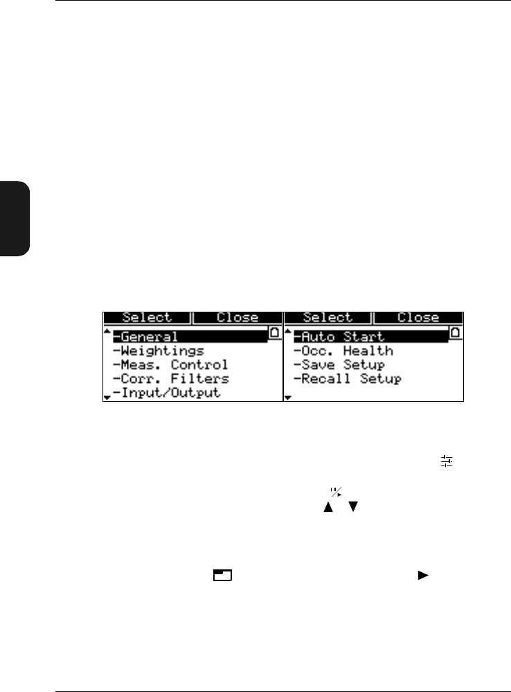
The following Settings are available:
●General (for setting the measurement range, the Peaks
Over level and the second exchange rate)
●Weightings (for setting the frequency weightings for
Detector 1 and 2)
●Measurement Control (for setting up an Auto Start meas-
urement
●Correction Filters (for selecting correction filters for
sound incidence and windscreen)
●Input/Output (for setting up the Aux 1 and Aux 2 sock-
ets)
●Auto Start (for selecting an Auto Start)
●Occupational Health (for setting up the Occupational
Health parameters)
●Save Setup (for saving a measurement set-up)
●Recall Setup (for recalling a measurement set-up)
Note: You can also change the measurement range by press-
ing the key.
1.4.4 Calibration Menu
Pushing the key will display the Calibration menu. Refer
to Chapter 4 for more information.
●Calibration (for calibrating the Mediator)
●Calibration History (contains information about the ini-
tial calibration and the 20 latest calibrations)
1.4.5 File System
Memory
Data files, measurement settings, calibration data and cal-
endar data (date and time) are all saved in RAM. This mem-
ory is maintained when you turn off the instrument. If the

Chapter 1– Introduction
Menu Structure
BB1119 – 11 1–13
2238 Mediator
User Manual
batteries are removed, the back-up battery will retain the
memory for minimum 6 months (if charged), so that data is
saved.
The serial number and some internal calibration factors are
stored in Flash RAM, which is a non-volatile memory.
Buffer
Holds all of the measurement results from the last measure-
ment period. The buffer is updated once a second. It is cleared
each time you start a measurement with the key. Results
in the buffer can be output to a printer or saved in a file.
Data Files
Measurements are saved in Mediator as files with a file
number and an extension. In addition the files can be iden-
tified by the date and time when the file was saved.
You can normally store up to 500 files for each software
package. However, the number of files may be reduced if a
large amount of data is occupied by the Logging module. A
warning is displayed if there is not sufficient memory for the
current measurement.
All files are preserved when you turn off the instrument,
except for the data in the buffer. All measurement data are
copied from the buffer. Measurements can be stored automat-
ically (measurements with a preset measurement time) or
manually (at any time after a measurement is paused).
A basic measurement data file consists of a group of set-up
data and a group of associated measurement data. The set-
up data are:
●Serial number for the Mediator
●Initial calibration parameters
●Calibration set-up
●Measurement set-up
0

Chapter 1 – Introduction
Backlight
1–14 Brüel & Kjær2238 Mediator
User Manual
Measurement data are:
●Set-up and Calibration data
●Broadband RMS data
●Broadband Peak data
For more information about Data Files, see Chapter 5.
1.5 Backlight
The backlight makes the display easier to read in low light
situations. Press to turn it on or off. To save batteries,
the light will switch off automatically after 30 seconds.

BB1119 – 11 2–1
2238 Mediator
User Manual
Chapter 2
Getting Started
2.1 Getting Started..................................................................... 2–2
2.2 Fitting Batteries .................................................................. 2 – 2
Checking the Battery Level .............................................. 2 – 2
Using an External Power Supply ..................................... 2 – 4
The Back-up Battery ......................................................... 2 – 4
Switching the Mediator On and Off ................................. 2 – 5
Dismantling/Mounting the Microphone........................... 2 – 5
2.3 Pushkey Definitions........................................................... 2 – 8
2.4 Measurement Window .................................................... 2 – 10
2.5 Changing the Language ................................................. 2 – 12

Chapter 2 – Getting Started
Getting Started
2–2 Brüel & Kjær2238 Mediator
User Manual
2.1 Getting Started
As supplied from the factory, the Mediator is fitted complete
with microphone and input stage. You only need to fit the
batteries before the instrument is ready for measuring
2.2 Fitting Batteries
Fitting Batteries for the First Time:
1. The battery compartment is located in the centre of the
back of the instrument. Press the two tabs on the upper
edge of the battery compartment and remove the lid.
2. Insert new batteries (four 1.5 V LR6/AA size alkaline
batteries) following the +/– orientation shown in the bot-
tom of the battery compartment.
3. Press the compartment lid back into place.
Note: If you cannot switch on the Mediator after inserting
the batteries, check that you have inserted them correctly.
The Mediator will not switch on if the batteries are inserted
incorrectly, however, it will not be damaged.
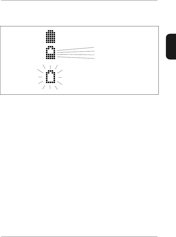
2.2.1 Checking the Battery Level
The battery symbol in the upper right hand corner of the
Measurement Window indicates the current battery level.
When the battery is full, the battery level indicator is fully
black. As the batteries are used, the level will fall until the
indicator is completely empty. When it is time to replace the
batteries, the indicator will be empty and blinking.
The battery level indicator has five indication lines in it. Each
line represents approximately 20% of remaining battery time
(at room temperature), see Fig.2.1. When the indicator is
empty and blinking, there is less than 15 minutes left. Under
Chapter 2– Getting Started
Fitting Batteries
BB1119 – 11 2–3
2238 Mediator
User Manual
extreme cold or hot environments, the remaining time may
be less.
Caution
It is possible for batteries to explode or leak if they are
handled incorrectly, so:
●For long-term storage, remove the batteries and keep the
sound level meter in a dry place.
Note: For very long-term storage (more than 6 month)
you must save the files and settings on a PC, if required.
See section 2.2.3.
●Never mix different makes or types of battery.
●Never mix new and old batteries.
Note: Rechargeable batteries can be used, however, the op-
erating time may vary considerably, depending on the type
and condition of the cells. The batteries will not be charged
when using an external power supply for the Mediator, they
must be charged outside the instrument.
Fig.2.1 Interpreting the battery level indicator
980337e
Batteries full, 100% left
80% left
60% left
40% left
20% left
Replace batteries, approx 15 minutes left

Chapter 2 – Getting Started
Fitting Batteries
2–4 Brüel & Kjær2238 Mediator
User Manual
2.2.2 Using an External Power Supply
The sound level meter can be powered from a regulated 7 –
15 V DC supply via the External Power socket on the base
(e.g. from a mains supply adaptor, see ordering information
in Product Data). The power supply must be able to supply
minimum 400mA in the nominal voltage range. Maximum
allowable ripple from the adaptor is 100 mVpeak-peak.
You can connect the external power supply even when the
batteries are installed. The sound level meter automatically
selects the source with the highest supply voltage. The ex-
ternal power supply will not damage the batteries and it will
not charge rechargeable batteries.
Note: It is recommended that batteries are always fitted
when using an external power supply. This prevents loss of
power if the external supply is accidentally disconnected.
2.2.3 The Back-up Battery
The sound level meter has a back-up battery for running the
clock and maintaining the data files, even when it is switched
off or the main batteries are removed. Other data, including
the serial number, the microphone serial number and cali-
bration data, are stored in Flash RAM and will remain irre-
spective of the back-up battery. If the back-up battery is flat,
a “Preparing file system” message will appear when the in-
strument is switched on and files in the memory are lost.
The back-up battery is recharged automatically when there
are standard batteries in the sound level meter. It is fully
charged after about 10 hours. Fully charged, the back-up bat-
tery runs the clock and retains records and settings for about
6 months. These charge times are typical for a sound level
meter at room temperature.

Chapter 2– Getting Started
Fitting Batteries
BB1119 – 11 2–5
2238 Mediator
User Manual
2.2.4 Switching the Mediator On and Off
Switching On
Press . The Brüel & Kjær logo is displayed for a few seconds
before the Measurement Window appears. The instrument
returns to pause mode with the set-up it had when it was
last switched off.
Default Set-up
You can revert to the default set-up by recalling Default
from the Save/Recall Window in the Measurement Set-up
menu, see section 4.1.11. All results in the buffer are deleted
and the instrument returns to the default set-up in pause
mode. Refer to section 10.2 in Appendix 1 for a list of default
parameters.
Switching Off
The Mediator can only be switched off from pause mode. Press
to enter pause mode and then press to switch off
the instrument. Even when the instrument is switched off,
the memory circuits are still energized and all settings and
saved measurement data are maintained.
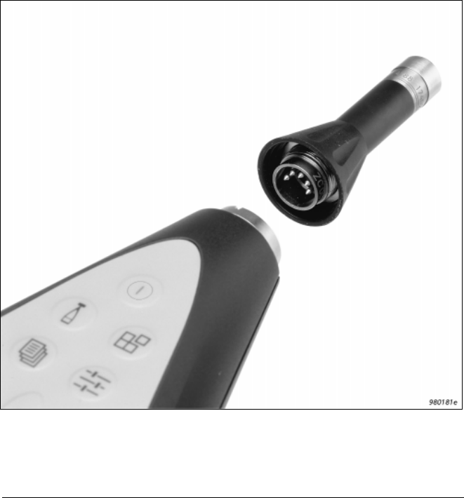
2.2.5 Dismantling/Mounting the Microphone
If it is required to dismantle/mount the microphone, note the
following precautions:
●When screwing on the microphone, input stage, protec-
tion grid and extension cables, do it gently to avoid
damaging the threads.
●Keep dust and foreign matter off the microphone dia-
phragm. Do not touch the diaphragm with anything —
it is very delicate. Small amounts of dust on the dia-
phragm will not affect the microphone response.
2–6 Brüel & Kjær2238 Mediator
User Manual
Dismantling/Mounting the Microphone and Input Stage
The microphone supplied with the Mediator is the Prepolar-
ized Free-field 1/2″ Microphone Type 4188 that requires no
external polarization voltage.
1. Unscrew the threaded retaining ring (see Fig. 2.2) that
secures the input stage. The input stage can now be
removed from the input stage socket at the top of the
Mediator.
Fig.2.2 Mounting the input stage and microphone onto the sound level
meter. 5-pin DIN connectors are used
Chapter 2– Getting Started
Fitting Batteries
BB1119 – 11 2–7
2238 Mediator
User Manual
2. Unscrew the microphone from the Input Stage ZC0030.
Do not remove the protection grid from the microphone.
Fitting is the reverse of dismantling.
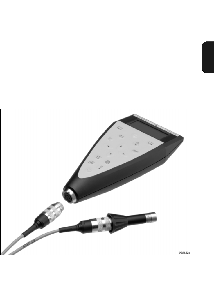
Connecting a Microphone Extension Cable
Two optionally available extension cables can be used with
the Mediator:
●AO 0561 3 m long
●AO 0560 10 m long
Note: Older cables Types AO 0408 and AO 0409 can also be
used.
Fig.2.3 Connecting a microphone extension cable to the sound level meter

Chapter 2 – Getting Started
Pushkey Definitions
2–8 Brüel & Kjær2238 Mediator
User Manual
To Connect:
1. Insert the microphone extension cable into the input
stage. Secure the connection by turning the threaded
retaining ring.
2. Insert the other end of the microphone extension cable
into the input stage socket and secure by turning the
threaded retaining ring. (see Fig. 2.3).
Note: Connecting a recommended microphone extension ca-
ble has no effect on the sound level meter’s calibration. There-
fore, you do not have to re-calibrate after connecting one of
the recommended microphone extension cables.
2.3 Pushkey Definitions
Each pushkey on the sound level meter’s front panel is
marked with a pictogram. This section gives a brief explana-
tion of the buttons.
Power Press this key to switch the instru-
ment on or off. The instrument will
be in pause mode when started up.
Calibrate Press this key to calibrate your in-
strument. See section 5.1 for cali-
bration instructions.
System Press this key to display the Sys-
tem menu for configuring the in-
strument and for changing
application programs. See section
4.1 in Chapter 3 for system options.
Data Files Press this key to select the Data
Files menu. The menu options in
this window allows you to save,
print and edit printout files and to
access the File Manager facility.
Chapter 2– Getting Started
Pushkey Definitions
BB1119 – 11 2–9
2238 Mediator
User Manual
Set-up Press this key to access/step
through the set-up options in the
Measurement Set-up menu. See
section 4.1.2 in Chapter 3 for de-
tails about the available settings.
Up/Down Arrows Press these keys to step up/down
in the menu items in the selected
window. Also for entering/exiting
edit mode in the Measurement
Window.
Left/Right Arrows Press these keys to select the pa-
rameters in the selected window.
Note: For the sake of consistency
the keys are always used
to select menu items, and the
keys are always used to se-
lect values.
Range Press this key to access the Range
Setting menu. Use the
keys to step through the available
measurement ranges or scroll with
the key.
Reset Resets the current measurement
data and sets the buffer and timer
to zero. If a measurement is in
progress, it will continue immedi-
ately after reset. If the instrument
is paused, it will still be paused
after pressing Reset.
Note: If a measurement has been
in progress for more than a minute
a warning is displayed and you
must confirm the command before
any data is deleted.
Meas. Results Press this key in any of the set-up
menus to return to the Measure-
0

Chapter 2 – Getting Started
Measurement Window
2–10 Brüel & Kjær2238 Mediator
User Manual
ment Window. If menu changes
have not been saved, they will be
cancelled.
Pause/Continue Press this key to pause/continue
the current measurement. If the
sound level meter is in pause mode,
the measurement is continued
without resetting data or the timer.
Select Softkey with functions <Select>,
<Save>, <Recall> or <Ok> de-
pending on the cursor position in
the current menu. The <Menu>
function displays the File Manager
Options Window.
Cancel Softkey with functions <Cancel>,
<Undo> or <Close> depending on
the cursor position in the current
menu.
Backlight Switches the display’s backlight on
or off. To save batteries, the back-
light switches off automatically af-
ter 30 seconds.
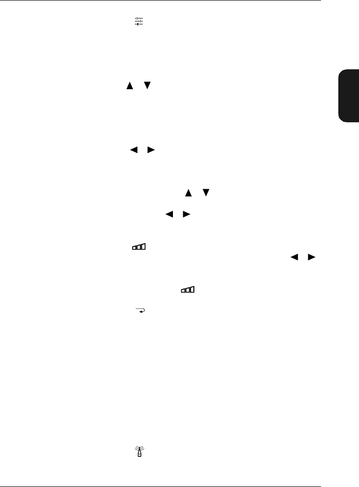
2.4 Measurement Window
During normal operation the Measurement Window is used
to view the measured data. It provides several kinds of in-
formation about your settings and measurements.
1. Bar graph: This is a quasi-analogue display that shows
a graphical representation of the current sound pressure
level (Inst.), based on the RMS value from Detector1. It
is updated 5 times a second.
a. The bottom end of the measurement range (in dB): All
sound below this level will register as under-range. To
change the starting point for the measurement range,
2–11 Brüel & Kjær2238 Mediator
User Manual
press while measurement is paused, you can then
step up the measurement range.
b. The upper end of the measurement range (in dB) and
overload indicator: Peaks above this level will trigger
an “OVERLOAD” indication that will appear under the
bar graph, see Fig. 2.5. If an overload has occurred in
the last one second, this indication will stay for the
next second. This indication will appear both in pause
mode and in measurement mode. If an overload occurs
during a measurement in progress, a “latched over-
load” symbol will appear to the right of the bar graph,
see Fig. 2.5. The latched overload remains until the
measurement is reset, also if the measurement is
paused. To change the measurement range, press .
Fig.2.4 The Measurement Window
Fig.2.5 Overload indicators
980335e
Bargraph
Battery Indicator
Illegal Entry
Value Fields
Run/Pause Indicator
Parameter Fields
980336e
Overload indicator Latched overload symbol

Chapter 2 – Getting Started
Changing the Language
2–12 Brüel & Kjær2238 Mediator
User Manual
2. Run/Pause indicator: Displays the current status of
measurement. Press to continue or pause
a measurement. Press to start a “new” measurement
(resetting measurement data and the timer).
3. Battery level: When the batteries are new, the indi-
cator is completely black. As the batteries are used, the
level falls. Replace the batteries when this indicator is
empty and blinking.
4. Parameter fields: Specifies the measurement parameters
5. Value fields: Indicates the measurement values for the
selected parameters.
6. Illegal Entry: The symbol lights up for a second if
you press a key that has no function in the current win-
dow.
2.5 Changing the Language
The default user interface language for the Mediator is Eng-
lish.
How to Change the Language
The following languages can be selected
●English
●Français
●Deutsch
●Italiano
●Español
1. From the Measurement Window press the hard key
to select the System menu.
2. Select the Language menu item with the cursor
keys and enter by pressing the <Select> softkey.
0
980310

Chapter 2– Getting Started
Changing the Language
BB1119 – 11 2–13
2238 Mediator
User Manual
3. Select the language you want to install by using the
or keys.
4. When the desired language is displayed, press the
<Save> softkey to enter the selection.
5. Press the <Cancel> softkey twice to return to the
Measurement Window, or press the Meas. Results
key.

2–14 Brüel & Kjær2238 Mediator
User Manual

BB1119 – 11 3–1
2238 Mediator
User Manual
Chapter 3
System Menu
3.1 System Menu......................................................................... 3–2
Introduction ....................................................................... 3 – 2
Selecting the System Menu and Parameters................... 3 – 2
Selecting Application Module ........................................... 3 – 4
Setting the Date and Time................................................ 3 – 4
Setting up the Serial Interface Parameters..................... 3 – 5
Setting up the Printer Interface Parameters................... 3 – 6
Choosing the Language..................................................... 3 – 7
Adjusting the Display Contrast........................................ 3 – 7
Displaying the International Standards.......................... 3 – 8
Displaying System Information........................................ 3 – 8
Chapter 3 – System Menu
System Menu
3–2 Brüel & Kjær2238 Mediator
User Manual
3.1 System Menu
3.1.1 Introduction
This chapter explains how to set up basic parameters in the
System menu, such as application program, interface and
language. Once these parameters are set up, they are not
normally changed until a measurement session is completed.
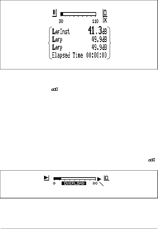
3.1.2 Selecting the System Menu and Parameters
The System menu is used for setting up and reading basic
system parameters. It contains the menu items shown in
Fig. 3.1.
1. The System menu is accessed by pressing the System
key when the instrument is paused. If the instrument is
measuring you must press to pause. Select the de-
sired menu item with the cursor keys.
This will also cause the <Select> and <Close> soft keys
to appear.
2. Press the <Select> softkey or the cursor key
to enter the selection.
This will also cause the <Ok> and <Cancel> soft keys to
appear.
Fig.3.1 The System menu. The arrows to the left indicate that there is
more than one window

Chapter 3 – System Menu
System Menu
BB1119 – 11 3–3
2238 Mediator
User Manual
Alternatively you can step through the menu items by press-
ing the System key repeatedly. The first time you press the
key the System menu is displayed and the following key clicks
steps you directly through the menu items, starting with the
first item in the menu.
The arrows on the left-hand side of some of the screens in-
dicate that there is more than one screen page. These pages
are cyclic, i.e., when you pass the top or the bottom line of
the menu you automatically go the bottom or top line of the
next/previous page, respectively.
Selecting Parameters
1. Select the desired parameter from the sub-menu with the
cursor keys.
2. Then use the cursor keys to step through the avail-
able settings or values of that parameter until the one
you need is displayed.
The range of available settings for each parameter is
given in the following sections.
Note: If you want to change a parameter value, you may
hold the cursor keys down to automatically in-
crease or decrease the value.
3. Press the <Ok> soft key to confirm the selection. If you
wish to undo any of these, press the <Cancel> soft key
and all settings/values will revert to what they were the
last time the <Select> soft key was pressed.
4. Repeat steps 1, 2 and 3 until you are satisfied with the
setting or value of each parameter.
5. Press the <Close> softkey to revert to the Measurement
Window after you have pressed the <Ok> or <Cancel> key.
Note: Normally you can use the Meas. Result key to
go directly from a menu to the Measurement Window.
Chapter 3 – System Menu
System Menu
3–4 Brüel & Kjær2238 Mediator
User Manual
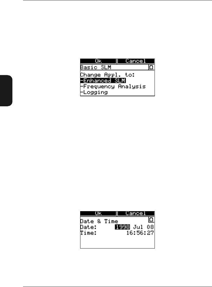
3.1.3 Selecting Application Module
Select the desired application module from the Application
Window. You can only select the application modules that
have been installed in the instrument. Refer to the associated
User Manuals for installation of application modules.
The currently possible options are:
●Enhanced SLM — Enhanced SLM Software BZ7125
●Freq. Anal. SLM — Frequency Analysis Software
BZ 7123
●Logging SLM — Logging SLM Software BZ7124
3.1.4 Setting the Date and Time
The Date & Time Window has the appearance as shown in
Fig. 3.3.
Fig.3.2 The Application Window. This example contains three applica-
tion modules (the Basic SLM Software is always installed)
Fig.3.3 The Date & Time Window
Chapter 3 – System Menu
System Menu
BB1119 – 11 3–5
2238 Mediator
User Manual
You can set:
●Year
●Month
●Date
●Time
The clock is running while you set the date and time. Simply
step the clock settings forwards or backwards until the clock
is synchronized with the real time.
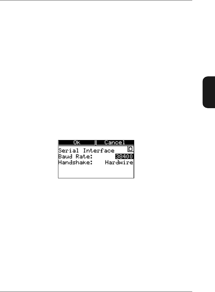
3.1.5 Setting up the Serial Interface Parameters
The Baud Rate and Handshake interface parameters can be
set up from the Serial Interface Window illustrated in
Fig. 3.4. Notice that these parameters are used only for con-
trol via the RS 232 interface.
You must set up the interfaces of the Mediator and the in-
strument connected to the serial interface socket to the same
baud rate and handshake settings to enable communication.
Setting the Baud Rate
●4800 ●9600
●19200 ●38400
●115200
Select the desired baud rate in the Baud Rate field.
Fig.3.4 The Serial Interface Window
Chapter 3 – System Menu
System Menu
3–6 Brüel & Kjær2238 Mediator
User Manual
Selecting Handshake
●Hardwired
●Modem
Select the desired type of handshake in the Handshake field.
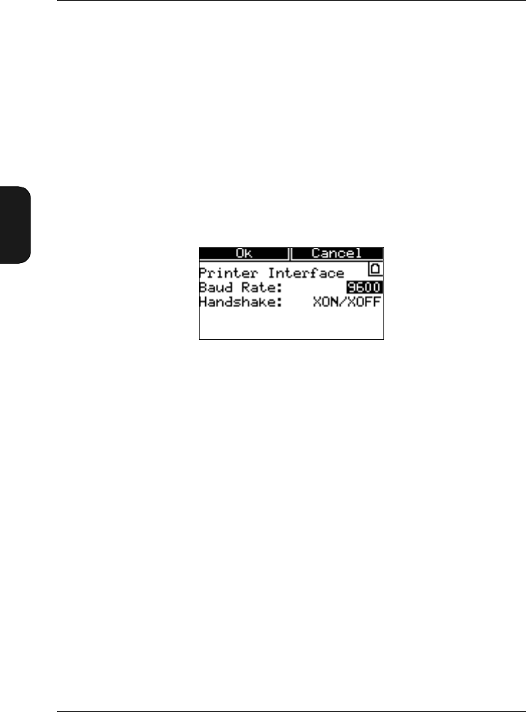
3.1.6 Setting up the Printer Interface Parameters
You can set up separate Baud Rate and Handshake interface
parameters for a printer, in the Printer Interface Win-
dow illustrated in Fig.3.5.
Setting the Baud Rate
●4800 ●9600
●19200 ●38400
●115200
Select the desired baud rate in the Baud Rate field.
Selecting Handshake
●XON/XOFF
●Hardwired
Select the desired type of handshake in the Handshake field.
Fig.3.5 The Printer Interface Window
Chapter 3 – System Menu
System Menu
BB1119 – 11 3–7
2238 Mediator
User Manual
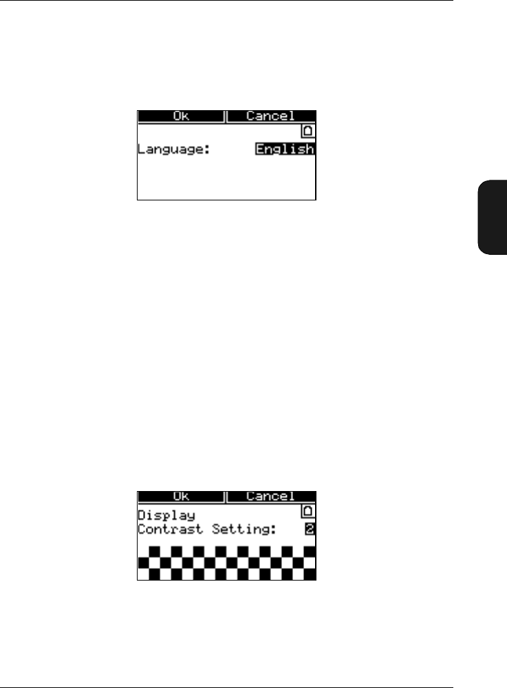
3.1.7 Choosing the Language
The language used in the instrument’s display screen can be
changed in the Language Window, as illustrated in Fig.3.6.
The following languages can be selected
●English ●Francais
●Deutsch ●Italiano
●Espanol
3.1.8 Adjusting the Display Contrast
You can adjust the LCD screens contrast in the Display
Window (see Fig.3.7), to compensate for various lighting con-
ditions and viewing angles. The contrast adjustment is par-
ticularly useful in very high or low temperature
environments.
Fig.3.6 The Language Window
Fig.3.7 The Display Window
Chapter 3 – System Menu
System Menu
3–8 Brüel & Kjær2238 Mediator
User Manual
Contrast Adjust
●1 5
You can adjust the contrast in five steps, where 5 indicates
the highest contrast level. The default setting is 3.
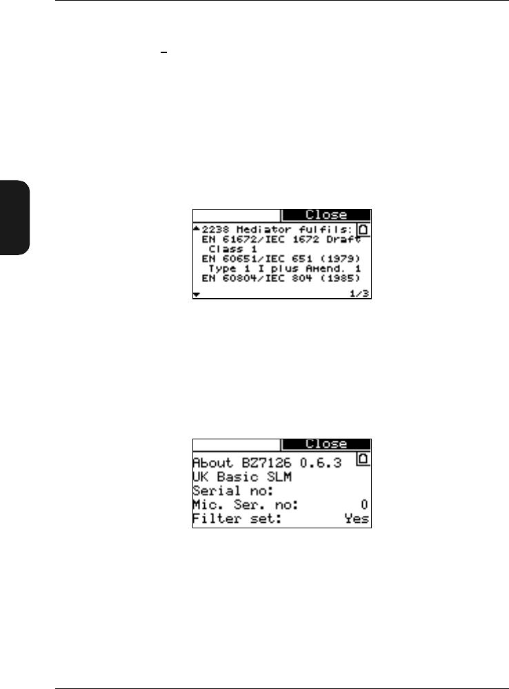
3.1.9 Displaying the International Standards
The Standards Window in Fig. 3.8 shows the international
standards that Mediator complies with.
3.1.10 Displaying System Information
The About System Window is shown in Fig. 3.9 and contains
the following information:
●Current application module (type)
●Mediator serial number
●Microphone serial number (supplied microphone)
●Filter set
Fig.3.8 The Standards Window
Fig.3.9 The About System Window

BB1119 – 11 4–1
2238 Mediator
User Manual
Chapter 4
Measurement Set-up Menu
4.1 Measurement Set-up Menu ............................................ 4–2
Introduction ....................................................................... 4 – 2
Selecting the Measurement Set-up Menu
and Parameters ................................................................. 4 – 2
Setting up General Measurement Parameters................ 4 – 3
Setting Frequency Weightings ......................................... 4 – 5
Measurement Control ....................................................... 4 – 6
Selecting Correction Filters .............................................. 4 – 7
Setting up the Input/Output Function............................. 4 – 8
Setting Mediator to Start Automatically ......................... 4 – 9
Setting the Occupational Health Parameters................ 4– 11
Saving Measurement Set-ups......................................... 4 – 12
Recalling Measurement Set-ups..................................... 4 – 13
Chapter 4 – Measurement Set-up Menu
Measurement Set-up Menu
4–2 Brüel & Kjær2238 Mediator
User Manual
4.1 Measurement Set-up Menu
4.1.1 Introduction
This chapter explains how to set up basic measurement pa-
rameters in the Measurement Set-up menu, such as range
and weighting.
4.1.2 Selecting the Measurement Set-up Menu and
Parameters
The Measurement Set-up menu is used for setting up basic
measurement parameters and measurement control parame-
ters. Basic SLM Software BZ 7126 contains the menu items
shown in Fig. 4.1.
1. The Set-up menu is accessed by pressing the System
key when the instrument is paused. If the instrument is
measuring you must press to pause. Select the de-
sired menu item with the cursor keys.
This will also cause the <Select> and <Close> soft keys
to appear.
2. Press the <Select> softkey or the cursor key
to enter the selection.
This will also cause the <Ok> and <Cancel> soft keys to
appear.
Fig.4.1 The Measurement Set-up menu (two windows)
Chapter 4 – Measurement Set-up Menu
Measurement Set-up Menu
BB1119 – 11 4–3
2238 Mediator
User Manual
Alternatively you can step through the menu items by press-
ing the Set-up key repeatedly. The first time you press the
key the Set-up menu is displayed and the following key clicks
steps you directly through the menu items, starting with the
first item in the menu.
The arrows on the left-hand side of some of the screen indicate
that there is more than one screen page. These pages are
cyclic, i.e., when you pass the top or the bottom line of the
menu you automatically go the bottom or top line of the next/
previous page, respectively.
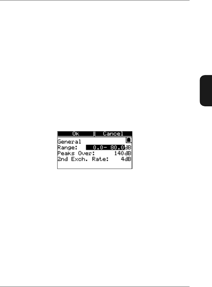
4.1.3 Setting up General Measurement Parameters
The General Window is used for setting up the measurement
range, the peaks over indication and the second exchange
rate, see Fig. 4.2.
Measurement Range
In Range you can select the following default measurement
ranges:
●0 to 80 dB ●10 to 90 dB
●20 to 100 dB ●30 to 110 dB
●40 to 120 dB ●50 to 130 dB
●60 to 140 dB
Note that the dynamic range is always 80 dB. However, if a
non-standard transducer is used and calibrated, the upper
and lower limits may be offset.
Fig.4.2 The General Window

Chapter 4 – Measurement Set-up Menu
Measurement Set-up Menu
4–4 Brüel & Kjær2238 Mediator
User Manual
The range you choose will depend on the environment in
which you are measuring. It is important to select the meas-
urement range so that the instrument is sensitive enough to
measure all relevant sound, but not so sensitive that it over-
loads. Your measurement will not be accurate if an overload
occurs. See section 2.4 for more information about overloads.
To Set the Measurement Range
Check the current measurement range. It is shown at the
top of the Measurement Window.
Use the quasi-analogue display to decide if you have set the
range correctly. If the display is blank most of the time, then
sound levels are too low; select a lower measurement range.
If the display becomes full and the “Overload” warning ap-
pears under the bar graph, then sound levels are overloading
the instrument; select a higher range.
Alternatively you can access the Range Setting Window di-
rectly by using the key.
Setting the Peaks Over Indication
Peaks Over fixes a level for counting the number of times
this level is exceeded by peak values and registered during
a measurement. Intervals of 1s are used and only one over-
load per period is registered.
The Peaks Over level can be set in 1 dB steps from 0 to
180 dB. The setting is independent of the selected linear
measurement range (see above). The default level is 140 dB.
Note that the first decimal(s) and the last decimal of the
value field are set up independently. Use the cursor
keys to select the desired decimal.
To monitor the Peaks Over value on the screen, select the
#cPeaks field in the Measurement Window.
Setting the Second Exchange Rate
The 2nd Exch. Rate is used for evaluation of hearing risk
and is described in Appendix section 10.1.
Chapter 4 – Measurement Set-up Menu
Measurement Set-up Menu
BB1119 – 11 4–5
2238 Mediator
User Manual
The 3 dB Exchange Rate is always measured. You can select
an additional Exchange Rate of 4 or 5 (dB). The Second
Exchange Rate is used for measuring averaged sound levels
with 4 dB (LDOD) or 5 dB (LOSHA) Exchange Rate, respective-
ly. The LXav parameter will change accordingly in the Meas-
urement Window.
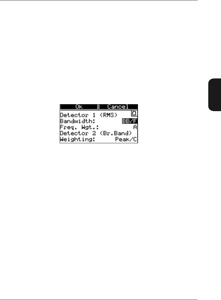
4.1.4 Setting Frequency and Time Weightings
The Weightings Window is used for setting up time and
frequency weightings for detector 1 and frequency weightings
for detector 2, see Fig. 4.3.
In the basic version, Detector 1 is RMS and Detector2 is Peak.
Setting Bandwidth and Time Weighting for Detector 1 (RMS)
●Broad-band (F, S, I)
●1/3-octave (F, S, I)
●1/1-octave (F, S, I)
Select the desired option in the Bandwidth field.
Note: The 1/3-octave and 1/1-octave options only ap-
pears when the 1/1-octave and 1/3-octave Filter Set is installed
in Mediator.
Setting Frequency Weighting for Detector 1
●A, C, L (Broad-band)
●31.5 Hz ... 8 kHz (1/1-octave)
Fig.4.3 The Weightings Window

Chapter 4 – Measurement Set-up Menu
Measurement Set-up Menu
4–6 Brüel & Kjær2238 Mediator
User Manual
●20 Hz ... 12.5 kHz (1/3-octave)
Select the desired standardized frequency weighting or centre
frequency in the Freq. Wgt. field. The centre frequencies
depend on the setting in the Bandwidth field.
Setting Frequency Weighting for Detector 2 (Broad-band)
●Peak/C
●Peak/L
You can select the C or L frequency weighting for Detector 2
in the Weighting field.
4.1.5 Measurement Control
The Meas. Control Window is used to set up a preset meas-
urement time and to activate/deactivate it, see Fig. 4.4.
In the Basic module only one measurement can be specified
in the No. of Meas. field (in the Enhanced module you
can specify up to 99 measurements).
When switched On, the Auto Start is started as a normal
measurement, using the key. During an Auto Start you
can control the instrument in the normal way, for example,
you can pause a measurement and resume it.
Fig.4.4 The Measurement Control Window
Chapter 4 – Measurement Set-up Menu
Measurement Set-up Menu
BB1119 – 11 4–7
2238 Mediator
User Manual
Switching the Sequence On/Off
The Sequence field is for switching the measurement se-
quence On or Off. The sequence parameters only appears
when sequence is set to On.
Setting the Preset Measurement Time
Preset Time is for pre-setting the measurement time.
●Hours: Can be set from 0 to 99 in one hour steps
●Minutes: Can be set from 0 to 59 in one minute steps
●Seconds: Can be set from 0 to 59 in one second steps
Note: Minimum measurement time is 30 seconds
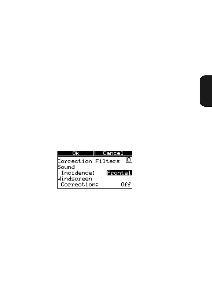
4.1.6 Selecting Correction Filters
The Correc. Filters Window in Fig. 4.5 allows you to se-
lect filters to make corrections for sound incidence and wind-
screen influence.
Selecting the Sound Incidence Filter
The Sound Incidence correction can be set to:
●Frontal
●Random
In general Frontal is used for sound with 0° incidence and
Random is used for diffuse sound. In practice the correction
depends on your local standard and the application. Generally
ISO requires Frontal and ANSI requires Random.
Fig.4.5 The Correction Filters Window
Chapter 4 – Measurement Set-up Menu
Measurement Set-up Menu
4–8 Brüel & Kjær2238 Mediator
User Manual
Selecting the Windscreen Correction
The Windscreen Correction can be set to:
●On
●Off
The windscreen filter makes a frequency correction corre-
sponding to the influence of Windscreen UA 0237. With the
correction on, Class1 precision is maintained over the full
frequency range (see specifications).
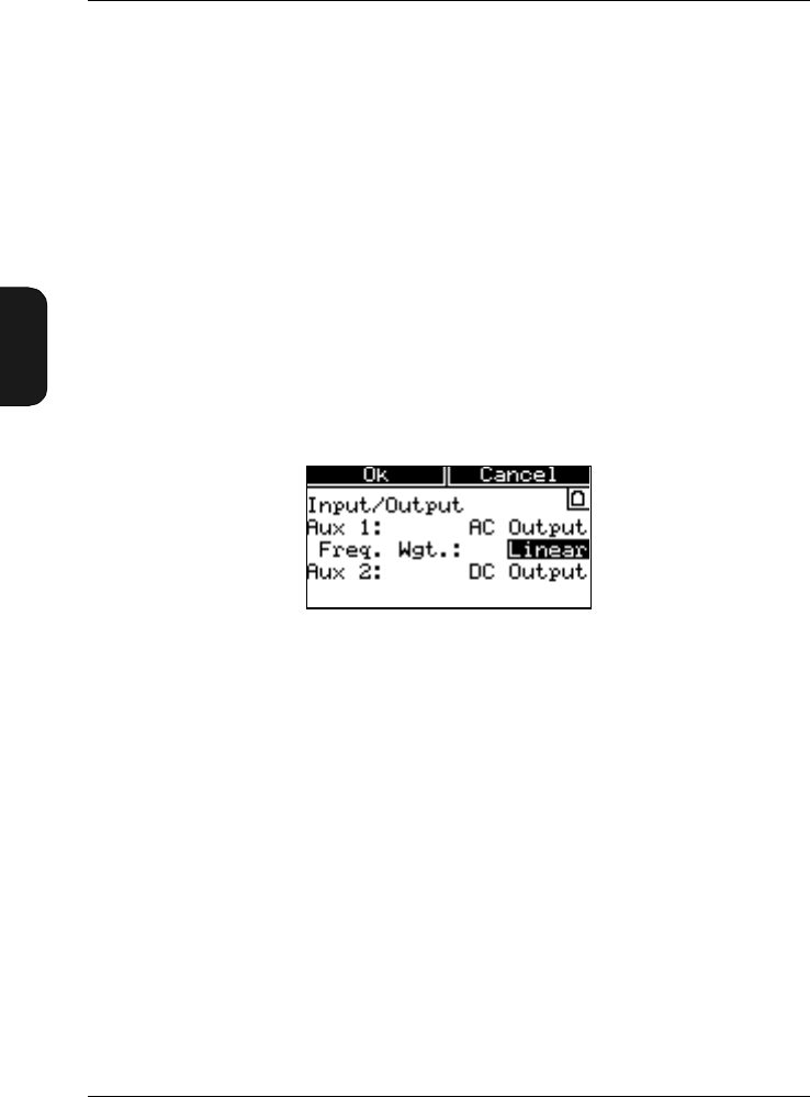
4.1.7 Setting up the Input/Output Function
The Input/Output Window controls the function of the
Aux1 and Aux2 inputs/outputs. See Fig. 4.6.
In the Basic module Aux 1 is always set to AC output and
Aux2 is always set to DC output.
Selecting Frequency Weighting for Aux 1
In the Freq. Wgt. field you can select:
●Linear
●Det. 1
AC Output supplies the AC output signal to the Aux 1 socket.
Frequency weighting depends on the Freq. Wgt. field (see
below). Full-scale indication corresponds to 1VRMS and the
output is attenuated according to the selected range. This
output signal can be used, for example, for recording the
measured signal on a DAT recorder.
Fig.4.6 The Input/Output Window
Chapter 4 – Measurement Set-up Menu
Measurement Set-up Menu
BB1119 – 11 4–9
2238 Mediator
User Manual
L frequency weighting is used when Linear is selected. When
you select Det. 1, the frequency weighting selected on the
RMS detector is used.
Aux 2
DC Out supplies a DC output signal equivalent to the AC
output signal. It is the time weighted signal (Fast, Inst.) from
detector 1. Full-scale indication corresponds to 4.0V DC
(50 mV/dB).
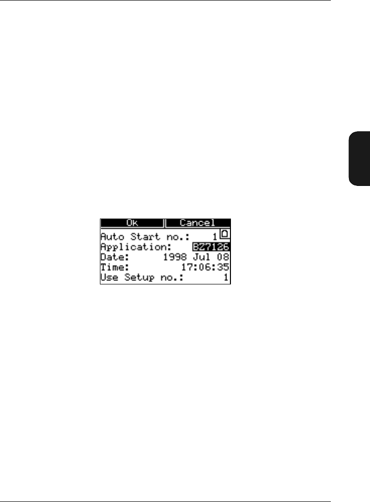
4.1.8 Setting Mediator to Start Automatically
The Auto Start Window allows you to set up Mediator to
start automatically at any time and date within the next
month. The Auto Start Window is illustrated in Fig. 4.7.
After setting up an Auto Start the Mediator must be switched
off. Then, at the set time, it will switch on, load the specified
set-up, reset and start measuring.
Once the Mediator has started measuring with Auto Start,
you can control it in the normal way. Measurements will
continue until the Mediator is switched off manually or the
batteries run out.
If the Mediator is already switched on at the time it has been
set to automatically start measuring, Auto Start is cancelled
and has no effect. Auto Start does not affect your use of the
Mediator while it is switched on or your current measurement
results.
Fig.4.7 The Auto Start Window

Chapter 4 – Measurement Set-up Menu
Measurement Set-up Menu
4–10 Brüel & Kjær2238 Mediator
User Manual
When the set Auto Start time has passed, Auto Start will be
switched off when you switch off the instrument. This pre-
vents the instrument from repeating an automatic measure-
ment every month.
Selecting an Auto Start
In the Auto Start no. field you can set up up to four dif-
ferent Auto Starts. You must ensure that there are no con-
flicts with other Auto Starts. If two Auto Starts in different
applications are set up to start within the same time span,
the Auto Start that starts first takes priority.
Application
The Application field shows the name of the application
module from which the current Auto Start was created. The
following options exist:
●None
Disables the current Auto Start and indicates that this Auto
Start has not been set up.
●BZ xxxx
Activates the Auto Start and shows the owner status for the
current Auto Start. If the application name is different from
the application module that you are currently using, i.e. if
the Auto Start has been set up with a different application
module, you cannot change the set-up parameters. If you
want to change the owner status for the Auto Start you can
do so by using the cursor keys. When you have
changed the owner status to the current application name
you can change the parameters as desired.
Setting Start Time for an Auto Start
The Date and the Time fields are used for setting up month,
day and time for the current Auto Start. The Mediator will
be automatically switched on shortly (approx. 30 s) before the
set time, so that it is ready for measurement at the specified
time.
Chapter 4 – Measurement Set-up Menu
Measurement Set-up Menu
BB1119 – 11 4–11
2238 Mediator
User Manual
Selecting the Set-up for an Auto Start
With the Use Setup No. field a stored measurement set-up
(1 to 4) can be attached to an Auto Start. When the Auto
Start is executed, the specified measurement set-up is auto-
matically loaded.
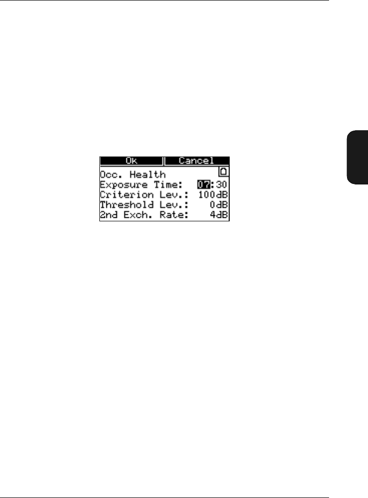
4.1.9 Setting the Occupational Health Parameters
You can measure noise dose levels by setting up the param-
eters in the Occupational Health Window, see Fig. 4.8.
The Mediator can measure A-, C- or Lin.-weighted dose levels
with Exchange rates of 3 dB (Leq) and 4 or 5 dB (Lav) levels
with A- and C-weighting. Select the desired dose parameter
in the Measurement Window. The Leq value (with exchange
rate of 3) is always measured. Lav is measured simultaneous-
ly, but before measurement you must select exchange rate of
4 or 5dB in the General Window. Note that the 4 or 5dB
Lav parameters are measured with F or S time weighting.
The dose level represents the amount of received sound en-
ergy expressed as a percentage of the daily allowed dose
(100% level).
Setting the Exposure Time
In the Exposure Time field you can set, in hours and min-
utes, the actual time that you are exposed to noise during a
workday. The noise dose calculation is based on the time you
are exposed to the noise (Exposure Time) relative to a nor-
mal 8 hour workday.
Fig.4.8 The Occupational Health Window
Chapter 4 – Measurement Set-up Menu
Measurement Set-up Menu
4–12 Brüel & Kjær2238 Mediator
User Manual
Specifying the Criterion Level
The Criterion Lev. sound level is specified in your local
standard. It is the level of a sound which, continuously ap-
plied for eight hours, results in a 100% criterion exposure.
The calculation of the noise dose level is based on the criterion
level and the exposure time.
Specifying the Threshold Level
The Threshold Lev. level may be specified in your local
standard. Any sound levels below the threshold value do not
contribute to the Dose measurement data. For example, if
you set the threshold value to 80, any sound levels below
80 dB are not taken into consideration by the instrument
when it calculates integrated values (Leq, Lav, Dose).
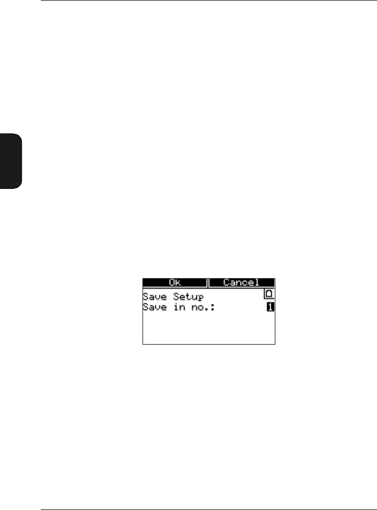
4.1.10 Saving Measurement Set-ups
You can save up to four measurement set-ups for each appli-
cation package in the Save Setup Window, see Fig.4.9.
When you save a measurement set-up, you save all the pa-
rameters in the Measurement Set-up menu (see section 4.1.2).
Ensure that these parameters are set up correctly before you
proceed.
Saving the Current Measurement Set-up
●1 – 4
Fig.4.9 The Save Setup Window
Chapter 4 – Measurement Set-up Menu
Measurement Set-up Menu
BB1119 – 11 4–13
2238 Mediator
User Manual
In the Save in no. field, select the number which you want
to save the current set-up as. The selected set-up is saved
when you press the <Ok> Softkey.
4.1.11 Recalling Measurement Set-ups
Measurement set-ups are recalled in the Recall Setup Win-
dow, see Fig.4.10.
When you recall a measurement set-up, you recall all the
parameters listed under Recalling Measurement Set-ups
above.
Recalling a Measurement Set-up
●1 – 4
●Default
From the Recall from no. field you can recall a stored set-
up by entering the desired set-up number. The stored set-ups
are identified by the date they were saved. The date for a
stored set-up appears in the bottom line. You can also recall
the factory default set-up. Refer to section 10.2 in Appendix
1 for a list of default parameters. The selected set-up is
recalled when you press the <Ok> Softkey.
Fig.4.10 The Recall Setup Window


BB1119 – 11 5–1
2238 Mediator
User Manual
Chapter 5
Measuring
5.1 Calibrating.............................................................................. 5–2
Introduction ....................................................................... 5 – 2
Calibrating the Mediator .................................................. 5 – 3
Checking the Calibration.................................................. 5 – 7
Calibration History ........................................................... 5 – 7
5.2 Starting a New Measurement ....................................... 5 – 8
5.3 Pausing a Measurement .................................................. 5 – 9
5.4 Continuing a Measurement............................................ 5 – 9
5.5 Measuring in 1/1- and 1/3-octave bands ................... 5 – 10
5.6 Setting the Mediator to Start Automatically ....... 5 – 10
5.7 Changing Displayed Measurement Parameters.5–11

Chapter 5 – Measuring
Calibrating
5–2 Brüel & Kjær2238 Mediator
User Manual
5.1 Calibrating
5.1.1 Introduction
When to Calibrate
The standards recommend that you calibrate your sound level
meter before each set of measurements (see section 5.1.2) and
check the calibration after each set (see section 5.1.3).
Connecting a recommended microphone extension cable (see
section 2.2.5) has no effect on Mediator’s calibration. There-
fore, you do not have to recalibrate after connecting one of
the recommended microphone extension cables.
Principle of Calibration
Mediator uses a sensitivity value to check for drift. This is
shown in the Calibration Window. When calibrating, Me-
diator first checks the calibration signal against the calibra-
tion level you have specified. It shows you the new sensitivity
value required for correct calibration, the current (previous)
and the initial (factory) sensitivity values and asks if you
want to recalibrate. If you press <Accept>, Mediator cali-
brates itself according to this new calibration level (i.e. it
adjusts the sensitivity according to the calibration level.
During this procedure, Mediator is automatically set to use
the reference measurement range and settings. To ensure
that a calibration is valid, Mediator compares the output from
both detectors during calibration. It also ensures that the
calibration level is stable during calibration. The maximum
allowed standard deviation is 0.1dB over a 4 second period.
Calibrating for Free-field or Diffuse Field Measurements
The sound level meter is calibrated in the same way for free-
field measurements (according to IEC) and diffuse field meas-
urements (according to ANSI). However, the calibration levels
for some calibrators may be different, depending on which
measurements are to be made. See the calibrator’s user man-
ual for more details. The correction filters are automatically

Chapter 5 – Measuring
Calibrating
BB1119 – 11 5–3
2238 Mediator
User Manual
set to Frontal and Windscreen Off during calibration. Af-
ter calibration they return to the previous settings.
Which Calibrators Can I Use?
Mediator is normally used with the supplied microphone Type
4188. The initial (factory) calibration is performed with the
microphone supplied with Mediator. However, an unspecified
transducer, e.g. another microphone or a hydrophone may be
used. In principle, since you specify the calibration level, any
calibration level in the range 50 to 200dB can be used, de-
pending on the transducer.
Microphones are usually calibrated at 94, 114 or 124 dB. The
default value for Mediator is 94.0dB. Sound Level Calibrator
Type 4231 provides 94 or 114 dB SPL at 1 kHz. Multifunction
Acoustic Calibrator Type 4226 provides 94, 104 or 114dB
SPL. Hydrophone Calibrator Type 4229 generates 151 to
166 dB re 1µPa at 250Hz.
Each calibrator is slightly different. The actual calibration
level is not necessarily equal to the nominal calibration level.
It is, therefore, important to set the calibration level to the
one given on the calibration chart for the calibrator used.
5.1.2 Calibrating the Mediator
For day to day calibration, you only need to calibrate at one
level at one frequency. In order to comply with the standards,
calibrate the sound level meter with a reference signal of
94 dB* at 1 kHz.
To calibrate with microphone Type 4188:
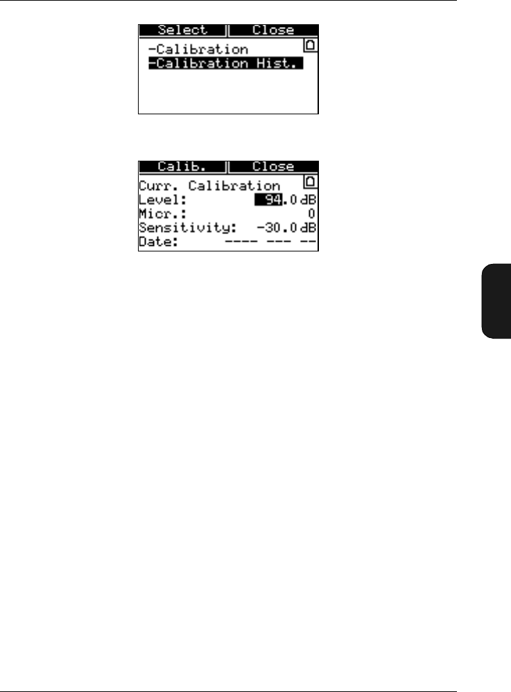
1. Switch on the Mediator and press the Calibrate key.
Select Calibration from the Calibration menu, see
Fig. 5.2.
* When using Type 4231 set the calibration level to 93.9dB for free-field calibration ac-
cording to IEC standards. For pressure calibration according to ANSI standards, set the
level to 94.0 dB.
Chapter 5 – Measuring
Calibrating
BB1119 – 11 5–5
2238 Mediator
User Manual
●Microphone — shows the serial number for the Type
4188 supplied with the Mediator or if an unspecified
transducer has been used for the calibration
●Calibration Level — the calibration level that was
specified for the current calibration. The
Calibration Level must be within 50 to 200dB and
can be stepped in 1 and 0.1 dB steps. The default value
is 94.0dB
●Sensitivity — the sensitivity value calculated by
Mediator as a result of the current calibration. You
cannot access this field
●Date — the date for the current calibration. You can-
not access this field
2. Check that microphone Type 4188 is selected and that
the calibration Level is set to 94.0 dB (or the calibration
level specified on the calibrators calibration chart).
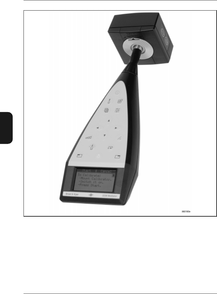
3. Press Calib. and Fit the calibrator carefully onto the
sound level meter and rest the sound level meter on a
table or other flat surface. Ensure that the calibrator fits
snugly on the microphone (see Fig.5.1).
Fig.5.2 The Calibration menu
Fig.5.3 The Current Calibration Window
Chapter 5 – Measuring
Calibrating
5–6 Brüel & Kjær2238 Mediator
User Manual
4. For the multifunction acoustic calibrator, set it up to
calibrate at 94dB and 1 kHz (see the calibrator’s instruc-
tion manual).
5. Switch on the calibrator.
The calibrator emits a 1 kHz calibration signal.
6. Press Start and wait until the calibration is finished.
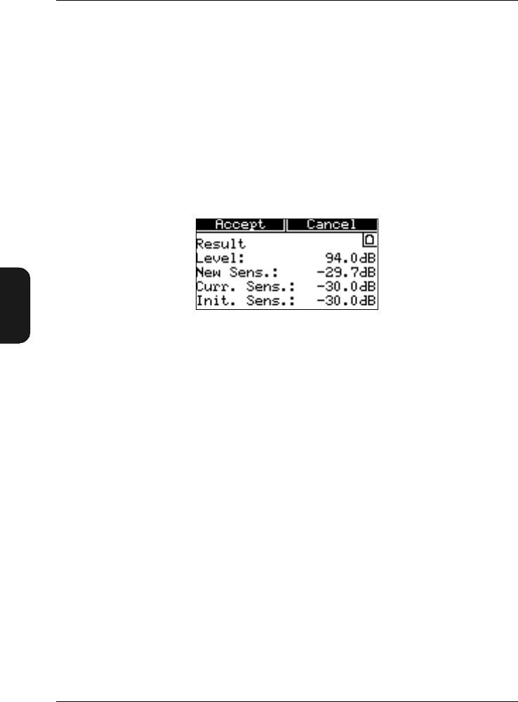
If the calibration is successful the Calibration Result
Window will appear as shown in Fig. 5.4.
●Calibration Level — the calibration level you have
specified
●New Sens. — the new sensitivity value calculated by
Mediator as a result of the calibration
●Current Sens. — the current sensitivity value that
is valid until you press the Accept key. Comparing
the New Sens. and the Current Sens. values gives
you the option to evaluate the relative deviation since
the last calibration
●Initial Sens. — the factory sensitivity value. Al-
lows you to evaluate the absolute deviation since the
instrument was manufactured. If the New Sens. val-
ue deviates more than ±1.5 dB from the
Initial Sens. value, an error message will appear
7. Press Accept if the New Sens. value is within accept-
able limits. The New Sens. value is implemented.
Fig.5.4 The Calibration Result Window
Chapter 5 – Measuring
Calibrating
BB1119 – 11 5–7
2238 Mediator
User Manual
Press Cancel if you cannot accept the New Sens. value.
A new calibration must be performed. This also applies
if the Calibration Error warning appears.
●Check that the microphone has been fitted properly
●Check that the calibrator has been switched on and
is working properly
●Check that the Calibration Level has been entered
correctly
●External noise or vibrations may have affected the
calibration
●Inspect the microphone to see if it has been damaged
5.1.3 Checking the Calibration
Follow the instructions given in section 5.1.2 until item 8. If
the New Sens. value is similar to the Current Sens. value
press the Cancel key to return to the main screen. Otherwise
a recalibration is required.
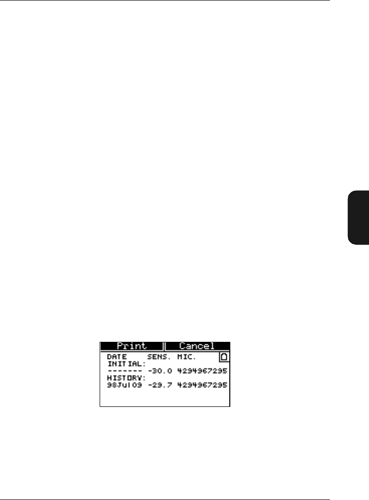
5.1.4 Calibration History
Select Calibration History from the Calibration menu.
The Calibration History Window will appear as shown
in Fig. 5.5.
The first line in the Calibration History Window always
shows the initial (factory) calibration sensitivity and the se-
rial number for the supplied microphone. In addition the
Fig.5.5 The Calibration History Window

Chapter 5 – Measuring
Starting a New Measurement
5–8 Brüel & Kjær2238 Mediator
User Manual
Calibration History Window contains information about
the 20 latest calibrations. The following information is stored:
●Date — year, month and day for the calibration
●Sens. — the calculated sensitivity for the calibration
●Mic. — indicates whether the calibration was per-
formed with the supplied 4188 microphone (serial
number) or with an unspecified transducer (Unspec.)
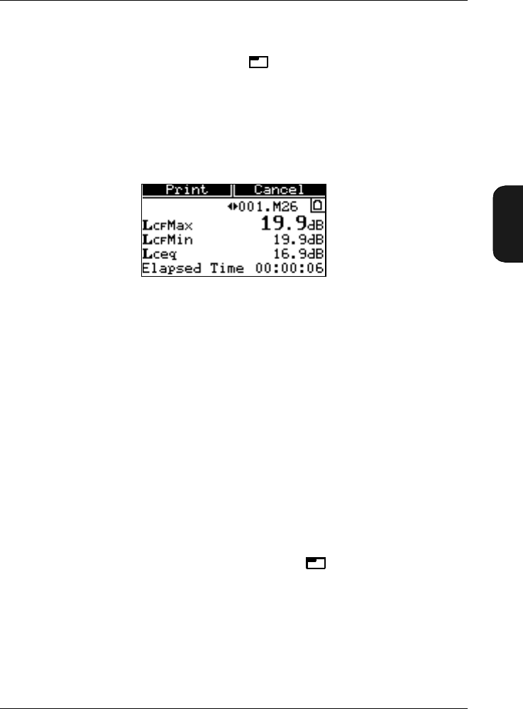
Press Print if you want to print out the calibration history
list.
5.2 Starting a New Measurement
1. Switch on the Mediator.
●If another application program has been used, select
the Basic SLM software from the System menu. Nor-
mally you do not need to change any parameters in
the System menu (see section 4.1).
2. Calibrate the sound level meter as described in section
5.1.2.
3. Set up the parameters in the Measurement Setting menu,
as described in section 4.1.2. Normally you will only need
to:
●Select a suitable measurement range. This reduces
the risk of you having to change the range during a
measurement in order to avoid overloads. Overloads
reduce the validity of your results and changing the
measurement range causes a reset.
●If you want to measure according to IEC standards
(i.e. free-field), set Sound Incidence to Frontal in
the Correction Filters Window and simply point
the sound level meter towards the sound source.
●If you want to measure according to ANSI standards
(i.e. diffuse-field), set Sound Incidence to Random in

Chapter 5 – Measuring
Pausing a Measurement
BB1119 – 11 5–9
2238 Mediator
User Manual
the Correction Filters Window. The direction of
the sound level meter is unimportant. If, however, the
sound field is free, measure with the sound level meter
at an angle of between 70 and 80° to the sound source.
●Select the desired measurement parameters in the
Measurement Window.
4. Press . The sound level meter starts measuring with
the selected set-up.
Note: If you want to delete the measured data and set the
buffer and timer to zero, press . If the measurement has
been in progress for more than one minute, a warning is
displayed and you must confirm that data is to be deleted.
5.3 Pausing a Measurement
The Pause mode of the Mediator allows you to store results
in its memory or transfer results across the interface to a
printer or computer.
Press . The Pause symbol appears in the upper left-
hand corner of the display. The clock stops counting the meas-
urement time. The display and quasi-analogue scale continue
to show the current status of the displayed parameters and
input signal level, respectively. In Pause mode, however, no
results or overload indications are added to the buffer.
5.4 Continuing a Measurement
Press . The Measurement symbol is shown instead of
the Pause symbol.
The clock continues counting the measurement time from the
point at which it stopped. Results are added to the buffer.
0

Chapter 5 – Measuring
Measuring in 1/1- and 1/3-octave bands
5–10 Brüel & Kjær2238 Mediator
User Manual
5.5 Measuring in 1/1- and 1/3-octave
bands*
Follow the instructions below to perform 1/1- and 1/3-octave
band measurements.
1. Select 1/3-octave or 1/1-octave in the Bandwidth
field as required (see section 4.1.4).
2. Select the centre frequency of the band in which you want
to start the analysis, in the Freq. Wgt. field in the
Weightings Window.
3. After you have completed the measurement in that fre-
quency band, press .
4. Store the measurement result in a file (see section 6.3).
5. Select the centre frequency of the band in which you want
to continue the analysis. You are now ready to measure
in the next frequency band.
6. Repeat steps 3 to 5 for the other bands in which you
want to measure.
For automatic frequency analysis measurements Frequency
Analysis Software BZ 7123 is recommended. It is, however,
possible to make a frequency analysis as a series of meas-
urements in various frequency bands, as explained above.
5.6 Setting the Mediator to Start
Automatically
The Mediator can be set to automatically start at any time
and date within the next month (for example from 19th May
to 18th June). To set up an Auto Start, refer to section 4.1.8.
*Only available with Mediator 2238–A–F (version with filter set installed)

Chapter 5 – Measuring
Changing Displayed Measurement Parameters
BB1119 – 11 5–11
2238 Mediator
User Manual
5.7 Changing Displayed Measurement
Parameters
The parameters available are listed in section 1.3. The se-
lected parameters and the measurement values are shown at
the bottom of the Measurement Window.
After a Reset, “– – –.–” is shown for all integrated values
until after the first second. Instantaneous (and SPL) values
are displayed continuously. This is because the levels are not
yet available. Some of the averaged values take even longer,
depending on the averaging times. When pressing Pause
all values are displayed continuously. The Bar Graph always
shows the current SPL level (LXYinst), regardless of the se-
lected parameters.
The parameters can be changed while a measurement is in
progress.
1. Use the cursor key to go to the desired parameter
line in the Measurement Window.
2. Select the desired measurement parameter with the
cursor keys.
3. Return to the basic Measurement Window with the
or
cursor keys.
When the time or frequency weightings or the exchange rate
are changed, the associated measurement parameters in the
Measurement Window are automatically changed and the
counter is reset.
Note: If the measurement has been in progress for more than
one minute, a warning is displayed and you must confirm
that data is to be deleted.
0


BB1119 – 11 6–1
2238 Mediator
User Manual
Chapter 6
Data Handling
6.1 Data File System................................................................. 6–2
Saved Data......................................................................... 6 – 3
Set-up Data........................................................................ 6 – 3
Measurement Data............................................................ 6 – 4
6.2 Selecting the Data Files Menu...................................... 6 – 4
6.3 Store Files............................................................................... 6 – 5
6.4 Print Options......................................................................... 6 – 5
6.5 Print........................................................................................... 6 – 7
6.6 File Manager ......................................................................... 6 – 7
Recall Files......................................................................... 6 – 8
Print ................................................................................... 6 – 9
Delete ................................................................................. 6 – 9
Delete All ........................................................................... 6 – 9
Disk Summary................................................................. 6 – 10

Chapter 6 – Data Handling
Data File System
6–2 Brüel & Kjær2238 Mediator
User Manual
6.1 Data File System
A total of 2000 data files of measurement results can be
stored in memory. However, you can only store up to 500 files
for each software package. Data files are copied from the
buffer. All records are preserved when you turn off the in-
strument, except for the data in the buffer. Measurements
can be stored automatically (during an Auto Start sequence)
or manually (at any time after a measurement is stopped).
File Names
Measurements are saved in Mediator as files with a file name
that consists of file number and an extension. In addition the
files can be identified by the date and time when the file was
saved.
Example:
001.M26 YYMMDD TTMMSS
File name: Consists of a three digit number from 000 to 500.
Number 000 is used for back-up purposes, for example, in a
power-down situation with flat batteries, the content of the
buffer is saved in no. 000. File numbers are generated auto-
matically as consecutive numbers.
Extension: The following extensions are used to identify the
software package in which the files were made. The two digits
in the extension correspond to the last digits in the type
number:
M26: Basic SLM Software BZ 7126
M25: Enhanced SLM Software BZ 7125
M23: Frequency Analysis Software BZ7123
M24: Logging SLM Software BZ 7124
ID: The date and time (YYMMDD TTMMSS) information is
used to identify the files.

Chapter 6– Data Handling
Data File System
BB1119 – 11 6–3
2238 Mediator
User Manual
6.1.1 Saved Data
A basic measurement data file consists of a group of set-up
data and a group of associated measurement data. The set-
up data are:
●Serial number for the Mediator
●Measurement set-up
●Calibration data
●Measurement data
Measurement data are:
●Overall results
●RMS Broadband data
●Broad-band Peak data
6.1.2 Set-up Data
Measurement Set-up
All measurement set-up parameters that was used for the
measurement.
Calibration Set-up (for individual measurements)
●Microphone type
●Sensitivity
●Calibration date
6.1.3 Measurement Data
Overall Results
●Start date
●Start time
●Elapsed time
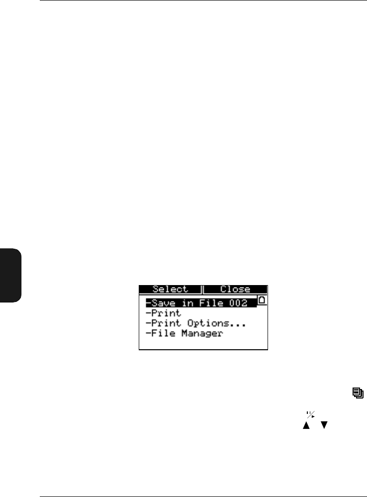
Chapter 6 – Data Handling
Selecting the Data Files Menu
6–4 Brüel & Kjær2238 Mediator
User Manual
●Overload
●Under-range
Broadband Data for Detector 1
LFMax, LSMax, LIMax, LFMin, LSMin, LIMin, Leq, LIeq, LAep,d,
LAE, EA, LFav4, LSav4, Dose, FDoseX, SDoseX, AUX1, AUX2
Note: Only the parameters with the selected time weighting
are saved.
Peak Data for Detector 2
●Number of peaks
●LXpkMax
6.2 Selecting the Data Files Menu
The Data Files menu is used for saving and printing files
and for accessing the File Manager. It contains the menu
items shown in Fig. 6.1.
1. The Data Files Window is accessed by pressing the
Data Files key when the instrument is paused. If the
instrument is measuring you must press to pause.
Select the desired menu item with the cursor
keys.
This will also cause the <Select> and <Close> soft keys
to appear.
Fig.6.1 The Data Files Window

Chapter 6– Data Handling
Store Files
BB1119 – 11 6–5
2238 Mediator
User Manual
2. Press the <Select> softkey to enter the selection.
This will also cause the <Ok> and <Cancel> soft keys to
appear.
6.3 Store Files
Automatically Saved Files
Measurements that are made with at preset measurement
time are stored automatically with consecutive numbers.
If the Mediator switches off because of flat batteries, the
content of the buffer is saved in file no. 000.
How to Store the Current Measurement Manually
1. Press the Pause/Continue key to pause the meas-
urement.
2. Press the Data Files key to display the Data Files
menu.
3. Press the <Select> softkey or the cursor key
to store the measurement with the displayed file name.
A “Saving File ...” message is displayed while saving
takes place.
6.4 Print Options
Before you print a file or the contents of the buffer, you should
select which measurement parameters you want to print out.
The Print Options list applies to both the Print function
for the buffer as well as the Print function in the File
Manager.
Setting the Print Options
1. Select Print Options from the Data Files menu.

Chapter 6 – Data Handling
Print
6–6 Brüel & Kjær2238 Mediator
User Manual
2. Use the cursor keys to tag the parameters that you want
to print out. Use the cursor keys to tag (+) or
untag a long list of parameters. Note that parameters
that are already tagged will be de-selected. If you only
want to tag or untag a few parameters, select the desired
parameter with the cursor keys and tag or untag
with the cursor keys. The following parameters
can be printed:
●LMAX
●LMIN
●LAFTm5
●Leq
●LIeq
●LAep,d
●LAE
●EA
●Lav4
●Dose
●Dose4
●#Peaks
●Lpkmax
3. Press <Close> when you have tagged the desired
parameters.
6.5 Print
Simply select the Print option when you have connected the
printer (refer to section 7.1) and set up the desired parame-
ters in Print Options (see above). A “Printing ...” mes-
sage is displayed while the print file is being transferred.
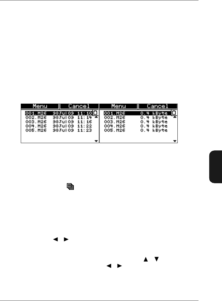
Chapter 6– Data Handling
File Manager
BB1119 – 11 6–7
2238 Mediator
User Manual
6.6 File Manager
The File Manager is used to give an overview of the data
files in the memory and has options for recalling, printing
and deleting these files. The Disk Summary option shows the
memory status.
File List
When you select the File Manager option from the Data
Files menu, you get at file list similar to the first screen
picture illustrated in Fig. 6.2. A file is identified by the file
name and extension and the date and time it was saved.
Pressing the Data Files key when the File List is dis-
played will show the file sizes instead of the dates. A single
file in the Basic module take up approximately 1kbyte of
memory.
Tagging Files
Use the cursor keys to tag the files that you want to select.
Use the cursor keys to tag (+) or untag a long list of
files. Note that files that are already tagged will be de-se-
lected. If you only want to tag or untag a few parameters,
select the desired parameter with the cursor keys
and tag or untag with the cursor keys.
Note: Whenever you leave the File Manager all file tags
will be deleted.
Fig.6.2 The File List in the File Manager menu. The list is shown with
both dates and file sizes
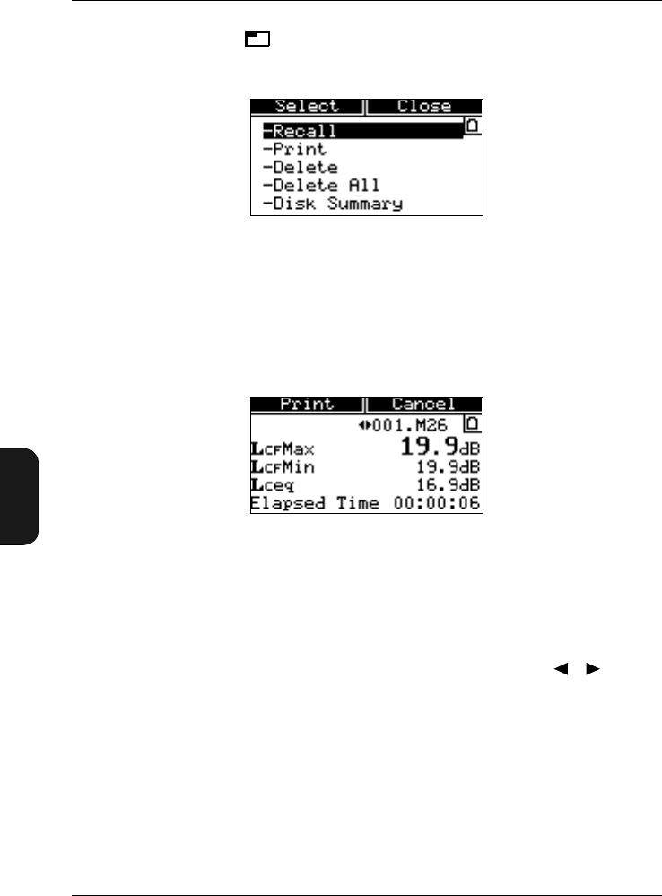
Chapter 6 – Data Handling
File Manager
6–8 Brüel & Kjær2238 Mediator
User Manual
Press the <Menu> softkey to show the options in the
File Manager Options Window, see Fig. 6.3.
6.6.1 Recall Files
Select Recall from the File Manager Options Window to
recall all the tagged files from the File List.
The Recall Files Window contains the same parameter
fields as the Measurement Window (except for instantaneous
values). The Bar Graph is replaced with a File Number field.
When the basic Recall Files Window is selected, you can
scroll through the recalled files by using the cursor
keys. The <Print> option will print the currently recalled file
with the parameters from the Print Options list.
6.6.2 Print
Select Print from the File Manager Options Window to
print all the tagged files from the File List. The Print Win-
dow will appear to show which file is currently being printed.
Fig.6.3 The File Manager Options Window
Fig.6.4 The Recall Files Window
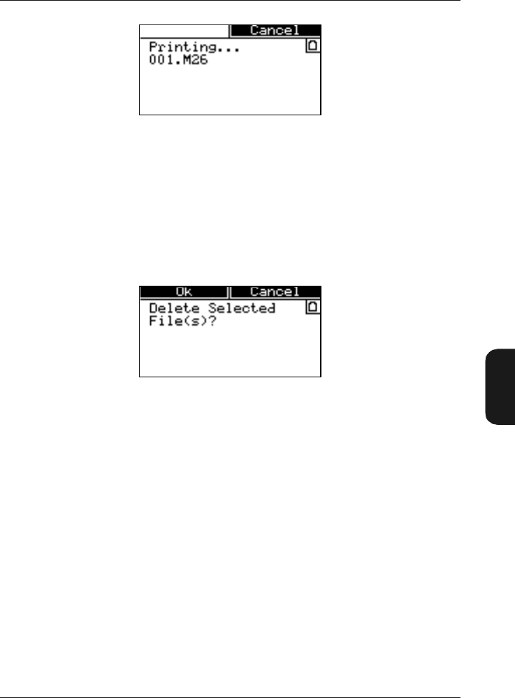
Chapter 6– Data Handling
File Manager
BB1119 – 11 6–9
2238 Mediator
User Manual
6.6.3 Delete
Select Delete from the File Manager Options Window to
delete all the tagged files from the File List. A delete prompt
will appear to confirm that you want to delete the selected
files. The File List will appear to show the remaining files.
6.6.4 Delete All
Similar to the Delete option above, except that all files
(tagged and untagged) will be deleted.
6.6.5 Disk Summary
Select Disk Summary from the File Manager Options
Window to get an overview of the disk memory.
The following parameters are displayed:
●Total: Shows the total disk space in kbytes
●Used: Shows the used disk space in kbytes
Fig.6.5 The Print Window
Fig.6.6 The Delete Window


BB1119 – 11 7–1
2238 Mediator
User Manual
Chapter 7
Printing and Transferring Data
7.1 Output to a Printer............................................................. 7–2
7.2 Transferring Data to 7815, 7820, 7821 and 7825.7–2
7.3 Aux 1 and Aux 2 Output ................................................... 7 – 3
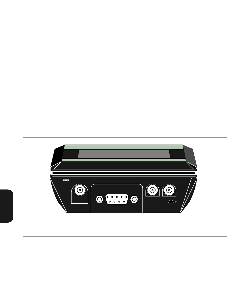
Chapter 7 – Printing and Transferring Data
Output to a Printer
7–2 Brüel & Kjær2238 Mediator
User Manual
7.1 Output to a Printer
7.1.1 Setting up for Portable Printer Type 2322
Mediator includes a standard serial port interface. We rec-
ommend using Portable Printer Type 2322 as the printing
format has been optimized for this printer. However, it is
possible to use an IBM Proprinter compatible printer.
Connecting Type 2322
1. Switch off the Mediator and Type 2322 before connecting
the serial interface cable
2. Connect the 9-pin connector on the cable to the 9-pin
Serial Interface socket on the base of Mediator.
3. Carefully tighten the cable’s connector screws to the
screw holes in the sound level meter.
4. Connect the round connector on the cable (arrows facing
upwards) to Type 2322.
Fig.7.1 Location of the serial interface connector
960160e
Serial Interface
Serial interface socket
Aux 1 Aux 2
7-15V

Chapter 7–Printing and Transferring Data
Output to a Printer
BB1119 – 11 7–3
2238 Mediator
User Manual
Setting up Interface Parameters
Ensure that the interface parameters in the
Printer Interface Window are set as follows:
✩Baud Rate: 9600
✩Handshake: XON/XOFF
7.1.2 To Print a Measurement
Connect the printer and set up the interface parameters as
described above. If the printer has not been connected, you
must save the measurement as a file (refer to File Manager
in section 6.6 for printing files) before switching the Mediator
off.
1. Press to pause the measurement.
2. Press the Data Files key to open the Data Files
Window.
3. Select Print from the menu list. A “Printing ...” mes-
sage is displayed while data is transferred to the printer.
Refer to Chapter 6 for details about setting up print options
and printing files.
Measurement Print Format
A Measurement print includes:
1. Header
2. Settings (measurement parameters)
3. Calibration Data (Microphone, Sensitivity and Date)
4. Overall Results (Start Date/Time, Elapsed Time, Over-
load and Underrange)
5. RMS and Peak Measurement Results (selected measure-
ment parameters, see section 6.4)

7–4 Brüel & Kjær2238 Mediator
User Manual
7.1.3 Calibration History
Connect the printer and set up the interface parameters as
described above.
1. Press to pause the measurement.
2. Press the Calibration key.
3. Select Calibration History from the Calibration
menu.
4. Press the Print key to print the Calibration History.
Calibration History Print Format
A Calibration History print includes:
1. Header
2. Calibration History (Date, Time, Sensitivity, Microphone
and Initial Calibration)
7.2 Transferring Data to 7815, 7820,
7821 and 7825
Data export to a PC is normally made to one of the application
programs: 7815 Noise Explorer, 7820/7821 Evaluator or
7825 Protector. The procedure for setting up the interface
is identical for these programs. For installation of the appli-
cation program, refer to the Installation Guide for the respec-
tive program.
1. If the default values have been changed, switch on the
Mediator and set:
✩Baud Rate: 38400
✩Handshake: Hardwired
Refer to section 3.1.5.

Chapter 7–Printing and Transferring Data
Transferring Data to 7815, 7820, 7821 and 7825
BB1119 – 11 7–5
2238 Mediator
User Manual
Note: 38400 is the recommended baud rate. Depending
on your system, a higher baud rate may be possible or a
lower transfer rate may be necessary.
2. Switch off the PC and the Mediator.
Caution: When connecting the Mediator to the PC, en-
sure that both instruments are switched off. Otherwise
they could be damaged.
3. Choose a free COM port on the PC. Normally the COM 1
or COM 2 port. Connect the Mediator to the PC via the
9-pin Serial Interface socket on the base of the Mediator
using cable AO 1386. AO 1386 has 9-pin connectors at
each end. A 9-pin to 25-pin adaptor is supplied with the
cable for use with PC’s with 25-pin serial connectors.
4. Switch on the PC and open the desired application pro-
gram.
5. Select the New Measurement option in the Insert
menu to open the Insert New Measurement Window.
6. Select SLM Type 2238 from the pull-down menu and
click Setup. The Communication Window is displayed.
7. Set the appropriate COM port and Baud Rate parameters
and click OK.
8. Click Next> in the Insert New Measurement Window.
If properly connected, the Mediator is automatically
switched on and measurement file data is transferred to
the application program. Otherwise a Communication
Error prompt is displayed. You must check that the cable
is properly connected and that the interface parameters
are set up correctly.
Note: Disconnect the Mediator from the PC after completion
of data transmission. Leaving it connected risks draining the
batteries because it might power on when the PC is switched
off.

Chapter 7 – Printing and Transferring Data
Aux 1 and Aux 2 Output
7–6 Brüel & Kjær2238 Mediator
User Manual
7.3 Aux 1 and Aux 2 Output
Aux 1
The AC signal emitted from the Aux 1 Output socket is L-
weighted or weighted with the frequency weighting selected
for Detector 1. It can be used for recording noise signals on
tape, transferring signals to an analyser or listening to the
input on headphones.
Aux 2
A DC level corresponding to the instantaneous RMS (Fast)
level is emitted from the Aux 2 socket at the base of the
sound level meter for recording on a plotter.


Chapter 8 – Maintenance and Repair
Maintenance and Repair
8–2 Brüel & Kjær2238 Mediator
User Manual
8.1 Maintenance and Repair
The Mediator is designed and constructed to provide many
years of reliable operation. However, if a fault occurs that
impairs the sound level meter’s correct function, then remove
the batteries to prevent risk of further damage.
For more information about preventing or identifying faults
or damage to your sound level meter, please read the other
sections of this chapter.
For repair, contact your local Brüel & Kjær dealer.
8.1.1 Care, Cleaning and Storage
The Mediator is a precision instrument. When handling, stor-
ing, or cleaning your instrument, please take note of the
following precautions:
Storing the Instrument
●Keep the sound level meter in a dry place
●For long-term storage, remove the batteries
●Do not exceed storage temperature limits of –25 to +60°C
(–13 to +140°F)
Cleaning the Instrument
If the instrument casing becomes dirty, then wipe it with a
cloth lightly dampened with water. Do not use abrasive
cleansers or solvents. Do not allow moisture to enter the
microphone, connectors, or casing.
Handling the instrument
●Do not try to remove the microphone grid, you can easily
damage the microphone in this way
●Do not attempt to open the instrument. There are no
user-serviceable parts inside. If you think your instru-

Chapter 8– Maintenance and Repair
Maintenance and Repair
BB1119 – 11 8–3
2238 Mediator
User Manual
ment requires service, then please contact your
Brüel & Kjær dealer
●Do not allow the instrument to get wet
●Never mix different makes or types of battery
●Never mix new and old batteries
●Do not allow fully discharged batteries to remain inside
the instrument
●Protect the instrument from impact. Do not drop it.
Transport it in the supplied Shoulder Bag (KE0323)
●Avoid large, sudden changes in temperature and humid-
ity. Especially when there is risk of condensation inside
the Mediator, for example, if it is very cold and you
subject it to a hot and humid environment.

8–4 Brüel & Kjær2238 Mediator
User Manual

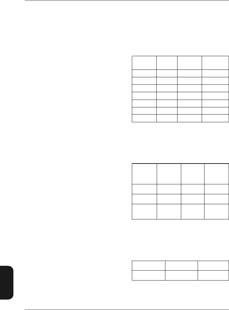
Chapter 9 – Specifications
9–2 Brüel & Kjær2238 Mediator
User Manual
9.1 Specifications
(2238–A and 2238–A–F)
Mediator Type 2238 conforms with both the exist-
ing Sound Level Meter Standards and with the
more comprehensive and more stringent IEC1672
(draft) standard. For the new standard some spec-
ifications are different, and some additional spec-
ifications are required
The different/additional specifications can be found
in section 9.3
General Specifications:
Specifications apply to the 2238 Mediator fitted
with the supplied microphone and preamplifier and
running Basic SLM Software (supplied with each
2238 Mediator)
Note: All references to 1/3-octave bands or 1/1-
octave bands apply only to the Type 2238 –A–F.
Standards:
Conforms with the following:
• EN60651/IEC651 (1979) Type 1 plus Amend-
ment 1
• EN60804/IEC804 (1985) Type 1 plus Amend-
ment 2
• Draft IEC1672/EN 61672 — March 1998,
Class 1
• ANSIS1.4 (1983) Type S 1
• ANSIS1.43–199X Type 1 (Draft 1993)
Supplied Microphone:
Type 4188 Prepolarized Free-field 1/2″ Condenser
Microphone
Nominal Sensitivity: –30dB re 1V/Pa or
31.6 mV/Pa
Capacitance: 12 pF (at 250Hz)
Supplied Microphone
Preamplifier:
ZC0030
Input Impedance: 10 GΩ||0.2 pF
Extension Cables: Available in lengths of 3m and
10 m. No recalibration is required
Measuring Range:
At 1kHz, the difference between the nominal up-
per boundary level on the least sensitive level
range and the lowest sound pressure level meas-
urable on the most sensitive level range.
A-weighted: 25 to 140 dB
C-weighted: 27 to 140 dB
Lin.: 33 to 140 dB
Linear Operating Ranges (worst Case A-
weighted):
For the individual level ranges, at 1kHz, the nom-
inal upper boundary levels minus the lowest sound
pressure level measurable with a noise margin of
5 dB.
With a Microphone Type 4188 of nominal sensi-
tivity:
Inherent Noise level:
Inherent noise is the combination of the electrical
noise and the thermal noise from the microphone
at 20°C. Typical values with supplied microphone
of nominal sensitivity (in dB) are given in the table
below and in Fig.9.1 and Fig.9.2:
Primary Indicator Range:
The upper limit of each Primary Indicator Range
is the same as the upper limit for CF (crest factor)
= 10 of each range setting. The lower limit is either
the upper limit –80dB or one of the following val-
ues, whichever is highest
Upper
limit
Lower
limit
Max. peak
level
Upper limit
(CF = 10)
140 dB 60 dB 143 dB 123 dB
130 dB 50 dB 133 dB 113 dB
120 dB 40 dB 123 dB 103 dB
110 dB 30 dB 113 dB 93 dB
100 dB 25 dB 103 dB 83 dB
90 dB 25 dB 93 dB 73 dB
80 dB 25 dB 83 dB 63 dB
Weighting Electrical
noise
(2238)
Thermal
noise
(4188)
Combine
d Noise
"A" 14 14.5 17.4
"C" 17 13.2 18.5
Lin. 5 Hz–
20 kHz 22 14.2 23
Linear C-weighted A-weighted
38 dB 32 dB 30 dB

Chapter 9– Specifications
BB1119 – 11 9–3
2238 Mediator
User Manual
Indicator Range:
0 to –80 dB relative to upper limit for each range
setting
Frequency Weighting:
Fig. 9.3 shows the curves for the A, C and L fre-
quency weightings The microphone response is
not included
Resolution:
Discrete parameters: 0.1 dB
Broad-band Statistics: 0.5 dB
Detectors:
Simultaneous detection of RMS and Peak with
independent frequency weightings
RMS Detectors
Time Weighting: The RMS detector facilitates
three exponential time weightings (Fast, Slow, Im-
pulse) according to IEC 651 Type 1 (factory
checked to meet Type 0).
Frequency Weightings: A, C or L (also 1/1 and
1/3-octave bands with 2238– A –F)
Tone Burst Response: See Fig. 9.4
Peak detector:
L-weighting: Conforms to IEC 651 and IEC 1672
C-weighing: Conforms to IEC 1672
Rise Time <100 µs (L-weighting)
Overload detector
Monitors all signal paths
Frequency Response:
The effect of the Mediator's casing on the frequen-
cy response is shown in Fig. 9.5. The frequency
and directional responses of the Mediator are
shown in Fig. 9.6, Fig. 9.7and Fig. 9.8)
Measurements:
The available measurement parameters are listed
in the table. RMS and Peak measurements run in
parallel with individual frequency weightings
Symbol Key (for measurement
parameters):
X: Frequency weighting A, C or L
V: Frequency weighting C or L
Y: Time weighting F, S or I
Measurement Control:
Manual control, or pre-set measurement time in
the range 30s to 99 h, 59m, 59s with automatic
storage of measurement
Auto Start:
The Mediator supports four Auto Starts which al-
low set-up of measurement start times up to a
month in advance
Reference Conditions for
Acoustic Calibration:
Using Sound Level Calibrator Type 4231 or Multi-
function Acoustic Calibrator Type 4226
Type of Sound Field: Free-field
Reference Direction of Sound Incidence:
Frontal, perpendicular to microphone diaphragm.
Reference Sound Pressure Level: 94dB
Reference Frequency: 1kHz
Reference Temperature: +20°C (+68°F)
Reference Measuring Level Range: 50–130dB
(automatically set during calibration sequence)
Calibration Correction with Extension Cable:
0dB
Stored Instantaneous
(display only)
LXeq LXYp
LXYav4 LXYInst
LXYav5 LVpk
LAE
LAep,d
EA
LXYmax
LXYmin
LXpkmax
Number of Peaks
Dose%A
Dose%AY4
Dose%AY5
Overload%
Underrange%
Elapsed Time
Start Time
Start Date
Time

Chapter 9 – Specifications
9–4 Brüel & Kjær2238 Mediator
User Manual
Calibration History: 20 most recent calibrations.
The initial calibration value is stored for compari-
son with later calibrations
Display:
128 ×64 dot matrix display with backlight
Measurement Display: Range and quasi-ana-
logue bar graph, plus four measurement parame-
ters that can be freely selected from all available
parameters during measurements
Memory:
2 Mbytes. Up to 500 measurement files can be
stored, including time stamp, complete set-up and
calibration data
Serial Printer:
Measurement data can be printed on Portable
Printer Type 2322 or on an IBM Proprinter-com-
patible printer.
Measurement data can be output as a binary file
for post-processing on a PC
Aux 1 Output:
Connector: 2-pin LEMO
AC Output Signal: Range-adjusted AC output, L-
weighted or with the frequency weighting selected
on the RMS detector. Short-circuit protected
Output: 1VRMS corresponding to full-scale indi-
cation
Max. Load: 10 kΩ|| 1 nF
Output Impedance: Typically 100 Ω
Aux 2 Output:
Connector: 2-pin LEMO
DC Output Signal: DC version of signal on RMS
detector 1 (Fast, Inst). Delayed 0.8s. Short-circuit
protected
Output: 0 to 4.0VDC, (50mV/dB)
Update Rate: 160 times per second
Max. Load: 10 kΩ|| 1 nF
Output Impedance: Typically 100 Ω
Clock:
Real-time (calendar)
Serial Input/Output:
Conforms to EIA/TIA 574 (RS– 232), coupled as
Data Terminal Equipment (DTE). Cable (AO 1386)
is supplied with the Mediator
Connector: 9-pin D-type male
Baud Rates: 4800, 9600, 19200, 38400 and
115200
Word Length: 8 bits, no parity, 1 stop bit
Serial Interface:
Handshake: Hardwired, Modem
Printer Interface:
Handshake: XON/XOFF, Hardwired
Settling Time:
From Power On: <10s
Environmental Effects:
Storage Temperature: –25 to +70°C (–13 to
+158°F)
Operating Temperature: –10 to +50°C (14 to
122°F)
Effect of Temperature: <0.5 dB (–10 to +50°C)
Effect of Humidity: <0.5dB for 30% < RH<90 %
(at 40°C, 1kHz)
Batteries:
Four 1.5V LR6/AA alkaline cells
Lifetime (at room temperature): Typically
>10hours. Automatic switch-off when battery volt-
age sinks below threshold, to avoid invalid meas-
urements
Indicator: Warning on display when less than 15
minutes of lifetime is remaining
Internal Back-up Battery: Keeps clock and data
files operating for at least 6 months (typically) if
fully charged. The back-up battery is charged from
the main batteries. Charging time: approx. 10
hours
External DC Power Supply:
Voltage: Regulated 7 to 15 V
Voltage Ripple: < 20mVpeak to peak
Power: Approximately 150 mA at 7 V (approx.
210 mA with filter set)
Centre Pin: Positive
Weight and Dimensions:
460 g (with batteries), 257 ×97×41 mm
Language:
Each instrument is loaded with English, German,
French, Italian and Spanish text. You can select
any of these languages at any time
9.2 Additional Specifications for
2238 – A – F (Version with
Filter Set Installed)
Standards:
Conforms with the following:

Chapter 9– Specifications
BB1119 – 11 9–5
2238 Mediator
User Manual
• EN 61260/IEC 1260 (1995) Octave and 1/3-oc-
tave Bands Class 1
• ANSI S1.11– 1986 Octave and 1/3-octave
Bands, Order 3, Type 1-D. Optional Range
Octave and 1/3-octave Band
Filters:
Conform to IEC 1260 (1995) and ANSI S1.11 –
1986.
Frequency Rating System: Base 10
Reference Attenuation: 0dB
Linear Operating Range: As Indicator range
Nominal Octave Band Centre Frequencies:
31.5 Hz, 63 Hz, 125Hz, 250 Hz, 500Hz, 1kHz,
2kHz, 4kHz, 8kHz
Nominal 1/3-octave Band Centre Frequencies:
20 Hz, 25Hz, 31.5 Hz, 40Hz, 50Hz, 63Hz, 80Hz,
100Hz, 125 Hz, 160Hz, 200Hz, 250Hz, 315Hz,
400Hz, 500Hz, 630Hz, 800Hz, 1kHz, 1.25kHz,
1.6 kHz, 2 kHz, 2.5 kHz, 3.15 kHz, 4kHz, 5 kHz,
6.3 kHz, 8kHz, 10kHz, 12.5kHz
Batteries:
Lifetime (at room temperature): With filter se-
lected: Typically >7 hours
9.3 Specifications According to
IEC 1672 (2238–A and
2238–A–F)
Steady Level Linearity at 1kHz:
This is the nominal upper boundary levels minus
the lowest sound pressure level that can be meas-
ured with maximum 0.3dB unlinearity within a
10 dB step. Unlinearity is due to inherent noise,
which must be at least 13dB below the lower limit.
Inherent noise is the combination of the electrical
noise and the thermal noise from the microphone
at 20°C. See Fig.9.1 and Fig. 9.2.
For any level range, the upper limit is the upper
boundary of the range. The lower limit is either
the upper limit –80 dB, or one of the following
values, whichever is highest:
Peak-C Ranges:
For any range, the upper limit is the upper bound-
ary of the range +3 dB. The lower limit is either
the upper limit –63 dB, or 60dB (LVpk (
V = fre-
quency weighting L or C)), whichever is highest
Range of Integration Time:
Time Averaged Sound Levels and Sound Expo-
sure Levels can be measured over time intervals
ranging from 1s to >10months (month of 31 days)
Inherent Noise:
Typical time averaged sound levels for integration
times of 1 minute are shown in Fig.9.1 and Fig. 9.2
for a Mediator fitted with a microphone Type 4188
of nominal sensitivity and exposed to a very low
sound level.
Broad Band values for Fast and Slow time weight-
ed measurements are:
Test Information:
Microphone Reference Point: 1.3 mm behind the
front of the protection grid.
During test the microphone signal can be substi-
tuted by an electrical signal input to an adapter
WA 0302 (13 pF) which replaces the microphone.
For a calibration factor of 0 dB the relationship
between applied voltage and reading in SPL fol-
lows the table below
Note: Due to stray capacitance an attenuation of
0.6 dB may result with WA 0302
Input Voltage Maximum: 15 Vpeak-peak
EMC
Classification Group: X
Reference Direction for Testing Radio Frequen-
cy Susceptibility: Microphone facing antenna
9.4 Effect of Accessories:
Fig. 9.16, Fig. 9.17 and Fig. 9.18 show the typical
effect of various accessories on the frequency re-
sponse of Mediator
Linear C-weighted A-weighted
41 dB 35 dB 33 dB
Weighting Fast Slow
A<20dB <20dB
C*21 dB 20 dB
Lin*24 dB 23 dB
* Average of 10 readings taken randomly over a
time interval of 1 minute
Applied Voltage 34 mV 6.76 V
SPL 94 dB 140 dB
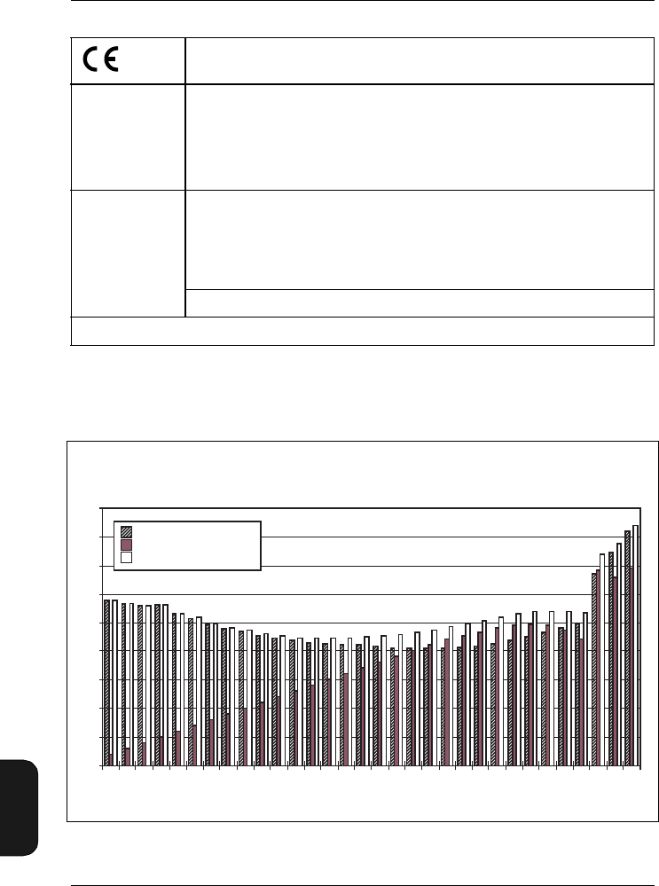
Chapter 9 – Specifications
9–6 Brüel & Kjær2238 Mediator
User Manual
CE-mark indicates compliance with: EMC Directive.
EMC Emission EN 50081–1: Generic emission standard. Part 1: Residential, commercial and light
industry.
EN 50081–2: Generic emission standard. Part 2: Industrial environment.
CISPR 22: Radio disturbance characteristics of information technology equipment.
Class B Limits.
FCC Rules, Part 15: Complies with the limits for a Class B digital device.
EMC Immunity EN 50082–1: Generic immunity standard. Part 1: Residential, commercial and light
industry. RF immunity implies that sound level indications of 50 dB or greater will
be affected by no more than 0.5dB.
EN 50082–2: Generic immunity standard. Part 2: Industrial environment. RF im-
munity implies that sound level indications of 65 dB or greater will be affected by
no more than 0.5dB.
These levels of immunity are 9dB better than required by IEC1672.
Note: The above conformance is guaranteed only when using the included/optional accessories.
Brüel& Kjær reserves the right to change specifications and accessories without notice
Fig.9.1 The three components of inherent noise in each 1/3-octave band and in the
broad bands A, C and L (5 Hz – 20 kHz)
Noise
Level
(dB)
25
20
15
10
5
0
-5
-10
-15
-20
25 40 63 100 160 250 400 630 1k 2.5k 4k 6.3k 10k A C Lin
Centre Frequency
Electrical Noise
Thermal Noise
Combined Noise
980280
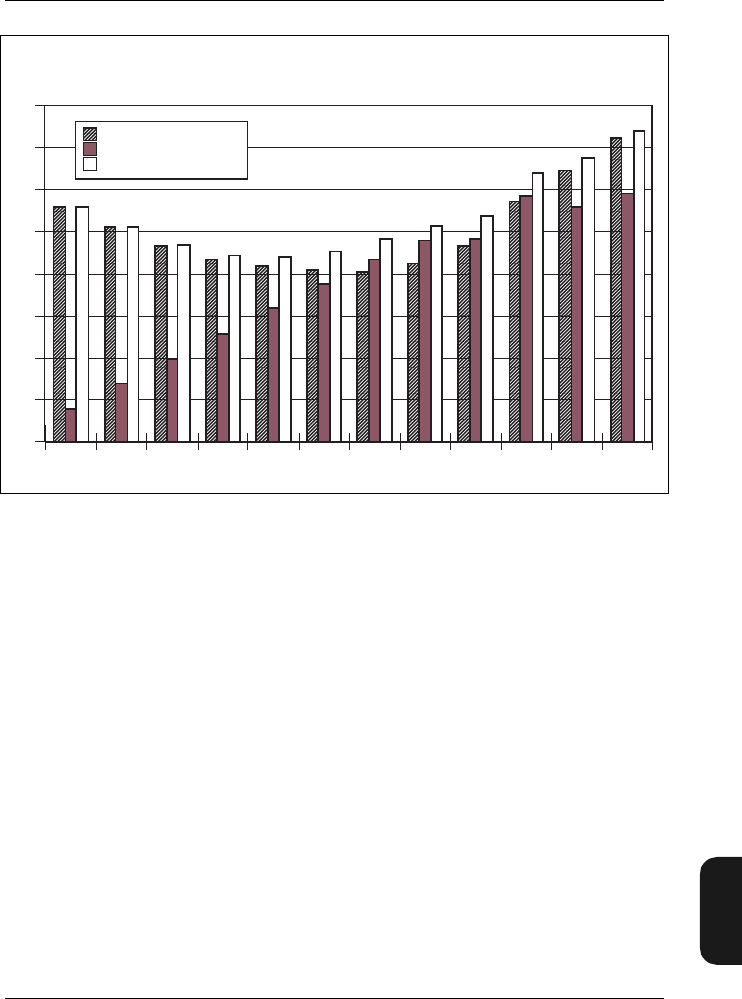
Chapter 9– Specifications
BB1119 – 11 9–7
2238 Mediator
User Manual
Fig.9.2 The three components of inherent noise in each octave band and in the
broad bands A, C and L
Noise
Level
(dB)
25
20
15
10
5
0
-5
-10
-15
31,5 63 125 250
Centre Frequency
500 1000 2000 4000 8000 A C Lin
Electrical Noise
Thermal Noise
Combined Noise
980281
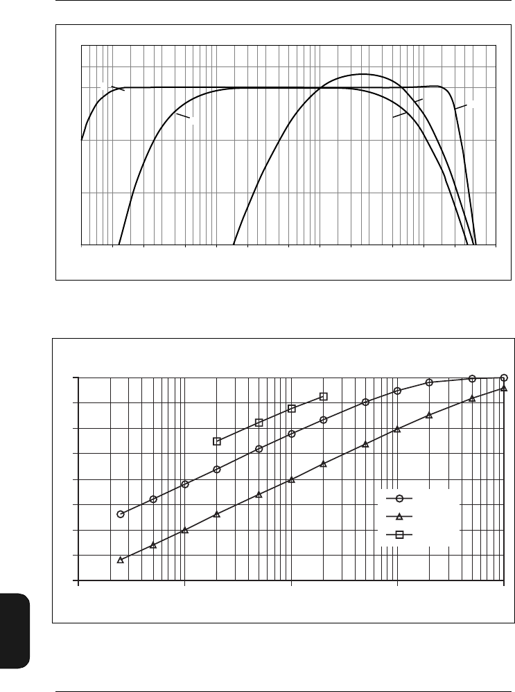
Chapter 9 – Specifications
9–8 Brüel & Kjær2238 Mediator
User Manual
Fig.9.3 Curves for the A and C and L weightings. The curves do not include the
microphone response
Fig.9.4 Curves showing the detector response of Mediator to 4kHz tone bursts of
various durations
10 100 1k 10k
0
–10
–5
–15 20 50 200 500 2k 5k 20k 50k5
2
(dB)
Relative Response
980385
e
Frequency (Hz)
AL
CC
L
Response
(dB)
0
-5
-10
-15
-20
-25
-30
-35
-40
0,1 1 10 100 1000
Duration (ms)
Fast
Slow
Impulse
980279e
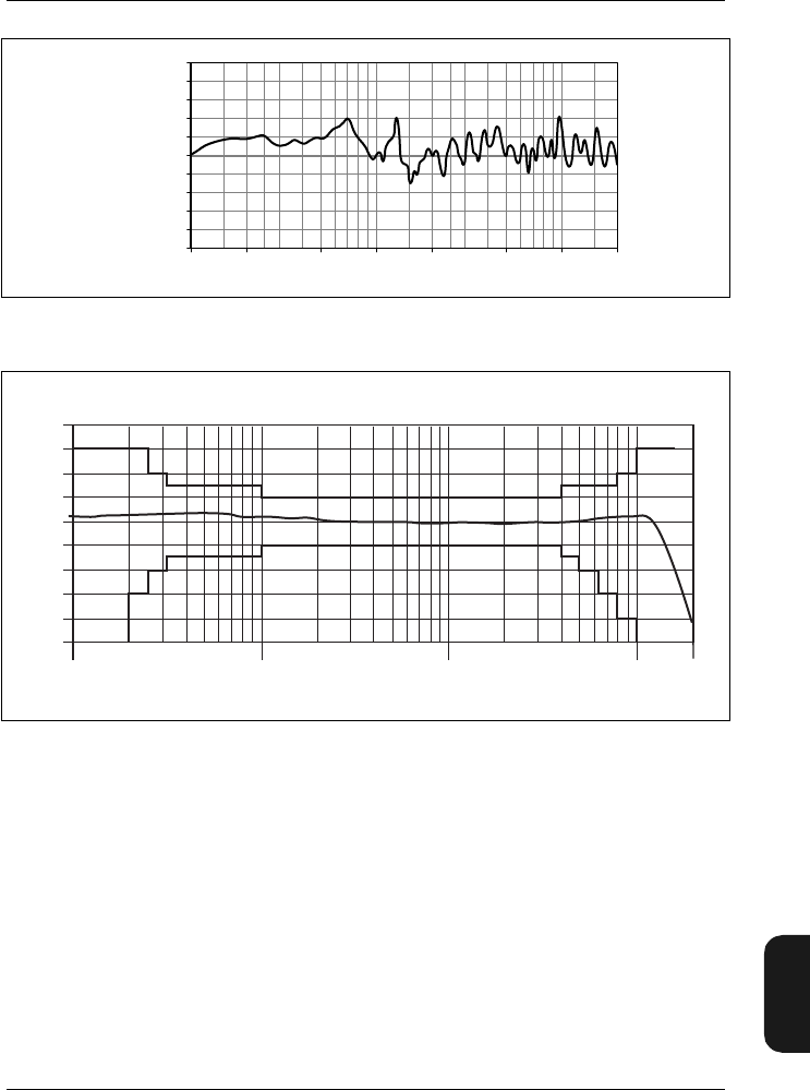
Chapter 9– Specifications
BB1119 – 11 9–9
2238 Mediator
User Manual
Fig.9.5 Effect of Mediator’s casing on frequency response
Fig.9.6 Free-field frequency response of Mediator fitted with the supplied micro-
phone Type 4188. IEC 651 Type 1 tolerances are also shown
931236/2e
Relative
Response
(dB)
100 1k 10k
0
– 1 200 500 2k 5k 20k
1
Frequency (Hz)
Relative Response (dB)
4
3
2
1
0
-1
-2
-3
-4
-5
10 100 1000 10000
Frequency (Hz) 980283
20000
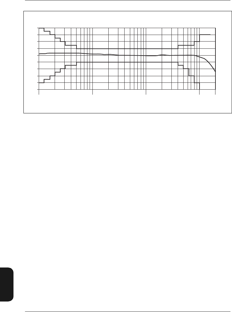
Chapter 9 – Specifications
9–10 Brüel & Kjær2238 Mediator
User Manual
Fig.9.7 Random incidence frequency response of Mediator (random incidence filter
selected) fitted with the supplied microphone Type 4188. IEC651 Type 1
tolerances are also shown
Relative Response (dB)
4
3
2
1
0
-1
-2
-3
-4
-5
10 100 1000 10000
Frequency (Hz)
20000
980282

Chapter 9– Specifications
BB1119 – 11 9–11
2238 Mediator
User Manual
Fig.9.8 Directional characteristics of the Mediator fitted with the supplied micro-
phone Type 4188. Characteristics measured at 1, 2, 4, 8 and 12.5kHz
980386/1e
B
r
ü
e
l
&
K
j
æ
r
0
330
300
270
240
210
180
150
120
90
60
30
40
50 30 20 10 0
50 40 30 20 10 0
Q
P
5
1
0
2
B
r
ü
e
l
&
K
j
æ
r
Q
P
5
1
0
2
12.5
kHz
B
r
ü
e
l
&
K
j
æ
r
0
330
300
270
240
210
180
150
120
90
60
30
40
50 30 20 10 0
50 40 30 20 10 0
Q
P
5
1
0
2
B
r
ü
e
l
&
K
j
æ
r
Q
P
5
1
0
2
8 kHz
B
r
ü
e
l
&
K
j
æ
r
0
330
300
270
240
210
180
150
120
90
60
30
40
50 30 20 10 0
50 40 30 20 10 0
Q
P
5
1
0
2
B
r
ü
e
l
&
K
j
æ
r
Q
P
5
1
0
2
4 kHz
B
r
ü
e
l
&
K
j
æ
r
0
330
300
270
240
210
180
150
120
90
60
30
40
50 30 20 10 0
50 40 30 20 10 0
Q
P
5
1
0
2
B
r
ü
e
l
&
K
j
æ
r
Q
P
5
1
0
2
2 kHz
B
r
ü
e
l
&
K
j
æ
r
0
330
300
270
240
210
180
150
120
90
60
30
40
50 30 20 10 0
50 40 30 20 10 0
Q
P
5
1
0
2
B
r
ü
e
l
&
K
j
æ
r
Q
P
5
1
0
2
1 kHz
0
Brüel & Kjær 2238 Mediator
BK
7/6-'89
OVL
02:00:00
F MaxL 83·6 dBA
40 .... 120+
5dB
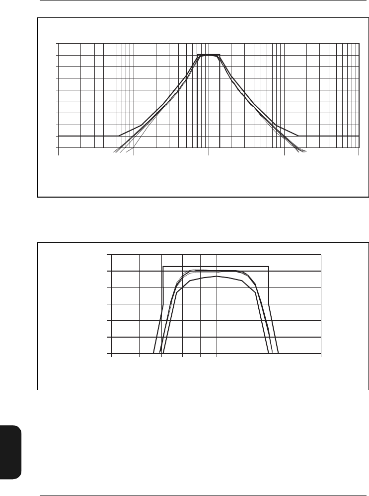
Chapter 9 – Specifications
9–12 Brüel & Kjær2238 Mediator
User Manual
Fig.9.9 Curves showing the shape of the octave-band filters (from 0 to –80dB).
IEC 1260 tolerances are also shown
Fig.9.10 Curves showing the shape of the octave-band filters (from 0 to –3.5 dB).
IEC 1260 tolerances are also shown
Response
(dB)
10
0
-10
-20
-30
-40
-50
-60
-70
-80
0,01 0,1 1 10 100
Multiple of Centre Frequency
980289
1
0
-1
-2
-3
-4
-5
1
Multiple of Centre Frequency
Response
(dB)
0,5 2
980286
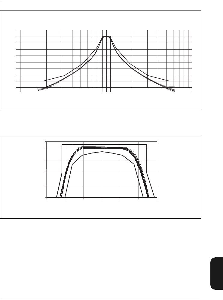
Chapter 9– Specifications
BB1119 – 11 9–13
2238 Mediator
User Manual
Fig.9.11 Curves showing the shape of the 1/3-octave-band filters (from 0 to –80dB).
IEC 1260 tolerances are also shown
Fig.9.12 Curves showing the shape of the 1/3-octave-band filters (from 0 to –4 dB).
IEC 1260 tolerances are also shown
Response
(dB)
10
0
-10
-20
-30
-40
-50
-60
-70
-80
Multiple of Centre Frequency
0,1 110
980288
Response
(dB) 0
-1
-2
-3
-4
0,85 0,9 0,95 1 1,05 1,1 1,15
Multiple of Centre Frequency 980287
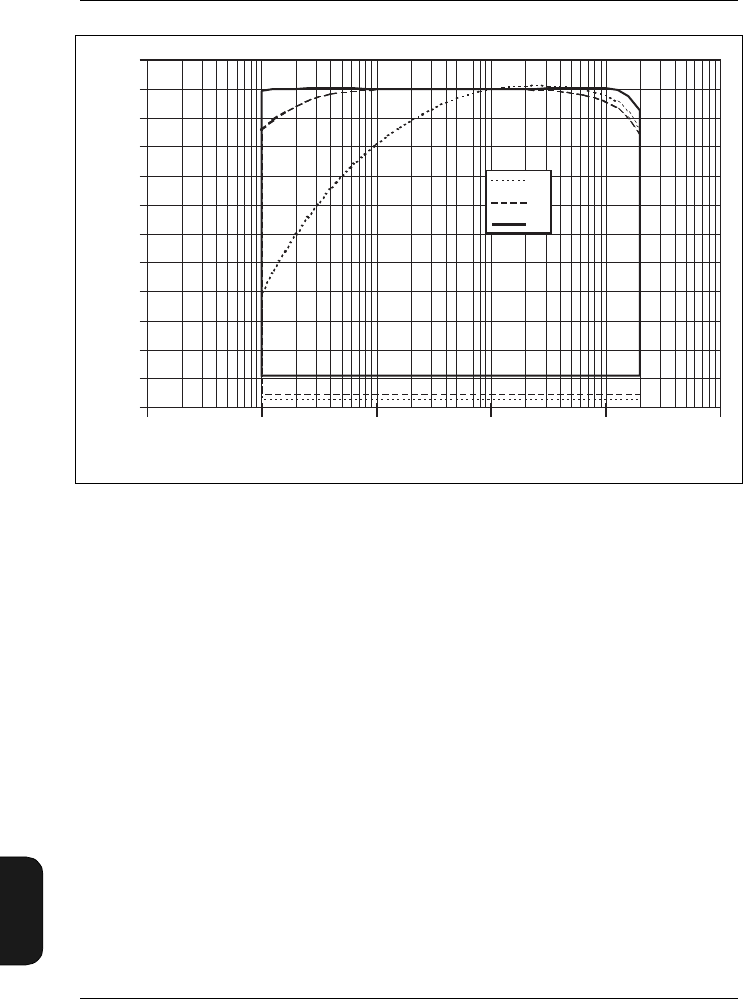
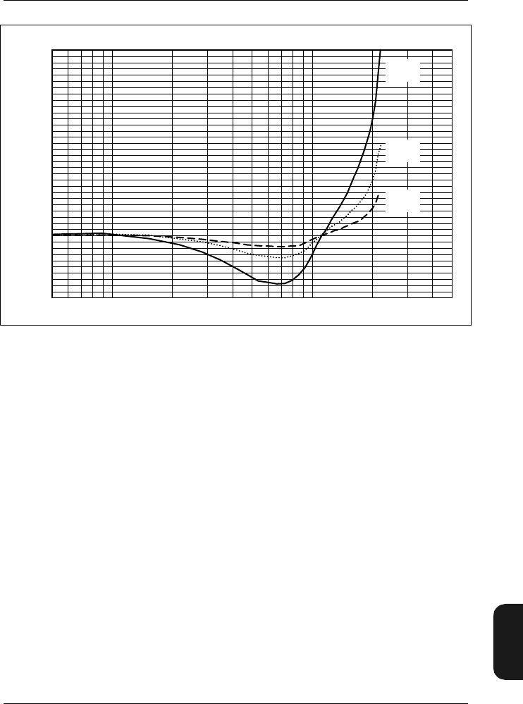
Chapter 9– Specifications
BB1119 – 11 9–15
2238 Mediator
User Manual
Fig.9.14 Typical variation in frequency response (normalized at 250 Hz) as a func-
tion of change in ambient pressure, relative to 101.3 kPa (Type 4188)
940762e
1k 10k Frequency (Hz)
– 1
0
2
Correction (dB)
1
3
500 50k
– 10kPa
change
– 20kPa
change
– 40kPa
change
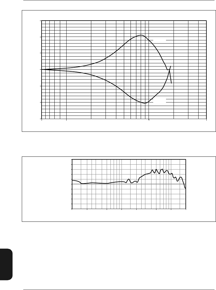
Chapter 9 – Specifications
9–16 Brüel & Kjær2238 Mediator
User Manual
Fig.9.15 Typical variations in frequency response as a function of temperature, rela-
tive to the response at 20°C (Type 4188)
Fig.9.16 Influence of Protective Cover UA 1236 on Mediator's frequency response
940806/1e
Frequency (Hz)1 k 10 k 50 k
1.0
Response (dB)
– 1.5
– 1.0
– 0.5
0.0
0.5
500 Hz
1.5
– 10°C
50°C
931234/1e
Relative
Response
(dB)
100 1k 10k
0
– 1 200 500 2k 5k 20k
1
Frequency (Hz)
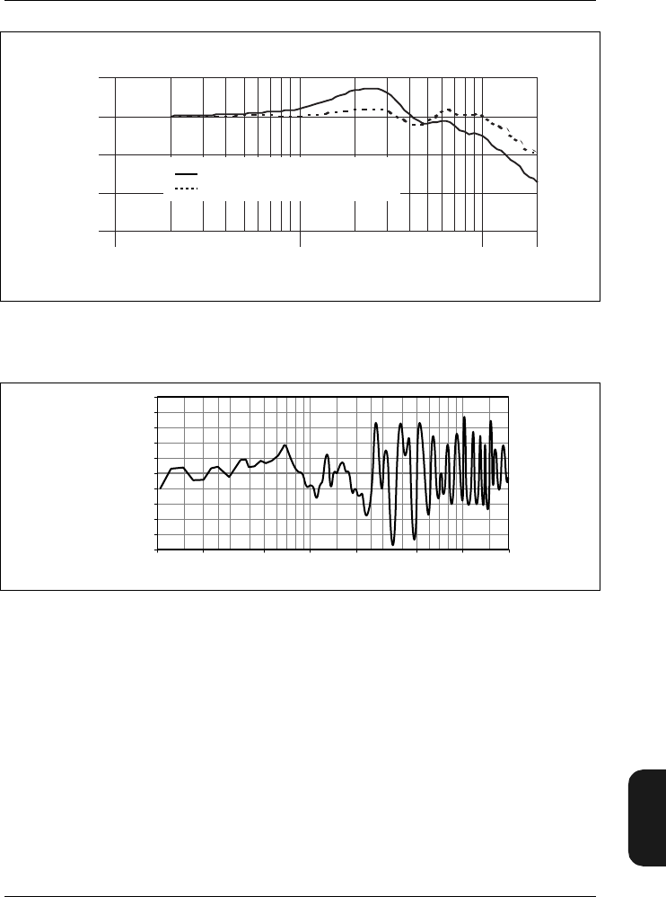
Chapter 9– Specifications
BB1119 – 11 9–17
2238 Mediator
User Manual
Fig.9.17 Influence of Windscreen UA0237 on Mediator’s frequency response, with
and without the windscreen correction filter
Fig.9.18 Influence on Mediator’s frequency response when mounted on Tripod UA1251
1,0
0,0
-1,0
-2,0
-3,0
Response (dB)
100 1000 10000
Frequency (Hz)
980285
Influence of windscreen
Windscreen with correction filter
100 1k 10k
0
– 1 200 500 2k 5k 20k
1
931235/1e
Frequency (Hz)
Relative
Response
(dB)

9–18 Brüel & Kjær2238 Mediator
User Manual
9.5 Accessories Included:
Type 4188: Prepolarized Free-field 1/2″
Condenser Microphone
ZC0030: Microphone Preamplifier
AO1386: 9-pole Cable with 25-pole Adap-
tor (for computer and serial
printer)
KE0323: Shoulder Bag
UA1236: Protective Cover
QB 0013: 4 Alkaline Batteries
9.6 Optional Accessories
AO0560/0409: Microphone Extension Cable
(10 m)
AO0561/0408: Microphone Extension Cable
(3 m)
ZG 0386 Power Supply (European ver-
sion)
ZG 0387 Power Supply (UK version)
ZG 0388 Power Supply (US version)

BB1119 – 11 10 – 1
2238 Mediator
User Manual
Chapter 10
Appendix 1: General
10.1 Exchange Rate.................................................................... 10 – 2
10.2 List of Default Parameters ........................................... 10 – 4
10.3 Interface Errors.................................................................. 10 – 6
10.4 Messages and Warnings................................................. 10 – 8
10.5 Error messages................................................................. 10 – 12

Chapter 10 – Appendix 1: General
Exchange Rate
10–2 Brüel & Kjær2238 Mediator
User Manual
10.1 Exchange Rate
When measuring noise for the evaluation of hearing risk, the
time factor has an important influence.
It is generally assumed that doubling the noise energy also
doubles the hearing risk. This means that if the noise energy
is doubled (i.e. it increases by 3 dB) the allowed exposure time
should be halved.
Thus, as the equal energy concept requires a halving of the
exposure time for a 3 dB increase in level (Leq), it is said to
have an Exchange Rate of 3dB. This is standardized by ISO.
However, in the USA, the OSHA regulation allows a 5dB
increase in level for each halving of the exposure time (i.e.
the Exchange Rate is 5 dB). It therefore uses an Lav with
this Exchange Rate. This Lav5 (or LOSHA) has a different
relationship between level and time than the equal energy
concept standardized by ISO.
This is shown in Fig.10.1. Going from an exposure time of
8 hours to 4hours allows an increase of 3dB in the Leq in
accordance with ISO, but an increase of 5dB in the LAV5 in
accordance with OSHA.
An Exchange Rate of 4 dB also exists (Lav4 or LDOD).
Leq and LEP,d are always measured based on a 3 dB Exchange
Rate. The second Exchange Rate (4 or 5dB) determines
whether Lav4 or Lav5 is measured.
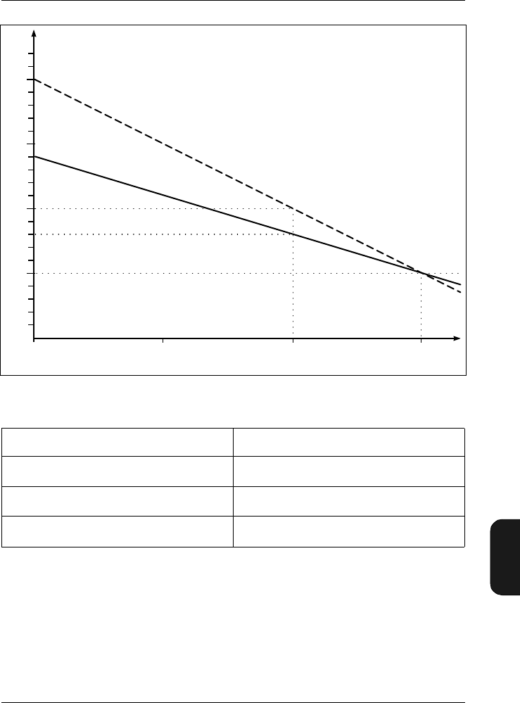
Chapter 10– Appendix 1: General
Exchange Rate
BB1119 – 11 10 – 3
2238 Mediator
User Manual
Fig.10.1 The effect of an Exchange Rate of 3 or 5dB
Exchange Rate (dB) Parameter
3L
eq and Lep,d (always measured)
4L
av,4 (LDOD)
5L
av,5 (LOSHA)
Table 10.1 The LAV parameter measured by the sound level meter is de-
pendent on the Exchange Rate
860884e
OSHA
ISO
90
95
100
105
241 8h t
Leq
dB(A)
93

Chapter 10 – Appendix 1: General
List of Default Parameters
10–4 Brüel & Kjær2238 Mediator
User Manual
10.2 List of Default Parameters
Menu Set-up Parameter Default Value
General
Range 30 – 110 dB
Peaks Over 140dB
2nd Exch. Rate 4 dB
Weightings
Bandwidth (Detector 1) Broad Band
Freq. Wgt. (Detector1) A (“F”)
Weighting (Detector2) Peak
Meas. Control Sequence Off
Corr. Filters Sound Incidence Frontal
Windscreen Filter Off
Input/Output Aux 1 AC Output
Aux2 DC Output
Auto Start Auto Start No. 1
Owner None
Occ. Health
Exposure Time 7:30 (2700 s)
Criterion 100 dB
Threshold 0 dB
Save Setup Save in No. 1
Recall Setup Recall From No. Default
Interface
Baud Rate (printer) 9600
Handshake (printer) XON/XOFF
Baud Rate (remote) 9600
Language English

Chapter 10– Appendix 1: General
Messages and Warnings
BB1119 – 11 10 – 5
2238 Mediator
User Manual
10.3 Messages and Warnings
If you get a message or warning while using or calibrating
your Mediator, then refer to the chart below.
Display Contrast Adjust 2
Message Occurs Solution
When a calibration is
executed Wait until the cali-
bration is finished
When a new
calibration sensitivity
value has been
accepted
Wait until the new
value has been
saved
When a measurement
has been in progress
for more than 1 minute
and you are about to
delete the measure-
ment data if you:
1: Change the meas-
urement range.
2: Make changes to
the measurement set-
up.
3: Make a calibration
Normal situation to
avoid deleting the
measurement.
Press “OK” if meas-
urement data should
be deleted or “Can-
cel” if you want to
continue the meas-
urement
Menu Set-up Parameter Default Value
Performing
calibration check
Please wait
Saving
Please wait
Warning
Measurement will
be reset.
Continue?

Chapter 10 – Appendix 1: General
Messages and Warnings
10–6 Brüel & Kjær2238 Mediator
User Manual
When a measurement
sequence is set up and
the required number of
files for the sequence
exceeds the number
available in memory
Reduce the number
of measurements in
the sequence or
save some of the
files in memory on a
PC.
When a file is being
saved Wait until the file is
saved
When the selected
files are being deleted Wait until the files
have been deleted
Before a number of
selected files are being
deleted
Normal situation to
avoid deleting files
accidentally. Press
“OK” to delete the
files or press “Can-
cel” to skip deleting
the files
When “Delete All” has
been activated and the
files are being deleted
Wait until all the files
have been deleted
Warning
X files needed
Y files available
Continue anyway
Saving file
Deleting selected
file(s) ...
Delete selected
file(s)?
Deleting all
files ...

Chapter 10– Appendix 1: General
Messages and Warnings
BB1119 – 11 10 – 7
2238 Mediator
User Manual
Before all files are
deleted when “Delete
All” has been selected
Normal situation to
avoid deleting files
accidentally. Press
“OK” to delete all
files or press “Can-
cel” to skip deleting
all files
An operation has been
activated that requires
that a number of files
are tagged
Tag the desired files
When “Disk Summary”
in the File Manager
has been selected
Shows an overview
of disk space and
files available
When Print has been
selected in the Data
Files Window or in the
Print Manager. The file
name for the file that is
being printed is shown
in the second line if
Print has been
selected in the File
Manager
Wait until the files
are printed or press
“Cancel” to stop
printing
When a print operation
is cancelled Normal situation
when a print opera-
tion is cancelled
Delete all files?
No tagged files!
To tag files use
left or right arrow
in the file manager
Disk summary
X kbytes total
Y kbytes use
Z kbytes free
Q files available
Printing ...
Cancelling ...

Chapter 10 – Appendix 1: General
Interface Errors
10–8 Brüel & Kjær2238 Mediator
User Manual
10.4 Interface Errors
When the application
module is changed
and measurement
data has not been
saved
Normal situation to
avoid loosing meas-
urement data. Press
“OK” to change
application and
loose data or press
“Cancel” to return to
the current applica-
tion module and
save data
Message Description Number
Header not
found
An unknown header was supplied to
the Mediator 1
Illegal data
type
The current interface message
requires a different data type 2
Parameter error The received interface message was
ambiguous 3
Char data not
found
An unknown character data was
supplied to the Mediator 4
Suffix data not
found
An unknown suffix was supplied to
the Mediator 5
Nr string to
long
The supplied numeric string is too
long 6
Nr out of range The supplied numeric exceeds the
legal range for the data type 7
Non-decimal out
of range
The supplied binary, octal or hex
coded numeric exceeds the legal
range for the data type
8
Change
application?

Chapter 10– Appendix 1: General
Interface Errors
BB1119 – 11 10 – 9
2238 Mediator
User Manual
String too long The supplied string is too long 9
Block data too
long
The supplied block data exceeds
max length of block 10
Too many
parameters
The supplied interface message
contains more parameters than
allowed
11
Out of memory System error. Mediator was unable
to allocate enough memory to handle
the interface message used. Use
less complex interface commands
12
Output is
cancelled
The response to the previous query
message was not read from the
Mediator
13
Deadlocked The Mediator interface is in a
deadlock condition caused by input
buffer full, parser blocked, response
formatter blocked and output buffer
full. Avoid this by always reading the
response to a query before supplying
the Mediator with new interface
commands. Switch the Mediator off
and on again to exit the deadlocked
condition.
14
Unexpected byte An unexpected byte was detected
when something else was expected.
For example a space was detected
instead of a message terminator
15
Unexpected END
detected
An unexpected LF (decimal 10)
message terminator was detected.
For example a “;” or a “+” followed
by LF will cause an interface error
16 because these jobs are not
correctly finished
16
Message Description Number

Chapter 10 – Appendix 1: General
Interface Errors
10–10 Brüel & Kjær2238 Mediator
User Manual
Interface
overrun
Interface messages were received at
a rate faster than the Mediator can
processes them. This caused an
internal input buffer overrun
21
Interface
handshake error
An interface handshake error was
detected. Reset the Mediator and try
again
22
Illegal key
number used
An unspecified key number has been
selected
Setup during
measurement
The set-up cannot be changed while
a measurement is proceeding
No Filter
installed
An octave or 1/3-octave filter has
been specified and no filter set is
installed
Autostart not
applicable
The specified Auto Start is not
allowed. The Auto Start has not been
set up with the current application
module or the date is out of range
File write
error
An error has occurred while storing
data
Illegal value The specified value is out of range
Setup during
measurement
Mediator was in measurement mode
when you tried to change the set-up.
Change to pause mode
23
No filter
installed
You tried to set up a measurement
parameter that requires the filter set 24
Date out of
range
Normally occurs when the date for
an Auto Start is not valid 25
Message Description Number

Chapter 10– Appendix 1: General
Error messages
BB1119 – 11 10–11
2238 Mediator
User Manual
10.5 Error messages
If you get an error message while using or calibrating your
Mediator, then refer to the chart below.
Auto Start not
applicable
There is an error in the set-up for
the specified Auto Start 26
File write
error
Will not normally occur. The
measurement file is corrupt or the
instrument is defect
27
Illegal value The specified value is not allowed 28
Message Occurs Solution
During calibration. For
example, if foreign
sounds have corrupted
the calibration signal
or if the calibrator is
not switched on.
Make sure you have
turned on and fitted
the calibrator cor-
rectly. Check the
calibrator’s batter-
ies, and/or move to
a quieter location.
Alternatively use
114dB calibration
level. If the error
persists, then con-
tact your
Brüel& Kjær dealer.
Message Description Number
Calibration error
Unstable input
signal

Chapter 10 – Appendix 1: General
Error messages
10–12 Brüel & Kjær2238 Mediator
User Manual
During calibration, if
the instrument has dis-
covered that the
required calibration
level is more than
±1.5 dB from the fac-
tory calibration (the
“Initial Sens.” value).
Return to the Cali-
bration Window and
enter a calibration
level that is within
the acceptable
range. Make sure
you have selected
the correct calibra-
tion level on your
calibrator. If the error
persists, then you
may need a new
factory calibration.
Contact your
Brüel& Kjær dealer
for assistance.
The output from both-
detectors are com-
pared and the
difference is outside
the acceptable range
Try to calibrate
again. If the error
message persists
your Mediator is
faulty and must be
repaired. Contact
your local
Brüel& Kjær dealer
The calibrator level is
above the maximum
specified dynamic
range (Only with an
unspecified trans-
ducer)
Reduce the calibra-
tion level and per-
form calibration
again
The calibrator level is
below the maximum
specified dynamic
range (Only with an
unspecified trans-
ducer)
Increase the calibra-
tion level and per-
form calibration
again
Message Occurs Solution
Calibration error
New sens. exceeds
acceptance range
±1.5 dB
Detector error!
See error details
in User Manual
Calibration error!
Calibrator level
too high
Calibration error!
Calibrator level
too low

BB1119 – 11 11 – 1
2238 Mediator
User Manual
Chapter 11
Appendix 2: Interface
11.1 Controlling Mediator via the Serial Interface...... 11 – 3
Introduction ..................................................................... 11 – 3
11.2 Formats for Interface Messages ................................. 11 – 4
Terminology for Interface Messages............................... 11 – 4
Use of Syntax Diagrams.................................................. 11 – 6
General Rules for Constructing an Interface Message . 11 – 7
Mnemonic Codes.............................................................. 11 – 8
Message Terminator........................................................ 11 – 9
11.3 Types of Data....................................................................... 11 – 9
11.4 Character Data................................................................. 11 – 10
Numeric Data ................................................................ 11– 10
String Data .................................................................... 11 – 12
11.5 Information Protocol ...................................................... 11 – 13
Introduction ................................................................... 11 – 13
Header............................................................................ 11 – 13

Chapter 11 – Appendix 2: Interface
11–2 Brüel & Kjær2238 Mediator
User Manual
11.6 Setting up the PC............................................................ 11 – 15
Commands..................................................................... 11 – 16
Bandwidth ..................................................................... 11 – 17
Continue......................................................................... 11 – 18
Error? ............................................................................. 11 – 18
File ................................................................................. 11 – 19
Frequency_Weighting_1 ............................................... 11– 23
Frequency_Weighting_2 ............................................... 11– 25
Header............................................................................ 11 – 26
Identify? ......................................................................... 11 – 26
Key ................................................................................. 11– 27
PArameter?.................................................................... 11 – 29
PAUse ............................................................................ 11 – 32
RAnge............................................................................. 11– 32
REset.............................................................................. 11– 34
SEtup ............................................................................. 11 – 34
STatus? .......................................................................... 11– 39
SYstem........................................................................... 11 – 40
Version........................................................................... 11 – 41

Chapter 11– Appendix 2: Interface
Controlling Mediator via the Serial Interface
BB1119 – 11 11 – 3
2238 Mediator
User Manual
11.1 Controlling Mediator via the
Serial Interface
11.1.1 Introduction
This chapter describes the operation of the Mediator via its
serial interface. It assumes that you are familiar with the
manual operation of the sound level meter and have some
interface programming experience.
Echo
All characters sent via the interface to Mediator are echoed
back to the controller, exactly as entered.
Switching on
To avoid accidentally switching Mediator on, the following
procedure must be observed when it is desired to switch the
Mediator on via the interface.
●The baud rate and handshake parameters must be set
to the same for Mediator and the controller (refer to
section 3.1.5)
●The first character that is transmitted will activate the
Mediator
●Within a short period (8 to 10 seconds) the Mediator must
receive more than 4 additional characters to switch on.
If no further characters are received within this period
it will not be switched on. Use the Echo facility to verify
that the Mediator is switched on. Send a character/com-
mand via the interface until the character/command is
echoed back.

Chapter 11 – Appendix 2: Interface
Formats for Interface Messages
11–4 Brüel & Kjær2238 Mediator
User Manual
11.2 Formats for Interface Messages
11.2.1 Terminology for Interface Messages
The data transmitted to and from a Mediator conforms to a
subset of the ANSI/IEEE Standard, IEEE 488.2 (1987), “IEEE
Standard Codes, Formats, Protocols and Common Com-
mands”.
Data that is transferred to or from a Mediator, via the serial
interface, is referred to as a “message”. Two types of message
can be sent to the Mediator, “command” and “query” messag-
es. Messages output by the Mediator replying to a query
message from a controller are referred to as “response” mes-
sages.
Messages to the Mediator
The interface messages are designed according to the ANSI/
IEEE Std 488.2 (1987), “IEEE Standard Codes, Formats, Pro-
tocols and Common Commands”, allowing for compound mes-
sages.
Messages that include both a message header and a message
sub-header are called compound headers. In compound head-
ers, the message header is called the header path or the “root”
header. Interface messages are constructed in a hierarchy in
which some of the messages are “root” messages while other
messages are only defined for a specific message header.
It is always legal to fully specify any message header using
the (:) and the compound header (header path + sub-header),
or “root” header only, if no sub-header is defined for the
message in question. However, since the parser will recognize
only a “root” header after a program message terminator
(<Te> or <LF>), the (:) is not required for the first “root”
header.
Some main rules are:

Chapter 11– Appendix 2: Interface
Formats for Interface Messages
BB1119 – 11 11 – 5
2238 Mediator
User Manual
●Interface messages may be joined together using the Pro-
gram Message Unit Separator (;).
●After a Program Message Terminator (<Te>) the parser
recognizes only “root” headers (this is also the case after
Power Up).
●After reception of a compound header including a header
path and a sub-header, the parser assumes the same
header path until it recognizes either a (:) or a <Te>. This
allows several sub-headers to be joined together with a
(;) using only header path in the first message.
Example:
PArameter:LEq?;LMAx?;LMIn?<Te>
In this example the PArameter command is the “root” head-
er which can be preceded with the optional (:). The LEq?
command following the (:) is a sub-header which can be suc-
ceeded by other sub-headers using the (;) as separator. The
“root” header is active until another (:) is used or the <Te>
command appears:
PArameter:LEq?;LMAx?:Frequency_Weighting_1?:Fre
quency_Weighting_2?<Te>
The (;) following the LEq? query is used to join the two
interface messages, and the (:) following the LMAx? query is
required to change the “root” header.
Example:
:SEtup:N1 10;:SEtup:N2 50;:Setup:N3 90<Te>
When interface messages are joined together using (;), the
“root” header may be omitted for a sequence of interface sub-
headers belonging to the same “root” header as shown in the
following example:
:SEtup:N1 10;N2 50;N3 90<Te>
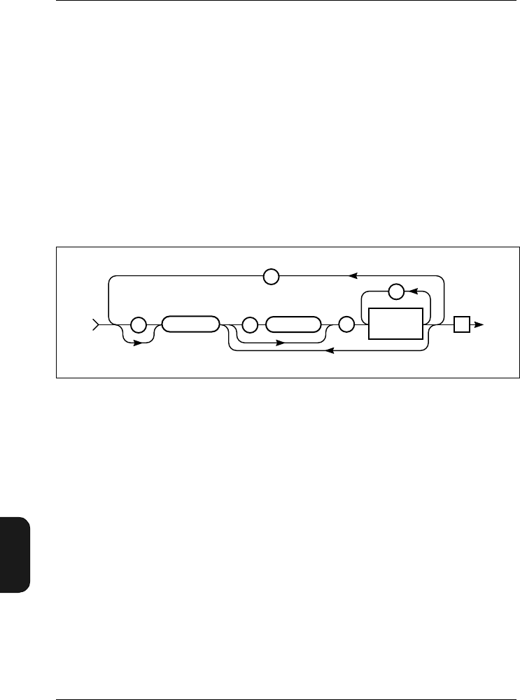
Chapter 11 – Appendix 2: Interface
Formats for Interface Messages
11–6 Brüel & Kjær2238 Mediator
User Manual
Messages from the Mediator
The structure of the response messages returned by the Me-
diator unit depends on the nature of the query from the
controller. The messages are in minimum code (mnemonics)
or written in full – see section 11.2.4.
11.2.2 Use of Syntax Diagrams
In this manual, syntax diagrams are used to explain the
individual messages. Syntax diagrams use three types of sym-
bol, as illustrated in Fig. 11.1.
Rectangular symbols indicate that the enclosed data must be
replaced by a data item defined elsewhere or chosen by the
user. The name of the data item is quoted in the upper left-
hand corner of the symbol. The type of the data item, and
its allowed length in parentheses are, where appropriate,
given in the lower right-hand corner. Circular symbols enclose
single character literal data that must be included in the
message. Elongated, round-ended symbols indicate literal
word data, such as message headers.
Data items that may be by-passed are indicated by lines to
and from the main flow line. Data items that may be repeated
are indicated by lines that loop vertically from the main flow
line back over the data item and back to the main flow line.
If an item of data is repeated, then the number of repetitions
Fig.11.1 General message syntax
941582e
Data can be bypassed
Te: :
;
,
Data Field
SP
–
IJKL_MNOPABCD_EFGH

Chapter 11– Appendix 2: Interface
Formats for Interface Messages
BB1119 – 11 11 – 7
2238 Mediator
User Manual
is indicated by a number above the flowline. Flow is from left
to right unless arrows indicate otherwise.
11.2.3 General Rules for Constructing an Interface
Message
The Mediator allows you to input the message headers and
any character type data fields in full. For ease of use, the
data field names correspond to those on the Mediator’s menu
and screen texts wherever possible.
In order to reduce coding and transmission time, mnemonics
can be entered for each of the message components which
use character type data. The mnemonics are derived from the
names of the individual headers or data fields, and their
syntax is the same for headers and character type data fields.
In this manual a message’s minimum allowable mnemonic is
given in bold upper case text, for example
Frequency_Weighting_1:F100. In addition, the following
rules apply:
1. All entries can always be written out in full. For example:
Frequency_Weighting_1:F100
2. Both upper and lower case letters are recognized and are
equivalent:
frequency_WEIGHting_1:f100
3. All headers and character type data fields can be trun-
cated to the mnemonic.
Frequency_Weighting_1:F100
Freq_Wgt_1:F100
F_W_1:F100
4. All mnemonics are unique and consist of one or more
words, with each word consisting of one to three charac-
ters, plus the word concatenators (_).

Chapter 11 – Appendix 2: Interface
Formats for Interface Messages
11–8 Brüel & Kjær2238 Mediator
User Manual
5. When the amplifier receives character type messages, it
checks the entire message. Therefore, any mis-spelled
words are detected as unknown commands.
6. The amplifier returns the full message or only the mne-
monics when transmitting data containing headers and
character type data fields over the bus. This is deter-
mined by the setting of the parameter Header (see section
11.5.2).
7. Between the header and the first data field, a header
separator is entered. The header separator is a space
(SP).
8. Between each of the data fields, the data separator (a
comma <,>) must be entered. See section 11.2.2.
11.2.4 Mnemonic Codes
The following general rules clarify the construction of the
mnemonics (minimum codes). The rules apply for all headers
and data fields which use character type data.
1. If the first letter of every word produces a unique code,
then this is the mnemonic. For example, the header
Frequency_Weighting_1 becomes F_W_1
2. If the first letter of every word does not give a unique
mnemonic, then include two or more characters of one or
more words until the mnemonic is unique. For example,
the message
SETUP_SEQUENCE ON becomes SE_SE ON
SETUP_SEQUENCE OFF becomes SE_SE OF
Notes:
●Word concatenators are always required in mnemonics
which include more than one word, except immediately
before the question mark (?) in an input message header.
Here, the inclusion of the word concatenator is optional.

Chapter 11– Appendix 2: Interface
Types of Data
BB1119 – 11 11 – 9
2238 Mediator
User Manual
●In the tables and syntax diagrams throughout this inter-
face manual, the mnemonics are the characters appearing
in bold within the headers and character type data fields.
●Headers are output either in full or in mnemonic form
by the amplifier.
11.2.5 Message Terminator
The only legal Program Message Terminator character is the
NL (line feed – decimal 10). The <Te> is considered to be a LF.
11.3 Types of Data
A message can contain one or more data fields, or none. The
type of allowed data varies for each message, but the available
types are:
●character data
●numeric data (decimal and integer)
●string data
The data separator used between all data fields is a comma
(,). Fig. Fig. 11.2 shows the general syntax of a message con-
taining all legal data types.
Fig.11.2 General format for a message with all legal data types 941499e
Te
,
Only for instrument output
Character
Data
Numeric
(Decimal)
Data
Header
;
String
Data
SP
–
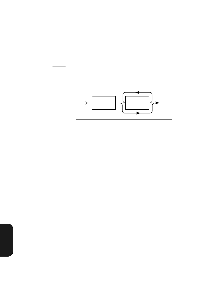
Chapter 11 – Appendix 2: Interface
Character Data
11–10 Brüel & Kjær2238 Mediator
User Manual
11.4 Character Data
Character data must begin with an alphabetic character, ei-
ther upper or lower case. This initial alphabetic character
can be followed by any printable ASCII character (from 32
through 127 (decimal)), with the exception of a space (SP), a
comma (,), a semi-colon (;), a colon (:), or the delete character
(DEL). Fig.11.3 shows the valid form of entry for character
data.
All headers and set-up parameter names are character data,
as are many of the parameter settings. In the syntax dia-
grams, character data is represented by “Char.”. When char-
acter data must be included, the data is written out in full
in the syntax diagrams with the mnemonic codes marked as
bold upper-case characters.
11.4.1 Numeric Data
Numeric data that is entered through the interface closely
follows the format defined in the ANSI/IEEE 488.2 (1987)
Standard, “IEEE Standard Codes, Formats, Protocols and
Common Commands” and the ISO 6093–1985 Standard,
“Representation of numerical values in character strings for
information interchange”.
The types of numeric data are represented in the syntax
diagrams by NR1, NR2 and NR3, conforming to the above
mentioned standards. The data is checked for illegal numbers
not conforming to the above standards. The syntax for NR1
data (implicit point representation) is shown in Fig.11.4 .
Fig.11.3 General syntax for character data fields
931103e
Alpha Alpha Prnt.
ASCII Char.
Except
SP , ; DEL
–
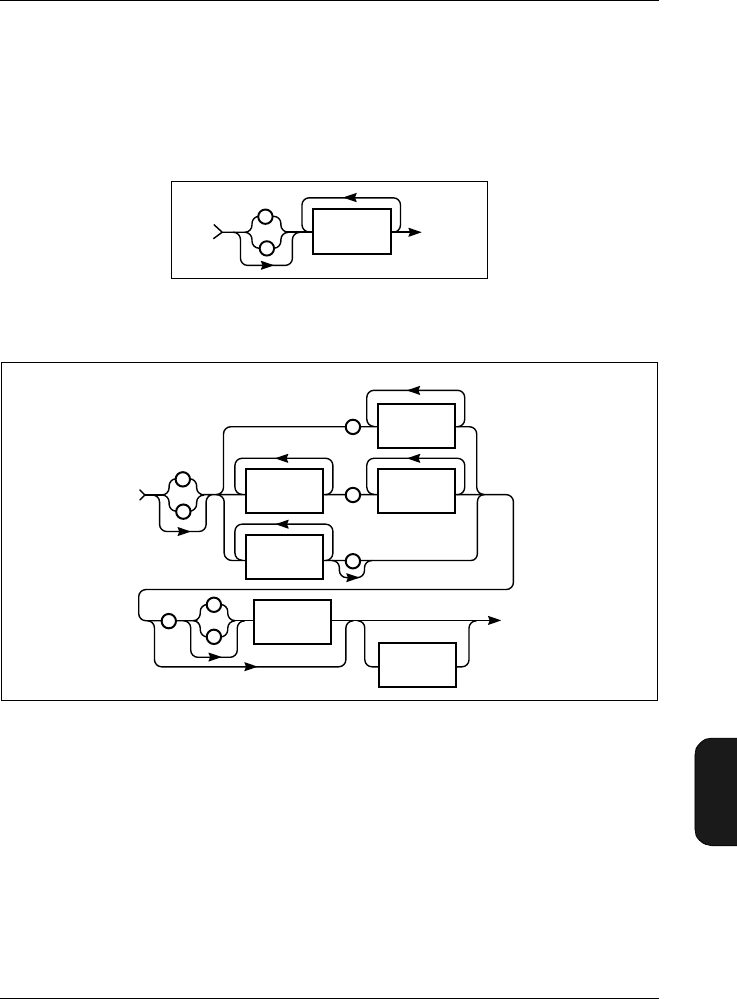
Chapter 11– Appendix 2: Interface
Character Data
BB1119 – 11 11–11
2238 Mediator
User Manual
NR2 data (floating point number with an explicit decimal
point) is not represented below as it is included in NR3.
Mediator usually accepts the full NR3 (explicit point scaled
representation, see Fig.11.5 ), except where syntax diagrams
state that NR1 or NR2 is required.
A digit is any of the 10 number symbols, 0 through 9.
In this manual both commands and queries are illustrated
using syntax diagrams, and are usually accompanied by ex-
amples. When a syntax diagram illustrates the input of nu-
meric data, an explanation is given as to how the Mediator
accepts the numeric data. A legal range is always given (un-
less only specific values are allowed, and these are shown),
Fig.11.4 Syntax for numerical data of type NR1
Fig.11.5 Syntax for numerical data of type NR3
931104e
+
–
Digit
931106e
.
.
+
+
–
–
Digit
Suffix
(input only)
E-Digit
NR1 (1-3)
.
Digit
Digit
Digit
E
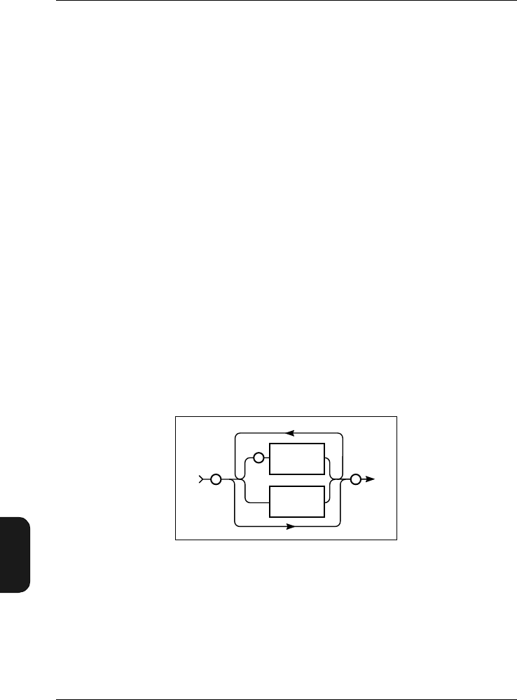
Chapter 11 – Appendix 2: Interface
Character Data
11–12 Brüel & Kjær2238 Mediator
User Manual
and the value received by the amplifier is rounded so that it
lies within the allowable range.
If many values are legal, the explanation given will indicate
whether Mediator chooses the nearest value above (Round
Up) the nearest value below (Round Down) or just the nearest
value (Round Nearest). The value is always rounded to the
given resolution.
The default value for the parameter is also given. This is the
factory setting for that parameter.
11.4.2 String Data
String data is the format used to enter text in a message. In
addition, it is used to enter special characters not allowed in
character data fields.
String data is always enclosed in quotation marks. To include
one quotation mark in the string data field, two quotation
marks need to be entered. Fig. 11.6 gives the syntax for en-
tering string data. The length in characters of a fixed length
string data is given in parentheses after the data type name.
Example:
"This is the text."
"This text contains "" one quotation mark."
Fig.11.6 Syntax for entering string data
931107e
"
"
"
"
(to be
inserted)
Any ASCII
character
except"
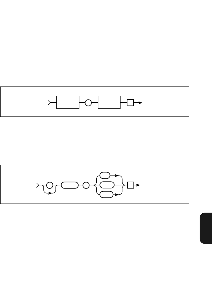
Chapter 11– Appendix 2: Interface
Information Protocol
BB1119 – 11 11–13
2238 Mediator
User Manual
11.5 Information Protocol
11.5.1 Introduction
Each command or query described in this manual has a name,
or Header. The header can be thought of as a variable name,
and the value or option it is assigned is the parameter value
which the Mediator actually uses to carry out the specified
operation. See Fig.11.7.
11.5.2 Header
The Header command allows you to specify how the response
messages are to be sent from the Mediator:
OFfIf you specify OFf, no header will be re-
turned to you by the amplifier as a query
response.
Fig.11.7 The header designates the parameter name for the value (or
option) which follows
Fig.11.8 Syntax for Header command
941101e
Te
Par. Header Parameter
Value(s)
Char
SP
–
970184e
Te
HEADER SHORT
To Mediator
:
OFF
LONG
SP
–

Chapter 11 – Appendix 2: Interface
Information Protocol
11–14 Brüel & Kjær2238 Mediator
User Manual
Short If you specify Short as the header, charac-
ter data from the amplifier will be sent as
mnemonics. That is, the letters shown in
bold only for each command.
Long If you specify a Long header, the Mediator
will return the entire name for each com-
mand header and character data.
Example of a response with a Long header to the query:
Bandwidth?
:BANDWIDTH OCTAVE_3
Example of the response with a Short header to query:
Bandwidth?
:B O_3
Example of the response with an OFf header to the query:
Bandwidth?
O_3
You can query Mediator regarding the header setting as
shown in Fig. 11.9.
The default setting is Long
Fig.11.9 Syntax for Header? query and Mediator response
970185e
TeHEADER?
Header OFf
Te
From Mediator
:
Header
Char
:
HEADER
To Mediator
SP
–

Chapter 11– Appendix 2: Interface
Setting up the PC
BB1119 – 11 11–15
2238 Mediator
User Manual
Example Response:
:Header Long
:H S
OF
11.6 Setting up the PC
Warning! When connecting Mediator to a PC, ensure that
both the computer and the Mediator are switched off. Other-
wise the instruments could be damaged.
1. Connect the computer to Mediator via the SerialInter-
face socket on the base of the Mediator using 9-pole
Cable with 25-pole Adaptor AO 1386. If the computer has
a 9-pole interface socket, remove the adaptor.
2. Start a communications program (e.g. BK–Link or Pro-
Comm) on the computer.
Refer to section 7.2 for Brüel & Kjær software such as
Noise Explorer 7815, Protector 7825 and Evaluator
7820/7821, which are written specifically for communi-
cating with your sound level meter, working with and
displaying sound level meter data.
3. Configure the computer as follows (depending on the com-
munications program):
9600 Baud
8 data bits
1 stop bit
Parity: none
Handshake: Hardwired
4. Switch on Mediator via the interface.
5. Set the Mediator’s Baud Rate to 9600 and Handshake
to Hardwired (see section 3.1.5). for the remote inter-
face.

Chapter 11 – Appendix 2: Interface
Setting up the PC
11–16 Brüel & Kjær2238 Mediator
User Manual
6. Press 〈Enter〉 on the computer.
Communication is established and the prompt (> ) is
shown on the computer screen. The Mediator can now be
controlled from the computer.
Note: The baud rates and handshake of the Mediator and
the computer must be the same to enable them to communi-
cate without losing or corrupting data. A higher baud rate
may be possible depending on your system.
11.6.1 Commands
The command and query messages available are listed in
Table 11.1. The commands and queries are explained in the
following sections, in alphabetical order.
Message Command Query Message Command Query
Bandwidth ••PArameter •
Continue •PAUse •
Error •RAnge ••
File •REset •
Frequency_
Weighting_1 ••SEtup ••
Frequency_
Weighting_2 ••STatus •
Header ••SYstem ••
IDentify •Version •
Key •
Table 11.1 Command and query message overview
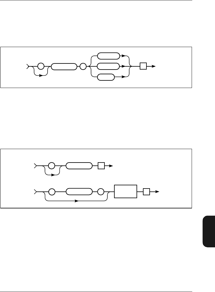
Chapter 11– Appendix 2: Interface
Setting up the PC
BB1119 – 11 11–17
2238 Mediator
User Manual
11.6.2 Bandwidth
The Bandwidth command is used for setting the bandwidth
for Detector 1. The syntax is shown in Fig. 11.10.
The default setting is: Broad band
Note: The 1/3- and 1/1-octave options are only available when
the 1/1-octave and 1/3-octave Filter Set is installed in the
Mediator.
The syntax for the query Bandwidth? and the response re-
turned by the Mediator appears in Fig. 11.11.
Example (setting the bandwidth to 1/3 octave):
Interface job from controller:
Bandwidth Octave_3
Fig.11.10 Syntax for Bandwidth command
Fig.11.11 Syntax for the Bandwidth? query and Mediator response
980293e
Te
To Mediator
: BANDWIDTH
BROAD
OCTAVE_1
OCTAVE_3
SP
–
980147e
Te
From Mediator
:Bandwidth
Char
Te
BANDWIDTH?
:
To Mediator
BANDWIDTH?SP
–
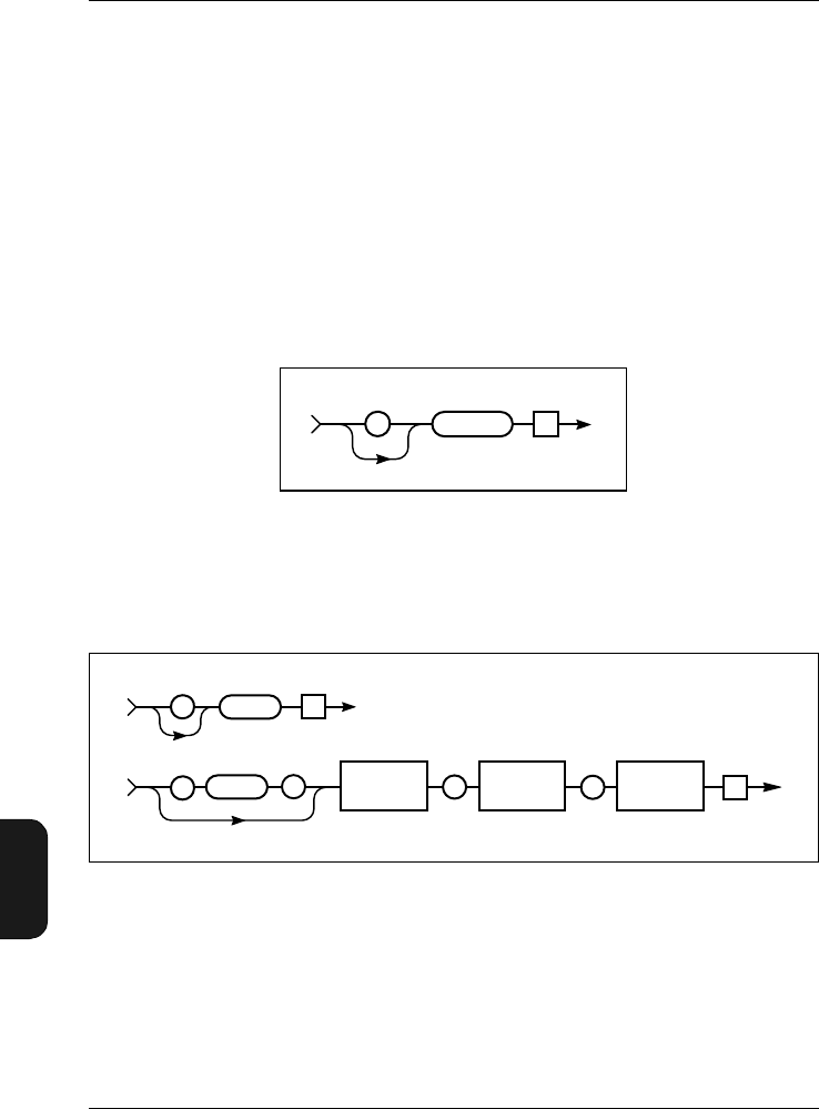
Chapter 11 – Appendix 2: Interface
Setting up the PC
11–18 Brüel & Kjær2238 Mediator
User Manual
Query from controller:
Bandwidth?
From Mediator:
:Bandwidth Octave_3
11.6.3 Continue
The Continue command starts a measurement without reset-
ting the mediator. The syntax is shown in Fig. 11.12.
11.6.4 Error?
The Error? query returns information from the Mediator
about the error condition of the device, where “Error No” is
the number of the error, “Err Msg” is a string containing a
short description of the error, and “Log Buffer” contains a
Fig.11.12 Syntax for Continue command
Fig.11.13 Syntax for Error? query and amplifier response
980157e
Te
CONTINUE
:
To Mediator
To Mediator
From Mediator
Te
ERROR?
Header OFf
:
:
970204e
Error No
Nr.1
Err Msg
String (25)
Log Buffer
String (100) Te
,
ERROR?SP
–,

Chapter 11– Appendix 2: Interface
Setting up the PC
BB1119 – 11 11–19
2238 Mediator
User Manual
string with the interface message which was executing when
the error occurred. If the error was a device error, the log
buffer will be empty.
After the response to the ERror? query is sent, the error
buffer is reset and Error No is set to 0. See section 10.4 for
a detailed listing of all interface and device errors.
Example:
Query from controller:
Error?
From Mediator:
:Error 16,"UNEXPECTED END DETECTED ","^10^END
11.6.5 File
The File queries are used for performing operations on the
files in the Mediator memory.
Files are numbered from 0 to 512 for each software package.
File number 0 is only used for back-up purposes, so that the
total number of files is 511. File names normally consist of
three characters with a three character extension, however,
the file name may contain up to 8 characters.
Copy? query
Copy? is used for getting one or more files from the Mediator
File Manager. You can specify a block of files by using the
“*” and “?” wild card characters. The syntax for the Copy?
query is shown in Fig. 11.14.
The first figure in the block size descriptor specifies how many
figures follow, these figures specify the size of the binary data
block.
Example (copying file 21 from the Basic software package):
Interface job from controller:
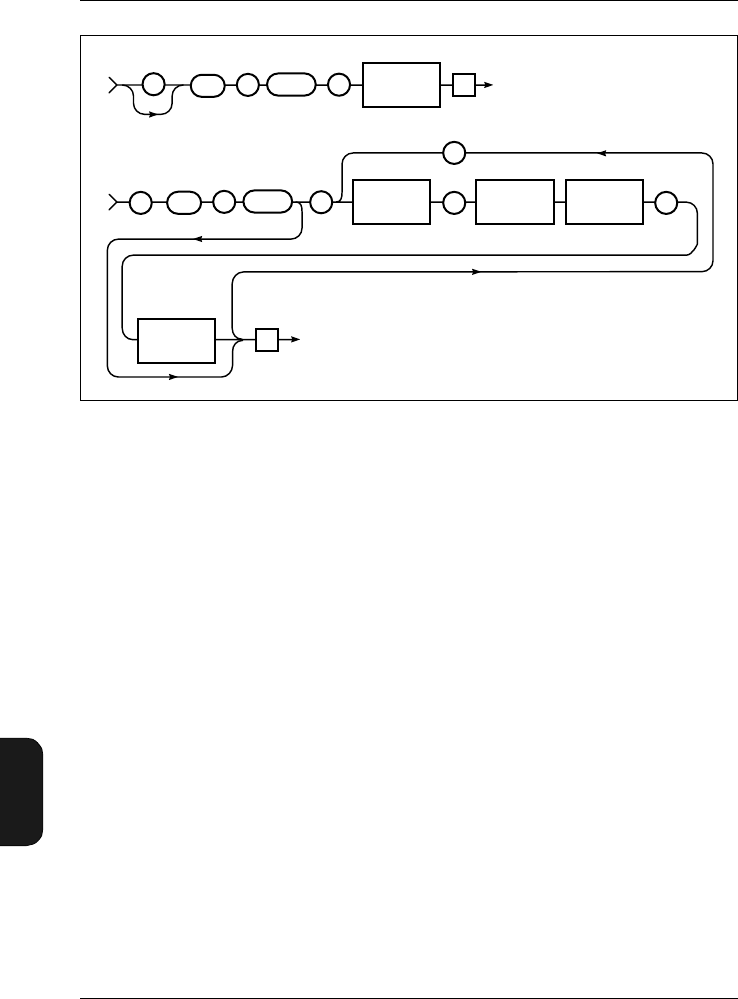
Chapter 11 – Appendix 2: Interface
Setting up the PC
11–20 Brüel & Kjær2238 Mediator
User Manual
File:Copy? "021.M26"
From Mediator:
:FILE:COPY "021.M26",#3409 (binary data)
Delete? query
DElete? is used for deleting one or more files from the Me-
diator File Manager. You can specify a block of files by using
the “*” and “?” wild card characters. The syntax for the DE-
lete? query is shown in Fig.11.15.
The response to a DElete? query is a File_Ok or File_Failed
message from the Mediator.
Example (deleting all files from the Basic software module):
Interface job from controller:
File:DElete? "*.M26"
From Mediator:
Fig.11.14 Syntax for the File:Copy command
980303e
Te
To Mediator
::
FFILE CCOPY?
:
FFILE CCOPY?
From Mediator
, ,
File Check
Sum
(0...65535)
Nr 1
Te
SP
–
SP
–
:
,
String (12)
File Name
String (12)
File Name Block File
Data
(Block Size
Descriptor)
Binary Data
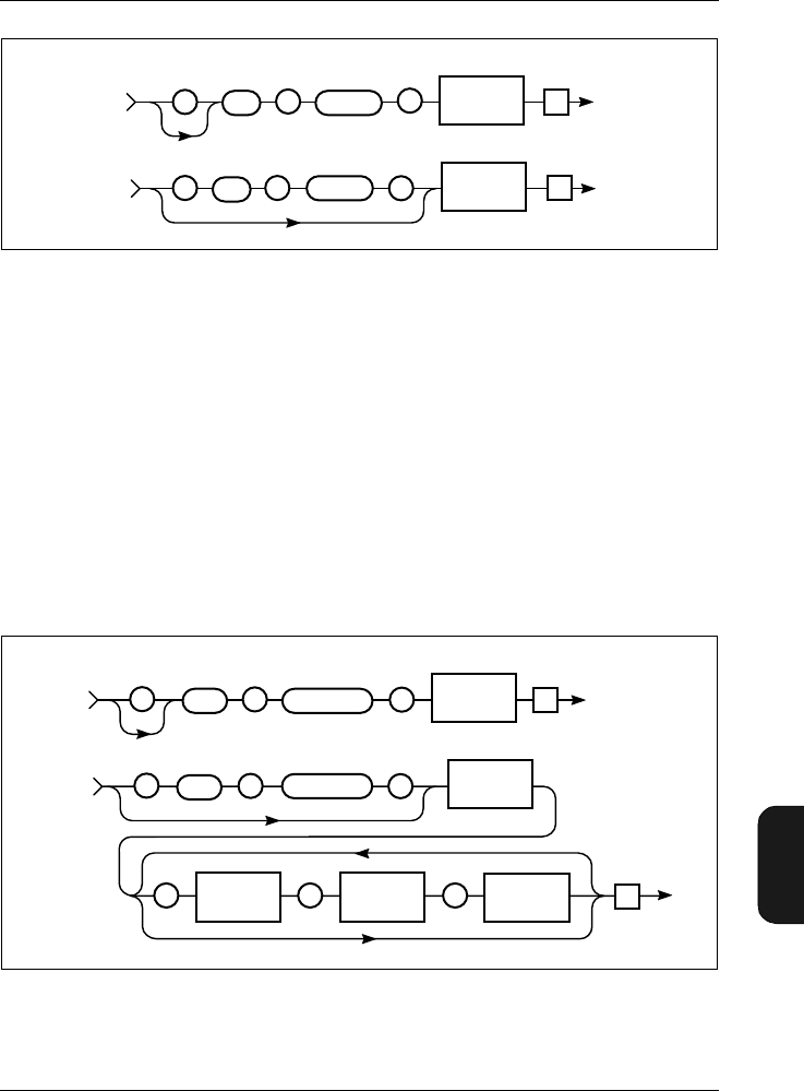
Chapter 11– Appendix 2: Interface
Setting up the PC
BB1119 – 11 11–21
2238 Mediator
User Manual
:FILE:DELETE FILE_OK
Directory? Query
The File_DIrectory? query shows the entire contents of the
Mediator File Manager or you can specify the file names
you want to see. The directory string shows the number of
files, the file names and the associated file information, i.e.,
day, month, year, hour, minute and second. The syntax for
the File_DIrectory? query and response returned by the Me-
diator appear in Fig. 11.16.
Fig.11.15 Syntax for the File:DElete command
Fig.11.16 Syntax for the File_DIrectory? query and Mediator response
980302e
From Mediator
:
FILE SP
DELETE?
To Mediator
::
FILE DELETE?
FILE_OK
or
FILE_FAIL
Te
Te
File Name
String (12)
–
SP
–
:
980211e
From Mediator
::
FILE
File Size
String
DIRECTORY?
File Name
String (12)
To Mediator
: :
FILE DIRECTORY?
Number of
Files
Nr 1
File Name
String (12) Te
, , Te
File Info
String
,
SP
–
SP
–
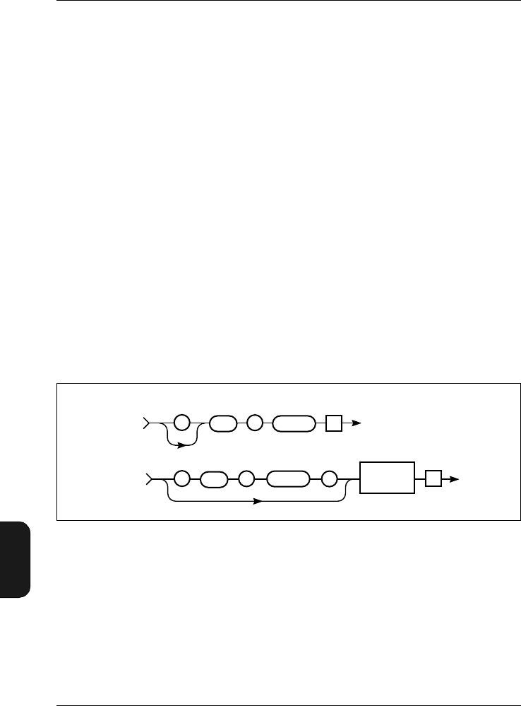
Chapter 11 – Appendix 2: Interface
Setting up the PC
11–22 Brüel & Kjær2238 Mediator
User Manual
Example (show all files with extension M26):
Interface job from controller:
File:DIrectory? "*.M26"
From Mediator:
:FILE:DIRECTORY 7,"MEASPAR.M26","1998-07-23
09:57:30","468","SETUP_0.M26","1998-07-23
09:30:58","115","SETUP_1.M26","1998-07-23
09:30:58","115","SETUP_2.M26","1998-07-23
09:30:58","115","SETUP_3.M26","1998-07-23
09:30:58","115","SETUP_4.M26","1998-07-23
09:30:58","115","001.M26","1998-07-23 10:13:46","409"
Space? Query
The File_Space? query shows how much memory space re-
mains in the Mediator memory. The syntax for the
File_Space? query and response returned by the Mediator
appear in Fig. 11.17.
Example (space query):
Interface job from controller:
File:Space?
From Mediator:
Fig.11.17 Syntax for the File_Space? query and Mediator response
980301e
From Mediator
::
To Mediator
::
FILE
FILE
SPACE?
SPACE?
Disk space
in Bytes
String
Te
Te
SP
–
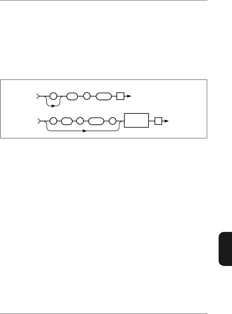
Chapter 11– Appendix 2: Interface
Setting up the PC
BB1119 – 11 11–23
2238 Mediator
User Manual
:FILE:SPACE? "2011648"
Save? query
SAve? is used for storing the current measurement file (refer
to section 6.1.1 for information about saved data). The file is
saved with a file number and an extension that identifies the
current software module, for example, 005.M26. The syntax
for the SAve? query is shown in Fig. 11.18.
The response to a SAve? query is a File_Ok or File_Failed
message from Mediator. The File_Failed message will nor-
mally only occur if there is not sufficient memory space.
Example (saving the current measurement file):
Interface job from controller:
File:SAve?
From Mediator:
:FILE:SAVE FILE_OK
11.6.6 Frequency_Weighting_1
The Frequency_Weighting_1 command is used for setting up
the frequency weighting options for Detector1. The syntax is
shown in Fig.11.19.
Fig.11.18 Syntax for the File:SAve command
980380e
From Mediator
:
FILE SP
–
To Mediator
::
FILE SAVE?
SAVE?
FILE_OK
or
FILE_FAIL
Te
Te
:
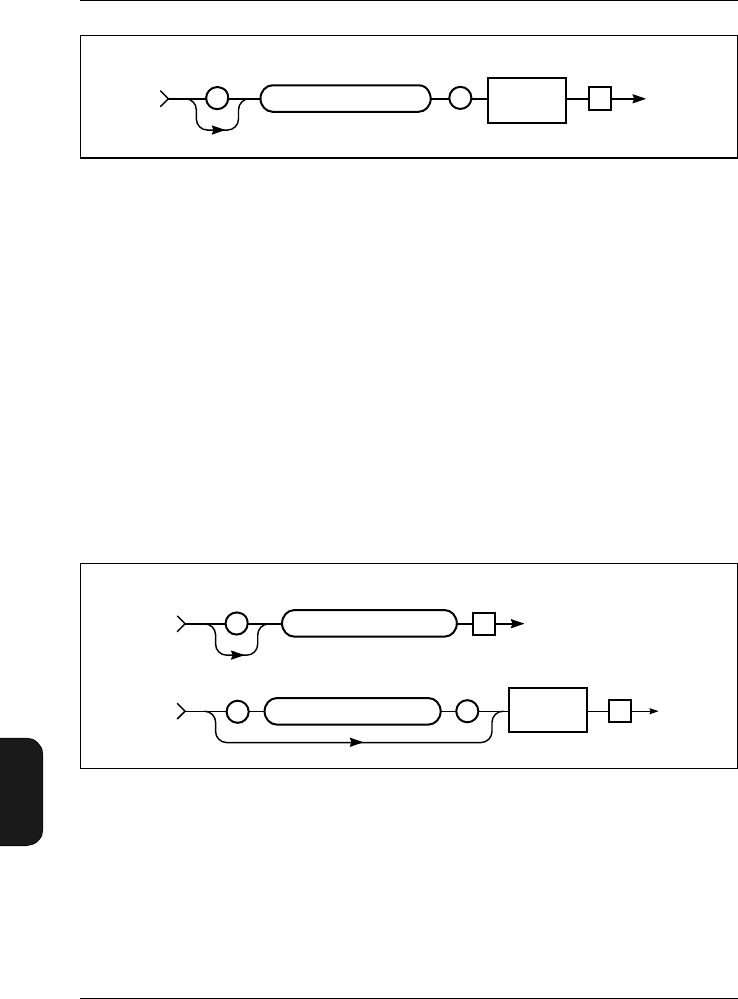
Chapter 11 – Appendix 2: Interface
Setting up the PC
11–24 Brüel & Kjær2238 Mediator
User Manual
The default setting is: A-weighting
The frequency weighting values are: A, C, Lin, F20, F25,
F31_5, F40, F50, F63, F80, F100, F125, F160, F200, F250,
F315, F400, F500, F630, F800, F1K, F1K25, F1K6, F2K,
F2K5, F3K15, F4K, F5K, F6K3, F8K, F10K, F12K5.
Note 1: The “K” is used as decimal separator.
Note 2: Some combinations of weightings are mutually ex-
clusive for the two detectors.
The syntax for the query Frequency_Weighting_1? and the
response returned by the Mediator appears in Fig. 11.20.
Example (setting frequency weighting for Detector1 to C-
weighting):
Interface job from controller:
Fig.11.19 Syntax for Frequency_Weighting_1 command
Fig.11.20 Syntax for the Frequency_Weighting_1? query and Mediator re-
sponse
Parameter
Char/Nr.
:
To Mediator
Te
980163e
FREQUENCY_WEIGHTING_1SP
–
980149e
Te
From Mediator
:
Te
:
To Mediator
Wgt. Value
Char
FREQUENCY_WEIGHTING_1?
SP
–
FREQUENCY_WEIGHTING_1?
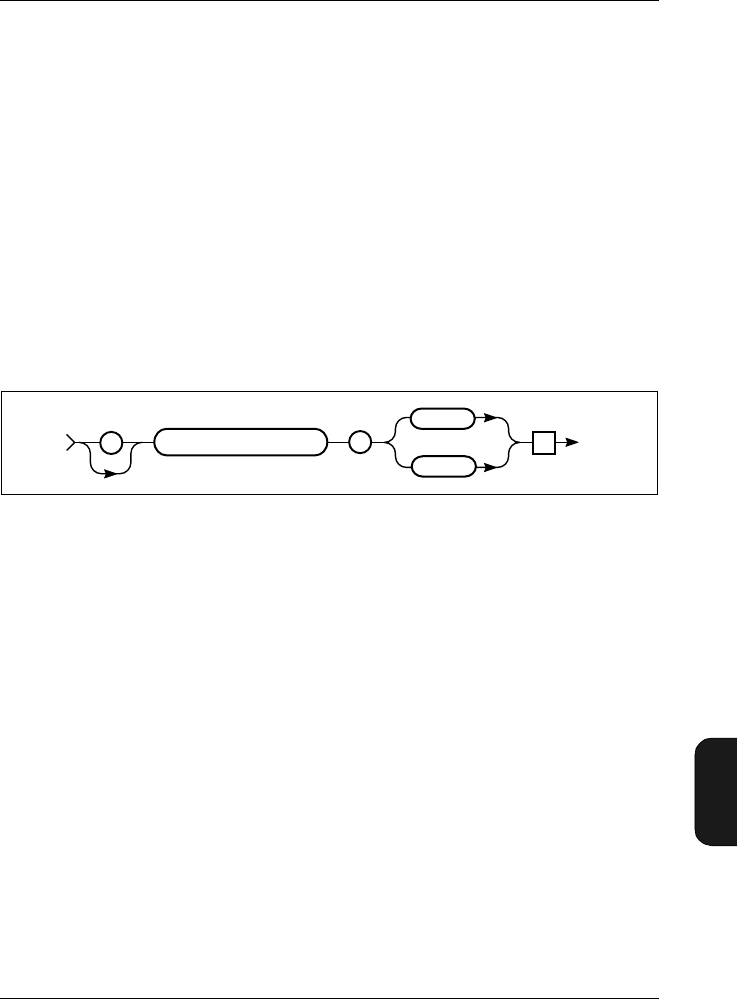
Chapter 11– Appendix 2: Interface
Setting up the PC
BB1119 – 11 11–25
2238 Mediator
User Manual
Frequency_Weighting_1 C
Query from controller:
Frequency_Weighting_1?
From Mediator:
:FREQUENCY_WEIGHTING_1 C
11.6.7 Frequency_Weighting_2
The Frequency_Weighting_2 command is used for setting up
the frequency weighting options for Detector2. The syntax is
shown in Fig.11.21.
The default setting is: Peak and C-weighting
Peak weighting can be C or L.
The syntax for the query Frequency_Weighting_2? and the
response returned by the Mediator appears in Fig. 11.22.
Example (setting frequency weighting for Detector2 to Peak
and L-weighting):
Interface job from controller:
Frequency_Weighting_2 Peak_L
Query from controller:
Frequency_Weighting_2?
From Mediator:
Fig.11.21 Syntax for Freq_Wgt_2 command
980345e
Te
From Mediator
::
FREQUENCY_WEIGHTING_2?
PEAK_C
PEAK_L
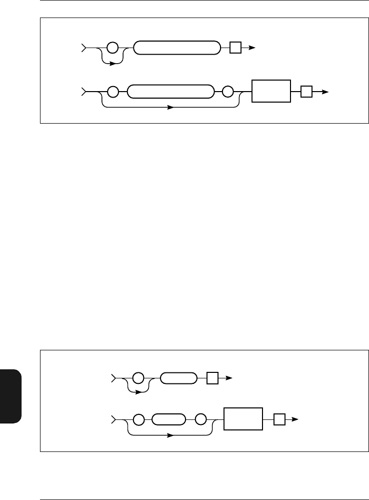
Chapter 11 – Appendix 2: Interface
Setting up the PC
11–26 Brüel & Kjær2238 Mediator
User Manual
:FREQUENCY_WEIGHTING_2 PEAK_L
11.6.8 Header
Refer to section 11.5.2.
11.6.9 Identify?
The Identify? query returns the device ID, which for the
Mediator is “B&K 2238”. This is a standard Brüel & Kjær
method of determining which device is currently connected
via the interface. The syntax for the Identify? query is shown
in Fig.11.23.
Fig.11.22 Syntax for the Frequency_Weighting_2? query and Mediator re-
sponse
Fig.11.23 Syntax for the Identify? query and Mediator response
980150e
Te
From Mediator
:
Te
:
To Mediator
Wgt. Value
Char
FREQUENCY_WEIGHTING_2?
SP
–
FREQUENCY_WEIGHTING_2?
970199e
Te
IDENTIFY?
To Mediator
Header OFf
Te
From Mediator
:Device ID
String (8)
:
IDENTIFY SP
–
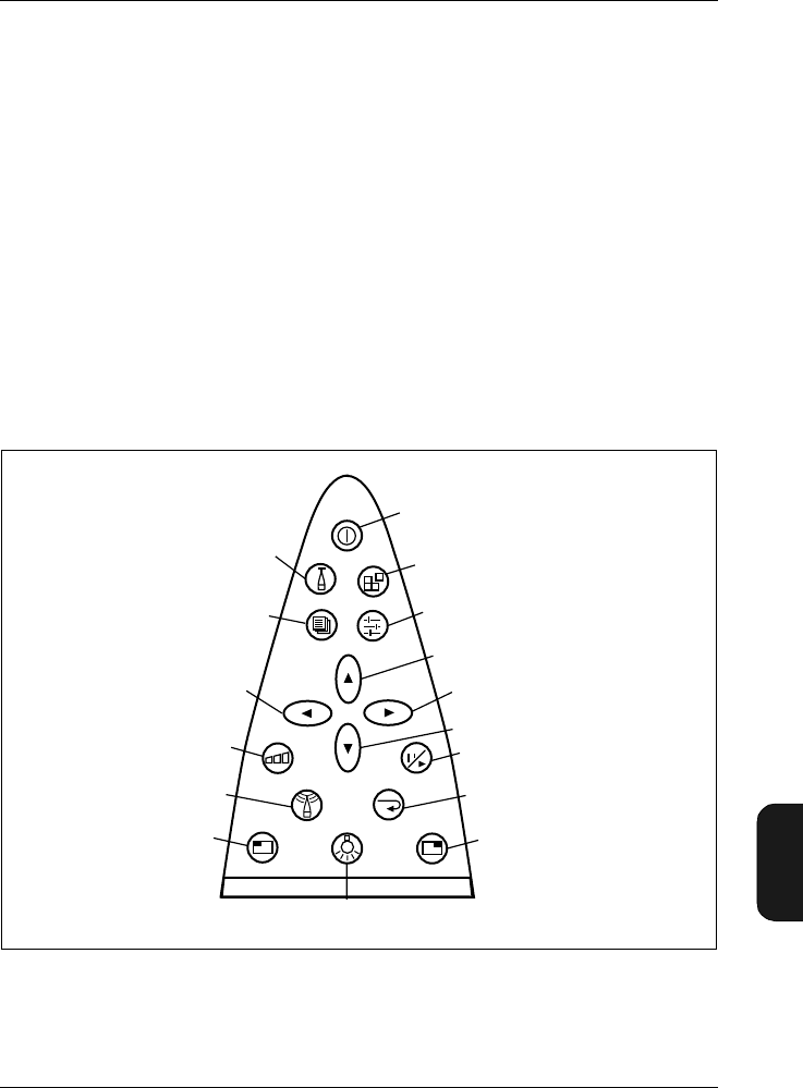
Chapter 11– Appendix 2: Interface
Setting up the PC
BB1119 – 11 11–27
2238 Mediator
User Manual
Example:
Query from controller:
Identify?
From Mediator:
:IDENTIFY "BK2238"
11.6.10 Key
The Key command allows you to use the pushkey functions
via the interface. See section 2.3 for a description of pushkey
functionality. The 16 keys on the front panel are numbered
according to Fig. 11.24.
Fig.11.24 Numbering of keys on the front panel
0
1
23
4
5
6
7
8
910
11
12
13
14 15
16
980205e
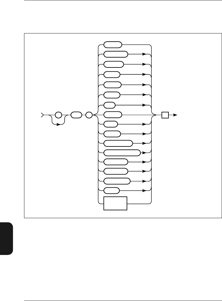
Chapter 11 – Appendix 2: Interface
Setting up the PC
11–28 Brüel & Kjær2238 Mediator
User Manual
You may use the key numbers shown in Fig. 11.24 or the key
names used in the syntax diagram in Fig. 11.25.
Note: An interface error may occur if a key command se-
quence is used for recalling one of the four user defined set-
ups or the factory set-up or if you try to change the interface
parameters in the Remote Interface Window. This is be-
cause these commands reset the interface to set up the new
interface parameters.
Fig.11.25 Syntax for the Key command
ONOFF
SYSTEM
DATA
RANGE
SETUP
UP
DOWN
LEFT
RIGHT
RESET_START
PAUSE_CONTINUE
MEASURE
SOFT_LEFT
SOFT_RIGHT
LIGHT
980159e
KEY
To Mediator
Te
SP
–
:
CALIBRATE
Value
(Key 1 to16)
Nr. 1
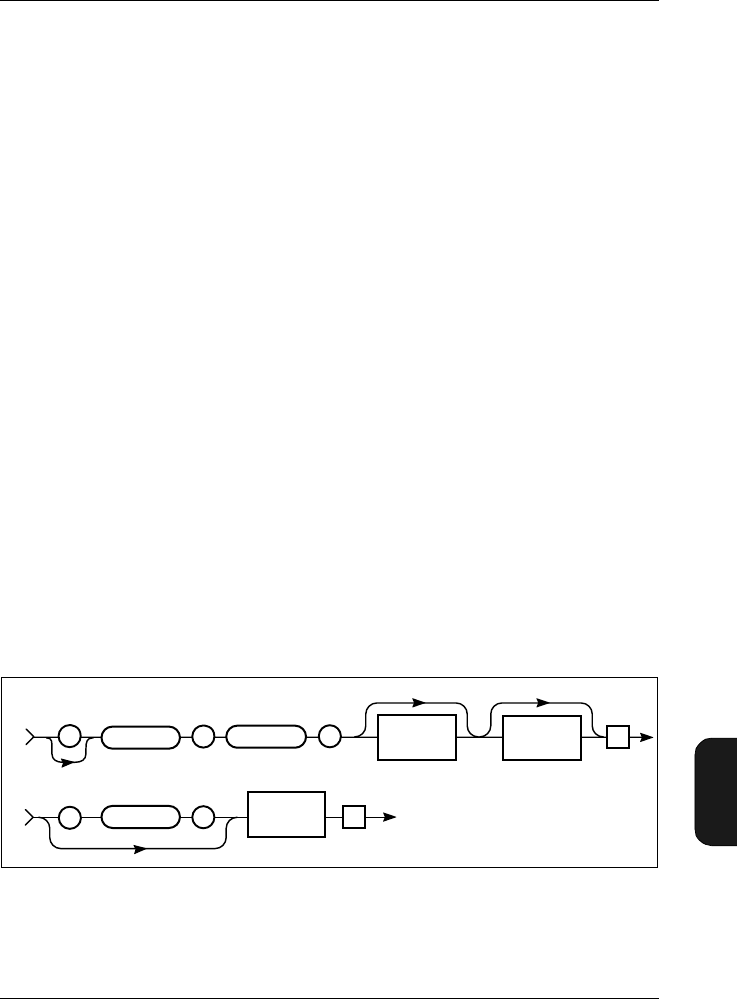
Chapter 11– Appendix 2: Interface
Setting up the PC
BB1119 – 11 11–29
2238 Mediator
User Manual
Example (key sequence for stepping the measurement range
10 dB up):
Interface job from controller:
Key 5<Te>
Key 10<Te>
Key 14<Te>
Key 14<Te>
Alternatively:
Key RAnge<Te>
Key RAnge<Te>
Key Soft_Left<Te>
Note: When you use a “manual” key sequence command you
must normally ensure that the cursor is in a known position,
for example by sending the Key MEasure<Te> and Key
Soft_Right<Te> commands immediate before the key se-
quence.
11.6.11 PArameter?
The PArameter? query is used for checking the selected meas-
urement parameters. The syntax for the query PArameter?
and the response returned by the Mediator appears in
Fig. 11.26.
Fig.11.26 Syntax for the PArameter? query and Mediator response
980346e
PARAMETER
PARAMETER
Sub Header?
See table See table
See text
See table
Te
Frequency
Weighting
Parameter
Time
Weighting
Parameter
: :
To Mediator
SP
–
Te
From Mediator
:
Parameter
SP
–Char

Chapter 11 – Appendix 2: Interface
Setting up the PC
11–30 Brüel & Kjær2238 Mediator
User Manual
Sub Header Frequency
Weighting
Setting
Time
Weighting
Setting
Aux_1——
Aux_2——
Dose — —
Dose_Lav — Fast
Slow
EAd——
ED ——
ELapsed — —
Inst
A
C
Lin
Octave
Fast
Slow
Impulse
LAv
A
C
Lin
Octave
Fast
Slow
LEq
A
C
Lin
Octave
—
LEPd——
LIeq
A
C
Lin
Octave
—
Table 11.2 Sub-header and parameter settings for
the PArameter? query

Chapter 11– Appendix 2: Interface
Setting up the PC
BB1119 – 11 11–31
2238 Mediator
User Manual
LMAx
A
C
Lin
Octave
Fast
Slow
Impulse
LMIn
A
C
Lin
Octave
Fast
Slow
Impulse
LP
A
C
Lin
Octave
Fast
Slow
Impulse
LPK ——
LPKMax — —
No_Peaks — —
Overload — —
Underrange — —
Sub Header Frequency
Weighting
Setting
Time
Weighting
Setting
Table 11.2 Cont.Sub-header and parameter settings for
the PArameter? query

Chapter 11 – Appendix 2: Interface
Setting up the PC
11–32 Brüel & Kjær2238 Mediator
User Manual
Example (reading the measured LAeq value):
Query from controller:
PArameter:LEq? A
From Mediator (value in dB):
:PARAMETER_LEQ 46.9
11.6.12 PAUse
The PAUse command message puts the Mediator in Pause
mode. The pause will take effect on the next even second of
the Mediator’s clock. Therefore, you must wait for one full
second before sending the next command to be sure that the
pause condition is in effect.
11.6.13 RAnge
The RAnge command message is used for setting the meas-
urement range.
Fig.11.27 Syntax for the PAUse command
Fig.11.28 Syntax for the RAnge command
980156e
Te
PAUSE
:
To Mediator
980308e
Te
Value
(80-140)
Nr 1
RANGE?
:
To Mediator
SP

Chapter 11– Appendix 2: Interface
Setting up the PC
BB1119 – 11 11–33
2238 Mediator
User Manual
The default range setting is: 30 – 110 dB
You must enter the Value field as the upper value in the
desired measurement range. Table 11.3 lists the default field
settings.
The RAnge? query message shows the current measurement
range. The syntax for the query and the response returned
by the Mediator appears in Fig. 11.29.
Field Name Field Setting Comments
Value (command) 80
90
100
110
120
130
140
0 – 80
10 – 90
20 – 100
30 – 110
40 – 120
50 – 130
60 – 140
Status (query response) 0 – 80
10 – 90
20 – 100
30 – 110
40 – 120
50 – 130
60 – 140
These are the default ranges.
However, if a non-standard
transducer is used the ranges
may be different.
Table 11.3 RAnge data fields and codes
Fig.11.29 Syntax for the RAnge? query message and Mediator response
980152e
Te
From Mediator
:
TeRANGE?
RANGE?
:
To Mediator
SP
–
Value
(80 - 140)
Nr 1
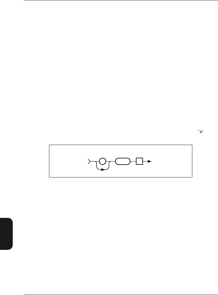
Chapter 11 – Appendix 2: Interface
Setting up the PC
11–34 Brüel & Kjær2238 Mediator
User Manual
Example (setting the measurement range to 50 – 130 dB):
Interface job from controller:
RAnge 130
Query from controller:
RAnge?
From Mediator:
:RANGE 130
11.6.14 REset
The REset command message resets the Mediator. The meas-
urement is restarted, i.e., the current measurement data is delet-
ed and the buffer and the Elapsed Time parameter are set
to zero. This command is equivalent to pressing the key.
Note: There is no reset warning.
11.6.15 SEtup
The SEtup commands are used for setting up most of the
measurement parameters in the Measurement Setting menu.
A separate sub-header is used for the Auto Start commands,
to distinguish the four possible Auto Start sequences.
Auto Start Command
The syntax for the Auto_Start_X command is shown in
Fig. 11.31.
Fig.11.30 Syntax for the REset command
0
980155e
TeRESET:
To Mediator
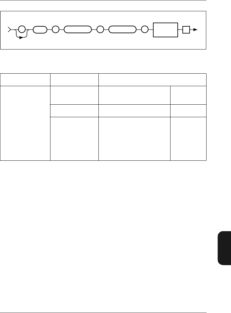
Chapter 11– Appendix 2: Interface
Setting up the PC
BB1119 – 11 11–35
2238 Mediator
User Manual
Example (setting the owner for Auto Start number 3 to the
current application module):
Interface job from controller:
SEtup:Auto_Start_3:Application Current_Bz
Query from controller:
SEtup:Auto_Start_3?
From Mediator:
:SETUP:AUTO_START_3
1998,7,23,11,13,27,"BZ7126",1
Fig.11.31 Syntax for the SEtup:Auto_Start_X command
Sub Header 1 Sub Header 2 Parameter Setting
Auto_Start_1
Auto_Start_2
Auto_Start_3
Auto_Start_4
Application Current_Bz
None Char.
Setup_No1 ... 4 NR1
Time
(Year) –3000 ... 3000
(Month) 1 ... 12
(Day) 1 ... 31
(Hour) 0 ... 23
(Minute) 0 ... 59
(Second) 0 ... 59
NR1
Table 11.4 Auto_Start_X sub-header and parameter settings
980305e
SETUP Sub Header 1
See table See table
Te
Parameter
: : Sub Header 2
See table
:
To Mediator
SP
–

Chapter 11 – Appendix 2: Interface
Setting up the PC
11–36 Brüel & Kjær2238 Mediator
User Manual
Other SEtup Commands
The remaining SEtup commands use the syntax illustrated
in Fig. 11.32.
Fig.11.32 Syntax for the SEtup command
Sub Header Parameter Setting Comments
Aux_1_FW LINear_Frequency_
Weighting
Detector_1_Frequen
cy_Weighting
Char Sets Linear Frequency
weighting or Detector 1 out-
put to the Aux 1 output
Criterion_Level 70 ... 100 NR3 Sets Criterion level between
70 and 100 dB
Exchange_Rate 4, 5NR1 Sets Exchange Rate to 4 or
5dB
Exposure_Time (Hour) 0 ... 23
(Minute) 0 ... 59 NR1 Sets Exposure Time in
hours and minutes
Peaks_Over 0 ... 180 NR3 Sets the peak counting level
PREset_Time (Hour) 0 ... 9999
(Minute) 0 ... 59
(Second) 0 ... 59
NR1 Sets the measurement time
for each measurement in an
Auto Start sequence
Random_Frontal Random
Frontal Char Sets Random or Frontal fre-
quency correction
Recall 0 ... 4 NR1 Recall measurement set-up
0 to 4 (0 is default set-up)
Table 11.5 Sub-header and parameter settings for the SEtup command
980215e
Te
: :
SETUP SP
—
Sub Header
See table See table
Parameter

Chapter 11– Appendix 2: Interface
Setting up the PC
BB1119 – 11 11–37
2238 Mediator
User Manual
The syntax for the query SEtup? and the response returned
by Mediator appears in Fig. 11.33.
SAve 1 ... 4 NR1 Saves measurement set-up
in memory 1 to 4
SEquence OFf, ON Char Switches the Auto Start
sequence On or Off
Threshold_Level 0 ... 100 NR3 Sets the Threshold level in
dB for Occupational Health
Wind_Screen OFf, ON Char Switches the windscreen
frequency correction On or
Off
Sub Header Parameter Setting Comments
Table 11.5 Sub-header and parameter settings for the SEtup command

Chapter 11 – Appendix 2: Interface
Setting up the PC
11–38 Brüel & Kjær2238 Mediator
User Manual
Example (checking the Preset Time set to 10 minutes):
Query from controller:
SEtup:Preset_Time?
From Mediator:
:SETUP:PRESET_TIME 0,10,0
Sub Header
Auto_Start_1?
Auto_Start_2?
Auto_Start_3?
Auto_Start_4?
Aux_1?
Aux_1_FW?
Aux_2?
Criterion_Level?
Exchange_Rate?
Exposure_Time?
Peaks_Over?
Preset_Time?
Random_Frontal?
SEquence?
Threshold_Level?
Wind_Screen?
Table 11.6 SEtup queries
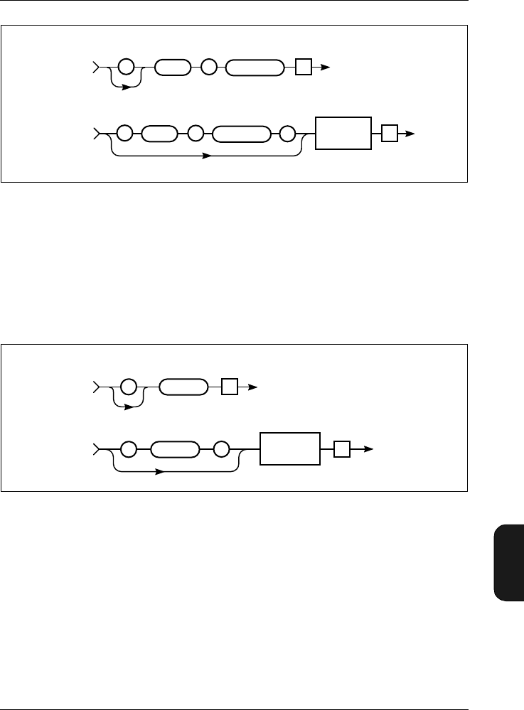
Chapter 11– Appendix 2: Interface
Setting up the PC
BB1119 – 11 11–39
2238 Mediator
User Manual
11.6.16 STatus?
The STatus? query is used to check whether the Mediator is
in pause mode or is measuring. The syntax is shown in
Fig. 11.34.
The status can be: Measuring or Paused
Example:
Query from controller:
STatus?
Fig.11.33 Syntax for the SEtup? query and Mediator response
Fig.11.34 Syntax for the STatus? query and Mediator response
980216e
Te
To Mediator
: :
SETUP
Te
From Mediator
:
Sub Header?
See table
:
SETUP Sub Header?
See table
Parameter
See table
SP
–
980153e
Te
From Mediator
TeSTATUS?
STATUS?
:
:
To Mediator
SP
–
Status
(Measuring/
Paused) Char
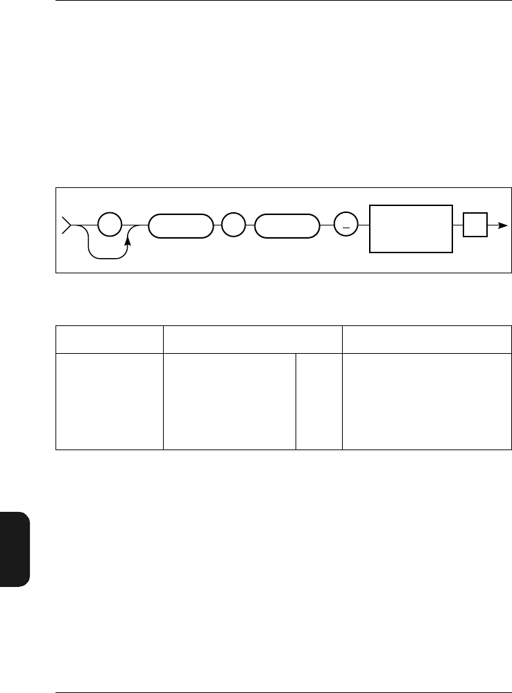
Chapter 11 – Appendix 2: Interface
Setting up the PC
11–40 Brüel & Kjær2238 Mediator
User Manual
From Mediator:
:STATUS PAUSED
11.6.17 SYstem
The SYstem command is used for setting the date and time
on the Mediator’s calendar and clock. The syntax is shown
in Fig. 11.35.
The syntax for the query SYstem? and the response returned
by the Mediator appears in Fig. 11.36.
Example (setting the time to 1. January 1999, 10:15:00):
Interface job from controller:
SYstem:Time 1999,01,01,10,15,00
Query from controller:
SYstem:Time?
Fig.11.35 Syntax for SYstem commands
Sub Header Date and Time Setting Comments
Time
(Year) –3000 ... 3000
(Month) 1 ... 12
(Day) 1 ... 31
(Hour) 0 ... 23
(Minute) 0 ... 59
(Second) 0 ... 59
NR1 Comma separated in the
form of:
YY,MM,DD,HH,MM,SS
Table 11.7 Parameter settings for the SYstem:Time command
980217e
Te
::
SYSTEM TIME
Date (YY,MM,DD)
Time (HH,MM,SS)
Nr 1
SP

Chapter 11– Appendix 2: Interface
Setting up the PC
BB1119 – 11 11–41
2238 Mediator
User Manual
From Mediator:
:SYSTEM:TIME 1999,01,01,10,15,00
11.6.18 Version
The Version? query message shows the running software ver-
sion of the Mediator. The Syntax is shown i Fig. 11.37.
Fig.11.36 Syntax for the SYstem? queries and Mediator response
Fig.11.37 Syntax for the Version? query message and Mediator response
TIME?
SYSTEM
::Parameter
Value
Nr 1
SP
TIME?
980219e
SYSTEM
::
To Mediator
From Mediator
Te
Te
980304e
Te
To Mediator
VERSION?
VERSION?
From Mediator
Module
(BZ....) Version No.
, ,
String Nr 1
Te
Revision No. History No.
,
Nr 1 Nr 1
:
:SP
–

Chapter 11 – Appendix 2: Interface
Setting up the PC
11–42 Brüel & Kjær2238 Mediator
User Manual
Example (checking the current version):
Query from controller:
Version?
From Mediator:
:VERSION "BZ7126",1,0,0
Field Name Field Setting Comments
Version status BZ 7126
BZ 7125
BZ 7123
BZ 7124
Basic SLM Software
Enhanced SLM Software
Frequency Analysis Software
Logging SLM Software
Table 11.8 Version data fields and codes

BB1119 – 11 12 –43
2238 Mediator
User Manual
Chapter 12
Index
Numerics
1/1-octave and 1/3-octave filter set ............... 1–5
9-pole cable .............................. 1–4, 7–5, 11–15
A
About System Window .................................. 3–8
AC Output ..................................................... 7–6
Accessories (effect of) .................................... 9–5
Application
module ............................................ 1–7, 3–4
programs ................................ 1–5, 2–8, 7–5
status ..................................................... 4–10
Window .................................................... 3–4
ASCII characters ....................................... 11–10
Auto Start .................................. 4–9, 5–10, 6–2
application status .................................. 4–10
sequence ................................................ 4–10
Window .................................................... 4–9
Auto_Start_1...4 command ....................... 11–35
Auto_Start_1..4? query ............................. 11–38
Aux 1 ............................................ 1–5, 4–8, 9–4
Aux 2 ............................................ 1–5, 4–8, 9–4
Aux_1? query ............................................. 11–38
Aux_1_FW command ................................ 11–36
Aux_1_FW? query ..................................... 11–38
Aux_2? query ............................................. 11–38
A-weighting ................................................... 1–5
B
Backlight .......................................... 1–14, 2–10
pushkey .................................................. 2–10
Back-up battery ................................. 1–13, 2–4
Bandwidth ................................................... 5–10
command ............................................. 11–17
Bar graph ................................ 2–10, 4–4, 5–11
Basic
configuration ........................................... 1–4
SLM software ................................. 1–4, 1–7
version (BZ 7126) .................................... 1–3
Batteries ............................. 6–2, 8–3, 9–4, 9–5
checking level .......................................... 2–2
fitting ....................................................... 2–2
handling ................................................... 2–3
operating time ......................................... 2–3
recharging ................................................ 2–3
saving ..................................................... 2–10
type .......................................................... 1–4
Battery
back-up ......................................... 1–13, 2–4
flat ............................................................ 2–4
level ........................................................ 2–12
remaining time ........................................ 2–3
symbol ...................................................... 2–2
Baud rate ........................ 3–5, 7–3, 7–4, 11–15
Broadband data ......................... 1–14, 6–3, 6–4
Buffer ..................................... 1–13, 6–2, 11–34
C
Calendar data .............................................. 1–12
Calibrate pushkey ......................................... 2–8
Calibration .................................................... 5–2
data ........................................................ 1–12

Index
12 –44 Brüel & Kjær2238 Mediator
User Manual
factor .......................................................1–13
Free-field/Diffuse Field ...........................5–2
history ....................................................1–12
menu ............................................1–10, 1–12
principle of ...............................................5–2
set-up .............................................1–13, 6–3
signal ........................................................5–2
time ...........................................................6–3
when to .....................................................5–2
Window .....................................................5–2
Calibrator
types .........................................................5–3
Cancel pushkey ............................................2–10
Care of Mediator ............................................8–2
Centre frequency .........................................5–10
Changing
applications ..............................................1–7
displayed parameter ..............................5–11
language .................................................2–12
Character data ................................11–9, 11–10
Checking
battery level .............................................2–2
calibration ................................................5–7
Cleaning Mediator .........................................8–2
COM port .......................................................7–5
Command
Auto_Start_1...4 ...................................11–35
Aux_1_FW ............................................11–36
Bandwidth ............................................11–17
Continue ...............................................11–18
Criterion_Level ....................................11–36
Exchange_Rate ....................................11–36
Exposure_Time ....................................11–36
File ........................................................11–19
Frequency_Weighting_1 ......................11–23
Frequency_Weighting_2 ......................11–25
Key ........................................................11–27
PAUse ...................................................11–32
Peaks_Over ..........................................11–36
Preset_Time .........................................11–36
Random_Frontal ..................................11–36
RAnge ...................................................11–32
Recall ....................................................11–36
REset ....................................................11–34
SAve .....................................................11–37
SEquence ..............................................11–37
SEtup ....................................................11–34
SYstem .................................................11–40
Threshold_Level ..................................11–37
Wind_Screen ........................................11–37
Command message overview ....................11–16
Communication
error ..........................................................7–5
program ................................................11–15
Compound message .....................................11–4
Computer (setting up) ...............................11–15
Concatenator ................................................11–8
Condenser microphone ................1–4, 5–3, 9–2
Connecting a microphone extension cable ...2–7
Connectors .....................................................1–5
Constructing interface message .................11–7
Continue command ....................................11–18
Contrast .........................................................3–7
Controlling Mediator via the interface .......11–3
Conventions in this Manual ..........................1–3
Correction filters .........................1–5, 4–7, 5–2
Creterion_Level command ........................11–36
Criterion level ..............................................4–12
Criterion_Level? query ..............................11–38
Cursor keys ..................................2–9, 3–2, 4–2
C-weighting ....................................................1–5
D
D/A converter .................................................1–5
DAT recorder .................................................4–8
Data
files ...................................1–10, 1–12, 1–13
extension ..........................................1–13
menu ..........................................2–8, 6–4
number of .........................................1–13
set-up data .......................................1–13
system .................................................6–2
Files pushkey .........................2–8, 6–7, 7–3
separator ................................................11–8
types .......................................................11–9
character ........................................11–10
numeric ...........................................11–10
string ..............................................11–12
Date and time
information ..............................................6–2
setting .......................................................3–4
DC Output ............................................4–9, 7–6
Decimal separator .....................................11–24
Default
measurement set-up ..............................4–13
parameters ....................................2–5, 10–4
set-up ........................................................2–5
Delete
all files ......................................................6–9
files ...........................................................6–9
Detectors .1–5, 2–10, 4–5, 9–3, 11–23, 11–25
Peak ..........................................................1–5
RMS ..........................................................1–5
setting up
bandwidth ..........................................4–5
frequency weighting ..........................4–5
Diffuse sound field .........................................4–7
Disk Summary ...............................................6–9
Display ..................................................3–7, 9–4
Displayed parameters .................................5–11
Dose
levels .......................................................4–11
percentage ................................................1–9
Dose%X ..........................................................1–9
Dose%XY4 ......................................................1–9

Index
BB1119 – 11 12 –45
2238 Mediator
User Manual
Dose%XY5 ..................................................... 1–9
Dynamic range .............................................. 4–3
E
EA .................................................................. 1–8
Effect of accessories ...................................... 9–5
Elapsed time ......................................... 1–9, 6–3
EMC ...................................................... 9–5, 9–6
Enhanced SLM Software ..................... 1–6, 3–4
Environmental effects ................................... 9–4
Error
list of interface ...................................... 10–8
messages .............................................. 10–11
Error? query .............................................. 11–18
Evaluator .......................................... 7–4, 11–15
Exchange rate .............. 4–4, 4–11, 5–11, 10–2
Exchange_Rate command ........................ 11–36
Exchange_Rate? query ............................. 11–38
Explicit point scaled representation ........ 11–11
Exposure time .................................. 4–11, 10–2
Exposure_Time command ........................ 11–36
Exposure_Time? query ............................. 11–38
External
DC supply ................................................ 9–4
power socket ............................................ 2–4
power supply ........................................... 2–4
F
Fast (F) .......................................................... 1–5
Field
parameter .............................................. 2–12
value ...................................................... 2–12
File
delete ........................................................ 6–9
extension .................................................. 6– 2
list ................................................... 6–7, 6–8
Manager ................................. 2–8, 6–4, 6–7
Options Window ................................ 6–8
names ....................................................... 6–2
print ................................................ 6–6, 6–8
recall ........................................................ 6–8
size ........................................................... 6–7
store ......................................................... 6–5
File command ............................................ 11–19
File_Copy query ........................................ 11– 19
File_DElete query ..................................... 11–20
File_DIrectory? query ............................... 11–21
File_SAve query ........................................ 11–23
File_Space? query ..................................... 11–22
Filter set ......................... 1–4, 1–7, 4–5, 11–17
Fitting batteries ............................................ 2–2
Flash RAM ......................................... 1–13, 2–4
Formats for interface messages ................. 11–4
Frequency
Analysis Software ................. 1–4, 1–5, 3–4
response ................................................... 9–3
weighting ..1–5, 1–7, 4–5, 4–8, 5–11, 7–6,
9–3
Frequency_Weighting_1 command .......... 11–23
Frequency_Weighting_1? query ............... 11–24
Frequency_Weighting_2 command .......... 11–25
Frequency_Weighting_2? query ............... 11–25
Frontal setting .............................................. 5–3
G
General
measurement parameters ....................... 4–3
specifications ........................................... 9–2
Window ......................................... 4–3, 4–11
Getting started .............................................. 2–2
H
Handshake ..................... 3–6, 7–3, 7–4, 11–15
Hardwired ........................................ 3–6, 11–15
Header
long ...................................................... 11–14
path ........................................................ 11–4
separator ................................................ 11–8
short ..................................................... 11–14
How Mediator works ..................................... 1–4
Hydrophone ................................................... 5–3
I
Identify? query .......................................... 11–26
Illegal entry ...................................... 1–11, 2–12
Implicit point representation ................... 11–10
Impulse (I) ..................................................... 1–5
Indicator range .............................................. 9–2
Inherent noise ...................................... 9–2, 9–5
Initial
calibration parameters ......................... 1–13
Input/Output
function .................................................... 4–8
Window .................................................... 4–8
Instantaneous value ................................... 5–11
Interface
error .......................................... 10–8, 11–28
message formats .................................... 11–4
parameters (setting up) ................. 3–5, 7–3
International standards ............................... 3–8
J
Joining messages ........................................ 11–5
K
Key
command ............................................. 11–27
position ................................................ 11–27

Index
12 –46 Brüel & Kjær2238 Mediator
User Manual
L
Language
changing ........................................2–12, 9–4
setting up .................................................3–7
Latched overload .........................................2–11
LAV ...................................................4–11, 10–2
LAV5 ............................................................10–2
LCD screen ....................................................3–7
LDOD .............................................................4–5
Left/Right Arrow pushkey ............................2–9
Light (backlight) ..........................................1–14
Linear weighting ...........................................1–5
Logging SLM Software .........................1–5, 3–4
Long header ...............................................11–14
LOSHA ................................................4–5, 10–2
LXAV ..............................................................4–5
LXE ................................................................1–8
LXep,d ............................................................1–8
LXeq ...............................................................1–8
LXpk ...............................................................1–9
LXpkMax .......................................................6–4
LXpkmax ........................................................1–9
LXYav4 ...........................................................1–8
LXYav5 ...........................................................1–8
LXYinst ..........................................................1–8
LXYmax .........................................................1–8
LXYmin ..........................................................1–8
LXYp ..............................................................1–8
M
Maintenance and repair ................................8–2
Measurement
Control Window .......................................4–6
data ................................................1–13, 6–3
parameters ..................................1–7, 11–34
range ........ 1–12, 2–9, 2–11, 4–3, 9–2, 9–5
Result pushkey .........1–11, 2–9, 2–13, 3–3
settings ............................................3–2, 4–2
set-up ..................................1–13, 4–12, 6–3
set-up (default) .......................................4–13
Set-up menu ..............1–10, 1–11, 2–9, 4–2
Window ...1–7, 1–10, 2–2, 2–5, 2–9, 2–10,
3–3, .............................................4–4, 5–11
Memory ....................................1–12, 1–13, 9–4
Menu
items (selecting) .......................................2–9
keys .........................................................1–10
structure .................................................1–10
Message
compound ...............................................11–4
from the Mediator ..................................11–6
header .....................................................11–4
joining .....................................................11–5
sub-header ..............................................11–4
syntax .....................................................11–6
terminator ...................................11–4, 11–9
to the Mediator ......................................11–4
Messages and warnings ..............................10–5
Microphone ..................................1–4, 5–3, 9–2
extension cable ................................2–7, 5–2
preamplifier ....................................1–4, 9–2
type ...........................................................6–3
Minimum code (mnemonics) ............11–6, 11–8
Mnemonics .............................11–6, 11–7, 11–8
Modem ............................................................3–6
N
Navigation ...................................................1–10
Noise Explorer ..................................7–4, 11–15
Non-volatile memory ...................................1–13
NR1, NR2, NR3 .........................................11–10
Null-modem cable ..........................................1–4
Number of
data files ........................................1–13, 6–2
peaks ...............................................1–9, 6–4
Numbering files .............................................6–2
Numeric data ..................................11–9, 11–10
O
Occupational Health
parameters .............................................4–11
Window ...................................................4–11
Octave filters .................................................1–5
Operating time ..............................................2–3
OSHA ...........................................................10–2
Output
AC .............................................................7–6
DC .............................................................7–6
Overall results ...............................................6–3
Overload ............................2–11, 4–4, 6–4, 9–3
warning ....................................................4–4
Overload% ......................................................1–9
P
Parameter ......................................................1–7
changing the displayed ..........................5–11
default ....................................................10–4
fields .......................................................2–12
header .....................................................11–8
selecting ...................................................2–9
text ............................................................1–3
PArameter? query .....................................11–29
Pause
Continue pushkey ..................................2–10
mode ........ 2–5, 2–8, 2–9, 3–2, 6–4, 11–32
PAUse command .......................................11–32
Peak
detector .....................................................1–5
data .................................1–14, 6–3, 6–4
weighting .....................................4–5, 11–25
Peaks Over
indication .................................................4–4
value .........................................................4–4

Index
BB1119 – 11 12 –47
2238 Mediator
User Manual
Peaks_Over command .............................. 11–36
Peaks_Over? query ................................... 11–38
Power pushkey .............................................. 2–8
Prepolarized microphone ............ 1–4, 5–3, 9–2
Preset Time ................................................... 4–7
Preset_Time command ............................. 11–36
PReset_Time? query ................................. 11–38
Print
a measurement ........................................ 7–3
files .................................................. 6–6, 6–8
Options list .............................................. 6–5
Window .................................................... 6–8
Printer
interface parameters (setting up) ........... 3–6
Interface Window .................................... 3–6
Program message
terminator .................................. 11–5, 11–9
unit separator ........................................ 11–5
Protective cover ............................................. 1–4
Protector ........................................... 7–4, 11–15
Protocol ...................................................... 11–13
Pushkeys
Backlight ............................................... 2–10
Calibrate .................................................. 2–8
Cancel .................................................... 2–10
Data Files ................................................ 2–8
definitions ................................................ 2–8
Left/Right Arrow ..................................... 2–9
Meas. Result ............................................ 2–9
numbering ........................................... 11–27
Pause/Continue ..................................... 2–10
pictograms ...................................... 1–3, 2–8
Power ....................................................... 2–8
Range ....................................................... 2–9
Reset ........................................................ 2–9
Select ...................................................... 2–10
Set-up ....................................................... 2–9
System ..................................................... 2–8
Up/Down Arrow ....................................... 2–9
Q
Quasi-analogue display ..................... 2–10, 4–4
Query ............................................ 11–11, 11–13
Auto_Start_1...4? ................................. 11–38
Aux_1? ................................................. 11–38
Aux_1_FW? .......................................... 11–38
Aux_2? ................................................. 11–38
Criterion_Level? .................................. 11–38
Error? ................................................... 11–18
Exchange_Rate? .................................. 11–38
Exposure_Time? .................................. 11–38
File_Copy ............................................. 11– 19
File_DElete .......................................... 11–20
File_Directory ...................................... 11–21
File_SAve ............................................. 11–23
File_Space? .......................................... 11–22
Frequency_Weighting_1? .................... 11–24
Frequency_Weighting_2? .................... 11–25
Identify ................................................ 11–26
message overview ................................ 11–16
messages .............................................. 11–16
PArameter? .......................................... 11–29
Peaks_Over? ........................................ 11–38
PReset_Time? ...................................... 11–38
Random_Frontal? ................................ 11–38
RAnge? ................................................. 11–33
SEquence? ........................................... 11– 38
SEtup? ................................................. 11–37
STatus? ................................................ 11–39
SYstem? ............................................... 11– 40
Threshold_Level? ................................ 11–38
Version? ............................................... 11–41
Wind_Screen? ...................................... 11–38
R
Random_Frontal command ...................... 11–36
Random_Frontal? query ........................... 11–38
Range
pushkey ................................ 1–12, 2–9, 4–4
setting .................................................... 2–11
Setting window ........................................ 4–4
RAnge command ....................................... 11–32
RAnge? query ............................................ 11–33
Recall
files ........................................................... 6–8
Files Window ........................................... 6–8
measurement set-up .................. 4–12, 4–13
Setup Window ....................................... 4–13
Recall command ........................................ 11–36
Rechargeable batteries ................................. 2–3
Repair ............................................................ 8–2
REset command ........................................ 11–34
Reset pushkey ............................................... 2–9
Resolution ...................................................... 9–3
RMS
detector ........................................... 1–5, 4–9
weighting ................................................. 4–5
Root header ................................................. 11–4
RS-232 interface ............................................ 1–4
Run/Pause indicator ................................... 2–12
S
SAve command .......................................... 11–37
Save Setup Window .................................... 4–12
Saved data ..................................................... 6–3
Saving
current meas. set-up ............................. 4–12
measurement set-ups ............................ 4–12
Select pushkey ............................................ 2–10
Selecting
Data Files menu ...................................... 6–4
menu items .............................................. 2–9
parameters ..................................... 2–9, 3–3
Sensitivity value .................................. 5–2, 6–3

Index
12 –48 Brüel & Kjær2238 Mediator
User Manual
SEquence command ..................................11–37
SEquence? query .......................................11–38
Serial
input/output .............................................9–4
interface .................................................11–4
cable ....................................................1–4
parameters .........................................3–5
socket ............................7–2, 7–5, 11–15
Interface Window .....................................3–5
number ..........................................1–13, 6–3
printer ......................................................9–4
Setting up
Auto Start .....................................4–9, 4–11
bandwidth for Detector 1 ........................4–5
Baud Rate ................................................3–5
computer interface ...............................11–15
contrast ....................................................3–7
corrrection filters .....................................4–7
Criterion Level .......................................4–12
date and time ...........................................3–4
Exposure Time .......................................4–11
frequency weighting .......................4–5, 4–8
general measurement parameters ..........4–3
Handshake ...............................................3–6
input/output function ..............................4–8
interface parameters ...............................3–5
Language ..................................................3–7
measurement range .................................2–9
Mediator to start automatically ............5–10
Occupational Health parameters ..........4–11
Preset Time ..............................................4–7
start time for Auto Start .......................4–10
Threshold Level .....................................4–12
windscreen filter ......................................4–8
Settling time ..................................................9–4
Set-up
data ................................................1–14, 6–3
pushkey ....................................................2–9
SEtup command ........................................11–34
SEtup? query .............................................11–37
Short header ..............................................11–14
Shoulder bag .........................................1–4, 8–3
Slow (S) ..........................................................1–5
Socket
External Power ........................................2–4
reference to ...............................................1–3
Soft keys ............................1–3, 1–10, 3–3, 4–2
Software package .......................................11–19
Sound incidence
frontal .......................................................4–7
random .....................................................4–7
SPL ...............................................................5–11
Standards .....................................1–4, 9–2, 9–4
Window .....................................................3–8
Start
date ...........................................................6–3
time ...........................................................6–3
STatus? query ............................................11–39
Store files .......................................................6–5
Storing Mediator ...........................................8–2
String data ......................................11–9, 11–12
Sub-header ...................................................11–4
Summary of contents ....................................1–2
Switching
a sequence On/Off ....................................4–7
Mediator On/Off ..............................2–5, 2–8
Syntax diagrams ...............................11–6, 11–7
System
information ..............................................3–8
key ...................................................3–3, 4–2
menu ................. 1–7, 1–10, 1–11, 2–8, 3–2
pushkey ....................................................2–8
SYstem command ......................................11–40
SYstem? query ...........................................11–40
T
Tagfiles ...........................................................6–7
parameters ...............................................6–6
Terminator ........................................11–4, 11–9
Threshold level ............................................4–12
Threshold_Level command .......................11–37
Threshold_Level? query ............................11–38
Time .............................................................1–10
weighting ..............................1–5, 1–7, 5–11
Transmission time .......................................11–7
Types of data ................................................11–9
U
Under-range ........................................2–10, 6–4
Underrange% .................................................1–9
Unknown command .....................................11–8
Up/Down Arrow pushkey ..............................2–9
V
Value fields ..................................................2–12
Version? query ...........................................11–41
W
Weight and dimensions .................................9–4
Weightings Window ...........................4–5, 5–10
Wind_Screen command .............................11–37
Wind_Screen? query ..................................11–38
Windscreen ....................................................5–3
filter ..........................................................4–8
Word concatenator .......................................11–8
X
X suffix ...........................................................1–7
Y
Y suffix ...........................................................1–7
