BSD SNi P 2 05 03 84
User Manual: BSD-SNiP-2-05-03-84
Open the PDF directly: View PDF ![]() .
.
Page Count: 81
- Title
- Copyright
- Disclaimer
- Contents
- Chapter 01 Introduction
- Chapter 02 Define Loads and Load Combinations
- Chapter 03 Live Load Distribution
- Chapter 04 Define a Bridge Design Request
- Chapter 05 Design Concrete Box Grider Bridges
- Chapter 06 Design Multi-Cell Concrete Box Bridges using AMA
- Chapter 07 Design Precast Concrete Girder Bridges
- Chapter 08 Run a Bridge Design Request
- Chapter 09 Display Bridge Design Results
- Bibliography

Bridge Superstructure Design
SNiP 2.05.03-84

CSiBridge®
Bridge Superstructure Design
Russian Bridge Code
SNiP 2.05.03-84
ISO BRG102816M13 Rev. 0
Proudly developed in the United States of America October 2016

Copyright
Copyright Computers & Structures, Inc., 1978-2016
All rights reserved.
The CSI Logo® and CSiBridge® are registered trademarks of Computers & Structures,
Inc. Watch & LearnTM is a trademark of Computers & Structures, Inc. Adobe and
Acrobat are registered trademarks of Adobe Systems Incorported. AutoCAD is a
registered trademark of Autodesk, Inc.
The computer program CSiBridge® and all associated documentation are proprietary and
copyrighted products. Worldwide rights of ownership rest with Computers & Structures,
Inc. Unlicensed use of these programs or reproduction of documentation in any form,
without prior written authorization from Computers & Structures, Inc., is explicitly
prohibited.
No part of this publication may be reproduced or distributed in any form or by any
means, or stored in a database or retrieval system, without the prior explicit written
permission of the publisher.
Further information and copies of this documentation may be obtained from:
Computers & Structures, Inc.
www.csiamerica.com
info@csiamerica.com (for general information)
support@csiamerica.com (for technical support)
DISCLAIMER
CONSIDERABLE TIME, EFFORT AND EXPENSE HAVE GONE INTO THE
DEVELOPMENT AND TESTING OF THIS SOFTWARE. HOWEVER, THE USER
ACCEPTS AND UNDERSTANDS THAT NO WARRANTY IS EXPRESSED OR
IMPLIED BY THE DEVELOPERS OR THE DISTRIBUTORS ON THE ACCURACY
OR THE RELIABILITY OF THIS PRODUCT.
THIS PRODUCT IS A PRACTICAL AND POWERFUL TOOL FOR STRUCTURAL
DESIGN. HOWEVER, THE USER MUST EXPLICITLY UNDERSTAND THE BASIC
ASSUMPTIONS OF THE SOFTWARE MODELING, ANALYSIS, AND DESIGN
ALGORITHMS AND COMPENSATE FOR THE ASPECTS THAT ARE NOT
ADDRESSED.
THE INFORMATION PRODUCED BY THE SOFTWARE MUST BE CHECKED BY
A QUALIFIED AND EXPERIENCED ENGINEER. THE ENGINEER MUST
INDEPENDENTLY VERIFY THE RESULTS AND TAKE PROFESSIONAL
RESPONSIBILITY FOR THE INFORMATION THAT IS USED.

Contents
Bridge Superstructure Design
1 Introduction
1.1 Organization 1-1
1.2 Recommended Reading/Practice 1-2
2 Define Loads and Load Combinations
2.1 Load Pattern Types 2-1
2.2 Design Load Combinations 2-3
3 Live Load Distribution
3.1 Methods for Deterrmining Live Load Distribution 3-1
3.2 Determination of Live Load Distribution Factors 3-2
3.3 Apply LLD Factors 3-3
3.3.1 User Specified (Method 1) 3-3
3.3.2 Forces Read Directly from Girders (Method 2) 3-4
3.3.3 Uniformly Distributed to Girders (Method 3) 3-4
i

CSiBridge Superstructure Design
3.4 Generate Virtual Combinations (Method 1 and 3) 3-4
3.4.1 Stress Check (Methods 1 and 3) 3-4
3.4.2 Shear or Moment Check (Methods 1 and 3) 3-5
3.5 Read Forces/Stresses Directly from Girders (Method 2) 3-5
3.5.1 Stress Check (Method 2) 3-5
3.5.2 Shear or Moment Check (Method 2) 3-5
4 Define a Bridge Design Request
4.1 Name and Bridge Object 4-4
4.2 Check Type 4-4
4.3 Station Range 4-6
4.4 Design Parameters 4-6
4.5 Demand Sets 4-18
4.6 Live Load Distribution Factors 4-18
5 Design Concrete Box Girder Bridges
5.1 Stress Design 5-2
5.2 Flexure Design 5-2
5.2.1 Design Process 5-3
5.2.2 Algorithms 5-4
5.3 Shear Design 5-5
5.3.1 Variables 5-5
5.3.2 Design Process 5-6
5.3.3 Algorithm 5-6
ii

Contents
6 Design Multi-Cell Concrete Box Bridges using AMA
6.1 Stress Design 6-1
6.2 Flexure Design 6-2
6.2.1 Design Process 6-3
6.2.2 Algorithms 6-4
6.3 Shear Design 6-5
6.3.1 Variables 6-5
6.3.2 Design Process 6-6
6.3.3 Algorithm 6-6
7 Design Precast Concrete Girder Bridges
7.1 Stress Design 7-1
7.2 Flexure Design 7-2
7.2.1 Design Process 7-3
7.2.2 Algorithms 7-4
7.3 Shear Design 7-5
7.3.1 Variables 7-6
7.3.2 Design Process 7-6
7.3.3 Algorithm 7-6
8 Run a Bridge Design Request
8.1 Description of Example Model 8-2
8.2 Design Preferences 8-3
8.3 Load Combinations 8-3
8.4 Bridge Design Request 8-5
8.5 Start Design/Check of the Bridge 8-6
iii

CSiBridge Superstructure Design
9 Display Bridge Design Results
9.1 Display Results as a Plot 9-1
9.1.1 Additional Display Examples 9-2
9.2 Display Data Tables 9-7
9.3 Advanced Report Writer 9-8
9.4 Verification 9-11
Bibliography
iv

Chapter 1
Introduction
As the ultimate versatile, integrated tool for modeling, analysis, and design of
bridge structures, CSiBridge can apply appropriate code-specific design pro-
cesses to concrete box girder bridge design, design when the superstructure in-
cludes Precast Concrete Box bridges with a composite slab and steel I-beam
bridges with composite slabs. The ease with which these tasks can be accom-
plished makes CSiBridge the most productive bridge design package in the in-
dustry.
Design using CSiBridge is based on load patterns, load cases, load combina-
tions and design requests. The design output can then be displayed graphically
and printed using a customized reporting format.
It should be noted that the design of bridge superstructure is a complex subject
and the design codes cover many aspects of this process. CSiBridge is a tool to
help the user with that process. Only the aspects of design documented in this
manual are automated by the CSiBridge design capabilities. The user must
check the results produced and address other aspects not covered by
CSiBridge.
1 - 1

CSiBridge Bridge Superstructure Design
1.1 Organization
This manual is designed to help you become productive using CSiBridge de-
sign in accordance with the available codes when modeling concrete box girder
bridges and precast concrete girder bridges. Chapter 2 describes code-specific
design prerequisites. Chapter 3 describes Live Load Distribution Factors.
Chapter 4 describes defining the design request, which includes the design re-
quest name, a bridge object name (i.e., the bridge model), check type (i.e., the
type of design), station range (i.e., portion of the bridge to be designed), design
parameters (i.e., overwrites for default parameters) and demand sets (i.e., load-
ing combinations). Chapter 5 identifies code-specific algorithms used by
CSiBridge in completing concrete box girder bridges. Chapter 6 provides code-
specific algorithms used by CSiBridge in completing concrete box and multi-
cell box girder bridges. Chapter 7 describes code-specific design parameters for
precast I and U girder. Chapter 8 describes how to run a Design Request using
an example that applies the AASHTO LRFD 2007 code, and Chapter 11 de-
scribes design output for the example in Chapter 9, which can be presented
graphically as plots, in data tables, and in reports generated using the Advanced
Report Writer feature.
1.2 Recommended Reading/Practice
It is strongly recommended that you read this manual and review any applica-
ble “Watch & Learn” Series™ tutorials, which are found on our web site,
http://www.csiamerica.com, before attempting to design a concrete box girder
or precast concrete bridge using CSiBridge. Additional information can be
found in the online Help facility available from within the software’s main
menu.
1 - 2 Organization

Chapter 2
Define Loads and Load Combinations
This chapter describes the steps that are necessary to define the loads and load
combinations that the user intends to use in the design of the bridge superstruc-
ture. The user may define the load combinations manually. First, the user will
need to select the Russian SNiP code using the Design/Rating > Superstruc-
ture Design > Preference command. Load pattern types can be defined using
the Loads > Load Patterns command. CSiBridge contains a number of load
pattern types that are shown below in Tables 2-1 and 2-2. Users may define
and use any load pattern name.
2.1 Load Pattern Types
Tables 2-1 and 2-2 show the permanent and transient load pattern types that
can be defined in CSiBridge. The tables also show the AASHTO abbreviation
and the load pattern descriptions. Users may choose any name to identify a
load pattern type.
Table 2-1 PERMANENT Load Pattern Types
CSiBridge
Load Pattern Type
Description of Load Pattern
CREEP Force effects due to creep
DOWNDRAG Downdrag force
DEAD Dead load of structural components and non-
structural attachments
Russian SNiP 2 - 1

CSiBridge Bridge Superstructure Design
Table 2-1 PERMANENT Load Pattern Types
CSiBridge
Load Pattern Type
Description of Load Pattern
SUPERDEAD Superimposed dead load of wearing surfaces
and utilities
BRAKING Vehicle braking force
HORIZ. EARTH PR Horizontal earth pressures
LOCKED IN Misc. locked-in force effects resulting from the
construction process
EARTH SURCHARGE Earth surcharge loads
VERT. EARTH PR Vertical earth pressure
PRESTRESS Hyperstatic forces from post-tensioning
Table 2-2 TRANSIENT Load Pattern Types
CSiBridge
Load Pattern Type
Description of Load Pattern
BRAKING Vehicle braking force
CENTRIFUGAL Vehicular centrifugal loads
VEHICLE COLLISION Vehicular collision force
VESSEL COLLISION Vessel collision force
QUAKE Earthquake
FRICTION Friction effects
ICE Ice loads
- Vehicle Dynamic Load Allowance
BRIDGE LL Vehicular live load
LL SURCHARGE Live load surcharge
PEDESTRIAN LL Pedestrian live load
SETTLEMENT Force effects due settlement
TEMP GRADIENT Temperature gradient loads
TEMPERATURE Uniform temperature effects
STEAM FLOW Water load and steam pressure
WIND–LIVE LOAD Wind on live load
WIND Wind loads on structure
2 - 2 Load Pattern Types

Chapter 2 - Define Loads and Load Combinations
2.2 Design Load Combinations
Load combinations may be defined using the Design/Rating>Load Combina-
tions command.
Design Load Combinations 2 - 3

Chapter 3
Live Load Distribution
This chapter describes the algorithms used by CSiBridge that can be used to
control assignment of live load demands to individual girders. An explanation
is given with respect to how the distribution factors are applied in a shear,
stress, and moment check.
Live load distribution factors can be used to control sharing of live load de-
mands by individual girders in spine models that use single frame objects to
model an entire cross-section. The use of live load distribution factors is also
allowed on area and solid object models.
Legend:
Girder = beam + tributary area of composite slab or web + tributary area of top
and bottom slab
Section Cut = all girders present in the cross-section at the cut location
LLD = Live Load Distribution
3.1 Methods for Determining Live Load Distribution
CSiBridge gives the user a choice of three methods to address distribution of
live load to individual girders.
Method 1 – The LLD factors are specified directly by the user.
3 - 1

CSiBridge Bridge Superstructure Design
Method 2 – CSiBridge reads the calculated live load demands directly from in-
dividual girders (available only for Area or Solid models).
Method 3 – CSiBridge distributes the live load uniformly into all girders.
It is important to note that to obtain relevant results, the definition of a Moving
Load case must be adjusted depending on which method is selected.
When the LLD factors are user specified (Method 1), the number of loaded
lanes and MultiLane Scale Factors included in the demand set combinations
should correspond to the assumptions based on which the LLD factor was
derived. (For example when factors based on AASHTO LRFD code are used
only one lane with a MultiLane Scale Factor = 1 should be loaded into Mov-
ing Load cases included in the demand set combinations. The vehicle classes
defined in the moving load case shall comprise the truck and lane load as de-
fined in LRFD clause 5.7.1.2.1.2 or 5.7.1.4.1.2.)
When CSiBridge reads the demands directly from individual girders (Method
2, applicable to area and solid models only) or when CSiBridge applies the
LLD factors uniformly (Method 3), multiple traffic lanes with relevant Mul-
tilane Scale Factors should be loaded in accordance with code requirements.
3.2 Determination of Live Load Distribution Factors
The Russian SNiP code does not give specific guidance on how to calculate
Live Load Distribution factors for exterior and interior beams. Other bridge
codes, such as AASHTO LRFD or CAN/CSA S6, specify comprehensive
methods for determining LLD factors for various types of cross-sections. The
LLD factors typically are dependent on the following parameters:
span lengththe length of span for which moment or shear is being calculat-
ed.
the number of girders
girder designationthe first and last girders are designated as exterior gird-
ers and the other girders are classified as interior girders
roadway width and spacing of girders
3 - 2 Determination of Live Load Distribution Factors

Chapter 3 - Live Load Distribution
overhangconsists of the horizontal distance from the centerline of the exte-
rior web of the left exterior beam at deck level to the interior edge of the curb
or traffic barrier
the beamsincludes the area, moment of inertia, torsion constant, center of
gravity
the thickness of the composite slab t1 and the thickness of concrete slab
haunch t2
the tributary area of the composite slabwhich is bounded at the interior
girder by the midway distances to neighboring girders and at the exterior
girder; includes the entire overhang on one side, and is bounded by the mid-
way distances to the neighboring girder on the other side
Young’s modulus for both the slab and the beamsangle of skew support.
If the live load demands are to be read by CSiBridge directly from the individ-
ual girders (Method 2; see the next subsection), the model type must be area or
solid. This is the case because with the spine model option, CSiBridge models
the entire cross-section as one frame element and there is no way to extract
forces on individual girders. All other model types and LLD factor method
permutations are allowed.
3.3 Apply LLD Factors
The application of live load distribution factors varies, depending on which
method has been selected: user specified (Method 1); directly from individual
girders (Method 2); or uniformly distributed onto all girders (Method 3).
3.3.1 User Specified (Method 1)
When this method is selected, CSiBridge reads the girder designations (i.e., ex-
terior and interior) and assigns live load distribution factors to the individual
girders accordingly.
Apply LLD Factors 3 - 3

CSiBridge Bridge Superstructure Design
3.3.2 Forces Read Directly from Girders (Method 2)
When this method is selected, CSiBridge sets the live load distribution factor
for all girders to 1.
3.3.3 Uniformly Distributed to Girders (Method 3)
When this method is selected, the live load distribution factor is equal to 1/n
where n is the number of girders in the section. All girders have identical LLD
factors disregarding their designation (exterior, interior) and demand type
(shear, moment).
3.4 Generate Virtual Combinations (Methods 1 and 3)
When the method for determining the live load distribution is user-specified or
uniformly distributed (Methods 1 or 3), CSiBridge generates virtual load com-
bination for every valid section cut selected for design. The virtual combina-
tions are used during a stress check and check of the shear and moment to cal-
culate the forces on the girders. After those forces have been calculated, the
virtual combinations are deleted. The process is repeated for all section cuts se-
lected for design.
Four virtual COMBO cases are generated for each COMBO that the user has
specified in the Design Request (see Chapter 4). The program analyzes the de-
sign type of each load case present in the user specified COMBO and multi-
plies all non-moving load case types by 1/ n (where n is the number of girders)
and the moving load case type by the section cut values of the LLD factors (ex-
terior moment, exterior shear, interior moment and interior shear LLD factors).
This ensures that dead load is shared evenly by all girders, while live load is
distributed based on the LLD factors.
The program then completes a stress check and a check of the shear and the
moment for each section cut selected for design.
3.4.1 Stress Check (Methods 1 and 3)
At the Section Cut being analyzed, the girder stresses at all stress output points
are read from CSiBridge for every virtual COMBO generated. To ensure that
3 - 4 Generate Virtual Combinations (Methods 1 and 3)

Chapter 3 - Live Load Distribution
live load demands are shared equally irrespective of lane eccentricity by all
girders, CSiBridge uses averaging when calculating the girder stresses. It cal-
culates the stresses on a beam by integrating axial and M3 moment demands on
all the beams in the entire section cut and dividing the demands by the number
of girders. Similarly, P and M3 forces in the composite slab are integrated and
stresses are calculated in the individual tributary areas of the slab by dividing
the total slab demand by the number of girders.
When stresses are read from analysis into design, the stresses are multiplied by
n (where n is number of girders) to make up for the reduction applied in the
Virtual Combinations.
3.4.2 Shear or Moment Check (Methods 1 and 3)
At the Section Cut being analyzed, the entire section cut forces are read from
CSiBridge for every Virtual COMBO generated. The forces are assigned to in-
dividual girders based on their designation. (forces from two virtual Combina-
tions one for shear and one for momentgenerated for exterior beam are
assigned to both exterior beams, and similarly, Virtual Combinations for interi-
or beams are assigned to interior beams.)
3.5 Read Forces/Stresses Directly from Girders (Method 2)
When the method for determining the live load distribution is based on forces
read directly from the girders, the method varies based on which Design Check
has been specified in the Design Request (see Chapter 4).
3.5.1 Stress Check (Method 2)
At the Section Cut being analyzed, the girder stresses at all stress output points
are read from CSiBridge for every COMBO specified in the Design Request.
CSiBridge calculates the stresses on a beam by integrating axial, M3 and M2
moment demands on the beam at the center of gravity of the beam. Similarly P,
M3 and M2 demands in the composite slab are integrated at the center of gravi-
ty of the slab tributary area.
Read Forces/Stresses Directly from Girders (Method 2) 3 - 5

CSiBridge Bridge Superstructure Design
3.5.2 Shear or Moment Check (Method 2)
At the Section Cut being analyzed, the girder forces are read from CSiBridge
for every COMBO specified in the Design Request (see Chapter 4). CSiBridge
calculates the demands on a girder by integrating axial, M3 and M2 moment
demands on the girder at the center of gravity of the girder.
3 - 6 Read Forces/Stresses Directly from Girders (Method 2)

Chapter 4
Define a Bridge Design Request
This chapter describes the Bridge Design Request, which is defined using the
Design/Rating > Superstructure Design > Design Requests command.
Each Bridge Design Request is unique and specifies which bridge object is to
be designed, the type of check to be performed (e.g., concrete box stress, pre-
cast composite stress, and so on), the station range (i.e., the particular zone or
portion of the bridge that is to be designed), the design parameters (i.e., param-
eters that may be used to overwrite the default values automatically set by the
program) and demand sets (i.e., the load combination[s] to be considered).
Multiple Bridge Design Requests may be defined for the same bridge object.
Before defining a design request, the applicable code should be specified using
the Design/Rating > Superstructure > Preferences command. Currently, the
AASHTO STD 2002, AASHTO LRFD 2007, AASHTO LRFD 2012,
CAN/CSA S6, EN 1992, Indian IRC, and SNiP codes are available for the de-
sign of a concrete box girder; the AASHTO 2007 LRFD, AASHTO LRFD
2012, CAN/CSA S6, EN 1992, Indian IRC, and SNiP codes are available for
the design of a Precast I or U Beam with Composite Slab; the AASHTO LFRD
2007, AASHTO LRFD 2012, CAN/CSA S6, EN 1992-1-1, and SNiP are
available for Steel I-Beam with Composite Slab superstructures; and the
AASHTO LRFD 2012 is available for a U tub bridge with a composite slab.
Name and Bridge Object 4 - 1
CSiBridge Bridge Superstructure Design
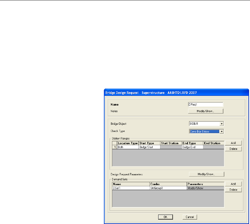
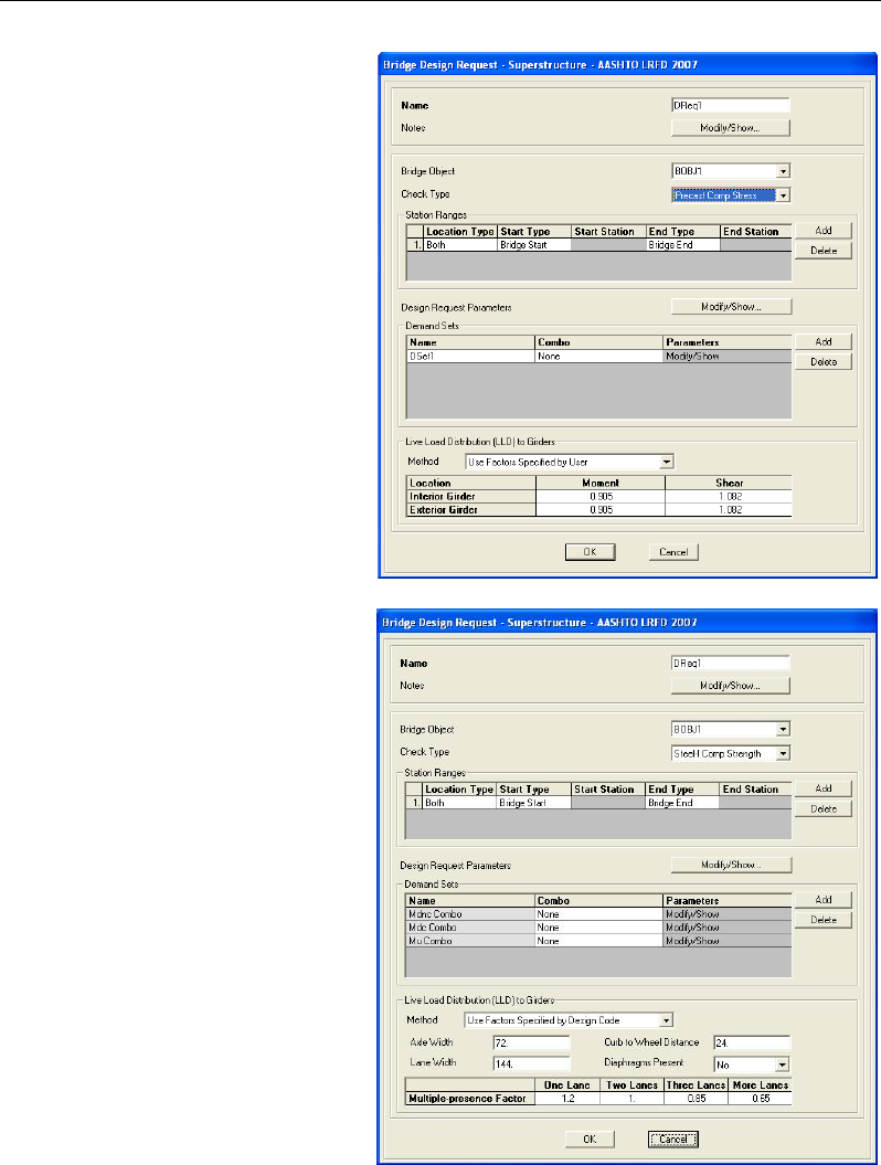
Figure 4-1 shows the Bridge Design Request form when the bridge object is for
a concrete box girder bridge, and the check type is concrete box stress. Figure
4-2 shows the Bridge Design Request form when the bridge object is for a
Composite I or U girder bridge and the check type is precast composite stress.
Figure 4-3 shows the Bridge Design Request form when the bridge object is for
a Steel I-Beam bridge and the check type is composite strength.
Figure 4-1 Bridge Design
Request - Concrete Box
Girder Bridges
4 - 2 Name and Bridge Object
Chapter 4 - Define a Bridge Design Request
Figure 4-2 Bridge Design
Request - Composite I or
U Girder Bridges
Figure 4-3 Bridge Design
Request – Steel I Beam
with Composite Slab
Name and Bridge Object 4 - 3

CSiBridge Bridge Superstructure Design
4.1 Name and Bridge Object
Each Bridge Design Request must have unique name. Any name can be used.
If multiple Bridge Objects are used to define a bridge model, select the bridge
object to be designed for the Design Request. If a bridge model contains only a
single bridge object, the name of that bridge object will be the only item avail-
able from the Bridge Object drop-down list.
4.2 Check Type
The Check Type refers to the type of design to be performed and the available
options depend on the type of bridge deck being modeled.
For a Concrete Box Girder bridge, CSiBridge provides the following check
type options:
AASHTO STD 2002
Concrete Box Stress
AASHTO LRFD 2007
Concrete Box Stress
Concrete Box Flexure
Concrete Box Shear and Torsion
Concrete Box Principal
CAN/CSA S6, EN 1992-1-1, IRC: 112, and SNiP
Concrete Box Stress
Concrete Box Flexure
Concrete Box Shear
For Multi-Cell Concrete Box Girder bridge, CSiBridge provides the following
check type options:
4 - 4 Name and Bridge Object

Chapter 4 - Define a Bridge Design Request
AASHTO LRFD 2007, CAN/CSA S6, EN 1992-1-1, IRC: 112, and SNiP
Concrete Box Stress
Concrete Box Flexure
Concrete Box Shear
For bridge models with precast I or U Beams with Composite Slabs,
CSiBridge provides three check type options, as follows:
AASHTO LRFD 2007, CAN/CSA S6, EN 1992-1-1, IRC: 112, and SNiP
Precast Comp Stress
Precast Comp Shear
Precast Comp Flexure
For bridge models with steel I-beam with composite slab superstructures,
CSiBridge provides the following check type option:
AASHTO LRFD 2007 and 2012
Steel Comp Strength
Steel Comp Service
Steel Comp Fatigue
Steel Comp Constructability Staged
Steel Comp Constructability NonStaged
EN 1994-2:2005 and SNiP
Steel Comp Ultimate
Steel Comp Service Stresses
Steel Comp Service Rebar
Steel Comp Constructability Staged
Check Type 4 - 5

CSiBridge Bridge Superstructure Design
Steel Comp Constructability NonStaged
The bold type denotes the name that appears in the check type drop-down list.
A detailed description of the design algorithm can be found in Chapter 5 for
concrete box girder bridges, in Chapter 6 for multi-cell box girder bridges, in
Chapter 7 for precast I or U beam with composite slabs, and in Chapter 8 for
steel I-beam with composite slab.
4.3 Station Range
The station range refers to the particular zone or portion of the bridge that is to
be designed. The user may choose the entire length of the bridge, or specify
specific zones using station ranges. Multiple zones (i.e., station ranges) may be
specified as part of a single design request.
When defining a station range, the user specifies the Location Type, which de-
termines if the superstructure forces are to be considered before or at a station
point. The user may choose the location type as before the point, after the
point, or both.
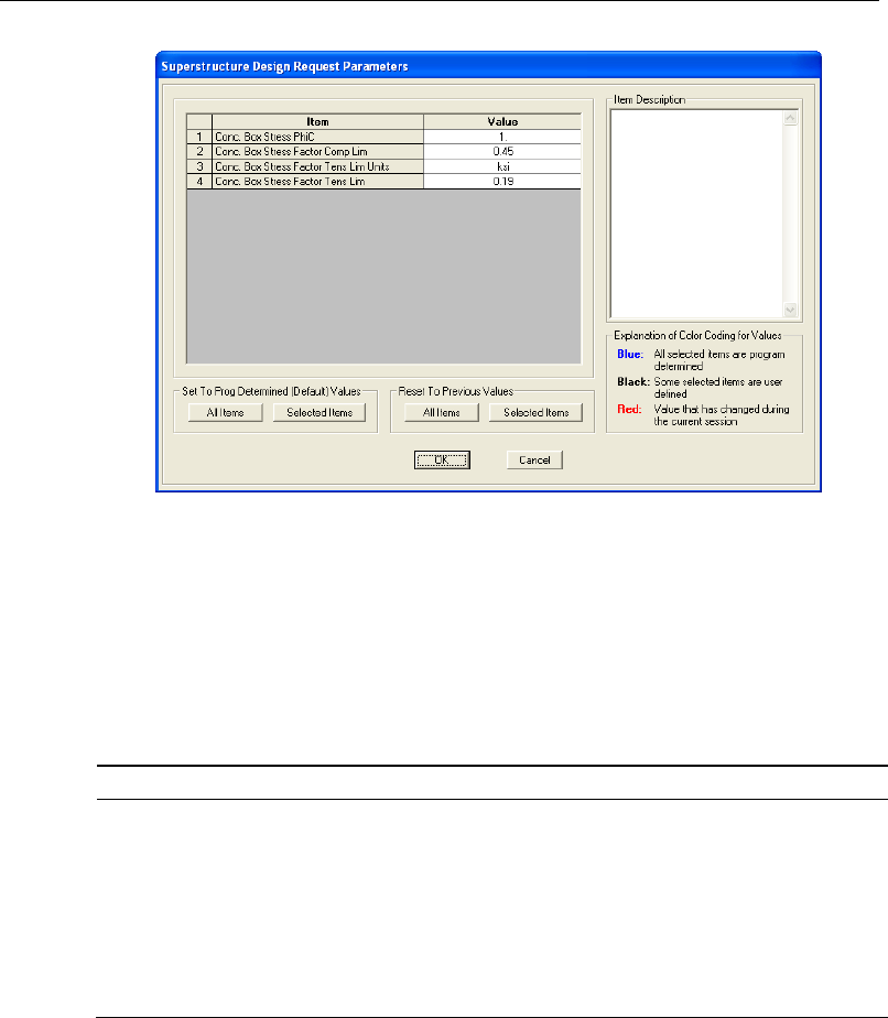
4.4 Design Parameters
Design parameters are overwrites that can be used to change the default values
set automatically by the program. The parameters are specific to each code,
deck type, and check type. Figure 4-4 shows the Superstructure Design Re-
quest Parameters form.
4 - 6 Station Range
Chapter 4 - Define a Bridge Design Request
Figure 4-3 Superstructure Design Request Parameters form
Table 4-1 shows the parameters for concrete box girder bridges. Table 4-2
shows the parameters for multi-cell concrete box bridges. Table 4-3 shows the
parameters applicable when the superstructure has a deck that includes precast
I or U girders with composite slabs. Table 4-4 shows the parameters applicable
when the superstructure has a deck that includes steel I-beams.
Table 4-1 Design Request Parameters for Concrete Box Girders
AASHTO STD 2002
Concrete Box Stress
Resistance Factor - multiplies both compression and tension
stress limits
Multiplier on
′
c
f
to calculate the compression stress limit
Multiplier on sqrt(
′
c
f
) to calculate the tension stress limit,
given in the units specified
The tension limit factor may be specified using either MPa or
ksi units for
′
c
f
and the resulting tension limit
Design Parameters 4 - 7

CSiBridge Bridge Superstructure Design
Table 4-1 Design Request Parameters for Concrete Box Girders
AASHTO LRFD 2007
Concrete Box Stress
Concrete Box Stress, PhiC, - Resistance Factor that multi-
plies both compression and tension stress limits
Concrete Box Stress Factor Compression Limit - Multiplier
on
′
c
f
to calculate the compression stress limit
Concrete Box Stress Factor Tension Limit Units - Multiplier
on sqrt(
′
c
f
) to calculate the tension stress limit, given in the
units specified
Concrete Box Stress Factor Tension Limit - The tension limit
factor may be specified using either MPa or ksi units for
′
c
f
and the resulting tension limit
Concrete Box Shear Concrete Box Shear, PhiC, - Resistance Factor that multi-
plies both compression and tension stress limits
Concrete Box Shear, PhiC, Lightweight Resistance Factor
that multiplies nominal shear resistance to obtain factored
resistance for light-weight concrete
Include Resal (Hunching-girder) shear effects – Yes or No.
Specifies whether the component of inclined flexural com-
pression or tension, in the direction of the applied shear, in
variable depth members shall or shall not be considered
when determining the design factored shear force in accord-
ance with Article 5.8.6.2.
Concrete Box Shear Rebar Material - A previously defined
rebar material label that will be used to determine the area
of shear rebar required
Longitudinal Torsional Rebar Material - A previously defined
rebar material that will be used to determine the area of lon-
gitudinal torsional rebar required
Concrete Box
Flexure
Concrete Box Flexure, PhiC, - Resistance Factor that multi-
plies both compression and tension stress limits
Concrete Box
Principal
See the Box Stress design parameter specifications
CAN/CSA S6
Concrete Box Stress
Multi-Cell Concrete Box Stress Factor Compression Limit -
Multiplier on
′
c
f
to calculate the compression stress limit
Multi-Cell Concrete Box Stress Factor Tension Limit - The
tension limit factor may be specified using either MPa or ksi
units for
′
c
f
and the resulting tension limit
Concrete Box Shear
Phi Concrete
ϕc
-- Resistance factor for concrete (see CSA
4 - 8 Design Parameters

Chapter 4 - Define a Bridge Design Request
Table 4-1 Design Request Parameters for Concrete Box Girders
Clause 8.4.6)
Phi PT ϕp -- Resistance factor for tendons (see CSA Clause
8.4.6)
Cracking Strength Factor – Multiplies sqrt(
′
c
f
) to obtain
cracking strength
EpsilonX Negative Limit -- Longitudinal negative strain limit
(see Clause 8.9.3.8)
EpsilonX Positive Limit -- Longitudinal positive strain limit
(see Clause 8.9.3.8)
Tab slab rebar cover – Distance from the outside face of the
top slab to the centerline of the exterior closed transverse
torsion reinforcement
Web rebar cover – Distance from the outside face of the web
to the centerline of the exterior closed transverse torsion re-
inforcement
Bottom Slab rebar cover – Distance from the outside face of
the bottoms lab to the centerline of the exterior closed trans-
verse torsion reinforcement
Shear Rebar Material – A previously defined rebar material
label that will be used to determine the required area of
transverse rebar in the girder
Longitudinal Rebar Material – A previously defined rebar
material that will be used to determine the required area of
longitudinal rebar in the girder
Concrete Box
Flexure
Phi Concrete ϕc -- Resistance factor for concrete (see CSA
Clause 8.4.6)
Phi Pt ϕp -- Resistance factor for tendons (see CSA Clause
8.4.6)
Phi Rebar ϕs -- Resistance factor for reinforcing bars (see
CSA Clause 8.4.6)
Eurocode EN 1992 and SNiP
Concrete Box Stress Compression limit – Multiplier on fc k to calculate the com-
pression stress limit
Tension limit – Multiplier on fc k to calculate the tension
stress limit
Concrete Box Shear Gamma C for Concrete – Partial factor for concrete.
Gamma C for Rebar – Partial safety factor for reinforcing
steel.
Gamma C for PT – Partial safety factor for prestressing
steel.
Angle Theta – The angle between the concrete compression
strut and the beam axis perpendicular to the shear force.
Design Parameters 4 - 9

CSiBridge Bridge Superstructure Design
Table 4-1 Design Request Parameters for Concrete Box Girders
The value must be between 21.8 degrees and 45 degrees.
Factor for PT Duct Diameter – Factor that multiplies post-
tensioning duct diameter when evaluating the nominal web
thickness in accordance with Section 6.2.3(6) of the code.
Typical values 0.5 to 1.2.
Factor for PT Transmission Length – Factor for the trans-
mission length of the post tensioning used in shear re-
sistance equation 6.4 of the code. Typical value 1.0 for post
tensioning.
Inner Arm Method – The method used to calculate the inner
lever arm “z” of the section (integer).
Inner Arm Limit – Factor that multiplies the depth of the sec-
tion to get the lower limit of the inner lever arm “z” of the sec-
tion.
Effective Depth Limit – Factor that multiplies the depth of the
section to get the lower limit of the effective depth to the ten-
sile reinforcement “d” of the section.
Type of Section – Type of section for shear design.
Determining Factor Nu1 – Method that will be used to calcu-
late the η1 factor.
Factor Nu1 – η1 factor
Determining Factor AlphaCW – Method that will be used to
calculate the αcw factor.
Factor AlphaCW – αcw factor
Factor Fywk – Multiplier of vertical shear rebar characteristic
yield strength to obtain a stress limit in shear rebar used in
6.10.aN. Typical value 0.8 to 1.0.
Shear Rebar Material – A previously defined material label
that will be used to determine the required area of transverse
rebar in the girder.
Longitudinal Rebar Material – A previously defined material
that will be used to determine the required area of longitudi-
nal rebar in the girder.
Concrete Box
Flexure
Gamma c for Concrete – Partial safety factor for concrete.
Gamma c for Rebar – Partial safety factor for reinforcing
steel.
Gamma c for PT – Partial safety factor for prestressing steel.
PT pre-strain – Factor to estimate pre-strain in the post-
tensioning. Multiplies fpk to obtain the stress in the tendons
after losses. Typical value between 0.4 and 0.9.
4 - 10 Design Parameters

Chapter 4 - Define a Bridge Design Request
Table 4-2 Design Request Parameters for Multi-Cell Concrete Box
AASHTO LRFD 2007
Multi-Cell Concrete
Box Stress
Multi-Cell Concrete Box Stress, PhiC, - Resistance Factor
that multiplies both compression and tension stress limits
Multi-Cell Concrete Box Stress Factor Compression Limit -
Multiplier on
′
c
f
to calculate the compression stress limit
Multi-Cell Concrete Box Stress Factor Tension Limit Units -
Multiplier on sqrt
( )
′
c
f
to calculate the tension stress limit,
given in the units specified
Multi-Cell Concrete Box Stress Factor Tension Limit - The
tension limit factor may be specified using either MPa or ksi
units for
′
c
f
and the resulting tension limit
Multi-Cell Concrete
Box Shear
Multi-Cell Concrete Box Shear, PhiC, - Resistance Factor
that multiplies both compression and tension stress limits
Multi-Cell Concrete Box Shear, PhiC, Lightweight Re-
sistance Factor that multiplies nominal shear resistance to
obtain factored resistance for light-weight concrete
Negative limit on strain in nonprestressed longitudinal rein-
forcement – in accordance with Section 5.8.3.4.2; Default
Value = -0.4x10⁻³, Typical value(s): 0 to -0.4x10⁻³
Positive limit on strain in nonprestressed longitudinal rein-
forcement - in accordance with Section 5.8.3.4.2; Default
Value = 6.0x10⁻³, Typical value(s): 6.0x10⁻³
PhiC for Nu - Resistance Factor used in equation 5.8.3.5-1;
Default Value = 1.0, Typical value(s): 0.75 to 1.0
Phif for Mu - Resistance Factor used in equation 5.8.3.5-1;
Default Value = 0.9, Typical value(s): 0.9 to 1.0
Specifies which method for shear design will be used – ei-
ther Modified Compression Field Theory (MCFT) in accord-
ance with 5.8.3.4.2 or Vci Vcw method in accordance with
5.8.3.4.3. Currently only the MCFT option is available.
A previously defined rebar material label that will be used to
determine the required area of transverse rebar in the girder.
A previously defined rebar material that will be used to de-
termine the required area of longitudinal rebar in the girder
Multi-Cell Concrete
Box Flexure
Multi-Cell Concrete Box Flexure, PhiC, - Resistance Factor
that multiplies both compression and tension stress limits
CAN/CSA S6
Design Parameters 4 - 11

CSiBridge Bridge Superstructure Design
Table 4-2 Design Request Parameters for Multi-Cell Concrete Box
Multi-Cell Concrete
Box Stress
Multi-Cell Concrete Box Stress Factor Compression Limit -
Multiplier on
′
c
f
to calculate the compression stress limit
Multi-Cell Concrete Box Stress Factor Tension Limit - The
tension limit factor may be specified using either MPa or ksi
units for
′
c
f
and the resulting tension limit
Multi-Cell Concrete
Box Shear
Highway Class – The highway class shall be determined in
accordance with CSA Clause 1.4.2.2, Table 1.1 for the av-
erage daily traffic and average daily truck traffic volumes for
which the structure is designed
Phi Concrete ϕc -- Resistance factor for concrete (see CSA
Clause 8.4.6)
Phi PT ϕp -- Resistance factor for tendons (see CSA Clause
8.4.6)
Phi Rebar ϕs -- Resistance factor for reinforcing bars (see
CSA Clause 8.4.6)
Cracking Strength Factor -- Multiplies sqrt(
′
c
f
) to obtain
cracking strength
EpsilonX Negative Limit -- Longitudinal negative strain limit
(see Clause 8.9.3.8)
EpsilonX Positive Limit -- Longitudinal positive strain limit
(see Clause 8.9.3.8)
Shear Rebar Material – A previously defined rebar material
that will be used to determine the required area of trans-
verse rebar in the girder
Longitudinal Rebar Material – A previously defined rebar
material that will be used to determine the required area of
longitudinal rebar in the girder
Multi-Cell Concrete
Box Flexure
Highway Class – The highway class shall be determined in
accordance with CSA Clause 1.4.2.2, Table 1.1 for the av-
erage daily traffic and average daily truck traffic volumes for
which the structure is designed
Phi Concrete ϕc -- Resistance factor for concrete (see CSA
Clause 8.4.6)
Phi PT ϕp -- Resistance factor for tendons (see CSA Clause
8.4.6)
Phi Rebar ϕs -- Resistance factor for reinforcing bars (see
CSA Clause 8.4.6)
Eurocode EN 1992 and SNiP
Multi-Cell Concrete
Box Stress
Compression limit – Multiplier on fc k to calculate the com-
pression stress limit
4 - 12 Design Parameters

Chapter 4 - Define a Bridge Design Request
Table 4-2 Design Request Parameters for Multi-Cell Concrete Box
Tension limit – Multiplier on fc k to calculate the tension
stress limit
Multi-Cell Concrete
Box Shear
Gamma C for Concrete – Partial factor for concrete.
Gamma C for Rebar – Partial safety factor for reinforcing
steel.
Gamma C for PT – Partial safety factor for prestressing
steel.
Angle Theta – The angle between the concrete compression
strut and the beam axis perpendicular to the shear force.
The value must be between 21.8 degrees and 45 degrees.
Factor for PT Duct Diameter – Factor that multiplies post-
tensioning duct diameter when evaluating the nominal web
thickness in accordance with Section 6.2.3(6) of the code.
Typical values 0.5 to 1.2.
Factor for PT Transmission Length – Factor for the trans-
mission length of the post tensioning used in shear re-
sistance equation 6.4 of the code. Typical value 1.0 for post
tensioning.
Inner Arm Method – The method used to calculate the inner
lever arm “z” of the section (integer).
Inner Arm Limit – Factor that multiplies the depth of the sec-
tion to get the lower limit of the inner lever arm “z” of the sec-
tion.
Effective Depth Limit – Factor that multiplies the depth of the
section to get the lower limit of the effective depth to the ten-
sile reinforcement “d” of the section.
Type of Section – Type of section for shear design.
Determining Factor Nu1 – Method that will be used to calcu-
late the η1 factor.
Factor Nu1 – η1 factor
Determining Factor AlphaCW – Method that will be used to
calculate the αcw factor.
Factor AlphaCW – αcw factor
Factor Fywk – Multiplier of vertical shear rebar characteristic
yield strength to obtain a stress limit in shear rebar used in
6.10.aN. Typical value 0.8 to 1.0.
Shear Rebar Material – A previously defined material label
that will be used to determine the required area of transverse
rebar in the girder.
Longitudinal Rebar Material – A previously defined material
that will be used to determine the required area of longitudi-
nal rebar in the girder.
Design Parameters 4 - 13

CSiBridge Bridge Superstructure Design
Table 4-2 Design Request Parameters for Multi-Cell Concrete Box
Multi-Cell Concrete
Box Flexure
Gamma c for Concrete – Partial safety factor for concrete.
Gamma c for Rebar – Partial safety factor for reinforcing
steel.
Gamma c for PT – Partial safety factor for prestressing steel.
PT pre-strain – Factor to estimate pre-strain in the post-
tensioning. Multiplies fpk to obtain the stress in the tendons
after losses. Typical value between 0.4 and 0.9.
Table 4-3 Design Request Parameters for Precast I or U Beams
AASHTO
Precast Comp
Stress
Precast Comp Stress, PhiC, - Resistance Factor that multi-
plies both compression and tension stress limits
Precast Comp Stress Factor Compression Limit - Multiplier
on f′c to calculate the compression stress limit
Precast Comp Stress Factor Tension Limit Units - Multiplier
on sqrt(f
′
c) to calculate the tension stress limit, given in the
units specified
Precast Comp Stress Factor Tension Limit - The tension limit
factor may be specified using either MPa or ksi units for f′c
and the resulting tension limit
Precast Comp
Shear
PhiC, - Resistance Factor that multiplies both compression
and tension stress limits
PhiC, Lightweight Resistance Factor that multiplies nominal
shear resistance to obtain factored resistance for light-weight
concrete
Negative limit on strain in nonprestressed longitudinal rein-
forcement – in accordance with Section 5.8.3.4.2; Default
Value = -0.4x10⁻³, Typical value(s): 0 to -0.4x10⁻³
4 - 14 Design Parameters

Chapter 4 - Define a Bridge Design Request
Table 4-3 Design Request Parameters for Precast I or U Beams
Positive limit on strain in nonprestressed longitudinal rein-
forcement - in accordance with Section 5.8.3.4.2; Default
Value = 6.0x10⁻³, Typical value(s): 6.0x10⁻³
PhiC for Nu - Resistance Factor used in equation 5.8.3.5-1;
Default Value = 1.0, Typical value(s): 0.75 to 1.0
Phif for Mu - Resistance Factor used in equation 5.8.3.5-1;
Default Value = 0.9, Typical value(s): 0.9 to 1.0
Specifies what method for shear design will be used - either
Modified Compression Field Theory (MCFT) in accordance
with 5.8.3.4.2 or Vci Vcw method in accordance with 5.8.3.4.3
Currently only the MCFT option is available.
A previously defined rebar material label that will be used to
determine the required area of transverse rebar in the girder
A previously defined rebar material that will be used to deter-
mine the required area of longitudinal rebar in the girder
Precast Comp
Flexure
Precast Comp Flexure, PhiC, - Resistance Factor that multi-
plies both compression and tension stress limits
CAN/CSA S6
Precast Comp
Stress
Precast Comp Stress Factor Compression Limit - Multiplier
on f′c to calculate the compression stress limit
Precast Comp Stress Factor Tension Limit - The tension limit
factor may be specified using either MPa or ksi units for f′c
and the resulting tension limit
Precast Comp
Shear
Highway Class – The highway class shall be determined in
accordance with CSA Clause 1.4.2.2, Table 1.1 for the aver-
age daily traffic and average daily truck traffic volumes for
which the structure is designed
Phi Concrete ϕc -- Resistance factor for concrete (see CSA
Clause 8.4.6)
Phi PT ϕp -- Resistance factor for tendons (see CSA Clause
8.4.6)
Phi Rebar ϕs -- Resistance factor for reinforcing bars (see
CSA Clause 8.4.6)
Cracking Strength Factor -- Multiplies sqrt(
′
c
f
) to obtain
cracking strength
EpsilonX Negative Limit -- Longitudinal negative strain limit
(see Clause 8.9.3.8)
EpsilonX Positive Limit -- Longitudinal positive strain limit (see
Clause 8.9.3.8)
Shear Rebar Material – A previously defined rebar material
label that will be used to determine the required area of trans-
verse rebar in the girder.
Design Parameters 4 - 15

CSiBridge Bridge Superstructure Design
Table 4-3 Design Request Parameters for Precast I or U Beams
Longitudinal Rebar Material – A previously defined rebar ma-
terial that will be used to determine the required area of longi-
tudinal rebar n the girder
Precast Comp
Flexure
Highway Class – The highway class shall be determined in
accordance with CSA Clause 1.4.2.2, Table 1.1 for the aver-
age daily traffic and average daily truck traffic volumes for
which the structure is designed
Phi Concrete ϕc -- Resistance factor for concrete (see CSA
Clause 8.4.6)
Phi PT ϕp -- Resistance factor for tendons (see CSA Clause
8.4.6)
Phi Rebar ϕs -- Resistance factor for reinforcing bars (see
CSA Clause 8.4.6)
Eurocode EN 1992 and SNiP
Precast Comp
Stress
Compression limit – Multiplier on fc k to calculate the com-
pression stress limit
Tension limit – Multiplier on fc k to calculate the tension stress
limit
Precast Comp
Shear
Gamma C for Concrete – Partial factor for concrete.
Gamma C for Rebar – Partial safety factor for reinforcing
steel.
Gamma C for PT – Partial safety factor for prestressing steel.
Angle Theta – The angle between the concrete compression
strut and the beam axis perpendicular to the shear force. The
value must be between 21.8 degrees and 45 degrees.
Factor for PT Transmission Length – Factor for the transmis-
sion length of the post tensioning used in shear resistance
equation 6.4 of the code. Typical value 1.0 for post tension-
ing.
Inner Arm Method – The method used to calculate the inner
lever arm “z” of the section (integer).
Inner Arm Limit – Factor that multiplies the depth of the sec-
tion to get the lower limit of the inner lever arm “z” of the sec-
tion.
Effective Depth Limit – Factor that multiplies the depth of the
section to get the lower limit of the effective depth to the ten-
sile reinforcement “d” of the section.
Type of Section – Type of section for shear design.
Determining Factor Nu1 – Method that will be used to calcu-
late the η1 factor.
Factor Nu1 – η1 factor
4 - 16 Design Parameters

Chapter 4 - Define a Bridge Design Request
Table 4-3 Design Request Parameters for Precast I or U Beams
Determining Factor AlphaCW – Method that will be used to
calculate the αcw factor.
Factor AlphaCW – αcw factor
Factor Fywk – Multiplier of vertical shear rebar characteristic
yield strength to obtain a stress limit in shear rebar used in
6.10.aN. Typical value 0.8 to 1.0.
Shear Rebar Material – A previously defined material label
that will be used to determine the required area of transverse
rebar in the girder.
Longitudinal Rebar Material – A previously defined material
that will be used to determine the required area of longitudinal
rebar in the girder.
Precast Comp
Flexure
Gamma c for Concrete – Partial safety factor for concrete.
Gamma c for Rebar – Partial safety factor for reinforcing
steel.
Gamma c for PT – Partial safety factor for prestressing steel.
PT pre-strain – Factor to estimate pre-strain in the post-
tensioning. Multiplies fpk to obtain the stress in the tendons af-
ter losses. Typical value between 0.4 and 0.9.
Table 4-4 Design Request Parameters for Steel I-Beam
AASHTO LRFD 2007
Steel I-Beam -
Strength
Resistance factor Phi for flexur
e
Resistance factor Phi for shear
Do webs have longitudinal stiffeners?
Use Stage Analysis load case to determine stresses on com-
posite section?
Multiplies short term modular ratio (Es/Ec) to obtain long-term
modular ratio
Use AASHTO, Appendix A to determine resistance in nega-
tive
moment regions?
Steel I Beam Comp -
Service
Use Stage Analysis load case to determine stresses on com-
posite section?
Shored Construction?
Does concrete slab resist tension?
Multiplies short term modular ratio (Es/Ec) to obtain long-term
modular ratio
Design Parameters 4 - 17

CSiBridge Bridge Superstructure Design
Table 4-4 Design Request Parameters for Steel I-Beam
Steel-I Comp -
Fatigue
There are no user defined design request parameters for
fatigue
Steel I Comp
Construct Stgd
Resistance factor Phi for flexure
Resistance factor Phi for shear
Resistance factor Phi for Concrete in Tension
Do webs have longitudinal stiffeners?
Concrete modulus of rupture factor in accordance with
AASHTO LRFD Section 5.4.2.6, factor that multiplies sqrt of
f'c to obtain modulus of rupture, default value 0.24 (ksi) or
0.63 (MPa), must be > 0
The modulus of rupture factor may be specified using either
MPa or ksi units
Steel I Comp
Construct Non Stgd
Resistance factor Phi for flexure
Resistance factor Phi for shear
Resistance factor Phi for Concrete in Tension
Do webs have longitudinal stiffeners?
Concrete modulus of rupture factor in accordance with
AASHTO LRFD Section 5.4.2.6, factor that multiplies sqrt of
f'c to obtain modulus of rupture, default value 0.24 (ksi) or
0.63 (MPa), must be > 0
The modulus of rupture factor may be specified using either
MPa or ksi units
4.5 Demand Sets
A demand set name is required for each load combination that is to be consid-
ered in a design request. The load combinations may be selected from a list of
user defined or default load combinations that are program determined (see
Chapter 2).
4.6 Live Load Distribution Factors
When the superstructure has a deck that includes precast I or U girders with
composite slabs or multi-cell boxes, Live Load Distribution Factors can be
specified. LLD factors are described in Chapter 3.
4 - 18 Demand Sets

Chapter 5
Design Concrete Box Girder Bridges
This chapter describes the algorithms applied in accordance with the Russian
SNiP 2.05.03-84 for design and stress check of the superstructure of a concrete
box type bridge deck section.
When interim revisions of the codes are published by the relevant authorities,
and (when applicable) they are subsequently incorporated into CSiBridge, the
program gives the user an option to select what type of interims shall be used
for the design. The interims can be selected by clicking on the Code Prefer-
ences button.
In CSiBridge, when distributing loads for concrete box design, the section is
always treated as one beam; all load demands (permanent and transient) are
distributed evenly to the webs for stress and flexure and proportionally to the
slope of the web for shear. Torsion effects are always considered and assigned
to the outer webs and the top and bottom slabs.
With respect to shear and torsion check, in accordance with AASHTO Article
5.8.6, CSA Clause 8.9, and EN 1992-1-1 Section 6.3 torsion is considered.
5 - 1

CSiBridge Bridge Superstructure Design
5.1 Stress Design
The following design parameters are defined by the user in the Design Request
(see Chapter 4):
FactorCompLim – Rb multiplier; Default Value = 1.0. The Rb is multiplied by
the FactorCompLim to obtain the concrete compression limit.
FactorTensLim - fctk multiplier; Default Value = 1.0. The Rbt is multiplied by
the FactorTensLim to obtain the concrete tension limit.
The stresses are evaluated at three points at the top fiber of the top slab and
three points at the bottom fiber of the bottom slab: the left corner, the center-
line web, and the right corner of the relevant slab tributary area. The locations
are labeled in the output plots and tables.
Concrete compressive and tensile strengths are read at every point, and com-
pression and tension limits are evaluated using the FactorCompLim − Rb mul-
tiplier and the FactorTensLim − Rbt multiplier.
The stresses are evaluated for each demand set (Chapter 4). If the demand set
contains live load, the program positions the load to capture extreme stress at
each of the evaluation points.
Extremes are found for each point and the controlling demand set name is rec-
orded.
5.2 Flexure Design
The following design parameters are defined by the user in the Design Request
(see Chapter 4):
mb– Operation condition factor for concrete, multiplies Rb in the moment re-
sistance equation; Default Value = 1.0.
mas – Reinforcement work coefficient, multiplies Rs in the moment resistance
equation; Default Value = 1.0.
5 - 2 Stress Design

Chapter 5 - Design Concrete Box Girder Bridges
map – Prestressing work coefficient, multiplies Rp in the moment resistance
equation; Default Value = 1.0.
εprePT – Factor to estimate pre-strain in PT. Multiplies Rp to obtain stress in ten-
dons after losses. Typical values are between 0.4 and 0.9
5.2.1 Design Process
The derivation of the moment resistance of the section is based on assumptions
specified in Section 3.56 of the code:
Plane sections remain plane.
The strain in bonded reinforcement or bonded prestressing tendons, whether
in tension or in compression, is the same as that in the surrounding concrete.
The tensile strength of the concrete is ignored.
The stresses in the concrete in compression are limited by stresses equal to
Rb and equally distributed within the limits of the conditional compression
region of the concrete.
The tensile stresses in the reinforcement is limited by the the tensile strength
in non-prestressed (Rs) and prestressed (Rp) reinforcement
The factor ξy, defining the effective height of the compression zone follow
from SNiP 3.61:
=
1 +
(1
1.1)
where:
- ω = 0.85 – 0.008Rb for elements with ordinary reinforcement;
- the stresses in the reinforcement σ1, MPa, are set equal to Rs for non-
prestressed reinforcement, Rp + 500 – σp for prestressed reinforce-
ment. The amount of prestressing in prestressing tendons σp is taken in-
to account when assessing the stresses in the tendons. CSiBridge de-
Flexure Design 5 - 3

CSiBridge Bridge Superstructure Design
termines the initial amount of prestressing by multiplying the prestress-
ing steel tensile strength Rp by the user-specified factor εprePT.
- the stress σ2 is the ultimate stress in the reinforcement of the compres-
sion region are set equal to 500 MPa
5.2.2 Algorithms
At each section:
The equivalent slab thickness is evaluated based on the slab area and the slab
width assuming a rectangular shape.
slab
slabeq slab
A
tb
=
The tendon and rebar locations, areas, and materials are read. Only bonded
tendons are processed; unbonded tendons are ignored.
The section properties are calculated for the section before skew, grade, and
superelevation have been applied. This is consistent with the demands being
reported in the section local axis. The entire top and bottom slabs are consid-
ered effective in compression.
The ultimate moment resistance of a section is determined using the formula in
SNiP 3.62.
The height of the compression zone x is determined as follows:
=min ,+
If the depth of compression zone is smaller than the flange depth hf the moment
resistance is calculated as follows:
=(0.5)
otherwise
=min ,+
5 - 4 Flexure Design

Chapter 5 - Design Concrete Box Girder Bridges
=(0.5)+0.5
The resistance is evaluated for bending about horizontal axis 3 only. Separate
capacity is calculated for positive and negative moment. The capacity is based
on bonded tendons and mild steel located in the tension zone as defined in the
Bridge Object. Tendons and mild steel reinforcement located in the compres-
sion zone are not considered. It is assumed that all defined tendons in a section,
stressed or not, will reach stress Rp. If a certain tendon should not be consid-
ered for the flexural capacity calculation, its area must be set to zero.
5.3 Shear Design
The following design parameter is defined by the user in the Design Request
(see Chapter 4):
Effective depth limit – The factor that multiplies the depth of the section to
get the lower limit of the effective depth to the tensile reinforcement h0 of the
section (h0 = Effective depth limit * Section Depth).
5.3.1 Variables
A0 Area enclosed by the centerlines of the connecting exterior webs and
top and bottom slabs, including inner hollow area
Asw Area of transverse shear reinforcement per unit
b Web width
h0 Effective section depth
girder
d
Depth of girder
dPTBot Distance from the top fiber to the center of prestressing steel near the
bottom fiber
dPTTop Distance from the bottom fiber to the center of prestressing steel near
the top fiber
Tu Ultimate design torsion per section cut
Shear Design 5 - 5

CSiBridge Bridge Superstructure Design
Vu Ultimate design shear force demand excluding the force in the ten-
dons
Vp Component in the direction of the applied shear of the effective pre-
stressing force; if Vp has the same sign as VEd, the component is re-
sisting the applied shear.
Vt Shear in web resulting from torsion
5.3.2 Design Process
The shear resistance is determined in accordance with SNiP, Clause 3.77. The
procedure assumes that the concrete shear stresses are distributed uniformly
over an area b wide and d deep, that the direction of principal compressive
stresses remains constant over d, and that the shear strength of the section can
be determined by considering the biaxial stress conditions at just one location
in the web. For design, the user should select only those sections that comply
with these assumptions by defining appropriate station ranges in the Design
Request (see Chapter 4).
The Shear and Torsion Design is completed on a per web basis. The D/C ratio
is calculated as a fraction of applied shear over resistance. The section design
shear force is distributed into individual webs assuming that the vertical shear
that is carried by a web decreases with increased inclination of the web from
vertical. Section torsion moments are assigned to external webs and slabs.
5.3.3 Algorithm
All section properties and demands are converted from CSiBridge model
units to N, mm.
For every COMBO specified in the Design Request that contains envelopes,
a new force demand set is generated. The new force demand set is built up
from the maximum tension values of P and the maximum absolute values of
V2 and M3 of the two StepTypes (Max and Min) present in the envelope
COMBO case. The StepType of this new force demand set is named ABS
and the signs of the P, V2, and M3 are preserved. The ABS case follows the
industry practice where sections are designed for extreme shear and moments
5 - 6 Shear Design
Chapter 5 - Design Concrete Box Girder Bridges
that are not necessarily corresponding to the same design vehicle position.
The section cut is designed for all three StepTypes in the COMBOMax,
Min and ABSand the controlling StepType is reported.
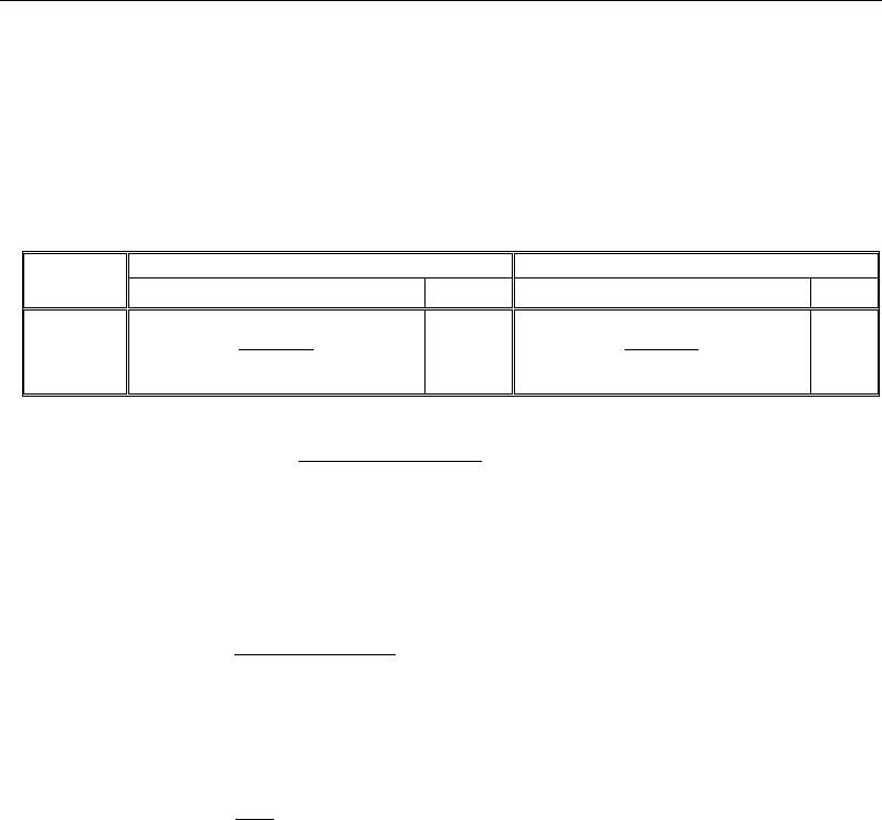
On the basis of the location and inclination of each web, the per-web demand
values are evaluated as shown in the following table:
Location
Outer Web
Inner Web
V
Ed
T
Ed
V
Ed
T
Ed
Shear and
Torsion
Check
2 web
web
cos
c
Vκ
α
TEd
2 web
web
cos
c
Vκ
α
0
where
( )
( )
web
web web
web
1
cos | |
cos | |
n
α
κα
=
∑
The component in the direction of the applied shear of the effective prestress-
ing force, positive if resisting the applied shear, is evaluated:
( )
2 2tot web
web
cos
c
p
VV
V−κ
=α
The component of shear due to torsion in the external webs is calculated as
follows:
=
where ds is the web height measured between mid-depths of
top and bottom slab
The effective depth of section h0 of prestressed sections is determined as fol-
lows:
If MEd > 0, h0 = max(Effective depth limit * dgirder , dPTbot)
If MEd < 0, h0 = max(Effective depth limit * dgirder , dPTtop)
The effective depth of section h0 of non-prestressed sections is de-
termined as follows:
If MEd > 0, then h0 = max(Effective depth limit * dgirder , drebarbot)
If MEd < 0, then h0 = max(Effective depth limit * dgirder, drebartop)
Shear Design 5 - 7

CSiBridge Bridge Superstructure Design
When section contains both non-prestressed and prestressed reinforcement the
effective depth of section h0 of sections is calculated based on resultant of forc-
es in the non-prestressed As*Rs and pre-stressed reinforecement Ap*Rp and veri-
fied against the minimum Effective depth limit * dgirder
The shear resistance of the web is calculated per SNiP Section 3.77
= 0.3
where: =min
(1 + , 1.3)
= 5 (stirrups positioned normal to the longitudinal axis of the ele-
ment)
=
=
= area of vertical shear reinforcement (stirrups)
= distance between stirrups
b = web width
The area of vertical transverse reinforcement specified in the Bridge Object is
used to calculate the coefficient . The density (area per unit length) of pro-
vided transverse reinforcement in a given girder is based on values specified in
the Bridge Object within distance 0.5*h0 measured downstation and upstation
from a given section cut.
= 1 0.01
The demand over capacity ratio is evaluated as:
=+
5 - 8 Shear Design

Chapter 6
Design Multi-Cell Concrete Box Bridges using AMA
This chapter describes the algorithms used by CSiBridge for design checks
when the superstructure has a deck that includes cast-in-place multi-cell con-
crete box design and uses the Approximate Method of Analysis, as described in
the Russian SNiP 2.05.03-84.
When interim revisions of the codes are published by the relevant authorities,
and (when applicable) they are subsequently incorporated into CSiBridge, the
program gives the user an option to select what type of interims shall be used
for the design. The interims can be selected by clicking on the Code Prefer-
ences button.
For MulticellConcBox design in CSiBridge, each web and its tributary slabs
are designed separately. Moments and shears due to live load are distributed to
individual webs in accordance with the live load distribution method specified
in the Design Request (Chapter 4). Torsion effects are ignored.
6.1 Stress Design
The following design parameters are defined by the user in the Design Request
(see Chapter 4):
Stress Design 6 - 1

CSiBridge Bridge Superstructure Design
– FactorCompLim – Rb multiplier; Default Value = 1.0. The Rb is multiplied by
the FactorCompLim to obtain the concrete compression limit.
– FactorTensLim - fctk multiplier; Default Value = 1.0. The Rbt is multiplied by
the FactorTensLim to obtain the concrete tension limit.
The stresses are evaluated at three points at the top fiber of the top slab and
three points at the bottom fiber of the bottom slab: the left corner, the center-
line web, and the right corner of the relevant slab tributary area. The locations
are labeled in the output plots and tables.
Concrete compressive and tensile strengths are read at every point, and com-
pression and tension limits are evaluated using the FactorCompLim − Rb mul-
tiplier and the FactorTensLim − Rbt multiplier.
The stresses assume linear distribution and take into account axial (P) and ei-
ther both bending moments (M2 and M3) or only P and M3, depending on
which method for determining LLDF has been specified in the design request
(see Chapters 3 and 4).
The stresses are evaluated for each demand set (Chapter 4). If the demand set
contains live load, the program positions the load to capture extreme stress at
each of the evaluation points.
Extremes are found for each point and the controlling demand set name is rec-
orded.
6.2 Flexure Design
The following design parameters are defined by the user in the Design Request
(see Chapter 4):
– mb– Operation condition factor for concrete, multiplies Rb in the moment re-
sistance equation; Default Value = 1.0.
– mas – Reinforcement work coefficient, multiplies Rs in the moment resistance
equation; Default Value = 1.0.
– map – Prestressing work coefficient, multiplies Rp in the moment resistance
equation; Default Value = 1.0.
6 - 2 Flexure Design

Chapter 6 - Design Multi-Cell Concrete Box Bridges using AMA
– εprePT – Factor to estimate pre-strain in PT. Multiplies Rp to obtain stress in
tendons after losses. Typical values are between 0.4 and 0.9
6.2.1 Design Process
The derivation of the moment resistance of the section is based on assumptions
specified in Section 3.56 of the code:
- Plane sections remain plane.
- The strain in bonded reinforcement or bonded prestressing tendons, whether
in tension or in compression, is the same as that in the surrounding concrete.
- The tensile strength of the concrete is ignored.
- The stresses in the concrete in compression are limited by stresses equal to
Rb and equally distributed within the limits of the conditional compression
region of the concrete.
- The tensile stresses in the reinforcement is limited by the the tensile strength
in non-prestressed (Rs) and prestressed (Rp) reinforcement
- The factor ξy, defining the effective height of the compression zone follow
from SNiP 3.61:
=
1 +
(1
1.1)
where:
- ω = 0.85 – 0.008Rb for elements with ordinary reinforcement;
- the stresses in the reinforcement σ1, MPa, are set equal to Rs for non-
prestressed reinforcement, Rp + 500 – σp for prestressed reinforcement. The
amount of prestressing in prestressing tendons σp is taken into account when
assessing the stresses in the tendons. CSiBridge determines the initial amount
of prestressing by multiplying the prestressing steel tensile strength Rp by the
user-specified factor εprePT.
- the stress σ2 is the ultimate stress in the reinforcement of the compres-
sion region are set equal to 500 MPa
Flexure Design 6 - 3

CSiBridge Bridge Superstructure Design
6.2.2 Algorithms
At each section:
- The equivalent slab thickness is evaluated based on the slab area and the slab
width assuming a rectangular shape.
slab
slabeq slab
A
tb
=
- The tendon and rebar locations, areas, and materials are read. Only bonded
tendons are processed; unbonded tendons are ignored.
- The section properties are calculated for the section before skew, grade, and
superelevation have been applied. This is consistent with the demands being
reported in the section local axis. The entire top and bottom slabs are consid-
ered effective in compression.
The ultimate moment resistance of a section is determined using the formula in
SNiP 3.62.
The height of the compression zone x is determined as follows:
=min ,
If the depth of compression zone is smaller than the flange depth hf the moment
resistance is calculated as follows:
=(0.5)
otherwise
=min ,
=(0.5)+0.5
The resistance is evaluated for bending about horizontal axis 3 only. Separate
capacity is calculated for positive and negative moment. The capacity is based
on bonded tendons and mild steel located in the tension zone as defined in the
Bridge Object. Tendons and mild steel reinforcement located in the compres-
sion zone are not considered. It is assumed that all defined tendons in a section,
6 - 4 Flexure Design

Chapter 6 - Design Multi-Cell Concrete Box Bridges using AMA
stressed or not, will reach stress Rp. If a certain tendon should not be consid-
ered for the flexural capacity calculation, its area must be set to zero.
6.3 Shear Design
The following design parameters are defined by the user in the Design Request
(see Chapter 4):
– Effective depth limit – The factor that multiplies the depth of the section to
get the lower limit of the effective depth to the tensile reinforcement h0 of the
section (h0 = Effective depth limit * Section Depth).
6.3.1 Variables
A0 Area enclosed by the centerlines of the connecting exterior webs and
top and bottom slabs, including inner hollow area
Asw Area of transverse shear reinforcement per unit
b Web width
h0 Effective section depth
girder
d
Depth of girder
dPTBot Distance from the top fiber to the center of prestressing steel near the
bottom fiber
dPTTop Distance from the bottom fiber to the center of prestressing steel near
the top fiber
Vu Ultimate design shear force demand excluding the force in the ten-
dons
Vp Component in the direction of the applied shear of the effective pre-
stressing force; if Vp has the same sign as VEd, the component is re-
sisting the applied shear.
Shear Design 6 - 5

CSiBridge Bridge Superstructure Design
6.3.2 Design Process
The shear resistance is determined in accordance with SNiP, clause 3.77. The
procedure assumes that the concrete shear stresses are distributed uniformly
over an area b wide and d deep, that the direction of principal compressive
stresses remains constant over d, and that the shear strength of the section can
be determined by considering the biaxial stress conditions at just one location
in the web. For design, the user should select only those sections that comply
with these assumptions by defining appropriate station ranges in the Design
Request (see Chapter 4).
The Shear Design is completed on a per web basis. The D/C ratio is calculated
for each web. For a description of distribution of live and other loads into indi-
vidual webs, please refer to Chapter 3. Section torsion moments are ignored.
6.3.3 Algorithm
All section properties and demands are converted from CSiBridge model
units to N, mm.
For every COMBO specified in the Design Request that contains envelopes,
a new force demand set is generated. The new force demand set is built up
from the maximum tension values of P and the maximum absolute values of
V2 and M3 of the two StepTypes (Max and Min) present in the envelope
COMBO case. The StepType of this new force demand set is named ABS
and the signs of the P, V2, and M3 are preserved. The ABS case follows the
industry practice where sections are designed for extreme shear and moments
that are not necessarily corresponding to the same design vehicle position.
The section cut is designed for all three StepTypes in the COMBOMax,
Min and ABSand the controlling StepType is reported.
The component in the direction of the applied shear of the effective prestress-
ing force, positive if resisting the applied shear, is evaluated:
2 2tot
web
c
p
VV
Vn
−
=
The effective depth of section h0 of prestressed sections is determined as fol-
lows:
6 - 6 Shear Design

Chapter 6 - Design Multi-Cell Concrete Box Bridges using AMA
If MEd > 0, h0 = max(Effective depth limit * dgirder , dPTbot)
If MEd < 0, h0 = max(Effective depth limit * dgirder , dPTtop)
The effective depth of section h0 of non-prestressed sections is determined as
follows:
If MEd > 0, then h0 = max(Effective depth limit * dgirder , drebarbot)
If MEd < 0, then h0 = max(Effective depth limit * dgirder, drebartop)
When section contains both non-prestressed and prestressed reinforcement the
effective depth of section h0 of sections is calculated based on resultant of forc-
es in the non-prestressed As*Rs and pre-stressed reinforecement Ap*Rp and veri-
fied against the minimum Effective depth limit * dgirder Effective depth limit *
dgirder
The shear resistance of the web is calculated per SNiP section 3.77
= 0.3
where:
=min
(1 + , 1.3)
= 5 (stirrups positioned normal to the longitudinal axis of the element)
=
=
= area of vertical shear reinforcement (stirrups)
= distance between stirrups
b= web width
The area of vertical transverse reinforcement specified in the Bridge Object is
used to calculate the coefficient . The density (area per unit length) of pro-
vided transverse reinforcement in a given girder is based on values specified in
the Bridge Object within distance 0.5*h0 measured downstation and upstation
from a given section cut.
= 1 0.01
The demand over capacity ratio is evaluated as:
Shear Design 6 - 7

CSiBridge Bridge Superstructure Design
=
6 - 8 Shear Design

Chapter 7
Design Precast Concrete Girder Bridges
This chapter describes the algorithms used by CSiBridge for design and stress
check when the superstructure has a deck that includes precast I or U girders
with composite slabs in accordance with the Russian SNiP 2.05.03-84.
When interim revisions of the codes are published by the relevant authorities,
and (when applicable) they are subsequently incorporated into CSiBridge, the
program gives the user an option to select what type of interims shall be used
for the design. The interims can be selected by clicking on the Code Prefer-
ences button.
For PrecastComp design in CSiBridge each beam and its tributary composite
slab is designed separately. Moments and shears due to live load are distributed
to individual beans in accordance with the live load distribution method speci-
fied in the Design Request. Torsion effects are ignored.
7.1 Stress Design
The following design parameters are defined by the user in the Design Request
(see Chapter 4):
– FactorCompLim – Rb multiplier; Default Value = 1.0. The Rb is multiplied by
the FactorCompLim to obtain the concrete compression limit.
Stress Design 7 - 1

CSiBridge Bridge Superstructure Design
– FactorTensLim - fctk multiplier; Default Value = 1.0. The Rbt is multiplied by
the FactorTensLim to obtain the concrete tension limit.
The stresses are evaluated at three points at the top fiber of the composite slab:
the left corner, the centerline beam, and the right corner of the composite slab
tributary area. The locations of stress output points at the slab bottom fiber and
beam top and bottom fibers depend on the type of precast beam present in the
section cut. The locations are labeled in the output plots and tables.
Concrete compressive and tensile strengths are read at every point, and com-
pression and tension limits are evaluated using the FactorCompLim − Rb mul-
tiplier and the FactorTensLim − Rbt multiplier.
The stresses assume linear distribution and take into account axial (P) and ei-
ther both bending moments (M2 and M3) or only P and M3, depending on
which method for determining LLDF has been specified in the design request
(see Chapters 3 and 4).
The stresses are evaluated for each demand set (Chapter 4). If the demand set
contains live load, the program positions the load to capture extreme stress at
each of the evaluation points.
Extremes are found for each point and the controlling demand set name is rec-
orded.
7.2 Flexure Design
The following design parameters are defined by the user in the Design Request
(see Chapter 4):
– mb– Operation condition factor for concrete, multiplies Rb in the moment re-
sistance equation; Default Value = 1.0.
– mas – Reinforcement work coefficient, multiplies Rs in the moment resistance
equation; Default Value = 1.0.
– map – Prestressing work coefficient, multiplies Rp in the moment resistance
equation; Default Value = 1.0.
7 - 2 Flexure Design

Chapter 7 - Design Precast Concrete Girder Bridges
–
ε
prePT – Factor to estimate pre-strain in PT. Multiplies Rp to obtain stress in
tendons after losses. Typical values are between 0.4 and 0.9
7.2.1 Design Process
The derivation of the moment resistance of the section is based on assumptions
specified in Section 3.56 of the code:
- Plane sections remain plane.
- The strain in bonded reinforcement or bonded prestressing tendons, whether
in tension or in compression, is the same as that in the surrounding concrete.
- The tensile strength of the concrete is ignored.
- The stresses in the concrete in compression are limited by stresses equal to
Rb and equally distributed within the limits of the conditional compression
region of the concrete.
- For positive bending when the compression region contains the composite
slab and precast beam the area of the prestressed beam is adjusted in propor-
tion to the concrete strength of the composite slab and the precast beam.
- The tensile stresses in the reinforcement is limited by the the tensile strength
in non-prestressed (Rs) and prestressed (Rp) reinforcement
- The factor ξy, defining the effective height of the compression zone follow
from SNiP 3.61:
=
1 + 1
2
(1
1.1)
where:
- ω = 0.85 – 0.008Rb for elements with ordinary reinforcement;
- the stresses in the reinforcement σ1, MPa, are set equal to Rs for non-
prestressed reinforcement, Rp + 500 – σp for prestressed reinforcement. The
amount of prestressing in prestressing tendons σp is taken into account when
assessing the stresses in the tendons. CSiBridge determines the initial amount
Flexure Design 7 - 3

CSiBridge Bridge Superstructure Design
of prestressing by multiplying the prestressing steel tensile strength Rp by the
user-specified factor εprePT.
- the stress σ2 is the ultimate stress in the reinforcement of the compression re-
gion are set equal to 500 MPa
7.2.2 Algorithms
At each section:
- The equivalent slab thickness is evaluated based on the slab area and the slab
width assuming a rectangular shape.
slab
slabeq slab
A
tb
=
- The tendon and rebar locations, areas, and materials are read. Only bonded
tendons are processed; unbonded tendons are ignored.
- The section properties are calculated for the section before skew, grade, and
superelevation have been applied. This is consistent with the demands being
reported in the section local axis. The entire top and bottom slabs are consid-
ered effective in compression.
- The ultimate moment resistance of a section is determined using the formula
in SNiP 3.62.
- The height of the compression zone x is determined as follows:
=min ,
If the depth of compression zone is smaller than the flange depth hf the mo-
ment resistance is calculated as follows:
=(0.5)
otherwise
=min ,+
7 - 4 Flexure Design

Chapter 7 - Design Precast Concrete Girder Bridges
=(0.5)+0.5
The resistance is evaluated for bending about horizontal axis 3 only. Separate
capacity is calculated for positive and negative moment. The capacity is based
on bonded tendons and mild steel located in the tension zone as defined in the
Bridge Object. Tendons and mild steel reinforcement located in the compres-
sion zone are not considered. It is assumed that all defined tendons in a section,
stressed or not, will reach stress Rp. If a certain tendon should not be consid-
ered for the flexural capacity calculation, its area must be set to zero.
7.3 Shear Design
The following design parameters are defined by the user in the Design Request
(see Chapter 4):
– Effective depth limit – The factor that multiplies the depth of the section to
get the lower limit of the effective depth to the tensile reinforcement h0 of the
section (h0 = Effective depth limit * Section Depth).
7.3.1 Variables
A0 Area enclosed by the centerlines of the connecting exterior webs and
top and bottom slabs, including inner hollow area
Asw Area of transverse shear reinforcement per unit
b Web width
h0 Effective section depth
girder
d
Depth of girder
dPTBot Distance from the top fiber to the center of prestressing steel near the
bottom fiber
dPTTop Distance from the bottom fiber to the center of prestressing steel near
the top fiber
Shear Design 7 - 5

CSiBridge Bridge Superstructure Design
Vu Ultimate design shear force demand excluding the force in the ten-
dons
Vp Component in the direction of the applied shear of the effective pre-
stressing force; if Vp has the same sign as VEd, the component is re-
sisting the applied shear.
7.3.2 Design Process
The shear resistance is determined in accordance with SNiP, clause 3.77. The
procedure assumes that the concrete shear stresses are distributed uniformly
over an area b wide and d deep, that the direction of principal compressive
stresses remains constant over d, and that the shear strength of the section can
be determined by considering the biaxial stress conditions at just one location
in the web. For design, the user should select only those sections that comply
with these assumptions by defining appropriate station ranges in the Design
Request (see Chapter 4).
The Shear Design is completed on a per beam basis. The D/C ratio is calculat-
ed and the required area of rebar is reported for each beam. For a description of
distribution of live and other loads into individual beams, please refer to Chap-
ter 3. Section torsion moments are ignored.
7.3.3 Algorithm
All section properties and demands are converted from CSiBridge model units
to N, mm.
For every COMBO specified in the Design Request that contains envelopes,
a new force demand set is generated. The new force demand set is built up
from the maximum tension values of P and the maximum absolute values of
V2 and M3 of the two StepTypes (Max and Min) present in the envelope
COMBO case. The StepType of this new force demand set is named ABS
and the signs of the P, V2, and M3 are preserved. The ABS case follows the
industry practice where sections are designed for extreme shear and moments
that are not necessarily corresponding to the same design vehicle position.
The section cut is designed for all three StepTypes in the COMBOMax,
Min and ABSand the controlling StepType is reported.
7 - 6 Shear Design

Chapter 7 - Design Precast Concrete Girder Bridges
The component in the direction of the applied shear of the effective prestress-
ing force, positive if resisting the applied shear, is evaluated:
2 2tot
web
c
p
VV
Vn
−
=
The effective depth of section h0 of prestressed sections is determined as fol-
lows:
If MEd > 0, h0 = max(Effective depth limit * dgirder , dPTbot)
If MEd < 0, h0 = max(Effective depth limit * dgirder , dPTtop)
The effective depth of section h0 of non-prestressed sections is determined as
follows:
If MEd > 0, then h0 = max(Effective depth limit * dgirder , drebarbot)
If MEd < 0, then h0 = max(Effective depth limit * dgirder, drebartop)
When section contains both non-prestressed and prestressed reinforcement
the effective depth of section h0 of sections is calculated based on resultant of
forces in the non-prestressed As*Rs and pre-stressed reinforecement Ap*Rp
and verified against the minimum Effective depth limit * dgirder Effective
depth limit * dgirder
The shear resistance of the web is calculated per SNiP section 3.77
= 0.3
where:
=min
(1 + , 1.3)
= 5 (stirrups positioned normal to the longitudinal axis of the ele-
ment)
=
=
Shear Design 7 - 7

CSiBridge Bridge Superstructure Design
= area of vertical shear reinforcement (stirrups)
= distance between stirrups
b = web width
The area of vertical transverse reinforcement specified in the Bridge Object is
used to calculate the coefficient . The density (area per unit length) of pro-
vided transverse reinforcement in a given girder is based on values specified in
the Bridge Object within distance 0.5*h0 measured downstation and upstation
from a given section cut.
= 1 0.01
The demand over capacity ratio is evaluated as:
=
7 - 8 Shear Design

Chapter 8
Run a Bridge Design Request
This chapter identifies the steps involved in running a Bridge Design Request.
(Chapter 4 explains how to define the Request.) Running the Request applies
the following to the specified Bridge Object:
Program defaults in accordance with the selected codethe Preferences
Type of design to be performedthe check type (Section 4.2.1)
Portion of the bridge to be designedthe station ranges (Section 4.1.3)
Overwrites of the Preferencesthe Design Request parameters (Section
4.1.4)
Load combinationsthe demand sets (Chapter 2)
Live Load Distribution factors, where applicable (Chapter 3)
For this example, the AASHTO LRFD 2007 code is applied to the model of a
concrete box-girder bridge shown in Figure 8-1.
It is assumed that the user is familiar with the steps that are necessary to create
a CSiBridge model of a concrete box girder bridge. If additional assistance is
needed to create the model, a 30-minute Watch and Learn video entitled,
”Bridge – Bridge Information Modeler” is available at the CSI website
8 - 1
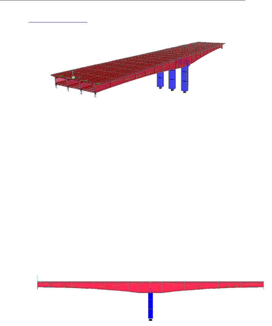
CSiBridge Bridge Superstructure Design
www.csiamerica.com. The tutorial video guides the user through the creation
of the bridge model referenced in this chapter.
Figure 8-1 3D view of example concrete box girder bridge model
8.1 Description of Example Model
The example bridge is a two-span prestressed concrete box girder bridge with
the following features:
Abutments: The abutments are skewed by 15 degrees and connected to the
bottom of the box girder only.
Prestress: The concrete box girder bridge is prestressed with four 10-in2
tendons (one in each girder) and a jacking force of 2160 kips per tendon.
Bents: The one interior bent has three 5-foot-square columns.
Deck: The concrete box girder has a nominal depth of 5 feet. The deck has
a parabolic variation in depth from 5 feet at the abutments to a maximum
of 10 feet at the interior bent support.
Spans: The two spans are each approximately 100 feet long.
Figure 8-2 Elevation view of the example bridge
8 - 2 Description of Example Model
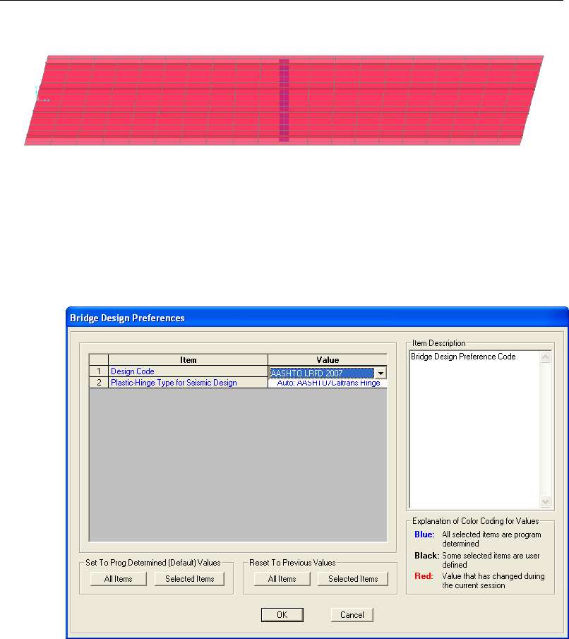
Chapter 8 - Run a Bridge Design Request
Figure 8-3 Plan view of the example bridge
8.2 Design Preferences
Use the Design/Rating > Superstructure Design > Preferences command to
select the AASHTO LRFD 2007 design code. The Bridge Design Preferences
form shown in Figure 8-4 displays.
Figure 8-4 Bridge Design Preferences form
8.3 Load Combinations
For this example, the default design load combinations were activated using the
Design/Rating > Load Combinations > Add Defaults command. After the
Bridge Design option has been selected, the Code-Generated Load Combina-
tions for Bridge Design form shown in Figure 8-5 displays. The form is used to
Design Preferences 8 - 3
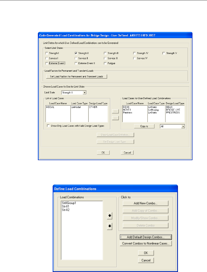
CSiBridge Bridge Superstructure Design
specify the desired limit states. Only the Strength II limit state was selected for
this example. Normally, several limit states would be selected.
Figure 8-5 Code-Generated Load Combinations for Bridge Design form
The defined load combinations for this example are shown in Figure 8-6.
Figure 8-6 Define Load Combinations form
8 - 4 Load Combinations
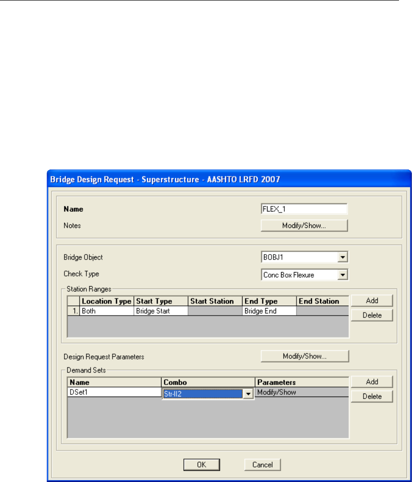
Chapter 8 - Run a Bridge Design Request
The Str-II1, Str-II2 and StrIIGroup1 designations for the load combinations are
specified by the program and indicate that the limit state for the combinations
is Strength Level II.
8.4 Bridge Design Request
After the Design/Rating > Superstructure Design > Design Request com-
mand has been used, the Bridge Design Request form shown in Figure 8-7 dis-
plays.
Figure 8-7 Define Load Combinations form
The name given to this example Design Request is FLEX_1, the Check Type
is for Concrete Box Flexure and the Demand Set, DSet1, specifies the combi-
nation as StrII (Strength Level II).
Bridge Design Request 8 - 5
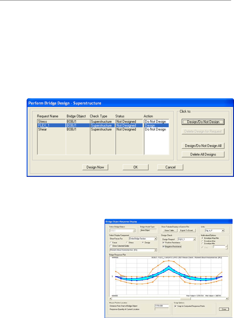
CSiBridge Bridge Superstructure Design
The only Design Request Parameter option for a Concrete Box Flexural check
type is for PhiC. A value of 0.9 for PhiC is used.
8.5 Start Design/Check of the Bridge
After an analysis has been run, the bridge model is ready for a design/check.
Use the Design/Rating > Superstructure Design > Run Super command to
start the design process. Select the design to be run using the Perform Bridge
Design form shown in Figure 8-8:
Figure 8-8 Perform Bridge Design - Superstructure
The user may select the desired Design Request(s) and click on the Design
Now button. A plot of the bridge model, similar to that shown in Figure 8-9,
will display.
If several Design Requests
have been run, the individ-
ual Design Requests can be
selected from the Design
Check options drop-down
list. This plot is described
further in Chapter 9.
Figure 8-9 Plot of flexure
check results
8 - 6 Start Design/Check of the Bridge

Chapter 9
Display Bridge Design Results
Bridge design results can be displayed on screen and as printed output. The
on-screen display can depict the bridge response graphically as a plot or in data
tables. The Advanced Report Writer can be used to create the printed output,
which can include the graphical display as well as the database tables.
This chapter displays the results for the example used in Chapter 8. The model
is a concrete box girder bridge and the code applied is AASHTO LRFD 2007.
Creation of the model is shown in a 30-minute Watch and Learn video on the
CSI website, www.csiamerica.com.
9.1 Display Results as a Plot
To view the forces, stresses, and design results graphically, click the Home >
Display > Show Bridge Superstructure Design Results command, which will
display the Bridge Object Response Display form shown in Figure 9-1.
The plot shows the design results for the FLEX_1 Design Request created using
the process described in the preceding chapters. The demand moments are en-
veloped and shown in the blue region, and the negative capacity moments are
shown with a brown line. If the demand moments do not exceed the capacity
moments, the superstructure may be deemed adequate in response to the flexure
Design Request. Move the mouse pointer onto the demand or capacity plot to
view the values for each nodal point. Move the pointer to the capacity moment
Display Results as a Plot 9 - 1
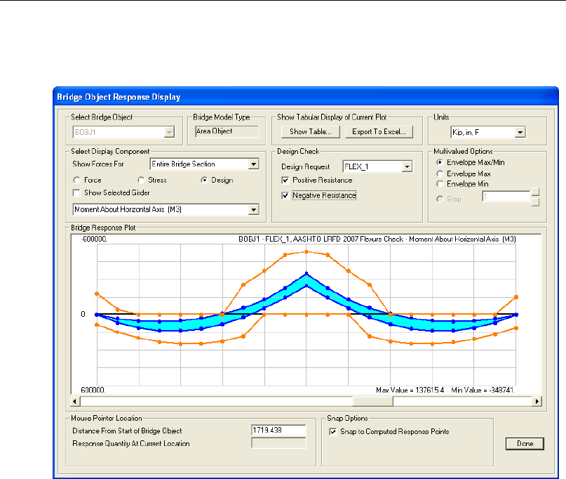
CSiBridge Bridge Superstructure Design
at station 1200 and 536981.722 kip-in is shown. A verification calculation that
shows agreement with this CSiBridge result is provided in Section 11.4.
Figure 9-1 Plot of flexure check results for the example bridge design model
9.1.1 Additional Display Examples
Use the Home > Display > Show Bridge Forces/Stresses command to select,
on the example form shown in Figure 9-2, the location along the top or bottom
portions of a beam or slab for which stresses are to be displayed. Figures 9-3
through 9-9 illustrate the left, middle, and right portions as they apply to Multi-
cell Concrete Box Sections. Location 1, as an example, refers to the top left se-
lection option while location 5 would refer to the bottom center selection option.
Locations 1, 2, and 3 refer to the top left, top center, and top right selection op-
tion while locations 4, 5, and 6 refer to the bottom left, bottom center, and bot-
tom right selection options.
9 - 2 Display Results as a Plot
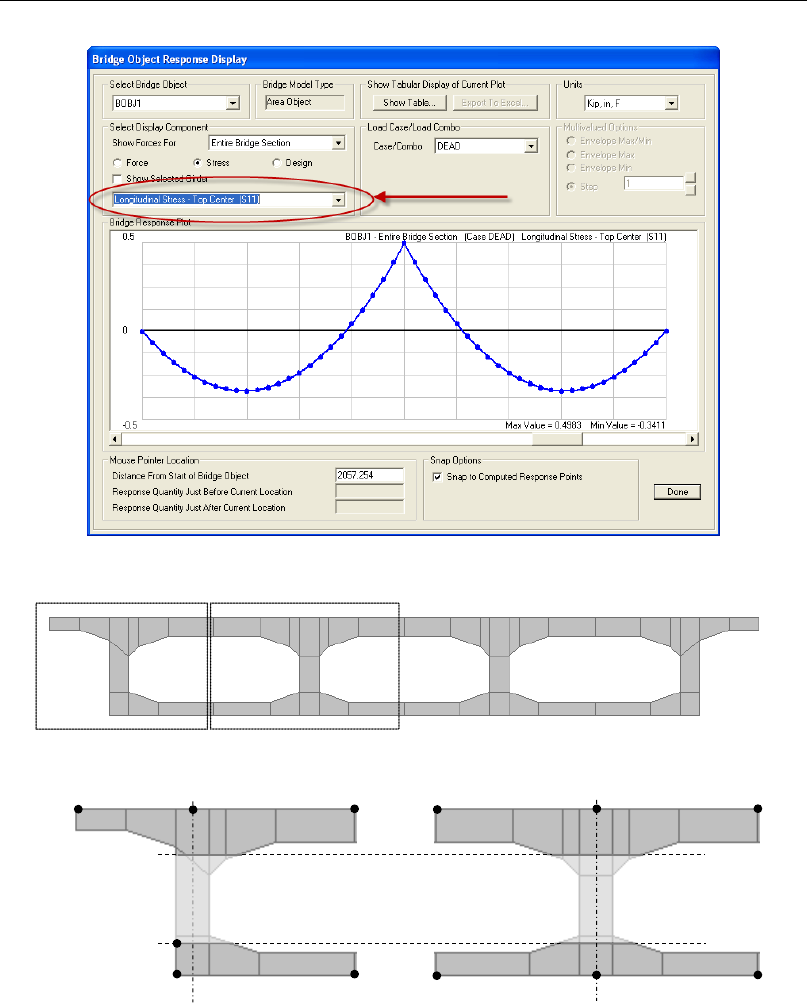
Chapter 9 - Display Bridge Design Results
Figure 9-2 Select the location on the beam or slab for which results are to be displayed
Figure 9-3 Bridge Concrete Box Deck Section - External Girders Vertical
Top slab cut line
Bottom slab cut line
Centerline of the web
Centerline of the web
1
2
3
4
5
6
4
5
6
1
2
3
Display Results as a Plot 9- 3
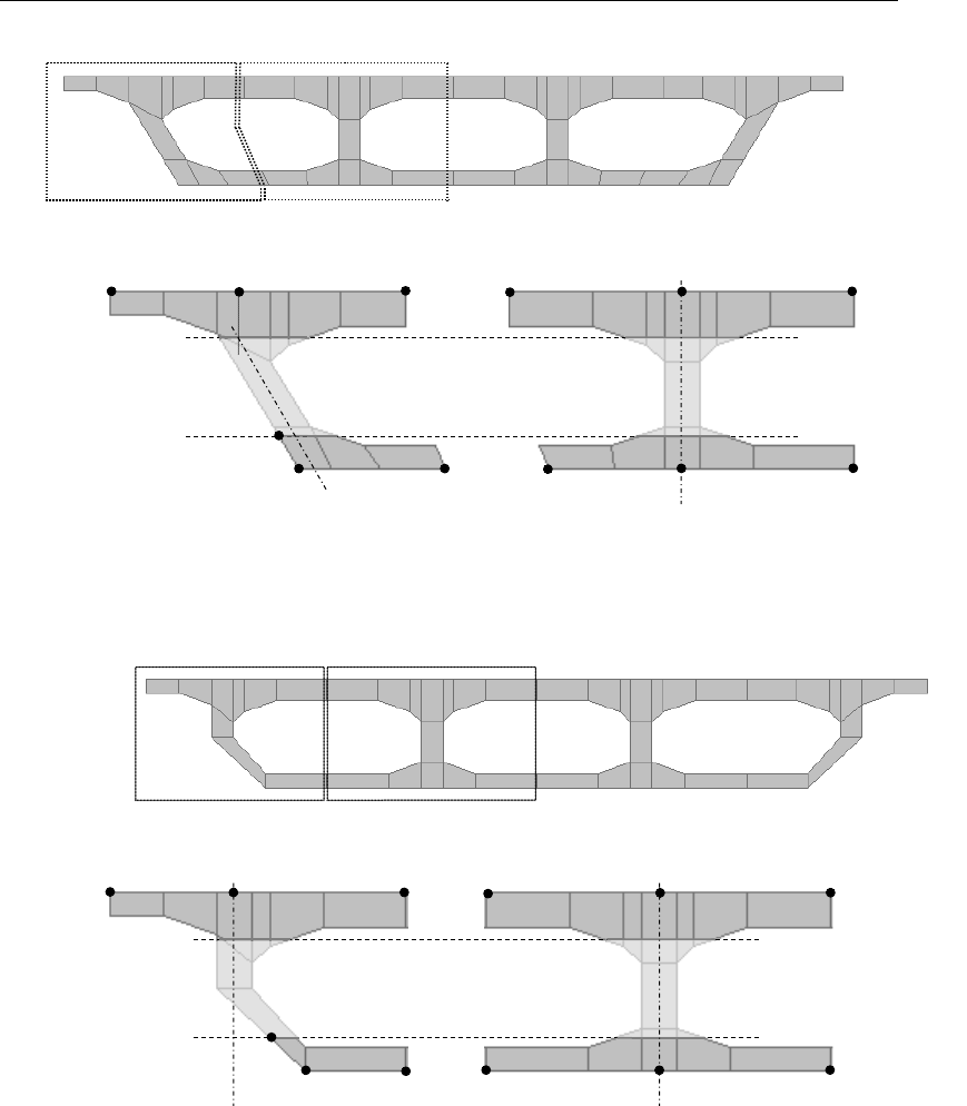
CSiBridge Bridge Superstructure Design
Figure 9-4 Bridge Concrete Box Deck Section - External Girders Sloped
Figure 9-5 Bridge Concrete Box Deck Section - External Girders Clipped
Top slab cut
Bottom slab cut line
Centerline of the web
4
5
6
1
2
3
1
2
3
4
5
6
Centerline of the web
Top slab cut
Bottom slab cut line
1
2
3
4
5
6
Centerline of the web
4
5
6
Centerline of the web
1
2
3
9 - 4 Display Results as a Plot
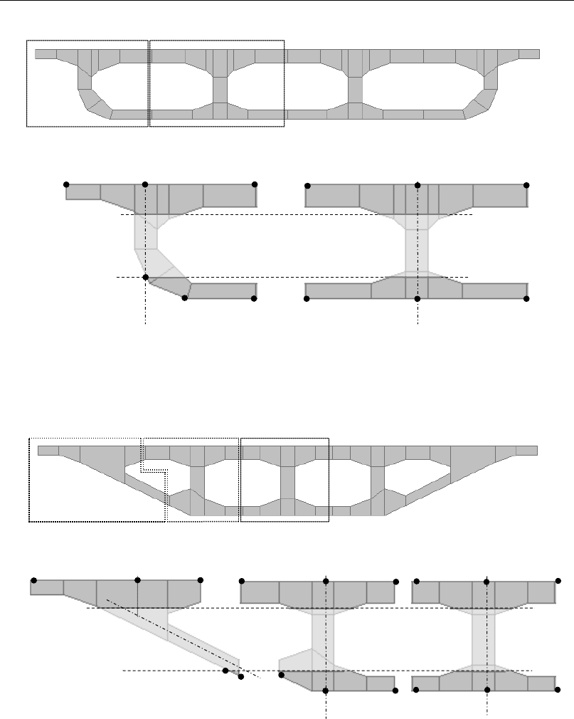
Chapter 9 - Display Bridge Design Results
Figure 9-6 Bridge Concrete Box Deck Section - External Girders and Radius
Figure 9-7 Bridge Concrete Box Deck Section - External Girders Sloped Max
Centerline of the web
Centerline of the web
4
5
6
1
2
1
2
6
3
5
4
1
2
3
4, 5
6
Top slab cut
Bottom slab cut line
Centerline of the web
Centerline of the web
1
2
3
1
2
3
4
5
6
4
5
6
Centerline of the web
Top slab cut line
Bottom slab cut line
3
Display Results as a Plot 9- 5
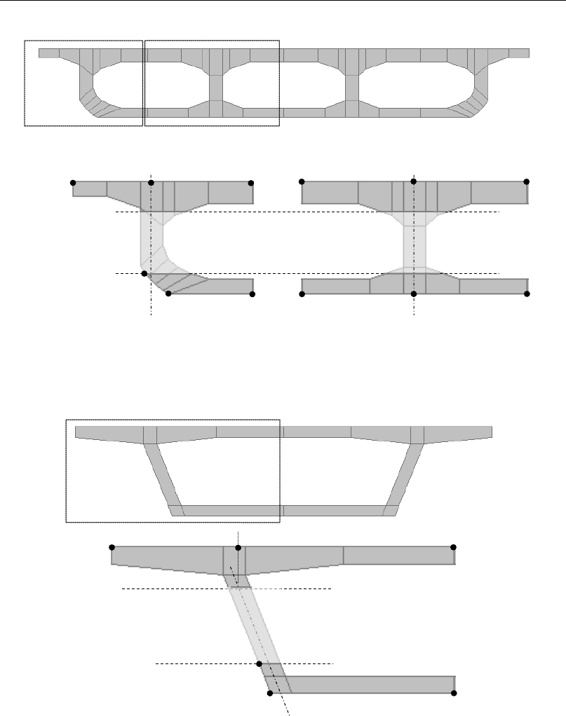
CSiBridge Bridge Superstructure Design
Figure 9-8 Bridge Concrete Box Deck Section - Advanced
Figure 9-9 Bridge Concrete Box Deck Section - AASHTO - PCI - ASBI Standard
Bottom slab cut line
Top slab cut line
Top slab cut line
Bottom slab cut line
1
2
3
Centerline of the web
Centerline of the web
1
2
3
4
5
6
Centerline of the web
1
2
3
4
5
6
4
5
6
9 - 6 Display Results as a Plot
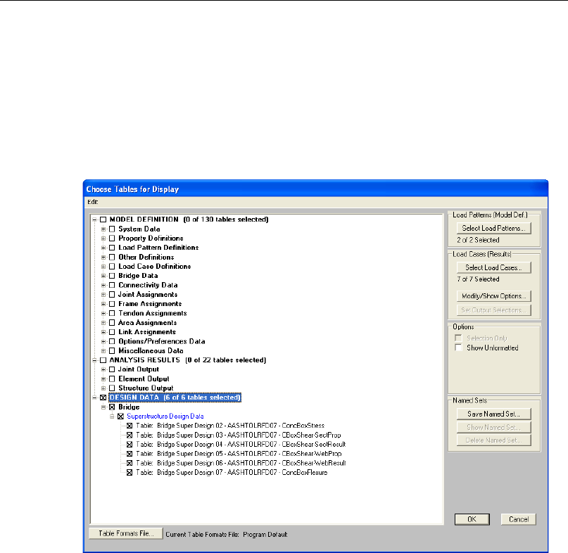
Chapter 9 - Display Bridge Design Results
9.2 Display Data Tables
To view design results on screen in tables, click the Home > Display > Show
Tables command, which will display the Choose Tables for Display form
shown in Figure 9-10. Use the options on that form to select which data results
are to be viewed. Multiple selection may be made.
Figure 9-10 Choose Tables for Display form
When all selections have been made, click the OK button and a database table
similar to that shown in Figure 9-11 will display. Note the drop-down list in the
upper right-hand corner of the table. That drop-down list will include the vari-
ous data tables that match the selections made on the Choose Tables for Display
form. Select from that list to change to a different database table.
Display Data Tables 9- 7
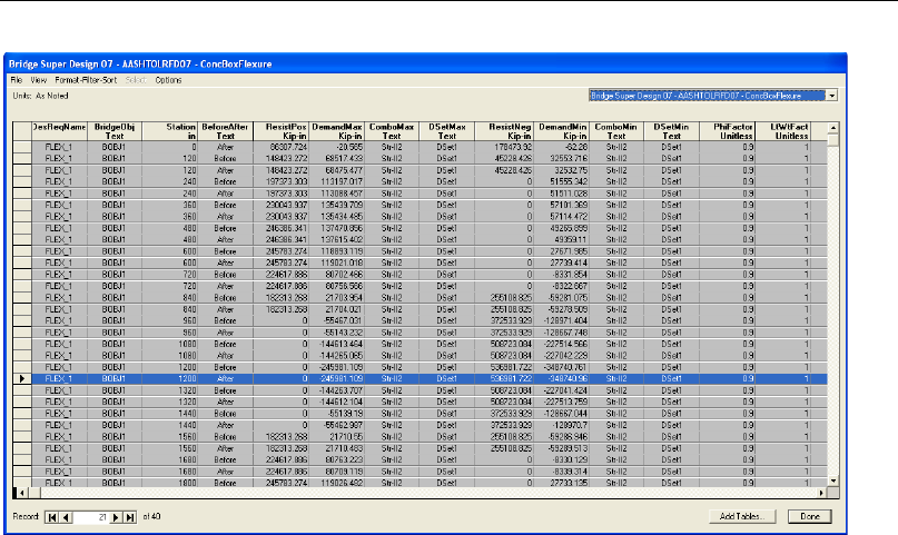
CSiBridge Bridge Superstructure Design
Figure 9-11 Design database table for AASHTO LRFD 2007 flexure check
The scroll bar along the bottom of the form can be used to scroll to the right to
view additional data columns.
9.3 Advanced Report Writer
The File > Report > Create Report command is a single button click output
option but it may not be suitable for bridge structures because of the size of the
document that is generated. Instead, the Advanced Report Writer feature within
CSiBridge is a simple and easy way to produce a custom output report.
To create a custom report that includes input and output, first export the files us-
ing one of the File > Export commands: Access; Excel; or Text. When this
command is executed, a form similar to that shown in Figure 9-12 displays.
9 - 8 Advanced Report Writer
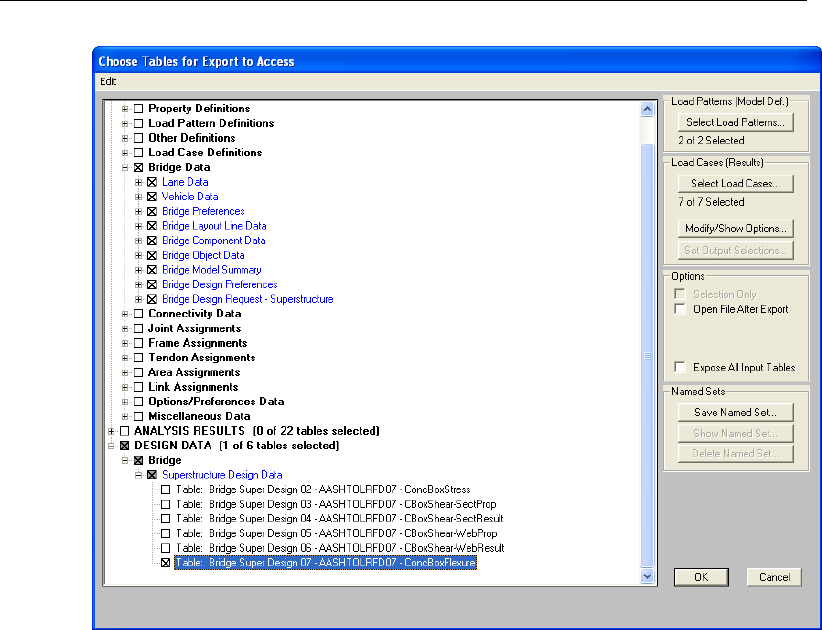
Chapter 9 - Display Bridge Design Results
Figure 9-12 Choose Tables for Export to Access form
This important step allows control over the size of the report to be generated.
Export only those tables to be included in the final report. However, it is possi-
ble to export larger quantities of data and then use the Advanced Report Writer
to select only specific data sets for individual reports, thus creating multiple
smaller reports. For this example, only the Bridge Data (input) and Concrete
Box Flexure design (output) are exported.
After the data tables have been exported and saved to an appropriate location,
click the File > Report > Advanced Report Writer command to display a
form similar to that show in Figure 9-13. Click the appropriate button (e.g., Find
existing DB File, Convert Excel File, Convert Text File) and locate the exported
data tables. The tables within that Database, Excel, or Text file will be listed in
the List of Tables in Current Database File display box.
Advanced Report Writer 9- 9

CSiBridge Bridge Superstructure Design
Figure 9-13 Create Custom Report form
Select the tables to be included in the report from that display box. The selected
items will then display in the Items Included in Report display box. Use the var-
ious options on the form to control the order in which the selected tables appear
in the report as well as the headers (i.e., Section names), page breaks, pictures,
and blanks required for final output in .rft, .txt, or .html format.
After the tables have been selected and the headers, pictures, and other format-
ting items have been addressed, click the Create Report button to generate the
report. The program will request a filename and the path to be used to store the
report. Figure 9-14 shows an example of the printed output generated by the
Report Writer.
9 - 10 Advanced Report Writer
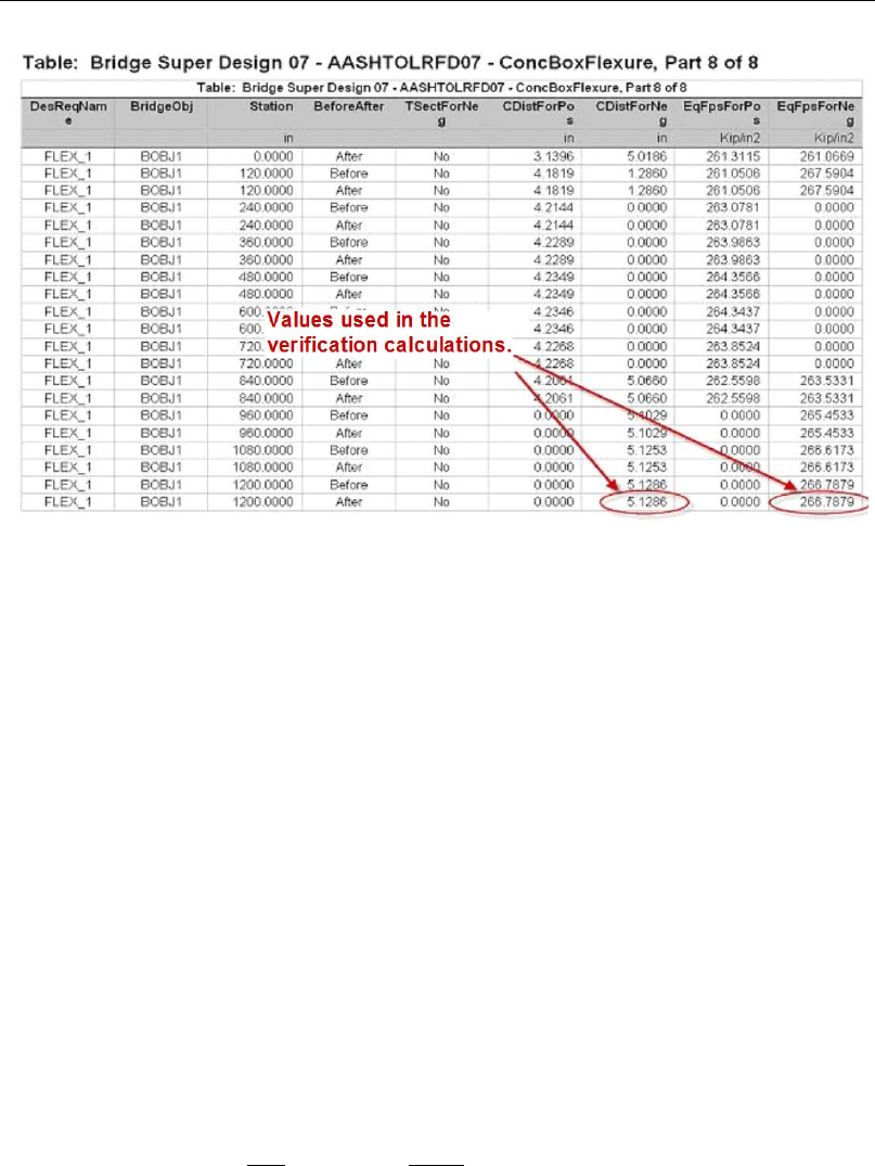
Chapter 9 - Display Bridge Design Results
Figure 9-14 An example of the printed output
9.4 Verification
As a verification check of the design results, the output at station 1200 is exam-
ined. The following output for negative bending has been pulled from the
ConBoxFlexure data table, a portion of which is shown in Figure 9-10:
Demand moment, “DemandMax” (kip-in) = −245973.481
Resisting moment, “ResistingNeg” (kip-in) = 536981.722
Total area of prestressing steel, “AreaPTTop” (in2) = 20.0
Top k factor, “kFactorTop” = 0.2644444
Neutral axis depth, c, “CDistForNeg” (in) = 5.1286
Effective stress in prestressing, fps, “EqFpsForNeg” (kip/in2) = 266.7879
A hand calculation that verifies the results follows:
For top k factor, from (eq. 5.7.3.1.1-2),
245 1
2 1 04 2 1 04 0 26444
270
PY
PU
f.
k. . .
f
= −= − =
(Results match)
Verification 9- 11

CSiBridge Bridge Superstructure Design
For neutral axis depth, from (AASHTO LRFD eq. 5.7.3.1.1-4),
( )
slab webeq slabeq
1 webeq
0.85 ,
0.85
PT PU c
PU
c PT
PT
Af f b b t
cf
f b kA Y
β
′
−−
=
′+
for a T-section
1 webeq
,
0.85
PT PU
PU
c PT
PT
Af
cf
f b kA Y
β
=
′+
when not a T-section
20.0(270) 5.1286
270
0.85(4)(0.85)(360) 0.26444(20) 114
c= =
+
(Results match)
For effective stress in prestressing, from (AASHTO LRFD eq. 5.7.3.1.1-1),
5 1286
1 270 1 0 26444 266 788
144
PS PU
PT
c.
ff k . .
Y
=−=− =
(Results match)
For resisting moment, from (AASHTO LRFD eq. 5.7.3.2.2-1),
( )
slabeq
11
SLAB webeq slabeq
0.85
2 22
ββ
′
= −+ − −
N PT PS PT c
t
cc
M Af Y f b b t
1
2
β
= −
N PT PS PT
c
M Af Y ,
when the box section is not a T-section
N
M
= −=
5.1286(0.85)
20.0(266.788) 144 596646.5
2
kip-in
RN
MM
φ
= = =0.85(596646.5) 536981.8
kip-in (Results match)
The preceding calculations are a check of the flexure design output. Other de-
sign results for concrete box stress, concrete box shear, and concrete box princi-
pal have not been included. The user is encouraged to perform a similar check
of these designs and to review Chapters 5, 6, and 7 for detailed descriptions of
the design algorithms.
9 - 12 Verification

Bibliography
ACI, 2007. Building Code Requirements for Structural Concrete (ACI 318-08)
and Commentary (ACI 318R-08), American Concrete Institute, P.O.
Box 9094, Farmington Hills, Michigan.
AASHTO, 2007. AASHTO LRFD Bridge Design Specifications — Customary
U.S. Units, 4th Edition, 2008 Interim Revision, American Association
of State Highway and Transportation Officials, 444 North Capitol
Street, NW, Suite 249, Washington, D.C. 20001.
AASHTO, 2009. AASHTO Guide Specifications for LRFD Seismic Bridge
Design. American Association of Highway and Transportation Offi-
cials, 444 North Capital Street, NW Suite 249, Washington, DC 20001.
AASHTO 2012. AASHTO LRFD Bridge Design Specifications — U.S.
Units, 6th Edition, American Association of State High way and
Transportation Officials, 2012.
Canadian Standards Association (CSA), 2006. Canadian Highway Bridge De-
sign Code. Canadian Standards Association, 5060 Spectrum Way,
Suite 100, Mississauga, Ontario, Canada, L4W 5N6. November.
EN 1994-2:2005, Eurocode 4: Design of composite steel and concrete struc-
tures, Part 2: Composite Bridges, European Committee for Standardi-
zation, Management Centre: rue de Stassart, 36 B-1050 Brussels.
Bibliography - 1

SAFE Reinforced Concrete Design
Indian Roads Congress (IRC), May 2010: Standard Specifications and Code of
Practice for Road Bridges, Section V, Steel Road Bridges. Kama Koti
Marg, Sector 6, RK Puram, New Delhi- 110 022.
R - 2
